oracle communications network charging and control ussd
TRANSCRIPT
Oracle® Communications Network Charging and Control USSD Gateway User's Guide
Release 12.0.0
December 2017

ii USSD Gateway User's Guide
Copyright
Copyright © 2017, Oracle and/or its affiliates. All rights reserved.
This software and related documentation are provided under a license agreement containing restrictions on use and disclosure and are protected by intellectual property laws. Except as expressly permitted in your license agreement or allowed by law, you may not use, copy, reproduce, translate, broadcast, modify, license, transmit, distribute, exhibit, perform, publish, or display any part, in any form, or by any means. Reverse engineering, disassembly, or decompilation of this software, unless required by law for interoperability, is prohibited.
The information contained herein is subject to change without notice and is not warranted to be error-free. If you find any errors, please report them to us in writing.
If this is software or related documentation that is delivered to the U.S. Government or anyone licensing it on behalf of the U.S. Government, then the following notice is applicable:
U.S. GOVERNMENT END USERS: Oracle programs, including any operating system, integrated software, any programs installed on the hardware, and/or documentation, delivered to U.S. Government end users are "commercial computer software" pursuant to the applicable Federal Acquisition Regulation and agency-specific supplemental regulations. As such, use, duplication, disclosure, modification, and adaptation of the programs, including any operating system, integrated software, any programs installed on the hardware, and/or documentation, shall be subject to license terms and license restrictions applicable to the programs. No other rights are granted to the U.S. Government.
This software or hardware is developed for general use in a variety of information management applications. It is not developed or intended for use in any inherently dangerous applications, including applications that may create a risk of personal injury. If you use this software or hardware in dangerous applications, then you shall be responsible to take all appropriate fail-safe, backup, redundancy, and other measures to ensure its safe use. Oracle Corporation and its affiliates disclaim any liability for any damages caused by use of this software or hardware in dangerous applications.
Oracle and Java are registered trademarks of Oracle and/or its affiliates. Other names may be trademarks of their respective owners.
Intel and Intel Xeon are trademarks or registered trademarks of Intel Corporation. All SPARC trademarks are used under license and are trademarks or registered trademarks of SPARC International, Inc. AMD, Opteron, the AMD logo, and the AMD Opteron logo are trademarks or registered trademarks of Advanced Micro Devices. UNIX is a registered trademark of The Open Group.
This software or hardware and documentation may provide access to or information about content, products, and services from third parties. Oracle Corporation and its affiliates are not responsible for and expressly disclaim all warranties of any kind with respect to third-party content, products, and services unless otherwise set forth in an applicable agreement between you and Oracle. Oracle Corporation and its affiliates will not be responsible for any loss, costs, or damages incurred due to your access to or use of third-party content, products, or services, except as set forth in an applicable agreement between you and Oracle.
iii
Contents
About This Document .................................................................................................................. v Document Conventions .............................................................................................................. vi
Chapter 1
System Overview .................................................................................. 1
Introduction .................................................................................................................................. 1 What is USSD Gateway? ............................................................................................................ 1 Callback ....................................................................................................................................... 3 Handset Interaction ..................................................................................................................... 5 Performance Reports .................................................................................................................. 6
Chapter 2
Getting Started ...................................................................................... 9
Overview ...................................................................................................................................... 9 Accessing USSD Gateway .......................................................................................................... 9 Accessing UPC Portal ...............................................................................................................11 Common Buttons and Fields .....................................................................................................11 Using the Find Screens .............................................................................................................12
Chapter 3
USSD Gateway Base Configuration Screens .................................... 15
Overview ....................................................................................................................................15 USSD Gateway Base Configuration Screen .............................................................................15 Trigger Prefix .............................................................................................................................16 Language ...................................................................................................................................18 Service Interface ........................................................................................................................21 Operator ....................................................................................................................................23
Chapter 4
USSD Gateway Configuration Screen ............................................... 27
Overview ....................................................................................................................................27 USSD Gateway Menu Configuration Screen ............................................................................27 Gateway Configuration Screen .................................................................................................27
Chapter 5
USSD Gateway Service Configuration Screen .................................. 33
Overview ....................................................................................................................................33 USSD Gateway Service Configuration Screen .........................................................................33 Service Trigger ..........................................................................................................................34
Chapter 6
Menu and Status Screens ................................................................... 39
Overview ....................................................................................................................................39 USSD Gateway Menu Configuration Screen ............................................................................39 Menu Wizard .............................................................................................................................40
iv USSD Gateway User's Guide
Status Wizard ............................................................................................................................ 43 Menu Info Configuration ............................................................................................................ 45 Status Info Configuration ........................................................................................................... 47 Menu Language Display ............................................................................................................ 49 Status Language Display .......................................................................................................... 54
Chapter 7
Subscribers Screens .......................................................................... 59
Overview .................................................................................................................................... 59 USSD Gateway Subscribers Screens ....................................................................................... 59 Access Control Screen .............................................................................................................. 60 IMSI Tracing Screen .................................................................................................................. 62 CDR Viewer Screen .................................................................................................................. 64 UPC CDR Viewer Screen .......................................................................................................... 67
Chapter 8
UPC Portal Screens ............................................................................ 69
Overview .................................................................................................................................... 69 USSD Platform User Selection Screens ................................................................................... 69 USSD Portal Message Class Screens ...................................................................................... 71
Chapter 9
UPC Portal Nodes ............................................................................... 75
Overview .................................................................................................................................... 75 Control Plan Editor Screen ........................................................................................................ 75 Making Nodes Available ............................................................................................................ 76 Available Feature Nodes ........................................................................................................... 77 Language Setting ...................................................................................................................... 78 Send Buffer ................................................................................................................................ 81 User Input .................................................................................................................................. 83 User Selection ........................................................................................................................... 87 Version Branching ..................................................................................................................... 91
Glossary of Terms .............................................................................. 93
Index .................................................................................................... 99
v
About This Document
Scope
The scope of this document includes all functionality a user must know in order to effectively operate the USSD GW application. It does not include detailed design of the service.
Audience
This guide is written primarily for USSD GW System Administrators. However, the overview sections of the document may be useful to anyone requiring an introduction to the application.
Prerequisites
Although there are no prerequisites for using this guide, familiarity with the target platform would be an advantage.
This manual describes system tasks that should only be carried out by suitably trained operators.
Related Documents
The following documents are related to this document:
USSD GW Technical Guide CPE User's Guide SLEE Technical Guide SMS User's Guide SMS Technical Guide
vi USSD Gateway User's Guide
Document Conventions
Typographical Conventions
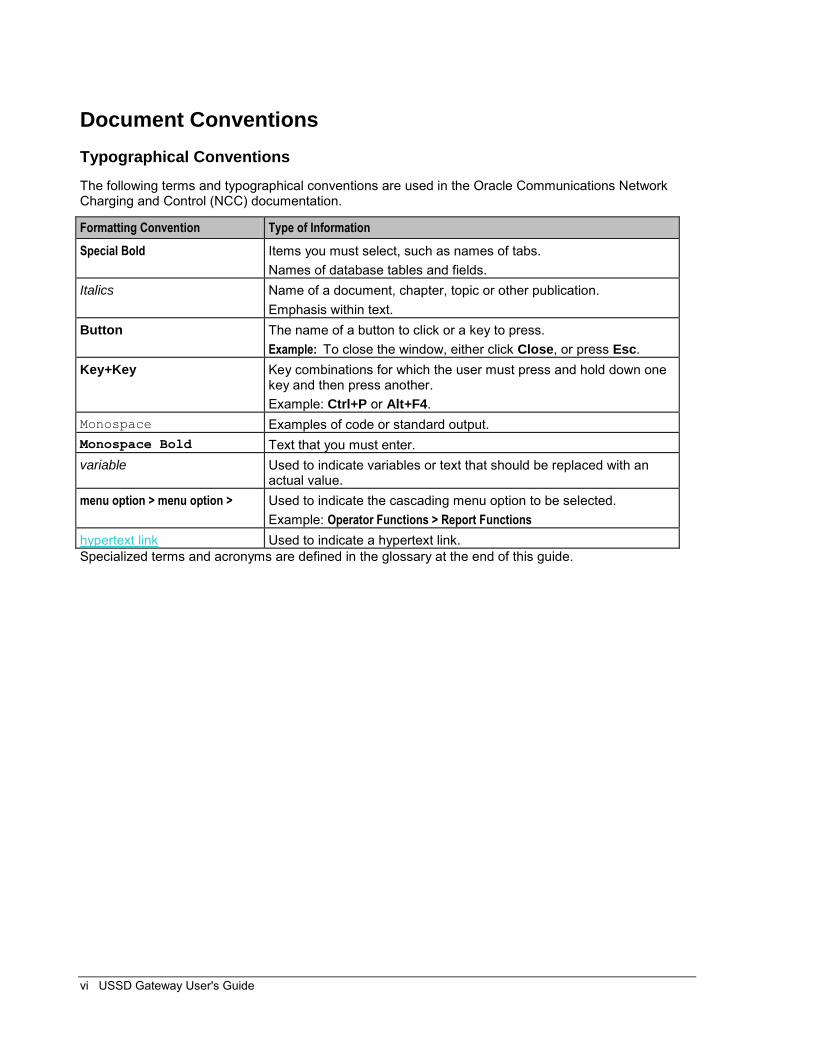
The following terms and typographical conventions are used in the Oracle Communications Network Charging and Control (NCC) documentation.
Formatting Convention Type of Information
Special Bold Items you must select, such as names of tabs. Names of database tables and fields.
Italics Name of a document, chapter, topic or other publication. Emphasis within text.
Button The name of a button to click or a key to press. Example: To close the window, either click Close, or press Esc.
Key+Key Key combinations for which the user must press and hold down one key and then press another. Example: Ctrl+P or Alt+F4.
Monospace Examples of code or standard output. Monospace Bold Text that you must enter. variable Used to indicate variables or text that should be replaced with an
actual value. menu option > menu option > Used to indicate the cascading menu option to be selected.
Example: Operator Functions > Report Functions hypertext link Used to indicate a hypertext link. Specialized terms and acronyms are defined in the glossary at the end of this guide.
Chapter 1, System Overview 1
Chapter 1
System Overview
Introduction
Purpose
This chapter describes the USSD Gateway and the basic functionality of the system.
In this chapter
This chapter contains the following topics.
What is USSD Gateway? .............................................................................................................. 1 Callback ......................................................................................................................................... 3 Handset Interaction ....................................................................................................................... 5 Performance Reports .................................................................................................................... 6
What is USSD Gateway?
Introduction
The USSD GW provides the following functions:
interaction using USSD messages between the subscriber's handset and the platform: processing fast access, single string (typeahead) requests presenting information to mobile users using USSD messages complex interaction through navigation of menus based on user input (interactive USSD)
IMSI Management: different services can be configured for different IMSI prefixes barring by IMSI or IMSI prefix logging forbidden attempts to use the service tracing for all calls from an IMSI or IMSI prefix CDR Viewing screen provides full information about a call and provides EDR searching support
for both USSD phase 1 / MAP1 and USSD phase 2 / MAP2, and roaming USSD Session Control
separate control plans for charging and call monitoring with Location Capabilities Pack, session can be initiated directly back to a roaming subscriber.
Control plans
Advanced Control Services (ACS) and the ACS Control Plan Editor (CPE) provide GUI tools to create control plans for USSD-based services. You can use a rich suite of feature nodes in USSD control plans, which enable decision making, interactive dialogue and more.
For more information on managing control plans, see CPE User's Guide. For more information about the USSD GW feature nodes, see Feature Nodes Reference Guide.
UIS and UPC
USSD GW is provided in two main parts:
Chapter 1
2 USSD Gateway User's Guide
UIS UPC
USSD Interactive Services Gateway
The USSD Interactive Services Gateway (UIS) enables operators to provide interactive menu-based portal services to end users.
UIS translates between the network USSD messages received from handsets to the INAP messages used to communicate with ACS. UIS also determines the service that should handle in the incoming service initiation request.
UIS enables operators to provide a range of services using USSD messages from (and to) a subscriber's handset. Interaction is configured using ACS control plans. UIS can also process fast access, single-string requests to trigger platform functionality, including:
Subscriber account detail reports (with CCS) Voucher recharges (with CCS), and USSD Roaming call back.
USSD Gateway Portal Service
USSD GW's USSD Portal Service (UPC) is an optional part of USSD GW that provides extended interactivity through the UPC Portal Screens and USSD GW feature nodes.
The UPC Portal Screens (on page 69) are used to extend the interactive USSD menus created using the UIS screens (for example by providing menu branching).
Handset integration
USSD GW uses the USSD protocol as defined by GSM phase 1 & 2. This means the majority of subscribers can use the menus without needing to upgrade their handsets.
This approach is an alternative delivery mechanism to WAP, as WAP support is still limited to middle- and higher-tier handsets.
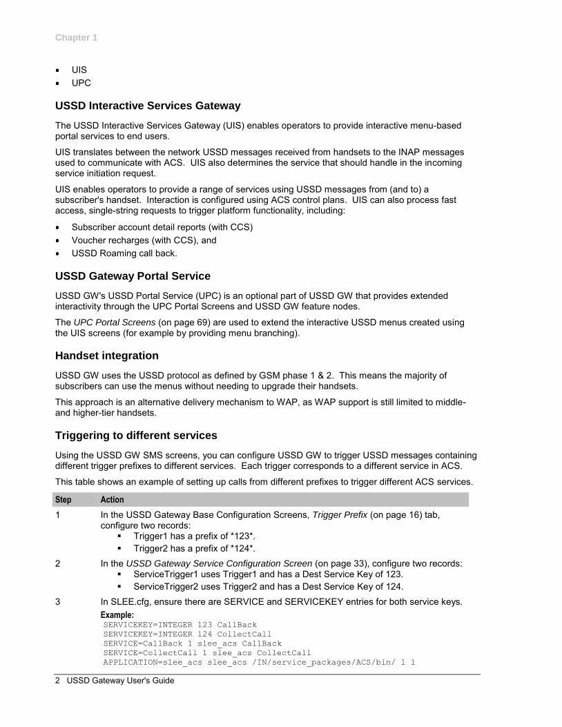
Triggering to different services
Using the USSD GW SMS screens, you can configure USSD GW to trigger USSD messages containing different trigger prefixes to different services. Each trigger corresponds to a different service in ACS.
This table shows an example of setting up calls from different prefixes to trigger different ACS services.
Step Action
1 In the USSD Gateway Base Configuration Screens, Trigger Prefix (on page 16) tab, configure two records:
Trigger1 has a prefix of *123*. Trigger2 has a prefix of *124*.
2 In the USSD Gateway Service Configuration Screen (on page 33), configure two records: ServiceTrigger1 uses Trigger1 and has a Dest Service Key of 123. ServiceTrigger2 uses Trigger2 and has a Dest Service Key of 124.
3 In SLEE.cfg, ensure there are SERVICE and SERVICEKEY entries for both service keys. Example: SERVICEKEY=INTEGER 123 CallBack
SERVICEKEY=INTEGER 124 CollectCall
SERVICE=CallBack 1 slee_acs CallBack
SERVICE=CollectCall 1 slee_acs CollectCall
APPLICATION=slee_acs slee_acs /IN/service_packages/ACS/bin/ 1 1
Chapter 1
Chapter 1, System Overview 3
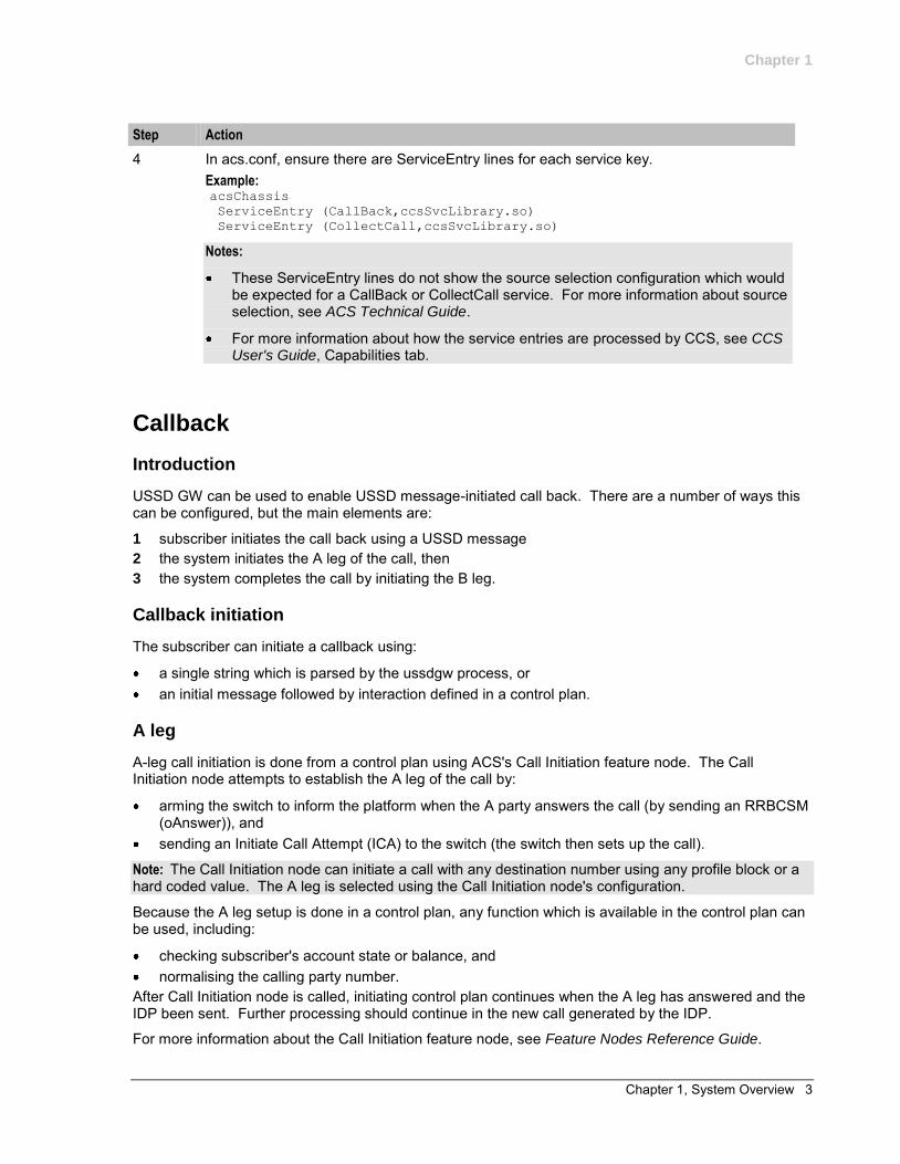
Step Action
4 In acs.conf, ensure there are ServiceEntry lines for each service key. Example: acsChassis
ServiceEntry (CallBack,ccsSvcLibrary.so)
ServiceEntry (CollectCall,ccsSvcLibrary.so)
Notes:
These ServiceEntry lines do not show the source selection configuration which would be expected for a CallBack or CollectCall service. For more information about source selection, see ACS Technical Guide.
For more information about how the service entries are processed by CCS, see CCS User's Guide, Capabilities tab.
Callback
Introduction
USSD GW can be used to enable USSD message-initiated call back. There are a number of ways this can be configured, but the main elements are:
1 subscriber initiates the call back using a USSD message 2 the system initiates the A leg of the call, then 3 the system completes the call by initiating the B leg.
Callback initiation
The subscriber can initiate a callback using:
a single string which is parsed by the ussdgw process, or an initial message followed by interaction defined in a control plan.
A leg
A-leg call initiation is done from a control plan using ACS's Call Initiation feature node. The Call Initiation node attempts to establish the A leg of the call by:
arming the switch to inform the platform when the A party answers the call (by sending an RRBCSM (oAnswer)), and
sending an Initiate Call Attempt (ICA) to the switch (the switch then sets up the call).
Note: The Call Initiation node can initiate a call with any destination number using any profile block or a hard coded value. The A leg is selected using the Call Initiation node's configuration.
Because the A leg setup is done in a control plan, any function which is available in the control plan can be used, including:
checking subscriber's account state or balance, and normalising the calling party number.
After Call Initiation node is called, initiating control plan continues when the A leg has answered and the IDP been sent. Further processing should continue in the new call generated by the IDP.
For more information about the Call Initiation feature node, see Feature Nodes Reference Guide.
Chapter 1
4 USSD Gateway User's Guide
B leg
When the A party answers, the switch returns an ERBCSM (oAnswer) to the control plan and a new forked control plan starts. The new call can use any control plan functionality, including:
monitoring the new call, and using a retrieved details (including MSRN) for charging.
The new forked call is responsible for connecting to the B leg (for example, by using an AT or a UATB node).
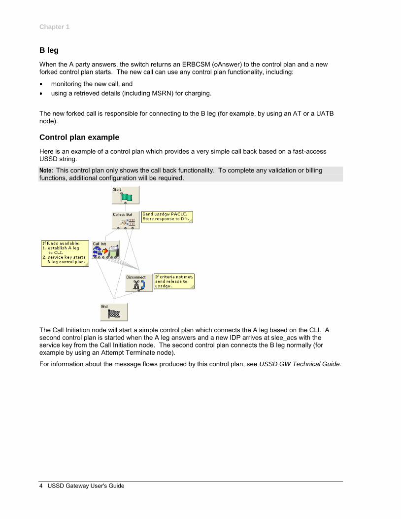
Control plan example
Here is an example of a control plan which provides a very simple call back based on a fast-access USSD string.
Note: This control plan only shows the call back functionality. To complete any validation or billing functions, additional configuration will be required.
The Call Initiation node will start a simple control plan which connects the A leg based on the CLI. A second control plan is started when the A leg answers and a new IDP arrives at slee_acs with the service key from the Call Initiation node. The second control plan connects the B leg normally (for example by using an Attempt Terminate node).
For information about the message flows produced by this control plan, see USSD GW Technical Guide.
Chapter 1
Chapter 1, System Overview 5
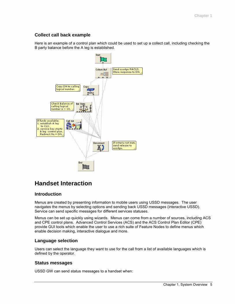
Collect call back example
Here is an example of a control plan which could be used to set up a collect call, including checking the B party balance before the A leg is established.
Handset Interaction
Introduction
Menus are created by presenting information to mobile users using USSD messages. The user navigates the menus by selecting options and sending back USSD messages (interactive USSD). Service can send specific messages for different services statuses.
Menus can be set up quickly using wizards. Menus can come from a number of sources, including ACS and CPE control plans. Advanced Control Services (ACS) and the ACS Control Plan Editor (CPE) provide GUI tools which enable the user to use a rich suite of Feature Nodes to define menus which enable decision making, interactive dialogue and more.
Language selection
Users can select the language they want to use for the call from a list of available languages which is defined by the operator.
Status messages
USSD GW can send status messages to a handset when:
Chapter 1
6 USSD Gateway User's Guide
a subscriber's session is ended by the gateway (session cut off). a session is put in suspended mode (reconnect) (except when the handset is entering MAP 1
disconnect mode)
Notes:
If there is no other status cause when the session ends, the display message will have a status cause that maps to “session ending”.
When a session is suspended, the last display must be preserved otherwise it will always be overwritten with the status display.
UPS menus
In general, to use the concept of menu IDs within ACS, menu sets are provided which allow menus to be grouped together in a logical block that may represent a service or a type of service.
USSD GW feature nodes control extended interaction (including menu branching) and other specific functions.
Menu sets enable menus to be grouped in logical blocks.
Performance Reports
Description
Performance Reports are generated by the USSD GW application on the SCP. They are single line events that are only output as NOTICE-type Alarm messages.
These reports are designed to have minimal impact on the performance of the SCP. This includes the ability for the output of these reports to be disabled or only activated for specific USSD Trigger Prefixes.
Report timing
The report must be consistently aligned with the system clock on the SLC. To achieve this, only an integer value that can be computed to be a factor of 60 or 3600, must be used.
Example: 30 or 300
See Example values (on page 6) for a list of allowed values that can be specified to accurately align reports generation to the SLC system clock.
Warning: A warning message will be displayed if a value NOT divisible by 60 or 3600 is entered. This means the report is not aligned to the system clock and hence reports cannot be generated at fixed intervals.
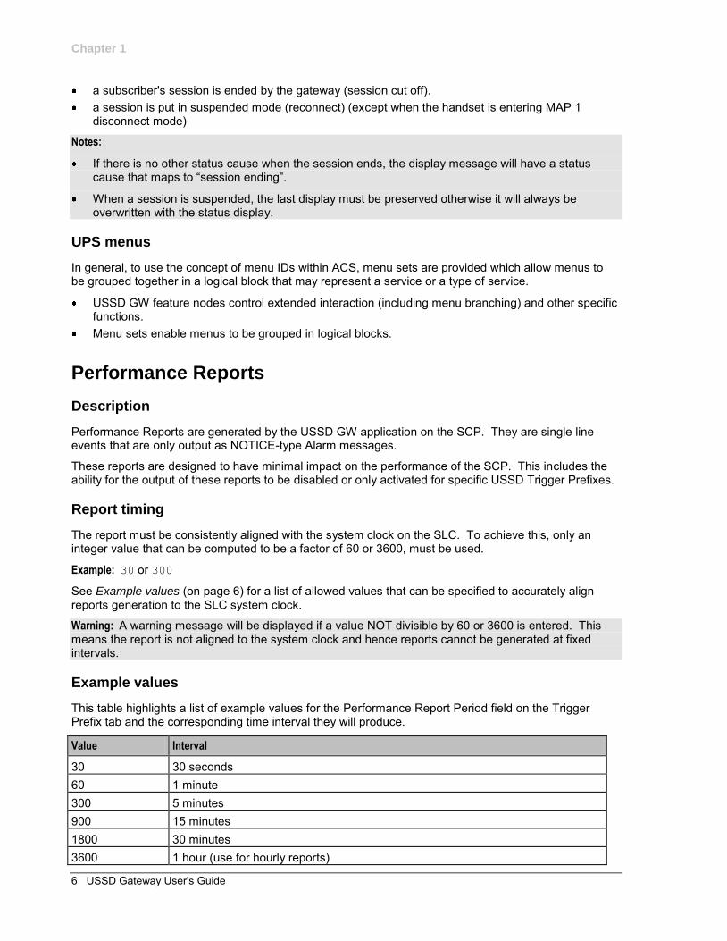
Example values
This table highlights a list of example values for the Performance Report Period field on the Trigger Prefix tab and the corresponding time interval they will produce.
Value Interval
30 30 seconds 60 1 minute 300 5 minutes 900 15 minutes 1800 30 minutes 3600 1 hour (use for hourly reports)
Chapter 1
Chapter 1, System Overview 7
Accessing performance reports
Performance reports are generated as single-line alarm messages that can be viewed on one of the following:
SMS in Operator Functions -> Alarm Management Panel SLC in the ussdgw log file
Example
Here are a few examples of Performance Report.
Example 1: Feb 23 22:23:30.007958 cmnError(24758) NOTICE: USSD Performance:
Trigger Prefix '*999#' Period=11; Requests=5; Responses=5; Timeouts=0; Others=0;
Latency: Min=0.158024, Mean=0.165843, Max=0.177295
Example 2: Feb 23 22:24:00.033720 cmnError(24758) NOTICE: USSD Performance:
Trigger Prefix '*999#' Period=30; Requests=23; Responses=22; Timeouts=0; Others=0;
Latency: Min=0.137390, Mean=0.161867, Max=0.219761
Example 3: Feb 23 22:24:30.002919 cmnError(24758) NOTICE: USSD Performance:
Trigger Prefix '*999#' Period=30; Requests=2; Responses=3; Timeouts=0; Others=0;
Latency: Min=0.137340, Mean=0.152989, Max=0.174586
Example 4: Feb 23 22:25:00.001234 cmnError(24758) NOTICE: USSD Performance:
Trigger Prefix '*999#' Period=30; Requests=12; Responses=12; Timeouts=1; Others=0;
Latency: Min=0.122345, Mean=0.154529, Max=0.174236
Result:
On the Trigger Prefix tab screen, the Performance Report Period is set to 30 seconds for each of the above examples. Therefore, the following timestamps are generated by the respective alarm message:
Example 1: 22:23:30.007958 Example 2: 22:24:00.033720 Example 3: 22:24:30.002919 Example 4: 22:25:00.001234

Chapter 2, Getting Started 9
Chapter 2
Getting Started
Overview
Purpose
This chapter explains how to access the USSD Gateway and describes the contents of the main screens.
In this chapter
This chapter contains the following topics.
Accessing USSD Gateway ............................................................................................................ 9 Accessing UPC Portal ................................................................................................................. 11 Common Buttons and Fields ....................................................................................................... 11 Using the Find Screens ............................................................................................................... 12
Accessing USSD Gateway
Procedure
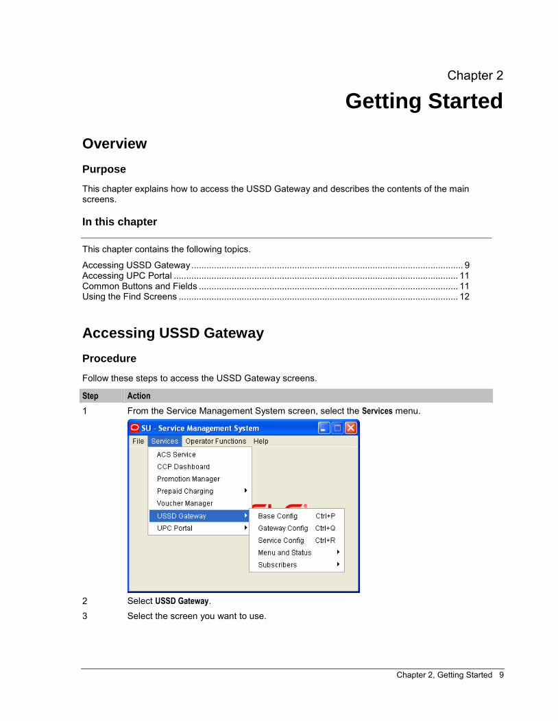
Follow these steps to access the USSD Gateway screens.
Step Action
1 From the Service Management System screen, select the Services menu.
2 Select USSD Gateway. 3 Select the screen you want to use.
Chapter 2
10 USSD Gateway User's Guide
USSD Gateway menu options
This table describes the menu options accessible from the USSD Gateway menu option.
Menu Description
Base Config Provides access to the creation and maintenance screens for base USSD Gateway configuration.
Gateway Config Provides access to the creation and maintenance screens for global USSD Gateway configuration.
Service Config Provides access to the creation and maintenance screens for USSD Gateway services.
Menu and Status Provides access to the creation and maintenance screens for menus and statuses of USSD Gateway.
Subscribers Provides access to the creation and maintenance screens for subscribers.
Base Config screen
The USSD Gateway Base Configuration Screen contains four tabs:
Trigger Prefix (on page 16) Language (on page 18) Service Interface (on page 21) Operator (on page 23)
Gateway Config screen
The USSD Gateway Configuration screen contains one tab:
Gateway Configuration (on page 27)
Service Config screen
The USSD Gateway Service Configuration screen contains one tab:
Service Trigger (on page 34)
Menu and Status screens
The Menu and Status option contains three sub menus:
Wizard - This option contains two screens: Menu Wizard (on page 40) Status Wizard (on page 43)
Config - The USSD Gateway Menu Configuration Screens contains two tabs: Menu Info (on page 45) Status Info Configuration (on page 47)
Display - The USSD Gateway Menu Display Screens contains two tabs: Menu Language (on page 49) Status Language (on page 54)
Subscribers screens
The Subscribers menu option contains the screens:
Access Control Screen (on page 60)
Chapter 2
Chapter 2, Getting Started 11
IMSI Tracing (on page 62) CDR Viewer (on page 64) UPC CDR Viewer Screen (on page 67)
Accessing UPC Portal
Procedure
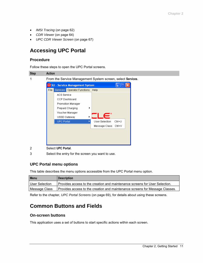
Follow these steps to open the UPC Portal screens.
Step Action
1 From the Service Management System screen, select Services.
2 Select UPC Portal. 3 Select the entry for the screen you want to use.
UPC Portal menu options
This table describes the menu options accessible from the UPC Portal menu option.
Menu Description
User Selection Provides access to the creation and maintenance screens for User Selection. Message Class Provides access to the creation and maintenance screens for Message Classes.
Refer to the chapter, UPC Portal Screens (on page 69), for details about using these screens.
Common Buttons and Fields
On-screen buttons
This application uses a set of buttons to start specific actions within each screen.
Chapter 2
12 USSD Gateway User's Guide
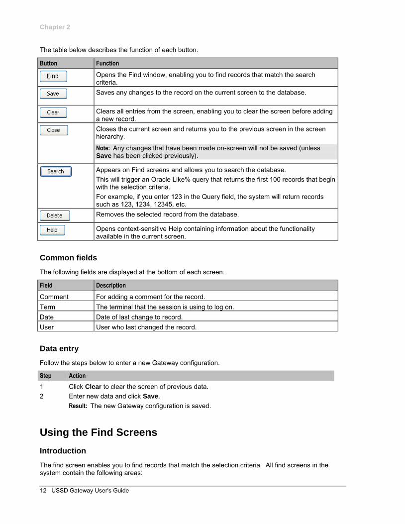
The table below describes the function of each button.
Button Function
Opens the Find window, enabling you to find records that match the search criteria.
Saves any changes to the record on the current screen to the database.
Clears all entries from the screen, enabling you to clear the screen before adding a new record.
Closes the current screen and returns you to the previous screen in the screen hierarchy.
Note: Any changes that have been made on-screen will not be saved (unless Save has been clicked previously).
Appears on Find screens and allows you to search the database. This will trigger an Oracle Like% query that returns the first 100 records that begin with the selection criteria. For example, if you enter 123 in the Query field, the system will return records such as 123, 1234, 12345, etc.
Removes the selected record from the database.
Opens context-sensitive Help containing information about the functionality available in the current screen.
Common fields
The following fields are displayed at the bottom of each screen.
Field Description
Comment For adding a comment for the record. Term The terminal that the session is using to log on. Date Date of last change to record. User User who last changed the record.
Data entry
Follow the steps below to enter a new Gateway configuration.
Step Action
1 Click Clear to clear the screen of previous data. 2 Enter new data and click Save.
Result: The new Gateway configuration is saved.
Using the Find Screens
Introduction
The find screen enables you to find records that match the selection criteria. All find screens in the system contain the following areas:
Chapter 2
Chapter 2, Getting Started 13
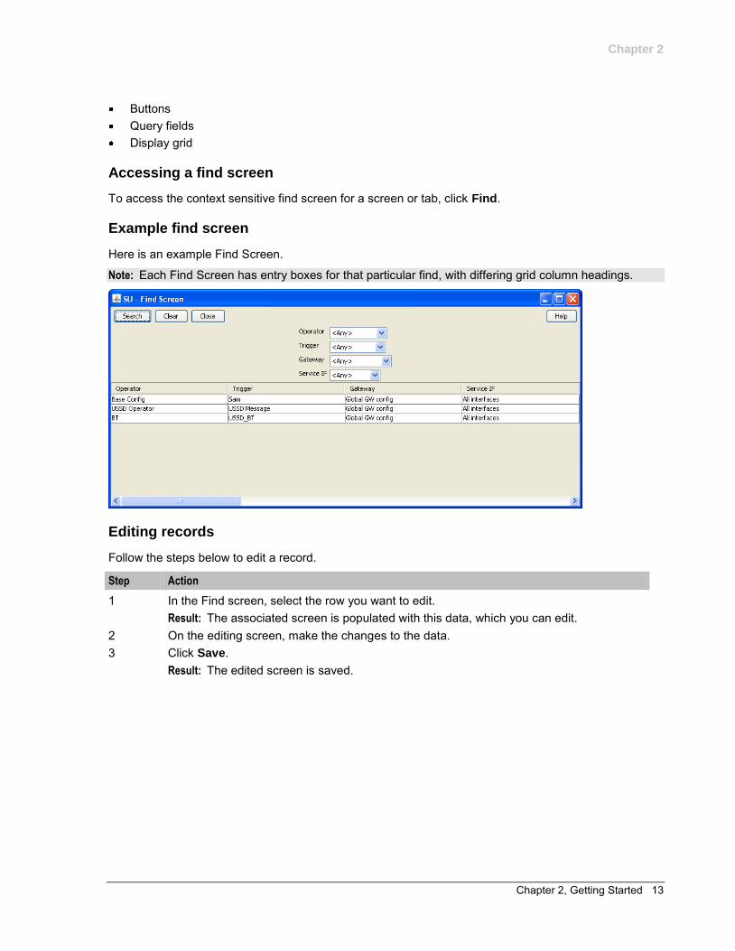
Buttons Query fields Display grid
Accessing a find screen
To access the context sensitive find screen for a screen or tab, click Find.
Example find screen
Here is an example Find Screen.
Note: Each Find Screen has entry boxes for that particular find, with differing grid column headings.
Editing records
Follow the steps below to edit a record.
Step Action
1 In the Find screen, select the row you want to edit. Result: The associated screen is populated with this data, which you can edit.
2 On the editing screen, make the changes to the data. 3 Click Save.
Result: The edited screen is saved.
Chapter 2
14 USSD Gateway User's Guide
Searching the database
Follow these steps to search the database.
Step Action
1 Enter selection criteria in one or more query fields at the top of the screen and click Search. If a field is left empty, the search retrieves all instances of that field. Result: This triggers an Oracle Like% query that returns the first 100 records that begin with the selection criteria. These are displayed in the display table at the bottom of the screen. Example: If you enter 123 in a query field, the system returns records such as 123, 1234, and 12345.
Note: These are the first 100 records entered in the database, and they display in no particular order. If you do not find the record you are searching for, you need to conduct a more specific search.
2 To display the record in the main screen, select the record line and click Close.
Chapter 3, USSD Gateway Base Configuration Screens 15
Chapter 3
USSD Gateway Base Configuration Screens
Overview
Introduction
This chapter explains the contents of the Gateway Base Configuration Screens.
In this chapter
This chapter contains the following topics.
USSD Gateway Base Configuration Screen ............................................................................... 15 Trigger Prefix ............................................................................................................................... 16 Language ..................................................................................................................................... 18 Service Interface .......................................................................................................................... 21 Operator....................................................................................................................................... 23
USSD Gateway Base Configuration Screen
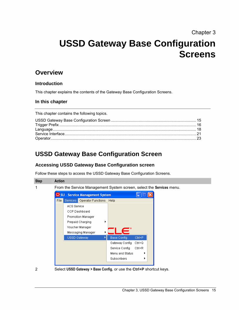
Accessing USSD Gateway Base Configuration screen
Follow these steps to access the USSD Gateway Base Configuration Screens.
Step Action
1 From the Service Management System screen, select the Services menu.
2 Select USSD Gateway > Base Config, or use the Ctrl+P shortcut keys.
Chapter 3
16 USSD Gateway User's Guide
Trigger Prefix
Introduction
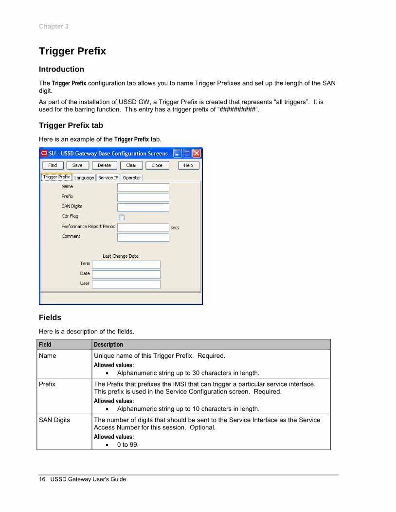
The Trigger Prefix configuration tab allows you to name Trigger Prefixes and set up the length of the SAN digit.
As part of the installation of USSD GW, a Trigger Prefix is created that represents “all triggers”. It is used for the barring function. This entry has a trigger prefix of “##########”.
Trigger Prefix tab
Here is an example of the Trigger Prefix tab.
Fields
Here is a description of the fields.
Field Description
Name Unique name of this Trigger Prefix. Required. Allowed values:
Alphanumeric string up to 30 characters in length.
Prefix The Prefix that prefixes the IMSI that can trigger a particular service interface. This prefix is used in the Service Configuration screen. Required. Allowed values:
Alphanumeric string up to 10 characters in length.
SAN Digits The number of digits that should be sent to the Service Interface as the Service Access Number for this session. Optional. Allowed values:
0 to 99.
Chapter 3
Chapter 3, USSD Gateway Base Configuration Screens 17
Field Description
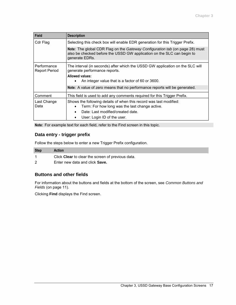
Cdr Flag Selecting this check box will enable EDR generation for this Trigger Prefix.
Note: The global CDR Flag on the Gateway Configuration tab (on page 28) must also be checked before the USSD GW application on the SLC can begin to generate EDRs.
Performance Report Period
The interval (in seconds) after which the USSD GW application on the SLC will generate performance reports. Allowed values:
An integer value that is a factor of 60 or 3600.
Note: A value of zero means that no performance reports will be generated.
Comment This field is used to add any comments required for this Trigger Prefix. Last Change Data
Shows the following details of when this record was last modified: Term: For how long was the last change active. Date: Last modified/created date. User: Login ID of the user.
Note: For example text for each field, refer to the Find screen in this topic.
Data entry - trigger prefix
Follow the steps below to enter a new Trigger Prefix configuration.
Step Action
1 Click Clear to clear the screen of previous data. 2 Enter new data and click Save.
Buttons and other fields
For information about the buttons and fields at the bottom of the screen, see Common Buttons and Fields (on page 11).
Clicking Find displays the Find screen.
Chapter 3
18 USSD Gateway User's Guide
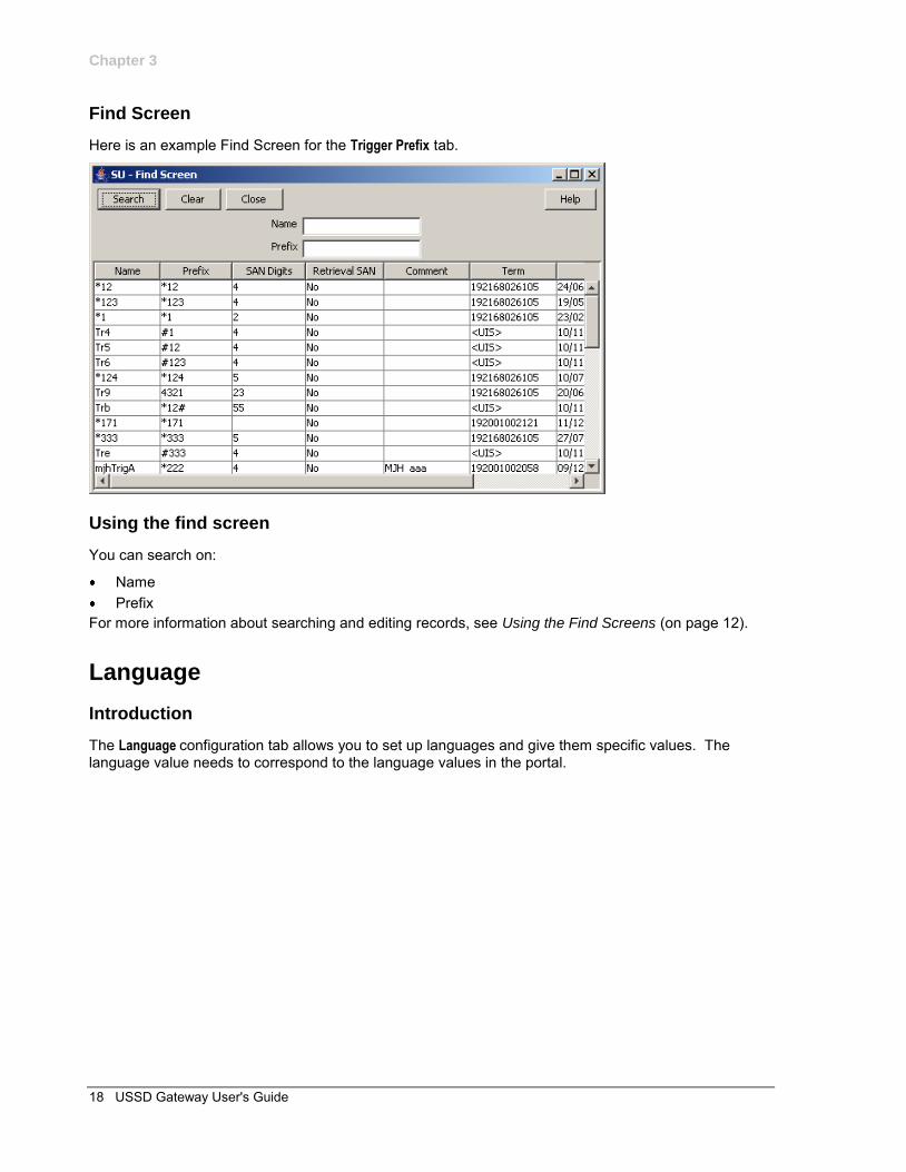
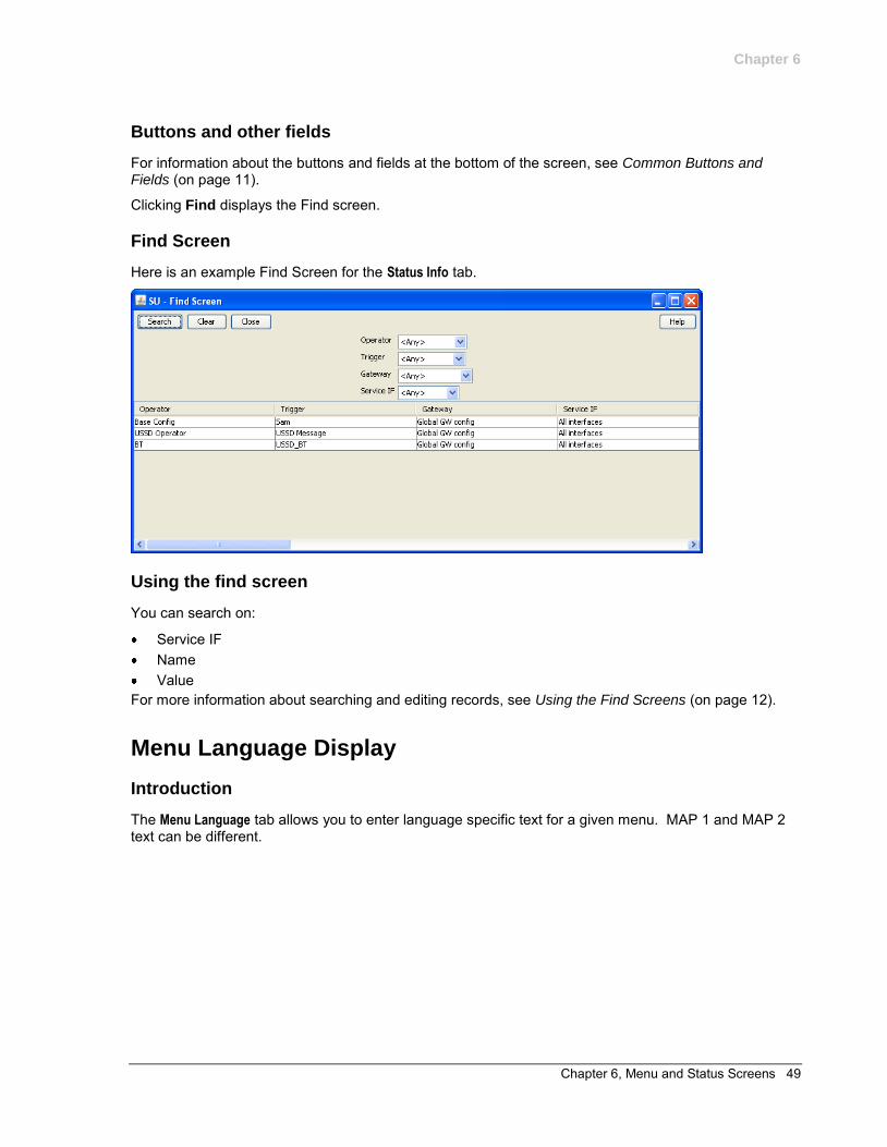
Find Screen
Here is an example Find Screen for the Trigger Prefix tab.
Using the find screen
You can search on:
Name Prefix
For more information about searching and editing records, see Using the Find Screens (on page 12).
Language
Introduction
The Language configuration tab allows you to set up languages and give them specific values. The language value needs to correspond to the language values in the portal.
Chapter 3
Chapter 3, USSD Gateway Base Configuration Screens 19
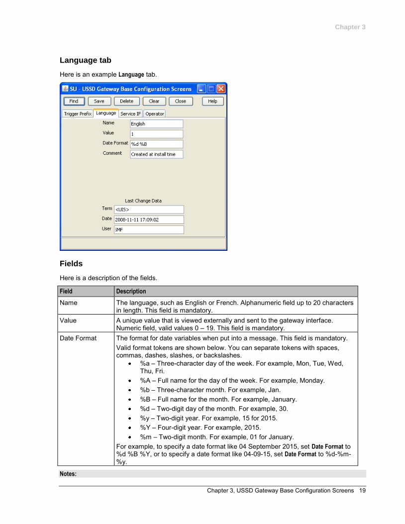
Language tab
Here is an example Language tab.
Fields
Here is a description of the fields.
Field Description
Name The language, such as English or French. Alphanumeric field up to 20 characters in length. This field is mandatory.
Value A unique value that is viewed externally and sent to the gateway interface. Numeric field, valid values 0 – 19. This field is mandatory.
Date Format The format for date variables when put into a message. This field is mandatory. Valid format tokens are shown below. You can separate tokens with spaces, commas, dashes, slashes, or backslashes.
%a – Three-character day of the week. For example, Mon, Tue, Wed, Thu, Fri.
%A – Full name for the day of the week. For example, Monday. %b – Three-character month. For example, Jan. %B – Full name for the month. For example, January. %d – Two-digit day of the month. For example, 30. %y – Two-digit year. For example, 15 for 2015. %Y – Four-digit year. For example, 2015. %m – Two-digit month. For example, 01 for January.
For example, to specify a date format like 04 September 2015, set Date Format to %d %B %Y, or to specify a date format like 04-09-15, set Date Format to %d-%m-%y.
Notes:
Chapter 3
20 USSD Gateway User's Guide
For example text for each field, refer to the Find screen in this topic.
If ACS is being used as a service interface, the language ID fields must match the SRF ID in the ACS configuration. This means that if the SRF ID of 1 corresponds to English in the ACS configuration, the language entry on this tab must match.
For example: ACS configuration
English, MSG=2, SRF=1
USSD configuration
Name: English Value: 1 Date Format=%d %B %Y
Data entry
Follow these steps to enter a new Language configuration.
Step Action
1 Click Clear to clear the screen of previous data. 2 Enter new data and click Save.
Buttons and other fields
For information about the buttons and fields at the bottom of the screen, see Common Buttons and Fields (on page 11).
Clicking Find displays the Find screen.
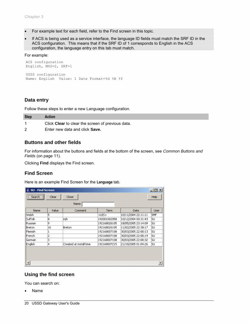
Find Screen
Here is an example Find Screen for the Language tab.
Using the find screen
You can search on:
Name
Chapter 3
Chapter 3, USSD Gateway Base Configuration Screens 21
For more information about searching and editing records, see Using the Find Screens (on page 12).
Service Interface
Introduction
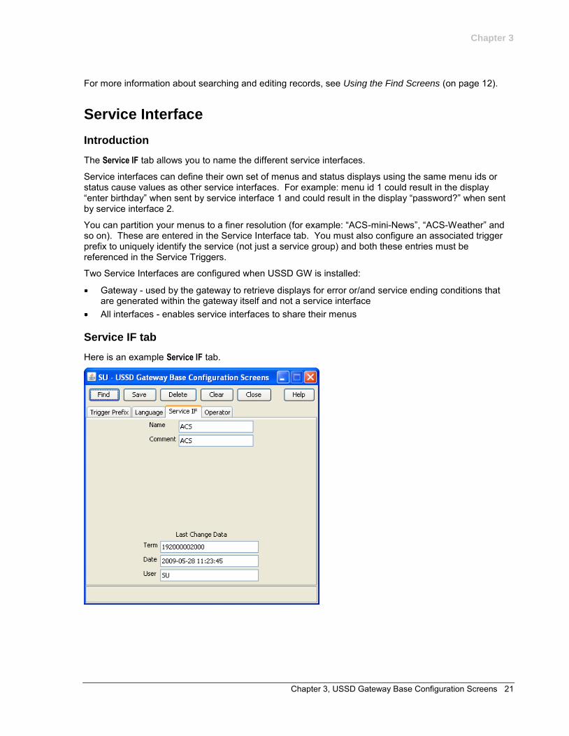
The Service IF tab allows you to name the different service interfaces.
Service interfaces can define their own set of menus and status displays using the same menu ids or status cause values as other service interfaces. For example: menu id 1 could result in the display “enter birthday” when sent by service interface 1 and could result in the display “password?” when sent by service interface 2.
You can partition your menus to a finer resolution (for example: “ACS-mini-News”, “ACS-Weather” and so on). These are entered in the Service Interface tab. You must also configure an associated trigger prefix to uniquely identify the service (not just a service group) and both these entries must be referenced in the Service Triggers.
Two Service Interfaces are configured when USSD GW is installed:
Gateway - used by the gateway to retrieve displays for error or/and service ending conditions that are generated within the gateway itself and not a service interface
All interfaces - enables service interfaces to share their menus
Service IF tab
Here is an example Service IF tab.
Chapter 3
22 USSD Gateway User's Guide
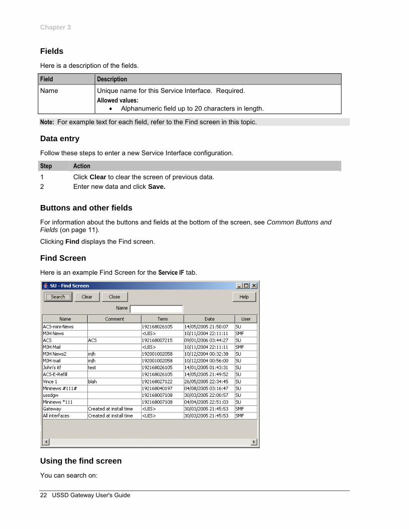
Fields
Here is a description of the fields.
Field Description
Name Unique name for this Service Interface. Required. Allowed values:
Alphanumeric field up to 20 characters in length.
Note: For example text for each field, refer to the Find screen in this topic.
Data entry
Follow these steps to enter a new Service Interface configuration.
Step Action
1 Click Clear to clear the screen of previous data. 2 Enter new data and click Save.
Buttons and other fields
For information about the buttons and fields at the bottom of the screen, see Common Buttons and Fields (on page 11).
Clicking Find displays the Find screen.
Find Screen
Here is an example Find Screen for the Service IF tab.
Using the find screen
You can search on:
Chapter 3
Chapter 3, USSD Gateway Base Configuration Screens 23
Name For more information about searching and editing records, see Using the Find Screens (on page 12).
Operator
Introduction
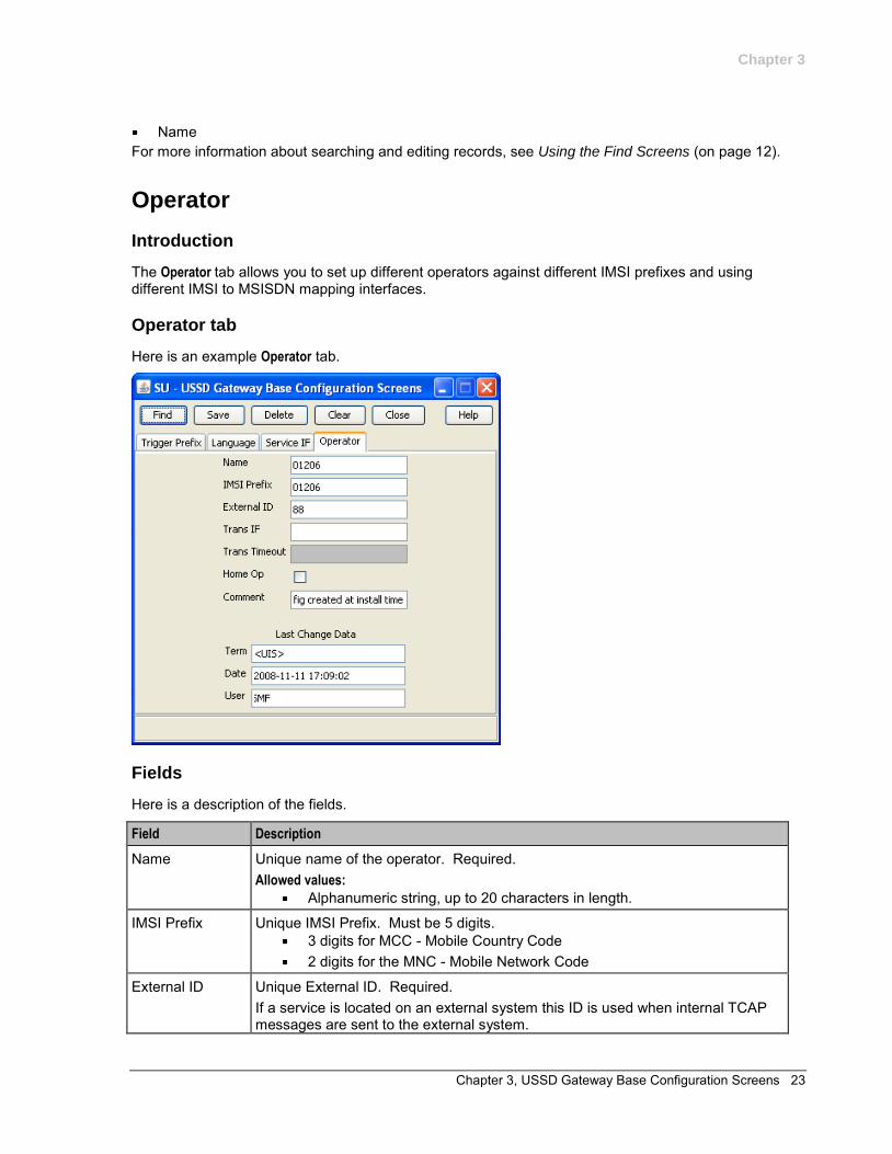
The Operator tab allows you to set up different operators against different IMSI prefixes and using different IMSI to MSISDN mapping interfaces.
Operator tab
Here is an example Operator tab.
Fields
Here is a description of the fields.
Field Description
Name Unique name of the operator. Required. Allowed values:
Alphanumeric string, up to 20 characters in length.
IMSI Prefix Unique IMSI Prefix. Must be 5 digits. 3 digits for MCC - Mobile Country Code 2 digits for the MNC - Mobile Network Code
External ID Unique External ID. Required. If a service is located on an external system this ID is used when internal TCAP messages are sent to the external system.
Chapter 3
24 USSD Gateway User's Guide
Field Description
Trans IF The SLEE ID of the interface which does the IMSI-MSISDN translation. Optional. For information about SLEE IDs, see SLEE Technical Guide.
Trans Timeout Milliseconds ussdgw process will wait for a response to the IMSI to MSISDN translation request. Required if a Trans IF value is provided. Allowed values:
0 – 99
Home Op If ticked, this operator is the home operator.
Note: For example text for each field, refer to the Find screen in this topic.
Data entry
Follow these steps to enter a new Operator configuration.
Step Action
1 Click Clear to clear the screen of previous data. 2 Enter new data and click Save.
Buttons and other fields
For information about the buttons and fields at the bottom of the screen, see Common Buttons and Fields (on page 11).
Clicking Find displays the Find screen.
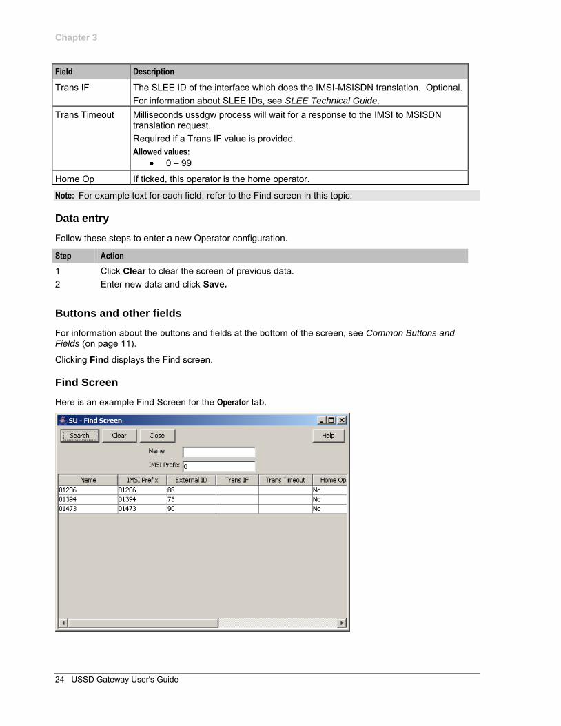
Find Screen
Here is an example Find Screen for the Operator tab.
Chapter 3
Chapter 3, USSD Gateway Base Configuration Screens 25
Using the find screen
You can search on:
Name IMSI Prefix
For more information about searching and editing records, see Using the Find Screens (on page 12).

Chapter 4, USSD Gateway Configuration Screen 27
Chapter 4
USSD Gateway Configuration Screen
Overview
Introduction
This chapter explains the contents of the USSD Gateway Configuration screen.
In this chapter
This chapter contains the following topics.
USSD Gateway Menu Configuration Screen .............................................................................. 27 Gateway Configuration Screen ................................................................................................... 27
USSD Gateway Menu Configuration Screen
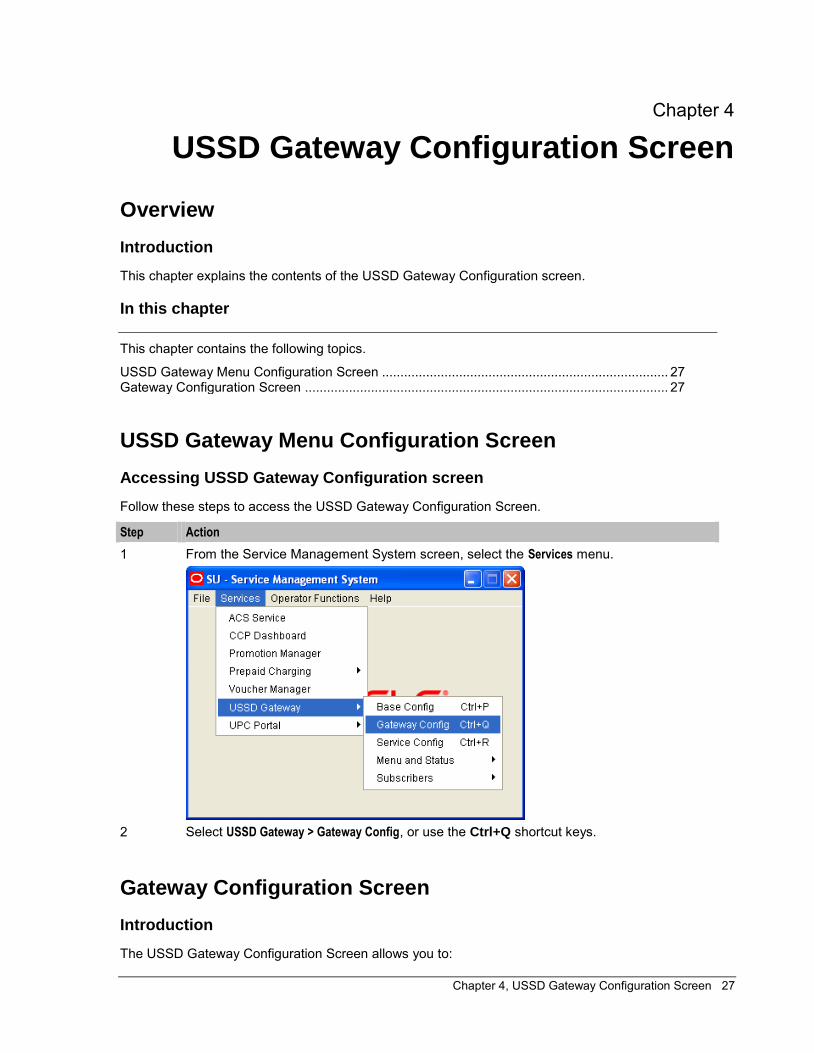
Accessing USSD Gateway Configuration screen
Follow these steps to access the USSD Gateway Configuration Screen.
Step Action
1 From the Service Management System screen, select the Services menu.
2 Select USSD Gateway > Gateway Config, or use the Ctrl+Q shortcut keys.
Gateway Configuration Screen
Introduction
The USSD Gateway Configuration Screen allows you to:
Chapter 4
28 USSD Gateway User's Guide
Change the default gateway interface configuration (Global GW config) Add new gateway interfaces
Setting up different gateway configurations enables you to configure different gateways to have different service triggers defined. This enables the treatment of service triggers to be handled differently by different gateways.
You do not have to set up different gateway configuration for each gateway.
Important: reloading the configuration
If the USSD Gateway Configuration Screen is updated, the SLEE must to be restarted for these changes to take effect.
For instructions about how to restart the SLEE, see SLEE Technical Guide.
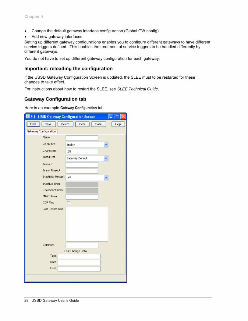
Gateway Configuration tab
Here is an example Gateway Configuration tab.
Chapter 4
Chapter 4, USSD Gateway Configuration Screen 29
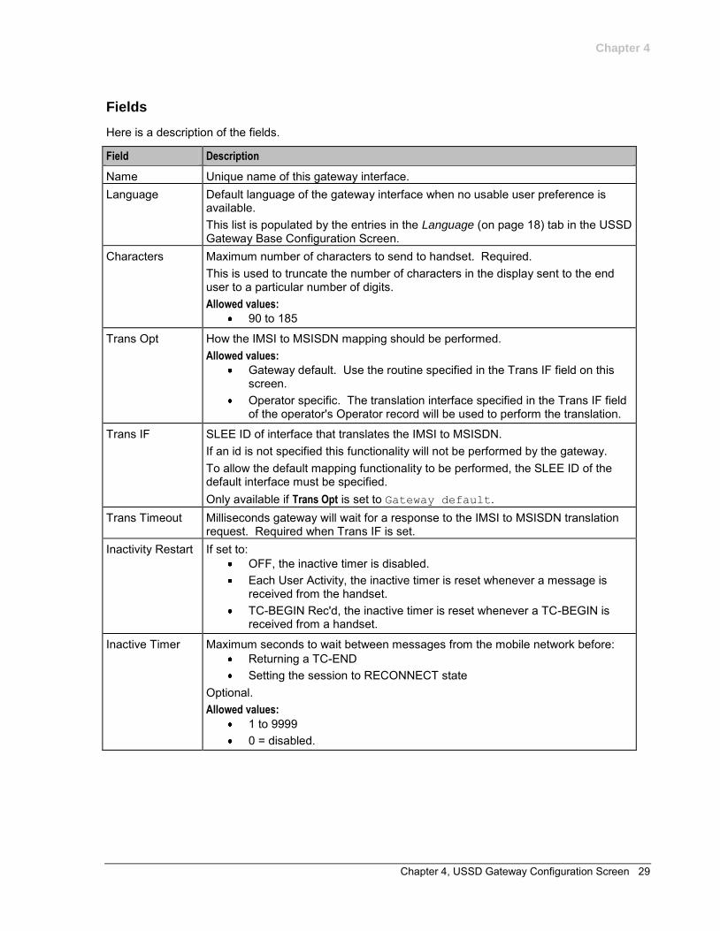
Fields
Here is a description of the fields.
Field Description
Name Unique name of this gateway interface. Language Default language of the gateway interface when no usable user preference is
available. This list is populated by the entries in the Language (on page 18) tab in the USSD Gateway Base Configuration Screen.
Characters Maximum number of characters to send to handset. Required. This is used to truncate the number of characters in the display sent to the end user to a particular number of digits. Allowed values:
90 to 185
Trans Opt How the IMSI to MSISDN mapping should be performed. Allowed values:
Gateway default. Use the routine specified in the Trans IF field on this screen.
Operator specific. The translation interface specified in the Trans IF field of the operator's Operator record will be used to perform the translation.
Trans IF SLEE ID of interface that translates the IMSI to MSISDN. If an id is not specified this functionality will not be performed by the gateway. To allow the default mapping functionality to be performed, the SLEE ID of the default interface must be specified. Only available if Trans Opt is set to Gateway default.
Trans Timeout Milliseconds gateway will wait for a response to the IMSI to MSISDN translation request. Required when Trans IF is set.
Inactivity Restart If set to: OFF, the inactive timer is disabled. Each User Activity, the inactive timer is reset whenever a message is
received from the handset. TC-BEGIN Rec'd, the inactive timer is reset whenever a TC-BEGIN is
received from a handset.
Inactive Timer Maximum seconds to wait between messages from the mobile network before: Returning a TC-END Setting the session to RECONNECT state
Optional. Allowed values:
1 to 9999 0 = disabled.
Chapter 4
30 USSD Gateway User's Guide
Field Description
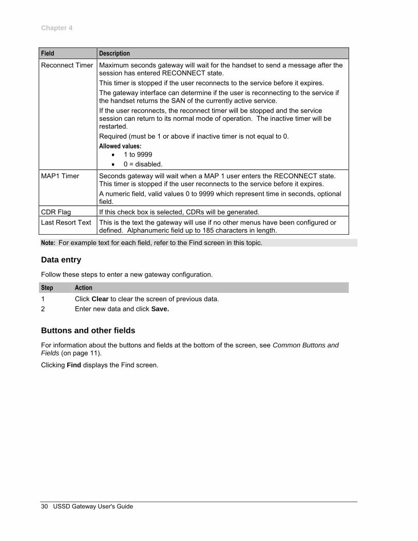
Reconnect Timer Maximum seconds gateway will wait for the handset to send a message after the session has entered RECONNECT state. This timer is stopped if the user reconnects to the service before it expires. The gateway interface can determine if the user is reconnecting to the service if the handset returns the SAN of the currently active service. If the user reconnects, the reconnect timer will be stopped and the service session can return to its normal mode of operation. The inactive timer will be restarted. Required (must be 1 or above if inactive timer is not equal to 0. Allowed values:
1 to 9999 0 = disabled.
MAP1 Timer Seconds gateway will wait when a MAP 1 user enters the RECONNECT state. This timer is stopped if the user reconnects to the service before it expires. A numeric field, valid values 0 to 9999 which represent time in seconds, optional field.
CDR Flag If this check box is selected, CDRs will be generated. Last Resort Text This is the text the gateway will use if no other menus have been configured or
defined. Alphanumeric field up to 185 characters in length.
Note: For example text for each field, refer to the Find screen in this topic.
Data entry
Follow these steps to enter a new gateway configuration.
Step Action
1 Click Clear to clear the screen of previous data. 2 Enter new data and click Save.
Buttons and other fields
For information about the buttons and fields at the bottom of the screen, see Common Buttons and Fields (on page 11).
Clicking Find displays the Find screen.
Chapter 4
Chapter 4, USSD Gateway Configuration Screen 31
Find Screen
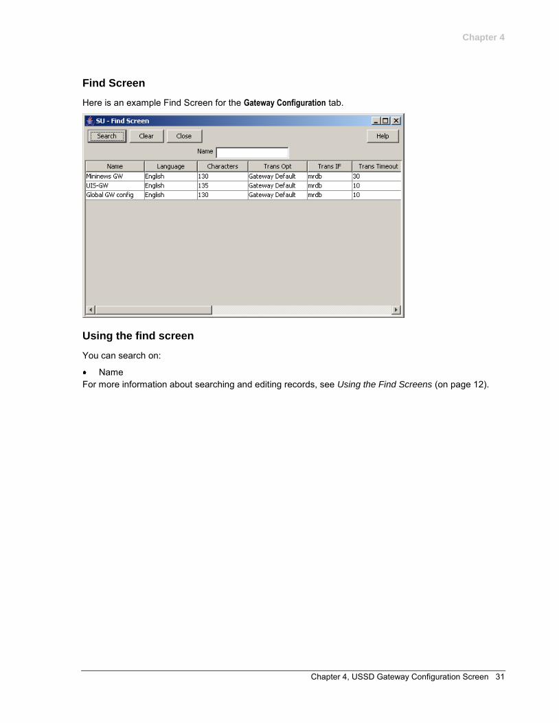
Here is an example Find Screen for the Gateway Configuration tab.
Using the find screen
You can search on:
Name For more information about searching and editing records, see Using the Find Screens (on page 12).

Chapter 5, USSD Gateway Service Configuration Screen 33
Chapter 5
USSD Gateway Service Configuration Screen
Overview
Introduction
This chapter explains the contents of the USSD Gateway Service Configuration screen.
In this chapter
This chapter contains the following topics.
USSD Gateway Service Configuration Screen ........................................................................... 33 Service Trigger ............................................................................................................................ 34
USSD Gateway Service Configuration Screen
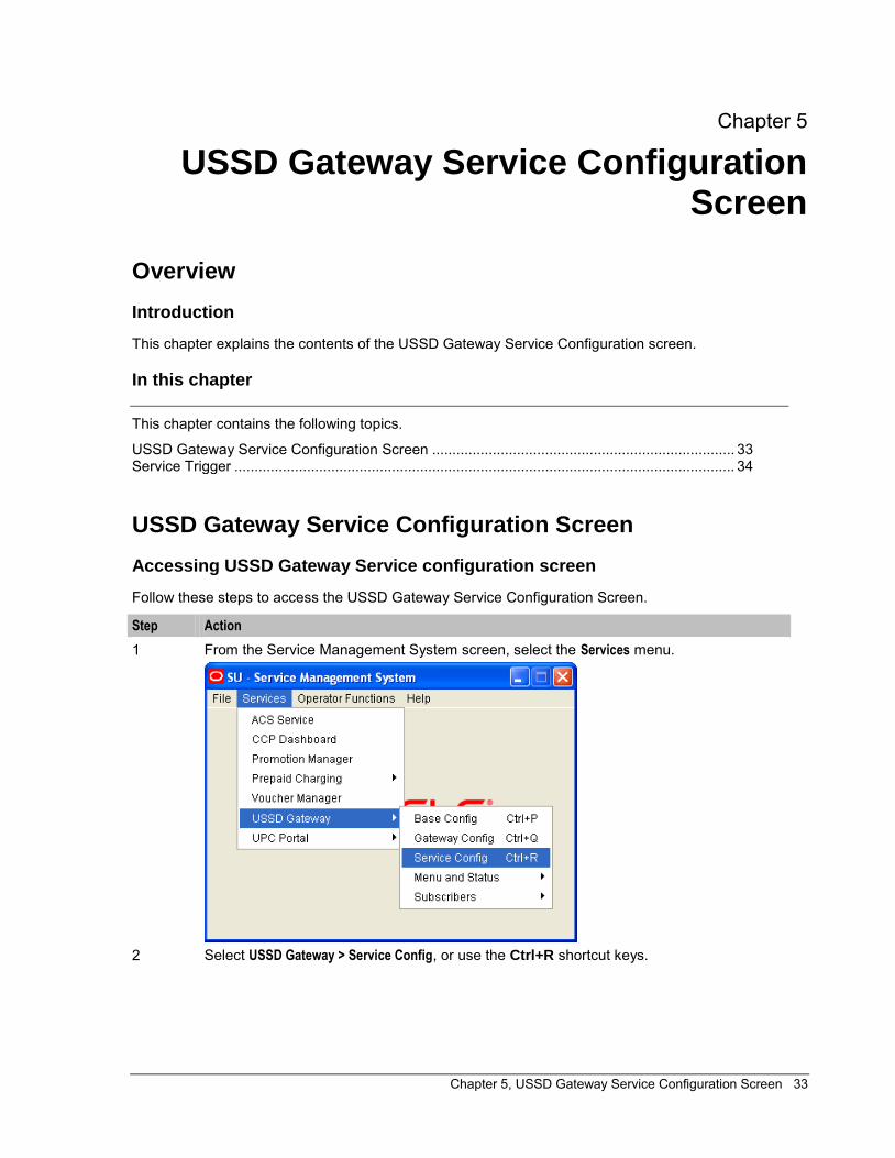
Accessing USSD Gateway Service configuration screen
Follow these steps to access the USSD Gateway Service Configuration Screen.
Step Action
1 From the Service Management System screen, select the Services menu.
2 Select USSD Gateway > Service Config, or use the Ctrl+R shortcut keys.
Chapter 5
34 USSD Gateway User's Guide
Service Trigger
Introduction
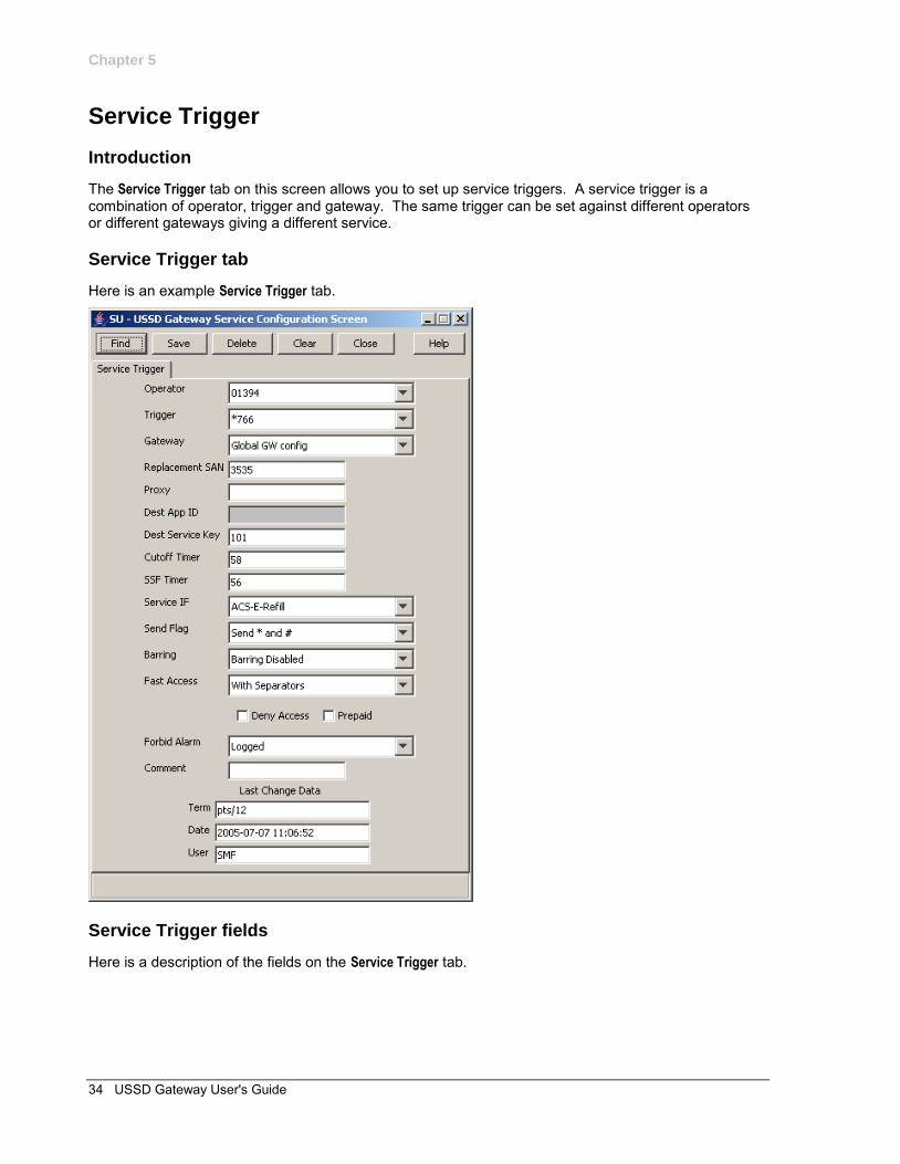
The Service Trigger tab on this screen allows you to set up service triggers. A service trigger is a combination of operator, trigger and gateway. The same trigger can be set against different operators or different gateways giving a different service.
Service Trigger tab
Here is an example Service Trigger tab.
Service Trigger fields
Here is a description of the fields on the Service Trigger tab.
Chapter 5
Chapter 5, USSD Gateway Service Configuration Screen 35
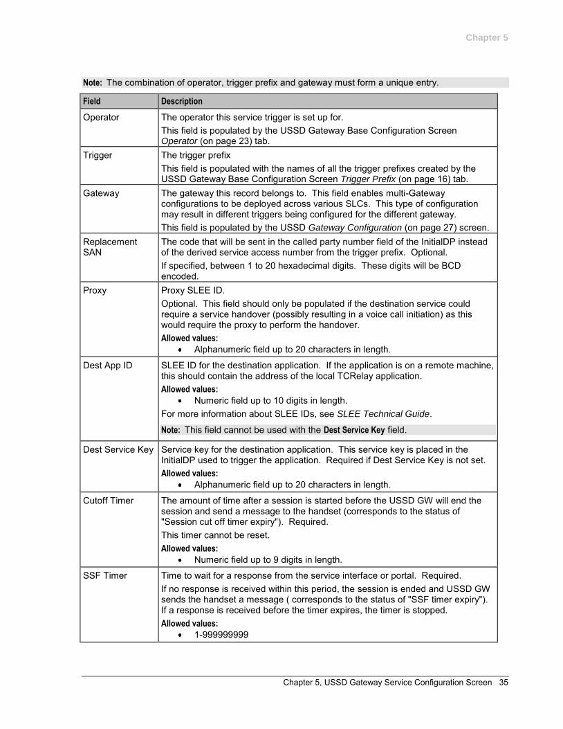
Note: The combination of operator, trigger prefix and gateway must form a unique entry.
Field Description
Operator The operator this service trigger is set up for. This field is populated by the USSD Gateway Base Configuration Screen Operator (on page 23) tab.
Trigger The trigger prefix This field is populated with the names of all the trigger prefixes created by the USSD Gateway Base Configuration Screen Trigger Prefix (on page 16) tab.
Gateway The gateway this record belongs to. This field enables multi-Gateway configurations to be deployed across various SLCs. This type of configuration may result in different triggers being configured for the different gateway. This field is populated by the USSD Gateway Configuration (on page 27) screen.
Replacement SAN
The code that will be sent in the called party number field of the InitialDP instead of the derived service access number from the trigger prefix. Optional. If specified, between 1 to 20 hexadecimal digits. These digits will be BCD encoded.
Proxy Proxy SLEE ID. Optional. This field should only be populated if the destination service could require a service handover (possibly resulting in a voice call initiation) as this would require the proxy to perform the handover. Allowed values:
Alphanumeric field up to 20 characters in length.
Dest App ID SLEE ID for the destination application. If the application is on a remote machine, this should contain the address of the local TCRelay application. Allowed values:
Numeric field up to 10 digits in length. For more information about SLEE IDs, see SLEE Technical Guide.
Note: This field cannot be used with the Dest Service Key field.
Dest Service Key Service key for the destination application. This service key is placed in the InitialDP used to trigger the application. Required if Dest Service Key is not set. Allowed values:
Alphanumeric field up to 20 characters in length.
Cutoff Timer The amount of time after a session is started before the USSD GW will end the session and send a message to the handset (corresponds to the status of "Session cut off timer expiry"). Required. This timer cannot be reset. Allowed values:
Numeric field up to 9 digits in length.
SSF Timer Time to wait for a response from the service interface or portal. Required. If no response is received within this period, the session is ended and USSD GW sends the handset a message ( corresponds to the status of "SSF timer expiry"). If a response is received before the timer expires, the timer is stopped. Allowed values:
1-999999999
Chapter 5
36 USSD Gateway User's Guide
Field Description
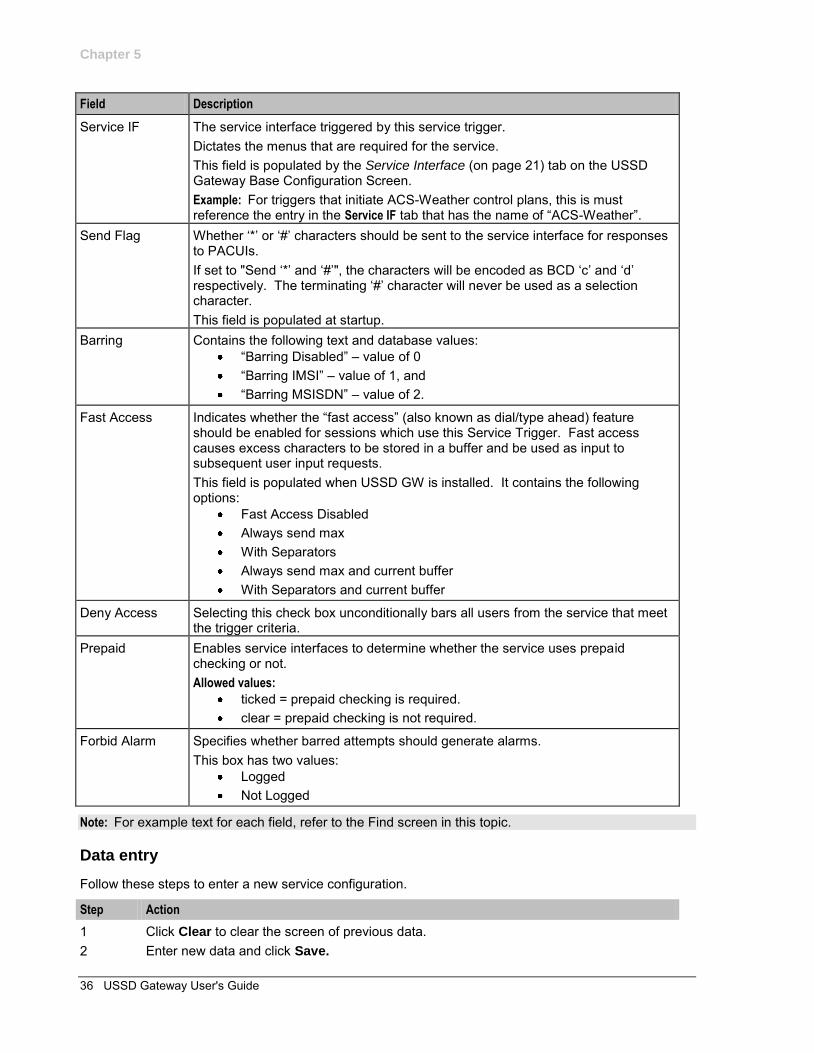
Service IF The service interface triggered by this service trigger. Dictates the menus that are required for the service. This field is populated by the Service Interface (on page 21) tab on the USSD Gateway Base Configuration Screen. Example: For triggers that initiate ACS-Weather control plans, this is must reference the entry in the Service IF tab that has the name of “ACS-Weather”.
Send Flag Whether ‘*’ or ‘#’ characters should be sent to the service interface for responses to PACUIs. If set to "Send ‘*’ and ‘#’", the characters will be encoded as BCD ‘c’ and ‘d’ respectively. The terminating ‘#’ character will never be used as a selection character. This field is populated at startup.
Barring Contains the following text and database values: “Barring Disabled” – value of 0 “Barring IMSI” – value of 1, and “Barring MSISDN” – value of 2.
Fast Access Indicates whether the “fast access” (also known as dial/type ahead) feature should be enabled for sessions which use this Service Trigger. Fast access causes excess characters to be stored in a buffer and be used as input to subsequent user input requests. This field is populated when USSD GW is installed. It contains the following options:
Fast Access Disabled Always send max With Separators Always send max and current buffer With Separators and current buffer
Deny Access Selecting this check box unconditionally bars all users from the service that meet the trigger criteria.
Prepaid Enables service interfaces to determine whether the service uses prepaid checking or not. Allowed values:
ticked = prepaid checking is required. clear = prepaid checking is not required.
Forbid Alarm Specifies whether barred attempts should generate alarms. This box has two values:
Logged Not Logged
Note: For example text for each field, refer to the Find screen in this topic.
Data entry
Follow these steps to enter a new service configuration.
Step Action
1 Click Clear to clear the screen of previous data. 2 Enter new data and click Save.
Chapter 5
Chapter 5, USSD Gateway Service Configuration Screen 37
Buttons and other fields
For information about the buttons and fields at the bottom of the screen, see Common Buttons and Fields (on page 11).
Clicking Find displays the Find screen.
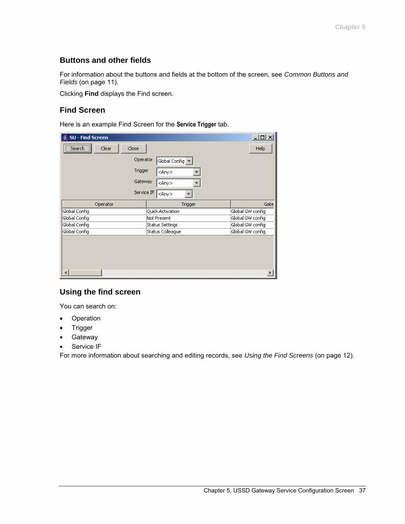
Find Screen
Here is an example Find Screen for the Service Trigger tab.
Using the find screen
You can search on:
Operation Trigger Gateway Service IF
For more information about searching and editing records, see Using the Find Screens (on page 12).

Chapter 6, Menu and Status Screens 39
Chapter 6
Menu and Status Screens
Overview
Introduction
This chapter explains the contents of the USSD Gateway Menu and Status screens.
In this chapter
This chapter contains the following topics.
USSD Gateway Menu Configuration Screen .............................................................................. 39 Menu Wizard ............................................................................................................................... 40 Status Wizard .............................................................................................................................. 43 Menu Info Configuration .............................................................................................................. 45 Status Info Configuration ............................................................................................................. 47 Menu Language Display .............................................................................................................. 49 Status Language Display............................................................................................................. 54
USSD Gateway Menu Configuration Screen
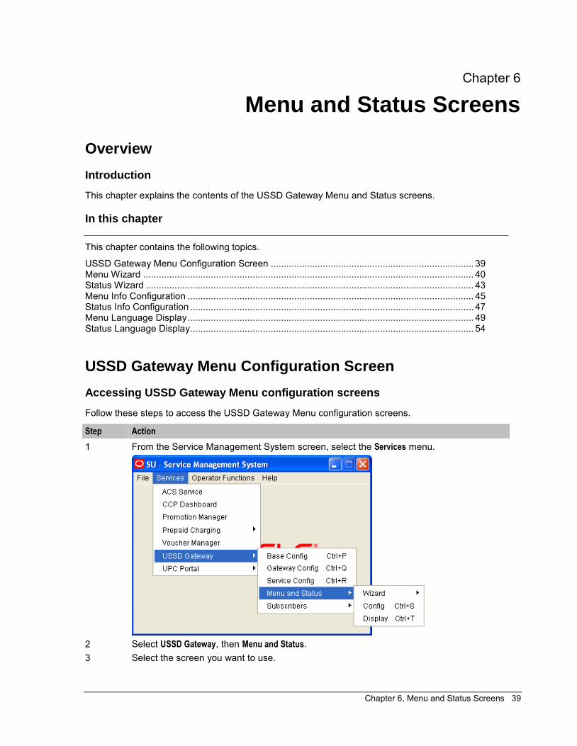
Accessing USSD Gateway Menu configuration screens
Follow these steps to access the USSD Gateway Menu configuration screens.
Step Action
1 From the Service Management System screen, select the Services menu.
2 Select USSD Gateway, then Menu and Status. 3 Select the screen you want to use.
Chapter 6
40 USSD Gateway User's Guide
Menu Wizard
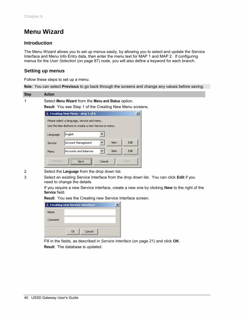
Introduction
The Menu Wizard allows you to set up menus easily, by allowing you to select and update the Service Interface and Menu Info Entry data, then enter the menu text for MAP 1 and MAP 2. If configuring menus for the User Selection (on page 87) node, you will also define a keyword for each branch.
Setting up menus
Follow these steps to set up a menu.
Note: You can select Previous to go back through the screens and change any values before saving.
Step Action
1 Select Menu Wizard from the Menu and Status option. Result: You see Step 1 of the Creating New Menu screens.
2 Select the Language from the drop down list. 3 Select an existing Service Interface from the drop down list. You can click Edit if you
need to change the details. If you require a new Service interface, create a new one by clicking New to the right of the Service field. Result: You see the Creating new Service Interface screen.
Fill in the fields, as described in Service Interface (on page 21) and click OK. Result: The database is updated.
Chapter 6
Chapter 6, Menu and Status Screens 41
Step Action
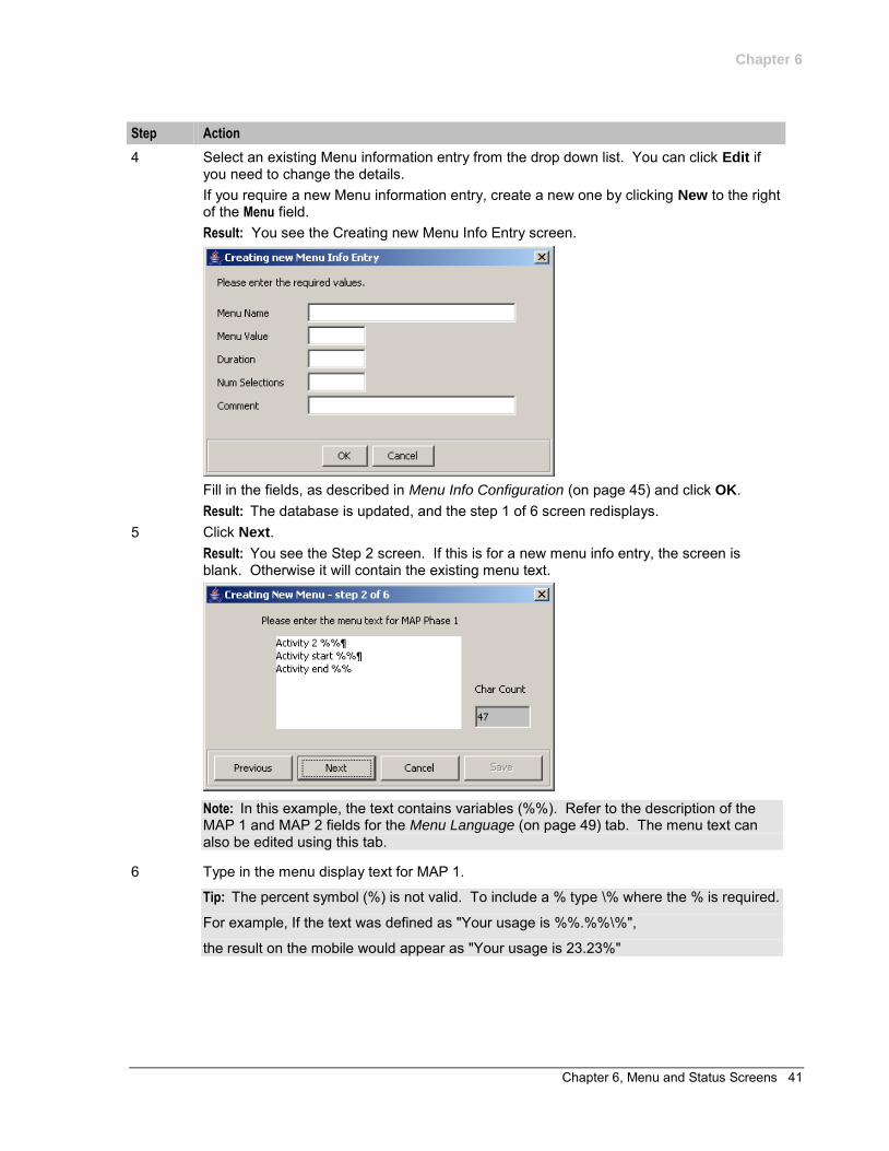
4 Select an existing Menu information entry from the drop down list. You can click Edit if you need to change the details. If you require a new Menu information entry, create a new one by clicking New to the right of the Menu field. Result: You see the Creating new Menu Info Entry screen.
Fill in the fields, as described in Menu Info Configuration (on page 45) and click OK. Result: The database is updated, and the step 1 of 6 screen redisplays.
5 Click Next. Result: You see the Step 2 screen. If this is for a new menu info entry, the screen is blank. Otherwise it will contain the existing menu text.
Note: In this example, the text contains variables (%%). Refer to the description of the MAP 1 and MAP 2 fields for the Menu Language (on page 49) tab. The menu text can also be edited using this tab.
6 Type in the menu display text for MAP 1.
Tip: The percent symbol (%) is not valid. To include a % type \% where the % is required.
For example, If the text was defined as "Your usage is %%.%%\%",
the result on the mobile would appear as "Your usage is 23.23%"
Chapter 6
42 USSD Gateway User's Guide
Step Action
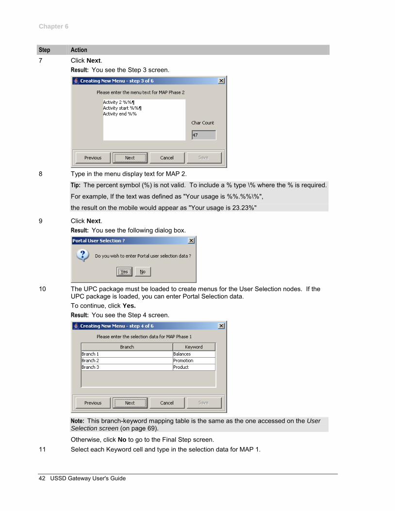
7 Click Next. Result: You see the Step 3 screen.
8 Type in the menu display text for MAP 2.
Tip: The percent symbol (%) is not valid. To include a % type \% where the % is required.
For example, If the text was defined as "Your usage is %%.%%\%",
the result on the mobile would appear as "Your usage is 23.23%"
9 Click Next. Result: You see the following dialog box.
10 The UPC package must be loaded to create menus for the User Selection nodes. If the
UPC package is loaded, you can enter Portal Selection data. To continue, click Yes. Result: You see the Step 4 screen.
Note: This branch-keyword mapping table is the same as the one accessed on the User Selection screen (on page 69).
Otherwise, click No to go to the Final Step screen. 11 Select each Keyword cell and type in the selection data for MAP 1.

Chapter 6
Chapter 6, Menu and Status Screens 43
Step Action
12 Click Next. Result: You see the Step 5 screen.
13 Select each Keyword cell and type in the selection data for MAP 2. 14 Click Next.
Result: You see the Final Step screen.
15 To complete the menu creation, click Save.
Status Wizard
Introduction
The Status Wizard allows you to set up status menus easily, by allowing you to select and update the Service Interface and Status Info Entry data, then enter the status text for a specific language.
Setting up status menus
Follow these steps to set up a status menu.
Note: You can click Previous to go back through the screens and change any values before saving.
Step Action
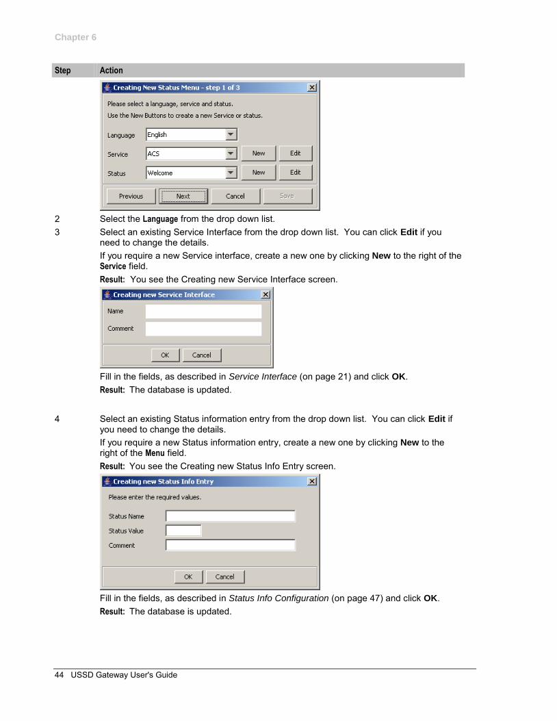
1 Select Status Wizard from the Menu and Status option. Result: You see the Creating New Status Menu - step 1 of 3 screen.
Chapter 6
44 USSD Gateway User's Guide
Step Action
2 Select the Language from the drop down list. 3 Select an existing Service Interface from the drop down list. You can click Edit if you
need to change the details. If you require a new Service interface, create a new one by clicking New to the right of the Service field. Result: You see the Creating new Service Interface screen.
Fill in the fields, as described in Service Interface (on page 21) and click OK. Result: The database is updated.
4 Select an existing Status information entry from the drop down list. You can click Edit if you need to change the details. If you require a new Status information entry, create a new one by clicking New to the right of the Menu field. Result: You see the Creating new Status Info Entry screen.
Fill in the fields, as described in Status Info Configuration (on page 47) and click OK. Result: The database is updated.
Chapter 6
Chapter 6, Menu and Status Screens 45
Step Action
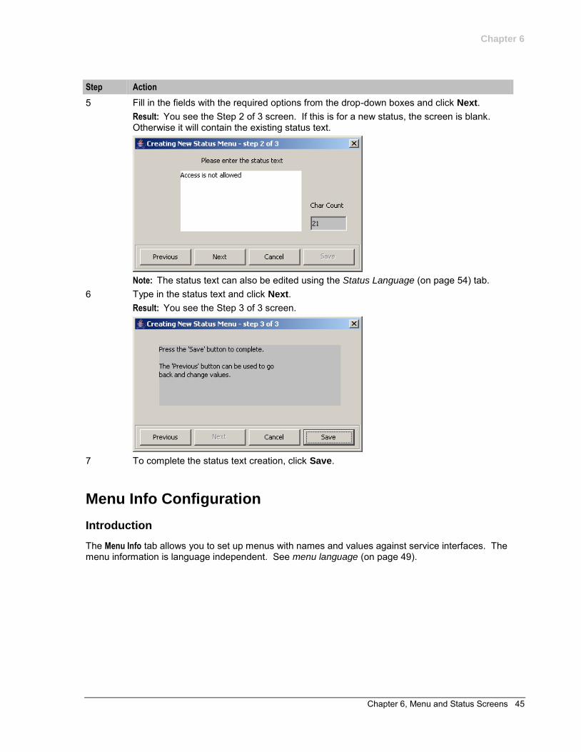
5 Fill in the fields with the required options from the drop-down boxes and click Next. Result: You see the Step 2 of 3 screen. If this is for a new status, the screen is blank. Otherwise it will contain the existing status text.
Note: The status text can also be edited using the Status Language (on page 54) tab.
6 Type in the status text and click Next. Result: You see the Step 3 of 3 screen.
7 To complete the status text creation, click Save.
Menu Info Configuration
Introduction
The Menu Info tab allows you to set up menus with names and values against service interfaces. The menu information is language independent. See menu language (on page 49).
Chapter 6
46 USSD Gateway User's Guide
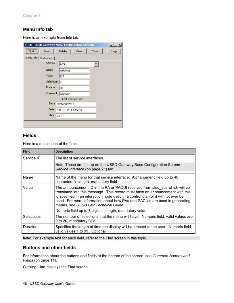
Menu Info tab
Here is an example Menu Info tab.
Fields
Here is a description of the fields.
Field Description
Service IF The list of service interfaces.
Note: These are set up on the USSD Gateway Base Configuration Screen Service Interface (on page 21) tab.
Name Name of the menu for that service interface. Alphanumeric field up to 40 characters in length, mandatory field.
Value The announcement ID in the PA or PACUI received from slee_acs which will be translated into this message. This record must have an announcement with this id specified in an interaction node used in a control plan or it will not ever be used. For more information about how PAs and PACUIs are used in generating menus, see USSD GW Technical Guide. Numeric field up to 7 digits in length, mandatory value.
Selections The number of selections that the menu will have. Numeric field, valid values are 0 to 20, mandatory field.
Duration Specifies the length of time the display will be present to the user. Numeric field, valid values 1 to 99. Optional.
Note: For example text for each field, refer to the Find screen in this topic.
Buttons and other fields
For information about the buttons and fields at the bottom of the screen, see Common Buttons and Fields (on page 11).
Clicking Find displays the Find screen.
Chapter 6
Chapter 6, Menu and Status Screens 47
Data entry
Follow these steps to enter a new menu Info.
Step Action
1 Click Clear to clear the screen of previous data. 2 Enter new data and click Save.
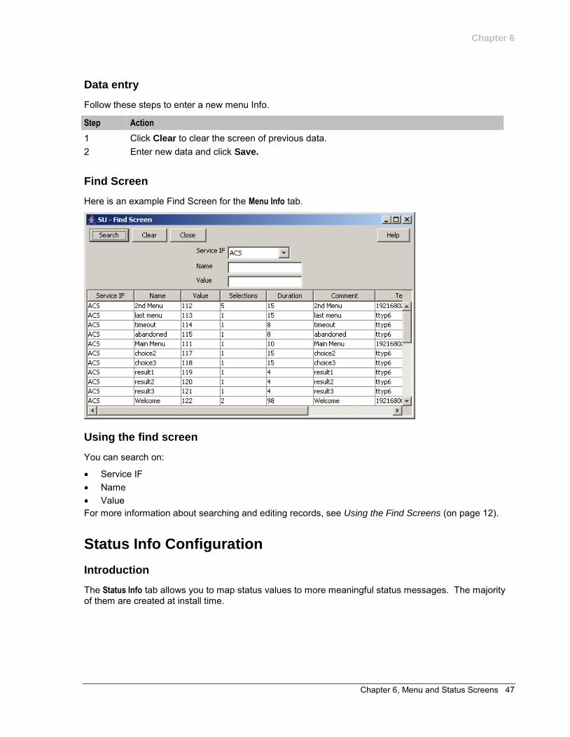
Find Screen
Here is an example Find Screen for the Menu Info tab.
Using the find screen
You can search on:
Service IF Name Value
For more information about searching and editing records, see Using the Find Screens (on page 12).
Status Info Configuration
Introduction
The Status Info tab allows you to map status values to more meaningful status messages. The majority of them are created at install time.
Chapter 6
48 USSD Gateway User's Guide
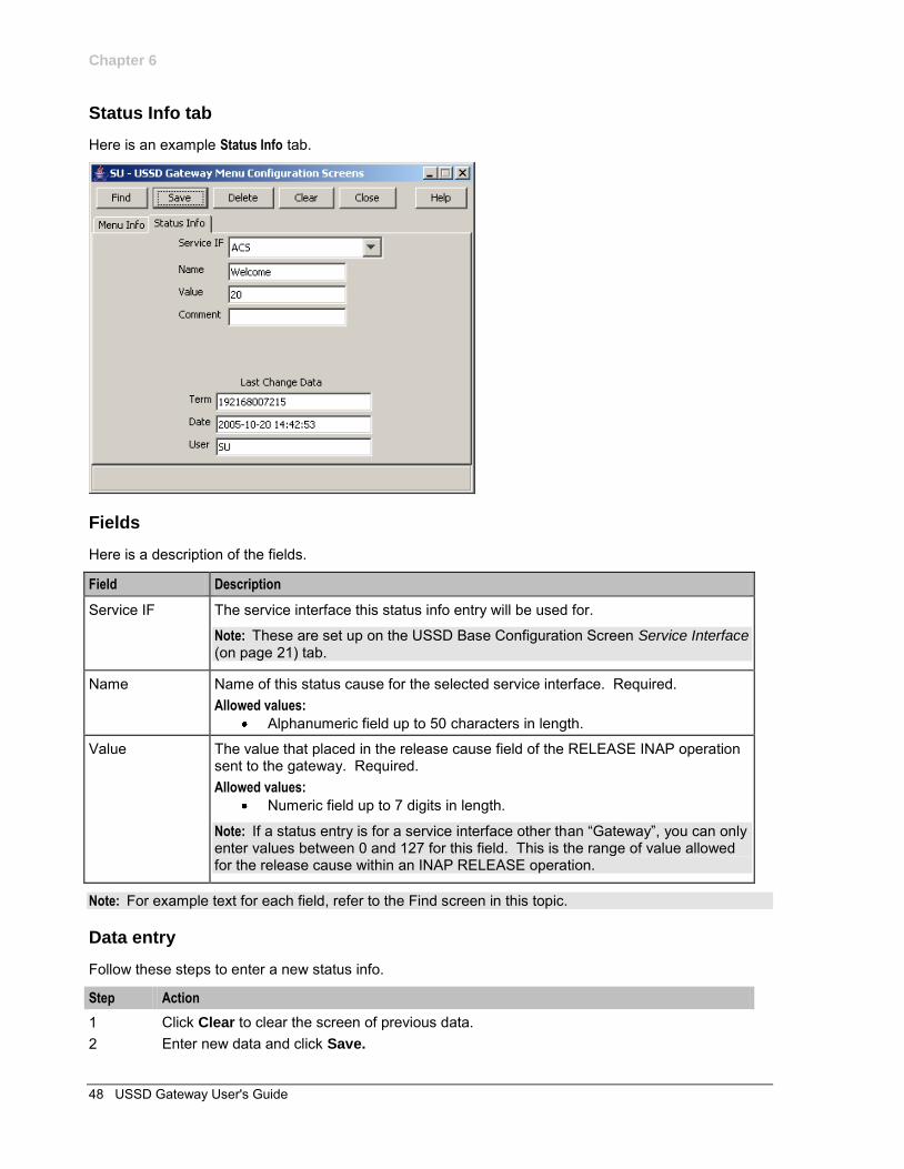
Status Info tab
Here is an example Status Info tab.
Fields
Here is a description of the fields.
Field Description
Service IF The service interface this status info entry will be used for.
Note: These are set up on the USSD Base Configuration Screen Service Interface (on page 21) tab.
Name Name of this status cause for the selected service interface. Required. Allowed values:
Alphanumeric field up to 50 characters in length.
Value The value that placed in the release cause field of the RELEASE INAP operation sent to the gateway. Required. Allowed values:
Numeric field up to 7 digits in length.
Note: If a status entry is for a service interface other than “Gateway”, you can only enter values between 0 and 127 for this field. This is the range of value allowed for the release cause within an INAP RELEASE operation.
Note: For example text for each field, refer to the Find screen in this topic.
Data entry
Follow these steps to enter a new status info.
Step Action
1 Click Clear to clear the screen of previous data. 2 Enter new data and click Save.
Chapter 6
Chapter 6, Menu and Status Screens 49
Buttons and other fields
For information about the buttons and fields at the bottom of the screen, see Common Buttons and Fields (on page 11).
Clicking Find displays the Find screen.
Find Screen
Here is an example Find Screen for the Status Info tab.
Using the find screen
You can search on:
Service IF Name Value
For more information about searching and editing records, see Using the Find Screens (on page 12).
Menu Language Display
Introduction
The Menu Language tab allows you to enter language specific text for a given menu. MAP 1 and MAP 2 text can be different.
Chapter 6
50 USSD Gateway User's Guide
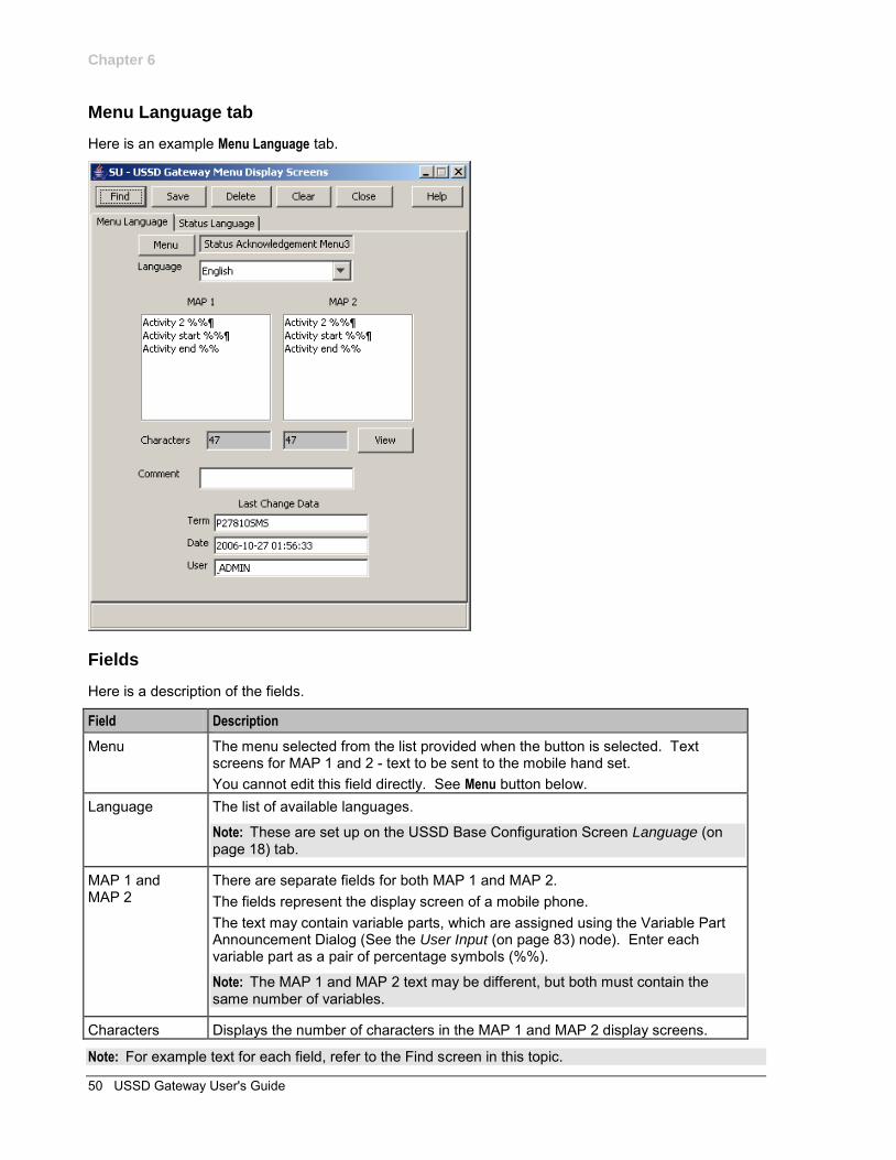
Menu Language tab
Here is an example Menu Language tab.
Fields
Here is a description of the fields.
Field Description
Menu The menu selected from the list provided when the button is selected. Text screens for MAP 1 and 2 - text to be sent to the mobile hand set. You cannot edit this field directly. See Menu button below.
Language The list of available languages.
Note: These are set up on the USSD Base Configuration Screen Language (on page 18) tab.
MAP 1 and MAP 2
There are separate fields for both MAP 1 and MAP 2. The fields represent the display screen of a mobile phone. The text may contain variable parts, which are assigned using the Variable Part Announcement Dialog (See the User Input (on page 83) node). Enter each variable part as a pair of percentage symbols (%%).
Note: The MAP 1 and MAP 2 text may be different, but both must contain the same number of variables.
Characters Displays the number of characters in the MAP 1 and MAP 2 display screens.
Note: For example text for each field, refer to the Find screen in this topic.
Chapter 6
Chapter 6, Menu and Status Screens 51
Buttons
Here is a description of the buttons.
Button Description
Menu Clicking this button displays the Menu Selector screen, allowing you to search for and select a menu value, which will be entered into the Menu field.
View Clicking this button displays the Text Display Viewer screen, which displays the text and the number of characters. See Viewing menu text (on page 51).
Data entry
Follow these steps to enter a new menu language.
Step Action
1 Click Clear to clear the screen of previous data. 2 Enter new data and click Save.
Buttons and other fields
For information about the buttons and fields at the bottom of the screen, see Common Buttons and Fields (on page 11).
Clicking Find displays the Find screen.
Viewing menu text
Follow these steps to view menu text.
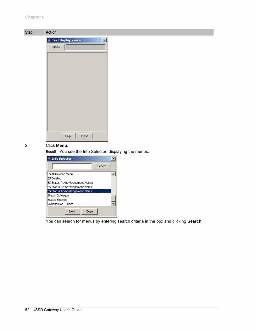
Step Action
1 On the Menu Language tab, click View. Result: You see the Text Display Viewer. If this is the first time you have used the text display viewer during the current session, the screen will display the text in the MAP 1 and MAP 2 text fields on the tab. If no menu has been selected, the field will be blank. If you have already used the text display viewer, you will see the last menu text you viewed before.
Chapter 6
52 USSD Gateway User's Guide
Step Action
2 Click Menu.
Result: You see the Info Selector, displaying the menus.
You can search for menus by entering search criteria in the box and clicking Search.
Chapter 6
Chapter 6, Menu and Status Screens 53
Step Action
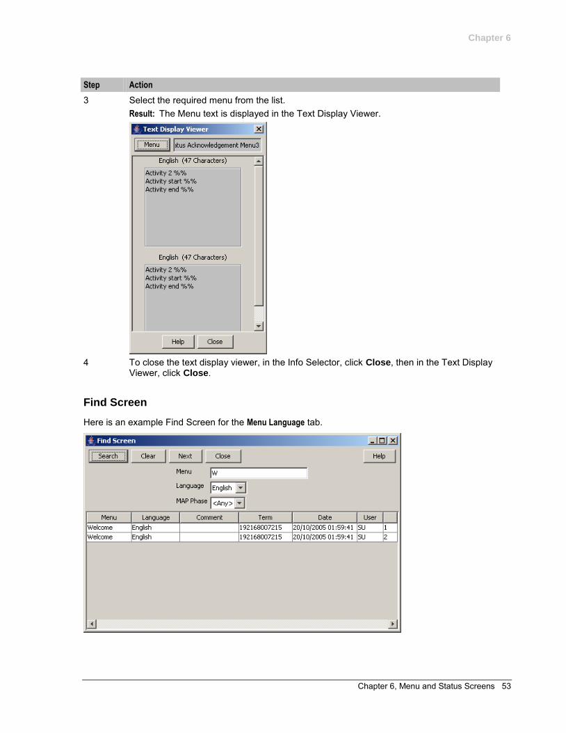
3 Select the required menu from the list. Result: The Menu text is displayed in the Text Display Viewer.
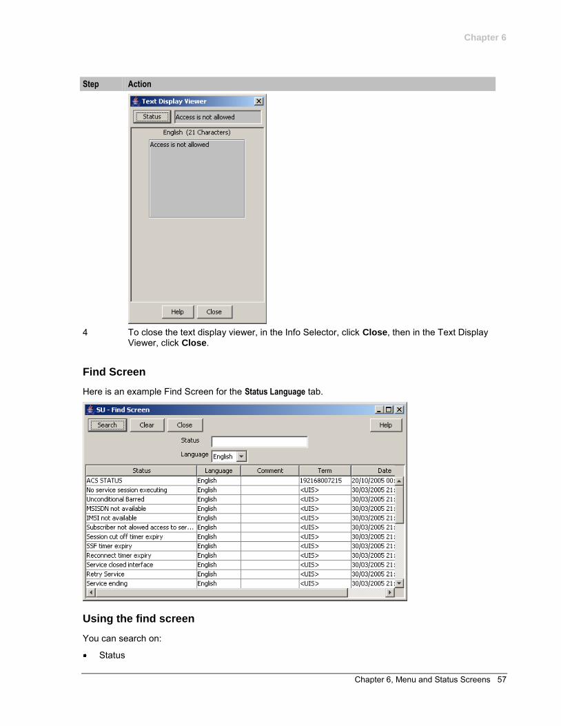
4 To close the text display viewer, in the Info Selector, click Close, then in the Text Display
Viewer, click Close.
Find Screen
Here is an example Find Screen for the Menu Language tab.
Chapter 6
54 USSD Gateway User's Guide
Using the find screen
You can search on:
Menu Language MAP Phase
For more information about searching and editing records, see Using the Find Screens (on page 12).
Status Language Display
Introduction
The Status Language tab allows you to set language specific status text for a given status.
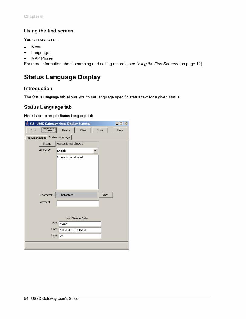
Status Language tab
Here is an example Status Language tab.
Chapter 6
Chapter 6, Menu and Status Screens 55
Fields
Here is a description of the fields.
Field Description
Status Displays status info name once selected, created by the USSD Gateway Menu Configuration Screen Status Info Configuration (on page 47) tab. You cannot edit this field directly. See Status button below.
Language The list of available languages.
Note: These are set up on the USSD Base Configuration Screen Language (on page 18) tab.
Text box This represents the display screen of a mobile phone Characters Displays the number of characters in the message in the field above.
Note: For example text for each field, refer to the Find screen in this topic.
Buttons
Here is a description of the buttons.
Button Description
Status Clicking this button displays the Status Selector screen, allowing you to search for and select a value, which will be entered into the Status field.
View Clicking this button displays the Text Display Viewer, which allows you to view the text of a status, its language and number of characters. See Viewing status text (on page 55).
Data entry
Follow these steps to enter a new status language.
Step Action
1 Click Clear to clear the screen of previous data. 2 Enter new data and click Save.
Buttons and other fields
For information about the buttons and fields at the bottom of the screen, see Common Buttons and Fields (on page 11).
Clicking Find displays the Find screen.
Viewing status text
Follow these steps to view status text.
Step Action
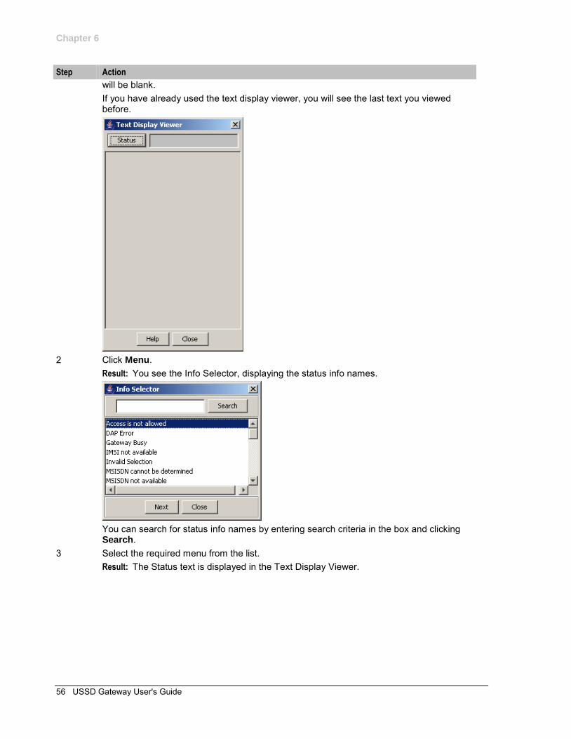
1 On the Status Language tab, click View. Result: You see the Text Display Viewer. If this is the first time you have used the text display viewer during the current session, the screen will display the text in the field in the tab. If no status has been selected, the field
Chapter 6
56 USSD Gateway User's Guide
Step Action
will be blank. If you have already used the text display viewer, you will see the last text you viewed before.
2 Click Menu.
Result: You see the Info Selector, displaying the status info names.
You can search for status info names by entering search criteria in the box and clicking Search.
3 Select the required menu from the list. Result: The Status text is displayed in the Text Display Viewer.
Chapter 6
Chapter 6, Menu and Status Screens 57
Step Action
4 To close the text display viewer, in the Info Selector, click Close, then in the Text Display
Viewer, click Close.
Find Screen
Here is an example Find Screen for the Status Language tab.
Using the find screen
You can search on:
Status

Chapter 6
58 USSD Gateway User's Guide
Language For more information about searching and editing records, see Using the Find Screens (on page 12).
Chapter 7, Subscribers Screens 59
Chapter 7
Subscribers Screens
Overview
Introduction
This chapter explains the contents of the Subscribers screens.
In this chapter
This chapter contains the following topics.
USSD Gateway Subscribers Screens ......................................................................................... 59 Access Control Screen ................................................................................................................ 60 IMSI Tracing Screen .................................................................................................................... 62 CDR Viewer Screen .................................................................................................................... 64 UPC CDR Viewer Screen ............................................................................................................ 67
USSD Gateway Subscribers Screens
Accessing USSD Gateway Subscribers screens
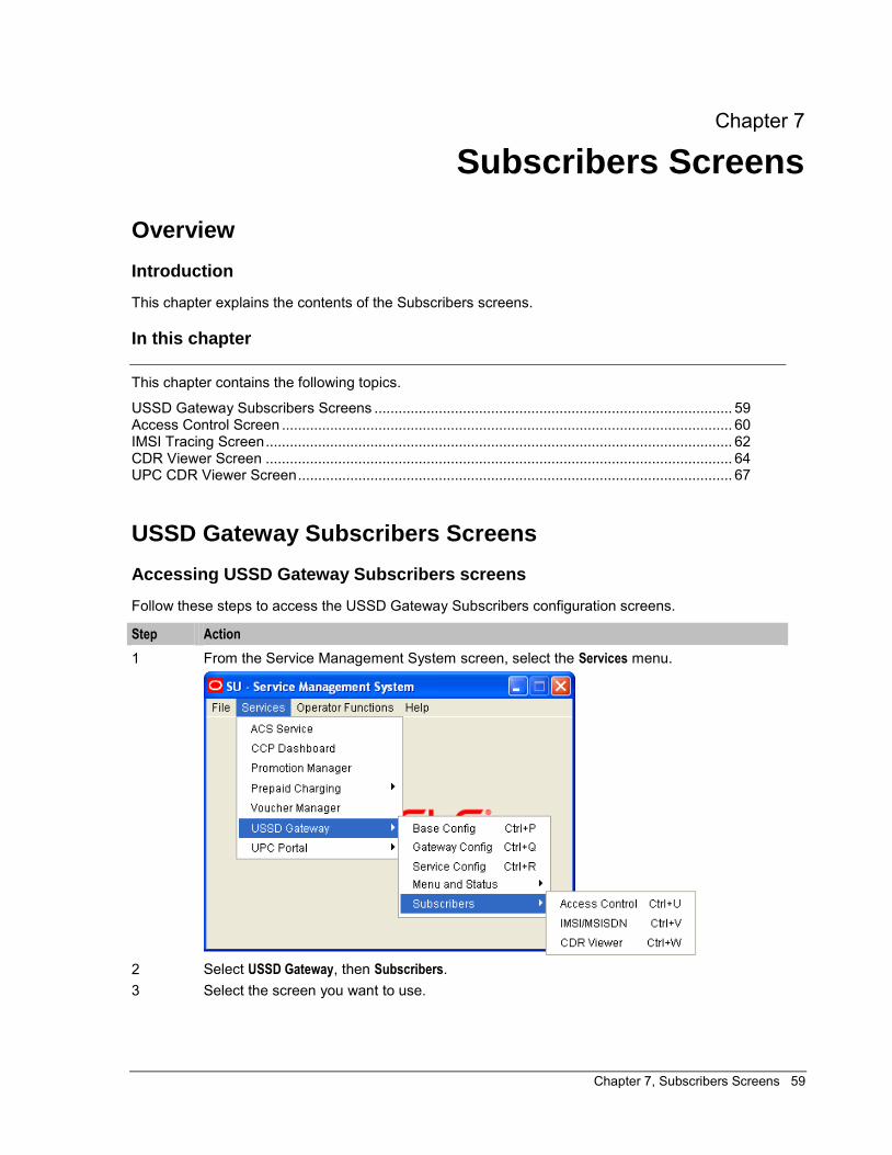
Follow these steps to access the USSD Gateway Subscribers configuration screens.
Step Action
1 From the Service Management System screen, select the Services menu.
2 Select USSD Gateway, then Subscribers. 3 Select the screen you want to use.
Chapter 7
60 USSD Gateway User's Guide
Access Control Screen
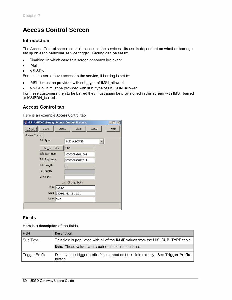
Introduction
The Access Control screen controls access to the services. Its use is dependent on whether barring is set up on each particular service trigger. Barring can be set to:
Disabled, in which case this screen becomes irrelevant IMSI MSISDN
For a customer to have access to the service, if barring is set to:
IMSI, it must be provided with sub_type of IMSI_allowed MSISDN, it must be provided with sub_type of MSISDN_allowed.
For these customers then to be barred they must again be provisioned in this screen with IMSI_barred or MSISDN_barred.
Access Control tab
Here is an example Access Control tab.
Fields
Here is a description of the fields.
Field Description
Sub Type This field is populated with all of the NAME values from the UIS_SUB_TYPE table.
Note: These values are created at installation time.
Trigger Prefix Displays the trigger prefix. You cannot edit this field directly. See Trigger Prefix button.
Chapter 7
Chapter 7, Subscribers Screens 61
Field Description
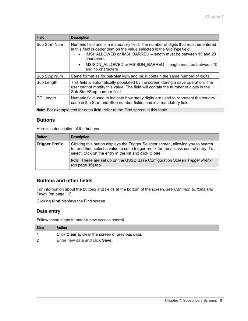
Sub Start Num Numeric field and is a mandatory field. The number of digits that must be entered in this field is dependent on the value selected in the Sub Type field.
IMSI_ALLOWED or IMSI_BARRED – length must be between 15 and 20 characters
MSISDN_ALLOWED or MSISDN_BARRED – length must be between 10 and 15 characters
Sub Stop Num Same format as for Sub Start Num and must contain the same number of digits. Sub Length This field is automatically populated by the screen during a save operation. The
user cannot modify this value. The field will contain the number of digits in the Sub Start/Stop number field.
CC Length Numeric field used to indicate how many digits are used to represent the country code in the Start and Stop number fields, and is a mandatory field.
Note: For example text for each field, refer to the Find screen in this topic.
Buttons
Here is a description of the buttons.
Button Description
Trigger Prefix Clicking this button displays the Trigger Selector screen, allowing you to search for and then select a value to set a trigger prefix for the access control entry. To select, click on the entry in the list and click Close.
Note: These are set up on the USSD Base Configuration Screen Trigger Prefix (on page 16) tab.
Buttons and other fields
For information about the buttons and fields at the bottom of the screen, see Common Buttons and Fields (on page 11).
Clicking Find displays the Find screen.
Data entry
Follow these steps to enter a new access control.
Step Action
1 Click Clear to clear the screen of previous data. 2 Enter new data and click Save.
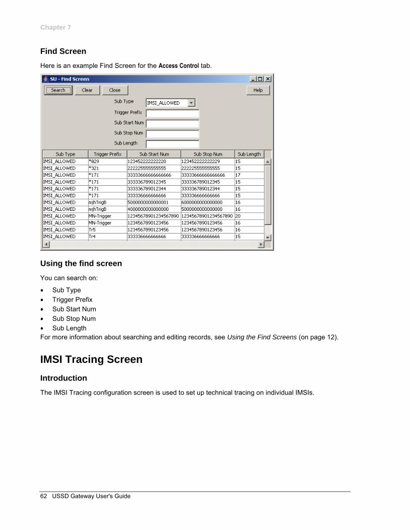
Chapter 7
62 USSD Gateway User's Guide
Find Screen
Here is an example Find Screen for the Access Control tab.
Using the find screen
You can search on:
Sub Type Trigger Prefix Sub Start Num Sub Stop Num Sub Length
For more information about searching and editing records, see Using the Find Screens (on page 12).
IMSI Tracing Screen
Introduction
The IMSI Tracing configuration screen is used to set up technical tracing on individual IMSIs.
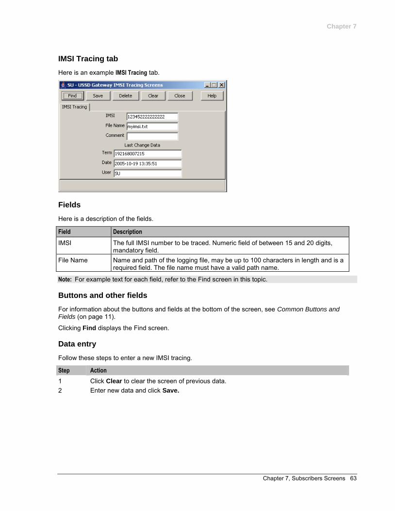
Chapter 7
Chapter 7, Subscribers Screens 63
IMSI Tracing tab
Here is an example IMSI Tracing tab.
Fields
Here is a description of the fields.
Field Description
IMSI The full IMSI number to be traced. Numeric field of between 15 and 20 digits, mandatory field.
File Name Name and path of the logging file, may be up to 100 characters in length and is a required field. The file name must have a valid path name.
Note: For example text for each field, refer to the Find screen in this topic.
Buttons and other fields
For information about the buttons and fields at the bottom of the screen, see Common Buttons and Fields (on page 11).
Clicking Find displays the Find screen.
Data entry
Follow these steps to enter a new IMSI tracing.
Step Action
1 Click Clear to clear the screen of previous data. 2 Enter new data and click Save.
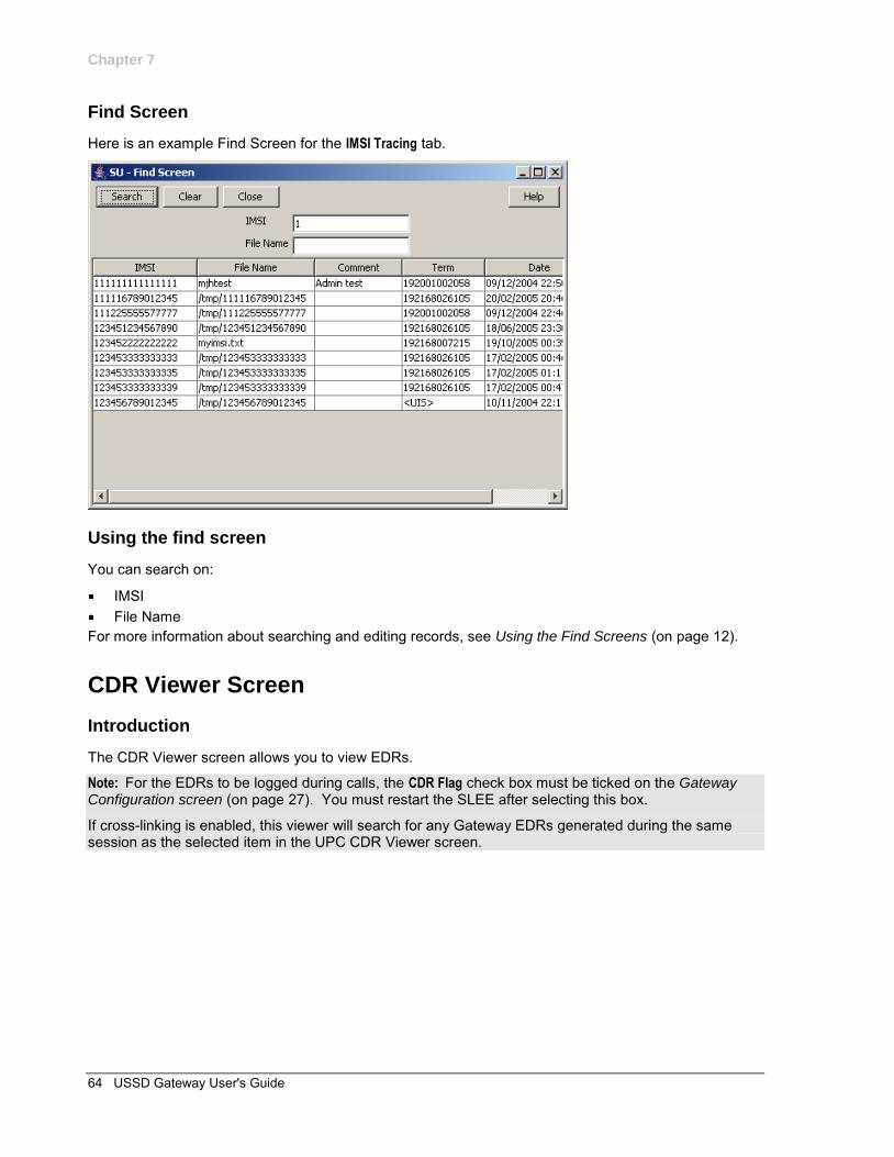
Chapter 7
64 USSD Gateway User's Guide
Find Screen
Here is an example Find Screen for the IMSI Tracing tab.
Using the find screen
You can search on:
IMSI File Name
For more information about searching and editing records, see Using the Find Screens (on page 12).
CDR Viewer Screen
Introduction
The CDR Viewer screen allows you to view EDRs.
Note: For the EDRs to be logged during calls, the CDR Flag check box must be ticked on the Gateway Configuration screen (on page 27). You must restart the SLEE after selecting this box.
If cross-linking is enabled, this viewer will search for any Gateway EDRs generated during the same session as the selected item in the UPC CDR Viewer screen.
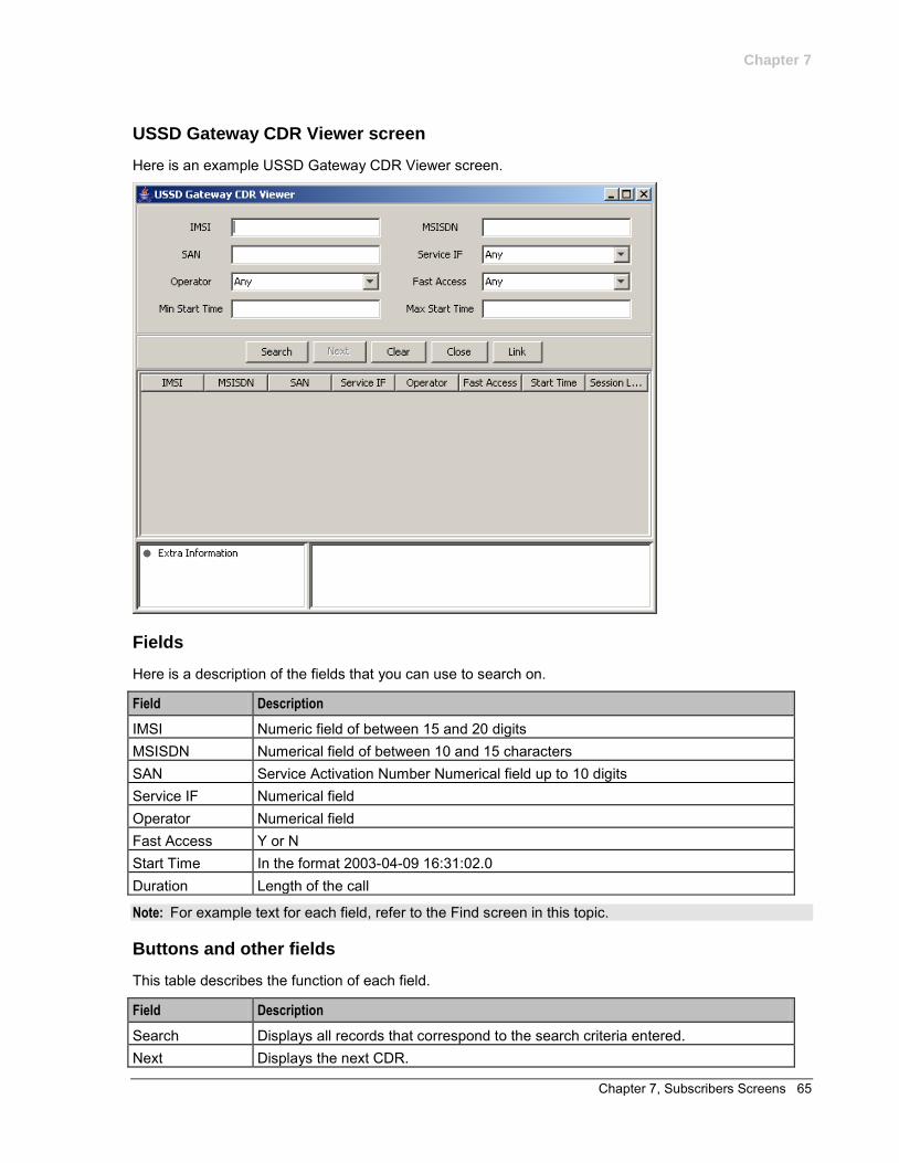
Chapter 7
Chapter 7, Subscribers Screens 65
USSD Gateway CDR Viewer screen
Here is an example USSD Gateway CDR Viewer screen.
Fields
Here is a description of the fields that you can use to search on.
Field Description
IMSI Numeric field of between 15 and 20 digits MSISDN Numerical field of between 10 and 15 characters SAN Service Activation Number Numerical field up to 10 digits Service IF Numerical field Operator Numerical field Fast Access Y or N Start Time In the format 2003-04-09 16:31:02.0 Duration Length of the call
Note: For example text for each field, refer to the Find screen in this topic.
Buttons and other fields
This table describes the function of each field.
Field Description
Search Displays all records that correspond to the search criteria entered. Next Displays the next CDR.
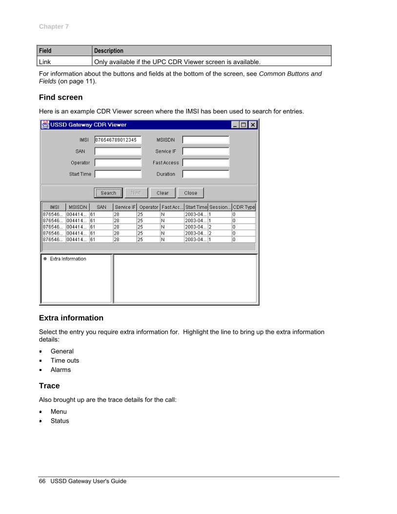
Chapter 7
66 USSD Gateway User's Guide
Field Description
Link Only available if the UPC CDR Viewer screen is available.
For information about the buttons and fields at the bottom of the screen, see Common Buttons and Fields (on page 11).
Find screen
Here is an example CDR Viewer screen where the IMSI has been used to search for entries.
Extra information
Select the entry you require extra information for. Highlight the line to bring up the extra information details:
General Time outs Alarms
Trace
Also brought up are the trace details for the call:
Menu Status
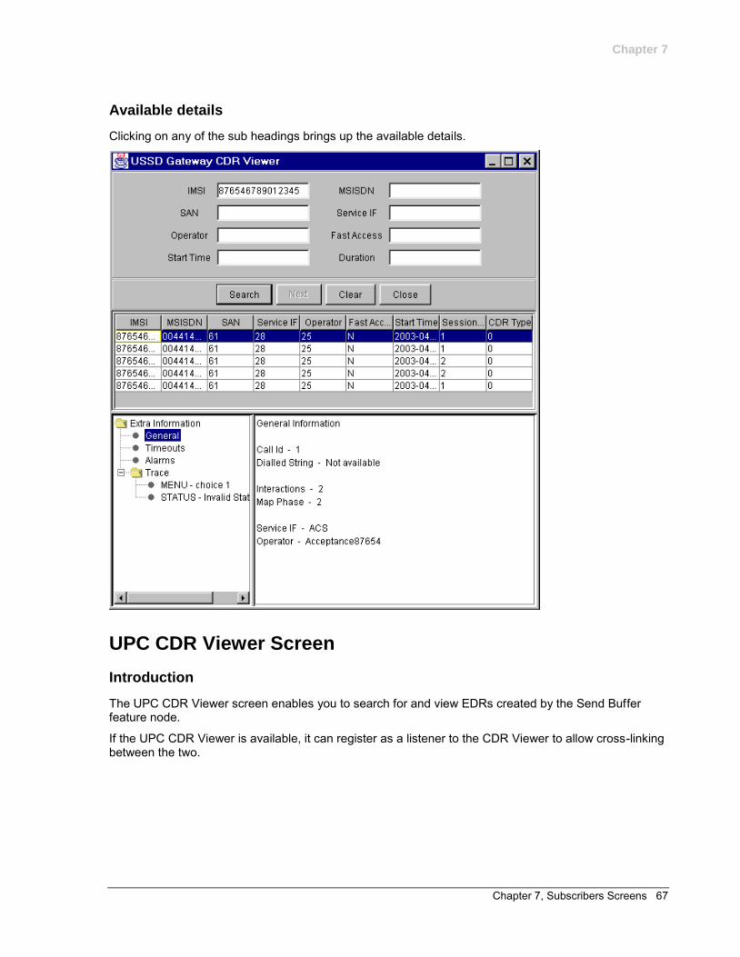
Chapter 7
Chapter 7, Subscribers Screens 67
Available details
Clicking on any of the sub headings brings up the available details.
UPC CDR Viewer Screen
Introduction
The UPC CDR Viewer screen enables you to search for and view EDRs created by the Send Buffer feature node.
If the UPC CDR Viewer is available, it can register as a listener to the CDR Viewer to allow cross-linking between the two.
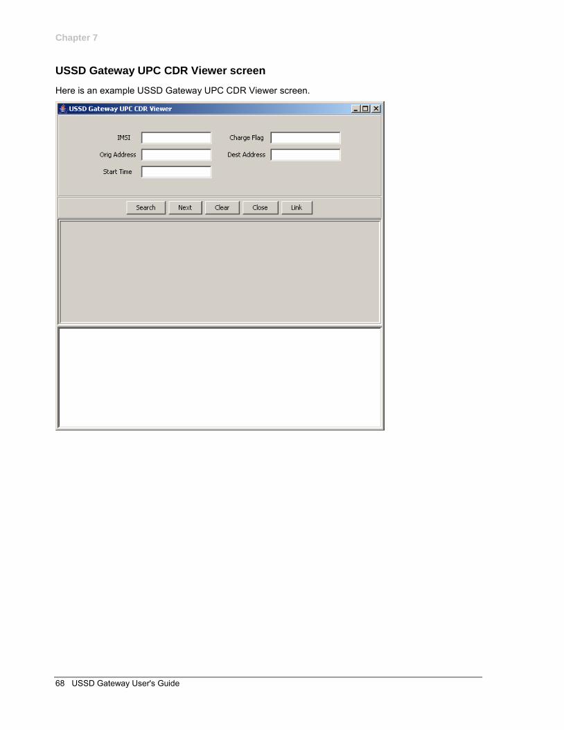
Chapter 7
68 USSD Gateway User's Guide
USSD Gateway UPC CDR Viewer screen
Here is an example USSD Gateway UPC CDR Viewer screen.
Chapter 8, UPC Portal Screens 69
Chapter 8
UPC Portal Screens
Overview
Introduction
This chapter explains the contents of the UPC Portal screens.
In this chapter
This chapter contains the following topics.
USSD Platform User Selection Screens ..................................................................................... 69 USSD Portal Message Class Screens ........................................................................................ 71
USSD Platform User Selection Screens
Introduction
The User Selection configuration screen allows you to enter keyword specific text for a given menu exit branch. MAP 1 and MAP 2 keywords can be different. This screen is used with the User Selection (on page 87) node.
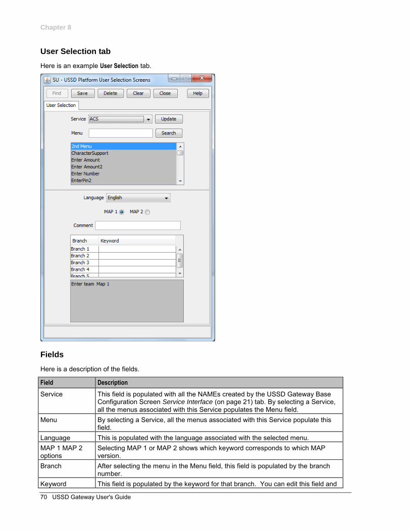
Chapter 8
70 USSD Gateway User's Guide
User Selection tab
Here is an example User Selection tab.
Fields
Here is a description of the fields.
Field Description
Service This field is populated with all the NAMEs created by the USSD Gateway Base Configuration Screen Service Interface (on page 21) tab. By selecting a Service, all the menus associated with this Service populates the Menu field.
Menu By selecting a Service, all the menus associated with this Service populate this field.
Language This is populated with the language associated with the selected menu. MAP 1 MAP 2 options
Selecting MAP 1 or MAP 2 shows which keyword corresponds to which MAP version.
Branch After selecting the menu in the Menu field, this field is populated by the branch number.
Keyword This field is populated by the keyword for that branch. You can edit this field and
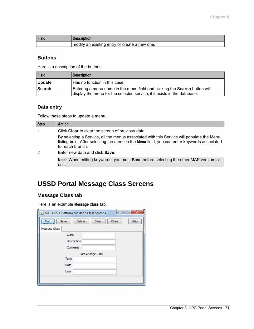
Chapter 8
Chapter 8, UPC Portal Screens 71
Field Description
modify an existing entry or create a new one.
Buttons
Here is a description of the buttons.
Field Description
Update Has no function in this case. Search Entering a menu name in the menu field and clicking the Search button will
display the menu for the selected service, if it exists in the database.
Data entry
Follow these steps to update a menu.
Step Action
1 Click Clear to clear the screen of previous data. By selecting a Service, all the menus associated with this Service will populate the Menu listing box. After selecting the menu in the Menu field, you can enter keywords associated for each branch.
2 Enter new data and click Save.
Note: When editing keywords, you must Save before selecting the other MAP version to edit.
USSD Portal Message Class Screens
Message Class tab
Here is an example Message Class tab.
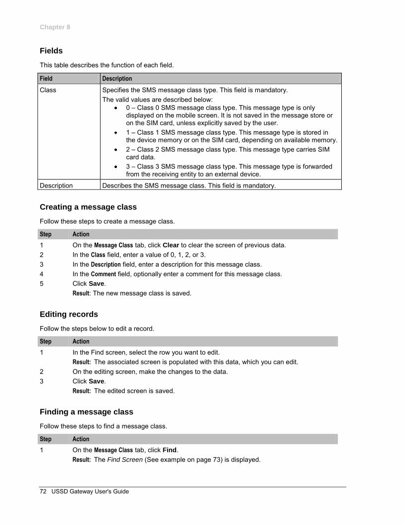
Chapter 8
72 USSD Gateway User's Guide
Fields
This table describes the function of each field.
Field Description
Class Specifies the SMS message class type. This field is mandatory. The valid values are described below:
0 – Class 0 SMS message class type. This message type is only displayed on the mobile screen. It is not saved in the message store or on the SIM card, unless explicitly saved by the user.
1 – Class 1 SMS message class type. This message type is stored in the device memory or on the SIM card, depending on available memory.
2 – Class 2 SMS message class type. This message type carries SIM card data.
3 – Class 3 SMS message class type. This message type is forwarded from the receiving entity to an external device.
Description Describes the SMS message class. This field is mandatory.
Creating a message class
Follow these steps to create a message class.
Step Action
1 On the Message Class tab, click Clear to clear the screen of previous data. 2 In the Class field, enter a value of 0, 1, 2, or 3. 3 In the Description field, enter a description for this message class. 4 In the Comment field, optionally enter a comment for this message class. 5 Click Save.
Result: The new message class is saved.
Editing records
Follow the steps below to edit a record.
Step Action
1 In the Find screen, select the row you want to edit. Result: The associated screen is populated with this data, which you can edit.
2 On the editing screen, make the changes to the data. 3 Click Save.
Result: The edited screen is saved.
Finding a message class
Follow these steps to find a message class.
Step Action
1 On the Message Class tab, click Find. Result: The Find Screen (See example on page 73) is displayed.
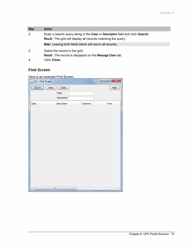
Chapter 8
Chapter 8, UPC Portal Screens 73
Step Action
2 Enter a search query string in the Class or Description field and click Search. Result: The grid will display all records matching the query.
Note: Leaving both fields blank will return all records.
3 Select the record in the grid. Result: The record is displayed on the Message Class tab.
4 Click Close.
Find Screen
Here is an example Find Screen.

Chapter 9, UPC Portal Nodes 75
Chapter 9
UPC Portal Nodes
Overview
Introduction
This chapter explains the contents of the Gateway Portal nodes provisioning screens.
In this chapter
This chapter contains the following topics.
Control Plan Editor Screen .......................................................................................................... 75 Making Nodes Available .............................................................................................................. 76 Available Feature Nodes ............................................................................................................. 77 Language Setting ........................................................................................................................ 78 Send Buffer .................................................................................................................................. 81 User Input .................................................................................................................................... 83 User Selection ............................................................................................................................. 87 Version Branching ....................................................................................................................... 91
Control Plan Editor Screen
Introduction
You can select the portal nodes from the ACS Control Plan Editor screen, as shown below. Double click on the node icon to open the node configuration screen.
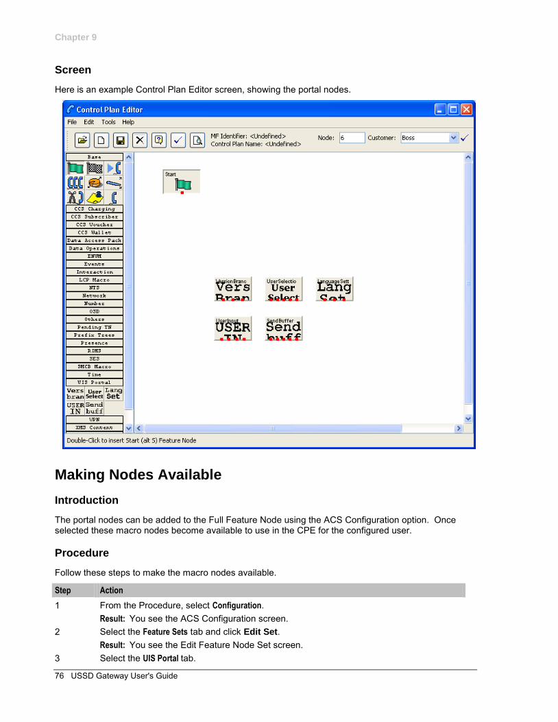
Chapter 9
76 USSD Gateway User's Guide
Screen
Here is an example Control Plan Editor screen, showing the portal nodes.
Making Nodes Available
Introduction
The portal nodes can be added to the Full Feature Node using the ACS Configuration option. Once selected these macro nodes become available to use in the CPE for the configured user.
Procedure
Follow these steps to make the macro nodes available.
Step Action
1 From the Procedure, select Configuration. Result: You see the ACS Configuration screen.
2 Select the Feature Sets tab and click Edit Set. Result: You see the Edit Feature Node Set screen.
3 Select the UIS Portal tab.
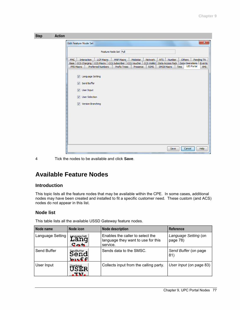
Chapter 9
Chapter 9, UPC Portal Nodes 77
Step Action
4 Tick the nodes to be available and click Save.
Available Feature Nodes
Introduction
This topic lists all the feature nodes that may be available within the CPE. In some cases, additional nodes may have been created and installed to fit a specific customer need. These custom (and ACS) nodes do not appear in this list.
Node list
This table lists all the available USSD Gateway feature nodes.
Node name Node icon Node description Reference
Language Setting
Enables the caller to select the language they want to use for this service.
Language Setting (on page 78)
Send Buffer
Sends data to the SMSC. Send Buffer (on page 81)
User Input
Collects input from the calling party. User Input (on page 83)
Chapter 9
78 USSD Gateway User's Guide
Node name Node icon Node description Reference
User Selection
Enables user selection from a menu. User Selection (on page 87)
Version Branching
Branches on the Version of MAP used.
Version Branching (on page 91)
Language Setting
Node description
The Language Setting node enables the subscriber to select one of a set of configured languages.
This node plays an announcement to the user, prompting them to select a language to use for the USSD call. This user’s temporary profile is updated with the selected language.
Note: The selection only lasts for the duration of the call.
Node icon
Restrictions
This node may be used any number of times within a control plan.
Node exits
This node has one entry and three exits. The number of exits cannot be changed.
Exit Cause Description
1 Error Node encountered an error during execution. The Error or Timeout announcement will be played.
2 Improper User Input
User entered a digit which does not map to a language.
3 Success Temporary profile updated with selected language.
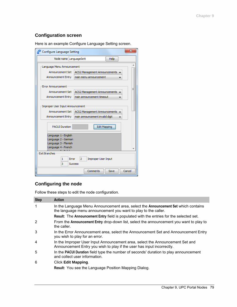
Chapter 9
Chapter 9, UPC Portal Nodes 79
Configuration screen
Here is an example Configure Language Setting screen.
Configuring the node
Follow these steps to edit the node configuration.
Step Action
1 In the Language Menu Announcement area, select the Announcement Set which contains the language menu announcement you want to play to the caller. Result: The Announcement Entry field is populated with the entries for the selected set.
2 From the Announcement Entry drop-down list, select the announcement you want to play to the caller.
3 In the Error Announcement area, select the Announcement Set and Announcement Entry you wish to play for an error.
4 In the Improper User Input Announcement area, select the Announcement Set and Announcement Entry you wish to play if the user has input incorrectly.
5 In the PACUI Duration field type the number of seconds' duration to play announcement and collect user information.
6 Click Edit Mapping. Result: You see the Language Position Mapping Dialog.
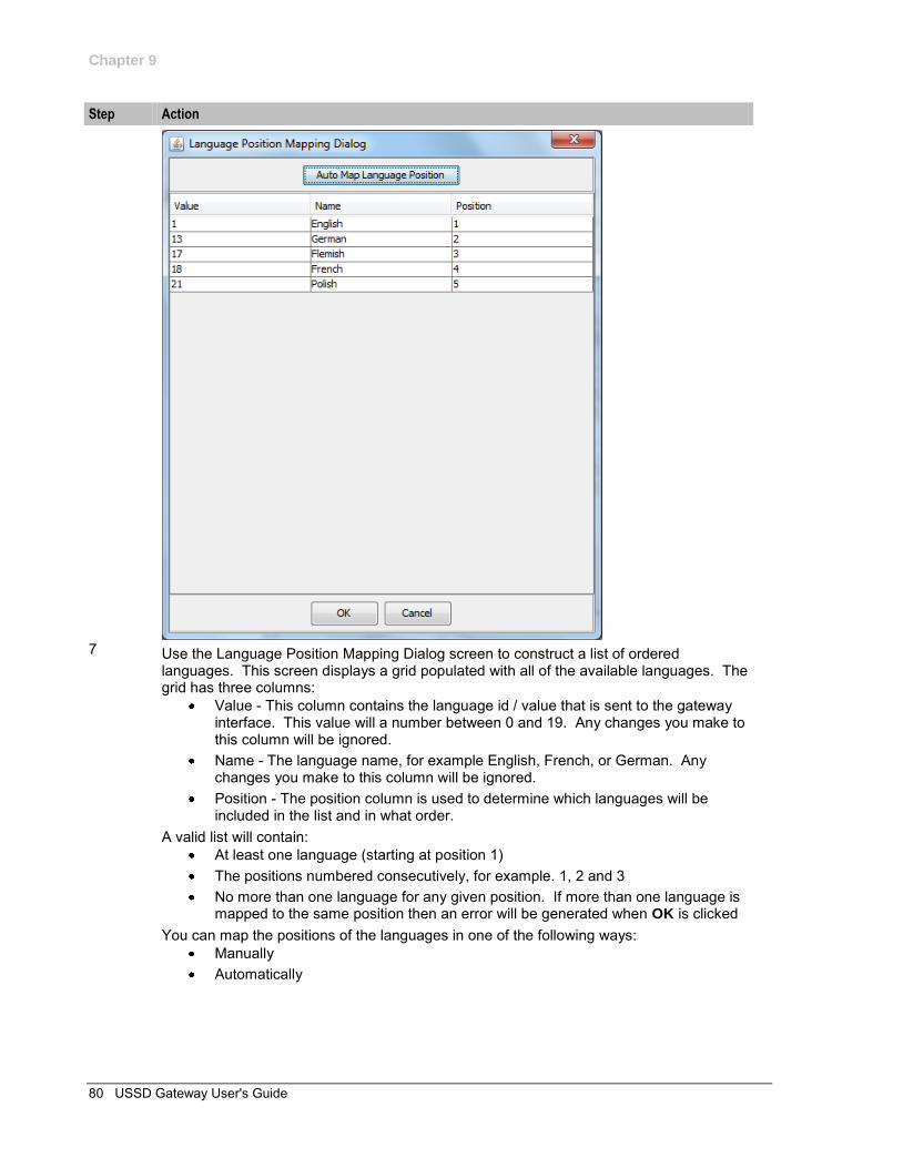
Chapter 9
80 USSD Gateway User's Guide
Step Action
7 Use the Language Position Mapping Dialog screen to construct a list of ordered
languages. This screen displays a grid populated with all of the available languages. The grid has three columns:
Value - This column contains the language id / value that is sent to the gateway interface. This value will a number between 0 and 19. Any changes you make to this column will be ignored.
Name - The language name, for example English, French, or German. Any changes you make to this column will be ignored.
Position - The position column is used to determine which languages will be included in the list and in what order.
A valid list will contain: At least one language (starting at position 1) The positions numbered consecutively, for example. 1, 2 and 3 No more than one language for any given position. If more than one language is
mapped to the same position then an error will be generated when OK is clicked You can map the positions of the languages in one of the following ways:
Manually Automatically
Chapter 9
Chapter 9, UPC Portal Nodes 81
Step Action
8 To manually map the languages: a. Click on the Position cell in the row for the language. b. Type the number in the cell c. Repeat for each language. To automatically map the language positions: a. Click Auto Map Language Position. Result: A list will be generated which contains all of the available languages, positioned in the order that they are stored in the system database. You can subsequently manually edit this configuration if required.
9 Click OK. Result: Validation checks are carried out to determine whether or not the criteria detailed above has been met. If not, you will be informed via an error dialog. If the validation checks are successful, then the dialog box will close, and the language list on the Configure Language Setting screen will be updated.
Send Buffer
Node description
The Send Buffer node sends the final selection buffer that has been built through the various Menu Selection and User Entry macro nodes to an SMSC through the UCP Interface.
Once the final selection buffer has been sent, the Send Buffer node writes an EDR to record the transaction.
Node icon
Restrictions
This node may be used any number of times within a control plan.
Node exits
This node has one entry and five exits. The number of exits cannot be changed.
Exit Cause Description
1 Success Both the final selection buffer, and the CDR have been successfully sent.
2 Error Node encountered an error receiving or sending data. 3 Empty Buffer Final selection buffer retrieved from the configured ProfileTag has been
allocated but is empty. This situation will occur if the previous node in the call plan was a menu selection node that was set to clear the buffer.
4 No Buffer Final selection buffer does not exist. Suggests a configuration error in the CPE.
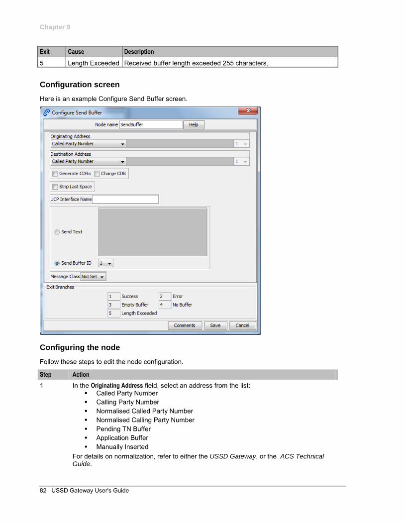
Chapter 9
82 USSD Gateway User's Guide
Exit Cause Description
5 Length Exceeded Received buffer length exceeded 255 characters.
Configuration screen
Here is an example Configure Send Buffer screen.
Configuring the node
Follow these steps to edit the node configuration.
Step Action
1 In the Originating Address field, select an address from the list: Called Party Number Calling Party Number Normalised Called Party Number Normalised Calling Party Number Pending TN Buffer Application Buffer Manually Inserted
For details on normalization, refer to either the USSD Gateway, or the ACS Technical Guide.
Chapter 9
Chapter 9, UPC Portal Nodes 83
Step Action
2 If you selected: Application Buffer, select the buffer value from the drop down list to the far right of
the field. Manually Inserted, type the originating address in the text field to the right of the
field. Maximum of 31 characters. 3 In the Destination Address field, select an address from the list. This will normally contain
the MSISDN of the subscriber using the service. The available options are the same as for the originating address.
4 Select the Generate CDRs check box if you wish to generate CDRs.
Note: You can view these CDRs on the UPC CDR Viewer Screen (on page 67).
5 Select the Charge CDR check box if you wish to charge CDRs. 6 Select the Strip Last Space check box if you wish to strip the last space from the buffer. 7 Type the name of the UCP interface to be used.
This alphanumeric field can be populated with up to 19 characters. 8 The Send Text option allows you to enter hard coded text, in the text field, which is sent to
the UCP interface at run time. 9 The Send Buffer ID option allows you to select the buffer, in the drop down box, in which
data is collected. 10 The Message Class drop-down menu selects "Not Set".
Note: This feature is for future enhancements.
11 Click Save.
User Input
Node description
This node plays an announcement to the subscriber which prompts them for input. It then collects the input and appends it to the configured selection buffer.
Node icon
Restrictions
This node may be used any number of times within a control plan.
Node exits
This node has one entry and four exits. The number of exits cannot be changed.
Exit Cause Description
1 Error Node encountered an error during execution.
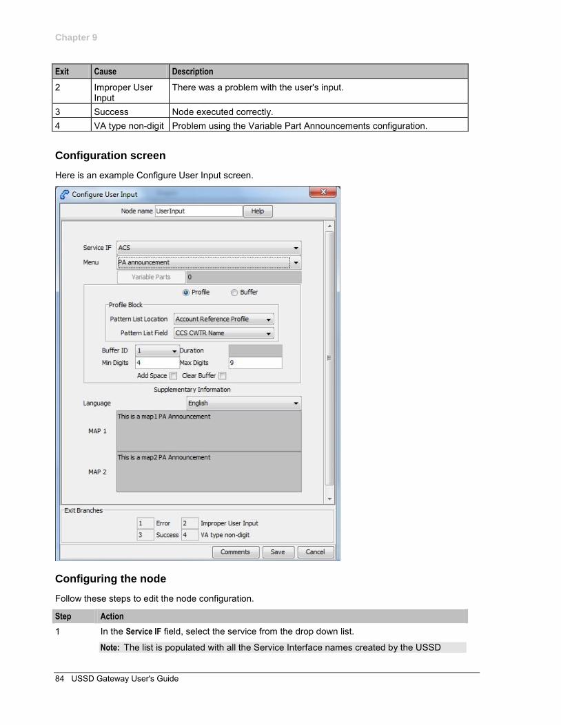
Chapter 9
84 USSD Gateway User's Guide
Exit Cause Description
2 Improper User Input
There was a problem with the user's input.
3 Success Node executed correctly. 4 VA type non-digit Problem using the Variable Part Announcements configuration.
Configuration screen
Here is an example Configure User Input screen.
Configuring the node
Follow these steps to edit the node configuration.
Step Action
1 In the Service IF field, select the service from the drop down list.
Note: The list is populated with all the Service Interface names created by the USSD
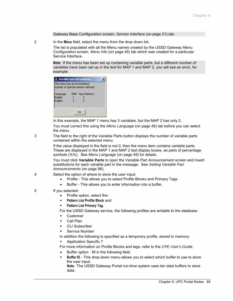
Chapter 9
Chapter 9, UPC Portal Nodes 85
Gateway Base Configuration screen, Service Interface (on page 21) tab.
2 In the Menu field, select the menu from the drop down list. The list is populated with all the Menu names created by the USSD Gateway Menu Configuration screen, Menu Info (on page 45) tab which was created for a particular Service Interface.
Note: If the menu has been set up containing variable parts, but a different number of variables have been set up in the text for MAP 1 and MAP 2, you will see an error, for example:
In this example, the MAP 1 menu has 3 variables, but the MAP 2 has only 2. You must correct this using the Menu Language (on page 49) tab before you can select the menu.
3 The field to the right of the Variable Parts button displays the number of variable parts contained within the selected menu. If the value displayed in the field is not 0, then the menu item contains variable parts. These are displayed in the MAP 1 and MAP 2 text display boxes, as pairs of percentage symbols (%%). See Menu Language (on page 49) for details. You must click Variable Parts to open the Variable Part Announcement screen and insert substitutions for each variable part in the message. See Setting Variable Part Announcements (on page 86).
4 Select the option of where to store the user input: Profile - This allows you to select Profile Blocks and Primary Tags Buffer - This allows you to enter information into a buffer.
5 If you selected: Profile option, select the: Pattern List Profile Block and Pattern List Primary Tag. For the USSD Gateway service, the following profiles are writable to the database: Customer Call Plan CLI Subscriber Service Number In addition the following is specified as a temporary profile, stored in memory: Application Specific 7 For more information on Profile Blocks and tags, refer to the CPE User's Guide.
Buffer option - fill in the following field: Buffer ID - This drop-down menu allows you to select which buffer to use to store
the user input. Note: The USSD Gateway Portal run-time system uses ten data buffers to store data.

Chapter 9
86 USSD Gateway User's Guide
6 In the Duration field, set the length of time, in seconds that the user has to enter their selection.
Note: Optional
7 In the Min Digits and Max Digits fields, set the minimum and maximum number of digits the user is required to input.
8 Ticking the Add Space check box will add a space at the end of the string entered into the buffer.
9 Ticking the Clear Buffer check box will clear any value entered into the buffer before any selection has been entered.
10 In the Language field, select the language to use. This is populated with the language names created by the USSD Gateway Base Configuration screen, Language (on page 18) tab. The MAP 1 and MAP 2 fields will display the text information presented to the user using a MAP1 or MAP2 version device, in the selected language.
11 Click Save.
Setting Variable Part Announcements
If the menu contains one or more variable announcement parts, use the Variable Part Announcement screen to define each variable part.
Here is an example Variable Part Announcement Dialog.
This example contains four variable parts, each illustrating a different option from the list of buffers.
Chapter 9
Chapter 9, UPC Portal Nodes 87
Buffers
Here are the buffers available in the Variable Part Announcements Dialog and the action to perform when the buffer is selected.
Buffer Action
Called Party Number Calling Party Number Normalised Called Party Number Normalised Calling Party Number Pending TN Buffer
No further action required
Application Buffer Select the buffer used to store the user input in the drop down list
Manually inserted Type a value in the text field. Profile Location. Select the:
Pattern List Profile Block and Pattern List Primary Tag.
For more information on Profile Blocks and tags, refer to CPE User's Guide.
For a description of the buffers, refer to CPE User's Guide.
User Selection
Node description
The User Selection node displays a menu and collects the user's choice. The node matches the choice to a keyword in the UPC menu string. If a keyword matches, it is appended to the final selection buffer.
Node icon
Restrictions
This node may be used any number of times within a control plan.
Node exits
The User Selection node has one entry and may have 5 through 25 exits. Each exit is mapped to a day of week range, and must be connected to an appropriate node. You can configure the number of exits using the Editing the number of exit branches (on page 90).
Exit Cause Description
1 Error Node encountered an error during execution. 2 Improper User
Input User Selection doesn't match keyword choice.
3 VA type non-digit Problem using the Variable Part Announcements configuration. 4 0 User selected 0.
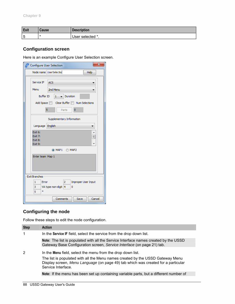
Chapter 9
88 USSD Gateway User's Guide
Exit Cause Description
5 * User selected *.
Configuration screen
Here is an example Configure User Selection screen.
Configuring the node
Follow these steps to edit the node configuration.
Step Action
1 In the Service IF field, select the service from the drop down list.
Note: The list is populated with all the Service Interface names created by the USSD Gateway Base Configuration screen, Service Interface (on page 21) tab.
2 In the Menu field, select the menu from the drop down list. The list is populated with all the Menu names created by the USSD Gateway Menu Display screen, Menu Language (on page 49) tab which was created for a particular Service Interface.
Note: If the menu has been set up containing variable parts, but a different number of
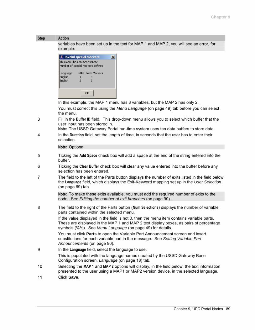
Chapter 9
Chapter 9, UPC Portal Nodes 89
Step Action
variables have been set up in the text for MAP 1 and MAP 2, you will see an error, for example:
In this example, the MAP 1 menu has 3 variables, but the MAP 2 has only 2. You must correct this using the Menu Language (on page 49) tab before you can select the menu.
3 Fill in the Buffer ID field. This drop-down menu allows you to select which buffer that the user input has been stored in. Note: The USSD Gateway Portal run-time system uses ten data buffers to store data.
4 In the Duration field, set the length of time, in seconds that the user has to enter their selection.
Note: Optional
5 Ticking the Add Space check box will add a space at the end of the string entered into the buffer.
6 Ticking the Clear Buffer check box will clear any value entered into the buffer before any selection has been entered.
7 The field to the left of the Parts button displays the number of exits listed in the field below the Language field, which displays the Exit-Keyword mapping set up in the User Selection (on page 69) tab.
Note: To make these exits available, you must add the required number of exits to the node. See Editing the number of exit branches (on page 90).
8 The field to the right of the Parts button (Num Selections) displays the number of variable parts contained within the selected menu. If the value displayed in the field is not 0, then the menu item contains variable parts. These are displayed in the MAP 1 and MAP 2 text display boxes, as pairs of percentage symbols (%%). See Menu Language (on page 49) for details. You must click Parts to open the Variable Part Announcement screen and insert substitutions for each variable part in the message. See Setting Variable Part Announcements (on page 90).
9 In the Language field, select the language to use. This is populated with the language names created by the USSD Gateway Base Configuration screen, Language (on page 18) tab.
10 Selecting the MAP 1 and MAP 2 options will display, in the field below, the text information presented to the user using a MAP1 or MAP2 version device, in the selected language.
11 Click Save.
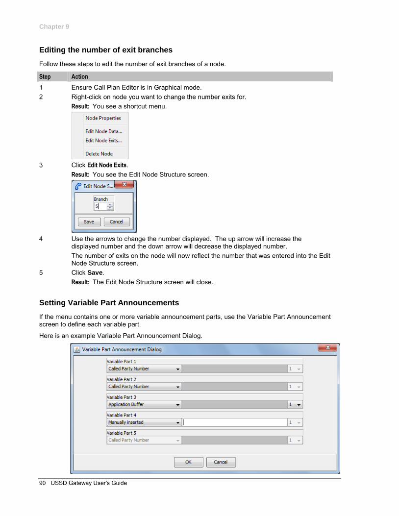
Chapter 9
90 USSD Gateway User's Guide
Editing the number of exit branches
Follow these steps to edit the number of exit branches of a node.
Step Action
1 Ensure Call Plan Editor is in Graphical mode. 2 Right-click on node you want to change the number exits for.
Result: You see a shortcut menu.
3 Click Edit Node Exits.
Result: You see the Edit Node Structure screen.
4 Use the arrows to change the number displayed. The up arrow will increase the
displayed number and the down arrow will decrease the displayed number. The number of exits on the node will now reflect the number that was entered into the Edit Node Structure screen.
5 Click Save. Result: The Edit Node Structure screen will close.
Setting Variable Part Announcements
If the menu contains one or more variable announcement parts, use the Variable Part Announcement screen to define each variable part.
Here is an example Variable Part Announcement Dialog.
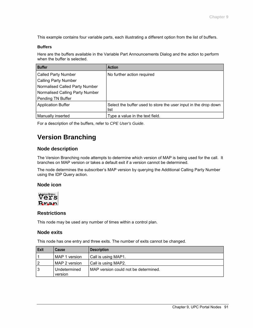
Chapter 9
Chapter 9, UPC Portal Nodes 91
This example contains four variable parts, each illustrating a different option from the list of buffers.
Buffers
Here are the buffers available in the Variable Part Announcements Dialog and the action to perform when the buffer is selected.
Buffer Action
Called Party Number Calling Party Number Normalised Called Party Number Normalised Calling Party Number Pending TN Buffer
No further action required
Application Buffer Select the buffer used to store the user input in the drop down list
Manually inserted Type a value in the text field.
For a description of the buffers, refer to CPE User's Guide.
Version Branching
Node description
The Version Branching node attempts to determine which version of MAP is being used for the call. It branches on MAP version or takes a default exit if a version cannot be determined.
The node determines the subscriber’s MAP version by querying the Additional Calling Party Number using the IDP Query action.
Node icon
Restrictions
This node may be used any number of times within a control plan.
Node exits
This node has one entry and three exits. The number of exits cannot be changed.
Exit Cause Description
1 MAP 1 version Call is using MAP1. 2 MAP 2 version Call is using MAP2. 3 Undetermined
version MAP version could not be determined.
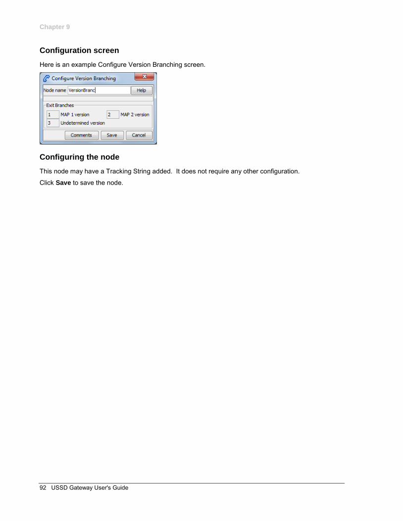
Chapter 9
92 USSD Gateway User's Guide
Configuration screen
Here is an example Configure Version Branching screen.
Configuring the node
This node may have a Tracking String added. It does not require any other configuration.
Click Save to save the node.
Glossary 93
Glossary of Terms
AAA
Authentication, Authorization, and Accounting. Specified in Diameter RFC 3588.
ACS
Advanced Control Services configuration platform.
ANI
Automatic Number Identification - Term used in the USA by long-distance carriers for CLI.
BCSM
Basic Call State Model - describes the basic processing steps that must be performed by a switch in order to establish and tear down a call.
CAMEL
Customized Applications for Mobile network Enhanced Logic
This is a 3GPP (Third Generation Partnership Project) initiative to extend traditional IN services found in fixed networks into mobile networks. The architecture is similar to that of traditional IN, in that the control functions and switching functions are remote. Unlike the fixed IN environment, in mobile networks the subscriber may roam into another PLMN (Public Land Mobile Network), consequently the controlling function must interact with a switching function in a foreign network. CAMEL specifies the agreed information flows that may be passed between these networks.
CC
Country Code. Prefix identifying the country for a numeric international address.
CCS
1) Charging Control Services component.
2) Common Channel Signalling. A signalling system used in telephone networks that separates signalling information from user data.
CDR
Call Data Record
Note: The industry standard for CDR is EDR (Event Detail Record).
CLI
Calling Line Identification - the telephone number of the caller. Also referred to as ANI.
CPE
Control Plan Editor (previously Call Plan Editor) - software used to define the logic and data associated with a call -for example, "if the subscriber calls 0800 nnnnnn from a phone at location xxx then put the call through to bb bbb bbbb".
94 USSD Gateway User's Guide
Diameter
A feature rich AAA protocol. Utilises SCTP and TCP transports.
DP
Detection Point
DTMF
Dual Tone Multi-Frequency - system used by touch tone telephones where one high and one low frequency, or tone, is assigned to each touch tone button on the phone.
FDA
First Delivery Attempt - the delivery of a short message directly to the SME rather than relaying it through the MC.
GPRS
General Packet Radio Service - employed to connect mobile cellular users to PDN (Public Data Network- for example the Internet).
GSM
Global System for Mobile communication.
It is a second generation cellular telecommunication system. Unlike first generation systems, GSM is digital and thus introduced greater enhancements such as security, capacity, quality and the ability to support integrated services.
GUI
Graphical User Interface
HLR
The Home Location Register is a database within the HPLMN (Home Public Land Mobile Network). It provides routing information for MT calls and SMS. It is also responsible for the maintenance of user subscription information. This is distributed to the relevant VLR, or SGSN (Serving GPRS Support Node) through the attach process and mobility management procedures such as Location Area and Routing Area updates.
HPLMN
Home PLMN
ICA
InitiateCallAttempt. A CAMEL/INAP operation sent by the SLC to an SSP request that a voice call is started.
IDP
INAP message: Initial DP (Initial Detection Point)
Glossary 95
IMSI
International Mobile Subscriber Identifier. A unique identifier allocated to each mobile subscriber in a GSM and UMTS network. It consists of a MCC (Mobile Country Code), a MNC (Mobile Network Code) and a MSIN (Mobile Station Identification Number).
The IMSI is returned by the HLR query (SRI-SM) when doing FDA. This tells the MSC exactly who the subscriber is that the message is to be sent to.
IN
Intelligent Network
INAP
Intelligent Network Application Part - a protocol offering real time communication between IN elements.
Initial DP
Initial Detection Point - INAP Operation. This is the operation that is sent when the switch reaches a trigger detection point.
IP
1) Internet Protocol
2) Intelligent Peripheral - This is a node in an Intelligent Network containing a Specialized Resource Function (SRF).
ISDN
Integrated Services Digital Network - set of protocols for connecting ISDN stations.
ITU
International Telecommunication Union
MAP
Mobile Application Part - a protocol which enables real time communication between nodes in a mobile cellular network. A typical usage of the protocol would be for the transfer of location information from the VLR to the HLR.
MC
Message Centre. Also known as SMSC.
MCC
Mobile Country Code. In the location information context, this is padded to three digits with leading zeros. Refer to ITU E.212 ("Land Mobile Numbering Plan") documentation for a list of codes.
MNC
Mobile Network Code. The part of an international address following the mobile country code (MCC), or at the start of a national format address. This specifies the mobile network code, that is, the operator owning the address. In the location information context, this is padded to two digits with a leading zero. Refer to ITU E.212 ("Land Mobile Numbering Plan") documentation for a list of codes.
96 USSD Gateway User's Guide
MS
Mobile Station
MSC
Mobile Switching Centre. Also known as a switch.
MSIN
Mobile Station Identification Number.
MSISDN
Mobile Station ISDN number. Uniquely defines the mobile station as an ISDN terminal. It consists of three parts; the country code (CC), the national destination code (NDC) and the subscriber number (SN).
MSRN
Mobile Station Roaming Number
MT
Mobile Terminated
PACUI
Play Announcement and Collect User Information
PLMN
Public Land Mobile Network
RRBCSM
Request Report BCSM.
SAN
Service Access Number
SCP
Service Control Point. Also known as SLC.
SCTP
Stream Control Transmission Protocol. A transport-layer protocol analogous to the TCP or User Datagram Protocol (UDP). SCTP provides some similar services as TCP (reliable, in-sequence transport of messages with congestion control) but adds high availability.
Session
Diameter exchange relating to a particular user or subscriber access to a provided service (for example, a telephone call).
Glossary 97
SGSN
Serving GPRS Support Node
SIM
Usually referred to as a SIM card, the Subscriber Identity Module is the user subscription to the mobile network. The SIM contains relevant information that enables access onto the subscripted operator’s network.
SLC
Service Logic Controller (formerly UAS).
SLEE
Service Logic Execution Environment
SME
Short Message Entity - This is an entity which may send or receive short messages. It may be located in a fixed network, a mobile, or an SMSC.
SMS
Depending on context, can be:
Service Management System hardware platform Short Message Service Service Management System platform NCC Service Management System application
SMSC
Short Message Service Centre stores and forwards a short message to the indicated destination subscriber number.
SN
Service Number
SRF
Specialized Resource Function – This is a node on an IN which can connect to both the SSP and the SLC and delivers additional special resources into the call, mostly related to voice data, for example play voice announcements or collect DTMF tones from the user. Can be present on an SSP or an Intelligent Peripheral (IP).
SRI
Send Routing Information - This process is used on a GSM network to interrogate the HLR for subscriber routing information.
SSF
Sub Service Field.
98 USSD Gateway User's Guide
SSP
Service Switching Point
Switching Point
Anything that can send and receive C7 messages.
System Administrator
The person(s) responsible for the overall set-up and maintenance of the IN.
TCAP
Transaction Capabilities Application Part – layer in protocol stack, message protocol.
TCP
Transmission Control Protocol. This is a reliable octet streaming protocol used by the majority of applications on the Internet. It provides a connection-oriented, full-duplex, point to point service between hosts.
UIS
USSD Interactive Services
UPC
USSD Portal Components
USSD
Unstructured Supplementary Service Data - a feature in the GSM MAP protocol that can be used to provide subscriber functions such as Balance Query.
VLR
Visitor Location Register - contains all subscriber data required for call handling and mobility management for mobile subscribers currently located in the area controlled by the VLR.
WAP
Wireless Application Protocol. A standard designed to allow the content of the Internet to be viewed on the screen of a mobile device such as mobile phones, personal organisers and pagers. It also overcomes the processing limitation of such devices. The information and services available are stripped down to their basic text format.
Index 99
Index
A
A leg • 3 AAA • 93 About This Document • v Access Control Screen • 10, 60 Access Control tab • 60 Accessing a find screen • 13 Accessing performance reports • 7 Accessing UPC Portal • 11 Accessing USSD Gateway • 9 Accessing USSD Gateway Base Configuration
screen • 15 Accessing USSD Gateway Configuration
screen • 27 Accessing USSD Gateway Menu configuration
screens • 39 Accessing USSD Gateway Service
configuration screen • 33 Accessing USSD Gateway Subscribers screens
• 59 ACS • 93 ANI • 93 Audience • v Available details • 67 Available Feature Nodes • 77
B
B leg • 4 Base Config screen • 10 BCSM • 93 Buffers • 87, 91 Buttons • 11, 51, 55, 61, 71 Buttons and other fields • 17, 20, 22, 24, 30, 37,
46, 49, 51, 55, 61, 63, 65
C
Callback • 3 Callback initiation • 3 CAMEL • 93 CC • 93 CCS • 93 CDR • 93 CDR Viewer Screen • 11, 64 CLI • 93 Collect call back example • 5 Common Buttons and Fields • 11, 17, 20, 22,
24, 30, 37, 46, 49, 51, 55, 61, 63, 66 Common fields • 12 Configuration screen • 79, 82, 84, 88, 92 Configuring the node • 79, 82, 84, 88, 92 Control Plan Editor Screen • 75 Control plan example • 4 Control plans • 1 Copyright • ii
CPE • 93 Creating a message class • 72
D
Data entry • 12, 20, 22, 24, 30, 36, 47, 48, 51, 55, 61, 63, 71
Data entry - trigger prefix • 17 Description • 6 Diameter • 94 Document Conventions • vi DP • 94 DTMF • 94
E
Editing records • 13, 72 Editing the number of exit branches • 87, 89, 90 Example • 7 Example find screen • 13 Example values • 6 Extra information • 66
F
FDA • 94 Fields • 16, 19, 22, 23, 29, 46, 48, 50, 55, 60,
63, 65, 70, 72 Find screen • 66 Find Screen • 18, 20, 22, 24, 31, 37, 47, 49, 53,
57, 62, 64, 72, 73 Finding a message class • 72
G
Gateway Config screen • 10 Gateway Configuration Screen • 10, 27, 35, 64 Gateway Configuration tab • 17, 28 Getting Started • 9 GPRS • 94 GSM • 94 GUI • 94
H
Handset integration • 2 Handset Interaction • 5 HLR • 94 HPLMN • 94
I
ICA • 94 IDP • 94 Important
reloading the configuration • 28 IMSI • 95 IMSI Tracing Screen • 11, 62 IMSI Tracing tab • 63 IN • 95 INAP • 95 Initial DP • 95
100 USSD Gateway User's Guide
Introduction • 1, 3, 5, 12, 16, 18, 21, 23, 27, 34, 40, 43, 45, 47, 49, 54, 60, 62, 64, 67, 69, 75, 76, 77
Invalid special markers • 84, 88 IP • 95 ISDN • 95 ITU • 95
L
Language • 10, 18, 29, 50, 55, 86, 89 Language selection • 5 Language Setting • 77, 78 Language tab • 19
M
Making Nodes Available • 76 MAP • 95 MC • 95 MCC • 95 Menu and Status screens • 10 Menu and Status Screens • 39 Menu Info Configuration • 10, 41, 45, 85 Menu Info tab • 46 Menu Language Display • 10, 41, 45, 49, 85,
88, 89 Menu Language tab • 50 Menu Wizard • 10, 40 Message Class tab • 71 MNC • 95 MS • 96 MSC • 96 MSIN • 96 MSISDN • 96 MSRN • 96 MT • 96
N
Node description • 78, 81, 83, 87, 91 Node exits • 78, 81, 83, 87, 91 Node icon • 78, 81, 83, 87, 91 Node list • 77
O
On-screen buttons • 11 Operator • 10, 23, 35 Operator tab • 23 Overview • 9, 15, 27, 33, 39, 59, 69, 75
P
PACUI • 96 Performance Reports • 6 PLMN • 96 Prerequisites • v Procedure • 9, 11, 76
R
Related Documents • v Report timing • 6 Restrictions • 78, 81, 83, 87, 91 RRBCSM • 96
S
SAN • 96 Scope • v SCP • 96 Screen • 76 SCTP • 96 Searching the database • 14 Send Buffer • 77, 81 Service Config screen • 10 Service IF tab • 21 Service Interface • 10, 21, 36, 40, 44, 46, 48,
70, 84, 88 Service Trigger • 10, 34 Service Trigger fields • 34 Service Trigger tab • 34 Session • 96 Setting up menus • 40 Setting up status menus • 43 Setting Variable Part Announcements • 85, 86,
89, 90 SGSN • 97 SIM • 97 SLC • 97 SLEE • 23, 28, 29, 34, 97 SME • 97 SMS • 97 SMSC • 97 SN • 97 Special markers • 84, 88 SRF • 97 SRI • 97 SSF • 97 SSP • 98 Status Info Configuration • 10, 44, 47, 55 Status Info tab • 48 Status Language Display • 10, 45, 54 Status Language tab • 54 Status messages • 5 Status Wizard • 10, 43 Subscribers screens • 10 Subscribers Screens • 59 Switching Point • 98 System Administrator • 98 System Overview • 1
T
TCAP • 98 TCP • 98 Trace • 66 Trigger Prefix • 2, 10, 16, 35, 61
Index 101
Trigger Prefix tab • 16 Triggering to different services • 2 Typographical Conventions • vi
U
UIS • 98 UIS and UPC • 1 UPC • 98 UPC CDR Viewer Screen • 11, 67, 83 UPC Portal menu options • 11 UPC Portal Nodes • 75 UPC Portal Screens • 2, 11, 69 UPS menus • 6 User Input • 50, 77, 83 User Selection • 40, 69, 78, 87 User Selection tab • 70 Using the find screen • 18, 20, 22, 25, 31, 37,
47, 49, 54, 57, 62, 64 Using the Find Screens • 12, 18, 21, 23, 25, 31,
37, 47, 49, 54, 58, 62, 64 USSD • 98 USSD Gateway Base Configuration Screen • 15 USSD Gateway Base Configuration Screens •
15 USSD Gateway CDR Viewer screen • 65 USSD Gateway Configuration Screen • 27 USSD Gateway Menu Configuration Screen •
27, 39 USSD Gateway menu options • 10 USSD Gateway Portal Service • 2 USSD Gateway Service Configuration Screen •
2, 33 USSD Gateway Subscribers Screens • 59 USSD Gateway UPC CDR Viewer screen • 68 USSD Interactive Services Gateway • 2 USSD Platform User Selection Screens • 42,
69, 89 USSD Portal Message Class Screens • 71
V
Variables • 40, 50, 84, 86, 88, 90 Version Branching • 78, 91 Viewing menu text • 51 Viewing status text • 55 VLR • 98
W
WAP • 98 What is USSD Gateway? • 1