optimove cr07 axis control unit - gema powder coating
TRANSCRIPT

En
Translation of the original operating instructions
Operating instructions and spare parts list
OptiMove CR07 Axis control unit

V 12/13
Documentation OptiMove CR07 Axis control unit
© Copyright 2012 Gema Switzerland GmbH
All rights reserved.
This publication is protected by copyright. Unauthorized copying is prohibited by law. No part of this publication may be reproduced, photocopied, translated, stored on a retrieval system or transmitted in any form or by any means for any purpose, neither as a whole nor partially, without the express written consent of Gema Switzerland GmbH.
MagicCompact, MagicCylinder, MagicPlus, MagicControl, OptiFlex, OptiControl, OptiGun, OptiSelect, OptiStar and SuperCorona are registered trademarks of Gema Switzerland GmbH.
OptiFlow, OptiCenter, OptiMove, OptiSpeeder, OptiFeed, OptiSpray, OptiSieve, OptiAir, OptiPlus, OptiMaster, MultiTronic, EquiFlow, Precise Charge Control (PCC), Smart Inline Technology (SIT) and Digital Valve Control (DVC) are trademarks of Gema Switzerland GmbH.
All other product names are trademarks or registered trademarks of their respective holders.
Reference is made in this manual to different trademarks or registered trademarks. Such references do not mean that the manufacturers concerned approve of or are bound in any form by this manual. We have endeavored to retain the preferred spelling of the trademarks, and registered trademarks of the copyright holders.
To the best of our knowledge and belief, the information contained in this publication was correct and valid on the date of publication. Gema Switzerland GmbH makes no representations or warranties with respect to the contents or use of this publication, and reserves the right to revise this publication and make changes to its content without prior notice.
For the latest information about Gema products, visit www.gemapowdercoating.com.
For patent information, see www.gemapowdercoating.com/patents or www.gemapowdercoating.us/patents.
Printed in Switzerland
Gema Switzerland GmbH Mövenstrasse 17 9015 St.Gallen Switzerland
Phone: +41-71-313 83 00 Fax.: +41-71-313 83 83
E-Mail: [email protected]

V 12/13
OptiMove CR07 Table of contents • 1
Table of contents General safety regulations 5
Safety symbols (pictograms) ................................................................................... 5 Proper use ............................................................................................................... 5 Product-specific safety measures ........................................................................... 6
OptiMove CR07 Axis control unit ............................................................... 6 Special security measures ...................................................................................... 7
About this manual 9 General information ................................................................................................ 9
Function description 11 OptiMove CR07 Axis control unit .......................................................................... 11
Operating panel ....................................................................................... 11 Field of application ................................................................................................ 12
Technical data 13 OptiMove CR07 Axis control unit .......................................................................... 13
General data ............................................................................................ 13 Electrical data .......................................................................................... 13 Dimensions .............................................................................................. 13
Design and function 15 OptiMove CR07 Axis control unit - structure ......................................................... 15 Function description .............................................................................................. 15
Configuration ............................................................................................ 16
Operating and display elements, operating modes 17 Display and input buttons ...................................................................................... 17 Operating modes .................................................................................................. 20
"Manual" operating mode ......................................................................... 20 "Remote" operating mode ........................................................................ 20 Keyboard lock .......................................................................................... 21
Commissioning 23 Connections - rear side ......................................................................................... 23 Initial start-up ......................................................................................................... 24
Measures before initial start-up................................................................ 24 Electrical wiring and screening concept ................................................... 24
Setting the system parameters ............................................................................. 24 System parameters - overview ................................................................ 25 System parameter P1: setting the upper stroke limit ............................... 26
Operation 27 Operating the axis control unit .............................................................................. 27 Switch on/off the axes control unit ........................................................................ 27

V 12/13
2 • Table of contents OptiMove CR07
Travel to reference point ....................................................................................... 27 Start/stop the axis ................................................................................................. 28 Program change ................................................................................................... 29 Displaying the cycle time ...................................................................................... 29 Edit programs ....................................................................................................... 30
Axes operating modes 31 General information .............................................................................................. 31 Pendulum operating mode ................................................................................... 31
Editing/setting .......................................................................................... 32 Sequence program ............................................................................................... 32
Structure of a program step (procedure step) ......................................... 33 Programming example - positioning ........................................................ 34 Programming example - pendulum movements ..................................... 34 Programming example with path-time diagram ....................................... 35
Semiautomatic pendulum operating mode ........................................................... 36 Sequence program X_GunClean ......................................................................... 36 Setup .................................................................................................................... 37
Setup mode by keyboard (pendulum operating mode / semiautomatic mode)....................................................................................................... 37 Setup mode by keyboard (sequence program) ....................................... 37
RAM reset ............................................................................................................. 38 Entering the RAM reset mode ................................................................. 38 Default values after RAM reset ............................................................... 38
DigitalBus parallel interface 41 Overview ............................................................................................................... 41
16 bits parallel bus structure ................................................................... 42 Command table and value ranges .......................................................... 44
Control sequence ................................................................................................. 45 Control sequence for program number change (identification number 6)45 Control sequence for program parameter (identification numbers 0-5) .. 45 Data transfer ............................................................................................ 45
Software description ............................................................................................. 46 Program procedure diagram ................................................................... 46
Digital Connector CD02 with connection designations ........................................ 47
CAN bus 49 General information .............................................................................................. 49 Hardware .............................................................................................................. 49
CAN bus cable - plug assignment ........................................................... 49 Setting the user address (ID Number) ..................................................... 50 Setting the Baud rate ............................................................................... 50
Fault remedying 51 General information .............................................................................................. 51
Hardware 53 Pin allocations ...................................................................................................... 53
Plug 2.1 - Power IN ................................................................................. 53 Plug 2.2 - Drive supply ............................................................................ 53 Plug 2.3 - Drive I/O .................................................................................. 53 Plug 2.4 – Aux DigitalBus parallel interface ............................................ 54 Plug 2.5 - CAN bus IN ............................................................................. 54 Plug 2.6 - CAN bus OUT ......................................................................... 55

V 12/13
OptiMove CR07 Table of contents • 3
Spare parts list 57 Ordering spare parts ............................................................................................. 57 OptiMove CR07 – Front plate and power pack ..................................................... 58 OptiMove CR07 – Front plate and power pack ..................................................... 59 OptiMove CR07 – Rear panel ............................................................................... 60 OptiMove CR07 – Rear panel ............................................................................... 61 Appendix - program table ...................................................................................... 62


V 12/13
OptiMove CR07 General safety regulations • 5
General safety regulations
This chapter sets out the fundamental safety regulations that must be followed by the user and third parties using the OptiMove CR07.
These safety regulations must be read and understood before the OptiMove CR07 is put into operation.
Safety symbols (pictograms) The following warnings with their meanings can be found in the Gema Switzerland operating instructions. The general safety precautions must also be followed as well as the regulations in the operating instructions.
DANGER! Danger due to electrically live or moving parts. Possible consequences: death or serious injury
WARNING! Improper use of the equipment could damage the machine or cause it to malfunction. Possible consequences: minor injuries or damage to equipment
INFORMATION! Useful tips and other information
Proper use 1. The OptiMove CR07 is built to the latest specification and
conforms to the recognized technical safety regulations and is designed for the normal application of powder coating.
2. Any other use is considered non-compliant. The manufacturer shall not be liable for damage resulting from such use; the user bears sole responsibility for such actions. Gema Switzerland GmbH must be consulted prior to any use of the OptiMove CR07 for any purposes or substances other than those indicated in our guidelines.
3. Observance of the operating, service and maintenance instructions specified by the manufacturer is also part of conformity of use. The OptiMove CR07 should only be used,

V 12/13
6 • General safety regulations OptiM ove CR07
maintained and started up by trained personnel, who are informed about and are familiar with the possible hazards involved.
4. Start-up (i.e. the execution of a particular operation) is forbidden until it has been established that the OptiMove CR07 axis control unit has been set up and wired according to the guidelines for machinery (2006/42 EG). EN 60204-1 (machine safety) must also be observed.
5. Unauthorized modifications to the OptiMove CR07 exempt the manufacturer from any liability from resulting damage.
6. The relevant accident prevention regulations, as well as other generally recognized safety regulations, occupational health and structural regulations are to be observed.
7. Furthermore, the country-specific safety regulations also must be observed.
Explosion protection Protection type Temperature class
II 3D IP54 85 °C
Product-specific safety measures - Installation work performed by the customer must be carried
out according to local regulations.
- All components must be grounded according to the local regulations before start-up.
OptiMove CR07 Axis control unit The OptiMove CR07 axis control unit is a constituent part of the equipment and is therefore integrated in the system's safety concept.
If it is to be used in a manner outside the scope of the safety concept, then corresponding measures must be taken.
NOTE! For further security information, see the more detailed Gema safety regulations!

V 12/13
OptiMove CR07 General safety regulations • 7
Special security measures 1. It must be ensured, that all components are earthed according
to the local regulations before start-up.
2. The OptiMove CR07 axis control unit should be switched on and operated only after carefully reading these operating instructions. Incorrect operation of the axis control unit can lead to accidents, malfunctions or damage to the plant.
WARNING! The power of the axes is very much stronger than that of a human being! All axes must be secured against access during operation (see local regulations). Never stand under the Z carriage when the reciprocator is not operating!
3. The installation work to be done by the customer must be carried out according to local regulations.
4. The plugs and sockets of the axis control unit and the power unit of the Reciprocator should only be unplugged when the power supply is disconnected
5. The connecting cables between the control unit and the axis must be laid in such a way, that they cannot be damaged during axis operation. Please observe the local safety regulations!
6. The maximum upper stroke limit of the reciprocator must always be set with reference to the maximum height of the booth gun slots. If an incorrect (too high) stroke limit is set, this can lead to damage to the reciprocator and/or the booth!
WARNING: During a test run, it must be guaranteed that the unit is not damaged by the test! In particular, the limitations of the stroke range have to be observed (for further information, see chapter "System parameter P1 - Setting the upper mechanical stop")!
7. The voltage supply of the axis is guaranteed by the OptiMove CR07 Axis control unit. The supply voltage amounts to 230 VAC and must always be conducted in the emergency stop circuit. In case of an emergency, the voltage supply to the motor may be interrupted with the emergency stop switch.
8. When repairing the axis, both the CR07 Axis control unit and the axis must be disconnected from the mains according to the local safety regulations!
9. Repairs may be done only by authorized Gema service centers. Unauthorized conversions and modifications can lead to injuries and damage to the equipment. The Gema Switzerland GmbH guarantee would no longer be valid.
10. We point out that the customer himself is responsible for the safe operation of the equipment. Gema Switzerland GmbH is in no way responsible for any resulting damage.


V 12/13
OptiMove CR07 About this manual • 9
About this manual
General information This operating manual contains all the important information you require for the working with the OptiMove CR07 axis control unit. It will safely guide you through the start-up process and give you references and tips for the optimal use of your new powder coating system.
Information about the function mode of the individual system components - booth, axis, gun control unit, powder gun or powder injector - should be referenced to their enclosed corresponding documents.
DANGER:
Working without operating instructions Working without operating instructions or with individual pages from the operating instructions may result in damage to property and personal injury if relevant safety information is not observed. ► Before working with the device, organize the required documents and
read the section "Safety regulations".
► Work should only be carried out in accordance with the instructions of the relevant documents.
► Always work with the complete original document.


V 12/13
OptiMove CR07 Function description • 11
Function description
OptiMove CR07 Axis control unit
Operating panel
OptiMove CR07 - operating panel
1 Operating and display elements
2 Power switch ON/OFF
1
2

V 12/13
12 • Function description OptiMove CR07
Field of application The OptiMove CR07 Axis control unit is designed exclusively for operating electrically driven axes in electrostatic powder coating equipments. Any other use is considered non-compliant. The manufacturer shall not be liable for damage resulting from such use; the user bears sole responsibility for such actions.
The start-up (i.e. the start of intended operation) is forbidden until it is determined that the control unit and the equipment are installed and connected according to the machine guideline (2006/42/EG). EN 60204-1 (machine safety) must also be observed.
For a better understanding of the interrelationships in powder coating, it is recommended to read completely the operating instructions of the other components, so as to be familiar with their functions too!

V 12/13
OptiMove CR07 Technical data • 13
Technical data
OptiMove CR07 Axis control unit
General data OptiMove CR07 Number of axes per control unit 1
Maximum available programs 255
Max. stroke height (theoretical) 5 m
Maximum speed 0.6 m/s
Minimum speed 0.08 m/s
Acceleration 0.1-2.0 m/s²
Electrical data OptiMove CR07 Nominal input voltage 230 VAC
Tolerance +10% / -10%
Frequency 50/60 Hz
Control current circuit 24 VDC
Fuse F1 10 AT
Power consumption 1.1 kW
Protection type IP54
Operating temperature 0°C - +40°C
(+32°F - +104°F)
Storing temperature -20°C - +70°C (-4°F - +158°F)
Dimensions OptiMove CR07 Width 173 mm
Depth 212 mm
Height 177 mm
Weight 3 kg


V 12/13
OptiMove CR07 Design and function • 15
Design and function
OptiMove CR07 Axis control unit - structure The OptiMove CR07 Axis control unit is available as an enclosure version for building into an AS0x control system.
Function description The OptiMove CR07 Axis control unit is used in axis control systems. A complete axis control system consists of an OptiMove control unit, a frequency converter and an axis with AC motor. The frequency converter receives the supply voltage and the control signals directly from the OptiMove axis control unit.
The OptiMove CR07 axis control unit contains the regulation, visualization and input unit and is responsible for the exact positioning adjustment of the carriage by evaluating the signal from the reciprocator incremental pulse generator in the axis.
The drive motor is equipped with an electrical retaining brake. When the axes control unit holds an axis position (axis standstill), the holding brake will be activated and the frequency transformer released with a time delay (motor without current).

V 12/13
16 • Design and function OptiMove CR07
Configuration
1
OptiMove
23
4
5 6
OptiMove CR07 Axis control unit - function
1 Position preset value 4 Frequency converter
2 Regulator 5 Incremental pulse generator
3 RPM preset value 6 AC motor
Actual value "Position" from incremental pulse generator

V 12/13
OptiMove CR07 Operating and display elements, operating modes • 17
Operating and display elements, operating modes
Display and input buttons The control unit is operated by a foil keyboard with input and display elements. All displays (A1-A3) are 7 segment displays and all LEDs are green.
In the "Manual" operating mode, all operation functions are released with the foil keyboard. In the "Remote" operating mode, only visualization functions are available.
WARNING: The input keys should only be pressed with fingertips and under no circumstances with fingernails or hard objects!
A2
A3
T7 T8 T9
T5 T6
A1

V 12/13
18 • Operating and display elements, operating modes OptiMove CR07
Display Meaning
A1 Actual value display (axis position) Preset value input (position above, speed upwards, dwell time, program address)
A2 Actual value display (axis speed) Preset value input (position below, speed downwards)
A3 Displays the selected program number or the error code
Keys Meaning
Start axis (T7)
Stop axis (T8) press for 5 seconds = system parameter
Start reference point travel (T9)
Input keys for preset values and system parameters (increase value)
Input keys for preset values and system parameters (decrease value)
T5, T6 Input keys for program number, error acknowledgment
Activate display mode (select desired value input LED 4 - LED 9)

V 12/13
OptiMove CR07 Operating and display elements, operating modes • 19
LED Meaning 1 2 3
Preset- actual value mode (dark = actual value mode / green = preset value mode)
4 - 9 Parameter selection display
10 Axis started
11 Axis stopped
12 Axis referencing
Remote Remote, semiautomatic, keyboard lock
Remote A1
A2
A3
LED 10 LED 11 LED 12
LED 5 7 9 LED 2
LED 3
LED 4 6 8
LED 1

V 12/13
20 • Operating and display elements, operating modes OptiMove CR07
Operating modes The OptiMove CR07 Axis control unit provides following operating modes:
- Manual
- Remote
- Semiautomatic
- Keyboard lock
The OptiMove CR07 Axis control unit enables the simply creation of 255 programs with the help of the necessary parameters.
"Manual" operating mode The manual operation permits the selection and the start of the travel programs by the operator on the panel. In addition, the operator has the possibility to change the program number or directly modify the running program.
In this operating mode, all display and operating functions are possible by the operating panel, such as:
- Program numbers selection
- Input mode/display mode selection
- Preset value setting in the input mode (only in pendulum operation)
- Start/Stop
- Error messages acknowledgement
- System parameter mode
"Remote" operating mode In the remote operating mode, the control unit is controlled by CAN bus or DigitalBus.
Only a limited operation is possible by the operating panel, namely:
- Input mode/display mode selection (preset values and actual values visualization)
- Error messages acknowledgement
This is displayed on the operating panel by lighting-up of the green Remote LED. In the remote operating mode, the start and the stop keys are out of function.

V 12/13
OptiMove CR07 Operating and display elements, operating modes • 21
Keyboard lock In the Keyboard lock operating mode, the control unit operating panel is locked. The prerequisite for it is that the System parameter P9 must already have been correctly set (P9=1, for more see "Setting the system parameters“).
If the systems parameter P9=1 is set, the keyboard lock function can be activated through the remote digital input. This is displayed on the operating panel by lighting-up of the green Remote LED.
Only a limited operation is possible by the operating panel, namely:
- Start, stop, referencing axes
- Input mode/display mode selection (preset values and actual values visualization)
- Error messages acknowledgement


V 12/13
OptiMove CR07 Commissioning • 23
Commissioning
Connections - rear side
Connections - rear side
2.1 Power supply
2.2 Axis power supply
2.3 Axis control signals
2.4 DigitalBus parallel interface
2.5 CAN bus input
2.6 CAN bus output
The cable connections have different plugs and cannot be wrongly connected on assembly.
WARNING: Before disconnecting the cables from the sockets, always switch off the equipment and disconnect the mains cable!

V 12/13
24 • Commissioning OptiMove CR07
Initial start-up
Measures before initial start-up All devices are parameterized and marked on delivery (station, axis and address definition), however, they can be adapted according to client's plant specifications.
NOTE! All changed values have absolutely to be entered into the parameter table (therefore, see the appendix)!
Electrical wiring and screening concept All CAN bus users are to be wired in accordance to the enclosed electrical diagrams.
WARNING: The control unit must be connected to the EMERGENCY STOP power circuit, i.e. when an EMERGENCY STOP takes place, the axis brake is activated, and the control unit will be switched off!
- Assembly and fitting of electric devices may only be done by an electrics specialist!
- For trouble-free operation with high data transmission rates, a clear grounding concept is mandatory. A uniform grounding potential is a prerequisite for this!
- Exclusively screened cables are to be used for the wiring! The cable shield must be connected largely at both ends to the ground!
WARNING: Both ends of the cable shield must be connected generally, or as often as possible to the ground, otherwise malfunctions can occur! Furthermore, the reliability of the unit and the normal processing procedure could be reduced!
Setting the system parameters The OptiMove CR07 Axis control unit is adapted with the system parameters to the axis type and the plant-specific characteristics.
In order to set the system parameters, proceed as follows:
1. To enter the system parameter mode, press and hold the key for 5 seconds. The LEDs L1-L3 illuminate
2. Select the desired parameter P1-P12 on the display A1 by using
the keys
3. Set the corresponding parameter values on the display A2 by
using the keys

V 12/13
OptiMove CR07 Commissioning • 25
4. Press the key, in order to exit the system parameter mode
System parameters - overview Name Description Values Remark
P1 Upper stroke limit 0.00 - 5.00 m 0.30 m
P2 Operating mode
1 - Pendulum operation 2 - Sequence program 3 - Semiautomatic pendulum operation 4 - X-GunClean sequence program
P3 Acceleration 0.10 - 2.00 m/s2
1.50 m/s2 Horizontal axis 0.10 m/s2
P4 max. speed 0.08 - 0.60 m/s
0.60 m/s Horizontal axis 0.10 m/s
P5 Open loop gain 10 - 100 40
P6 Adaptation of incremental pulse generator
10 - 1500 pulses/cm 750
for Horizontal axis with serial number (see Rating plate):
18401.xxxx = 1012 (displayed as .0.1.2)
18402.xxxx = 940
P7 Holding brake delay time 0 - 500 ms 100
P8 Communication 0 - Digital Bus Error = 1 1 - CAN Open 2 - Digital Bus Error = 0
from software version 1.06
P9 Keyboard lock
0 - Keyboard lock inactive 1 - Keyboard lock active
Activate keyboard lock by signal Remote = 1 Exception: Start, stop, axes referencing, error acknowledgement, preset value display
P10 Referencing mode 0 - Proximity switch 1 - Running into end buffer
ZA06 and XT11 are referenced with proximity switch
P11 CAN Baud rate 0 - 7 3 - 125 kBit/s
P12 CAN-Node ID 0 - 127 1
Default values are marked by bold print
WARNING: If an incorrect system parameter is set, this can lead to damage to the axes and/or the booth!

V 12/13
26 • Commissioning OptiMove CR07
System parameter P1: setting the upper stroke limit If the axis control unit operates with a Gema axis, all system parameters are already set to the values for this axis. The only system parameter to be set is the upper stroke limit.
The maximum stroke height (max. travel) is limited by the upper stroke limit. The maximum stroke height is limited by the corresponding height of the used reciprocator or by the maximum height of the gun slots in the booth. The upper stroke limit of the OptiMove CR07 Axis control unit is always set at 0.3 meters by the factory.
In order to set the upper stroke limit (system parameter 1), proceed as follows:
1. To enter the system parameter mode, press and hold the key for 5 seconds. The LEDs L1-L3 illuminate
2. Select the parameter P1 on the display A1 by using the keys
3. Set the upper stroke limit value on the display A2 using the
keys
WARNING: Always pay attention to the gun positions and the maximum height of the gun slots in the booth! If an incorrect (too high) stroke limit is set, this can lead to damage to the axis and/or the booth!
4. Press the key, in order to exit the system parameter mode

V 12/13
OptiMove CR07 Operation • 27
Operation
Operating the axis control unit Up to 255 programs can be entered and/or recalled with the OptiMove CR07 Axis control unit. Each program contains data about the speeds and the positions of the axis movements.
Switch on/off the axes control unit 1. Press the key
The LED above the key illuminates
By first switch on of the equipment, the preselected factory settings are displayed:
xxx on the display A1 = value for position
xxx on the display A2 = value for speed
xxx on the display A3 = program number
2. Press the key The device is switched off
By switching off the equipment (also when the equipment is disconnected from the mains), the actual settings are retained.
Travel to reference point In order that the OptiMove CR07 axes control unit can enter the position of the axis as accurately as possible during operation, the triggered axis must first travel to the reference point each time it is switching on. The prerequisite for this is that the reference point is already set correctly (see also the corresponding instructions in the respective axis operating manual).
NOTE! The axis must also be referenced again after each axis-specific error (H01, H02, H03, H04). If the axis is referenced, it can not be referenced a second time unless the above conditions are given!
1. Press the key The OptiMove control unit is switched on.

V 12/13
28 • Operation OptiMove CR07
The blinking LED of the key indicates that reference point travel has not been carried out yet.
2. Press the key The control unit starts the reference travel
3. At the end of the reference travel, the LED of the key expires and the axis is referenced
NOTE! If the axis can collide somewhere, or the guns are incorrectly mounted, or the lower reversing point is situated too low, the axis
can be stopped by pressing the key. By pressing the key again, the reference travel will continue.
The procedure described above relates to the reference point traveling in manual operation. In the automatic operation mode, the reference point traveling is triggered with ID no. 7 by the DigitalBus, and with the corresponding command by the CAN bus.
Start/stop the axis 1. Switch on the axis control unit (see also "Switch on/off the axis
control unit")
2. If necessary, change to another program (see also "Program change")
3. Press the key. The axis is started, and the selected program is activated. The corresponding LED illuminates
4. Press the key. The axis is stopped
- The display A1 shows the actual axis position. The corresponding LED remains unlit

V 12/13
OptiMove CR07 Operation • 29
Program change The program change can be done by keyboard (manually) or through external control signals. In addition, a program change can be made either during operation or at a standstill. In both cases the modifications are stored in the program memory, i.e. after restarting the OptiMove control unit, the last entered axis programs are available again.
NOTE! If a program change is made during operation, the axis terminates the old command, which is still in the memory, and takes over the new program (positions or speed) by the next cycle change!
1. Select the desired program number using keys
- The LED illuminates for 3 seconds and then deletes, i.e. the program change has been accepted. The new program number is shown on the display A3
- The display A1 shows the axis position. The corresponding LED remains unlit
- The display A2 shows the axis speed. The corresponding LED remains unlit
Displaying the cycle time Only possible in pendulum mode / semiautomatic mode!
1. Start the axis (see also "Start/stop the axis")
2. Press in the display area A2 and keep it pressed. The display A2 shows the cycle time of the actual program sequence in seconds (from 00.0 to 99.9). If the axis is restarted, then the cycle time 00.0 seconds is displayed. Only when a cycle (whole pendulum movement) has been traveled, the measured cycle time is shown and updated after each further cycle (pendulum movement)
3. Read off the cycle time and use it in the program for the calculation of the optimal sine curve

V 12/13
30 • Operation OptiMove CR07
Edit programs In the Edit program mode, the input parameter values can be selected or changed.
NOTE! All program data must be determined. Therefore, use the program tables in the appendix of this operating manual!
The programs can be edited during operation and also at a standstill.
NOTE! If the system parameter P2 is set to "2" or "4", editing is only possible at a standstill!
In both cases the modifications are stored in the program memory, i.e. after restarting the OptiMove CR07 Axis control unit, the last entered program values are available again.
NOTE! If a program is edited during operation, the axis terminates the old command, which is still in the memory, and takes over the new program values by the next cycle change!
NOTE! The input mode is locked in Remote operating mode!
V 12/13
OptiMove CR07 Axes operating modes • 31
Axes operating modes
General information The OptiMove CR07 Axis control unit is universally used for all Gema axes. To be ideally equipped for all conditions, the operating mode can be set in the system parameter mode P2. The following axes operating modes can be selected:
- Pendulum operating mode
- Sequence program
- Semiautomatic pendulum operating mode
- X_GunClean sequence program
In the following chapter, the different axis operating modes are described in detail.
Pendulum operating mode In the pendulum operation mode, the axis executes a continuous stroke movement according to the set parameters. With the keyboard, the different values as well as the start and stop functions can be set in a user-friendly way. The operator can read the set and current data directly on the display. To be equipped for all operating processes, up to 255 different programs can be stored.
NOTE! The system parameter P2 must be set on 1 (pendulum operating mode)!
The equipment is operated by the operating panel. The following possibilities are available:
- Referencing axes
- Start/Stop
- Edit programs
- Program change
- Select Input mode/display mode
- Acknowledgement of error messages

V 12/13
32 • Axes operating modes OptiMove CR07
Editing/setting
1. Select the desired program number using keys (see also "Program change"). The display A3 shows the program number
2. Press the key:
The LEDs in the display area A1 and A2 and the LEDs and
illuminate green
3. Input the desired value for the upper reversing point on the
display A1 using the keys
4. Input the desired value for the lower reversing point on the
display A2 using the keys
NOTE! If a same value is selected for the input of the upper and the lower position, this results in a positioning command, i.e. the axis stops in this position!
5. Press the key again:
LEDs and illuminate green
6. Input the desired value for the speed upwards on the display A1
using the keys
7. Input the desired value for the speed downwards on the display
A2 using the keys
8. Press the key again, or press or or , in order to exit the Editing mode
Sequence program A sequence program is created by joining a number of individual program steps. The program steps are then processed in a certain order. A sequence program can consist of a single program step, if only one position is to be approached, e.g. when positioning the X axis.
NOTE! The prerequisite for the programming of sequence programs is that the system parameter P2 is already set correctly P2=2 (see also "Setting the system parameters")!

V 12/13
OptiMove CR07 Axes operating modes • 33
Structure of a program step (procedure step) Display Input parameter Input range
Travel position [m]
0.00 - P_max.
(P_max. is set with system parameter P1)
Speed [m/s]
0.08 - V_max.
(V_max. is set with system parameter P4)
Dwell time (in the travel position) [sec.]
0 - 5.00
Following program address 0 - 255
Display A3 Program number 1 - 255
1. Select the desired program number using keys (see also "Program change"). The display A3 shows the program number
2. Press the key:
LED illuminates green. The LED in the display area A1 illuminates green too. The display A2 remains dark
3. Input the desired value for the desired position on the display A1
using the keys
4. Press the Select key again:
LED illuminates green
5. Input the desired speed value on the display A1 using the keys
6. Press the Select key again:
LED illuminates green
7. Input the desired dwell time value on the display A1 using the
keys
8. Press the Select key again:
LED illuminates green
9. Input the address of the following program on the display A1
using the keys 0 = no further program step
10. Press the key again, or press or or , in order to exit the Editing mode

V 12/13
34 • Axes operating modes OptiMove CR07
Programming example - positioning
Program no. 1
Display Input value
1.00 m
0.20 m/s
0 s
0
Programming example - pendulum movements
Program no. 1 Program no. 2
Display Input value Input value
0.10 m 1.80 m
0.20 m/s 0.30 m/s
0 s 0 s
2 1

V 12/13
OptiMove CR07 Axes operating modes • 35
Programming example with path-time diagram

V 12/13
36 • Axes operating modes OptiMove CR07
Semiautomatic pendulum operating mode Basically, the semiautomatic pendulum operating mode operates in the same way as the standard pendulum operating mode. However, the axis can be started or stopped by a control signal. In this operating mode, the pendulum movement is completely executed and the travel stops at the lower reversing point. Thereby, a sequence control with object recognition and "Axis start/stop" can be realized in a simple way.
NOTE! The system parameter P2 must be set on 3 (semiautomatic pendulum operating mode)!
The start release takes place by pin 3 at plug 2.1 Power IN or the parallel interface at plug 2.4 (for more details, see section "Pin allocation"). During operation, the axis cannot be stopped with the stop key.
Only a limited operation is possible by the operating panel, namely:
- Referencing axes
- Program editing when axis is moving
- Program change when axis is moving
- Input mode/display mode selection (preset values and actual values visualization)
- Error messages acknowledgement
The program editing requires the same procedure as in the standard semiautomatic operating mode.
Sequence program X_GunClean The X_GunClean sequence program is based in terms of function and operation on the sequence program. This program is used to execute a gun cleaning with the X axis. The programs 1-253 allow to travel to different positions. Thereby, the digital output 2 always remains on low. The programs 254 and 255 actuate the digital output 2 (see graph). The operator has now the possibility to trigger a gun cleaning with these two positions.
NOTE! The system parameter P2 must be set on 4 (X_GunClean)!
The program editing requires the same procedure as in the sequence program.
Dwell time Dwell time
Start Stop
Start End Pause Start Stop
Program 1 - 253
Program 254 - 255
P2 = 4 - X-GunCleanSequence program

V 12/13
OptiMove CR07 Axes operating modes • 37
Setup If an object is hanging in the booth, it is very advantageous if the upper and lower reversing point (or travel positions in sequence programs) can be directly taken from the object to be coated in a Teach-In procedure. The program parameters of the present program can be set, and the axis travels with this modification. It is also possible to select the program number.
Setup mode by keyboard (pendulum operating mode / semiautomatic mode)
1. Press the and key at the same time. The corresponding LED blinks
2. Press in the display area A1, in order to start the axis
- LED 1 blinks
- Axis travels to the upper reversing point
3. Adjust the upper reversing point on display A1 using the keys
- Axis travels with the modification
- The position of the upper reversing point is programmed
4. Press in the display area A2 in order to start the axis
- LED 2 blinks
- Axis travels to the lower reversing point
5. Adjust the lower reversing point on display A2 using the keys
- Axis travels with the modification
- The position of the lower reversing point is programmed
6. Select the desired program number using keys. The display A3 shows the program number
7. Press the key, in order to exit the setup mode
Setup mode by keyboard (sequence program)
1. Press the and key at the same time. The corresponding LED blinks
2. Press in the display area A1, in order to start the axis
- The axis travels to the position of the first program step
3. On the display A1, adjust the positions using the keys
- LED 1 blinks
- Axis travels with the modification
- The position of the first program step is programmed

V 12/13
38 • Axes operating modes OptiMove CR07
4. Press to select the next program step
- Display A3 shows - - -
5. Select the desired program number using keys. The display A3 shows the program number
6. Repeat the steps 2-5 for further programs
7. Press the key, in order to exit the setup mode
RAM reset In the RAM reset mode, all preset values and system parameters are loaded with default values.
Entering the RAM reset mode
1. Switch off the axis control unit by pressing
2. Keep pressed the key, and at the same time switch on the
axis control unit with . Keep pressed the key for further 10 seconds. The value 255 appears on the display A3, and the LED L3 blinks. All other displays remain dark
3. Press the key, in order to exit the RAM reset mode
Default values after RAM reset Name Default value
Preset values Upper position (m) 0.30 Lower position (m) 0.00 Speed upwards [m/s] 0.20 Speed downwards [m/s] 0.20 System parameters P1 - Upper stroke limit (also applied as travel position
for horizontal axis) 0.30
P2 - Operating mode 1 P3 - Acceleration [m/s2] 1.50 P4 - Max. speed [m/s] 0.60

V 12/13
OptiMove CR07 Axes operating modes • 39
Name Default value P5 - Open loop gain 40 P6 - Incremental pulse generator adjustment [pulse/cm] 750 P7 - Compensation of holding brake delay time [ms] 100 P8 - Communication 0 P9 - Keyboard lock 0 P10 - Referencing mode 0 P11 - CAN-Baud rate 3 P12 - CAN-Node ID 1
NOTE! These default values are valid from software version V1.10!


V 12/13
OptiMove CR07 DigitalBus parallel interface • 41
DigitalBus parallel interface
Overview The axis control unit is connected to a superordinated control unit (e.g. PLC) with the DigitalBus. The DigitalBus has a 17 bit parallel interface. The interface comprises 15 digital inputs and 2 digital outputs. The digital inputs are subdivided into a data bus, consisting of 12 bits and a control bus, consisting of 3 bits. The digital outputs consist of the error message bit and the program active bit.
DigitalInput / Output
Strobe 1System On / OffRemote / ManuellError
Strobe 2System On / OffRemote / Manuell
Strobe 12System On / OffRemote / ManuellError
Error
Controlling by superordinated control unit
PLC Control
Data bus 12 bit: 9 bit preset value / 3 bit ID no.
Control bus 3 bit:
Outputs 2 bit
OptiMove
OptiMove
OptiMove

V 12/13
42 • DigitalBus parallel interface OptiM ove CR07
16 bits parallel bus structure D8 D7 D6 D5 D4 D3 D2 D1 D0 A2 A1 A0 Remote System Strobe Error
Programactive
Value Command Input Output Output
Data Control Status
Data bits (Data) The data bus width is 12 bits. The first 9 bits are used to transfer the data for the different operating parameters to the control unit. The data for the corresponding preset values are assigned with an identification number, consisting of 3 bits.
Control bits (Control) For inputs, there are 3 control bits available:
- Axis Start - Start/Stop axis - Strobe - Data transfer activation
- Remote - Operating mode
Status bits (Status) For outputs, there are 2 status bits available:
- Error - Axis not referenced
- Program active
Status bit 1: Status bit 1 has assigned two functions:
1. After switching on, an impulse of 0.1 s is present, that means, the axis has to be referenced:
OptiMove ON
2. The composite error message indicates all errors which are present in the control unit. Error function according to system parameter P8:
P8=0 - Error
P8=2 - Error
Status bit 2: Status bit 2 indicates the operating status of the axis. The following diagram shows how the output reacts in the different operating modes:

V 12/13
OptiMove CR07 DigitalBus parallel interface • 43
NOTE! By traveling to a reference point, the output always remains on "low"!
Dwell time Dwell time
Dwell time Dwell time
Start Stop
Start End
Start Stop lower reversing point
Start Stop
Pause Start Stop
Start End Pause Start Stop
Program 1 - 253
Program 254 - 255
P2 = 1 Pendulum operating mode
P2 = 2 sequence program
P2 = 3 Pendulum operating mode semiautomatic
P2 = 4 X-GunClean Sequence program

V 12/13
44 • DigitalBus parallel interface OptiM ove CR07
Command table and value ranges
Command code A0:A2 Designation Value
range Unit Resolution Pendulum operation
P2=1 P2=3
Sequence program
P2=2 P2=4
0 Upper position 0.00 - 5.00 m 0.01 X X
1 Lower position 0.00 - 5.00 m 0.01 X X
2 Speed upwards 0.08 - 0.60 m/s 0.01 X X
3 Speed downwards 0.08 - 0.60 m/s 0.01 X
4 Dwell time 0 - 5.00 s 0.01 X
5 Following program address
0 - 255 - 1 X
6 Program no. 1 - 255 - 1 X X
7 Start travel to reference point
0 - 1 - 1 X X
X = is used in the respective mode
NOTE! If a program is edited during operation, the axis terminates the old command, which is still in the memory, and takes over the new program values by the next cycle change!
NOTE! If the system parameter P2 is set to "2" or "4", editing is only possible at a standstill!

V 12/13
OptiMove CR07 DigitalBus parallel interface • 45
Control sequence
Control sequence for program number change (identification number 6)
Control sequence for program parameter (identification numbers 0-5)
Data transfer The data transfer from the data bus is initiated by a negative flank of the Strobe control signal.
The Data bus is read in for data validation 3 times and the results compared, after every negative Strobe flank. If an error occurs, the digital output Error is set at high and the error message H30 is shown on display A3.
DATA STABLEData bus
Strobe signal
OptiMove
Composite error message Errorlow - correct transmission
Composite error message Errorhigh - incorrect transmission
DATA STABLE
Reading and processing
Ts ≥ 20 ms Ts ≥ 100 ms Ts ≥ 20 ms
DATA STABLE Data bus
Strobe signal
OptiMove
Composite error message Errorlow - correct transmission
Composite error message Errorhigh - incorrect transmission
DATA STABLE
Reading and processing
Ts ≥ 20 ms Ts ≥ 20 ms Ts ≥ 20 ms

V 12/13
46 • DigitalBus parallel interface OptiM ove CR07
Software description For each OptiMove Axis control unit, one strobe signal and one error signal exists. The data signals and the identification number signals are used in common for all OptiMove control units. The OptiMove control unit takes over the data with the negative flank of the strobe signal.
Explanation: The simultaneous transmission of identical data to all OptiMove units only occurs on the negative flank of all strobe signals.
Example of a PLC program:
Program procedure diagram

V 12/13
OptiMove CR07 DigitalBus parallel interface • 47
Digital Connector CD02 with connection designations The interface between the OptiMove CR07 Axis control unit and the PLC is given by the Digital Connector CD02. All parallel interface signals of up to 12 devices are fed connection-friendly on plugs.
The exact plug assignment for the connection to the PLC is evident in the following illustration:
1 3 5 7 9 11
2 4 6 8 10 12
X3X4 X2X5X1
1 2 3
Digital Connector CD02
X5 1-12 Strobe 13-24 Start axis
X4 1-12 D8 13-24 Remote/Man.
X3 1-12 Prog. aktiv 13-24 Error/not referenced
X2 1-8/13-20 D0-D7 9-11/21-23 A0-A2
X1 1: GND 2: +24 VDC 3: PE
Unit no.

V 12/13
OptiMove CR07 CAN bus • 49
CAN bus
General information The OptiMove CR07 Axis control unit is fitted with a CAN bus interface as standard, and can be operated as a simple CANopen slave in a network with a central control unit (Master).
The communication between the users in the network takes place by CAN bus, therefore each existent component must be classified with an individual user address (Node-ID = identification number). The allocation is described in the section "Setting the user address (ID number)". The transmission speed setting is determined by adjusting the Baud rate (see therefore "Setting the Baud rate").
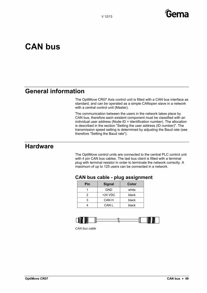
Hardware The OptiMove control units are connected to the central PLC control unit with 4 pin CAN bus cables. The last bus client is fitted with a terminal plug with terminal resistor in order to terminate the network correctly. A maximum of up to 125 users can be connected in a network.
CAN bus cable - plug assignment Pin Signal Color
1 GND white
2 +24 VDC black
3 CAN H black
4 CAN L black
CAN bus cable

V 12/13
50 • CAN bus OptiMove CR07
Setting the user address (ID Number)
1. To enter the system parameter mode, press and hold the key for 5 seconds. The LEDs L1-L3 illuminate
2. Select the parameter P12 on the display A1 by using the keys
3. Select an address between 1 and 127 on the display A2 using
the keys
4. Press the key, in order to exit the system parameter mode
WARNING: The selected address in the system parameter P12 may never be "0", the address must be unique and may not conflict with the numbers of other existing users!
Setting the Baud rate
1. To enter the system parameter mode, press and hold the key for 5 seconds. The LEDs L1-L3 illuminate
2. Select the parameter P11 on the display A1 by using the keys
3. Select a value between 0 and 7 on the display A2 using the
keys
Set value - P11 CAN Baud rate 0 20 kBit/s
1 50 kBit/s
2 100 kBit/s
3 125 kBit/s (Default) 4 250 kBit/s
5 500 kBit/s
6 800 kBit/s
7 1 Mbit/s
The Baud rate is selected with 125 kBits as default. This setting permits a maximum cable length of approx. 500 m from the first to the last CAN bus client. If longer cables are used, select a lower Baud rate.
4. Press the key, in order to exit the system parameter mode

V 12/13
OptiMove CR07 Fault remedying • 51
Fault remedying
General information All error messages are displayed as an error code (H01-H99) on the seven segment display A3 (instead of the program number).
If an error occurs in the system, the cause must be eliminated first, before further operation is possible.
If the cause has been eliminated, this must be acknowledged by pressing
the keys.
Number Description Action
Axis
H01 Upper end stop (system parameter P1) overrun
Emergency stop
Axis can only travel downwards
Axis must be referenced again
H02 Tracking error too large In order to prevent a larger tracking error, the speed must be reduced.
H03 Encoder cable break Emergency stop
Axis must be referenced again
H04 Wrong encoder rotating direction Emergency stop
Axis must be referenced again
H05 Desired travel position is larger then the defined end position (system parameter P1)
Travel position must be limited according to SP1
H06 Lower end stop overrun Emergency stop
Axis can only travel upwards
Axis must be referenced again
H07 Proximity switch signal is permanent active during the reference travel
Referencing not successful
H08 No proximity switch signal during the reference travel
Referencing not successful
H09 Speed value larger than system parameter P4 Limit speed according to system parameter P4
H10 Axis position not correctly stored during switching off
Axis position = Upper end stop. Axis can only travel downwards.
H11 Frequency converter error Emergency stop
H12 Axis cannot be started, because not referenced

V 12/13
52 • Fault remedying OptiMove CR07
Number Description Action
H13 Axis cannot be referenced, because already referenced
H15 Parameter input in sequence program not possible, because program is running
H16 Axis cannot be started during reference travel
Hardware
H20 24 VDC supply voltage too high (26.5 VDC) Stop axis (soft stop)
H21
24 VDC supply voltage too low (20.8 VDC) Emergency stop
Store axis position, current program number and axis status
Stop the system
H23 EEPROM content invalid Load factory configuration
DigitalBus
H30 Data validation error Reject data
H31 Data outside the value range Reject data
H32 Data reception overflow Reject data
CAN bus
H40 Permanent CAN bus error (BUS_OFF), i.e. no power supply or cable is not connected
H41 Too many errors during sending (ERROR_PASSIVE)
H42 Overflow on data reception
H43 Overflow on transmission
H44 Master failed Stop axis (soft stop)
H45 Data outside the value range Reject data
H46 Invalid Node ID set Node ID = 127

V 12/13
OptiMove CR07 Hardware • 53
Hardware
Pin allocations
Plug 2.1 - Power IN Pin Function
1 Neutral conductor
2 Phase (230 VAC)
3 Axis start (230 VAC)
PE Ground
Plug 2.2 - Drive supply Pin Function
1 Neutral conductor
2 Phase
3 Not connected
PE Ground
Plug 2.3 - Drive I/O Pin Function
1 GND frequency converter
2 24 V frequency converter
3 Frequency converter error
4 RPM preset value
5 Motor right running (UP)
6 Motor left running (DOWN)
7 Reserve
8 Reserve
9 24 VDC OptiMove
10 Motor brake
11 Proximity switch
12 Reserve
13 B+
14 B-

V 12/13
54 • Hardware OptiMove CR07
Pin Function 15 A-
16 A+
17 O+
18 O-
19 GND OptiMove
Enclosure Shield
Plug 2.4 – Aux DigitalBus parallel interface Pin Bit Function A D0 Preset values, program no. Binary value 1
B D1 Preset values, program no. Binary value 2
C D2 Preset values, program no. Binary value 3
D D3 Preset values, program no. Binary value 4
E D4 Preset values, program no. Binary value 5
F D5 Preset values, program no. Binary value 6
G D6 Preset values, program no. Binary value 7
H D7 Preset values, program no. Binary value 8
I A0 Identification number Binary value 1
K A1 Identification number Binary value 2
L A2 Identification number Binary value 3
M 12 IN Axis_Start
N 13 IN Strobe (data transfer from data bus)
O 14 IN Remote/manual
P D8 Preset values, program no. Binary value 9
R GND_External GND
S 1 OUT Error, axis not referenced
T 2 OUT Program_Active
U 24VDC_Extern 24 VDC digital outputs
Enclosure Shield Shield
Plug 2.5 - CAN bus IN Pin Function
1 GND
2 24 VDC
3 CAN_H
4 CAN_L
Enclosure Shield

V 12/13
OptiMove CR07 Hardware • 55
Plug 2.6 - CAN bus OUT Pin Function
1 GND
2 24 VDC
3 CAN_H
4 CAN_L
Enclosure Shield


V 12/13
OptiMove CR07 Spare parts list • 57
Spare parts list
Ordering spare parts When ordering spare parts for powder coating equipment, please indicate the following specifications:
- Type and serial number of your powder coating equipment
- Order number, quantity and description of each spare part
Example: - Type OptiMove CR07
Serial number 1234 5678
- Order no. 203 386, 1 piece, Clamp - Ø 18/15 mm
When ordering cable or hose material, the required length must also be given. The spare part numbers of this bulk stock is always marked with an *. Wearing parts are always marked with a #.
All dimensions of plastic hoses are specified with the external and internal diameter:
Example: Ø 8/6 mm, 8 mm outside diameter (o/d) / 6 mm inside diameter (i/d)
WARNING! Only original Gema spare parts should be used, because the explosion protection will also be preserved that way! The use of spare parts from other manufacturers will invalidate the Gema guarantee conditions!

V 12/13
58 • Spare parts list OptiMove CR07
OptiMove CR07 – Front plate and power pack OptiMove CR07 Axis control unit - complete 1010 550 Front plate - complete (pos. 1-13) 1010 540
Front plate with foil keyboard (pos. 1-6) 1010 539
1 Front frame - complete (incl. pos. 1.1) 1007 048
1.1 Special screw 1007 019
2 Special screw – M4x20/7 mm 1003 000
3 Front plate gasket 1007 042
5 Screw – M4x6 mm 221 767
6 Toothed lock washer – Ø 5.3/106x0.6 mm 1002 999
7 Display - complete 1010 293
8 Spacer sleeve – Ø 3.4/6x6.5 mm 1001 925
9 Spacer sleeve - Ø 3.6/7x5 mm 247 758
10 Main board V1.0 – complete 1010 290
10.1 EPROM - program version V x.x (current software) 1000 610
11 Spacer 263 508
12 Locknut - M3 262 498
13 Washer - Ø 3.2/7x0.5 mm 201 944
14 Power pack - 24 VDC 1009 849

V 12/13
OptiMove CR07 Spare parts list • 59
OptiMove CR07 – Front plate and power pack
OptiMove CR07 – Front plate and power pack
2
34
8
10 14
5
71
6
12 13
11
13
12
9

V 12/13
60 • Spare parts list OptiMove CR07
OptiMove CR07 – Rear panel 1 Rear panel gasket 1007 033
2 Relay socket 251 135
3 Relay – 24 VDC/10 A, 2UK 1002 915
4 Freewheeling diode for relay 258 075
5 Safety strap for relay socket 1001 063
6 Fuse holder 200 131
7 Fuse - 10 AT 200 174
8 Dust protection cap for connector socket 265 446
9 Dust protection cap for plug 265 438
10 Cap screw - M4x16 mm 216 801
11 DigitalBus connection - complete 1000 284
12 Reciprocator control signals connection - complete 1010 739
13 CAN bus IN connection - complete 387 541
14 Connection to axis power supply – complete 1010 740
15 CAN bus OUT connection - complete 387 550
Mains cable for ZAxx – L=20 m 1000 280
Signal cable for ZAxx – L=20 m 1000 281
Optional features (not shown) CAN bus cable 0.50 m 1002 655
CAN bus cable 4.50 m 387 592
CAN bus cable 5.50 m 388 521
CAN bus cable 6.50 m 388 530
Bus terminal resistor 387 606
CAN hub - complete 1001 787
Digital Connector CD02 (CR07-PLC interface) 382 825
Digital cable 19 pins - 1.50 m 1001 500
Digital cable 19 pins - 3.50 m 1000 933
Digital cable 19 pins - 4.50 m 1000 934
Digital cable 19 pins - 5.50 m 1000 935
Digital cable 19 pins - 6.50 m 1000 936

V 12/13
OptiMove CR07 Spare parts list • 61
OptiMove CR07 – Rear panel
OptiMove CR07 – Rear panel
9
9
8
10
4 5
3 2
6 7
1
11
13
15
12
14

V 12/13
62 • Spare parts list OptiMove CR07
Appendix - program table
1
2
3
4
5
6
7
8
9
10
11
12
13
14
15
16
17
18
19
20
21
22
23
24
25
26
27
28
29
30
31
32
33
34
35

V 12/13
OptiMove CR07 Spare parts list • 63
36
37
38
39
40
41
42
43
44
45
46
47
48
49
50
101
102
103
104
105
106
107
108
109
110
111
112
113
114
115
116
117
118
119
120 X position

V 12/13
64 • Spare parts list OptiMove CR07
131
132
133
134
135
136
137
138
139
140
141
142
143
144
145
146
147
148
149
150
201
202
203
204
205
206
207
208
209
210
211
212
213
214
215

V 12/13
OptiMove CR07 Spare parts list • 65
216
217
218
219
220
221
222
223
224
225
226
227
228
229
230
231
232
233
234
235
236
237
238
239
240
241
242
243
244
245
246
247
248
249
250