optimization of gamma knife radiosurgery
TRANSCRIPT

Optimization of Gamma Knife Radiosurgery
Michael C. Ferris and David M. Shepard
Abstract. The Gamma Knife is a highly specialized treatment unit that pro-
vides an advanced stereotactic approach to the treatment of tumors, vascular
malformations, and pain disorders within the head. Inside a shielded treatmentunit, beams from 201 radioactive sources are focused so that they intersect at
the same location in space, resulting in a spherical region of high dose referredto as a shot of radiation. The location and width of the shots can be ad-justed using focussing helmets. By properly combining a set of shots, largertreatment volumes can be successfully treated with the Gamma Knife.
The goal of this project is to automate the treatment planning process.For each patient, an optimization seeks to produce a dose distribution thatconforms closely to the treatment volume. The variables in the optimizationcan include the number of shots of radiation along with the size, the location,
and the weight assigned to each. Formulation of such problems using a varietyof mathematical programming models is described, and the solution of several
test and real-patient examples is demonstrated.
1. Introduction
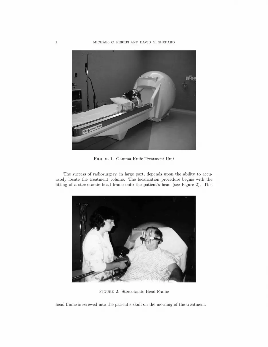
The Leksell Gamma Knife is a highly specialized treatment unit that providesan advanced stereotactic approach to the treatment of tumors, vascular malforma-tions, and pain disorders within the head [Gan97]. Over 100 Gamma Knife unitsare installed worldwide, and more than 20,000 patients are treated each year. In-side the shielded treatment unit (see Figure 1), beams from 201 Co-60 radioactivesources are focused so that they intersect at the same location in space. The resultis a spherical region of high dose referred to as a shot of radiation. Four differentshot sizes are available to the user. By combining multiple shots of radiation, thetreatment plan can be customized to treat lesions of varying sizes and shapes.
The goal of this project is to automate the treatment planning process. Foreach patient, the optimization seeks to produce a dose distribution that conformsclosely to the treatment volume. The variables in the optimization can includethe number of shots of radiation along with the size, the location, and the weightassigned to each. This paper will address the approaches that we have investigatedfor solving this problem. The advantages and disadvantages of two approaches willbe discussed, and optimized patient plans will be shown.
1991 Mathematics Subject Classification. Primary: 90C50; Secondary: 90C30, 90C11.This material is based on research supported in part by National Science Foundation Grants
CDA-9726385 and CCR-9972372, the Air Force Office of Scientific Research Grant F49620-98-1-
0417 and Microsoft Corporation.
1
2 MICHAEL C. FERRIS AND DAVID M. SHEPARD
Figure 1. Gamma Knife Treatment Unit
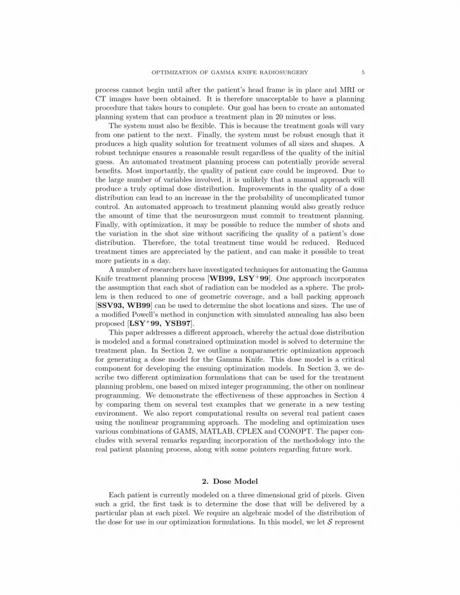
The success of radiosurgery, in large part, depends upon the ability to accu-rately locate the treatment volume. The localization procedure begins with thefitting of a stereotactic head frame onto the patient’s head (see Figure 2). This
Figure 2. Stereotactic Head Frame
head frame is screwed into the patient’s skull on the morning of the treatment.

OPTIMIZATION OF GAMMA KNIFE RADIOSURGERY 3
Once the head frame is in place, the patient undergoes MRI or CT imaging.The imaging studies make it possible to precisely determine the position of thetreatment volume with respect to the stereotactic head frame.
During the treatment, the patient’s head frame attaches to a focusing helmet(see Figure 3). This focusing helmet serves as a collimator that further reduces the
Figure 3. Focussing Helmet Attached to Frame
size of each beam. There are a total of four focusing helmets. These helmets can beused produce a shot of radiation that is 4mm, 8mm, 14mm, or 18mm in diameter(see Figure 4).
The neurosurgeon, the radiation oncologist, and the physicist work togetherin order to develop the patient’s treatment plan. For some cases, the treatmentplanning process is relatively straightforward. For example, some small lesions canbe covered with a single shot of radiation. Consequently, the treatment planningprocess can be completed in a few minutes. Unfortunately, the treatment planningprocess becomes much more complex when the tumor volume is large or irregularlyshaped. These cases typically require several shots of radiation. Through an itera-tive process, the planners must determine the number of shots of radiation that arerequired along with the size, the location, and the weight that should be assignedto each. Each time that there is a change in the shot size, the staff must removethe current focusing helmet and replace it with the helmet of the correct size. Thisis a fairly time consuming process, because each helmet weighs approximately 500pounds and must be manipulated mechanically. For each shot of radiation, the lo-cation of the center of the shot is determined by the connection between the helmetand the patient’s head frame. Adjustments in this connection are made betweeneach shot. At the time of delivery, the door to the treatment unit opens and thepatient couch is advanced inside the shielded treatment vault (see Figure 5).
For many patients, the treatment planning process becomes both tedious andtime consuming, and the quality of the treatment plan that is produced dependsupon both the experience and the patience of the planner. Because of these fac-tors, we have sought to develop an automated process for creating Gamma Knife

4 MICHAEL C. FERRIS AND DAVID M. SHEPARD
Figure 4. Stored Focussing Helmets for 4mm, 8mm, 14mm and18mm shots
Figure 5. Operation of the Gamma Knife
treatment plans. As a first step in this process, the planner outlines the treatmentvolume and any sensitive structures. A series of treatment goals are then defined.Based upon these goals, an optimization algorithm determines the best possibletreatment plan.
The ideal optimization technique for Gamma Knife treatment planning must befast, flexible, and robust. The system must be fast, because the treatment planning
OPTIMIZATION OF GAMMA KNIFE RADIOSURGERY 5
process cannot begin until after the patient’s head frame is in place and MRI orCT images have been obtained. It is therefore unacceptable to have a planningprocedure that takes hours to complete. Our goal has been to create an automatedplanning system that can produce a treatment plan in 20 minutes or less.
The system must also be flexible. This is because the treatment goals will varyfrom one patient to the next. Finally, the system must be robust enough that itproduces a high quality solution for treatment volumes of all sizes and shapes. Arobust technique ensures a reasonable result regardless of the quality of the initialguess. An automated treatment planning process can potentially provide severalbenefits. Most importantly, the quality of patient care could be improved. Due tothe large number of variables involved, it is unlikely that a manual approach willproduce a truly optimal dose distribution. Improvements in the quality of a dosedistribution can lead to an increase in the the probability of uncomplicated tumorcontrol. An automated approach to treatment planning would also greatly reducethe amount of time that the neurosurgeon must commit to treatment planning.Finally, with optimization, it may be possible to reduce the number of shots andthe variation in the shot size without sacrificing the quality of a patient’s dosedistribution. Therefore, the total treatment time would be reduced. Reducedtreatment times are appreciated by the patient, and can make it possible to treatmore patients in a day.
A number of researchers have investigated techniques for automating the GammaKnife treatment planning process [WB99, LSY+99]. One approach incorporatesthe assumption that each shot of radiation can be modeled as a sphere. The prob-lem is then reduced to one of geometric coverage, and a ball packing approach[SSV93, WB99] can be used to determine the shot locations and sizes. The use ofa modified Powell’s method in conjunction with simulated annealing has also beenproposed [LSY+99, YSB97].
This paper addresses a different approach, whereby the actual dose distributionis modeled and a formal constrained optimization model is solved to determine thetreatment plan. In Section 2, we outline a nonparametric optimization approachfor generating a dose model for the Gamma Knife. This dose model is a criticalcomponent for developing the ensuing optimization models. In Section 3, we de-scribe two different optimization formulations that can be used for the treatmentplanning problem, one based on mixed integer programming, the other on nonlinearprogramming. We demonstrate the effectiveness of these approaches in Section 4by comparing them on several test examples that we generate in a new testingenvironment. We also report computational results on several real patient casesusing the nonlinear programming approach. The modeling and optimization usesvarious combinations of GAMS, MATLAB, CPLEX and CONOPT. The paper con-cludes with several remarks regarding incorporation of the methodology into thereal patient planning process, along with some pointers regarding future work.
2. Dose Model
Each patient is currently modeled on a three dimensional grid of pixels. Givensuch a grid, the first task is to determine the dose that will be delivered by aparticular plan at each pixel. We require an algebraic model of the distribution ofthe dose for use in our optimization formulations. In this model, we let S represent
6 MICHAEL C. FERRIS AND DAVID M. SHEPARD
the set of the shots that we will consider, and W represent the possible shot sizes(typically 4mm, 8mm, 14mm and 18mm).
The complete dose distribution can be calculated as a sum of contributionsfrom each shot delivered, once the location of the center of that shot (xs, ys, zs) isknown, and the length of time of delivery ts,w is known. In practice this meansthat for all (i, j, k)
Dose(i, j, k) =∑
(s,w)∈S×W
ts,wDw(xs, ys, zs, i, j, k),(2.1)
where Dw(xs, ys, zs, i, j, k) is the dose delivered to the pixel (i, j, k) by the shot ofwidth w centered at (xs, ys, zs).
To determine the form of Dw, the following procedure was followed. First,we simulated the delivery of a shot of width w ∈ W, centered at the middle of thehead of a previously scanned patient on the Gamma Knife. For each shot width, wedetermined the dose delivered in the x, y and z directions at given distances fromthe center of the shot from the simulation. The three values were then averagedto give a value of dose (for each width of shot) at a particular distance from thecenter, for example,
D̄w(d) =Dw(0, 0, 0, d, 0, 0) +Dw(0, 0, 0, 0, d, 0) +Dw(0, 0, 0, 0, 0, d)
3.
These values were used as data in a nonlinear parameter estimation problem.The problem is reduced to determining a functional form for the dose delivered
at a pixel that is a distance d away from the center of the shot. A sum of errorfunctions has been noted in the literature to approximate this dose distribution[CKM98]. We therefore used the following functional form
2∑
i=1
λi
(
1− erf
(
d− ri
σi
))
(2.2)
(with d representing the distance) and fit the six parameters λi, ri and σi to thedata described above via least-squares, with different values for each width shot.In our work, we use the notation erf (x) to represent the integral of the standardnormal distribution from −∞ to x. The resulting nonlinear optimization problem
minλ,r,σ
∥
∥
∥
∥
∥
D̄w(d)−2
∑
i=1
λi
(
1− erf
(
d− ri
σi
))
∥
∥
∥
∥
∥
2
was solved using CONOPT. As can be seen by two representative pictorial repre-sentations of the resulting fits in Figure 6, the functional fit is very close to theobserved data. The fit is best for the small shots (see Figure 6(a) for example),and decreases slightly in accuracy for the larger ones (see Figure 6(b) for example).The particular values of the parameters that we generated are given in Table 1. Itis clear that a closer fit can be achieved using more parameters in (2.2). However,this will lead to more computational overhead in the optimization, which we believeis not necessary.
It is possible that the averaging in the x, y and z directions creates a small errorfor the particular patient at hand. Furthermore, there may be variations in doseacross patients. These effects have been ignored in the subsequent formulations.In future work, along with investigations of the above issues, we may fit ellipsoidsinstead of spheres to the dose data since various researchers have commented that

OPTIMIZATION OF GAMMA KNIFE RADIOSURGERY 7
0 10 20 30 40 50 60−0.5
0
0.5
1measuredcomputed
(a) 4mm shot
0 10 20 30 40 50 60−0.5
0
0.5
1measuredcomputed
(b) 18mm shot
Figure 6. Nonlinear Parametric Fitting for Dose Data
Shot λ1 r1 σ1 λ2 r2 σ2
4mm 0.649200 1.365916 4.413680 0.599844 2.661771 0.668291
8mm 0.401007 7.035785 5.702334 0.648584 4.849365 1.149176
14mm 0.363704 13.97259 7.196694 0.657808 8.199979 1.321161
18mm 0.381801 17.67857 8.194611 0.634696 10.31583 1.441725
Table 1. Parameter for Dose Model
the dose is skewed in certain directions. While cubic b-spline approaches mayoutperform the fit that we achieve here, it is currently unclear how to use suchapproaches within the GAMS modeling format that we employ.
3. Optimization Formulation
Once a description of the dose is determined, an optimization model can beformulated. The basic variables of the optimization include the number of shots ofradiation that will be delivered, along with the width of the shot w, the coordinatesof the center location of the shot (xs, ys, zs), and the time ts,w that each shot isexposed. In practice, we consider a grid of pixels, noting two subsets of this grid,namely T and N , that represent the subset of pixels that are in (out) of the targetrespectively.
Neurosurgeons commonly use isodose curves as a means of judging the qualityof a treatment plan. The 50% isodose curve is a curve that encompasses all of thepixels that receive at least 50% of that maximum dose that is delivered to any pixelin the patient. The neurosurgeon may wish to impose a requirement that the entiretarget is surrounded by an isodose line of x%. For example, a constraint that the50% line must surround the target can be modeled by imposing strict lower andupper bounds on the dose allowed in the target, namely for all (i, j, k) ∈ T
1 ≤ Dose(i, j, k) ≤ 2.

8 MICHAEL C. FERRIS AND DAVID M. SHEPARD
In this way, the 50% isodose curve is guaranteed to cover the target. The iso-dose requirements can be changed by simply modifying the numerical values of thebounds.
We have tested a variety of optimization formulations. For this paper, however,we will simply discuss two. The first formulation imposes a constraint on theminimum isodose line that must surround the target. Given this constraint, thegoal is to minimize the dose outside of the target. The formulation is:
min∑
(i,j,k)∈N
Dose(i, j, k)
subject to Dose(i, j, k) =∑
(s,w)∈S×W
ts,wDw(xs, ys, zs, i, j, k)
1 ≤ Dose(i, j, k) ≤ 2, ∀(i, j, k) ∈ T
ts,w ≥ 0
card ({(s, w) ∈ S ×W|ts,w > 0}) ≤ n.
(3.1)
The final constraint states that no more than n shots are to be used in the plan.The second formulation uses a constraint to control the conformity of the plan.
The constraint specifies that at least y% of the total dose must be deposited inthe target. An upper bound is also placed on the dose to the target. Given theseconstraints the optimizer seeks to minimize the total underdosage in the target. Apixel is considered to be underdosed if it receives less than the prescribed isodose,which for the example formulation is assumed to be 1. We actually use the opti-mization process to model UnderDose. UnderDose is constrained to be no less thatmax(0, 1 −Dose) at every pixel in the target, and since we minimize UnderDose,it will take on the maximium of these two values at optimality. The completeformulation is:
min∑
(i,j,k)∈T
UnderDose(i, j, k)
subject to Dose(i, j, k) =∑
(s,w)∈S×W ts,wDw(xs, ys, zs, i, j, k)∑
(i,j,k)∈T Dose(i, j, k)∑
(i,j,k)Dose(i, j, k)≥ P
0 ≤ UnderDose(i, j, k) ≥ 1−Dose(i, j, k), ∀(i, j, k) ∈ T
Dose(i, j, k) ≤ 2, ∀(i, j, k) ∈ T
ts,w ≥ 0
card ({(s, w) ∈ S ×W|ts,w > 0}) ≤ n.
(3.2)
In this formulation, P is the fraction of the total dose that must be deposited inthe target; typically we choose values for P between 25% and 40%. For solutionpurposes, we rearrange the equation involving P so that it is a purely linear equation(i.e. multiply both sides by the term in the denominator). In practical application,rather than calculate the dose at every pixel, it is easy to accurately estimate thetotal dose delivered by a plan based solely on the ts,w variables and other pre-calculated constants.

OPTIMIZATION OF GAMMA KNIFE RADIOSURGERY 9
Both of the formulations are based on the assumption that the neurosurgeoncan use the volume of the target and the irregularity of its shape in order to a-prioridetermine a realistic upper bound n on the number of shots required for treatment.Therefore, the model bounds the number of shots a priori, rather than forcing themodel to minimize this number. Since most of the comments we make in the sequelapply equally well to either formulation, we will restrict our exposition mainly to(3.1) in the sequel solely for clarity.
Practical issues must also be considered. For example, a large number of shotscan lead to a treatment time that is unacceptably long. This is because after eachshot is delivered, the staff must enter the room and perform a series of adjustments.Also, if a change in the shot width is required, the user must exchange focusinghelmets.
Several issues need to be resolved to create models that are practical, imple-mentable, and solvable (in a reasonable time frame). Two main approaches areproposed in this paper, namely using mixed integer programming (MIP) and non-linear programming (NLP).
3.1. MIP approach. Since the optimization technology associated with solv-ing nonlinear mixed integer programming problems is very limited, we restrict at-tention to linear models and thus need to ensure that the dose calculation constraint(2.1) is linear. To do this, we need to have Dw(· · · ) as data, and thus need to deter-mine all possible (xs, ys, zs) before optimization. We therefore a-priori choose a gridof possible shot locations GS , and precalculate Ds,w(i, j, k) := Dw(xs, ys, zs, i, j, k)for each grid location s ∈ GS , every pixel (i, j, k) and each width w ∈ W and usethe optimization algorithm to decide whether or not to use a shot at a particu-lar location. A major drawback of this approach is the enormous amount of datathat is required. We will discuss approaches to overcome this in the sequel. It isclear that the only shots that will be considered in this approach are shots that liewithin the target. This is because our grid is generated a-priori, and we can easilydetermine whether or not a shot lies within the target.
However, the mixed integer approach allows us to introduce a new binary vari-able ψs,w (heuristically, use the shot (s, w) or not) and impose the constraint
ts,w ≤ T̄ψs,w
to force ψs,w = 1 whenever ts,w > 0. Here T̄ is an (easy to estimate) upper boundon the length of time that a particular shot can be exposed. Once these variablesare introduced, we then write the limiting shot constraint as
∑
(s,w)∈GS×W
ψs,w ≤ n.

10 MICHAEL C. FERRIS AND DAVID M. SHEPARD
For the problem outlined in (3.1), the resulting mixed integer optimization problemis:
min∑
(i,j,k)∈R
Dose(i, j, k)
subject to Dose(i, j, k) =∑
(s,w)∈GS×W
ts,wDs,w(i, j, k)
1 ≤ Dose(i, j, k) ≤ 2, ∀(i, j, k) ∈ T
0 ≤ ts,w ≤ T̄ψs,w, ψs,w ∈ {0, 1}∑
(s,w)∈GS×Wψs,w ≤ n.
Note that we have replaced N with R in the above problem. In order to reduce theamount of data required and since the dose drops off rapidly away from its center,we only minimize the dose in a rind R around the target, instead of everywhere.
The above formulation is a large-scale mixed integer problem [NW88, Wol98]that is typically computationally intractable in the time allowed. Several methodsare outlined below to further reduce the large amounts of data arising from therealistic dose calculations.
The benefits of reducing the possible shot locations GS are two-fold. Firstly,the number of integer variables ψs,w (typically the limiting computational factorfor solution) is reduced. Secondly, the amount of precalculated data required isreduced. The following heuristic was used to attempt to reduce the number ofshots as much as possible. We first generate a coarse grid of large shots and fora particular grid spacing and grid offset, we calculate the number of these shotsthat hit the target. By searching over all grid offsets, we determine the offset thatmaximizes the number of large shots from this grid that are on target. Havingestablished this, we randomly place small shots near the boundary of the targetuntil a prespecified number of shots is generated. It is an unresolved research issueto determine the proportion of large to small shots, and the number of possiblelocations that we should use.
There are several interesting features of the MIP approach. As noted above,there are large amounts of data, and many integer variables unless GS is severelyrestricted. By restricting the grid too much, the resulting constrained problemis infeasible. Furthermore, even with the restrictions and a very fast MIP solversuch as CPLEX, the problems take enormous amounts of time to solve or determineinteger infeasibility. The major benefit of this approach, however, is that it providesa guarantee of global optimality for that particular choice of GS and R.
3.2. Nonlinear Approach. A very different approach is to use nonlinearprogramming and approximate the counting of shots. The basic idea is to use amigrating shot technique. This approach takes a limited number of shots, and theposition each shot can change over the course of the optimization. Given we areusing n shots, we introduce variables xs, ys and zs and use the nonlinear functionformulation (2.2) for the dose calculation. Note that with this approach there arejust 3n variables to specify shot location, and n is typically small in the application(namely 5 - 20).
This has the key advantage over the MIP formulation that the “data” is muchsmaller. However, the nonlinear programming problems are still quite difficult tosolve (they are not convex, and hence may have local solutions that are not global
OPTIMIZATION OF GAMMA KNIFE RADIOSURGERY 11
solutions). Secondly, while it is easy to limit the number of shot locations to n, theactual constraint requires that there are no more than n shots are to be used in theplan. The missing feature is to choose a particular width of shot at each location.
To implement this feature, we use a two phase approach. Note that a shot ofwidth w is used at location s if ts,w > 0. The main idea is to approximate the stepfunction H(t) = 1 if t > 0 and H(t) = 0 when t = 0 by a nonlinear function,
H(t) ≈ Hα(t) :=2 arctanαt
π.
For increasing values of α, Hα becomes a closer approximation to the step functionH. Therfore, for the approach outlined with (3.1), we solve the following problem
min∑
(i,j,k)∈R
Dose(i, j, k)
subject to Dose(i, j, k) =∑
(s,w)∈{1,... ,n}×W
ts,wDw(xs, ys, zs, i, j, k)
1 ≤ Dose(i, j, k) ≤ 2, ∀(i, j, k) ∈ T
ts,w ≥ 0∑
w∈W Hα(ts,w) ≤ 1, ∀s ∈ {1, . . . , n},
with this approximation and α = 10, then we fix any shots that have zero width tohave ts,w = 0, and reoptimize the following problem (with α = 100)
min∑
(i,j,k)∈R
Dose(i, j, k)
subject to Dose(i, j, k) =∑
(s,w)∈{1,... ,n}×W
ts,wDw(xs, ys, zs, i, j, k)
1 ≤ Dose(i, j, k) ≤ 2, ∀(i, j, k) ∈ T
ts,w ≥ 0∑
(s,w)∈{1,... ,n}×W Hα(ts,w) ≤ n
ts,w = 0, ∀(s, w) ∈ F.
Here F represents the subset of {1, . . . , n} × W of variables that were fixed at 0based on the solution of the first optimization. Note that both problems are highlynonconvex, so there is no guarantee of global optimality. We experimented withstarting points somewhat and use equal values of t for the results of the sequel.
Another disadvantage of the nonlinear approach is that it is difficult to constrainthe location of the shots to within the target. In fact, we do not add such aconstraint, but choose appropriate starting values for (xs, ys, zs) within the (interiorof the) target to encourage the final shot locations to also be within the target. Inall our experiments, this was indeed the case, although several shots can be locatedclose to the boundary.
4. Computational Results
4.1. Two-dimensional testing environment. We created a testing envi-ronment for our models within MATLAB, using the image processing toolbox. Thetesting environment provided a means to generate two-dimensional “tumors” of var-ious shapes and sizes and visualize the results of the optimization applied to these

12 MICHAEL C. FERRIS AND DAVID M. SHEPARD
targets. The optimization models were written in the GAMS modeling language[BKM88], a high-level modeling system for mathematical programming problems.It consists of a language compiler and a variety of integrated high-performancesolvers. We used the MATLAB/GAMS interface [Fer98] to communicate betweenthese two software packages. GAMS was chosen for the optimizations based on itsability to formulate various types of models and then apply state-of-the-art opti-mization algorithms for their solution. In particular, for the mixed integer problemswe used the CPLEX optimization package [ILO], whereas for nonlinear programs,CONOPT [Dru85] was used. While the two dimensional testing environment sig-nificantly reduces the amount of data present in the model, we found this to bean excellent testing tool to pinpoint the advantages and disadvantages of variousformulations. In particular, it is very easy to change between a wide variety ofmodel types, objective functions and constraints.
We present results for two cases. In the first instance, we prescribe 3 shotsof radiation. The rind around the target has width 10. The resulting size of thetarget and rind is respectively 235 and 1092 pixels. The results of applying themixed integer and nonlinear programming approaches are shown in Figure 7. Thetumor outline is shown is cyan, while the scale of the intensities is given on the barto the right of each figure. The MIP solution, shown in Figure 7(a), results in two8mm and one 14mm shots, with a total dose to the rind of 510. The optimizationtook 165 seconds, terminating with a relative optimality tolerance of 1%. The sizeof the grid of potential shots was 150.
The NLP solution, shown in Figure 7(a), results in one 8mm and two 14mmshots, that combine to give a total dose to the rind of 490. The optimization took65 seconds, somewhat faster than the MIP algorithm. Although the solution is notguaranteed optimal, it results in a comparable solution to the MIP code. Since theNLP code can choose the locations of the shots (as opposed to selecting one of theshots from the grid) it is possible to find better solutions using the NLP approachthan the MIP approach.
To show the effects of more data on our approaches, Figure 8 exhibits thecorresponding solutions for a larger case. Again, the target is outlined in cyan, thistime containing 1008 pixels. The rind again has radius 10, resulting in 1365 pixels.We attempted to find solutions using seven shots.
The NLP solution, shown as Figure 8(b) took 1354 seconds to generate. It usestwo 8mm, three 14mm and two 18mm, with a total dose to the enclosing rind of1017. Note that the optimization time is slightly over the 20 minute limit, but canbe reduced (for example) by reducing the number of pixels in the rind.
The MIP solution that is shown as Figure 8(a) consists of one 8mm, two 14mmand four 18mm, with a total dose to the disk of 1123, again with 150 potentiallocations for shots. The optimization was terminated after two hours with relativeoptimality tolerance 17%, having explored 15,000 nodes of the branch and boundtree. We believe that this demonstrates that more work is needed in this area beforethe MIP approach becomes a viable alternative to the NLP approach.
4.2. Real patient (three-dimensional) data. After determining which mod-els gave satisfactory results, we switched to three dimensional models, based onreal patient data. Currently, the mixed integer programming solvers are unable toprocess the real patient data in an acceptable time, so we present only nonlinearprogramming results in this section.

OPTIMIZATION OF GAMMA KNIFE RADIOSURGERY 13
*
*
*
*
*
*
0
0.2
0.4
0.6
0.8
1
1.2
1.4
1.6
1.8
(a) MIP solution
**
*
0
0.2
0.4
0.6
0.8
1
1.2
1.4
1.6
1.8
(b) NLP solution
Figure 7. Smaller Two-Dimensional Test Case
*
*
*
*
*
*
*
0.2
0.4
0.6
0.8
1
1.2
1.4
1.6
1.8
2
(a) MIP solution
*
*
*
**
*
*
0.2
0.4
0.6
0.8
1
1.2
1.4
1.6
1.8
2
(b) NLP solution
Figure 8. Larger Two-Dimensional Test Case
(a) Manual 13 shot solution (b) Optimized 13 shot solution
Figure 9. Isodose Curves for Patient 1; Axial Slice

14 MICHAEL C. FERRIS AND DAVID M. SHEPARD
The nonlinear programming approach to treatment planning has currently beenapplied to eight patient cases, and each optimized plan was compared to the originaltreatment plan produced by the neurosurgeon. These comparisons were basedupon analysis of the dose-volume histogram, the minimum target dose and thethe conformity index (the volume of the prescription isodose divided by the targetvolume). Treatment plans using 5-8 shots were typically optimized in less than 15minutes on a Sparc Ultra-10 with a 330 MHz processor.
A treatment plan comparison is shown in Figure 9. Each image includes apink line that indicates the border of the tumor. The 50% isodose line is shown inyellow, and the 30% isodose line is shown in green. Due to the massive size of thispatient’s tumor (35.3 cubic centimeters), a large number of shots were requiredin order to achieve adequate tumor coverage. In fact, this tumor is at the verylimit of size of tumors that are treated using the Gamma Knife at the Universityof Maryland. Consequently, the treatment planning process was very tedious andrequired a great deal of artful manipulation on the part of the neurosurgeon.
The manual treatment plan (Figure 9a) used 13 shots of radiation, and isan excellent plan for such a large tumor. An optimized plan (Figure 9b) wasproduced using the same number of shots. A constraint guaranteed that the entiretumor volume was surrounded by the 47% isodose line, and the optimizer soughtto minimize the total dose delivered outside of the tumor. The optimized plan isvery similar in quality to the plan produced by an experienced nuerosugeon. Infact, the optimized plan increased the minimum target dose by 2% and provideda small improvement in the conformity index (1.28 versus 1.27). The purpose ofincluding these results here is to show that an automatic plan can reproduce (orslightly improve) a plan determined by an expert in the field, for even the mostdifficult cases.
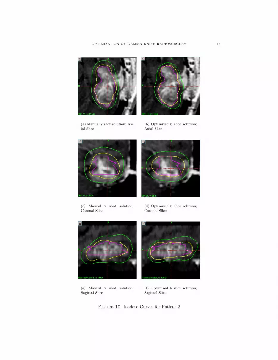
The results for a second patient are shown in Figure 10. In each figure, thepurple line denotes the border of the tumor. The 50% isodose line is in yellow, andthe 30% is line is in green. In this case, the manual treatement plan used 7 shotsof radiation. The optimization was set up to use 6 shots of radiation. A constraintwas included that specified that at least 30% of the total dose delivered to the pa-tient had to be deposited in the target. Given this contraint, the optimizer soughtto minimize the underdosage to the tumor (as in (3.2)). A voxel was considered tobe underdosed if it received less than 50% of the maximum tumor dose. Again, thefigures show the plan to be similar in quality, although in this case, the minimumtumor dose was increased from 43% to 44% and the conformity index was simul-taneously improved from 1.70 to 1.75. Furthermore, the optimization process usedone less shot of radiation than the expert.
The results shown in Figures 9-10 illustrate that this inverse treatment planningcan be used to produce high-quality conformal treatment plans. A more detailedanalysis of patient data will be provided in a future publication.
The robustness of the technique is of critical importance. For the eight pa-tient cases optimized thus far, each shot was initially assigned a random locationinside of the target. The initial guess incorporated uniform beam weights. Despitethis somewhat arbitrary starting point, high-quality dose distributions have beenobtained in all cases.
OPTIMIZATION OF GAMMA KNIFE RADIOSURGERY 15
(a) Manual 7 shot solution; Ax-
ial Slice
(b) Optimized 6 shot solution;
Axial Slice
(c) Manual 7 shot solution;
Coronal Slice
(d) Optimized 6 shot solution;
Coronal Slice
(e) Manual 7 shot solution;
Sagittal Slice
(f) Optimized 6 shot solution;
Sagittal Slice
Figure 10. Isodose Curves for Patient 2

16 MICHAEL C. FERRIS AND DAVID M. SHEPARD
5. Conclusions and Future Work
Currently neurosurgeons produce suboptimal treatment plans by hand. Webelieve an automated approach based on optimization will generate not only moreuniform, better treatment plans, but also produce them in less time than is currentlyused. The results given in this paper seem to indicate that the approach outlinedhere is sufficiently robust and quick to be used in a practical setting.
We believe it is important to integrate our procedure into the real system.Currently, we generate the target volume on the Gamma Knife and export it to theoptimization program. The optimization program then generates a treatment planthat is imported back onto the Gamma Knife. This is somewhat time consuming,and likely to produce some data errors due to finite precision arithmetic and fixedsize output. A full integration into the Gamma Knife planning system would reducethis time, and remove any of these errors.
We believe it is important to reduce the optimization times still further. Thiswould give the ability to try “what if scenarios” at treatment planning time. Forexample, can conformality be improved if more shots are allowed? Can we treatthe tumor at the 60% isodose level?
Apart from the time considerations, the outstanding question from an optimiza-tion viewpoint is the issue of global versus local optimality. While the nonlinearprogramming approach has proven very effective in practice, there is no guaranteethat there is not a better treatment plan. Understanding how to improve the ro-bustness of the model and solution techniques will enable more definite bounds tobe given on the solution quality compared to the best possible solution.
6. Acknowledgements
We would like to thank Lijun Ma, Ph.D. and Cedric Yu, D.Sc., for their assis-tance with this project.
References
[BKM88] A. Brooke, D. Kendrick, and A. Meeraus, GAMS: A user’s guide, The Scientific Press,South San Francisco, CA, 1988.
[CKM98] P. S. Cho, H. G. Kuterdem, and R. J. Marks, A spherical dose model for radiosurgery
treatment planning, Physics in Medicine and Biology 43 (1998), 3145–3148.
[Dru85] A. Drud, CONOPT: A GRG code for large sparse dynamic nonlinear optimization
problems, Mathematical Programming 31 (1985), 153–191.[Fer98] M. C. Ferris, MATLAB and GAMS: Interfacing optimization and visualization soft-
ware, Mathematical Programming Technical Report 98-19, Computer Sciences Depart-
ment, University of Wisconsin, Madison, Wisconsin, 1998.[Gan97] J. C. Ganz, Gamma knife surgery, Springer-Verlag Wien, Austria, 1997.
[ILO] ILOG CPLEX Division, 889 Alder Avenue, Incline Village, Nevada, CPLEX optimizer,http://www.cplex.com/.
[LSY+99] L. Luo, H. Shu, W. Yu, Y. Yan, X. Bao, and Y. Fu, Optimizing computerized treatment
planning for the gamma knife by source culling, International Journal of Radiation
Oncology, Biology and Physics 45 (1999), no. 5, 1339–1346.
[NW88] G. L. Nemhauser and L. A. Wolsey, Integer and combinatorial optimization, John Wiley& Sons, New York, NY, 1988.
[SSV93] R. A. Stone, V. Smith, and L. Verhey, Inverse planning for the Gamma Knife, Medical
Physics 20 (1993), 865.
[WB99] Q. J. Wu and J. D. Bourland, Morphology-guided radiosurgery treatment planning and
optimization for multiple isocenters, Medical Physics 26 (1999), no. 10, 2151–2160.
[Wol98] L. A. Wolsey, Integer programming, John Wiley & Sons, New York, NY, 1998.

OPTIMIZATION OF GAMMA KNIFE RADIOSURGERY 17
[YSB97] Y. Yan, H. Shu, and X. Bao, Clinical treatment planning optimization by Powell’s
method for Gamma unit treatmen system, International Journal of Radiation Oncology,
Biology and Physics 39 (1997), 247–254.
Computer Sciences Department, University of Wisconsin, 1210 West Dayton Street,
Madison, Wisconsin 53706
E-mail address: [email protected]
Department of Radiation Oncology, University of Maryland School of Medicine,
22 South Green Street, Baltimore, MD 21201
E-mail address: [email protected]