operation and safety manual - jms powered access
TRANSCRIPT
Operation and Safety ManualKeep this manual with the machine at all times.
LIFTLUXModels210-25 & 245-25
Prior to S/N 20465Excluding S/N’s: 16563, 18190, 19542, 19543, 19933, 20020, 20242, & 20317
P/N - 3121303September 26, 2008

FOREWORD
FOREWORD
This manual is a very important tool! Keep it with the machine at all times.
The purpose of this manual is to provide owners, users, operators, lessors, and lessees with the precautions andoperating procedures essential for the safe and proper machine operation for its intended purpose.
Due to continuous product improvements, JLG Industries, Inc. reserves the right to make specification changeswithout prior notification. Contact JLG Industries, Inc. for updated information.
3121303 – JLG Lift – a
FOREWORD
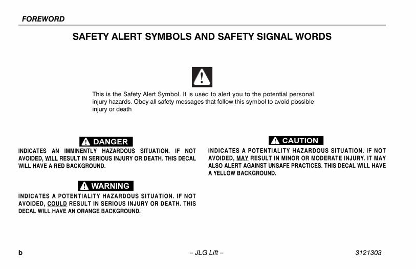
SAFETY ALERT SYMBOLS AND SAFETY SIGNAL WORDS
INDICATES AN IMMINENTLY HAZARDOUS SITUATION. IF NOTAVOIDED, WILL RESULT IN SERIOUS INJURY OR DEATH. THIS DECALWILL HAVE A RED BACKGROUND.
INDICATES A POTENTIALITY HAZARDOUS SITUATION. IF NOTAVOIDED, COULD RESULT IN SERIOUS INJURY OR DEATH. THISDECAL WILL HAVE AN ORANGE BACKGROUND.
INDICATES A POTENTIALITY HAZARDOUS SITUATION. IF NOTAVOIDED, MAY RESULT IN MINOR OR MODERATE INJURY. IT MAYALSO ALERT AGAINST UNSAFE PRACTICES. THIS DECAL WILL HAVEA YELLOW BACKGROUND.
This is the Safety Alert Symbol. It is used to alert you to the potential personalinjury hazards. Obey all safety messages that follow this symbol to avoid possibleinjury or death
b – JLG Lift – 3121303
FOREWORD
THIS PRODUCT MUST COMPLY WITH ALL SAFETY RELATED BULLE-TINS. CONTACT JLG INDUSTRIES, INC. OR THE LOCAL AUTHORIZEDJLG REPRESENTATIVE FOR INFORMATION REGARDING SAFETY-RELATED BULLETINS WHICH MAY HAVE BEEN ISSUED FOR THISPRODUCT.
NOTICEJLG INDUSTRIES, INC. SENDS SAFETY RELATED BULLETINS TO THEOWNER OF RECORD OF THIS MACHINE. CONTACT JLG INDUSTRIES,INC. TO ENSURE THAT THE CURRENT OWNER RECORDS AREUPDATED AND ACCURATE.
NOTICEJLG INDUSTRIES, INC. MUST BE NOTIFIED IMMEDIATELY IN ALLINSTANCES WHERE JLG PRODUCTS HAVE BEEN INVOLVED IN ANACCIDENT INVOLVING BODILY INJURY OR DEATH OF PERSONNELOR WHEN SUBSTANTIAL DAMAGE HAS OCCURRED TO PERSONALPROPERTY OR THE JLG PRODUCT.
Contact:
Product Safety and Reliability DepartmentJLG Industries, Inc.13224 Fountainhead PlazaHagerstown, MD 21742
or Your Local JLG Office(See addresses on rear cover)
In USA:
Toll Free: 877-JLG-SAFE (877-554-7233)
Outside USA:
Phone: 240-420-2661E-mail: [email protected]
For:• Accident Reporting
• Product Safety Publica-tions
• Current Owner Updates
• Questions Regarding Product Safety
• Standards and Regulations Compliance Information
• Questions Regarding Spe-cial Product Applications
• Questions Regarding Prod-uct Modifications
3121303 – JLG Lift – c
FOREWORD
REVISION LOG
Original Issue - May 5, 2005
Revised - May 23, 2005
Revised - July 31, 2006
Revised - July 3, 2008
Revised - September 26, 2008
d – JLG Lift – 3121303
TABLE OF CONTENTS
SECTION - PARAGRAPH, SUBJECT PAGE SECTION - PARAGRAPH, SUBJECT PAGE
SECTION - 1 - SAFETY PRECAUTIONS
1.1 GENERAL . . . . . . . . . . . . . . . . . . . . . . . . . . . . . . . . .1-11.2 PRE-OPERATION . . . . . . . . . . . . . . . . . . . . . . . . . . .1-1
Operator Training and Knowledge. . . . . . . . . . . 1-1Workplace Inspection. . . . . . . . . . . . . . . . . . . . . 1-2Machine Inspection . . . . . . . . . . . . . . . . . . . . . . 1-3
1.3 OPERATION . . . . . . . . . . . . . . . . . . . . . . . . . . . . . . .1-3General . . . . . . . . . . . . . . . . . . . . . . . . . . . . . . . . 1-3Trip and Fall Hazards . . . . . . . . . . . . . . . . . . . . . 1-4Electrocution Hazards . . . . . . . . . . . . . . . . . . . . 1-5Tipping Hazards . . . . . . . . . . . . . . . . . . . . . . . . . 1-7Crushing and Collision Hazards. . . . . . . . . . . . . 1-8
1.4 TOWING, LIFTING, AND HAULING . . . . . . . . . . . . .1-91.5 MAINTENANCE . . . . . . . . . . . . . . . . . . . . . . . . . . . .1-9
General . . . . . . . . . . . . . . . . . . . . . . . . . . . . . . . . 1-9Maintenance Hazards. . . . . . . . . . . . . . . . . . . . 1-10Battery Hazards . . . . . . . . . . . . . . . . . . . . . . . . 1-10
SECTION - 2 - USER RESPONSIBILITIES, MACHINE PREPA-RATION AND INSPECTION
2.1 PERSONNEL TRAINING . . . . . . . . . . . . . . . . . . . . .2-1Operator Training . . . . . . . . . . . . . . . . . . . . . . . . 2-1Training Supervision. . . . . . . . . . . . . . . . . . . . . . 2-1Operator Responsibility . . . . . . . . . . . . . . . . . . . 2-1
2.2 PREPARATION, INSPECTION, AND MAINTENANCE. . . . . . . . . . . . . . . . . . . . . . . . . . . 2-2
2.3 PRE-START INSPECTION. . . . . . . . . . . . . . . . . . . . 2-4Function Check . . . . . . . . . . . . . . . . . . . . . . . . . . 2-5General . . . . . . . . . . . . . . . . . . . . . . . . . . . . . . . . 2-8
SECTION - 3 - USER RESPONSIBILITIES AND MACHINE CON-TROL
3.1 GENERAL . . . . . . . . . . . . . . . . . . . . . . . . . . . . . . . . 3-13.2 PERSONNEL TRAINING . . . . . . . . . . . . . . . . . . . . . 3-1
Operator Training . . . . . . . . . . . . . . . . . . . . . . . . 3-1Training Supervision . . . . . . . . . . . . . . . . . . . . . . 3-2Operator Responsibility. . . . . . . . . . . . . . . . . . . . 3-2
3.3 OPERATING CHARACTERISTICS AND LIMITATIONS. . . . . . . . . . . . . . . . . . . . . . . . . . . . . 3-2
General . . . . . . . . . . . . . . . . . . . . . . . . . . . . . . . . 3-2Placards. . . . . . . . . . . . . . . . . . . . . . . . . . . . . . . . 3-2Capacities . . . . . . . . . . . . . . . . . . . . . . . . . . . . . . 3-3
3.4 CONTROLS AND INDICATORS . . . . . . . . . . . . . . . 3-3Ground Control Stations . . . . . . . . . . . . . . . . . . . 3-3Engine Control. . . . . . . . . . . . . . . . . . . . . . . . . . . 3-4Power Outrigger . . . . . . . . . . . . . . . . . . . . . . . . . 3-7
3.5 PLATFORM CONTROL STATION . . . . . . . . . . . . . 3-8Platform Control Descriptions . . . . . . . . . . . . . . . 3-9
3121303 – JLG Lift – i
TABLE OF CONTENTS
SECTION - PARAGRAPH, SUBJECT PAGE SECTION - PARAGRAPH, SUBJECT PAGE
SECTION - 4 - MACHINE OPERATION
4.1 DESCRIPTION . . . . . . . . . . . . . . . . . . . . . . . . . . . . . 4-1General Description of the Functions and Components. . . . . . . . . . . . . . . . . . . . . . . . . . 4-1Tilt Switch . . . . . . . . . . . . . . . . . . . . . . . . . . . . . . 4-1High Drive Speed Cutout . . . . . . . . . . . . . . . . . . 4-3Maximum Height Cutout . . . . . . . . . . . . . . . . . . 4-3Maximum Drive Height Cutout. . . . . . . . . . . . . . 4-3Oscillating Axle Limit Switch . . . . . . . . . . . . . . . 4-3Platform Extend/Drive/Lift Select . . . . . . . . . . . . 4-3Load Sensing System (LSS) . . . . . . . . . . . . . . . 4-4
4.2 OPERATION. . . . . . . . . . . . . . . . . . . . . . . . . . . . . . . 4-54.3 LIFTING AND LOWERING . . . . . . . . . . . . . . . . . . . . 4-64.4 AUTOMATIC SELF LEVELING. . . . . . . . . . . . . . . . . 4-64.5 DRIVING THE MACHINE FROM THE PLATFORM . 4-74.6 STEERING . . . . . . . . . . . . . . . . . . . . . . . . . . . . . . . . 4-74.7 HYDRAULIC PLATFORM EXTENSION . . . . . . . . . . 4-74.8 EMERGENCY LOWERING - MANUAL DESCENT . 4-74.9 PARKING AND STOWING . . . . . . . . . . . . . . . . . . . . 4-84.10 LIMIT SWITCHES & SAFETY DEVICES . . . . . . . . . 4-84.11 TIE DOWN/LIFT LUGS. . . . . . . . . . . . . . . . . . . . . . . 4-9
Tie Down . . . . . . . . . . . . . . . . . . . . . . . . . . . . . . 4-9Lifting . . . . . . . . . . . . . . . . . . . . . . . . . . . . . . . . . 4-9
4.12 TRANSPORT AND STORAGE OF THE MACHINE 4-10
SECTION - 5 - EMERGENCY PROCEDURES
5.1 GENERAL . . . . . . . . . . . . . . . . . . . . . . . . . . . . . . . . .5-1Emergency Stop Switch . . . . . . . . . . . . . . . . . . . 5-1Platform Caught Overhead. . . . . . . . . . . . . . . . . 5-1Righting of Tipped Machine . . . . . . . . . . . . . . . . 5-1Post-Incident Inspection. . . . . . . . . . . . . . . . . . . 5-1
5.2 EMERGENCY OPERATION . . . . . . . . . . . . . . . . . . .5-2Operator Unable to Control Machine . . . . . . . . . 5-2
5.3 MANUAL DESCENT . . . . . . . . . . . . . . . . . . . . . . . . .5-2Manual Platform Deck Retraction. . . . . . . . . . . . 5-4
5.4 EMERGENCY TOWING . . . . . . . . . . . . . . . . . . . . . .5-5Prior to Towing . . . . . . . . . . . . . . . . . . . . . . . . . . 5-5Incident Notification . . . . . . . . . . . . . . . . . . . . . . 5-6
SECTION - 6 - GENERAL SPECIFICATIONS AND OPERATOR MAINTENANCE
6.1 INTRODUCTION. . . . . . . . . . . . . . . . . . . . . . . . . . . .6-16.2 OPERATING SPECIFICATIONS . . . . . . . . . . . . . . .6-2
Dimensional Data . . . . . . . . . . . . . . . . . . . . . . . 6-3Capacities . . . . . . . . . . . . . . . . . . . . . . . . . . . . . 6-3Engine . . . . . . . . . . . . . . . . . . . . . . . . . . . . . . . . 6-4Component Weights . . . . . . . . . . . . . . . . . . . . . 6-4Lubrication . . . . . . . . . . . . . . . . . . . . . . . . . . . . . 6-7
6.3 OPERATOR MAINTENANCE . . . . . . . . . . . . . . . . . .6-86.4 TIRES AND WHEELS . . . . . . . . . . . . . . . . . . . . . . .6-13
ii – JLG Lift – 3121303
TABLE OF CONTENTS
SECTION - PARAGRAPH, SUBJECT PAGE SECTION - PARAGRAPH, SUBJECT PAGE
Tire Damage . . . . . . . . . . . . . . . . . . . . . . . . . . . 6-13Tire Replacement . . . . . . . . . . . . . . . . . . . . . . . 6-14Wheel Replacement . . . . . . . . . . . . . . . . . . . . . 6-14Wheel Installation . . . . . . . . . . . . . . . . . . . . . . . 6-15
6.5 LSS TESTING AND EVALUATION . . . . . . . . . . . . .6-16
SECTION - 7 - INSPECTION AND REPAIR LOG
LIST OF FIGURES
2-1. Walk - Around Inspection Diagram. . . . . . . . . . . . . 2-72-2. Walk - Around Inspection Points (Sheet 1) . . . . . . 2-82-3. Walk - Around Inspection Points (Sheet 2) . . . . . . 2-93-1. Ground Control Stations. . . . . . . . . . . . . . . . . . . . . 3-33-2. Engine Control . . . . . . . . . . . . . . . . . . . . . . . . . . . . 3-43-3. Platform Ground Control . . . . . . . . . . . . . . . . . . . . 3-53-4. Power Outriggers . . . . . . . . . . . . . . . . . . . . . . . . . . 3-73-5. Platform Control Station . . . . . . . . . . . . . . . . . . . . . 3-83-6. Decal Location - Sheet 1 of 3 . . . . . . . . . . . . . . . . 3-113-7. Decal Location - Sheet 2 of 3 . . . . . . . . . . . . . . . . 3-123-8. Decal Location - Sheet 3 of 3 . . . . . . . . . . . . . . . . 3-134-1. Grade and Sideslope . . . . . . . . . . . . . . . . . . . . . . . 4-24-2. Lifting and Tie Down Location . . . . . . . . . . . . . . . . 4-95-1. Drive Disconnect Hub. . . . . . . . . . . . . . . . . . . . . . . 5-56-1. Engine Operating Temperature Specifications
(Deutz) - Sheet 1 of 2. . . . . . . . . . . . . . . . . . . . . . 6-56-2. Engine Operating Temperature Specifications
(Deutz) - Sheet 2 of 2. . . . . . . . . . . . . . . . . . . . . . 6-66-3. Operator Maintenance & Lubrication Diagram . . . 6-8
3121303 – JLG Lift – iii
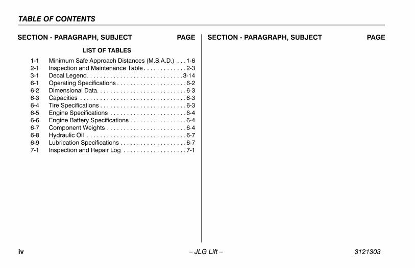
TABLE OF CONTENTS
SECTION - PARAGRAPH, SUBJECT PAGE SECTION - PARAGRAPH, SUBJECT PAGE
LIST OF TABLES
1-1 Minimum Safe Approach Distances (M.S.A.D.) . . . 1-62-1 Inspection and Maintenance Table . . . . . . . . . . . . . 2-33-1 Decal Legend. . . . . . . . . . . . . . . . . . . . . . . . . . . . . 3-146-1 Operating Specifications . . . . . . . . . . . . . . . . . . . . . 6-26-2 Dimensional Data. . . . . . . . . . . . . . . . . . . . . . . . . . . 6-36-3 Capacities . . . . . . . . . . . . . . . . . . . . . . . . . . . . . . . . 6-36-4 Tire Specifications . . . . . . . . . . . . . . . . . . . . . . . . . . 6-36-5 Engine Specifications . . . . . . . . . . . . . . . . . . . . . . . 6-46-6 Engine Battery Specifications . . . . . . . . . . . . . . . . . 6-46-7 Component Weights . . . . . . . . . . . . . . . . . . . . . . . . 6-46-8 Hydraulic Oil . . . . . . . . . . . . . . . . . . . . . . . . . . . . . . 6-76-9 Lubrication Specifications . . . . . . . . . . . . . . . . . . . . 6-77-1 Inspection and Repair Log . . . . . . . . . . . . . . . . . . . 7-1
iv – JLG Lift – 3121303
SECTION 1 - SAFETY PRECAUTIONS
SECTION 1. SAFETY PRECAUTIONS
1.1 GENERALThis section outlines the necessary precautions for properand safe machine usage and maintenance. In order to pro-mote proper machine usage, it is mandatory that a daily rou-tine is established based on the content of this manual. Amaintenance program, using the information provided in thismanual and the Service and Maintenance Manual, must alsobe established by a qualified person and must be followed toensure that the machine is safe to operate.
The owner/user/operator/lessor/lessee of the machineshould not accept operating responsibility until this manualhas been read, training is accomplished, and operation ofthe machine has been completed under the supervision ofan experienced and qualified operator.
These sections contain the responsibilities of the owner,user, operator, lessor, and lessee concerning safety, train-ing, inspection, maintenance, application, and operation.Ifthere are any questions with regard to safety, training,inspection, maintenance, application, and operation, pleasecontact JLG Industries, Inc. (“JLG”).
FAILURE TO COMPLY WITH THE SAFETY PRECAUTIONS LISTED INTHIS MANUAL COULD RESULT IN MACHINE DAMAGE, PROPERTYDAMAGE, PERSONAL INJURY OR DEATH.
1.2 PRE-OPERATION
Operator Training and Knowledge• The Operators and Safety Manual must be read in its
entirety before operating the machine. For clarification,questions, or additional information regarding any por-tions of this manual, contact JLG Industries, Inc.
3121303 – JLG Lift – 1-1
SECTION 1 - SAFETY PRECAUTIONS
• An operator must not accept operating responsibilitiesuntil adequate training has been given by competent andauthorized persons.
• Allow only those authorized and qualified personnel tooperate the machine who have demonstrated that theyunderstand the safe and proper operation and mainte-nance of the unit.
• Read, understand, and obey all DANGERS, WARNINGS,CAUTIONS, and operating instructions on the machineand in this manual.
• Ensure that the machine is to be used in a manner whichis within the scope of its intended application as deter-mined by JLG.
• All operating personnel must be familiar with the emer-gency controls and emergency operation of the machineas specified in this manual.
• Read, understand, and obey all applicable employer,local, and governmental regulations as they pertain toyour utilization and application of the machine.
Workplace Inspection• Precautions to avoid all hazards in the work area must be
taken by the user before operation of the machine.
• Do not operate or raise the platform from a position ontrucks, trailers, railway cars, floating vessels, scaffolds orother equipment unless the application is approved inwriting by JLG.
• Before operation, check work area for overhead hazardssuch as electric lines, bridge cranes, and other potentialoverhead obstructions.
• Check floor surfaces for holes, bumps, drop-offs, obstruc-tions, debris, concealed holes, and other potential haz-ards.
• Check the work area for hazardous locations. Do notoperate the machine in hazardous environments unlessapproved for that purpose by JLG.
• Ensure that the ground conditions are adequate to sup-port the maximum tire load indicated on the tire loaddecals located on the chassis adjacent to each wheel.
• Do not operate the machine when wind conditions exceed12.5 m/s (28 mph).
• This machine can be operated in nominal ambient tem-peratures of -15oC to 45oC (5oF to 113oF). Consult JLG tooptimize operation outside of this temperature range.
1-2 – JLG Lift – 3121303
SECTION 1 - SAFETY PRECAUTIONS
Machine Inspection • Do not operate this machine until the inspections and
functional checks have been performed as specified inSection 2 of this manual.
• Do not operate this machine until it has been serviced andmaintained according to the maintenance and inspectionrequirements as specified in the machine’s Service andMaintenance Manual.
• Ensure all safety devices are operating properly. Modifica-tion of these devices is a safety violation.
MODIFICATION OR ALTERATION OF AN AERIAL WORK PLATFORMSHALL BE MADE ONLY WITH PRIOR WRITTEN PERMISSION FROM THEMANUFACTURER.
• Do not operate any machine on which the safety orinstruction placards or decals are missing or illegible.
• Check the machine for modifications to original compo-nents. Ensure that any modifications have been approvedby JLG.
• Avoid accumulation of debris on platform deck. Keepmud, oil, grease, and other slippery substances from foot-wear and platform deck.
1.3 OPERATION
General • Do not use the machine for any purpose other than posi-
tioning personnel, their tools, and equipment.
• Before operation, the user must be familiar with themachine capabilities and operating characteristics of allfunctions.
• Never operate a malfunctioning machine. If a malfunctionoccurs, shut down the machine. Remove the unit fromservice and notify the proper authorities.
• Do not remove, modify, or disable any safety devices.
• Never slam a control switch or lever through neutral to anopposite direction. Always return switch to neutral andstop before moving the switch to the next function. Oper-ate controls with slow and even pressure.
• Do not allow personnel to tamper with or operate themachine from the ground with personnel in the platform,except in an emergency.
• Do not carry materials directly on platform railing unlessapproved by JLG.
• When two or more persons are in the platform, the opera-tor shall be responsible for all machine operations.
3121303 – JLG Lift – 1-3
SECTION 1 - SAFETY PRECAUTIONS
• Always ensure that power tools are properly stowed andnever left hanging by their cord from the platform workarea.
• Do not assist a stuck or disabled machine by pushing orpulling except by pulling at the chassis tie-down lugs.
• Stow scissor arm assembly and shut off all power beforeleaving machine.
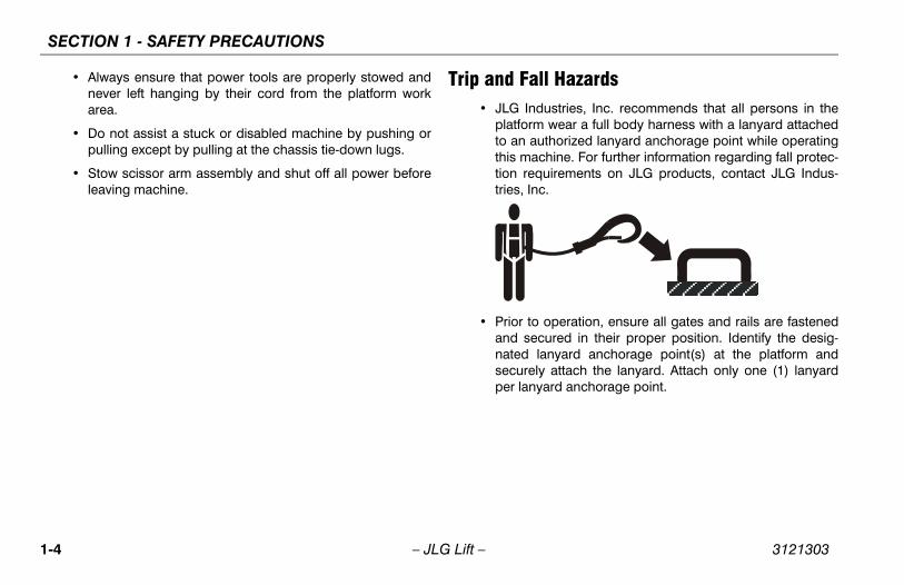
Trip and Fall Hazards• JLG Industries, Inc. recommends that all persons in the
platform wear a full body harness with a lanyard attachedto an authorized lanyard anchorage point while operatingthis machine. For further information regarding fall protec-tion requirements on JLG products, contact JLG Indus-tries, Inc.
• Prior to operation, ensure all gates and rails are fastenedand secured in their proper position. Identify the desig-nated lanyard anchorage point(s) at the platform andsecurely attach the lanyard. Attach only one (1) lanyardper lanyard anchorage point.
1-4 – JLG Lift – 3121303
SECTION 1 - SAFETY PRECAUTIONS
.
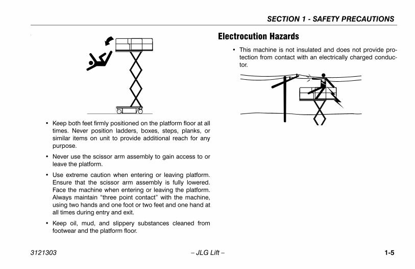
• Keep both feet firmly positioned on the platform floor at alltimes. Never position ladders, boxes, steps, planks, orsimilar items on unit to provide additional reach for anypurpose.
• Never use the scissor arm assembly to gain access to orleave the platform.
• Use extreme caution when entering or leaving platform.Ensure that the scissor arm assembly is fully lowered.Face the machine when entering or leaving the platform.Always maintain “three point contact” with the machine,using two hands and one foot or two feet and one hand atall times during entry and exit.
• Keep oil, mud, and slippery substances cleaned fromfootwear and the platform floor.
Electrocution Hazards• This machine is not insulated and does not provide pro-
tection from contact with an electrically charged conduc-tor.
3121303 – JLG Lift – 1-5
SECTION 1 - SAFETY PRECAUTIONS
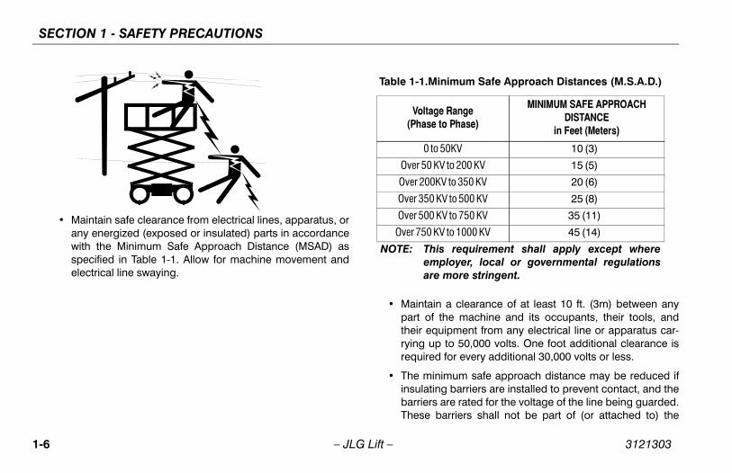
• Maintain safe clearance from electrical lines, apparatus, orany energized (exposed or insulated) parts in accordancewith the Minimum Safe Approach Distance (MSAD) asspecified in Table 1-1. Allow for machine movement andelectrical line swaying.
• Maintain a clearance of at least 10 ft. (3m) between anypart of the machine and its occupants, their tools, andtheir equipment from any electrical line or apparatus car-rying up to 50,000 volts. One foot additional clearance isrequired for every additional 30,000 volts or less.
• The minimum safe approach distance may be reduced ifinsulating barriers are installed to prevent contact, and thebarriers are rated for the voltage of the line being guarded.These barriers shall not be part of (or attached to) the
Table 1-1.Minimum Safe Approach Distances (M.S.A.D.)
Voltage Range(Phase to Phase)
MINIMUM SAFE APPROACH DISTANCE
in Feet (Meters)
0 to 50KV 10 (3)
Over 50 KV to 200 KV 15 (5)
Over 200KV to 350 KV 20 (6)
Over 350 KV to 500 KV 25 (8)
Over 500 KV to 750 KV 35 (11)
Over 750 KV to 1000 KV 45 (14)
NOTE: This requirement shall apply except whereemployer, local or governmental regulationsare more stringent.
1-6 – JLG Lift – 3121303
SECTION 1 - SAFETY PRECAUTIONS
machine. The minimum safe approach distance shall bereduced to a distance within the designed working dimen-sions of the insulating barrier. This determination shall bemade by a qualified person in accordance with theemployer, local, or governmental requirements for workpractices near energized equipment.
DO NOT MANEUVER MACHINE OR PERSONNEL INSIDE PROHIBITEDZONE (MSAD). ASSUME ALL ELECTRICAL PARTS AND WIRING AREENERGIZED UNLESS KNOWN OTHERWISE.
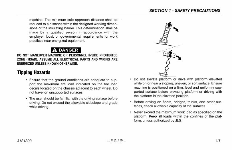
Tipping Hazards• Ensure that the ground conditions are adequate to sup-
port the maximum tire load indicated on the tire loaddecals located on the chassis adjacent to each wheel. Donot travel on unsupported surfaces.
• The user should be familiar with the driving surface beforedriving. Do not exceed the allowable sideslope and gradewhile driving.
.
• Do not elevate platform or drive with platform elevatedwhile on or near a sloping, uneven, or soft surface. Ensuremachine is positioned on a firm, level and uniformly sup-ported surface before elevating platform or driving withthe platform in the elevated position.
• Before driving on floors, bridges, trucks, and other sur-faces, check allowable capacity of the surfaces.
• Never exceed the maximum work load as specified on theplatform. Keep all loads within the confines of the plat-form, unless authorized by JLG.
3121303 – JLG Lift – 1-7
SECTION 1 - SAFETY PRECAUTIONS
• Keep the chassis of the machine a minimum of 0.6m (2 ft)from holes, bumps, drop-offs, obstructions, debris, con-cealed holes, and other potential hazards at the groundlevel.
• Never attempt to use the machine as a crane. Do not tie-off machine to any adjacent structure. Never attach wire,cable, or any similar items to platform.
• Do not operate the machine when wind conditions exceedthe maximum allowable wind speed.
• Do not cover the platform sides or carry large surface-areaitems in the platform when operating outdoors. The addi-tion of such items increases the exposed wind area of themachine.
• Do not increase the platform size with unauthorized deckextensions or attachments.
• If scissor arm assembly or platform is caught so that oneor more wheels are off the ground, all persons must beremoved before attempting to free the machine. Usecranes, forklift trucks, or other appropriate equipment tostabilize machine and remove personnel.
Crushing and Collision Hazards• Approved head gear must be worn by all operating and
ground personnel.
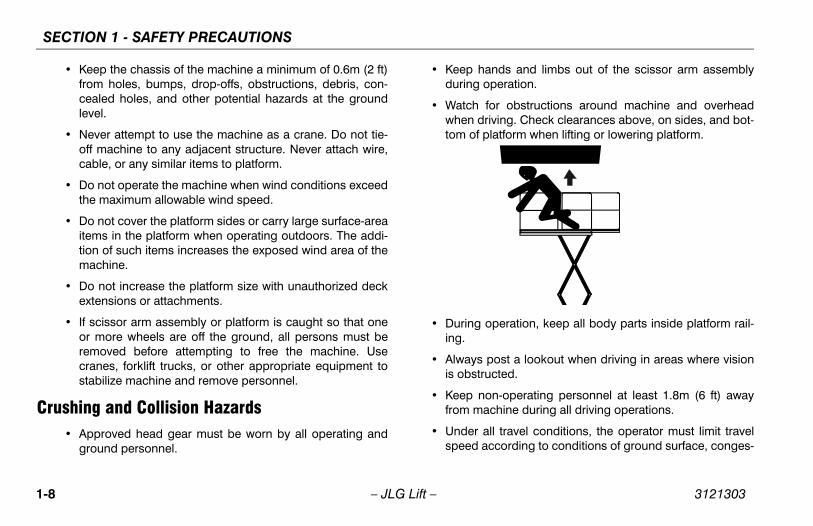
• Keep hands and limbs out of the scissor arm assemblyduring operation.
• Watch for obstructions around machine and overheadwhen driving. Check clearances above, on sides, and bot-tom of platform when lifting or lowering platform.
• During operation, keep all body parts inside platform rail-ing.
• Always post a lookout when driving in areas where visionis obstructed.
• Keep non-operating personnel at least 1.8m (6 ft) awayfrom machine during all driving operations.
• Under all travel conditions, the operator must limit travelspeed according to conditions of ground surface, conges-
1-8 – JLG Lift – 3121303
SECTION 1 - SAFETY PRECAUTIONS
tion, visibility, slope, location of personnel, and other fac-tors causing hazards of collision or injury to personnel.
• Be aware of stopping distances in all drive speeds. Whendriving in high speed, switch to low speed before stop-ping. Travel grades in low speed only.
• Do not use high speed drive in restricted or close quartersor when driving in reverse.
• Exercise extreme caution at all times to prevent obstaclesfrom striking or interfering with operating controls and per-sons in the platform.
• Ensure that operators of other overhead and floor levelmachines are aware of the aerial work platform’s pres-ence. Disconnect power to overhead cranes. Barricadefloor area if necessary.
• Avoid operating over ground personnel. Warn personnelnot to work, stand, or walk under a raised platform. Posi-tion barricades on floor as necessary.
1.4 TOWING, LIFTING, AND HAULING• Never allow personnel in platform while towing, lifting, or
hauling.
• This machine should not be towed, except in the event ofemergency, malfunction, power failure, or loading/unload-ing. Refer to emergency towing procedures.
• Ensure platform is fully retracted and completely empty oftools prior to towing, lifting or hauling.
• When lifting machine with a forklift, position forks only atdesignated areas of the machine. Lift with a forklift of ade-quate capacity.
• Refer to Section 4 for lifting information.
1.5 MAINTENANCE
General
This section contains general safety precautions which must beobserved during maintenance of this machine. Additional pre-cautions to be observed during machine maintenance areinserted at the appropriate points in this maunual and in the Ser-vice and Maintenance Manual. It is of utmost importance thatmaintenance personnel pay strict attention to these precautionsto avoid possible injury to personnel or damage to the machineor property. A maintenance program must be established by a
3121303 – JLG Lift – 1-9
SECTION 1 - SAFETY PRECAUTIONS
qualified person and must be followed to ensure that themachine is safe.
Maintenance Hazards• Shut off power to all controls and ensure that all operating
systems are secured from inadvertent motion prior to per-forming any adjustments or repairs.
• Never work under an elevated platform until it has beenfully lowered to the full down position, if possible, or other-wise supported and restrained from movement withappropriate safety props, blocking, or overhead supports.
• Always relieve hydraulic pressure from all hydraulic cir-cuits before loosening or removing hydraulic compo-nents.
• Always disconnect batteries when servicing electricalcomponents or when performing welding on the machine.
• Shut down the engine (if equipped) while fuel tanks arebeing filled.
• Ensure replacement parts or components are identical orequivalent to original parts or components.
• Never attempt to move heavy parts without the aid of amechanical device. Do not allow heavy objects to rest inan unstable position. Ensure adequate support is pro-vided when raising components of the machine.
• Remove all rings, watches, and jewelry when performingany maintenance. Do not wear loose fitting clothing orlong hair unrestrained which may become caught orentangled in equipment.
• Use only clean approved non-flammable cleaing solvents.
• Never alter, remove, or substitute any items such as coun-terweights, tires, batteries, platforms or other items thatmay reduce or affect the overall weight or stability of themachine.
• Reference the Service and Maintenance Manual for theweights of critical stability items.
MODIFICATION OR ALTERATION OF AN AERIAL WORK PLATFORMSHALL BE MADE ONLY WITH PRIOR WRITTEN PERMISSION FROM THEMANUFACTURER.
Battery Hazards• Always disconnect batteries when servicing electrical
components or when performing welding on the machine.
• Do not allow smoking, open flame, or sparks near batteryduring charging or servicing.
• Do not contact tools or other metal objects across the bat-tery terminals.
1-10 – JLG Lift – 3121303
SECTION 1 - SAFETY PRECAUTIONS
• Always wear hand, eye, and face protection when servic-ing batteries. Ensure that battery acid does not come incontact with skin or clothing.
BATTERY FLUID IS HIGHLY CORROSIVE. AVOID CONTACT WITH SKINAND CLOTHING AT ALL TIMES. IMMEDIATELY RINSE ANY CONTACTEDAREA WITH CLEAN WATER AND SEEK MEDICAL ATTENTION.
• Charge batteries only in a well ventilated area.
• Avoid overfilling the battery fluid level. Add distilled waterto batteries only after the batteries are fully charged.
3121303 – JLG Lift – 1-11
SECTION 1 - SAFETY PRECAUTIONS
NOTES:
1-12 – JLG Lift – 3121303
SECTION 2 - USER RESPONSIBILITIES, MACHINE PREPARATION AND INSPECTION
SECTION 2. USER RESPONSIBILITIES, MACHINE PREPARATION AND INSPECTION
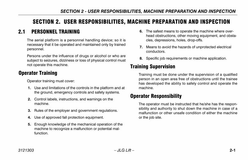
2.1 PERSONNEL TRAININGThe aerial platform is a personnel handling device; so it isnecessary that it be operated and maintained only by trainedpersonnel.
Persons under the influence of drugs or alcohol or who aresubject to seizures, dizziness or loss of physical control mustnot operate this machine.
Operator TrainingOperator training must cover:
1. Use and limitations of the controls in the platform and at the ground, emergency controls and safety systems.
2. Control labels, instructions, and warnings on the machine.
3. Rules of the employer and government regulations.
4. Use of approved fall protection equipment.
5. Enough knowledge of the mechanical operation of the machine to recognize a malfunction or potential mal-function.
6. The safest means to operate the machine where over-head obstructions, other moving equipment, and obsta-cles, depressions, holes, drop-offs.
7. Means to avoid the hazards of unprotected electrical conductors.
8. Specific job requirements or machine application.
Training SupervisionTraining must be done under the supervision of a qualifiedperson in an open area free of obstructions until the traineehas developed the ability to safely control and operate themachine.
Operator ResponsibilityThe operator must be instructed that he/she has the respon-sibility and authority to shut down the machine in case of amalfunction or other unsafe condition of either the machineor the job site.
3121303 – JLG Lift – 2-1
SECTION 2 - USER RESPONSIBILITIES, MACHINE PREPARATION AND INSPECTION
2.2 PREPARATION, INSPECTION, AND MAINTENANCE
The following table covers the periodic machine inspectionsand maintenance recommended by JLG Industries, Inc.Consult local regulations for further requirements for aerialwork platforms. The frequency of inspections and mainte-nance must be increased as necessary when the machine isused in a harsh or hostile environment, if the machine isused with increased frequency, or if the machine is used in asevere manner.
NOTICEJLG INDUSTRIES, INC. RECOGNIZES A FACTORY-CERTIFIED SERVICETECHNICIAN AS A PERSON WHO HAS SUCCESSFULLY COMPLETEDTHE JLG SERVICE TRAINING SCHOOL FOR THE SPECIFIC JLG PROD-UCT MODEL.
2-2 – JLG Lift – 3121303
SECTION 2 - USER RESPONSIBILITIES, MACHINE PREPARATION AND INSPECTION
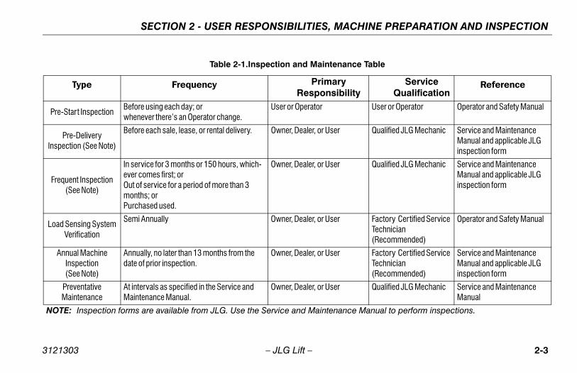
Table 2-1.Inspection and Maintenance Table
Type Frequency PrimaryResponsibility
Service Qualification
Reference
Pre-Start InspectionBefore using each day; or whenever there’s an Operator change.
User or Operator User or Operator Operator and Safety Manual
Pre-Delivery Inspection (See Note)
Before each sale, lease, or rental delivery. Owner, Dealer, or User Qualified JLG Mechanic Service and Maintenance Manual and applicable JLG inspection form
Frequent Inspection(See Note)
In service for 3 months or 150 hours, which-ever comes first; orOut of service for a period of more than 3 months; orPurchased used.
Owner, Dealer, or User Qualified JLG Mechanic Service and Maintenance Manual and applicable JLG inspection form
Load Sensing System Verification
Semi Annually Owner, Dealer, or User Factory Certified Service Technician(Recommended)
Operator and Safety Manual
Annual Machine Inspection(See Note)
Annually, no later than 13 months from the date of prior inspection.
Owner, Dealer, or User Factory Certified Service Technician(Recommended)
Service and Maintenance Manual and applicable JLG inspection form
Preventative Maintenance
At intervals as specified in the Service and Maintenance Manual.
Owner, Dealer, or User Qualified JLG Mechanic Service and Maintenance Manual
NOTE: Inspection forms are available from JLG. Use the Service and Maintenance Manual to perform inspections.
3121303 – JLG Lift – 2-3
SECTION 2 - USER RESPONSIBILITIES, MACHINE PREPARATION AND INSPECTION
2.3 PRE-START INSPECTIONThe Pre-Start Inspection should include each of the follow-ing:
1. Cleanliness – Check all surfaces for leakage (oil, fuel, or battery fluid) or foreign objects. Report any leakage to the proper maintenance personnel.
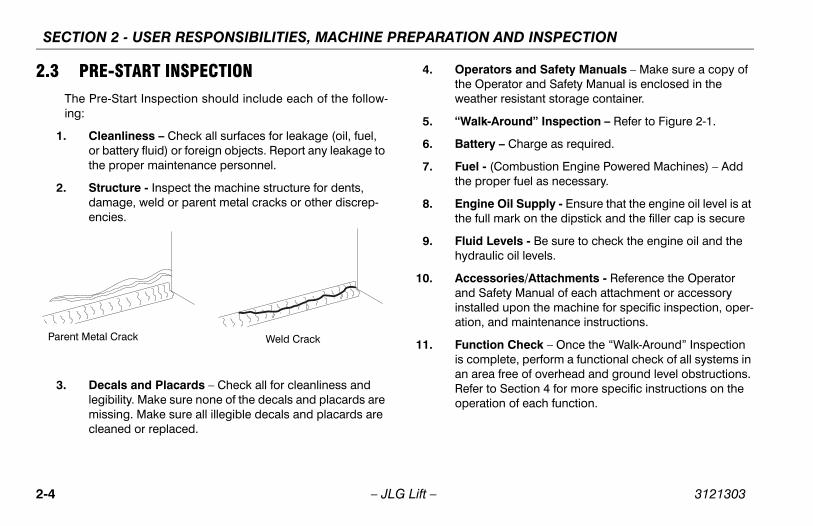
2. Structure - Inspect the machine structure for dents, damage, weld or parent metal cracks or other discrep-encies.
3. Decals and Placards – Check all for cleanliness and legibility. Make sure none of the decals and placards are missing. Make sure all illegible decals and placards are cleaned or replaced.
4. Operators and Safety Manuals – Make sure a copy of the Operator and Safety Manual is enclosed in the weather resistant storage container.
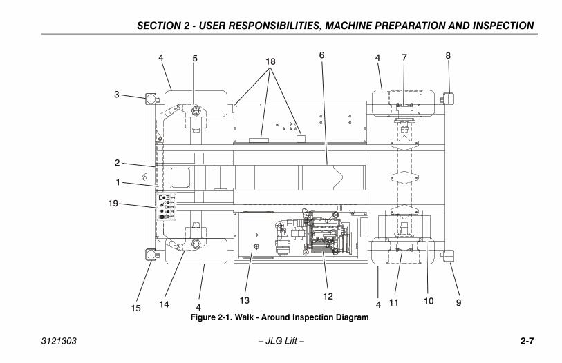
5. “Walk-Around” Inspection – Refer to Figure 2-1.
6. Battery – Charge as required.
7. Fuel - (Combustion Engine Powered Machines) – Add the proper fuel as necessary.
8. Engine Oil Supply - Ensure that the engine oil level is at the full mark on the dipstick and the filler cap is secure
9. Fluid Levels - Be sure to check the engine oil and the hydraulic oil levels.
10. Accessories/Attachments - Reference the Operator and Safety Manual of each attachment or accessory installed upon the machine for specific inspection, oper-ation, and maintenance instructions.
11. Function Check – Once the “Walk-Around” Inspection is complete, perform a functional check of all systems in an area free of overhead and ground level obstructions. Refer to Section 4 for more specific instructions on the operation of each function.
Parent Metal Crack Weld Crack
2-4 – JLG Lift – 3121303
SECTION 2 - USER RESPONSIBILITIES, MACHINE PREPARATION AND INSPECTION
IF THE MACHINE DOES NOT OPERATE PROPERLY, TURN OFF THEMACHINE IMMEDIATELY! REPORT THE PROBLEM TO THE PROPERMAINTENANCE PERSONNEL. DO NOT OPERATE THE MACHINE UNTILIT IS DECLARED SAFE FOR OPERATION.
Function CheckPerform the Function Check as follows:
1. From the ground control panel with no load in the plat-form:
a. Check that all function control switches and locksare in place.
b. Operate all functions and check all limiting and cut-out switches.
c. Check for proper lifting and lowering of the plat-form.
d. If the platform extension is extended, check that theextension retracts.
NOTE: Be sure the platform extension is retracted before lower-ing.
e. Ensure that all machine functions are disabledwhen the Emergency Stop Button is activated.
f. Check manual descent.
g. Check for proper lifting and lowering of the plat-form.
h. Check the function of the protective scissor cage.
2. From the platform control console:
a. Ensure that the control console is firmly secured inthe proper location.
b. Check that all guards protecting the switches are inplace.
c. Operate all functions
d. Check the high drive cut out switch by raising theplatform by 3.5 m (11.5 ft) on the 210-25 and 3.7 m(12.1 ft) on the 245-25 and assure that the highdrive speed is cut out.
e. Ensure that all machine functions are disabledwhen the Emergency Stop Button is pushed in.
f. Ensure that all LED’s in the control box are workingproperly.
g. Check that the platform extension extends andretracts properly.
3121303 – JLG Lift – 2-5
SECTION 2 - USER RESPONSIBILITIES, MACHINE PREPARATION AND INSPECTION
3. With the platform in the transport (stowed) position:
a. Drive the machine on a level grade and stop toensure the brakes hold.
b. To ensure proper operation of the tilt sensor, drivethe machine onto a tilt greater than the preset 3°and attempt to lift.
2-6 – JLG Lift – 3121303
SECTION 2 - USER RESPONSIBILITIES, MACHINE PREPARATION AND INSPECTION
1
2
3
4 5 6 4 7 8
94 111213
4141510
18
19
Figure 2-1. Walk - Around Inspection Diagram
3121303 – JLG Lift – 2-7
SECTION 2 - USER RESPONSIBILITIES, MACHINE PREPARATION AND INSPECTION
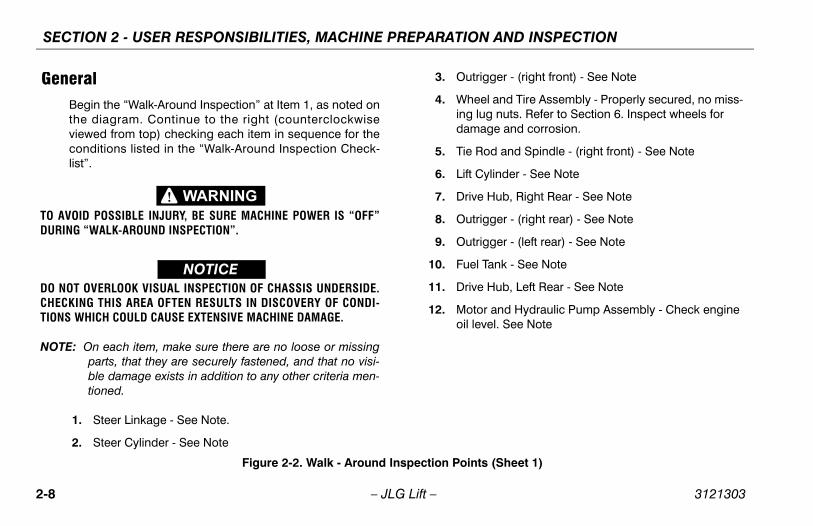
GeneralBegin the “Walk-Around Inspection” at Item 1, as noted onthe diagram. Continue to the right (counterclockwiseviewed from top) checking each item in sequence for theconditions listed in the “Walk-Around Inspection Check-list”.
TO AVOID POSSIBLE INJURY, BE SURE MACHINE POWER IS “OFF”DURING “WALK-AROUND INSPECTION”.
NOTICEDO NOT OVERLOOK VISUAL INSPECTION OF CHASSIS UNDERSIDE.CHECKING THIS AREA OFTEN RESULTS IN DISCOVERY OF CONDI-TIONS WHICH COULD CAUSE EXTENSIVE MACHINE DAMAGE.
NOTE: On each item, make sure there are no loose or missingparts, that they are securely fastened, and that no visi-ble damage exists in addition to any other criteria men-tioned.
1. Steer Linkage - See Note.
2. Steer Cylinder - See Note
3. Outrigger - (right front) - See Note
4. Wheel and Tire Assembly - Properly secured, no miss-ing lug nuts. Refer to Section 6. Inspect wheels for damage and corrosion.
5. Tie Rod and Spindle - (right front) - See Note
6. Lift Cylinder - See Note
7. Drive Hub, Right Rear - See Note
8. Outrigger - (right rear) - See Note
9. Outrigger - (left rear) - See Note
10. Fuel Tank - See Note
11. Drive Hub, Left Rear - See Note
12. Motor and Hydraulic Pump Assembly - Check engine oil level. See Note
Figure 2-2. Walk - Around Inspection Points (Sheet 1)
2-8 – JLG Lift – 3121303
SECTION 2 - USER RESPONSIBILITIES, MACHINE PREPARATION AND INSPECTION
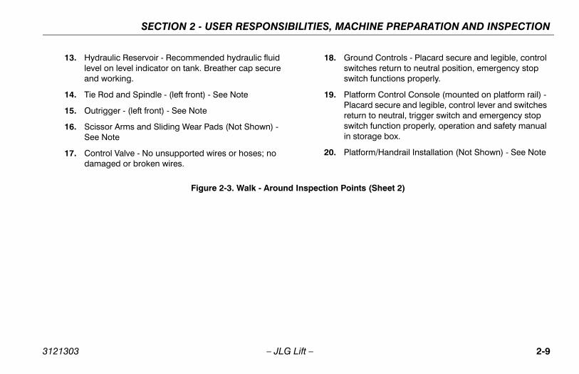
13. Hydraulic Reservoir - Recommended hydraulic fluid level on level indicator on tank. Breather cap secure and working.
14. Tie Rod and Spindle - (left front) - See Note
15. Outrigger - (left front) - See Note
16. Scissor Arms and Sliding Wear Pads (Not Shown) - See Note
17. Control Valve - No unsupported wires or hoses; no damaged or broken wires.
18. Ground Controls - Placard secure and legible, control switches return to neutral position, emergency stop switch functions properly.
19. Platform Control Console (mounted on platform rail) - Placard secure and legible, control lever and switches return to neutral, trigger switch and emergency stop switch function properly, operation and safety manual in storage box.
20. Platform/Handrail Installation (Not Shown) - See Note
Figure 2-3. Walk - Around Inspection Points (Sheet 2)
3121303 – JLG Lift – 2-9
SECTION 2 - USER RESPONSIBILITIES, MACHINE PREPARATION AND INSPECTION
NOTES:
2-10 – JLG Lift – 3121303
SECTION 3 - USER RESPONSIBILITIES AND MACHINE CONTROL
SECTION 3. USER RESPONSIBILITIES AND MACHINE CONTROL
3.1 GENERAL
NOTICESINCE THE MANUFACTURER HAS NO DIRECT CONTROL OVERMACHINE APPLICATION AND OPERATION, CONFORMANCE WITHGOOD SAFETY PRACTICES IN THESE AREAS IT IS THE RESPONSIBIL-ITY OF THE USER AND HIS OPERATING PERSONNEL.
This section provides the necessary information needed tounderstand control functions. Included in this section are theoperating characteristics and limitations, and functions andpurposes of controls and indicators. It is important that theuser read and understand the proper procedures beforeoperating the machine. These procedures will aid in obtain-ing optimum service life and safe operation.
3.2 PERSONNEL TRAININGThe scissor lift is a personnel handling device; therefore, it isessential that it be operated and maintained only by autho-rized personnel who have demonstrated that they under-stand the proper use and maintenance of the machine. It isimportant that all personnel who are assigned to and respon-sible for the operation and maintenance of the machineundergo a thorough training program and check out period
in order to become familiar with the characteristics prior tooperating the machine.
Persons under the influence of drugs or alcohol or who aresubject to seizures, dizziness or loss of physical control mustnot be permitted to operate the machine.
Operator TrainingOperator training must include instruction in the following:
1. Use and limitations of the platform controls, ground con-trols, emergency controls and safety systems.
2. Knowledge and understanding of this manual and of the control markings, instructions and warnings on the machine itself.
3. Knowledge and understanding of all safety work rules of the employer and of Federal, State and Local Statutes, including training in the recognition and avoidance of potential hazards in the work place; with particular atten-tion to the work to be performed.
4. Proper use of all required personnel safety equipment.
5. Sufficient knowledge of the mechanical operation of the machine to recognize a malfunction or potential mal-function.
3121303 – JLG Lift – 3-1
SECTION 3 - USER RESPONSIBILITIES AND MACHINE CONTROL
6. The safest means to operate near overhead obstruc-tions, other moving equipment, obstacles, depressions, holes, drop-offs, etc. on the supporting surface.
7. Means to avoid the hazards of unprotected electrical conductors.
8. Any other requirements of a specific job or machine application.
Training SupervisionTraining must be done under the supervision of a qualifiedoperator or supervisor in an open area free of obstructionsuntil the trainee has developed the ability to safely control ascissor lift in congested work locations.
Operator ResponsibilityThe operator must be instructed that he has the responsibil-ity and authority to shut down the machine in case of a mal-function or other unsafe condition of either the machine orthe job site and to request further information from his super-visor or JLG Distributor before proceeding.
3.3 OPERATING CHARACTERISTICS AND LIMITATIONS
GeneralA thorough knowledge of the operating characteristics andlimitations of the machine is always the first requirement forany user, regardless of user’s experience with similar typesof equipment.
PlacardsImportant points to remember during operation are providedat the control stations by DANGER, WARNING, CAUTION,IMPORTANT and INSTRUCTION placards. This informationis placed at various locations for the express purpose ofalerting personnel of potential hazards constituted by theoperating characteristics and load limitations of the machine.See foreword for definitions of the above placards.
3-2 – JLG Lift – 3121303
SECTION 3 - USER RESPONSIBILITIES AND MACHINE CONTROL
CapacitiesRaising platform above the stowed position with or withoutany load in platform, is based on the following criteria:
1. Machine is level and positioned on a firm supporting surface.
2. Load is within manufacturer’s rated capacity.
3. All machine systems are functioning properly.
3.4 CONTROLS AND INDICATORS
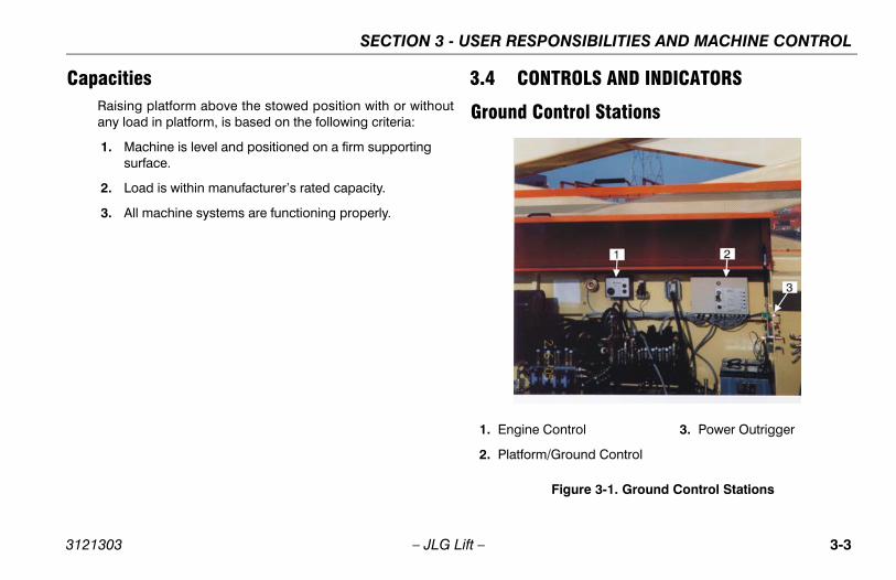
Ground Control Stations
1. Engine Control
2. Platform/Ground Control
3. Power Outrigger
Figure 3-1. Ground Control Stations
3121303 – JLG Lift – 3-3
SECTION 3 - USER RESPONSIBILITIES AND MACHINE CONTROL
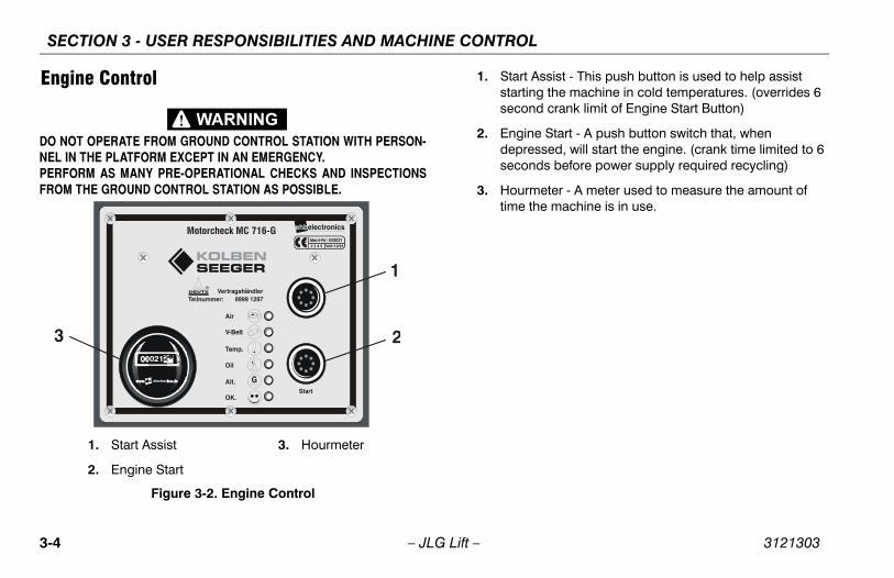
Engine Control
DO NOT OPERATE FROM GROUND CONTROL STATION WITH PERSON-NEL IN THE PLATFORM EXCEPT IN AN EMERGENCY.PERFORM AS MANY PRE-OPERATIONAL CHECKS AND INSPECTIONSFROM THE GROUND CONTROL STATION AS POSSIBLE.
1. Start Assist - This push button is used to help assist starting the machine in cold temperatures. (overrides 6 second crank limit of Engine Start Button)
2. Engine Start - A push button switch that, when depressed, will start the engine. (crank time limited to 6 seconds before power supply required recycling)
3. Hourmeter - A meter used to measure the amount of time the machine is in use.
Vertragshandler
ehbelectronics
Start
1
23
Figure 3-2. Engine Control
1. Start Assist
2. Engine Start
3. Hourmeter
3-4 – JLG Lift – 3121303
SECTION 3 - USER RESPONSIBILITIES AND MACHINE CONTROL
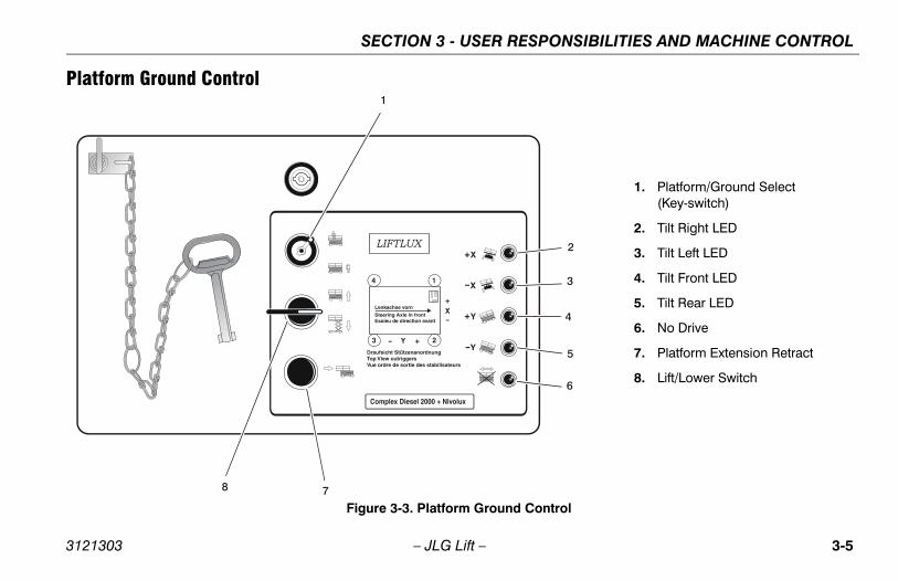
Platform Ground Control
2
3
4
8 7
6
5
1
1. Platform/Ground Select (Key-switch)
2. Tilt Right LED
3. Tilt Left LED
4. Tilt Front LED
5. Tilt Rear LED
6. No Drive
7. Platform Extension Retract
8. Lift/Lower Switch
Figure 3-3. Platform Ground Control
3121303 – JLG Lift – 3-5
SECTION 3 - USER RESPONSIBILITIES AND MACHINE CONTROL
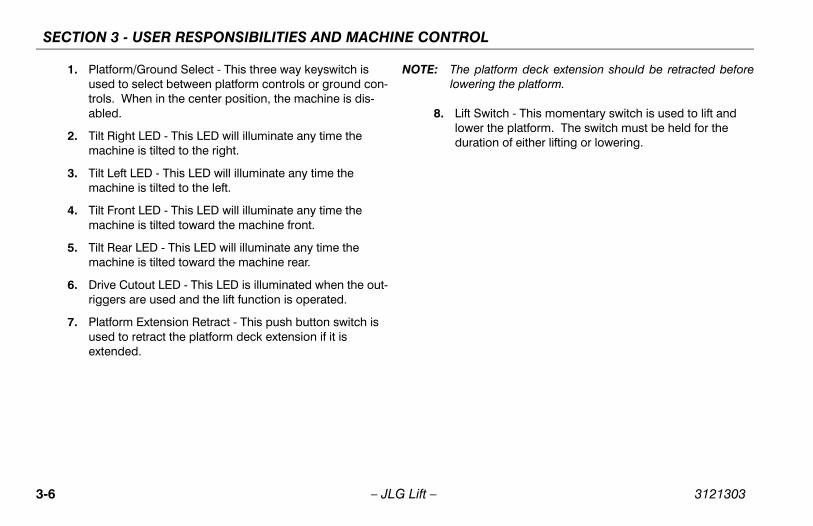
1. Platform/Ground Select - This three way keyswitch is used to select between platform controls or ground con-trols. When in the center position, the machine is dis-abled.
2. Tilt Right LED - This LED will illuminate any time the machine is tilted to the right.
3. Tilt Left LED - This LED will illuminate any time the machine is tilted to the left.
4. Tilt Front LED - This LED will illuminate any time the machine is tilted toward the machine front.
5. Tilt Rear LED - This LED will illuminate any time the machine is tilted toward the machine rear.
6. Drive Cutout LED - This LED is illuminated when the out-riggers are used and the lift function is operated.
7. Platform Extension Retract - This push button switch is used to retract the platform deck extension if it is extended.
NOTE: The platform deck extension should be retracted beforelowering the platform.
8. Lift Switch - This momentary switch is used to lift and lower the platform. The switch must be held for the duration of either lifting or lowering.
3-6 – JLG Lift – 3121303
SECTION 3 - USER RESPONSIBILITIES AND MACHINE CONTROL
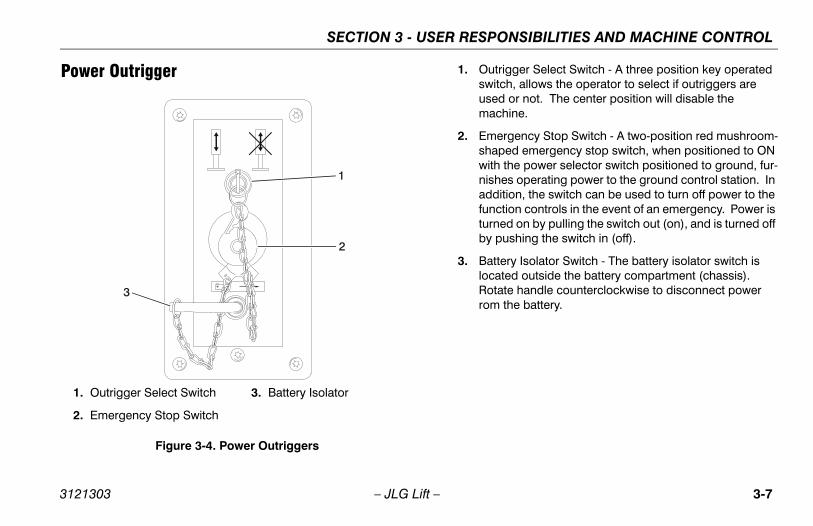
Power Outrigger 1. Outrigger Select Switch - A three position key operated switch, allows the operator to select if outriggers are used or not. The center position will disable the machine.
2. Emergency Stop Switch - A two-position red mushroom-shaped emergency stop switch, when positioned to ON with the power selector switch positioned to ground, fur-nishes operating power to the ground control station. In addition, the switch can be used to turn off power to the function controls in the event of an emergency. Power is turned on by pulling the switch out (on), and is turned off by pushing the switch in (off).
3. Battery Isolator Switch - The battery isolator switch is located outside the battery compartment (chassis). Rotate handle counterclockwise to disconnect power rom the battery.
+
1
2
3
1. Outrigger Select Switch
2. Emergency Stop Switch
3. Battery Isolator
Figure 3-4. Power Outriggers
3121303 – JLG Lift – 3-7
SECTION 3 - USER RESPONSIBILITIES AND MACHINE CONTROL
3.5 PLATFORM CONTROL STATION
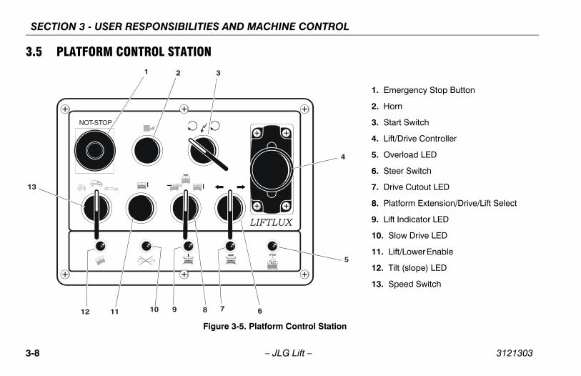
1. Emergency Stop Button
2. Horn
3. Start Switch
4. Lift/Drive Controller
5. Overload LED
6. Steer Switch
7. Drive Cutout LED
8. Platform Extension/Drive/Lift Select
9. Lift Indicator LED
10. Slow Drive LED
11. Lift/Lower Enable
12. Tilt (slope) LED
13. Speed Switch
Figure 3-5. Platform Control Station
3-8 – JLG Lift – 3121303
SECTION 3 - USER RESPONSIBILITIES AND MACHINE CONTROL
Platform Control DescriptionsWhen platform/ground control select switch is switched toplatform all movements and operations are controlled via theplatform control panel. The controls are activated througheither push-buttons or toggle switches, whose functions aremarked with symbols and/or written text.
1. Emergency Stop Button - Button, when depressed, will immediately shut the machine off. Cuts out all functions except emergency platform lowering.
2. Horn - Button, when depressed, activates the horn.
3. Start Switch - Start the Diesel engine by turning the start switch on the control panel to the right.
4. Lift/Drive Contoller - The controller works in conjunction with the platform extension, drive and the lift switch, depending upon which switch is selected.
5. Overload LED - This LED will illuminate (red) when the platform becomes overloaded.
6. Steer Switch - Choose the direction of steering by acti-vating the steer button according to the direction sym-bols. This switch must be held for the duration of steering.
7. Drive LED - This LED light remains illuminated when the machine is in a drivable configuration.
8. Platform Extension/Drive/Lift Select - Switch that selects the functions of platform extension, drive, or lift.
9. Lift Indicator LED - LED light remains illuminated until the maximum height is reached.
10. Slow Drive LED - LED light remains illuminated when the machine is in slow drive speed mode.
11. Lift/Lower Enable - This switch works in conjunction with the lift/lower function. It must be depressed once after selecting the lift/lower direction.
12. Tilt (slope) LED - This LED light will remain on until the machine is driven on a slope greater than 3°. Once the tilt limit is exceeded the light will go out.
3121303 – JLG Lift – 3-9
SECTION 3 - USER RESPONSIBILITIES AND MACHINE CONTROL
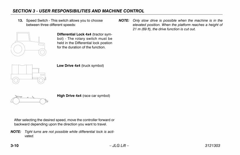
13. Speed Switch - This switch allows you to choose between three different speeds:
After selecting the desired speed, move the controller forward orbackward depending upon the direction you want to travel.
NOTE: Tight turns are not possible while differential lock is acti-vated.
NOTE: Only slow drive is possible when the machine is in theelevated position. When the platform reaches a height of21 m (69 ft), the drive function is cut out.
Differential Lock 4x4 (tractor sym-bol) - The rotary switch must beheld in the Differential lock postionfor the duration of the function.
Low Drive 4x4 (truck symbol)
High Drive 4x4 (race car symbol)
3-10 – JLG Lift – 3121303
SECTION 3 - USER RESPONSIBILITIES AND MACHINE CONTROL
End of TubeBoth Ends
Both Ends
Both Ends
Both Ends
5 7
18
1
2
5
38303
1
2
6
16 Both Sides
15
519
123
11
12142810522
12
11
23
1
19
6Both Sides
Both Sides
Both Sides
Both Sides
Both Sides
Both Sides
Both Sides
Exteriorof Cover
Top of TubesBoth Sides
Top of TubesBoth Sides
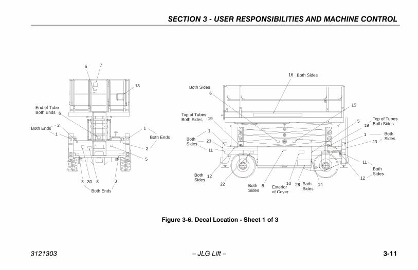
Figure 3-6. Decal Location - Sheet 1 of 3
3121303 – JLG Lift – 3-11
SECTION 3 - USER RESPONSIBILITIES AND MACHINE CONTROL
4 Both Sides
20
4
Both Sides
13
20Place Arrow to Left of Joystickon the Platform Control Box
EachCorner
23
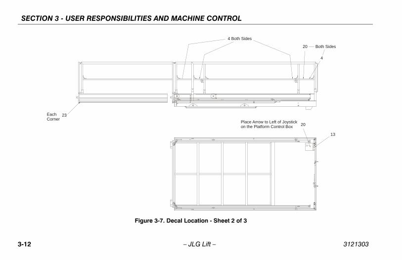
Figure 3-7. Decal Location - Sheet 2 of 3
3-12 – JLG Lift – 3121303
SECTION 3 - USER RESPONSIBILITIES AND MACHINE CONTROL
29 28
24
21
9Place on the Insideof the Hood 17
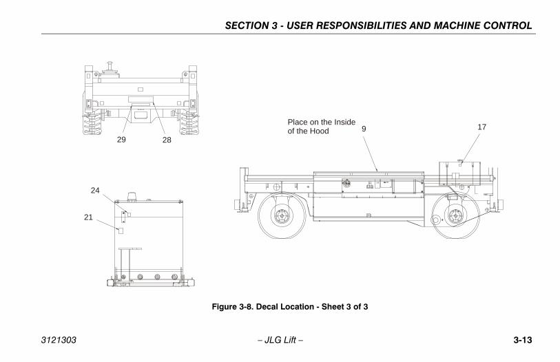
Figure 3-8. Decal Location - Sheet 3 of 3
3121303 – JLG Lift – 3-13
SECTION 3 - USER RESPONSIBILITIES AND MACHINE CONTROL
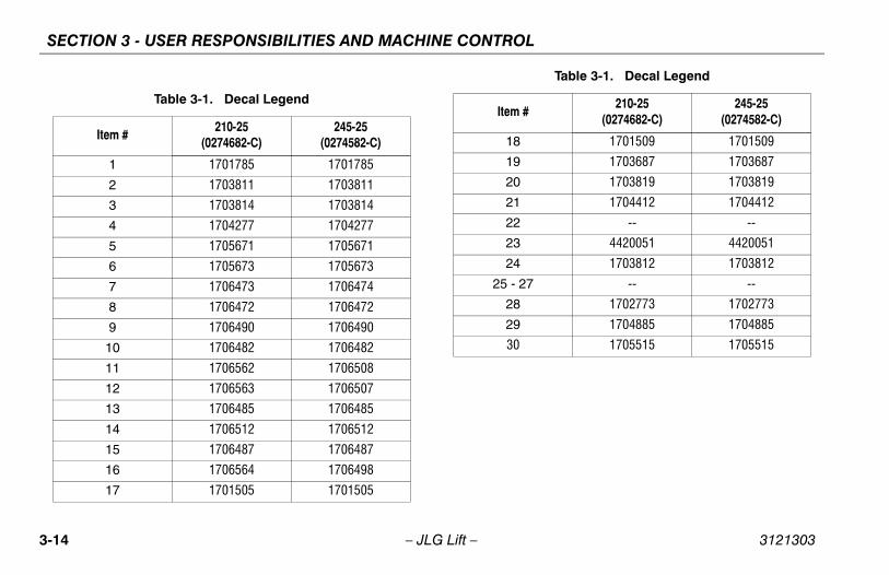
Table 3-1. Decal Legend
Item #210-25
(0274682-C)245-25
(0274582-C)
1 1701785 1701785
2 1703811 1703811
3 1703814 1703814
4 1704277 1704277
5 1705671 1705671
6 1705673 1705673
7 1706473 1706474
8 1706472 1706472
9 1706490 1706490
10 1706482 1706482
11 1706562 1706508
12 1706563 1706507
13 1706485 1706485
14 1706512 1706512
15 1706487 1706487
16 1706564 1706498
17 1701505 1701505
18 1701509 1701509
19 1703687 1703687
20 1703819 1703819
21 1704412 1704412
22 -- --
23 4420051 4420051
24 1703812 1703812
25 - 27 -- --
28 1702773 1702773
29 1704885 1704885
30 1705515 1705515
Table 3-1. Decal Legend
Item #210-25
(0274682-C)245-25
(0274582-C)
3-14 – JLG Lift – 3121303
SECTION 4 - MACHINE OPERATION
SECTION 4. MACHINE OPERATION
4.1 DESCRIPTION
General Description of the Functions and Components.
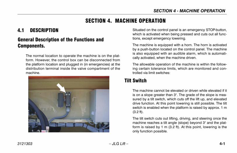
The normal location to operate the machine is on the plat-form. However, the control box can be disconnected fromthe platform location and plugged in (in emergencies) at thedistribution terminal inside the valve compartment of themachine.
Situated on the control panel is an emergency STOP-button,which is activated when being pressed and cuts out all func-tions, except emergency lowering.
The machine is equipped with a horn. The horn is activatedby a push-button located on the control panel. The machineis also equipped with an audible alarm, which is automati-cally activated, when the machine driven.
The allowable operation of the machine is within the follow-ing certain tolerance limits, which are monitored and con-trolled via limit switches:
Tilt Switch
The machine cannot be elevated or driven while elevated if itis on a slope greater than 3°. The grade of the slope is mea-sured by a tilt switch, which cuts off the lift up, and elevateddrive function. At this point lowering is still possible. The tiltswitch is enabled when the platform is raised by approx. 1 m(3.2 ft).
The tilt switch cuts out lifting, driving, and steering once themachine reaches a tilt angle (slope) beyond 3° and the plat-form is raised by 1 m (3.2 ft). At this point, lowering is theonly function possible.
3121303 – JLG Lift – 4-1
SECTION 4 - MACHINE OPERATION
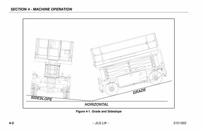
SIDESLOPEHORIZONTAL
GRADE
Figure 4-1. Grade and Sideslope
4-2 – JLG Lift – 3121303
SECTION 4 - MACHINE OPERATION
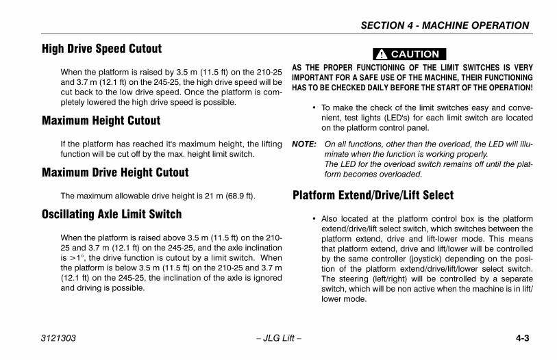
High Drive Speed Cutout
When the platform is raised by 3.5 m (11.5 ft) on the 210-25and 3.7 m (12.1 ft) on the 245-25, the high drive speed will becut back to the low drive speed. Once the platform is com-pletely lowered the high drive speed is possible.
Maximum Height Cutout
If the platform has reached it's maximum height, the liftingfunction will be cut off by the max. height limit switch.
Maximum Drive Height Cutout
The maximum allowable drive height is 21 m (68.9 ft).
Oscillating Axle Limit Switch
When the platform is raised above 3.5 m (11.5 ft) on the 210-25 and 3.7 m (12.1 ft) on the 245-25, and the axle inclinationis >1°, the drive function is cutout by a limit switch. Whenthe platform is below 3.5 m (11.5 ft) on the 210-25 and 3.7 m(12.1 ft) on the 245-25, the inclination of the axle is ignoredand driving is possible.
AS THE PROPER FUNCTIONING OF THE LIMIT SWITCHES IS VERYIMPORTANT FOR A SAFE USE OF THE MACHINE, THEIR FUNCTIONINGHAS TO BE CHECKED DAILY BEFORE THE START OF THE OPERATION!
• To make the check of the limit switches easy and conve-nient, test lights (LED's) for each limit switch are locatedon the platform control panel.
NOTE: On all functions, other than the overload, the LED will illu-minate when the function is working properly.The LED for the overload switch remains off until the plat-form becomes overloaded.
Platform Extend/Drive/Lift Select
• Also located at the platform control box is the platformextend/drive/lift select switch, which switches between theplatform extend, drive and lift-lower mode. This meansthat platform extend, drive and lift/lower will be controlledby the same controller (joystick) depending on the posi-tion of the platform extend/drive/lift/lower select switch.The steering (left/right) will be controlled by a separateswitch, which will be non active when the machine is in lift/lower mode.
3121303 – JLG Lift – 4-3
SECTION 4 - MACHINE OPERATION
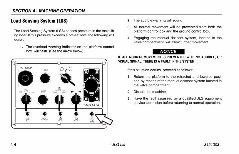
Load Sensing System (LSS)
The Load Sensing System (LSS) senses pressure in the main liftcylinder. If this pressure exceeds a pre-set level the following willoccur:
1. The overload warning indicator on the platform controlbox will flash. (See the arrow below)
2. The audible warning will sound.
3. All normal movement will be prevented from both theplatform control box and the ground control box.
4. Engaging the manual descent system, located in thevalve compartment, will allow further movement.
NOTICEIF ALL NORMAL MOVEMENT IS PREVENTED WITH NO AUDIBLE, ORVISUAL SIGNAL, THERE IS A FAULT IN THE SYSTEM.
If this situation occurs, proceed as follows:
1. Return the platform to the retracted and lowered posi-tion by means of the manual descent system located inthe valve compartment.
2. Disable the machine.
3. Have the fault assessed by a qualified JLG equipmentservice technician before returning to normal operation.
4-4 – JLG Lift – 3121303
SECTION 4 - MACHINE OPERATION
NOTICETHE LOAD SENSING SYSTEM MUST BE CALIBRATED WHEN ONE ORMORE OF THE FOLLOWING CONDITIONS OCCUR:
a. LSS component replacement.
b. LSS Sensor removal or replacement.
c. Platform is removed or replaced.
NOTICETHE LOAD SENSING SYSTEM REQUIRES PERIODIC FUNCTION VERIFI-CATION NOT TO EXCEED 6 MONTHS FROM PREVIOUS VERIFICATION.REFER TO TESTING AND EVALUATION IN SECTION 6.
4.2 OPERATION
NOTE: The platform control box can be plugged in at groundlevel inside the valve compartment.
• There is an emergency stop switch positioned on the plat-form control box (red button) and one located groundlevel at the chassis. When activated, the signals of thecontrol board will be cut off instantly and all functions willbe stopped, except the functions emergency descent andemergency lifting (at ground level). These will still work ifthe emergency button at the control box is pressed.
• The Master Switch at the chassis acts as an isolator switchfor the batteries and cuts off the power supply.
• The auto leveling outriggers can be turned on or off (Out-rigger-Switch ON/OFF). This is a keyswitch which islocated outside the hydraulic tank compartment. The acti-vation of the outriggers is controlled by the lift select func-tion. The lift up select allows the outriggers to extend. Thelift down select allows the outriggers to retract.
• The machine is equipped with a horn, which can be acti-vated from the control box. While driving, a constantacoustic signal is activated as an additional motion alarm.
3121303 – JLG Lift – 4-5
SECTION 4 - MACHINE OPERATION
4.3 LIFTING AND LOWERINGIf the lift/drive-switch is in the lift position lifting/lowering willbe activated by the joystick controller in conjunction with theenable button. After the joystick passes the neutral positionthe maximum lift speed is reached.
NOTE: If the lift/drive-switch is in the drive position, the functionslift/lower are deactivated. The emergency lift/lowerswitch, located in the bottom chassis however stillremains active. This switch can only be activated whenthe keyswitch is in the ground control position.
NOTE: With outriggers selected, the outriggers are part of the liftfunction, and the machine will not lift until the outriggersare deployed and the machine is level.
DO NOT LIFT DOWN WITHOUT COMPLETELY RETRACTING THE PLAT-FORM EXTENSION.
NOTE: The machine is equipped with gravity lift down.Theengine does not need to be running to lower the platform.
4.4 AUTOMATIC SELF LEVELINGThe machine is equipped with an auto leveling feature thatallows the operator to automatically level the machine. Thisfunction can be turned on or off at the ground control station.
With the auto leveling function selected, the outriggers aredeployed by using the lift controller. Lift up will extend theoutriggers and LIft down will retract the outriggers.
All outriggers must be extended and in contact with the sup-port surface before the platform is lifted from the stowedposition. If one or more outriggers, despite being fullyextended, not be in contact with the support surface the out-riggers must be retracted and the machine moved to a moreappropriate position.
IF THE MACHINE BECOMES UNLEVEL, CAREFULLY LOWER THE PLAT-FORM AND REPOSITION THE MACHINE.
NOTE: The outriggers can not be used from the ground controlstation.
When the automatic leveling system is activated, the drivefunction is cutout, the control lamps on the Nivolux-box showthe results of the measurement and the outriggers start to
4-6 – JLG Lift – 3121303
SECTION 4 - MACHINE OPERATION
extend. At this stage the system solely controls the setting ofthe outriggers to level the chassis.
NOTICEALWAYS BE SURE THAT THE OPERATING SURFACE THE MACHINE ISTO BE USED ON IS FIRM AND FREE OF ANY VOIDS OR OBSTRUCTIONSTHAT MAY CAUSE THE OUTRIGGERS TO NOT PERFORM PROPERLY.
To retract the outriggers activate the function "lowering" withthe joystick. As soon as all outriggers are completelyretracted the maximum hydraulic pressure will be reached atwhich time the machine will be okay to drive.
4.5 DRIVING THE MACHINE FROM THE PLATFORM
To activate the drive of the machine, the controller (joystick) has tobe moved forward for forward-drive and back for reverse-drive.The controller has a neutral zone of about ± 7% of the total possi-ble moving distance. After reaching the end of the neutral zone,the valves "drive, brake and motion alarm" will be activated. Themachine starts to move.
4.6 STEERINGThe steer function is operated by activating the rotary steerswitch in the direction indicated by the symbols on the con-trol panel.
4.7 HYDRAULIC PLATFORM EXTENSION
With the lift/drive/extension switch in the extension position, theplatform can be hydraulically extended.The function is activatedby moving the controller forward to extend and backwards toretract.
4.8 EMERGENCY LOWERING - MANUAL DESCENT
All control switches have to be set to the neutral position.After that, the emergency lowering valve, which is located onthe lift cylinder, can be opened hydraulically by a hand pumplocated inside the hydraulic compartment. Once the loweringis completed all levers of the emergency lowering functionhave to be put into the neutral position. Refer to Section 5,Emergency Procedures, for instructions on manual lowering.
3121303 – JLG Lift – 4-7
SECTION 4 - MACHINE OPERATION
4.9 PARKING AND STOWINGOnce the work carried out is completed the machine has tobe fully lowered and the battery isolator switch should beturned off.
THE MACHINE HAS TO BE LOCKED BY THE KEYSWITCH ON THEGROUND CONTROL PANEL SWITCH TO AVOID THE USE BY ANYUNAUTHORIZED PERSONNEL.
In case the machine is not used for a longer period of time,the batteries should be charged once every two weeks dueto the self discharge and power consumption of the machineat rest.
4.10 LIMIT SWITCHES & SAFETY DEVICES1. Limit Switches for Drive Mode - High drive is possible,
when the platform is lowered. When the platform israised by 3.5 m (11.5 ft)(210-25) and 3.7 (12.1 ft)(245-25) or greater, only low drive is possible.
2. Outrigger Interlock - This switch allows the machine tobe driven when all outriggers are completely retracted.The switch also prevents the mahine from being lifteduntil the machine is level.
3. Tilt Switch - If the machine is exceeding a tilt angle of 3°,the platform cannot be elevated by 1 m (3.2 ft) or greateror if driving while elevated the drive function will be cutout.
4. Maximum Height Switch - The Maximum Height Switchcuts out the lift once the platform reaches 21m (69 ft).
5. Scissor Protection Cage - To avoid jamming of objects inthe scissor device a protective cage is designed, whichby means of struts will automatically be raised, once theplatform elevates.
4-8 – JLG Lift – 3121303
SECTION 4 - MACHINE OPERATION
4.11 TIE DOWN/LIFT LUGS
Tie Down
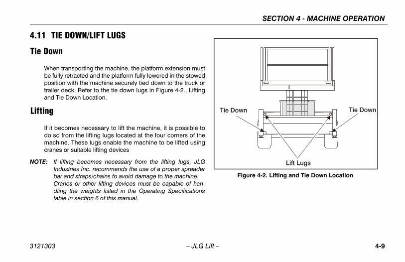
When transporting the machine, the platform extension mustbe fully retracted and the platform fully lowered in the stowedposition with the machine securely tied down to the truck ortrailer deck. Refer to the tie down lugs in Figure 4-2., Liftingand Tie Down Location.
Lifting
If it becomes necessary to lift the machine, it is possible todo so from the lifting lugs located at the four corners of themachine. These lugs enable the machine to be lifted usingcranes or suitable lifting devices
NOTE: If lifting becomes necessary from the lifting lugs, JLGIndustries Inc. recommends the use of a proper spreaderbar and straps/chains to avoid damage to the machine.Cranes or other lifting devices must be capable of han-dling the weights listed in the Operating Specificationstable in section 6 of this manual.
Lift Lugs
Tie DownTie Down
Figure 4-2. Lifting and Tie Down Location
3121303 – JLG Lift – 4-9
SECTION 4 - MACHINE OPERATION
4.12 TRANSPORT AND STORAGE OF THE MACHINE
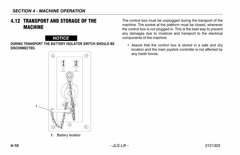
NOTICEDURING TRANSPORT THE BATTERY ISOLATOR SWITCH SHOULD BEDISCONNECTED.
The control box must be unplugged during the transport of themachine. The socket at the platform must be closed, wheneverthe control box is not plugged in. This is the best way to preventany damages due to moisture and transport to the electricalcomponents of the machine.
• Assure that the control box is stored in a safe and drylocation and the main joystick controller is not affected byany harsh forces.
1
1. Battery Isolator
4-10 – JLG Lift – 3121303
SECTION 5 - EMERGENCY PROCEDURES
SECTION 5. EMERGENCY PROCEDURES
5.1 GENERALThis section provides information on the procedures to befollowed and on the systems and controls to be used in theevent an emergency situation is encountered duringmachine operation. Prior to operation of the machine andperiodically thereafter, the entire operating manual, includingthis section, should be reviewed by all personnel whoseresponsibilities include any work or contact with themachine.
Emergency Stop SwitchThese large red buttons, one located outside the valve com-partment and one at the Platform Control Station, will imme-diately stop the machine when depressed.
NOTICECHECK MACHINE DAILY TO MAKE SURE EMERGENCY STOP BUTTONIS IN PLACE AND THAT GROUND CONTROL INSTRUCTIONS ARE INPLACE AND LEGIBLE.
Platform Caught OverheadIf the platform becomes jammed or snagged in overheadstructures or equipment, do not continue operation of themachine from either the platform or the ground until theoperator and all personnel are safely moved to a securelocation. Only then should an attempt be made to free theplatform using any necessary equipment and personnel. Donot operate controls to cause one or more wheels to leavethe ground.
Righting of Tipped MachineA forktruck of suitable capacity or equivalent equipmentshould be placed under the elevated side of the chassis, witha crane or other suitable lifting equipment used to lift theplatform while the chassis is lowered by the forklift or otherequipment.
Post-Incident InspectionFollowing any incident, thoroughly inspect the machine andtest all functions first from the ground controls, then from theplatform controls. Do not lift above 3 m (10 ft) until you aresecure that all damage has been repaired, if required, andthat all controls are operating correctly.
3121303 – JLG Lift – 5-1
SECTION 5 - EMERGENCY PROCEDURES
5.2 EMERGENCY OPERATIONUse of Ground Controls
NOTICEKNOW HOW TO USE THE GROUND CONTROLS IN AN EMERGENCY SIT-UATION.
Ground personnel must be thoroughly familiar with themachine operating characteristics and the ground controlfunctions. Training should include operation of the machine,review and understanding of this section and hands-on oper-ation of the controls in simulated emergencies.
Operator Unable to Control Machine1. Operate the machine from ground controls ONLY with
the assistance of other personnel and equipment (cranes, overhead hoists, etc.) as may be required to safely remove the danger or emergency condition.
2. Other qualified personnel on the platform may use the platform controls. DO NOT CONTINUE OPERATION IF CONTROLS DO NOT FUNCTION NORMALLY.
3. Cranes, forklift trucks or other equipment which may be available are to be used to remove platform occupants
and stabilize motion of the machine in case machine controls are inadequate or malfunction when used.
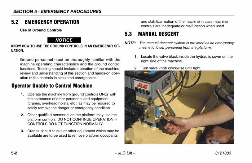
5.3 MANUAL DESCENT
NOTE: The manual descent system is provided as an emergencymeans to lower personnel from the platform.
1. Locate the valve block inside the hydraulic cover on the right side of the machine
2. Turn valve knob clockwise until tight..
5-2 – JLG Lift – 3121303
SECTION 5 - EMERGENCY PROCEDURES
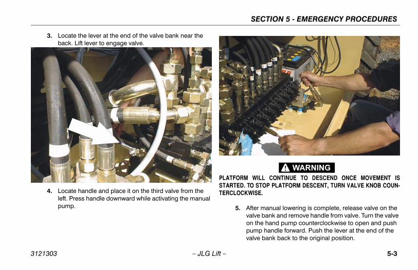
3. Locate the lever at the end of the valve bank near the back. Lift lever to engage valve.
4. Locate handle and place it on the third valve from the left. Press handle downward while activating the manual pump.
.
PLATFORM WILL CONTINUE TO DESCEND ONCE MOVEMENT ISSTARTED. TO STOP PLATFORM DESCENT, TURN VALVE KNOB COUN-TERCLOCKWISE.
5. After manual lowering is complete, release valve on the valve bank and remove handle from valve. Turn the valve on the hand pump counterclockwise to open and push pump handle forward. Push the lever at the end of the valve bank back to the original position.
3121303 – JLG Lift – 5-3
SECTION 5 - EMERGENCY PROCEDURES
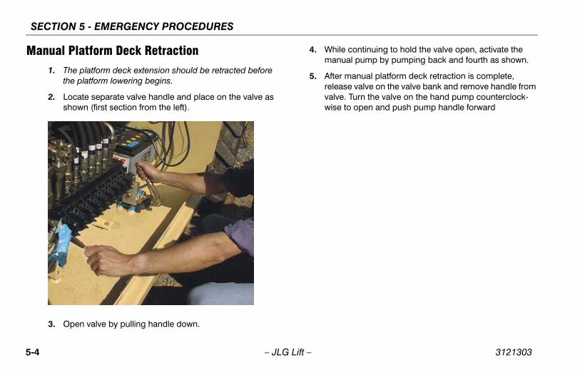
Manual Platform Deck Retraction1. The platform deck extension should be retracted before
the platform lowering begins.
2. Locate separate valve handle and place on the valve as shown (first section from the left).
3. Open valve by pulling handle down.
4. While continuing to hold the valve open, activate the manual pump by pumping back and fourth as shown.
5. After manual platform deck retraction is complete, release valve on the valve bank and remove handle from valve. Turn the valve on the hand pump counterclock-wise to open and push pump handle forward
5-4 – JLG Lift – 3121303
SECTION 5 - EMERGENCY PROCEDURES
5.4 EMERGENCY TOWING
RUNAWAY VEHICLE/MACHINE HAZARD. MACHINE HAS NO TOWINGBRAKES. TOWING VEHICLE MUST BE ABLE TO CONTROL MACHINE ATALL TIMES. ON-HIGHWAY TOWING NOT PERMITTED. FAILURE TO FOL-LOW INSTRUCTIONS COULD CAUSE SERIOUS INJURY OR DEATH.
MAXIMUM TOWING SPEED 5 M.P.H. (8 K.M.H.) FOR NO LONGER THAN30-45 MINUTES.
MAXIMUM TOWING GRADE 25%.
Prior to TowingPrior to towing the machine, complete the following:
DO NOT TOW MACHINE WITH ENGINE OPERATING OR DRIVE HUBSENGAGED.
1. Completely lower platform.
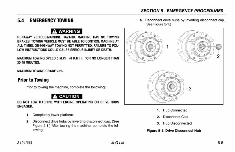
2. Disconnect drive hubs by inverting disconnect cap. (SeeFigure 5-1.) After towing the machine, complete the fol-lowing:
a. Reconnect drive hubs by inverting disconnect cap.(See Figure 5-1.)
1
2
3
Figure 5-1. Drive Disconnect Hub
1. Hub Connected
2. Disconnect Cap
3. Hub Disconnected
3121303 – JLG Lift – 5-5
SECTION 5 - EMERGENCY PROCEDURES
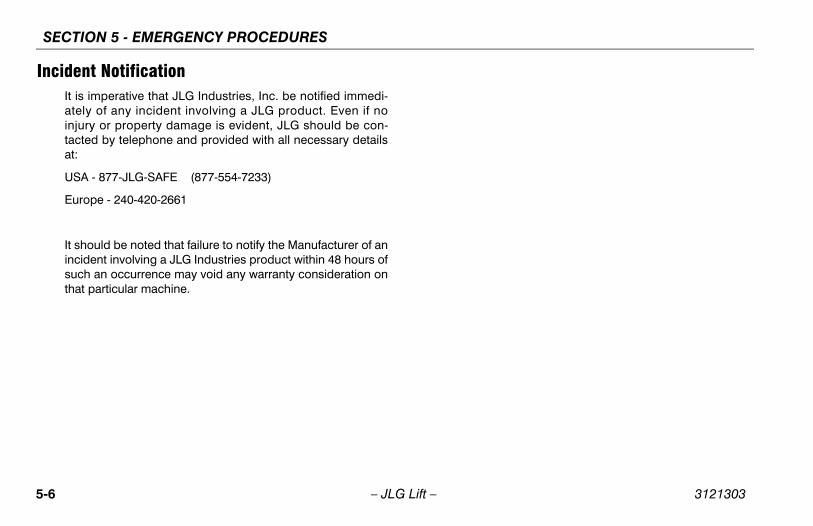
Incident NotificationIt is imperative that JLG Industries, Inc. be notified immedi-ately of any incident involving a JLG product. Even if noinjury or property damage is evident, JLG should be con-tacted by telephone and provided with all necessary detailsat:
USA - 877-JLG-SAFE (877-554-7233)
Europe - 240-420-2661
It should be noted that failure to notify the Manufacturer of anincident involving a JLG Industries product within 48 hours ofsuch an occurrence may void any warranty consideration onthat particular machine.
5-6 – JLG Lift – 3121303
SECTION 6 - GENERAL SPECIFICATIONS AND OPERATOR MAINTENANCE
SECTION 6. GENERAL SPECIFICATIONS AND OPERATOR MAINTENANCE
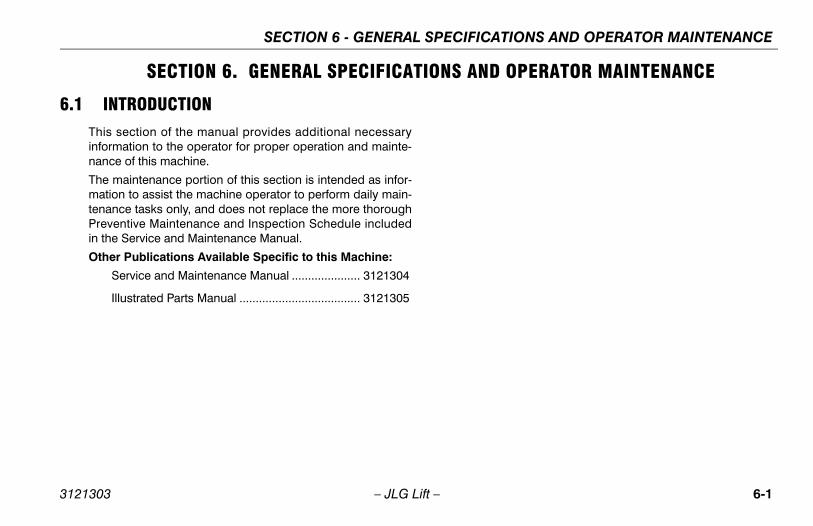
6.1 INTRODUCTIONThis section of the manual provides additional necessaryinformation to the operator for proper operation and mainte-nance of this machine.
The maintenance portion of this section is intended as infor-mation to assist the machine operator to perform daily main-tenance tasks only, and does not replace the more thoroughPreventive Maintenance and Inspection Schedule includedin the Service and Maintenance Manual.
Other Publications Available Specific to this Machine:
Service and Maintenance Manual ..................... 3121304
Illustrated Parts Manual ..................................... 3121305
3121303 – JLG Lift – 6-1
SECTION 6 - GENERAL SPECIFICATIONS AND OPERATOR MAINTENANCE
6.2 OPERATING SPECIFICATIONS
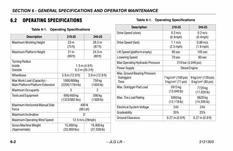
Table 6-1. Operating Specifications
Description 210-25 245-25
Maximum Working Height 23 m (75 ft)
26.5 m (87 ft)
Maximum Platform Height 21 m (69 ft)
24.5 m (80 ft)
Turning Radius InsideOutside
1.5 m (4.9 ft)6.2 m (20.3 ft)
Wheelbase 3.9 m (12.8 ft) 3.9 m (12.8 ft)
Max Work Load (Capacity) - Main Platform/Platform Extension
1000/800kg (2205/1764 lb)
750 kg (1650 lb)
Maximum Occupants 5 2
Tools and Equipment 600/400 kg (1323/882 lbs)
590 kg (1300 lb)
Maximum Horizontal Manual Side Force
400 N (90 Lbf)
Maximum Inclination 3°
Maximum Operating Wind Speed 12.5 m/s (28mph)
Gross Machine Weight (Approximate)
15,000 kg (33,069 lbs)
16,800 kg (37,038 lb)
Drive Speed (slow) 0.2 m/s (0.4mph)
0.2 m/s (0.4mph)
Drive Speed (fast) 1.1 m/s (2.5 mph)
0.86 m/s (1.9 mph)
Lift Speed (platform empty) 95 sec 105 sec
Lowering Speed 70 sec 80 sec
Max Operating Hydraulic Pressure 210 bar (3,046 psi)
Power Supply Diesel Engine
Max. Ground Bearing Pressure: Outriggers Tires
7 kg/cm² (100 psi)5 kg/cm² (71 psi)
9 kg/cm² (128 psi)6 kg/cm² (85 psi)
Max. Outrigger Pad Load 5915 kg(13,040 lb)
7720 kg
(17,020 lb)
Max. Tire Load Rating 5950 kg(13,118 lb)
6620 kg(14,595 lb)
Electrical System Voltage 24V 24V
Gradeability 35% 25%
Ground Clearance 0.27 m (0.9 ft) 0.27 m (0.9 ft)
Table 6-1. Operating Specifications
Description 210-25 245-25
6-2 – JLG Lift – 3121303
SECTION 6 - GENERAL SPECIFICATIONS AND OPERATOR MAINTENANCE
Dimensional Data Capacities
Tires
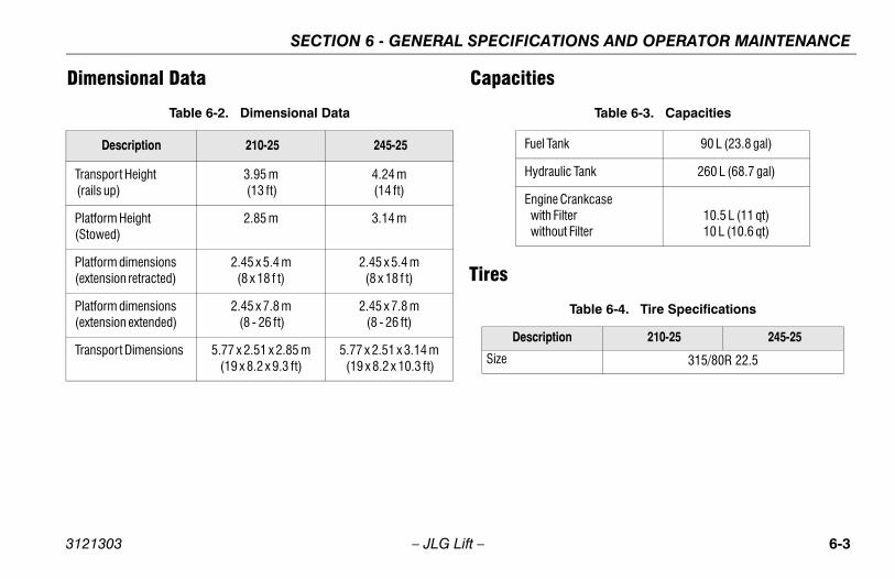
Table 6-2. Dimensional Data
Description 210-25 245-25
Transport Height (rails up)
3.95 m (13 ft)
4.24 m (14 ft)
Platform Height (Stowed)
2.85 m 3.14 m
Platform dimensions (extension retracted)
2.45 x 5.4 m (8 x 18 f t)
2.45 x 5.4 m (8 x 18 f t)
Platform dimensions (extension extended)
2.45 x 7.8 m (8 - 26 ft)
2.45 x 7.8 m (8 - 26 ft)
Transport Dimensions 5.77 x 2.51 x 2.85 m (19 x 8.2 x 9.3 ft)
5.77 x 2.51 x 3.14 m (19 x 8.2 x 10.3 ft)
Table 6-3. Capacities
Fuel Tank 90 L (23.8 gal)
Hydraulic Tank 260 L (68.7 gal)
Engine Crankcase with Filter without Filter
10.5 L (11 qt)10 L (10.6 qt)
Table 6-4. Tire Specifications
Description 210-25 245-25
Size 315/80R 22.5
3121303 – JLG Lift – 6-3
SECTION 6 - GENERAL SPECIFICATIONS AND OPERATOR MAINTENANCE
Engine Component Weights
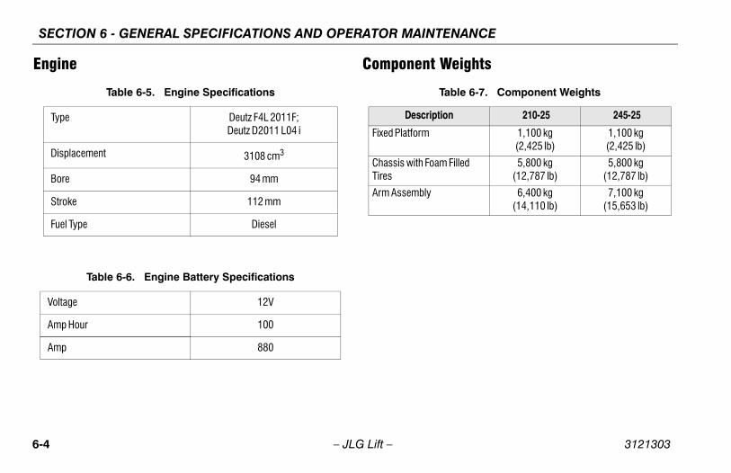
Table 6-5. Engine Specifications
Type Deutz F4L 2011F; Deutz D2011 L04 i
Displacement 3108 cm3
Bore 94 mm
Stroke 112 mm
Fuel Type Diesel
Table 6-6. Engine Battery Specifications
Voltage 12V
Amp Hour 100
Amp 880
Table 6-7. Component Weights
Description 210-25 245-25
Fixed Platform 1,100 kg(2,425 lb)
1,100 kg(2,425 lb)
Chassis with Foam Filled Tires
5,800 kg (12,787 lb)
5,800 kg (12,787 lb)
Arm Assembly 6,400 kg (14,110 lb)
7,100 kg(15,653 lb)
6-4 – JLG Lift – 3121303
SECTION 6 - GENERAL SPECIFICATIONS AND OPERATOR MAINTENANCE
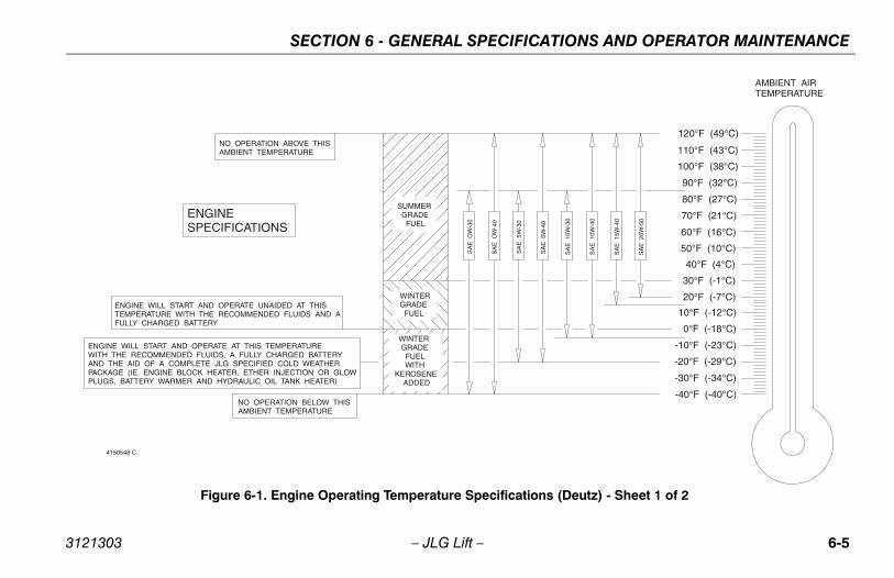
NO OPERATION ABOVE THISAMBIENT TEMPERATURE
ENGINESPECIFICATIONS
SUMMER GRADE FUEL
WINTERGRADE FUEL
WINTER GRADE FUEL WITHKEROSENE ADDED
ENGINE WILL START AND OPERATE UNAIDED AT THISTEMPERATURE WITH THE RECOMMENDED FLUIDS AND AFULLY CHARGED BATTERY
ENGINE WILL START AND OPERATE AT THIS TEMPERATUREWITH THE RECOMMENDED FLUIDS, A FULLY CHARGED BATTERYAND THE AID OF A COMPLETE JLG SPECIFIED COLD WEATHERPACKAGE (IE. ENGINE BLOCK HEATER, ETHER INJECTION OR GLOWPLUGS, BATTERY WARMER AND HYDRAULIC OIL TANK HEATER)
NO OPERATION BELOW THISAMBIENT TEMPERATURE
AMBIENT AIRTEMPERATURE
SA
E O
W-3
0
SA
E O
W-4
0
SA
E 5
W-3
0
SA
E 5
W-4
0
SA
E 1
0W-3
0
SA
E 1
0W-4
0
SA
E 1
5W-4
0
SA
E 2
0W-5
0
120°F (49°C)
110°F (43°C)
100°F (38°C)
90°F (32°C)
80°F (27°C)
70°F (21°C)
60°F (16°C)
50°F (10°C)
40°F (4°C)
30°F (-1°C)
20°F (-7°C)
10°F (-12°C)
0°F (-18°C)
-10°F (-23°C)
-20°F (-29°C)
-30°F (-34°C)
-40°F (-40°C)
4150548 C
Figure 6-1. Engine Operating Temperature Specifications (Deutz) - Sheet 1 of 2
3121303 – JLG Lift – 6-5
SECTION 6 - GENERAL SPECIFICATIONS AND OPERATOR MAINTENANCE
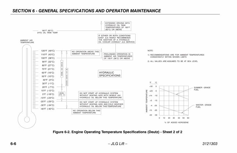
NOTE:
1) RECOMMENDATIONS ARE FOR AMBIENT TEMPERATURES CONSISTANTLY WITHIN SHOWN LIMITS
2) ALL VALUES ARE ASSUMED TO BE AT SEA LEVEL
SUMMER - GRADEFUEL
WINTER - GRADEFUEL
% OF ADDED KEROSENE
+32 0
+23 -5
+14 -10
+5 -15
-4 -20
-13 -25
-22 -30
0 10 20 30 40 50 60
°F °C
AM
BIE
NT
TE
MP
ER
ATU
RE
120°F (49°C)
110°F (43°C)
100°F (38°C)
90°F (32°C)
80°F (27°C)
70°F (21°C)
60°F (16°C)
50°F (10°C)
40°F (4°C)
30°F (-1°C)
20°F (-7°C)
10°F (-12°C)
0°F (-18°C)
-10°F (-23°C)
-20°F (-29°C)
-30°F (-34°C)
-40°F (-40°C)
AMBIENT AIRTEMPERATURE
180°F (82°C)(HYD. OIL TANK TEMP.
NO OPERATION BELOW THISAMBIENT TEMPERATURE
DO NOT START UP HYDRAULIC SYSTEMWITHOUT HEATING AIDS AND COLD WEATHERHYDRAULIC OIL BELOW THIS TEMPERATURE
DO NOT START UP HYDRAULIC SYSTEMWITHOUT HEATING AIDS WITH MOBILE 424HYDRAULIC OIL BELOW THIS TEMPERATURE
HYDRAULICSPECIFICATIONS
NO OPERATION ABOVE THISAMBIENT TEMPERATURE PROLONGED OPERATION IN
AMBIENT AIR TEMPERATURESOF 100°F (38°C) OR ABOVE
IF EITHER OR BOTH CONDITIONSEXIST JLG HIGHLY RECOMMENDSTHE ADDITION OF A HYDRAULICOIL COOLER (CONSULT JLG SERVICE)
EXTENDED DRIVING WITHHYDRAULIC OIL TANKTEMPERATURES OF 180°F(82°C) OR ABOVE
MO
BIL
424
10W
-30
EX
XO
N U
NIV
IS H
VI
26
MOBILDTE 13
Figure 6-2. Engine Operating Temperature Specifications (Deutz) - Sheet 2 of 2
6-6 – JLG Lift – 3121303
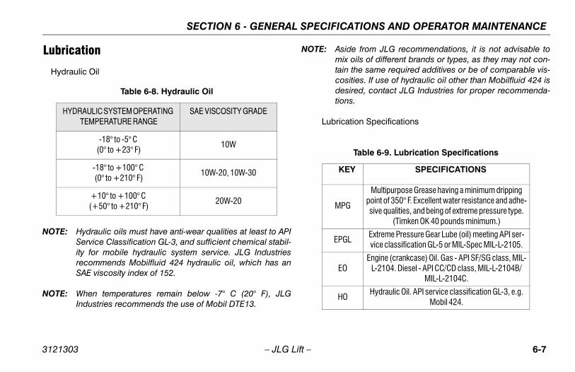
SECTION 6 - GENERAL SPECIFICATIONS AND OPERATOR MAINTENANCE
Lubrication
Hydraulic Oil
NOTE: Hydraulic oils must have anti-wear qualities at least to APIService Classification GL-3, and sufficient chemical stabil-ity for mobile hydraulic system service. JLG Industriesrecommends Mobilfluid 424 hydraulic oil, which has anSAE viscosity index of 152.
NOTE: When temperatures remain below -7° C (20° F), JLGIndustries recommends the use of Mobil DTE13.
NOTE: Aside from JLG recommendations, it is not advisable tomix oils of different brands or types, as they may not con-tain the same required additives or be of comparable vis-cosities. If use of hydraulic oil other than Mobilfluid 424 isdesired, contact JLG Industries for proper recommenda-tions.
Lubrication Specifications
Table 6-8. Hydraulic Oil
HYDRAULIC SYSTEM OPERATING TEMPERATURE RANGE
SAE VISCOSITY GRADE
-18° to -5° C (0° to +23° F)
10W
-18° to +100° C (0° to +210° F)
10W-20, 10W-30
+10° to +100° C (+50° to +210° F)
20W-20
Table 6-9. Lubrication Specifications
KEY SPECIFICATIONS
MPG
Multipurpose Grease having a minimum dripping point of 350° F. Excellent water resistance and adhe-sive qualities, and being of extreme pressure type.
(Timken OK 40 pounds minimum.)
EPGLExtreme Pressure Gear Lube (oil) meeting API ser-vice classification GL-5 or MIL-Spec MIL-L-2105.
EOEngine (crankcase) Oil. Gas - API SF/SG class, MIL-
L-2104. Diesel - API CC/CD class, MIL-L-2104B/MIL-L-2104C.
HOHydraulic Oil. API service classification GL-3, e.g.
Mobil 424.
3121303 – JLG Lift – 6-7
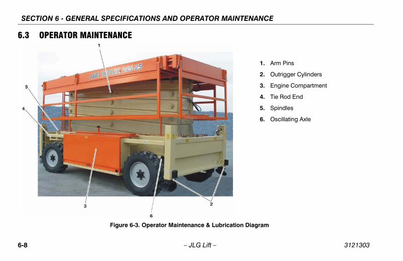
SECTION 6 - GENERAL SPECIFICATIONS AND OPERATOR MAINTENANCE
6.3 OPERATOR MAINTENANCE
Figure 6-3. Operator Maintenance & Lubrication Diagram
1. Arm Pins
2. Outrigger Cylinders
3. Engine Compartment
4. Tie Rod End
5. Spindles
6. Oscillating Axle
6-8 – JLG Lift – 3121303
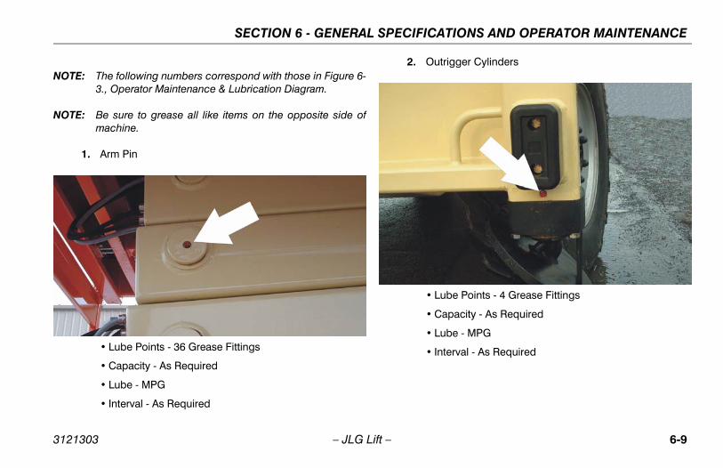
SECTION 6 - GENERAL SPECIFICATIONS AND OPERATOR MAINTENANCE
NOTE: The following numbers correspond with those in Figure 6-3., Operator Maintenance & Lubrication Diagram.
NOTE: Be sure to grease all like items on the opposite side ofmachine.
1. Arm Pin
• Lube Points - 36 Grease Fittings
• Capacity - As Required
• Lube - MPG
• Interval - As Required
2. Outrigger Cylinders
• Lube Points - 4 Grease Fittings
• Capacity - As Required
• Lube - MPG
• Interval - As Required
3121303 – JLG Lift – 6-9
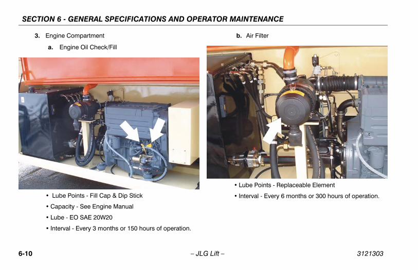
SECTION 6 - GENERAL SPECIFICATIONS AND OPERATOR MAINTENANCE
3. Engine Compartment
a. Engine Oil Check/Fill
• Lube Points - Fill Cap & Dip Stick
• Capacity - See Engine Manual
• Lube - EO SAE 20W20
• Interval - Every 3 months or 150 hours of operation.
b. Air Filter
• Lube Points - Replaceable Element
• Interval - Every 6 months or 300 hours of operation.
6-10 – JLG Lift – 3121303
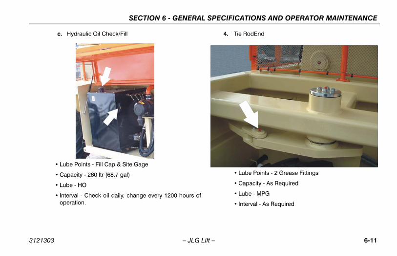
SECTION 6 - GENERAL SPECIFICATIONS AND OPERATOR MAINTENANCE
c. Hydraulic Oil Check/Fill
• Lube Points - Fill Cap & Site Gage
• Capacity - 260 ltr (68.7 gal)
• Lube - HO
• Interval - Check oil daily, change every 1200 hours ofoperation.
4. Tie RodEnd
• Lube Points - 2 Grease Fittings
• Capacity - As Required
• Lube - MPG
• Interval - As Required
3121303 – JLG Lift – 6-11
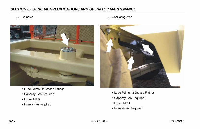
SECTION 6 - GENERAL SPECIFICATIONS AND OPERATOR MAINTENANCE
5. Spindles
• Lube Points - 2 Grease Fittings
• Capacity - As Required
• Lube - MPG
• Interval - As required
6. Oscillating Axle
• Lube Points - 3 Grease Fittings
• Capacity - As Required
• Lube - MPG
• Interval - As Required
6-12 – JLG Lift – 3121303
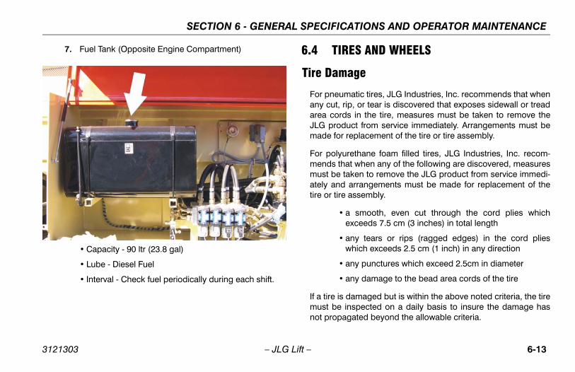
SECTION 6 - GENERAL SPECIFICATIONS AND OPERATOR MAINTENANCE
7. Fuel Tank (Opposite Engine Compartment)
• Capacity - 90 ltr (23.8 gal)
• Lube - Diesel Fuel
• Interval - Check fuel periodically during each shift.
6.4 TIRES AND WHEELS
Tire Damage
For pneumatic tires, JLG Industries, Inc. recommends that whenany cut, rip, or tear is discovered that exposes sidewall or treadarea cords in the tire, measures must be taken to remove theJLG product from service immediately. Arrangements must bemade for replacement of the tire or tire assembly.
For polyurethane foam filled tires, JLG Industries, Inc. recom-mends that when any of the following are discovered, measuresmust be taken to remove the JLG product from service immedi-ately and arrangements must be made for replacement of thetire or tire assembly.
• a smooth, even cut through the cord plies whichexceeds 7.5 cm (3 inches) in total length
• any tears or rips (ragged edges) in the cord plieswhich exceeds 2.5 cm (1 inch) in any direction
• any punctures which exceed 2.5cm in diameter
• any damage to the bead area cords of the tire
If a tire is damaged but is within the above noted criteria, the tiremust be inspected on a daily basis to insure the damage hasnot propagated beyond the allowable criteria.
3121303 – JLG Lift – 6-13
SECTION 6 - GENERAL SPECIFICATIONS AND OPERATOR MAINTENANCE
Tire Replacement
JLG recommends a replacement tire be the same size, ply andbrand as originally installed on the machine. lease refer to theJLG Parts Manual for the part number of the approved tires for aparticular machine and model. If not using a JLG approvedreplacement tire, we recommend that replacement tires havethe following characteristics:
• Equal or greater ply/load rating and size of original
• Tire tread contact width equal or greater than original
• Wheel diameter, width, and offset dimensions equal tothe original.
Unless specifically approved by JLG Industries Inc. do notreplace a foam filled tire assembly with a pneumatic tire. Whenselecting and installing a replacement tire, ensure that all tiresare inflated to the pressure recommended by JLG. Due to sizevariations between tire brands, both tires on the same axleshould be the same.
Wheel ReplacementThe rims installed on each product model have beendesigned for stability requirements which consist of trackwidth, tire pressure, and load capacity. Size changes such asrim width, center piece location, larger or smaller diameter,etc., without written factory recommendations, may result inan unsafe condition regarding stability.
6-14 – JLG Lift – 3121303
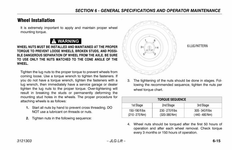
SECTION 6 - GENERAL SPECIFICATIONS AND OPERATOR MAINTENANCE
Wheel InstallationIt is extremely important to apply and maintain proper wheelmounting torque.
WHEEL NUTS MUST BE INSTALLED AND MAINTAINED AT THE PROPERTORQUE TO PREVENT LOOSE WHEELS, BROKEN STUDS, AND POSSI-BLE DANGEROUS SEPARATION OF WHEEL FROM THE AXLE. BE SURETO USE ONLY THE NUTS MATCHED TO THE CONE ANGLE OF THEWHEEL.
Tighten the lug nuts to the proper torque to prevent wheels fromcoming loose. Use a torque wrench to tighten the fasteners. Ifyou do not have a torque wrench, tighten the fasteners with alug wrench, then immediately have a service garage or dealertighten the lug nuts to the proper torque. Over-tightening willresult in breaking the studs or permanently deforming themounting stud holes in the wheels. The proper procedure forattaching wheels is as follows:
1. Start all nuts by hand to prevent cross threading. DO NOT use a lubricant on threads or nuts.
2. Tighten nuts in the following sequence:
.
3. The tightening of the nuts should be done in stages. Fol-lowing the recommended sequence, tighten the nuts perwheel torque chart.
4. Wheel nuts should be torqued after the first 50 hours ofoperation and after each wheel removal. Check torqueevery 3 months or 150 hours of operation.
TORQUE SEQUENCE
1st Stage 2nd Stage 3rd Stage
150-190 ft lbs(210 - 270 Nm)
230 - 270 ft lbs(320-380 Nm)
305 - 343 ft lbs( 440 - 480 Nm)
1
2
3 4
5
6
6 LUG PATTERN
3121303 – JLG Lift – 6-15
SECTION 6 - GENERAL SPECIFICATIONS AND OPERATOR MAINTENANCE
6.5 LSS TESTING AND EVALUATION
Confirm Load Sensing System Performance with CalibratedWeights:
1. Operate the vehicle from Ground Control and place the platform in the fully stowed position for safety. Place 120% of the machines rated load in the center of the platform and ensure that the overload visual and audible warnings are active. Reduce the platform load to 100% rated load and ensure that the warnings are not active. For vehicles with multiple capacities, evaluate each operating mode with the proper rated load.
6-16 – JLG Lift – 3121303
SECTION 7 - INSPECTION AND REPAIR LOG
SECTION 7. INSPECTION AND REPAIR LOG
Table 7-1. Inspection and Repair Log
Date Comments
3121303 – JLG Lift – 7-1
SECTION 7 - INSPECTION AND REPAIR LOG
Table 7-1. Inspection and Repair Log
Date Comments
7-2 – JLG Lift – 3121303
TRA
NS
FE
R O
F O
WN
ER
SH
IP
To P
rod
uct
Ow
ner
:If
yo
u n
ow
ow
n b
ut
AR
E N
OT
th
e o
rig
inal
pu
rch
aser
of
the
pro
du
ct c
over
ed b
y th
is
man
ual
, we
wo
uld
like
to
kn
ow
wh
o y
ou
are
. Fo
r th
e p
urp
ose
of
rece
ivin
g s
afet
y-re
late
d
bulle
tin
s, it
is v
ery
imp
ort
ant
to k
eep
JL
G In
du
stri
es, I
nc.
up
dat
ed w
ith
th
e cu
rren
t ow
ner
ship
of
all J
LG
pro
du
cts.
JL
G m
ain
tain
s ow
ner
info
rmat
ion
for
each
JL
G p
rod
uct
an
d u
ses
this
info
rmat
ion
in c
ases
wh
ere
ow
ner
no
tifi
cati
on
is n
eces
sary
.P
leas
e u
se t
his
form
to
pro
vid
e JL
G w
ith
up
dat
ed in
form
atio
n w
ith
reg
ard
to
th
e cu
rren
t ow
ner
ship
of
JLG
pro
du
cts.
Ple
ase
retu
rn c
om
ple
ted
form
to
th
e JL
G P
rod
uct
S
afet
y &
Rel
iab
ility
Dep
artm
ent
via
facs
imile
or
mai
l to
ad
dre
ss a
s sp
ecif
ied
bel
ow
.
Th
ank
You
,P
rod
uct
Saf
ety
& R
elia
bili
ty D
epar
tmen
tJL
G In
du
stri
es, I
nc.
1322
4 F
ou
nta
inh
ead
Pla
zaH
ager
stow
n, M
D21
742
US
ATe
lep
ho
ne:
+1-
717-
485-
6591
Fax:
+1-
301-
745-
3713
NO
TE
: L
ease
d o
r re
nte
d u
nit
s sh
ou
ld n
ot
be
incl
ud
ed o
n t
his
form
.
Mfg
. Mo
del
: __
____
____
___ _
____
____
____
____
____
____
____
____
____
____
____
____
_
Ser
ial N
um
ber
: __
____
____
____
____
____
____
____
____
____
____
____
____
____
____
__
Pre
vio
us
Ow
ner
: __
____
____
____
____
____
____
____
____
____
____
____
____
____
____
_
Ad
dre
ss:
____
____
____
____
____
____
____
____
____
____
____
____
____
____
____
____
_
____
____
____
____
____
____
____
____
____
____
____
____
____
____
____
____
____
____
_
Co
un
try:
__
____
____
____
____
____
___
Tele
ph
on
e: (
____
___)
___
____
____
____
____
_
Dat
e o
f Tr
ansf
er:
____
____
____
____
____
____
____
____
_
Cu
rren
t O
wn
er:
____
____
____
____
____
____
____
____
____
____
____
____
____
____
____
Ad
dre
ss:
____
____
____
____
____
____
____
____
____
____
____
____
____
____
____
____
_
____
____
____
____
____
____
____
____
____
____
____
____
____
____
____
____
____
____
_
Co
un
try:
__
____
____
____
____
____
___
Tele
ph
on
e: (
____
___)
___
____
____
____
____
_
Wh
o in
yo
ur
org
aniz
atio
n s
ho
uld
we
no
tify
?
Nam
e:
____
____
____
____
____
____
____
____
____
____
____
____
____
____
____
____
___
Tit
le:_
____
____
____
____
____
____
____
____
____
____
____
____
____
____
____
____
___
��
����
���
�
��
� ��
�
�
��
��


Corporate Office
JLG Industries, Inc.
1 JLG Drive
McConnellsburg PA. 17233-9533
USA
(717) 485-5161
(717) 485-6417
JLG Worldwide LocationsJLG Industries (Australia)P.O. Box 511911 Bolwarra RoadPort MacquarieN.S.W. 2444Australia
+61 2 65 811111
+61 2 65 810122
JLG Latino Americana Ltda.Rua Eng. Carlos Stevenson,80-Suite 7113092-310 Campinas-SPBrazil
+55 19 3295 0407
+55 19 3295 1025
JLG Industries (UK) LtdBentley HouseBentley AvenueMiddletonGreater ManchesterM24 2GP - England
+44 (0)161 654 1000
+44 (0)161 654 1001
JLG France SASZ.I. de Baulieu47400 FauilletFrance
+33 (0)5 53 88 31 70
+33 (0)5 53 88 31 79
JLG Deutschland GmbHMax-Planck-Str. 21D - 27721 Ritterhude - IhlpohlGermany
+49 (0)421 69 350 20
+49 (0)421 69 350 45
JLG Equipment Services Ltd.Rm 1107 Landmark North39 Lung Sum AvenueSheung Shui N. T.Hong Kong
(852) 2639 5783
(852) 2639 5797
JLG Industries (Italia) s.r.l.Via Po. 2220010 Pregnana Milanese - MIItaly
+39 029 359 5210
+39 029 359 5845
JLG Europe B.V.Polaris Avenue 632132 JH HoofddorpThe Netherlands
+31 (0)23 565 5665
+31 (0)23 557 2493
JLG PolskaUI. Krolewska00-060 WarsawaPoland
+48 (0)914 320 245
+48 (0)914 358 200
JLG Industries (Scotland)Wright Business Centre1 Lonmay RoadQueenslie, Glasgow G33 4ELScotland
+44 (0)141 781 6700
+44 (0)141 773 1907
Plataformas Elevadoras JLG Iberica, S.L.Trapadella, 2P.I. Castellbisbal Sur08755 Castellbisbal, BarcelonaSpain
+34 93 772 4700
+34 93 771 1762
JLG Sverige ABEnkopingsvagen 150Box 704SE - 176 27 JarfallaSweden
+46 (0)850 659 500
+46 (0)850 659 534
www.jlg.com
3121303