one hundred years of aircraft electronics
TRANSCRIPT
JOURNAL OF GUIDANCE CONTROL AND DYNAMICS
Vol 26 No 2 MarchndashApril 2003
One Hundred Years of Aircraft Electronics
Myron KaytonKayton Engineering Company Santa Monica California 90406
I Introduction
T HE purpose of this paper is to review the progress of aircraftelectronics during the hundred years since the rst controlled
ight by the Wright brothers and to project into the rst decades ofthe 21st century The paper makes occasional reference to mannedspacecraft and none to boosters which are arts unto themselvesElectronics for aircraft are often called ldquoavionicsrdquo Electronics forspacecraftand automobilesare either called avionicsor ldquoastrionicsrdquoand ldquovetronicsrdquo respectively
Human ight was almost entirely invented in Europe after thin-wall steel tubing became available in the 1880s Among the rstrecorded ights are Otto Lilienthalrsquos unpowered hang gliders inthe 1890s and Clement Aderrsquos steam-powered hang gliders TheWright brothers in far off 1903 America were the rst to con-trol a gasoline-powered wood-and-wire biplane in three axes byuse of a front-mountedelevator for pitch control a marine-inspiredrudder for side slip and wing-warp roll control (revived in 1977for the human-powered Gossamer Condor) The Wrights used alever for pitch control and a hip harness for roll control At rstthey coupled the rudder to wing warp but later added a secondlever for the rudder1 By the early 1910s Farmanrsquos and Bleriotrsquosaircraft were in the con guration we know today aft rudder andtailplane hinged control surfaces pilotrsquos stick and rudder pedalstractor propeller and gasoline engine After Europe self-destructedduring World War I the focus of aviation innovation moved to theUnited States and has remained here ever since
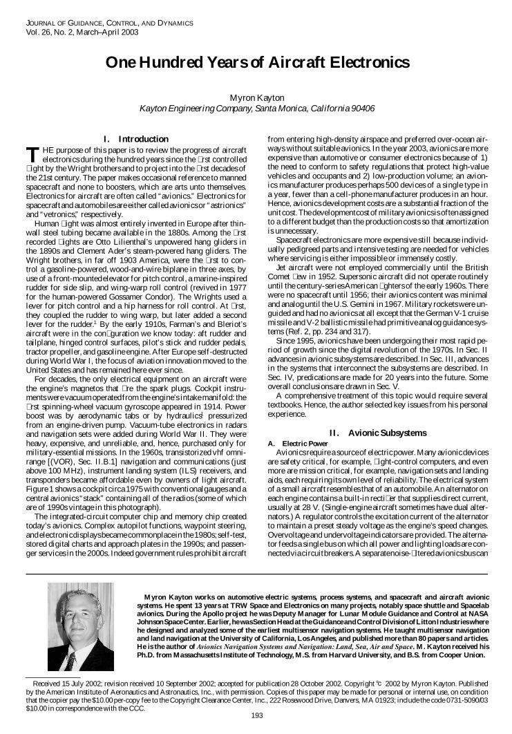
For decades the only electrical equipment on an aircraft werethe enginersquos magnetos that re the spark plugs Cockpit instru-ments were vacuumoperatedfrom the enginersquos intake manifold the rst spinning-wheel vacuum gyroscope appeared in 1914 Powerboost was by aerodynamic tabs or by hydraulics1 pressurizedfrom an engine-driven pump Vacuum-tube electronics in radarsand navigation sets were added during World War II They wereheavy expensive and unreliable and hence purchased only formilitary-essential missions In the 1960s transistorized vhf omni-range [(VOR) Sec IIB1] navigation and communications (justabove 100 MHz) instrument landing system (ILS) receivers andtransponders became affordable even by owners of light aircraftFigure 1 shows a cockpit circa 1975 with conventionalgauges and acentral avionics ldquostackrdquo containingall of the radios (some of whichare of 1990s vintage in this photograph)
The integrated-circuit computer chip and memory chip createdtodayrsquos avionics Complex autopilot functions waypoint steeringandelectronicdisplaysbecamecommonplacein the1980sself-teststored digital charts and approach plates in the 1990s and passen-ger services in the 2000s Indeed government rules prohibit aircraft
Myron Kayton works on automotive electric systems process systems and spacecraft and aircraft avionicsystems He spent 13 years at TRW Space and Electronics on many projects notably space shuttle and Spacelabavionics During the Apollo project he was Deputy Manager for Lunar Module Guidance and Control at NASAJohnsonSpaceCenter Earlier he wasSection Head at the GuidanceandControlDivisionofLittonIndustries wherehe designed and analyzed some of the earliest multisensor navigation systems He taught multisensor navigationand land navigation at the University of California Los Angeles and published more than 80 papers and articlesHe is the author of Avionics Navigation Systems and Navigation Land Sea Air and Space M Kayton received hisPhD from Massachusetts Institute of Technology MS from Harvard University and BS from Cooper Union
Received 15 July 2002 revision received 10 September 2002 accepted for publication 28 October 2002 Copyright cdeg 2002 by Myron Kayton Publishedby the American Institute of Aeronautics and Astronautics Inc with permission Copies of this paper may be made for personal or internal use on conditionthat the copier pay the $1000 per-copy fee to the Copyright Clearance Center Inc 222 Rosewood Drive Danvers MA 01923 include the code 0731-509003$1000 in correspondence with the CCC
from entering high-density airspace and preferred over-ocean air-ways without suitable avionics In the year 2003 avionics are moreexpensive than automotive or consumer electronics because of 1)the need to conform to safety regulations that protect high-valuevehicles and occupants and 2) low-production volume an avion-ics manufacturer produces perhaps 500 devices of a single type ina year fewer than a cell-phone manufacturer produces in an hourHence avionics development costs are a substantial fraction of theunit costThe developmentcostofmilitaryavionicsis oftenassignedto a different budget than the production costs so that amortizationis unnecessary
Spacecraft electronics are more expensive still because individ-ually pedigreed parts and intensive testing are needed for vehicleswhere servicing is either impossible or immensely costly
Jet aircraft were not employed commercially until the BritishComet ew in 1952 Supersonic aircraft did not operate routinelyuntil the century-seriesAmerican ghters of the early 1960s Therewere no spacecraft until 1956 their avionics content was minimaland analog until the US Gemini in 1967 Military rocketswere un-guided and had no avionics at all except that the German V-1 cruisemissile and V-2 ballisticmissile had primitive analog guidance sys-tems (Ref 2 pp 234 and 317)
Since 1995 avionics have been undergoing their most rapid pe-riod of growth since the digital revolution of the 1970s In Sec IIadvances in avionic subsystems are described In Sec III advancesin the systems that interconnect the subsystems are described InSec IV predications are made for 20 years into the future Someoverall conclusions are drawn in Sec V
A comprehensive treatment of this topic would require severaltextbooks Hence the author selected key issues from his personalexperience
II Avionic SubsystemsA Electric Power
Avionics require a sourceof electricpower Many avionicdevicesare safety critical for example ight-control computers and evenmore are mission critical for example navigation sets and landingaids each requiring its own level of reliabilityThe electrical systemof a small aircraft resembles that of an automobileAn alternatoroneach engine contains a built-in recti er that supplies direct currentusually at 28 V (Single-engine aircraft sometimes have dual alter-nators) A regulator controls the excitation current of the alternatorto maintain a preset steady voltage as the enginersquos speed changesOvervoltage and undervoltageindicators are provided The alterna-tor feeds a single bus on which all power and lighting loads are con-nectedvia circuitbreakersA separatenoise- lteredavionicsbuscan
193
194 KAYTON
Fig 1 Cessna-210 cockpit circa 1975 with dedicated gauges 1990sloran and GPS installed in the avionics stack between the pilots (photo-graph by author)
be switched to the mainbusThe alternatorcontinuouslychargesoneor more batteries The crew can manually select alternatorbatterypower or battery-onlypower (in case of alternator failure)
In large aircraft each engine drives an alternator that generatesthree-phase power In older aircraft a hydromechanical constant-speed drive maintained the alternator at constant speed generating115 V at 400 Hz even as the engine speed varied from idle to fullpower Multiple ac generators must either be synchronized or thebuses isolated from each other during switching In newer aircraft(Boeing 777 MD-90) the alternator is rigidly connected to theengine so that its speed varies Recti er banks and electronics (in-verters and converters)convert the variable-frequencyac to 24-V dcand 400-Hz constant-frequencyac There has been some interest inallowing thedistributionfrequencyto varywhich would complicatethe power converters within each electronic device
There has always been development activity on ac systems atfrequencies of 800 Hz and higher to reduce the weight of wiringmotors and transformers There have been efforts to raise the am-plitude above 28 and 120 V to reduce current in the distributionwiring In all-electric automobiles and in experimental suspensionand engine-valvecontrolson gasolineautomobiles350-V dc poweris already used The US F-22 ghter and AH-64 helicopter dis-tribute power at 270 V dc whereas Airbus plans to distribute at380 V dc on future airlinersStudies have been done for distributionas high as 10000-V dc The safety risk to maintenance technicianscrews and passengersfrom multihundred-voltpower is yet to be un-derstood Higher voltages will save wire weight but will exacerbatedestructive arcing from aged and frayed wires (Sec IIIA)
Each alternator drives main buses to which loads are connectedby circuit breakers the return is via the three-phaseneutral in an acsystem A large aircraft will have 2000 electrically powered unitseach one requiring a circuit breaker Safety-critical loads (cabinlights instruments) are connected to an emergency bus which isswitchable to the ac buses and to a battery that is kept charged bythe alternatorsSometimes essential loads are assigned to multiple
buses such as an ldquoinstrument busrdquo (for safety) and a ldquoradio busrdquo(for dispatch) Bus interties have been manually switched but areincreasingly automated for example utilizing software tables thatidentify the loads required in each mission phase under variousfailure conditions Power systems are monitored for under- andovervoltage under- and overfrequency current and temperatureThe monitor circuits must themselves be tested periodicallyat eachpower-up
Circuit breakers are usually located in a side panel or overheadpanel The breakers trip automatically after a brief time delay fol-lowing the onset of excess current In most aircraft the breakerscan be opened and closed (reset) manually There is a trend towardlocating solid-state breakers remotely (with remote manual engageand disengage)to avoid bringing power wiring onto the ight deckThe result is a saving in wire weight and a reduction in re haz-ard This has been done in many automobile circuits since the late1980s Remote circuit breakers (relays) are manually tripped andreset by cockpit switches via dedicated wires or multiplexed databuses Multiplexing saves relay-control wiring but introduces therisk that loss of power will disable the multiplexers themselvesthereby preventingoperation of the remote relays needed to restorepower Remote relays are often reconguredby computeraccordingto tables stored in software to put equipment into the proper modesfor each ight phase Automated power moding is especiallyimpor-tant in aircraft that lack a ight engineerrsquos station In 2003 concernescalated about arcs from wire-to-wire and from wire-to-airframethat conducttoo littlecurrentto tripcircuitbreakersbut carryenoughenergy to ignite fuel oil and fabrics One solution is to sample theelectric current at millisecond rates and look for waveforms thatimply arcing Tripping would then occur when the average currenton a wire is excessive or when the waveform implies arcing fromdamaged or aged insulation If such circuit breakers mature theyare apt to be required for long-life systems aircraft and others
In most aircraft ac is distributed to power supplies in each boxwhere it is steppedup or down recti ed and ltered Each box con-tains a converter that produces 3- or 5-V dc for digital chips 12- or15-V dc for analog integratedcircuits 28-V dc for battery chargersand 400 Hz for synchroexcitationIn newer aircraftdc is distributedto converters in each electronic box where it is chopped at 50 kHzor higher for example by a triac The chopped power is steppeddown in a small high-frequency transformer recti ed and lteredto produce power for the chips Some of the power produced by theconverters is regulated between 05 and 5 with ripple less than1 Ef ciency (a measure of internal heat dissipation) varies from50 to 90 dependingon load and design Switched power suppliesradiate at the switching frequency and its harmonics and hence re-quire shielding They feed power pulses onto the distribution linesand hence need input ltering
Large aircraft carry auxiliary power units (APUs) driven by asmall engine that burns kerosene Some APUs run only on theground to supply air conditioninghydraulics and electricityand tostart the engines Others are rated for in- ight use as an emergencysource of power Aircraft with fewer than four engines sometimeshave a deployablewind generatoras a source of emergencyelectricpower and hydraulics for example DC-10 The twin-engine Boe-ing 777 has two generators per engine and an in- ight-rated APUHence it is permitted to takeoffwith any one generatorinoperative3
Military aircraft have less power redundancy than airlinersThe Apollo command module was and the Space Shuttle Orbiter
is powered by fuel cells that consume hydrogen and oxygen TheInternational Space Station depends on solar arrays and on batter-ies during eclipses Internal electric power is usually distributed at28-V dc on small spacecraft The space shuttle generates and dis-tributes power at 120 V three phase 400 Hz Space station poweris distributed at 120-V dc (Early in the design 440-V distributionat 20 kHz was considered)The space station produces80 kW fromall four solar panels
B Navigation1 Horizontal Navigation
The Wright brothersdid not travel far enough to need navigationWhen mail planes became routine and the rst daredevils ew the
KAYTON 195
Fig 2 Four-course airways in the vicinity of Boston MA circa 1960(FAA chart)
Fig 3 Magnetic ux-gate sensor (courtesy of Humphreys)
Atlantic in the 1920s the need for navigationaids became apparentFrom 1929 to 1948 nondirectional beacons (in the 200ndash400 KHzband on 65 channels) were the mainstay of local navigation inseveral areas of the world (Ref 4 Chap 1) Crews could y towardthem using the magnetic compass to correct for crosswind Thebeaconsrsquopoweroutputwas restrictedto a rangeof 100 miles therebynot interfering with each other A few high-power nondirectionalbeacons worldwide allowed navigation 1000 miles out to sea forexample in San Francisco and Hawaii Figure 2 shows the airwayssurrounding Boston circa 1960 mostly de ned by 200ndash400 kHzradio beacons
On long ights crews ew by dead reckoning measuring air-speed and resolving it into eastndashnorth components manually usingmagnetic-compassheading (Ref 5 p 29) By World War I aircrafthad cockpit-mountedalcohol- oated magnetic compasses as head-ing references they are still widely used Figure 3 shows a ux-gatemagnetic sensor usually mounted on the n and reading remotelyon the horizontal situation display Older complex magnetic com-passes stored magnetic variation in three-dimensional cams Thecamrsquos output as a function of latitude and longitude (rotation andaxial translationof the cam follower) corrected the measured head-ingModernmagneticcompassesare correctedby tablesof variationstoredas a functionof positionin thenavigationcomputerMagneticcompasses are not useful at high magnetic latitudes
Fig 4 Air-data sensors on Boeing 737 two pitots one angle-of-attackone temperature probe (photograph by author)
Airspeed measurements are needed for ight control and naviga-tionThe Wright brothersdid not need to measure airspeedbut theirsuccessors installed uttering tapes and rotating-cup anemometerson their biplanes In the 1930s venturi tubes were mounted on air-craft to be replaced by pitot tubes during World War II In high-performance aircraft the air-data computer (Sec IIID) computestrue airspeed and altitude
Dead-reckonedposition is computed relative to the surveyed air-portof departureor alonga radiobeam(whoseover ight is indicatedby an audible null) As speeds increasedanalog air-data computersderived true airspeed and altitude from static and impact pressureand impact temperature measurements (Ref 5 Chap 8) Figure 4shows a cluster of sensors for pitot-pressure (static and impact)temperature and angle of attack
Over oceans dead-reckoningerrors exceeded (often greatly ex-ceeded) 10 n miles Hence for long ights dead reckoning by air-speed and compass was supplementedby celestial navigation (bub-ble sextant sighted through a side window or through an astrodomeatop the aircraft) All of the famous record-breaking ights car-ried a navigator who was skilled in dead reckoning and celestialnavigation
The VOR is the overland navigation aid for most of the worldrsquosaircraft (Ref 5 Chap 44) There are 1012 stations in the UnitedStates alone In underdeveloped areas and the former Soviet blocnondirectionalbeacons were the norm Over-ocean celestial navi-gation continued in use until loran and Doppler-magnetic-compasssystemswere introducedin the1960s(Ref 5 p 12 andChap10)Atthat time the navigatorrsquos station and astrodomes were eliminatedon all but long-range military aircraft When radio aids or visualsightings were used errors of 1 mile were achievable
Inertial navigation (Ref 5 Chap 7) was introduced into militaryaircraft in the early 1960s as a way for interceptors to nd theirway home in foul weather in Europe and as a way for long-distancebombers to locate their targets within a few miles (A mappingradar was the terminal sensor) Inertial navigators evolved from
196 KAYTON
the marine gyrocompass (1905) the naval analog gun re-controlcomputer (1910s) and the analog aircraft gunsight in the 1940s(Ref 6) Figure 5 shows the rst aircraft inertial navigator owncross-country by the Massachusetts Institute of Technology (MIT)Instrumentation Laboratory (now The Charles Stark Draper Lab-oratory Inc) in the late 1950s It was a huge geometric analogcomputer resemblingan armillary sphere whose latitude and longi-tude gimbals were a sidereal drive like that of a telescopeThe sizewas reduced until triple four-gimbal inertial navigators using digi-tal minicomputerswere added to over-ocean airliners in the 1970sbeginning the process of elimination of the human navigatorsrsquo sta-tions Triple inertial navigators detect each othersrsquo excessive driftand allow the crew to decide which one gives the best estimate ofposition They are still used on wide-body jets Near landfall theinertial systems are updated by a VOR x after which the aircraftnavigates to its destination on the VOR airways Figure 6 showsan inertial navigator of the late 1990s with an integral global po-sitioning receiver The inertial instruments are ldquostrapped-downrdquo tothe aircraft that is they are no longer angularly isolated in gimbalsAeronautical Radio Inc (ARINC) speci cations call the inertialsensor and computer the ldquoinertial reference systemrdquo whereas oth-ers call them an ldquoinertial navigatorrdquo
To correct the inevitable drift of the inertial navigators on long ights loran was tried at 2 MHz (Ref 4 Chap 6) and was relocatedto 100 kHz (Ref 5 Chap 451) to achieve greater range Loran
Fig 5 Spire inertial navigator circa 1956 ve-gimbals rst aircraftinertial navigator (courtesy of The Charles Stark Draper Laboratory)
Fig 6 Strapdown GPS-inertial navigatortops of two laser gyroscopesvisible on left sensor electronics inputndashoutput computer and GPSboards to right battery behind handle used on F-18 F-22 and othermilitary aircraft and helicopters (courtesy of Litton Guidance and Con-trol Systems now Northrop-Grumman Electronics)
measures the difference in time of arrival of eight-pulse radio clus-ters from station pairs The stations are arranged in masterndashslaveldquochainsrdquo Two or three slaves receive the coded pulses from themaster and transmit their own eight-pulsecodes The receiver mea-sures the time delay between receiving the master and slave pulsesthus locating the aircraft on a hyperbola whose foci are the masterand slave transmitting antennas In the 1980s atomic clocks wereinstalled at all master and slave stations so any station pair couldform a hyperbola The slow cycle time of pulses and the need for along antenna kept loran from being popular on aircraft Because ofthe scanty coverageof the loranchainsoutsideof developedareas itwas supplementedby Omega in the 1970s Omega was a worldwidenavigation aid whose signals were radiated by eight ground-basedradio stations near 10 kHz (Ref 5 Chap 452) Omega requiredcontinuousuninterruptedreceptionfrom the point of takeoffhencewas a radio dead-reckoningsystem It was widely used by corporatejets and several over-oceanairlines but was decommissioned in late1997 From 1964 to 1996 Transit satellites provided intermittentworldwide xes to an accuracy of several hundred meters at a xedlocation (Ref 7 Chap 1292)
Navigation computers must be told their initial position and thewaypoints to be followed These were once entered manually dur-ing pre ight preparation At least one commercial accident wasattributed to transpositionof digits during the manual load In 2003navigation data are loaded from a tape read by a tape reader that ispermanentlyinstalledonboard(commercialpractice)or playedintothe data bus from outside (military practice)The tapes are preparedby an airlinersquos dispatch departmentor by military mission-planningstaffs When clearances are changed en route waypoints were onceentered manually but now are selected manually from a menu ei-ther way diverting the crewsrsquo attention for a substantial time Selec-tion of packaged approach and departure procedures alleviates thisproblem
In 2003 globalpositioningsystem [(GPS) Sec IIB3] is becom-ing the dominant navigation aid for all vehicles land sea air andlow orbit Several scoreof manufacturersproduceGPS receiversofwhich about 10 produce ight-qualied sets [conforming to techni-cal standardorders (TSOs) Sec IIIB] Two or three manufacturersproduce GPS sets for military use that include the encrypters re-quired to obtain full accuracy Loran is used by ships and generalaviation and might become a backup for GPS because their failuremodes and atmospheric sensitivities are so different Loran backupwould permit the US military to disrupt GPS deliberately thoughat the sacri ce of landingcapabilitybecauseLoran errors are greaterthan 03 n mile (Ref 5 Chap 451) Figure 7 shows a loran groundstation in 2000an upgradeof lorangroundstationswas begun thusassuring service into the rst two decades of the third millenniumIn 2003 GPS is displacing loran in general aviation in the UnitedStates but loran is being discussed as a coarse monitor for GPS forexample on nonprecisionGPS approaches
Fig 7 Loran ground station at Kaneohe Hawaii (courtesy of USCoast Guard)
KAYTON 197
Fig 8 Inertial instruments under test 1950s some tables are tilted toplace their axis of rotation parallel to the Earthrsquos spin axis laboratorylocation is unknown to author
The earliest inertial instruments and computers were mechani-cal Modern angular-rate sensors are laser-based (Ref 5 Chap 7)whereas accelerometers are still mechanical Figure 8 shows iner-tial instruments under test in the 1960s The trend is for gyros andaccelerometersto be grown on microchipsMicromechanicalgyrosarevibratingsiliconelementswhoseCoriolisde ectionis measuredMicromechanical accelerometers have proof masses whose de ec-tion is measured (in inexpensive instruments) or whose de ectionis restored to zero or whose de ecting elements vibrate as in the50-year-old ldquovibrating string accelerometerrdquo (Ref 5 p 322)
Mechanical analog computers began to be replaced by digitalminicomputers in the 1960s using drum and ferrite core memo-ries In 2003 dedicated inertial-navigationcomputers use commer-cial microprocessors and microchip memories (Sec IIIC) Atti-tude is universally derived from angular pulses processed digitallyby quaternion algorithms (Ref 5 Chap 742) The read-out is inheadingpitch and roll which are displayedon the attitude-directorhorizontalsituationdisplayandhead-updisplayInitializationof theinertial algorithms is by gravity levelingand gyrocompassingwhilestanding still at a known position and velocity (zero except on anaircraft carrier)
Manual xes were obtainedin militaryaircraftbyplacinga cursoron a radar image (Ref 5 Chap 11) The most precise images are ob-tained fromsyntheticaperture radars that create1000-ft-longvirtualantennas by measuring the velocity of the aircraft precisely for sev-eral secondswhile synthesizingthe image from the Doppler-shiftedradar returns Imprecise velocity measurements defocus the imagewhich dependson coherenceof phase measurementsbetween earlyand late returns while the aircraft traverses the length of the virtualantenna In 2003 Doppler-velocity-aidedinertial and stellar-aidedinertial navigators are used only in specialized military vehicles
Map matcherswere built for military use in updating inertial nav-igatorsThe earliest system automatic terrain recognitionand navi-gation (ATRAN) matched a seriesof radar images to stored imagesit was not deployedTerrain contourmatching (TERCOM) matchesstored terrainpro les to observedpro les as measuredby the differ-ence betweenbaroinertialand radar altitudeTERCOM has beende-ployedoncruisemissilesIt updatespositionoverselectedpatchesofroughterrainwherea uniquematchcanbe found(Ref 5 Chap26)
Naval aircraft must locate moving carriers at sea In the 1950sthe US Navy sponsored tactical air navigation (TACAN) whichmodulated the amplitude of distance measuring equipment (DME)pulses at L band (960ndash1215 MHz) The resulting receivers werelighterand more expensivethanVOR receiversbutnomore accurate(Ref 5 Chap 447)
2 Vertical NavigationVertical navigation has long been based on barometric altimetry
used in conjunction with a standard pro le of pressure vs altitude
Barometric altimetry is therefore not a precise measure of altitudein an atmosphere that does not match the standard However it isa good way to separate aircraft vertically along an airway becauseall aircraft measure the same pressure Barometric measurementshave 1-s lags due to the ow of air into and out of the tubing thatconnects the pitot-static ports to the transducerHence the verticalaccelerometerof an inertial system was mixed with barodata to givesmoothed altitude rate (Ref 5 p 374) This is particularlyvaluableto military users who need vertical velocity for bombing and forterrain updates Radar altimeters are used for terrain clearance andlanding for example to control the are
Altimetry errors increasewith altitudebecause the rate of changeof pressure with respect to altitude decreases exponentially Be-low 29000 ft civil aircraft are separated in 1000-ft layers Above29000 ft separationwas 2000 ft everywhereuntil 1997 when spac-ing was reduced to 1000 ft over the North Atlantic on certain air-ways Separationover Australia and other ocean areas was reducedIn 2002 separation was reduced to 1000 ft over northern Europebelow 41000 ft In 2005 the United States will probably adopt thesame reducedseparationReducedseparationrequiresspeciallycal-ibrated pressure probes and air data computers Supersonic aircraftare separated by 4000 ft above 45000-ft altitude
3 Airway NavigationIn 2003 overland air navigation throughout the world continued
to be on VOR-de ned airways (Ref 5 pp 41 646) China andthe former Soviet Union are installing VORs at entry corridors andin their interiors Meantime the GPS at 12 and 16 GHz (Ref 5Chap 55 and Refs 8 and 9) is becoming the mainstayof navigationas methods of detecting satellite outages and receiver errors arefound It has been adopted by India for in-country navigation
Figure 9 shows one of the block IIF spacecraft that emit the navi-gationsignalsand that will be launchedin the rst decadeof the 21stcentury Over land it is expected that the wide area augmentationsystem (WAAS) will replace VOR as the navigation aid de ningairways and a sole means of navigation in the rst decade of the2000s WAAS is a network of ground stations each of which hasseveral xed GPS receivers that transmit the measured GPS errorsto nearby aircraft (directly on vhf radio via satellite or via mode-Sradio link from existing surveillance radars) En route aircraft canthereby correct their own GPS-derived positions to achieve 10-merrors in- ight It is possible that WAAS systems in some countrieswill be privately owned and collect fees from users The techniqueof measuring GPS errors at a xed station and broadcasting themto nearby vehicles is called differential GPS (DGPS) In the UnitedStates the Federal Aviation Administrationrsquos (FAArsquos) WAAS willbe separate from the Coast Guardrsquos marine and land DGPS systemsthat broadcast correctionson medium frequencies
For most of GPSrsquos history the US government has deliberatelycorrupted the GPS clock (Ref 5 pp 198 235 Ref 8) furtherincreasing navigation errors In 2000 this ldquoselective availabilityrdquo
Fig 9 GPS block IIF spacecraft (courtesy of The Boeing Company)
198 KAYTON
was eliminated However civil air operators in all countries fearthat during a war which might not even concern their countries theUnited Stateswill againcorruptthe GPS clockHence theEuropeanUnion is slowly developingits own WAAS (calledGalileoEGNOSor GNSS) which may use GPS Glonass geosynchronoussatellitesand DME for fault tolerance In November 2002 only 7 workingGlonass satelliteswere in orbitof the 24-satelliteconstellationthusgiving intermittent coverage If the Galileo signals in space are thesame as GPSrsquos the world will have a uni ed navigation system
The United States may begin to decommission its 1012 VORsin 2005 and may terminate service in the 2010s except for a smallnumber of stations that de ne key airways1011 GPS-aided inertialsystemsare slowlybecomingthemainstayof navigationoveroceansand in undevelopedareas Section IIIG describes air traf c controlin developed and undevelopedareas
To many practitionersnavigationis the determinationof the statevector (position and velocity) whereas guidance is the steering ofthe aircraft based on navigation data To other practitioners forexampleARINC speci cationsnavigationincludesthe state vectordeterminationand steeringprocess hence the navigationcomputerand ight management computer are the same
C CommunicationThe Wright brothers communicated by shouting over the din of
their engine Now communication in an aircraft consists of an in-ternal intercom and external radio links for voice and data The rstrecorded use of a radio on an aircraft was in 1912 over New YorkCity when a pilot used a wide-bandwidth spark-gap transmitter tosend Morse code messages to a ground stationDuring World War Iairborne spotters sent Morse code messages to correct artillery re
For decades external links were via high-frequency radio (inthe 30ndash300 MHz band) by Morse code or voice Static caused byworldwide lightning is the principal source of hf noise VHF (near100 MHz) radio was introduced after World War II in the west foroverland use via a network of line-of-sight unattended radio sta-tions The frequency band from 118 to 127 MHz was reserved ex-clusively for civil aeronauticaluse However hf radio remained theusual over-ocean means of communication until satellites becameavailable in the 1990s Even in 2003 hf is more widely used thansatellites Some aircraft carry steerable antennas for example theInternational Maritime Satellite (INMARSAT) Aero-H that trackgeosynchronouscommunication satellites (comsats)
In the 1970s the vhf band was extended to 760 channels at 118ndash137MHz spaced25-kHzapartAt thebeginningof the21st centurythe spacing may be reduced further rst in Europe The US aero-nautical network costs more than 1 billion dollars per year to main-tainandupgradefor examplemaintainingrelaystationsand leasingtelephone lines to traf c control centers Military aircraft carry uhf(225ndash400 MHz) radios that incorporate encryption devices In the1990s aeronautical comsats became available to relay voice anddata between land stations and aircraft INMARSAT operates fourgeosynchronousspacecraft that relay marine and aeronauticalmes-sagesat L bandformore than US $10minThey are usedfor ldquocom-panyradiordquobutmay beextendedinto traf c controlMany new aero-nautical communication services are in development mostly usingsatellites that are at low enough altitude to work with recessed slotantennas Competition will undoubtedly reduce per-minute costs
Communication at international airports is supposed to be inEnglish so that every pilot can understand instructions sent to ev-ery other pilot for safety reasons There has been an increasingnumber of accidents caused by misunderstanding of traf c con-trol instructions spoken among non-English-speaking controllersand non-English-speakingpilots Aeronautical-Englishcourses aregiven regularlyto reduce the problem Wise traf c controllersspeakslowly and with limited vocabulary to crews who seem to lackEnglish languageskillsData-linkedtraf c instructionswill initiallybe in English but might be translated automatically to the languageof the crew
The International Civil Aviation Organization (ICAO) de neda mode-S modulation on surveillance radar (interrogation at1030 MHZ and replies at 1090 MHz) that allows the groundand air-craft to exchangeinformationat low data rates (1200bps)and allows
the groundto senddata to speci c aircraft (addressedby transpondercode)When itbeganmode-Swas calledthediscreteaddressbeaconsystem Mode-S is used air-to-air by onboard collision-avoidancedevices [Traf c Alert and Collision Avoidance Systems (TCAS)Sec IIE] and may in the future disseminate differential GPS cor-rections
InNorthAmericaARINC (jointlyownedby theairlines)operatesa vhf company radio data link ARINC communication addressingand reportingsystem(ACARS) via about200groundstationsIn theUnited States ACARS carries dispatch repair pre ight clearancesand gate information in Canada ight clearances are delivered byACARS ACARS transmits data as well as voice Other communi-cation systems are being developed to transmit voice data fax andemail between company dispatchers and aircraft Experiments aretransmitting air-traf c control displays and weather displays to air-craft an idea rst suggested in the 1950s (Ref 4) Links will be viatransceivers in the gate area of an airport and via satellite in ight
D Flight ControlThe earliest aircraft in the late 19th century were hang gliders
stabilized by shifting the pilotrsquos body weight The Wright brothersadded an elevator lever and wing-warp rollyaw coupled controlby shifting their bodies laterally12 In 1908 Glenn Curtiss addedprimitiveaileronsand decoupledthe roll and yaw controlsBy 1910Bleriot and Farman introduced the stick and rudder pedal as theprimary ight controls
Pilots of earlyaircraft ew by handusingrudderpedalsanda stickor controlcolumn ( y-by-cable)The controlswere connectedto therudders ailerons elevatorsand aps by wire rope or rigid linkagesIn large aircraft the stickcolumn was connected to aerodynamictabs that de ected the control surfaces resulting in ampli ed forcesbut sluggish response Control tabs continue in use on the B-52Boeing 707 DC-8 and DC-9 for example Trim wheels reduce thepilotrsquos muscular force in level ight by holding the tabs at a xedangle1 Throttles were connected to carburetors by spring-loadedwire rope as in automobiles
Before World War II primitive pneumatic autopilots (poweredby manifold vacuum) held the wings level and sometimes held thefuselagelevelThe pilotmade turns and maintainedspeedmanuallyClimbs and descents were manual The control authority was lessthan 25 of the force that a pilot could apply to ensure that thepilot could always overpower a defective autopilot Elmer Sperrydemonstrateda pneumatic autopilot in 1913 on a ying boat1 Dur-ing World War II some bombers had vacuum-tube autopilots tostabilize the aircraft during bomb runs and to reduce pilot fatigueduring long missions
In the 1950s some aircraft became so heavy or ew so fast thathydraulicboostwas required to move their control surfacesAt rstthe hydraulicsassisted the direct cable connectionto the control sur-face As aircraft grew in weight pure y-by-oil arose in which thewire rope from the control column pulls a hydraulic valve not thecontrol surface itself The X-15 researchaircraft was one of the rstof these In the late 1940s the rocket-poweredX-1 found that ightcontrols could become ineffective at transonic speeds In the late1950s the ldquocentury seriesrdquo of military supersonic ghters and inthe late 1960s the Concorde supersonic transport required stabilityaugmentationwhich was done with analog electronicsthat insertedlow-authority signals into electrohydraulic actuators In 2003 al-most all jet aircraft employ analog yaw dampers which are stabilityaugmenters that can be turned off at the cost of extra pilotworkloadThe earliest yaw dampers were on the US B-47 and B-49 bomberscirca 1946 (Ref 1) Figure 10 shows an electrohydraulic actuatorfor a yaw damper Figure 11 shows a single-axisrate gyroscopeandsingle-axis accelerometer for an aircraft ight stabilizationsystem
In the late 1940s hydraulic motors were introduced as the solemeans of moving the pitch trim and aps slowly The C-5 cargotransport has dual-hydraulic trim motors each powered from aseparate switch and separate hydraulic system Electric actuationcalled y-by-wirewas not introduceduntil the Gemini spacecraftrsquosreaction-control jets in the mid-1960s The rst aircraft y-by-wiresystem was the F-16rsquos quadruply redundant analog ight controlsin the mid-1970s The space shuttle (1977) French Mirage ghter
KAYTON 199
Fig 10 Boeing 737 rudder actuator electrically operated hydrauli-cally powered (photograph by author)
Fig 11 Single-axis ight-control gyroscope and accelerometer 1960s[courtesy of Sperry Flight Systems (now Honeywell Inc)]
(1980) and Swedish Grippen ghter (1988) employ y-by-wirewithout cable backups In a fully y-by-wire system the controlcolumn or hand controller sends electrical signals to a computerthat operates the control surfaces (or spacecraftrsquos reaction jets)Where there is no backup mechanical system the y-by-wire sys-tem has redundant electric power supplies redundant sensors andfault-tolerant(perhaps redundant)actuatorsBackup modes accom-modate failures of sensors actuators and computers
Most y-by-wire aircraft in 2003 have mechanical cable sec-ondary control systems that have poor handling qualities but allowsafe ight The Airbus 320 series has pure y-by-wire in pitch-elevator and in roll with mechanical cables in pitch-trimand in rud-derDual pilotndashcopilothand-controllersrequirea methodof overrid-ing a failed unit Full de ection of one controller can be interpretedby the ight control computers as a signal to ignore the other Theauthorbelievesthat two-hand-controllerlogic is still notworkedout
Even with electronic redundancythe weight of a y-by-wiresys-tem on a large aircraft is lower than that of an all-mechanicalsystemwith its wire ropes pulleys guides temperature compensationandforce feedback Data do not yet exist that compare the reliabilityof y-by-wire with that of an equivalent mechanical system Elec-tronic redundancy has been architected in many ways as explainedin Sec IIIE
Most y-by-oil actuators are of two types Those used with splitcontrol surfaces accept a single control input the voting being doneby the de ection of the control surfaces (A failed actuator or con-trol channel moves one surface differently than the others) Thoseused with a singlecontrol surfacehavemultiplecontrol inputsinter-nal voting and multiple hydraulic drives During the past 20 yearsdistributedhydraulicsystemshavebeen tested in which each electri-cally powered actuatorcontainsone ormore small hydraulicpumps
thus avoiding long runs of hose to and from central reservoirsEvenmore radical are plans for all-electric airplanes in which the actua-tors are electrical thus avoiding hydraulics entirely To the authorrsquosknowledge there are no such systems in operation on manned air-craft Electric pitch trim is common in civil airliners and militaryaircraft
A y-by-oilor y-by-wiresystem needsarti cial ldquofeelrdquo feedbackto the stick hand controller and rudder pedals The earliest feelsystems used springs Newer feel systems are servos actuated bysignals proportional to measured dynamic pressure and trim angle(They may contain springs)
Modern large civil jet engines produce thrust-by-wirebeginningwith the Boeing 757 The throttles send signals to a full-authoritydigital engine computer (FADEC) that adjusts the fuel ow damperdoors nozzles inlet cones and other engine actuators required togenerate ef cient quiet thrust The FADEC computer is part of theengine cooled by engine air and driven by crew-operated throttlesand the ight-management computer The B-2 having no ruddercontrolsyaw by differentialthrustTest havebeenmade usingdiffer-ential thrust for yaw control of civil aircraft in case of a hydraulicoutage (Hiram Maxim proposed differential thrust control about1900) Pitch trim is routinelyadjusted by pumping fuel fore and aftmanually or automatically Baf es in the tanks reduce the oscilla-tions caused by sloshing13
At near-sonic speeds the wings and control surfaces deformshock waves form and the airplanersquos stability properties changeeven leading to control reversals (Ref 1 Chap 19) The ight con-trol system is able to maintain stability by altering the algorithmsThe nonlinearitiesof high-speed ight are discussed in Ref 14 Vi-brations (below 100 Hz) due to aeroelasticity are called utter Ithas been an engineerrsquos dream to sense the vibration in real-time andeliminate the utter Thin- lm sensors are said to be available in15-kHz bandwidth
The ight control computers receive inputs from a digital air-datacomputer that derives static pressure dynamic pressure airspeedoutside air temperature angle of attack and angle of sideslip frompressure and temperature measurements (Ref 5 Chap 343 andChap 8) The ight control computers also receive inputs froman autopilot that permits handsoff straight and level ight turnsclimbs descents approaches and even landings The more com-plex autopilots couple attitude control with thrust control to achievefour-dimensionalnavigation (Sec IIIG) The space shuttle has de-ployable air-data probes for use below Mach 4
The debate still rages as to whether y-by-wire ight controlsshould incorporateenvelopeprotectionthat preventsa crew fromex-ceeding preselected limits usually accelerationand angle-of-attacklimits In civil aircraftenvelopeprotectionis providedin Airbus air-craft but not in Boeing aircraft In military aircraft crewmen whoare trained to y near the limits of the airframeare allowed to exceedthem acceptinga damagedaircraft rather than be downed by enemyaction Some argue that civil pilots should also be able to exceedlimits to save an aircraft from unforecast extreme situations
Hardwareand softwareare developedusingan ldquoironbirdrdquosimula-tor a test rig that duplicates the ight actuatorshydraulic lines andthe forceson control surfacesAnalyticallysimulated sensorsor livesensorson rotatingplatforms are includedThe iron bird veri es thedetailed functioningof hardware and software (Sec IIID2) Flightexperiments are sometimes made with a variable-stability aircraft(Sec IIID2) so that details of the control algorithms and crewinterface can be tested before the design aircraft is built Flying-qualities speci cations for example Cooper ratings (see Ref 15)exist that combine the test pilotrsquos subjectiveopinion with the objec-tive characteristics of the oscillations of the aircraft Ratings coverlevel ight crosswind landings turbulence high angles of attackand other ight conditions
E Onboard Collision AvoidanceIn the 1980s onboard equipment became available to pre-
dict air-to-air collisions and recommend maneuvers Traf c alertand collision-avoidance systems (TCAS) interrogate nearby air-craft to measure range using traf c-controllikepulses (transpondermode-S) In Europe TCAS are called airborne collision avoidance
200 KAYTON
systems (ACAS) Advanced TCAS sets have directional antennasthat measure the approximate azimuths of other aircraft and displaythem on the horizontal situation display (HSD) In a multiaircraftencounter the aircraft must exchange data (on the mode-S link)to ensure that the maneuvers do not con ict (Ref 5 pp 684ndash686Ref 16) Software upgrades for TCAS developed by Mitre Cor-poration continue to reduce false alarms and improve multiaircraftavoidance maneuvers17 In 2002 version 7 for TCAS will reversethe resolution advisory if the other aircraft maneuvers improperly
In the late 1990stests were conductedwith aircraft thatbroadcasttheir measured position (by whatever means but usually GPS) anddisplayed the positions of nearby aircraft on its HSD or weatherradar Terrain storms icing shear and nearby aircraft could beshown on the same cluttered display in each cockpit It is not clearin 2003 how such automatic dependent surveillance (ADS-B forldquobroadcastrdquo) systems will interact with TCAS and with the ground-based traf c control system In January 2001 the rst near miss(about 100 m) occurredin Japandue to con icting instructionsfroma TCAS and ground controller In 2002 the rst midair collisionoccurred in southeast Germany due to con icting instructions by aTCAS and a ground controller Two aircraft were crossing at thesame assigned altitude over a VOR (possibly poor European owcontrol in assigning altitudes)The TCAS on the Boeing 757 issueda y down advisory while the ground controller told a Tu-154 toldquodescend immediatelyrdquo They collided while both were descendingto avoid collision killing all aboard both aircraft It seems essentialthat onboard advisories (especiallywhen other nearby aircraft haveno TCAS or ADS-B) be transmitted to the ground to guide groundcontrollers in issuing instructions to unequipped aircraft
Since the 1960s ground proximity warning systems which areradar altimeters alerted the crew when the aircraft descendedbelowa preset height above terrain in an effort to reduce the incidenceof ldquocontrolled ight into terrainrdquo In the 1990s newer equipmentbecameavailableBasedonmeasuredpositionthe terrainawarenesswarning system (sold under trade names such as EGPWS) consultsa digital terrain database (stored in 5-n mile squares and as ne as025 n miles in mountainous areas near airports) and compares tobarometric altitude An alert is sounded if the present or forward-projected clearance is too low or if the aircraft is descending tooquickly for its altitude It alerts much earlier than a radar altimeterSuch a system is described in Ref 18
Some military aircraft y close to the ground to avoid enemyradars and some y in formation These avionics are discussed inRef 5 Chaps 18 and 116
F CockpitBy the end of World War II the basic displaysand the T con gu-
ration on the instrument panel had evolved The vertical gyroscopewas in the center the directional gyro below and the altimeter andairspeed indicator on each side Crews operated the aircraft witha stick or control column rudder pedals throttles switches dialsand fuses Barometers were replaced by precision barometric al-timeters that had a setting for sea-levelpressureThe turn-and-bankindicator (combined yaw rate gyro and lateral accelerometer) andmagnetic compass completed the basic instrument panel by the late1930s Many aircraft had a radio-magnetic indicator that showed aplan view of the aircraftrsquos magnetic heading and directions to ra-dio stations Long-range aircraft had a navigatorrsquos station at whicha plotting board and astrodome were located Radium-lit dials al-lowed night ightswhen no electricpower was availableBy the late1970s the vertical gyroscopewas being supplementedon complexaircraftby the ightdirectoralso calledan ldquo8-ballrdquo (Fig 12)whoseattitude indications came from a remote inertial navigator
The increasing complexity of avionics made dedicated subsys-tem display panels obsolete and forced the installation of multi-purpose cathode-ray tube (CRT) displays beginning in the 1970s(Fig 13) In each phase of ight the crew sees different displaysthe circumferential buttons have different labels and the subsys-tems are in different modes Failures are annunciated sometimeswith recommendedactionsIn 2003new aircrafthave at-paneldis-plays (usually arrays of liquid crystals)color-codedto show classesof information and to identify critical failures They are driven by
Fig 12 Mechanical ight-director indicator shows attitude and steer-ing errors [courtesy of Sperry Flight Systems (now Honeywell Inc)]
Fig 13 MD-11 cockpit with multifunctiondisplaysand controls [cour-tesy of McDonnell Douglas Company (now The Boeing Company)]
redundantsymbol generatorssometimes packaged separately fromthe displayThe extent of pilot overrides of automatic actions is stillan open issue North American manufacturers tend to alert the crewand leave the choice of actions to them European manufacturerstend to preprogram contingenciesand take automatic actions Sim-ulation and ight experiencewill re ne the extent of interventioninthe 2000s
In the 1970s optical map presentations were superimposed onvideo symbology These electrooptical devices were so expensivethat few if any went into production In 2003 all map displays areelectronic The HSD and vertical situation display (VSD) are ei-ther CRTs or increasingly at liquid-crystalpanels Their pictorialrepresentation emulates the earlier generation of analog displays(Ref 5 Chap 153) Figure 13 shows a cockpit with HSDs VSDsand status displays often called a ldquoglass cockpitrdquo in the aggregateWeather radarshistoricallyhad theirown displaysbut in the newestaircraftweather is superimposedon theHSD alongwith nearbytraf- c and terrain heightsTurbulencemicroburstswind-shear and icepictorials will be added with appropriate switches to declutter thedisplay
Hand controllersare replacingthe stick and controlcolumn in y-by-wire aircraftServofeedbackadds appropriatefeel dependingoncomputed aerodynamic pressure on the control surfaces In single-pilot military aircraft the hand controllersare coveredwith buttonsoften one per nger to allow rapid actions without removing onersquoshands from the controlsThe buttonsare for radio controlsautopilotengage trim and missile launch for example Civil aircraft haveseveral buttons on the control wheel or hand controller
KAYTON 201
Fig 14 HUD con gured for takeoff shows heading airspeed altitudepitch and other data (courtesy of Rockwell Collins Flight Dynamics)
Head-up displays (HUD) were invented in the 1960s for gun- re control and for low-visibility landing in northwest EuropeThey were little used in civil aviation until the 1990s when theywere installed in SwissAir Alaska Airlines Federal Express andSouthwest Airlines aircraft Figure 14 shows the view through anHUD whose symbology is focused at in nity such HUDs qualifyaircraft for Category II landing HUDs with many more symbolsare widely used in military ghters for steering toward targetsand aiming guns and missiles with the computed lead angle TheSpace Shuttle Orbiterrsquos HUDs are key displays during the power-off landing although crews are trained to land with the HUDfailed
Synthesizedvoicealarms havebeen in use for 10yearsA ldquospeakrdquobuttonenablesa computer to recognizea limitedvocabularyof com-mands thus reducing crew workload Centralized alarm systemsscan engine data and electronicbuilt-in-testcircuits (Sec IIIE) dis-playing faults on multifunction status screens
For 50 years pilots boarded aircraft with a briefcase full ofcharts checklists and emergency procedures while ight engi-neers boarded with subsystem user manuals Beginning in the late1980s these began to be stored digitally and displayed on multi-function displays In 2002 Boeing announced an ldquoelectronic ightbagrdquo that uses a dedicated at screen in the cockpit Also in 2002the FAA issued guidelines for electronic ight bags The guide-lines cover portable and permanently installed computers Electricpower data and radiation interfaces are de ned The guidelinesprohibit the use of portable computers as the sole source of dataIn 2003 crews still carry hard copies in another decade manywill not
Simulatorsareneeded to designthecockpitlayoutto placeinstru-ments to design the controls switches and keypads and to create asubsystemmanagementpolicy High- delity simulators are neededfor economical crew training The venerable Link trainer (patented1929) taught three generations of students to y on instruments Itwas a fully enclosed tiny cab mounted on a pivot that would tipover without active control The cab had a full set of instrumentsdriven by an analog computerThe pilotrsquos stick movements kept thecab level pitched or rolled by driving two pneumatic bellows inpitch and two in roll (Linkrsquos father was an organ maker) An analogpen recorder showed the computed ground track If you could y aLink trainer you could y any light aircraft In the 1990s level-Dsimulators (terminologyof the US and European aviation authori-ties) have trained pilots to y in the copilotrsquos seat in revenue servicewithout previouslyhaving own the real aircraftThe level-Dcab ismounted on six hydraulic rams that give it six degreesof freedomina cube about 2 m on each sideThe cab includes the pilot instructorsimulated cockpit instructor station and a projector that displaysexternal scenery often more than 200-deg wide These simulatorsare drivenby severaldigitalcomputers that execute the aerodynamicequations for each aircraft type and generate realistic projected vi-sual displays of selected airport areas Part-task computer-based
trainers are becoming ever more important in drilling crews on thelogic and menus of inertial navigators GPS sets autopilots and ight management systems Military training simulators emphasizeradars weapon management and electronicwarfare The advancesin the cockpits of ghter aircraft are described in Ref 19
During and after World War II long-rangeaircraftcivil and mili-tary carried two pilots a ight engineerand a navigatorAs a resultof automatednavigationand subsystemmanagementaircraftof the1990s require only two crew stations although on ights longerthan 8 h three or four pilots are often aboard to allow for rest Willaircraft someday be pilotless as are intraairport rail cars Metro raillines in Paris and Toulouse and elevators
The onboard cockpit of a manned spacecraft resembles that of anaircraft 10 years older because risks and low-production volumesdiscourage use of the latest technologies That was true of Apolloand is also true of the Space Shuttle Orbiter and the InternationalSpace Station In 2003 the orbiters are being upgraded one-by-one to glass cockpits By 2004 all orbiters will have 11 at-paneldisplays The design of manned spacecraft cockpits makes heavyuse of developmental simulators because so much of it is beingbuilt for the rst time
G Passenger ServicesThe only passengers carried by the Wright brothers were stu-
dent pilots (in late models circa 1908) The Wrights would havebeen astonishedat electronic services for passengersSince at leastWorld-War II electrical intercoms have been installed in civil andmilitary passenger aircraft to allow ight crews to make announce-ments (often unintelligible)and talk to the cabin crew Cabin crewscan respond to passenger annunciations for service by observingan indicator light over the seat These features required wiring ateach seat In the 1970s multiplexed audio was added at each seatto provide taped music news and comedy programs and on someairlines to allow passengers to listen to air-trafc-control conver-sations Movies were added as were video product advertisementsand taped safety messages In some aircraft movie lm traveledthe length of the cabin reaching several mechanical projectors enroute Audio was multiplexed to all of the seats A transducer in theseat arm drove a pneumatic headset (like an old-fashioned stetho-scope) which is still ubiquitous at the centenary of the Wrightbrothers
The entertainmentpart of the cabin electronic is often referred toas in- ight entertainment(IFE) A typical system consists of redun-dant head-end servers driving demultiplexers in each bank of seatsvia copper wire (Radio links are much discussed to reduce wiring)Passengers signal the head end as to what they want to see or hearThe head end may connect to antennas for satellite television satel-litevoiceor groundcell phonesThe headend includesa data loaderwhich often stores several weeks of programming lms advertise-ments and announcementsin several languagesEach manufacturerhas its own loading medium and formats usually on tape or CD-ROM The lm industry expects to load directly to each aircraft viasatellite as they will to stationary movie theaters thus saving thecost of masters and reducing piracy
Corporate jets sometimes provide satellite television and videogames for pampered passengers Some airlines experimented withforward-lookingvideo cameras for example mounted in the wheelwell or on the upper n (These also allow the ight crew to observethe con guration of aps and speed brakes but not of slats)
In the 1990s telephone (via cell or satellite) and route-of- ightdisplays were added In the 2000s gambling video games com-puter battery charging (if the risk of explosionof lithiumbatteries isacceptable) rental computers a central printer internet and localtelevision are becoming available displayed on at screens at eachseat Airlines will match their services to the cultural preferencesof their passengers Europeans seem to demand news and sportswhereas Asians want gambling
Noise-canceling headsets became available in the late 1990smeasuring the actual sound pressure within the headset and com-paring it with the electronic input to the headset A milliwattampli er creates whatever arti cial noise is needed to drive thedifference to zero thus canceling the acoustic noise Alternatively
202 KAYTON
the low-frequency noise level can be measured outside the headsetand an ampli er can cancel the sound inside In either case passen-gers can listen to voice or music with backgroundnoise suppressedmore than 10 dB or can simply wear the headset to cancel ambi-ent noise while sleeping The big obstacle is cost Noise-cancelingheadsets cost more than US $100 whereas the usual pneumaticheadset costs less than a dollar Investmentand theft are likely to bethe deciding factors perhaps rst-class and business-jetpassengerswill be the rst to be offered this service Designers must avoid thepossibility of ear damage caused by ampli er failures
A further step to noise reduction would be a distributed array ofmicrophones throughout the cabin that measure ambient noise anda computer that would calculate the sound eld at each of severaldistributed loudspeakers that would emit sound at the computedfrequencies out of phase to cancel the noise at its location Thiswould produce quiet zones in the aircraft whose size increases asthe numberof loudspeakersincreasesThe major disadvantageis thelarge amount of electric power needed if quiet zones are to extendover most of the cabin
After the terrorist attack on the United States in 2001 securitybecame a larger issue demanding cabin video surveillance fromthe cockpit and a fault-tolerantdata bus with video and crew audioseparate from the entertainment system
In the 1990s passenger service equipment seemed to be hand-made bulky and subject to frequent failure In the 2000s majoravionics companies were entering the market thereby raising thequality of equipmentprovidedby a turnkeyvendorThe large avion-ics monopolies have the world-wide repair facilities to service IFEand have a large enough production volume to make their equip-ment reliable and cleverly designed albeit at high cost Airlineswill probably pro t from the sale of some entertainment servicesfor example pay television internet access and gambling as theydo from the sale of alcohol
III Avionic SystemA Installation
Figure 15 shows the installation of avionics in a large multipur-pose aircraft Antennas on the top bottom and nose receive andtransmit radio signals at all attitudes Coaxial cables transmit theantenna outputs to the avionics bay A weather radar or military re-control radar is placed in a plastic radome at the nose Air-datasensors on the nose (Fig 4) either have local electrical transducersor more commonly connect to transducers in the avionics bay viapneumatic tubing The avionics bay is sometimes placed directlybehind the nose simplifying the radar wiring and pneumatic tub-ing In other aircraft the nosewheel is located as far forward as
Fig 15 Antenna farm and avionics bay on multipurpose aircraft note placement of redundant antennas [courtesy of McDonnell Douglas Company(now The Boeing Company)]
possible thus moving the avionics bay aft and complicating theradar wiring and air-data tubing Power wiring is fed to the avionicsbay from the generators via appropriate circuit breakers Electron-ics in the avionics bay are cooled most often by conditioned airoccasionally in military aircraft by water-cooled cold plates Thesignals generated in the avionics bay are delivered to 1) cockpitinstruments 2) control-surfaceactuators (almost always electrohy-draulic) 3) tail-mounted recordersand 4) antennasas signals to beradiated
Critical signal and power wiring must be routedby diverse redun-dant paths to reduce the likelihood that chemical res mechanicaldamage explosions or gun re will disable the aircraft All sub-systems must survive extreme environmentsnonoperatingbut only ight-criticalsubsystemsneedoperatein caseof coolingsystemfail-ure Military ghtershave externalmountingracks (internalracks insome stealth ghters) to which power and signal wiring is suppliedMissiles fuel tanks or pods attach to the racks
Aircraft wiring consists of power cables (16 gauge or thickerprotected by circuit breakers) signal wires (once also 16 gaugenow fragile 22 gauge or thicker)and coaxial cable (from antennas)Wires are rated by current-carrying capacity at a maximum tem-perature and by the breakdown voltage of the insulation Wires arebundled in harnesses or ribbons often shielded as shown in Fig 16
Fig 16 Wire bundles in DC-8 airliner in 1970s (courtesy of McDonnellDouglas Company now The Boeing Company)
KAYTON 203
Wires are colorcodedand printedwith identi cationnumberskeyedto schematicdiagrams to aiddebuggingIn thepast a singlewire hasbeen run from origin to destinationbut there is interest in providingintermediate connectors so sections of cable can be replaced with-out splicing (at a cost in reliability)Designers have been concernedwith cha ng vibration overheating perforation of insulation dueto overvoltage and chemical damage for example from fuel hy-draulic oil and toilet residue Insulation must self-extinguishwhenburned vertically or horizontally while emitting minimum amountsof toxicgasesSeveralairlinercrasheshavebeen attributedto chafedwiring2021 Some multiplexed aircraft use beroptic signal cableespecially when the airframe contains large amounts of nonmetal-lic composite materials that do not shield lightning and man-maderadiation An unperforated metal aircraft would act as a Faradaycage whose internal electric eld was independent of the external eld A real aircraft has windows antenna perforations and otherapertures that allow the electric eld to enter Wire runs for non-safety non-mission-critical functions can be replaced by internalradio transmissions for example in security sensors re alarmsand entertainment systems
ARINC standards exist for rack sizes cooling and connec-tors on commercial aircraft [see commercial aeronautical stan-dards produced by the International Civil Aviation Organization(ICAO) MontrealARINC AnnapolisMaryland Radio TechnicalCommittee for Aeronautics (RTCA Inc) Washington DC andthe European Commission for Aviation Electronics (EUROCAE)Paris] Military aircraft have used custom racks usually because oftight spaces into which equipment must be t for example ght-ers The trend is to use commercial racks for cargo tanker andbomber aircraftMission-essentialracks can use single cooling fansif the economic value of lost missions is less than that of a redun-dant fan Safety-critical systems require redundant fans or must beuncooled
B StandardsThe ICAO a United Nations agency de nes the signals in space
for civil navigationand communicationaidsWithin a vehicle inter-subsystemformatsarede ned byARINC for civil aircraftfor exam-ple the ARINC 429 and ARINC 629 buses22 and by military stan-dards for example MIL-STD-1553 and 1773 data buses RTCAInc and EUROCAE de ne the environmental conditions and re-quired testing for avionics on civil aircraft RTCA and EUROCAEoften work together to produce identical standards Governmentsde ne the rules of ight the electronics that must be in working or-der before takeoffand during landing the rules to be followedby thecrew in case of failures traf c separation distances pilot trainingetc The European JointAviation Regulationsare being rationalizedwith US and Japanese regulationsOther countries typically adoptthe regulations of the United States Europe or Japan
Certi cation covers all equipment aboard the aircraft at the timeof certi cation each of which bears a factory part number Becauseaircraft remain in service for many decades far longer than the lifespan of the electronics there is a perennial problem in assuring thatreplacementparts and modi cations do not degradethe safety of theaircraftAfter many decades the aircraftmanufactureror subsystemmanufacturersmay no longerexistReplacementdevicesmay incor-porate different chips circuit-boardmaterials assembly processesconnectors and software To assist in the certi cation of replace-ment parts the FAA may create a technical standard order (TSO)requiring that quality control systems exist at the manufacturer thatthe device meets the FAArsquos minimum performance standards thatperformance data on the product have been submitted to the FAAand that calibration test and installationprocedureshave been sub-mitted to the FAA Manufacturers who conform to the TSO marktheir equipment and can sell replacement parts TSOs are typicallywritten for subsystems such as VOR or GPS
Most parts do not haveTSOs Evennew partsmade by theoriginalequipmentmanufacturermay not conform to the original speci ca-tions Replacement parts made by third parties may differ even fur-ther from the parts that were on the aircraft when it was certi catedMidlife modi cations to the aircraft may add subsystems that werenot on the certi ed aircraft perhaps parts that were not even known
when it was certi ed For add-on radios or ight-controlequipmentobtaining a TSO or parts manufacturerrsquos authorization (PMA) mayrequire ight testing
In 2003 standard parts were de ned by the FAA as those madeto a speci cation that is complete enough so anyone can build anexact replica and that are so marked The FAA does not requirethat replacement standard parts be further certi ed although thereis considerable question of which parts are standard Nonstandardparts require a PMA an FAA certi cation that the aircraft manu-facturer or airline operator agrees that the part does not degrade thesafety of the aircraftLow-budget operators sometimes use replace-ment parts that do not bear TSO marks were not produced underPMAs or are falsely marked In 1996 the US FAA establisheda voluntary industry distributor accreditation program that allowsreplacement parts to be certi ed Still civil aircraft parts practicesworldwide are loosely de ned and controlled
The reliability of electronic piece parts can be predicted usinghistorical data collected by the US military in MIL-HDBK-217F(Ref 23) taking into account the environmentin which the parts areused These parts are assembled into line-replaceableunits (LRU)The probability that an LRU performs its function(s) is calculatedfrom the reliability of its parts allowing for internal redundancyThe probabilitiesof various kinds of failure are computed from theLRU failureratesallowingfor interconnectivityIf the time to detectand repair a fault (manually or automatically)can be estimated theavailabilityof a subsystem in executing its various functions can becalculated
Through the early 1990s military agencies insisted on customdevelopments even when nearly equivalent parts existed For ex-ample the MIL-STD-1750 computer chip was obsolete by the timeit was produced when Motorola and Intel were making faster andmore powerful chips As budgets became tight in the last decade ofthe 20th century the military began to use commercial electronicsoften with modi cations for example for cold-plate cooling andunpressurized bays Military parts are chosen at the discretion ofthe aircraftrsquos project of cer who has in the past been subject totight constraints imposed by military speci cations
Commercial parts are certi ed to perform within speci cation attemperaturesfrom 0 to 70plusmnC Industrialparts are certi ed from iexcl40to 85plusmnC Military and space parts are sometimes asked to operatewithin speci cation betweeniexcl55 and 125plusmnC The differencesare insubstrate material encapsulation (plastic vs ceramic) and testingIn 2003 no major manufacturer of chips produces to full militaryspeci cation Fortunately the automobile industry is asking thatequipmentdestinedforoperationin the enginecompartmentoperatefrom iexcl40 to 125plusmnC thus ensuring a future supply of parts for themilitary and space communities Meantime test laboratories areldquoupscreeningrdquolargenumbersof commercialparts to select thosethatperform at extreme temperatures vibration and radiation levels
The selection of quality parts is not enough to ensure a reliablecircuitVoltageandpower dissipationmust bewell belowthe ratingsof parts Parts must be secured to the circuitboard to avoid stressingsolder joints during vibration Flexible leads from chips must allowfor differential expansionof board and chip during thermal cyclingChips must often be hermeticallysealed and boards must be coatedto prevent moisture from shorting leads or corroding metals Thereis still controversy over whether plastic encapsulation of chips cansubstitute for the more costly ceramic encapsulation in avionicsIn the vicinity of motors relays and switching power suppliesmagnetic elds must sometimes be excludedfrom circuitry Boardsmust be tested at various stages of assembly and burn in
In 2003 most avionics boards used through-hole and surface-mount parts the latter especially in radio-frequencycircuits wheresmall size improves performance By proper design testing andinspection surface-mount boards are expected to match the relia-bility and lifespan of lower-density through-holeboards Chips arecemented directly to boards to relieve loads caused by accelera-tion and thermal expansionThe use of pin-grid-and ball-grid-arraychips in safety-critical systems is still controversialbecause the in-terior solder joints cannot be inspected Surface-mount parts aretoo small to be hand assembled hence they incur the high cost ofprogramming pick-and-place robots and bed-of-nails testers often
204 KAYTON
thousands of dollars per board when they are produced in low pro-duction volume As chip density increases on a board the cost ofrepairs increases thus motivating the use of chips that have beentested before insertion
C Computation and Data TransmissionThere were no data to be transmitted among subsystems50 years
ago Each subsystem was self-contained although it might havehad internal analog computing elements (ampli ers lters gearsand servomotors) Beginning in the 1960s digital computers wereinstalled at rst in military aircraft thus requiring the transmissionof data from sensors to computer computer to computer computerto actuatorscomputer to displaysand computer to recordersTheseinterconnectionswere individually wired
Subsystem-dedicatedcomputershave the advantagethat softwareis written by technology specialists and reveri cation is not com-plicated by the presence of other subsystem software Fault tol-erance can be hierarchical with most decisions made at the sub-system level and programmed by subsystem experts By contrastcentralized computers were in favor when minicomputers rst ewon aircraft A single computer replicated for redundancy servicedmany subsystems There was a reliability advantage because du-plicate power supplies processors clocks interfaces connectorsand memories were avoided However software was written bycomputer scientists who usually did not understand the underlyingtechnologies Furthermore any change in code in one subsystemrequired reveri cation of the entire software In the 1990s the trendwas toward federated systems consisting of an array of subsystem-dedicated computers each having its own level of fault tolerance(high for ight control low for maintenance recorders) System-level mission ight management and maintenancecomputers mayconnect to all subsystems but are not safety critical if properlybuffered
Through the 1990s large aircraft had several thousandpoundsofsignalwiringandseveralthousandpoundsof powerwiring (Fig 16)Beginningwith mannedspacecraftandmilitaryaircraftin the1970ssignals were multiplexed on data buses to reduce wiring and cir-cuit breakers were remotely operated (sometimes via multiplexedbuses)to reducepowerwiringARINC has standardizedseveraldatabuses for intersubsystem communication on commercial airlinersthe ARINC-429 one-way broadcast bus and the ARINC-629 two-way multi-terminal bus (Ref 5 pp 693 694) The US militaryinvented the MIL-1553 (copper wire) and MIL-1773 ( beroptic)data buses which they use on many aircraft Special-purpose con-trol chips are made in quantityfor thesebusesThe RS-422 one-waybus is sometimes used in general aviation (under the name Com-mercial Standard Bus) as is the aviation standardcommercial bus atwo-way bus sanctionedby the GeneralAviationManufacturersAs-sociationThe automobile industryrsquos two on-boarddiagnosticbuses(Ref 24) do not transmit safety-criticalsignalsThe industry is con-sidering various safety-signal buses which may also be adopted bythe aviation industry since inexpensiveparts will become availableMost 1990s buses send data on copper wire Because some air-craft are built of composite materials the wiring and avionics areno longer shielded by the metal fuselage but become exposed toman-made electric elds and lightning thus motivating the use of beroptic data transmission There is constant pressure to increaseintersubsystemdata rates especiallyfor nonsafetysubsystemssuchas imaging sensors
Manned spacecraft led aircraft in the use of multiplexing due tothe need to save wire weight The space shuttle was the rst fullymultiplexed aircraft in which most sensor and actuator signals aremultiplexed and all functions are executed in its nearly centralizedcomputercomplex Hence multiplexpath redundancyis quadruplematching the needs of the most critical subsystems
Gemini and Apollo were the rst spacecraftto use digital comput-ers (Fig 17) In the early 1970s the Space Shuttle Orbiter was de-signed with four identicalparallelvotingcentraldigital computersin which navigationcommunicationattitude control failure detec-tion and other algorithms executed The four main computers feedredundantdisplaycomputersand engine-controlcomputersThe in-tent was to achieve reliability by having as few mini-computers as
Fig 17 Apollo guidance computer and display and keyboard assem-bly used on the command and lunar modules circa 1969 computerhad 2 MHz clock 23sup1sec add 2048 words of core-rope RAM 36864words of core-rope ROM word length 16 bits weighed approximately30 kg consumed 100 W dc Display had 2 electroluminescent panels 10numerical keys 2 sign keys 7 function keys operator entered 2-digitprogram or verb (actions) followed by data weighed approximately7 kg Both units hermetically sealed at atmospheric pressure (courtesyof The Charles Stark Draper Laboratory)
possibleA fth main computerwas addedas a spare to be poweredup during boost and entry but was removed in the 1990s as unneces-saryDuring the 1990s the main computermemorieswereupgradedfrom64 to 128 kB Software and hardwarechangesrequire reverify-ing the entire system on a test bed (avionics integration laboratory)Laptop computers were introduced to support experiments recent ights have containedmore than 20 laptops In 2006 the computercomplex will be entirely replaced on one orbiter converting thecentral minicomputer architecture to distributed microcomputersThe other orbiters will be converted at 1-year intervals The spacestation has federated subsystem- and experiment-computers inter-connected by paths whose redundancy differs by function Mostchanges will require reveri cation of one subsystem although allexternal interfaces may also be reveri ed
D Software1 Software Engineering
Software was unknown to the Wright brothers and to severalgenerationsof pilots and engineersthereafter It was rst introducedin the analog computers of the late 1950s in which ight-controlalgorithms and stability lters were xed wired During designpaper analysis and ight tests con rmed the values of resistors andcapacitors in the analog circuits Digital software was introducedin the North American A3J Litton Diane (on the Grumman A2F)and other airborne digital computers of the early 1960s Complexsoftware began with the F-16 mission computer the space shuttlecentral computers and a few aircraft in the 1970s
Most onboard software executes in hard real time because com-mands must often be issued within millisecondsof sensor measure-ments Early airborne software was assembly coded that is writ-ten in mnemonics for the executable computer instructions Whenhigh-order equation languages such as FORTRAN became avail-able they were not used in ight computersbecause their compilersproduced slow lengthy code (typically 10 times worse than as-sembly code) In Ref 25 what may have been the rst compilerthat translated equations into machine code is described Since thelate 1950s compilers accept matrix instructions and transcenden-tal functions Memory was scarce and clocks were slow (LittonrsquosC-900 had about 8000 bytes of memory and the Apollo clock ranat about 300 kHz) As semiconductormemory became cheap (com-pared to dollar-a-bit ferrite cores) and clock speeds passed 1 MHzonboardalgorithmscame to be written in new high-orderlanguagesfor example HAL (for the space shuttle) CP-1 (for Navy aircraft)and ADA (for 1980ndash2000 US defense department code) Theircompilerswere expensivelyvalidatedWith cheap memory and fastclocks the number of compiled instructions was less important
KAYTON 205
The earliest avionics software was synchronous each taskexecuted successively on a xed-time schedule ensuring thateverything got done in each computing cycle (001 s for ight con-trol 1 s for navigation) Best practice still requires safety-of-ightsoftware to be synchronous Where there are too many nonsafetytasks to schedule in each cycle they can compete to execute in non-critical time slots on a prioritized basis recognizing that not all ofthem will be done each cycle In 2003 the trend is toward complexsofter real-timeoperatingsystemsthat allowextensiveinterruptsbutdo not guarantee completion Airborne computers contain severalclasses of software of which the following are examples For thesafety of ight class there are an operating system certain devicedrivers and moding ight control algorithms power-control algo-rithms and display formats For the mission-essential class thereare device driversand modingdisplayformats navigationcommu-nication mission replanning and gun re and missile control Forthe convenienceclass there are drivers for ight data recorders andmaintenance recorders
Airborne software is written in modules by specialists in equip-ment design or mission design For reliability the modules are writ-ten as simply as possible following design rules peculiar to eachcompany The operating system is furnished by the computer man-ufacturer and must ensure that modules start and nish within aset period often 1 ms It often must work with a coprocessor forconvolution or fast-Fourier transforms and must have fault-tolerantfeatures such as rollback points and a watchdog timer Interruptsmust be prioritizedand consistentwith the semaphores that lock thedata storage during execution of a module Operating systems canbe written in a high-order language or in assembly code (In 2003various dialects of C are in favor) Except for the hardware driversand interrupt routines the classes of software listed above are usu-ally written in a high-order language with plentiful comments forthe edi cation of future modi ers of the code
Device drivers (keypads gyroscopes and actuators) continue tobe written in assembly codeThe device drivers and high-ordercodeare linked (perhaps compiled into ldquoobject coderdquo) and tested usingapproved vehicle dynamic algorithms and sensor models Testingcan beona general-purposecomputeror onanemulationof the ightcomputer Modules are tested to verify that they execute correctlyon time and give correct numerical results
Once tested the modules are assembled using software tools andtested in ever larger blocks Statistics are kept on the rate and type offailures discovered26 When the failure rate is suf ciently low thesoftware is moved to an avionics integration laboratory where it istested further with simulated and live avionics boxes As develop-ment proceeds mathematical models are replaced by live hardwarein the simulation laboratory Inputs to the hardware are induced byrotating tables image synthesizersor mathematicalmodels Math-ematical models of the aircraft dynamics and sensors must be vali-datedDuring testingof the assembledprogramengineersandpilotsrun tests designed to provoke errors After several years of testinga software version is deemed ready for release to a working air-craft Thus where mission-critical and ight-safety software arein separate computers development of the latter must begin rstCon guration control is essential during the development processto identify the extent of testing of each version of modules andassembled code The modularizationof airborne code and process-control code are in apparent contrast to the interlocked structure ofpersonal-computercode in which functions are not simply remov-able for business reasons
Airborne code is 10ndash100 times as expensive per written instruc-tion (whether written in assembler or high-order language)as batchcode for record keeping New projects reuse code sequenceswherepossible to reduce retesting of the modules even though the assem-bled code always required retestingThe predictabilityof softwarersquoscost and schedule improved steadily during the 1980s and 1990s(Ref 27) Those versions that are released are loaded into the ightcomputers
The loading of navigation waypoints was discussed in Sec IIAProgramcode is rarelyreloadedbutwhen it is loadingfromground-based computers can take hours Airplane informationmanagementsystems (AIMS) and special-purpose loaders reduce loading time
Airlines will sometimes exchange a computer with a preloadedonerather than wait for a real-time download
2 Flight-Control SoftwareIn 1911 aerodynamicist George H Bryan wrote the linearized
equations of angular motion of an airplane relating torques to an-gles of attack side slip and body rates (see Ref 1) The constantcoef cients (stability derivatives) could be recalculated as aircraftspeed and altitude changed thus giving a sequenceof quasi-steady-statesolutionsbecausetheoscillationsweremuch faster than the rateof change of speed and altitude The Wright brothers did not knowtheoretical aerodynamics but instead based their designs on em-pirical wind-tunnel and ight tests The Bryan equations have beenused ever since to design aircraft of ever increasing performance
When autopilots came into use in the 1940s they applied torquesto the airplanersquos control surfaces in response to sensed angular bodyrates and lateral accelerations The Bryan equations were used insimpli ed analog form in the autopilots themselves and during thedevelopment of the autopilots Final values of gains and time con-stantswere always set during ight tests and were dif cult to changebecause they were wired as resistors and capacitorsA good autopi-lot gave rapid response and damped recovery from gusts and pilotinputs as in the B-47 bomber Analog autopilots had progressed tothe stagewhere they couldadjust their own gainsbased on measureddynamic pressure In 2003 linearized equations are still used butare computed digitally as environmental conditions change Com-pressibilityof the ow and wide rangesof altitudemust be includedThe computationof the ow eld in real-time in- ight is impossiblein 2003 The typical ight-control computer has less than 25 ofits software devoted to aerodynamicsThe rest is to fault tolerancemoding calibration sensor drivers and actuator drivers as in thecases at the start of this section Multiaxis Kalman lters are a pre-dictable if sometimes non-intuitive solution to three-dimensionalcontrol problems
Wind-tunnel tests validate the stability derivatives Since the1960s variable-stability aircraft became an important tool thatwould have astonished the Wright brothers (Ref 1 Chap 3) Suchaircrafthave two cockpitsone for a safetypilotwho takesoff landsand is prepared to intervene during tests The second cockpit is asimulation of the cockpit of the aircraft in design and is coupled toan autopilot whose characteristics duplicate the intended aircraftAn F-104 (without a safety cockpit) and a Gulfstream were riggedto simulate the poweroff landings of Space Shuttle Orbiter duringthe conceptual phases of design Variable-stability aircraft are alsoused for pilot training (Sec IIIF)
Proprietary aerodynamic software is an asset of every airframecompany just as are the jigs that assemble body parts Data-reduction software is also needed to analyze the results of ighttests on prototypes and for certi cation Simpli ed algorithms areused in ight trainers (Sec IIF)
Flight-control software is developedand tested analytically thentested on an iron bird simulator (Sec IID)
3 Air-Data ComputationThe Wright brothers carried no instruments on their rst ights
Later aircraft had a barometric altimeter and airspeed indicator (a uttering tape or anemometer at rst) (Sec IIB2) A barometercomputes pressure by offsetting for the radioed value of sea-levelpressure The pressurendashaltitude curve is assumed to be invariantA pitot tube measures dynamic pressure which is related to air-speed assuming a xed air density As speeds became supersonicfreestream pressure and airspeed had to be calculated from localmeasurements at the fuselage Corrections were made with cammechanisms In the 1960s digital computers were able to solve theair ow equations around a body using closed-form equations thatcalculate freestream speed pressure and temperature from body- xed measurements (Ref 5 Chap 8) With the introduction ofsmooth-skin stealth aircraft in the 1990s pitot tubes were elimi-nated and the ow equationsbecame more complex based on mea-surements of pressureat multiple ush body ports With hypersonic ight of the space shuttle Mach number increased and the air-datasoftware calculates freestream parameters from measurements at
206 KAYTON
multiple ports below approximatelyMach 4 Air-data ports must bekept scrupulously clean
Air-data computers are usually not internallyredundantMultiplecomputers are carried or the equations are embedded in severalmultipurposecomputersfor example ight-controlcomputersAir-data equations must execute for safety-of- ight
4 Multisensor AlgorithmsIn the early days of long-distance ight (before 1960s) a full-
time human navigator plotted position on a map based on headingand airspeed (Sec IIB1) For intervals of an hour the calcula-tions were based on a at Earth with eastndashwest distances beingmultiplied by cosine(latitude) to get longitude differences on longlegsWhere the navigatorcouldvisual celestialor radar xes weretaken to reset position on the map This procedure was automatedin analog computers then digital computers in the 1960s and 1970susing straightforward geometric algorithms The computer calcu-lated the intersectionof VOR radials or of DME range circles to xthe aircraftrsquos position (Ref 5 Chap 2) The algorithms correctedranges for the aircraftrsquos altitude above the radio station especiallywhen close to the station These algorithms became the core of the ight-managementcomputerwhen off-airwaysarea navigationwaspermitted
As multiple navigation aids became available onboard the mostobviousway to mix their outputs was to do a least-squares t of thedata streams This required storing past data from each navigationalaid (navaid)or usinga least-squaresrecursive lter (Ref 5 Chap2)In the late 1950s several analysts in the United States experimentedwith algorithms that extended the least-squares method to includedynamic models of their sensors as a way to weight incoming multi-sensor data so as to form best estimates of the system state Battin24
at MIT did so for space trajectorieswhereas Swerling at Rand Cor-poration did so for radars In 1960 Kalman at Stanford Universitygeneralized the method for any number of sensors and presented asystematic matrix-computation procedure for mixing any numberof sensors whose properties were describable by linear differentialequations In the 1970s the Kalman lter came into use as a way toweight the measurements from multiple sensors (at rst an inertialsystem and a radio aid) using a simpli ed linear dynamic model ofeach sensor (see Ref 5) The lter computeda time-varyinggain foreach sensor It permitted the estimateof calibrationerrors in the sen-sors from a long stream of data Navigation companies developedproprietaryalgorithmsthatreinitializedthecovariancematrix to pre-vent the gains from falling too low adding pragmatic reasonabilitytests suspension of ltering during periods of high-rate maneuver-ing or sensor gaps for example when roll angle shaded an antennaand changing the linear models slowly as the geometry of the xchangedSome algorithms process system state vectors others pro-cess raw sensor data In 1979 the square root formulation triangu-larized the covariance matrix thus reducing the amount of compu-tation Today with computers of enormous memory and speed theKalman lter universallyestimates the navigation state the attitudestate sensor biases and sometimes clock drift onboard aircraft
5 Fault-Tolerant SoftwareSubsystem-level software detects annunciates and perhaps cor-
rects failures in sensors computers and other electronic boxesSystem-level software compares subsystem outputs to detect an-nunciate and perhaps correct subsystem errors (Sec IIIE)
Design features are often included within the software such asredundant calculations using different algorithms even within thesame computer Deci-second rollback points for which the entirestate is stored allow recovery from software failures by restartingat the rollback28
Each avionics company has proprietary fault-tolerance algo-rithms for its own typesof equipmentThey may compare redundantmeasurements of position and velocity or may compare GPS pseu-doranges or inertial angular pulses Tests for reasonable changes ina computing interval and for algebraic sign are typical Voting ofmultiple measurements is common Older algorithms averaged butnewer ones select the middle upper-middle or lower-middle valueto preventhuge errors from biasing the averageAn early exampleof
voting was in the DC-10 landing system of the early 1970s It hadtwo dual-channels pairs (four identical analog control channels)A discompare in either pair dropped it out leaving the other paironline If both pairs dropped out a manual landing was required
E Subsystem ManagementBefore 1950 there were few subsystems on an aircraft for ex-
ample fuel hydraulics and landing gear Each subsystem had itsown onndashoff switch mode switches indicator lights and dedicateddisplays The crew made all of the system-level decisions Todayaircraft contain many complex subsystems such as 1) engines 2)fuel storage and distribution3) APU 4) hydraulic pumps and uiddistribution5) air conditioningof crew passengersand equipment6) deicing 7) landinggear 8) re protection9) oxygendistributionand sometimes generation 10) electric power generation and dis-tribution11) lighting interior and exterior12) avionics13) galleyand 14)military-specializedweaponcontrolsterrainavoidanceetc(Sec IIIJ)
Each subsystem has modes data to be input failure conditionsand recon guration commands following failures These are set bythe crew or by a system-level computer
Until the 1990s hard-copy user manuals were carried onto theaircraft The ight engineer used them to diagnose failures and re-con gure the subsystemsIn 2003considerablesubsystemmanage-ment is done by computers that detect failures and show subsysteminformation including block diagrams with color-coded valves andswitchesBoeing calls its monitorAIMS (see the end of Sec IIID1and Ref 29) whereas Airbus calls theirs electronic centralized air-craft monitor Neverthelesshard-copyuser manuals are still carriedaboard aircraft
If minutes can be allowed for a decisionthe computercan presentthe choices to the crew for action If the response must be withinseconds (as in ight control during landing or in selecting betweenupper and lower antennas during roll) the computers must respondautomatically and may alert the crew as to what was done Cir-cuit breakers are often operated manually because of the risk thatremoving power will prevent automated restoration
A failure can occur in hardware or in software either of whichcan cause out-of-tolerance behavior of the avionics system Thefault is the measurable cause of a failure It might be low voltagein a power supply a hard-on failure of an output transistor or anincorrectblock of computer code that was never tested under certainconditions of ight for example excess attitude high sink rate orlate engagementof a sensorEach device (LRU which is removablefrom the aircraft) has built-in test (BIT) circuits that monitor forexample voltages memories registers amplitudes of analog sig-nals and clock speed Manufacturers typically claim that their BITdetects 85ndash95 of failures
Avionic systems that can cause loss of life or noncompletion ofan important mission detect and perhaps correct for these failuresAvionic systems whose failures cause expensive damage or loss ofa re yable mission can afford to incorporate just enough softwareand circuitry for fault tolerance to pay for the lifetime risk of lossIn these cases the circuitry and software must detect and annun-ciate the failure Time-critical faults must be recongured so thesystem can continue to operate Frequently fault tolerance includesan independent monitor for integrity checks Yount30 discusses thearchitecturesof ight-critical systems
Historicallyavionics have not been responsible for loss of life orexpensive damage Flight control navigation radios and gun re-control could be done manually albeit with less accuracy and withmore dif culty However as electronics costs fall they are beingused in safety-of- ight applicationsFor example a Category I or IIlanding aid must detect a failure allowing the crew to go aroundwithout hitting terrain or buildingsHowever a Category III landingaid must allow the landing to continue even if the failure occursafter the engines are throttled back when go-around is impossibleHence Category III failures are time critical
At the system level a mission computer or avionics computermonitors the outputs of multiple sensors to determine whether theyare consistent and if not to identify the failed LRU with the aid ofthe BIT signalsBit-by-bit comparison of redundantchannels is not
KAYTON 207
practicalbecause addresses timing and exact sensor values alwaysdiffer Hence to observe communicationerrors on the data buses itis better to compare error codes attached to each message Avioniccomputers that receive data from multiple sensors compare the sen-sorsrsquo outputsand infer the existenceof sensor faultsComputers thatreceive data from multiple subsystems compare their outputs andtheir BIT and infer the existence of subsystem faults Both kinds offault data are stored in a maintenance recorder that is accessible tomechanics
With enoughredundancythealgorithmscan recon gureby iden-tifying the bad signals ignoring them and continuing to operateRecon gured systemsmust alert the operatorsand maintenanceper-sonnel that a masked failureexists and must be repairedeven thoughthe system seems to work normally Osder31 reviews the status ofredundancy management in 1999 The architectures of redundantsystems are discussed by Hammett32 System-wide diagnosis suc-ceedsbest when capablesystem engineersenforcea common policyof BIT and fault tolerance on an aircraft or spacecraft Regulatoryrules typicallyprohibitsafety-of-ight systems from takingoff witha masked failure
Inertial sensorscan be replicatedjumbo jets carry three completeinertialmeasurementunits (IMUs) Alternativelythe IMU can havemultiple internal gyros and accelerometers For example an IMUcan have three two-axisgyroscopesor four one-axisaccelerometersRedundant axes allow the detection of one or more failures andwith still more redundancy the correctionof one or two failures Inthe 1970s experimental IMUs were built with six one-axis sensorsspread evenly over the sphere allowing the detectionand correctionof any two failures Manned vehicles usually use replicated IMUs
An on-demand test is needed that activates all of the displays(gauges and screens) with a test pattern that is easily perceived asnormal by the crew Fault tolerance is linked to postmission repairtechniquesandmean time to repairStatus lightson thecircuitboardsand removableunits commonly show the BIT resultsof the unitTheavionics designer must be aware of how LRUs will be tested andrepaired at each airbase Usually a simple test is run on the LRUand it is sent to the manufacturer if the test fails Many airline andmilitary personnel say that 50 of removed LRUs test ldquogoodrdquo atthe manufacturerbut the techniciansoften prefer to change an LRUthan to diagnose it under the pressure of ight schedules
Before the 1990s large aircraft carried analog data recorders thatscratched four tracks of data (altitude airspeed heading and ver-tical acceleration) onto a metal foil that was periodically replacedThe recorder was installed at the rear of the aircraft and was de-signed to survive a crash whereupon the foil was readout The rstdigital recorders sampled 17 points (tracks) and worked with ex-ternal analog-to-digitalconverters In 2003 new large aircraft carryejectable survivable datavoice recorders with internal emergencylocatortransmitters(Sec IV) These digitalrecordersstore 88 to 300pointssampledas oftenas four times per secondfor25 h Survivablevoice recorders store four analog audio channels for 30 min Bothoverwrite stale data and audio unless they are read-out or removed
Some airlines and military organizationsare experimenting withthe transmission of selected faults by radio to the next airport tospeed up the process of turning the aircraft around33 Engine vibra-tion and temperatures have been recorded in an attempt to extendthe time between overhauls
F Landing AidsBefore 1950 all aircraft landed visually A blind landing using
primitive instruments had been demonstrated in 1929 but was inno way operational During World War II the ground-controlledapproach (GCA) was perfected mostly for military use A height- nding radar at the airport monitored the landing while a human inthe radar room spoke to the pilot guiding upndashdown and leftndashrightThe pilot was supposed to see the runway before landingbut storieswere told of GCA touchdowns in fog as during the Berlin airliftin 1948ndash1949 Fortunately those aircraft were small slow pistonpowered and therefore tolerant of piloting errors
In the 1950s the ILS (Ref 5 Chap 135) replacedGCA for civiloperationsGround-basedILS transmitterscreatea straight-linepathalong the runway centerlineabout3-deg above the horizontal from
about 15 miles from touchdown to the runway threshold ILS hasbeen in use since World War II In 2003 there are about a thousandinstallations in the United States alone
According to ICAO rules worldwide an approach may not beattemptedunless the visibility[runwayvisual range (RVR)] exceedsa threshold A decision height (DH) is de ned for each runwayat which an abort is required if the runway lights are not visibleAt Category I airports the RVR is 800 m and the DH is 60 mThe desired positioning accuracy on the approach is about 16 mhorizontally and 8 m vertically 2 sigma (encompassing95 of allCategory I landings)At Category II airports the RVR is 350 m andthe DH is 30 m At Category III airports the RVR varies from 50to 200 m and the DH from 0 to 30 m At Category III the avionicsmust be fault tolerant and crews must be specially trained If thethrottles are pushed forward for an abort below 20 m altitudemanyjet aircraft will touch the runway Hence fail-operationalautopilotsand fail-operational receivers are required for DH less than 20 m
ILS continues to be used for Category I and II landings and formost Category III Aircraft approachingon the ILS beam may mea-sure rangewith a DME and may measure altitudeabove local terrainwith a radar altimeter ILS is likely to be replaced by a DGPS localarea augmentation system (LAAS) or microwave landing system(MLS) for Categories IIIB and IIIC The goal is to land withoutDH and RVR restrictions a condition called Category IIIC not yetauthorized anywhere in the world The rst Category IIIA autho-rization was for a Lockheed 1011 in 1971
An MLS (Ref 5 pp 620ndash628) was standardized by ICAO Alarge fraction of the major runways in northwestern Europe havebeen equipped with it as are a few at international gateways in thenortheastern and northwestern United States For about 15 yearsthe US military and NATO have been using portable MLS for ghters and cargo aircraft that must land on unimproved runwayshastily scraped near battle elds MLS allows curved approachesata crew-selected glide-slope angle MLS is relatively impervious tore ections from buildings and taxiing aircraft and hence permitsmore aircraft operations per hour It can be erected and calibratedin a few hours vs weeks for an ILS
The differential GPS LAAS is being tested for precision ap-proaches in the United States in which height above the runwayand horizontalpositionare measured to an accuracyof about 1 m byGPS with inertial smoothing34 Differentialstations and pseudolites(emitting GPS-like signals) at the airport permit three-dimensionalpositioning and failure detection Because aircraft carry GPS andinertialsystems for en routeuse little additionalairborneequipmentis needed for LAAS A few LAAS stations at an airport can coverboth ends of all runways The probable future of LAAS is discussedin Sec IV
If LAAS succeedsMLS deploymentmay be arresteduntilGPS isdecommissioned In the 1990s researchers were testing synthetic-vision landing aids usually using millimeter-wave radars that dis-play images of the runway on a HUD The amount of image pro-cessing is reducedif corner re ectorsor transpondersare positionedalong the edges of the runway Synthetic vision will probably rstbe used by the military on unprepared airstrips
The nationwide WAAS (Sec IIB3) is intended for en routenavigation and nonprecision approaches It may be certi able forCategory I approaches depending on the result of extensive testsbeing conducted mostly in the United States A European ver-sion of WAAS may rely on Galileo (GLONASS Eurosatellitesand GPS) Loran is a possible monitor for nonprecision and Cat-egory I approaches Multimode GPSndashloran sets were being ana-lyzed and tested in the late 1990s sometimes with ILS and MLSSoftware would compare the sensors make a best estimate of theaircraftrsquos state vector display ight-path deviation and annunciatediscrepancies
Landing on aircraft carriers is discussed at length in Ref 5Chap138SpaceShuttleOrbiter landingsare simulatedonNASArsquosfour Gulfstreamaircraftwhose left cockpitsemulate the orbiterandwhose right cockpits have conventional Gulfstream instrumentsThe Gulfstream emulates the steep 20-deg ight path of the or-biter by using reverse thrust in ight In orbiter emulationmode theGulfstreamrsquos ight controls emulate the much heavier less stable
208 KAYTON
Fig 18 Paci c ocean tracks circa 1984 (FAA chart)
orbiterCrews are trained intensivelyin the Gulfstreams for the nalapproach below about 6000 m
G Air-Traf c ControlIn the 1920s the earliest airways were lighted by ashing lamps
on towers The airways connected cities whose roofs were paintedwith the cityrsquos name In the 1930s four-courseradio ranges (Ref 4Chap2) were installedin theUnited States thatguidedaircraftalongthe lightedairwaysin foulweatherAt the start of World War II therewere 12 traf c-control centers and 40000 km of lighted airways inthe United States Routes were divided into 1000-ft-high altitudelayers and into horizontal blocks between radio beacons Aircraftreportedenteringa blockwhereuponthe controllersclosed the blockuntil the aircraft reported leaving This was a direct outgrowth ofrailroadpractice (Ref 2 p 231) The advent of jet aircraft extendedthe airways above 29000 ft with 2000-ft vertical spacing [beingreduced to 1000 ft world-wide (Sec IIB2)]
After World War II ICAO chose the US VOR at 108-118 MHzto mark overlandairwaysVORs were installed throughoutthe westand at international entry points in the former Soviet Union andChina They are still the mainstay of overland civil navigationworldwide
Based on VOR an elaborate system of air-traf c control hasevolvedoverlandin the industrializedworld The airspaceis dividedinto sectors in which human controllers are responsible for issuinginstructions En route airspace terminal airspace and airport con-trol zoneseach have their own radio frequenciesand navigationaids(Ref 5 Chap 14) Most oceans are free- ight areas usually with ight information advisories of known traf c supplied by oceaniccontrol centers The north Atlantic and north Paci c have tracks
50ndash100 n miles apart in which clearancesare issued (Fig 18) Nav-igation on these airways is described in Sec IIB3
Congestion on airways was relieved beginning in the 1970s byarea navigation (R-Nav) in which new airways were created be-tween phantom VORs (to save the cost of adding new VOR sta-tions) Area-navigationcomputers use signals from existing VORsand DMEs to calculate the departure from these airways and thedistance along them (Ref 5 pp 42ndash44) As inertial navigators andGPS became prevalent free ight was introduced in the en routespace outside terminal areas35 Suitably equipped aircraft can yoff airways and are assuredseparationCon ict-predictionsoftwarein the traf c-control centers assists controllers whereas TCAS orADS-B (Sec IIE) on the aircraft assists pilots A modern con-trol center has excess work stations that can be used for train-ing either by shadowing actual ights or by generating syntheticair traf c
The airspace over northwestern Europe is forecast to saturatein the rst decade of 2000 resulting in delays and quotas un-less improved avionics can process more aircraft Reduced verticalseparation (Sec IIB2) has been one response A continentwideair-traf c-control system will be another The United Kingdom hasconsolidated all its en route domestic and oceanic traf c controlin two centers A central European center is being built in Viennawhich will consolidate the en route airspace of eight or more coun-trieswithoutregard to nationalboundariesFive ow-controlcentersissue clearancesto aircraft that cross nationalboundariesYet manyEuropean nations refuse to cede sovereignty of their airspace to aninternational body such as Eurocontrol NATO insists on its owncontrol of European military traf c With frequent handoffs andthe complexities of assigning aircraft to noncon icting altitudes
KAYTON 209
Fig 19 CandidateDGPS sites in United States for aeronautical WAAS(from Ref 36)
accidents and delays are inevitable (Sec IIE) Africa haswidespread uncoordinatedcontrol of overland and oceanic traf c
GPS is accurate enough (better than 20 m with an aviation-quali ed receiver) to keep en route aircraft within airways but fail-ures cannot always be detected Hours may elapse after a satellitefailurebefore its statusbit is reset from the groundHenceas GPS re-places the network of VORs WAAS (DGPS Sec IIB) will providenavigation and failure detection en route36 Experiments indicatethat fewer than 50 ground stations will cover the entire continen-tal United States transmitting corrections via vhf radio satellite ormode-Slinks (Fig 19)WAAS will navigatenon-precisionlandingswhereas vertical navigation will be barometric Japan is planninga WAAS-like network using a geosynchronous communicationndashnavigationsatelliteIt will reduceseparationover land andonPaci croutes under Japanese control
Enroute vertical navigation became especially important whenfuelprices increasedin the mid-1970sFour-dimensionalnavigationcomputers (sometimes called ight management systems) computeoptimized climb and descent pro les and control the throttles toplace the aircraft at a horizontal and vertical point in space at adesired time This allows higher density of traf c if controllers canroute aircraft in ldquotubesrdquo rather than clear all of the airspace above aclimbing aircraft or below a descending aircraft Tubes are of mostimmediate interestin thecongestedairspaceof northwestEurope In2000 the US FAA establishedlow-altitudearrivaldepartureroutesthat are tubes underlying en route space
When the Wright brothers ew no human had reached the northor southpole In 2003 ightsof 6500n milesover thearctichavebe-gun connecting the eastern United States to Hong Kong India andSingapore and connectingwestern Europe to eastern Asia Redun-dant onboard navigation and satellite radios are required For twin-engine aircraft an emergency eld with fuel medical services andrescue staff is required within 200-min ying time of all points onthe route Hence Siberian airways airports and surveillanceradarsare emerging in the 2000s to serve these ights at a substantialover ight fee
H WeatherThe Wright brothers ew in steady ocean winds during clear
weather They had no need for forecasts of winds aloft icing orvolcanic ash Before weather satellites pilotsrsquo information aboutweatherwas limited to pre ight brie ngsvoice reports from groundstations and visual observationsin ight The pre ight brie ng wasbased on reports from a few airports and from imprecise presatelliteweather bureau forecasts Storms came onto land from the oceanswithout warning When ying in instrument weather aircraft com-monly blunderedinto embedded thunderstormsAircraftwere oftenlost due to weather especially on ights in undevelopedareas
In- ight wind was not measurabledirectlyOverlandpilots couldobserve the passing terrain through an optical drift meter thus vi-sually reading the drift (or ldquocrabrdquo) angle From airspeed and driftangle they could manually calculate the crosswind component By
comparing the time between xes with the measured airspeed (if ying a straight line at constant airspeed) they could estimate thealong-track component of wind velocity In 2003 wind velocity iscontinuouslymeasured in aircraft that carry both inertial navigatorsand air-data systems The inertial system measures ground velocitywhile the air-data system measures airspeed along axis The vectordifference is the horizontal wind vector
Modern pilots civil or military must know the present terminalarea weather (for example barometric pressure wind velocity andtemperature for takeoff) forecast en route weather (for examplewinds aloft for route planning and fuel consumption) and forecastterminal weather at their intended and alternate destinationsTheyget this pre ight information from their airline or military mete-orologist or from internet sites Airline and military pilots do notusually select their own routes and altitudes dispatchers do it forthem Once airborne the pilots may choose alternate routes or maybe told to use an alternate route by air-traf c control They wouldlike access to weather information in- ight
The rst in- ight avionicaid to avoidingweatherwas the airbornenose-mounted weather radar which gave the pilot an image of wa-ter vapor ahead of the aircraft at X-band thus delineating stormsThey were rst installed on commercial aircraft in 1955 In uncon-trolledairspace the pilotcouldmaneuveraroundthe storm freelyincontrolled airspace clearance to maneuver was requested Modernairborne weather-radars show the Doppler-derivedspeeds of waterdroplets in false color thus displaying the intensity of storms Innewer aircraft the weather display is often superimposed on theHSD thus allowing the crew to be aware of all information in thehorizontalplaneExperimentsin the2000suplinkedgroundweathermaps for onboard display of windshear icing and thunderstormson the HSD A declutter switch is helpful
In aircraft without weather radar thunderstorms can be detectedonboard by two nose-mounted antennas 4 in apart that measurethe time delay in receiving lightning pulses The relative bearing ofthe lightning strike thus obtained is inaccurate but good enough tomaneuver away from the storm
Wind-shear describes two phenomena1) One form of wind-shear consists of microburst cells that are
active within 1000 ft above the ground caused by down owing airspreading over the ground Microbursts might be detected whilelanding by observing the Doppler shift of returns from water parti-cles on the weather radar
2) The other form of wind-shear is clear-air turbulence at cruis-ing altitude caused by speed gradients in the horizontally movingair mass Clear air has few water droplets hence speed gradientsare not easily detected In developed areas pilot reports are col-lected by traf c controllers who develop a mental image of windshears at cruising altitudes and broadcast the information to pilotsby voice Radiosonde balloons tracked by radar collect sporadichigh-altitudewind velocities
The backscatter from laser beams shows a Doppler shift whenre ecting from water droplets and dust Temperature pro les havebeeninterpretedin termsofwind shearVerticalaccelerationpro lesand rotationalmotions of the aircraft have been interpretedin termsof wind shear Simulations show that 20 s of warning is desirable incruiseand landingto allow thecrewto adjustpower to the impendingencounter with wind shear
On the ground weather and air traf c are observed with differ-ent radars In 2003 NEXRAD weather radars are being installedthroughout the United States They transmit images en route stormactivity to traf c-control centers where humans voice link the in-formation to nearby aircraftExperiments have been made to uplinkthese radar images directly to aircraft
At US airports 47 terminal Doppler weather radars [(TDWR)at C band] are being installed in 2003 to observe the glide path andtransmitmicroburst informationto tower operatorswho voice link itto crews TDWR can also detect wing-tip vortices of heavy aircraftthat can upset lighter aircraft following too closely
Ice adds weight to an aircraft and distorts the air ow around thewing control surfaces propeller and helicopter rotor Chunks ofice can damage turbine engines Protection against icing is evennow entirely manual the crew turns on pitot heaters carburetor
210 KAYTON
heater and deicing boots on the leading edge of wings and pro-pellers when they suspect icing often by observing glaze on thewings Heat comes from the enginersquos exhaust turbocompressorsor electric resistors
Capacitive optical and piezoelectric ice detectors are availablein 2003 some of which glue to the aircraftrsquos skin They can alarmthe crew turn on deicing boots or turn on hot air ow to leadingedges (In many aircraft the pilots cannot see the wings) The rateof accretion can be measured A typical sensor is a piezoelectriccrystal whose vibration frequency increaseswhen loaded by a sheetof ice more than 05-mm thick Ice detection in the air ahead mightbe done by processing the weather radar image and displaying iceon the HSD along with microbursts storms and nearby traf cHowever ice can form on the wings when an aircraft with coldfuel tanks descends through moist air in which case looking aheadis useless
I RescueIn 2003 engines fail far less often than they did before World
War II Nevertheless aircraft are lost at sea due to engine failureor re during landings and controlled ight into terrain Militaryaircraft are downed due to enemy action
Before the 1970s the only electronic aids to rescuing downedairmen (or sailors) were radio transmissions National coast guardspatrolled waters close to shore and in the United States the CivilAir Patrol searchedoverlandfor aircraftthatwere overduein closingtheir ightplansCoastGuard shore stationswere able to triangulatethe position of a prolonged transmission as the US and Britishnavies learned to do during World War II However because manyaircraft were lost far at sea in mountains or in countries withoutpatrols surviving airmen and sailors were usually on their ownMilitary search and rescue rarely used navigation aids
In developed countries all aircraft are required to carry an aft-mounted emergency locator transmitter (ELT) and all ships arerequired to carry an ELT on a oat that detaches from the top ofa mast ELTs emit a characteristic warbling tone on one or moreemergency frequencies (1215 243 and 406 MHz)
During the 1980s the United States and Russia equipped severalsatelliteswith transpondersthat rebroadcastELT emissionsGroundstations in cooperating countries measure the Doppler shift historyof the rebroadcastELT transmissionsand compute the approximateposition of the emergency transmitter At 406 MHz accuracy is 5ndash15 km at the other frequencies accuracy is 15ndash30 km Thousandsof rescues have been made using the system named COSPAS inthe former Soviet Union and SARSAT in the west For example inIndia hundreds of shermen have been rescued as a result of thesetransmissions
Modern military search-and-rescue missions resemble penetra-tion missions Navigation allows the aircraft to y minimum-riskpaths inbound and outboundbased on the location of enemy radarsand missile sites The onboard detection of enemy radars may inreal time modify the path that was chosen pre ight In 2003 hand-held beacons allowed survivors to transmit spread-spectrumsignalsvia satellite that identify themselves their condition and their GPSposition
J Military AvionicsThe military has special needs that are not met by civil avionics
The following are examples of those needs1) Land on carriers in foul weather and at night (Ref 5
Chap 138)2) Locate tankers for refueling and stationkeeping(Ref 5 p 6)3) Stationkeep in formation ight (This was always done
manually in the 20th century but is soon to be done with DGPS)4) Land at unimproved airports equipped with portable navaids
(Ref 5 p 627)5) Drop parachute cargo at precise locations6) Find and identify targets previously located by intelligence
Drop guided and unguided bombs on them7) Find other aircraft using air-to-air radar and attack them with
gun re missiles or radiation37 Arm and aim air-to-air and air-to-ground missiles35 Figure 20 shows a re-control radar installed inan F-16 with the nose opened
Fig 20 Nose-mounted multimode radar antenna in an F-16 withradome open simultaneous tracking of multiple airborne targets map-ping of the ground and measurement of velocity APG-68 radar usedin many ghter aircraft worldwide (courtesy of Northrop GrummanCorporation)
8)Guidecruisemissiles to their targetsAt the turn of the21stcen-tury theyare inertiallyguidedwith midcourseterrain-matchupdates(TERCOM Ref 5 Chap 26) or terminal-area scene matchers
9) Plan missions to avoid radars and antiaircraftmissiles Replanin ight as new sites are identi ed Fly at tree-top altitude to reduceexposure to radars and missiles (Ref 5 p 17)
10) Detect enemy radars locate them and identify their type byanalyzing their emissions38
11) Suppress enemy radars and communications by activejamming
12) Divert or destroy guided missiles by interfering with theirradar or optical guidance signals
13) Achieve radar stealth to allow concealed approaches to tar-gets for example by interfering with radar returns
14) Patrol national borders to detect and interdict illegal immi-grants or contraband
15) Support ground troops on battle elds for example by drop-ping guided or unguided bombs This requires communication onfrequencies and formats employed by the ground forces for exam-ple 30ndash88 MHz FM
16) Operate unmanned vehicles for observation and weapon de-liveryMiniaturizationandhighdata ratescharacterizetheiravionics(next section)
17) Identify friendly forces so they will not be red on There isrecurring talk of shooting at vehicles that do not reply to identi ca-tion friend or foe (IFF) interrogationsbut failure of equipment andinability to distribute current encryption keys has precluded suchstringent rules of engagement Stringent rules lead to friendly recasualties
18) Control ight at angles of attack greater than 45 deg Roll thevehicle around the velocity vector rather than the longitudinalaxis
19) Defend aircraft-carriertask forces with far-rangingpatrols ofsurveillanceaircraft helicopters and submarines
20) Locate and attack submarines (in 2003 with magneticanomaly detectors and water-dropped sonobuoys)
21) Command and control battle elds and ships at various lev-els of the military hierarchy Many command centers interface toaircraft
22) Rescue soldiers airmen and sailors often in hostile territory(Sec IIII)
23) Train crews in all tasks from operating complex equipmentfor example ying aircraft and helicopters to maintaining equip-ment to ghting on battle elds
The military has developed specialized low-production volumeand thereforecostly avionic devices to meet these and other needsFor example the joint tactical information distribution system per-mits aircraft ground forces and naval forces to exchangedata suchas eachotherrsquos positionstargetpositionsandvoicemessagesin a se-cure mannerAirborneterminalsare said to cost more than $250000each exclusive of development costs Specialized military avionicsare often installed in self-contained pods carried in wing-mounted
KAYTON 211
weapon racksTheyare for example infraredimagery collectionofsignal intelligence or electronic warfare ( jamming) Some stealthaircraftmount infraredequipment in deployableturretsAvionicsonsome military aircraft are exposed to unusual stress 1) high-impactlandings on aircraft carriers 2) exposure to nuclear radiation inwartime 3) gun re penetratingthe skin hencethe need forphysicalseparationof redundantcontrolcables electricwires and hydrauliclines 4) shock produced by guns that are sometimes mounted nearavionics equipment 5) high gravitational acceleration maneuversof ghter aircraft and 6) exposure to low atmospheric pressure inthe open bays of aircraft Avionic packages subject to such stressesrequire special design rugged parts and additional testing
K Unmanned Air VehiclesThese ying robots emerged from towed banners that were used
for target practice during and just after World War II The bannerswere replaced by towed surplus gliders and then by remote-piloteddrones during the 1960s Those drones took off and ew straightlines and steady turns as practice targets for ghter aircraft shootingguns and missiles and for ground missile batteries
In the 1970s chip-scale circuits and servomotors became avail-able that allowed model airplane enthusiasts to pilot their aircraftremotely with three-axisattitude control throttle control and a fewdiscretesto deploydethermalizersor parachutesLate in thatdecaderemotely piloted model helicoptersbecame availablecommerciallyThey could carry virtually no payload and so no military or com-mercial applications were found
During the Viet Nam War brave F-4 pilots were routinely askedto y head-on to antiaircraft batteries to launch missiles They ex-perienced horrendous losses As a result unmanned aircraft weredeveloped to release missiles that sought the radars at the antiair-craft sitesThe remote pilotwas in a traileron the groundThey wererecoveredby landingon a runway The developmentof launch-and-leave missiles dropped from a manned aircraft made these attackrobots obsoleteReconnaissanceversionsof theseunmannedair ve-hiclesor remotelypilotedvehiclesweredevelopedthat carriedvideocameras and widebandcommunicationlinks for real-time transmis-sion Unmanned reconnaissancevehicles were widely used duringthe Gulf War
In 2003 the sole applications of unmanned air vehicles seem tobe military There seem to be two trends
1) Large complex vehicles carry sensors and weapons They arethe size of ghteraircraftand arepropelleror jet poweredTheyhavefault-tolerant subsystems to permit recovery and reuse They arebecomingmore autonomousso that a groundoperatorcan y severalof them With tight command-and-controlthe remote pilot can nda target identify it and attack it These decisionsare less likely to beautonomous than the routes and pointing angles Their technologyresembles that of deep space robots
2) The second trend is to small vehicles from 6 in to 6 ft insize They can look around corners over hills and onto roof-topsexplore the inside of buildings or hover over parts of a battle eldWhen fully developedthey will use microminiaturevalvesand sen-sors have no redundancy be battery powered and be recoverablebut cheap enough to be disposable Fixed wing helicopter and or-nithopter versions are in development each of which has unique ight-control problems
Further in the future swarms of unmanned air vehicles (UAVs)may cooperate by partitioning search areas or attacking targets se-quentially in response to group commands In 2003 UAVs y inmilitary restricted airspace but planning is underway to y largeUAVs routinely in civil airspace
The subsystems of unmanned vehicles are the same as those ofmanned aircraft except that there is no need for life support andarmor There have been few if any commercial applications
IV Future TrendsAvionics improvements continue to be limited by low-volume
production Investment in complex software and application-speci c integrated circuits is often not economical for low volumeThe emergence of a worldwide duopoly in the design and produc-tion of large commercial aircraft at the end of the 1990s forced a
reduction in the number of avionics manufacturersA near-duopolyexists for US militaryaircraftHence in 1999mergers created twolarge avionic suppliers in the United States At worst these consol-idations will sti e new ideas reduce salaries and discourage smartengineers from entering the avionics and large-aircraft industriesIf so progress in avionics may be led by commuter and general-aviation aircraft where competition still reigns (about 10 manufac-turers in 2003) Passenger service electronics will be a growth areain large aircraft
Military-specic chips are desirable for example for radar pro-cessing and electronicwarfare however military developmentbud-gets are declining worldwide despite the terrorist attacks of 2001Even if the military servicesof several countriescollaboratedon thedesign and testing of a custom chip production would be low anddevelopment costs would constitute a large fraction of the chiprsquosprice (as did the US militaryrsquos very high-speed integrated circuitsof the 1970s) Hence military services will continue to buy com-puter digital-signalprocessingand communicationchips and adaptthem burn them in or screen them in severe environments whenneeded They will continue to customize gate arrays where budgetspermit
For more than two decades conformal packaging has been pro-posed In one version chips and passive components would bemountedon exiblecircuitboards In anotherversioncircuitboards(rigid or exible) would be built into a vehiclersquos skin panel with in-tegral connectorsfor power and signalsAt rst the panels would benonstructuralmounted as are present antennas Later the electron-ics might be mounted on structural elements and installed duringfabrication of the vehicle Cost cooling and later upgrades dis-courage such developments except for military services with largebudgets
Aircraft and spacecraftremain in operationfordecadesfar longerthan the life of consumer electronicsproducts To service avionicsowners either buy extra spare boards or purchase newly designedboards that are functionally equivalent Most aircraft and mannedspacecraft replace their entire avionics suites every 15ndash20 yearsMost wiring is replaced during these upgrades perhaps all wiringshould be replaced
Power generation and distribution on aircraft will exceed 250 Vprobablyat dc due to the high ef ciencyof switchingpower convert-ers to reduce the weight of wire and magnetic equipment Fiberop-tic transmission of data will become more common at least formission-critical and safety-criticaldata as a way to increase immu-nity to lightning and man-made radiation
Actuators for ight control will contain more fault-tolerant fea-tures All-electric actuation may begin to replace electrohydraulicactuation in control surfaces other than trim
Light aircraft will probably adopt the 42-V dc systems shortly tobe introducedinto automobilesbecausereliable inexpensiveequip-ment will be available All aircraft will adopt circuit breakers thatdetect arcing as well as overcurrents to protect against damagedwiring
Expensivelaboratoryand ight-testbedswill continueto evaluateequipment and ight procedures develop software test responsesto failure modes and test interferenceamong radiating equipmentsPublic demand for reliability of aircraft will strengthenthe need fortest beds and the duopoly of large manufacturers will be able toraise the price of their vehicles to cover these costs
High- delity training simulators will continue to replace yingtime as fuel costs rise during the 21st century Part-task computer-based trainers will teach crews how to use the keyboards and dis-plays of ight-management systems inertial navigation systemscommunication panels etc It is possible that the existence of aduopoly in large aircraft will force the standardization of graphicuser interfaces to the bene t of crews and ight safety A world-wide English-languagestandardis most probablea US standardaEuropeanstandardandanAsian standardfor ideographiclanguagesis the worst case
ICAO has encouragedits member countries to adopt space-basednavigation and communication a program called Future Air Navi-gation System (FANS) In 2003 it is already being used in proce-dural airspace (over oceans and undeveloped land areas) and may
212 KAYTON
eventually replace ground-based navaids everywhere With world-wide GPS in routine use civil inertial systems will be less accurateserving only to measure attitude and angular rate lter GPS land-ings and detect failuresThey will probably t into displays behindthe instrument panel (as directional and vertical gyros do) Militaryusers might continue to purchase a few precise inertial systems forexample to measure the velocity of an aircraft that is deliveringweapons These ultralow-volume precise inertial systems will becostly
WAAS is the likely en route nonprecision landing and Cate-gory I landing aid especially in areas that are not now equippedwith ILS LAAS is the likely Category III landing aid The roles ofradar surveillancemode-S ILS MLS TCAS ADS-B and privatecommunicationlinks are not clear Flush antennasand air-data portswill reduce drag and radar cross section
Looking even further ahead private communicationndashnavigationsatellites will be in routine service for example Iridium Thurayaand INMARSAT offering pay-per-call communication with navi-gation for a small extra charge Thus in the second decade of the2000s GPS may be decommissioned because user charges are notrecoverableby the US taxpayers (who subsidize users worldwide)as they would be for private systems If so inertial navigators willreturnto todayrsquos performancelevels to extrapolatebetween intermit-tent xes taken when messages are exchanged with traf c-controlauthoritiesHowever communicationndashnavigationsatellitesmay notbe suitable as high-category landing aids because signals are dis-continuous Thus if GPS is decommissioned LAAS will dependon airport pseudolitesor more likely airports will prefer MLS Thepost-FANS avionic system is not now apparent The military maylearn to treat navigation as a commercially procured service
Private communication links for example in Canada Mexicoand Australia are already being used for safety-of- ight traf c-control messages a technique that is likely to spread Dedicatedaeronautical channels are so busy that costs are unlikely to be re-duced by sharing communication channels with terrestrial and ma-rineusersTherewouldbe a safetyrisk thaturgentcalls for exampleMayday would be delayed by frivolous traf c for example Inter-net entertainmentBy the end of the rst decade of the 21st centurymany routine traf c-control messages will be sent via data link onexisting vhf radio channels thus relegating voice to exceptionalproblems
Few new airports are being built only Nagoya in the developedworld Mexico City Chicago and Paris are considering but notbuilding new airports Hence traf c density can only be increasedby clever avionics in the aircraft and in the control centers Thenumber of ground centers will fall as free ight is implementedand collision avoidance is shared between ground controllers and ight crews Algorithms in control centers will permit aircraft tobe cleared to cross paths in altitude-restricted tubes The numberof oceanic centers and ight information centers will probably bereduced as satellite communications to aircraft become commonA continent-wideEuropean system will be created requiring fewerhandoffs
The relative cost of TCAS (Sec IIE) vs each aircraft broadcast-ing its position is still to be determined Hence onboard collisionavoidance will evolve along two lines
1) Improved azimuth measurement will permit the calculationofhorizontal and vertical maneuvers by TCAS
2) Each participating aircraft will broadcast (ldquosquitterrdquo) itsonboard-derived position several times per second so that all air-craft will display nearby aircraft that are properlyequipped on theirHSDs The system called ADS-B depends on accurate positionmeasurements in a common coordinateframe Becauseaircraftcan-not make independent decisions on how to maneuver squitteringmust include an interaircraftcommunicationlink such as the mode-S link used in todayrsquos TCAS to coordinate avoidance maneuversSquittering will also reduce collisions on runways and taxiways
As satellite navigation(initiallyGPS) becomesubiquitousADS-B will be cheaper than TCAS Both of them require interaircraftcommunication to coordinate maneuvers so aircraft do not steerinto each other while avoiding collision The vhf communicationfrequencies (108ndash137 MHz) and the radar transponder mode-S
frequency(1090 MHz) have been proposed Intentions to maneuvermust be known to the groundcontrollerswho will issue instructionsto aircraft not equipped with TCAS or ADS-B
In thecockpitclear-air-turbulencedetectorsare unlikelyto have along-enough range to allow avoidance maneuvers More likely theair-traf c-control system will collect turbulence reports annotatethem with position and uplink a composite image to nearby aircraftfor visual display on the HSD Computer recognition of a limitedvocabulary of spoken commands will be included in aircraft andcrewed spacecraft to reduce workload In 2003 there are problemsof language accent and hoarseness Thus for at least a decadeeach member of the crew will carry a voice-personalizationcassetteaboard and use a limited vocabulary
The HSD and VSD will be overburdenedwith symbols steeringcues other traf c weather terrain and turbulence Colored pre-sentations will differentiate classes of information and ldquodeclutterrdquoswitches will help the crew see what is important in each ightphase HUDs will become more common on aircraft operating inareasof poor landingweatherMicromechanicalinertialsensorswillbe embedded in panel instruments rather than being installed in theavionic bay
Fault-tolerant y-by-wire already permits the design of unstableairframes stabilized by full-time electronic augmentation At theturn of the 21st century tests were being conducted of high-angle-of-attack steep approaches that require electronic control There isno indication that unmanned cargo or passenger aircraft would beaccepted by passengers aircraft owners or residents beneath air-ways and airports nor is there evidence that pilotless aircraft wouldhave cost advantages given the complexity of onboard electronicsand the probable need for a remote pilot on the ground If pilot-less gate-to-gate operation becomes possible the ight crew mightconsist of one person backed up by a remote pilot who monitorsdozens of aircraft and is prepared to intervene in case of incapacityof the single crew member A remote pilotwould deter hijackersbutwould encourage attacks on the ground stations where a hijackercould commandeer scores of aircraft There is a risk that terroristswill attack parked aircraft plant explosives loosen bolts or jamcontrol surfaces Thus aircraft may carry an onboard perimeter-defense package that can be set up when it is parked overnight andthat will annunciate the presence of intruders
The author does not envision the airborne use of the navigationalgorithms used by migrating animals because in a xed traf c-control environment their learning features are not important andtheir errors while adapting to change are dangerous39 Migratingbirds and sh are adapted to the death of many individualswhereasmanned vehicles expect the survival of every individual Further-more the details of those algorithms are not expected to have beendeciphered within the next 10 years
V ConclusionsManned aircraft avionics evolved from simple instruments be-
fore World War II to complex automated systems that have reducedcivil crew size from four people to two and permitted operations invirtuallyall weather The airplanewhich began without any electri-cal equipment except ignition has become a carrier of passengerscargo weapons and electronic sensors Civil and military aircrafthave features undreamed of in the days of the Wright brothers Af-ter World War II transistorized electronics permitted widespreadinnovation in avionics In the 1970s avionics became digital withmultifunction displays all of which emulated the earlier analogsystems and displays In the 2000s wholly new functions are be-ing performed by complex avionics made possible by inexpensivecustom chip sets
AcknowledgmentsThe author thanks the following colleagues for reviewing and
commentingon the manuscriptP Akersof theFederalAviationAd-ministrationSec IIIB Warren Cooper for Fig 20 via the Westing-houseRadar Museum DanielMartinecandL Carpenterof ARINCSec IIIWilliamMurray (retired)ofMcDonnell-DouglasSec IIAAlbert Neubauer of Litton Guidanceand Control for Fig 6 StephenOsder of Osder Associates Sec IIIE and Heywood Shirer of the
KAYTON 213
US Coast Guard on navaid users The author invites other col-leagues to comment based on their own experience
References1Abzug M J and Larrabee E E Airplane Stability and Control Cam-
bridge Univ Press Cambridge England UK 1997 Chaps 3 192Kayton M Navigation Land Sea Air and Space IEEE Press New
York 1990 pp 231 234 3173Andrade L and Tenning C ldquoDesign of the Boeing 777 Electrical
Systemrdquo IEEE Aerospace and Electronic Systems Magazine Vol 7 July1992 pp 4ndash11
4Sandretto P C Electronic Avigation Engineering ITT Corp 1958Chaps 1 2 6
5Kayton M and Fried W R Avionics Navigation Systems 2nd edWiley New York 1997 Chaps 2 7 8 11 14 Secs 18 26 343 44447 451 452 55 116 135 138 153 pp 6 12 17 29 41 42ndash44322 374 620ndash628 646 684ndash686 693 694
6Draper C S ldquoOrigins of Inertial Navigationrdquo Journal of Guidance andControl Vol 4 No 5 1981 pp 449ndash463
7Kayton M and Fried W R Avionics Navigation Systems 1st edWiley New York 1969 Sec 1292
8Misra P and Enge P Global Positioning System Signals Measure-ments and Performance Ganga-Jamuna 2001 plus CD-ROM
9Parkinson B W and Spilker J J (ed) Global Positioning SystemTheory and Applications AIAA Reston VA 1996
10ldquoFederal Radionavigation Planrdquo Dept of Defense and Dept of Trans-portation 2001
11ldquoFederal Radionavigation Systemsrdquo Dept of Defense and Dept ofTransportation 2001
12Hooven F J ldquoWright Brothers Flight Control Systemrdquo Scienti cAmerican Nov 1978 pp 167ndash182
13Abzug M J ldquoFuel Slosh in Skewed Tanksrdquo Journal of GuidanceControl and Dynamics Vol 19 No 5 1996 pp 1172ndash1177
14Graham D and McRuer D ldquoRetrospective Essay on Nonlinearitiesin Aircraft Flight Controlrdquo Journal of Guidance Control and DynamicsVol 14 No 6 1991 pp 1089ndash1098
15Black G T and Thomas W T ldquoFlying Qualities Lessons LearnedrdquoIEEE NAECON Conference IEEE Press Piscataway NJ 1988 pp 299ndash306
16Nordwall B D ldquoTCAS More Foolproof than Generally RecognizedrdquoAviation Week and Space Technology Vol 15 July 2002 pp 36 37
17Stinsky A I Reed J E and Fee J J ldquoEnhanced TCAS-II Track-ing Accuracyrdquo AIAAndashIEEE Digital Avionics Systems Conference 1984pp 577ndash585
18Breen B C ldquoControlled Flight into Terrain and the Enhanced GroundProximity Warning Systemrdquo IEEE Aerospace and Electronic Systems Mag-azine Vol 14 Jan 1999 pp 19ndash24
19Adams E C ldquoTactical CockpitsmdashThe Coming Revolutionrdquo IEEEAerospace and Electronic Systems Magazine Vol 9 March 1994 pp 10ndash26
20Dornheim M ldquoAging Aircraft WiringrdquoAviation Week and SpaceTech-nology Vol 2 April 2001 pp 94ndash98
21Furst C and Haupt R ldquoAging of Wirerdquo IEEE Spectrum Vol 38 Feb2001 pp 35ndash39
22Spitzer C R Digital Avionic Systems 2nd ed McGrawndashHill NewYork 1993
23ldquoReliability Prediction of Electronic Equipmentrdquo MIL-HDBK-217FUSAF Rome Air Development Center US Government Dec 1991
24Surface Vehicle Standard Class B Data Communications Network In-terface Society of Automotive Engineers Standard J1850 May 2001
25Battin R H ldquoSpace Guidance EvolutionA Personal Narrativerdquo Jour-nal of Guidance Control and Dynamics Vol 5 No 2 1982 pp 97ndash110
26Musa J D ldquoTools for Measuring Software Reliabilityrdquo IEEE Spec-trum Vol 26 Feb 1989 pp 39ndash42
27Boehm B W Software Engineering Economics PrenticendashHall UpperSaddle River NJ 1981
28Gray J and Siewiorek D P ldquoHigh Availability Computer SystemsrdquoIEEE Computer Vol 24 Sept 1991 pp 39ndash48
29Witwer B ldquoDeveloping the 777 Airplane Information ManagementSystemrdquo IEEE Transactions on Aerospace and Electronic Systems Vol 13April 1977 pp 637ndash648
30Yount L J ldquoArchitectural Solutions to Safety Problems of DigitalFlight-Critical Systems for Commercial Transportsrdquo AIAAndashIEEE DigitalAvionics Conference 1984 pp 28ndash35
31Osder S ldquoPractical View of Redundancy Management Applicationand Theoryrdquo Journal of Guidance Control and Dynamics Vol 22 No 11999 pp 12ndash21
32Hammett R ldquoDesign by Extrapolation An Evaluation of Fault-Tolerant Avionicsrdquo IEEE Aerospace and Electronic Systems MagazineVol 17 April 2002 pp 17ndash25
33Mecham M ldquoWhen Will It Breakrdquo Aviation Week and Space Tech-nology 6 Jan 2003 pp 39 40
34van Graas F Diggle J W et al ldquoOhio UniversityFAA Flight TestDemonstration of Local Area Augmentation Systemrdquo Navigation Vol 45No 2 1998 pp 129ndash135
35Gerold A ldquoFree FlightSo Far So GoodrdquoAvionics Oct 2001pp 37ndash42
36Loh R Wullschleger V et al ldquoUS Wide-Area Augmentation Sys-temrdquo Navigation Vol 42 Fall 1995 pp 435ndash465
37Seifer A D ldquoEffect of Sensor Errors on Automatic Gun re ControlrdquoIEEE Transactions on Aerospace and Electronic Systems Vol 16 March1980 pp 202ndash216
38Stephens J P ldquoAdvances in Signal Processing Technology for Elec-tronic Warfarerdquo IEEE Aerospace andElectronic Systems Magazine Vol 11Nov 1996 pp 31ndash38
39Kayton M ldquoAnimal Navigation The Ultimate Neural NetworkrdquoIEEE Aerospace and Electronic Systems Magazine Vol 4 March 1989pp 3ndash7
BibliographyCommercial aeronautical standards produced by the International Civil
Aviation Organization (ICAO) Montreal Canada ARINC Annapolis MDRadio Technical Committee for Aeronautics Washington DC and the Eu-ropean Commission for Aviation Electronics Paris France
Farrell J F Integrated Aircraft Navigation Academic Press New York1976
Hewitt M Redeiss H et al ldquoA Review of Foreign Technology inAircraft Flight Controlsrdquo IEEE NAECON Conference 1984 pp 652ndash659
Hoag D G ldquoThe History of Apollo Onboard Guidance Navigation andControlrdquo Journal of Guidance Control and Dynamics Vol 6 No 1 1983pp 4ndash13
IEEE Standards for Inertial Instrument Testing Inst of Electrical andElectronics Engineers New York 1983
Leondes C T (ed) Control and Dynamics Theory Volume 20 Nonlin-ear and Kalman Filtering Techniques Academic Press New York 1983
Liebe C C ldquoAccuracy Performance of Star TrackersmdashA Tutorialrdquo IEEETransactions on Aerospace and Electronic Systems Vol 38 No 2 2002pp 587ndash599
Matsakis D ldquoUSNO and GPS Itrsquos AboutTimerdquo GPS World Feb 2000pp 32ndash40
Roskam J ldquoEvolution of Airplane Stability and Control A DesignerrsquosViewpointrdquo Journal of Guidance Control and Dynamics Vol 14 No 31991 pp 481ndash490
US Government Advisory Circulars Federal Aviation AdministrationTopics of landing terrain warning collision avoidance icing oceanic navi-gation etc
US Government Dept of Defense standards and speci cations on elec-trical power testing parts selection software failure prediction etc
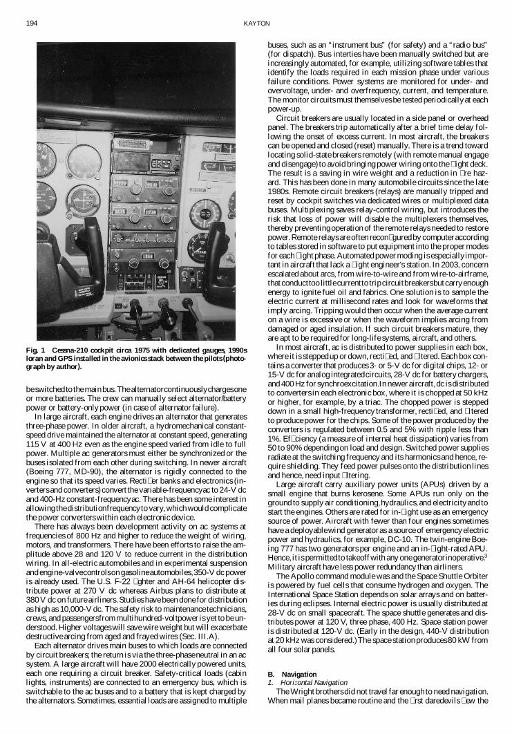
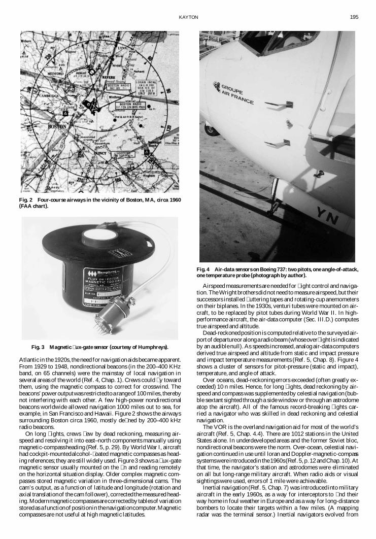
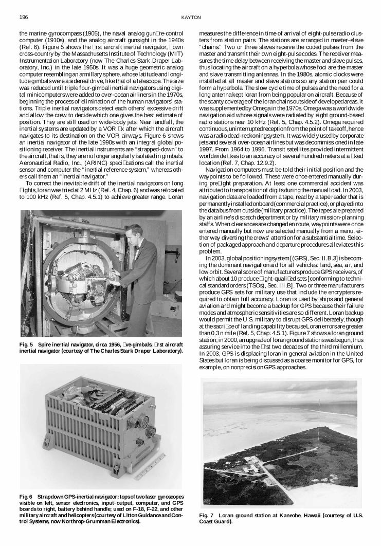
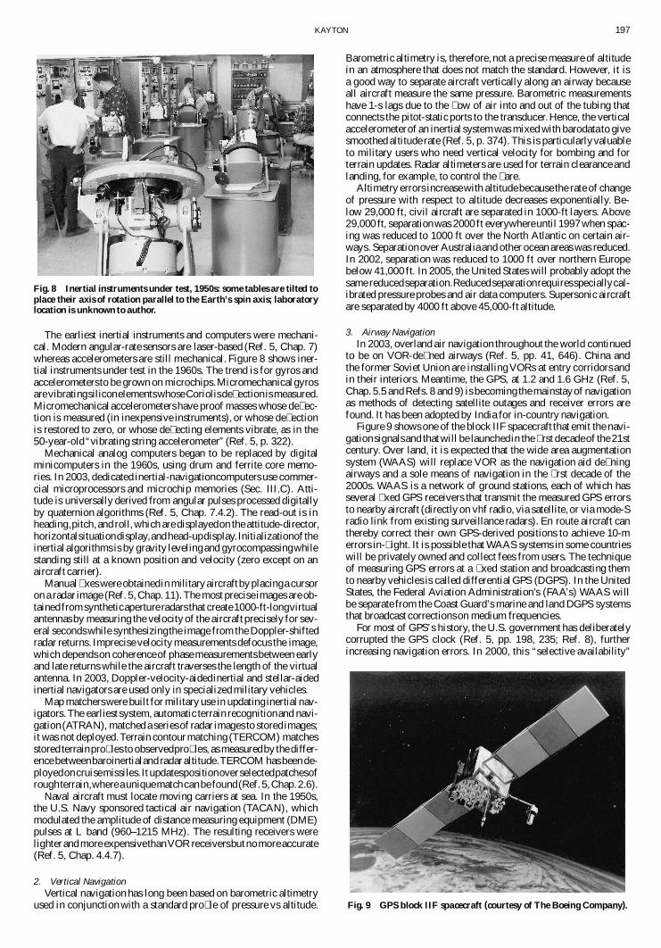
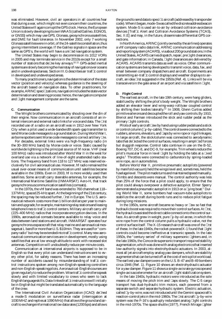
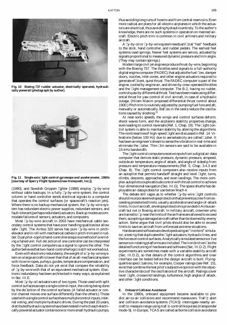
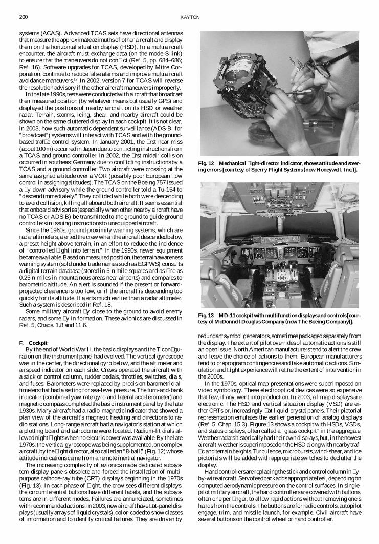
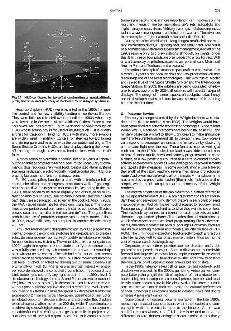
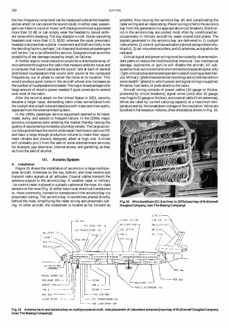
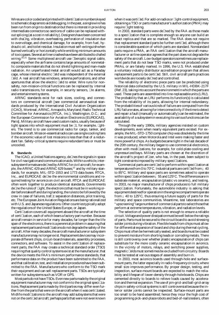
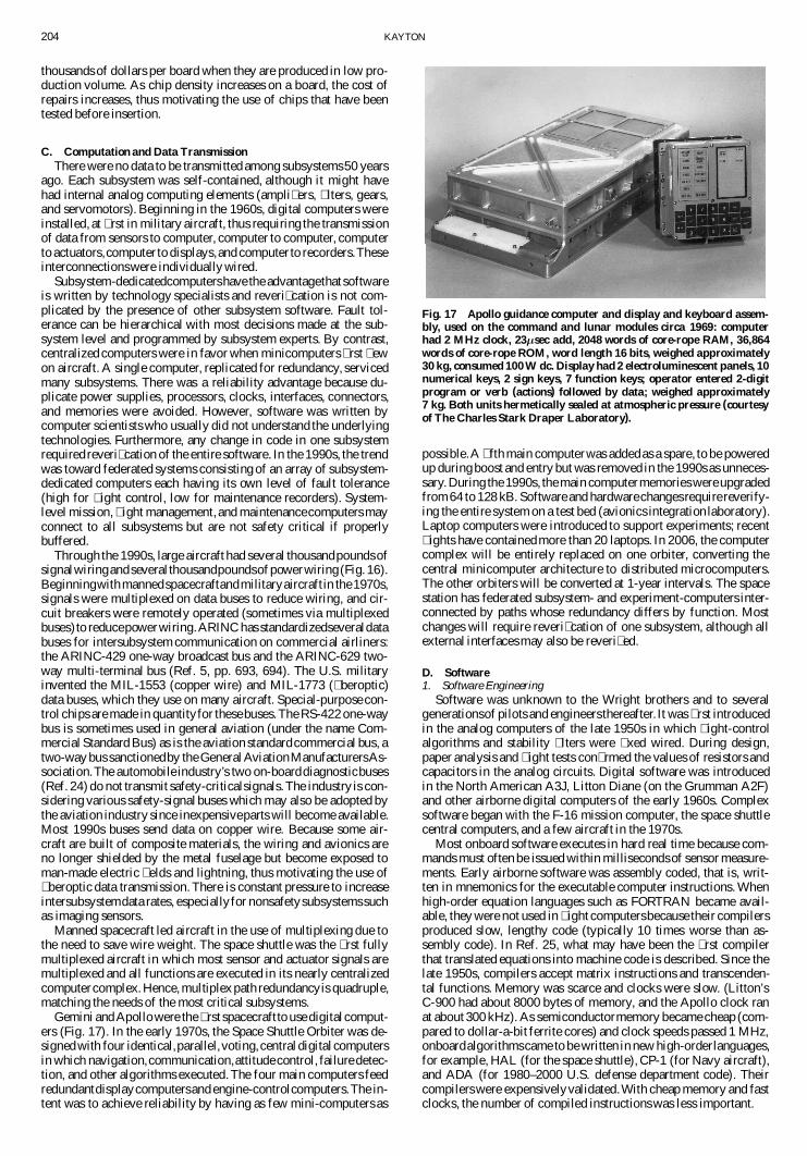
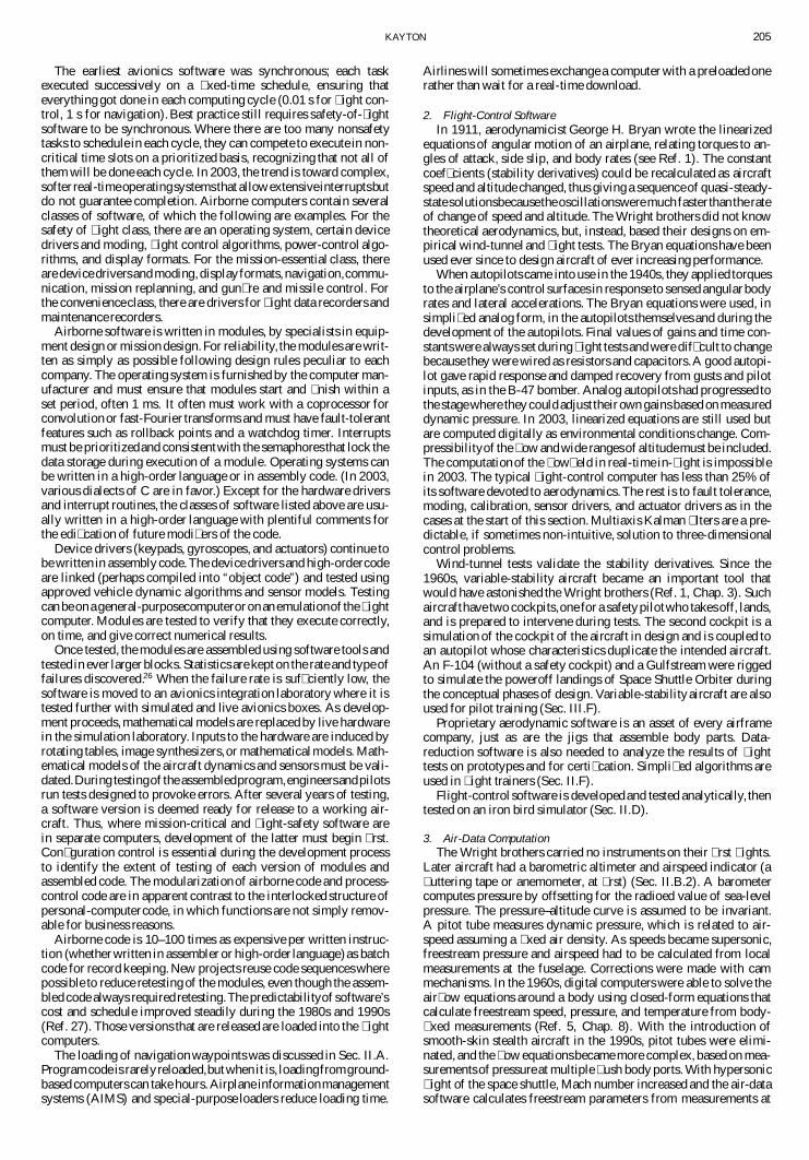
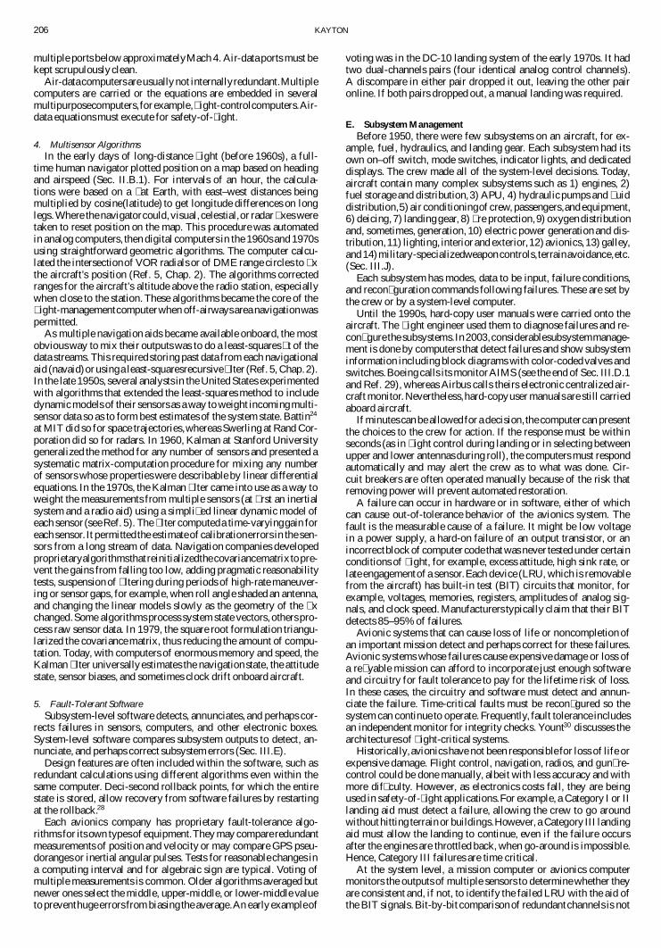
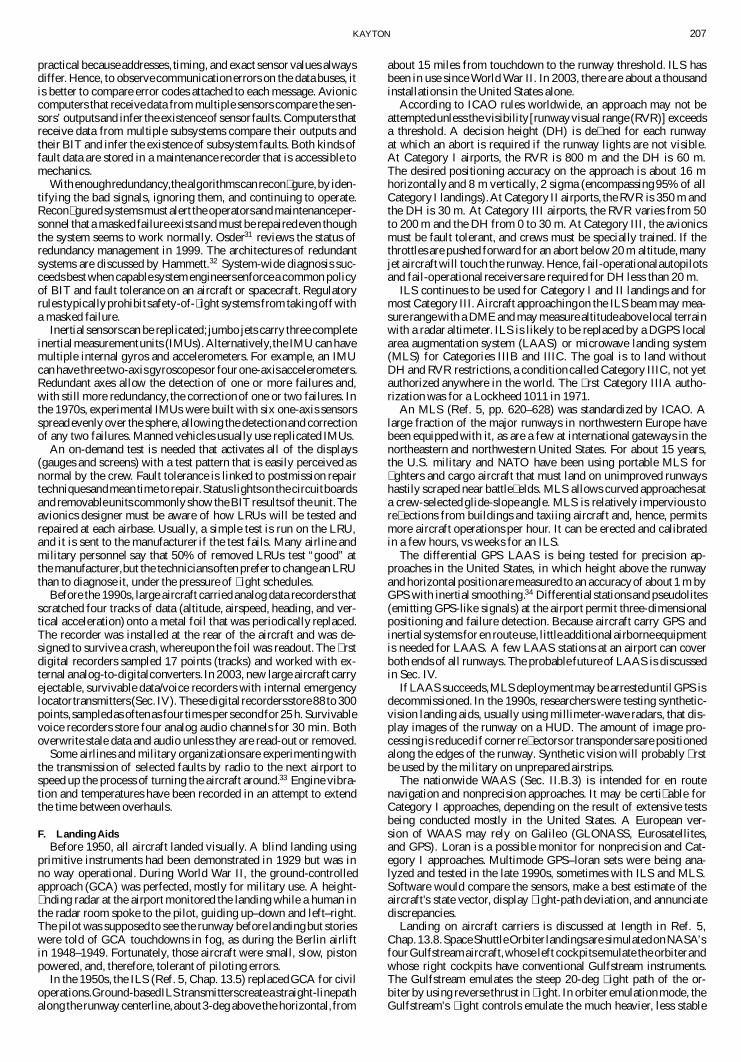
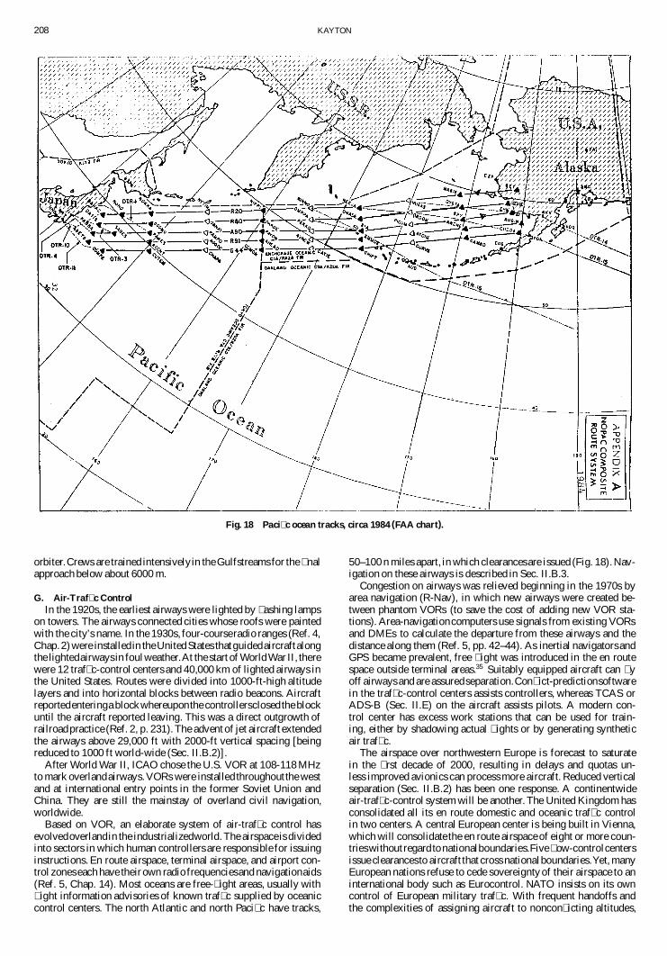
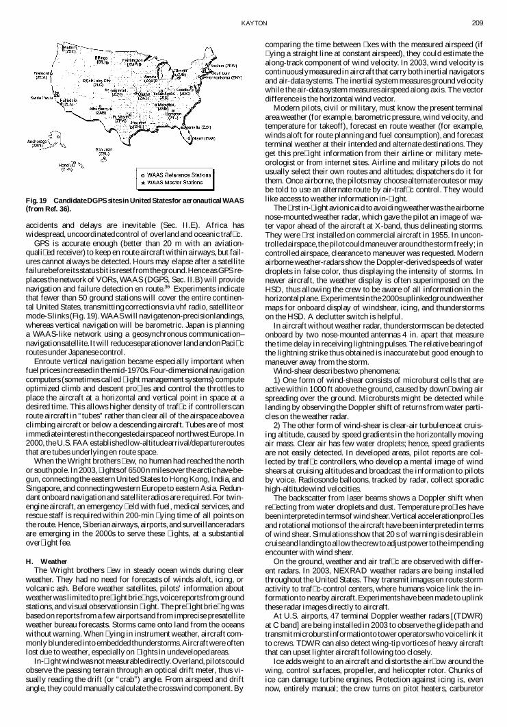
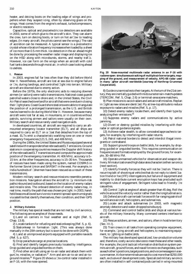