one-dimensional long-range self-arranged optically bound structures
TRANSCRIPT
One-dimensional long-range self-arranged optically boundstructures
Oto Brzobohatya, Vıtezslav Karaseka, Tomas Cizmara,b, Pavel Zemaneka, VenerandaGarces-Chavezb, and Kishan Dholakiab
a Institute of Scientific Instruments of the ASCR, v.v.i., Academy of Sciences of the CzechRepublic, Kralovopolska 147, 612 64 Brno, Czech Republic;
b SUPA, School of Physics and Astronomy, University of St Andrews, North Haugh, Fife,Scotland, KY16 9SS
ABSTRACT
We used two counter-propagating incoherent (non-interfering) quasi-Bessel beams propagating in a suspension ofpolystyrene microparticles and created so-called one dimensional optically bound matter. Due to the relativelyhigh degree of homogeneity of the Bessel beams the created self-organized structures were up to 200 micrometerslong with well defined distances between objects. Static and dynamic behaviour of each particle in the self-arranged structure was recorded by fast CCD camera and analyzed. The inter-particle distances were comparedwith the theoretical predictions based on coupled dipole method and very good coincidences were found.
Keywords: optical binding, optical forces, optical tweezers, optical trapping, Bessel beams
1. INTRODUCTION
Optical binding1 denotes an interesting type of the light-matter interaction for mesoscopic objects which leadsto self-arrangement into so called “optical matter”.2 This intriguing self-arrangement is based upon delicateequilibrium between the optical forces resulting both from the incident beam and from the light re-scatteredby the objects which then results in well defined stable equilibrium positions for the particles concerned. Themechanism is different from the well-known optical trapping because here no predefined potential wells (opticaltraps) exist before the objects are placed to the field. The presence of the objects modifies the field distributionso that possible optical traps are created for interacting objects. The aim in the field of optical binding is tounderstand these phenomena in depth to pave the way for controlled self-assembly of colloidal particles solelyby light.
In this paper we concentrate on longitudinal optical binding3,4 occurring along the beam propagation whilelaterally the objects are confined by the mechanism of optical trapping in the high intensity core of the beam. Incontrast to the lateral (transverse) binding1 the longitudinal binding forms optical matter in three dimensionsfar from any surface and has the potential for long-range particle arrangement. We demonstrate long-range1-D optical binding of micrometer and sub-micrometer sized objects placed within propagation invariant (non-diffracting) Bessel light beams5,6 in a counter-propagating geometry. The optical forces corresponding to lightscattering by the objects are dominant over gradient forces because the Bessel beam (BB) has negligible intensityvariation along its propagation axis. The beam is not significantly disturbed by the inserted objects due to itsself-reconstructing property7,8 leading to an increased number of objects being organized in the beam.9–11
Using the experimental configuration we have observed the first signatures of multistability within the boundmatter system. We have also explored the dynamics of each particle in a self-arranged single chain (with variousnumber of particles) and of systems with two or three such chains. The determination of particles equilibriumpositions and phase transitions of the system (when more objects cause the bound structure to become unstableand collapse) is supported by numerical modelling.
Further author information: (Send correspondence to P.Z.)P.Z.: E-mail: [email protected], Telephone: 00420 541 514 202
16th Polish-Slovak-Czech Optical Conference on Wave and Quantum Aspects of Contemporary Optics, edited by Agnieszka Popiolek-Masajada, Elzbieta Jankowska, Waclaw Urbanczyk, Proc. of SPIE Vol. 7141,
714113 · © 2008 SPIE · CCC code: 0277-786X/08/$18 · doi: 10.1117/12.822384
Proc. of SPIE Vol. 7141 714113-12008 SPIE Digital Library -- Subscriber Archive Copy
E
2V[ E
[iw]
=y\ IG p6GW
a
E
L!dIJT P6S1L
60
40
20
-20-40-60
zFmm]
0.8
0.6
0.4
0.2I0 15 30 45 60
10
5
EC
0-5
-10
500 1000z'[im]
1500
0.8
0.6
0.4
0.2
02000
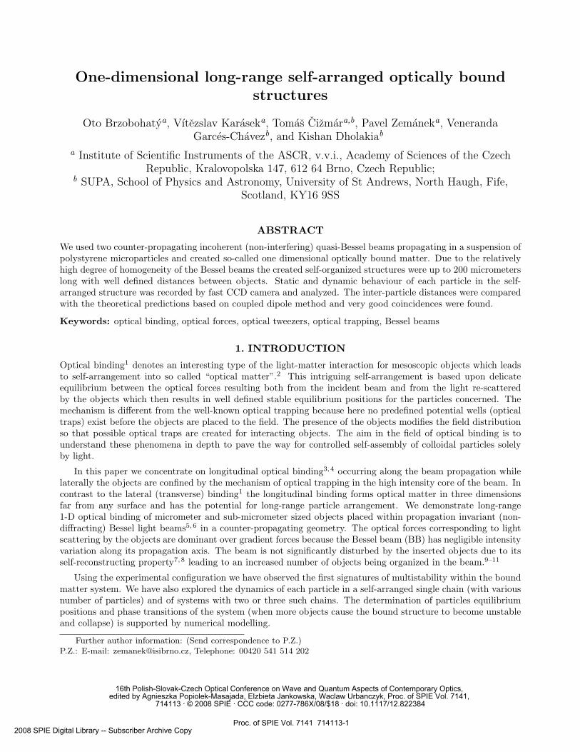
Figure 1. The setup: LASER - low coherence fiber laser (IPG ILM-10-1064-LP), PBS - polarizing beam-splitter, metallicmirrors, axicons (cone lenses) with apex angle 170◦ (EKSPLA 130-0270), L1 - planoconvex lenses f = 150 mm (ThorlabsLA1433-B), L2 - achromatic doublets f = 30 mm, f = 40 mm and f = 60 mm for various beam core radius, SPF- spatial filters, C - cuvette, LDO - Mitutoyo long working distance objective (f = 200 mm, numerical aperture 0.5,magnification 80), CCD - fast CCD camera (IDT XS-3 ). The bottom insets show the cross-sections of optical intensityof both demagnified overlapping Bessel beams.
2. EXPERIMENTAL PROCEDURE
Simplified scheme of the experimental set-up is shown in Fig. 1. The low temporal coherence fiber laser workingat 1064 nm with maximal power 10 W was used. Its output beam was split into two beams with optical pathdifference 60× larger than the coherence length of the laser, equal to 1 cm, and so no interference between bothbeams occurred. As the two beams passed through axicons they formed pseudo non-diffracting (Bessel) beams(BBs). Behind the axicon the wavevectors of refracted plane waves cover the surface of a cone with semi-apexangle α0 and the Bessel beam is a product of their interference. These beams went through a demagnifyingtelescope decreasing their high intensity BB core radius down to micrometer range. BB deformation caused byimperfections of the conical tips of the axicons were suppressed by centred beam-block placed in the Fourierplane (spatial filters SPF).12
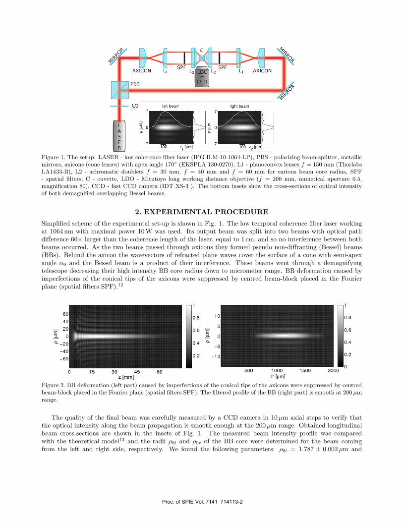
Figure 2. BB deformation (left part) caused by imperfections of the conical tips of the axicons were suppressed by centredbeam-block placed in the Fourier plane (spatial filters SPF). The filtered profile of the BB (right part) is smooth at 200 µmrange.
The quality of the final beam was carefully measured by a CCD camera in 10µm axial steps to verify thatthe optical intensity along the beam propagation is smooth enough at the 200µm range. Obtained longitudinalbeam cross-sections are shown in the insets of Fig. 1. The measured beam intensity profile was comparedwith the theoretical model13 and the radii ρ0l and ρ0r of the BB core were determined for the beam comingfrom the left and right side, respectively. We found the following parameters: ρ0l = 1.787 ± 0.002 µm and
Proc. of SPIE Vol. 7141 714113-2
ρ0r = 1.827 ± 0.002 µm for fL2 = 30 mm; ρ0l = 2.44 ± 0.01 µm and ρ0r = 2.43 ± 0.05 µm for fL2 = 40 mm, andρ0l = 3.75 ± 0.01 µm and ρ0r = 3.70 ± 0.02 µm for fL2 = 60 mm.
Colloidal sample consisted of polystyrene beads placed in an optical quality cuvette filled with D2O to suppressunwanted thermal convection of the fluid due to laser absorption. The sample was diluted so that one particlecrossed the beam within in 2-5 minutes during quantitative measurements. Bead positions were observed bybright field illumination and recorded by a fast CCD camera IDT XS-3. Thousands of frames were recordedwith various beads concentrations and number of bound beads in the beam. The individual bead positions wereobtained from each frame by a correlation algorithm14 and inter-beads separations were analyzed. We repeatedthe experiments in 1mM NaCL solution with no change in the experimental results. Thus we ensured that anypotential electrostatic interactions between beads have negligible effect at the observed inter-beads separations.
3. THEORETICAL EXPLANATION OF EXPERIMENTAL DATA
In order to interpret our experimental data we developed a numerical model based upon the coupled dipolemethod (CDM)15–19 that was enhanced up by the fast Fourier transform method20 and existing symmetries inthe configuration. This method is based upon dividing each object into elementary, mutually interacting dipolesplaced on an orthogonal grid with inter-dipole distances so small that the field in the vicinity of each dipolecan be considered uniform. In our case we use the criterion that the distance between the dipoles is smallerthan λ/40. Using this method the interaction of electromagnetic field with arbitrarily shaped objects can bemodelled.21 The CDM calculates the distribution of dipole moments of individual dipoles modelling the objectsand the total force acting upon the object is obtained as the sum of forces acting upon these dipoles.22 Thetotal forces acting on each object are calculated for various inter-beads separations and stable configurations aredetermined.19
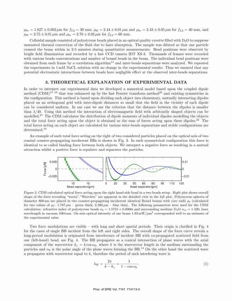
An example of such total force acting on the right of two considered particles placed on the optical axis of twocoaxial counter-propagating incoherent BBs is shown in Fig. 3. In such symmetrical configuration this force isidentical to so called binding force between both objects. We interpret a negative force as resulting in a mutualattraction whilst a positive force is repulsive and separates the particles.
Figure 3. CDM calculated optical force acting upon the right hand side bead in a two beads setup. Right plot shows overallshape of the force revealing “waves”.“Wavelets” are apparent in the detailed view in the left plot. Polystyrene spheres ofdiameter 800 nm are placed in two counter-propagating incoherent identical Bessel beams with core radii ρ0 (calculatedfor two values of ρ0: 1.787 µm – green thick, 2.380 µm – blue thin). The following parameters were used for the CDMcalculation: refractive index of polystyrene beads nb = 1.5755 + 0.0006i and surrounding medium D2O nm = 1.320; laserwavelength in vacuum 1064 nm. On-axis optical intensity of one beam 1.93 mW/µm2 corresponded well to an estimate ofthe experimental value
Two force modulations are visible – with long and short spatial periods. Their origin is clarified in Fig. 4for the cases of single BB incident from the left and right sides. The overall shape of the force curve reveals along-period modulation is originated from interference of incident BB with co-propagated scattered field fromone (left-hand) bead, see Fig. 4. The BB propagates as a conical intersection of plane waves with the axialcomponent of the wavevector kz = k cos α0, where k is the wavevector length in the medium surrounding theparticles and α0 is the polar angle of the plane waves forming the BB.13 On the other hand the scattered wavea propagates with wavevector equal to k, therefore the period of such interfering wave is
λW =2π
k − kz=
λ
1 − cos α0. (1)
Proc. of SPIE Vol. 7141 714113-3
I.:
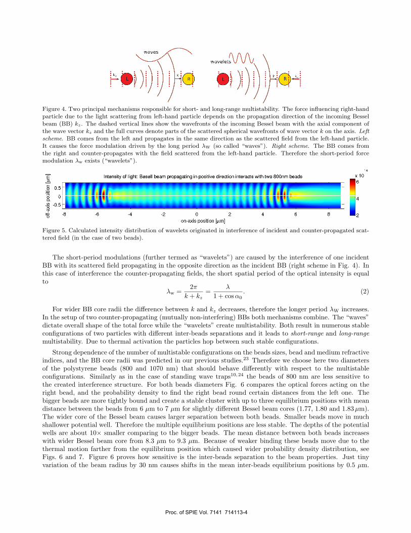
Figure 4. Two principal mechanisms responsible for short- and long-range multistability. The force influencing right-handparticle due to the light scattering from left-hand particle depends on the propagation direction of the incoming Besselbeam (BB) kz. The dashed vertical lines show the wavefronts of the incoming Bessel beam with the axial component ofthe wave vector kz and the full curves denote parts of the scattered spherical wavefronts of wave vector k on the axis. Leftscheme. BB comes from the left and propagates in the same direction as the scattered field from the left-hand particle.It causes the force modulation driven by the long period λW (so called “waves”). Right scheme. The BB comes fromthe right and counter-propagates with the field scattered from the left-hand particle. Therefore the short-period forcemodulation λw exists (“wavelets”).
Figure 5. Calculated intensity distribution of wavelets originated in interference of incident and counter-propagated scat-tered field (in the case of two beads).
The short-period modulations (further termed as “wavelets”) are caused by the interference of one incidentBB with its scattered field propagating in the opposite direction as the incident BB (right scheme in Fig. 4). Inthis case of interference the counter-propagating fields, the short spatial period of the optical intensity is equalto
λw =2π
k + kz=
λ
1 + cos α0. (2)
For wider BB core radii the difference between k and kz decreases, therefore the longer period λW increases.In the setup of two counter-propagating (mutually non-interfering) BBs both mechanisms combine. The “waves”dictate overall shape of the total force while the “wavelets” create multistability. Both result in numerous stableconfigurations of two particles with different inter-beads separations and it leads to short-range and long-rangemultistability. Due to thermal activation the particles hop between such stable configurations.
Strong dependence of the number of multistable configurations on the beads sizes, bead and medium refractiveindices, and the BB core radii was predicted in our previous studies.23 Therefore we choose here two diametersof the polystyrene beads (800 and 1070 nm) that should behave differently with respect to the multistableconfigurations. Similarly as in the case of standing wave traps10,24 the beads of 800 nm are less sensitive tothe created interference structure. For both beads diameters Fig. 6 compares the optical forces acting on theright bead, and the probability density to find the right bead round certain distances from the left one. Thebigger beads are more tightly bound and create a stable cluster with up to three equilibrium positions with meandistance between the beads from 6 µm to 7 µm for slightly different Bessel beam cores (1.77, 1.80 and 1.83 µm).The wider core of the Bessel beam causes larger separation between both beads. Smaller beads move in muchshallower potential well. Therefore the multiple equilibrium positions are less stable. The depths of the potentialwells are about 10× smaller comparing to the bigger beads. The mean distance between both beads increaseswith wider Bessel beam core from 8.3 µm to 9.3 µm. Because of weaker binding these beads move due to thethermal motion farther from the equilibrium position which caused wider probability density distribution, seeFigs. 6 and 7. Figure 6 proves how sensitive is the inter-beads separation to the beam properties. Just tinyvariation of the beam radius by 30 nm causes shifts in the mean inter-beads equilibrium positions by 0.5 µm.
Proc. of SPIE Vol. 7141 714113-4
15
10
2 beads of size: a - 35nm, various p0 2 beads of size a = 535nr var us p
_55 C 8.5 7 75I fliersptrere separatuon(pmj
1 77 rm
1 80 rm
1 83 rr,r
0.5
0.4
0.2
55 6 65 7 75 8
Interspiiere separationIpmI
6
22
8 10 12 14I ntersphere separatlon[,JmI
0.6
i,4
6 8 10 12 14Intersç*ere separa*iontprnj
2 bead5 01 site: a = 400flrti, vanDal p 2 beis of ute: a = 400nm, yroas
[uJn] z
FE
W OLO1 w -
L2
3 yeads of cize: a = 400nm, various p0
177 Irm
180 Irm
183 rr,r
0.4
0.2
3 beads of size: a= 4000m,va,Iousp
1C24 8 10
034 5 6 7 8
I oterspbero ruparationrro Intersphere separatron(pml
40
%1
177 Irm
180 Irm
183 rr,r
r,1
0.8
0.4
0.2
3 eads of cize: a = 35nm, various p0 3 beads of size: a = 535(10,, varrousp
4 5 3 4 5 8
nleroptero ruparation(poI Intersphere separatron(pml
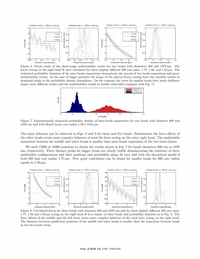
Figure 6. Detail study of the short-range multistability events for two beads with diameters 800 and 1070 nm. Theforces acting on the right bead R were calculated for three slightly different BB core sizes: 1.77, 1.80, and 1.83 µm. Theevaluated probability densities of the inter-beads separations demonstrate the spread of two beads separations and provemultistability events. In the case of bigger particles the shape of the optical forces coming form the wavelets results indominant peaks in the probability density dependence. On the contrary the curve for smaller beads have much shallowershape (note different scales) and the multistability would be hardly observable (compare with Fig. 7).
Figure 7. Experimentally measured probability density of inter-beads separations for two beads with diameter 800 and1070 nm and with Bessel beam core radius 1.80 ± 0.03 µm.
The same behavior can be observed in Figs. 8 and 9 for three and five beads. Furthermore the force effects ofthe other beads create more complex behavior of total the force acting on the outer right bead. The multistableseparation between the middle and outer beads is smaller than inter-beads separation of the two bead cluster.
We used 17000 or 19300 positions to obtain the results shown in Fig. 7 for beads diameters 800 nm or 1070nm, respectively. Three distinct peaks for bigger beads are clearly visible demonstrating the existence of threemultistable configurations and their positions and probability shape fit very well with the theoretical model ifboth BB had core radius 1.77 µm. Very good coincidence can be found for smaller beads for BB core radiusequals to 1.83 µm.
Figure 8. Calculated forces for three beads with diameter 800 and 1070 nm and for three slightly different BB core sizes:1.77, 1.80 and 1.83 µm acting on the right bead R in a cluster of three beads and probability densities as in Fig. 6. Theforce effects of the middle and the left bead create more complex behavior of the total force acting on the right bead.The distance between equilibrium positions of the middle and outer beads is smaller than the separation between beadsin the two-beads setup.
Proc. of SPIE Vol. 7141 714113-5
7.5
7
sepa
ratio
n 2
9)0)
01
nnr
.In fl!tI
I_U
fl.-
.r. lit
'uni
ui
....
....
....
....
r
sepa
ratio
n 2
I9)
10)
01 ., n fl!tI un...
.r. lit
-. it
u ni fl
SA
M
5
4.5 5 55 6 6.5 7
5
4.5 5 55 6 6.5 7
L2 L1 M R1 R2sep2 sep1 sep1 sep2
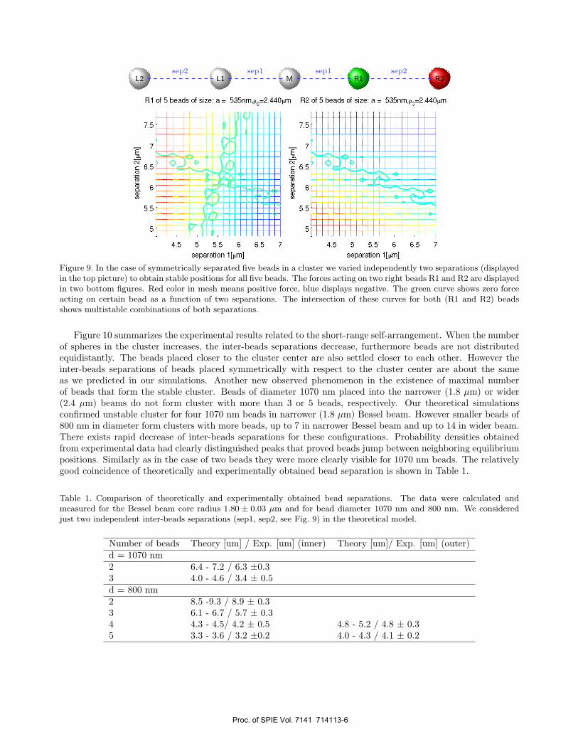
Figure 9. In the case of symmetrically separated five beads in a cluster we varied independently two separations (displayedin the top picture) to obtain stable positions for all five beads. The forces acting on two right beads R1 and R2 are displayedin two bottom figures. Red color in mesh means positive force, blue displays negative. The green curve shows zero forceacting on certain bead as a function of two separations. The intersection of these curves for both (R1 and R2) beadsshows multistable combinations of both separations.
Figure 10 summarizes the experimental results related to the short-range self-arrangement. When the numberof spheres in the cluster increases, the inter-beads separations decrease, furthermore beads are not distributedequidistantly. The beads placed closer to the cluster center are also settled closer to each other. However theinter-beads separations of beads placed symmetrically with respect to the cluster center are about the sameas we predicted in our simulations. Another new observed phenomenon in the existence of maximal numberof beads that form the stable cluster. Beads of diameter 1070 nm placed into the narrower (1.8 µm) or wider(2.4 µm) beams do not form cluster with more than 3 or 5 beads, respectively. Our theoretical simulationsconfirmed unstable cluster for four 1070 nm beads in narrower (1.8 µm) Bessel beam. However smaller beads of800 nm in diameter form clusters with more beads, up to 7 in narrower Bessel beam and up to 14 in wider beam.There exists rapid decrease of inter-beads separations for these configurations. Probability densities obtainedfrom experimental data had clearly distinguished peaks that proved beads jump between neighboring equilibriumpositions. Similarly as in the case of two beads they were more clearly visible for 1070 nm beads. The relativelygood coincidence of theoretically and experimentally obtained bead separation is shown in Table 1.
Table 1. Comparison of theoretically and experimentally obtained bead separations. The data were calculated andmeasured for the Bessel beam core radius 1.80 ± 0.03 µm and for bead diameter 1070 nm and 800 nm. We consideredjust two independent inter-beads separations (sep1, sep2, see Fig. 9) in the theoretical model.
Number of beads Theory [um] / Exp. [um] (inner) Theory [um]/ Exp. [um] (outer)d = 1070 nm2 6.4 - 7.2 / 6.3 ±0.33 4.0 - 4.6 / 3.4 ± 0.5d = 800 nm2 8.5 -9.3 / 8.9 ± 0.33 6.1 - 6.7 / 5.7 ± 0.34 4.3 - 4.5/ 4.2 ± 0.5 4.8 - 5.2 / 4.8 ± 0.35 3.3 - 3.6 / 3.2 ±0.2 4.0 - 4.3 / 4.1 ± 0.2
Proc. of SPIE Vol. 7141 714113-6
d=802 nno
. . .. S
d=1070 515
S S
S..
0 5 10 IS 20 0 5 10 IS 20
z [pIn]
C S S S S .
070 rm beads, = I Bum, 2.4Um and 3.7 Im
- -25 0 25 50
. . . . .1a
-50 -25 0 25 50zmI
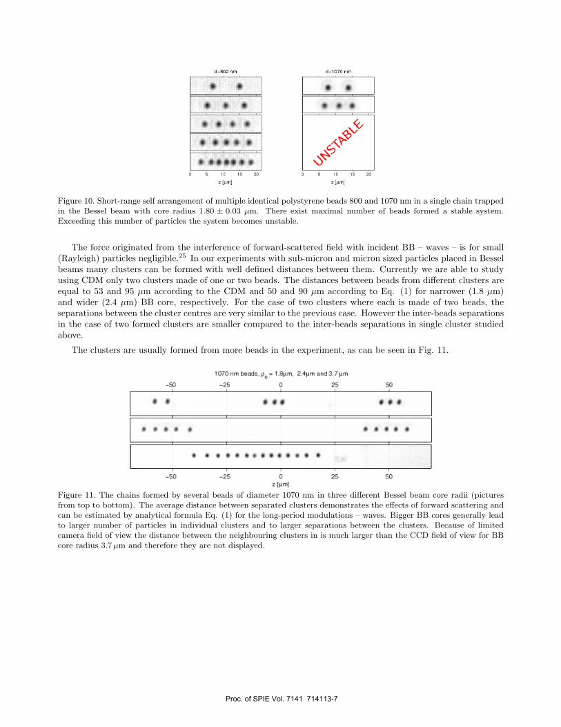
Figure 10. Short-range self arrangement of multiple identical polystyrene beads 800 and 1070 nm in a single chain trappedin the Bessel beam with core radius 1.80 ± 0.03 µm. There exist maximal number of beads formed a stable system.Exceeding this number of particles the system becomes unstable.
The force originated from the interference of forward-scattered field with incident BB – waves – is for small(Rayleigh) particles negligible.25 In our experiments with sub-micron and micron sized particles placed in Besselbeams many clusters can be formed with well defined distances between them. Currently we are able to studyusing CDM only two clusters made of one or two beads. The distances between beads from different clusters areequal to 53 and 95 µm according to the CDM and 50 and 90 µm according to Eq. (1) for narrower (1.8 µm)and wider (2.4 µm) BB core, respectively. For the case of two clusters where each is made of two beads, theseparations between the cluster centres are very similar to the previous case. However the inter-beads separationsin the case of two formed clusters are smaller compared to the inter-beads separations in single cluster studiedabove.
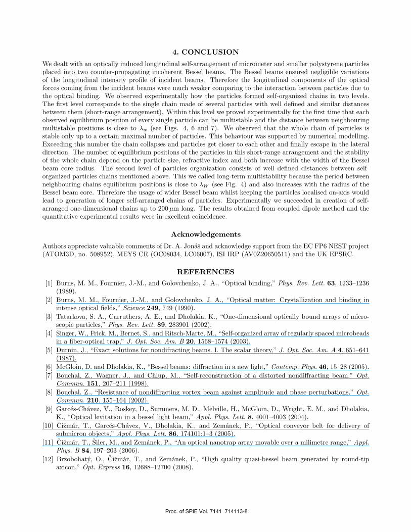
The clusters are usually formed from more beads in the experiment, as can be seen in Fig. 11.
Figure 11. The chains formed by several beads of diameter 1070 nm in three different Bessel beam core radii (picturesfrom top to bottom). The average distance between separated clusters demonstrates the effects of forward scattering andcan be estimated by analytical formula Eq. (1) for the long-period modulations – waves. Bigger BB cores generally leadto larger number of particles in individual clusters and to larger separations between the clusters. Because of limitedcamera field of view the distance between the neighbouring clusters in is much larger than the CCD field of view for BBcore radius 3.7 µm and therefore they are not displayed.
Proc. of SPIE Vol. 7141 714113-7
4. CONCLUSION
We dealt with an optically induced longitudinal self-arrangement of micrometer and smaller polystyrene particlesplaced into two counter-propagating incoherent Bessel beams. The Bessel beams ensured negligible variationsof the longitudinal intensity profile of incident beams. Therefore the longitudinal components of the opticalforces coming from the incident beams were much weaker comparing to the interaction between particles due tothe optical binding. We observed experimentally how the particles formed self-organized chains in two levels.The first level corresponds to the single chain made of several particles with well defined and similar distancesbetween them (short-range arrangement). Within this level we proved experimentally for the first time that eachobserved equilibrium position of every single particle can be multistable and the distance between neighbouringmultistable positions is close to λw (see Figs. 4, 6 and 7). We observed that the whole chain of particles isstable only up to a certain maximal number of particles. This behaviour was supported by numerical modelling.Exceeding this number the chain collapses and particles get closer to each other and finally escape in the lateraldirection. The number of equilibrium positions of the particles in this short-range arrangement and the stabilityof the whole chain depend on the particle size, refractive index and both increase with the width of the Besselbeam core radius. The second level of particles organization consists of well defined distances between self-organized particles chains mentioned above. This we called long-term multistability because the period betweenneighbouring chains equilibrium positions is close to λW (see Fig. 4) and also increases with the radius of theBessel beam core. Therefore the usage of wider Bessel beam whilst keeping the particles localised on-axis wouldlead to generation of longer self-arranged chains of particles. Experimentally we succeeded in creation of self-arranged one-dimensional chains up to 200 µm long. The results obtained from coupled dipole method and thequantitative experimental results were in excellent coincidence.
Acknowledgements
Authors appreciate valuable comments of Dr. A. Jonas and acknowledge support from the EC FP6 NEST project(ATOM3D, no. 508952), MEYS CR (OC08034, LC06007), ISI IRP (AV0Z20650511) and the UK EPSRC.
REFERENCES[1] Burns, M. M., Fournier, J.-M., and Golovchenko, J. A., “Optical binding,” Phys. Rev. Lett. 63, 1233–1236
(1989).[2] Burns, M. M., Fournier, J.-M., and Golovchenko, J. A., “Optical matter: Crystallization and binding in
intense optical fields,” Science 249, 749 (1990).[3] Tatarkova, S. A., Carruthers, A. E., and Dholakia, K., “One-dimensional optically bound arrays of micro-
scopic particles,” Phys. Rev. Lett. 89, 283901 (2002).[4] Singer, W., Frick, M., Bernet, S., and Ritsch-Marte, M., “Self-organized array of regularly spaced microbeads
in a fiber-optical trap,” J. Opt. Soc. Am. B 20, 1568–1574 (2003).[5] Durnin, J., “Exact solutions for nondifracting beams. I. The scalar theory,” J. Opt. Soc. Am. A 4, 651–641
(1987).[6] McGloin, D. and Dholakia, K., “Bessel beams: diffraction in a new light,” Contemp. Phys. 46, 15–28 (2005).[7] Bouchal, Z., Wagner, J., and Chlup, M., “Self-reconstruction of a distorted nondiffracting beam,” Opt.
Commun. 151, 207–211 (1998).[8] Bouchal, Z., “Resistance of nondiffracting vortex beam against amplitude and phase perturbations,” Opt.
Commun. 210, 155–164 (2002).[9] Garces-Chavez, V., Roskey, D., Summers, M. D., Melville, H., McGloin, D., Wright, E. M., and Dholakia,
K., “Optical levitation in a bessel light beam,” Appl. Phys. Lett. 8, 4001–4003 (2004).[10] Cizmar, T., Garces-Chavez, V., Dholakia, K., and Zemanek, P., “Optical conveyor belt for delivery of
submicron objects,” Appl. Phys. Lett. 86, 174101:1–3 (2005).[11] Cizmar, T., Siler, M., and Zemanek, P., “An optical nanotrap array movable over a milimetre range,” Appl.
Phys. B 84, 197–203 (2006).[12] Brzobohaty, O., Cizmar, T., and Zemanek, P., “High quality quasi-bessel beam generated by round-tip
axicon,” Opt. Express 16, 12688–12700 (2008).
Proc. of SPIE Vol. 7141 714113-8
[13] Cizmar, T., Kollarova, V., Bouchal, Z., and Zemanek, P., “Sub-micron particle organization by self-imagingof non-diffracting beams,” New. J. Phys. 8, 43 (2006).
[14] Cheezum, M. K., Walker, W. F., and Guilford, W. H., “Quantitative comparison of algorithms for trackingsingle fluorescent particles,” Biophys. J. 81, 2378–2388 (2001).
[15] Purcell, E. M. and Pennypacker, C. R., “Scattering and absorption of ligh by nonspherical dielectric grains,”Astrophys J. 186, 705—714 (1973).
[16] Draine, B., “The discrete-dipole approximation and its application to interstellar graphite grains,” AstrophysJ. 333, 848–872 (1988).
[17] Chaumet, P. C. and Nieto-Vesperinas, M., “Coupled dipole method determination of the electromagneticforce on a particle over a flat dielectric substrate,” Phys. Rev. B 61, 14119–14127 (2000).
[18] Chaumet, P. C. and Nieto-Vesperinas, M., “Optical binding of particles with or without the presence of aflat dielectric surface,” Phys. Rev. B 64, 035422 1–7 (2001).
[19] Karasek, V., Dholakia, K., and Zemanek, P., “Analysis of optical binding in one dimension,” Appl. Phys.B 84, 149–156 (2006).
[20] Goodman, J. J., Draine, B. T., and Flatau, P. J., “Application of fast-fourier-transform techniques to thediscrete-dipole approximation,” Opt. Lett. 16, 1198—1200 (1991).
[21] Chaumet, P. C. and Billaudeau, C., “Coupled dipole method to compute optical torque: Application to amicropropeller,” J. Appl. Phys. 1011, 023106 (2007).
[22] Hoekstra, A. G., Frijlink, M., Waters, L. B. F. M., and Sloot, P. M. A., “Radiation forces in the discrete-dipole approximation,” J. Opt. Soc. Am. A 18, 1944—1953 (2001).
[23] Karasek, V., Cizmar, T., and Zemanek, P., “Optical binding in non-diffracting beams,” in [Optical Trappingand Optical Micromanipulation III: Proceedings of SPIE ], Dholakia, K. and Spalding, G. C., eds., 6236,632608: 1–10 (2006).
[24] Cizmar, T., Siler, M., Sery, M., Zemanek, P., Garces-Chavez, V., and Dholakia, K., “Optical sorting anddetection of sub-micron objects in a motional standing wave,” Phys. Rev. B 74, 035105 (2006).
[25] Karasek, V. and Zemanek, P., “Analytical description of longitudinal optical binding of two sphericalnanoparticles,” J. Opt. A: Pure Appl. Opt. 9, S215–S220 (2007).
Proc. of SPIE Vol. 7141 714113-9