on alleviation of shear locking in the kriging-based finite element method
TRANSCRIPT
ON ALLEVIATION OF SHEAR LOCKING IN THE KRIGING-BASED FINITE ELEMENT METHOD
WONG Foek Tjong 1 and Worsak KANOK-NUKULCHAI 2
ABSTRACT: Recently, Kriging-based finite element method (K-FEM) has been developed for analysis of Reissner-Mindlin plates. This method provides sufficient flexibility in customizing the interpolation function for desired smoothness and accuracy. In the application to thin plates, however, the well-known finite element drawback of transverse shear locking still remains in the K-FEM, particularly when low order basis function is used. In this study, the concept of assumed natural transverse shear strain is introduced to alleviate the shear locking. The positions of the shear strain sampling points and the assumed natural strain fields are determined approximately by assuming the deflection field is linear within the triangular integration cells. Numerical tests on a hard simply supported square plate and on a clamped circular plate are carried out to assess the effectiveness of the present method. The tests show that the shear locking can be considerably reduced but it still cannot be completely eliminated. In the application to thick plates, however, the solutions of the present method are less accurate compared to those of the standard K-FEM.
KEYWORDS: shear locking, Kriging, Reissner-Mindlin, assumed natural transverse shear strain.
1. INTRODUCTION
The element-free Galerkin method (EFGM) with Kriging interpolation (KI) [1] and elements as integration cells can be viewed as a subclass of FEM with shape functions untied to the element structure. Realizing this fact, Plengkhom and Kanok-Nukulchai [2] presented a new class of FEM by introducing the Kriging shape functions in the conventional FEM. In the conventional FEM, the shape function associated with a node is a hat function tied to the element structure. Its influence extends over one layer of elements around the node. In the K-FEM, shape functions are constructed using KI over a set of nodes encompassing a number of layers of elements. Thus, the shape function associated with a node extends beyond one layer of elements. With K-FEM, very smooth field variables and their derivatives can be attained without any smoothing process. Any requirement for high order shape functions can be easily fulfilled without any change to the element. The advantage of this method over mesh-free methods is that it inherits the computational procedure of FEM so that the modification from a standard FE program to a K-FEM program is straightforward.
The K-FEM has been successfully applied to solve 1-D bar and 2-D plane stress/plane strain problems [2]. Very recently, it has also been developed for analyses of plates based on Reissner-Mindlin theory [3]. Despite many attractive features of the K-FEM, in the application to thin plates, the well-known finite element drawback of transverse shear locking still remains in the K-FEM. The use of high order basis in KI can alleviate the shear locking [3], but there is no guarantee to eliminate the locking completely. In previous work on the EFGM with moving least-squares (MLS) approximation [4], 1 Graduate student in School of Engineering and Technology, Asian Institute of Technology, Thailand and lecturer of Petra
Christian University, Indonesia. 2 Professor of School of Engineering and Technology, Asian Institute of Technology, Thailand.
International Civil Engineering Conference "Towards Sustainable Civil Engineering Practice"Surabaya, August 25-26, 2006
39
employing the derivatives of the deflection shape functions as the shape functions for the rotations has been proven to be very effective to eliminate the shear locking completely. However, this simple yet very effective strategy cannot be applied in the K-FEM because it is unlike the MLS shape function, the Kriging shape function passes through the nodes. In this study, the concept of assumed natural transverse shear strain [5-7] is introduced to alleviate the shear locking in the K-FEM. The positions of the shear strain sampling points and the assumed natural strain fields are determined approximately by assuming the deflection field is linear within the triangular integration cells. Thus the positions of the sampling points and the assumed natural strain fields are exactly the same as those of the three-node triangular element of Mitaim [5].
2. KRIGING INTERPOLATION
Named after Danie G. Krige, a South African mining engineer, Kriging is a well-known geostatistical technique for spatial data interpolation in geology and mining [1, 8]. Using this interpolation, every unknown value at a point can be interpolated from known values at scattered points in its specified neighborhood. This section presents a summary of KI formulation in the context of K-FEM. A detail explanation and derivation of Kriging can be found in the geostatistics literatures (e.g. [8, 9]).
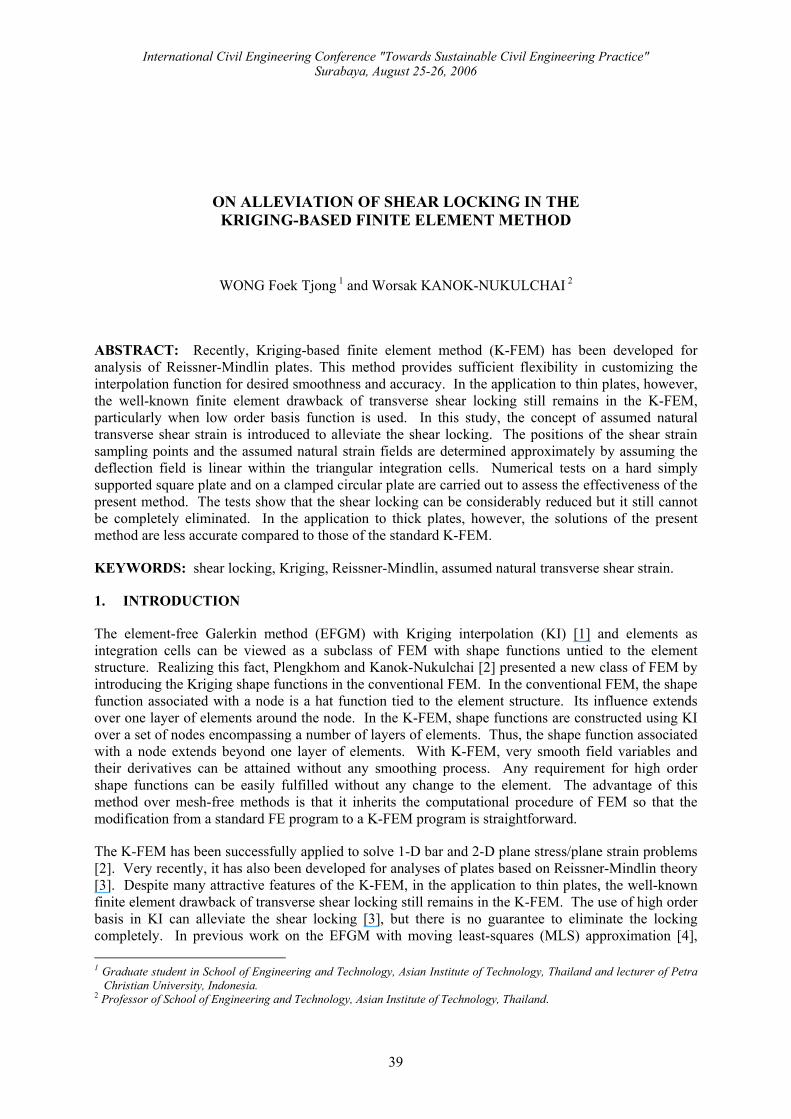
Consider a two-dimensional domain meshed with triangular elements (Figure 1). For each element, the KI is defined over a set of nodes in a sub-domain elΩ ⊆Ω encompassing a predetermined number of layers of elements. The KI function over sub-domain elΩ can be expressed in the usual FE form as
h ( ) ( )u =x N x d (1)
where N(x) is the 1 n× matrix of shape functions and d is the 1n× matrix of field values at the nodes. In contrast to FE, here n in not the number of nodes in the element, but it is the number of all nodes in the domain of interpolation (DOI) of element el.
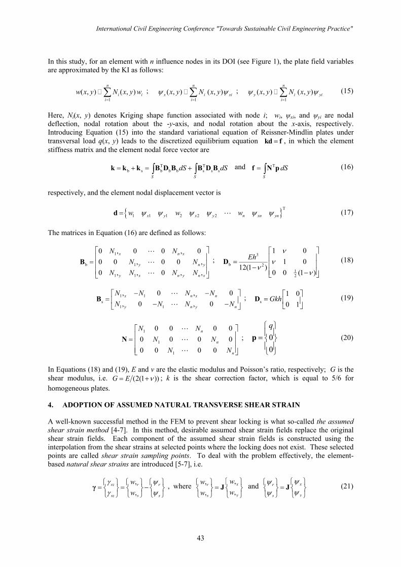
Figure 1. Domain of interpolation for element el with one, two and three layers of elements [2]
The shape function matrix is obtained from
T T( ) ( ) ( )= +N x p x A r x B (2)
In this equation,
[ ]T1( ) ( ) ... ( )mp p=p x x x (3)
is the vector of m-term-polynomial basis and
One layer Two layers Three layers
Element el
WONG and KANOK-NUKULCHAI
40
[ ]T1( ) ( ) ... ( )nC h C h=r x (4)
is the vector of covariance between random function U at nodes i=1,…,n, U(x i) and U at the point x, U(x). Note that in Kriging formulation, a deterministic function u(x) is viewed as a realization of a random function U(x). The covariance between a pair of random variables U(x) and U(x i) depends only on the distance between x and xi, i.e. i ih = −x x . Thus, ( ) cov[ ( ), ( )]i iC h U U= x x . Matrices
m n×A and n n×B are defined as follows:
T 1 1 T 1( )− − −=A P R P P R , 1( )−= −B R I PA (5)
in which
11 1
1
( ) ... ( )... ... ...( ) ... ( )
n
n nn
C h C h
C h C h
⎡ ⎤⎢ ⎥= ⎢ ⎥⎢ ⎥⎣ ⎦
R , 1 1 1
1
( ) ... ( )... ... ...( ) ... ( )
m
n m n
p p
p p
⎡ ⎤⎢ ⎥= ⎢ ⎥⎢ ⎥⎣ ⎦
x xP
x x
(6)
and I is the n n× identity matrix. In Equation (6), R is the n n× matrix of covariance between U(x) at nodes x1, …, xn, ( ) cov[ ( ), ( )]ij i jC h U U= x x , and P is the n m× matrix of polynomial values at the nodes.
Constructing the Kriging shape functions, Equation (2), requires a model of covariance function, C(h). This covariance model is more conveniently expressed in term of coefficient of correlation function or, shortly, correlation function. The coefficient of correlation function between a pair of random variables U(x) and U(x+h) is 2( ) ( )h C hρ σ= , where [ ] [ ]2 var ( ) var ( )U Uσ = = +x x h . According to Gu [1], σ2 has no influence on the final results and so in this study it is taken as 1. One of the widely used correlation model is the gaussian correlation function [1-3] , that is,
2( ) exp( ( / ) )h h dρ θ= − (7)
where θ>0 is the correlation parameter, h is the distance between two points, and d is a scale factor to normalize the distance. In this study, d is taken to be the maximum distance between a pair of nodes in the DOI. Besides the gaussian, the authors introduced the quartic spline (QS) correlation function [3],
2 3 41 6( / ) 8( / ) 3( / ) for 0 / 1
( )0 for / 1
h d h d h d h dh
h dθ θ θ θ
ρθ
⎧ − + − ≤ ≤= ⎨
>⎩ (8)
The quality of the Kriging is influenced by the parameter θ. Plengkhom and Kanok-Nukulchai [2] proposed the lower and upper bound criteria for θ to guarantee the quality of KI. The lower bound is given by
10
11 1 10
na
ii
N − +
=
− ≤ ×∑ (9)
where Ni denotes Kriging shape function associated with node i, a is the order of basis function, while the upper bound is given by
det( ) 1 10 b−≤ ×R (10)
International Civil Engineering Conference "Towards Sustainable Civil Engineering Practice"
41
where b is the dimension of problem. For two-dimensional problem with quadratic basis function, for example, a=2 and b=2.
Numerical investigations on the upper and lower bound values of θ reveal that the parameter bounds vary with respect to the number of nodes in the DOI. Based on the results of the search for the lower and upper bound values of θ satisfying Equations 9 and 10, the authors proposed the parameter functions [3] for practical implementation of the K-FEM as follows:
For gaussian correlation parameter, the parameter function is
low up(1 )f fθ θ θ= + − , 0 1f≤ ≤ (11)
where f is a scale factor, θlow and θup are the lower and upper bound functions, respectively, whose expressions are as follows:
low 2
0.08286 0.2386 for 3 10-8.364E - 4 0.1204 0.5283 for 10 55
0.02840 2.002 for 55
n nn n n
n nθ
− ≤ <⎧⎪= + − ≤ ≤⎨⎪ + >⎩
(12)
up 2
0.34 0.7 for 3 10-2.484E-3 +0.3275 0.2771 for 10 55
0.05426 7.237 for 55
n nn n n
n nθ
− ≤ <⎧⎪= − ≤ ≤⎨⎪ + >⎩
(13)
For QS correlation parameter, the parameter function is
0.1329 0.3290 for 3 101 for 10
n nn
θ− ≤ <⎧
= ⎨ ≥⎩ (14)
3. THE STANDARD DISCRETIZED EQUILIBRIUM EQUATIONS
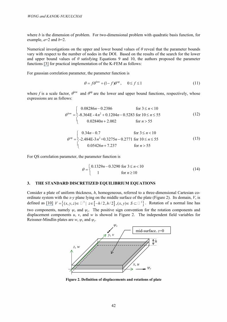
Consider a plate of uniform thickness, h, homogeneous, referred to a three-dimensional Cartesian co-ordinate system with the x-y plane lying on the middle surface of the plate (Figure 2). Its domain, V, is defined as [10] [ ]{ }3 2( , , ) | / 2 , / 2 , ( , )V x y z z h h x y S= ∈ ∈ − ∈ ⊂ . Rotation of a normal line has
two components, namely ψx and ψy. The positive sign convention for the rotation components and displacement components u, v, and w is showed in Figure 2. The independent field variables for Reissner-Mindlin plates are w, ψx and ψy.
Figure 2. Definition of displacements and rotations of plate
x, u
y, v
z, w h
ψx
ψy
mid-surface, z=0
WONG and KANOK-NUKULCHAI
42
In this study, for an element with n influence nodes in its DOI (see Figure 1), the plate field variables are approximated by the KI as follows:
1
( , ) ( , )n
i ii
w x y N x y w=∑ ;
1
( , ) ( , )n
x i xii
x y N x yψ ψ=∑ ;
1
( , ) ( , )n
y i yii
x y N x yψ ψ=∑ (15)
Here, Ni(x, y) denotes Kriging shape function associated with node i; wi, ψxi, and ψyi are nodal deflection, nodal rotation about the -y-axis, and nodal rotation about the x-axis, respectively. Introducing Equation (15) into the standard variational equation of Reissner-Mindlin plates under transversal load q(x, y) leads to the discretized equilibrium equation =kd f , in which the element stiffness matrix and the element nodal force vector are
T Tb s b b b s s s
S S
dS dS= + = +∫ ∫k k k B D B B D B and T
S
dS= ∫f N p (16)
respectively, and the element nodal displacement vector is
{ }T
1 1 1 2 2 2x y x y n xn ynw w wψ ψ ψ ψ ψ ψ=d L (17)
The matrices in Equation (16) are defined as follows:
1
b 1
1 1
0 , 0 0 , 00 0 , 0 0 ,0 , , 0 , ,
x n x
y n y
y x n y n x
N NN N
N N N N
⎡ ⎤⎢ ⎥= ⎢ ⎥⎢ ⎥⎣ ⎦
BL
L
L
; 3
b 212
1 01 0
12(1 )0 0 (1 )
Ehν
νν
ν
⎡ ⎤⎢ ⎥= ⎢ ⎥−⎢ ⎥−⎣ ⎦
D (18)
1 1s
1 1
, 0 , 0, 0 , 0
x n x n
y n y n
N N N NN N N N
− −⎡ ⎤= ⎢ ⎥− −⎣ ⎦
BL
L ;
s
1 00 1
Gkh⎡ ⎤
= ⎢ ⎥⎣ ⎦
D (19)
1
1
1
0 0 0 00 0 0 00 0 0 0
n
n
n
N NN N
N N
⎡ ⎤⎢ ⎥= ⎢ ⎥⎢ ⎥⎣ ⎦
NL
L
L
; 00
q⎧ ⎫⎪ ⎪= ⎨ ⎬⎪ ⎪⎩ ⎭
p (20)
In Equations (18) and (19), E and ν are the elastic modulus and Poisson’s ratio, respectively; G is the shear modulus, i.e. (2(1 ))G E ν= + ; k is the shear correction factor, which is equal to 5/6 for homogeneous plates.
4. ADOPTION OF ASSUMED NATURAL TRANSVERSE SHEAR STRAIN
A well-known successful method in the FEM to prevent shear locking is what so-called the assumed shear strain method [4-7]. In this method, desirable assumed shear strain fields replace the original shear strain fields. Each component of the assumed shear strain fields is constructed using the interpolation from the shear strains at selected points where the locking does not exist. These selected points are called shear strain sampling points. To deal with the problem effectively, the element-based natural shear strains are introduced [5-7], i.e.
,,
rz r r
sz s s
ww
γ ψγ ψ⎧ ⎫ ⎧ ⎫ ⎧ ⎫
= = −⎨ ⎬ ⎨ ⎬ ⎨ ⎬⎩ ⎭ ⎩ ⎭ ⎩ ⎭
γ , where ,,,,
xr
ys
wwww⎧ ⎫⎧ ⎫
=⎨ ⎬ ⎨ ⎬⎩ ⎭ ⎩ ⎭
J and xr
ys
ψψψψ⎧ ⎫⎧ ⎫
=⎨ ⎬ ⎨ ⎬⎩ ⎭ ⎩ ⎭
J (21)
International Civil Engineering Conference "Towards Sustainable Civil Engineering Practice"
43
Here, r and s are natural coordinates and J is Jacobian matrix. Physically, the transverse shear strains will vanish if the thickness-to-span ratio of the plate is extremely small [7], i.e. =γ 0 or
,r rwψ = and ,s swψ = (22)
In the framework of the FEM and also in this study, the deflection and the rotations are approximated with the same shape functions. Consequently, the polynomial order of the rotations is not the same as that of the derivative of deflection. In other words, there is inconsistency in the orders of the approximate functions. This inconsistency may lead to shear locking. To prevent this inconsistency, a new assumed deflection field w% [5-7] is introduced for each component of γ. The order of w% should be selected so that w r∂ ∂% (or w s∂ ∂% ) can include all polynomial terms of ψr (or ψs).
The shear strain sampling points for γrz and γsz can be obtained using the following equations,
w r w r∂ ∂ = ∂ ∂% ; w s w s∂ ∂ = ∂ ∂% (23)
Since in this study the deflection is approximated by the KI (Equation 15) in the Cartesian coordinate, the positions of the sampling points cannot be determined straightforwardly. Hence the positions of the sampling points are determined approximately by assuming the deflection field is linear within the triangular integration cells. As a result, the positions of the sampling points are exactly the same as those of the three-node triangular element of S. Mitaim [5]. These positions are
(r1=0.5, s1=0) for γrz ; (r2=0, s2=0.5) for γsz (24)
With only one sampling point for each natural transverse shear strain component, the constant value of shear strain component at each sampling point is utilized as the assumed natural strain.
Using the assumed natural transverse shear strains, the shear stiffness matrix ks in Equation 16 becomes [5]
T Ts s s s s s s
ˆ ˆ ˆ ˆ ˆ ˆS
dS A= =∫k B D B B D B (25)
In this equation, A is the area of the triangular element, 12A = J ; sD̂ is the natural transverse shear
constitutive matrix, Ts
ˆs
−=D J D J ; sB̂ is the substitute shear strain-displacement matrix. The procedure to obtain sB̂ is as follows:
Step 1. Calculate the natural shear strain-displacement matrix at the shear strain sampling points,
s 1 1 s s1 s1( , ) ( , )r s x y=B JB% ; s 2 2 s s2 s2( , ) ( , )r s x y=B JB% (26)
Here, Bs(xs1,ys1) is Bs in Equation 19 evaluated at the Cartesian coordinates of the first sampling point, (xs1,ys1); Bs(xs2,ys2) is Bs evaluated at the Cartesian coordinates of the second sampling point, (xs2,ys2).
Step 2. Take the first row of s 1 1( , )r sB% and the second row of s 2 2( , )r sB% to construct the substitute shear strain-displacement matrix,
st
s 1 1s nd
s 2 2
The 1 row of ( , )ˆThe 2 row of ( , )
r sr s
⎡ ⎤= ⎢ ⎥⎣ ⎦
BB
B
%
% (27)
WONG and KANOK-NUKULCHAI
44
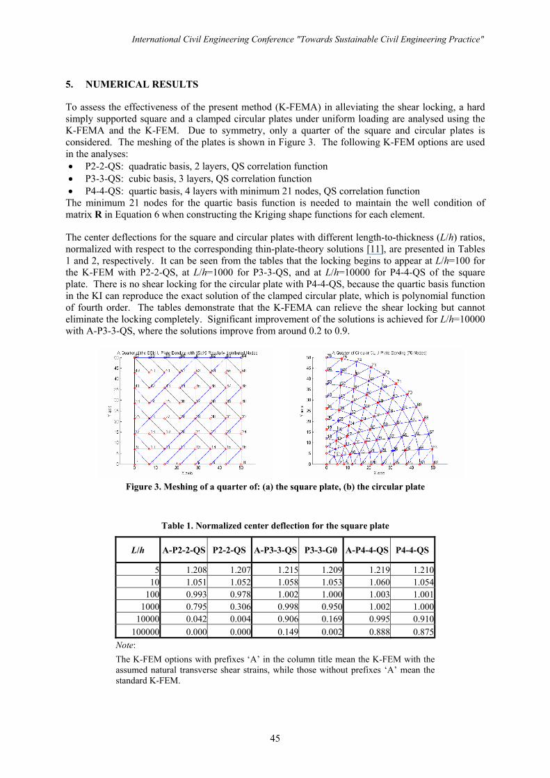
5. NUMERICAL RESULTS
To assess the effectiveness of the present method (K-FEMA) in alleviating the shear locking, a hard simply supported square and a clamped circular plates under uniform loading are analysed using the K-FEMA and the K-FEM. Due to symmetry, only a quarter of the square and circular plates is considered. The meshing of the plates is shown in Figure 3. The following K-FEM options are used in the analyses: • P2-2-QS: quadratic basis, 2 layers, QS correlation function • P3-3-QS: cubic basis, 3 layers, QS correlation function • P4-4-QS: quartic basis, 4 layers with minimum 21 nodes, QS correlation function
The minimum 21 nodes for the quartic basis function is needed to maintain the well condition of matrix R in Equation 6 when constructing the Kriging shape functions for each element.
The center deflections for the square and circular plates with different length-to-thickness (L/h) ratios, normalized with respect to the corresponding thin-plate-theory solutions [11], are presented in Tables 1 and 2, respectively. It can be seen from the tables that the locking begins to appear at L/h=100 for the K-FEM with P2-2-QS, at L/h=1000 for P3-3-QS, and at L/h=10000 for P4-4-QS of the square plate. There is no shear locking for the circular plate with P4-4-QS, because the quartic basis function in the KI can reproduce the exact solution of the clamped circular plate, which is polynomial function of fourth order. The tables demonstrate that the K-FEMA can relieve the shear locking but cannot eliminate the locking completely. Significant improvement of the solutions is achieved for L/h=10000 with A-P3-3-QS, where the solutions improve from around 0.2 to 0.9.
Figure 3. Meshing of a quarter of: (a) the square plate, (b) the circular plate
Table 1. Normalized center deflection for the square plate
L/h A-P2-2-QS P2-2-QS A-P3-3-QS P3-3-G0 A-P4-4-QS P4-4-QS
5 1.208 1.207 1.215 1.209 1.219 1.21010 1.051 1.052 1.058 1.053 1.060 1.054
100 0.993 0.978 1.002 1.000 1.003 1.0011000 0.795 0.306 0.998 0.950 1.002 1.000
10000 0.042 0.004 0.906 0.169 0.995 0.910100000 0.000 0.000 0.149 0.002 0.888 0.875
Note: The K-FEM options with prefixes ‘A’ in the column title mean the K-FEM with the assumed natural transverse shear strains, while those without prefixes ‘A’ mean thestandard K-FEM.
International Civil Engineering Conference "Towards Sustainable Civil Engineering Practice"
45
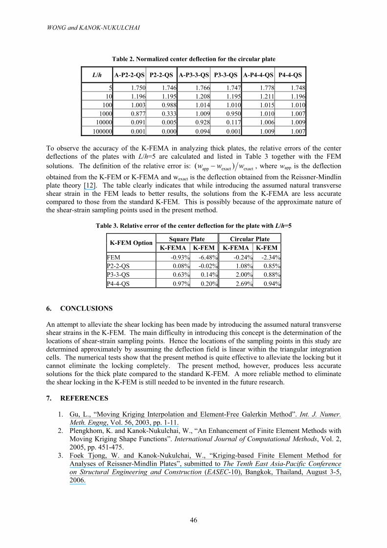
Table 2. Normalized center deflection for the circular plate
L/h A-P2-2-QS P2-2-QS A-P3-3-QS P3-3-QS A-P4-4-QS P4-4-QS
5 1.750 1.746 1.766 1.747 1.778 1.74810 1.196 1.195 1.208 1.195 1.211 1.196
100 1.003 0.988 1.014 1.010 1.015 1.0101000 0.877 0.333 1.009 0.950 1.010 1.007
10000 0.091 0.005 0.928 0.117 1.006 1.009100000 0.001 0.000 0.094 0.001 1.009 1.007
To observe the accuracy of the K-FEMA in analyzing thick plates, the relative errors of the center deflections of the plates with L/h=5 are calculated and listed in Table 3 together with the FEM solutions. The definition of the relative error is: app exact exact( )w w w− , where wapp is the deflection obtained from the K-FEM or K-FEMA and wexact is the deflection obtained from the Reissner-Mindlin plate theory [12]. The table clearly indicates that while introducing the assumed natural transverse shear strain in the FEM leads to better results, the solutions from the K-FEMA are less accurate compared to those from the standard K-FEM. This is possibly because of the approximate nature of the shear-strain sampling points used in the present method.
Table 3. Relative error of the center deflection for the plate with L/h=5
Square Plate Circular Plate K-FEM Option K-FEMA K-FEM K-FEMA K-FEM
FEM -0.93% -6.48% -0.24% -2.34% P2-2-QS 0.08% -0.02% 1.08% 0.85% P3-3-QS 0.63% 0.14% 2.00% 0.88% P4-4-QS 0.97% 0.20% 2.69% 0.94%
6. CONCLUSIONS
An attempt to alleviate the shear locking has been made by introducing the assumed natural transverse shear strains in the K-FEM. The main difficulty in introducing this concept is the determination of the locations of shear-strain sampling points. Hence the locations of the sampling points in this study are determined approximately by assuming the deflection field is linear within the triangular integration cells. The numerical tests show that the present method is quite effective to alleviate the locking but it cannot eliminate the locking completely. The present method, however, produces less accurate solutions for the thick plate compared to the standard K-FEM. A more reliable method to eliminate the shear locking in the K-FEM is still needed to be invented in the future research.
7. REFERENCES
1. Gu, L., “Moving Kriging Interpolation and Element-Free Galerkin Method”. Int. J. Numer. Meth. Engng, Vol. 56, 2003, pp. 1-11.
2. Plengkhom, K. and Kanok-Nukulchai, W., “An Enhancement of Finite Element Methods with Moving Kriging Shape Functions”. International Journal of Computational Methods, Vol. 2, 2005, pp. 451-475.
3. Foek Tjong, W. and Kanok-Nukulchai, W., “Kriging-based Finite Element Method for Analyses of Reissner-Mindlin Plates”, submitted to The Tenth East Asia-Pacific Conference on Structural Engineering and Construction (EASEC-10), Bangkok, Thailand, August 3-5, 2006.
WONG and KANOK-NUKULCHAI
46
4. Kanok-Nukulchai, W., Barry, W., Saran-Yasoontorn. K. and Bouillard. P.H., “On Elimination of Shear Locking in the Element-Free Galerkin Method”, Int. J. Numer. Meth. Engng, Vol. 52, 2001, pp. 705-725.
5. Mitaim, S., “A Family of Triangular Plate Elements Based on the Assumed Strain Method”, Asian Institute of Technology Thesis, No. ST-94-22. Pathumthani, Thailand, 1994.
6. Ma, H., “Development of a Geometrically Nonlinear Shell Element by Assumed Strain Methods”, Asian Institute of Technology Dissertation, No. ST-90-1. Pathumthani, Thailand, 1990.
7. Lee, S.J., “Free Vibration Analysis of Plates by Using a Four-Node Finite Element Formulated with Assumed Natural Transverse Shear Strain”. Journal of Sound and Vibration, Vol. 278, 2004, pp. 657-684.
8. Olea, R.A., Geostatistics for Engineers and Earth Scientists. Boston, Kluwer Academic Publishers, 1999.
9. Wackernagel, H., Multivariate Geostatistics. Second Edition, Springer, 1998. 10. Garcia, O., Fancello, E.A., Barcellos, C.S. and Duarte, C.A., “hp-Clouds in Mindlin’s thick
plate model”. Int. J. Numer. Meth. Engng, Vol. 47, 2000, pp. 1381-1400. 11. Timoshenko, S. and Woinowsky-Krieger, S., Theory of Plates and Shells. Second Edition,
McGraw-Hill, 1959. 12. Reismann, H., Elastic Plates, Theory and Application. New York, John Wiley and Sons,
1988.
International Civil Engineering Conference "Towards Sustainable Civil Engineering Practice"
47

48