omr (optical mark recognition) based attendance system final report
TRANSCRIPT
AProject Report On
OMR BASED ATTENDANCE SYSTEM
Submitted By
SAYYED DAUD
KHAN ABDUL KADIR
KHAN MAINUDDEEN
MULLA MOINUnder the guidance of
Prof. SHIBURAJ PAPPU
Submitted as a partial fulfillment of
Bachelor of EngineeringB.E. (Semester VIII), COMPUTER
[2013 - 2014]from
Rizvi College of EngineeringNew Rizvi Educational Complex, Off-Carter Road,
Bandra(w), Mumbai - 400050
Affiliated to
University of Mumbai
CERTIFICATE
This is certify that the project report entitled“OMR BASED ATTENDANCE SYSTEM”
Submitted By
SAYYED DAUDKHAN ABDUL KADIRKHAN MAINUDDEEN
MULLA MOIN
of Rizvi College of Engineering,Computer Department has been approved in partial fulfillment of re-quirement for the degree of Bachelor of Engineering.
Prof. Shiburaj Pappu
Prof. Dinesh B. Deore Dr. Varsha ShahHOD, Computer Department Principal RCOE
Prof. Prof.Internal Examiner External Examiner
Date:

Acknowledgement
I am profoundly grateful to Prof.Shiburaj Pappu for his expert guidance and continuous encourage-ment throughout to see that this project rights its target since its commencement to its completion.
I would like to express deepest appreciation towards Dr. Varsha Shah, Principal RCOE, Mumbai andProf. Dinesh B. Deore, HoD (Computer Department)whose invaluable guidance supported me in com-pleting this project.
At last I must express my sincere heartfelt gratitude to all the staff members of (Computer Department)who helped me directly or indirectly during this course of work.
SAYYED DAUD
KHAN ABDUL KADIR
KHAN MAINUDDEEN
MULLA MOIN
ABSTRACT
This project is actually an application that we are developing which enables implementation of OMRusing an ordinary scanner.Our project is to implement attendance system for our college using OMRtechnique.A sheet containing blank circles will be passed to mark attendance instead of signatures. Thecounting of attendance and their storage in database will be done automatically using this software.Defaulter list will also get prepared by clicking a single button.
Keywords :OMR-optical mark recoginition
Contents
1 Introduction 11.1 Motivation and Problem Statement . . . . . . . . . . . . . . . . . . . . . . . . . . . . . 21.2 Objectives . . . . . . . . . . . . . . . . . . . . . . . . . . . . . . . . . . . . . . . . . . 2
2 Literature Survey 32.1 Paper1-A Low-Cost OMR Solution for Educational Applications . . . . . . . . . . . . . 3
2.1.1 Summary . . . . . . . . . . . . . . . . . . . . . . . . . . . . . . . . . . . . . . 32.1.2 Advantages . . . . . . . . . . . . . . . . . . . . . . . . . . . . . . . . . . . . . 32.1.3 Disadvantages . . . . . . . . . . . . . . . . . . . . . . . . . . . . . . . . . . . 3
2.2 Paper2-Implementation of OMR Technology with the Help Ordinary Scanner . . . . . . 42.2.1 Summary . . . . . . . . . . . . . . . . . . . . . . . . . . . . . . . . . . . . . . 42.2.2 Advantages . . . . . . . . . . . . . . . . . . . . . . . . . . . . . . . . . . . . . 42.2.3 Disadvantages . . . . . . . . . . . . . . . . . . . . . . . . . . . . . . . . . . . 4
3 Proposed Work 53.1 Module1:-Detection of Attendance marks using java. . . . . . . . . . . . . . . . . . . . 5
3.1.1 System Design . . . . . . . . . . . . . . . . . . . . . . . . . . . . . . . . . . . 53.1.2 Image Acquisition . . . . . . . . . . . . . . . . . . . . . . . . . . . . . . . . . 53.1.3 Steps Involved . . . . . . . . . . . . . . . . . . . . . . . . . . . . . . . . . . . 63.1.4 Design the form . . . . . . . . . . . . . . . . . . . . . . . . . . . . . . . . . . . 63.1.5 Create a template for the marked areas . . . . . . . . . . . . . . . . . . . . . . . 63.1.6 Tilt correction . . . . . . . . . . . . . . . . . . . . . . . . . . . . . . . . . . . . 73.1.7 Use image processing to accentuate the marks . . . . . . . . . . . . . . . . . . . 73.1.8 Find the marks using the template . . . . . . . . . . . . . . . . . . . . . . . . . 83.1.9 Mark recognition . . . . . . . . . . . . . . . . . . . . . . . . . . . . . . . . . . 83.1.10 Algorithm . . . . . . . . . . . . . . . . . . . . . . . . . . . . . . . . . . . . . . 8
3.2 Module2:-Developing a User Interface . . . . . . . . . . . . . . . . . . . . . . . . . . . 103.2.1 Creating a Structure of User interface using HTML and CSS3 (Bootstrap) . . . . 10
3.3 Module3:-Uploading the scanned image and utilizing it as an input to java code . . . . . 113.3.1 Uploading Image . . . . . . . . . . . . . . . . . . . . . . . . . . . . . . . . . . 113.3.2 Running java code on web browser:- . . . . . . . . . . . . . . . . . . . . . . . . 11
4 Project Design 134.1 Requirement Analysis . . . . . . . . . . . . . . . . . . . . . . . . . . . . . . . . . . . . 13
4.1.1 Stakeholder Identifications . . . . . . . . . . . . . . . . . . . . . . . . . . . . . 144.1.2 Investigation . . . . . . . . . . . . . . . . . . . . . . . . . . . . . . . . . . . . 14

5 Implementation & Technologies Used 165.1 Softwares . . . . . . . . . . . . . . . . . . . . . . . . . . . . . . . . . . . . . . . . . . 16
5.1.1 Eclipse(Kepler-v4.3.2) . . . . . . . . . . . . . . . . . . . . . . . . . . . . . . . 165.1.2 Xampp(v1.8.3) . . . . . . . . . . . . . . . . . . . . . . . . . . . . . . . . . . . 165.1.3 Web Browser (Google chrome) . . . . . . . . . . . . . . . . . . . . . . . . . . 175.1.4 Notepad++(v6.5.5) . . . . . . . . . . . . . . . . . . . . . . . . . . . . . . . . . 175.1.5 Windows 7-Ultimate . . . . . . . . . . . . . . . . . . . . . . . . . . . . . . . . 17
5.2 Programming Languages used:- . . . . . . . . . . . . . . . . . . . . . . . . . . . . . . 185.2.1 Java Standard edition(j2se v1.7) . . . . . . . . . . . . . . . . . . . . . . . . . . 185.2.2 SQL(Structured Query Language) . . . . . . . . . . . . . . . . . . . . . . . . . 185.2.3 HTML(HyperText Markup Language) . . . . . . . . . . . . . . . . . . . . . . . 195.2.4 CSS(V 3.0) . . . . . . . . . . . . . . . . . . . . . . . . . . . . . . . . . . . . . 195.2.5 PHP . . . . . . . . . . . . . . . . . . . . . . . . . . . . . . . . . . . . . . . . . 205.2.6 AJAX . . . . . . . . . . . . . . . . . . . . . . . . . . . . . . . . . . . . . . . . 205.2.7 Jquery . . . . . . . . . . . . . . . . . . . . . . . . . . . . . . . . . . . . . . . . 215.2.8 Bootstrap . . . . . . . . . . . . . . . . . . . . . . . . . . . . . . . . . . . . . . 225.2.9 Javascript . . . . . . . . . . . . . . . . . . . . . . . . . . . . . . . . . . . . . . 23
5.3 Models . . . . . . . . . . . . . . . . . . . . . . . . . . . . . . . . . . . . . . . . . . . 245.3.1 ER Diagram . . . . . . . . . . . . . . . . . . . . . . . . . . . . . . . . . . . . 245.3.2 Sequence Diagram . . . . . . . . . . . . . . . . . . . . . . . . . . . . . . . . . 255.3.3 Data Flow Diagram . . . . . . . . . . . . . . . . . . . . . . . . . . . . . . . . . 265.3.4 Database Structure diagram . . . . . . . . . . . . . . . . . . . . . . . . . . . . 27
5.4 User Interface Snapshots . . . . . . . . . . . . . . . . . . . . . . . . . . . . . . . . . . 285.4.1 Login Screen . . . . . . . . . . . . . . . . . . . . . . . . . . . . . . . . . . . . 285.4.2 Home Screen . . . . . . . . . . . . . . . . . . . . . . . . . . . . . . . . . . . . 28
6 Test Cases, Project Time Line & Task Distribution 296.1 Test Cases . . . . . . . . . . . . . . . . . . . . . . . . . . . . . . . . . . . . . . . . . . 29
6.1.1 Case 1: Testing with sheet mark with black pen or pencil . . . . . . . . . . . . . 296.1.2 Case 2: Testing with sheet mark tilted . . . . . . . . . . . . . . . . . . . . . . . 306.1.3 Case 3: Testing with scrubed Sheet . . . . . . . . . . . . . . . . . . . . . . . . 316.1.4 Case 4: Testing with improper filled sheet . . . . . . . . . . . . . . . . . . . . . 32
6.2 Task Distribution . . . . . . . . . . . . . . . . . . . . . . . . . . . . . . . . . . . . . . 336.3 Project Time Line . . . . . . . . . . . . . . . . . . . . . . . . . . . . . . . . . . . . . . 34
7 Conclusion and Future Scope 357.1 Future Scope . . . . . . . . . . . . . . . . . . . . . . . . . . . . . . . . . . . . . . . . 357.2 Conclusion . . . . . . . . . . . . . . . . . . . . . . . . . . . . . . . . . . . . . . . . . 36
References 37
APPENDICES 37
A Project Hosting 38
List of Figures
3.1 Flow Diagram of Image Acquisition . . . . . . . . . . . . . . . . . . . . . . . . . . . . 63.2 Sample Sheet . . . . . . . . . . . . . . . . . . . . . . . . . . . . . . . . . . . . . . . . 73.3 Web Application Database. . . . . . . . . . . . . . . . . . . . . . . . . . . . . . . . . . 12
5.1 System ER Diagram . . . . . . . . . . . . . . . . . . . . . . . . . . . . . . . . . . . . 245.2 System Sequence Diagram . . . . . . . . . . . . . . . . . . . . . . . . . . . . . . . . . 255.3 System Data Flow . . . . . . . . . . . . . . . . . . . . . . . . . . . . . . . . . . . . . . 265.4 System Data Flow . . . . . . . . . . . . . . . . . . . . . . . . . . . . . . . . . . . . . . 275.5 Login page of Web Application. . . . . . . . . . . . . . . . . . . . . . . . . . . . . . . 285.6 Basic Structure of Web Application. . . . . . . . . . . . . . . . . . . . . . . . . . . . . 28
6.1 Demo Purpose-Sheet1 . . . . . . . . . . . . . . . . . . . . . . . . . . . . . . . . . . . 296.2 Demo Purpose-Sheet2 . . . . . . . . . . . . . . . . . . . . . . . . . . . . . . . . . . . 306.3 Demo Purpose-Sheet3 . . . . . . . . . . . . . . . . . . . . . . . . . . . . . . . . . . . 316.4 Demo Purpose-Sheet4 . . . . . . . . . . . . . . . . . . . . . . . . . . . . . . . . . . . 326.5 Task Distribution . . . . . . . . . . . . . . . . . . . . . . . . . . . . . . . . . . . . . . 33
Chapter 1 Introduction
Chapter 1
Introduction
Optical Mark Recognition (OMR), also called mark sensing, is a technique to sense the presence orabsence of marks by recognizing their depth (darkness) on sheet [1,4]. A mark is a response positionon the questionnaire sheet that is filled with pencil or ballpoint pen. The way of marking is simple toeveryone and OMR device can process mark information on sheets rapidly. Thus, OMR has been widelyused as a direct input device for data of censuses and surveys and is fit for handling discrete data, whosevalues fall into a limited number of values.
OMR is a technology that detects the absence or presence of a mark, but not the shape of the mark.OMR software interprets the output from the scanner, and translates it into the desired ASCII output.Forms are scanned through an scanner. The forms contain small circles, referred to as bubbles, or boxesthat are filled in by the respondent. Optical Mark Reader (OMR) reads marks written by pencil or ball-point pen in the pre-defined positions on the attendance sheet. The OMR can judge the existence ofwritten marks by recognizing their darkness on the sheet.
In the field of education, OMR technique is often used to process objective questions in the examina-tion, such as College Boards Scholastic Aptitude Test (SAT), the Graduate Record Examination (GRE)in the United States, and the College English Test (CET) in China. However, there are a few distinctdrawbacks which limit the application of OMR technology.
In this process there are two fundamental forces that form the basis of evolutionary systems.
• First, the questionnaire sheets which can be processed by OMR devices must be 90110 gsm(gramsper square meter, unit of paper weight). Such high quality papers are much more expensive thanthe common plain papers 6070 gsm and general schools can not afford to use them in commonexams.
• Second, the high precision layout of standard questionnaire sheet is required. The questionnairesheets must be precisely designed and printed. The printing and cutting slips need to be and 0.2mm or even less which can only be obtained through professional printing house].Finally, OMRmachine is dedicated device that can only be used to process OMR sheets. This is a burden carriedby the colleges.
In this paper, attendance calculating using OMR technique is presented. Besides implementing allthe functions of the traditional OMR, our system will supports plain sheets (70 gsm or less) and lowprinting quality attendance sheets and digitally storing of information is also done.
The implementation is done using Java. We are using Net beans IDE so as to easily manage thegraphical layout and all the resources. For the GUI,java was chosen mainly because of its platform
Rizvi College of Engineering, Bandra, Mumbai. 1
Chapter 1 Introduction
independence and lightweight of the components in java swing.
1.1 Motivation and Problem Statement
In every colleges, an attendance sheet is passed for making the attendance to the student. If we considerapprox. 80 student in a class for 1 subject then it require 4 sheets of attendance for 2 weeks. likewisethere may be 5 or 6 subject ,so for one month they may require 48 sheet .similarly there may be 4semester of different year(F.E,S.E,T.EandB.E) in six month. so the total may increased to approx 200sheets for six months. Similarly there may be six branch of engg., so the count goes on and on.
For making defaulter list, Each staff members need to count the no. of attendance of a particularstudent. It takes time as well as energy if something went wrong. Then the calculated attendance isgiven to a person for making defaulter list. All the data is manipulated according to cut off of defaulter.Again it take Time as well as man power.
1.2 Objectives
• First, Our project aim is to implement the attendance system for our college using OMR tech-nique.This application will help reduce the tedious work of staff members.
• Second, Since traditional way of making defaulter list requires lots of time as well as attendancesheets,this problem can be solved by our application.
• Third, This application can be implemented at institutes level,which will bring a tremendous changein the trend of Educational system record management.
• Fourth, Another main objective of this application is to make the process of making defaulter listmore speedy,more accurate and cost efficiency.
Rizvi College of Engineering, Bandra, Mumbai. 2
Chapter 2 Literature Survey
Chapter 2
Literature Survey
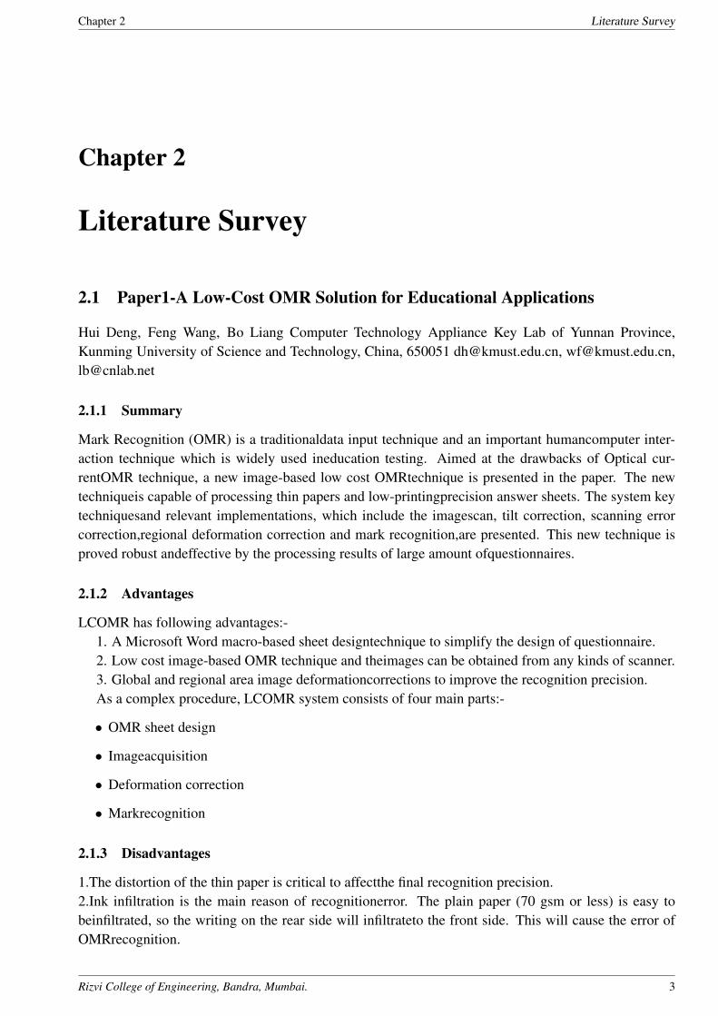
2.1 Paper1-A Low-Cost OMR Solution for Educational Applications
Hui Deng, Feng Wang, Bo Liang Computer Technology Appliance Key Lab of Yunnan Province,Kunming University of Science and Technology, China, 650051 [email protected], [email protected],[email protected]
2.1.1 Summary
Mark Recognition (OMR) is a traditionaldata input technique and an important humancomputer inter-action technique which is widely used ineducation testing. Aimed at the drawbacks of Optical cur-rentOMR technique, a new image-based low cost OMRtechnique is presented in the paper. The newtechniqueis capable of processing thin papers and low-printingprecision answer sheets. The system keytechniquesand relevant implementations, which include the imagescan, tilt correction, scanning errorcorrection,regional deformation correction and mark recognition,are presented. This new technique isproved robust andeffective by the processing results of large amount ofquestionnaires.
2.1.2 Advantages
LCOMR has following advantages:-1. A Microsoft Word macro-based sheet designtechnique to simplify the design of questionnaire.2. Low cost image-based OMR technique and theimages can be obtained from any kinds of scanner.3. Global and regional area image deformationcorrections to improve the recognition precision.As a complex procedure, LCOMR system consists of four main parts:-
• OMR sheet design
• Imageacquisition
• Deformation correction
• Markrecognition
2.1.3 Disadvantages
1.The distortion of the thin paper is critical to affectthe final recognition precision.2.Ink infiltration is the main reason of recognitionerror. The plain paper (70 gsm or less) is easy tobeinfiltrated, so the writing on the rear side will infiltrateto the front side. This will cause the error ofOMRrecognition.
Rizvi College of Engineering, Bandra, Mumbai. 3
Chapter 2 Literature Survey
2.2 Paper2-Implementation of OMR Technology with the Help Ordinary Scan-ner
Garima Krishna, Hemant Ram Rana, Ishu Madan, Kashif, Narendra Sahu, Department of ComputerScience And Engineering College of Engineering, Roorki, India.
2.2.1 Summary
In this fast and furious time, people dont want to invest their time in processing. They just want to givean input and take an output immediately. This project is actually an application that we are developingwhich enables implementation of OMR using an ordinary scanner. It provides tools to the user to designan OMR sheet based on the layout they want. The design of the sheet will be stored as image fileformat (JPEG). The user can take as many print outs as required, distribute it among others from whominformation is desired, and get the filled sheets scanned. The scanned image files will then be providedas input to the software, processing will be done, value of filled fields will be extracted and then the datawill be manipulated as instructed by the user. The implementation is done using Java. We are usingNet beans IDE so as to easily manage the graphical layout and all the resources. For the GUI java waschosen mainly because of its platform independence and lightweight of the components in java swing.
2.2.2 Advantages
This System has following advantages:-1. The program is also small and compact, easily fitting in a diskette.2. No special equipment is needed thus retaining a very low cost. The forms themselves need no
special printing (IR dedicated OMR scanners need red ink forms), and they can be printed in everyprinter and photocopied in large quantities.
3. Finally the algorithms can work and manage the pivot driving areas by themselves, freeing theuser from the tedious and error prone task of manually marking these points.
2.2.3 Disadvantages
1.The distortion of the thin paper is critical to affectthe final recognition precision.2.It won’t work when the image is significantly damaged.
Rizvi College of Engineering, Bandra, Mumbai. 4
Chapter 3 Proposed Work
Chapter 3
Proposed Work
Problem Statement1:-While making this system, our first aim was to detect marks (bubbles) which are the key concept in
our project. To Detect Bubbles, We used multiple basic image detection algorithms. While building theentire system, we gone through three main stages which are explained below:-
3.1 Module1:-Detection of Attendance marks using java.
3.1.1 System Design
This System is programmed using java and some native libraries. The system can be deployed onany operating system since whole system will be done in java (platform independent).Aimed at thedrawbacks of traditional OMR, our system will have following Advantages.
1. A Microsoft PowerPoint-based sheet design technique to simplify the design of attendance sheets.2. The sheets can be scanned from any kinds of scanner.3. Image tilts correction to improve the recognition precision. As a complex procedure, our system
consists of four main parts: OMR sheet design, image Acquisition, Tilt correction and mark recognition.
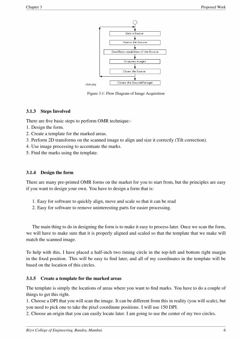
3.1.2 Image Acquisition
• In our study, high speed scanner is used to acquire the images of attendance sheets.
• Twain and ISIS scan interfaces are both supported.
• The average processing speed is more than 50 pages per minute.
• Image data are transferred from scanner to computer and stored in memory of the computer withTIF image format.
The figure below shows the control flow of a typical image acquisition process.Once the image isacquired from the source,it is passed to another process of application.
Rizvi College of Engineering, Bandra, Mumbai. 5
Chapter 3 Proposed Work
chart.png
Figure 3.1: Flow Diagram of Image Acquisition
3.1.3 Steps Involved
There are five basic steps to perform OMR technique:-1. Design the form.2. Create a template for the marked areas.3. Perform 2D transforms on the scanned image to align and size it correctly (Tilt correction).4. Use image processing to accentuate the marks.5. Find the marks using the template.
3.1.4 Design the form
There are many pre-printed OMR forms on the market for you to start from, but the principles are easyif you want to design your own. You have to design a form that is:
1. Easy for software to quickly align, move and scale so that it can be read2. Easy for software to remove uninteresting parts for easier processing.
The main thing to do in designing the form is to make it easy to process later. Once we scan the form,we will have to make sure that it is properly aligned and scaled so that the template that we make willmatch the scanned image.
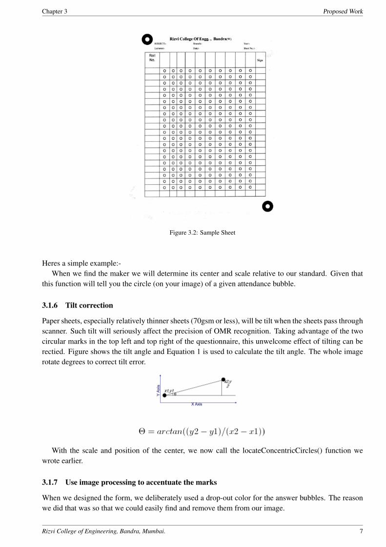
To help with this, I have placed a half-inch two timing circle in the top-left and bottom right marginin the fixed position. This will be easy to find later, and all of my coordinates in the template will bebased on the location of this circles.
3.1.5 Create a template for the marked areas
The template is simply the locations of areas where you want to find marks. You have to do a couple ofthings to get this right.1. Choose a DPI that you will scan the image. It can be different from this in reality (you will scale), butyou need to pick one to take the pixel coordinate positions. I will use 150 DPI.2. Choose an origin that you can easily locate later. I am going to use the center of my two circles.
Rizvi College of Engineering, Bandra, Mumbai. 6
Chapter 3 Proposed Work
Figure 3.2: Sample Sheet
Heres a simple example:-When we find the maker we will determine its center and scale relative to our standard. Given that
this function will tell you the circle (on your image) of a given attendance bubble.
3.1.6 Tilt correction
Paper sheets, especially relatively thinner sheets (70gsm or less), will be tilt when the sheets pass throughscanner. Such tilt will seriously affect the precision of OMR recognition. Taking advantage of the twocircular marks in the top left and top right of the questionnaire, this unwelcome effect of tilting can berectied. Figure shows the tilt angle and Equation 1 is used to calculate the tilt angle. The whole imagerotate degrees to correct tilt error.
With the scale and position of the center, we now call the locateConcentricCircles() function wewrote earlier.
3.1.7 Use image processing to accentuate the marks
When we designed the form, we deliberately used a drop-out color for the answer bubbles. The reasonwe did that was so that we could easily find and remove them from our image.
Rizvi College of Engineering, Bandra, Mumbai. 7
Chapter 3 Proposed Work
3.1.8 Find the marks using the template
To find out which bubbles are filled in, we need to loop through all of the bubbles in a column, figureout where they are in the image, and then look at the pixels in that location and see if the bubble looksfilled in. Since we have dropped out the black in the area, filled in bubbles will be easy to find. First weneed to look at the rectangle over the answer bubble and count up the number of dark pixels.
3.1.9 Mark recognition
After coordinate system is constructed, marks recognition becomes an easy task. Two status of markshould be estimated, one is filled, and another is blank. We adopted a simple method to estimate themark filled or not. In current system, the threshold of filled status is set to 0.4. It means if the cover rateis more than 40
3.1.10 Algorithm
Finding corner points of bounding box: To find the corner points we need to design algorithm for thosecases when the sheet is not being kept straight during scanning, due to human error. In those casesrotation up to 11 degree is acceptable. Now for finding the corner points we first need to know whetherour sheet was rotated towards the right, or towards left, or not rotated at all. For this a random point fromthe top is taken, and traversed downwards till a black pixel is encountered. From that point traversal isdone towards the left. If there are maximum black pixels, it means that the sheet is rotated towards theright; otherwise it is towards the left. Using the appropriate algorithm the corner points can be found.
The algorithm for finding the appropriate points in case the image is tilted towards the left is: img:Image to be analyzed w: Width of image h: Height of image ratio: Minimum limit for number of blackpixels blackCount: Number of black pixels findPoints(): Finds the corner points. leftUp():Finds upperleft corner point. rightUp(): Finds upper right corner points. leftDown(): Finds down left corner point.rightDown(): Finds down right corner point.
1 ratio= 0.8*w;2 blackCount=0;3 leftUp();4 rightUp();5 leftDown();6 rightDown();leftUp()1 for i =2 to h/4 do2. for j=2 to w/4 do3. if( img[ j][i] is BLACK &&img[ j 1][i] is WHITE then4. while j¡w do5. if img[ j + 1][i]is BLACK then blackCount++6. else if img[ j + 1][i]is WHITE then count number of consecutive white pixels and store in white-
Count7. if( whiteCount¿ 5) then8. i=i-1;9. end while10. end if11. if( blackCount¿ ratio)12. print i,j;
Rizvi College of Engineering, Bandra, Mumbai. 8
Chapter 3 Proposed Work
13. return;14. else15. continue;16. end for17. end for
Rizvi College of Engineering, Bandra, Mumbai. 9
Chapter 3 Proposed Work
Problem Statement2:-Once we were able to detect the marks and store the values of each student attendance, our next was
to create a UI (User Interface).For providing a user interface to our stakeholders, we people made it inweb based technologies such as HTML,CSS3 and PHP. We utilizes database called MySQL which isalready come with xampp Software.
3.2 Module2:-Developing a User Interface
3.2.1 Creating a Structure of User interface using HTML and CSS3 (Bootstrap)
HTML or HyperText MarkupLanguage is the standard markup language used to create web applicationsand websites.
HTML is written in the form of HTML elements consisting of tags enclosed in angle brackets (like¡html¿). HTML tags most commonly come in pairs like ¡h1¿ and ¡/h1¿, although some tags representempty elements and so are unpaired, for example ¡img¿. The first tag in a pair is the start tag, and thesecond tag is the end tag (they are also called opening tags and closing tags).
The purpose of a web browser is to read HTML documents and compose them into visible or audibleweb pages. The browser does not display the HTML tags, but uses the tags to interpret the content of thepage. HTML describes the structure of a website semantically along with cues for presentation, makingit a markup language rather than a programming language.
Web browsers can also refer to Cascading Style Sheets (CSS) to define the look and layout of textand other material. The W3C, maintainer of both the HTML and the CSS standards, encourages the useof CSS over explicit presentational HTML.
HTML elements form the building blocks of all websites and web applications. HTML allows im-ages and objects to be embedded and can be used to create interactive. It provides a means to createstructured documents by denoting structural semantics for text such as headings, paragraphs, lists, links,quotes and other items. It can embed scripts written in languages such as JavaScript which affect thebehavior of HTML web pages.
Web browsers can also refer to Cascading Style Sheets (CSS) to define the look and layout of textand other material. The W3C, maintainer of both the HTML and the CSS standards, encourages the useof CSS over explicit presentational HTML.
Once we people were able to completed the basic format for our User interface, next thing was to addfunctionality to this static page, to make it a dynamic web application.
Rizvi College of Engineering, Bandra, Mumbai. 10
Chapter 3 Proposed Work
Problem statement 3:-Adding functionality to the static web pages was a big task and problem. After Searching for 2 3
weeks, we come to know that PHP (Hypertext Preprocessor) will be the best thing to use. Our next aimwas to upload the image to some particular location and then retrieve it so that we can use that image asinput to our java code
3.3 Module3:-Uploading the scanned image and utilizing it as an input to javacode
3.3.1 Uploading Image
For uploading, PHP has provided some built-in functions which people had utilized in our project.
• POST method uploads
This feature lets people upload both text and binary files. With PHP’s authentication and filemanipulation functions, you have full control over who is allowed to upload and what is to be donewith the file once it has been uploaded.
PHP is capable of receiving file uploads from any RFC-1867 compliant browser. The global$ FILES exists as of PHP 4.1.0 (Use $HTTP POST FILES instead if using an earlier version).These arrays will contain all the uploaded file information
The contents of $ FILES from the example form is as follows. Note that this assumes the use ofthe file upload nameuserfile, as used in the example script above. This can be any name.
$ FILES[’userfile’][’name’]
The original name of the file on the client machine.
$ FILES[’userfile’][’type’]
The mime type of the file, if the browser provided this information. An example would be ”im-age/gif”. This mime type is however not checked on the PHP side and therefore don’t take its valuefor granted.
$ FILES[’userfile’][’size’]
The size, in bytes, of the uploaded file.
$ FILES[’userfile’][’tmp name’]
The temporary filename of the file in which the uploaded file was stored on the server.
$ FILES[’userfile’][’error’]
The error code associated with this file upload. This element was added in PHP 4.2.0
3.3.2 Running java code on web browser:-
A big problem was to run a java code over a web browser. Then few weeks later we got methods in PHPwhich solved our problem. These methods help us to avoid making the web services for our java codewhich was the tedious work but thankfully we solved that issue
For Running java code on a web browser, two methods can be used
1. exec Execute an external program
string exec ( string $command [, array &$output [, int &$return var ]] ) exec() executes the givencommand.
Rizvi College of Engineering, Bandra, Mumbai. 11
Chapter 3 Proposed Work
Command :-The command that will be executed.
output
If the output argument is present, then the specified array will be filled with every line of outputfrom the command. Trailing whitespace, is not included in this array. Note that if the array alreadycontains some elements, exec() will append to the end of the array. If you do not want the functionto append elements, call unset()on the array before passing it to exec().
return var
If the return var argument is present along with the output argument, then the return status of theexecuted command will be written to this variable.
2. system Execute an external program and display the output
string system ( string $command [, int &$return var ] )
system() is just like the C version of the function in that it executes the given command and outputsthe result.
command
The command that will be executed.
return var
If the return var argument is present, then the return status of the executed command will be writtento this variable.
Anyone of them can be used to run the java source code, but before running them we were in a needof a compiled jar file with all the required input were has to be taken from argument line. After achiev-ing the required command line were able to run the java source code using exec() or system() .The hugedifference between both these methods is that exec() just run the source code and does not display anyoutput whereas the system() gives output to the screen.
Required command line to use exec() method:-C:/xampp/newfolder/omrproj¿java jar omrproj.jar data/filled.tif 1
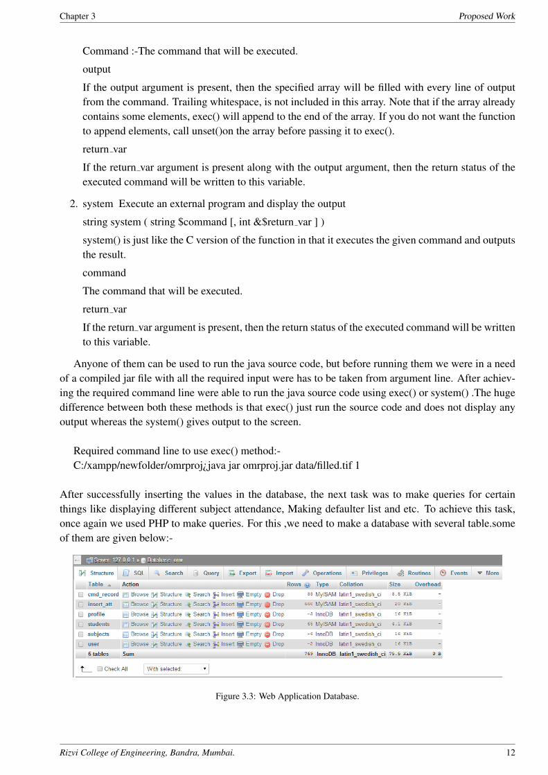
After successfully inserting the values in the database, the next task was to make queries for certainthings like displaying different subject attendance, Making defaulter list and etc. To achieve this task,once again we used PHP to make queries. For this ,we need to make a database with several table.someof them are given below:-
Figure 3.3: Web Application Database.
Rizvi College of Engineering, Bandra, Mumbai. 12

Chapter 4 Project Design
Chapter 4
Project Design
4.1 Requirement Analysis
Requirements analysis, also called requirements engineering, is the process of determining user expecta-tions for a new or modified product. These features, called requirements, must be quantifiable, relevantand detailed. In software engineering, such requirements are often called functional specifications. Re-quirements analysis is an important aspect of project management. Requirements analysis involvesfrequent communication with system users to determine specific feature expectations, resolution of con-flict or ambiguity in requirements as demanded by the various users or groups of users, avoidance offeature creep and documentation of all aspects of the project development process from start to finish.Energy should be directed towards ensuring that the final system or product conforms to client needsrather than attempting to mold user expectations to fit the requirements.
Requirements analysis is a team effort that demands a combination of hardware, software and humanfactors engineering expertise as well as skills in dealing with people. Requirements analysis in systemsengineering and software engineering, encompasses those tasks that go into determining the needs orconditions to meet for a new or altered product, taking account of the possibly conflicting requirementsof the various stakeholders, analyzing, documenting, validating and managing software or system re-quirements.
Requirements analysis is critical to the success of systems or software project.The requirementsshould be documented, actionable, measurable, testable, traceable, related to identified business needsor opportunities, and defined to a level of detail sufficient for system design. Conceptually, requirementsanalysis includes three types of activity:
• Eliciting requirements: the task of communicating with customers and users to determine whattheir requirements are. This is sometimes also called requirements gathering.
• Analyzing requirements: determining whether the stated requirements are unclear, incomplete,ambiguous, or contradictory, and then resolving these issues.
• Recording requirements: Requirements might be documented in various forms, such as natural-language documents, use cases, user stories, or process specifications. Requirements analysis canbe a long and arduous process during which many delicate psychological skills are involved. Newsystems change the environment and relationships between people, so it is important to identify allthe stakeholders, take into account all their needs and ensure they understand the implications ofthe new systems.
Rizvi College of Engineering, Bandra, Mumbai. 13
Chapter 4 Project Design
Analysts can employ several techniques to elicit the requirements from the customer. Historically,this has included such things as holding interviews, or holding focus groups (more aptly named inthis context as requirements workshops) and creating requirements lists. More modern techniquesinclude prototyping, and use cases. Where necessary, the analyst will employ a combination ofthese methods to establish the exact requirements of the stakeholders, so that a system that meetsthe business needs is produced.
4.1.1 Stakeholder Identifications
Stakeholder means a person, group or organization that has interest or concern in an organization.Not allstakeholders are equal. Stakeholders can affect or be affected by the organization’s actions, objectivesand policies. Some of the related ones are given:-
1.Principal-Able to check
• Staff info
• Student info
• Total attendance individual Student
2.Administrator-can do
• Staff info and edit
• Student info and edit
• Make the defaulter list
• Edit the defaulter list
• Editing the criteria 25 ,50, 75 percent
3.Staff membersHave ability to
• Fill the form
• Scan the sheet
• staff profile and Edit
• check attendance table
4.1.2 Investigation
To study any system the analyst needs to do collect facts and all relevant information. The facts whenexpressed in quantitative form are termed as data .accurate information can be collected with the helpof certain methods or techniques. These specific methods for finding information is called fact findingtechniques
Rizvi College of Engineering, Bandra, Mumbai. 14
Chapter 4 Project Design
The analyst may use more than one technique for investigation.
• Interview :
This method is used to collect the information from groups or individuals. Analyst selects thepeople who are related with the system for an interview. In this method the analyst site face to facewith the people and records their responses.
During the initial stages of system development, our group member used to conduct a questionsessions with staff members so that we may come to know what really the stakeholders really want
• Questionnaires :
It is technique used to extract information from number of people. This is cheapest source offact finding. It consists of series of questions framed together in logical manner. The questionsare simple, clear and to the point. While developing this project, n numbers of questions wereasked to Teachers about current situations of counting the attendance and creating the defaulterlist. Questions where like:-
1. What problem teachers got while counting the attendance?
2. How they insert the hardcopy values?
3. How much time it take to count a single sheet attendance data?
4. IV. What happens if the system get crash or the file is affected by virus? and so on
Rizvi College of Engineering, Bandra, Mumbai. 15
Chapter 5 Implementation & Technologies Used
Chapter 5
Implementation & Technologies Used
Technologies used:-
5.1 Softwares
5.1.1 Eclipse(Kepler-v4.3.2)
In computer programming, Eclipse is an integrated development environment (IDE). It contains a baseworkspace and an extensible plug-in system for customizing the environment. Written mostly in Java,Eclipse can be used to develop applications.
By means of various plug-ins, Eclipse may also be used to develop applications in other programminglanguages: Ada, ABAP,C, C++, COBOL, Fortran, Haskell, JavaScript, Lasso, Perl, PHP, Python, R,Ruby (including Ruby on Rails framework), Scala,Clojure, Groovy, Scheme, and Erlang.
It can also be used to develop packages for the software Mathematica. Development environments in-clude the Eclipse Java development tools (JDT) for Java and Scala, Eclipse CDT for C/C++ and EclipsePDT for PHP, among others.
5.1.2 Xampp(v1.8.3)
XAMPP is an open-source web server package that works on various platforms. It is actually an acronymwith X meaning cross platform, A for Apache HTTP server, M for MySQL, P for PHP, and P for Perl.XAMPP was designed to help webpage developers, programmers, and designers check and review theirwork using their computers even without connection to the web or internet.
So, basically XAMPP may be used to stand as pages for the internet even without connection to it.It can also be used to create and configure with databases written in MySQL and/or SQLite. And sinceXAMPP is designed as a cross-platform server package, it is available for a variety of operating systemsand platforms like Microsoft Windows, Mac OS X, Linux, and Solaris.
To use XAMPP, only one zip, exe or tar file is needed. Users just need to download this file and runthe application. There is also not much configuration and tinkering to be done in terms of settings andits components.The XAMPP package is also updated on a regular basis to synchronize with the updates made on the
Rizvi College of Engineering, Bandra, Mumbai. 16
Chapter 5 Implementation & Technologies Used
different platforms involved in the package like Apache, PHP, Perl, and MySQL.
XAMPP is a free and open source cross-platform web server solution stack package, consistingmainly of the Apache HTTP Server, MySQL database, and interpreters for scripts written in the PHPand Perlprogramming languages.
5.1.3 Web Browser (Google chrome)
A web browser, or simply ”browser,” is an applicationused to access and view websites. Common webbrowsers include Microsoft Internet Explorer, Google Chrome, Mozilla Firefox, and Apple Safari.
The primary function of a web browser is to renderHTML, the code used to design or ”mark up”webpages.Each time a browser loads a web page, it processes the HTML, which may include text, links, and ref-erences to images and other items, such ascascading style sheets and JavaScript functions. The browserprocesses these items, then renders them in the browser window.
Early web browsers, such as Mosaic and Netscape Navigator, were simple applications that ren-dered HTML, processed form input, and supported bookmarks. As websites have evolved, so have webbrowser requirements. Today’s browsers are far more advanced, supporting multiple types of HTML(such as XHTML and HTML 5), dynamic JavaScript, and encryption used by secure websites.
The capabilities of modern web browsers allow web developers to create highly interactive websites.For example, Ajax enables a browser to dynamically update information on a webpage without theneed to reload the page. Advances in CSS allow browsers to display a (responsive website— respon-sive web design) layouts and a wide array of visual effects. Cookies allow browsers to remember yoursettings for specific websites.
The major web browsers are Google Chrome, Mozilla Firefox, Internet Explorer, Opera, and Safari.
5.1.4 Notepad++(v6.5.5)
Notepad++ is a text editor and source code editor for Windows.
It differs from the built-in Windows text editor Notepad, is that Notepad++ supports tabbed editing,which allows working with multiple open files in a single window. Notepad++ opens large files signifi-cantly faster than Windows Notepad.
Notepad++ is distributed as free software. The project was hosted on SourceForge.net, from whereit has been downloaded over 28 million times[3][4] and twice won the SourceForge Community ChoiceAward for Best Developer Tool.[5] The project has been hosted on TuxFamily since June 2010. Notepad++uses the Scintilla editor component.
5.1.5 Windows 7-Ultimate
Windows 7 is an operating system produced by Microsoft for use on personal computers, includinghome and business desktops, laptops, netbooks, tablet PCs, and media center PCs.
Rizvi College of Engineering, Bandra, Mumbai. 17
Chapter 5 Implementation & Technologies Used
5.2 Programming Languages used:-
5.2.1 Java Standard edition(j2se v1.7)
Java is a high-level programming language developed by Sun Microsystems. It was originally designedfor developing programs for set-top boxes and handheld devices, but later became a popular choice forcreating web applications.
The Java syntax is similar to C++, but is strictly anobject-oriented programming language. For ex-ample, most Java programs contain classes, which are used to define objects, and methods, which areassigned to individual classes. Java is also known for being more strict than C++, meaning variables andfunctions must be explicitly defined.
This means Java source code may produce errors or ”exceptions” more easily than other languages,but it also limits other types of errors that may be caused by undefined variables or unassigned types.
Unlike Windows executables (.EXE files) or Macintosh applications (.APP files), Java programs arenot run directly by the operating system. Instead, Java programs are interpreted by the Java Virtual Ma-chine, or JVM, which runs on multiple platforms.
This means all Java programs aremultiplatform and can run on different platforms, including Macin-tosh, Windows, and Unix computers. However, the JVM must be installed for Java applications orapplets to run at all. Fortunately, the JVM is included as part of the Java Runtime Environment (JRE),which is available as a free download.
5.2.2 SQL(Structured Query Language)
Stands for ”Structured Query Language,” and can be pronounced as either ”sequel” or ”S-Q-L.” It isa query language used for accessing and modifying information in a database. Some common SQLcommands include ”insert,” ”update,” and ”delete.” The language was first created by IBM in 1975 andwas called SEQUEL for ”Structured English Query Language.” Since then, it has undergone a numberof changes, many coming from Oracle products.
Today, SQL is commonly used for Web database development and management. Though SQL isnow considered to be a standard language, there are still a number of variations of it, such as mSQL andmySQL. By using a scripting language like PHP, SQL commands can be executed when a Web pageloads. This makes it possible to create dynamic Web pages that can display different information eachtime they load.
The Structured Query Language (SQL) is the set of instructions used to interact with a relationaldatabase. In fact, SQL is the only language that most databases actually understand. Whenever youinteract with such a database, the software translates your commands (whether they are mouse clicks orform entries) into SQL statement that the database knows how to interpret.
SQL has three major components: the Data Manipulation Language (DML), the Data Definition Lan-guage (DDL), and the Data Control Language (DCL).
Rizvi College of Engineering, Bandra, Mumbai. 18
Chapter 5 Implementation & Technologies Used
5.2.3 HTML(HyperText Markup Language)
Stands for ”Hyper-Text Markup Language.” This is the language that Web pages are written in. Alsoknown as hypertext documents, Web pages must conform to the rules of HTML in order to be displayedcorrectly in a Web browser. The HTML syntax is based on a list of tags that describe the page’s formatand what is displayed on the Web page.
Fortunately, the HTML language is relatively easy to learn. Even more fortunately (so much for goodgrammar), many Web development programs allow you to create Web pages using a graphical interface.These programs allow you to place objects and text on the page and the HTML code is written for you.
HTML (Hypertext Markup Language) is the set of markup symbols or codes inserted in a file in-tended for display on a World Wide Web browser page. The markup tells the Web browser how todisplay a Web page’s words and images for the user. Each individual markup code is referred to as anelement (but many people also refer to it as a tag). Some elements come in pairs that indicate whensome display effect is to begin and when it is to end.
HTML elements form the building blocks of all websites and web applications. HTML allows im-ages and objects to be embedded and can be used to create interactive. It provides a means to createstructured documents by denoting structural semantics for text such as headings, paragraphs, lists, links,quotes and other items. It can embed scripts written in languages such as JavaScript which affect thebehavior of HTML web pages.
Web browsers can also refer to Cascading Style Sheets (CSS) to define the look and layout of textand other material. The W3C, maintainer of both the HTML and the CSS standards, encourages the useof CSS over explicit presentational HTML.
5.2.4 CSS(V 3.0)
Cascading Style Sheets (CSS) is a style sheet language used for describing the look and formatting ofadocument written in a markup language. While most often used to style web pages and interfaceswrittenin HTML and XHTML, the language can be applied to any kind of XML document, includingplainXML, SVG and XUL.
CSS is a cornerstone specication of the web and almost all web pages useCSS style sheets to de-scribe their presentation. CSS can also allow the same markup page to be presented in different stylesfor different renderingmethods, such as on-screen, in print, by voice (when read out by a speech-basedbrowser or screen reader) and on Braille-based, tactile devices.
It can also be used to allow the web page to display differently depending on the screen size or deviceon which it is being viewed. Cascading style sheets are used to format the layout of Web pages. Theycan be used to define text styles, table sizes, and other aspects of Web pages that previously could onlybe defined in a page’s HTML.
CSS helps Web developers create a uniform look across several pages of a Web site. Instead of defin-ing the style of each table and each block of text within a page’s HTML, commonly used styles need tobe defined only once in a CSS document. Once the style is defined in cascading style sheet, it can beused by any page that references the CSS file.
Rizvi College of Engineering, Bandra, Mumbai. 19
Chapter 5 Implementation & Technologies Used
Plus, CSS makes it easy to change styles across several pages at once. For example, a Web devel-oper may want to increase the default text size from 10pt to 12pt for fifty pages of a Web site. If thepages all reference the same style sheet, the text size only needs to be changed on the style sheet and allthe pages will show the larger text.
While CSS is great for creating text styles, it is helpful for formatting other aspects of Web pagelayout as well. For example, CSS can be used to define the cell padding of table cells, the style, thickness,and color of a table’s border, and the padding around images or other objects. CSS gives Web developersmore exact control over how Web pages will look than HTML does. This is why most Web pages todayincorporate cascading style sheets.
5.2.5 PHP
Stands for ”Hypertext Preprocessor.” (It is a recursive acronym, if you can understand what that means.)PHP is an HTML-embedded Web scripting language. This means PHP code can be inserted into theHTML of a Web page.
When a PHP page is accessed, the PHP code is read or ”parsed” by the server the page resides on.The output from the PHP functions on the page are typically returned as HTML code, which can beread by the browser. Because the PHP code is transformed into HTML before the page is loaded, userscannot view the PHP code on a page.
This make PHP pages secure enough to access databases and other secure information.In an HTML document, PHP script (similar syntax to that of Perl orC ) is enclosed within special
PHP tags. Because PHP is embedded within tags, the author can jump between HTML and PHP (similarto ASP and Cold Fusion) instead of having to rely on heavy amounts of code to output HTML. And,because PHP is executed on the server, the clientcannot view the PHP code.
PHP can perform any task that any CGI program can do, but its strength lies in its compatibility withmany types of databases. Also, PHP can talk across networks using IMAP, SNMP, NNTP, POP3, orHTTP.
A lot of the syntax of PHP is borrowed from other languages such as C, Java and Perl. However,PHP has a number of unique features and specific functions as well. The goal of the language is to allowWeb developers to write dynamically generated pages quickly and easily. PHP is also great for creatingdatabase-driven Web sites. If you would like to learn more about PHP, the official site is PHP.net.
PHP can perform any task that any CGI program can do, but its strength lies in its compatibility withmany types of databases. Also, PHP can talk across networks using IMAP, SNMP, NNTP, POP3, orHTTP.
5.2.6 AJAX
AJAX is Asynchronous JavaScript and XML. AJAX is not a new programming language, but a newwayto use existing standards. AJAX is the art of exchanging data with a server, and updating parts of awebpage - without reloading the whole page.
Rizvi College of Engineering, Bandra, Mumbai. 20

Chapter 5 Implementation & Technologies Used
Ajax is not a single technology, but a group of technologies. HTML and CSS can be used in combi-nationto mark up and style information.
Ajax is a combination of Web development technologies used for creating dynamic websites. Whilethe term ”Ajax” is not written in all caps like most tech acronyms, the letters stand for ”AsynchronousJavaScript And XML.” Therefore, websites that use Ajax combine JavaScript and XML to display dy-namic content.
The ”asynchronous” part of Ajax refers to the way requests are made to the Web server. When ascriptsends a request to the Web server, it may receive data, which can then be displayed on the Webpage. Since these events happen at slightly different times, they are considered to be asynchronous.Most Ajax implementations use the XMLHttpRequest API, which includes a list of server requests thatcan be called within JavaScript code.
The data is usually sent back to the browser in an XML format, since it is easy to parse. However,it is possible for the server to send data as unformatted plain text as well.
What makes Ajax so powerful is that scripts can run on the client side, rather than on the server. Thismeans a JavaScript function can make a request to a server after a webpage has already finished loading.The data received from the server can then be displayed on the page without reloading the other content.If a server-side scripting language like PHP or ASP was used, the entire page would need to be reloadedin order for the new content to be displayed.
While you may not realize it, you have probably seen Ajax at work on several different websites.For example, search engines that provide a list of search suggestions as you type are most likely usingAjax to display the suggestions. Image searches that produce more thumbnails as you scroll through theresults typically use Ajax to retrieve the continual list of images. When you click ”Older Posts” at thebottom of a Facebook page, Ajax is used to display additional postings.
Ajax has helped make the Web more dynamic by enabling webpages to retrieve and load new contentwithout needing to reload the rest of the page. By using Ajax, Web developers can create interactivewebsites that use resources efficiently and provide visitors with a responsive interface.
The DOM is accessed with JavaScript to dynamically display, and allow the user to interact with, theinformation presented. JavaScript and the XML Http Request object provide a method for exchangingdata asynchronously between browser and server to avoid full page reloads.
5.2.7 Jquery
jQuery is not a language, but it is a well written JavaScript code. As quoted on official jQuery website,”it is a fast and concise JavaScript Library that simplifies HTML document traversing, event handling,animating, and Ajax interactions for rapid web development”.
jQuery is a JavaScript library that allows web developers to add extra functionality to their websites.It is open source and provided for free under the MIT license. In recent years, jQuery has become themost popular JavaScript library used inweb development. To implement jQuery, a web developer simplyneeds to reference the jQuery JavaScript file within the HTMLof a webpage. Some websites host theirown local copy of jQuery, while others simply reference the library hosted by Google or the jQuery
Rizvi College of Engineering, Bandra, Mumbai. 21
Chapter 5 Implementation & Technologies Used
server. For example, a webpage may load the jQuery library using the following line within the ¡head¿section of the HTML:
¡script type=”text/javascript” src=”//ajax.googleapis.com/ajax/libs/jquery/1.9.1/jquery.min.js¿̈¡/script¿
Once the jQuery library is loaded, a webpage can call any jQuery function supported by the library.Common examples include modifying text, processing form data, moving elements on a page, and per-forming animations. jQuery can also work with Ajax code and scripting languages, such as PHP andASP to access data from a database. Since jQuery runs on the client side (rather than the web server), itcan update information on a webpage in realtime, without reloading the page.
A common example is ”autocomplete,” in which a search form automatically displays common searchesas you type your query. In fact, this is how TechTerms.com provides search suggestions when you typein the search box.
Besides its free license, the other main reason jQuery has gained such popularity is its cross-browsercompatibility. Since each browser renders HTML, CSS, and JavaScript differently, it can be difficultfor a web developer to make a website appear the same across all browsers. Instead of having to writecustom functions for each browser, a web developer can use a single jQuery function that will work inChrome, Safari, Firefox, and Internet Explorer.
This multi-browser support has led many developers to switch from standard JavaScript to jQuery, sinceit greatly simplifies the coding process.
5.2.8 Bootstrap
Bootstrap is a front-end framework from Twitter designed to kickstart the front-end development of we-bapps and sites. Among other things, it includes base CSS and HTML for typography, icons, forms,buttons, tables, layout grids, navigation along with custom-built jQuery plug-ins and support for respon-sive layouts.
It is tested and supported in the major modern browsers, such as the latest versions of Safari, GoogleChrome, Firefox 5+, and Internet Explorer 8+.
At its core, Bootstrap is just CSS, but its built with Less, a flexible pre-processor that offers muchmore power and flexibility than regular CSS. With Less, we gain a range of features like nested decla-rations, variables, mixins, operations, and color functions. Additionally, since Bootstrap is purely CSSwhen compiled via Less, we gain two important benefits:
First, Bootstrap remains very easy to implement; just drop it in your code and go. Compiling Lesscan be accomplished via Javascript, an unofficial Mac application, or via Node.js (read more about thisat http://lesscss.org).
Second, once complied, Bootstrap contains nothing but CSS, meaning there are no superfluous im-ages, Flash, or Javascript. All that remains is simple and powerful CSS for your web developmentneeds.
Bootstrap works by providing a clean and uniform solution to the most common, everyday interface
Rizvi College of Engineering, Bandra, Mumbai. 22

Chapter 5 Implementation & Technologies Used
tasks developers come across. At Twitter, Bootstrap has quickly become one of our many go-to front-end tools when starting new applications and sites.
This is because while it is very extensive, its flexible enough to work for many unique design needs.
5.2.9 Javascript
JavaScript (JS) is a dynamic computer programming language. It is most commonly used as part of webbrowsers, whose implementations allow client-side scripts to interact with the user, control the browser,communicate asynchronously, and alter the document content that is displayed. It is also being used inserver-side programming, game development and the creation of desktop and mobile applications.
JavaScript is a prototype-based scripting language with dynamic typing and has first-class functions.Its syntax was influenced by C. JavaScript copies many names and naming conventions from Java, butthe two languages are otherwise unrelated and have very different semantics. The key design principleswithin JavaScript are taken from the Self and Scheme programming languages.[6] It is a multi-paradigmlanguage, supporting object-oriented,imperative, and functional programming styles.
Like Java, this is a programming language designed by Sun Microsystems, in conjunction withNetscape, that can be integrated into standard HTML pages. While JavaScript is based on the Javasyntax, it is a scripting language, and therefore cannot be used to create stand-alone programs. Instead,it is used mainly to create dynamic, interactive Web pages.
For example, Web developers can use JavaScript to validate form input, create image rollovers, andto open those annoying pop-up windows. Like so many other things, we have to take the good with thebad.
Rizvi College of Engineering, Bandra, Mumbai. 23
Chapter 5 Implementation & Technologies Used
5.3 Models
5.3.1 ER Diagram
Also called an entity-relationship (ER) diagram, a graphical representation of entities and their relation-ships to each other, typically used in computing in regard to the organization of data within databases orinformation systems. An entity is a piece of data-an object or concept about which data is stored.
Figure 5.1: System ER Diagram
Rizvi College of Engineering, Bandra, Mumbai. 24
Chapter 5 Implementation & Technologies Used
5.3.2 Sequence Diagram
A sequence diagram is an interaction diagram that shows how processes operate with one another and inwhat order. It is a construct of a Message Sequence Chart. A sequence diagram shows object interactionsarranged in time sequence. It depicts the objects and classes involved in the scenario and the sequence ofmessages exchanged between the objects needed to carry out the functionality of the scenario. Sequencediagrams are typically associated with use case realizations in the Logical View of the system underdevelopment. Sequence diagrams are sometimes called event diagrams, event scenarios
Figure 5.2: System Sequence Diagram
Rizvi College of Engineering, Bandra, Mumbai. 25
Chapter 5 Implementation & Technologies Used
5.3.3 Data Flow Diagram
A data flow diagram (DFD) is a graphical representation of the ”flow” of data through an informationsystem, modeling its process aspects. Often they are a preliminary step used to create an overview ofthe system which can later be elaborated.DFDs can also be used for the visualization of data processing(structured design)
Figure 5.3: System Data Flow
Rizvi College of Engineering, Bandra, Mumbai. 26

Chapter 5 Implementation & Technologies Used
5.3.4 Database Structure diagram
Database design is the process of producing a detailed data model of a database. This logical data modelcontains all the needed logical and physical design choices and physical storage parameters needed togenerate a design in a data definition language, which can then be used to create a database. A fullyattributed data model contains detailed attributes for each entity.
Figure 5.4: System Data Flow
Rizvi College of Engineering, Bandra, Mumbai. 27
Chapter 5 Implementation & Technologies Used
5.4 User Interface Snapshots
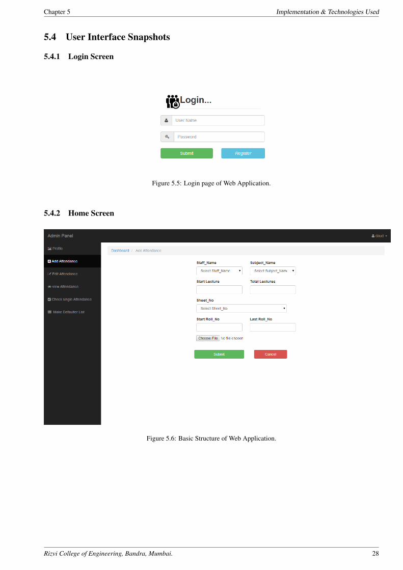
5.4.1 Login Screen
Figure 5.5: Login page of Web Application.
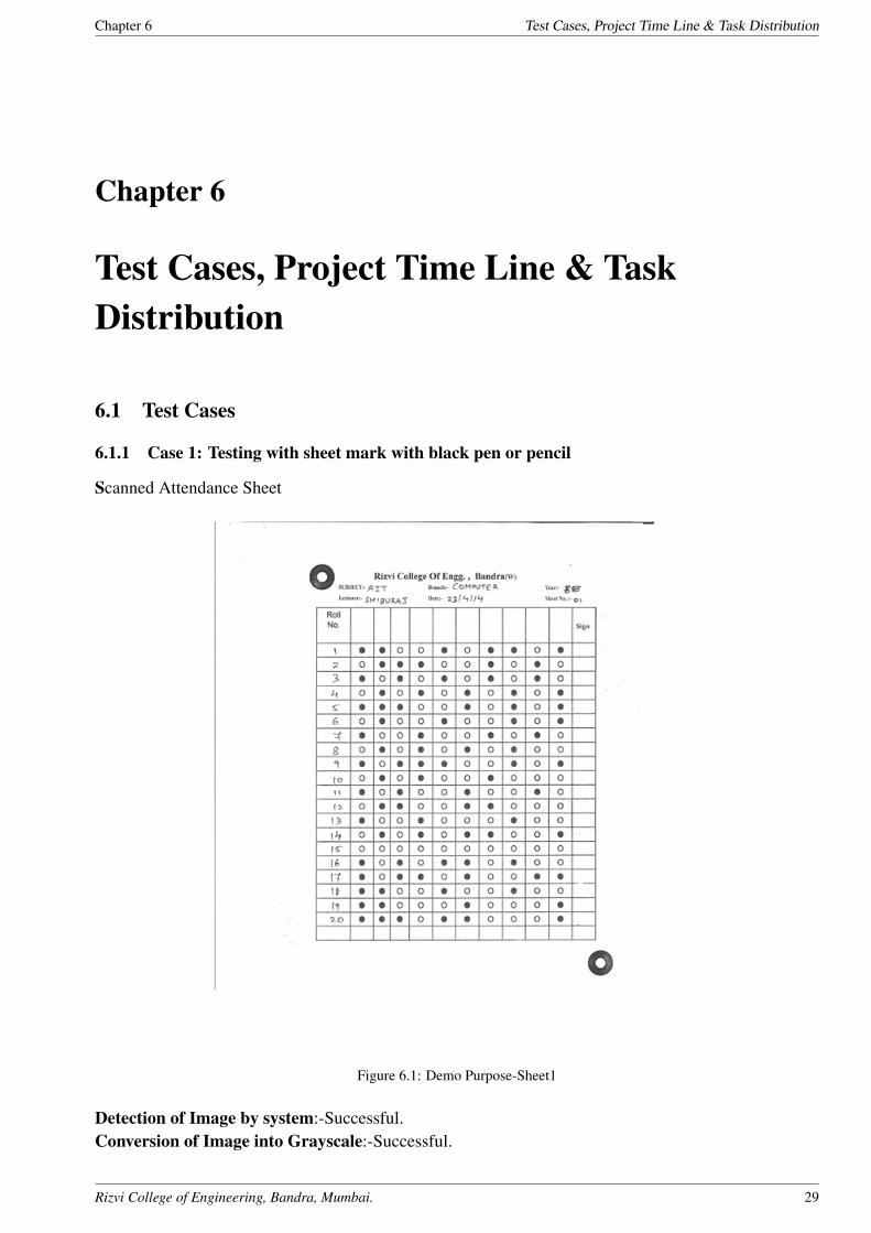
5.4.2 Home Screen
Figure 5.6: Basic Structure of Web Application.
Rizvi College of Engineering, Bandra, Mumbai. 28
Chapter 6 Test Cases, Project Time Line & Task Distribution
Chapter 6
Test Cases, Project Time Line & TaskDistribution
6.1 Test Cases
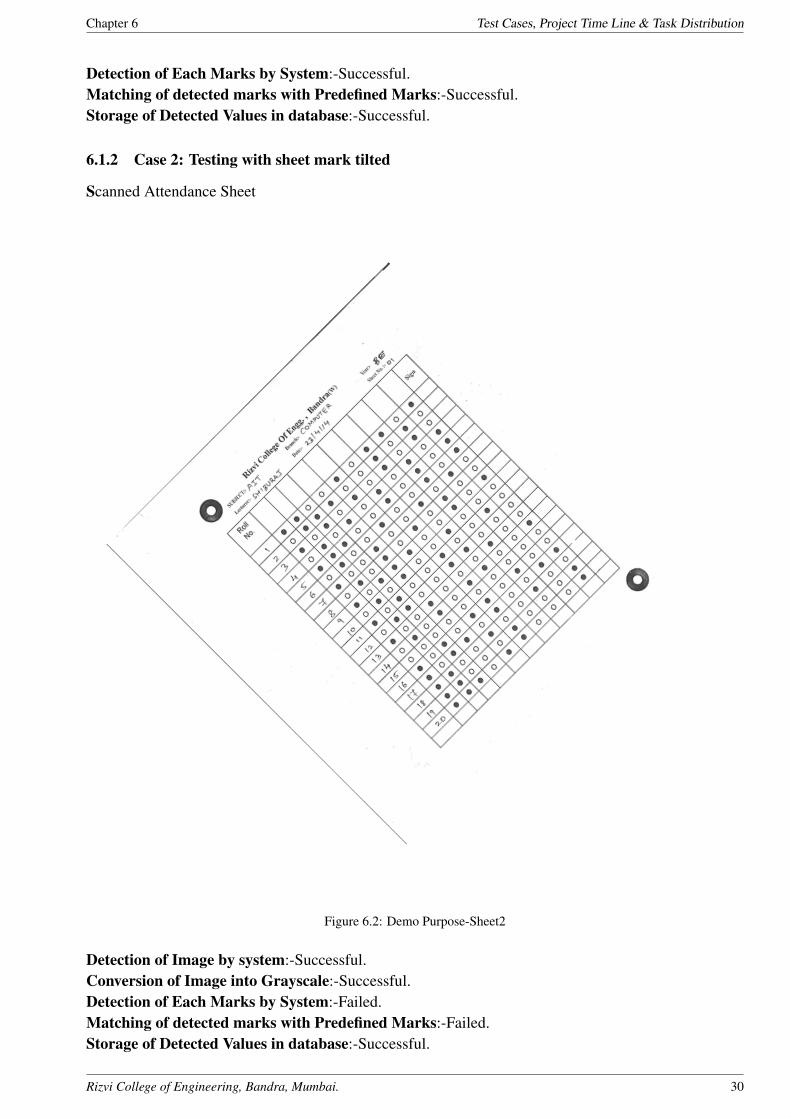
6.1.1 Case 1: Testing with sheet mark with black pen or pencil
Scanned Attendance Sheet
Figure 6.1: Demo Purpose-Sheet1
Detection of Image by system:-Successful.Conversion of Image into Grayscale:-Successful.
Rizvi College of Engineering, Bandra, Mumbai. 29
Chapter 6 Test Cases, Project Time Line & Task Distribution
Detection of Each Marks by System:-Successful.Matching of detected marks with Predefined Marks:-Successful.Storage of Detected Values in database:-Successful.
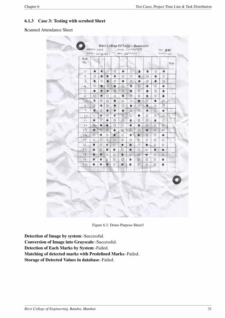
6.1.2 Case 2: Testing with sheet mark tilted
Scanned Attendance Sheet
Figure 6.2: Demo Purpose-Sheet2
Detection of Image by system:-Successful.Conversion of Image into Grayscale:-Successful.Detection of Each Marks by System:-Failed.Matching of detected marks with Predefined Marks:-Failed.Storage of Detected Values in database:-Successful.
Rizvi College of Engineering, Bandra, Mumbai. 30
Chapter 6 Test Cases, Project Time Line & Task Distribution
6.1.3 Case 3: Testing with scrubed Sheet
Scanned Attendance Sheet
Figure 6.3: Demo Purpose-Sheet3
Detection of Image by system:-Successful.Conversion of Image into Grayscale:-Successful.Detection of Each Marks by System:-Failed.Matching of detected marks with Predefined Marks:-Failed.Storage of Detected Values in database:-Failed.
Rizvi College of Engineering, Bandra, Mumbai. 31
Chapter 6 Test Cases, Project Time Line & Task Distribution
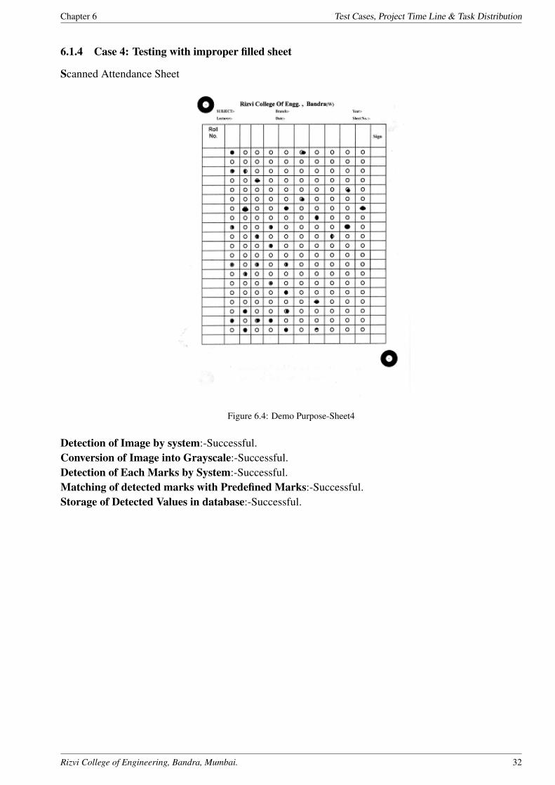
6.1.4 Case 4: Testing with improper filled sheet
Scanned Attendance Sheet
Figure 6.4: Demo Purpose-Sheet4
Detection of Image by system:-Successful.Conversion of Image into Grayscale:-Successful.Detection of Each Marks by System:-Successful.Matching of detected marks with Predefined Marks:-Successful.Storage of Detected Values in database:-Successful.
Rizvi College of Engineering, Bandra, Mumbai. 32
Chapter 6 Test Cases, Project Time Line & Task Distribution
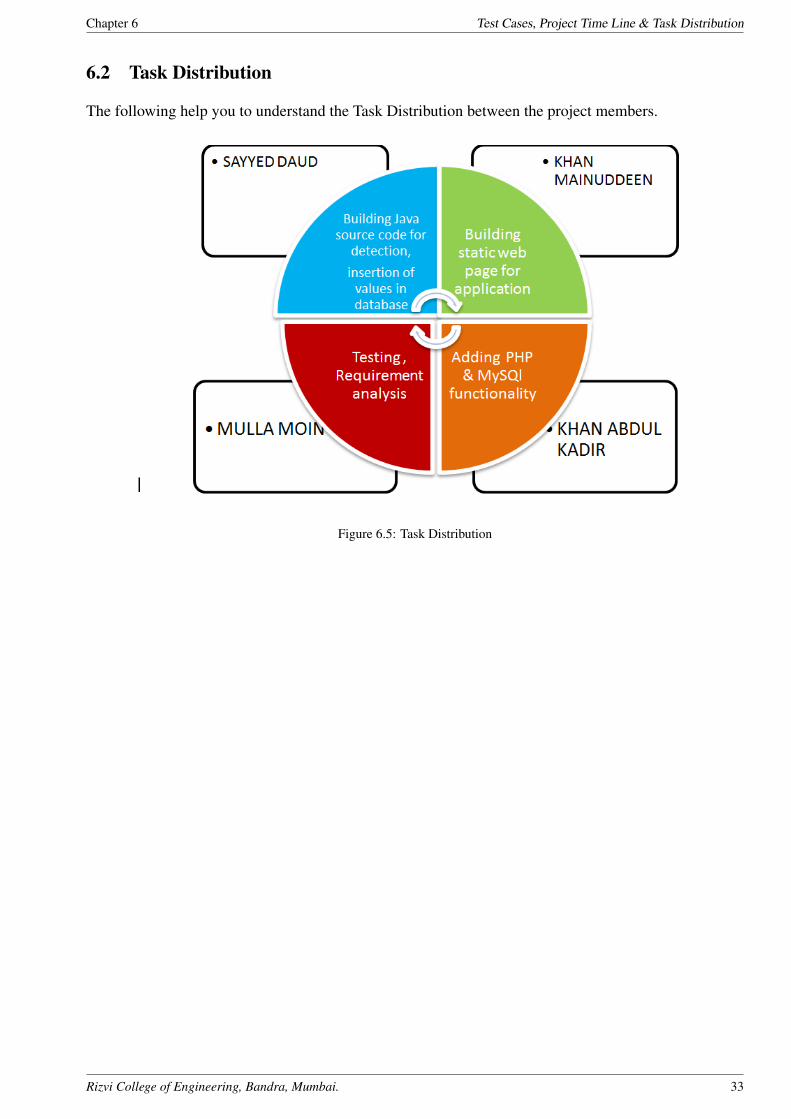
6.2 Task Distribution
The following help you to understand the Task Distribution between the project members.
Figure 6.5: Task Distribution
Rizvi College of Engineering, Bandra, Mumbai. 33
Chapter 6 Test Cases, Project Time Line & Task Distribution
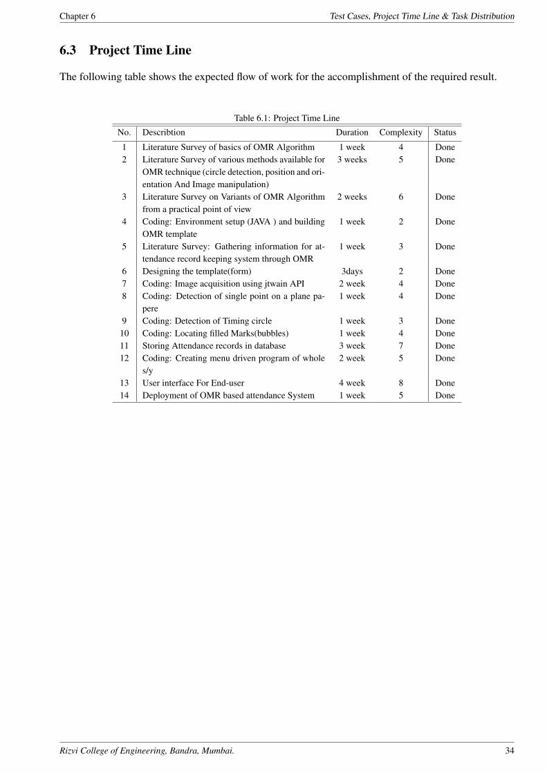
6.3 Project Time Line
The following table shows the expected flow of work for the accomplishment of the required result.
Table 6.1: Project Time Line
No. Describtion Duration Complexity Status
1 Literature Survey of basics of OMR Algorithm 1 week 4 Done2 Literature Survey of various methods available for
OMR technique (circle detection, position and ori-entation And Image manipulation)
3 weeks 5 Done
3 Literature Survey on Variants of OMR Algorithmfrom a practical point of view
2 weeks 6 Done
4 Coding: Environment setup (JAVA ) and buildingOMR template
1 week 2 Done
5 Literature Survey: Gathering information for at-tendance record keeping system through OMR
1 week 3 Done
6 Designing the template(form) 3days 2 Done7 Coding: Image acquisition using jtwain API 2 week 4 Done8 Coding: Detection of single point on a plane pa-
pere1 week 4 Done
9 Coding: Detection of Timing circle 1 week 3 Done10 Coding: Locating filled Marks(bubbles) 1 week 4 Done11 Storing Attendance records in database 3 week 7 Done12 Coding: Creating menu driven program of whole
s/y2 week 5 Done
13 User interface For End-user 4 week 8 Done14 Deployment of OMR based attendance System 1 week 5 Done
Rizvi College of Engineering, Bandra, Mumbai. 34
Chapter 7 Conclusion and Future Scope
Chapter 7
Conclusion and Future Scope
7.1 Future Scope
Right now,this system is able to work for one semester students attendance because of the lack of com-plex database model.But in future,it might possible to create such database with help of good skilleddevelopers.
For detection of image ,tiff images are used which are very memory consuming.but tiff images givebetter image quality and its detections.so in future,we can make use of less memory images which helpto reduce memories wastage.
Although we are scanning the images with help of scanner devices but the hardware is much morecostlier . In future we can take the snapshots of sheets with help of our mobile phone,but for this weneed to scale the image in more appropriate way.
If in future all the restriction of this software is able to removed then it will be possible to implementit to overall indian as well as world colleges.
Rizvi College of Engineering, Bandra, Mumbai. 35
Chapter 7 Conclusion and Future Scope
7.2 Conclusion
This project is an application that perform OMR technique to extract students attendance using an ordi-nary scanner. It provides tools to the user to design an OMR sheet based on the layout they want. Thedesign of the sheet will be stored as image le format (Tiff). The user can take as many print outs asrequired, distribute it among others from whom information is desired, and get the lled sheets scanned.The scanned image les will then be provided as input to the software, processing will be done, valueof lled elds will be extracted and then the data will be manipulated as instructed by the user and thenstorage of data will be done in database.
OMR based Attendance system is a robust and low-cost OMR technique that can be adopted widelyin the developing countries. Partially resolves the drawbacks of traditional OMR technique and im-proves its usability.If this system is implemented successfully, the teachers of colleges will be capableof designing attendance sheets by themselves and the supervisor of colleges can adopt this technique toinvestigate the students attendance as well as their attention towards studies easily and quickly.
Rizvi College of Engineering, Bandra, Mumbai. 36
References
References
[1] Optical mark reading;A. M. Smith, In Proceedings of the 9th annual ACM SIGUCCS conferenceon User services, United States, 1981, pp: 257263.
[2] OCR and OMR Are Hotter Than Ever;; Moore B, http://www.idat.com/a-ocromr.html (DOV 16Sep, 2003)
[3] Optical Mark Recognition;Bergeron B P , Postgraduate Medicine, 104(2): 23-24
[4] Optical Mark Recognition-FAQ,http://tev.itc.it/people/modena/kia-ocr-faq.html.
[5] ICR/OCR/OMR component for Win32 and .net,http://www.pegasustools.com
[6] http://en.wikipedia.org/wiki/Optical mark recognition
Rizvi College of Engineering, Bandra, Mumbai. 37
Project Hosting
Appendix A
Project Hosting
The project is hosted at Google Code. The complete source code along with the manual to operate theproject and supplementary files are uploaded.
Project Link :https://www.academia.edu/6900320/OMR Optical Mark Recognition Final Report
QR CODE:
Rizvi College of Engineering, Bandra, Mumbai. 38