observer/jump seat option ica supplement - cessna support
TRANSCRIPT
TEXTRON AVIATION INC.AIRCRAFT DIVISION
WICHITA, KANSAS 67277
Observer/Jump Seat Option
ICA Supplement
MODEL NO: 700
SUPPLEMENT NO: ICA-700-25-00001SUPPLEMENT DATE: 9/26/2019
© TEXTRON AVIATION INC.Form 2261 Rev 1
TEXTRON AVIATION INC.AIRCRAFT DIVISION
WICHITA, KANSAS 67277
REVISIONS
ICA-700-25-00001 Rev: - Date: 09/26/2019
ICA Summary Pages 1-7
Manuals Affected Description Title5-10-01 pages1-29
MSG-3 Inspection Time Limits
5-10-02 pages1-28
Systems, APU, and Powerplant Inspection Tasks
5-12-00 pages1-9
MSG-3 Inspection Documents and Other Required Tasks
5-12-02 pages1-4
Inspection Document 2
5-12-11 pages1-6
Inspection Document 11
5-18-00 pages1-5
Supplier Information
Maintenance Manual
25-10-00 pages601-604
Flight Compartment - Inspection/Check
• Adds the observer/jump seat inspection and the observer/jump seat oxygen mask inspection.
Maintenance Manual 35-10-00 pages1-5
Crew Oxygen System - Description and Operation
• Adds the observer/jump seat oxygen mask.
Maintenance Manual 35-10-00 pages601-
Crew Oxygen System - Inspection/Check
• Adds instructions for the inspection of the observer/jump seat oxygen mask.
Maintenance Manual 35-10-10 pages401-404
Crew Oxygen Mask - Removal/Installation
• Adds instructions for the removal and operation of the observer/jump seat oxygen mask.
Appendix A: Illustrated PartsCatalog
NOT USED
Appendix B: Wiring DiagramManual
NOT USED
Appendix C: Model 700-0011Interior Maintenance Manualand Illustrated Parts Catalog
25-20-35 pages1-3
Left-Hand Forward Closet with Jumpseat - Maintenance
• Contains Operation and Maintenance Instructions for the Left-Hand Forward Closet with Jump Seat.
Page 1 of 7Sep 26/2019
© TEXTRON AVIATION INC.ICA-700-25-00001 Form 2261 Rev 1
TEXTRON AVIATION INC.AIRCRAFT DIVISION
WICHITA, KANSAS 67277
25-20-36-01pages 1-4
25-20-36-02pages 1-2
25-20-36-03pages 1-2
25-20-36-04pages 1-2
25-20-36-05pages 1-3
25-20-36-06pages 1-3
25-20-36-07pages 1-2
25-20-36-08pages 1-2
25-20-36-09pages 1-5
25-20-36-10pages 1-2
25-20-36-11pages 1-2
25-20-36-12pages 1-2
25-20-36-13pages 1-2
25-20-36-14pages 1-4
Model 700-0011 InteriorMaintenance Manual andIllustrated Parts Catalog
25-20-36-15pages 1-3
• Contains necessary Illustrated Parts for the Left-Hand Forward Closet with Jump Seat.
1. Export ComplianceA. This publication contains technical data and is subject to U.S. export regulations. This information has
been exported from the United States in accordance with export administration regulations. Diversioncontrary to U.S. law is prohibited.
ECCN: 9E991
2. Revision BarsA. Revision bars in this ICA supplement identify new ICAs and/or changes to the current ICAs in the
released maintenance manual.• New ICAs that are not in the current maintenance manual will have a revision bar from top to
bottom along the left margin.• ICAs that are in the current maintenance manual and have information added, deleted or revised
will have a revision bar(s) in the left margin adjacent to the added, deleted or revised information.
Page 2 of 7Sep 26/2019
© TEXTRON AVIATION INC.ICA-700-25-00001 Form 2261 Rev 1
TEXTRON AVIATION INC.AIRCRAFT DIVISION
WICHITA, KANSAS 67277
• New or changed illustrations will have a change bar for the entire length of the page.
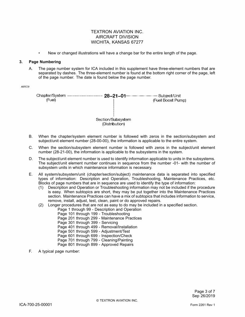
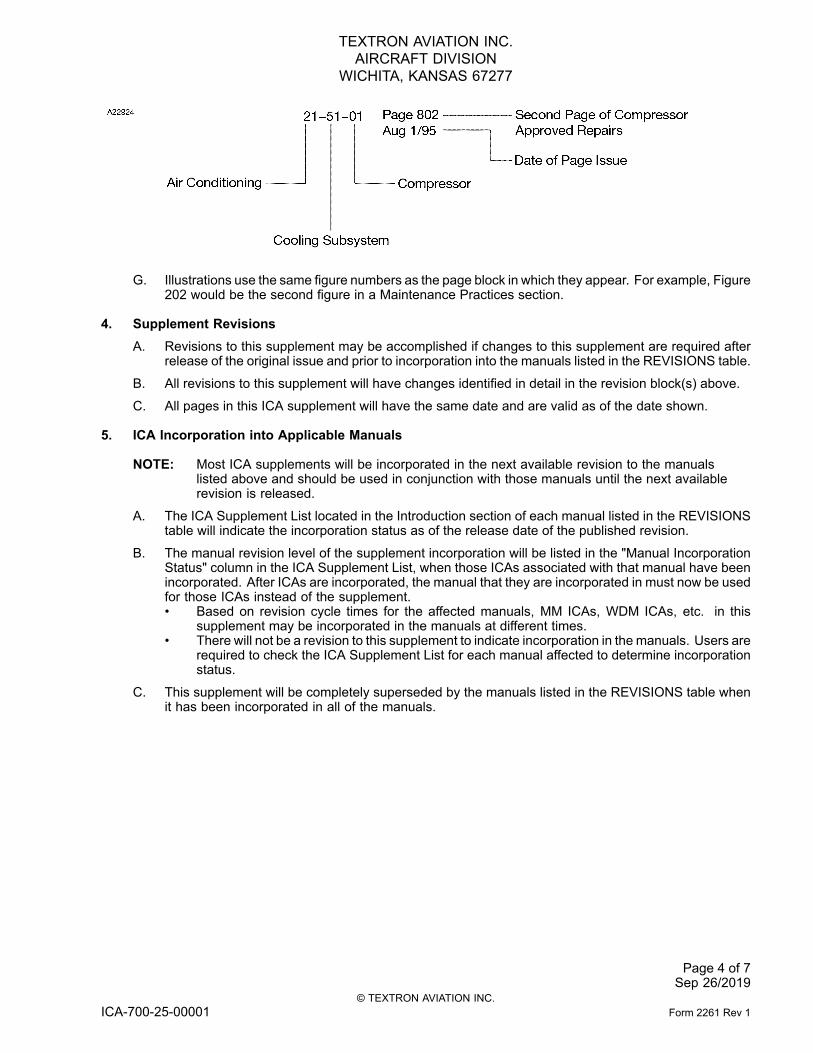
3. Page NumberingA. The page number system for ICA included in this supplement have three-element numbers that are
separated by dashes. The three-element number is found at the bottom right corner of the page, leftof the page number. The date is found below the page number.
B. When the chapter/system element number is followed with zeros in the section/subsystem andsubject/unit element number (28-00-00), the information is applicable to the entire system.
C. When the section/subsystem element number is followed with zeros in the subject/unit elementnumber (28-21-00), the information is applicable to the subsystems in the system.
D. The subject/unit element number is used to identify information applicable to units in the subsystems.The subject/unit element number continues in sequence from the number -01- with the number ofsubsystem units in which maintenance information is necessary.
E. All system/subsystem/unit (chapter/section/subject) maintenance data is separated into specifiedtypes of information: Description and Operation, Troubleshooting, Maintenance Practices, etc.Blocks of page numbers that are in sequence are used to identify the type of information:(1) Description and Operation or Troubleshooting information may not be included if the procedure
is easy. When subtopics are short, they may be put together into the Maintenance Practicessection. Maintenance Practices can have a mix of subtopics that includes information to service,remove, install, adjust, test, clean, paint or do approved repairs.
(2) Longer procedures that are not as easy to do may be included in a specified section.Page 1 through 99 - Description and OperationPage 101 through 199 - TroubleshootingPage 201 through 299 - Maintenance PracticesPage 301 through 399 - ServicingPage 401 through 499 - Removal/InstallationPage 501 through 599 - Adjustment/TestPage 601 through 699 - Inspection/CheckPage 701 through 799 - Cleaning/PaintingPage 801 through 899 - Approved Repairs
F. A typical page number:
Page 3 of 7Sep 26/2019
© TEXTRON AVIATION INC.ICA-700-25-00001 Form 2261 Rev 1
TEXTRON AVIATION INC.AIRCRAFT DIVISION
WICHITA, KANSAS 67277
G. Illustrations use the same figure numbers as the page block in which they appear. For example, Figure202 would be the second figure in a Maintenance Practices section.
4. Supplement RevisionsA. Revisions to this supplement may be accomplished if changes to this supplement are required after
release of the original issue and prior to incorporation into the manuals listed in the REVISIONS table.
B. All revisions to this supplement will have changes identified in detail in the revision block(s) above.
C. All pages in this ICA supplement will have the same date and are valid as of the date shown.
5. ICA Incorporation into Applicable Manuals
NOTE: Most ICA supplements will be incorporated in the next available revision to the manualslisted above and should be used in conjunction with those manuals until the next availablerevision is released.
A. The ICA Supplement List located in the Introduction section of each manual listed in the REVISIONStable will indicate the incorporation status as of the release date of the published revision.
B. The manual revision level of the supplement incorporation will be listed in the "Manual IncorporationStatus" column in the ICA Supplement List, when those ICAs associated with that manual have beenincorporated. After ICAs are incorporated, the manual that they are incorporated in must now be usedfor those ICAs instead of the supplement.• Based on revision cycle times for the affected manuals, MM ICAs, WDM ICAs, etc. in this
supplement may be incorporated in the manuals at different times.• There will not be a revision to this supplement to indicate incorporation in the manuals. Users are
required to check the ICA Supplement List for each manual affected to determine incorporationstatus.
C. This supplement will be completely superseded by the manuals listed in the REVISIONS table whenit has been incorporated in all of the manuals.
Page 4 of 7Sep 26/2019
© TEXTRON AVIATION INC.ICA-700-25-00001 Form 2261 Rev 1
TEXTRON AVIATION INC.AIRCRAFT DIVISION
WICHITA, KANSAS 67277
INTRODUCTION
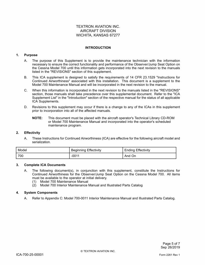
1. PurposeA. The purpose of this Supplement is to provide the maintenance technician with the information
necessary to ensure the correct functionality and performance of the Observer/Jump Seat Option onthe Cessna Model 700 until this information gets incorporated into the next revision to the manualslisted in the "REVISIONS" section of this supplement.
B. This ICA supplement is designed to satisfy the requirements of 14 CFR 23.1529 "Instructions forContinued Airworthiness" associated with this installation. This document is a supplement to theModel 700 Maintenance Manual and will be incorporated in the next revision to the manual.
C. When this information is incorporated in the next revision to the manuals listed in the "REVISIONS"section, those manuals shall take precedence over this supplemental document. Refer to the "ICASupplement List" in the "Introduction" section of the respective manual for the status of all applicableICA Supplements.
D. Revisions to this supplement may occur if there is a change to any of the ICAs in this supplementprior to incorporation into all of the affected manuals.
NOTE: This document must be placed with the aircraft operator's Technical Library CD-ROMor Model 700 Maintenance Manual and incorporated into the operator's scheduledmaintenance program.
2. EffectivityA. These Instructions for Continued Airworthiness (ICA) are effective for the following aircraft model and
serialization.
Model Beginning Effectivity Ending Effectivity
700 -0011 And On
3. Complete ICA DocumentsA. The following document(s), in conjunction with this supplement, constitute the Instructions for
Continued Airworthiness for the Observer/Jump Seat Option on the Cessna Model 700. All itemsmust be available to the operator at initial delivery.(1) Model 700 Maintenance Manual(2) Model 700 Interior Maintenance Manual and Illustrated Parts Catalog
4. System ComponentsA. Refer to Appendix C: Model 700-0011 Interior Maintenance Manual and Illustrated Parts Catalog.
Page 5 of 7Sep 26/2019
© TEXTRON AVIATION INC.ICA-700-25-00001 Form 2261 Rev 1
TEXTRON AVIATION INC.AIRCRAFT DIVISION
WICHITA, KANSAS 67277
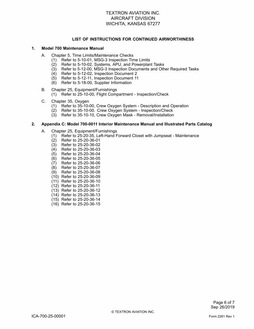
LIST OF INSTRUCTIONS FOR CONTINUED AIRWORTHINESS
1. Model 700 Maintenance ManualA. Chapter 5, Time Limits/Maintenance Checks
(1) Refer to 5-10-01, MSG-3 Inspection Time Limits(2) Refer to 5-10-02, Systems, APU, and Powerplant Tasks(3) Refer to 5-12-00, MSG-3 Inspection Documents and Other Required Tasks(4) Refer to 5-12-02, Inspection Document 2(5) Refer to 5-12-11, Inspection Document 11(6) Refer to 5-18-00, Supplier Information
B. Chapter 25, Equipment/Furnishings(1) Refer to 25-10-00, Flight Compartment - Inspection/Check
C. Chapter 35, Oxygen(1) Refer to 35-10-00, Crew Oxygen System - Description and Operation(2) Refer to 35-10-00. Crew Oxygen System - Inspection/Check(3) Refer to 35-10-10, Crew Oxygen Mask - Removal/Installation
2. Appendix C: Model 700-0011 Interior Maintenance Manual and Illustrated Parts CatalogA. Chapter 25, Equipment/Furnishings
(1) Refer to 25-20-35, Left-Hand Forward Closet with Jumpseat - Maintenance(2) Refer to 25-20-36-01(3) Refer to 25-20-36-02(4) Refer to 25-20-36-03(5) Refer to 25-20-36-04(6) Refer to 25-20-36-05(7) Refer to 25-20-36-06(8) Refer to 25-20-36-07(9) Refer to 25-20-36-08(10) Refer to 25-20-36-09(11) Refer to 25-20-36-10(12) Refer to 25-20-36-11(13) Refer to 25-20-36-12(14) Refer to 25-20-36-13(15) Refer to 25-20-36-14(16) Refer to 25-20-36-15
Page 6 of 7Sep 26/2019
© TEXTRON AVIATION INC.ICA-700-25-00001 Form 2261 Rev 1
TEXTRON AVIATION INC.AIRCRAFT DIVISION
WICHITA, KANSAS 67277
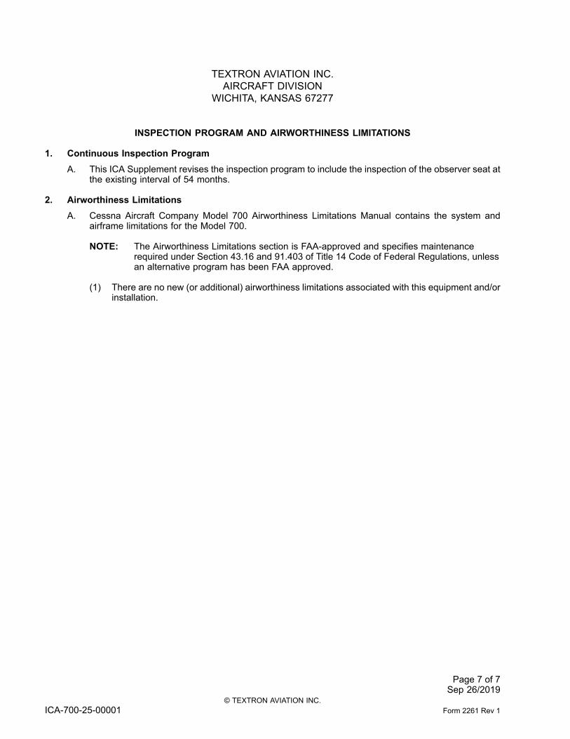
INSPECTION PROGRAM AND AIRWORTHINESS LIMITATIONS
1. Continuous Inspection ProgramA. This ICA Supplement revises the inspection program to include the inspection of the observer seat at
the existing interval of 54 months.
2. Airworthiness LimitationsA. Cessna Aircraft Company Model 700 Airworthiness Limitations Manual contains the system and
airframe limitations for the Model 700.
NOTE: The Airworthiness Limitations section is FAA-approved and specifies maintenancerequired under Section 43.16 and 91.403 of Title 14 Code of Federal Regulations, unlessan alternative program has been FAA approved.
(1) There are no new (or additional) airworthiness limitations associated with this equipment and/orinstallation.
Page 7 of 7Sep 26/2019
© TEXTRON AVIATION INC.ICA-700-25-00001 Form 2261 Rev 1
CESSNA®MODEL 700
MAINTENANCE MANUAL
MSG-3 INSPECTION TIME LIMITS
1. Purpose and UseA. MSG-3 Inspection Tasks in Table 1 provide a list of MSG-3 derived inspection and servicing tasks that
must be completed for the Model 700 MSG-3 Inspection Program.
NOTE: In addition to the tasks listed in Table 1 below, there are other scheduled inspectionrequirements detailed in Chapter 5-12-00, MSG-3 Inspection Documents and OtherRequired Tasks that must be accomplished to be in compliance with the Chapter 5-10-00,Maintenance Planning Document, Standard Manufacturer’s Recommended ContinuousAirworthiness Inspection Program.
B. This section also includes:(1) Component Time Limit Tasks - Refer to Table 2 for Component Time Limits Tasks that have been
duplicated from Table 1 to assist operators in maintenance planning.(2) Baseline Corrosion Prevention and Control Program (CPCP) Tasks - Refer to Table 3 for
Corrosion Prevention and Control Program (CPCP) Tasks that have been duplicated from Table1 to assist operators with proper implementation of a CPCP.
(3) For details on how to properly implement a CPCP, refer to the Citation Standard PracticesManual, Chapter 51, Corrosion Prevention and Control Program - Description and Operation.
NOTE: Airplane washing is a key component of any CPCP. Washing removes corrosiveagents from the surface of the airplane.
NOTE: The wash schedule found in Chapter 5, MSG-3 Inspection Documents andOther Required Tasks, Table 4 Discretionary Maintenance is for airplanes thatoperate in mild to moderate corrosion areas. If an airplane flies into any SevereCorrosion Areas during its operation route, a more frequent wash schedule maybe required. Refer to the Citation Standard Practices Manual, Chapter 20, Exterior- Cleaning/Washing/Rinse - Servicing and Chapter 51, Corrosion Prevention andControl Program - Description and Operation for more information.
NOTE: Textron Aviation strongly recommends washing or rinsing the airplane as soon aspossible, no later than three days, after any operation that exposes the airplaneto Runway De-Icing (RDI) fluids. Any delay can result in the greater likelihoodof corrosion.
NOTE: Operators can refer to the exterior cleaning procedures in the Citation StandardPractices Manual, Chapter 20, Exterior - Cleaning/Washing/Rinse - Servicing.Operators can refer to the Citation Standard Practices Manual, Chapter 51,Corrosion - Description and Operation and the Corrosion Severity Maps can befound in the Citation Standard Practices Manual, Chapter 51, Corrosion SeverityMaps - Description and Operation.
C. Table 1 MSG-3 Inspection Tasks gives a list of all the inspection and servicing requirements that mustbe completed for the Model 700 MSG-3 Inspection Program. Table 1 has columns for MaintenanceManual Task, Task Title, Interval/Note(s), Inspection Document, Zone, and Effectivity.(1) The Maintenance Manual Task column gives the task number in chapter order.(2) The Task Title column gives the title of the related task.(3) The Interval/Note(s) column gives the minimum frequency at which the scheduled Task must
be completed. As each operator establishes their inspection program, these intervals must beobeyed.
(4) The Inspection Document column gives the inspection document for where the relatedMaintenance Manual Task is contained.
(5) The Zone column gives a reference to the physical location(s) on the airplane that is related tothe scheduled Task. Some operational and functional checks do not list a zone, but list a codethat is related to special conditions required to perform the task. These codes are: ENG, AUX,BAT, LAB, and FLT.• ENG - One or both airplane engines necessary to be running.
5-10-01 Page 1© TEXTRON AVIATION INC. Sep 26/2019
ICA-700-25-00001 Form 2261 Rev 1
CESSNA®MODEL 700
MAINTENANCE MANUAL
• AUX - External source of electrical, hydraulic, pneumatic power, or a combination of these.Airplane engine power sources should not be used for these tests. It is possible to performmany of the tests in the AUX code with the airplane's battery power. However, it is notrecommended due to the power drain on the batteries.
• BAT - These tests must be performed with the component operated by the airplane’sbatteries or the batteries built into the individual component in the case of the ELT or othercomponents with internal battery power.
• LAB - Used when special equipment requires that the component be removed from theairplane and taken to a place equipped to perform the check or calibration.
• FLT - Test is to be performed during a flight.
D. The MM task numbers are hyperlinked to task details in this manual. The Zone number(s) are alsohyperlinked to Chapter 6, Airplane Zoning - Description and Operation to assist in planning andcompleting the tasks.
E. For operators developing a Custom Continuous Airworthiness Inspection Program, it may be helpfulto refer to the following sections for a correlation between the MRBR Task Numbers and MM TaskNumbers.
NOTE: The tasks referenced in the following sections are duplicates of tasks listed in Chapter5-10-01, MSG-3 Inspection Time Limits. However, the following sections organize thetask data in a format similar to the MRBR along with the corresponding MaintenanceManual Task - to - MRBR Task(s) and other useful information to assist operators indeveloping and/or optimizing a Custom Continuous Airworthiness Inspection Program.
(1) Chapter 5-10-01, MSG-3 Inspection Time Limits(a) Chapter 5-10-02, Systems, APU, and Powerplant Inspection Tasks(b) Chapter 5-10-03, Structures Inspection Tasks(c) Chapter 5-10-04, Zonal Inspection Tasks(d) Chapter 5-10-05, Enhanced Zonal Analysis Procedure (EZAP) Inspection Tasks(e) Chapter 5-10-06, Lightning/High Intensity Radiated Fields (L/HIRF) Inspection Tasks
(2) Chapter 5-12-00, MSG-3 Inspection Documents and Other Required Tasks(3) Chapter 5-13-00, Regulatory Inspections/Time Limits(4) Chapter 5-14-00, Airworthiness Directives(5) Chapter 5-15-00, Instructions for Continued Airworthiness (ICA) Supplements(6) Chapter 5-16-00, Supplemental Type Certificates (STC)(7) Chapter 5-17-00, Service Letters and Service Bulletins(8) Chapter 5-18-00, Supplier Information(9) Chapter 5-19-00, Discretionary Maintenance(10) Chapter 5-50-00, Unscheduled Maintenance Checks
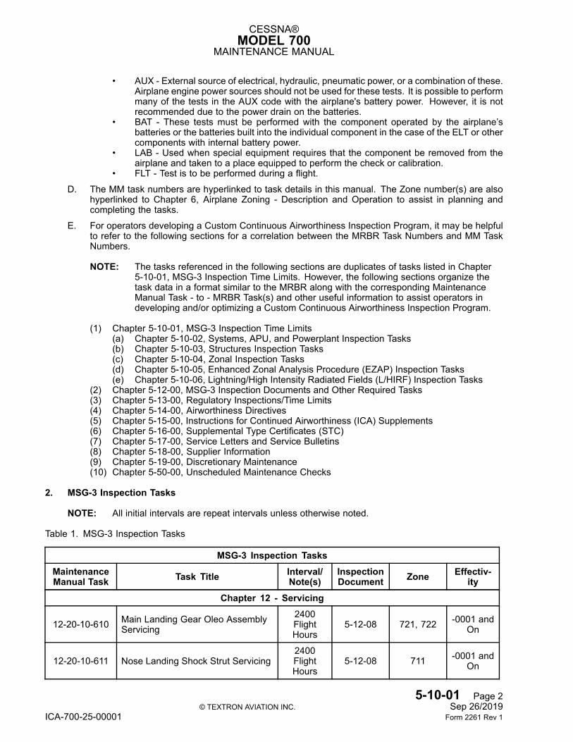
2. MSG-3 Inspection Tasks
NOTE: All initial intervals are repeat intervals unless otherwise noted.
Table 1. MSG-3 Inspection Tasks
MSG-3 Inspection TasksMaintenanceManual Task Task Title Interval/
Note(s)InspectionDocument Zone Effectiv-
ityChapter 12 - Servicing
12-20-10-610 Main Landing Gear Oleo AssemblyServicing
2400FlightHours
5-12-08 721, 722 -0001 andOn
12-20-10-611 Nose Landing Shock Strut Servicing2400FlightHours
5-12-08 711 -0001 andOn
5-10-01 Page 2© TEXTRON AVIATION INC. Sep 26/2019
ICA-700-25-00001 Form 2261 Rev 1
CESSNA®MODEL 700
MAINTENANCE MANUAL
Table 1. MSG-3 Inspection Tasks (continued)MSG-3 Inspection Tasks
MaintenanceManual Task Task Title Interval/
Note(s)InspectionDocument Zone Effectiv-
ity
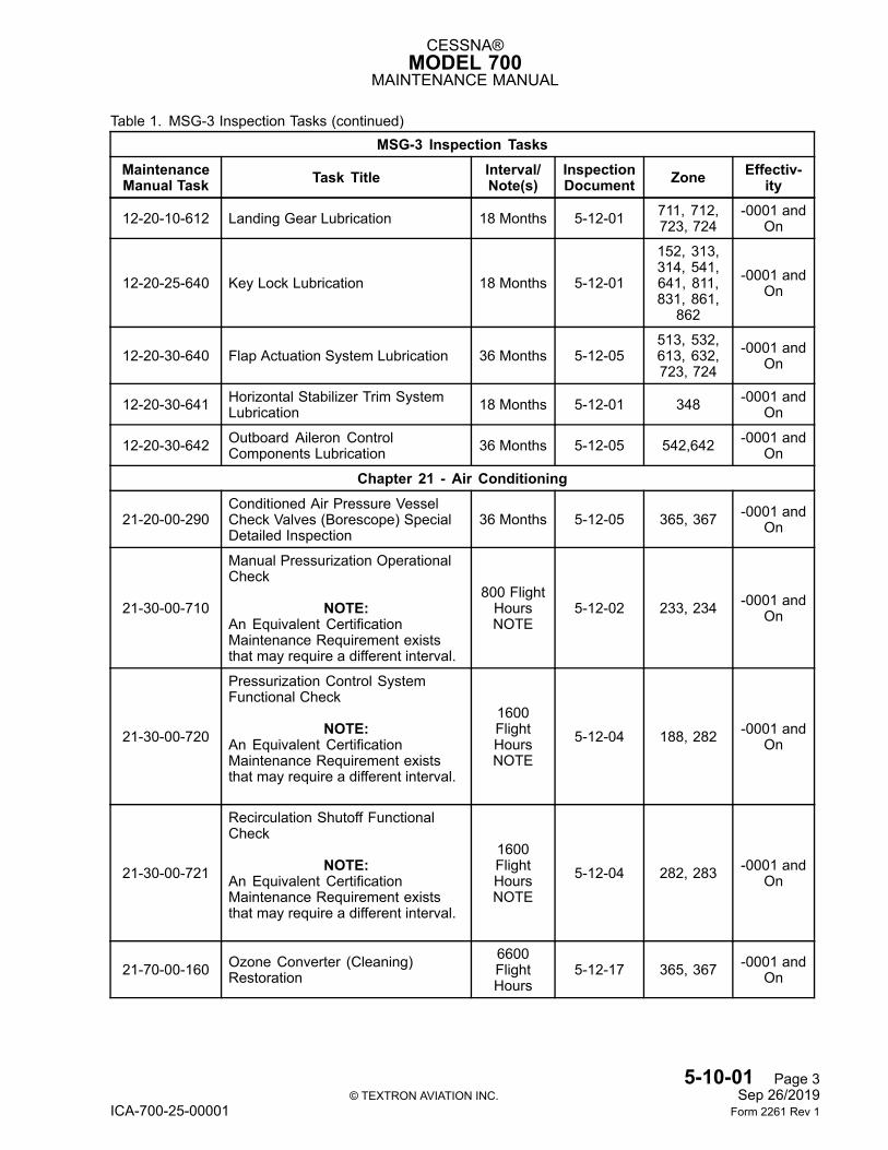
12-20-10-612 Landing Gear Lubrication 18 Months 5-12-01 711, 712,723, 724
-0001 andOn
12-20-25-640 Key Lock Lubrication 18 Months 5-12-01
152, 313,314, 541,641, 811,831, 861,
862
-0001 andOn
12-20-30-640 Flap Actuation System Lubrication 36 Months 5-12-05513, 532,613, 632,723, 724
-0001 andOn
12-20-30-641 Horizontal Stabilizer Trim SystemLubrication 18 Months 5-12-01 348 -0001 and
On
12-20-30-642 Outboard Aileron ControlComponents Lubrication 36 Months 5-12-05 542,642 -0001 and
On
Chapter 21 - Air Conditioning
21-20-00-290Conditioned Air Pressure VesselCheck Valves (Borescope) SpecialDetailed Inspection
36 Months 5-12-05 365, 367 -0001 andOn
21-30-00-710
Manual Pressurization OperationalCheck
NOTE:An Equivalent CertificationMaintenance Requirement existsthat may require a different interval.
800 FlightHoursNOTE
5-12-02 233, 234 -0001 andOn
21-30-00-720
Pressurization Control SystemFunctional Check
NOTE:An Equivalent CertificationMaintenance Requirement existsthat may require a different interval.
1600FlightHoursNOTE
5-12-04 188, 282 -0001 andOn
21-30-00-721
Recirculation Shutoff FunctionalCheck
NOTE:An Equivalent CertificationMaintenance Requirement existsthat may require a different interval.
1600FlightHoursNOTE
5-12-04 282, 283 -0001 andOn
21-70-00-160 Ozone Converter (Cleaning)Restoration
6600FlightHours
5-12-17 365, 367 -0001 andOn
5-10-01 Page 3© TEXTRON AVIATION INC. Sep 26/2019
ICA-700-25-00001 Form 2261 Rev 1
CESSNA®MODEL 700
MAINTENANCE MANUAL
Table 1. MSG-3 Inspection Tasks (continued)MSG-3 Inspection Tasks
MaintenanceManual Task Task Title Interval/
Note(s)InspectionDocument Zone Effectiv-
ity
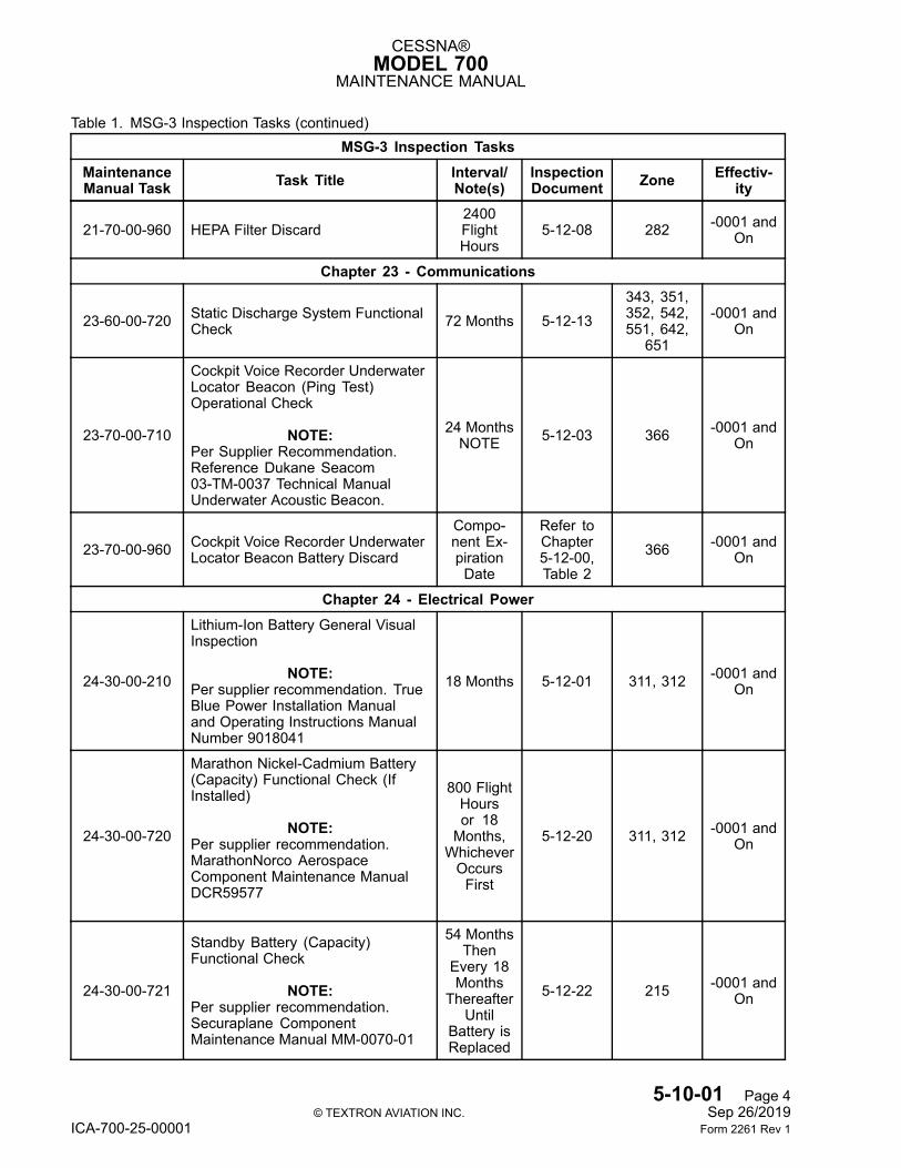
21-70-00-960 HEPA Filter Discard2400FlightHours
5-12-08 282 -0001 andOn
Chapter 23 - Communications
23-60-00-720 Static Discharge System FunctionalCheck 72 Months 5-12-13
343, 351,352, 542,551, 642,
651
-0001 andOn
23-70-00-710
Cockpit Voice Recorder UnderwaterLocator Beacon (Ping Test)Operational Check
NOTE:Per Supplier Recommendation.Reference Dukane Seacom03-TM-0037 Technical ManualUnderwater Acoustic Beacon.
24 MonthsNOTE 5-12-03 366 -0001 and
On
23-70-00-960 Cockpit Voice Recorder UnderwaterLocator Beacon Battery Discard
Compo-nent Ex-pirationDate
Refer toChapter5-12-00,Table 2
366 -0001 andOn
Chapter 24 - Electrical Power
24-30-00-210
Lithium-Ion Battery General VisualInspection
NOTE:Per supplier recommendation. TrueBlue Power Installation Manualand Operating Instructions ManualNumber 9018041
18 Months 5-12-01 311, 312 -0001 andOn
24-30-00-720
Marathon Nickel-Cadmium Battery(Capacity) Functional Check (IfInstalled)
NOTE:Per supplier recommendation.MarathonNorco AerospaceComponent Maintenance ManualDCR59577
800 FlightHoursor 18Months,WhicheverOccursFirst
5-12-20 311, 312 -0001 andOn
24-30-00-721
Standby Battery (Capacity)Functional Check
NOTE:Per supplier recommendation.Securaplane ComponentMaintenance Manual MM-0070-01
54 MonthsThen
Every 18Months
ThereafterUntil
Battery isReplaced
5-12-22 215 -0001 andOn
5-10-01 Page 4© TEXTRON AVIATION INC. Sep 26/2019
ICA-700-25-00001 Form 2261 Rev 1
CESSNA®MODEL 700
MAINTENANCE MANUAL
Table 1. MSG-3 Inspection Tasks (continued)MSG-3 Inspection Tasks
MaintenanceManual Task Task Title Interval/
Note(s)InspectionDocument Zone Effectiv-
ity
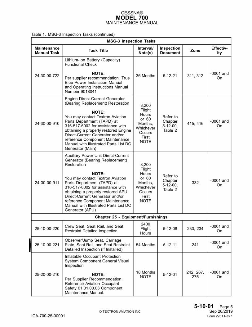
24-30-00-722
Lithium-Ion Battery (Capacity)Functional Check
NOTE:Per supplier recommendation. TrueBlue Power Installation Manualand Operating Instructions ManualNumber 9018041
36 Months 5-12-21 311, 312 -0001 andOn
24-30-00-910
Engine Direct-Current Generator(Bearing Replacement) Restoration
NOTE:You may contact Textron AviationParts Department (TAPD) at316-517-6002 for assistance withobtaining a properly restored EngineDirect-Current Generator and/orreference Component MaintenanceManual with Illustrated Parts List DCGenerator (Main)
3,200FlightHoursor 60Months,WhicheverOccursFirstNOTE
Refer toChapter5-12-00,Table 2
415, 416 -0001 andOn
24-30-00-911
Auxiliary Power Unit Direct-CurrentGenerator (Bearing Replacement)Restoration
NOTE:You may contact Textron AviationParts Department (TAPD) at316-517-6002 for assistance withobtaining a properly restored APUDirect-Current Generator and/orreference Component MaintenanceManual with Illustrated Parts List DCGenerator (APU)
3,200FlightHoursor 60Months,WhicheverOccursFirstNOTE
Refer toChapter5-12-00,Table 2
332 -0001 andOn
Chapter 25 - Equipment/Furnishings
25-10-00-220 Crew Seat, Seat Rail, and SeatRestraint Detailed Inspection
2400FlightHours
5-12-08 233, 234 -0001 andOn
25-10-00-221Observer/Jump Seat, CarriagePlate, Seat Rail, and Seat RestraintDetailed Inspection (If Installed)
54 Months 5-12-11 241 -0001 andOn
25-20-00-210
Inflatable Occupant ProtectionSystem Component General VisualInspection
NOTE:Per Supplier Recommendation.Reference Aviation OccupantSafety 01.01.00.03 ComponentMaintenance Manual.
18 MonthsNOTE 5-12-01 242, 267,
275-0001 and
On
5-10-01 Page 5© TEXTRON AVIATION INC. Sep 26/2019
ICA-700-25-00001 Form 2261 Rev 1
CESSNA®MODEL 700
MAINTENANCE MANUAL
Table 1. MSG-3 Inspection Tasks (continued)MSG-3 Inspection Tasks
MaintenanceManual Task Task Title Interval/
Note(s)InspectionDocument Zone Effectiv-
ity
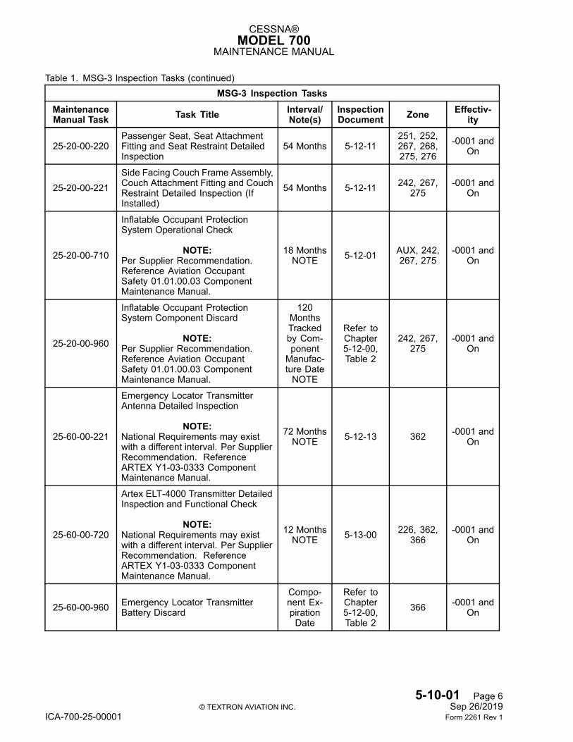
25-20-00-220Passenger Seat, Seat AttachmentFitting and Seat Restraint DetailedInspection
54 Months 5-12-11251, 252,267, 268,275, 276
-0001 andOn
25-20-00-221Side Facing Couch Frame Assembly,Couch Attachment Fitting and CouchRestraint Detailed Inspection (IfInstalled)
54 Months 5-12-11 242, 267,275
-0001 andOn
25-20-00-710
Inflatable Occupant ProtectionSystem Operational Check
NOTE:Per Supplier Recommendation.Reference Aviation OccupantSafety 01.01.00.03 ComponentMaintenance Manual.
18 MonthsNOTE 5-12-01 AUX, 242,
267, 275-0001 and
On
25-20-00-960
Inflatable Occupant ProtectionSystem Component Discard
NOTE:Per Supplier Recommendation.Reference Aviation OccupantSafety 01.01.00.03 ComponentMaintenance Manual.
120MonthsTrackedby Com-ponentManufac-ture DateNOTE
Refer toChapter5-12-00,Table 2
242, 267,275
-0001 andOn
25-60-00-221
Emergency Locator TransmitterAntenna Detailed Inspection
NOTE:National Requirements may existwith a different interval. Per SupplierRecommendation. ReferenceARTEX Y1-03-0333 ComponentMaintenance Manual.
72 MonthsNOTE 5-12-13 362 -0001 and
On
25-60-00-720
Artex ELT-4000 Transmitter DetailedInspection and Functional Check
NOTE:National Requirements may existwith a different interval. Per SupplierRecommendation. ReferenceARTEX Y1-03-0333 ComponentMaintenance Manual.
12 MonthsNOTE 5-13-00 226, 362,
366-0001 and
On
25-60-00-960 Emergency Locator TransmitterBattery Discard
Compo-nent Ex-pirationDate
Refer toChapter5-12-00,Table 2
366 -0001 andOn
5-10-01 Page 6© TEXTRON AVIATION INC. Sep 26/2019
ICA-700-25-00001 Form 2261 Rev 1
CESSNA®MODEL 700
MAINTENANCE MANUAL
Table 1. MSG-3 Inspection Tasks (continued)MSG-3 Inspection Tasks
MaintenanceManual Task Task Title Interval/
Note(s)InspectionDocument Zone Effectiv-
ity
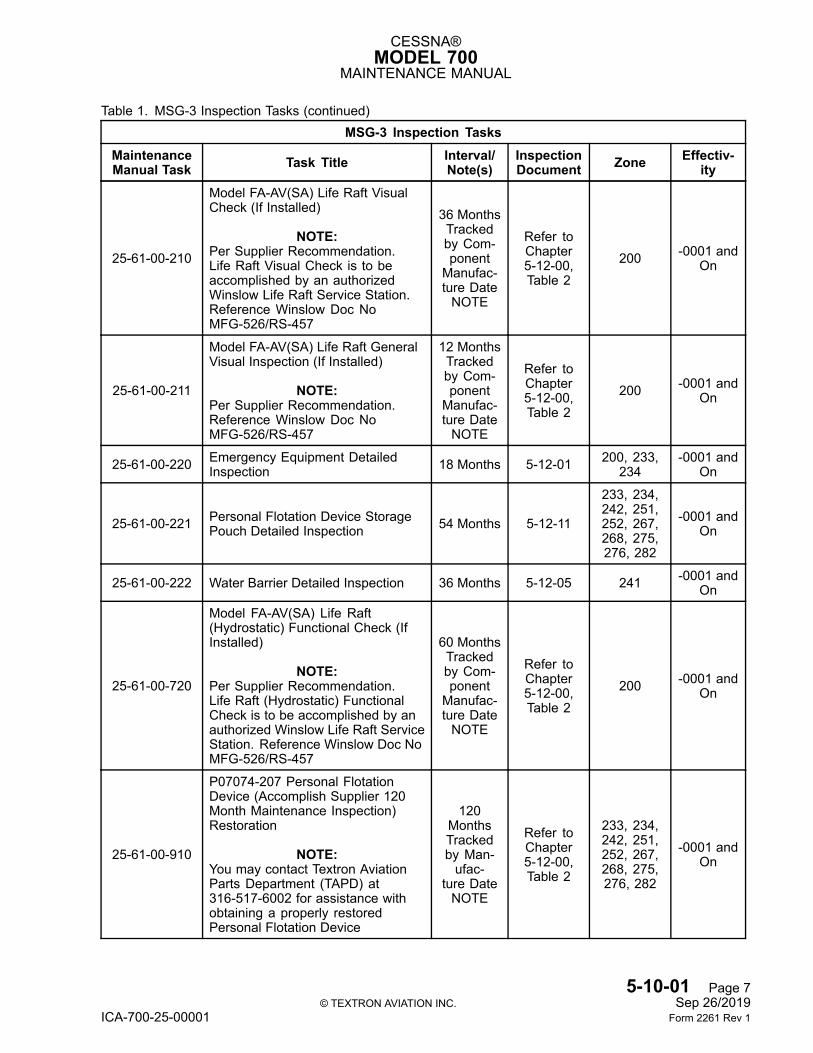
25-61-00-210
Model FA-AV(SA) Life Raft VisualCheck (If Installed)
NOTE:Per Supplier Recommendation.Life Raft Visual Check is to beaccomplished by an authorizedWinslow Life Raft Service Station.Reference Winslow Doc NoMFG-526/RS-457
36 MonthsTrackedby Com-ponentManufac-ture DateNOTE
Refer toChapter5-12-00,Table 2
200 -0001 andOn
25-61-00-211
Model FA-AV(SA) Life Raft GeneralVisual Inspection (If Installed)
NOTE:Per Supplier Recommendation.Reference Winslow Doc NoMFG-526/RS-457
12 MonthsTrackedby Com-ponentManufac-ture DateNOTE
Refer toChapter5-12-00,Table 2
200 -0001 andOn
25-61-00-220 Emergency Equipment DetailedInspection 18 Months 5-12-01 200, 233,
234-0001 and
On
25-61-00-221 Personal Flotation Device StoragePouch Detailed Inspection 54 Months 5-12-11
233, 234,242, 251,252, 267,268, 275,276, 282
-0001 andOn
25-61-00-222 Water Barrier Detailed Inspection 36 Months 5-12-05 241 -0001 andOn
25-61-00-720
Model FA-AV(SA) Life Raft(Hydrostatic) Functional Check (IfInstalled)
NOTE:Per Supplier Recommendation.Life Raft (Hydrostatic) FunctionalCheck is to be accomplished by anauthorized Winslow Life Raft ServiceStation. Reference Winslow Doc NoMFG-526/RS-457
60 MonthsTrackedby Com-ponentManufac-ture DateNOTE
Refer toChapter5-12-00,Table 2
200 -0001 andOn
25-61-00-910
P07074-207 Personal FlotationDevice (Accomplish Supplier 120Month Maintenance Inspection)Restoration
NOTE:You may contact Textron AviationParts Department (TAPD) at316-517-6002 for assistance withobtaining a properly restoredPersonal Flotation Device
120MonthsTrackedby Man-ufac-
ture DateNOTE
Refer toChapter5-12-00,Table 2
233, 234,242, 251,252, 267,268, 275,276, 282
-0001 andOn
5-10-01 Page 7© TEXTRON AVIATION INC. Sep 26/2019
ICA-700-25-00001 Form 2261 Rev 1
CESSNA®MODEL 700
MAINTENANCE MANUAL
Table 1. MSG-3 Inspection Tasks (continued)MSG-3 Inspection Tasks
MaintenanceManual Task Task Title Interval/
Note(s)InspectionDocument Zone Effectiv-
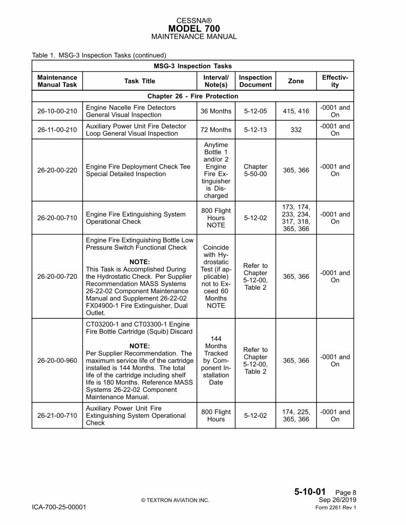
ityChapter 26 - Fire Protection
26-10-00-210 Engine Nacelle Fire DetectorsGeneral Visual Inspection 36 Months 5-12-05 415, 416 -0001 and
On
26-11-00-210 Auxiliary Power Unit Fire DetectorLoop General Visual Inspection 72 Months 5-12-13 332 -0001 and
On
26-20-00-220 Engine Fire Deployment Check TeeSpecial Detailed Inspection
AnytimeBottle 1and/or 2EngineFire Ex-tinguisheris Dis-charged
Chapter5-50-00 365, 366 -0001 and
On
26-20-00-710 Engine Fire Extinguishing SystemOperational Check
800 FlightHoursNOTE
5-12-02173, 174,233, 234,317, 318,365, 366
-0001 andOn
26-20-00-720
Engine Fire Extinguishing Bottle LowPressure Switch Functional Check
NOTE:This Task is Accomplished Duringthe Hydrostatic Check. Per SupplierRecommendation MASS Systems26-22-02 Component MaintenanceManual and Supplement 26-22-02FX04900-1 Fire Extinguisher, DualOutlet.
Coincidewith Hy-drostaticTest (if ap-plicable)not to Ex-ceed 60MonthsNOTE
Refer toChapter5-12-00,Table 2
365, 366 -0001 andOn
26-20-00-960
CT03200-1 and CT03300-1 EngineFire Bottle Cartridge (Squib) Discard
NOTE:Per Supplier Recommendation. Themaximum service life of the cartridgeinstalled is 144 Months. The totallife of the cartridge including shelflife is 180 Months. Reference MASSSystems 26-22-02 ComponentMaintenance Manual.
144MonthsTrackedby Com-ponent In-stallationDate
Refer toChapter5-12-00,Table 2
365, 366 -0001 andOn
26-21-00-710Auxiliary Power Unit FireExtinguishing System OperationalCheck
800 FlightHours 5-12-02 174, 225,
365, 366-0001 and
On
5-10-01 Page 8© TEXTRON AVIATION INC. Sep 26/2019
ICA-700-25-00001 Form 2261 Rev 1
CESSNA®MODEL 700
MAINTENANCE MANUAL
Table 1. MSG-3 Inspection Tasks (continued)MSG-3 Inspection Tasks
MaintenanceManual Task Task Title Interval/
Note(s)InspectionDocument Zone Effectiv-
ity
26-21-00-720
Auxiliary Power Unit FireExtinguishing Bottle Low PressureSwitch Functional Check
NOTE:This Task is Accomplished Duringthe Hydrostatic Check. Per SupplierRecommendation MASS Systems26-22-02 Component MaintenanceManual and Supplement 26-22-02FX05000-1 Fire Extinguisher, DualOutlet.
Coincidewith Hy-drostaticTest (if ap-plicable)not to Ex-ceed 60MonthsNOTE
Refer toChapter5-12-00,Table 2
365 -0001 andOn
26-21-00-960
CT03400-1 Auxiliary Power Unit FireBottle Cartridge (Squib) Discard
NOTE:Per Supplier Recommendation. Themaximum service life of the cartridgeinstalled is 144 Months. The totallife of the cartridge including shelflife is 180 Months. Reference MASSSystems 26-22-02 ComponentMaintenance Manual.
144MonthsTrackedby Com-ponent In-stallationDate
Refer toChapter5-12-00,Table 2
365 -0001 andOn
26-22-00-720 Portable Fire Extinguisher (WeightCheck) Functional Check 12 Months 5-13-00 234, 275 -0001 and
On
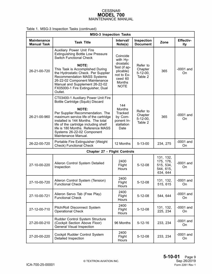
Chapter 27 - Flight Controls
27-10-00-220 Aileron Control System DetailedInspection
2400FlightHours
5-12-08
131, 132,175, 176,515, 534,544, 615,634, 644
-0001 andOn
27-10-00-720 Aileron Control System (Tension)Functional Check
2400FlightHours
5-12-08 131, 132,515, 615
-0001 andOn
27-10-00-721 Aileron Servo Tab (Free Play)Functional Check
2400FlightHours
5-12-08 544, 644 -0001 andOn
27-12-00-710 Pitch/Roll Disconnect SystemOperational Check
2400FlightHours
5-12-08 131, 132,225, 234
-0001 andOn
27-20-00-210Rudder Control System Structure(Cockpit Section Above Floor)General Visual Inspection
96 Months 5-12-16 233, 234 -0001 andOn
27-20-00-220 Cockpit Rudder Control SystemDetailed Inspection
2400FlightHours
5-12-08 233, 234 -0001 andOn
5-10-01 Page 9© TEXTRON AVIATION INC. Sep 26/2019
ICA-700-25-00001 Form 2261 Rev 1

CESSNA®MODEL 700
MAINTENANCE MANUAL
Table 1. MSG-3 Inspection Tasks (continued)MSG-3 Inspection Tasks
MaintenanceManual Task Task Title Interval/
Note(s)InspectionDocument Zone Effectiv-
ity
27-20-00-221 Rudder Assembly DetailedInspection
2400FlightHours
5-12-08 343 -0001 andOn
27-30-00-220
Horizontal Stabilizer Rear Sparand Cove Section Structureand Corrosion Special DetailedInspection
NOTE:This is a CPCP Task
18 Months 5-12-01 351, 352 -0001 andOn
27-30-00-221 Elevator Servo Tab ActuatorStructure Detailed Inspection 72 Months 5-12-13 351, 352,
353, 354-0001 and
On
27-30-00-222 Elevator System Detailed Inspection2400FlightHours
5-12-08
131, 132,141, 142,153, 154,163, 164,175, 176,185, 186,346, 348,351, 352,365, 366,367, 368
-0001 andOn
27-30-00-720 Elevator System (Tension)Functional Check
2400FlightHours
5-12-08
131, 132,141, 142,153, 154,163, 164,175, 176,185, 186,346, 365,
367
-0001 andOn
27-50-00-220 Flap Actuation System DetailedInspection 36 Months 5-12-05 513, 532,
613, 632-0001 and
On
Chapter 28 - Fuel
28-10-00-220 Fuel Panel and Fuel Panel SealDetailed Inspection 54 Months 5-12-11
161, 162,171, 172,512, 521,531, 541,612, 621,631, 641
-0001 andOn
28-40-00-710 Low Fuel Level Sensor OperationalCheck 54 Months 5-12-11 225 -0001 and
On
Chapter 29 - Hydraulic Power
29-10-00-210 Hydraulic System Ecology BottleGeneral Visual Inspection
2400FlightHours
5-12-08 318 -0001 andOn
5-10-01 Page 10© TEXTRON AVIATION INC. Sep 26/2019
ICA-700-25-00001 Form 2261 Rev 1
CESSNA®MODEL 700
MAINTENANCE MANUAL
Table 1. MSG-3 Inspection Tasks (continued)MSG-3 Inspection Tasks
MaintenanceManual Task Task Title Interval/
Note(s)InspectionDocument Zone Effectiv-
ity
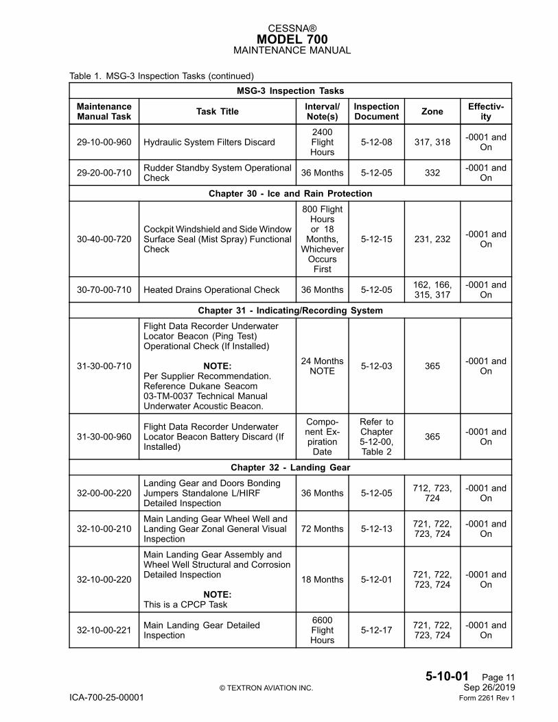
29-10-00-960 Hydraulic System Filters Discard2400FlightHours
5-12-08 317, 318 -0001 andOn
29-20-00-710 Rudder Standby System OperationalCheck 36 Months 5-12-05 332 -0001 and
On
Chapter 30 - Ice and Rain Protection
30-40-00-720Cockpit Windshield and SideWindowSurface Seal (Mist Spray) FunctionalCheck
800 FlightHoursor 18Months,WhicheverOccursFirst
5-12-15 231, 232 -0001 andOn
30-70-00-710 Heated Drains Operational Check 36 Months 5-12-05 162, 166,315, 317
-0001 andOn
Chapter 31 - Indicating/Recording System
31-30-00-710
Flight Data Recorder UnderwaterLocator Beacon (Ping Test)Operational Check (If Installed)
NOTE:Per Supplier Recommendation.Reference Dukane Seacom03-TM-0037 Technical ManualUnderwater Acoustic Beacon.
24 MonthsNOTE 5-12-03 365 -0001 and
On
31-30-00-960Flight Data Recorder UnderwaterLocator Beacon Battery Discard (IfInstalled)
Compo-nent Ex-pirationDate
Refer toChapter5-12-00,Table 2
365 -0001 andOn
Chapter 32 - Landing Gear
32-00-00-220Landing Gear and Doors BondingJumpers Standalone L/HIRFDetailed Inspection
36 Months 5-12-05 712, 723,724
-0001 andOn
32-10-00-210Main Landing Gear Wheel Well andLanding Gear Zonal General VisualInspection
72 Months 5-12-13 721, 722,723, 724
-0001 andOn
32-10-00-220
Main Landing Gear Assembly andWheel Well Structural and CorrosionDetailed Inspection
NOTE:This is a CPCP Task
18 Months 5-12-01 721, 722,723, 724
-0001 andOn
32-10-00-221 Main Landing Gear DetailedInspection
6600FlightHours
5-12-17 721, 722,723, 724
-0001 andOn
5-10-01 Page 11© TEXTRON AVIATION INC. Sep 26/2019
ICA-700-25-00001 Form 2261 Rev 1
CESSNA®MODEL 700
MAINTENANCE MANUAL
Table 1. MSG-3 Inspection Tasks (continued)MSG-3 Inspection Tasks
MaintenanceManual Task Task Title Interval/
Note(s)InspectionDocument Zone Effectiv-
ity
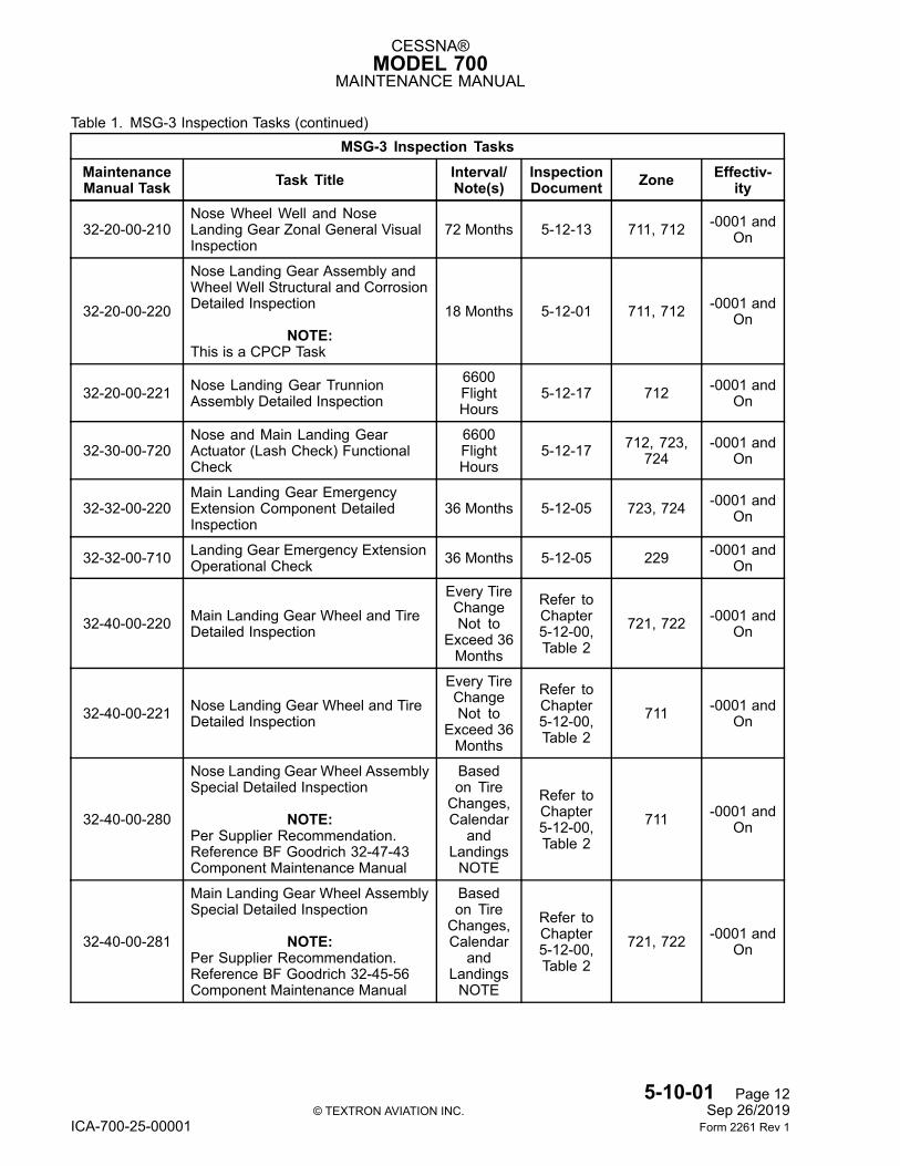
32-20-00-210Nose Wheel Well and NoseLanding Gear Zonal General VisualInspection
72 Months 5-12-13 711, 712 -0001 andOn
32-20-00-220
Nose Landing Gear Assembly andWheel Well Structural and CorrosionDetailed Inspection
NOTE:This is a CPCP Task
18 Months 5-12-01 711, 712 -0001 andOn
32-20-00-221 Nose Landing Gear TrunnionAssembly Detailed Inspection
6600FlightHours
5-12-17 712 -0001 andOn
32-30-00-720Nose and Main Landing GearActuator (Lash Check) FunctionalCheck
6600FlightHours
5-12-17 712, 723,724
-0001 andOn
32-32-00-220Main Landing Gear EmergencyExtension Component DetailedInspection
36 Months 5-12-05 723, 724 -0001 andOn
32-32-00-710 Landing Gear Emergency ExtensionOperational Check 36 Months 5-12-05 229 -0001 and
On
32-40-00-220 Main Landing Gear Wheel and TireDetailed Inspection
Every TireChangeNot to
Exceed 36Months
Refer toChapter5-12-00,Table 2
721, 722 -0001 andOn
32-40-00-221 Nose Landing Gear Wheel and TireDetailed Inspection
Every TireChangeNot to
Exceed 36Months
Refer toChapter5-12-00,Table 2
711 -0001 andOn
32-40-00-280
Nose Landing Gear Wheel AssemblySpecial Detailed Inspection
NOTE:Per Supplier Recommendation.Reference BF Goodrich 32-47-43Component Maintenance Manual
Basedon TireChanges,Calendar
andLandingsNOTE
Refer toChapter5-12-00,Table 2
711 -0001 andOn
32-40-00-281
Main Landing Gear Wheel AssemblySpecial Detailed Inspection
NOTE:Per Supplier Recommendation.Reference BF Goodrich 32-45-56Component Maintenance Manual
Basedon TireChanges,Calendar
andLandingsNOTE
Refer toChapter5-12-00,Table 2
721, 722 -0001 andOn
5-10-01 Page 12© TEXTRON AVIATION INC. Sep 26/2019
ICA-700-25-00001 Form 2261 Rev 1
CESSNA®MODEL 700
MAINTENANCE MANUAL
Table 1. MSG-3 Inspection Tasks (continued)MSG-3 Inspection Tasks
MaintenanceManual Task Task Title Interval/
Note(s)InspectionDocument Zone Effectiv-
ity
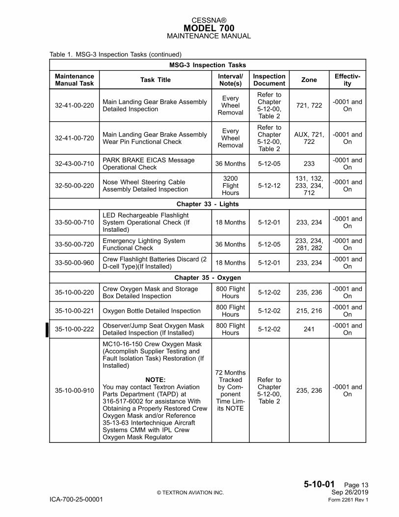
32-41-00-220 Main Landing Gear Brake AssemblyDetailed Inspection
EveryWheelRemoval
Refer toChapter5-12-00,Table 2
721, 722 -0001 andOn
32-41-00-720 Main Landing Gear Brake AssemblyWear Pin Functional Check
EveryWheelRemoval
Refer toChapter5-12-00,Table 2
AUX, 721,722
-0001 andOn
32-43-00-710 PARK BRAKE EICAS MessageOperational Check 36 Months 5-12-05 233 -0001 and
On
32-50-00-220 Nose Wheel Steering CableAssembly Detailed Inspection
3200FlightHours
5-12-12131, 132,233, 234,
712-0001 and
On
Chapter 33 - Lights
33-50-00-710LED Rechargeable FlashlightSystem Operational Check (IfInstalled)
18 Months 5-12-01 233, 234 -0001 andOn
33-50-00-720 Emergency Lighting SystemFunctional Check 36 Months 5-12-05 233, 234,
281, 282-0001 and
On
33-50-00-960 Crew Flashlight Batteries Discard (2D-cell Type)(If Installed) 18 Months 5-12-01 233, 234 -0001 and
On
Chapter 35 - Oxygen
35-10-00-220 Crew Oxygen Mask and StorageBox Detailed Inspection
800 FlightHours 5-12-02 235, 236 -0001 and
On
35-10-00-221 Oxygen Bottle Detailed Inspection 800 FlightHours 5-12-02 215, 216 -0001 and
On
35-10-00-222 Observer/Jump Seat Oxygen MaskDetailed Inspection (If Installed)
800 FlightHours 5-12-02 241 -0001 and
On
35-10-00-910
MC10-16-150 Crew Oxygen Mask(Accomplish Supplier Testing andFault Isolation Task) Restoration (IfInstalled)
NOTE:You may contact Textron AviationParts Department (TAPD) at316-517-6002 for assistance WithObtaining a Properly Restored CrewOxygen Mask and/or Reference35-13-63 Intertechnique AircraftSystems CMM with IPL CrewOxygen Mask Regulator
72 MonthsTrackedby Com-ponent
Time Lim-its NOTE
Refer toChapter5-12-00,Table 2
235, 236 -0001 andOn
5-10-01 Page 13© TEXTRON AVIATION INC. Sep 26/2019
ICA-700-25-00001 Form 2261 Rev 1
CESSNA®MODEL 700
MAINTENANCE MANUAL
Table 1. MSG-3 Inspection Tasks (continued)MSG-3 Inspection Tasks
MaintenanceManual Task Task Title Interval/
Note(s)InspectionDocument Zone Effectiv-
ity
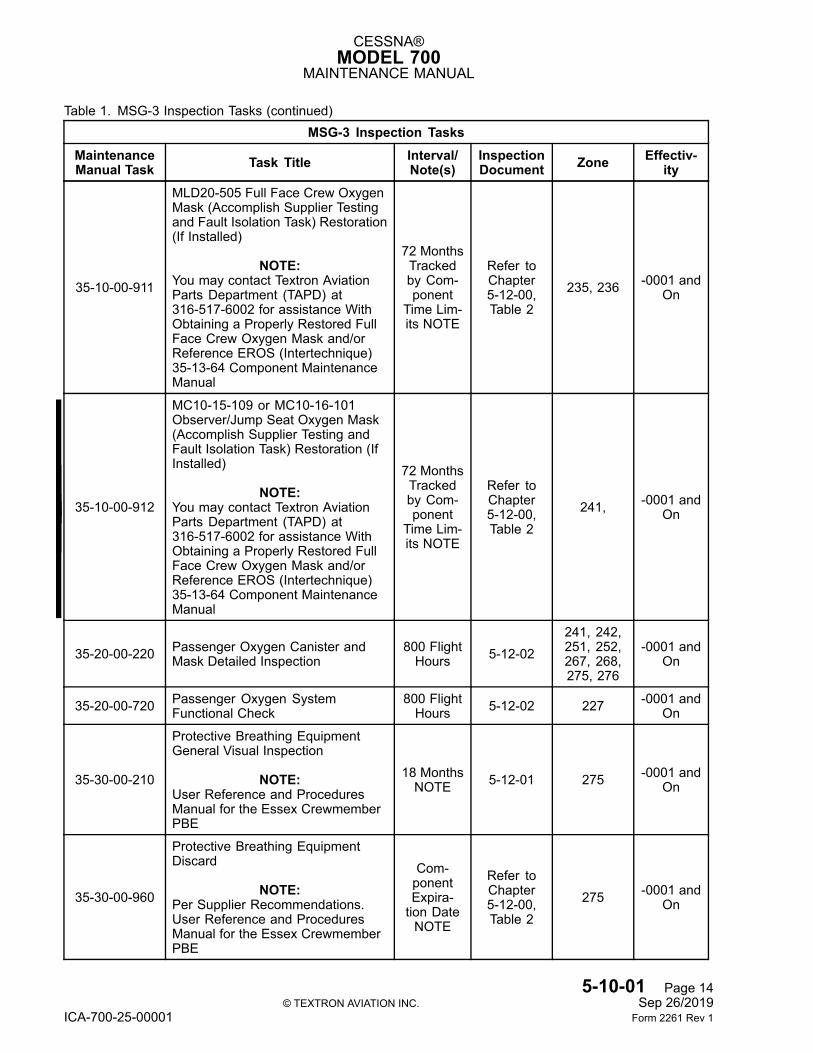
35-10-00-911
MLD20-505 Full Face Crew OxygenMask (Accomplish Supplier Testingand Fault Isolation Task) Restoration(If Installed)
NOTE:You may contact Textron AviationParts Department (TAPD) at316-517-6002 for assistance WithObtaining a Properly Restored FullFace Crew Oxygen Mask and/orReference EROS (Intertechnique)35-13-64 Component MaintenanceManual
72 MonthsTrackedby Com-ponent
Time Lim-its NOTE
Refer toChapter5-12-00,Table 2
235, 236 -0001 andOn
35-10-00-912
MC10-15-109 or MC10-16-101Observer/Jump Seat Oxygen Mask(Accomplish Supplier Testing andFault Isolation Task) Restoration (IfInstalled)
NOTE:You may contact Textron AviationParts Department (TAPD) at316-517-6002 for assistance WithObtaining a Properly Restored FullFace Crew Oxygen Mask and/orReference EROS (Intertechnique)35-13-64 Component MaintenanceManual
72 MonthsTrackedby Com-ponent
Time Lim-its NOTE
Refer toChapter5-12-00,Table 2
241, -0001 andOn
35-20-00-220 Passenger Oxygen Canister andMask Detailed Inspection
800 FlightHours 5-12-02
241, 242,251, 252,267, 268,275, 276
-0001 andOn
35-20-00-720 Passenger Oxygen SystemFunctional Check
800 FlightHours 5-12-02 227 -0001 and
On
35-30-00-210
Protective Breathing EquipmentGeneral Visual Inspection
NOTE:User Reference and ProceduresManual for the Essex CrewmemberPBE
18 MonthsNOTE 5-12-01 275 -0001 and
On
35-30-00-960
Protective Breathing EquipmentDiscard
NOTE:Per Supplier Recommendations.User Reference and ProceduresManual for the Essex CrewmemberPBE
Com-ponentExpira-tion DateNOTE
Refer toChapter5-12-00,Table 2
275 -0001 andOn
5-10-01 Page 14© TEXTRON AVIATION INC. Sep 26/2019
ICA-700-25-00001 Form 2261 Rev 1
CESSNA®MODEL 700
MAINTENANCE MANUAL
Table 1. MSG-3 Inspection Tasks (continued)MSG-3 Inspection Tasks
MaintenanceManual Task Task Title Interval/
Note(s)InspectionDocument Zone Effectiv-
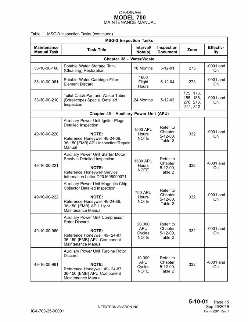
ityChapter 38 - Water/Waste
38-10-00-160 Potable Water Storage Tank(Cleaning) Restoration 18 Months 5-12-01 273 -0001 and
On
38-10-00-961 Potable Water Cartridge FilterElement Discard
1600FlightHours
5-12-04 273 -0001 andOn
38-30-00-210Toilet Catch Pan and Waste Tubes(Borescope) Special DetailedInspection
24 Months 5-12-03175, 176,185, 186,276, 278,311, 312
-0001 andOn
Chapter 49 - Auxiliary Power Unit (APU)
49-10-00-220
Auxiliary Power Unit Igniter PlugsDetailed Inspection
NOTE:Reference Honeywell 49-24-09,36-150 [EMB] APU Inspection/RepairManual
1500 APUHoursNOTE
Refer toChapter5-12-00,Table 2
332 -0001 andOn
49-10-00-221
Auxiliary Power Unit Starter MotorBrushes Detailed Inspection
NOTE:Reference Honeywell ServiceInformation Letter D201608000071
1500 APUHoursNOTE
Refer toChapter5-12-00,Table 2
332 -0001 andOn
49-10-00-222
Auxiliary Power Unit Magnetic ChipCollector Detailed Inspection
NOTE:Reference Honeywell 49-24-86,36-150 [EMB] APU LightMaintenance Manual
750 APUHoursNOTE
Refer toChapter5-12-00,Table 2
332 -0001 andOn
49-10-00-960
Auxiliary Power Unit CompressorRotor Discard
NOTE:Reference Honeywell 49- 24-87,36-150 [EMB] APU ComponentMaintenance Manual
20,000APUCyclesNOTE
Refer toChapter5-12-00,Table 2
332 -0001 andOn
49-10-00-961
Auxiliary Power Unit Turbine RotorDiscard
NOTE:Reference Honeywell 49- 24-87,36-150 [EMB] APU ComponentMaintenance Manual
10,000APUCyclesNOTE
Refer toChapter5-12-00,Table 2
332 -0001 andOn
5-10-01 Page 15© TEXTRON AVIATION INC. Sep 26/2019
ICA-700-25-00001 Form 2261 Rev 1

CESSNA®MODEL 700
MAINTENANCE MANUAL
Table 1. MSG-3 Inspection Tasks (continued)MSG-3 Inspection Tasks
MaintenanceManual Task Task Title Interval/
Note(s)InspectionDocument Zone Effectiv-
ity
49-10-00-962
Auxiliary Power Unit Fuel FilterDiscard
NOTE:Reference Honeywell 49-24-86,36-150 [EMB] APU LightMaintenance Manual
1500 APUHoursNOTE
Refer toChapter5-12-00,Table 2
332 -0001 andOn
49-10-00-963
Auxiliary Power Unit Oil Filter Discard
NOTE:Reference Honeywell 49-24-86,36-150 [EMB] APU LightMaintenance Manual
750 APUHoursNOTE
Refer toChapter5-12-00,Table 2
332 -0001 andOn
49-10-00-964
Auxiliary Power Unit Oil Discard
NOTE:Reference Honeywell 49-24-86,36-150 [EMB] APU LightMaintenance Manual
750 APUHoursNOTE
Refer toChapter5-12-00,Table 2
332 -0001 andOn
Chapter 52 - Doors
52-10-00-210 Cabin Door Seal General VisualInspection 18 Months 5-12-01 812 -0001 and
On
52-10-00-220 Cabin Entry Door Internal DetailedInspection 72 Months 5-12-13 811 -0001 and
On
52-10-00-221 Cabin Door Detailed Inspection3200FlightHours
5-12-12 811, 812 -0001 andOn
52-10-00-720 Cabin Door Gas Strut FunctionalCheck
800 FlightHours 5-12-02 812 -0001 and
On
52-10-00-721 Cabin Door Locking FunctionalCheck
3200FlightHours
5-12-12 812 -0001 andOn
52-20-00-220 Emergency Exit Door DetailedInspection 72 Months 5-12-13 822, 823 -0001 and
On
52-20-00-710 Emergency Exit Door OperationalCheck 24 Months 5-12-03 225, 822,
823-0001 and
On
52-30-00-210 Baggage Door Internal GeneralVisual Inspection 72 Months 5-12-13 832 -0001 and
On
52-30-00-211 Baggage Door Seal General VisualInspection 96 Months 5-12-16 831 -0001 and
On
52-30-00-220 Baggage Door CounterbalanceCable Detailed Inspection
2400FlightHours
5-12-08 281 -0001 andOn
5-10-01 Page 16© TEXTRON AVIATION INC. Sep 26/2019
ICA-700-25-00001 Form 2261 Rev 1
CESSNA®MODEL 700
MAINTENANCE MANUAL
Table 1. MSG-3 Inspection Tasks (continued)MSG-3 Inspection Tasks
MaintenanceManual Task Task Title Interval/
Note(s)InspectionDocument Zone Effectiv-
ity
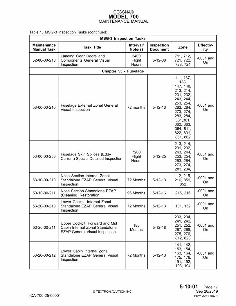
52-80-00-210Landing Gear Doors andComponents General VisualInspection
2400FlightHours
5-12-08711, 712,721, 722,723, 724
-0001 andOn
Chapter 53 - Fuselage
53-00-00-210 Fuselage External Zonal GeneralVisual Inspection 72 months 5-12-13
111, 137,138,
147, 148,213, 214,231, 232,243, 244,253, 254,263, 264,273, 274,283, 284,331,361,362, 363,364, 811,822, 831,861, 862
-0001 andOn
53-00-00-250 Fuselage Skin Splices (EddyCurrent) Special Detailed Inspection
7200FlightHours
5-12-25
213, 214,231, 232,243, 244,253, 254,263, 264,273, 274,283, 284,
-0001 andOn
53-10-00-210Nose Section Internal ZonalStandalone EZAP General VisualInspection
72 Months 5-12-13112, 215,216, 851,
852-0001 and
On
53-10-00-211 Nose Section Standalone EZAP(Cleaning) Restoration 96 Months 5-12-16 215, 216 -0001 and
On
53-20-00-210Lower Cockpit Internal ZonalStandalone EZAP General VisualInspection
72 Months 5-12-13 131, 132 -0001 andOn
53-20-00-211Upper Cockpit, Forward and MidCabin Internal Zonal StandaloneEZAP General Visual Inspection
180Months 5-12-18
233, 234,241, 242,251, 252,267, 268,275, 276,812, 823
-0001 andOn
53-20-00-212Lower Cabin Internal ZonalStandalone EZAP General VisualInspection
72 Months 5-12-13
141, 142,153, 154,163, 164,175, 176,191, 192,193, 194
-0001 andOn
5-10-01 Page 17© TEXTRON AVIATION INC. Sep 26/2019
ICA-700-25-00001 Form 2261 Rev 1
CESSNA®MODEL 700
MAINTENANCE MANUAL
Table 1. MSG-3 Inspection Tasks (continued)MSG-3 Inspection Tasks
MaintenanceManual Task Task Title Interval/
Note(s)InspectionDocument Zone Effectiv-
ity
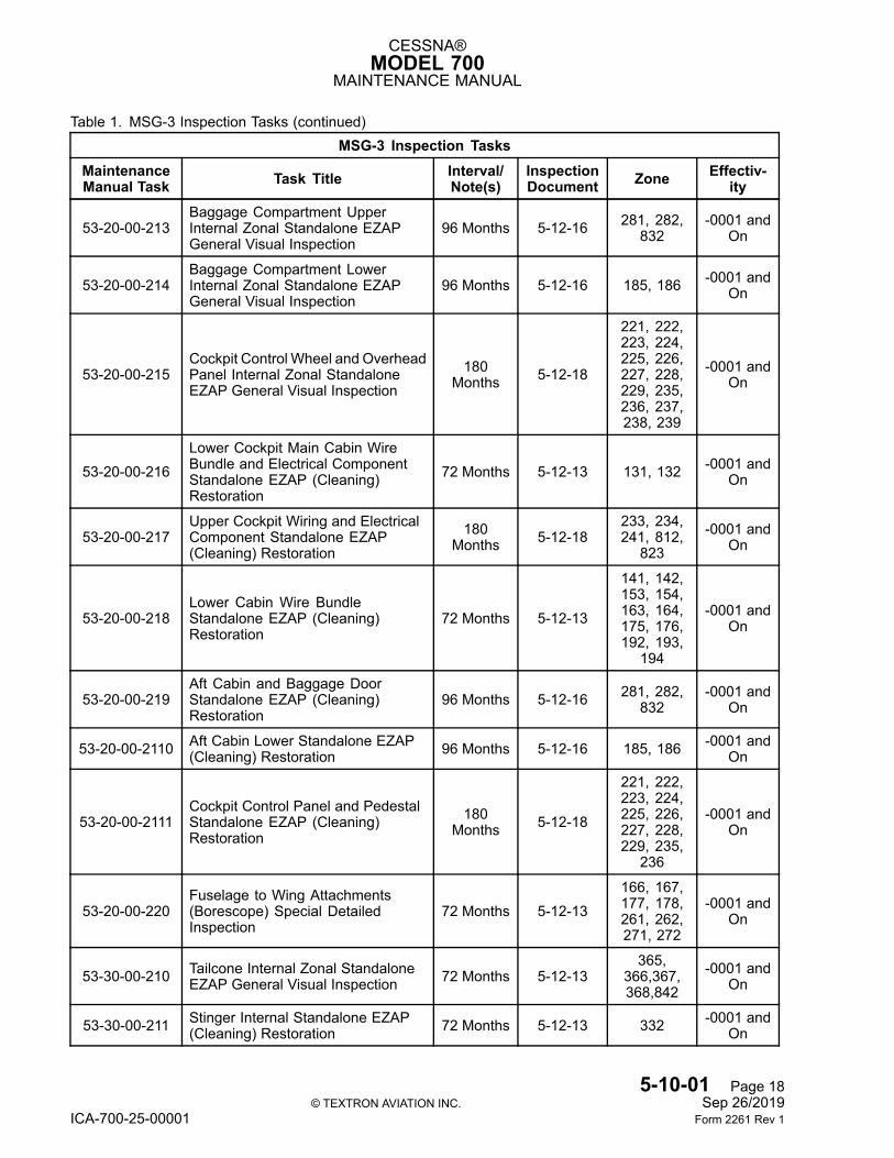
53-20-00-213Baggage Compartment UpperInternal Zonal Standalone EZAPGeneral Visual Inspection
96 Months 5-12-16 281, 282,832
-0001 andOn
53-20-00-214Baggage Compartment LowerInternal Zonal Standalone EZAPGeneral Visual Inspection
96 Months 5-12-16 185, 186 -0001 andOn
53-20-00-215Cockpit Control Wheel and OverheadPanel Internal Zonal StandaloneEZAP General Visual Inspection
180Months 5-12-18
221, 222,223, 224,225, 226,227, 228,229, 235,236, 237,238, 239
-0001 andOn
53-20-00-216Lower Cockpit Main Cabin WireBundle and Electrical ComponentStandalone EZAP (Cleaning)Restoration
72 Months 5-12-13 131, 132 -0001 andOn
53-20-00-217Upper Cockpit Wiring and ElectricalComponent Standalone EZAP(Cleaning) Restoration
180Months 5-12-18
233, 234,241, 812,
823-0001 and
On
53-20-00-218Lower Cabin Wire BundleStandalone EZAP (Cleaning)Restoration
72 Months 5-12-13
141, 142,153, 154,163, 164,175, 176,192, 193,
194
-0001 andOn
53-20-00-219Aft Cabin and Baggage DoorStandalone EZAP (Cleaning)Restoration
96 Months 5-12-16 281, 282,832
-0001 andOn
53-20-00-2110 Aft Cabin Lower Standalone EZAP(Cleaning) Restoration 96 Months 5-12-16 185, 186 -0001 and
On
53-20-00-2111Cockpit Control Panel and PedestalStandalone EZAP (Cleaning)Restoration
180Months 5-12-18
221, 222,223, 224,225, 226,227, 228,229, 235,
236
-0001 andOn
53-20-00-220Fuselage to Wing Attachments(Borescope) Special DetailedInspection
72 Months 5-12-13166, 167,177, 178,261, 262,271, 272
-0001 andOn
53-30-00-210 Tailcone Internal Zonal StandaloneEZAP General Visual Inspection 72 Months 5-12-13
365,366,367,368,842
-0001 andOn
53-30-00-211 Stinger Internal Standalone EZAP(Cleaning) Restoration 72 Months 5-12-13 332 -0001 and
On
5-10-01 Page 18© TEXTRON AVIATION INC. Sep 26/2019
ICA-700-25-00001 Form 2261 Rev 1
CESSNA®MODEL 700
MAINTENANCE MANUAL
Table 1. MSG-3 Inspection Tasks (continued)MSG-3 Inspection Tasks
MaintenanceManual Task Task Title Interval/
Note(s)InspectionDocument Zone Effectiv-
ity
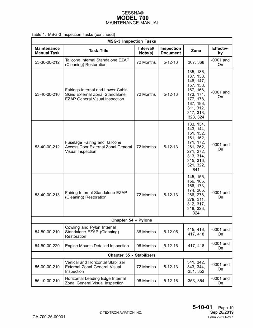
53-30-00-212 Tailcone Internal Standalone EZAP(Cleaning) Restoration 72 Months 5-12-13 367, 368 -0001 and
On
53-40-00-210Fairings Internal and Lower CabinSkins External Zonal StandaloneEZAP General Visual Inspection
72 Months 5-12-13
135, 136,137, 138,146, 147,157, 158,167, 168,173, 174,177, 178,187, 188,311, 312,317, 318,323, 324
-0001 andOn
53-40-00-212Fuselage Fairing and TailconeAccess Door External Zonal GeneralVisual Inspection
72 Months 5-12-13
133, 134,143, 144,151, 152,161, 162,171, 172,261, 262,271, 272,313, 314,315, 316,321, 322,
841
-0001 andOn
53-40-00-213 Fairing Internal Standalone EZAP(Cleaning) Restoration 72 Months 5-12-13
145, 155,156, 165,166, 173,174, 265,266, 278,279, 311,312, 317,318, 323,
324
-0001 andOn
Chapter 54 - Pylons
54-50-00-210Cowling and Pylon InternalStandalone EZAP (Cleaning)Restoration
36 Months 5-12-05 415, 416,417, 418
-0001 andOn
54-50-00-220 Engine Mounts Detailed Inspection 96 Months 5-12-16 417, 418 -0001 andOn
Chapter 55 - Stabilizers
55-00-00-210Vertical and Horizontal StabilizerExternal Zonal General VisualInspection
72 Months 5-12-13341, 342,343, 344,351, 352
-0001 andOn
55-10-00-210 Horizontal Leading Edge InternalZonal General Visual Inspection 96 Months 5-12-16 353, 354 -0001 and
On
5-10-01 Page 19© TEXTRON AVIATION INC. Sep 26/2019
ICA-700-25-00001 Form 2261 Rev 1
CESSNA®MODEL 700
MAINTENANCE MANUAL
Table 1. MSG-3 Inspection Tasks (continued)MSG-3 Inspection Tasks
MaintenanceManual Task Task Title Interval/
Note(s)InspectionDocument Zone Effectiv-
ity
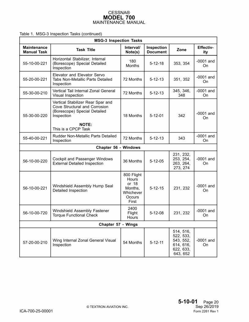
55-10-00-221Horizontal Stabilizer, Internal(Borescope) Special DetailedInspection
180Months 5-12-18 353, 354 -0001 and
On
55-20-00-221Elevator and Elevator ServoTabs Non-Metallic Parts DetailedInspection
72 Months 5-12-13 351, 352 -0001 andOn
55-30-00-210 Vertical Tail Internal Zonal GeneralVisual Inspection 72 Months 5-12-13 345, 346,
348-0001 and
On
55-30-00-220
Vertical Stabilizer Rear Spar andCove Structural and Corrosion(Borescope) Special DetailedInspection
NOTE:This is a CPCP Task
18 Months 5-12-01 342 -0001 andOn
55-40-00-221 Rudder Non-Metallic Parts DetailedInspection 72 Months 5-12-13 343 -0001 and
On
Chapter 56 - Windows
56-10-00-220 Cockpit and Passenger WindowsExternal Detailed Inspection 36 Months 5-12-05
231, 232,253, 254,263, 264,273, 274
-0001 andOn
56-10-00-221 Windshield Assembly Hump SealDetailed Inspection
800 FlightHoursor 18Months,WhicheverOccursFirst
5-12-15 231, 232 -0001 andOn
56-10-00-720 Windshield Assembly FastenerTorque Functional Check
2400FlightHours
5-12-08 231, 232 -0001 andOn
Chapter 57 - Wings
57-20-00-210 Wing Internal Zonal General VisualInspection 54 Months 5-12-11
514, 516,522, 533,543, 552,614, 616,622, 633,643, 652
-0001 andOn
5-10-01 Page 20© TEXTRON AVIATION INC. Sep 26/2019
ICA-700-25-00001 Form 2261 Rev 1
CESSNA®MODEL 700
MAINTENANCE MANUAL
Table 1. MSG-3 Inspection Tasks (continued)MSG-3 Inspection Tasks
MaintenanceManual Task Task Title Interval/
Note(s)InspectionDocument Zone Effectiv-
ity
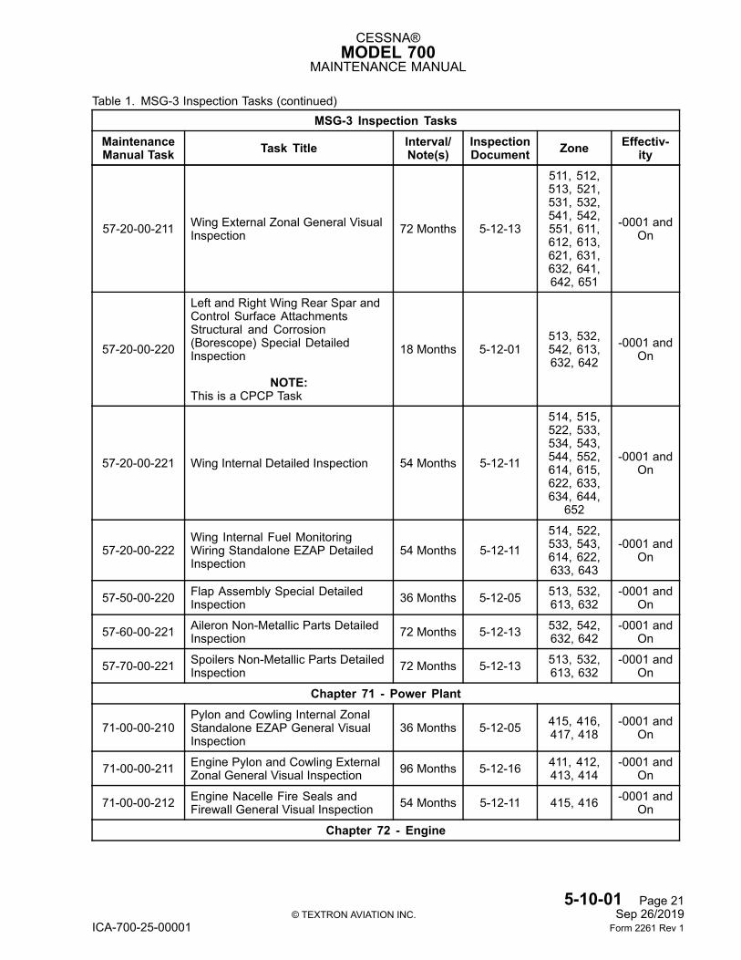
57-20-00-211 Wing External Zonal General VisualInspection 72 Months 5-12-13
511, 512,513, 521,531, 532,541, 542,551, 611,612, 613,621, 631,632, 641,642, 651
-0001 andOn
57-20-00-220
Left and Right Wing Rear Spar andControl Surface AttachmentsStructural and Corrosion(Borescope) Special DetailedInspection
NOTE:This is a CPCP Task
18 Months 5-12-01513, 532,542, 613,632, 642
-0001 andOn
57-20-00-221 Wing Internal Detailed Inspection 54 Months 5-12-11
514, 515,522, 533,534, 543,544, 552,614, 615,622, 633,634, 644,
652
-0001 andOn
57-20-00-222Wing Internal Fuel MonitoringWiring Standalone EZAP DetailedInspection
54 Months 5-12-11514, 522,533, 543,614, 622,633, 643
-0001 andOn
57-50-00-220 Flap Assembly Special DetailedInspection 36 Months 5-12-05 513, 532,
613, 632-0001 and
On
57-60-00-221 Aileron Non-Metallic Parts DetailedInspection 72 Months 5-12-13 532, 542,
632, 642-0001 and
On
57-70-00-221 Spoilers Non-Metallic Parts DetailedInspection 72 Months 5-12-13 513, 532,
613, 632-0001 and
On
Chapter 71 - Power Plant
71-00-00-210Pylon and Cowling Internal ZonalStandalone EZAP General VisualInspection
36 Months 5-12-05 415, 416,417, 418
-0001 andOn
71-00-00-211 Engine Pylon and Cowling ExternalZonal General Visual Inspection 96 Months 5-12-16 411, 412,
413, 414-0001 and
On
71-00-00-212 Engine Nacelle Fire Seals andFirewall General Visual Inspection 54 Months 5-12-11 415, 416 -0001 and
On
Chapter 72 - Engine
5-10-01 Page 21© TEXTRON AVIATION INC. Sep 26/2019
ICA-700-25-00001 Form 2261 Rev 1

CESSNA®MODEL 700
MAINTENANCE MANUAL
Table 1. MSG-3 Inspection Tasks (continued)MSG-3 Inspection Tasks
MaintenanceManual Task Task Title Interval/
Note(s)InspectionDocument Zone Effectiv-
ity
Refer toHoneywellAerospace72-05-25
Engine LightMaintenance
Manual
Honeywell Engine PeriodicInspections
NOTE:Refer to Honeywell Aerospace72-05-25 Engine Light MaintenanceManual Chapter 5-20-00.
EngineHours orCyclesNOTE
Refer toChapter5-10-02 orHoneywellAerospace72-05-25Engine
Light Main-tenanceManual
415, 416 -0001 andOn
Chapter 78 - Exhaust
78-30-00-220 Thrust Reverser Assembly DetailedInspection
3200FlightHours
5-12-12 411, 412 -0001 andOn
NOTE 1: Components which have exceeded replacement times due to a current change in the inspectionprogram, may continue in service, if the component is serviceable, and the component is immediatelyordered and scheduled for replacement. Possible delays resulting from component shortage shall notresult in extending time past 60 days.
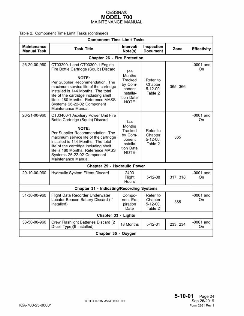
3. Component Time Limit Tasks
NOTE: Table 2 is a consolidated list of component time limit tasks (duplicated from Table 1), to assistoperators in maintenance planning.
NOTE: Refer to the Model 700 Airworthiness Limitations Manual, Chapter 4, Airworthiness LimitationsInspection Time Limits for a list of the Airworthiness Component Time Limit Tasks.
Table 2. Component Time Limit Tasks
Component Time Limit TasksMaintenanceManual Task Task Title Interval/
Note(s)InspectionDocument Zone Effectivity
Chapter 21 - Air Conditioning21-70-00-960 HEPA Filter Discard 2400
FlightHours
5-12-08 282-0001 and
On
Chapter 23 - Communications23-70-00-960 Cockpit Voice Recorder Underwater
Locator Beacon Battery DiscardCompo-nent Ex-pirationDate
Refer toChapter5-12-00,Table 2
366-0001 and
On
Chapter 24 - Electrical Power
5-10-01 Page 22© TEXTRON AVIATION INC. Sep 26/2019
ICA-700-25-00001 Form 2261 Rev 1
CESSNA®MODEL 700
MAINTENANCE MANUAL
Table 2. Component Time Limit Tasks (continued)Component Time Limit Tasks
MaintenanceManual Task Task Title Interval/
Note(s)InspectionDocument Zone Effectivity
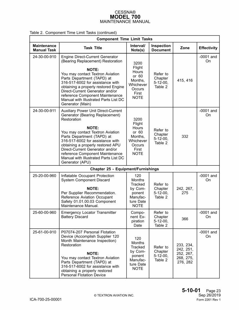
24-30-00-910 Engine Direct-Current Generator(Bearing Replacement) Restoration
NOTE:You may contact Textron AviationParts Department (TAPD) at316-517-6002 for assistance withobtaining a properly restored EngineDirect-Current Generator and/orreference Component MaintenanceManual with Illustrated Parts List DCGenerator (Main)
3200FlightHoursor 60Months,WhicheverOccursFirstNOTE
Refer toChapter5-12-00,Table 2
415, 416
-0001 andOn
24-30-00-911 Auxiliary Power Unit Direct-CurrentGenerator (Bearing Replacement)Restoration
NOTE:You may contact Textron AviationParts Department (TAPD) at316-517-6002 for assistance withobtaining a properly restored APUDirect-Current Generator and/orreference Component MaintenanceManual with Illustrated Parts List DCGenerator (APU)
3200FlightHoursor 60Months,WhicheverOccursFirstNOTE
Refer toChapter5-12-00,Table 2
332
-0001 andOn
Chapter 25 - Equipment/Furnishings25-20-00-960 Inflatable Occupant Protection
System Component Discard
NOTE:Per Supplier Recommendation.Reference Aviation OccupantSafety 01.01.00.03 ComponentMaintenance Manual.
120MonthsTrackedby Com-ponentManufac-ture DateNOTE
Refer toChapter5-12-00,Table 2
242, 267,275
-0001 andOn
25-60-00-960 Emergency Locator TransmitterBattery Discard
Compo-nent Ex-pirationDate
Refer toChapter5-12-00,Table 2
366-0001 and
On
25-61-00-910 P07074-207 Personal FlotationDevice (Accomplish Supplier 120Month Maintenance Inspection)Restoration
NOTE:You may contact Textron AviationParts Department (TAPD) at316-517-6002 for assistance withobtaining a properly restoredPersonal Flotation Device
120MonthsTrackedby Com-ponentManufac-ture DateNOTE
Refer toChapter5-12-00,Table 2
233, 234,242, 251,252, 267,268, 275,276, 282
-0001 andOn
5-10-01 Page 23© TEXTRON AVIATION INC. Sep 26/2019
ICA-700-25-00001 Form 2261 Rev 1
CESSNA®MODEL 700
MAINTENANCE MANUAL
Table 2. Component Time Limit Tasks (continued)Component Time Limit Tasks
MaintenanceManual Task Task Title Interval/
Note(s)InspectionDocument Zone Effectivity
Chapter 26 - Fire Protection26-20-00-960 CT03200-1 and CT03300-1 Engine
Fire Bottle Cartridge (Squib) Discard
NOTE:Per Supplier Recommendation. Themaximum service life of the cartridgeinstalled is 144 Months. The totallife of the cartridge including shelflife is 180 Months. Reference MASSSystems 26-22-02 ComponentMaintenance Manual.
144MonthsTrackedby Com-ponentInstalla-tion DateNOTE
Refer toChapter5-12-00,Table 2
365, 366
-0001 andOn
26-21-00-960 CT03400-1 Auxiliary Power Unit FireBottle Cartridge (Squib) Discard
NOTE:Per Supplier Recommendation. Themaximum service life of the cartridgeinstalled is 144 Months. The totallife of the cartridge including shelflife is 180 Months. Reference MASSSystems 26-22-02 ComponentMaintenance Manual.
144MonthsTrackedby Com-ponentInstalla-tion DateNOTE
Refer toChapter5-12-00,Table 2
365
-0001 andOn
Chapter 29 - Hydraulic Power29-10-00-960 Hydraulic System Filters Discard 2400
FlightHours
5-12-08 317, 318-0001 and
On
Chapter 31 - Indicating/Recording Systems31-30-00-960 Flight Data Recorder Underwater
Locator Beacon Battery Discard (IfInstalled)
Compo-nent Ex-pirationDate
Refer toChapter5-12-00,Table 2
365-0001 and
On
Chapter 33 - Lights33-50-00-960 Crew Flashlight Batteries Discard (2
D-cell Type)(If Installed) 18 Months 5-12-01 233, 234 -0001 andOn
Chapter 35 - Oxygen
5-10-01 Page 24© TEXTRON AVIATION INC. Sep 26/2019
ICA-700-25-00001 Form 2261 Rev 1
CESSNA®MODEL 700
MAINTENANCE MANUAL
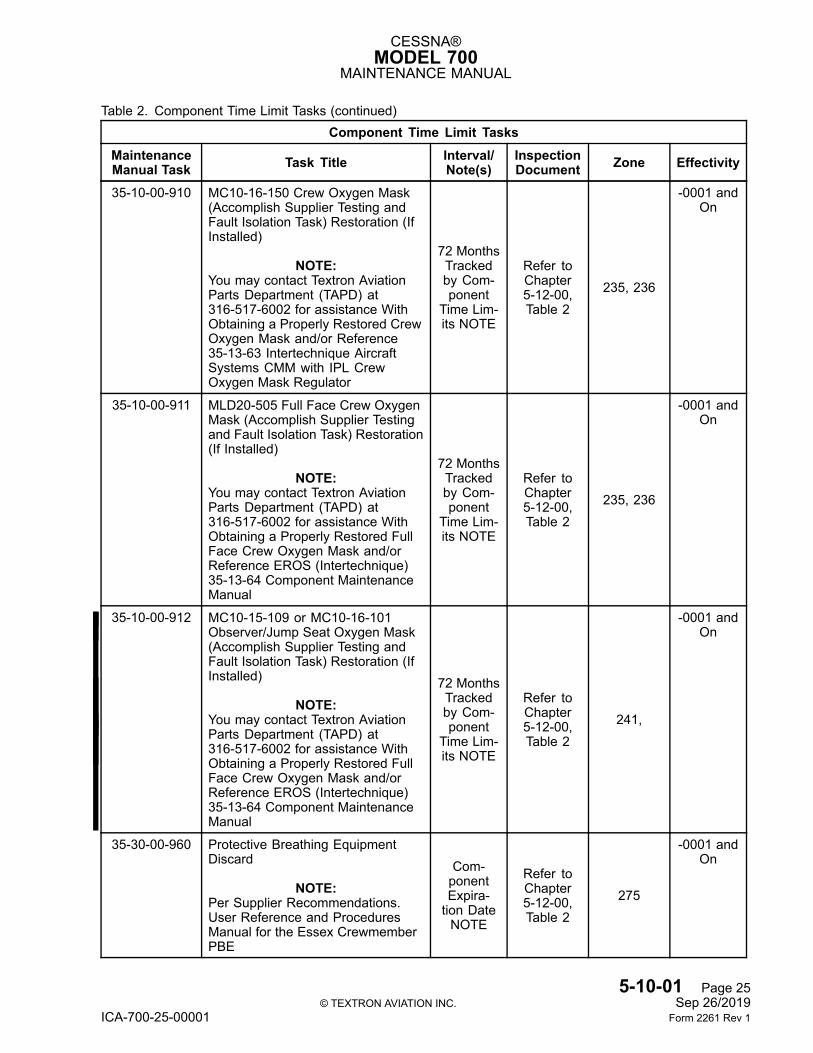
Table 2. Component Time Limit Tasks (continued)Component Time Limit Tasks
MaintenanceManual Task Task Title Interval/
Note(s)InspectionDocument Zone Effectivity
35-10-00-910 MC10-16-150 Crew Oxygen Mask(Accomplish Supplier Testing andFault Isolation Task) Restoration (IfInstalled)
NOTE:You may contact Textron AviationParts Department (TAPD) at316-517-6002 for assistance WithObtaining a Properly Restored CrewOxygen Mask and/or Reference35-13-63 Intertechnique AircraftSystems CMM with IPL CrewOxygen Mask Regulator
72 MonthsTrackedby Com-ponent
Time Lim-its NOTE
Refer toChapter5-12-00,Table 2
235, 236
-0001 andOn
35-10-00-911 MLD20-505 Full Face Crew OxygenMask (Accomplish Supplier Testingand Fault Isolation Task) Restoration(If Installed)
NOTE:You may contact Textron AviationParts Department (TAPD) at316-517-6002 for assistance WithObtaining a Properly Restored FullFace Crew Oxygen Mask and/orReference EROS (Intertechnique)35-13-64 Component MaintenanceManual
72 MonthsTrackedby Com-ponent
Time Lim-its NOTE
Refer toChapter5-12-00,Table 2
235, 236
-0001 andOn
35-10-00-912 MC10-15-109 or MC10-16-101Observer/Jump Seat Oxygen Mask(Accomplish Supplier Testing andFault Isolation Task) Restoration (IfInstalled)
NOTE:You may contact Textron AviationParts Department (TAPD) at316-517-6002 for assistance WithObtaining a Properly Restored FullFace Crew Oxygen Mask and/orReference EROS (Intertechnique)35-13-64 Component MaintenanceManual
72 MonthsTrackedby Com-ponent
Time Lim-its NOTE
Refer toChapter5-12-00,Table 2
241,
-0001 andOn
35-30-00-960 Protective Breathing EquipmentDiscard
NOTE:Per Supplier Recommendations.User Reference and ProceduresManual for the Essex CrewmemberPBE
Com-ponentExpira-tion DateNOTE
Refer toChapter5-12-00,Table 2
275
-0001 andOn
5-10-01 Page 25© TEXTRON AVIATION INC. Sep 26/2019
ICA-700-25-00001 Form 2261 Rev 1
CESSNA®MODEL 700
MAINTENANCE MANUAL
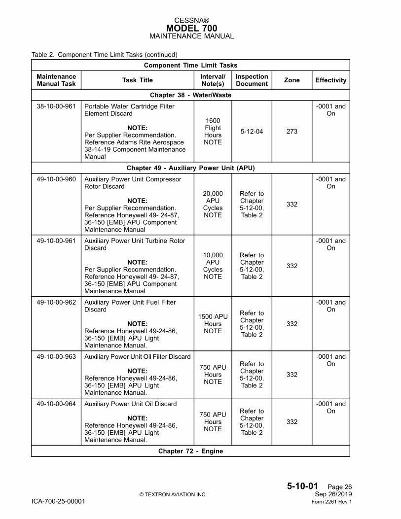
Table 2. Component Time Limit Tasks (continued)Component Time Limit Tasks
MaintenanceManual Task Task Title Interval/
Note(s)InspectionDocument Zone Effectivity
Chapter 38 - Water/Waste38-10-00-961 Portable Water Cartridge Filter
Element Discard
NOTE:Per Supplier Recommendation.Reference Adams Rite Aerospace38-14-19 Component MaintenanceManual
1600FlightHoursNOTE
5-12-04 273
-0001 andOn
Chapter 49 - Auxiliary Power Unit (APU)49-10-00-960 Auxiliary Power Unit Compressor
Rotor Discard
NOTE:Per Supplier Recommendation.Reference Honeywell 49- 24-87,36-150 [EMB] APU ComponentMaintenance Manual
20,000APUCyclesNOTE
Refer toChapter5-12-00,Table 2
332
-0001 andOn
49-10-00-961 Auxiliary Power Unit Turbine RotorDiscard
NOTE:Per Supplier Recommendation.Reference Honeywell 49- 24-87,36-150 [EMB] APU ComponentMaintenance Manual
10,000APUCyclesNOTE
Refer toChapter5-12-00,Table 2
332
-0001 andOn
49-10-00-962 Auxiliary Power Unit Fuel FilterDiscard
NOTE:Reference Honeywell 49-24-86,36-150 [EMB] APU LightMaintenance Manual.
1500 APUHoursNOTE
Refer toChapter5-12-00,Table 2
332
-0001 andOn
49-10-00-963 Auxiliary Power Unit Oil Filter Discard
NOTE:Reference Honeywell 49-24-86,36-150 [EMB] APU LightMaintenance Manual.
750 APUHoursNOTE
Refer toChapter5-12-00,Table 2
332
-0001 andOn
49-10-00-964 Auxiliary Power Unit Oil Discard
NOTE:Reference Honeywell 49-24-86,36-150 [EMB] APU LightMaintenance Manual.
750 APUHoursNOTE
Refer toChapter5-12-00,Table 2
332
-0001 andOn
Chapter 72 - Engine
5-10-01 Page 26© TEXTRON AVIATION INC. Sep 26/2019
ICA-700-25-00001 Form 2261 Rev 1
CESSNA®MODEL 700
MAINTENANCE MANUAL
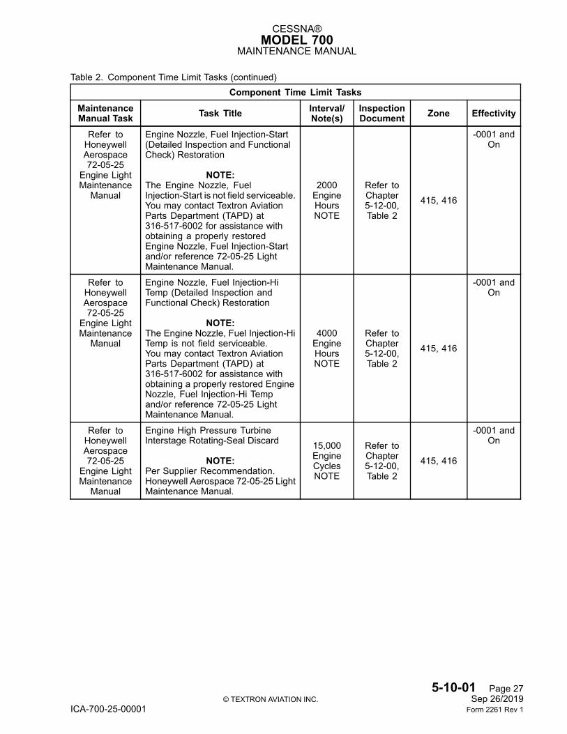
Table 2. Component Time Limit Tasks (continued)Component Time Limit Tasks
MaintenanceManual Task Task Title Interval/
Note(s)InspectionDocument Zone Effectivity
Refer toHoneywellAerospace72-05-25
Engine LightMaintenance
Manual
Engine Nozzle, Fuel Injection-Start(Detailed Inspection and FunctionalCheck) Restoration
NOTE:The Engine Nozzle, FuelInjection-Start is not field serviceable.You may contact Textron AviationParts Department (TAPD) at316-517-6002 for assistance withobtaining a properly restoredEngine Nozzle, Fuel Injection-Startand/or reference 72-05-25 LightMaintenance Manual.
2000EngineHoursNOTE
Refer toChapter5-12-00,Table 2
415, 416
-0001 andOn
Refer toHoneywellAerospace72-05-25
Engine LightMaintenance
Manual
Engine Nozzle, Fuel Injection-HiTemp (Detailed Inspection andFunctional Check) Restoration
NOTE:The Engine Nozzle, Fuel Injection-HiTemp is not field serviceable.You may contact Textron AviationParts Department (TAPD) at316-517-6002 for assistance withobtaining a properly restored EngineNozzle, Fuel Injection-Hi Tempand/or reference 72-05-25 LightMaintenance Manual.
4000EngineHoursNOTE
Refer toChapter5-12-00,Table 2
415, 416
-0001 andOn
Refer toHoneywellAerospace72-05-25
Engine LightMaintenance
Manual
Engine High Pressure TurbineInterstage Rotating-Seal Discard
NOTE:Per Supplier Recommendation.Honeywell Aerospace 72-05-25 LightMaintenance Manual.
15,000EngineCyclesNOTE
Refer toChapter5-12-00,Table 2
415, 416
-0001 andOn
5-10-01 Page 27© TEXTRON AVIATION INC. Sep 26/2019
ICA-700-25-00001 Form 2261 Rev 1
CESSNA®MODEL 700
MAINTENANCE MANUAL
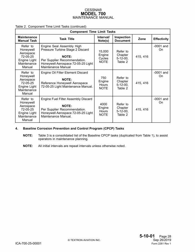
Table 2. Component Time Limit Tasks (continued)Component Time Limit Tasks
MaintenanceManual Task Task Title Interval/
Note(s)InspectionDocument Zone Effectivity
Refer toHoneywellAerospace72-05-25
Engine LightMaintenance
Manual
Engine Seal Assembly HighPressure Turbine Stage 2 Discard
NOTE:Per Supplier Recommendation.Honeywell Aerospace 72-05-25 LightMaintenance Manual
15,000EngineCyclesNOTE
Refer toChapter5-12-00,Table 2
415, 416
-0001 andOn
Refer toHoneywellAerospace72-05-25
Engine LightMaintenance
Manual
Engine Oil Filter Element Discard
NOTE:Reference Honeywell Aerospace72-05-25 Light Maintenance Manual.
750EngineHoursNOTE
Refer toChapter5-12-00,Table 2
415, 416
-0001 andOn
Refer toHoneywellAerospace72-05-25
Engine LightMaintenance
Manual
Engine Fuel Filter Assembly Discard
NOTE:Per Supplier Recommendation.Honeywell Aerospace 72-05-25 LightMaintenance Manual.
4000EngineHoursNOTE
Refer toChapter5-12-00,Table 2
415, 416
-0001 andOn
4. Baseline Corrosion Prevention and Control Program (CPCP) Tasks
NOTE: Table 3 is a consolidated list of the Baseline CPCP tasks (duplicated from Table 1), to assistoperators in maintenance planning.
NOTE: All initial intervals are repeat intervals unless otherwise noted.
5-10-01 Page 28© TEXTRON AVIATION INC. Sep 26/2019
ICA-700-25-00001 Form 2261 Rev 1
CESSNA®MODEL 700
MAINTENANCE MANUAL
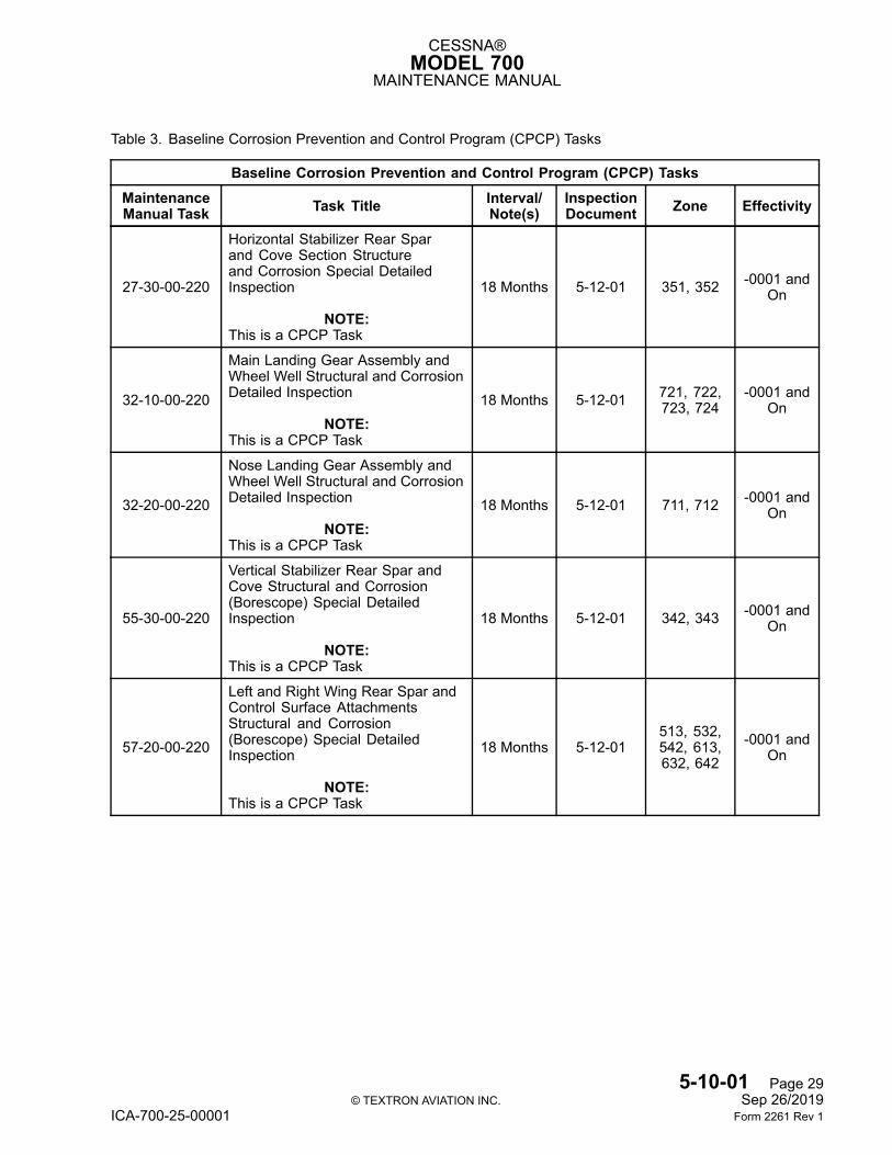
Table 3. Baseline Corrosion Prevention and Control Program (CPCP) Tasks
Baseline Corrosion Prevention and Control Program (CPCP) TasksMaintenanceManual Task Task Title Interval/
Note(s)InspectionDocument Zone Effectivity
27-30-00-220
Horizontal Stabilizer Rear Sparand Cove Section Structureand Corrosion Special DetailedInspection
NOTE:This is a CPCP Task
18 Months 5-12-01 351, 352 -0001 andOn
32-10-00-220
Main Landing Gear Assembly andWheel Well Structural and CorrosionDetailed Inspection
NOTE:This is a CPCP Task
18 Months 5-12-01 721, 722,723, 724
-0001 andOn
32-20-00-220
Nose Landing Gear Assembly andWheel Well Structural and CorrosionDetailed Inspection
NOTE:This is a CPCP Task
18 Months 5-12-01 711, 712 -0001 andOn
55-30-00-220
Vertical Stabilizer Rear Spar andCove Structural and Corrosion(Borescope) Special DetailedInspection
NOTE:This is a CPCP Task
18 Months 5-12-01 342, 343 -0001 andOn
57-20-00-220
Left and Right Wing Rear Spar andControl Surface AttachmentsStructural and Corrosion(Borescope) Special DetailedInspection
NOTE:This is a CPCP Task
18 Months 5-12-01513, 532,542, 613,632, 642
-0001 andOn
5-10-01 Page 29© TEXTRON AVIATION INC. Sep 26/2019
ICA-700-25-00001 Form 2261 Rev 1
CESSNA®MODEL 700
MAINTENANCE MANUAL
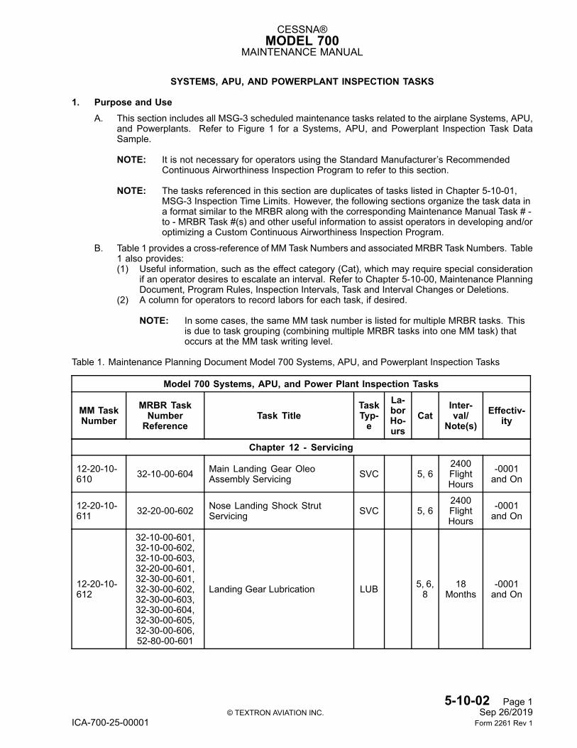
SYSTEMS, APU, AND POWERPLANT INSPECTION TASKS
1. Purpose and UseA. This section includes all MSG-3 scheduled maintenance tasks related to the airplane Systems, APU,
and Powerplants. Refer to Figure 1 for a Systems, APU, and Powerplant Inspection Task DataSample.
NOTE: It is not necessary for operators using the Standard Manufacturer’s RecommendedContinuous Airworthiness Inspection Program to refer to this section.
NOTE: The tasks referenced in this section are duplicates of tasks listed in Chapter 5-10-01,MSG-3 Inspection Time Limits. However, the following sections organize the task data ina format similar to the MRBR along with the corresponding Maintenance Manual Task # -to - MRBR Task #(s) and other useful information to assist operators in developing and/oroptimizing a Custom Continuous Airworthiness Inspection Program.
B. Table 1 provides a cross-reference of MM Task Numbers and associated MRBR Task Numbers. Table1 also provides:(1) Useful information, such as the effect category (Cat), which may require special consideration
if an operator desires to escalate an interval. Refer to Chapter 5-10-00, Maintenance PlanningDocument, Program Rules, Inspection Intervals, Task and Interval Changes or Deletions.
(2) A column for operators to record labors for each task, if desired.
NOTE: In some cases, the same MM task number is listed for multiple MRBR tasks. Thisis due to task grouping (combining multiple MRBR tasks into one MM task) thatoccurs at the MM task writing level.
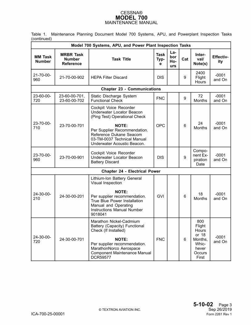
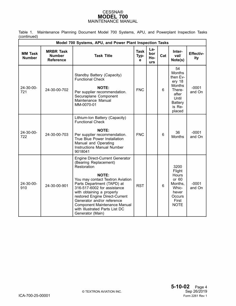
Table 1. Maintenance Planning Document Model 700 Systems, APU, and Powerplant Inspection Tasks
Model 700 Systems, APU, and Power Plant Inspection Tasks
MM TaskNumber
MRBR TaskNumberReference
Task TitleTaskTyp-e
La-borHo-urs
CatInter-val/
Note(s)Effectiv-
ity
Chapter 12 - Servicing
12-20-10-610 32-10-00-604 Main Landing Gear Oleo
Assembly Servicing SVC 5, 62400FlightHours
-0001and On
12-20-10-611 32-20-00-602 Nose Landing Shock Strut
Servicing SVC 5, 62400FlightHours
-0001and On
12-20-10-612
32-10-00-601,32-10-00-602,32-10-00-603,32-20-00-601,32-30-00-601,32-30-00-602,32-30-00-603,32-30-00-604,32-30-00-605,32-30-00-606,52-80-00-601
Landing Gear Lubrication LUB 5, 6,8
18Months
-0001and On
5-10-02 Page 1© TEXTRON AVIATION INC. Sep 26/2019
ICA-700-25-00001 Form 2261 Rev 1
CESSNA®MODEL 700
MAINTENANCE MANUAL
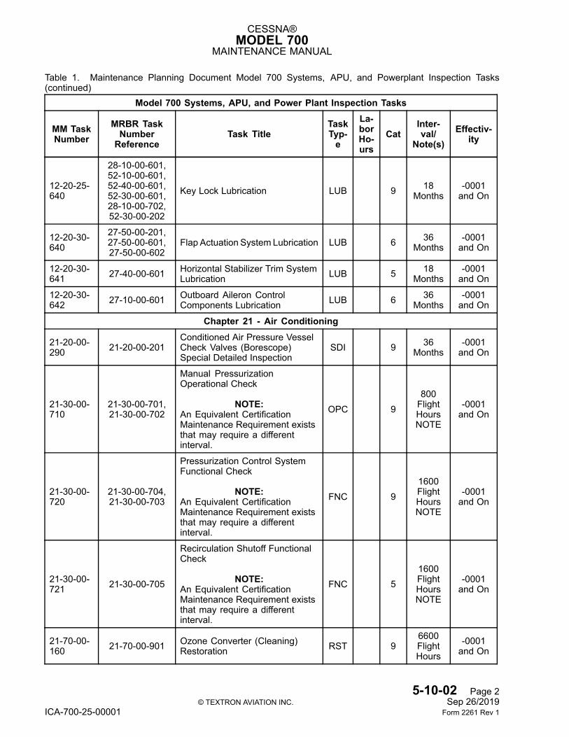
Table 1. Maintenance Planning Document Model 700 Systems, APU, and Powerplant Inspection Tasks(continued)
Model 700 Systems, APU, and Power Plant Inspection Tasks
MM TaskNumber
MRBR TaskNumberReference
Task TitleTaskTyp-e
La-borHo-urs
CatInter-val/
Note(s)Effectiv-
ity
12-20-25-640
28-10-00-601,52-10-00-601,52-40-00-601,52-30-00-601,28-10-00-702,52-30-00-202
Key Lock Lubrication LUB 9 18Months
-0001and On
12-20-30-640
27-50-00-201,27-50-00-601,27-50-00-602
Flap Actuation System Lubrication LUB 6 36Months
-0001and On
12-20-30-641 27-40-00-601 Horizontal Stabilizer Trim System
Lubrication LUB 5 18Months
-0001and On
12-20-30-642 27-10-00-601 Outboard Aileron Control
Components Lubrication LUB 6 36Months
-0001and On
Chapter 21 - Air Conditioning
21-20-00-290 21-20-00-201
Conditioned Air Pressure VesselCheck Valves (Borescope)Special Detailed Inspection
SDI 9 36Months
-0001and On
21-30-00-710
21-30-00-701,21-30-00-702
Manual PressurizationOperational Check
NOTE:An Equivalent CertificationMaintenance Requirement existsthat may require a differentinterval.
OPC 9800FlightHoursNOTE
-0001and On
21-30-00-720
21-30-00-704,21-30-00-703
Pressurization Control SystemFunctional Check
NOTE:An Equivalent CertificationMaintenance Requirement existsthat may require a differentinterval.
FNC 91600FlightHoursNOTE
-0001and On
21-30-00-721 21-30-00-705
Recirculation Shutoff FunctionalCheck
NOTE:An Equivalent CertificationMaintenance Requirement existsthat may require a differentinterval.
FNC 51600FlightHoursNOTE
-0001and On
21-70-00-160 21-70-00-901 Ozone Converter (Cleaning)
Restoration RST 96600FlightHours
-0001and On
5-10-02 Page 2© TEXTRON AVIATION INC. Sep 26/2019
ICA-700-25-00001 Form 2261 Rev 1
CESSNA®MODEL 700
MAINTENANCE MANUAL
Table 1. Maintenance Planning Document Model 700 Systems, APU, and Powerplant Inspection Tasks(continued)
Model 700 Systems, APU, and Power Plant Inspection Tasks
MM TaskNumber
MRBR TaskNumberReference
Task TitleTaskTyp-e
La-borHo-urs
CatInter-val/
Note(s)Effectiv-
ity
21-70-00-960 21-70-00-902 HEPA Filter Discard DIS 9
2400FlightHours
-0001and On
Chapter 23 - Communications23-60-00-720
23-60-00-701,23-60-00-702
Static Discharge SystemFunctional Check FNC 9 72
Months-0001and On
23-70-00-710 23-70-00-701
Cockpit Voice RecorderUnderwater Locator Beacon(Ping Test) Operational Check
NOTE:Per Supplier Recommendation.Reference Dukane Seacom03-TM-0037 Technical ManualUnderwater Acoustic Beacon.
OPC 6 24Months
-0001and On
23-70-00-960 23-70-00-901
Cockpit Voice RecorderUnderwater Locator BeaconBattery Discard
DIS 9Compo-nent Ex-pirationDate
-0001and On
Chapter 24 - Electrical Power
24-30-00-210 24-30-00-201
Lithium-Ion Battery GeneralVisual Inspection
NOTE:Per supplier recommendation.True Blue Power InstallationManual and OperatingInstructions Manual Number9018041
GVI 6 18Months
-0001and On
24-30-00-720 24-30-00-701
Marathon Nickel-CadmiumBattery (Capacity) FunctionalCheck (If Installed)
NOTE:Per supplier recommendation.MarathonNorco AerospaceComponent Maintenance ManualDCR59577
FNC 6
800FlightHoursor 18Months,Whic-heverOccursFirst
-0001and On
5-10-02 Page 3© TEXTRON AVIATION INC. Sep 26/2019
ICA-700-25-00001 Form 2261 Rev 1
CESSNA®MODEL 700
MAINTENANCE MANUAL
Table 1. Maintenance Planning Document Model 700 Systems, APU, and Powerplant Inspection Tasks(continued)
Model 700 Systems, APU, and Power Plant Inspection Tasks
MM TaskNumber
MRBR TaskNumberReference
Task TitleTaskTyp-e
La-borHo-urs
CatInter-val/
Note(s)Effectiv-
ity
24-30-00-721 24-30-00-702
Standby Battery (Capacity)Functional Check
NOTE:Per supplier recommendation.Securaplane ComponentMaintenance ManualMM-0070-01
FNC 6
54Monthsthen Ev-ery 18MonthsThere-afterUntil
Batteryis Re-placed
-0001and On
24-30-00-722 24-30-00-703
Lithium-Ion Battery (Capacity)Functional Check
NOTE:Per supplier recommendation.True Blue Power InstallationManual and OperatingInstructions Manual Number9018041
FNC 6 36Months
-0001and On
24-30-00-910 24-30-00-901
Engine Direct-Current Generator(Bearing Replacement)Restoration
NOTE:You may contact Textron AviationParts Department (TAPD) at316-517-6002 for assistancewith obtaining a properlyrestored Engine Direct-CurrentGenerator and/or referenceComponent Maintenance Manualwith Illustrated Parts List DCGenerator (Main)
RST 6
3200FlightHoursor 60Months,Whic-heverOccursFirstNOTE
-0001and On
5-10-02 Page 4© TEXTRON AVIATION INC. Sep 26/2019
ICA-700-25-00001 Form 2261 Rev 1
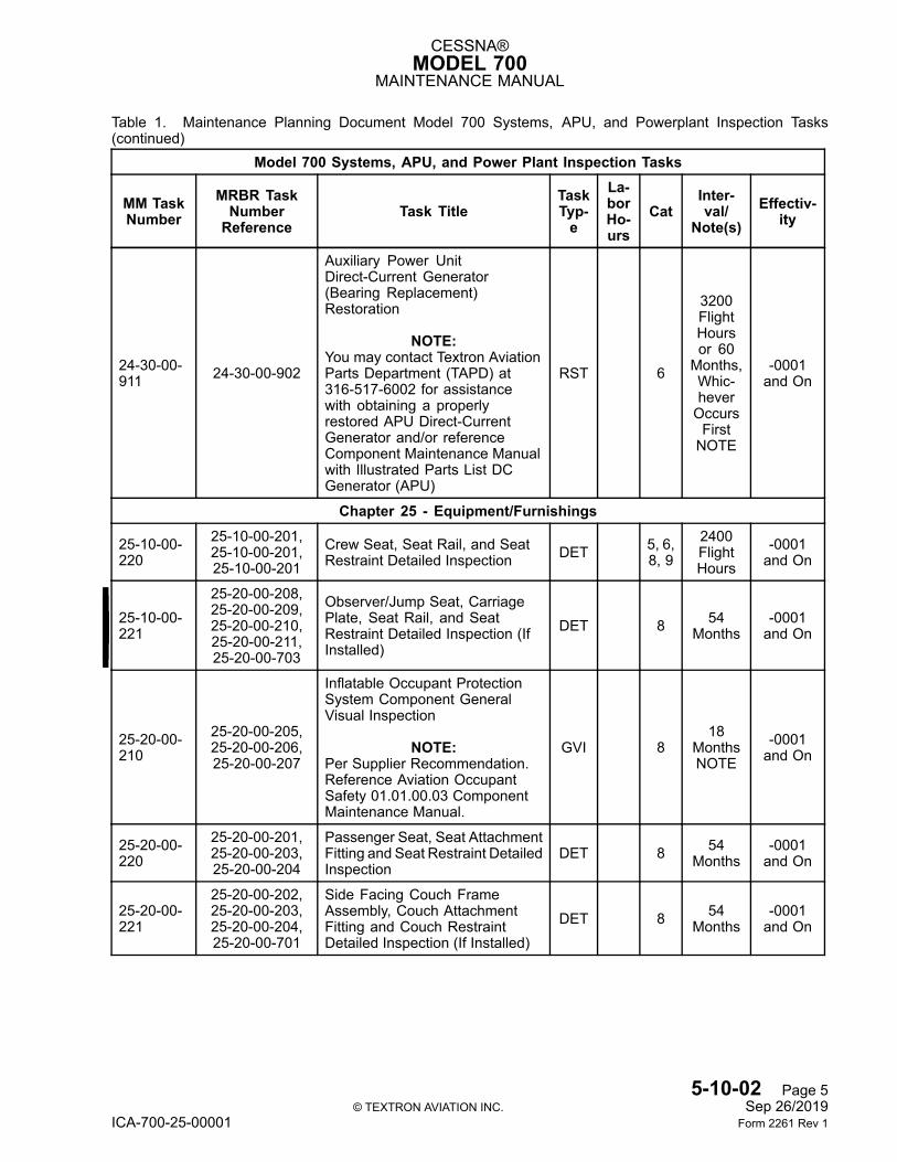
CESSNA®MODEL 700
MAINTENANCE MANUAL
Table 1. Maintenance Planning Document Model 700 Systems, APU, and Powerplant Inspection Tasks(continued)
Model 700 Systems, APU, and Power Plant Inspection Tasks
MM TaskNumber
MRBR TaskNumberReference
Task TitleTaskTyp-e
La-borHo-urs
CatInter-val/
Note(s)Effectiv-
ity
24-30-00-911 24-30-00-902
Auxiliary Power UnitDirect-Current Generator(Bearing Replacement)Restoration
NOTE:You may contact Textron AviationParts Department (TAPD) at316-517-6002 for assistancewith obtaining a properlyrestored APU Direct-CurrentGenerator and/or referenceComponent Maintenance Manualwith Illustrated Parts List DCGenerator (APU)
RST 6
3200FlightHoursor 60Months,Whic-heverOccursFirstNOTE
-0001and On
Chapter 25 - Equipment/Furnishings
25-10-00-220
25-10-00-201,25-10-00-201,25-10-00-201
Crew Seat, Seat Rail, and SeatRestraint Detailed Inspection DET 5, 6,
8, 92400FlightHours
-0001and On
25-10-00-221
25-20-00-208,25-20-00-209,25-20-00-210,25-20-00-211,25-20-00-703
Observer/Jump Seat, CarriagePlate, Seat Rail, and SeatRestraint Detailed Inspection (IfInstalled)
DET 8 54Months
-0001and On
25-20-00-210
25-20-00-205,25-20-00-206,25-20-00-207
Inflatable Occupant ProtectionSystem Component GeneralVisual Inspection
NOTE:Per Supplier Recommendation.Reference Aviation OccupantSafety 01.01.00.03 ComponentMaintenance Manual.
GVI 818
MonthsNOTE
-0001and On
25-20-00-220
25-20-00-201,25-20-00-203,25-20-00-204
Passenger Seat, Seat AttachmentFitting and Seat Restraint DetailedInspection
DET 8 54Months
-0001and On
25-20-00-221
25-20-00-202,25-20-00-203,25-20-00-204,25-20-00-701
Side Facing Couch FrameAssembly, Couch AttachmentFitting and Couch RestraintDetailed Inspection (If Installed)
DET 8 54Months
-0001and On
5-10-02 Page 5© TEXTRON AVIATION INC. Sep 26/2019
ICA-700-25-00001 Form 2261 Rev 1
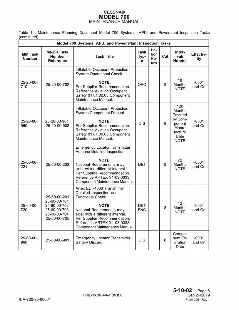
CESSNA®MODEL 700
MAINTENANCE MANUAL
Table 1. Maintenance Planning Document Model 700 Systems, APU, and Powerplant Inspection Tasks(continued)
Model 700 Systems, APU, and Power Plant Inspection Tasks
MM TaskNumber
MRBR TaskNumberReference
Task TitleTaskTyp-e
La-borHo-urs
CatInter-val/
Note(s)Effectiv-
ity
25-20-00-710 25-20-00-702
Inflatable Occupant ProtectionSystem Operational Check
NOTE:Per Supplier Recommendation.Reference Aviation OccupantSafety 01.01.00.03 ComponentMaintenance Manual.
OPC 818
MonthsNOTE
-0001and On
25-20-00-960
25-20-00-901,25-20-00-902
Inflatable Occupant ProtectionSystem Component Discard
NOTE:Per Supplier Recommendation.Reference Aviation OccupantSafety 01.01.00.03 ComponentMaintenance Manual.
DIS 8
120MonthsTrackedby Com-ponentManu-factureDateNOTE
-0001and On
25-60-00-221 25-60-00-202
Emergency Locator TransmitterAntenna Detailed Inspection
NOTE:National Requirements mayexist with a different interval.Per Supplier Recommendation.Reference ARTEX Y1-03-0333Component Maintenance Manual.
DET 872
MonthsNOTE
-0001and On
25-60-00-720
25-60-00-20125-60-00-701,25-60-00-702,25-60-00-703,25-60-00-704,25-60-00-705
Artex ELT-4000 TransmitterDetailed Inspection andFunctional Check
NOTE:National Requirements mayexist with a different interval.Per Supplier Recommendation.Reference ARTEX Y1-03-0333Component Maintenance Manual.
DETFNC 8
12MonthsNOTE
-0001and On
25-60-00-960 25-60-00-901 Emergency Locator Transmitter
Battery Discard DIS 8Compo-nent Ex-pirationDate
-0001and On
5-10-02 Page 6© TEXTRON AVIATION INC. Sep 26/2019
ICA-700-25-00001 Form 2261 Rev 1
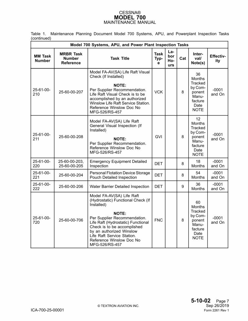
CESSNA®MODEL 700
MAINTENANCE MANUAL
Table 1. Maintenance Planning Document Model 700 Systems, APU, and Powerplant Inspection Tasks(continued)
Model 700 Systems, APU, and Power Plant Inspection Tasks
MM TaskNumber
MRBR TaskNumberReference
Task TitleTaskTyp-e
La-borHo-urs
CatInter-val/
Note(s)Effectiv-
ity
25-61-00-210 25-60-00-207
Model FA-AV(SA) Life Raft VisualCheck (If Installed)
NOTE:Per Supplier Recommendation.Life Raft Visual Check is to beaccomplished by an authorizedWinslow Life Raft Service Station.Reference Winslow Doc NoMFG-526/RS-457
VCK 8
36MonthsTrackedby Com-ponentManu-factureDateNOTE
-0001and On
25-61-00-211 25-60-00-208
Model FA-AV(SA) Life RaftGeneral Visual Inspection (IfInstalled)
NOTE:Per Supplier Recommendation.Reference Winslow Doc NoMFG-526/RS-457
GVI 8
12MonthsTrackedby Com-ponentManu-factureDateNOTE
-0001and On
25-61-00-220
25-60-00-203,25-60-00-205
Emergency Equipment DetailedInspection DET 8 18
Months-0001and On
25-61-00-221 25-60-00-204 Personal Flotation Device Storage
Pouch Detailed Inspection DET 8 54Months
-0001and On
25-61-00-222 25-60-00-206 Water Barrier Detailed Inspection DET 9 36
Months-0001and On
25-61-00-720 25-60-00-706
Model FA-AV(SA) Life Raft(Hydrostatic) Functional Check (IfInstalled)
NOTE:Per Supplier Recommendation.Life Raft (Hydrostatic) FunctionalCheck is to be accomplishedby an authorized WinslowLife Raft Service Station.Reference Winslow Doc NoMFG-526/RS-457
FNC 8
60MonthsTrackedby Com-ponentManu-factureDateNOTE
-0001and On
5-10-02 Page 7© TEXTRON AVIATION INC. Sep 26/2019
ICA-700-25-00001 Form 2261 Rev 1

CESSNA®MODEL 700
MAINTENANCE MANUAL
Table 1. Maintenance Planning Document Model 700 Systems, APU, and Powerplant Inspection Tasks(continued)
Model 700 Systems, APU, and Power Plant Inspection Tasks
MM TaskNumber
MRBR TaskNumberReference
Task TitleTaskTyp-e
La-borHo-urs
CatInter-val/
Note(s)Effectiv-
ity
25-61-00-910 25-60-00-902
P07074-207 Personal FlotationDevice (Accomplish Supplier 120Month Maintenance Inspection)Restoration
NOTE:You may contact Textron AviationParts Department (TAPD) at316-517-6002 for assistance withobtaining a properly restoredPersonal Flotation Device
RST 8
120MonthsTrackedby Man-ufactureDateNOTE
-0001and On
Chapter 26 - Fire Protection
26-10-00-210
26-10-00-201,26-10-00-202,26-10-00-203
Engine Nacelle Fire DetectorsGeneral Visual Inspection GVI 6 36
Months-0001and On
26-11-00-210 26-10-00-204 Auxiliary Power Unit Fire Detector
Loop General Visual Inspection GVI 6 72Months
-0001and On
26-20-00-220Chapter5-50-00
26-20-00-201 Engine Fire Deployment CheckTee Special Detailed Inspection SDI 8
AnytimeBottle 1and/or 2EngineFireExtin-guisheris Dis-charged
-0001and On
26-20-00-710
26-20-00-701,26-20-00-702,26-20-00-703,26-20-00-704,26-20-00-708
Engine Fire Extinguishing SystemOperational Check OPC 8, 9
800FlightHoursNOTE
-0001and On
26-20-00-720 26-20-00-701
Engine Fire Extinguishing BottleLow Pressure Switch FunctionalCheck
NOTE:This Task is Accomplished Duringthe Hydrostatic Check. PerSupplier Recommendation MASSSystems 26-22-02 ComponentMaintenance Manual andSupplement 26-22-02 FX04900-1Fire Extinguisher, Dual Outlet.
FNC 9
Coin-cidewith
Hydro-staticTest (ifapplica-ble) notto Ex-ceed 60MonthsNOTE
-0001and On
5-10-02 Page 8© TEXTRON AVIATION INC. Sep 26/2019
ICA-700-25-00001 Form 2261 Rev 1
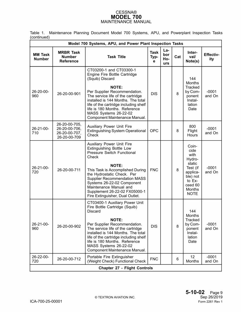
CESSNA®MODEL 700
MAINTENANCE MANUAL
Table 1. Maintenance Planning Document Model 700 Systems, APU, and Powerplant Inspection Tasks(continued)
Model 700 Systems, APU, and Power Plant Inspection Tasks
MM TaskNumber
MRBR TaskNumberReference
Task TitleTaskTyp-e
La-borHo-urs
CatInter-val/
Note(s)Effectiv-
ity
26-20-00-960 26-20-00-901
CT03200-1 and CT03300-1Engine Fire Bottle Cartridge(Squib) Discard
NOTE:Per Supplier Recommendation.The service life of the cartridgeinstalled is 144 Months. The totallife of the cartridge including shelflife is 180 Months. ReferenceMASS Systems 26-22-02Component Maintenance Manual.
DIS 8
144MonthsTrackedby Com-ponentInstal-lationDate
-0001and On
26-21-00-710
26-20-00-705,26-20-00-706,26-20-00-707,26-20-00-709
Auxiliary Power Unit FireExtinguishing System OperationalCheck
OPC 8800FlightHours
-0001and On
26-21-00-720 26-20-00-711
Auxiliary Power Unit FireExtinguishing Bottle LowPressure Switch FunctionalCheck
NOTE:This Task is Accomplished Duringthe Hydrostatic Check. PerSupplier Recommendation MASSSystems 26-22-02 ComponentMaintenance Manual andSupplement 26-22-02 FX05000-1Fire Extinguisher, Dual Outlet.
FNC 8
Coin-cidewith
Hydro-staticTest (ifapplica-ble) notto Ex-ceed 60MonthsNOTE
-0001and On
26-21-00-960 26-20-00-902
CT03400-1 Auxiliary Power UnitFire Bottle Cartridge (Squib)Discard
NOTE:Per Supplier Recommendation.The service life of the cartridgeinstalled is 144 Months. The totallife of the cartridge including shelflife is 180 Months. ReferenceMASS Systems 26-22-02Component Maintenance Manual.
DIS 8
144MonthsTrackedby Com-ponentInstal-lationDate
-0001and On
26-22-00-720 26-20-00-712 Portable Fire Extinguisher
(Weight Check) Functional Check FNC 6 12Months
-0001and On
Chapter 27 - Flight Controls
5-10-02 Page 9© TEXTRON AVIATION INC. Sep 26/2019
ICA-700-25-00001 Form 2261 Rev 1
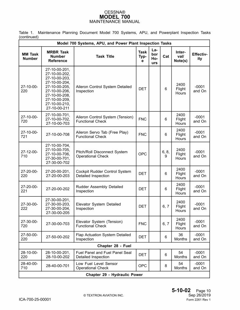
CESSNA®MODEL 700
MAINTENANCE MANUAL
Table 1. Maintenance Planning Document Model 700 Systems, APU, and Powerplant Inspection Tasks(continued)
Model 700 Systems, APU, and Power Plant Inspection Tasks
MM TaskNumber
MRBR TaskNumberReference
Task TitleTaskTyp-e
La-borHo-urs
CatInter-val/
Note(s)Effectiv-
ity
27-10-00-220
27-10-00-201,27-10-00-202,27-10-00-203,27-10-00-204,27-10-00-205,27-10-00-206,27-10-00-208,27-10-00-209,27-10-00-210,27-10-00-211
Aileron Control System DetailedInspection DET 6
2400FlightHours
-0001and On
27-10-00-720
27-10-00-701,27-10-00-702,27-10-00-703
Aileron Control System (Tension)Functional Check FNC 6
2400FlightHours
-0001and On
27-10-00-721 27-10-00-708 Aileron Servo Tab (Free Play)
Functional Check FNC 62400FlightHours
-0001and On
27-12-00-710
27-10-00-704,27-10-00-705,27-10-00-706,27-30-00-701,27-30-00-702
Pitch/Roll Disconnect SystemOperational Check OPC 6, 8,
92400FlightHours
-0001and On
27-20-00-220
27-20-00-201,27-20-00-203
Cockpit Rudder Control SystemDetailed Inspection DET 6
2400FlightHours
-0001and On
27-20-00-221 27-20-00-202 Rudder Assembly Detailed
Inspection DET 62400FlightHours
-0001and On
27-30-00-222
27-30-00-201,27-30-00-203,27-30-00-204,27-30-00-205
Elevator System DetailedInspection DET 6, 7
2400FlightHours
-0001and On
27-30-00-720 27-30-00-703 Elevator System (Tension)
Functional Check FNC 6, 72400FlightHours
-0001and On
27-50-00-220 27-50-00-202 Flap Actuation System Detailed
Inspection DET 6 36Months
-0001and On
Chapter 28 - Fuel28-10-00-220
28-10-00-201,28-10-00-202
Fuel Panel and Fuel Panel SealDetailed Inspection DET 6 54
Months-0001and On
28-40-00-710 28-40-00-701 Low Fuel Level Sensor
Operational Check OPC 8 54Months
-0001and On
Chapter 29 - Hydraulic Power
5-10-02 Page 10© TEXTRON AVIATION INC. Sep 26/2019
ICA-700-25-00001 Form 2261 Rev 1
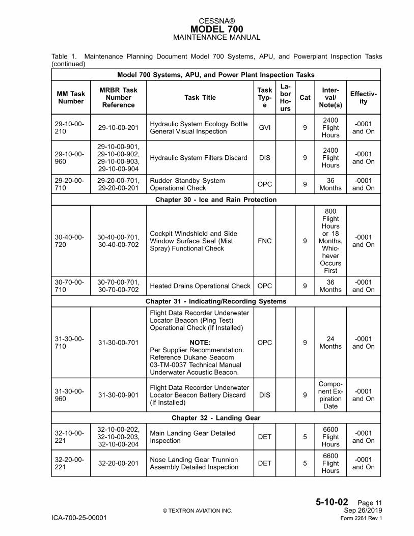
CESSNA®MODEL 700
MAINTENANCE MANUAL
Table 1. Maintenance Planning Document Model 700 Systems, APU, and Powerplant Inspection Tasks(continued)
Model 700 Systems, APU, and Power Plant Inspection Tasks
MM TaskNumber
MRBR TaskNumberReference
Task TitleTaskTyp-e
La-borHo-urs
CatInter-val/
Note(s)Effectiv-
ity
29-10-00-210 29-10-00-201 Hydraulic System Ecology Bottle
General Visual Inspection GVI 92400FlightHours
-0001and On
29-10-00-960
29-10-00-901,29-10-00-902,29-10-00-903,29-10-00-904
Hydraulic System Filters Discard DIS 92400FlightHours
-0001and On
29-20-00-710
29-20-00-701,29-20-00-201
Rudder Standby SystemOperational Check OPC 9 36
Months-0001and On
Chapter 30 - Ice and Rain Protection
30-40-00-720
30-40-00-701,30-40-00-702
Cockpit Windshield and SideWindow Surface Seal (MistSpray) Functional Check
FNC 9
800FlightHoursor 18Months,Whic-heverOccursFirst
-0001and On
30-70-00-710
30-70-00-701,30-70-00-702 Heated Drains Operational Check OPC 9 36
Months-0001and On
Chapter 31 - Indicating/Recording Systems
31-30-00-710 31-30-00-701
Flight Data Recorder UnderwaterLocator Beacon (Ping Test)Operational Check (If Installed)
NOTE:Per Supplier Recommendation.Reference Dukane Seacom03-TM-0037 Technical ManualUnderwater Acoustic Beacon.
OPC 9 24Months
-0001and On
31-30-00-960 31-30-00-901
Flight Data Recorder UnderwaterLocator Beacon Battery Discard(If Installed)
DIS 9Compo-nent Ex-pirationDate
-0001and On
Chapter 32 - Landing Gear
32-10-00-221
32-10-00-202,32-10-00-203,32-10-00-204
Main Landing Gear DetailedInspection DET 5
6600FlightHours
-0001and On
32-20-00-221 32-20-00-201 Nose Landing Gear Trunnion
Assembly Detailed Inspection DET 56600FlightHours
-0001and On
5-10-02 Page 11© TEXTRON AVIATION INC. Sep 26/2019
ICA-700-25-00001 Form 2261 Rev 1
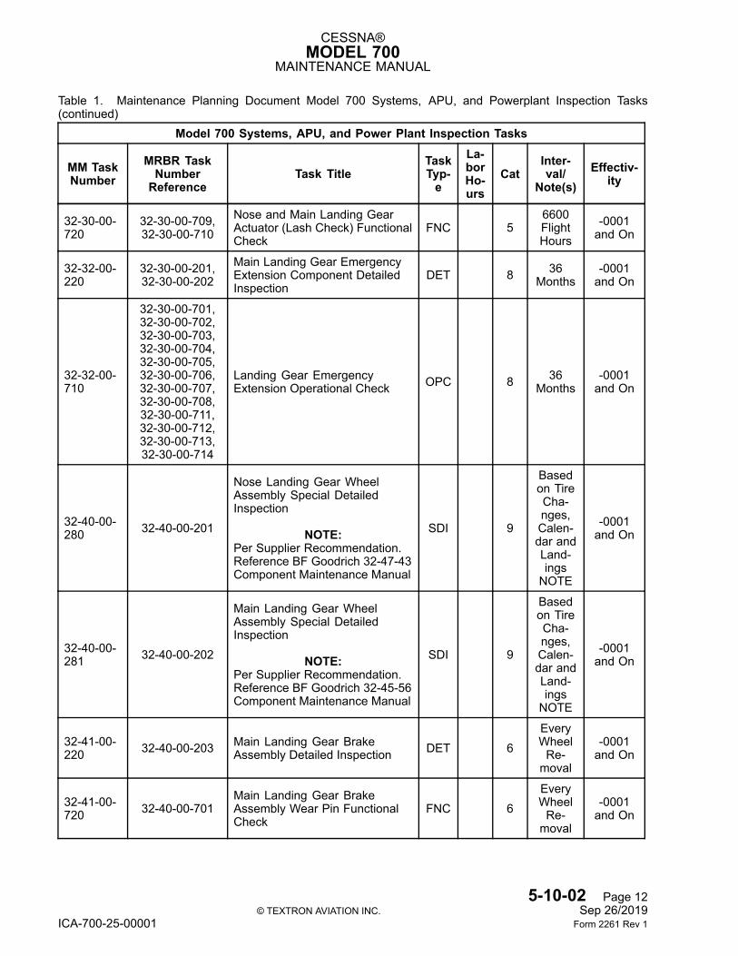
CESSNA®MODEL 700
MAINTENANCE MANUAL
Table 1. Maintenance Planning Document Model 700 Systems, APU, and Powerplant Inspection Tasks(continued)
Model 700 Systems, APU, and Power Plant Inspection Tasks
MM TaskNumber
MRBR TaskNumberReference
Task TitleTaskTyp-e
La-borHo-urs
CatInter-val/
Note(s)Effectiv-
ity
32-30-00-720
32-30-00-709,32-30-00-710
Nose and Main Landing GearActuator (Lash Check) FunctionalCheck
FNC 56600FlightHours
-0001and On
32-32-00-220
32-30-00-201,32-30-00-202
Main Landing Gear EmergencyExtension Component DetailedInspection
DET 8 36Months
-0001and On
32-32-00-710
32-30-00-701,32-30-00-702,32-30-00-703,32-30-00-704,32-30-00-705,32-30-00-706,32-30-00-707,32-30-00-708,32-30-00-711,32-30-00-712,32-30-00-713,32-30-00-714
Landing Gear EmergencyExtension Operational Check OPC 8 36
Months-0001and On
32-40-00-280 32-40-00-201
Nose Landing Gear WheelAssembly Special DetailedInspection
NOTE:Per Supplier Recommendation.Reference BF Goodrich 32-47-43Component Maintenance Manual
SDI 9
Basedon TireCha-nges,Calen-dar andLand-ingsNOTE
-0001and On
32-40-00-281 32-40-00-202
Main Landing Gear WheelAssembly Special DetailedInspection
NOTE:Per Supplier Recommendation.Reference BF Goodrich 32-45-56Component Maintenance Manual
SDI 9
Basedon TireCha-nges,Calen-dar andLand-ingsNOTE
-0001and On
32-41-00-220 32-40-00-203 Main Landing Gear Brake
Assembly Detailed Inspection DET 6EveryWheelRe-moval
-0001and On
32-41-00-720 32-40-00-701
Main Landing Gear BrakeAssembly Wear Pin FunctionalCheck
FNC 6EveryWheelRe-moval
-0001and On
5-10-02 Page 12© TEXTRON AVIATION INC. Sep 26/2019
ICA-700-25-00001 Form 2261 Rev 1
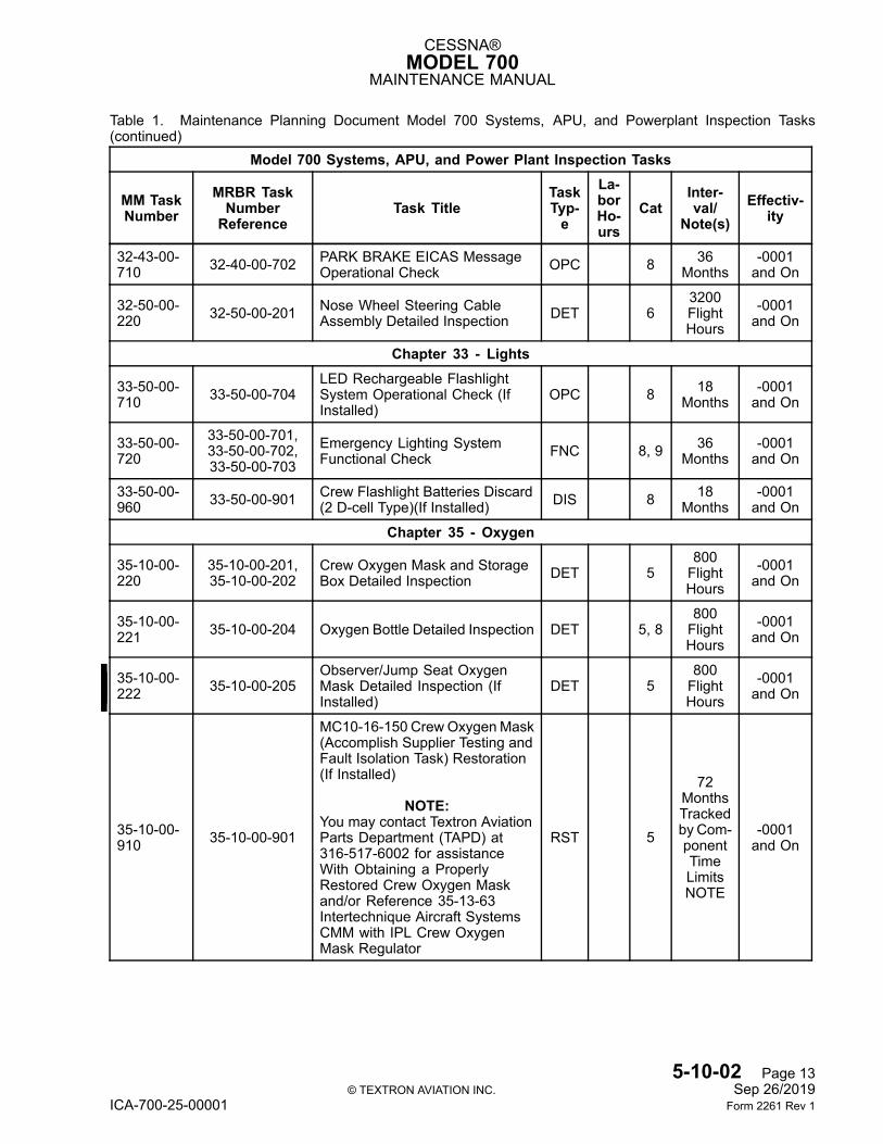
CESSNA®MODEL 700
MAINTENANCE MANUAL
Table 1. Maintenance Planning Document Model 700 Systems, APU, and Powerplant Inspection Tasks(continued)
Model 700 Systems, APU, and Power Plant Inspection Tasks
MM TaskNumber
MRBR TaskNumberReference
Task TitleTaskTyp-e
La-borHo-urs
CatInter-val/
Note(s)Effectiv-
ity
32-43-00-710 32-40-00-702 PARK BRAKE EICAS Message
Operational Check OPC 8 36Months
-0001and On
32-50-00-220 32-50-00-201 Nose Wheel Steering Cable
Assembly Detailed Inspection DET 63200FlightHours
-0001and On
Chapter 33 - Lights
33-50-00-710 33-50-00-704
LED Rechargeable FlashlightSystem Operational Check (IfInstalled)
OPC 8 18Months
-0001and On
33-50-00-720
33-50-00-701,33-50-00-702,33-50-00-703
Emergency Lighting SystemFunctional Check FNC 8, 9 36
Months-0001and On
33-50-00-960 33-50-00-901 Crew Flashlight Batteries Discard
(2 D-cell Type)(If Installed) DIS 8 18Months
-0001and On
Chapter 35 - Oxygen
35-10-00-220
35-10-00-201,35-10-00-202
Crew Oxygen Mask and StorageBox Detailed Inspection DET 5
800FlightHours
-0001and On
35-10-00-221 35-10-00-204 Oxygen Bottle Detailed Inspection DET 5, 8
800FlightHours
-0001and On
35-10-00-222 35-10-00-205
Observer/Jump Seat OxygenMask Detailed Inspection (IfInstalled)
DET 5800FlightHours
-0001and On
35-10-00-910 35-10-00-901
MC10-16-150 CrewOxygenMask(Accomplish Supplier Testing andFault Isolation Task) Restoration(If Installed)
NOTE:You may contact Textron AviationParts Department (TAPD) at316-517-6002 for assistanceWith Obtaining a ProperlyRestored Crew Oxygen Maskand/or Reference 35-13-63Intertechnique Aircraft SystemsCMM with IPL Crew OxygenMask Regulator
RST 5
72MonthsTrackedby Com-ponentTimeLimitsNOTE
-0001and On
5-10-02 Page 13© TEXTRON AVIATION INC. Sep 26/2019
ICA-700-25-00001 Form 2261 Rev 1
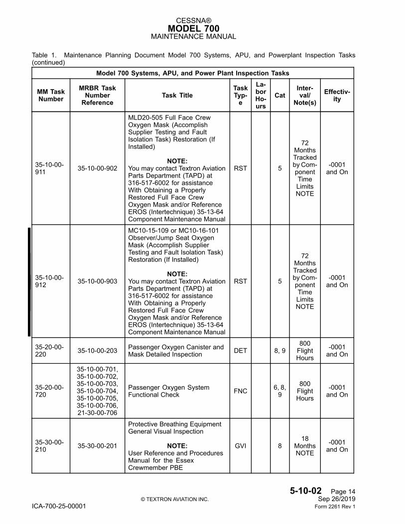
CESSNA®MODEL 700
MAINTENANCE MANUAL
Table 1. Maintenance Planning Document Model 700 Systems, APU, and Powerplant Inspection Tasks(continued)
Model 700 Systems, APU, and Power Plant Inspection Tasks
MM TaskNumber
MRBR TaskNumberReference
Task TitleTaskTyp-e
La-borHo-urs
CatInter-val/
Note(s)Effectiv-
ity
35-10-00-911 35-10-00-902
MLD20-505 Full Face CrewOxygen Mask (AccomplishSupplier Testing and FaultIsolation Task) Restoration (IfInstalled)
NOTE:You may contact Textron AviationParts Department (TAPD) at316-517-6002 for assistanceWith Obtaining a ProperlyRestored Full Face CrewOxygen Mask and/or ReferenceEROS (Intertechnique) 35-13-64Component Maintenance Manual
RST 5
72MonthsTrackedby Com-ponentTimeLimitsNOTE
-0001and On
35-10-00-912 35-10-00-903
MC10-15-109 or MC10-16-101Observer/Jump Seat OxygenMask (Accomplish SupplierTesting and Fault Isolation Task)Restoration (If Installed)
NOTE:You may contact Textron AviationParts Department (TAPD) at316-517-6002 for assistanceWith Obtaining a ProperlyRestored Full Face CrewOxygen Mask and/or ReferenceEROS (Intertechnique) 35-13-64Component Maintenance Manual
RST 5
72MonthsTrackedby Com-ponentTimeLimitsNOTE
-0001and On
35-20-00-220 35-10-00-203 Passenger Oxygen Canister and
Mask Detailed Inspection DET 8, 9800FlightHours
-0001and On
35-20-00-720
35-10-00-701,35-10-00-702,35-10-00-703,35-10-00-704,35-10-00-705,35-10-00-706,21-30-00-706
Passenger Oxygen SystemFunctional Check FNC 6, 8,
9800FlightHours
-0001and On
35-30-00-210 35-30-00-201
Protective Breathing EquipmentGeneral Visual Inspection
NOTE:User Reference and ProceduresManual for the EssexCrewmember PBE
GVI 818
MonthsNOTE
-0001and On
5-10-02 Page 14© TEXTRON AVIATION INC. Sep 26/2019
ICA-700-25-00001 Form 2261 Rev 1
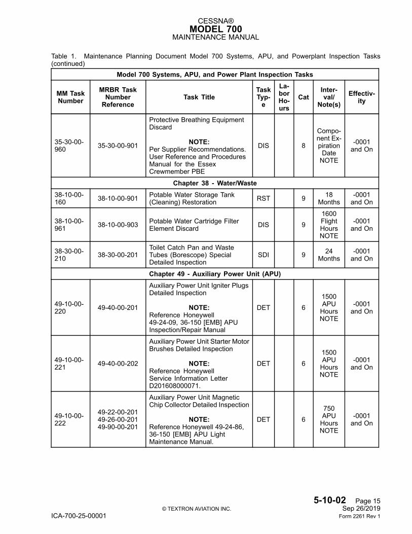
CESSNA®MODEL 700
MAINTENANCE MANUAL
Table 1. Maintenance Planning Document Model 700 Systems, APU, and Powerplant Inspection Tasks(continued)
Model 700 Systems, APU, and Power Plant Inspection Tasks
MM TaskNumber
MRBR TaskNumberReference
Task TitleTaskTyp-e
La-borHo-urs
CatInter-val/
Note(s)Effectiv-
ity
35-30-00-960 35-30-00-901
Protective Breathing EquipmentDiscard
NOTE:Per Supplier Recommendations.User Reference and ProceduresManual for the EssexCrewmember PBE
DIS 8
Compo-nent Ex-pirationDateNOTE
-0001and On
Chapter 38 - Water/Waste38-10-00-160 38-10-00-901 Potable Water Storage Tank
(Cleaning) Restoration RST 9 18Months
-0001and On
38-10-00-961 38-10-00-903 Potable Water Cartridge Filter
Element Discard DIS 91600FlightHoursNOTE
-0001and On
38-30-00-210 38-30-00-201
Toilet Catch Pan and WasteTubes (Borescope) SpecialDetailed Inspection
SDI 9 24Months
-0001and On
Chapter 49 - Auxiliary Power Unit (APU)
49-10-00-220 49-40-00-201
Auxiliary Power Unit Igniter PlugsDetailed Inspection
NOTE:Reference Honeywell49-24-09, 36-150 [EMB] APUInspection/Repair Manual
DET 61500APUHoursNOTE
-0001and On
49-10-00-221 49-40-00-202
Auxiliary Power Unit Starter MotorBrushes Detailed Inspection
NOTE:Reference HoneywellService Information LetterD201608000071.
DET 61500APUHoursNOTE
-0001and On
49-10-00-222
49-22-00-20149-26-00-20149-90-00-201
Auxiliary Power Unit MagneticChip Collector Detailed Inspection
NOTE:Reference Honeywell 49-24-86,36-150 [EMB] APU LightMaintenance Manual.
DET 6750APUHoursNOTE
-0001and On
5-10-02 Page 15© TEXTRON AVIATION INC. Sep 26/2019
ICA-700-25-00001 Form 2261 Rev 1
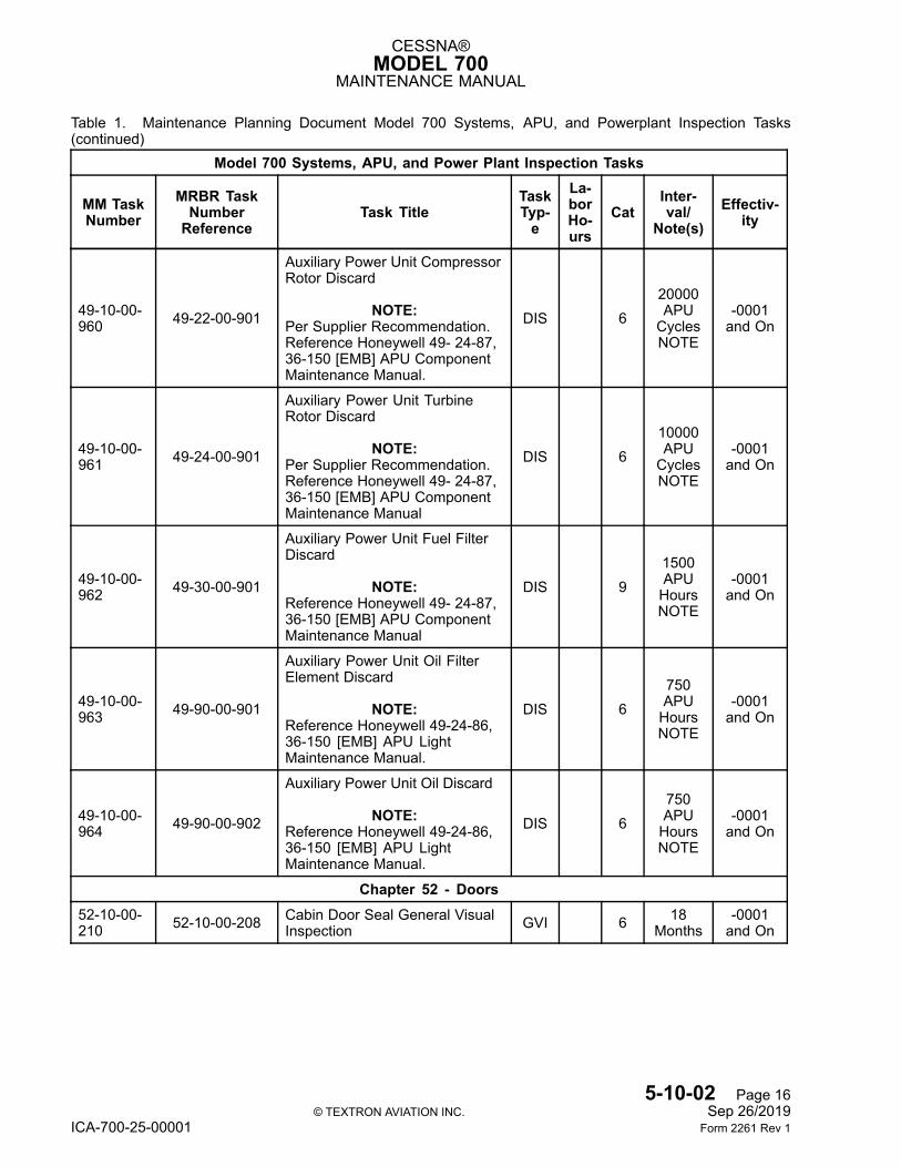
CESSNA®MODEL 700
MAINTENANCE MANUAL
Table 1. Maintenance Planning Document Model 700 Systems, APU, and Powerplant Inspection Tasks(continued)
Model 700 Systems, APU, and Power Plant Inspection Tasks
MM TaskNumber
MRBR TaskNumberReference
Task TitleTaskTyp-e
La-borHo-urs
CatInter-val/
Note(s)Effectiv-
ity
49-10-00-960 49-22-00-901
Auxiliary Power Unit CompressorRotor Discard
NOTE:Per Supplier Recommendation.Reference Honeywell 49- 24-87,36-150 [EMB] APU ComponentMaintenance Manual.
DIS 620000APUCyclesNOTE
-0001and On
49-10-00-961 49-24-00-901
Auxiliary Power Unit TurbineRotor Discard
NOTE:Per Supplier Recommendation.Reference Honeywell 49- 24-87,36-150 [EMB] APU ComponentMaintenance Manual
DIS 610000APUCyclesNOTE
-0001and On
49-10-00-962 49-30-00-901
Auxiliary Power Unit Fuel FilterDiscard
NOTE:Reference Honeywell 49- 24-87,36-150 [EMB] APU ComponentMaintenance Manual
DIS 91500APUHoursNOTE
-0001and On
49-10-00-963 49-90-00-901
Auxiliary Power Unit Oil FilterElement Discard
NOTE:Reference Honeywell 49-24-86,36-150 [EMB] APU LightMaintenance Manual.
DIS 6750APUHoursNOTE
-0001and On
49-10-00-964 49-90-00-902
Auxiliary Power Unit Oil Discard
NOTE:Reference Honeywell 49-24-86,36-150 [EMB] APU LightMaintenance Manual.
DIS 6750APUHoursNOTE
-0001and On
Chapter 52 - Doors52-10-00-210 52-10-00-208 Cabin Door Seal General Visual
Inspection GVI 6 18Months
-0001and On
5-10-02 Page 16© TEXTRON AVIATION INC. Sep 26/2019
ICA-700-25-00001 Form 2261 Rev 1
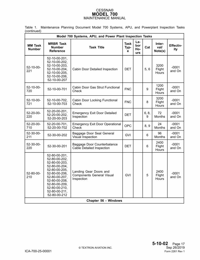
CESSNA®MODEL 700
MAINTENANCE MANUAL
Table 1. Maintenance Planning Document Model 700 Systems, APU, and Powerplant Inspection Tasks(continued)
Model 700 Systems, APU, and Power Plant Inspection Tasks
MM TaskNumber
MRBR TaskNumberReference
Task TitleTaskTyp-e
La-borHo-urs
CatInter-val/
Note(s)Effectiv-
ity
52-10-00-221
52-10-00-201,52-10-00-202,52-10-00-203,52-10-00-204,52-10-00-205,52-10-00-206,52-10-00-207
Cabin Door Detailed Inspection DET 5, 63200FlightHours
-0001and On
52-10-00-720 52-10-00-701 Cabin Door Gas Strut Functional
Check FNC 91200FlightHours
-0001and On
52-10-00-721
52-10-00-702,52-10-00-703
Cabin Door Locking FunctionalCheck FNC 8
3200FlightHours
-0001and On
52-20-00-220
52-20-00-201,52-20-00-202,52-20-00-203
Emergency Exit Door DetailedInspection DET 6, 8,
972
Months-0001and On
52-20-00-710
52-20-00-701,52-20-00-702
Emergency Exit Door OperationalCheck OPC 8, 9 24
Months-0001and On
52-30-00-211 52-30-00-202 Baggage Door Seal General
Visual Inspection GVI 6 96Months
-0001and On
52-30-00-220 52-30-00-201 Baggage Door Counterbalance
Cable Detailed Inspection DET 62400FlightHours
-0001and On
52-80-00-210
52-80-00-201,52-80-00-202,52-80-00-203,52-80-00-204,52-80-00-205,52-80-00-206,52-80-00-207,52-80-00-208,52-80-00-209,52-80-00-210,52-80-00-211,52-80-00-212
Landing Gear Doors andComponents General VisualInspection
GVI 52400FlightHours
-0001and On
Chapter 56 - Windows
5-10-02 Page 17© TEXTRON AVIATION INC. Sep 26/2019
ICA-700-25-00001 Form 2261 Rev 1
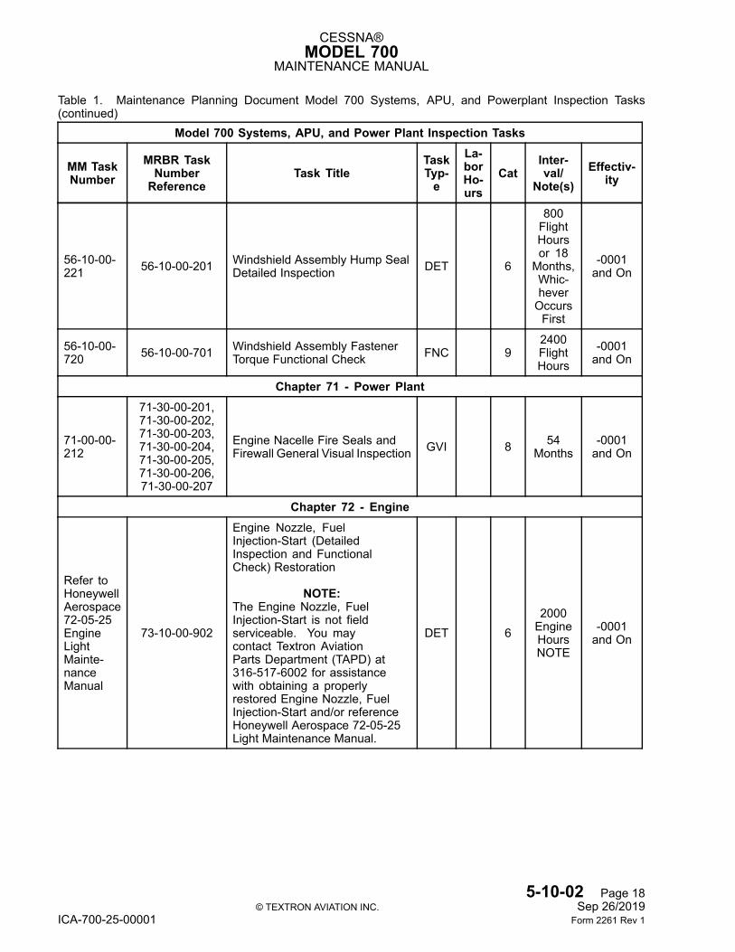
CESSNA®MODEL 700
MAINTENANCE MANUAL
Table 1. Maintenance Planning Document Model 700 Systems, APU, and Powerplant Inspection Tasks(continued)
Model 700 Systems, APU, and Power Plant Inspection Tasks
MM TaskNumber
MRBR TaskNumberReference
Task TitleTaskTyp-e
La-borHo-urs
CatInter-val/
Note(s)Effectiv-
ity
56-10-00-221 56-10-00-201 Windshield Assembly Hump Seal
Detailed Inspection DET 6
800FlightHoursor 18Months,Whic-heverOccursFirst
-0001and On
56-10-00-720 56-10-00-701 Windshield Assembly Fastener
Torque Functional Check FNC 92400FlightHours
-0001and On
Chapter 71 - Power Plant
71-00-00-212
71-30-00-201,71-30-00-202,71-30-00-203,71-30-00-204,71-30-00-205,71-30-00-206,71-30-00-207
Engine Nacelle Fire Seals andFirewall General Visual Inspection GVI 8 54
Months-0001and On
Chapter 72 - Engine
Refer toHoneywellAerospace72-05-25EngineLightMainte-nanceManual
73-10-00-902
Engine Nozzle, FuelInjection-Start (DetailedInspection and FunctionalCheck) Restoration
NOTE:The Engine Nozzle, FuelInjection-Start is not fieldserviceable. You maycontact Textron AviationParts Department (TAPD) at316-517-6002 for assistancewith obtaining a properlyrestored Engine Nozzle, FuelInjection-Start and/or referenceHoneywell Aerospace 72-05-25Light Maintenance Manual.
DET 62000EngineHoursNOTE
-0001and On
5-10-02 Page 18© TEXTRON AVIATION INC. Sep 26/2019
ICA-700-25-00001 Form 2261 Rev 1
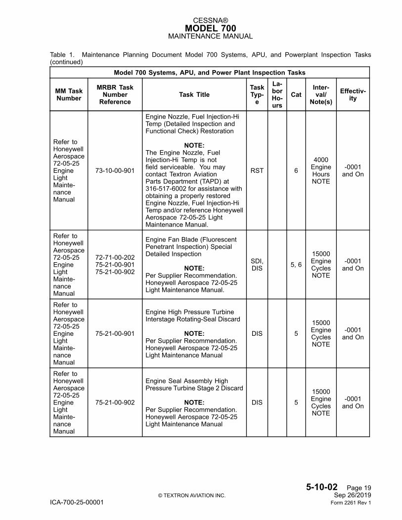
CESSNA®MODEL 700
MAINTENANCE MANUAL
Table 1. Maintenance Planning Document Model 700 Systems, APU, and Powerplant Inspection Tasks(continued)
Model 700 Systems, APU, and Power Plant Inspection Tasks
MM TaskNumber
MRBR TaskNumberReference
Task TitleTaskTyp-e
La-borHo-urs
CatInter-val/
Note(s)Effectiv-
ity
Refer toHoneywellAerospace72-05-25EngineLightMainte-nanceManual
73-10-00-901
Engine Nozzle, Fuel Injection-HiTemp (Detailed Inspection andFunctional Check) Restoration
NOTE:The Engine Nozzle, FuelInjection-Hi Temp is notfield serviceable. You maycontact Textron AviationParts Department (TAPD) at316-517-6002 for assistance withobtaining a properly restoredEngine Nozzle, Fuel Injection-HiTemp and/or reference HoneywellAerospace 72-05-25 LightMaintenance Manual.
RST 64000EngineHoursNOTE
-0001and On
Refer toHoneywellAerospace72-05-25EngineLightMainte-nanceManual
72-71-00-20275-21-00-90175-21-00-902
Engine Fan Blade (FluorescentPenetrant Inspection) SpecialDetailed Inspection
NOTE:Per Supplier Recommendation.Honeywell Aerospace 72-05-25Light Maintenance Manual.
SDI,DIS 5, 6
15000EngineCyclesNOTE
-0001and On
Refer toHoneywellAerospace72-05-25EngineLightMainte-nanceManual
75-21-00-901
Engine High Pressure TurbineInterstage Rotating-Seal Discard
NOTE:Per Supplier Recommendation.Honeywell Aerospace 72-05-25Light Maintenance Manual
DIS 515000EngineCyclesNOTE
-0001and On
Refer toHoneywellAerospace72-05-25EngineLightMainte-nanceManual
75-21-00-902
Engine Seal Assembly HighPressure Turbine Stage 2 Discard
NOTE:Per Supplier Recommendation.Honeywell Aerospace 72-05-25Light Maintenance Manual
DIS 515000EngineCyclesNOTE
-0001and On
5-10-02 Page 19© TEXTRON AVIATION INC. Sep 26/2019
ICA-700-25-00001 Form 2261 Rev 1
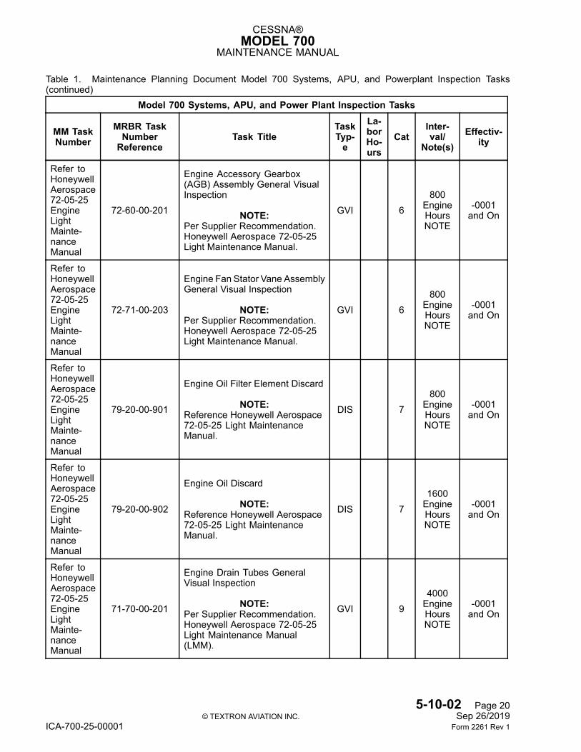
CESSNA®MODEL 700
MAINTENANCE MANUAL
Table 1. Maintenance Planning Document Model 700 Systems, APU, and Powerplant Inspection Tasks(continued)
Model 700 Systems, APU, and Power Plant Inspection Tasks
MM TaskNumber
MRBR TaskNumberReference
Task TitleTaskTyp-e
La-borHo-urs
CatInter-val/
Note(s)Effectiv-
ity
Refer toHoneywellAerospace72-05-25EngineLightMainte-nanceManual
72-60-00-201
Engine Accessory Gearbox(AGB) Assembly General VisualInspection
NOTE:Per Supplier Recommendation.Honeywell Aerospace 72-05-25Light Maintenance Manual.
GVI 6800
EngineHoursNOTE
-0001and On
Refer toHoneywellAerospace72-05-25EngineLightMainte-nanceManual
72-71-00-203
Engine Fan Stator Vane AssemblyGeneral Visual Inspection
NOTE:Per Supplier Recommendation.Honeywell Aerospace 72-05-25Light Maintenance Manual.
GVI 6800
EngineHoursNOTE
-0001and On
Refer toHoneywellAerospace72-05-25EngineLightMainte-nanceManual
79-20-00-901
Engine Oil Filter Element Discard
NOTE:Reference Honeywell Aerospace72-05-25 Light MaintenanceManual.
DIS 7800
EngineHoursNOTE
-0001and On
Refer toHoneywellAerospace72-05-25EngineLightMainte-nanceManual
79-20-00-902
Engine Oil Discard
NOTE:Reference Honeywell Aerospace72-05-25 Light MaintenanceManual.
DIS 71600EngineHoursNOTE
-0001and On
Refer toHoneywellAerospace72-05-25EngineLightMainte-nanceManual
71-70-00-201
Engine Drain Tubes GeneralVisual Inspection
NOTE:Per Supplier Recommendation.Honeywell Aerospace 72-05-25Light Maintenance Manual(LMM).
GVI 94000EngineHoursNOTE
-0001and On
5-10-02 Page 20© TEXTRON AVIATION INC. Sep 26/2019
ICA-700-25-00001 Form 2261 Rev 1
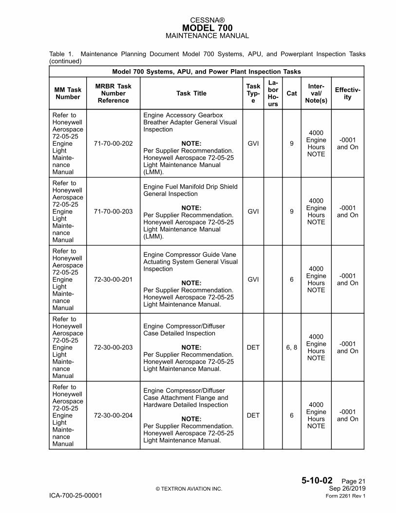
CESSNA®MODEL 700
MAINTENANCE MANUAL
Table 1. Maintenance Planning Document Model 700 Systems, APU, and Powerplant Inspection Tasks(continued)
Model 700 Systems, APU, and Power Plant Inspection Tasks
MM TaskNumber
MRBR TaskNumberReference
Task TitleTaskTyp-e
La-borHo-urs
CatInter-val/
Note(s)Effectiv-
ity
Refer toHoneywellAerospace72-05-25EngineLightMainte-nanceManual
71-70-00-202
Engine Accessory GearboxBreather Adapter General VisualInspection
NOTE:Per Supplier Recommendation.Honeywell Aerospace 72-05-25Light Maintenance Manual(LMM).
GVI 94000EngineHoursNOTE
-0001and On
Refer toHoneywellAerospace72-05-25EngineLightMainte-nanceManual
71-70-00-203
Engine Fuel Manifold Drip ShieldGeneral Inspection
NOTE:Per Supplier Recommendation.Honeywell Aerospace 72-05-25Light Maintenance Manual(LMM).
GVI 94000EngineHoursNOTE
-0001and On
Refer toHoneywellAerospace72-05-25EngineLightMainte-nanceManual
72-30-00-201
Engine Compressor Guide VaneActuating System General VisualInspection
NOTE:Per Supplier Recommendation.Honeywell Aerospace 72-05-25Light Maintenance Manual.
GVI 64000EngineHoursNOTE
-0001and On
Refer toHoneywellAerospace72-05-25EngineLightMainte-nanceManual
72-30-00-203
Engine Compressor/DiffuserCase Detailed Inspection
NOTE:Per Supplier Recommendation.Honeywell Aerospace 72-05-25Light Maintenance Manual.
DET 6, 84000EngineHoursNOTE
-0001and On
Refer toHoneywellAerospace72-05-25EngineLightMainte-nanceManual
72-30-00-204
Engine Compressor/DiffuserCase Attachment Flange andHardware Detailed Inspection
NOTE:Per Supplier Recommendation.Honeywell Aerospace 72-05-25Light Maintenance Manual.
DET 64000EngineHoursNOTE
-0001and On
5-10-02 Page 21© TEXTRON AVIATION INC. Sep 26/2019
ICA-700-25-00001 Form 2261 Rev 1
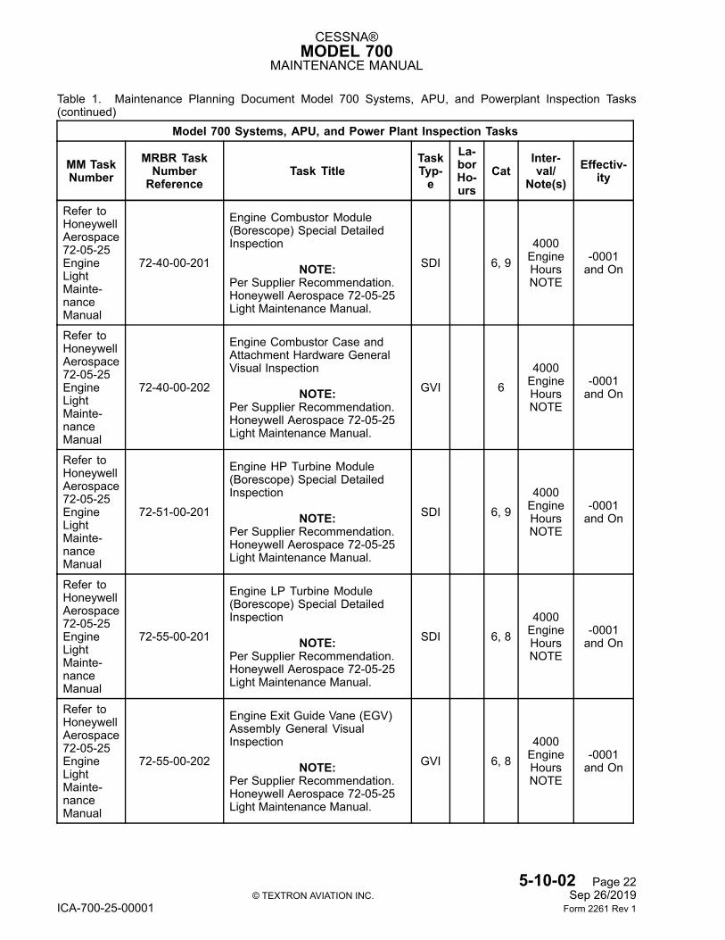
CESSNA®MODEL 700
MAINTENANCE MANUAL
Table 1. Maintenance Planning Document Model 700 Systems, APU, and Powerplant Inspection Tasks(continued)
Model 700 Systems, APU, and Power Plant Inspection Tasks
MM TaskNumber
MRBR TaskNumberReference
Task TitleTaskTyp-e
La-borHo-urs
CatInter-val/
Note(s)Effectiv-
ity
Refer toHoneywellAerospace72-05-25EngineLightMainte-nanceManual
72-40-00-201
Engine Combustor Module(Borescope) Special DetailedInspection
NOTE:Per Supplier Recommendation.Honeywell Aerospace 72-05-25Light Maintenance Manual.
SDI 6, 94000EngineHoursNOTE
-0001and On
Refer toHoneywellAerospace72-05-25EngineLightMainte-nanceManual
72-40-00-202
Engine Combustor Case andAttachment Hardware GeneralVisual Inspection
NOTE:Per Supplier Recommendation.Honeywell Aerospace 72-05-25Light Maintenance Manual.
GVI 64000EngineHoursNOTE
-0001and On
Refer toHoneywellAerospace72-05-25EngineLightMainte-nanceManual
72-51-00-201
Engine HP Turbine Module(Borescope) Special DetailedInspection
NOTE:Per Supplier Recommendation.Honeywell Aerospace 72-05-25Light Maintenance Manual.
SDI 6, 94000EngineHoursNOTE
-0001and On
Refer toHoneywellAerospace72-05-25EngineLightMainte-nanceManual
72-55-00-201
Engine LP Turbine Module(Borescope) Special DetailedInspection
NOTE:Per Supplier Recommendation.Honeywell Aerospace 72-05-25Light Maintenance Manual.
SDI 6, 84000EngineHoursNOTE
-0001and On
Refer toHoneywellAerospace72-05-25EngineLightMainte-nanceManual
72-55-00-202
Engine Exit Guide Vane (EGV)Assembly General VisualInspection
NOTE:Per Supplier Recommendation.Honeywell Aerospace 72-05-25Light Maintenance Manual.
GVI 6, 84000EngineHoursNOTE
-0001and On
5-10-02 Page 22© TEXTRON AVIATION INC. Sep 26/2019
ICA-700-25-00001 Form 2261 Rev 1
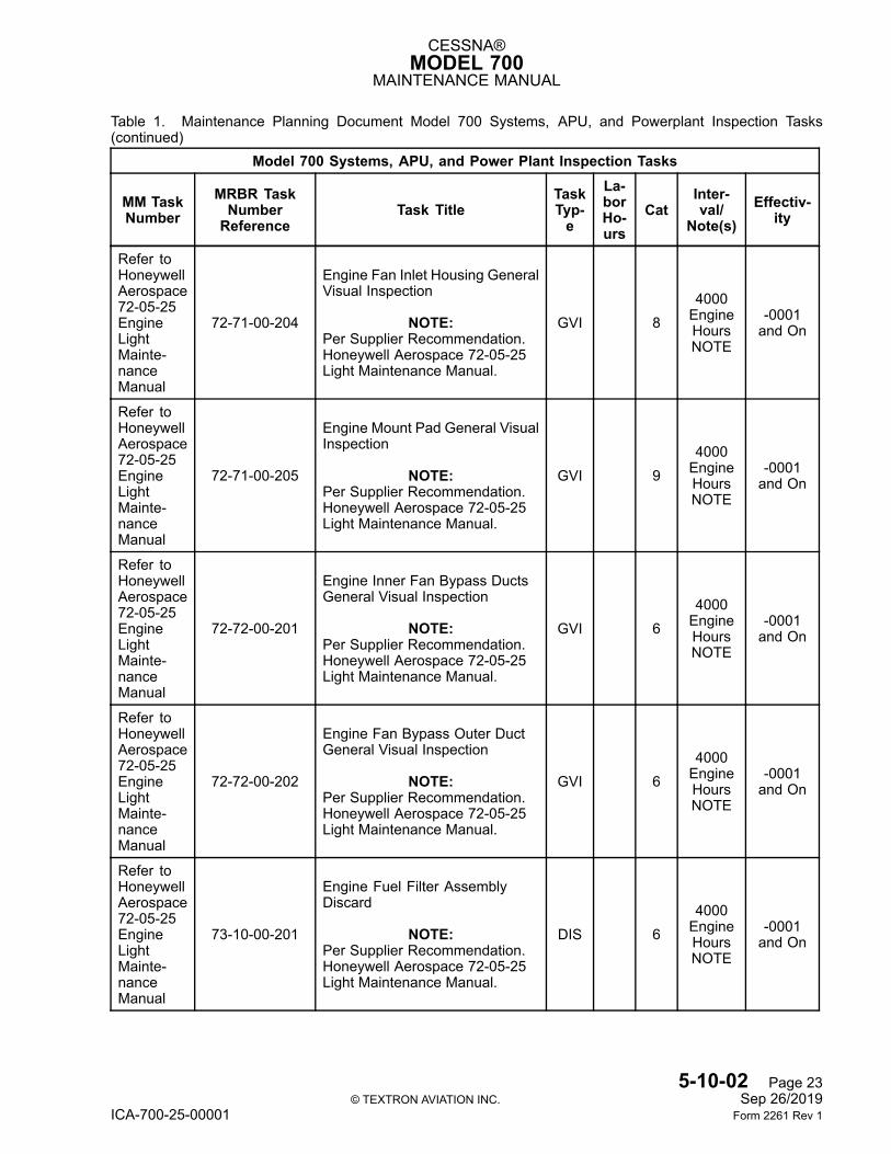
CESSNA®MODEL 700
MAINTENANCE MANUAL
Table 1. Maintenance Planning Document Model 700 Systems, APU, and Powerplant Inspection Tasks(continued)
Model 700 Systems, APU, and Power Plant Inspection Tasks
MM TaskNumber
MRBR TaskNumberReference
Task TitleTaskTyp-e
La-borHo-urs
CatInter-val/
Note(s)Effectiv-
ity
Refer toHoneywellAerospace72-05-25EngineLightMainte-nanceManual
72-71-00-204
Engine Fan Inlet Housing GeneralVisual Inspection
NOTE:Per Supplier Recommendation.Honeywell Aerospace 72-05-25Light Maintenance Manual.
GVI 84000EngineHoursNOTE
-0001and On
Refer toHoneywellAerospace72-05-25EngineLightMainte-nanceManual
72-71-00-205
Engine Mount Pad General VisualInspection
NOTE:Per Supplier Recommendation.Honeywell Aerospace 72-05-25Light Maintenance Manual.
GVI 94000EngineHoursNOTE
-0001and On
Refer toHoneywellAerospace72-05-25EngineLightMainte-nanceManual
72-72-00-201
Engine Inner Fan Bypass DuctsGeneral Visual Inspection
NOTE:Per Supplier Recommendation.Honeywell Aerospace 72-05-25Light Maintenance Manual.
GVI 64000EngineHoursNOTE
-0001and On
Refer toHoneywellAerospace72-05-25EngineLightMainte-nanceManual
72-72-00-202
Engine Fan Bypass Outer DuctGeneral Visual Inspection
NOTE:Per Supplier Recommendation.Honeywell Aerospace 72-05-25Light Maintenance Manual.
GVI 64000EngineHoursNOTE
-0001and On
Refer toHoneywellAerospace72-05-25EngineLightMainte-nanceManual
73-10-00-201
Engine Fuel Filter AssemblyDiscard
NOTE:Per Supplier Recommendation.Honeywell Aerospace 72-05-25Light Maintenance Manual.
DIS 64000EngineHoursNOTE
-0001and On
5-10-02 Page 23© TEXTRON AVIATION INC. Sep 26/2019
ICA-700-25-00001 Form 2261 Rev 1
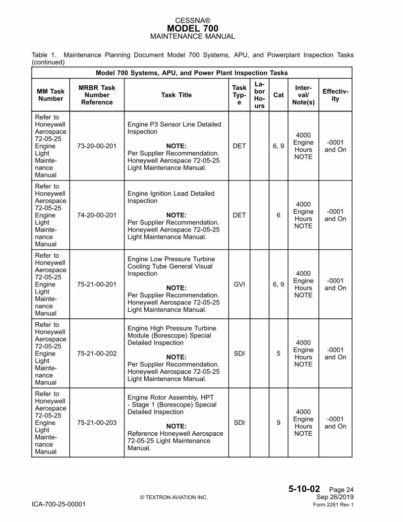
CESSNA®MODEL 700
MAINTENANCE MANUAL
Table 1. Maintenance Planning Document Model 700 Systems, APU, and Powerplant Inspection Tasks(continued)
Model 700 Systems, APU, and Power Plant Inspection Tasks
MM TaskNumber
MRBR TaskNumberReference
Task TitleTaskTyp-e
La-borHo-urs
CatInter-val/
Note(s)Effectiv-
ity
Refer toHoneywellAerospace72-05-25EngineLightMainte-nanceManual
73-20-00-201
Engine P3 Sensor Line DetailedInspection
NOTE:Per Supplier Recommendation.Honeywell Aerospace 72-05-25Light Maintenance Manual.
DET 6, 94000EngineHoursNOTE
-0001and On
Refer toHoneywellAerospace72-05-25EngineLightMainte-nanceManual
74-20-00-201
Engine Ignition Lead DetailedInspection
NOTE:Per Supplier Recommendation.Honeywell Aerospace 72-05-25Light Maintenance Manual.
DET 64000EngineHoursNOTE
-0001and On
Refer toHoneywellAerospace72-05-25EngineLightMainte-nanceManual
75-21-00-201
Engine Low Pressure TurbineCooling Tube General VisualInspection
NOTE:Per Supplier Recommendation.Honeywell Aerospace 72-05-25Light Maintenance Manual.
GVI 6, 94000EngineHoursNOTE
-0001and On
Refer toHoneywellAerospace72-05-25EngineLightMainte-nanceManual
75-21-00-202
Engine High Pressure TurbineModule (Borescope) SpecialDetailed Inspection
NOTE:Per Supplier Recommendation.Honeywell Aerospace 72-05-25Light Maintenance Manual.
SDI 54000EngineHoursNOTE
-0001and On
Refer toHoneywellAerospace72-05-25EngineLightMainte-nanceManual
75-21-00-203
Engine Rotor Assembly, HPT- Stage 1 (Borescope) SpecialDetailed Inspection
NOTE:Reference Honeywell Aerospace72-05-25 Light MaintenanceManual.
SDI 94000EngineHoursNOTE
-0001and On
5-10-02 Page 24© TEXTRON AVIATION INC. Sep 26/2019
ICA-700-25-00001 Form 2261 Rev 1
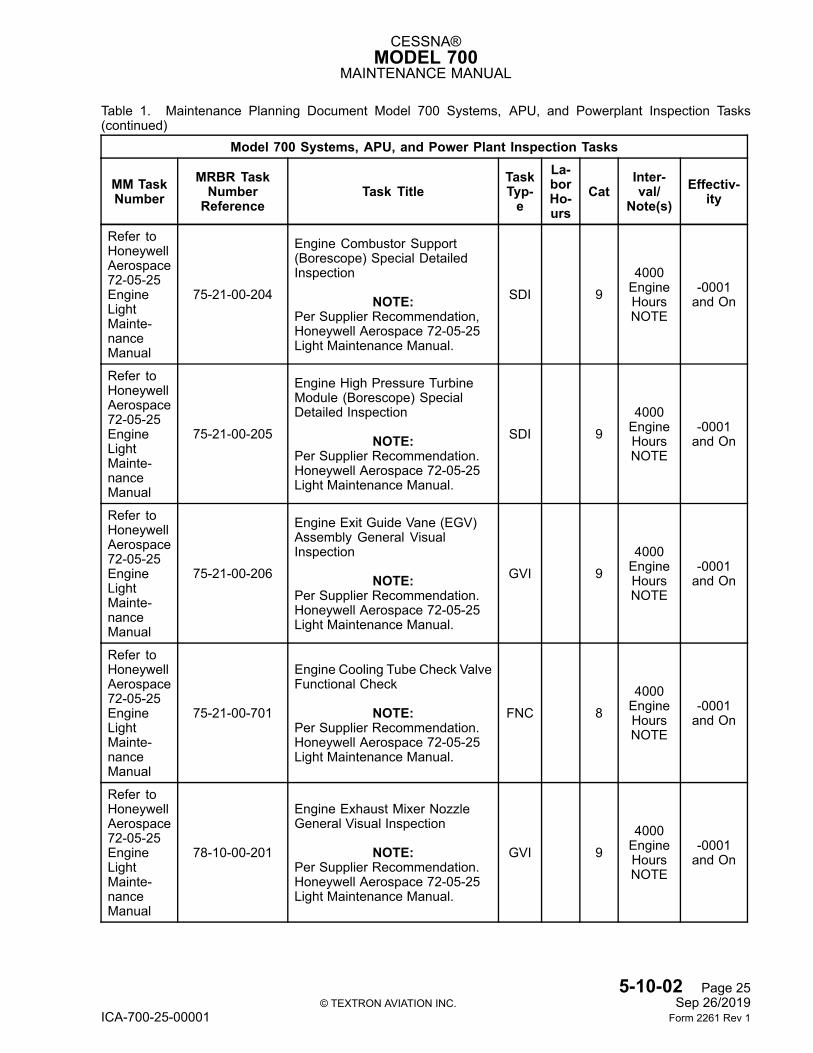
CESSNA®MODEL 700
MAINTENANCE MANUAL
Table 1. Maintenance Planning Document Model 700 Systems, APU, and Powerplant Inspection Tasks(continued)
Model 700 Systems, APU, and Power Plant Inspection Tasks
MM TaskNumber
MRBR TaskNumberReference
Task TitleTaskTyp-e
La-borHo-urs
CatInter-val/
Note(s)Effectiv-
ity
Refer toHoneywellAerospace72-05-25EngineLightMainte-nanceManual
75-21-00-204
Engine Combustor Support(Borescope) Special DetailedInspection
NOTE:Per Supplier Recommendation,Honeywell Aerospace 72-05-25Light Maintenance Manual.
SDI 94000EngineHoursNOTE
-0001and On
Refer toHoneywellAerospace72-05-25EngineLightMainte-nanceManual
75-21-00-205
Engine High Pressure TurbineModule (Borescope) SpecialDetailed Inspection
NOTE:Per Supplier Recommendation.Honeywell Aerospace 72-05-25Light Maintenance Manual.
SDI 94000EngineHoursNOTE
-0001and On
Refer toHoneywellAerospace72-05-25EngineLightMainte-nanceManual
75-21-00-206
Engine Exit Guide Vane (EGV)Assembly General VisualInspection
NOTE:Per Supplier Recommendation.Honeywell Aerospace 72-05-25Light Maintenance Manual.
GVI 94000EngineHoursNOTE
-0001and On
Refer toHoneywellAerospace72-05-25EngineLightMainte-nanceManual
75-21-00-701
Engine Cooling Tube Check ValveFunctional Check
NOTE:Per Supplier Recommendation.Honeywell Aerospace 72-05-25Light Maintenance Manual.
FNC 84000EngineHoursNOTE
-0001and On
Refer toHoneywellAerospace72-05-25EngineLightMainte-nanceManual
78-10-00-201
Engine Exhaust Mixer NozzleGeneral Visual Inspection
NOTE:Per Supplier Recommendation.Honeywell Aerospace 72-05-25Light Maintenance Manual.
GVI 94000EngineHoursNOTE
-0001and On
5-10-02 Page 25© TEXTRON AVIATION INC. Sep 26/2019
ICA-700-25-00001 Form 2261 Rev 1
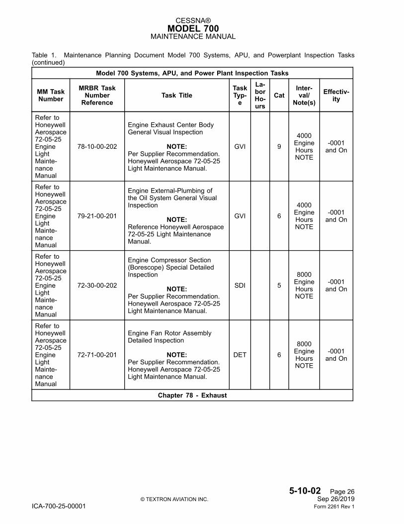
CESSNA®MODEL 700
MAINTENANCE MANUAL
Table 1. Maintenance Planning Document Model 700 Systems, APU, and Powerplant Inspection Tasks(continued)
Model 700 Systems, APU, and Power Plant Inspection Tasks
MM TaskNumber
MRBR TaskNumberReference
Task TitleTaskTyp-e
La-borHo-urs
CatInter-val/
Note(s)Effectiv-
ity
Refer toHoneywellAerospace72-05-25EngineLightMainte-nanceManual
78-10-00-202
Engine Exhaust Center BodyGeneral Visual Inspection
NOTE:Per Supplier Recommendation.Honeywell Aerospace 72-05-25Light Maintenance Manual.
GVI 94000EngineHoursNOTE
-0001and On
Refer toHoneywellAerospace72-05-25EngineLightMainte-nanceManual
79-21-00-201
Engine External-Plumbing ofthe Oil System General VisualInspection
NOTE:Reference Honeywell Aerospace72-05-25 Light MaintenanceManual.
GVI 64000EngineHoursNOTE
-0001and On
Refer toHoneywellAerospace72-05-25EngineLightMainte-nanceManual
72-30-00-202
Engine Compressor Section(Borescope) Special DetailedInspection
NOTE:Per Supplier Recommendation.Honeywell Aerospace 72-05-25Light Maintenance Manual.
SDI 58000EngineHoursNOTE
-0001and On
Refer toHoneywellAerospace72-05-25EngineLightMainte-nanceManual
72-71-00-201
Engine Fan Rotor AssemblyDetailed Inspection
NOTE:Per Supplier Recommendation.Honeywell Aerospace 72-05-25Light Maintenance Manual.
DET 68000EngineHoursNOTE
-0001and On
Chapter 78 - Exhaust
5-10-02 Page 26© TEXTRON AVIATION INC. Sep 26/2019
ICA-700-25-00001 Form 2261 Rev 1
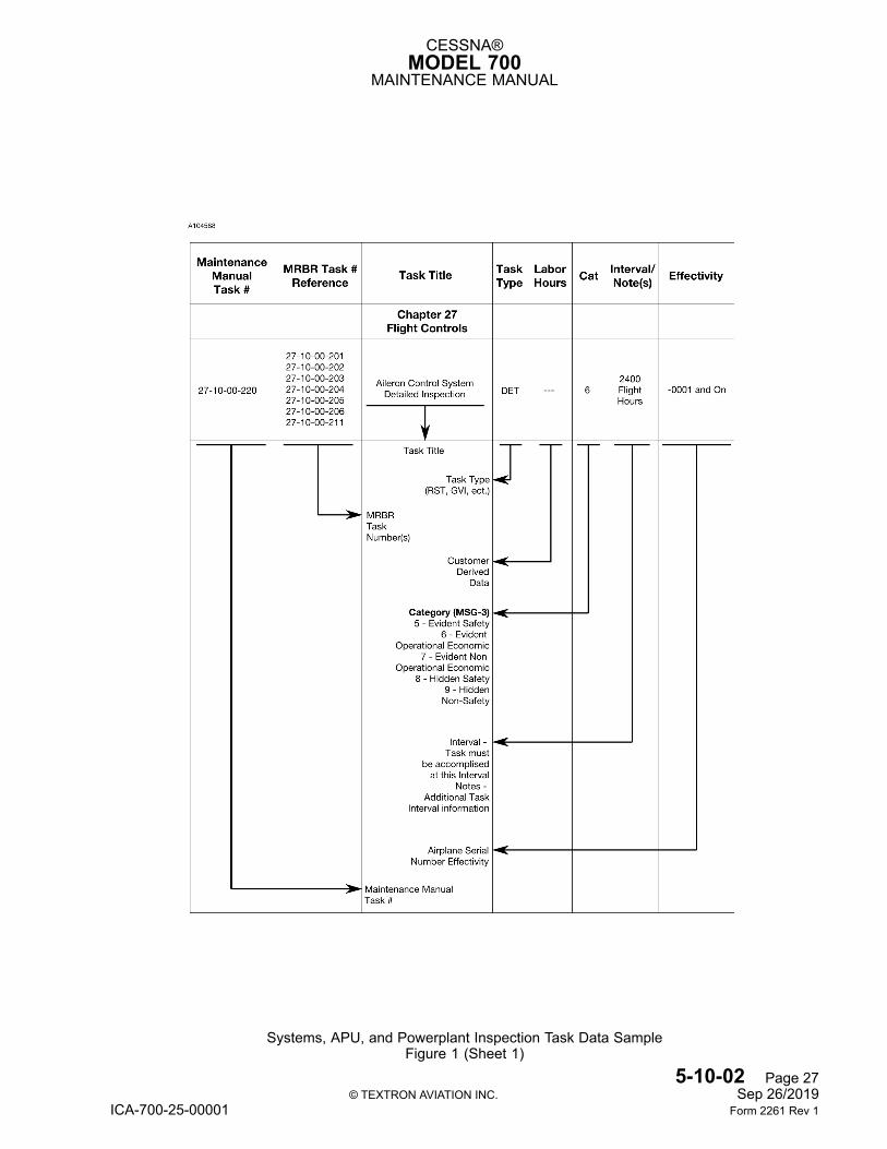
CESSNA®MODEL 700
MAINTENANCE MANUAL
Systems, APU, and Powerplant Inspection Task Data SampleFigure 1 (Sheet 1)
5-10-02 Page 27© TEXTRON AVIATION INC. Sep 26/2019
ICA-700-25-00001 Form 2261 Rev 1
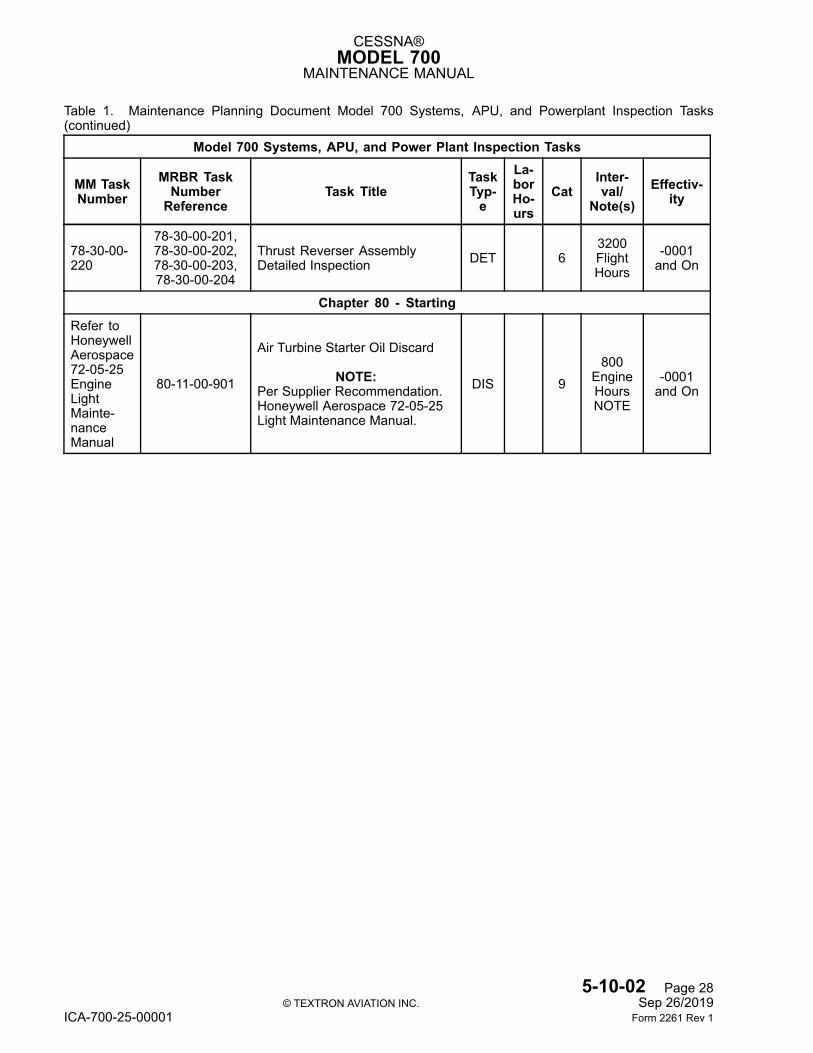
CESSNA®MODEL 700
MAINTENANCE MANUAL
Table 1. Maintenance Planning Document Model 700 Systems, APU, and Powerplant Inspection Tasks(continued)
Model 700 Systems, APU, and Power Plant Inspection Tasks
MM TaskNumber
MRBR TaskNumberReference
Task TitleTaskTyp-e
La-borHo-urs
CatInter-val/
Note(s)Effectiv-
ity
78-30-00-220
78-30-00-201,78-30-00-202,78-30-00-203,78-30-00-204
Thrust Reverser AssemblyDetailed Inspection DET 6
3200FlightHours
-0001and On
Chapter 80 - StartingRefer toHoneywellAerospace72-05-25EngineLightMainte-nanceManual
80-11-00-901
Air Turbine Starter Oil Discard
NOTE:Per Supplier Recommendation.Honeywell Aerospace 72-05-25Light Maintenance Manual.
DIS 9800
EngineHoursNOTE
-0001and On
5-10-02 Page 28© TEXTRON AVIATION INC. Sep 26/2019
ICA-700-25-00001 Form 2261 Rev 1
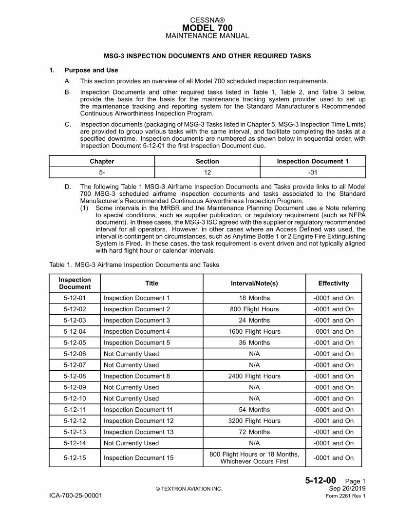
CESSNA®MODEL 700
MAINTENANCE MANUAL
MSG-3 INSPECTION DOCUMENTS AND OTHER REQUIRED TASKS
1. Purpose and UseA. This section provides an overview of all Model 700 scheduled inspection requirements.
B. Inspection Documents and other required tasks listed in Table 1, Table 2, and Table 3 below,provide the basis for the basis for the maintenance tracking system provider used to set upthe maintenance tracking and reporting system for the Standard Manufacturer’s RecommendedContinuous Airworthiness Inspection Program.
C. Inspection documents (packaging of MSG-3 Tasks listed in Chapter 5, MSG-3 Inspection Time Limits)are provided to group various tasks with the same interval, and facilitate completing the tasks at aspecified downtime. Inspection documents are numbered as shown below in sequential order, withInspection Document 5-12-01 the first Inspection Document due.
Chapter Section Inspection Document 15- 12 -01
D. The following Table 1 MSG-3 Airframe Inspection Documents and Tasks provide links to all Model700 MSG-3 scheduled airframe inspection documents and tasks associated to the StandardManufacturer’s Recommended Continuous Airworthiness Inspection Program.(1) Some intervals in the MRBR and the Maintenance Planning Document use a Note referring
to special conditions, such as supplier publication, or regulatory requirement (such as NFPAdocument). In these cases, the MSG-3 ISC agreed with the supplier or regulatory recommendedinterval for all operators. However, in other cases where an Access Defined was used, theinterval is contingent on circumstances, such as Anytime Bottle 1 or 2 Engine Fire ExtinguishingSystem is Fired. In these cases, the task requirement is event driven and not typically alignedwith hard flight hour or calendar intervals.
Table 1. MSG-3 Airframe Inspection Documents and Tasks
InspectionDocument Title Interval/Note(s) Effectivity
5-12-01 Inspection Document 1 18 Months -0001 and On
5-12-02 Inspection Document 2 800 Flight Hours -0001 and On
5-12-03 Inspection Document 3 24 Months -0001 and On
5-12-04 Inspection Document 4 1600 Flight Hours -0001 and On
5-12-05 Inspection Document 5 36 Months -0001 and On
5-12-06 Not Currently Used N/A -0001 and On
5-12-07 Not Currently Used N/A -0001 and On
5-12-08 Inspection Document 8 2400 Flight Hours -0001 and On
5-12-09 Not Currently Used N/A -0001 and On
5-12-10 Not Currently Used N/A -0001 and On
5-12-11 Inspection Document 11 54 Months -0001 and On
5-12-12 Inspection Document 12 3200 Flight Hours -0001 and On
5-12-13 Inspection Document 13 72 Months -0001 and On
5-12-14 Not Currently Used N/A -0001 and On
5-12-15 Inspection Document 15 800 Flight Hours or 18 Months,Whichever Occurs First -0001 and On
5-12-00 Page 1© TEXTRON AVIATION INC. Sep 26/2019
ICA-700-25-00001 Form 2261 Rev 1
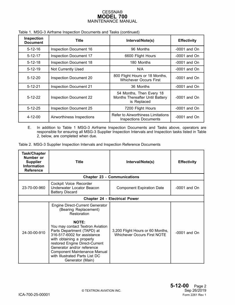
CESSNA®MODEL 700
MAINTENANCE MANUAL
Table 1. MSG-3 Airframe Inspection Documents and Tasks (continued)InspectionDocument Title Interval/Note(s) Effectivity
5-12-16 Inspection Document 16 96 Months -0001 and On
5-12-17 Inspection Document 17 6600 Flight Hours -0001 and On
5-12-18 Inspection Document 18 180 Months -0001 and On
5-12-19 Not Currently Used N/A -0001 and On
5-12-20 Inspection Document 20 800 Flight Hours or 18 Months,Whichever Occurs First -0001 and On
5-12-21 Inspection Document 21 36 Months -0001 and On
5-12-22 Inspection Document 2254 Months, Then Every 18
Months Thereafter Until Batteryis Replaced
-0001 and On
5-12-25 Inspection Document 25 7200 Flight Hours -0001 and On
4-12-00 Airworthiness Inspections Refer to Airworthiness LimitationsInspections Documents -0001 and On
E. In addition to Table 1 MSG-3 Airframe Inspection Documents and Tasks above, operators areresponsible for ensuring all MSG-3 Supplier Inspection Intervals and Inspection tasks listed in Table2, below, are completed when due.
Table 2. MSG-3 Supplier Inspection Intervals and Inspection Reference Documents
Task/ChapterNumber orSupplier
InformationReference
Title Interval/Note(s) Effectivity
Chapter 23 - Communications
23-70-00-960Cockpit Voice RecorderUnderwater Locator BeaconBattery Discard
Component Expiration Date -0001 and On
Chapter 24 - Electrical Power
24-30-00-910
Engine Direct-Current Generator(Bearing Replacement)
Restoration
NOTE:You may contact Textron AviationParts Department (TAPD) at316-517-6002 for assistancewith obtaining a properlyrestored Engine Direct-CurrentGenerator and/or referenceComponent Maintenance Manualwith Illustrated Parts List DC
Generator (Main)
3,200 Flight Hours or 60 Months,Whichever Occurs First NOTE -0001 and On
5-12-00 Page 2© TEXTRON AVIATION INC. Sep 26/2019
ICA-700-25-00001 Form 2261 Rev 1
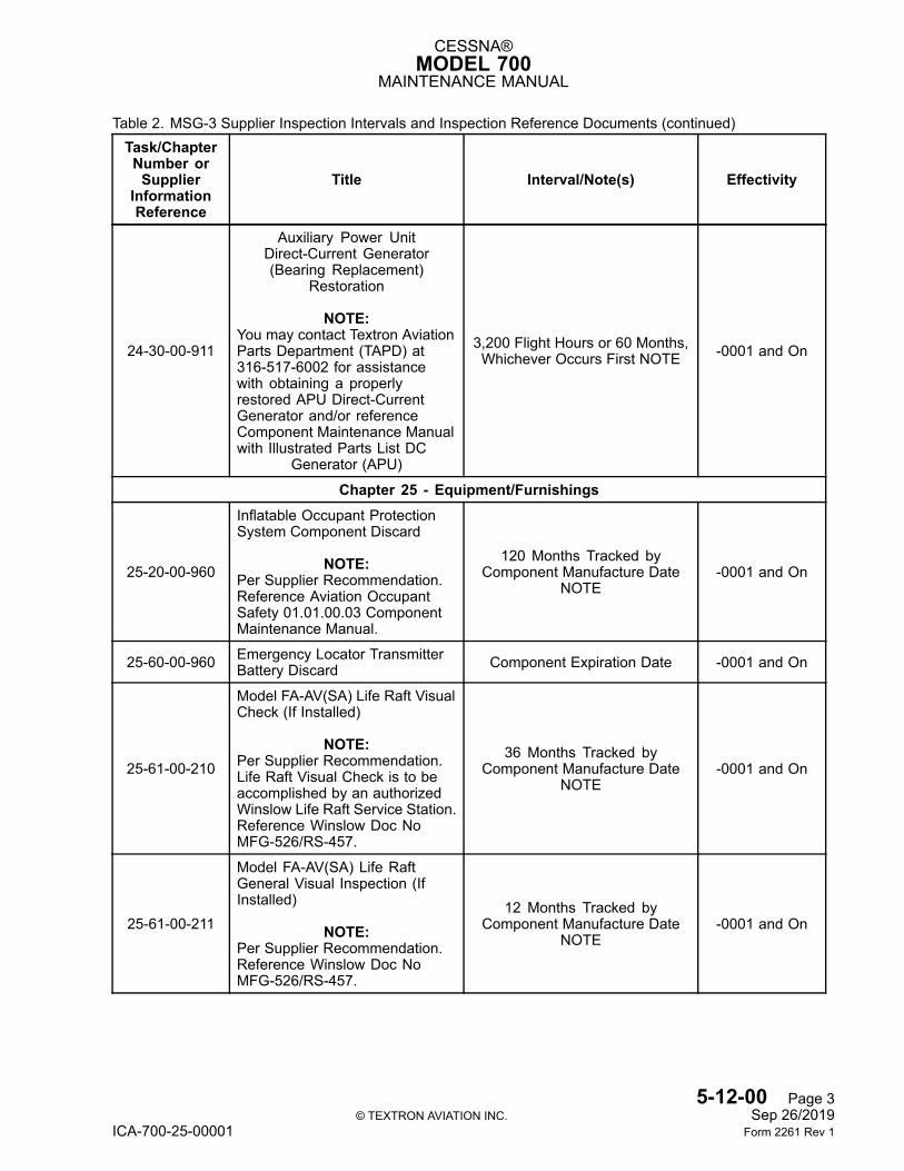
CESSNA®MODEL 700
MAINTENANCE MANUAL
Table 2. MSG-3 Supplier Inspection Intervals and Inspection Reference Documents (continued)Task/ChapterNumber orSupplier
InformationReference
Title Interval/Note(s) Effectivity
24-30-00-911
Auxiliary Power UnitDirect-Current Generator(Bearing Replacement)
Restoration
NOTE:You may contact Textron AviationParts Department (TAPD) at316-517-6002 for assistancewith obtaining a properlyrestored APU Direct-CurrentGenerator and/or referenceComponent Maintenance Manualwith Illustrated Parts List DC
Generator (APU)
3,200 Flight Hours or 60 Months,Whichever Occurs First NOTE -0001 and On
Chapter 25 - Equipment/Furnishings
25-20-00-960
Inflatable Occupant ProtectionSystem Component Discard
NOTE:Per Supplier Recommendation.Reference Aviation OccupantSafety 01.01.00.03 ComponentMaintenance Manual.
120 Months Tracked byComponent Manufacture Date
NOTE-0001 and On
25-60-00-960 Emergency Locator TransmitterBattery Discard Component Expiration Date -0001 and On
25-61-00-210
Model FA-AV(SA) Life Raft VisualCheck (If Installed)
NOTE:Per Supplier Recommendation.Life Raft Visual Check is to beaccomplished by an authorizedWinslow Life Raft Service Station.Reference Winslow Doc NoMFG-526/RS-457.
36 Months Tracked byComponent Manufacture Date
NOTE-0001 and On
25-61-00-211
Model FA-AV(SA) Life RaftGeneral Visual Inspection (IfInstalled)
NOTE:Per Supplier Recommendation.Reference Winslow Doc NoMFG-526/RS-457.
12 Months Tracked byComponent Manufacture Date
NOTE-0001 and On
5-12-00 Page 3© TEXTRON AVIATION INC. Sep 26/2019
ICA-700-25-00001 Form 2261 Rev 1
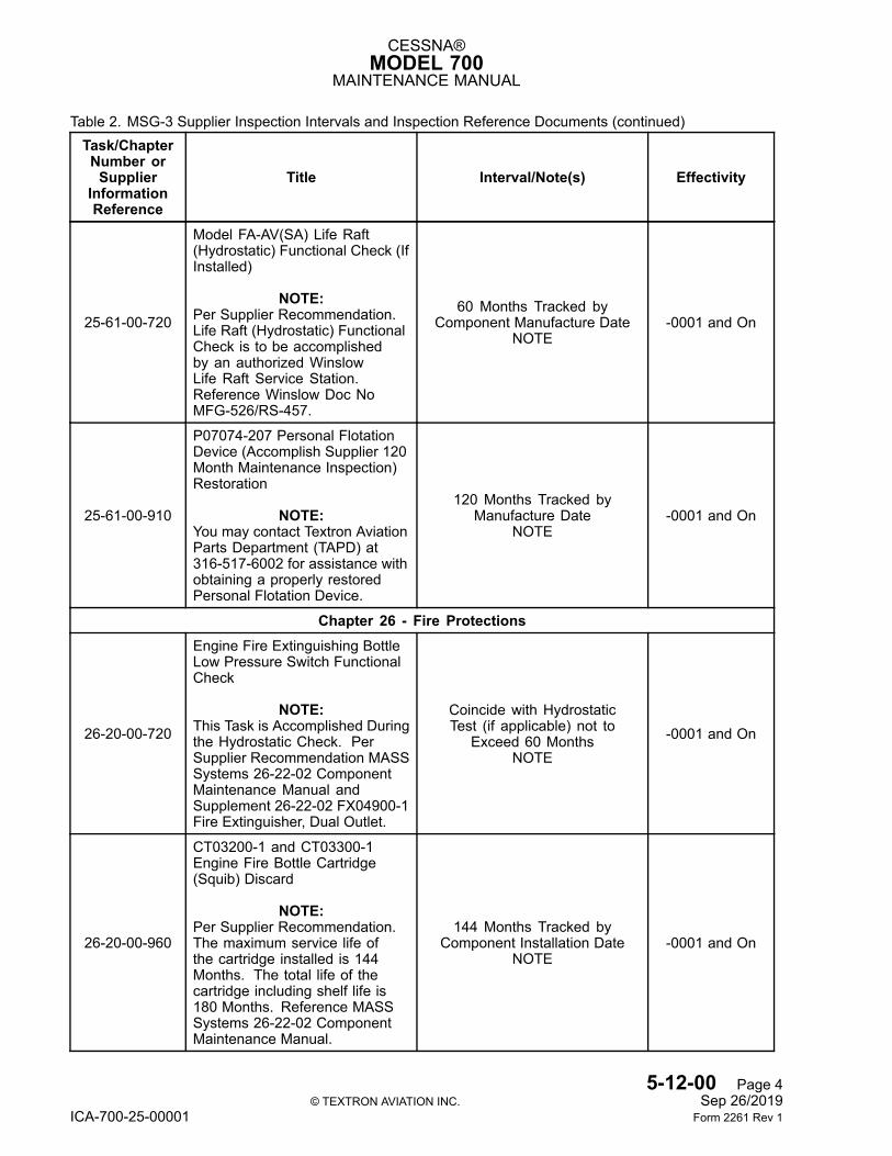
CESSNA®MODEL 700
MAINTENANCE MANUAL
Table 2. MSG-3 Supplier Inspection Intervals and Inspection Reference Documents (continued)Task/ChapterNumber orSupplier
InformationReference
Title Interval/Note(s) Effectivity
25-61-00-720
Model FA-AV(SA) Life Raft(Hydrostatic) Functional Check (IfInstalled)
NOTE:Per Supplier Recommendation.Life Raft (Hydrostatic) FunctionalCheck is to be accomplishedby an authorized WinslowLife Raft Service Station.Reference Winslow Doc NoMFG-526/RS-457.
60 Months Tracked byComponent Manufacture Date
NOTE-0001 and On
25-61-00-910
P07074-207 Personal FlotationDevice (Accomplish Supplier 120Month Maintenance Inspection)Restoration
NOTE:You may contact Textron AviationParts Department (TAPD) at316-517-6002 for assistance withobtaining a properly restoredPersonal Flotation Device.
120 Months Tracked byManufacture Date
NOTE-0001 and On
Chapter 26 - Fire Protections
26-20-00-720
Engine Fire Extinguishing BottleLow Pressure Switch FunctionalCheck
NOTE:This Task is Accomplished Duringthe Hydrostatic Check. PerSupplier Recommendation MASSSystems 26-22-02 ComponentMaintenance Manual andSupplement 26-22-02 FX04900-1Fire Extinguisher, Dual Outlet.
Coincide with HydrostaticTest (if applicable) not to
Exceed 60 MonthsNOTE
-0001 and On
26-20-00-960
CT03200-1 and CT03300-1Engine Fire Bottle Cartridge(Squib) Discard
NOTE:Per Supplier Recommendation.The maximum service life ofthe cartridge installed is 144Months. The total life of thecartridge including shelf life is180 Months. Reference MASSSystems 26-22-02 ComponentMaintenance Manual.
144 Months Tracked byComponent Installation Date
NOTE-0001 and On
5-12-00 Page 4© TEXTRON AVIATION INC. Sep 26/2019
ICA-700-25-00001 Form 2261 Rev 1
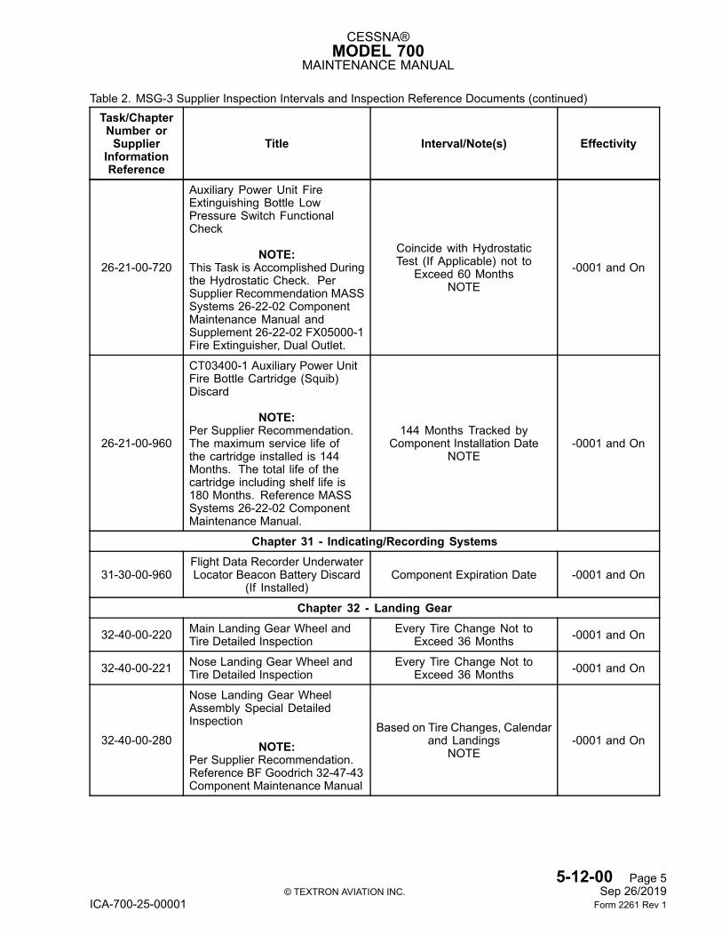
CESSNA®MODEL 700
MAINTENANCE MANUAL
Table 2. MSG-3 Supplier Inspection Intervals and Inspection Reference Documents (continued)Task/ChapterNumber orSupplier
InformationReference
Title Interval/Note(s) Effectivity
26-21-00-720
Auxiliary Power Unit FireExtinguishing Bottle LowPressure Switch FunctionalCheck
NOTE:This Task is Accomplished Duringthe Hydrostatic Check. PerSupplier Recommendation MASSSystems 26-22-02 ComponentMaintenance Manual andSupplement 26-22-02 FX05000-1Fire Extinguisher, Dual Outlet.
Coincide with HydrostaticTest (If Applicable) not to
Exceed 60 MonthsNOTE
-0001 and On
26-21-00-960
CT03400-1 Auxiliary Power UnitFire Bottle Cartridge (Squib)Discard
NOTE:Per Supplier Recommendation.The maximum service life ofthe cartridge installed is 144Months. The total life of thecartridge including shelf life is180 Months. Reference MASSSystems 26-22-02 ComponentMaintenance Manual.
144 Months Tracked byComponent Installation Date
NOTE-0001 and On
Chapter 31 - Indicating/Recording Systems
31-30-00-960Flight Data Recorder UnderwaterLocator Beacon Battery Discard
(If Installed)Component Expiration Date -0001 and On
Chapter 32 - Landing Gear
32-40-00-220 Main Landing Gear Wheel andTire Detailed Inspection
Every Tire Change Not toExceed 36 Months -0001 and On
32-40-00-221 Nose Landing Gear Wheel andTire Detailed Inspection
Every Tire Change Not toExceed 36 Months -0001 and On
32-40-00-280
Nose Landing Gear WheelAssembly Special DetailedInspection
NOTE:Per Supplier Recommendation.Reference BF Goodrich 32-47-43Component Maintenance Manual
Based on Tire Changes, Calendarand Landings
NOTE-0001 and On
5-12-00 Page 5© TEXTRON AVIATION INC. Sep 26/2019
ICA-700-25-00001 Form 2261 Rev 1
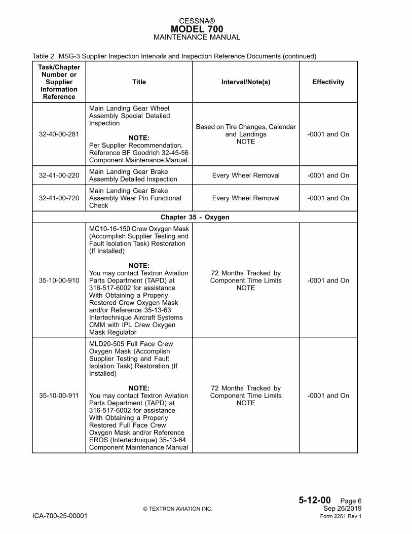
CESSNA®MODEL 700
MAINTENANCE MANUAL
Table 2. MSG-3 Supplier Inspection Intervals and Inspection Reference Documents (continued)Task/ChapterNumber orSupplier
InformationReference
Title Interval/Note(s) Effectivity
32-40-00-281
Main Landing Gear WheelAssembly Special DetailedInspection
NOTE:Per Supplier Recommendation.Reference BF Goodrich 32-45-56Component Maintenance Manual.
Based on Tire Changes, Calendarand Landings
NOTE-0001 and On
32-41-00-220 Main Landing Gear BrakeAssembly Detailed Inspection Every Wheel Removal -0001 and On
32-41-00-720Main Landing Gear BrakeAssembly Wear Pin FunctionalCheck
Every Wheel Removal -0001 and On
Chapter 35 - Oxygen
35-10-00-910
MC10-16-150 CrewOxygenMask(Accomplish Supplier Testing andFault Isolation Task) Restoration(If Installed)
NOTE:You may contact Textron AviationParts Department (TAPD) at316-517-6002 for assistanceWith Obtaining a ProperlyRestored Crew Oxygen Maskand/or Reference 35-13-63Intertechnique Aircraft SystemsCMM with IPL Crew OxygenMask Regulator
72 Months Tracked byComponent Time Limits
NOTE-0001 and On
35-10-00-911
MLD20-505 Full Face CrewOxygen Mask (AccomplishSupplier Testing and FaultIsolation Task) Restoration (IfInstalled)
NOTE:You may contact Textron AviationParts Department (TAPD) at316-517-6002 for assistanceWith Obtaining a ProperlyRestored Full Face CrewOxygen Mask and/or ReferenceEROS (Intertechnique) 35-13-64Component Maintenance Manual
72 Months Tracked byComponent Time Limits
NOTE-0001 and On
5-12-00 Page 6© TEXTRON AVIATION INC. Sep 26/2019
ICA-700-25-00001 Form 2261 Rev 1
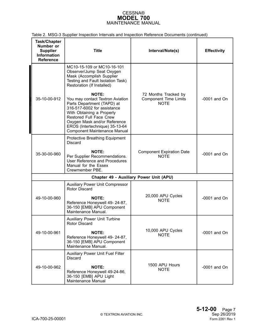
CESSNA®MODEL 700
MAINTENANCE MANUAL
Table 2. MSG-3 Supplier Inspection Intervals and Inspection Reference Documents (continued)Task/ChapterNumber orSupplier
InformationReference
Title Interval/Note(s) Effectivity
35-10-00-912
MC10-15-109 or MC10-16-101Observer/Jump Seat OxygenMask (Accomplish SupplierTesting and Fault Isolation Task)Restoration (If Installed)
NOTE:You may contact Textron AviationParts Department (TAPD) at316-517-6002 for assistanceWith Obtaining a ProperlyRestored Full Face CrewOxygen Mask and/or ReferenceEROS (Intertechnique) 35-13-64Component Maintenance Manual
72 Months Tracked byComponent Time Limits
NOTE-0001 and On
35-30-00-960
Protective Breathing EquipmentDiscard
NOTE:Per Supplier Recommendations.User Reference and ProceduresManual for the EssexCrewmember PBE.
Component Expiration DateNOTE -0001 and On
Chapter 49 - Auxiliary Power Unit (APU)
49-10-00-960
Auxiliary Power Unit CompressorRotor Discard
NOTE:Reference Honeywell 49- 24-87,36-150 [EMB] APU ComponentMaintenance Manual.
20,000 APU CyclesNOTE -0001 and On
49-10-00-961
Auxiliary Power Unit TurbineRotor Discard
NOTE:Reference Honeywell 49- 24-87,36-150 [EMB] APU ComponentMaintenance Manual.
10,000 APU CyclesNOTE -0001 and On
49-10-00-962
Auxiliary Power Unit Fuel FilterDiscard
NOTE:Reference Honeywell 49-24-86,36-150 [EMB] APU LightMaintenance Manual
1500 APU HoursNOTE -0001 and On
5-12-00 Page 7© TEXTRON AVIATION INC. Sep 26/2019
ICA-700-25-00001 Form 2261 Rev 1
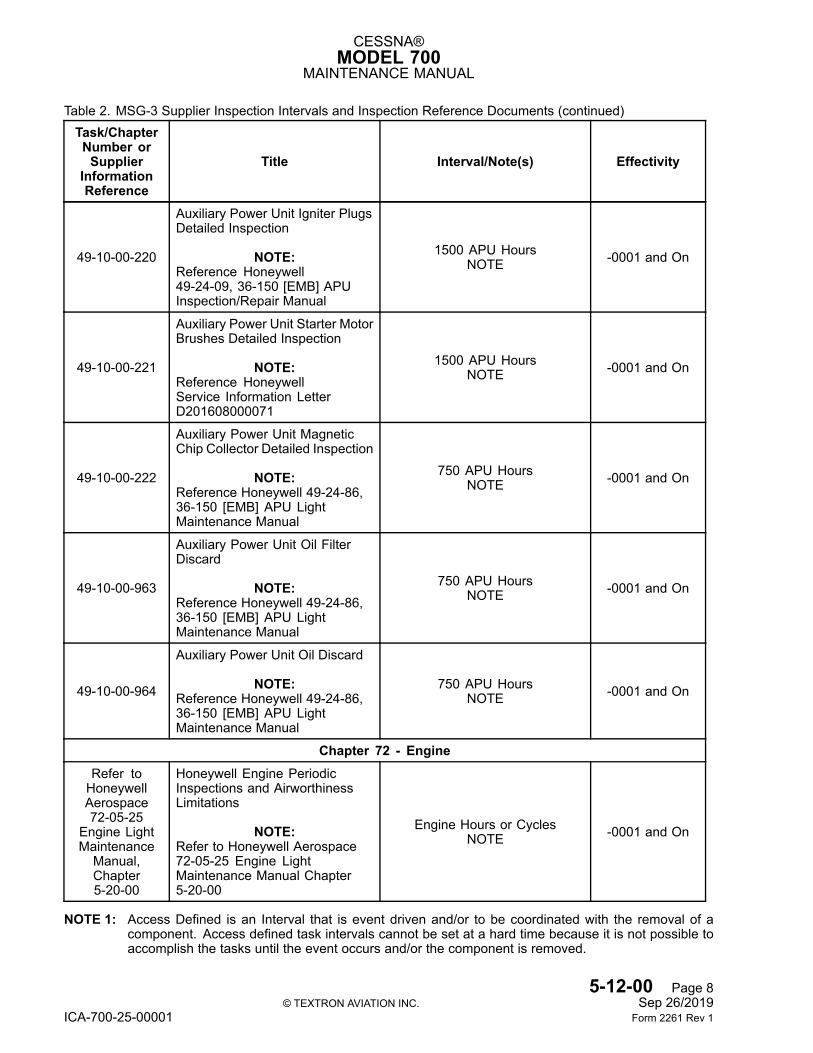
CESSNA®MODEL 700
MAINTENANCE MANUAL
Table 2. MSG-3 Supplier Inspection Intervals and Inspection Reference Documents (continued)Task/ChapterNumber orSupplier
InformationReference
Title Interval/Note(s) Effectivity
49-10-00-220
Auxiliary Power Unit Igniter PlugsDetailed Inspection
NOTE:Reference Honeywell49-24-09, 36-150 [EMB] APUInspection/Repair Manual
1500 APU HoursNOTE -0001 and On
49-10-00-221
Auxiliary Power Unit Starter MotorBrushes Detailed Inspection
NOTE:Reference HoneywellService Information LetterD201608000071
1500 APU HoursNOTE -0001 and On
49-10-00-222
Auxiliary Power Unit MagneticChip Collector Detailed Inspection
NOTE:Reference Honeywell 49-24-86,36-150 [EMB] APU LightMaintenance Manual
750 APU HoursNOTE -0001 and On
49-10-00-963
Auxiliary Power Unit Oil FilterDiscard
NOTE:Reference Honeywell 49-24-86,36-150 [EMB] APU LightMaintenance Manual
750 APU HoursNOTE -0001 and On
49-10-00-964
Auxiliary Power Unit Oil Discard
NOTE:Reference Honeywell 49-24-86,36-150 [EMB] APU LightMaintenance Manual
750 APU HoursNOTE -0001 and On
Chapter 72 - EngineRefer toHoneywellAerospace72-05-25
Engine LightMaintenanceManual,Chapter5-20-00
Honeywell Engine PeriodicInspections and AirworthinessLimitations
NOTE:Refer to Honeywell Aerospace72-05-25 Engine LightMaintenance Manual Chapter5-20-00
Engine Hours or CyclesNOTE -0001 and On
NOTE 1: Access Defined is an Interval that is event driven and/or to be coordinated with the removal of acomponent. Access defined task intervals cannot be set at a hard time because it is not possible toaccomplish the tasks until the event occurs and/or the component is removed.
5-12-00 Page 8© TEXTRON AVIATION INC. Sep 26/2019
ICA-700-25-00001 Form 2261 Rev 1
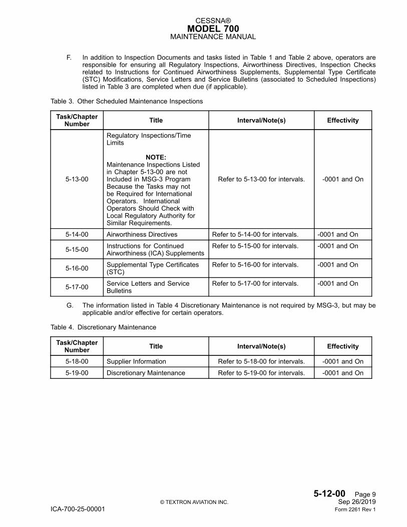
CESSNA®MODEL 700
MAINTENANCE MANUAL
F. In addition to Inspection Documents and tasks listed in Table 1 and Table 2 above, operators areresponsible for ensuring all Regulatory Inspections, Airworthiness Directives, Inspection Checksrelated to Instructions for Continued Airworthiness Supplements, Supplemental Type Certificate(STC) Modifications, Service Letters and Service Bulletins (associated to Scheduled Inspections)listed in Table 3 are completed when due (if applicable).
Table 3. Other Scheduled Maintenance Inspections
Task/ChapterNumber Title Interval/Note(s) Effectivity
5-13-00
Regulatory Inspections/TimeLimits
NOTE:Maintenance Inspections Listedin Chapter 5-13-00 are notIncluded in MSG-3 ProgramBecause the Tasks may notbe Required for InternationalOperators. InternationalOperators Should Check withLocal Regulatory Authority forSimilar Requirements.
Refer to 5-13-00 for intervals. -0001 and On
5-14-00 Airworthiness Directives Refer to 5-14-00 for intervals. -0001 and On
5-15-00 Instructions for ContinuedAirworthiness (ICA) Supplements
Refer to 5-15-00 for intervals. -0001 and On
5-16-00 Supplemental Type Certificates(STC)
Refer to 5-16-00 for intervals. -0001 and On
5-17-00 Service Letters and ServiceBulletins
Refer to 5-17-00 for intervals. -0001 and On
G. The information listed in Table 4 Discretionary Maintenance is not required by MSG-3, but may beapplicable and/or effective for certain operators.
Table 4. Discretionary Maintenance
Task/ChapterNumber Title Interval/Note(s) Effectivity
5-18-00 Supplier Information Refer to 5-18-00 for intervals. -0001 and On
5-19-00 Discretionary Maintenance Refer to 5-19-00 for intervals. -0001 and On
5-12-00 Page 9© TEXTRON AVIATION INC. Sep 26/2019
ICA-700-25-00001 Form 2261 Rev 1
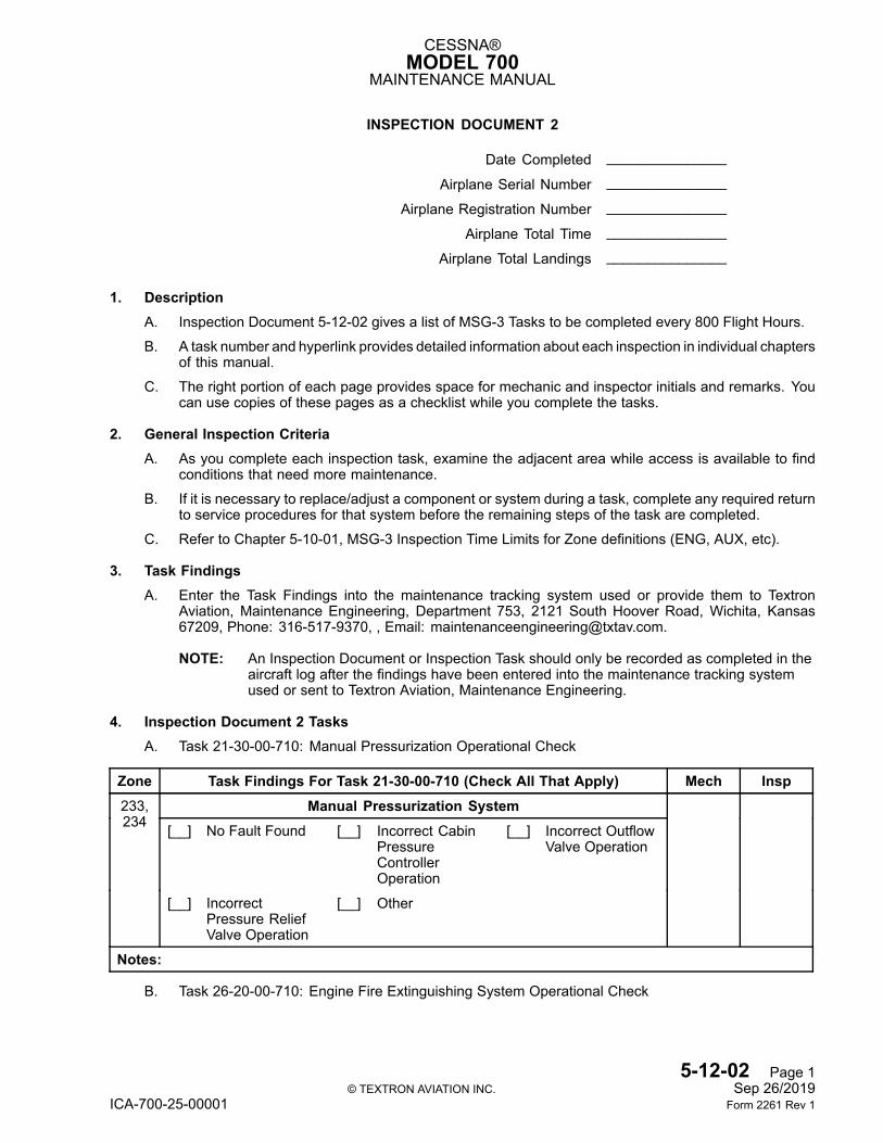
CESSNA®MODEL 700
MAINTENANCE MANUAL
INSPECTION DOCUMENT 2
Date Completed _______________
Airplane Serial Number _______________
Airplane Registration Number _______________
Airplane Total Time _______________
Airplane Total Landings _______________
1. DescriptionA. Inspection Document 5-12-02 gives a list of MSG-3 Tasks to be completed every 800 Flight Hours.
B. A task number and hyperlink provides detailed information about each inspection in individual chaptersof this manual.
C. The right portion of each page provides space for mechanic and inspector initials and remarks. Youcan use copies of these pages as a checklist while you complete the tasks.
2. General Inspection CriteriaA. As you complete each inspection task, examine the adjacent area while access is available to find
conditions that need more maintenance.
B. If it is necessary to replace/adjust a component or system during a task, complete any required returnto service procedures for that system before the remaining steps of the task are completed.
C. Refer to Chapter 5-10-01, MSG-3 Inspection Time Limits for Zone definitions (ENG, AUX, etc).
3. Task FindingsA. Enter the Task Findings into the maintenance tracking system used or provide them to Textron
Aviation, Maintenance Engineering, Department 753, 2121 South Hoover Road, Wichita, Kansas67209, Phone: 316-517-9370, , Email: [email protected].
NOTE: An Inspection Document or Inspection Task should only be recorded as completed in theaircraft log after the findings have been entered into the maintenance tracking systemused or sent to Textron Aviation, Maintenance Engineering.
4. Inspection Document 2 TasksA. Task 21-30-00-710: Manual Pressurization Operational Check
Zone Task Findings For Task 21-30-00-710 (Check All That Apply) Mech InspManual Pressurization System
[__] No Fault Found [__] Incorrect CabinPressureControllerOperation
[__] Incorrect OutflowValve Operation
233,234
[__] IncorrectPressure ReliefValve Operation
[__] Other
Notes:
B. Task 26-20-00-710: Engine Fire Extinguishing System Operational Check
5-12-02 Page 1© TEXTRON AVIATION INC. Sep 26/2019
ICA-700-25-00001 Form 2261 Rev 1
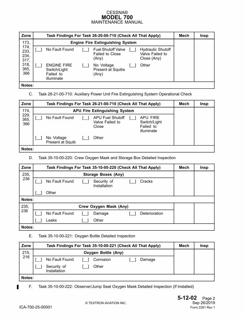
CESSNA®MODEL 700
MAINTENANCE MANUAL
Zone Task Findings For Task 26-20-00-710 (Check All That Apply) Mech InspEngine Fire Extinguishing System
[__] No Fault Found [__] Fuel Shutoff ValveFailed to Close(Any)
[__] Hydraulic ShutoffValve Failed toClose (Any)
173,174,233,234,317,318,365,366
[__] ENGINE FIRESwitch/LightFailed toilluminate
[__] No VoltagePresent at Squibs(Any)
[__] Other
Notes:
C. Task 26-21-00-710: Auxiliary Power Unit Fire Extinguishing System Operational Check
Zone Task Findings For Task 26-21-00-710 (Check All That Apply) Mech InspAPU Fire Extinguishing System
[__] No Fault Found [__] APU Fuel ShutoffValve Failed toClose
[__] APU FIRESwitch/LightFailed toilluminate
174,229,365,366
[__] No VoltagePresent at Squib
[__] Other
Notes:
D. Task 35-10-00-220: Crew Oxygen Mask and Storage Box Detailed Inspection
Zone Task Findings For Task 35-10-00-220 (Check All That Apply) Mech InspStorage Boxes (Any)
[__] No Fault Found [__] Security ofInstallation
[__] Cracks
235,236
[__] Other
Notes:Crew Oxygen Mask (Any)
[__] No Fault Found [__] Damage [__] Deterioration
235,236
[__] Leaks [__] Other
Notes:
E. Task 35-10-00-221: Oxygen Bottle Detailed Inspection
Zone Task Findings For Task 35-10-00-221 (Check All That Apply) Mech InspOxygen Bottle (Any)
[__] No Fault Found [__] Corrosion [__] Damage
215,216
[__] Security ofInstallation
[__] Other
Notes:
F. Task 35-10-00-222: Observer/Jump Seat Oxygen Mask Detailed Inspection (If Installed)
5-12-02 Page 2© TEXTRON AVIATION INC. Sep 26/2019
ICA-700-25-00001 Form 2261 Rev 1
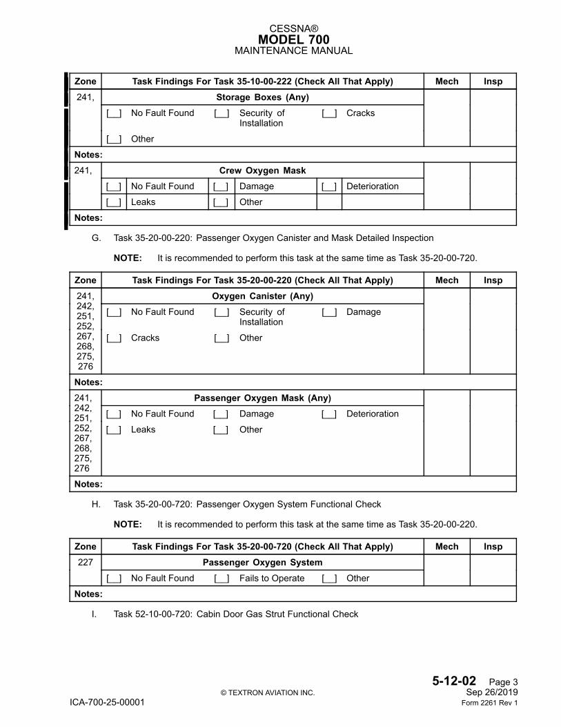
CESSNA®MODEL 700
MAINTENANCE MANUAL
Zone Task Findings For Task 35-10-00-222 (Check All That Apply) Mech InspStorage Boxes (Any)
[__] No Fault Found [__] Security ofInstallation
[__] Cracks
241,
[__] Other
Notes:Crew Oxygen Mask
[__] No Fault Found [__] Damage [__] Deterioration
241,
[__] Leaks [__] Other
Notes:
G. Task 35-20-00-220: Passenger Oxygen Canister and Mask Detailed Inspection
NOTE: It is recommended to perform this task at the same time as Task 35-20-00-720.
Zone Task Findings For Task 35-20-00-220 (Check All That Apply) Mech InspOxygen Canister (Any)
[__] No Fault Found [__] Security ofInstallation
[__] Damage
241,242,251,252,267,268,275,276
[__] Cracks [__] Other
Notes:Passenger Oxygen Mask (Any)
[__] No Fault Found [__] Damage [__] Deterioration
241,242,251,252,267,268,275,276
[__] Leaks [__] Other
Notes:
H. Task 35-20-00-720: Passenger Oxygen System Functional Check
NOTE: It is recommended to perform this task at the same time as Task 35-20-00-220.
Zone Task Findings For Task 35-20-00-720 (Check All That Apply) Mech InspPassenger Oxygen System227
[__] No Fault Found [__] Fails to Operate [__] Other
Notes:
I. Task 52-10-00-720: Cabin Door Gas Strut Functional Check
5-12-02 Page 3© TEXTRON AVIATION INC. Sep 26/2019
ICA-700-25-00001 Form 2261 Rev 1
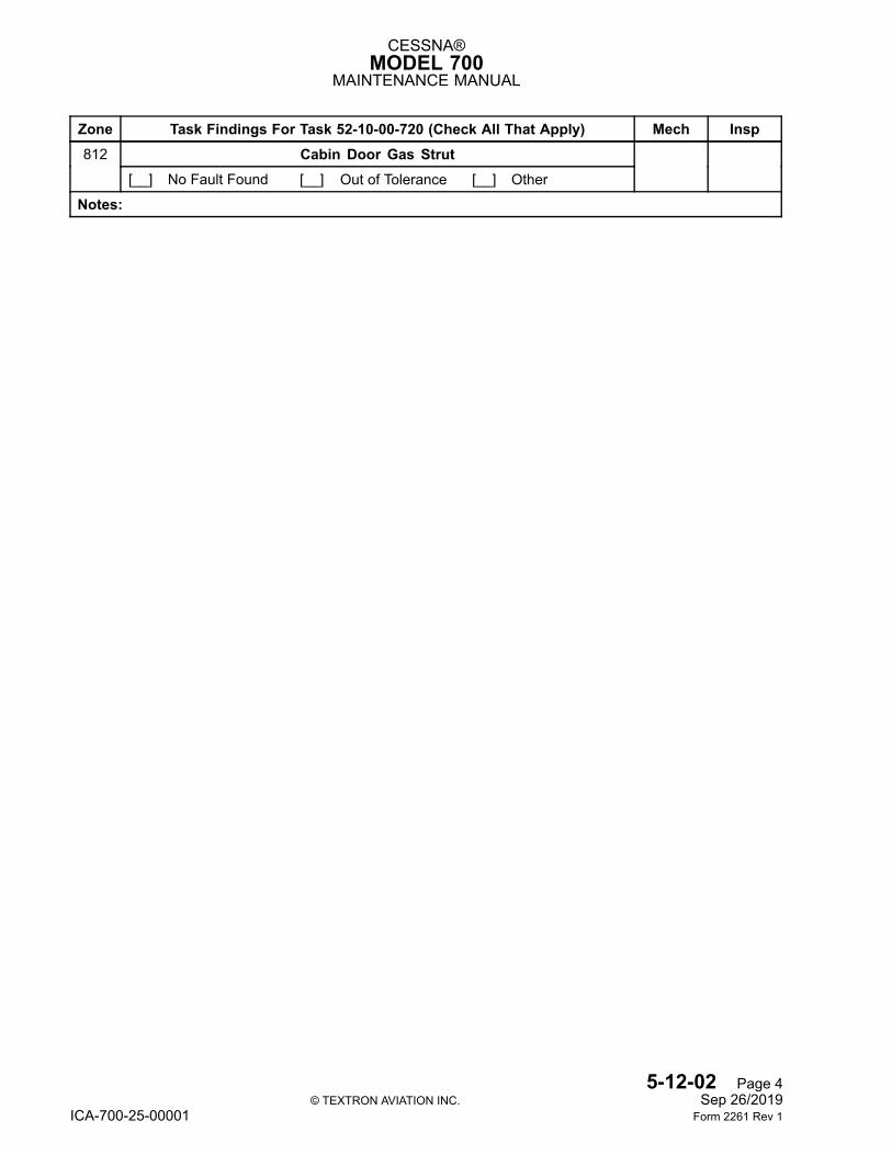
CESSNA®MODEL 700
MAINTENANCE MANUAL
Zone Task Findings For Task 52-10-00-720 (Check All That Apply) Mech InspCabin Door Gas Strut812
[__] No Fault Found [__] Out of Tolerance [__] Other
Notes:
5-12-02 Page 4© TEXTRON AVIATION INC. Sep 26/2019
ICA-700-25-00001 Form 2261 Rev 1
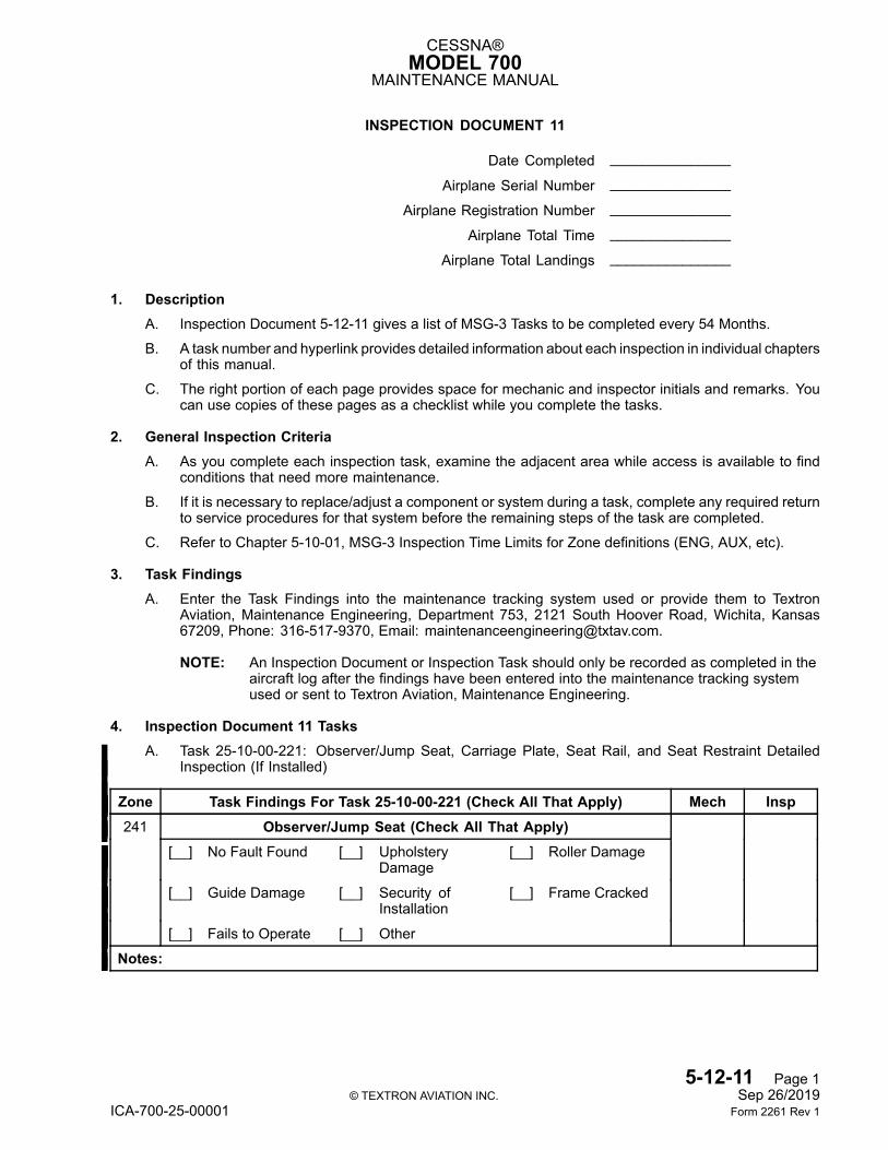
CESSNA®MODEL 700
MAINTENANCE MANUAL
INSPECTION DOCUMENT 11
Date Completed _______________
Airplane Serial Number _______________
Airplane Registration Number _______________
Airplane Total Time _______________
Airplane Total Landings _______________
1. DescriptionA. Inspection Document 5-12-11 gives a list of MSG-3 Tasks to be completed every 54 Months.
B. A task number and hyperlink provides detailed information about each inspection in individual chaptersof this manual.
C. The right portion of each page provides space for mechanic and inspector initials and remarks. Youcan use copies of these pages as a checklist while you complete the tasks.
2. General Inspection CriteriaA. As you complete each inspection task, examine the adjacent area while access is available to find
conditions that need more maintenance.
B. If it is necessary to replace/adjust a component or system during a task, complete any required returnto service procedures for that system before the remaining steps of the task are completed.
C. Refer to Chapter 5-10-01, MSG-3 Inspection Time Limits for Zone definitions (ENG, AUX, etc).
3. Task FindingsA. Enter the Task Findings into the maintenance tracking system used or provide them to Textron
Aviation, Maintenance Engineering, Department 753, 2121 South Hoover Road, Wichita, Kansas67209, Phone: 316-517-9370, Email: [email protected].
NOTE: An Inspection Document or Inspection Task should only be recorded as completed in theaircraft log after the findings have been entered into the maintenance tracking systemused or sent to Textron Aviation, Maintenance Engineering.
4. Inspection Document 11 TasksA. Task 25-10-00-221: Observer/Jump Seat, Carriage Plate, Seat Rail, and Seat Restraint Detailed
Inspection (If Installed)
Zone Task Findings For Task 25-10-00-221 (Check All That Apply) Mech InspObserver/Jump Seat (Check All That Apply)
[__] No Fault Found [__] UpholsteryDamage
[__] Roller Damage
[__] Guide Damage [__] Security ofInstallation
[__] Frame Cracked
241
[__] Fails to Operate [__] Other
Notes:
5-12-11 Page 1© TEXTRON AVIATION INC. Sep 26/2019
ICA-700-25-00001 Form 2261 Rev 1
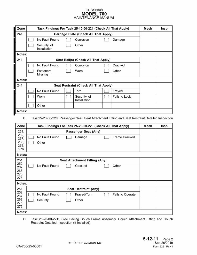
CESSNA®MODEL 700
MAINTENANCE MANUAL
Zone Task Findings For Task 25-10-00-221 (Check All That Apply) Mech InspCarriage Plate (Check All That Apply)
[__] No Fault Found [__] Corrosion [__] Damage
241
[__] Security ofInstallation
[__] Other
Notes:Seat Rail(s) (Check All That Apply)
[__] No Fault Found [__] Corrosion [__] Cracked
241
[__] FastenersMissing
[__] Worn [__] Other
Notes:Seat Restraint (Check All That Apply)
[__] No Fault Found [__] Torn [__] Frayed
[__] Worn [__] Security ofInstallation
[__] Fails to Lock
241
[__] Other
Notes:
B. Task 25-20-00-220: Passenger Seat, Seat Attachment Fitting and Seat Restraint Detailed Inspection
Zone Task Findings For Task 25-20-00-220 (Check All That Apply) Mech InspPassenger Seat (Any)
[__] No Fault Found [__] Damage [__] Frame Cracked
251,252,267,268,275,276
[__] Other
Notes:Seat Attachment Fitting (Any)251,
252,267,268,275,276
[__] No Fault Found [__] Cracked [__] Other
Notes:Seat Restraint (Any)
[__] No Fault Found [__] Frayed/Torn [__] Fails to Operate
251,252,267,268,275,276
[__] Security [__] Other
Notes:
C. Task 25-20-00-221: Side Facing Couch Frame Assembly, Couch Attachment Fitting and CouchRestraint Detailed Inspection (If Installed)
5-12-11 Page 2© TEXTRON AVIATION INC. Sep 26/2019
ICA-700-25-00001 Form 2261 Rev 1
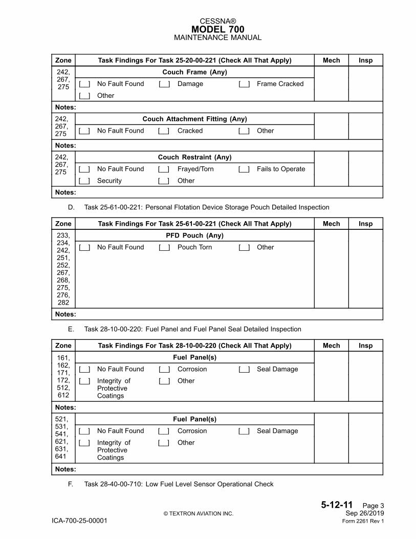
CESSNA®MODEL 700
MAINTENANCE MANUAL
Zone Task Findings For Task 25-20-00-221 (Check All That Apply) Mech InspCouch Frame (Any)
[__] No Fault Found [__] Damage [__] Frame Cracked
242,267,275
[__] Other
Notes:Couch Attachment Fitting (Any)242,
267,275 [__] No Fault Found [__] Cracked [__] Other
Notes:Couch Restraint (Any)
[__] No Fault Found [__] Frayed/Torn [__] Fails to Operate
242,267,275
[__] Security [__] Other
Notes:
D. Task 25-61-00-221: Personal Flotation Device Storage Pouch Detailed Inspection
Zone Task Findings For Task 25-61-00-221 (Check All That Apply) Mech InspPFD Pouch (Any)233,
234,242,251,252,267,268,275,276,282
[__] No Fault Found [__] Pouch Torn [__] Other
Notes:
E. Task 28-10-00-220: Fuel Panel and Fuel Panel Seal Detailed Inspection
Zone Task Findings For Task 28-10-00-220 (Check All That Apply) Mech InspFuel Panel(s)
[__] No Fault Found [__] Corrosion [__] Seal Damage161,162,171,172,512,612
[__] Integrity ofProtectiveCoatings
[__] Other
Notes:Fuel Panel(s)
[__] No Fault Found [__] Corrosion [__] Seal Damage
521,531,541,621,631,641
[__] Integrity ofProtectiveCoatings
[__] Other
Notes:
F. Task 28-40-00-710: Low Fuel Level Sensor Operational Check
5-12-11 Page 3© TEXTRON AVIATION INC. Sep 26/2019
ICA-700-25-00001 Form 2261 Rev 1
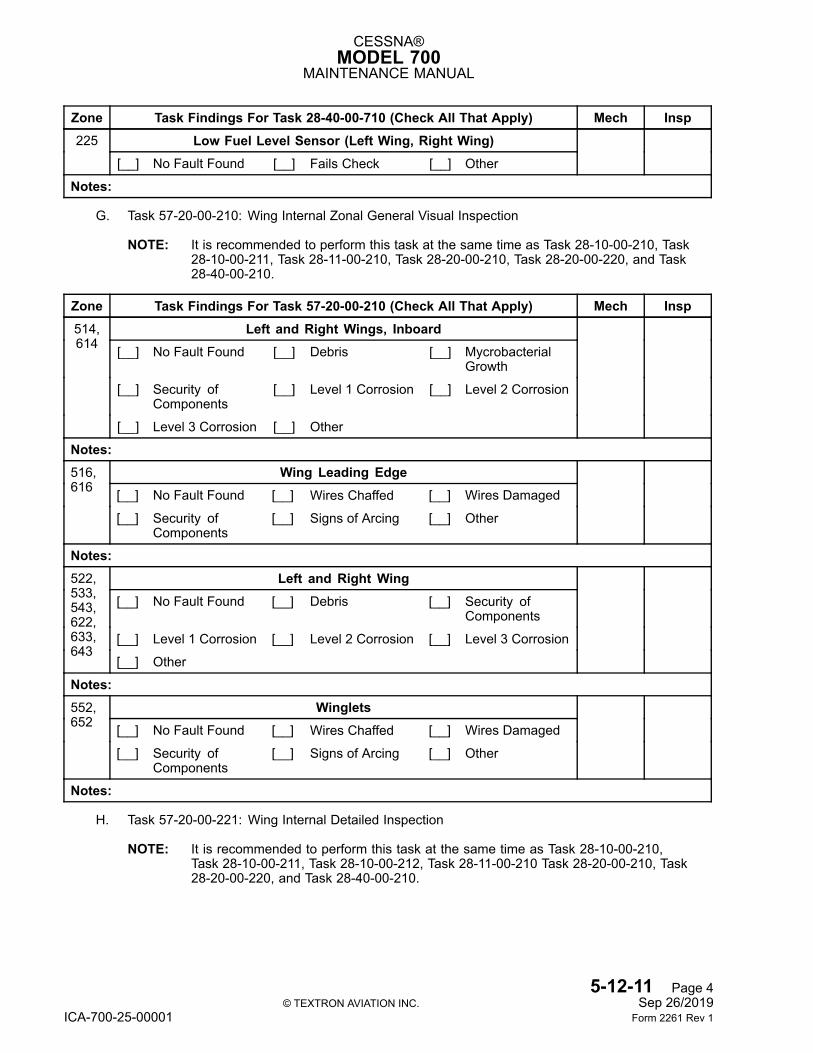
CESSNA®MODEL 700
MAINTENANCE MANUAL
Zone Task Findings For Task 28-40-00-710 (Check All That Apply) Mech InspLow Fuel Level Sensor (Left Wing, Right Wing)225
[__] No Fault Found [__] Fails Check [__] Other
Notes:
G. Task 57-20-00-210: Wing Internal Zonal General Visual Inspection
NOTE: It is recommended to perform this task at the same time as Task 28-10-00-210, Task28-10-00-211, Task 28-11-00-210, Task 28-20-00-210, Task 28-20-00-220, and Task28-40-00-210.
Zone Task Findings For Task 57-20-00-210 (Check All That Apply) Mech InspLeft and Right Wings, Inboard
[__] No Fault Found [__] Debris [__] MycrobacterialGrowth
[__] Security ofComponents
[__] Level 1 Corrosion [__] Level 2 Corrosion
514,614
[__] Level 3 Corrosion [__] Other
Notes:Wing Leading Edge
[__] No Fault Found [__] Wires Chaffed [__] Wires Damaged
516,616
[__] Security ofComponents
[__] Signs of Arcing [__] Other
Notes:Left and Right Wing
[__] No Fault Found [__] Debris [__] Security ofComponents
[__] Level 1 Corrosion [__] Level 2 Corrosion [__] Level 3 Corrosion
522,533,543,622,633,643
[__] Other
Notes:Winglets
[__] No Fault Found [__] Wires Chaffed [__] Wires Damaged
552,652
[__] Security ofComponents
[__] Signs of Arcing [__] Other
Notes:
H. Task 57-20-00-221: Wing Internal Detailed Inspection
NOTE: It is recommended to perform this task at the same time as Task 28-10-00-210,Task 28-10-00-211, Task 28-10-00-212, Task 28-11-00-210 Task 28-20-00-210, Task28-20-00-220, and Task 28-40-00-210.
5-12-11 Page 4© TEXTRON AVIATION INC. Sep 26/2019
ICA-700-25-00001 Form 2261 Rev 1
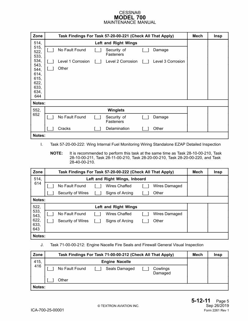
CESSNA®MODEL 700
MAINTENANCE MANUAL
Zone Task Findings For Task 57-20-00-221 (Check All That Apply) Mech InspLeft and Right Wings
[__] No Fault Found [__] Security ofFasteners
[__] Damage
[__] Level 1 Corrosion [__] Level 2 Corrosion [__] Level 3 Corrosion
514,515,522,533,534,543,544,614,615,622,633,634,644
[__] Other
Notes:Winglets
[__] No Fault Found [__] Security ofFasteners
[__] Damage
552,652
[__] Cracks [__] Delamination [__] Other
Notes:
I. Task 57-20-00-222: Wing Internal Fuel Monitoring Wiring Standalone EZAP Detailed Inspection
NOTE: It is recommended to perform this task at the same time as Task 28-10-00-210, Task28-10-00-211, Task 28-11-00-210, Task 28-20-00-210, Task 28-20-00-220, and Task28-40-00-210.
Zone Task Findings For Task 57-20-00-222 (Check All That Apply) Mech InspLeft and Right Wings, Inboard
[__] No Fault Found [__] Wires Chaffed [__] Wires Damaged
514,614
[__] Security of Wires [__] Signs of Arcing [__] Other
Notes:Left and Right Wings
[__] No Fault Found [__] Wires Chaffed [__] Wires Damaged
522,533,543,622,633,643
[__] Security of Wires [__] Signs of Arcing [__] Other
Notes:
J. Task 71-00-00-212: Engine Nacelle Fire Seals and Firewall General Visual Inspection
Zone Task Findings For Task 71-00-00-212 (Check All That Apply) Mech InspEngine Nacelle
[__] No Fault Found [__] Seals Damaged [__] CowlingsDamaged
415,416
[__] Other
Notes:
5-12-11 Page 5© TEXTRON AVIATION INC. Sep 26/2019
ICA-700-25-00001 Form 2261 Rev 1
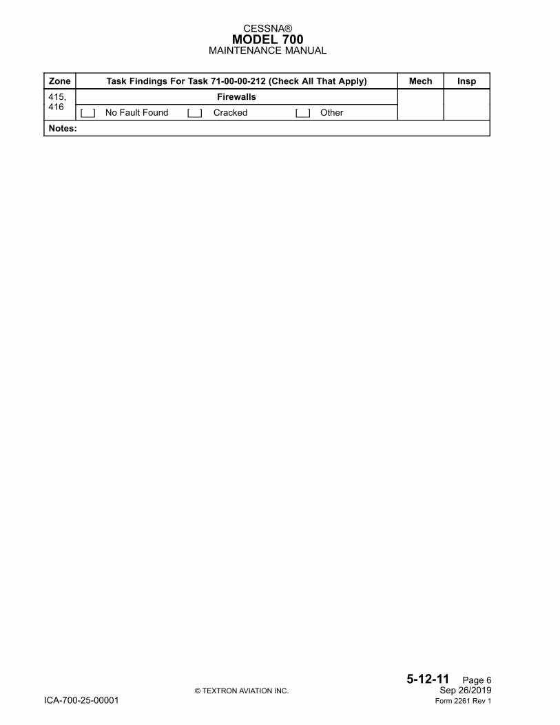
CESSNA®MODEL 700
MAINTENANCE MANUAL
Zone Task Findings For Task 71-00-00-212 (Check All That Apply) Mech InspFirewalls415,
416 [__] No Fault Found [__] Cracked [__] Other
Notes:
5-12-11 Page 6© TEXTRON AVIATION INC. Sep 26/2019
ICA-700-25-00001 Form 2261 Rev 1
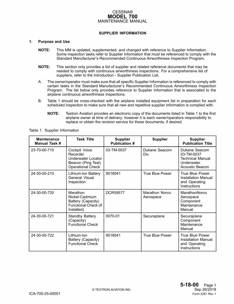
CESSNA®MODEL 700
MAINTENANCE MANUAL
SUPPLIER INFORMATION
1. Purpose and Use
NOTE: This MM is updated, supplemented, and changed with reference to Supplier Information.Some inspection tasks refer to Supplier Information that must be referenced to comply with theStandard Manufacturer’s Recommended Continuous Airworthiness Inspection Program.
NOTE: This section only provides a list of supplier and related reference documents that may beneeded to comply with continuous airworthiness inspections. For a comprehensive list ofsuppliers, refer to the Introduction - Supplier Publication List.
A. The owner/operator must make sure that all specific Supplier Information is referenced to comply withcertain tasks in the Standard Manufacturer’s Recommended Continuous Airworthiness InspectionProgram. The list below only provides reference to Supplier Information that is associated to theairplane continuous airworthiness inspections.
B. Table 1 should be cross-checked with the airplane installed equipment list in preparation for eachscheduled inspection to make sure that all new and repetitive supplier information is complied with.
NOTE: Textron Aviation provides an electronic copy of the documents listed in Table 1 to the firstairplane owner at time of delivery; however it is each owner/operators responsibility toreplace or obtain the revision service for these documents, if desired.
Table 1. Supplier Information
MaintenanceManual Task #
Task Title SupplierPublication #
Supplier SupplierPublication Title
23-70-00-710 Cockpit VoiceRecorderUnderwater LocatorBeacon (Ping Test)Operational Check
03-TM-0037 Dukane SeacomDiv.
Dukane Seacom03-TM-0037Technical ManualUnderwaterAcoustic Beacon
24-30-00-210 Lithium-Ion BatteryGeneral VisualInspection
9018041 True Blue Power True Blue PowerInstallation Manualand OperatingInstructions
24-30-00-720 MarathonNickel-CadmiumBattery (Capacity)Functional Check (IfInstalled)
DCR59577 Marathon NorcoAerospace
MarathonNorcoAerospaceComponentMaintenanceManual
24-30-00-721 Standby Battery(Capacity)Functional Check
0070-01 Securaplane SecuraplaneComponentMaintenanceManual
24-30-00-722 Lithium-IonBattery (Capacity)Functional Check
9018041 True Blue Power True Blue PowerInstallation Manualand OperatingInstructions
5-18-00 Page 1© TEXTRON AVIATION INC. Sep 26/2019
ICA-700-25-00001 Form 2261 Rev 1

CESSNA®MODEL 700
MAINTENANCE MANUAL
Table 1. Supplier Information (continued)MaintenanceManual Task #
Task Title SupplierPublication #
Supplier SupplierPublication Title
24-30-00-910 Engine Direct-Current Generator(BearingReplacement)Restoration
24-31-41 Safran Power USA,LLC
ComponentMaintenanceManual withIllustrated PartsList DC Generator(Main)
24-30-00-911 Auxiliary PowerUnit Direct-CurrentGenerator (BearingReplacement)Restoration
24-31-42 Safran Power USA,LLC
ComponentMaintenanceManual withIllustrated PartsList DC Generator(APU)
25-20-00-210 Inflatable OccupantProtection SystemComponentGeneral VisualInspection
01.01.00.03 Aviation OccupantSafety
Aviation OccupantSafety 01.01.00.03ComponentMaintenanceManual
25-20-00-710 Inflatable OccupantProtection SystemOperational Check
01.01.00.03 Aviation OccupantSafety
Aviation OccupantSafety 01.01.00.03ComponentMaintenanceManual
25-20-00-960 Inflatable OccupantProtection SystemComponent Discard
01.01.00.03 Aviation OccupantSafety
Aviation OccupantSafety 01.01.00.03ComponentMaintenanceManual
25-60-00-221 EmergencyLocator TransmitterAntenna DetailedInspection
ARTEX Y1-03-0333 Artex AircraftSupplies
ARTEX Y1-03-0333ComponentMaintenanceManual
25-60-00-720 Artex ELT-4000TransmitterDetailed Inspectionand FunctionalCheck
ARTEX Y1-03-0333 Artex AircraftSupplies
ARTEX Y1-03-0333ComponentMaintenanceManual
25-61-00-210 Model FA-AV(SA)Life Raft VisualCheck (If Installed)
526/RS-457 Winslow Life RaftCompany
Winslow Doc NoMFG-526/RS-457
25-61-00-720 Model FA-AV(SA)Life Raft FunctionalCheck (If Installed)
526/RS-457 Winslow Life RaftCompany
Winslow Doc NoMFG-526/RS-457
25-61-00-910 P07074-207Personal FlotationDevice (AccomplishSupplier 120 MonthMaintenanceInspection)Restoration
25-60-41 EAM Worldwide Eastern AeroMarine 25-60-41ComponentMaintenanceManual
5-18-00 Page 2© TEXTRON AVIATION INC. Sep 26/2019
ICA-700-25-00001 Form 2261 Rev 1
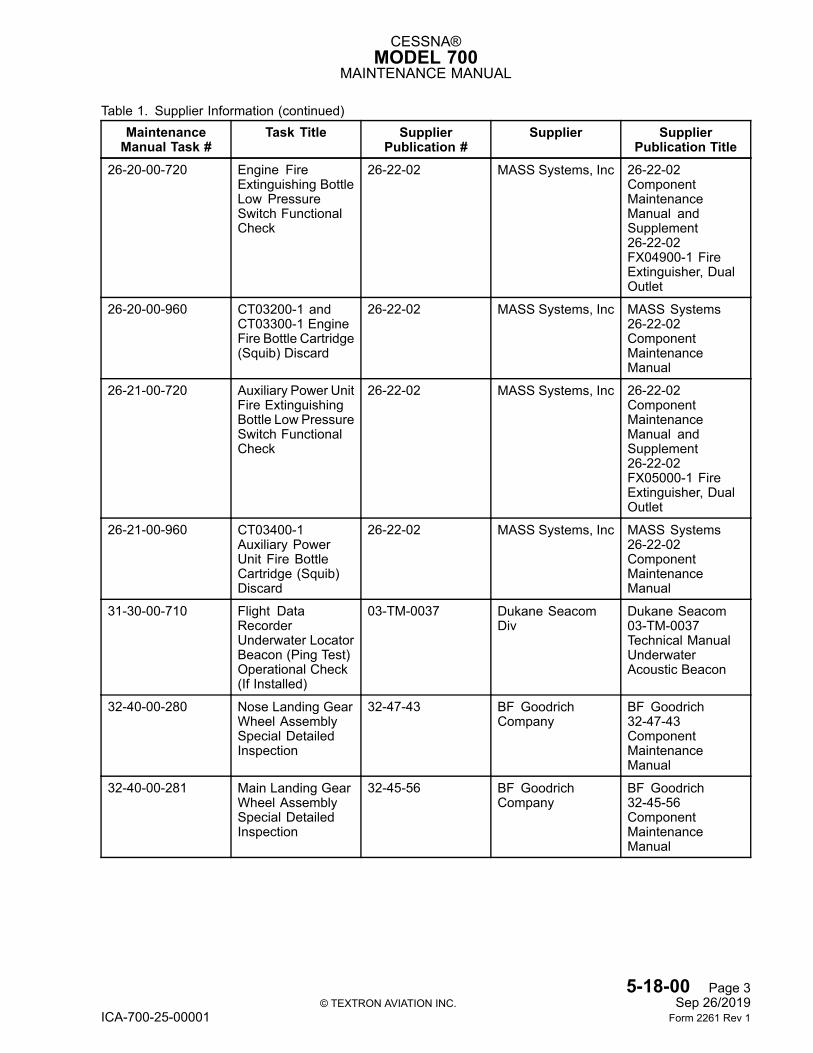
CESSNA®MODEL 700
MAINTENANCE MANUAL
Table 1. Supplier Information (continued)MaintenanceManual Task #
Task Title SupplierPublication #
Supplier SupplierPublication Title
26-20-00-720 Engine FireExtinguishing BottleLow PressureSwitch FunctionalCheck
26-22-02 MASS Systems, Inc 26-22-02ComponentMaintenanceManual andSupplement26-22-02FX04900-1 FireExtinguisher, DualOutlet
26-20-00-960 CT03200-1 andCT03300-1 EngineFire Bottle Cartridge(Squib) Discard
26-22-02 MASS Systems, Inc MASS Systems26-22-02ComponentMaintenanceManual
26-21-00-720 Auxiliary Power UnitFire ExtinguishingBottle Low PressureSwitch FunctionalCheck
26-22-02 MASS Systems, Inc 26-22-02ComponentMaintenanceManual andSupplement26-22-02FX05000-1 FireExtinguisher, DualOutlet
26-21-00-960 CT03400-1Auxiliary PowerUnit Fire BottleCartridge (Squib)Discard
26-22-02 MASS Systems, Inc MASS Systems26-22-02ComponentMaintenanceManual
31-30-00-710 Flight DataRecorderUnderwater LocatorBeacon (Ping Test)Operational Check(If Installed)
03-TM-0037 Dukane SeacomDiv
Dukane Seacom03-TM-0037Technical ManualUnderwaterAcoustic Beacon
32-40-00-280 Nose Landing GearWheel AssemblySpecial DetailedInspection
32-47-43 BF GoodrichCompany
BF Goodrich32-47-43ComponentMaintenanceManual
32-40-00-281 Main Landing GearWheel AssemblySpecial DetailedInspection
32-45-56 BF GoodrichCompany
BF Goodrich32-45-56ComponentMaintenanceManual
5-18-00 Page 3© TEXTRON AVIATION INC. Sep 26/2019
ICA-700-25-00001 Form 2261 Rev 1
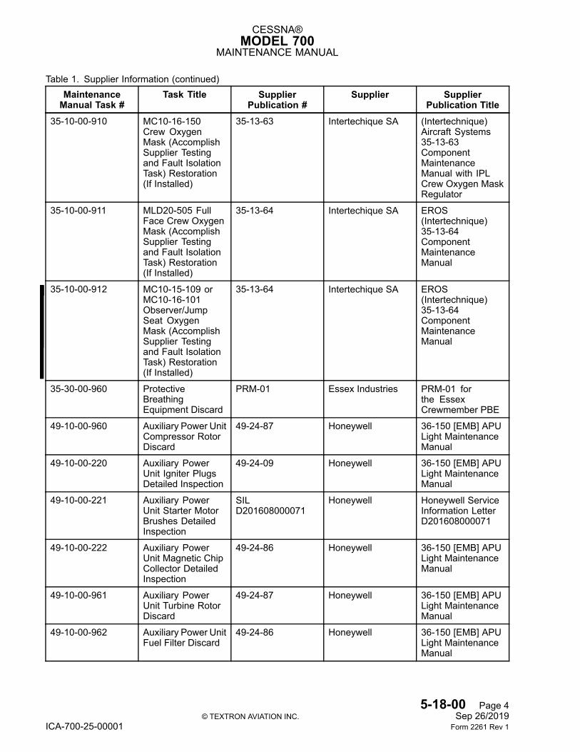
CESSNA®MODEL 700
MAINTENANCE MANUAL
Table 1. Supplier Information (continued)MaintenanceManual Task #
Task Title SupplierPublication #
Supplier SupplierPublication Title
35-10-00-910 MC10-16-150Crew OxygenMask (AccomplishSupplier Testingand Fault IsolationTask) Restoration(If Installed)
35-13-63 Intertechique SA (Intertechnique)Aircraft Systems35-13-63ComponentMaintenanceManual with IPLCrew Oxygen MaskRegulator
35-10-00-911 MLD20-505 FullFace Crew OxygenMask (AccomplishSupplier Testingand Fault IsolationTask) Restoration(If Installed)
35-13-64 Intertechique SA EROS(Intertechnique)35-13-64ComponentMaintenanceManual
35-10-00-912 MC10-15-109 orMC10-16-101Observer/JumpSeat OxygenMask (AccomplishSupplier Testingand Fault IsolationTask) Restoration(If Installed)
35-13-64 Intertechique SA EROS(Intertechnique)35-13-64ComponentMaintenanceManual
35-30-00-960 ProtectiveBreathingEquipment Discard
PRM-01 Essex Industries PRM-01 forthe EssexCrewmember PBE
49-10-00-960 Auxiliary Power UnitCompressor RotorDiscard
49-24-87 Honeywell 36-150 [EMB] APULight MaintenanceManual
49-10-00-220 Auxiliary PowerUnit Igniter PlugsDetailed Inspection
49-24-09 Honeywell 36-150 [EMB] APULight MaintenanceManual
49-10-00-221 Auxiliary PowerUnit Starter MotorBrushes DetailedInspection
SILD201608000071
Honeywell Honeywell ServiceInformation LetterD201608000071
49-10-00-222 Auxiliary PowerUnit Magnetic ChipCollector DetailedInspection
49-24-86 Honeywell 36-150 [EMB] APULight MaintenanceManual
49-10-00-961 Auxiliary PowerUnit Turbine RotorDiscard
49-24-87 Honeywell 36-150 [EMB] APULight MaintenanceManual
49-10-00-962 Auxiliary Power UnitFuel Filter Discard
49-24-86 Honeywell 36-150 [EMB] APULight MaintenanceManual
5-18-00 Page 4© TEXTRON AVIATION INC. Sep 26/2019
ICA-700-25-00001 Form 2261 Rev 1

CESSNA®MODEL 700
MAINTENANCE MANUAL
Table 1. Supplier Information (continued)MaintenanceManual Task #
Task Title SupplierPublication #
Supplier SupplierPublication Title
49-10-00-963 Auxiliary Power UnitOil Filter Discard
49-24-86 Honeywell 36-150 [EMB] APULight MaintenanceManual
49-10-00-964 Auxiliary Power UnitOil Discard
49-24-86 Honeywell 36-150 [EMB] APULight MaintenanceManual
5-12-00 HoneywellEngine PeriodicInspections
72-05-25 Honeywell HoneywellAerospace72-05-25 EngineLight MaintenanceManual
5-18-00 Page 5© TEXTRON AVIATION INC. Sep 26/2019
ICA-700-25-00001 Form 2261 Rev 1
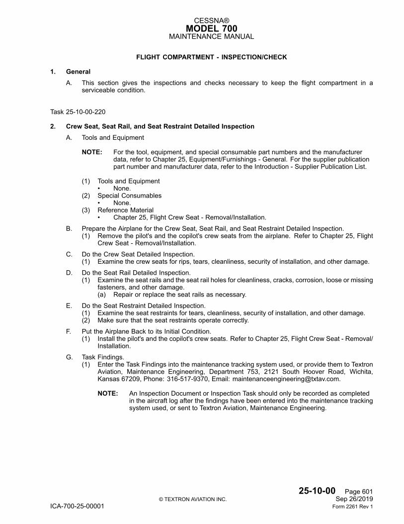
CESSNA®MODEL 700
MAINTENANCE MANUAL
FLIGHT COMPARTMENT - INSPECTION/CHECK
1. GeneralA. This section gives the inspections and checks necessary to keep the flight compartment in a
serviceable condition.
Task 25-10-00-220
2. Crew Seat, Seat Rail, and Seat Restraint Detailed InspectionA. Tools and Equipment
NOTE: For the tool, equipment, and special consumable part numbers and the manufacturerdata, refer to Chapter 25, Equipment/Furnishings - General. For the supplier publicationpart number and manufacturer data, refer to the Introduction - Supplier Publication List.
(1) Tools and Equipment• None.
(2) Special Consumables• None.
(3) Reference Material• Chapter 25, Flight Crew Seat - Removal/Installation.
B. Prepare the Airplane for the Crew Seat, Seat Rail, and Seat Restraint Detailed Inspection.(1) Remove the pilot's and the copilot's crew seats from the airplane. Refer to Chapter 25, Flight
Crew Seat - Removal/Installation.
C. Do the Crew Seat Detailed Inspection.(1) Examine the crew seats for rips, tears, cleanliness, security of installation, and other damage.
D. Do the Seat Rail Detailed Inspection.(1) Examine the seat rails and the seat rail holes for cleanliness, cracks, corrosion, loose or missing
fasteners, and other damage.(a) Repair or replace the seat rails as necessary.
E. Do the Seat Restraint Detailed Inspection.(1) Examine the seat restraints for tears, cleanliness, security of installation, and other damage.(2) Make sure that the seat restraints operate correctly.
F. Put the Airplane Back to its Initial Condition.(1) Install the pilot's and the copilot's crew seats. Refer to Chapter 25, Flight Crew Seat - Removal/
Installation.
G. Task Findings.(1) Enter the Task Findings into the maintenance tracking system used, or provide them to Textron
Aviation, Maintenance Engineering, Department 753, 2121 South Hoover Road, Wichita,Kansas 67209, Phone: 316-517-9370, Email: [email protected].
NOTE: An Inspection Document or Inspection Task should only be recorded as completedin the aircraft log after the findings have been entered into the maintenance trackingsystem used, or sent to Textron Aviation, Maintenance Engineering.
25-10-00 Page 601© TEXTRON AVIATION INC. Sep 26/2019
ICA-700-25-00001 Form 2261 Rev 1
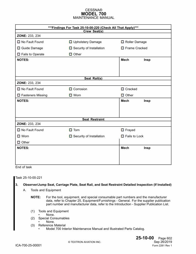
CESSNA®MODEL 700
MAINTENANCE MANUAL
***Findings For Task 25-10-00-220 (Check All That Apply)***Crew Seat(s)
ZONE: 233, 234
No Fault Found Upholstery Damage Roller Damage
Guide Damage Security of Installation Frame Cracked
Fails to Operate Other
NOTES: Mech Insp
Seat Rail(s)ZONE: 233, 234
No Fault Found Corrosion Cracked
Fasteners Missing Worn Other
NOTES: Mech Insp
Seat RestraintZONE: 233, 234
No Fault Found Torn Frayed
Worn Security of Installation Fails to Lock
Other
NOTES: Mech Insp
End of task
Task 25-10-00-221
3. Observer/Jump Seat, Carriage Plate, Seat Rail, and Seat Restraint Detailed Inspection (If Installed)A. Tools and Equipment
NOTE: For the tool, equipment, and special consumable part numbers and the manufacturerdata, refer to Chapter 25, Equipment/Furnishings - General. For the supplier publicationpart number and manufacturer data, refer to the Introduction - Supplier Publication List.
(1) Tools and Equipment• None.
(2) Special Consumables• None.
(3) Reference Material• Model 700 Interior Maintenance Manual and Illustrated Parts Catalog.
25-10-00 Page 602© TEXTRON AVIATION INC. Sep 26/2019
ICA-700-25-00001 Form 2261 Rev 1
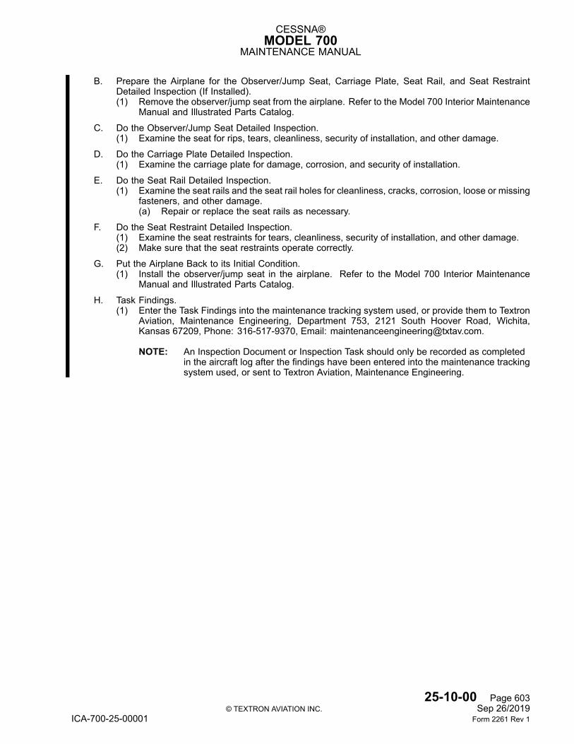
CESSNA®MODEL 700
MAINTENANCE MANUAL
B. Prepare the Airplane for the Observer/Jump Seat, Carriage Plate, Seat Rail, and Seat RestraintDetailed Inspection (If Installed).(1) Remove the observer/jump seat from the airplane. Refer to the Model 700 Interior Maintenance
Manual and Illustrated Parts Catalog.
C. Do the Observer/Jump Seat Detailed Inspection.(1) Examine the seat for rips, tears, cleanliness, security of installation, and other damage.
D. Do the Carriage Plate Detailed Inspection.(1) Examine the carriage plate for damage, corrosion, and security of installation.
E. Do the Seat Rail Detailed Inspection.(1) Examine the seat rails and the seat rail holes for cleanliness, cracks, corrosion, loose or missing
fasteners, and other damage.(a) Repair or replace the seat rails as necessary.
F. Do the Seat Restraint Detailed Inspection.(1) Examine the seat restraints for tears, cleanliness, security of installation, and other damage.(2) Make sure that the seat restraints operate correctly.
G. Put the Airplane Back to its Initial Condition.(1) Install the observer/jump seat in the airplane. Refer to the Model 700 Interior Maintenance
Manual and Illustrated Parts Catalog.
H. Task Findings.(1) Enter the Task Findings into the maintenance tracking system used, or provide them to Textron
Aviation, Maintenance Engineering, Department 753, 2121 South Hoover Road, Wichita,Kansas 67209, Phone: 316-517-9370, Email: [email protected].
NOTE: An Inspection Document or Inspection Task should only be recorded as completedin the aircraft log after the findings have been entered into the maintenance trackingsystem used, or sent to Textron Aviation, Maintenance Engineering.
25-10-00 Page 603© TEXTRON AVIATION INC. Sep 26/2019
ICA-700-25-00001 Form 2261 Rev 1
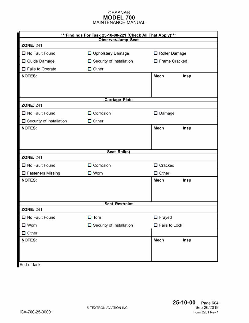
CESSNA®MODEL 700
MAINTENANCE MANUAL
***Findings For Task 25-10-00-221 (Check All That Apply)***Observer/Jump Seat
ZONE: 241
No Fault Found Upholstery Damage Roller Damage
Guide Damage Security of Installation Frame Cracked
Fails to Operate Other
NOTES: Mech Insp
Carriage PlateZONE: 241
No Fault Found Corrosion Damage
Security of Installation Other
NOTES: Mech Insp
Seat Rail(s)ZONE: 241
No Fault Found Corrosion Cracked
Fasteners Missing Worn Other
NOTES: Mech Insp
Seat RestraintZONE: 241
No Fault Found Torn Frayed
Worn Security of Installation Fails to Lock
Other
NOTES: Mech Insp
End of task
25-10-00 Page 604© TEXTRON AVIATION INC. Sep 26/2019
ICA-700-25-00001 Form 2261 Rev 1
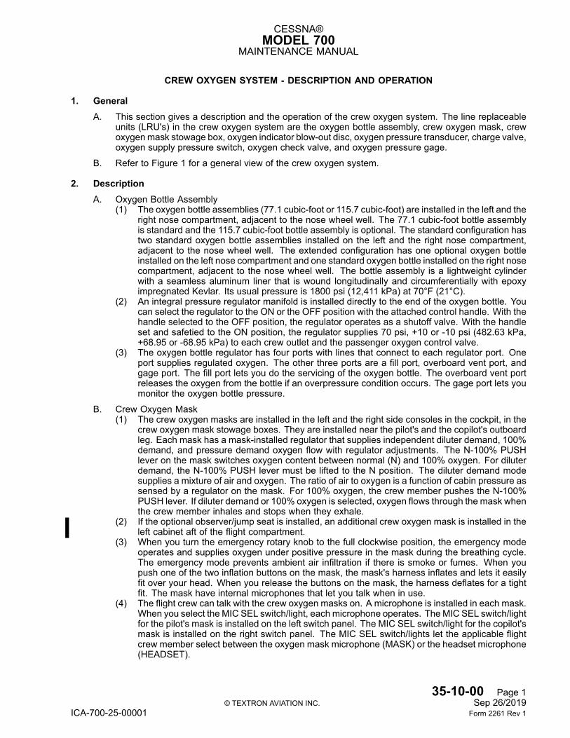
CESSNA®MODEL 700
MAINTENANCE MANUAL
CREW OXYGEN SYSTEM - DESCRIPTION AND OPERATION
1. GeneralA. This section gives a description and the operation of the crew oxygen system. The line replaceable
units (LRU's) in the crew oxygen system are the oxygen bottle assembly, crew oxygen mask, crewoxygenmask stowage box, oxygen indicator blow-out disc, oxygen pressure transducer, charge valve,oxygen supply pressure switch, oxygen check valve, and oxygen pressure gage.
B. Refer to Figure 1 for a general view of the crew oxygen system.
2. DescriptionA. Oxygen Bottle Assembly
(1) The oxygen bottle assemblies (77.1 cubic-foot or 115.7 cubic-foot) are installed in the left and theright nose compartment, adjacent to the nose wheel well. The 77.1 cubic-foot bottle assemblyis standard and the 115.7 cubic-foot bottle assembly is optional. The standard configuration hastwo standard oxygen bottle assemblies installed on the left and the right nose compartment,adjacent to the nose wheel well. The extended configuration has one optional oxygen bottleinstalled on the left nose compartment and one standard oxygen bottle installed on the right nosecompartment, adjacent to the nose wheel well. The bottle assembly is a lightweight cylinderwith a seamless aluminum liner that is wound longitudinally and circumferentially with epoxyimpregnated Kevlar. Its usual pressure is 1800 psi (12,411 kPa) at 70°F (21°C).
(2) An integral pressure regulator manifold is installed directly to the end of the oxygen bottle. Youcan select the regulator to the ON or the OFF position with the attached control handle. With thehandle selected to the OFF position, the regulator operates as a shutoff valve. With the handleset and safetied to the ON position, the regulator supplies 70 psi, +10 or -10 psi (482.63 kPa,+68.95 or -68.95 kPa) to each crew outlet and the passenger oxygen control valve.
(3) The oxygen bottle regulator has four ports with lines that connect to each regulator port. Oneport supplies regulated oxygen. The other three ports are a fill port, overboard vent port, andgage port. The fill port lets you do the servicing of the oxygen bottle. The overboard vent portreleases the oxygen from the bottle if an overpressure condition occurs. The gage port lets youmonitor the oxygen bottle pressure.
B. Crew Oxygen Mask(1) The crew oxygen masks are installed in the left and the right side consoles in the cockpit, in the
crew oxygen mask stowage boxes. They are installed near the pilot's and the copilot's outboardleg. Each mask has a mask-installed regulator that supplies independent diluter demand, 100%demand, and pressure demand oxygen flow with regulator adjustments. The N-100% PUSHlever on the mask switches oxygen content between normal (N) and 100% oxygen. For diluterdemand, the N-100% PUSH lever must be lifted to the N position. The diluter demand modesupplies a mixture of air and oxygen. The ratio of air to oxygen is a function of cabin pressure assensed by a regulator on the mask. For 100% oxygen, the crew member pushes the N-100%PUSH lever. If diluter demand or 100% oxygen is selected, oxygen flows through the mask whenthe crew member inhales and stops when they exhale.
(2) If the optional observer/jump seat is installed, an additional crew oxygen mask is installed in theleft cabinet aft of the flight compartment.
(3) When you turn the emergency rotary knob to the full clockwise position, the emergency modeoperates and supplies oxygen under positive pressure in the mask during the breathing cycle.The emergency mode prevents ambient air infiltration if there is smoke or fumes. When youpush one of the two inflation buttons on the mask, the mask's harness inflates and lets it easilyfit over your head. When you release the buttons on the mask, the harness deflates for a tightfit. The mask have internal microphones that let you talk when in use.
(4) The flight crew can talk with the crew oxygen masks on. A microphone is installed in each mask.When you select the MIC SEL switch/light, each microphone operates. TheMIC SEL switch/lightfor the pilot's mask is installed on the left switch panel. The MIC SEL switch/light for the copilot'smask is installed on the right switch panel. The MIC SEL switch/lights let the applicable flightcrew member select between the oxygen mask microphone (MASK) or the headset microphone(HEADSET).
35-10-00 Page 1© TEXTRON AVIATION INC. Sep 26/2019
ICA-700-25-00001 Form 2261 Rev 1
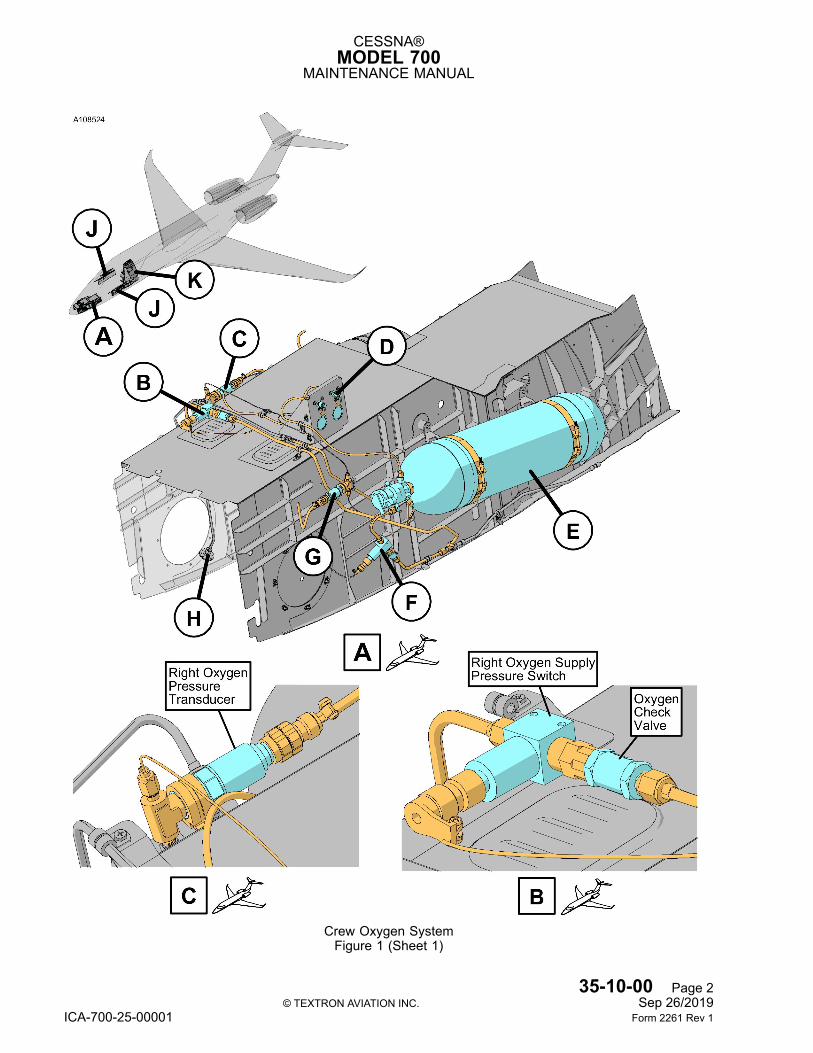
CESSNA®MODEL 700
MAINTENANCE MANUAL
Crew Oxygen SystemFigure 1 (Sheet 1)
35-10-00 Page 2© TEXTRON AVIATION INC. Sep 26/2019
ICA-700-25-00001 Form 2261 Rev 1
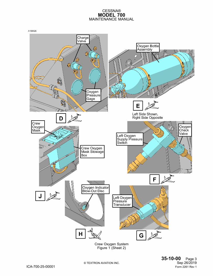
CESSNA®MODEL 700
MAINTENANCE MANUAL
Crew Oxygen SystemFigure 1 (Sheet 2)
35-10-00 Page 3© TEXTRON AVIATION INC. Sep 26/2019
ICA-700-25-00001 Form 2261 Rev 1
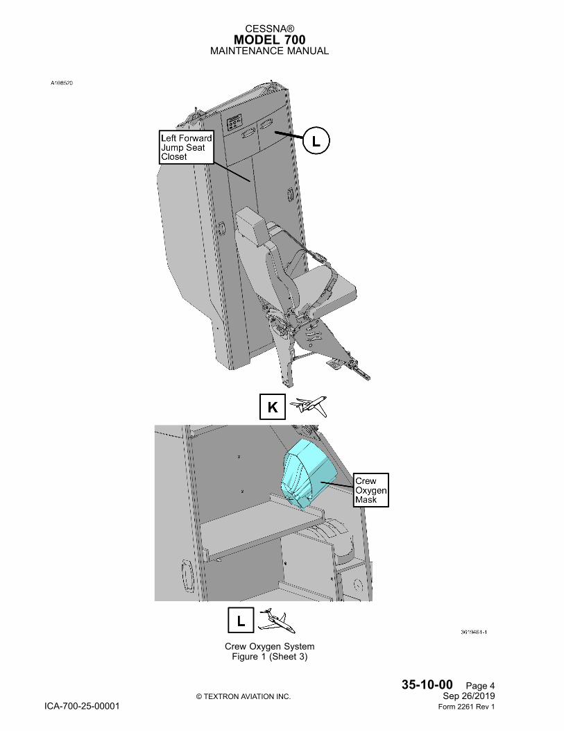
CESSNA®MODEL 700
MAINTENANCE MANUAL
Crew Oxygen SystemFigure 1 (Sheet 3)
35-10-00 Page 4© TEXTRON AVIATION INC. Sep 26/2019
ICA-700-25-00001 Form 2261 Rev 1
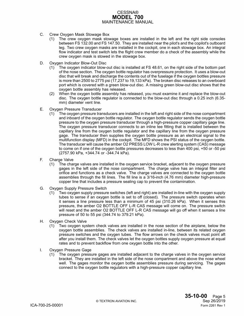
CESSNA®MODEL 700
MAINTENANCE MANUAL
C. Crew Oxygen Mask Stowage Box(1) The crew oxygen mask stowage boxes are installed in the left and the right side consoles
between FS 132.00 and FS 147.50. They are installed near the pilot's and the copilot's outboardleg. Two crew oxygen masks are installed in the cockpit, one in each stowage box. An integralflow indicator and test switch lets the flight crew member do a check of the assembly while thecrew oxygen mask is stowed in the stowage box.
D. Oxygen Indicator Blow-Out Disc(1) The oxygen indicator blow-out disc is installed at FS 48.61, on the right side of the bottom part
of the nose section. The oxygen bottle regulator has overpressure protection. It uses a blow-outdisc that will break and discharge the contents out of the fuselage if the oxygen bottles pressureis more than 2500 to 2775 psi (17,237 to 19,133 kPa). The broken disc releases to an overboardport which is covered with a green blow-out disc. A missing green blow-out disc shows that theoxygen bottle assembly has released.
(2) When the oxygen bottle assembly has released, you must examine it and replace the blow-outdisc. The oxygen bottle regulator is connected to the blow-out disc through a 0.25 inch (6.35-mm) diameter vent line.
E. Oxygen Pressure Transducer(1) The oxygen pressure transducers are installed in the left and right side of the nose compartment
and inboard of the oxygen bottle regulator. The oxygen bottle regulator sends the oxygen bottlepressure to the oxygen pressure transducer through a high-pressure copper capillary gage line.The oxygen pressure transducer connects to an inline tee fitting that is installed between thecapillary line from the oxygen bottle regulator and the capillary line from the oxygen pressuregage. The transducer then supplies the oxygen bottle pressure as an electrical signal to themultifunction display (MFD) in the cockpit. The MFD shows the PSI status of the oxygen bottle.The transducer will cause the amber O2 PRESS LOW L-R crew alerting system (CAS) messageto come on if one of the oxygen bottle pressures decreases to less than 400 psi, +50 or -50 psi(2757.90 kPa, +344.74 or -344.74 kPa).
F. Charge Valve(1) The charge valves are installed in the oxygen service bracket, adjacent to the oxygen pressure
gages in the left side of the nose compartment. The charge valve has an integral filter andorifice and functions as a check valve. The charge valves are connected to the oxygen bottleassemblies through the fill lines. The fill line is a 3/16-inch (4.76 mm) diameter high-pressurecopper line that includes a pressure sealing cap to prevent the contamination.
G. Oxygen Supply Pressure Switch(1) Two oxygen supply pressure switches (left and right) are installed in-line with the oxygen supply
tubes to sense if an oxygen bottle is set to off (closed). The pressure switch operates whenit senses a line pressure less than a minimum of 45 psi (310.26 kPa). When it senses thispressure, the amber O2 BOTTLE OFF L-R CAS message will come on. The pressure switchwill reset and the amber O2 BOTTLE OFF L-R CAS message will go off when it senses a linepressure of 50 to 55 psi (344.74 to 379.21 kPa).
H. Oxygen Check Valve(1) Two oxygen system check valves are installed in the nose section of the airplane, below the
oxygen bottle assemblies. The check valves are installed in-line, between its related oxygenpressure switches and the oxygen tubes. The flow arrows on the check valves must point aftafter you install them. The check valves let the oxygen bottles supply oxygen pressure at equalrates and to prevent backflow from one oxygen bottle into the other.
I. Oxygen Pressure Gage(1) The oxygen pressure gages are installed adjacent to the charge valves in the oxygen service
bracket. They are installed in the left side of the nose compartment and above the nose wheelwell. The gages monitor the oxygen bottle assemblies pressure during servicing. The gagesconnect to the oxygen bottle regulators with a high-pressure copper capillary line.
35-10-00 Page 5© TEXTRON AVIATION INC. Sep 26/2019
ICA-700-25-00001 Form 2261 Rev 1
CESSNA®MODEL 700
MAINTENANCE MANUAL
3. OperationA. General
(1) The oxygen system supplies pressure regulated oxygen to the flight crew constantly and to thepassengers when necessary. The pilot can select the oxygen flow for the flight crew only. Theoxygen system operates at a maximum airplane altitude of 45,000 feet (13,716 m). The oxygensystem is necessary during cabin decompression. The oxygen system takes into considerationthe rate of cabin pressure decrease, flight crew reaction time, and airplane descent rate from45,000 feet (13,716 m). The cabin altitude must not go more than 39,000 feet (11,887 m). Theoxygen systems LRU's can operate from sea level up to 40,000 feet (12,192 m) cabin altitude.The oxygen system operates with oxygen that agrees withMilitary SpecificationMIL-PRF-27210.
B. Crew Oxygen System(1) Oxygen is available to the flight crew at all times. The oxygen pressure is regulated at the two
high-pressure oxygen bottle assemblies with an integral regulator assemblies and downstreamof the bottles by the oxygen sequence regulators. When the regulators on the oxygen bottlesare set to the ON position, the oxygen pressure is supplied to the gages, fill, and supply lines.
(2) Before flight, the pilot will do a check of the oxygen quantity and select the oxygen flow schedule.The two oxygen pressure gages, in the nose, show the pressure in the oxygen bottles. Thepermitted preflight pressure range is shown with a green arc on each gage. The oxygen pressureof each bottle also shows on the multifunction display (MFD) in the cockpit. The permittedpreflight pressure range will show with green text and a green pointer on the MFD. If the oxygenpressure is less than 400 psi (2757.90 kPa), the amber O2 PRESS LOW crew alerting system(CAS) message will come on. If one of the oxygen bottle assemblies is off or if the oxygenpressure is 45 psi (310.26 kPa), the amber O2 BOTTLE OFF L-R CAS message will come on.
35-10-00 Page 6© TEXTRON AVIATION INC. Sep 26/2019
ICA-700-25-00001 Form 2261 Rev 1
CESSNA®MODEL 700
MAINTENANCE MANUAL
CREW OXYGEN SYSTEM - INSPECTION/CHECK
1. GeneralA. This section gives the inspections and checks necessary to keep the crew oxygen system in a
serviceable condition.
Task 35-10-00-220
2. Crew Oxygen Mask and Storage Box Detailed InspectionA. Tools and Equipment
NOTE: For the tool, equipment, and special part numbers and the manufacturer data, refer toChapter 35, Oxygen - General. For the supplier publication part number and manufacturerdata, refer to the Introduction - Supplier Publication List.
(1) Tools and Equipment• None.
(2) Special Consumables• None.
(3) Reference Material• Chapter 24, External Electrical Power - Maintenance Practices• Chapter 35, Oxygen - Maintenance Practices• Chapter 35, Crew Oxygen Mask - Removal/Installation.
B. Prepare the Airplane for the Crew Oxygen Mask and Storage Box Detailed Inspection.
WARNING: Before you do maintenance on the oxygen system, obey theoxygen system safety precautions and warnings given inChapter 35, Oxygen - Maintenance Practices.
(1) Disconnect external electrical power from the airplane. Refer to Chapter 24, External ElectricalPower - Maintenance Practices.
(2) Remove the crew oxygenmask. Refer to Chapter 35, CrewOxygenMask - Removal/Installation.
C. Do the Crew Oxygen Mask and Storage Box Detailed Inspection.(1) Examine the crew oxygen mask stowage box for debris, cracks, and security of components.(2) Examine the crew oxygenmasks and the hoses for correct installation, deterioration, cleanliness,
correct stowage, holes, cuts, or tears.(3) Visually examine the crew oxygen mask and the microphone connections for condition and
security of installation.(4) Make sure that the microphone cord on the crew oxygen masks is connected to the fitting on
the pilot's and the copilot's side console.
D. Put the Airplane Back to its Initial Condition.(1) Install the crew oxygen masks. Refer to Chapter 35, Crew Oxygen Mask - Removal/Installation.
E. Task Findings.(1) Enter the Task Findings into the maintenance tracking system used, or provide them to Textron
Aviation, Maintenance Engineering, Department 753, 2121 South Hoover Road, Wichita,Kansas 67209, Phone: 316-517-9370, Email: [email protected].
NOTE: An Inspection Document or Inspection Task should only be recorded as completedin the aircraft log after the findings have been entered into the maintenance trackingsystem used, or sent to Textron Aviation, Maintenance Engineering.
35-10-00 Page 601© TEXTRON AVIATION INC. Sep 26/2019
ICA-700-25-00001 Form 2261 Rev 1
CESSNA®MODEL 700
MAINTENANCE MANUAL
***Findings For Task 35-10-00-220 (Check All That Apply)***Storage Boxes (Any)
ZONE: 235, 236
No Fault Found Security of Installation Cracks
Other
NOTES: Mech Insp
Crew Oxygen Mask (Any)ZONE: 235, 236
No Fault Found Damage Deterioration
Leaks Other
NOTES: Mech Insp
End of task
Task 35-10-00-221
3. Oxygen Bottle Detailed InspectionA. Tools and Equipment
NOTE: For the tool, equipment, and special part numbers and the manufacturer data, refer toChapter 35, Oxygen - General. For the supplier publication part number and manufacturerdata, refer to the Introduction - Supplier Publication List.
(1) Tools and Equipment• None.
(2) Special Consumables• None.
(3) Reference Material• Chapter 6, Dimensions and Areas - Description and Operation• Chapter 35, Oxygen - Maintenance Practices.
B. Prepare the Airplane for the Oxygen Bottle Detailed Inspection.
WARNING: Before you do maintenance on the oxygen system, obey theoxygen system safety precautions and warnings given inChapter 35, Oxygen - Maintenance Practices.
(1) Open the left and the right nose access doors to get access to the left and the right oxygen bottleassemblies. Refer to Chapter 6, Dimensions and Areas - Description and Operation.
C. Do the Oxygen Bottle Detailed Inspection.(1) Examine the oxygen bottle assemblies for correct installation, corrosion, and other damage.
35-10-00 Page 602© TEXTRON AVIATION INC. Sep 26/2019
ICA-700-25-00001 Form 2261 Rev 1
CESSNA®MODEL 700
MAINTENANCE MANUAL
D. Put the Airplane Back to its Initial Condition.(1) Close the left and the right nose access doors. Refer to Chapter 6, Dimensions and Areas -
Description and Operation.
E. Task Findings.(1) Enter the Task Findings into the maintenance tracking system used, or provide them to Textron
Aviation, Maintenance Engineering, Department 753, 2121 South Hoover Road, Wichita,Kansas 67209, Phone: 316-517-9370, Email: [email protected].
NOTE: An Inspection Document or Inspection Task should only be recorded as completedin the aircraft log after the findings have been entered into the maintenance trackingsystem used, or sent to Textron Aviation, Maintenance Engineering.
***Findings For Task 35-10-00-221 (Check All That Apply)***Oxygen Bottle (Any)
ZONE: 215, 216
No Fault Found Corrosion Damage
Security of Installation Other
NOTES: Mech Insp
End of task
Task 35-10-00-222
4. Observer/Jump Seat Oxygen Mask Detailed Inspection (If Installed)A. Tools and Equipment
NOTE: For the tool, equipment, and special part numbers and the manufacturer data, refer toChapter 35, Oxygen - General. For the supplier publication part number and manufacturerdata, refer to the Introduction - Supplier Publication List.
(1) Tools and Equipment• None.
(2) Special Consumables• None.
(3) Reference Material• Chapter 24, External Electrical Power - Maintenance Practices• Chapter 35, Oxygen - Maintenance Practices• Chapter 35, Crew Oxygen Mask - Removal/Installation.
B. Prepare the Airplane for the Observer/Jump Seat Oxygen Mask Detailed Inspection (If Installed).
WARNING: Before you do maintenance on the oxygen system, obey theoxygen system safety precautions and warnings given inChapter 35, Oxygen - Maintenance Practices.
(1) Disconnect external electrical power from the airplane. Refer to Chapter 24, External ElectricalPower - Maintenance Practices.
(2) Remove the crew oxygenmask. Refer to Chapter 35, CrewOxygenMask - Removal/Installation.
C. Do the Observer/Jump Seat Oxygen Mask Detailed Inspection (If Installed).(1) Examine the crew oxygen mask stowage box for debris, cracks, and security of components.
35-10-00 Page 603© TEXTRON AVIATION INC. Sep 26/2019
ICA-700-25-00001 Form 2261 Rev 1
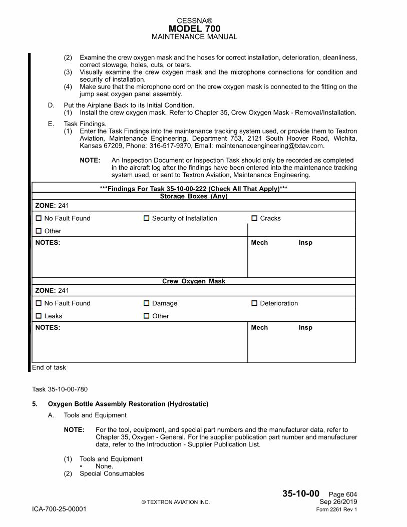
CESSNA®MODEL 700
MAINTENANCE MANUAL
(2) Examine the crew oxygen mask and the hoses for correct installation, deterioration, cleanliness,correct stowage, holes, cuts, or tears.
(3) Visually examine the crew oxygen mask and the microphone connections for condition andsecurity of installation.
(4) Make sure that the microphone cord on the crew oxygen mask is connected to the fitting on thejump seat oxygen panel assembly.
D. Put the Airplane Back to its Initial Condition.(1) Install the crew oxygen mask. Refer to Chapter 35, Crew Oxygen Mask - Removal/Installation.
E. Task Findings.(1) Enter the Task Findings into the maintenance tracking system used, or provide them to Textron
Aviation, Maintenance Engineering, Department 753, 2121 South Hoover Road, Wichita,Kansas 67209, Phone: 316-517-9370, Email: [email protected].
NOTE: An Inspection Document or Inspection Task should only be recorded as completedin the aircraft log after the findings have been entered into the maintenance trackingsystem used, or sent to Textron Aviation, Maintenance Engineering.
***Findings For Task 35-10-00-222 (Check All That Apply)***Storage Boxes (Any)
ZONE: 241
No Fault Found Security of Installation Cracks
Other
NOTES: Mech Insp
Crew Oxygen MaskZONE: 241
No Fault Found Damage Deterioration
Leaks Other
NOTES: Mech Insp
End of task
Task 35-10-00-780
5. Oxygen Bottle Assembly Restoration (Hydrostatic)A. Tools and Equipment
NOTE: For the tool, equipment, and special part numbers and the manufacturer data, refer toChapter 35, Oxygen - General. For the supplier publication part number and manufacturerdata, refer to the Introduction - Supplier Publication List.
(1) Tools and Equipment• None.
(2) Special Consumables
35-10-00 Page 604© TEXTRON AVIATION INC. Sep 26/2019
ICA-700-25-00001 Form 2261 Rev 1
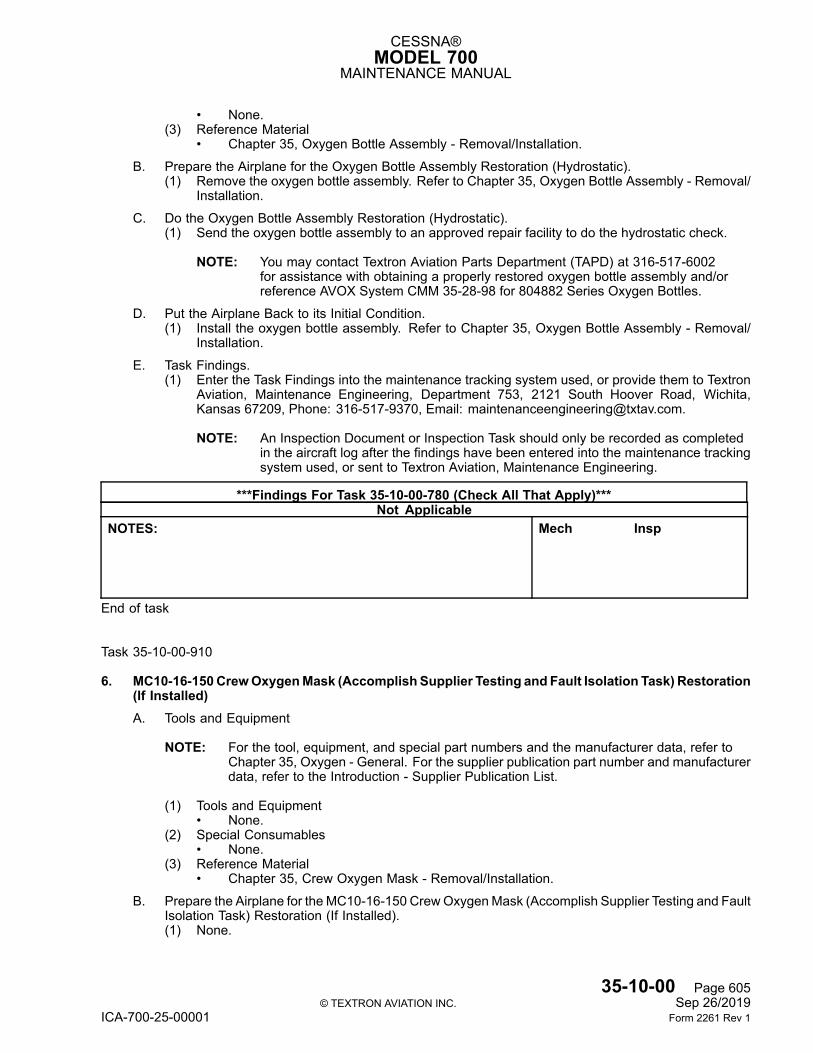
CESSNA®MODEL 700
MAINTENANCE MANUAL
• None.(3) Reference Material
• Chapter 35, Oxygen Bottle Assembly - Removal/Installation.
B. Prepare the Airplane for the Oxygen Bottle Assembly Restoration (Hydrostatic).(1) Remove the oxygen bottle assembly. Refer to Chapter 35, Oxygen Bottle Assembly - Removal/
Installation.
C. Do the Oxygen Bottle Assembly Restoration (Hydrostatic).(1) Send the oxygen bottle assembly to an approved repair facility to do the hydrostatic check.
NOTE: You may contact Textron Aviation Parts Department (TAPD) at 316-517-6002for assistance with obtaining a properly restored oxygen bottle assembly and/orreference AVOX System CMM 35-28-98 for 804882 Series Oxygen Bottles.
D. Put the Airplane Back to its Initial Condition.(1) Install the oxygen bottle assembly. Refer to Chapter 35, Oxygen Bottle Assembly - Removal/
Installation.
E. Task Findings.(1) Enter the Task Findings into the maintenance tracking system used, or provide them to Textron
Aviation, Maintenance Engineering, Department 753, 2121 South Hoover Road, Wichita,Kansas 67209, Phone: 316-517-9370, Email: [email protected].
NOTE: An Inspection Document or Inspection Task should only be recorded as completedin the aircraft log after the findings have been entered into the maintenance trackingsystem used, or sent to Textron Aviation, Maintenance Engineering.
***Findings For Task 35-10-00-780 (Check All That Apply)***Not Applicable
NOTES: Mech Insp
End of task
Task 35-10-00-910
6. MC10-16-150CrewOxygenMask (Accomplish Supplier Testing and Fault Isolation Task) Restoration(If Installed)A. Tools and Equipment
NOTE: For the tool, equipment, and special part numbers and the manufacturer data, refer toChapter 35, Oxygen - General. For the supplier publication part number and manufacturerdata, refer to the Introduction - Supplier Publication List.
(1) Tools and Equipment• None.
(2) Special Consumables• None.
(3) Reference Material• Chapter 35, Crew Oxygen Mask - Removal/Installation.
B. Prepare the Airplane for the MC10-16-150 CrewOxygenMask (Accomplish Supplier Testing and FaultIsolation Task) Restoration (If Installed).(1) None.
35-10-00 Page 605© TEXTRON AVIATION INC. Sep 26/2019
ICA-700-25-00001 Form 2261 Rev 1
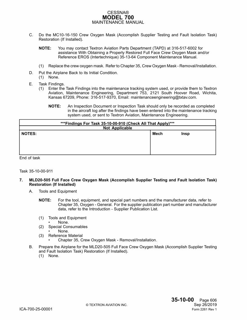
CESSNA®MODEL 700
MAINTENANCE MANUAL
C. Do the MC10-16-150 Crew Oxygen Mask (Accomplish Supplier Testing and Fault Isolation Task)Restoration (If Installed).
NOTE: You may contact Textron Aviation Parts Department (TAPD) at 316-517-6002 forassistance With Obtaining a Properly Restored Full Face Crew Oxygen Mask and/orReference EROS (Intertechnique) 35-13-64 Component Maintenance Manual.
(1) Replace the crew oxygenmask. Refer to Chapter 35, CrewOxygenMask - Removal/Installation.
D. Put the Airplane Back to its Initial Condition.(1) None.
E. Task Findings.(1) Enter the Task Findings into the maintenance tracking system used, or provide them to Textron
Aviation, Maintenance Engineering, Department 753, 2121 South Hoover Road, Wichita,Kansas 67209, Phone: 316-517-9370, Email: [email protected].
NOTE: An Inspection Document or Inspection Task should only be recorded as completedin the aircraft log after the findings have been entered into the maintenance trackingsystem used, or sent to Textron Aviation, Maintenance Engineering.
***Findings For Task 35-10-00-910 (Check All That Apply)***Not Applicable
NOTES: Mech Insp
End of task
Task 35-10-00-911
7. MLD20-505 Full Face Crew Oxygen Mask (Accomplish Supplier Testing and Fault Isolation Task)Restoration (If Installed)A. Tools and Equipment
NOTE: For the tool, equipment, and special part numbers and the manufacturer data, refer toChapter 35, Oxygen - General. For the supplier publication part number and manufacturerdata, refer to the Introduction - Supplier Publication List.
(1) Tools and Equipment• None.
(2) Special Consumables• None.
(3) Reference Material• Chapter 35, Crew Oxygen Mask - Removal/Installation.
B. Prepare the Airplane for the MLD20-505 Full Face Crew Oxygen Mask (Accomplish Supplier Testingand Fault Isolation Task) Restoration (If Installed).(1) None.
35-10-00 Page 606© TEXTRON AVIATION INC. Sep 26/2019
ICA-700-25-00001 Form 2261 Rev 1
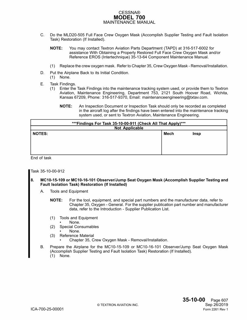
CESSNA®MODEL 700
MAINTENANCE MANUAL
C. Do the MLD20-505 Full Face Crew Oxygen Mask (Accomplish Supplier Testing and Fault IsolationTask) Restoration (If Installed).
NOTE: You may contact Textron Aviation Parts Department (TAPD) at 316-517-6002 forassistance With Obtaining a Properly Restored Full Face Crew Oxygen Mask and/orReference EROS (Intertechnique) 35-13-64 Component Maintenance Manual.
(1) Replace the crew oxygenmask. Refer to Chapter 35, CrewOxygenMask - Removal/Installation.
D. Put the Airplane Back to its Initial Condition.(1) None.
E. Task Findings.(1) Enter the Task Findings into the maintenance tracking system used, or provide them to Textron
Aviation, Maintenance Engineering, Department 753, 2121 South Hoover Road, Wichita,Kansas 67209, Phone: 316-517-9370, Email: [email protected].
NOTE: An Inspection Document or Inspection Task should only be recorded as completedin the aircraft log after the findings have been entered into the maintenance trackingsystem used, or sent to Textron Aviation, Maintenance Engineering.
***Findings For Task 35-10-00-911 (Check All That Apply)***Not Applicable
NOTES: Mech Insp
End of task
Task 35-10-00-912
8. MC10-15-109 or MC10-16-101 Observer/Jump Seat Oxygen Mask (Accomplish Supplier Testing andFault Isolation Task) Restoration (If Installed)A. Tools and Equipment
NOTE: For the tool, equipment, and special part numbers and the manufacturer data, refer toChapter 35, Oxygen - General. For the supplier publication part number and manufacturerdata, refer to the Introduction - Supplier Publication List.
(1) Tools and Equipment• None.
(2) Special Consumables• None.
(3) Reference Material• Chapter 35, Crew Oxygen Mask - Removal/Installation.
B. Prepare the Airplane for the MC10-15-109 or MC10-16-101 Observer/Jump Seat Oxygen Mask(Accomplish Supplier Testing and Fault Isolation Task) Restoration (If Installed).(1) None.
35-10-00 Page 607© TEXTRON AVIATION INC. Sep 26/2019
ICA-700-25-00001 Form 2261 Rev 1
CESSNA®MODEL 700
MAINTENANCE MANUAL
C. Do the MC10-15-109 or MC10-16-101 Observer/Jump Seat Oxygen Mask (Accomplish SupplierTesting and Fault Isolation Task) Restoration (If Installed).
NOTE: You may contact Textron Aviation Parts Department (TAPD) at 316-517-6002 forassistance With Obtaining a Properly Restored Full Face Crew Oxygen Mask and/orReference EROS (Intertechnique) 35-13-64 Component Maintenance Manual.
(1) Replace the crew oxygenmask. Refer to Chapter 35, CrewOxygenMask - Removal/Installation.
D. Put the Airplane Back to its Initial Condition.(1) None.
E. Task Findings.(1) Enter the Task Findings into the maintenance tracking system used, or provide them to Textron
Aviation, Maintenance Engineering, Department 753, 2121 South Hoover Road, Wichita,Kansas 67209, Phone: 316-517-9370, Email: [email protected].
NOTE: An Inspection Document or Inspection Task should only be recorded as completedin the aircraft log after the findings have been entered into the maintenance trackingsystem used, or sent to Textron Aviation, Maintenance Engineering.
***Findings For Task 35-10-00-912 (Check All That Apply)***Not Applicable
NOTES: Mech Insp
End of task
Task 35-10-00-960
9. Oxygen Bottle Assembly DiscardA. Tools and Equipment
NOTE: For the tool, equipment, and special part numbers and the manufacturer data, refer toChapter 35, Oxygen - General. For the supplier publication part number and manufacturerdata, refer to the Introduction - Supplier Publication List.
(1) Tools and Equipment• None.
(2) Special Consumables• None.
(3) Reference Material• Chapter 35, Oxygen Bottle Assembly - Removal/Installation.
B. Prepare the Airplane for the Oxygen Bottle Assembly Discard.(1) None.
C. Do the Oxygen Bottle Assembly Discard.(1) Remove and discard the oxygen bottle assembly. Refer to Chapter 35, Oxygen Bottle Assembly
- Removal/Installation.
35-10-00 Page 608© TEXTRON AVIATION INC. Sep 26/2019
ICA-700-25-00001 Form 2261 Rev 1
CESSNA®MODEL 700
MAINTENANCE MANUAL
D. Put the Airplane Back to its Initial Condition.(1) Install a replacement oxygen bottle assembly. Refer to Chapter 35, Oxygen Bottle Assembly -
Removal/Installation.
NOTE: You may contact Textron Aviation Parts Department (TAPD) at 316-517-6002 forassistance with obtaining a replacement oxygen bottle assembly.
E. Task Findings.(1) Enter the Task Findings into the maintenance tracking system used, or provide them to Textron
Aviation, Maintenance Engineering, Department 753, 2121 South Hoover Road, Wichita,Kansas 67209, Phone: 316-517-9370, Email: [email protected].
NOTE: An Inspection Document or Inspection Task should only be recorded as completedin the aircraft log after the findings have been entered into the maintenance trackingsystem used, or sent to Textron Aviation, Maintenance Engineering.
***Findings For Task 35-10-00-960 (Check All That Apply)***Not Applicable
NOTES: Mech Insp
End of task
35-10-00 Page 609© TEXTRON AVIATION INC. Sep 26/2019
ICA-700-25-00001 Form 2261 Rev 1
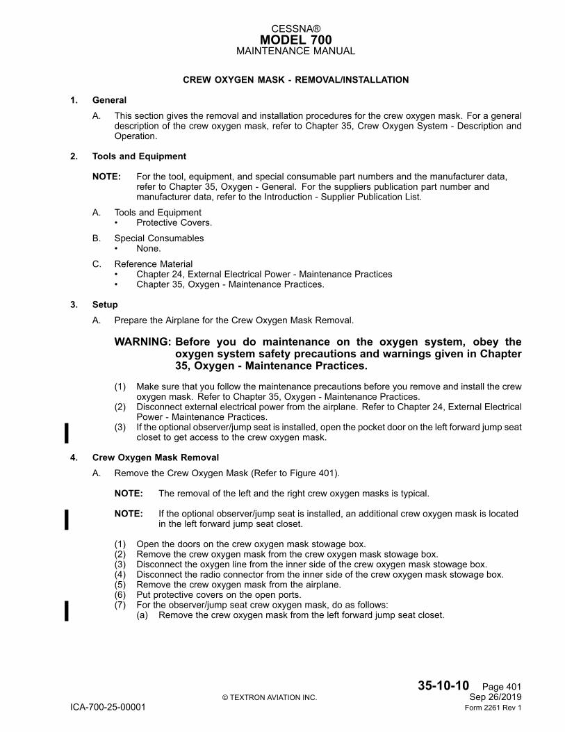
CESSNA®MODEL 700
MAINTENANCE MANUAL
CREW OXYGEN MASK - REMOVAL/INSTALLATION
1. GeneralA. This section gives the removal and installation procedures for the crew oxygen mask. For a general
description of the crew oxygen mask, refer to Chapter 35, Crew Oxygen System - Description andOperation.
2. Tools and Equipment
NOTE: For the tool, equipment, and special consumable part numbers and the manufacturer data,refer to Chapter 35, Oxygen - General. For the suppliers publication part number andmanufacturer data, refer to the Introduction - Supplier Publication List.
A. Tools and Equipment• Protective Covers.
B. Special Consumables• None.
C. Reference Material• Chapter 24, External Electrical Power - Maintenance Practices• Chapter 35, Oxygen - Maintenance Practices.
3. SetupA. Prepare the Airplane for the Crew Oxygen Mask Removal.
WARNING: Before you do maintenance on the oxygen system, obey theoxygen system safety precautions and warnings given in Chapter35, Oxygen - Maintenance Practices.
(1) Make sure that you follow the maintenance precautions before you remove and install the crewoxygen mask. Refer to Chapter 35, Oxygen - Maintenance Practices.
(2) Disconnect external electrical power from the airplane. Refer to Chapter 24, External ElectricalPower - Maintenance Practices.
(3) If the optional observer/jump seat is installed, open the pocket door on the left forward jump seatcloset to get access to the crew oxygen mask.
4. Crew Oxygen Mask RemovalA. Remove the Crew Oxygen Mask (Refer to Figure 401).
NOTE: The removal of the left and the right crew oxygen masks is typical.
NOTE: If the optional observer/jump seat is installed, an additional crew oxygen mask is locatedin the left forward jump seat closet.
(1) Open the doors on the crew oxygen mask stowage box.(2) Remove the crew oxygen mask from the crew oxygen mask stowage box.(3) Disconnect the oxygen line from the inner side of the crew oxygen mask stowage box.(4) Disconnect the radio connector from the inner side of the crew oxygen mask stowage box.(5) Remove the crew oxygen mask from the airplane.(6) Put protective covers on the open ports.(7) For the observer/jump seat crew oxygen mask, do as follows:
(a) Remove the crew oxygen mask from the left forward jump seat closet.
35-10-10 Page 401© TEXTRON AVIATION INC. Sep 26/2019
ICA-700-25-00001 Form 2261 Rev 1
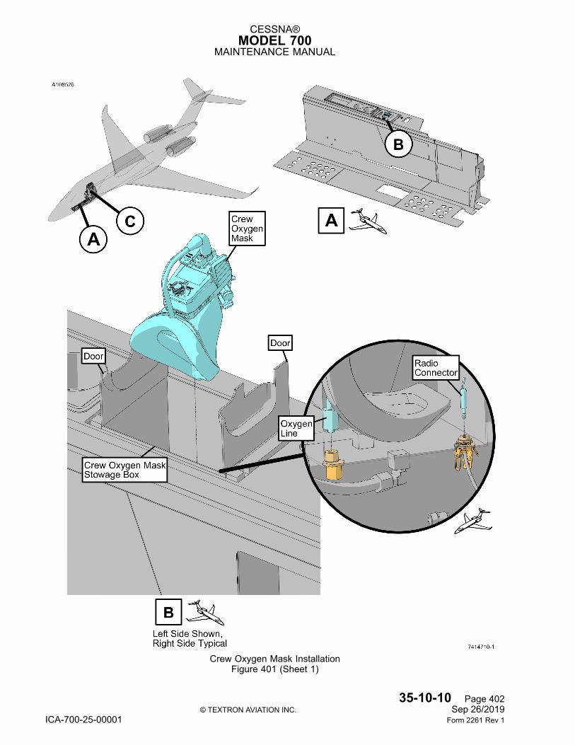
CESSNA®MODEL 700
MAINTENANCE MANUAL
Crew Oxygen Mask InstallationFigure 401 (Sheet 1)
35-10-10 Page 402© TEXTRON AVIATION INC. Sep 26/2019
ICA-700-25-00001 Form 2261 Rev 1
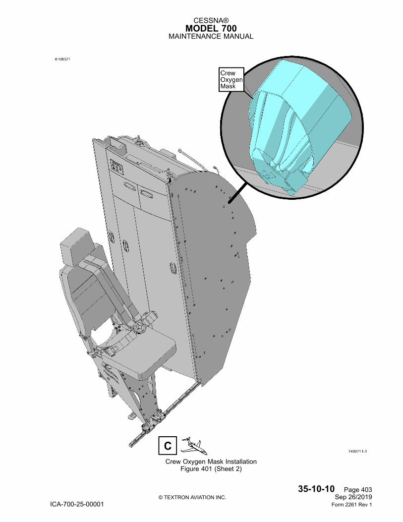
CESSNA®MODEL 700
MAINTENANCE MANUAL
Crew Oxygen Mask InstallationFigure 401 (Sheet 2)
35-10-10 Page 403© TEXTRON AVIATION INC. Sep 26/2019
ICA-700-25-00001 Form 2261 Rev 1
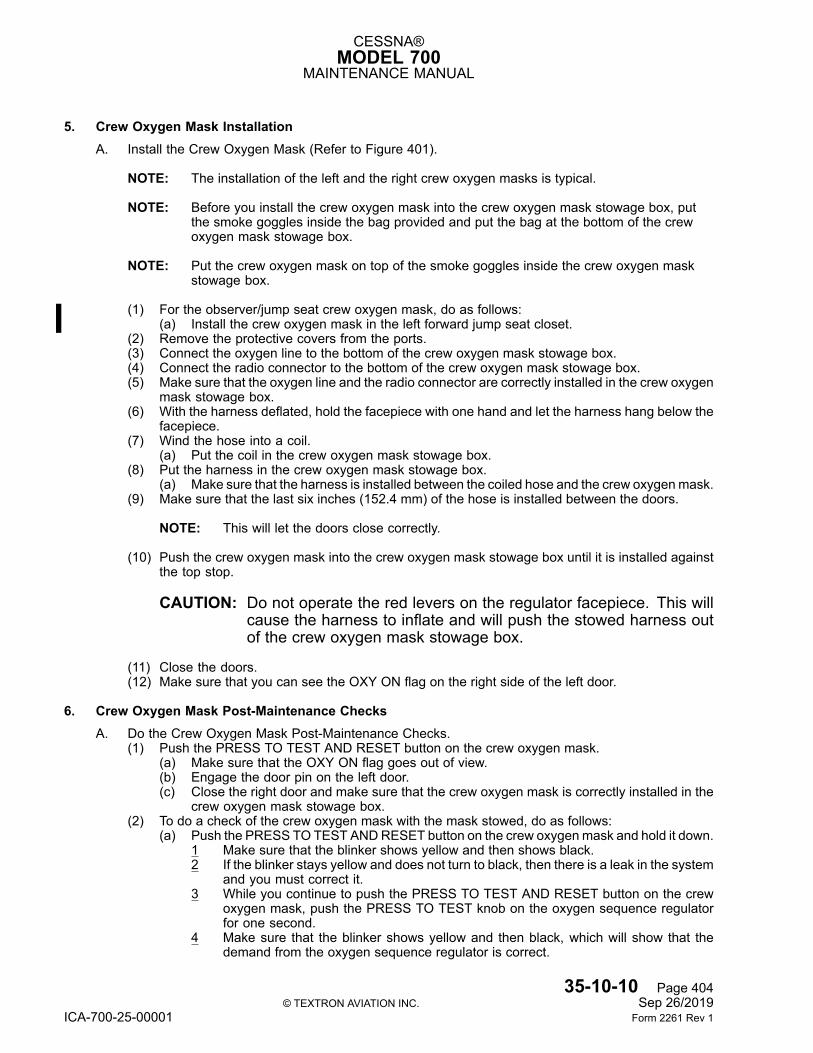
CESSNA®MODEL 700
MAINTENANCE MANUAL
5. Crew Oxygen Mask InstallationA. Install the Crew Oxygen Mask (Refer to Figure 401).
NOTE: The installation of the left and the right crew oxygen masks is typical.
NOTE: Before you install the crew oxygen mask into the crew oxygen mask stowage box, putthe smoke goggles inside the bag provided and put the bag at the bottom of the crewoxygen mask stowage box.
NOTE: Put the crew oxygen mask on top of the smoke goggles inside the crew oxygen maskstowage box.
(1) For the observer/jump seat crew oxygen mask, do as follows:(a) Install the crew oxygen mask in the left forward jump seat closet.
(2) Remove the protective covers from the ports.(3) Connect the oxygen line to the bottom of the crew oxygen mask stowage box.(4) Connect the radio connector to the bottom of the crew oxygen mask stowage box.(5) Make sure that the oxygen line and the radio connector are correctly installed in the crew oxygen
mask stowage box.(6) With the harness deflated, hold the facepiece with one hand and let the harness hang below the
facepiece.(7) Wind the hose into a coil.
(a) Put the coil in the crew oxygen mask stowage box.(8) Put the harness in the crew oxygen mask stowage box.
(a) Make sure that the harness is installed between the coiled hose and the crew oxygenmask.(9) Make sure that the last six inches (152.4 mm) of the hose is installed between the doors.
NOTE: This will let the doors close correctly.
(10) Push the crew oxygen mask into the crew oxygen mask stowage box until it is installed againstthe top stop.
CAUTION: Do not operate the red levers on the regulator facepiece. This willcause the harness to inflate and will push the stowed harness outof the crew oxygen mask stowage box.
(11) Close the doors.(12) Make sure that you can see the OXY ON flag on the right side of the left door.
6. Crew Oxygen Mask Post-Maintenance ChecksA. Do the Crew Oxygen Mask Post-Maintenance Checks.
(1) Push the PRESS TO TEST AND RESET button on the crew oxygen mask.(a) Make sure that the OXY ON flag goes out of view.(b) Engage the door pin on the left door.(c) Close the right door and make sure that the crew oxygen mask is correctly installed in the
crew oxygen mask stowage box.(2) To do a check of the crew oxygen mask with the mask stowed, do as follows:
(a) Push the PRESS TO TEST ANDRESET button on the crew oxygenmask and hold it down.1 Make sure that the blinker shows yellow and then shows black.2 If the blinker stays yellow and does not turn to black, then there is a leak in the system
and you must correct it.3 While you continue to push the PRESS TO TEST AND RESET button on the crew
oxygen mask, push the PRESS TO TEST knob on the oxygen sequence regulatorfor one second.
4 Make sure that the blinker shows yellow and then black, which will show that thedemand from the oxygen sequence regulator is correct.
35-10-10 Page 404© TEXTRON AVIATION INC. Sep 26/2019
ICA-700-25-00001 Form 2261 Rev 1
CESSNA®MODEL 700
MAINTENANCE MANUAL
(b) Release the PRESS TO TEST AND RESET button on the crew oxygen mask.
7. CloseoutA. Put the Airplane Back to its Initial Condition.
(1) If the optional observer/jump seat is installed, close the pocket door on the left forward jump seatcloset.
35-10-10 Page 405© TEXTRON AVIATION INC. Sep 26/2019
ICA-700-25-00001 Form 2261 Rev 1
TEXTRON AVIATION INC.AIRCRAFT DIVISION
WICHITA, KANSAS 67277
SUPPLEMENT NO: ICA-700-25-00001
APPENDIX A: ILLUSTRATED PARTS CATALOG
NOT APPLICABLE
© TEXTRON AVIATION INC.Form 2261 Rev 1
TEXTRON AVIATION INC.AIRCRAFT DIVISION
WICHITA, KANSAS 67277
SUPPLEMENT NO: ICA-700-25-00001
APPENDIX B: WIRING DIAGRAM MANUAL
NOT APPLICABLE
© TEXTRON AVIATION INC.Form 2261 Rev 1
TEXTRON AVIATION INC.AIRCRAFT DIVISION
WICHITA, KANSAS 67277
SUPPLEMENT NO: ICA-700-25-00001
APPENDIX C: INTERIOR MAINTENANCE MANUAL AND ILLUSTRATED PARTSCATALOG
© TEXTRON AVIATION INC.Form 2261 Rev 1
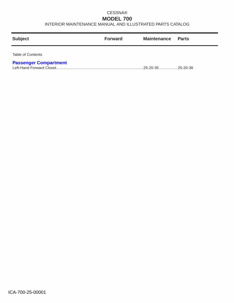
Subject Forward Maintenance Parts
CESSNA®
MODEL 700INTERIOR MAINTENANCE MANUAL AND ILLUSTRATED PARTS CATALOG
Left-Hand Forward Closet..................................................................................25-20-35 .................25-20-36
Table of Contents
Passenger Compartment
ICA-700-25-00001
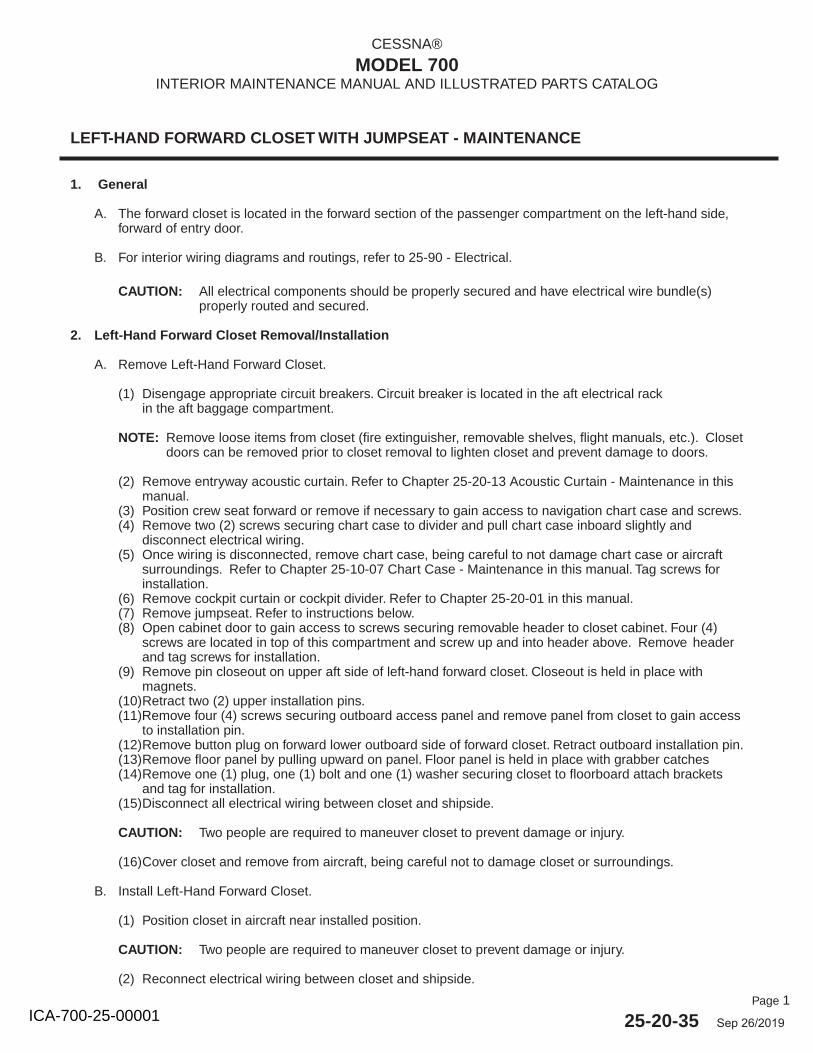
Page 1
25-20-35 Sep 26/2019
CESSNA®
MODEL 700INTERIOR MAINTENANCE MANUAL AND ILLUSTRATED PARTS CATALOG
LEFT-HAND FORWARD CLOSET WITH JUMPSEAT - MAINTENANCE
1. General
A. The forward closet is located in the forward section of the passenger compartment on the left-hand side,forward of entry door.
B. For interior wiring diagrams and routings, refer to 25-90 - Electrical.
CAUTION: All electrical components should be properly secured and have electrical wire bundle(s)properly routed and secured.
2. Left-Hand Forward Closet Removal/Installation
A. Remove Left-Hand Forward Closet.
(1) Disengage appropriate circuit breakers. Circuit breaker is located in the aft electrical rackin the aft baggage compartment.
NOTE: Remove loose items from closet (fire extinguisher, removable shelves, flight manuals, etc.). Closet doors can be removed prior to closet removal to lighten closet and prevent damage to doors.
(2) Remove entryway acoustic curtain. Refer to Chapter 25-20-13 Acoustic Curtain - Maintenance in thismanual.
(3) Position crew seat forward or remove if necessary to gain access to navigation chart case and screws.(4) Remove two (2) screws securing chart case to divider and pull chart case inboard slightly and
disconnect electrical wiring.(5) Once wiring is disconnected, remove chart case, being careful to not damage chart case or aircraft
surroundings. Refer to Chapter 25-10-07 Chart Case - Maintenance in this manual. Tag screws forinstallation.
(6) Remove cockpit curtain or cockpit divider. Refer to Chapter 25-20-01 in this manual.(7) Remove jumpseat. Refer to instructions below.(8) Open cabinet door to gain access to screws securing removable header to closet cabinet. Four (4)
screws are located in top of this compartment and screw up and into header above. Remove headerand tag screws for installation.
(9) Remove pin closeout on upper aft side of left-hand forward closet. Closeout is held in place withmagnets.
(10) Retract two (2) upper installation pins.(11)Remove four (4) screws securing outboard access panel and remove panel from closet to gain access
to installation pin.(12) Remove button plug on forward lower outboard side of forward closet. Retract outboard installation pin.(13) Remove floor panel by pulling upward on panel. Floor panel is held in place with grabber catches(14) Remove one (1) plug, one (1) bolt and one (1) washer securing closet to floorboard attach brackets
and tag for installation.(15) Disconnect all electrical wiring between closet and shipside.
CAUTION: Two people are required to maneuver closet to prevent damage or injury.
(16) Cover closet and remove from aircraft, being careful not to damage closet or surroundings.
B. Install Left-Hand Forward Closet.
(1) Position closet in aircraft near installed position.
CAUTION: Two people are required to maneuver closet to prevent damage or injury.
(2) Reconnect electrical wiring between closet and shipside.
ICA-700-25-00001
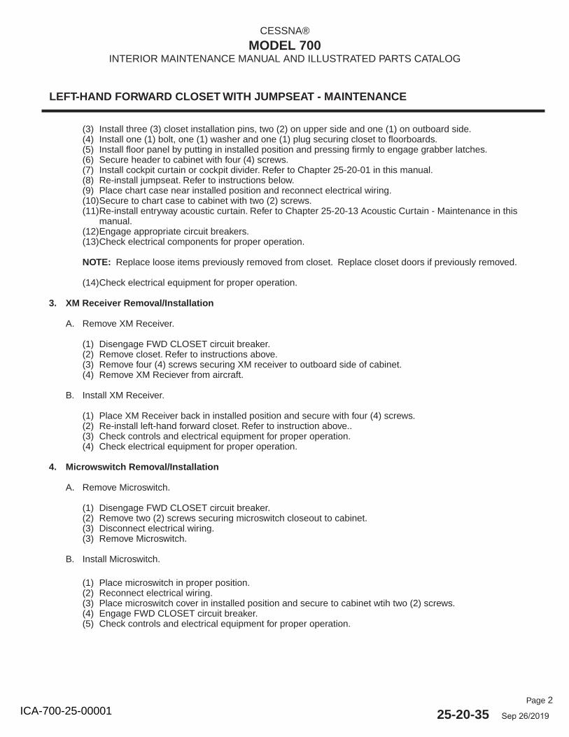
Page 2
25-20-35 Sep 26/2019
CESSNA®
MODEL 700INTERIOR MAINTENANCE MANUAL AND ILLUSTRATED PARTS CATALOG
LEFT-HAND FORWARD CLOSET WITH JUMPSEAT - MAINTENANCE
(3) Install three (3) closet installation pins, two (2) on upper side and one (1) on outboard side.(4) Install one (1) bolt, one (1) washer and one (1) plug securing closet to floorboards.(5) Install floor panel by putting in installed position and pressing firmly to engage grabber latches.(6) Secure header to cabinet with four (4) screws.(7) Install cockpit curtain or cockpit divider. Refer to Chapter 25-20-01 in this manual.(8) Re-install jumpseat. Refer to instructions below.(9) Place chart case near installed position and reconnect electrical wiring.(10) Secure to chart case to cabinet with two (2) screws.(11) Re-install entryway acoustic curtain. Refer to Chapter 25-20-13 Acoustic Curtain - Maintenance in this
manual.(12) Engage appropriate circuit breakers.(13) Check electrical components for proper operation.
NOTE: Replace loose items previously removed from closet. Replace closet doors if previously removed.
(14) Check electrical equipment for proper operation.
3. XM Receiver Removal/Installation
A. Remove XM Receiver.
(1) Disengage FWD CLOSET circuit breaker.(2) Remove closet. Refer to instructions above.(3) Remove four (4) screws securing XM receiver to outboard side of cabinet.(4) Remove XM Reciever from aircraft.
B. Install XM Receiver.
(1) Place XM Receiver back in installed position and secure with four (4) screws.(2) Re-install left-hand forward closet. Refer to instruction above..(3) Check controls and electrical equipment for proper operation.(4) Check electrical equipment for proper operation.
4. Microwswitch Removal/Installation
A. Remove Microswitch.
(1) Disengage FWD CLOSET circuit breaker.(2) Remove two (2) screws securing microswitch closeout to cabinet.(3) Disconnect electrical wiring.(3) Remove Microswitch.
B. Install Microswitch.
(1) Place microswitch in proper position.(2) Reconnect electrical wiring.(3) Place microswitch cover in installed position and secure to cabinet wtih two (2) screws.(4) Engage FWD CLOSET circuit breaker.(5) Check controls and electrical equipment for proper operation.
ICA-700-25-00001
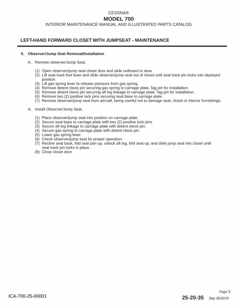
Page 3
25-20-35 Sep 26/2019
CESSNA®
MODEL 700INTERIOR MAINTENANCE MANUAL AND ILLUSTRATED PARTS CATALOG
LEFT-HAND FORWARD CLOSET WITH JUMPSEAT - MAINTENANCE
5. Observer/Jump Seat Removal/Installation
A. Remove observer/Jump Seat.
(1) Open observer/jump seat closet door and slide outboard to stow.(2) Lift seat track foot lever and slide observer/jump seat out of closet until seat track pin locks into deployed
position.(3) Lift gas spring lever to release pressure from gas spring.(4) Remove detent clevis pin securing gas spring to carriage plate. Tag pin for installation.(5) Remove detent clevis pin securing aft leg linkage to carriage plate. Tag pin for installation.(6) Remove two (2) positive lock pins securing seat base to carriage plate.(7) Remove observer/jump seat from aircraft, being careful not to damage seat, closet or interior furnishings.
A. Install Observer/Jump Seat.
(1) Place observer/jump seat into position on carriage plate.(2) Secure seat base to carriage plate with two (2) positive lock pins.(3) Secure aft leg linkage to carriage plate with detent clevis pin.(4) Secure gas spring to carriage plate with detent clevis pin.(5) Lower gas spring lever.(6) Check observer/jump seat for proper operation.(7) Recline seat back, fold seat pan up, unlock aft leg, fold seat up, and slide jump seat into closet until
seat track pin locks in place.(8) Close closet door.
ICA-700-25-00001
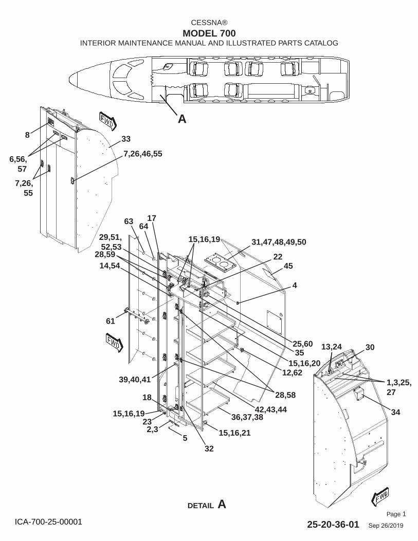
Page 1
25-20-36-01 Sep 26/2019
CESSNA®
MODEL 700INTERIOR MAINTENANCE MANUAL AND ILLUSTRATED PARTS CATALOG
DETAIL A
A
7,26,55
6,56,57
8
15,16,19
1,3,25,27
13,24 30
33
14,54
2,3
6364
7,26,46,55
34
31,47,48,49,50
4
12,62
61
29,51,52,53
28,59
35
515,16,21
36,37,3842,43,44
39,40,41
17
15,16,19
25,60
18 28,58
22
23
32
45
15,16,20
ICA-700-25-00001
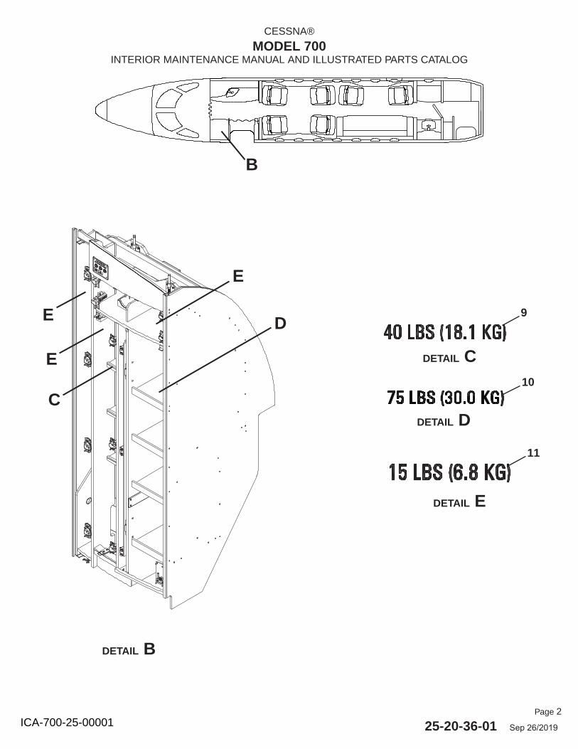
Page 2
25-20-36-01 Sep 26/2019
CESSNA®
MODEL 700INTERIOR MAINTENANCE MANUAL AND ILLUSTRATED PARTS CATALOG
B
DETAIL B
DETAIL C
DETAIL D
DETAIL E
9
10
11
E
E
DE
C
ICA-700-25-00001
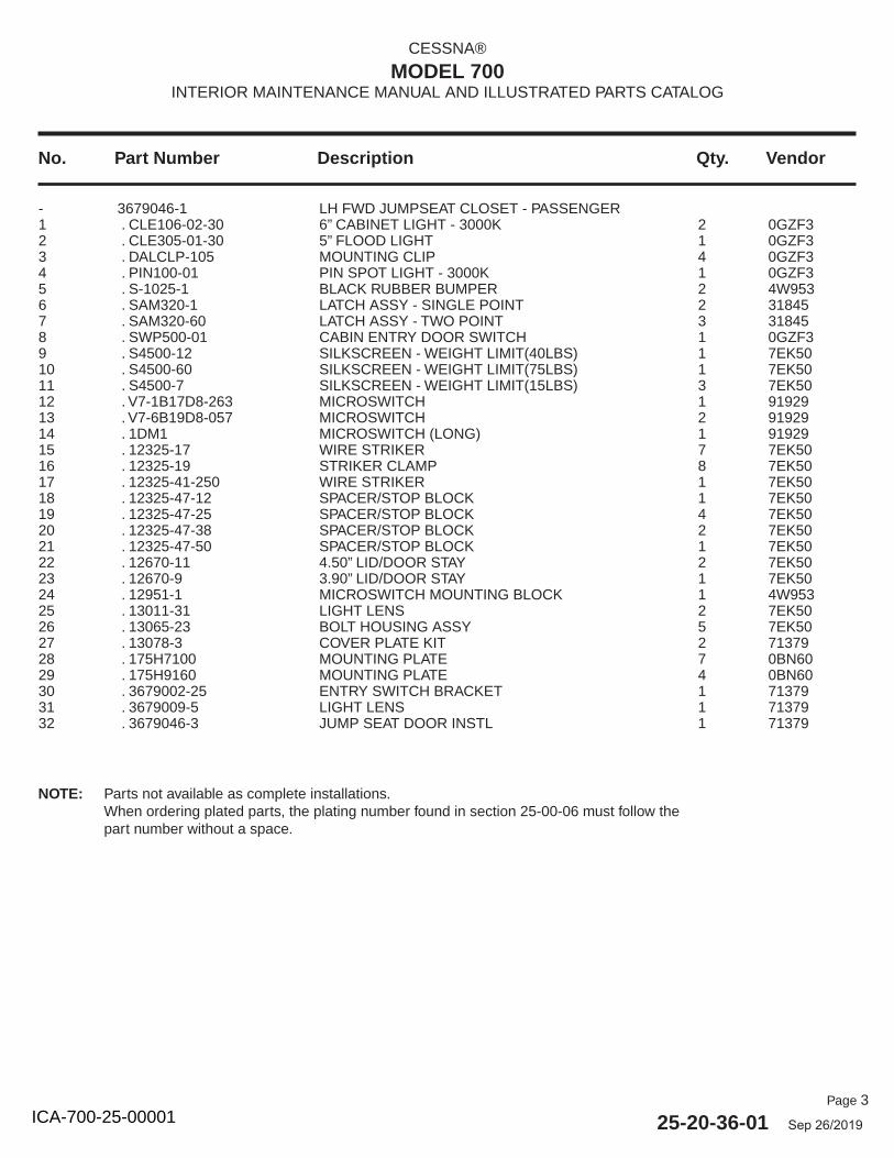
Page 3
25-20-36-01 Sep 26/2019
No. Part Number Description Qty. Vendor
CESSNA®
MODEL 700INTERIOR MAINTENANCE MANUAL AND ILLUSTRATED PARTS CATALOG
- 3679046-1 LH FWD JUMPSEAT CLOSET - PASSENGER 1 . CLE106-02-30 6” CABINET LIGHT - 3000K 2 0GZF32 . CLE305-01-30 5” FLOOD LIGHT 1 0GZF33 . DALCLP-105 MOUNTING CLIP 4 0GZF34 . PIN100-01 PIN SPOT LIGHT - 3000K 1 0GZF35 . S-1025-1 BLACK RUBBER BUMPER 2 4W9536 . SAM320-1 LATCH ASSY - SINGLE POINT 2 318457 . SAM320-60 LATCH ASSY - TWO POINT 3 318458 . SWP500-01 CABIN ENTRY DOOR SWITCH 1 0GZF39 . S4500-12 SILKSCREEN - WEIGHT LIMIT(40LBS) 1 7EK5010 . S4500-60 SILKSCREEN - WEIGHT LIMIT(75LBS) 1 7EK5011 . S4500-7 SILKSCREEN - WEIGHT LIMIT(15LBS) 3 7EK5012 . V7-1B17D8-263 MICROSWITCH 1 9192913 . V7-6B19D8-057 MICROSWITCH 2 9192914 . 1DM1 MICROSWITCH (LONG) 1 9192915 . 12325-17 WIRE STRIKER 7 7EK5016 . 12325-19 STRIKER CLAMP 8 7EK5017 . 12325-41-250 WIRE STRIKER 1 7EK5018 . 12325-47-12 SPACER/STOP BLOCK 1 7EK5019 . 12325-47-25 SPACER/STOP BLOCK 4 7EK5020 . 12325-47-38 SPACER/STOP BLOCK 2 7EK5021 . 12325-47-50 SPACER/STOP BLOCK 1 7EK5022 . 12670-11 4.50” LID/DOOR STAY 2 7EK5023 . 12670-9 3.90” LID/DOOR STAY 1 7EK5024 . 12951-1 MICROSWITCH MOUNTING BLOCK 1 4W95325 . 13011-31 LIGHT LENS 2 7EK5026 . 13065-23 BOLT HOUSING ASSY 5 7EK5027 . 13078-3 COVER PLATE KIT 2 7137928 . 175H7100 MOUNTING PLATE 7 0BN6029 . 175H9160 MOUNTING PLATE 4 0BN6030 . 3679002-25 ENTRY SWITCH BRACKET 1 7137931 . 3679009-5 LIGHT LENS 1 7137932 . 3679046-3 JUMP SEAT DOOR INSTL 1 71379
NOTE: Parts not available as complete installations.When ordering plated parts, the plating number found in section 25-00-06 must follow the part number without a space.
ICA-700-25-00001
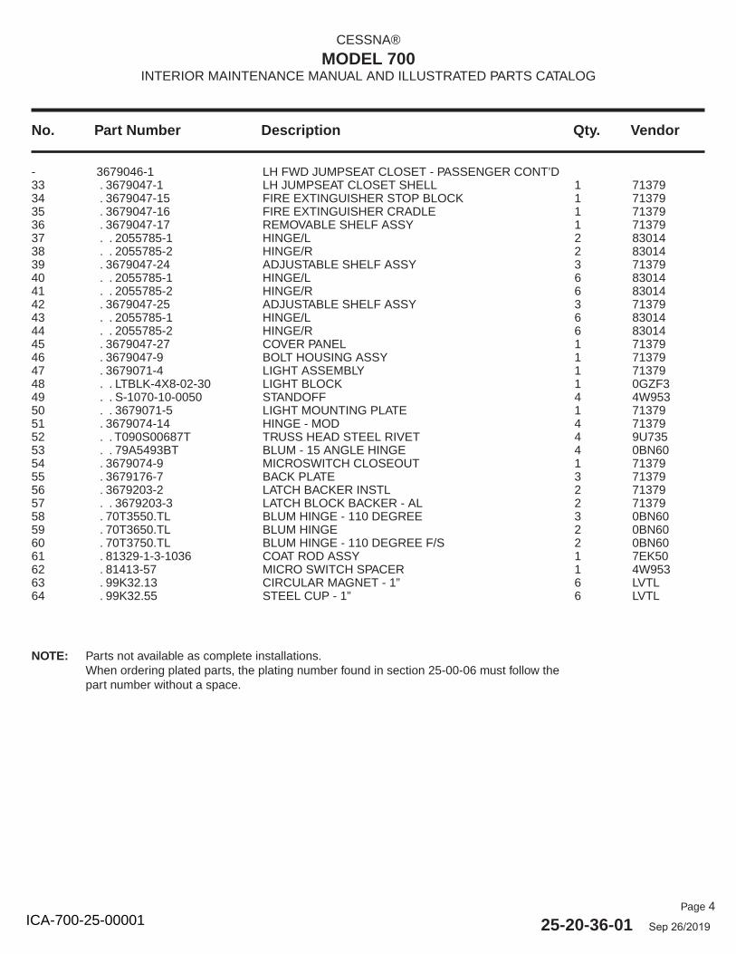
Page 4
25-20-36-01 Sep 26/2019
No. Part Number Description Qty. Vendor
CESSNA®
MODEL 700INTERIOR MAINTENANCE MANUAL AND ILLUSTRATED PARTS CATALOG
- 3679046-1 LH FWD JUMPSEAT CLOSET - PASSENGER CONT’D 33 . 3679047-1 LH JUMPSEAT CLOSET SHELL 1 7137934 . 3679047-15 FIRE EXTINGUISHER STOP BLOCK 1 7137935 . 3679047-16 FIRE EXTINGUISHER CRADLE 1 7137936 . 3679047-17 REMOVABLE SHELF ASSY 1 7137937 . . 2055785-1 HINGE/L 2 8301438 . . 2055785-2 HINGE/R 2 8301439 . 3679047-24 ADJUSTABLE SHELF ASSY 3 7137940 . . 2055785-1 HINGE/L 6 8301441 . . 2055785-2 HINGE/R 6 8301442 . 3679047-25 ADJUSTABLE SHELF ASSY 3 7137943 . . 2055785-1 HINGE/L 6 8301444 . . 2055785-2 HINGE/R 6 8301445 . 3679047-27 COVER PANEL 1 7137946 . 3679047-9 BOLT HOUSING ASSY 1 7137947 . 3679071-4 LIGHT ASSEMBLY 1 7137948 . . LTBLK-4X8-02-30 LIGHT BLOCK 1 0GZF349 . . S-1070-10-0050 STANDOFF 4 4W95350 . . 3679071-5 LIGHT MOUNTING PLATE 1 7137951 . 3679074-14 HINGE - MOD 4 7137952 . . T090S00687T TRUSS HEAD STEEL RIVET 4 9U73553 . . 79A5493BT BLUM - 15 ANGLE HINGE 4 0BN6054 . 3679074-9 MICROSWITCH CLOSEOUT 1 7137955 . 3679176-7 BACK PLATE 3 7137956 . 3679203-2 LATCH BACKER INSTL 2 7137957 . . 3679203-3 LATCH BLOCK BACKER - AL 2 7137958 . 70T3550.TL BLUM HINGE - 110 DEGREE 3 0BN6059 . 70T3650.TL BLUM HINGE 2 0BN6060 . 70T3750.TL BLUM HINGE - 110 DEGREE F/S 2 0BN6061 . 81329-1-3-1036 COAT ROD ASSY 1 7EK5062 . 81413-57 MICRO SWITCH SPACER 1 4W95363 . 99K32.13 CIRCULAR MAGNET - 1” 6 LVTL64 . 99K32.55 STEEL CUP - 1” 6 LVTL
NOTE: Parts not available as complete installations.When ordering plated parts, the plating number found in section 25-00-06 must follow the part number without a space.
ICA-700-25-00001
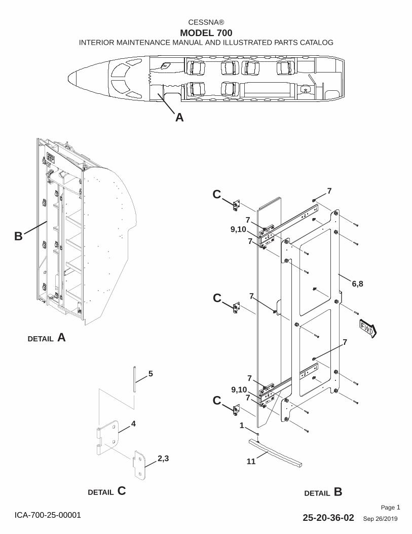
Page 1
25-20-36-02 Sep 26/2019
CESSNA®
MODEL 700INTERIOR MAINTENANCE MANUAL AND ILLUSTRATED PARTS CATALOG
A
DETAIL A
B
DETAIL BDETAIL C
C
C
C
1
11
7
6,8
5
2,3
4
9,107
7
7
9,107
7
7
ICA-700-25-00001
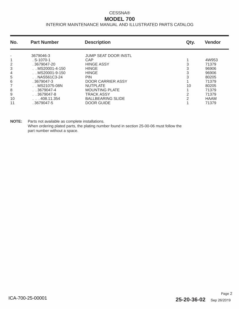
Page 2
25-20-36-02 Sep 26/2019
No. Part Number Description Qty. Vendor
CESSNA®
MODEL 700INTERIOR MAINTENANCE MANUAL AND ILLUSTRATED PARTS CATALOG
- 3679046-3 JUMP SEAT DOOR INSTL 1 . S-1070-1 CAP 1 4W9532 . 3679047-20 HINGE ASSY 3 713793 . . MS20001-4-150 HINGE 3 969064 . . MS20001-9-150 HINGE 3 969065 . . NAS561C3-24 PIN 3 802056 . 3679047-3 DOOR CARRIER ASSY 1 713797 . . MS21075-08N NUTPLATE 10 802058 . . 3679047-4 MOUNTING PLATE 1 713799 . . 3679047-8 TRACK ASSY 2 7137910 . . . 408.11.354 BALLBEARING SLIDE 2 HAAM11 . 3679047-5 DOOR GUIDE 1 71379
NOTE: Parts not available as complete installations.When ordering plated parts, the plating number found in section 25-00-06 must follow the part number without a space.
ICA-700-25-00001
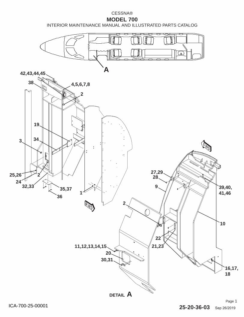
Page 1
25-20-36-03 Sep 26/2019
CESSNA®
MODEL 700INTERIOR MAINTENANCE MANUAL AND ILLUSTRATED PARTS CATALOG
A
DETAIL A
36
35,371
224
25,26 2827,29
4,5,6,7,8
42,43,44,45
3
32,33
19
34
11,12,13,14,15
30,3120
22
21,23
2
16,17,18
38
39,40,41,46
2
9
10
ICA-700-25-00001
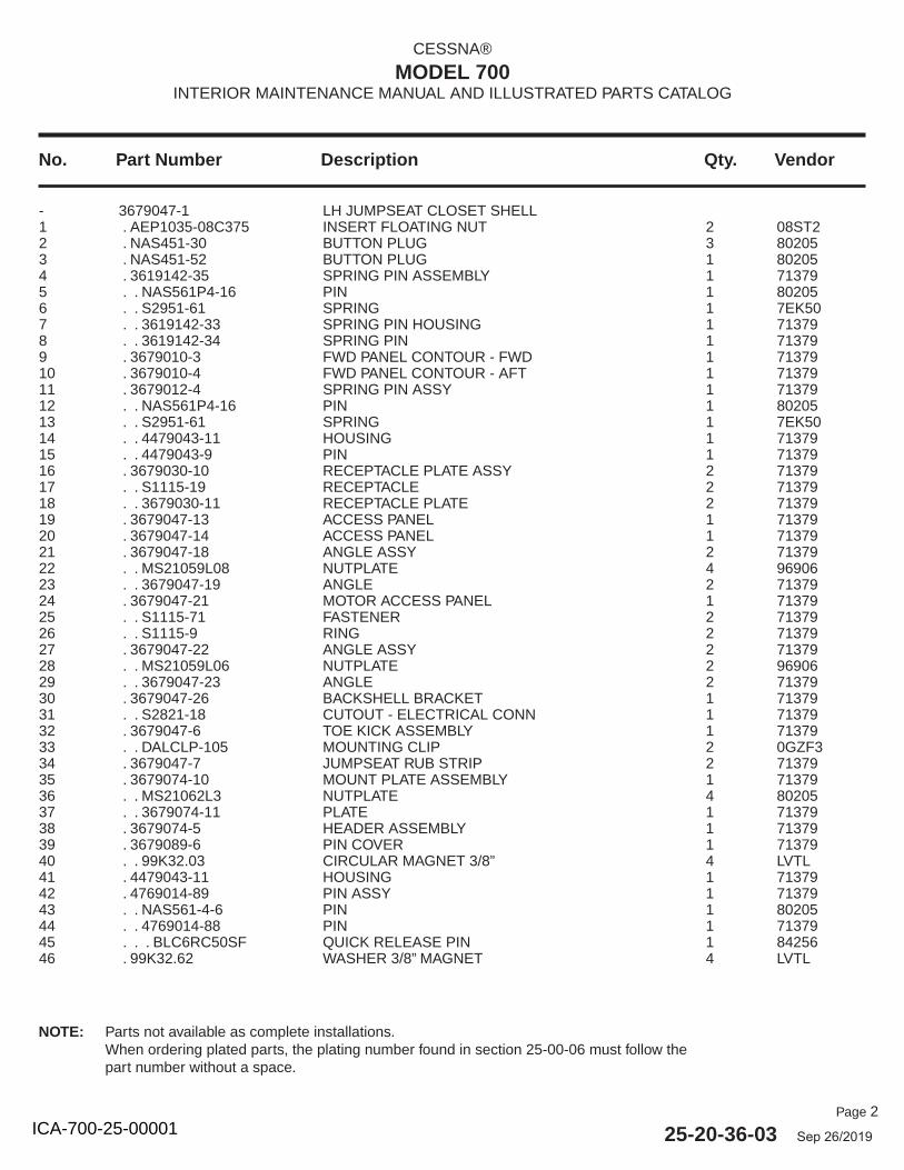
Page 2
25-20-36-03 Sep 26/2019
No. Part Number Description Qty. Vendor
CESSNA®
MODEL 700INTERIOR MAINTENANCE MANUAL AND ILLUSTRATED PARTS CATALOG
- 3679047-1 LH JUMPSEAT CLOSET SHELL 1 . AEP1035-08C375 INSERT FLOATING NUT 2 08ST22 . NAS451-30 BUTTON PLUG 3 802053 . NAS451-52 BUTTON PLUG 1 802054 . 3619142-35 SPRING PIN ASSEMBLY 1 713795 . . NAS561P4-16 PIN 1 802056 . . S2951-61 SPRING 1 7EK507 . . 3619142-33 SPRING PIN HOUSING 1 713798 . . 3619142-34 SPRING PIN 1 713799 . 3679010-3 FWD PANEL CONTOUR - FWD 1 7137910 . 3679010-4 FWD PANEL CONTOUR - AFT 1 7137911 . 3679012-4 SPRING PIN ASSY 1 7137912 . . NAS561P4-16 PIN 1 8020513 . . S2951-61 SPRING 1 7EK5014 . . 4479043-11 HOUSING 1 7137915 . . 4479043-9 PIN 1 7137916 . 3679030-10 RECEPTACLE PLATE ASSY 2 7137917 . . S1115-19 RECEPTACLE 2 7137918 . . 3679030-11 RECEPTACLE PLATE 2 7137919 . 3679047-13 ACCESS PANEL 1 7137920 . 3679047-14 ACCESS PANEL 1 7137921 . 3679047-18 ANGLE ASSY 2 7137922 . . MS21059L08 NUTPLATE 4 9690623 . . 3679047-19 ANGLE 2 7137924 . 3679047-21 MOTOR ACCESS PANEL 1 7137925 . . S1115-71 FASTENER 2 7137926 . . S1115-9 RING 2 7137927 . 3679047-22 ANGLE ASSY 2 7137928 . . MS21059L06 NUTPLATE 2 9690629 . . 3679047-23 ANGLE 2 7137930 . 3679047-26 BACKSHELL BRACKET 1 7137931 . . S2821-18 CUTOUT - ELECTRICAL CONN 1 7137932 . 3679047-6 TOE KICK ASSEMBLY 1 7137933 . . DALCLP-105 MOUNTING CLIP 2 0GZF334 . 3679047-7 JUMPSEAT RUB STRIP 2 7137935 . 3679074-10 MOUNT PLATE ASSEMBLY 1 7137936 . . MS21062L3 NUTPLATE 4 8020537 . . 3679074-11 PLATE 1 7137938 . 3679074-5 HEADER ASSEMBLY 1 7137939 . 3679089-6 PIN COVER 1 7137940 . . 99K32.03 CIRCULAR MAGNET 3/8” 4 LVTL41 . 4479043-11 HOUSING 1 7137942 . 4769014-89 PIN ASSY 1 7137943 . . NAS561-4-6 PIN 1 8020544 . . 4769014-88 PIN 1 7137945 . . . BLC6RC50SF QUICK RELEASE PIN 1 8425646 . 99K32.62 WASHER 3/8” MAGNET 4 LVTL
NOTE: Parts not available as complete installations.When ordering plated parts, the plating number found in section 25-00-06 must follow the part number without a space.
ICA-700-25-00001
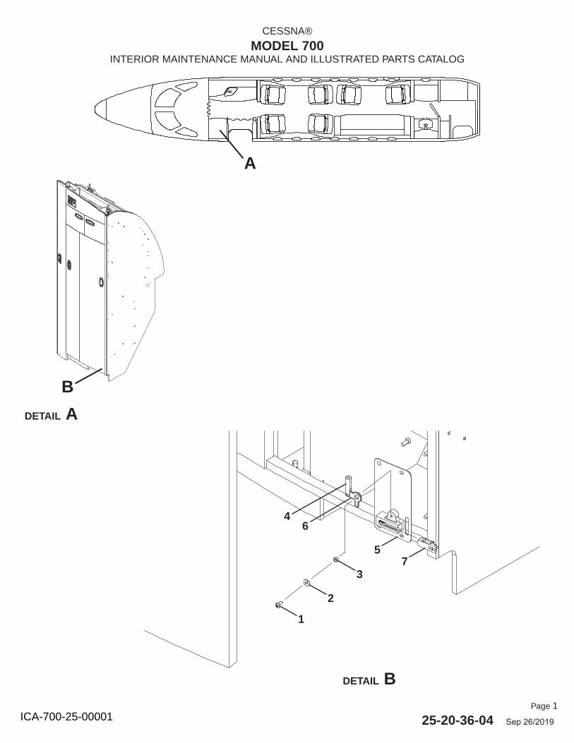
Page 1
25-20-36-04 Sep 26/2019
CESSNA®
MODEL 700INTERIOR MAINTENANCE MANUAL AND ILLUSTRATED PARTS CATALOG
A
DETAIL A
DETAIL B
B
1
2
3
5
6
7
4
ICA-700-25-00001
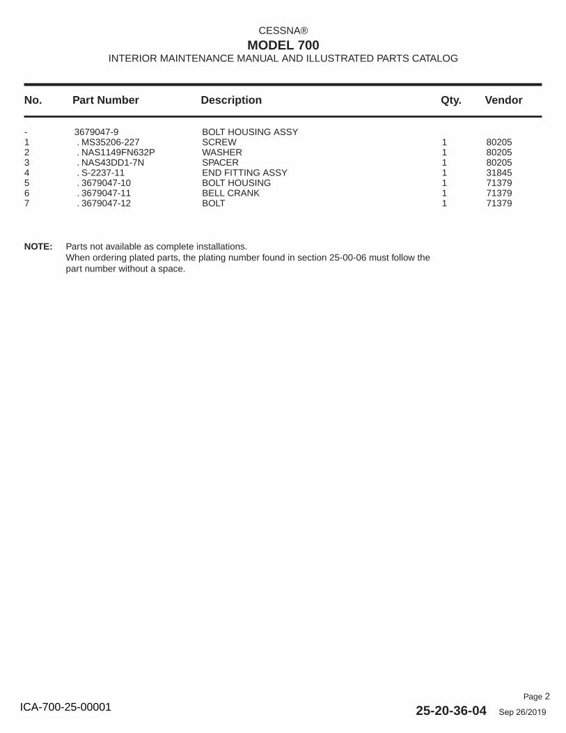
Page 2
25-20-36-04 Sep 26/2019
No. Part Number Description Qty. Vendor
CESSNA®
MODEL 700INTERIOR MAINTENANCE MANUAL AND ILLUSTRATED PARTS CATALOG
- 3679047-9 BOLT HOUSING ASSY 1 . MS35206-227 SCREW 1 802052 . NAS1149FN632P WASHER 1 802053 . NAS43DD1-7N SPACER 1 802054 . S-2237-11 END FITTING ASSY 1 318455 . 3679047-10 BOLT HOUSING 1 713796 . 3679047-11 BELL CRANK 1 713797 . 3679047-12 BOLT 1 71379
NOTE: Parts not available as complete installations.When ordering plated parts, the plating number found in section 25-00-06 must follow the part number without a space.
ICA-700-25-00001
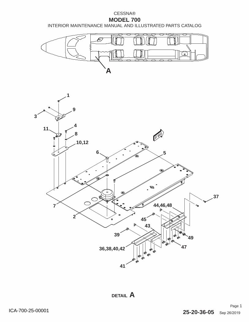
Page 1
25-20-36-05 Sep 26/2019
CESSNA®
MODEL 700INTERIOR MAINTENANCE MANUAL AND ILLUSTRATED PARTS CATALOG
DETAIL A
A
1
9
4
8
10,12
11
3
6 5
2
39
7
37
36,38,40,42
41
43
47
49
44,46,48
45
ICA-700-25-00001
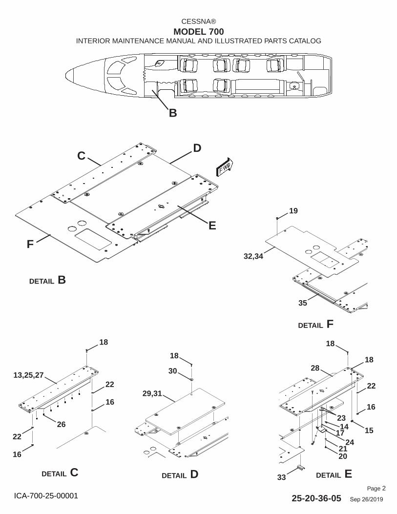
Page 2
25-20-36-05 Sep 26/2019
CESSNA®
MODEL 700INTERIOR MAINTENANCE MANUAL AND ILLUSTRATED PARTS CATALOG
B
DETAIL B
DC
E
F
DETAIL C DETAIL D DETAIL E
DETAIL F18
22
16
26
13,25,27
29,31
30
18
18
15
18
22
16
24
20
17
2314
28
19
32,34
35
33
21
22
16
ICA-700-25-00001
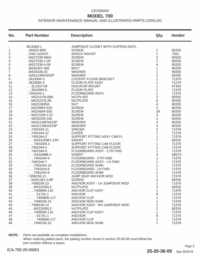
Page 3
25-20-36-05 Sep 26/2019
No. Part Number Description Qty. Vendor
CESSNA®
MODEL 700INTERIOR MAINTENANCE MANUAL AND ILLUSTRATED PARTS CATALOG
- 3619384-1 JUMPSEAT CLOSET WITH CURTAIN INSTL 1 . AN525-8R6 SCREW 1 802052 . CM2-110AST SHOCK MOUNT 1 79413 . MS27039-0804 SCREW 2 802054 . MS27039-1-09 SCREW 2 802055 . MS27039-4-09 SCREW 4 802056 . MS35307-360 BOLT 1 802057 . MS35335-35 WASHER 1 969068 . NAS1149F0332P WASHER 2 802059 . 3619384-3 COCKPIT FLOOR BRACKET 1 7137910 . 3619384-4 FLOOR PLATE ASSY 1 7137911 . . SL2337-08 ISOLATOR MOUNT 1 9739312 . . 3619384-5 FLOOR PLATE 1 7137913 . 7491044-1 FLOORBOARD INSTL 1 7137914 . . MS21075L08N NUTPLATE 2 8020515 . . MS21075L3N NUTPLATE 6 8020516 . . MS21083N3 NUT 4 8020517 . . MS24693-S25 SCREW 2 8020518 . . MS24694-S55 SCREW 28 8020519 . . MS27039-1-07 SCREW 4 8020520 . . MS35206-226 SCREW 2 8020521 . . NAS1149FN616P WASHER 2 8020522 . . NAS1149G0316P WASHER 4 8020523 . . 7491044-11 SPACER 2 7137924 . . 7491044-12 COVER 1 7137925 . . 7491044-2 SUPPORT FITTING ASSY CAB FL 1 7137926 . . . MS21209F1-15P INSERT 7 8020527 . . . 7491044-3 SUPPORT FITTING CAB FLOOR 1 7137928 . . 7491044-4 SUPPORT FITTING CAB FLOOR 1 7137929 . . 7491044-5 FLOORBOARD ASSY - CTR FWD 1 7137930 . . . GAA588B-3 INSERT 4 08ST231 . . . 7491044-6 FLOORBOARD - CTR FWD 1 7137932 . . 7491044-7 FLOORBOARD ASSY - LH FWD 1 7137933 . . . 7491044-10 FLOORBOARD SHIM 1 7137934 . . . 7491044-8 FLOORBOARD - LH FWD 1 7137935 . . . 7491044-9 FLOORBOARD SHIM 1 7137936 . 7498156-11 JUMP SEAT ANCHOR MOD 1 7137937 . . NAS1351-3-8P SCREW 4 8020538 . . 7498156-13 ANCHOR ASSY - LH JUMPSEAT MOD 1 7137939 . . . MS21055L3 NUTPLATE 2 8020540 . . . 7408906-116 ANCHOR CLIP ASSY 1 7137941 . . . . S1741-1 ANCHOR 8 7137942 . . . . 7408906-117 ANCHOR CLIP 1 7137943 . . . 7498156-15 ANCHOR MOD SHIM 1 7137944 . . 7498156-14 ANCHOR ASSY - RH JUMPSEAT MOD 1 7137945 . . . MS21055L3 NUTPLATE 2 8020546 . . . 7408906-116 ANCHOR CLIP ASSY 1 7137947 . . . . S1741-1 ANCHOR 8 7137948 . . . . 7408906-117 ANCHOR CLIP 1 7137949 . . . 7498156-15 ANCHOR MOD SHIM 1 71379
NOTE: Parts not available as complete installations.When ordering plated parts, the plating number found in section 25-00-06 must follow the part number without a space.
ICA-700-25-00001
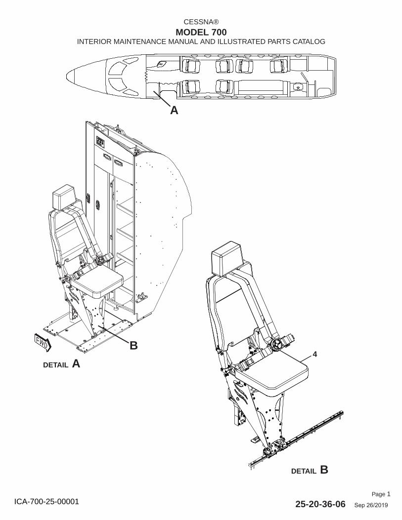
Page 1
25-20-36-06 Sep 26/2019
CESSNA®
MODEL 700INTERIOR MAINTENANCE MANUAL AND ILLUSTRATED PARTS CATALOG
DETAIL B
A
DETAIL A
B4
ICA-700-25-00001
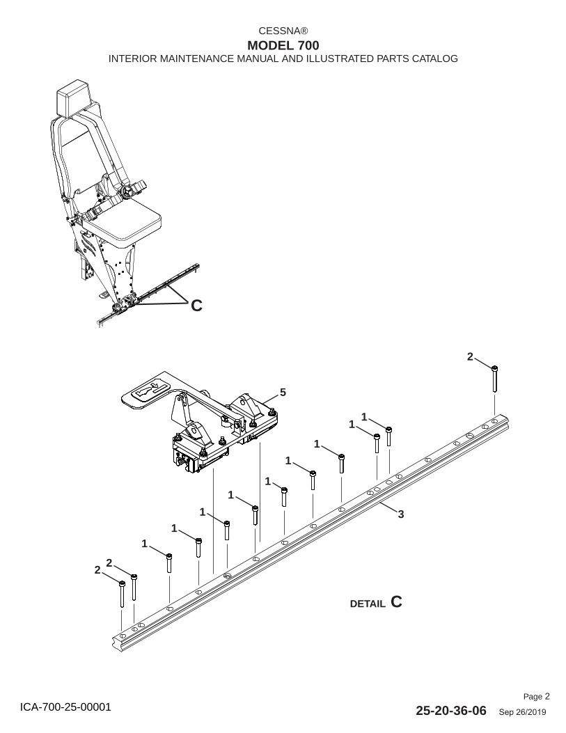
Page 2
25-20-36-06 Sep 26/2019
CESSNA®
MODEL 700INTERIOR MAINTENANCE MANUAL AND ILLUSTRATED PARTS CATALOG
DETAIL C
1
2
1
22
1
1
1
1
5
3
C
1
11
ICA-700-25-00001
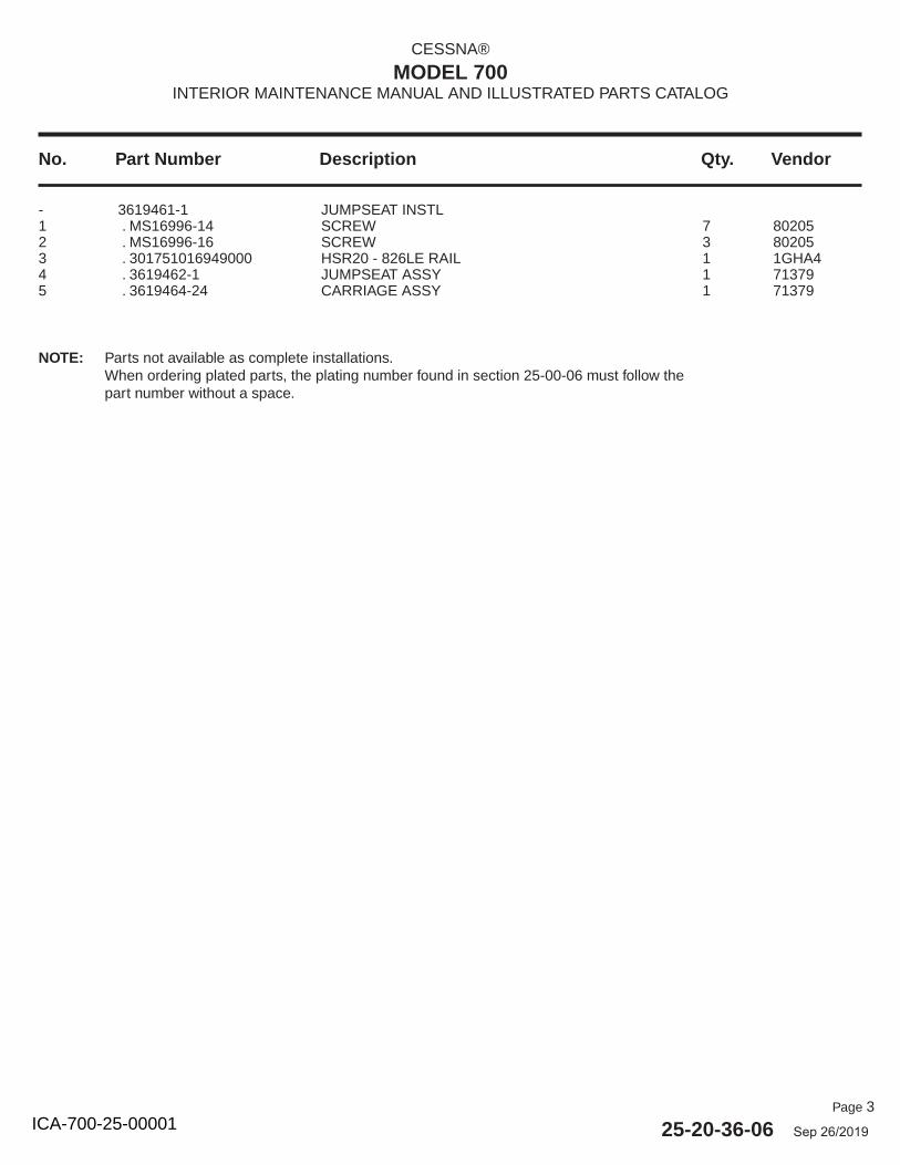
Page 3
25-20-36-06 Sep 26/2019
No. Part Number Description Qty. Vendor
CESSNA®
MODEL 700INTERIOR MAINTENANCE MANUAL AND ILLUSTRATED PARTS CATALOG
- 3619461-1 JUMPSEAT INSTL 1 . MS16996-14 SCREW 7 802052 . MS16996-16 SCREW 3 802053 . 301751016949000 HSR20 - 826LE RAIL 1 1GHA44 . 3619462-1 JUMPSEAT ASSY 1 713795 . 3619464-24 CARRIAGE ASSY 1 71379
NOTE: Parts not available as complete installations.When ordering plated parts, the plating number found in section 25-00-06 must follow the part number without a space.
ICA-700-25-00001
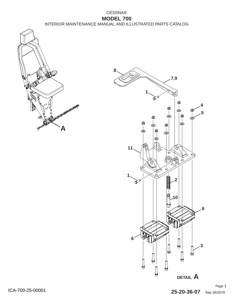
Page 1
25-20-36-07 Sep 26/2019
CESSNA®
MODEL 700INTERIOR MAINTENANCE MANUAL AND ILLUSTRATED PARTS CATALOG
DETAIL A
A
7,9
1
8
1
4
5
11
6
6
3
10
2
ICA-700-25-00001
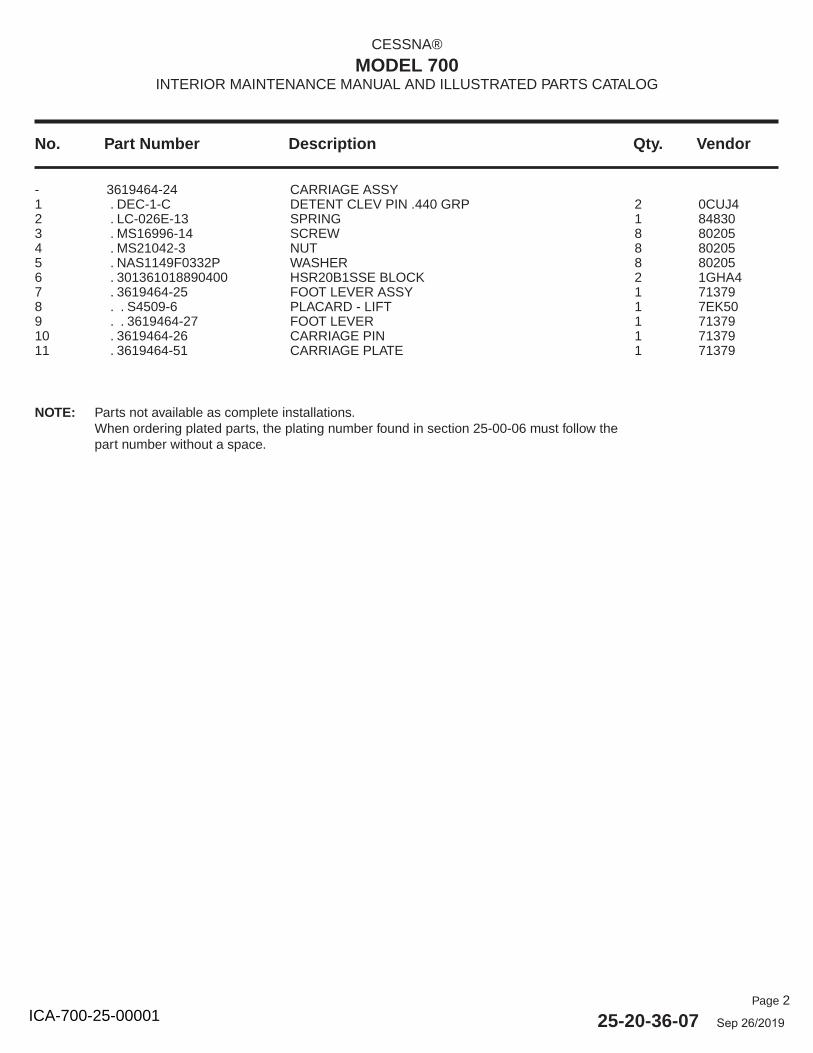
Page 2
25-20-36-07 Sep 26/2019
No. Part Number Description Qty. Vendor
CESSNA®
MODEL 700INTERIOR MAINTENANCE MANUAL AND ILLUSTRATED PARTS CATALOG
- 3619464-24 CARRIAGE ASSY 1 . DEC-1-C DETENT CLEV PIN .440 GRP 2 0CUJ42 . LC-026E-13 SPRING 1 848303 . MS16996-14 SCREW 8 802054 . MS21042-3 NUT 8 802055 . NAS1149F0332P WASHER 8 802056 . 301361018890400 HSR20B1SSE BLOCK 2 1GHA47 . 3619464-25 FOOT LEVER ASSY 1 713798 . . S4509-6 PLACARD - LIFT 1 7EK509 . . 3619464-27 FOOT LEVER 1 7137910 . 3619464-26 CARRIAGE PIN 1 7137911 . 3619464-51 CARRIAGE PLATE 1 71379
NOTE: Parts not available as complete installations.When ordering plated parts, the plating number found in section 25-00-06 must follow the part number without a space.
ICA-700-25-00001
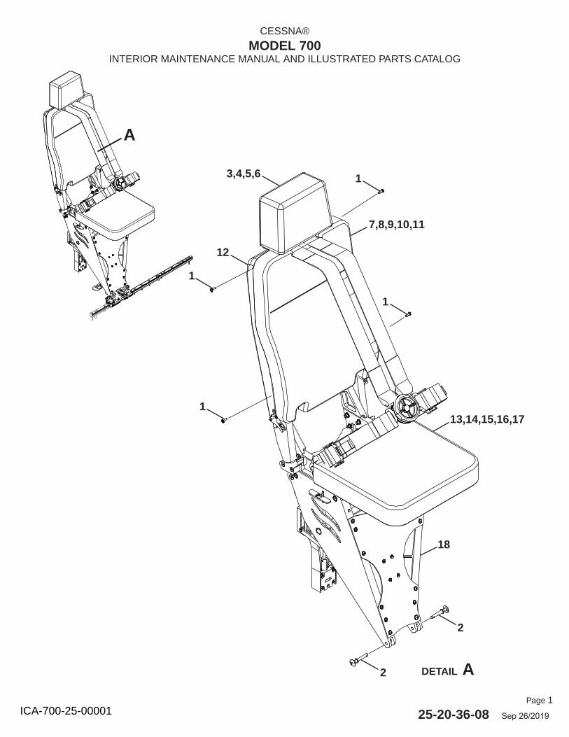
Page 1
25-20-36-08 Sep 26/2019
CESSNA®
MODEL 700INTERIOR MAINTENANCE MANUAL AND ILLUSTRATED PARTS CATALOG
A
DETAIL A
7,8,9,10,11
13,14,15,16,17
12
18
1
1
1
1
2
2
3,4,5,6
ICA-700-25-00001
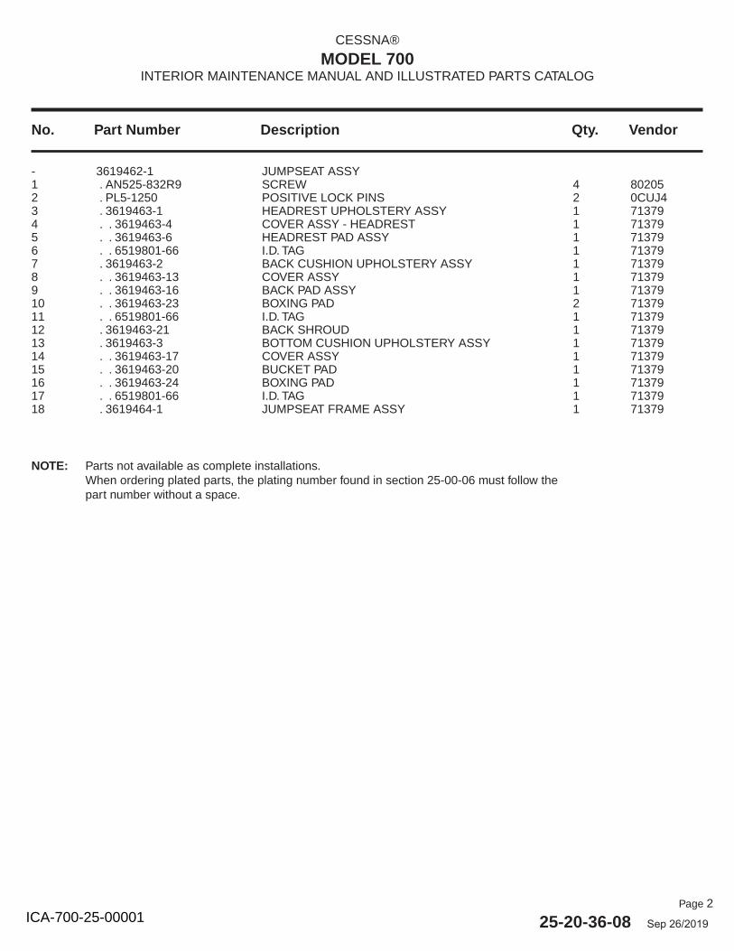
Page 2
25-20-36-08 Sep 26/2019
No. Part Number Description Qty. Vendor
CESSNA®
MODEL 700INTERIOR MAINTENANCE MANUAL AND ILLUSTRATED PARTS CATALOG
- 3619462-1 JUMPSEAT ASSY 1 . AN525-832R9 SCREW 4 802052 . PL5-1250 POSITIVE LOCK PINS 2 0CUJ43 . 3619463-1 HEADREST UPHOLSTERY ASSY 1 713794 . . 3619463-4 COVER ASSY - HEADREST 1 713795 . . 3619463-6 HEADREST PAD ASSY 1 713796 . . 6519801-66 I.D. TAG 1 713797 . 3619463-2 BACK CUSHION UPHOLSTERY ASSY 1 713798 . . 3619463-13 COVER ASSY 1 713799 . . 3619463-16 BACK PAD ASSY 1 7137910 . . 3619463-23 BOXING PAD 2 7137911 . . 6519801-66 I.D. TAG 1 7137912 . 3619463-21 BACK SHROUD 1 7137913 . 3619463-3 BOTTOM CUSHION UPHOLSTERY ASSY 1 7137914 . . 3619463-17 COVER ASSY 1 7137915 . . 3619463-20 BUCKET PAD 1 7137916 . . 3619463-24 BOXING PAD 1 7137917 . . 6519801-66 I.D. TAG 1 7137918 . 3619464-1 JUMPSEAT FRAME ASSY 1 71379
NOTE: Parts not available as complete installations.When ordering plated parts, the plating number found in section 25-00-06 must follow the part number without a space.
ICA-700-25-00001
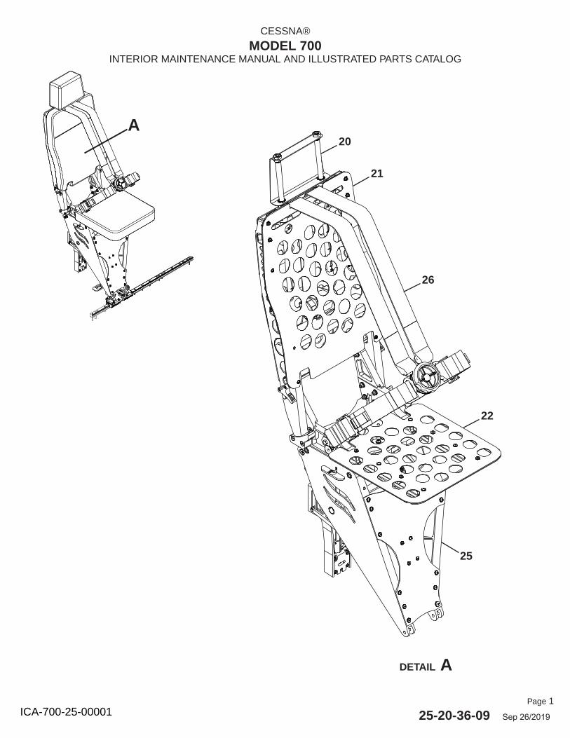
Page 1
25-20-36-09 Sep 26/2019
CESSNA®
MODEL 700INTERIOR MAINTENANCE MANUAL AND ILLUSTRATED PARTS CATALOG
DETAIL A
A20
22
21
25
26
ICA-700-25-00001
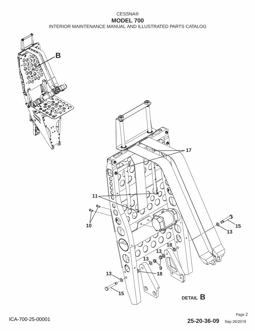
Page 2
25-20-36-09 Sep 26/2019
CESSNA®
MODEL 700INTERIOR MAINTENANCE MANUAL AND ILLUSTRATED PARTS CATALOG
B
DETAIL B
1513
15
13
10
11
17
18
13
13
9
18
ICA-700-25-00001
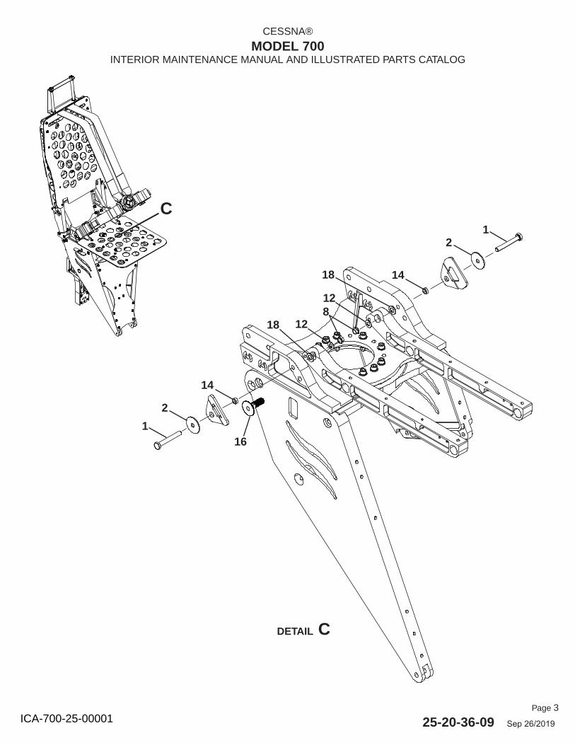
Page 3
25-20-36-09 Sep 26/2019
CESSNA®
MODEL 700INTERIOR MAINTENANCE MANUAL AND ILLUSTRATED PARTS CATALOG
C
DETAIL C
1
2
14
128
16
12
14
12
18
18
ICA-700-25-00001
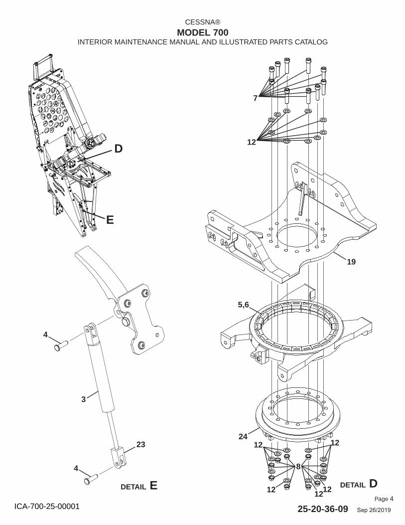
Page 4
25-20-36-09 Sep 26/2019
CESSNA®
MODEL 700INTERIOR MAINTENANCE MANUAL AND ILLUSTRATED PARTS CATALOG
24
7
5,6
D
DETAIL DDETAIL E
E
4
4
3
23
19
12
8
12 12
12 1212
ICA-700-25-00001
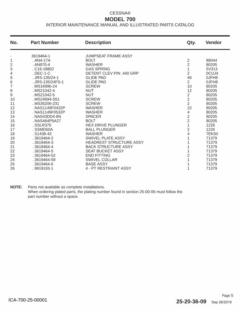
Page 5
25-20-36-09 Sep 26/2019
No. Part Number Description Qty. Vendor
CESSNA®
MODEL 700INTERIOR MAINTENANCE MANUAL AND ILLUSTRATED PARTS CATALOG
- 3619464-1 JUMPSEAT FRAME ASSY 1 . AN4-17A BOLT 2 880442 . AN970-4 WASHER 2 802053 . C16-18802 GAS SPRING 1 5V3134 . DEC-1-C DETENT CLEV PIN .440 GRP 2 0CUJ45 . JRS-135/24-1 GLIDE PAD 46 0JFH86 . JRS-135/24FS-1 GLIDE PAD 2 0JFH87 . MS16996-24 SCREW 10 802058 . MS21042-4 NUT 12 802059 . MS21042-5 NUT 2 8020510 . MS24694-S51 SCREW 2 8020511 . MS35206-231 SCREW 2 8020512 . NAS1149F0432P WASHER 22 8020513 . NAS1149F0532P WASHER 4 8020514 . NAS43DD4-8N SPACER 2 8020515 . NAS464P5A27 BOLT 2 8020516 . SSLR375 HEX DRIVE PLUNGER 1 122617 . SSMD50A BALL PLUNGER 2 122618 . S1438-43 WASHER 4 7EK5019 . 3619464-2 SWIVEL PLATE ASSY 1 7137920 . 3619464-3 HEADREST STRUCTURE ASSY 1 7137921 . 3619464-4 BACK STRUCTURE ASSY 1 7137922 . 3619464-5 SEAT BUCKET ASSY 1 7137923 . 3619464-52 END FITTING 2 7137924 . 3619464-59 SWIVEL COLLAR 1 7137925 . 3619464-6 BASE ASSY 1 7137926 . 9919193-1 4 - PT RESTRAINT ASSY 1 71379
NOTE: Parts not available as complete installations.When ordering plated parts, the plating number found in section 25-00-06 must follow the part number without a space.
ICA-700-25-00001
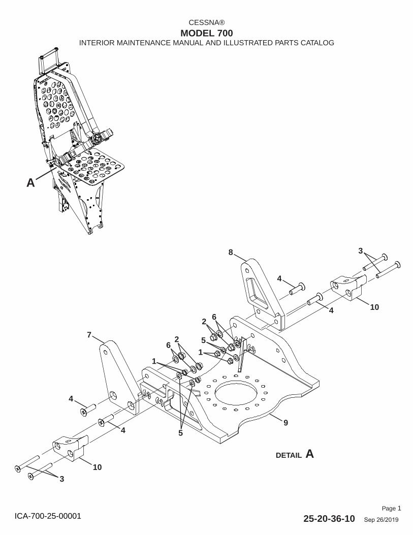
Page 1
25-20-36-10 Sep 26/2019
CESSNA®
MODEL 700INTERIOR MAINTENANCE MANUAL AND ILLUSTRATED PARTS CATALOG
DETAIL A
A
103
4
4
7
8
9
3
104
4
2 6
51
26
1
5
ICA-700-25-00001
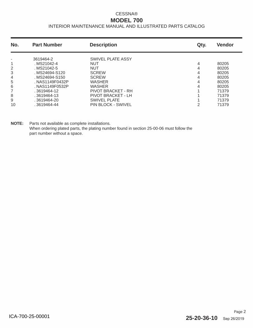
Page 2
25-20-36-10 Sep 26/2019
No. Part Number Description Qty. Vendor
CESSNA®
MODEL 700INTERIOR MAINTENANCE MANUAL AND ILLUSTRATED PARTS CATALOG
- 3619464-2 SWIVEL PLATE ASSY 1 . MS21042-4 NUT 4 802052 . MS21042-5 NUT 4 802053 . MS24694-S120 SCREW 4 802054 . MS24694-S150 SCREW 4 802055 . NAS1149F0432P WASHER 4 802056 . NAS1149F0532P WASHER 4 802057 . 3619464-12 PIVOT BRACKET - RH 1 713798 . 3619464-13 PIVOT BRACKET - LH 1 713799 . 3619464-20 SWIVEL PLATE 1 7137910 . 3619464-44 PIN BLOCK - SWIVEL 2 71379
NOTE: Parts not available as complete installations.When ordering plated parts, the plating number found in section 25-00-06 must follow the part number without a space.
ICA-700-25-00001
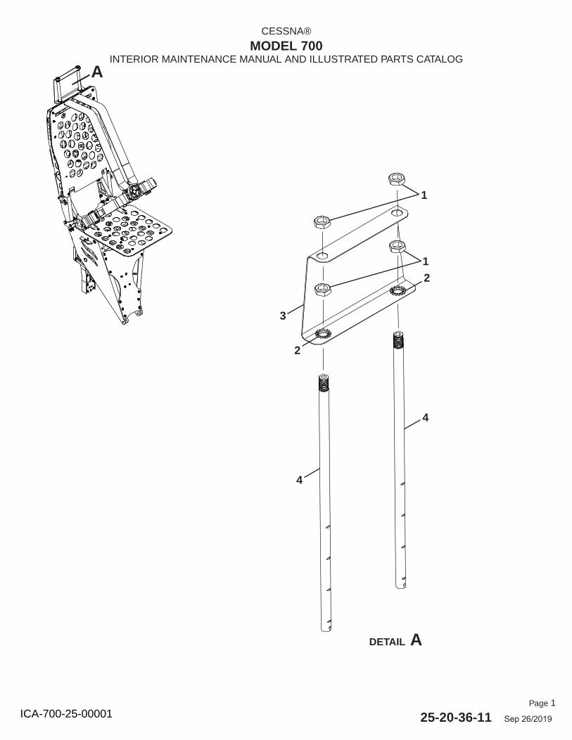
Page 1
25-20-36-11 Sep 26/2019
CESSNA®
MODEL 700INTERIOR MAINTENANCE MANUAL AND ILLUSTRATED PARTS CATALOG
DETAIL A
A
1
1
3
4
4
2
2
ICA-700-25-00001
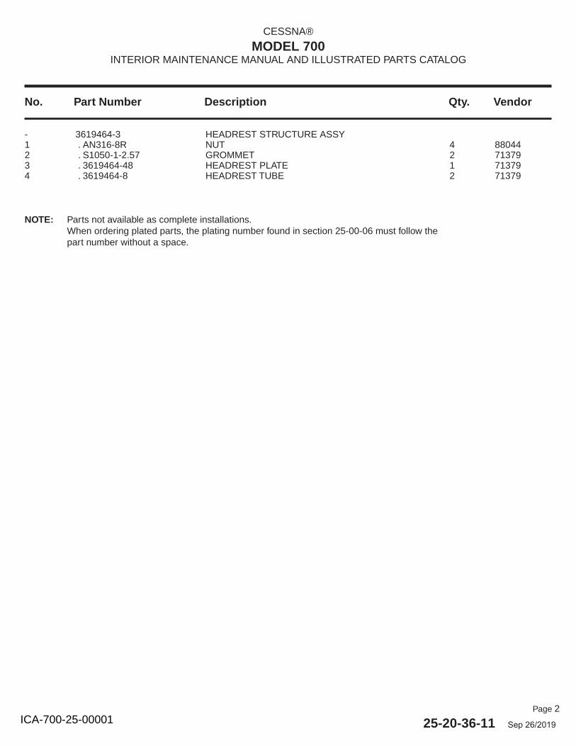
Page 2
25-20-36-11 Sep 26/2019
No. Part Number Description Qty. Vendor
CESSNA®
MODEL 700INTERIOR MAINTENANCE MANUAL AND ILLUSTRATED PARTS CATALOG
- 3619464-3 HEADREST STRUCTURE ASSY 1 . AN316-8R NUT 4 880442 . S1050-1-2.57 GROMMET 2 713793 . 3619464-48 HEADREST PLATE 1 713794 . 3619464-8 HEADREST TUBE 2 71379
NOTE: Parts not available as complete installations.When ordering plated parts, the plating number found in section 25-00-06 must follow the part number without a space.
ICA-700-25-00001
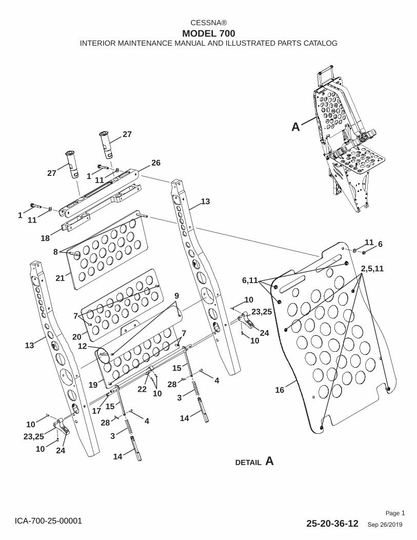
Page 1
25-20-36-12 Sep 26/2019
CESSNA®
MODEL 700INTERIOR MAINTENANCE MANUAL AND ILLUSTRATED PARTS CATALOG
DETAIL A
16
2,5,11
23,25
24
428
3
14
15
428
3
14
15
13
13
21
20
19 22 10
17
23,25
24
27
27
1 11
111
18
26
8
7
9
12
7
11 6
6,11
A
10
10
10
10
ICA-700-25-00001
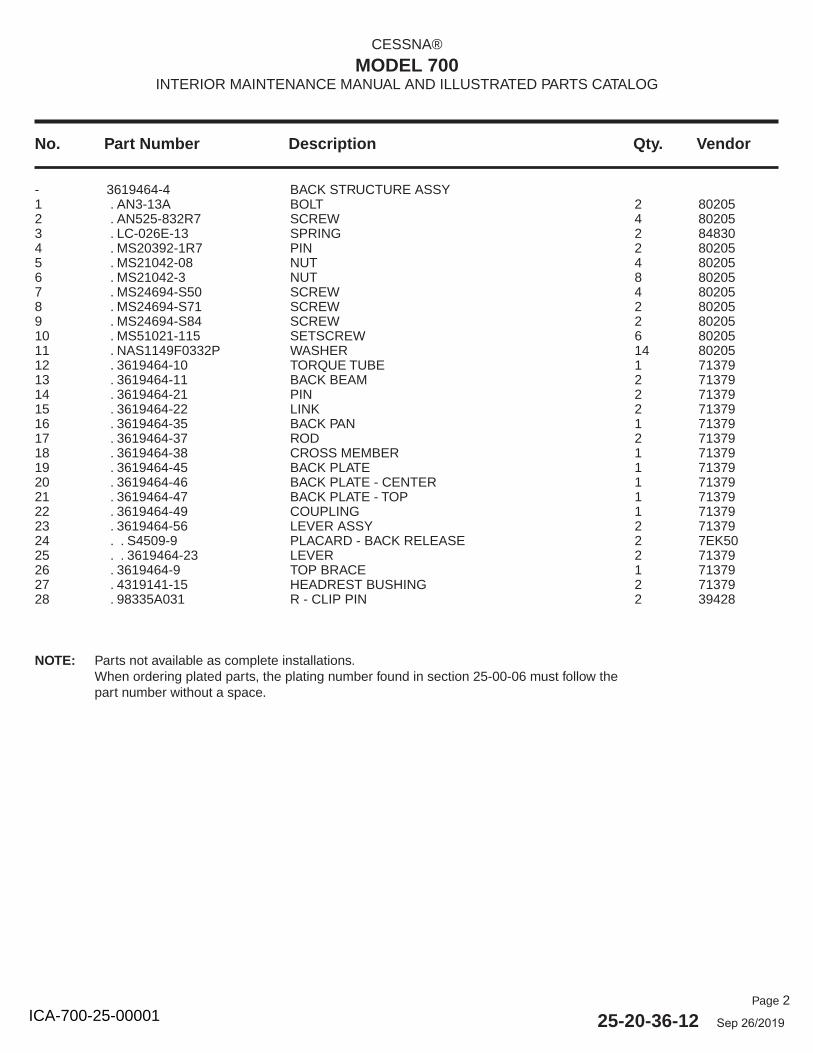
Page 2
25-20-36-12 Sep 26/2019
No. Part Number Description Qty. Vendor
CESSNA®
MODEL 700INTERIOR MAINTENANCE MANUAL AND ILLUSTRATED PARTS CATALOG
- 3619464-4 BACK STRUCTURE ASSY 1 . AN3-13A BOLT 2 802052 . AN525-832R7 SCREW 4 802053 . LC-026E-13 SPRING 2 848304 . MS20392-1R7 PIN 2 802055 . MS21042-08 NUT 4 802056 . MS21042-3 NUT 8 802057 . MS24694-S50 SCREW 4 802058 . MS24694-S71 SCREW 2 802059 . MS24694-S84 SCREW 2 8020510 . MS51021-115 SETSCREW 6 8020511 . NAS1149F0332P WASHER 14 8020512 . 3619464-10 TORQUE TUBE 1 7137913 . 3619464-11 BACK BEAM 2 7137914 . 3619464-21 PIN 2 7137915 . 3619464-22 LINK 2 7137916 . 3619464-35 BACK PAN 1 7137917 . 3619464-37 ROD 2 7137918 . 3619464-38 CROSS MEMBER 1 7137919 . 3619464-45 BACK PLATE 1 7137920 . 3619464-46 BACK PLATE - CENTER 1 7137921 . 3619464-47 BACK PLATE - TOP 1 7137922 . 3619464-49 COUPLING 1 7137923 . 3619464-56 LEVER ASSY 2 7137924 . . S4509-9 PLACARD - BACK RELEASE 2 7EK5025 . . 3619464-23 LEVER 2 7137926 . 3619464-9 TOP BRACE 1 7137927 . 4319141-15 HEADREST BUSHING 2 7137928 . 98335A031 R - CLIP PIN 2 39428
NOTE: Parts not available as complete installations.When ordering plated parts, the plating number found in section 25-00-06 must follow the part number without a space.
ICA-700-25-00001
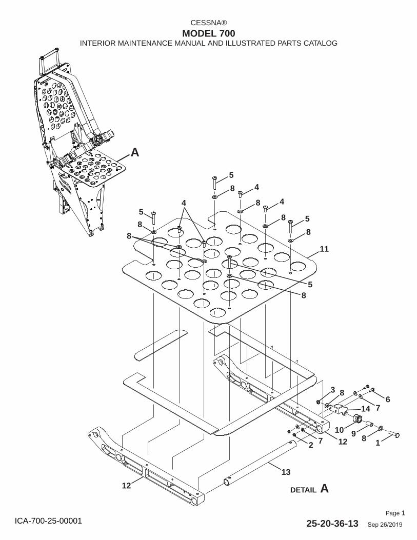
Page 1
25-20-36-13 Sep 26/2019
CESSNA®
MODEL 700INTERIOR MAINTENANCE MANUAL AND ILLUSTRATED PARTS CATALOG
DETAIL A
A
11
5
8
4
8
5
8 4
85
8
18910
3
122 7
13
12
8
76
8
4
58
14
ICA-700-25-00001
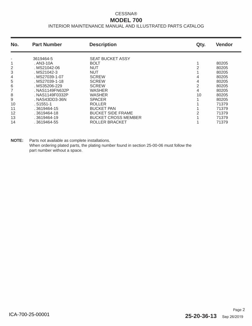
Page 2
25-20-36-13 Sep 26/2019
No. Part Number Description Qty. Vendor
CESSNA®
MODEL 700INTERIOR MAINTENANCE MANUAL AND ILLUSTRATED PARTS CATALOG
- 3619464-5 SEAT BUCKET ASSY 1 . AN3-10A BOLT 1 802052 . MS21042-06 NUT 2 802053 . MS21042-3 NUT 1 802054 . MS27039-1-07 SCREW 4 802055 . MS27039-1-18 SCREW 4 802056 . MS35206-229 SCREW 2 802057 . NAS1149FN632P WASHER 4 802058 . NAS1149F0332P WASHER 10 802059 . NAS43DD3-36N SPACER 1 8020510 . S1551-1 ROLLER 1 7137911 . 3619464-15 BUCKET PAN 1 7137912 . 3619464-18 BUCKET SIDE FRAME 2 7137913 . 3619464-19 BUCKET CROSS MEMBER 1 7137914 . 3619464-55 ROLLER BRACKET 1 71379
NOTE: Parts not available as complete installations.When ordering plated parts, the plating number found in section 25-00-06 must follow the part number without a space.
ICA-700-25-00001

Page 1
25-20-36-14 Sep 26/2019
CESSNA®
MODEL 700INTERIOR MAINTENANCE MANUAL AND ILLUSTRATED PARTS CATALOG
DETAIL A
A 1
2428
27
2824
3126229
22
20
19
13
23
10
36
35
30
241111
2430
33
2428
41
40,42
27
4
34
29
3
25 6529
237
38 8
2114
32
65
3
9,15,22
7,20
46
43
22
222
944
821
39
1722
2212
21
16
172318
22
17
22
45
5
6
4712
66
ICA-700-25-00001
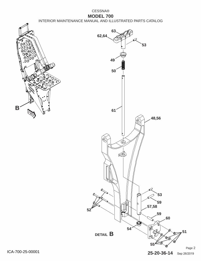
Page 2
25-20-36-14 Sep 26/2019
CESSNA®
MODEL 700INTERIOR MAINTENANCE MANUAL AND ILLUSTRATED PARTS CATALOG
B
6362,64
53
49
50
61
48,56
52
53
5957,58
5960
5154
55
DETAIL B
ICA-700-25-00001
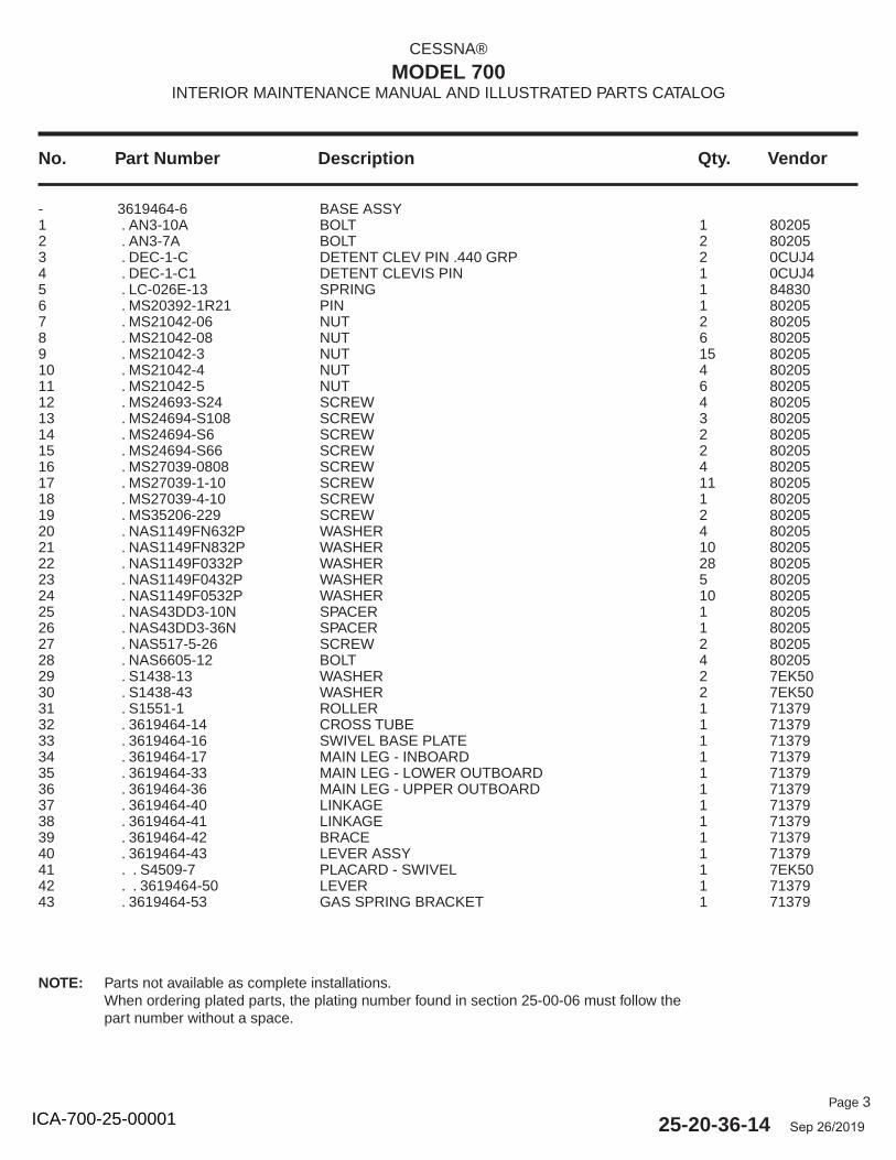
Page 3
25-20-36-14 Sep 26/2019
No. Part Number Description Qty. Vendor
CESSNA®
MODEL 700INTERIOR MAINTENANCE MANUAL AND ILLUSTRATED PARTS CATALOG
NOTE: Parts not available as complete installations.When ordering plated parts, the plating number found in section 25-00-06 must follow the part number without a space.
- 3619464-6 BASE ASSY 1 . AN3-10A BOLT 1 802052 . AN3-7A BOLT 2 802053 . DEC-1-C DETENT CLEV PIN .440 GRP 2 0CUJ44 . DEC-1-C1 DETENT CLEVIS PIN 1 0CUJ45 . LC-026E-13 SPRING 1 848306 . MS20392-1R21 PIN 1 802057 . MS21042-06 NUT 2 802058 . MS21042-08 NUT 6 802059 . MS21042-3 NUT 15 8020510 . MS21042-4 NUT 4 8020511 . MS21042-5 NUT 6 8020512 . MS24693-S24 SCREW 4 8020513 . MS24694-S108 SCREW 3 8020514 . MS24694-S6 SCREW 2 8020515 . MS24694-S66 SCREW 2 8020516 . MS27039-0808 SCREW 4 8020517 . MS27039-1-10 SCREW 11 8020518 . MS27039-4-10 SCREW 1 8020519 . MS35206-229 SCREW 2 8020520 . NAS1149FN632P WASHER 4 8020521 . NAS1149FN832P WASHER 10 8020522 . NAS1149F0332P WASHER 28 8020523 . NAS1149F0432P WASHER 5 8020524 . NAS1149F0532P WASHER 10 8020525 . NAS43DD3-10N SPACER 1 8020526 . NAS43DD3-36N SPACER 1 8020527 . NAS517-5-26 SCREW 2 8020528 . NAS6605-12 BOLT 4 8020529 . S1438-13 WASHER 2 7EK5030 . S1438-43 WASHER 2 7EK5031 . S1551-1 ROLLER 1 7137932 . 3619464-14 CROSS TUBE 1 7137933 . 3619464-16 SWIVEL BASE PLATE 1 7137934 . 3619464-17 MAIN LEG - INBOARD 1 7137935 . 3619464-33 MAIN LEG - LOWER OUTBOARD 1 7137936 . 3619464-36 MAIN LEG - UPPER OUTBOARD 1 7137937 . 3619464-40 LINKAGE 1 7137938 . 3619464-41 LINKAGE 1 7137939 . 3619464-42 BRACE 1 7137940 . 3619464-43 LEVER ASSY 1 7137941 . . S4509-7 PLACARD - SWIVEL 1 7EK5042 . . 3619464-50 LEVER 1 7137943 . 3619464-53 GAS SPRING BRACKET 1 71379
ICA-700-25-00001
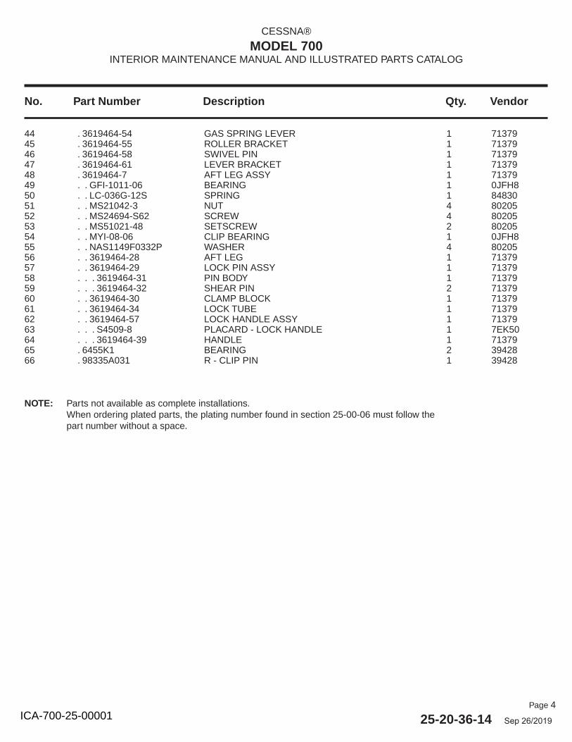
Page 4
25-20-36-14 Sep 26/2019
No. Part Number Description Qty. Vendor
CESSNA®
MODEL 700INTERIOR MAINTENANCE MANUAL AND ILLUSTRATED PARTS CATALOG
44 . 3619464-54 GAS SPRING LEVER 1 7137945 . 3619464-55 ROLLER BRACKET 1 7137946 . 3619464-58 SWIVEL PIN 1 7137947 . 3619464-61 LEVER BRACKET 1 7137948 . 3619464-7 AFT LEG ASSY 1 7137949 . . GFI-1011-06 BEARING 1 0JFH850 . . LC-036G-12S SPRING 1 8483051 . . MS21042-3 NUT 4 8020552 . . MS24694-S62 SCREW 4 8020553 . . MS51021-48 SETSCREW 2 8020554 . . MYI-08-06 CLIP BEARING 1 0JFH855 . . NAS1149F0332P WASHER 4 8020556 . . 3619464-28 AFT LEG 1 7137957 . . 3619464-29 LOCK PIN ASSY 1 7137958 . . . 3619464-31 PIN BODY 1 7137959 . . . 3619464-32 SHEAR PIN 2 7137960 . . 3619464-30 CLAMP BLOCK 1 7137961 . . 3619464-34 LOCK TUBE 1 7137962 . . 3619464-57 LOCK HANDLE ASSY 1 7137963 . . . S4509-8 PLACARD - LOCK HANDLE 1 7EK5064 . . . 3619464-39 HANDLE 1 7137965 . 6455K1 BEARING 2 3942866 . 98335A031 R - CLIP PIN 1 39428
NOTE: Parts not available as complete installations.When ordering plated parts, the plating number found in section 25-00-06 must follow the part number without a space.
ICA-700-25-00001
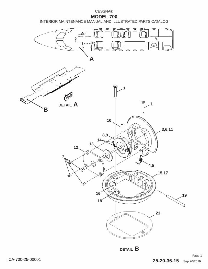
Page 1
25-20-36-15 Sep 26/2019
CESSNA®
MODEL 700INTERIOR MAINTENANCE MANUAL AND ILLUSTRATED PARTS CATALOG
A
DETAIL AB
DETAIL B
1
1
3,6,11
1918
16
15,17
4,5
7
1213
148,9
21
10
ICA-700-25-00001
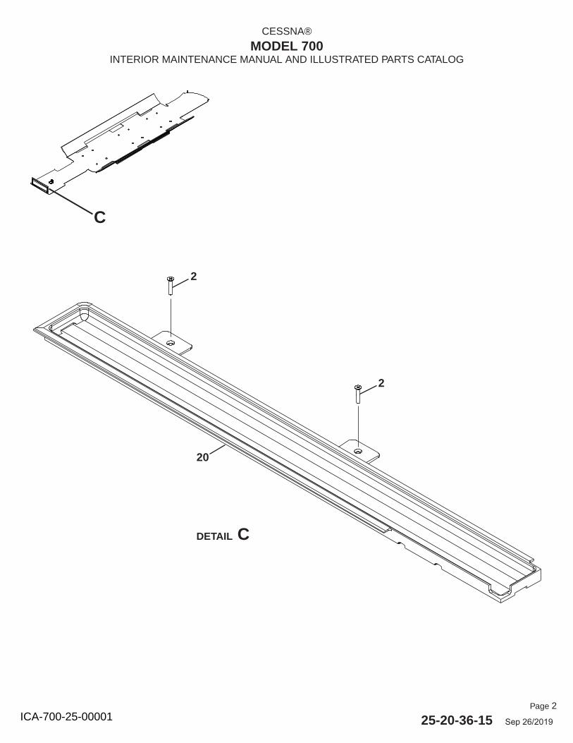
Page 2
25-20-36-15 Sep 26/2019
CESSNA®
MODEL 700INTERIOR MAINTENANCE MANUAL AND ILLUSTRATED PARTS CATALOG
C
DETAIL C
20
2
2
ICA-700-25-00001
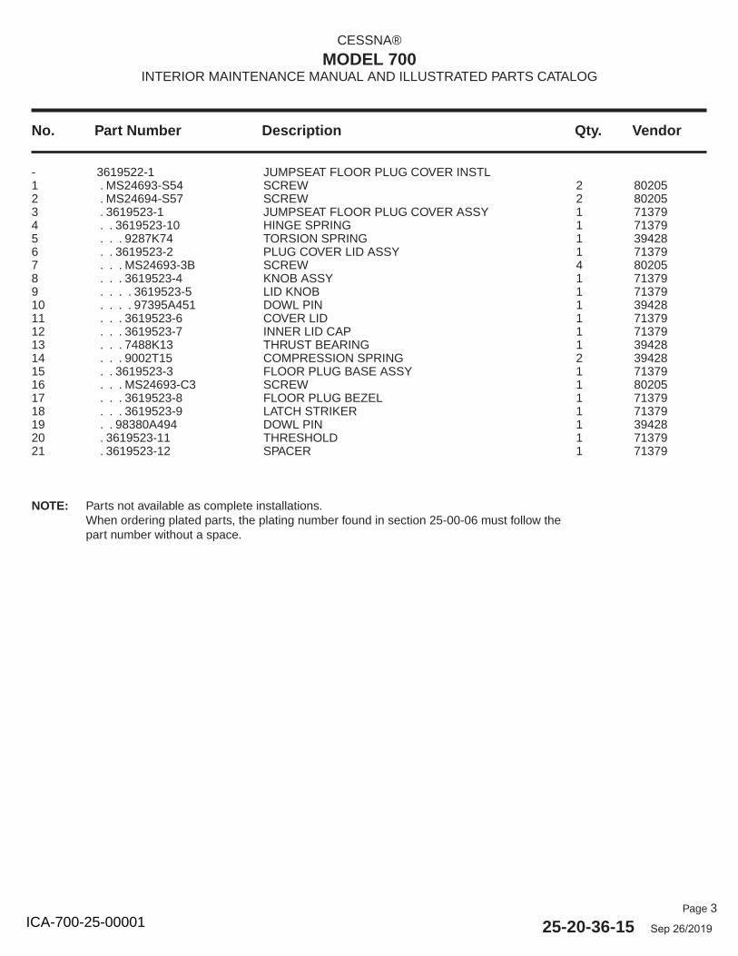
Page 3
25-20-36-15 Sep 26/2019
No. Part Number Description Qty. Vendor
CESSNA®
MODEL 700INTERIOR MAINTENANCE MANUAL AND ILLUSTRATED PARTS CATALOG
- 3619522-1 JUMPSEAT FLOOR PLUG COVER INSTL 1 . MS24693-S54 SCREW 2 802052 . MS24694-S57 SCREW 2 802053 . 3619523-1 JUMPSEAT FLOOR PLUG COVER ASSY 1 713794 . . 3619523-10 HINGE SPRING 1 713795 . . . 9287K74 TORSION SPRING 1 394286 . . 3619523-2 PLUG COVER LID ASSY 1 713797 . . . MS24693-3B SCREW 4 802058 . . . 3619523-4 KNOB ASSY 1 713799 . . . . 3619523-5 LID KNOB 1 7137910 . . . . 97395A451 DOWL PIN 1 3942811 . . . 3619523-6 COVER LID 1 7137912 . . . 3619523-7 INNER LID CAP 1 7137913 . . . 7488K13 THRUST BEARING 1 3942814 . . . 9002T15 COMPRESSION SPRING 2 3942815 . . 3619523-3 FLOOR PLUG BASE ASSY 1 7137916 . . . MS24693-C3 SCREW 1 8020517 . . . 3619523-8 FLOOR PLUG BEZEL 1 7137918 . . . 3619523-9 LATCH STRIKER 1 7137919 . . 98380A494 DOWL PIN 1 3942820 . 3619523-11 THRESHOLD 1 7137921 . 3619523-12 SPACER 1 71379
NOTE: Parts not available as complete installations.When ordering plated parts, the plating number found in section 25-00-06 must follow the part number without a space.
ICA-700-25-00001