novel electro-mechanical mechanism for blade pitch-control of horizontal-axis, home-scale wind...
TRANSCRIPT
American Institute of Aeronautics and Astronautics
1
Novel Electro-Mechanical Mechanism for Blade Pitch-Control of Horizontal-Axis, Home-scale Wind Turbines
Ahmed F. Abdel Gawad1 College of Engineering and Islamic Architecture, Umm Al-Qura University, Makkah, P. O. Box: 5555, Saudi Arabia
In the present research work, the pitch-control is carried out such that the rotor blades are rotated around their longitudinal axis while the rotor continues its normal rotation. It is really a challenge to produce a clever design to pitch the rotor blades by the optimal amount so as to maximize the power output at all wind speeds. The mechanism is implemented to a three-blade, horizontal-axis, home-scale wind turbine. The mechanism is powered by a suitable DC motor. The tests were carried out in the open section of a delivery wind tunnel. The air speed was measured by a suitable anemometer. The corresponding rotational speed (rpm) and output voltage at different wind speeds were measured and recorded for calibration of the control system. The mechanism proved to be successful in controlling the pitch angle over a wide range of wind speeds.
Nomenclature CW = clockwise CCW = counter-clockwise DC = direct current FLC = fuzzy logic controller HAWT = horizontal-axis wind turbine IPC = individual pitch control N = turbine rotational speed NREL = National Renewable Energy Laboratory Po = output power PI = proportional–integral rpm = rotational speed (revolution/minute) Uo = wind speed VAWT = vertical-axis wind turbine Vi = instantaneous output voltage Vo = output voltage of the generator Vr = rating output voltage
I. Introduction Nowadays, the renewable energy sources constitute a fairly good portion of the total energy sources allover the
world. This portion is growing rapidly due to many reasons. One of these reasons is the expected end of fossil energy sources in the near future. Environmental pollution, which reaches unacceptable levels, is another reason for the increasing global interest in renewable energy sources.
Wind, solar, marine wave, tidal, geothermal energies are examples of the available renewable energy sources. Wind energy is the fastest-growing renewable energy source in the world. About five years ago, the global installed capacity exceeded 50,000 MW, with a growth of about 10,000 MW/year1.
Concerning the Middle East, there is a big potential for wind power-generation. The mountainous nature of many parts provides continuous airstreams with a suitable range of air speed for commercial purposes. Also, there are very long distances of coastal lines along the Mediterranean and Red seas that are suitable for wind power-generation. Even in other areas, where wind speeds are not enough to construct large-scale wind turbines, small-scale (home-scale) turbines may be used.
1 Professor, Mechechanical Engineering Department, AIAA Associate Fellow.
10th International Energy Conversion Engineering Conference30 July - 01 August 2012, Atlanta, Georgia
AIAA 2012-4245
Copyright © 2012 by the American Institute of Aeronautics and Astronautics, Inc. All rights reserved.
American Institute of Aeronautics and Astronautics
2
There are few different techniques to maximize the power output and optimize turbine performance at all wind speeds. These techniques include blade pitch-control, camber control with flaps and generator torque control.
Blade pitch-control is the system which monitors and adjusts the inclination angle of the blades and thus controls the rotational speed of the blades. At lower wind speeds, the pitching system leads to an acceleration of the hub rotational speed, while at higher speeds; blade pitch-control reduces the wind load on the blades and structure of the turbine and keeps the generator at the rated power. Such a method is currently used by turbines in the 500 kW to 1 MW range.
Traditionally, there are different types of pitch-control systems including hydraulic, mechanical, electrical, and electro-mechanical systems. About one third of the installed wind machines use pitch-control mechanisms2.
In the present investigation, the pitch control is carried out such that the rotor blades are rotated around their longitudinal axis while the rotor continues its normal rotation. The main objective is to develop a suitable simple, low-cost, and robust control mechanism.
The present mechanism is consistent with the current trend in shifting towards the electro-mechanical systems due to their known reliability and low maintenance needs. The mechanism is implemented to a three-blade model. The section of the blades that were molded from fiberglass resembles a standard airfoil section.
The mechanism is powered by a suitable electric motor. The model tests were carried out in the open section of a delivery wind tunnel. An electronic circuit of a microcontroller was used to control the movement of the control mechanism. In the following sections, concentration is much paid to the control mechanism more than the control circuit.
Many researchers concerned the problem of active control of wind turbines of all sizes and types. In the following section, some of these researches are illustrated to show a broader view of the control issue of the wind turbines.
II. Previous Investigations
A. General control problem The control subject in general was studied by many investigators. Johnson3 developed, tested, and analyzed an
adaptive control strategy. His controller was designed to reduce the energy loss that results from uncertainty in a turbine’s aerodynamic parameters. He verified the operation of his adaptive controller using both simulations and experimentation on a real, mid-sized (600 kW), variable speed turbine. He argued that the cost of changing the control strategy on an existing turbine is very small when compared with the cost of the turbine.
Ragheb2 carried out a survey of the different types of control that are applied in wind turbines. These types include: mechanical pitch control, pitch power control, passive and active stall power control, combination pitch and stall control, flap power control, yaw power control, orientation yaw control. He stated that about one third of the installed wind machines use pitch-control mechanisms.
As a more specific task, Laks et al.4 reviewed the objectives and techniques used in the control of horizontal axis wind turbines at the individual turbine level, where controls are applied to the turbine blade pitch and generator. They modeled the turbine system as a flexible structure operating in the presence of turbulent wind disturbances. They mentioned that proper characterization of the wind inflow to a turbine is important for improved turbine design as the concentrated wind gusts, rapid wind direction changes, or passage of energetic atmospheric structures impose critical loads on individual wind turbines and blades. They also stated that the pitch related limitation may be circumvented with new actuation technologies currently being investigated, including such devices as trailing edge flaps, micro-tabs, adaptive trailing edge devices, etc.
B. Blade-pitch control The blade-pitch control problem was the main subject of many researchers. Muljadi and Butterfield5 analyzed
and simulated the operation of variable-speed wind turbines with pitch control. In medium wind speeds, the generator and power converter controlled the wind turbine to capture maximum energy from the wind. They investigated two methods to adjust the aerodynamic power: pitch control and generator load control. In the high wind speed region, the wind turbine was controlled to maintain the aerodynamic power produced by the wind turbine. They showed that the wind turbine can be operated at its optimum energy capture while minimizing the load on the wind turbine for a wide range of wind speeds.
Bindner6 presented a model for design and analysis of controllers for pitch controlled wind turbine to evaluate and improve pitch controllers for conventional three bladed pitch controlled wind turbines (Vestas Wind Systems WD34 400 kW). His wind turbine model includes tower and blade bending, gearbox, generator, pitch system, aerodynamics, and controller.
American Institute of Aeronautics and Astronautics
3
Thiringer and Petersson7 investigated the speed control of a modern pitch-regulated wind turbine. They derived a controller structure and the significance of various parameters in the controller structure was investigated. Thus, they analyzed the influence of the speed control bandwidth on the speed variations, torque stresses and energy production. Their control structure operates without any knowledge of the wind speed or shaft torque; instead these quantities are estimated from the rotor speed and electric power. Thus, they concluded that the lower bandwidths are the ones to prefer. They mentioned that at low wind speeds, the rotor speed was controlled using the electrodynamic torque of the generator and at high wind speeds the rotor speed was controlled using the pitch angle.
Hansen et al.8 presented three different controller designs based on proportional–integral (PI) regulation of rotor speed and power through the collective blade pitch angle and generator moment. They used the aeroelastic and electrical modeling for the time-domain analysis. They illustrated that numerical optimization can be used to tune controller parameters, especially when the optimization is used as refinement of a qualified initial guess.
Sun1 developed a method of achieving variable speed operation of wind turbines via a pitch servo-mechanism. She considered three types of pitch actuator dynamics and integrated them into control design. Her proposed pitch control algorithms were based on the nonlinear model instead of the commonly used linear or linear plus perturbation model. She derived the pitch control algorithms using back-stepping method and applied them to a numerical example for verification. She stated that both analytical and simulation studies confirm that the developed pitch control schemes ensure smooth and asymptotic rotor speed tracking. She concluded that since the actuator dynamics were considered in her design, the developed pitch control algorithms were less sensitive to operating points and more practical and suitable for real-time implementation
C. Blade-pitch control by Matlab Simulink toolbox Matlab Simulink toolbox was used to simulate blade-pitch control. El-Tous9 aimed to design a simple controller
to maximize the extracted energy of wind turbines through pitch angle control of a variable speed wind turbine using Matlab Simulink toolbox. He concentrated on the extraction of maximum available energy, reduction of torque and output power variations, which gives stresses in the gearbox and mechanical structure. He stated that a variable-rotor- speed turbine allows to partially store energy from wind gusts in the rotating mass of the turbine rotor instead of transmitting them through the drive train.
In the same direction, Ramakrishnan and Srivatsa10 described the modeling of the various components in a pitch controlled wind energy system and the design of the pitch controller, and discussed the response of the pitch-controlled system to wind velocity variations. They modeled the complete pitch control system with either a hydraulic actuator controller or their proposed stepper motor mechanism in Matlab Simulink toolbox during the turbulent nature of the wind condition. They concluded that their pitch control system is easy to implement; however, the response is slow and the output power variation is large and that fast torque changes caused by wind gusts impact generator performance. They found that the cost of their mechanism is low compared to a corresponding hydraulic actuator mechanism and can be used up to 30 KW wind turbine.
D. Individual pitch control (IPC) The individual pitch control (IPC) technique was examined by Bossanyi11 who discussed the possibility of using
the individual pitch actuators for each blade by sending different pitch angle demands to each blade. He stated that, to design the necessary control algorithms, a linear model of the turbine which embodies the asymmetric loading and the effect of individual pitch action is required. He concluded that the pitch actuators clearly experience greater activity and must be designed with this in view, but the additional duty is not prohibitively large and it is possible to transform the problem into two decoupled single-input, single-output control loops. He demonstrated that a very significant reduction in operational loading can be achieved by means of individual pitch action, provided a suitable measurement of the asymmetric loading is available using reliable sensors.
Afterwards, Selvam12 pointed out that the up-scaling of wind turbines, even towards 10 MW wind turbines, may be necessary to lower the costs of offshore wind energy and this requires considerable reductions of turbine loads. He studied the utilization of the IPC technique to reduce the blade and tower loads using advanced feedback-feedforward control method and compared it with the traditional scalar control concept. He stated that the IPC technique has many practical advantages over other control methods.
As a continuing effort, Selvam et al.13 focused on the problem of wind turbine fatigue load reduction by means of individual pitch control (IPC). The control approach has a two-degree-of-freedom structure, consisting of an optimal multivariable controller and a feedforward-disturbance-rejection controller based on estimated wind speed signals. Their approach was tested and compared with the conventional IPC method. Their results demonstrated very good load reduction at a wide range of frequencies, giving rise to fatigue load reduction of the non-rotating turbine components.
American Institute of Aeronautics and Astronautics
4
E. Fuzzy-logic controller Some of the investigations were related to fuzzy-logic controllers of the blade-pitch. Zhang et al.14 developed
a fuzzy-logic pitch-angle controller. They explained that the fuzzy-logic control technique has the potential over other techniques (e.g., proportional–integral (PI) controller) when the system contains strong non-linearity. The non-linearity appears when the wind turbulence is strong or the control objectives include fatigue loads. Their simulation showed that the fuzzy-logic controller can achieve better control performances than conventional pitch-angle control strategies; namely: lower fatigue loads, and lower power and torque peaks.
Recently, Musyafa’ et al.15 built and demonstrated a wind turbine prototype with a pitch-angle control based on fuzzy logic to maximize the output power. They aimed to reduce torque and output power variation in high-rated wind speed areas and to maximize available energy in the low-rated wind speed areas. They carried out simulations and comparisons of the fuzzy-logic controller (FLC) and PI controller. They found out that, in the varying low-rated wind speed of 4-6 m/s, the use of fuzzy logic controller can maximize the average output power of 14.5 W compared to 14.0 W at a fixed pitch angle of the blade for 1-m diameter, three-blade wind turbine.
F. Balde pitch-control of vertical-axis wind turbines (VAWT) Although the present work concentrates on horizontal-axis wind turbines (HAWT), it is beneficial to show that
investigators concerned the balde pitch-control technique for the vertical-axis wind turbines (VAWT) also. Lazauskas16 compared the theoretical performance of three variable pitch mechanisms for vertical-axis wind turbine (VAWT). These mechanisms are the "sinusoidal forced pitch variation", "self-acting stabilized pitch control", and "Aero-pitch" in which stabilizing moments are related to the blade relative velocity. He stated that the examined pitch control systems can all be configured to produce better starting torque, a broader operating range, and greater efficiency than fixed pitch VAWT.
Pradeep et al.17 simulated a dynamical-system model and a control algorithm to enhance the efficiency of a small, vertical axis wind turbine (VAWT). Their wind turbine was designed for suburban regions, without very favorable wind conditions, by considering both blade pitch and camber controls. The pitch control was achieved by rotating each individual blade about its vertical axis, while camber control was realized using a trailing edge flap on each blade. They applied the pitch control in association with a permanent magnet synchronous generator and a matrix converter. They stated that applying their pitch control model leads to large improvements in the amount of power extracted from the turbine, thus, highly increasing its overall efficiency.
Paraschivoiu et al.18 proposed a procedure for computing the optimal variation of the blades’ pitch angle of an H-Darrieus wind turbine that maximizes its torque at given operational conditions for a 7 kW prototype. They used the CARDAAV code, based on the “Double-Multiple Streamtube” model to determine the performances of the straight-bladed vertical axis wind turbine. Their code was coupled with a genetic algorithm optimizer and the variation of the blades’ pitch angle is modeled with an analytical function whose coefficients are used as variables in the optimization process. They stated that a gain of almost 30% in the annual energy production was obtained with the polynomial optimal pitch control.
III. Home-scale Wind Turbines There is an increasing interest in the development and construction of home-scale wind turbines. There are many
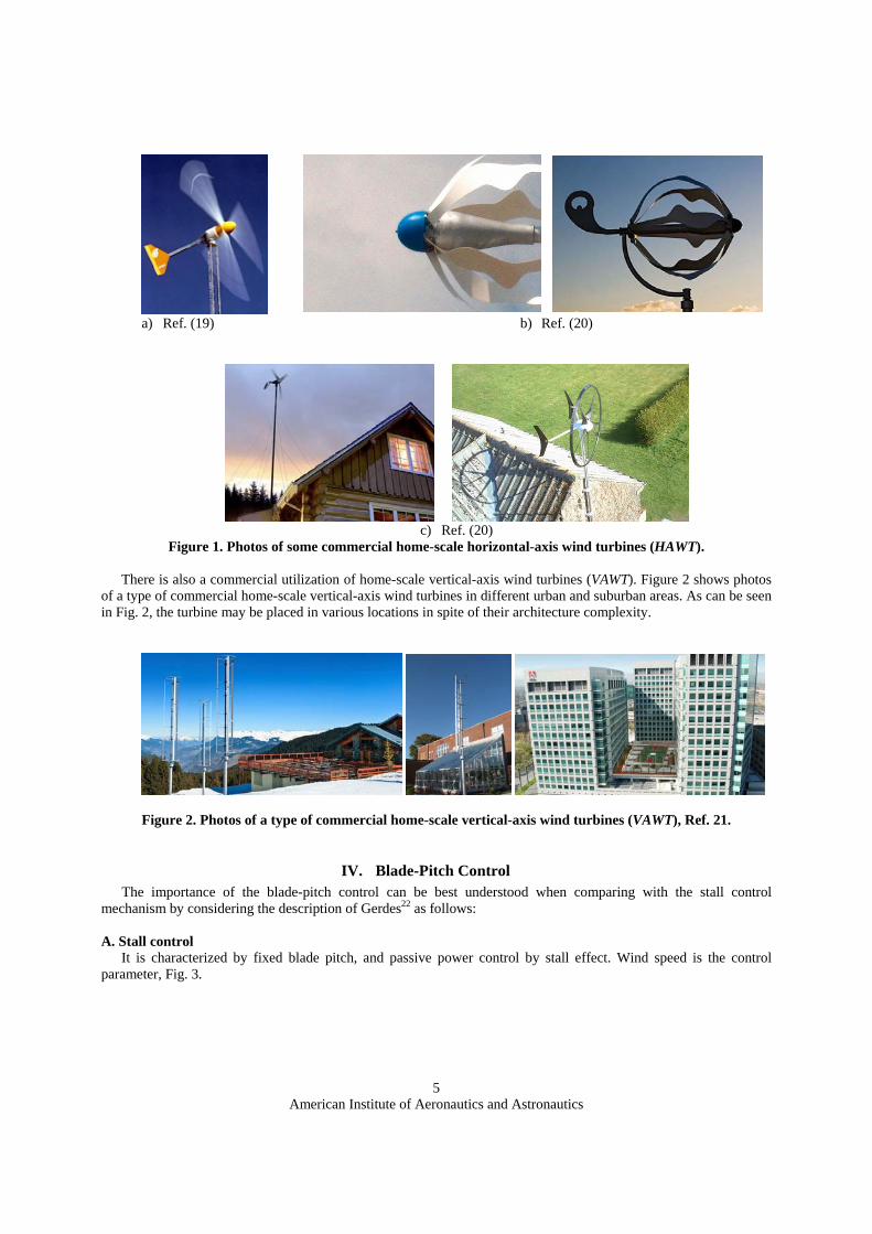
advantages of this type of turbines that encourage the utilization of them. These advantages include low-cost, and easy manufacturing and maintenance as well as durability. Usually, they produce power from 200 to 1000 W and work at low wind speeds; starting from 5 m/s. Their size ranges between 0.4 m to 2.0 m. These turbines may be used individually or in groups either on top of buildings or in the backyards of residential or commercial complexes. The home-scale wind turbines are useful for both urban and suburban areas.
Figure 1 shows photos of some commercial home-scale horizontal-axis wind turbines (HAWT). These turbines may have the traditional shape of wind turbines with simple wind direction guide, Fig. 1(a). Other turbines may take unusual aerodynamic shapes to improve their aerodynamic performance and increase their output power, Figs. 1(b) and 1(c). As can be seen in Fig. 1(c), the turbines may be installed using long towers on top of the houses or in the backyards.
American Institute of Aeronautics and Astronautics
5
a) Ref. (19) b) Ref. (20)
c) Ref. (20)
Figure 1. Photos of some commercial home-scale horizontal-axis wind turbines (HAWT).
There is also a commercial utilization of home-scale vertical-axis wind turbines (VAWT). Figure 2 shows photos of a type of commercial home-scale vertical-axis wind turbines in different urban and suburban areas. As can be seen in Fig. 2, the turbine may be placed in various locations in spite of their architecture complexity.
Figure 2. Photos of a type of commercial home-scale vertical-axis wind turbines (VAWT), Ref. 21.
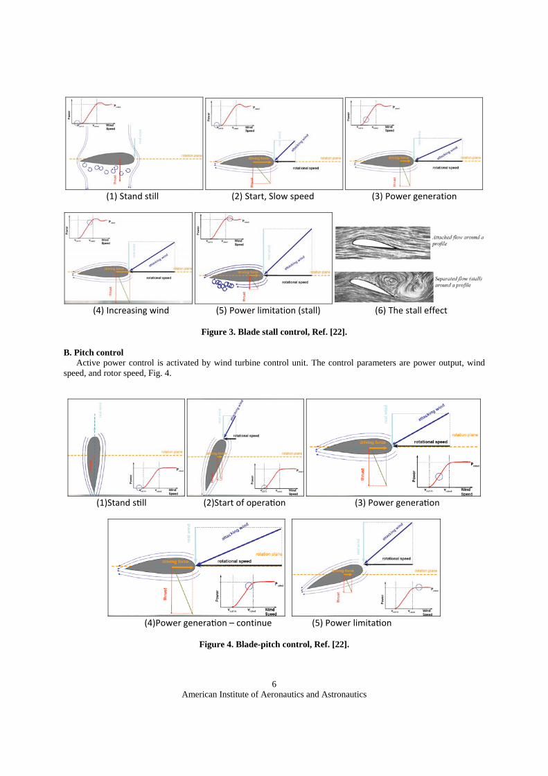
IV. Blade-Pitch Control The importance of the blade-pitch control can be best understood when comparing with the stall control
mechanism by considering the description of Gerdes22 as follows: A. Stall control
It is characterized by fixed blade pitch, and passive power control by stall effect. Wind speed is the control parameter, Fig. 3.
American Institute of Aeronautics and Astronautics
6
(1) Stand still (2) Start, Slow speed (3) Power generation
(4) Increasing wind (5) Power limitation (stall) (6) The stall effect
Figure 3. Blade stall control, Ref. [22].
B. Pitch control
Active power control is activated by wind turbine control unit. The control parameters are power output, wind speed, and rotor speed, Fig. 4.
(1)Stand still (2)Start of operation (3) Power generation
(4)Power generation – continue (5) Power limitation
Figure 4. Blade-pitch control, Ref. [22].
American Institute of Aeronautics and Astronautics
7
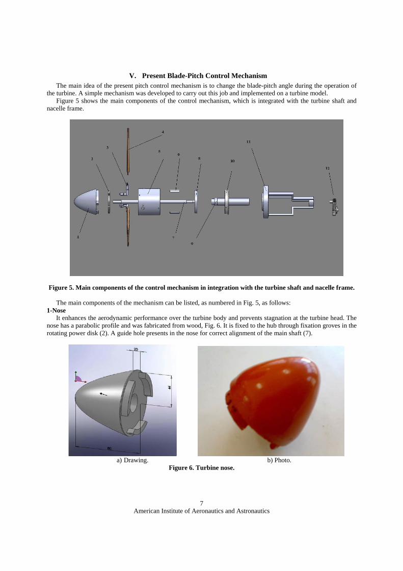
V. Present Blade-Pitch Control Mechanism The main idea of the present pitch control mechanism is to change the blade-pitch angle during the operation of
the turbine. A simple mechanism was developed to carry out this job and implemented on a turbine model. Figure 5 shows the main components of the control mechanism, which is integrated with the turbine shaft and
nacelle frame.
Figure 5. Main components of the control mechanism in integration with the turbine shaft and nacelle frame. The main components of the mechanism can be listed, as numbered in Fig. 5, as follows:
1-Nose It enhances the aerodynamic performance over the turbine body and prevents stagnation at the turbine head. The
nose has a parabolic profile and was fabricated from wood, Fig. 6. It is fixed to the hub through fixation groves in the rotating power disk (2). A guide hole presents in the nose for correct alignment of the main shaft (7).
a) Drawing. b) Photo.
Figure 6. Turbine nose.
American Institute of Aeronautics and Astronautics
8
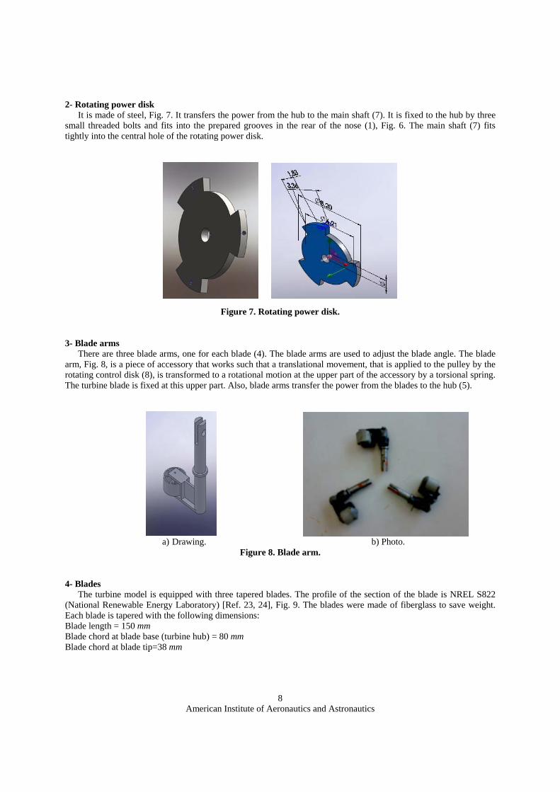
2- Rotating power disk It is made of steel, Fig. 7. It transfers the power from the hub to the main shaft (7). It is fixed to the hub by three
small threaded bolts and fits into the prepared grooves in the rear of the nose (1), Fig. 6. The main shaft (7) fits tightly into the central hole of the rotating power disk.
Figure 7. Rotating power disk.
3- Blade arms
There are three blade arms, one for each blade (4). The blade arms are used to adjust the blade angle. The blade arm, Fig. 8, is a piece of accessory that works such that a translational movement, that is applied to the pulley by the rotating control disk (8), is transformed to a rotational motion at the upper part of the accessory by a torsional spring. The turbine blade is fixed at this upper part. Also, blade arms transfer the power from the blades to the hub (5).
a) Drawing. b) Photo.
Figure 8. Blade arm. 4- Blades
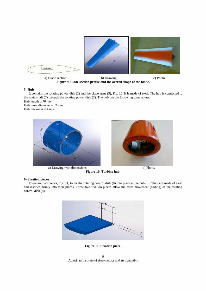
The turbine model is equipped with three tapered blades. The profile of the section of the blade is NREL S822 (National Renewable Energy Laboratory) [Ref. 23, 24], Fig. 9. The blades were made of fiberglass to save weight. Each blade is tapered with the following dimensions: Blade length = 150 mm Blade chord at blade base (turbine hub) = 80 mm Blade chord at blade tip=38 mm
American Institute of Aeronautics and Astronautics
9
a) Blade section. b) Drawing. c) Photo.
Figure 9. Blade section profile and the overall shape of the blade.
5- Hub It contains the rotating power disk (2) and the blade arms (3), Fig. 10. It is made of steel. The hub is connected to
the main shaft (7) through the rotating power disk (2). The hub has the following dimensions: Hub length ≅ 70 mm Hub inner diameter = 82 mm Hub thickness = 4 mm
a) Drawing with dimensions. b) Photo.
Figure 10. Turbine hub. 6- Fixation pieces
There are two pieces, Fig. 11, to fix the rotating control disk (8) into place in the hub (5). They are made of steel and inserted firmly into their places. These two fixation pieces allow the axial movement (sliding) of the rotating control disk (8).
Figure 11. Fixation piece.
American Institute of Aeronautics and Astronautics
10
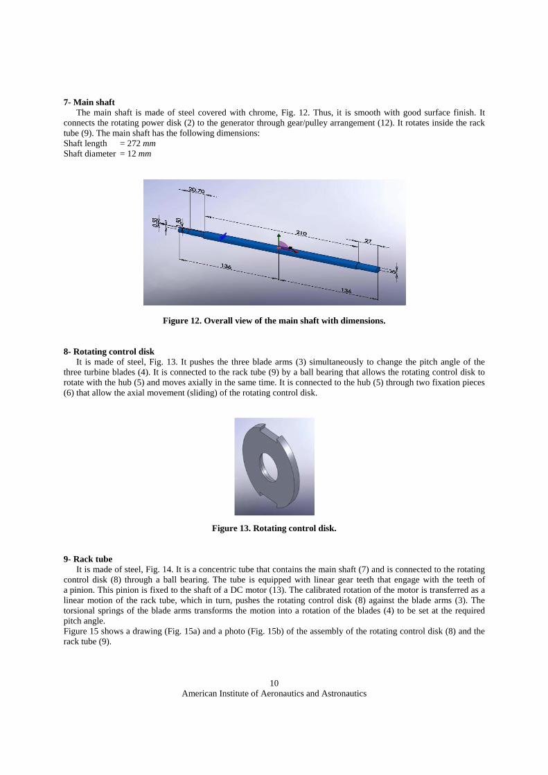
7- Main shaft The main shaft is made of steel covered with chrome, Fig. 12. Thus, it is smooth with good surface finish. It
connects the rotating power disk (2) to the generator through gear/pulley arrangement (12). It rotates inside the rack tube (9). The main shaft has the following dimensions: Shaft length = 272 mm Shaft diameter = 12 mm
Figure 12. Overall view of the main shaft with dimensions. 8- Rotating control disk
It is made of steel, Fig. 13. It pushes the three blade arms (3) simultaneously to change the pitch angle of the three turbine blades (4). It is connected to the rack tube (9) by a ball bearing that allows the rotating control disk to rotate with the hub (5) and moves axially in the same time. It is connected to the hub (5) through two fixation pieces (6) that allow the axial movement (sliding) of the rotating control disk.
Figure 13. Rotating control disk.
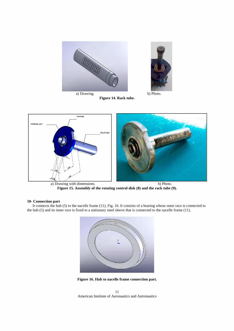
9- Rack tube
It is made of steel, Fig. 14. It is a concentric tube that contains the main shaft (7) and is connected to the rotating control disk (8) through a ball bearing. The tube is equipped with linear gear teeth that engage with the teeth of a pinion. This pinion is fixed to the shaft of a DC motor (13). The calibrated rotation of the motor is transferred as a linear motion of the rack tube, which in turn, pushes the rotating control disk (8) against the blade arms (3). The torsional springs of the blade arms transforms the motion into a rotation of the blades (4) to be set at the required pitch angle. Figure 15 shows a drawing (Fig. 15a) and a photo (Fig. 15b) of the assembly of the rotating control disk (8) and the rack tube (9).
American Institute of Aeronautics and Astronautics
11
a) Drawing. b) Photo.
Figure 14. Rack tube.
a) Drawing with dimensions. b) Photo.
Figure 15. Assembly of the rotating control disk (8) and the rack tube (9). 10- Connection part
It connects the hub (5) to the nacelle frame (11), Fig. 16. It consists of a bearing whose outer race is connected to the hub (5) and its inner race is fixed to a stationary steel sleeve that is connected to the nacelle frame (11).
Figure 16. Hub to nacelle frame connection part.
American Institute of Aeronautics and Astronautics
12
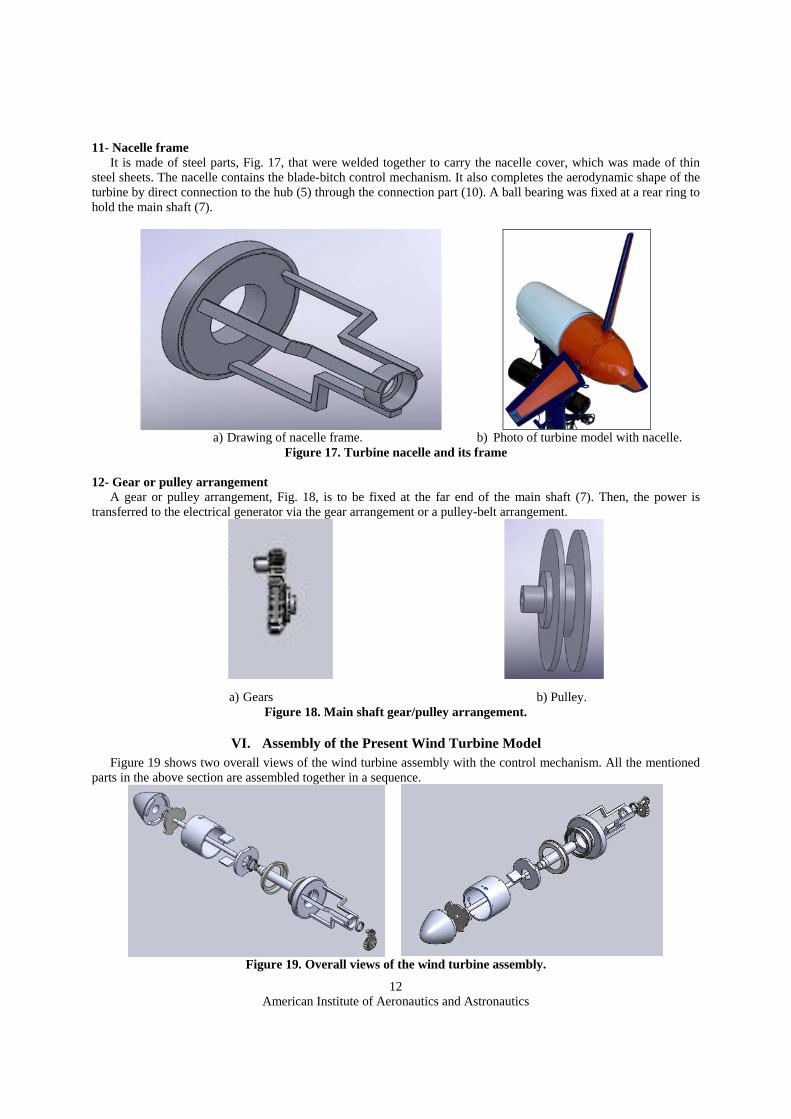
11- Nacelle frame It is made of steel parts, Fig. 17, that were welded together to carry the nacelle cover, which was made of thin
steel sheets. The nacelle contains the blade-bitch control mechanism. It also completes the aerodynamic shape of the turbine by direct connection to the hub (5) through the connection part (10). A ball bearing was fixed at a rear ring to hold the main shaft (7).
a) Drawing of nacelle frame. b) Photo of turbine model with nacelle.
Figure 17. Turbine nacelle and its frame 12- Gear or pulley arrangement
A gear or pulley arrangement, Fig. 18, is to be fixed at the far end of the main shaft (7). Then, the power is transferred to the electrical generator via the gear arrangement or a pulley-belt arrangement.
a) Gears b) Pulley.
Figure 18. Main shaft gear/pulley arrangement.
VI. Assembly of the Present Wind Turbine Model Figure 19 shows two overall views of the wind turbine assembly with the control mechanism. All the mentioned
parts in the above section are assembled together in a sequence.
Figure 19. Overall views of the wind turbine assembly.
American Institute of Aeronautics and Astronautics
13
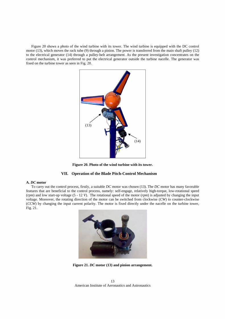
Figure 20 shows a photo of the wind turbine with its tower. The wind turbine is equipped with the DC control
motor (13), which moves the rack tube (9) through a pinion. The power is transferred from the main shaft pulley (12) to the electrical generator (14) through a pulley-belt arrangement. As the present investigation concentrates on the control mechanism, it was preferred to put the electrical generator outside the turbine nacelle. The generator was fixed on the turbine tower as seen in Fig. 20.
Figure 20. Photo of the wind turbine with its tower.
VII. Operation of the Blade Pitch-Control Mechanism
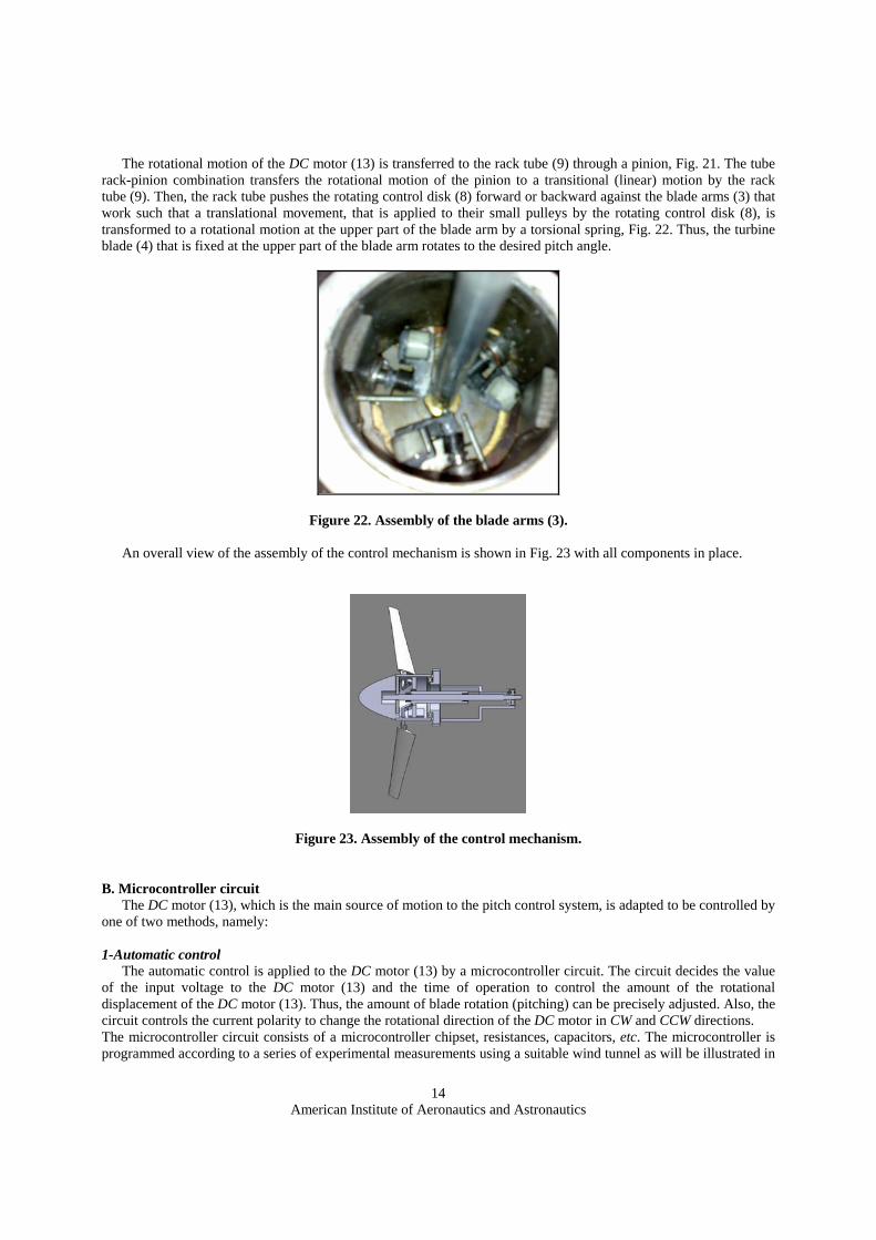
A. DC motor To carry out the control process, firstly, a suitable DC motor was chosen (13). The DC motor has many favorable
features that are beneficial to the control process, namely: self-engage, relatively high-torque, low-rotational speed (rpm) and low start-up voltage (5 - 12 V). The rotational speed of the motor (rpm) is adjusted by changing the input voltage. Moreover, the rotating direction of the motor can be switched from clockwise (CW) to counter-clockwise (CCW) by changing the input current polarity. The motor is fixed directly under the nacelle on the turbine tower, Fig. 21.
Figure 21. DC motor (13) and pinion arrangement.
(13)
(14)
American Institute of Aeronautics and Astronautics
14
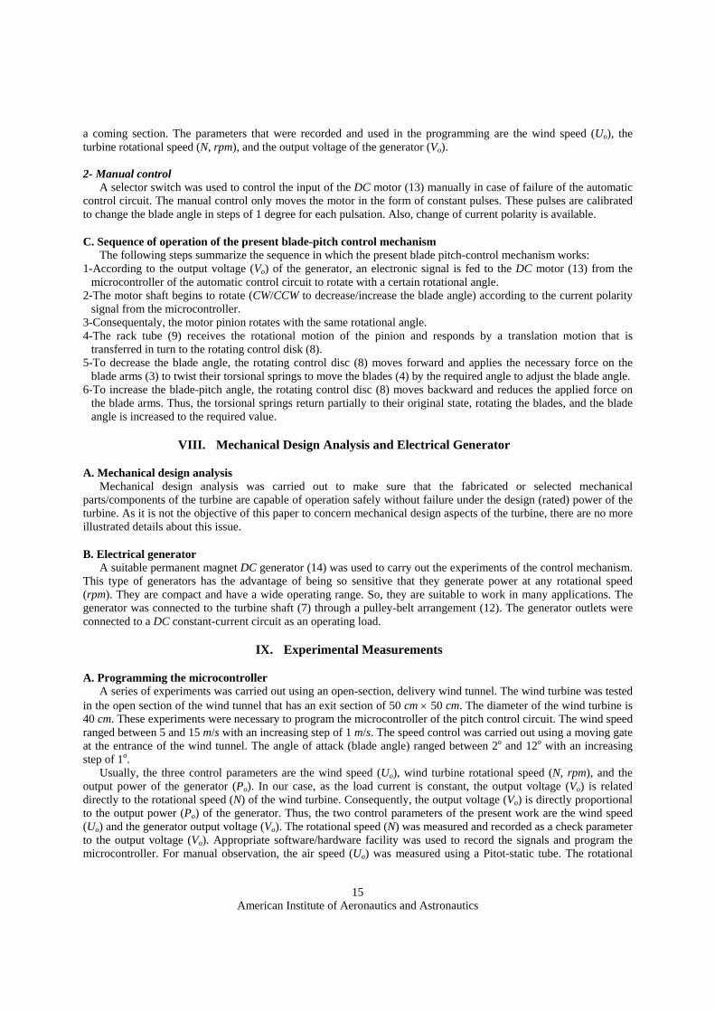
The rotational motion of the DC motor (13) is transferred to the rack tube (9) through a pinion, Fig. 21. The tube rack-pinion combination transfers the rotational motion of the pinion to a transitional (linear) motion by the rack tube (9). Then, the rack tube pushes the rotating control disk (8) forward or backward against the blade arms (3) that work such that a translational movement, that is applied to their small pulleys by the rotating control disk (8), is transformed to a rotational motion at the upper part of the blade arm by a torsional spring, Fig. 22. Thus, the turbine blade (4) that is fixed at the upper part of the blade arm rotates to the desired pitch angle.
Figure 22. Assembly of the blade arms (3).
An overall view of the assembly of the control mechanism is shown in Fig. 23 with all components in place.
Figure 23. Assembly of the control mechanism.
B. Microcontroller circuit The DC motor (13), which is the main source of motion to the pitch control system, is adapted to be controlled by
one of two methods, namely: 1-Automatic control
The automatic control is applied to the DC motor (13) by a microcontroller circuit. The circuit decides the value of the input voltage to the DC motor (13) and the time of operation to control the amount of the rotational displacement of the DC motor (13). Thus, the amount of blade rotation (pitching) can be precisely adjusted. Also, the circuit controls the current polarity to change the rotational direction of the DC motor in CW and CCW directions. The microcontroller circuit consists of a microcontroller chipset, resistances, capacitors, etc. The microcontroller is programmed according to a series of experimental measurements using a suitable wind tunnel as will be illustrated in
American Institute of Aeronautics and Astronautics
15
a coming section. The parameters that were recorded and used in the programming are the wind speed (Uo), the turbine rotational speed (N, rpm), and the output voltage of the generator (Vo). 2- Manual control
A selector switch was used to control the input of the DC motor (13) manually in case of failure of the automatic control circuit. The manual control only moves the motor in the form of constant pulses. These pulses are calibrated to change the blade angle in steps of 1 degree for each pulsation. Also, change of current polarity is available.
C. Sequence of operation of the present blade-pitch control mechanism The following steps summarize the sequence in which the present blade pitch-control mechanism works:
1-According to the output voltage (Vo) of the generator, an electronic signal is fed to the DC motor (13) from the microcontroller of the automatic control circuit to rotate with a certain rotational angle.
2-The motor shaft begins to rotate (CW/CCW to decrease/increase the blade angle) according to the current polarity signal from the microcontroller.
3-Consequentaly, the motor pinion rotates with the same rotational angle. 4-The rack tube (9) receives the rotational motion of the pinion and responds by a translation motion that is
transferred in turn to the rotating control disk (8). 5-To decrease the blade angle, the rotating control disc (8) moves forward and applies the necessary force on the
blade arms (3) to twist their torsional springs to move the blades (4) by the required angle to adjust the blade angle. 6-To increase the blade-pitch angle, the rotating control disc (8) moves backward and reduces the applied force on
the blade arms. Thus, the torsional springs return partially to their original state, rotating the blades, and the blade angle is increased to the required value.
VIII. Mechanical Design Analysis and Electrical Generator
A. Mechanical design analysis Mechanical design analysis was carried out to make sure that the fabricated or selected mechanical
parts/components of the turbine are capable of operation safely without failure under the design (rated) power of the turbine. As it is not the objective of this paper to concern mechanical design aspects of the turbine, there are no more illustrated details about this issue.
B. Electrical generator A suitable permanent magnet DC generator (14) was used to carry out the experiments of the control mechanism.
This type of generators has the advantage of being so sensitive that they generate power at any rotational speed (rpm). They are compact and have a wide operating range. So, they are suitable to work in many applications. The generator was connected to the turbine shaft (7) through a pulley-belt arrangement (12). The generator outlets were connected to a DC constant-current circuit as an operating load.
IX. Experimental Measurements
A. Programming the microcontroller A series of experiments was carried out using an open-section, delivery wind tunnel. The wind turbine was tested
in the open section of the wind tunnel that has an exit section of 50 cm × 50 cm. The diameter of the wind turbine is 40 cm. These experiments were necessary to program the microcontroller of the pitch control circuit. The wind speed ranged between 5 and 15 m/s with an increasing step of 1 m/s. The speed control was carried out using a moving gate at the entrance of the wind tunnel. The angle of attack (blade angle) ranged between 2o and 12o with an increasing step of 1o.
Usually, the three control parameters are the wind speed (Uo), wind turbine rotational speed (N, rpm), and the output power of the generator (Po). In our case, as the load current is constant, the output voltage (Vo) is related directly to the rotational speed (N) of the wind turbine. Consequently, the output voltage (Vo) is directly proportional to the output power (Po) of the generator. Thus, the two control parameters of the present work are the wind speed (Uo) and the generator output voltage (Vo). The rotational speed (N) was measured and recorded as a check parameter to the output voltage (Vo). Appropriate software/hardware facility was used to record the signals and program the microcontroller. For manual observation, the air speed (Uo) was measured using a Pitot-static tube. The rotational
American Institute of Aeronautics and Astronautics
16
speed (N) of the wind turbine was measured using a non-contact (optical) tachometer. A suitable electrical multimeter was used to record the values of the output voltage (Vo).
B. Validation of the present control mechanism and circuit To make sure that the present blade-pitch control mechanism works well, a validation process was carried out.
The validation was based on experimental measurements of the output voltage (Vo) while making small changes of the wind speed. The signal of the output voltage (Vo) was directly connected to the control circuit after adaptation. The control mechanism and circuit should maintain the rating value of the output voltage (Vr).
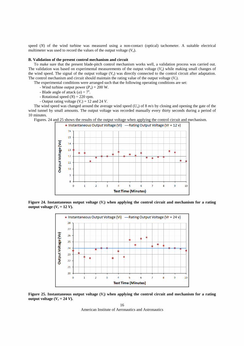
The experimental conditions were arranged such that the following operating conditions are set: - Wind turbine output power (Po) = 200 W. - Blade angle of attack (α) = 7o. - Rotational speed (N) = 220 rpm. - Output rating voltage (Vr) = 12 and 24 V.
The wind speed was changed around the average wind speed (Uo) of 8 m/s by closing and opening the gate of the wind tunnel by small amounts. The output voltage was recorded manually every thirty seconds during a period of 10 minutes.
Figures. 24 and 25 shows the results of the output voltage when applying the control circuit and mechanism.
Figure 24. Instantaneous output voltage (Vi) when applying the control circuit and mechanism for a rating output voltage (Vr = 12 V).
Figure 25. Instantaneous output voltage (Vi) when applying the control circuit and mechanism for a rating output voltage (Vr = 24 V).
American Institute of Aeronautics and Astronautics
17
As can be seen in Figs. 24 and 25, the control mechanism succeeded in maintaining the average value of the
output voltage at the rating value in spite of the unexpected and sudden changes in the flow speed. The fluctuations are in the range of 10% of the average value. Also, the response time of the control mechanism is acceptable. It is clear that the inertia of the mechanism is not big due to the light weight of the blades that were casted from fiberglass.
X. Conclusion The present work concerns the blade-pitch control of a home-scale horizontal-axis wind turbine. The basic idea
was to introduce a simple, low-cost and robust control mechanism that is suitable for this type of wind turbines. Based on the previous discussions, it is clear that the mechanism has a good performance. The mechanism is easy to manufacture and maintain. The response-time of the mechanism is generally acceptable for this application. The using of fiberglass as the blade material helps greatly in reducing the overall mechanism inertia. The inertia may be reduced further by using materials fabricated from plastics, plastic alloys or composites.
Also, a simple electronic circuit with a microcontroller was used to control the mechanism. To properly program the microcontroller a series of experiments were carried out to record the wind speed (Uo) and corresponding shaft rotational speed (N) and generator output voltage (Vo). The two main control parameters of the present work is the wind speed (Uo) and the generator output voltage (Vo). The rotational speed (N) was measured and recorded as a check parameter to the output voltage (Vo). The output power may be used as the control parameter with appropriate measuring instrumentation.
The control process may be further developed by using appropriate probes, transducers, data acquisition arrangements, and software (e.g., Fuzzy-logic) to be fully monitored and adjusted by a laptop or a personal computer. This process helps in re-programming/re-adjusting the control circuit for new/unexpected operating conditions. However, this may lead to a higher-cost mechanism.
Finally, it is obvious that the proposed control mechanism is feasible for commercial large-scale production.
Acknowledgments The author would like to acknowledge Mr. M. I. Ibrahim, Mr. M. A. Soliman, Mr. A. I. Ewida and Mr. A. A. Mohamed for their help in manufacturing the wind turbine and the control mechanism, Mr. S. A. Sallam, Mr. M. A. Mohamed for helping in the experiments, and Mr. M. R. Said and Mr. E. S. Hasan for their help in the assembly, programming, and testing of the control circuit.
References 1Sun, Z. J., "Nonlinear Pitch Control Based Variable Speed Operation of Wind Turbines," SEAMS Workshop (Cha-
Cha Days 2007), National Institute of Aerospace, Hampton, Virginia, October 19-21, 2007, URL: http://www.chachadays.org/chachadays2007/SunTalk07.pdf [cited 7 May 2012].
2Ragheb, M., "Control of Wind Turbines," June 2009, URL: https://netfiles.uiuc.edu/mragheb/www/NPRE%20475%20Wind%20Power%20Systems/Control%20of%20Wind%20Turbines.pdf [cited 7 May 2012].
3Johnson, K. E., "Adaptive Torque Control of Variable Speed Wind Turbines," National Renewable Energy Laboratory, Rept. NREL/TP-500-36265, Colorado, USA, August 2004.
4Laks, J. H., Pao, L. Y., and Wright, A. D., "Control of Wind Turbines: Past, Present, and Future," 2009 American Control Conference (ACC2009), St. Louis, Missouri, USA, June 10 - 12, 2009, URL:
http://ecee.colorado.edu/~pao/anonftp/LaksPaoWright_ACC09.pdf [cited 7 May 2012]. 5Muljadi, E., and Butterfield, C.P., "Pitch-Controlled Variable-Speed Wind Turbine Generation," 1999 IEEE
Industry Applications Society Annual Meeting, Phoenix, Arizona, October 3-7, 1999. 6Bindner, H., "Active Control: Wind Turbine Model," Risø National Laboratory, Rept. Risø -R-920(EN), Roskilde,
Denmark, July 1999. 7Thiringer, T., and Petersson, A., "Control of a Variable-Speed Pitch-Regulated Wind Turbine," Chalmers
University of Technology, Rept. Division of Electric Power Engineering, Department of Energy and Environment, G¨Oteborg, Sweden 2005, URL: Http://Cvi.Se/Uploads/Pdf/Kunskapsdatabas%20teknik/Forskningsresultat/Styrsystem/Varvstyr_CTH_Thiringer_Petersson_Hela.Pdf [cited 7 May 2012].
American Institute of Aeronautics and Astronautics
18
8Hansen, M. H., Hansen, A., Larsen, T. J., Øye, S., Sørensen, P., and Fuglsang, P., "Control Design for a Pitch-Regulated, Variable Speed Wind Turbine," Risø National Laboratory, Rept. Risø-R-1500(EN), Wind Energy Department, Roskilde, Denmark, January 2005.
9El-Tous, Y., "Pitch Angle Control of Variable Speed Wind Turbine," American J. of Engineering and Applied Sciences, Vol. 1, No. 2, 2008, pp. 118-120.
10Ramakrishnan, V., and Srivatsa, S. K., "Pitch Control of Wind Turbine Generator by Using New Mechanism," Journal of Electrical Systems, Vol. 6, Issue 4, December 2010.
11Bossanyi, E. A., "Individual Blade Pitch Control for Load Reduction," Wind Energy J., Vol. 6, 2003, pp. 119-128.
12Selvam, K., "Individual Pitch Control for Large Scale Wind Turbines-Multivariable Control Approach," Energy Research Centre of the Netherlands, Rept. ECN-E–07-053, 2007, URL:
http://www.ecn.nl/docs/library/report/2007/e07053.pdf [cited 7 May 2012]. 13Selvam, K., Kanev, S., vanWingerden, J. W., van Engelen, T., and Verhaegen, M., "Feedback–feedforward
Individual Pitch Control for Wind Turbine Load Reduction," International Journal of Robust and Nonlinear Control, 2008.
14Zhang, J., Cheng, M., Chen, Z., and Fu, X., "Pitch Angle Control for Variable Speed Wind Turbines," The 3rd International Conference on Deregulation and Restructuring and Power Technologies (DRPT 2008), Nanjing, China, 6-9 April 2008.
15Musyafa’, A., Harika, A., Negara, I. M. Y., and Robandi, I., "Pitch Angle Control of Variable Low Rated Speed Wind Turbine Using Fuzzy Logic Controller," International Journal of Engineering & Technology (IJET-IJENS), Vol. 10, No. 05, 2010.
16Lazauskas, L., "Three Pitch Control Systems for Vertical Axis Wind Turbines Compared," Wind Engineering J., Vol. 16, No. 5, 1992.
17Pradeep, B., Paluszek, M. A., and Mueller, J. B., "Individual Blade Pitch and Camber Control for Vertical Axis Wind Turbines," 7th World Wind Energy Conference 2008 (WWEC2008), Kingston, Canada, June 24-26, 2008, URL: http://www.psatellite.com/papers/WWEC2008.pdf [cited 7 May 2012].
18Paraschivoiu, I., Trifu, O., and Saeed, F., "H-DarrieusWind Turbine with Blade Pitch Control," International Journal of Rotating Machinery, Volume 2009, Article ID 505343. 2009. 19http://www.windustry.org/your-wind-project/home-and-farm-scale-wind/home-and-farm-scale-wind [cited 7 May 2012]. 20http://www.treehugger.com/renewable-energy/hot-home-wind-turbines-you-can-actually-buy-plus-one-you-wish-you-could.html [cited 7 May 2012]. 21http://www.windspireenergy.com/ [cited 7 May 2012]. 22Gerdes, G. J., "Wind Turbine Technology-Turbine Control," Workshop on Renewable Energies, Nadi, Republic of the Fiji Islands, November 14-25, 2005. 23Somers, D. M., "The S822 and S823 Airfoils," National Renewable Energy Laboratory, USA, NREL/SR-500-36342, 2005. 24Padmanabhan, K. K., and Saravanan, R., "Study of the Performance and Robustness of NREL and NACA Blade for Wind Turbine Applications," European Journal of Scientific Research, Vol.72, No.3, 2012, pp. 440-446.