norstat.pdf - air & hydraulic supplies inc
TRANSCRIPT


About Our Company
Since 1962 Norstat, has been servicing the industrial automation marketplace by offering safety and automation solutions
to the machine and process control industries with a complete line of safety, control, and automation products. Our trained
engineering staff both in Rockaway and in the field close to our customers can offer expert solutions for all your safety and
automation requirements.
Our SAFETY program includes Safety Light Curtains & Barriers, Muting Light Curtain Systems, Safety Controllers, Safety
Interlocks and Non Contact Safety Switches, Safety Control Relays and Audible and Visual Signaling Devices. Our
AUTOMATION program includes, Foot Switches and Limit Switches for axis control, Connectors for sensors and solenoid valves.
The program enables machine builders, automation integrators and distributors a full product line enabling conformance to all
domestic and international safety standards.
Visit us on the web at www.norstat.com, www.norstatblog.com for a complete view of the entire program
MISSION STATEMENT
Our goal is to offer our customers the most comprehensive, synergistic and state of the art program of Safety and Automation products providing the best solutions to their application requirements. We accomplish the task through an
engineering and sales staff that comprises the best and the brightest in the field of technology. We have worldwide
experience in supporting our customers and are the “Source for all your Safety and Automation” needs
Get Safe
Get Automated

Table of Contents
01 - SAFETY SWITCHES
Keyed Safety Interlock Switches 01.02 - 01.03
Solenoid Locking Safety Interlock Switches 01.04 - 01.07
Manual & Cut Key Locking 01.08
Safety Rope Pull Switches 01.09
E-Stop Buttons 01.10
02 - NON CONTACT SAFETY SWITCHES
Magnetically Operated Safety Switches 02.02 – 02.03
ISIS Magnetically Operated Safety System 02.04 – 02.07
F-Series Active Signaling System 02.08 – 02.11
Electronic Safety Switches SSS & SS-R, SS-C 02.12
03 - SAFETY RELAYS
Emergency Stop & Gate Monitor (Category 2-3) 03.02
Emergency Stop & Gate Monitor (Category 4) 03.03 – 03.04
Expansion Modules 03.05 & 03.09
Mat & Edge Monitoring 03.06
Two Hand Control 03.06
Light Curtain 03.07
Safety Relay With Time Delay 03.08
Safety Relay With Multiple Outputs 03.09
04 - OPTICAL / AUDIBLE SIGNALING DEVICES
Glossary 04.02 – 04.06
Signal Tower Program 04.07 – 04.08
Product Descriptions 04.09
LED Bulb 04.10 – 04.11
LED Life Chart 04.13
SA
FE
TY
SW
ITC
HE
S
NO
N C
ON
TA
CT
S
AFE
TY
RE
LA
YS
S
IGN
ALIN
G
AU
TO
MA
TIO
N
AS
SE
MB
LIE
S
PO
WE
R S
UP
PLIE
S
PA
NE
LS
& P
CS

Table of Contents
05 - AUTOMATION PRODUCTS
Small Limit Switches 05.02 – 05.03
IEC Body Limit Switches 05.04 – 05.05
Small Limit Switches with Cable 05.06
Footswitches 05.07
Enabling Switch 05.08
Handwheel 05.09
06 - DIN 43650 MOLDED ASSEMBLIES & CONNECTORS
DIN 43650 Assemblies & Connectors 06.02 – 06.15
M12 Assemblies & Connectors 06.16 – 06.25
M8 Assemblies & Connectors 06.26 – 06.33
Micro-mini (8mm) Assemblies & Connectors 06.34 – 06.35
-
09/10/ 11 OTHER INFORMATION
Other Products 09.01 – 09.04
Introduction to Safety 10.01 – 10.08
SA
FE
TY
SW
ITC
HE
S
NO
N C
ON
TA
CT
S
AFE
TY
RE
LA
YS
S
IGN
ALIN
G
AU
TO
MA
TIO
N
AS
SE
MB
LIE
S
PO
WE
R S
UP
PLIE
S
PA
NE
LS
& P
CS

About This Catalog
Contents We offer over 10,000 different part numbers! This catalog represents only a very small portion of the products that are available to you. The parts listed here are the more popular products, but there are many more variations, models and types offered. Complete full line catalogs are available in hard copy form or CD. Additional information is also available on our website. Please call us with your application needs.
Global Standards
300 Roundhill Drive, Unit 4, Rockaway, NJ 07866 Telephone – (973) 586-2500 FAX – (973) 596-1590
E-Mail – [email protected] Website – www.norstat.com
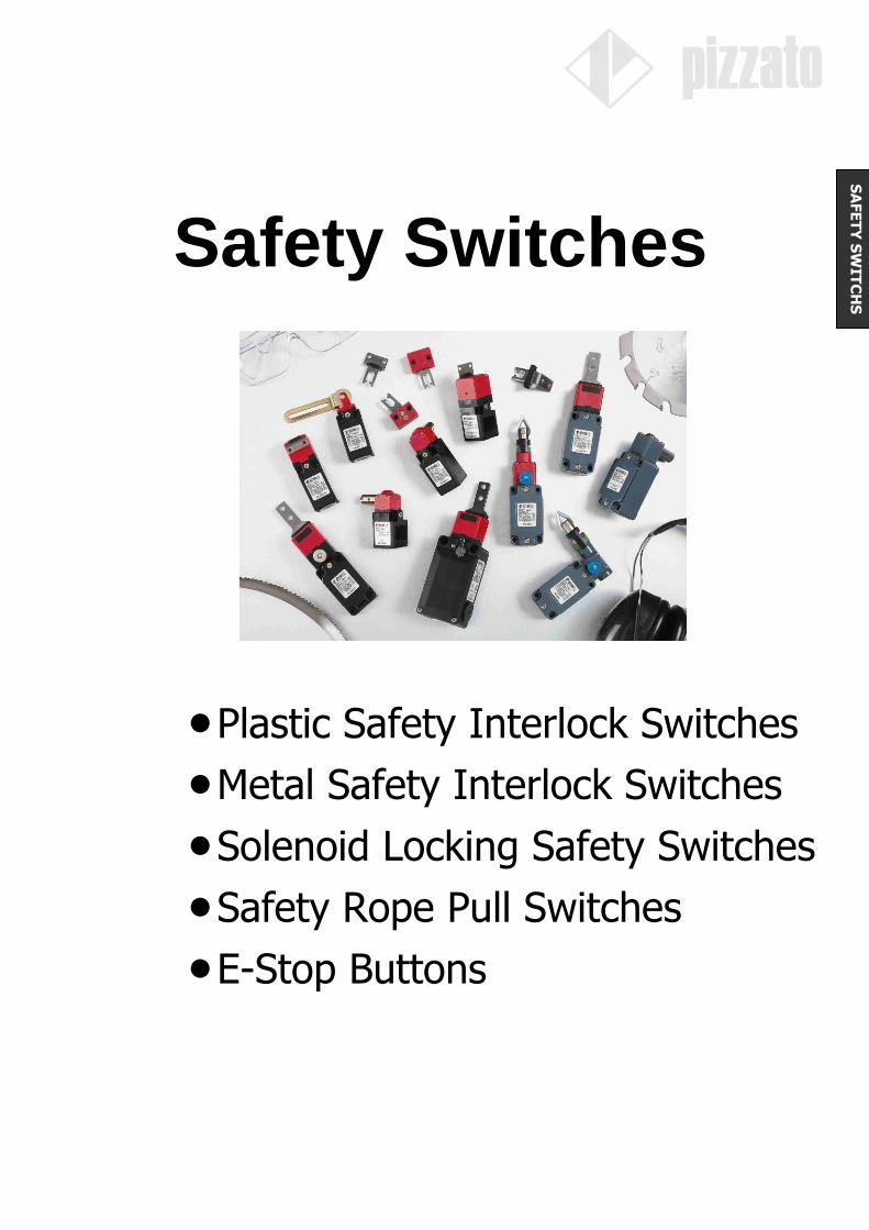
Safety Switches
Plastic Safety Interlock Switches
Metal Safety Interlock Switches
Solenoid Locking Safety Switches
Safety Rope Pull Switches
E-Stop Buttons
SA
FE
TY
SW
ITC
HS

Keyed Safety Interlock Switches Compact Size Plastic Body Switches
Actuator Keys Plastic Body Plastic Body
Positively driven contacts
Many unique actuator keys styles
5mm backlash
Trapped switch head (FR Series)
Bifurcated (twin) contacts
Key retention force: Regular - 10N (2.3 Pounds) “E3” Version - 30N (6.7 Pounds)
Available factory wired with M12
FR Series FP Series
Compact Size Standard NEMA & IEC Body
Switching Contacts
2NC – 1NO 2NC – 1NO
Positively Driven Positively Driven
Part Numbers Key Only
Without Key FR 2092 FP 2093
Straight Key FR 2092 D FP 2093 F
90 Key FR 2092 D1 FP 2093 F1
Hinged Key FR 2092 D2 FP 2093 F2
Double Hinged Key FR 2092 D3 FP 2093 F3
Special Hinged Key
Technical Information Material Glass-reinforced Polymer Mechanical Endurance 1 Million Operations
Cable Entry Pg 13.5 Max. Operation Frequency 3,600 Cycles Per Hour
Protection Rating FR = IP65; FP = IP66 Max./Min. Actuator Speed 0.5 m/s – 1mm/s
NEMA Rating 1, 4X Voltage/Current Rating 500 VAC – 600 VDC / 10A
Temperature Rating -25C to +80C Approvals UL 508, CE, IEC 947-5-1
Additional products are available from the manufacturer. Please call us with your application needs.
11
12
21
22
33
34
Slow Action
0 o 4.6
5.3
7.8 o 0 o4.5
4.9
8.3 o
300 Roundhill Drive, Unit 4, Rockaway, NJ 07866 Telephone – (973) 586-2500 FAX – (973) 596-1590
E-Mail – [email protected] Website – www.norstat.com
Page 01.02
SA
FE
TY
SW
ITC
HE
S
Straight Key 90 Key
Hinged Key (Pivots Left & Right) Hinged Key
(Pivots Left & Right
and Up & Down)
Hinged Key (Pivots Left & Right with Standard Footprint)

Keyed Safety Interlock Switches
Compact Size Metal Body Switches
Actuator Keys Metal Body Metal Body
Rugged metal housing & head
Positively driven contacts
Many unique actuator keys styles
5mm backlash prevents accidental switching due to vibration
Bifurcated (twin) contacts
Key retention force: Regular - 10N (2.3 Pounds) “E3” Version - 30N (6.7 Pounds)
Available factory wired with M12
FD Series FL Series
Standard NEMA & IEC Body 3 Cable Entries
Switching Contacts
2NC – 1NO 2NC – 1NO
Positively Driven Positively Driven
Part Numbers Key Only Without Key FD 2093 FL 2093
Straight Key FD 2093 F FL 2093 F
90 Key FD 2093 F1 FL 2093 F1
Hinged Key FD 2093 F2 FL 2093
Double Hinged Key FD 2093 F3 FL 2093 F3
Special Hinged Key FD 2093 F7 FL 2093 F7
Technical Information Material Baked Epoxy Coated Metal Mechanical Endurance 1 Million Operations
Cable Entry Pg 13.5 Max. Operation Frequency 3,600 Cycles Per Hour
Protection Rating IP66 Max./Min. Actuator Speed 0.5 m/s – 1mm/s
NEMA Rating 1, 4X Voltage / Current Rating 500 VAC – 600 VDC / 10A
Temperature Rating -25C to +80C Approvals UL 508, CE, IEC947-5-1
Additional products are available from the manufacturer. Please call us with your application needs.
300 Roundhill Drive, Unit 4, Rockaway, NJ 07866 Telephone – (973) 586-2500 FAX – (973) 596-1590
E-Mail – [email protected] Website – www.norstat.com
Page 01.03
SA
FE
TY
SW
ITC
HE
S
0 o4.5
4.9
8.3 o 0 o4.5
4.9
8.3 o
11
12
21
22
33
34
Slow Action
Straight Key 90 Key
Hinged Key (Pivots Left & Right)
Hinged Key (Pivots Left & Right and Up & Down)
Hinged Key
(Pivots Left & Right with Standard Footprint)

Solenoid Locking Safety Interlock Switches
Compact Size – Plastic Body For Machines with Inertia Actuator Keys Unlocked with Power Locked with Power
1000N (225 Pounds) locking force
40N (9 Pounds) key retention
Manual override on “D” versions
5mm backlash Internal cascade circuit (24V only) used to stager solenoid activation, reduces the power requirements for multiple switch applications
Key Locked in Switch Without Power to the Solenoid
Key is Unlocked in Switch Without Power to the Solenoid
With Emergency Override
Without Emergency Override
Switching Contacts
3 NC Contacts 3 NC Contacts
Positively Driven 2 Switched By Solenoid;
1 Switched by Key 2 Switched By Solenoid;
1 Switched by Key
Part Numbers Solenoid Voltage 24V 120V 24V 120V
Without Key FS 2996 D024 FS 2996 D120 FS 2996 E024 FS 2996 E120
Straight Key FS 2996 D024 F FS 2996 D120 F FS 2996 E024 F FS 2996 E120 F
90 Key FS 2996 D024 F1 FS 2996 D120 F1 FS 2996 E024 F1 FS 2996 E120 F1
Hinged Key FS 2996 D024 F2 FS 2996 D120 F2 FS 2996 E024 F2 FS 2996 E120 F2
Double Hinged Key FS 2996 D024 F3 FS 2996 D120 F3 FS 2996 E024 F3 FS 2996 E120 F3
Special Hinged Key FS 2996 D024 F7 FS 2996 D120 F7 FS 2996 E024 F7 FS 2996 E120 F7
Technical Information Material Glass reinforced Polymer Mechanical Endurance 800,000 Operations
Cable Entry Pg 13.5 Max. Operation Frequency 600 Cycles Per Hour
Protection Rating IP66 Max./Min. Actuator Speed 0.5 m/s – 1mm/s
NEMA Rating 1, 4X Voltage / Current Rating 500 VAC – 600 VDC / 10A
Temperature Rating -25C to +80C Approvals CE, UL 508, IEC947-5-1
Addiitional products are available from the manufacturer. Please call us with your application needs.
Slow Action
31
3212 22
11 21
11-1221-22
31-320 9 9.5 oo
11-1221-22
31-320 9 9.5 oo
300 Roundhill Drive, Unit 4, Rockaway, NJ 07866 Telephone – (973) 586-2500 FAX – (973) 596-1590
E-Mail – [email protected] Website – www.norstat.com
Page 01.04
SA
FE
TY
SW
ITC
HE
S

Solenoid Locking Safety Interlock Switches
Additional Information Multiple Switch Installation Solenoid Cascade Delay (24V Versions Only) The inrush power required to initiate the locking solenoid is
approximately 56 VA for 0.1 seconds. If several switches are
installed in parallel, the combined energy requirements for these
units is considerable and may cause an excess burden to the power supply. To elevate this problem, the 24 Volt versions of the FS
solenoid locking switches have a built in millisecond time delay for the activation of the solenoid. This delay can be configured into 4
ranges, that are set through two internal dip switches. Setting the time delay will sequence the inrush demands of the solenoid,
reducing the demands on the power supply.
Additional Contact and Solenoid Configuration
Addiitional products are available from the manufacturer. Please call us with your application needs.
12
12
12
12
300 Roundhill Drive, Unit 4, Rockaway, NJ 07866 Telephone – (973) 586-2500 FAX – (973) 596-1590
E-Mail – [email protected] Website – www.norstat.com
Page 01.05
SA
FE
TY
SW
ITC
HE
S

New FG Solenoid Locking Metal Body Safety Interlock Switches
For Machines with Inertia
Features
Actuator holding force 2500N (562 lbs) 4 stainless steel actuators available
8 contact blocks with 4 pole contacts Rotating switch head
Metal housing with 3 cable entries Locking or unlocking solenoid options
Protection rating IP 67 LED Indicator Lights
300 Roundhill Drive, Unit 4, Rockaway, NJ 07866 Telephone – (973) 586-2500 FAX – (973) 596-1590
E-Mail – [email protected] Website – www.norstat.com
Page 01.06
SA
FE
TY
SW
ITC
HE
S
D E
Locked on entry Unlocked on entry
Unlocked with Locked with
Solenoid Activation Solenoid Activation
VF KEY F20 VF KEY F21 VF KEY F22 VF KEY F28
60A 60B 60C 60D
60E 60F 60G 60N
A B Z
2 Green 1 Red / 1 Green No LEDs
Lights with User connection
Solenoid
Cable Entry
3 M20 Ports
Contact Options
Solenoid Operated Key Operated
60A 1 NO + 1 NC 1 NO + 1 NC
60B 2 NC 1 NO + 1 NC
60C 3 NC 1 NC
60D 1 NO + 1 NC 2 NC
60E 1 NO + 2 NC 1 NC
60F 1 NO + 2 NC 1 NO
60G 2 NC 2 NC
60N 1 NO + 1 NC 2 NO

Solenoid Locking Metal Body Safety Interlock Switches
With 4 Contacts For Machines with Inertia Actuator Keys Unlocked with Power Locked with Power
Key Locked in Switch Without Power to the Solenoid
Key is Unlocked in Switch Without Power to the Solenoid
Red & Green LED Indication with independent lead wire connection, allows installer to determine color code and indication function With Emergency Override
Without Emergency Override
Switching Contacts
Contact Block 60B Contact Block 60B
2 NC Solenoid Activated 2 NC Solenoid Activated
1 NO / 1 NC Key Activated 1 NO / 1 NC Key Activated
Part Numbers Solenoid Voltage 24V 24V
Without Key FG 60B D1 D0B FG 60B D1 E0B
Straight Key – F20 FG 60B D1 D0B F20 FG 60B D1 E0B F20
90 Key – F21 FG 60B D1 D0B F21 FG 60B D1 E0B F21
Straight Key with Grommets – F22 FG 60B D1 D0B F21 FG 60B D1 E0B F21
Double Hinged Key – F26 FG 60B D1 D0B F26 FG 60B D1 E0B F26
Technical Material Glass reinforced Polymer Mechanical Endurance 800,000 Operations
Cable Entry M20 Max. Operation Frequency 600 Cycles Per Hour
Protection Rating IP66 Max./Min. Actuator Speed 0.5 m/s – 1mm/s
NEMA Rating 1, 4X Voltage / Current Rating 500 VAC – 600 VDC / 10A
Temperature Rating -25C to +80C Approvals CE, UL 508, IEC947-5-1
Addiitional products are available from the manufacturer. Please call us with your application needs.
Manual & Keyed Locking
300 Roundhill Drive, Unit 4, Rockaway, NJ 07866 Telephone – (973) 586-2500 FAX – (973) 596-1590
E-Mail – [email protected] Website – www.norstat.com
Page 01.07
SA
FE
TY
SW
ITC
HE
S
SA
FE
TY
SW
ITC
HE
S

Safety Interlock Switches Metal Body Switches
Actuator Keys Keyed Locking Mechanical Delay
Key Locking – allows access by authorized personnel only. Used in normal operation or during set ups or repairs
Mechanical Delay – unique solution for machines with inertia, eliminates the need for external power, timing circuits or motion sensors
FP Series FP Series
Operation Operation
The actuation key can be locked into place, in the switch, by turning the cut
key into the 180 position. Only in this
state will the 2 N/C contacts be closed
(and the 1 N/O contact be open).
Turning the key to the 0 position will
allow the actuation key to be removed.
If the cut key is in the 0 position or
the actuation key is removed, the 2
N/C contacts will open (and the 1 N/O contact will close). The cut key can be
removed in the 0 or 180 position to
prevent unauthorized access.
The actuation key is locked into place when the thumbscrew knob is turned
all the way counter clockwise. At this
point the 2 N/C contacts be closed (and the 1 N/O contact be open).
When the thumbscrew knob is rotated clockwise, two turns, the 2 N/C
contacts will open (and the 1 N/O contact will close). To remove the key
you must continue to turn the
thumbscrew clockwise to the end position (approximately 26 turns).
This operation takes 18 to 20 seconds, giving the machine time to wind down.
Switching Contacts
2NC – 1NO 2NC – 1NO
Positively Driven Positively Driven
Part Numbers Without Key FP 2099 FP 20R2
Straight Key FP 2099 F FP 20R2 F
90 Key FP 2099 F1 FP 20R2 F1
Hinged Key FP 2099 F2
Double Hinged Key FP 2099 F3 FP 20R2 F3
Special Hinged Key FP 2099 F7 FP 20R2 F7
Technical Material Glass reinforced Polymer Mechanical Endurance 1 Million Operations
Cable Entry Pg 13.5 Max. Operation Frequency 3,600 Cycles Per Hour
Protection Rating IP66 Max./Min. Actuator Speed 0.5 m/s – 1mm/s
NEMA Rating 1, 4X Voltage / Current Rating 500 VAC – 600 VDC / 10A
Temperature Rating -25C to +80C Approvals UL 508, CE, IEC947-5-1
Additional products are available from the manufacturer. Please call us with your application needs.
Safety Rope Pull Switches
With Tension Monitoring and Reset Provides Greater Area of E-Stop Access
Rope pull switches Straight Cable 90 Cable
11
12
21
22
33
34
Slow Action
Straight Key 90 Key
Hinged Key (Pivots Left & Right)
Hinged Key (Pivots Left & Right and Up & Down)
Hinged Key (Pivots Left & Right with Standard Footprint)
0 90o180o
120o
0 2
3
5 26 turns
300 Roundhill Drive, Unit 4, Rockaway, NJ 07866 Telephone – (973) 586-2500 FAX – (973) 596-1590
E-Mail – [email protected] Website – www.norstat.com
Page 01.08 SA
FE
TY
SW
ITC
HE
S

with tension monitoring and reset button are generally used for e-stop applications. We also offer rope switches for non-safety stop command (without reset button) and start command applications (without reset button and tension monitoring).
We now offer a new rope installation system. The FAST line features quick mounting end connectors with built in tension adjustment
For Cable Lengths Up to 6 Meters (Lengths can be extended by using cable supports)
For Cable Lengths Up to 16 Meters (Lengths can be extended by using cable supports)
With Reset Button
and Tension Monitoring
With Reset Button
and Tension Monitoring
Switching Contacts
2 NC – 1NO Contacts 2 NC – 1NO Contacts
Part Numbers Top Entry Left Entry Right Entry
FD 2078 FL 2083 FL 2084
Accessories
Safety Rope
Rope Clamp Thimble Turnbuckle
VF F05-100 (100 M Roll) VF M870 VF C870 VF AF-TR2
Technical Information Material Baked Epoxy Coated Metal Mechanical Endurance 1 Million Operations
Cable Entry Pg 13.5 Max. Operation Frequency 1 Cycle / 6 s
Protection Rating IP66 Max./Min. Actuator Speed 0.5 m/s – 1mm/s
NEMA Rating 1, 4X Voltage /Current Rating 500 VAC – 600 VDC / 10A
Temperature Rating -25C to +80C Approvals CE, UL 508, IEC 947-5-1
Additional products are available from the manufacturer. Please call us with your application needs.
Enclosed E-Stop Button
Box and E-Stop Button Simple to Install, Easy to Wire
11
12
21
22
33
34
Slow Action
0 4 8 8.5
R1.5 S R6.5
0
S
8 14 16
R4.5 R11.5
300 Roundhill Drive, Unit 4, Rockaway, NJ 07866 Telephone – (973) 586-2500 FAX – (973) 596-1590
E-Mail – [email protected] Website – www.norstat.com
Page 01.09
SA
FE
TY
SW
ITC
HE
S

The CC series offers a simple way to surface mount an E-Stop button
Boxes are rated NEMA 1, NEMA 4X and IP 65
Boxes are available with or without the e-stop button; fully enclosed or with a 22mm mounting hole
Other switch types are available upon request
Contacts 2 NC 1 NC – 1 NO
Part Numbers CC01 AAB 00 AC CC01 AAB 00 AD
Box Only
CPA07075NG012
Technical Material Glass-reinforced Polymer Temperature Rating -25C to +70C
Protection Rating IP 65 Protection Rating IP 65
NEMA Rating 1, 4X Maximum Wire Size 14 AWG
Left Knockout Size ½ NPT / Pg 13.5 / M20x1.5 Minimum Wire Size 18 AWG
Right Knockout Size 3/8 NPT / Pg 11 Voltage Rating 500 VAC; 600 VDC
Bottom Knockout Size ½ NPT / Pg 13.5 / M20x1.5 Current Rating 16A
Additional products are available from the manufacturer. Please call us with your application needs.
300 Roundhill Drive, Unit 4, Rockaway, NJ 07866 Telephone – (973) 586-2500 FAX – (973) 596-1590
E-Mail – [email protected] Website – www.norstat.com
Page 01.10
NO
N C
ON
TA
CT

Non Contact
Safety Switches
Non-Contact Safety Systems
Uniquely Coded Switch System
Solid State Non-Contact Switches
Magnetic Non-Contact Switches
02.01
Non Contact Safety Switches
MagnaSafe Series
magna
Magnetically Operated Safety Switches
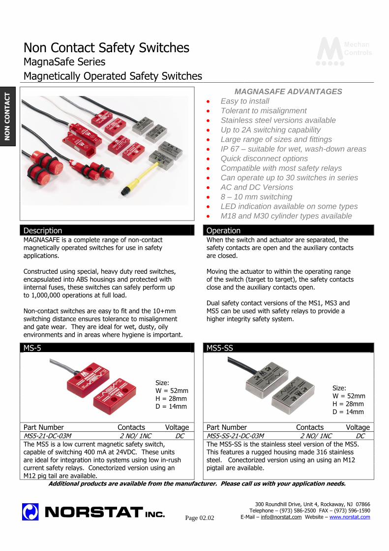
MAGNASAFE ADVANTAGES Easy to install Tolerant to misalignment Stainless steel versions available Up to 2A switching capability Large range of sizes and fittings IP 67 – suitable for wet, wash-down areas Quick disconnect options Compatible with most safety relays Can operate up to 30 switches in series AC and DC Versions 8 – 10 mm switching LED indication available on some types M18 and M30 cylinder types available Description Operation MAGNASAFE is a complete range of non-contact When the switch and actuator are separated, the magnetically operated switches for use in safety safety contacts are open and the auxiliary contacts
applications. are closed.
Constructed using special, heavy duty reed switches, Moving the actuator to within the operating range
encapsulated into ABS housings and protected with of the switch (target to target), the safety contacts iinternal fuses, these switches can safely perform up close and the auxiliary contacts open.
to 1,000,000 operations at full load. Dual safety contact versions of the MS1, MS3 and
Non-contact switches are easy to fit and the 10+mm MS5 can be used with safety relays to provide a
switching distance ensures tolerance to misalignment higher integrity safety system. and gate wear. They are ideal for wet, dusty, oily
environments and in areas where hygiene is important.
MS-5 MS5-SS
Part Number Contacts Voltage Part Number Contacts Voltage MS5-21-DC-03M 2 NO/ 1NC DC MS5-SS-21-DC-03M 2 NO/ 1NC DC The MS5 is a low current magnetic safety switch, The MS5-SS is the stainless steel version of the MS5. capable of switching 400 mA at 24VDC. These units This features a rugged housing made 316 stainless
are ideal for integration into systems using low in-rush steel. Conectorized version using an using an M12 current safety relays. Conectorized version using an pigtail are available.
M12 pig tail are available. Additional products are available from the manufacturer. Please call us with your application needs.
Size: W = 52mm
H = 28mm D = 14mm
Size: W = 52mm
H = 28mm
D = 14mm
300 Roundhill Drive, Unit 4, Rockaway, NJ 07866 Telephone – (973) 586-2500 FAX – (973) 596-1590
E-Mail – [email protected] Website – www.norstat.com
Page 02.02
NO
N C
ON
TA
CT
Non Contact Safety Switches MagnaSafe Series Magnetically Operated Safety Switches
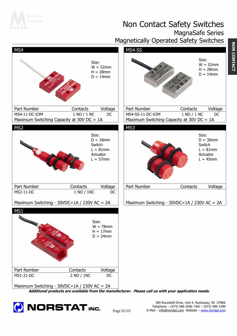
MS4 MS4-SS
Part Number Contacts Voltage Part Number Contacts Voltage
MS4-11-DC-03M 1 NO / 1 NC DC MS4-SS-11-DC-03M 1 NO / 1 NC DC
Maximum Switching Capacity at 30V DC = 1A Maximum Switching Capacity at 30V DC = 1A
MS2 MS3
Part Number Contacts Voltage Part Number Contacts Voltage
MS2-11-DC 1 NO / 1NC DC MS3-21-DC 187.80 2 NO / 1NC DC
MS2-11-AC 182.81 1 NO / 1NC AC MS3-21-AC 295.83 2 NO / 1NC AC
Maximum Switching - 30VDC=1A / 230V AC = 2A Maximum Switching - 30VDC=1A / 230V AC = 2A
MS1
Part Number Contacts Voltage
MS1-21-DC 2 NO / 1NC DC MS1-21-AC 295.83 2 NO / 1NC AC Maximum Switching - 30VDC=1A / 230V AC = 2A
Additional products are available from the manufacturer. Please call us with your application needs.
Size: W = 52mm
H = 28mm D = 14mm
Size:
W = 52mm H = 28mm D = 14mm
Size: D = 18mm
Switch
L = 81mm Actuator L = 57mm
Size: D = 30mm
Switch
L = 81mm Actuator L = 45mm
Size:
W = 78mm H = 17mm D = 24mm
300 Roundhill Drive, Unit 4, Rockaway, NJ 07866 Telephone – (973) 586-2500 FAX – (973) 596-1590
E-Mail – [email protected] Website – www.norstat.com
Page 02.03
NO
N C
ON
TA
CT
Non Contact Safety Switches
ISIS Safety System
magna
Magnetically Operated Safety Switches
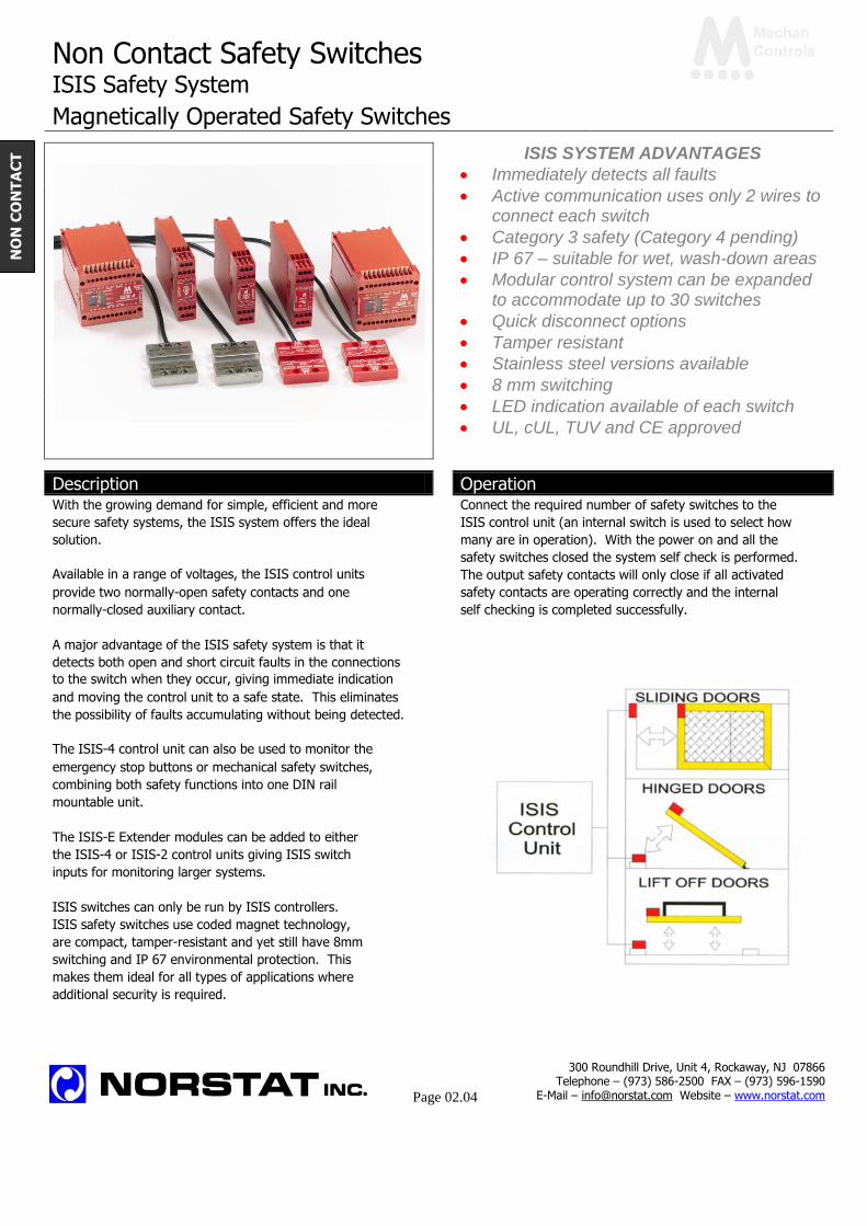
ISIS SYSTEM ADVANTAGES Immediately detects all faults Active communication uses only 2 wires to
connect each switch Category 3 safety (Category 4 pending) IP 67 – suitable for wet, wash-down areas Modular control system can be expanded
to accommodate up to 30 switches Quick disconnect options Tamper resistant Stainless steel versions available 8 mm switching LED indication available of each switch UL, cUL, TUV and CE approved Description Operation With the growing demand for simple, efficient and more Connect the required number of safety switches to the
secure safety systems, the ISIS system offers the ideal ISIS control unit (an internal switch is used to select how
solution. many are in operation). With the power on and all the
safety switches closed the system self check is performed.
Available in a range of voltages, the ISIS control units ISI isis
The output safety contacts will only close if all activated
provide two normally-open safety contacts and one safety contacts are operating correctly and the internal
normally-closed auxiliary contact. self checking is completed successfully.
A major advantage of the ISIS safety system is that it detects both open and short circuit faults in the connections to the switch when they occur, giving immediate indication and moving the control unit to a safe state. This eliminates the possibility of faults accumulating without being detected. The ISIS-4 control unit can also be used to monitor the ISIS
emergency stop buttons or mechanical safety switches, combining both safety functions into one DIN rail mountable unit. The ISIS-E Extender modules can be added to either the ISIS-4 or ISIS-2 control units giving ISIS switch inputs for monitoring larger systems. ISIS switches can only be run by ISIS controllers. ISIS safety switches use coded magnet technology, are compact, tamper-resistant and yet still have 8mm switching and IP 67 environmental protection. This makes them ideal for all types of applications where additional security is required.
300 Roundhill Drive, Unit 4, Rockaway, NJ 07866 Telephone – (973) 586-2500 FAX – (973) 596-1590
E-Mail – [email protected] Website – www.norstat.com
Page 02.04
NO
N C
ON
TA
CT
Non Contact Safety Switches
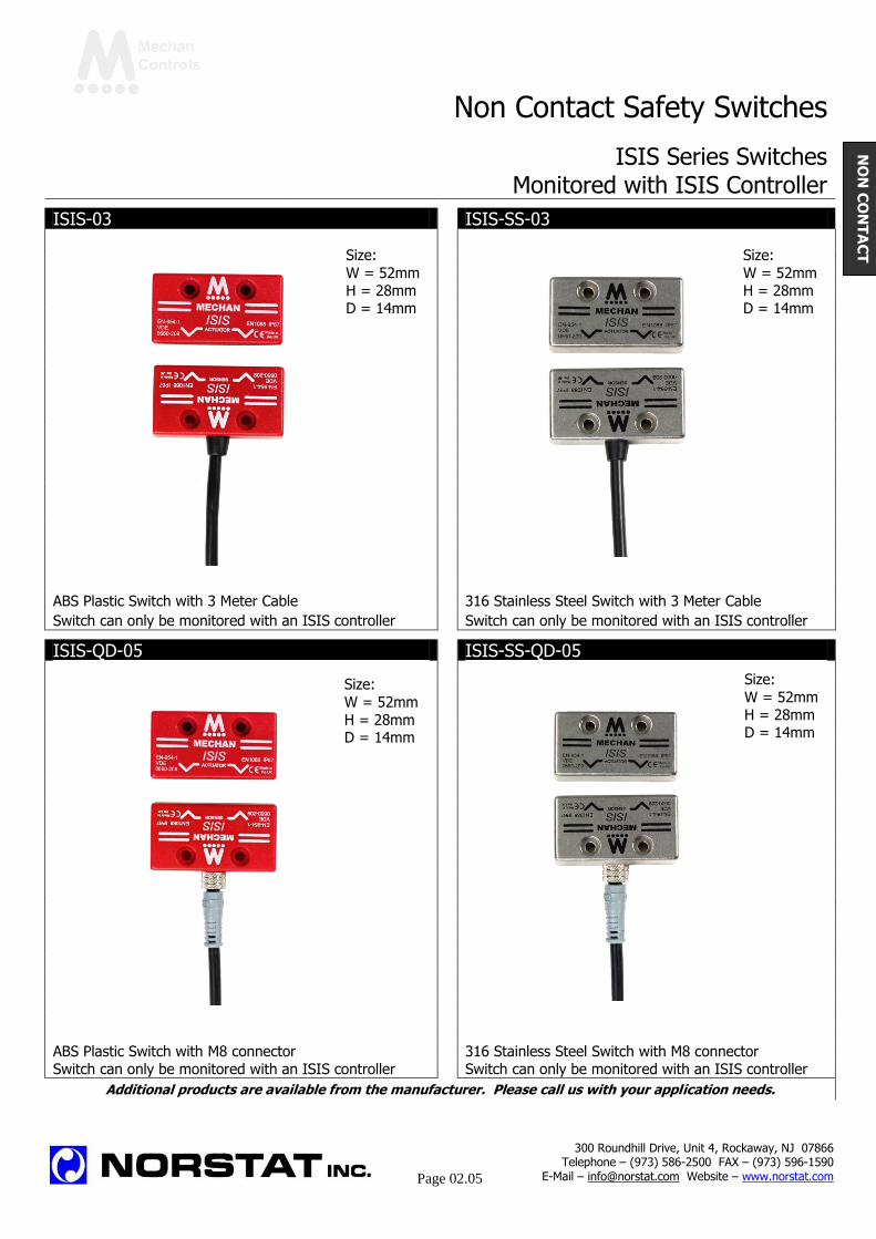
ISIS Series Switches Monitored with ISIS Controller
ISIS-03 ISIS-SS-03
ABS Plastic Switch with 3 Meter Cable 316 Stainless Steel Switch with 3 Meter Cable
Switch can only be monitored with an ISIS controller Switch can only be monitored with an ISIS controller
ISIS-QD-05 ISIS-SS-QD-05
ABS Plastic Switch with M8 connector 316 Stainless Steel Switch with M8 connector Switch can only be monitored with an ISIS controller Switch can only be monitored with an ISIS controller
Additional products are available from the manufacturer. Please call us with your application needs.
Size:
W = 52mm H = 28mm D = 14mm
Size:
W = 52mm H = 28mm D = 14mm
Size:
W = 52mm
H = 28mm D = 14mm
Size:
W = 52mm H = 28mm D = 14mm
300 Roundhill Drive, Unit 4, Rockaway, NJ 07866 Telephone – (973) 586-2500 FAX – (973) 596-1590
E-Mail – [email protected] Website – www.norstat.com
Page 02.05
NO
N C
ON
TA
CT
Non Contact Safety Switches
ISIS Controllers and Extended Module For Monitoring ISIS Switches
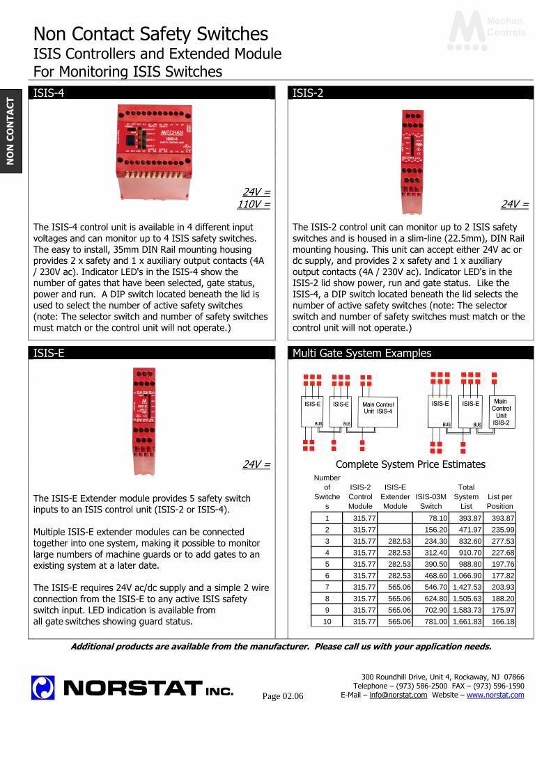
ISIS-4 ISIS-2
24V = 110V = 24V =
The ISIS-4 control unit is available in 4 different input
voltages and can monitor up to 4 ISIS safety switches.
The easy to install, 35mm DIN Rail mounting housing provides 2 x safety and 1 x auxiliary output contacts (4A
/ 230V ac). Indicator LED's in the ISIS-4 show the number of gates that have been selected, gate status,
power and run. A DIP switch located beneath the lid is
used to select the number of active safety switches (note: The selector switch and number of safety switches
must match or the control unit will not operate.)
The ISIS-2 control unit can monitor up to 2 ISIS safety
switches and is housed in a slim-line (22.5mm), DIN Rail
mounting housing. This unit can accept either 24V ac or dc supply, and provides 2 x safety and 1 x auxiliary
output contacts (4A / 230V ac). Indicator LED's in the ISIS-2 lid show power, run and gate status. Like the
ISIS-4, a DIP switch located beneath the lid selects the
number of active safety switches (note: The selector switch and number of safety switches must match or the
control unit will not operate.)
ISIS-E Multi Gate System Examples
24V = Complete System Price Estimates
The ISIS-E Extender module provides 5 safety switch inputs to an ISIS control unit (ISIS-2 or ISIS-4).
Multiple ISIS-E extender modules can be connected
together into one system, making it possible to monitor
large numbers of machine guards or to add gates to an existing system at a later date.
The ISIS-E requires 24V ac/dc supply and a simple 2 wire
connection from the ISIS-E to any active ISIS safety
switch input. LED indication is available from all gate switches showing guard status.
Additional products are available from the manufacturer. Please call us with your application needs.
300 Roundhill Drive, Unit 4, Rockaway, NJ 07866 Telephone – (973) 586-2500 FAX – (973) 596-1590
E-Mail – [email protected] Website – www.norstat.com
Page 02.06
NO
N C
ON
TA
CT
Number
of
Switche
s
ISIS-2
Control
Module
ISIS-E
Extender
Module
ISIS-03M
Switch
Total
System
List
List per
Position
1 315.77 78.10 393.87 393.87
2 315.77 156.20 471.97 235.99
3 315.77 282.53 234.30 832.60 277.53
4 315.77 282.53 312.40 910.70 227.68
5 315.77 282.53 390.50 988.80 197.76
6 315.77 282.53 468.60 1,066.90 177.82
7 315.77 565.06 546.70 1,427.53 203.93
8 315.77 565.06 624.80 1,505.63 188.20
9 315.77 565.06 702.90 1,583.73 175.97
10 315.77 565.06 781.00 1,661.83 166.18

Non Contact Safety Switches ISIS System Installation Drawings Connection Diagrams ISIS-4 Connection Diagram ISIS-2 Connection Diagram
Typical 4 Gate system with manual reset, optional
mechanical or emergency stop button inputs, switching dual contactors (K1 & K2) which are monitored.
Typical 2 Gate system with manual reset, switching
dual contactors (K1 & K2) which are monitored by the ISIS-2.
ISIS-4 and ISIS-E Connection Diagram 8 Gate system, using the ISIS-4 and 1 x ISIS-E extender module. More extender modules can be added to monitor more gate switches if required, simply connect the ISIS-E 2-wire 'Bus' connection into the next available gate switch
input on the ISIS-4 / ISIS-2 control module, or the ISIS-E extender module.
Additional products are available from the manufacturer. Please call us with your application needs.
300 Roundhill Drive, Unit 4, Rockaway, NJ 07866 Telephone – (973) 586-2500 FAX – (973) 596-1590
E-Mail – [email protected] Website – www.norstat.com
Page 02.07
NO
N C
ON
TA
CT

Non Contact Safety Switches
F-Series Safety System
magna
Active Signaling Safety Switches
F-SERIES ADVANTAGES Immediately detects all faults Active communication uses only 2 wires to
connect each switch Safety Category 3 or 4 IP 67 – suitable for wet, wash-down areas Modular control system can be expanded
to accommodate up to 30 switches Expansion modules linked via jumper
cables Individual status LED & contact for each Uniquely coded switches available 8 to 10mm switching Quick disconnect options UL, cUL, TUV and CE approved Description Operation Mechan Controls developed the electronic non-contact safety switch in 1973. The F-SERIES, is the latest version of this product, which now has a record of more than 30 YEARS proven safety and reliability. The F-SERIES is a uniquely flexible DIN rail mounting safety control unit designed for monitoring up to 30 Mechan safety switches. The main control module (FM1) contains the power supply, dual safety contacts and a monitoring circuit for easy integration into your control circuits along with the input and indication for one safety switch. The extender modules provide inputs for 1 (FX1) or 2 (FX2) Mechan safety switches and provide both LED and volt free contact indication from each of the safety switches enabling fast, easy diagnosis of open gates or faults. Mechan safety switches are available in a variety of sizes to suit all applications. They are tamper-proof, i.e. only a Mechan actuator will operate the system, and with an 8-10 mm switching distance, they are easy to install, tolerant to misalignment and guard wear. Designed to withstand the harshest environments, the electronic switching is encapsulated into an ABS housing making the Mechan safety switches immune to water, hot hosing, dust or oil etc.
When the safety switch actuator is brought within the operating range of the sensor (8-10mm target to target), a signal is generated and transmitted to the safety control unit The control unit evaluates this signal and if all monitored gates are closed and the control module's internal self-check is completed, the Mechan safety contacts will close.
300 Roundhill Drive, Unit 4, Rockaway, NJ 07866 Telephone – (973) 586-2500 FAX – (973) 596-1590
E-Mail – [email protected] Website – www.norstat.com
Page 02.08
NO
N C
ON
TA
CT
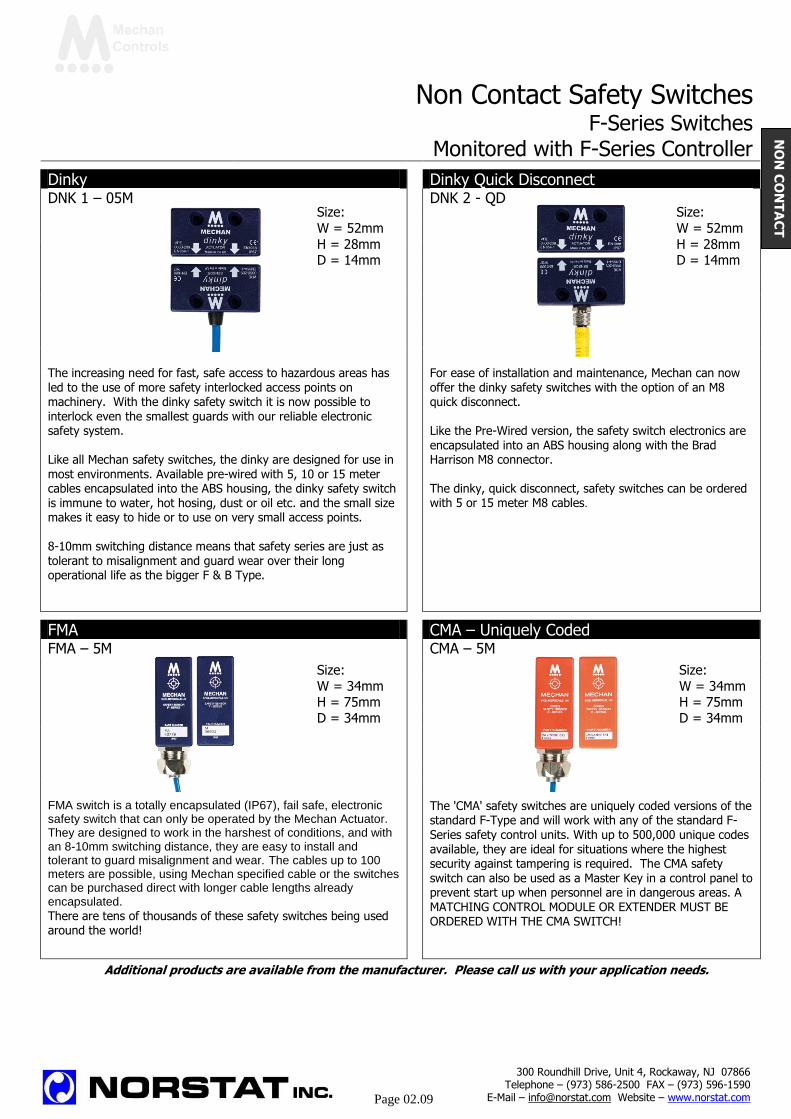
Non Contact Safety Switches F-Series Switches Monitored with F-Series Controller
Dinky Dinky Quick Disconnect DNK 1 – 05M DNK 2 - QD
The increasing need for fast, safe access to hazardous areas has led to the use of more safety interlocked access points on machinery. With the dinky safety switch it is now possible to interlock even the smallest guards with our reliable electronic safety system. Like all Mechan safety switches, the dinky are designed for use in most environments. Available pre-wired with 5, 10 or 15 meter cables encapsulated into the ABS housing, the dinky safety switch is immune to water, hot hosing, dust or oil etc. and the small size makes it easy to hide or to use on very small access points.
8-10mm switching distance means that safety series are just as tolerant to misalignment and guard wear over their long operational life as the bigger F & B Type.
For ease of installation and maintenance, Mechan can now offer the dinky safety switches with the option of an M8 quick disconnect. Like the Pre-Wired version, the safety switch electronics are encapsulated into an ABS housing along with the Brad Harrison M8 connector. The dinky, quick disconnect, safety switches can be ordered with 5 or 15 meter M8 cables.
FMA CMA – Uniquely Coded FMA – 5M CMA – 5M
FMA switch is a totally encapsulated (IP67), fail safe, electronic safety switch that can only be operated by the Mechan Actuator. They are designed to work in the harshest of conditions, and with an 8-10mm switching distance, they are easy to install and tolerant to guard misalignment and wear. The cables up to 100 meters are possible, using Mechan specified cable or the switches can be purchased direct with longer cable lengths already encapsulated.
There are tens of thousands of these safety switches being used around the world!
The 'CMA' safety switches are uniquely coded versions of the standard F-Type and will work with any of the standard F-Series safety control units. With up to 500,000 unique codes available, they are ideal for situations where the highest security against tampering is required. The CMA safety switch can also be used as a Master Key in a control panel to prevent start up when personnel are in dangerous areas. A MATCHING CONTROL MODULE OR EXTENDER MUST BE ORDERED WITH THE CMA SWITCH!
Additional products are available from the manufacturer. Please call us with your application needs.
Size:
W = 52mm
H = 28mm D = 14mm
Size:
W = 52mm
H = 28mm D = 14mm
Size:
W = 34mm H = 75mm D = 34mm
Size:
W = 34mm H = 75mm D = 34mm
300 Roundhill Drive, Unit 4, Rockaway, NJ 07866 Telephone – (973) 586-2500 FAX – (973) 596-1590
E-Mail – [email protected] Website – www.norstat.com
Page 02.09
NO
N C
ON
TA
CT
Non Contact Safety Switches
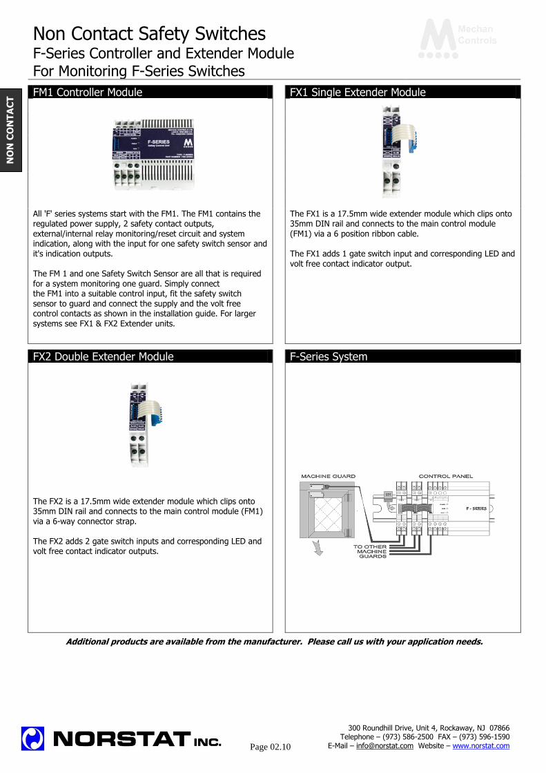
F-Series Controller and Extender Module For Monitoring F-Series Switches
FM1 Controller Module FX1 Single Extender Module
All 'F' series systems start with the FM1. The FM1 contains the regulated power supply, 2 safety contact outputs, external/internal relay monitoring/reset circuit and system indication, along with the input for one safety switch sensor and it's indication outputs. The FM 1 and one Safety Switch Sensor are all that is required for a system monitoring one guard. Simply connect the FM1 into a suitable control input, fit the safety switch sensor to guard and connect the supply and the volt free control contacts as shown in the installation guide. For larger systems see FX1 & FX2 Extender units.
The FX1 is a 17.5mm wide extender module which clips onto 35mm DIN rail and connects to the main control module (FM1) via a 6 position ribbon cable. The FX1 adds 1 gate switch input and corresponding LED and volt free contact indicator output.
FX2 Double Extender Module F-Series System
The FX2 is a 17.5mm wide extender module which clips onto 35mm DIN rail and connects to the main control module (FM1) via a 6-way connector strap. The FX2 adds 2 gate switch inputs and corresponding LED and volt free contact indicator outputs.
Additional products are available from the manufacturer. Please call us with your application needs.
300 Roundhill Drive, Unit 4, Rockaway, NJ 07866 Telephone – (973) 586-2500 FAX – (973) 596-1590
E-Mail – [email protected] Website – www.norstat.com
Page 02.10
NO
N C
ON
TA
CT

Non Contact Safety Switches F-Series System Installation Drawings Connections Diagrams F-Series System Assembly The FM1 control module monitors one gate switch. Where more than one safety switch is to be monitored, If no further gate switches are to be monitored, the connect the required number of FX2’s and/or FX1’s to the
CT1 (Terminator plug, supplied with the FM1) is main control module (FM1). Fit the CT1 (Terminal plug,
fitted as shown. supplied with the FM1) to the last unit as shown.
F-Series Connection
Standard F-SERIES safety switches for a dual channel control circuit. The FM1 is switching two contactors which have normally closed contacts monitored by the FM1 reset circuit (terminals 2 & 3). If on of the contacts welds closed, the second
contactor will operate normally on the next demand on the safety system and the reset circuit will prevent a start up.
Additional products are available from the manufacturer. Please call us with your application needs.
NO
N C
ON
TA
CT

Non Contact Safety Switches
SSS Switches
magna
Electronic Stand Alone Safety Switch
MAGNASAFE ADVANTAGES Easy to install Tolerant to misalignment Tamper proof switching Up to 2A switching capability IP 67 – suitable for wet, wash-down areas Quick disconnect options Compatible with most safety relays 10 mm switching LED indication available EMC tested CE, UL and cUL approved Description Operation The SSS is a tamper-proof, standalone safety switch
that can be used to switch relays, contactors or safety
relays directly. Only a Mechan actuator will operate the SSS switch correctly.
Featuring dynamic signal technology, these switches
offer the advantages of electronic switching for standalone applications.
When the switch actuator is bought within the operating
range of the fixed switch (8-10mm target to target), a
dynamic signal is generated in the actuator and transmitter to the switch.
When the switch is in position (target to target) the NO
contacts close and the NC contacts (SSS-11) open.
SSS SSS-QD
Part Number Contacts Voltage Part Number Contacts Voltage SSS-11-03M 1 NO/ 1NC DC SSS-11-QD 1 NO/ 1NC DC SSS-20-03M 2 NO DC SSS-20-QD 2 NO DC
Additional products are available from the manufacturer. Please call us with your application needs.
Size:
W = 87mm H = 17mm D = 24mm
Size:
W = 87mm H = 17mm D = 24mm
300 Roundhill Drive, Unit 4, Rockaway, NJ 07866 Telephone – (973) 586-2500 FAX – (973) 596-1590
E-Mail – [email protected] Website – www.norstat.com
Page 02.12
NO
N C
ON
TA
CT

SS-R Electronic Safety Switch
MECHAN CONTROLS
Description
Mechan SS-R safety switches are electronically operated
non-contact safety switches for use in machine guarding
applications.
The non-contact operation makes the SS-R easy to install
and tolerant to misalignment, providing a simple reliable
solution to machine guard interlocking.
The electronic switching provides additional security and a SS-R single point switching, leading to a more reliable and secure
long term switching solution. The switch and actuator are
IP67 rated and can be used in wet or dusty environments and Pending
are ideal for connecting to any safety relay. Approvals
CE Complies with the relevant sections of the CE Operation marking directive.
UL Pending The SS-R has 2 x N/O safety contacts and 1 x N/C indicator
contact along with a dual color LED for simple diagnostics. EUROPEAN DIRECTIVES
When installed on a machine guard, power is applied, and Machinery Directive 98/37/EC the switch and actuator are within the specified operating
Low Voltage Directive 73/23/EC range (See table on page 4 for switching distances). The
Safety Contacts will be closed and the Auxiliary Contact Electromagnetic Compatibility Directive 89/336/EC
will be open. The dual color LED will be GREEN.
EUROPEAN STANDARDS When the actuator moves out of the operating range, the
EN292 Safety of Machinery Safety Contacts will open the Auxiliary Contact will close Basic concepts, general principles for design. for indication. The dual color LED will be RED.
EN 60204 Safety of Machinery The SS-R safety switch and actuator have a 8 mm switching Electrical equipment of machines. distance can approach each other from most angles. When
EN 954-1 Safety of Machinery the switch is closed the targets on the printed face of the
Safety related parts of controls systems switch must be aligned. To avoid physical damage, do not
EN 1088 Interlocking devices associated with guards. use the switch and actuator as a stop, set a 2 mm gap for
best operation and tolerance to machine guard vibration. EN Safety of Machinery
60947-5-3 Specification for low voltage switchgear and
Applications control gear.
Interlocked guards where additional security is required.
Door locking is not required. Declaration of Conformity
Food and Beverage packing/filling systems A Declaration of Conformity may be obtained from Mechan Dairy Pharmaceutical Paper Industry Controls Can Forming and Filling, (Aluminum, Steel, Plastic)
Semiconductor Manufacture/Assembly.
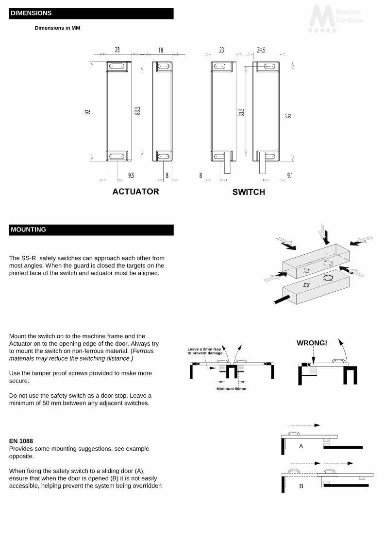
DIMENSIONS
Dimensions in MM
MOUNTING
The SS-R safety switches can approach each other from
most angles. When the guard is closed the targets on the
printed face of the switch and actuator must be aligned.
Mount the switch on to the machine frame and the WRONG! Actuator on to the opening edge of the door. Always try
Leave a 2mm Gap to mount the switch on non-ferrous material. (Ferrous to prevent damage.
materials may reduce the switching distance.)
Use the tamper proof screws provided to make more
secure.
Minimum 50mm
Do not use the safety switch as a door stop. Leave a
minimum of 50 mm between any adjacent switches.
EN 1088 A Provides some mounting suggestions, see example
opposite.
When fixing the safety switch to a sliding door (A),
ensure that when the door is opened (B) it is not easily
accessible, helping prevent the system being overridden B
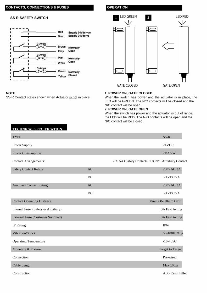
TECHNICAL SPECIFICATION
TYPE SS-R
Power Supply 24VDC
Power Consumption 2VA/2W
Contact Arrangements: 2 X N/O Safety Contacts, 1 X N/C Auxiliary Contact
Safety Contact Rating AC 230VAC/2A
DC 24VDC/2A
Auxiliary Contact Rating AC 230VAC/2A
DC 24VDC/2A
Contact Operating Distance 8mm ON/10mm OFF
Internal Fuse (Safety & Auxiliary) 3A Fast Acting
External Fuse (Customer Supplied) 3A Fast Acting
IP Rating IP67
Vibration/Shock 50-100Hz/10g
Operating Temperature -10-+55C
Mounting & Fixture Target to Target
Connection Pre-wired
Cable Length Max 100m
Construction ABS Resin Filled
CONTACTS, CONNECTIONS & FUSES OPERATION
2 SS-R SAFETY SWITCH 1
NOTE 1 POWER ON, GATE CLOSED
SS-R Contact states shown when Actuator is not in place. When the switch has power and the actuator is in place, the
LED will be GREEN. The N/O contacts will be closed and the
N/C contact will be open.
2 POWER ON, GATE OPEN
When the switch has power and the actuator is out of range,
the LED will be RED. The N/O contacts will be open and the
N/C contact will be closed.

MECHAN
SS-C Electronic Coded Safety Switch
Electronic safety switch
1 x N/O + 1 x N/C
10mm Operating distance
Dual color LED Indication
500mA Switching
IP67
Slim-line ABS Housing
UL Pending
CE
DESCRIPTION
The Mechan SS-C Safety switches are electronic, non-contact safety switches.
Mechan’s unique electronic switching provides additional security and a single switching point
leading to a more reliable and secure long term safety switching solution.
The SS-C switch is pre-wired with 5 or 10 meters of cable and has a dual color indicator LED
to clearly show the guard status.
The SS-C is fully encapsulated to IP67 and is suitable for use in wet, wash down or dusty
areas. Its slim-line package and 10mm switching distance makes the SS-C easy to fit to most
guarding systems.
With 1 x N/O and 1 x N/C contact the SS-C is ideal for use with many of the new ‘Low Inrush’
current safety relays where category 3 or 4 performance is required for a safety application.
300 Roundhill Drive, Unit 4, Rockaway, NJ 07866 Telephone – (973) 586-2500 FAX – (973) 596-1590
E-Mail – [email protected] Website – www.norstat.com
Page

TECHNICAL SPECIFICATION
Type SS-C Electronic Safety Switch
Technology Electronic
Approvals CE;
Power Supply 24vDC
Power Consumption 2VA / 2W
Contact Arrangements 1 x N/O Safety; 1 x N/C Auxiliary
Safety Contact Operating Distance 9mm ON / 10 mm OFF
Safety Contact Rating AC : 110Vac / 500mA / DC: 24Vdc / 500mA
Auxiliary Contact Operating Distance 9mm OFF / 10 mm ON
Auxiliary Contact Rating AC : 110Vac / 500mA / DC: 24Vdc / 500mA
External Fuse (Customer Supplied) 300 mA
Dimensions Switch 82.5 x 19 x 17mm
Dimensions Actuator 82.5 x 19 x 19mm
IP Rating IP67
Cable length 100 meters max
Vibration / Shock 50—100Hz / 10g
Operating Temperature -10 to +55C
Mounting & Fixture Target to Target
Construction Blue ABS Resin Filled
DIMENSIONS
Dimensions in MM

CONNECTIONS
SS-C SAFETY SWITCH
NOTE
SS-C Shown when Actuator is not in place.
.
Ordering Information
Part Number Contacts Contact Rating External Fuse IP Housing Cable Exit & Length Code
____________________________________________________________________________________________________
SS-C-03M 1N/O + 1 N/C 110VAC/500mA 300mA IP67 ABS 3m pre wired 363-000
24VDC/500mA
_____________________________________________________________________________________________________
SS-C-05M 1N/O + 1 N/C 110VAC/500mA 300mA IP67 ABS 5m pre wired 363-001
24VDC/500mA
_____________________________________________________________________________________________________
ACTUATOR ONLY
_____________________________________________________________________________________________________
SS-C-ACT IP67 ABS 363-099
300 Roundhill Drive, Unit 4, Rockaway, NJ 07866 Telephone – (973) 586-2500 FAX – (973) 596-1590
E-Mail – [email protected] Website – www.norstat.com
Page
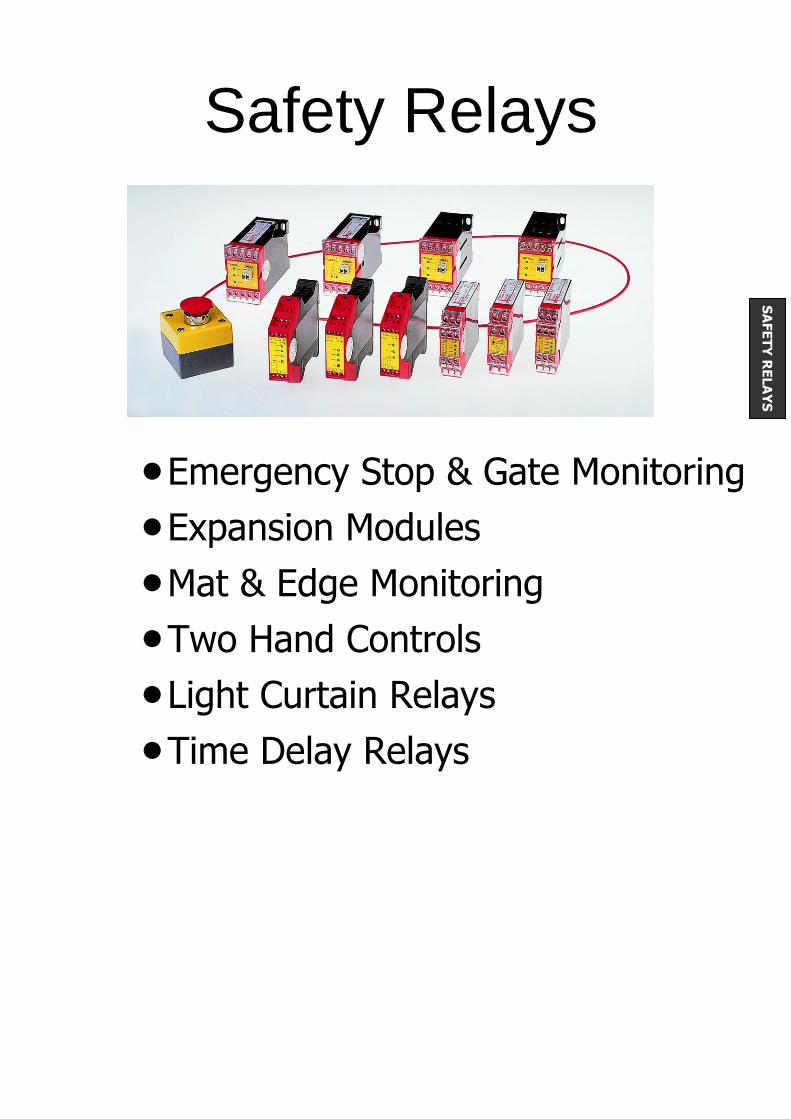
Safety Relays
Emergency Stop & Gate Monitoring
Expansion Modules
Mat & Edge Monitoring
Two Hand Controls
Light Curtain Relays
Time Delay Relays
SA
FE
TY
RE
LA
YS

Safety Relays
Category 2-3 Application
Emergency Stop & Gate Monitoring Smallest safety relay available
Easy to wire: simply connect the safety components (NC e-stop buttons and safety switches) in series with the power source for the relay. Add a momentary start button (or jumper for auto reset) to Y1 & Y2 terminals and your done!
For single channel (Cat 2) installation, connect the single contact safety components in series with the 24V+ (A1 Terminals).
For dual channel (Cat 3) installation, connect one contact of the dual contact safety components in series with the 24V+ (A1) and the other contact in series with the 0V (A2).
SAFE 1.1 SAFE 1 With Start Control Monitoring
(Manual Reset) Without Start Control Monitoring
(Automatic Reset)
Emergency Stop and Gate Monitoring Applications
Emergency Stop and Gate Monitoring Applications
Connection Diagram
Part Numbers
Operation Voltage 24V AC/DC 24V AC/DC
Output Contacts 3 NO Safety, 1 NC Auxiliary 3 NO Safety, 1 NC Auxiliary
Max. Contact Capacity 5A (AC or DC) 5A (AC or DC)
Min. Contact Capacity 1 mA 1 mA
Switching Capacity 1250 VA (Resistive Load) 1250 VA (Resistive Load)
Power Consumption 2.5 VA / 2.5 W 2.5 VA / 2.5 W
Start Up Delay / Fallback <50ms / <80ms <50ms / <80ms
Simultaneity - -
Security 6.3A quick acting or 4A time lag 6.3A quick acting or 4A time lag
Temperature Range -25C to +55C -25C to +55C
Approvals CE, BG, UL, cUL CE, BG, UL, cUL
Additional Products are available from the manufacturer. Please call us with your application needs.
C H AN N EL
SIN GLE
2414
4241
Y1A1
2313
+24V
0V
34
A2
STAR T
Y2
33
3 3
3 4
+ -
Ele c tr o n ic Fu s e
~ ~
C o n tr o l L o g ic
K2
K1
A2 ( - )A1 ( + ) Y1 Y2 1 3 2 3
1 4 2 4
4 1
4 2
300 Roundhill Drive, Unit 4, Rockaway, NJ 07866 Telephone – (973) 586-2500 FAX – (973) 596-1590
E-Mail – [email protected] Website – www.norstat.com
Page 03.02
SA
FE
TY
RE
LA
YS
24 14 34
23 13
42 41
Y1 A1 START
33
A2
Y2
CHANNEL 0V +24V
DUAL

Safety Relays
Category 4 Applications
Emergency Stop & Gate Monitoring The smallest safety relay
available!
Designed for dual safety channel (Cat 4) applications
Easy to install: 1. Connect 24V (A1) & 0V (A2) 2. Connect safety channel 1 between S11 & S12 3. Connect safety channel 2 between S21 & S22 4. Connect restart button (or jumper for automatic restart) between S33 & S34
The relay monitors the two safety circuits and will open the output contacts if either circuit is broken. The relay checks that both circuits open at the same time, ensuring the switches are operating correctly
SAFE 2 SAFE 2.1 With Start Control Monitoring
(Manual Reset) Without Start Control Monitoring
(Automatic Reset)
Emergency Stop and Gate Monitoring Applications
Emergency Stop and Gate Monitoring Applications
Connection Diagram
Part Numbers
Operation Voltage 24V AC/DC 24V AC/DC
Output Contacts 2 NO Safety 2 NO Safety
Max. Contact Capacity 6A (AC or DC) 6A (AC or DC)
Min. Contact Capacity 1 mA 1 mA
Switching Capacity 1500 VA (Resistive Load) 1500 VA (Resistive Load)
Power Consumption 2.5 VA / 2.5 W 2.5 VA / 2.5 W
Start Up Delay / Fallback <50ms / <30ms <50ms / <30ms
Simultaneity 40 ms 40 ms
Security 6.3A quick acting or 4A time lag 6.3A quick acting or 4A time lag
Temperature Range -25C to +55C -25C to +55C
Approvals CE, BG, UL, cUL CE, BG, UL, cUL
Additional products are available from the manufacturer. Please call us with your application needs.
Safety Relays
1 4
2 31 3
A1
ST AR T
A2
2 4
S3 3 S3 4
S2 1 S2 2
S1 1 S1 2
0 V
+ 2 4 V
2 4
2 3
+ -
Ele c tr o n ic Fu s e
~ ~
S2 1
K2
K1
1 4
C o n tr o l L o g ic
A2 ( - )A1 ( + ) S1 1 1 3S1 2 S2 2 S3 3 S3 4
300 Roundhill Drive, Unit 4, Rockaway, NJ 07866 Telephone – (973) 586-2500 FAX – (973) 596-1590
E-Mail – [email protected] Website – www.norstat.com
Page 03.03
SA
FE
TY
RE
LA
YS
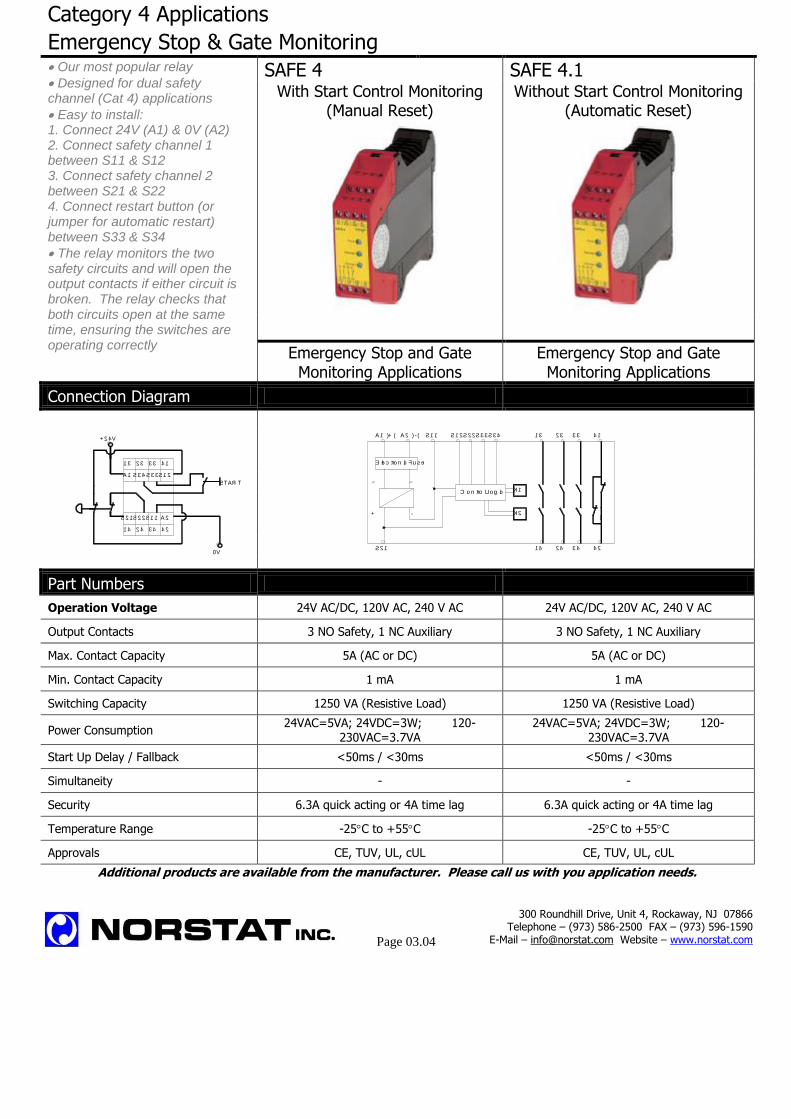
Category 4 Applications
Emergency Stop & Gate Monitoring Our most popular relay
Designed for dual safety channel (Cat 4) applications
Easy to install: 1. Connect 24V (A1) & 0V (A2) 2. Connect safety channel 1 between S11 & S12 3. Connect safety channel 2 between S21 & S22 4. Connect restart button (or jumper for automatic restart) between S33 & S34
The relay monitors the two safety circuits and will open the output contacts if either circuit is broken. The relay checks that both circuits open at the same time, ensuring the switches are operating correctly
SAFE 4 SAFE 4.1 With Start Control Monitoring
(Manual Reset) Without Start Control Monitoring
(Automatic Reset)
Emergency Stop and Gate Monitoring Applications
Emergency Stop and Gate Monitoring Applications
Connection Diagram
Part Numbers
Operation Voltage 24V AC/DC, 120V AC, 240 V AC 24V AC/DC, 120V AC, 240 V AC
Output Contacts 3 NO Safety, 1 NC Auxiliary 3 NO Safety, 1 NC Auxiliary
Max. Contact Capacity 5A (AC or DC) 5A (AC or DC)
Min. Contact Capacity 1 mA 1 mA
Switching Capacity 1250 VA (Resistive Load) 1250 VA (Resistive Load)
Power Consumption 24VAC=5VA; 24VDC=3W; 120-
230VAC=3.7VA 24VAC=5VA; 24VDC=3W; 120-
230VAC=3.7VA
Start Up Delay / Fallback <50ms / <30ms <50ms / <30ms
Simultaneity - -
Security 6.3A quick acting or 4A time lag 6.3A quick acting or 4A time lag
Temperature Range -25C to +55C -25C to +55C
Approvals CE, TUV, UL, cUL CE, TUV, UL, cUL
Additional products are available from the manufacturer. Please call us with you application needs.
+ 2 4 V
S1 1
3 42 4 4 2
A2
S3 3
3 3
S3 4 S1 2
4 1
0 V
STAR T
SAFE 4
S2 2S2 1
A1
1 3 2 3
1 4
S1 1
S2 1 1 4
1 3S3 4S3 3S2 2S1 2
C o n tro l L o g ic K1
K2
A1 (+ ) A2 ( - )
~~
Ele c tro n ic Fu s e
-+
2 4
2 3
3 4
3 3
4 2
4 1
300 Roundhill Drive, Unit 4, Rockaway, NJ 07866 Telephone – (973) 586-2500 FAX – (973) 596-1590
E-Mail – [email protected] Website – www.norstat.com
Page 03.04
Safety Relays
Category 4 Applications
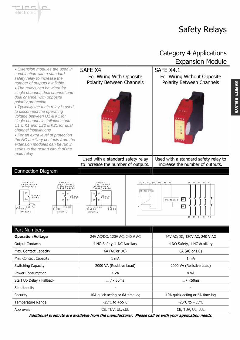
Expansion Module Extension modules are used in combination with a standard safety relay to increase the number of outputs available
The relays can be wired for single channel, dual channel and dual channel with opposite polarity protection
Typically the main relay is used to disconnect the operating voltage between U1 & K1 for single channel installations and U1 & K1 and U22 & K21 for dual channel installations
For an extra level of protection the NC auxiliary contacts from the extension modules can be run in series to the restart circuit of the main relay
SAFE X4 SAFE X4.1 For Wiring With Opposite Polarity Between Channels
For Wiring Without Opposite Polarity Between Channels
Used with a standard safety relay to increase the number of outputs.
Used with a standard safety relay to increase the number of outputs.
Connection Diagram
Part Numbers
Operation Voltage 24V AC/DC, 120V AC, 240 V AC 24V AC/DC, 120V AC, 240 V AC
Output Contacts 4 NO Safety, 1 NC Auxiliary 4 NO Safety, 1 NC Auxiliary
Max. Contact Capacity 6A (AC or DC) 6A (AC or DC)
Min. Contact Capacity 1 mA 1 mA
Switching Capacity 2000 VA (Resistive Load) 2000 VA (Resistive Load)
Power Consumption 4 VA 4 VA
Start Up Delay / Fallback … / <50ms … / <50ms
Simultaneity - -
Security 10A quick acting or 6A time lag 10A quick acting or 6A time lag
Temperature Range -25C to +55C -25C to +55C
Approvals CE, TUV, UL, cUL CE, TUV, UL, cUL
Additional products are available from the manufacturer. Please call us with your application needs.
( C a te g o r y 2 )
SAFE X4 .1Sin g le C h a n n e l
R e la yM a s te r
1 4
1 3
U 1( 2 4 VD C )
K2 1 K1
SAFE X4 .1
1 4
1 3
U 1( 2 4 VD C )
K2 1 K1
SAFE X4 .1D u a l C h a n n e l
W ith o u t O p p o s ite Po la r ity Pr o te c tio n
R e la yM a s te r
2 3
2 4
SAFE X4 .1
1 4
1 3
K2 1 K1
R e la yM a s te r
2 3
2 4
SAFE X4 .1
U 2 2( 0 VD C )
U 1( 2 4 VD C )
D u a l C h a n n e l SAFE X4
W ith O p p o s ite Po la r ity Pr o te c tio n
C o n tro l L o g ic
+ -
Ele c tr o n ic Fu s e
~ ~
A2 ( - )A1 (+) U 1 U 2 2 K1 K2 1
K2
K1
3 3
3 4
1 3
1 4
2 3
2 4
4 3 Y1
4 4 Y2
SA
FE
TY
RE
LA
YS

Safety Relays
Category 4 Applications
Mat & Edge Monitoring – 2 Hand Control The SAFE M is used with contact edges and mats, which are normally open until the contact is made (as opposed to safety switches and e-stop buttons which are normally closed). These can be used for 2 wire or 4 wire edges and mats. 4 wire applications insure that the wires to and from the device are monitored
The SAFE Z.2 is used to insure the closure of two buttons or switches, each with 1 NO & 1NC contacts, within ½ a second of each other
SAFE M – SAFE M.1 SAFE Z.2 SAFE M – Auto Restart
SAFE M.1 – Manual Restart Insures Simultaneous Closure of
Two Buttons or Switches
Mat and Edge Control Monitoring
Applications Two Hand Anti Tie Down
Control Application
Connection Diagram
SAFE M SAFE Z.2
Part Numbers
Operation Voltage 24V AC/DC 24V AC/DC, 120 or 230 VAC
Output Contacts 3 NO Safety, 1 NC Aux. 2 NO Safety, 1 NC Aux., 1 PNP
Max. Contact Capacity 5A (AC or DC) 6A (AC or DC)
Min. Contact Capacity 1 mA 1 mA
Switching Capacity 1250 VA (Resistive Load) 1500 VA (Resistive Load)
Power Consumption 2.5 VA / 2.5 W 3 VA
Start Up Delay / Fallback <50ms / <30ms <50ms / <25ms
Simultaneity .5 s
Security 6.3A quick acting or 4A time lag 6.3A quick acting or 4A time lag
Temperature Range -25C to +55C -25C to +55C
Approvals CE, BG, (UL, cUL pending) CE, TUV, UL, cUL
Additional products are available from the manufacturer. Please call us with your application needs.
300 Roundhill Drive, Unit 4, Rockaway, NJ 07866 Telephone – (973) 586-2500 FAX – (973) 596-1590
E-Mail – [email protected] Website – www.norstat.com
Page 03.05
1 4
2 31 3
A1
STAR T
A2
2 4
S3 3 S3 4
S2 1 S2 2
S1 1 S1 2
0 V
+ 2 4 V
S1Y1 Y23 4
1 4 2 4
S1 1 S1 2 S2 1
3 2 A2
S2 2
0 V
S2
A1 1 3 2 3 3 1
+ 2 4 V
STAR TA2 ( - )A1 ( + ) 1 3 2 3S2 2 S1 2 S1 1 S2 1 Y1 Y2 3 1
+ -
Ele c tr o n ic Fu s e
~ ~
K2
K1
1 4 2 4
C o n tr o l L o g ic
3 4( PN P)
3 2
+ -
~ ~
K2
K1
14 24
Control Logic
A2 (-)A1 (+) S11 13 23S34
S23
X2 X1S22 K12
14 24
13 23
300 Roundhill Drive, Unit 4, Rockaway, NJ 07866 Telephone – (973) 586-2500 FAX – (973) 596-1590
E-Mail – [email protected] Website – www.norstat.com
Page 03.06
SA
FE
TY
RE
LA
YS
Safety Relays
Category 4 Applications
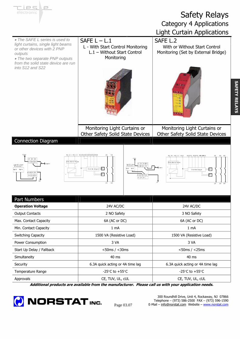
Light Curtain Applications The SAFE L series is used to light curtains, single light beams or other devices with 2 PNP outputs
The two separate PNP outputs from the solid state device are run into S12 and S22
SAFE L – L.1 SAFE L.2 L - With Start Control Monitoring
L.1 – Without Start Control Monitoring
With or Without Start Control Monitoring (Set by External Bridge)
Monitoring Light Curtains or Other Safety Solid State Devices
Monitoring Light Curtains or Other Safety Solid State Devices
Connection Diagram
Part Numbers
Operation Voltage 24V AC/DC 24V AC/DC
Output Contacts 2 NO Safety 3 NO Safety
Max. Contact Capacity 6A (AC or DC) 6A (AC or DC)
Min. Contact Capacity 1 mA 1 mA
Switching Capacity 1500 VA (Resistive Load) 1500 VA (Resistive Load)
Power Consumption 3 VA 3 VA
Start Up Delay / Fallback <50ms / <30ms <50ms / <25ms
Simultaneity 40 ms 40 ms
Security 6.3A quick acting or 4A time lag 6.3A quick acting or 4A time lag
Temperature Range -25C to +55C -25C to +55C
Approvals CE, TUV, UL, cUL CE, TUV, UL, cUL
Additional products are available from the manufacturer. Please call us with your application needs.
300 Roundhill Drive, Unit 4, Rockaway, NJ 07866 Telephone – (973) 586-2500 FAX – (973) 596-1590
E-Mail – [email protected] Website – www.norstat.com
Page 03.07
SA
FE
TY
RE
LA
YS
1 4
2 31 3
A1
STAR T
A2
2 4
S3 3 S3 4
0 V
S1 1 S1 2
S1 2 S2 2
PN P PN P
L ig h t C u r ta in R e c e iv e r
+ 2 4 V 2 3
2 4
+ -
Ele c tr o n ic Fu s e
~ ~
K2
K1
1 4
C o n tr o l L o g ic
A2 ( - )A1 ( + ) S1 1 1 3S1 2 S2 2 S3 3 S3 4S1 2
2 31 3 3 3 BR 1
1 4
A1
STAR T
0 V
A2
2 4 3 4
BR 2
S1 1 S1 2 S2 2
Y1 Y2
PN P PN P
L ig h t C u r ta in R e c e iv e r
+ 2 4 V
Ele c tro n ic Fu s e
+ -
~ ~
K2
K1
1 4 2 4 3 4
C o n tro l L o g ic
A2 ( - )A1 (+ ) S1 1 1 3 2 3 3 3S1 2 Y1 S2 2 Y2 BR 1BR 2
Safety Relays
Category 4 Applications
Relay With Safe Time Delayed Outputs
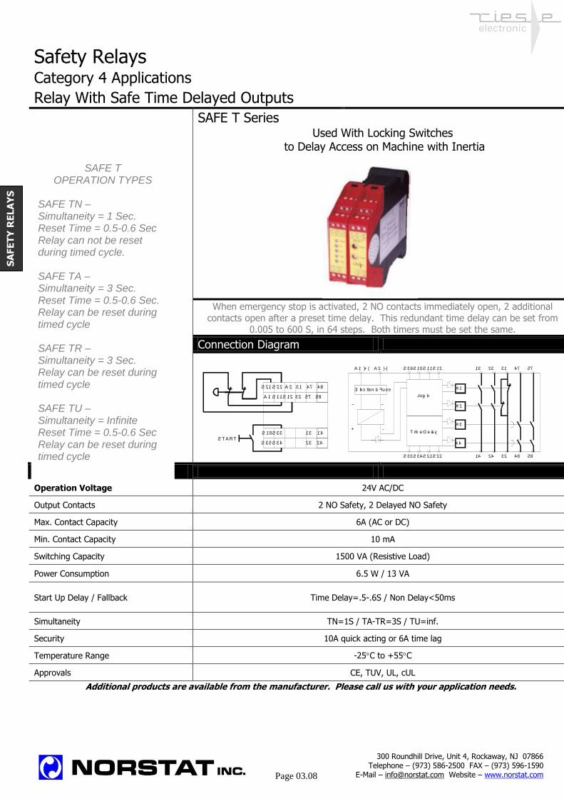
SAFE T Series Used With Locking Switches
to Delay Access on Machine with Inertia
When emergency stop is activated, 2 NO contacts immediately open, 2 additional
contacts open after a preset time delay. This redundant time delay can be set from 0.005 to 600 S, in 64 steps. Both timers must be set the same.
Connection Diagram
Part Numbers
Operation Voltage 24V AC/DC
Output Contacts 2 NO Safety, 2 Delayed NO Safety
Max. Contact Capacity 6A (AC or DC)
Min. Contact Capacity 10 mA
Switching Capacity 1500 VA (Resistive Load)
Power Consumption 6.5 W / 13 VA
Start Up Delay / Fallback Time Delay=.5-.6S / Non Delay<50ms
Simultaneity TN=1S / TA-TR=3S / TU=inf.
Security 10A quick acting or 6A time lag
Temperature Range -25C to +55C
Approvals CE, TUV, UL, cUL
Additional products are available from the manufacturer. Please call us with your application needs.
A 1 S 11 57 5832S 12
S 10 S 33 14
S 35 S 34 23 24
13
S T A RT
A 2 31 47 48S 21 S 22
Logic
2414
K2
S21
~~
-+T ime Delay
S33 S34 S22 32 48 58
K3
K4
K1Elec tronic Fuse
2313A1 (+) A2 (-) S36 S10 S11 S12 31 47 57
SA
FE
TY
RE
LA
YS
SAFE T OPERATION TYPES
SAFE TN – Simultaneity = 1 Sec. Reset Time = 0.5-0.6 Sec Relay can not be reset during timed cycle. SAFE TA – Simultaneity = 3 Sec. Reset Time = 0.5-0.6 Sec. Relay can be reset during timed cycle SAFE TR – Simultaneity = 3 Sec. Relay can be reset during timed cycle SAFE TU – Simultaneity = Infinite Reset Time = 0.5-0.6 Sec Relay can be reset during timed cycle
300 Roundhill Drive, Unit 4, Rockaway, NJ 07866 Telephone – (973) 586-2500 FAX – (973) 596-1590
E-Mail – [email protected] Website – www.norstat.com
Page 03.08
Safety Relays
Category 4 Applications
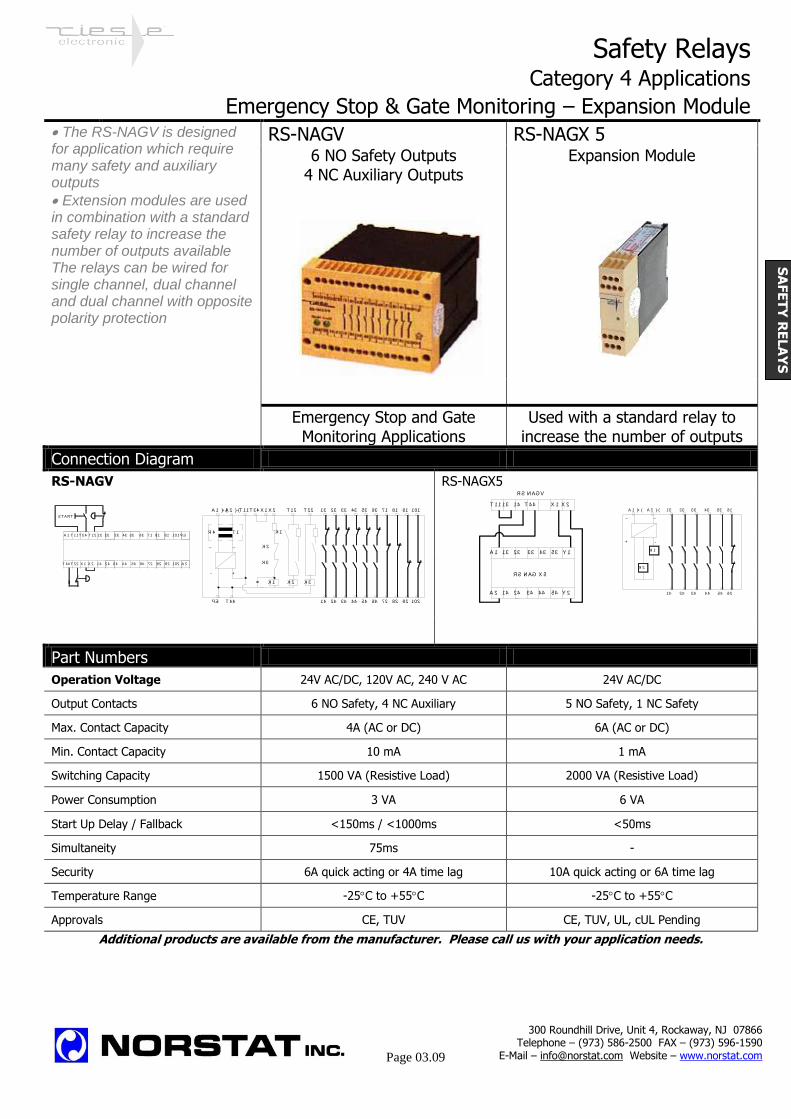
Emergency Stop & Gate Monitoring – Expansion Module The RS-NAGV is designed for application which require many safety and auxiliary outputs
Extension modules are used in combination with a standard safety relay to increase the number of outputs available The relays can be wired for single channel, dual channel and dual channel with opposite polarity protection
RS-NAGV RS-NAGX 5 6 NO Safety Outputs
4 NC Auxiliary Outputs Expansion Module
Emergency Stop and Gate Monitoring Applications
Used with a standard relay to increase the number of outputs
Connection Diagram
RS-NAGV RS-NAGX5
Part Numbers
Operation Voltage 24V AC/DC, 120V AC, 240 V AC 24V AC/DC
Output Contacts 6 NO Safety, 4 NC Auxiliary 5 NO Safety, 1 NC Safety
Max. Contact Capacity 4A (AC or DC) 6A (AC or DC)
Min. Contact Capacity 10 mA 1 mA
Switching Capacity 1500 VA (Resistive Load) 2000 VA (Resistive Load)
Power Consumption 3 VA 6 VA
Start Up Delay / Fallback <150ms / <1000ms <50ms
Simultaneity 75ms -
Security 6A quick acting or 4A time lag 10A quick acting or 6A time lag
Temperature Range -25C to +55C -25C to +55C
Approvals CE, TUV CE, TUV, UL, cUL Pending
Additional products are available from the manufacturer. Please call us with your application needs.
300 Roundhill Drive, Unit 4, Rockaway, NJ 07866 Telephone – (973) 586-2500 FAX – (973) 596-1590
E-Mail – [email protected] Website – www.norstat.com
Page 03.09
A 1 T 11 T 34 T 12 23 33 53 63 81 91 101 P E
T 44 T 22 X 1 14 34 54 64 82 92 A 2
S T A RT
13 43 71
102724424X 2
K1
X2
~
A2 (-)
+
T 1
T 44
~
A1 (+)
-
R4
PE
K3
K2
T 11 T 34 X1
K2
T 12
K1
K3
T 22 1012313 33 43 53 63 71 81 91
2414 34 44 54 64 72 82 92 102
T 4414T 11 13
13 23 33 43
14 24 4434
A 1
A 2
RS -NA GV
RS -NA G X 5
X 2X 1
Y 2
Y 153
54 24
23
14
13A 1 (+) A 2 (-)
~
+
~
-
33 43 53 61
34 44 54 62
K 1
K 2
SA
FE
TY
RE
LA
YS

Safety Relays
Dimensions
In mm Dimensions
SAFE 1
SAFE 2
SAFE 2.2
SAFE L
SAFE 4
SAFE X4
SAFE L.2
SAFE T
RS-NAGX5
RS-NAGV
22.5
99
114
99
35 114
22.5 99
80
22.5
86
118
100 118
73
300 Roundhill Drive, Unit 4, Rockaway, NJ 07866 Telephone – (973) 586-2500 FAX – (973) 596-1590
E-Mail – [email protected] Website – www.norstat.com
Page 03.10
SA
FE
TY
RE
LA
YS

Optical / Audible Signaling Devices
Stack Lights
Single Beacons
Buzzer Modules
Optical/Audible Modules
Installation Beacons
SIG
NA
LIN
G

Signaling Devices Glossary
Permanent light element with incandescent bulb
50mm Diameter Permanent light elements with BA15d sockets can accommodate incandescent bulbs (sold separately) with either 5 or 10-Watt power, for optical indication. Common signal Lenses can be used with either LED or incandescent bulbs. The bulb used determines the voltage range.
Permanent light element with LED bulb
Permanent light elements with BA15d sockets can accommodate colored LED-lamp bulbs (sold separately), providing vibration proof optical indication, with long service life. Common signal elements can be used with either LED or incandescent bulbs. The bulb used determines the voltage range.
Blinking light element with incandescent or LED bulb
Blinking signal elements with integrated blinking circuit and a BA15d socket. The blinking frequency is approximately 2 Hz. Blinking signal elements can be used with either LED or incandescent bulbs. The bulb used determines the voltage range. .
1 Joule Flashing light element
Flashing light elements are ideal for providing light indication for large bright areas, due to the high intensity light created by the integrated Xenon-flash tube. The flash frequency is approximately 1 Hz. The elements are offered with either 3 or 6 Joule light intensity. Voltage ranges include 12-48 VAC/DC, 100-120VAC and 220-240 VAC.
Audible signal element
Audible signal elements provide an extra level of indication or warning. The buzzer module can either be installed separately or on top of a stack light. The tone can be set to continuous tone, pulse tone or two-tone via an internal switch. Volume and frequency can be adjusted via internal potentiometers. Voltage ranges include 12-48 VAC/DC, 100-120VAC and 220-240 VAC.
300 Roundhill Drive, Unit 4, Rockaway, NJ 07866 Telephone – (973) 586-2500 FAX – (973) 596-1590
E-Mail – [email protected] Website – www.norstat.com
Page 04.03
SIG
NA
LIN
G

● Modular design with a sturdy enclosure for all indoor and outdoor
applications
● Wherever equipment is required to display machine status and provide
warning signals.
● High level of protection against electric shock with IP 54 (IP 65 is optional).
● A flexible modular system guarantees easy operation. Up to five modules
with a choice of six globe colors can be simply plugged together in any
permutation, even at a later point in time.
● The mechanical and electronic systems are decoupled. From it results a
stable construction insensitive to vibration .
● You have the choice between four different modules:
— Module with continuous beam max. 7 W
— Blinking-light module max. 7 W
— Flashing-light module max. 0,6 joules
— Acoustic module 85 dB (A)
● Versatility in installation: also the mounting methods will meet all your
requirements. Stand, tube or direct mounting.
● The environmentally friendly materials used in manufacture
comply with the DIN ISO 14000.
+45 °C +60 °C IP 54 IP 65 -25 °C -30 °C 90%
Protective Protective Operating Operating Relative
system system temperature temperature humidity
(optional) (with LED)
The modular construction guarantees flexible adaptation to any application
Dimensions:
L1 L1 L2
∅ 54 [2.13“]
M 16 x 1,5
Stand mounting gasket
Tube Mounting mounting stand single-stage 107 (4.2”)
Length of tube 100 78 (3.1”) 88 (3.58”) 2-stages 170 (6.7”)
Length of tube 250 228 (9.0”) 238 (9.4”) 3-stages 233 (9.2”)
Length of tube 400 378 (14.9”) 388 (15.2”) 4-stages 296 (11.6”)
5-stages 359 (14.1”)
The bayonet fixing ensures that you install the modules easily and rapidly
BR 50 Signal Tower Program

Technical data:
Globe colors
red yellow amber green blue transparent Module data Continuous-beam module Blinking-light module 1.5 Hz Flashing-light module Acoustic module
Light bulb LED Light bulb LED
Modular stages max. 5 (sequence and color freely selectable)
Angle of beam 360°
Percentage duty cycle 100%
Rated power, 7 W depending 7 W depending
max. with 5 stages 5 W on voltage 5 W on voltage
Lamp socket BA 15 d BA 15 d
Flashing power 0.6 Joules
Service life of after 8 mill. flashes
light bulb/tube approx. 1500 h approx. 100000 h approx. 1500 h approx. 100000 h min. 70% light emission
Sound level at 1 m (39.3”) distance 85 dB (A)
Sound patterns 7
AC voltage rating 230 V 50/60 Hz - 15% to + 10%
Current capacity rating 230 V 0.035 A 0.015 A 0.03 A - 0.011 A 0.015 A
AC voltage rating 115 V 50/60 Hz -15% to +10%
Current capacity rating 115 V 0.064 A 0.015 A - - 0.02 A 0.015 A
DC voltage rating 24 V - 15% bis + 20%
Current capacity rating 0.3 A 0.030 A 0.25 A 0.030 A 0.04 A 0.012 A
Weight of modules 80 g 90 g 90 g 130 g
The acoustic module is always installed at the top of the signal tower.
Other data: Installation Vertical or horizontal - mounting stand, tube mounting, direct mounting
Accessories Gasket for light module + basic module IP 65, gasket for tubular stand on plinth IP 65,
gasket for direct mounting IP 65 (IP 65 not for sound module)
Wall bracket with hood
Weight of plinth Stand mounting (w/o module): approx. 220 g
Tube mounting (w/o module): approx. 200 g
Direct mounting (w/o module): approx. 180 g
Materials Globe: polycarbonate, Plinth: ABS, Tube: stainless steel
Tube threat 30 mm (1.18”), M 16 x 1.5
Base and end module Gasket and installation material Wall bracket with hood
for direct mounting for mounting stand Order No.: 28250010000 Order No.: 28250210000 Order No.: 28250200000
Option with IP 65:
a) Ring gasket for light module / base module (1 per light module plus 1 base module), order no.: 28250220000
b) Ring gasket for mounting tube (only applies to stand or tube mounting), order no.: 28250230000
Lamp installation/
Removal Tool
Wall bracket for
direct mounting
(optional IP 65) and for
double side mounting,
up to
10 modules
Available
Future
300 Roundhill Drive, Unit 4, Rockaway, NJ 07866 Telephone – (973) 586-2500 FAX – (973) 596-1590
E-Mail – [email protected] Website – www.norstat.com
Page 04.14
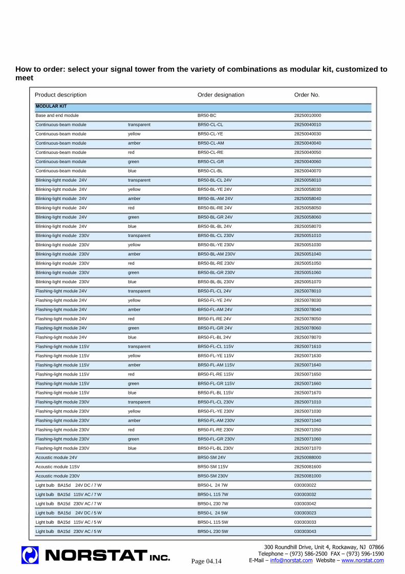
How to order: select your signal tower from the variety of combinations as modular kit, customized to meet
Product description MODULAR KIT
Base and end module
Continuous-beam module
Continuous-beam module
Continuous-beam module
Continuous-beam module
Continuous-beam module
Continuous-beam module
Blinking-light module 24V
Blinking-light module 24V
Blinking-light module 24V
Blinking-light module 24V
Blinking-light module 24V
Blinking-light module 24V
Blinking-light module 230V
Blinking-light module 230V
Blinking-light module 230V
Blinking-light module 230V
Blinking-light module 230V
Blinking-light module 230V
Flashing-light module 24V
Flashing-light module 24V
Flashing-light module 24V
Flashing-light module 24V
Flashing-light module 24V
Flashing-light module 24V
Flashing-light module 115V
Flashing-light module 115V
Flashing-light module 115V
Flashing-light module 115V
Flashing-light module 115V
Flashing-light module 115V
Flashing-light module 230V
Flashing-light module 230V
Flashing-light module 230V
Flashing-light module 230V
Flashing-light module 230V
Flashing-light module 230V
Acoustic module 24V
Acoustic module 115V
Acoustic module 230V
Light bulb BA15d 24V DC / 7 W
Light bulb BA15d 115V AC / 7 W
Light bulb BA15d 230V AC / 7 W
Light bulb BA15d 24V DC / 5 W
Light bulb BA15d 115V AC / 5 W
Light bulb BA15d 230V AC / 5 W
8
Order designation Order No.
BR50-BC 28250010000
transparent BR50-CL-CL 28250040010
yellow BR50-CL-YE 28250040030
amber BR50-CL-AM 28250040040
red BR50-CL-RE 28250040050
green BR50-CL-GR 28250040060
blue BR50-CL-BL 28250040070
transparent BR50-BL-CL 24V 28250058010
yellow BR50-BL-YE 24V 28250058030
amber BR50-BL-AM 24V 28250058040
red BR50-BL-RE 24V 28250058050
green BR50-BL-GR 24V 28250058060
blue BR50-BL-BL 24V 28250058070
transparent BR50-BL-CL 230V 28250051010
yellow BR50-BL-YE 230V 28250051030
amber BR50-BL-AM 230V 28250051040
red BR50-BL-RE 230V 28250051050
green BR50-BL-GR 230V 28250051060
blue BR50-BL-BL 230V 28250051070
transparent BR50-FL-CL 24V 28250078010
yellow BR50-FL-YE 24V 28250078030
amber BR50-FL-AM 24V 28250078040
red BR50-FL-RE 24V 28250078050
green BR50-FL-GR 24V 28250078060
blue BR50-FL-BL 24V 28250078070
transparent BR50-FL-CL 115V 28250071610
yellow BR50-FL-YE 115V 28250071630
amber BR50-FL-AM 115V 28250071640
red BR50-FL-RE 115V 28250071650
green BR50-FL-GR 115V 28250071660
blue BR50-FL-BL 115V 28250071670
transparent BR50-FL-CL 230V 28250071010
yellow BR50-FL-YE 230V 28250071030
amber BR50-FL-AM 230V 28250071040
red BR50-FL-RE 230V 28250071050
green BR50-FL-GR 230V 28250071060
blue BR50-FL-BL 230V 28250071070
BR50-SM 24V 28250088000
BR50-SM 115V 28250081600
BR50-SM 230V 28250081000
BR50-L 24 7W 030303022
BR50-L 115 7W 030303032
BR50-L 230 7W 030303042
BR50-L 24 5W 030303023
BR50-L 115 5W 030303033
BR50-L 230 5W 030303043
300 Roundhill Drive, Unit 4, Rockaway, NJ 07866 Telephone – (973) 586-2500 FAX – (973) 596-1590
E-Mail – [email protected] Website – www.norstat.com
Page 04.14

For your individual requirements.
Product description Order designation Order No.
ACCESSORIES
LED light bulbs BA15d / 24V transparent BR50-LED-WH
LED light bulbs BA15d / 24V yellow BR50-LED-YE
LED light bulbs BA15d / 24V red BR50-LED-RE
LED light bulbs BA15d / 24V green BR50-LED-GR
LED light bulbs BA15d / 24V blue BR50-LED-BL
LED light bulbs BA15d / 115V transparent BR50-LED-WH
LED light bulbs BA15d / 115V yellow BR50-LED-YE
LED light bulbs BA15d / 115V red BR50-LED-RE
LED light bulbs BA15d / 115V green BR50-LED-GR
LED light bulbs BA15d / 115V blue BR50-LED-BL
LED light bulbs BA15d / 230V transparent BR50-LED-WH
LED light bulbs BA15d / 230V yellow BR50-LED-YE
LED light bulbs BA15d / 230V red BR50-LED-RE
LED light bulbs BA15d / 230V green BR50-LED-GR
LED light bulbs BA15d / 230V blue BR50-LED-BL
Tubular stand with plinth 100 mm (3.93”) BR50-S100 28250150010
Tubular stand with plinth 250 mm (9.82”) BR50-S250 28250150020
Tubular stand with plinth 400 mm (15.7”) BR50-S400 28250150040
Threaded tubular stand with bracket (without seal and cable) 100 mm (3.93”) BR50-T100 28250160010
Threaded tubular stand with bracket (without seal and cable) 250 mm (9.82”) BR50-T250 28250160020
Threaded tubular stand with bracket (without seal and cable) 400 mm (15.7”) BR50-T400 28250160040
Wall bracket with hood for mounting stand BR50-W 28250200000
Gasket for light module + base module IP 65 BR50-MG 28250220000
Tube gasket IP 65 BR50-TG 28250230000
Mounting kit with gasket for direct mounting IP 65 BR50-BG 28250210000
The new LED’s do not fit into the 115 V and 230 V blinking modules
How to order:
Mounting stand
Sample order for
mounting stand: Order No.
1x base and end module 28250010000
1x stand with plinth 250 mm 28250150020
1x continuous-beam module red 28250040050
1x continuous-beam module yellow 28250040030
1x continuous-beam module green 28250040060
3x light bulb 24V/7W 030303022
Direct mounting
Sample order for
plinth/direct mounting: Order No.
1x base and end module 28250010000
1x continuous-beam green 28250040060
1x continuous-beam red 28250040050
1x continuous-beam clear 28250040010
1x continuous-beam amber 28250040040
1x continuous-beam blue 28250040070
5x light bulb 24V/5W 030303023
1x assembly kit 28250210000
Tube mounting
Sample order for
tube mounting: Order No.
1x base and end module 28250010000
1x continuous-beam red 28250040050
1x continuous-beam clear 28250040010
1x continuous-beam amber 28250040040
1x threaded tubular stand
with bracket 28250160020
3x light bulb 24V/7W 030303022
9
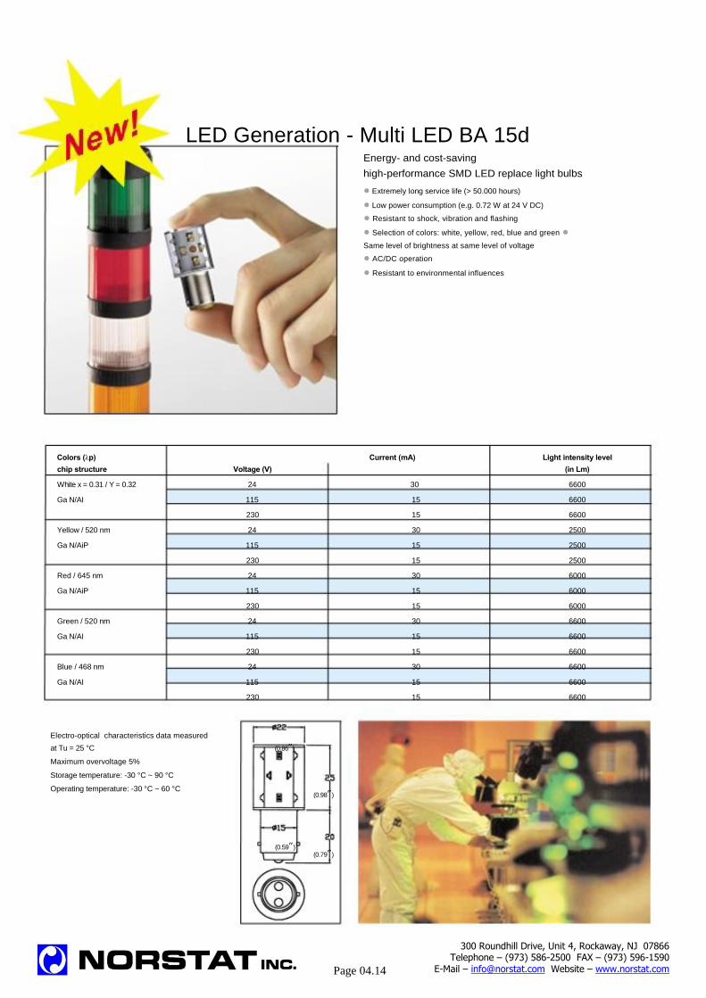
LED Generation - Multi LED BA 15d Energy- and cost-saving
high-performance SMD LED replace light bulbs
● Extremely long service life (> 50.000 hours)
● Low power consumption (e.g. 0.72 W at 24 V DC)
● Resistant to shock, vibration and flashing
● Selection of colors: white, yellow, red, blue and green ●
Same level of brightness at same level of voltage
● AC/DC operation
● Resistant to environmental influences
Colors (λp)
chip structure Voltage (V)
White x = 0.31 / Y = 0.32 24
Ga N/AI 115
230
Yellow / 520 nm 24
Ga N/AiP 115
230
Red / 645 nm 24
Ga N/AiP 115
230
Green / 520 nm 24
Ga N/AI 115
230
Blue / 468 nm 24
Ga N/AI 115
230
Electro-optical characteristics data measured
at Tu = 25 °C (0.86”)
Maximum overvoltage 5%
Storage temperature: -30 °C ~ 90 °C
Operating temperature: -30 °C ~ 60 °C
(0.59”)
Current (mA) Light intensity level
(in Lm)
30 6600
15 6600
15 6600
30 2500
15 2500
15 2500
30 6000
15 6000
15 6000
30 6600
15 6600
15 6600
30 6600
15 6600
15 6600
(0.98”)
(0.79”)
300 Roundhill Drive, Unit 4, Rockaway, NJ 07866 Telephone – (973) 586-2500 FAX – (973) 596-1590
E-Mail – [email protected] Website – www.norstat.com
Page 04.14

Norstat Signal Products
PF BR50 Stack Lights Part Description
Part name & number
Description
Terminal Base Element BR50-BC 28250010000
Buzzer/Acoustic Module BR50-SM-24V 28250088000
Buzzer/Acoustic Module BR50-SM-115V 28250081600
Buzzer/Acoustic Module BR50-SM-230V 28250081000
Clear Lens Element 12-240V BR50-CL-CL 28250040010
Yellow lens Element 12-240V BR50-CL-YE 28250040030
Amber Lens Element 12-240V BR50-CL-AM 28250040040
Red Lens Element 12-240V BR50-CL-RE 28250040050
Green Lens Element 12-240V BR50-CL-GR 28250040060
Blue Lens Element 12-240V BR50-CL-BL 28250040070
Flashing Light Module Clear 24V BR50-FL-CL-24V 28250078010
Flashing Light Module Yellow 24V BR50-FL-YE-24V 28250078030
Flashing Light Module Amber 24V BR50-FL-AM-24V 28250078040
Flashing Light Module Red 24V BR50-FL-RE-24V 28250078050
Flashing Light Module Green 24V BR50-FL-GR-24V 28250078060
Flashing Light Module Blue 24V BR50-FL-BL-24V 28250078070
Flashing Light Module Clear 115V BR50-FL-CL-115V 28250071610
Flashing Light Module Yellow 115V BR50-FL-YE-115V 28250071630
Flashing Light Module Amber 115V BR50-FL-AM-115V 28250071640
Flashing Light Module Red 115V BR50-FL-RE-115V 28250071650
Flashing Light Module Green 115V BR50-FL-GR-115V 28250071660
Flashing Light Module Blue 115V BR50-FL-BL-115V 28250071670
Flashing Light Module Clear 230V BR50-FL-CL-230V 28250071010
Flashing Light Module Yellow 230V BR50-FL-YE-230V 28250071030
Flashing Light Module Amber 230V BR50-FL-AM-230V 28250071040
Flashing Light Module Red 230V BR50-FL-RE-230V 28250071050
Flashing Light Module Green 230V BR50-FL-GR-230V 28250071060
Flashing Light Module Blue 230V BR50-FL-BL-230V 28250071070
Blinking Light Module Clear 24V BR50-BL-CL-24V 28250058010
Blinking Light Module Yellow 24V BR50-BL-YE-24V 28250058030
Blinking Light Module Amber 24V BR50-BL-AM-24V 28250058040
Blinking Light Module Red 24V BR50-BL-RE-24V 28250058050
Blinking Light Module Green 24V BR50-BL-GR-24V 28250058060
Blinking Light Module Blue 24V BR50-BL-BL-24V 28250058070
Blinking Light Module Clear 115V BR50-BL-CL 115 28250051610
Blinking Light Module Yellow 115V BR50-BL-YE 115 28250051630
Blinking Light Module Amber 115V BR50-BL-AM 115 28250051640
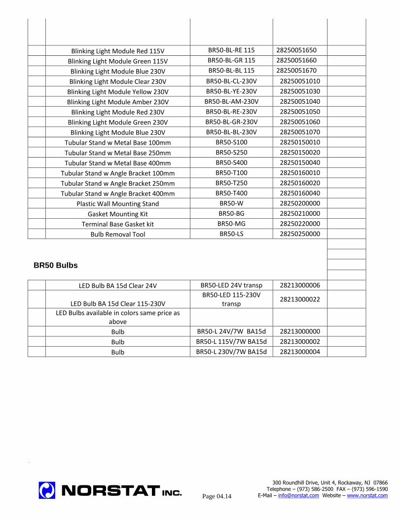
Blinking Light Module Red 115V BR50-BL-RE 115 28250051650
Blinking Light Module Green 115V BR50-BL-GR 115 28250051660
Blinking Light Module Blue 230V BR50-BL-BL 115 28250051670
Blinking Light Module Clear 230V BR50-BL-CL-230V 28250051010
Blinking Light Module Yellow 230V BR50-BL-YE-230V 28250051030
Blinking Light Module Amber 230V BR50-BL-AM-230V 28250051040
Blinking Light Module Red 230V BR50-BL-RE-230V 28250051050
Blinking Light Module Green 230V BR50-BL-GR-230V 28250051060
Blinking Light Module Blue 230V BR50-BL-BL-230V 28250051070
Tubular Stand w Metal Base 100mm BR50-S100 28250150010
Tubular Stand w Metal Base 250mm BR50-S250 28250150020
Tubular Stand w Metal Base 400mm BR50-S400 28250150040
Tubular Stand w Angle Bracket 100mm BR50-T100 28250160010
Tubular Stand w Angle Bracket 250mm BR50-T250 28250160020
Tubular Stand w Angle Bracket 400mm BR50-T400 28250160040
Plastic Wall Mounting Stand BR50-W 28250200000
Gasket Mounting Kit BR50-BG 28250210000
Terminal Base Gasket kit BR50-MG 28250220000
Bulb Removal Tool BR50-LS 28250250000
BR50 Bulbs
LED Bulb BA 15d Clear 24V BR50-LED 24V transp 28213000006
LED Bulb BA 15d Clear 115-230V BR50-LED 115-230V
transp 28213000022
LED Bulbs available in colors same price as
above
Bulb BR50-L 24V/7W BA15d 28213000000
Bulb BR50-L 115V/7W BA15d 28213000002
Bulb BR50-L 230V/7W BA15d 28213000004
.
300 Roundhill Drive, Unit 4, Rockaway, NJ 07866
Telephone – (973) 586-2500 FAX – (973) 596-1590 E-Mail – [email protected] Website – www.norstat.com
Page 04.14

Automation Products
Position Switches
Footswitches
AU
TO
MA
TIO
N

FR & FM Series Switches For Position & End of Travel Sensing Top Mount Sensing Pizzato offers a huge range of limit and position switches. Each switch is also available with several different contact options. All these switches are listed on their website: www.pizzato.com
Most switches now feature bifurcated contacts. Each contact has two armature bridges and two sets of contact points. The resulting internal redundancy creates a huge increase in the life expectancy of the switches
These switches are also available pre wired from the factory with M12 connectors
Contacts Plastic Metal Plastic Metal Plastic Metal
1 NC – 1 NO
Snap Action Positively Driven
FR 515 FM 515 FR 502 FM 502 FR 520 FM 520
2 NC – 1 NO Slow Action
Positively Driven
FR 2015 FM 2015 FR 2002 FM 2002 FR 2020 FM 2020
Technical Material Polymer or Coated Metal Mechanical Endurance 1 Million Operations
Cable Entry Pg 13.5 Max. Operation Frequency 3,600 Cycles Per Hour
Protection Rating FR = IP65; FP = IP66 Max./Min. Actuator Speed 0.5 m/s – 1mm/s
NEMA Rating 1, 4X Voltage Rating 400 V
Temperature Rating -25C to +80C Current Rating 10A
Additional products are available from the manufacturer. Please call us with your application needs.
AU
TO
MA
TIO
N

FR & FM Switches For Position & End of Travel Sensing Switch Body and Actuator Sold Separately Pizzato offers a huge range of limit and position switches. Each switch is also available with several different contact options. All these switches are listed on their website: www.pizzato.com
Most switches now feature bifurcated contacts. Each contact has two armature bridges and two sets of contact points. The resulting internal redundancy creates a huge increase in the life expectancy of the switches
Switch Bodies Plastic Metal 1 NC – 1 NO
Snap Action Positively Driven
FR 538
FM 538
2 NC – 1 NO
Slow Action Positively Driven
FR 2038
FM 2038
Actuators
VF LE30 VF LE31 VF LE33 VF LE34
VF LE51 VF LE52 VF LE55 VF LE56
Technical Material Polymer or Coated Metal Mechanical Endurance 1 Million Operations
Cable Entry Pg 13.5 Max. Operation Frequency 3,600 Cycles Per Hour
Protection Rating FR = IP65; FP = IP66 Max./Min. Actuator Speed 0.5 m/s – 1mm/s
NEMA Rating 1, 4X Voltage Rating 400 V
Temperature Rating -25C to +80C Current Rating 10A
Additional products are available from the manufacturer. Please call us with your application needs.
AU
TO
MA
TIO
N
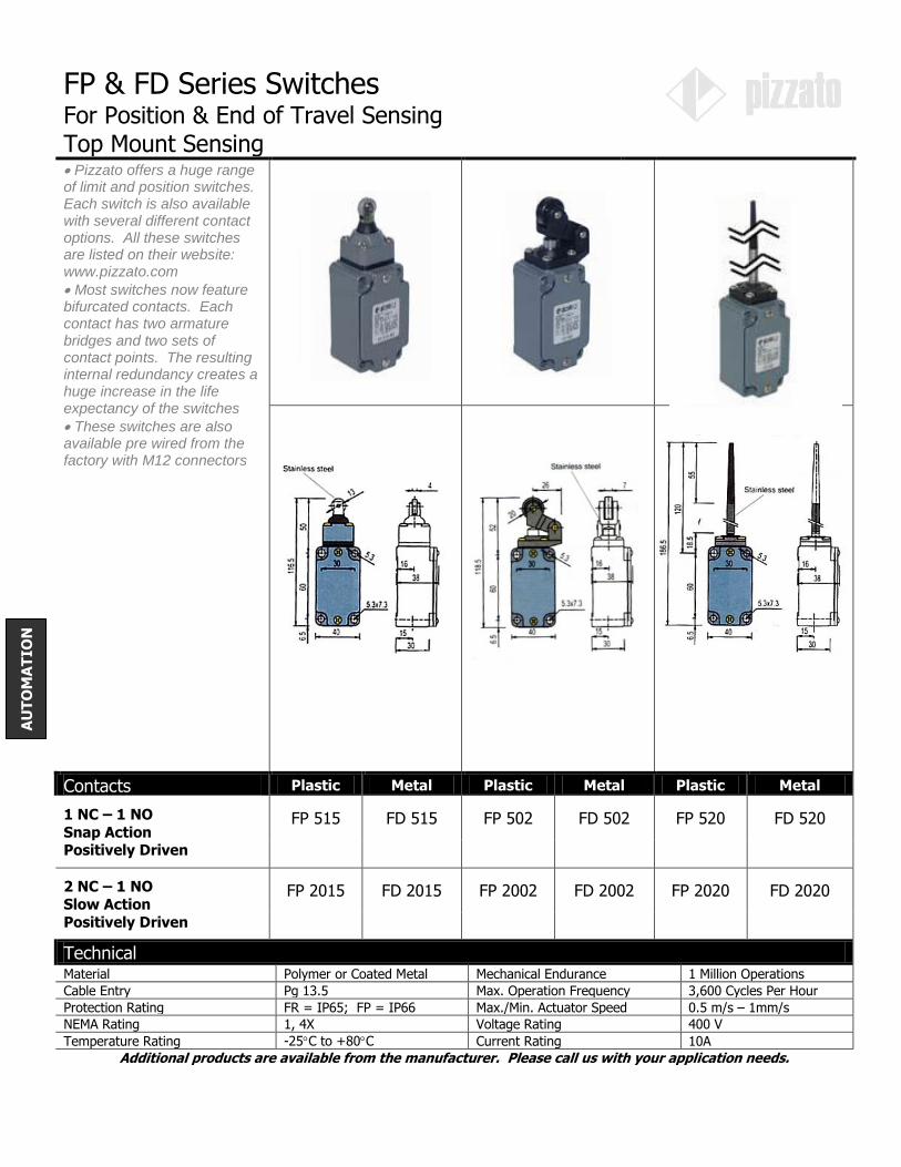
FP & FD Series Switches For Position & End of Travel Sensing Top Mount Sensing Pizzato offers a huge range of limit and position switches. Each switch is also available with several different contact options. All these switches are listed on their website: www.pizzato.com
Most switches now feature bifurcated contacts. Each contact has two armature bridges and two sets of contact points. The resulting internal redundancy creates a huge increase in the life expectancy of the switches
These switches are also available pre wired from the factory with M12 connectors
Contacts Plastic Metal Plastic Metal Plastic Metal
1 NC – 1 NO
Snap Action Positively Driven
FP 515 FD 515 FP 502 FD 502 FP 520 FD 520
2 NC – 1 NO
Slow Action
Positively Driven
FP 2015 FD 2015 FP 2002 FD 2002 FP 2020 FD 2020
Technical Material Polymer or Coated Metal Mechanical Endurance 1 Million Operations
Cable Entry Pg 13.5 Max. Operation Frequency 3,600 Cycles Per Hour
Protection Rating FR = IP65; FP = IP66 Max./Min. Actuator Speed 0.5 m/s – 1mm/s
NEMA Rating 1, 4X Voltage Rating 400 V
Temperature Rating -25C to +80C Current Rating 10A
Additional products are available from the manufacturer. Please call us with your application needs.
AU
TO
MA
TIO
N

FP & FD Switches For Position & End of Travel Sensing Switch Body and Actuator Sold Separately Pizzato offers a huge range of limit and position switches. Each switch is also available with several different contact options. All these switches are listed on their website: www.pizzato.com
Most switches now feature bifurcated contacts. Each contact has two armature bridges and two sets of contact points. The resulting internal redundancy creates a huge increase in the life expectancy of the switches
Switch Bodies Plastic Metal
1 NC – 1 NO Snap Action
Positively Driven
FP 538
FD 538
2 NC – 1 NO Slow Action
Positively Driven
FP 2038
FD 2038
Actuators
VF L31 VF L57 VF L33 VF L34
VF L51 VF L52 VF L35 VF L56
Technical Material Polymer or Coated Metal Mechanical Endurance 1 Million Operations
Cable Entry Pg 13.5 Max. Operation Frequency 3,600 Cycles Per Hour
Protection Rating FR = IP65; FP = IP66 Max./Min. Actuator Speed 0.5 m/s – 1mm/s
NEMA Rating 1, 4X Voltage Rating 400 V
Temperature Rating -25C to +80C Current Rating 10A
Additional products are available from the manufacturer. Please call us with your application needs.
300 Roundhill Drive, Unit 4, Rockaway, NJ 07866 Telephone – (973) 586-2500 FAX – (973) 596-1590
E-Mail – [email protected] Website – www.norstat.com
Page 05.05
AU
TO
MA
TIO
N

FA-FB Switches For Position & End of Travel Sensing With 2 Meter Cable Attached This series of switches is very popular because of their versatility and durability
The housing is a very rugged cast metal, the contacts are fully enclosed, the cable is attached and then potted
These switches are also available with M12 connectors
A lower cost plastic body series is also available
FA Series FB Series
Prewired With 2 Meter Cable Prewired With 2 Meter Cable
Part Number
FA 4115 2DN FB 4115 2SN
Contacts
1 NO / 1 NC Snap Action 1 NO / 1 NC Snap Action
Technical Material Baked Epoxy Coated Metal Mechanical Endurance 20 Million Operations
Protection Rating P67 Max. Operation Frequency 3,600 Cycles Per Hour
NEMA Rating 4X, 6 Max./Min. Actuator Speed 0.5 m/s – 1mm/s
Temperature Rating -25C to +70C Voltage Rating 500 VAC / 600 VDC
Cable 18/5 Current Rating 10A
Approvals CE, UL & cUL Roller Material Stainless Steel
Conforming to UL 508 Operation Max. Speed 0.1 m/s with 30 cam
Utilization Categories Q300, A600 Minimum Operation Force 10 N
Addtitonal products are available from the manufacturer. Please call us with your application needs.
0 2 5
1.3
0 2 5
1.3
21
22
13
14
300 Roundhill Drive, Unit 4, Rockaway, NJ 07866 Telephone – (973) 586-2500 FAX – (973) 596-1590
E-Mail – [email protected] Website – www.norstat.com
Page 05.06
AU
TO
MA
TIO
N

Footswitches Reinforced Thermoplastic With Cover
These plastic covered footswitches are designed for industrial applications. Many customers are getting away from the
typical big metal bulletproof footswitches, in favor of these much more reasonably priced alternatives.
Contacts & Part Number
1 NC / 1 NO PX 10100
Snap Action with
positively driven back up of the NC contact
Accessories & Part Numbers
Extra Contact Set VF B501 VF B901
An extra block can be mounted in the footswitch to provide additional contacts
1 NC / 1 NO Contacts Snap Action with positively driven back
up of the NC contact
2 NO Contacts Slow Action with both contacts
positively driven
Joiner Kit VF KIT 20
Joiner kits can be used to connect several footswitches into one multiple pedal unit
Technical Material Glass Reinforced Thermoplastic Mechanical Endurance 20 Million Operations
Cable Entry Pg 13.5 in back Max. Operation Frequency 3,600 Cycles Per Hour
Additional Entry 1 Knockout on each side Actuation Force 16 N
Protection Rating IP 65 Voltage Rating 500 VAC / 600 VDC
Temperature Rating -25C to +80C Current Rating 10A
Additional products are available from the manufactruer. Please call us with your application needs.
300 Roundhill Drive, Unit 4, Rockaway, NJ 07866 Telephone – (973) 586-2500 FAX – (973) 596-1590
E-Mail – [email protected] Website – www.norstat.com
Page 05.07
AU
TO
MA
TIO
N
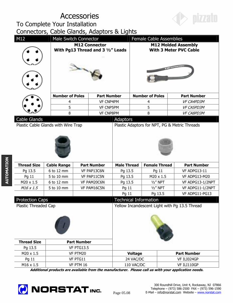
Accessories To Complete Your Installation Connectors, Cable Glands, Adaptors & Lights M12 Male Switch Connector Female Cable Assemblies
M12 Connector
With Pg13 Thread and 3 ½” Leads M12 Molded Assembly
With 3 Meter PVC Cable
Number of Poles Part Number Number of Poles Part Number
4 VF CNP4PM 4 VF CA4PD3M
5 VF CNP5PM 5 VF CA5PD3M
8 VF CNP8PM 8 VF CA8PD3M
Cable Glands Adaptors
Plastic Cable Glands with Wire Trap Plastic Adaptors for NPT, PG & Metric Threads
Thread Size Cable Range Part Number Male Thread Female Thread Part Number
Pg 13.5 6 to 12 mm VF PAP13C6N Pg 13.5 Pg 11 VF ADPG13-11
Pg 11 5 to 10 mm VF PAP11C5N Pg 13.5 M20 x 1.5 VF ADPG13-M20
M20 x 1.5 6 to 12 mm VF PAM20C6N Pg 13.5 ½” NPT VF ADPG13-1/2NPT
M16 x 1.5 5 to 10 mm VF PAM16C5N Pg 11 ½” NPT VF ADPG11-1/2NPT
Pg 11 Pg 13.5 VF ADPG11-PG13
Protection Caps Technical Information
Plastic Threaded Cap Yellow Incandescent Light with Pg 13.5 Thread
Thread Size Part Number
Pg 13.5 VF PTG13.5 M20 x 1.5 VF PTM20 Voltage Part Number
Pg 11 VF PTG11 24 VAC/DC VF ILI024GP
M16 x 1.5 VF PTM 16 110 VAC/DC VF ILI110GP
Additional products are available from the manufacturer. Please call us with your application needs.
1
4
2
3
2
3
1
5
4
2
3
45
6
7
1
8
AU
TO
MA
TIO
N
300 Roundhill Drive, Unit 4, Rockaway, NJ 07866 Telephone – (973) 586-2500 FAX – (973) 596-1590
E-Mail – [email protected] Website – www.norstat.com
Page 05.08

Molded Cable Assemblies, Connectors and Distribution Boxes
DIN 43650 Molded Assemblies
DIN 43650 Connectors
M12 & M8 Molded Assemblies
M12 & M8 Connectors
Distribution Boxes
300 Roundhill Drive, Unit 4, Rockaway, NJ 07866 Telephone – (973) 586-2500 FAX – (973) 596-1590
E-Mail – [email protected] Website – www.norstat.com
Page 05.10
AS
SE
MB
LIE
S
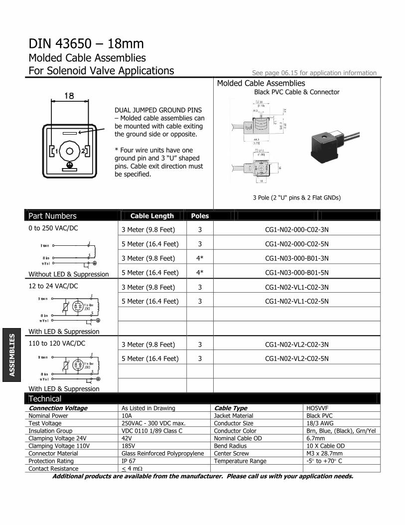
DIN 43650 – 18mm
Molded Cable Assemblies For Solenoid Valve Applications See page 06.15 for application information
Molded Cable Assemblies Black PVC Cable & Connector
3 Pole (2 “U" pins & 2 Flat GNDs)
Part Numbers Cable Length Poles
0 to 250 VAC/DC 3 Meter (9.8 Feet) 3 CG1-N02-000-C02-3N
5 Meter (16.4 Feet) 3 CG1-N02-000-C02-5N
3 Meter (9.8 Feet) 4* CG1-N03-000-B01-3N
Without LED & Suppression 5 Meter (16.4 Feet) 4* CG1-N03-000-B01-5N
12 to 24 VAC/DC 3 Meter (9.8 Feet) 3 CG1-N02-VL1-C02-3N
5 Meter (16.4 Feet) 3 CG1-N02-VL1-C02-5N
With LED & Suppression
110 to 120 VAC/DC 3 Meter (9.8 Feet) 3 CG1-N02-VL2-C02-3N
5 Meter (16.4 Feet) 3 CG1-N02-VL2-C02-5N
With LED & Suppression
Technical Connection Voltage As Listed in Drawing Cable Type HO5VVF
Nominal Power 10A Jacket Material Black PVC
Test Voltage 250VAC - 300 VDC max. Conductor Size 18/3 AWG
Insulation Group VDC 0110 1/89 Class C Conductor Color Brn, Blue, (Black), Grn/Yel
Clamping Voltage 24V 42V Nominal Cable OD 6.7mm
Clamping Voltage 110V 185V Bend Radius 10 X Cable OD
Connector Material Glass Reinforced Polypropylene Center Screw M3 x 28.7mm
Protection Rating IP 67 Temperature Range -5 to +70 C
Contact Resistance < 4 m
Additional products are available from the manufacturer. Please call us with your application needs.
DUAL JUMPED GROUND PINS – Molded cable assemblies can
be mounted with cable exiting the ground side or opposite.
* Four wire units have one ground pin and 3 “U” shaped
pins. Cable exit direction must be specified.
Grn/Yel
Brown
Blue
1
2
Blue
Grn/Yel
Brown
Yellow
2
LED
1
Blue
Grn/Yel
Brown
Yellow
2
LED
1
AS
SE
MB
LIE
S

DIN 43650 – 18mm Connectors
See page 06.15 for application information For Solenoid Valve Applications Connectors
Part Numbers Poles Gland Size 12-24V 110-130V
Without Components 3 Pg 9/11 (.23” to .43”) G1-NU2-000 G1-NU2-000
3 ½” NPT G1-NF2-000 G1-NF2-000
4 Pg 9/11 (.23” to .43”) G1-NU3-000 G1-NU3-000
4 ½” NPT G1-NF3-000 G1-NF3-000
LED Only 3 Pg 9/11 (.23” to .43”) G1-TU2-L01 G1-TU2-LO2
3 ½” NPT G1-TF2-L01 G1-TF2-LO2
Varistor & LED 3 Pg 9/11 (.23” to .43”) G1-TU2-VL1 G1-TU2-VL2
3 ½” NPT G1-TF2-VL1 G1-TF2-VL2
Diode & LED 3 Pg 9/11 (.23” to .43”) G1-TU2-DL1 G1-TU2-DL2
3 ½” NPT G1-TF2-DL1 G1-TF2-DL2
Rectifier 3 Pg 9/11 (.23” to .43”) G1-TU2-RL2
3 ½” NPT G1-TF2-RL2
Technical Connection Voltage As Listed in Drawing Max Wire Size 16 AWG
Nominal Power 10A (16A Maximum) Center Screw M3 x 32.5mm
Insulation Group VDC 0110 1/89 Class C Temperature Range -2 to +176 F
Connector Material Glass Reinforced Polypropylene
Varistor Clamp – 24/110 42V / 185V
Protection Rating IP 65 Diode Type 1N4007
Contact Resistance < 4 m Rectifier Factor X .9
Additional products are available from the manufacturer. Please call us with your application needs.
300 Roundhill Drive, Unit 4, Rockaway, NJ 07866 Telephone – (973) 586-2500 FAX – (973) 596-1590
E-Mail – [email protected] Website – www.norstat.com
06.02
3
AS
SE
MB
LIE
S
2
1
1
2
2
1
2
1
1
2
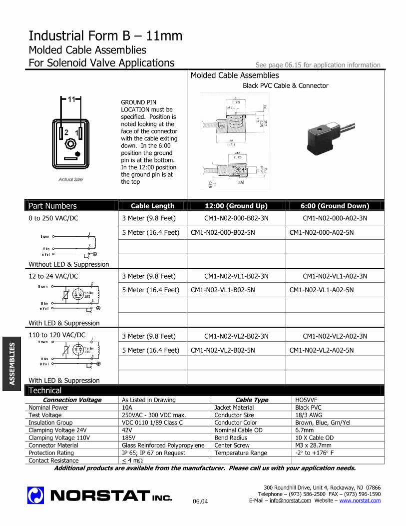
Industrial Form B – 11mm Molded Cable Assemblies For Solenoid Valve Applications See page 06.15 for application information
Molded Cable Assemblies Black PVC Cable & Connector
Part Numbers Cable Length 12:00 (Ground Up) 6:00 (Ground Down)
0 to 250 VAC/DC 3 Meter (9.8 Feet) CM1-N02-000-B02-3N CM1-N02-000-A02-3N
5 Meter (16.4 Feet) CM1-N02-000-B02-5N CM1-N02-000-A02-5N
Without LED & Suppression
12 to 24 VAC/DC 3 Meter (9.8 Feet) CM1-N02-VL1-B02-3N CM1-N02-VL1-A02-3N
5 Meter (16.4 Feet) CM1-N02-VL1-B02-5N CM1-N02-VL1-A02-5N
With LED & Suppression
110 to 120 VAC/DC 3 Meter (9.8 Feet) CM1-N02-VL2-B02-3N CM1-N02-VL2-A02-3N
5 Meter (16.4 Feet) CM1-N02-VL2-B02-5N CM1-N02-VL2-A02-5N
With LED & Suppression
Technical Connection Voltage As Listed in Drawing Cable Type HO5VVF
Nominal Power 10A Jacket Material Black PVC
Test Voltage 250VAC - 300 VDC max. Conductor Size 18/3 AWG
Insulation Group VDC 0110 1/89 Class C Conductor Color Brown, Blue, Grn/Yel
Clamping Voltage 24V 42V Nominal Cable OD 6.7mm
Clamping Voltage 110V 185V Bend Radius 10 X Cable OD
Connector Material Glass Reinforced Polypropylene Center Screw M3 x 28.7mm
Protection Rating IP 65; IP 67 on Request Temperature Range -2 to +176 F
Contact Resistance < 4 m
Additional products are available from the manufacturer. Please call us with your application needs.
GROUND PIN LOCATION must be specified. Position is noted looking at the face of the connector with the cable exiting down. In the 6:00
position the ground pin is at the bottom. In the 12:00 position the ground pin is at the top
300 Roundhill Drive, Unit 4, Rockaway, NJ 07866 Telephone – (973) 586-2500 FAX – (973) 596-1590
E-Mail – [email protected] Website – www.norstat.com
06.04
AS
SE
MB
LIE
S
Grn/Yel
Brown
Blue
1
2
Blue
Grn/Yel
Brown
Yellow
2
LED
1
Blue
Grn/Yel
Brown
Yellow
2
LED
1
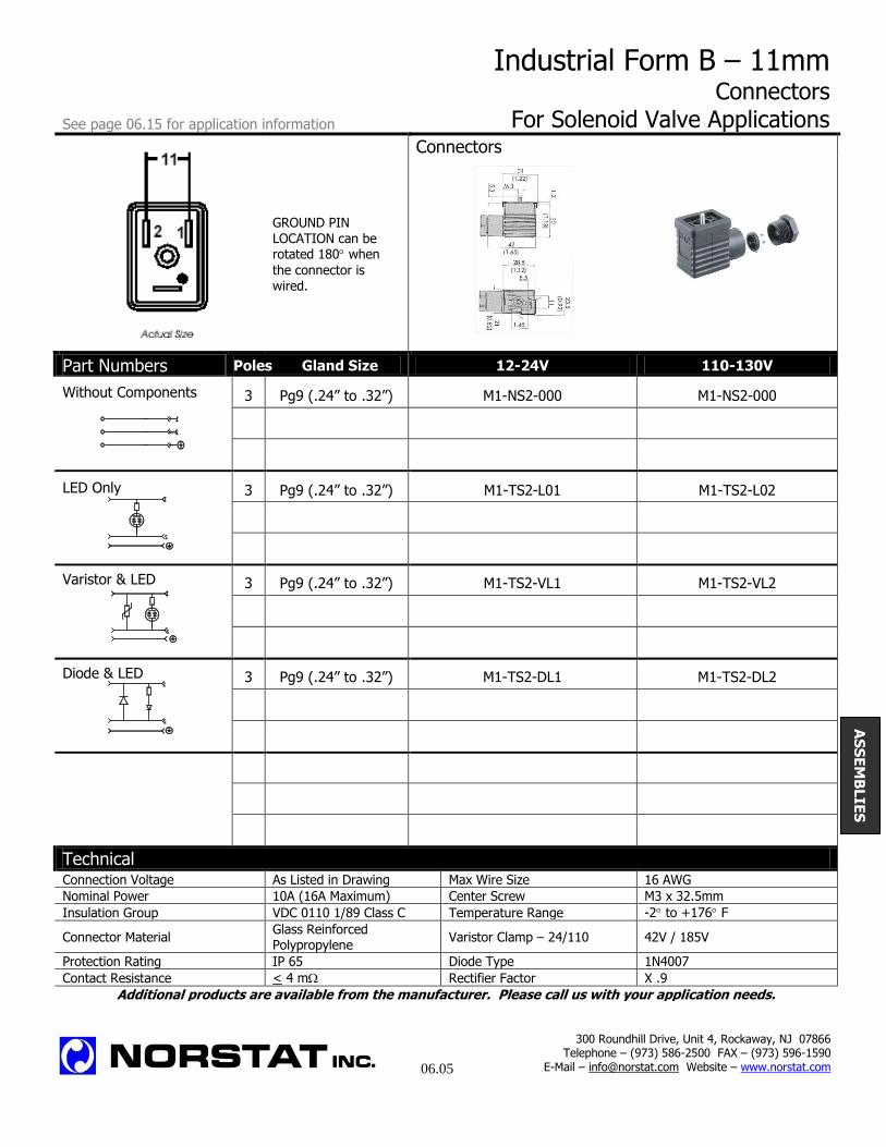
Industrial Form B – 11mm Connectors
See page 06.15 for application information For Solenoid Valve Applications Connectors
GROUND PIN LOCATION can be rotated 180 when
the connector is wired.
Part Numbers Poles Gland Size 12-24V 110-130V
Without Components 3 Pg9 (.24” to .32”) M1-NS2-000 M1-NS2-000
LED Only 3 Pg9 (.24” to .32”) M1-TS2-L01 M1-TS2-L02
Varistor & LED 3 Pg9 (.24” to .32”) M1-TS2-VL1 M1-TS2-VL2
Diode & LED 3 Pg9 (.24” to .32”) M1-TS2-DL1 M1-TS2-DL2
Technical Connection Voltage As Listed in Drawing Max Wire Size 16 AWG
Nominal Power 10A (16A Maximum) Center Screw M3 x 32.5mm
Insulation Group VDC 0110 1/89 Class C Temperature Range -2 to +176 F
Connector Material Glass Reinforced Polypropylene
Varistor Clamp – 24/110 42V / 185V
Protection Rating IP 65 Diode Type 1N4007
Contact Resistance < 4 m Rectifier Factor X .9
Additional products are available from the manufacturer. Please call us with your application needs.
2
1
300 Roundhill Drive, Unit 4, Rockaway, NJ 07866 Telephone – (973) 586-2500 FAX – (973) 596-1590
E-Mail – [email protected] Website – www.norstat.com
06.05
AS
SE
MB
LIE
S
1
2
2
1
1
2

Industrial Form C – 9.4mm
Molded Cable Assemblies For Solenoid Valve Applications See page 06.15 for application information
Molded Cable Assemblies Black PVC Cable & Connector
3 Pole (3 Flat Pins)
Part Numbers Cable Length Poles
0 to 250 VAC/DC 3 Meter (9.8 Feet) 3 CP2-N02-000-C01-3
5 Meter (16.4 Feet) 3 CP2-N02-000-C01-5
3 Meter (9.8 Feet) 4*
Without LED & Suppression 5 Meter (16.4 Feet) 4*
12 to 24 VAC/DC 3 Meter (9.8 Feet) 3 CP2-N02-VL1-C01-3
5 Meter (16.4 Feet) 3 CP2-N02-VL1-C01-5
With LED & Suppression
110 to 120 VAC/DC 3 Meter (9.8 Feet) 3 CP2-N02-VL2-C01-3
5 Meter (16.4 Feet) 3 CP2-N02-VL2-C01-5
With LED & Suppression
Technical Connection Voltage As Listed in Drawing Cable Type HO3VVF
Nominal Power 3A Jacket Material Black PVC
Test Voltage 250VAC - 300 VDC max. Conductor Size 20/3 AWG
Insulation Group VDC 0110 1/89 Class C Conductor Color Brn, Blue, (Blk), Grn/Yel
Clamping Voltage 24V 42V Nominal Cable OD 6.7mm
Clamping Voltage 110V 185V Bend Radius 10 X Cable OD
Connector Material Glass Reinforced Polypropylene Center Screw M3 x 21.5mm
Protection Rating IP 65; IP 67 on Request Temperature Range -2 to +176 F
Contact Resistance < 4 m
Additional products are available from the manufacturer. Please call us with your application needs.
DUAL JUMPED GROUND
PINS – Molded cable assemblies can be mounted
with cable exiting the ground side or opposite.
* Four wire units have one
ground pin and 3 “U”
shaped pins. Cable exit direction must be specified.
9. 4
9. 4
Grn/Yel
Brown
Blue
1
2
Blue
Grn/Yel
Brown
Yellow
2
LED
1
Blue
Grn/Yel
Brown
Yellow
2
LED
1
300 Roundhill Drive, Unit 4, Rockaway, NJ 07866 Telephone – (973) 586-2500 FAX – (973) 596-1590
E-Mail – [email protected] Website – www.norstat.com
06.06
AS
SE
MB
LIE
S

Industrial Form C – 9.4mm Connectors
See page 06.15 for application information For Solenoid Valve Applications Connectors
GROUND PIN LOCATION can be
rotated 90 when
the connector is
wired.
Part Numbers Poles Gland Size 12-24V 110-130V
Without Components 3 Pg9 (.24” to .32”) P2-NZ2-000 P2-NZ2-000
4 Pg9 (.24” to .32”) P2-NZ3-000 P2-NZ3-000
LED Only 3 Pg9 (.24” to .32”) P2-TZ2-L01 P2-TZ2-L02
Varistor & LED 3 Pg9 (.24” to .32”) P2-TZ2-VL1 P2-TZ2-VL2
Diode & LED 3 Pg9 (.24” to .32”) P2-TZ2-DL1 P2-TZ2-DL2
Technical Connection Voltage As Listed in Drawing Max Wire Size 16 AWG
Nominal Power 10A (16A Maximum) Center Screw M3 x 28.5mm
Insulation Group VDC 0110 1/89 Class C Temperature Range -2 to +176 F
Connector Material Glass Reinforced Polypropylene
Varistor Clamp – 24/110 34V / 185V
Protection Rating IP 65; IP 67 on Request Diode Type 1N4007
Contact Resistance < 4 m Rectifier Factor X .9
Additional products are available from the manufacturer. Please call us with your application needs.
1
2
2
1
1
2
2
1
9. 4
9. 4
300 Roundhill Drive, Unit 4, Rockaway, NJ 07866 Telephone – (973) 586-2500 FAX – (973) 596-1590
E-Mail – [email protected] Website – www.norstat.com
06.07
AS
SE
MB
LIE
S
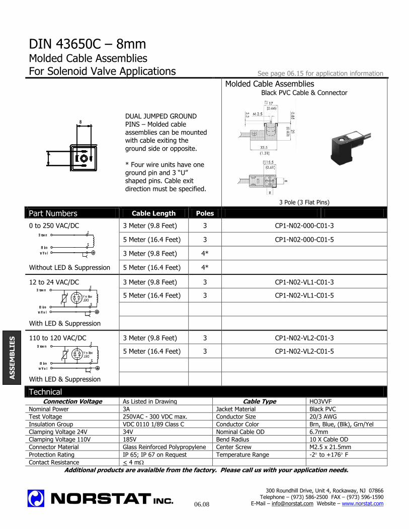
DIN 43650C – 8mm
Molded Cable Assemblies For Solenoid Valve Applications See page 06.15 for application information
Molded Cable Assemblies Black PVC Cable & Connector
3 Pole (3 Flat Pins)
Part Numbers Cable Length Poles
0 to 250 VAC/DC 3 Meter (9.8 Feet) 3 CP1-N02-000-C01-3
5 Meter (16.4 Feet) 3 CP1-N02-000-C01-5
3 Meter (9.8 Feet) 4*
Without LED & Suppression 5 Meter (16.4 Feet) 4*
12 to 24 VAC/DC 3 Meter (9.8 Feet) 3 CP1-N02-VL1-C01-3
5 Meter (16.4 Feet) 3 CP1-N02-VL1-C01-5
With LED & Suppression
110 to 120 VAC/DC 3 Meter (9.8 Feet) 3 CP1-N02-VL2-C01-3
5 Meter (16.4 Feet) 3 CP1-N02-VL2-C01-5
With LED & Suppression
Technical Connection Voltage As Listed in Drawing Cable Type HO3VVF
Nominal Power 3A Jacket Material Black PVC
Test Voltage 250VAC - 300 VDC max. Conductor Size 20/3 AWG
Insulation Group VDC 0110 1/89 Class C Conductor Color Brn, Blue, (Blk), Grn/Yel
Clamping Voltage 24V 34V Nominal Cable OD 6.7mm
Clamping Voltage 110V 185V Bend Radius 10 X Cable OD
Connector Material Glass Reinforced Polypropylene Center Screw M2.5 x 21.5mm
Protection Rating IP 65; IP 67 on Request Temperature Range -2 to +176 F
Contact Resistance < 4 m
Additional products are avaialble from the factory. Please call us with your application needs.
DUAL JUMPED GROUND
PINS – Molded cable
assemblies can be mounted with cable exiting the
ground side or opposite.
* Four wire units have one
ground pin and 3 “U” shaped pins. Cable exit
direction must be specified.
8
8
Grn/Yel
Brown
Blue
1
2
Blue
Grn/Yel
Brown
Yellow
2
LED
1
Blue
Grn/Yel
Brown
Yellow
2
LED
1
300 Roundhill Drive, Unit 4, Rockaway, NJ 07866 Telephone – (973) 586-2500 FAX – (973) 596-1590
E-Mail – [email protected] Website – www.norstat.com
06.08
AS
SE
MB
LIE
S

DIN43650C – 8mm Connectors
See page 06.15 for application information For Solenoid Valve Applications Connectors
GROUND PIN LOCATION can be
rotated 90 when
the connector is
wired.
Part Numbers Poles Gland Size 12-24V 110-130V
Without Components 3 Pg9 (.24” to .32”) P1-NZ2-000 P1-NZ2-000
4 Pg9 (.24” to .32”) P1-NZ3-000 P1-NZ3-000
LED Only 3 Pg9 (.24” to .32”) P1-TZ2-L01 P1-TZ2-L02
Varistor & LED 3 Pg9 (.24” to .32”) P1-TZ2-VL1 P1-TZ2-VL2
Diode & LED 3 Pg9 (.24” to .32”) P1-TZ2-DL1 P1-TZ2-DL2
Technical Connection Voltage As Listed in Drawing Max Wire Size 16 AWG
Nominal Power 10A (16A Maximum) Center Screw M3 x 28.5mm
Insulation Group VDC 0110 1/89 Class C Temperature Range -2 to +176 F
Connector Material Glass Reinforced Polypropylene
Varistor Clamp – 24/110 34V / 185V
Protection Rating IP 65; IP 67 on Request Diode Type 1N4007
Contact Resistance < 4 m Rectifier Factor X .9
Additional products are available from the manufacturer. Please call us with your application needs.
1
2
2
1
1
2
2
1
300 Roundhill Drive, Unit 4, Rockaway, NJ 07866 Telephone – (973) 586-2500 FAX – (973) 596-1590
E-Mail – [email protected] Website – www.norstat.com
06.09
AS
SE
MB
LIE
S
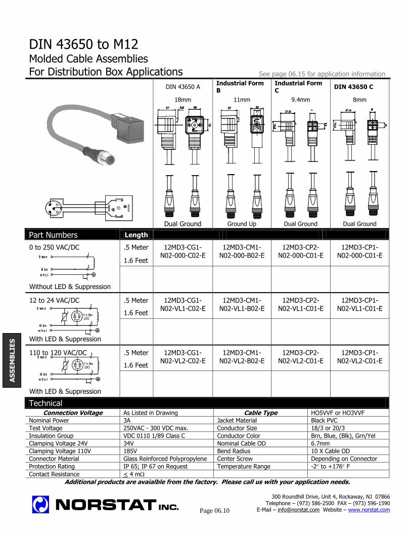
DIN 43650 to M12
Molded Cable Assemblies For Distribution Box Applications See page 06.15 for application information
DIN 43650 A
Industrial Form B
Industrial Form C
DIN 43650 C
18mm 11mm 9.4mm 8mm
Dual Ground Ground Up Dual Ground Dual Ground
Part Numbers Length
0 to 250 VAC/DC .5 Meter 12MD3-CG1-
N02-000-C02-E
12MD3-CM1-
N02-000-B02-E
12MD3-CP2-
N02-000-C01-E
12MD3-CP1-
N02-000-C01-E 1.6 Feet
Without LED & Suppression
12 to 24 VAC/DC .5 Meter 12MD3-CG1-
N02-VL1-C02-E
12MD3-CM1-
N02-VL1-B02-E
12MD3-CP2-
N02-VL1-C01-E
12MD3-CP1-
N02-VL1-C01-E
1.6 Feet
With LED & Suppression
110 to 120 VAC/DC .5 Meter 12MD3-CG1-
N02-VL2-C02-E
12MD3-CM1-
N02-VL2-B02-E
12MD3-CP2-
N02-VL2-C01-E
12MD3-CP1-
N02-VL2-C01-E 1.6 Feet
With LED & Suppression
Technical Connection Voltage As Listed in Drawing Cable Type HO5VVF or HO3VVF
Nominal Power 3A Jacket Material Black PVC
Test Voltage 250VAC - 300 VDC max. Conductor Size 18/3 or 20/3
Insulation Group VDC 0110 1/89 Class C Conductor Color Brn, Blue, (Blk), Grn/Yel
Clamping Voltage 24V 34V Nominal Cable OD 6.7mm
Clamping Voltage 110V 185V Bend Radius 10 X Cable OD
Connector Material Glass Reinforced Polypropylene Center Screw Depending on Connector
Protection Rating IP 65; IP 67 on Request Temperature Range -2 to +176 F
Contact Resistance < 4 m
Additional products are avaialble from the factory. Please call us with your application needs.
300 Roundhill Drive, Unit 4, Rockaway, NJ 07866 Telephone – (973) 586-2500 FAX – (973) 596-1590
E-Mail – [email protected] Website – www.norstat.com
Page 06.10
AS
SE
MB
LIE
S
9.4
9.49.4
3
41
2
5
Blue
Grn/Yel
Brown
Yellow
2
LED
1
Grn/Yel
Brown
Blue
1
2
Blue
Grn/Yel
Brown
Yellow
2
LED
1

Multiple Connector Assemblies Molded Cable Assemblies
See page 06.15 for application information For Distribution Box Applications
DIN 43650 A Industrial Form B Industrial Form C DIN 43650 C
Distance between connectors = 7.9” (200mm) 18mm 11mm 9.4mm 8mm
(Other lengths available upon request). Dual Ground Ground Up Dual Ground Dual Ground
Part Numbers Heads
0 to 250 VAC/DC 2 CG1-D02-000-C02-1 CM1-D02-000-B02-1 CP2-D02-000-C02-1 CP1-D02-000-C02-1
3 CG1-302-000-C02-1 CM1-302-000-B02-1 CP2-302-000-C02-1 CP1-302-000-C02-1
Without LED & Suppression 4 CG1-402-000-C02-1 CM1-402-000-B02-1 CP2-402-000-C02-1 CP1-402-000-C02-1
12 to 24 VAC/DC 2
CG1-D02-VL1-C02-1
CM1-D02-VL1-B02-1
CP2-D02-VL1-C02-1
CP1-D02-VL1-C02-1
3
CG1-302-VL1-C02-1
CM1-302-VL1-B02-1
CP2-302-VL1-C02-1
CP1-302-VL1-C02-1
With LED & Suppression 4
CG1-402-VL1-C02-1
CM1-402-VL1-B02-1
CP2-402-VL1-C02-1
CP1-402-VL1-C02-1
110 to 120 VAC/DC 2
CG1-D02-VL2-C02-1
CM1-D02-VL2-B02-1
CP2-D02-VL2-C02-1
CP1-D02-VL2-C02-1
3
CG1-302-VL2-C02-1
CM1-302-VL2-B02-1
CP2-302-VL2-C02-1
CP1-302-VL2-C02-1
With LED & Suppression 4
CG1-402-VL2-C02-1
CM1-402-VL2-B02-1
CP2-402-VL2-C02-1
CP1-402-VL2-C02-1
Technical Connection Voltage As Listed in Drawing Cable Type HO5VVF or HO3VVF
Nominal Power 3A Jacket Material Black PVC
Test Voltage 250VAC - 300 VDC max. Conductor Size 18/3 or 20/3
Insulation Group VDC 0110 1/89 Class C Conductor Color Brn, Blue, (Blk), Grn/Yel
Clamping Voltage 24V 34V Nominal Cable OD 6.7mm
Clamping Voltage 110V 185V Bend Radius 10 X Cable OD
Connector Material Glass Reinforced Polypropylene Center Screw Depending on Connector
Protection Rating IP 65; IP 67 on Request Temperature Range -2 to +176 F
Contact Resistance < 4 m
Additional products are avaialble from the factory. Please call us with your application needs.
300 Roundhill Drive, Unit 4, Rockaway, NJ 07866 Telephone – (973) 586-2500 FAX – (973) 596-1590
E-Mail – [email protected] Website – www.norstat.com
06.11
Standard main cable length = 3.3 Feet (1 Meter) (Other lengths available upon request)
Grn/Yel
Brown
Blue
1
2
Blue
Grn/Yel
Brown
Yellow
2
LED
1
Blue
Grn/Yel
Brown
Yellow
2
LED
1
AS
SE
MB
LIE
S

Accessories For Connectors and Molded Cable Assemblies See page 06.15 for application information
Center Screws
Size Used for Plated Screw
M2.5 x
21.5 8mm Molded 500-015-000
M2.5 x 28.5 8mm Connectors 500-015-00A
M3 x 21.5 9.5mm Molded 650-015-000
M3 x 28.7 9.5mm Connectors 200-015-00A
M3 x 28.5 18mm, 11mm, 10mm Molded 700-015-00B
M3 x 32.5 18mm, 11mm, 10mm Connectors 100-015-000
Gaskets
DIN 43650 A Industrial Form B DIN 43650 C & Micro Mini
18mm 11mm 8mm & 9.4mm
Flat Sectional Flat Sectional Flat Sectional
Nitrile Rubber Nitrile Rubber Nitrile Rubber Nitrile Rubber Nitrile Rubber Nitrile Rubber
100-014-00A 100-013-000 300-014-00A 300-013-00A 500-014-00A 500-013-000
Silicone Silicone Silicone Silicone Silicone Silicone
100-121-000 100-123-000 300-121-000 300-123-000 500-121-000 500-123-000
Label Plate Center Screw Washer
Label Plate used on all Plastic Washer used
versions of the molded with the center screw
cable assemblies to provide extra
sealing capacity
200-007-000 M3 Washer
Additional products are available from the manufacturer. Please call us with your application needs.
300 Roundhill Drive, Unit 4, Rockaway, NJ 07866 Telephone – (973) 586-2500 FAX – (973) 596-1590
E-Mail – [email protected] Website – www.norstat.com
06.12
AS
SE
MB
LIE
S
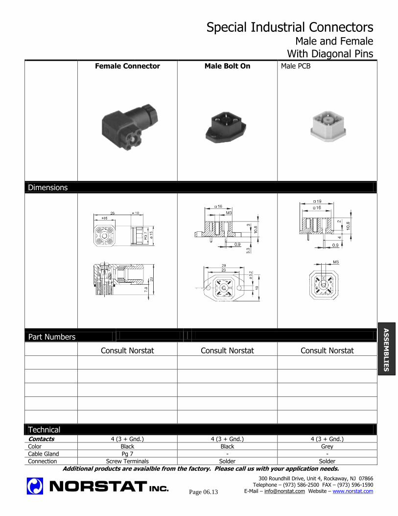
Special Industrial Connectors Male and Female With Diagonal Pins
Female Connector Male Bolt On Male PCB
Dimensions
Part Numbers
Consult Norstat Consult Norstat Consult Norstat
Technical Contacts 4 (3 + Gnd.) 4 (3 + Gnd.) 4 (3 + Gnd.)
Color Black Black Grey
Cable Gland Pg 7 - -
Connection Screw Terminals Solder Solder
Additional products are avaialble from the factory. Please call us with your application needs.
300 Roundhill Drive, Unit 4, Rockaway, NJ 07866 Telephone – (973) 586-2500 FAX – (973) 596-1590
E-Mail – [email protected] Website – www.norstat.com
Page 06.13
AS
SE
MB
LIE
S
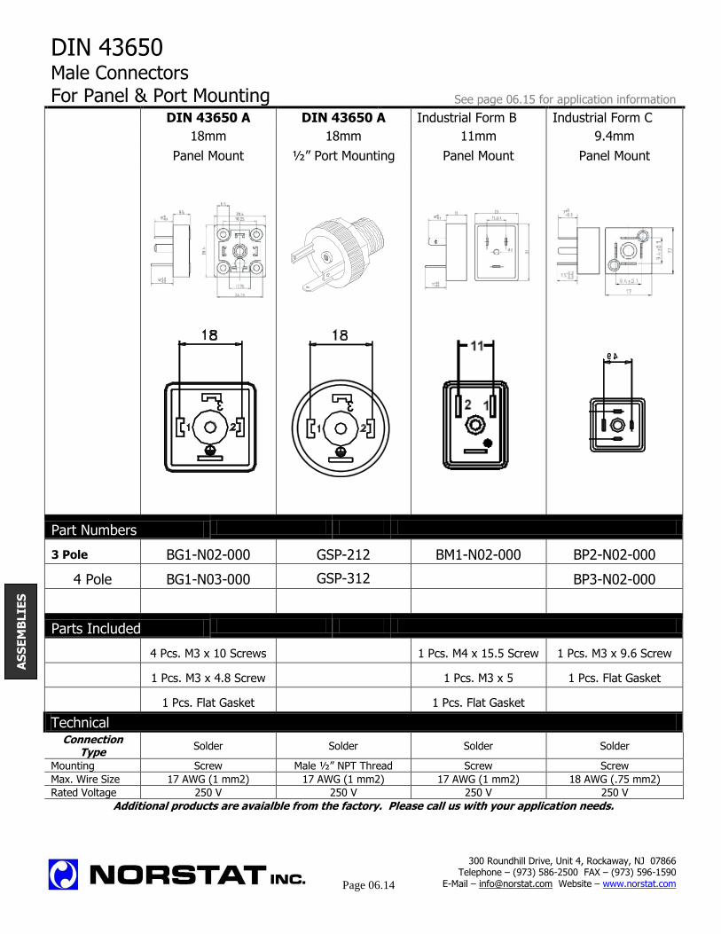
DIN 43650 Male Connectors For Panel & Port Mounting See page 06.15 for application information
DIN 43650 A DIN 43650 A Industrial Form B Industrial Form C
18mm 18mm 11mm 9.4mm
Panel Mount ½” Port Mounting Panel Mount Panel Mount
Part Numbers
3 Pole BG1-N02-000 GSP-212 BM1-N02-000 BP2-N02-000
4 Pole BG1-N03-000 GSP-312
BP3-N02-000
Parts Included
4 Pcs. M3 x 10 Screws 1 Pcs. M4 x 15.5 Screw 1 Pcs. M3 x 9.6 Screw
1 Pcs. M3 x 4.8 Screw 1 Pcs. M3 x 5 1 Pcs. Flat Gasket
1 Pcs. Flat Gasket 1 Pcs. Flat Gasket
Technical Connection
Type Solder Solder Solder Solder
Mounting Screw Male ½” NPT Thread Screw Screw
Max. Wire Size 17 AWG (1 mm2) 17 AWG (1 mm2) 17 AWG (1 mm2) 18 AWG (.75 mm2)
Rated Voltage 250 V 250 V 250 V 250 V
Additional products are avaialble from the factory. Please call us with your application needs.
300 Roundhill Drive, Unit 4, Rockaway, NJ 07866 Telephone – (973) 586-2500 FAX – (973) 596-1590
E-Mail – [email protected] Website – www.norstat.com
Page 06.14
AS
SE
MB
LIE
S
3
9.4
9.4
3

General Information Frequently Asked Questions About DIN43650 Connectors and Assemblies What is DIN? DIN (or Deutsche Industrial Normale) is a series of uniformity standards developed in Germany, which apply to commonly manufactured items. What is DIN 43650? DIN 43650 is the standard for a series of electrical connectors, which are commonly used with solenoid valves (especially those used on valves in hydraulics and pneumatics). Other applications include the connection special sensors, such as pressure switches, filter switches, optical, proximity and limit switches.
What does DIN 43650 include? The DIN43650 family consists of 5 connectors: Although their “official” names are listed on top, we generally refer to them as 18mm, 11mm, 10mm, 8mm or 9.4mm, which is the actual spacing between pin #1 and pin #2. How are these connectors applied? Generally, the male connector is attached to the solenoid valve or sensor and the female side connects to the cable. The general rule in applying connectors is that a female connector is used to transfer the power to the male. This prevents the possibility of direct exposure to “hot pins”, (exposed male pins carrying voltage). Female connectors are offered as shells, which allow you to attach your own cable via screw terminals or in molded cable assembly form, pre-wired with the cable attached to a solid molded plastic connector.
Why use a molded assembly? Molded assemblies provide a more secure installation, offer many technical advantages and save installation time, labor and cost. Hand wiring a DIN connector is very labor intensive. Considering the overall cost of the connector, wire and labor, molded cable assemblies are generally much less expensive. What other advantages do molded cable assemblies offer?
- Solid plastic construction super durability and resistance to harsh environments
- Impact resistant with greater cable strain relief - Cleaner looking installation - Available in all DIN 43650 configurations - Offered in a large range of cable lengths - With (or without) built in LED indication and surge
suppression
What does the light indicate? The LED on the top of the connector indicates if the connector is receiving power and is used for diagnostic purposes. Connectors with dual colored LED’s are also available to show the state of pressure and filter switches. Why use surge suppression? In solenoid valve applications, a magnetic field is created around the coil. When the power is turned off (as the coil is de-energized) the remaining magnetic field collapses back onto the coil. This creates an electrical surge, which can exceed 3,000 volts. This happens in both AC and DC applications, with
operating voltages as low as 12 volts. The resulting surge can cause component damage (both short and long term) and can create noise problems that can interfere with control and measurement signals. Building in surge suppression into the connector, stops the transient surge at the source. Some solenoid valves offer built in surge suppression, however since heat can effect the performance of surge suppression components, this is not always possible.
How does common surge suppression work? Typically simple surge suppression components either re-direct or absorb the transient surge. There are several different components which are commonly used:
Suppression Diodes – (also called “fly-back” diodes or “avalanche” diodes) allow voltage and current to flow in only one direction. Placed in parallel to the load, the diodes react to the surge’s polarity and re-direct the spike back to the coil where it dissipates. Diodes offer very good suppression; eliminating most of the surge. The are, however, polarity dependant (if they are installed incorrectly they cause a dead short). They also only work in DC circuits and can cause a release delay problem (the energy directed to the coil may delay the solenoid operation). Varistors – (also called VDR’s or MOV’s) are voltage dependant resistors, which close the circuit once an assigned voltage is exceeded. Placed in parallel to the coil, they redirect any voltage, which is above the assigned or “cut off” levels, back to the coil where they dissipate. Varistors work for both AC and DC application and are polarity independent. Zener Diodes (also called Z diodes) are also voltage dependant devices which work similarly to Varistors. Resistor-Capacitor Networks – (also called RC’s and snubbers) absorb the surge and gradually discharge the energy back onto the circuit.
06.15
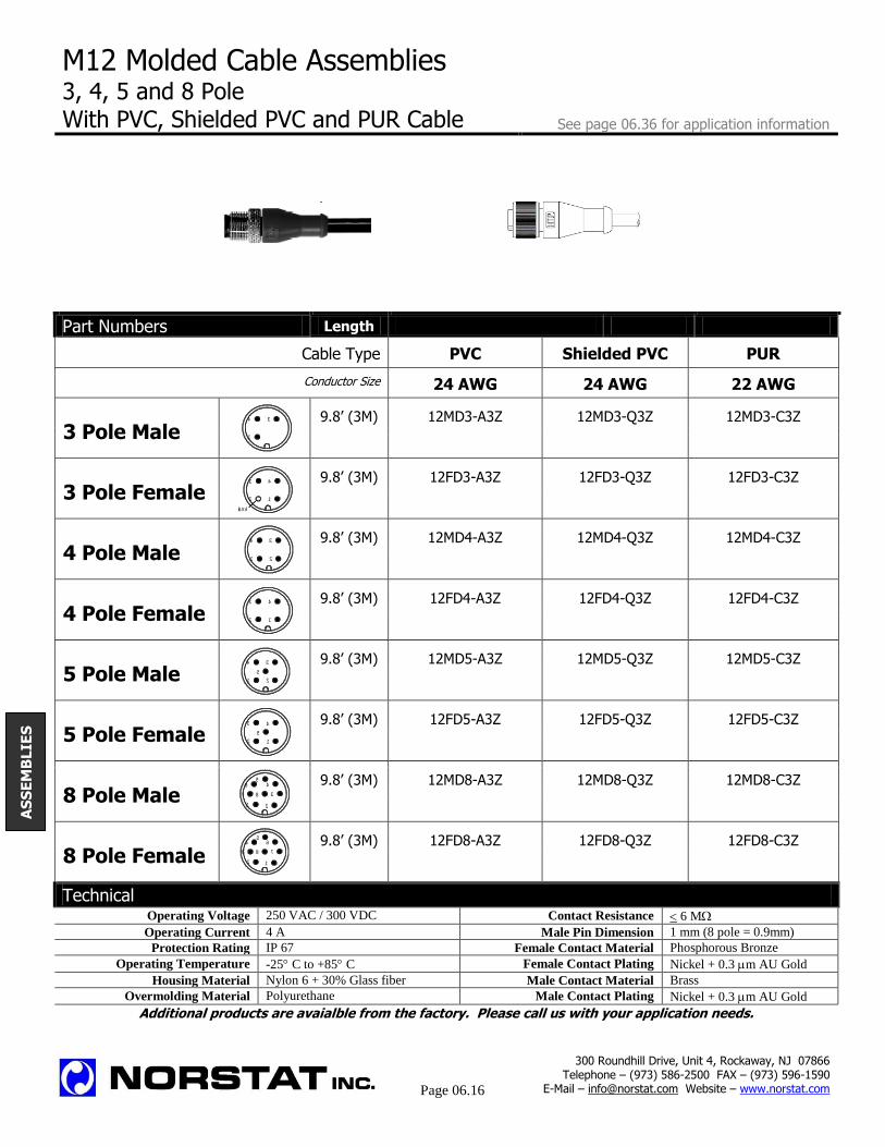
M12 Molded Cable Assemblies 3, 4, 5 and 8 Pole
With PVC, Shielded PVC and PUR Cable See page 06.36 for application information
Part Numbers Length
Cable Type PVC Shielded PVC PUR
Conductor Size 24 AWG 24 AWG 22 AWG
3 Pole Male 9.8’ (3M) 12MD3-A3Z 12MD3-Q3Z 12MD3-C3Z
3 Pole Female 9.8’ (3M) 12FD3-A3Z 12FD3-Q3Z 12FD3-C3Z
4 Pole Male 9.8’ (3M) 12MD4-A3Z 12MD4-Q3Z 12MD4-C3Z
4 Pole Female 9.8’ (3M) 12FD4-A3Z 12FD4-Q3Z 12FD4-C3Z
5 Pole Male 9.8’ (3M) 12MD5-A3Z 12MD5-Q3Z 12MD5-C3Z
5 Pole Female 9.8’ (3M) 12FD5-A3Z 12FD5-Q3Z 12FD5-C3Z
8 Pole Male 9.8’ (3M) 12MD8-A3Z 12MD8-Q3Z 12MD8-C3Z
8 Pole Female 9.8’ (3M) 12FD8-A3Z 12FD8-Q3Z 12FD8-C3Z
Technical Operating Voltage 250 VAC / 300 VDC Contact Resistance 6 M
Operating Current 4 A Male Pin Dimension 1 mm (8 pole = 0.9mm)
Protection Rating IP 67 Female Contact Material Phosphorous Bronze
Operating Temperature -25 C to +85 C Female Contact Plating Nickel + 0.3 m AU Gold
Housing Material Nylon 6 + 30% Glass fiber Male Contact Material Brass
Overmolding Material Polyurethane Male Contact Plating Nickel + 0.3 m AU Gold
Additional products are avaialble from the factory. Please call us with your application needs.
AS
SE
MB
LIE
S
300 Roundhill Drive, Unit 4, Rockaway, NJ 07866 Telephone – (973) 586-2500 FAX – (973) 596-1590
E-Mail – [email protected] Website – www.norstat.com
Page 06.16
1
34
Blank
3
2
4
1
1
3
2
4
1
43
2
1
3
2
4
5
4
12
5
3
1 2
3
45
6
7 8
12
45
6
73 8

M12 Molded Cable Assemblies 3, 4, 5 and 8 Pole
See page 06.36 for application information With PVC, Shielded PVC and PUR Cable
Part Numbers Length
Cable Type PVC Shielded PVC PUR
Conductor Size 24 AWG 24 AWG 22 AWG
3 Pole Male 9.8’ (3M) 12MA3-A3Z 12MA3-Q3Z 12MA3-C3Z
3 Pole Female 9.8’ (3M) 12FA3-A3Z 12FA3-Q3Z 12FA3-C3Z
4 Pole Male 9.8’ (3M) 12MA4-A3Z 12MA4-Q3Z 12MA4-C3Z
4 Pole Female 9.8’ (3M) 12FA4-A3Z 12FA4-Q3Z 12FA4-C3Z
5 Pole Male 9.8’ (3M) 12MA5-A3Z 12MA5-Q3Z 12MA5-C3Z
5 Pole Female 9.8’ (3M) 12FA5-A3Z 12FA5-Q3Z 12FA5-C3Z
8 Pole Male 9.8’ (3M) 12MA8-A3Z 12MA8-Q3Z 12MA8-C3Z
8 Pole Female 9.8’ (3M) 12FA8-A3Z 12FA8-Q3Z 12FA8-C3Z
Technical Operating Voltage 250 VAC / 300 VDC Contact Resistance 6 M
Operating Current 4 A Male Pin Dimension 1 mm (8 pole = 0.9mm)
Protection Rating IP 67 Female Contact Material Phosphorous Bronze
Operating Temperature -25 C to +85 C Female Contact Plating Nickel + 0.3 m AU Gold
Housing Material Nylon 6 + 30% Glass fiber Male Contact Material Brass
Overmolding Material Polyurethane Male Contact Plating Nickel + 0.3 m AU Gold
Additional products are avaialble from the factory. Please call us with your application needs.
300 Roundhill Drive, Unit 4, Rockaway, NJ 07866 Telephone – (973) 586-2500 FAX – (973) 596-1590
E-Mail – [email protected] Website – www.norstat.com
Page 06.17
1
34
Blank
3
2
4
1
1
3
2
4
1
43
2
1
3
2
4
5
4
12
5
3
1 2
3
45
6
7 8
12
45
6
73 8
AS
SE
MB
LIE
S
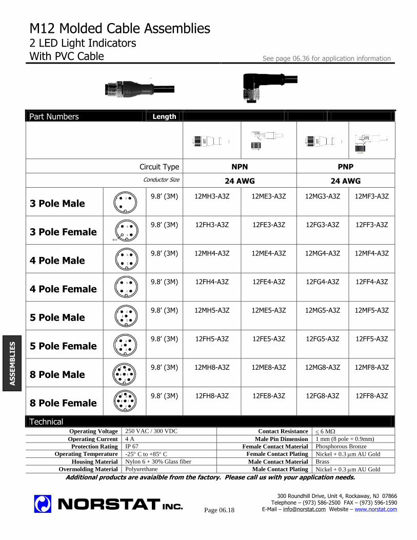
M12 Molded Cable Assemblies 2 LED Light Indicators With PVC Cable See page 06.36 for application information
Part Numbers Length
Circuit Type NPN
PNP
Conductor Size 24 AWG 24 AWG
3 Pole Male 9.8’ (3M) 12MH3-A3Z 12ME3-A3Z 12MG3-A3Z 12MF3-A3Z
3 Pole Female 9.8’ (3M) 12FH3-A3Z 12FE3-A3Z 12FG3-A3Z 12FF3-A3Z
4 Pole Male 9.8’ (3M) 12MH4-A3Z 12ME4-A3Z 12MG4-A3Z 12MF4-A3Z
4 Pole Female 9.8’ (3M) 12FH4-A3Z 12FE4-A3Z 12FG4-A3Z 12FF4-A3Z
5 Pole Male 9.8’ (3M) 12MH5-A3Z 12ME5-A3Z 12MG5-A3Z 12MF5-A3Z
5 Pole Female 9.8’ (3M) 12FH5-A3Z 12FE5-A3Z 12FG5-A3Z 12FF5-A3Z
8 Pole Male 9.8’ (3M) 12MH8-A3Z 12ME8-A3Z 12MG8-A3Z 12MF8-A3Z
8 Pole Female 9.8’ (3M) 12FH8-A3Z 12FE8-A3Z 12FG8-A3Z 12FF8-A3Z
Technical Operating Voltage 250 VAC / 300 VDC Contact Resistance 6 M
Operating Current 4 A Male Pin Dimension 1 mm (8 pole = 0.9mm)
Protection Rating IP 67 Female Contact Material Phosphorous Bronze
Operating Temperature -25 C to +85 C Female Contact Plating Nickel + 0.3 m AU Gold
Housing Material Nylon 6 + 30% Glass fiber Male Contact Material Brass
Overmolding Material Polyurethane Male Contact Plating Nickel + 0.3 m AU Gold
Additional products are avaialble from the factory. Please call us with your application needs.
AS
SE
MB
LIE
S
300 Roundhill Drive, Unit 4, Rockaway, NJ 07866 Telephone – (973) 586-2500 FAX – (973) 596-1590
E-Mail – [email protected] Website – www.norstat.com
Page 06.18
1
34
Blank
3
2
4
1
1
3
2
4
1
43
2
1
3
2
4
5
4
12
5
3
1 2
3
45
6
7 8
12
45
6
73 8
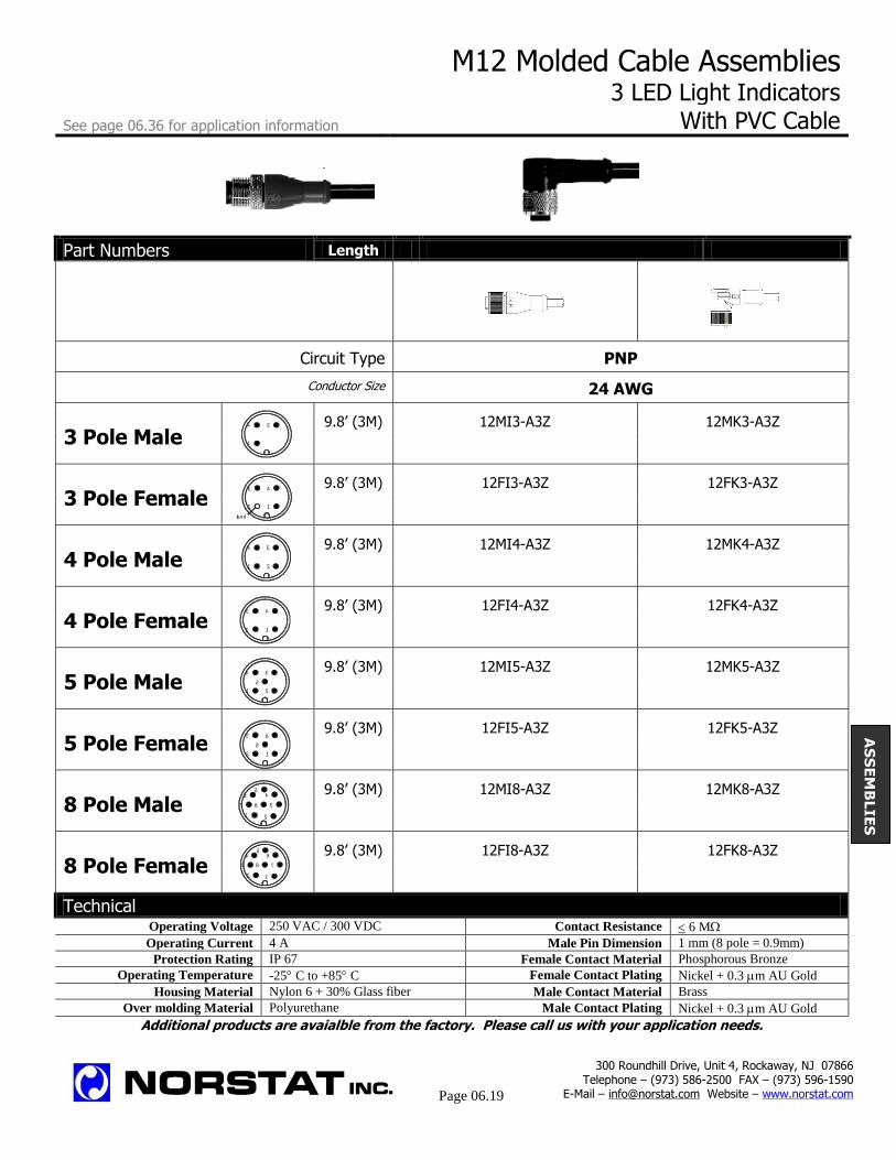
M12 Molded Cable Assemblies 3 LED Light Indicators
See page 06.36 for application information With PVC Cable
Part Numbers Length
Circuit Type PNP
np Conductor Size 24 AWG
3 Pole Male 9.8’ (3M) 12MI3-A3Z 12MK3-A3Z
3 Pole Female 9.8’ (3M) 12FI3-A3Z 12FK3-A3Z
4 Pole Male 9.8’ (3M) 12MI4-A3Z 12MK4-A3Z
4 Pole Female 9.8’ (3M) 12FI4-A3Z 12FK4-A3Z
5 Pole Male 9.8’ (3M) 12MI5-A3Z 12MK5-A3Z
5 Pole Female 9.8’ (3M) 12FI5-A3Z 12FK5-A3Z
8 Pole Male 9.8’ (3M) 12MI8-A3Z 12MK8-A3Z
8 Pole Female 9.8’ (3M) 12FI8-A3Z 12FK8-A3Z
Technical Operating Voltage 250 VAC / 300 VDC Contact Resistance 6 M
Operating Current 4 A Male Pin Dimension 1 mm (8 pole = 0.9mm)
Protection Rating IP 67 Female Contact Material Phosphorous Bronze
Operating Temperature -25 C to +85 C Female Contact Plating Nickel + 0.3 m AU Gold
Housing Material Nylon 6 + 30% Glass fiber Male Contact Material Brass
Over molding Material Polyurethane Male Contact Plating Nickel + 0.3 m AU Gold
Additional products are avaialble from the factory. Please call us with your application needs.
AS
SE
MB
LIE
S
300 Roundhill Drive, Unit 4, Rockaway, NJ 07866 Telephone – (973) 586-2500 FAX – (973) 596-1590
E-Mail – [email protected] Website – www.norstat.com
Page 06.19
1
34
Blank
3
2
4
1
1
3
2
4
1
43
2
1
3
2
4
5
4
12
5
3
1 2
3
45
6
7 8
12
45
6
73 8

M12 Molded Cable Assemblies Male to Female Cables With PVC or PUR Cable See page 06.36 for application information
Part Numbers Length
Cable Type PVC PUR PVC PUR
3 Pole Male 3.2’ (1M) 12FA3A1Z- 12FA3C1Z- 12FD3A1Z- 12FD3C1Z-
to 12MD 12MD 12MD 12MD
3 Pole Female
4 Pole Male 3.2’ (1M) 12FA4A1Z- 12FA4C1Z- 12FD4A1Z- 12FD4C1Z-
to 12MD 12MD 12MD 12MD
4 Pole Female
5 Pole Male 3.2’ (1M) 12FA5A1Z- 12FA5C1Z- 12FD5A1Z- 12FD5C1Z-
to 12MD 12MD 12MD 12MD
5 Pole Female
8 Pole Male 3.2’ (1M) 12FA8A1Z- 12FA8C1Z- 12FD8A1Z- 12FD8C1Z-
to 12MD 12MD 12MD 12MD
8 Pole Female
Technical Operating Voltage 250 VAC / 300 VDC Contact Resistance 6 M
Operating Current 4 A Male Pin Dimension 1 mm (8 pole = 0.9mm)
Protection Rating IP 67 Female Contact Material Phosphorous Bronze
Operating Temperature -25 C to +85 C Female Contact Plating Nickel + 0.3 m AU Gold
Housing Material Nylon 6 + 30% Glass fiber Male Contact Material Brass
Over molding Material Polyurethane Male Contact Plating Nickel + 0.3 m AU Gold
Additional products are avaialble from the factory. Please call us with your application needs.
AS
SE
MB
LIE
S
300 Roundhill Drive, Unit 4, Rockaway, NJ 07866 Telephone – (973) 586-2500 FAX – (973) 596-1590
E-Mail – [email protected] Website – www.norstat.com
Page 06.20
1
34
Blank
3
2
4
1
1
3
2
4
1
43
2
1
3
2
4
5
4
12
5
3
1 2
3
45
6
7 8
12
45
6
73 8

M12 Y Assemblies & T Connector 5 Pole M12 Single Male to Double Female
See page 06.36 for application information For Expanding Ports on Distribution Boxes “T” and “Y” connectors provide the ability to expand the inputs and
output of a distribution box. The
distribution boxes offer two independent wires to each port.
By using the “T” or “Y” connectors, each port can accommodate two
sensors or output devices.
T Connector Y Assembly
Configuration
Male Connector Male Connector
Female Connector Female Connector Female Connector Female Connector
Part Numbers
Split Circuit 12T34-000 Y - PCV Cable 4 Pole 1M
Parallel Circuit 12T35-000 Y - PUR Cable 4 Pole 1M
Parallel Circuit with LED 12T45-000 Standard cable length 3.2’ (1 Meter)
Other cable lengths available upon request.
Circuits
T Connector Circuits Y Assembly Circuit
Split Circuit Parallel Circuit Parallel Circuit w/LED Split Circuit
Technical Operating Voltage 250 VAC / 300 VDC Contact Resistance 6 M
Operating Current 4 A Male Pin Dimension 1 mm (8 pole = 0.9mm)
Protection Rating IP 67 Female Contact Material Phosphorous Bronze
Operating Temperature -25 C to +85 C Female Contact Plating Nickel + 0.3 m AU Gold
Housing Material Nylon 6 + 30% Glass fiber Male Contact Material Brass
Over molding Material Polyurethane Male Contact Plating Nickel + 0.3 m AU Gold
Additional products are avaialble from the factory. Please call us with your application needs.
300 Roundhill Drive, Unit 4, Rockaway, NJ 07866 Telephone – (973) 586-2500 FAX – (973) 596-1590
E-Mail – [email protected] Website – www.norstat.com
Page 06.21
1
3
2
4
5
4
12
5
3 4
12
5
3
1
3
2
4
Blank
3
2
4
1
Blank
3
2
4
1
AS
SE
MB
LIE
S

M12 Connectors with Solder Terminals in 4, 5 and 8 Position See page 06.36 for application information
Straight Pg7 Right Angle Pg7 Straight Pg11 Right Angle Pg 11
Part Numbers Length
Type Straight Right Angle Straight Right Angle
Cable Gland Pg7 Pg7 Pg11 Pg11
Cable Entry Single Cable Single Cable Single or Double Cable Single or Double Cable
Cable Range .15” - .23” (4-6mm)
.15” - .23” (4-6mm)
.23” - .43” (6-11mm) 2 x .15” - .23” (4-6mm)
.23” - .43” (6-11mm) 2 x .15” - .23” (4-6mm)
4 Pole Male
Black Clear
12MC4-000 12MZ4-000
12MB4-000 12MT4-000
12ML4-000 NA
12MU4-000 NA
4 Pole Female
Black Clear
12FC4-000
12FZ4-000
12FB4-000
12FT4-000
12FL4-000
NA
12FU4-000
NA
5 Pole Male
Black Clear
12MC5-000 12MZ5-000
12MB5-000
12MT5-000
12ML5-000 NA
12MU5-000 NA
5 Pole Female
Black
Clear
12FC5-000
12FZ5-000
12FB5-000 12FT5-000
12FL5-000 NA
12FU5-000 NA
8 Pole Male
Black
Clear
12MC8-000
12MZ8-000
12MB8-000
12MT8-000
12ML8-000
NA
12MU8-000
NA
8 Pole Female
Black Clear
12FC8-000 12FZ8-000
12FB8-000
12FT8-000
12FL8-000
NA
12FU8-000
NA
Technical Operating Voltage 250 VAC / 300 VDC Contact Resistance 6 M LED Bridge Circuit for Clear Connectors
Operating Current 4 A Male Pin Dimension 1 mm (8 pole = 0.9mm)
Protection Rating IP 67 Female Contact Material Phosphorous Bronze
Operating Temperature -25 C to +85 C Female Contact Plating Nickel + 0.3 m AU Gold
Housing Material Nylon 6 + 30% Glass fiber Male Contact Material Brass ELB001 ELB001
Over molding Material Polyurethane Male Contact Plating Nickel + 0.3 m AU Gold Single Yellow LED Bi Color LED
Additional products are avaialble from the factory. Please call us with your application needs.
300 Roundhill Drive, Unit 4, Rockaway, NJ 07866 Telephone – (973) 586-2500 FAX – (973) 596-1590
E-Mail – [email protected] Website – www.norstat.com
Page 06.22
1
3
2
4
1
43
2
1
3
2
4
5
4
12
5
3
AS
SE
MB
LIE
S
1 2
3
45
6
7 8
12
45
6
73 8
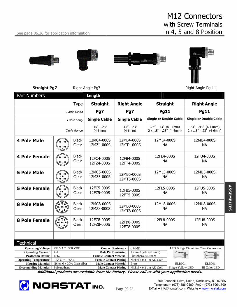
M12 Connectors with Screw Terminals
See page 06.36 for application information in 4, 5 and 8 Position
Straight Pg7 Right Angle Pg7 Straight Pg11 Right Angle Pg 11
Part Numbers Length
Type Straight Right Angle Straight Right Angle
Cable Gland Pg7 Pg7 Pg11 Pg11
Cable Entry Single Cable Single Cable Single or Double Cable Single or Double Cable
Cable Range .15” - .23” (4-6mm)
.15” - .23” (4-6mm)
.23” - .43” (6-11mm) 2 x .15” - .23” (4-6mm)
.23” - .43” (6-11mm) 2 x .15” - .23” (4-6mm)
4 Pole Male
Black Clear
12MC4-000S 12MZ4-000S
12MB4-000S 12MT4-000S
12ML4-000S NA
12MU4-000S NA
4 Pole Female
Black Clear
12FC4-000S
12FZ4-000S
12FB4-000S
12FT4-000S
12FL4-000S
NA
12FU4-000S
NA
5 Pole Male
Black Clear
12MC5-000S 12MZ5-000S
12MB5-000S
12MT5-000S
12ML5-000S NA
12MU5-000S NA
5 Pole Female
Black
Clear
12FC5-000S
12FZ5-000S
12FB5-000S 12FT5-000S
12FL5-000S NA
12FU5-000S NA
8 Pole Male
Black
Clear
12MC8-000S
12MZ8-000S
12MB8-000S
12MT8-000S
12ML8-000S
NA
12MU8-000S
NA
8 Pole Female
Black Clear
12FC8-000S 12FZ8-000S
12FB8-000S
12FT8-000S
12FL8-000S
NA
12FU8-000S
NA
Technical Operating Voltage 250 VAC / 300 VDC Contact Resistance 6 M LED Bridge Circuit for Clear Connectors
Operating Current 4 A Male Pin Dimension 1 mm (8 pole = 0.9mm)
Protection Rating IP 67 Female Contact Material Phosphorous Bronze
Operating Temperature -25 C to +85 C Female Contact Plating Nickel + 0.3 m AU Gold
Housing Material Nylon 6 + 30% Glass fiber Male Contact Material Brass ELB001 ELB001
Over molding Material Polyurethane Male Contact Plating Nickel + 0.3 m AU Gold Single Yellow LED Bi Color LED
Additional products are avaialble from the factory. Please call us with your application needs.
300 Roundhill Drive, Unit 4, Rockaway, NJ 07866 Telephone – (973) 586-2500 FAX – (973) 596-1590
E-Mail – [email protected] Website – www.norstat.com
Page 06.23
1
3
2
4
1
43
2
1
3
2
4
5
4
12
5
3
1 2
3
45
6
7 8
12
45
6
73 8
AS
SE
MB
LIE
S
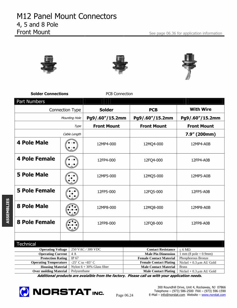
M12 Panel Mount Connectors 4, 5 and 8 Pole Front Mount See page 06.36 for application information
Solder Connections PCB Connection With 200mm Wire
Part Numbers
Connection Type Solder PCB With Wire
Mounting Hole Pg9/.60”/15.2mm Pg9/.60”/15.2mm Pg9/.60”/15.2mm
Type Front Mount Front Mount Front Mount
Cable Length 7.9” (200mm)
4 Pole Male 12MP4-000
12MQ4-000
12MP4-A0B
4 Pole Female 12FP4-000
12FQ4-000
12FP4-A0B
5 Pole Male 12MP5-000
12MQ5-000
12MP5-A0B
5 Pole Female 12FP5-000
12FQ5-000
12FP5-A0B
8 Pole Male 12MP8-000
12MQ8-000
12MP8-A0B
8 Pole Female 12FP8-000
12FQ8-000
12FP8-A0B
Technical Operating Voltage 250 VAC / 300 VDC Contact Resistance 6 M
Operating Current 4 A Male Pin Dimension 1 mm (8 pole = 0.9mm)
Protection Rating IP 67 Female Contact Material Phosphorous Bronze
Operating Temperature -25 C to +85 C Female Contact Plating Nickel + 0.3 m AU Gold
Housing Material Nylon 6 + 30% Glass fiber Male Contact Material Brass
Over molding Material Polyurethane Male Contact Plating Nickel + 0.3 m AU Gold
Additional products are avaialble from the factory. Please call us with your application needs.
300 Roundhill Drive, Unit 4, Rockaway, NJ 07866 Telephone – (973) 586-2500 FAX – (973) 596-1590
E-Mail – [email protected] Website – www.norstat.com
Page 06.24
1
3
2
4
1
43
2
1
3
2
4
5
4
12
5
3
1 2
3
45
6
7 8
12
45
6
73 8
AS
SE
MB
LIE
S

M12 Panel Mount Connectors 4, 5 and 8 Pole
See page 06.36 for application information Back Mount
Solder Connections PCB Connections With 200mm Wire
Part Numbers
Connection Type Solder PCB With Wire
Mounting Hole Pg9/.60”/15.2mm Pg9/.60”/15.2mm Pg9/.60”/15.2mm
Type Back Mount Back Mount Back Mount
Cable Length 7.9” (200mm)
4 Pole Male 12MR4-000
12MS4-000
12MR4-A0B
4 Pole Female 12FR4-000
12FS4-000
12FR4-A0B
5 Pole Male 12MR5-000
12MS5-000
12MR5-A0B
5 Pole Female 12FR5-000
12FS5-000
12FR5-A0B
8 Pole Male 12MR8-000
12MS8-000
12MR8-A0B
8 Pole Female 12FR8-000
12FS8-000
12FR8-A0B
Technical Operating Voltage 250 VAC / 300 VDC Contact Resistance 6 M
Operating Current 4 A Male Pin Dimension 1 mm (8 pole = 0.9mm)
Protection Rating IP 67 Female Contact Material Phosphorous Bronze
Operating Temperature -25 C to +85 C Female Contact Plating Nickel + 0.3 m AU Gold
Housing Material Nylon 6 + 30% Glass fiber Male Contact Material Brass
Over molding Material Polyurethane Male Contact Plating Nickel + 0.3 m AU Gold
Additional products are avaialble from the factory. Please call us with your application needs.
300 Roundhill Drive, Unit 4, Rockaway, NJ 07866 Telephone – (973) 586-2500 FAX – (973) 596-1590
E-Mail – [email protected] Website – www.norstat.com
Page 06.25
1
3
2
4
1
43
2
1
3
2
4
5
4
12
5
3
1 2
3
45
6
7 8
12
45
6
73 8
AS
SE
MB
LIE
S
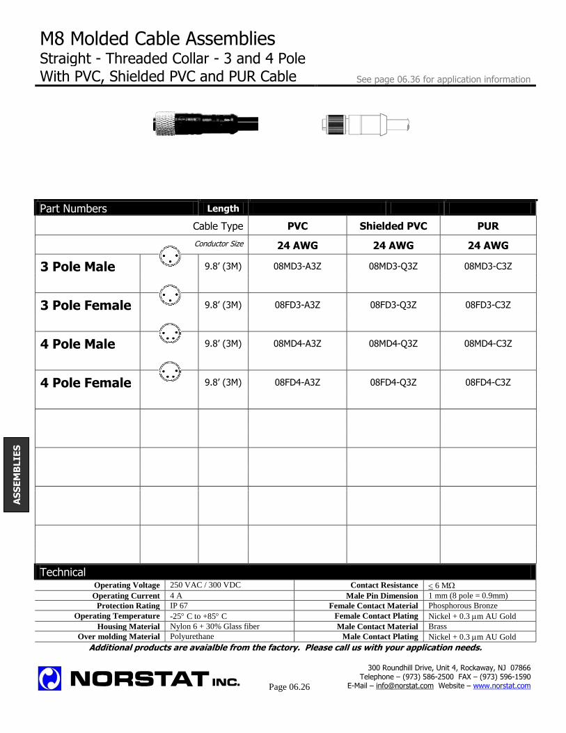
M8 Molded Cable Assemblies Straight - Threaded Collar - 3 and 4 Pole With PVC, Shielded PVC and PUR Cable See page 06.36 for application information
Part Numbers Length
Cable Type PVC Shielded PVC PUR
Conductor Size 24 AWG 24 AWG 24 AWG
3 Pole Male 9.8’ (3M) 08MD3-A3Z 08MD3-Q3Z 08MD3-C3Z
3 Pole Female 9.8’ (3M) 08FD3-A3Z 08FD3-Q3Z 08FD3-C3Z
4 Pole Male 9.8’ (3M) 08MD4-A3Z 08MD4-Q3Z 08MD4-C3Z
4 Pole Female 9.8’ (3M) 08FD4-A3Z 08FD4-Q3Z 08FD4-C3Z
Technical Operating Voltage 250 VAC / 300 VDC Contact Resistance 6 M
Operating Current 4 A Male Pin Dimension 1 mm (8 pole = 0.9mm)
Protection Rating IP 67 Female Contact Material Phosphorous Bronze
Operating Temperature -25 C to +85 C Female Contact Plating Nickel + 0.3 m AU Gold
Housing Material Nylon 6 + 30% Glass fiber Male Contact Material Brass
Over molding Material Polyurethane Male Contact Plating Nickel + 0.3 m AU Gold
Additional products are avaialble from the factory. Please call us with your application needs.
AS
SE
MB
LIE
S
300 Roundhill Drive, Unit 4, Rockaway, NJ 07866 Telephone – (973) 586-2500 FAX – (973) 596-1590
E-Mail – [email protected] Website – www.norstat.com
Page 06.26
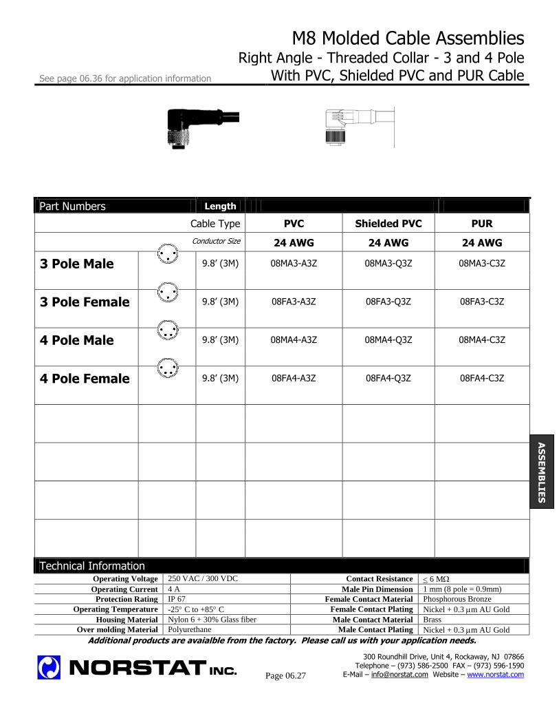
M8 Molded Cable Assemblies Right Angle - Threaded Collar - 3 and 4 Pole
See page 06.36 for application information With PVC, Shielded PVC and PUR Cable
Part Numbers Length
Cable Type PVC Shielded PVC PUR
Conductor Size 24 AWG 24 AWG 24 AWG
3 Pole Male 9.8’ (3M) 08MA3-A3Z 08MA3-Q3Z 08MA3-C3Z
3 Pole Female 9.8’ (3M) 08FA3-A3Z 08FA3-Q3Z 08FA3-C3Z
4 Pole Male 9.8’ (3M) 08MA4-A3Z 08MA4-Q3Z 08MA4-C3Z
4 Pole Female 9.8’ (3M) 08FA4-A3Z 08FA4-Q3Z 08FA4-C3Z
Technical Information Operating Voltage 250 VAC / 300 VDC Contact Resistance 6 M
Operating Current 4 A Male Pin Dimension 1 mm (8 pole = 0.9mm)
Protection Rating IP 67 Female Contact Material Phosphorous Bronze
Operating Temperature -25 C to +85 C Female Contact Plating Nickel + 0.3 m AU Gold
Housing Material Nylon 6 + 30% Glass fiber Male Contact Material Brass
Over molding Material Polyurethane Male Contact Plating Nickel + 0.3 m AU Gold
Additional products are avaialble from the factory. Please call us with your application needs.
300 Roundhill Drive, Unit 4, Rockaway, NJ 07866 Telephone – (973) 586-2500 FAX – (973) 596-1590
E-Mail – [email protected] Website – www.norstat.com
Page 06.27
AS
SE
MB
LIE
S

M8 Molded Cable Assemblies With LED Indication for NPN Sensors Straight - Threaded Collar - 3 and 4 Pole - PVC Cable See page 06.36 for application information
Part Numbers Length
Connector Type
Type
Straight Right Angle
Cable Type PVC - 24 AWG PVC - 24 AWG
3 Pole Male 9.8’ (3M) 08MH3-A3Z 08ME3-A3Z
3 Pole Female 9.8’ (3M) 08FH3-A3Z 08FE3-A3Z
4 Pole Male 9.8’ (3M) 08MH4-A3Z 08ME4-A3Z
4 Pole Female 9.8’ (3M) 08FH4-A3Z 08FE4-A3Z
Technical Operating Voltage 250 VAC / 300 VDC Contact Resistance 6 M
Operating Current 4 A Male Pin Dimension 1 mm (8 pole = 0.9mm)
Protection Rating IP 67 Female Contact Material Phosphorous Bronze
Operating Temperature -25 C to +85 C Female Contact Plating Nickel + 0.3 m AU Gold
Housing Material Nylon 6 + 30% Glass fiber Male Contact Material Brass
Over molding Material Polyurethane Male Contact Plating Nickel + 0.3 m AU Gold
Additional products are avaialble from the factory. Please call us with your application needs.
300 Roundhill Drive, Unit 4, Rockaway, NJ 07866 Telephone – (973) 586-2500 FAX – (973) 596-1590
E-Mail – [email protected] Website – www.norstat.com
Page 06.28
AS
SE
MB
LIE
S

M8 Molded Cable Assemblies With LED Indication for PNP Sensors See page 06.36 for application information Right Angle - Threaded Collar - 3 and 4 Pole – PVC Cable
Part Numbers Length
Connector Type Straight Right Angle
Cable Type PVC - 24 AWG PVC - 24 AWG
3 Pole Male 9.8’ (3M) 08MG3-A3Z 08MF3-A3Z
3 Pole Female 9.8’ (3M) 08FG3-A3Z 08FF3-A3Z
4 Pole Male 9.8’ (3M) 08MG4-A3Z 08MF4-A3Z
4 Pole Female 9.8’ (3M) 08FG4-A3Z 08FF4-A3Z
Technical Operating Voltage 250 VAC / 300 VDC Contact Resistance 6 M
Operating Current 4 A Male Pin Dimension 1 mm (8 pole = 0.9mm)
Protection Rating IP 67 Female Contact Material Phosphorous Bronze
Operating Temperature -25 C to +85 C Female Contact Plating Nickel + 0.3 m AU Gold
Housing Material Nylon 6 + 30% Glass fiber Male Contact Material Brass
Over molding Material Polyurethane Male Contact Plating Nickel + 0.3 m AU Gold
Additional products are avaialble from the factory. Please call us with your application needs.
300 Roundhill Drive, Unit 4, Rockaway, NJ 07866 Telephone – (973) 586-2500 FAX – (973) 596-1590
E-Mail – [email protected] Website – www.norstat.com
Page 06.29
AS
SE
MB
LIE
S

M8 Molded Cable Assemblies Male to Female Cables With PVC or PUR Cable See page 06.36 for application information
Part Numbers Length
Cable Type PVC PUR PVC PUR
3 Pole Male 3.2’ (1M) 08FA3A1Z- 08FA3C1Z- 08FD3A1Z- 08FD3C1Z-
to 08MD 08MD 08MD 08MD
3 Pole Female
4 Pole Male 3.2’ (1M) 08FA4A1Z- 08FA4C1Z- 08FD4A1Z- 08FD4C1Z-
to 08MD 08MD 08MD 08MD
4 Pole Female
Technical Operating Voltage 250 VAC / 300 VDC Contact Resistance 6 M
Operating Current 4 A Male Pin Dimension 1 mm (8 pole = 0.9mm)
Protection Rating IP 67 Female Contact Material Phosphorous Bronze
Operating Temperature -25 C to +85 C Female Contact Plating Nickel + 0.3 m AU Gold
Housing Material Nylon 6 + 30% Glass fiber Male Contact Material Brass
Over molding Material Polyurethane Male Contact Plating Nickel + 0.3 m AU Gold
Additional products are avaialble from the factory. Please call us with your application needs.
AS
SE
MB
LIE
S
300 Roundhill Drive, Unit 4, Rockaway, NJ 07866 Telephone – (973) 586-2500 FAX – (973) 596-1590
E-Mail – [email protected] Website – www.norstat.com
Page 06.30

M8 Y Assemblies 3 and 4 Pole
See page 06.36 for application information With PVC, Shielded PVC and PUR Cable
Configuration
“Y” assemblies provide the ability to expand the inputs and output of a distribution box. The distribution boxes offer two independent wires to each port. By using the “Y” connectors, each port can accommodate two sensors or output devices.
Male M12 Connector
Female M8 Connector Female M8 Connector
Part Numbers
M12 Male to Double M8 3.2’ (1M) Y - PCV Cable 4 Pole 1M
Female Connectors Y - PUR Cable 4 Pole 1M
Circuits
Technical Operating Voltage 250 VAC / 300 VDC Contact Resistance 6 M
Operating Current 4 A Male Pin Dimension 1 mm (8 pole = 0.9mm)
Protection Rating IP 67 Female Contact Material Phosphorous Bronze
Operating Temperature -25 C to +85 C Female Contact Plating Nickel + 0.3 m AU Gold
Housing Material Nylon 6 + 30% Glass fiber Male Contact Material Brass
Overmolding Material Polyurethane Male Contact Plating Nickel + 0.3 m AU Gold
Additional products are avaialble from the factory. Please call us with your application needs.
300 Roundhill Drive, Unit 4, Rockaway, NJ 07866 Telephone – (973) 586-2500 FAX – (973) 596-1590
E-Mail – [email protected] Website – www.norstat.com
Page 06.31
AS
SE
MB
LIE
S
1
3
2
4
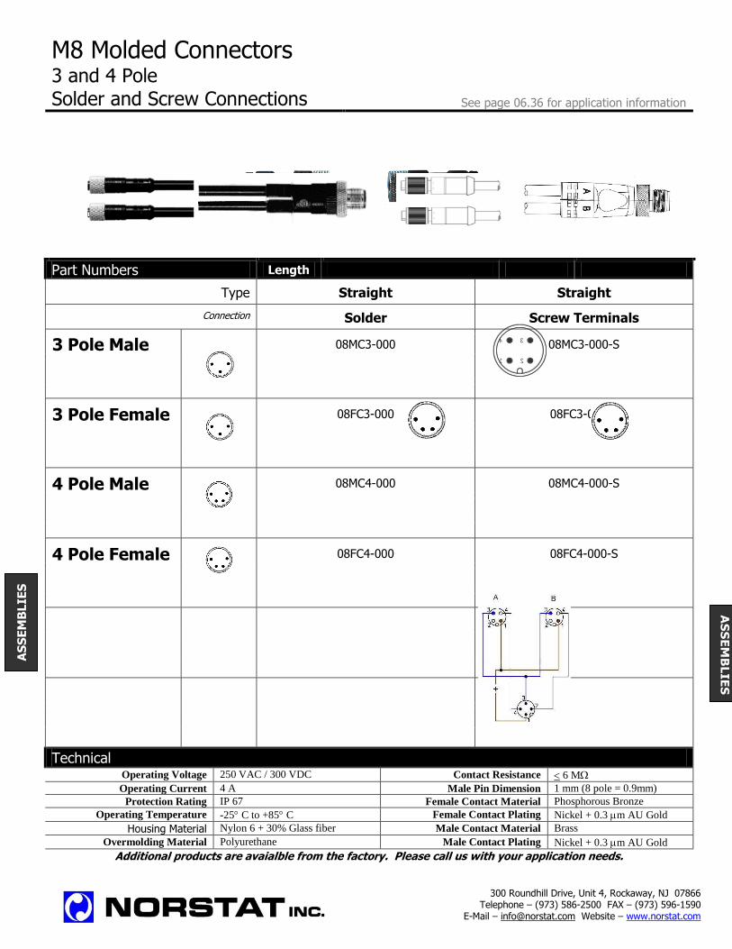
M8 Molded Connectors 3 and 4 Pole Solder and Screw Connections See page 06.36 for application information
Part Numbers Length
Type Straight Straight
Connection Solder Screw Terminals
3 Pole Male 08MC3-000 08MC3-000-S
3 Pole Female 08FC3-000 08FC3-000-S
4 Pole Male 08MC4-000 08MC4-000-S
4 Pole Female 08FC4-000 08FC4-000-S
Technical
Operating Voltage 250 VAC / 300 VDC Contact Resistance 6 M
Operating Current 4 A Male Pin Dimension 1 mm (8 pole = 0.9mm)
Protection Rating IP 67 Female Contact Material Phosphorous Bronze
Operating Temperature -25 C to +85 C Female Contact Plating Nickel + 0.3 m AU Gold
Housing Material Nylon 6 + 30% Glass fiber Male Contact Material Brass
Overmolding Material Polyurethane Male Contact Plating Nickel + 0.3 m AU Gold
Additional products are avaialble from the factory. Please call us with your application needs.
AS
SE
MB
LIE
S
300 Roundhill Drive, Unit 4, Rockaway, NJ 07866 Telephone – (973) 586-2500 FAX – (973) 596-1590
E-Mail – [email protected] Website – www.norstat.com
AS
SE
MB
LIE
S
1
3
2
4

M8 Panel Mount Connectors Front Mount - 3 and 4 Pole - Threaded Collar
See page 06.36 for application information With Solder, PCB Connections or Pre Wired
Solder Connections PCB Connections With 200mm Wire
Part Numbers
Connector Type Solder PCB With Wire
Mounting Hole Pg 7/.49”/12.5mm Pg 7/.49”/12.5mm Pg 7/.49”/12.5mm
Wire Length 7.9” (200mm)
3 Pole Male 08MP3-000 08MQ3-000 08MP3-A0B
3 Pole Female 08FP3-000 08FQ3-000 08FP3-A0B
4 Pole Male 08MP4-000 08MQ4-000 08MP4-A0B
4 Pole Female 08FP4-000 08FQ4-000 08FP4-A0B
Technical Operating Voltage 250 VAC / 300 VDC Contact Resistance 6 M
Operating Current 4 A Male Pin Dimension 1 mm (8 pole = 0.9mm)
Protection Rating IP 67 Female Contact Material Phosphorous Bronze
Operating Temperature -25 C to +85 C Female Contact Plating Nickel + 0.3 m AU Gold
Housing Material Nylon 6 + 30% Glass fiber Male Contact Material Brass
Overmolding Material Polyurethane Male Contact Plating Nickel + 0.3 m AU Gold
Additional products are avaialble from the factory. Please call us with your application needs.
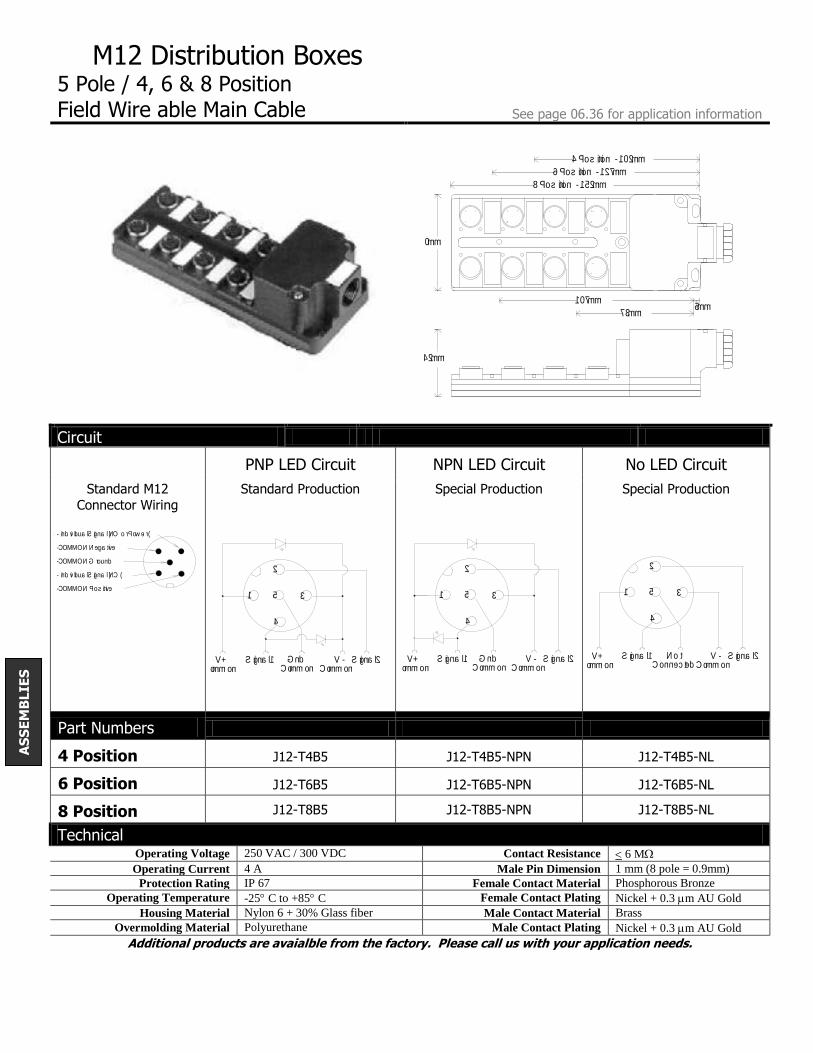
M12 Distribution Boxes 5 Pole / 4, 6 & 8 Position Field Wire able Main Cable See page 06.36 for application information
Circuit
PNP LED Circuit NPN LED Circuit No LED Circuit
Standard M12
Connector Wiring Standard Production Special Production Special Production
Part Numbers
4 Position J12-T4B5 J12-T4B5-NPN J12-T4B5-NL
6 Position J12-T6B5 J12-T6B5-NPN J12-T6B5-NL
8 Position J12-T8B5
J12-T8B5-NPN
J12-T8B5-NL
Technical
Operating Voltage 250 VAC / 300 VDC Contact Resistance 6 M
Operating Current 4 A Male Pin Dimension 1 mm (8 pole = 0.9mm)
Protection Rating IP 67 Female Contact Material Phosphorous Bronze
Operating Temperature -25 C to +85 C Female Contact Plating Nickel + 0.3 m AU Gold
Housing Material Nylon 6 + 30% Glass fiber Male Contact Material Brass
Overmolding Material Polyurethane Male Contact Plating Nickel + 0.3 m AU Gold
Additional products are avaialble from the factory. Please call us with your application needs.
4 - Individual Signal (NO or Power)
3 - COMMON Negative
5 - COMMON Ground
2 - Individual Signal (NC)
1 - COMMON Positive
2
1 35
4
Signal 2 V-Common
V+Common
Signal 1
PNP STANDARD
GndCommon
2
1 35
4
Signal 2 V-Common
V+Common
Signal 1
NPN
GndCommon
2
1 35
4
Signal 2 V-Common
V+Common
Signal 1 NotConnected
8 Position - 152mm
4 Position - 102mm
6 Position - 127mm
107mm
73mm5mm
60mm
42mm
AS
SE
MB
LIE
S
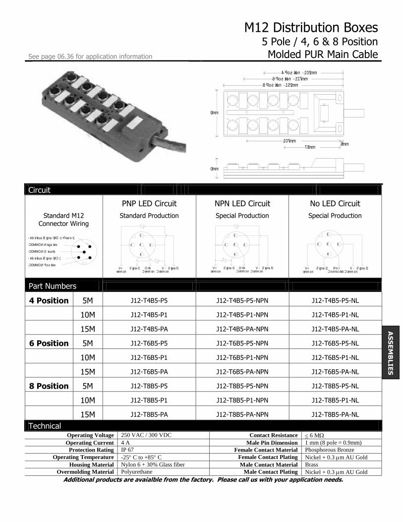
M12 Distribution Boxes 5 Pole / 4, 6 & 8 Position
See page 06.36 for application information Molded PUR Main Cable
Circuit
PNP LED Circuit NPN LED Circuit No LED Circuit
Standard M12
Connector Wiring Standard Production Special Production Special Production
Part Numbers
4 Position 5M J12-T4B5-P5 J12-T4B5-P5-NPN J12-T4B5-P5-NL
10M J12-T4B5-P1 J12-T4B5-P1-NPN J12-T4B5-P1-NL
15M J12-T4B5-PA J12-T4B5-PA-NPN J12-T4B5-PA-NL
6 Position 5M J12-T6B5-P5 J12-T6B5-P5-NPN J12-T6B5-P5-NL
10M J12-T6B5-P1 J12-T6B5-P1-NPN J12-T6B5-P1-NL
15M J12-T6B5-PA J12-T6B5-PA-NPN J12-T6B5-PA-NL
8 Position 5M J12-T8B5-P5 J12-T8B5-P5-NPN J12-T8B5-P5-NL
10M J12-T8B5-P1 J12-T8B5-P1-NPN J12-T8B5-P1-NL
15M J12-T8B5-PA J12-T8B5-PA-NPN J12-T8B5-PA-NL
Technical Operating Voltage 250 VAC / 300 VDC Contact Resistance 6 M
Operating Current 4 A Male Pin Dimension 1 mm (8 pole = 0.9mm)
Protection Rating IP 67 Female Contact Material Phosphorous Bronze
Operating Temperature -25 C to +85 C Female Contact Plating Nickel + 0.3 m AU Gold
Housing Material Nylon 6 + 30% Glass fiber Male Contact Material Brass
Overmolding Material Polyurethane Male Contact Plating Nickel + 0.3 m AU Gold
Additional products are avaialble from the factory. Please call us with your application needs.
4 - Individual Signal (NO or Power)
3 - COMMON Negative
5 - COMMON Ground
2 - Individual Signal (NC)
1 - COMMON Positive
2
1 35
4
Signal 2 V-Common
V+Common
Signal 1
PNP STANDARD
GndCommon
2
1 35
4
Signal 2 V-Common
V+Common
Signal 1
NPN
GndCommon
2
1 35
4
Signal 2 V-Common
V+Common
Signal 1 NotConnected
8 Position - 152mm
4 Position - 102mm
6 Position - 127mm
60mm
107mm
73mm5mm
10mm
AS
SE
MB
LIE
S

General Information Frequently Asked Questions About M8 and M12 Connectors and Assemblies What is an M8 / M12 Connector?
The M12 (also called a “micro” connector) and M8 (also
called “nano” connector) are standard electrical connectors
typically used as an interface for sensors (proximity switches,
photo-optics, small limit switches, etc.). The M12 refers to the
thread size of the mating screw collars.
What are the benefits of the M8 / M12 Connectors?
This connector features a small diameter and is designed for
harsh environments. Molded cables are rated to IP 67
(temporary immersion) and field wired connectors are rated to
IP 65 (wash down).
How are the M12 Connectors typically wired?
3 Wire Sensor
(Single Output)
4 Wire Sensor (Double Output)
What is the usual color code for M12 assemblies?
How are the M8 Connectors typically wired?
3 Pole M8
4 Pole M8
What is the usual color code for M8 assemblies?
3 Pole M8
4 Pole M8
What are the benefits of using Distribution Boxes?
Simplifies installation by operating up to 8 input or
output points with one cable; cleans up cabling confusion
and saves labor in cable routing.
Offers common ground, negative and positive wires to
further reduce labor in wiring.
Modular plug in input and output cables provide easy
installation, change out and maintenance.
Compatible with standard M12 plug wiring schemes.
How do distribution boxes work?
Distribution Boxes are designed around the standard wiring
used for the connectors. Common wiring (to each connector
position) is provided for positive, negative and ground
positions. Each connector has 2 individual wires available to
transfer NO & NC position status for input devices or one wire
can be used to provide separate power for output devices.
What is the wiring scheme used for distribution boxes?
Input Devices
Output Devices
Male Front View
4 - Signal
1 - Positive
3 - Negative
Female Front View
4 - Signal
1 - Positive
3 - Negative
Male Front View
4 - Signal
1 - Positive
3 - Negative
Female Front View
4 - Signal
1 - Positive
3 - Negative
2 - Signal 2 - Signal
Female Front View
1 - Brown
4 - Black
5 - Green/Yellow
3 - Blue
2 - White
Male Front View
2 - White
5 - Green/Yellow
4 - Black
1 - Brown
3 - Blue
Male Front View Female Front View
3 - Negative 3 - Negative
4 - Signal 4 - Signal
1 - Positive 1 - Positive
Male Front View Female Front View 4 - Signal
3 - Negative 1 - Positive
2 - Signal 4 - Signal 2 - Signal
3 - Negative 1 - Positive
Male Front View Female Front View
1 - Brown 1 - Brown
4 - Black 4 - Black2 - White 2 - White
3 - Blue 3 - Blue
3 - Common Negative
5 - Common Ground
1 - Common Positive
4 - Individual Signal (NO)
2 - Individual Signal (NC)
3 - Common Negative 4 - Individual Positive
5 - Common Ground
Male Front View
1 - Brown
4 - Black
3 - Blue
Female Front View
1 - Brown
4 - Black
3 - Blue
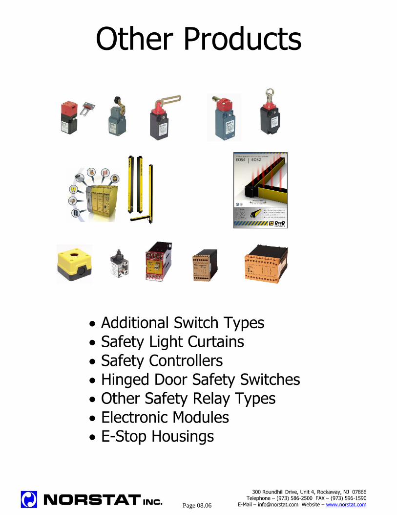
Other Products
Additional Switch Types
Safety Light Curtains
Safety Controllers
Hinged Door Safety Switches
Other Safety Relay Types
Electronic Modules
E-Stop Housings
300 Roundhill Drive, Unit 4, Rockaway, NJ 07866 Telephone – (973) 586-2500 FAX – (973) 596-1590
E-Mail – [email protected] Website – www.norstat.com
Page 08.06

Additional Products
Small Safety Switch Wide Body Safety Switches Solenoid & Key Locking Blank Control Box
FC (Metal) & FK (Plastic) FL (Metal) & FX (Plastic) FS Series CP Series
Hinged Operated Safety
Switches
Hinged Operated Safety
Switches
Hinged Operated Safety
Switches
Hinged Operated Safety
Switches
FD Series FK Series FR (Metal) & FM (Plastic) FZ (Metal) & FX (Plastic)
Pivot Point Safety Switches Pivot Point Safety Switches Pivot Point Safety Switches Safety Rope Pull
FR (Metal) & FM (Plastic) FZ (Metal) & FX (Plastic) FK Series FP (Plastic) & FD (Metal)
Safety Rope Pull Safety Rope Pull Safety Rope Pull Safety Rope Pull
FC Series FC Series FP (Plastic) & FD (Metal) FL Series

Additional Products
Position Switch Body Position Switch Body Position Switch Body Position Switch Body Metal Heavy Duty Small Metal Heavy Duty Robust Plastic Metal Heavy Duty
FL Series FC Series FX Series FZ Series
Position Switch Body Pre-wired Switches Micro-switches Contact Blocks
Small Plastic Body Plastic Body Mechanical
FK Series FF Series MS Series VF-B
Contact Blocks Safety Relays Safety Relays Safety Relays Electronic Switching Switches up to 10A Switches up to 8A
VF-E SAFE S.6 SAFE S.10 RS-NAGMP
Safety Relays Safety Relay Safety Relay Force Guide Relay Mat & Edge Control Muting Application With Timer
RS-NAGAO RS-NAGU RS-NAGT SAFE-IRZ
300 Roundhill Drive, Unit 4, Rockaway, NJ 07866 Telephone – (973) 586-2500 FAX – (973) 596-1590
E-Mail – [email protected] Website – www.norstat.com
Page 09.03

Additional Products
Safety Controller
Programmable Safety
Encoders Relays & Opto Couplers Interface Modules & Cables CNC & I/O Systems
Very Small Housings
Pizzato Safety Range Safety Light Barriers CAT 4 Safety Light Barriers CAT 2 Safety Light Barriers

Introduction to Safety
Who is Responsible? Everyone has a role in the safe operation and functioning of a machine, including the machine designer/builder, safe guarding supplier, the manufacturer/user and the operational and maintenance personnel. The American National Standards Institute, in their ANSI B11.19-2003 Performance Criteria for
Safeguarding for Machine Tools publication, states the following:
4 Responsibility
4.1 Safeguarding supplier 4.1.1 The safeguarding supplier, within the scope of its work activity shall ensure that safeguarding meets the design,
construction, integration and installation requirement of this standard.
4.2 Safeguarding user 4.2.1 The user shall be responsible for ensuring that safeguarding is provided, integrated, installed, maintained, and used in
accordance with the requirements of this standard.
4.2.2 The user shall be responsible for ensuring the supervisors, operators, maintenance and service personnel are trained in
the proper installation, adjustment and maintenance of the safeguarding, within the scope of their work activity.
4.3 Personnel Personnel involved with the installation, operation or maintenance of the safeguarding shall be responsible for following
the training and safety procedures provided by the user in the operation and maintenance of the safeguarding.
The American National Standards Institute, further defines these roles in Annex A – Guidance in
Understanding the B11 Standards, B11.19 and B11.TR3, in the same publication, with the following chart:
10.01
For information only, please see appropriate standards for details.

Risk Assessment
3.8 Risk Assessment
A comprehensive estimation of the probability and the degree of possible injury or damage to health in a
hazardous situation – EN 292.1991
Different types of machines have different levels of associated risk. It’s these risk levels that need to be determined at the design stage in order to specify how far you, the designer, needs to go with the mechanical and electrical design, in order to meet the requirements of US, British and European Machine Directives. In simple terms the assessment of risk determines to a large extent, the level of safety precautions that are necessary to institute into the design of your machine. New and already existing European and US standards, such as ANSI B11…, RIA 15.06, EN292 and EN60204, define Risk Assessment as a process intended to help designers and safety engineers define the most appropriate measures, enabling them to achieve the highest possible levels of safety according to “state of the art” and resulting constraints or regulations. Also included, is information for formulating documentation, which is necessary when compiling a technical file, as required for regulations both here and abroad, as well as if legal action is taken against the machine designer or user. There are many different charts and systems offered to establish the level of risk on a machine. The chart listed below outlines one of the more popular methods, however the choice of system to use should be based on the procedure that best suites your application requirements.
Severity of injury Possibility of avoiding the hazard
S1 Slight injury (bruise) P1 Possible
S2 Severe injury (amputation or death) P2 Less possible
Frequency of exposure to hazard Likelihood of occurrence (if an interlock fails)
F1 Seldom L1 Very unlikely
F2 Frequent to continuous L2 Unlikely L3 Highly likely
10.02
1S
S2
1
2P
F P22
1P
F1
P
2
4
3
1
B
L3
2 1
4
2
3
32
12
1B
B
L2
B
B
B
L1
For information only, please see appropriate standards for details.
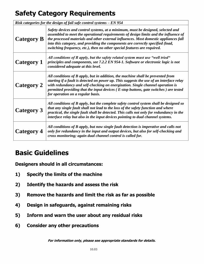
Safety Category Requirements
Basic Guidelines
Designers should in all circumstances:
1) Specify the limits of the machine
2) Identify the hazards and assess the risk
3) Remove the hazards and limit the risk as far as possible
4) Design in safeguards, against remaining risks
5) Inform and warn the user about any residual risks
6) Consider any other precautions
Risk categories for the design of fail safe control systems – EN 954
Category B
Safety devices and control systems, at a minimum, must be designed, selected and
assembled to meet the operational requirements of design limits and the influence of
the processed materials and other external influences. Most domestic appliances fall
into this category, and providing the components are correctly specified (load,
switching frequency, etc.), then no other special features are required.
Category 1 All conditions of B apply, but the safety related system must use “well tried“
principles and components, see 7.2.2 EN 954-1. Software or electronic logic is not
considered adequate at this level.
Category 2
All conditions of B apply, but in addition, the machine shall be prevented from
starting if a fault is detected on power up. This suggests the use of an interface relay
with redundancy and self-checking on energization. Single channel operation is
permitted providing that the input devices ( E-stop buttons, gate switches ) are tested
for operation on a regular basis.
Category 3
All conditions of B apply, but the complete safety control system shall be designed so
that any single fault shall not lead to the loss of the safety function and where
practical, the single fault shall be detected. This calls not only for redundancy in the
interface relay but also in the input devices pointing to dual channel systems.
Category 4 All conditions of B apply, but now single fault detection is imperative and calls not
only for redundancy in the input and output devices, but also for self-checking and
cross monitoring; again dual channel control is called for.
10.03
For information only, please see appropriate standards for details.
Common Safety Principles From the Standards
Control Reliability The capacity of the machine control system, the safeguarding, other control components and related
interfacing to achieve a safe state in the event of a failure within their safety related functions.” ANSI B11.19-2003 3.14 Definitions
“The control system shall be constructed so that a failure within the system does not prevent the normal
stopping action from being applied to the equipment when required, but does prevent initiation of a
successive stroke until failure is corrected. The failure shall be detectable by a simple test or indicated by
the control system.” OSHA Code of Federal Regulations, 1910.217, (b) (13) 29 CRF Ch. XVII (7-1-91)
“Control components failure protection” of electrical, electronic or pneumatic systems frequently consists of
multiple, independent, parallel or series circuitry or components so arranged that any single failure would
not significantly affect the stopping performance of the system or the machine tool. If a failure of a
component has occurred, this arrangement either sends a stop command to the machine tool or prevents a
successive cycle from being initiated.” ANSI B11.19-1990 Section E5.5
Single Component Failure “A component may fail open, closed or to the point that its intended function is no longer viable. All failures
should be considered in the evaluation of the system” ANSI B11.19-1990 Section E5.5
"Safety system .... must be designed and constructed .... such that a single component failure or single
operating error will not cause injury to personnel due to point of operation hazards." OSHA Code of Federal Regulations, 1910.217 29 CRF Ch. XVII (7-1-91)
"The control system shall be designed, constructed and installed such that a single control component failure
within the system does not prevent stopping action from taking place but will prevent successive system
cycles until the failure has been corrected." ANSI B11.20.6.13 Control Reliability
Redundancy “The use of multiple means to perform the same function” ANSI B11.19-2003 3.48 Definitions
“Component redundancy is the use of two or more control components in parallel or series circuits.” ANSI B11.20 E6.13 Control Reliability
10.04
For information only, please see appropriate standards for details.
Common Safety Principles From the Standards
Monitoring
“The checking of system components to detect a failure of a component, subassembly or module that affects
the performance of the safety related functions.” ANSI B11.19-2003 3.14 Definitions
“Failure of one of the redundant components can go undetected, allowing the appearance of safe
operation.” “ When the additional elements of the redundant circuit subsequently fails an unsafe condition
can occur. Monitoring and response to such single failures is essential." ANSI B11.20 E6.13 Control Reliability
“That redundancy, and comparison and/or diagnostic checking, exist for the critical items that may cause
injury, and the electrical, electronic, electromechanical and mechanical parts and components are selected
so that they can withstand operational and external environments.” OSHA Code of Federal Regulations, 1910.217 29 CRF Ch. XVII (7-1-91)
“The control system shall perform checks for proper operation of all cycle control logic elements switches
and contacts at least once each cycle.” OSHA Code of Federal Regulations, 1910.217 29 CRF Ch. XVII (7-1-91)
Positive Force
"Electromechanical systems that require redundancy and checking of relay contacts should use relays that
are designed with a mechanical linkage to provide a positive relation between normally open and normally
closed contacts to check the contact operation." ANSI B11.19
“2.1 All -or-Nothing relays with positively driven contacts are all-or-nothing relays whose contacts are
mechanically connected together in such a way that break contacts and make contacts can never be closed at
the same time.” EN50205 Relays with Positively Driven Contacts
“Position sensors used in circuits with safety-related functions shall have positive (direct) opening
operation” NFPA 79 10.1.4.2
Operation
"System Emergency Stop shall immediately initiate stopping action of those motions which pose an imminent
hazard to personnel. Resetting of the emergency stop shall not initiate, restart or create any hazardous
motion. A manually operated emergency stop shall be provided at each operator station and shall be hard
wired into the emergency stop circuit and shall function independently from the programmable electronic
system (PES)" ANSI B11.20.6.7.1
7-6 Emergency Stop. - (d) The emergency stop circuit shall: (1) operate by deactivation or deenergization
and on loss of power. (2) have only hardware based components (i.e., it shall not rely on software to
operate), although it may be possible to initiate the circuit from the software of the programmable electronic
system. ANSI/NFPA 79
10.05
For information only, please see appropriate standards for details.

Safety Organizations Reference Sources
There are many different organizations involved in machine and control safety standards, in the United States, Canada and Europe. Manufacturers associations are also a good source for the safety requirements of specific manufacturing sectors. The following is a list of some of the more popular agencies and information sources.
ANSI CEMA NFPA American National Standards Institute
Conveyor Equipment Manufacturers Association
National Fire Protection Association
1819 L Street NW 6724 Lone Oak Boulevard 1 Batterymarch Park Washington, DC 20036 Naples, FL 34109 Quincy, MA 002269-9101
Tel: (202) 293-8020 Tel: (941) 514-3441 Tel: (617) 770-3000 Fax: (202) 293-9287 FAX: (941) 514-3470 Fax: (617) 770-0700
www.ansi.org www.cemanet.org www.nfpa.org
ASME CENELEC OSHA American Society of Mechanical Engineers
(European Committee for Electro technical Standardization)
Occupational Safety and Health Administration
3 Park Avenue 35, Rue de Stassart 200 Constitution Avenue, NW New York, NY 10016-5990 1050 Brussels Washington, DC 20210 Tel: (212) 591-7722 Tel: 011-32-2-519-68-71 Tel: (800) 321-6742 FAX: (212) 591-7674 Fax: 011-32-2-519-19 www.osha.gov www.asme.org www.cenelec.org ASSE CEN RIA American Society of Safety
Engineers
European Committee for
Standardization
Robotics Industry Association
1800 East Oakton Street 36, Rue de Stassart 900 Victors Way, PO Box 3742
Des Plaines, IL 60018 1050 Brussels Ann Arbor, MI 48106 Tel: (847) 699-2929 Tel: 011-32-2-550-08-19 Tel: (734) 994-6088 Fax: (847) 768-3434 Fax: 011-32-2-550-08-11 Fax: (734) 994-3338 www.asse.org www.cenorm.be www.robotics.org CCOHS DCI TUV Canadian Center for Occupational Health & Safety
Document Center, Inc. TUV America, Inc.
250 Main Street East 11 Industrial Road, Suite 9 5 Cherry Hill Drive Hamilton, ON L8N 1H6 Canada Belmont, CA 94002 Danvers, MA 01923 Tel: (800) 688-4284 Tel: (650) 591-7600 Tel: (800) TUV-0123 Fax: (905) 527-2206 Fax: (650) 591-7617 Fax: (987-777-8411
www.ccohs.ca www.document-center.com www.TUVamerica.com
CSA GLOBAL UL Canadian Standards Association Global Engineering Documents Underwriters Laboratories, Inc.
5060 Spectrum Way, Suite 100 15 Inverness Way East 333 Pfingsten Road Mississauga, ON L4W 5N6 CAN. Englewood, CO 80112 Northbrook, IL 60062 Tel: (416) 747-4000 Tel: (800) 624-3974 Tel: (847) 272-8800 Fax: (416) 747-2473 Fax: (303) 792-2192 Fax: (847) 272-8129 www.csa.ca www.global.his.com
10.08
