nncutting tools - sme business services ltd
TRANSCRIPT
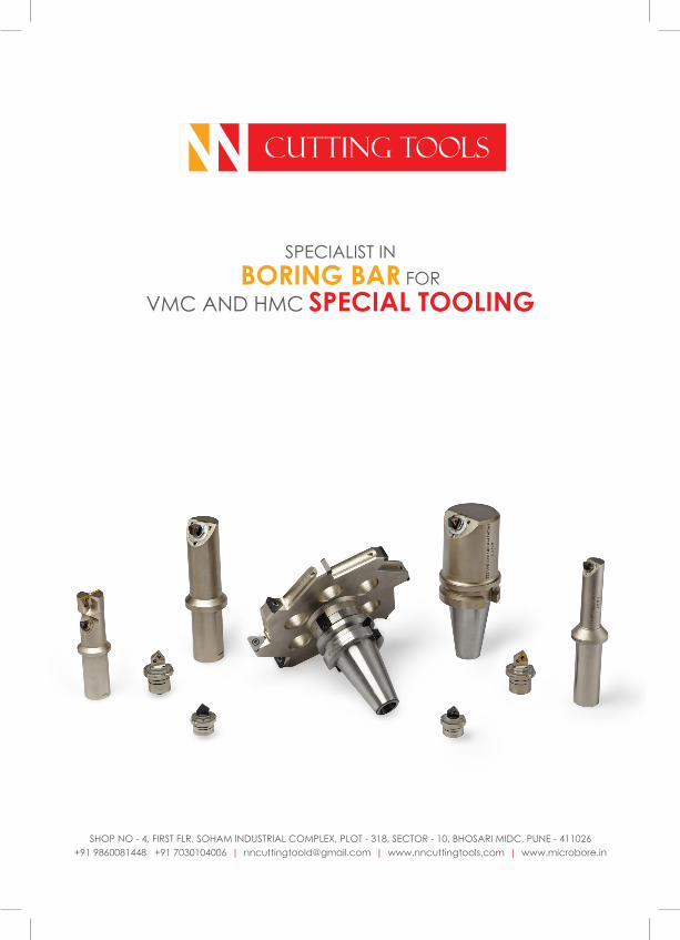
NN CUTTING TOOLS
SPECIALIST IN BORING BAR FOR
VMC AND HMC SPECIAL TOOLING
SHOP NO - 4, FIRST FLR, SOHAM INDUSTRIAL COMPLEX, PLOT - 318, SECTOR - 10, BHOSARI MIDC, PUNE - 411026+91 9860081448 +91 7030104006 | [email protected] | www.nncuttingtools.com | www.microbore.in
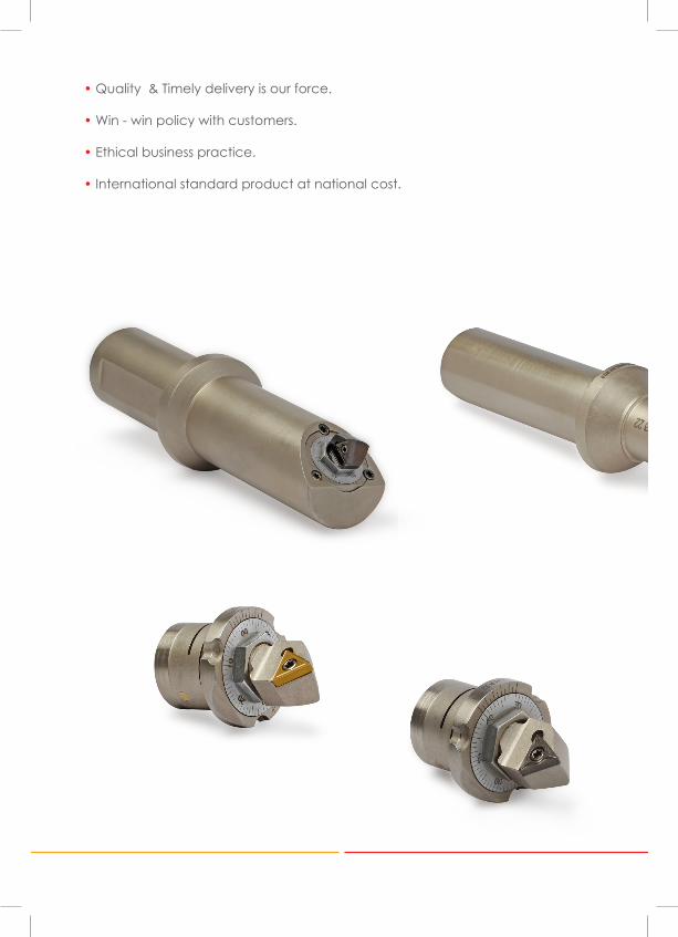
• Quality & Timely delivery is our force.
• Win - win policy with customers.
• Ethical business practice.
• International standard product at national cost.
NN CUTTING TOOLS
N. N. CUTTING TOOLS was established in the year of 2011, by Mr. N. Magar. He has more than 20 years experience in this field. It is one of the top most company in Pune in the manufacturing of MICRO BORE UNITS as well as MICRO BORING BARS STRAIGHT AND ANGULAR. We also offered products like Cartridge & unit, Micro Boring Cartridge like sandvik, Rough & Finish boring bars, Combination boring bars, T Slot Cutter, Side & Face Milling Cutter, U Drill, Core Drill, Spot Face Cutter, Trepanning Tools, CNC Tool holder, CNC Turning, CNC boring bar, Grooving Tools, Face Grooving Tools, Special tools as per customer needs. We are using high grade raw material for the products.
Our company is highly quality oriented and maintains rigid quality standard. Engineers has complete knowledge of the products. We are engaged in supplying of CNC Tools. Having robust construction & immaculate finishing. And these tools are stringently checked on various parameters to ensure their excellent performance and compliance with international quality standard. Moreover, these tools are offered at competitive prices. So these tools find their wide applications in various industries. We have formed strong business association with some of the well-known and authorized industry. Our prime motto is to offer the utmost client satisfaction; therefore we follow fair business practices and ethics. Our offered products are well tested and inspected on various parameters. We are also offering trial service of the product to customers.
We N N Cutting Tools are leading Manufacturers And Suppliers of Industrial cutting tool and Milling tools, VMC Tool in india from Pune, Maharashtra.
NN CUTTING TOOLS
NN CUTTING TOOLS
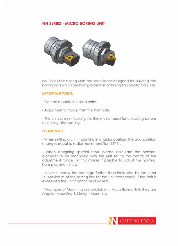
NN Series fine boring units are specifically designed for building into boring bars which are high precision machining for specific bore size.
IMPORTANT POINT:
- Can be mounted in blind holes.
- Adjustment is made from the front side.
- The units are self-locking i.e. there is no need for unlocking before or locking after setting.
PLEASE NOTE :
- When setting a unit, mounting in angular position, the axial position changes equal to radial movement/tan 53° 8’.
- When designing special tools, please calculate the nominal diameter to be machined with the unit set to the centre of the adjustment range, ‘X’ this makes it possible to adjust the nominal bore plus and minus.
- Never unscrew the cartridge further than indicated by the letter ‘X’ Maximum of the setting key for the unit concerned. If the limit is exceeded the unit cannot be repaired.
- Two types of Mounting are available in Micro Boring Unit, they are Angular Mounting & Straight Mounting.
NN SERIES - MICRO BORING UNIT
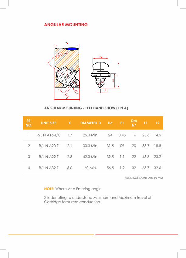
SR.NO. UNIT SIZE X DIAMETER D Dc F1 Dm
h7 L1 L2
1 R/L N A16-T/C 1.7 25.3 Min. 24 0.45 16 25.6 14.5
2 R/L N A20-T 2.1 33.3 Min. 31.5 09 20 33.7 18.8
3 R/L N A22-T 2.8 42.3 Min. 39.5 1.1 22 45.3 23.2
4 R/L N A32-T 5.0 60 Min. 56.5 1.2 32 63.7 32.6
NOTE: Where Ao = Entering angle
X is denoting to understand Minimum and Maximum travel of Cartridge form zero conduction.
ALL DIMENSIONS ARE IN MM
ANGULAR MOUNTING - LEFT HAND SHOW (L N A)
ANGULAR MOUNTING
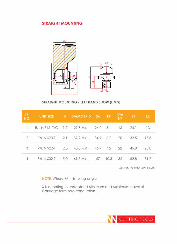
SR.NO. UNIT SIZE X DIAMETER D Dc F1 Dm
h7 L1 L2
1 R/L N S16- T/C 1.7 27.5 Min. 26.0 5.1 16 24.1 13
2 R/L N S20-T 2.1 37.2 Min. 34.9 6.2 20 32.5 17.8
3 R/L N S22-T 2.8 48.8 Min. 46.9 7.2 22 45.8 23.8
4 R/L N S32-T 5.0 69.5 Min. 67 10.3 32 62.8 31.7
NN CUTTING TOOLS
NOTE: Where Ao = Entering angle
X is denoting to understand Minimum and Maximum travel of Cartridge form zero conduction.
ALL DIMENSIONS ARE IN MM
STRAIGHT MOUNTING - LEFT HAND SHOW (L N S)
STRAIGHT MOUNTING
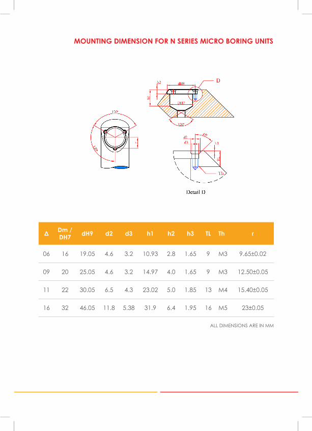
Δ Dm / DH7 dH9 d2 d3 h1 h2 h3 TL Th r
06 16 19.05 4.6 3.2 10.93 2.8 1.65 9 M3 9.65±0.02
09 20 25.05 4.6 3.2 14.97 4.0 1.65 9 M3 12.50±0.05
11 22 30.05 6.5 4.3 23.02 5.0 1.85 13 M4 15.40±0.05
16 32 46.05 11.8 5.38 31.9 6.4 1.95 16 M5 23±0.05
ALL DIMENSIONS ARE IN MM
MOUNTING DIMENSION FOR N SERIES MICRO BORING UNITS
SR.NO.
ORDERINGCODE
ENTERING ANGLE,
AO
INSERT TYPE ISO
MINIMUM CUTTING
DIAFEED DIRECTION
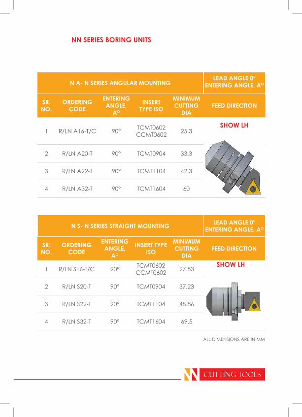
1 R/LN S16-T/C 90° TCMT0602CCMT0602 27.53
2 R/LN S20-T 90° TCMT0904 37.23
3 R/LN S22-T 90° TCMT1104 48.86
4 R/LN S32-T 90° TCMT1604 69.5
NN SERIES BORING UNITS
SHOW LH
NN CUTTING TOOLS
N S- N SERIES STRAIGHT MOUNTING LEAD ANGLE 0°ENTERING ANGLE, AO
SR.NO.
ORDERINGCODE
ENTERING ANGLE,
AO
INSERT TYPE ISO
MINIMUM CUTTING
DIA FEED DIRECTION
1 R/LN A16-T/C 90° TCMT0602CCMT0602 25.3
2 R/LN A20-T 90° TCMT0904 33.3
3 R/LN A22-T 90° TCMT1104 42.3
4 R/LN A32-T 90° TCMT1604 60
SHOW LH
N A- N SERIES ANGULAR MOUNTINGLEAD ANGLE 0°
ENTERING ANGLE, AO
ALL DIMENSIONS ARE IN MM
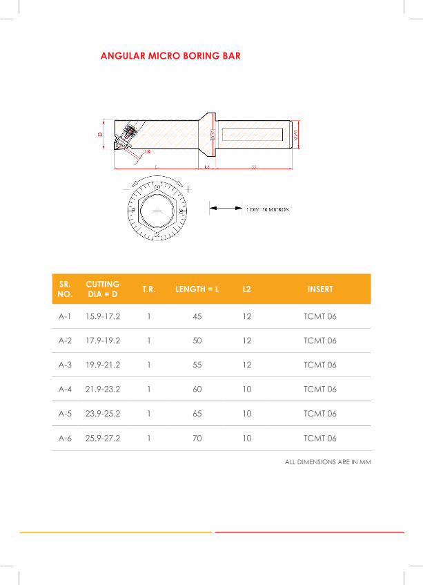
ANGULAR MICRO BORING BAR
SR.NO.
CUTTING DIA = D T.R. LENGTH = L L2 INSERT
A-1 15.9-17.2 1 45 12 TCMT 06
A-2 17.9-19.2 1 50 12 TCMT 06
A-3 19.9-21.2 1 55 12 TCMT 06
A-4 21.9-23.2 1 60 10 TCMT 06
A-5 23.9-25.2 1 65 10 TCMT 06
A-6 25.9-27.2 1 70 10 TCMT 06
ALL DIMENSIONS ARE IN MM
NN CUTTING TOOLS
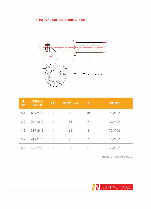
STRAIGHT MICRO BORING BAR
SR.NO.
CUTTING DIA = D T.R. LENGTH = L L2 INSERT
S-1 18.9-20.2 1 50 10 TCMT 06
S-2 20.9-22.2 1 55 9 TCMT 06
S-3 22.9-24.2 1 65 8 TCMT 06
S-4 24.9-26.2 1 75 7 TCMT 06
S-5 26.9-28.2 1 85 6 TCMT 06
ALL DIMENSIONS ARE IN MM
NN CUTTING TOOLS
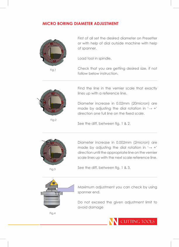
MICRO BORING DIAMETER ADJUSTMENT
First of all set the desired diameter on Presetter or with help of dial outside machine with help of spanner.
Load tool in spindle.
Check that you are getting desired size, if not follow below instruction.
Find the line in the vernier scale that exactly lines up with a reference line.
Diameter increase in 0.02mm (20micron) are made by adjusting the dial rotation in ‘→ +’ direction one full line on the fixed scale.
See the diff. between fig. 1 & 2.
Diameter increase in 0.002mm (2micron) are made by adjusting the dial rotation in ‘→ +’ direction until the appropriate line on the vernier scale lines up with the next scale reference line.
See the diff. between fig. 1 & 3.
Maximum adjustment you can check by using spanner end.
Do not exceed the given adjustment limit to avoid damage
Fig.1
Fig.2
Fig.3
Fig.4