nmd operator manual - peterbilt
TRANSCRIPT

535MO
DE
L
536MO
DE
L 537MO
DE
L
548MO
DE
L

Safety..................................... 1
Emergency..................................... 2
Controls..................................... 3
Driving..................................... 4
Maintenance..................................... 5
Information..................................... 6
Contents
© 2021 PACCAR Inc. - All Rights ReservedThis manual illustrates and describes the operation of features or equipment which may be eitherstandard or optional on this vehicle. This manual may also include a description of features andequipment which are no longer available or were not ordered on this vehicle. Please disregard anyillustrations or descriptions relating to features or equipment which are not on this vehicle. PACCARreserves the right to discontinue, change specifications, or change the design of its vehicles at anytime without notice and without incurring any obligation. The information contained in this manual isproprietary to PACCAR. Reproduction, in whole or in part, by any means is strictly prohibited withoutprior written authorization from PACCAR Inc.
Contents

Chapter 1 | SAFETY
Using this Manual..................................................................................................................................6Safety Alerts..........................................................................................................................................6Illustrations............................................................................................................................................7General Safety Instructions...................................................................................................................8Data Recorder..................................................................................................................................... 11Environmental Protection Agency....................................................................................................... 11Repairs................................................................................................................................................ 11Additional Sources of Information....................................................................................................... 12Cab Access.........................................................................................................................................12Deckplate Access................................................................................................................................14How to Open the Hood........................................................................................................................15Close the Hood................................................................................................................................... 16Seat.....................................................................................................................................................17Vehicle Loading...................................................................................................................................22Visual inspection while approaching the vehicle................................................................................. 23
SAFETY -
4 Y53-6113-1A1 (11/20)
1
Daily Checks....................................................................................................................................... 24Weekly Checks................................................................................................................................... 25Systems Check................................................................................................................................... 26
SAFETY -
Y53-6113-1A1 (11/20) 5
1
Using this ManualPlease take the time to get acquainted with your vehicle by reading this Operator’s Manual. We recommend that you read and understand this manual from beginning to end before you operate this equipment. This manual contains useful information for the safe and efficient operation of this equipment. It also provides service information, with an outline for performing safety checks and basic preventive maintenance inspections. We have tried to present the information you’ll need to learn about functions, controls, and operation—and to present it as clearly as possible. We hope you’ll find this manual easy to use.
NOTE
After you've read this manual, it shouldbe stored in the cab for convenient ref-erence and remain with this truckwhen sold.
Your vehicle may not have all the features or options mentioned in this manual. Therefore, you should pay careful attention to the instructions that pertain to just your vehicle. In addition, if your vehicle is equipped with special equipment or options not discussed in this manual, consult your dealer or the manufacturer of the equipment.There are several tools built into this manual to help you find what you need quickly and easily; first is the Quick Table of Contents. Located at the front of the manual, this table lists the main subjects covered and gives section numbers where you can find these subjects. Use the Quick Table of Contents to find information on a large subject and then use the detailed table of contents found on the first page of each chapter. Cross-referenced citations also help you get the information you need. If some other part of the manual contains further information on the subject you are reading about, we’ll indicate that in a cross-reference like this: (See Safety Alerts on page 6).
Finally, you’ll find a helpful Subject Index. It’s in the back of the manual and alphabetically lists the subjects covered. All information contained in this manual is based on the latest production information available at the time of publication. Peterbilt Motors Company reserves the right to make changes at any time without notice.
Safety AlertsRead and follow all of the safety alerts contained in this manual. They are there for your protection and information. These alerts can help you avoid injury to yourself, your passengers, and help prevent costly damage to the vehicle. Safety alerts are highlighted by safety alert symbols and signal words such as “WARNING,”“CAUTION,” or “NOTE.” DO NOT ignore any of these alerts.
SAFETY - Using this Manual
6 Y53-6113-1A1 (11/20)
1
Warnings
The safety message following this symboland signal word provides a warning againstoperating procedures which could causedeath or injury. They could also causeequipment or property damage. The alertwill identify the hazard, how to avoid it, andthe probable consequence of not avoidingthe hazard.Example:
WARNING
Hot engine oil can be dangerous. Youcould be burned. Let the engine oilcool down before changing it. Failureto comply may result in death, person-al injury, equipment or property dam-age.
Cautions
The safety message following this symboland signal word provides a caution againstoperating procedures which could causeequipment or property damage. The alertwill identify the hazard, how to avoid it, andthe probable consequence of not avoidingthe hazard.Example:
CAUTION
Continuing to operate your vehicle withinsufficient oil pressure will cause seri-ous engine damage. Failure to complymay result in equipment or propertydamage.
Notes
The message following this symbol andsignal word provides important informationthat is not safety related but should befollowed. The alert will highlight things thatmay not be obvious and is useful to yourefficient operation of the vehicle.Example:
NOTE
Pumping the accelerator will not assistin starting the engine.
IllustrationsSome of the illustrations throughout thismanual are generic and will not lookexactly like the engine or parts used inyour application. The illustrations cancontain symbols to indicate an actionrequired and/or an acceptable orunacceptable condition.The illustrations are intended to showrepair or replacement procedures. Theprocedure will be the same for allapplications, although the illustrations maydiffer.
SAFETY - Illustrations
Y53-6113-1A1 (11/20) 7
1
General SafetyInstructions
WARNING
Improper practices, carelessness, orignoring any warnings may causeproperty damage, personal injury, ordeath.
WARNING
Manually rotating the crankshaft re-quires a trained technician and specialtytools. DO NOT pull or pry on the fan inan attempt to rotate the crankshaft. Ap-plying force to the fan can damage thefan blades or cause premature fan fail-ure. Failure to comply with the approvedprocedure may result in property dam-age, personal injury, or death.
Before performing any repair, read andunderstand all of the safety precautionsand warnings. The following is a list ofgeneral safety precautions that must befollowed to provide personal safety. Failure
to follow these instructions may causedeath or injury. Special safety precautionsare included in the procedures when theyapply.Keep in mind that even a well maintainedvehicle must be operated within the rangeof its mechanical capabilities and the limitsof its load ratings. See the Weight Ratingslabel on the driver's door edge.Every new vehicle is designed to conformto all Federal Motor Vehicle SafetyStandards applicable at the time ofmanufacture. Even with these safetyfeatures, continued safe and reliableoperation depends greatly upon regularvehicle maintenance. Follow themaintenance recommendations found inthe Preventive Maintenance section. Thiswill help preserve your investment.Make sure your vehicle is in top workingcondition before heading out on the road, itis the responsible driver's duty to do so.Inspect the vehicle according to theDriver's Check List.
• Work areas should be dry, well lit,well ventilated, free from clutter,loose tools, parts, ignition sourcesand hazardous substances.
• Wear protective glasses andprotective shoes when working.
• DO NOT wear loose-fitting or tornclothing. Tie back and/or tuck inlong hair. Remove all jewelry whenworking.
• Before beginning any repair,disconnect the battery (negative [-]cable) and discharge anycapacitors.
• Put a “DO NOT OPERATE” tag inthe operator's compartment or onthe controls.
• Allow the engine to cool beforeslowly loosening the coolant fill capto relieve the pressure from thecooling system.
SAFETY - General Safety Instructions
8 Y53-6113-1A1 (11/20)
1
WARNING
Removing the fill cap on a hot enginecan cause scalding coolant to sprayout and burn you badly. If the enginehas been in operation within the previ-ous 30 minutes, be very careful in re-moving the fill cap. Protect face,hands, and arms against escaping flu-id and steam by covering the cap witha large, thick rag. DO NOT try to re-move it until the surge tank cools downor if you see any steam or coolant es-caping. Always remove the cap veryslowly and carefully. Be ready to backoff if any steam or coolant begins toescape. Failure to comply may resultin death, personal injury, equipment orproperty damage.
• Always use wheel chocks or properjack stands to support the vehicleor vehicle components beforeperforming any service work. DONOT work on anything that issupported only by lifting jacks or ahoist. Before resting a vehicle onjack stands, be sure the stands arerated for the load you will beplacing on them.
• Before removing or disconnectingany lines, fittings, or related items,relieve all pressure in the air, oil,fuel, and cooling systems. Remainalert for possible pressure whendisconnecting any device from asystem that contains pressure.High pressure oil or fuel can causedeath or personal injury.
• Always wear protective clothingwhen working on any refrigerantlines and make sure that theworkplace is well ventilated.Inhalation of fumes can causedeath or personal injury. To protectthe environment, liquid refrigerantsystems must be properly emptiedand filled using equipment thatprevents the release of refrigerantgas. Federal law requires capturingand recycling refrigerant.
• When moving or lifting any heavyequipment or parts, make sure touse proper techniques andassistance. Ensure all liftingdevices such as chains, hooks, orslings are in good condition andare of the correct load capacity.Make sure all lifting devices arepositioned correctly.
• Corrosion inhibitors and lubricatingoils may contain alkali. DO NOTget the substance in eyes andavoid prolonged or repeatedcontact with skin. DO NOTswallow. If ingested, seekimmediate medical attention. DONOT induce vomiting. In case ofcontact, immediately wash skinwith soap and water. In case ofharmful contact, immediatelycontact a physician. Always keepany chemicals OUT OF REACHOF CHILDREN.
• Naphtha and Methyl Ethyl Ketone(MEK) are flammable materials andmust be used with caution. Followthe manufacturer's instructions toensure safety when using thesematerials. Always keep anychemicals OUT OF REACH OFCHILDREN.
• When working on the vehicle, bealert for hot parts on systems thathave just been turned off, exhaustgas flow, and hot fluids in lines,tubes, and compartments. Contactwith any hot surface may causeburns.
• Always use tools that are in goodcondition. Make sure you have the
SAFETY - General Safety Instructions
Y53-6113-1A1 (11/20) 9
1
proper understanding of how to usethe tools before performing anyservice work. Use only genuinereplacement parts from PACCAR.
• Always use the same fastener partnumber (or equivalent) whenreplacing items. DO NOT use afastener of lesser quality ifreplacements are necessary. (e.g.,DO NOT replace a SAE 10.9 gradewith 8.8 grade fastener.)
• Always torque fasteners and fuelconnections to the requiredspecifications. Overtightening orunder-tightening can allow leakage.
• Close the manual fuel valves priorto performing maintenance andrepairs, and when storing thevehicle inside.
• DO NOT perform any repair whenimpaired, tired, fatigued, or afterconsuming alcohol or drugs thatcan impair your functioning.
• Some state and federal agencies inthe United States of America havedetermined that used engine oilcan be carcinogenic and can causereproductive toxicity. Avoidinhalation of vapors, ingestion, and
prolonged contact with used engineoil.
• DO NOT connect the jump startingor battery charging cables to anyignition or governor control wiring.This can cause electrical damageto the ignition or governor.
• Coolant is toxic. If not reused,dispose of coolant in accordancewith local environmentalregulations.
CAUTION
Corrosive chemicals can damage theengine. DO NOT use corrosive chemi-cals on the engine. Failure to complymay result in equipment or propertydamage.
California Proposition 65 Warning• Diesel engine exhaust and some of
its constituents are known to theState of California to cause cancer,birth defects, and otherreproductive harm.
• The catalyst substrate located inthe Diesel Particulate Filter (DPF)contains vanadium pentoxide,
which has been determined by theState of California to cause cancer.Always wear protective clothingand eye protection when handlingthe catalyst assembly. Dispose ofthe catalyst in accordance withlocal regulations. If catalystmaterial gets into the eyes,immediately flood eyes with waterfor a minimum of 15 minutes. Avoidprolonged contact with skin. Incase of contact, immediately washskin with soap and water. In caseof harmful contact, immediatelycontact a physician.
• Other chemicals in this vehicle arealso known to the State ofCalifornia to cause cancer, birthdefects or other reproductive harm.
• Battery posts, terminals, andrelated accessories contain leadand lead compounds, chemicalsknown to the State of California tocause cancer and reproductiveharm. Wash hands after handling.
SAFETY - General Safety Instructions
10 Y53-6113-1A1 (11/20)
1
Data RecorderCalifornia Vehicle Code - Section 9951 -Disclosure of Recording DeviceYour vehicle may be equipped with one ormore recording devices commonly referredto as "event data recorders" (EDR) or"sensing and diagnostic modules" (SDM).If you are involved in an accident, thedevice(s) may have the ability to recordvehicle data that occurred just prior toand/or during the accident. For additionalinformation on your rights associated withthe use of this data, contact:
• The California Department of MotorVehicles - Licensing OperationsDivision
• http://www.dmv.ca.gov/
environment if spilled or not disposed ofproperly.
WARNING
Diesel engine exhaust and some of itsconstituents are known to the State ofCalifornia to cause cancer, birth de-fects, and other reproductive harm.Other chemicals in this vehicle are al-so known to the State of California tocause cancer, birth defects or other re-productive harm. This warning require-ment is mandated by California law(Proposition 65) and does not resultfrom any change in the manner inwhich vehicles are manufactured.
Contact your local government agency forinformation concerning proper disposal.
Repairs
WARNING
DO NOT attempt repair work withoutsufficient training, service manuals,and the proper tools. You could be kil-
led or injured, or you could make yourvehicle unsafe. Perform only thosetasks you are fully qualified to do.
WARNING
Modifying your vehicle can make it un-safe. Some modifications can affectyour vehicle's electrical system, stabili-ty, or other important functions. Beforemodifying your vehicle, check withyour dealer to make sure it can bedone safely. Improper modificationscan cause death or personal injury.
CAUTION
The installation of electronic devices tothe On Board Diagnostics (OBD) con-nector, the vehicle Controller Area Net-work (CAN), or their associated wiringis not permitted. Doing so can ad-versely affect vehicle performanceand/or cause fault codes to be record-ed. The OBD connector is provided fortemporary connection of service toolsand for diagnostic purposes only.
SAFETY - Data Recorder
Environmental ProtectionAgencySome of the ingredients in engine oil, hydraulic oil, transmission and axle oil, engine coolant, diesel fuel, air conditioning refrigerant (R12, R134a, and PAG oil), batteries, etc., may contaminate the
Y53-6113-1A1 (11/20) 11
1
Your dealer’s service center is the bestplace to have your vehicle repaired. Youcan find dealers all over the country withthe equipment and trained personnel to getyou back on the road quickly—and keepyou there.Your vehicle is a complex machine.Anyone attempting repairs on it needsgood mechanical training and the propertools. However, all warranty repairs mustbe performed by an authorized servicefacility. If you aren’t an experiencedmechanic, or don’t have the rightequipment, please leave all repairs to anauthorized service facility. They are theones best equipped to do the job safelyand correctly.
Maintenance ManualsIf you do decide to do any complex repairwork, you’ll need the maintenancemanuals. Order them from your authorizeddealer. Please provide your Chassis SerialNumber when you order, to be sure youget the correct manuals for your vehicle.Allow about four weeks for delivery. Therewill be a charge for these manuals.
Final Chassis Bill of MaterialA complete, non-illustrated computerprintout listing of the parts used to custom-build your vehicle is available through thedealer from whom you purchased yourvehicle.
Additional Sources ofInformationMajor component suppliers also supplyoperation manuals specific to theirproducts. Additional manuals and otherpieces of literature are included in theglove box literature package. Look forinformation on products such as theengine, driver's seat, transmission, axles,wheels, tires, ABS/ESC, radio, fifth wheel,lane departure, and adaptive cruisecontrol. If you are missing these pieces ofliterature, ask your dealer for copies.Another place to learn more about truckingis from local truck driving schools. Contactone near you to learn about courses theyoffer. Federal and state agencies such asthe department of licensing also haveinformation. The Interstate CommerceCommission can give you information
about regulations governing transportationacross state lines.
Cab AccessThe following cab and frame entry/exitprocedure recommendations wereprepared with personal safety foremost inmind.
WARNING
Do not jump out of the cab or get intothe cab without proper caution. Youcould slip or fall, possibly suffering ainjury or death. You could slip and fallif the steps are wet or icy, or if youstep in fuel, oil, or grease.
To help avoid personal injury dueto a slip or fall
• Always face the vehicle whenaccessing or leaving the cab orframe access area.
• Use three points of contact (twofeet one hand or one foot twohands) to grip the steps or
SAFETY - Additional Sources of Information
12 Y53-6113-1A1 (11/20)
1
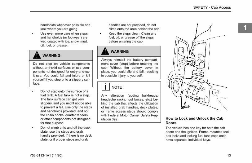
handholds whenever possible andlook where you are going.
• Use even more care when stepsand handholds (or footwear) arewet, coated with ice, snow, mud,oil, fuel, or grease.
WARNING
Do not step on vehicle componentswithout anti-skid surfaces or use com-ponents not designed for entry-and-ex-it use. You could fall and injure or killyourself if you step onto a slippery sur-face.
• Do not step onto the surface of afuel tank. A fuel tank is not a step.The tank surface can get veryslippery, and you might not be ableto prevent a fall. Use only the stepsand handholds provided, and notthe chain hooks, quarter fenders,or other components not designedfor that purpose.
• Do not climb onto and off the deckplate; use the steps and grabhandle provided. If there is no deckplate, or if proper steps and grab
handles are not provided, do notclimb onto the area behind the cab.
• Keep the steps clean. Clean anyfuel, oil, or grease off the stepsbefore entering the cab.
WARNING
Always reinstall the battery compart-ment cover (step) before entering thecab. Without the battery cover inplace, you could slip and fall, resultingin possible injury to yourself.
NOTE
Any alteration (adding bulkheads,headache racks, tool boxes, etc.) be-hind the cab that affects the utilizationof installed grab handles, deck plates,or frame access steps should complywith Federal Motor Carrier Safety Reg-ulation 399. How to Lock and Unlock the Cab
DoorsThe vehicle has one key for both the cabdoors and the ignition. Frame-mounted toolbox locks and locking fuel tank caps eachhave separate, individual keys.
SAFETY - Cab Access
Y53-6113-1A1 (11/20) 13
1
WARNING
To help lessen the chance and/or se-verity of death or personal injury incase of an accident, always lock thedoors while driving. Along with usingthe lap shoulder belts properly, lockingthe doors helps prevent doors from in-advertently opening and occupantsfrom being ejected from the vehicle.
To lock or unlock the doors from outsidethe cab:
1. • Rotate the key toward the rearof the vehicle to lock(clockwise), or
• Rotate the key toward the frontof the vehicle (counterclockwise) to unlock.
Remote Keyless Entry (Option)Remote Keyless Entry (RKE) is a systemthat adds security and convenience to yourvehicle. The system will lock or unlock cabdoors with the key fob. The system willalert you with parking lights when theselected doors are locked or unlocked. Thesystem includes two key fobs that provide
secure rolling code technology thatprevents someone from recording the entrysignal.
NOTE
FCC ID: L2C0031T IC: 3432A-0031TFCC ID: L2C0032R IC: 3432A-0032RThis device complies with Part 15 ofthe FCC Rules and with RSS-210 ofIndustry Canada. Operation is subjectto the following two conditions (1) Thisdevice may not cause harmful interfer-ence, and (2) This device must acceptany interference received, including in-terference that may cause undesiredoperation. Changes or modificationsnot expressively approved by the partyresponsible for compliance could voidthe user's authority to operate theequipment. The term IC: before the ra-dio certification number only signifiesthat Industry Canada technical specifi-cations were met.
Operate Door Locks using RemoteKeyless EntryOpen doors will not lock using the key fob.The key fob should be within 30 feet (9
meters) of the vehicle and should not be inproximity of other RF sources such astelevision, radio or cell phone transmitters.To unlock the cab doors:
1. Press the UNLOCK button once.The driver's door will unlock andthe parking lights will come on for40 seconds.
2. Quickly press the UNLOCK buttona second time within 5 seconds tounlock the passenger door.
3. Press the LOCK button. The doorswill lock and the parking lights willcome on for 2 seconds.
Deckplate Access
WARNING
Always reinstall steps before enteringthe cab or accessing the deck plate.Without steps you could slip and fall.Failure to comply may result in person-al injury or death.
SAFETY - Deckplate Access
14 Y53-6113-1A1 (11/20)
1
WARNING
Keep steps clean. Clean any fuel, oil,or grease off the steps before enteringthe cab or accessing the deck plate.Stepping on a slippery surface cancause a fall which may result in deathor personal injury.
WARNING
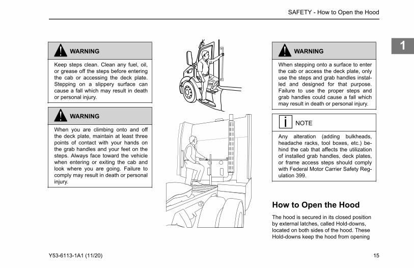
When you are climbing onto and offthe deck plate, maintain at least threepoints of contact with your hands onthe grab handles and your feet on thesteps. Always face toward the vehiclewhen entering or exiting the cab andlook where you are going. Failure tocomply may result in death or personalinjury.
WARNING
When stepping onto a surface to enterthe cab or access the deck plate, onlyuse the steps and grab handles instal-led and designed for that purpose.Failure to use the proper steps andgrab handles could cause a fall whichmay result in death or personal injury.
NOTE
Any alteration (adding bulkheads,headache racks, tool boxes, etc.) be-hind the cab that affects the utilizationof installed grab handles, deck plates,or frame access steps should complywith Federal Motor Carrier Safety Reg-ulation 399.
How to Open the HoodThe hood is secured in its closed positionby external latches, called Hold-downs,located on both sides of the hood. TheseHold-downs keep the hood from opening
SAFETY - How to Open the Hood
Y53-6113-1A1 (11/20) 15
1
unexpectedly. Once the Hold-downs areunlatched, the hood may be tilted open.
Unlatching Hood Hold-downs
Hood Hold-downs
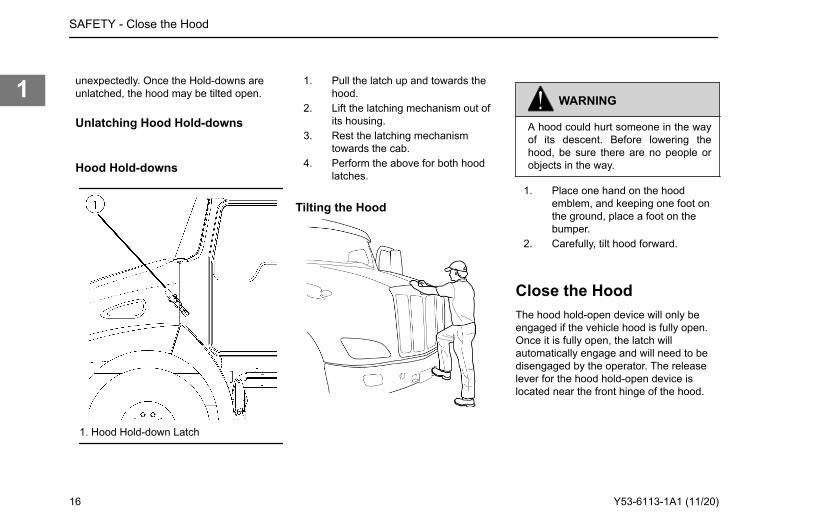
1. Hood Hold-down Latch
1. Pull the latch up and towards thehood.
2. Lift the latching mechanism out ofits housing.
3. Rest the latching mechanismtowards the cab.
4. Perform the above for both hoodlatches.
Tilting the Hood
WARNING
A hood could hurt someone in the wayof its descent. Before lowering thehood, be sure there are no people orobjects in the way.
1. Place one hand on the hoodemblem, and keeping one foot onthe ground, place a foot on thebumper.
2. Carefully, tilt hood forward.
Close the HoodThe hood hold-open device will only beengaged if the vehicle hood is fully open.Once it is fully open, the latch willautomatically engage and will need to bedisengaged by the operator. The releaselever for the hood hold-open device islocated near the front hinge of the hood.
SAFETY - Close the Hood
16 Y53-6113-1A1 (11/20)
1
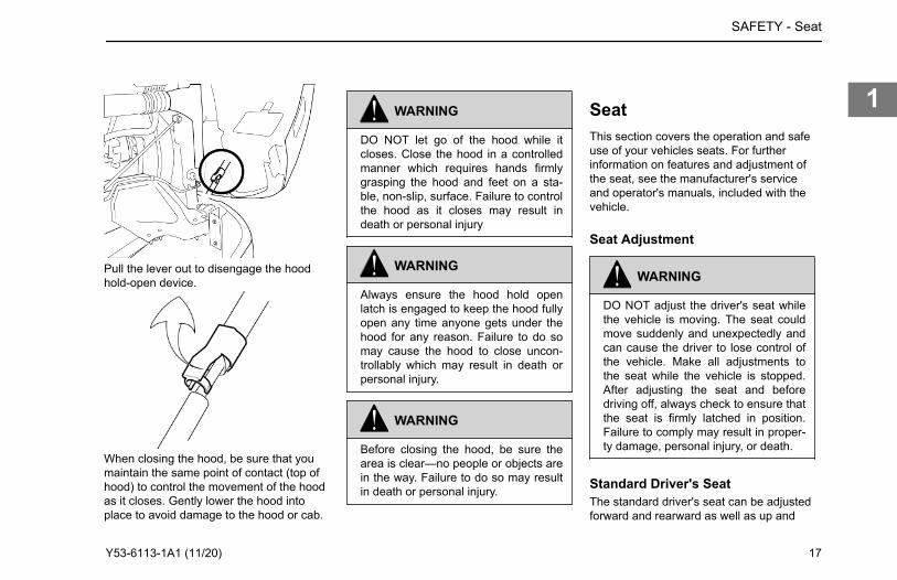
Pull the lever out to disengage the hoodhold-open device.
WARNING
DO NOT let go of the hood while itcloses. Close the hood in a controlledmanner which requires hands firmlygrasping the hood and feet on a sta-ble, non-slip, surface. Failure to controlthe hood as it closes may result indeath or personal injury
WARNING
Always ensure the hood hold openlatch is engaged to keep the hood fullyopen any time anyone gets under thehood for any reason. Failure to do somay cause the hood to close uncon-trollably which may result in death orpersonal injury.
WARNING
Before closing the hood, be sure thearea is clear—no people or objects arein the way. Failure to do so may resultin death or personal injury.
SeatThis section covers the operation and safeuse of your vehicles seats. For furtherinformation on features and adjustment ofthe seat, see the manufacturer's serviceand operator's manuals, included with thevehicle.
Seat Adjustment
WARNING
DO NOT adjust the driver's seat whilethe vehicle is moving. The seat couldmove suddenly and unexpectedly andcan cause the driver to lose control ofthe vehicle. Make all adjustments tothe seat while the vehicle is stopped.After adjusting the seat and beforedriving off, always check to ensure thatthe seat is firmly latched in position.Failure to comply may result in proper-ty damage, personal injury, or death.
Standard Driver's SeatThe standard driver's seat can be adjustedforward and rearward as well as up and
SAFETY - Seat
When closing the hood, be sure that you maintain the same point of contact (top of hood) to control the movement of the hood as it closes. Gently lower the hood into place to avoid damage to the hood or cab.
Y53-6113-1A1 (11/20) 17
1
down. The seat back angle can also beadjusted. These three movements areeach controlled by levers located eitherbeneath or at the sides of the seat.
Reclining SeatsRaise the seat all the way up so that theseat will tilt back and completely clearobjects behind you.
WARNING
DO NOT drive or ride with your seatback in the reclined position. Youcould be injured by sliding under theseat belts in a collision. Failure to com-ply may result in personal injury ordeath.
Safety Restraint BeltsSafety belts have proven to be the singlemost effective means available forreducing the potential for either death orpersonal injury in motor vehicle accidents.The combination lap/shoulder belt isequipped with a locking mechanism. Thesystem adjusts automatically to a person'ssize and movements as long as the pull onthe belt is slow. Hard braking or a collision
locks the belt. The belt will also lock whendriving up or down a steep hill or in a sharpcurve.Unbelted riders could be thrown into thewindshield or other parts of the cab orcould be thrown out of the cab. They couldstrike another person. Injuries can be muchworse when riders are unbelted. Alwaysobserve user warnings pertaining to safetybelts. Your vehicle is equipped with a seatbelt indicator lamp located on the dash.
WARNING
DO NOT drive vehicle without yourseat belt and your passengers' beltsfastened. Riding without a safety beltproperly fastened can lead to injury ordeath in an emergency.
WARNING
DO NOT use the swivel function whilea passenger is in the seat and the ve-hicle is in motion. The seat belt will notprovide proper protection if the pas-senger is not facing forward and thevehicle is in an accident. Failure to
comply may result in death or personalinjury.
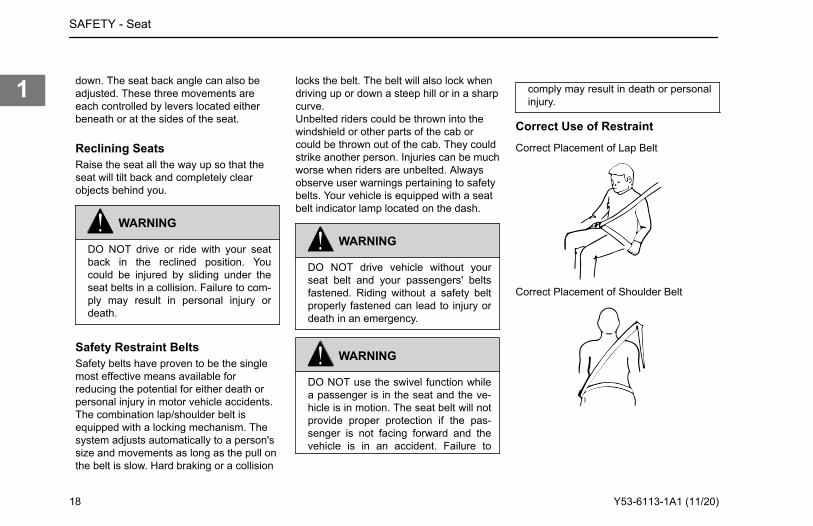
Correct Use of RestraintCorrect Placement of Lap Belt
Correct Placement of Shoulder Belt
SAFETY - Seat
18 Y53-6113-1A1 (11/20)
1
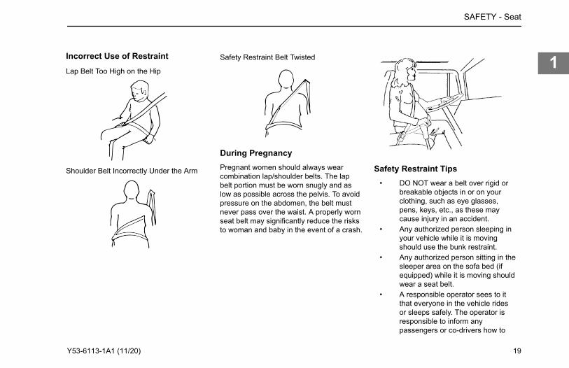
Incorrect Use of RestraintLap Belt Too High on the Hip
Shoulder Belt Incorrectly Under the Arm
Safety Restraint Belt Twisted
During PregnancyPregnant women should always wearcombination lap/shoulder belts. The lapbelt portion must be worn snugly and aslow as possible across the pelvis. To avoidpressure on the abdomen, the belt mustnever pass over the waist. A properly wornseat belt may significantly reduce the risksto woman and baby in the event of a crash.
Safety Restraint Tips• DO NOT wear a belt over rigid or
breakable objects in or on yourclothing, such as eye glasses,pens, keys, etc., as these maycause injury in an accident.
• Any authorized person sleeping inyour vehicle while it is movingshould use the bunk restraint.
• Any authorized person sitting in thesleeper area on the sofa bed (ifequipped) while it is moving shouldwear a seat belt.
• A responsible operator sees to itthat everyone in the vehicle ridesor sleeps safely. The operator isresponsible to inform anypassengers or co-drivers how to
SAFETY - Seat
Y53-6113-1A1 (11/20) 19
1
properly use the seat belts andbunk restraint in the vehicle.
• DO NOT strap in more than oneperson with each belt.
• Keep seat belt and bunk restraintbuckles free of any obstruction thatmay prevent secure locking.
• Damaged or worn belts in the cabor sleeper subjected to excessivestretch forces from normal wear,must be replaced. They may notprotect you if you are in anaccident.
• Any belts or restraints that havebeen subjected to an accidentshould be inspected for any loose(attaching) hardware or damagedbuckles.
• If belts show damage to any part ofassembly, such as webbing,bindings, buckles or retractors,they must be replaced.
• DO NOT allow safety belts (seat orbunk) to become damaged bygetting caught in door, bunk, orseat hardware, or rubbing againstsharp objects.
• All belts must be kept clean or theretractors may not work properly.
• Never bleach or dye seat or bunkrestraint belts: chemicals canweaken them. Do, however, keepthem clean by following the carelabel on the belts. Let them drycompletely before allowing them toretract or be stowed away.
• Make sure the seat belts and bunkrestraint of the unoccupiedpassenger seat or bunk is fullywound up on its retractor or isstowed, so that the belt or restrainttongue is in its properly stowedposition. This reduces thepossibility of the tongue becominga striking object in case of asudden stop.
• DO NOT modify or disassemblethe seat belts or bunk restraint inyour vehicle. They will not beavailable to keep you and yourpassengers safe.
• If any seat belt or bunk restraint isnot working properly, see anauthorized dealer for repair orreplacement.
How to Use Lap/Shoulder BeltFollow these steps to fasten your seat beltand be sure anyone riding with you doesthe same.
WARNING
Proper seat belt adjustment and use isimportant to maximize occupant safe-ty. Failure to wear or adjust the safetybelt properly may result in death orpersonal injury.
To fasten the belt:1. Grasp the belt tongue.2. Pull belt in a continuous slow
motion across your chest and lap.3. Insert belt tongue into buckle on
inboard side of seat.4. Push down until the tongue is
securely locked with an audibleclick.
5. Pull belt to check for properfastening and adjustment.
a. Pull shoulder section to makesure belt fits snugly across thechest and pelvis.
SAFETY - Seat
20 Y53-6113-1A1 (11/20)
1
b. There should be less than oneinch (25 mm) gap between thebody and the belt.
c. The shoulder belt must bepositioned over the shoulder,it must never rest against theneck or be worn under thearm.
d. Make sure any slack is woundup on the retractor and thatthe belt is not twisted.
If the belt is locked, lean the body back toremove any tension in the belt. Afterreleasing the belt, allow the belt to retractcompletely by guiding the belt tongue untilthe belt comes to a stop.To unfasten the belt, push the releasebutton on the buckle and the belt shouldspring out of the buckle. The seat beltindicator will turn off once the driver's seat
belt is fastened.
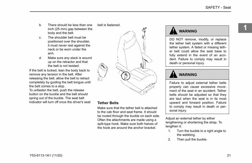
Tether BeltsMake sure that the tether belt is attachedto the cab floor and seat frame. It shouldbe routed through the buckle on each side.Often the attachments are made using asplit-type hook. Make sure both halves ofthe hook are around the anchor bracket.
WARNING
DO NOT remove, modify, or replacethe tether belt system with a differenttether system. A failed or missing teth-er belt could allow the seat base tofully extend in the event of an acci-dent. Failure to comply may result indeath or personal injury.
WARNING
Failure to adjust external tether beltsproperly can cause excessive move-ment of the seat in an accident. Tetherbelts should be adjusted so that theyare taut when the seat is in its mostupward and forward position. Failureto comply may result in death or per-sonal injury.
Adjust an external tether by eitherlengthening or shortening the strap. Tolengthen it:
1. Turn the buckle to a right angle tothe webbing.
2. Then pull the buckle.
SAFETY - Seat
Y53-6113-1A1 (11/20) 21
1
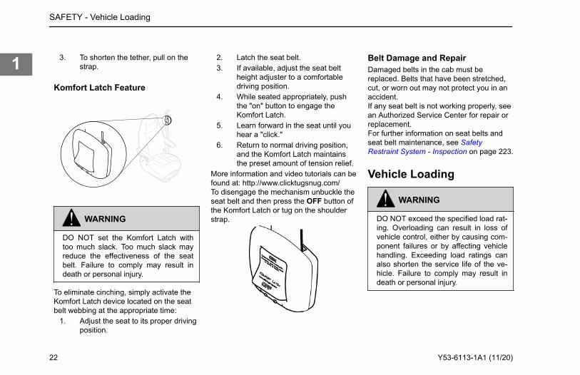
3. To shorten the tether, pull on thestrap.
Komfort Latch Feature
WARNING
DO NOT set the Komfort Latch withtoo much slack. Too much slack mayreduce the effectiveness of the seatbelt. Failure to comply may result indeath or personal injury.
To eliminate cinching, simply activate theKomfort Latch device located on the seatbelt webbing at the appropriate time:
1. Adjust the seat to its proper drivingposition.
2. Latch the seat belt.3. If available, adjust the seat belt
height adjuster to a comfortabledriving position.
4. While seated appropriately, pushthe "on" button to engage theKomfort Latch.
5. Learn forward in the seat until youhear a "click."
6. Return to normal driving position,and the Komfort Latch maintainsthe preset amount of tension relief.
More information and video tutorials can befound at: http://www.clicktugsnug.com/To disengage the mechanism unbuckle theseat belt and then press the OFF button ofthe Komfort Latch or tug on the shoulderstrap.
Belt Damage and RepairDamaged belts in the cab must bereplaced. Belts that have been stretched,cut, or worn out may not protect you in anaccident.If any seat belt is not working properly, seean Authorized Service Center for repair orreplacement.For further information on seat belts andseat belt maintenance, see SafetyRestraint System - Inspection on page 223.
Vehicle Loading
WARNING
DO NOT exceed the specified load rat-ing. Overloading can result in loss ofvehicle control, either by causing com-ponent failures or by affecting vehiclehandling. Exceeding load ratings canalso shorten the service life of the ve-hicle. Failure to comply may result indeath or personal injury.
SAFETY - Vehicle Loading
22 Y53-6113-1A1 (11/20)
1
WARNING
An unevenly distributed load or exces-sive load over one axle can adverselyaffect the braking and handling of yourvehicle, which could result in an acci-dent. Even if your load is under the le-gal limits, be sure it is distributed even-ly. Failure to comply may result indeath, personal injury, equipment orproperty damage.
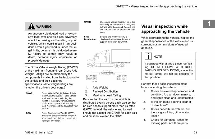
The Gross Vehicle Weight Rating (GVWR)or the maximum front and rear Gross AxleWeight Ratings are determined by thecomponents installed from the factory on tothe vehicle and their designedspecifications. (Axle weight ratings arelisted on the driver's door edge.)
GVWR Gross Vehicle Weight Rating. This isthe MAXIMUM WEIGHT your vehicleis allowed to carry, including theweight of the empty vehicle, loadingplatform, occupants, fuel, and anyload. Never exceed the GVWR of yourvehicle.
GCW Gross Combination Weight (GCW).This is the actual combined weight ofyour vehicle and its load: vehicle, plustrailer(s), plus cargo.
GAWR Gross Axle Weight Rating. This is thetotal weight that one axle is designedto transmit to the ground. You will findthis number listed on the driver's dooredge.
LoadDistribution
Be sure any load you carry isdistributed so that no axle has tosupport more than its GAWR.
1 - Axle Weight2 - Payload Distribution
3 - MAXIMUM LOAD RATING7,880 (3,574)4,120 (1,869)
12,000 (5,443)
Lbs (Kg)
7,540 (3,420)24,348 (11,061)31,925 (14,481)
Lbs (Kg)
(1)
(3)(2)
1. Axle Weight2. Payload Distribution3. Maximum Load Rating
Be sure that the load on the vehicle isdistributed evenly across each axle so thatno axle has to support more than its ratedGAWR. In total, the vehicle and its loadshould not exceed the GAWR for each axleand must not exceed the GCW.
Visual inspection whileapproaching the vehicleWhile approaching the vehicle, inspect thegeneral appearance of the vehicle and itssurroundings for any signs of neededattention.
NOTE
If equipped with a three-piece roof fair-ing, DO NOT DRIVE WITH ROOFFAIRING FOLDED DOWN, since themarker lamps will not be effective inthat position.
Perform these basic inspection stepsbefore operating the vehicle.
1. Check the overall appearance andcondition. Are windows, mirrors,and lights clean and unobstructed?
2. Is the air-intake opening clear ofobstructions?
3. Check beneath the vehicle. Arethere signs of fuel, oil, or waterleaks?
4. Check for damaged, loose, ormissing parts. Are there parts
SAFETY - Visual inspection while approaching the vehicle
Y53-6113-1A1 (11/20) 23
1
showing signs of excessive wear orlack of lubrication? Have a qualifiedmechanic examine anyquestionable items and repair themwithout delay.
5. Check your load. Is it securedproperly?
Daily Checks
NOTE
These checks are in addition to, not inplace of, Federal Motor Carrier SafetyRegulations. These regulations maybe purchased by writing to: Superin-tendent of Documents U.S. Govern-ment Printing Office Bookstore 710 N.Capitol St. N.W. Washington, DC20402, or [email protected].
Engine• Engine oil• Engine coolant• Power steering fluid• Engine belt
• Fuel filter (water separator) FuelSystem on page 249
• Windshield washer fluid• Battery cables - check the
condition of the battery andalternator cables for signs ofchafing or rubbing. Make sure thatall clamps (straps) holding thecables are present and in goodworking order.
• Hood latch• Brake lines and hoses• Steering components - (pitman
arm, drag link, tie rod, steeringshaft, power steering hoses, etc.).
• Hydraulic clutch fluid
Chassis and Cab Exterior• Lights – are any exterior lights
cracked or damaged? Perform anExterior Lights Self Test (ELST)using the dash mounted rotaryswitch, next to the steering wheel(See ELST).
NOTE
On certain vehicles equippedwith LED technology, tail lights
may emit a faint glow when thedoor is open and the domelight is illuminated.
• Window and mirrors - clean andadjusted?
• Tires, wheels and hubs Tires onpage 266 Wheels on page 269
• Suspension components - checkfor loose or missing fasteners.Check damage to springs or othersuspension parts such as cracks,gouges, distortions, bulges orchafing.
• Brake lines and hoses - checklines, linkages, chambers, parkingand service brake operation.
• Air system - Air System on page204
• Steps and grab handles.• Frame mounted tanks (fuel, diesel
exhaust fluid, etc) - checkunderneath the vehicle for signs offluid leaks. If any are found, correctbefore operating the vehicle. Is thetank fill cap secure? Are the tankstraps tight? Is the strap webbing inplace?
• Trailer connections - are theysecure and the lines clear? If theyare not being used, are they stored
SAFETY - Daily Checks
24 Y53-6113-1A1 (11/20)
1
properly? Is the trailer spare wheelsecure and inflated? Is the landinggear up and the handle secured?
• Fifth wheel - Is the kingpin or thesliding fifth wheel locked?
Cab Interior• Seat - adjust the seat for easy
reach of controls and visibility.• Seat belts - fasten and adjust
safety restraint belts (which mayinclude restraints in the sleeper).
• Steering column - adjust for easyreach and visibility.
• Mirrors - check and readjustmirrors if necessary.
• Lamps - turn ignition key to the ONposition to allow the bulb checkand systems check to run. Resolveany issues. Perform an ELST tocheck the operation of exteriorlights.
• Instruments - check all instruments.See Systems Check on page 26.
• Windshield - check operation ofwindshield wipers and washers.
• Horn - check operation of horn.• Fuel - check vehicle's fuel level. Is
there enough fuel?
• Diesel exhaust fluid - check level.Is there enough fluid?
• Air conditioning filters in the cab.
Weekly Checks
NOTE
These checks are in addition to, not inplace of, Federal Motor Carrier SafetyRegulations. These regulations maybe purchased by writing to: Superin-tendent of Documents U.S. Govern-ment Printing Office Bookstore 710 N.Capitol St. N.W. Washington, DC20402, or [email protected].
Engine• Belts• Hoses• Clamps• Radiator• Air filter and its housing• Engine Aftertreatment system
components• Exhaust pipes
• Engine air pre-cleaner (option) -For vocational vehicles withoptional engine air pre-cleaner,check the purge valve at thebottom of the hood mountedengine air pre-cleaner for anyobstructions. Make sure the purgevalve will open and close asneeded to purge dirt and waterfrom the engine intake air.
• Automatic transmission fluid(where applicable) - Check level,after the engine has warmed up tooperating temperature.
Chassis and Cab Exterior• Battery - check battery and
terminals.• Wheel cap nuts - are they all in
place and torqued properly -tighten if necessary. Wheels onpage 269
• Controls and wiring - check forcondition and adjustment
• Steering components - checkpitman arm, drag link, intermediateshaft U-joint pinch bolt, tie rod,steering shaft and power steeringhoses, etc., for loose, broken, ormissing parts.
SAFETY - Weekly Checks
Y53-6113-1A1 (11/20) 25
1
• Cab air conditioner fresh air filter -check for condition andcleanliness.
• PACCAR 20k Front Axle KingpinJoint Grease/Tie Rod Ends (option)(VOCATIONAL USE) - Forvocational vehicles with this axle,grease with Heavy-DutyMultipurpose Lithium Based: #1 or#2 grade, every 50 hours. (Refer toFront Axle and Suspension onpage 252 for maintenanceinstructions.)
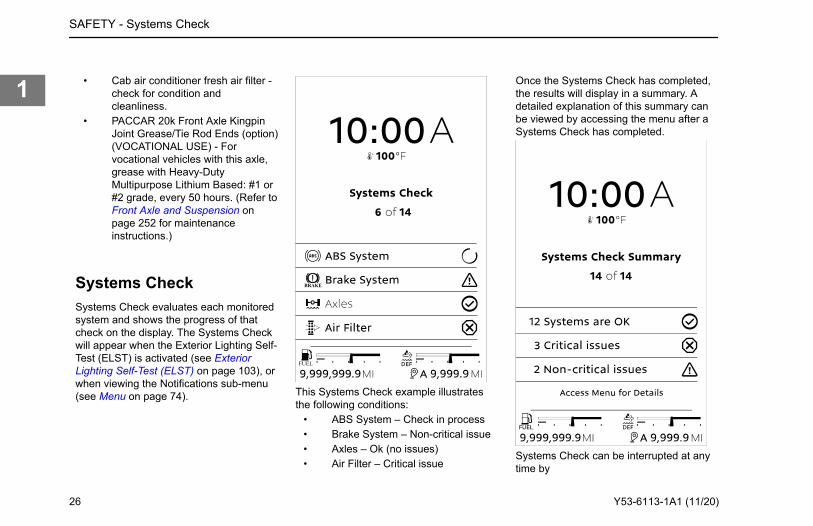
Systems CheckSystems Check evaluates each monitoredsystem and shows the progress of thatcheck on the display. The Systems Checkwill appear when the Exterior Lighting Self-Test (ELST) is activated (see ExteriorLighting Self-Test (ELST) on page 103), orwhen viewing the Notifications sub-menu(see Menu on page 74).
FUEL
BRAKE
This Systems Check example illustratesthe following conditions:
• ABS System – Check in process• Brake System – Non-critical issue• Axles – Ok (no issues)• Air Filter – Critical issue
Once the Systems Check has completed,the results will display in a summary. Adetailed explanation of this summary canbe viewed by accessing the menu after aSystems Check has completed.
Systems Check can be interrupted at anytime by
SAFETY - Systems Check
26 Y53-6113-1A1 (11/20)
1
• Pressing Select.• Switching the exterior lights OFF.• Turning the ignition key to OFF or
ACC.• Releasing the parking brake.
SAFETY - Systems Check
Y53-6113-1A1 (11/20) 27
1
Chapter 2 | EMERGENCYRoadside Assistance...........................................................................................................................29Low Air Alarm .....................................................................................................................................29Stop Engine Light................................................................................................................................30Low Oil Pressure.................................................................................................................................30Check Engine Lamp Turns On............................................................................................................30Engine is Overheating.........................................................................................................................31How to Inspect and Replace a Fuse................................................................................................... 32Where are the Fuses Located?...........................................................................................................34How to Jump Start a Battery............................................................................................................... 34How to Recover a Vehicle...................................................................................................................36
EMERGENCY -
28 Y53-6113-1A1 (11/20)
2
Roadside AssistanceCall toll-free to talk to someone at thePACCAR Customer Center.
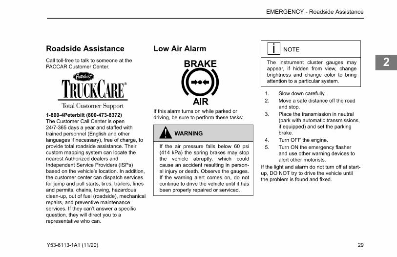
Low Air Alarm
If this alarm turns on while parked ordriving, be sure to perform these tasks:
WARNING
If the air pressure falls below 60 psi(414 kPa) the spring brakes may stopthe vehicle abruptly, which couldcause an accident resulting in person-al injury or death. Observe the gauges.If the warning alert comes on, do notcontinue to drive the vehicle until it hasbeen properly repaired or serviced.
NOTE
The instrument cluster gauges mayappear, if hidden from view, changebrightness and change color to bringattention to a particular system.
1. Slow down carefully.2. Move a safe distance off the road
and stop.3. Place the transmission in neutral
(park with automatic transmissions,if equipped) and set the parkingbrake.
4. Turn OFF the engine.5. Turn ON the emergency flasher
and use other warning devices toalert other motorists.
If the light and alarm do not turn off at start-up, DO NOT try to drive the vehicle untilthe problem is found and fixed.
EMERGENCY - Roadside Assistance
1-800-4Peterbilt (800-473-8372)The Customer Call Center is open24/7-365 days a year and staffed with trained personnel (English and other languages if necessary), free of charge, to provide total roadside assistance. Their custom mapping system can locate the nearest Authorized dealers and Independent Service Providers (ISPs) based on the vehicle's location. In addition, the customer center can dispatch services for jump and pull starts, tires, trailers, fines and permits, chains, towing, hazardous clean-up, out of fuel (roadside), mechanical repairs, and preventive maintenance services. If they can’t answer a specific question, they will direct you to a representative who can.
Y53-6113-1A1 (11/20) 29
2
Stop Engine Light
This warning light illuminates when theengine has a serious problem. This is anemergency and the vehicle should besafely stopped at the soonest opportunity.
WARNING
This should be considered an emer-gency. You should stop the vehicle assafely as possible and turn OFF the ig-nition. The vehicle must be servicedand the problem corrected before driv-ing again. Failure to do so may causesevere engine or Diesel Particulate Fil-ter damage, or cause an accidentwhich may result in death or personalinjury.
Low Oil Pressure
CAUTION
Continuing to operate your vehicle withinsufficient oil pressure will cause seri-ous engine damage. Failure to complymay result in equipment or propertydamage.
It is important to maintain oil pressurewithin acceptable limits. If oil pressuredrops below the minimum psi (kPa) the oilpressure gauge will illuminate and changecolor. Additionally, the Stop Engine Lampwill turn red.
NOTE
The instrument cluster gauges mayappear, if hidden from view, changebrightness and change color to bringattention to a particular system.
1. Slow down carefully.
2. Move a safe distance off the roadand stop.
3. Place the transmission in neutral(park with automatic transmissions,if equipped) and set the parkingbrake.
4. Turn OFF the engine.5. Turn ON the emergency flasher
and use other warning devices toalert other motorists.
6. Wait a few minutes to allow oil todrain into the engine oil pan, andthen check the oil level.
7. Add oil if necessary. If the problempersists, contact an authorizeddealer as soon as possible.
Check Engine Lamp TurnsOn
Vehicle should be serviced to correct theproblem but the situation should not beconsidered an emergency. The vehicle canstill be safely driven.
EMERGENCY - Stop Engine Light
30 Y53-6113-1A1 (11/20)
2
Engine is Overheating
CAUTION
The cooling system may overheat ifthe engine coolant is at the minimumlevel. A sudden loss of coolant,caused by a split hose or broken hoseclamp could also lead to an overheatcondition. Always inspect to ensurehoses and clamps are not cracked,worn, or loose. Failure to comply mayresult in equipment or property dam-age.
NOTE
The system may also temporarily over-heat during severe operating condi-tions such as:• Climbing a hill on a hot day
• Stopping after high-speed/high-load driving
• Debris blocking air flow throughthe cooling module (radiator)
If the engine coolant temperature warninglamp comes on and the audible alarmsounds showing an overheat condition, orif you have any other reason to suspect theengine may be overheating, DO NOTTURN OFF THE ENGINE unless a lowwater warning device indicates a loss ofcoolant.Follow these steps if the engine coolanttemperature is rising, or the temperature isalready above normal, and there are noother warning alarms displayed in theinstrument cluster.
NOTE
The instrument cluster gauges mayappear, if hidden from view, changebrightness and change color to bringattention to a particular system.
1. Reduce engine speed, or stop.When stopped, place thetransmission in neutral (N) and set
the parking brake. Keep the enginerunning.
WARNING
To reduce the chance of personal in-jury, vehicle damage, and/or deathfrom overheated engines, which canresult in a fire, never leave the engineidling without an alert driver present. Ifthe engine does overheat, as indicatedby the engine coolant temperaturelamp, immediate action is required tocorrect the condition. Continued unat-tended operation of the engine, evenfor a short time, may result in seriousengine damage or a fire. Failure tocomply may result in death, personalinjury, equipment or property damage.
EMERGENCY - Engine is Overheating
Y53-6113-1A1 (11/20) 31
2
WARNING
Removing the fill cap on a hot enginecan cause scalding coolant to sprayout and burn you badly. If the enginehas been in operation within the previ-ous 30 minutes, be very careful in re-moving the fill cap. Protect face,hands, and arms against escaping flu-id and steam by covering the cap witha large, thick rag. DO NOT try to re-move it until the surge tank cools downor if you see any steam or coolant es-caping. Always remove the cap veryslowly and carefully. Be ready to backoff if any steam or coolant begins toescape. Failure to comply may resultin death, personal injury, equipment orproperty damage.
NOTE
Keep the engine running at idle speedunless a warning icon turns on that re-quires the engine to be shut off.
2. Check to ensure the Oil PressureGauge reads normal.
3. Make sure the engine fan is turningby switching the Engine FanSwitch from AUTO to MAN(Manual).
4. Idle the engine to see if thisreduces the coolant temperature. Ifthe temperature does not begin todrop, shut off the engine andcontact your nearest authorizeddealer.
5. If the temperature begins to returnto normal, allow the engine to idle 3to 5 minutes before shutting it off.This allows the engine to coolgradually and uniformly.
6. If overheating came from severeoperating conditions, thetemperature should have cooled bythis time. If it has not, stop theengine and let it cool beforechecking to see if the coolant islow.
7. Be sure the vehicle is parked onlevel ground or the readings maybe incorrect. Check the coolantlevel at the coolant surge tank.
Check the coolant level after each tripwhen the engine has cooled. The coolantlevel should be visible within the surgetank. Add coolant if necessary.
How to Inspect andReplace a FuseTurn the ignition off and turn all lights off.Locate the fuses in either the cab, sleeper,or main power fuse box.All the electrical circuits have fuses toprotect them from a short circuit oroverload. If something electrical on yourchassis stops working, the first thing youshould check for is a blown fuse.
WARNING
DO NOT replace a fuse with a fuse ofa higher rating. Doing so may damagethe electrical system and cause a fire.Failure to comply may result in death,personal injury, equipment or propertydamage.
CAUTION
Never patch fuses with aluminum foilor wire. This may cause serious dam-age elsewhere in the electrical circuit,and it may cause a fire.
EMERGENCY - How to Inspect and Replace a Fuse
32 Y53-6113-1A1 (11/20)
2
CAUTION
If a circuit keeps blowing fuses, havethe electrical system inspected for ashort circuit or overload by an author-ized dealer as soon as possible. Fail-ure to do so could cause serious dam-age to the electrical system and/or ve-hicle.
CAUTION
Before replacing a fuse, turn OFF alllights and accessories and remove theignition key to avoid damaging theelectrical system.
1. Turn off all lights and accessoriesand remove the ignition key toavoid damaging the electricalsystem.
2. Determine from the chart on thefuse panel which fuse controls thatcomponent.
• If the circuit has a fuse, removethat fuse and see if it is blown.
• If the circuit has a polyswitch,have your electrical system
inspected by an authorizeddealer.
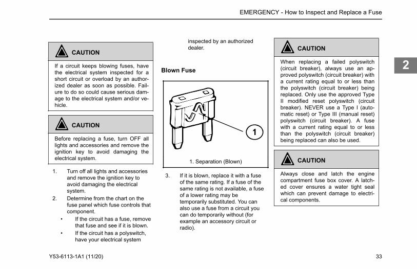
Blown Fuse
1. Separation (Blown)
3. If it is blown, replace it with a fuseof the same rating. If a fuse of thesame rating is not available, a fuseof a lower rating may betemporarily substituted. You canalso use a fuse from a circuit youcan do temporarily without (forexample an accessory circuit orradio).
CAUTION
When replacing a failed polyswitch(circuit breaker), always use an ap-proved polyswitch (circuit breaker) witha current rating equal to or less thanthe polyswitch (circuit breaker) beingreplaced. Only use the approved TypeII modified reset polyswitch (circuitbreaker). NEVER use a Type I (auto-matic reset) or Type III (manual reset)polyswitch (circuit breaker). A fusewith a current rating equal to or lessthan the polyswitch (circuit breaker)being replaced can also be used.
CAUTION
Always close and latch the enginecompartment fuse box cover. A latch-ed cover ensures a water tight sealwhich can prevent damage to electri-cal components.
EMERGENCY - How to Inspect and Replace a Fuse
Y53-6113-1A1 (11/20) 33
2
Where are the FusesLocated?Fuses for the cab are located in the fusepanel behind the drivers side kick panel.Main power relays are located on thepower distribution center, in the enginecompartment, mounted to the front wall ofthe cab.
How to Jump Start aBatteryJump starting a vehicle is not arecommended practice due to the variousbattery installations and electrical options.However, if the vehicle battery isdischarged (dead), the vehicle may bejump started (using energy from a goodbattery in another vehicle).
WARNING
Batteries contain acid that can burnand gases that can explode. Ignoringsafety procedures may result in death,
personal injury, equipment or propertydamage.
WARNING
Never jump start a battery near fire,flames, or electrical sparks. Batteriesgenerate explosive gases that couldexplode. Keep sparks, flames, andlighted cigarettes away from batteries.Failure to comply may result in proper-ty damage, personal injury, or death.
WARNING
Never remove or tamper with batterycaps. Ignoring this could allow batteryacid to contact eyes, skin, fabrics, orpainted surfaces. Failure to complymay result in death, personal injury,equipment or property damage. Becareful that metal tools (or any metal incontact with the positive terminal) donot contact the positive battery termi-nal and any other metal on the vehicleat the same time. Remove metal jew-elry and avoid leaning over the battery.
WARNING
When jump starting using a batterycharger/booster, verify that the batterycharger/booster is set to the same jumpstart voltage and amperage specifica-tions as the vehicle electrical systemand batteries (i.e., if the vehicle electri-cal system is a 12 volt system, the jumpstart voltage on the battery charger/booster shall be set at no higher than a12 volt setting). Failure to comply maycause an explosion and/or fire resultingin death, personal injury, and/or equip-ment or property damage.
WARNING
Heed all warnings and instructions ofthe jumper cable manufacturer. Failureto comply may result in death, person-al injury, equipment or property dam-age.
EMERGENCY - Where are the Fuses Located?
34 Y53-6113-1A1 (11/20)
2
CAUTION
Applying a higher voltage booster bat-tery will cause expensive damage tosensitive electronic components, suchas relays and the radio. Failure tocomply may result in equipment dam-age.
CAUTION
Improper hook-up of jumper cables ornot following these procedures candamage the alternator or cause seri-ous damage to both vehicles.
1. Remove any jewelry that maycome in contact with the batteryterminals.
2. Select a jumper cable that is longenough to attach to both vehicles ina way that ensures neither vehicletouches each other.
3. Position the two vehicles together,but do not allow them to touch.
4. Turn OFF all lights, heater, radio,and any other accessory on bothvehicles.
5. Set the parking brake.6. Shift the transmission into park
position or neutral for manualtransmissions.
7. If either vehicle is equipped withbattery disconnects ensure theyare in the OFF position prior toconnecting the two vehicles.
8. Attach one end of a jumper cableto the positive (+) terminal of thedischarged (dead) battery. This willhave a large red + or P on thebattery case, post, or clamp.
9. Attach the other end of the samecable to the positive (+) terminal ofthe good (booster) battery.
10. Attach the remaining jumper cableFIRST to the negative (-) terminal(black or N) of the good battery.
11. Attach the other end of thenegative cable to a bare metal partnot bolted to the engine block.
NOTE
Always connect positive (+) to positive(+) and negative (-) to negative (-).
12. If either vehicle is equipped withbattery disconnects, ensure thatthey are in the ON position.
13. Start the vehicle that has the goodbattery first. Let it run for 5 minutes.
14. Start the vehicle that has thedischarged (dead) battery.
The engine should start. If the engine failsto start, do not continue to crank thestarter. Instead, contact the nearestauthorized dealer.
WARNING
When disconnecting jumper cables,make sure they do not get caught inany moving parts in the engine com-partment. Failure to comply may resultin death, personal injury, equipment orproperty damage.
Reverse the above procedure exactlywhen removing the jumper cables. Withengine running, disconnect jumper cablesfrom both vehicles in the exact reverseorder, making sure to first remove thenegative cable from the vehicle with thedischarged battery.
EMERGENCY - How to Jump Start a Battery
Y53-6113-1A1 (11/20) 35
2
How to Recover a Vehicle
CAUTION
Remove the drive axle shafts or lift thedriving wheels off the ground beforetowing the vehicle. Towing the vehiclewith either the wheels on the ground orthe axle shafts in the axles will causedamage to the axle gears.
CAUTION
If your vehicle has a Meritor axle witha driver-controlled main differentiallock, install the caging bolt before re-moving the axles for towing, see Howto Manually Lock a Differential. Instal-ling the caging bolt prevents damageby locking internal axle components inposition.
CAUTION
Connect recovery rigging only to hitch-es intended for that purpose. DO NOT
attach to bumpers or brackets. Useonly equipment designed for this pur-pose. Failure to comply may result inequipment damage.
WARNING
Before towing a vehicle, test your airbrakes to ensure that you have proper-ly connected and inspected the recov-ery vehicle’s brake system. Failure todo so could lead to a loss of vehiclecontrol which may result in an accidentinvolving death or personal injury.
All lubricating and clutch application oilpressure is provided by an engine-drivenpump, which will not work when the engineis stopped. You could seriously damageyour vehicle by towing it with the drivelineconnected and the drive wheels on theground. Worse, when vehicles are towed,either by wrecker or piggyback, thelubricant in the top front of the drive axlewill drain to the rear. This will leave the topcomponents dry. The resulting friction maydamage them. Always remove the maindrive axle shafts before towing yourvehicle.
1. Review and understand all thecautions and warnings of thissection.
2. Disconnect the drive axle shaftsand cover the open hubs. This isnecessary because if thetransmission is driven by thedriveshaft (rear wheels on theground), no lubricant will reach thegears and bearings, causingdamage to the transmission. .
See How to Prepare the Axles for Towingon page 39
3. Connect the towing chain or cableusing best recovery practices .
See Best Practices for Recovery Riggingon page 41
4. Make sure the recovered vehicle'sparking brakes are released. .
See Manually Release the Parking Brakeon page 37
5. If you desire to use the recoveredvehicle’s brakes, ensure that thevehicle’s air system is connected tothat of the recovery vehicle. Ensurethat any air line that has beenremoved from a driver-controlledmain differential lock is firmlycapped to prevent loss of airpressure from the recovery vehicle
EMERGENCY - How to Recover a Vehicle
36 Y53-6113-1A1 (11/20)
2
if it is supplying air pressure. If youdon’t desire to use the recoveredvehicle’s brakes, ensure that youcage the spring brakes beforeattempting to move the vehicle.
See How to Manually Lock a Differential onpage 40
6. Follow state/provincial and locallaws that apply to vehicles in tow.
7. Do not tow vehicles at speeds inexcess of 55 mph (90 km/h).
For additional information concerningheavy duty truck recovery, refer to thefollowing Technology & MaintenanceCouncil (TMC) literature.
• Recommended Practice #602–A —“Front Towing Devices For Trucksand Tractors”
• Recommended Practice #602–B —“Recovery Attachment Points ForTrucks, Tractors, and CombinationVehicles"
• Recommended Practice #626 —“Heavy Duty Truck TowingProcedures”
[email protected] Website: http://tmc.truckline.com
Manually Release the ParkingBrakeThere may be times when there is notenough air pressure, or the engine's aircompressor is not able to produce enoughpressure, to release the parking brakes. Insuch cases, the parking brakes (or SpringBrakes) can be manually released.
WARNING
DO NOT drive vehicle with malfunc-tioning brakes. If one of the brake cir-cuits becomes inoperative, brakingdistances will increase substantiallyand handling characteristics whilebraking will be affected. You could losecontrol of your vehicle or cause an ac-cident. Have it towed to the nearestdealer or qualified repair facility for re-pair. Failure to comply may result inproperty damage, personal injury, ordeath.
WARNING
DO NOT operate a vehicle when thespring brakes have been manually re-leased. Driving a vehicle after itsspring brakes are manually released isextremely dangerous. The brakes maynot function. Failure to comply may re-sult in death, personal injury, equip-ment or property damage.
WARNING
DO NOT disassemble a spring brakechamber. These chambers contain apowerful spring that is compressed.Sudden release of this spring may re-sult in death or personal injury.
EMERGENCY - How to Recover a Vehicle
Copies of these can be obtained from thefollowing address: Technology &Maintenance Council 950 N. Glebe Road(703) 838-1763 Arlington, VA 22203 Email:
Y53-6113-1A1 (11/20) 37
2
WARNING
Releasing the spring brakes on an un-secured vehicle could lead to an acci-dent. The vehicle could roll, which mayresult in death, personal injury, equip-ment or property damage. Always se-cure the vehicle with wheel chocks,chains, or other safe means to preventrolling before manually releasing thespring brakes.
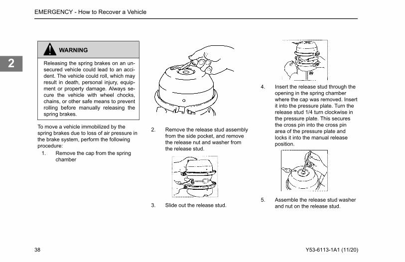
To move a vehicle immobilized by thespring brakes due to loss of air pressure inthe brake system, perform the followingprocedure:
1. Remove the cap from the springchamber
2. Remove the release stud assemblyfrom the side pocket, and removethe release nut and washer fromthe release stud.
3. Slide out the release stud.
4. Insert the release stud through theopening in the spring chamberwhere the cap was removed. Insertit into the pressure plate. Turn therelease stud 1/4 turn clockwise inthe pressure plate. This securesthe cross pin into the cross pinarea of the pressure plate andlocks it into the manual releaseposition.
5. Assemble the release stud washerand nut on the release stud.
EMERGENCY - How to Recover a Vehicle
38 Y53-6113-1A1 (11/20)
2
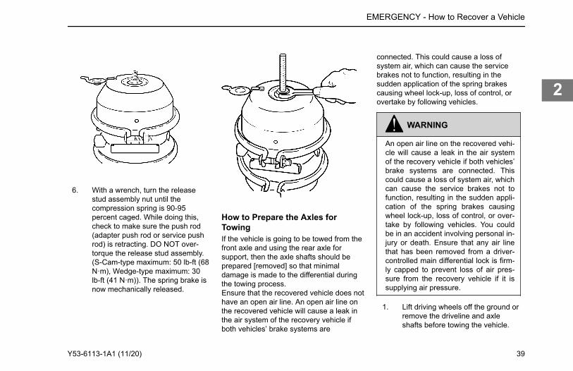
6. With a wrench, turn the releasestud assembly nut until thecompression spring is 90-95percent caged. While doing this,check to make sure the push rod(adapter push rod or service pushrod) is retracting. DO NOT over-torque the release stud assembly.(S-Cam-type maximum: 50 lb-ft (68N·m), Wedge-type maximum: 30lb-ft (41 N·m)). The spring brake isnow mechanically released.
How to Prepare the Axles forTowingIf the vehicle is going to be towed from thefront axle and using the rear axle forsupport, then the axle shafts should beprepared [removed] so that minimaldamage is made to the differential duringthe towing process.Ensure that the recovered vehicle does nothave an open air line. An open air line onthe recovered vehicle will cause a leak inthe air system of the recovery vehicle ifboth vehicles’ brake systems are
connected. This could cause a loss ofsystem air, which can cause the servicebrakes not to function, resulting in thesudden application of the spring brakescausing wheel lock-up, loss of control, orovertake by following vehicles.
WARNING
An open air line on the recovered vehi-cle will cause a leak in the air systemof the recovery vehicle if both vehicles’brake systems are connected. Thiscould cause a loss of system air, whichcan cause the service brakes not tofunction, resulting in the sudden appli-cation of the spring brakes causingwheel lock-up, loss of control, or over-take by following vehicles. You couldbe in an accident involving personal in-jury or death. Ensure that any air linethat has been removed from a driver-controlled main differential lock is firm-ly capped to prevent loss of air pres-sure from the recovery vehicle if it issupplying air pressure.
1. Lift driving wheels off the ground orremove the driveline and axleshafts before towing the vehicle.
EMERGENCY - How to Recover a Vehicle
Y53-6113-1A1 (11/20) 39
2
CAUTION
Failure to lift the driving wheels off theground or remove the driveline andaxle shafts before towing the vehiclecould seriously damage your vehicle.All lubricating and clutch application oilpressure is provided by an engine-driven pump, which does not workwhen the engine is stopped. When ve-hicles are towed either by wrecker orpiggyback, lubricant in the top front ofthe drive axle will drain to the rear.This will leave the top components dry,resulting in friction that will seriouslydamage these components.
2. If the vehicle has driver controlleddifferential lock, then manually lockthe differential.
3. Remove drive axle shafts.4. Cover the open ends of the hubs to
prevent dirt and debris fromentering the axle.
CAUTION
Water, dirt, and other material can en-ter an open hub or axle. This can con-
taminate the axle fluid and cause pos-sible damage to components. Ensurethat the hubs are covered with plasticwhenever a drive axle shaft is re-moved.
How to Manually Lock a DifferentialFollow these procedures if the vehicle hasa driver controlled differential lock.Always lock the differential when the axlesare being removed to aid in re-installation.This procedure should be done before theaxle shafts are removed.
CAUTION
Failure to install the caging bolt whentowing vehicles with driver-controlmain differential lock can result indamage by failing to lock internal com-ponents in position.
WARNING
An open air line on the recovered vehi-cle will cause a leak in the air systemof the recovery vehicle if both vehicles’brake systems are connected. This
could cause a loss of system air, whichcan cause the service brakes not tofunction, resulting in the sudden appli-cation of the spring brakes causingwheel lock-up, loss of control, or over-take by following vehicles. You couldbe in an accident involving personal in-jury or death. Ensure that any air linethat has been removed from a driver-controlled main differential lock is firm-ly capped to prevent loss of air pres-sure from the recovery vehicle if it issupplying air pressure.
CAUTION
A recovered vehicle will have no op-erational brake system. Additionally,the rear axle spring brakes will proba-bly be applied.
• If you desire to use the recoveredvehicle’s brakes, ensure that thevehicle's air system is connected tothat of the recovery vehicle. Alsoensure that any air line that hasbeen removed from a driver-controlled main differential lock is
EMERGENCY - How to Recover a Vehicle
40 Y53-6113-1A1 (11/20)
2
firmly capped to prevent loss of airpressure from the recovery vehicle.
• If you don’t want to use therecovered vehicle’s brakes, ensurethat you cage the spring brakesbefore attempting to move thevehicle.
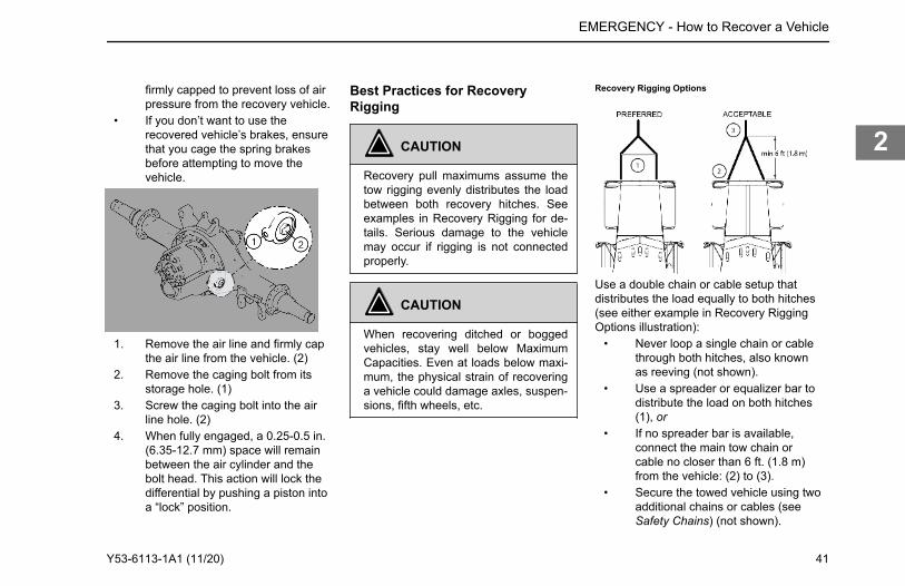
1. Remove the air line and firmly capthe air line from the vehicle. (2)
2. Remove the caging bolt from itsstorage hole. (1)
3. Screw the caging bolt into the airline hole. (2)
4. When fully engaged, a 0.25-0.5 in.(6.35-12.7 mm) space will remainbetween the air cylinder and thebolt head. This action will lock thedifferential by pushing a piston intoa “lock” position.
Best Practices for RecoveryRigging
CAUTION
Recovery pull maximums assume thetow rigging evenly distributes the loadbetween both recovery hitches. Seeexamples in Recovery Rigging for de-tails. Serious damage to the vehiclemay occur if rigging is not connectedproperly.
CAUTION
When recovering ditched or boggedvehicles, stay well below MaximumCapacities. Even at loads below maxi-mum, the physical strain of recoveringa vehicle could damage axles, suspen-sions, fifth wheels, etc.
Recovery Rigging Options
Use a double chain or cable setup thatdistributes the load equally to both hitches(see either example in Recovery RiggingOptions illustration):
• Never loop a single chain or cablethrough both hitches, also knownas reeving (not shown).
• Use a spreader or equalizer bar todistribute the load on both hitches(1), or
• If no spreader bar is available,connect the main tow chain orcable no closer than 6 ft. (1.8 m)from the vehicle: (2) to (3).
• Secure the towed vehicle using twoadditional chains or cables (seeSafety Chains) (not shown).
EMERGENCY - How to Recover a Vehicle
Y53-6113-1A1 (11/20) 41
2
Returning to Service AfterRecoveringOnce the vehicle is recovered, the axlesneed to have oil added to prevent geardamage during operation.
1. Into the pinion cage, add 1 pint (.47liter) of lubricant or into theinteraxle differential, add 2 pints(.94 liter) of approved lubricant.
2. After adding the specified type andamount of lubricant, drive thevehicle. It should be unloaded.Drive 1 to 2 miles (1.5 to 3 km) at aspeed lower than 25 mph (40km/h). This will thoroughly circulatethe lubricant through the assembly.
3. If the parking brakes weremanually released, they will needto be modified back to their normaloperating condition.
4. If the differential lock was manuallylocked, then the caging bolt needsto be put back in its storagelocation and the differential lock airline needs to be re-installed in itsnormal position.
Add lubricant back to the axles afterrecovering the vehicle and before putting itback into service.
What to do if the Vehicle is Stuck inSand, Mud, Snow or Ice
WARNING
DO NOT spin the wheels faster than35 mph (55 km/h). Spinning a tire atspeedometer readings faster than 35mph (55 km/h) can be dangerous.Tires can explode from spinning toofast. Under some conditions, a tiremay be spinning at a speed twice thatshown on the speedometer. Any re-sulting tire explosion could cause in-jury or death to a bystander or passen-ger, as well as extensive vehicle dam-age: including tire, transmission,and/or rear axle malfunction.
These suggestions are provided to improvethe ability to free a vehicle if the vehiclegets stuck in sand, mud, snow, or ice:
• Move the gearshift lever or selectorfrom First to Reverse
• Apply light pressure on theaccelerator pedal while thetransmission is in gear
• Remove your foot from theaccelerator while shifting
• Do not race the engine
• For best traction and safety, avoidspinning the wheels
Follow these practices to avoidtransmission damage:
• Always start vehicle in motion withthe shift lever in first gear.
• Be sure that transmission is fullyengaged in gear before releasingthe clutch pedal (manual only).
• Do not shift into reverse while thevehicle is moving.
• If the vehicle needs to berecovered from being stuck, do notpermit the vehicle to be towed forlong distances without removingthe driveshaft.
If tire chains are needed, make sure theyare installed on both sides of the drivingaxle. Installing chains on only one side ofthe axle can cause equipment damage.
EMERGENCY - How to Recover a Vehicle
42 Y53-6113-1A1 (11/20)
2
CAUTION
Chains on the tires of only one tandemaxle can damage the driveline U-jointsand the inter-axle differential. Repairscould be costly and time-consuming.Failure to comply may result in equip-ment damage.
Towing the VehicleA dealer or commercial towing service willhave the necessary equipment to safelytow the vehicle and should be able to makearrangements to limit any damage to thevehicle. The towing service and the dealershould be aware of towing regulations andsafety precautions.The towing service will ensure that thefollowing precautions are taken:
• Use of a safety chain system• Abide by all local towing
regulations• Ensure that the towing device does
not contact any surfaces that couldbe damaged while in transit
• If towing from the front, ensure thatthe rear axles are prepared fortowing
• If towing from the rear, ensure thatall body components such as roof,side, and chassis fairings aresecured properly to avoid damagewhile in transit
WARNING
Secure the roof, side, and chassis fair-ings while towing from the rear. An un-secured fairing may come off of thevehicle during transit. Failure to securethe fairings while towing may cause aninjurious accident resulting in death orpersonal injury.
EMERGENCY - How to Recover a Vehicle
Y53-6113-1A1 (11/20) 43
2
Chapter 3 | CONTROLSInstrument Panel.................................................................................................................................46Gauges................................................................................................................................................47Warning Lights and Indicators.............................................................................................................48Menu Control Switch...........................................................................................................................63Steering Wheel Controls (Option)....................................................................................................... 63Exterior Lights Switch (ELS)............................................................................................................... 66Peterbilt Digital Display....................................................................................................................... 67Display Notifications............................................................................................................................69Views...................................................................................................................................................70Menu................................................................................................................................................... 74Post Trip..............................................................................................................................................77Dash Switches.................................................................................................................................... 77Steering Column Controls...................................................................................................................96Door Mounted Mirror Controls...........................................................................................................101Ignition Key Switch............................................................................................................................103Exterior Lighting Self-Test (ELST).....................................................................................................103
CONTROLS -
44 Y53-6113-1A1 (11/20)
3
Heating and Air Conditioning............................................................................................................ 104Cab Accessories................................................................................................................................111
CONTROLS -
Y53-6113-1A1 (11/20) 45
3
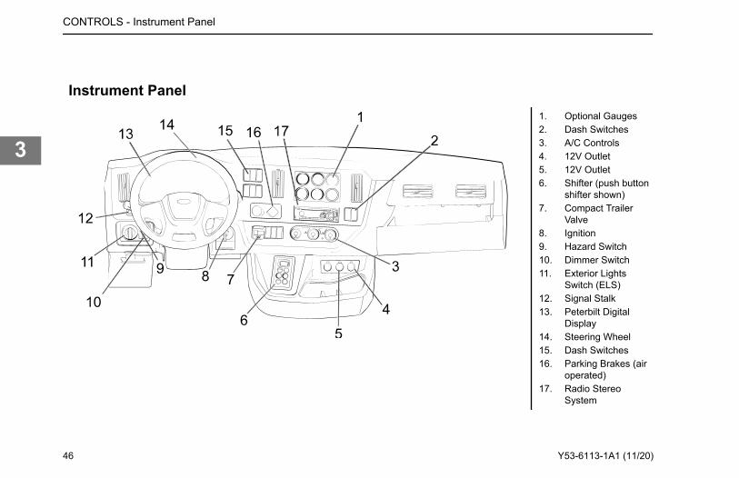
Instrument Panel1. Optional Gauges2. Dash Switches3. A/C Controls4. 12V Outlet5. 12V Outlet6. Shifter (push button
shifter shown)7. Compact Trailer
Valve8. Ignition9. Hazard Switch10. Dimmer Switch11. Exterior Lights
Switch (ELS)12. Signal Stalk13. Peterbilt Digital
Display14. Steering Wheel15. Dash Switches16. Parking Brakes (air
operated)17. Radio Stereo
System
CONTROLS - Instrument Panel
46 Y53-6113-1A1 (11/20)
3
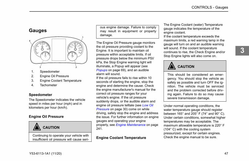
Gauges
1. Speedometer2. Engine Oil Pressure3. Engine Coolant Temperature4. Tachometer
SpeedometerThe Speedometer indicates the vehiclespeed in miles per hour (mph) and inkilometers per hour (km/h).
Engine Oil Pressure
CAUTION
Continuing to operate your vehicle withinsufficient oil pressure will cause seri-
ous engine damage. Failure to complymay result in equipment or propertydamage.
The Engine Oil Pressure gauge monitorsthe oil pressure providing coolant to theEngine. It is important to maintain oilpressure within acceptable limits. If oilpressure drops below the minimum PSI/kPa, the Stop Engine warning light willilluminate, a Popup will appear (see Popups on page 69), and an audiblealarm will sound.If the oil pressure fails to rise within 10seconds of starting the engine, stop theengine and determine the cause. Checkthe engine manufacturer's manual for thecorrect oil pressure ranges for yourvehicle's engine. If the oil pressuresuddenly drops, or the audible alarm andengine oil pressure telltale (see Low OilPressure on page 30) come on whiledriving, safely stop the engine and addressthe issue. For further information on enginegauges and operating your engineproperly, see Engine Maintenance on page241.
Engine Coolant Temperature
The Engine Coolant (water) Temperaturegauge indicates the temperature of theengine coolant.If the coolant temperature exceeds themaximum limits, a red warning lamp in thegauge will turn on and an audible warningwill sound. If the coolant temperaturecontinues to rise, the Check Engine and/orStop Engine lights will also come on.
CAUTION
This should be considered an emer-gency. You should stop the vehicle assafely as possible and turn OFF the ig-nition. The vehicle must be servicedand the problem corrected before driv-ing again. Failure to do so may causesevere transmission damage.
Under normal operating conditions, thewater temperature gauge should registerbetween 165° and 205° F (74° and 90° C).Under certain conditions, somewhat highertemperatures may be acceptable. Themaximum allowable temperature is 220° F(104° C) with the cooling systempressurized, except for certain engines.Check the engine manual to be sure.
CONTROLS - Gauges
Y53-6113-1A1 (11/20) 47
3
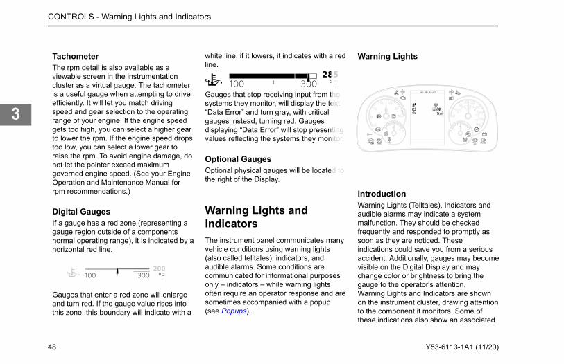
TachometerThe rpm detail is also available as aviewable screen in the instrumentationcluster as a virtual gauge. The tachometeris a useful gauge when attempting to driveefficiently. It will let you match drivingspeed and gear selection to the operatingrange of your engine. If the engine speedgets too high, you can select a higher gearto lower the rpm. If the engine speed dropstoo low, you can select a lower gear toraise the rpm. To avoid engine damage, donot let the pointer exceed maximumgoverned engine speed. (See your EngineOperation and Maintenance Manual forrpm recommendations.)
Digital GaugesIf a gauge has a red zone (representing agauge region outside of a componentsnormal operating range), it is indicated by ahorizontal red line.
Gauges that enter a red zone will enlargeand turn red. If the gauge value rises intothis zone, this boundary will indicate with a
white line, if it lowers, it indicates with a redline.
Gauges that stop receiving input from thesystems they monitor, will display the text“Data Error” and turn gray, with criticalgauges instead, turning red. Gaugesdisplaying “Data Error” will stop presentingvalues reflecting the systems they monitor.
Optional GaugesOptional physical gauges will be located tothe right of the Display.
Warning Lights andIndicatorsThe instrument panel communicates manyvehicle conditions using warning lights(also called telltales), indicators, andaudible alarms. Some conditions arecommunicated for informational purposesonly – indicators – while warning lightsoften require an operator response and aresometimes accompanied with a popup(see Popups).
Warning Lights
IntroductionWarning Lights (Telltales), Indicators andaudible alarms may indicate a systemmalfunction. They should be checkedfrequently and responded to promptly assoon as they are noticed. Theseindications could save you from a seriousaccident. Additionally, gauges may becomevisible on the Digital Display and maychange color or brightness to bring thegauge to the operator's attention.Warning Lights and Indicators are shownon the instrument cluster, drawing attentionto the component it monitors. Some ofthese indications also show an associated
CONTROLS - Warning Lights and Indicators
48 Y53-6113-1A1 (11/20)
3
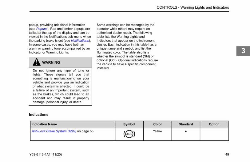
popup, providing additional information(see Popups). Red and amber popups aretallied at the top of the display and can beviewed in the Notifications sub-menu whenthe parking brake is set (see Notifications).In some cases, you may have both analarm or warning tone accompanied by anIndicator or Warning Lights.
WARNING
Do not ignore any type of tone orlights. These signals tell you thatsomething is malfunctioning on yourvehicle and provide you an indicationof what system is affected. It could bea failure of an important system, suchas the brakes, which could lead to anaccident and may result in propertydamage, personal injury, or death.
Some warnings can be managed by theoperator while others may require anauthorized dealer repair. The followingtable lists the Warning Lights andIndicators that appear on the instrumentcluster. Each indication in this table has aunique name and symbol, and list theilluminated color. The table also listswhether the symbol is standard (Std) oroptional (Opt). Optional indications requirethe vehicle to have a specific componentinstalled.
Indications
Indication Name Symbol Color Standard Option
Anti-Lock Brake System (ABS) on page 55 Yellow ●
CONTROLS - Warning Lights and Indicators
Y53-6113-1A1 (11/20) 49
3
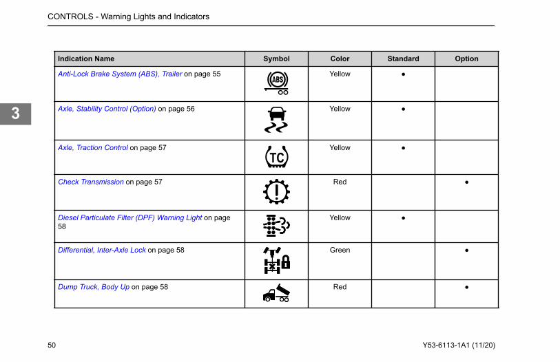
Indication Name Symbol Color Standard Option
Anti-Lock Brake System (ABS), Trailer on page 55 Yellow ●
Axle, Stability Control (Option) on page 56 Yellow ●
Axle, Traction Control on page 57 Yellow ●
Check Transmission on page 57 Red ●
Diesel Particulate Filter (DPF) Warning Light on page58
Yellow ●
Differential, Inter-Axle Lock on page 58 Green ●
Dump Truck, Body Up on page 58 Red ●
CONTROLS - Warning Lights and Indicators
50 Y53-6113-1A1 (11/20)
3
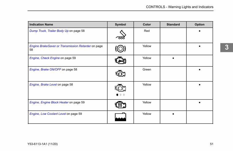
Indication Name Symbol Color Standard Option
Dump Truck, Trailer Body Up on page 58 Red ●
Engine BrakeSaver or Transmission Retarder on page58
Yellow ●
Engine, Check Engine on page 59 Yellow ●
Engine, Brake ON/OFF on page 58 Green ●
Engine, Brake Level on page 58 Yellow ●
Engine, Engine Block Heater on page 59 Yellow ●
Engine, Low Coolant Level on page 59 Yellow ●
CONTROLS - Warning Lights and Indicators
Y53-6113-1A1 (11/20) 51
3
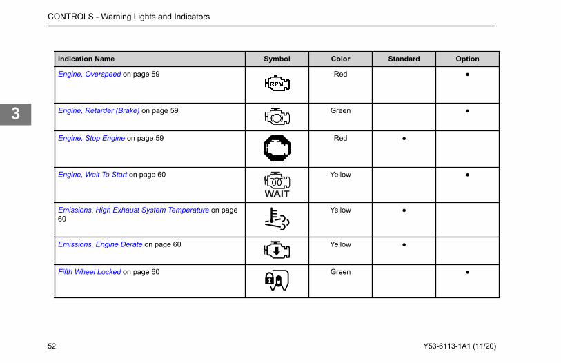
Indication Name Symbol Color Standard Option
Engine, Overspeed on page 59 Red ●
Engine, Retarder (Brake) on page 59 Green ●
Engine, Stop Engine on page 59 Red ●
Engine, Wait To Start on page 60 Yellow ●
Emissions, High Exhaust System Temperature on page60
Yellow ●
Emissions, Engine Derate on page 60 Yellow ●
Fifth Wheel Locked on page 60 Green ●
CONTROLS - Warning Lights and Indicators
52 Y53-6113-1A1 (11/20)
3
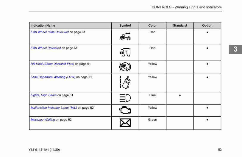
Indication Name Symbol Color Standard Option
Fifth Wheel Slide Unlocked on page 61 Red ●
Fifth Wheel Unlocked on page 61 Red ●
Hill Hold (Eaton Ultrashift Plus) on page 61 Yellow ●
Lane Departure Warning (LDW) on page 61 Yellow ●
Lights, High Beam on page 61 Blue ●
Malfunction Indicator Lamp (MIL) on page 62 Yellow ●
Message Waiting on page 62 Green ●
CONTROLS - Warning Lights and Indicators
Y53-6113-1A1 (11/20) 53
3
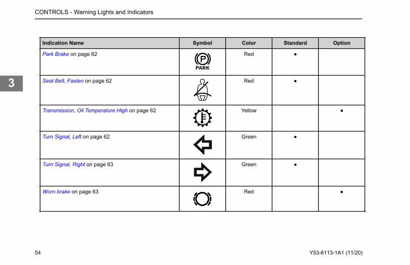
Indication Name Symbol Color Standard Option
Park Brake on page 62 Red ●
Seat Belt, Fasten on page 62 Red ●
Transmission, Oil Temperature High on page 62 Yellow ●
Turn Signal, Left on page 62 Green ●
Turn Signal, Right on page 63 Green ●
Worn brake on page 63 Red ●
CONTROLS - Warning Lights and Indicators
54 Y53-6113-1A1 (11/20)
3
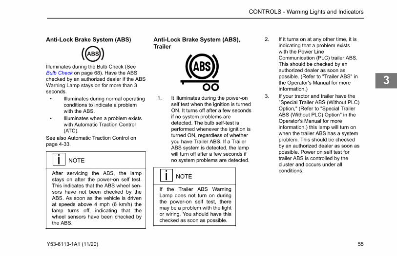
Anti-Lock Brake System (ABS)
Illuminates during the Bulb Check (See Bulb Check on page 68). Have the ABSchecked by an authorized dealer if the ABSWarning Lamp stays on for more than 3seconds.
• Illuminates during normal operatingconditions to indicate a problemwith the ABS.
• Illuminates when a problem existswith Automatic Traction Control(ATC).
See also Automatic Traction Control onpage 4-33.
NOTE
After servicing the ABS, the lampstays on after the power-on self test.This indicates that the ABS wheel sen-sors have not been checked by theABS. As soon as the vehicle is drivenat speeds above 4 mph (6 km/h) thelamp turns off, indicating that thewheel sensors have been checked bythe ABS.
Anti-Lock Brake System (ABS),Trailer
1. It illuminates during the power-onself test when the ignition is turnedON. It turns off after a few secondsif no system problems aredetected. The bulb self-test isperformed whenever the ignition isturned ON, regardless of whetheryou have Trailer ABS. If a TrailerABS system is detected, the lampwill turn off after a few seconds ifno system problems are detected.
NOTE
If the Trailer ABS WarningLamp does not turn on duringthe power-on self test, theremay be a problem with the lightor wiring. You should have thischecked as soon as possible.
2. If it turns on at any other time, it isindicating that a problem existswith the Power LineCommunication (PLC) trailer ABS.This should be checked by anauthorized dealer as soon aspossible. (Refer to "Trailer ABS" inthe Operator's Manual for moreinformation.)
3. If your tractor and trailer have the"Special Trailer ABS (Without PLC)Option," (Refer to "Special TrailerABS (Without PLC) Option" in theOperator's Manual for moreinformation.) this lamp will turn onwhen the trailer ABS has a systemproblem. This should be checkedby an authorized dealer as soon aspossible. Power on self test fortrailer ABS is controlled by thecluster and occurs under allconditions.
CONTROLS - Warning Lights and Indicators
Y53-6113-1A1 (11/20) 55
3
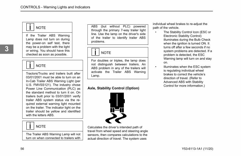
NOTE
If the Trailer ABS WarningLamp does not turn on duringthe power-on self test, theremay be a problem with the lightor wiring. You should have thischecked as soon as possible.
NOTE
Tractors/Trucks and trailers built after03/01/2001 must be able to turn on anIn-Cab Trailer ABS Warning Light (perU.S. FMVSS121). The industry chosePower Line Communication (PLC) asthe standard method to turn it on. Ontrailers built prior to 03/01/2001 verifytrailer ABS system status via the re-quired external warning light mountedon the trailer. The indicator light on thetrailer should be yellow and identifiedwith the letters ABS.
NOTE
The Trailer ABS Warning Lamp will notturn on when connected to trailers with
ABS (but without PLC) poweredthrough the primary 7-way trailer lightline. Use the lamp on the driver's sideof the trailer to identify trailer ABSproblems.
NOTE
For doubles or triples, the lamp doesnot distinguish between trailers. AnABS problem in any of the trailers willactivate the Trailer ABS WarningLamp.
Axle, Stability Control (Option)
Calculates the driver’s intended path oftravel from wheel speed and steering anglesensors, then compares calculations to theactual direction of travel. The system uses
individual wheel brakes to re-adjust thepath of the vehicle.
• The Stability Control Icon (ESC orElectronic Stability Control)illuminates during the Bulb Checkwhen the ignition is turned ON. Itturns off after a few seconds if nosystem problems are detected. If aproblem is detected, the ESCWarning lamp will turn on and stayon.
• Illuminates when the ESC systemis regulating individual wheelbrakes to correct the vehicle’sdirection of travel. (Refer toAdvanced ABS with StabilityControl for more information.)
CONTROLS - Warning Lights and Indicators
56 Y53-6113-1A1 (11/20)
3
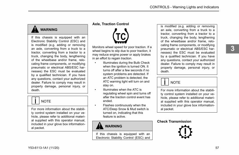
WARNING
If this chassis is equipped with anElectronic Stability Control (ESC) andis modified (e.g. adding or removingan axle, converting from a truck to atractor, converting from a tractor to atruck, changing the body, lengtheningof the wheelbase and/or frame, relo-cating frame components, or modifyingpneumatic or electrical ABS/ESC har-nesses) the ESC must be evaluatedby a qualified technician. If you haveany questions, contact your authorizeddealer. Failure to comply may result inproperty damage, personal injury, ordeath.
NOTE
For more information about the stabili-ty control system installed on your ve-hicle, please refer to additional materi-al supplied with this operator manual,included in your glove box information-al packet.
Axle, Traction Control
Monitors wheel speed for poor traction. If awheel begins to slip due to poor traction, itmay reduce engine power or apply brakesin an effort to regain traction.
• Illuminates during the Bulb Checkwhen the ignition is turned ON. Itturns off after a few seconds if nosystem problems are detected. Ifan ATC problem is detected, theATC warning light will turn on andstay on.
• Illuminates when the ATC isregulating wheel spin and turns offafter the traction control event hasended.
• Flashes continuously when theATC/Deep Snow & Mud switch isturned on, indicating that thisfeature is active.
WARNING
If this chassis is equipped with anElectronic Stability Control (ESC) and
is modified (e.g. adding or removingan axle, converting from a truck to atractor, converting from a tractor to atruck, changing the body, lengtheningof the wheelbase and/or frame, relo-cating frame components, or modifyingpneumatic or electrical ABS/ESC har-nesses) the ESC must be evaluatedby a qualified technician. If you haveany questions, contact your authorizeddealer. Failure to comply may result inproperty damage, personal injury, ordeath.
NOTE
For more information about the stabili-ty control system installed on your ve-hicle, please refer to additional materi-al supplied with this operator manual,included in your glove box information-al packet.
Check Transmission
CONTROLS - Warning Lights and Indicators
Y53-6113-1A1 (11/20) 57
3
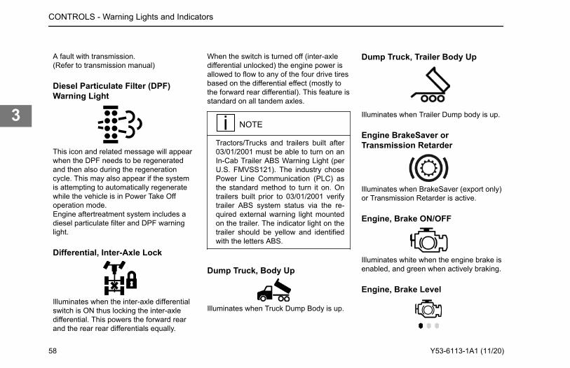
A fault with transmission.(Refer to transmission manual)
Diesel Particulate Filter (DPF)Warning Light
This icon and related message will appearwhen the DPF needs to be regeneratedand then also during the regenerationcycle. This may also appear if the systemis attempting to automatically regeneratewhile the vehicle is in Power Take Offoperation mode.Engine aftertreatment system includes adiesel particulate filter and DPF warninglight.
Differential, Inter-Axle Lock
Illuminates when the inter-axle differentialswitch is ON thus locking the inter-axledifferential. This powers the forward rearand the rear rear differentials equally.
When the switch is turned off (inter-axledifferential unlocked) the engine power isallowed to flow to any of the four drive tiresbased on the differential effect (mostly tothe forward rear differential). This feature isstandard on all tandem axles.
NOTE
Tractors/Trucks and trailers built after03/01/2001 must be able to turn on anIn-Cab Trailer ABS Warning Light (perU.S. FMVSS121). The industry chosePower Line Communication (PLC) asthe standard method to turn it on. Ontrailers built prior to 03/01/2001 verifytrailer ABS system status via the re-quired external warning light mountedon the trailer. The indicator light on thetrailer should be yellow and identifiedwith the letters ABS.
Dump Truck, Body Up
Illuminates when Truck Dump Body is up.
Dump Truck, Trailer Body Up
Illuminates when Trailer Dump body is up.
Engine BrakeSaver orTransmission Retarder
Illuminates when BrakeSaver (export only)or Transmission Retarder is active.
Engine, Brake ON/OFF
Illuminates white when the engine brake isenabled, and green when actively braking.
Engine, Brake Level
CONTROLS - Warning Lights and Indicators
58 Y53-6113-1A1 (11/20)
3
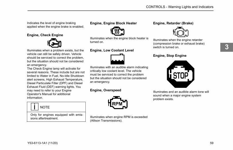
Indicates the level of engine brakingapplied when the engine brake is enabled.
Engine, Check Engine
Illuminates when a problem exists, but thevehicle can still be safely driven. Vehicleshould be serviced to correct the problem,but the situation should not be consideredan emergency.The Check Engine lamp will activate forseveral reasons. These include but are notlimited to Water in Fuel, No-Idle Shutdownalert screens, High Exhaust Temperature,Diesel Particulate Filter (DPF) and DieselExhaust Fluid (DEF) warning lights. Youmay need to refer to your EngineOperator's Manual for additionalinformation.
NOTE
Only for engines equipped with emis-sions aftertreatment.
Engine, Engine Block Heater
Illuminates when the engine block heater isturned on.
Engine, Low Coolant Level
Illuminates with an audible alarm indicatingcritically low coolant level. The vehiclemust be serviced to correct the problembut the situation should not be consideredan emergency.
Engine, Overspeed
Illuminates when engine RPM is exceeded(Allison Transmissions).
Engine, Retarder (Brake)
Illuminates when the engine retarder(compression brake or exhaust brake)switch is turned on.
Engine, Stop Engine
Illuminates and an audible alarm tone willsound when a major engine systemproblem exists.
CONTROLS - Warning Lights and Indicators
Y53-6113-1A1 (11/20) 59
3
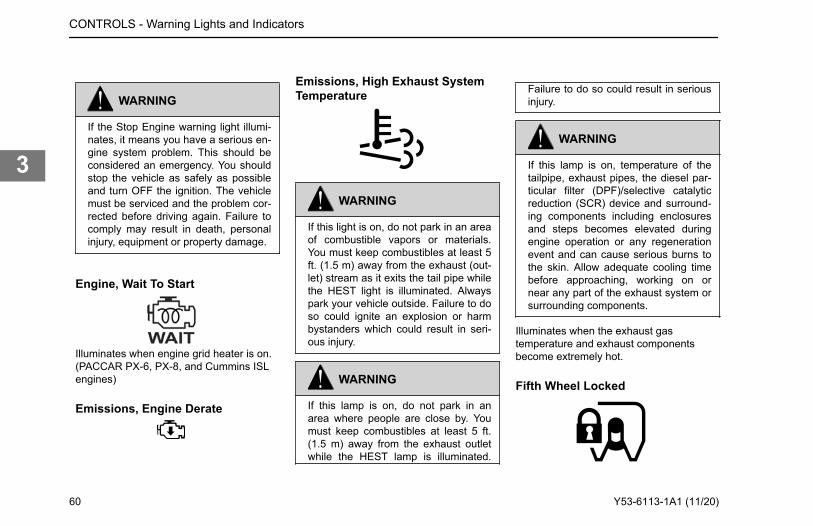
WARNING
If the Stop Engine warning light illumi-nates, it means you have a serious en-gine system problem. This should beconsidered an emergency. You shouldstop the vehicle as safely as possibleand turn OFF the ignition. The vehiclemust be serviced and the problem cor-rected before driving again. Failure tocomply may result in death, personalinjury, equipment or property damage.
Engine, Wait To Start
Illuminates when engine grid heater is on.(PACCAR PX-6, PX-8, and Cummins ISLengines)
Emissions, Engine Derate
Emissions, High Exhaust SystemTemperature
WARNING
If this light is on, do not park in an areaof combustible vapors or materials.You must keep combustibles at least 5ft. (1.5 m) away from the exhaust (out-let) stream as it exits the tail pipe whilethe HEST light is illuminated. Alwayspark your vehicle outside. Failure to doso could ignite an explosion or harmbystanders which could result in seri-ous injury.
WARNING
If this lamp is on, do not park in anarea where people are close by. Youmust keep combustibles at least 5 ft.(1.5 m) away from the exhaust outletwhile the HEST lamp is illuminated.
Failure to do so could result in seriousinjury.
WARNING
If this lamp is on, temperature of thetailpipe, exhaust pipes, the diesel par-ticular filter (DPF)/selective catalyticreduction (SCR) device and surround-ing components including enclosuresand steps becomes elevated duringengine operation or any regenerationevent and can cause serious burns tothe skin. Allow adequate cooling timebefore approaching, working on ornear any part of the exhaust system orsurrounding components.
Illuminates when the exhaust gastemperature and exhaust componentsbecome extremely hot.
Fifth Wheel Locked
CONTROLS - Warning Lights and Indicators
60 Y53-6113-1A1 (11/20)
3
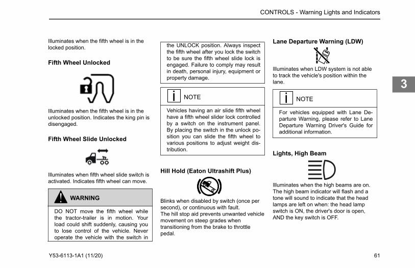
Illuminates when the fifth wheel is in thelocked position.
Fifth Wheel Unlocked
Illuminates when the fifth wheel is in theunlocked position. Indicates the king pin isdisengaged.
Fifth Wheel Slide Unlocked
Illuminates when fifth wheel slide switch isactivated. Indicates fifth wheel can move.
WARNING
DO NOT move the fifth wheel whilethe tractor-trailer is in motion. Yourload could shift suddenly, causing youto lose control of the vehicle. Neveroperate the vehicle with the switch in
the UNLOCK position. Always inspectthe fifth wheel after you lock the switchto be sure the fifth wheel slide lock isengaged. Failure to comply may resultin death, personal injury, equipment orproperty damage.
NOTE
Vehicles having an air slide fifth wheelhave a fifth wheel slider lock controlledby a switch on the instrument panel.By placing the switch in the unlock po-sition you can slide the fifth wheel tovarious positions to adjust weight dis-tribution.
Hill Hold (Eaton Ultrashift Plus)
Blinks when disabled by switch (once persecond), or continuous with fault.The hill stop aid prevents unwanted vehiclemovement on steep grades whentransitioning from the brake to throttlepedal.
Lane Departure Warning (LDW)
Illuminates when LDW system is not ableto track the vehicle's position within thelane.
NOTE
For vehicles equipped with Lane De-parture Warning, please refer to LaneDeparture Warning Driver's Guide foradditional information.
Lights, High Beam
Illuminates when the high beams are on.The high beam indicator will flash and atone will sound to indicate that the headlamps are left on when: the head lampswitch is ON, the driver's door is open,AND the key switch is OFF.
CONTROLS - Warning Lights and Indicators
Y53-6113-1A1 (11/20) 61
3
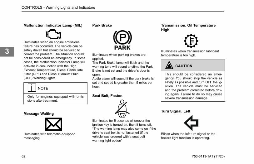
Malfunction Indicator Lamp (MIL)
Illuminates when an engine emissionsfailure has occurred. The vehicle can besafely driven but should be serviced tocorrect the problem. The situation shouldnot be considered an emergency. In somecases, the Malfunction Indicator Lamp willactivate in conjunction with the HighExhaust Temperature, Diesel ParticulateFilter (DPF) and Diesel Exhaust Fluid(DEF) Warning Lights.
NOTE
Only for engines equipped with emis-sions aftertreatment.
Message Waiting
Illuminates with telematic-equippedmessaging.
Park Brake
Illuminates when parking brakes areapplied.The Park Brake lamp will flash and thewarning tone will sound anytime the ParkBrake is not set and the driver's door isopen.Audio alarm will sound if the park brake isset and speed is greater than 5 miles perhour.
Seat Belt, Fasten
Illuminates for 5 seconds whenever theignition key is turned on, then it turns off.*The warning lamp may also come on if thedriver's seat belt is not fastened (if thevehicle was ordered with a seat beltwarning light option*
Transmission, Oil TemperatureHigh
Illuminates when transmission lubricanttemperature is too high.
CAUTION
This should be considered an emer-gency. You should stop the vehicle assafely as possible and turn OFF the ig-nition. The vehicle must be servicedand the problem corrected before driv-ing again. Failure to do so may causesevere transmission damage.
Turn Signal, Left
Blinks when the left turn signal or thehazard light function is operating.
CONTROLS - Warning Lights and Indicators
62 Y53-6113-1A1 (11/20)
3
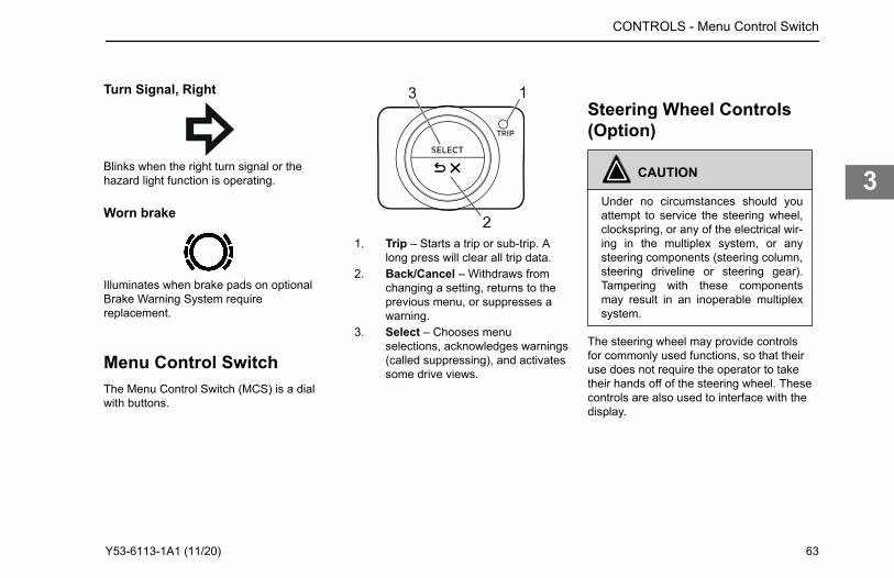
Turn Signal, Right
Blinks when the right turn signal or thehazard light function is operating.
Worn brake
1. Trip – Starts a trip or sub-trip. Along press will clear all trip data.
2. Back/Cancel – Withdraws fromchanging a setting, returns to theprevious menu, or suppresses awarning.
3. Select – Chooses menuselections, acknowledges warnings(called suppressing), and activatessome drive views.
Steering Wheel Controls(Option)
CAUTION
Under no circumstances should youattempt to service the steering wheel,clockspring, or any of the electrical wir-ing in the multiplex system, or anysteering components (steering column,steering driveline or steering gear).Tampering with these componentsmay result in an inoperable multiplexsystem.
The steering wheel may provide controlsfor commonly used functions, so that theiruse does not require the operator to taketheir hands off of the steering wheel. Thesecontrols are also used to interface with thedisplay.
CONTROLS - Menu Control Switch
Illuminates when brake pads on optional Brake Warning System require replacement.
Menu Control SwitchThe Menu Control Switch (MCS) is a dial with buttons.
Y53-6113-1A1 (11/20) 63
3
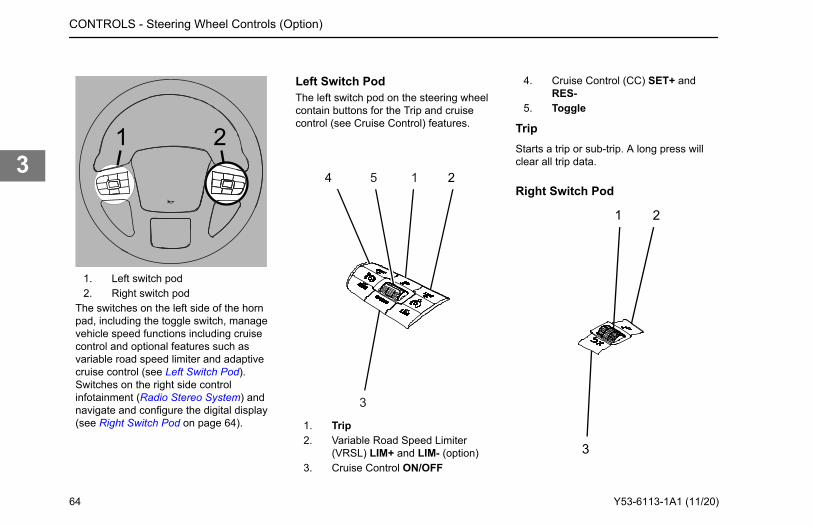
21
1. Left switch pod2. Right switch pod
The switches on the left side of the hornpad, including the toggle switch, managevehicle speed functions including cruisecontrol and optional features such asvariable road speed limiter and adaptivecruise control (see Left Switch Pod).Switches on the right side controlinfotainment (Radio Stereo System) andnavigate and configure the digital display(see Right Switch Pod on page 64).
Left Switch PodThe left switch pod on the steering wheelcontain buttons for the Trip and cruisecontrol (see Cruise Control) features.
4 25 1
3
1. Trip2. Variable Road Speed Limiter
(VRSL) LIM+ and LIM- (option)3. Cruise Control ON/OFF
4. Cruise Control (CC) SET+ andRES-
5. Toggle
TripStarts a trip or sub-trip. A long press willclear all trip data.
Right Switch Pod
1 2
3
CONTROLS - Steering Wheel Controls (Option)
64 Y53-6113-1A1 (11/20)
3
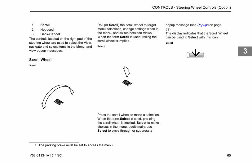
1. Scroll2. Not used3. Back/Cancel
The controls located on the right pod of thesteering wheel are used to select the View,navigate and select items in the Menu, andview popup messages.
Scroll WheelScroll
Roll (or Scroll) the scroll wheel to targetmenu selections, change settings when inthe menu, and switch between Views.When the term Scroll is used, rolling thescroll wheel is implied.Select
Press the scroll wheel to make a selection.When the term Select is used, pressingthe scroll wheel is implied. Select to makechoices in the menu; additionally, useSelect to cycle through or suppress a
popup message (see Popups on page69).1The display indicates that the Scroll Wheelcan be used to Select with this icon:Select
CONTROLS - Steering Wheel Controls (Option)
1 The parking brake must be set to access the menu.
Y53-6113-1A1 (11/20) 65
3
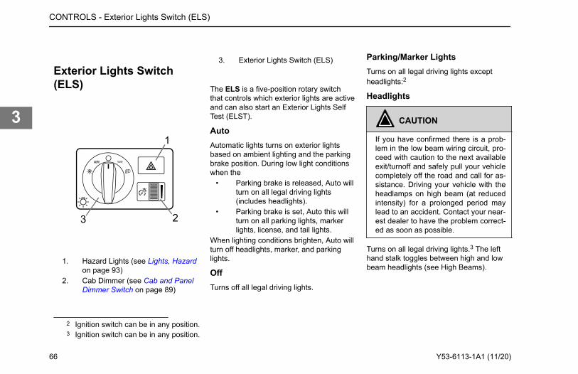
Exterior Lights Switch(ELS)
23
1. Hazard Lights (see Lights, Hazardon page 93)
2. Cab Dimmer (see Cab and PanelDimmer Switch on page 89)
3. Exterior Lights Switch (ELS)
The ELS is a five-position rotary switchthat controls which exterior lights are activeand can also start an Exterior Lights SelfTest (ELST).
AutoAutomatic lights turns on exterior lightsbased on ambient lighting and the parkingbrake position. During low light conditionswhen the
• Parking brake is released, Auto willturn on all legal driving lights(includes headlights).
• Parking brake is set, Auto this willturn on all parking lights, markerlights, license, and tail lights.
When lighting conditions brighten, Auto willturn off headlights, marker, and parkinglights.
OffTurns off all legal driving lights.
Parking/Marker LightsTurns on all legal driving lights exceptheadlights:2
Headlights
CAUTION
If you have confirmed there is a prob-lem in the low beam wiring circuit, pro-ceed with caution to the next availableexit/turnoff and safely pull your vehiclecompletely off the road and call for as-sistance. Driving your vehicle with theheadlamps on high beam (at reducedintensity) for a prolonged period maylead to an accident. Contact your near-est dealer to have the problem correct-ed as soon as possible.
Turns on all legal driving lights.3 The lefthand stalk toggles between high and lowbeam headlights (see High Beams).
2 Ignition switch can be in any position.3 Ignition switch can be in any position.
CONTROLS - Exterior Lights Switch (ELS)
66 Y53-6113-1A1 (11/20)
3
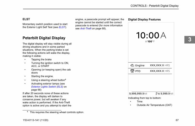
ELSTMomentary switch position used to startthe Exterior Light Self Test (see ELST).
Peterbilt Digital DisplayThe digital display will stay visible during alldriving situations and in some parkedsituations. When the parking brake is setthe following actions will wake the display,making it visible:
• Tapping the brake• Turning the ignition switch to ON,
ACC, or START• Opening (or keeping open) the cab
doors• Starting the engine.• Using a steering wheel button4
• Activating exterior lamps (seeExterior Lights Switch (ELS) onpage 66)
If after 20 seconds none of these actionsare taken, the display will darken toconserve power, but will awaken if anywake action is performed. If the Anti-Theftoption is active and you attempt to start the
engine, a passcode prompt will appear; theengine cannot be started until the correctpasscode is entered (for more informationsee Anti-Theft on page 68).
Digital Display Features
Indicating from top to bottom:• Time• Outside Air Temperature (OAT)
CONTROLS - Peterbilt Digital Display
4 This requires the steering wheel controls option.
Y53-6113-1A1 (11/20) 67
3
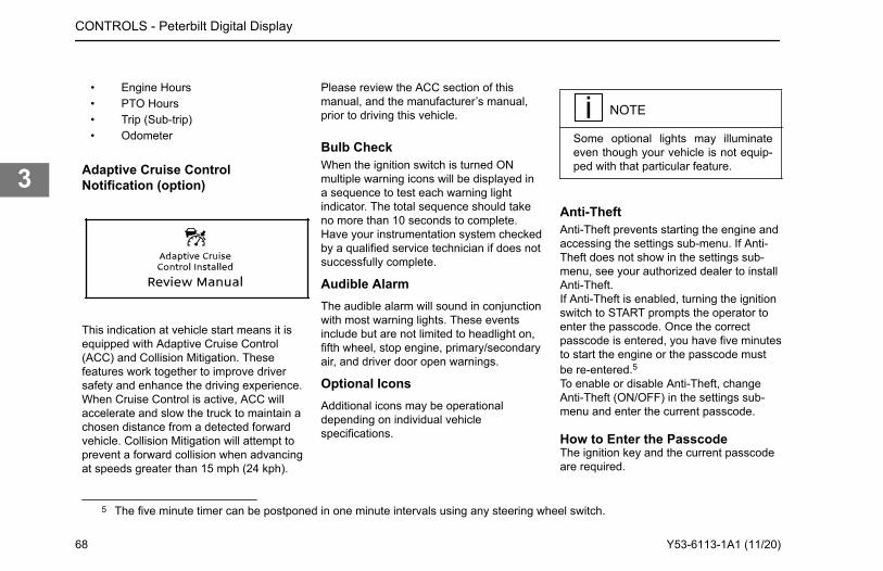
• Engine Hours• PTO Hours• Trip (Sub-trip)• Odometer
Adaptive Cruise ControlNotification (option)
This indication at vehicle start means it isequipped with Adaptive Cruise Control(ACC) and Collision Mitigation. Thesefeatures work together to improve driversafety and enhance the driving experience.When Cruise Control is active, ACC willaccelerate and slow the truck to maintain achosen distance from a detected forwardvehicle. Collision Mitigation will attempt toprevent a forward collision when advancingat speeds greater than 15 mph (24 kph).
Please review the ACC section of thismanual, and the manufacturer’s manual,prior to driving this vehicle.
Bulb CheckWhen the ignition switch is turned ONmultiple warning icons will be displayed ina sequence to test each warning lightindicator. The total sequence should takeno more than 10 seconds to complete.Have your instrumentation system checkedby a qualified service technician if does notsuccessfully complete.
Audible AlarmThe audible alarm will sound in conjunctionwith most warning lights. These eventsinclude but are not limited to headlight on,fifth wheel, stop engine, primary/secondaryair, and driver door open warnings.
Optional IconsAdditional icons may be operationaldepending on individual vehiclespecifications.
NOTE
Some optional lights may illuminateeven though your vehicle is not equip-ped with that particular feature.
Anti-TheftAnti-Theft prevents starting the engine andaccessing the settings sub-menu. If Anti-Theft does not show in the settings sub-menu, see your authorized dealer to installAnti-Theft.If Anti-Theft is enabled, turning the ignitionswitch to START prompts the operator toenter the passcode. Once the correctpasscode is entered, you have five minutesto start the engine or the passcode mustbe re-entered.5To enable or disable Anti-Theft, changeAnti-Theft (ON/OFF) in the settings sub-menu and enter the current passcode.
How to Enter the PasscodeThe ignition key and the current passcodeare required.
5 The five minute timer can be postponed in one minute intervals using any steering wheel switch.
CONTROLS - Peterbilt Digital Display
68 Y53-6113-1A1 (11/20)
3
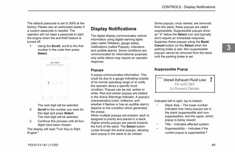
The default passcode is set to 0000 at thefactory. Please see an authorized dealer ifa custom passcode is needed. Theoperator will not need a passcode to startthe engine when the anti-theft feature isturned off.
1. Using the Scroll, scroll to the firstnumber in the code then pressSelect.
8
2
9
1
FUEL DEF
9,99 9,99 9.9 9,99 9.9MI MIA
DNR
FA 100101012:44 °
0 0 0
The next digit will be selected.2. Scroll to the number you want for
this digit and press Select.The next digit will be selected.
3. Continue this process until all fourdigits have been chosen.
The display will read "Turn Key to StartEngine."
Display NotificationsThe digital display communicates vehicleinformation using digital warning lights(also called Telltales), gauge states,notifications (called Popups), indicators,and audible alarms. Some conditions arecommunicated for informational purposesonly while others may require an operatorresponse.
PopupsA popup communicates information. Thiscould be due to a gauge indicating outsideof its normal operating range or to notifythe operator about a specific truckcondition. Popups can be red, amber orwhite. Red and amber popups are totaledin the Active Warnings Indicator. A popup'scharacteristics (color, brilliance, andwhether it flashes or has an audible alarm)depend on the condition which generatedthe popup.When multiple popups are present, each isassigned a priority and placed in a stack.Higher priority popups are placed towardsthe front of the stack. The Select buttoncycles through the active popups, allowingeach popup in the stack to be viewed.
Some popups, once viewed, are removedfrom the stack; these popups are calledsuppressible. Suppressible popups showan “X” below the Select icon and typicallydon't require an immediate response.Suppress these popups using the Back/Cancel button (or the Select when theparking brake is set). Non-suppressiblepopups cannot be removed from the stackuntil the parking brake is set.
Suppressible Popup
Indicated left to right, top to bottom:• Stack Size – The lower number
indicates how many popups are inthe stack (suppressible and non-suppressible), and the upper, whichpopup is being viewed.
• Title – Indicates affected system.• Suppressibility – Indicates if the
current popup is suppressible.6
CONTROLS - Display Notifications
Y53-6113-1A1 (11/20) 69
3

• Instructions – Contain instructionsor elaborating information.
The menu is not accessible until all popupshave been suppressed.7
Active WarningsRed and amber popups will generate anactive warning. Active warnings provide anadditional reminder of the new and ongoingconditions which have generated a popup(both suppressed an unsuppressed). Anactive warnings count is presented in the
• Systems Check• Notifications sub-menu• Post-trip• Active Warnings indicator.
The active warnings count may changewithout user interaction if individualwarnings are intermittent, time based, selfcorrecting, or the situation is rectified.
ViewsA view presents a specific set of gaugesand/or indications on the display. The
operator can cycle through the availableviews using the Scroll. When a view isshown, its position in the view sequence isindicated on the right. Some views monitoroptional systems, appearing only if thosesystems are installed and/or active. Themenu is also positioned in the viewsequence. When the parking brake is set,some views provide additional options andinformation. Use the Select to accessthese options. All views present thefollowing indications:
Indicating clockwise from the upper left:• Time• Aux Lights
6 The Select icon used here is for the Menu Control Switch (MCS); vehicles with steering wheel controls indicate differently.7 All popups become suppressible when the parking brake is set.
CONTROLS - Views
70 Y53-6113-1A1 (11/20)
3
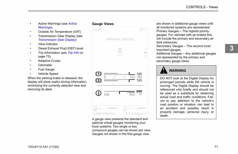
• Active Warnings (see ActiveWarnings).
• Outside Air Temperature (OAT)• Transmission Gear Display (see
Transmission Gear Display)• View Indicator• Diesel Exhaust Fluid (DEF) level.• Trip Information (see Trip Info on
page 73).• Adaptive Cruise.• Odometer• Fuel Gauge• Vehicle Speed
When the parking brake is released, thedisplay will show useful driving information,minimizing the currently selected view andremoving its label.
Gauge Views
A gauge view presents the standard andoptional virtual gauges monitoring yourtruck systems. Two single or twocompound gauges can be shown per view.Gauges not shown in the first gauge view
are shown in additional gauge views untilall monitored systems are represented:Primary Gauges – The highest prioritygauges. For vehicles with air brakes thiswill include the primary and secondary airtank pressures.Secondary Gauges – The second mostimportant gauges.Additional Gauges – Any additional gaugesnot represented by the primary andsecondary gauge views.
WARNING
DO NOT look at the Digital Display forprolonged periods while the vehicle ismoving. The Digital Display should bereferenced only briefly and should notbe used as a substitute for observingactual road and traffic conditions. Fail-ure to pay attention to the vehicle’sroad position or situation can lead toan accident and possibly result inproperty damage, personal injury, ordeath.
CONTROLS - Views
Y53-6113-1A1 (11/20) 71
3
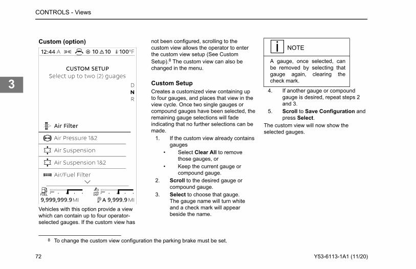
Custom (option)
Vehicles with this option provide a viewwhich can contain up to four operator-selected gauges. If the custom view has
not been configured, scrolling to thecustom view allows the operator to enterthe custom view setup (See CustomSetup).8 The custom view can also bechanged in the menu.
Custom SetupCreates a customized view containing upto four gauges, and places that view in theview cycle. Once two single gauges orcompound gauges have been selected, theremaining gauge selections will fadeindicating that no further selections can bemade.
1. If the custom view already containsgauges
• Select Clear All to removethose gauges, or
• Keep the current gauge orcompound gauge.
2. Scroll to the desired gauge orcompound gauge.
3. Select to choose that gauge.The gauge name will turn whiteand a check mark will appearbeside the name.
NOTE
A gauge, once selected, canbe removed by selecting thatgauge again, clearing thecheck mark.
4. If another gauge or compoundgauge is desired, repeat steps 2and 3.
5. Scroll to Save Configuration andpress Select.
The custom view will now show theselected gauges.
8 To change the custom view configuration the parking brake must be set.
CONTROLS - Views
72 Y53-6113-1A1 (11/20)
3
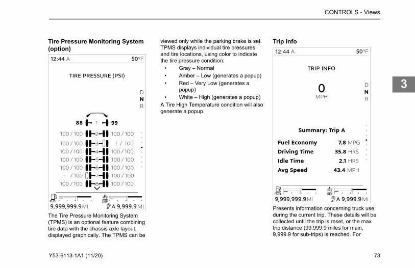
Tire Pressure Monitoring System(option)
viewed only while the parking brake is set.TPMS displays individual tire pressuresand tire locations, using color to indicatethe tire pressure condition:
• Gray – Normal• Amber – Low (generates a popup)• Red – Very Low (generates a
popup)• White – High (generates a popup)
A Tire High Temperature condition will alsogenerate a popup.
Trip Info
Presents information concerning truck useduring the current trip. These details will becollected until the trip is reset, or the maxtrip distance (99,999.9 miles for main,9,999.9 for sub-trips) is reached. For
CONTROLS - Views
The Tire Pressure Monitoring System (TPMS) is an optional feature combining tire data with the chassis axle layout, displayed graphically. The TPMS can be
Y53-6113-1A1 (11/20) 73
3
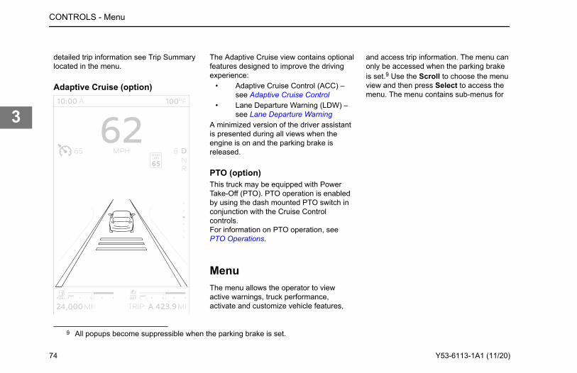
detailed trip information see Trip Summarylocated in the menu.
Adaptive Cruise (option)
The Adaptive Cruise view contains optionalfeatures designed to improve the drivingexperience:
• Adaptive Cruise Control (ACC) –see Adaptive Cruise Control
• Lane Departure Warning (LDW) –see Lane Departure Warning
A minimized version of the driver assistantis presented during all views when theengine is on and the parking brake isreleased.
PTO (option)This truck may be equipped with PowerTake-Off (PTO). PTO operation is enabledby using the dash mounted PTO switch inconjunction with the Cruise Controlcontrols.For information on PTO operation, see PTO Operations.
MenuThe menu allows the operator to viewactive warnings, truck performance,activate and customize vehicle features,
and access trip information. The menu canonly be accessed when the parking brakeis set.9 Use the Scroll to choose the menuview and then press Select to access themenu. The menu contains sub-menus for
9 All popups become suppressible when the parking brake is set.
CONTROLS - Menu
74 Y53-6113-1A1 (11/20)
3
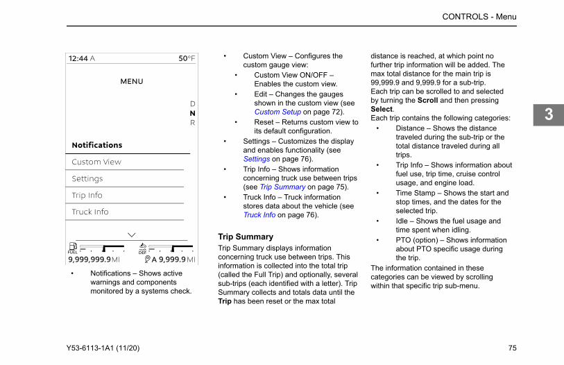
• Notifications – Shows activewarnings and componentsmonitored by a systems check.
• Custom View – Configures thecustom gauge view:
• Custom View ON/OFF –Enables the custom view.
• Edit – Changes the gaugesshown in the custom view (seeCustom Setup on page 72).
• Reset – Returns custom view toits default configuration.
• Settings – Customizes the displayand enables functionality (seeSettings on page 76).
• Trip Info – Shows informationconcerning truck use between trips(see Trip Summary on page 75).
• Truck Info – Truck informationstores data about the vehicle (seeTruck Info on page 76).
Trip SummaryTrip Summary displays informationconcerning truck use between trips. Thisinformation is collected into the total trip(called the Full Trip) and optionally, severalsub-trips (each identified with a letter). TripSummary collects and totals data until theTrip has been reset or the max total
distance is reached, at which point nofurther trip information will be added. Themax total distance for the main trip is99,999.9 and 9,999.9 for a sub-trip.Each trip can be scrolled to and selectedby turning the Scroll and then pressingSelect.Each trip contains the following categories:
• Distance – Shows the distancetraveled during the sub-trip or thetotal distance traveled during alltrips.
• Trip Info – Shows information aboutfuel use, trip time, cruise controlusage, and engine load.
• Time Stamp – Shows the start andstop times, and the dates for theselected trip.
• Idle – Shows the fuel usage andtime spent when idling.
• PTO (option) – Shows informationabout PTO specific usage duringthe trip.
The information contained in thesecategories can be viewed by scrollingwithin that specific trip sub-menu.
CONTROLS - Menu
Y53-6113-1A1 (11/20) 75
3
SettingsSettings allows the operator to customizethe display:10 Selections are made bynavigating to the desired setting with theScroll and pressing Select to change thesetting. Press Back/Cancel to return to theprevious menu.Date & Time
• Format – Changes the clock to a12-hour or 24-hour format.
• Automatic Time (option) – Whenactive, automatically sets time anddate based on location.
• Set Time – Sets the clock.11
• Set Date – Sets the date.12
Units & Language• Unit Standard/Metric – Changes
the numerical readout to Standard,Metric or Metric with PSI units.
• Language – Changes the languageto English, Spanish, or French.
Features• Anti-Theft – Turns Anti-Theft
On/Off (see Anti-Theft).
• Dark Cabin – Turns Dark CabinOn/Off; this prevents cab interiorlights from turning on when a cabdoor is opened.
• Trailer Detect – Turns TrailerDetect On/Off .
• LVD Setup – Sets the Low VoltageDisconnect setting (see LowVoltage Disconnect).
Truck InfoTruck info stores specifications and dataabout the vehicle:
• Chassis• Engine• ABS• Transmission• Cruise Control (ACC/PCC) (option)• GHG Vehicle Speed Limits (option)• TPMS (option)• PTO (option)• Driver Assistance (LDW/LCA/LKA)
(option)• Other Software
Information specific to these categoriescan be shown by navigating to a categoryusing the Scroll and then pressing Select.
10 If Anti-Theft is enabled, settings will not be accessible until the correct passcode is entered.11 Not available if automatic time is active.12 Not available if automatic time is active.
CONTROLS - Menu
76 Y53-6113-1A1 (11/20)
3
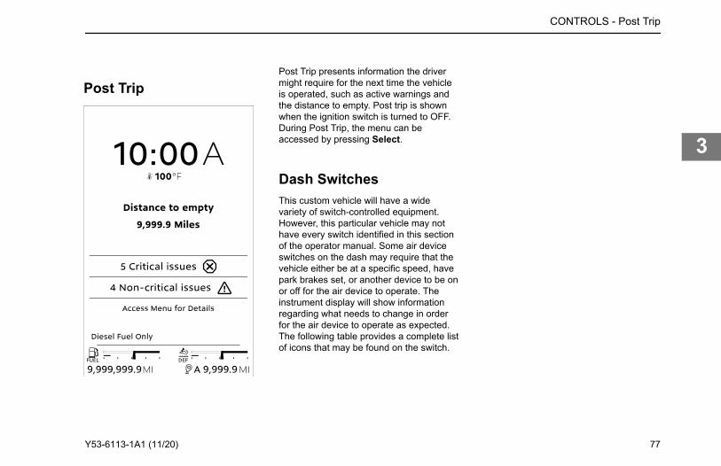
Post TripPost Trip presents information the drivermight require for the next time the vehicleis operated, such as active warnings andthe distance to empty. Post trip is shownwhen the ignition switch is turned to OFF.During Post Trip, the menu can beaccessed by pressing Select.
Dash SwitchesThis custom vehicle will have a widevariety of switch-controlled equipment.However, this particular vehicle may nothave every switch identified in this sectionof the operator manual. Some air deviceswitches on the dash may require that thevehicle either be at a specific speed, havepark brakes set, or another device to be onor off for the air device to operate. Theinstrument display will show informationregarding what needs to change in orderfor the air device to operate as expected.The following table provides a complete listof icons that may be found on the switch.
CONTROLS - Post Trip
Y53-6113-1A1 (11/20) 77
3
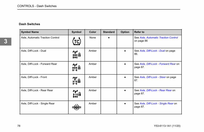
Dash Switches
Symbol Name Symbol Color Standard Option Refer to
Axle, Automatic Traction Control None ● See Axle, Automatic Traction Controlon page 86
Axle, Diff-Lock - Dual Amber ● See Axle, Diff-Lock - Dual on page86.
Axle, Diff-Lock - Forward Rear Amber ● See Axle, Diff-Lock - Forward Rear onpage 87.
Axle, Diff-Lock - Front Amber ● See Axle, Diff-Lock - Steer on page87.
Axle, Diff-Lock - Rear Rear Amber ● See Axle, Diff-Lock - Rear Rear onpage 87.
Axle, Diff-Lock - Single Rear Amber ● See Axle, Diff-Lock - Single Rear onpage 87.
CONTROLS - Dash Switches
78 Y53-6113-1A1 (11/20)
3
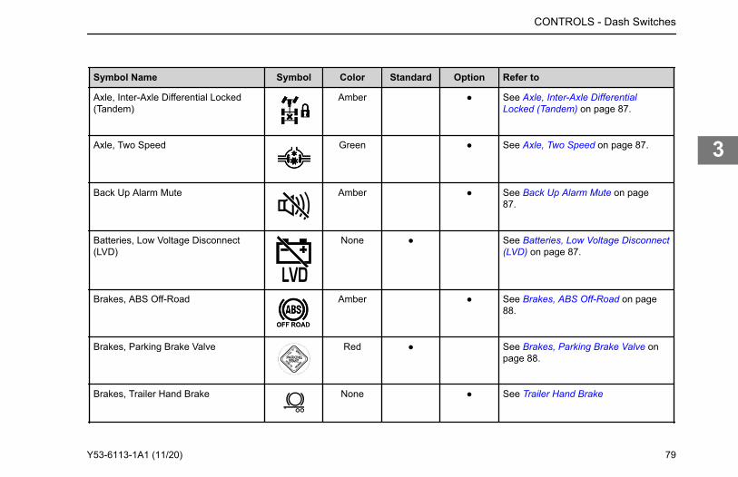
Symbol Name Symbol Color Standard Option Refer to
Axle, Inter-Axle Differential Locked(Tandem)
Amber ● See Axle, Inter-Axle DifferentialLocked (Tandem) on page 87.
Axle, Two Speed Green ● See Axle, Two Speed on page 87.
Back Up Alarm Mute Amber ● See Back Up Alarm Mute on page87.
Batteries, Low Voltage Disconnect(LVD)
None ● See Batteries, Low Voltage Disconnect(LVD) on page 87.
Brakes, ABS Off-Road Amber ● See Brakes, ABS Off-Road on page88.
Brakes, Parking Brake Valve Red ● See Brakes, Parking Brake Valve onpage 88.
Brakes, Trailer Hand Brake None ● See Trailer Hand Brake
CONTROLS - Dash Switches
Y53-6113-1A1 (11/20) 79
3
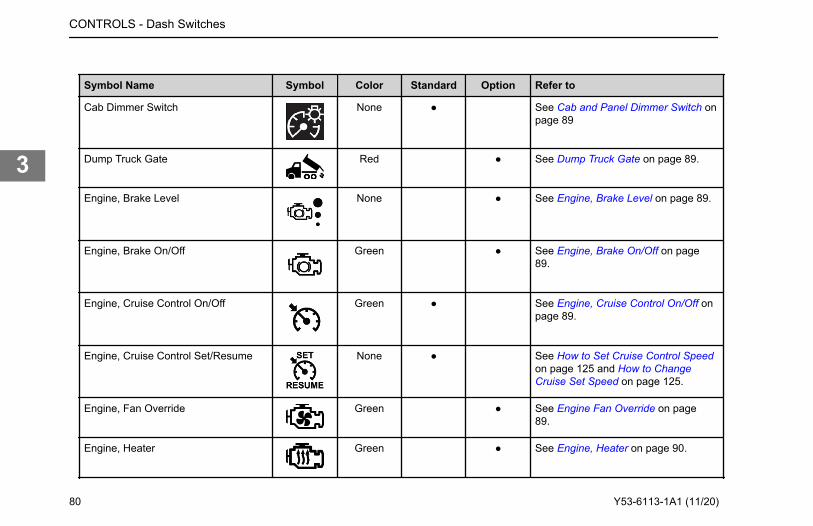
Symbol Name Symbol Color Standard Option Refer to
Cab Dimmer Switch None ● See Cab and Panel Dimmer Switch onpage 89
Dump Truck Gate Red ● See Dump Truck Gate on page 89.
Engine, Brake Level None ● See Engine, Brake Level on page 89.
Engine, Brake On/Off Green ● See Engine, Brake On/Off on page89.
Engine, Cruise Control On/Off Green ● See Engine, Cruise Control On/Off onpage 89.
Engine, Cruise Control Set/Resume None ● See How to Set Cruise Control Speedon page 125 and How to ChangeCruise Set Speed on page 125.
Engine, Fan Override Green ● See Engine Fan Override on page89.
Engine, Heater Green ● See Engine, Heater on page 90.
CONTROLS - Dash Switches
80 Y53-6113-1A1 (11/20)
3
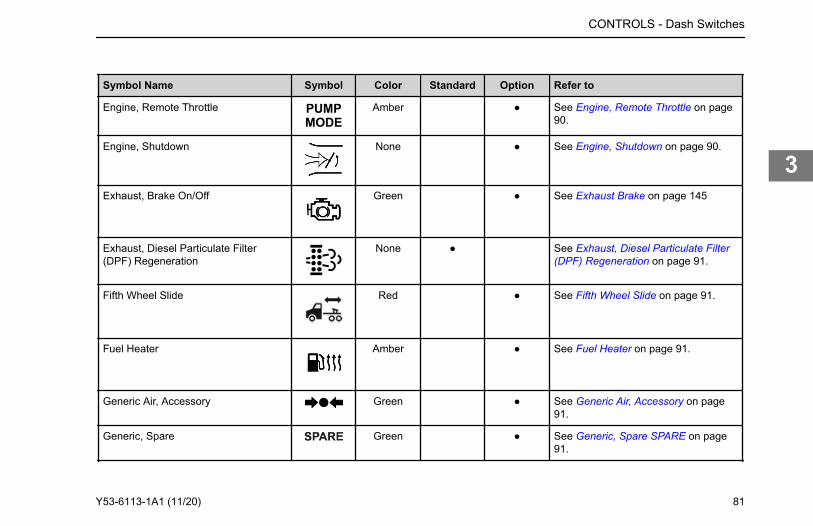
Symbol Name Symbol Color Standard Option Refer to
Engine, Remote Throttle Amber ● See Engine, Remote Throttle on page90.
Engine, Shutdown None ● See Engine, Shutdown on page 90.
Exhaust, Brake On/Off Green ● See Exhaust Brake on page 145
Exhaust, Diesel Particulate Filter(DPF) Regeneration
None ● See Exhaust, Diesel Particulate Filter(DPF) Regeneration on page 91.
Fifth Wheel Slide Red ● See Fifth Wheel Slide on page 91.
Fuel Heater Amber ● See Fuel Heater on page 91.
Generic Air, Accessory Green ● See Generic Air, Accessory on page91.
Generic, Spare Green ● See Generic, Spare SPARE on page91.
CONTROLS - Dash Switches
Y53-6113-1A1 (11/20) 81
3
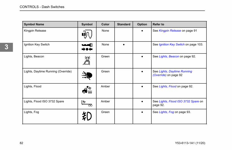
Symbol Name Symbol Color Standard Option Refer to
Kingpin Release None ● See Kingpin Release on page 91
Ignition Key Switch None ● See Ignition Key Switch on page 103.
Lights, Beacon Green ● See Lights, Beacon on page 92.
Lights, Daytime Running (Override) Green ● See Lights, Daytime Running(Override) on page 92
Lights, Flood Amber ● See Lights, Flood on page 92.
Lights, Flood ISO 3732 Spare Amber ● See Lights, Flood ISO 3732 Spare onpage 92.
Lights, Fog Green ● See Lights, Fog on page 93.
CONTROLS - Dash Switches
82 Y53-6113-1A1 (11/20)
3
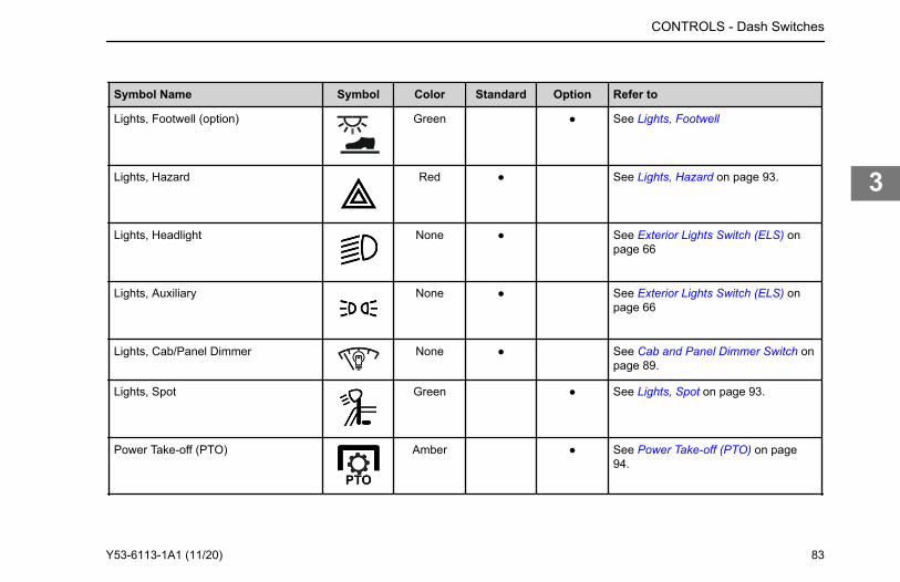
Symbol Name Symbol Color Standard Option Refer to
Lights, Footwell (option) Green ● See Lights, Footwell
Lights, Hazard Red ● See Lights, Hazard on page 93.
Lights, Headlight None ● See Exterior Lights Switch (ELS) onpage 66
Lights, Auxiliary None ● See Exterior Lights Switch (ELS) onpage 66
Lights, Cab/Panel Dimmer None ● See Cab and Panel Dimmer Switch onpage 89.
Lights, Spot Green ● See Lights, Spot on page 93.
Power Take-off (PTO) Amber ● See Power Take-off (PTO) on page94.
CONTROLS - Dash Switches
Y53-6113-1A1 (11/20) 83
3
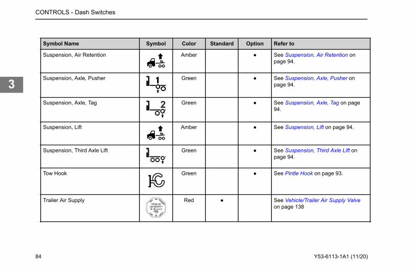
Symbol Name Symbol Color Standard Option Refer to
Suspension, Air Retention Amber ● See Suspension, Air Retention onpage 94.
Suspension, Axle, Pusher Green ● See Suspension, Axle, Pusher onpage 94.
Suspension, Axle, Tag Green ● See Suspension, Axle, Tag on page94.
Suspension, Lift Amber ● See Suspension, Lift on page 94.
Suspension, Third Axle Lift Green ● See Suspension, Third Axle Lift onpage 94.
Tow Hook Green ● See Pintle Hook on page 93.
Trailer Air Supply Red ● See Vehicle/Trailer Air Supply Valveon page 138
CONTROLS - Dash Switches
84 Y53-6113-1A1 (11/20)
3
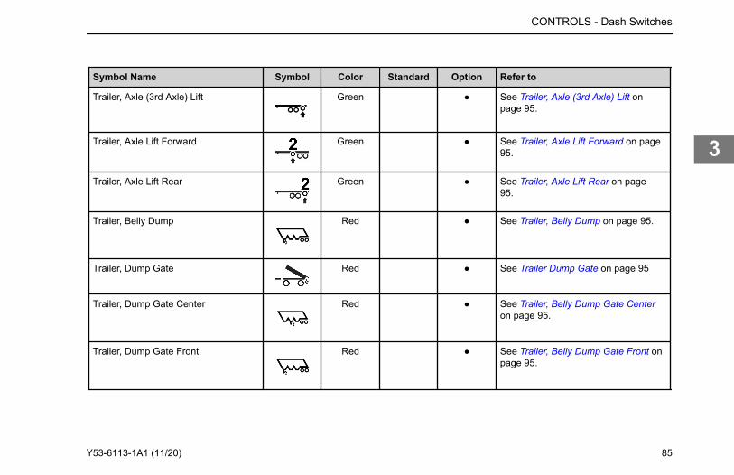
Symbol Name Symbol Color Standard Option Refer to
Trailer, Axle (3rd Axle) Lift Green ● See Trailer, Axle (3rd Axle) Lift onpage 95.
Trailer, Axle Lift Forward Green ● See Trailer, Axle Lift Forward on page95.
Trailer, Axle Lift Rear Green ● See Trailer, Axle Lift Rear on page95.
Trailer, Belly Dump Red ● See Trailer, Belly Dump on page 95.
Trailer, Dump Gate Red ● See Trailer Dump Gate on page 95
Trailer, Dump Gate Center Red ● See Trailer, Belly Dump Gate Centeron page 95.
Trailer, Dump Gate Front Red ● See Trailer, Belly Dump Gate Front onpage 95.
CONTROLS - Dash Switches
Y53-6113-1A1 (11/20) 85
3
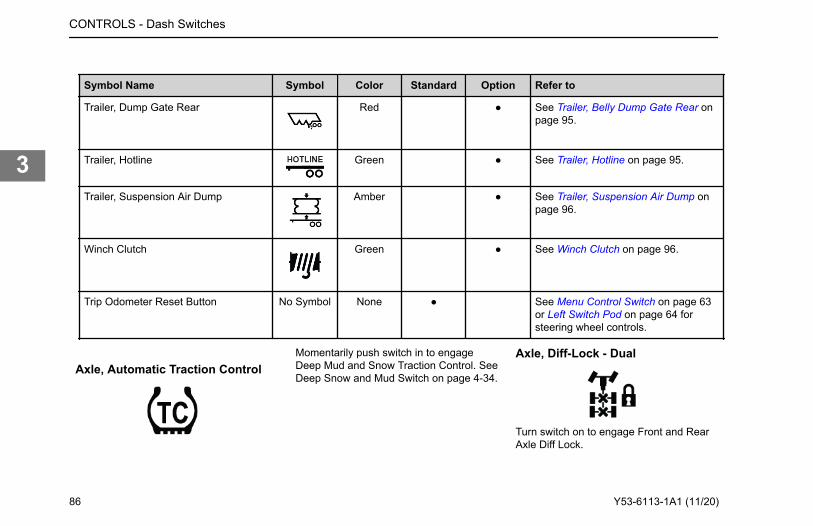
Symbol Name Symbol Color Standard Option Refer to
Trailer, Dump Gate Rear Red ● See Trailer, Belly Dump Gate Rear onpage 95.
Trailer, Hotline Green ● See Trailer, Hotline on page 95.
Trailer, Suspension Air Dump Amber ● See Trailer, Suspension Air Dump onpage 96.
Winch Clutch Green ● See Winch Clutch on page 96.
Trip Odometer Reset Button No Symbol None ● See Menu Control Switch on page 63or Left Switch Pod on page 64 forsteering wheel controls.
Axle, Automatic Traction ControlMomentarily push switch in to engageDeep Mud and Snow Traction Control. SeeDeep Snow and Mud Switch on page 4-34.
Axle, Diff-Lock - Dual
Turn switch on to engage Front and RearAxle Diff Lock.
CONTROLS - Dash Switches
86 Y53-6113-1A1 (11/20)
3
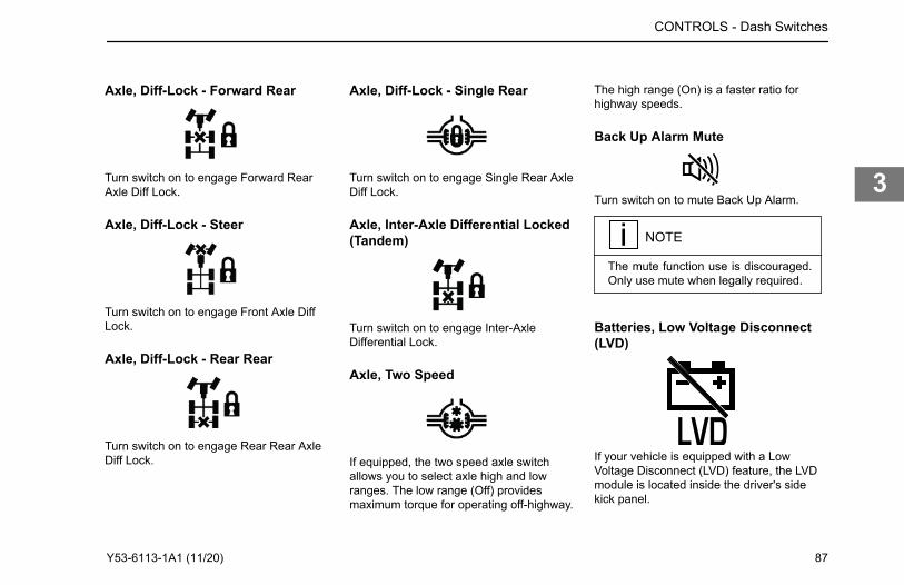
Axle, Diff-Lock - Forward Rear
Turn switch on to engage Forward RearAxle Diff Lock.
Axle, Diff-Lock - Steer
Turn switch on to engage Front Axle DiffLock.
Axle, Diff-Lock - Rear Rear
Turn switch on to engage Rear Rear AxleDiff Lock.
Axle, Diff-Lock - Single Rear
Turn switch on to engage Single Rear AxleDiff Lock.
Axle, Inter-Axle Differential Locked(Tandem)
Turn switch on to engage Inter-AxleDifferential Lock.
Axle, Two Speed
If equipped, the two speed axle switchallows you to select axle high and lowranges. The low range (Off) providesmaximum torque for operating off-highway.
The high range (On) is a faster ratio forhighway speeds.
Back Up Alarm Mute
Turn switch on to mute Back Up Alarm.
NOTE
The mute function use is discouraged.Only use mute when legally required.
Batteries, Low Voltage Disconnect(LVD)
If your vehicle is equipped with a LowVoltage Disconnect (LVD) feature, the LVDmodule is located inside the driver's sidekick panel.
CONTROLS - Dash Switches
Y53-6113-1A1 (11/20) 87
3
PurposeThe LVD may increase battery life andprevent unnecessary jump start conditionsby ensuring that an unattended load doesnot deplete the battery charge to a levelthat will prevent you from starting yourvehicle.
OperationThe LVD will disconnect non-vital batteryloads when battery voltage drops below12.3V for 3 minutes and the key switch isin the ACC or OFF position. During the last2 minutes the LVD will emit a slow audiblebeep. 30 seconds before disconnectingloads the alarm will change to a fast beep.The battery voltage must come back upabove a certain voltage before the LVD willreset.See an authorized dealer if the LVD fails toreconnect loads during normal operation.
Circuits Disconnected by LVD• Cab Dome Lamps• Cab Accessories• Spare Battery A & B
NOTE
All LVD circuits are color-coded blueon the central electrical panel cover la-bel.
WARNING
DO NOT use the Spare Battery A andB circuits or other circuits that are con-trolled by the LVD to power electronicengine controls, ABS circuits, or safe-ty/work related lighting. Before addingany device to the vehicle's electricalsystem, consult your nearest author-ized dealer or read the contents ofTMC RP136. Failure to do so maycause equipment damage or lead topersonal injury.
NOTE
The determination of what circuits/loads that were connected to the LVDwas based upon the recommendationfrom Technology and Maintenance
Council (TMC) of the American Truck-ing Association. To review the recom-mended practice, see TMC RP-136.
Brakes, ABS Off-Road
Turn switch on to engage ABS Off-Roadmode. See Anti-Lock Brake System (ABS)on page 55.
Brakes, Parking Brake Valve
Pull yellow knob to activate parking brakes.
Brake, Trailer Hand
This dash mounted switch provides airpressure to apply the trailer brakes only. Itoperates independently of the foot treadlevalve.
CONTROLS - Dash Switches
88 Y53-6113-1A1 (11/20)
3
Cab and Panel Dimmer SwitchThis switch is used to alter the brightnessof the instrument panel lights and controlsthe cab overhead, ambient lighting.
NOTE
The Headlight Switch is an ON or OFFswitch. The panel lights are on full in-tensity during the day and dim whenheadlights are on.
Dump Truck Gate
Turn switch on to open Dump Truck Gate.
Engine, Brake Level
position 33% engine braking when enginebraking is active.For more information on when and how touse the engine brake in your vehicle, seethe engine brake owner’s manual foradditional engine brake information.
Engine, Brake On/Off
Turn switch ON to activate Engine Brakesystem. This symbol is also used for anexhaust brake. Vehicles equipped with anengine brake will not also have an exhaustbrake. For more information on when andhow to use the engine brake in yourvehicle, see the engine brake owner’smanual for additional engine brakeinformation.
Engine, Cruise Control On/Off
Turn switch on to activate Cruise ControlSystem.
Engine, Cruise Control Set/Resume
The Cruise Control Set/Resume switchallows you to SET the desired speed orRESUME the desired speed after thecruise control function has beeninterrupted.
Engine Fan Override
The engine fan switch allows you to controlthe engine fan manually or automatically.With the ignition key switch ON and the fanswitch in the MANUAL position, the enginefan will be on regardless of enginetemperature. With the engine fan switch inthe AUTOMATIC position, the engine fanwill automatically turn on when the enginecoolant reaches a temperature of about200°F (93°C) or when the air conditioningsystem has reached set point pressure.
CONTROLS - Dash Switches
If the engine brake is on, the up position will provide 100% engine braking, the middle position 60%, and the down
Y53-6113-1A1 (11/20) 89
3
With an electronic engine, the fan may alsobe activated by air intake temperature, oiltemperature and compression brakeusage.
WARNING
DO NOT work on or near the fan withthe engine running. Anyone near theengine fan when it turns on could beinjured. If it is set at MANUAL, the fanwill turn on any time the ignition keyswitch is turned to the ON position. InAUTO, it could engage suddenly with-out warning. Before turning on the igni-tion or switching from AUTO to MAN-UAL, be sure no workers are near thefan. Failure to comply may result indeath or personal injury.
CAUTION
The fan or equipment near it could bedamaged if the fan turns on suddenlywhen you do not expect it. Keep alltools and equipment away from thefan.
CAUTION
DO NOT operate the engine fan in theMANUAL position for extended peri-ods of time. The fan hub was designedfor intermittent operation. Sustainedoperation will shorten the fan hub’sservice life as well as reduce fueleconomy.
Engine, Heater
Turn switch on to activate the EngineHeater.
Engine, Remote Throttle
Turn switch on to activate Remote ThrottleControl.
Engine, Shutdown
Momentarily push switch in to activate theshutdown system.
Exhaust, Brake On/Off
Turn switch ON to activate Exhaust Brakesystem. This symbol is also used for anengine brake. Vehicles equipped with anexhaust brake will not also have an enginebrake. For more information on when andhow to use the exhaust brake in yourvehicle, see the exhaust brake owner’smanual for additional exhaust brakeinformation.
CONTROLS - Dash Switches
90 Y53-6113-1A1 (11/20)
3
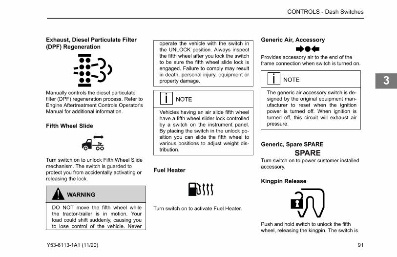
Exhaust, Diesel Particulate Filter(DPF) Regeneration
Manually controls the diesel particulatefilter (DPF) regeneration process. Refer toEngine Aftertreatment Controls Operator'sManual for additional information.
Fifth Wheel Slide
Turn switch on to unlock Fifth Wheel Slidemechanism. The switch is guarded toprotect you from accidentally activating orreleasing the lock.
WARNING
DO NOT move the fifth wheel whilethe tractor-trailer is in motion. Yourload could shift suddenly, causing youto lose control of the vehicle. Never
operate the vehicle with the switch inthe UNLOCK position. Always inspectthe fifth wheel after you lock the switchto be sure the fifth wheel slide lock isengaged. Failure to comply may resultin death, personal injury, equipment orproperty damage.
NOTE
Vehicles having an air slide fifth wheelhave a fifth wheel slider lock controlledby a switch on the instrument panel.By placing the switch in the unlock po-sition you can slide the fifth wheel tovarious positions to adjust weight dis-tribution.
Fuel Heater
Turn switch on to activate Fuel Heater.
Generic Air, Accessory
Provides accessory air to the end of theframe connection when switch is turned on.
NOTE
The generic air accessory switch is de-signed by the original equipment man-ufacturer to reset when the ignitionpower is turned off. When ignition isturned off, this circuit will exhaust airpressure.
Generic, Spare SPARE
Turn switch on to power customer installedaccessory.
Kingpin Release
Push and hold switch to unlock the fifthwheel, releasing the kingpin. The switch is
CONTROLS - Dash Switches
Y53-6113-1A1 (11/20) 91
3
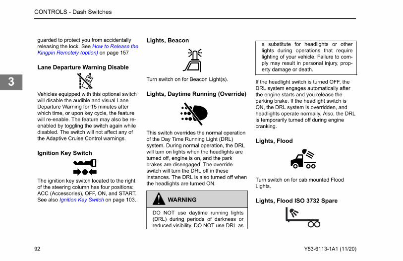
guarded to protect you from accidentallyreleasing the lock. See How to Release theKingpin Remotely (option) on page 157
Lane Departure Warning Disable
Vehicles equipped with this optional switchwill disable the audible and visual LaneDeparture Warning for 15 minutes afterwhich time, or upon key cycle, the featurewill re-enable. The feature may also be re-enabled by toggling the switch again whiledisabled. The switch will not affect any ofthe Adaptive Cruise Control warnings.
Ignition Key Switch
The ignition key switch located to the rightof the steering column has four positions:ACC (Accessories), OFF, ON, and START.See also Ignition Key Switch on page 103.
Lights, Beacon
Turn switch on for Beacon Light(s).
Lights, Daytime Running (Override)
This switch overrides the normal operationof the Day Time Running Light (DRL)system. During normal operation, the DRLwill turn on lights when the headlights areturned off, engine is on, and the parkbrakes are disengaged. The overrideswitch will turn the DRL off in theseinstances. The DRL is also turned off whenthe headlights are turned ON.
WARNING
DO NOT use daytime running lights(DRL) during periods of darkness orreduced visibility. DO NOT use DRL as
a substitute for headlights or otherlights during operations that requirelighting of your vehicle. Failure to com-ply may result in personal injury, prop-erty damage or death.
If the headlight switch is turned OFF, theDRL system engages automatically afterthe engine starts and you release theparking brake. If the headlight switch isON, the DRL system is overridden, andheadlights operate normally. Also, the DRLis temporarily turned off during enginecranking.
Lights, Flood
Turn switch on for cab mounted FloodLights.
Lights, Flood ISO 3732 Spare
CONTROLS - Dash Switches
92 Y53-6113-1A1 (11/20)
3
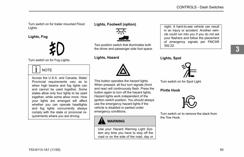
Turn switch on for trailer mounted FloodLights.
Lights, Fog
Turn switch on for Fog Lights.
NOTE
Across the U.S.A. and Canada, State/Provincial requirements vary as towhen high beams and fog lights canand cannot be used together. Somestates allow only four lights to be usedtogether, while some allow more. Howyour lights are arranged will affectwhether you can operate headlightsand fog lights concurrently alwayscomply with the state or provincial re-quirements where you are driving.
Lights, Footwell (option)
Two position switch that illuminates boththe driver and passenger side foot space.
Lights, Hazard
This button operates the hazard lights.When pressed, all four turn signals (frontand rear) will continuously flash. Press thebutton again to turn off the hazard lights.Hazard lights work independent of theignition switch position. You should alwaysuse the emergency hazard lights if thevehicle is disabled or parked underemergency conditions.
WARNING
Use your Hazard Warning Light Sys-tem any time you have to stop off theroad or on the side of the road, day or
night. A hard-to-see vehicle can resultin an injury or accident. Another vehi-cle could run into you if you do not setyour flashers and follow the placementof emergency signals per FMCSR392.22.
Lights, Spot
Turn switch on for Spot Light.
Pintle Hook
Turn switch on to remove the slack fromthe Tow Hook.
CONTROLS - Dash Switches
Y53-6113-1A1 (11/20) 93
3
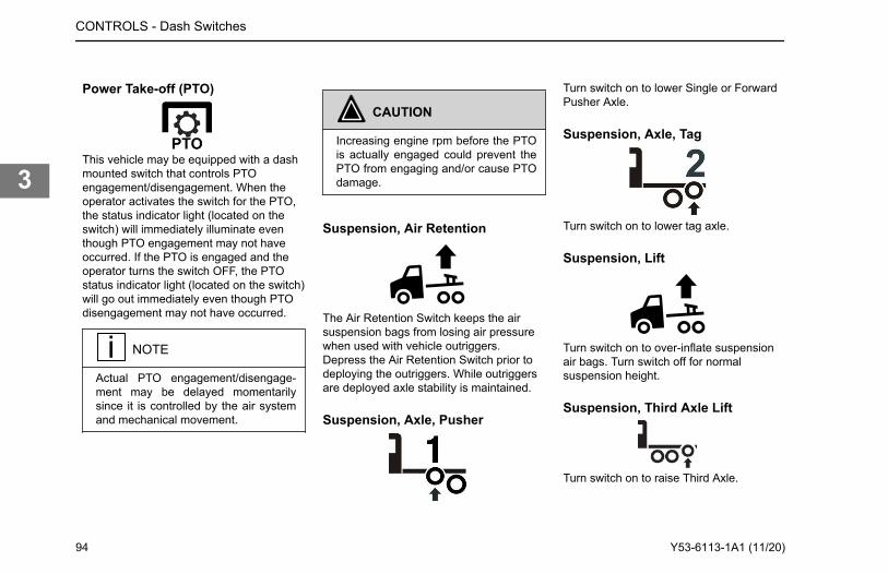
Power Take-off (PTO)
This vehicle may be equipped with a dashmounted switch that controls PTOengagement/disengagement. When theoperator activates the switch for the PTO,the status indicator light (located on theswitch) will immediately illuminate eventhough PTO engagement may not haveoccurred. If the PTO is engaged and theoperator turns the switch OFF, the PTOstatus indicator light (located on the switch)will go out immediately even though PTOdisengagement may not have occurred.
NOTE
Actual PTO engagement/disengage-ment may be delayed momentarilysince it is controlled by the air systemand mechanical movement.
CAUTION
Increasing engine rpm before the PTOis actually engaged could prevent thePTO from engaging and/or cause PTOdamage.
Suspension, Air Retention
The Air Retention Switch keeps the airsuspension bags from losing air pressurewhen used with vehicle outriggers.Depress the Air Retention Switch prior todeploying the outriggers. While outriggersare deployed axle stability is maintained.
Suspension, Axle, Pusher
Turn switch on to lower Single or ForwardPusher Axle.
Suspension, Axle, Tag
Turn switch on to lower tag axle.
Suspension, Lift
Turn switch on to over-inflate suspensionair bags. Turn switch off for normalsuspension height.
Suspension, Third Axle Lift
Turn switch on to raise Third Axle.
CONTROLS - Dash Switches
94 Y53-6113-1A1 (11/20)
3
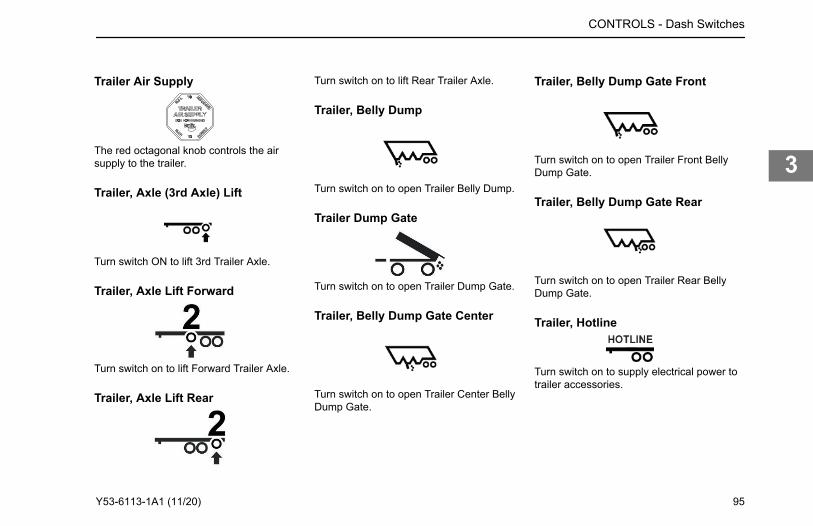
Trailer Air Supply
The red octagonal knob controls the airsupply to the trailer.
Trailer, Axle (3rd Axle) Lift
Turn switch ON to lift 3rd Trailer Axle.
Trailer, Axle Lift Forward
Turn switch on to lift Forward Trailer Axle.
Trailer, Axle Lift Rear
Turn switch on to lift Rear Trailer Axle.
Trailer, Belly Dump
Turn switch on to open Trailer Belly Dump.
Trailer Dump Gate
Turn switch on to open Trailer Dump Gate.
Trailer, Belly Dump Gate Center
Turn switch on to open Trailer Center BellyDump Gate.
Trailer, Belly Dump Gate Front
Turn switch on to open Trailer Front BellyDump Gate.
Trailer, Belly Dump Gate Rear
Turn switch on to open Trailer Rear BellyDump Gate.
Trailer, Hotline
Turn switch on to supply electrical power totrailer accessories.
CONTROLS - Dash Switches
Y53-6113-1A1 (11/20) 95
3
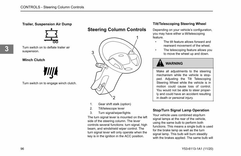
Trailer, Suspension Air Dump
Turn switch on to deflate trailer airsuspension.
Winch Clutch
Turn switch on to engage winch clutch.
Steering Column Controls1
3
21. Gear shift stalk (option)2. Tilt/telescope lever3. Turn signal/wiper/lights
The turn signal lever is mounted on the leftside of the steering column. The levercontrols several functions: turn signal, highbeam, and windshield wiper control. Theturn signal lever will only operate when thekey is in the ignition in the ACC position.
Tilt/Telescoping Steering WheelDepending on your vehicle’s configuration,you may have either a tilt/telescopingfeature.
• The tilt feature allows forward andrearward movement of the wheel.
• The telescoping feature allows youto move the wheel up and down.
WARNING
Make all adjustments to the steeringmechanism while the vehicle is stop-ped. Adjusting the Tilt TelescopingSteering Wheel while the vehicle is inmotion could cause loss of control.You would not be able to steer proper-ly and could have an accident resultingin death or personal injury.
Stop/Turn Signal Lamp OperationYour vehicle uses combined stop/turnsignal lamps at the rear of the vehicle,using the same bulb to perform bothfunctions. This means a single bulb is usedfor the brake lamp as well as the turnsignal lamp. This bulb will burn steadilywith the brakes applied. The same bulb will
CONTROLS - Steering Column Controls
96 Y53-6113-1A1 (11/20)
3
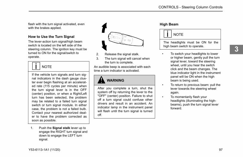
flash with the turn signal activated, evenwith the brakes applied.
How to Use the Turn SignalThe lever-action turn signal/high beamswitch is located on the left side of thesteering column. The ignition key must beturned to ON for the signal/switch tooperate.
NOTE
If the vehicle turn signals and turn sig-nal indicators in the dash gauge clus-ter ever begin flashing at an accelerat-ed rate (115 cycles per minute) whenthe turn signal lever is in the OFF(center) position, or when a Right/Leftturn has been selected, the problemmay be related to a failed turn signalswitch or turn signal module. In eithercase, the problem is not a failed bulb.Contact your nearest authorized deal-er to have the problem corrected assoon as possible.
1. Push the Signal stalk lever up toengage the RIGHT turn signal anddown to engage the LEFT turnsignal.
2. Release the signal stalk.3. The turn signal will cancel when
the turn is complete.An audible beep is associated with eachtime a turn indicator is activated.
WARNING
After you complete a turn, shut thesystem off by returning the lever to the"OFF" (center) position. Failure to shutoff a turn signal could confuse otherdrivers and result in an accident. Anindicator lamp in the instrument panelwill flash until the turn signal is turnedoff.
High Beam
NOTE
The headlights must be ON for thehigh beam switch to operate.
• To switch your headlights to loweror higher beam, gently pull the turnsignal lever, toward the steeringwheel, until you hear the switchclick and the beam changes. Theblue indicator light in the instrumentpanel will be ON when the highbeam is being used.
• To return to previous beam: pull thelever towards the steering wheelagain.
• To momentarily flash yourheadlights (illuminating the high-beams), push the turn signal leverforward.
CONTROLS - Steering Column Controls
Y53-6113-1A1 (11/20) 97
3
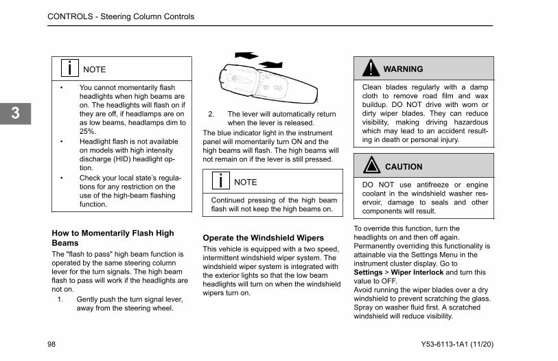
NOTE
• You cannot momentarily flashheadlights when high beams areon. The headlights will flash on ifthey are off, if headlamps are onas low beams, headlamps dim to25%.
• Headlight flash is not availableon models with high intensitydischarge (HID) headlight op-tion.
• Check your local state’s regula-tions for any restriction on theuse of the high-beam flashingfunction.
How to Momentarily Flash HighBeamsThe "flash to pass" high beam function isoperated by the same steering columnlever for the turn signals. The high beamflash to pass will work if the headlights arenot on.
1. Gently push the turn signal lever,away from the steering wheel.
2. The lever will automatically returnwhen the lever is released.
The blue indicator light in the instrumentpanel will momentarily turn ON and thehigh beams will flash. The high beams willnot remain on if the lever is still pressed.
NOTE
Continued pressing of the high beamflash will not keep the high beams on.
Operate the Windshield WipersThis vehicle is equipped with a two speed,intermittent windshield wiper system. Thewindshield wiper system is integrated withthe exterior lights so that the low beamheadlights will turn on when the windshieldwipers turn on.
WARNING
Clean blades regularly with a dampcloth to remove road film and waxbuildup. DO NOT drive with worn ordirty wiper blades. They can reducevisibility, making driving hazardouswhich may lead to an accident result-ing in death or personal injury.
CAUTION
DO NOT use antifreeze or enginecoolant in the windshield washer res-ervoir, damage to seals and othercomponents will result.
To override this function, turn theheadlights on and then off again.Permanently overriding this functionality isattainable via the Settings Menu in theinstrument cluster display. Go toSettings > Wiper Interlock and turn thisvalue to OFF.Avoid running the wiper blades over a drywindshield to prevent scratching the glass.Spray on washer fluid first. A scratchedwindshield will reduce visibility.
CONTROLS - Steering Column Controls
98 Y53-6113-1A1 (11/20)
3
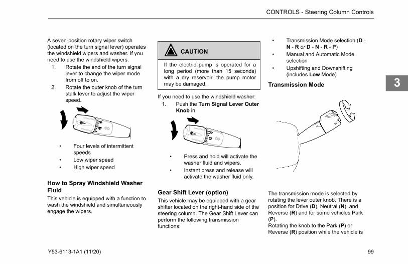
A seven-position rotary wiper switch(located on the turn signal lever) operatesthe windshield wipers and washer. If youneed to use the windshield wipers:
1. Rotate the end of the turn signallever to change the wiper modefrom off to on.
2. Rotate the outer knob of the turnstalk lever to adjust the wiperspeed.
• Four levels of intermittentspeeds
• Low wiper speed• High wiper speed
CAUTION
If the electric pump is operated for along period (more than 15 seconds)with a dry reservoir, the pump motormay be damaged.
If you need to use the windshield washer:1. Push the Turn Signal Lever Outer
Knob in.
• Press and hold will activate thewasher fluid and wipers.
• Instant press and release willactivate the washer fluid only.
Gear Shift Lever (option)This vehicle may be equipped with a gearshifter located on the right-hand side of thesteering column. The Gear Shift Lever canperform the following transmissionfunctions:
• Transmission Mode selection (D -N - R or D - N - R - P)
• Manual and Automatic Modeselection
• Upshifting and Downshifting(includes Low Mode)
Transmission Mode
The transmission mode is selected byrotating the lever outer knob. There is aposition for Drive (D), Neutral (N), andReverse (R) and for some vehicles Park(P).Rotating the knob to the Park (P) orReverse (R) position while the vehicle is
CONTROLS - Steering Column Controls
How to Spray Windshield Washer FluidThis vehicle is equipped with a function to wash the windshield and simultaneously engage the wipers.
Y53-6113-1A1 (11/20) 99
3
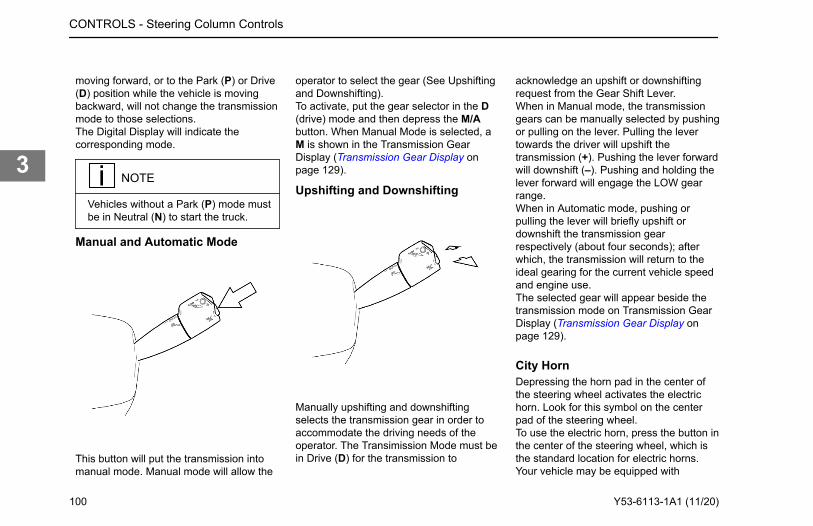
moving forward, or to the Park (P) or Drive(D) position while the vehicle is movingbackward, will not change the transmissionmode to those selections.The Digital Display will indicate thecorresponding mode.
NOTE
Vehicles without a Park (P) mode mustbe in Neutral (N) to start the truck.
Manual and Automatic Mode
This button will put the transmission intomanual mode. Manual mode will allow the
operator to select the gear (See Upshiftingand Downshifting).To activate, put the gear selector in the D(drive) mode and then depress the M/Abutton. When Manual Mode is selected, aM is shown in the Transmission GearDisplay (Transmission Gear Display onpage 129).
Upshifting and Downshifting
Manually upshifting and downshiftingselects the transmission gear in order toaccommodate the driving needs of theoperator. The Transimission Mode must bein Drive (D) for the transmission to
acknowledge an upshift or downshiftingrequest from the Gear Shift Lever.When in Manual mode, the transmissiongears can be manually selected by pushingor pulling on the lever. Pulling the levertowards the driver will upshift thetransmission (+). Pushing the lever forwardwill downshift (–). Pushing and holding thelever forward will engage the LOW gearrange.When in Automatic mode, pushing orpulling the lever will briefly upshift ordownshift the transmission gearrespectively (about four seconds); afterwhich, the transmission will return to theideal gearing for the current vehicle speedand engine use.The selected gear will appear beside thetransmission mode on Transmission GearDisplay (Transmission Gear Display onpage 129).
City HornDepressing the horn pad in the center ofthe steering wheel activates the electrichorn. Look for this symbol on the centerpad of the steering wheel.To use the electric horn, press the button inthe center of the steering wheel, which isthe standard location for electric horns.Your vehicle may be equipped with
CONTROLS - Steering Column Controls
100 Y53-6113-1A1 (11/20)
3
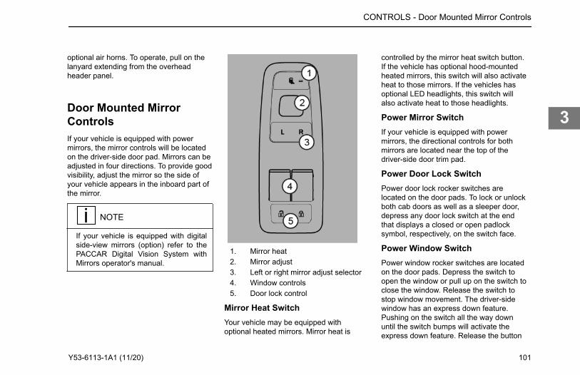
optional air horns. To operate, pull on thelanyard extending from the overheadheader panel.
Door Mounted MirrorControlsIf your vehicle is equipped with powermirrors, the mirror controls will be locatedon the driver-side door pad. Mirrors can beadjusted in four directions. To provide goodvisibility, adjust the mirror so the side ofyour vehicle appears in the inboard part ofthe mirror.
NOTE
If your vehicle is equipped with digitalside-view mirrors (option) refer to thePACCAR Digital Vision System withMirrors operator's manual.
1. Mirror heat2. Mirror adjust3. Left or right mirror adjust selector4. Window controls5. Door lock control
Mirror Heat SwitchYour vehicle may be equipped withoptional heated mirrors. Mirror heat is
controlled by the mirror heat switch button.If the vehicle has optional hood-mountedheated mirrors, this switch will also activateheat to those mirrors. If the vehicles hasoptional LED headlights, this switch willalso activate heat to those headlights.
Power Mirror SwitchIf your vehicle is equipped with powermirrors, the directional controls for bothmirrors are located near the top of thedriver-side door trim pad.
Power Door Lock SwitchPower door lock rocker switches arelocated on the door pads. To lock or unlockboth cab doors as well as a sleeper door,depress any door lock switch at the endthat displays a closed or open padlocksymbol, respectively, on the switch face.
Power Window SwitchPower window rocker switches are locatedon the door pads. Depress the switch toopen the window or pull up on the switch toclose the window. Release the switch tostop window movement. The driver-sidewindow has an express down feature.Pushing on the switch all the way downuntil the switch bumps will activate theexpress down feature. Release the button
CONTROLS - Door Mounted Mirror Controls
Y53-6113-1A1 (11/20) 101
3
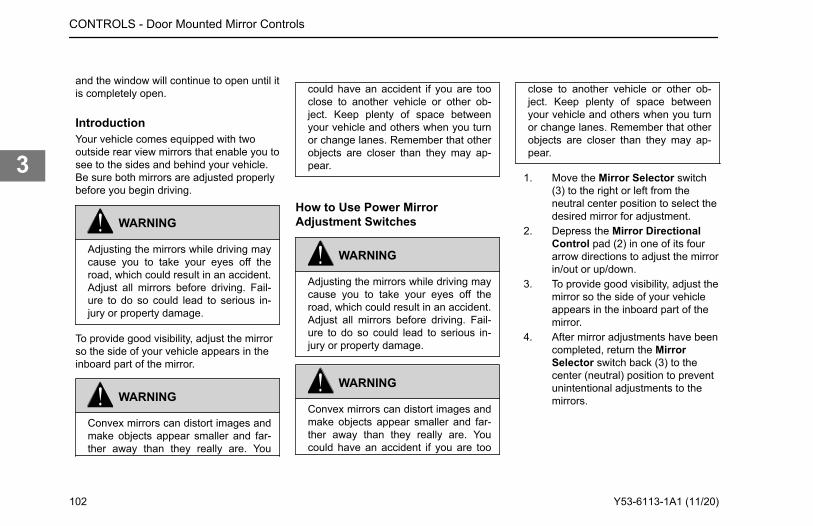
and the window will continue to open until itis completely open.
IntroductionYour vehicle comes equipped with twooutside rear view mirrors that enable you tosee to the sides and behind your vehicle.Be sure both mirrors are adjusted properlybefore you begin driving.
WARNING
Adjusting the mirrors while driving maycause you to take your eyes off theroad, which could result in an accident.Adjust all mirrors before driving. Fail-ure to do so could lead to serious in-jury or property damage.
To provide good visibility, adjust the mirrorso the side of your vehicle appears in theinboard part of the mirror.
WARNING
Convex mirrors can distort images andmake objects appear smaller and far-ther away than they really are. You
could have an accident if you are tooclose to another vehicle or other ob-ject. Keep plenty of space betweenyour vehicle and others when you turnor change lanes. Remember that otherobjects are closer than they may ap-pear.
How to Use Power MirrorAdjustment Switches
WARNING
Adjusting the mirrors while driving maycause you to take your eyes off theroad, which could result in an accident.Adjust all mirrors before driving. Fail-ure to do so could lead to serious in-jury or property damage.
WARNING
Convex mirrors can distort images andmake objects appear smaller and far-ther away than they really are. Youcould have an accident if you are too
close to another vehicle or other ob-ject. Keep plenty of space betweenyour vehicle and others when you turnor change lanes. Remember that otherobjects are closer than they may ap-pear.
1. Move the Mirror Selector switch(3) to the right or left from theneutral center position to select thedesired mirror for adjustment.
2. Depress the Mirror DirectionalControl pad (2) in one of its fourarrow directions to adjust the mirrorin/out or up/down.
3. To provide good visibility, adjust themirror so the side of your vehicleappears in the inboard part of themirror.
4. After mirror adjustments have beencompleted, return the MirrorSelector switch back (3) to thecenter (neutral) position to preventunintentional adjustments to themirrors.
CONTROLS - Door Mounted Mirror Controls
102 Y53-6113-1A1 (11/20)
3
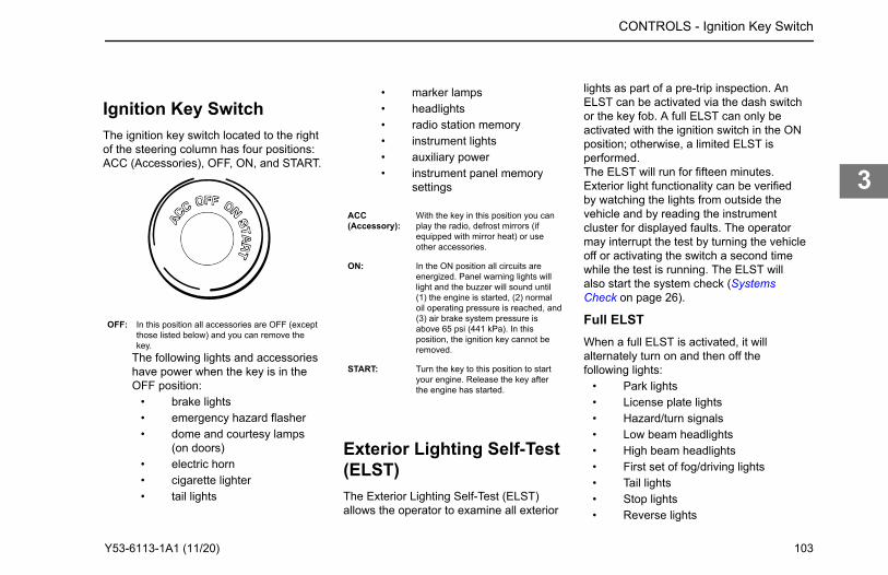
Ignition Key SwitchThe ignition key switch located to the rightof the steering column has four positions:ACC (Accessories), OFF, ON, and START.
OFF: In this position all accessories are OFF (exceptthose listed below) and you can remove thekey.
The following lights and accessorieshave power when the key is in theOFF position:
• brake lights• emergency hazard flasher• dome and courtesy lamps
(on doors)• electric horn• cigarette lighter• tail lights
• marker lamps• headlights• radio station memory• instrument lights• auxiliary power• instrument panel memory
settings
ACC(Accessory):
With the key in this position you canplay the radio, defrost mirrors (ifequipped with mirror heat) or useother accessories.
ON: In the ON position all circuits areenergized. Panel warning lights willlight and the buzzer will sound until(1) the engine is started, (2) normaloil operating pressure is reached, and(3) air brake system pressure isabove 65 psi (441 kPa). In thisposition, the ignition key cannot beremoved.
START: Turn the key to this position to startyour engine. Release the key afterthe engine has started.
Exterior Lighting Self-Test(ELST)The Exterior Lighting Self-Test (ELST)allows the operator to examine all exterior
lights as part of a pre-trip inspection. AnELST can be activated via the dash switchor the key fob. A full ELST can only beactivated with the ignition switch in the ONposition; otherwise, a limited ELST isperformed.The ELST will run for fifteen minutes.Exterior light functionality can be verifiedby watching the lights from outside thevehicle and by reading the instrumentcluster for displayed faults. The operatormay interrupt the test by turning the vehicleoff or activating the switch a second timewhile the test is running. The ELST willalso start the system check (SystemsCheck on page 26).
Full ELSTWhen a full ELST is activated, it willalternately turn on and then off thefollowing lights:
• Park lights• License plate lights• Hazard/turn signals• Low beam headlights• High beam headlights• First set of fog/driving lights• Tail lights• Stop lights• Reverse lights
CONTROLS - Ignition Key Switch
Y53-6113-1A1 (11/20) 103
3
• Fog lights (option)• Driving lights (option)• Daytime Running Lights (option)
The following lights stay on during theduration of a full test:
• Clearance lights• Identification lights• Side Marker lights• Beacon/Strobe (option)• Work/Load lights (option)• Sign light (option)
Limited ELSTA limited ELST will alternately turn on andthen off the following lights:
• Hazard/turn signals• Low beam headlights• High beam headlights• Park lights• Daytime running lights (option)• License plate lights• Tail lights• Stop lights
The following lights will stay on during theduration of a limited test:
• Clearance lights• Identification lights• Side marker lights
Test the Exterior LightsFor a full ELST, the parking brake must beset and the ignition switch must be in theON position. For a limited ELST, theignition switch must be in the ACC or OFFposition.A full ELST will test all exterior lights (alsochecking the mirror and headlight heaters ifthe engine is on). A limited ELST will testonly the legal driving lights.
1. Turn the Exterior Lighting Switch(ELS) to the momentary ELSTposition and release the switch, or
The ELST icon will illuminate.2. Press the ELST button on the key
fob.A full ELST will continue until the parkingbrake is released or the ignition switch isturned to OFF. Both the full and limitedELST will stop if either the dash or key fobELST buttons are pressed, or the fifteenminute test duration has elapsed.
Heating and AirConditioningThis vehicle's heating and air conditioningsystem operates in four distinct modes:manual, automatic, semi-automatic, andmaximum defrost. Each mode provides thedriver with the greatest level of comfort andconvenience.The recommended mode for all conditionsthat do not require windshield defrosting isthe automatic mode. This mode is capableof maintaining cab comfort under variousdriving conditions without driver interaction.The cab heater and air conditioner controlsare located together in the center of thedash just to the right of the steeringcolumn. The sleeper heater and airconditioner controls are located in thesleeper cabinet.
CONTROLS - Heating and Air Conditioning
104 Y53-6113-1A1 (11/20)
3
WARNING
DO NOT drive with visibility reducedby fog, condensation, or frost on thewindshield. Your view may be ob-scured, which may result in death, per-sonal injury, equipment or propertydamage. For clear visibility and safedriving it is extremely important for youto follow the instructions pertaining tothe function and use of the ventilation/heating and defogging/defrosting sys-tem. If in doubt, consult your dealer.Maximum heating output and fast de-frosting can be obtained only after theengine has reached operating temper-ature.
WARNING
Exhaust fumes from the engine con-tain carbon monoxide, a colorless andodorless gas. DO NOT breathe the en-gine exhaust gas. A poorly maintained,damaged or corroded exhaust systemcan allow carbon monoxide to enterthe cab. Entry of carbon monoxide intothe cab is also possible from other ve-
hicles nearby. Failure to properly main-tain your vehicle could cause carbonmonoxide to enter the cab, resulting indeath or personal injury.
WARNING
Never idle your vehicle for prolongedperiods of time if you sense that ex-haust fumes are entering the cab. In-vestigate the cause of the fumes andcorrect it as soon as possible. If thevehicle must be driven under theseconditions, drive only with the windowsopen. Failure to repair the source ofthe exhaust fumes may result in death,personal injury, equipment or propertydamage.
CAUTION
Do not stay in the vehicle with the en-gine running or idling for more than 10minutes with the vehicle's Heater andA/C ventilation system in RECIRC orat LOW FAN SPEED. Even with theventilation system on, running the en-gine while parked or stopped for pro-
longed periods of time is not recom-mended.
NOTE
Keep the engine exhaust system andthe vehicle's cab ventilation systemproperly maintained. It is recommend-ed that the vehicle's exhaust systemand cab be inspected (1) By a compe-tent technician every 15,000 miles(24,000 km) (2) Whenever a change isnoticed in the sound of the exhaustsystem (3) Whenever the exhaust sys-tem, underbody, or cab is damaged.
NOTE
If you are required to idle your vehiclefor long periods of time, install an aux-iliary heater or automatic idle control.These auxiliary devices can reducefuel consumption and save you mon-ey.
CONTROLS - Heating and Air Conditioning
Y53-6113-1A1 (11/20) 105
3
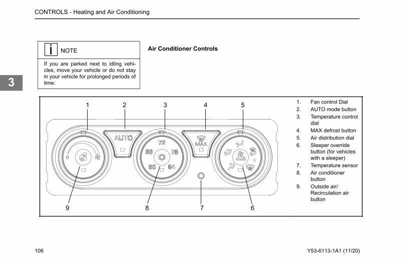
NOTE
If you are parked next to idling vehi-cles, move your vehicle or do not stayin your vehicle for prolonged periods oftime.
Air Conditioner Controls
1
9 8 7 6
2 3 4 5 1. Fan control Dial2. AUTO mode button3. Temperature control
dial4. MAX defrost button5. Air distribution dial6. Sleeper override
button (for vehicleswith a sleeper)
7. Temperature sensor8. Air conditioner
button9. Outside air/
Recirculation airbutton
CONTROLS - Heating and Air Conditioning
106 Y53-6113-1A1 (11/20)
3
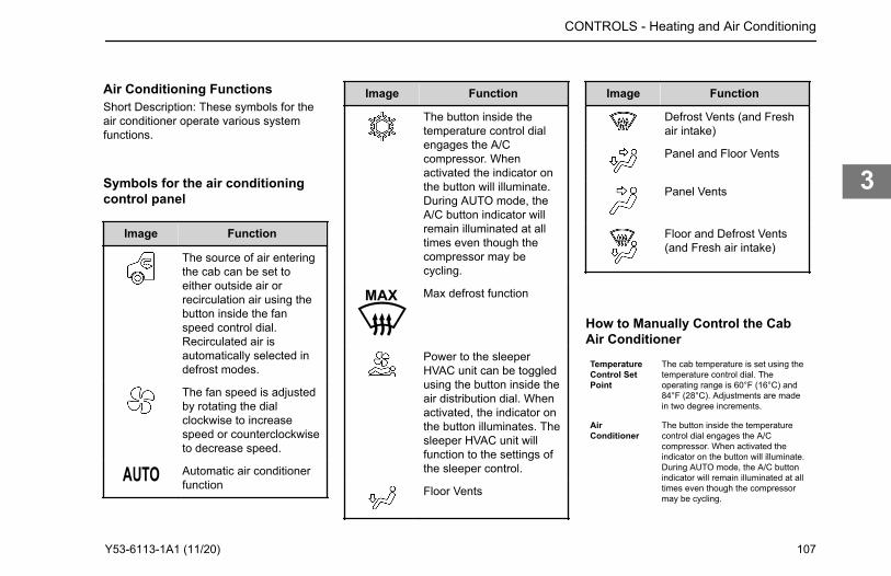
Air Conditioning FunctionsShort Description: These symbols for theair conditioner operate various systemfunctions.
Symbols for the air conditioningcontrol panel
Image Function
The source of air enteringthe cab can be set toeither outside air orrecirculation air using thebutton inside the fanspeed control dial.Recirculated air isautomatically selected indefrost modes.
The fan speed is adjustedby rotating the dialclockwise to increasespeed or counterclockwiseto decrease speed.
Automatic air conditionerfunction
Image Function
The button inside thetemperature control dialengages the A/Ccompressor. Whenactivated the indicator onthe button will illuminate.During AUTO mode, theA/C button indicator willremain illuminated at alltimes even though thecompressor may becycling.
Max defrost function
Power to the sleeperHVAC unit can be toggledusing the button inside theair distribution dial. Whenactivated, the indicator onthe button illuminates. Thesleeper HVAC unit willfunction to the settings ofthe sleeper control.
Floor Vents
Image Function
Defrost Vents (and Freshair intake)
Panel and Floor Vents
Panel Vents
Floor and Defrost Vents(and Fresh air intake)
How to Manually Control the CabAir Conditioner
TemperatureControl SetPoint
The cab temperature is set using thetemperature control dial. Theoperating range is 60°F (16°C) and84°F (28°C). Adjustments are madein two degree increments.
AirConditioner
The button inside the temperaturecontrol dial engages the A/Ccompressor. When activated theindicator on the button will illuminate.During AUTO mode, the A/C buttonindicator will remain illuminated at alltimes even though the compressormay be cycling.
CONTROLS - Heating and Air Conditioning
Y53-6113-1A1 (11/20) 107
3
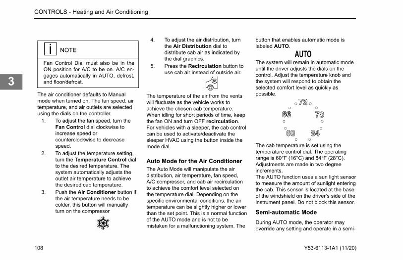
NOTE
Fan Control Dial must also be in theON position for A/C to be on. A/C en-gages automatically in AUTO, defrost,and floor/defrost.
The air conditioner defaults to Manualmode when turned on. The fan speed, airtemperature, and air outlets are selectedusing the dials on the controller.
1. To adjust the fan speed, turn theFan Control dial clockwise toincrease speed orcounterclockwise to decreasespeed.
2. To adjust the temperature setting,turn the Temperature Control dialto the desired temperature. Thesystem automatically adjusts theoutlet air temperature to achievethe desired cab temperature.
3. Push the Air Conditioner button ifthe air temperature needs to becolder, this button will manuallyturn on the compressor
4. To adjust the air distribution, turnthe Air Distribution dial todistribute cab air as indicated bythe dial graphics.
5. Press the Recirculation button touse cab air instead of outside air.
The temperature of the air from the ventswill fluctuate as the vehicle works toachieve the chosen cab temperature.When idling for short periods of time, keepthe fan ON and turn OFF recirculation.For vehicles with a sleeper, the cab controlcan be used to activate/deactivate thesleeper HVAC using the button inside themode dial.
Auto Mode for the Air ConditionerThe Auto Mode will manipulate the airdistribution, air temperature, fan speed,A/C compressor, and cab air recirculationto achieve the comfort level selected onthe temperature dial. Depending on thespecific environmental conditions, the airtemperature can be slightly higher or lowerthan the set point. This is a normal functionof the AUTO mode and is not to bemistaken for a malfunctioning system. The
button that enables automatic mode islabeled AUTO.
The system will remain in automatic modeuntil the driver adjusts the dials on thecontrol. Adjust the temperature knob andthe system will respond to obtain theselected comfort level as quickly aspossible.
The cab temperature is set using thetemperature control dial. The operatingrange is 60°F (16°C) and 84°F (28°C).Adjustments are made in two degreeincrements.The AUTO function uses a sun light sensorto measure the amount of sunlight enteringthe cab. This sensor is located at the baseof the windshield on the driver’s side of theinstrument panel. Do not block this sensor.
Semi-automatic ModeDuring AUTO mode, the operator mayoverride any setting and operate in a semi-
CONTROLS - Heating and Air Conditioning
108 Y53-6113-1A1 (11/20)
3
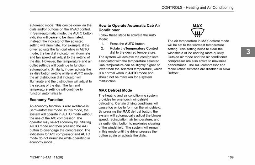
How to Operate Automatic Cab AirConditionerFollow these steps to activate the AutoMode:
1. Press the AUTO button.2. Rotate theTemperature Control
dial to the desired temperature.The system will achieve the comfort levelassociated with the temperature selected.Cab temperature can be slightly higher orlower than the selected temperature, whichis a normal when in AUTO mode andshould not be mistaken for a systemmalfunction.
MAX Defrost ModeThe heating and air conditioning systemprovides for one touch windshielddefrosting. Certain driving conditions willcause fog or ice to form on the windshield.By pressing the MAX defrost button, thesystem will automatically adjust the blowerspeed, recirculation, air temperature, andair outlet distribution to maximize clearingof the windshield. The system will remainin this mode until the driver presses thebutton again or adjusts the dials.
The air temperature in MAX defrost modewill be set to the warmest temperaturesetting. This setting helps to clear thewindshield of ice and fog more quickly.Outside air mode and the air conditionercompressor are also active to maximizeperformance. The A/C compressor andrecirculation switches are disabled in MAXDefrost.
CONTROLS - Heating and Air Conditioning
automatic mode. This can be done via the dials and/or buttons on the HVAC control. In Semi-automatic mode, the AUTO button indicator will cease to be illuminated. Instead, the indicator of the adjusted setting will illuminate. For example, if the driver adjusts the fan dial while in AUTO mode, the fan dial indicator will illuminate and fan speed will adjust to the setting of the dial. However, the temperature and air outlet settings will continue to function automatically. Similarly, if user adjusts the air distribution setting while in AUTO mode, the air distribution dial indicator will illuminate and the distribution will adjust to the setting of the dial. The fan and temperature settings will continue to function automatically.
Economy FunctionAn economy function is also available in Semi-automatic mode. In this mode, the system will operate in AUTO mode without the use of the A/C compressor. The operator may select economy by initiating AUTO mode and then pressing the A/C button to disengage the compressor. The indicators for A/C compressor and AUTO mode do not illuminate while operating in economy mode.
Y53-6113-1A1 (11/20) 109
3
Air Conditioner Operating Tips
CAUTION
During extreme cold weather, DO NOTblow hot defroster air onto cold wind-shields. This could crack the glass.Turn the Air Flow Control Dial to De-frost and adjust the fan speed accord-ingly while the engine warms. If theengine is already warm, move theTemperature Control Dial to "cool,"then gradually increase the tempera-ture when you see that the windshieldis starting to warm up. Failure to com-ply may result in equipment damage.
Defrosting and Defogging theWindshieldThe cab windshield and side windows canbe cleared of ice and fog in two ways. Thefirst is to use the MAX defrost mode. Thesecond is to manually adjust the airdistribution dial to the defrost position.The manual defrost/defogging mode differsfrom the MAX defrost mode by allowing thedriver to select an air temperature otherthan full heat. This allows the driver tomaintain a constant cab temperature while
defrosting the windshield. However, notethat performance may be reduced.
• Adjust the fan speed to high byrotating the fan control dialclockwise.
• Set the air distribution dial to thedefrost mode setting. Thisautomatically engages the outsideair and the air conditionercompressor.
• Adjust the temperature dial to addheat as needed.
For maximum performance, adjust thetemperature to maximum heat by rotatingthe temperature dial clockwise. The drivermay also use the floor/defrost setting onthe air control
For Maximum Cooling• Adjust the fan speed to high by
rotating the fan control dialclockwise.
• Set the air distribution dial to thepanel setting.
• Adjust the air temperature tomaximum cool by rotating thetemperature dial counterclockwise.
• Engage the air conditionercompressor by pressing the airconditioner button.
• Set the air source to recirculationmode by pressing the outside air/recirculation air button. The buttonindicator light should beilluminated.
For Maximum Heating• Adjust the fan speed to high by
rotating the fan control dialclockwise.
• Set the air distribution dial to thefloor setting.
• Adjust the air temperature tomaximum heat by rotating thetemperature dial clockwise.
NOTE
The engine must be at operating tem-perature for maximum heating. If oper-ating in AUTO mode, heating airflow isnot allowed until the engine warmssufficiently to provide required coolanttemperatures.
Air DehumidificationThe air conditioner system can be used toreduce the humidity level of the cab andclear fog from the windshield.
CONTROLS - Heating and Air Conditioning
110 Y53-6113-1A1 (11/20)
3
• Adjust fan speed to the desiredairflow setting.
• Engage the air conditionercompressor by pressing the airconditioner button.
• Set the air source to outside airmode by pressing the outside air/recirculation air button. The buttonindicator light should NOT beilluminated.
NOTE
The A/C compressor may not engagewhen the outside temperature is below34ºF (1ºC).
have difficulties in obtaining the desiredcabin temperature if the temperaturesetting is repeatedly changed.The mode of air distribution inside the cabis set using the air distribution dial. Fiveicons on the dial indicate the primary modeoptions. The driver may also select asecondary mode in between the primarymodes indicated by points on the dial.Airflow is provided to the side windows inall modes.
Outside Air/Recirculation AirSelecting air recirculation mode completelyisolates the cab interior from the outsideair. This mode is helpful in preventing dust,pollen, and odors from entering the cab.Additionally, recirculation mode can reducethe amount of time needed to cool downthe vehicle while in maximum cool down.Note that the mode may increase foggingon the windshield. A coarse air filter isprovided for recirculation air and is locatedunder the IP. The outside air modeprovides for 100% outside air into the cab.This mode is helpful with windshielddefogging. A pleated air filter located underhood provides filtration for dust, pollen, anddebris. If equipped, your vehicle may alsoprovide for ember filtration or fineparticulate filtration.
Cab Accessories
NOTE
The 12V accessory power port will op-erate with the ignition key in either theOFF, ACC (accessory), or ON position.
This vehicle comes standard with twocupholders and power ports located in thecenter of the dashboard. This vehicle maycontain a variety of optional cabaccessories. Electrically powered cabaccessories, such as the stereo system,can be used when the ignition switch is inthe ACC position and can be affected bythe Low Voltage Disconnect (see LowVoltage Disconnect).
Radio Stereo System (option)Your vehicle has one of two stereosystems. An AM/FM stereo receiver isstandard equipment and may have acombination of CD, satellite radio, USBmedia, or Bluetooth. A stereo systemintegrated with GPS navigation andtelematics is also available (option). Forinstructions on how to operate your
CONTROLS - Cab Accessories
Cab Air DistributionEqual distribution of air is important in maintaining a constant cab interior temperature. For best performance, all vents should remain open to allow AUTO mode to function properly. To maintain the selected cab temperature, AUTO mode may provide an air temperature from the vents that differs from the temperature set point. To ensure proper operation, it is recommended that the driver redirects the air instead of adjusting the temperature set point or closing the vent. The system may
Y53-6113-1A1 (11/20) 111
3
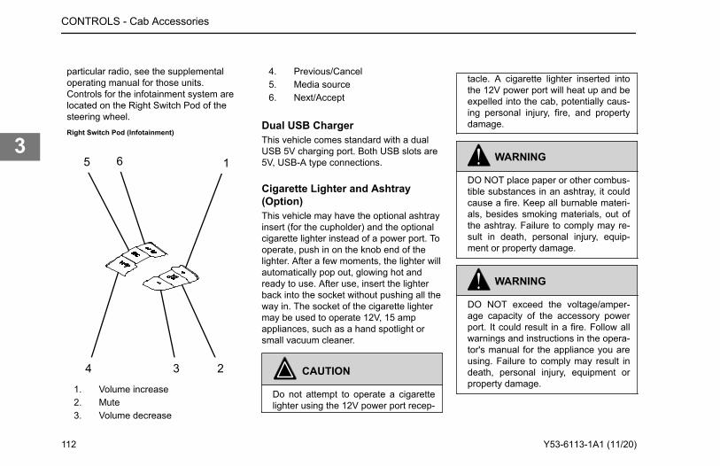
particular radio, see the supplementaloperating manual for those units.Controls for the infotainment system arelocated on the Right Switch Pod of thesteering wheel.Right Switch Pod (Infotainment)
1
4 3 2
5 6
1. Volume increase2. Mute3. Volume decrease
4. Previous/Cancel5. Media source6. Next/Accept
Dual USB ChargerThis vehicle comes standard with a dualUSB 5V charging port. Both USB slots are5V, USB-A type connections.
Cigarette Lighter and Ashtray(Option)This vehicle may have the optional ashtrayinsert (for the cupholder) and the optionalcigarette lighter instead of a power port. Tooperate, push in on the knob end of thelighter. After a few moments, the lighter willautomatically pop out, glowing hot andready to use. After use, insert the lighterback into the socket without pushing all theway in. The socket of the cigarette lightermay be used to operate 12V, 15 ampappliances, such as a hand spotlight orsmall vacuum cleaner.
CAUTION
Do not attempt to operate a cigarettelighter using the 12V power port recep-
tacle. A cigarette lighter inserted intothe 12V power port will heat up and beexpelled into the cab, potentially caus-ing personal injury, fire, and propertydamage.
WARNING
DO NOT place paper or other combus-tible substances in an ashtray, it couldcause a fire. Keep all burnable materi-als, besides smoking materials, out ofthe ashtray. Failure to comply may re-sult in death, personal injury, equip-ment or property damage.
WARNING
DO NOT exceed the voltage/amper-age capacity of the accessory powerport. It could result in a fire. Follow allwarnings and instructions in the opera-tor's manual for the appliance you areusing. Failure to comply may result indeath, personal injury, equipment orproperty damage.
CONTROLS - Cab Accessories
112 Y53-6113-1A1 (11/20)
3
Glove BoxA glove box is provided to store importantdocuments, the vehicle literature set(including this Operator's Manual), andother related materials. You can choosefrom a variety of other interior storageoptions to store your personal supplies orsmall tools:
• center console• map pocket on the door• overhead storage compartments
WARNING
DO NOT drive with the glove boxopen, it can be dangerous. In an acci-dent or sudden stop, you or a passen-ger could be thrown against the coverand be injured. To reduce the risk ofpersonal injury during an accident orsudden stop, keep the glove boxclosed when the vehicle is in motion.
WARNING
DO NOT carry loose objects in yourcab, it can be dangerous. In a suddenstop, or even going over a bump in the
road, they could fly through the air andstrike you or a passenger. You couldbe injured or even killed. Secure allloose objects in the cab before movingthe vehicle. Carry any heavy objectssuch as luggage in the exterior storagecompartment and close it securely.
Dome LightInterior cab lighting is controlled using thethree-position, overhead, dome lightswitch:
• On – Turns on the center, overheaddome light and both the left andright, pressible, map lights.
• Center Position – Turns on theoverhead dome light when eithercab door is open, or when thedoors are unlocked using the keyfob.
• Off – Turns off the center, overheadcab light and disables both the leftand right, pressible, map lights.
The wash down, ambient lighting iscontrolled using the dimmer switch (see Cab and Panel Dimmer Switch on page89).
AppliancesIf your vehicle is equipped with a televisionor other appliance, be sure they arecompatible with your vehicle's electricalsystem. Secure them in the cab so theycannot come loose during a sudden stop.
WARNING
In a sudden stop or collision a heavyobject in your cab could strike you oranyone with you. You could be injuredor even killed. Secure any appliance(such as a radio, or TV) you add toyour sleeper or cab.
Vehicle Telematic SystemYour vehicle may be equipped with anonboard telematics system. This system isa Global Positioning Satellite (GPS)-linkedcomputer. It receives input from multiplesources to locate your vehicle. Read andunderstand the Supplemental Telematicsand Navigation System Owner’s Manualand observe the Warnings, Cautions, andNotes that follow before using the system.
CONTROLS - Cab Accessories
Y53-6113-1A1 (11/20) 113
3
WARNING
Verify legal weight and height restric-tions for the route suggested by thetelematic system. Failure to verifyheight restrictions could lead to caus-ing death, personal injury or propertydamage. Failure to verify weight re-strictions could result in a traffic infrac-tion.
WARNING
Only glance at the system monitorwhile driving. Prolonged periods ofviewing while driving could result in anaccident involving death or personalinjury.
WARNING
DO NOT program the telematic sys-tem while driving. Always stop your ve-hicle when programming or changingthe settings on the telematic system.Programming the system while drivingcan cause you to take your eyes off
the road, which could result in an acci-dent involving death, personal injury orequipment damage.
WARNING
Regardless of how and where the nav-igation system directs you, it is yourresponsibility to operate the vehicle ina safe and legal manner. Failure tocomply may result in death, personalinjury, equipment or property damage.
WARNING
Ensure the volume level of all audiodevices is set to a level that still allowsyou to hear outside traffic and emer-gency vehicles. Failure to comply mayresult in death, personal injury, equip-ment or property damage.
CAUTION
DO NOT rely on the telematic systemto route you to the closest emergency
services. Not all emergency servicesare in the database.
NOTE
The map database is the most currentavailable at the time of production. Thedatabase is designed to provide youwith route suggestions and does nottake into account the relative safety ofa suggested route or of factors thatmay affect the time required to reachyour destination. See the Supplemen-tal Navigation System Owner’s Manualfor more information.
Using the Telematic SystemScreen Display On/Off
1. Press and hold the POWER/LIGHTbutton for approximately 1 second.
2. After the display has been turnedon, the following Warning/Informational screen will appear.
CONTROLS - Cab Accessories
114 Y53-6113-1A1 (11/20)
3
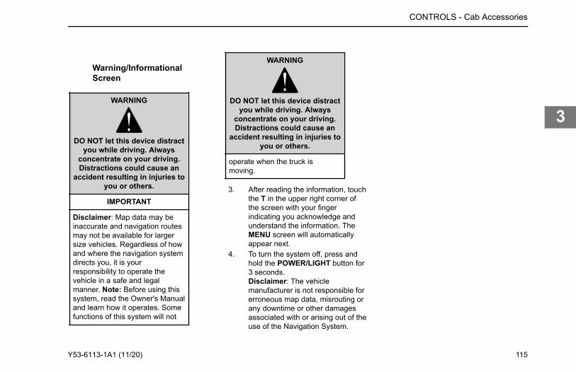
Warning/InformationalScreen
WARNING
DO NOT let this device distractyou while driving. Always
concentrate on your driving.Distractions could cause an
accident resulting in injuries toyou or others.
IMPORTANT
Disclaimer: Map data may beinaccurate and navigation routesmay not be available for largersize vehicles. Regardless of howand where the navigation systemdirects you, it is yourresponsibility to operate thevehicle in a safe and legalmanner. Note: Before using thissystem, read the Owner's Manualand learn how it operates. Somefunctions of this system will not
WARNING
DO NOT let this device distractyou while driving. Always
concentrate on your driving.Distractions could cause an
accident resulting in injuries toyou or others.
operate when the truck ismoving.
3. After reading the information, touchthe T in the upper right corner ofthe screen with your fingerindicating you acknowledge andunderstand the information. TheMENU screen will automaticallyappear next.
4. To turn the system off, press andhold the POWER/LIGHT button for3 seconds.Disclaimer: The vehiclemanufacturer is not responsible forerroneous map data, misrouting orany downtime or other damagesassociated with or arising out of theuse of the Navigation System.
CONTROLS - Cab Accessories
Y53-6113-1A1 (11/20) 115
3
Chapter 4 | DRIVINGStarting and Operating...................................................................................................................... 117Starting and Warming Up.................................................................................................................. 117Engine Operations............................................................................................................................ 121Transmission.....................................................................................................................................128Hydraulic Brakes...............................................................................................................................133Air Brake System (option)................................................................................................................. 135Brake Safety and Emergency........................................................................................................... 141Retarders.......................................................................................................................................... 144Axle and Suspension........................................................................................................................ 147Fifth Wheel........................................................................................................................................156Driving Tips and Techniques............................................................................................................. 161Stopping the Vehicle......................................................................................................................... 163Antilock Brake Systems (ABS)..........................................................................................................165
DRIVING -
116 Y53-6113-1A1 (11/20)
4
Remember When Starting Vehicle in ColdWeather on page 118.
WARNING
Do not use starting fluids with this en-gine. This engine is equipped with anintake air heater: use of starting fluidcan cause an explosion, fire, personalinjury, severe damage to the engine,and property damage.
WARNING
NEVER start or let the engine run inan enclosed, unventilated area. Ex-haust fumes from the engine containcarbon monoxide, a colorless andodorless gas. Carbon monoxide canbe fatal if inhaled. Failure to complymay result in property damage, per-sonal injury, or death.
CAUTION
Do not park or operate the vehicle inareas where the hot exhaust system
may come in contact with dry grass,brush, spilled fuel, or other materialthat can cause a fire.
Starting and Warming Up
How to Start Vehicle in NormalWeather
CAUTION
Never operate the starter motor whilethe engine is running. The starter andflywheel gears could clash or jam, se-verely damaging them.
NOTE
Some starters are equipped with over-crank protection. Check the EngineOperation and Maintenance Manualfor details.
When the outside temperature is above50°F (10°C), you can use the following
DRIVING - Starting and Operating
Starting and OperatingFor detailed information on starting and operating the engine, refer to the Engine Operation and Maintenance Manual provided with your vehicle.Since each vehicle is custom-equipped, all engine operation instructions in this manual are general. You will want to consult the manual for your engine to find out details about your specific engine’s needs. You may need to use a slightly different procedure from the one outlined here.Also, read the American Trucking Association's (ATA) Truck Driver's Handbook. It will give you tips on starting, shifting, and driving your vehicle.This section includes instructions for both Normal Temperature starting and Cold Weather starting. The engine type (brand) and size determines what type of cold weather starting aid is installed in your vehicle. Refer to your Engine Operation and Maintenance Manual to learn what precautions you should take before starting the engine. Many new electronic engines cannot use ether or other starting fluids. These engines are equipped with a flame-start air intake heating system. See Tips to
Y53-6113-1A1 (11/20) 117
4
procedure. If Anti-Theft is enabled, the firsttime you turn the ignition switch to START,you will need to enter the Passcode.
1. Set the parking brake.2. Put your main transmission in
Neutral.3. Disengage (depress) the clutch
(with manual transmission).4. Turn the ignition switch to START.
NOTE
If Anti-Theft is enabled, you will needto enter the Passcode in order to startthe engine (see Anti-Theft).
5. If the engine does not start within30 seconds, release the ignitionswitch. To avoid overtaxing thestarter motor or the batteries, don’tuse the starter for more than 30seconds. Let the starter motor cooland the batteries recover for twominutes before trying again. If theengine still won’t start after acouple of tries, check the fuel linesfor possible fuel starvation or airleaks. Starting failure may meanfuel is not reaching the injectors.
6. As soon as the engine starts, beginto watch the oil pressure gauge.Check your engine manufacturer’smanual for the right pressure foryour engine. If the oil pressuredoesn’t rise within a few seconds,stop the engine. Find out what iswrong before restarting the engine.
7. Slowly engage (release) the clutchafter the engine has started.
8. Wait for the oil pressure gauge toreach normal operating pressurebefore operating the vehicle oridling faster than 1,000 rpm.
Tips to Remember When StartingVehicle in Cold WeatherIf you follow a few simple guidelines, youwill extend the service life of your engine:
• Keep the electrical system in topcondition.
• Use the best quality fuel of therecommended grade.
• Use recommended enginelubricating oil.
• For manual transmissions andauxiliary transmissions, leave thetransmission in neutral and allowthe transmission lubricating oil to
warm up (approximately 3-5minutes) before operating vehicle.
Engine Block Heater (Option)To preheat the engine before starting, plugthe optional engine block heater into aproperly grounded AC electrical source.DO NOT start the engine with the heaterplugged in.
WARNING
Engine block heaters can cause fireswhich may result in property damage,personal injury, or death if not properlymaintained and operated. Regularly in-spect the engine block heater wiringand connector for damaged or frayedwires. DO NOT use the heater if thereare any signs of problems. Contactyour authorized dealer or the manufac-turer of the heater if you are in need ofrepairs or information.
DRIVING - Starting and Warming Up
118 Y53-6113-1A1 (11/20)
4
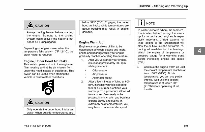
CAUTION
Always unplug heater before startingthe engine. Damage to the coolingsystem could occur if the heater is notturned OFF (unplugged).
Depending on engine make, when thetemperature falls below -10°F (-24°C), theblock heater is required.
Engine, Under Hood Air IntakeThis switch opens a door in the engine airfilter housing so that the air is taken fromunder the hood instead of outside air. Thisswitch can be useful when starting thevehicle in cold weather conditions.
CAUTION
Only operate the under hood intake airswitch when outside temperatures are
below 32°F (0°C). Engaging the underhood air intake while temperatures areabove freezing may result in enginedamage.
Engine Warm UpEngine warm-up allows oil film to beestablished between pistons and liners,shafts and bearings while your enginegradually reaches operating temperature.
1. After you’ve started your engine,idle it at approximately 600 rpmwhile you check:
• Oil pressure• Air pressure• Alternator output
2. After a few minutes of idling at 600rpm, increase your idle speed to900 or 1,000 rpm. Continue yourwarm-up. This procedure allows oilto warm and flow freely whilepistons, liners, shafts, and bearingsexpand slowly and evenly. Inextremely cold temperatures, youmay have to increase idle speed.
NOTE
In colder climates where the tempera-ture is often below freezing, the warm-up for turbocharged engines is espe-cially important. Chilled external oillines leading to the turbocharger willslow the oil flow until the oil warms, re-ducing oil available for the bearings.Watch the engine oil temperature orpressure gauge for a warming trendbefore increasing engine idle speed(rpm).
3. Continue the engine warm-up untilthe coolant temperature reaches atleast 130°F (54°C). At thistemperature, you can use partialthrottle. Wait until the coolanttemperature is at least 160°F(71°C) before operating at fullthrottle.
DRIVING - Starting and Warming Up
Y53-6113-1A1 (11/20) 119
4
NOTE
Under most circumstances, idling yourengine for long periods merely wastesfuel. In severe arctic weather condi-tions, however, you may need longeridling to be sure all parts of your en-gine are fully lubricated.
WARNING
Exhaust fumes from the engine con-tain carbon monoxide, a colorless andodorless gas. DO NOT breathe the en-gine exhaust gas. A poorly maintained,damaged, or corroded exhaust systemcan allow carbon monoxide to enterthe cab. Entry of carbon monoxide intothe cab is also possible from other ve-hicles nearby. Failure to properly main-tain your vehicle could cause carbonmonoxide to enter the cab, resulting inpersonal injury or death.
WARNING
Never idle your vehicle for prolongedperiods of time if you sense that ex-
haust fumes are entering the cab. In-vestigate the cause of the fumes andcorrect it as soon as possible. If thevehicle must be driven under theseconditions, drive only with the windowsopen. Failure to repair the source ofthe exhaust fumes may result in death,personal injury, equipment or propertydamage.
WARNING
To reduce the chance of personal in-jury, vehicle damage, and/or deathfrom overheated engines, which canresult in a fire, never leave the engineidling without an alert driver present. Ifthe engine does overheat, as indicatedby the engine coolant temperaturelamp, immediate action is required tocorrect the condition. Continued unat-tended operation of the engine, evenfor a short time, may result in seriousengine damage or a fire. Failure tocomply may result in death, personalinjury, equipment or property damage.
CAUTION
The use of a winterfront can result inexcessive coolant, engine oil, and in-take air temperatures, which may leadto overheating and possible enginedamage.
CAUTION
DO NOT allow your engine to idle, atlow rpm (400-600 rpm), longer thanfive minutes. Long periods of idling af-ter the engine has reached operatingtemperatures can decrease enginetemperature and cause gummed pis-ton rings, clogged injectors, and possi-ble engine damage from lack of lubri-cation. The normal torsional vibrationsgenerated can also cause transmis-sion wear.
DRIVING - Starting and Warming Up
120 Y53-6113-1A1 (11/20)
4
NOTE
Keep the engine exhaust system andthe vehicle's cab ventilation systemproperly maintained. It is recommend-ed that the vehicle's exhaust systemand cab be inspected (1) By a compe-tent technician every 15,000 miles(24,140 km); (2) Whenever a changeis noticed in the sound of the exhaustsystem; or (3) Whenever the exhaustsystem, underbody, or cab is dam-aged.
NOTE
If you are parked next to idling vehi-cles, move your vehicle or do not stayin your vehicle for prolonged periods oftime.
transmission before starting out on theroad.To warm-up the transmission lubricating oilduring engine warm-up, with a singletransmission (manual and automatic):
1. Put the transmission in Neutral.2. Release the clutch pedal (manual
only) and operate the transmissionin neutral for 3 to 5 minutes prior tooperating the transmission in eitherforward or reverse range.
3. If you have a two-transmissioncombination:
a. Put the main transmission ingear.
b. Put the auxiliary transmissionin Neutral. This will allow thetransmission countershaft toturn, agitating the oil andwarming it.
Engine Operations
PTO Operations (option)This truck may be equipped with PowerTake-Off (PTO). PTO operation is enabledby using the dash mounted PTO switch inconjunction with the cruise control feature.
When enabled, the tachometer willrepresent PTO operation, and may displaythe following additional PTO relatedinformation:
• Engine RPM – indicated near thetachometer as well as on the scaleline.
• PTO hours – shows engine hoursused during PTO activity.
• DPF Status – shows DieselParticulate Filter usage as apercentage.
• Engine Torque – shows thepercentage of max engine torquebeing exerted.
Dependent on your engine these modescan be read inside the tachometer. Formore information on PTO operation see How to Start the PTO, How to Stop thePTO, and/or consult your PTOmanufacture's operating instructions.
How to Start the PTOThe PTO operation can be enabled andactivated in many different ways. Refer toyour PTO manufacturer's OperatingInstructions for specific guidance on how tooperate the PTO. The information belowprovides the basic process of enabling andactivating PTO and what the operator
DRIVING - Engine Operations
How to Warm Up the TransmissionIn cold weather (below 32°F (0°C), you may find shifting sluggish when you first start up. Transmission warm-up is especially important at this time, but it is always a good idea to warm-up your
Y53-6113-1A1 (11/20) 121
4
should observe during this process;however, defer to your PTO manufacturer'sOperating Instructions in all cases wherethere is a disagreement in instruction.
NOTE
Actual PTO engagement/disengage-ment may be delayed momentarilysince it is controlled by the air systemand mechanical movement.
CAUTION
Increasing engine rpm before the PTOis actually engaged could prevent thePTO from engaging and/or cause PTOdamage.
1. Toggle the PTO ON/OFF switch tothe ON position. Text indicatingPTO engagement will appear at thecenter of the display. Vehicles withPACCAR or an Eaton automatedtransmission will display the lettersAN in the transmission gearindicator.
2. Press the Cruise Control (CC)ON/OFF button to enable PTO
speed control operations. A whitespeed control enabled icon willappear
3. Press the SET + and RES – CruiseControl (CC) buttons to commanda desired engine speed. PTOSpeed Control is now active.
4. To increase or decrease PTOengine speed use a combination ofshort and long presses of the SET+ and RES – Cruise Control (CC)buttons.
PTO speed indicates on the digitaltachometer and below it, as a numericalreadout.
How to Stop the PTOWhen PTO Speed Control is active, thereare many ways to disable it depending onhow the vehicle is configured.
• Tap the service brake• Engage the clutch• Turn Cruise Control Off• Release the Parking Brake - (This
is applicable only if PTO wasactivated while the truck wasstationary.)
• Toggling the PTO switch to OFF
Stopping the PTO will return the enginespeed to its default setting. It is not advisedto stop the PTO when engine speed isabove the default setting. Remember, toquit PTO operations fully, toggle the PTOswitch to OFF.
Engine Fan ControlThe engine fan switch on the dash has amanual and an automatic mode. In themanual mode, the engine fan will engageuntil the switch is back into automaticmode. In automatic mode, the engine fanoperation is controlled by the enginecomputer.
DRIVING - Engine Operations
122 Y53-6113-1A1 (11/20)
4
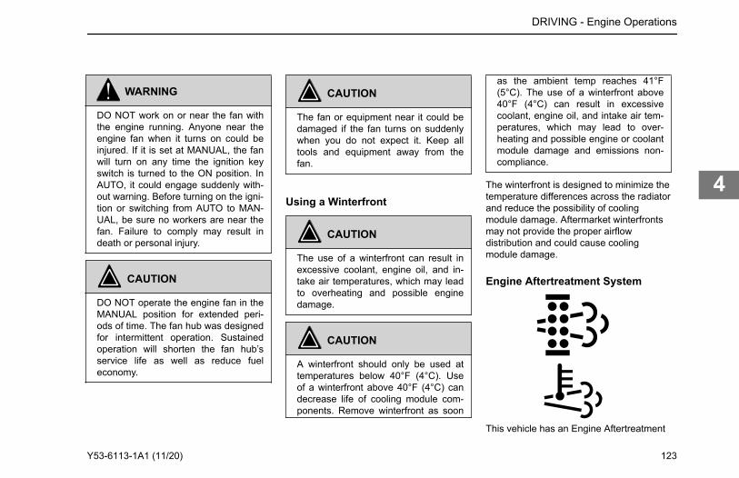
WARNING
DO NOT work on or near the fan withthe engine running. Anyone near theengine fan when it turns on could beinjured. If it is set at MANUAL, the fanwill turn on any time the ignition keyswitch is turned to the ON position. InAUTO, it could engage suddenly with-out warning. Before turning on the igni-tion or switching from AUTO to MAN-UAL, be sure no workers are near thefan. Failure to comply may result indeath or personal injury.
CAUTION
DO NOT operate the engine fan in theMANUAL position for extended peri-ods of time. The fan hub was designedfor intermittent operation. Sustainedoperation will shorten the fan hub’sservice life as well as reduce fueleconomy.
CAUTION
The fan or equipment near it could bedamaged if the fan turns on suddenlywhen you do not expect it. Keep alltools and equipment away from thefan.
Using a Winterfront
CAUTION
The use of a winterfront can result inexcessive coolant, engine oil, and in-take air temperatures, which may leadto overheating and possible enginedamage.
CAUTION
A winterfront should only be used attemperatures below 40°F (4°C). Useof a winterfront above 40°F (4°C) candecrease life of cooling module com-ponents. Remove winterfront as soon
as the ambient temp reaches 41°F(5°C). The use of a winterfront above40°F (4°C) can result in excessivecoolant, engine oil, and intake air tem-peratures, which may lead to over-heating and possible engine or coolantmodule damage and emissions non-compliance.
The winterfront is designed to minimize thetemperature differences across the radiatorand reduce the possibility of coolingmodule damage. Aftermarket winterfrontsmay not provide the proper airflowdistribution and could cause coolingmodule damage.
Engine Aftertreatment System
This vehicle has an Engine Aftertreatment
DRIVING - Engine Operations
Y53-6113-1A1 (11/20) 123
4
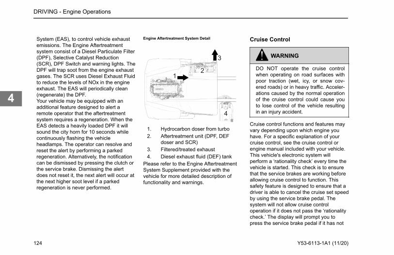
System (EAS), to control vehicle exhaustemissions. The Engine Aftertreatmentsystem consist of a Diesel Particulate Filter(DPF), Selective Catalyst Reduction(SCR), DPF Switch and warning lights. TheDPF will trap soot from the engine exhaustgases. The SCR uses Diesel Exhaust Fluidto reduce the levels of NOx in the engineexhaust. The EAS will periodically clean(regenerate) the DPF.Your vehicle may be equipped with anadditional feature designed to alert aremote operator that the aftertreatmentsystem requires a regeneration. When theEAS detects a heavily loaded DPF it willsound the city horn for 10 seconds whilecontinuously flashing the vehicleheadlamps. The operator can resolve andreset the alert by performing a parkedregeneration. Alternatively, the notificationcan be dismissed by pressing the clutch orthe service brake. Dismissing the alertdoes not reset it, the next alert will occur atthe next higher soot level if a parkedregeneration is never performed.
Engine Aftertreatment System Detail
12
3
4
1. Hydrocarbon doser from turbo2. Aftertreatment unit (DPF, DEF
doser and SCR)3. Filtered/treated exhaust4. Diesel exhaust fluid (DEF) tank
Please refer to the Engine AftertreatmentSystem Supplement provided with thevehicle for more detailed description offunctionality and warnings.
Cruise Control
WARNING
DO NOT operate the cruise controlwhen operating on road surfaces withpoor traction (wet, icy, or snow cov-ered roads) or in heavy traffic. Acceler-ations caused by the normal operationof the cruise control could cause youto lose control of the vehicle resultingin an injury accident.
Cruise control functions and features mayvary depending upon which engine youhave. For a specific explanation of yourcruise control, see the cruise control orengine manual included with your vehicle.This vehicle's electronic system willperform a ‘rationality check’ every time thevehicle is started. This check is to ensurethat the service brakes are working beforeallowing cruise control to function. Thissafety feature is designed to ensure that adriver is able to cancel the cruise set speedby using the service brake pedal. Thesystem will not allow cruise controloperation if it does not pass the ‘rationalitycheck.’ The display will prompt you topress the service brake pedal if it has not
DRIVING - Engine Operations
124 Y53-6113-1A1 (11/20)
4
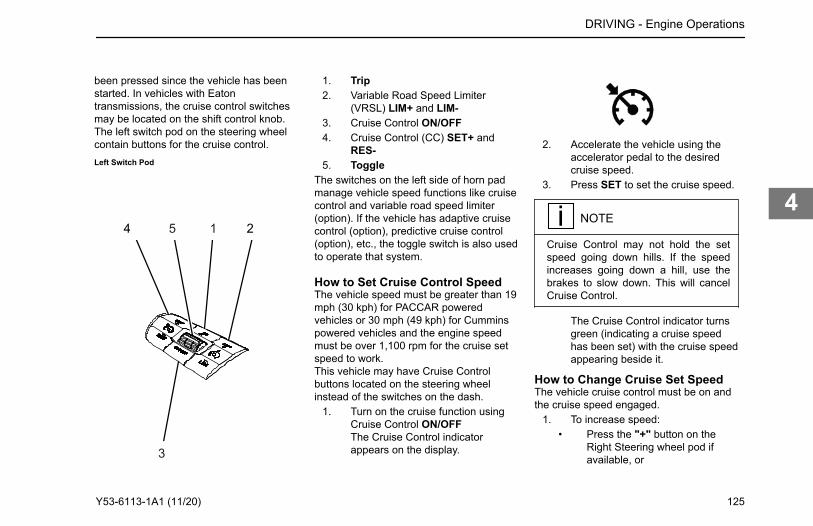
been pressed since the vehicle has beenstarted. In vehicles with Eatontransmissions, the cruise control switchesmay be located on the shift control knob.The left switch pod on the steering wheelcontain buttons for the cruise control.Left Switch Pod
4 25 1
3
1. Trip2. Variable Road Speed Limiter
(VRSL) LIM+ and LIM-3. Cruise Control ON/OFF4. Cruise Control (CC) SET+ and
RES-5. Toggle
The switches on the left side of horn padmanage vehicle speed functions like cruisecontrol and variable road speed limiter(option). If the vehicle has adaptive cruisecontrol (option), predictive cruise control(option), etc., the toggle switch is also usedto operate that system.
How to Set Cruise Control SpeedThe vehicle speed must be greater than 19mph (30 kph) for PACCAR poweredvehicles or 30 mph (49 kph) for Cumminspowered vehicles and the engine speedmust be over 1,100 rpm for the cruise setspeed to work.This vehicle may have Cruise Controlbuttons located on the steering wheelinstead of the switches on the dash.
1. Turn on the cruise function usingCruise Control ON/OFFThe Cruise Control indicatorappears on the display.
2. Accelerate the vehicle using theaccelerator pedal to the desiredcruise speed.
3. Press SET to set the cruise speed.
NOTE
Cruise Control may not hold the setspeed going down hills. If the speedincreases going down a hill, use thebrakes to slow down. This will cancelCruise Control.
The Cruise Control indicator turnsgreen (indicating a cruise speedhas been set) with the cruise speedappearing beside it.
How to Change Cruise Set SpeedThe vehicle cruise control must be on andthe cruise speed engaged.
1. To increase speed:• Press the "+" button on the
Right Steering wheel pod ifavailable, or
DRIVING - Engine Operations
Y53-6113-1A1 (11/20) 125
4
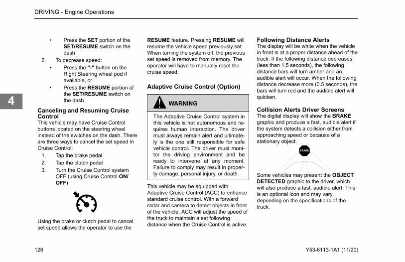
• Press the SET portion of theSET/RESUME switch on thedash
2. To decrease speed:• Press the "-" button on the
Right Steering wheel pod ifavailable, or
• Press the RESUME portion ofthe SET/RESUME switch onthe dash
Canceling and Resuming CruiseControlThis vehicle may have Cruise Controlbuttons located on the steering wheelinstead of the switches on the dash. Thereare three ways to cancel the set speed inCruise Control:
1. Tap the brake pedal2. Tap the clutch pedal3. Turn the Cruise Control system
OFF (using Cruise Control ON/OFF)
Using the brake or clutch pedal to cancelset speed allows the operator to use the
RESUME feature. Pressing RESUME willresume the vehicle speed previously set.When turning the system off, the previousset speed is removed from memory. Theoperator will have to manually reset thecruise speed.
Adaptive Cruise Control (Option)
WARNING
The Adaptive Cruise Control system inthis vehicle is not autonomous and re-quires human interaction. The drivermust always remain alert and ultimate-ly is the one still responsible for safevehicle control. The driver must moni-tor the driving environment and beready to intervene at any moment.Failure to comply may result in proper-ty damage, personal injury, or death.
This vehicle may be equipped withAdaptive Cruise Control (ACC) to enhancestandard cruise control. With a forwardradar and camera to detect objects in frontof the vehicle, ACC will adjust the speed ofthe truck to maintain a set followingdistance when the Cruise Control is active.
Following Distance AlertsThe display will be white when the vehiclein front is at a proper distance ahead of thetruck. If the following distance decreases(less than 1.5 seconds), the followingdistance bars will turn amber and anaudible alert will occur. When the followingdistance decrease more (0.5 seconds), thebars will turn red and the audible alert willquicken.
Collision Alerts Driver ScreensThe digital display will show the BRAKEgraphic and produce a fast, audible alert ifthe system detects a collision either fromapproaching speed or because of astationary object.
BRAKE
Some vehicles may present the OBJECTDETECTED graphic to the driver, whichwill also produce a fast, audible alert. Thisis an optional icon and may varydepending on the specifications of thetruck.
DRIVING - Engine Operations
126 Y53-6113-1A1 (11/20)
4
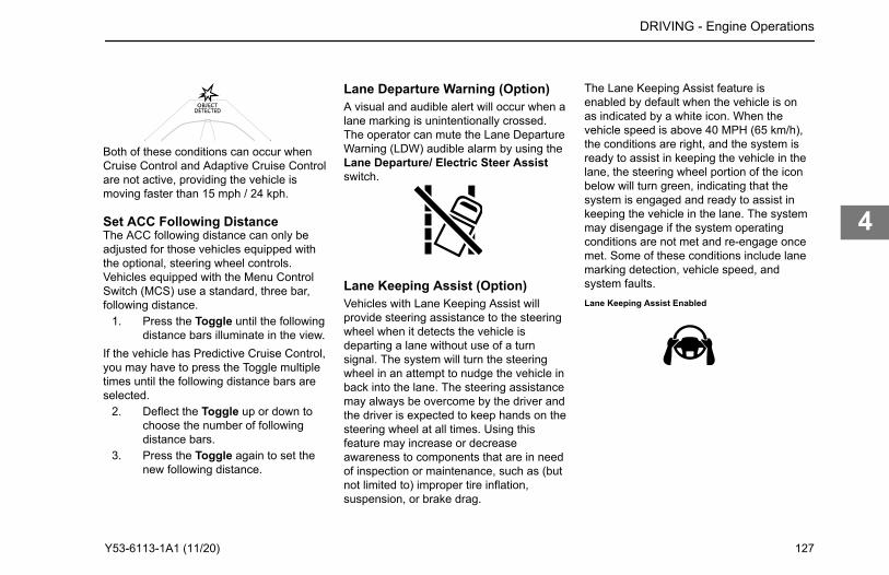
Both of these conditions can occur whenCruise Control and Adaptive Cruise Controlare not active, providing the vehicle ismoving faster than 15 mph / 24 kph.
Set ACC Following DistanceThe ACC following distance can only beadjusted for those vehicles equipped withthe optional, steering wheel controls.Vehicles equipped with the Menu ControlSwitch (MCS) use a standard, three bar,following distance.
1. Press the Toggle until the followingdistance bars illuminate in the view.
If the vehicle has Predictive Cruise Control,you may have to press the Toggle multipletimes until the following distance bars areselected.
2. Deflect the Toggle up or down tochoose the number of followingdistance bars.
3. Press the Toggle again to set thenew following distance.
Lane Departure Warning (Option)A visual and audible alert will occur when alane marking is unintentionally crossed.The operator can mute the Lane DepartureWarning (LDW) audible alarm by using theLane Departure/ Electric Steer Assistswitch.
Lane Keeping Assist (Option)Vehicles with Lane Keeping Assist willprovide steering assistance to the steeringwheel when it detects the vehicle isdeparting a lane without use of a turnsignal. The system will turn the steeringwheel in an attempt to nudge the vehicle inback into the lane. The steering assistancemay always be overcome by the driver andthe driver is expected to keep hands on thesteering wheel at all times. Using thisfeature may increase or decreaseawareness to components that are in needof inspection or maintenance, such as (butnot limited to) improper tire inflation,suspension, or brake drag.
The Lane Keeping Assist feature isenabled by default when the vehicle is onas indicated by a white icon. When thevehicle speed is above 40 MPH (65 km/h),the conditions are right, and the system isready to assist in keeping the vehicle in thelane, the steering wheel portion of the iconbelow will turn green, indicating that thesystem is engaged and ready to assist inkeeping the vehicle in the lane. The systemmay disengage if the system operatingconditions are not met and re-engage oncemet. Some of these conditions include lanemarking detection, vehicle speed, andsystem faults.Lane Keeping Assist Enabled
DRIVING - Engine Operations
Y53-6113-1A1 (11/20) 127
4
WARNING
Ultimate responsibility for the safe op-eration of the vehicle remains with thedriver at all times. Even with Lane De-parture Warning or Electric Steer As-sist, the driver must remain alert, reactappropriately and in a timely manner,and use good driving practices. Failureto do so may result in death, personalinjury and/or property damage.
Lane Keeping Assist Engaged
For the Lane Keeping Assist feature tosafely operate, the driver must remain incontrol of the vehicle with their hands onthe wheel. If the system cannot detect thepresence of the driver’s hands on thewheel, it will disengage the Lane KeepingAssist feature. After some time of notdetecting the driver’s input to the wheel, awarning will be given to keep hands on thewheel.
Air Filter Restriction Indicator(Option)An Air Filter Restriction Indicator may beinstalled on the air filter housing or airinduction piping for access to clean, filteredair.As the filter plugs and restriction increases,a red indicator will appear in a window onthe indicator. When red appears, the airfilter should be replaced. The indicator canbe reset by pressing the button at the endof the indicator.
Transmission
Transmission TipsRiding the ClutchThe clutch is not a footrest. DO NOT drivewith your foot resting on the clutch pedal. It
DRIVING - Transmission
128 Y53-6113-1A1 (11/20)
4
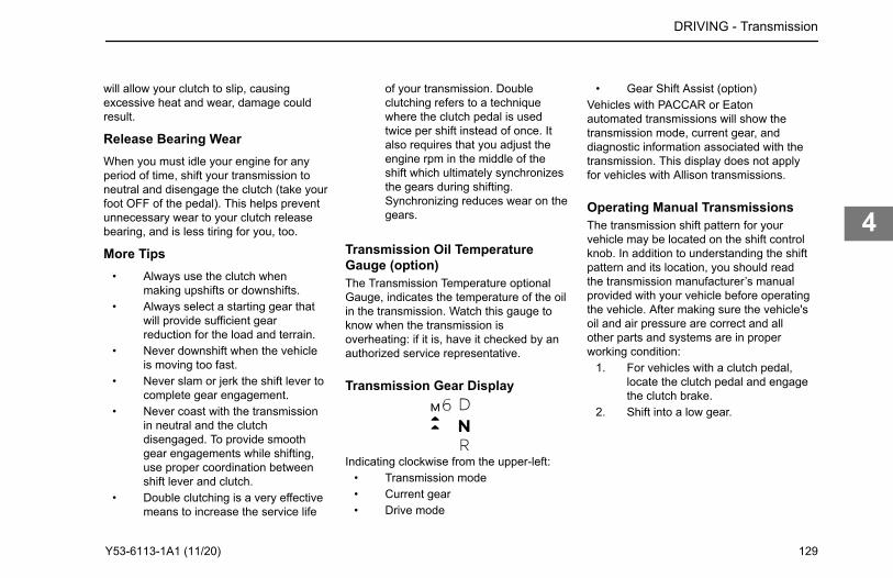
will allow your clutch to slip, causingexcessive heat and wear, damage couldresult.
Release Bearing WearWhen you must idle your engine for anyperiod of time, shift your transmission toneutral and disengage the clutch (take yourfoot OFF of the pedal). This helps preventunnecessary wear to your clutch releasebearing, and is less tiring for you, too.
More Tips• Always use the clutch when
making upshifts or downshifts.• Always select a starting gear that
will provide sufficient gearreduction for the load and terrain.
• Never downshift when the vehicleis moving too fast.
• Never slam or jerk the shift lever tocomplete gear engagement.
• Never coast with the transmissionin neutral and the clutchdisengaged. To provide smoothgear engagements while shifting,use proper coordination betweenshift lever and clutch.
• Double clutching is a very effectivemeans to increase the service life
of your transmission. Doubleclutching refers to a techniquewhere the clutch pedal is usedtwice per shift instead of once. Italso requires that you adjust theengine rpm in the middle of theshift which ultimately synchronizesthe gears during shifting.Synchronizing reduces wear on thegears.
Transmission Oil TemperatureGauge (option)The Transmission Temperature optionalGauge, indicates the temperature of the oilin the transmission. Watch this gauge toknow when the transmission isoverheating: if it is, have it checked by anauthorized service representative.
Transmission Gear Display
Indicating clockwise from the upper-left:• Transmission mode• Current gear• Drive mode
• Gear Shift Assist (option)Vehicles with PACCAR or Eatonautomated transmissions will show thetransmission mode, current gear, anddiagnostic information associated with thetransmission. This display does not applyfor vehicles with Allison transmissions.
Operating Manual TransmissionsThe transmission shift pattern for yourvehicle may be located on the shift controlknob. In addition to understanding the shiftpattern and its location, you should readthe transmission manufacturer’s manualprovided with your vehicle before operatingthe vehicle. After making sure the vehicle'soil and air pressure are correct and allother parts and systems are in properworking condition:
1. For vehicles with a clutch pedal,locate the clutch pedal and engagethe clutch brake.
2. Shift into a low gear.
DRIVING - Transmission
Y53-6113-1A1 (11/20) 129
4
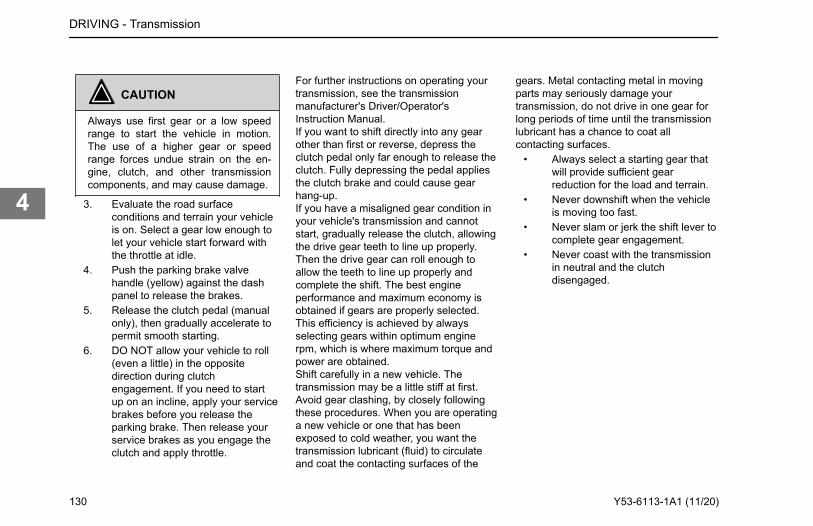
CAUTION
Always use first gear or a low speedrange to start the vehicle in motion.The use of a higher gear or speedrange forces undue strain on the en-gine, clutch, and other transmissioncomponents, and may cause damage.
3. Evaluate the road surfaceconditions and terrain your vehicleis on. Select a gear low enough tolet your vehicle start forward withthe throttle at idle.
4. Push the parking brake valvehandle (yellow) against the dashpanel to release the brakes.
5. Release the clutch pedal (manualonly), then gradually accelerate topermit smooth starting.
6. DO NOT allow your vehicle to roll(even a little) in the oppositedirection during clutchengagement. If you need to startup on an incline, apply your servicebrakes before you release theparking brake. Then release yourservice brakes as you engage theclutch and apply throttle.
For further instructions on operating yourtransmission, see the transmissionmanufacturer's Driver/Operator'sInstruction Manual.If you want to shift directly into any gearother than first or reverse, depress theclutch pedal only far enough to release theclutch. Fully depressing the pedal appliesthe clutch brake and could cause gearhang-up.If you have a misaligned gear condition inyour vehicle's transmission and cannotstart, gradually release the clutch, allowingthe drive gear teeth to line up properly.Then the drive gear can roll enough toallow the teeth to line up properly andcomplete the shift. The best engineperformance and maximum economy isobtained if gears are properly selected.This efficiency is achieved by alwaysselecting gears within optimum enginerpm, which is where maximum torque andpower are obtained.Shift carefully in a new vehicle. Thetransmission may be a little stiff at first.Avoid gear clashing, by closely followingthese procedures. When you are operatinga new vehicle or one that has beenexposed to cold weather, you want thetransmission lubricant (fluid) to circulateand coat the contacting surfaces of the
gears. Metal contacting metal in movingparts may seriously damage yourtransmission, do not drive in one gear forlong periods of time until the transmissionlubricant has a chance to coat allcontacting surfaces.
• Always select a starting gear thatwill provide sufficient gearreduction for the load and terrain.
• Never downshift when the vehicleis moving too fast.
• Never slam or jerk the shift lever tocomplete gear engagement.
• Never coast with the transmissionin neutral and the clutchdisengaged.
DRIVING - Transmission
130 Y53-6113-1A1 (11/20)
4
How to Use the Hydraulic Clutch
CAUTION
Be careful not to apply the clutchbrake while the vehicle is moving. Thepurpose of the clutch brake is to stopthe transmission so that you can shiftinto a starting gear without grindinggears. Applying the clutch brake whenthe vehicle is moving causes a brakingeffect on the drivetrain and shortensthe service life of the clutch brake.
CAUTION
DO NOT push the clutch pedal com-pletely to the floor when shifting whilethe vehicle is in motion. using theclutch brake while shifting a vehicle inmotion will damage the clutch brake. Anon functioning clutch brake will makeshifting very difficult when the vehicleis stationary.
1. Depress the clutch pedal past thefirst 1/2 in. (13 mm) forapproximately 5 1/2 in. (139.7 mm)of total pedal travel.
2. Depress the clutch pedal another1/2 in. (13 mm) to engage theclutch brake.
The clutch brake is used for stoppingtransmission gears, allowing you to easilyshift into first gear or reverse withoutgrinding gears. The clutch brake is notnecessary when shifting into other gearswhile in motion.If the clutch pedal is pressed completely tothe floor and the transmission is notshifting, then it is time to have the clutchadjusted or serviced.If the transmission has a butt-toothcondition and you cannot engage a gear,gradually release the clutch. Then the drivegear can roll enough to allow the teeth toline up properly and complete the shift.The clutch is not a footrest. Do not drivewith your foot resting on the clutch pedal. Itwill allow your clutch to slip, causingexcessive heat and wear, damage couldresult.When you must idle your engine for anyperiod of time, shift your transmission toneutral and disengage the clutch (take yourfoot OFF of the pedal). This helps preventunnecessary wear to your clutch releasebearing, and it is less tiring for you, too.
• Always use the clutch whenmaking upshifts or downshifts.
• Never coast with the transmissionin neutral and the clutchdisengaged.
• To provide smooth gearengagements while shifting, useproper coordination between shiftlever and clutch.
How to Shift Using Double ClutchMethodDouble clutching is easier on thetransmission and on the engine, helpingmatch your vehicle's engine speed withdriveline speed to achieve clash-free shifts.The manual transmission in your vehicle isnot equipped with gear synchronizers.Whether you are upshifting ordownshifting, it is best to double clutch.To double clutch:
1. Push the clutch pedal down todisengage the clutch.
2. Move the gear shift lever to neutral.3. Release the pedal to engage the
clutch. This lets you control the rpmof the transmission mainshaftgears, allowing you to match therpm of the mainshaft gears to thoseof the output shaft.
DRIVING - Transmission
Y53-6113-1A1 (11/20) 131
4
• Upshifts: let the engine andgears slow down to the rpmrequired for the next gear.
• Downshifts: press accelerator,increase engine and gearspeed to the rpm required in thelower gear.
4. Now quickly press the pedal todisengage the clutch and move thegear shift lever to the next gearspeed position.
5. Release the pedal to engage theclutch.
Automatic TransmissionsAn automatic transmission makes shiftingmuch easier. It remains important tocompletely understand how to operate thetransmission to optimize its efficiency.Please read the manual for your automatictransmission included with your vehicle.
WARNING
DO NOT leave the cab of your vehiclewithout applying the parking brake.The truck could roll and cause an acci-dent resulting in death or personal in-
jury. Always apply the parking brakebefore you leave the cab.
Automated TransmissionsThis vehicle may have a PACCAR or Eatonautomated transmission. It remainsimportant to completely understand how tooperate the transmission to optimize itsefficiency. Please read the manual for theautomated transmission included with yourvehicle.Not all automated transmissions have a"park" position, so you will need to applythe parking brake before leaving the cab.
WARNING
If your vehicle has an automatedtransmission, be aware that it can rollbackwards when stopped on a hill orgrade, or when starting from a stop ona hill or grade. Failure to comply mayresult in death, personal injury, equip-ment or property damage. Observe thefollowing guidelines: (1) When stoppedon a hill or grade, press the brake ped-al. (2) When starting from a stop on ahill or grade, quickly remove your foot
from the brake pedal and firmly presson the accelerator pedal.
WARNING
DO NOT leave the cab of your vehiclewithout applying the parking brake.The truck could roll and cause an acci-dent resulting in death or personal in-jury. Always apply the parking brakebefore you leave the cab.
Hill Hold
The hill hold feature is available as anoption with certain automatedtransmissions. This feature holds thevehicle while on a hill to allow the operatorto release the service brakes and press theaccelerator. This feature will hold thevehicle if the vehicle is attempting to go upa hill from a stop in either drive or reverse.
Shift ConfigurationSome transmissions are equipped withmore than one shifting configuration tomatch various operating conditions. Please
DRIVING - Transmission
132 Y53-6113-1A1 (11/20)
4
read the automated transmission manualincluded with your vehicle for instructionson how to change shift configurations.
Controls for Vehicles with an EatonAutomated or a PACCARTransmissionThis vehicle may be equipped with eitheran Eaton Automated or a PACCARTransmission. The Automated or PACCARTransmission controls are located on theright hand side of the steering column.
Auxiliary TransmissionIf you have an auxiliary transmission, seeyour transmission manufacturer’s manualfor its proper operation.
Steerable Drive Axle
NOTE
The customer cannot change axle ra-tios or tires without first obtaining ap-proval from PACCAR. Contact yournearest dealer.
Driver/Operator's Instruction Manual tolearn how to operate correctly.
Hydraulic Brakes
WARNING
Do not operate the vehicle in the eventof a malfunction in any air or hydrauliccircuit. Such a malfunction may pre-vent the brake system from operatingproperly, and could result in an injuryaccident. The vehicle should not beoperated until the system is repairedand both braking circuits, including allpneumatic, hydraulic, and mechanicalcomponents are working properly.
The operation of the vehicle's brakingsystem is based on the principle ofhydraulics. Hydraulic action begins whenforce is applied to the brake pedal. Thisforce creates hydraulic pressure in themaster cylinder and is amplified withassistance of a power booster. Thesupplemental boost in force is developedwhen pressurized power steering fluid fromthe steering pump presses on the mastercylinder piston. As a safety precaution, the
pressurized fluid from the master cylinderhas two mutually independent circuits. Theprimary circuit supplies the front wheelswhile the secondary circuit supplies therear wheels. The displaced fluid from themaster cylinder travels through brake pipesterminating at the wheel cylinders whichactuate the brake pad mechanisms.Actuation of these mechanisms force thebrake pads against the rotors to stop thewheels.A reserve electric motor pump provides aredundant power source for the hydraulicbooster in the event normal flow from thepower steering pump is interrupted.Manual braking is also available in theevent both the power and reserve systemsare inoperative.
WARNING
Never drive your vehicle with the park-ing brake applied. Always release theparking brakes prior to moving the ve-hicle. Failure to disengage the parkingbrakes prior to moving your vehiclecould result in excessive heat buildupin the brake system, resulting in a fire.Failure to comply may result in proper-ty damage, personal injury, or death.
DRIVING - Hydraulic Brakes
If you have a Steerable Drive Axle installed on your vehicle, refer to the auxiliary transmission/transfer case manufacturer's
Y53-6113-1A1 (11/20) 133
4
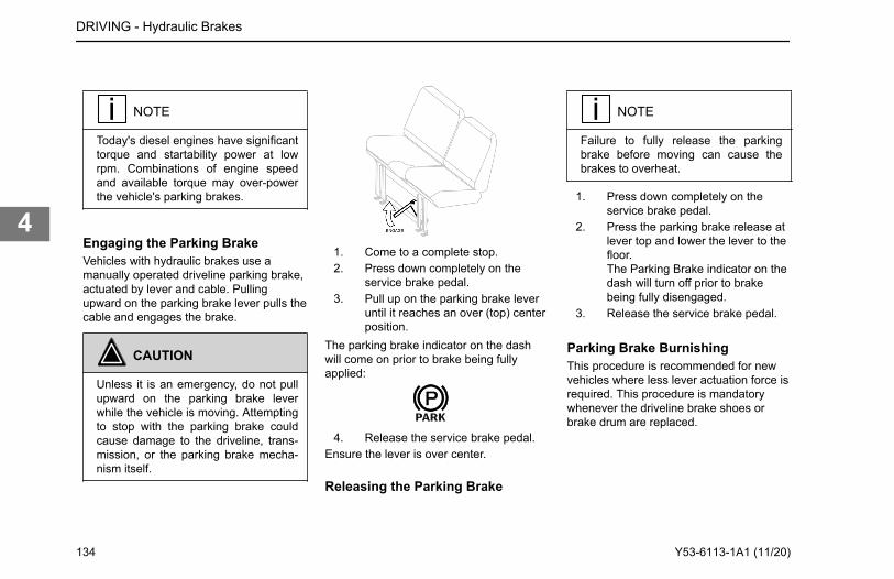
NOTE
Today's diesel engines have significanttorque and startability power at lowrpm. Combinations of engine speedand available torque may over-powerthe vehicle's parking brakes.
Engaging the Parking BrakeVehicles with hydraulic brakes use amanually operated driveline parking brake,actuated by lever and cable. Pullingupward on the parking brake lever pulls thecable and engages the brake.
CAUTION
Unless it is an emergency, do not pullupward on the parking brake leverwhile the vehicle is moving. Attemptingto stop with the parking brake couldcause damage to the driveline, trans-mission, or the parking brake mecha-nism itself.
1. Come to a complete stop.2. Press down completely on the
service brake pedal.3. Pull up on the parking brake lever
until it reaches an over (top) centerposition.
The parking brake indicator on the dashwill come on prior to brake being fullyapplied:
4. Release the service brake pedal.Ensure the lever is over center.
Releasing the Parking Brake
NOTE
Failure to fully release the parkingbrake before moving can cause thebrakes to overheat.
1. Press down completely on theservice brake pedal.
2. Press the parking brake release atlever top and lower the lever to thefloor.The Parking Brake indicator on thedash will turn off prior to brakebeing fully disengaged.
3. Release the service brake pedal.
Parking Brake BurnishingThis procedure is recommended for newvehicles where less lever actuation force isrequired. This procedure is mandatorywhenever the driveline brake shoes orbrake drum are replaced.
DRIVING - Hydraulic Brakes
134 Y53-6113-1A1 (11/20)
4
WARNING
If a new drum or new brake shoes areinstalled, the driveline brake must beburnished. Failure to properly burnishthe parking brake before putting it inservice could result in an inoperativeparking brake, possible vehicle roll-away, and serious personal injury ordamage to the vehicle.
1. Drive the vehicle at 15 mph (24km/h) in a low gear (first or second)on a dry, hard road surface.
2. Apply the parking brake lever witha moderate force (approximately40 pounds) until the vehicle isbrought to a stop. Do not allow thewheels to lock up.
3. After stopping, release the parkingbrake lever and drive the vehicle at20 mph (32 km/h) in a low gear forapproximately 2.5 miles, to allowthe brake drum to cool.
4. Repeat steps 1, 2, and 3 aboveuntil a total of 10 stops have beencompleted.
5. Adjust the parking brake lever. Seethe Medium Duty MaintenanceManual.
ABS Warning LampThe ABS warning lamp will come on briefly,then go off, when the key switch is firstturned on. If the lamp remains ON until aspeed of 4 mph (6 km/h) is reached, thengoes OFF, there may be a stored faultcode. If the lamp remains ON when aspeed in excess of 4 mph (6 km/h) isreached, there may be an active fault in theABS system.
CAUTION
If the ABS warning light does not illu-minate when the ignition is first turnedon, there is a problem with the bulb orwiring. You should have this checkedas soon as possible.
WARNING
No indication will be given via thedashboard warning lights or buzzer iftires of the wrong size are installed on
your vehicle. The Anti-Lock Brake Sys-tem (ABS) is calibrated for the specifictire revolutions per mile. Use of a tireand/or wheel size different from thatoriginally installed on your vehicle maycause the ABS system to not functionduring a hard braking event. Thiscould cause an accident or seriouspersonal injury. Consult with your deal-er before using a different tire and/orwheel size than was originally installedon your vehicle.
Air Brake System (option)This vehicle's braking system and manyvehicle accessories may depend on thestorage and application of a high-pressureair supply. For vehicles equipped with anair brake system, the service brake,parking brake, and trailer brake will utilizethis supply.Vehicles equipped with an air brake systemare of the dual circuit type: it has a circuitfor the front wheels, a separate circuit forthe rear wheels, and one for the trailer. Thesystem is supplied by an engine-drivencompressor. The vehicle's compressor
DRIVING - Air Brake System (option)
Y53-6113-1A1 (11/20) 135
4
takes outside air and compresses it,usually to 100-130 psi (689-896 kPa). Thecompressor air then goes to the air tanksto be stored until needed.When you operate your air brakes, thestored compressed air flows into thechambers where it is used to apply yourtruck and trailer brakes. That is why, whenyou push down on the brake pedal, you donot feel the same amount of pressure onthe pedal that you do when you apply thebrakes on your car. All you are doing onyour truck is opening an air valve to allowair to flow into the brake chambers.
WARNING
The antilock brake system is a criticalvehicle safety system. For the safetyof you and others around you, havethe vehicle submitted for periodic pre-ventive maintenance checks as well ashaving any suspected problems imme-diately checked by an authorized deal-er. Failure to properly maintain yourbrake system can lead to serious acci-dents. Failure to comply may result in-property damage, personal injury, ordeath.
WARNING
Never drive your vehicle with the park-ing brake applied. Always release theparking brakes prior to moving the ve-hicle. Failure to disengage the parkingbrakes prior to moving your vehiclecould result in excessive heat buildupin the brake system, resulting in a fire.Failure to comply may result in proper-ty damage, personal injury, or death.
NOTE
Today's diesel engines have significanttorque and startability power at lowrpm. Combinations of engine speedand available torque may over-powerthe vehicle's parking brakes.
Front Brake SystemWhen the brake pedal is depressed, thefront circuit portion of the treadle valvedelivers air from the front service air tank tothe front axle brake chambers via a quick-release valve.
Simultaneously (on full truckconfigurations), air is also supplied to themodulating valve control port. In the eventof a rear service circuit failure, themodulating valve will exhaust air from thespring brake chambers, applying the springbrakes in proportion to the front circuitapplication.
Rear Brake SystemWhen the brake pedal is depressed, therear circuit portion of the treadle valvedelivers air from the rear service air tank tothe service brake relay valve control port.The relay valve then delivers air directlyfrom the rear service air tank to the rearbrake chambers in proportion to the treadlepressure.
Using the Parking BrakeThe yellow diamond-shaped knob on thedash controls the vehicle parking brakes.These are spring brakes that you activateby releasing air pressure from theirchambers. When they are not in use, airpressure compresses the springs andreleases the brakes. Pulling the valve OUTapplies the parking brake, which exhaustsair from the chambers and allows thesprings to extend and apply the brakes.
DRIVING - Air Brake System (option)
136 Y53-6113-1A1 (11/20)
4
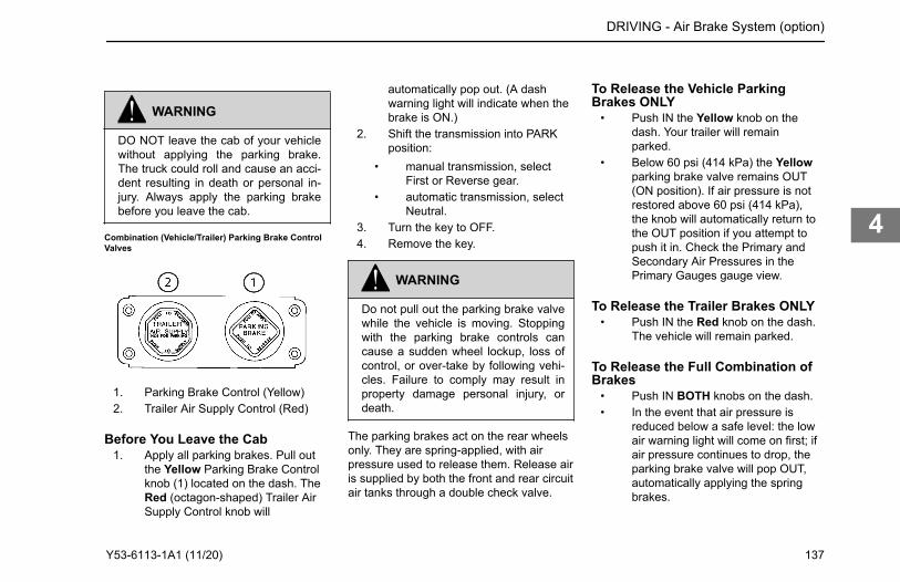
WARNING
DO NOT leave the cab of your vehiclewithout applying the parking brake.The truck could roll and cause an acci-dent resulting in death or personal in-jury. Always apply the parking brakebefore you leave the cab.
Combination (Vehicle/Trailer) Parking Brake ControlValves
1. Parking Brake Control (Yellow)2. Trailer Air Supply Control (Red)
Before You Leave the Cab1. Apply all parking brakes. Pull out
the Yellow Parking Brake Controlknob (1) located on the dash. TheRed (octagon-shaped) Trailer AirSupply Control knob will
automatically pop out. (A dashwarning light will indicate when thebrake is ON.)
2. Shift the transmission into PARKposition:
• manual transmission, selectFirst or Reverse gear.
• automatic transmission, selectNeutral.
3. Turn the key to OFF.4. Remove the key.
WARNING
Do not pull out the parking brake valvewhile the vehicle is moving. Stoppingwith the parking brake controls cancause a sudden wheel lockup, loss ofcontrol, or over-take by following vehi-cles. Failure to comply may result inproperty damage personal injury, ordeath.
The parking brakes act on the rear wheelsonly. They are spring-applied, with airpressure used to release them. Release airis supplied by both the front and rear circuitair tanks through a double check valve.
To Release the Vehicle ParkingBrakes ONLY
• Push IN the Yellow knob on thedash. Your trailer will remainparked.
• Below 60 psi (414 kPa) the Yellowparking brake valve remains OUT(ON position). If air pressure is notrestored above 60 psi (414 kPa),the knob will automatically return tothe OUT position if you attempt topush it in. Check the Primary andSecondary Air Pressures in thePrimary Gauges gauge view.
To Release the Trailer Brakes ONLY• Push IN the Red knob on the dash.
The vehicle will remain parked.
To Release the Full Combination ofBrakes
• Push IN BOTH knobs on the dash.• In the event that air pressure is
reduced below a safe level: the lowair warning light will come on first; ifair pressure continues to drop, theparking brake valve will pop OUT,automatically applying the springbrakes.
DRIVING - Air Brake System (option)
Y53-6113-1A1 (11/20) 137
4
CAUTION
Do not try to put the vehicle in motionbefore pressure in the system reaches100 psi (689 kPa) because the wheelsare locked by the spring brake action.Unnecessary stress and possiblebrake malfunction could occur if thevehicle is forced to move before the airsystem reaches 100 psi (689 kPa).Failure to comply may result in equip-ment damage.
WARNING
If the air pressure falls below 60 psi(414 kPa) the spring brakes may stopthe vehicle abruptly, which couldcause an accident resulting in person-al injury or death. Observe the gauges.If the warning alert comes on, do notcontinue to drive the vehicle until it hasbeen properly repaired or serviced.
WARNING
Using the trailer hand brake or airbrakes to hold a parked vehicle is dan-gerous. Because they work with airpressure, these brakes could comeloose. Your vehicle could roll, causingan accident involving death or person-al injury. Always set the parkingbrakes. Never rely on the trailer handbrake or truck air brakes to hold aparked vehicle.
Vehicle/Trailer Air Supply Valve
Initial ChargeThe red octagon knob controls the airsupply to the trailer. With the systemcompletely discharged, both the Red(trailer air supply) and the Yellow (parkingbrake) knobs are OUT; thus, vehicle andthe trailer parking (spring) brakes areapplied.To supply air to the trailer system andrelease the trailer parking brakes:
1. Allow the vehicle air systempressure to build up to operatinglevel.
2. When system pressure reaches 50psi (345 kPa) the Red knob may bepushed IN.
3. Hold the Red knob IN by hand untilthe trailer air pressure builds to apre-set level, about 45 psi (310kPa). At this point it will remain in,charging the trailer system andreleasing only the trailer brakes.
4. The Yellow knob will remain OUT(vehicle brakes ON).
Normal Run Position• The Yellow knob (system park)
may now be pushed IN, which willsupply air to the vehicle springbrakes, releasing them.
DRIVING - Air Brake System (option)
138 Y53-6113-1A1 (11/20)
4
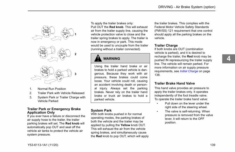
1
2
3
1. Normal Run Position2. Trailer Park with Vehicle Released3. System Park or Trailer Charge with
Vehicle Parked
To apply the trailer brakes only:Pull OUT the Red knob. This will exhaustair from the trailer supply line, causing thevehicle protection valve to close and thetrailer spring brakes to apply. The trailer isnow in emergency or park. This modewould be used to uncouple from the trailer(running without a trailer connected).
WARNING
Using the trailer hand brake or airbrakes to hold a parked vehicle is dan-gerous. Because they work with airpressure, these brakes could comeloose. Your vehicle could roll, causingan accident involving death or person-al injury. Always set the parkingbrakes. Never rely on the trailer handbrake or truck air brakes to hold aparked vehicle.
System ParkWith both knobs pushed in for normaloperating modes, the parking brakes ofboth the vehicle and the trailer may beapplied by pulling the Yellow knob OUT.This will exhaust the air from the vehiclespring brakes, and simultaneously causethe Red knob to pop OUT, which will apply
the trailer brakes. This complies with theFederal Motor Vehicle Safety Standards(FMVSS) 121 requirement that one controlshould apply all the parking brakes on thevehicle.
Trailer ChargeIf both knobs are OUT (combinationvehicle is parked), and it is desired torecharge the trailer, the Red knob may bepushed IN repressurizing the trailer supplyline. The vehicle will remain parked. Formore information on air supply pressurerequirements, see Initial Charge on page138.
Trailer Brake Hand ValveThis hand valve provides air pressure toapply the trailer brakes only. It operatesindependently of the foot treadle valve.To operate the trailer brake hand valve:
• Pull down on the lever under theright side of the steering wheel.
• The valve is self-returning. Whenpressure is removed from the valvelever, it will return to the OFFposition.
DRIVING - Air Brake System (option)
Trailer Park or Emergency Brake Application OnlyIf you ever have a failure or disconnect the air supply hose to the trailer, the trailer parking brakes will set. The Red knob will automatically pop OUT and seal off the vehicle air tanks to protect the vehicle air system pressure.
Y53-6113-1A1 (11/20) 139
4
NOTE
The trailer brake is not to be used as asubstitute for the service brakes. Usingthis brake frequently, instead of usingthe foot brake, will cause the trailerbrakes to wear out sooner.
WARNING
Using the trailer hand brake or airbrakes to hold a parked vehicle is dan-gerous. Because they work with airpressure, these brakes could comeloose. Your vehicle could roll, causingan accident involving death or person-al injury. Always set the parkingbrakes. Never rely on the trailer handbrake or truck air brakes to hold aparked vehicle.
Brake ComponentsThe following is a brief description of theair/brake system.
Compressor: supplies air to the system. Systempressure is controlled by thegovernor.
Governor controls the air pressure in the systemby actuating the compressordischarge mechanism. Its cut-outpressure is 115 to 125 psi (793 to 862kPa). Its preset cut-in pressure is setto between 13 to 25 psi (90 to 172kPa) below the cut-out pressuresetting (cut-out and cut-in interval isnot adjustable).
Safety Valve installed on the supply air tank outlet.It should vent off at 150 psi (1034kPa) permitting air to escape.
Air Dryer collects and removes moisture andcontaminants from the air as it travelsfrom the compressor to the wet tank.
CompressedAir Tanks
The wet tank receives air from the airdryer and cools it somewhat, allowingmoisture to condense for draining.Relatively dry air is then supplied tothe two service air tanks fordistribution to their respective brakecircuits. The service air tanks areisolated from each other by checkvalves.
Dual ServiceBrake TreadleValve
delivers air to the two service brakecircuits.
DoubleCheck Valve
directs the higher air pressure fromeither the rear (primary) or front(secondary) service air tank to themodulating valve.
• Limits spring brakehold-off air pressuredelivered to the
spring brakechambers.
• Provides a quickrelease of airpressure from thespring brakechambers to speedspring brakeapplication.
• Modulates springbrake application inproportion to frontservice application inthe event of a rearservice failure.
• Preventscompounding ofservice and springapplications.
ModulatingValve (SR-1)
used only on full trucks, not tractors,performs four functions:
Quick-Release Valve
speeds the release of air from thebrake chambers. When air isreleased, the air in the brakechambers is exhausted at the quick-release valve, rather than exhaustingback through the treadle valve.
Single CheckValve
allows air flow in one direction only.
ParkingBrake Valve
Yellow diamond-shaped knob. Itcontrols the application and release of
DRIVING - Air Brake System (option)
140 Y53-6113-1A1 (11/20)
4
the parking (spring) brakes of thevehicle or of the vehicle-trailercombinations. If the air system isbeing charged from zero pressure,the parking brake valve will not hold inthe release position until the systempressure exceeds 60 psi (414 kPa),which is the pressure required tooverride the load of this valve'splunger return spring.
Trailer SupplyValve
The Red octagonal-shaped knobprotects the vehicle system; itfunctions in conjunction with theparking brake valve (yellow). Thetrailer supply valve is responsible forsynchronizing the vehicle and trailerparking and emergency brakes. If theair system is being charged from zeropressure, the trailer supply valve willnot hold in the applied position untilthe system pressure exceeds 50 psi(345 kPa). It automatically pops outand exhausts air if supply air pressuredrops below 60 psi (414 kPa).
VehicleProtectionValve
The functions of this valve are to (1)receive all pneumatic signalspertinent to the operation of the trailerbrake system, (2) transmit thesesignals to the trailer, and (3) protectthe vehicle air supply in case ofseparation of the air lines connectingthe vehicle to the trailer.
Brake Safety andEmergency
WARNING
Do not operate the vehicle in the eventof a malfunction in any air circuit. Thevehicle should not be operated untilthe system is repaired and both brak-ing circuits, including all pneumaticand mechanical components, areworking properly. Loss of system aircan cause the service brakes to notfunction resulting in the sudden appli-cation of the spring brakes causingwheel lock-up, loss of control, or over-take by following vehicles. Failure tocomply may result in property damage,personal injury, or death.
• If pressure is lost in the vehiclefront or rear circuit, the "check"valves isolate the unaffected circuit,allowing this circuit to continuenormal operation. The trailerbrakes are still functional.
• If air pressure is lost in the trailersupply/park circuit, and the
pressure drops below 60 psi (414kPa), the trailer spring brakes areautomatically applied, and thevehicle air pressure circuits areunaffected.
• If air pressure is lost in the trailerbrake service circuit, and thepressure in the vehicle front andrear circuits drops below 60 psi(414 kPa), the vehicle and trailerspring brakes are automaticallyapplied.
ABS Warning LampThe ABS warning lamp will come on briefly,then go off, when the key switch is firstturned on. If the lamp remains ON until aspeed of 4 mph (6 km/h) is reached, thengoes OFF, there may be a stored faultcode. If the lamp remains ON when aspeed in excess of 4 mph (6 km/h) isreached, there may be an active fault in theABS system.
DRIVING - Brake Safety and Emergency
Y53-6113-1A1 (11/20) 141
4
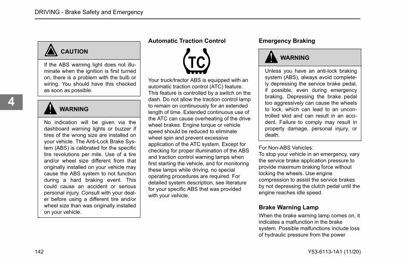
CAUTION
If the ABS warning light does not illu-minate when the ignition is first turnedon, there is a problem with the bulb orwiring. You should have this checkedas soon as possible.
WARNING
No indication will be given via thedashboard warning lights or buzzer iftires of the wrong size are installed onyour vehicle. The Anti-Lock Brake Sys-tem (ABS) is calibrated for the specifictire revolutions per mile. Use of a tireand/or wheel size different from thatoriginally installed on your vehicle maycause the ABS system to not functionduring a hard braking event. Thiscould cause an accident or seriouspersonal injury. Consult with your deal-er before using a different tire and/orwheel size than was originally installedon your vehicle.
Automatic Traction Control
Your truck/tractor ABS is equipped with anautomatic traction control (ATC) feature.This feature is controlled by a switch on thedash. Do not allow the traction control lampto remain on continuously for an extendedlength of time. Extended continuous use ofthe ATC can cause overheating of the drivewheel brakes. Engine torque or vehiclespeed should be reduced to eliminatewheel spin and prevent excessiveapplication of the ATC system. Except forchecking for proper illumination of the ABSand traction control warning lamps whenfirst starting the vehicle, and for monitoringthese lamps while driving, no specialoperating procedures are required. Fordetailed system description, see literaturefor your specific ABS that was providedwith your vehicle.
Emergency Braking
WARNING
Unless you have an anti-lock brakingsystem (ABS), always avoid complete-ly depressing the service brake pedal,if possible, even during emergencybraking. Depressing the brake pedaltoo aggressively can cause the wheelsto lock, which can lead to an uncon-trolled skid and can result in an acci-dent. Failure to comply may result inproperty damage, personal injury, ordeath.
For Non-ABS Vehicles:To stop your vehicle in an emergency, varythe service brake application pressure toprovide maximum braking force withoutlocking the wheels. Use enginecompression to assist the service brakesby not depressing the clutch pedal until theengine reaches idle speed.
Brake Warning LampWhen the brake warning lamp comes on, itindicates a malfunction in the brakesystem. Possible malfunctions include lossof hydraulic pressure from the power
DRIVING - Brake Safety and Emergency
142 Y53-6113-1A1 (11/20)
4
steering circuit or a pressure differentialbetween the primary and secondary brakecircuits.
WARNING
Do not operate the vehicle if the brakelight or buzzer comes on. The light orbuzzer indicates a failure in one of thebrake components/system. Drive yourvehicle to the side of the road immedi-ately. Failure to do this may lead to anaccident and severe injury.
If the buzzer sounds while driving, or if theBRAKE light comes on, do the following:
1. Slow down carefully. Here aresome things you can do to assist inslowing the vehicle:
• Downshift - Putting thetransmission into a lower gearwill help slow the vehicle.
• Pump the brakes - Pumping thebrake pedal may generateenough hydraulic pressure tostop the vehicle.
• Use the parking brake - Theparking or emergency brake isseparate from the hydraulicsystem. Therefore it can beused to slow the vehicle.
2. Move a safe distance off the roadand stop.
3. Set the parking brake.4. Turn on the emergency flasher and
use other warning devices to alertother motorists.
Wet Brakes
WARNING
DO NOT drive through water deepenough to wet brake components, as itmay cause the brakes to work less ef-ficiently than normal. The vehicle'sstopping distance may be longer thanexpected, and the vehicle may pull tothe left or right when brakes are ap-plied, which could contribute to an ac-cident involving death or personal in-jury.
If you have been driving in heavy rain ordeep standing water, your brakes will get
wet. Water in the brakes can cause themto be weak, to apply unevenly, or to grab.These conditions can cause a lack ofbraking power, wheel lockups, or pulling ofthe vehicle to one side or the other.Avoid driving through deep puddles orflowing water if possible. If not possible,you should to the following:
• Slow down.• Place transmission in lower gear.• Gently press on the brake pedal.• Increase engine speed while
keeping light pressure on the brakepedal for a short distance to dry outthe brake linings.
DRIVING - Brake Safety and Emergency
Y53-6113-1A1 (11/20) 143
4
Brake Operation
WARNING
DO NOT drive through water deepenough to wet brake components, as itmay cause the brakes to work less ef-ficiently than normal. The vehicle'sstopping distance may be longer thanexpected, and the vehicle may pull tothe left or right when brakes are ap-plied, which could contribute to an ac-cident involving death or personal in-jury.
To rectify this condition, check the rear andboth sides of the vehicle for clear traffic,then apply the brakes gently, releasing andgently reapplying until the brakes dry out,restoring normal operation. Always checkbrakes after driving through deep water tohelp reduce the possibility of personalinjury or an accident.
Overheated BrakesUnder normal braking conditions, theenergy generated will bring the internalbrake drum temperature to about 500˚ F(260˚ C). This is well within the safe zone:the maximum safe temperature of lining for
drum type brakes is usually about 800˚ F(427˚ C).If service brakes are used for emergencybraking, used improperly, or for prolongedperiods, internal brake drum temperaturesmay exceed 800˚ F (427˚ C). Such brakeoverheating may be detected by a burningsmell or smoke coming from a drum. If thisoccurs, you should immediately stop andcheck for cracked brake drums or liningfires. If neither exists, continue driving andresume a slow speed as soon as possibleto cool the brakes. If the vehicle was toremain stopped, the heat transfer coulddestroy the linings and distort the brakedrum.To prevent drums from distortion while theycool down:
• Park the vehicle on level surfaceand block the wheels.
• Release the parking brake andallow the brakes to cool down. SeeBrakes, Parking Brake Valve onpage 88.
RetardersVarious retarders are available, whichfunction against the engine, driveline, or
transmission. These are devices that useyour engine’s power to slow down yourvehicle. They save wear and tear on yourservice brakes and can be a safety feature,too, because they can keep your brakesfrom overheating. Ideally, you shouldalways slow your vehicle with your retarder(where permitted by law) and use yourservice brakes only for stoppingcompletely. Operating this way will greatlyprolong the life of your brakes.
WARNING
DO NOT use any of the vehicle’s re-tarders in any situation that requiresan immediate stop and/or in situationsof poor traction (such as wet, icy orsnow covered roads). Trying to usethe retarder instead of the servicebrakes may cause a loss of vehiclecontrol, which may result in an acci-dent involving death or personal injury.
DRIVING - Retarders
144 Y53-6113-1A1 (11/20)
4
WARNING
The service brakes must be used in anemergency. The retarder alone mightnot stop you fast enough to prevent anaccident. Failure to comply may resultin death, personal injury, equipment orproperty damage.
The retarder is NOT intended as theprimary brake for the vehicle, nor is it anemergency brake. The retarder only helpsthe service brakes by using pressure toslow the drivetrain. Use the service brakesfor quick stops. Do not use the retarderwhen operating on road surfaces with poortraction (such as wet, icy, or snow coveredroads or gravel). Retarders can cause thewheels to skid on a slippery surface.We recommend that you do not use yourengine retarder to slow down when you arebobtailing or pulling an empty trailer.
WARNING
Using an engine retarder can cause awheel lockup. The trailer is not loadingthe tires enough to give the traction
you may need. When you are bobtailor unloaded, you can have a seriousaccident if your wheels lock suddenlyduring braking. You could be killed orinjured. DO NOT use your retarderwhen you are driving bobtail or with anunloaded trailer.
This vehicle may have a transmissionretarder. Take your foot off the throttle andoperate the retarder switch. When you donot need full retarder effect, you can applyit intermittently (off and on) to causegradual or partial slowing. Continuousapplication of your retarder will cause yourhydraulic fluid to get hotter. Intermittentapplication will help prevent overheating.
WARNING
DO NOT rely on your automatic trans-mission hydraulic retarder to stop yourvehicle. If your engine shuts down, thevehicle’s retarder will cease to operatewhich may lead to an accident involv-
ing death or personal injury. Always beready to suddenly apply the servicebrakes.
NOTE
The exhaust brake and engine brakeare two types of engine retarders. Re-fer also to the engine manufacturer’sOperator Manual and to the EngineRetarder manual for additional instruc-tions.
Exhaust BrakeWith the exhaust brake switch ON, thebrake automatically creates its brakingeffect when you remove your foot from theaccelerator pedal.The brake switch is located on theaccessory dash panel. It controls whetherthe brake is ON (ready to slow the vehicledown) or OFF (no braking action).
• Do not use the engine retarder(such as an exhaust brake) to slowthe vehicle down when you arepulling an empty trailer. See EngineBrakes for further details.
DRIVING - Retarders
Y53-6113-1A1 (11/20) 145
4
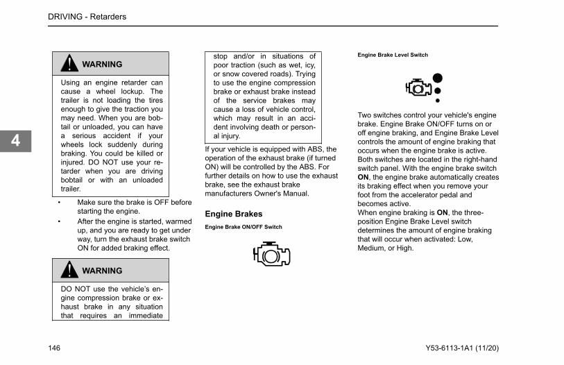
WARNING
Using an engine retarder cancause a wheel lockup. Thetrailer is not loading the tiresenough to give the traction youmay need. When you are bob-tail or unloaded, you can havea serious accident if yourwheels lock suddenly duringbraking. You could be killed orinjured. DO NOT use your re-tarder when you are drivingbobtail or with an unloadedtrailer.
• Make sure the brake is OFF beforestarting the engine.
• After the engine is started, warmedup, and you are ready to get underway, turn the exhaust brake switchON for added braking effect.
WARNING
DO NOT use the vehicle’s en-gine compression brake or ex-haust brake in any situationthat requires an immediate
stop and/or in situations ofpoor traction (such as wet, icy,or snow covered roads). Tryingto use the engine compressionbrake or exhaust brake insteadof the service brakes maycause a loss of vehicle control,which may result in an acci-dent involving death or person-al injury.
If your vehicle is equipped with ABS, theoperation of the exhaust brake (if turnedON) will be controlled by the ABS. Forfurther details on how to use the exhaustbrake, see the exhaust brakemanufacturers Owner's Manual.
Engine BrakesEngine Brake ON/OFF Switch
Engine Brake Level Switch
Two switches control your vehicle's enginebrake. Engine Brake ON/OFF turns on oroff engine braking, and Engine Brake Levelcontrols the amount of engine braking thatoccurs when the engine brake is active.Both switches are located in the right-handswitch panel. With the engine brake switchON, the engine brake automatically createsits braking effect when you remove yourfoot from the accelerator pedal andbecomes active.When engine braking is ON, the three-position Engine Brake Level switchdetermines the amount of engine brakingthat will occur when activated: Low,Medium, or High.
DRIVING - Retarders
146 Y53-6113-1A1 (11/20)
4
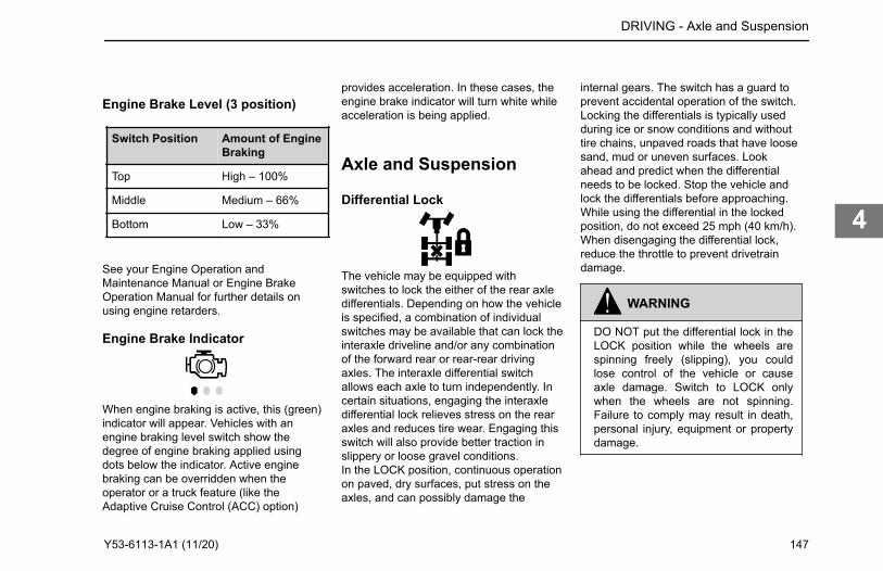
Engine Brake Level (3 position)
Switch Position Amount of EngineBraking
Top High – 100%
Middle Medium – 66%
Bottom Low – 33%
See your Engine Operation andMaintenance Manual or Engine BrakeOperation Manual for further details onusing engine retarders.
Engine Brake Indicator
provides acceleration. In these cases, theengine brake indicator will turn white whileacceleration is being applied.
Axle and Suspension
Differential Lock
The vehicle may be equipped withswitches to lock the either of the rear axledifferentials. Depending on how the vehicleis specified, a combination of individualswitches may be available that can lock theinteraxle driveline and/or any combinationof the forward rear or rear-rear drivingaxles. The interaxle differential switchallows each axle to turn independently. Incertain situations, engaging the interaxledifferential lock relieves stress on the rearaxles and reduces tire wear. Engaging thisswitch will also provide better traction inslippery or loose gravel conditions.In the LOCK position, continuous operationon paved, dry surfaces, put stress on theaxles, and can possibly damage the
internal gears. The switch has a guard toprevent accidental operation of the switch.Locking the differentials is typically usedduring ice or snow conditions and withouttire chains, unpaved roads that have loosesand, mud or uneven surfaces. Lookahead and predict when the differentialneeds to be locked. Stop the vehicle andlock the differentials before approaching.While using the differential in the lockedposition, do not exceed 25 mph (40 km/h).When disengaging the differential lock,reduce the throttle to prevent drivetraindamage.
WARNING
DO NOT put the differential lock in theLOCK position while the wheels arespinning freely (slipping), you couldlose control of the vehicle or causeaxle damage. Switch to LOCK onlywhen the wheels are not spinning.Failure to comply may result in death,personal injury, equipment or propertydamage.
DRIVING - Axle and Suspension
When engine braking is active, this (green) indicator will appear. Vehicles with an engine braking level switch show the degree of engine braking applied using dots below the indicator. Active engine braking can be overridden when the operator or a truck feature (like the Adaptive Cruise Control (ACC) option)
Y53-6113-1A1 (11/20) 147
4
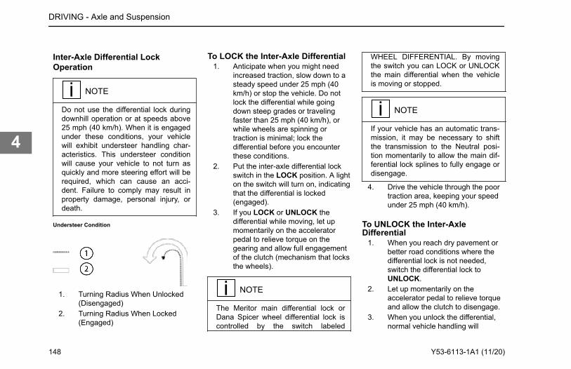
Inter-Axle Differential LockOperation
NOTE
Do not use the differential lock duringdownhill operation or at speeds above25 mph (40 km/h). When it is engagedunder these conditions, your vehiclewill exhibit understeer handling char-acteristics. This understeer conditionwill cause your vehicle to not turn asquickly and more steering effort will berequired, which can cause an acci-dent. Failure to comply may result inproperty damage, personal injury, ordeath.
Understeer Condition
1. Turning Radius When Unlocked(Disengaged)
2. Turning Radius When Locked(Engaged)
To LOCK the Inter-Axle Differential1. Anticipate when you might need
increased traction, slow down to asteady speed under 25 mph (40km/h) or stop the vehicle. Do notlock the differential while goingdown steep grades or travelingfaster than 25 mph (40 km/h), orwhile wheels are spinning ortraction is minimal; lock thedifferential before you encounterthese conditions.
2. Put the inter-axle differential lockswitch in the LOCK position. A lighton the switch will turn on, indicatingthat the differential is locked(engaged).
3. If you LOCK or UNLOCK thedifferential while moving, let upmomentarily on the acceleratorpedal to relieve torque on thegearing and allow full engagementof the clutch (mechanism that locksthe wheels).
NOTE
The Meritor main differential lock orDana Spicer wheel differential lock iscontrolled by the switch labeled
WHEEL DIFFERENTIAL. By movingthe switch you can LOCK or UNLOCKthe main differential when the vehicleis moving or stopped.
NOTE
If your vehicle has an automatic trans-mission, it may be necessary to shiftthe transmission to the Neutral posi-tion momentarily to allow the main dif-ferential lock splines to fully engage ordisengage.
4. Drive the vehicle through the poortraction area, keeping your speedunder 25 mph (40 km/h).
To UNLOCK the Inter-AxleDifferential
1. When you reach dry pavement orbetter road conditions where thedifferential lock is not needed,switch the differential lock toUNLOCK.
2. Let up momentarily on theaccelerator pedal to relieve torqueand allow the clutch to disengage.
3. When you unlock the differential,normal vehicle handling will
DRIVING - Axle and Suspension
148 Y53-6113-1A1 (11/20)
4
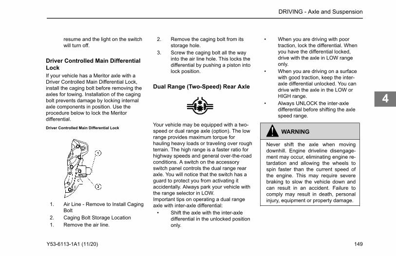
resume and the light on the switchwill turn off.
Driver Controlled Main DifferentialLockIf your vehicle has a Meritor axle with aDriver Controlled Main Differential Lock,install the caging bolt before removing theaxles for towing. Installation of the cagingbolt prevents damage by locking internalaxle components in position. Use theprocedure below to lock the Meritordifferential.Driver Controlled Main Differential Lock
1. Air Line - Remove to Install CagingBolt
2. Caging Bolt Storage Location1. Remove the air line.
2. Remove the caging bolt from itsstorage hole.
3. Screw the caging bolt all the wayinto the air line hole. This locks thedifferential by pushing a piston intolock position.
Dual Range (Two-Speed) Rear Axle
Your vehicle may be equipped with a two-speed or dual range axle (option). The lowrange provides maximum torque forhauling heavy loads or traveling over roughterrain. The high range is a faster ratio forhighway speeds and general over-the-roadconditions. A switch on the accessoryswitch panel controls the dual range rearaxle. You will notice that the switch has aguard to protect you from activating itaccidentally. Always park your vehicle withthe range selector in LOW.Important tips on operating a dual rangeaxle with inter-axle differential:
• Shift the axle with the inter-axledifferential in the unlocked positiononly.
• When you are driving with poortraction, lock the differential. Whenyou have the differential locked,drive with the axle in LOW rangeonly.
• When you are driving on a surfacewith good traction, keep the inter-axle differential unlocked. You candrive with the axle in the LOW orHIGH range.
• Always UNLOCK the inter-axledifferential before shifting the axlespeed range.
WARNING
Never shift the axle when movingdownhill. Engine driveline disengage-ment may occur, eliminating engine re-tardation and allowing the wheels tospin faster than the current speed ofthe engine. This may require severebraking to slow the vehicle down andcan result in an accident. Failure tocomply may result in death, personalinjury, equipment or property damage.
DRIVING - Axle and Suspension
Y53-6113-1A1 (11/20) 149
4
CAUTION
If you shift the axle range with the in-ter-axle differential in LOCK, you couldseriously damage the axles. Nevershift the axle range with the differentiallocked.
Proper shifting of the axle depends on thesynchronization of engine/driveline andwheel speed. When you shift the axle, theconnection between the engine and wheelsis momentarily disengaged while thegearing is synchronized. Normally whenthe axle is shifted the speed of the engine,axle, and wheels adjust, allowing for propergear engagement.When going downhill the wheels will notslow down, but will tend to speed up, whichmakes gear synchronization almostimpossible. As a result, the axle is neitherin HIGH nor LOW range and all engine/driveline retardation is lost. Without engineretardation it is more difficult to slow thevehicle down and greater stress is put onthe brake system.
CAUTION
To avoid damaging your vehicle shiftthe axle at slower travel speeds untilyou are used to driving with a dualrange axle.
How to Operate Two-Speed Axle -Low to HighThese steps should be used if operating atwo-speed axle in LOW range on roughterrain and preparing to drive on animproved surface.When you go from rough terrain to highwaydriving, shift the axle to the HIGH rangefollowing this procedure:
1. Be sure the differential isUNLOCKED.
2. Maintain your vehicle speed(accelerator depressed) and movethe Range Selector lever to HIGH.
3. Keep driving with the acceleratordepressed until you want the axleto shift.
4. To make the axle shift, release theaccelerator until the axle shifts. Youare now in the HIGH axle range forhighway speeds. Shift the
transmission normally to reachyour desired cruising speed.
How to Operate Two-Speed Axle -High to LowThese steps should be used if operating atwo-speed axle in HIGH range on improvedroads and preparing to drive on roughterrain.When you go from highway driving torough terrain, shift the axle to the LOWrange following this procedure:
1. Maintain vehicle speed (acceleratordepressed) and move the RangeSelector lever to LOW.
2. Keep driving with the acceleratordepressed until you want the axleto downshift.
3. To make the axle downshift,release and depress theaccelerator quickly to increase theengine rpm. The axle will shift toLOW range.
4. You are now in the LOW axle rangefor rough terrain and heavy loads.Shift the transmission normally tomaintain the desired speed.
DRIVING - Axle and Suspension
150 Y53-6113-1A1 (11/20)
4
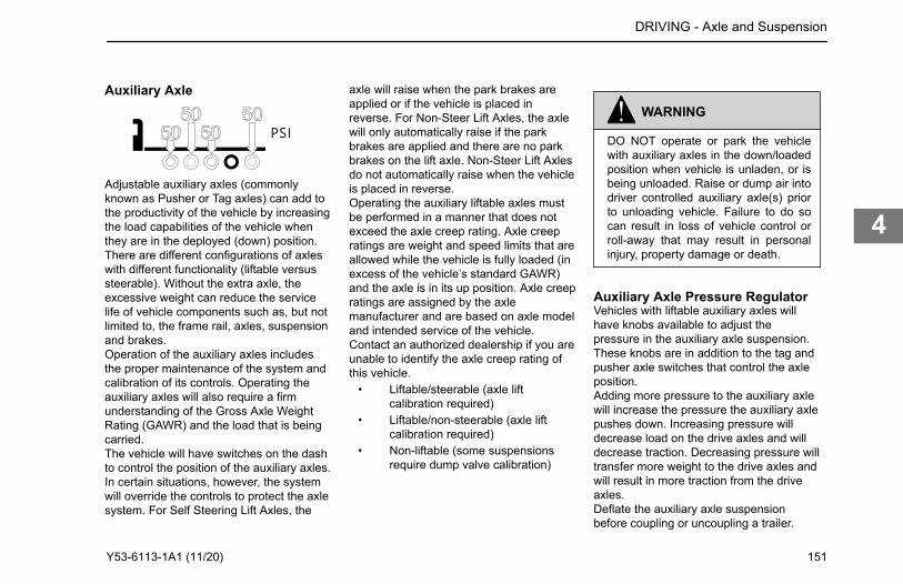
Auxiliary Axle axle will raise when the park brakes areapplied or if the vehicle is placed inreverse. For Non-Steer Lift Axles, the axlewill only automatically raise if the parkbrakes are applied and there are no parkbrakes on the lift axle. Non-Steer Lift Axlesdo not automatically raise when the vehicleis placed in reverse.Operating the auxiliary liftable axles mustbe performed in a manner that does notexceed the axle creep rating. Axle creepratings are weight and speed limits that areallowed while the vehicle is fully loaded (inexcess of the vehicle’s standard GAWR)and the axle is in its up position. Axle creepratings are assigned by the axlemanufacturer and are based on axle modeland intended service of the vehicle.Contact an authorized dealership if you areunable to identify the axle creep rating ofthis vehicle.
• Liftable/steerable (axle liftcalibration required)
• Liftable/non-steerable (axle liftcalibration required)
• Non-liftable (some suspensionsrequire dump valve calibration)
WARNING
DO NOT operate or park the vehiclewith auxiliary axles in the down/loadedposition when vehicle is unladen, or isbeing unloaded. Raise or dump air intodriver controlled auxiliary axle(s) priorto unloading vehicle. Failure to do socan result in loss of vehicle control orroll-away that may result in personalinjury, property damage or death.
Auxiliary Axle Pressure RegulatorVehicles with liftable auxiliary axles willhave knobs available to adjust thepressure in the auxiliary axle suspension.These knobs are in addition to the tag andpusher axle switches that control the axleposition.Adding more pressure to the auxiliary axlewill increase the pressure the auxiliary axlepushes down. Increasing pressure willdecrease load on the drive axles and willdecrease traction. Decreasing pressure willtransfer more weight to the drive axles andwill result in more traction from the driveaxles.Deflate the auxiliary axle suspensionbefore coupling or uncoupling a trailer.
DRIVING - Axle and Suspension
Adjustable auxiliary axles (commonly known as Pusher or Tag axles) can add to the productivity of the vehicle by increasing the load capabilities of the vehicle when they are in the deployed (down) position. There are different configurations of axles with different functionality (liftable versus steerable). Without the extra axle, the excessive weight can reduce the service life of vehicle components such as, but not limited to, the frame rail, axles, suspension and brakes.Operation of the auxiliary axles includes the proper maintenance of the system and calibration of its controls. Operating the auxiliary axles will also require a firm understanding of the Gross Axle Weight Rating (GAWR) and the load that is being carried.The vehicle will have switches on the dash to control the position of the auxiliary axles. In certain situations, however, the system will override the controls to protect the axle system. For Self Steering Lift Axles, the
Y53-6113-1A1 (11/20) 151
4
After the trailer is coupled or uncoupled,then increase pressure to balance tractionand axle load requirements. Inflate airsprings of the auxiliary axles to the desiredpressure after coupling to a loaded trailerwhile still maintaining proper traction of thedrive axles.Adjust the pressure regulator control knobto a lower pressure until desired traction isobtained. By reducing air pressure atpusher or tag axle, load will be transferredto drive axles. Do not overload drive axles.Always deflate air springs of the auxiliaryaxles before attempting to unload vehicle.This allows maximum traction of the driveaxles to control the vehicle.Depending on the suspension, variouscalibrations may be required. Contact yourauthorized dealer or axle/suspensionmanufacturer for specific calibrationprocedures.Some suspensions require dump valvecalibration. For example, some dead axlesdo not lift, but the air can be dumped out ofthem to unload them when empty. Airpressure is controlled via an adjustableregulator. These axles need to becalibrated for load.Contact your authorized dealer or axle/suspension manufacturer for dump valvecalibration procedures.
Axle Creep RatingVehicles outfitted with auxiliary axles andfull truck configuration will have an axlecreep rating which defines how much loadis allowed when the vehicle has a full loadand maneuvering the vehicle, at very slowspeeds, with auxiliary axles in the upposition. In these situations, the loadexceeds the gross axle weight rating of theaxles.Operator's using vehicles equipped withliftable auxiliary axles must consider creepratings when any liftable axle is unloadedor in the raised position. Liftable auxiliaryaxles should only be raised (or unloaded)to improve maneuverability in an off-roaduse or when vehicle is unloaded.
WARNING
NEVER operate the vehicle with morepressure in the lift axles than is neces-sary to carry the load, as determinedby the calibration procedure described.Failure to do so can result in loss oftraction and stability at the steer and/ordrive axles and can result in increasedbraking distance, which could causeloss of vehicle control resulting in anaccident. Failure to comply may result
in death, personal injury, equipment orproperty damage.
NOTE
Axle Creep ratings MUST NOT be ex-ceeded.
CAUTION
Always lower the axles as soon aspossible after receiving a load. Neverexceed 5 mph (8 km/h) when drivingwith a load with the auxiliary axle(s)raised/unloaded. Failure to lower theaxle(s) can overload the frame and re-maining axles, and could cause equip-ment damage.
DRIVING - Axle and Suspension
152 Y53-6113-1A1 (11/20)
4
CAUTION
DO NOT modify the air system and/orcontrol functionality on a factory instal-led auxiliary axle(s). Modifying the fac-tory operation of the pusher and/or tagaxle(s) will void your warranty, and cancause equipment damage.
CAUTION
A change in tire size on either the aux-iliary axles or the drive/steer axles canchange the calibration of the auxiliaryaxles. If tires are installed with a differ-ent loaded radius, the calibration pro-cedure must be repeated. Failure to doso can cause equipment damage.
Contact your dealer or axle manufacturerto determine what the creep rating is foryour particular axle(s) and configuration.Creep ratings are generally limited to thefollowing:
• Tandem rear axles only• Straight trucks only• Maximum spring mount centers per
axle manufacturers specifications
• Maximum tire static loaded radius(SLR) per axle manufacturersspecifications
Pusher or Tag SuspensionCalibrationPerform this procedure at or near a weightscale. Procedure can be performed whileparked on the weight scale if scale isavailable. To obtain the desired axle loaddistribution, you must correlate thesuspension air gauge pressure to theactual axle load by scaling the axleweight(s) and adjusting the pressure toobtain the desired load. Once the desiredload or load range is achieved, documentthe pressure-to-load ratio or setting forfuture use.
NOTE
This procedure must be performed pri-or to placing the vehicle into service.
Add: Perform this procedure at or near aweight scale. Procedure can be performedwhile parked on the weight scale if scale isavailable.
Setting thePressure-to-Load Ratio
To obtain the desired axle loaddistribution, you must correlate thesuspension air gauge pressure to theactual axle load by scaling the axleweight(s) and adjusting the pressure toobtain the desired load. Once thedesired load or load range is achieved,document the pressure-to-load ratio orsetting for future use.
These instructions are general in nature.For more specific instructions, review thepusher or tag suspension manufacturersmaintenance manual or contact thenearest authorized dealer.
1. Park the loaded vehicle on a levelsurface with the wheels blocked.
2. Release vehicles spring brakes.(Do not release for Liftable/Non-Steerable pusher or tag axles)
3. Lower the pusher/tag axles with theAxle Lift Control flip valve. (Forsome non-liftable axles, inflate airsuspension)
4. Adjust the amount of load on eachaxle by turning the PressureRegulator clockwise to increasethe load, or counterclockwise todecrease the load. (Thesuspension manufacturer maypublish pre-established Pressure-to-Load Ratio Pressure Settings to
DRIVING - Axle and Suspension
Y53-6113-1A1 (11/20) 153
4
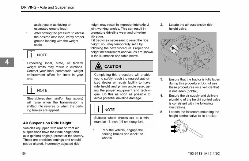
assist you in achieving anestimated ground load).
5. After setting the pressure to obtainthe desired axle load, verify properground loading with the weightscale.
NOTE
Exceeding local, state, or federalweight limits may result in citations.Contact your local commercial weightenforcement office for limits in yourarea.
NOTE
Steerable-pusher and/or tag axle(s)will raise when the transmission isshifted into reverse or when the park-ing brakes are applied.
Air Suspension Ride HeightVehicles equipped with rear or front airsuspensions have their ride height andaxle (pinion) angle(s) preset at the factory.These are precision settings and shouldnot be altered. Incorrectly adjusted ride
height may result in improper interaxle U-joint working angles. This can result inpremature driveline wear and drivelinevibration.If it becomes necessary to reset the rideheight, you may temporarily set it byfollowing the next procedure. Proper rideheight measurement and values are shownin the illustration and table below.
CAUTION
Completing this procedure will enableyou to safely reach the nearest author-ized dealer or repair facility to haveride height and pinion angle reset us-ing the proper equipment and techni-que. Do this as soon as possible toavoid potential driveline damage.
NOTE
Suitable wheel chocks are at a mini-mum an 18-inch (46 cm) long 4x4.
1. Park the vehicle, engage theparking brakes and clock thewheels.
2. Locate the air suspension rideheight valve.
3. Ensure that the tractor is fully ladenduring this procedure. Do not usethese procedures on a vehicle thatis not laden (bobtail).
4. Ensure the air supply and deliveryplumbing of the height control valveis consistent with the followingillustrations.
5. Loosen the fasteners mounting theheight control valve to its bracket.
DRIVING - Axle and Suspension
154 Y53-6113-1A1 (11/20)
4
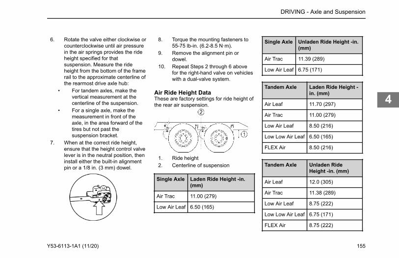
6. Rotate the valve either clockwise orcounterclockwise until air pressurein the air springs provides the rideheight specified for thatsuspension. Measure the rideheight from the bottom of the framerail to the approximate centerline ofthe rearmost drive axle hub:
• For tandem axles, make thevertical measurement at thecenterline of the suspension.
• For a single axle, make themeasurement in front of theaxle, in the area forward of thetires but not past thesuspension bracket.
7. When at the correct ride height,ensure that the height control valvelever is in the neutral position, theninstall either the built-in alignmentpin or a 1/8 in. (3 mm) dowel.
8. Torque the mounting fasteners to55-75 lb-in. (6.2-8.5 N·m).
9. Remove the alignment pin ordowel.
10. Repeat Steps 2 through 6 abovefor the right-hand valve on vehicleswith a dual-valve system.
Air Ride Height DataThese are factory settings for ride height ofthe rear air suspension.
1. Ride height2. Centerline of suspension
Single Axle Laden Ride Height -in.(mm)
Air Trac 11.00 (279)
Low Air Leaf 6.50 (165)
Single Axle Unladen Ride Height -in.(mm)
Air Trac 11.39 (289)
Low Air Leaf 6.75 (171)
Tandem Axle Laden Ride Height -in. (mm)
Air Leaf 11.70 (297)
Air Trac 11.00 (279)
Low Air Leaf 8.50 (216)
Low Low Air Leaf 6.50 (165)
FLEX Air 8.50 (216)
Tandem Axle Unladen RideHeight -in. (mm)
Air Leaf 12.0 (305)
Air Trac 11.38 (289)
Low Air Leaf 8.75 (222)
Low Low Air Leaf 6.75 (171)
FLEX Air 8.75 (222)
DRIVING - Axle and Suspension
Y53-6113-1A1 (11/20) 155
4
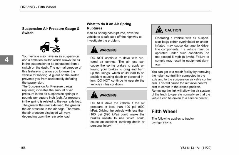
Suspension Air Pressure Gauge &Switch
Your vehicle may have an air suspensionand a deflation switch which allows the airin the suspension to be exhausted from aswitch on the dash. The normal purpose ofthis feature is to allow you to lower thevehicle for loading. A guard on the switchprevents you from accidentally deflatingthe suspension.The Suspension Air Pressure gauge(optional) indicates the amount of airpressure in the air suspension springs inpounds per square inch (psi). Air pressurein the spring is related to the rear axle load.The greater the rear axle load, the greaterthe air pressure in the air bags. Therefore,the air pressure displayed will vary,depending upon the rear axle load.
What to do if an Air SpringRupturesIf an air spring has ruptured, drive thevehicle to a safe stop off the highway toinvestigate the problem.
WARNING
DO NOT continue to drive with rup-tured air springs. The air loss cancause the spring brakes to apply al-lowing your brakes to drag and burnup the linings, which could lead to anaccident causing death or personal in-jury. DO NOT continue to operate thevehicle in this condition.
WARNING
DO NOT drive the vehicle if the airpressure is less than 100 psi (690kPa). Driving the vehicle with less than100 psi (690 kPa) could make thebrakes unsafe to use which couldcause an accident involving death orpersonal injury.
CAUTION
Operating a vehicle with air suspen-sion bags either overinflated or under-inflated may cause damage to drive-line components. If a vehicle must beoperated under such conditions, donot exceed 5 mph (8 km/h). Failure tocomply may result in equipment dam-age.
You can get to a repair facility by removingthe height control link connected to theaxle and to the suspension air valve controlarm. This will cause the air valve controlarm to center in the closed position.Removing the link will allow the air systemof the truck to operate normally so that thevehicle can be driven to a service center.
Fifth WheelThe following applies to tractorconfigurations:
DRIVING - Fifth Wheel
156 Y53-6113-1A1 (11/20)
4
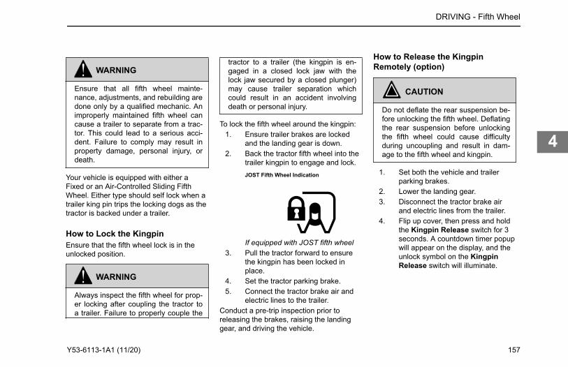
WARNING
Ensure that all fifth wheel mainte-nance, adjustments, and rebuilding aredone only by a qualified mechanic. Animproperly maintained fifth wheel cancause a trailer to separate from a trac-tor. This could lead to a serious acci-dent. Failure to comply may result inproperty damage, personal injury, ordeath.
Your vehicle is equipped with either aFixed or an Air-Controlled Sliding FifthWheel. Either type should self lock when atrailer king pin trips the locking dogs as thetractor is backed under a trailer.
How to Lock the KingpinEnsure that the fifth wheel lock is in theunlocked position.
WARNING
Always inspect the fifth wheel for prop-er locking after coupling the tractor toa trailer. Failure to properly couple the
tractor to a trailer (the kingpin is en-gaged in a closed lock jaw with thelock jaw secured by a closed plunger)may cause trailer separation whichcould result in an accident involvingdeath or personal injury.
To lock the fifth wheel around the kingpin:1. Ensure trailer brakes are locked
and the landing gear is down.2. Back the tractor fifth wheel into the
trailer kingpin to engage and lock.JOST Fifth Wheel Indication
If equipped with JOST fifth wheel3. Pull the tractor forward to ensure
the kingpin has been locked inplace.
4. Set the tractor parking brake.5. Connect the tractor brake air and
electric lines to the trailer.Conduct a pre-trip inspection prior toreleasing the brakes, raising the landinggear, and driving the vehicle.
How to Release the KingpinRemotely (option)
CAUTION
Do not deflate the rear suspension be-fore unlocking the fifth wheel. Deflatingthe rear suspension before unlockingthe fifth wheel could cause difficultyduring uncoupling and result in dam-age to the fifth wheel and kingpin.
1. Set both the vehicle and trailerparking brakes.
2. Lower the landing gear.3. Disconnect the tractor brake air
and electric lines from the trailer.4. Flip up cover, then press and hold
the Kingpin Release switch for 3seconds. A countdown timer popupwill appear on the display, and theunlock symbol on the KingpinRelease switch will illuminate.
DRIVING - Fifth Wheel
Y53-6113-1A1 (11/20) 157
4
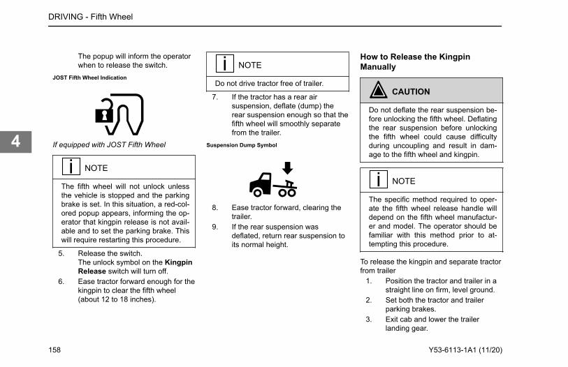
The popup will inform the operatorwhen to release the switch.
JOST Fifth Wheel Indication
If equipped with JOST Fifth Wheel
NOTE
The fifth wheel will not unlock unlessthe vehicle is stopped and the parkingbrake is set. In this situation, a red-col-ored popup appears, informing the op-erator that kingpin release is not avail-able and to set the parking brake. Thiswill require restarting this procedure.
5. Release the switch.The unlock symbol on the KingpinRelease switch will turn off.
6. Ease tractor forward enough for thekingpin to clear the fifth wheel(about 12 to 18 inches).
NOTE
Do not drive tractor free of trailer.
7. If the tractor has a rear airsuspension, deflate (dump) therear suspension enough so that thefifth wheel will smoothly separatefrom the trailer.
Suspension Dump Symbol
8. Ease tractor forward, clearing thetrailer.
9. If the rear suspension wasdeflated, return rear suspension toits normal height.
How to Release the KingpinManually
CAUTION
Do not deflate the rear suspension be-fore unlocking the fifth wheel. Deflatingthe rear suspension before unlockingthe fifth wheel could cause difficultyduring uncoupling and result in dam-age to the fifth wheel and kingpin.
NOTE
The specific method required to oper-ate the fifth wheel release handle willdepend on the fifth wheel manufactur-er and model. The operator should befamiliar with this method prior to at-tempting this procedure.
To release the kingpin and separate tractorfrom trailer
1. Position the tractor and trailer in astraight line on firm, level ground.
2. Set both the tractor and trailerparking brakes.
3. Exit cab and lower the trailerlanding gear.
DRIVING - Fifth Wheel
158 Y53-6113-1A1 (11/20)
4
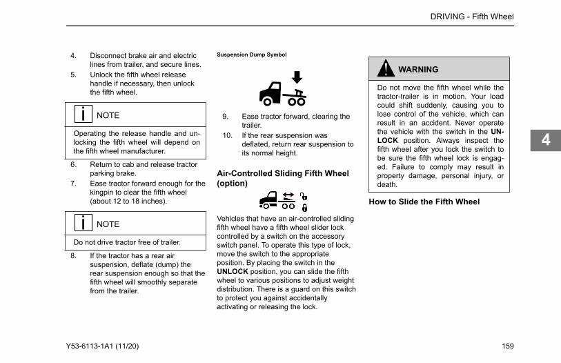
4. Disconnect brake air and electriclines from trailer, and secure lines.
5. Unlock the fifth wheel releasehandle if necessary, then unlockthe fifth wheel.
NOTE
Operating the release handle and un-locking the fifth wheel will depend onthe fifth wheel manufacturer.
6. Return to cab and release tractorparking brake.
7. Ease tractor forward enough for thekingpin to clear the fifth wheel(about 12 to 18 inches).
NOTE
Do not drive tractor free of trailer.
8. If the tractor has a rear airsuspension, deflate (dump) therear suspension enough so that thefifth wheel will smoothly separatefrom the trailer.
Suspension Dump Symbol
9. Ease tractor forward, clearing thetrailer.
10. If the rear suspension wasdeflated, return rear suspension toits normal height.
Air-Controlled Sliding Fifth Wheel(option)
Vehicles that have an air-controlled slidingfifth wheel have a fifth wheel slider lockcontrolled by a switch on the accessoryswitch panel. To operate this type of lock,move the switch to the appropriateposition. By placing the switch in theUNLOCK position, you can slide the fifthwheel to various positions to adjust weightdistribution. There is a guard on this switchto protect you against accidentallyactivating or releasing the lock.
WARNING
Do not move the fifth wheel while thetractor-trailer is in motion. Your loadcould shift suddenly, causing you tolose control of the vehicle, which canresult in an accident. Never operatethe vehicle with the switch in the UN-LOCK position. Always inspect thefifth wheel after you lock the switch tobe sure the fifth wheel lock is engag-ed. Failure to comply may result inproperty damage, personal injury, ordeath.
How to Slide the Fifth Wheel
DRIVING - Fifth Wheel
Y53-6113-1A1 (11/20) 159
4
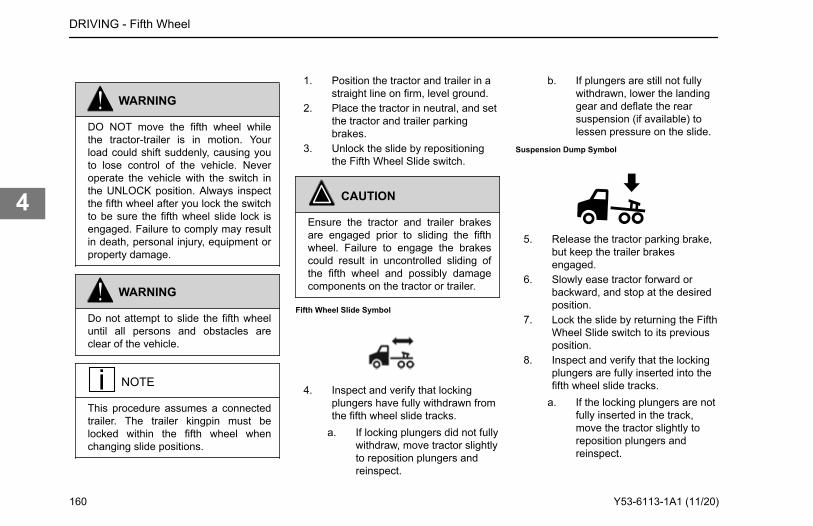
WARNING
DO NOT move the fifth wheel whilethe tractor-trailer is in motion. Yourload could shift suddenly, causing youto lose control of the vehicle. Neveroperate the vehicle with the switch inthe UNLOCK position. Always inspectthe fifth wheel after you lock the switchto be sure the fifth wheel slide lock isengaged. Failure to comply may resultin death, personal injury, equipment orproperty damage.
WARNING
Do not attempt to slide the fifth wheeluntil all persons and obstacles areclear of the vehicle.
NOTE
This procedure assumes a connectedtrailer. The trailer kingpin must belocked within the fifth wheel whenchanging slide positions.
1. Position the tractor and trailer in astraight line on firm, level ground.
2. Place the tractor in neutral, and setthe tractor and trailer parkingbrakes.
3. Unlock the slide by repositioningthe Fifth Wheel Slide switch.
CAUTION
Ensure the tractor and trailer brakesare engaged prior to sliding the fifthwheel. Failure to engage the brakescould result in uncontrolled sliding ofthe fifth wheel and possibly damagecomponents on the tractor or trailer.
Fifth Wheel Slide Symbol
4. Inspect and verify that lockingplungers have fully withdrawn fromthe fifth wheel slide tracks.
a. If locking plungers did not fullywithdraw, move tractor slightlyto reposition plungers andreinspect.
b. If plungers are still not fullywithdrawn, lower the landinggear and deflate the rearsuspension (if available) tolessen pressure on the slide.
Suspension Dump Symbol
5. Release the tractor parking brake,but keep the trailer brakesengaged.
6. Slowly ease tractor forward orbackward, and stop at the desiredposition.
7. Lock the slide by returning the FifthWheel Slide switch to its previousposition.
8. Inspect and verify that the lockingplungers are fully inserted into thefifth wheel slide tracks.
a. If the locking plungers are notfully inserted in the track,move the tractor slightly toreposition plungers andreinspect.
DRIVING - Fifth Wheel
160 Y53-6113-1A1 (11/20)
4
WARNING
Do not operate the vehicle un-less the locking plungers arefully inserted into the fifthwheel slide track. Operatingthe vehicle while the plungersare not fully inserted couldlead to the slide moving unex-pectedly, resulting in a loss ofvehicle control and potentiallycausing property damage, seri-ous injury, or death.
9. If the landing gear was lowered,raise the landing gear.
10. If the rear suspension wasdeflated, return rear suspension toits normal height.
Fifth Wheel LubricationFrequently operate and lubricate movableor sliding fifth wheels to prevent corrosion.
CAUTION
Both the fifth wheel plate and the slidetracks (if a slider) should be cleaned
and lubricated periodically to ensuresmooth turning and sliding action. Fail-ure to keep these surfaces lubricatedcan lead to frame or driveline damage.
For maintenance information see FifthWheel Monthly Maintenance on page 251, Fifth Wheel Bi-Annual Maintenance onpage 251 and Sliding Fifth Wheels on page252.
Driving Tips andTechniquesThis section covers additional driving tipsand techniques on how to drive yourvehicle more efficiently.
Coasting
WARNING
DO NOT coast with the transmission inneutral or with the clutch pedal de-pressed, it is a dangerous practice.Coasting in neutral may result in dam-age to your drivetrain when you try tore-engage the transmission. You could
lose control of the vehicle which canlead to an accident involving death orpersonal injury.
Do not coast with the transmission inneutral or with the clutch pedal depressed.Besides being illegal and dangerous,coasting is also expensive. It causespremature failure or damage to the clutchand transmission and overloads the brakesystem. Coasting with the transmission inneutral also prevents proper transmissioncomponent lubrication. During coasting thetransmission is driven by the rear wheels,and the countershaft gear (which lubricatesthe transmission components by oil splash)will only be turning at idle speed.
DRIVING - Driving Tips and Techniques
Y53-6113-1A1 (11/20) 161
4
Descending a Grade
WARNING
DO NOT hold the brake pedal downtoo long or too often while going downa steep or long grade. This couldcause the brakes to overheat and re-duce their effectiveness. As a result,the vehicle will not slow down at theusual rate. To reduce the risk of an ac-cident which could cause death or per-sonal injury, before going down asteep or long grade, reduce speed andshift the transmission into a lower gearto help control your vehicle speed.Failure to follow procedures for properdownhill operation could result in lossof vehicle control.
Engine Overspeed
CAUTION
To avoid engine damage, do not let theengine rpm go beyond the maximumgoverned rpm. Engine damage mayresult if overspeed conditions occur.
NOTE
Often these recommendations aresecondary to maintaining an adequateand safe speed relative to the sur-rounding traffic and road conditions.
Operate the engine within the optimumengine rpm range and do not allow the rpmto exceed the maximum governed speed.See your Engine Operation andMaintenance manual for informationregarding engine rpm. When the engine isused as a brake to control vehicle speed(e.g., while driving down a grade), do notallow the engine rpm to exceed maximumgoverned speed. Under normal load androad conditions operate the engine in thelower end of the range.The tachometer is an instrument that aidsin obtaining the best performance of theengine and manual transmission, servingas a guide for shifting gears. Refer to theEngine Operation and Maintenancemanual for optimum engine rpm.
• If the engine rpm moves beyondthe maximum governed speed,indicating an overspeed condition,apply the service brake or shift to a
higher gear to bring engine rpmwithin the optimum speed range.
• When driving downhill: shift to alower gear, use the engine brake (ifso equipped), and use the servicebrake, keeping the engine speedbelow 2,100 rpm.
When the engine speed reaches itsmaximum governed speed, the injectionpump governor cuts off fuel to the engine.However, the governor has no control overthe engine rpm when it is being driven bythe vehicle's transmission, for example, onsteep downgrades. Apply service brakes orshift to a higher gear. Fuel economy andengine performance are also directlyrelated to driving habits:
• The best results in trip time andfuel economy are obtained whiledriving the vehicle at a steadyspeed.
• Shift into higher or lower gears (orapply the service brake) to keepengine rpm near the lower end ofthe optimum operating range.
• Avoid rapid acceleration andbraking.
DRIVING - Driving Tips and Techniques
162 Y53-6113-1A1 (11/20)
4
WARNING
DO NOT look at the Instrument ClusterDisplay for prolonged periods while thevehicle is moving. Only glance at themonitor briefly while driving. Failure todo so can result in the driver not beingattentive to the vehicle’s road positionor situation, which could lead to an ac-cident and possible death, personal in-jury, or equipment damage.
Maintenance factors affecting fuelconsumption:
• Air and/or fuel filters partiallyclogged
• Engine valves out of adjustment• Injection pump improperly
synchronized• Injection nozzles defective or
uncalibrated• Improperly inflated tires• Wheel bearings improperly
adjusted• Clutch improperly adjusted or worn
(slipping)• Fuel leaks
Wrong driving habits must be correctedand the recommendations on economicdriving should be followed. Driving factorsaffecting fuel consumption:
• Excessive speed and unnecessaryfast acceleration
• Long periods of idling• Driving with foot resting on the
(manual transmission) clutch pedal
General ConditionOther factors affecting fuel consumptionare related to loads and the type of roadson which the vehicle operates. It is not
always possible to choose the mostadequate road, but the ideal road is theone that allows a steady speed in highgear, without requiring frequent brakingand acceleration. The following generalconditions can affect fuel consumption:
• Overload• Unbalanced load• Very high load• Inadequate roads• Traffic conditions
Stopping the VehicleA hot engine stores a great amount ofheat. It doesn’t cool down immediatelyafter you shut it off. Always cool yourengine down before shutting it off. You willgreatly increase its service life.Idle the engine at 1,000 rpm for fiveminutes. Then low idle for 30 secondsbefore shutdown. This will allow circulatingcoolant and lubricating oil to carry awayheat from the cylinder head, valves,pistons, cylinder liners, turbocharger, andbearings. This way you can preventserious engine damage that may resultfrom uneven cooling.
DRIVING - Stopping the Vehicle
The digital display provides information to help the driver optimize vehicle efficiency. See Trip Summary on page 75 for more information. A driver will find the section describing Trip Information and the rpm detail useful.
Fuel ConsumptionThe vehicle's fuel consumption is connected to five important factors: maintenance, driving habits, general condition of the road, traffic conditions, and vehicle load.Proper maintenance will keep the vehicle running like new even after long periods of use. The driver must perform the daily and weekly checks of the vehicle.
Y53-6113-1A1 (11/20) 163
4
TurbochargerThis cooling-down practice is especiallyimportant on a turbocharged engine. Theturbocharger contains bearings and sealsthat are subjected to hot exhaust gases.While the engine is operating, heat iscarried away by circulating oil. If you stopthe engine suddenly, the temperature ofthe turbocharger could rise as much as100°F (55°C) above the temperaturereached during operation. A sudden rise intemperature like this could cause thebearings to seize or the oil seals to loosen.
RefuelingAir space in your fuel tanks allows water tocondense there. To prevent thiscondensation while you are stopped, fillyour tanks to 95 percent of capacity. Whenrefueling, add approximately the sameamount to each fuel tank on vehicles withmore than one tank.
WARNING
DO NOT carry additional fuel contain-ers in your vehicle. Fuel containers, ei-ther full or empty, may leak, explode,and cause or feed a fire. Failure to
comply may result in death or personalinjury.
WARNING
Diesel fuel in the presence of an igni-tion source could cause an explosion.A mixture of gasoline or alcohol withdiesel fuel increases this risk of explo-sion. DO NOT remove a fuel tank capnear an open flame. Use only the fueland/or additives recommended foryour engine. Failure to comply may re-sult in death, personal injury, equip-ment or property damage.
CAUTION
Use only Ultra Low Sulfur Diesel(ULSD) Fuel, as recommended by en-gine manufacturers. If you need furtherinformation on fuel specifications, con-sult the Engine Operation and Mainte-nance Manual.
If your vehicle is equipped with fuel shut offvalves for the take-off and return lines, theyare located on the fuel lines entering the
top of the fuel tank. Fuel shut off valves forthe fuel crossover line are on the bottom ofthe fuel tank, at the crossover lineconnection.
Final Stopping ProceduresYour vehicle will be easier to start drivingwhen you are ready, and it will be safer foranyone who might be around it. Pleaseremember, too, that in some states it isillegal to leave the engine running and thevehicle unattended.
WARNING
Using the trailer hand brake or airbrakes to hold a parked vehicle is dan-gerous. Because they work with airpressure, these brakes could comeloose. Your vehicle could roll, causingan accident involving death or person-al injury. Always set the parkingbrakes. Never rely on the trailer handbrake or truck air brakes to hold aparked vehicle.
DRIVING - Stopping the Vehicle
164 Y53-6113-1A1 (11/20)
4
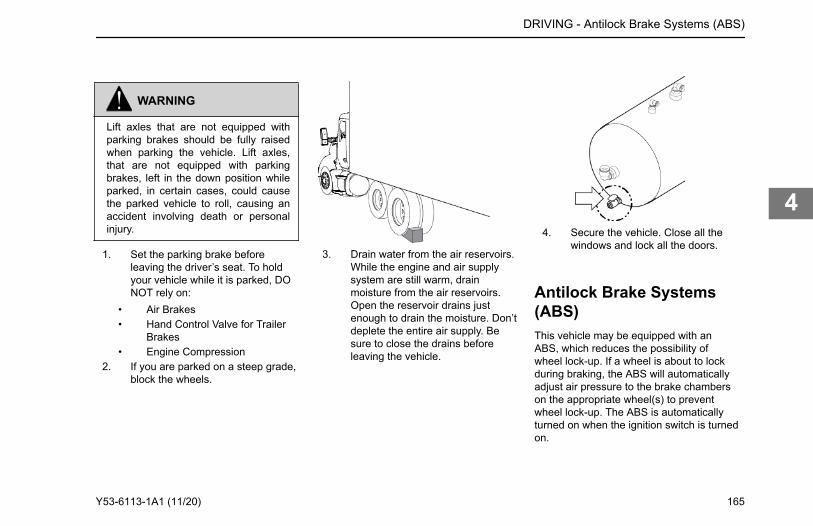
WARNING
Lift axles that are not equipped withparking brakes should be fully raisedwhen parking the vehicle. Lift axles,that are not equipped with parkingbrakes, left in the down position whileparked, in certain cases, could causethe parked vehicle to roll, causing anaccident involving death or personalinjury.
1. Set the parking brake beforeleaving the driver’s seat. To holdyour vehicle while it is parked, DONOT rely on:
• Air Brakes• Hand Control Valve for Trailer
Brakes• Engine Compression
2. If you are parked on a steep grade,block the wheels.
3. Drain water from the air reservoirs.While the engine and air supplysystem are still warm, drainmoisture from the air reservoirs.Open the reservoir drains justenough to drain the moisture. Don’tdeplete the entire air supply. Besure to close the drains beforeleaving the vehicle.
4. Secure the vehicle. Close all thewindows and lock all the doors.
Antilock Brake Systems(ABS)This vehicle may be equipped with anABS, which reduces the possibility ofwheel lock-up. If a wheel is about to lockduring braking, the ABS will automaticallyadjust air pressure to the brake chamberson the appropriate wheel(s) to preventwheel lock-up. The ABS is automaticallyturned on when the ignition switch is turnedon.
DRIVING - Antilock Brake Systems (ABS)
Y53-6113-1A1 (11/20) 165
4
WARNING
The antilock brake system is a criticalvehicle safety system. For the safetyof you and others around you, havethe vehicle submitted for periodic pre-ventive maintenance checks as well ashaving any suspected problems imme-diately checked by an authorized deal-er. Failure to properly maintain yourbrake system can lead to serious acci-dents. Failure to comply may result in-property damage, personal injury, ordeath.
WARNING
DO NOT rely on an antilock brake sys-tem that is functioning improperly. Youcould lose control of the vehicle result-ing in a severe accident, causing per-sonal injury or death. If your ABS lampgoes on while you are driving or stayson after the self-check, your anti-locksystem might not be working. The ABSmay not function in an emergency. Youwill still have conventional brakes, butnot antilock brakes. If the lamp indi-
cates a problem, have the ABSchecked.
Vehicles without ABS are typicallyequipped with a bobtail brake proportioningsystem. When a trailer is not connected,the drive axle brake application pressurewill automatically be limited by theproportioning system. When driven in abobtail mode, these tractors will requiregreater brake pedal application to providethe equivalent braking to a bobtail tractornot equipped with a proportioning system.
Trailer ABS Power LineCommunication (PLC)North American on-highway vehicles areequipped with a separate electrical circuitto power the ABS on towed vehicle(s). Inmost cases, the ABS power will besupplied through the Auxiliary circuit on theprimary 7-way trailer light line connector. Ifthe vehicle was manufactured with aswitchable Auxiliary circuit for traileraccessories, an additional 7-way connectorwould have been provided for trailer ABSpower. In either case, the ABS power lineon the vehicle will be PLC equipped.
CAUTION
DO NOT splice into the non-switchableAuxiliary circuit on the primary 7-waytrailer light line. Doing so may causethe trailer ABS to malfunction. This cir-cuit is dedicated for trailer ABS power.To add a switchable auxiliary circuit,contact a dealership.
NOTE
Tractors/Trucks and trailers built after03/01/2001 must be able to turn on anIn-Cab Trailer ABS Warning Light (perU.S. FMVSS121). The industry chosePower Line Communication (PLC) asthe standard method to turn it on. Ontrailers built prior to 03/01/2001 verifytrailer ABS system status via the re-quired external warning light mountedon the trailer. The indicator light on thetrailer should be yellow and identifiedwith the letters ABS.
For doubles or triples, the lamp does notdistinguish between trailers. An ABS
DRIVING - Antilock Brake Systems (ABS)
166 Y53-6113-1A1 (11/20)
4
problem in any of the trailers will activatethe Trailer ABS Warning Lamp.If you change the intended service in anyway (e.g., number of axles, multipletrailers, add switchable trailer accessories,etc.) from the date the vehicle wasmanufactured, you should contact yourtrailer manufacturer and/or trailer antilockbrake manufacturer to determine if thepower available at the 7-way trailer lightline is adequate. Failure to do so mightresult in insufficient power to the trailerABS system, which may affect itsoperation.
CAUTION
The center pin of the 7-way trailer lightline may be constantly powered forABS. Make sure it will not accidentallyturn on trailer equipment.
with the option to turn on this lamp forthese types of trailers, then this lamp willturn on when that trailer ABS has a systemproblem. This should be checked by adealer as soon as possible. The TrailerABS Warning Lamp will not turn on for thepower-on test when connected to thesetypes of trailers.
NOTE
Very few trailers built before03/01/2001 have this option. Trailersbuilt after 03/01/2001 are built withPLC technology.
DRIVING - Antilock Brake Systems (ABS)
Special Trailer ABS Without PLC (Option)If a trailer does not have PLC, but it does have ABS that is powered through an optional second trailer connector (ISO 3731) and that trailer ABS is designed to control the Trailer ABS Warning Lamp in the cab and the vehicle has been ordered
Y53-6113-1A1 (11/20) 167
4
Chapter 5 | MAINTENANCENew Vehicle Maintenance Schedule.................................................................................................171First Day............................................................................................................................................171First 50-100 mi / 80-160 km.............................................................................................................. 171First 500 mi / 800 km.........................................................................................................................172First 2,000 mi / 3,218 km...................................................................................................................172First 3,000-5,000 mi / 4,800-8,000 km.............................................................................................. 172Preventive Maintenance Intervals.....................................................................................................173Fender Liners....................................................................................................................................196Lubricants..........................................................................................................................................197Air System.........................................................................................................................................204Dual Air System Function Test..........................................................................................................206Air Dryer Maintenance...................................................................................................................... 206Air Tanks........................................................................................................................................... 208Air Gauges and Air Leaks................................................................................................................. 209Air Compressor................................................................................................................................. 210Brake System.................................................................................................................................... 211
MAINTENANCE -
168 Y53-6113-1A1 (11/20)
5
Cab Maintenance..............................................................................................................................217Safety Restraint System - Inspection................................................................................................223Cooling System Maintenance........................................................................................................... 225Windshield Wiper/Washer.................................................................................................................229Headlights......................................................................................................................................... 230Electrical System...............................................................................................................................232Engine Maintenance......................................................................................................................... 241Fuel System...................................................................................................................................... 249Frame................................................................................................................................................250Front Axle and Suspension...............................................................................................................252Heater and Air Conditioner Maintenance..........................................................................................255Noise and Emission Control..............................................................................................................257Diesel Exhaust Fluid Tank.................................................................................................................260Rear Axle and Suspension................................................................................................................260Rear Axle Alignment......................................................................................................................... 263Steering System................................................................................................................................264Driveline............................................................................................................................................ 266Tires.................................................................................................................................................. 266Wheels.............................................................................................................................................. 269
MAINTENANCE -
Y53-6113-1A1 (11/20) 169
5
Transmission Maintenance............................................................................................................... 273Hydraulic Clutch................................................................................................................................273Specification Reference Charts.........................................................................................................274
MAINTENANCE -
170 Y53-6113-1A1 (11/20)
5
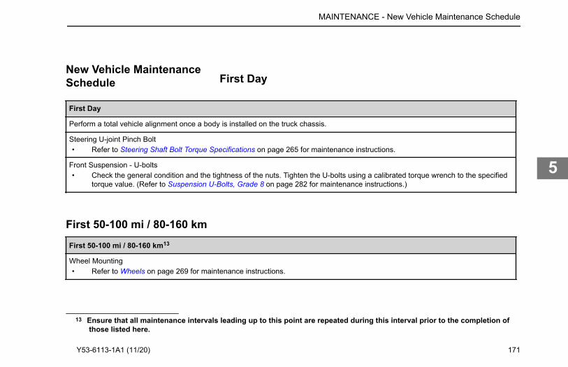
New Vehicle MaintenanceSchedule First Day
First Day
Perform a total vehicle alignment once a body is installed on the truck chassis.
Steering U-joint Pinch Bolt• Refer to Steering Shaft Bolt Torque Specifications on page 265 for maintenance instructions.
Front Suspension - U-bolts• Check the general condition and the tightness of the nuts. Tighten the U-bolts using a calibrated torque wrench to the specified
torque value. (Refer to Suspension U-Bolts, Grade 8 on page 282 for maintenance instructions.)
First 50-100 mi / 80-160 kmFirst 50-100 mi / 80-160 km13
Wheel Mounting• Refer to Wheels on page 269 for maintenance instructions.
13 Ensure that all maintenance intervals leading up to this point are repeated during this interval prior to the completion of
MAINTENANCE - New Vehicle Maintenance Schedule
those listed here.
Y53-6113-1A1 (11/20) 171
5
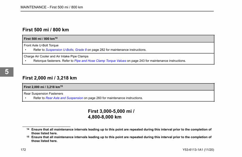
First 500 mi / 800 kmFirst 500 mi / 800 km14
Front Axle U-Bolt Torque• Refer to Suspension U-Bolts, Grade 8 on page 282 for maintenance instructions.
Charge Air Cooler and Air Intake Pipe Clamps• Retorque fasteners. Refer to Pipe and Hose Clamp Torque Values on page 243 for maintenance instructions.
First 2,000 mi / 3,218 kmFirst 2,000 mi / 3,218 km15
Rear Suspension Fasteners• Refer to Rear Axle and Suspension on page 260 for maintenance instructions.
First 3,000-5,000 mi /4,800-8,000 km
14 Ensure that all maintenance intervals leading up to this point are repeated during this interval prior to the completion ofthose listed here.
15 Ensure that all maintenance intervals leading up to this point are repeated during this interval prior to the completion ofthose listed here.
MAINTENANCE - First 500 mi / 800 km
172 Y53-6113-1A1 (11/20)
5
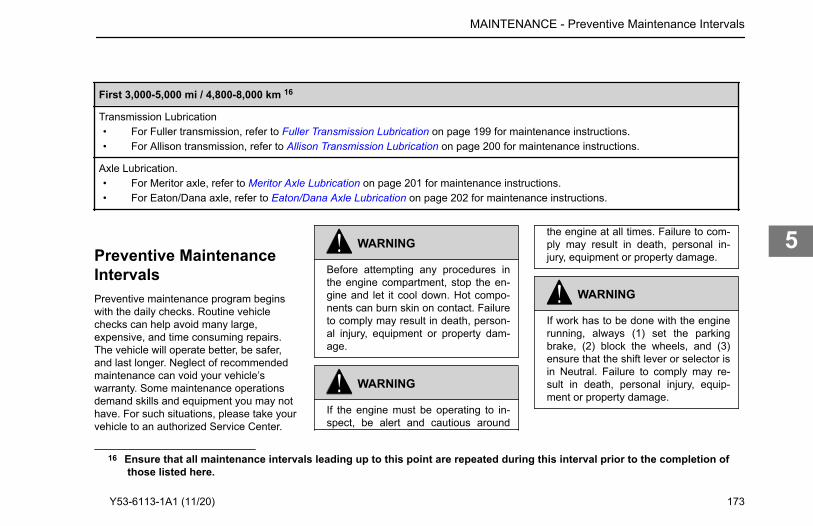
First 3,000-5,000 mi / 4,800-8,000 km 16
Transmission Lubrication• For Fuller transmission, refer to Fuller Transmission Lubrication on page 199 for maintenance instructions.• For Allison transmission, refer to Allison Transmission Lubrication on page 200 for maintenance instructions.
Axle Lubrication.• For Meritor axle, refer to Meritor Axle Lubrication on page 201 for maintenance instructions.• For Eaton/Dana axle, refer to Eaton/Dana Axle Lubrication on page 202 for maintenance instructions.
Preventive MaintenanceIntervalsPreventive maintenance program beginswith the daily checks. Routine vehiclechecks can help avoid many large,expensive, and time consuming repairs.The vehicle will operate better, be safer,and last longer. Neglect of recommendedmaintenance can void your vehicle’swarranty. Some maintenance operationsdemand skills and equipment you may nothave. For such situations, please take yourvehicle to an authorized Service Center.
WARNING
Before attempting any procedures inthe engine compartment, stop the en-gine and let it cool down. Hot compo-nents can burn skin on contact. Failureto comply may result in death, person-al injury, equipment or property dam-age.
WARNING
If the engine must be operating to in-spect, be alert and cautious around
the engine at all times. Failure to com-ply may result in death, personal in-jury, equipment or property damage.
WARNING
If work has to be done with the enginerunning, always (1) set the parkingbrake, (2) block the wheels, and (3)ensure that the shift lever or selector isin Neutral. Failure to comply may re-sult in death, personal injury, equip-ment or property damage.
16 Ensure that all maintenance intervals leading up to this point are repeated during this interval prior to the completion of
MAINTENANCE - Preventive Maintenance Intervals
those listed here.
Y53-6113-1A1 (11/20) 173
5
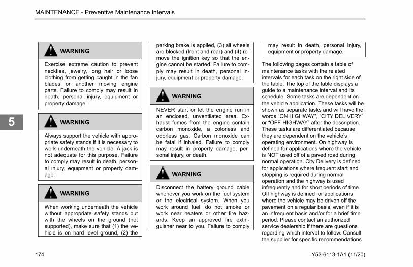
WARNING
Exercise extreme caution to preventneckties, jewelry, long hair or looseclothing from getting caught in the fanblades or another moving engineparts. Failure to comply may result indeath, personal injury, equipment orproperty damage.
WARNING
Always support the vehicle with appro-priate safety stands if it is necessary towork underneath the vehicle. A jack isnot adequate for this purpose. Failureto comply may result in death, person-al injury, equipment or property dam-age.
WARNING
When working underneath the vehiclewithout appropriate safety stands butwith the wheels on the ground (notsupported), make sure that (1) the ve-hicle is on hard level ground, (2) the
parking brake is applied, (3) all wheelsare blocked (front and rear) and (4) re-move the ignition key so that the en-gine cannot be started. Failure to com-ply may result in death, personal in-jury, equipment or property damage.
WARNING
NEVER start or let the engine run inan enclosed, unventilated area. Ex-haust fumes from the engine containcarbon monoxide, a colorless andodorless gas. Carbon monoxide canbe fatal if inhaled. Failure to complymay result in property damage, per-sonal injury, or death.
WARNING
Disconnect the battery ground cablewhenever you work on the fuel systemor the electrical system. When youwork around fuel, do not smoke orwork near heaters or other fire haz-ards. Keep an approved fire extin-guisher near to you. Failure to comply
may result in death, personal injury,equipment or property damage.
The following pages contain a table ofmaintenance tasks with the relatedintervals for each task on the right side ofthe table. The top of the table displays aguide to a maintenance interval and itsschedule. Some tasks are dependent onthe vehicle application. These tasks will beshown as separate tasks and will have thewords “ON HIGHWAY”, “CITY DELIVERY”or “OFF-HIGHWAY” after the description.These tasks are differentiated becausethey are dependent on the vehicle’soperating environment. On highway isdefined for applications where the vehicleis NOT used off of a paved road duringnormal operation. City Delivery is definedfor applications where frequent start andstopping is required during normaloperation and the highway is usedinfrequently and for short periods of time.Off highway is defined for applicationswhere the vehicle may be driven off thepavement on a regular basis, even if it isan infrequent basis and/or for a brief timeperiod. Please contact an authorizedservice dealership if there are questionsregarding which interval to follow. Consultthe supplier for specific recommendations
MAINTENANCE - Preventive Maintenance Intervals
174 Y53-6113-1A1 (11/20)
5
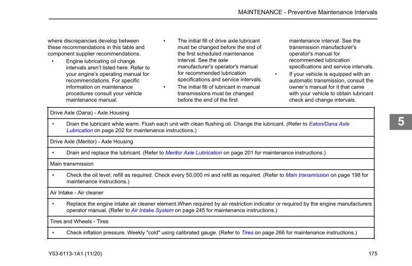
where discrepancies develop betweenthese recommendations in this table andcomponent supplier recommendations.
• Engine lubricating oil changeintervals aren’t listed here. Refer toyour engine’s operating manual forrecommendations. For specificinformation on maintenanceprocedures consult your vehiclemaintenance manual.
• The initial fill of drive axle lubricantmust be changed before the end ofthe first scheduled maintenanceinterval. See the axlemanufacturer's operator's manualfor recommended lubricationspecifications and service intervals.
• The initial fill of lubricant in manualtransmissions must be changedbefore the end of the first
maintenance interval. See thetransmission manufacturer'soperator's manual forrecommended lubricationspecifications and service intervals.
• If your vehicle is equipped with anautomatic transmission, consult theowner’s manual for it that camewith your vehicle to obtain lubricantcheck and change intervals.
Drive Axle (Dana) - Axle Housing
• Drain the lubricant while warm. Flush each unit with clean flushing oil. Change the lubricant. (Refer to Eaton/Dana AxleLubrication on page 202 for maintenance instructions.)
Drive Axle (Meritor) - Axle Housing
• Drain and replace the lubricant. (Refer to Meritor Axle Lubrication on page 201 for maintenance instructions.)
Main transmission
• Check the oil level; refill as required. Check every 50,000 mi and refill as required. (Refer to Main transmission on page 198 formaintenance instructions.)
Air Intake - Air cleaner
• Replace the engine intake air cleaner element.When required by air restriction indicator or required by the engine manufacturersoperator manual. (Refer to Air Intake System on page 245 for maintenance instructions.)
Tires and Wheels - Tires
• Check inflation pressure. Weekly "cold" using calibrated gauge. (Refer to Tires on page 266 for maintenance instructions.)
MAINTENANCE - Preventive Maintenance Intervals
Y53-6113-1A1 (11/20) 175
5
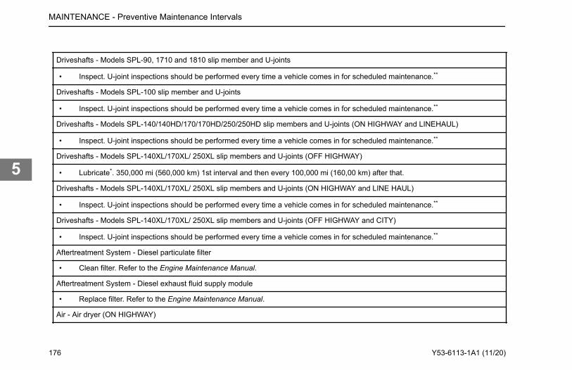
Driveshafts - Models SPL-90, 1710 and 1810 slip member and U-joints
• Inspect. U-joint inspections should be performed every time a vehicle comes in for scheduled maintenance.**
Driveshafts - Models SPL-100 slip member and U-joints
• Inspect. U-joint inspections should be performed every time a vehicle comes in for scheduled maintenance.**
Driveshafts - Models SPL-140/140HD/170/170HD/250/250HD slip members and U-joints (ON HIGHWAY and LINEHAUL)
• Inspect. U-joint inspections should be performed every time a vehicle comes in for scheduled maintenance.**
Driveshafts - Models SPL-140XL/170XL/ 250XL slip members and U-joints (OFF HIGHWAY)
• Lubricate*. 350,000 mi (560,000 km) 1st interval and then every 100,000 mi (160,00 km) after that.
Driveshafts - Models SPL-140XL/170XL/ 250XL slip members and U-joints (ON HIGHWAY and LINE HAUL)
• Inspect. U-joint inspections should be performed every time a vehicle comes in for scheduled maintenance.**
Driveshafts - Models SPL-140XL/170XL/ 250XL slip members and U-joints (OFF HIGHWAY and CITY)
• Inspect. U-joint inspections should be performed every time a vehicle comes in for scheduled maintenance.**
Aftertreatment System - Diesel particulate filter
• Clean filter. Refer to the Engine Maintenance Manual.
Aftertreatment System - Diesel exhaust fluid supply module
• Replace filter. Refer to the Engine Maintenance Manual.
Air - Air dryer (ON HIGHWAY)
MAINTENANCE - Preventive Maintenance Intervals
176 Y53-6113-1A1 (11/20)
5
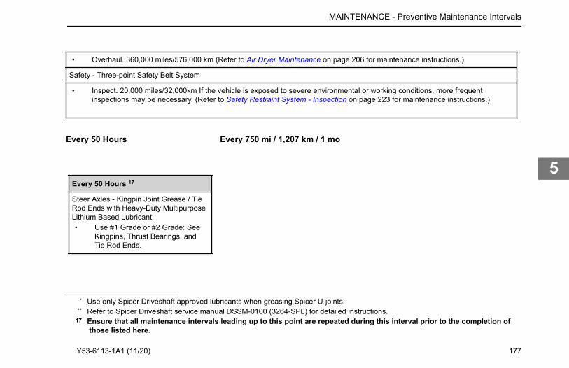
• Overhaul. 360,000 miles/576,000 km (Refer to Air Dryer Maintenance on page 206 for maintenance instructions.)
Safety - Three-point Safety Belt System
• Inspect. 20,000 miles/32,000km If the vehicle is exposed to severe environmental or working conditions, more frequentinspections may be necessary. (Refer to Safety Restraint System - Inspection on page 223 for maintenance instructions.)
Every 50 Hours
Every 50 Hours 17
Steer Axles - Kingpin Joint Grease / TieRod Ends with Heavy-Duty MultipurposeLithium Based Lubricant• Use #1 Grade or #2 Grade: See
Kingpins, Thrust Bearings, andTie Rod Ends.
Every 750 mi / 1,207 km / 1 mo
* Use only Spicer Driveshaft approved lubricants when greasing Spicer U-joints.** Refer to Spicer Driveshaft service manual DSSM-0100 (3264-SPL) for detailed instructions.
17 Ensure that all maintenance intervals leading up to this point are repeated during this interval prior to the completion of
MAINTENANCE - Preventive Maintenance Intervals
those listed here.
Y53-6113-1A1 (11/20) 177
5
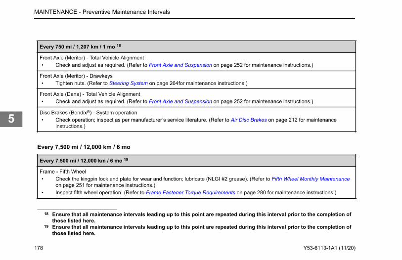
Every 750 mi / 1,207 km / 1 mo 18
Front Axle (Meritor) - Total Vehicle Alignment• Check and adjust as required. (Refer to Front Axle and Suspension on page 252 for maintenance instructions.)
Front Axle (Meritor) - Drawkeys• Tighten nuts. (Refer to Steering System on page 264for maintenance instructions.)
Front Axle (Dana) - Total Vehicle Alignment• Check and adjust as required. (Refer to Front Axle and Suspension on page 252 for maintenance instructions.)
Disc Brakes (Bendix®) - System operation• Check operation; inspect as per manufacturer’s service literature. (Refer to Air Disc Brakes on page 212 for maintenance
instructions.)
Every 7,500 mi / 12,000 km / 6 mo
Every 7,500 mi / 12,000 km / 6 mo 19
Frame - Fifth Wheel• Check the kingpin lock and plate for wear and function; lubricate (NLGI #2 grease). (Refer to Fifth Wheel Monthly Maintenance
on page 251 for maintenance instructions.)• Inspect fifth wheel operation. (Refer to Frame Fastener Torque Requirements on page 280 for maintenance instructions.)
18 Ensure that all maintenance intervals leading up to this point are repeated during this interval prior to the completion ofthose listed here.
19 Ensure that all maintenance intervals leading up to this point are repeated during this interval prior to the completion ofthose listed here.
MAINTENANCE - Preventive Maintenance Intervals
178 Y53-6113-1A1 (11/20)
5
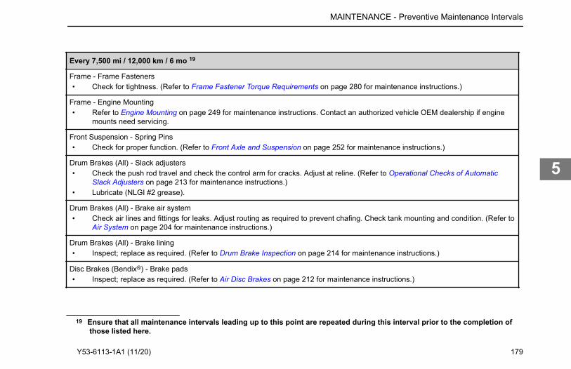
Every 7,500 mi / 12,000 km / 6 mo 19
Frame - Frame Fasteners• Check for tightness. (Refer to Frame Fastener Torque Requirements on page 280 for maintenance instructions.)
Frame - Engine Mounting• Refer to Engine Mounting on page 249 for maintenance instructions. Contact an authorized vehicle OEM dealership if engine
mounts need servicing.
Front Suspension - Spring Pins• Check for proper function. (Refer to Front Axle and Suspension on page 252 for maintenance instructions.)
Drum Brakes (All) - Slack adjusters• Check the push rod travel and check the control arm for cracks. Adjust at reline. (Refer to Operational Checks of Automatic
Slack Adjusters on page 213 for maintenance instructions.)• Lubricate (NLGI #2 grease).
Drum Brakes (All) - Brake air system• Check air lines and fittings for leaks. Adjust routing as required to prevent chafing. Check tank mounting and condition. (Refer to
Air System on page 204 for maintenance instructions.)
Drum Brakes (All) - Brake lining• Inspect; replace as required. (Refer to Drum Brake Inspection on page 214 for maintenance instructions.)
Disc Brakes (Bendix®) - Brake pads• Inspect; replace as required. (Refer to Air Disc Brakes on page 212 for maintenance instructions.)
19 Ensure that all maintenance intervals leading up to this point are repeated during this interval prior to the completion of
MAINTENANCE - Preventive Maintenance Intervals
those listed here.
Y53-6113-1A1 (11/20) 179
5
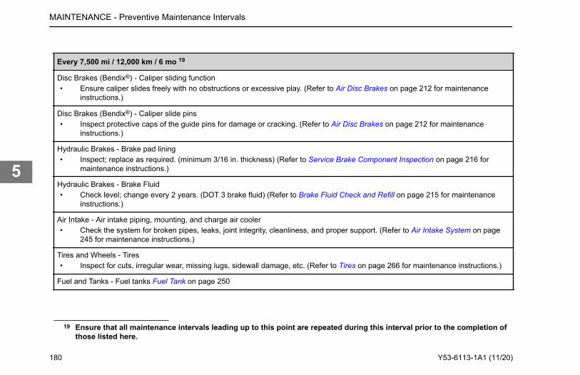
Every 7,500 mi / 12,000 km / 6 mo 19
Disc Brakes (Bendix®) - Caliper sliding function• Ensure caliper slides freely with no obstructions or excessive play. (Refer to Air Disc Brakes on page 212 for maintenance
instructions.)
Disc Brakes (Bendix®) - Caliper slide pins• Inspect protective caps of the guide pins for damage or cracking. (Refer to Air Disc Brakes on page 212 for maintenance
instructions.)
Hydraulic Brakes - Brake pad lining• Inspect; replace as required. (minimum 3/16 in. thickness) (Refer to Service Brake Component Inspection on page 216 for
maintenance instructions.)
Hydraulic Brakes - Brake Fluid• Check level; change every 2 years. (DOT 3 brake fluid) (Refer to Brake Fluid Check and Refill on page 215 for maintenance
instructions.)
Air Intake - Air intake piping, mounting, and charge air cooler• Check the system for broken pipes, leaks, joint integrity, cleanliness, and proper support. (Refer to Air Intake System on page
245 for maintenance instructions.)
Tires and Wheels - Tires• Inspect for cuts, irregular wear, missing lugs, sidewall damage, etc. (Refer to Tires on page 266 for maintenance instructions.)
Fuel and Tanks - Fuel tanks Fuel Tank on page 250
19 Ensure that all maintenance intervals leading up to this point are repeated during this interval prior to the completion ofthose listed here.
MAINTENANCE - Preventive Maintenance Intervals
180 Y53-6113-1A1 (11/20)
5
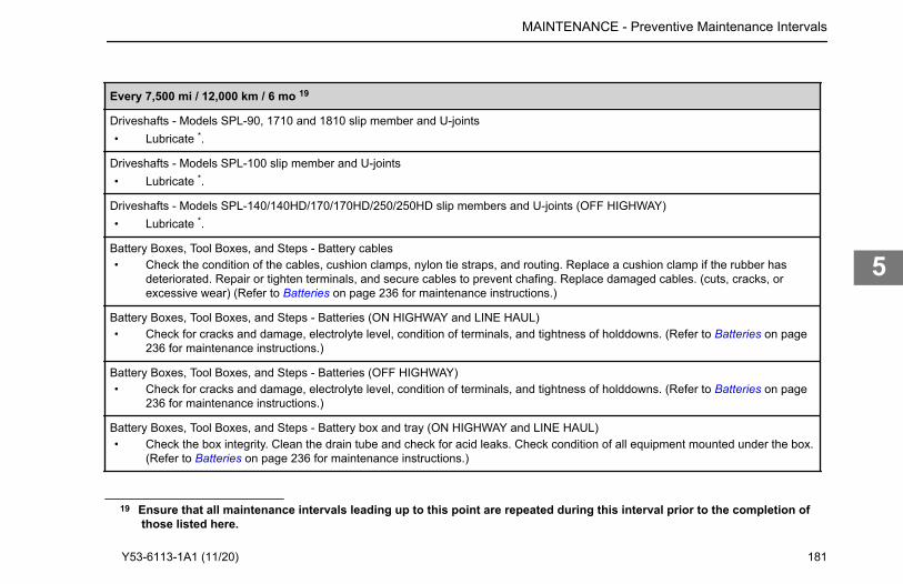
Every 7,500 mi / 12,000 km / 6 mo 19
Driveshafts - Models SPL-90, 1710 and 1810 slip member and U-joints• Lubricate *.
Driveshafts - Models SPL-100 slip member and U-joints• Lubricate *.
Driveshafts - Models SPL-140/140HD/170/170HD/250/250HD slip members and U-joints (OFF HIGHWAY)• Lubricate *.
Battery Boxes, Tool Boxes, and Steps - Battery cables• Check the condition of the cables, cushion clamps, nylon tie straps, and routing. Replace a cushion clamp if the rubber has
deteriorated. Repair or tighten terminals, and secure cables to prevent chafing. Replace damaged cables. (cuts, cracks, orexcessive wear) (Refer to Batteries on page 236 for maintenance instructions.)
Battery Boxes, Tool Boxes, and Steps - Batteries (ON HIGHWAY and LINE HAUL)• Check for cracks and damage, electrolyte level, condition of terminals, and tightness of holddowns. (Refer to Batteries on page
236 for maintenance instructions.)
Battery Boxes, Tool Boxes, and Steps - Batteries (OFF HIGHWAY)• Check for cracks and damage, electrolyte level, condition of terminals, and tightness of holddowns. (Refer to Batteries on page
236 for maintenance instructions.)
Battery Boxes, Tool Boxes, and Steps - Battery box and tray (ON HIGHWAY and LINE HAUL)• Check the box integrity. Clean the drain tube and check for acid leaks. Check condition of all equipment mounted under the box.
(Refer to Batteries on page 236 for maintenance instructions.)
19 Ensure that all maintenance intervals leading up to this point are repeated during this interval prior to the completion of
MAINTENANCE - Preventive Maintenance Intervals
those listed here.
Y53-6113-1A1 (11/20) 181
5
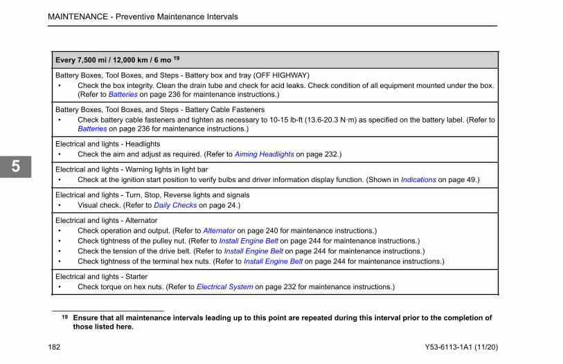
Every 7,500 mi / 12,000 km / 6 mo 19
Battery Boxes, Tool Boxes, and Steps - Battery box and tray (OFF HIGHWAY)• Check the box integrity. Clean the drain tube and check for acid leaks. Check condition of all equipment mounted under the box.
(Refer to Batteries on page 236 for maintenance instructions.)
Battery Boxes, Tool Boxes, and Steps - Battery Cable Fasteners• Check battery cable fasteners and tighten as necessary to 10-15 lb-ft (13.6-20.3 N·m) as specified on the battery label. (Refer to
Batteries on page 236 for maintenance instructions.)
Electrical and lights - Headlights• Check the aim and adjust as required. (Refer to Aiming Headlights on page 232.)
Electrical and lights - Warning lights in light bar• Check at the ignition start position to verify bulbs and driver information display function. (Shown in Indications on page 49.)
Electrical and lights - Turn, Stop, Reverse lights and signals• Visual check. (Refer to Daily Checks on page 24.)
Electrical and lights - Alternator• Check operation and output. (Refer to Alternator on page 240 for maintenance instructions.)• Check tightness of the pulley nut. (Refer to Install Engine Belt on page 244 for maintenance instructions.)• Check the tension of the drive belt. (Refer to Install Engine Belt on page 244 for maintenance instructions.)• Check tightness of the terminal hex nuts. (Refer to Install Engine Belt on page 244 for maintenance instructions.)
Electrical and lights - Starter• Check torque on hex nuts. (Refer to Electrical System on page 232 for maintenance instructions.)
19 Ensure that all maintenance intervals leading up to this point are repeated during this interval prior to the completion ofthose listed here.
MAINTENANCE - Preventive Maintenance Intervals
182 Y53-6113-1A1 (11/20)
5
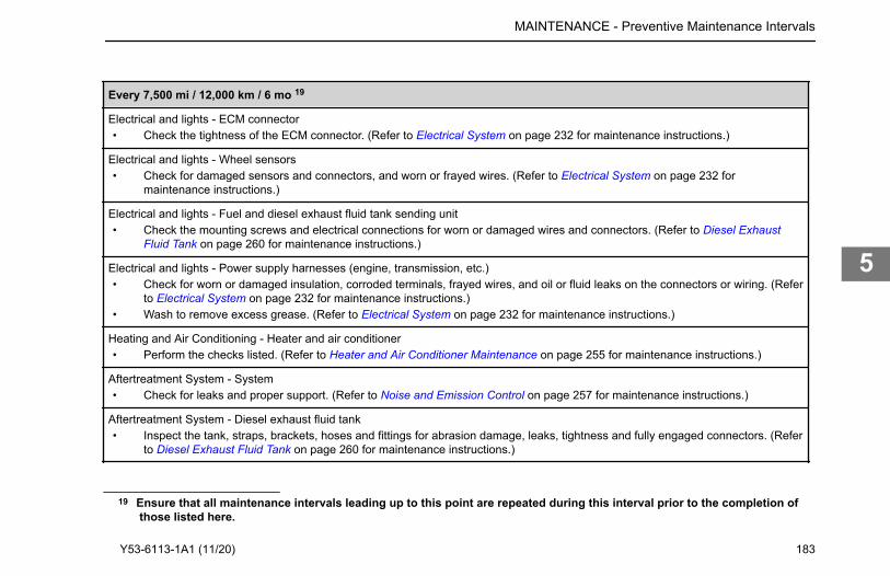
Every 7,500 mi / 12,000 km / 6 mo 19
Electrical and lights - ECM connector• Check the tightness of the ECM connector. (Refer to Electrical System on page 232 for maintenance instructions.)
Electrical and lights - Wheel sensors• Check for damaged sensors and connectors, and worn or frayed wires. (Refer to Electrical System on page 232 for
maintenance instructions.)
Electrical and lights - Fuel and diesel exhaust fluid tank sending unit• Check the mounting screws and electrical connections for worn or damaged wires and connectors. (Refer to Diesel Exhaust
Fluid Tank on page 260 for maintenance instructions.)
Electrical and lights - Power supply harnesses (engine, transmission, etc.)• Check for worn or damaged insulation, corroded terminals, frayed wires, and oil or fluid leaks on the connectors or wiring. (Refer
to Electrical System on page 232 for maintenance instructions.)• Wash to remove excess grease. (Refer to Electrical System on page 232 for maintenance instructions.)
Heating and Air Conditioning - Heater and air conditioner• Perform the checks listed. (Refer to Heater and Air Conditioner Maintenance on page 255 for maintenance instructions.)
Aftertreatment System - System• Check for leaks and proper support. (Refer to Noise and Emission Control on page 257 for maintenance instructions.)
Aftertreatment System - Diesel exhaust fluid tank• Inspect the tank, straps, brackets, hoses and fittings for abrasion damage, leaks, tightness and fully engaged connectors. (Refer
to Diesel Exhaust Fluid Tank on page 260 for maintenance instructions.)
19 Ensure that all maintenance intervals leading up to this point are repeated during this interval prior to the completion of
MAINTENANCE - Preventive Maintenance Intervals
those listed here.
Y53-6113-1A1 (11/20) 183
5
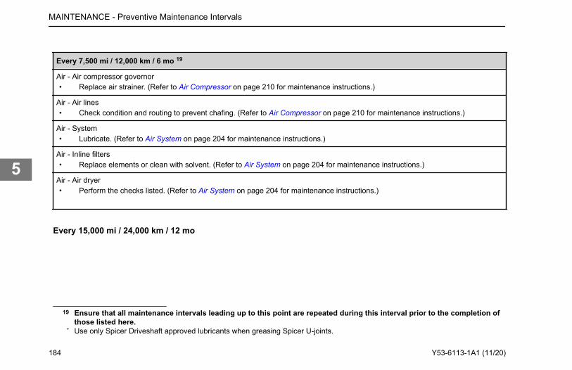
Every 7,500 mi / 12,000 km / 6 mo 19
Air - Air compressor governor• Replace air strainer. (Refer to Air Compressor on page 210 for maintenance instructions.)
Air - Air lines• Check condition and routing to prevent chafing. (Refer to Air Compressor on page 210 for maintenance instructions.)
Air - System• Lubricate. (Refer to Air System on page 204 for maintenance instructions.)
Air - Inline filters• Replace elements or clean with solvent. (Refer to Air System on page 204 for maintenance instructions.)
Air - Air dryer• Perform the checks listed. (Refer to Air System on page 204 for maintenance instructions.)
Every 15,000 mi / 24,000 km / 12 mo
19 Ensure that all maintenance intervals leading up to this point are repeated during this interval prior to the completion ofthose listed here.
* Use only Spicer Driveshaft approved lubricants when greasing Spicer U-joints.
MAINTENANCE - Preventive Maintenance Intervals
184 Y53-6113-1A1 (11/20)
5
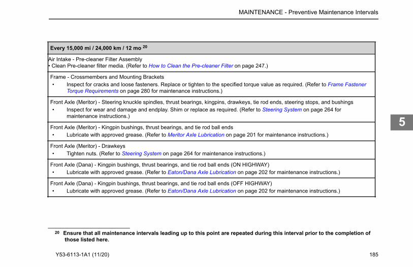
Every 15,000 mi / 24,000 km / 12 mo 20
Air Intake - Pre-cleaner Filter Assembly• Clean Pre-cleaner filter media. (Refer to How to Clean the Pre-cleaner Filter on page 247.)
Frame - Crossmembers and Mounting Brackets• Inspect for cracks and loose fasteners. Replace or tighten to the specified torque value as required. (Refer to Frame Fastener
Torque Requirements on page 280 for maintenance instructions.)
Front Axle (Meritor) - Steering knuckle spindles, thrust bearings, kingpins, drawkeys, tie rod ends, steering stops, and bushings• Inspect for wear and damage and endplay. Shim or replace as required. (Refer to Steering System on page 264 for
maintenance instructions.)
Front Axle (Meritor) - Kingpin bushings, thrust bearings, and tie rod ball ends• Lubricate with approved grease. (Refer to Meritor Axle Lubrication on page 201 for maintenance instructions.)
Front Axle (Meritor) - Drawkeys• Tighten nuts. (Refer to Steering System on page 264 for maintenance instructions.)
Front Axle (Dana) - Kingpin bushings, thrust bearings, and tie rod ball ends (ON HIGHWAY)• Lubricate with approved grease. (Refer to Eaton/Dana Axle Lubrication on page 202 for maintenance instructions.)
Front Axle (Dana) - Kingpin bushings, thrust bearings, and tie rod ball ends (OFF HIGHWAY)• Lubricate with approved grease. (Refer to Eaton/Dana Axle Lubrication on page 202 for maintenance instructions.)
20 Ensure that all maintenance intervals leading up to this point are repeated during this interval prior to the completion of
MAINTENANCE - Preventive Maintenance Intervals
those listed here.
Y53-6113-1A1 (11/20) 185
5

Every 15,000 mi / 24,000 km / 12 mo 20
Front Axle (Dana) - Steering knuckle spindles, thrust bearings, kingpins, drawkeys, tie rod ends, steering stops, and bushings (ONHIGHWAY)• Inspect for wear and damage and for endplay. Shim or replace as required. (Refer to Front Axle and Suspension on page 252
for maintenance instructions.)
Front Axle (Dana) - Steering knuckle spindles, thrust bearings, kingpins, drawkeys, tie rod ends, steering stops, and bushings (OFFHIGHWAY)• Inspect for wear and damage and for endplay. Shim or replace as required. (Refer to Front Axle and Suspension on page 252
for maintenance instructions.)
Front Suspension - Front Spring• Front Axle and Suspension on page 252 for maintenance instructions.)
Front Suspension - Spring Pins and Shackles• Inspect for worn parts and excessive joint clearance. Shim or replace as required. (Refer to Front Axle and Suspension on page
252 for maintenance instructions.)
Front Suspension - Shock Absorbers• Inspect for leaking, body damage, and damaged or worn bushings. Replace as required. Check the shock mounting stud
torque. (Refer to Front Axle and Suspension on page 252 for maintenance instructions.)
Front Suspension - Spring Pins• Lubricate with approved grease. (Refer to Front Axle and Suspension on page 252 for maintenance instructions.)
20 Ensure that all maintenance intervals leading up to this point are repeated during this interval prior to the completion ofthose listed here.
MAINTENANCE - Preventive Maintenance Intervals
186 Y53-6113-1A1 (11/20)
5
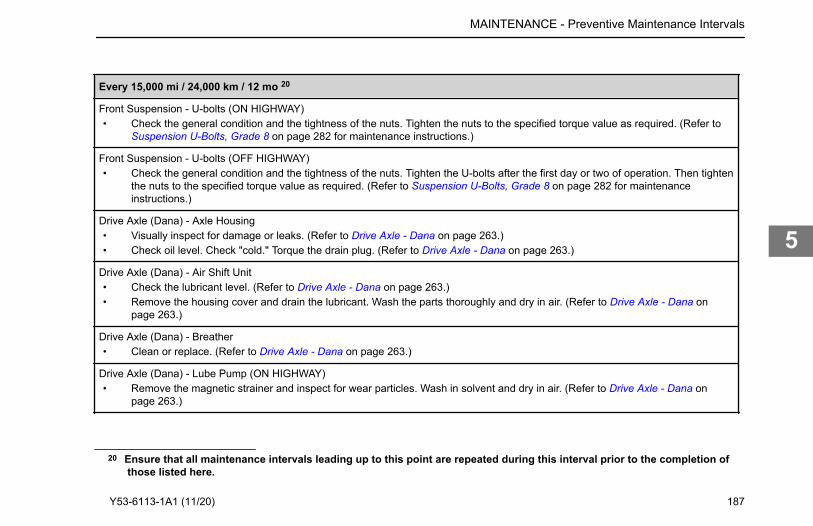
Every 15,000 mi / 24,000 km / 12 mo 20
Front Suspension - U-bolts (ON HIGHWAY)• Check the general condition and the tightness of the nuts. Tighten the nuts to the specified torque value as required. (Refer to
Suspension U-Bolts, Grade 8 on page 282 for maintenance instructions.)
Front Suspension - U-bolts (OFF HIGHWAY)• Check the general condition and the tightness of the nuts. Tighten the U-bolts after the first day or two of operation. Then tighten
the nuts to the specified torque value as required. (Refer to Suspension U-Bolts, Grade 8 on page 282 for maintenanceinstructions.)
Drive Axle (Dana) - Axle Housing• Visually inspect for damage or leaks. (Refer to Drive Axle - Dana on page 263.)• Check oil level. Check "cold." Torque the drain plug. (Refer to Drive Axle - Dana on page 263.)
Drive Axle (Dana) - Air Shift Unit• Check the lubricant level. (Refer to Drive Axle - Dana on page 263.)• Remove the housing cover and drain the lubricant. Wash the parts thoroughly and dry in air. (Refer to Drive Axle - Dana on
page 263.)
Drive Axle (Dana) - Breather• Clean or replace. (Refer to Drive Axle - Dana on page 263.)
Drive Axle (Dana) - Lube Pump (ON HIGHWAY)• Remove the magnetic strainer and inspect for wear particles. Wash in solvent and dry in air. (Refer to Drive Axle - Dana on
page 263.)
20 Ensure that all maintenance intervals leading up to this point are repeated during this interval prior to the completion of
MAINTENANCE - Preventive Maintenance Intervals
those listed here.
Y53-6113-1A1 (11/20) 187
5
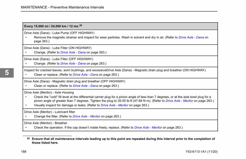
Every 15,000 mi / 24,000 km / 12 mo 20
Drive Axle (Dana) - Lube Pump (OFF HIGHWAY)• Remove the magnetic strainer and inspect for wear particles. Wash in solvent and dry in air. (Refer to Drive Axle - Dana on
page 263.)
Drive Axle (Dana) - Lube Filter (ON HIGHWAY)• Change. (Refer to Drive Axle - Dana on page 263.)
Drive Axle (Dana) - Lube Filter (OFF HIGHWAY)• Change. (Refer to Drive Axle - Dana on page 263.)
Inspect for cracked leaves, worn bushings, and excessiveDrive Axle (Dana) - Magnetic drain plug and breather (ON HIGHWAY)• Clean or replace. (Refer to Drive Axle - Dana on page 263.)
Drive Axle (Dana) - Magnetic drain plug and breather (OFF HIGHWAY)• Clean or replace. (Refer to Drive Axle - Dana on page 263.)
Drive Axle (Meritor) - Axle Housing• Check the "cold" fill level at the differential carrier plug for a pinion angle of less than 7 degrees, or at the axle bowl plug for a
pinion angle of greater than 7 degrees. Tighten the plug to 35-50 lb-ft (47-68 N·m). (Refer to Drive Axle - Meritor on page 263.)• Visually inspect for damage or leaks. (Refer to Drive Axle - Meritor on page 263.)
Drive Axle (Meritor) - Lubricant filter• Change the filter. (Refer to Drive Axle - Meritor on page 263.)
Drive Axle (Meritor) - Breather• Check the operation. If the cap doesn’t rotate freely, replace. (Refer to Drive Axle - Meritor on page 263.)
20 Ensure that all maintenance intervals leading up to this point are repeated during this interval prior to the completion ofthose listed here.
MAINTENANCE - Preventive Maintenance Intervals
188 Y53-6113-1A1 (11/20)
5
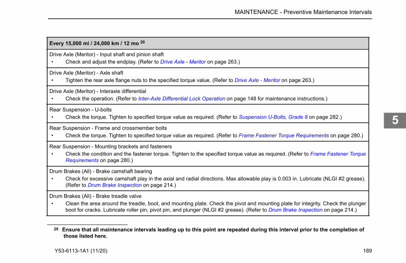
Every 15,000 mi / 24,000 km / 12 mo 20
Drive Axle (Meritor) - Input shaft and pinion shaft• Check and adjust the endplay. (Refer to Drive Axle - Meritor on page 263.)
Drive Axle (Meritor) - Axle shaft• Tighten the rear axle flange nuts to the specified torque value. (Refer to Drive Axle - Meritor on page 263.)
Drive Axle (Meritor) - Interaxle differential• Check the operation. (Refer to Inter-Axle Differential Lock Operation on page 148 for maintenance instructions.)
Rear Suspension - U-bolts• Check the torque. Tighten to specified torque value as required. (Refer to Suspension U-Bolts, Grade 8 on page 282.)
Rear Suspension - Frame and crossmember bolts• Check the torque. Tighten to specified torque value as required. (Refer to Frame Fastener Torque Requirements on page 280.)
Rear Suspension - Mounting brackets and fasteners• Check the condition and the fastener torque. Tighten to the specified torque value as required. (Refer to Frame Fastener Torque
Requirements on page 280.)
Drum Brakes (All) - Brake camshaft bearing• Check for excessive camshaft play in the axial and radial directions. Max allowable play is 0.003 in. Lubricate (NLGI #2 grease).
(Refer to Drum Brake Inspection on page 214.)
Drum Brakes (All) - Brake treadle valve• Clean the area around the treadle, boot, and mounting plate. Check the pivot and mounting plate for integrity. Check the plunger
boot for cracks. Lubricate roller pin, pivot pin, and plunger (NLGI #2 grease). (Refer to Drum Brake Inspection on page 214.)
20 Ensure that all maintenance intervals leading up to this point are repeated during this interval prior to the completion of
MAINTENANCE - Preventive Maintenance Intervals
those listed here.
Y53-6113-1A1 (11/20) 189
5
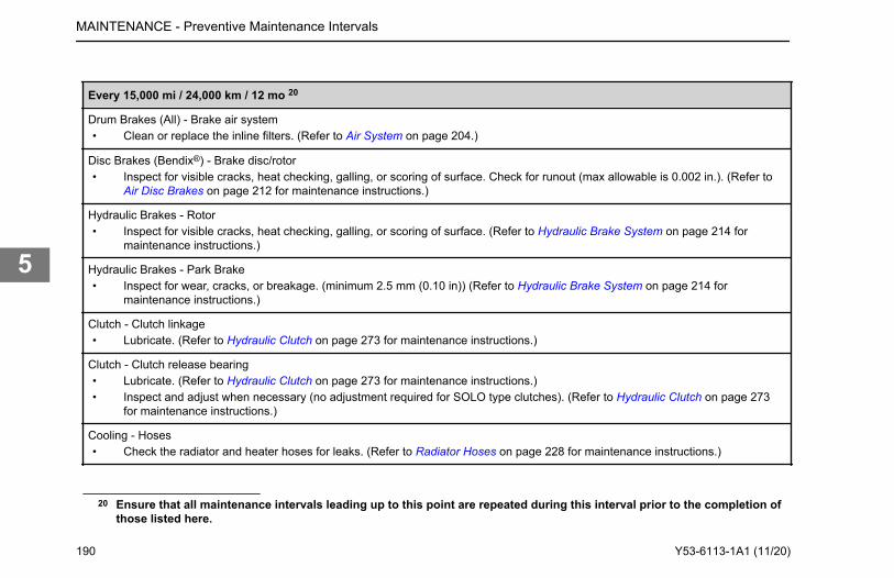
Every 15,000 mi / 24,000 km / 12 mo 20
Drum Brakes (All) - Brake air system• Clean or replace the inline filters. (Refer to Air System on page 204.)
Disc Brakes (Bendix®) - Brake disc/rotor• Inspect for visible cracks, heat checking, galling, or scoring of surface. Check for runout (max allowable is 0.002 in.). (Refer to
Air Disc Brakes on page 212 for maintenance instructions.)
Hydraulic Brakes - Rotor• Inspect for visible cracks, heat checking, galling, or scoring of surface. (Refer to Hydraulic Brake System on page 214 for
maintenance instructions.)
Hydraulic Brakes - Park Brake• Inspect for wear, cracks, or breakage. (minimum 2.5 mm (0.10 in)) (Refer to Hydraulic Brake System on page 214 for
maintenance instructions.)
Clutch - Clutch linkage• Lubricate. (Refer to Hydraulic Clutch on page 273 for maintenance instructions.)
Clutch - Clutch release bearing• Lubricate. (Refer to Hydraulic Clutch on page 273 for maintenance instructions.)• Inspect and adjust when necessary (no adjustment required for SOLO type clutches). (Refer to Hydraulic Clutch on page 273
for maintenance instructions.)
Cooling - Hoses• Check the radiator and heater hoses for leaks. (Refer to Radiator Hoses on page 228 for maintenance instructions.)
20 Ensure that all maintenance intervals leading up to this point are repeated during this interval prior to the completion ofthose listed here.
MAINTENANCE - Preventive Maintenance Intervals
190 Y53-6113-1A1 (11/20)
5
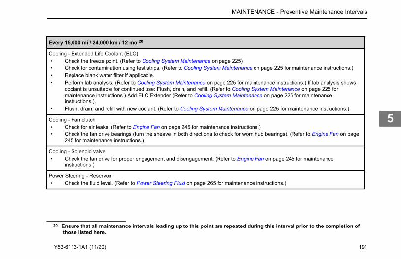
Every 15,000 mi / 24,000 km / 12 mo 20
Cooling - Extended Life Coolant (ELC)• Check the freeze point. (Refer to Cooling System Maintenance on page 225)• Check for contamination using test strips. (Refer to Cooling System Maintenance on page 225 for maintenance instructions.)• Replace blank water filter if applicable.• Perform lab analysis. (Refer to Cooling System Maintenance on page 225 for maintenance instructions.) If lab analysis shows
coolant is unsuitable for continued use: Flush, drain, and refill. (Refer to Cooling System Maintenance on page 225 formaintenance instructions.) Add ELC Extender (Refer to Cooling System Maintenance on page 225 for maintenanceinstructions.).
• Flush, drain, and refill with new coolant. (Refer to Cooling System Maintenance on page 225 for maintenance instructions.)
Cooling - Fan clutch• Check for air leaks. (Refer to Engine Fan on page 245 for maintenance instructions.)• Check the fan drive bearings (turn the sheave in both directions to check for worn hub bearings). (Refer to Engine Fan on page
245 for maintenance instructions.)
Cooling - Solenoid valve• Check the fan drive for proper engagement and disengagement. (Refer to Engine Fan on page 245 for maintenance
instructions.)
Power Steering - Reservoir• Check the fluid level. (Refer to Power Steering Fluid on page 265 for maintenance instructions.)
20 Ensure that all maintenance intervals leading up to this point are repeated during this interval prior to the completion of
MAINTENANCE - Preventive Maintenance Intervals
those listed here.
Y53-6113-1A1 (11/20) 191
5
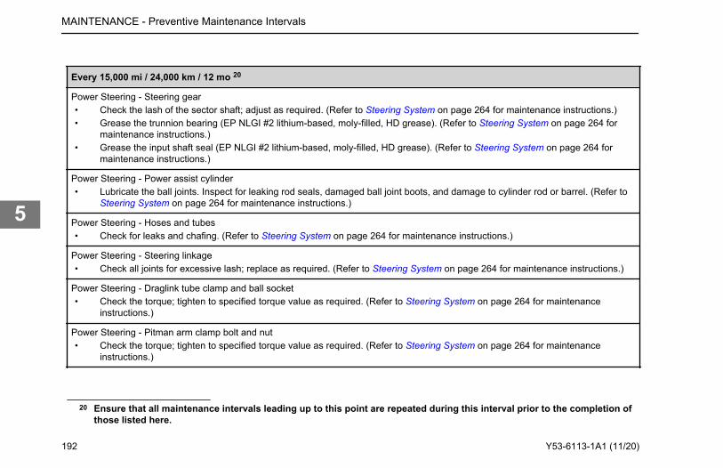
Every 15,000 mi / 24,000 km / 12 mo 20
Power Steering - Steering gear• Check the lash of the sector shaft; adjust as required. (Refer to Steering System on page 264 for maintenance instructions.)• Grease the trunnion bearing (EP NLGI #2 lithium-based, moly-filled, HD grease). (Refer to Steering System on page 264 for
maintenance instructions.)• Grease the input shaft seal (EP NLGI #2 lithium-based, moly-filled, HD grease). (Refer to Steering System on page 264 for
maintenance instructions.)
Power Steering - Power assist cylinder• Lubricate the ball joints. Inspect for leaking rod seals, damaged ball joint boots, and damage to cylinder rod or barrel. (Refer to
Steering System on page 264 for maintenance instructions.)
Power Steering - Hoses and tubes• Check for leaks and chafing. (Refer to Steering System on page 264 for maintenance instructions.)
Power Steering - Steering linkage• Check all joints for excessive lash; replace as required. (Refer to Steering System on page 264 for maintenance instructions.)
Power Steering - Draglink tube clamp and ball socket• Check the torque; tighten to specified torque value as required. (Refer to Steering System on page 264 for maintenance
instructions.)
Power Steering - Pitman arm clamp bolt and nut• Check the torque; tighten to specified torque value as required. (Refer to Steering System on page 264 for maintenance
instructions.)
20 Ensure that all maintenance intervals leading up to this point are repeated during this interval prior to the completion ofthose listed here.
MAINTENANCE - Preventive Maintenance Intervals
192 Y53-6113-1A1 (11/20)
5
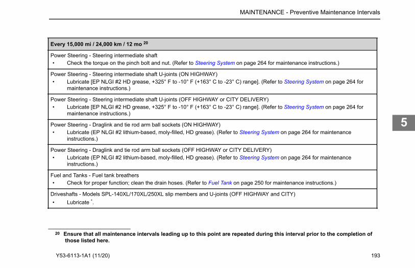
Every 15,000 mi / 24,000 km / 12 mo 20
Power Steering - Steering intermediate shaft• Check the torque on the pinch bolt and nut. (Refer to Steering System on page 264 for maintenance instructions.)
Power Steering - Steering intermediate shaft U-joints (ON HIGHWAY)• Lubricate [EP NLGI #2 HD grease, +325° F to -10° F (+163° C to -23° C) range]. (Refer to Steering System on page 264 for
maintenance instructions.)
Power Steering - Steering intermediate shaft U-joints (OFF HIGHWAY or CITY DELIVERY)• Lubricate [EP NLGI #2 HD grease, +325° F to -10° F (+163° C to -23° C) range]. (Refer to Steering System on page 264 for
maintenance instructions.)
Power Steering - Draglink and tie rod arm ball sockets (ON HIGHWAY)• Lubricate (EP NLGI #2 lithium-based, moly-filled, HD grease). (Refer to Steering System on page 264 for maintenance
instructions.)
Power Steering - Draglink and tie rod arm ball sockets (OFF HIGHWAY or CITY DELIVERY)• Lubricate (EP NLGI #2 lithium-based, moly-filled, HD grease). (Refer to Steering System on page 264 for maintenance
instructions.)
Fuel and Tanks - Fuel tank breathers• Check for proper function; clean the drain hoses. (Refer to Fuel Tank on page 250 for maintenance instructions.)
Driveshafts - Models SPL-140XL/170XL/250XL slip members and U-joints (OFF HIGHWAY and CITY)• Lubricate *.
20 Ensure that all maintenance intervals leading up to this point are repeated during this interval prior to the completion of
MAINTENANCE - Preventive Maintenance Intervals
those listed here.
Y53-6113-1A1 (11/20) 193
5
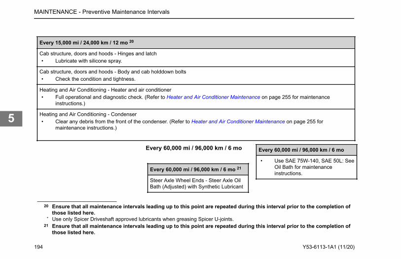
Every 15,000 mi / 24,000 km / 12 mo 20
Cab structure, doors and hoods - Hinges and latch• Lubricate with silicone spray.
Cab structure, doors and hoods - Body and cab holddown bolts• Check the condition and tightness.
Heating and Air Conditioning - Heater and air conditioner• Full operational and diagnostic check. (Refer to Heater and Air Conditioner Maintenance on page 255 for maintenance
instructions.)
Heating and Air Conditioning - Condenser• Clear any debris from the front of the condenser. (Refer to Heater and Air Conditioner Maintenance on page 255 for
maintenance instructions.)
Every 60,000 mi / 96,000 km / 6 mo
Every 60,000 mi / 96,000 km / 6 mo 21
Steer Axle Wheel Ends - Steer Axle OilBath (Adjusted) with Synthetic Lubricant
Every 60,000 mi / 96,000 km / 6 mo
• Use SAE 75W-140, SAE 50L: SeeOil Bath for maintenanceinstructions.
20 Ensure that all maintenance intervals leading up to this point are repeated during this interval prior to the completion ofthose listed here.
* Use only Spicer Driveshaft approved lubricants when greasing Spicer U-joints.21 Ensure that all maintenance intervals leading up to this point are repeated during this interval prior to the completion of
those listed here.
MAINTENANCE - Preventive Maintenance Intervals
194 Y53-6113-1A1 (11/20)
5
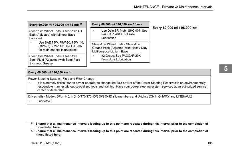
Every 60,000 mi / 96,000 km / 6 mo 21
Steer Axle Wheel Ends - Steer Axle OilBath (Adjusted) with Mineral BaseLubricant• Use SAE 75W, 75W-90, 75W140,
80W-90, 85W-140: See Oil Bathfor maintenance instructions.
Steer Axle Wheel Ends - Steer AxleSemi-Fluid (Adjusted) with Semi-FluidSynthetic Grease
Every 60,000 mi / 96,000 km / 6 mo
• Use Delo SF, Mobil SHC 007: SeePACCAR 20K Front AxleLubrication
Steer Axle Wheel Ends - Steer AxleGrease Pack (Adjusted) with Heavy-DutyMultipurpose Lithium Base• #2 Grade: See PACCAR 20K
Front Axle Lubrication
Every 60,000 mi / 96,000 km
Every 60,000 mi / 96,000 km 22
Power Steering System - Fluid and Filter Change• It is extremely difficult for an owner-operator to change the fluid or filter of the Power Steering Reservoir in an environmentally
responsible manner without specialized tools and training. Have your power steering system serviced at an authorized servicecenter or dealership.
Driveshafts - Models SPL- 140/140HD/170/170HD/250/250HD slip members and U-joints (ON HIGHWAY and LINEHAUL)• Lubricate *.
21 Ensure that all maintenance intervals leading up to this point are repeated during this interval prior to the completion ofthose listed here.
22 Ensure that all maintenance intervals leading up to this point are repeated during this interval prior to the completion of
MAINTENANCE - Preventive Maintenance Intervals
those listed here.
Y53-6113-1A1 (11/20) 195
5
Every 60,000 mi / 96,000 km 22
Air - Air dryer (OFF HIGHWAY)• Overhaul. (Refer to Air Dryer Maintenance on page 206 for maintenance instructions.)
Every 120,000 miles /193,000 km / 2yr
Steer Axle Wheel Ends
Every 120,000 miles /193,000 km / 2 yr23
Steer Axle Oil Bath LMS with SyntheticLubricant
• Use SAE 75W-90: See Oil bathfor maintenance instructions.
Air Intake - Pre-cleaner Filter Assembly
Every 120,000 miles /193,000 km / 2 yr
• Install new Pre-cleaner Filter Assembly.(Refer to How to Remove the Pre-cleanerFilter on page 247.))
Main and Auxiliary Transmission -(PACCAR 8 Speed Transmission) (ONHIGHWAY)• Drain lubricant while warm. Flush eachunit with clean flushing oil.
Fender LinersThe fender liners are located on both sidesof the hood underside and protect theheadlight assembly and other engine baycontent from water and debris. Somemaintenance processes require one orboth liners to be removed.
How to Remove a Fender LinerPerformed with hood open (How to Openthe Hood on page 15) standing on eitherside of hood.
1. Unlock all four liner fasteners bytwisting each ¼ turn counter-clockwise.
22 Ensure that all maintenance intervals leading up to this point are repeated during this interval prior to the completion ofthose listed here.
* Use only Spicer Driveshaft approved lubricants when greasing Spicer U-joints.23 Ensure that all maintenance intervals leading up to this point are repeated during this interval prior to the completion of
those listed here.
MAINTENANCE - Fender Liners
196 Y53-6113-1A1 (11/20)
5
2. Gently pull liner up and away fromhood to remove.
3. Place fender liner aside.
How to Reinstall a Fender LinerPerformed with hood open (How to Openthe Hood on page 15) standing onappropriate side of hood.
1. Hook bottom of liner to inside hood,below the headlight assembly.
2. Replace fender liner in hood, liningup locking fasteners.Align hood guide with groove onliner: “LOCATE TO HOODREINFORCEMENT.”
3. Gently insert then twist all fourlocking fasteners ¼ turn clockwiseto secure liner.
truck running at top economy andprolonging its life is proper lubricationservicing. Neglecting this essential aspectof vehicle care can cost time and money inthe long run.
WARNING
Handle lubricants carefully. Vehicle lu-bricants (oil and grease) can be poi-sonous and cause sickness, personalinjury, or death. They can also damagethe paint on the vehicle.
CAUTION
DO NOT mix different types of lubri-cants. Mixing lubricants (oil andgrease) of different brands or typescould damage vehicle components;therefore, drain (or remove) old lubri-cants from the unit before refilling it.
EngineProper engine lubrication depends on theoutside temperatures where you will bedriving. Use the oil recommended for theconditions you are most likely to beoperating in. You will find a complete
engine lubrication service guide in theEngine Operation Manual that came withyour vehicle. The engine operator manualcontains specific maintenance tasks thatyou or a qualified service technician needto perform to maintain the engine.
WARNING
Exhaust fumes from the engine con-tain carbon monoxide, a colorless andodorless gas. DO NOT breathe the en-gine exhaust gas. A poorly maintained,damaged, or corroded exhaust systemcan allow carbon monoxide to enterthe cab. Entry of carbon monoxide intothe cab is also possible from other ve-hicles nearby. Failure to properly main-tain your vehicle could cause carbonmonoxide to enter the cab, resulting inpersonal injury or death.
MAINTENANCE - Lubricants
LubricantsSchedule service more frequently if you are operating under severe conditions such as extreme heat or cold, with very heavy loads, off-road, etc. For any special service requirements, consult your service manuals and your lubricant supplier. Please remember: one key to keeping your
Y53-6113-1A1 (11/20) 197
5
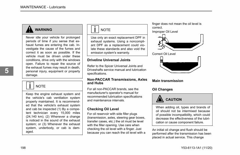
WARNING
Never idle your vehicle for prolongedperiods of time if you sense that ex-haust fumes are entering the cab. In-vestigate the cause of the fumes andcorrect it as soon as possible. If thevehicle must be driven under theseconditions, drive only with the windowsopen. Failure to repair the source ofthe exhaust fumes may result in death,personal injury, equipment or propertydamage.
NOTE
Keep the engine exhaust system andthe vehicle's cab ventilation systemproperly maintained. It is recommend-ed that the vehicle's exhaust systemand cab be inspected (1) By a compe-tent technician every 15,000 miles(24,140 km); (2) Whenever a changeis noticed in the sound of the exhaustsystem; or (3) Whenever the exhaustsystem, underbody, or cab is dam-aged.
NOTE
Use only an exact replacement DPF inexhaust systems. Using a noncompli-ant DPF as a replacement could vio-late these standards and also void theemission system's warranty.
Driveline Universal JointsRefer to the Spicer Universal Joints andDriveshafts service manual and lubricationspecifications.
Non-PACCAR Transmissions, Axlesand HubsFor all non-PACCAR brands, see themanufacturer's operator's manual forrecommended lubrication specificationsand maintenance intervals.
Checking Oil LevelFor oil reservoir with side filler plugs(transmission, axles, steering gear boxes,transfer cases, etc.) the oil must be levelwith the filler opening. Use care whenchecking the oil level with a finger. Justbecause you can reach the oil level with a
finger does not mean the oil level iscorrect.Improper Oil Level
Correct Oil Level
Main transmission
Oil Changes
CAUTION
When adding oil, types and brands ofoil should not be intermixed becauseof possible incompatibility, which coulddecrease the effectiveness of the lubri-cation or cause component failure.
An initial oil change and flush should beperformed after the transmission has beenplaced in actual service. This change
MAINTENANCE - Lubricants
198 Y53-6113-1A1 (11/20)
5
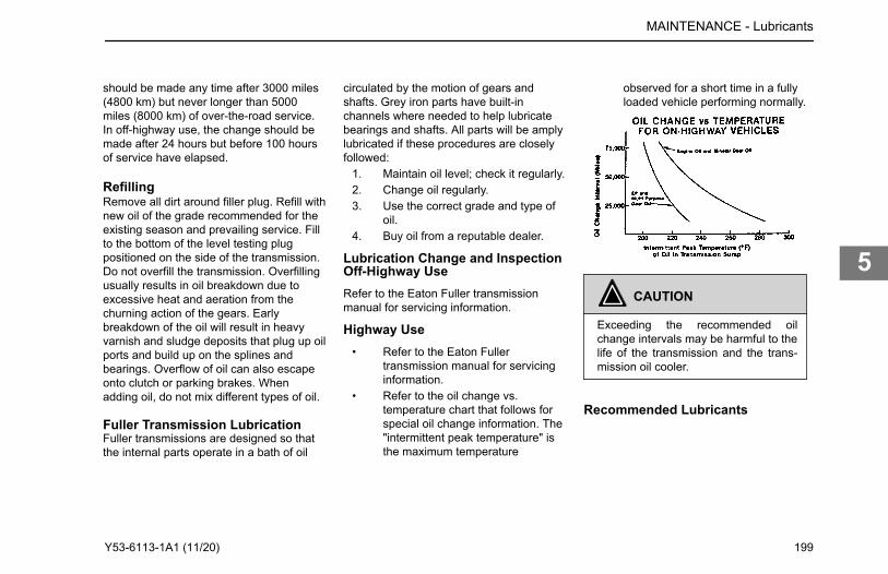
circulated by the motion of gears andshafts. Grey iron parts have built-inchannels where needed to help lubricatebearings and shafts. All parts will be amplylubricated if these procedures are closelyfollowed:
1. Maintain oil level; check it regularly.2. Change oil regularly.3. Use the correct grade and type of
oil.4. Buy oil from a reputable dealer.
Lubrication Change and InspectionOff-Highway UseRefer to the Eaton Fuller transmissionmanual for servicing information.
Highway Use• Refer to the Eaton Fuller
transmission manual for servicinginformation.
• Refer to the oil change vs.temperature chart that follows forspecial oil change information. The"intermittent peak temperature" isthe maximum temperature
observed for a short time in a fullyloaded vehicle performing normally.
CAUTION
Exceeding the recommended oilchange intervals may be harmful to thelife of the transmission and the trans-mission oil cooler.
Recommended Lubricants
MAINTENANCE - Lubricants
should be made any time after 3000 miles (4800 km) but never longer than 5000 miles (8000 km) of over-the-road service. In off-highway use, the change should be made after 24 hours but before 100 hours of service have elapsed.
RefillingRemove all dirt around filler plug. Refill with new oil of the grade recommended for the existing season and prevailing service. Fill to the bottom of the level testing plug positioned on the side of the transmission. Do not overfill the transmission. Overfilling usually results in oil breakdown due to excessive heat and aeration from the churning action of the gears. Early breakdown of the oil will result in heavy varnish and sludge deposits that plug up oil ports and build up on the splines and bearings. Overflow of oil can also escape onto clutch or parking brakes. When adding oil, do not mix different types of oil.
Fuller Transmission LubricationFuller transmissions are designed so that the internal parts operate in a bath of oil
Y53-6113-1A1 (11/20) 199
5
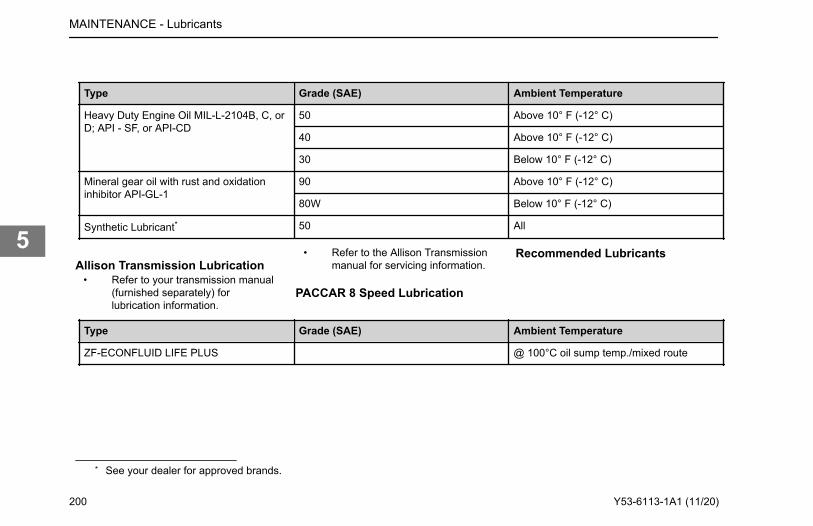
Type Grade (SAE) Ambient Temperature
Heavy Duty Engine Oil MIL-L-2104B, C, orD; API - SF, or API-CD
50 Above 10° F (-12° C)
40 Above 10° F (-12° C)
30 Below 10° F (-12° C)
Mineral gear oil with rust and oxidationinhibitor API-GL-1
90 Above 10° F (-12° C)
80W Below 10° F (-12° C)
Synthetic Lubricant* 50 All
Allison Transmission Lubrication• Refer to your transmission manual
(furnished separately) forlubrication information.
• Refer to the Allison Transmissionmanual for servicing information.
PACCAR 8 Speed Lubrication
Recommended Lubricants
Type Grade (SAE) Ambient Temperature
ZF-ECONFLUID LIFE PLUS @ 100°C oil sump temp./mixed route
* See your dealer for approved brands.
MAINTENANCE - Lubricants
200 Y53-6113-1A1 (11/20)
5
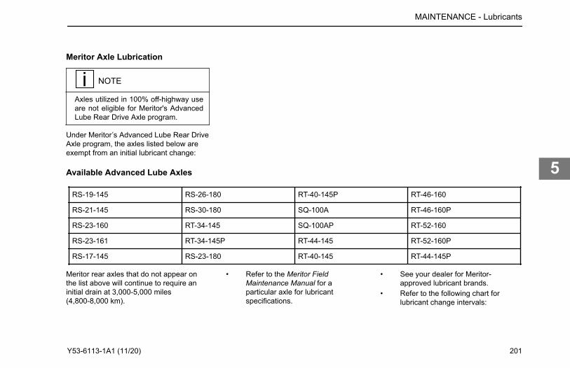
Meritor Axle Lubrication
NOTE
Axles utilized in 100% off-highway useare not eligible for Meritor's AdvancedLube Rear Drive Axle program.
Under Meritor’s Advanced Lube Rear DriveAxle program, the axles listed below areexempt from an initial lubricant change:
Available Advanced Lube Axles
RS-19-145 RS-26-180 RT-40-145P RT-46-160
RS-21-145 RS-30-180 SQ-100A RT-46-160P
RS-23-160 RT-34-145 SQ-100AP RT-52-160
RS-23-161 RT-34-145P RT-44-145 RT-52-160P
RS-17-145 RS-23-180 RT-40-145 RT-44-145P
Meritor rear axles that do not appear onthe list above will continue to require aninitial drain at 3,000-5,000 miles(4,800-8,000 km).
• Refer to the Meritor FieldMaintenance Manual for aparticular axle for lubricantspecifications.
• See your dealer for Meritor-approved lubricant brands.
• Refer to the following chart forlubricant change intervals:
MAINTENANCE - Lubricants
Y53-6113-1A1 (11/20) 201
5
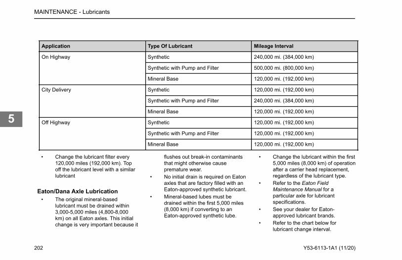
Application Type Of Lubricant Mileage Interval
On Highway Synthetic 240,000 mi. (384,000 km)
Synthetic with Pump and Filter 500,000 mi. (800,000 km)
Mineral Base 120,000 mi. (192,000 km)
City Delivery Synthetic 120,000 mi. (192,000 km)
Synthetic with Pump and Filter 240,000 mi. (384,000 km)
Mineral Base 120,000 mi. (192,000 km)
Off Highway Synthetic 120,000 mi. (192,000 km)
Synthetic with Pump and Filter 120,000 mi. (192,000 km)
Mineral Base 120,000 mi. (192,000 km)
• Change the lubricant filter every120,000 miles (192,000 km). Topoff the lubricant level with a similarlubricant
Eaton/Dana Axle Lubrication• The original mineral-based
lubricant must be drained within3,000-5,000 miles (4,800-8,000km) on all Eaton axles. This initialchange is very important because it
flushes out break-in contaminantsthat might otherwise causepremature wear.
• No initial drain is required on Eatonaxles that are factory filled with anEaton-approved synthetic lubricant.
• Mineral-based lubes must bedrained within the first 5,000 miles(8,000 km) if converting to anEaton-approved synthetic lube.
• Change the lubricant within the first5,000 miles (8,000 km) of operationafter a carrier head replacement,regardless of the lubricant type.
• Refer to the Eaton FieldMaintenance Manual for aparticular axle for lubricantspecifications.
• See your dealer for Eaton-approved lubricant brands.
• Refer to the chart below forlubricant change interval.
MAINTENANCE - Lubricants
202 Y53-6113-1A1 (11/20)
5
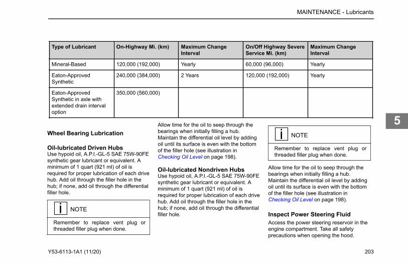
Type of Lubricant On-Highway Mi. (km) Maximum ChangeInterval
On/Off Highway SevereService Mi. (km)
Maximum ChangeInterval
Mineral-Based 120,000 (192,000) Yearly 60,000 (96,000) Yearly
Eaton-ApprovedSynthetic
240,000 (384,000) 2 Years 120,000 (192,000) Yearly
Eaton-ApprovedSynthetic in axle withextended drain intervaloption
350,000 (560,000)
Wheel Bearing Lubrication
Oil-lubricated Driven HubsUse hypoid oil, A.P.I.-GL-5 SAE 75W-90FEsynthetic gear lubricant or equivalent. Aminimum of 1 quart (921 ml) of oil isrequired for proper lubrication of each drivehub. Add oil through the filler hole in thehub; if none, add oil through the differentialfiller hole.
NOTE
Remember to replace vent plug orthreaded filler plug when done.
Allow time for the oil to seep through thebearings when initially filling a hub.Maintain the differential oil level by addingoil until its surface is even with the bottomof the filler hole (see illustration in Checking Oil Level on page 198).
Oil-lubricated Nondriven HubsUse hypoid oil, A.P.I.-GL-5 SAE 75W-90FEsynthetic gear lubricant or equivalent. Aminimum of 1 quart (921 ml) of oil isrequired for proper lubrication of each drivehub. Add oil through the filler hole in thehub; if none, add oil through the differentialfiller hole.
NOTE
Remember to replace vent plug orthreaded filler plug when done.
Allow time for the oil to seep through thebearings when initially filling a hub.Maintain the differential oil level by addingoil until its surface is even with the bottomof the filler hole (see illustration in Checking Oil Level on page 198).
Inspect Power Steering FluidAccess the power steering reservoir in theengine compartment. Take all safetyprecautions when opening the hood.
MAINTENANCE - Lubricants
Y53-6113-1A1 (11/20) 203
5
CAUTION
When adding fluid, be sure to use fluidof the same type. While many fluidshave the same description and intend-ed purpose, they should not be mixeddue to incompatible additives. Mixingincompatible fluids may lead to equip-ment damage.
1. Turn engine off and open hood.2. Wipe outside of power steering
reservoir cover so that no dirt canfall into the reservoir.
3. Verify that the fluid level is at thecorrect level. Add more fluid ifrequired.
4. Check fluid for air bubbles whichmay indicate contamination,discoloration, or burnt smell;correct source of such problemsbefore replacing fluid and filter.
If incompatible (insoluble) fluids are mixedin a power steering system, air bubblescan be produced at the interface of the twofluids. This can cause cavitation, whichreduces the lubrication between movingparts in the gear. This could result in worncomponents. The mixture of two different
fluids, although harmless to individualinternal components, may initiate achemical reaction that produces a newcompound that will attack seals and otherinternal components. DO NOT mix differentfluids.
Air SystemThe operation of the vehicle’s brakingsystem and many vehicle accessoriesdepends upon the storage and applicationof a high-pressure air supply.
WARNING
DO NOT attempt to modify, alter, re-pair or disconnect any component ofthe air system. Repairs or modifica-tions to the air system, other than whatis described in this section, should on-ly be performed by an authorized deal-er. Failure to comply may result in per-sonal injury or death.
WARNING
Prior to the removal of any air systemcomponent, always block and hold thevehicle by a secure means other thanthe vehicle's own brakes. Depleting airsystem pressure may cause the vehi-cle to roll unexpectedly resulting in anaccident causing personal injury ordeath. Keep hands away from cham-ber push rods and slack adjusters,they may apply as system pressuredrops.
WARNING
After completing any repairs to the airsystem, always test for air leaks andcheck the brakes for safe operationbefore putting the vehicle in service.Failure to comply may result in proper-ty damage, personal injury, or death.
MAINTENANCE - Air System
204 Y53-6113-1A1 (11/20)
5
WARNING
Never connect or disconnect a hose orline containing air pressure. It maywhip as air escapes. Never remove acomponent or pipe plug unless you arecertain all system pressure has beendepleted. Failure to comply may resultin property damage, personal injury, ordeath.
WARNING
Never exceed recommended air pres-sure and always wear safety glasseswhen working with air pressure. Neverlook into air jets or direct them at any-one. Failure to comply may result inproperty damage, personal injury, ordeath.
WARNING
Never attempt to disassemble a com-ponent until you have read and under-stood recommended procedures.Some components contain powerful
springs and injury can result if notproperly disassembled. Use only prop-er tools and observe all precautionspertaining to use of those tools. Failureto comply may result in property dam-age, personal injury, or death.
WARNING
Completely bypassing a Bendix® AD-IS air dryer will bypass the system’spressure protection valves. This couldlead to loss of air pressure or damageto the vehicle’s air system, which couldcause an accident involving death orpersonal injury. Always adhere to themanufacturer’s procedure if it is nec-essary in an emergency to temporarilybypass an AD-IS series air dryer. Fail-ure to comply may result in death, per-sonal injury, equipment or propertydamage.
WARNING
If a different air dryer brand or model isinstalled on the vehicle other thanwhat was originally installed, it could
cause the air system to not performcorrectly unless the full air system de-sign is reviewed and modificationsmade to comply with Federal MotorVehicle Safety Standards (FMVSS)121 AirBrake Systems. Failure toabide by this warning and maintaincompliance to FMVSS 121 couldcause loss of vehicle control and maylead to death or serious personal in-jury.
WARNING
If the supply and service air tanks arenot drained at the recommended fre-quency, water could enter the air linesand valves. This could cause corrosionor blockage, which could compromisethe brake system safety and potential-ly cause an accident. Failure to complymay result in property damage, per-sonal injury, or death.
Your vehicle’s compressor takes outside airand compresses it, usually to 100-120 psi(689-827 kPa). The compressed air thengoes to the reservoirs to be stored untilneeded. When you operate your airbrakes, the stored compressed air flows
MAINTENANCE - Air System
Y53-6113-1A1 (11/20) 205
5
into the chambers where it is used to applyyour truck and trailer brakes. That is why,when you push down on your brake pedal,you don’t feel the same amount ofpressure on the pedal that you do whenyou apply the brakes on your car. All youare doing on your truck is opening an airvalve to allow air to flow into the brakechambers. Contamination of the air supplysystem is the major cause of problems inair-operated components such as brakevalves, and suspension height controlvalves. To keep contaminants to the lowestpossible level, follow these maintenanceprocedures.
Daily Checks• Drain moisture from the supply and
service air tanks.• Operate air devices to circulate
lubricant within the unit.
Periodically• Clean filter screens ahead of the
valves by removing the screensand soaking them in solvent. Blowthem dry with pressurized airbefore reinstalling them.
Twice a Year• Maintain the air compressor to
prevent excessive oil bypass. Seeyour maintenance manual fordetails.
• Replace worn seals in valves andair motors as needed.
Dual Air System FunctionTestConduct this test at least every 3 monthsor if there is any indication of a potentialproblem.Park the vehicle on level ground and blockthe wheels. Have an assistant open drainvalves and, where required, observe brakeaction at the wheels. If a malfunctionoccurs during this test, do not move thevehicle until the problem has beencorrected. Engine should be Off with thekey switch to the ON or RUN position.
NOTE
Tractor air system must be connectedto trailer.
Air Dryer Maintenance
NOTE
Because no two vehicles operate un-der identical conditions, maintenanceand maintenance intervals will vary.Experience is a valuable guide in de-termining the best maintenance inter-val for any one particular operation.
NOTE
A small amount of oil in the systemmay be normal and should not, in it-self, be considered a reason to replacethe desiccant cartridge. Oil staineddesiccant can function adequately.
Every 900 operating hours or 25,000 miles(40,000 km) or every 3 months check formoisture in the air brake system byopening air tanks, drain cocks, or valvesand checking for presence of water.A tablespoon of water found in the air tankwould point to the need for a desiccantcartridge change. However, the followingconditions can also cause water
MAINTENANCE - Dual Air System Function Test
206 Y53-6113-1A1 (11/20)
5
accumulation and should be consideredbefore replacing the desiccant cartridge.
• Air usage is exceptionally high andnot normal for a highway vehicle.This may be due to accessory airdemands or some unusual airrequirement that does not allow thecompressor to load and unload(compressing and non-compressing cycle) in a normalfashion or it may be due toexcessive leaks in the air system.
• In areas where more than a 30°F(17°C) range of temperature occursin one day, small amounts of watercan accumulate in the air brakesystem due to condensation. Underthese conditions, the presence ofsmall amounts of moisture isnormal and should not beconsidered as an indication that thedryer is not performing properly.
• An outside air source has beenused to charge the air system. Thisair did not pass through the dryingbed.
Maintenance
CAUTION
Replace oil-coalescing desiccant airdryer cartridge every 1 year regardlessof mileage. Only use oil-coalescingdesiccant replacement cartridge whenreplacing. Failure to perform this main-tenance task will void the PACCARTransmission warranty and may resultin expensive transmission damage.
Replace (non-oil-coalescing) desiccantcartridge:
• On-highway operation replaceevery 2-3 years, 350,000 miles(560,000 km) or 10,800 hours.
• High duty cycle usage such astransit bus, refuse hauler, dumptruck, cement mixers and off-highway operation replace every 1year, 100,000 miles (160,000 km)or 3,600 hours.
NOTE
Review the warranty policy before per-forming any maintenance procedures.An extended warranty may be voidedif unauthorized maintenance is per-formed during this period.
Bendix® AD-HF Series Air DryerYour vehicle may be equipped with aBendix® AD-HF series air dryer. Any airdryer replacement should be made with anidentical component.
MAINTENANCE - Air Dryer Maintenance
Y53-6113-1A1 (11/20) 207
5
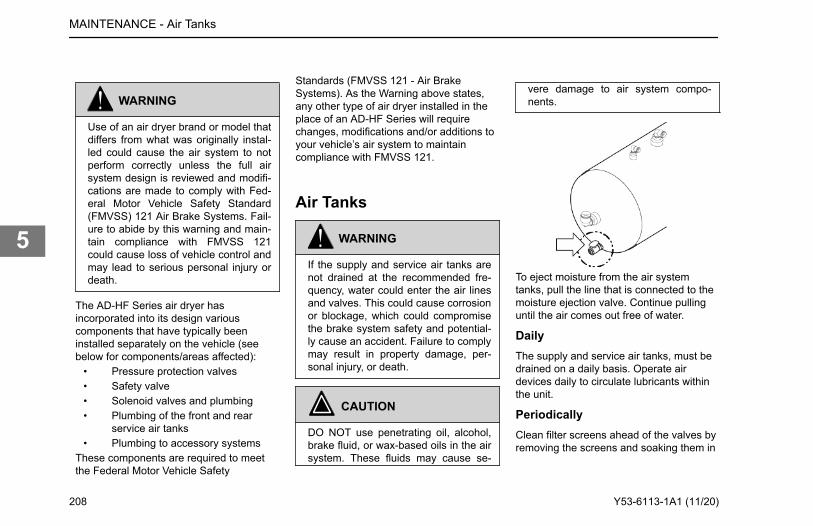
WARNING
Use of an air dryer brand or model thatdiffers from what was originally instal-led could cause the air system to notperform correctly unless the full airsystem design is reviewed and modifi-cations are made to comply with Fed-eral Motor Vehicle Safety Standard(FMVSS) 121 Air Brake Systems. Fail-ure to abide by this warning and main-tain compliance with FMVSS 121could cause loss of vehicle control andmay lead to serious personal injury ordeath.
The AD-HF Series air dryer hasincorporated into its design variouscomponents that have typically beeninstalled separately on the vehicle (seebelow for components/areas affected):
• Pressure protection valves• Safety valve• Solenoid valves and plumbing• Plumbing of the front and rear
service air tanks• Plumbing to accessory systems
These components are required to meetthe Federal Motor Vehicle Safety
Standards (FMVSS 121 - Air BrakeSystems). As the Warning above states,any other type of air dryer installed in theplace of an AD-HF Series will requirechanges, modifications and/or additions toyour vehicle’s air system to maintaincompliance with FMVSS 121.
Air Tanks
WARNING
If the supply and service air tanks arenot drained at the recommended fre-quency, water could enter the air linesand valves. This could cause corrosionor blockage, which could compromisethe brake system safety and potential-ly cause an accident. Failure to complymay result in property damage, per-sonal injury, or death.
CAUTION
DO NOT use penetrating oil, alcohol,brake fluid, or wax-based oils in the airsystem. These fluids may cause se-
vere damage to air system compo-nents.
To eject moisture from the air systemtanks, pull the line that is connected to themoisture ejection valve. Continue pullinguntil the air comes out free of water.
DailyThe supply and service air tanks, must bedrained on a daily basis. Operate airdevices daily to circulate lubricants withinthe unit.
PeriodicallyClean filter screens ahead of the valves byremoving the screens and soaking them in
MAINTENANCE - Air Tanks
208 Y53-6113-1A1 (11/20)
5
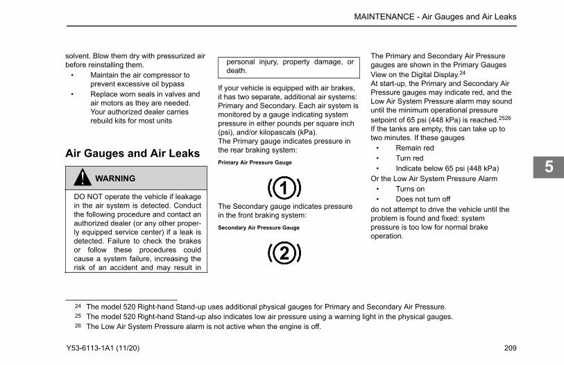
solvent. Blow them dry with pressurized airbefore reinstalling them.
• Maintain the air compressor toprevent excessive oil bypass
• Replace worn seals in valves andair motors as they are needed.Your authorized dealer carriesrebuild kits for most units
Air Gauges and Air Leaks
WARNING
DO NOT operate the vehicle if leakagein the air system is detected. Conductthe following procedure and contact anauthorized dealer (or any other proper-ly equipped service center) if a leak isdetected. Failure to check the brakesor follow these procedures couldcause a system failure, increasing therisk of an accident and may result in
personal injury, property damage, ordeath.
If your vehicle is equipped with air brakes,it has two separate, additional air systems:Primary and Secondary. Each air system ismonitored by a gauge indicating systempressure in either pounds per square inch(psi), and/or kilopascals (kPa).The Primary gauge indicates pressure inthe rear braking system:Primary Air Pressure Gauge
The Secondary gauge indicates pressurein the front braking system:Secondary Air Pressure Gauge
The Primary and Secondary Air Pressuregauges are shown in the Primary GaugesView on the Digital Display.24
At start-up, the Primary and Secondary AirPressure gauges may indicate red, and theLow Air System Pressure alarm may sounduntil the minimum operational pressuresetpoint of 65 psi (448 kPa) is reached.2526
If the tanks are empty, this can take up totwo minutes. If these gauges
• Remain red• Turn red• Indicate below 65 psi (448 kPa)
Or the Low Air System Pressure Alarm• Turns on• Does not turn off
do not attempt to drive the vehicle until theproblem is found and fixed: systempressure is too low for normal brakeoperation.
24 The model 520 Right-hand Stand-up uses additional physical gauges for Primary and Secondary Air Pressure.25 The model 520 Right-hand Stand-up also indicates low air pressure using a warning light in the physical gauges.26 The Low Air System Pressure alarm is not active when the engine is off.
MAINTENANCE - Air Gauges and Air Leaks
Y53-6113-1A1 (11/20) 209
5
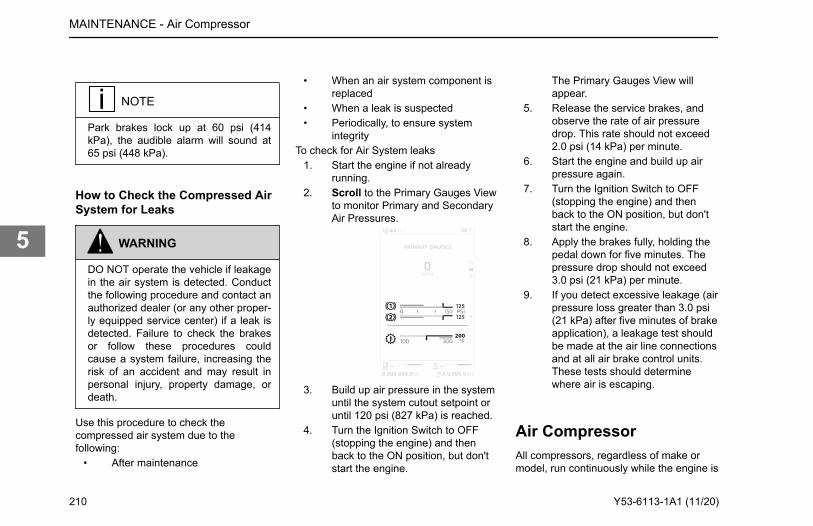
NOTE
Park brakes lock up at 60 psi (414kPa), the audible alarm will sound at65 psi (448 kPa).
How to Check the Compressed AirSystem for Leaks
WARNING
DO NOT operate the vehicle if leakagein the air system is detected. Conductthe following procedure and contact anauthorized dealer (or any other proper-ly equipped service center) if a leak isdetected. Failure to check the brakesor follow these procedures couldcause a system failure, increasing therisk of an accident and may result inpersonal injury, property damage, ordeath.
Use this procedure to check thecompressed air system due to thefollowing:
• After maintenance
• When an air system component isreplaced
• When a leak is suspected• Periodically, to ensure system
integrityTo check for Air System leaks
1. Start the engine if not alreadyrunning.
2. Scroll to the Primary Gauges Viewto monitor Primary and SecondaryAir Pressures.
3. Build up air pressure in the systemuntil the system cutout setpoint oruntil 120 psi (827 kPa) is reached.
4. Turn the Ignition Switch to OFF(stopping the engine) and thenback to the ON position, but don'tstart the engine.
The Primary Gauges View willappear.
5. Release the service brakes, andobserve the rate of air pressuredrop. This rate should not exceed2.0 psi (14 kPa) per minute.
6. Start the engine and build up airpressure again.
7. Turn the Ignition Switch to OFF(stopping the engine) and thenback to the ON position, but don'tstart the engine.
8. Apply the brakes fully, holding thepedal down for five minutes. Thepressure drop should not exceed3.0 psi (21 kPa) per minute.
9. If you detect excessive leakage (airpressure loss greater than 3.0 psi(21 kPa) after five minutes of brakeapplication), a leakage test shouldbe made at the air line connectionsand at all air brake control units.These tests should determinewhere air is escaping.
Air CompressorAll compressors, regardless of make ormodel, run continuously while the engine is
MAINTENANCE - Air Compressor
210 Y53-6113-1A1 (11/20)
5
running. System pressure is controlled bythe governor. The governor acts inconjunction with the unloading mechanismin the compressor cylinder block to startand stop compression of air. Thecompressor is unloaded when the systempressure reaches 120 psi (827 kPa) andcompression is reestablished when systempressure falls to 100 psi (690 kPa).
Preventive MaintenanceThe following service checks are providedfor your information only and should beperformed by a certified mechanic. Contactyour dealer or the engine manufacturer'sMaintenance Manual for further informationon servicing air compressors. Aftercompleting any repairs to the air system,always test for air leaks, and check thebrakes for safe operation before putting thevehicle in service. Below is a list of areasto maintain for the air compressor:
• Inspect compressor air filterelement, if so equipped, andreplace element if clogged. Checkcompressor mounting and drive foralignment and belt tension. Adjustif necessary.
• Remove compressor dischargevalve cap nuts and check forpresence of excessive carbon. If
excessive carbon is found, clean orreplace the compressor cylinderhead. Also, check compressordischarge line for carbon, andclean or replace the discharge lineif necessary.
• Disassemble compressor andthoroughly clean and inspect allparts. Repair or replace all worn ordamaged parts, or replacecompressor with a factoryexchange unit.
Brake SystemTo learn more about brakes, see the Index,under Brakes.
WARNING
DO NOT work on the brake systemwithout the parking brake set andwheels chocked securely. If the vehicleis not secured to prevent uncontrolledvehicle movement, it could roll andcause damage to the vehicle, seriouspersonal injury, or death.
CAUTION
The air brake system of this vehiclewas configured for ONE of the follow-ing operations: tractor or truck, andcomplies with the respective portionsof FMVSS 121. A tractor shall not beoperated or configured as a truck, norshall a truck be operated or configuredas a tractor, without significant modifi-cations to the air brake system in orderto retain compliance with FMVSS 121.Contact your dealer for instructions.
WARNING
DO NOT use brake linings with a thick-ness below the specified minimum.Such linings will have lining rivets ex-posed that can damage the brakedrum and reduce brake efficiency,which could cause death, personal in-jury or system failure.
MAINTENANCE - Brake System
Y53-6113-1A1 (11/20) 211
5
WARNING
DO NOT use any replacement part inthe brake system unless it conformsexactly to original specifications. Anonconforming part in your vehicle'sbrake system could cause a malfunc-tion resulting in an accident causingdeath or personal injury. Sizes andtypes are so related to one anotherthat a seemingly unimportant changein one may result in a change in howwell the brakes work for you on theroad. If parts do not work togetherproperly, you could lose control of yourvehicle, which could cause a seriousaccident.
Brake adjustment and brake balance mustbe set carefully to (1) make the mostefficient use of the forces available forbraking and (2) allow equal stopping forcesat all wheels. Once a brake system is setto specifications, changing any one of itscomponents or any combination ofcomponents may cause the system to notwork as well. All parts have to worktogether to perform as they should. Anyreplacement components in your brakesystem should be exactly equal to the
original components. Any changes fromthe original specifications can affect thewhole system. All of the following areas areinterrelated and must conform to originalspecifications:
• Tire size• Drum brakes• Cam radius• Wedge angle• Drum radius• Brake linings• Brake chambers• Slack adjusters• Disc brakes• Disc rotors
All vehicle operators should check theirbrakes regularly.
Air Disc BrakesHave brake pads inspected by a qualifiedmechanic for wear at regular intervalsaccording to the Preventive MaintenanceIntervals on page 173. In severe service oroff-highway applications inspect the liningsmore frequently.Regularly inspect for pad/rotor wear:
• Park on level ground and chock thewheels.
• Temporarily release the parkingbrakes.
• Compare the relative position oftwo notches; one located on thecaliper and the other on the carrier.See the illustration below todetermine if the brakes require adetailed inspection by a qualifiedmechanic.
• Have a qualified mechanic performa detailed inspection if the notchesare not found. The pads and rotorsshould be measured and comparedagainst the manufacturersspecifications located in the brakemanufacturer’s service manual.
MAINTENANCE - Brake System
212 Y53-6113-1A1 (11/20)
5
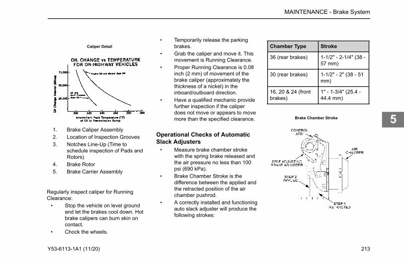
Caliper Detail
1. Brake Caliper Assembly2. Location of Inspection Grooves3. Notches Line-Up (Time to
schedule inspection of Pads andRotors)
4. Brake Rotor5. Brake Carrier Assembly
Regularly inspect caliper for RunningClearance:
• Stop the vehicle on level groundand let the brakes cool down. Hotbrake calipers can burn skin oncontact.
• Chock the wheels.
• Temporarily release the parkingbrakes.
• Grab the caliper and move it. Thismovement is Running Clearance.
• Proper Running Clearance is 0.08inch (2 mm) of movement of thebrake caliper (approximately thethickness of a nickel) in theinboard/outboard direction.
• Have a qualified mechanic providefurther inspection if the caliperdoes not move or appears to movemore than the specified clearance.
Operational Checks of AutomaticSlack Adjusters
• Measure brake chamber strokewith the spring brake released andthe air pressure no less than 100psi (690 kPa).
• Brake Chamber Stroke is thedifference between the applied andthe retracted position of the airchamber pushrod.
• A correctly installed and functioningauto slack adjuster will produce thefollowing strokes:
Chamber Type Stroke
36 (rear brakes) 1-1/2" - 2-1/4" (38 -57 mm)
30 (rear brakes) 1-1/2" - 2" (38 - 51mm)
16, 20 & 24 (frontbrakes)
1" - 1-3/4" (25.4 -44.4 mm)
Brake Chamber Stroke
MAINTENANCE - Brake System
Y53-6113-1A1 (11/20) 213
5
WARNING
Manual adjustment of automatic slackadjusters is a dangerous practice thatcould have serious consequences. Itgives the operator a false sense of se-curity about the effectiveness of thebrakes. Contact the Service Depart-ment at your dealership if the strokeexceeds specifications. A stroke ex-ceeding specifications may indicate aproblem with the slack adjuster or thebrake foundation.
Drum Brake InspectionHave brake drum linings inspected by aqualified mechanic for wear at regularintervals according to the maintenanceschedule. In severe service or off-highwayapplications inspect the linings morefrequently. In addition, periodically checkthe brake chamber stroke. Replace theslack adjuster if proper stroke cannot bemaintained.Operational checks of automatic slackadjusters
1. Start the vehicle and get the airsystem up to normal operating
pressure. Do not apply the parkingbrake.
2. Apply pressure to the brake pedaland measure the distance the airchamber pushrod traveled.
3. Compare the results to thespecification to determine if theautomatic slack adjusters needreplacing.
WARNING
Manual adjustment of automatic slackadjusters is a dangerous practice thatcould have serious consequences. Itgives the operator a false sense of se-curity about the effectiveness of thebrakes. Contact the Service Depart-ment at your dealership if the strokeexceeds specifications. A stroke ex-ceeding specifications may indicate aproblem with the slack adjuster or thebrake foundation.
Automatic Slack Adjuster StrokeSpecification
Chamber Type Stroke
36 (rear brakes) 1.5-2.5 in. (38-57mm)
30 (rear brakes) 1.5-2 in. (38-51mm)
16, 20 and 24 (frontbrakes)
1-1.75 in.(25.4-44.4 mm)
Hydraulic Brake SystemTo operate your vehicle safely, you needsome understanding of its brake systems.Brake adjustment and brake balance mustbe set carefully to allow equal stoppingforces at all wheels. Tires are also a veryimportant part of the whole system. Howfast you can stop depends on how muchfriction there is between the road and yourtires.All of the following areas are interrelatedand must conform to original specifications:
• wheel size• tire size• brake pads
MAINTENANCE - Brake System
214 Y53-6113-1A1 (11/20)
5
• brake rotors• front wheel bearings• front end alignment• parking brake drum radius
Once a brake system is set tospecifications, changing any one of itscomponents or any combination ofcomponents may degrade the system. Allparts have to work together to perform asthey should.Your brake system is hydraulicallyoperated. Refer to Service BrakeComponent Inspection on page 216 formore information on inspecting the brakes.Any replacement components in the brakesystem must meet the specifications of theoriginal components. Any changes fromthe original specifications can affect theperformance of the entire system.
WARNING
Do not use any replacement part in thebrake system unless it conforms ex-actly to original specifications. A non-conforming part in your vehicle's brakesystem could cause a malfunction re-sulting in an injury accident. Consult
you local dealer for suitable replace-ment parts.
WARNING
Do not work on the brake system with-out the parking brake set, the keys re-moved from the vehicle, and wheelschocked securely. If the vehicle is notproperly secured to prevent inadver-tent vehicle movement, it could rolland cause serious personal injury ordamage to the vehicle.• Use wood blocks (4 in. X 4 in. X
6 in. or larger) against the frontand rear surfaces of the tires. Besure the vehicle cannot move.
Brake Fluid Check and Refill
WARNING
Wear protective clothing when han-dling hydraulic fluid. It is mildly toxicand can cause skin and eye irritation.
WARNING
Use only the type of hydraulic fluidspecified. Do not use or mix differenttypes of hydraulic fluid. The wrong hy-draulic fluid will damage the rubberparts of the brake system which maylead to loss of braking and possiblycause serious personal injury.
CAUTION
Hydraulic brake systems use two dis-tinct and incompatible fluids. Powersteering fluid is used in the hydraulicbrake booster system. Brake fluid isused in the master cylinder and brakepipes. Do not mix these fluids when re-plenishing the system or seal damagecan result.
CAUTION
Hydraulic brake fluid may damagepainted surfaces of the vehicle.
MAINTENANCE - Brake System
Y53-6113-1A1 (11/20) 215
5
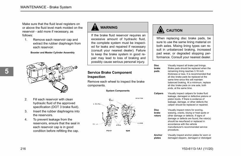
Make sure that the fluid level registers onor above the fluid level mark molded on thereservoir - add more if necessary, asfollows:
1. Remove each reservoir cap andextract the rubber diaphragm fromeach reservoir.
Booster and Master Cylinder Assembly
2. Fill each reservoir with cleanhydraulic fluid of the approvedspecification (DOT 3 brake fluid).
3. Insert the rubber diaphragms intothe reservoirs.
4. To prevent leakage from thereservoirs, ensure that the seal ineach reservoir cap is in goodcondition before refitting the cap.
WARNING
If the brake fluid reservoir requires anexcessive amount of hydraulic fluid,the complete system must be inspect-ed for leaks and repaired if necessary(consult your nearest dealer). Failureto keep the brake system in good re-pair may lead to loss of braking andpossibly cause serious personal injury.
Service Brake ComponentInspectionRemove each wheel to inspect the brakecomponents.
System Components
CAUTION
When replacing disc brake pads, besure to use the same lining material onboth axles. Mixing lining types can re-sult in unbalanced braking, increasedpad wear, or degraded stopping per-formance. Consult your nearest dealer.
Discbrakepads
Visually inspect all brake pad linings.Brake pads should be replaced when theremaining lining reaches 3.16 inchthickness or less. It is recommended thatall disc brake pads be replaced at thesame time since this will maintainbalanced braking. At a minimum, replaceall disc brake pads on one axle, bothends, at the same time.
Calipers Visually inspect calipers for brake fluidleakage, damaged or defective pistons orpiston boots. If there is evidence ofleakage, damage, or other defects thecaliper should be replaced or repaired.
Discbrakerotors
Visually inspect rotors for scoring,warping, cracks, bluing or heat spots orother damage or defects. If signs ofdamage or defects are found, the rotor(s)should be resurfaced or replaced inaccordance with the vehiclemanufacturer's recommended serviceprocedure.
Anchorplates
Visually inspect anchor plates for worn ordamaged slippers, damaged or dislodged
MAINTENANCE - Brake System
216 Y53-6113-1A1 (11/20)
5
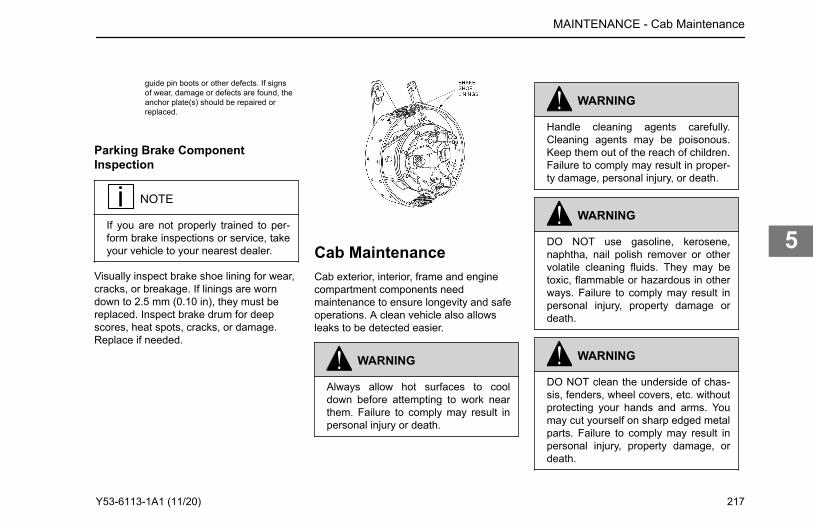
guide pin boots or other defects. If signsof wear, damage or defects are found, theanchor plate(s) should be repaired orreplaced.
Parking Brake ComponentInspection
NOTE
If you are not properly trained to per-form brake inspections or service, takeyour vehicle to your nearest dealer.
Visually inspect brake shoe lining for wear,cracks, or breakage. If linings are worndown to 2.5 mm (0.10 in), they must bereplaced. Inspect brake drum for deepscores, heat spots, cracks, or damage.Replace if needed.
Cab MaintenanceCab exterior, interior, frame and enginecompartment components needmaintenance to ensure longevity and safeoperations. A clean vehicle also allowsleaks to be detected easier.
WARNING
Always allow hot surfaces to cooldown before attempting to work nearthem. Failure to comply may result inpersonal injury or death.
WARNING
Handle cleaning agents carefully.Cleaning agents may be poisonous.Keep them out of the reach of children.Failure to comply may result in proper-ty damage, personal injury, or death.
WARNING
DO NOT use gasoline, kerosene,naphtha, nail polish remover or othervolatile cleaning fluids. They may betoxic, flammable or hazardous in otherways. Failure to comply may result inpersonal injury, property damage ordeath.
WARNING
DO NOT clean the underside of chas-sis, fenders, wheel covers, etc. withoutprotecting your hands and arms. Youmay cut yourself on sharp edged metalparts. Failure to comply may result inpersonal injury, property damage, ordeath.
MAINTENANCE - Cab Maintenance
Y53-6113-1A1 (11/20) 217
5
WARNING
Moisture, ice, and road salt on brakesmay affect braking efficiency. Test thebrakes carefully after each vehiclewash. Failure to comply may result indeath, personal injury, equipment orproperty damage.
Vehicle Cleaning• Observe all caution labels• Always read directions on the
container before using any product• Do not use any solution that can
damage the body paint• Most chemical cleaners are
concentrates that require dilution• Only use spot removing fluids in
well ventilated areas• Any vehicle is subjected to
deterioration from multiple causes(i.e. industrial fumes, ice, snow,corrosive road salt, etc.,)
Exterior and Engine CompartmentCorrosive materials used to remove ice,snow and dust from the road can collect onthe entire vehicle with concentrated
accumulations throughout the underbodyand engine compartment. If thesematerials are not removed, acceleratedcorrosion (rust) can occur on underbodyparts such as fuel lines, frame rails, floorpan, electrical and exhaust system, eventhough they have been provided withcorrosion protection.At least every spring, flush these materialsfrom the entire vehicle, including theunderbody and engine compartment, withplain water using light water pressure. Onvehicles used in applications and/or areasthat experience high usage of, or exposureto, corrosive materials, cleaning of theentire vehicle should be done morefrequently. If desired, your dealer can dothis service for you.
CAUTION
Do not direct high pressure water ontoseals or flexible hoses. Water may en-ter the part which will contaminate thesystem lubricants and fluids. To pre-vent damage to these components,keep a gentle flow of water moving atall times. Failure to comply may resultin equipment damage.
CAUTION
Do not direct high pressure water ontoelectrical components, plug connec-tors, seals or flexible hoses on the en-gine. Failure to comply can acceleratecorrosion and degrade electrical com-ponent which may cause a fire orequipment damage.
To prevent rust, keep chromed parts cleanand protected with wax at all times,especially in winter conditions when theroads are salted.
• If necessary, use a commercialchrome cleaner to remove lightrust.
• Chrome surfaces are best cleanedwith fresh water. Wipe dry topreserve their luster. A commercialchrome cleaner will remove lightrust. After cleaning, wax flatsurfaces and apply a thin coat ofrust preventive lubricant aroundbolts or other fasteners.
• Clean aluminum wheels andbumpers with cool water. Tar-remover will get rid of heavydeposits of road grime. To prevent
MAINTENANCE - Cab Maintenance
218 Y53-6113-1A1 (11/20)
5

spotting, wipe aluminum surfacesdry after washing.
• Under corrosive conditions, suchas driving on salted roads, cleanaluminum parts with steam or high-pressure water from a hose. A mildautomotive soap solution will help.Rinse thoroughly.
To maintain the tailpipe's quality finish,wash the tailpipe with a soft cloth, mildautomotive soap, and water or glasscleaner. A non-abrasive chrome polish canbe used sparingly on hard-to-clean areas.DO NOT clean your high-heat chromeusing scouring pads, abrasive chromepolish, highly acidic chemical cleaners orany other abrasive cleaners.Even high quality stainless steel parts canrust under prolonged exposure to saltwater, especially when the salt-ladenmoisture is held against the metal surfaceby road grime. It is important to frequentlyclean salty moisture and grime fromstainless steel surfaces.
• If surface rust is encountered,wash the surface and use acommercial polishing compound toclean off the rust, followed by acoating of wax.
• Never use steel wool whencleaning stainless steel. Minute
particles of the steel wool canbecome embedded in the surfaceof the stainless steel part andcause rust staining.
Weather StrippingFrequent washing of the vehicle is requiredto remove road grime and contaminantsthat can stain and oxidize paint andaccelerate corrosion of plated and polishedmetal surfaces. Waxing offers addedprotection against staining and oxidation.Do not apply wax in the hot sun and do notfriction burn the paint with a buffingmachine. Occasionally spray weather-stripping on doors and windows withsilicone compound to help preserveresiliency. This is especially useful infreezing weather to prevent doors andwindows from sticking shut with ice.
NOTE
To allow enough time for your truck'sfinish to cure, wait at least thirty daysafter the date of manufacture beforewaxing.
Cleaning Interior Vinyl andUpholstery
NOTE
Strong cleaning agents such as handsanitizer, solvents, paint thinners, win-dow cleaner and gasoline/ diesel fuelmust never be used on your vehicle'sinterior. Repeated exposure to chemi-cals such as sunscreen, insect repel-lents containing DEET, or brake fluidmay cause accelerated wear, tacki-ness or discoloration of interior surfa-ces.
Wipe vinyl upholstery and lining with agood commercial upholstery cleaner. Donot use acetone or lacquer thinner. Cleanfabric upholstery with upholstery shampoospecially formulated for this purpose.
• First remove loose dirt, dust ordebris with a vacuum cleaner.
• Use a soft brush to loosen caked-on dirt before vacuuming it away.
• Wipe the fabric surface with aslightly damp cloth and dry the seatfabric thoroughly. If the fabric is stilldirty, wipe using a mixture of mild
MAINTENANCE - Cab Maintenance
Y53-6113-1A1 (11/20) 219
5
soap and lukewarm water, then drythoroughly.
• If the stain does not come out usean upholstery shampoo speciallyformulated for this purpose. Testthe cleaner on a hidden place tomake sure it does not harm thefabric. Follow the instructions onthe container.
Other interior surfaces may be cleanedusing a mixture of mild soap and lukewarmwater, or an automotive interior cleaner,used on its intended surface (i.e. useleather conditioner on leather surfaces,etc.).Avoid frequent or repeated use of thefollowing products on interior surfaces:
• Alcohol-based cleaners (includinghand sanitizer)
• Methanol-based cleaners• Bleach• Acetone• Any other strong solvent• Abrasive cleaners• Sunscreen
How to Wash the Exterior of theVehicleYour dealer has a number of vehicle-careproducts and can advise you on whichones to use for cleaning the exterior andinterior of your vehicle.
WARNING
Handle cleaning agents carefully.Cleaning agents may be poisonous.Keep them out of the reach of children.Failure to comply may result in proper-ty damage, personal injury, or death.
WARNING
DO NOT use gasoline, kerosene,naphtha, nail polish remover or othervolatile cleaning fluids. They may betoxic, flammable or hazardous in otherways. Failure to comply may result inpersonal injury, property damage ordeath.
WARNING
DO NOT clean the underside of chas-sis, fenders, wheel covers, etc. withoutprotecting your hands and arms. Youmay cut yourself on sharp edged metalparts. Failure to comply may result inpersonal injury, property damage, ordeath.
WARNING
Moisture, ice, and road salt on brakesmay affect braking efficiency. Test thebrakes carefully after each vehiclewash. Failure to comply may result indeath, personal injury, equipment orproperty damage.
MAINTENANCE - Cab Maintenance
220 Y53-6113-1A1 (11/20)
5
CAUTION
DO NOT aim the water jet directly atdoor locks or latch. Tape the key holesto prevent water from seeping into thelock cylinders. Water in lock cylindersshould be removed with compressedair. To prevent locks from freezing inthe winter, squirt glycerin or lock deicerinto the lock cylinders.
NOTE
To allow enough time for your truck'sfinish to cure, wait at least thirty daysafter the date of manufacture beforewaxing.
1. Begin by spraying water over thedry surface to remove all loose dirtbefore applying the car washsolution.
CAUTION
Do not direct high pressure water ontoseals or flexible hoses. Water may en-
ter the part which will contaminate thesystem lubricants and fluids. To pre-vent damage to these components,keep a gentle flow of water moving atall times. Failure to comply may resultin equipment damage.
CAUTION
Do not direct high pressure water ontoelectrical components, plug connec-tors, seals or flexible hoses on the en-gine. Failure to comply can acceleratecorrosion and degrade electrical com-ponent which may cause a fire orequipment damage.
• Do not wash the vehicle indirect sunshine.
• Do not spray water directly intothe cab vents.
2. Using soapy water, wash thevehicle with a clean soft cloth or asoft brush made for automotivecleaning.
• Use cool water and a mild,automotive-type soap. Strongindustrial detergents, cleaningagents and household-typesoaps are not recommended
and may damage the vehicle'spaint.
• Do not use stiff brushes, papertowels, steel wool, or abrasivecleaning compounds becausethey will scratch painted, plated,and polished metal surfaces.
3. Rinse painted surfaces with gentlewater pressure frequently whilewashing to flush away dirt thatmight scratch the finishes duringthe washing operation.
4. Hose dirt and grime from the entirechassis.
CAUTION
Do not direct high pressure water ontoseals or flexible hoses. Water may en-ter the part which will contaminate thesystem lubricants and fluids. To pre-vent damage to these components,keep a gentle flow of water moving atall times. Failure to comply may resultin equipment damage.
MAINTENANCE - Cab Maintenance
Y53-6113-1A1 (11/20) 221
5
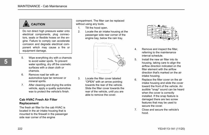
CAUTION
Do not direct high pressure water ontoelectrical components, plug connec-tors, seals or flexible hoses on the en-gine. Failure to comply can acceleratecorrosion and degrade electrical com-ponent which may cause a fire orequipment damage.
5. Wipe everything dry with a chamoisto avoid water spots. To preventwater spotting, dry off the cosmeticsurfaces with a clean cloth orchamois.
6. Remove road tar with anautomotive-type tar remover ormineral spirits.
7. After cleaning and drying the entirevehicle, apply a quality automotivewax to protect the vehicle's finish.
Cab HVAC Fresh Air FilterReplacementThe fresh air filter for the cab HVAC islocated in the air intake housing that ismounted to the firewall in the passengerside rear corner of the engine
compartment. The filter can be replacedwithout using any tools.
1. Tilt the hood open.2. Locate the air intake housing at the
passenger side rear corner of theengine bay, below the rain tray.
3. Locate the filter cover labeled“OPEN” with an arrow pointingtowards the rear of the vehicle.Slide the filter cover towards therear of the vehicle, until you areable to remove the cover.
4. Remove and inspect the filter,referring to the maintenanceinterval schedule.
5. Install the new air filter into itshousing, taking care to align theairflow direction indicated on thefilter element with the airflowdirection that's marked on the airintake housing.
6. Replace the filter cover on the airintake housing and slide the covertoward the front of the vehicle. Anaudible "snap" sound can be heardwhen the cover is correctlyinstalled. If the snap feature isdamaged there are two screwfeatures that may be used tosecure the cover.
7. Close and secure the vehicle'shood.
MAINTENANCE - Cab Maintenance
222 Y53-6113-1A1 (11/20)
5
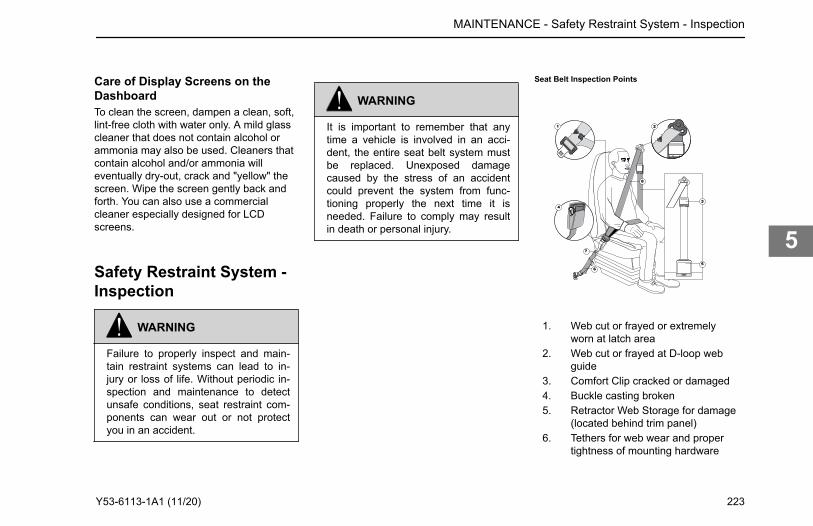
Care of Display Screens on theDashboardTo clean the screen, dampen a clean, soft,lint-free cloth with water only. A mild glasscleaner that does not contain alcohol orammonia may also be used. Cleaners thatcontain alcohol and/or ammonia willeventually dry-out, crack and "yellow" thescreen. Wipe the screen gently back andforth. You can also use a commercialcleaner especially designed for LCDscreens.
Safety Restraint System -Inspection
WARNING
Failure to properly inspect and main-tain restraint systems can lead to in-jury or loss of life. Without periodic in-spection and maintenance to detectunsafe conditions, seat restraint com-ponents can wear out or not protectyou in an accident.
WARNING
It is important to remember that anytime a vehicle is involved in an acci-dent, the entire seat belt system mustbe replaced. Unexposed damagecaused by the stress of an accidentcould prevent the system from func-tioning properly the next time it isneeded. Failure to comply may resultin death or personal injury.
Seat Belt Inspection Points
1. Web cut or frayed or extremelyworn at latch area
2. Web cut or frayed at D-loop webguide
3. Comfort Clip cracked or damaged4. Buckle casting broken5. Retractor Web Storage for damage
(located behind trim panel)6. Tethers for web wear and proper
tightness of mounting hardware
MAINTENANCE - Safety Restraint System - Inspection
Y53-6113-1A1 (11/20) 223
5
7. Mounting hardware for corrosion,proper tightness of bolts and nuts
8. Web for deterioration, due toexposure to the sun
Factors contributing to reduced seat beltlife:
• Heavy trucks typically accumulatetwice as many miles as theaverage passenger car in a giventime period.
• Seat and cab movement in truckscauses almost constant movementof the belt due to ridecharacteristics and seat design.The constant movement of the beltinside the restraint hardware andthe potential for the belt to come incontact with the cab and othervehicle parts, contributes to thewear of the entire system.
• Environmental conditions, such asdirt and ultraviolet rays from thesun, will reduce the life of the seatbelt system.
Due to these factors, the three-point safetybelt system installed in your vehiclerequires thorough inspection every 20,000miles (32,000 km). If the vehicle is exposedto severe environmental or workingconditions, more frequent inspections may
be necessary. Any seat belt system thatshows cuts, fraying, extreme or unusualwear, significant discoloration due to UV(ultraviolet) exposure, abrasion to the seatbelt webbing, or damage to the buckle,latch plate, retractor hardware, or any otherobvious problem should be replacedimmediately, regardless of mileage.
Inspection GuidelinesFollow these guidelines when inspectingfor cuts, fraying, extreme or unusual wearof the webbing, and damage to the buckle,retractor, hardware, or other factors.Damage to these areas indicates that beltsystem replacement is necessary.
WARNING
Replace the entire belt system (retrac-tor and buckle side) if replacement ofany one part is necessary. Unexposeddamage to one or more componentscould prevent the system from func-tioning properly the next time it isneeded. Failure to comply may resultin death or personal injury.
1. Check the web wear in the system.The webbing must be closely
examined to determine if it iscoming into contact with any sharpor rough surfaces on the seat orother parts of the cab interior.These areas are typical placeswhere the web will experiencecutting or abrasion. Cuts, fraying,or excessive wear would indicatethe need for replacement of theseat belt system.
2. The pillar web guide (D-loop) is thearea where almost constantmovement of the seat belt webbingoccurs because of relativemovement between the seat andcab.
3. Check the Komfort Latch for cracksor possible damage and check forproper operation.
4. Check buckle and latch for properoperation and to determine if latchplate is worn, deformed, ordamaged.
5. Inspect the retractor web storagedevice, which is mounted on thefloor of the vehicle, for damage.The retractor is the heart of theoccupant restraint system and canoften be damaged if abused, evenunintentionally. Check operation toensure that it is not locked up and
MAINTENANCE - Safety Restraint System - Inspection
224 Y53-6113-1A1 (11/20)
5
that it spools out and retractswebbing properly.
6. If tethers are used, be sure theyare properly attached to the seatand, if adjustable, that they areadjusted in accordance withinstallation instructions. Tethersmust also be inspected for webwear and proper tightness ofmounting hardware.
7. Mounting hardware should beevaluated for corrosion, and fortightness of bolts and nuts.
8. Check web in areas exposed toultraviolet rays from the sun. If thecolor of the web in these areas isgray to light brown, the physicalstrength of the web may havedeteriorated due to exposure to thesun's ultraviolet rays. Replace thesystem.
instructions very closely. It is vitallyimportant that all components bereinstalled in the same position as theoriginal components that were removedand that the fasteners be torqued tospecification. This will maintain the designintegrity of the mounting points for the seatbelt assembly. Contact your dealer if youhave any questions concerning seat beltreplacement.
Cooling SystemMaintenanceThe cooling system in your vehicle wasfactory filled with extended life coolant thatmeets or exceeds all ASTM D6210 andCaterpillar EC-1 requirements. PACCARrecommends only using a 50:50 mixture ofdistilled water and ELC when coolingsystem service is required. A 50:50 mixtureof ELC and distilled water will providefreeze protection down to -34°F (-36.7°C),which is adequate for most locations inNorth America. For extremely coldoperating conditions, a 60:40 mixture(coolant/water ratio) can be used toprovide freeze protection down to -62°F(-52.2°C).
Unless otherwise optioned, factory fillcoolant is an ethylene glycol, nitritedorganic acid technology (NOAT) extendedlife coolant (ELC) formulation at a 50:50coolant-to-distilled water mixture. Thefactory fill exceeds ASTM D6210 andCaterpillar EC-1 requirements. Maintainingcoolant chemistry and freeze protection iscritical to engine and cooling systemcomponent health and longevity.
WARNING
Coolant is toxic. DO NOT get the fluidin eyes. If contact occurs, flood eyeswith large amounts of water for 15 mi-nutes. Avoid prolonged or repeatedcontact with skin. In case of contact,immediately wash skin with soap andwater. DO NOT take internally. If swal-lowed, seek immediate medical atten-tion. DO NOT induce vomiting. Failureto comply may result in death, person-al injury, equipment or property dam-age.
MAINTENANCE - Cooling System Maintenance
Once the need for replacement of the seat belt has been determined, be certain it is only replaced with an authorized PACCAR Parts replacement seat belt. If the inspection indicates that any part of the seat belt system requires replacement, the entire system must be replaced. An installation guide is attached to every replacement belt. Utilize the proper guide for your type of seat, and follow the
Y53-6113-1A1 (11/20) 225
5
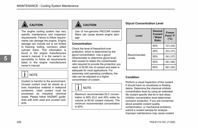
CAUTION
The engine cooling system has veryspecific maintenance and inspectionrequirements. Failure to follow require-ments can damage the engine. Enginedamage can include but is not limitedto freezing, boiling, corrosion, pittedcylinder liners. This information isfound in the engine manufacturersowner’s manual. It is the owner’s re-sponsibility to follow all requirementslisted in the engine manufacturersowner’s manual.
NOTE
Coolant is harmful to the environment.Unused coolant must be stored as atoxic hazardous material in leakproofcontainers. Used coolant must beprocessed as industrial chemicalwaste. Please follow HAZMAT guide-lines with both used and unused cool-ants.
CAUTION
Use of non-genuine PACCAR coolantfilters can cause severe engine dam-age.
ConcentrationCheck the level of freeze/boil-overprotection, which is determined by theglycol concentration. Use a glycolrefractometer to determine glycol level.Add coolant to obtain the coolant/waterratio required to provide the protection youneed. A 50:50 mix of coolant and water isadequate for most applications. Forextremely cold operating conditions, theratio can be adjusted to a higherconcentration of coolant.
NOTE
Maximum recommended ELC concen-tration is 60% ELC and 40% water byvolume (a 60:40 coolant mixture). Theminimum recommended concentrationis 40%.
Glycol Concentration Level
Level
DesiredCoolant/ WaterRatio
FreezePoint °F
(°C)
RecommendedLevels
40% -12 (-24)
45% -23 (-31)
50% -34 (-37)
55% -50 (-46)
60% -62 (-52)
ConditionPerform a visual inspection of the coolant.It should have no cloudiness or floatingdebris. Determine the chemical inhibitorconcentration level by using an extendedlife coolant specific test kit or test strips.Inhibitor concentration level determinescorrosion protection. If you are concernedabout possible coolant quality,contamination, or mechanical problems,submit a coolant sample for analysis.Improper maintenance may cause coolant
MAINTENANCE - Cooling System Maintenance
226 Y53-6113-1A1 (11/20)
5
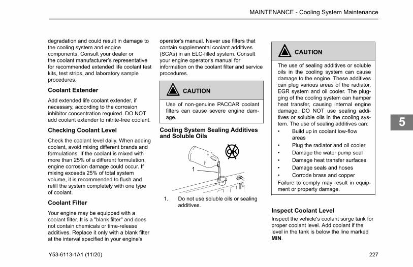
operator's manual. Never use filters thatcontain supplemental coolant additives(SCAs) in an ELC-filled system. Consultyour engine operator's manual forinformation on the coolant filter and serviceprocedures.
CAUTION
Use of non-genuine PACCAR coolantfilters can cause severe engine dam-age.
Cooling System Sealing Additivesand Soluble Oils
OK
1
1. Do not use soluble oils or sealingadditives.
CAUTION
The use of sealing additives or solubleoils in the cooling system can causedamage to the engine. These additivescan plug various areas of the radiator,EGR system and oil cooler. The plug-ging of the cooling system can hamperheat transfer, causing internal enginedamage. DO NOT use sealing addi-tives or soluble oils in the cooling sys-tem. The use of sealing additives can:• Build up in coolant low-flow
areas• Plug the radiator and oil cooler• Damage the water pump seal• Damage heat transfer surfaces• Damage seals and hoses• Corrode brass and copperFailure to comply may result in equip-ment or property damage.
Inspect Coolant LevelInspect the vehicle's coolant surge tank forproper coolant level. Add coolant if thelevel in the tank is below the line markedMIN.
MAINTENANCE - Cooling System Maintenance
degradation and could result in damage to the cooling system and engine components. Consult your dealer orthe coolant manufacturer’s representative for recommended extended life coolant test kits, test strips, and laboratory sample procedures.
Coolant ExtenderAdd extended life coolant extender, if necessary, according to the corrosion inhibitor concentration required. DO NOT add coolant extender to nitrite-free coolant.
Checking Coolant LevelCheck the coolant level daily. When adding coolant, avoid mixing different brands and formulations. If the coolant is mixed with more than 25% of a different formulation, engine corrosion damage could occur. If mixing exceeds 25% of total system volume, it is recommended to flush and refill the system completely with one type of coolant.
Coolant FilterYour engine may be equipped with a coolant filter. It is a "blank filter" and does not contain chemicals or time-release additives. Replace it only with a blank filter at the interval specified in your engine's
Y53-6113-1A1 (11/20) 227
5
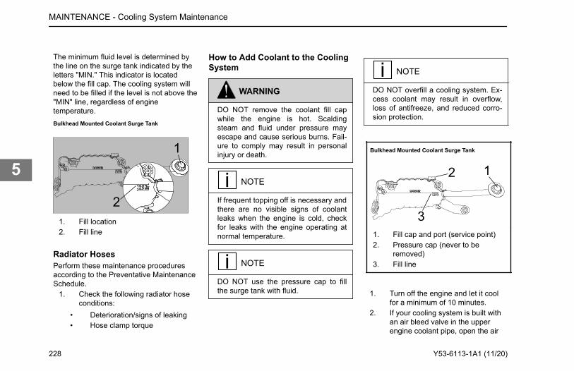
The minimum fluid level is determined bythe line on the surge tank indicated by theletters "MIN." This indicator is locatedbelow the fill cap. The cooling system willneed to be filled if the level is not above the"MIN" line, regardless of enginetemperature.Bulkhead Mounted Coolant Surge Tank
1
21. Fill location2. Fill line
Radiator HosesPerform these maintenance proceduresaccording to the Preventative MaintenanceSchedule.
1. Check the following radiator hoseconditions:
• Deterioration/signs of leaking• Hose clamp torque
How to Add Coolant to the CoolingSystem
WARNING
DO NOT remove the coolant fill capwhile the engine is hot. Scaldingsteam and fluid under pressure mayescape and cause serious burns. Fail-ure to comply may result in personalinjury or death.
NOTE
If frequent topping off is necessary andthere are no visible signs of coolantleaks when the engine is cold, checkfor leaks with the engine operating atnormal temperature.
NOTE
DO NOT use the pressure cap to fillthe surge tank with fluid.
NOTE
DO NOT overfill a cooling system. Ex-cess coolant may result in overflow,loss of antifreeze, and reduced corro-sion protection.
Bulkhead Mounted Coolant Surge Tank
12
31. Fill cap and port (service point)2. Pressure cap (never to be
removed)3. Fill line
1. Turn off the engine and let it coolfor a minimum of 10 minutes.
2. If your cooling system is built withan air bleed valve in the upperengine coolant pipe, open the air
MAINTENANCE - Cooling System Maintenance
228 Y53-6113-1A1 (11/20)
5
bleed valve before filling the surgetank.
3. Close any open coolant drainvalves in the lower engine coolantpipe.
4. Remove the surge tank fill cap (1),but DO NOT remove the surgetank pressure cap (2).
5. Fill the system with premixedcoolant through the surge tank fillport. Pour coolant at a steady rateuntil it reaches the lower of the twolines indicated by either "COLDMIN" or "MIN" on the surge tank.Wait for one minute after addingcoolant. If the coolant level drops,add coolant until it returns to thelower line.
6. Close the air bleed valve if openedin Step 2.
7. Start the engine and maintain anidle at a low rpm.
8. While the engine is idling air willpurge from the cooling system viathe surge tank's coolant fill port,which will lower the coolant level inthe surge tank. Continue to fill thesurge tank until the coolant levelremains approximately 1/2 in. (13mm) above the "MIN" line. This
may take up to 2 minutes,depending on the outsidetemperature.
9. Maintain a low idle until thethermostat opens and theoperating temperature stabilizes. Asign that the thermostat hasopened is when the upper coolantpipe gets hot on the bottom sideindicating hot coolant is nowrunning through it.
10. Add coolant to the surge tank untilthe coolant remains 1/2 in. (13 mm)above the "COLD MIN" or "MIN"level.
11. Operate the engine at high idle for10 minutes. Afterward, add coolantto the surge tank until the coolantremains 1/2 in. (13 mm) above the"COLD FULL" line.
12. Reinstall the surge tank fill cap (1).
Windshield Wiper/WasherThe windshield wiper system is designedto be maintenance-free. Check wiperblades annually, every 60,000 miles(96,000 km), or when they begin to showsigns of wear.
Check the washer reservoir water leveldaily, located in the engine compartment. Ifnecessary, refill to the proper level.
How to Refill the Washer FluidReservoir
CAUTION
DO NOT use antifreeze or enginecoolant in the windshield washer res-ervoir, damage to seals and othercomponents will result.
1. Park the vehicle and apply theparking brakes.
2. Open the hood and secure it in theopen position.
3. Locate the washer fluid reservoirlocated on the driver's side of theengine compartment, behind thewheel, and open the filler cap.
4. Fill the 2.1 Gallon (7.9 Liter)reservoir with windshield washerfluid and replace the cap.
5. Close and secure the hood.
MAINTENANCE - Windshield Wiper/Washer
Y53-6113-1A1 (11/20) 229
5
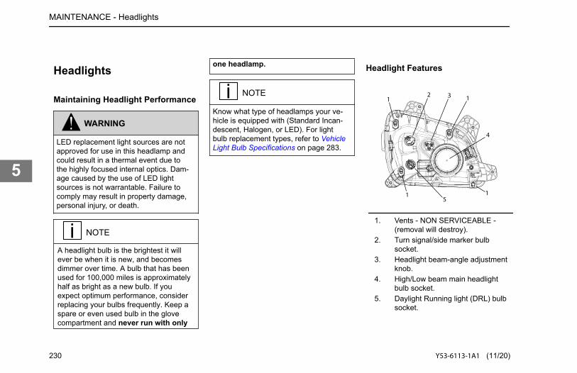
Headlights
Maintaining Headlight Performance
WARNING
LED replacement light sources are notapproved for use in this headlamp andcould result in a thermal event due tothe highly focused internal optics. Dam-age caused by the use of LED lightsources is not warrantable. Failure tocomply may result in property damage,personal injury, or death.
NOTE
one headlamp.
NOTE
Know what type of headlamps your ve-hicle is equipped with (Standard Incan-descent, Halogen, or LED). For lightbulb replacement types, refer to VehicleLight Bulb Specifications on page 283.
Headlight Features
1 1
1 1
2 3
4
5
1. Vents - NON SERVICEABLE -(removal will destroy).
2. Turn signal/side marker bulbsocket.
3. Headlight beam-angle adjustmentknob.
4. High/Low beam main headlightbulb socket.
5. Daylight Running light (DRL) bulbsocket.
MAINTENANCE - Headlights
230 Y53-6113-1A1 (11/20)
5
A headlight bulb is the brightest it will ever be when it is new, and becomes dimmer over time. A bulb that has been used for 100,000 miles is approximately half as bright as a new bulb. If you expect optimum performance, consider replacing your bulbs frequently. Keep a spare or even used bulb in the glove compartment and never run with only
• Fender liners and access capsmust be re-installed after service toprotect the headlamp from highpressure water spray and gravelbombardment.
• Lenses can be polished by aprofessional polishing service notmore than twice before beingreplaced.
• The headlight assembly isequipped with filtered vents thatallow for cooling of the bulbs andevacuation of water vapor. Thefilters are intended to keep insectsout and are NOT serviceablebecause the caps that hold thefilters will be destroyed if they areremoved. Keep obstructions, orobstructing agents like mud, awayfrom the vents.
• A discolored bulb (one that is otherthan clear) is an indication that ithas overheated. It may performpoorly, be close to failure, andshould be replaced as soon aspossible.
• Headlight cover lenses should becleaned with a mild, particulate-free, dish soap (e.g. Dawn, or Joy).The headlight should never becleaned with an abrasive scouring
powder or soap, nor withpetrochemicals like Gasoline orDiesel as these will break down thehard coating and cause crazing inthe lens.
• Be aware that some truck loadscan require re-aiming of theheadlights by a trained techniciandue to a change in vehicle rake.
• If the cover lens is worn to the pointthat it is no longer transparent, buttranslucent or opaque, theheadlight should be replaced.
• Bulbs should be replaced with apremium brand (e.g. Phillips,Osram, Sylvania, Federal-Mogul,or GE). Bulbs with the long lifedesignation "LL" arerecommended, but not required.
• The headlight covers are designedto withstand the force of wind, butcannot be used to push solidobjects, or be pushed on, withsignificant force.
• When replacing a bulb, do nottouch the globe with your fingers.Oil from human skin can focus thelight locally, resulting in early bulbfailure.
How to Replace a Headlight BulbEach headlight assembly contains threebulbs:
• Low beam/high beam• Daytime running light (DRL)/
parking light• Turn signal/side marker/side turn.
Replacing a headlight bulb is accomplishedby opening the hood and accessing therear of the headlight (located behind aremovable fender panel). See Vehicle LightBulb Specifications for bulb replacementdata.
1. Park the vehicle and apply theparking brake.
2. Open the hood and secure it in theopen position (see How to Openthe Hood).
3. Remove fender liner to accessheadlight assembly (How toRemove a Fender Liner on page196).
4. Replace a headlight assemblybulb:When replacing the low beam/highbeam bulb, the low beam/highbeam socket cap must first beunscrewed and removed.
MAINTENANCE - Headlights
Y53-6113-1A1 (11/20) 231
5
a. Twist bulb socket counter-clockwise to loosen andremove socket and bulb fromthe headlight assembly.
b. Change the bulb in the socket.c. Replace socket and bulb into
headlight assembly by liningup the tab on the socket withthe slot in the headlighthousing and then insert.
d. Twist socket clockwise to lock.Replace low beam/high beamsocket cap if removed earlierin this step.
5. Reinstall fender liner (How toReinstall a Fender Liner on page197).
6. Close and secure hood (See Closethe Hood).
Final Checks1. After everything is reconnected,
turn on your headlights and checkfor operation.
2. Have your headlights periodicallychecked for proper alignment bydealer.
3. Keep your headlights clean, usingonly clean soap and water. A dirty
headlight reduces performance andcreates glare.
Aiming HeadlightsThe headlights were properly aimed at thefactory to meet safety specifications. If theheadlights need to be adjusted, pleasehave an authorized dealership aim theheadlights.
Electrical System
WARNING
Battery posts, terminals and relatedaccessories contain lead and leadcompounds, chemicals known to theState of California to cause cancer andreproductive harm. Wash hands afterhandling.
CAUTION
DO NOT modify or improperly repairthe vehicles electrical system or powerdistribution box. All electrical repairs
should be performed by an authorizeddealer. Improper repair or modifica-tions will void your warranty and/orcause serious damage to your vehicle.
Engine Aftertreatment SystemPower RequirementsThe engine aftertreatment system usesbattery power for up to 10 minutes after theignition is turned off. After the ignition turnsoff, the engine aftertreatment systemcirculates DEF to help cool down the fluidand prevent overheating. For situationswhere the battery will be disconnected (i.e.for service or maintenance of the vehicle),please wait 10 minutes beforedisconnecting battery power.
CAUTION
Wait at least 10 minutes after the keyswitch is turned OFF before discon-necting battery power. The systemuses battery power to circulate DEFand prevent overheating of the DEFsystem. Failure to comply may resultin property damage.
MAINTENANCE - Electrical System
232 Y53-6113-1A1 (11/20)
5
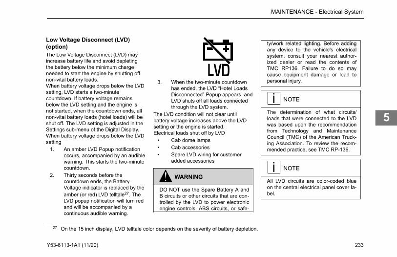
Low Voltage Disconnect (LVD)(option)The Low Voltage Disconnect (LVD) mayincrease battery life and avoid depletingthe battery below the minimum chargeneeded to start the engine by shutting offnon-vital battery loads.When battery voltage drops below the LVDsetting, LVD starts a two-minutecountdown. If battery voltage remainsbelow the LVD setting and the engine isnot started, when the countdown ends, allnon-vital battery loads (hotel loads) will beshut off. The LVD setting is adjusted in theSettings sub-menu of the Digital Display.When battery voltage drops below the LVDsetting
1. An amber LVD Popup notificationoccurs, accompanied by an audiblewarning. This starts the two-minutecountdown.
2. Thirty seconds before thecountdown ends, the BatteryVoltage indicator is replaced by theamber (or red) LVD telltale27. TheLVD popup notification will turn redand will be accompanied by acontinuous audible warning.
3. When the two-minute countdownhas ended, the LVD “Hotel LoadsDisconnected” Popup appears, andLVD shuts off all loads connectedthrough the LVD system.
The LVD condition will not clear untilbattery voltage increases above the LVDsetting or the engine is started.Electrical loads shut off by LVD
• Cab dome lamps• Cab accessories• Spare LVD wiring for customer
added accessories
WARNING
DO NOT use the Spare Battery A andB circuits or other circuits that are con-trolled by the LVD to power electronicengine controls, ABS circuits, or safe-
ty/work related lighting. Before addingany device to the vehicle's electricalsystem, consult your nearest author-ized dealer or read the contents ofTMC RP136. Failure to do so maycause equipment damage or lead topersonal injury.
NOTE
The determination of what circuits/loads that were connected to the LVDwas based upon the recommendationfrom Technology and MaintenanceCouncil (TMC) of the American Truck-ing Association. To review the recom-mended practice, see TMC RP-136.
NOTE
All LVD circuits are color-coded blueon the central electrical panel cover la-bel.
MAINTENANCE - Electrical System
27 On the 15 inch display, LVD telltale color depends on the severity of battery depletion.
Y53-6113-1A1 (11/20) 233
5
LVD SetupChange the LVD battery voltage set pointfor LVD to turn on Low Voltage Disconnect(LVD) (option) on page 233.
Fuses, Circuit Breakers and RelaysFuses, circuit breakers, and relays arelocated in the Power Distribution Box to theleft of the steering column behind theclutch pedal. Additional fuses for thealternator, engine electronics and trailerbattery charge circuit may be located in thePower Distribution Center (PDC) inside thebattery box and/ or on the engine side ofthe cab firewall.
Adding Electrical Options
WARNING
Do not add a fuse with a rating higherthan 30 amps. Follow the circuit pro-tection size/type recommended by thecomponent manufacturer. Installing afuse or circuit breaker greater thandesignated may damage the electricalsystem which could lead to equipmentdamage and/or personal injury.
WARNING
Never install a circuit breaker/poly-switch in a location indicated for “fuseonly.” Using a polyswitch (circuitbreaker) in a fuse-only circuit maycause the circuit to overheat when ashort exists, which could lead to equip-ment damage and/or personal injury.
NOTE
Polyswitches/circuit breakers are al-lowed in certain locations as indicatedby the label on the fuse box. In theseapplications, a fuse may be used in-stead of a circuit breaker.
NOTE
Do not install a circuit breaker in placeof a fuse for the following circuits:
• ACC FEED• BODY IGN• CAB ABS - BATT• CAB ABS - IGN
• CAB ACC• CB PWR• CECU - BATT (2 PLCS)• CECU IGN• DOOR IGN• ENG AUX• ENG SD• FOG LMPS• GAUGE CL• HIGH BEAM SUP• LH DR / DOOR LOCK• LOW BEAM SUP• PARK LMP SNSE• RADIO MEM• RADIO PWR• RH DOOR• SLPR ACC• RKE• TRLR ABS• TURN MOD PWR
Typical - See reverse side of PowerDistribution Box cover for fuse and relaylocations
Maximum Number of LampsAllowed per Circuit
• Vehicle Stop/Turn Signal Circuit
MAINTENANCE - Electrical System
234 Y53-6113-1A1 (11/20)
5
The lighting control unit is limited to 5 ampstotal, or two (2) 25 watt incandescent bulbsper side. Do not wire more than twoincandescent bulbs per side to the vehicletail lamp fixtures. If more than two bulbsare required for each tail lamp fixture,install LED type lamps, or contact yournearest authorized dealer for other options.
• Trailer Turn and Vehicle ForwardSide Facing Turn Lamp Circuit
The lighting control unit is limited to 20amps or nine (9) 25 watt incandescentbulbs total (per side) for the combination oftrailer turn lamps and vehicle forward sidefacing turn lamps. Do not wire more thannine incandescent bulbs per side for thecombination of trailer turn lamps andvehicle forward side facing turn lamps.If more than nine bulbs per side arerequired, install LED type lamps, or contactyour nearest authorized dealer for otheroptions.
CAUTION
Before installing additional vehiclestop/turn lamps, trailer turn lamps oradditional forward side facing turnlamps on the vehicle, make sure the
lighting circuit limits described aboveare not exceeded. Exceeding the num-ber of lamps designated above can/willcause the electronic control unit to de-fault to a protection mode, causing thelamps to not function properly.
Similar to the headlamp system, if aproblem is detected with the electroniccontrol unit, the control unit will cycle theturn signals off once every 9 seconds. Youcan detect that this is occurring if the turnsignal indicators in the dash operateintermittently.If you experience intermittent turn signaloperation, the problem is either a short inthe turn signal circuit or the maximumnumber of bulbs has been exceeded forthe circuit.If you experience any vehicle stop/turnsignal issues, contact your nearestauthorized dealer.
Vehicle CAN BusYour vehicle is equipped with a CAN buselectrical system. Because of how theelectrical system is designed it is importantthat any accessories added after thevehicle is built are installed only on the K-CAN or the S-CAN. These dedicated CANs
are provided on the driver's side of the cab,near to the interior fuse panel. Access tothe K-CAN and S-CANs is provided by twoRP1226 connectors. DO NOT tap into,connect to, tamper with, or splice into anyCAN network other than the K-CAN or theS-CAN. Connecting to a unapproved CANnetwork may trigger CAN fault codes.
CAUTION
Connecting to an unapproved CANnetwork may trigger CAN fault codes.The manufacturer will not warrant fail-ures or damage caused to CAN net-work components when the failure ordamage is a result of improper con-nections to the CAN network.
MAINTENANCE - Electrical System
Y53-6113-1A1 (11/20) 235
5
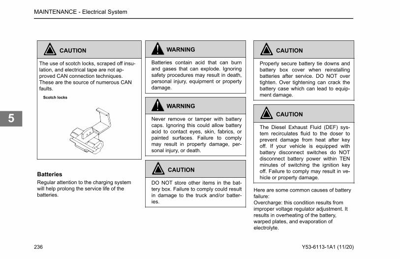
CAUTION
The use of scotch locks, scraped off insu-lation, and electrical tape are not ap-proved CAN connection techniques.These are the source of numerous CANfaults.
Scotch locks
BatteriesRegular attention to the charging systemwill help prolong the service life of thebatteries.
WARNING
Batteries contain acid that can burnand gases that can explode. Ignoringsafety procedures may result in death,personal injury, equipment or propertydamage.
WARNING
Never remove or tamper with batterycaps. Ignoring this could allow batteryacid to contact eyes, skin, fabrics, orpainted surfaces. Failure to complymay result in property damage, per-sonal injury, or death.
CAUTION
DO NOT store other items in the bat-tery box. Failure to comply could resultin damage to the truck and/or batter-ies.
CAUTION
Properly secure battery tie downs andbattery box cover when reinstallingbatteries after service. DO NOT overtighten. Over tightening can crack thebattery case which can lead to equip-ment damage.
CAUTION
The Diesel Exhaust Fluid (DEF) sys-tem recirculates fluid to the doser toprevent damage from heat after keyoff. If your vehicle is equipped withbattery disconnect switches do NOTdisconnect battery power within TENminutes of switching the ignition keyoff. Failure to comply may result in ve-hicle or property damage.
Here are some common causes of batteryfailure:Overcharge: this condition results fromimproper voltage regulator adjustment. Itresults in overheating of the battery,warped plates, and evaporation ofelectrolyte.
MAINTENANCE - Electrical System
236 Y53-6113-1A1 (11/20)
5
Undercharge: the voltage regulator ismalfunctioning, the drive belt is slipping, oryour vehicle has undergone long periods ofidling or short distance driving. Theseconditions result in battery plates becomingcovered with a hard coating.Vibration: loose battery hold-downs maycause battery plate failure.Short Circuits: these discharge the batteryby draining electricity.Dirty or Loose Connections: improperconnections may stop the flow of electricalpower to and from the battery.
Battery Charging
WARNING
Batteries can injure you severely. Theycontain acid, produce poisonous andexplosive gases, and supply levels ofelectric current high enough to causeburns. A spark or flame near a batteryon charge may cause it to explodewith great force. Never remove or tam-per with the battery caps. Failure tocomply may result in property damage,personal injury, or death.
have your vehicle's batteries charged by aqualified service facility. To help reduce therisk of personal injuries, follow theseguidelines carefully when recharging abattery:
• Before attempting any service inthe electrical installation,disconnect the battery negativecable.
• Allow no sparks or open flameanywhere near the charging area.
• Charge a battery only in a well-ventilated area, such as outdoorsor in a fully open garage whichcontains no pilot lights or otherflames. Gases generated duringthe charging process must beallowed to escape.
• Always make sure the batterycharger is OFF before connectingor disconnecting the cable clamps.
• To avoid short circuits, damage tothe vehicle, or personal injury,never place metal tools or jumpercables on the battery or nearby.Metal that accidentally comes incontact with the positive batteryterminal or any other metal on thevehicle (that is in contact with the
positive terminal), could cause ashort circuit or an explosion.
Charging Reminders• Use protective eyewear• Keep all batteries away from
children• Never reverse battery poles• Never attempt to place the vehicle
in motion, or run the engine withbatteries disconnected
• Keep the battery clean and dry• Look for any signs of damage• Battery terminals should not be
coated with improper grease. Usea commercially available,noncorrosive, non-conductiveterminal coating, or petroleum jelly.
• Never use a fast charger as abooster to start the engine. Thiscan seriously damage sensitiveelectronic components such asrelays, radio, etc., as well as thebattery charger. Fast charging abattery is dangerous and shouldonly be attempted by a competentmechanic with the properequipment.
MAINTENANCE - Electrical System
Except for using small trickle charges to maintain battery condition, you should
Y53-6113-1A1 (11/20) 237
5
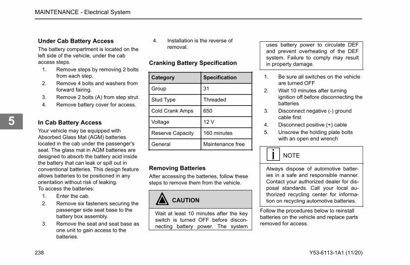
Under Cab Battery AccessThe battery compartment is located on theleft side of the vehicle, under the cabaccess steps.
1. Remove steps by removing 2 boltsfrom each step.
2. Remove 4 bolts and washers fromforward fairing.
3. Remove 2 bolts (A) from step strut.4. Remove battery cover for access.
In Cab Battery AccessYour vehicle may be equipped withAbsorbed Glass Mat (AGM) batterieslocated in the cab under the passenger'sseat. The glass mat in AGM batteries aredesigned to absorb the battery acid insidethe battery that can leak or spill out inconventional batteries. This design featureallows batteries to be positioned in anyorientation without risk of leaking.To access the batteries:
1. Enter the cab.2. Remove six fasteners securing the
passenger side seat base to thebattery box assembly.
3. Remove the seat and seat base asone unit to gain access to thebatteries.
4. Installation is the reverse ofremoval.
Cranking Battery Specification
Category Specification
Group 31
Stud Type Threaded
Cold Crank Amps 650
Voltage 12 V
Reserve Capacity 160 minutes
General Maintenance free
Removing BatteriesAfter accessing the batteries, follow thesesteps to remove them from the vehicle.
CAUTION
Wait at least 10 minutes after the keyswitch is turned OFF before discon-necting battery power. The system
uses battery power to circulate DEFand prevent overheating of the DEFsystem. Failure to comply may resultin property damage.
1. Be sure all switches on the vehicleare turned OFF
2. Wait 10 minutes after turningignition off before disconnecting thebatteries
3. Disconnect negative (-) groundcable first
4. Disconnect positive (+) cable5. Unscrew the holding plate bolts
with an open end wrench
NOTE
Always dispose of automotive batter-ies in a safe and responsible manner.Contact your authorized dealer for dis-posal standards. Call your local au-thorized recycling center for informa-tion on recycling automotive batteries.
Follow the procedures below to reinstallbatteries on the vehicle and replace partsremoved for access.
MAINTENANCE - Electrical System
238 Y53-6113-1A1 (11/20)
5
Installing BatteriesFollow the procedure below to reinstallmain batteries on the vehicle:
NOTE
Always dispose of automotive batter-ies in a safe and responsible manner.Contact your authorized dealer for dis-posal standards. Call your local au-thorized recycling center for informa-tion on recycling automotive batteries.
NOTE
Make sure to reconnect the ground(negative) cable last.
WARNING
Battery replacement may alter or dis-turb battery cable routing. Check to in-sure battery cables are free from anypoint of chaffing. Failure to complymay result in death, personal injury,equipment or property damage.
1. Place batteries in vehicle andtighten bolt of holding plate
2. Reconnect positive cable3. Reconnect ground (negative)
ground cable
Replace Battery Box Cover
WARNING
Always reinstall steps before enteringthe cab or accessing the deck plate.Without steps you could slip and fall.Failure to comply may result in person-al injury or death.
WARNING
Fairings not installed properly couldcome loose and cause other motoriststo have an injury accident. It is impor-tant that fairings be installed properly.Failure to comply may result in death,personal injury, equipment or propertydamage.
1. Replace battery cover.2. Install two bolts in step strut.
Torque to 24-32 lb-ft (33-43 N·m).
3. Install fairing and install four bolts.Torque to 6-7 lb-ft (8-9 N·m).
4. Install steps by installing two boltsin each step. Torque to 24-32 lb-ft(33-43 N·m).
Slow Battery Charging
WARNING
Charger cables must be connectedpositive to positive (+ to +) and nega-tive to negative (- to -). If connectedimproperly, batteries could explode.Failure to comply may result in proper-ty damage, personal injury, or death.
WARNING
Always make sure the battery chargeris OFF before connecting or discon-necting the cable clamps. To reducethe danger of explosions and resultingdeath or personal injury, do not con-nect or disconnect charger cableswhile the charger is operating.
MAINTENANCE - Electrical System
Y53-6113-1A1 (11/20) 239
5
NOTE
Some vehicles may have an ultra ca-pacitor mounted in the battery box.These devices have a similar shape toa battery but have two positive postsand one negative posts. Do not attachbattery chargers to these devices torecharge the vehicles batteries. Con-nect directly to the conventional twopost charging batteries to chargethem.
NOTE
Follow the instructions that come withyour battery charger.
1. Access the battery terminals, thebatteries do not have to beremoved from the vehicle.
2. Make sure the battery charger isturned off.
3. Disconnect the battery cables.4. Connect charger cables.5. Start charging the battery at a rate
not over 6 amperes. Normally, abattery should be charged at no
more than 10 percent of its ratedcapacity.
6. After charging, turn OFF chargerand disconnect charger cables.
AlternatorTake the following precautions to avoidburning out alternator diodes:
• DO NOT start the engine withalternator disconnected(connections removed) from thecircuit.
• Before welding, disconnect allelectronic connections to thevehicle batteries.
• Remove battery power cable andinsulate it from the vehicle.
• DO NOT run the engine with thebatteries disconnected.
• DO NOT disconnect the batterycables or alternator connectioncables with the engine running
• Never turn the ignition switch fromthe ON position to the STARTposition with the engine running.
• When charging the battery(installed in the vehicle) disconnectthe battery cables.
• DO NOT reverse the cables of thealternator, starter motor, or battery.
• DO NOT polarize the alternator.The alternator should not bepolarized like a generator. Toensure correct polarity, use a testlamp or a voltmeter.
Remote Keyless EntryThe system will lock or unlock cab doorswith the key fob. The system will alert youwith parking lights when the selected doorsare locked or unlocked. There are two keyfobs provided with the system whichprovide secure rolling code technology thatprevents someone from recording the entrysignal.If you have issues with a key fob, replacethe battery and reprogram the key fob. Insome situations, the key fob may need tobe replaced and in others, a fuse may havefailed that could render both key fobsinoperative. Contact your dealer for help ifa key fob does not work and it is notbecause of a bad battery.The key fob uses one CR2032, 3V battery.Batteries should last approximately threeyears, depending on use. Consistentlyreduced range is an indicator that thebattery needs replacement. Batteries are
MAINTENANCE - Electrical System
240 Y53-6113-1A1 (11/20)
5
available at most discount, hardware, anddrug stores. The battery can be accessedby removing the cover of the key fob. Aftera new battery is installed, the key fob mayneed to be reprogrammed to pair with thevehicle.
Quantity Type
1 CR2032
How to replace key fob batteryIf the key fob will not unlock the doors,replace the battery.
1. Remove the cover of the key fob.2. Replace the battery and dispose of
the old battery.3. Check to see if the key fob is still
paired to the vehicle. If not,reprogram the key fob.
1. Turn the ignition switch to the ONposition.
2. Open the driver and passengerdoors.
3. Press and hold the passengerdoor’s unlock button for 5 seconds,then release the button.
4. Within 3 seconds press and holdthe passenger door’s lock buttonfor 5 seconds, then release thebutton. At this time you should hearthe vehicle cycle the lockingsystem by unlocking, thenrelocking the doors. (This indicatesthat the door module has entered“learning mode.”)
5. Within the next 10 seconds, pressand hold the key fob’s lock buttonfor 5 seconds, (you should hear thevehicle lock the doors) then pressand release the unlock button.
6. Once programming is complete (orthe 10 seconds from Step 5 haspassed), the vehicle will cycle thelocking system twice (unlock, lock,unlock, lock). This process shouldbe repeated for each fob to bepaired with the module. Amaximum of five key fobs may bepaired to a single module.
Engine MaintenanceThese topics relate to the operatormaintenance tasks for the engine.Information provided here is in addition toinformation contained in the EngineOperator Manual supplied with the vehicle.
WARNING
Exhaust fumes from the engine con-tain carbon monoxide, a colorless andodorless gas. DO NOT breathe the en-gine exhaust gas. A poorly maintained,damaged, or corroded exhaust systemcan allow carbon monoxide to enterthe cab. Entry of carbon monoxide intothe cab is also possible from other ve-hicles nearby. Failure to properly main-tain your vehicle could cause carbonmonoxide to enter the cab, resulting inpersonal injury or death.
MAINTENANCE - Engine Maintenance
Programming Key FobsThe key fob may need to be paired with the truck when the battery is replaced or when the key fob has not been used for an extended period of time.
Y53-6113-1A1 (11/20) 241
5
WARNING
NEVER start or let the engine run inan enclosed, unventilated area. Ex-haust fumes from the engine containcarbon monoxide, a colorless andodorless gas. Carbon monoxide canbe fatal if inhaled. Failure to complymay result in property damage, per-sonal injury, or death.
WARNING
Never idle your vehicle for prolongedperiods of time if you sense that ex-haust fumes are entering the cab. In-vestigate the cause of the fumes andcorrect it as soon as possible. If thevehicle must be driven under theseconditions, drive only with the windowsopen. Failure to repair the source ofthe exhaust fumes may result in death,personal injury, equipment or propertydamage.
NOTE
Keep the engine exhaust system andthe vehicle's cab ventilation systemproperly maintained. It is recommend-ed that the vehicle's exhaust systemand cab be inspected (1) By a compe-tent technician every 15,000 miles(24,140 km); (2) Whenever a changeis noticed in the sound of the exhaustsystem; or (3) Whenever the exhaustsystem, underbody, or cab is dam-aged.
Check Engine Oil Level
WARNING
Hot engine oil can be dangerous. Youcould be burned. Let the engine oilcool down before changing it. Failureto comply may result in death, person-al injury, equipment or property dam-age.
To check the engine oil level:
1. Park the vehicle on level groundand wait 15 minutes after shuttingthe engine OFF. This allows timefor the oil to drain to the oil pan.
2. Remove the dipstick and wipe it offwith a clean, lint-free rag.
3. Reinsert the dipstick all the way inand pull it out again to check oillevel. Correct oil level is betweenthe low (L) and high (H) marks onthe dipstick.
MAINTENANCE - Engine Maintenance
242 Y53-6113-1A1 (11/20)
5
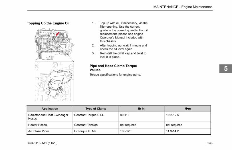
Topping Up the Engine Oil 1. Top up with oil, if necessary, via thefiller opening. Use the correctgrade in the correct quantity. For oilreplacement, please see engineOperator’s Manual included withthis chassis.
2. After topping up, wait 1 minute andcheck the oil level again.
3. Reinstall the oil fill cap and twist tolock it in place.
Pipe and Hose Clamp TorqueValuesTorque specifications for engine parts.
Application Type of Clamp lb-in. N•m
Radiator and Heat ExchangerHoses
Constant Torque CT-L 90-110 10.2-12.5
Heater Hoses Constant Tension not required not required
Air Intake Pipes Hi Torque HTM-L 100-125 11.3-14.2
MAINTENANCE - Engine Maintenance
Y53-6113-1A1 (11/20) 243
5
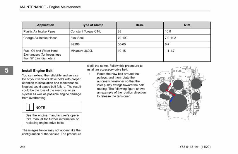
Application Type of Clamp lb-in. N•m
Plastic Air Intake Pipes Constant Torque CT-L 88 10.0
Charge Air Intake Hoses Flex Seal 70-100 7.9-11.3
B9296 50-60 6-7
Fuel, Oil and Water HeatExchangers (for hoses lessthan 9/16 in. diameter).
Miniature 3600L 10-15 1.1-1.7
Install Engine BeltYou can extend the reliability and servicelife of your vehicle's drive belts with properattention to installation and maintenance.Neglect could cause belt failure. The resultcould be the loss of the electrical or airsystem as well as possible engine damagefrom overheating.
NOTE
See the engine manufacturer's opera-tor's manual for further information onreplacing engine drive belts.
The images below may not appear like theconfiguration of the vehicle. The procedure
is still the same. Follow this procedure toinstall an accessory drive belt:
1. Route the new belt around thepulleys, and then rotate theautomatic tensioner so that theidler pulley swings toward the beltrouting. The following figure showsan example of the rotation directionto release the tensioner.
MAINTENANCE - Engine Maintenance
244 Y53-6113-1A1 (11/20)
5
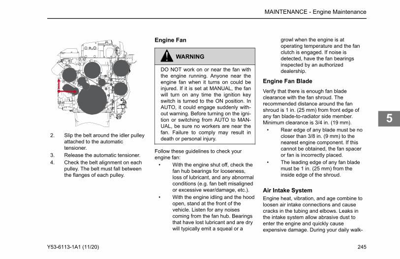
2. Slip the belt around the idler pulleyattached to the automatictensioner.
3. Release the automatic tensioner.4. Check the belt alignment on each
pulley. The belt must fall betweenthe flanges of each pulley.
Engine Fan
WARNING
DO NOT work on or near the fan withthe engine running. Anyone near theengine fan when it turns on could beinjured. If it is set at MANUAL, the fanwill turn on any time the ignition keyswitch is turned to the ON position. InAUTO, it could engage suddenly with-out warning. Before turning on the igni-tion or switching from AUTO to MAN-UAL, be sure no workers are near thefan. Failure to comply may result indeath or personal injury.
Follow these guidelines to check yourengine fan:
• With the engine shut off, check thefan hub bearings for looseness,loss of lubricant, and any abnormalconditions (e.g. fan belt misalignedor excessive wear/damage, etc.).
• With the engine idling and the hoodopen, stand at the front of thevehicle. Listen for any noisescoming from the fan hub. Bearingsthat have lost lubricant and are drywill typically emit a squeal or a
growl when the engine is atoperating temperature and the fanclutch is engaged. If noise isdetected, have the fan bearingsinspected by an authorizeddealership.
Engine Fan BladeVerify that there is enough fan bladeclearance with the fan shroud. Therecommended distance around the fanshroud is 1 in. (25 mm) from front edge ofany fan blade-to-radiator side member.Minimum clearance is 3/4 in. (19 mm).
• Rear edge of any blade must be nocloser than 3/8 in. (9 mm) to thenearest engine component. If thiscannot be obtained, the fan spaceror fan is incorrectly placed.
• The leading edge of any fan blademust be 1 in. (25 mm) from theinside edge of the shroud.
Air Intake SystemEngine heat, vibration, and age combine toloosen air intake connections and causecracks in the tubing and elbows. Leaks inthe intake system allow abrasive dust toenter the engine and quickly causeexpensive damage. During your daily walk-
MAINTENANCE - Engine Maintenance
Y53-6113-1A1 (11/20) 245
5
around inspection, carefully check alltubing, elbows, clamps, supports, andfasteners for condition and tightness.Check the charge-air-cooler for air leaksannually. The air leaks can be caused bycracked tubes or header. For service seeyour authorized dealer.
CAUTION
DO NOT use air intake pipes and con-nections as a step or to pull yourselfup. This could loosen the connectionsand open the system to unfiltered airwhich could damage the engine.
Turbocharger
WARNING
DO NOT operate engine with turbo-charger intake piping disconnected. Asuction is created when the engine isrunning. This suction could draw yourhand or anything else near it into theimpeller fan. You could be injured. Al-
ways keep the intake piping connectedwhen you will be running the engine.
When servicing the air intake and exhaustsystems on a turbocharged engine, checkthe items listed below:
Lubricating SystemCheck the oil lines, housing, andconnections. Look for leaks, damage, ordeterioration. Leaks could mean you havedamaged oil lines or oil seals.
ManifoldWith the engine operating, check forleaking manifold or flange gaskets.
High Frequency VibrationVibration may indicate turbo rotorimbalance. Have your dealer investigatethis immediately. If you detect anydeficiencies, take the vehicle to anauthorized dealer for servicing. Delay couldlead to severe and expensive damage toyour vehicle.
Engine Air FiltersThe following service information is basicto all air cleaner makes and models.
Service the filter elements when the(option) locks in the extreme High position.Have the element serviced at anauthorized Kenworth Dealer. Paperelements require care and proper handling,because they are critical to engine servicelife.Service the air cleaner periodically. If thevehicle operates in areas with heavy dust,maintenance should be more frequent.
Replace Engine Air FilterIf the vehicle is equipped with Cabmounted air cleaner and under hood airintake option, remove the air solenoid first..
1. Park the vehicle. Set the parkingbrake and turn the ignition OFF.
2. If the air cleaner is under the hood,open the hood to access the airfilter housing.
3. Loosen the hardware that holds thehousing cap to the main filterenclosure.
4. Pull the air filter housing cap awayfrom the main enclosure to accessthe filter.
5. Visually inspect the filter housing,enclosure, and hardware fordamage.
MAINTENANCE - Engine Maintenance
246 Y53-6113-1A1 (11/20)
5
6. The filter can be removed bygently pulling it directly out of themain enclosure. Be careful not todrop or tap the filter on the housingduring removal as this could loosendirt and dust trapped in the filter.DO NOT clean or reuse the originalfilter.
7. Inspect the sealing surfaces andclean out any debris from theinside of the filter enclosure beforeinstalling the new filter. Be carefulto not push any contaminant intothe engine inlet.
8. Visually inspect the new filter priorto installation. There should not beany damage to the filter media orgaskets, such as dents, dings,cracks, or holes.
9. After installing the filter, inspect fora good seal, if possible.
10. Install the filter housing cap andtighten the hardware. DO NOT usethe housing cap to drive the filterinto position.
11. Start the engine and allow the airsystem to reach operatingpressure. Activate the under hoodair switch and verify that there areno air leaks.
Engine Air Filter Pre-Cleaner(Option)Certain truck models may have an engineair filter pre-cleaner. This pre-cleanerkeeps the main engine air filter fromquickly filling with dust in vocationalapplications. The pre-cleaner should beinspected and cleaned periodically asdefined in the Maintenance chapter orsooner based on your vehicle's application.Vehicles operating in extremely dustyenvironments may need to inspect andclean the pre-cleaner more frequently thansuggested in the Maintenance chapter. Theair filter restriction gauge may not be anaccurate indicator of pre-cleaner condition.
How to Remove the Pre-cleanerFilterTools and Components:
• 8mm torque wrenchPerform with hood open (see How to Openthe Hood), standing on either side of hood.
1. Locate Pre-cleaner at underside ofhood, top center.
2. Remove fender liner for betteraccess to Pre-cleaner (see How toRemove a Fender Liner on page196).
3. Remove upper left and lower rightPre-cleaner fasteners usingwrench, and set aside.
4. Loosen, but do not remove, lowerleft and upper right Pre-cleanerfasteners.
5. Twist Pre-cleaner counter-clockwise to unlock, then remove.
NOTE
Verify hood plenum is free of debris.
If cleaning the Pre-cleaner, see How toClean the Pre-cleaner Filter. If installing areplacement, see How to Install a Pre-cleaner Filter.
How to Clean the Pre-cleaner FilterTools and Components:
• Gentle soap• Warm, low-pressure water source
MAINTENANCE - Engine Maintenance
Y53-6113-1A1 (11/20) 247
5
CAUTION
Do not use high-pressure water or airto clean or dry the Pre-cleaner FilterAssembly. High-pressure water or aircould damage the filter media, reduc-ing its effectiveness, and decrease theservice life of both the Pre-cleaner Fil-ter Assembly and the Primary EngineAir Cleaner. Failure to comply may re-sult in equipment or property damage.
The Pre-cleaner must be removed from thevehicle prior to cleaning (see How toRemove the Pre-cleaner Filter on page247.).
1. Shake Pre-cleaner until majority ofdust and debris is removed.
2. Examine Pre-cleaner for damageto the filter media:
a. If the filter media is damaged,stop this procedure and installa new Pre-cleaner assembly.
3. Apply (or spray) soap on both sidesof the Pre-cleaner media and allowa few minutes for the soap to sinkin.
4. Flush dirt from filter using warm,low-pressure water applied tocleaner (engine side) side of filteruntil water runs clear.
5. Rinse Pre-cleaner using warm,low-pressure water until no soapremains.
6. Gently shake filter of excess waterand allow Pre-cleaner to dry beforeinstalling.
See How to Install the Pre-cleaner Filter onpage 248 for installation.
How to Install the Pre-cleaner FilterTools and Components:
• 8mm torque wrench• New (or cleaned and dry) Pre-
cleaner Filter AssemblySteps in this procedure assume that theHow to Remove the Pre-cleaner Filterprocedure was performed.
1. Insert new (or cleaned and dry)Pre-cleaner into cavity, aligningboth installed fasteners with largerholes on Pre-cleaner.
2. Twist Pre-cleaner clockwise to lockin filter.
3. Tighten then torque both fastenersto 7–11 lb-ft (9–15 N∙m).
4. Install and tighten remainingfasteners, then torque to 7–11 lb-ft(9–15 N∙m).
5. Reinstall Fender Liner (How toReinstall a Fender Liner on page197).
6. Close and secure hood (Close theHood on page 16).
Exhaust SystemThe exhaust system is part of the noiseand emission control system. Periodicallycheck the exhaust system for wear,exhaust leaks, and loose or missing parts.For details on how to maintain theemissions components in the exhaustsystem, see "Noise and Emission Control"in your vehicle operator's manual. Pleaserefer to the engine operator's manual formore details on how to maintain theemissions components in the exhaustsystem.
MAINTENANCE - Engine Maintenance
248 Y53-6113-1A1 (11/20)
5
Engine Mounting
CAUTION
DO NOT re-torque or reuse existingflange head bolts. These bolts are fac-tory set to the specified torque. If boltsare loose or damaged, they must bereplaced with the new bolts. Failure tocomply may result in property damage.
Periodic Inspection: Inspect engine mountsevery 60,000 miles (96,000 km).Check for the following:
• Inspect both mount and legfasteners. Check for loose orbroken bolts. Replace asnecessary.
• Check mount and leg for fractures,breaks or deformation. Replace asnecessary.
• Check for complete insertion ofmotor mount. Replace asnecessary.
• New leg to mount flange head boltsshould be torqued to 210-230 lb-ft(284-311 N·m).
Fuel SystemPlease follow these recommendationswhen you are changing your fuel filters orstrainer elements. Your vehicle's enginewill run better and last longer if you do. Seethe engine manufacturer'srecommendations for proper water andmicron requirements.
Draining the Primary Fuel FilterThe following tools are suggested for thisprocedure:
• Container (1 liter capacity)(optional)
• 3/8" diameter rubber hose(optional)
Perform with engine OFF. Cover anyelectrical equipment and wiring that mightget soaked with fuel – diesel fuel maypermanently damage electrical insulation.If draining to replace filter, drain intocontainer with a minimum 1 liter (1 qt)capacity, and use hose to route fluid.
1. Open the hood (see How to Openthe Hood), and locate the primaryfuel filter.
2. Open drain valve (by hand only)until draining occurs.If draining to replace the filter,before opening valve, push oneend of hose onto drain valve androute other end to the container.
3. Drain fluid from filter assembly:• If draining water from fuel, drain
filter bowl of water until clearfuel is visible, then close drainvalve, or
• If replacing filter, drain until flowstops, then close valve.
CAUTION
Do not overtighten thevalve. Over tightening candamage the threads.
If a hose was used to drain fluid,remove hose.
If entire filter assembly was drained,proceed to Replacing the Primary FuelFilter.
Replacing the Primary Fuel FilterThe following tools are suggested for thisprocedure:
MAINTENANCE - Fuel System
Y53-6113-1A1 (11/20) 249
5
• Bowl wrench RK61680• 1" wrench• New PACCAR primary fuel filter
element designed for thisapplication
• 2 new O-ringsStart procedure with engine off. Cover anyelectrical equipment and wiring that mightget soaked with fuel; diesel fuel maypermanently damage electrical insulation.To expel air from density-type strainerelements, soak them in clean fuel beforeinstalling them. Lubricate new O-rings withclean fuel to ensure a positive seal.
1. Disconnect clip-type electricalconnections from bowl bottom:
a. Disconnect water in fuel (WIF)sensor from wire bundle.
b. Disconnect electrical heatersensor from wire bundle.
2. Using bowl wrench, loosen filterbowl and lower at least 2 inches.Take care not to damage bowlsensors on surroundingcomponents.
3. Slowly remove bowl and filter fromupper filter assembly.
4. Remove the filter element and bothupper and lower O-rings.
5. Install new filter element:a. Install new upper and lower
O-rings.b. Install new fuel filter element.
6. Reconnect clip-type electricalconnections to bowl bottom:
a. Reconnect water in fuel (WIF)sensor to wire bundle.
b. Reconnect electrical heatersensor to wire bundle.
7. If your vehicle has a fuel blendingvalve, turn valve to “Prime.”
8. Prime fuel filter assembly:• If your assembly contains a
manual priming pump (PX-7engines) press priming pumprepeatedly until pumping actionbecomes firm, or
• Allow the electric priming pumpto prime assembly (non PX-7engines).
9. Start the vehicle.For PX-7 and PX-9 engines, idlefor 5 minutes.
10. If your vehicle has a fuel blendingvalve, turn valve to “Run.”
Observe fuel filter assembly for leaks.Dispose of old filter element and O-ringsproperly.
Fuel Tank
Frame
WARNING
DO NOT cut, splice or weld frame railsor drill through the top or bottom flang-es of the rails. These operations couldaffect frame rail strength leading to afailure resulting in an accident. Railfailures resulting from such modifica-tions are not warrantable. Failure tocomply may result in property damage,personal injury, or death.
MAINTENANCE - Frame
250 Y53-6113-1A1 (11/20)
5
WARNING
Frame welding is NOT recommended.The high heat of welding nullifies thespecial heat treatment of the rails,greatly reducing the tensile strength ofthe frame rail. If a frame member be-comes cracked from overloading, fati-gue, surface damage, or a collision,the only permanent repair is to replacethe damaged frame member with anew part.
Emergency WeldingIn an emergency, a temporary repair maybe performed. Observe the followingprecautions to protect electronic systemsduring welding operations. Emergencywelding procedures are further explained inthe maintenance manuals. Please refer tothe ordering information on the back coverto obtain a maintenance manual.In the event of emergency welding of aframe rail and when welding any other partof your truck or any component attached toyour truck, observe the followingprecautions before welding:
• Disconnect all electronic devices. Itis not possible to list all of the
electronics that could be affected,but a few examples include thefollowing: alternator, engineElectronic Control Unit (ECU),transmission ECU, ABS ECU,navigation devices, diagnosticdevices, and monitoring devices.
• Disconnect battery cables andinsulate them from the vehicle.
• Do not use the ECU or engineground stud for the ground of thewelding probe.
• Ensure that the ground connectionfor the welder is as close to theweld point as possible. Thisensures maximum weld currentand minimum risk to damage ofelectrical components on thevehicle.
PaintingDo not electrostatically paint your truck orany component on your truck without firstremoving all of the electronic componentsfrom the truck. It is not possible to list all ofthe electronics that could be affected, but afew examples include the alternator,engine Electronic Control Unit (ECU),transmission ECU, ABS ECU, navigation
devices, diagnostic devices, andmonitoring devices.
Fifth Wheel Monthly Maintenance• Refer to specific manufacturer's
literature for any specialinstructions
• Steam clean the fifth wheel• Check lock guard operation using a
commercial lock tester• Clean and oil all moving parts• Lubricate the lock mechanism with
a lithium-base grease• All grease fittings (especially those
which grease the top surface of thefifth wheel)
Fifth Wheel Bi-Annual Maintenance
NOTE
Whenever possible, torque all framefasteners on the nut end, not the bolthead.
• Refer to specific manufacturer'sliterature for any specialinstructions.
MAINTENANCE - Frame
Y53-6113-1A1 (11/20) 251
5
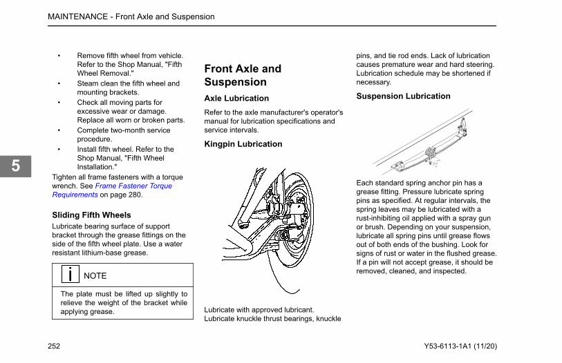
• Remove fifth wheel from vehicle.Refer to the Shop Manual, "FifthWheel Removal."
• Steam clean the fifth wheel andmounting brackets.
• Check all moving parts forexcessive wear or damage.Replace all worn or broken parts.
• Complete two-month serviceprocedure.
• Install fifth wheel. Refer to theShop Manual, "Fifth WheelInstallation."
Tighten all frame fasteners with a torquewrench. See Frame Fastener TorqueRequirements on page 280.
Sliding Fifth WheelsLubricate bearing surface of supportbracket through the grease fittings on theside of the fifth wheel plate. Use a waterresistant lithium-base grease.
NOTE
The plate must be lifted up slightly torelieve the weight of the bracket whileapplying grease.
Front Axle andSuspensionAxle LubricationRefer to the axle manufacturer's operator'smanual for lubrication specifications andservice intervals.
Kingpin Lubrication
Lubricate with approved lubricant.Lubricate knuckle thrust bearings, knuckle
pins, and tie rod ends. Lack of lubricationcauses premature wear and hard steering.Lubrication schedule may be shortened ifnecessary.
Suspension Lubrication
Each standard spring anchor pin has agrease fitting. Pressure lubricate springpins as specified. At regular intervals, thespring leaves may be lubricated with arust-inhibiting oil applied with a spray gunor brush. Depending on your suspension,lubricate all spring pins until grease flowsout of both ends of the bushing. Look forsigns of rust or water in the flushed grease.If a pin will not accept grease, it should beremoved, cleaned, and inspected.
MAINTENANCE - Front Axle and Suspension
252 Y53-6113-1A1 (11/20)
5
CAUTION
DO NOT spray the suspension withchemical products or mineral oil; it cancause damage to the bushings.
Wheel AlignmentFor driving safety and comfort, and toprolong the life of your vehicle, it isimportant to have wheels correctly aligned.Check tire wear frequently. Uneven tirewear is a sign that the wheels may bemisaligned. If you see uneven wear, takeyour vehicle to an authorized dealerfamiliar with aligning wheels on yourvehicle.
Suspension U-BoltsIt is important that U-bolts remain tight.Severe use of your vehicle will cause themto loosen faster, and all vehicles need tohave their U-bolts checked and tightenedregularly. Be sure someone with the propertraining and the right tools checks andtightens the U-bolts on your vehicle. Newsprings can settle in after service, relievingthe tension on the U-bolts. Loose U-boltscan cause leaf spring breakage, axlemisalignment, hard steering, and abnormaltire wear. All vehicles should havesuspension U-bolts tightened after the first500 miles (800 km) of operation. Re-torquethe front spring pinch bolts and shacklepinch bolts.
WARNING
DO NOT operate the vehicle if the sus-pension U-bolts are not properly tight-ened. Loose U-bolts will cause theaxle to not be properly secured to thesuspension, which could cause loss ofvehicle control and an accident. LooseU-bolts can also cause uneven tirewear and poor alignment. Failure tocomply may result in death, personalinjury, equipment or property damage.
U-bolts are difficult to tighten unless youhave the right equipment. If you cannottighten them correctly yourself, be sure tohave them checked and tightened regularlyby an authorized mechanic. Tighten U-boltnuts to the specified torque value with thevehicle loaded to its normal gross weight.See Suspension U-Bolts, Grade 8 on page282 specifications for torque valuesapplying to U-bolts and nuts.
MAINTENANCE - Front Axle and Suspension
InspectionFor all vehicles, mandatory maintenance procedures include retightening all U-bolts and inspecting the suspension for loose, damaged, or abnormally worn fasteners. Visually inspect the shock absorbers, the rubber bushings, the leaf springs, and that the suspension is aligned and functioning properly. Mono leaf spring suspensions should also have their rear shackle brackets checked for proper alignment. Even with proper maintenance, however, the service life of leaf springs are affected by many factors: fatigue, vehicle gross weight, type of load, road conditions, and vehicle speed. Check for cracks, wear marks, splits, or other defects on the surface of the spring. Defective parts must be replaced. Because repaired springs cannot be fully restored to their original service life, replace the complete assembly if cracks or other defects are detected.
Y53-6113-1A1 (11/20) 253
5
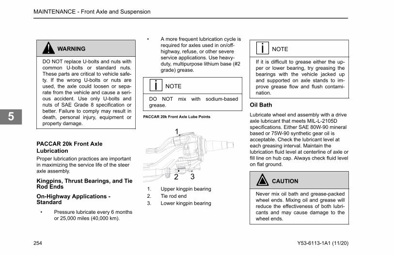
WARNING
DO NOT replace U-bolts and nuts withcommon U-bolts or standard nuts.These parts are critical to vehicle safe-ty. If the wrong U-bolts or nuts areused, the axle could loosen or sepa-rate from the vehicle and cause a seri-ous accident. Use only U-bolts andnuts of SAE Grade 8 specification orbetter. Failure to comply may result indeath, personal injury, equipment orproperty damage.
PACCAR 20k Front AxleLubricationProper lubrication practices are importantin maximizing the service life of the steeraxle assembly.
Kingpins, Thrust Bearings, and TieRod EndsOn-Highway Applications -Standard
• Pressure lubricate every 6 monthsor 25,000 miles (40,000 km).
• A more frequent lubrication cycle isrequired for axles used in on/off-highway, refuse, or other severeservice applications. Use heavy-duty, multipurpose lithium base (#2grade) grease.
NOTE
DO NOT mix with sodium-basedgrease.
PACCAR 20k Front Axle Lube Points
1
2 31. Upper kingpin bearing2. Tie rod end3. Lower kingpin bearing
NOTE
If it is difficult to grease either the up-per or lower bearing, try greasing thebearings with the vehicle jacked upand supported on axle stands to im-prove grease flow and flush contami-nation.
Oil BathLubricate wheel end assembly with a driveaxle lubricant that meets MIL-L-2105Dspecifications. Either SAE 80W-90 mineralbased or 75W-90 synthetic gear oil isacceptable. Check the lubricant level ateach greasing interval. Maintain thelubrication fluid level at centerline of axle orfill line on hub cap. Always check fluid levelon flat ground.
CAUTION
Never mix oil bath and grease-packedwheel ends. Mixing oil and grease willreduce the effectiveness of both lubri-cants and may cause damage to thewheel ends.
MAINTENANCE - Front Axle and Suspension
254 Y53-6113-1A1 (11/20)
5
Heater and Air ConditionerMaintenanceThe combination heater-air conditionerprovides comfort for those in the cabthrough accurate control of the cabenvironment in all weather conditions.Regular attention to the items below willhelp you keep the heater-air conditionerunit running well. Keep the vehicle'sventilation system, engine exhaust system,and cab joints properly maintained. It isrecommended that the vehicle's exhaustsystem and cab be serviced by acompetent technician as follows:
• Inspected every 15,000 miles• Whenever a change is noticed in
the sound of the exhaust system• Whenever the exhaust system,
vehicle underbody, or cab isdamaged
To allow for proper operation of the vehicleventilation system, proceed as follows:
• Keep the inlet grille at the base ofthe windshield clear of snow, ice,leaves, and other obstructions at alltimes.
• Keep the exhaust pipe area clearto help reduce the buildup ofexhaust gas under the vehicle.
• Check the drain tube of the freshair inlet for trapped water beforeassuming that there is a leak in theheating system.
Special Precautions
WARNING
Excessive heat may cause the pres-surized components of the air condi-tioning system to explode. Never weld,solder, steam clean, or use a blowtorch near any part of the air condition-ing system. Failure to comply may re-sult in death, personal injury, equip-ment or property damage.
WARNING
Air conditioning refrigerant can be haz-ardous to your health. DO NOT ex-pose yourself to leaking refrigerant forprolonged periods near excessiveheat, open flames, or without proper
ventilation. Failure to do so may resultin death or personal injury.
If a refrigerant leak develops in thepresence of excessive heat or an openflame, hazardous gases may begenerated. If you become aware of arefrigerant leak on your vehicle have yoursystem serviced immediately and observethe following precautions: Stay away fromthe hot engine until the exhaust manifoldhas cooled. Do not permit any open flamein the area. Even a match or a cigarettelighter may generate a hazardous quantityof poisonous gas. Do not smoke in thearea. Inhaling gaseous refrigerant througha cigarette may cause violent illness.
MAINTENANCE - Heater and Air Conditioner Maintenance
Y53-6113-1A1 (11/20) 255
5
Heater
CAUTION
During extreme cold weather, DO NOTblow hot defroster air onto cold wind-shields. This could crack the glass.Turn the Air Flow Control Dial to De-frost and adjust the fan speed accord-ingly while the engine warms. If theengine is already warm, move theTemperature Control Dial to "cool,"then gradually increase the tempera-ture when you see that the windshieldis starting to warm up. Failure to com-ply may result in equipment damage.
• Check all heater controls for full-range operation.
• Check hoses, connections, andheater core for condition and leaks.
Air Conditioner
WARNING
The air conditioning system is underpressure. If not handled properly dur-ing servicing, it could explode. Anyservicing that requires depressurizing
and recharging the air conditioningsystem must be conducted by a quali-fied technician with the right facilitiesto do the job. Failure to comply mayresult in death, personal injury, equip-ment or property damage.
WARNING
Wear eye protection any time you blowcompressed air. Small particles blownby compressed air could injure youreyes.
• Listen to the compressor and driveclutch for noise and vibration. If youfind problems, have the systemchecked thoroughly. Amalfunctioning clutch usuallyindicates trouble elsewhere in thesystem.
• Check the evaporator core, filter,and condenser core for debrisrestricting air flow. Clean ifnecessary. Small particles may beremoved with compressed airblown through the core in theopposite direction of normal airflow.
• Check the engine belt for conditionand proper tension.
• Check all hoses for kinks,deterioration, chafing, and leaks.Adjust kinked or chafing hoses toeliminate restrictions and preventfurther wear.
• Check all components andconnections for refrigerant leaks. Ifyou discover a leak, do not try totighten a connection. Tightening aconnection may cause a leak toworsen. Have a qualified techniciancorrect the problem.
NOTE
A leaking evaporator or condensercore cannot be repaired; it must be re-placed.
Have the air conditioning system fullyserviced annually by your authorizeddealer. Qualified service technicians willhave to evacuate and recharge the system.
Cabin Fresh Air FilterThe cab air conditioning filter is locatedinside the cab behind the passenger sidekick panel (located below the glovebox).
MAINTENANCE - Heater and Air Conditioner Maintenance
256 Y53-6113-1A1 (11/20)
5
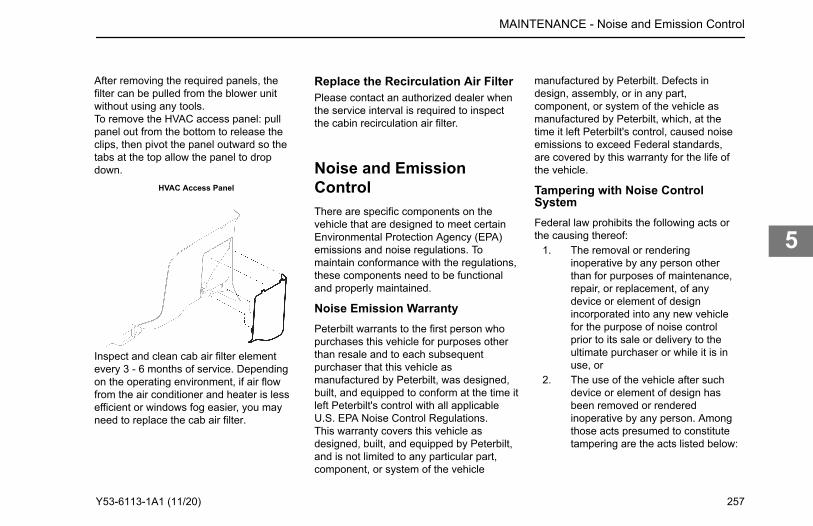
After removing the required panels, thefilter can be pulled from the blower unitwithout using any tools.To remove the HVAC access panel: pullpanel out from the bottom to release theclips, then pivot the panel outward so thetabs at the top allow the panel to dropdown.
HVAC Access Panel
Replace the Recirculation Air FilterPlease contact an authorized dealer whenthe service interval is required to inspectthe cabin recirculation air filter.
Noise and EmissionControlThere are specific components on thevehicle that are designed to meet certainEnvironmental Protection Agency (EPA)emissions and noise regulations. Tomaintain conformance with the regulations,these components need to be functionaland properly maintained.
Noise Emission WarrantyPeterbilt warrants to the first person whopurchases this vehicle for purposes otherthan resale and to each subsequentpurchaser that this vehicle asmanufactured by Peterbilt, was designed,built, and equipped to conform at the time itleft Peterbilt's control with all applicableU.S. EPA Noise Control Regulations.This warranty covers this vehicle asdesigned, built, and equipped by Peterbilt,and is not limited to any particular part,component, or system of the vehicle
manufactured by Peterbilt. Defects indesign, assembly, or in any part,component, or system of the vehicle asmanufactured by Peterbilt, which, at thetime it left Peterbilt's control, caused noiseemissions to exceed Federal standards,are covered by this warranty for the life ofthe vehicle.
Tampering with Noise ControlSystemFederal law prohibits the following acts orthe causing thereof:
1. The removal or renderinginoperative by any person otherthan for purposes of maintenance,repair, or replacement, of anydevice or element of designincorporated into any new vehiclefor the purpose of noise controlprior to its sale or delivery to theultimate purchaser or while it is inuse, or
2. The use of the vehicle after suchdevice or element of design hasbeen removed or renderedinoperative by any person. Amongthose acts presumed to constitutetampering are the acts listed below:
MAINTENANCE - Noise and Emission Control
Inspect and clean cab air filter element every 3 - 6 months of service. Depending on the operating environment, if air flow from the air conditioner and heater is less efficient or windows fog easier, you may need to replace the cab air filter.
Y53-6113-1A1 (11/20) 257
5
Air IntakeSystem
Removing or rendering inoperativethe air filter housing/silencers orintake piping
EngineCoolingSystem
Removing or rendering the fanclutch inoperativeRemoving the fan shroud
Engine Removing or rendering engine speedgovernor inoperative so as to allow enginespeed to exceed manufacturer'sspecificationsModifying ECU parameters
ExhaustSystem
Removing or rendering inoperativeexhaust system components
FuelSystem
Removing or rendering engine speedgovernor inoperative, allowing enginespeed to exceed manufacturer'sspecificationsRemoving of air signal attenuator onengines equipped with this deviceRemoving of diesel exhaust fluid tank andsystem
Inner FenderShields andCab Skirts
Removing shield or skirtsCutting away parts of shields, skirtsor damaged or loose portions ofshields or skirts
NoiseInsulatingBlankets
Removing noise insulators fromengine block or from around the oilpan
Cutting holes in, or cutting away partof noise insulatorsRemoving hood-mounted noiseinsulation
Inspecting Noise and EmissionComponentsThe following instructions are based oninspection of the noise control system atregular intervals as indicated in the NoiseControl System - Maintenance Log onpage 281.Air Intake System
• Do all checks and maintenanceprocedures listed in this manualunder engine air intake system andair filter housing.
• Check the induction tubing, elbowconnections, clamps, brackets, andfasteners for deterioration, cracks,and security.
• If you find an air leak anywherebetween the air filter housing andthe engine, repair that leakimmediately.
CAUTION
Air leaks cause excessive noise andmay result in serious damage to theengine. If you do not repair them theengine damage will not be covered byyour warranty. Repair all air leaks assoon as you find them.
Engine Mounted Noise Insulators• Check condition. Is the insulator
secure? How you do this willdepend on the method of attachingthe noise insulators on the engineand around the oil pan (bolts, snapfasteners, or straps). Tighten loosefasteners and repair or replace anyworn or damaged fasteners.
• Check insulators around fastenersand stress points, especially wherethey may be affected by enginevibration. Repair any cracked ordamaged mounting points. Usesuitable reinforcing plates toensure that the insulators willremain in position.
Exhaust System• Check for exhaust leaks, which
would indicate a leaking manifold
MAINTENANCE - Noise and Emission Control
258 Y53-6113-1A1 (11/20)
5
gasket; replace gasket ifnecessary.
• Check cap screws for tightness,including those at the flanges.Refer to the engine manufacturer'sservice manual for propertightening sequence and torquevalues.
Joints and Clamps• Check for leaks, and tighten as
necessary. Check for deteriorationor dents in pipes and clamps whichcould allow exhaust to escape.
• Replace any serviceable joints,flexible pipes and gaskets at theservice intervals.
Selective Catalysts Reduction (SCR)• Check SCR canister filter, clamps
and mounting brackets. Tighten ifnecessary. Inspect SCR canisterfor signs of rust or corrosion.
Exhaust Piping• Check exhaust piping for rust,
corrosion, or damage. Replacedeteriorated piping before holesappear. If piping is perforated atany point, temporary patching orlagging is acceptable until you canhave permanent repairs made. Onturbocharged engines, check joints
at flanges and mounting bracketsfor tightness.
Diesel Particulate Filter (DPF)• Check DPF, clamps, and mounting
brackets. Tighten if necessary.Inspect DPF for signs of rust orcorrosion.
• Check internal baffling. You can dothis by listening for rattling soundswhile tapping on the (DPF with arubber mallet or revving the engineup and down through its normaloperating range.
Mufflers• Check muffler, clamps, and
mounting brackets. Tighten ifnecessary. Inspect muffler for signsof rust or corrosion.
• Check internal baffling. You can dothis by listening for rattling soundswhile tapping the muffler with arubber mallet or revving the engineup and down through its normaloperating range.
DEF Tank (See Engine AftertreatmentSystem manual)Exhaust Tail Pipe
• Check the mounting. Tighten asnecessary. The miter cut at the tipof the pipe must be facing the rear
of the vehicle. Do not modify theend of the pipe in any way.
Engine Fan and Shroud
WARNING
Do not work on the fan with the enginerunning. The engine fan can engage atany time without warning. Anyone nearthe fan when it turns on could be in-jured. Before turning on the ignition, besure that no one is near the fan.
• Check all fasteners for tightness.Check for stress cracks in theshroud. Make sure the shroud isadjusted so that it does not touchthe fan blades.
• Check to verify that the fan isdisengaged (not turning) with theengine running at normal operatingtemperatures (from cold to thepoint that the fan engages).
• Check fan blade mounting bolts.Inspect fan blades to be sure theyare not cracked or bent.
Transmission and Driveline• Substituting a different main
transmission or drivelinecomponents, other than design-
MAINTENANCE - Noise and Emission Control
Y53-6113-1A1 (11/20) 259
5
specified units, may result inincreased vehicle noise emission.
Hood Insulation Blanket• Check all fasteners for condition
and security. Repair or replace anybroken or defective fasteners.
Blanket• Check for chafing or tears. Patch it
if necessary. Find the cause of thedamage. If any component oraccessory is causing wear ordamage and cannot be relocated,put reinforcing pads on the blanketat the site of wear.
Inner Fenders Shields and Cab Skirts• Check all fasteners, especially the
self-tapping hex head screws. Arethey secure? Remove and replaceany loose rivets.
Shields and Skirts• Check shields and skirts for cracks
at mounting and stress points.Check fender shields for tire marks,worn spots, or damage fromobjects thrown from tire treads. Youcan repair cracked or damagedfiberglass fender shields withfiberglass and resin.
• If you find damage at a fasteningpoint, you can gain additional
strength by installing a suitablereinforcing plate. This plate shouldbe drilled to accept a rivet andlaminated to the shield withfiberglass and resin.
• Check cab skirts, sills, andbrackets for overall condition andrepair them as necessary.Damaged rubber fender shields orcab skirting cannot be repaired.You will need to replace it.
NOTE
Your authorized dealer can perform allof these checks and repairs or re-placements.
Diesel Exhaust Fluid TankVehicles that comply with 2010 EPAemission requirements will have a DieselExhaust Fluid (DEF) tank mounted to thevehicle frame.
Rear Axle and SuspensionYour vehicle's suspension, by design,requires a minimal amount of maintenance.However, suspensions in over-the-roadoperations require periodic inspection toensure trouble-free performance.
WARNING
DO NOT work on the vehicle withoutthe parking brake set and wheelsblocked securely. If the vehicle is notsecured to prevent uncontrolled vehi-cle movement, it could roll and may re-sult in death, personal injury, equip-ment or property damage.
MAINTENANCE - Diesel Exhaust Fluid Tank
260 Y53-6113-1A1 (11/20)
5
WARNING
DO NOT operate the vehicle if the sus-pension U-bolts are not properly tight-ened. Loose U-bolts will cause theaxle to not be properly secured to thesuspension, which could cause loss ofvehicle control and an accident. LooseU-bolts can also cause uneven tirewear and poor alignment. Failure tocomply may result in death, personalinjury, equipment or property damage.
WARNING
Failure to maintain the specified torquevalues or to replace worn parts cancause component system failure, pos-sibly resulting in an accident. Improp-erly tightened (loose) suspension U-bolts can lead to unsafe vehicle condi-tions, including: hard steering, axlemisalignment, spring breakage or ab-normal tire wear. Failure to complymay result in death, personal injury,equipment or property damage.
CAUTION
DO NOT spray the suspension withchemical products or mineral oil; it cancause damage to the bushings.
NOTE
Failure to follow these recommenda-tions could void warranty.
Visual InspectionFor all vehicles, mandatory maintenanceprocedures include retightening of U-boltsand complete inspection. Even with propermaintenance, however, many factors affectthe service life of springs and suspensioncomponents: fatigue, vehicle gross weight,type of load, road conditions, and vehiclespeed. All vehicles need to have their U-bolts checked and tightened regularly, butsevere use of your vehicle can cause themto loosen faster. It is important that U-boltsremain tight. Be sure someone with propertraining and the right tools checks andtightens the U-bolts on your vehicle. Afterthe first 500 miles (800 km) of operation,
periodically inspect the suspension asnoted below:
• Visually check for loose or missingfasteners, cracks in hanger, or axleconnection brackets
• Check that springs are centered inhangers and in good condition
• Check for cracks, wear marks,splits, or other defects on thesurface of the spring
• Replace defective parts. Becauserepaired springs cannot be fullyrestored to their original servicelife, replace the complete assemblyif cracks or other defects aredetected
• After replacement of any part ordiscovery of loose components,check the torque of all fasteners
• New springs settle-in after thevehicle's initial service, causing theU-bolts to become loose
Rear Suspension FastenersTo maintain the performance of the airsuspension, check fastener torque valuesafter the first 2,000 miles (3,200 km) ofservice and every 60,000 miles (96,000km) thereafter. Torque recommendationsapply to fasteners supplied and installed by
MAINTENANCE - Rear Axle and Suspension
Y53-6113-1A1 (11/20) 261
5
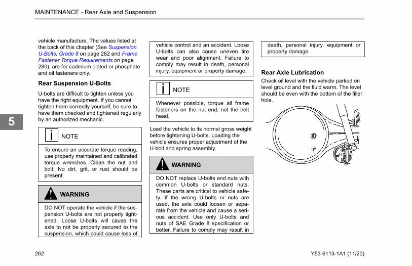
vehicle manufacture. The values listed atthe back of this chapter (See SuspensionU-Bolts, Grade 8 on page 282 and FrameFastener Torque Requirements on page280), are for cadmium plated or phosphateand oil fasteners only.
Rear Suspension U-BoltsU-bolts are difficult to tighten unless youhave the right equipment. If you cannottighten them correctly yourself, be sure tohave them checked and tightened regularlyby an authorized mechanic.
NOTE
To ensure an accurate torque reading,use properly maintained and calibratedtorque wrenches. Clean the nut andbolt. No dirt, grit, or rust should bepresent.
WARNING
DO NOT operate the vehicle if the sus-pension U-bolts are not properly tight-ened. Loose U-bolts will cause theaxle to not be properly secured to thesuspension, which could cause loss of
vehicle control and an accident. LooseU-bolts can also cause uneven tirewear and poor alignment. Failure tocomply may result in death, personalinjury, equipment or property damage.
NOTE
Whenever possible, torque all framefasteners on the nut end, not the bolthead.
Load the vehicle to its normal gross weightbefore tightening U-bolts. Loading thevehicle ensures proper adjustment of theU-bolt and spring assembly.
WARNING
DO NOT replace U-bolts and nuts withcommon U-bolts or standard nuts.These parts are critical to vehicle safe-ty. If the wrong U-bolts or nuts areused, the axle could loosen or sepa-rate from the vehicle and cause a seri-ous accident. Use only U-bolts andnuts of SAE Grade 8 specification orbetter. Failure to comply may result in
death, personal injury, equipment orproperty damage.
Rear Axle LubricationCheck oil level with the vehicle parked onlevel ground and the fluid warm. The levelshould be even with the bottom of the fillerhole.
MAINTENANCE - Rear Axle and Suspension
262 Y53-6113-1A1 (11/20)
5
CAUTION
DO NOT mix lubricants of differentgrades; although, mixing differentbrands of the same grade lubricant(meeting MIL-L-2105C), is acceptable.Lubricants of different grades are notcompatible and could damage theaxle.
NOTE
In all cases, lubricant supplier as-sumes full responsibility for the per-formance of their product, and forproduct and patent liability.
For recommended types and brands oflubricants, contact your dealer.
Dana Spicer and FabcoNo initial drain is required on Dana Spiceraxles that are factory filled with an DanaSpicer-approved synthetic lubricant.
• Petroleum-based lubricants mustbe drained within the first 5,000miles (8,000 km) if converting to anapproved synthetic lubricant.
Initial Change: See PreventiveMaintenance Intervals on page 173 forstandard rear axle service intervals.Change mineral-based lubricant in otherDana Spicer and Fabco axle assemblies(new or rebuilt) within the first 3,000 to5,000 miles (4,800 to 8,000 km).
• For petroleum-based axles, uselubricants meeting MIL L2105C/Dgrade specifications or approvedsynthetic lubrication. Do not use oiladditives.
All Vehicles with Dana Spicer and FabcoAxles: See Preventive MaintenanceIntervals on page 173. Contact your dealerfor approved synthetic lubricant brands.
• Dana Spicer Axles with syntheticlubrication and Out Runner Seals:drain, flush, and refill at 500,000miles (804,000 km).
Axle Housing Breather Vent:• Check and clean the axle housing
breather vent at each oil levelcheck.
Meritor:• See Meritor Lubrication
Maintenance Manual (MM1).
Drive Axle - DanaDrain the lubricant while warm. Flush eachunit with clean flushing oil. Change thelubricant.
Drive Axle - MeritorDrain and replace the lubricant.
Rear Axle AlignmentContinual road shock and load stressesmay force the rear axles out of alignment.If you detect rapid tire wear on the rearaxles, you may have misaligned axles. Ifyou suspect rapid tire wear, have your rearaxle alignment checked and adjusted by anauthorized dealer.Suspension alignment should be checkedwhen any one of the following conditionsexist:
• Total vehicle alignment requiredafter a body has been installed ontruck chassis.
• Discovery of loose suspensionfasteners (Loose, defined as anytorque below the recommendedtorque value)
• Discovery of elongated holes in asuspension component
MAINTENANCE - Rear Axle Alignment
Y53-6113-1A1 (11/20) 263
5
• Bushing replacement• Excessive or abnormal tire wear• Immediately after post body
installation (See First Day in theMaintenance Chapter)
Steering System
WARNING
DO NOT operate the vehicle if thesteering system is not working proper-ly. You could lose control of your vehi-cle if the steering system is not in goodworking condition, which could resultin a serious accident. For driving safe-ty, visually check the steering gear andcomponents. Frequent checks are im-portant for driving safety, especially af-ter traveling over rough roads. Failureto comply may result in personal injury,property damage, or death.
WARNING
If this chassis is equipped with anelectronic stability system (ESC) andany part of the steering system (e.g.,linkage, steering driveline, column,front end alignment, etc) is repaired,removed, or disassembled in any way,or if the steering angle sensor is re-placed, the steering angle sensor mustbe recalibrated. Any repairs or adjust-ments to any part of the steering sys-tem must be performed by an author-ized dealer. Failure to comply may re-sult in personal injury, property dam-age, or death.
Hydraulic fluid (under low pressure)provides the power to operate the steeringgear. It also serves to lubricate movingparts and remove heat. A loss of steeringefficiency will occur if too much heat buildsup in the system.If the steering feels unbalanced from side-to-side while turning, check for thefollowing possible causes:
• Unequal tire pressures• Vehicle overloaded or unevenly
distributed load
• Wheels out of alignment• Wheel bearings improperly
adjustedIf you cannot correct the problem, checkwith an authorized dealer.Your vehicle is equipped with integralpower steering. The system includes anengine-driven fluid pump, a fluid reservoir,the steering gear, and connecting hoses.Because of the hydraulic power assist, littleeffort is required to turn the steering wheel.When no input is applied through thesteering wheel, the steering gear will returnto the neutral position. If, for any reason,the power assist system goes out, steeringthe vehicle is still possible but it will requiremuch greater effort.Visually check the following parts:
• Crosstube: Is it straight?• Drag link tube clamp: Check for
looseness or interference• Ball joints and steering U-joints:
Check for looseness• Steering wheel for excessive free-
play. Check the simplest probablecauses first: (A) unequal tirepressures; (B) loose cap nuts; (C)bent crosstube; or (D) lack oflubrication
MAINTENANCE - Steering System
264 Y53-6113-1A1 (11/20)
5
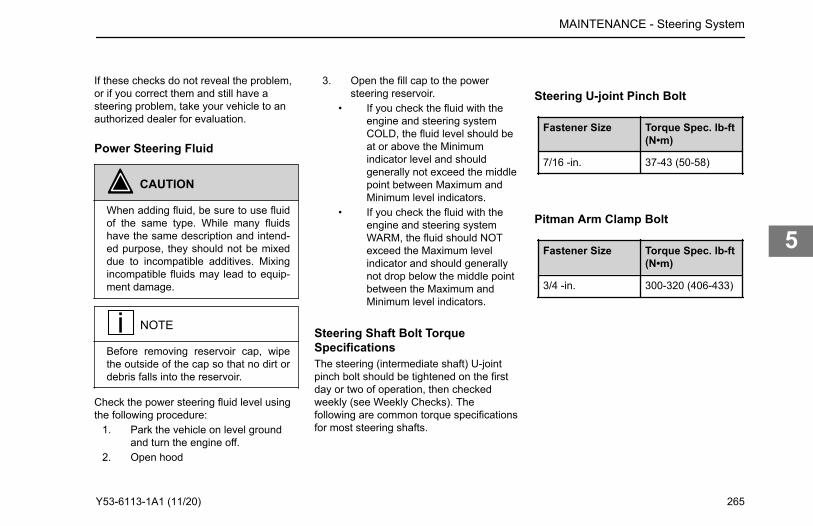
If these checks do not reveal the problem,or if you correct them and still have asteering problem, take your vehicle to anauthorized dealer for evaluation.
Power Steering Fluid
CAUTION
When adding fluid, be sure to use fluidof the same type. While many fluidshave the same description and intend-ed purpose, they should not be mixeddue to incompatible additives. Mixingincompatible fluids may lead to equip-ment damage.
NOTE
Before removing reservoir cap, wipethe outside of the cap so that no dirt ordebris falls into the reservoir.
Check the power steering fluid level usingthe following procedure:
1. Park the vehicle on level groundand turn the engine off.
2. Open hood
3. Open the fill cap to the powersteering reservoir.
• If you check the fluid with theengine and steering systemCOLD, the fluid level should beat or above the Minimumindicator level and shouldgenerally not exceed the middlepoint between Maximum andMinimum level indicators.
• If you check the fluid with theengine and steering systemWARM, the fluid should NOTexceed the Maximum levelindicator and should generallynot drop below the middle pointbetween the Maximum andMinimum level indicators.
Steering Shaft Bolt TorqueSpecificationsThe steering (intermediate shaft) U-jointpinch bolt should be tightened on the firstday or two of operation, then checkedweekly (see Weekly Checks). Thefollowing are common torque specificationsfor most steering shafts.
Steering U-joint Pinch Bolt
Fastener Size Torque Spec. lb-ft(N•m)
7/16 -in. 37-43 (50-58)
Pitman Arm Clamp Bolt
Fastener Size Torque Spec. lb-ft(N•m)
3/4 -in. 300-320 (406-433)
MAINTENANCE - Steering System
Y53-6113-1A1 (11/20) 265
5
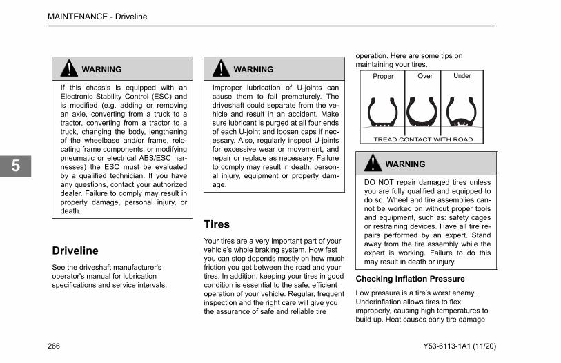
WARNING
If this chassis is equipped with anElectronic Stability Control (ESC) andis modified (e.g. adding or removingan axle, converting from a truck to atractor, converting from a tractor to atruck, changing the body, lengtheningof the wheelbase and/or frame, relo-cating frame components, or modifyingpneumatic or electrical ABS/ESC har-nesses) the ESC must be evaluatedby a qualified technician. If you haveany questions, contact your authorizeddealer. Failure to comply may result inproperty damage, personal injury, ordeath.
DrivelineSee the driveshaft manufacturer'soperator's manual for lubricationspecifications and service intervals.
WARNING
Improper lubrication of U-joints cancause them to fail prematurely. Thedriveshaft could separate from the ve-hicle and result in an accident. Makesure lubricant is purged at all four endsof each U-joint and loosen caps if nec-essary. Also, regularly inspect U-jointsfor excessive wear or movement, andrepair or replace as necessary. Failureto comply may result in death, person-al injury, equipment or property dam-age.
TiresYour tires are a very important part of yourvehicle’s whole braking system. How fastyou can stop depends mostly on how muchfriction you get between the road and yourtires. In addition, keeping your tires in goodcondition is essential to the safe, efficientoperation of your vehicle. Regular, frequentinspection and the right care will give youthe assurance of safe and reliable tire
operation. Here are some tips onmaintaining your tires.
Proper Over Under
TREAD CONTACT WITH ROAD
WARNING
DO NOT repair damaged tires unlessyou are fully qualified and equipped todo so. Wheel and tire assemblies can-not be worked on without proper toolsand equipment, such as: safety cagesor restraining devices. Have all tire re-pairs performed by an expert. Standaway from the tire assembly while theexpert is working. Failure to do thismay result in death or injury.
Checking Inflation PressureLow pressure is a tire’s worst enemy.Underinflation allows tires to fleximproperly, causing high temperatures tobuild up. Heat causes early tire damage
MAINTENANCE - Driveline
266 Y53-6113-1A1 (11/20)
5
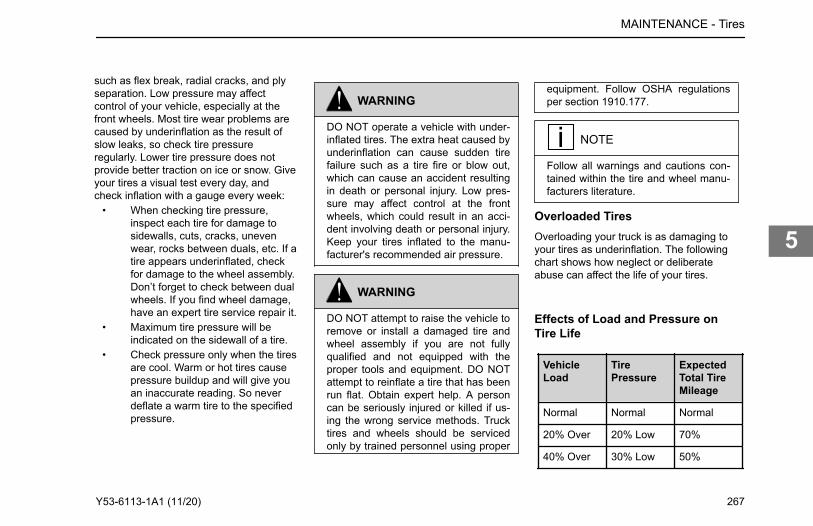
such as flex break, radial cracks, and plyseparation. Low pressure may affectcontrol of your vehicle, especially at thefront wheels. Most tire wear problems arecaused by underinflation as the result ofslow leaks, so check tire pressureregularly. Lower tire pressure does notprovide better traction on ice or snow. Giveyour tires a visual test every day, andcheck inflation with a gauge every week:
• When checking tire pressure,inspect each tire for damage tosidewalls, cuts, cracks, unevenwear, rocks between duals, etc. If atire appears underinflated, checkfor damage to the wheel assembly.Don’t forget to check between dualwheels. If you find wheel damage,have an expert tire service repair it.
• Maximum tire pressure will beindicated on the sidewall of a tire.
• Check pressure only when the tiresare cool. Warm or hot tires causepressure buildup and will give youan inaccurate reading. So neverdeflate a warm tire to the specifiedpressure.
WARNING
DO NOT operate a vehicle with under-inflated tires. The extra heat caused byunderinflation can cause sudden tirefailure such as a tire fire or blow out,which can cause an accident resultingin death or personal injury. Low pres-sure may affect control at the frontwheels, which could result in an acci-dent involving death or personal injury.Keep your tires inflated to the manu-facturer's recommended air pressure.
WARNING
DO NOT attempt to raise the vehicle toremove or install a damaged tire andwheel assembly if you are not fullyqualified and not equipped with theproper tools and equipment. DO NOTattempt to reinflate a tire that has beenrun flat. Obtain expert help. A personcan be seriously injured or killed if us-ing the wrong service methods. Trucktires and wheels should be servicedonly by trained personnel using proper
equipment. Follow OSHA regulationsper section 1910.177.
NOTE
Follow all warnings and cautions con-tained within the tire and wheel manu-facturers literature.
Overloaded TiresOverloading your truck is as damaging toyour tires as underinflation. The followingchart shows how neglect or deliberateabuse can affect the life of your tires.
Effects of Load and Pressure onTire Life
VehicleLoad
TirePressure
ExpectedTotal TireMileage
Normal Normal Normal
20% Over 20% Low 70%
40% Over 30% Low 50%
MAINTENANCE - Tires
Y53-6113-1A1 (11/20) 267
5
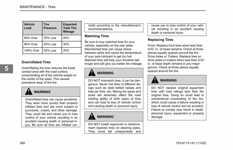
VehicleLoad
TirePressure
ExpectedTotal TireMileage
60% Over 35% Low 40%
80% Over 45% Low 30%
100% Over 55% Low 25%
Overinflated TiresOverinflating the tires reduces the treadcontact area with the road surface,concentrating all of the vehicle weight onthe center of the tread. This causespremature wear of the tire.
WARNING
Overinflated tires can cause accidents.They wear more quickly than properlyinflated tires and are more subject topunctures, cracks, and other damage.They could fail and cause you to losecontrol of your vehicle resulting in anaccident causing death or personal in-jury. Be sure all tires are inflated cor-
rectly according to the manufacturer'srecommendations.
Matching TiresBe sure to buy matched tires for yourvehicle, especially on the rear axles.Mismatched tires can cause stressbetween axles and cause the temperatureof your axle lubricant to get too hot.Matched tires will help your driveline lastlonger and will give you better tire mileage.
WARNING
DO NOT mismatch tires, it can be dan-gerous. Never mix tires of different de-sign such as steel belted radials andbias ply tires, etc. Mixing tire types andsizes will adversely affect the roadholding ability of both types of tiresand can lead to loss of vehicle controland causing death or personal injury.
WARNING
DO NOT install regrooved or reinforce-ment repaired tires on steering axles.They could fail unexpectedly and
cause you to lose control of your vehi-cle resulting in an accident causingdeath or personal injury.
Replacing TiresFront: Replace front tires when less than4/32 -in. of tread remains. Check at threeplaces equally spaced around the tire.Drive Axles or Trailers: Replace tires ondrive axles or trailers when less than 2/32 -in. of tread depth remains in any majorgroove. Check at three places equallyspaced around the tire.
WARNING
DO NOT replace original equipmenttires with load ratings less than theoriginal tires. Doing so could lead tounintentional overloading of the tire,which could cause a failure resulting inloss of vehicle control and an accident.Failure to comply may result in death,personal injury, equipment or propertydamage.
MAINTENANCE - Tires
268 Y53-6113-1A1 (11/20)
5
NOTE
To prolong your tires' life and makethem safer, have their radial and later-al run-out checked at your dealer. Andof course you should have your tiresbalanced anytime you change a tire.
Tire ChainsIf you need tire chains, install them on bothsides of each driving axle.
NOTE
To prolong your tires' life and makethem safer, have their radial and later-al run-out checked at your dealer. Andof course you should have your tiresbalanced anytime you change a tire.
Speed Restricted Tires
WARNING
This vehicle is equipped with speed re-stricted tires. Check each tire’s side-wall and/or tire manufacturer's data
book for maximum rated speed. Thevehicle should not be operated atspeeds in excess of the maximum rat-ed speed. Failure to comply with thesespeed restrictions could cause suddentire failure, which can result in propertydamage or personal injury.
Greenhouse Gas Certified Tires
NOTE
The tires installed on this vehicle at thefactory as original equipment are certi-fied for Greenhouse Gas and Fuel Effi-ciency regulations. Replacement tiresmust be of an equal or larger loadeddrive tire size and an equal or lowerrolling resistance level (TRRL or Crr).Consult with your tire supplier(s) forappropriate replacement tires.
In order to limit the rolling resistance of thetires and optimize fuel economy, themaintenance procedures specified by thetire manufacturer must be followed. Pleasesee Vehicle Emissions Limited Express
Warranty for warranty on greenhouse gascertified tires.
WheelsAfter the vehicle travels about 50 to 100miles (80 to 160 km), wheel mountingsseat in and will lose some initial torque.Check hub/wheel mountings after thisinitial period and retighten. Threads shouldbe clean and dry. Do not lubricate wheelnuts or studs.
WARNING
Never use oil or grease on studs ornuts; improper torque readings will re-sult, which could cause improperwheel clamping and could lead to awheel failure resulting in an accident.Failure to comply may result in death,personal injury, equipment or propertydamage.
MAINTENANCE - Wheels
Y53-6113-1A1 (11/20) 269
5
Wheel Replacement with DiscBrake Option
WARNING
Use only the wheel brand, size andpart number originally installed. Use ofa different wheel brand or size couldcause valve stem to interfere with abrake component which could lead toloss of vehicle control. Failure to com-ply may result in death, personal in-jury, equipment or property damage.
Vehicles equipped with front disc brakesare fitted with wheels designed specificallyfor disc brake applications. If it everbecomes necessary to replace an originalequipment wheel, the replacement wheelmust be the same brand and size as thetake-off wheel. On vehicles equipped with22.5 in. disc wheels, installing the wrongreplacement wheel could result in thewheel valve stem making contact with thedisc brake assembly. When installing anyreplacement wheel, always inspect thetires/wheels to ensure there is adequateclearance between other vehiclecomponents. With the hood open, checkfor clearance between the wheel and discbrake assembly. Use a hydraulic jack to
raise the front of the vehicle off the groundto allow the wheel to spin freely. Whilerotating the wheel, check to ensure there isadequate clearance between the wheeland disc brake assembly.
WARNING
Improperly mounting and demountingtire and rim assemblies is dangerous.Failure to observe proper precautionscould cause the tire rim assembly toburst explosively, causing death orpersonal injury. See the wheel manu-facturer's literature for the proper wayto mount and demount your tires andrims. Follow their precautions exactly.
WARNING
Always ensure the hood hold openlatch is engaged to keep the hood fullyopen any time anyone gets under thehood for any reason. Failure to do somay cause the hood to close uncon-trollably which may result in death orpersonal injury.
WARNING
Always support the vehicle with appro-priate safety stands if it is necessary towork underneath the vehicle. A jack isnot adequate for this purpose. Failureto comply may result in death, person-al injury, equipment or property dam-age.
Disc Wheels
WARNING
Use the correct components and toolswhen working on wheels. Grooves inthe wheel disc or other damage to thedisc can weaken the wheel and causeit to eventually come off. This couldcause you to lose control of your vehi-cle, and may result in an accident.Failure to comply may result in proper-ty damage, personal injury, or death.
The end of the wheel wrench must besmooth. Burrs on the end of the wrenchcan tear grooves in the disc. Thesegrooves may lead to cracks in the disc, andcan cause it to fail.
MAINTENANCE - Wheels
270 Y53-6113-1A1 (11/20)
5
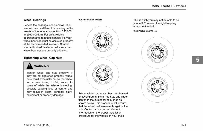
Wheel BearingsService the bearings, seals and oil. Thisinterval may be different depending on theresults of the regular inspection. 350,000mi (560,000 km). For safe, reliableoperation and adequate service life, yourwheel bearings must be adjusted properlyat the recommended intervals. Contactyour authorized dealer to make sure thewheel bearings are properly adjusted.
Tightening Wheel Cap Nuts
WARNING
Tighten wheel cap nuts properly. Ifthey are not tightened properly, wheelnuts could eventually cause the wheelto become loose, to fail, and/or tocome off while the vehicle is moving,possibly causing loss of control andmay result in death, personal injury,equipment or property damage.
Hub Piloted Disc Wheels
Proper wheel torque can best be obtainedon level ground. Install lug nuts and finger-tighten in the numerical sequence asshown below. This procedure will ensurethat the wheel is drawn evenly against thehub. Contact an authorized dealer forinformation on the proper installationprocedure for the wheels on your truck.
This is a job you may not be able to doyourself. You need the right torquingequipment to do it.Stud Piloted Disc Wheels
MAINTENANCE - Wheels
Y53-6113-1A1 (11/20) 271
5
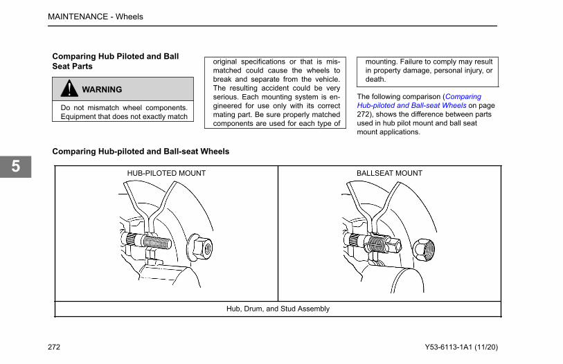
Comparing Hub Piloted and BallSeat Parts
WARNING
Do not mismatch wheel components.Equipment that does not exactly match
original specifications or that is mis-matched could cause the wheels tobreak and separate from the vehicle.The resulting accident could be veryserious. Each mounting system is en-gineered for use only with its correctmating part. Be sure properly matchedcomponents are used for each type of
mounting. Failure to comply may resultin property damage, personal injury, ordeath.
The following comparison (ComparingHub-piloted and Ball-seat Wheels on page272), shows the difference between partsused in hub pilot mount and ball seatmount applications.
Comparing Hub-piloted and Ball-seat Wheels
HUB-PILOTED MOUNT BALLSEAT MOUNT
Hub, Drum, and Stud Assembly
MAINTENANCE - Wheels
272 Y53-6113-1A1 (11/20)
5
Hub-piloted mountings use M22 x 1.5 metric threads (about 7/8 in.diameter). The stud stands out at least 1.94 in. beyond the brakedrum. All studs are right-hand threads. Pilot bosses (machinedsurfaces) on the hub, fit tightly to the wheel center bore.
Ball-seat (stud-piloted) mountings use 3/4x16 or 1-1/8x16 threads.The dual mounting studs provide 1.30 in. 1.44 in. standout. Right-hand and left-hand threads are required. Inner and outer wheelnuts center the wheels by seating against wheel ball seats.
Wheels
Hub-piloted wheels have stud holes reamed straight through (noball seats). Center bore diameter is 8-21/32 in.
Ball-seat wheels have spherical chamfers machined on each studhole. Center bore diameter is 8-23/32 in.
Wheel Nuts
Hub-piloted wheel nuts have a hex body and a flange for clampingagainst wheel face. Hex size is 1-5/16 in. (33 mm).
Ball-seat inner and outer wheel nuts mate with spherical chamferson wheels. The inner nut has 13/16 in. square end. The outer nuthas a 1-1/2 in. hex.
Transmission MaintenanceSee the transmission manufacturer'soperator's manual for lubricationspecifications and service intervals.
CAUTION
When adding oil, types and brands ofoil should not be intermixed becauseof possible incompatibility, which could
decrease the effectiveness of the lubri-cation or cause component failure.
Vehicles configured with Eaton Automatedor a PACCAR transmission must maintainthe oil coalescing desiccant cartridge of theair dryer as part of transmissionmaintenance.
CAUTION
Replace oil-coalescing desiccant airdryer cartridge every 1 year regardless
of mileage. Only use oil-coalescingdesiccant replacement cartridge whenreplacing. Failure to perform this main-tenance task will void the PACCARTransmission warranty and may resultin expensive transmission damage.
Hydraulic ClutchThe clutch pedal position is factory set anddoes not require adjustment.
MAINTENANCE - Transmission Maintenance
Y53-6113-1A1 (11/20) 273
5
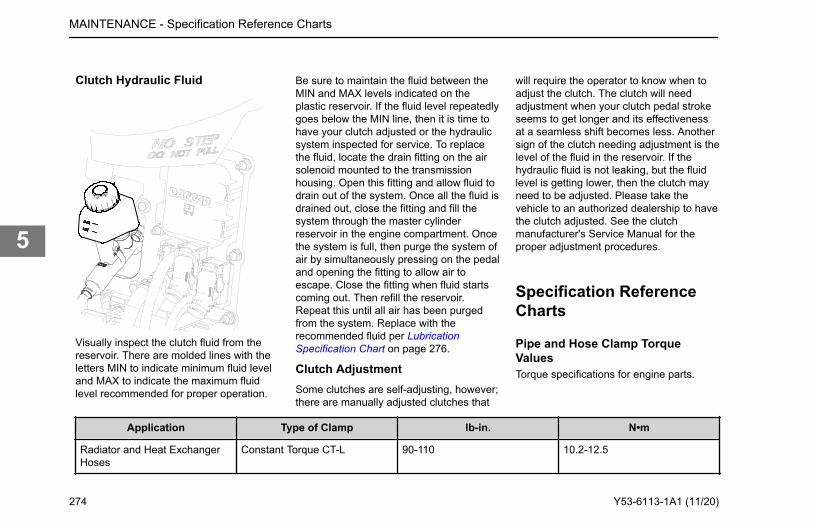
Clutch Hydraulic Fluid
Visually inspect the clutch fluid from thereservoir. There are molded lines with theletters MIN to indicate minimum fluid leveland MAX to indicate the maximum fluidlevel recommended for proper operation.
Be sure to maintain the fluid between theMIN and MAX levels indicated on theplastic reservoir. If the fluid level repeatedlygoes below the MIN line, then it is time tohave your clutch adjusted or the hydraulicsystem inspected for service. To replacethe fluid, locate the drain fitting on the airsolenoid mounted to the transmissionhousing. Open this fitting and allow fluid todrain out of the system. Once all the fluid isdrained out, close the fitting and fill thesystem through the master cylinderreservoir in the engine compartment. Oncethe system is full, then purge the system ofair by simultaneously pressing on the pedaland opening the fitting to allow air toescape. Close the fitting when fluid startscoming out. Then refill the reservoir.Repeat this until all air has been purgedfrom the system. Replace with therecommended fluid per LubricationSpecification Chart on page 276.
Clutch AdjustmentSome clutches are self-adjusting, however;there are manually adjusted clutches that
will require the operator to know when toadjust the clutch. The clutch will needadjustment when your clutch pedal strokeseems to get longer and its effectivenessat a seamless shift becomes less. Anothersign of the clutch needing adjustment is thelevel of the fluid in the reservoir. If thehydraulic fluid is not leaking, but the fluidlevel is getting lower, then the clutch mayneed to be adjusted. Please take thevehicle to an authorized dealership to havethe clutch adjusted. See the clutchmanufacturer's Service Manual for theproper adjustment procedures.
Specification ReferenceCharts
Pipe and Hose Clamp TorqueValuesTorque specifications for engine parts.
Application Type of Clamp lb-in. N•m
Radiator and Heat ExchangerHoses
Constant Torque CT-L 90-110 10.2-12.5
MAINTENANCE - Specification Reference Charts
274 Y53-6113-1A1 (11/20)
5
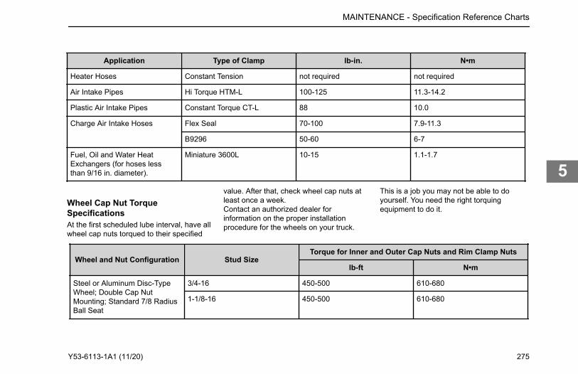
Application Type of Clamp lb-in. N•m
Heater Hoses Constant Tension not required not required
Air Intake Pipes Hi Torque HTM-L 100-125 11.3-14.2
Plastic Air Intake Pipes Constant Torque CT-L 88 10.0
Charge Air Intake Hoses Flex Seal 70-100 7.9-11.3
B9296 50-60 6-7
Fuel, Oil and Water HeatExchangers (for hoses lessthan 9/16 in. diameter).
Miniature 3600L 10-15 1.1-1.7
Wheel Cap Nut TorqueSpecificationsAt the first scheduled lube interval, have allwheel cap nuts torqued to their specified
value. After that, check wheel cap nuts atleast once a week.Contact an authorized dealer forinformation on the proper installationprocedure for the wheels on your truck.
This is a job you may not be able to doyourself. You need the right torquingequipment to do it.
Wheel and Nut Configuration Stud SizeTorque for Inner and Outer Cap Nuts and Rim Clamp Nuts
lb-ft N•m
Steel or Aluminum Disc-TypeWheel; Double Cap NutMounting; Standard 7/8 RadiusBall Seat
3/4-16 450-500 610-680
1-1/8-16 450-500 610-680
MAINTENANCE - Specification Reference Charts
Y53-6113-1A1 (11/20) 275
5
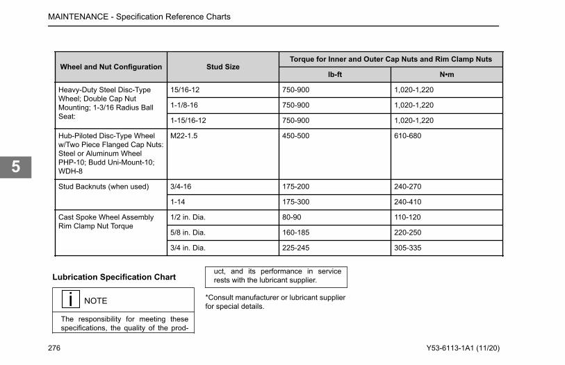
Wheel and Nut Configuration Stud SizeTorque for Inner and Outer Cap Nuts and Rim Clamp Nuts
lb-ft N•m
Heavy-Duty Steel Disc-TypeWheel; Double Cap NutMounting; 1-3/16 Radius BallSeat:
15/16-12 750-900 1,020-1,220
1-1/8-16 750-900 1,020-1,220
1-15/16-12 750-900 1,020-1,220
Hub-Piloted Disc-Type Wheelw/Two Piece Flanged Cap Nuts:Steel or Aluminum WheelPHP-10; Budd Uni-Mount-10;WDH-8
M22-1.5 450-500 610-680
Stud Backnuts (when used) 3/4-16 175-200 240-270
1-14 175-300 240-410
Cast Spoke Wheel AssemblyRim Clamp Nut Torque
1/2 in. Dia. 80-90 110-120
5/8 in. Dia. 160-185 220-250
3/4 in. Dia. 225-245 305-335
Lubrication Specification Chart
NOTE
The responsibility for meeting thesespecifications, the quality of the prod-
uct, and its performance in servicerests with the lubricant supplier.
*Consult manufacturer or lubricant supplierfor special details.
MAINTENANCE - Specification Reference Charts
276 Y53-6113-1A1 (11/20)
5
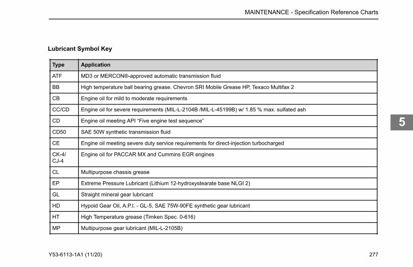
Lubricant Symbol Key
Type Application
ATF MD3 or MERCON®-approved automatic transmission fluid
BB High temperature ball bearing grease. Chevron SRI Mobile Grease HP, Texaco Multifax 2
CB Engine oil for mild to moderate requirements
CC/CD Engine oil for severe requirements (MIL-L-2104B /MIL-L-45199B) w/ 1.85 % max. sulfated ash
CD Engine oil meeting API “Five engine test sequence”
CD50 SAE 50W synthetic transmission fluid
CE Engine oil meeting severe duty service requirements for direct-injection turbocharged
CK-4/CJ-4
Engine oil for PACCAR MX and Cummins EGR engines
CL Multipurpose chassis grease
EP Extreme Pressure Lubricant (Lithium 12-hydroxystearate base NLGI 2)
GL Straight mineral gear lubricant
HD Hypoid Gear Oil, A.P.I. - GL-5, SAE 75W-90FE synthetic gear lubricant
HT High Temperature grease (Timken Spec. 0-616)
MP Multipurpose gear lubricant (MIL-L-2105B)
MAINTENANCE - Specification Reference Charts
Y53-6113-1A1 (11/20) 277
5
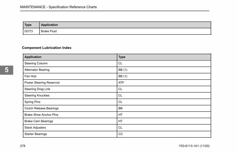
Type Application
DOT3 Brake Fluid
Component Lubrication Index
Application Type
Steering Column CL
Alternator Bearing BB (1)
Fan Hub BB (1)
Power Steering Reservoir ATF
Steering Drag Link CL
Steering Knuckles CL
Spring Pins CL
Clutch Release Bearings BB
Brake Shoe Anchor Pins HT
Brake Cam Bearings HT
Slack Adjusters CL
Starter Bearings CC
MAINTENANCE - Specification Reference Charts
278 Y53-6113-1A1 (11/20)
5
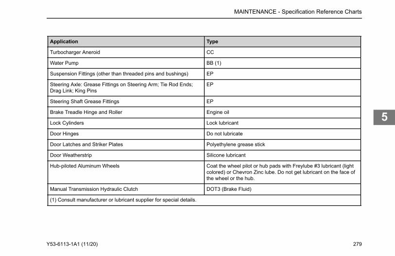
Application Type
Turbocharger Aneroid CC
Water Pump BB (1)
Suspension Fittings (other than threaded pins and bushings) EP
Steering Axle: Grease Fittings on Steering Arm; Tie Rod Ends;Drag Link; King Pins
EP
Steering Shaft Grease Fittings EP
Brake Treadle Hinge and Roller Engine oil
Lock Cylinders Lock lubricant
Door Hinges Do not lubricate
Door Latches and Striker Plates Polyethylene grease stick
Door Weatherstrip Silicone lubricant
Hub-piloted Aluminum Wheels Coat the wheel pilot or hub pads with Freylube #3 lubricant (lightcolored) or Chevron Zinc lube. Do not get lubricant on the face ofthe wheel or the hub.
Manual Transmission Hydraulic Clutch DOT3 (Brake Fluid)
(1) Consult manufacturer or lubricant supplier for special details.
MAINTENANCE - Specification Reference Charts
Y53-6113-1A1 (11/20) 279
5
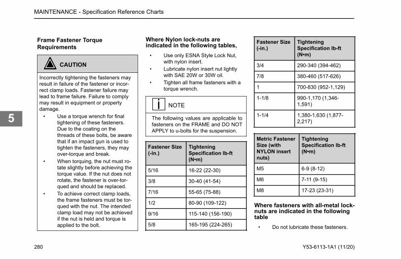
Frame Fastener TorqueRequirements
CAUTION
Incorrectly tightening the fasteners mayresult in failure of the fastener or incor-rect clamp loads. Fastener failure maylead to frame failure. Failure to complymay result in equipment or propertydamage.
• Use a torque wrench for finaltightening of these fasteners.Due to the coating on thethreads of these bolts, be awarethat if an impact gun is used totighten the fasteners, they mayover-torque and break.
• When torquing, the nut must ro-tate slightly before achieving thetorque value. If the nut does notrotate, the fastener is over-tor-qued and should be replaced.
• To achieve correct clamp loads,the frame fasteners must be tor-qued with the nut. The intendedclamp load may not be achievedif the nut is held and torque isapplied to the bolt.
Where Nylon lock-nuts areindicated in the following tables,
• Use only ESNA Style Lock Nut,with nylon insert.
• Lubricate nylon insert nut lightlywith SAE 20W or 30W oil.
• Tighten all frame fasteners with atorque wrench.
NOTE
The following values are applicable tofasteners on the FRAME and DO NOTAPPLY to u-bolts for the suspension.
Fastener Size(-in.)
TighteningSpecification lb-ft(N•m)
5/16 16-22 (22-30)
3/8 30-40 (41-54)
7/16 55-65 (75-88)
1/2 80-90 (109-122)
9/16 115-140 (156-190)
5/8 165-195 (224-265)
Fastener Size(-in.)
TighteningSpecification lb-ft(N•m)
3/4 290-340 (394-462)
7/8 380-460 (517-626)
1 700-830 (952-1,129)
1-1/8 990-1,170 (1,346-1,591)
1-1/4 1,380-1,630 (1,877-2,217)
Metric FastenerSize (withNYLON insertnuts)
TighteningSpecification lb-ft(N•m)
M5 6-9 (8-12)
M6 7-11 (9-15)
M8 17-23 (23-31)
Where fasteners with all-metal lock-nuts are indicated in the followingtable
• Do not lubricate these fasteners.
MAINTENANCE - Specification Reference Charts
280 Y53-6113-1A1 (11/20)
5
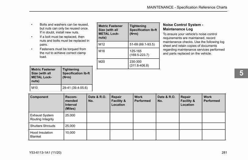
• Bolts and washers can be reused,but nuts can only be reused once.If in doubt, install new nuts.
• If a bolt must be replaced, thennuts and bolts must be replaced inpairs.
• Fasteners must be torqued fromthe nut to achieve correct clampload.
Metric FastenerSize (with allMETAL Lock-nuts)
TighteningSpecification lb-ft(N•m)
M10 29-41 (39.4-55.6)
Metric FastenerSize (with allMETAL Lock-nuts)
TighteningSpecification lb-ft(N•m)
M12 51-69 (69.1-93.5)
M16 125-165(169.5-223.7)
M20 230-300(311.8-406.8)
Noise Control System -Maintenance LogTo ensure your vehicle's noise controlrequirements are maintained, recordmaintenance checks. Use the following logsheet and retain copies of documentsregarding maintenance services performedand parts replaced on the vehicle.
Component Recom-mendedInterval(Miles)
Date & R.O.No.
RepairFacility &Location
WorkPerformed
Date & R.O.No.
RepairFacility &Location
WorkPerformed
Exhaust SystemRouting Integrity
25,000
Shutters Shrouds 25,000
Hood InsulationBlanket
10,000
MAINTENANCE - Specification Reference Charts
Y53-6113-1A1 (11/20) 281
5
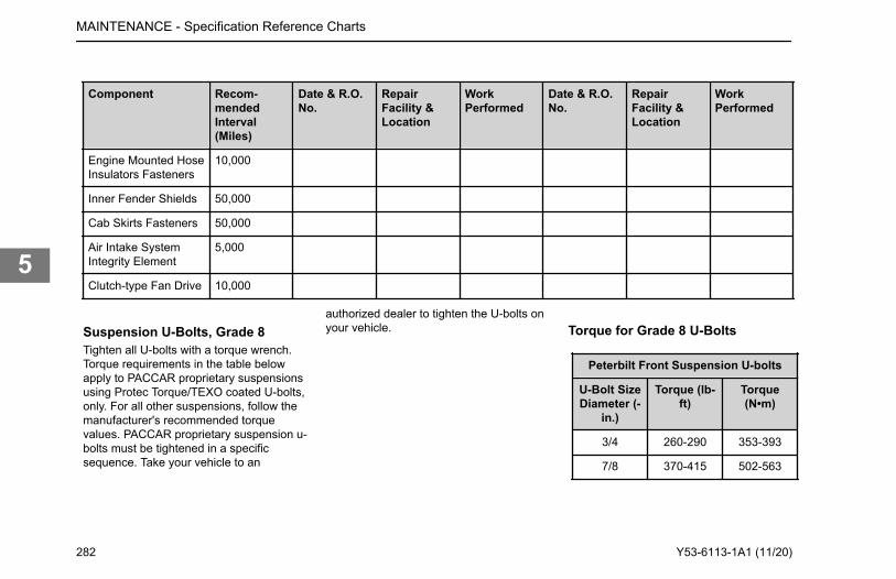
Component Recom-mendedInterval(Miles)
Date & R.O.No.
RepairFacility &Location
WorkPerformed
Date & R.O.No.
RepairFacility &Location
WorkPerformed
Engine Mounted HoseInsulators Fasteners
10,000
Inner Fender Shields 50,000
Cab Skirts Fasteners 50,000
Air Intake SystemIntegrity Element
5,000
Clutch-type Fan Drive 10,000
Suspension U-Bolts, Grade 8Tighten all U-bolts with a torque wrench.Torque requirements in the table belowapply to PACCAR proprietary suspensionsusing Protec Torque/TEXO coated U-bolts,only. For all other suspensions, follow themanufacturer's recommended torquevalues. PACCAR proprietary suspension u-bolts must be tightened in a specificsequence. Take your vehicle to an
authorized dealer to tighten the U-bolts onyour vehicle. Torque for Grade 8 U-Bolts
Peterbilt Front Suspension U-bolts
U-Bolt SizeDiameter (-
in.)
Torque (lb-ft)
Torque(N•m)
3/4 260-290 353-393
7/8 370-415 502-563
MAINTENANCE - Specification Reference Charts
282 Y53-6113-1A1 (11/20)
5
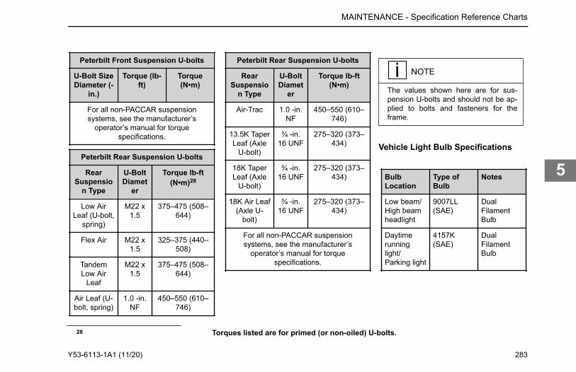
Peterbilt Front Suspension U-bolts
U-Bolt SizeDiameter (-
in.)
Torque (lb-ft)
Torque(N•m)
For all non-PACCAR suspensionsystems, see the manufacturer’s
operator’s manual for torquespecifications.
Peterbilt Rear Suspension U-bolts
RearSuspensio
n Type
U-BoltDiamet
er
Torque lb-ft(N•m)28
Low AirLeaf (U-bolt,
spring)
M22 x1.5
375–475 (508–644)
Flex Air M22 x1.5
325–375 (440–508)
TandemLow Air
Leaf
M22 x1.5
375–475 (508–644)
Air Leaf (U-bolt, spring)
1.0 -in.NF
450–550 (610–746)
Peterbilt Rear Suspension U-bolts
RearSuspensio
n Type
U-BoltDiamet
er
Torque lb-ft(N•m)
Air-Trac 1.0 -in.NF
450–550 (610–746)
13.5K TaperLeaf (Axle
U-bolt)
¾ -in.16 UNF
275–320 (373–434)
18K TaperLeaf (Axle
U-bolt)
¾ -in.16 UNF
275–320 (373–434)
18K Air Leaf(Axle U-
bolt)
¾ -in.16 UNF
275–320 (373–434)
For all non-PACCAR suspensionsystems, see the manufacturer’s
operator’s manual for torquespecifications.
NOTE
The values shown here are for sus-pension U-bolts and should not be ap-plied to bolts and fasteners for theframe.
Vehicle Light Bulb Specifications
BulbLocation
Type ofBulb
Notes
Low beam/High beamheadlight
9007LL(SAE)
DualFilamentBulb
Daytimerunninglight/Parking light
4157K(SAE)
DualFilamentBulb
28 Torques listed are for primed (or non-oiled) U-bolts.
MAINTENANCE - Specification Reference Charts
Y53-6113-1A1 (11/20) 283
5
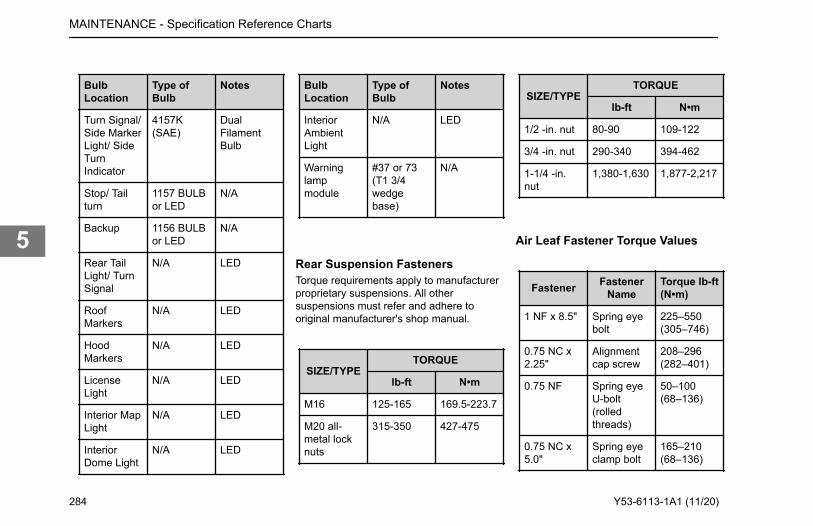
BulbLocation
Type ofBulb
Notes
Turn Signal/Side MarkerLight/ SideTurnIndicator
4157K(SAE)
DualFilamentBulb
Stop/ Tailturn
1157 BULBor LED
N/A
Backup 1156 BULBor LED
N/A
Rear TailLight/ TurnSignal
N/A LED
RoofMarkers
N/A LED
HoodMarkers
N/A LED
LicenseLight
N/A LED
Interior MapLight
N/A LED
InteriorDome Light
N/A LED
BulbLocation
Type ofBulb
Notes
InteriorAmbientLight
N/A LED
Warninglampmodule
#37 or 73(T1 3/4wedgebase)
N/A
Rear Suspension FastenersTorque requirements apply to manufacturerproprietary suspensions. All othersuspensions must refer and adhere tooriginal manufacturer's shop manual.
SIZE/TYPETORQUE
lb-ft N•m
M16 125-165 169.5-223.7
M20 all-metal locknuts
315-350 427-475
SIZE/TYPETORQUE
lb-ft N•m
1/2 -in. nut 80-90 109-122
3/4 -in. nut 290-340 394-462
1-1/4 -in.nut
1,380-1,630 1,877-2,217
Air Leaf Fastener Torque Values
Fastener FastenerName
Torque lb-ft(N•m)
1 NF x 8.5" Spring eyebolt
225–550(305–746)
0.75 NC x2.25"
Alignmentcap screw
208–296(282–401)
0.75 NF Spring eyeU-bolt(rolledthreads)
50–100(68–136)
0.75 NC x5.0"
Spring eyeclamp bolt
165–210(68–136)
MAINTENANCE - Specification Reference Charts
284 Y53-6113-1A1 (11/20)
5
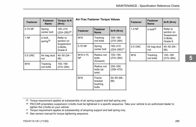
Fastener FastenerName
Torque lb-ft(N•m)
0.75 NF Springcenter bolt
165–210(224–285)29
1 NF U-bolt,spring30
Refer tosection onSuspensionU-Bolts,Grade 8.
0.5 UNC Air bag studnut
40–50 (54–68)
M16 Trackingrod bolts
155–195(210–264)
Air-Trac Fastener Torque Values
Fastener FastenerName lb•ft (N•m)
M16 Trackingrod bolts
155–195(210–264)
0.75 NF Springcenter bolt
165–210(224–285)31
M16 0.75NF
Radius rodbolts(forward)
155–195(210–264)
Radius rodbolts (ataxle)
250–350(339–475)
M16 Framebracketbushingbolts
50–65 (68–88)
Fastener FastenerName lb•ft (N•m)
1.0 NF U-bolt32 Refer tosection onSuspensionU-Bolts,Grade 8.
0.5 UNC Air bag studnut
40–50 (54–68)
M16 Trackingrod bolts
155–195(210–264)
29 Torque requirement applies at subassembly of air spring support and leaf spring only.30 PACCAR proprietary suspension U-bolts must be tightened in a specific sequence. Take your vehicle to an authorized dealer to
tighten the U-bolts on your vehicle.31 Torque requirement applies at subassembly of airspring support and leaf spring only.32 See owners manual for torque tightening sequence.
MAINTENANCE - Specification Reference Charts
Y53-6113-1A1 (11/20) 285
5
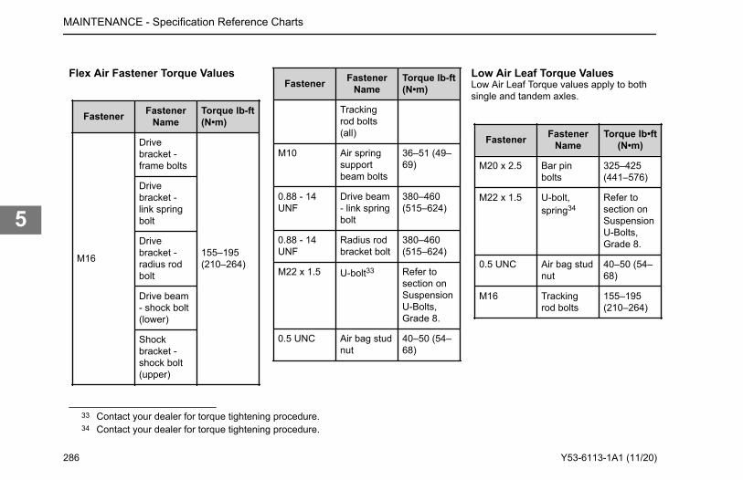
Flex Air Fastener Torque Values
Fastener FastenerName
Torque lb-ft(N•m)
M16
Drivebracket -frame bolts
155–195(210–264)
Drivebracket -link springbolt
Drivebracket -radius rodbolt
Drive beam- shock bolt(lower)
Shockbracket -shock bolt(upper)
Fastener FastenerName
Torque lb-ft(N•m)
Trackingrod bolts(all)
M10 Air springsupportbeam bolts
36–51 (49–69)
0.88 - 14UNF
Drive beam- link springbolt
380–460(515–624)
0.88 - 14UNF
Radius rodbracket bolt
380–460(515–624)
M22 x 1.5 U-bolt33 Refer tosection onSuspensionU-Bolts,Grade 8.
0.5 UNC Air bag studnut
40–50 (54–68)
Low Air Leaf Torque ValuesLow Air Leaf Torque values apply to bothsingle and tandem axles.
Fastener FastenerName
Torque lb•ft(N•m)
M20 x 2.5 Bar pinbolts
325–425(441–576)
M22 x 1.5 U-bolt,spring34
Refer tosection onSuspensionU-Bolts,Grade 8.
0.5 UNC Air bag studnut
40–50 (54–68)
M16 Trackingrod bolts
155–195(210–264)
33 Contact your dealer for torque tightening procedure.34 Contact your dealer for torque tightening procedure.
MAINTENANCE - Specification Reference Charts
286 Y53-6113-1A1 (11/20)
5
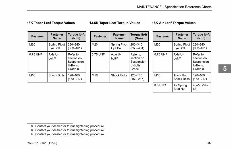
18K Taper Leaf Torque Values
Fastener FastenerName
Torque lb•ft(N•m)
M20 Spring PivotEye Bolt
260–340(353–461)
0.75 UNF Axle U-bolt35
Refer tosection onSuspensionU-Bolts,Grade 8.
M16 Shock Bolts 120–160(163–217)
13.5K Taper Leaf Torque Values
Fastener FastenerName
Torque lb•ft(N•m)
M20 Spring PivotEye Bolt
260–340(353–461)
0.75 UNF Axle U-bolt36
Refer tosection onSuspensionU-Bolts,Grade 8.
M16 Shock Bolts 120–160(163–217)
18K Air Leaf Torque Values
Fastener FastenerName
Torque lb•ft(N•m)
M20 Spring PivotEye Bolt
260–340(353–461)
0.75 UNF Axle U-bolt37
Refer tosection onSuspensionU-Bolts,Grade 8.
M16 Track Rod,Shock Bolts
120–160(163–217)
0.5 UNC Air SpringStud Nut
40–50 (54–68)
35 Contact your dealer for torque tightening procedure.36 Contact your dealer for torque tightening procedure.37 Contact your dealer for torque tightening procedure.
MAINTENANCE - Specification Reference Charts
Y53-6113-1A1 (11/20) 287
5
Chapter 6 | INFORMATIONConsumer Information.......................................................................................................................289Vehicle Identification Labels..............................................................................................................289Clean Idle..........................................................................................................................................292Greenhouse Gas Certified Configuration..........................................................................................293Vehicle Emissions Limited Express Warranty................................................................................... 296
INFORMATION -
288 Y53-6113-1A1 (11/20)
6
Consumer InformationHow to Order Replacement PartsReplacement parts may be obtained froman authorized dealership. When you order,it is IMPORTANT that you have thefollowing information ready:
• Your name and address• Serial number of the truck• The name of the part you need• The name and number of the
component for which the part isrequired
• The quantity of parts you need• How you want your order shipped
remedy campaign. However, NHTSAcannot get involved in individual problemsbetween you, your dealer, and vehiclemanufacturer. Contacting NHTSA ispossible through telephone, written mailand email. NHTSA also has a websitewhere you can input your commentsdirectly to them on the web. Please useany of the four ways to contact NHTSA:
Toll Free 1-888-327-4236 (800-424-9153TTY) 8:00 a.m. to 10:00 p.m. ESTMonday-Friday
Office of Defects Investigations/CRDNVS-216 1200 New Jersey Ave. SEWashington, D.C. 20590
www.safercar.gov
email: [email protected]
Transport CanadaCanadian customers who wish to report asafety-related defect to Transport Canada,Defect Investigations and Recalls, maytelephone the toll free hotline1-800-333-0510, or contact TransportCanada by mail at:
Transport Canada, ASFAD Place de VilleTower C 330 Sparks St. Ottawa, ON K1A0N5For additional road safety information,please visit the Road Safety website at:http://www.tc.gc.ca
Vehicle IdentificationLabelsEach vehicle completed by Peterbilt MotorsCompany uses a vehicle identificationnumber (VIN) that contains the model yeardesignation of your vehicle. The practice isin compliance with 49 CFR 565, Code ofFederal Regulations.The full, 17-digit VIN is located on theWeight Rating Data Label. The label islocated on the driver's side door edge oron the driver's side door frame.
INFORMATION - Consumer Information
National Highway Traffic and Safety Administration (NHTSA)If you believe that your vehicle has a defect, which could cause a crash or could cause death or personal injury, you should immediately inform the National Highway Traffic Safety Administration (NHTSA) in addition to notifying the vehicle manufacturer. If NHTSA receives similar complaints, it may open an investigation, and if it finds that a safety defect exists in a group of vehicles, it may order a recall and
Y53-6113-1A1 (11/20) 289
6
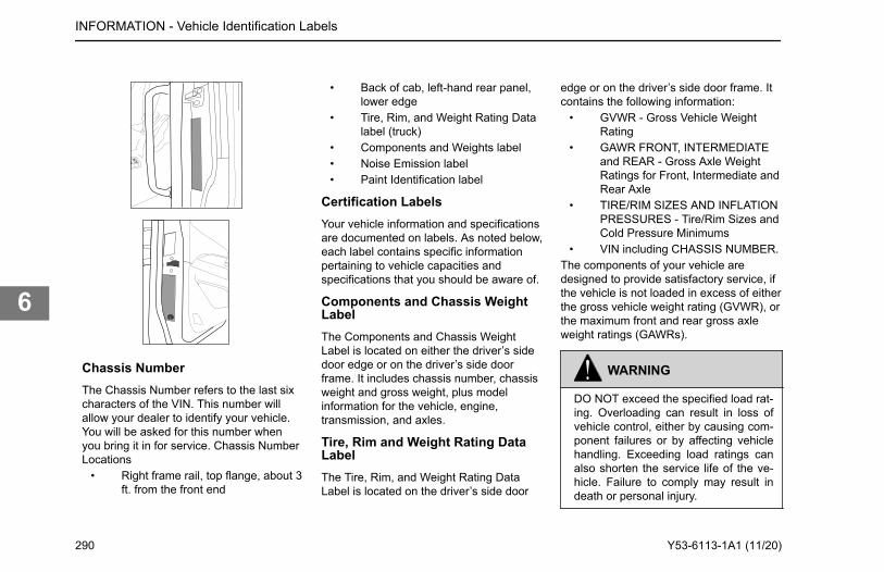
Chassis NumberThe Chassis Number refers to the last sixcharacters of the VIN. This number willallow your dealer to identify your vehicle.You will be asked for this number whenyou bring it in for service. Chassis NumberLocations
• Right frame rail, top flange, about 3ft. from the front end
• Back of cab, left-hand rear panel,lower edge
• Tire, Rim, and Weight Rating Datalabel (truck)
• Components and Weights label• Noise Emission label• Paint Identification label
Certification LabelsYour vehicle information and specificationsare documented on labels. As noted below,each label contains specific informationpertaining to vehicle capacities andspecifications that you should be aware of.
Components and Chassis WeightLabelThe Components and Chassis WeightLabel is located on either the driver’s sidedoor edge or on the driver’s side doorframe. It includes chassis number, chassisweight and gross weight, plus modelinformation for the vehicle, engine,transmission, and axles.
Tire, Rim and Weight Rating DataLabelThe Tire, Rim, and Weight Rating DataLabel is located on the driver’s side door
edge or on the driver’s side door frame. Itcontains the following information:
• GVWR - Gross Vehicle WeightRating
• GAWR FRONT, INTERMEDIATEand REAR - Gross Axle WeightRatings for Front, Intermediate andRear Axle
• TIRE/RIM SIZES AND INFLATIONPRESSURES - Tire/Rim Sizes andCold Pressure Minimums
• VIN including CHASSIS NUMBER.The components of your vehicle aredesigned to provide satisfactory service, ifthe vehicle is not loaded in excess of eitherthe gross vehicle weight rating (GVWR), orthe maximum front and rear gross axleweight ratings (GAWRs).
WARNING
DO NOT exceed the specified load rat-ing. Overloading can result in loss ofvehicle control, either by causing com-ponent failures or by affecting vehiclehandling. Exceeding load ratings canalso shorten the service life of the ve-hicle. Failure to comply may result indeath or personal injury.
INFORMATION - Vehicle Identification Labels
290 Y53-6113-1A1 (11/20)
6
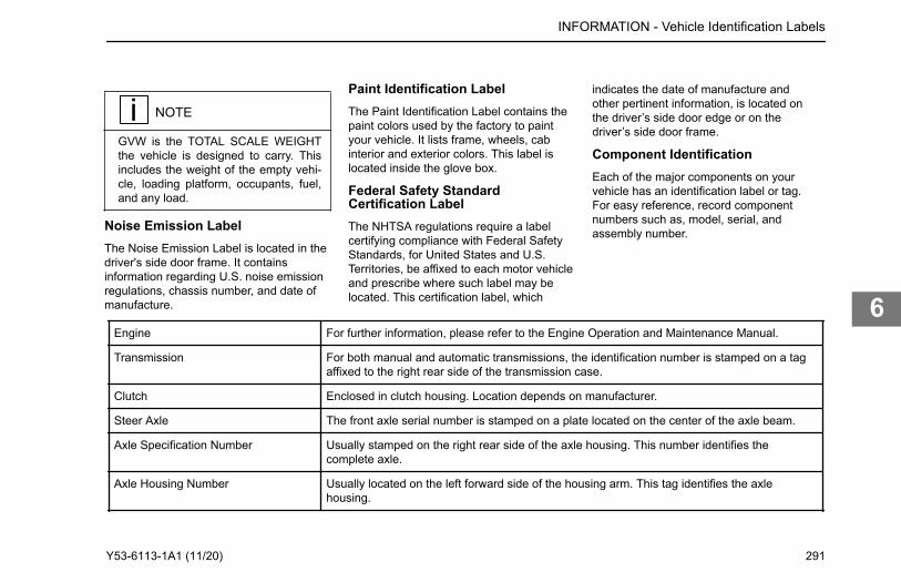
NOTE
GVW is the TOTAL SCALE WEIGHTthe vehicle is designed to carry. Thisincludes the weight of the empty vehi-cle, loading platform, occupants, fuel,and any load.
Noise Emission LabelThe Noise Emission Label is located in thedriver's side door frame. It containsinformation regarding U.S. noise emissionregulations, chassis number, and date ofmanufacture.
Paint Identification LabelThe Paint Identification Label contains thepaint colors used by the factory to paintyour vehicle. It lists frame, wheels, cabinterior and exterior colors. This label islocated inside the glove box.
Federal Safety StandardCertification LabelThe NHTSA regulations require a labelcertifying compliance with Federal SafetyStandards, for United States and U.S.Territories, be affixed to each motor vehicleand prescribe where such label may belocated. This certification label, which
indicates the date of manufacture andother pertinent information, is located onthe driver’s side door edge or on thedriver’s side door frame.
Component IdentificationEach of the major components on yourvehicle has an identification label or tag.For easy reference, record componentnumbers such as, model, serial, andassembly number.
Engine For further information, please refer to the Engine Operation and Maintenance Manual.
Transmission For both manual and automatic transmissions, the identification number is stamped on a tagaffixed to the right rear side of the transmission case.
Clutch Enclosed in clutch housing. Location depends on manufacturer.
Steer Axle The front axle serial number is stamped on a plate located on the center of the axle beam.
Axle Specification Number Usually stamped on the right rear side of the axle housing. This number identifies thecomplete axle.
Axle Housing Number Usually located on the left forward side of the housing arm. This tag identifies the axlehousing.
INFORMATION - Vehicle Identification Labels
Y53-6113-1A1 (11/20) 291
6
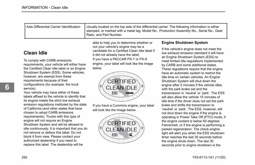
Axle Differential Carrier Identification Usually located on the top side of the differential carrier. The following information is eitherstamped, or marked with a metal tag: Model No., Production Assembly No., Serial No., GearRatio, and Part Number.
Clean IdleTo comply with CARB emissionsrequirements, your vehicle will either havethe Certified Clean Idle label or an EngineShutdown System (ESS). Some vehicles,however, are exempt from theserequirements because of theirconfigurations (for example: fire truckservice).Your vehicle may have either of theselabels affixed to the vehicle to identify thatits engine meets the strict low exhaustemission regulations instituted by the stateof California (and other states that havechosen to adopt CARB emissionsrequirements). Trucks with this type ofengine will not require an EngineShutdown System and will be allowed toidle continuously. It is important that you donot remove or deface this label. Do notblock it from view. Please contact yourauthorized dealership if you need toreplace this label. The dealership will be
able to help you to determine whether ornot your vehicle's engine may be acandidate for a Certified Clean Idle label ifit did not already have the label.If you have a PACCAR PX-7 or PX-9engine, your label will look like the imagebelow.
If you have a Cummins engine, your labelwill look like the image below.
Engine Shutdown SystemIf the vehicle’s engine does not meet thelow exhaust emission standard it will havean Engine Shutdown System (ESS) tomeet limited idle regulations implementedby CARB and some additional states.These regulations require that the enginehave an automatic system to restrict theidle time on certain vehicles. An EngineShutdown System will shut down theengine after 5 minutes if the vehicle idleswith the park brake set and thetransmission in ‘neutral’ or ‘park’. The ESSwill also allow the vehicle 15 minutes ofidle time if the driver does not set the parkbrake and shifts the transmission to‘neutral’ or ‘park’. The ESS, however, willnot shut down the engine if the engine isoperating in Power Take Off (PTO) mode, ifthe engine coolant is below 60 degreesFahrenheit, or if the engine is performing aparked regeneration. The check enginelight will alert you when the ESS shutdowntimer reaches the last 30 seconds beforethe engine shuts down. The last 30seconds prior to engine shutdown is the
INFORMATION - Clean Idle
292 Y53-6113-1A1 (11/20)
6
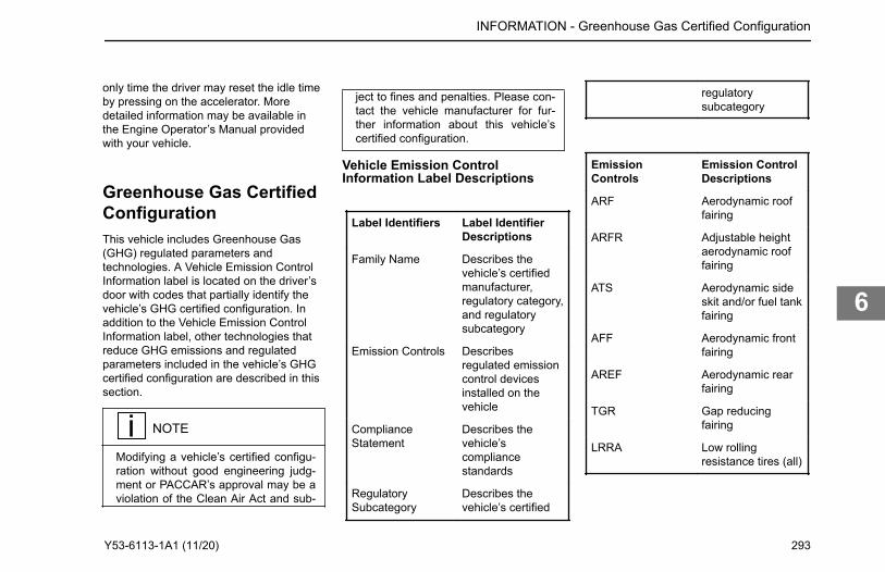
only time the driver may reset the idle timeby pressing on the accelerator. Moredetailed information may be available inthe Engine Operator’s Manual providedwith your vehicle.
Greenhouse Gas CertifiedConfigurationThis vehicle includes Greenhouse Gas(GHG) regulated parameters andtechnologies. A Vehicle Emission ControlInformation label is located on the driver’sdoor with codes that partially identify thevehicle’s GHG certified configuration. Inaddition to the Vehicle Emission ControlInformation label, other technologies thatreduce GHG emissions and regulatedparameters included in the vehicle’s GHGcertified configuration are described in thissection.
NOTE
Modifying a vehicle’s certified configu-ration without good engineering judg-ment or PACCAR’s approval may be aviolation of the Clean Air Act and sub-
ject to fines and penalties. Please con-tact the vehicle manufacturer for fur-ther information about this vehicle’scertified configuration.
Vehicle Emission ControlInformation Label Descriptions
Label Identifiers Label IdentifierDescriptions
Family Name Describes thevehicle’s certifiedmanufacturer,regulatory category,and regulatorysubcategory
Emission Controls Describesregulated emissioncontrol devicesinstalled on thevehicle
ComplianceStatement
Describes thevehicle’scompliancestandards
RegulatorySubcategory
Describes thevehicle’s certified
regulatorysubcategory
EmissionControls
Emission ControlDescriptions
ARF Aerodynamic rooffairing
ARFR Adjustable heightaerodynamic rooffairing
ATS Aerodynamic sideskit and/or fuel tankfairing
AFF Aerodynamic frontfairing
AREF Aerodynamic rearfairing
TGR Gap reducingfairing
LRRA Low rollingresistance tires (all)
INFORMATION - Greenhouse Gas Certified Configuration
Y53-6113-1A1 (11/20) 293
6
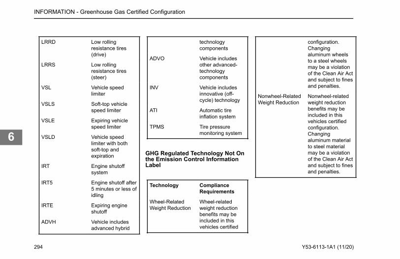
LRRD Low rollingresistance tires(drive)
LRRS Low rollingresistance tires(steer)
VSL Vehicle speedlimiter
VSLS Soft-top vehiclespeed limiter
VSLE Expiring vehiclespeed limiter
VSLD Vehicle speedlimiter with bothsoft-top andexpiration
IRT Engine shutoffsystem
IRT5 Engine shutoff after5 minutes or less ofidling
IRTE Expiring engineshutoff
ADVH Vehicle includesadvanced hybrid
technologycomponents
ADVO Vehicle includesother advanced-technologycomponents
INV Vehicle includesinnovative (off-cycle) technology
ATI Automatic tireinflation system
TPMS Tire pressuremonitoring system
GHG Regulated Technology Not Onthe Emission Control InformationLabel
Technology ComplianceRequirements
Wheel-RelatedWeight Reduction
Wheel-relatedweight reductionbenefits may beincluded in thisvehicles certified
configuration.Changingaluminum wheelsto a steel wheelsmay be a violationof the Clean Air Actand subject to finesand penalties.
Nonwheel-RelatedWeight Reduction
Nonwheel-relatedweight reductionbenefits may beincluded in thisvehicles certifiedconfiguration.Changingaluminum materialto steel materialmay be a violationof the Clean Air Actand subject to finesand penalties.
INFORMATION - Greenhouse Gas Certified Configuration
294 Y53-6113-1A1 (11/20)
6
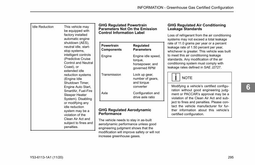
Idle Reduction This vehicle maybe equipped withfactory installedautomatic engineshutdown (AES),neutral idle, start-stop systems,intelligent controls(Predictive CruiseControl and NeutralCoast), orextended idlereduction systems(Engine IdleShutdown Timer,Engine Auto Start,SmartAir, Fuel-FireSleeper HeaterSystem). Disablingor modifying anyidle reductionsystem may be aviolation of theClean Air Act andsubject to fines andpenalties.
GHG Regulated PowertrainParameters Not On the EmissionControl Information Label
PowertrainComponents
RegulatedParameters
Engine Engine idle speed,torque,horsepower, andgoverned RPM
Transmission Lock up gear,number of gears,and torqueconverter
Axle Configuration anddrive axle ratio
GHG Regulated AerodynamicPerformanceThe vehicle needs to stay in as-builtaerodynamic performance unless goodengineering judgment shows that themodification will improve safety or will notincrease greenhouse gases.
GHG Regulated Air ConditioningLeakage StandardsLoss of refrigerant from the air conditioningsystems may not exceed a total leakagerate of 11.0 grams per year or a percentleakage rate of 1.50 percent per year,whichever is greater. This vehicle was builtto meet this air conditioning leakagestandards. Any modification of the airconditioning system must comply withleakage rates defined in SAE J2727.
NOTE
Modifying a vehicle’s certified configu-ration without good engineering judg-ment or PACCAR’s approval may be aviolation of the Clean Air Act and sub-ject to fines and penalties. Please con-tact the vehicle manufacturer for fur-ther information about this vehicle’scertified configuration.
INFORMATION - Greenhouse Gas Certified Configuration
Y53-6113-1A1 (11/20) 295
6
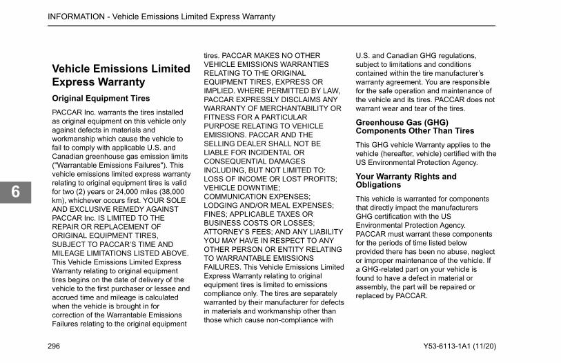
Vehicle Emissions LimitedExpress WarrantyOriginal Equipment TiresPACCAR Inc. warrants the tires installedas original equipment on this vehicle onlyagainst defects in materials andworkmanship which cause the vehicle tofail to comply with applicable U.S. andCanadian greenhouse gas emission limits("Warrantable Emissions Failures"). Thisvehicle emissions limited express warrantyrelating to original equipment tires is validfor two (2) years or 24,000 miles (38,000km), whichever occurs first. YOUR SOLEAND EXCLUSIVE REMEDY AGAINSTPACCAR Inc. IS LIMITED TO THEREPAIR OR REPLACEMENT OFORIGINAL EQUIPMENT TIRES,SUBJECT TO PACCAR’S TIME ANDMILEAGE LIMITATIONS LISTED ABOVE.This Vehicle Emissions Limited ExpressWarranty relating to original equipmenttires begins on the date of delivery of thevehicle to the first purchaser or lessee andaccrued time and mileage is calculatedwhen the vehicle is brought in forcorrection of the Warrantable EmissionsFailures relating to the original equipment
tires. PACCAR MAKES NO OTHERVEHICLE EMISSIONS WARRANTIESRELATING TO THE ORIGINALEQUIPMENT TIRES, EXPRESS ORIMPLIED. WHERE PERMITTED BY LAW,PACCAR EXPRESSLY DISCLAIMS ANYWARRANTY OF MERCHANTABILITY ORFITNESS FOR A PARTICULARPURPOSE RELATING TO VEHICLEEMISSIONS. PACCAR AND THESELLING DEALER SHALL NOT BELIABLE FOR INCIDENTAL ORCONSEQUENTIAL DAMAGESINCLUDING, BUT NOT LIMITED TO:LOSS OF INCOME OR LOST PROFITS;VEHICLE DOWNTIME;COMMUNICATION EXPENSES;LODGING AND/OR MEAL EXPENSES;FINES; APPLICABLE TAXES ORBUSINESS COSTS OR LOSSES;ATTORNEY’S FEES; AND ANY LIABILITYYOU MAY HAVE IN RESPECT TO ANYOTHER PERSON OR ENTITY RELATINGTO WARRANTABLE EMISSIONSFAILURES. This Vehicle Emissions LimitedExpress Warranty relating to originalequipment tires is limited to emissionscompliance only. The tires are separatelywarranted by their manufacturer for defectsin materials and workmanship other thanthose which cause non-compliance with
U.S. and Canadian GHG regulations,subject to limitations and conditionscontained within the tire manufacturer’swarranty agreement. You are responsiblefor the safe operation and maintenance ofthe vehicle and its tires. PACCAR does notwarrant wear and tear of the tires.
Greenhouse Gas (GHG)Components Other Than TiresThis GHG vehicle Warranty applies to thevehicle (hereafter, vehicle) certified with theUS Environmental Protection Agency.
Your Warranty Rights andObligationsThis vehicle is warranted for componentsthat directly impact the manufacturersGHG certification with the USEnvironmental Protection Agency.PACCAR must warrant these componentsfor the periods of time listed belowprovided there has been no abuse, neglector improper maintenance of the vehicle. Ifa GHG-related part on your vehicle isfound to have a defect in material orassembly, the part will be repaired orreplaced by PACCAR.
INFORMATION - Vehicle Emissions Limited Express Warranty
296 Y53-6113-1A1 (11/20)
6
component has failed due to abuse,neglect, improper maintenance,unapproved modifications (both physicalcomponents and computer programming)or using non-Original Equipmentreplacement parts. If there are anyquestions regarding these warranty rightsand responsibilities, please contact thevehicle OEM manufacturer at the customercenter telephone number provided with thevehicle operating instructions. Prior to theexpiration of the applicable warranty,Owner must give notice of any warrantedfailure to an authorized PACCAR dealerand deliver the vehicle to such facility forrepair. Owner is responsible for incidentalcosts such as: communication expenses,meals, lodging incurred by Owner oremployees of Owner as a result of aWarrantable Condition. Owner isresponsible for downtime expenses, cargodamage, fines, all applicable taxes, allbusiness costs, and other losses resultingfrom a Warrantable Condition. Owner isresponsible for maintaining all emissionsrelated engine and vehicle computerprogram settings in accordance withmanufacturer specifications. Thisresponsibility includes GHG specificsettings that may not be altered before theGHG-related expiration mileage has been
reached for each system. Owner isresponsible for maintaining all physicalparts related to GHG-regulations in the as-built configuration and in proper workingorder for the full regulatory useful life of435,000 miles (700,000 km) or 10 years forClass 8 vehicles, 185,000 miles (300,000km) or 10 years for Class 5-7.
Replacement PartsPACCAR recommends that any serviceparts used for maintenance, repair orreplacement of GHG components be newor genuine approved rebuilt parts andassemblies. The use of non-genuineengine or vehicle replacement parts thatare not equivalent to the PACCAR engineor OEM vehicle manufacturer’s originalpart specification as built from the factorymay impair the engine and vehicleemissions control system from working orfunctioning effectively, and may jeopardizeyour GHG warranty coverage. In addition,genuine vehicle or engine parts must bereplaced with the same material andfunction as the part assembled on thevehicle from the factory. The owner mayelect to have maintenance, replacement orrepair of the emission control partsperformed by a facility other than anauthorized PACCAR dealer and may elect
INFORMATION - Vehicle Emissions Limited Express Warranty
Manufacturer's Warranty CoverageThis warranty coverage is provided for five years or 100,000 miles (160,000 km), whichever occurs first, from the date of delivery of the vehicle to the first purchaser or first lessee. Where a Warrantable Condition exists, PACCAR will diagnose and repair the vehicle, parts and labor included, at no cost to the first purchaser or first lessee and each subsequent purchaser or lessee. This warranty does not override any extended warranty purchased to cover specific vehicle components.
Owner's Warranty ResponsibilitiesThe vehicle owner is responsible for performing required maintenance that is listed in your engine and vehicle Operator’s Manuals. The owner is responsible for presenting the vehicle to a service location as soon as a problem exists. Any warranty repairs should be completed in a reasonable amount of time. Retain all receipts covering maintenance on this equipment. PACCAR cannot deny warranty solely for the lack of receipts or for the failure to ensure the performance of all scheduled maintenance. PACCAR may deny warranty coverage if a vehicle
Y53-6113-1A1 (11/20) 297
6
to use parts other than new or genuineapproved rebuilt parts and assemblies forsuch maintenance, replacement or repair;however, the cost of such service or partsand subsequent failures resulting fromsuch service or parts may not be fullywarranted if the manufacturer determinesthat the replacement part is not of similarmaterial and function as the OEM partassembled to the vehicle at the factory.
PACCAR ResponsibilitiesThe warranty coverage begins when thevehicle is delivered to the first purchaser orfirst lessee. Repairs and service performedby any authorized PACCAR dealer usingnew or genuine approved rebuilt parts andassemblies will utilize replacement partsthat are selected and installed to supportthe GHG compliance certification.PACCAR will repair parts found byPACCAR to be defective without charge forparts or labor (including diagnosis whichresults in determination that there hasbeen a failure of a warranted part).
Warranty LimitationsSole and exclusive remedy againstPACCAR and the Selling Dealer arisingfrom the purchase and use of this vehicleis limited to the repair or replacement of
"warrantable failures", for replacementparts that are similar in material andfunction to OEM specifications and subjectto PACCAR’s time, mileage, and hourlimitations of the greenhouse gas warranty.The maximum time, mileage and hourlimitations of the warranty begin with theDate of Delivery to the first purchaser orfirst lessee. The accrued time, mileage, orhours is calculated when the vehicle isbrought in for correction of warrantablefailures. PACCAR is not responsible forfailures or damage resulting from whatPACCAR determines to be abuse, neglector uncontrollable acts of nature, including,but not limited to: damage due to accident;operation without adequate coolants orlubricants; overfueling; overspeeding; lackof maintenance of cooling, lubricating orintake systems; improper storage, starting,warm-up, run-in or shutdown practices;unauthorized modifications to the vehicleand its components. PACCAR is also notresponsible for failures caused by incorrectoil, fuel or diesel exhaust fluid or by water,dirt or other contaminants in the fuel, oil ordiesel exhaust fluid. Failure of replacementparts used in repairs due to the above non-warrantable conditions is not warrantable.This warranty is void if the vehicle isaltered with parts that do not meet the
material and functional specifications asmanufactured from the factory. Anyalterations to vehicle or engine computersettings will void GHG warranty andpotentially cause the vehicle to becomenon-compliant with EPA Clean Air ActGHG regulations. Any alterations to GHGspecific settings prior to the GHG relatedexpiration mileage for each system willvoid GHG warranty and potentially causethe vehicle to become non-compliant withEPA Clean Air Act GHG regulations. Thiswarranty is void if certain GHGcomponents are not properly maintainedand thus cannot perform to their designedcapability. PACCAR is not responsible forfailures resulting from improper repair orthe use of parts which are not genuineapproved parts. PACCAR is notresponsible for the material and labor costsof emission control parts and assembliesreplaced during Scheduled Maintenance ofthe engine as specified in PACCAROperator’s Manuals. THIS WARRANTY,TOGETHER WITH THE EXPRESSCOMMERCIAL WARRANTIES ARE THESOLE WARRANTIES MADE BY PACCARIN REGARD TO THIS VEHICLE. THISLIMITED GHG WARRANTY IS THE SOLEWARRANTY MADE BY PACCAR ANDTHE SELLING DEALER. EXCEPT FOR
INFORMATION - Vehicle Emissions Limited Express Warranty
298 Y53-6113-1A1 (11/20)
6
INFORMATION - Vehicle Emissions Limited Express Warranty
THE ABOVE LIMITED WARRANTY, PACCAR AND THE SELLING DEALER MAKE NO OTHER WARRANTIES, EXPRESS OR IMPLIED. PACCAR AND THE SELLING DEALER EXPRESSLY DISCLAIM ANY WARRANTY OF MERCHANTABILITY OR WARRANTY OF FITNESS FOR A PARTICULAR PURPOSE. PACCAR AND THE SELLING DEALER SHALL NOT BE LIABLE FOR INCIDENTAL OR CONSEQUENTIAL DAMAGES INCLUDING, BUT NOT LIMITED TO: LOSS OF INCOME OR LOST PROFITS; ENGINE OR VEHICLE DOWNTIME; THIRD PARTY DAMAGE, INCLUDING DAMAGE OR LOSS TO OTHER ENGINES, VEHICLES OR PROPERTY, ATTACHMENTS, TRAILERS AND CARGO; LOSS OR DAMAGE TO PERSONAL CONTENTS; COMMUNICATION EXPENSES; LODGING AND/OR MEAL EXPENSES; FINES; APPLICABLE TAXES OR BUSINESS COSTS OR LOSSES; ATTORNEYS’ FEES; AND ANY LIABILITY YOU MAY HAVE IN RESPECT TO ANY OTHER PERSON OR ENTITY.
Y53-6113-1A1 (11/20) 299
6
GlossaryAnti-lock Braking System - A federally mandated anti-skid braking device used on cars and trucks.
Low Voltage Disconnect - An electronic system that will disconnect or turn off electrical systems when a preset voltage is reached on the batteries caused by too much electrical drain
from appliances or heaters inside the sleeper.
Adaptive Cruise Control - An electronic system that automatically adjusts the speed of a truck in cruise control to a predetermined following distance and/or time. This feature includes a
warning system to warn the driver for collision avoidance.
Predictive Cruise Control - An optional cruise control function that increases or decreases vehicle speed based on geographical terrain.
300 | Glossary |

| Glossary | 301
Index
Numerics18K Taper Leaf SuspensionRear Suspension Fasteners 287
AABS Warning Lamp 135, 141Accessories 111Active Cruise Control Set Following Distance 127Active Warnings 70Adaptive Cruise Control 126Adaptive Cruise Control Notification, See ADAS NotificationADAS, See Driver AssistantADAS Notification 68Adding Coolant, See How to Add Coolant to the Cooling SystemAdding Electrical Options 234Additives to Cooling System 225Adjust Side Mirrors 101Advanced Driver Assistant System, See Driver AssistantAiming Headlamps 232Air Brake System 135Air Conditioner 104Air ConditionerDefrost Windshield 109Air Disc Brakes 212Air Dryer Maintenance 206Air Filter Restriction Indicator 128Air Gauges and Air Leaks 209Air Intake System 245Air Leaf Fastener Torque ValueRear Suspension Fasteners 284Air Ride Height Data 155Air Tanks 208Air-Controlled Sliding Fifth Wheel 159Air-Operated Kingpin Release, See How to Release the Kingpin from the Cab
Air-Trac Fastener Torque ValueRear Suspension Fasteners 285Allison Transmission Lubrication 200Alternator 240Anti-Lock Brake System (ABS) 55Anti-Lock Brake System (ABS), Trailer 55Anti-Theft 68Appliances 113Ashtray, See Cigarette Lighter and AshtrayAutomatic Slack Adjuster Stroke Specification 214Axle, Automatic Traction Control 86Axle, Traction Control 56, 57, 142
See also ATCAxleAuxiliary 151AxleDiff Lock 147AxleDifferential Lock 147AxleDual Range 149AxlePusher Tag 151AxleTwo Speed 149
BBatteries 236Batteries, Low Voltage Disconnect (LVD) 87Battery, Jump Start 34Before You Leave the Cab 137Belt
Komfort Latch 22Lap/Shoulder 20Safety 18Tether 21
Bendix® AD-HF Series Air Dryer 207Brake Components 140Brake Fluid Check and Refill 215Brake Operation 144
Index
Brake Safety and Emergency 141Brake System 211Brake Warning Lamp 142Brake, ParkingManual release 37Brakes, ABS Off-Road 88Bulb Check 68
CCab
How to Lock and Unlock the Doors 13Cab Air Filter 222Cab and Panel Dimmer Switch 89Cab HVAC Fresh Air Filter Replacement 222Cab Maintenance 217Cabin Fresh Air Filter 256CAN bus 235Care of Display Screens on the Dashboard 223CD Player, See Stereo RadioCharger, See Dual USB ChargerCheck Engine Lamp Turns On 30Check Engine Oil Level 242Check Transmission 57Cigarette Lighter and Ashtray 112Circuits Disconnected by LVD 88Cleaning LCD Display Screens 223Collision Alerts Driver Screens 126Comparing Hub Piloted and Ball Seat Parts 272Coolant fill 227Coolant level 227Cooling system maintenance 225Cooling System Overheating 31Cranking Battery Specification 238Cruise ControlCancel 126Cruise ControlChange Set Speed 125Cruise ControlResume Set Speed 126Cruise ControlSet Speed 125Cruise ControlStandard 124Custom 72Custom Setup 72
Custom View, See Custom
DDaily Checks 24Dana Spicer and Fabco 263Dash Brightness, See Cab and Panel Dimmer SwitchDash Switches 77Dashboard Display Screen 223Diesel Exhaust Fluid Tank 260Diesel Particulate Filter (DPF) Warning Light 58Differential, Inter-Axle Lock 58Dimmer Switch, See Cab and Panel Dimmer SwitchDisplay Notifications 69Dome LightLights 113Door Mounted Mirror Controls 101Draining the Primary Fuel Filter 249Drive Axle - Dana 263Drive Axle - Meritor 263Driver Assistant 74Driver Controlled Main Differential Lock 149Drum Brake Inspection 214Dual Air System Function Test 206Dual Range (Two-Speed) Rear Axle 149Dual USB Charger 112Dump Truck, Body Up 58Dump Truck, Trailer Body Up 58
EEaton/Dana Axle Lubrication 202Electric Steer Assist 127Electrical System 232ELS, See Exterior Lights SwitchELST, See Exterior Lights Self-TestEmergency Brake, See Parking BrakeEmergency Braking 142Emissions 123Emissions Engine Derate 60
Index
Emissions, High Exhaust System Temperature 60Engine Aftertreatment System 123Engine Air filter 246Engine Air Filter Pre-Cleaner 247Engine Air Filters 246Engine Brake 96Engine Brake IndicatorEngine Brake Operation 147Engine Brakes 146Engine BrakeSaver or Transmission Retarder 58Engine Coolant Temperature 47Engine Cooling Recommendations and Specifications 225Engine Fan 245Engine Fan Override 89Engine is overheating 31Engine Maintenance 241Engine Mounting 249Engine Oil Pressure 47Engine Warm Up 119Engine, Brake Level 58, 89Engine, Brake ON/OFF 58Engine, Check Engine 59Engine, Cruise Control On/Off 89Engine, Engine Block Heater 59Engine, Low Coolant Level 59Engine, Overspeed 59Engine, Retarder (Brake) 59Engine, Shutdown 90Engine, Stop Engine 59Engine, Wait To Start 60Every 120,000 miles /193,000 km / 2 yr Preventative Maintenance Intervals: 196Exhaust 123Exhaust Brake 145Exhaust System 248Exterior Lights Self-Test 103Exterior Lights Switch 66
FFifth Wheel 156–158Fifth Wheel Bi-Annual Maintenance 251
Fifth Wheel Locked IndicatorFifth Wheel 60Fifth Wheel Lubrication 161Fifth Wheel Monthly Maintenance 251Fifth Wheel Slide, See How to Slide the Fifth WheelFifth Wheel Slide Switch 91Fifth Wheel Slide Unlocked 61Fifth Wheel Unlocked IndicatorFifth Wheel 61Final Chassis Bill of Material 12Final Stopping Procedures 164Flashing Headlamps, Aftertreatment Warning 123Flex Air Fastener Torque ValueRear Suspension Fasteners 286Frame 250Frame Fastener Torque Requirements 280Front axle and Suspension 252Front Brake System 136Front Suspension U-Bolts, Grade 8 282Fuel System 249Fuel Tank 250Fuller Transmission Lubrication 199FuseInspect and replace 32FuseLocation 34Fuses, Circuit Breakers and Relays 234
GGauge Views 71Gauges
Digital 48Optional 48
General Safety Instructions 8Glove Box 113Greenhouse Gas Certified Configuration 293Greenhouse Gas Certified Tires 269
HHand Brake, See Parking BrakeHeadlight 230
Index
Headlight Adjustment 230Headlight Performance 230Headlights, See Exterior Lights SwitchHeater and Air Conditioner Maintenance 255Heating and Air Conditioning 104High Beam 97High Beam Flash 98Hill Hold 61Horn 100Horn honking, Aftertreatment Warning 123How to Add Coolant to the Cooling System 228How to Adjust Mirrors 101How to Check the Compressed Air System for Leaks 210How to Enter the Passcode 68How to Open the Hood 15How to Prepare the Axles for Towing 39How to Recover a VehicleTowing 36How to Replace a Headlight Bulb 231How to Start the PTO -(within PTO Operations) 121How to Wash the Exterior of the Vehicle 220HVAC 104HVAC Air Filter 222Hydraulic Brake System 214Hydraulic Brakes 133Hydraulic Clutch 273
IIce 42Ignition Key Switch 103Illustrations 7In Cab Battery Access 238Initial Charge 138Inside/Outside Engine Air Intake 119Inspect Power Steering Fluid 203Inspecting Noise and Emission Components 258Install Engine Belt 244Installing Batteries 239Instrument Panel 46Instrument Panel Brightness, See Cab and Panel Dimmer Switch
Inter-Axle Differential Lock Operation 148Interior Storage, See Glove BoxIntroduction 102
JJump Starting 34
KKenworth T440, T470 144Key Fob 240Keyless Entry 240Kingpin Release Switch 91
LLamps, Headlamps Flashing, Aftertreatment Warning 123Lane Departure Mute 92Lane Departure Warning (LDW) 61Left Switch Pod 64Light 230Light Self Test, See Exterior Lights Self-TestLighter, See Cigarette Lighter and AshtrayLights, Flood ISO 3732 Spare 92Lights, High Beam 61Lights, Map, See Lights, DomeLocking the Fifth Wheel, See How to Lock the KingpinLow Air Alarm 29Low Air Leaf Fastener Torque ValueRear Suspension Fasteners 286Low Oil Pressure Lamp 30Lubricants 197Lubrication Specification Chart 276LVD, See Low Voltage Disconnect
Index
MMain transmission 198Maintenance Manuals 12Malfunction Indicator Lamp (MIL) 62Manual Kingpin ReleaseFifth Wheel Operation 158Manually lock a differential 40Marker lights, See Exterior Lights SwitchMaximum Number of Lamps Allowed per Circuit 234MCS, See Menu Control SwitchMenu 74Menu Control Switch 63Meritor Axle Lubrication 201Message Waiting 62Mirror Controls 101Mirror switch 101Mud 42
NNew Vehicle Maintenance Schedule 171New Vehicle Maintenance Schedule: First 2,000 mi / 3,218 km 172New Vehicle Maintenance Schedule: First 50-100 mi / 80-160 km 171New Vehicle Maintenance Schedule: First 500 mi / 800 km 172New Vehicle Maintenance Schedule: First Day 171New Vehicle Maintenance Schedule:First 3,000-5,000 mi / 4800-8000 km 172Noise and Emission Control 257Noise Control System - Maintenance Log 281Normal Run Position 138
OOil Changes 198Oil Level 198Oil-lubricated Driven Hubs 203Oil-lubricated Nondriven Hubs 203Operate Door Locks using Remote Keyless Entry 14Operation 88
Operational checks of automatic slack adjusters 213Overflow tank 227Overheated Brakes 144
PPACCAR 20k Front Axle Lubrication 254PACCAR 8 SpeedRecommended Lubricants 200PACCAR Shifter 96Park Brake 62Parking Brake 134Parking Brake Burnishing 134Parking Brake Component Inspection 217Parking lights, See Exterior Lights SwitchPipe and Hose Clamp Torque Values 243, 274Popup 69Post Trip 77Power Steering Fluid 265Pre-Cleaner 247Prepare the Axles for Towing 39Preventative Maintenance Intervals:Every 50 Hours 177Preventative Maintenance Intervals:Every 60,000 mi / 96,000 km / 6 mo 194Preventive Maintenance Intervals 173Preventive Maintenance Intervals: Every 750 mi / 1,207 km / 1 mo 177Preventive Maintenance Intervals:Every 15,000 mi / 24,000 km / 12 mo 184Preventive Maintenance Intervals:Every 60,000 mi / 96,000 km 195Preventive Maintenance Intervals:Every 7,500 mi / 12,000 km / 6 mo 178Program Key Fobs 241PTO Mode 74PTO Operations 121PTO OperationsHow to Stop the PTO 122Purpose 88
RRadiator Hoses 228Radio, See Stereo RadioRear Axle Alignment 263Rear Axle and Suspension 260
Index
Rear Axle Lubrication 262Rear Brake System 136Rear Suspension Fasteners18K Air Leaf Suspension 287Rear Suspension U-Bolts, Grade 8 282Rear Suspension13.5K Taper Leaf Fastener Torque Values 287Reclining Seats 18Recommended Fuller Lubricants 199Recovery hitchBest practices 41Recovery hitchPrepare axles 39Refilling 199Release KingpinFifth Wheel Operation 158Releasing the Kingpin, See How to Release the Kingpin from the CabRemote Keyless Entry 240Removing Batteries 238Repairs 11Replace Battery Box Cover 239Replace HVAC Air Filter 222Replace the Recirculation Air Filter 257Replacing the Primary Fuel Filter 249Returning to Service after Recovering 42Right Switch Pod 64Roadside Assistance 29
SSafety 6, 12Safety Alerts 6Safety Restraint System - Inspection 223Sand 42Scroll Wheel 65Seat
Komfort Latch 22Lap/Shoulder Belt 20Safety Restraint Belts 18Tether Belts 21
Seat Adjustment 17Seat Belt, Fasten 62Service Brake Component Inspection 216Settings 76Sliding Fifth Wheels 252
Sliding the Fifth Wheel, See How to Slide the Fifth WheelSlow Battery Charging 239Snow 42Speedometer 47Stability Control 56, 57Standard Driver's Seat 17Steerable Drive Axle 133Steering Shaft Bolt Torque Specifications 265Steering System 264Steering Wheel Controls (option) 63Stereo Radio 111Stop Engine Light 30Stop/Turn Signal Lamp Operation 96Stopping Procedures 164Surge tank 227Suspension U-Bolts 282Suspension, Air Retention 94Suspension, Axle, Pusher 94Suspension, Axle, Tag 94Suspension, Lift 94System Park 139Systems Check 26
TTachometer 48Telltales 48Test the Exterior Lights 104Testing Exterior Lights, See Exterior Lights Self-TestTilt Telescope 96Tire Inflation 266Tire Pressure Monitoring System 73Tires 266To LOCK the Inter-Axle Differential 148To Release the Full Combination of Brakes 137To Release the Trailer Brakes ONLY 137To Release the Vehicle Parking Brakes ONLY 137To UNLOCK the Inter-Axle Differential 148Topping Up the Engine Oil 243Towing the Vehicle 43
Index
Trailer Brake Hand Valve 139Trailer Charge 139Trailer Dump Gate 95Trailer Hand Brake 88Trailer Park or Emergency Brake Application Only 139Trailer, Axle Lift Forward 95Trailer, Axle Lift Rear 95Transmission Gear Display 129Transmission Oil Temperature Gauge 129Transmission, Automated 132Transmission, Oil Temperature High 62TransmissionMaintenance 273Trip Info 73Trip Information, See Trip InfoTruck Info 76Truck Information, See Truck InfoTurbocharger 246Turn Signal 96, 97Turn Signal, Left 62Turn Signal, Right 63
UUnder Cab Battery Access 238Under hood air filter housing 246Under Hood Air Intake Symbol 119Under Hood Intake 119Unlock Fifth Wheel, See How to Release the Kingpin from the CabUnlocking the Fifth WheelFifth Wheel Operation 158USB Charger, See Dual USB ChargerUsing the Parking Brake 136Using the Telematic System 114
VVehicle Emissions Limited Express Warranty 296Vehicle ID Labels 289Vehicle is stuck 42Vehicle Light Bulb specifications 283
Vehicle Loading 22Vehicle Telematic System 113Vehicle/Trailer Air Supply Valve 138Views 70Visual inspection while approaching the vehicle 23
WWarm Up, Engine 119Warning Lights and Indicators 48Weekly Checks 25Welcome Screen 67Wet Brakes 143What is an Air Compressor 210What is the Air System 204Wheel Bearing Lubrication 203Wheel Cap Nut Torque Specifications 275Wheels 269Windshield Washer 99Windshield Wiper 98Windshield Wiper/Washer 229Worn brake 63
Index

P E T E R B I L T M O T O R S C O M P A N Y
Do not remove the manual from vehicle.
Before operating vehicle study the manual carefully.
Read and understand all warnings, cautions and notes.
Need help? Give us a call 24 hours a day
1.800.4.PETERBILT
Y53-6113-1A1
Printed in the U.S.A. 11/20
A PACCAR CompanyP.O. Box 90208Denton, Texas 76202