newnes electrical power engineer’s handbook second edition this page intentionally left blank...
TRANSCRIPT


Newnes Electrical Power Engineer’s
HandbookSecond Edition

Newnes ElectricalPower Engineer’s
HandbookSecond Edition
D.F. Warne
AMSTERDAM BOSTON HEIDELBERG LONDON NEW YORK OXFORD PARIS SAN DIEGO SAN FRANCISCO
SINGAPORE SYDNEY TOKYO
Newnes is an imprint of Elsevier

NewnesAn imprint of ElsevierLinacre House, Jordan Hill, Oxford OX2 8DP30 Corporate Drive, Burlington, MA 01803
First published 2005
Copyright © 2005, D.F. Warne. All rights reserved
The right of D.F. Warne to be identified as the author of this work has been asserted in accordance with the Copyright, Designs and Patents Act 1988
No part of this publication may be reproduced in any material form (including photocopying or storing in any medium by electronic means and whether or not transiently or incidentally to some other use of this publication) without the written permission of the copyright holder except in accordance with the provisions of the Copyright, Designs and Patents Act1988 or under the terms of a licence issued by the Copyright Licensing Agency Ltd, 90 Tottenham Court Road, London, England W1T 4LP. Applications for the copyright holder’s written permission to reproduce any part of this publication should be addressed to the publisher
Permissions may be sought directly from Elsevier’s Science and TechnologyRights Department in Oxford, UK: phone: (+44) (0) 1865 843830; fax: (+44) (0) 1865 853333; e-mail: [email protected]. You may also complete your request on-line via the Elsevier homepage (http://www.elsevier.com), by selecting ‘Customer Support’ and then ‘Obtaining Permissions’
British Library Cataloguing in Publication DataA catalogue record for this book is available from the British Library
Library of Congress Cataloguing in Publication DataA catalogue record for this book is available from the Library of Congress
ISBN 0 7506 6268 9
Printed and bound in Great Britain
For information on all Elsevier publicationsvisit our website at www.books.elsevier.com
Contents
Acknowledgements xvii
1 Introduction 1
2 Principles of electrical engineering 5
2.1 Nomenclature and units 5
2.2 Electromagnetic fields 52.2.1 Electric fields 52.2.2 Electric currents 72.2.3 Magnetic fields 92.2.4 Electromagnetism 11
2.3 Circuits 132.3.1 DC circuits 132.3.2 AC circuits 172.3.3 Magnetic circuits 21
2.4 Energy and power 222.4.1 Mechanical energy 222.4.2 Electrical energy 222.4.3 Per-unit notation 242.4.4 Energy transformation effects 25
3 Materials for electrical engineering 29
3.1 Introduction 29
3.2 Magnetic materials 293.2.1 Soft (high permeability) materials 31
3.2.1.1 Sheet steels 323.2.1.2 Amorphous alloys 333.2.1.3 Nickel iron alloys 343.2.1.4 Ferrites and garnets 343.2.1.5 Soft magnetic composites 35
3.2.2 Hard (permanent magnet) materials 353.2.2.1 Alnico alloys 353.2.2.2 Ferrites 353.2.2.3 Rare earth alloys 363.2.2.4 Bonded magnets 373.2.2.5 Applications 37
3.2.3 Other materials 383.2.4 Standards 39
3.3 Insulating materials 393.3.1 Solid dielectrics 41
3.3.1.1 Inorganic (ceramic and glass) materials 423.3.1.2 Plastic films 423.3.1.3 Flexible insulating sleeving 423.3.1.4 Rigid fibrous reinforced laminates 42
vi Contents
3.3.1.5 Resins and varnishes 433.3.1.6 Pressure-sensitive adhesive tapes 433.3.1.7 Cellulosic materials 433.3.1.8 Combined flexible materials 433.3.1.9 Mica products 433.3.1.10 Textile insulation 443.3.1.11 Elastomers and thermoplastics 44
3.3.2 Liquid dielectrics 463.3.3 Gas insulation 473.3.4 Vacuum insulation 483.3.5 Standards 48
3.4 Conducting materials 493.4.1 Conductors 49
3.4.1.1 Copper and its alloys 493.4.1.2 Aluminium and its alloys 533.4.1.3 Resistance alloys 54
3.4.2 Semiconductors 543.4.2.1 Impurity effects and doping 553.4.2.2 The transistor 573.4.2.3 Printed circuits and integrated circuits 583.4.2.4 The microprocessor 58
3.4.3 Superconductors 593.4.4 Standards 60
4 Measurements and instrumentation 63
4.1 Introduction 634.1.1 Definition of terms 634.1.2 Range, accuracy and error 634.1.3 Dynamic effects 644.1.4 Signals and standards 644.1.5 P&ID symbols 65
4.2 Pressure 654.2.1 The manometer 654.2.2 Elastic sensing elements 684.2.3 Piezo elements 68
4.3 Flow 704.3.1 Differential pressure flowmeters 704.3.2 Turbine flowmeters 724.3.3 Vortex shedding flowmeters 734.3.4 Electromagnetic flowmeters 744.3.5 Ultrasonic flowmeters 744.3.6 Mass flowmeters 75
4.4 Temperature 764.4.1 The thermocouple 764.4.2 The resistance thermometer 774.4.3 The pyrometer 77
4.5 Position 804.5.1 The potentiometer 804.5.2 The synchro and resolver 80
Contents vii
4.5.3 The linear variable differential transformer (LVDT) 824.5.4 The shaft encoder 824.5.5 The variable capacitance transducer 834.5.6 Laser distance measurement 844.5.7 Proximity switches and photocells 85
4.6 Level 854.6.1 The pressure-based system 854.6.2 Electrical probe 854.6.3 Ultrasonic transducers 864.6.4 Nucleonic methods 87
4.7 Weighing and force 884.7.1 Stress and strain 884.7.2 The strain gauge 894.7.3 Bridge circuits 894.7.4 The load cell 92
4.8 Acceleration and speed 924.8.1 Speed 924.8.2 Accelerometers and vibration transducers 93
4.9 Current 94
4.10 HART and Fieldbus 95
4.11 Data acquisition 96
4.12 Installation notes 102
5 Generators 105
5.1 Introduction 105
5.2 Main generator types 105
5.3 Principles of operation 1075.3.1 No-load operation 1075.3.2 The effect of load 1125.3.3 Damping of transients 1155.3.4 Voltage waveform 1155.3.5 Connecting generators in parallel 1175.3.6 Operating limits when in parallel with the mains 117
5.4 The Automatic Voltage Regulator (AVR) 118
5.5 Brushless excitation 1195.5.1 Separate exciter 1205.5.2 Capacitor excitation 1225.5.3 Induction generator 1235.5.4 Inductor alternator 125
5.6 Construction 1265.6.1 Stator 1265.6.2 Rotor 1275.6.3 Cooling 128
viii Contents
5.7 Rating and specification 1305.7.1 Rated output 1305.7.2 Reactances 1315.7.3 Main items of specification 131
5.8 Testing 132
5.9 Standards 133
6 Transformers 135
6.1 Principles of operation 135
6.2 Main features of construction 1396.2.1 The core 1396.2.2 Windings 1416.2.3 Winding connections 1446.2.4 Bushings 1486.2.5 Tapchangers 1496.2.6 Cooling equipment 154
6.3 Main classes of transformer 1546.3.1 Transformer for electronics 1546.3.2 Small transformers 1546.3.3 Distribution transformers 1556.3.4 Supply transformers 1566.3.5 Transmission (or intertie) transformers 1566.3.6 Generator (or step-up) transformers 1576.3.7 Phase-shifting transformers 1576.3.8 Converter transformers 1586.3.9 Railway transformers 1606.3.10 Rectifier and furnace transformers 1606.3.11 Dry-type transformers 1606.3.12 Gas-filled transformers 160
6.4 Rating principles 1616.4.1 Rated power 1616.4.2 Overloading 1626.4.3 Parallel operation of transformers 162
6.5 Test methods 1626.5.1 Specification testing 1626.5.2 In-service testing 165
6.6 Commissioning, maintenance and repair 1666.6.1 Commissioning 1666.6.2 Maintenance 1676.6.3 Diagnostics and repair 167
6.7 Standards 167
7 Switchgear 169
7.1 Introduction 169
7.2 Principles of operation 170

Contents ix
7.3 Low-voltage switchgear 1727.3.1 Switches, disconnectors, switch disconnectors and
fuse combination units 1727.3.1.1 Construction and operation 1727.3.1.2 Standards and testing 174
7.3.2 Air circuit breakers and moulded case circuit breakers 1757.3.2.1 Construction and operation 1757.3.2.2 Testing and standards 179
7.3.3 Miniature circuit breakers 1807.3.4 Residual current devices 1827.3.5 Standards 183
7.4 Medium-voltage (distribution) switchgear 1847.4.1 Types of circuit breaker 1847.4.2 Main classes of equipment 188
7.4.2.1 Primary switchgear 1887.4.2.2 Secondary switchgear 191
7.4.3 Rating principles 1927.4.4 Test methods 1927.4.5 Commissioning and maintenance 1977.4.6 Standards 197
7.5 High-voltage (transmission) switchgear 1977.5.1 System considerations 1977.5.2 Types of circuit breaker 1997.5.3 Main classes of equipment 200
7.5.3.1 Conventional or Air-Insulated Switchgear (AIS) 2017.5.3.2 Gas-insulated metal-enclosed switchgear 2017.5.3.3 Hybrid substations 203
7.5.4 Rating principles 2047.5.5 Test methods 2057.5.6 Commissioning and maintenance 2067.5.7 Standards 207
7.6 DC switchgear 2077.6.1 Technology and applications 2077.6.2 Semiconductor circuit breakers 2087.6.3 Air circuit breakers 2097.6.4 DC traction fault duties 2137.6.5 DC traction protection 2137.6.6 Safety features and interlocking 2157.6.7 Applicable standards and testing 216
8 Fuses and protection relays 219
8.1 Protection and co-ordination 219
8.2 Fuses 2218.2.1 Principles of design and operation 2218.2.2 Rating principles and properties 2248.2.3 Main classes of equipment 2278.2.4 Test methods 2318.2.5 Standards 232
x Contents
8.3 Protection relays 2338.3.1 Principles of design and operation 2338.3.2 Rating principles and properties 2388.3.3 Main classes of relay 2408.3.4 Test methods 2438.3.5 Standards 243
9 Wires and cables 247
9.1 Scope 247
9.2 Principles of power cable design 2479.2.1 Terminology 2479.2.2 General considerations 2489.2.3 Paper-insulated cables 2499.2.4 Polymeric cables 2509.2.5 Low Smoke and Fume (LSF) and fire performance cables 252
9.3 Main classes of cable 2539.3.1 Cables for the electricity supply industry 253
9.3.1.1 MV paper-insulated cables 2539.3.1.2 MV polymeric cables 2549.3.1.3 LV polymeric cables 257
9.3.2 Industrial cables 2599.3.2.1 Paper-insulated cables 2599.3.2.2 Polymeric cables for fixed installations 2609.3.2.3 Polymeric cables for flexible connections 261
9.3.3 Wiring cables 262
9.4 Parameters and test methods 2639.4.1 Current rating 2649.4.2 Capacitance 2649.4.3 Inductance 2659.4.4 Voltage drop 2659.4.5 Symmetrical and earth fault capacity 266
9.5 Optical communication cables 2679.5.1 Optical fibres 2679.5.2 Optical cable design 2689.5.3 Interconnections 2729.5.4 Installation 275
9.6 Standards 2769.6.1 Metallic wires and cables 2769.6.2 Optical communication cables 277
10 Motors, motor control and drives 279
10.1 Introduction 279
10.2 The direct current (DC) motor 280
10.3 The cage induction motor 28410.3.1 Torque characteristics 285
Contents xi
10.3.2 Voltage–frequency relationship 28710.3.3 Flux vector control 289
10.4 The slipring induction motor 290
10.5 The ac synchronous motor 290
10.6 The brushless servomotor 29110.6.1 Stationary torque characteristics 292
10.7 The reluctance motor 293
10.8 The switched reluctance motor 293
10.9 Mechanical and duty cycle considerations 29510.9.1 Mounting of the motor 29510.9.2 Degree of protection 29610.9.3 Duty cycles 296
10.10 Drive power circuits 29710.10.1 DC motor drive systems 298
10.10.1.1 AC to dc power conversion 29810.10.1.2 Single-converter drives 30010.10.1.3 Dual-converter drives 30110.10.1.4 Field control 30210.10.1.5 DC to dc power conversion 302
10.10.2 AC motor drive systems 30510.10.2.1 AC to ac power converters with
intermediate dc link 30510.10.2.2 General characteristics of a voltage
source inverter 306
10.11 Effects of semiconductor power converters 30710.11.1 Effects upon dc machines 30710.11.2 Effects upon ac machines 308
10.11.2.1 Machine rating: thermal effects 30810.11.2.2 Machine insulation 30810.11.2.3 Bearing currents 309
10.12 The commercial drive 309
10.13 Standards 311
11 Power electronic circuits and devices 313
11.1 Introduction 313
11.2 Diode converters 31311.2.1 Three-pulse rectifier 31311.2.2 Six-pulse rectifier 31511.2.3 Characteristics of the six-pulse input current 31511.2.4 Twelve-pulse rectifier with delta–star transformer 31811.2.5 Controlled rectifiers 321
11.3 Active devices 32311.3.1 Inductive switching waveforms 324

xii Contents
11.4 Principles of switching circuits 32411.4.1 DC–DC converters 32411.4.2 Two- and four-quadrant converters 32611.4.3 Three-phase inverter 32911.4.4 Sinusoidal Pulse Width Modulation (PWM) 330
11.5 High-frequency power supplies 33211.5.1 Forward converter 33411.5.2 Flyback converter 335
11.6 Standards 338
12 Batteries and fuel cells 339
12.1 Introduction 339
12.2 Primary cells 34012.2.1 Zinc carbon 34012.2.2 Alkaline manganese 34012.2.3 Mercury oxide 34012.2.4 Silver oxide 34112.2.5 Zinc air 34112.2.6 3 V lithium primary batteries 34212.2.7 Lithium thionyl chloride 34412.2.8 1.5 V lithium primary batteries 346
12.3 Secondary cells based upon aqueous electrolytes 34612.3.1 Sealed nickel cadmium 34812.3.2 Vented nickel cadmium 34912.3.3 Nickel metal hydride 35012.3.4 Lead acid – pasted plate 35112.3.5 Lead acid – tubular 35112.3.6 Lead acid – Plante 35212.3.7 Lead acid – valve regulated sealed (VRSLA) 353
12.4 Secondary lithium ion cells 35512.4.1 Lithium ion batteries 35512.4.2 Lithium polymer batteries 356
12.5 Fuel cells 35612.5.1 The Polymer Electrolyte Fuel Cell (PEFC) 35712.5.2 The Solid Oxide Fuel Cell (SOFC) 358
12.6 Battery charging 35912.6.1 Small commercial batteries (up to 10 Ah) 35912.6.2 Automotive batteries 35912.6.3 Motive power 36112.6.4 Standby power applications 363
12.7 Battery monitoring 36712.7.1 Load-discharge testing 36712.7.2 dV/dt-load testing 36712.7.3 Computer monitoring of cell voltages 36912.7.4 Conductance monitoring 369
Contents xiii
12.8 Installation, testing and commissioning 371
12.9 Operation and maintenance 37212.9.1 Primary cells 37212.9.2 Secondary cells 372
12.10 Standards 373
13 The power system 375
13.1 Introduction 375
13.2 Generation 37513.2.1 Distributed and renewable generation 376
13.3 Transmission 37613.3.1 Principles of design 380
13.3.1.1 HVDC transmission 38113.3.1.2 AC system compensation 38213.3.1.3 FACTS devices 383
13.3.2 System operation 384
13.4 Distribution 38513.4.1 System design 38713.4.2 System operation 388
13.5 De-regulation and privatization 389
13.6 Future trends 389
14 Power quality and electromagnetic compatibility 391
14.1 Power quality 39114.1.1 Introduction 39114.1.2 What determines power quality 39114.1.3 Supply characteristics 39214.1.4 Key parameters 39214.1.5 Common problems 395
14.1.5.1 Harmonic voltage and current distortion 39514.1.5.2 Voltage dips 396
14.1.6 Monitoring 396
14.2 Electromagnetic compatibility 39714.2.1 Introduction 397
14.2.1.1 Sources 39714.2.1.2 Coupling mechanisms 39814.2.1.3 Equipment sensitivity 398
14.2.2 Simple source models 39814.2.2.1 Receptor efficiency 400
14.2.3 Signal waveforms and spectra 40014.2.4 EMC limits and test levels 403
14.2.4.1 Emissions 40314.2.4.2 Immunity 404
14.2.5 Design for EMC 40614.2.5.1 Basic concepts 40614.2.5.2 Shielding 40814.2.5.3 Cable screens termination 40814.2.5.4 PCB design and layout 40814.2.5.5 Grounding 41014.2.5.6 Systems and installations 411
14.2.6 Measurements 41114.2.6.1 Emissions 41114.2.6.2 Immunity 412
14.3 Standards 41314.3.1 Generic standards 41314.3.2 Important product standards 41314.3.3 Basic standards 414
15 Electricity and potentially explosive atmospheres 415
15.1 Introduction 415
15.2 EU directives 415
15.3 UK legislation 416
15.4 Area classification 41615.4.1 Codes of practice for area classification 417
15.5 Hazardous area equipment 41915.5.1 Methods of protection 41915.5.2 Temperature classes and apparatus groups 41915.5.3 Equipment marking 422
15.6 Equipment selection 423
15.7 Equipment installation 42415.7.1 Protection from sparking 42415.7.2 Electrical protection 42515.7.3 Means of isolation 42515.7.4 Wiring systems 42515.7.5 Flameproof equipment 425
15.7.5.1 Solid obstacles 42515.7.5.2 Protection of flamepaths 42715.7.5.3 Cable entries 42715.7.5.4 Motors with variable frequency supply 42715.7.5.5 Conduit systems 429
15.7.6 Increased safety equipment 42915.7.6.1 Cable and conduit entries 42915.7.6.2 Wiring terminations 42915.7.6.3 Wiring within enclosures 43015.7.6.4 Thermal protection of electrical machines 430
15.7.7 Intrinsic safety equipment 43015.7.8 Pressurized apparatus 43115.7.9 Type n equipment 43115.7.10 Personal electrical apparatus 432
xiv Contents
Contents xv
15.8 Inspection and maintenance 43215.8.1 Inspection strategy 43215.8.2 Inspection schedules 43315.8.3 General requirements 433
15.8.3.1 Withdrawal from service 43315.8.3.2 Isolation 43315.8.3.3 Fault loop impedance or earth resistance 43315.8.3.4 Insulation resistance measurements 43415.8.3.5 Overloads 434
15.8.4 Specific requirements 43415.8.4.1 Flameproof equipment 43415.8.4.2 Increased safety 43415.8.4.3 Intrinsic safety 434
15.8.5 Maintenance 434
16 Principles of electrical safety 437
16.1 Injuries from electricity 43716.1.1 Electric shock 43716.1.2 Contact and internal burns 43916.1.3 Arc and flashover burns 43916.1.4 Fire injuries 44016.1.5 Explosion injuries 440
16.2 Precautions against electric shock and contact burn injuries 44016.2.1 General principles 44016.2.2 Prevention of direct contact injuries 440
16.2.2.1 Insulation and enclosures 44016.2.2.2 Safe by position 44116.2.2.3 Reduced voltage 44116.2.2.4 Extra-low voltage 44216.2.2.5 Limitation of energy 44216.2.2.6 Electrical separation 44216.2.2.7 Earth leakage protection 442
16.2.3 Prevention of indirect contact injuries 443
16.3 Precautions against arc and flashover burn injuries 444
16.4 Precautions against fire 444
16.5 Precautions against explosions 445
16.6 Preventive maintenance and safe systems of work 44516.6.1 Preventive maintenance 44516.6.2 Safe systems of work 445
16.6.2.1 Safe isolation procedures 44516.6.2.2 Live working practices 446
16.7 Standards 447
Index 449

Acknowledgements
When I was first asked to update the Newnes Electrical Engineer’s Handbook, it seemeda relatively straightforward task. But after studying the reviewer’s comments whichhad been assembled by the publisher it became clear that a number of changes in emphasis would be worthwhile. It was also evident that in North America, a clearerdistinction has to be made between electrical power engineering and electronics. Sincethe main target of this book is electrical power equipment, a change of title was agreedand so we now have the Newnes Electrical Power Engineer’s Handbook.
At the same time, some areas of the technology continue to advance apace, partic-ularly in the structure and operation of power systems, and in emc and power quality.So some chapters needed a substantial overhaul even though the Newnes ElectricalEngineer’s Handbook was published only five years ago.
New contributors have been introduced to handle the various updates, partly becauseof the retirement of former contributors and partly because of change of emphasis. The co-operation of all the contributors during the preparation of material and through theinevitable differences of pace at which the different sections have been completed, isgratefully acknowledged.
Every work of this type consumes a vast amount of time, with an inevitable sacri-fice of personal and social time. Without the patience and understanding of my wifeGill, the completion of the project would have been much more difficult. Her supportin this, as in all our ventures, is lovingly acknowledged.
D.F. WarneOctober 2004

Chapter 1
Introduction
In many countries the public perception of more traditional aspects of engineeringremains at best indifferent and at worst quite negative. Electrical engineering is per-haps seen as mature, unchanging and offering little scope for imagination, with poorprospects for any future career. There is a serious risk in many parts of Europe andNorth America that substantial areas of knowledge are being lost as large numbers of key experts are retiring without the opportunity to teach and train the specialists of the future. And yet the technology continues to move on, and the understanding ofthe basic mechanisms of circuits, electromagnetics and dielectrics continues to be aschallenging intellectually as it has ever been. There have even been very prominentwarnings of the dangers of neglecting the importance of electrical power systems andplant, and of underestimating the value of the skilled engineers necessary to supportthis infrastructure. The major power failures of the past few years, in the Easternseaboard of the USA, in Auckland, in Italy, in London and in parts of Scandinavia havehighlighted how dependent a modern society is on a reliable source of electricalenergy.
So, the need has never been stronger for a basic understanding of principles and a fundamental appreciation of how the major classes of electrical equipment operate.In a handbook, it is not possible to set out a comprehensive treatment but the aim is toprovide a balanced overview, and perhaps to engender the interest to pursue areas inmore depth. A more complete coverage of all the subjects addressed here can be foundin the Newnes Electrical Engineer’s Reference Book.
The structure of the handbook is, as before, based around three groups of chaptersas follows:
• fundamentals and general material• the design and operation of the main classes of electrical equipment• special technologies which apply to a range of equipment
The first group covers the fundamentals and principles which run through all aspectsof electrical power technology.
The opening chapter deals with the fundamentals of circuit theory and electric andmagnetic fields, together with a brief coverage of energy conversion principles.
This is followed by a review of the materials which are crucial to the design andoperation of electrical equipment. These are grouped under the headings of magnetic,insulating and conducting materials. In each of these areas, technology continues tomove ahead. Further improvement in the performance of permanent magnets is one ofthe key drivers behind the increasing use of electrical actuators and drives in cars andthe miniaturization of whole ranges of domestic and commercial equipment; and thechallenges in understanding the behaviour of soft magnetic materials, especially underconditions of distorted supply waveforms, are gradually being overcome. Developmentsin insulating materials mean that increased reliability can be achieved, and operation
at much higher temperatures can be considered. Under the heading of conductors, thereare continuing advances in superconductors, which are now able to operate at liquidnitrogen temperatures, and of course semiconductor developments continue to trans-form the way in which equipment can be controlled.
Finally, in this opening group there is a chapter on measurement and instrumenta-tion. Modern equipment and processes rely increasingly on sensors and instrumentationfor control and for condition assessment and diagnostics, so in this chapter there aresome changes in coverage, the emphasis now being on sensors and the way in whichsignals from sensors may be processed.
The next group of eight chapters form the core of the book and they cover the essen-tial groups of electrical equipment found today in commerce and industry.
The opening five chapters here cover generators, transformers, switchgear, fusesand wires and cables. These are the main technologies for the production and handlingof electrical power, from generation, transmission and distribution at high voltages andhigh powers down to the voltages found in factories, commercial premises and house-holds. Exciting developments include the advances made in high-voltage switchgearusing SF6 as an insulating and arc-extinguishing medium, the extension of polymerinsulation into high-voltage cables and the continuing compaction of miniature andmoulded-case circuit breakers. A new section in the wires and cables chapter addressesthe growing technology of optical fibre cables. Although the main use for this tech-nology is in telecommunications, which is outside the scope of the book, a chapter onwires and cables would not be complete without it and optical fibres have in any casefound a growing number of applications in electrical engineering.
The following four chapters describe different groups of equipment which use orstore electrical energy. Probably the most important here is electric motors and drives,since these use almost two-thirds of all electrical energy generated. Power electronicsis of growing importance not only in the conversion and conditioning of power, mostnotably in variable-speed motor drives, but also in static power supplies such as emer-gency standby, and in high-voltage applications in power systems. The range of bat-teries now available for a variety of applications is extensive and a chapter is set asidefor this, including the techniques for battery charging and the emerging and relatedtechnology of fuel cells. If fuel cells fulfil their promise and start to play a greater partin the generation of electricity in the future then we can expect to see this area grow,perhaps influencing the generator and power systems chapters in future editions of thehandbook.
The final group of four chapters covers subjects which embrace a range of tech-nologies and equipment. There is a chapter on power systems which describes the wayin which generators, switchgear, transformers, lines and cables are connected and con-trolled to transmit and distribute our electrical energy. The privatization of electricitysupply in countries across the world continues to bring great changes in the way thepower systems are operated, and these are touched upon here, as is the growing impactof distributed generation. The second chapter in this group covers the connected sub-jects of electromagnetic compatibility and power quality. With the growing number ofelectronically controlled equipment in use today, it is imperative that precautions aretaken to prevent interference and it is also important to understand the issues which areraised by the resulting disturbances in power supply, such as harmonics, unbalance, dipsand sags. The next chapter describes the certification and use of equipment for opera-tion in hazardous and explosive environments; this covers a wide range of equipmentand several different classes of protection. And finally, but perhaps most importantly,a chapter on health and safety has been added for this edition; this issue rightly pervades
2 Introduction
most areas of the use of electrical power and this topic is a valuable addition to thehandbook.
In most chapters there is a closing section on standards, which influence all aspectsof design, specification, procurement and operation of the equipment. At the highestlevel are the recommendations published by the International ElectrotechnicalCommission (IEC), which are performance standards, but they are not mandatoryunless referred to in a contract. Regional standards in Europe are Euro-Norms (ENs)or Harmonized Documents (HDs) published by the European Committee forElectrotechnical Standardization (CENELEC). CENELEC standards are part ofEuropean law and ENs must be transposed into national standards and no nationalstandard may conflict with an HD. Many ENs and HDs are based on IEC recommen-dations, but some have been specifically prepared to match European legislationrequirements such as EU Directives. National standards in the UK are published by the British Standards Institution (BSI). BSI standards are generally identical to IEC or CENELEC standards, but some of them address issues not covered by IEC or CENELEC. In North America, the main regional standards are published by theAmerican National Standards Institute (ANSI) in conjunction with the Institute ofElectrical and Electronics Engineers (IEEE). The ANSI/IEEE standards are generallydifferent from IEC recommendations, but the two are becoming closer as a result ofinternational harmonization following GATT treaties on international trade. Coverageof all these groups is attempted in the tables listing the key standards.
Newnes Electrical Power Engineer’s Handbook 3

Chapter 2
Principles of electrical engineering
Dr D.W. ShimminUniversity of Liverpool
2.1 Nomenclature and units
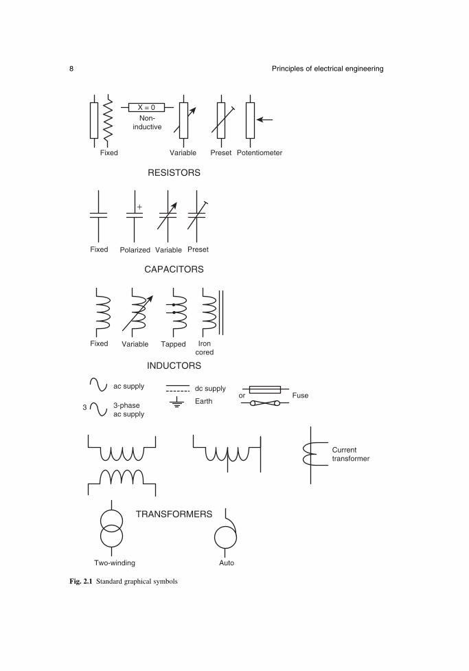
This book uses notation in accordance with the current British and InternationalStandards. Units for engineering quantities are printed in upright roman characters, witha space between the numerical value and the unit, but no space between the decimalprefix and the unit, e.g. 275 kV. Compound units have a space, dot or solidus betweenthe unit elements as appropriate, e.g. 1.5 N m, 9.81 m. s−2, or 300 m/s. Variable symbolsare printed in italic typeface, e.g. V. For ac quantities, the instantaneous value is printedin lower case italic, peak value in lower case italic with caret (^), and rms value in uppercase, e.g. i, î, I. Symbols for the important electrical quantities with their units are givenin Table 2.1, and decimal prefix symbols are shown in Table 2.2. Graphical symbols forbasic electrical engineering components are shown in Fig. 2.1.
2.2 Electromagnetic fields
2.2.1 Electric fields
Any object can take an electric or electrostatic charge. When the object is chargedpositively, it has a deficit of electrons, and when charged negatively it has an excess ofelectrons. The electron has the smallest known charge, –1.602 × 10⁻¹⁹ C.
Charged objects produce an electric field. The electric field strength E (V/m) at adistance d (m) from an isolated point charge Q (C) in air or a vacuum is given by
(2.1)
where the permittivity of free space εο = 8.854 × 10⁻¹² F/m. If the charge is inside aninsulating material with relative permittivity εr, the electric field strength becomes
(2.2)
Any charged object or particle experiences a force when inside an electric field. The forceF (N) experienced by a charge Q (C) in an electric field strength E (V/m) is given by
(2.3)F QE=
EQ
d=
4 2πε εo r
EQ
d=
4 2πεo

6 Principles of electrical engineering
Table 2.1 Symbols for standard quantities and units
Symbol Quantity Unit Unit symbol
A Geometric area square metre m2
B Magnetic flux density tesla TC Capacitance farad FE Electric field strength volt per metre V/mF Mechanical force newton NFm Magnetomotive force (mmf) ampere A or A ⋅ tG Conductance siemens SH Magnetic field strength ampere per metre A/mI Electric current ampere AJ Electric current density ampere per square metre A/m2
J Moment of inertia kilogram metre squared kg ⋅ m2
L Self-inductance henry HM Mutual inductance henry HN Number of turnsP Active or real power watt WQ Electric charge coulomb CQ Reactive power volt ampere reactive VArR Electrical resistance ohm ΩRm Reluctance ampere per weber A/WbS Apparent power volt ampere V ⋅ AT Mechanical torque newton metre N ⋅ mV Electric potential or voltage volt VW Energy or work joule JX Reactance ohm ΩY Admittance siemens SZ Impedance ohm Ω
f Frequency hertz Hzj Square root of –1l Length metre mm Mass kilogram kgn Rotational speed revolution per minute rpmp Number of machine pole pairst Time second sv Linear velocity metre per second m/s
ε Permittivity farad per metre F/mη Efficiencyθ Angle radian or degree rad or °λ Power factorΛ Permeance weber per ampere Wb/Aµ Permeability henry per metre H/mρ Resistivity ohm metre Ω ⋅ mσ Conductivity siemens per metre S/mφ Phase angle radian radΦ Magnetic flux weber Wbψ Magnetic flux linkage weber or weber-turn Wb or Wb ⋅ tω Angular velocity or radian per second rad/s
angular frequency
Electric field strength is a vector quantity. The direction of the force on one charge dueto the electric field of another is repulsive or attractive. Charges with the same polar-ity repel; charges with opposite polarities attract.
Work must be done to move charges of the same polarity together. The effortrequired is described by a voltage or electrostatic potential. The voltage at a point is defined as the work required to move a unit charge from infinity or from earth. (It is normally assumed that the earth is at zero potential.) Positively charged objectshave a positive potential relative to the earth.
If a positively charged object is held some distance above the ground, then the volt-age at points between the earth and the object rises with distance from the ground, sothat there is a potential gradient between the earth and the charged object. There is alsoan electric field pointing away from the object, towards the ground. The electric fieldstrength is equal to the potential gradient, and opposite in direction.
(2.4)
2.2.2 Electric currents
Electric charges are static if they are separated by an insulator. If charges are separatedby a conductor, they can move giving an electric current. A current of one ampereflows if one coulomb passes along the conductor every second.
(2.5)
A given current flowing through a thin wire represents a greater density of current thanif it flowed through a thicker wire. The current density J (A/m2) in a wire with crosssection area A (m2) carrying a current I (A) is given by
(2.6)
For wires made from most conducting materials, the current flowing through the wireis directly related to the difference in potential between the ends of the wire.
J IA=
IQt=
E = − ddVx
Newnes Electrical Power Engineer’s Handbook 7
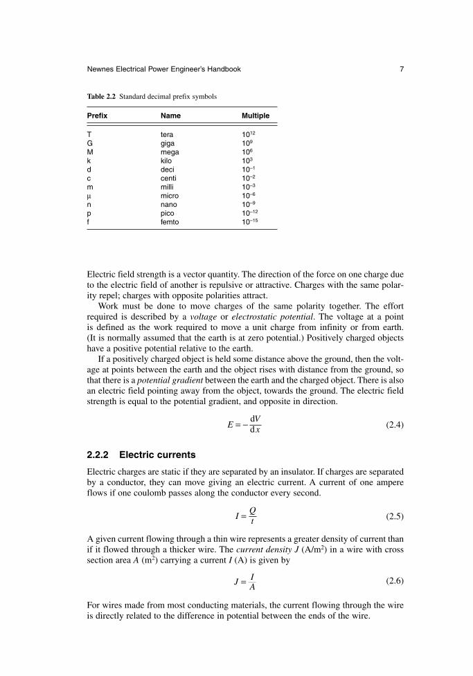
Table 2.2 Standard decimal prefix symbols
Prefix Name Multiple
T tera 1012
G giga 109
M mega 106
k kilo 103
d deci 10–1
c centi 10–2
m milli 10–3
µ micro 10–6
n nano 10–9
p pico 10–12
f femto 10–15
8 Principles of electrical engineering
Fixed
Fixed
Variable
VariablePolarized
RESISTORS
Preset
Preset
Fixed
ac supply
3-phase ac supply
dc supplyor Fuse
Current transformer
TRANSFORMERS
CAPACITORS
INDUCTORS
Earth
Two-winding Auto
3
TappedVariable Iron cored
Potentiometer
Non- inductive
X = 0
+
Fig. 2.1 Standard graphical symbols
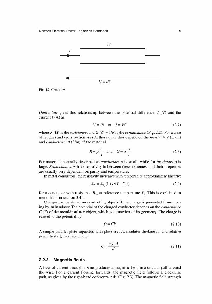
Ohm’s law gives this relationship between the potential difference V (V) and the current I (A) as
(2.7)
where R (Ω) is the resistance, and G (S) = 1/R is the conductance (Fig. 2.2). For a wireof length l and cross section area A, these quantities depend on the resistivity ρ (Ω.m)and conductivity σ (S/m) of the material
(2.8)
For materials normally described as conductors ρ is small, while for insulators ρ islarge. Semiconductors have resistivity in between these extremes, and their propertiesare usually very dependent on purity and temperature.
In metal conductors, the resistivity increases with temperature approximately linearly:
(2.9)
for a conductor with resistance RToat reference temperature To. This is explained in
more detail in section 3.4.1.Charges can be stored on conducting objects if the charge is prevented from mov-
ing by an insulator. The potential of the charged conductor depends on the capacitanceC (F) of the metal/insulator object, which is a function of its geometry. The charge isrelated to the potential by
(2.10)
A simple parallel-plate capacitor, with plate area A, insulator thickness d and relativepermittivity εr has capacitance
(2.11)
2.2.3 Magnetic fields
A flow of current through a wire produces a magnetic field in a circular path aroundthe wire. For a current flowing forwards, the magnetic field follows a clockwise path, as given by the right-hand corkscrew rule (Fig. 2.3). The magnetic field strength
CA
d= ε εo r
Q CV=
R R T TT = + −T oo( ( ))1 α
Rl
AG
A
l= =ρ σand
V IR I VG= =or
Newnes Electrical Power Engineer’s Handbook 9
V = IR
R
I
Fig. 2.2 Ohm’s law
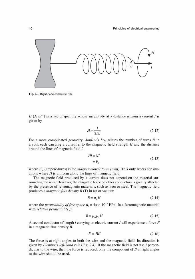
H (A m–1) is a vector quantity whose magnitude at a distance d from a current I is given by
(2.12)
For a more complicated geometry, Ampère’s law relates the number of turns N in a coil, each carrying a current I, to the magnetic field strength H and the distancearound the lines of magnetic field l.
(2.13)
where Fm (ampere-turns) is the magnetomotive force (mmf). This only works for situ-ations where H is uniform along the lines of magnetic field.
The magnetic field produced by a current does not depend on the material sur-rounding the wire. However, the magnetic force on other conductors is greatly affectedby the presence of ferromagnetic materials, such as iron or steel. The magnetic fieldproduces a magnetic flux density B (T) in air or vacuum
(2.14)
where the permeability of free space µo = 4π × 10–7 H/m. In a ferromagnetic materialwith relative permeability µr
(2.15)
A second conductor of length l carrying an electric current I will experience a force Fin a magnetic flux density B
(2.16)
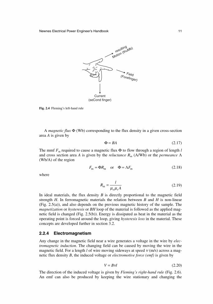
The force is at right angles to both the wire and the magnetic field. Its direction isgiven by Fleming’s left-hand rule (Fig. 2.4). If the magnetic field is not itself perpen-dicular to the wire, then the force is reduced; only the component of B at right anglesto the wire should be used.
F BIl=
B H= µ µo r
B H= µo
Hl NI
F
== m
HI
d=
2π
10 Principles of electrical engineering
H
I
Fig. 2.3 Right-hand corkscrew rule
A magnetic flux Φ (Wb) corresponding to the flux density in a given cross-sectionarea A is given by
(2.17)
The mmf Fm required to cause a magnetic flux Φ to flow through a region of length land cross section area A is given by the reluctance Rm (A/Wb) or the permeance Λ(Wb/A) of the region
(2.18)
where
(2.19)
In ideal materials, the flux density B is directly proportional to the magnetic fieldstrength H. In ferromagnetic materials the relation between B and H is non-linear (Fig. 2.5(a)), and also depends on the previous magnetic history of the sample. Themagnetization or hysteresis or BH loop of the material is followed as the applied mag-netic field is changed (Fig. 2.5(b)). Energy is dissipated as heat in the material as theoperating point is forced around the loop, giving hysteresis loss in the material. Theseconcepts are developed further in section 3.2.
2.2.4 Electromagnetism
Any change in the magnetic field near a wire generates a voltage in the wire by elec-tromagnetic induction. The changing field can be caused by moving the wire in themagnetic field. For a length l of wire moving sideways at speed ν (m/s) across a mag-netic flux density B, the induced voltage or electromotive force (emf) is given by
(2.20)
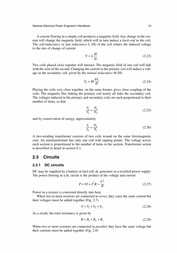
The direction of the induced voltage is given by Fleming’s right-hand rule (Fig. 2.6).An emf can also be produced by keeping the wire stationary and changing the
V B l= ν
Rl
Amo r
=µ µ
F R Fm m mor= =Φ Φ Λ
Φ = BA
Newnes Electrical Power Engineer’s Handbook 11
Current(seCond finger)
Field(Forefinger)
resulting
Motion (thuMb)
Fig. 2.4 Fleming’s left-hand rule
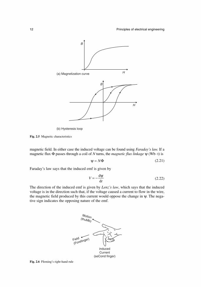
magnetic field. In either case the induced voltage can be found using Faraday’s law. If amagnetic flux Φ passes through a coil of N turns, the magnetic flux linkage ψ (Wb. t) is
(2.21)
Faraday’s law says that the induced emf is given by
(2.22)
The direction of the induced emf is given by Lenz’s law, which says that the inducedvoltage is in the direction such that, if the voltage caused a current to flow in the wire,the magnetic field produced by this current would oppose the change in ψ. The nega-tive sign indicates the opposing nature of the emf.
Vt
= − d
d
ψ
ψ = NΦ
12 Principles of electrical engineering
B
B
H
H
(a) Magnetization curve
(b) Hysteresis loop
Fig. 2.5 Magnetic characteristics
inducedCurrent
(seCond finger)
Motion(thuMb)
Field
(Forefinger)
Fig. 2.6 Fleming’s right-hand rule
A current flowing in a simple coil produces a magnetic field. Any change in the cur-rent will change the magnetic field, which will in turn induce a back-emf in the coil.The self-inductance or just inductance L (H) of the coil relates the induced voltage to the rate of change of current
(2.23)
Two coils placed close together will interact. The magnetic field of one coil will linkwith the wire of the second. Changing the current in the primary coil will induce a volt-age in the secondary coil, given by the mutual inductance M (H)
(2.24)
Placing the coils very close together, on the same former, gives close coupling of thecoils. The magnetic flux linking the primary coil nearly all links the secondary coil.The voltages induced in the primary and secondary coils are each proportional to theirnumber of turns, so that
(2.25)
and by conservation of energy, approximately
(2.26)
A two-winding transformer consists of two coils wound on the same ferromagneticcore. An autotransformer has only one coil with tapping points. The voltage acrosseach section is proportional to the number of turns in the section. Transformer actionis described in detail in section 6.1.
2.3 Circuits
2.3.1 DC circuits
DC may be supplied by a battery or fuel cell, dc generator or a rectified power supply.The power flowing in a dc circuit is the product of the voltage and current
(2.27)
Power in a resistor is converted directly into heat.When two or more resistors are connected in series, they carry the same current but
their voltages must be added together (Fig. 2.7)
(2.28)
As a result, the total resistance is given by
(2.29)
When two or more resistors are connected in parallel, they have the same voltage buttheir currents must be added together (Fig. 2.8)
R R R R= + +1 2 3
V V V V= + +1 2 3
P VI I RVR= = =2
2
II
NN
1
2
2
1=
VV
NN
1
2
1
2=
V MIt21=
dd
V LI
t= d
d
Newnes Electrical Power Engineer’s Handbook 13
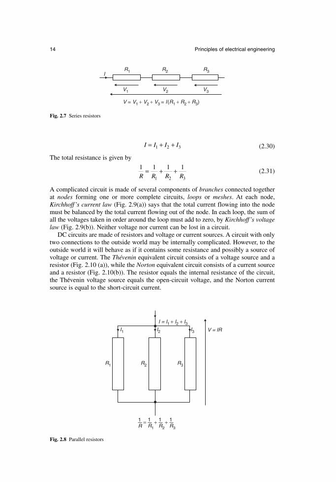
(2.30)
The total resistance is given by
(2.31)
A complicated circuit is made of several components of branches connected togetherat nodes forming one or more complete circuits, loops or meshes. At each node,Kirchhoff’s current law (Fig. 2.9(a)) says that the total current flowing into the nodemust be balanced by the total current flowing out of the node. In each loop, the sum ofall the voltages taken in order around the loop must add to zero, by Kirchhoff’s voltagelaw (Fig. 2.9(b)). Neither voltage nor current can be lost in a circuit.
DC circuits are made of resistors and voltage or current sources. A circuit with onlytwo connections to the outside world may be internally complicated. However, to theoutside world it will behave as if it contains some resistance and possibly a source ofvoltage or current. The Thévenin equivalent circuit consists of a voltage source and aresistor (Fig. 2.10 (a)), while the Norton equivalent circuit consists of a current sourceand a resistor (Fig. 2.10(b)). The resistor equals the internal resistance of the circuit,the Thevenin voltage source equals the open-circuit voltage, and the Norton currentsource is equal to the short-circuit current.
1 1 1 1
1 2 3R R R R= + +
I I I I= + +1 2 3
14 Principles of electrical engineering
V1
V = V1 + V2 + V3 = I (R1 + R2 + R3)
V2 V3
R1 R2 R3I
Fig. 2.7 Series resistors
R1
I1 I2 I3
R2 R3
1R
1R1
1R2
1R3
+ +=
V = IR
I = I1 + I2 + I3
Fig. 2.8 Parallel resistors
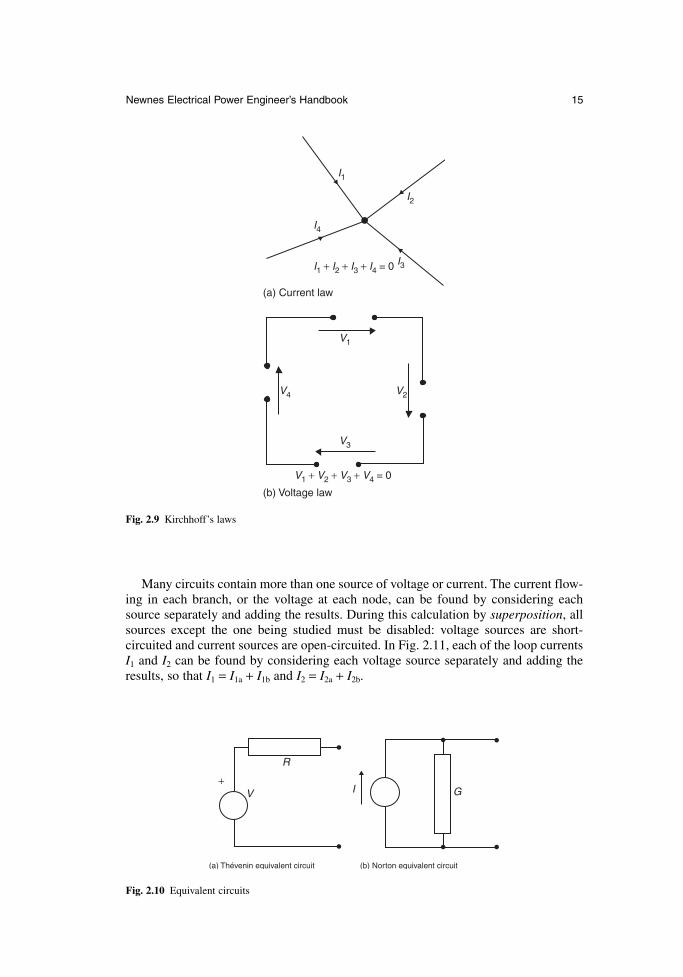
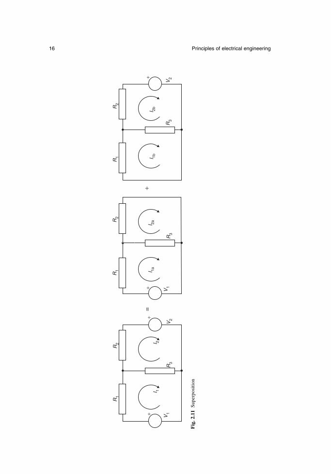
Many circuits contain more than one source of voltage or current. The current flow-ing in each branch, or the voltage at each node, can be found by considering eachsource separately and adding the results. During this calculation by superposition, allsources except the one being studied must be disabled: voltage sources are short-circuited and current sources are open-circuited. In Fig. 2.11, each of the loop currentsI1 and I2 can be found by considering each voltage source separately and adding theresults, so that I1 = I1a + I1b and I2 = I2a + I2b.
Newnes Electrical Power Engineer’s Handbook 15
V1
I1
I2
I3
I4
V1 + V2 + V3 + V4 = 0
I1 + I2 + I3 + I4 = 0
V3
V4 V2
(b) Voltage law
(a) Current law
Fig. 2.9 Kirchhoff’s laws
+V I
R
G
(a) Thévenin equivalent circuit (b) Norton equivalent circuit
Fig. 2.10 Equivalent circuits
16 Principles of electrical engineering
I 1aI 2a
V1
R3
R1
R2
++
I 1bI 2b
R3
V2
R1
R2
+
R1
V1
I 1I 2
R3
V2
R2
++
=
Fig
. 2.1
1Su
perp
ositi
on
2.3.2 AC circuits
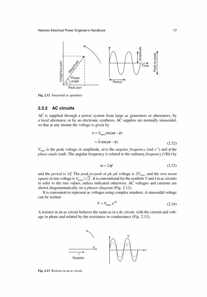
AC is supplied through a power system from large ac generators or alternators, by a local alternator, or by an electronic synthesis. AC supplies are normally sinusoidal,so that at any instant the voltage is given by
(2.32)
Vmax is the peak voltage or amplitude, ω is the angular frequency (rad s−1) and φ thephase angle (rad). The angular frequency is related to the ordinary frequency f (Hz) by
(2.33)
and the period is 1/f. The peak-to-peak or pk–pk voltage is 2Vmax, and the root meansquare or rms voltage is . It is conventional for the symbols V and I in ac circuitsto refer to the rms values, unless indicated otherwise. AC voltages and currents areshown diagrammatically on a phasor diagram (Fig. 2.12).
It is convenient to represent ac voltages using complex numbers. A sinusoidal voltagecan be written
(2.34)
A resistor in an ac circuit behaves the same as in a dc circuit, with the current and volt-age in phase and related by the resistance or conductance (Fig. 2.13).
V V j= max e φ
Vmax / 2
ω π= 2 f
υ ω φ
υ ω φ
= −
= −∧
V t
t
maxsin( )
sin( )
Newnes Electrical Power Engineer’s Handbook 17
Imag
inar
y pa
rt
Mag
nitu
dePhaseangle
Real part
Period
Pea
k-to
-pea
k
Am
plitu
de
Time
φ
Fig. 2.12 Sinusoidal ac quantities
V
V
I
It
Resistor
Fig. 2.13 Resistor in an ac circuit
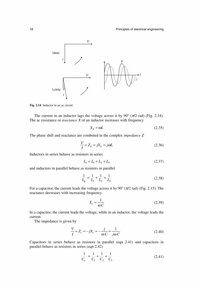
The current in an inductor lags the voltage across it by 90° (π/2 rad) (Fig. 2.14). The ac resistance or reactance X of an inductor increases with frequency
(2.35)
The phase shift and reactance are combined in the complex impedance Z
(2.36)
Inductors in series behave as resistors in series
(2.37)
and inductors in parallel behave as resistors in parallel
(2.38)
For a capacitor, the current leads the voltage across it by 90° (π/2 rad) (Fig. 2.15). Thereactance decreases with increasing frequency
(2.39)
In a capacitor, the current leads the voltage, while in an inductor, the voltage leads thecurrent.
The impedance is given by
(2.40)
Capacitors in series behave as resistors in parallel (eqn 2.41) and capacitors in parallel behave as resistors in series (eqn 2.42)
(2.41)1 1 1 1
1 2 3C C C Cs
= + +
V
IZ jX
j
C j Cc c= = − = − =ω ω
1
XCc = 1
ω
1 1 1 11 2 3L L L Lp
= + +
L L L Ls 1= + +2 3
VI
Z jX j LL L= = = ω
X LL = ω
18 Principles of electrical engineering
V
I
V
I
V
I
t
Ideal
Lossy δ
Fig. 2.14 Inductor in an ac circuit
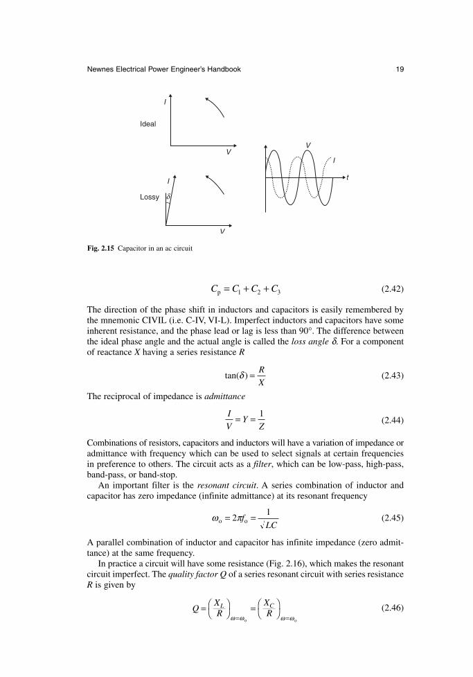
(2.42)
The direction of the phase shift in inductors and capacitors is easily remembered bythe mnemonic CIVIL (i.e. C-IV, VI-L). Imperfect inductors and capacitors have someinherent resistance, and the phase lead or lag is less than 90°. The difference betweenthe ideal phase angle and the actual angle is called the loss angle δ. For a componentof reactance X having a series resistance R
(2.43)
The reciprocal of impedance is admittance
(2.44)
Combinations of resistors, capacitors and inductors will have a variation of impedance oradmittance with frequency which can be used to select signals at certain frequenciesin preference to others. The circuit acts as a filter, which can be low-pass, high-pass,band-pass, or band-stop.
An important filter is the resonant circuit. A series combination of inductor andcapacitor has zero impedance (infinite admittance) at its resonant frequency
(2.45)
A parallel combination of inductor and capacitor has infinite impedance (zero admit-tance) at the same frequency.
In practice a circuit will have some resistance (Fig. 2.16), which makes the resonantcircuit imperfect. The quality factor Q of a series resonant circuit with series resistanceR is given by
(2.46)QXR
XR
L C=
=
= =ω ω ω ωo o
ω πo o= =21
fLC
I
VY
Z= = 1
tan( )δ = R
X
C C C Cp = + +1 2 3
Newnes Electrical Power Engineer’s Handbook 19
I
V
I
V
V
I
t
Ideal
Lossy δ
Fig. 2.15 Capacitor in an ac circuit
and for a parallel circuit with shunt resistance R
(2.47)
A filter with a high Q will have a sharper change of impedance with frequency thanone with a low Q, and reduced losses.
AC is generated and distributed using three phases, three equal voltages being generatedat 120° phase intervals. The phase voltage VP is measured with respect to a commonstar point or neutral point, and the line voltage VL is measured between the separatephases. In magnitude,
(2.48)
Any three-phase generator, transformer or load can be connected in a star or Y con-figuration, or in a delta configuration (Fig. 2.17).
V VL P= 3
Q RX
RXL C
=
=
= =ω ω ω ωo o
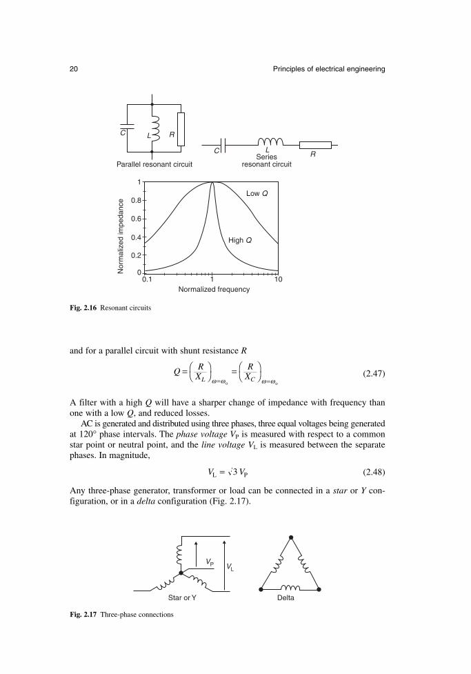
20 Principles of electrical engineering
C LRSeries
resonant circuit
C L R
Parallel resonant circuit
Low Q
High Q
0.1 1 10Normalized frequency
Nor
mal
ized
impe
danc
e
1
0.8
0.6
0.4
0.2
0
Fig. 2.16 Resonant circuits
Star or Y Delta
VP VL
Fig. 2.17 Three-phase connections
2.3.3 Magnetic circuits
A reluctance in a magnetic circuit behaves in the same way as a resistance in a dc elec-tric circuit. Reluctance in series add together
or
(2.49)
and for reluctances in parallel
or(2.50)
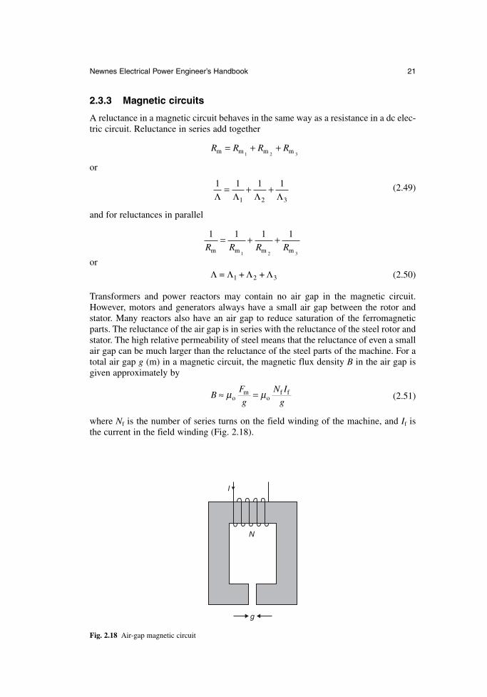
Transformers and power reactors may contain no air gap in the magnetic circuit.However, motors and generators always have a small air gap between the rotor and stator. Many reactors also have an air gap to reduce saturation of the ferromagneticparts. The reluctance of the air gap is in series with the reluctance of the steel rotor andstator. The high relative permeability of steel means that the reluctance of even a smallair gap can be much larger than the reluctance of the steel parts of the machine. For atotal air gap g (m) in a magnetic circuit, the magnetic flux density B in the air gap isgiven approximately by
(2.51)
where Nf is the number of series turns on the field winding of the machine, and If isthe current in the field winding (Fig. 2.18).
BFg
N Ig
≈ =µ µom
of f
Λ Λ Λ Λ= + +1 2 3
1 1 1 1
1 2 3R R R Rm m m m
= + +
1 1 1 1
1 2 3Λ Λ Λ Λ= + +
R R R Rm m m m= + +1 2 3
Newnes Electrical Power Engineer’s Handbook 21
I
N
g
Fig. 2.18 Air-gap magnetic circuit
2.4 Energy and power
2.4.1 Mechanical energy
According to Newton’s third law of motion, mechanical force causes movement in astraight line, such that the force F (N) accelerates a mass m (kg) with acceleration a (m/s2)
(2.52)
Rotational movement depends in the same way upon torque T (N m) accelerating amoment of inertia J (kg m2) with angular acceleration α (rad/s2)
(2.53)
Movement is often opposed by friction. Friction forces and torques always workagainst the movement. Friction between dry surfaces has a maximum value, depend-ing on the contact force. Once the driving force exceeds the limiting friction force, thesystem will move and the friction force says constant. Viscous damping gives arestraining force which increases with the speed. Friction between lubricated surfacesis mainly a viscous effect.
Objects store potential energy when they are lifted up. The stored energy W (J) ofa mass m is proportional to the height h (m) above ground level, when the accelerationdue to gravity g = 9.81 m/s
(2.54)
Moving objects have kinetic energy depending on their linear speed υ (m/s) or angu-lar speed ω (rad/s)
(2.55)
Mechanical work is done whenever an object is moved a distance x (m) against anopposing force, or through an angle θ (rad) against an opposing torque
(2.56)
Mechanical power P (W) is the rate of doing work
(2.57)
2.4.2 Electrical energy
In electrical circuits, electrical potential energy is stored in a capacitance C charged toa voltage V
(2.58)W CV= 1
22
P F
T
=
=
υ
ω
W Fx
T
=
= θ
W m
J
=
=
1
2
1
2
2
2
υ
ω
W mgh=
T J= α
F ma=
22 Principles of electrical engineering
while kinetic energy is stored in an inductance L carrying a current I
(2.59)
Capacitors and inductors store electrical energy. Resistors dissipate energy and convertit into heat. The power dissipated and lost to the electrical system in a resistor R hasalready been shown in eqn 2.27.
Electrical and mechanical systems can convert and store energy, but overall the totalenergy in a system is conserved. The overall energy balance in an electromechanicalsystem can be written as
electrical energy in + mechanical energy in= electrical energy lost in resistance
+ mechanical energy lost in friction+ magnetic energy lost in steel core (2.60)+ increase in stored mechanical energy+ increase in stored electrical energy
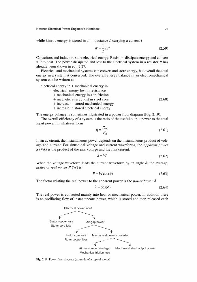
The energy balance is sometimes illustrated in a power flow diagram (Fig. 2.19).The overall efficiency of a system is the ratio of the useful output power to the total
input power, in whatever form
(2.61)
In an ac circuit, the instantaneous power depends on the instantaneous product of volt-age and current. For sinusoidal voltage and current waveforms, the apparent power S (VA) is the product of the rms voltage and the rms current.
(2.62)
When the voltage waveform leads the current waveform by an angle φ, the average,active or real power P (W) is
(2.63)
The factor relating the real power to the apparent power is the power factor λ(2.64)
The real power is converted mainly into heat or mechanical power. In addition there is an oscillating flow of instantaneous power, which is stored and then released each
λ φ= cos( )
P VI= cos( )φ
S VI=
η = P
Pout
in
W LI= 1
22
Newnes Electrical Power Engineer’s Handbook 23
Stator copper loss
Stator core loss
Electrical power input
Air-gap power
Rotor core loss
Rotor copper loss
Mechanical power converted
Air resistance (windage)
Mechanical friction loss
Mechanical shaft output power
Fig. 2.19 Power flow diagram (example of a typical motor)
cycle by the capacitance and inductance in the circuit. This imaginary or reactivepower Q (VAr) is given by
(2.65)
By convention an inductive circuit (where the current lags the voltage) absorbs VAr,while a capacitive circuit (where the current leads the voltage) acts as a source of VAr.The relationship between S, P and Q is
(2.66)
In a three-phase circuit, the total real power is the sum of the power flowing into eachphase. For a balanced three-phase circuit with phase-neutral voltage VP and phase cur-rent IP the total power is the sum of the powers in each phase
(2.67)
In terms of the line voltage VL, the real power is
(2.68)
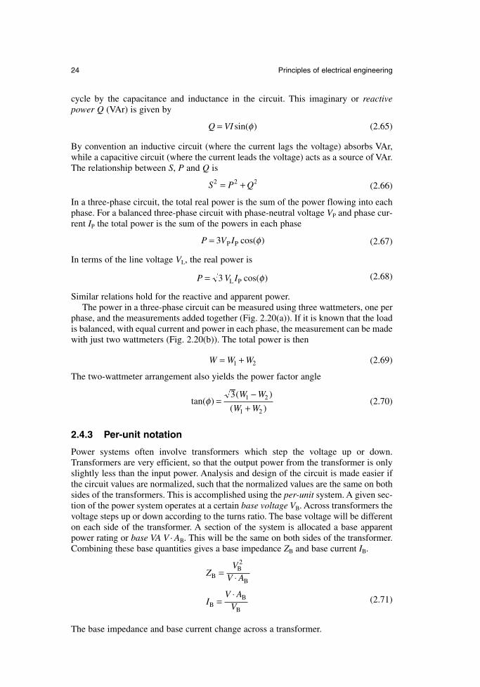
Similar relations hold for the reactive and apparent power.The power in a three-phase circuit can be measured using three wattmeters, one per
phase, and the measurements added together (Fig. 2.20(a)). If it is known that the loadis balanced, with equal current and power in each phase, the measurement can be madewith just two wattmeters (Fig. 2.20(b)). The total power is then
(2.69)
The two-wattmeter arrangement also yields the power factor angle
(2.70)
2.4.3 Per-unit notation
Power systems often involve transformers which step the voltage up or down.Transformers are very efficient, so that the output power from the transformer is onlyslightly less than the input power. Analysis and design of the circuit is made easier ifthe circuit values are normalized, such that the normalized values are the same on bothsides of the transformers. This is accomplished using the per-unit system. A given sec-tion of the power system operates at a certain base voltage VB. Across transformers thevoltage steps up or down according to the turns ratio. The base voltage will be differenton each side of the transformer. A section of the system is allocated a base apparentpower rating or base VA V . AB. This will be the same on both sides of the transformer.Combining these base quantities gives a base impedance ZB and base current IB.
(2.71)
The base impedance and base current change across a transformer.
ZV
V A
IV A
V
BB2
B
BB
B
= ⋅
=⋅
tan( )( )
( )φ =
−+
3 1 2
1 2
W W
W W
W W W= +1 2
P V I= 3 L P cos( )φ
P V I= 3 P P cos( )φ
S P Q2 2 2= +
Q VI= sin( )φ
24 Principles of electrical engineering
All voltages and impedances in the system are normalized using the appropriatebase value. The resulting normalized quantities are per-unit values. Once the circuithas been converted to per-unit values, the transformers have no effect on nominal tapposition, and can be replaced by their own equivalent per-unit impedance.
The per-unit values are sometimes quoted as per cent values, by multiplying by 100 per cent.
A particular advantage of the per-unit and per cent notation is that the resultingimpedances are very similar for equipment of very different sizes.
2.4.4 Energy transformation effects
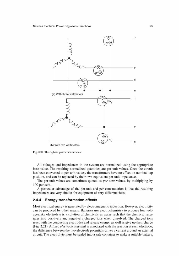
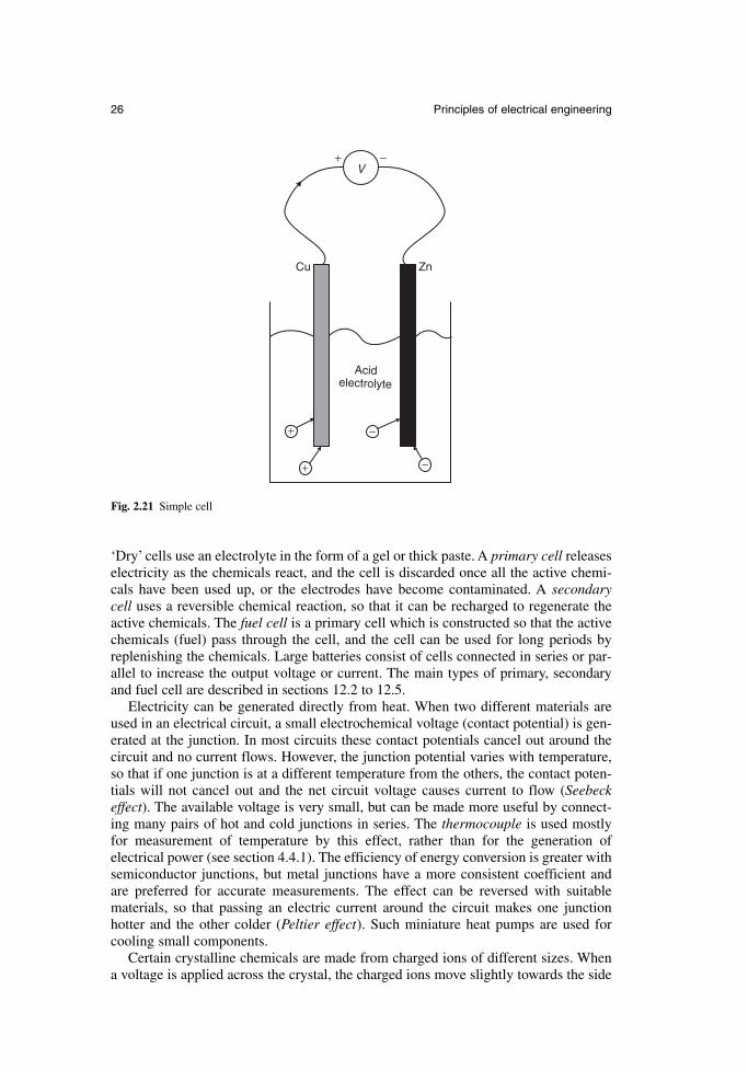
Most electrical energy is generated by electromagnetic induction. However, electricitycan be produced by other means. Batteries use electrochemistry to produce low volt-ages. An electrolyte is a solution of chemicals in water such that the chemical sepa-rates into positively and negatively charged ions when dissolved. The charged ionsreact with the conducting electrodes and release energy, as well as give up their charge(Fig. 2.21). A fixed electrode potential is associated with the reaction at each electrode;the difference between the two electrode potentials drives a current around an externalcircuit. The electrolyte must be sealed into a safe container to make a suitable battery.
Newnes Electrical Power Engineer’s Handbook 25
W
W
W
W1
W2
A
A
A
A
A
V
V
V
V
V
r
y
b
n
r
y
b
(a) With three wattmeters
(b) With two wattmeters
Fig. 2.20 Three-phase power measurement
‘Dry’ cells use an electrolyte in the form of a gel or thick paste. A primary cell releaseselectricity as the chemicals react, and the cell is discarded once all the active chemi-cals have been used up, or the electrodes have become contaminated. A secondary cell uses a reversible chemical reaction, so that it can be recharged to regenerate theactive chemicals. The fuel cell is a primary cell which is constructed so that the activechemicals (fuel) pass through the cell, and the cell can be used for long periods byreplenishing the chemicals. Large batteries consist of cells connected in series or par-allel to increase the output voltage or current. The main types of primary, secondaryand fuel cell are described in sections 12.2 to 12.5.
Electricity can be generated directly from heat. When two different materials areused in an electrical circuit, a small electrochemical voltage (contact potential) is gen-erated at the junction. In most circuits these contact potentials cancel out around thecircuit and no current flows. However, the junction potential varies with temperature,so that if one junction is at a different temperature from the others, the contact poten-tials will not cancel out and the net circuit voltage causes current to flow (Seebeckeffect). The available voltage is very small, but can be made more useful by connect-ing many pairs of hot and cold junctions in series. The thermocouple is used mostlyfor measurement of temperature by this effect, rather than for the generation of electrical power (see section 4.4.1). The efficiency of energy conversion is greater withsemiconductor junctions, but metal junctions have a more consistent coefficient andare preferred for accurate measurements. The effect can be reversed with suitablematerials, so that passing an electric current around the circuit makes one junction hotter and the other colder (Peltier effect). Such miniature heat pumps are used forcooling small components.
Certain crystalline chemicals are made from charged ions of different sizes. Whena voltage is applied across the crystal, the charged ions move slightly towards the side
26 Principles of electrical engineering
+ −
+
+
−
−
Cu
V
Zn
Acidelectrolyte
Fig. 2.21 Simple cell
of opposite polarity, causing a small distortion of the crystal. Conversely, applying aforce so as to distort the crystal moves the charged ions and generates a voltage. Thispiezoelectric effect is used to generate high voltages from a small mechanical force,but very little current is available. The use of piezoelectric sensors for the measurementof mechanical pressure and force is described in section 4.2.4. Ferromagnetic materialsalso distort slightly in a magnetic field. The magnetostrictive effect produces low frequency vibration (hum) in ac machines and transformers.
Electricity can be produced directly from light. The photovoltaic effect occurs whenlight falls on suitable materials, releasing electrons from the material and generatingelectricity. The magnitude of the effect is greater with short wavelength light (blue)than long wavelength light (red), and stops altogether beyond a wavelength threshold.Light falling on small photovoltaic cells is used for light measurement, communica-tions and for proximity sensors. On a larger scale, semiconductor solar cells are beingmade with usable efficiency for power generation.
Light is produced from electricity in incandescent filament bulbs, by heating a wireto a sufficiently high temperature that it glows. Fluorescent lights produce an electricaldischarge through a low-pressure gas. The discharge emits ultraviolet radiation, whichcauses a fluorescent coating on the inside of the tube to glow.
References
2A. Professional brief edited by Burns, R.W., Dellow, F. and Forbes, R.G., Symbols andAbbreviations for use in Electrical and Electronic Engineering. The Institution ofElectrical Engineers, 1992.
2B. BS 3939:1985, Graphical symbols for electrical power, telecommunications and elec-tronics diagrams, BSI, 1985.
2C. BS 5555:1993 (ISO 1000:1992), SI units and recommendations for the use of their multiples and certain other units, BSI, 1993.
2D. BS 5775:1993 (ISO 32:1992), Quantities, units and symbols, Part 5: electricity andmagnetism, BSI, 1993.
2E. Smith, R.J. and Dorf, R.C., Circuits, Devices and Systems (5th edn), Wiley, 1992, ISBN 0-471-55221-6.
2F. Hughes, E. (revised Smith, I.M.), Hughes Electrical Technology, Longman Scientificand Technical, 1995, ISBN 0-582-22696-1.
2G. Bird, J.O., Higher Electrical Technology, Butterworth-Heinemann, 1994, ISBN 0-7506-01019.
2H. Breithaupt, J., Understanding Physics for Advanced Level, S. Thornes, 1990, ISBN 0-7487-0510-4.
2I. Del Toro, V., Electrical Engineering Fundamentals, Prentice-Hall, 1986, ISBN 0-13-247131-0.
Newnes Electrical Power Engineer’s Handbook 27

Chapter 3
Materials for electrical engineering
Professor A.G. CleggMagnet Centre, University of Sunderland
A.G. WhitmanWith amendments byJ.E. NealKrempel Group
3.1 Introduction
Most types of electrical equipment rely, for their safe and efficient performance, on anelectrical circuit and the means to keep this circuit isolated from the surrounding mate-rials and environment. Many types of equipment also have a magnetic circuit, whichis linked to the electrical circuit by the laws outlined in Chapter 2.
The main material characteristics of relevance to electrical engineering are thereforethose associated with conductors for the electrical circuit, with the insulation systemnecessary to isolate this circuit and with the specialized steels and permanent magnetsused for magnetic circuit.
Other properties, such as mechanical, thermal and chemical properties are also relevant, but these are often important in specialized cases and their coverage is best left to other books which address these areas more broadly. The scope of this chapter is restricted to the main types and characteristics of conductors, insulationsystems and magnetic materials which are used generally in electrical plant and equipment.
3.2 Magnetic materials
All materials have magnetic properties. These characteristic properties may be dividedinto five groups as follows:
diamagnetic paramagnetic ferromagnetic antiferromagnetic ferrimagnetic
Only ferromagnetic and ferrimagnetic materials have properties which are useful inpractical applications.
Ferromagnetic properties are confined almost entirely to iron, nickel and cobalt andtheir alloys. The only exceptions are some alloys of manganese and some of the rareearth elements.
Ferrimagnetism is the magnetism of the mixed oxides of the ferromagnetic elements.These are variously called ferrites and garnets. The basic ferrite is magnetite, or Fe3O4,which can be written as FeO.Fe2O3. By substituting the FeO with other divalentoxides, a wide range of compounds with useful properties can be produced. The mainadvantage of these materials is that they have high electrical resistivity which mini-mizes eddy currents when they are used at high frequencies.
The important parameters in magnetic materials can be defined as follows:
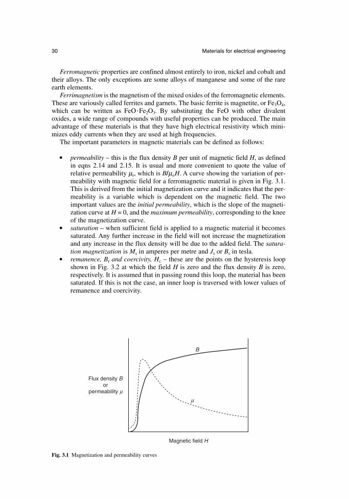
permeability – this is the flux density B per unit of magnetic field H, as definedin eqns 2.14 and 2.15. It is usual and more convenient to quote the value of relative permeability µr, which is B/µoH. A curve showing the variation of per-meability with magnetic field for a ferromagnetic material is given in Fig. 3.1.This is derived from the initial magnetization curve and it indicates that the per-meability is a variable which is dependent on the magnetic field. The twoimportant values are the initial permeability, which is the slope of the magneti-zation curve at H = 0, and the maximum permeability, corresponding to the kneeof the magnetization curve.
saturation – when sufficient field is applied to a magnetic material it becomessaturated. Any further increase in the field will not increase the magnetizationand any increase in the flux density will be due to the added field. The satura-tion magnetization is Ms in amperes per metre and Js or Bs in tesla.
remanence, Br and coercivity, Hc – these are the points on the hysteresis loopshown in Fig. 3.2 at which the field H is zero and the flux density B is zero,respectively. It is assumed that in passing round this loop, the material has beensaturated. If this is not the case, an inner loop is traversed with lower values ofremanence and coercivity.
30 Materials for electrical engineering
B
µ
Magnetic field H
Flux density Bor
permeability µ
Fig. 3.1 Magnetization and permeability curves
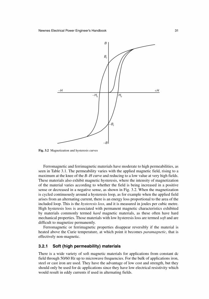
Ferromagnetic and ferrimagnetic materials have moderate to high permeabilities, asseen in Table 3.1. The permeability varies with the applied magnetic field, rising to amaximum at the knee of the B–H curve and reducing to a low value at very high fields.These materials also exhibit magnetic hysteresis, where the intensity of magnetizationof the material varies according to whether the field is being increased in a positivesense or decreased in a negative sense, as shown in Fig. 3.2. When the magnetizationis cycled continuously around a hysteresis loop, as for example when the applied fieldarises from an alternating current, there is an energy loss proportional to the area of theincluded loop. This is the hysteresis loss, and it is measured in joules per cubic metre.High hysteresis loss is associated with permanent magnetic characteristics exhibitedby materials commonly termed hard magnetic materials, as these often have hardmechanical properties. Those materials with low hysteresis loss are termed soft and aredifficult to magnetize permanently.
Ferromagnetic or ferrimagnetic properties disappear reversibly if the material isheated above the Curie temperature, at which point it becomes paramagnetic, that iseffectively non-magnetic.
3.2.1 Soft (high permeability) materials
There is a wide variety of soft magnetic materials for applications from constant dcfield through 50/60 Hz up to microwave frequencies. For the bulk of applications iron,steel or cast iron are used. They have the advantage of low cost and strength, but theyshould only be used for dc applications since they have low electrical resistivity whichwould result in eddy currents if used in alternating fields.
Newnes Electrical Power Engineer’s Handbook 31
B
−B
Br
−Br
−H +H−Hc Hc
Fig. 3.2 Magnetization and hysteresis curves
In choosing a high-permeability material for a particular application there may bespecial considerations. If the frequency of the applied voltage is 10 kHz or above, thenferrites or garnets will normally be used. For constant-field applications mild steel isused, and low-carbon iron is used where the highest permeability or lowest coercivityis needed. For 50/60 Hz power transformers, grain-oriented silicon steel is used, butthere is now serious competition from amorphous strip and although this is moreexpensive the core loss is significantly lower than that of silicon steel. For the highestpermeability and lowest coercivity in specialist applications up to about 10 kHz nickeliron would be the preferred choice although its cost may be prohibitive.
3.2.1.1 Sheet steels
There are a number of grades of sheet steel and these comprise by far the greatest partof the soft, high-permeability material used. These metallic materials have a compara-tively low electrical resistivity and they are used in sheet (or lamination) form becausethis limits the flow of eddy currents and the losses that result. The range of sheet thick-ness used for 50/60 Hz applications is 0.35–0.65 mm for non-oriented materials and0.13–0.35 mm for grain-oriented silicon steels. For higher frequencies of 400–1000 Hzthicknesses of 0.05–0.20 mm are used.
In grain-oriented steel an increasing level of silicon content reduces the losses butalso reduces the permeability; for many applications a 3 per cent silicon content rep-resents a good balance. The effect of silicon is to increase the electrical resistivity ofsteel; not only does this reduce eddy current losses but it also improves the stability ofthe steel and aids the production of grain orientation. The sheet is subject to cold rollingand a complex annealing treatment to produce the grain orientation in the rolling direc-tion and this also gives improved magnetic permeability in that direction. The propertiesare further improved at the annealing stage with a glass film on the surface that holds the steel in a state of tension and provides electrical insulation between laminations in
32 Materials for electrical engineering
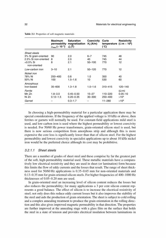
Table 3.1 Properties of soft magnetic materials
Maximum Saturation Coercivity Curie Resistivitypermeability magnetization Hc (A/m) temperature (Ω m × 108)µmax (× 10−3) Js (T) (°C)
Sheet steels3% Si grain-oriented 90 2.0 6–7 745 482.5% Si non-oriented 8 2.0 40 745 44<0.5% Si 8 2.1 50–100 770 12
non-oriented
Low-carbon iron 3–10 2.1 50–120 770 12
Nickel iron78% Ni 250–400 0.8 1.0 350 4050% Ni 100 1.5–1.6 10 530 60
AmorphousIron-based 35–600 1.3–1.8 1.0–1.6 310–415 120–140
Ferrite (Ω m)Mn Zn 1.8–3.0 0.45–0.50 15–27 110–220 0.05–10Ni Zn 0.12–1.5 0.20–0.35 30–300 250–400 >104
Garnet – 0.3–1.7 – 11–280 >106
a core. A phosphate coating is applied to complete the tensioning and insulation. The grain size in the resulting sheets is comparatively large and the domain boundariesare quite widely spaced. Artificial grain boundaries can be produced by laying downlines of ablated spots on the steel surface; the resulting stress and atomic disruptionpattern pins domain walls and leads to a smaller wall spacing. Various methods havebeen used to produce this ablating, including spark and laser techniques. All theseprocesses are applied within the steel manufacturer’s works and the resulting steel isoften referred to as fully processed. The main application of this grain-oriented mate-rial is in power transformers where low power loss is important, since the transformeris always connected even when its loading is at a minimum.
For rotating machinery, especially motors rated more than about 100 kW, non-oriented steels with a lower silicon content are used. Whilst efficiency remains impor-tant in this application, high permeability is now also important in order to minimizemagnetizing current and to maximize torque. This material is also used in smallertransformers, chokes for fluorescent tubes, metres and magnetic shielding.
For smaller motors silicon-free non-oriented steels are often used. These are pro-duced by the steel manufacturer and have a relatively high carbon content. The carbonmakes the sheet sufficiently hard for punching into laminations and after punching, thematerial is de-carburized and annealed to increase the grain size. Because of the needfor this secondary processing, the materials are often known as semi-processed. Thesematerials are generally cheaper than silicon steels but in their finished form they havea much higher permeability; in small motors particularly this can be more importantthan efficiency. Other applications include relays and magnetic clutches.
Silicon steels are also produced in the form of bars, rods or wires for relays, stepping motors and gyroscope housings. The tensile strength of the silicon steels maybe improved by the addition of alloying elements such as manganese; this type ofmaterial is used in highly stressed parts of the magnetic circuit in high-speed motorsor generators.
3.2.1.2 Amorphous alloys
This class of alloys, often called metallic glasses, is produced by rapid solidificationof the alloy at cooling rates of about a million degrees centigrade per second. Thealloys solidify with a glass-like atomic structure which is a non-crystalline frozen liquid. The rapid cooling is achieved by causing the molten alloy to flow through anorifice onto a rapidly rotating water-cooled drum. This can produce sheets as thin as10 µm and a metre or more wide.
There are two main groups of amorphous alloys. The first is the iron-rich group ofmagnetic alloys, which have the highest saturation magnetization among the amor-phous alloys and are based on inexpensive raw materials. Iron-rich alloys are currentlybeing used in long-term tests in power transformers in the USA. The second is thecobalt-based group, which have very low or zero magnetostriction, leading to the highestpermeability and the lowest core loss. Cobalt-based alloys are used for a variety ofhigh-frequency applications including pulsing devices and tape recorder heads, wheretheir mechanical hardness provides excellent wear resistance.
All of these alloys have a resistivity which is higher than that of conventional crys-talline electrical steels. Because of this, eddy current losses are minimized both at50/60 Hz and at higher frequencies. The alloys have other advantages including flexi-bility without loss of hardness, high tensile strength and good corrosion resistance.
Newnes Electrical Power Engineer’s Handbook 33
3.2.1.3 Nickel iron alloys
The very high magnetic permeability and low coercivity of nickel iron alloys is due totwo fundamental properties, which are magnetostriction and magnetic anisotropy. At anickel content of about 78 per cent both of these parameters are zero. Magnetostrictionhas been briefly referred to in section 2.4.4; it is the change of dimensions in a mate-rial due to magnetization, and when this is zero there are no internal stresses inducedduring magnetizing. Magnetic anisotropy is the difference between magnetic behav-iour in different directions; when this is zero the magnetization increases steeply underthe influence of a magnetic field, independent of crystal direction. Alloys with about78 per cent nickel content are variously called Mumetal or Permalloy.
Commercial alloys in this class have additions of chromium, copper and molybdenumin order to increase the resistivity and improve the magnetic properties. Applicationsinclude special transformers, circuit breakers, magnetic recording heads and magneticshielding.
Fifty per cent nickel iron alloys have the highest saturation magnetization of thisclass of materials, and consequently in the best flux-carrying capacity. They have ahigher permeability and better corrosion resistance than silicon iron materials, but aremore expensive. A wide range of properties can be produced by various processingtechniques. Severe cold reduction produces a cube texture and a square hysteresis loopin annealed strip, and the properties can be tailored by annealing the material belowthe Curie temperature in a magnetic field. Applications for this material includechokes, relays and small motors.
3.2.1.4 Ferrites and garnets
Ferrites are iron oxide compounds containing one or more other metal oxides. Theimportant high magnetic permeability materials are manganese zinc ferrite and nickelzinc ferrite. They are prepared from the constituent oxides in powder form, preferablyof the same particle size intimately mixed. The mixture is fired at about 1000°C andthis is followed by crushing, milling and then pressing of the powder in a die or extru-sion to the required shape. The resulting compact is a black brittle ceramic and anysubsequent machining must be by grinding. The materials may be prepared with highpermeability, and because their high electric resistivity limits eddy currents to a negli-gible level, they can be used at frequencies up to 20 MHz as the solid core of inductorsor transformers.
A combination of hysteresis, eddy current and residual losses occur, and these components may be separately controlled by composition and processing conditions,taking into account the required permeability and the working frequency.
The saturation flux density of ferrites is relatively low, making them unsuitable forpower applications. Their use is therefore almost entirely in the electronics andtelecommunications industry where they have now largely replaced laminated alloyand powder cores.
Garnets are used for frequencies of 100 MHz and above. They have resistivities inexcess of 108 Ω m compared with ferrite resistivity which is up to 103 Ω m. Since eddycurrent losses are limited by resistivity, they are greatly reduced in garnets. The basicYttrium Iron Garnet (YIG) composition is 3Y2O3·5Fe2O3. This is modified to obtainimproved properties such as very low loss and greater temperature stability by theaddition of other elements including Al and Gd. The materials are prepared by heatingof the mixed oxides under pressure at over 1300°C for up to 10 hours. Garnets are usedin microwave circuits in filters, isolators, circulators and mixers.
34 Materials for electrical engineering
3.2.1.5 Soft magnetic composites
Soft magnetic composites (SMC) consist of iron or iron alloy powder mixed with abinder and a small amount of lubricant. The composite is pressed into the final shapethat can be quite complex. The lubricant reduces the friction during pressing and aidsthe ejection of the part from the die. After pressing, the parts are either cured at 150 to275°C or heat treated at 500°C.
The isolation of the particles within the binder minimizes the eddy currents andmakes the components very suitable for medium frequency applications up to 1 kHzor more. They have the added advantages of being isotropic and can be used for com-ponents with quite complex shape.
3.2.2 Hard (permanent magnet) materials
The key properties of a permanent magnet material are given by the demagnetizationcurve, which is the section of the hysteresis curve in the second quadrant between Br and −Hc. It can be shown that when a piece of permanent magnet material is a partof a magnetic circuit, the magnetic field generated in a gap in the circuit is proportionalto B × H × V, where B and H represent a point on the demagnetization curve and V isthe volume of permanent magnet. To obtain a given field with a minimum volume ofmagnet the product B × H must therefore be a maximum, and the (BH)max value is use-ful in comparing material characteristics.
The original permanent magnet materials were steels, but these have now beensuperceded by better and more stable materials including Alnico, ferrites and rareearth alloys. The magnetic properties of all the permanent magnet materials are sum-marized in Table 3.2.
3.2.2.1 Alnico alloys
A wide range of alloys with magnetically useful properties is based on the Al–Ni–Co–Fesystem. These alloys are characterized by high remanence, high available energy andmoderately high coercivity. They have a low and reversible temperature coefficient ofabout −0.02%/°C and the widest useful temperature range (up to over 500°C) of anypermanent magnet material.
The alloys are produced either by melting or sintering together the constituent elements. Anisotropy is achieved by heating to a high temperature and allowing thematerial to cool at a controlled rate in a magnetic field in the direction in which themagnets are to be magnetized. The properties are much improved in this direction atthe expense of properties in the other directions. This is followed by a tempering treat-ment in the range 650–550°C. A range of coercivities can be produced by varying thecobalt content. The properties in the preferred direction may be further improved byproducing an alloy with columnar crystals.
3.2.2.2 Ferrites
The permanent magnet ferrites are also called ceramics and they are mixtures of ferric oxide and an oxide of a divalent heavy metal, usually barium or strontium. Theseferrites are made by mixing together barium or strontium carbonate with iron oxide.The mixture is fired and the resulting material is milled to a particle size of about 1 µm. The powder is then pressed to the required shape in a die and anisotropic magnetsare produced by applying a magnetic field in the pressing direction. The resulting com-pact is then fired.
Newnes Electrical Power Engineer’s Handbook 35
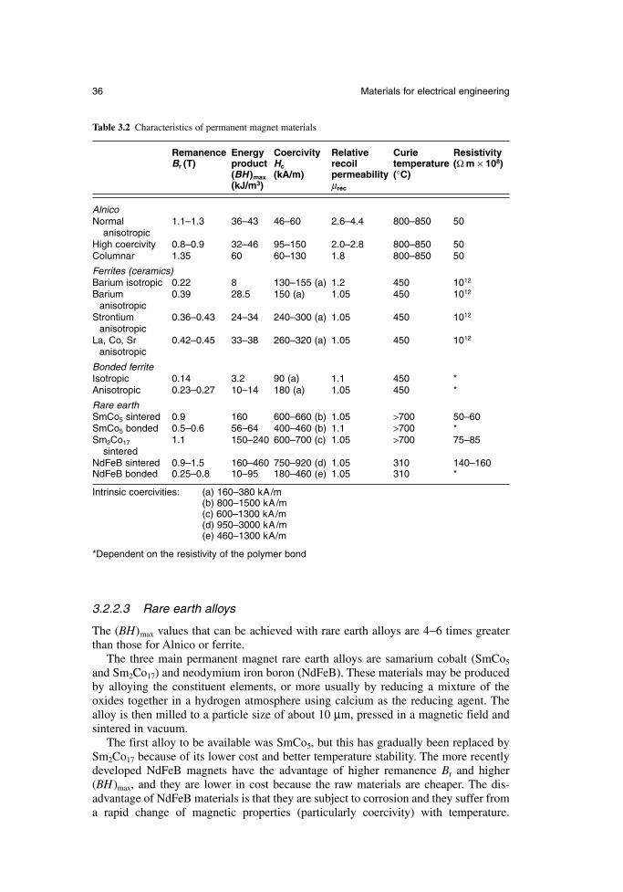
3.2.2.3 Rare earth alloys
The (BH)max values that can be achieved with rare earth alloys are 4−6 times greaterthan those for Alnico or ferrite.
The three main permanent magnet rare earth alloys are samarium cobalt (SmCo5
and Sm2Co17) and neodymium iron boron (NdFeB). These materials may be producedby alloying the constituent elements, or more usually by reducing a mixture of theoxides together in a hydrogen atmosphere using calcium as the reducing agent. Thealloy is then milled to a particle size of about 10 µm, pressed in a magnetic field andsintered in vacuum.
The first alloy to be available was SmCo5, but this has gradually been replaced bySm2Co17 because of its lower cost and better temperature stability. The more recentlydeveloped NdFeB magnets have the advantage of higher remanence Br and higher(BH)max, and they are lower in cost because the raw materials are cheaper. The dis-advantage of NdFeB materials is that they are subject to corrosion and they suffer froma rapid change of magnetic properties (particularly coercivity) with temperature.
36 Materials for electrical engineering
Table 3.2 Characteristics of permanent magnet materials
Remanence Energy Coercivity Relative Curie ResistivityBr (T) product Hc recoil temperature (Ω m × 108)
(BH )max (kA/m) permeability (°C)(kJ/m3) µrec
AlnicoNormal 1.1–1.3 36–43 46–60 2.6–4.4 800–850 50
anisotropicHigh coercivity 0.8–0.9 32–46 95–150 2.0–2.8 800–850 50Columnar 1.35 60 60–130 1.8 800–850 50
Ferrites (ceramics)Barium isotropic 0.22 8 130–155 (a) 1.2 450 1012
Barium 0.39 28.5 150 (a) 1.05 450 1012
anisotropicStrontium 0.36–0.43 24–34 240–300 (a) 1.05 450 1012
anisotropic La, Co, Sr 0.42–0.45 33–38 260–320 (a) 1.05 450 1012
anisotropic
Bonded ferriteIsotropic 0.14 3.2 90 (a) 1.1 450 *Anisotropic 0.23–0.27 10–14 180 (a) 1.05 450 *
Rare earthSmCo5 sintered 0.9 160 600–660 (b) 1.05 >700 50–60SmCo5 bonded 0.5–0.6 56–64 400–460 (b) 1.1 >700 *Sm2Co17 1.1 150–240 600–700 (c) 1.05 >700 75–85
sinteredNdFeB sintered 0.9–1.5 160–460 750–920 (d) 1.05 310 140–160NdFeB bonded 0.25–0.8 10–95 180–460 (e) 1.05 310 *
Intrinsic coercivities: (a) 160–380 kA/m(b) 800–1500 kA/m(c) 600–1300 kA/m(d) 950–3000 kA/m(e) 460–1300 kA/m
*Dependent on the resistivity of the polymer bond
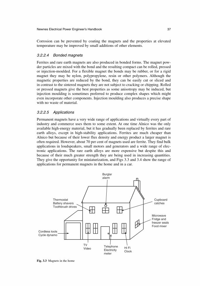
Corrosion can be prevented by coating the magnets and the properties at elevatedtemperature may be improved by small additions of other elements.
3.2.2.4 Bonded magnets
Ferrites and rare earth magnets are also produced in bonded forms. The magnet pow-der particles are mixed with the bond and the resulting compact can be rolled, pressedor injection-moulded. For a flexible magnet the bonds may be rubber, or for a rigidmagnet they may be nylon, polypropylene, resin or other polymers. Although the magnetic properties are reduced by the bond, they can be easily cut or sliced and in contrast to the sintered magnets they are not subject to cracking or chipping. Rolledor pressed magnets give the best properties as some anisotropy may be induced, butinjection moulding is sometimes preferred to produce complex shapes which mighteven incorporate other components. Injection moulding also produces a precise shapewith no waste of material.
3.2.2.5 Applications
Permanent magnets have a very wide range of applications and virtually every part ofindustry and commerce uses them to some extent. At one time Alnico was the onlyavailable high-energy material, but it has gradually been replaced by ferrites and rareearth alloys, except in high-stability applications. Ferrites are much cheaper thanAlnico but because of their lower flux density and energy product a larger magnet isoften required. However, about 70 per cent of magnets used are ferrite. They find bulkapplications in loudspeakers, small motors and generators and a wide range of elec-tronic applications. The rare earth alloys are more expensive but despite this andbecause of their much greater strength they are being used in increasing quantities.They give the opportunity for miniaturization, and Figs 3.3 and 3.4 show the range ofapplications for permanent magnets in the home and in a car.
Newnes Electrical Power Engineer’s Handbook 37
ThermostatBattery shavers Toothbrush drives
Cupboard catches
Hi Fi Clock
TVVideo
Telephone Electricity meter
Microwave Fridge andfreezer sealsFood mixer
Cordless tools Cycle dynamo
Burglaralarm
Fig. 3.3 Magnets in the home
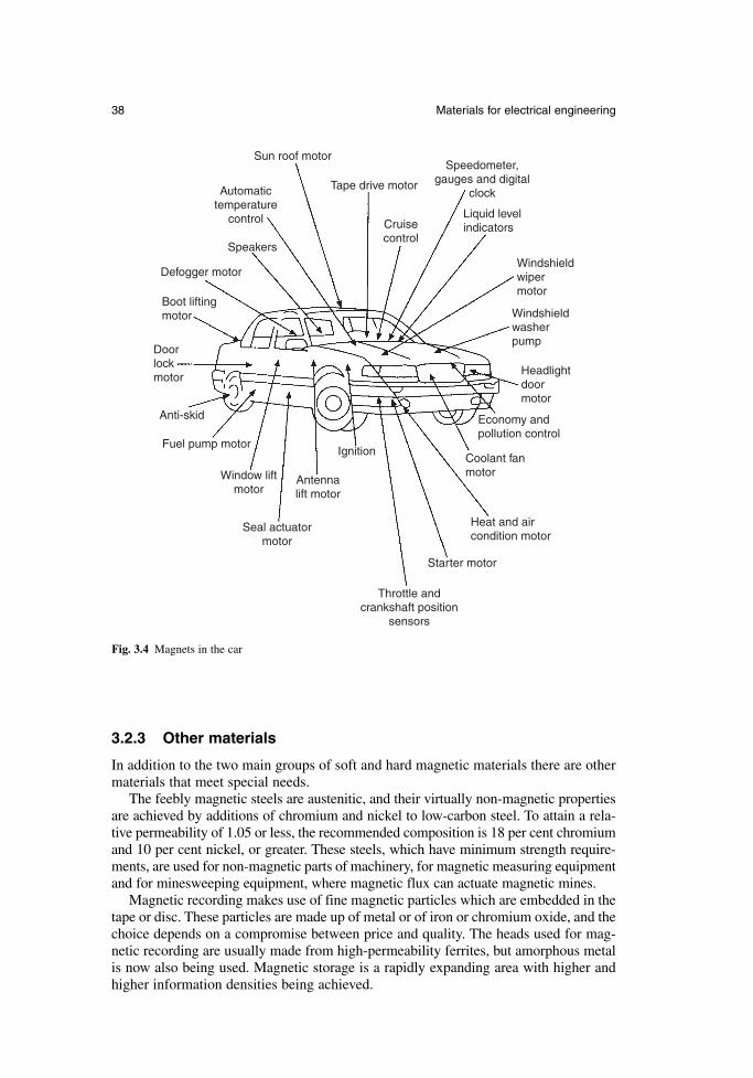
3.2.3 Other materials
In addition to the two main groups of soft and hard magnetic materials there are othermaterials that meet special needs.
The feebly magnetic steels are austenitic, and their virtually non-magnetic propertiesare achieved by additions of chromium and nickel to low-carbon steel. To attain a rela-tive permeability of 1.05 or less, the recommended composition is 18 per cent chromiumand 10 per cent nickel, or greater. These steels, which have minimum strength require-ments, are used for non-magnetic parts of machinery, for magnetic measuring equipmentand for minesweeping equipment, where magnetic flux can actuate magnetic mines.
Magnetic recording makes use of fine magnetic particles which are embedded in thetape or disc. These particles are made up of metal or of iron or chromium oxide, and thechoice depends on a compromise between price and quality. The heads used for mag-netic recording are usually made from high-permeability ferrites, but amorphous metalis now also being used. Magnetic storage is a rapidly expanding area with higher andhigher information densities being achieved.
38 Materials for electrical engineering
Sun roof motor
Tape drive motor
Cruisecontrol
Speedometer,gauges and digital
clock
Liquid levelindicators
Windshieldwipermotor
Headlightdoormotor
Economy andpollution control
Coolant fanmotor
Heat and aircondition motor
Windshieldwasherpump
Starter motor
Throttle andcrankshaft position
sensors
Ignition
Antennalift motor
Seal actuatormotor
Window liftmotor
Fuel pump motor
Anti-skid
Doorlockmotor
Boot liftingmotor
Defogger motor
Speakers
Automatictemperature
control
Fig. 3.4 Magnets in the car
3.2.4 Standards
The main national and international standard for magnetic materials is IEC 60404, towhich BS 6404 is equivalent. This standard has many parts with specifications for theproperties of silicon steels, nickel irons and permanent magnets. Also included aremeasurement standards for these materials. The BS standards are currently beingrenumbered with BSEN numbers. These standards have recently been reviewed byStanbury (reference 3D).
3.3 Insulating materials
The reason for using insulating materials is to separate electrically the conducting partsof equipment from each other and from earthed components. Earthed components mayinclude the mechanical casing or structure that is necessary to enable the equipment tobe handled and to operate. Whereas the ‘active’ parts of the equipment play a usefulrole in its operation, the insulation is in many ways a necessary evil. For example inan electric motor the copper of the winding and the steel core making up the magneticcircuit are the active components and both contribute to the power output of the motor;the insulation which keeps these two components apart contributes nothing, in fact ittakes up valuable space and it may be considered by the designer as not much morethan a nuisance.
For these reasons, insulating materials have become a design focus in many typesof electrical equipment, with many companies employing specialists in this field andcarrying out sophisticated life testing of insulation systems. Such is the importanceattached to this field that major international conferences on the subject are held reg-ularly, for instance by the IEEE in USA, IEE and Electrical Insulation Association(EIA) in UK and the European Electrical Insulation Association (EEIM) in Europe, allof which publish the papers presented. Conferences are also held in Canada, India andSouth Africa.
The simplest way to define an insulating material is to state what it is not. It is nota good conductor of electricity and it has a high electrical resistance that decreaseswith rising temperature, unlike conductors. The following are the most important prop-erties of insulating materials:
volume resistivity, which is also known as specific resistance relative permittivity (or dielectric constant), which is defined as the ratio of the
electric flux density produced in the material to that produced in vacuum by thesame electric field strength. The definitions have been set down in eqns 2.1 and2.2. Relative permittivity can be expressed as the ratio of the capacitance of acapacitor made of that material to that of the same capacitor using vacuum asits dielectric (see eqn 2.11).
dielectric loss (or electrical dissipation factor), which is defined as the ratio ofthe power loss in a dielectric material to the total power transmitted through it.It is given by the tangent of the loss angle and is commonly known as tan delta.Tan delta has been defined in eqn 2.43.
The volume resistivity, relative permittivity and tan delta values for a range of insu-lating materials are shown in Table 3.3.
The most important characteristic of an insulating material is its ability to with-stand electric stress without breaking down. This ability is sometimes known as its
Newnes Electrical Power Engineer’s Handbook 39
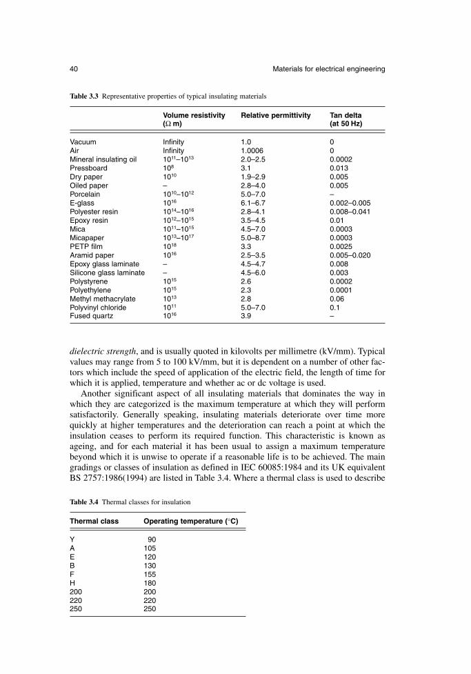
dielectric strength, and is usually quoted in kilovolts per millimetre (kV/mm). Typicalvalues may range from 5 to 100 kV/mm, but it is dependent on a number of other fac-tors which include the speed of application of the electric field, the length of time forwhich it is applied, temperature and whether ac or dc voltage is used.
Another significant aspect of all insulating materials that dominates the way inwhich they are categorized is the maximum temperature at which they will performsatisfactorily. Generally speaking, insulating materials deteriorate over time morequickly at higher temperatures and the deterioration can reach a point at which theinsulation ceases to perform its required function. This characteristic is known as ageing, and for each material it has been usual to assign a maximum temperaturebeyond which it is unwise to operate if a reasonable life is to be achieved. The maingradings or classes of insulation as defined in IEC 60085:1984 and its UK equivalentBS 2757:1986(1994) are listed in Table 3.4. Where a thermal class is used to describe
40 Materials for electrical engineering
Table 3.3 Representative properties of typical insulating materials
Volume resistivity Relative permittivity Tan delta(Ω m) (at 50 Hz)
Vacuum Infinity 1.0 0Air Infinity 1.0006 0Mineral insulating oil 1011–1013 2.0–2.5 0.0002Pressboard 108 3.1 0.013Dry paper 1010 1.9–2.9 0.005Oiled paper – 2.8–4.0 0.005Porcelain 1010–1012 5.0–7.0 –E-glass 1016 6.1–6.7 0.002–0.005Polyester resin 1014–1016 2.8–4.1 0.008–0.041Epoxy resin 1012–1015 3.5–4.5 0.01Mica 1011–1015 4.5–7.0 0.0003Micapaper 1013–1017 5.0–8.7 0.0003PETP film 1018 3.3 0.0025Aramid paper 1016 2.5–3.5 0.005–0.020Epoxy glass laminate – 4.5–4.7 0.008Silicone glass laminate – 4.5–6.0 0.003Polystyrene 1015 2.6 0.0002Polyethylene 1015 2.3 0.0001Methyl methacrylate 1013 2.8 0.06Polyvinyl chloride 1011 5.0–7.0 0.1Fused quartz 1016 3.9 –
Table 3.4 Thermal classes for insulation
Thermal class Operating temperature (°C)
Y 90A 105E 120B 130F 155H 180200 200220 220250 250
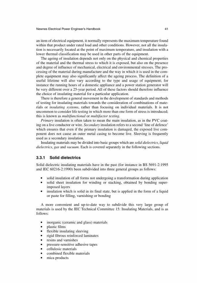
an item of electrical equipment, it normally represents the maximum temperature foundwithin that product under rated load and other conditions. However, not all the insula-tion is necessarily located at the point of maximum temperature, and insulation with alower thermal classification may be used in other parts of the equipment.
The ageing of insulation depends not only on the physical and chemical propertiesof the material and the thermal stress to which it is exposed, but also on the presenceand degree of influence of mechanical, electrical and environmental stresses. The pro-cessing of the material during manufacture and the way in which it is used in the com-plete equipment may also significantly affect the ageing process. The definition of auseful lifetime will also vary according to the type and usage of equipment; forinstance the running hours of a domestic appliance and a power station generator willbe very different over a 25-year period. All of these factors should therefore influencethe choice of insulating material for a particular application.
There is therefore a general movement in the development of standards and methodsof testing for insulating materials towards the consideration of combinations of mate-rials or insulating systems, rather than focusing on individual materials. It is notuncommon to consider life testing in which more than one form of stress is introduced;this is known as multifunctional or multifactor testing.
Primary insulation is often taken to mean the main insulation, as in the PVC coat-ing on a live conductor or wire. Secondary insulation refers to a second ‘line of defence’which ensures that even if the primary insulation is damaged, the exposed live com-ponent does not cause an outer metal casing to become live. Sleeving is frequentlyused as a secondary insulation.
Insulating materials may be divided into basic groups which are solid dielectrics, liquiddielectrics, gas and vacuum. Each is covered separately in the following sections.
3.3.1 Solid dielectrics
Solid dielectric insulating materials have in the past (for instance in BS 5691-2:1995and IEC 60216-2:1990) been subdivided into three general groups as follows:
solid insulation of all forms not undergoing a transformation during application solid sheet insulation for winding or stacking, obtained by bonding super-
imposed layers insulation which is solid in its final state, but is applied in the form of a liquid
or paste for filling, varnishing or bonding
A more convenient and up-to-date way to subdivide this very large group of materials is used by the IEC Technical Committee 15: Insulating Materials, and is asfollows:
inorganic (ceramic and glass) materials plastic films flexible insulating sleeving rigid fibrous reinforced laminates resins and varnishes pressure-sensitive adhesive tapes cellulosic materials combined flexible materials mica products
Newnes Electrical Power Engineer’s Handbook 41
This subdivision is organized on the basis of application and is therefore more help-ful to the practising engineer. A brief description of each of these classes of materialis given in the following sections.
3.3.1.1 Inorganic (ceramic and glass) materials
A major application for materials in this category is in high-voltage overhead lines as suspension insulators (see Figs 13.2 and 13.8), or as bushings on high-voltage transformers and switchgear (see Fig. 6.14). In either case the material is formed into a series of flanged discs to increase the creepage distance along the surface of thecomplete insulator. Ceramic materials are used for a number of reasons, whichinclude:
ease of production of a wide range of shapes good electrical breakdown strength retention of insulating characteristics in the event of surface damage
3.3.1.2 Plastic films
Materials such as polyethylene terephthalate (PETP, more commonly referred to aspolyester), polycarbonate, polyimide and polyethylene naphthalate (PEN) have beenused as films, depending on the operating temperature requirement, in a variety ofapplications. These include the insulation between foils in capacitors, slot insulation inrotating electrical machines (either itself or as a composite with other sheet materials)and more recently as a backing for mica-based products used in the insulation of high-voltage equipment. Plastic films are used in applications requiring dimensional stability,high dielectric strength, moisture resistance and physical toughness.
3.3.1.3 Flexible insulating sleeving
This fulfils a number of requirements including the provision of primary or secondaryelectrical insulation of component wiring, the protection of cables and componentsfrom the deleterious effects of mechanical and thermal damage, and as a rapid andlow-cost method of bunching and containing cables. Sleevings may find application inelectrical machines, transformers, domestic and heating appliances, light fittings, cableconnections, switchgear and as wiring harnesseses in domestic appliances and in vehicles. They are used because of their ease of application, flexibility and high dielec-tric strength and they lend themselves to an extremely wide range of formats. Theseinclude shrink sleeving, expandable constructions and textile-reinforced grades incor-porating glass, polyester, aramid or keramid yarns, or sometimes a combination togetherwith a coating of acrylic, silicone or polyurethane resins, for low and high voltage andtemperatures across the range −70°C to + 450°C.
3.3.1.4 Rigid fibrous reinforced laminates
In the manufacture of most electrical equipment, there is a need for items machinedout of solid board or in the form of tubes and rods. These items can take the form ofdensified wood or laminates of paper, woven cotton, glass or polyester, or glass orpolyester random mats laminated together with a thermosetting resin which might bephenolic, epoxy, polyester, melamine, silicone or polyimide, depending upon the prop-erties required. Rigid boards are used because they are capable of being machined to
42 Materials for electrical engineering

size, and they retain their shape and properties during their service life, unlike unsea-soned timber which was used in early equipment.
3.3.1.5 Resins and varnishes
In addition to their use in the laminates outlined in section 3.3.1.4, a wide range of var-nishes and resins are used by themselves in the impregnation and coating of electricalequipment in order to improve its resistance to working conditions, to enhance its elec-trical characteristics and to increase its working life. At first many resins and varnisheswere based on naturally occurring materials such as bitumen, shellac and vegetableoils, but now they are synthetically produced in a comprehensive range of thermo-plastic, thermosetting and elastomeric forms. The more common types are phenolic,polyester, epoxy, silicone and polyimide, and these can be formulated to provide themost suitable processing and the required final characteristics. Varnishes and resins areused because of their ability to impregnate, coat and bond basic insulating materials;this assists in the application of the insulating materials and it significantly improvestheir service life and their ability to withstand dirt and moisture.
3.3.1.6 Pressure-sensitive adhesive tapes
Certain types of pressure-sensitive adhesive (PSA) tapes have become so much a partof modern life that the trade names have been absorbed into everyday language. Theusefulness of PSA in short lengths for holding down, sealing or locating appliesequally in the field of insulation and a range of tapes has been developed which isbased on paper, films (as in section 3.3.1.2) or woven glass cloth, coated with suitableadhesive such as rubber, silicone or acrylic.
3.3.1.7 Cellulosic materials
Materials in the form of papers, pressboards and presspapers continue to play a vitalrole in oil-filled power transformers. Included in this area are also other materialswhich are produced by paper-making techniques, but which use aramid fibres; thesematerials find wide application in high-temperature and dry-type transformers as wellas in other types of electrical equipment. Cellulose materials are mainly used in con-junction with oil, and it is their porous nature which lends itself to successful use intransformers and cables.
3.3.1.8 Combined flexible materials
In order to produce suitable materials with the required properties such as tear strength,electric strength and thermal resistance at an acceptable price, a range of laminated orcombined flexible sheet products has been developed. These employ cellulosic, poly-ester and aramid papers or fleeces, also glass and polyester fabrics as well as other mate-rials, in combination with many of the plastic films already referred to, in a range offorms to suit the application. These products are used in large quantities in low-voltageelectric motors and generators.
3.3.1.9 Mica products
Materials based on mica, a naturally occurring mineral, play a central part in thedesign and manufacture of high-voltage rotating machines. Originally the material was
Newnes Electrical Power Engineer’s Handbook 43
in the form of mica splittings, but at present the industry uses predominantly micapaper,which is produced by breaking down the mica into small platelets by chemical ormechanical means, producing a slurry and then feeding this through a traditional paper-making machine. The resulting micapaper, when suitably supported by a woven glassor film backing (see section 3.3.1.2) and impregnated with epoxy or a similar resin, isused to insulate the copper bars which make up the stator winding of the machine.Micapaper is used in the ground insulation of the winding which is shown as part ofthe stator slot section illustrated in Fig. 3.5.
Micapaper products are available in a resin-rich form, in which all the necessaryresin for consolidation of the insulation around the winding is included within the material. This consolidation is usually carried out in large steam or electrically heatedpresses into which an insulated coil side or bar can be placed; heat and pressure are thenapplied as necessary to cure fully the resin-rich micapaper insulation. Alternatively,micapaper products are available for use with Vacuum Pressure Impregnation (VPI), inwhich most of the resin is introduced after winding the machine. The use of VPI elim-inates the need to consolidate the insulation in a press; consolidation is achieved eitherby the use of hydrostatic forces or by ensuring full impregnation of the bars or coilsalready placed or wound into slots. A large electrical machine stator is shown beinglowered into a VPI tank in Fig. 3.6.
Mica-based products dominate high-voltage insulation systems because of theirunique combination of properties, which include the following:
high dielectric strength low dielectric loss at high frequency high surface and volume resistivity excellent resistance to corona discharge and electric arc erosion temperature capability from −273°C to 1000°C flame resistance excellent chemical resistance high resistance to compressive forces
3.3.1.10 Textile insulation
Although the use of fully varnished fabric is becoming less common, products usingglass and polyester-based yarn, and to a lesser extent cotton and rayon, are still in use.
A much larger range of unvarnished narrow-fabric products, more commonly calledwoven tapes, exists and these products use various combinations of glass, polyester andaramid yarns to meet specific applications. Primarily these tapes are used as finishingon top of other insulation such as micapaper, in order to provide a tough outer surfacewhich can readily be coated with a final varnish or paint finish. When manufactured onmodern needle looms they are an economic proposition.
Woven tapes are used because of their ease of application, good conformity and bed-ding down. An example of the complex shapes that they can be used to cover is shownin Fig. 3.7, which illustrates the endwinding of a high-voltage electrical machine.
3.3.1.11 Elastomers and thermoplastics
There is a very wide range of polymeric and rubber-like insulation materials. These havetraditionally been dealt with in connection with electric cables and IEC and BSI reflectthis by dealing with them separately in Technical Committee 20: Electrical Cables.
44 Materials for electrical engineering
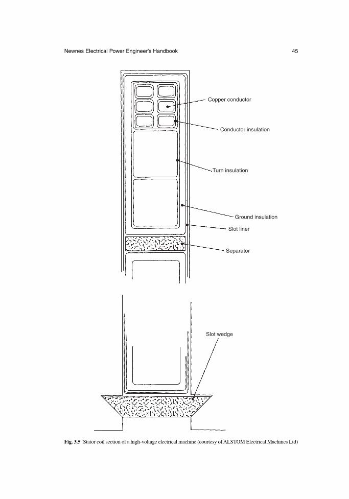
Newnes Electrical Power Engineer’s Handbook 45
Copper conductor
Conductor insulation
Turn insulation
Ground insulation
Slot liner
Separator
Slot wedge
Fig. 3.5 Stator coil section of a high-voltage electrical machine (courtesy of ALSTOM Electrical Machines Ltd)
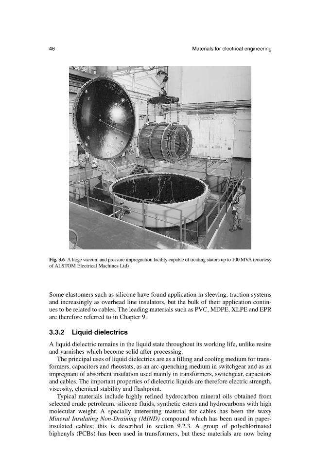
Some elastomers such as silicone have found application in sleeving, traction systemsand increasingly as overhead line insulators, but the bulk of their application contin-ues to be related to cables. The leading materials such as PVC, MDPE, XLPE and EPRare therefore referred to in Chapter 9.
3.3.2 Liquid dielectrics
A liquid dielectric remains in the liquid state throughout its working life, unlike resinsand varnishes which become solid after processing.
The principal uses of liquid dielectrics are as a filling and cooling medium for trans-formers, capacitors and rheostats, as an arc-quenching medium in switchgear and as animpregnant of absorbent insulation used mainly in transformers, switchgear, capacitorsand cables. The important properties of dielectric liquids are therefore electric strength,viscosity, chemical stability and flashpoint.
Typical materials include highly refined hydrocarbon mineral oils obtained fromselected crude petroleum, silicone fluids, synthetic esters and hydrocarbons with highmolecular weight. A specially interesting material for cables has been the waxyMineral Insulating Non-Draining (MIND) compound which has been used in paper-insulated cables; this is described in section 9.2.3. A group of polychlorinatedbiphenyls (PCBs) has been used in transformers, but these materials are now being
46 Materials for electrical engineering
Fig. 3.6 A large vaccum and pressure impregnation facility capable of treating stators up to 100 MVA (courtesyof ALSTOM Electrical Machines Ltd)
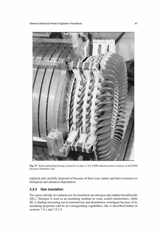
replaced and carefully disposed of because of their toxic nature and their resistance tobiological and chemical degradation.
3.3.3 Gas insulation
Two gases already in common use for insulation are nitrogen and sulphur hexafluoride(SF6). Nitrogen is used as an insulating medium in some sealed transformers, whileSF6 is finding increasing use in transmission and distribution switchgear because of itsinsulating properties and its arc-extinguishing capabilities; this is described further insections 7.4.1 and 7.5.3.2.
Newnes Electrical Power Engineer’s Handbook 47
Fig. 3.7 Stator endwinding bracing system for a 4-pole, 11 kV, 8 MW induction motor (courtesy of ALSTOMElectrical Machines Ltd)
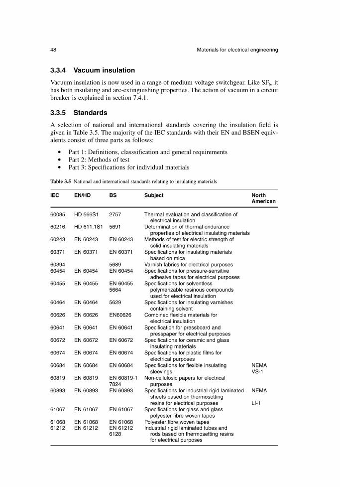
3.3.4 Vacuum insulation
Vacuum insulation is now used in a range of medium-voltage switchgear. Like SF6, ithas both insulating and arc-extinguishing properties. The action of vacuum in a circuitbreaker is explained in section 7.4.1.
3.3.5 Standards
A selection of national and international standards covering the insulation field isgiven in Table 3.5. The majority of the IEC standards with their EN and BSEN equiv-alents consist of three parts as follows:
Part 1: Definitions, classsification and general requirements Part 2: Methods of test Part 3: Specifications for individual materials
48 Materials for electrical engineering
Table 3.5 National and international standards relating to insulating materials
IEC EN/HD BS Subject North American
60085 HD 566S1 2757 Thermal evaluation and classification of electrical insulation
60216 HD 611.1S1 5691 Determination of thermal endurance properties of electrical insulating materials
60243 EN 60243 EN 60243 Methods of test for electric strength of solid insulating materials
60371 EN 60371 EN 60371 Specifications for insulating materialsbased on mica
60394 5689 Varnish fabrics for electrical purposes60454 EN 60454 EN 60454 Specifications for pressure-sensitive
adhesive tapes for electrical purposes60455 EN 60455 EN 60455 Specifications for solventless
5664 polymerizable resinous compounds used for electrical insulation
60464 EN 60464 5629 Specifications for insulating varnishes containing solvent
60626 EN 60626 EN60626 Combined flexible materials for electrical insulation
60641 EN 60641 EN 60641 Specification for pressboard and presspaper for electrical purposes
60672 EN 60672 EN 60672 Specifications for ceramic and glass insulating materials
60674 EN 60674 EN 60674 Specifications for plastic films for electrical purposes
60684 EN 60684 EN 60684 Specifications for flexible insulating NEMAsleevings VS-1
60819 EN 60819 EN 60819-1 Non-cellulosic papers for electrical 7824 purposes
60893 EN 60893 EN 60893 Specifications for industrial rigid laminated NEMAsheets based on thermosetting resins for electrical purposes LI-1
61067 EN 61067 EN 61067 Specifications for glass and glass polyester fibre woven tapes
61068 EN 61068 EN 61068 Polyester fibre woven tapes61212 EN 61212 EN 61212 Industrial rigid laminated tubes and
6128 rods based on thermosetting resins for electrical purposes
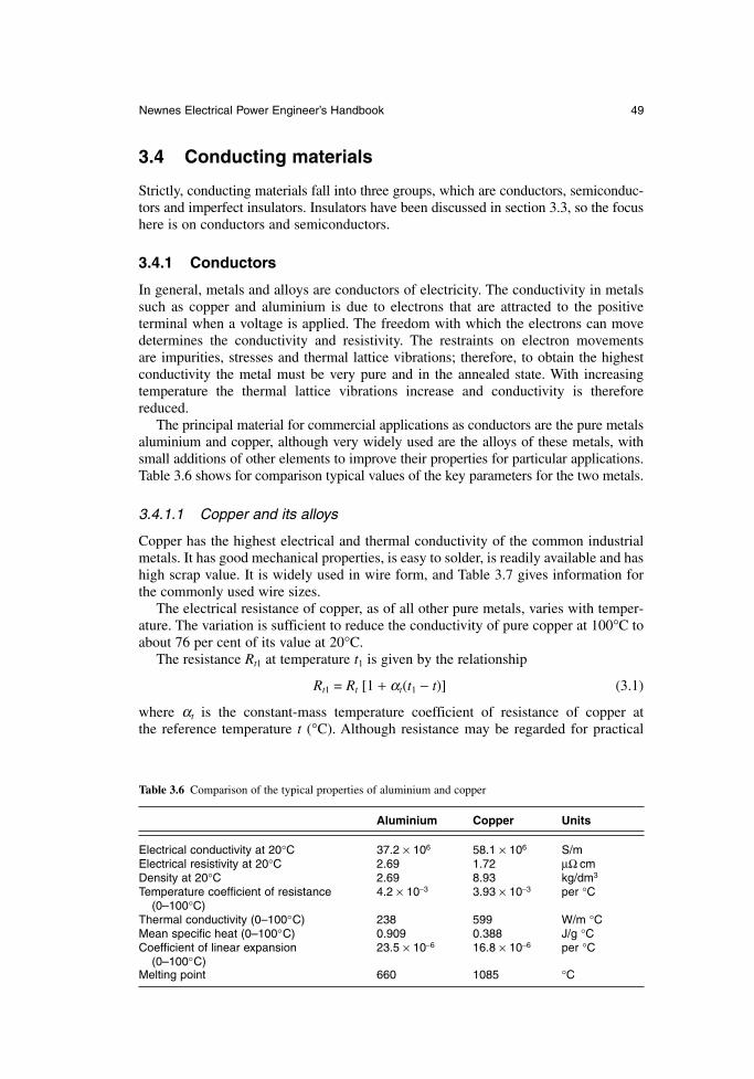
3.4 Conducting materials
Strictly, conducting materials fall into three groups, which are conductors, semiconduc-tors and imperfect insulators. Insulators have been discussed in section 3.3, so the focushere is on conductors and semiconductors.
3.4.1 Conductors
In general, metals and alloys are conductors of electricity. The conductivity in metalssuch as copper and aluminium is due to electrons that are attracted to the positive terminal when a voltage is applied. The freedom with which the electrons can movedetermines the conductivity and resistivity. The restraints on electron movements are impurities, stresses and thermal lattice vibrations; therefore, to obtain the highestconductivity the metal must be very pure and in the annealed state. With increasingtemperature the thermal lattice vibrations increase and conductivity is thereforereduced.
The principal material for commercial applications as conductors are the pure metalsaluminium and copper, although very widely used are the alloys of these metals, withsmall additions of other elements to improve their properties for particular applications.Table 3.6 shows for comparison typical values of the key parameters for the two metals.
3.4.1.1 Copper and its alloys
Copper has the highest electrical and thermal conductivity of the common industrialmetals. It has good mechanical properties, is easy to solder, is readily available and hashigh scrap value. It is widely used in wire form, and Table 3.7 gives information forthe commonly used wire sizes.
The electrical resistance of copper, as of all other pure metals, varies with temper-ature. The variation is sufficient to reduce the conductivity of pure copper at 100°C toabout 76 per cent of its value at 20°C.
The resistance Rt1 at temperature t1 is given by the relationship
Rt1 = Rt [1 + αt(t1 − t)] (3.1)
where αt is the constant-mass temperature coefficient of resistance of copper at the reference temperature t (°C). Although resistance may be regarded for practical
Newnes Electrical Power Engineer’s Handbook 49
Table 3.6 Comparison of the typical properties of aluminium and copper
Aluminium Copper Units
Electrical conductivity at 20°C 37.2 × 10⁶ 58.1 × 10⁶ S/mElectrical resistivity at 20°C 2.69 1.72 µΩ cmDensity at 20°C 2.69 8.93 kg/dm3
Temperature coefficient of resistance 4.2 × 10⁻³ 3.93 × 10⁻³ per °C(0–100°C)
Thermal conductivity (0–100°C) 238 599 W/m °CMean specific heat (0–100°C) 0.909 0.388 J/g °CCoefficient of linear expansion 23.5 × 10⁻⁶ 16.8 × 10⁻⁶ per °C
(0–100°C)Melting point 660 1085 °C
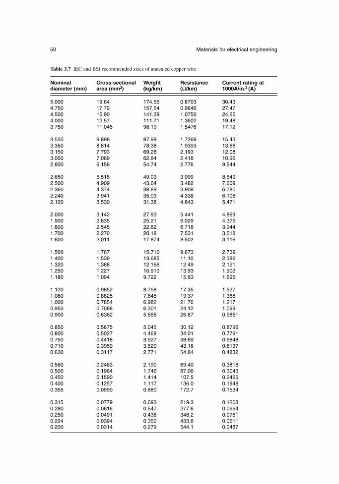
50 Materials for electrical engineering
Table 3.7 IEC and BSI recommended sizes of annealed copper wire
Nominal Cross-sectional Weight Resistance Current rating atdiameter (mm) area (mm2) (kg/km) (Ω/km) 1000A/in.2 (A)
5.000 19.64 174.56 0.8703 30.434.750 17.72 157.54 0.9646 27.474.500 15.90 141.39 1.0750 24.654.000 12.57 111.71 1.3602 19.483.750 11.045 98.19 1.5476 17.12
3.550 9.898 87.99 1.7269 15.433.350 8.814 78.38 1.9393 13.663.150 7.793 69.28 2.193 12.083.000 7.069 62.84 2.418 10.962.800 6.158 54.74 2.776 9.544
2.650 5.515 49.03 3.099 8.5492.500 4.909 43.64 3.482 7.6092.360 4.374 38.89 3.908 6.7802.240 3.941 35.03 4.338 6.1082.120 3.530 31.38 4.843 5.471
2.000 3.142 27.93 5.441 4.8691.900 2.835 25.21 6.029 4.3751.800 2.545 22.62 6.718 3.9441.700 2.270 20.18 7.531 3.5181.600 2.011 17.874 8.502 3.116
1.500 1.767 15.710 9.673 2.7391.400 1.539 13.685 11.10 2.3861.320 1.368 12.166 12.49 2.1211.250 1.227 10.910 13.93 1.9021.180 1.094 9.722 15.63 1.695
1.120 0.9852 8.758 17.35 1.5271.060 0.8825 7.845 19.37 1.3681.000 0.7854 6.982 21.76 1.2170.950 0.7088 6.301 24.12 1.0990.900 0.6362 5.656 26.87 0.9861
0.850 0.5675 5.045 30.12 0.87960.800 0.5027 4.469 34.01 0.77910.750 0.4418 3.927 38.69 0.68480.710 0.3959 3.520 43.18 0.61370.630 0.3117 2.771 54.84 0.4832
0.560 0.2463 2.190 69.40 0.38180.500 0.1964 1.746 87.06 0.30430.450 0.1590 1.414 107.5 0.24650.400 0.1257 1.117 136.0 0.19480.355 0.0990 0.880 172.7 0.1534
0.315 0.0779 0.693 219.3 0.12080.280 0.0616 0.547 277.6 0.09540.250 0.0491 0.436 348.2 0.07610.224 0.0394 0.350 433.8 0.06110.200 0.0314 0.279 544.1 0.0487
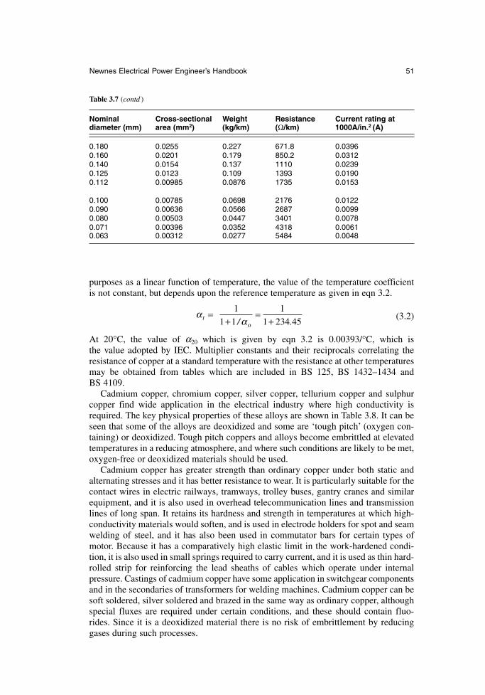
purposes as a linear function of temperature, the value of the temperature coefficientis not constant, but depends upon the reference temperature as given in eqn 3.2.
(3.2)
At 20°C, the value of α20 which is given by eqn 3.2 is 0.00393/°C, which is the value adopted by IEC. Multiplier constants and their reciprocals correlating theresistance of copper at a standard temperature with the resistance at other temperaturesmay be obtained from tables which are included in BS 125, BS 1432–1434 and BS 4109.
Cadmium copper, chromium copper, silver copper, tellurium copper and sulphurcopper find wide application in the electrical industry where high conductivity isrequired. The key physical properties of these alloys are shown in Table 3.8. It can beseen that some of the alloys are deoxidized and some are ‘tough pitch’ (oxygen con-taining) or deoxidized. Tough pitch coppers and alloys become embrittled at elevatedtemperatures in a reducing atmosphere, and where such conditions are likely to be met,oxygen-free or deoxidized materials should be used.
Cadmium copper has greater strength than ordinary copper under both static andalternating stresses and it has better resistance to wear. It is particularly suitable for thecontact wires in electric railways, tramways, trolley buses, gantry cranes and similarequipment, and it is also used in overhead telecommunication lines and transmissionlines of long span. It retains its hardness and strength in temperatures at which high-conductivity materials would soften, and is used in electrode holders for spot and seamwelding of steel, and it has also been used in commutator bars for certain types ofmotor. Because it has a comparatively high elastic limit in the work-hardened condi-tion, it is also used in small springs required to carry current, and it is used as thin hard-rolled strip for reinforcing the lead sheaths of cables which operate under internalpressure. Castings of cadmium copper have some application in switchgear componentsand in the secondaries of transformers for welding machines. Cadmium copper can besoft soldered, silver soldered and brazed in the same way as ordinary copper, althoughspecial fluxes are required under certain conditions, and these should contain fluo-rides. Since it is a deoxidized material there is no risk of embrittlement by reducinggases during such processes.
ααt =
+=
+
/ .
1
1 1
1
1 234 45o
Newnes Electrical Power Engineer’s Handbook 51
Table 3.7 (contd )
Nominal Cross-sectional Weight Resistance Current rating atdiameter (mm) area (mm2) (kg/km) (Ω/km) 1000A/in.2 (A)
0.180 0.0255 0.227 671.8 0.03960.160 0.0201 0.179 850.2 0.03120.140 0.0154 0.137 1110 0.02390.125 0.0123 0.109 1393 0.01900.112 0.00985 0.0876 1735 0.0153
0.100 0.00785 0.0698 2176 0.01220.090 0.00636 0.0566 2687 0.00990.080 0.00503 0.0447 3401 0.00780.071 0.00396 0.0352 4318 0.00610.063 0.00312 0.0277 5484 0.0048
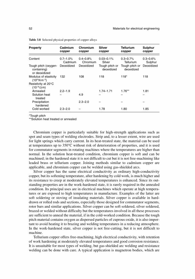
Chromium copper is particularly suitable for high-strength applications such asspot and seam types of welding electrodes. Strip and, to a lesser extent, wire are usedfor light springs which carry current. In its heat-treated state, the material can be usedat temperatures up to 350°C without risk of deterioration of properties, and it is usedfor commutator segments in rotating machines where the temperatures are higher thannormal. In the solution heat-treated condition, chromium copper is soft and can bemachined; in the hardened state it is not difficult to cut but it is not free-machining likeleaded brass or tellurium copper. Joining methods similar to cadmium copper areapplicable, and chromium copper can be welded using gas-shielded arcs.
Silver copper has the same electrical conductivity as ordinary high-conductivitycopper, but its softening temperature, after hardening by cold work, is much higher andits resistance to creep at moderately elevated temperatures is enhanced. Since its out-standing properties are in the work-hardened state, it is rarely required in the annealedcondition. Its principal uses are in electrical machines which operate at high tempera-tures or are exposed to high temperatures in manufacture. Examples of the latter aresoft soldering or stoving of insulating materials. Silver copper is available in hard-drawn or rolled rods and sections, especially those designed for commutator segments,rotor bars and similar applications. Silver copper can be soft soldered, silver soldered,brazed or welded without difficulty but the temperatures involved in all these processesare sufficient to anneal the material, if in the cold-worked condition. Because the toughpitch material contains oxygen as dispersed particles of cuprous oxide, it is also impor-tant to avoid heating it to brazing and welding temperatures in a reducing atmosphere.In the work-hardened state, silver copper is not free-cutting, but it is not difficult tomachine.
Tellurium copper offers free-machining, high electrical conductivity, with retentionof work hardening at moderately elevated temperatures and good corrosion resistance.It is unsuitable for most types of welding, but gas-shielded arc welding and resistancewelding can be done with care. A typical application is magnetron bodies, which are
52 Materials for electrical engineering
Table 3.8 Selected physical properties of copper alloys
Property Cadmium Chromium Silver Tellurium Sulphurcopper copper copper copper copper
Content 0.7–1.0% 0.4–0.8% 0.03–0.1% 0.3–0.7% 0.3–0.6%Cadmium Chromium Silver Tellurium Sulphur
Tough pitch (oxygen- Deoxidized Deoxidized Tough pitch or Tough pitch or Deoxidizedcontaining) deoxidized deoxidizedor deoxidized
Modulus of elasticity 132 108 118 118* 118(109 N m−2)
Resistivity at 20°C(10−8 Ω m)Annealed 2.2–1.9 1.74–1.71 1.76** 1.81Solution heat – 4.9 – – –
treatedPrecipitation 2.3–2.0 – – –
hardenedCold worked 2.3–2.0 – 1.78 1.80 1.85
*Tough pitch**Solution heat treated or annealed
often machined from solid. Tellurium copper can be soft soldered, silver soldered andbrazed without difficulty. For tough pitch, brazing should be done in an inert or slightlyoxidizing atmosphere since reducing atmospheres are conducive to embrittlement.Deoxidized tellurium copper is not subject to embrittlement.
Sulphur copper is free-machining and does not have the tendency of tellurium copper to form coarse stringers in the structure which can affect accuracy and finish.It has greater resistance to softening than high-conductivity copper at moderately hightemperatures and gives good corrosion resistance. Sulphur copper has applications inall machined parts requiring high electrical conductivity, such as contacts and connec-tors; its joining characteristics are similar to those of tellurium copper. It is deoxidizedwith a controlled amount of phosphorus and therefore does not suffer from hydrogenembrittlement in normal torch brazing, but long exposure to a reducing atmospherecan result in loss of sulphur and consequent embrittlement.
3.4.1.2 Aluminium and its alloys
For many years aluminium has been used as a conductor in most branches of electricalengineering. Several aluminium alloys are also good conductors, combining strengthwith acceptable conductivity. Aluminium is less dense and cheaper than copper, andits price is not subject to the same wide fluctuations as copper. World production ofaluminium has steadily increased over recent years to overtake that of copper, whichit has replaced in many electrical applications.
There are two specifications for aluminium, one for pure metal grade 1E and theother for a heat-treatable alloy 91E. Grade 1E is available in a number of forms whichare extruded tube (E1E), solid conductor (C1E), wire (G1E) and rolled strip (D1E).The heat-treatable alloy, which has moderate strength and a conductivity approachingthat of aluminium, is available in tubes and sections (E91E).The main application areas are as follows.
Busbars. Although aluminium has been used as busbars for many years, only recentlyhas it been accepted generally. The electricity supply industry has now adopted alu-minium busbars as standard in 400 kV substations, and they are also used widely inswitchgear, plating shops, rising mains and in UK aluminium smelting plants.Sometimes busbars are tin-plated in applications where joints have to be opened andre-made frequently.
Cable. The use of aluminium in wires and cables is described at length in Chapter 9.Aluminium is used extensively in cables rated up to 11 kV and house wiring cableabove 2.5 mm2 is also available with aluminium conductor.
Overhead lines. The Aluminium Conductor Steel Reinforced (ACSR) conductor referredto in section 13.3 and Fig. 13.3 is the standard adopted throughout the world, althoughin USA Aluminium Conductor Aluminium alloy wire Reinforced (ACAR) is rapidlygaining acceptance; it offers freedom from bimetallic corrosion and improved con-ductance for a given cross section.
Motors. Aluminium is cast into the cage rotors of induction motors forming the rotorbars and end rings. Motor frames are often die-cast or extruded from aluminium, andshaft-driven cooling fans are sometimes of cast aluminium.
Newnes Electrical Power Engineer’s Handbook 53
Foil windings. These are suitable for transformers, reactors and solenoids. They offerbetter space factor than a wire-wound copper coil, the aluminium conductor occupy-ing about 90 per cent of the space, compared to 60 per cent occupied by copper. Heattransfer is aided by the improved space factor and the reduced insulation that is neededin foil windings, and efficient radial heat transfer ensures an even temperature gradient.Windings of transformers are described in greater depth in section 6.2.2.
Heating elements. These have been developed in aluminium but they are not widelyused at present. Applications include foil film wallpaper, curing concrete and possiblysoil warming.
Heat sinks. They are an ideal application for aluminium because of its high thermalconductivity and the ease of extrusion or casting into solid or hollow shapes with inte-gral fins. They are used in a variety of applications such as semiconductor devices andtransformer tanks. The low weight of aluminium heat sinks make them ideal for pole-mounted transformers and there is the added advantage that the material does not reactwith transformer oil to form a sludge.
3.4.1.3 Resistance alloys
There are many alloys with high resistivity, the two main applications being resistorsand heating elements.
Alloys for standard resistors are required to have a low temperature coefficient ofresistivity in the region of room temperature. The traditionally used alloy is Manganin,but this has increasingly been replaced by Ni–Cr–Al alloys with the trade namesKarma and Evanohm. The resistivity of these alloys is about 1.3 µΩ m and the tem-perature coefficient is ± 0.5 × 10⁻⁵/°C. For lower precision applications copper–nickelalloys are used, but these have a lower resistivity and a relatively high thermo emfagainst copper.
For heating elements in electric fires, storage heaters and industrial and laboratoryfurnaces there is a considerable range of alloys available. A considerable resistivity isrequired from the alloy in order to limit the bulk of wire required, and the temperaturecoefficient of resistivity must be small so that the current remains reasonably constantwith a constant applied voltage. The Ni–Cr alloys are used for temperatures up to1100°C, and Cr–Fe–Al alloys are used up to 1400°C. Ceramic rods are used for highertemperatures and silicon carbide may be used up to 1600°C. For even higher temper-atures, the cermets MoSi2 and Zircothal are used. The maximum temperature at whichthe materials may be used depends on the type of atmosphere.
3.4.2 Semiconductors
A semiconductor is able to conduct electricity at room temperature more readily thanan insulator but less readily than a conductor. At low temperatures, pure semiconduc-tors behave like insulators. When the temperature of a semiconductor is increased, orwhen it is illuminated, electrons are energized and these become conduction electrons.Deficiencies or ‘holes’ are left behind; these are said to be carriers of positive elec-tricity. The resulting conduction is called intrinsic conduction.
The common semiconductors include elements such as silicon, germanium and sele-nium and compounds such as indium arsenide and gallium antimonide. Germaniumwas originally used for the manufacture of semiconductor devices, but because of
54 Materials for electrical engineering
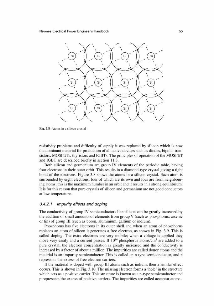
resistivity problems and difficulty of supply it was replaced by silicon which is nowthe dominant material for production of all active devices such as diodes, bipolar tran-sistors, MOSFETs, thyristors and IGBTs. The principles of operation of the MOSFETand IGBT are described briefly in section 11.3.
Both silicon and germanium are group IV elements of the periodic table, havingfour electrons in their outer orbit. This results in a diamond-type crystal giving a tightbond of the electrons. Figure 3.8 shows the atoms in a silicon crystal. Each atom is surrounded by eight electrons, four of which are its own and four are from neighbour-ing atoms; this is the maximum number in an orbit and it results in a strong equilibrium.It is for this reason that pure crystals of silicon and germanium are not good conductorsat low temperature.
3.4.2.1 Impurity effects and doping
The conductivity of group IV semiconductors like silicon can be greatly increased bythe addition of small amounts of elements from group V (such as phosphorus, arsenicor tin) of group III (such as boron, aluminium, gallium or indium).
Phosphorus has five electrons in its outer shell and when an atom of phosphorusreplaces an atom of silicon it generates a free electron, as shown in Fig. 3.9. This iscalled doping. The extra electrons are very mobile; when a voltage is applied theymove very easily and a current passes. If 1016 phosphorus atoms/cm3 are added to apure crystal, the electron concentration is greatly increased and the conductivity isincreased by a factor of about a million. The impurities are called donor atoms and thematerial is an impurity semiconductor. This is called an n-type semiconductor, and nrepresents the excess of free electron carriers.
If the material is doped with group III atoms such as indium, then a similar effectoccurs. This is shown in Fig. 3.10. The missing electron forms a ‘hole’ in the structurewhich acts as a positive carrier. This structure is known as a p-type semiconductor andp represents the excess of positive carriers. The impurities are called acceptor atoms.
Newnes Electrical Power Engineer’s Handbook 55
Si Si Si Si
Si Si Si Si
Si Si Si Si
Fig. 3.8 Atoms in a silicon crystal
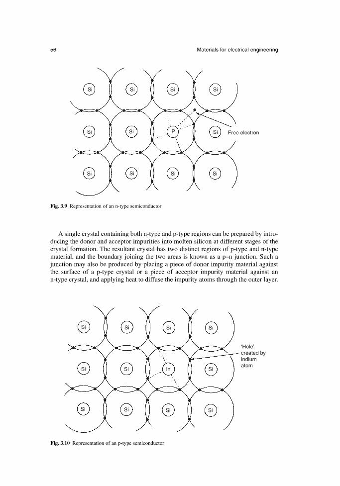
A single crystal containing both n-type and p-type regions can be prepared by intro-ducing the donor and acceptor impurities into molten silicon at different stages of thecrystal formation. The resultant crystal has two distinct regions of p-type and n-typematerial, and the boundary joining the two areas is known as a p–n junction. Such ajunction may also be produced by placing a piece of donor impurity material againstthe surface of a p-type crystal or a piece of acceptor impurity material against an n-type crystal, and applying heat to diffuse the impurity atoms through the outer layer.
56 Materials for electrical engineering
Si Si Si Si
Si Si In Si
Si Si Si Si
‘Hole’created byindiumatom
Fig. 3.10 Representation of an p-type semiconductor
Si Si Si Si
Si Si P Si
Si Si Si Si
Free electron
Fig. 3.9 Representation of an n-type semiconductor
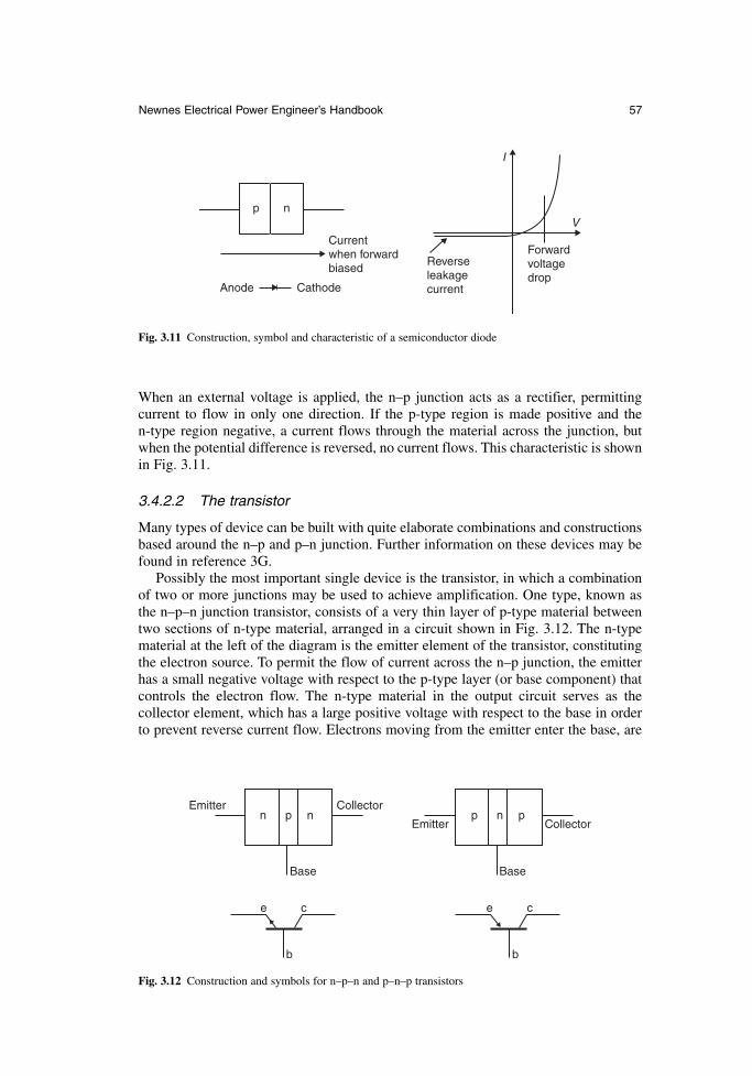
When an external voltage is applied, the n–p junction acts as a rectifier, permitting current to flow in only one direction. If the p-type region is made positive and the n-type region negative, a current flows through the material across the junction, butwhen the potential difference is reversed, no current flows. This characteristic is shownin Fig. 3.11.
3.4.2.2 The transistor
Many types of device can be built with quite elaborate combinations and constructionsbased around the n–p and p–n junction. Further information on these devices may befound in reference 3G.
Possibly the most important single device is the transistor, in which a combinationof two or more junctions may be used to achieve amplification. One type, known asthe n–p–n junction transistor, consists of a very thin layer of p-type material betweentwo sections of n-type material, arranged in a circuit shown in Fig. 3.12. The n-typematerial at the left of the diagram is the emitter element of the transistor, constitutingthe electron source. To permit the flow of current across the n–p junction, the emitterhas a small negative voltage with respect to the p-type layer (or base component) thatcontrols the electron flow. The n-type material in the output circuit serves as the collector element, which has a large positive voltage with respect to the base in orderto prevent reverse current flow. Electrons moving from the emitter enter the base, are
Newnes Electrical Power Engineer’s Handbook 57
p n
Currentwhen forwardbiased
Anode Cathode
Reverseleakagecurrent
Forwardvoltagedrop
V
I
Fig. 3.11 Construction, symbol and characteristic of a semiconductor diode
Emitter Collector
Emitter Collector
Base Base
n p n p n p
e c
b
e c
b
Fig. 3.12 Construction and symbols for n–p–n and p–n–p transistors
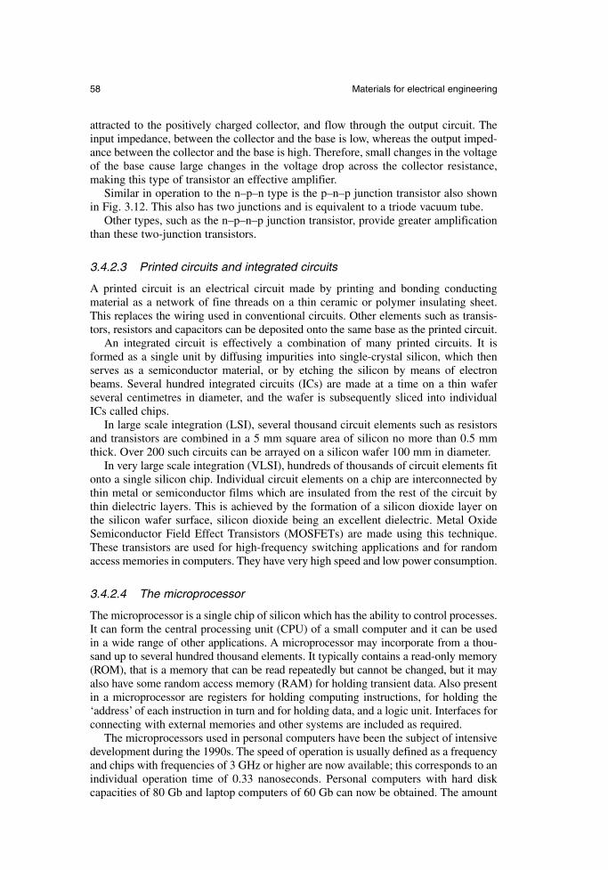
attracted to the positively charged collector, and flow through the output circuit. Theinput impedance, between the collector and the base is low, whereas the output imped-ance between the collector and the base is high. Therefore, small changes in the voltageof the base cause large changes in the voltage drop across the collector resistance,making this type of transistor an effective amplifier.
Similar in operation to the n–p–n type is the p–n–p junction transistor also shownin Fig. 3.12. This also has two junctions and is equivalent to a triode vacuum tube.
Other types, such as the n–p–n–p junction transistor, provide greater amplificationthan these two-junction transistors.
3.4.2.3 Printed circuits and integrated circuits
A printed circuit is an electrical circuit made by printing and bonding conductingmaterial as a network of fine threads on a thin ceramic or polymer insulating sheet.This replaces the wiring used in conventional circuits. Other elements such as transis-tors, resistors and capacitors can be deposited onto the same base as the printed circuit.
An integrated circuit is effectively a combination of many printed circuits. It isformed as a single unit by diffusing impurities into single-crystal silicon, which thenserves as a semiconductor material, or by etching the silicon by means of electronbeams. Several hundred integrated circuits (ICs) are made at a time on a thin wafer several centimetres in diameter, and the wafer is subsequently sliced into individualICs called chips.
In large scale integration (LSI), several thousand circuit elements such as resistorsand transistors are combined in a 5 mm square area of silicon no more than 0.5 mmthick. Over 200 such circuits can be arrayed on a silicon wafer 100 mm in diameter.
In very large scale integration (VLSI), hundreds of thousands of circuit elements fitonto a single silicon chip. Individual circuit elements on a chip are interconnected bythin metal or semiconductor films which are insulated from the rest of the circuit bythin dielectric layers. This is achieved by the formation of a silicon dioxide layer onthe silicon wafer surface, silicon dioxide being an excellent dielectric. Metal OxideSemiconductor Field Effect Transistors (MOSFETs) are made using this technique.These transistors are used for high-frequency switching applications and for randomaccess memories in computers. They have very high speed and low power consumption.
3.4.2.4 The microprocessor
The microprocessor is a single chip of silicon which has the ability to control processes.It can form the central processing unit (CPU) of a small computer and it can be usedin a wide range of other applications. A microprocessor may incorporate from a thou-sand up to several hundred thousand elements. It typically contains a read-only memory(ROM), that is a memory that can be read repeatedly but cannot be changed, but it mayalso have some random access memory (RAM) for holding transient data. Also presentin a microprocessor are registers for holding computing instructions, for holding the‘address’ of each instruction in turn and for holding data, and a logic unit. Interfaces forconnecting with external memories and other systems are included as required.
The microprocessors used in personal computers have been the subject of intensivedevelopment during the 1990s. The speed of operation is usually defined as a frequencyand chips with frequencies of 3 GHz or higher are now available; this corresponds to anindividual operation time of 0.33 nanoseconds. Personal computers with hard diskcapacities of 80 Gb and laptop computers of 60 Gb can now be obtained. The amount
58 Materials for electrical engineering
of information that can be transferred in parallel and held in registers is known as a bit,and 64-bit processors are now available.
3.4.3 Superconductors
The ideal superconducting state is characterized by two fundamental properties, whichare the disappearance of resistance when the temperature is reduced to a critical value,and the expulsion of any magnetic flux in the material when the critical temperature(Tc) is reached. Superconductivity was first discovered in the element mercury, in1911. Other elements have subsequently been found to exhibit superconductivity andtheories have been developed to explain the phenomenon. The critical temperatures forthese materials were typically about 10 K (−263°C), which meant that they had to becooled with liquid helium at 4 K. In general these materials have been of academicinterest only because they could only support a low current density in a low magneticfield without losing their superconducting properties.
In the 1950s a new class of materials was discovered. These are the metallic alloys,the most important among them being niobium titanium and niobium tin. The highestcritical temperature achieved by these materials is 23.2 K and they can be used to pro-duce magnetic flux densities of over 15 T. The main commercial application for theselow-Tc superconductors is for magnets in medical imaging equipment which requirethe high fields to excite magnetic resonance in nuclei of hydrogen and other elements.The magnet or solenoid of the magnetic resonance imaging (MRI) unit has an internaldiameter of about 1.2 m and the patient to be examined is put into this aperture. Theimage from the resonance test shows unexpected concentrations of fluids or tissue andenables a diagnosis. Superconducting magnets producing high magnetic fields are alsoused in magnetic research and in high-energy physics research; other applications suchas dc motors and generators, levitated trains, cables and ac switches have been exploredbut the complexity and high cost of providing the liquid helium environment preventedcommercial development in most cases.
In late 1986 a ceramic material LaBaCuO was discovered to be superconducting at 35 K and in 1987 the material YBaCuO was found to have a critical temperature of92 K. Since that time the critical temperatures of these new high temperature super-conducting (HTS) materials has progressively increased to over 130 K. Examples of theseare BiSrCaCuO (with a Tc of 106 K), ThBaCaCuO (Tc of 125 K) and HgBaCaCuO (Tc of 133 K). The enormous significance of these discoveries is that these materialswill be superconducting in liquid nitrogen, which has a boiling point of 77 K and ismuch easier and cheaper to provide than helium.
Much work has been directed towards finding materials with higher Tc values butthis has remained at 133 K for some time. However, considerable effort with resultingsuccess has been directed to the production of suitable HTS conductors. The HTS mate-rial is very brittle and it is deposited using laser deposition onto a suitable substrate tape.The tape is 3 mm wide and cables of up to 600 m in length have been produced.
There are many trials being made of the application of the HTS cables throughoutthe world including USA, Europe and Japan. There are prototypes of power trans-formers, underground power cables, large motors and generators, and fault current limiters in active development and in use. The electricity supply of the City of Genevain Switzerland is completely provided by power transformers wound with HTS conductors. Detroit is being re-equipped with HTS power cable for its transmissionsystem and copper cables weighing over 7 tons are being replaced with HTS cables ofless than 0.12 tons. These and other developments will help to establish the long-term
Newnes Electrical Power Engineer’s Handbook 59
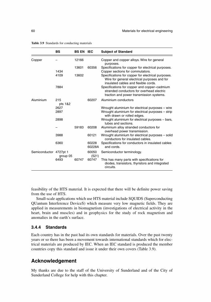
feasibility of the HTS material. It is expected that there will be definite power savingfrom the use of HTS.
Small-scale applications which use HTS material include SQUIDS (SuperconductingQUantum Interference DeviceS) which measure very low magnetic fields. They areapplied in measurements in biomagnetism (investigations of electrical activity in theheart, brain and muscles) and in geophysics for the study of rock magnetism andanomalies in the earth’s surface.
3.4.4 Standards
Each country has in the past had its own standards for materials. Over the past twentyyears or so there has been a movement towards international standards which for elec-trical materials are produced by IEC. When an IEC standard is produced the membercountries copy this standard and issue it under their own covers (Table 3.9).
Acknowledgement
My thanks are due to the staff of the University of Sunderland and of the City ofSunderland College for help with this chapter.
60 Materials for electrical engineering
Table 3.9 Standards for conducting materials
BS BS EN IEC Subject of Standard
Copper – 12166 Copper and copper alloys. Wire for general purposes.
13601 60356 Specifications for copper for electrical purposes.1434 Copper sections for commutators.4109 13602 Specifications for copper for electrical purposes.
Wire for general electrical purposes and for insulated cables and flexible cords.
7884 Specifications for copper and copper–cadmium stranded conductors for overhead electric traction and power transmission systems.
Aluminium 215 60207 Aluminium conductorspts 1&2
2627 Wrought aluminium for electrical purposes – wire2897 Wrought aluminium for electrical purposes – strip
with drawn or rolled edges.2898 Wrought aluminium for electrical purposes – bars,
tubes and sections.– 59183 60208 Aluminium alloy stranded conductors for
overhead power transmission.3988 60121 Wrought aluminium for electrical purposes – solid
conductors for insulated cables.6360 60228 Specifications for conductors in insulated cables
60228A and cords.
Semiconductor 4727pt 1 60050 Semiconductor terminology.group 05 (521)
6493 60747 60747 This has many parts with specifications for diodes, transistors, thyristors and integrated circuits.
References
3A. Laughton, M.A. and Warne, D.F. Electrical Engineer’s Reference Book (16th edn),Newnes, 2003.
3B. Brandes, E.A. and Brook, G.R. (eds), Smithells Metals Reference Book (7th edn),Butterworth-Heinemann, 1992.
3C. McCaig, M. and Clegg, A.G. Permanent Magnets in Theory and Practice (2nd edn),Pentech and Wiley, 1987.
3D. Stanbury, H. The Development of International Standards for Magnetic Alloys and Steels,UK Magnetics Society, 2004.
3E. Reeves, E.A. Newnes Electronics Engineer’s Pocket Book, BSI, 2004.3F. Narlikar, A.V. High Temperature Superconductivity, Springer Verlag, 2004.3G. Warnes, L.A.A. Electronic and Electrical Engineering, Macmillan, 1998 (good chapters
on semiconductors).
Newnes Electrical Power Engineer’s Handbook 61

Chapter 4
Measurements and instrumentation
E.A. ParrThamesteel
4.1 Introduction
4.1.1 Definition of terms
Measured variable and process variable are both terms for the physical quantity thatis to be measured. The measured value is the actual value which is measured orrecorded, in engineering units (e.g. the level is 1252 mm).
A primary element or sensor is the device which converts the measured value intoa form suitable for further conversion into an instrumentation signal. An orifice plateis a typical sensor. A transducer is a device which converts a signal from one quantityto another (e.g. a Pt100 temperature transducer converts a temperature to a resistance).A transmitter is a transducer which gives a standard instrumentation signal (e.g.4–20 mA) as an output signal.
4.1.2 Range, accuracy and error
Measuring span, measuring interval and range are terms which describe the differencebetween the lower and upper limits that can be measured. Turndown is the ratiobetween the upper limit and the lower limits where the specified accuracy can beobtained.
Error is a measurement of the difference between the measured value and the truevalue and accuracy is the maximum error which can occur between the process variableand the measured value when the transducer is operating under specified condi-tions. Error can be expressed in many ways. The commonest are absolute value, as apercentage of the actual value, or as a percentage of full scale.
Many devices have an inherent coarseness in their measuring capabilities. A wirewound potentiometer, for example, can only change its resistance in small steps.Resolution is used to define the smallest step in which a reading can be made.
In many applications, the accuracy of a measurement is less important than its consistency. Repeatability is defined as the difference in readings obtained when thesame measuring point is approached several times from the same direction.
Hysteresis occurs when the measured value depends on the direction of approach.Mechanical backlash and stiction are common causes of hysteresis.
The accuracy of a transducer will be adversely affected by environmental changes,particularly temperature cycling, and will degrade with time. Both of these effects willbe seen as a zero shift or a change of sensitivity (known as a span error).
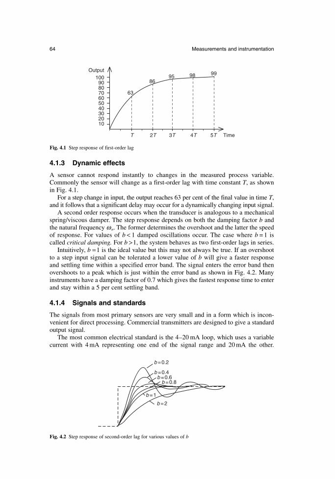
4.1.3 Dynamic effects
A sensor cannot respond instantly to changes in the measured process variable.Commonly the sensor will change as a first-order lag with time constant T, as shownin Fig. 4.1.
For a step change in input, the output reaches 63 per cent of the final value in time T,and it follows that a significant delay may occur for a dynamically changing input signal.
A second order response occurs when the transducer is analogous to a mechanicalspring/viscous damper. The step response depends on both the damping factor b andthe natural frequency ω n. The former determines the overshoot and the latter the speedof response. For values of b < 1 damped oscillations occur. The case where b = 1 iscalled critical damping. For b >1, the system behaves as two first-order lags in series.
Intuitively, b =1 is the ideal value but this may not always be true. If an overshootto a step input signal can be tolerated a lower value of b will give a faster response and settling time within a specified error band. The signal enters the error band thenovershoots to a peak which is just within the error band as shown in Fig. 4.2. Manyinstruments have a damping factor of 0.7 which gives the fastest response time to enterand stay within a 5 per cent settling band.
4.1.4 Signals and standards
The signals from most primary sensors are very small and in a form which is incon-venient for direct processing. Commercial transmitters are designed to give a standardoutput signal.
The most common electrical standard is the 4–20 mA loop, which uses a variablecurrent with 4 mA representing one end of the signal range and 20 mA the other.
64 Measurements and instrumentation
Output100
99989586
63
908070605040302010
2T 3T 4T 5T TimeT
Fig. 4.1 Step response of first-order lag
b =0.2
b =0.4b =0.6
b =0.8
b =1
b =2
Fig. 4.2 Step response of second-order lag for various values of b
This use of a current gives excellent noise reduction and errors from different earthpotentials around the plant are avoided. Because the signal is transmitted as a current,rather than a voltage, line resistance has no effect.
Several display or control devices can be connected in series provided the total loopresistance does not rise above some value specified for the transducer (typically 1 kΩ).Transducers using 4–20 mA can be current sourcing (with their own power supply) asshown in Fig. 4.3(a) or they may be designed for two-wire operation with the signalline carrying both the supply and the signal as shown in Fig. 4.3(b). The use of the offset zero of 4 mA allows many sensor or cable faults to be detected. A cable breakor sensor fault will cause the loop current to fall to zero and these fault conditions canthen be detected by the display or control device.
4.1.5 P&ID symbols
Instruments and controllers are usually part of a large control system. The system isgenerally represented by a Piping & Instrumentation Drawing (P&ID) which showsthe devices, their locations and the method of interconnection. The basic symbols anda typical example are shown in Fig. 4.4.
The devices are represented by circles called balloons containing a unique tagwhich has two parts. The first part is two or more letters describing the function. Thesecond part is a number which uniquely identifies the device, for example FE127 isflow sensor number 127. It is a good practice for devices to have their P&ID tag physically attached to them to aid maintenance.
4.2 Pressure
There are four types of pressure measurement. Differential pressure is the differencebetween two pressures applied to the transducer. Gauge pressure is made with respectto atmospheric pressure. It can be considered as a differential pressure measurementwith the low pressure leg left open, and is usually denoted by the suffix ‘g’ (e.g. 37psig).Most pressure transducers in hydraulic and pneumatic systems indicate gauge pressure.Absolute pressure is made with respect to a vacuum, so
Absolute pressure = gauge pressure + atmospheric pressure (4.1)
Atmospheric pressure is approximately 1 bar, 100 kPa or 14.7 psi.Head pressure is used in liquid level measurement and refers to pressure in terms
of the height of a liquid (e.g. inches water gauge). It is effectively a gauge pressuremeasurement, as in a vented vessel any changes in atmospheric pressure will affectboth legs of the transducer equally giving a reading which is directly related to the liquidheight. The head pressure is given by:
P = ρgh (4.2)
where P is the pressure in pascals, ρ is the density (kg m–2), g is the acceleration dueto gravity (9.8 ms–2) and h is the column height in metres.
4.2.1 The manometer
Manometers give a useful insight into the principle of pressure measurement. If a U-tube is part filled with liquid, and differing pressures are applied to both legs (Fig. 4.5),the liquid will fall on the high pressure side and rise on the low pressure side until the
Newnes Electrical Power Engineer’s Handbook 65
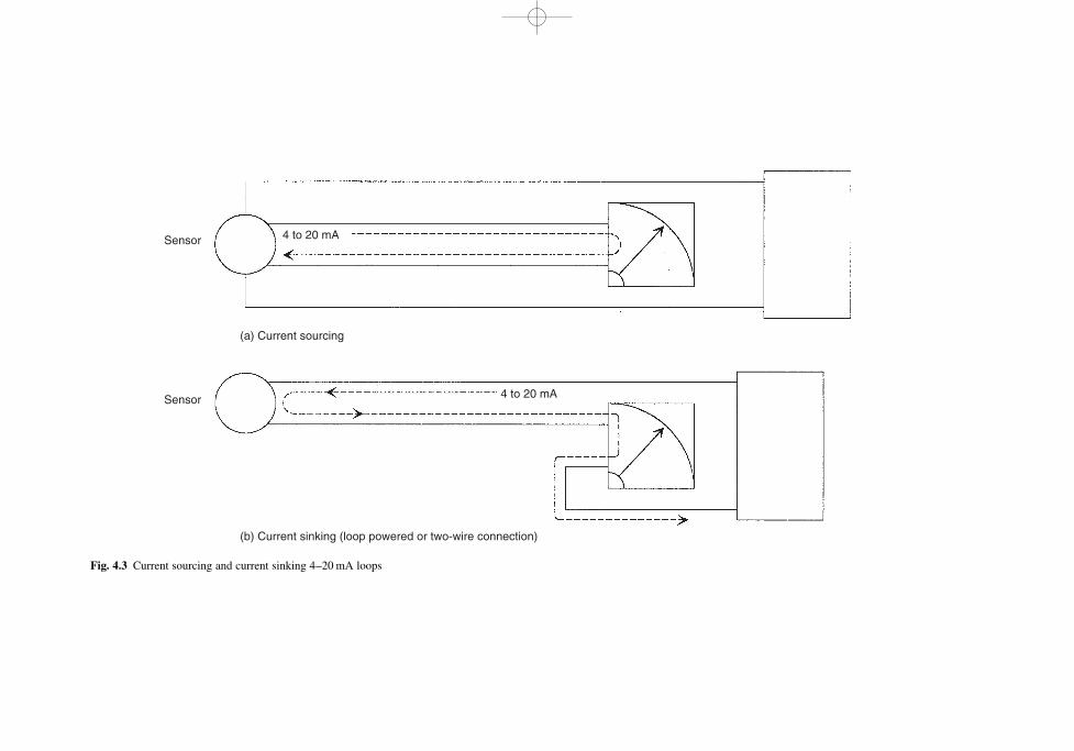
(a) Current sourcing
(b) Current sinking (loop powered or two-wire connection)
Sensor
Sensor
4 to 20 mA
4 to 20 mA
Fig. 4.3 Current sourcing and current sinking 4–20 mA loops
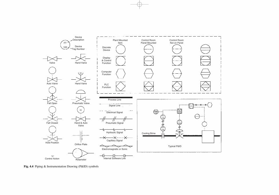
Valve
Auto Valve
Fall Open
Fall Closed
Hold Position
Control Action
Hand Valve
Device Description
Discrete Device
Plant Mounted Item
Control Room Panel Mounted
Control Room Not on Panel
Display & Control Function
Computer Function
PLC Function
FT
105
FT 106
FY 106
FY 106A
FIC 106
FAL 106
Device Tag Number
Hand Valve
Pneumatic Valve
Process Line
Signal Line
Electrical Signal
Pneumatic Signal
Hydraulic Signal
Capillary Signal
Electromagnetic or SonicTypical P&ID
Cooling Brine
Internal Software Link
Hand & Auto Valve
Orifice Plate
Rotameter
H
H
Fig. 4.4 Piping & Instrumentation Drawing (P&ID) symbols
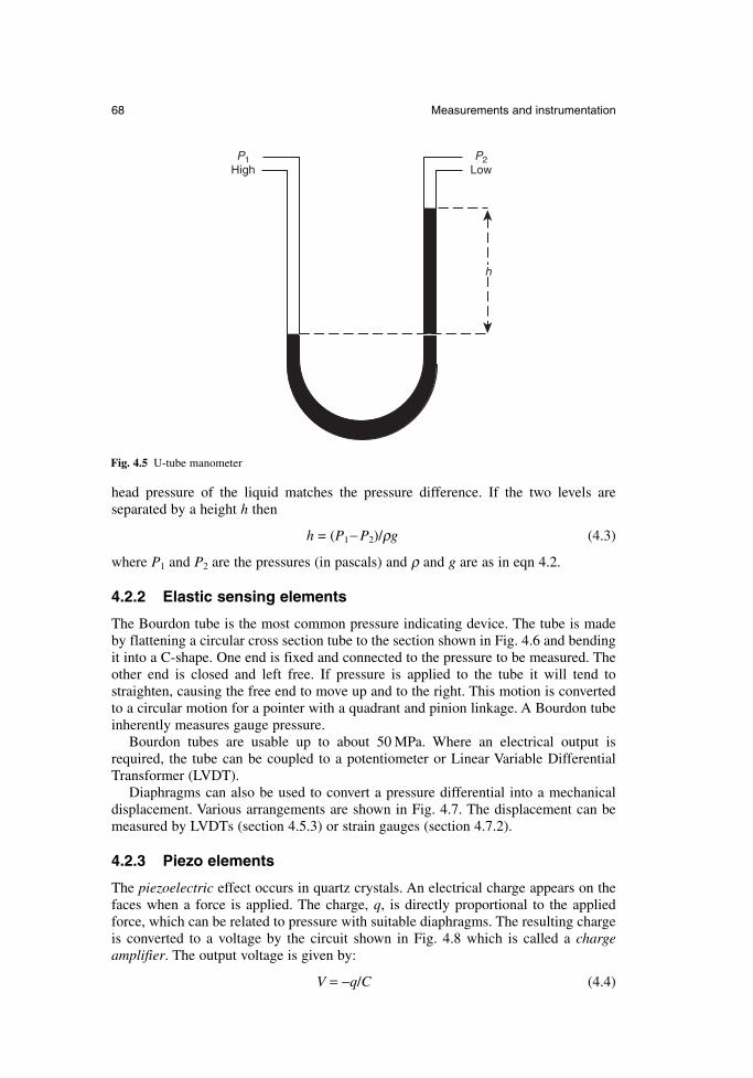
head pressure of the liquid matches the pressure difference. If the two levels are separated by a height h then
h = (P1− P2)/ρg (4.3)
where P1 and P2 are the pressures (in pascals) and ρ and g are as in eqn 4.2.
4.2.2 Elastic sensing elements
The Bourdon tube is the most common pressure indicating device. The tube is madeby flattening a circular cross section tube to the section shown in Fig. 4.6 and bendingit into a C-shape. One end is fixed and connected to the pressure to be measured. Theother end is closed and left free. If pressure is applied to the tube it will tend tostraighten, causing the free end to move up and to the right. This motion is convertedto a circular motion for a pointer with a quadrant and pinion linkage. A Bourdon tubeinherently measures gauge pressure.
Bourdon tubes are usable up to about 50 MPa. Where an electrical output isrequired, the tube can be coupled to a potentiometer or Linear Variable DifferentialTransformer (LVDT).
Diaphragms can also be used to convert a pressure differential into a mechanicaldisplacement. Various arrangements are shown in Fig. 4.7. The displacement can bemeasured by LVDTs (section 4.5.3) or strain gauges (section 4.7.2).
4.2.3 Piezo elements
The piezoelectric effect occurs in quartz crystals. An electrical charge appears on thefaces when a force is applied. The charge, q, is directly proportional to the appliedforce, which can be related to pressure with suitable diaphragms. The resulting chargeis converted to a voltage by the circuit shown in Fig. 4.8 which is called a chargeamplifier. The output voltage is given by:
V = −q/C (4.4)
68 Measurements and instrumentation
P1 High
P2 Low
h
Fig. 4.5 U-tube manometer
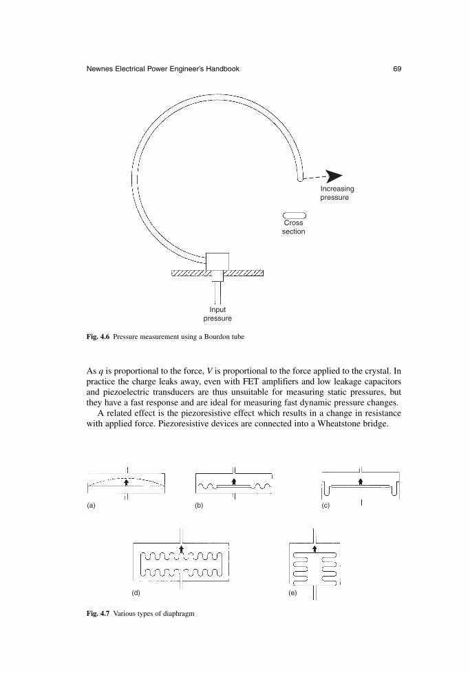
As q is proportional to the force, V is proportional to the force applied to the crystal. Inpractice the charge leaks away, even with FET amplifiers and low leakage capacitorsand piezoelectric transducers are thus unsuitable for measuring static pressures, butthey have a fast response and are ideal for measuring fast dynamic pressure changes.
A related effect is the piezoresistive effect which results in a change in resistancewith applied force. Piezoresistive devices are connected into a Wheatstone bridge.
Newnes Electrical Power Engineer’s Handbook 69
Increasing pressure
Input pressure
Cross section
Fig. 4.6 Pressure measurement using a Bourdon tube
(a) (b)
(d) (e)
(c)
Fig. 4.7 Various types of diaphragm
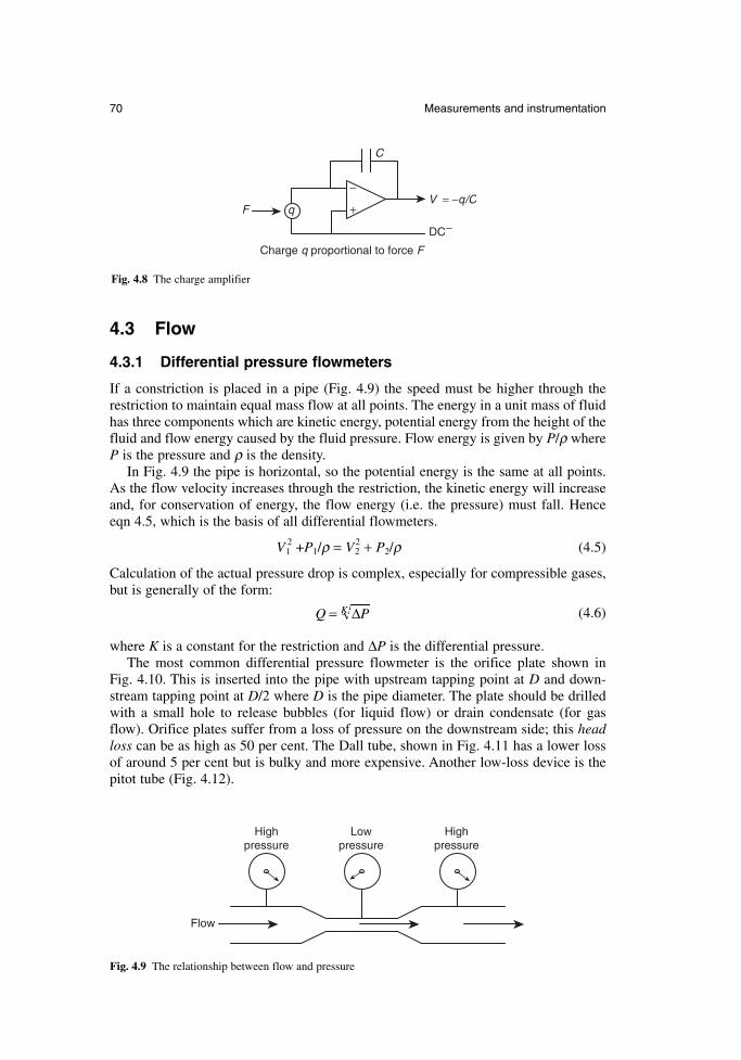
4.3 Flow
4.3.1 Differential pressure flowmeters
If a constriction is placed in a pipe (Fig. 4.9) the speed must be higher through therestriction to maintain equal mass flow at all points. The energy in a unit mass of fluidhas three components which are kinetic energy, potential energy from the height of thefluid and flow energy caused by the fluid pressure. Flow energy is given by P/ρ where P is the pressure and ρ is the density.
In Fig. 4.9 the pipe is horizontal, so the potential energy is the same at all points.As the flow velocity increases through the restriction, the kinetic energy will increaseand, for conservation of energy, the flow energy (i.e. the pressure) must fall. Hence eqn 4.5, which is the basis of all differential flowmeters.
V12 +P1/ρ = V2
2 + P2/ρ (4.5)
Calculation of the actual pressure drop is complex, especially for compressible gases,but is generally of the form:
(4.6)
where K is a constant for the restriction and ∆P is the differential pressure.The most common differential pressure flowmeter is the orifice plate shown in
Fig. 4.10. This is inserted into the pipe with upstream tapping point at D and down-stream tapping point at D/2 where D is the pipe diameter. The plate should be drilledwith a small hole to release bubbles (for liquid flow) or drain condensate (for gasflow). Orifice plates suffer from a loss of pressure on the downstream side; this headloss can be as high as 50 per cent. The Dall tube, shown in Fig. 4.11 has a lower lossof around 5 per cent but is bulky and more expensive. Another low-loss device is thepitot tube (Fig. 4.12).
Q PK= ∆
70 Measurements and instrumentation
F
C
V = −q/C
DC−
Charge q proportional to force F
−
+q
Fig. 4.8 The charge amplifier
High pressure
Flow
High pressure
Low pressure
Fig. 4.9 The relationship between flow and pressure
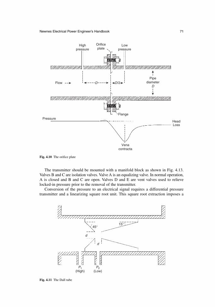
The transmitter should be mounted with a manifold block as shown in Fig. 4.13.Valves B and C are isolation valves. Valve A is an equalizing valve. In normal operation,A is closed and B and C are open. Valves D and E are vent valves used to relievelocked-in pressure prior to the removal of the transmitter.
Conversion of the pressure to an electrical signal requires a differential pressuretransmitter and a linearizing square root unit. This square root extraction imposes a
Newnes Electrical Power Engineer’s Handbook 71
PressureFlange
Vena contracta
Head Loss
High pressure
Low pressure
Orifice plate
FlowPipe
diameter D
D D/2
Fig. 4.10 The orifice plate
45°15°
d
d
P1 (High)
P2 (Low)
Fig. 4.11 The Dall tube
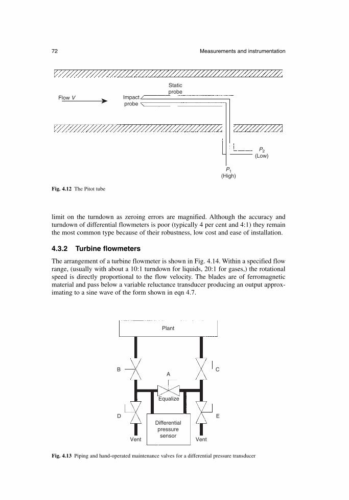
limit on the turndown as zeroing errors are magnified. Although the accuracy and turndown of differential flowmeters is poor (typically 4 per cent and 4:1) they remainthe most common type because of their robustness, low cost and ease of installation.
4.3.2 Turbine flowmeters
The arrangement of a turbine flowmeter is shown in Fig. 4.14. Within a specified flowrange, (usually with about a 10:1 turndown for liquids, 20:1 for gases,) the rotationalspeed is directly proportional to the flow velocity. The blades are of ferromagneticmaterial and pass below a variable reluctance transducer producing an output approx-imating to a sine wave of the form shown in eqn 4.7.
72 Measurements and instrumentation
Flow V Impact probe
Static probe
P1 (High)
P2 (Low)
Fig. 4.12 The Pitot tube
A
Equalize
Plant
Differential pressure sensor
Vent Vent
B
D
C
E
Fig. 4.13 Piping and hand-operated maintenance valves for a differential pressure transducer
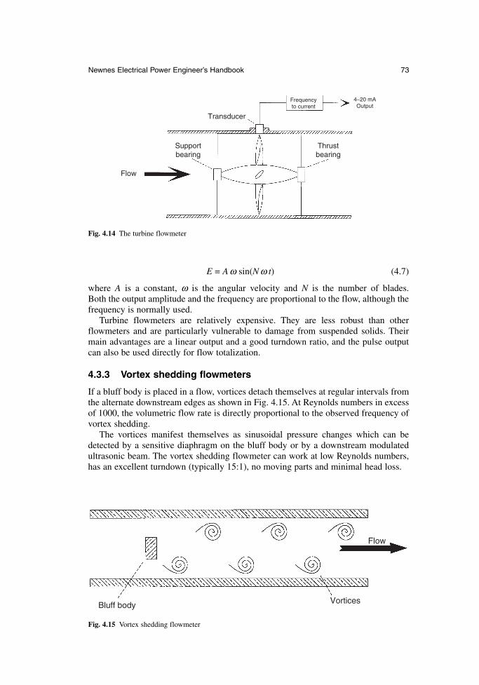
E = A ω sin(N ω t) (4.7)
where A is a constant, ω is the angular velocity and N is the number of blades. Both the output amplitude and the frequency are proportional to the flow, although thefrequency is normally used.
Turbine flowmeters are relatively expensive. They are less robust than otherflowmeters and are particularly vulnerable to damage from suspended solids. Theirmain advantages are a linear output and a good turndown ratio, and the pulse outputcan also be used directly for flow totalization.
4.3.3 Vortex shedding flowmeters
If a bluff body is placed in a flow, vortices detach themselves at regular intervals fromthe alternate downstream edges as shown in Fig. 4.15. At Reynolds numbers in excessof 1000, the volumetric flow rate is directly proportional to the observed frequency ofvortex shedding.
The vortices manifest themselves as sinusoidal pressure changes which can bedetected by a sensitive diaphragm on the bluff body or by a downstream modulatedultrasonic beam. The vortex shedding flowmeter can work at low Reynolds numbers,has an excellent turndown (typically 15:1), no moving parts and minimal head loss.
Newnes Electrical Power Engineer’s Handbook 73
Transducer
Thrust bearing
Support bearing
Flow
4−20 mAOutput
Frequency to current
Fig. 4.14 The turbine flowmeter
Bluff body Vortices
Flow
Fig. 4.15 Vortex shedding flowmeter
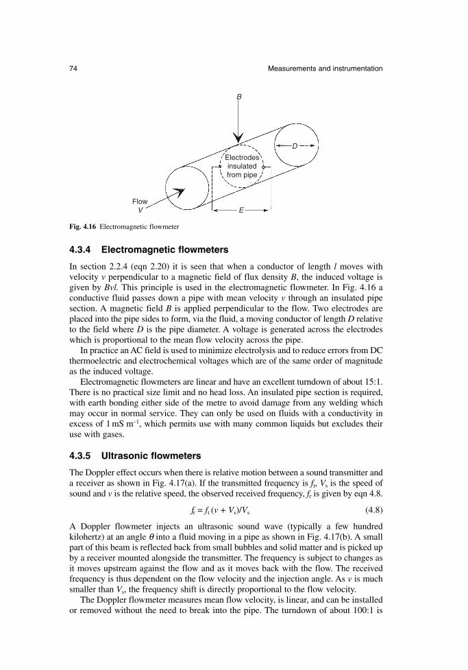
4.3.4 Electromagnetic flowmeters
In section 2.2.4 (eqn 2.20) it is seen that when a conductor of length l moves withvelocity v perpendicular to a magnetic field of flux density B, the induced voltage isgiven by Bvl. This principle is used in the electromagnetic flowmeter. In Fig. 4.16 aconductive fluid passes down a pipe with mean velocity v through an insulated pipesection. A magnetic field B is applied perpendicular to the flow. Two electrodes areplaced into the pipe sides to form, via the fluid, a moving conductor of length D relativeto the field where D is the pipe diameter. A voltage is generated across the electrodeswhich is proportional to the mean flow velocity across the pipe.
In practice an AC field is used to minimize electrolysis and to reduce errors from DCthermoelectric and electrochemical voltages which are of the same order of magnitudeas the induced voltage.
Electromagnetic flowmeters are linear and have an excellent turndown of about 15:1.There is no practical size limit and no head loss. An insulated pipe section is required,with earth bonding either side of the metre to avoid damage from any welding whichmay occur in normal service. They can only be used on fluids with a conductivity inexcess of 1 mS m–1, which permits use with many common liquids but excludes theiruse with gases.
4.3.5 Ultrasonic flowmeters
The Doppler effect occurs when there is relative motion between a sound transmitter anda receiver as shown in Fig. 4.17(a). If the transmitted frequency is ft, Vs is the speed ofsound and v is the relative speed, the observed received frequency, fr is given by eqn 4.8.
fr = ft (v + Vs)/Vs (4.8)
A Doppler flowmeter injects an ultrasonic sound wave (typically a few hundred kilohertz) at an angle θ into a fluid moving in a pipe as shown in Fig. 4.17(b). A smallpart of this beam is reflected back from small bubbles and solid matter and is picked upby a receiver mounted alongside the transmitter. The frequency is subject to changes asit moves upstream against the flow and as it moves back with the flow. The received frequency is thus dependent on the flow velocity and the injection angle. As v is muchsmaller than Vs, the frequency shift is directly proportional to the flow velocity.
The Doppler flowmeter measures mean flow velocity, is linear, and can be installedor removed without the need to break into the pipe. The turndown of about 100:1 is
74 Measurements and instrumentation
Electrodesinsulatedfrom pipe
D
EFlow
V
B
Fig. 4.16 Electromagnetic flowmeter
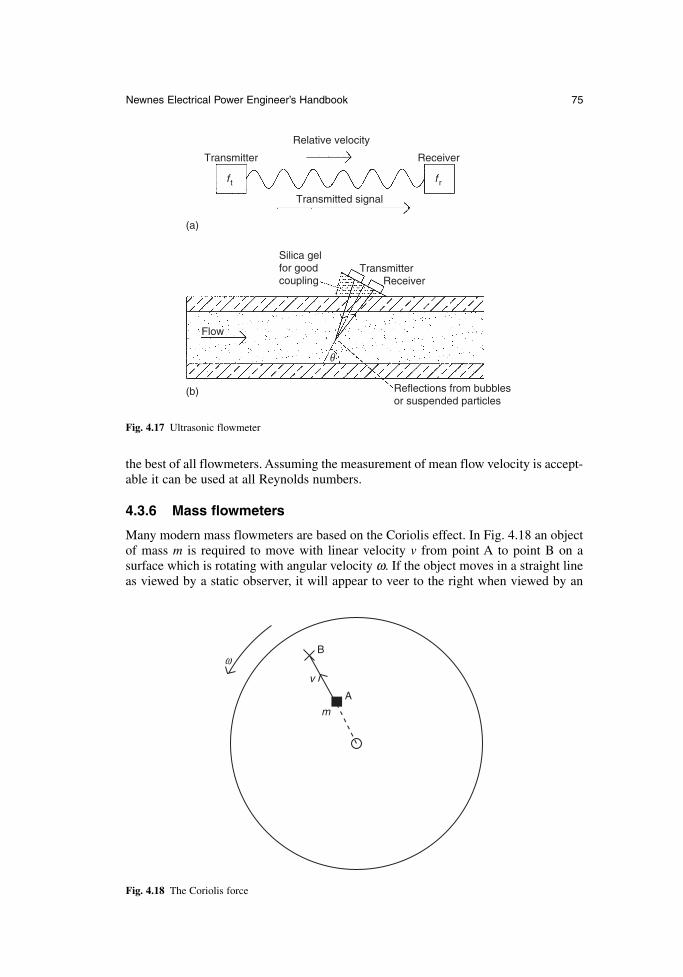
the best of all flowmeters. Assuming the measurement of mean flow velocity is accept-able it can be used at all Reynolds numbers.
4.3.6 Mass flowmeters
Many modern mass flowmeters are based on the Coriolis effect. In Fig. 4.18 an objectof mass m is required to move with linear velocity v from point A to point B on a surface which is rotating with angular velocity ω. If the object moves in a straight lineas viewed by a static observer, it will appear to veer to the right when viewed by an
Newnes Electrical Power Engineer’s Handbook 75
Transmitter
Relative velocity
Receiver
Transmitted signal
f t f r
Silica gelfor goodcoupling
Transmitter Receiver
Reflections from bubblesor suspended particles
Flow
(a)
(b)
θ
Fig. 4.17 Ultrasonic flowmeter
B
A
v
m
ω
Fig. 4.18 The Coriolis force
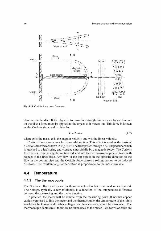
observer on the disc. If the object is to move in a straight line as seen by an observeron the disc a force must be applied to the object as it moves out. This force is knownas the Coriolis force and is given by
F = 2mω v (4.9)
where m is the mass, ω is the angular velocity and v is the linear velocity.Coriolis force also occurs for sinusoidal motion. This effect is used as the basis of
a Coriolis flowmeter shown in Fig. 4.19. The flow passes through a ‘C’shaped tube whichis attached to a leaf spring and vibrated sinusoidally by a magnetic forcer. The Coriolisforce arises from the angular motion induced into the two horizontal pipe sections withrespect to the fixed base. Any flow in the top pipe is in the opposite direction to theflow in the bottom pipe and the Coriolis force causes a rolling motion to be inducedas shown. The resultant angular deflection is proportional to the mass flow rate.
4.4 Temperature
4.4.1 The thermocouple
The Seebeck effect and its use in thermocouples has been outlined in section 2.4. The voltage, typically a few millivolts, is a function of the temperature differencebetween the measuring and the meter junction.
In practice, the meter will be remote from the measuring point. If normal coppercables were used to link the meter and the thermocouple, the temperature of the jointswould not be known and further voltages, and hence errors, would be introduced. Thethermocouple cables must therefore be taken back to the meter. Two forms of cable are
76 Measurements and instrumentation
View on A-A
FlowB
Leaf spring
Inlet
Outlet
A
Magneticforcer
Flow
A
No flow Flow
View on B-BB
Fig. 4.19 Coriolis force mass flowmeter
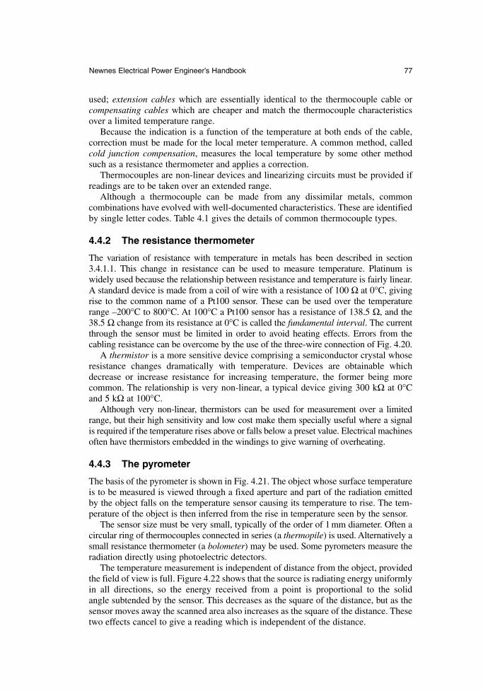
used; extension cables which are essentially identical to the thermocouple cable orcompensating cables which are cheaper and match the thermocouple characteristicsover a limited temperature range.
Because the indication is a function of the temperature at both ends of the cable,correction must be made for the local meter temperature. A common method, calledcold junction compensation, measures the local temperature by some other methodsuch as a resistance thermometer and applies a correction.
Thermocouples are non-linear devices and linearizing circuits must be provided ifreadings are to be taken over an extended range.
Although a thermocouple can be made from any dissimilar metals, common combinations have evolved with well-documented characteristics. These are identifiedby single letter codes. Table 4.1 gives the details of common thermocouple types.
4.4.2 The resistance thermometer
The variation of resistance with temperature in metals has been described in section3.4.1.1. This change in resistance can be used to measure temperature. Platinum iswidely used because the relationship between resistance and temperature is fairly linear.A standard device is made from a coil of wire with a resistance of 100 Ω at 0°C, givingrise to the common name of a Pt100 sensor. These can be used over the temperaturerange –200°C to 800°C. At 100°C a Pt100 sensor has a resistance of 138.5 Ω, and the38.5 Ω change from its resistance at 0°C is called the fundamental interval. The currentthrough the sensor must be limited in order to avoid heating effects. Errors from thecabling resistance can be overcome by the use of the three-wire connection of Fig. 4.20.
A thermistor is a more sensitive device comprising a semiconductor crystal whoseresistance changes dramatically with temperature. Devices are obtainable whichdecrease or increase resistance for increasing temperature, the former being morecommon. The relationship is very non-linear, a typical device giving 300 kΩ at 0°Cand 5 kΩ at 100°C.
Although very non-linear, thermistors can be used for measurement over a limitedrange, but their high sensitivity and low cost make them specially useful where a signal is required if the temperature rises above or falls below a preset value. Electrical machinesoften have thermistors embedded in the windings to give warning of overheating.
4.4.3 The pyrometer
The basis of the pyrometer is shown in Fig. 4.21. The object whose surface temperatureis to be measured is viewed through a fixed aperture and part of the radiation emittedby the object falls on the temperature sensor causing its temperature to rise. The tem-perature of the object is then inferred from the rise in temperature seen by the sensor.
The sensor size must be very small, typically of the order of 1 mm diameter. Often acircular ring of thermocouples connected in series (a thermopile) is used. Alternatively asmall resistance thermometer (a bolometer) may be used. Some pyrometers measure theradiation directly using photoelectric detectors.
The temperature measurement is independent of distance from the object, providedthe field of view is full. Figure 4.22 shows that the source is radiating energy uniformlyin all directions, so the energy received from a point is proportional to the solid angle subtended by the sensor. This decreases as the square of the distance, but as thesensor moves away the scanned area also increases as the square of the distance. Thesetwo effects cancel to give a reading which is independent of the distance.
Newnes Electrical Power Engineer’s Handbook 77
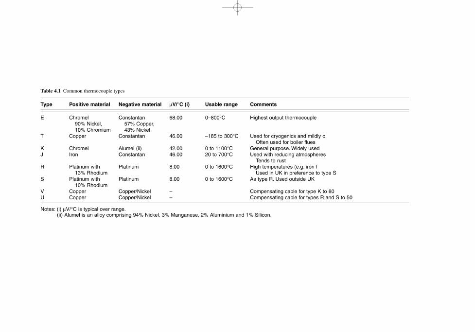
Table 4.1 Common thermocouple types
Type Positive material Negative material µV/°C (i) Usable range Comments
E Chromel Constantan 68.00 0–800°C Highest output thermocouple90% Nickel, 57% Copper,10% Chromium 43% Nickel
T Copper Constantan 46.00 −185 to 300°C Used for cryogenics and mildly oOften used for boiler flues
K Chromel Alumel (ii) 42.00 0 to 1100°C General purpose. Widely usedJ Iron Constantan 46.00 20 to 700°C Used with reducing atmospheres
Tends to rustR Platinum with Platinum 8.00 0 to 1600°C High temperatures (e.g. iron f
13% Rhodium Used in UK in preference to type SS Platinum with Platinum 8.00 0 to 1600°C As type R. Used outside UK
10% RhodiumV Copper Copper/Nickel – Compensating cable for type K to 80U Copper Copper/Nickel – Compensating cable for types R and S to 50
Notes: (i) µV/°C is typical over range.(ii) Alumel is an alloy comprising 94% Nickel, 3% Manganese, 2% Aluminium and 1% Silicon.
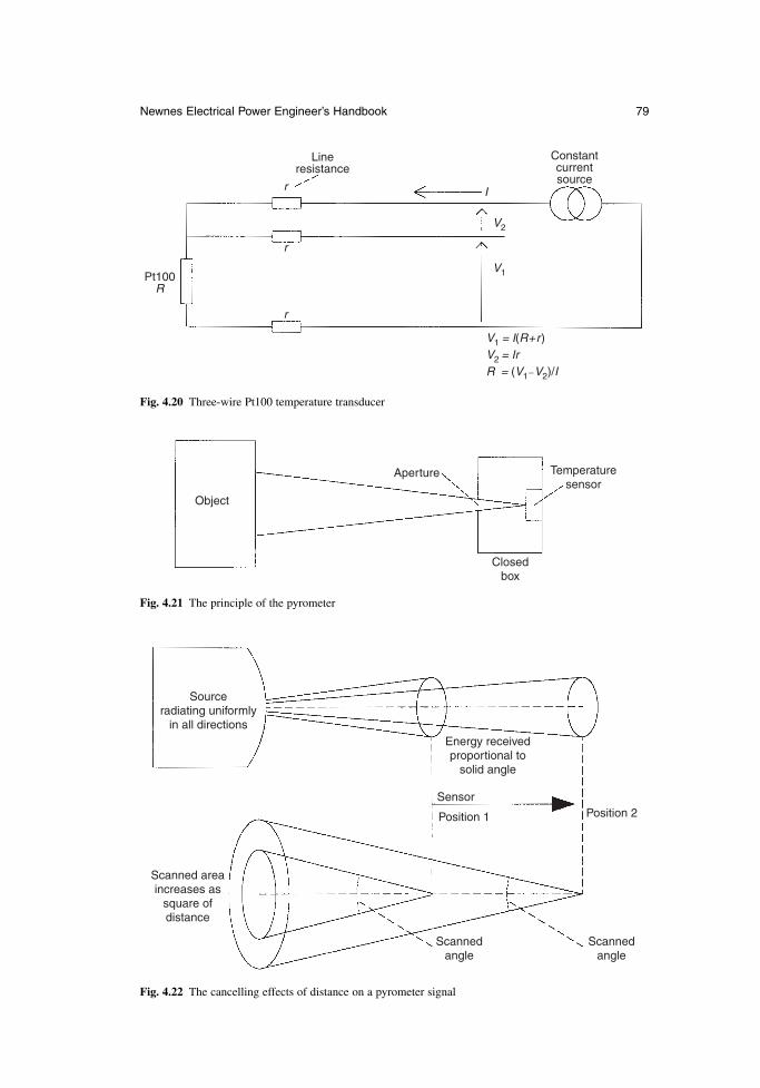
Newnes Electrical Power Engineer’s Handbook 79
Object
Aperture Temperaturesensor
Closedbox
Fig. 4.21 The principle of the pyrometer
Sourceradiating uniformly
in all directions
Scanned areaincreases as
square ofdistance
Energy receivedproportional to
solid angle
Sensor
Position 1 Position 2
Scannedangle
Scannedangle
Fig. 4.22 The cancelling effects of distance on a pyrometer signal
Lineresistance
Constantcurrentsource
Ir
r
r
Pt100R
V2
V1
V1 = I(R+r)V2 = IrR = (V1−V2)/I
Fig. 4.20 Three-wire Pt100 temperature transducer
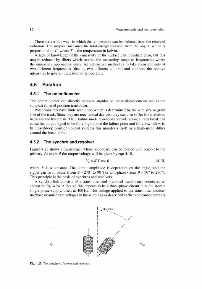
80 Measurements and instrumentation
There are various ways in which the temperature can be deduced from the receivedradiation. The simplest measures the total energy received from the object, which isproportional to T 4 where T is the temperature in kelvin.
A lack of knowledge of the emissivity of the surface can introduce error, but thismaybe reduced by filters which restrict the measuring range to frequencies where the emissivity approaches unity. An alternative method is to take measurements at two different frequencies (that is, two different colours) and compare the relativeintensities to give an indication of temperature.
4.5 Position
4.5.1 The potentiometer
The potentiometer can directly measure angular or linear displacements and is the simplest form of position transducer.
Potentiometers have finite resolution which is determined by the wire size or grainsize of the track. Since they are mechanical devices, they can also suffer from stiction,backlash and hysteresis. Their failure mode also needs consideration; a track break cancause the output signal to be fully high above the failure point and fully low below it.In closed-loop position control systems this manifests itself as a high-speed ditheraround the break point.
4.5.2 The synchro and resolver
Figure 4.23 shows a transformer whose secondary can be rotated with respect to theprimary. At angle θ the output voltage will be given by eqn 4.10,
Vo = K Vi cos θ (4.10)
where K is a constant. The output amplitude is dependent on the angle, and the signal can be in phase (from θ = 270° to 90°) or anti-phase (from θ = 90° to 270°). This principle is the basis of synchros and resolvers.
A synchro link consists of a transmitter and a control transformer connected asshown in Fig. 4.24. Although this appears to be a three-phase circuit, it is fed from asingle-phase supply, often at 400 Hz. The voltage applied to the transmitter induces in-phase or anti-phase voltages in the windings as described earlier and causes currents
Rotation
Vin Vout
Fig. 4.23 The principle of servos and resolvers
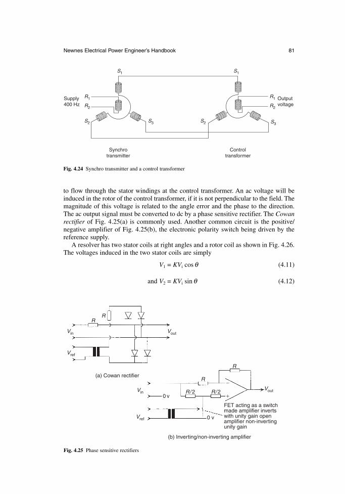
Newnes Electrical Power Engineer’s Handbook 81
to flow through the stator windings at the control transformer. An ac voltage will beinduced in the rotor of the control transformer, if it is not perpendicular to the field. Themagnitude of this voltage is related to the angle error and the phase to the direction.The ac output signal must be converted to dc by a phase sensitive rectifier. The Cowanrectifier of Fig. 4.25(a) is commonly used. Another common circuit is the positive/negative amplifier of Fig. 4.25(b), the electronic polarity switch being driven by the reference supply.
A resolver has two stator coils at right angles and a rotor coil as shown in Fig. 4.26.The voltages induced in the two stator coils are simply
V1 = KVi cos θ (4.11)
and V2 = KVi sin θ (4.12)
Synchrotransmitter
Controltransformer
S1 S1
R1
R2
S2 S3 S2 S3
R2
R1Supply400 Hz
Outputvoltage
Fig. 4.24 Synchro transmitter and a control transformer
RR
R
R
R/ 2 R/ 2
−
+Vout
VoutVin
Vref
Vref
Vin0 v
0 v
(a) Cowan rectifier
(b) Inverting/non-inverting amplifier
FET acting as a switchmade amplifier invertswith unity gain openamplifier non-invertingunity gain
Fig. 4.25 Phase sensitive rectifiers
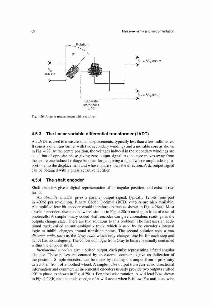
82 Measurements and instrumentation
Rotation
Vin400 Hz
Separatestator coils
at 90°
V1 = KVincos θ
°θ
V2 = KVinsin θ
Fig. 4.26 Angular measurement with a resolver
4.5.3 The linear variable differential transformer (LVDT)
An LVDT is used to measure small displacements, typically less than a few millimetres.It consists of a transformer with two secondary windings and a movable core as shownin Fig. 4.27. At the centre position, the voltages induced in the secondary windings areequal but of opposite phase giving zero output signal. As the core moves away fromthe centre one induced voltage becomes larger, giving a signal whose amplitude is pro-portional to the displacement and whose phase shows the direction. A dc output signalcan be obtained with a phase sensitive rectifier.
4.5.4 The shaft encoder
Shaft encoders give a digital representation of an angular position, and exist in twoforms.
An absolute encoder gives a parallel output signal, typically 12 bits (one part in 4096) per revolution. Binary Coded Decimal (BCD) outputs are also available. A simplified four-bit encoder would therefore operate as shown in Fig. 4.28(a). Mostabsolute encoders use a coded wheel similar to Fig. 4.28(b) moving in front of a set ofphotocells. A simple binary coded shaft encoder can give anomalous readings as theoutputs change state. There are two solutions to this problem. The first uses an addi-tional track, called an anti-ambiguity track, which is used by the encoder’s internallogic to inhibit changes around transition points. The second solution uses a unit distance code, such as the Gray code which only changes one bit for each step andhence has no ambiguity. The conversion logic from Gray to binary is usually containedwithin the encoder itself.
Incremental encoders give a pulsed output, each pulse representing a fixed angulardistance. These pulses are counted by an external counter to give an indication of the position. Simple encoders can be made by reading the output from a proximitydetector in front of a toothed wheel. A single-pulse output train carries no directionalinformation and commercial incremental encoders usually provide two outputs shifted90° in phase as shown in Fig. 4.29(a). For clockwise rotation, A will lead B as shownin Fig. 4.29(b) and the positive edge of A will occur when B is low. For anti-clockwise
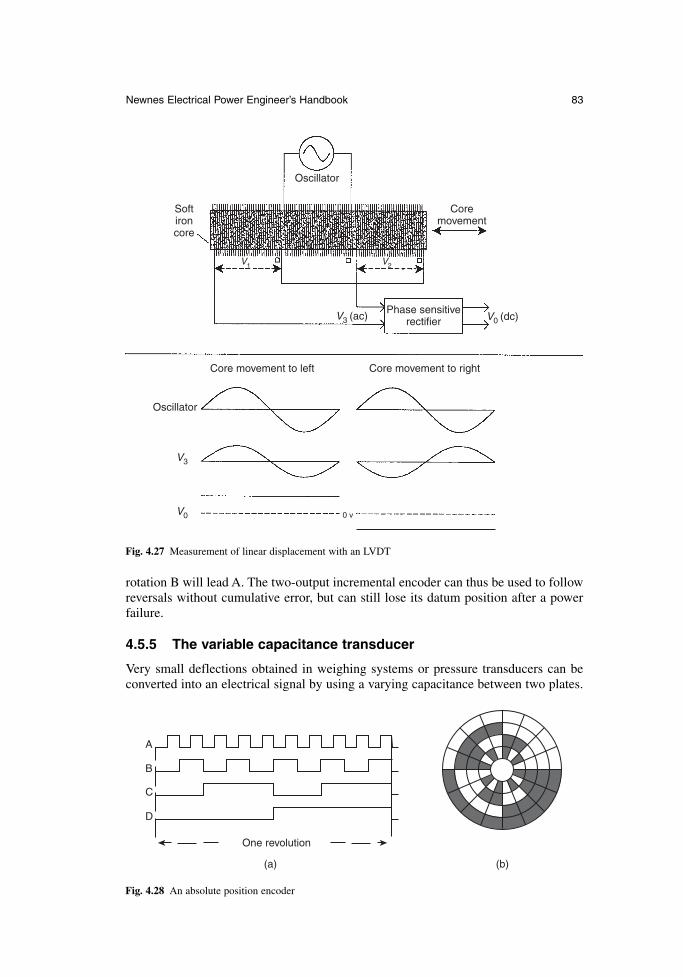
Newnes Electrical Power Engineer’s Handbook 83
rotation B will lead A. The two-output incremental encoder can thus be used to followreversals without cumulative error, but can still lose its datum position after a powerfailure.
4.5.5 The variable capacitance transducer
Very small deflections obtained in weighing systems or pressure transducers can beconverted into an electrical signal by using a varying capacitance between two plates.
(a) (b)
One revolution
A
B
C
D
Fig. 4.28 An absolute position encoder
Oscillator
Softironcore
Coremovement
Phase sensitiverectifier
Core movement to left Core movement to right
Oscillator
V3
V0 0 v
V3 (ac) V0 (dc)
V1 V2
Fig. 4.27 Measurement of linear displacement with an LVDT
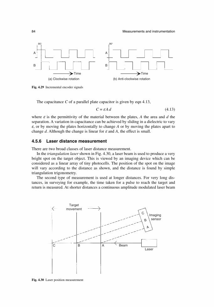
84 Measurements and instrumentation
The capacitance C of a parallel plate capacitor is given by eqn 4.13,
C = ε A d (4.13)
where ε is the permittivity of the material between the plates, A the area and d the separation. A variation in capacitance can be achieved by sliding in a dielectric to varyε, or by moving the plates horizontally to change A or by moving the plates apart tochange d. Although the change is linear for ε and A, the effect is small.
4.5.6 Laser distance measurement
There are two broad classes of laser distance measurement.In the triangulation laser shown in Fig. 4.30, a laser beam is used to produce a very
bright spot on the target object. This is viewed by an imaging device which can be considered as a linear array of tiny photocells. The position of the spot on the imagewill vary according to the distance as shown, and the distance is found by simple triangulation trigonometry.
The second type of measurement is used at longer distances. For very long dis-tances, in surveying for example, the time taken for a pulse to reach the target andreturn is measured. At shorter distances a continuous amplitude modulated laser beam
(a) Clockwise rotation (b) Anti-clockwise rotation
Time Time
A
B
A
B
90° 90°
Fig. 4.29 Incremental encoder signals
Targetmovement
Imaging sensor
C
B
A
BeamLaser
ABC
Fig. 4.30 Laser position measurement
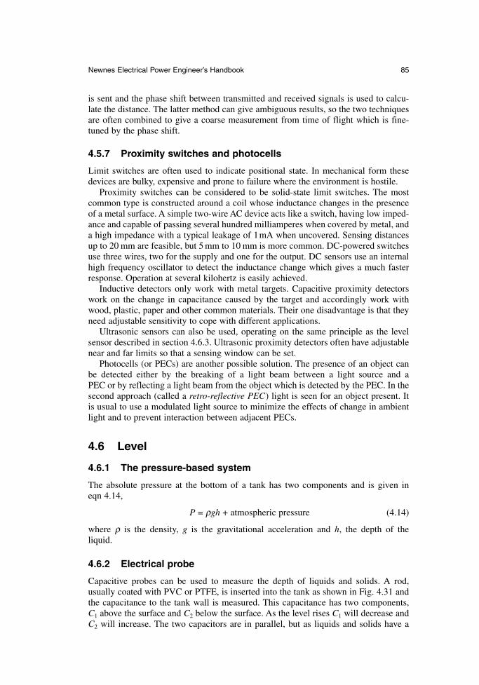
Newnes Electrical Power Engineer’s Handbook 85
is sent and the phase shift between transmitted and received signals is used to calcu-late the distance. The latter method can give ambiguous results, so the two techniquesare often combined to give a coarse measurement from time of flight which is fine-tuned by the phase shift.
4.5.7 Proximity switches and photocells
Limit switches are often used to indicate positional state. In mechanical form thesedevices are bulky, expensive and prone to failure where the environment is hostile.
Proximity switches can be considered to be solid-state limit switches. The mostcommon type is constructed around a coil whose inductance changes in the presenceof a metal surface. A simple two-wire AC device acts like a switch, having low imped-ance and capable of passing several hundred milliamperes when covered by metal, anda high impedance with a typical leakage of 1mA when uncovered. Sensing distancesup to 20 mm are feasible, but 5 mm to 10 mm is more common. DC-powered switchesuse three wires, two for the supply and one for the output. DC sensors use an internalhigh frequency oscillator to detect the inductance change which gives a much fasterresponse. Operation at several kilohertz is easily achieved.
Inductive detectors only work with metal targets. Capacitive proximity detectorswork on the change in capacitance caused by the target and accordingly work withwood, plastic, paper and other common materials. Their one disadvantage is that theyneed adjustable sensitivity to cope with different applications.
Ultrasonic sensors can also be used, operating on the same principle as the levelsensor described in section 4.6.3. Ultrasonic proximity detectors often have adjustablenear and far limits so that a sensing window can be set.
Photocells (or PECs) are another possible solution. The presence of an object canbe detected either by the breaking of a light beam between a light source and a PEC or by reflecting a light beam from the object which is detected by the PEC. In thesecond approach (called a retro-reflective PEC) light is seen for an object present. Itis usual to use a modulated light source to minimize the effects of change in ambientlight and to prevent interaction between adjacent PECs.
4.6 Level
4.6.1 The pressure-based system
The absolute pressure at the bottom of a tank has two components and is given ineqn 4.14,
P = ρgh + atmospheric pressure (4.14)
where ρ is the density, g is the gravitational acceleration and h, the depth of the liquid.
4.6.2 Electrical probe
Capacitive probes can be used to measure the depth of liquids and solids. A rod, usually coated with PVC or PTFE, is inserted into the tank as shown in Fig. 4.31 andthe capacitance to the tank wall is measured. This capacitance has two components, C1 above the surface and C2 below the surface. As the level rises C1 will decrease andC2 will increase. The two capacitors are in parallel, but as liquids and solids have a
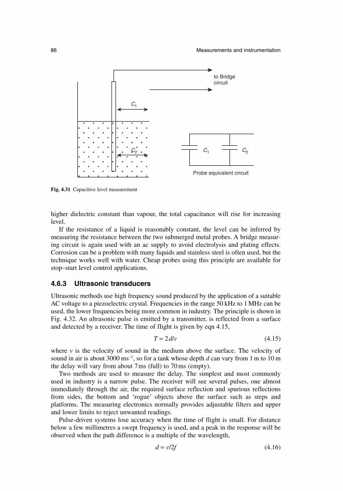
86 Measurements and instrumentation
higher dielectric constant than vapour, the total capacitance will rise for increasinglevel.
If the resistance of a liquid is reasonably constant, the level can be inferred bymeasuring the resistance between the two submerged metal probes. A bridge measur-ing circuit is again used with an ac supply to avoid electrolysis and plating effects.Corrosion can be a problem with many liquids and stainless steel is often used, but thetechnique works well with water. Cheap probes using this principle are available forstop–start level control applications.
4.6.3 Ultrasonic transducers
Ultrasonic methods use high frequency sound produced by the application of a suitableAC voltage to a piezoelectric crystal. Frequencies in the range 50 kHz to 1 MHz can beused, the lower frequencies being more common in industry. The principle is shown inFig. 4.32. An ultrasonic pulse is emitted by a transmitter, is reflected from a surfaceand detected by a receiver. The time of flight is given by eqn 4.15,
T = 2d/v (4.15)
where v is the velocity of sound in the medium above the surface. The velocity ofsound in air is about 3000 ms–1, so for a tank whose depth d can vary from 1 m to 10 mthe delay will vary from about 7ms (full) to 70 ms (empty).
Two methods are used to measure the delay. The simplest and most commonly used in industry is a narrow pulse. The receiver will see several pulses, one almostimmediately through the air, the required surface reflection and spurious reflectionsfrom sides, the bottom and ‘rogue’ objects above the surface such as steps and platforms. The measuring electronics normally provides adjustable filters and upperand lower limits to reject unwanted readings.
Pulse-driven systems lose accuracy when the time of flight is small. For distancebelow a few millimetres a swept frequency is used, and a peak in the response will beobserved when the path difference is a multiple of the wavelength,
d = v/2f (4.16)
Probe equivalent circuit
to Bridgecircuit
C1
C2 C1 C2
Fig. 4.31 Capacitive level measurement
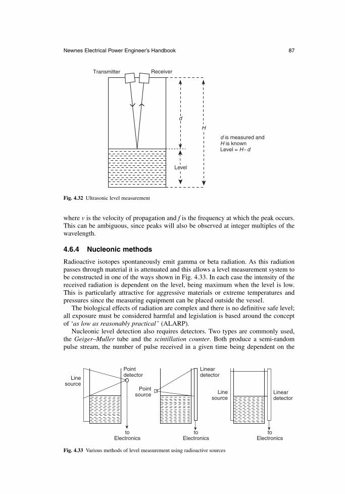
Newnes Electrical Power Engineer’s Handbook 87
where v is the velocity of propagation and f is the frequency at which the peak occurs.This can be ambiguous, since peaks will also be observed at integer multiples of thewavelength.
4.6.4 Nucleonic methods
Radioactive isotopes spontaneously emit gamma or beta radiation. As this radiationpasses through material it is attenuated and this allows a level measurement system tobe constructed in one of the ways shown in Fig. 4.33. In each case the intensity of thereceived radiation is dependent on the level, being maximum when the level is low.This is particularly attractive for aggressive materials or extreme temperatures andpressures since the measuring equipment can be placed outside the vessel.
The biological effects of radiation are complex and there is no definitive safe level;all exposure must be considered harmful and legislation is based around the conceptof ‘as low as reasonably practical ’ (ALARP).
Nucleonic level detection also requires detectors. Two types are commonly used,the Geiger–Muller tube and the scintillation counter. Both produce a semi-randompulse stream, the number of pulse received in a given time being dependent on the
Transmitter Receiver
d is measured andH is knownLevel = H−d
H
d
Level
Fig. 4.32 Ultrasonic level measurement
Lineardetector
Linesource
Lineardetector
Linesource
Pointsource
Pointdetector
toElectronics
toElectronics
toElectronics
Fig. 4.33 Various methods of level measurement using radioactive sources
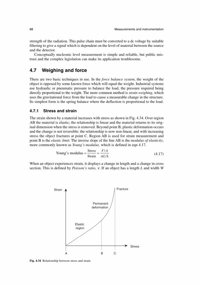
88 Measurements and instrumentation
strength of the radiation. This pulse chain must be converted to a dc voltage by suitablefiltering to give a signal which is dependent on the level of material between the sourceand the detector.
Conceptually nucleonic level measurement is simple and reliable, but public mis-trust and the complex legislation can make its application troublesome.
4.7 Weighing and force
There are two basic techniques in use. In the force balance system, the weight of theobject is opposed by some known force which will equal the weight. Industrial systemsuse hydraulic or pneumatic pressure to balance the load, the pressure required beingdirectly proportional to the weight. The more common method is strain weighing, whichuses the gravitational force from the load to cause a measurable change in the structure.Its simplest form is the spring balance where the deflection is proportional to the load.
4.7.1 Stress and strain
The strain shown by a material increases with stress as shown in Fig. 4.34. Over regionAB the material is elastic; the relationship is linear and the material returns to its orig-inal dimension when the stress is removed. Beyond point B, plastic deformation occursand the change is not reversible; the relationship is now non-linear, and with increasingstress the object fractures at point C. Region AB is used for strain measurement andpoint B is the elastic limit. The inverse slope of the line AB is the modulus of elasticity,more commonly known as Young’s modulus, which is defined in eqn 4.17.
Young’s modulus (4.17)
When an object experiences strain, it displays a change in length and a change in crosssection. This is defined by Poisson’s ratio, ν. If an object has a length L and width W
= =Stress
Strain
/F A
L L∆ /
Stress
Strain
Permanentdeformation
Elasticreglon
Fracture
A B C
Fig. 4.34 Relationship between stress and strain
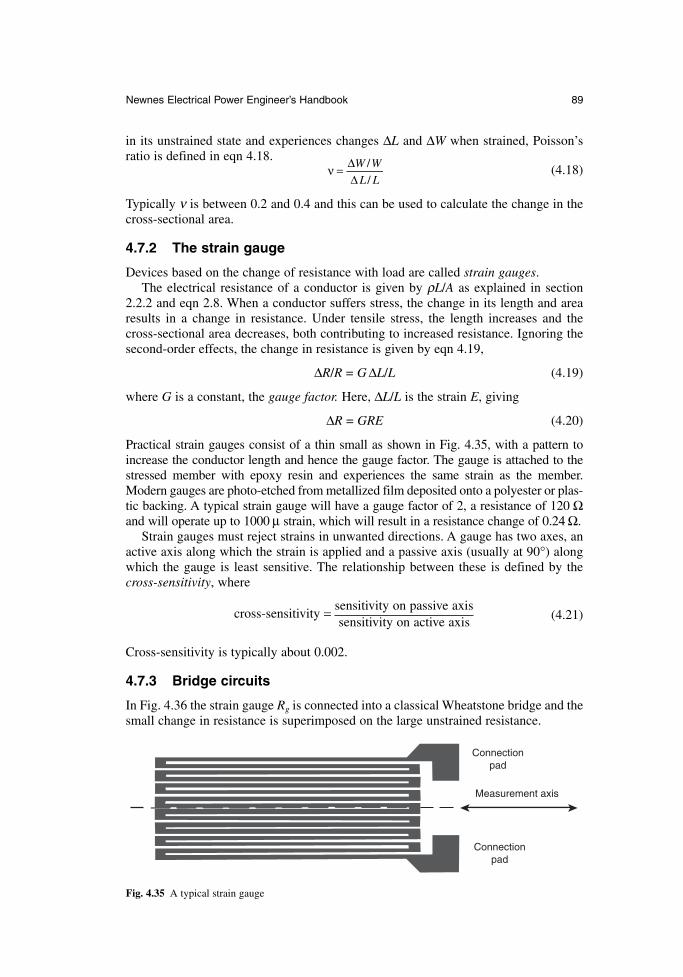
Newnes Electrical Power Engineer’s Handbook 89
in its unstrained state and experiences changes ∆L and ∆W when strained, Poisson’sratio is defined in eqn 4.18.
(4.18)
Typically ν is between 0.2 and 0.4 and this can be used to calculate the change in thecross-sectional area.
4.7.2 The strain gauge
Devices based on the change of resistance with load are called strain gauges.The electrical resistance of a conductor is given by ρL/A as explained in section
2.2.2 and eqn 2.8. When a conductor suffers stress, the change in its length and arearesults in a change in resistance. Under tensile stress, the length increases and thecross-sectional area decreases, both contributing to increased resistance. Ignoring thesecond-order effects, the change in resistance is given by eqn 4.19,
∆R/R = G ∆L/L (4.19)
where G is a constant, the gauge factor. Here, ∆L/L is the strain E, giving
∆R = GRE (4.20)
Practical strain gauges consist of a thin small as shown in Fig. 4.35, with a pattern toincrease the conductor length and hence the gauge factor. The gauge is attached to thestressed member with epoxy resin and experiences the same strain as the member.Modern gauges are photo-etched from metallized film deposited onto a polyester or plas-tic backing. A typical strain gauge will have a gauge factor of 2, a resistance of 120 Ωand will operate up to 1000 µ strain, which will result in a resistance change of 0.24 Ω.
Strain gauges must reject strains in unwanted directions. A gauge has two axes, anactive axis along which the strain is applied and a passive axis (usually at 90°) alongwhich the gauge is least sensitive. The relationship between these is defined by thecross-sensitivity, where
cross-sensitivity = sensitivity on passive axis(4.21)sensitivity on active axis
Cross-sensitivity is typically about 0.002.
4.7.3 Bridge circuits
In Fig. 4.36 the strain gauge Rg is connected into a classical Wheatstone bridge and thesmall change in resistance is superimposed on the large unstrained resistance.
ν = ∆∆W W
L L
/
/
Connectionpad
Connectionpad
Measurement axis
Fig. 4.35 A typical strain gauge
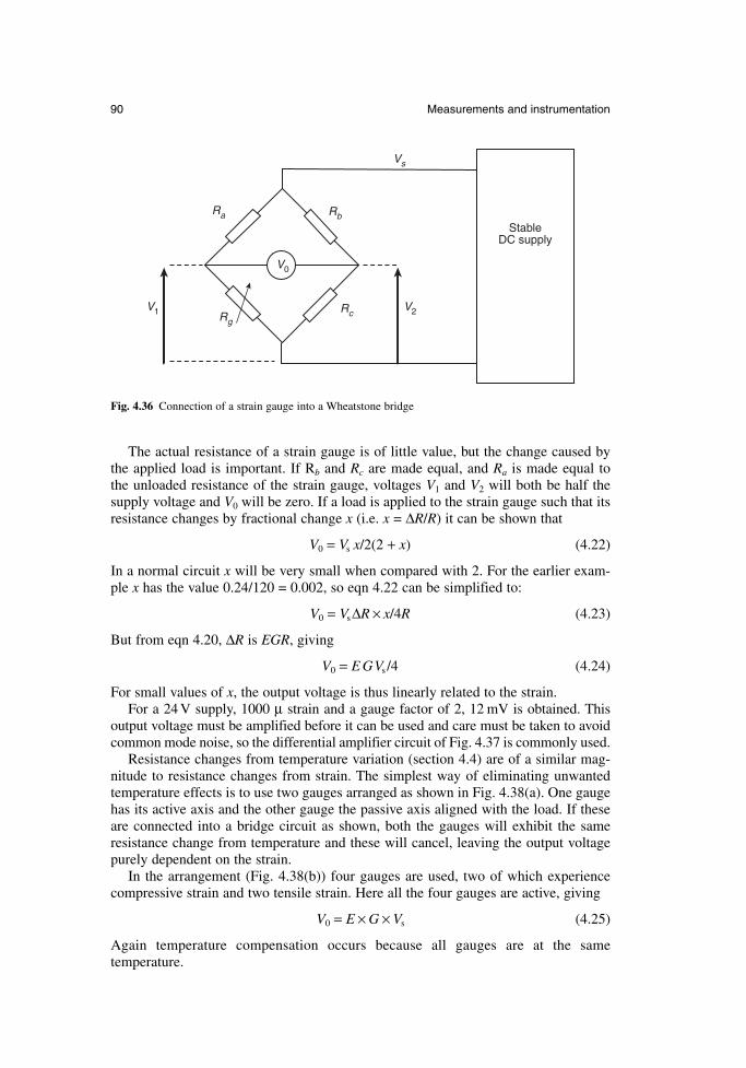
90 Measurements and instrumentation
The actual resistance of a strain gauge is of little value, but the change caused bythe applied load is important. If Rb and Rc are made equal, and Ra is made equal to the unloaded resistance of the strain gauge, voltages V1 and V2 will both be half thesupply voltage and V0 will be zero. If a load is applied to the strain gauge such that itsresistance changes by fractional change x (i.e. x = ∆R/R) it can be shown that
V0 = Vs x/2(2 + x) (4.22)
In a normal circuit x will be very small when compared with 2. For the earlier exam-ple x has the value 0.24/120 = 0.002, so eqn 4.22 can be simplified to:
V0 = Vs∆R × x/4R (4.23)
But from eqn 4.20, ∆R is EGR, giving
V0 = E GVs /4 (4.24)
For small values of x, the output voltage is thus linearly related to the strain.For a 24 V supply, 1000 µ strain and a gauge factor of 2, 12 mV is obtained. This
output voltage must be amplified before it can be used and care must be taken to avoidcommon mode noise, so the differential amplifier circuit of Fig. 4.37 is commonly used.
Resistance changes from temperature variation (section 4.4) are of a similar mag-nitude to resistance changes from strain. The simplest way of eliminating unwantedtemperature effects is to use two gauges arranged as shown in Fig. 4.38(a). One gaugehas its active axis and the other gauge the passive axis aligned with the load. If theseare connected into a bridge circuit as shown, both the gauges will exhibit the sameresistance change from temperature and these will cancel, leaving the output voltagepurely dependent on the strain.
In the arrangement (Fig. 4.38(b)) four gauges are used, two of which experiencecompressive strain and two tensile strain. Here all the four gauges are active, giving
V0 = E × G × Vs (4.25)
Again temperature compensation occurs because all gauges are at the same temperature.
StableDC supply
Vs
V1 V2
RbRa
RgRc
V0
Fig. 4.36 Connection of a strain gauge into a Wheatstone bridge
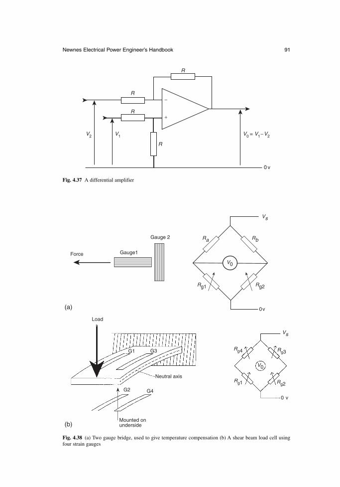
Newnes Electrical Power Engineer’s Handbook 91
Vs
Ra
Rg1 Rg2
Rb
Force Gauge1
Gauge 2
0v
V0
V0
Load
G1
G2
G3
G4
Mounted onunderside
Neutral axis
Vs
Rg4
Rg1 Rg2
Rg3
0 v
(a)
(b)
Fig. 4.38 (a) Two gauge bridge, used to give temperature compensation (b) A shear beam load cell usingfour strain gauges
−
+
R
R
R
R
V2
0 v
V0 = V1−V2V1
Fig. 4.37 A differential amplifier
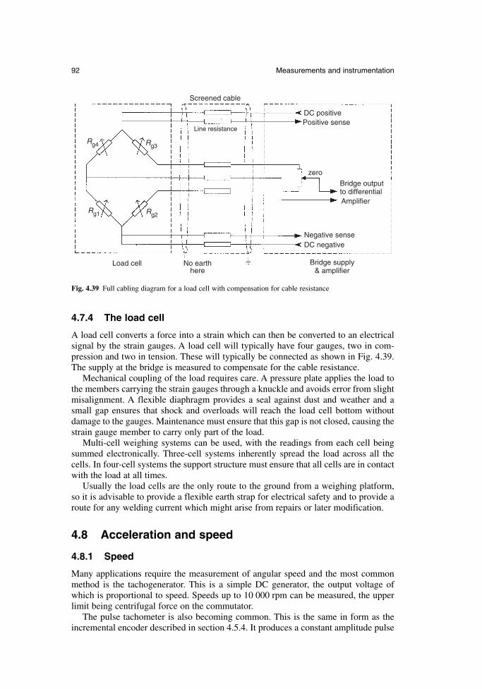
92 Measurements and instrumentation
4.7.4 The load cell
A load cell converts a force into a strain which can then be converted to an electricalsignal by the strain gauges. A load cell will typically have four gauges, two in com-pression and two in tension. These will typically be connected as shown in Fig. 4.39.The supply at the bridge is measured to compensate for the cable resistance.
Mechanical coupling of the load requires care. A pressure plate applies the load tothe members carrying the strain gauges through a knuckle and avoids error from slightmisalignment. A flexible diaphragm provides a seal against dust and weather and asmall gap ensures that shock and overloads will reach the load cell bottom withoutdamage to the gauges. Maintenance must ensure that this gap is not closed, causing thestrain gauge member to carry only part of the load.
Multi-cell weighing systems can be used, with the readings from each cell beingsummed electronically. Three-cell systems inherently spread the load across all thecells. In four-cell systems the support structure must ensure that all cells are in contactwith the load at all times.
Usually the load cells are the only route to the ground from a weighing platform,so it is advisable to provide a flexible earth strap for electrical safety and to provide aroute for any welding current which might arise from repairs or later modification.
4.8 Acceleration and speed
4.8.1 Speed
Many applications require the measurement of angular speed and the most commonmethod is the tachogenerator. This is a simple DC generator, the output voltage ofwhich is proportional to speed. Speeds up to 10 000 rpm can be measured, the upperlimit being centrifugal force on the commutator.
The pulse tachometer is also becoming common. This is the same in form as theincremental encoder described in section 4.5.4. It produces a constant amplitude pulse
DC positivePositive sense
zero
Bridge outputto differentialAmplifier
Negative senseDC negative
Bridge supply& amplifier
No earthhere
Load cell
Screened cable
Line resistance
Rg4
Rg1 Rg2
Rg3
Fig. 4.39 Full cabling diagram for a load cell with compensation for cable resistance
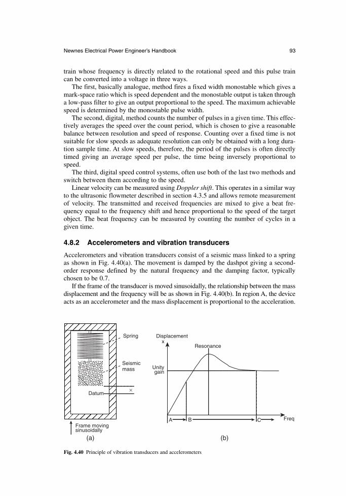
Newnes Electrical Power Engineer’s Handbook 93
train whose frequency is directly related to the rotational speed and this pulse train can be converted into a voltage in three ways.
The first, basically analogue, method fires a fixed width monostable which gives amark-space ratio which is speed dependent and the monostable output is taken througha low-pass filter to give an output proportional to the speed. The maximum achievablespeed is determined by the monostable pulse width.
The second, digital, method counts the number of pulses in a given time. This effec-tively averages the speed over the count period, which is chosen to give a reasonablebalance between resolution and speed of response. Counting over a fixed time is notsuitable for slow speeds as adequate resolution can only be obtained with a long dura-tion sample time. At slow speeds, therefore, the period of the pulses is often directlytimed giving an average speed per pulse, the time being inversely proportional tospeed.
The third, digital speed control systems, often use both of the last two methods andswitch between them according to the speed.
Linear velocity can be measured using Doppler shift. This operates in a similar wayto the ultrasonic flowmeter described in section 4.3.5 and allows remote measurementof velocity. The transmitted and received frequencies are mixed to give a beat fre-quency equal to the frequency shift and hence proportional to the speed of the targetobject. The beat frequency can be measured by counting the number of cycles in agiven time.
4.8.2 Accelerometers and vibration transducers
Accelerometers and vibration transducers consist of a seismic mass linked to a springas shown in Fig. 4.40(a). The movement is damped by the dashpot giving a second-order response defined by the natural frequency and the damping factor, typically chosen to be 0.7.
If the frame of the transducer is moved sinusoidally, the relationship between the massdisplacement and the frequency will be as shown in Fig. 4.40(b). In region A, the deviceacts as an accelerometer and the mass displacement is proportional to the acceleration.
Spring
Seismicmass
×
xResonance
Displacement
Unitygain
A B CFrame movingsinusoidally
(a) (b)
Freq
Datum
Fig. 4.40 Principle of vibration transducers and accelerometers
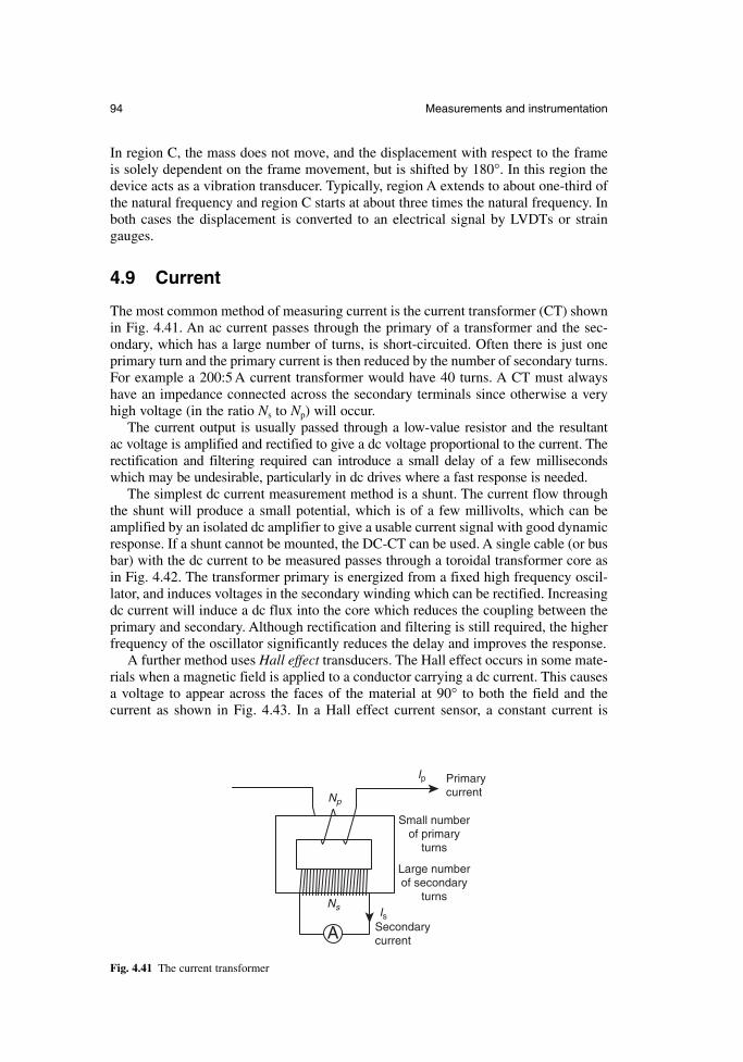
94 Measurements and instrumentation
In region C, the mass does not move, and the displacement with respect to the frameis solely dependent on the frame movement, but is shifted by 180°. In this region thedevice acts as a vibration transducer. Typically, region A extends to about one-third ofthe natural frequency and region C starts at about three times the natural frequency. Inboth cases the displacement is converted to an electrical signal by LVDTs or straingauges.
4.9 Current
The most common method of measuring current is the current transformer (CT) shownin Fig. 4.41. An ac current passes through the primary of a transformer and the sec-ondary, which has a large number of turns, is short-circuited. Often there is just oneprimary turn and the primary current is then reduced by the number of secondary turns.For example a 200:5 A current transformer would have 40 turns. A CT must alwayshave an impedance connected across the secondary terminals since otherwise a veryhigh voltage (in the ratio Ns to Np) will occur.
The current output is usually passed through a low-value resistor and the resultant ac voltage is amplified and rectified to give a dc voltage proportional to the current. Therectification and filtering required can introduce a small delay of a few millisecondswhich may be undesirable, particularly in dc drives where a fast response is needed.
The simplest dc current measurement method is a shunt. The current flow throughthe shunt will produce a small potential, which is of a few millivolts, which can beamplified by an isolated dc amplifier to give a usable current signal with good dynamicresponse. If a shunt cannot be mounted, the DC-CT can be used. A single cable (or busbar) with the dc current to be measured passes through a toroidal transformer core asin Fig. 4.42. The transformer primary is energized from a fixed high frequency oscil-lator, and induces voltages in the secondary winding which can be rectified. Increasingdc current will induce a dc flux into the core which reduces the coupling between theprimary and secondary. Although rectification and filtering is still required, the higherfrequency of the oscillator significantly reduces the delay and improves the response.
A further method uses Hall effect transducers. The Hall effect occurs in some mate-rials when a magnetic field is applied to a conductor carrying a dc current. This causesa voltage to appear across the faces of the material at 90° to both the field and the current as shown in Fig. 4.43. In a Hall effect current sensor, a constant current is
Primary currentNp
Ns
Ip
Is
Small number of primary
turns
Large number of secondary
turns
Secondary currentA
Fig. 4.41 The current transformer
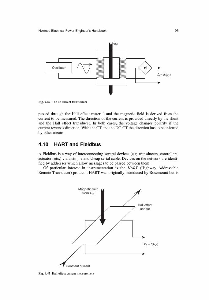
Newnes Electrical Power Engineer’s Handbook 95
passed through the Hall effect material and the magnetic field is derived from the current to be measured. The direction of the current is provided directly by the shuntand the Hall effect transducer. In both cases, the voltage changes polarity if the current reverses direction. With the CT and the DC-CT the direction has to be inferredby other means.
4.10 HART and Fieldbus
A Fieldbus is a way of interconnecting several devices (e.g. transducers, controllers,actuators etc.) via a simple and cheap serial cable. Devices on the network are identi-fied by addresses which allow messages to be passed between them.
Of particular interest in instrumentation is the HART (Highway AddressableRemote Transducer) protocol. HART was originally introduced by Rosemount but is
Oscillator
V0 = f(IDC)
IDC
Fig. 4.42 The dc current transformer
V0 = f(IDC)
Magnetic field from IDC
Hall effect sensor
Constant current
Fig. 4.43 Hall effect current measurement
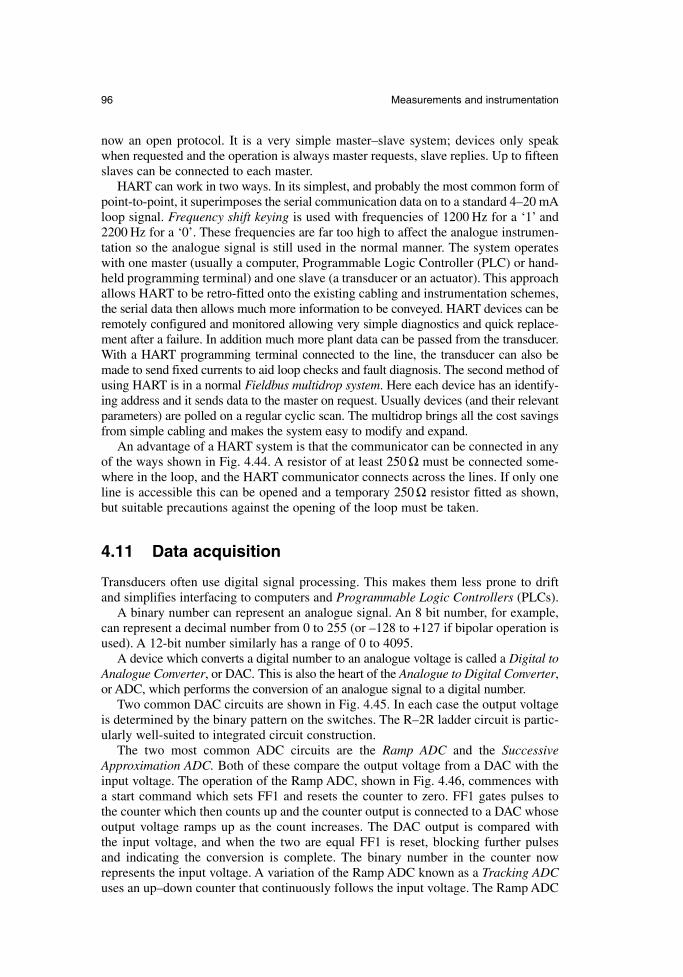
96 Measurements and instrumentation
now an open protocol. It is a very simple master–slave system; devices only speakwhen requested and the operation is always master requests, slave replies. Up to fifteenslaves can be connected to each master.
HART can work in two ways. In its simplest, and probably the most common form ofpoint-to-point, it superimposes the serial communication data on to a standard 4–20 mAloop signal. Frequency shift keying is used with frequencies of 1200 Hz for a ‘1’ and2200 Hz for a ‘0’. These frequencies are far too high to affect the analogue instrumen-tation so the analogue signal is still used in the normal manner. The system operateswith one master (usually a computer, Programmable Logic Controller (PLC) or hand-held programming terminal) and one slave (a transducer or an actuator). This approachallows HART to be retro-fitted onto the existing cabling and instrumentation schemes,the serial data then allows much more information to be conveyed. HART devices can beremotely configured and monitored allowing very simple diagnostics and quick replace-ment after a failure. In addition much more plant data can be passed from the transducer.With a HART programming terminal connected to the line, the transducer can also bemade to send fixed currents to aid loop checks and fault diagnosis. The second method ofusing HART is in a normal Fieldbus multidrop system. Here each device has an identify-ing address and it sends data to the master on request. Usually devices (and their relevantparameters) are polled on a regular cyclic scan. The multidrop brings all the cost savingsfrom simple cabling and makes the system easy to modify and expand.
An advantage of a HART system is that the communicator can be connected in anyof the ways shown in Fig. 4.44. A resistor of at least 250 Ω must be connected some-where in the loop, and the HART communicator connects across the lines. If only oneline is accessible this can be opened and a temporary 250 Ω resistor fitted as shown,but suitable precautions against the opening of the loop must be taken.
4.11 Data acquisition
Transducers often use digital signal processing. This makes them less prone to driftand simplifies interfacing to computers and Programmable Logic Controllers (PLCs).
A binary number can represent an analogue signal. An 8 bit number, for example,can represent a decimal number from 0 to 255 (or –128 to +127 if bipolar operation isused). A 12-bit number similarly has a range of 0 to 4095.
A device which converts a digital number to an analogue voltage is called a Digital toAnalogue Converter, or DAC. This is also the heart of the Analogue to Digital Converter,or ADC, which performs the conversion of an analogue signal to a digital number.
Two common DAC circuits are shown in Fig. 4.45. In each case the output voltageis determined by the binary pattern on the switches. The R–2R ladder circuit is partic-ularly well-suited to integrated circuit construction.
The two most common ADC circuits are the Ramp ADC and the SuccessiveApproximation ADC. Both of these compare the output voltage from a DAC with theinput voltage. The operation of the Ramp ADC, shown in Fig. 4.46, commences witha start command which sets FF1 and resets the counter to zero. FF1 gates pulses to the counter which then counts up and the counter output is connected to a DAC whoseoutput voltage ramps up as the count increases. The DAC output is compared with the input voltage, and when the two are equal FF1 is reset, blocking further pulses and indicating the conversion is complete. The binary number in the counter now represents the input voltage. A variation of the Ramp ADC known as a Tracking ADCuses an up–down counter that continuously follows the input voltage. The Ramp ADC
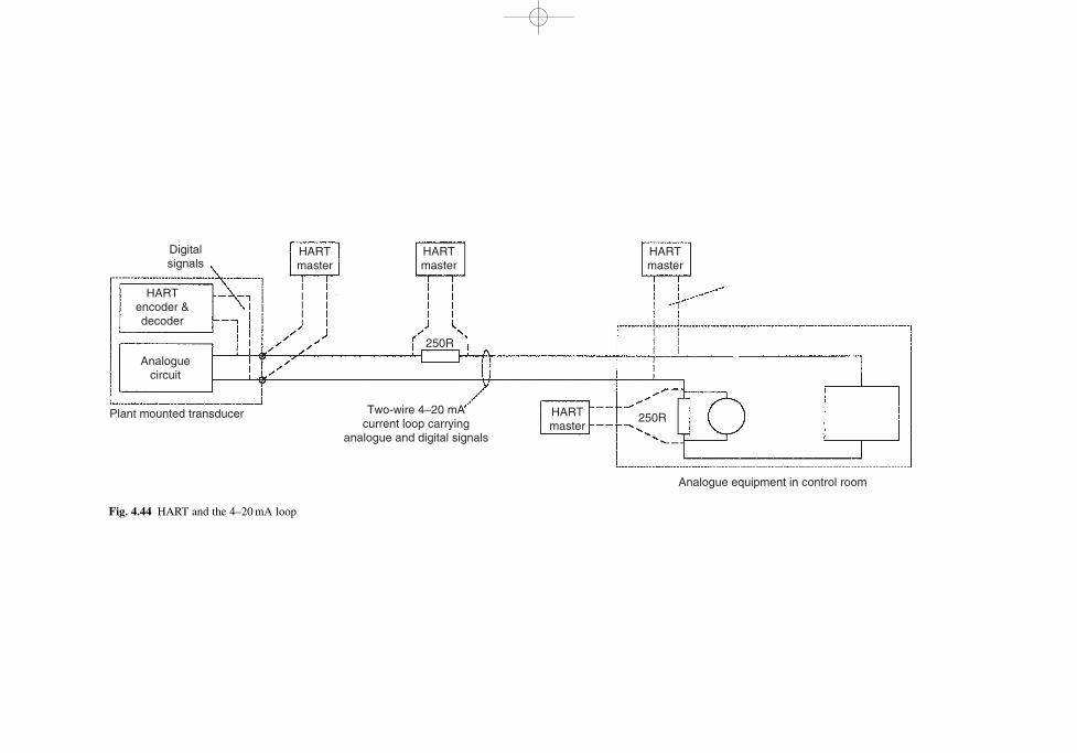
Digital signals
HART master
HART master
250R
HART master
HART master
Plant mounted transducer
Analogue circuit
Two-wire 4–20 mA current loop carrying
analogue and digital signals
250R
Analogue equipment in control room
HART encoder & decoder
Fig. 4.44 HART and the 4–20 mA loop
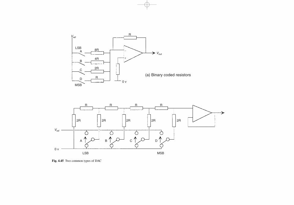
LSB
MSB
LSB
MSB
A 8R −
+
Vref
Vref
Vout
4R
2R
R
(a) Binary coded resistorsR
B
C
D0 v
0 v
R
2R
A B C D
2R 2R 2R 2R
R R R
Fig. 4.45 Two common types of DAC
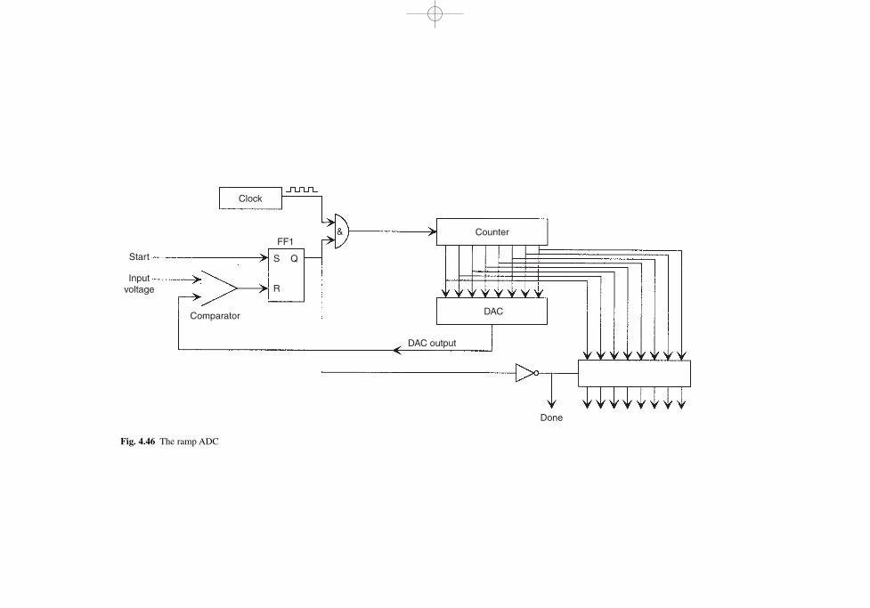
Clock
Comparator
S
R
Q
FF1&
DAC output
Done
DAC
Counter
Start
Input voltage
Fig. 4.46 The ramp ADC
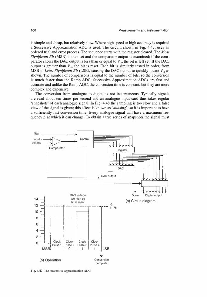
100 Measurements and instrumentation
Comparator
Control
DAC output
DAC voltage too high so bit is reset
Clock Pulse 1
Clock Pulse 2
Clock Pulse 3
Clock Pulse 4
1MSB LSB
Vin 11.75
0
0
2
4
6
8
10
12
14
1 1
Digital outputDone
DAC
Register
Start
Input voltage
(b) Operation
(a) Circuit diagram
Conversioncomplete
Fig. 4.47 The successive approximation ADC
is simple and cheap, but relatively slow. Where high speed or high accuracy is requireda Successive Approximation ADC is used. The circuit, shown in Fig. 4.47, uses anordered trial and error process. The sequence starts with the register cleared. The MostSignificant Bit (MSB) is then set and the comparator output is examined; if the com-parator shows the DAC output is less than or equal to Vin, the bit is left set. If the DACoutput is greater than Vin, the bit is reset. Each bit is similarly tested in order, fromMSB to Least Significant Bit (LSB), causing the DAC output to quickly locate Vin asshown. The number of comparisons is equal to the number of bits, so the conversionis much faster than the Ramp ADC. Successive Approximation ADCs are fast andaccurate and unlike the Ramp ADC, the conversion time is constant, but they are morecomplex and expensive.
The conversion from analogue to digital is not instantaneous. Typically signals are read about ten times per second and an analogue input card thus takes regular‘snapshots’ of each analogue signal. In Fig. 4.48 the sampling is too slow and a falseview of the signal is given; this effect is known as ‘aliasing’, so it is important to havea sufficiently fast conversion time. Every analogue signal will have a maximum fre-quency fc at which it can change. To obtain a true series of snapshots the signal must
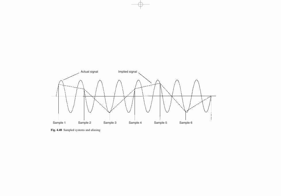
Sample 1 Sample 2
Actual signal Implied signal
Sample 3 Sample 4 Sample 5 Sample 6
Fig. 4.48 Sampled systems and aliasing
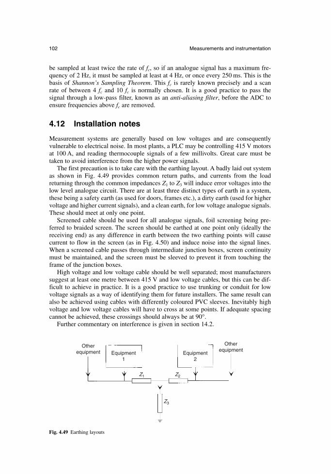
102 Measurements and instrumentation
Equipment 1
Equipment 2
Other equipment
Other equipment
Z1 Z2
Z3
Fig. 4.49 Earthing layouts
be sampled at least twice the rate of fc, so if an analogue signal has a maximum fre-quency of 2 Hz, it must be sampled at least at 4 Hz, or once every 250 ms. This is thebasis of Shannon’s Sampling Theorem. This fc is rarely known precisely and a scan rate of between 4 fc and 10 fc is normally chosen. It is a good practice to pass the signal through a low-pass filter, known as an anti-aliasing filter, before the ADC toensure frequencies above fc are removed.
4.12 Installation notes
Measurement systems are generally based on low voltages and are consequently vulnerable to electrical noise. In most plants, a PLC may be controlling 415 V motorsat 100 A, and reading thermocouple signals of a few millivolts. Great care must betaken to avoid interference from the higher power signals.
The first precaution is to take care with the earthing layout. A badly laid out systemas shown in Fig. 4.49 provides common return paths, and currents from the loadreturning through the common impedances Z1 to Z3 will induce error voltages into thelow level analogue circuit. There are at least three distinct types of earth in a system,these being a safety earth (as used for doors, frames etc.), a dirty earth (used for higher voltage and higher current signals), and a clean earth, for low voltage analogue signals.These should meet at only one point.
Screened cable should be used for all analogue signals, foil screening being pre-ferred to braided screen. The screen should be earthed at one point only (ideally thereceiving end) as any difference in earth between the two earthing points will causecurrent to flow in the screen (as in Fig. 4.50) and induce noise into the signal lines.When a screened cable passes through intermediate junction boxes, screen continuitymust be maintained, and the screen must be sleeved to prevent it from touching theframe of the junction boxes.
High voltage and low voltage cable should be well separated; most manufacturerssuggest at least one metre between 415 V and low voltage cables, but this can be dif-ficult to achieve in practice. It is a good practice to use trunking or conduit for lowvoltage signals as a way of identifying them for future installers. The same result canalso be achieved using cables with differently coloured PVC sleeves. Inevitably highvoltage and low voltage cables will have to cross at some points. If adequate spacingcannot be achieved, these crossings should always be at 90°.
Further commentary on interference is given in section 14.2.
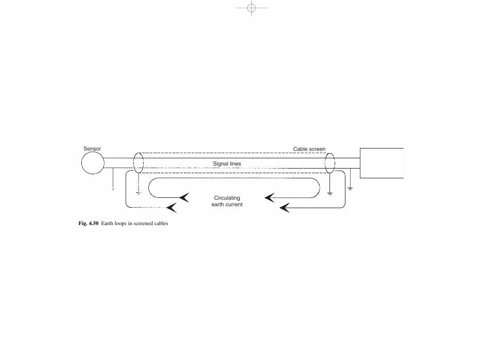
Sensor
Signal lines
Cable screen
Circulating earth current
Fig. 4.50 Earth loops in screened cables

Chapter 5
Generators
Dr G.W. McLeanGenerac Corporation
5.1 Introduction
Throughout the world there is a need for generators in many different applications. Inaddition to the underlying need for a public supply of electricity, there are a number ofsituations in which independent supplies are needed. The applications for generatorsare categorized broadly as follows:
public supply networks in which a number of high-power generator sets mayoperate in parallel
private or independent generators which may run in parallel with the publicsupply or isolated from it. Examples of this include:– peak shaving to reduce the maximum demand of electricity by a user;
this can avoid large financial penalties during times of generally highdemand on the system
– standby emergency generators to protect the supply to critical circuits such as hospitals or water supplies
– temporary supplies which are needed by the construction industry, or incases of breakdown
– combined heat and power using the waste heat from the generator engine isused for other purposes such as building heating
portable supplies, often trailer-mounted, where no alternative supply is available
5.2 Main generator types
The two main types of generator are ‘turbo’ or cylindrical-rotor and salient-pole gen-erators. Both these types are synchronous machines in which the rotor turns in exactsynchronism with the rotating magnetic field in the stator. Since most generators fallunder this class, it forms the basis of most of the chapter.
The largest generators used in major power stations are usually turbo-generators.They operate at high speeds and are usually directly coupled to a steam or gas turbine.The general construction of a turbo-generator is shown in Fig. 5.1. The rotor is madefrom solid steel for strength, and embedded in slots within the rotor are the field or excitation windings. The outer stator also contains windings which are located inslots, this is again for mechanical strength and so that the teeth between the slots forma good magnetic path. Most of the constructional features are very specialized, such as
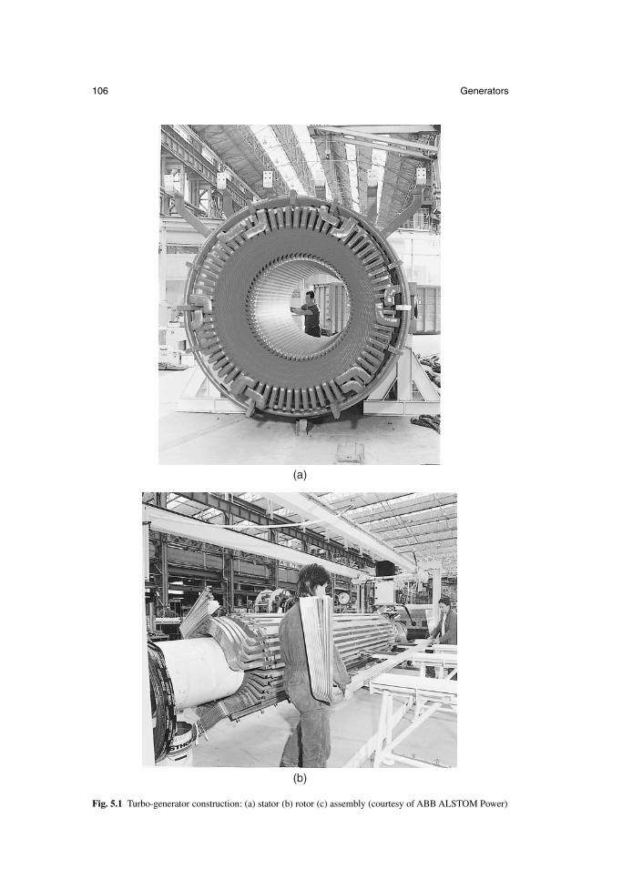
106 Generators
(a)
(b)
Fig. 5.1 Turbo-generator construction: (a) stator (b) rotor (c) assembly (courtesy of ABB ALSTOM Power)
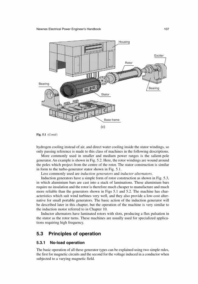
hydrogen cooling instead of air, and direct water cooling inside the stator windings, soonly passing reference is made to this class of machines in the following descriptions.
More commonly used in smaller and medium power ranges is the salient-pole generator. An example is shown in Fig. 5.2. Here, the rotor windings are wound aroundthe poles which project from the centre of the rotor. The stator construction is similarin form to the turbo-generator stator shown in Fig. 5.1.
Less commonly used are induction generators and inductor alternators.Induction generators have a simple form of rotor construction as shown in Fig. 5.3,
in which aluminium bars are cast into a stack of laminations. These aluminium barsrequire no insulation and the rotor is therefore much cheaper to manufacture and muchmore reliable than the generators shown in Figs 5.1 and 5.2. The machine has char-acteristics which suit wind turbines very well, and they also provide a low-cost alter-native for small portable generators. The basic action of the induction generator willbe described later in this chapter, but the operation of the machine is very similar tothe induction motor referred to in Chapter 10.
Inductor alternators have laminated rotors with slots, producing a flux pulsation inthe stator as the rotor turns. These machines are usually used for specialized applica-tions requiring high frequency.
5.3 Principles of operation
5.3.1 No-load operation
The basic operation of all these generator types can be explained using two simple rules,the first for magnetic circuits and the second for the voltage induced in a conductor whensubjected to a varying magnetic field.
Newnes Electrical Power Engineer’s Handbook 107
Housing
Rotor
Exciter
Bearing
Stator
Bearing
Base frame
(c)
Fig. 5.1 (Contd)
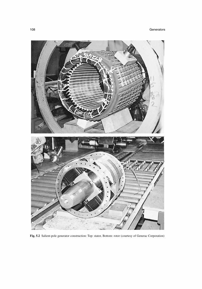
108 Generators
Fig. 5.2 Salient-pole generator construction: Top: stator, Bottom: rotor (courtesy of Generac Corporation)
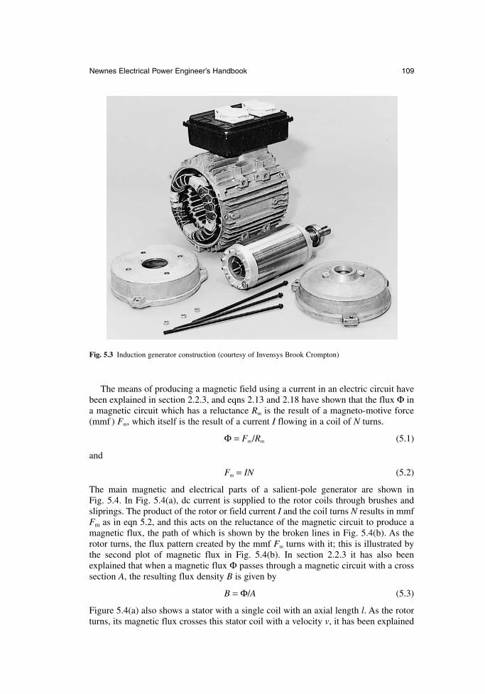
The means of producing a magnetic field using a current in an electric circuit havebeen explained in section 2.2.3, and eqns 2.13 and 2.18 have shown that the flux Φ ina magnetic circuit which has a reluctance Rm is the result of a magneto-motive force(mmf ) Fm, which itself is the result of a current I flowing in a coil of N turns.
Φ = Fm/Rm (5.1)
and
Fm = IN (5.2)
The main magnetic and electrical parts of a salient-pole generator are shown in Fig. 5.4. In Fig. 5.4(a), dc current is supplied to the rotor coils through brushes andsliprings. The product of the rotor or field current I and the coil turns N results in mmfFm as in eqn 5.2, and this acts on the reluctance of the magnetic circuit to produce amagnetic flux, the path of which is shown by the broken lines in Fig. 5.4(b). As therotor turns, the flux pattern created by the mmf Fm turns with it; this is illustrated bythe second plot of magnetic flux in Fig. 5.4(b). In section 2.2.3 it has also beenexplained that when a magnetic flux Φ passes through a magnetic circuit with a crosssection A, the resulting flux density B is given by
B = Φ/A (5.3)
Figure 5.4(a) also shows a stator with a single coil with an axial length l. As the rotorturns, its magnetic flux crosses this stator coil with a velocity v, it has been explained
Newnes Electrical Power Engineer’s Handbook 109
Fig. 5.3 Induction generator construction (courtesy of Invensys Brook Crompton)
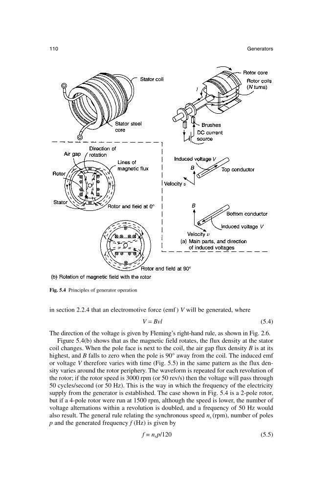
in section 2.2.4 that an electromotive force (emf ) V will be generated, where
V = Bvl (5.4)
The direction of the voltage is given by Fleming’s right-hand rule, as shown in Fig. 2.6.Figure 5.4(b) shows that as the magnetic field rotates, the flux density at the stator
coil changes. When the pole face is next to the coil, the air gap flux density B is at itshighest, and B falls to zero when the pole is 90° away from the coil. The induced emfor voltage V therefore varies with time (Fig. 5.5) in the same pattern as the flux den-sity varies around the rotor periphery. The waveform is repeated for each revolution ofthe rotor; if the rotor speed is 3000 rpm (or 50 rev/s) then the voltage will pass through50 cycles/second (or 50 Hz). This is the way in which the frequency of the electricitysupply from the generator is established. The case shown in Fig. 5.4 is a 2-pole rotor,but if a 4-pole rotor were run at 1500 rpm, although the speed is lower, the number ofvoltage alternations within a revolution is doubled, and a frequency of 50 Hz wouldalso result. The general rule relating the synchronous speed ns (rpm), number of polesp and the generated frequency f (Hz) is given by
f = nsp/120 (5.5)
110 Generators
Fig. 5.4 Principles of generator operation
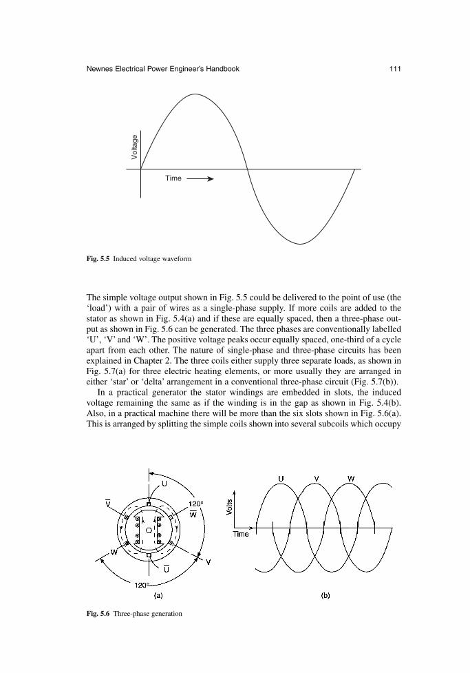
The simple voltage output shown in Fig. 5.5 could be delivered to the point of use (the‘load’) with a pair of wires as a single-phase supply. If more coils are added to the stator as shown in Fig. 5.4(a) and if these are equally spaced, then a three-phase out-put as shown in Fig. 5.6 can be generated. The three phases are conventionally labelled‘U’, ‘V’ and ‘W’. The positive voltage peaks occur equally spaced, one-third of a cycleapart from each other. The nature of single-phase and three-phase circuits has beenexplained in Chapter 2. The three coils either supply three separate loads, as shown inFig. 5.7(a) for three electric heating elements, or more usually they are arranged ineither ‘star’ or ‘delta’ arrangement in a conventional three-phase circuit (Fig. 5.7(b)).
In a practical generator the stator windings are embedded in slots, the induced voltage remaining the same as if the winding is in the gap as shown in Fig. 5.4(b).Also, in a practical machine there will be more than the six slots shown in Fig. 5.6(a).This is arranged by splitting the simple coils shown into several subcoils which occupy
Newnes Electrical Power Engineer’s Handbook 111
Time
Vol
tage
Fig. 5.5 Induced voltage waveform
Fig. 5.6 Three-phase generation
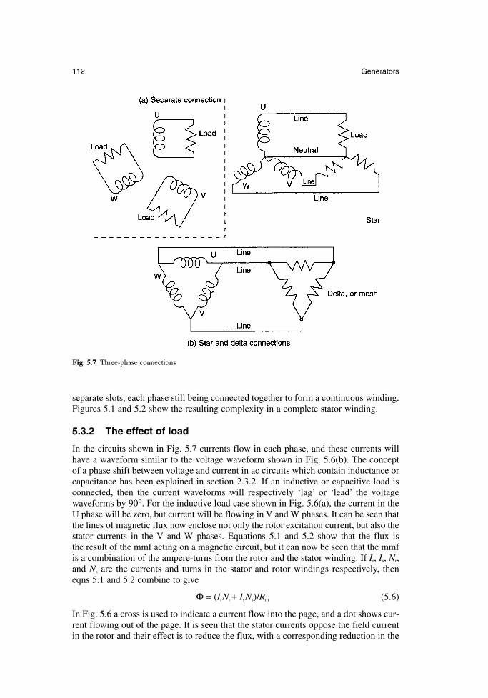
separate slots, each phase still being connected together to form a continuous winding.Figures 5.1 and 5.2 show the resulting complexity in a complete stator winding.
5.3.2 The effect of load
In the circuits shown in Fig. 5.7 currents flow in each phase, and these currents willhave a waveform similar to the voltage waveform shown in Fig. 5.6(b). The concept of a phase shift between voltage and current in ac circuits which contain inductance orcapacitance has been explained in section 2.3.2. If an inductive or capacitive load isconnected, then the current waveforms will respectively ‘lag’ or ‘lead’ the voltagewaveforms by 90°. For the inductive load case shown in Fig. 5.6(a), the current in theU phase will be zero, but current will be flowing in V and W phases. It can be seen thatthe lines of magnetic flux now enclose not only the rotor excitation current, but also thestator currents in the V and W phases. Equations 5.1 and 5.2 show that the flux is the result of the mmf acting on a magnetic circuit, but it can now be seen that the mmfis a combination of the ampere-turns from the rotor and the stator winding. If Ir, Is, Nr,and Ns are the currents and turns in the stator and rotor windings respectively, theneqns 5.1 and 5.2 combine to give
Φ = (IrNr + IsNs)/Rm (5.6)
In Fig. 5.6 a cross is used to indicate a current flow into the page, and a dot shows cur-rent flowing out of the page. It is seen that the stator currents oppose the field currentin the rotor and their effect is to reduce the flux, with a corresponding reduction in the
112 Generators
Fig. 5.7 Three-phase connections
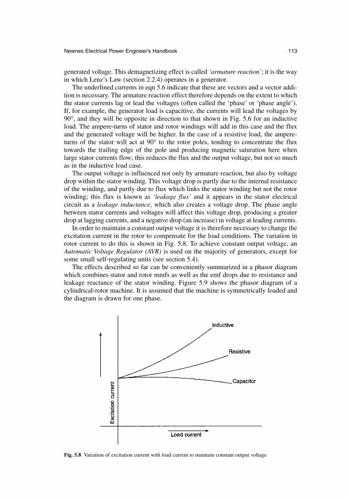
generated voltage. This demagnetizing effect is called ‘armature reaction’; it is the wayin which Lenz’s Law (section 2.2.4) operates in a generator.
The underlined currents in eqn 5.6 indicate that these are vectors and a vector addi-tion is necessary. The armature reaction effect therefore depends on the extent to whichthe stator currents lag or lead the voltages (often called the ‘phase’ or ‘phase angle’).If, for example, the generator load is capacitive, the currents will lead the voltages by90°, and they will be opposite in direction to that shown in Fig. 5.6 for an inductiveload. The ampere-turns of stator and rotor windings will add in this case and the fluxand the generated voltage will be higher. In the case of a resistive load, the ampere-turns of the stator will act at 90° to the rotor poles, tending to concentrate the fluxtowards the trailing edge of the pole and producing magnetic saturation here whenlarge stator currents flow; this reduces the flux and the output voltage, but not so muchas in the inductive load case.
The output voltage is influenced not only by armature reaction, but also by voltagedrop within the stator winding. This voltage drop is partly due to the internal resistanceof the winding, and partly due to flux which links the stator winding but not the rotorwinding; this flux is known as ‘leakage flux’ and it appears in the stator electrical circuit as a leakage inductance, which also creates a voltage drop. The phase anglebetween stator currents and voltages will affect this voltage drop, producing a greaterdrop at lagging currents, and a negative drop (an increase) in voltage at leading currents.
In order to maintain a constant output voltage it is therefore necessary to change theexcitation current in the rotor to compensate for the load conditions. The variation inrotor current to do this is shown in Fig. 5.8. To achieve constant output voltage, anAutomatic Voltage Regulator (AVR) is used on the majority of generators, except forsome small self-regulating units (see section 5.4).
The effects described so far can be conveniently summarized in a phasor diagramwhich combines stator and rotor mmfs as well as the emf drops due to resistance andleakage reactance of the stator winding. Figure 5.9 shows the phasor diagram of acylindrical-rotor machine. It is assumed that the machine is symmetrically loaded andthe diagram is drawn for one phase.
Newnes Electrical Power Engineer’s Handbook 113
Fig. 5.8 Variation of excitation current with load current to maintain constant output voltage
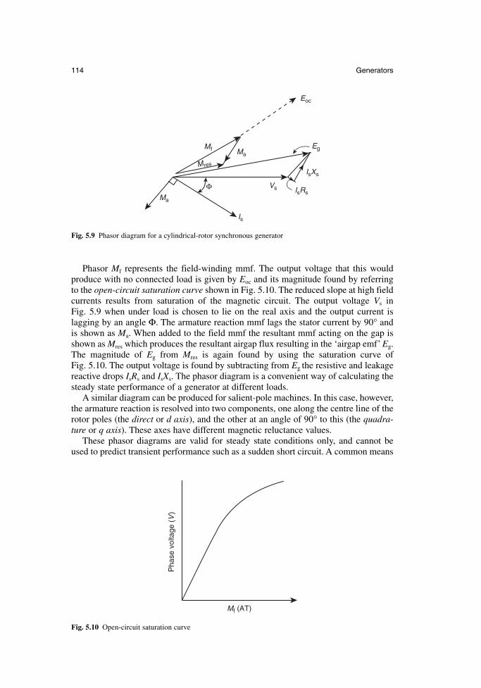
Phasor Mf represents the field-winding mmf. The output voltage that this wouldproduce with no connected load is given by Eoc and its magnitude found by referringto the open-circuit saturation curve shown in Fig. 5.10. The reduced slope at high fieldcurrents results from saturation of the magnetic circuit. The output voltage Vs in Fig. 5.9 when under load is chosen to lie on the real axis and the output current is lagging by an angle Φ. The armature reaction mmf lags the stator current by 90° andis shown as Ma. When added to the field mmf the resultant mmf acting on the gap isshown as Mres which produces the resultant airgap flux resulting in the ‘airgap emf’ Eg.The magnitude of Eg from Mres is again found by using the saturation curve of Fig. 5.10. The output voltage is found by subtracting from Eg the resistive and leakagereactive drops IsRs and IsXs. The phasor diagram is a convenient way of calculating thesteady state performance of a generator at different loads.
A similar diagram can be produced for salient-pole machines. In this case, however,the armature reaction is resolved into two components, one along the centre line of therotor poles (the direct or d axis), and the other at an angle of 90° to this (the quadra-ture or q axis). These axes have different magnetic reluctance values.
These phasor diagrams are valid for steady state conditions only, and cannot beused to predict transient performance such as a sudden short circuit. A common means
114 Generators
Ma
Eoc
Mf
Mres
Vs IsRs
IsXs
Eg
Ma
Is
Φ
Fig. 5.9 Phasor diagram for a cylindrical-rotor synchronous generator
Mf (AT)
Pha
se v
olta
ge (
V)
Fig. 5.10 Open-circuit saturation curve
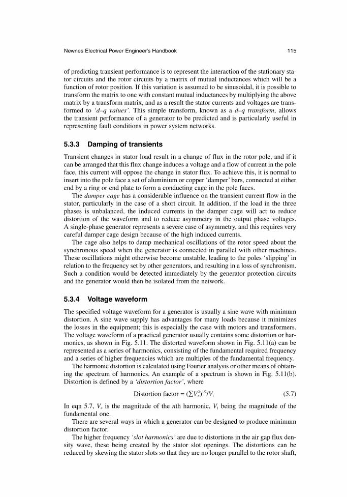
of predicting transient performance is to represent the interaction of the stationary sta-tor circuits and the rotor circuits by a matrix of mutual inductances which will be afunction of rotor position. If this variation is assumed to be sinusoidal, it is possible totransform the matrix to one with constant mutual inductances by multiplying the abovematrix by a transform matrix, and as a result the stator currents and voltages are trans-formed to ‘d–q values’. This simple transform, known as a d–q transform, allows the transient performance of a generator to be predicted and is particularly useful inrepresenting fault conditions in power system networks.
5.3.3 Damping of transients
Transient changes in stator load result in a change of flux in the rotor pole, and if itcan be arranged that this flux change induces a voltage and a flow of current in the poleface, this current will oppose the change in stator flux. To achieve this, it is normal toinsert into the pole face a set of aluminium or copper ‘damper’ bars, connected at eitherend by a ring or end plate to form a conducting cage in the pole faces.
The damper cage has a considerable influence on the transient current flow in thestator, particularly in the case of a short circuit. In addition, if the load in the threephases is unbalanced, the induced currents in the damper cage will act to reduce distortion of the waveform and to reduce asymmetry in the output phase voltages. A single-phase generator represents a severe case of asymmetry, and this requires verycareful damper cage design because of the high induced currents.
The cage also helps to damp mechanical oscillations of the rotor speed about thesynchronous speed when the generator is connected in parallel with other machines.These oscillations might otherwise become unstable, leading to the poles ‘slipping’ inrelation to the frequency set by other generators, and resulting in a loss of synchronism.Such a condition would be detected immediately by the generator protection circuitsand the generator would then be isolated from the network.
5.3.4 Voltage waveform
The specified voltage waveform for a generator is usually a sine wave with minimumdistortion. A sine wave supply has advantages for many loads because it minimizes the losses in the equipment; this is especially the case with motors and transformers.The voltage waveform of a practical generator usually contains some distortion or har-monics, as shown in Fig. 5.11. The distorted waveform shown in Fig. 5.11(a) can berepresented as a series of harmonics, consisting of the fundamental required frequencyand a series of higher frequencies which are multiples of the fundamental frequency.
The harmonic distortion is calculated using Fourier analysis or other means of obtain-ing the spectrum of harmonics. An example of a spectrum is shown in Fig. 5.11(b).Distortion is defined by a ‘distortion factor’, where
Distortion factor = (∑Vn2)1/2/V1 (5.7)
In eqn 5.7, Vn is the magnitude of the nth harmonic, V1 being the magnitude of the fundamental one.
There are several ways in which a generator can be designed to produce minimumdistortion factor.
The higher frequency ‘slot harmonics’ are due to distortions in the air gap flux den-sity wave, these being created by the stator slot openings. The distortions can bereduced by skewing the stator slots so that they are no longer parallel to the rotor shaft,
Newnes Electrical Power Engineer’s Handbook 115
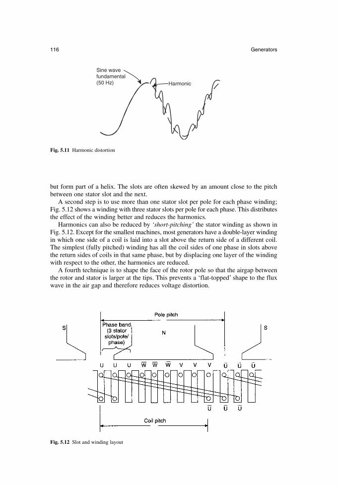
but form part of a helix. The slots are often skewed by an amount close to the pitchbetween one stator slot and the next.
A second step is to use more than one stator slot per pole for each phase winding;Fig. 5.12 shows a winding with three stator slots per pole for each phase. This distributesthe effect of the winding better and reduces the harmonics.
Harmonics can also be reduced by ‘short-pitching’ the stator winding as shown inFig. 5.12. Except for the smallest machines, most generators have a double-layer windingin which one side of a coil is laid into a slot above the return side of a different coil.The simplest (fully pitched) winding has all the coil sides of one phase in slots abovethe return sides of coils in that same phase, but by displacing one layer of the windingwith respect to the other, the harmonics are reduced.
A fourth technique is to shape the face of the rotor pole so that the airgap betweenthe rotor and stator is larger at the tips. This prevents a ‘flat-topped’ shape to the fluxwave in the air gap and therefore reduces voltage distortion.
116 Generators
Sine wave fundamental (50 Hz) Harmonic
Fig. 5.11 Harmonic distortion
Fig. 5.12 Slot and winding layout
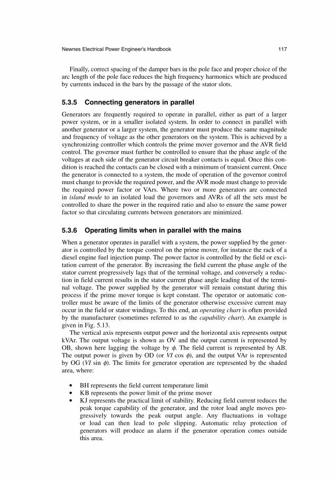
Finally, correct spacing of the damper bars in the pole face and proper choice of thearc length of the pole face reduces the high frequency harmonics which are producedby currents induced in the bars by the passage of the stator slots.
5.3.5 Connecting generators in parallel
Generators are frequently required to operate in parallel, either as part of a largerpower system, or in a smaller isolated system. In order to connect in parallel withanother generator or a larger system, the generator must produce the same magnitudeand frequency of voltage as the other generators on the system. This is achieved by asynchronizing controller which controls the prime mover governor and the AVR fieldcontrol. The governor must further be controlled to ensure that the phase angle of thevoltages at each side of the generator circuit breaker contacts is equal. Once this con-dition is reached the contacts can be closed with a minimum of transient current. Oncethe generator is connected to a system, the mode of operation of the governor controlmust change to provide the required power, and the AVR mode must change to providethe required power factor or VArs. Where two or more generators are connected in island mode to an isolated load the governors and AVRs of all the sets must be controlled to share the power in the required ratio and also to ensure the same powerfactor so that circulating currents between generators are minimized.
5.3.6 Operating limits when in parallel with the mains
When a generator operates in parallel with a system, the power supplied by the gener-ator is controlled by the torque control on the prime mover, for instance the rack of adiesel engine fuel injection pump. The power factor is controlled by the field or exci-tation current of the generator. By increasing the field current the phase angle of thestator current progressively lags that of the terminal voltage, and conversely a reduc-tion in field current results in the stator current phase angle leading that of the termi-nal voltage. The power supplied by the generator will remain constant during thisprocess if the prime mover torque is kept constant. The operator or automatic con-troller must be aware of the limits of the generator otherwise excessive current mayoccur in the field or stator windings. To this end, an operating chart is often providedby the manufacturer (sometimes referred to as the capability chart). An example isgiven in Fig. 5.13.
The vertical axis represents output power and the horizontal axis represents outputkVAr. The output voltage is shown as OV and the output current is represented by OB, shown here lagging the voltage by φ. The field current is represented by AB. The output power is given by OD (or VI cos φ), and the output VAr is represented by OG (VI sin φ). The limits for generator operation are represented by the shadedarea, where:
BH represents the field current temperature limit KB represents the power limit of the prime mover KJ represents the practical limit of stability. Reducing field current reduces the
peak torque capability of the generator, and the rotor load angle moves pro-gressively towards the peak output angle. Any fluctuations in voltage or load can then lead to pole slipping. Automatic relay protection of generators will produce an alarm if the generator operation comes outside this area.
Newnes Electrical Power Engineer’s Handbook 117
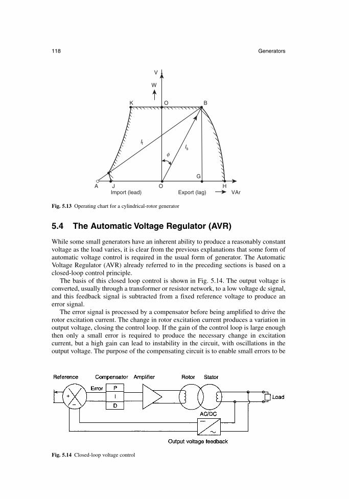
5.4 The Automatic Voltage Regulator (AVR)
While some small generators have an inherent ability to produce a reasonably constantvoltage as the load varies, it is clear from the previous explanations that some form ofautomatic voltage control is required in the usual form of generator. The AutomaticVoltage Regulator (AVR) already referred to in the preceding sections is based on aclosed-loop control principle.
The basis of this closed loop control is shown in Fig. 5.14. The output voltage isconverted, usually through a transformer or resistor network, to a low voltage dc signal,and this feedback signal is subtracted from a fixed reference voltage to produce anerror signal.
The error signal is processed by a compensator before being amplified to drive therotor excitation current. The change in rotor excitation current produces a variation inoutput voltage, closing the control loop. If the gain of the control loop is large enoughthen only a small error is required to produce the necessary change in excitation current, but a high gain can lead to instability in the circuit, with oscillations in the output voltage. The purpose of the compensating circuit is to enable small errors to be
118 Generators
V
W
O BK
A J O
G
IsIf
φ
HVArExport (lag)Import (lead)
Fig. 5.13 Operating chart for a cylindrical-rotor generator
Fig. 5.14 Closed-loop voltage control
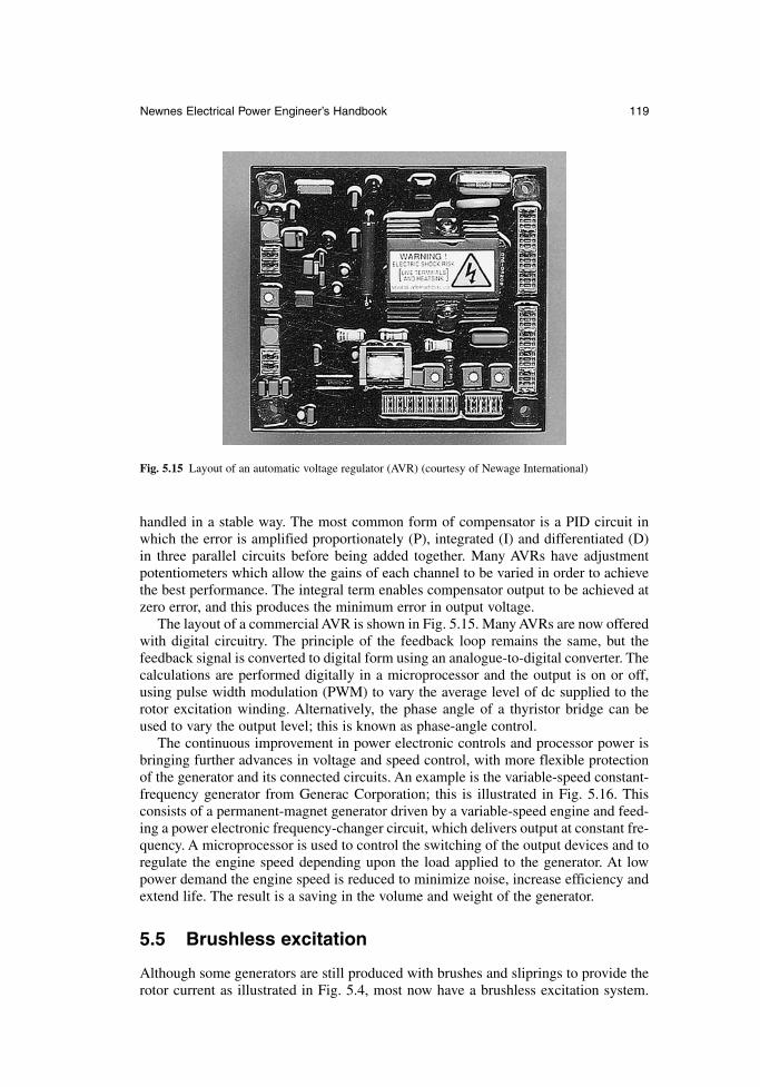
handled in a stable way. The most common form of compensator is a PID circuit inwhich the error is amplified proportionately (P), integrated (I) and differentiated (D)in three parallel circuits before being added together. Many AVRs have adjustmentpotentiometers which allow the gains of each channel to be varied in order to achievethe best performance. The integral term enables compensator output to be achieved atzero error, and this produces the minimum error in output voltage.
The layout of a commercial AVR is shown in Fig. 5.15. Many AVRs are now offeredwith digital circuitry. The principle of the feedback loop remains the same, but thefeedback signal is converted to digital form using an analogue-to-digital converter. Thecalculations are performed digitally in a microprocessor and the output is on or off,using pulse width modulation (PWM) to vary the average level of dc supplied to therotor excitation winding. Alternatively, the phase angle of a thyristor bridge can beused to vary the output level; this is known as phase-angle control.
The continuous improvement in power electronic controls and processor power isbringing further advances in voltage and speed control, with more flexible protectionof the generator and its connected circuits. An example is the variable-speed constant-frequency generator from Generac Corporation; this is illustrated in Fig. 5.16. Thisconsists of a permanent-magnet generator driven by a variable-speed engine and feed-ing a power electronic frequency-changer circuit, which delivers output at constant fre-quency. A microprocessor is used to control the switching of the output devices and toregulate the engine speed depending upon the load applied to the generator. At lowpower demand the engine speed is reduced to minimize noise, increase efficiency andextend life. The result is a saving in the volume and weight of the generator.
5.5 Brushless excitation
Although some generators are still produced with brushes and sliprings to provide therotor current as illustrated in Fig. 5.4, most now have a brushless excitation system.
Newnes Electrical Power Engineer’s Handbook 119
Fig. 5.15 Layout of an automatic voltage regulator (AVR) (courtesy of Newage International)
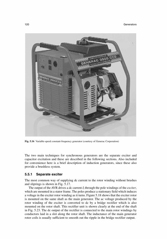
The two main techniques for synchronous generators are the separate exciter andcapacitor excitation and these are described in the following sections. Also includedfor convenience here is a brief description of induction generators, since these alsoprovide a brushless system.
5.5.1 Separate exciter
The most common way of supplying dc current to the rotor winding without brushesand sliprings is shown in Fig. 5.17.
The output of the AVR drives a dc current If through the pole windings of the exciter,which are mounted in a stator frame. The poles produce a stationary field which inducesa voltage in the exciter rotor winding as it turns. Figure 5.18 shows that the exciter rotoris mounted on the same shaft as the main generator. The ac voltage produced by therotor winding of the exciter is converted to dc by a bridge rectifier which is alsomounted on the rotor shaft. This rectifier unit is shown clearly at the end of the shaftin Fig. 5.23. The dc output of the rectifier is connected to the main rotor windings byconductors laid in a slot along the rotor shaft. The inductance of the main generatorrotor coils is usually sufficient to smooth out the ripple in the bridge rectifier output.
120 Generators
Fig. 5.16 Variable-speed constant-frequency generator (courtesy of Generac Corporation)
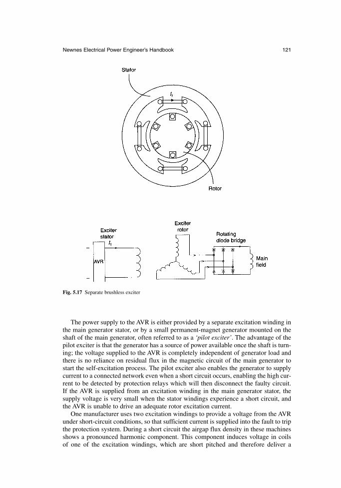
The power supply to the AVR is either provided by a separate excitation winding inthe main generator stator, or by a small permanent-magnet generator mounted on theshaft of the main generator, often referred to as a ‘pilot exciter’. The advantage of thepilot exciter is that the generator has a source of power available once the shaft is turn-ing; the voltage supplied to the AVR is completely independent of generator load andthere is no reliance on residual flux in the magnetic circuit of the main generator tostart the self-excitation process. The pilot exciter also enables the generator to supplycurrent to a connected network even when a short circuit occurs, enabling the high cur-rent to be detected by protection relays which will then disconnect the faulty circuit.If the AVR is supplied from an excitation winding in the main generator stator, the supply voltage is very small when the stator windings experience a short circuit, andthe AVR is unable to drive an adequate rotor excitation current.
One manufacturer uses two excitation windings to provide a voltage from the AVRunder short-circuit conditions, so that sufficient current is supplied into the fault to tripthe protection system. During a short circuit the airgap flux density in these machinesshows a pronounced harmonic component. This component induces voltage in coils of one of the excitation windings, which are short pitched and therefore deliver a
Newnes Electrical Power Engineer’s Handbook 121
Fig. 5.17 Separate brushless exciter
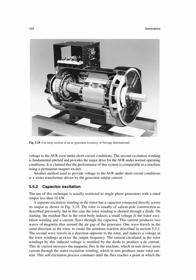
voltage to the AVR even under short-circuit conditions. The second excitation windingis fundamental-pitched and provides the major drive for the AVR under normal operatingconditions. It is claimed that the performance of this system is comparable to a machineusing a permanent-magnet exciter.
Another method used to provide voltage to the AVR under short-circuit conditionsis a series transformer driven by the generator output current.
5.5.2 Capacitor excitation
The use of this technique is usually restricted to single phase generators with a ratedoutput less than 10 kW.
A separate excitation winding in the stator has a capacitor connected directly acrossits output as shown in Fig. 5.19. The rotor is usually of salient-pole construction asdescribed previously, but in this case the rotor winding is shorted through a diode. Onstarting, the residual flux in the rotor body induces a small voltage in the stator exci-tation winding and a current flows through the capacitor. This current produces twowaves of magnetic flux around the air gap of the generator. One wave travels in thesame direction as the rotor, to create the armature reaction described in section 5.3.2.The second wave travels in a direction opposite to the rotor, and induces a voltage inthe rotor windings at twice the output frequency. The current circulated in the rotorwindings by this induced voltage is rectified by the diode to produce a dc current. This dc current increases the magnetic flux in the machine, which in turn drives morecurrent through the stator excitation winding, which in turn produces more rotor cur-rent. This self-excitation process continues until the flux reaches a point at which the
122 Generators
Fig. 5.18 Cut-away section of an ac generator (courtesy of Newage International)
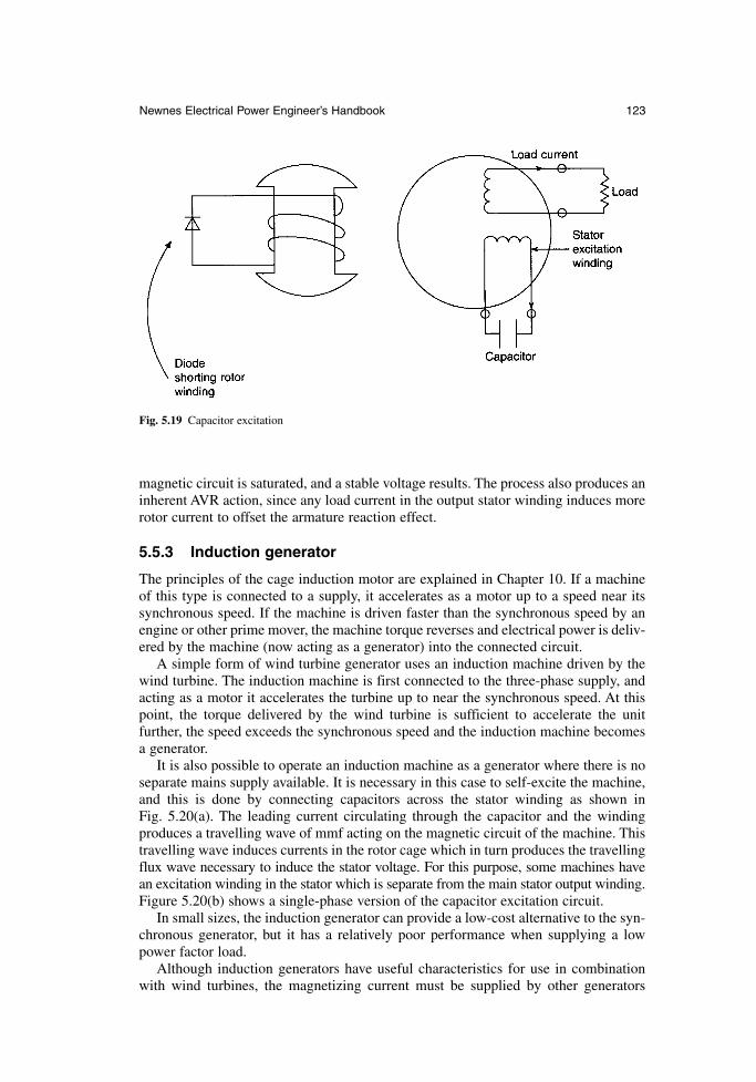
magnetic circuit is saturated, and a stable voltage results. The process also produces aninherent AVR action, since any load current in the output stator winding induces morerotor current to offset the armature reaction effect.
5.5.3 Induction generator
The principles of the cage induction motor are explained in Chapter 10. If a machineof this type is connected to a supply, it accelerates as a motor up to a speed near itssynchronous speed. If the machine is driven faster than the synchronous speed by anengine or other prime mover, the machine torque reverses and electrical power is deliv-ered by the machine (now acting as a generator) into the connected circuit.
A simple form of wind turbine generator uses an induction machine driven by thewind turbine. The induction machine is first connected to the three-phase supply, andacting as a motor it accelerates the turbine up to near the synchronous speed. At thispoint, the torque delivered by the wind turbine is sufficient to accelerate the unit further, the speed exceeds the synchronous speed and the induction machine becomesa generator.
It is also possible to operate an induction machine as a generator where there is noseparate mains supply available. It is necessary in this case to self-excite the machine,and this is done by connecting capacitors across the stator winding as shown in Fig. 5.20(a). The leading current circulating through the capacitor and the windingproduces a travelling wave of mmf acting on the magnetic circuit of the machine. Thistravelling wave induces currents in the rotor cage which in turn produces the travellingflux wave necessary to induce the stator voltage. For this purpose, some machines havean excitation winding in the stator which is separate from the main stator output winding.Figure 5.20(b) shows a single-phase version of the capacitor excitation circuit.
In small sizes, the induction generator can provide a low-cost alternative to the syn-chronous generator, but it has a relatively poor performance when supplying a lowpower factor load.
Although induction generators have useful characteristics for use in combinationwith wind turbines, the magnetizing current must be supplied by other generators
Newnes Electrical Power Engineer’s Handbook 123
Fig. 5.19 Capacitor excitation
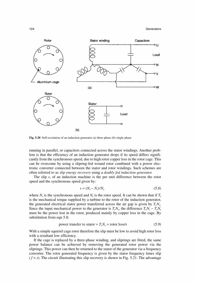
running in parallel, or capacitors connected across the stator windings. Another prob-lem is that the efficiency of an induction generator drops if its speed differs signifi-cantly from the synchronous speed, due to high rotor copper loss in the rotor cage. Thiscan be overcome by using a slipring-fed wound rotor combined with a power elec-tronic converter connected between the stator and rotor windings. Such schemes areoften referred to as slip energy recovery using a doubly fed induction generator.
The slip s, of an induction machine is the per unit difference between the rotorspeed and the synchronous speed given by:
s = (Ns − Nr) /Ns (5.8)
where Ns is the synchronous speed and Nr is the rotor speed. It can be shown that if Tr
is the mechanical torque supplied by a turbine to the rotor of the induction generator,the generated electrical stator power transferred across the air gap is given by TrNs.Since the input mechanical power to the generator is TrNr, the difference TrNr − TrNs
must be the power lost in the rotor, produced mainly by copper loss in the cage. Bysubstitution from eqn 5.8:
power transfer to stator = TrNs = rotor loss/s (5.9)
With a simple squirrel cage rotor therefore the slip must be low to avoid high rotor losswith a resultant low efficiency.
If the cage is replaced by a three-phase winding, and sliprings are fitted, the samepower balance can be achieved by removing the generated rotor power via thesliprings. This power can then be returned to the stator of the generator via a frequencyconverter. The rotor generated frequency is given by the stator frequency times slip ( f × s). The circuit illustrating this slip recovery is shown in Fig. 5.21. The advantage
124 Generators
Fig. 5.20 Self-excitation of an induction generator (a) three phase (b) single phase
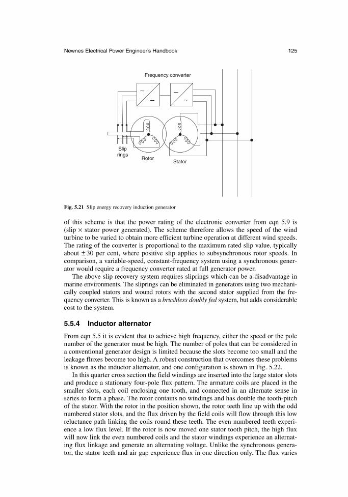
of this scheme is that the power rating of the electronic converter from eqn 5.9 is (slip × stator power generated). The scheme therefore allows the speed of the wind turbine to be varied to obtain more efficient turbine operation at different wind speeds.The rating of the converter is proportional to the maximum rated slip value, typicallyabout ± 30 per cent, where positive slip applies to subsynchronous rotor speeds. Incomparison, a variable-speed, constant-frequency system using a synchronous gener-ator would require a frequency converter rated at full generator power.
The above slip recovery system requires sliprings which can be a disadvantage inmarine environments. The sliprings can be eliminated in generators using two mechani-cally coupled stators and wound rotors with the second stator supplied from the fre-quency converter. This is known as a brushless doubly fed system, but adds considerablecost to the system.
5.5.4 Inductor alternator
From eqn 5.5 it is evident that to achieve high frequency, either the speed or the polenumber of the generator must be high. The number of poles that can be considered ina conventional generator design is limited because the slots become too small and theleakage fluxes become too high. A robust construction that overcomes these problemsis known as the inductor alternator, and one configuration is shown in Fig. 5.22.
In this quarter cross section the field windings are inserted into the large stator slotsand produce a stationary four-pole flux pattern. The armature coils are placed in thesmaller slots, each coil enclosing one tooth, and connected in an alternate sense inseries to form a phase. The rotor contains no windings and has double the tooth-pitchof the stator. With the rotor in the position shown, the rotor teeth line up with the oddnumbered stator slots, and the flux driven by the field coils will flow through this lowreluctance path linking the coils round these teeth. The even numbered teeth experi-ence a low flux level. If the rotor is now moved one stator tooth pitch, the high fluxwill now link the even numbered coils and the stator windings experience an alternat-ing flux linkage and generate an alternating voltage. Unlike the synchronous genera-tor, the stator teeth and air gap experience flux in one direction only. The flux varies
Newnes Electrical Power Engineer’s Handbook 125
––
Frequency converter
RotorStator
Slip rings
∼∼
Fig. 5.21 Slip energy recovery induction generator
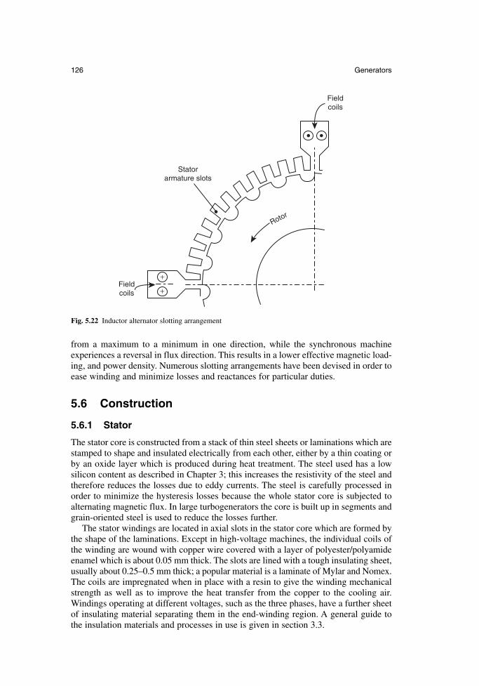
from a maximum to a minimum in one direction, while the synchronous machineexperiences a reversal in flux direction. This results in a lower effective magnetic load-ing, and power density. Numerous slotting arrangements have been devised in order toease winding and minimize losses and reactances for particular duties.
5.6 Construction
5.6.1 Stator
The stator core is constructed from a stack of thin steel sheets or laminations which arestamped to shape and insulated electrically from each other, either by a thin coating orby an oxide layer which is produced during heat treatment. The steel used has a lowsilicon content as described in Chapter 3; this increases the resistivity of the steel andtherefore reduces the losses due to eddy currents. The steel is carefully processed inorder to minimize the hysteresis losses because the whole stator core is subjected toalternating magnetic flux. In large turbogenerators the core is built up in segments andgrain-oriented steel is used to reduce the losses further.
The stator windings are located in axial slots in the stator core which are formed bythe shape of the laminations. Except in high-voltage machines, the individual coils ofthe winding are wound with copper wire covered with a layer of polyester/polyamideenamel which is about 0.05 mm thick. The slots are lined with a tough insulating sheet,usually about 0.25–0.5 mm thick; a popular material is a laminate of Mylar and Nomex.The coils are impregnated when in place with a resin to give the winding mechanicalstrength as well as to improve the heat transfer from the copper to the cooling air.Windings operating at different voltages, such as the three phases, have a further sheetof insulating material separating them in the end-winding region. A general guide tothe insulation materials and processes in use is given in section 3.3.
126 Generators
+
+
Stator armature slots
Rotor
Field coils
Field coils
Fig. 5.22 Inductor alternator slotting arrangement
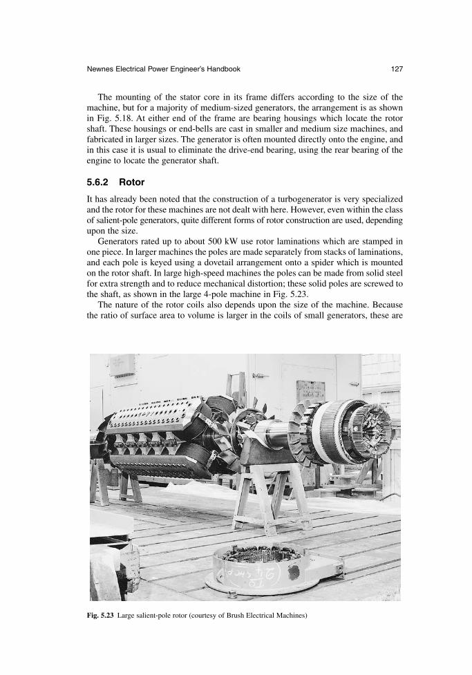
The mounting of the stator core in its frame differs according to the size of themachine, but for a majority of medium-sized generators, the arrangement is as shownin Fig. 5.18. At either end of the frame are bearing housings which locate the rotorshaft. These housings or end-bells are cast in smaller and medium size machines, andfabricated in larger sizes. The generator is often mounted directly onto the engine, andin this case it is usual to eliminate the drive-end bearing, using the rear bearing of theengine to locate the generator shaft.
5.6.2 Rotor
It has already been noted that the construction of a turbogenerator is very specializedand the rotor for these machines are not dealt with here. However, even within the classof salient-pole generators, quite different forms of rotor construction are used, dependingupon the size.
Generators rated up to about 500 kW use rotor laminations which are stamped inone piece. In larger machines the poles are made separately from stacks of laminations,and each pole is keyed using a dovetail arrangement onto a spider which is mountedon the rotor shaft. In large high-speed machines the poles can be made from solid steelfor extra strength and to reduce mechanical distortion; these solid poles are screwed tothe shaft, as shown in the large 4-pole machine in Fig. 5.23.
The nature of the rotor coils also depends upon the size of the machine. Because the ratio of surface area to volume is larger in the coils of small generators, these are
Newnes Electrical Power Engineer’s Handbook 127
Fig. 5.23 Large salient-pole rotor (courtesy of Brush Electrical Machines)
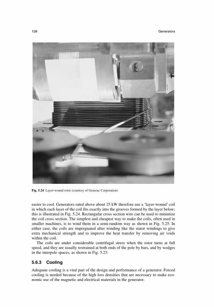
easier to cool. Generators rated above about 25 kW therefore use a ‘layer-wound’ coilin which each layer of the coil fits exactly into the grooves formed by the layer below;this is illustrated in Fig. 5.24. Rectangular cross section wire can be used to minimizethe coil cross section. The simplest and cheapest way to make the coils, often used insmaller machines, is to wind them in a semi-random way as shown in Fig. 5.25. Ineither case, the coils are impregnated after winding like the stator windings to giveextra mechanical strength and to improve the heat transfer by removing air voidswithin the coil.
The coils are under considerable centrifugal stress when the rotor turns at fullspeed, and they are usually restrained at both ends of the pole by bars, and by wedgesin the interpole spaces, as shown in Fig. 5.23.
5.6.3 Cooling
Adequate cooling is a vital part of the design and performance of a generator. Forcedcooling is needed because of the high loss densities that are necessary to make eco-nomic use of the magnetic and electrical materials in the generator.
128 Generators
Fig. 5.24 Layer-wound rotor (courtesy of Generac Corporation)
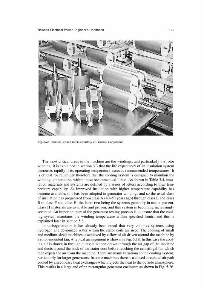
The most critical areas in the machine are the windings, and particularly the rotorwinding. It is explained in section 3.3 that the life expectancy of an insulation systemdecreases rapidly if its operating temperature exceeds recommended temperatures. Itis crucial for reliability therefore that the cooling system is designed to maintain thewinding temperatures within these recommended limits. As shown in Table 3.4, insu-lation materials and systems are defined by a series of letters according to their tem-perature capability. As improved insulation with higher temperature capability hasbecome available, this has been adopted in generator windings and so the usual classof insulation has progressed from class A (40–50 years ago) through class E and classB to class F and class H, the latter two being the systems generally in use at present.Class H materials are available and proven, and this system is becoming increasinglyaccepted. An important part of the generator testing process is to ensure that the cool-ing system maintains the winding temperature within specified limits, and this isexplained later in section 5.8.
In turbogenerators it has already been noted that very complex systems usinghydrogen and de-ionized water within the stator coils are used. The cooling of smalland medium-sized machines is achieved by a flow of air driven around the machine bya rotor-mounted fan. A typical arrangement is shown in Fig. 5.18. In this case the cool-ing air is drawn in through ducts; it is then drawn through the air gap of the machineand ducts around the back of the stator core before reaching the centrifugal fan whichthen expels the air from the machine. There are many variations to the cooling system,particularly for larger generators. In some machines there is a closed circulated air pathcooled by a secondary heat exchanger which rejects the heat to the outside atmosphere.This results in a large and often rectangular generator enclosure as shown in Fig. 5.26.
Newnes Electrical Power Engineer’s Handbook 129
Fig. 5.25 Random-wound rotors (courtesy of Generac Corporation)
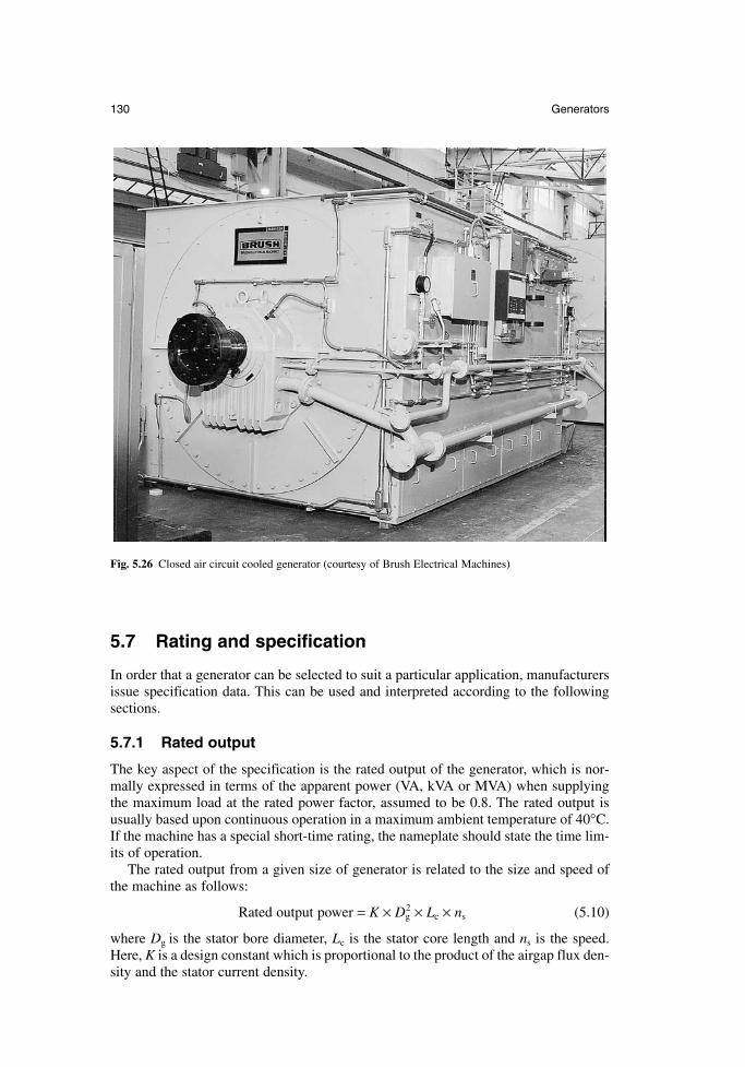
5.7 Rating and specification
In order that a generator can be selected to suit a particular application, manufacturersissue specification data. This can be used and interpreted according to the followingsections.
5.7.1 Rated output
The key aspect of the specification is the rated output of the generator, which is nor-mally expressed in terms of the apparent power (VA, kVA or MVA) when supplyingthe maximum load at the rated power factor, assumed to be 0.8. The rated output isusually based upon continuous operation in a maximum ambient temperature of 40°C.If the machine has a special short-time rating, the nameplate should state the time lim-its of operation.
The rated output from a given size of generator is related to the size and speed ofthe machine as follows:
Rated output power = K × Dg2 × Lc × ns (5.10)
where Dg is the stator bore diameter, Lc is the stator core length and ns is the speed.Here, K is a design constant which is proportional to the product of the airgap flux den-sity and the stator current density.
130 Generators
Fig. 5.26 Closed air circuit cooled generator (courtesy of Brush Electrical Machines)
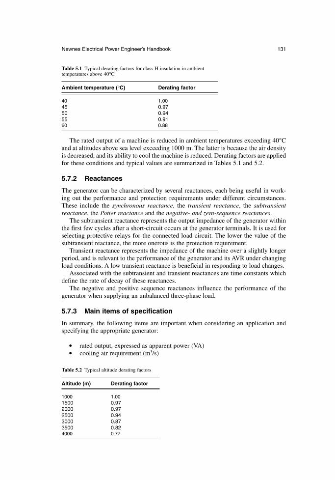
The rated output of a machine is reduced in ambient temperatures exceeding 40°Cand at altitudes above sea level exceeding 1000 m. The latter is because the air densityis decreased, and its ability to cool the machine is reduced. Derating factors are appliedfor these conditions and typical values are summarized in Tables 5.1 and 5.2.
5.7.2 Reactances
The generator can be characterized by several reactances, each being useful in work-ing out the performance and protection requirements under different circumstances.These include the synchronous reactance, the transient reactance, the subtransientreactance, the Potier reactance and the negative- and zero-sequence reactances.
The subtransient reactance represents the output impedance of the generator withinthe first few cycles after a short-circuit occurs at the generator terminals. It is used forselecting protective relays for the connected load circuit. The lower the value of thesubtransient reactance, the more onerous is the protection requirement.
Transient reactance represents the impedance of the machine over a slightly longerperiod, and is relevant to the performance of the generator and its AVR under changingload conditions. A low transient reactance is beneficial in responding to load changes.
Associated with the subtransient and transient reactances are time constants whichdefine the rate of decay of these reactances.
The negative and positive sequence reactances influence the performance of thegenerator when supplying an unbalanced three-phase load.
5.7.3 Main items of specification
In summary, the following items are important when considering an application andspecifying the appropriate generator:
rated output, expressed as apparent power (VA) cooling air requirement (m3/s)
Newnes Electrical Power Engineer’s Handbook 131
Table 5.1 Typical derating factors for class H insulation in ambient temperatures above 40°C
Ambient temperature (°C) Derating factor
40 1.0045 0.9750 0.9455 0.9160 0.88
Table 5.2 Typical altitude derating factors
Altitude (m) Derating factor
1000 1.001500 0.972000 0.972500 0.943000 0.873500 0.824000 0.77
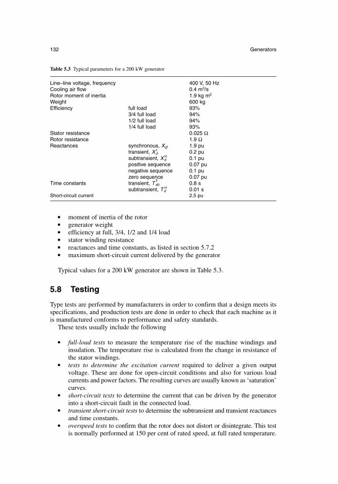
moment of inertia of the rotor generator weight efficiency at full, 3/4, 1/2 and 1/4 load stator winding resistance reactances and time constants, as listed in section 5.7.2 maximum short-circuit current delivered by the generator
Typical values for a 200 kW generator are shown in Table 5.3.
5.8 Testing
Type tests are performed by manufacturers in order to confirm that a design meets itsspecifications, and production tests are done in order to check that each machine as itis manufactured conforms to performance and safety standards.
These tests usually include the following
full-load tests to measure the temperature rise of the machine windings andinsulation. The temperature rise is calculated from the change in resistance ofthe stator windings.
tests to determine the excitation current required to deliver a given output voltage. These are done for open-circuit conditions and also for various loadcurrents and power factors. The resulting curves are usually known as ‘saturation’curves.
short-circuit tests to determine the current that can be driven by the generatorinto a short-circuit fault in the connected load.
transient short-circuit tests to determine the subtransient and transient reactancesand time constants.
overspeed tests to confirm that the rotor does not distort or disintegrate. This testis normally performed at 150 per cent of rated speed, at full rated temperature.
132 Generators
Table 5.3 Typical parameters for a 200 kW generator
Line–line voltage, frequency 400 V, 50 HzCooling air flow 0.4 m3/sRotor moment of inertia 1.9 kg m2
Weight 600 kgEfficiency full load 93%
3/4 full load 94%1/2 full load 94%1/4 full load 93%
Stator resistance 0.025 ΩRotor resistance 1.9 ΩReactances synchronous, Xd 1.9 pu
transient, Xd1 0.2 pu
subtransient, Xd11 0.1 pu
positive sequence 0.07 punegative sequence 0.1 puzero sequence 0.07 pu
Time constants transient, Td01 0.8 s
subtransient, Td11 0.01 s
Short-circuit current 2.5 pu
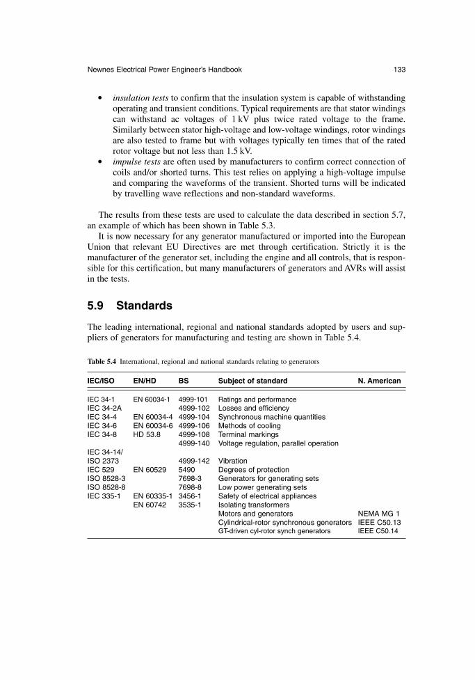
insulation tests to confirm that the insulation system is capable of withstandingoperating and transient conditions. Typical requirements are that stator windingscan withstand ac voltages of 1 kV plus twice rated voltage to the frame.Similarly between stator high-voltage and low-voltage windings, rotor windingsare also tested to frame but with voltages typically ten times that of the ratedrotor voltage but not less than 1.5 kV.
impulse tests are often used by manufacturers to confirm correct connection ofcoils and/or shorted turns. This test relies on applying a high-voltage impulseand comparing the waveforms of the transient. Shorted turns will be indicatedby travelling wave reflections and non-standard waveforms.
The results from these tests are used to calculate the data described in section 5.7,an example of which has been shown in Table 5.3.
It is now necessary for any generator manufactured or imported into the EuropeanUnion that relevant EU Directives are met through certification. Strictly it is the manufacturer of the generator set, including the engine and all controls, that is respon-sible for this certification, but many manufacturers of generators and AVRs will assistin the tests.
5.9 Standards
The leading international, regional and national standards adopted by users and sup-pliers of generators for manufacturing and testing are shown in Table 5.4.
Newnes Electrical Power Engineer’s Handbook 133
Table 5.4 International, regional and national standards relating to generators
IEC/ISO EN/HD BS Subject of standard N. American
IEC 34-1 EN 60034-1 4999-101 Ratings and performanceIEC 34-2A 4999-102 Losses and efficiencyIEC 34-4 EN 60034-4 4999-104 Synchronous machine quantitiesIEC 34-6 EN 60034-6 4999-106 Methods of coolingIEC 34-8 HD 53.8 4999-108 Terminal markings
4999-140 Voltage regulation, parallel operationIEC 34-14/ISO 2373 4999-142 VibrationIEC 529 EN 60529 5490 Degrees of protectionISO 8528-3 7698-3 Generators for generating setsISO 8528-8 7698-8 Low power generating setsIEC 335-1 EN 60335-1 3456-1 Safety of electrical appliances
EN 60742 3535-1 Isolating transformersMotors and generators NEMA MG 1Cylindrical-rotor synchronous generators IEEE C50.13GT-driven cyl-rotor synch generators IEEE C50.14

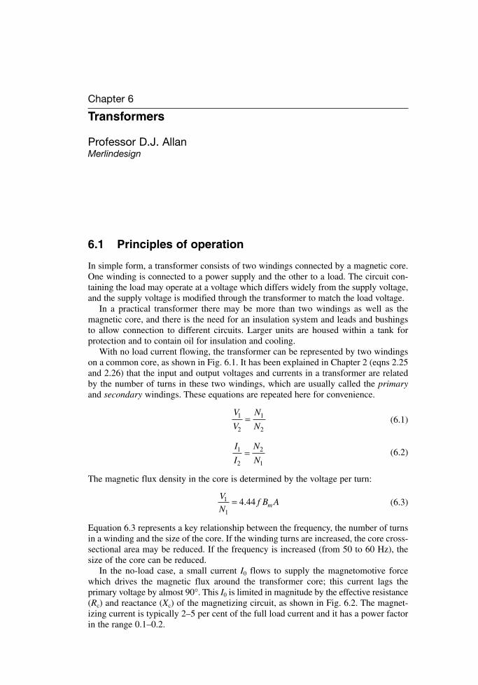
Chapter 6
Transformers
Professor D.J. AllanMerlindesign
6.1 Principles of operation
In simple form, a transformer consists of two windings connected by a magnetic core.One winding is connected to a power supply and the other to a load. The circuit con-taining the load may operate at a voltage which differs widely from the supply voltage,and the supply voltage is modified through the transformer to match the load voltage.
In a practical transformer there may be more than two windings as well as the magnetic core, and there is the need for an insulation system and leads and bushingsto allow connection to different circuits. Larger units are housed within a tank for protection and to contain oil for insulation and cooling.
With no load current flowing, the transformer can be represented by two windingson a common core, as shown in Fig. 6.1. It has been explained in Chapter 2 (eqns 2.25and 2.26) that the input and output voltages and currents in a transformer are relatedby the number of turns in these two windings, which are usually called the primaryand secondary windings. These equations are repeated here for convenience.
(6.1)
(6.2)
The magnetic flux density in the core is determined by the voltage per turn:
(6.3)
Equation 6.3 represents a key relationship between the frequency, the number of turnsin a winding and the size of the core. If the winding turns are increased, the core cross-sectional area may be reduced. If the frequency is increased (from 50 to 60 Hz), thesize of the core can be reduced.
In the no-load case, a small current I0 flows to supply the magnetomotive forcewhich drives the magnetic flux around the transformer core; this current lags theprimary voltage by almost 90°. This I0 is limited in magnitude by the effective resistance(Rc) and reactance (Xc) of the magnetizing circuit, as shown in Fig. 6.2. The magnet-izing current is typically 2–5 per cent of the full load current and it has a power factorin the range 0.1–0.2.
V
Nf B Am
1
1
4.44=
I
I
N
N1
2
2
1
=
V
V
N
N1
2
1
2
=
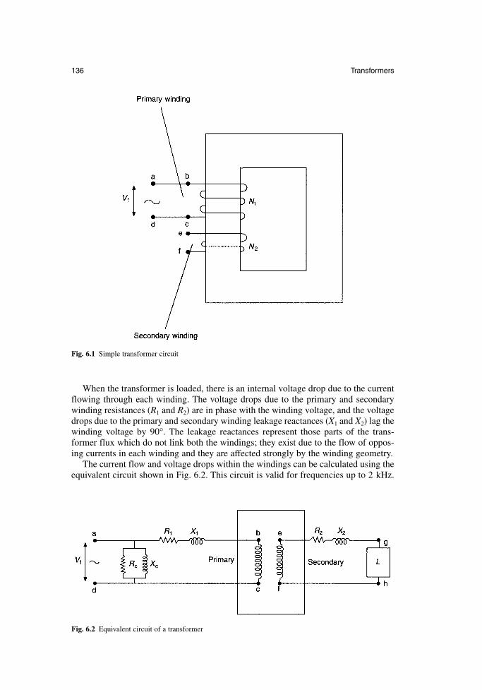
When the transformer is loaded, there is an internal voltage drop due to the currentflowing through each winding. The voltage drops due to the primary and secondarywinding resistances (R1 and R2) are in phase with the winding voltage, and the voltagedrops due to the primary and secondary winding leakage reactances (X1 and X2) lag thewinding voltage by 90°. The leakage reactances represent those parts of the trans-former flux which do not link both the windings; they exist due to the flow of oppos-ing currents in each winding and they are affected strongly by the winding geometry.
The current flow and voltage drops within the windings can be calculated using theequivalent circuit shown in Fig. 6.2. This circuit is valid for frequencies up to 2 kHz.
136 Transformers
Fig. 6.1 Simple transformer circuit
Fig. 6.2 Equivalent circuit of a transformer
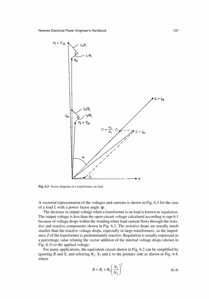
A vectorial representation of the voltages and currents is shown in Fig. 6.3 for the caseof a load L with a power factor angle .
The decrease in output voltage when a transformer is on load is known as regulation.The output voltage is less than the open-circuit voltage calculated according to eqn 6.1because of voltage drops within the winding when load current flows through the resis-tive and reactive components shown in Fig. 6.2. The resistive drops are usually muchsmaller than the reactive voltage drops, especially in large transformers, so the imped-ance Z of the transformer is predominantly reactive. Regulation is usually expressed asa percentage value relating the vector addition of the internal voltage drops (shown inFig. 6.3) to the applied voltage.
For many applications, the equivalent circuit shown in Fig. 6.2 can be simplified byignoring R and X, and referring R2, X2 and L to the primary side as shown in Fig. 6.4,where
(6.4)R R RN
N= +
1 2
1
2
2
Φ
Newnes Electrical Power Engineer’s Handbook 137
Fig. 6.3 Vector diagram of a transformer on load
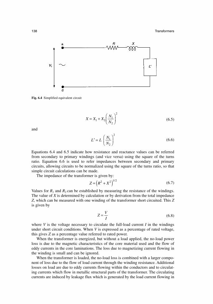
(6.5)
and
(6.6)
Equations 6.4 and 6.5 indicate how resistance and reactance values can be referredfrom secondary to primary windings (and vice versa) using the square of the turnsratio. Equation 6.6 is used to refer impedances between secondary and primary circuits, allowing circuits to be normalized using the square of the turns ratio, so thatsimple circuit calculations can be made.
The impedance of the transformer is given by:
(6.7)
Values for R1 and R2 can be established by measuring the resistance of the windings.The value of X is determined by calculation or by derivation from the total impedanceZ, which can be measured with one winding of the transformer short circuited. This Zis given by
(6.8)
where V is the voltage necessary to circulate the full-load current I in the windingsunder short circuit conditions. When V is expressed as a percentage of rated voltage,this gives Z as a percentage value referred to rated power.
When the transformer is energized, but without a load applied, the no-load powerloss is due to the magnetic characteristics of the core material used and the flow ofeddy currents in the core laminations. The loss due to magnetizing current flowing inthe winding is small and can be ignored.
When the transformer is loaded, the no-load loss is combined with a larger compo-nent of loss due to the flow of load current through the winding resistance. Additionallosses on load are due to eddy currents flowing within the conductors and to circulat-ing currents which flow in metallic structural parts of the transformer. The circulatingcurrents are induced by leakage flux which is generated by the load current flowing in
ZV
I=
Z R X= +( )2 2 1/2
′ =
L LN
N 1
2
2
X X XN
N= +
1 2
1
2
2
138 Transformers
Fig. 6.4 Simplified equivalent circuit
the windings and they are load dependent. These additional losses are known as straylosses.
The efficiency of a transformer is expressed as:
(6.9)
where input, output and losses are all expressed in units of power.The total losses consist of the no-load loss (or iron loss) which is constant with
voltage and the load loss (or copper loss) which is proportional to the square of loadcurrent. Total losses are usually less than 2 per cent for distribution transformers, andthey may be as low as 0.5 per cent in very large transformers.
When losses are considered in kilowatt values, the lowest loss transformer is foundto have no-load loss and loss values approximately equal. However, since many distri-bution and transmission transformers usually operate at only one-half or one-quarterof full load current, the equal losses criterion is an over simplification.
No-load and load losses are often specified as target values by the user for largertransformers, or they may be evaluated by the capitalization of losses. The capitaliza-tion formula is of the type:
CC = CT + A × P0 + B × PK (6.10)
where: CC = capitalized costCT = tendered priceA = capitalization rate for no-load loss (£/kW)
P0 = guaranteed no-load loss (kW)B = capitalization rate for load loss (£/kW)
PK = guaranteed load loss (kW).Values assigned to capitalization rates for no-load and load loss vary with the loadoperating regime of the transformer, the discount rate and forward interest rates.Typical capitalization rates for transmission transformers are £ 4000/kW for no-loadloss and £ 1000/kW for load loss. Where a purchaser is responsible for the cost oflosses the capitalization formulae are respected, but when a purchaser can pass the costof losses on to a consumer, transformers are purchased at the lowest capital cost.
6.2 Main features of construction
6.2.1 The core
The magnetic circuit in a transformer is built from sheets or laminations of electricalsteel. Hysteresis loss is controlled by selecting a material with appropriate character-istics, often with large grain size. Eddy current loss is controlled by increasing theresistivity of the material using the silicon content, and by rolling it into a very thin sheet.The power loss characteristics of the available materials are shown in Fig. 6.5. Generallyspeaking the steels with lower power loss are more expensive, so that the 0.3 mm thickCGO steel shown is the cheapest of the range shown in Fig. 6.5, and the very low loss
Efficiency output
input
(input losses)
input
losses
input
= ×
= − ×
= −
×
%
%
%
100
100
1 100
Newnes Electrical Power Engineer’s Handbook 139
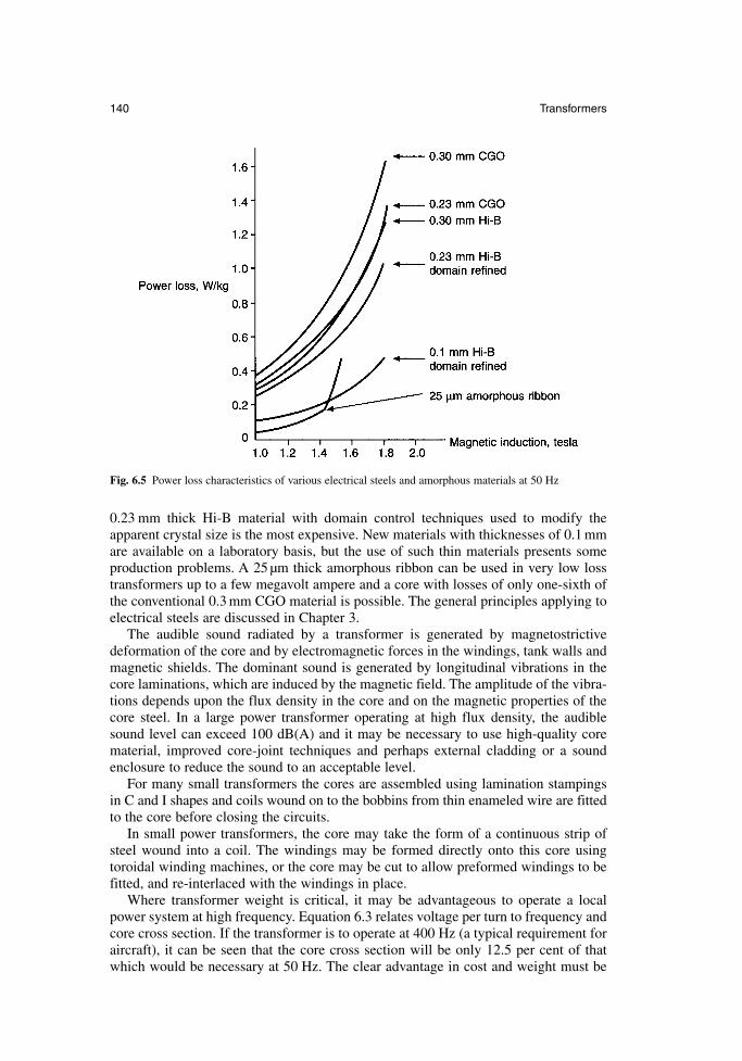
0.23 mm thick Hi-B material with domain control techniques used to modify theapparent crystal size is the most expensive. New materials with thicknesses of 0.1 mmare available on a laboratory basis, but the use of such thin materials presents someproduction problems. A 25 µm thick amorphous ribbon can be used in very low losstransformers up to a few megavolt ampere and a core with losses of only one-sixth ofthe conventional 0.3 mm CGO material is possible. The general principles applying toelectrical steels are discussed in Chapter 3.
The audible sound radiated by a transformer is generated by magnetostrictivedeformation of the core and by electromagnetic forces in the windings, tank walls andmagnetic shields. The dominant sound is generated by longitudinal vibrations in thecore laminations, which are induced by the magnetic field. The amplitude of the vibra-tions depends upon the flux density in the core and on the magnetic properties of thecore steel. In a large power transformer operating at high flux density, the audiblesound level can exceed 100 dB(A) and it may be necessary to use high-quality corematerial, improved core-joint techniques and perhaps external cladding or a soundenclosure to reduce the sound to an acceptable level.
For many small transformers the cores are assembled using lamination stampingsin C and I shapes and coils wound on to the bobbins from thin enameled wire are fittedto the core before closing the circuits.
In small power transformers, the core may take the form of a continuous strip ofsteel wound into a coil. The windings may be formed directly onto this core usingtoroidal winding machines, or the core may be cut to allow preformed windings to befitted, and re-interlaced with the windings in place.
Where transformer weight is critical, it may be advantageous to operate a localpower system at high frequency. Equation 6.3 relates voltage per turn to frequency andcore cross section. If the transformer is to operate at 400 Hz (a typical requirement foraircraft), it can be seen that the core cross section will be only 12.5 per cent of thatwhich would be necessary at 50 Hz. The clear advantage in cost and weight must be
140 Transformers
Fig. 6.5 Power loss characteristics of various electrical steels and amorphous materials at 50 Hz
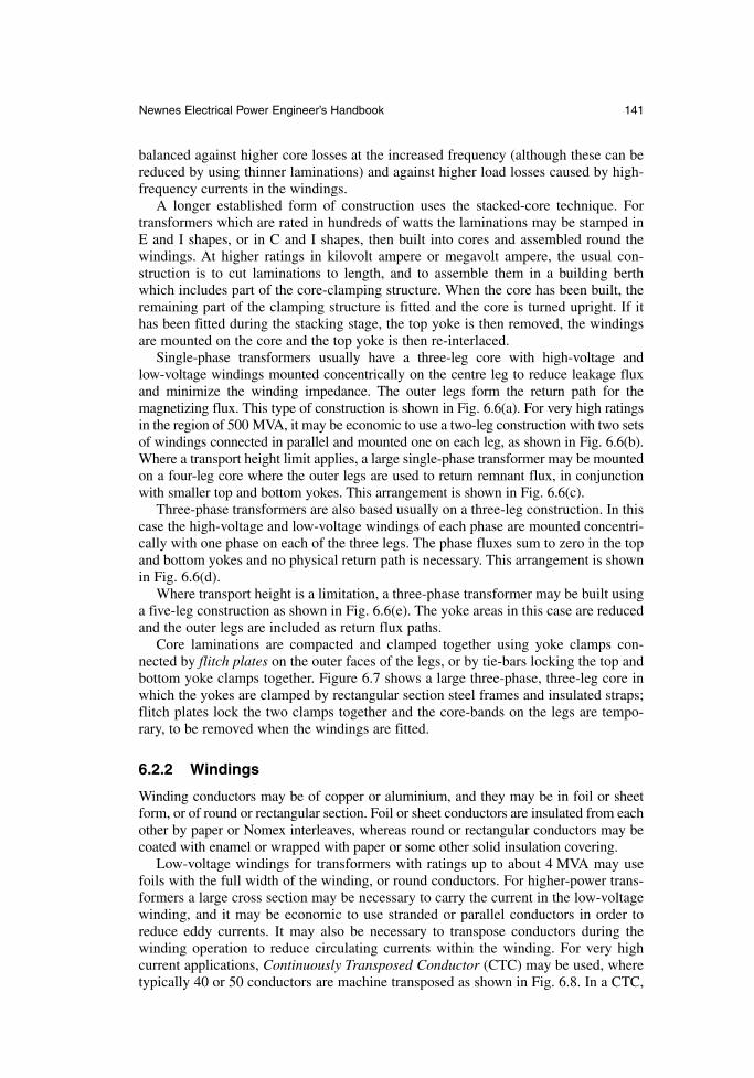
balanced against higher core losses at the increased frequency (although these can bereduced by using thinner laminations) and against higher load losses caused by high-frequency currents in the windings.
A longer established form of construction uses the stacked-core technique. Fortransformers which are rated in hundreds of watts the laminations may be stamped inE and I shapes, or in C and I shapes, then built into cores and assembled round thewindings. At higher ratings in kilovolt ampere or megavolt ampere, the usual con-struction is to cut laminations to length, and to assemble them in a building berthwhich includes part of the core-clamping structure. When the core has been built, theremaining part of the clamping structure is fitted and the core is turned upright. If ithas been fitted during the stacking stage, the top yoke is then removed, the windingsare mounted on the core and the top yoke is then re-interlaced.
Single-phase transformers usually have a three-leg core with high-voltage and low-voltage windings mounted concentrically on the centre leg to reduce leakage fluxand minimize the winding impedance. The outer legs form the return path for the magnetizing flux. This type of construction is shown in Fig. 6.6(a). For very high ratingsin the region of 500 MVA, it may be economic to use a two-leg construction with two setsof windings connected in parallel and mounted one on each leg, as shown in Fig. 6.6(b).Where a transport height limit applies, a large single-phase transformer may be mountedon a four-leg core where the outer legs are used to return remnant flux, in conjunctionwith smaller top and bottom yokes. This arrangement is shown in Fig. 6.6(c).
Three-phase transformers are also based usually on a three-leg construction. In thiscase the high-voltage and low-voltage windings of each phase are mounted concentri-cally with one phase on each of the three legs. The phase fluxes sum to zero in the topand bottom yokes and no physical return path is necessary. This arrangement is shownin Fig. 6.6(d).
Where transport height is a limitation, a three-phase transformer may be built usinga five-leg construction as shown in Fig. 6.6(e). The yoke areas in this case are reducedand the outer legs are included as return flux paths.
Core laminations are compacted and clamped together using yoke clamps con-nected by flitch plates on the outer faces of the legs, or by tie-bars locking the top andbottom yoke clamps together. Figure 6.7 shows a large three-phase, three-leg core inwhich the yokes are clamped by rectangular section steel frames and insulated straps;flitch plates lock the two clamps together and the core-bands on the legs are tempo-rary, to be removed when the windings are fitted.
6.2.2 Windings
Winding conductors may be of copper or aluminium, and they may be in foil or sheetform, or of round or rectangular section. Foil or sheet conductors are insulated from eachother by paper or Nomex interleaves, whereas round or rectangular conductors may becoated with enamel or wrapped with paper or some other solid insulation covering.
Low-voltage windings for transformers with ratings up to about 4 MVA may usefoils with the full width of the winding, or round conductors. For higher-power trans-formers a large cross section may be necessary to carry the current in the low-voltagewinding, and it may be economic to use stranded or parallel conductors in order toreduce eddy currents. It may also be necessary to transpose conductors during thewinding operation to reduce circulating currents within the winding. For very high current applications, Continuously Transposed Conductor (CTC) may be used, wheretypically 40 or 50 conductors are machine transposed as shown in Fig. 6.8. In a CTC,
Newnes Electrical Power Engineer’s Handbook 141
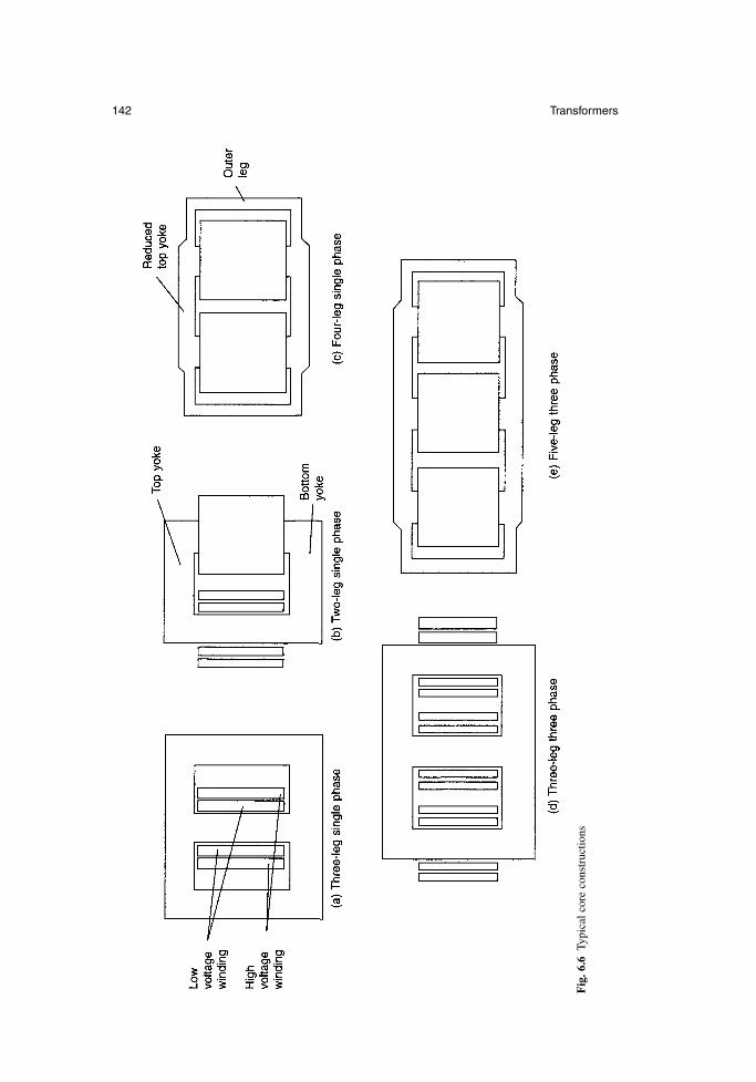
142 Transformers
Fig
. 6.6
Typi
cal c
ore
cons
truc
tions
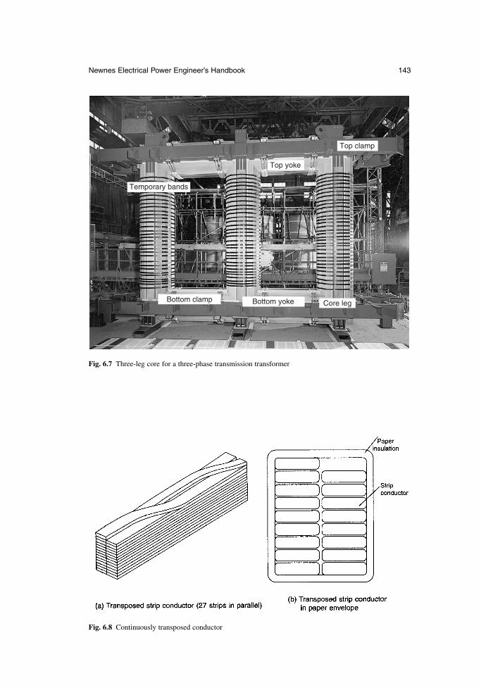
Newnes Electrical Power Engineer’s Handbook 143
Temporary bands
Top yoke
Top clamp
Bottom yoke Core legBottom clamp
Fig. 6.7 Three-leg core for a three-phase transmission transformer
Fig. 6.8 Continuously transposed conductor
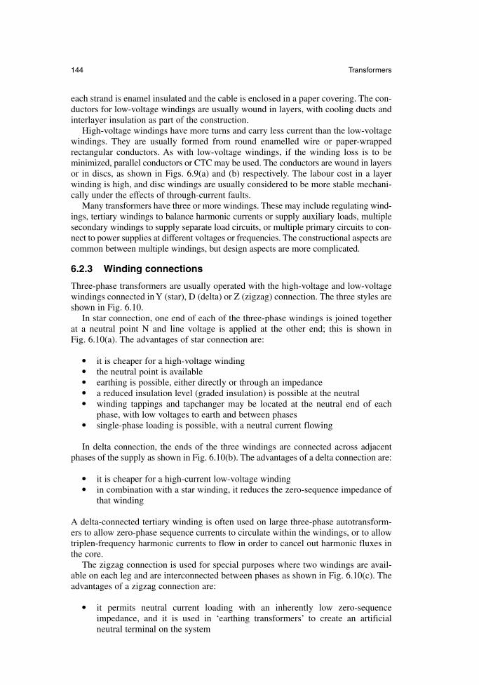
each strand is enamel insulated and the cable is enclosed in a paper covering. The con-ductors for low-voltage windings are usually wound in layers, with cooling ducts andinterlayer insulation as part of the construction.
High-voltage windings have more turns and carry less current than the low-voltagewindings. They are usually formed from round enamelled wire or paper-wrapped rectangular conductors. As with low-voltage windings, if the winding loss is to be minimized, parallel conductors or CTC may be used. The conductors are wound in layersor in discs, as shown in Figs. 6.9(a) and (b) respectively. The labour cost in a layerwinding is high, and disc windings are usually considered to be more stable mechani-cally under the effects of through-current faults.
Many transformers have three or more windings. These may include regulating wind-ings, tertiary windings to balance harmonic currents or supply auxiliary loads, multiplesecondary windings to supply separate load circuits, or multiple primary circuits to con-nect to power supplies at different voltages or frequencies. The constructional aspects arecommon between multiple windings, but design aspects are more complicated.
6.2.3 Winding connections
Three-phase transformers are usually operated with the high-voltage and low-voltagewindings connected in Y (star), D (delta) or Z (zigzag) connection. The three styles areshown in Fig. 6.10.
In star connection, one end of each of the three-phase windings is joined togetherat a neutral point N and line voltage is applied at the other end; this is shown in Fig. 6.10(a). The advantages of star connection are:
• it is cheaper for a high-voltage winding• the neutral point is available• earthing is possible, either directly or through an impedance• a reduced insulation level (graded insulation) is possible at the neutral• winding tappings and tapchanger may be located at the neutral end of each
phase, with low voltages to earth and between phases• single-phase loading is possible, with a neutral current flowing
In delta connection, the ends of the three windings are connected across adjacentphases of the supply as shown in Fig. 6.10(b). The advantages of a delta connection are:
• it is cheaper for a high-current low-voltage winding• in combination with a star winding, it reduces the zero-sequence impedance of
that winding
A delta-connected tertiary winding is often used on large three-phase autotransform-ers to allow zero-phase sequence currents to circulate within the windings, or to allowtriplen-frequency harmonic currents to flow in order to cancel out harmonic fluxes inthe core.
The zigzag connection is used for special purposes where two windings are avail-able on each leg and are interconnected between phases as shown in Fig. 6.10(c). Theadvantages of a zigzag connection are:
• it permits neutral current loading with an inherently low zero-sequenceimpedance, and it is used in ‘earthing transformers’ to create an artificial neutral terminal on the system
144 Transformers
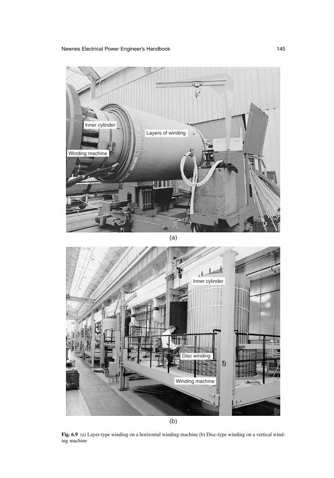
Newnes Electrical Power Engineer’s Handbook 145
Inner cylinder
Layers of winding
Winding machine
(a)
Inner cylinder
Disc winding
Winding machine
(b)
Fig. 6.9 (a) Layer-type winding on a horizontal winding machine (b) Disc-type winding on a vertical wind-ing machine
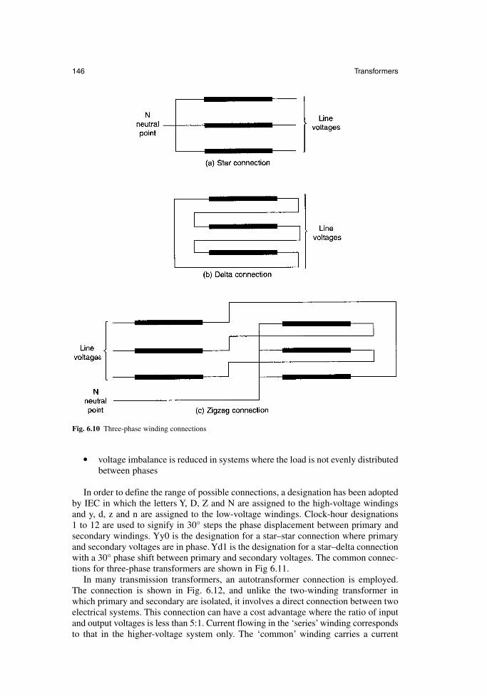
• voltage imbalance is reduced in systems where the load is not evenly distributedbetween phases
In order to define the range of possible connections, a designation has been adoptedby IEC in which the letters Y, D, Z and N are assigned to the high-voltage windingsand y, d, z and n are assigned to the low-voltage windings. Clock-hour designations 1 to 12 are used to signify in 30° steps the phase displacement between primary andsecondary windings. Yy0 is the designation for a star–star connection where primaryand secondary voltages are in phase. Yd1 is the designation for a star–delta connectionwith a 30° phase shift between primary and secondary voltages. The common connec-tions for three-phase transformers are shown in Fig 6.11.
In many transmission transformers, an autotransformer connection is employed.The connection is shown in Fig. 6.12, and unlike the two-winding transformer inwhich primary and secondary are isolated, it involves a direct connection between twoelectrical systems. This connection can have a cost advantage where the ratio of inputand output voltages is less than 5:1. Current flowing in the ‘series’ winding correspondsto that in the higher-voltage system only. The ‘common’ winding carries a current
146 Transformers
Fig. 6.10 Three-phase winding connections
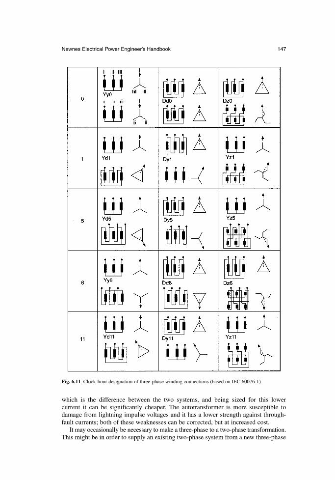
which is the difference between the two systems, and being sized for this lower current it can be significantly cheaper. The autotransformer is more susceptible todamage from lightning impulse voltages and it has a lower strength against through-fault currents; both of these weaknesses can be corrected, but at increased cost.
It may occasionally be necessary to make a three-phase to a two-phase transformation.This might be in order to supply an existing two-phase system from a new three-phase
Newnes Electrical Power Engineer’s Handbook 147
Fig. 6.11 Clock-hour designation of three-phase winding connections (based on IEC 60076-1)
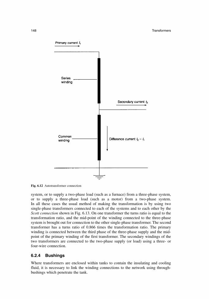
system, or to supply a two-phase load (such as a furnace) from a three-phase system,or to supply a three-phase load (such as a motor) from a two-phase system. In all these cases the usual method of making the transformation is by using twosingle-phase transformers connected to each of the systems and to each other by theScott connection shown in Fig. 6.13. On one transformer the turns ratio is equal to thetransformation ratio, and the mid-point of the winding connected to the three-phasesystem is brought out for connection to the other single-phase transformer. The secondtransformer has a turns ratio of 0.866 times the transformation ratio. The primarywinding is connected between the third phase of the three-phase supply and the mid-point of the primary winding of the first transformer. The secondary windings of thetwo transformers are connected to the two-phase supply (or load) using a three- orfour-wire connection.
6.2.4 Bushings
Where transformers are enclosed within tanks to contain the insulating and coolingfluid, it is necessary to link the winding connections to the network using through-bushings which penetrate the tank.
148 Transformers
Fig. 6.12 Autotransformer connection
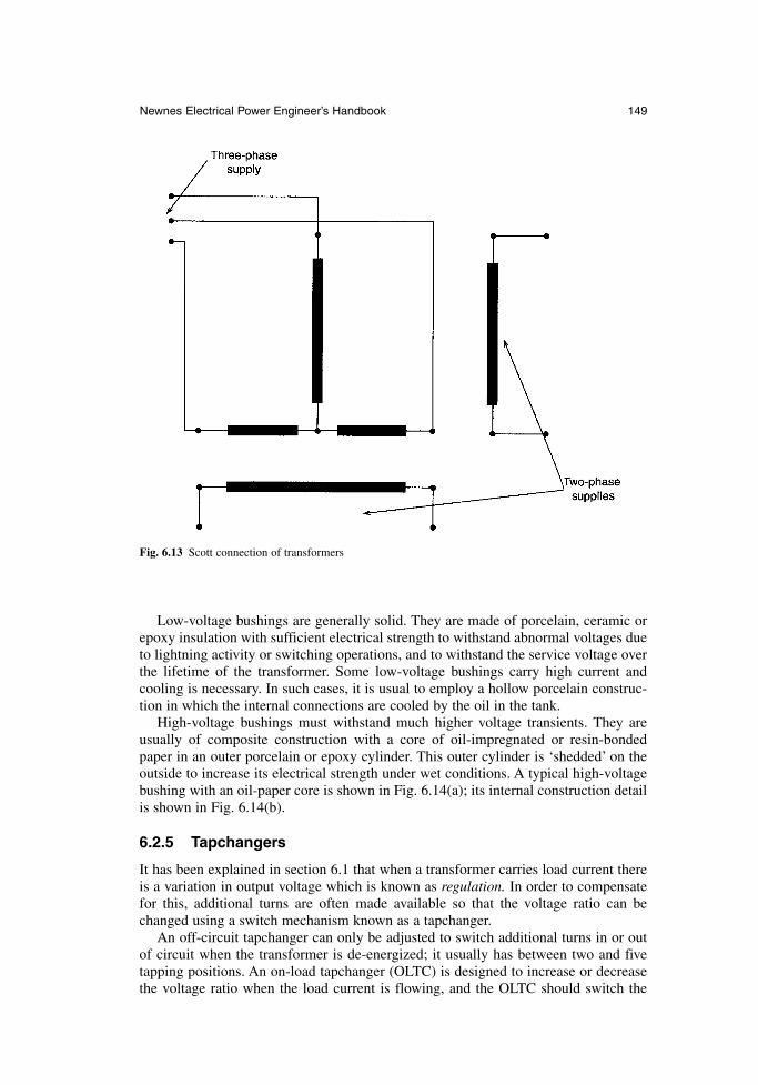
Low-voltage bushings are generally solid. They are made of porcelain, ceramic orepoxy insulation with sufficient electrical strength to withstand abnormal voltages dueto lightning activity or switching operations, and to withstand the service voltage overthe lifetime of the transformer. Some low-voltage bushings carry high current andcooling is necessary. In such cases, it is usual to employ a hollow porcelain construc-tion in which the internal connections are cooled by the oil in the tank.
High-voltage bushings must withstand much higher voltage transients. They areusually of composite construction with a core of oil-impregnated or resin-bondedpaper in an outer porcelain or epoxy cylinder. This outer cylinder is ‘shedded’ on theoutside to increase its electrical strength under wet conditions. A typical high-voltagebushing with an oil-paper core is shown in Fig. 6.14(a); its internal construction detailis shown in Fig. 6.14(b).
6.2.5 Tapchangers
It has been explained in section 6.1 that when a transformer carries load current thereis a variation in output voltage which is known as regulation. In order to compensatefor this, additional turns are often made available so that the voltage ratio can bechanged using a switch mechanism known as a tapchanger.
An off-circuit tapchanger can only be adjusted to switch additional turns in or outof circuit when the transformer is de-energized; it usually has between two and fivetapping positions. An on-load tapchanger (OLTC) is designed to increase or decreasethe voltage ratio when the load current is flowing, and the OLTC should switch the
Newnes Electrical Power Engineer’s Handbook 149
Fig. 6.13 Scott connection of transformers
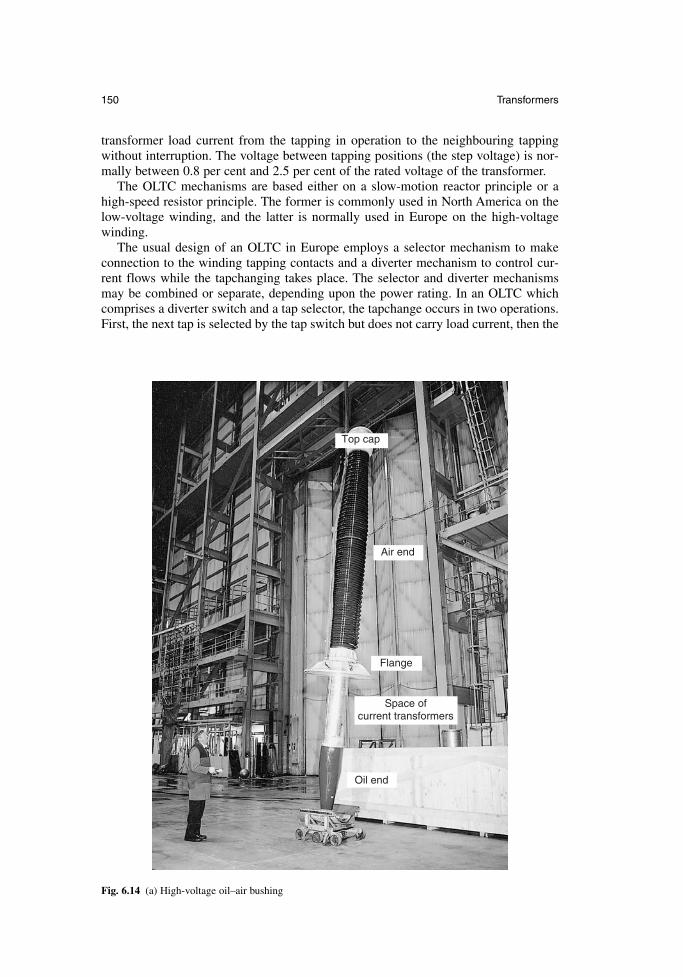
transformer load current from the tapping in operation to the neighbouring tappingwithout interruption. The voltage between tapping positions (the step voltage) is nor-mally between 0.8 per cent and 2.5 per cent of the rated voltage of the transformer.
The OLTC mechanisms are based either on a slow-motion reactor principle or ahigh-speed resistor principle. The former is commonly used in North America on thelow-voltage winding, and the latter is normally used in Europe on the high-voltagewinding.
The usual design of an OLTC in Europe employs a selector mechanism to makeconnection to the winding tapping contacts and a diverter mechanism to control cur-rent flows while the tapchanging takes place. The selector and diverter mechanismsmay be combined or separate, depending upon the power rating. In an OLTC whichcomprises a diverter switch and a tap selector, the tapchange occurs in two operations.First, the next tap is selected by the tap switch but does not carry load current, then the
150 Transformers
Top cap
Air end
Flange
Space ofcurrent transformers
Oil end
Fig. 6.14 (a) High-voltage oil–air bushing
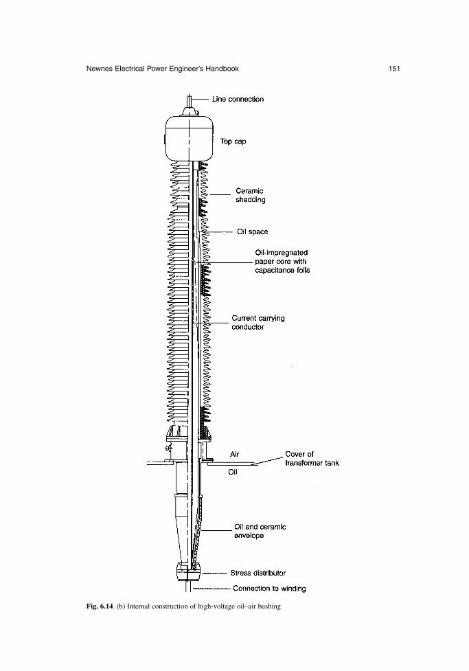
Newnes Electrical Power Engineer’s Handbook 151
Fig. 6.14 (b) Internal construction of high-voltage oil–air bushing
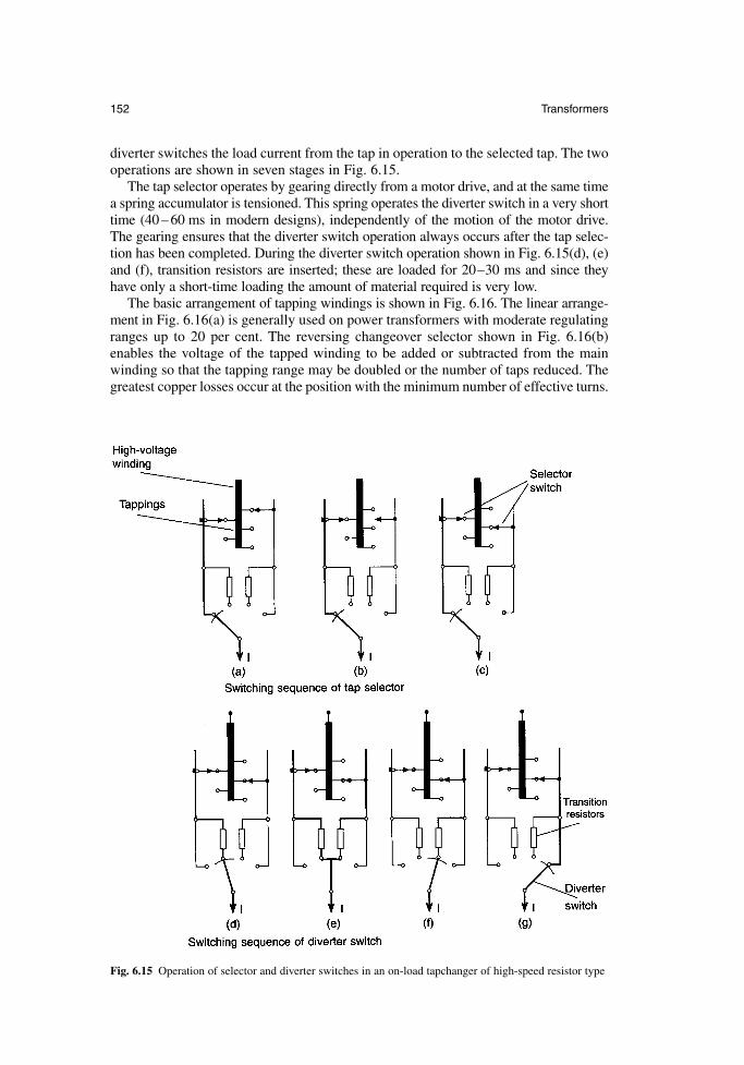
diverter switches the load current from the tap in operation to the selected tap. The twooperations are shown in seven stages in Fig. 6.15.
The tap selector operates by gearing directly from a motor drive, and at the same timea spring accumulator is tensioned. This spring operates the diverter switch in a very shorttime (40 – 60 ms in modern designs), independently of the motion of the motor drive.The gearing ensures that the diverter switch operation always occurs after the tap selec-tion has been completed. During the diverter switch operation shown in Fig. 6.15(d), (e)and (f), transition resistors are inserted; these are loaded for 20–30 ms and since theyhave only a short-time loading the amount of material required is very low.
The basic arrangement of tapping windings is shown in Fig. 6.16. The linear arrange-ment in Fig. 6.16(a) is generally used on power transformers with moderate regulatingranges up to 20 per cent. The reversing changeover selector shown in Fig. 6.16(b)enables the voltage of the tapped winding to be added or subtracted from the mainwinding so that the tapping range may be doubled or the number of taps reduced. Thegreatest copper losses occur at the position with the minimum number of effective turns.
152 Transformers
Fig. 6.15 Operation of selector and diverter switches in an on-load tapchanger of high-speed resistor type
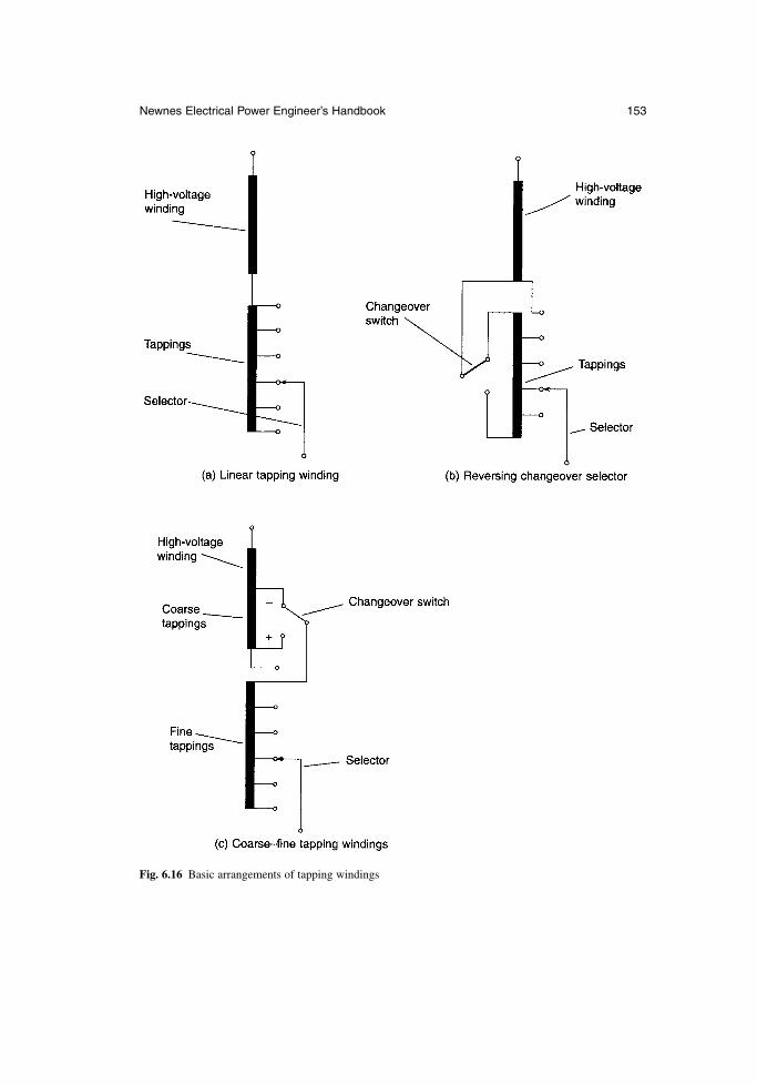
Newnes Electrical Power Engineer’s Handbook 153
Fig. 6.16 Basic arrangements of tapping windings
This reversing operation is achieved with a changeover selector which is part of the tapselector of the OLTC. The two-part coarse–fine arrangement shown in Fig. 6.16(c)may also be used. In this case the reversing changeover selector for the fine windingcan be connected to the ‘plus’ or ‘minus’ tapping of the coarse winding, and the cop-per losses are lowest at the position of the lowest number of effective turns. The coarsechangeover switch is part of the OLTC.
Regulation is mostly carried out at the neutral point in star windings, resulting in asimple, low-cost, compact OLTC and tapping windings with low insulation strength toearth. Regulation of delta windings requires a three-phase OLTC, in which the threephases are insulated for the highest system voltage which appears between them; alternatively three single-phase OLTCs may be used.
6.2.6 Cooling equipment
Transformers may be naturally cooled, in which case the cooling medium (oil or air)circulates by thermosyphon forces, or they may be forced cooled, with fans or pumpsto circulate the air or oil over the core and through the windings.
In oil-cooled transformers a more economic solution is to use directed oil-flow cooling in which oil is pumped directly into the windings. The oil is cooled by passing(or pumping) it through plate radiators, which may be externally cooled by fans, or byusing forced air-cooled tubular construction, or by pumping it through watercoolers.Designations for these cooling systems which identify both the cooling fluid and thetype of cooling have been assigned by IEC and these are summarized in Table 6.1.
6.3 Main classes of transformer
Transformers are used for a wide variety of purposes, with the complete range of volt-age and power ratings as well as many special features for particular applications. Thefollowing covers the main types.
6.3.1 Transformers for electronics
Transformers for electronic circuits or for low-voltage power supplies are used to matchthe supply voltage to the operating voltage of components or accessories, or to matchthe impedance of a load to a supply in order to maximize power throughput. They maybe used to match impedances in primary and secondary circuits using eqn 6.6.
The core is usually constructed in low-power transformers from C- and I-laminationsor from E- and I-laminations. The windings are usually of round enamelled wire, andthe assembly may be varnished or encapsulated in resin for mechanical consolidationand to prevent ingress of moisture. Increasing numbers of this type operate at high frequencies in the kilohertz range and use laminations of special steel often containingcobalt to reduce the iron losses.
6.3.2 Small transformers
These are used for stationary, portable or hand-held power supply units, as isolatingtransformers and for special applications, such as burner ignition, shavers, showerheaters, bells and toys. They may be used to supply three-phase power up to 40 kVAat frequencies up to 1 MHz. These transformers are usually air insulated, the smallerunits using enamelled windings wires and ring cores and the larger units using C- andI- or E- and I-laminated cores.
154 Transformers
Safety is a major concern for these transformers and they are identified as class I,class II or class III. Class I units are insulated and protected by an earth terminal. Class IItransformers have double insulation or reinforced insulation. Class III transformershave outputs at Safety Extra-Low Voltages (SELV) below 50 V ac or 120 V dc (seesection 16.2.2.4 for background on SELV).
6.3.3 Distribution transformers
These are used to distribute power to domestic or industrial premises. They may besingle-phase or three-phase, pole-mounted or ground-mounted, and they have ratingsranging from 16 kVA up to 2500 kVA.
The windings and core are immersed in mineral oil, with natural cooling, and thereare two windings per phase. The primary (high-voltage) winding has a highest voltageranging from 3.6 kV to 36 kV; the secondary (low-voltage) winding voltage does notexceed 1.1 kV. The high-voltage winding is usually provided with off-circuit tappingsof ± 2.5 per cent, or +2 × 2.5 per cent, –3 × 2.5 per cent.
The preferred values of rated output are 16, 25, 50, 100, 160, 250, 400, 630, 1000, 1600and 2500 kVA, and the preferred values of short-circuit impedance are 4 or 6 per cent.
Newnes Electrical Power Engineer’s Handbook 155
Table 6.1 Cooling system designations
For oil immersed transformers a four-letter code is used:
First letter: internal cooling medium in contact with windings:O mineral oil or insulating liquid with fire point ≤ 300°CK insulating liquid with fire point > 300°CL insulating liquid with no measurable fire point
Second letter: circulation mechanism for internal cooling medium:N natural thermosyphon flowF forced oil circulation, but thermosyphon cooling in windingsD forced oil circulation, with oil directed into the windings
Third letter: external cooling mediumA airW water
Fourth letter: circulation mechanism for external cooling mediumN natural convectionF forced circulation
Examples: ONAN or OFAF
For dry-type transformers a four-letter code is used:
First letter: internal cooling medium in contact with windings:A airG gas
Second letter: circulation mechanism for internal cooling medium:N natural convectionF forced cooling
Third letter: external cooling mediumA airG gas
Fourth letter: circulation mechanism for external cooling mediumN natural convectionF forced cooling
Examples: AN or GNAN
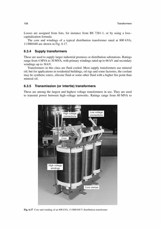
Losses are assigned from lists, for instance from BS 7281-1, or by using a loss–capitalization formula.
The core and windings of a typical distribution transformer rated at 800 kVA, 11 000/440 are shown in Fig. 6.17.
6.3.4 Supply transformers
These are used to supply larger industrial premises or distribution substations. Ratingsrange from 4 MVA to 30 MVA, with primary windings rated up to 66 kV and secondarywindings up to 36 kV.
Transformers in this class are fluid cooled. Most supply transformers use mineraloil; but for applications in residential buildings, oil rigs and some factories, the coolantmay be synthetic esters, silicone fluid or some other fluid with a higher fire point thanmineral oil.
6.3.5 Transmission (or intertie) transformers
These are among the largest and highest voltage transformers in use. They are used to transmit power between high-voltage networks. Ratings range from 60 MVA to
156 Transformers
High voltage connections
High voltage windings
Core
Core clamps
Low voltage connections
Fig. 6.17 Core and winding of an 800 kVA, 11 000/440 V distribution transformer
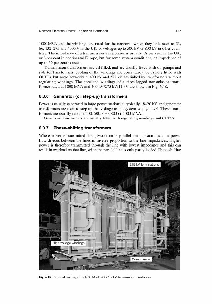
1000 MVA and the windings are rated for the networks which they link, such as 33,66, 132, 275 and 400 kV in the UK, or voltages up to 500 kV or 800 kV in other coun-tries. The impedance of a transmission transformer is usually 18 per cent in the UK,or 8 per cent in continental Europe, but for some system conditions, an impedance ofup to 30 per cent is used.
Transmission transformers are oil filled, and are usually fitted with oil pumps andradiator fans to assist cooling of the windings and cores. They are usually fitted withOLTCs, but some networks at 400 kV and 275 kV are linked by transformers withoutregulating windings. The core and windings of a three-legged transmission trans-former rated at 1000 MVA and 400 kV/275 kV/11 kV are shown in Fig. 6.18.
6.3.6 Generator (or step-up) transformers
Power is usually generated in large power stations at typically 18–20 kV, and generatortransformers are used to step up this voltage to the system voltage level. These trans-formers are usually rated at 400, 500, 630, 800 or 1000 MVA.
Generator transformers are usually fitted with regulating windings and OLTCs.
6.3.7 Phase-shifting transformers
Where power is transmitted along two or more parallel transmission lines, the powerflow divides between the lines in inverse proportion to the line impedances. Higherpower is therefore transmitted through the line with lowest impedance and this canresult in overload on that line, when the parallel line is only partly loaded. Phase-shifting
Newnes Electrical Power Engineer’s Handbook 157
275 kV terminations
High voltage windings
Core clamps
Fig. 6.18 Core and windings of a 1000 MVA, 400/275 kV transmission transformer
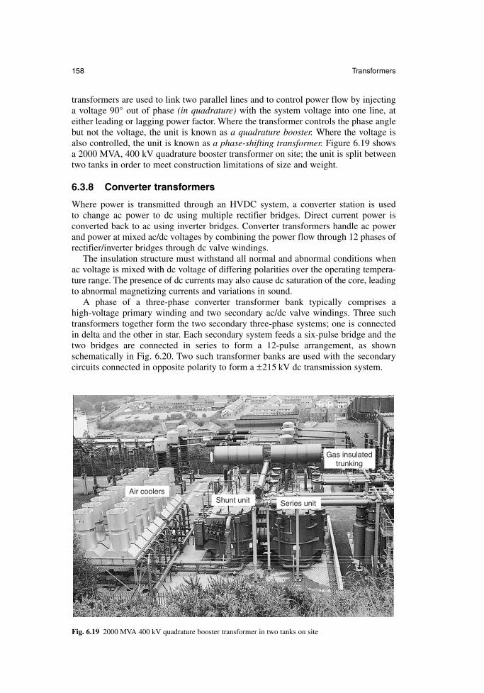
transformers are used to link two parallel lines and to control power flow by injectinga voltage 90° out of phase (in quadrature) with the system voltage into one line, ateither leading or lagging power factor. Where the transformer controls the phase anglebut not the voltage, the unit is known as a quadrature booster. Where the voltage isalso controlled, the unit is known as a phase-shifting transformer. Figure 6.19 showsa 2000 MVA, 400 kV quadrature booster transformer on site; the unit is split betweentwo tanks in order to meet construction limitations of size and weight.
6.3.8 Converter transformers
Where power is transmitted through an HVDC system, a converter station is used to change ac power to dc using multiple rectifier bridges. Direct current power isconverted back to ac using inverter bridges. Converter transformers handle ac powerand power at mixed ac/dc voltages by combining the power flow through 12 phases ofrectifier/inverter bridges through dc valve windings.
The insulation structure must withstand all normal and abnormal conditions whenac voltage is mixed with dc voltage of differing polarities over the operating tempera-ture range. The presence of dc currents may also cause dc saturation of the core, leadingto abnormal magnetizing currents and variations in sound.
A phase of a three-phase converter transformer bank typically comprises a high-voltage primary winding and two secondary ac/dc valve windings. Three suchtransformers together form the two secondary three-phase systems; one is connectedin delta and the other in star. Each secondary system feeds a six-pulse bridge and thetwo bridges are connected in series to form a 12-pulse arrangement, as shownschematically in Fig. 6.20. Two such transformer banks are used with the secondarycircuits connected in opposite polarity to form a ±215 kV dc transmission system.
158 Transformers
Gas insulated trunking
Shunt unit Series unit
Air coolers
Fig. 6.19 2000 MVA 400 kV quadrature booster transformer in two tanks on site
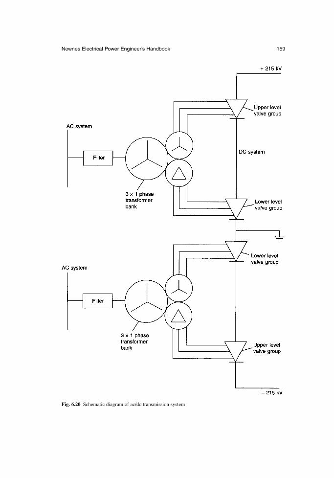
Newnes Electrical Power Engineer’s Handbook 159
Fig. 6.20 Schematic diagram of ac/dc transmission system
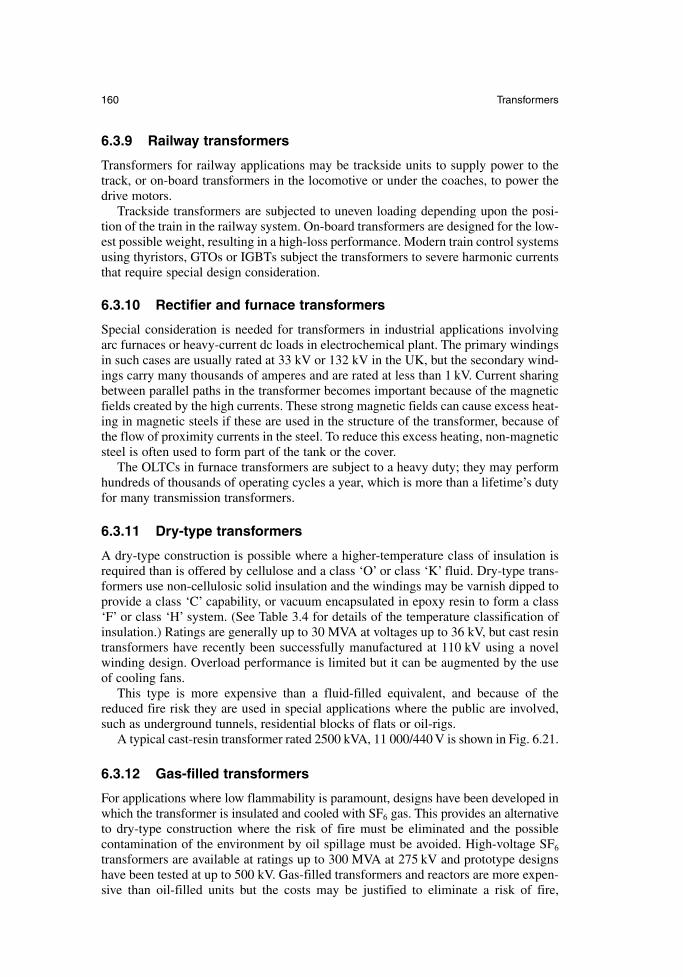
160 Transformers
6.3.9 Railway transformers
Transformers for railway applications may be trackside units to supply power to thetrack, or on-board transformers in the locomotive or under the coaches, to power thedrive motors.
Trackside transformers are subjected to uneven loading depending upon the posi-tion of the train in the railway system. On-board transformers are designed for the low-est possible weight, resulting in a high-loss performance. Modern train control systemsusing thyristors, GTOs or IGBTs subject the transformers to severe harmonic currentsthat require special design consideration.
6.3.10 Rectifier and furnace transformers
Special consideration is needed for transformers in industrial applications involvingarc furnaces or heavy-current dc loads in electrochemical plant. The primary windingsin such cases are usually rated at 33 kV or 132 kV in the UK, but the secondary wind-ings carry many thousands of amperes and are rated at less than 1 kV. Current sharingbetween parallel paths in the transformer becomes important because of the magneticfields created by the high currents. These strong magnetic fields can cause excess heat-ing in magnetic steels if these are used in the structure of the transformer, because ofthe flow of proximity currents in the steel. To reduce this excess heating, non-magneticsteel is often used to form part of the tank or the cover.
The OLTCs in furnace transformers are subject to a heavy duty; they may performhundreds of thousands of operating cycles a year, which is more than a lifetime’s dutyfor many transmission transformers.
6.3.11 Dry-type transformers
A dry-type construction is possible where a higher-temperature class of insulation isrequired than is offered by cellulose and a class ‘O’ or class ‘K’ fluid. Dry-type trans-formers use non-cellulosic solid insulation and the windings may be varnish dipped toprovide a class ‘C’ capability, or vacuum encapsulated in epoxy resin to form a class‘F’ or class ‘H’ system. (See Table 3.4 for details of the temperature classification ofinsulation.) Ratings are generally up to 30 MVA at voltages up to 36 kV, but cast resintransformers have recently been successfully manufactured at 110 kV using a novelwinding design. Overload performance is limited but it can be augmented by the useof cooling fans.
This type is more expensive than a fluid-filled equivalent, and because of thereduced fire risk they are used in special applications where the public are involved,such as underground tunnels, residential blocks of flats or oil-rigs.
A typical cast-resin transformer rated 2500 kVA, 11 000/440 V is shown in Fig. 6.21.
6.3.12 Gas-filled transformers
For applications where low flammability is paramount, designs have been developed inwhich the transformer is insulated and cooled with SF6 gas. This provides an alternativeto dry-type construction where the risk of fire must be eliminated and the possible contamination of the environment by oil spillage must be avoided. High-voltage SF6
transformers are available at ratings up to 300 MVA at 275 kV and prototype designshave been tested at up to 500 kV. Gas-filled transformers and reactors are more expen-sive than oil-filled units but the costs may be justified to eliminate a risk of fire,
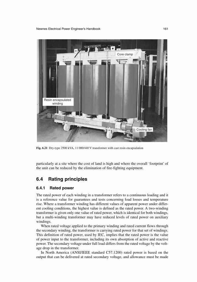
particularly at a site where the cost of land is high and where the overall ‘footprint’ ofthe unit can be reduced by the elimination of fire-fighting equipment.
6.4 Rating principles
6.4.1 Rated power
The rated power of each winding in a transformer refers to a continuous loading and itis a reference value for guarantees and tests concerning load losses and temperaturerise. Where a transformer winding has different values of apparent power under differ-ent cooling conditions, the highest value is defined as the rated power. A two-windingtransformer is given only one value of rated power, which is identical for both windings,but a multi-winding transformer may have reduced levels of rated power on auxiliarywindings.
When rated voltage applied to the primary winding and rated current flows throughthe secondary winding, the transformer is carrying rated power for that set of windings.This definition of rated power, used by IEC, implies that the rated power is the valueof power input to the transformer, including its own absorption of active and reactivepower. The secondary voltage under full load differs from the rated voltage by the volt-age drop in the transformer.
In North America (ANSI/IEEE standard C57.1200) rated power is based on theoutput that can be delivered at rated secondary voltage, and allowance must be made
Newnes Electrical Power Engineer’s Handbook 161
Resin encapsulated winding
Core clamp
Cooling fan
Fig. 6.21 Dry-type 2500 kVA, 11 000/440 V transformer with cast resin encapsulation
so that the necessary primary voltage can be applied to the transformer. The differencebetween basing rated power on loaded voltages (IEC) or open-circuit voltages(ANSI/IEEE) is significant.
6.4.2 Overloading
Although transformers are rated for continuous operation, it is possible to supply over-loads for limited periods. The analysis of overloading profiles is based on the deterio-ration of cellulose. At temperatures above the rated temperature, cellulose degrades ata faster rate, and the load cycle should therefore include a period of operation at lowertemperature to balance effects of these faster ageing rates at higher temperature. In general, the ageing rate doubles for every 8°C rise in temperature.
When the ambient temperature is below the rated ambient temperature it is also per-missible to overload the transformer, the limit of the overloading being the operatingtemperature of the winding. Under severe operational pressures it is sometimes neces-sary to overload a transformer well beyond its nameplate rating, but such an operationwill usually result in shorter life. IEC 354 provides a guide to overloading of oil-filledtransformers based on these principles.
A maximum winding temperature of 140°C should not be exceeded even underemergency conditions, because free gas can be produced by cellulose at temperaturesabove this, and gas bubbles may cause dielectric failure of the windings.
6.4.3 Parallel operation of transformers
For operational reasons it may be necessary to operate transformers connected directlyin parallel. For successful parallel operation, the transformers must have:
• the same voltage ratings and ratio (with some tolerance)• the same phase–angle relationship (clock-hour number)• the same percentage impedance (with some tolerance)
It is not advisable to parallel-operate transformers with widely different power ratings as the natural impedance for optimal design varies with the rating of the trans-former. The power divides between parallel-connected transformers in a relationshipwhich is inversely proportional to their impedances; a low-impedance transformeroperated in parallel with a higher-impedance unit will pass the greater part of thepower and may be overloaded. A mismatch in loading of up to 10 per cent is normallyacceptable.
6.5 Test methods
6.5.1 Specification testing
Transformers for power supply units and isolating transformers are subject to produc-tion testing, where compliance is generally checked by inspection and electrical tests.The electrical tests establish earth continuity (for class I), no-load output voltage,dielectric strength between live parts of the input circuit and accessible conductingparts of the transformer, and dielectric strength between input and output circuits.
Tests on larger transformers are carried out as part of the manufacturing process toensure that transformers meet the characteristics specified by the purchaser. The tests
162 Transformers
prescribed by IEC are grouped in three categories, these being routine tests, type testsand special tests:
(a) routine tests, to be carried out on all transformers(b) type tests, to be carried out on new designs or the first unit of a contract(c) special tests, to be carried out at the specific request of the purchaser
(a) Routine tests: These are carried out on all transformers and include,
• measurement of winding resistance using a dc measurement circuit or a bridge.This is the winding resistance used in the equivalent circuit.
• measurement of voltage ratio and check of phase displacement. The voltageratio is checked on each tap position and the connection symbol of three-phasetransformers is confirmed.
• measurement of short-circuit impedance and load loss. The short-circuit imped-ance (including reactance and ac resistance in series) is determined by measur-ing the primary voltage necessary to circulate full-load current with thesecondary terminals short-circuited. This provides the value of impedance usedin the equivalent circuit. The load loss (copper loss) is measured using the samecircuit.
• measurement of no-load loss and magnetizing current, at rated voltage and fre-quency. This is measured on one set of windings with the other windings open-circuit. Because the power factor at no-load may be between 0.1 and 0.2,special low power factor wattmeters are necessary to ensure accuracy. A three-wattmeter connection is used for load loss measurement of three-phasetransformers, because the previously used two-wattmeter method is inaccurate.
• dielectric tests, consisting of applied voltage and induced voltage tests, sometimes linked with a switching surge test. The applied voltage test verifiesthe integrity of the winding insulation to earth and between windings, and the induced voltage test verifies the insulation between turns and between wind-ings. The general requirements set down by IEC are shown in Table 6.2. Fortransformers rated up to 300 kV, the induced voltage test is for one minute at anovervoltage of between 2.5 and 3.5 times rated voltage, carried out at a higherfrequency to avoid core saturation. For rated voltages over 300 kV, the inducedtest is for 30 min at 1.3 or 1.5 times rated voltage, with an initial short periodat a higher voltage to initiate activity in any of the vulnerable partial dischargesites; this is linked with a partial discharge test. This long-term test will notprove the insulation against switching overvoltages, and so for this it must belinked to a switching impulse test.
• tests on OLTCs to confirm the timing of the tapchanger mechanism and toprove the capability on full-voltage and full-current operation.
(b) Type tests: These are carried out on new designs, or on the first unit of a contract.They include,
• temperature rise test using the normal cooling equipment to verify the temper-ature rise of the windings under full-load or overload conditions. For smallertransformers it may be possible to carry out the temperature rise test at full volt-age by supplying a suitable load. For larger transformers it is more usual to sup-ply the total losses (load loss and no-load loss) under short-circuit conditions
Newnes Electrical Power Engineer’s Handbook 163
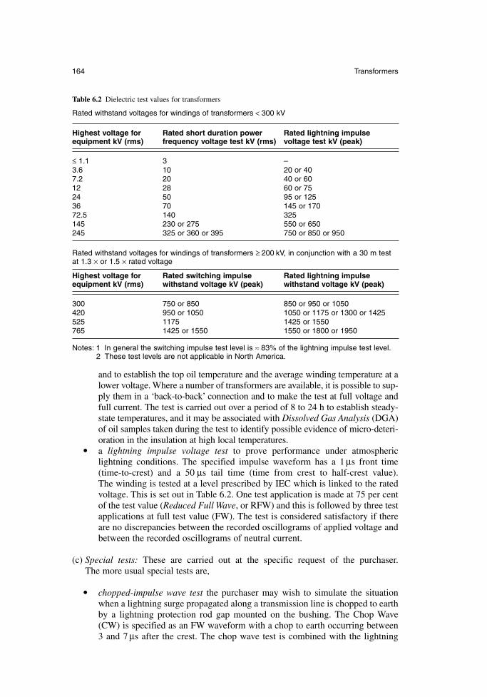
and to establish the top oil temperature and the average winding temperature at alower voltage. Where a number of transformers are available, it is possible to sup-ply them in a ‘back-to-back’ connection and to make the test at full voltage andfull current. The test is carried out over a period of 8 to 24 h to establish steady-state temperatures, and it may be associated with Dissolved Gas Analysis (DGA)of oil samples taken during the test to identify possible evidence of micro-deteri-oration in the insulation at high local temperatures.
• a lightning impulse voltage test to prove performance under atmosphericlightning conditions. The specified impulse waveform has a 1 µs front time(time-to-crest) and a 50 µs tail time (time from crest to half-crest value). The winding is tested at a level prescribed by IEC which is linked to the ratedvoltage. This is set out in Table 6.2. One test application is made at 75 per centof the test value (Reduced Full Wave, or RFW) and this is followed by three testapplications at full test value (FW). The test is considered satisfactory if thereare no discrepancies between the recorded oscillograms of applied voltage andbetween the recorded oscillograms of neutral current.
(c) Special tests: These are carried out at the specific request of the purchaser. The more usual special tests are,
• chopped-impulse wave test the purchaser may wish to simulate the situationwhen a lightning surge propagated along a transmission line is chopped to earthby a lightning protection rod gap mounted on the bushing. The Chop Wave(CW) is specified as an FW waveform with a chop to earth occurring between3 and 7 µs after the crest. The chop wave test is combined with the lightning
164 Transformers
Table 6.2 Dielectric test values for transformers
Rated withstand voltages for windings of transformers < 300 kV
Highest voltage for Rated short duration power Rated lightning impulseequipment kV (rms) frequency voltage test kV (rms) voltage test kV (peak)
≤ 1.1 3 –3.6 10 20 or 407.2 20 40 or 6012 28 60 or 7524 50 95 or 12536 70 145 or 17072.5 140 325145 230 or 275 550 or 650245 325 or 360 or 395 750 or 850 or 950
Rated withstand voltages for windings of transformers ≥ 200 kV, in conjunction with a 30 m testat 1.3 × or 1.5 × rated voltage
Highest voltage for Rated switching impulse Rated lightning impulseequipment kV (rms) withstand voltage kV (peak) withstand voltage kV (peak)
300 750 or 850 850 or 950 or 1050420 950 or 1050 1050 or 1175 or 1300 or 1425525 1175 1425 or 1550765 1425 or 1550 1550 or 1800 or 1950
Notes: 1 In general the switching impulse test level is ≈ 83% of the lightning impulse test level.2 These test levels are not applicable in North America.
impulse voltage test and the test sequence is 1-RFW, 1-FW, 2-CW and 2-FWtest applications, sometimes followed by a further RFW for comparison pur-poses. A successful test shows no discrepancies between applied voltage oscillo-grams or between neutral current oscillograms, although if rod gaps are used toperform the chopped-wave test there may be acceptable deviations betweenneutral current oscillograms after the time of chop. If a triggered gap is used tocontrol time of chop the oscillograms should be identical.
• determination of zero-sequence impedance, measured between the line terminalsof a star-connected or zigzag-connected winding connected together, and itsneutral terminal. This is expressed in ohms per phase, and it is a measure of theimpedance presented by the transformer to a three-phase fault to earth.
• short-circuit withstand test to verify the integrity of the transformer underthrough-fault conditions. IEC recommendations allow the withstand perform-ance of a winding to be demonstrated by calculation or by test. The resourceneeded to test fully a large power transformer is substantial, and few testfacilities are available in the world.
• determination of sound levels, which can be measured in terms of sound power,sound pressure or sound intensity. The latter method was developed especiallyfor measurement of low sound levels in the presence of high sound ambients. Intransformers which have been designed with low-flux density to reduce themagnetostriction effect, the predominant sound may be produced by the wind-ings as a result of movements caused by the load currents. This load current gen-erated sound should be measured by the sound intensity method.
6.5.2 In-service testing
Two types of in-service testing are used. Surveillance testing involves periodic checks,and condition monitoring offers a continuous check on transformer performance.
(a) Surveillance testing – oil samples
When transformers are in operation, many users carry out surveillance testing to monitor operation. The most simple tests are carried out on oil samples taken on a reg-ular basis. Measurement of oil properties, such as breakdown voltage, water content,acidity, dielectric loss angle, volume resistivity and particle content all give valuableinformation on the state of the transformer. DGA gives early warning of deteriorationdue to electrical or thermal causes, particularly sparking, arcing and service overheating.Analysis of the oil by High-Performance Liquid Chromatography (HPLC) may detectthe presence of furanes or furfuranes which will provide further information on moderate overheating of the insulation.
(b) On-line condition monitoring
Sensors can be built into the transformer so that parameters can be monitored on a con-tinuous basis. The parameters which are typically monitored are winding temperature,tank temperature, water content, dissolved hydrogen, partial discharge activity, loadcurrent and voltage transients. The data collection system may simply gather andanalyse the information, or it may be arranged to operate alarms or actuate disconnec-tions under specified conditions and limits which represent an emergency.
Whereas surveillance testing is carried out on some distribution transformers andalmost all larger transformers, the high cost of on-line condition monitoring has limited
Newnes Electrical Power Engineer’s Handbook 165
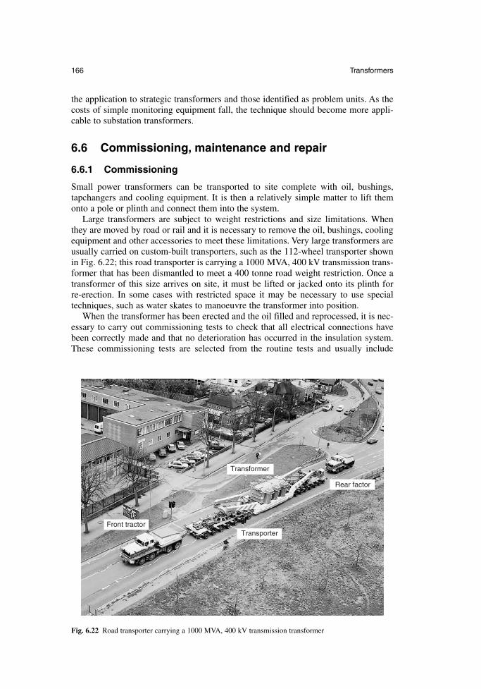
the application to strategic transformers and those identified as problem units. As thecosts of simple monitoring equipment fall, the technique should become more appli-cable to substation transformers.
6.6 Commissioning, maintenance and repair
6.6.1 Commissioning
Small power transformers can be transported to site complete with oil, bushings,tapchangers and cooling equipment. It is then a relatively simple matter to lift themonto a pole or plinth and connect them into the system.
Large transformers are subject to weight restrictions and size limitations. Whenthey are moved by road or rail and it is necessary to remove the oil, bushings, coolingequipment and other accessories to meet these limitations. Very large transformers areusually carried on custom-built transporters, such as the 112-wheel transporter shownin Fig. 6.22; this road transporter is carrying a 1000 MVA, 400 kV transmission trans-former that has been dismantled to meet a 400 tonne road weight restriction. Once atransformer of this size arrives on site, it must be lifted or jacked onto its plinth for re-erection. In some cases with restricted space it may be necessary to use special techniques, such as water skates to manoeuvre the transformer into position.
When the transformer has been erected and the oil filled and reprocessed, it is nec-essary to carry out commissioning tests to check that all electrical connections havebeen correctly made and that no deterioration has occurred in the insulation system.These commissioning tests are selected from the routine tests and usually include
166 Transformers
Transformer
Front tractorTransporter
Rear factor
Fig. 6.22 Road transporter carrying a 1000 MVA, 400 kV transmission transformer
winding resistance and ratio, magnetizing current at 440 V, and analysis of oil samplesto establish breakdown strength, water content and total gas content. If oil samplesindicate high water content then it may be necessary to dry the oil using methodsaddressed in the following section.
6.6.2 Maintenance
Transformers require little maintenance in service, apart from regular inspection andservicing of the OLTC mechanism. The diverter contacts experience significant weardue to arcing, and they must be replaced at regular intervals which are determined bythe operating regime. For furnace transformers it may be advisable to filter the oil regularly in a diverter compartment in order to remove carbon particles and maintainthe electrical strength.
The usual method of protecting the oil breather system in small transformers is to use silicone gel breathers to dry incoming air; in larger transformers refrigeratedbreathers continuously dry the air in a conservator. Regular maintenance (at least oncea month) is necessary to maintain a silica gel breather in efficient working order.
If oil samples indicate high water content then it may be necessary to dry the oil usinga heating–vacuum process. This also indicates high water content in the paper insulationand it may be necessary to redry the windings by applying a heating and vacuum cycleon site, or to return the transformer to the manufacturer for reprocessing or refurbish-ment. An alternative procedure is to pass the oil continuously through a molecular sievefilter. Molecular sieves absorb up to 40 per cent of their weight of water.
6.6.3 Diagnostics and repair
In the event of a failure, the user must first decide whether to repair or replace thetransformer. Where small transformers are involved, it is usually more economic toreplace the unit. In order to reach a decision, it is usually necessary to carry out diag-nostic tests to identify the number of faults and their location. Diagnostic tests mayinclude the surveillance tests referred to in section 6.5.2, and it may also be decided touse acoustic location devices to identify a sparking site, low-voltage impulse tests toidentify a winding fault and frequency response analysis of a winding to an appliedsquare wave to detect winding conductor displacement.
If the fault is in a winding, it usually requires either replacement of the winding ina repair workshop or rewinding by the manufacturer, but many faults external to thewindings, such as connection or core faults can be corrected on site.
Where a repair can be undertaken on site it is essential to maintain dry conditionsin the transformer by continual purging using dry air. Any material taken into the tankmust be fully processed and a careful log should be maintained of all materials takeninto and brought out of the tank.
When a repair is completed, the transformer must be re-dried and re-impregnated,and the necessary tests carried out to verify that the transformer can be returned toservice in good condition.
6.7 Standards
The performance requirements of power transformers are covered by a range of inter-national, regional and national standards. The main standards in IEC, CENELEC andBSI are shown in Table 6.3, together with their inter-relationship. Where appropriate,the equivalent ANSI/IEEE standard is also referenced.
Newnes Electrical Power Engineer’s Handbook 167
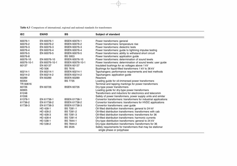
Table 6.3 Comparison of international, regional and national standards for transformers
IEC EN/HD BS Subject of standard
60076-1 EN 60076-1 BSEN 60076-1 Power transformers: general60076-2 EN 60076-2 BSEN 60076-2 Power transformers: temperature rise60076-3 EN 60076-3 BSEN 60076-3 Power transformers: dielectric tests60076-4 EN 60076-4 BSEN 60076-4 Power transformers: guide to lightning impulse testing60076-5 EN 60076-5 BSEN 60076-5 Power transformers: ability to withstand short circuit60076-8 BS 5953 Power transformers: application guide60076-10 EN 60076-10 BSEN 60076-10 Power transformers: determination of sound levels60076-10-1 EN 60076-10-1 BSEN 60076-10-1 Power transformers: determination of sound levels: user guide60137 EN 60137 BSEN 60137 Insulated bushings for ac voltages above 1 kV
HD 506 BS 7616 Bushings for liquid-filled transformers 1 kV to 36 kV60214-1 EN 60214-1 BSEN 60214-1 Tapchangers: performance requirements and test methods60214-2 EN 60214-2 BSEN 60214-2 Tapchangers: application guide60289 EN 60289 BSEN 60289 Reactors60354 BS 7735 Loading guide for oil-immersed power transformersTR 60616 Terminal and tapping markings for power transformers60726 EN 60726 BSEN 60726 Dry-type power transformers60905 Loading guide for dry-type power transformers61248 Transformers and inductors for electronics and telecomm61558 Safety of power transformers, power supply units and similar61378-1 EN 61738-1 BSEN 61738-1 Convertor transformers: transformers for industrial applications61738-2 EN 61738-2 BSEN 61738-2 Convertor transformers: transformers for HVDC applications61738-3 EN 61738-3 BSEN 61738-3 Convertor transformers: user guide
HD 428-1 BS 7281-1 Oil filled distribution transformers: general to 24 kVHD 428-2 BS 7281-2 Oil-filled distribution transformers: transformers with cabHD 428-3 BS 7281-3 Oil-filled distribution transformers: transformers for 36HD 428-4 BS 7281-4 Oil-filled distribution transformers: harmonic currentsHD 538-1 BS 7844-1 Dry-type distribution transformers: general to 24 kVHD 538-2 BS 7844-2 Dry-type distribution transformers: transformers for 36
BS 3535 Safety requirements for transformers that may be stationarsingle phase or polyphase
Chapter 7
Switchgear
N.P. AllenT. Harris
C.J. JonesVA TECH Transmission & Distribution Limited
S. LaneWhipp & Bourne
7.1 Introduction
Switchgear is used to connect and disconnect electric power supplies and systems. It is a general term which covers the switching device and its combination with associated control, measuring, protective and regulating equipment, together withaccessories, enclosures and supporting structures.
Switchgear is applied in electrical circuits and systems from low voltage, such as domestic 220/240V applications, right up to transmission networks up to 1100 kV. A wide range of technology is needed, and this chapter is split into the four mainsubdivisions of low voltage, medium voltage (distribution), high voltage (transmission)and dc.
The main classes of equipment are as follows:
disconnectors, or isolators switches fuse–switch combinations circuit breakers earthing switches
A disconnector is a mechanical switching device which in the open position provides a safe working gap in the electrical system which withstands normal workingsystem voltage and any overvoltages which may occur. It is able to open or close a circuit if a negligible current is switched, or if no significant change occurs in the voltage between the terminals of the poles. Currents can be carried for specified timesin normal operation and under abnormal conditions.
A switch is a mechanical device which is able to make, carry and interrupt currentoccurring under normal conditions in a system, and to close a circuit safely, even if afault is present. It must therefore be able to close satisfactorily carrying a peak currentcorresponding to the short-circuit fault level, and it must be able to carry this fault current for a specified period, usually one or three seconds.
A fuse and a switch can be used in combination with ratings chosen so that the fuseoperates at currents in excess of the rated interrupting or breaking capacity of the switch.
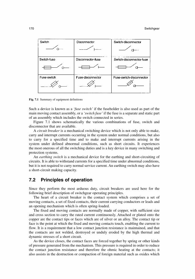
Such a device is known as a ‘fuse switch’ if the fuseholder is also used as part of themain moving contact assembly, or a ‘switch fuse’ if the fuse is a separate and static partof an assembly which includes the switch connected in series.
Figure 7.1 shows schematically the various combinations of fuse, switch and disconnector that are available.
A circuit breaker is a mechanical switching device which is not only able to make,carry and interrupt currents occurring in the system under normal conditions, but alsoto carry for a specified time and to make and interrupt currents arising in the system under defined abnormal conditions, such as short circuits. It experiences the most onerous of all the switching duties and is a key device in many switching and protection systems.
An earthing switch is a mechanical device for the earthing and short-circuiting ofcircuits. It is able to withstand currents for a specified time under abnormal conditions,but it is not required to carry normal service current. An earthing switch may also havea short-circuit making capacity.
7.2 Principles of operation
Since they perform the most arduous duty, circuit breakers are used here for the following brief description of switchgear operating principles.
The heart of a circuit breaker is the contact system which comprises a set of moving contacts, a set of fixed contacts, their current carrying conductors or leads andan opening mechanism which is often spring-loaded.
The fixed and moving contacts are normally made of copper, with sufficient sizeand cross section to carry the rated current continuously. Attached or plated onto thecopper are the contact tips or faces which are of silver or an alloy. The contact tip orface is the point at which the fixed and moving contacts touch, enabling the current toflow. It is a requirement that a low contact junction resistance is maintained, and thatthe contacts are not welded, destroyed or unduly eroded by the high thermal anddynamic stresses of a short circuit.
As the device closes, the contact faces are forced together by spring or other kindsof pressure generated from the mechanism. This pressure is required in order to reducethe contact junction resistance and therefore the ohmic heating at the contacts; it also assists in the destruction or compaction of foreign material such as oxides which
170 Switchgear
Fig. 7.1 Summary of equipment definitions
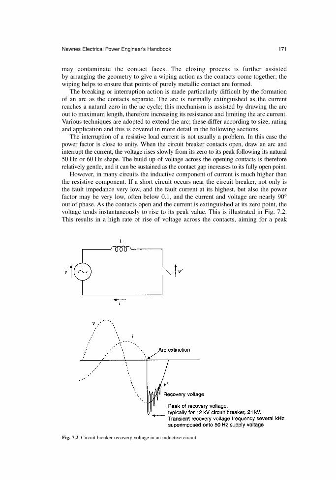
may contaminate the contact faces. The closing process is further assisted by arranging the geometry to give a wiping action as the contacts come together; thewiping helps to ensure that points of purely metallic contact are formed.
The breaking or interruption action is made particularly difficult by the formationof an arc as the contacts separate. The arc is normally extinguished as the currentreaches a natural zero in the ac cycle; this mechanism is assisted by drawing the arcout to maximum length, therefore increasing its resistance and limiting the arc current.Various techniques are adopted to extend the arc; these differ according to size, ratingand application and this is covered in more detail in the following sections.
The interruption of a resistive load current is not usually a problem. In this case thepower factor is close to unity. When the circuit breaker contacts open, draw an arc andinterrupt the current, the voltage rises slowly from its zero to its peak following its natural50 Hz or 60 Hz shape. The build up of voltage across the opening contacts is thereforerelatively gentle, and it can be sustained as the contact gap increases to its fully open point.
However, in many circuits the inductive component of current is much higher thanthe resistive component. If a short circuit occurs near the circuit breaker, not only isthe fault impedance very low, and the fault current at its highest, but also the powerfactor may be very low, often below 0.1, and the current and voltage are nearly 90°out of phase. As the contacts open and the current is extinguished at its zero point, thevoltage tends instantaneously to rise to its peak value. This is illustrated in Fig. 7.2.This results in a high rate of rise of voltage across the contacts, aiming for a peak
Newnes Electrical Power Engineer’s Handbook 171
Fig. 7.2 Circuit breaker recovery voltage in an inductive circuit
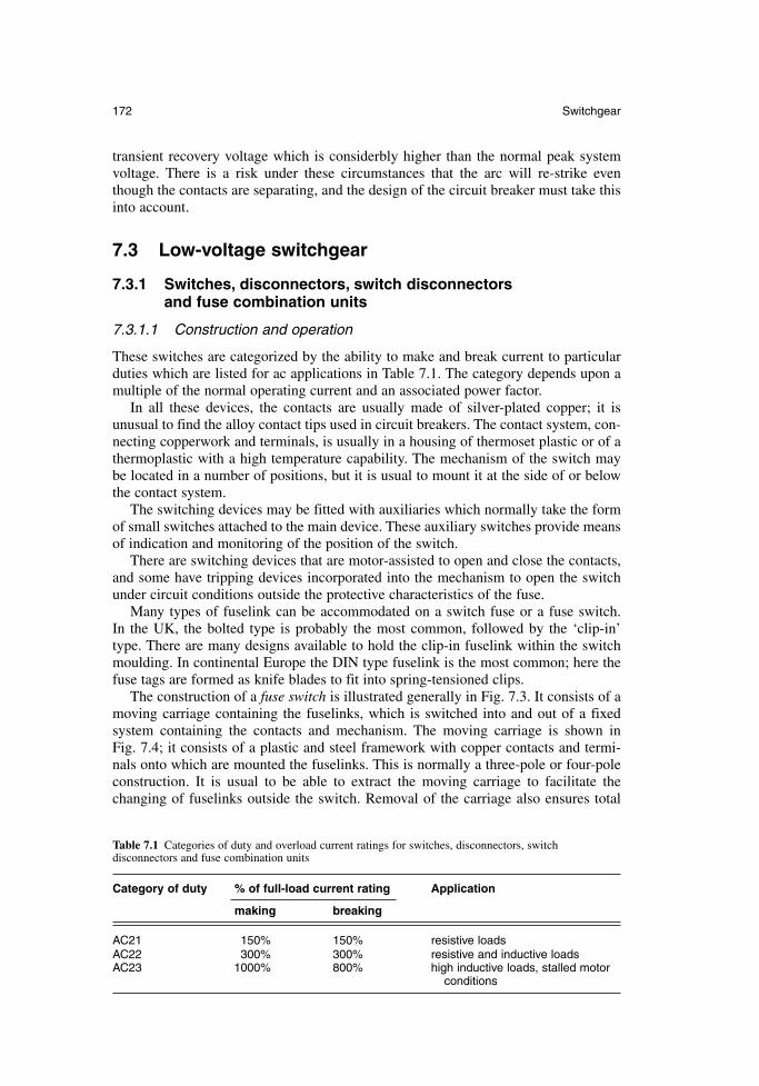
transient recovery voltage which is considerbly higher than the normal peak systemvoltage. There is a risk under these circumstances that the arc will re-strike eventhough the contacts are separating, and the design of the circuit breaker must take thisinto account.
7.3 Low-voltage switchgear
7.3.1 Switches, disconnectors, switch disconnectors and fuse combination units
7.3.1.1 Construction and operation
These switches are categorized by the ability to make and break current to particularduties which are listed for ac applications in Table 7.1. The category depends upon amultiple of the normal operating current and an associated power factor.
In all these devices, the contacts are usually made of silver-plated copper; it isunusual to find the alloy contact tips used in circuit breakers. The contact system, con-necting copperwork and terminals, is usually in a housing of thermoset plastic or of athermoplastic with a high temperature capability. The mechanism of the switch maybe located in a number of positions, but it is usual to mount it at the side of or belowthe contact system.
The switching devices may be fitted with auxiliaries which normally take the formof small switches attached to the main device. These auxiliary switches provide meansof indication and monitoring of the position of the switch.
There are switching devices that are motor-assisted to open and close the contacts,and some have tripping devices incorporated into the mechanism to open the switchunder circuit conditions outside the protective characteristics of the fuse.
Many types of fuselink can be accommodated on a switch fuse or a fuse switch. In the UK, the bolted type is probably the most common, followed by the ‘clip-in’type. There are many designs available to hold the clip-in fuselink within the switchmoulding. In continental Europe the DIN type fuselink is the most common; here thefuse tags are formed as knife blades to fit into spring-tensioned clips.
The construction of a fuse switch is illustrated generally in Fig. 7.3. It consists of amoving carriage containing the fuselinks, which is switched into and out of a fixed system containing the contacts and mechanism. The moving carriage is shown in Fig. 7.4; it consists of a plastic and steel framework with copper contacts and termi-nals onto which are mounted the fuselinks. This is normally a three-pole or four-poleconstruction. It is usual to be able to extract the moving carriage to facilitate the changing of fuselinks outside the switch. Removal of the carriage also ensures total
172 Switchgear
Table 7.1 Categories of duty and overload current ratings for switches, disconnectors, switch disconnectors and fuse combination units
Category of duty % of full-load current rating Application
making breaking
AC21 150% 150% resistive loadsAC22 300% 300% resistive and inductive loadsAC23 1000% 800% high inductive loads, stalled motor
conditions
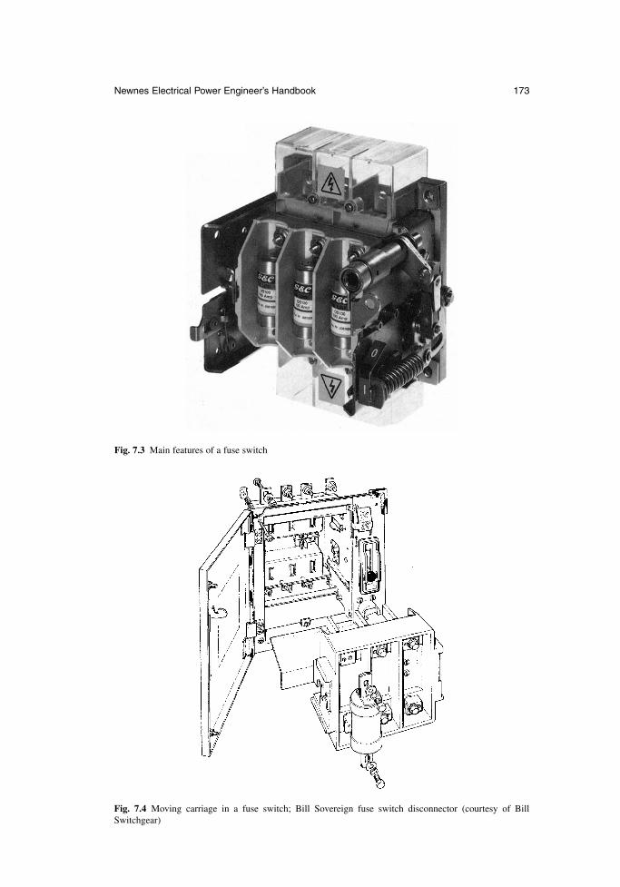
Newnes Electrical Power Engineer’s Handbook 173
Fig. 7.3 Main features of a fuse switch
Fig. 7.4 Moving carriage in a fuse switch; Bill Sovereign fuse switch disconnector (courtesy of BillSwitchgear)
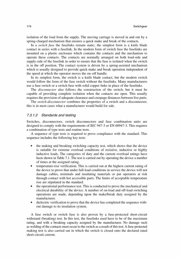
isolation of the load from the supply. The moving carriage is moved in and out by aspring-charged mechanism that ensures a quick make and break of the contacts.
In a switch fuse the fuselinks remain static; the simplest form is a knife blade contact in series with a fuselink. In the modern form of switch fuse the fuselinks aremounted on a plastic enclosure which contains the contacts and the mechanism tooperate these contacts. The contacts are normally arranged on both load-side and supply-side of the fuselink in order to ensure that the fuse is isolated when the switchis in the off position. The contact system is driven by a spring-assisted mechanismwhich is usually designed to provide quick make and break operation independent ofthe speed at which the operator moves the on–off handle.
In its simplest form, the switch is a knife blade contact, but the modern switchwould follow the form of the fuse switch without the fuselinks. Many manufacturersuse a fuse switch or a switch fuse with solid copper links in place of the fuselinks.
The disconnector also follows the construction of the switch, but it must be capable of providing complete isolation when the contacts are open. This usuallyrequires the provision of adequate clearance and creepage distances between live parts.
The switch-disconnector combines the properties of a switch and a disconnector;this is in most cases what a manufacturer would build for sale.
7.3.1.2 Standards and testing
Switches, disconnectors, switch disconnectors and fuse combination units aredesigned to comply with the requirements of IEC 947-3 or EN 60947-3. This requiresa combination of type tests and routine tests.
A sequence of type tests is required to prove compliance with the standard. Thissequence includes the following key tests:
the making and breaking switching capacity test, which shows that the deviceis suitable for extreme overload conditions of resistive, inductive or highlyinductive loads. The categories of duty and the current overload ratings havebeen shown in Table 7.1. The test is carried out by operating the device a numberof times at the assigned rating.
temperature-rise verification. This is carried out at the highest current rating ofthe device to prove that under full-load conditions in service the device will notdamage cables, terminals and insulating materials or put operators at riskthrough contact with hot accessible parts. The limits of acceptable temperaturerise are stipulated in the standard.
the operational performance test. This is conducted to prove the mechanical andelectrical durability of the device. A number of on-load and off-load switchingoperations are made, depending upon the make/break duty assigned by themanufacturer.
dielectric verification to prove that the device has completed the sequence with-out damage to its insulation system.
A fuse switch or switch fuse is also proven by a fuse-protected short-circuit withstand (breaking) test. In this test, the fuselinks used have to be of the maximumrating, and with a breaking capacity assigned by the manufacturer. No damage such as welding of the contacts must occur to the switch as a result of this test. A fuse-protectedmaking test is also carried out in which the switch is closed onto the declared ratedshort-circuit current.
174 Switchgear
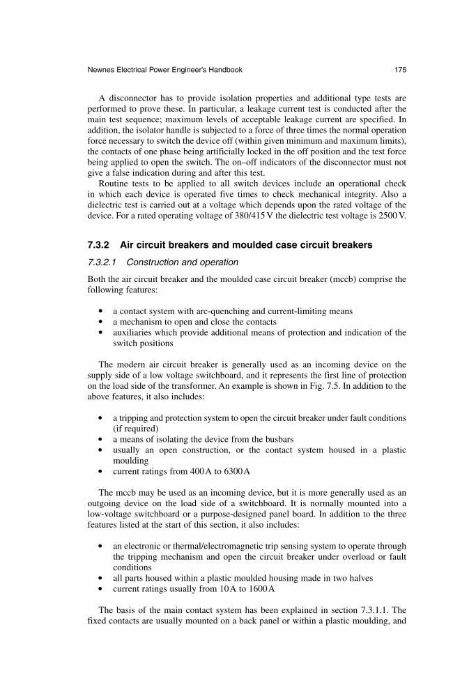
A disconnector has to provide isolation properties and additional type tests are performed to prove these. In particular, a leakage current test is conducted after themain test sequence; maximum levels of acceptable leakage current are specified. Inaddition, the isolator handle is subjected to a force of three times the normal operationforce necessary to switch the device off (within given minimum and maximum limits),the contacts of one phase being artificially locked in the off position and the test forcebeing applied to open the switch. The on–off indicators of the disconnector must notgive a false indication during and after this test.
Routine tests to be applied to all switch devices include an operational check in which each device is operated five times to check mechanical integrity. Also adielectric test is carried out at a voltage which depends upon the rated voltage of thedevice. For a rated operating voltage of 380/415 V the dielectric test voltage is 2500 V.
7.3.2 Air circuit breakers and moulded case circuit breakers
7.3.2.1 Construction and operation
Both the air circuit breaker and the moulded case circuit breaker (mccb) comprise thefollowing features:
• a contact system with arc-quenching and current-limiting means• a mechanism to open and close the contacts• auxiliaries which provide additional means of protection and indication of the
switch positions
The modern air circuit breaker is generally used as an incoming device on the supply side of a low voltage switchboard, and it represents the first line of protectionon the load side of the transformer. An example is shown in Fig. 7.5. In addition to theabove features, it also includes:
a tripping and protection system to open the circuit breaker under fault conditions(if required)
a means of isolating the device from the busbars usually an open construction, or the contact system housed in a plastic
moulding current ratings from 400A to 6300A
The mccb may be used as an incoming device, but it is more generally used as an outgoing device on the load side of a switchboard. It is normally mounted into a low-voltage switchboard or a purpose-designed panel board. In addition to the three features listed at the start of this section, it also includes:
an electronic or thermal/electromagnetic trip sensing system to operate throughthe tripping mechanism and open the circuit breaker under overload or faultconditions
all parts housed within a plastic moulded housing made in two halves current ratings usually from 10A to 1600A
The basis of the main contact system has been explained in section 7.3.1.1. Thefixed contacts are usually mounted on a back panel or within a plastic moulding, and
Newnes Electrical Power Engineer’s Handbook 175
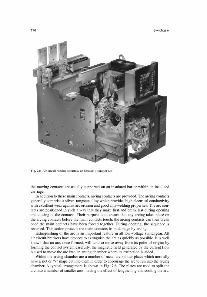
the moving contacts are usually supported on an insulated bar or within an insulatedcarriage.
In addition to these main contacts, arcing contacts are provided. The arcing contactsgenerally comprise a silver–tungsten alloy which provides high electrical conductivitywith excellent wear against arc erosion and good anti-welding properties. The arc con-tacts are positioned in such a way that they make first and break last during openingand closing of the contacts. Their purpose is to ensure that any arcing takes place onthe arcing contacts before the main contacts touch; the arcing contacts can then breakonce the main contacts have been forced together. During opening, the sequence isreversed. This action protects the main contacts from damage by arcing.
Extinguishing of the arc is an important feature in all low-voltage switchgear. Allair circuit breakers have devices to extinguish the arc as quickly as possible. It is wellknown that an arc, once formed, will tend to move away from its point of origin; byforming the contact system carefully, the magnetic field generated by the current flowis used to move the arc into an arcing chamber where its extinction is aided.
Within the arcing chamber are a number of metal arc-splitter plates which normallyhave a slot or ‘V’ shape cut into them in order to encourage the arc to run into the arcingchamber. A typical arrangement is shown in Fig. 7.6. The plates are used to split the arc into a number of smaller arcs, having the effect of lengthening and cooling the arc.
176 Switchgear
Fig. 7.5 Air circuit breaker (courtesy of Terasaki (Europe) Ltd)
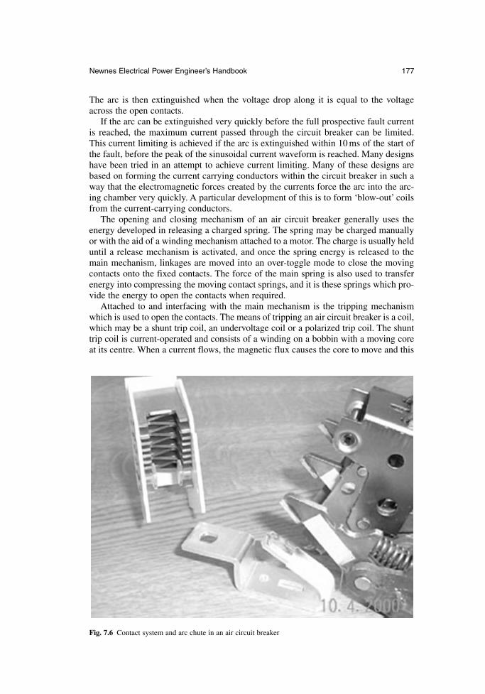
The arc is then extinguished when the voltage drop along it is equal to the voltageacross the open contacts.
If the arc can be extinguished very quickly before the full prospective fault currentis reached, the maximum current passed through the circuit breaker can be limited.This current limiting is achieved if the arc is extinguished within 10 ms of the start ofthe fault, before the peak of the sinusoidal current waveform is reached. Many designshave been tried in an attempt to achieve current limiting. Many of these designs arebased on forming the current carrying conductors within the circuit breaker in such away that the electromagnetic forces created by the currents force the arc into the arc-ing chamber very quickly. A particular development of this is to form ‘blow-out’ coilsfrom the current-carrying conductors.
The opening and closing mechanism of an air circuit breaker generally uses theenergy developed in releasing a charged spring. The spring may be charged manuallyor with the aid of a winding mechanism attached to a motor. The charge is usually helduntil a release mechanism is activated, and once the spring energy is released to themain mechanism, linkages are moved into an over-toggle mode to close the movingcontacts onto the fixed contacts. The force of the main spring is also used to transferenergy into compressing the moving contact springs, and it is these springs which pro-vide the energy to open the contacts when required.
Attached to and interfacing with the main mechanism is the tripping mechanismwhich is used to open the contacts. The means of tripping an air circuit breaker is a coil,which may be a shunt trip coil, an undervoltage coil or a polarized trip coil. The shunttrip coil is current-operated and consists of a winding on a bobbin with a moving coreat its centre. When a current flows, the magnetic flux causes the core to move and this
Newnes Electrical Power Engineer’s Handbook 177
Fig. 7.6 Contact system and arc chute in an air circuit breaker
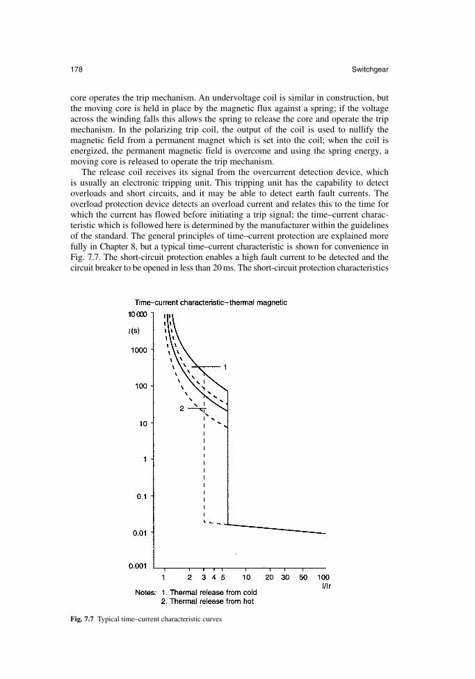
core operates the trip mechanism. An undervoltage coil is similar in construction, butthe moving core is held in place by the magnetic flux against a spring; if the voltageacross the winding falls this allows the spring to release the core and operate the tripmechanism. In the polarizing trip coil, the output of the coil is used to nullify the magnetic field from a permanent magnet which is set into the coil; when the coil isenergized, the permanent magnetic field is overcome and using the spring energy, amoving core is released to operate the trip mechanism.
The release coil receives its signal from the overcurrent detection device, which is usually an electronic tripping unit. This tripping unit has the capability to detectoverloads and short circuits, and it may be able to detect earth fault currents. The overload protection device detects an overload current and relates this to the time forwhich the current has flowed before initiating a trip signal; the time–current charac-teristic which is followed here is determined by the manufacturer within the guidelinesof the standard. The general principles of time–current protection are explained morefully in Chapter 8, but a typical time–current characteristic is shown for convenience inFig. 7.7. The short-circuit protection enables a high fault current to be detected and thecircuit breaker to be opened in less than 20 ms. The short-circuit protection characteristics
178 Switchgear
Fig. 7.7 Typical time–current characteristic curves
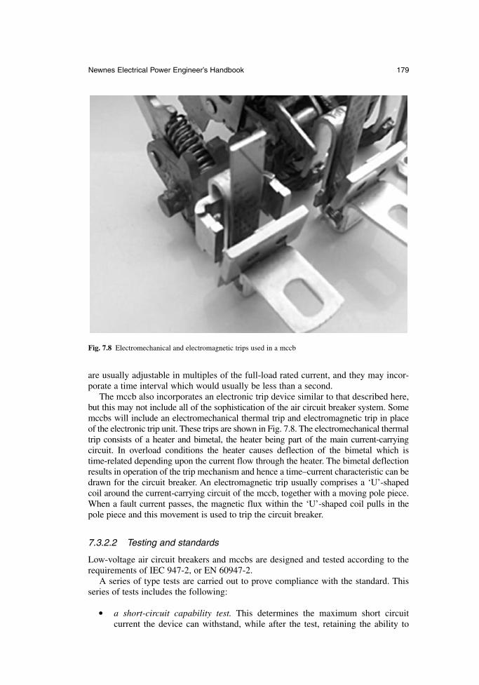
are usually adjustable in multiples of the full-load rated current, and they may incor-porate a time interval which would usually be less than a second.
The mccb also incorporates an electronic trip device similar to that described here,but this may not include all of the sophistication of the air circuit breaker system. Somemccbs will include an electromechanical thermal trip and electromagnetic trip in placeof the electronic trip unit. These trips are shown in Fig. 7.8. The electromechanical thermaltrip consists of a heater and bimetal, the heater being part of the main current-carryingcircuit. In overload conditions the heater causes deflection of the bimetal which is time-related depending upon the current flow through the heater. The bimetal deflectionresults in operation of the trip mechanism and hence a time–current characteristic can bedrawn for the circuit breaker. An electromagnetic trip usually comprises a ‘U’-shapedcoil around the current-carrying circuit of the mccb, together with a moving pole piece.When a fault current passes, the magnetic flux within the ‘U’-shaped coil pulls in thepole piece and this movement is used to trip the circuit breaker.
7.3.2.2 Testing and standards
Low-voltage air circuit breakers and mccbs are designed and tested according to therequirements of IEC 947-2, or EN 60947-2.
A series of type tests are carried out to prove compliance with the standard. Thisseries of tests includes the following:
a short-circuit capability test. This determines the maximum short circuit current the device can withstand, while after the test, retaining the ability to
Newnes Electrical Power Engineer’s Handbook 179
Fig. 7.8 Electromechanical and electromagnetic trips used in a mccb
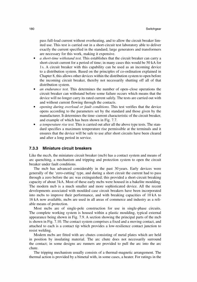
pass full-load current without overheating, and to allow the circuit breaker lim-ited use. This test is carried out in a short-circuit test laboratory able to deliverexactly the current specified in the standard; large generators and transformersare necessary for this work, making it expensive.
a short-time withstand test. This establishes that the circuit breaker can carry ashort-circuit current for a period of time; in many cases this would be 50 kA for1s. A circuit breaker with this capability can be used as an incoming device to a distribution system. Based on the principles of co-ordination explained inChapter 8, this allows other devices within the distribution system to open beforethe incoming circuit breaker, thereby not necessarily shutting off all of that distribution system.
an endurance test. This determines the number of open–close operations the circuit breaker can withstand before some failure occurs which means that thedevice will no longer carry its rated current safely. The tests are carried out withand without current flowing through the contacts.
opening during overload or fault conditions. This test verifies that the deviceopens according to the parameters set by the standard and those given by themanufacturer. It determines the time–current characteristic of the circuit breaker,and example of which has been shown in Fig. 7.7.
a temperature rise test. This is carried out after all the above type tests. The stan-dard specifies a maximum temperature rise permissible at the terminals and itensures that the device will be safe to use after short circuits have been clearedand after a long period in service.
7.3.3 Miniature circuit breakers
Like the mccb, the miniature circuit breaker (mcb) has a contact system and means ofarc quenching, a mechanism and tripping and protection system to open the circuitbreaker under fault conditions.
The mcb has advanced considerably in the past 30 years. Early devices were generally of the ‘zero-cutting’ type, and during a short circuit the current had to passthrough a zero before the arc was extinguished; this provided a short-circuit breakingcapacity of about 3kA. Most of these early mcbs were housed in a bakelite moulding.The modern mcb is a much smaller and more sophisticated device. All the recentdevelopments associated with moulded case circuit breakers have been incorporatedinto mcbs to improve their performance, and with breaking capacities of 10 kA to 16 kA now available, mcbs are used in all areas of commerce and industry as a reli-able means of protection.
Most mcbs are of single-pole construction for use in single-phase circuits. The complete working system is housed within a plastic moulding, typical externalappearance being shown in Fig. 7.9. A section showing the principal parts of the mcbis shown in Fig. 7.10. The contact system comprises a fixed and a moving contact, andattached to each is a contact tip which provides a low-resilience contact junction toresist welding.
Modern mcbs are fitted with arc chutes consisting of metal plates which are held in position by insulating material. The arc chute does not necessarily surround the contact; in some designs arc runners are provided to pull the arc into the arc chute.
The tripping mechanism usually consists of a thermal-magnetic arrangement. Thethermal action is provided by a bimetal with, in some cases, a heater. For ratings in the
180 Switchgear
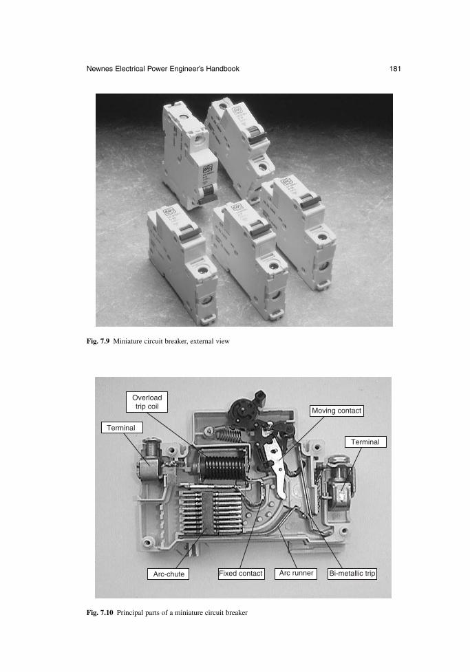
Newnes Electrical Power Engineer’s Handbook 181
Fig. 7.9 Miniature circuit breaker, external view
Overload trip coil
Terminal
Arc-chute Fixed contact Arc runner
Terminal
Moving contact
Bi-metallic trip
Fig. 7.10 Principal parts of a miniature circuit breaker
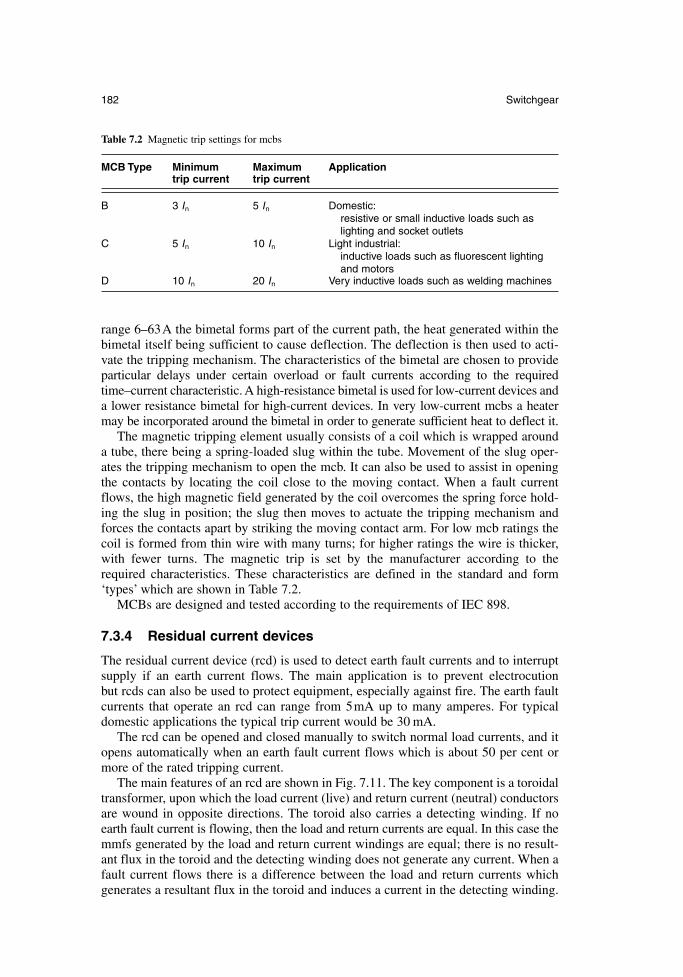
range 6–63A the bimetal forms part of the current path, the heat generated within thebimetal itself being sufficient to cause deflection. The deflection is then used to acti-vate the tripping mechanism. The characteristics of the bimetal are chosen to provideparticular delays under certain overload or fault currents according to the requiredtime–current characteristic. A high-resistance bimetal is used for low-current devices anda lower resistance bimetal for high-current devices. In very low-current mcbs a heatermay be incorporated around the bimetal in order to generate sufficient heat to deflect it.
The magnetic tripping element usually consists of a coil which is wrapped arounda tube, there being a spring-loaded slug within the tube. Movement of the slug oper-ates the tripping mechanism to open the mcb. It can also be used to assist in openingthe contacts by locating the coil close to the moving contact. When a fault currentflows, the high magnetic field generated by the coil overcomes the spring force hold-ing the slug in position; the slug then moves to actuate the tripping mechanism andforces the contacts apart by striking the moving contact arm. For low mcb ratings thecoil is formed from thin wire with many turns; for higher ratings the wire is thicker,with fewer turns. The magnetic trip is set by the manufacturer according to therequired characteristics. These characteristics are defined in the standard and form‘types’ which are shown in Table 7.2.
MCBs are designed and tested according to the requirements of IEC 898.
7.3.4 Residual current devices
The residual current device (rcd) is used to detect earth fault currents and to interruptsupply if an earth current flows. The main application is to prevent electrocution but rcds can also be used to protect equipment, especially against fire. The earth faultcurrents that operate an rcd can range from 5mA up to many amperes. For typicaldomestic applications the typical trip current would be 30 mA.
The rcd can be opened and closed manually to switch normal load currents, and itopens automatically when an earth fault current flows which is about 50 per cent ormore of the rated tripping current.
The main features of an rcd are shown in Fig. 7.11. The key component is a toroidaltransformer, upon which the load current (live) and return current (neutral) conductorsare wound in opposite directions. The toroid also carries a detecting winding. If noearth fault current is flowing, then the load and return currents are equal. In this case themmfs generated by the load and return current windings are equal; there is no result-ant flux in the toroid and the detecting winding does not generate any current. When afault current flows there is a difference between the load and return currents whichgenerates a resultant flux in the toroid and induces a current in the detecting winding.
182 Switchgear
Table 7.2 Magnetic trip settings for mcbs
MCB Type Minimum Maximum Applicationtrip current trip current
B 3 In 5 In Domestic:resistive or small inductive loads such as lighting and socket outlets
C 5 In 10 In Light industrial:inductive loads such as fluorescent lighting and motors
D 10 In 20 In Very inductive loads such as welding machines

The current generated in the detecting winding operates a relay which opens the maincontacts of the rcd.
The detecting winding has to produce from a very small output, sufficient power tooperate the tripping mechanism. Two alternative methods are used. In the first method,the output signal from the detecting coil is electronically amplified and the secondmethod uses a polarized relay operating on a sensitive mechanical trip mechanism. Theoperation of a polarized trip relay has already been described for circuit breakers insection 7.3.2.1; it is based on the magnetic output of a small coil nullifying the fieldfrom a permanent magnet, causing the release of an armature. The basic operation isillustrated in Fig. 7.12.
The operation of an rcd has here been described for single-phase operation, but itmay also be applied in a three-phase application where typically it might be used in alight industrial system for protection against fire. There are two arrangements of athree-phase rcd. Either the three phases are wound around a current transformer, or thethree phases and the neutral are wound onto a balancing transformer.
The rcd has only limited breaking capacity and it is not a replacement for overcur-rent protection devices such as the mcb. The residual current breaker with overcurrent(rcbo) is now available; this is an rcd with an overcurrent tripping mechanism andenhanced contacts to cope with interruption of fault conditions.
RCDs are designed and tested according to the requirements of IEC 1008 and IEC 1009.
7.3.5 Standards
The leading international standards adopted by for low-voltage switchgear are shownin Table 7.3.
Newnes Electrical Power Engineer’s Handbook 183
Test buttonMechanism
TerminalTerminal
Polarized trip relayContacts
Current transformer
Fig. 7.11 Residual current device
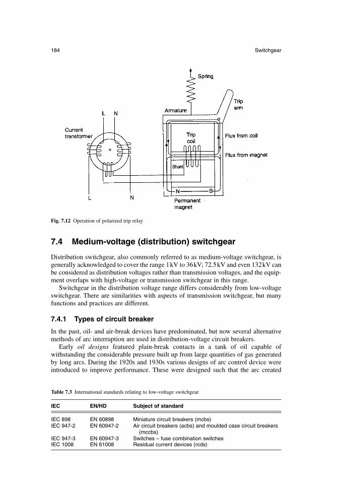
7.4 Medium-voltage (distribution) switchgear
Distribution switchgear, also commonly referred to as medium-voltage switchgear, isgenerally acknowledged to cover the range 1kV to 36kV; 72.5kV and even 132kV canbe considered as distribution voltages rather than transmission voltages, and the equip-ment overlaps with high-voltage or transmission switchgear in this range.
Switchgear in the distribution voltage range differs considerably from low-voltageswitchgear. There are similarities with aspects of transmission switchgear, but manyfunctions and practices are different.
7.4.1 Types of circuit breaker
In the past, oil- and air-break devices have predominated, but now several alternativemethods of arc interruption are used in distribution-voltage circuit breakers.
Early oil designs featured plain-break contacts in a tank of oil capable of withstanding the considerable pressure built up from large quantities of gas generatedby long arcs. During the 1920s and 1930s various designs of arc control device wereintroduced to improve performance. These were designed such that the arc created
184 Switchgear
Fig. 7.12 Operation of polarized trip relay
Table 7.3 International standards relating to low-voltage switchgear
IEC EN/HD Subject of standard
IEC 898 EN 60898 Miniature circuit breakers (mcbs)IEC 947-2 EN 60947-2 Air circuit breakers (acbs) and moulded case circuit breakers
(mccbs)IEC 947-3 EN 60947-3 Switches – fuse combination switchesIEC 1008 EN 61008 Residual current devices (rcds)
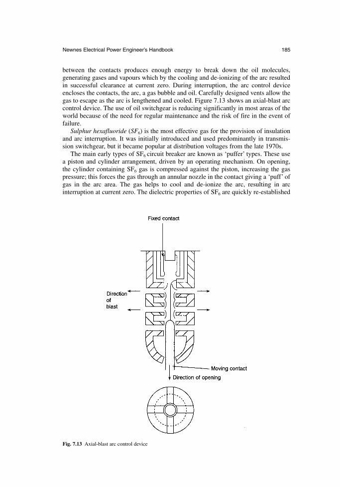
between the contacts produces enough energy to break down the oil molecules, generating gases and vapours which by the cooling and de-ionizing of the arc resultedin successful clearance at current zero. During interruption, the arc control deviceencloses the contacts, the arc, a gas bubble and oil. Carefully designed vents allow thegas to escape as the arc is lengthened and cooled. Figure 7.13 shows an axial-blast arccontrol device. The use of oil switchgear is reducing significantly in most areas of theworld because of the need for regular maintenance and the risk of fire in the event offailure.
Sulphur hexafluoride (SF6) is the most effective gas for the provision of insulationand arc interruption. It was initially introduced and used predominantly in transmis-sion switchgear, but it became popular at distribution voltages from the late 1970s.
The main early types of SF6 circuit breaker are known as ‘puffer’ types. These usea piston and cylinder arrangement, driven by an operating mechanism. On opening,the cylinder containing SF6 gas is compressed against the piston, increasing the gaspressure; this forces the gas through an annular nozzle in the contact giving a ‘puff’ ofgas in the arc area. The gas helps to cool and de-ionize the arc, resulting in arc interruption at current zero. The dielectric properties of SF6 are quickly re-established
Newnes Electrical Power Engineer’s Handbook 185
Fig. 7.13 Axial-blast arc control device
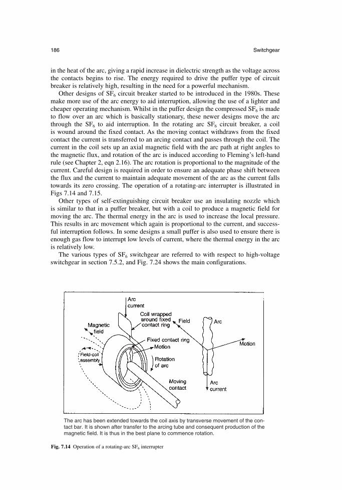
in the heat of the arc, giving a rapid increase in dielectric strength as the voltage acrossthe contacts begins to rise. The energy required to drive the puffer type of circuitbreaker is relatively high, resulting in the need for a powerful mechanism.
Other designs of SF6 circuit breaker started to be introduced in the 1980s. Thesemake more use of the arc energy to aid interruption, allowing the use of a lighter andcheaper operating mechanism. Whilst in the puffer design the compressed SF6 is madeto flow over an arc which is basically stationary, these newer designs move the arcthrough the SF6 to aid interruption. In the rotating arc SF6 circuit breaker, a coil is wound around the fixed contact. As the moving contact withdraws from the fixedcontact the current is transferred to an arcing contact and passes through the coil. Thecurrent in the coil sets up an axial magnetic field with the arc path at right angles tothe magnetic flux, and rotation of the arc is induced according to Fleming’s left-handrule (see Chapter 2, eqn 2.16). The arc rotation is proportional to the magnitude of thecurrent. Careful design is required in order to ensure an adequate phase shift betweenthe flux and the current to maintain adequate movement of the arc as the current fallstowards its zero crossing. The operation of a rotating-arc interrupter is illustrated inFigs 7.14 and 7.15.
Other types of self-extinguishing circuit breaker use an insulating nozzle which is similar to that in a puffer breaker, but with a coil to produce a magnetic field formoving the arc. The thermal energy in the arc is used to increase the local pressure.This results in arc movement which again is proportional to the current, and success-ful interruption follows. In some designs a small puffer is also used to ensure there isenough gas flow to interrupt low levels of current, where the thermal energy in the arcis relatively low.
The various types of SF6 switchgear are referred to with respect to high-voltageswitchgear in section 7.5.2, and Fig. 7.24 shows the main configurations.
186 Switchgear
The arc has been extended towards the coil axis by transverse movement of the con-tact bar. It is shown after transfer to the arcing tube and consequent production of themagnetic field. It is thus in the best plane to commence rotation.
Fig. 7.14 Operation of a rotating-arc SF6 interrupter
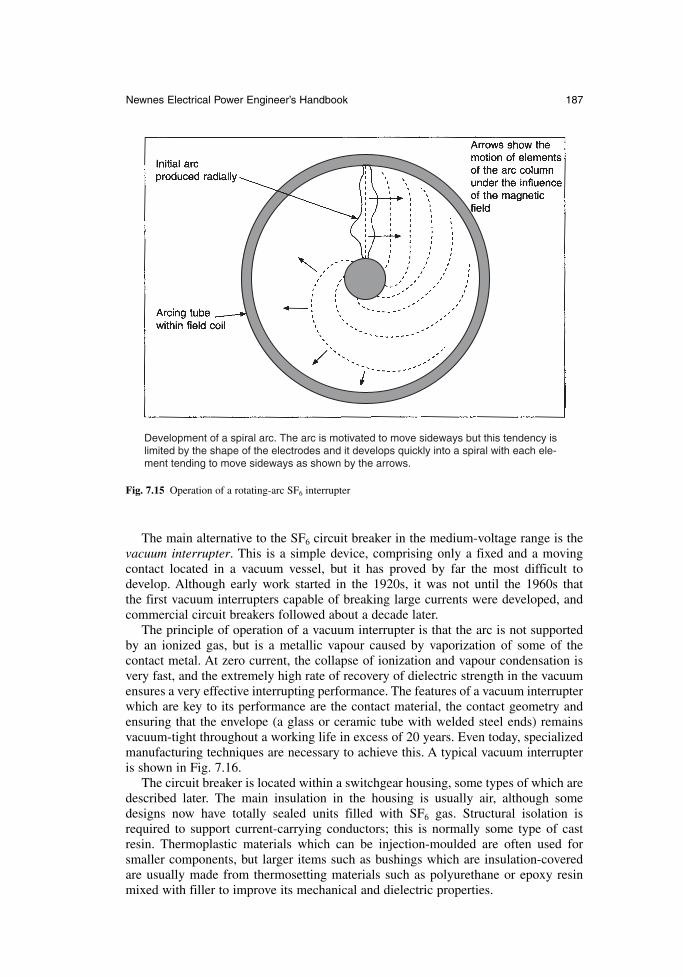
The main alternative to the SF6 circuit breaker in the medium-voltage range is thevacuum interrupter. This is a simple device, comprising only a fixed and a movingcontact located in a vacuum vessel, but it has proved by far the most difficult todevelop. Although early work started in the 1920s, it was not until the 1960s that the first vacuum interrupters capable of breaking large currents were developed, andcommercial circuit breakers followed about a decade later.
The principle of operation of a vacuum interrupter is that the arc is not supportedby an ionized gas, but is a metallic vapour caused by vaporization of some of the contact metal. At zero current, the collapse of ionization and vapour condensation isvery fast, and the extremely high rate of recovery of dielectric strength in the vacuumensures a very effective interrupting performance. The features of a vacuum interrupterwhich are key to its performance are the contact material, the contact geometry andensuring that the envelope (a glass or ceramic tube with welded steel ends) remainsvacuum-tight throughout a working life in excess of 20 years. Even today, specializedmanufacturing techniques are necessary to achieve this. A typical vacuum interrupteris shown in Fig. 7.16.
The circuit breaker is located within a switchgear housing, some types of which aredescribed later. The main insulation in the housing is usually air, although somedesigns now have totally sealed units filled with SF6 gas. Structural isolation isrequired to support current-carrying conductors; this is normally some type of castresin. Thermoplastic materials which can be injection-moulded are often used forsmaller components, but larger items such as bushings which are insulation-coveredare usually made from thermosetting materials such as polyurethane or epoxy resinmixed with filler to improve its mechanical and dielectric properties.
Newnes Electrical Power Engineer’s Handbook 187
Development of a spiral arc. The arc is motivated to move sideways but this tendency islimited by the shape of the electrodes and it develops quickly into a spiral with each ele-ment tending to move sideways as shown by the arrows.
Fig. 7.15 Operation of a rotating-arc SF6 interrupter
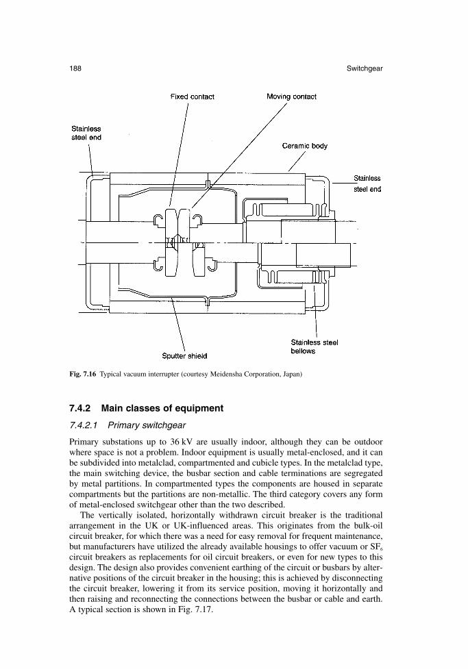
7.4.2 Main classes of equipment
7.4.2.1 Primary switchgear
Primary substations up to 36 kV are usually indoor, although they can be outdoorwhere space is not a problem. Indoor equipment is usually metal-enclosed, and it canbe subdivided into metalclad, compartmented and cubicle types. In the metalclad type,the main switching device, the busbar section and cable terminations are segregated by metal partitions. In compartmented types the components are housed in separatecompartments but the partitions are non-metallic. The third category covers any formof metal-enclosed switchgear other than the two described.
The vertically isolated, horizontally withdrawn circuit breaker is the traditionalarrangement in the UK or UK-influenced areas. This originates from the bulk-oil circuit breaker, for which there was a need for easy removal for frequent maintenance,but manufacturers have utilized the already available housings to offer vacuum or SF6
circuit breakers as replacements for oil circuit breakers, or even for new types to thisdesign. The design also provides convenient earthing of the circuit or busbars by alter-native positions of the circuit breaker in the housing; this is achieved by disconnectingthe circuit breaker, lowering it from its service position, moving it horizontally andthen raising and reconnecting the connections between the busbar or cable and earth.A typical section is shown in Fig. 7.17.
188 Switchgear
Fig. 7.16 Typical vacuum interrupter (courtesy Meidensha Corporation, Japan)
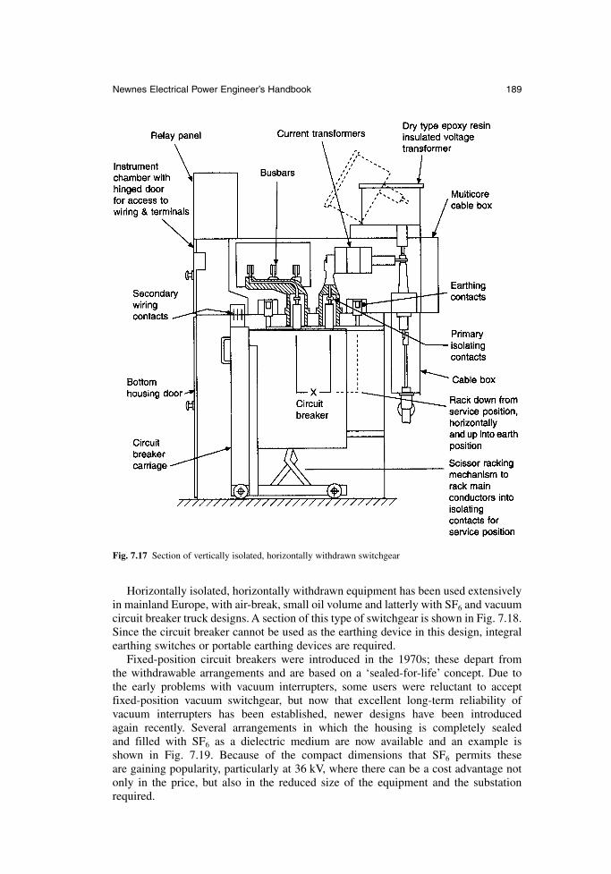
Horizontally isolated, horizontally withdrawn equipment has been used extensivelyin mainland Europe, with air-break, small oil volume and latterly with SF6 and vacuumcircuit breaker truck designs. A section of this type of switchgear is shown in Fig. 7.18.Since the circuit breaker cannot be used as the earthing device in this design, integralearthing switches or portable earthing devices are required.
Fixed-position circuit breakers were introduced in the 1970s; these depart from the withdrawable arrangements and are based on a ‘sealed-for-life’ concept. Due to the early problems with vacuum interrupters, some users were reluctant to acceptfixed-position vacuum switchgear, but now that excellent long-term reliability of vacuum interrupters has been established, newer designs have been introduced again recently. Several arrangements in which the housing is completely sealed and filled with SF6 as a dielectric medium are now available and an example is shown in Fig. 7.19. Because of the compact dimensions that SF6 permits these are gaining popularity, particularly at 36 kV, where there can be a cost advantage notonly in the price, but also in the reduced size of the equipment and the substationrequired.
Newnes Electrical Power Engineer’s Handbook 189
Fig. 7.17 Section of vertically isolated, horizontally withdrawn switchgear
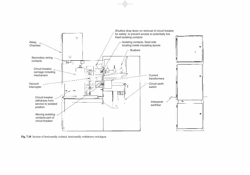
RelayChamber
Secondary wiringcontacts
Circuit breakercarriage includingmechanism
Circuit breakerwithdraws fromservice to isolatedposition
Moving isolatingcontacts part ofcircuit breaker
Shutters drop down on removal of circuit breakerfor safety, to prevent access to potentially livefixed isolating contacts
Isolating contacts, fixed sidelocating inside insulating spouts
Busbars
Currenttransformers
Circuit earthswitch
Interpanelearthbar
Vacuuminterrupter
Fig. 7.18 Section of horizontally isolated, horizontally withdrawn switchgear
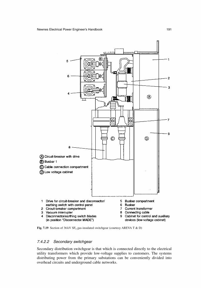
7.4.2.2 Secondary switchgear
Secondary distribution switchgear is that which is connected directly to the electricalutility transformers which provide low-voltage supplies to customers. The systems distributing power from the primary substations can be conveniently divided into overhead circuits and underground cable networks.
Newnes Electrical Power Engineer’s Handbook 191
Fig. 7.19 Section of 36 kV SF6 gas-insulated switchgear (courtesy AREVA T & D)
Most faults on overhead systems are caused by lightning strikes, branches brushingthe conductors, clashing of conductors in high wind, or large birds bridging the lines;they are usually transient in nature. In most cases the fault duration is short and the cir-cuit breakers used in these circuits, known as reclosers, are programmed to close againa very short time after they have opened. This allows the fault to be cleared with a min-imum of disruption to consumers. It is normal to programme the recloser to open, thenclose up to four times in order to allow time for the fault to disappear. If after this timethe fault is still present, it is assumed that the fault is not transient; the recloser thenlocks out and the faulty section of the line is isolated. A recloser normally controls sev-eral circuits. An 11kV pole-mounted auto-recloser is shown in Fig. 7.20. Reclosers areavailable with SF6 and vacuum interrupters; the equipment used in conjunction withreclosers are switches and sectionalizers, which can be air-break switches, vacuum orSF6 devices expulsion fuses and off-load switching devices.
Most urban areas in UK and Europe are supplied by underground cable. In this casethe step-down transformer (for example 11 000/415 V) which supplies a consumer circuit is connected to a protective device such as a fuse switch or circuit breaker in aring. A simplified distribution network with the main components is shown in Fig. 7.21. The ‘ring main unit’ usually has two load-break switches with the control protective device combined into a single unit. In UK this type of unit is ruggedlydesigned for outdoor use, but in continental Europe indoor designs are more normal.The traditional oil-filled unit has been replaced largely by SF6 equipment over recentyears. The ring main unit has normally been manually operated with a spring-operatedmechanism to ensure that their operation is not dependent on the force applied by theoperator. However, as utilities press to improve the reliability of supplies to consumersand to reduce the time lost through outages caused by faults, the use of automaticallyoperated motor-driven spring mechanisms is now on the increase.
7.4.3 Rating principles
The main consideration in the choice of switchgear for a particular system voltage isthe current it is capable of carrying continuously without overheating (the rated normal current) and the maximum current it can withstand, interrupt and make ontounder fault conditions (the rated short-circuit current). Studies and calculations basedon the circuits of interest will quantify these parameters. The switchgear rating canthen be chosen from tables of preferred ratings in the appropriate standard, such as IEC694 and IEC 56. Table 7.4 shows figures taken from IEC 56 showing the co-ordinationof rated values for circuit breakers. Ratings vary commonly from less than 400 A in asecondary system to 2000 A or more in a primary substation, with fault currents of 6 kA in some overhead line systems up to 40 kA and above in some primary circuits.
The standards also specify overvoltages and impulse voltages which the switchgearmust withstand. Normal overvoltages which occur during switching or which may be transferred due to lightning striking exposed circuits must be withstood. Theswitchgear also needs to provide sufficient isolating distances to allow personnel towork safely on a part of the system that has been disconnected. The lightning impulsewithstand voltage and the normal power frequency withstand voltage are specified relative to the normal system voltage in the standards.
7.4.4 Test methods
Type tests are performed on a single unit of the particular type and rating in question.They are performed to demonstrate that the equipment is capable of performing the
192 Switchgear
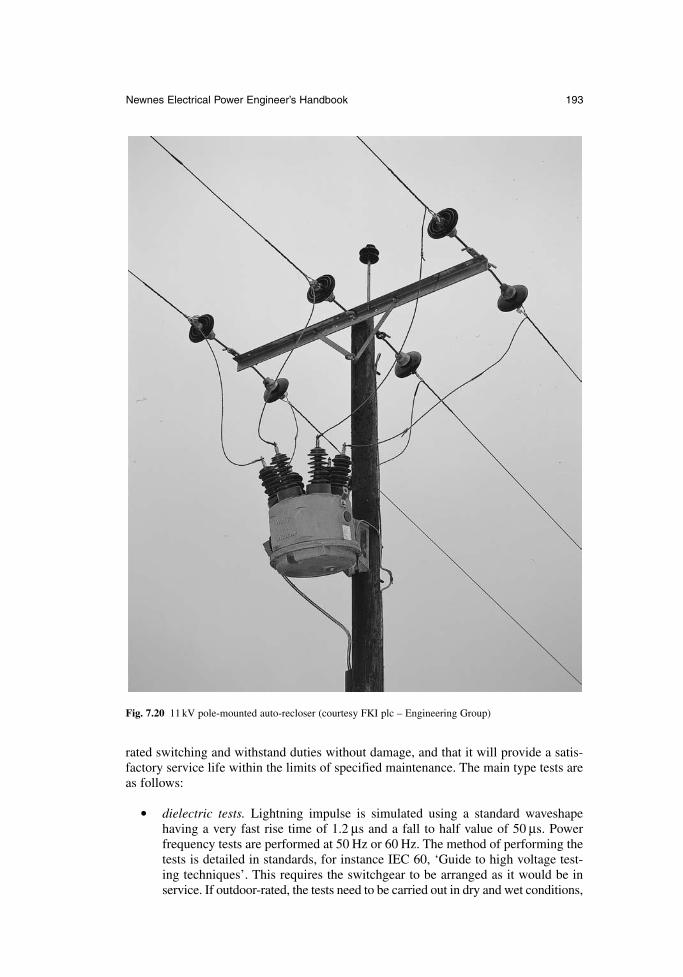
rated switching and withstand duties without damage, and that it will provide a satis-factory service life within the limits of specified maintenance. The main type tests areas follows:
dielectric tests. Lightning impulse is simulated using a standard waveshapehaving a very fast rise time of 1.2 µs and a fall to half value of 50 µs. Power frequency tests are performed at 50 Hz or 60 Hz. The method of performing thetests is detailed in standards, for instance IEC 60, ‘Guide to high voltage test-ing techniques’. This requires the switchgear to be arranged as it would be inservice. If outdoor-rated, the tests need to be carried out in dry and wet conditions,
Newnes Electrical Power Engineer’s Handbook 193
Fig. 7.20 11 kV pole-mounted auto-recloser (courtesy FKI plc – Engineering Group)
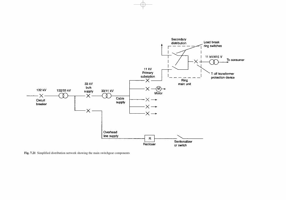
Fig. 7.21 Simplified distribution network showing the main switchgear components
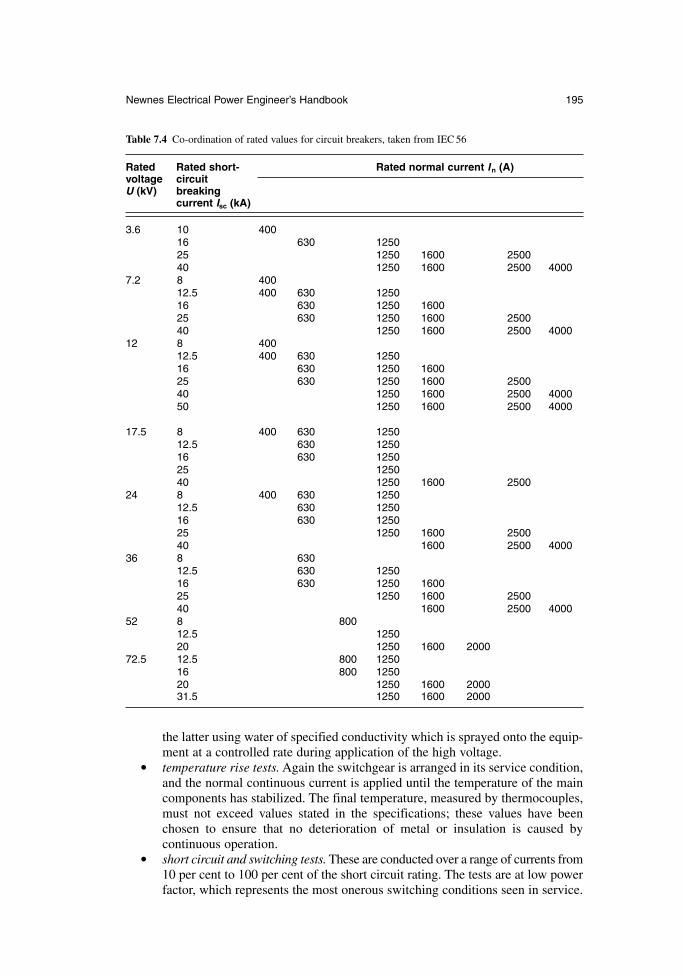
the latter using water of specified conductivity which is sprayed onto the equip-ment at a controlled rate during application of the high voltage.
temperature rise tests. Again the switchgear is arranged in its service condition,and the normal continuous current is applied until the temperature of the maincomponents has stabilized. The final temperature, measured by thermocouples,must not exceed values stated in the specifications; these values have been chosen to ensure that no deterioration of metal or insulation is caused by continuous operation.
short circuit and switching tests. These are conducted over a range of currents from10 per cent to 100 per cent of the short circuit rating. The tests are at low powerfactor, which represents the most onerous switching conditions seen in service.
Newnes Electrical Power Engineer’s Handbook 195
Table 7.4 Co-ordination of rated values for circuit breakers, taken from IEC 56
Rated Rated short- Rated normal current In (A)voltage circuitU (kV) breaking
current Isc (kA)
3.6 10 40016 630 125025 1250 1600 250040 1250 1600 2500 4000
7.2 8 40012.5 400 630 125016 630 1250 160025 630 1250 1600 250040 1250 1600 2500 4000
12 8 40012.5 400 630 125016 630 1250 160025 630 1250 1600 250040 1250 1600 2500 400050 1250 1600 2500 4000
17.5 8 400 630 125012.5 630 125016 630 125025 125040 1250 1600 2500
24 8 400 630 125012.5 630 125016 630 125025 1250 1600 250040 1600 2500 4000
36 8 63012.5 630 125016 630 1250 160025 1250 1600 250040 1600 2500 4000
52 8 80012.5 125020 1250 1600 2000
72.5 12.5 800 125016 800 125020 1250 1600 200031.5 1250 1600 2000
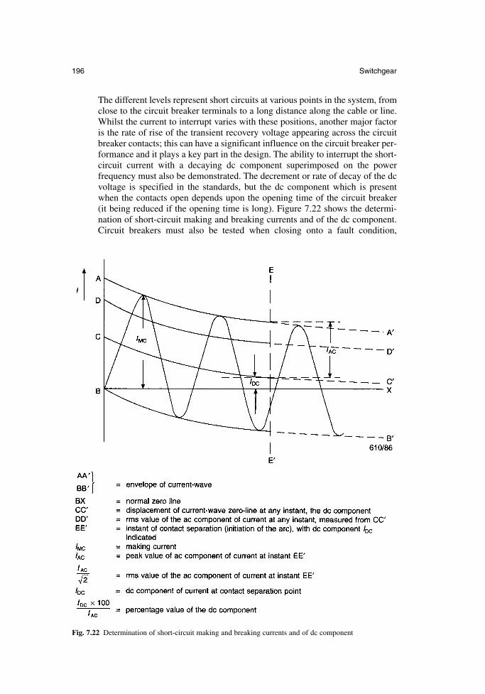
The different levels represent short circuits at various points in the system, fromclose to the circuit breaker terminals to a long distance along the cable or line.Whilst the current to interrupt varies with these positions, another major factoris the rate of rise of the transient recovery voltage appearing across the circuitbreaker contacts; this can have a significant influence on the circuit breaker per-formance and it plays a key part in the design. The ability to interrupt the short-circuit current with a decaying dc component superimposed on the power frequency must also be demonstrated. The decrement or rate of decay of the dcvoltage is specified in the standards, but the dc component which is presentwhen the contacts open depends upon the opening time of the circuit breaker (it being reduced if the opening time is long). Figure 7.22 shows the determi-nation of short-circuit making and breaking currents and of the dc component.Circuit breakers must also be tested when closing onto a fault condition,
196 Switchgear
Fig. 7.22 Determination of short-circuit making and breaking currents and of dc component
and then carrying the full short-circuit current for a specified period, usuallyone or three seconds.
mechanical endurance test. To demonstrate that the equipment has a satisfactory life, this test is performed over a specified number of operationswhich depends upon the type of equipment and duty; the number of open–closeoperations can vary from 1000 to 10 000. The tests are carried out without elec-trical load, but at the rated output of the mechanism of the device.
Routine tests are performed by the manufacturer on every unit of switchgear toensure that the construction is satisfactory and that the operating parameters are similar to the unit which was subjected to the type test. These tests are specified in thestandards, and the minimum performed will include the following:
power frequency voltage withstand dry tests on the main circuit voltage tests on the control and auxiliary circuits measurement of the resistance of the main circuit mechanical operating tests
7.4.5 Commissioning and maintenance
Switchgear is usually transported in sections which need to be carefully erected andconnected together at the substation.
Commissioning tests are performed after installation; these are necessary to ensurethat the connections are sound and that the equipment is functioning satisfactorily.These tests will normally include checks of current and voltage transformers, checkingof the protection scheme, circuit breaker operation and high-voltage withstand tests.
With the demise of oil-filled switchgear the requirement for maintenance has been significantly reduced. SF6 and vacuum circuit breakers which are ‘sealed for life’ should require no servicing of the interrupting device. Manufacturers provideinstructions on simple inspection and servicing of other parts of the circuit breaker;this is usually limited to cleaning, adjustment and lubrication of the mechanism.
7.4.6 Standards
Some of the commonly used standards and specifications for distribution switchgearare given in Table 7.5.
7.5 High-voltage (transmission) switchgear
7.5.1 System considerations
The transmission of high powers over long distances necessitates the use of High (HV),Extra High (EHV) or Ultra High (UHV) voltages. Historically, these voltages wereclassed as 72.5kV and above. The lower voltages were introduced first, and as the tech-nologies have developed these have increased so that now the highest transmission volt-ages being used are 1100 kV. For long transmission distances it is also possible to use DCsystems; these have particular advantages when two systems are to be connected, but theyare beyond the scope of this section, which considers only ac transmission switchgear.
In UK the 132 kV system was first established in 1932, and subsequent growth hasrequired expansion of the system up to 275 kV (1955) and 420 kV (1965). Other countries
Newnes Electrical Power Engineer’s Handbook 197
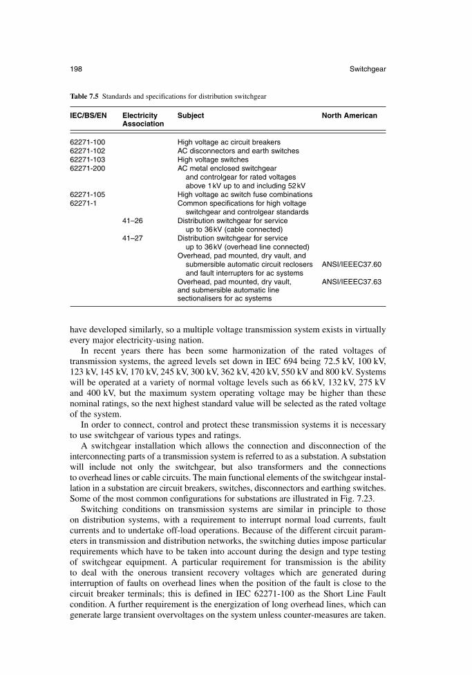
have developed similarly, so a multiple voltage transmission system exists in virtuallyevery major electricity-using nation.
In recent years there has been some harmonization of the rated voltages of transmission systems, the agreed levels set down in IEC 694 being 72.5 kV, 100 kV,123 kV, 145 kV, 170 kV, 245 kV, 300 kV, 362 kV, 420 kV, 550 kV and 800 kV. Systemswill be operated at a variety of normal voltage levels such as 66 kV, 132 kV, 275 kVand 400 kV, but the maximum system operating voltage may be higher than thesenominal ratings, so the next highest standard value will be selected as the rated voltageof the system.
In order to connect, control and protect these transmission systems it is necessaryto use switchgear of various types and ratings.
A switchgear installation which allows the connection and disconnection of theinterconnecting parts of a transmission system is referred to as a substation. A substationwill include not only the switchgear, but also transformers and the connections to overhead lines or cable circuits. The main functional elements of the switchgear instal-lation in a substation are circuit breakers, switches, disconnectors and earthing switches.Some of the most common configurations for substations are illustrated in Fig. 7.23.
Switching conditions on transmission systems are similar in principle to those on distribution systems, with a requirement to interrupt normal load currents, fault currents and to undertake off-load operations. Because of the different circuit param-eters in transmission and distribution networks, the switching duties impose particularrequirements which have to be taken into account during the design and type testingof switchgear equipment. A particular requirement for transmission is the ability to deal with the onerous transient recovery voltages which are generated during interruption of faults on overhead lines when the position of the fault is close to thecircuit breaker terminals; this is defined in IEC 62271-100 as the Short Line Faultcondition. A further requirement is the energization of long overhead lines, which cangenerate large transient overvoltages on the system unless counter-measures are taken.
198 Switchgear
Table 7.5 Standards and specifications for distribution switchgear
IEC/BS/EN Electricity Subject North AmericanAssociation
62271-100 High voltage ac circuit breakers62271-102 AC disconnectors and earth switches62271-103 High voltage switches62271-200 AC metal enclosed switchgear
and controlgear for rated voltages above 1kV up to and including 52kV
62271-105 High voltage ac switch fuse combinations62271-1 Common specifications for high voltage
switchgear and controlgear standards41–26 Distribution switchgear for service
up to 36kV (cable connected)41–27 Distribution switchgear for service
up to 36kV (overhead line connected)Overhead, pad mounted, dry vault, and
submersible automatic circuit reclosers ANSI/IEEEC37.60and fault interrupters for ac systems
Overhead, pad mounted, dry vault, ANSI/IEEEC37.63and submersible automatic line sectionalisers for ac systems
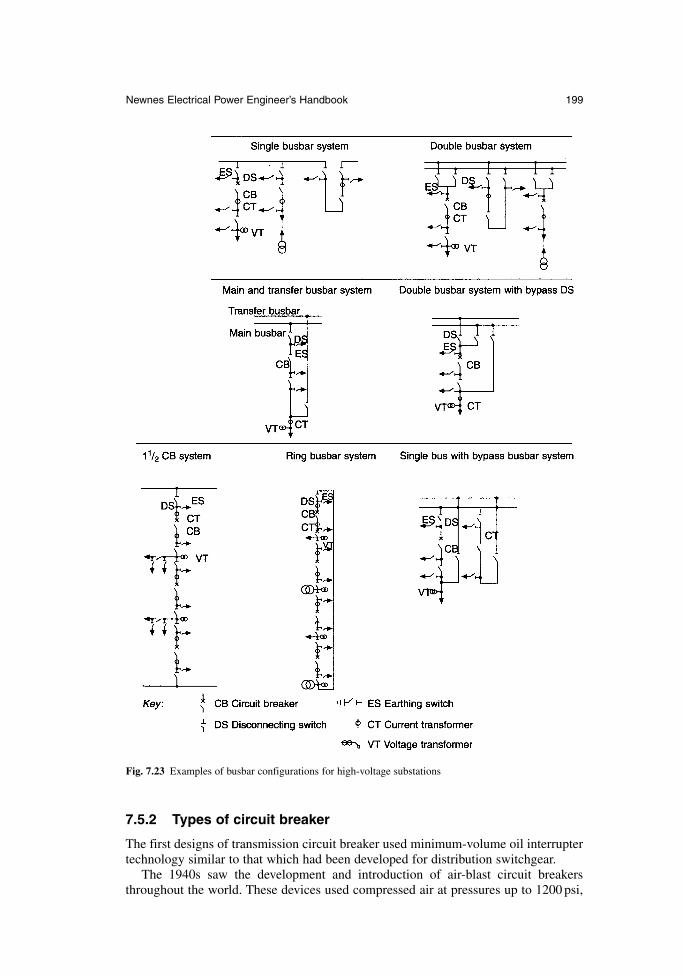
7.5.2 Types of circuit breaker
The first designs of transmission circuit breaker used minimum-volume oil interruptertechnology similar to that which had been developed for distribution switchgear.
The 1940s saw the development and introduction of air-blast circuit breakersthroughout the world. These devices used compressed air at pressures up to 1200 psi,
Newnes Electrical Power Engineer’s Handbook 199
Fig. 7.23 Examples of busbar configurations for high-voltage substations
not only to separate the contacts but also to cool and de-ionize the arc drawn betweenthe contacts. Early air-blast designs used interrupters which were not permanentlypressurized, and reclosed when the blast was shut off. Isolation was achieved sepa-rately by a series-connected switch which interrupted any residual resistive and/orcapacitive grading current, and had the full rated fault-making capacity.
The increase of system voltages to 400 kV in the late 1950s coincided with the discovery, investigation and specification of the kilometric or short line fault condition.Air-blast interrupters are particularly susceptible to high Rates of Rise of RecoveryVoltage (RRRV), and parallel-connected resistors are needed to assist interruption. At the increased short-circuit current levels of up to 60 kA which were now required,parallel resistors of up to a few hundred ohms per phase were required, and the dutyof breaking the resistor current could no longer be left to the series-connected airswitch. To deal with this, permanently pressurized interruptors incorporating parallel-resistor switching contacts were used. The original pressurized-head circuit breakersused multiple interrupters per phase in order to achieve the required fault-switchingcapacity at high transmission voltages; 10 or 12 interrupters were used for 400 kV.These were proved by direct unit testing at short-circuit testing stations, each having adirect output of 3GVA. It was in fact the ability to test which determined the numberof interrupters used in the design of a circuit breaker.
The introduction of synthetic testing methods increased the effective capacity ofshort-circuit testing stations by an order of magnitude, and this allowed the proving of circuit breakers having fewer interrupters. So, 400 kV air-blast circuit breakers with only four or six interrupters per phase were being supplied and installed up to thelate 1970s.
The next step-change in technology occurred with the introduction of SF6 circuitbreakers. The merits of electronegative gases such as SF6 had long been recognized,and freon had been used in the late 1930s to provide the primary insulating medium in 33 kV metalclad switchgear installed in two UK power stations. The reliability of seals was a problem, and it was only during the nuclear reactor programme that sufficiently reliable gas seals were developed to enable gas-insulated equipment to bereconsidered.
The first practical application of SF6 in switchgear was as an insulating medium forinstrument transformers in transmission substations in the late 1950s and early 1960s.These were quickly followed by the use of SF6 not only as an insulating medium butalso as the means of extinguishing arcs in circuit breakers. The first generation of SF6
circuit breakers were double-pressure devices which were based on air-blast designs,but using the advantages of SF6. These double-pressure designs were quickly followedby puffer circuit breakers which have already been described in section 7.4.1. Puffercircuit breakers, now in the form of second or third generation of development, form the basis of most present-day transmission circuit breaker designs. Figure 7.24illustrates the various forms of SF6 interrupter.
7.5.3 Main classes of equipment
Transmission substations may be built indoors or outdoors but because of the spacerequired it is usually difficult to justify an indoor substation. The strongest justifica-tion for an indoor substation is the effect of harsh environments on the design, operation and maintenance of the equipment.
The two main types of transmission switchgear currently available are conventionalor Air-Insulated Switchgear (AIS) and gas-insulated metal-enclosed switchgear.
200 Switchgear
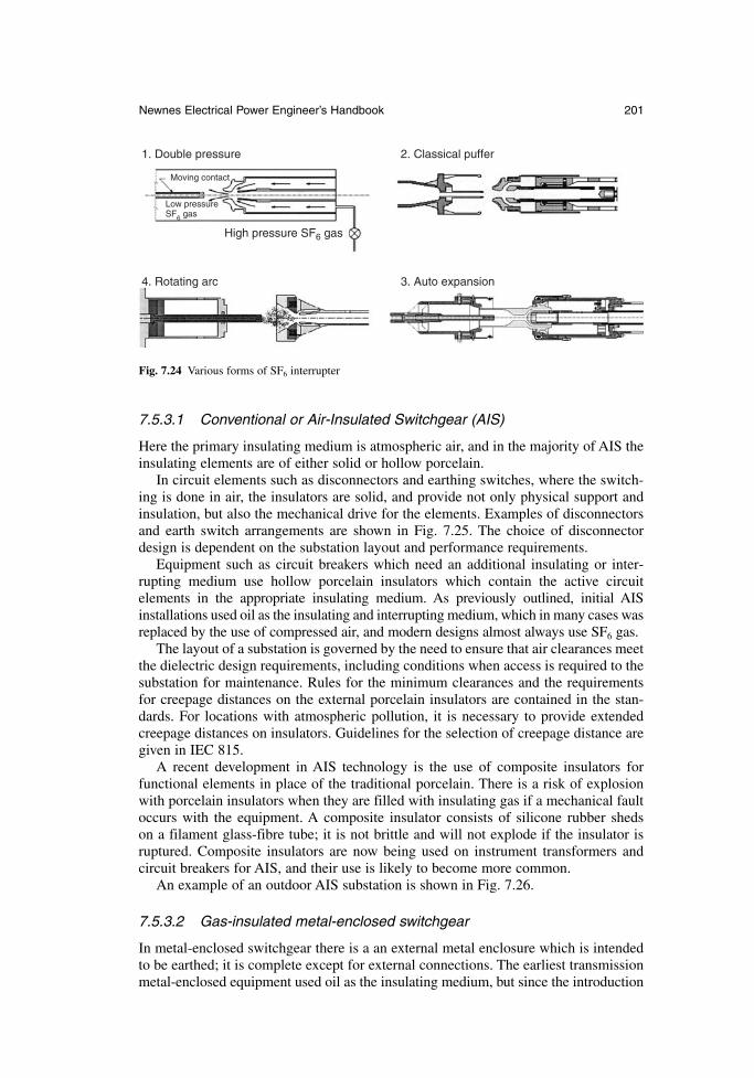
7.5.3.1 Conventional or Air-Insulated Switchgear (AIS)
Here the primary insulating medium is atmospheric air, and in the majority of AIS theinsulating elements are of either solid or hollow porcelain.
In circuit elements such as disconnectors and earthing switches, where the switch-ing is done in air, the insulators are solid, and provide not only physical support andinsulation, but also the mechanical drive for the elements. Examples of disconnectorsand earth switch arrangements are shown in Fig. 7.25. The choice of disconnectordesign is dependent on the substation layout and performance requirements.
Equipment such as circuit breakers which need an additional insulating or inter-rupting medium use hollow porcelain insulators which contain the active circuit elements in the appropriate insulating medium. As previously outlined, initial AISinstallations used oil as the insulating and interrupting medium, which in many cases wasreplaced by the use of compressed air, and modern designs almost always use SF6 gas.
The layout of a substation is governed by the need to ensure that air clearances meetthe dielectric design requirements, including conditions when access is required to thesubstation for maintenance. Rules for the minimum clearances and the requirementsfor creepage distances on the external porcelain insulators are contained in the stan-dards. For locations with atmospheric pollution, it is necessary to provide extendedcreepage distances on insulators. Guidelines for the selection of creepage distance aregiven in IEC 815.
A recent development in AIS technology is the use of composite insulators for functional elements in place of the traditional porcelain. There is a risk of explosionwith porcelain insulators when they are filled with insulating gas if a mechanical faultoccurs with the equipment. A composite insulator consists of silicone rubber sheds on a filament glass-fibre tube; it is not brittle and will not explode if the insulator isruptured. Composite insulators are now being used on instrument transformers and circuit breakers for AIS, and their use is likely to become more common.
An example of an outdoor AIS substation is shown in Fig. 7.26.
7.5.3.2 Gas-insulated metal-enclosed switchgear
In metal-enclosed switchgear there is a an external metal enclosure which is intendedto be earthed; it is complete except for external connections. The earliest transmissionmetal-enclosed equipment used oil as the insulating medium, but since the introduction
Newnes Electrical Power Engineer’s Handbook 201
1. Double pressure
4. Rotating arc
High pressure SF6 gas
Moving contact
Low pressureSF6 gas
2. Classical puffer
3. Auto expansion
Fig. 7.24 Various forms of SF6 interrupter
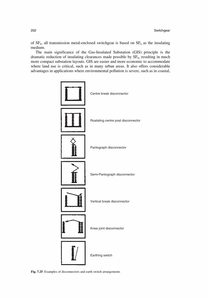
of SF6, all transmission metal-enclosed switchgear is based on SF6 as the insulatingmedium.
The main significance of the Gas-Insulated Substation (GIS) principle is the dramatic reduction of insulating clearances made possible by SF6, resulting in muchmore compact substation layouts. GIS are easier and more economic to accommodatewhere land use is critical, such as in many urban areas. It also offers considerableadvantages in applications where environmental pollution is severe, such as in coastal,
202 Switchgear
Centre break disconnector
Roatating centre post disconnector
Pantograph disconnector
Semi-Pantograph disconnector
Vertical break disconnector
Knee joint disconnector
Earthing switch
Fig. 7.25 Examples of disconnectors and earth switch arrangements
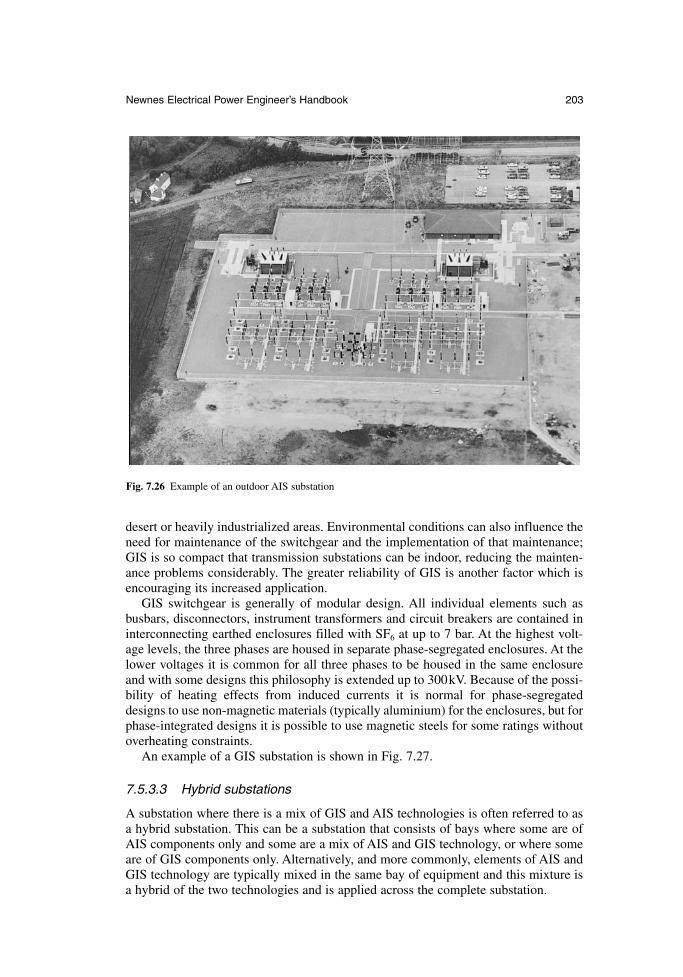
desert or heavily industrialized areas. Environmental conditions can also influence theneed for maintenance of the switchgear and the implementation of that maintenance;GIS is so compact that transmission substations can be indoor, reducing the mainten-ance problems considerably. The greater reliability of GIS is another factor which isencouraging its increased application.
GIS switchgear is generally of modular design. All individual elements such as busbars, disconnectors, instrument transformers and circuit breakers are contained ininterconnecting earthed enclosures filled with SF6 at up to 7 bar. At the highest volt-age levels, the three phases are housed in separate phase-segregated enclosures. At thelower voltages it is common for all three phases to be housed in the same enclosureand with some designs this philosophy is extended up to 300kV. Because of the possi-bility of heating effects from induced currents it is normal for phase-segregateddesigns to use non-magnetic materials (typically aluminium) for the enclosures, but forphase-integrated designs it is possible to use magnetic steels for some ratings withoutoverheating constraints.
An example of a GIS substation is shown in Fig. 7.27.
7.5.3.3 Hybrid substations
A substation where there is a mix of GIS and AIS technologies is often referred to asa hybrid substation. This can be a substation that consists of bays where some are ofAIS components only and some are a mix of AIS and GIS technology, or where someare of GIS components only. Alternatively, and more commonly, elements of AIS andGIS technology are typically mixed in the same bay of equipment and this mixture isa hybrid of the two technologies and is applied across the complete substation.
Newnes Electrical Power Engineer’s Handbook 203
Fig. 7.26 Example of an outdoor AIS substation
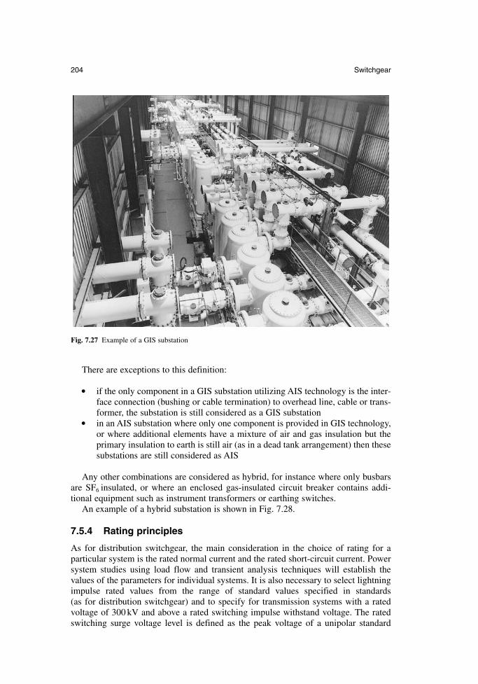
There are exceptions to this definition:
if the only component in a GIS substation utilizing AIS technology is the inter-face connection (bushing or cable termination) to overhead line, cable or trans-former, the substation is still considered as a GIS substation
in an AIS substation where only one component is provided in GIS technology,or where additional elements have a mixture of air and gas insulation but theprimary insulation to earth is still air (as in a dead tank arrangement) then thesesubstations are still considered as AIS
Any other combinations are considered as hybrid, for instance where only busbarsare SF6 insulated, or where an enclosed gas-insulated circuit breaker contains addi-tional equipment such as instrument transformers or earthing switches.
An example of a hybrid substation is shown in Fig. 7.28.
7.5.4 Rating principles
As for distribution switchgear, the main consideration in the choice of rating for a particular system is the rated normal current and the rated short-circuit current. Powersystem studies using load flow and transient analysis techniques will establish the values of the parameters for individual systems. It is also necessary to select lightningimpulse rated values from the range of standard values specified in standards (as for distribution switchgear) and to specify for transmission systems with a ratedvoltage of 300 kV and above a rated switching impulse withstand voltage. The ratedswitching surge voltage level is defined as the peak voltage of a unipolar standard
204 Switchgear
Fig. 7.27 Example of a GIS substation
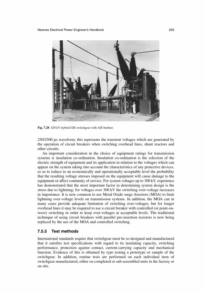
250/2500 µs waveform; this represents the transient voltages which are generated bythe operation of circuit breakers when switching overhead lines, shunt reactors andother circuits.
An important consideration in the choice of equipment ratings for transmission systems is insulation co-ordination. Insulation co-ordination is the selection of theelectric strength of equipment and its application in relation to the voltages which canappear on the system taking into account the characteristics of any protective devices,so as to reduce to an economically and operationally acceptable level the probabilitythat the resulting voltage stresses imposed on the equipment will cause damage to theequipment or affect continuity of service. For system voltages up to 300 kV, experiencehas demonstrated that the most important factor in determining system design is thestress due to lightning; for voltages over 300 kV the switching over-voltage increasesin importance. It is now common to use Metal Oxide surge Arrestors (MOA) to limitlightning over-voltage levels on transmission systems. In addition, the MOA can inmany cases provide adequate limitation of switching over-voltages, but for longeroverhead lines it may be required to use a circuit breaker with controlled (or point-on-wave) switching in order to keep over-voltages at acceptable levels. The traditionaltechnique of using circuit breakers with parallel pre-insertion resistors is now beingreplaced by the use of the MOA and controlled switching.
7.5.5 Test methods
International standards require that switchgear must be so designed and manufacturedthat it satisfies test specifications with regard to its insulating capacity, switching performance, protection against contact, current-carrying capacity and mechanicalfunction. Evidence of this is obtained by type testing a prototype or sample of theswitchgear. In addition, routine tests are performed on each individual item ofswitchgear manufactured, either on completed or sub-assembled units in the factory oron site.
Newnes Electrical Power Engineer’s Handbook 205
Fig. 7.28 420 kV hybrid-GIS switchgear with AIS busbars
Type tests are performed on transmission switchgear in a similar manner to thoseapplied to distribution switchgear (see section 7.4.4), but because of the difference inrated values, the necessary test values, the test equipment and techniques differ indetail. Some tests which are specific to transmission switchgear are as follows:
dielectric tests. In addition to lightning impulse and power frequency tests it is necessary to perform switching impulse tests for equipment with a ratedvoltage above 300 kV.
short-circuit and switching tests. The test parameters for transmission equip-ment involve much higher energy requirements than for distribution equipment,so special techniques have been developed over the years. To provide the highvoltage and high currents needed for transmission switchgear, it is usual to provide a ‘synthetic’ test source where the high voltage and high currents areprovided in the same test from different sources.
Routine tests are performed on all switchgear units or sub-assemblies to ensure thatthe performance of the factory-built unit will match that of the type-tested unit. The AIS is normally fully assembled in the factory and routine tested as a completefunctioning unit. Routine tests will include mechanical operations to check operatingcharacteristics, resistance checks of current-carrying paths, tests on control and auxil-iary circuits and power-frequency withstand tests to verify insulation quality. For GIS,particularly at higher voltage levels, it is not practical to assemble fully a completeinstallation in the factory. Therefore sub-assemblies of GIS or transportable assembliesare individually tested prior to shipment; for GIS at 145 kV or 245 kV this mightinvolve a complete ‘bay’ or circuit of equipment, but at 420 kV or 550 kV the size of the equipment dictates that only sub-assemblies can be transported to site as a unit.Tests on transportable assemblies include power-frequency withstand with partial dis-charge detection, verification of gas tightness, mechanical operations and main circuitresistance.
7.5.6 Commissioning and maintenance
Due to the size of transmission switchgear it is necessary to transport the equipmentto site in sub-assemblies and then to re-assemble to complete switchgear on site. This procedure is more extensive than for distribution switchgear and it results in moreelaborate commissioning tests.
After routine testing at the factory, AIS is dismantled into sub-assemblies for transport to site and then re-assembled at the substation. A short series of operationaland functional checks are performed before the equipment is put into service.
Site commissioning procedures for GIS are more elaborate than for AIS, since GIScan be particularly sensitive to assembly defects or to particulate contamination;because of the small electrical clearances made possible by SF6, it is essential that allparticulate contamination down to the size of about 1mm is excluded from the equip-ment. For these reasons extensive power-frequency withstand tests are performed onsite on the completed installation. The requirements for commissioning of GIS arecovered in IEC 62271-203.
Modern designs of transmission switchgear are becoming simpler and inherentlymore reliable, with reduced maintenance requirements. The traditional preventivemaintenance approach, with maintenance performed at prescribed intervals irrespec-tive of the condition of the switchgear, is being replaced by predictive maintenance in
206 Switchgear
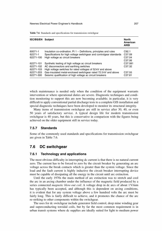
which maintenance is needed only when the condition of the equipment warrants intervention or where operational duties are severe. Diagnostic techniques and condi-tion monitoring to support this are now becoming available; in particular, it is very difficult to apply conventional partial discharge tests to a complete GIS installation andspecial diagnostic techniques have been developed to monitor its structural integrity.
Many items of transmission switchgear are still in service after 30, 40, or even 50 years of satisfactory service. A typical design life for modern transmissionswitchgear is 40 years, but this is conservative in comparison with the figures beingachieved on the older equipment still in service today.
7.5.7 Standards
Some of the commonly used standards and specifications for transmission switchgearare given in Table 7.6.
7.6 DC switchgear
7.6.1 Technology and applications
The most obvious difficulty in interrupting dc current is that there is no natural currentzero. The current has to be forced to zero by the circuit breaker by generating an arcvoltage across the break contacts which is greater than the system voltage. Since theload and the fault current is highly inductive the circuit breaker interrupting devicemust be capable of dissipating all the energy in the circuit until arc extinction.
Until the early 1970s the main method of arc extinction was to stretch and cool the arc in an arcing chamber under the influence of the magnetic field produced by aseries connected magnetic blow-out coil. A voltage drop in dc arcs of about 1V/mmhas typically been accepted, and although this is dependent on arcing conditions, it is evident that for any system voltage above a few hundred volts the arc must befairly long. This is fairly difficult to achieve, and it promotes the chance of the arc re-striking to other components within the switchgear.
The uses for dc switchgear include generator field control, deep mine winding gearand superconducting toroidal coils, but by far the most common requirement is inurban transit systems where dc supplies are ideally suited for light to medium power
Newnes Electrical Power Engineer’s Handbook 207
Table 7.6 Standards and specifications for transmission switchgear
IEC/BS/EN Subject NorthAmericanANSI
60071-1 Insulation co-ordination. Pt 1 – Definitions, principles and rules C92.162271-1 Specifications for high voltage switchgear and controlgear standards C37.0962271-100 High voltage ac circuit breakers C37.04
C37.0662271-101 Synthetic testing of high voltage ac circuit breakers C37.08162271-102 AC disconnectors and earthing switches C37.3262271-103 High voltage switches for rated voltages of 52 kV and above62271-203 Gas-insulated metal-enclosed switchgear rated 72.5 kV and above C37.5562271-300 Seismic qualification of high voltage ac circuit breakers C37.81
requirements. The majority of systems operate on supply voltages ranging from 650 Vto 1500 V with a few inter-city routes using 3000 V.
Urban dc rail systems can be categorized as rapid transit systems or light rail systems.An underground or suburban railway generally using large rolling stock such as the
London Underground is typically described as a rapid transit system. Such systemsrequire high normal current, high fault-rated dc circuit breakers because of the largeload currents drawn on start-up of the rolling stock and the low impedance of the trackpower supply connections. In order to limit the let-through current during a fault, andthereby protect the ac/dc conversion equipment, high-speed dc circuit breakers arenearly always specified for this type of system. Typical ratings for use in rapid transitsystems are 750 V, 6000 A rectifier circuit breakers and 4000 A track feeder circuitbreakers with a maximum fault interrupting rating of 125 kA at 900 V.
A light rail system is typically a tram system, with or without track, using an over-head catenary–pantograph supply. Switchgear ratings are lower with typical ratings of 750V, 2000A for rectifier breakers and 1250A for track feeder breakers, with amaximum fault interrupt rating of 50 kA, 900V. The circuit breakers used are gener-ally defined as semi-high speed.
7.6.2 Semiconductor circuit breakers
Semiconductors have been considered as a potential advance in the field of dc circuitbreakers for many years. The speed of operation far exceeds the capability of conven-tional mechanical circuit breakers and if the short-circuit current can be detected rapidly a semiconductor circuit breaker could be capable of switching the circuit infractions of a millisecond. This would limit the let-through fault current to a smallervalue with less possibility of damage to equipment. Semiconductor switches are capable of interrupting large short circuit currents on traction dc power supplies, butthey are unable alone to absorb and dissipate all the fault energy.
One method involves a forced commutation circuit in parallel with the semicon-ductor, providing a low impedance path into which the fault current is temporarilydiverted. This creates a current zero in the semiconductor switch circuit allowing it toturn off. Other methods such as series-resonant commutation can be used but in eachcase the high reverse voltage caused by rapid turn off of a highly inductive circuit must be limited, otherwise dc equipment will be damaged. This can be achieved usinga surge arrester or capacitor within the circuit breaker to absorb the energy or by circulating the energy around the fault circuit using a free-wheel diode.
Semiconductor circuit breakers are not widely used for three main reasons:
high forward conduction losses due to forward volt drop of the semiconductorjunction and the high current requirement of dc circuit breakers
isolation when the circuit breaker is switched off is reliant upon semiconductordielectric strength
the limitation to the speed of operation is the detection time of the protectiondevice. It is not possible to devise a protection relay that can operate rapidlyenough to reap the full benefits of the semiconductor switch and to reliably discriminate between all types of evolving faults and normal transient load conditions.
The use of a mechanical switch in parallel with the semiconductor eliminates theforward conduction loss and a series isolating switch operating after fault clearance
208 Switchgear
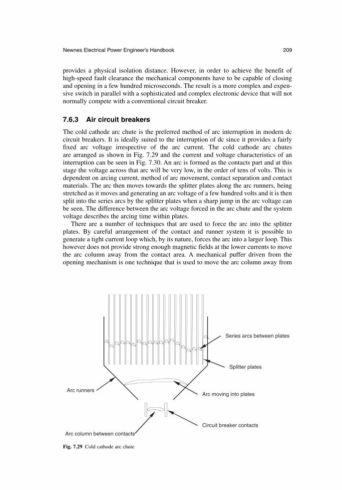
provides a physical isolation distance. However, in order to achieve the benefit of high-speed fault clearance the mechanical components have to be capable of closingand opening in a few hundred microseconds. The result is a more complex and expen-sive switch in parallel with a sophisticated and complex electronic device that will notnormally compete with a conventional circuit breaker.
7.6.3 Air circuit breakers
The cold cathode arc chute is the preferred method of arc interruption in modern dccircuit breakers. It is ideally suited to the interruption of dc since it provides a fairlyfixed arc voltage irrespective of the arc current. The cold cathode arc chutes are arranged as shown in Fig. 7.29 and the current and voltage characteristics of aninterruption can be seen in Fig. 7.30. An arc is formed as the contacts part and at thisstage the voltage across that arc will be very low, in the order of tens of volts. This isdependent on arcing current, method of arc movement, contact separation and contactmaterials. The arc then moves towards the splitter plates along the arc runners, beingstretched as it moves and generating an arc voltage of a few hundred volts and it is thensplit into the series arcs by the splitter plates when a sharp jump in the arc voltage canbe seen. The difference between the arc voltage forced in the arc chute and the systemvoltage describes the arcing time within plates.
There are a number of techniques that are used to force the arc into the splitterplates. By careful arrangement of the contact and runner system it is possible to generate a tight current loop which, by its nature, forces the arc into a larger loop. Thishowever does not provide strong enough magnetic fields at the lower currents to movethe arc column away from the contact area. A mechanical puffer driven from the opening mechanism is one technique that is used to move the arc column away from
Newnes Electrical Power Engineer’s Handbook 209
Circuit breaker contacts
Arc column between contacts
Arc moving into plates
Series arcs between plates
Splitter plates
Arc runners
Fig. 7.29 Cold cathode arc chute
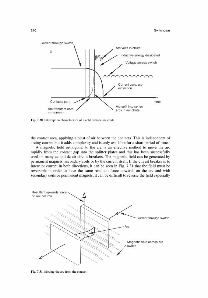
the contact area, applying a blast of air between the contacts. This is independent ofarcing current but it adds complexity and is only available for a short period of time.
A magnetic field orthogonal to the arc is an effective method to move the arc rapidly from the contact gap into the splitter plates and this has been successfully used on many ac and dc air circuit breakers. The magnetic field can be generated bypermanent magnets, secondary coils or by the current itself. If the circuit breaker is tointerrupt current in both directions, it can be seen in Fig. 7.31 that the field must bereversible in order to have the same resultant force upwards on the arc and with secondary coils or permanent magnets, it can be difficult to reverse the field especially
210 Switchgear
Voltage across switch
Current through switch
time
Arc volts in chute
Contacts part
Arc transfers onto arc runners
Arc split into series arcs in arc chute
Current zero, arc extinction
Inductive energy dissipated
Fig. 7.30 Interruption characterstics of a cold cathode arc chute
Arc
Current through switch
Resultant upwards force on arc column
Magnetic field across arcswitch
Fig. 7.31 Moving the arc from the contact
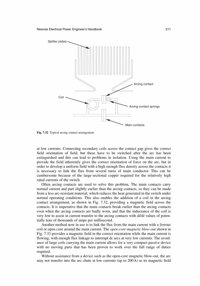
at low currents. Connecting secondary coils across the contact gap gives the correctfield orientation of field, but these have to be switched after the arc has been extinguished and this can lead to problems in isolation. Using the main current to provide the field inherently gives the correct orientation of force on the arc, but inorder to develop a uniform field with a high enough flux density across the contacts itis necessary to link the flux from several turns of main conductor. This can be cumbersome because of the large-sectional copper required for the relatively highrated currents of the switch.
Often arcing contacts are used to solve this problem. The main contacts carry normal current and part slightly earlier than the arcing contacts, so they can be madefrom a less arc-resistant material, which reduces the heat generated in the switch undernormal operating conditions. This also enables the addition of a coil in the arcing contact arrangement, as shown in Fig. 7.32, providing a magnetic field across the contacts. It is imperative that the main contacts break earlier than the arcing contactseven when the arcing contacts are badly worn, and that the inductance of the coil isvery low to assist in current transfer to the arcing contacts with dI/dt values of poten-tially tens of thousands of amps per millisecond.
Another method now in use is to link the flux from the main current with a ferrouscoil or open core around the main current. The open-core magnetic blow-out shown inFig. 7.33 provides a magnetic field in the correct orientation while the main current isflowing, with enough flux linkage to interrupt dc arcs at very low currents. The avoid-ance of large coils carrying the main current allows for a very compact passive devicewith no moving parts that has been proven to work over the full range of dutiesrequired.
Without assistance from a device such as the open-core magnetic blow-out, the arcmay not transfer into the arc chute at low currents (up to 200A) as its magnetic field
Newnes Electrical Power Engineer’s Handbook 211
Main contacts
Arcing contact springs
Arcing contact
Splitter plates
Coil
Fig. 7.32 Typical arcing contact arrangement
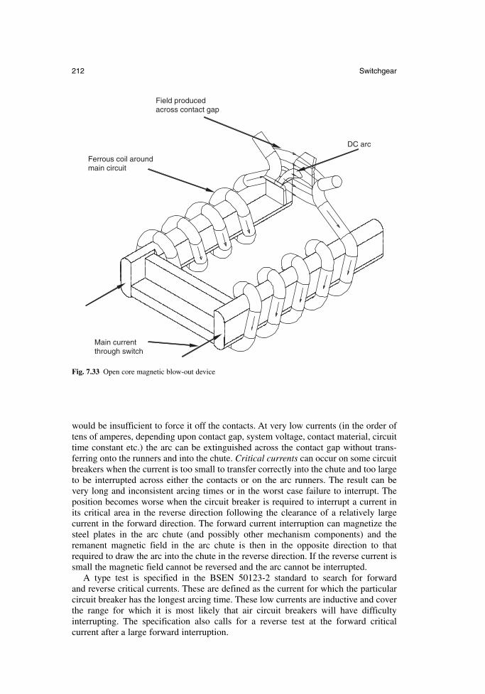
would be insufficient to force it off the contacts. At very low currents (in the order oftens of amperes, depending upon contact gap, system voltage, contact material, circuittime constant etc.) the arc can be extinguished across the contact gap without trans-ferring onto the runners and into the chute. Critical currents can occur on some circuitbreakers when the current is too small to transfer correctly into the chute and too largeto be interrupted across either the contacts or on the arc runners. The result can be very long and inconsistent arcing times or in the worst case failure to interrupt. Theposition becomes worse when the circuit breaker is required to interrupt a current inits critical area in the reverse direction following the clearance of a relatively large current in the forward direction. The forward current interruption can magnetize thesteel plates in the arc chute (and possibly other mechanism components) and the remanent magnetic field in the arc chute is then in the opposite direction to thatrequired to draw the arc into the chute in the reverse direction. If the reverse current issmall the magnetic field cannot be reversed and the arc cannot be interrupted.
A type test is specified in the BSEN 50123-2 standard to search for forward and reverse critical currents. These are defined as the current for which the particularcircuit breaker has the longest arcing time. These low currents are inductive and coverthe range for which it is most likely that air circuit breakers will have difficulty interrupting. The specification also calls for a reverse test at the forward critical current after a large forward interruption.
212 Switchgear
DC arc
Field produced across contact gap
Main current through switch
Ferrous coil around main circuit
Fig. 7.33 Open core magnetic blow-out device
7.6.4 DC traction fault duties
DC circuit breakers are classified according to their characteristics during fault inter-ruption. Some common requirements are highlighted in the circuit breaker designations:
very high speed current limiting circuit breakers, V high speed current limiting circuit breakers, H semi-high speed circuit breakers, S
Type V and type H circuit breakers are also described as current-limiting circuitbreakers because they have a break time which is sufficiently short to prevent the short-circuit current reaching the peak value it would have attained without interruption.Very high speed circuit breakers have a break time no greater than 4ms, irrespectiveof other parameters of the circuit. This speed of operation is limited to semiconductorcircuit breakers and hybrid circuit breakers that are a combination of semiconductorand mechanical switches. High speed circuit breakers have an opening time no greaterthan 5ms and a total break time not greater than 20ms when the current to be inter-rupted has a sustained value of at least 7 times the circuit breaker setting and dI/dt isgreater than or equal to 5kA/ms. Type S circuit breakers provide assured current inter-ruption, but current limitation may not take place. The circuit breaker in most commonuse is the type H because of its ability to operate quickly and limit damaging let-through fault current at an affordable price.
The specification of the circuit breaker type is decided by the fault levels the system can generate, and the types of fault are characterized by their location in thetraction system.
The functions for which the dc circuit breaker can be used within a standard trac-tion system are:
interconnector circuit breaker, I (also called bus-section or section circuitbreaker)
line feeder circuit breaker, L rectifier circuit breaker, R
These can have different requirements, and current interruption direction can alsobe specified, as well as direct-acting overload release direction. It can be advantageousfor discrimination purposes to specify the direction in which the release operates, to ensure that only the breaker feeding a fault opens and that supply is maintained elsewhere. Current interruption in both directions is necessary unless it can be shownthat there are no circumstances under which a circuit breaker can be opened when thecurrent is flowing in an opposite direction.
7.6.5 DC traction protection
The power supplied through the switchgear fluctuates as trains start, accelerate andregenerate, and one or more trains can be travelling or transferring onto different sections of track. To discriminate between a fault and such a variety of load conditionsrequires a sophisticated and well co-ordinated protection system. Depending upon thepoint in the system at which the fault occurs, it is quite common for the magnitude ofthe current to be less than that flowing due to the traction load.
While short-circuit currents on the dc traction supply can be large and damaging toequipment on the dc supply, the value of the short-circuit current on the ac supply due
Newnes Electrical Power Engineer’s Handbook 213
to dc faults could be fairly small. Also, ac switchgear protection operating and faultclearance times may be too long to protect the ac/dc conversion equipment effectively.The dc circuit breakers and the protection system must therefore be fast-operating.Electronic and/or electromagnetic protection relays are always used on modern dcswitchboards, the current being sensed by a shunt or other transducer and the circuitbreaker being tripped by the shunt trip coil. As the last line of defence, it is commonpractice to specify a high-set direct acting instantaneous series overcurrent releasewithin the circuit breaker.
In order to minimize the risk of an undetected fault condition the following typesof protection have been developed.
Direct-acting overcurrent protection: This is incorporated into the circuitbreaker, the device directly tripping the breaker through a mechanical linkageor magnetic circuit. The purpose is to provide protection for overload condi-tions and high-speed operation under high-current faults. In most networks thedevice will not provide discrimination between normal load conditions and lowlevel or distant faults. Line feeder and rectifier circuit breakers utilise this formof protection.
Rate of rise protection (dI/dt): This is now the most commonly used software-driven protection system in traction applications. As it measures the rate of riseof current through the switchgear it is able to react rapidly during the initialincrease of current at the on-set of a fault before the current reaches a large,damaging value. When properly developed it is effective in discriminatingbetween distant faults and normal train starting and accelerating currents, but adetailed knowledge of the system is imperative for correct setting of the relay.The settings are chosen to ensure that the device will not trip on the most severetrain starting condition but will trip under distant fault conditions. An extensionof this principle is DELTA I (∆I) protection, in which the initial dI/dt triggers acurrent measurement. After a set time, the change in current is measured and if it exceeds the set value (determined from the most onerous train starting current) a trip is issued. The dI/dt setting can be lower than that for standard rateof rise protection, offering better sensitivity for distant fault detection. In addi-tion the time delay setting can be reduced to give more sensitive protection forless distant faults.
Undervoltage protection: Relays can be used to monitor a reduced track voltageunder fault or load conditions at the substation and at points in between. The sys-tem may be used for both single and double-end fed systems, pilot wires beingused to trip the appropriate circuit breaker or breakers. In order to provide dis-crimination and to allow circuit breakers to be closed onto tracks at a reducedvoltage, undervoltage protection system needs to incorporate a time delay. Thismust be of the order of 100 ms, which renders this type of protection inadequatefor close-up faults. As the system measures only voltage it cannot be used toprovide directional discrimination.
Falling-voltage impedance protection: Impedance protection is an extension ofthe falling-voltage principle in which track current is also monitored. Theimpedance of a track section seen from the circuit breaker is the ratio of trackvoltage to the current flowing through the circuit breaker. An impedance value,normally equal to the loop impedance of the whole track section provides thesetting value. The presence of a fault closer to the substation will lead to the V/Ibeing reduced and if it falls below the set impedance value, a trip command can
214 Switchgear
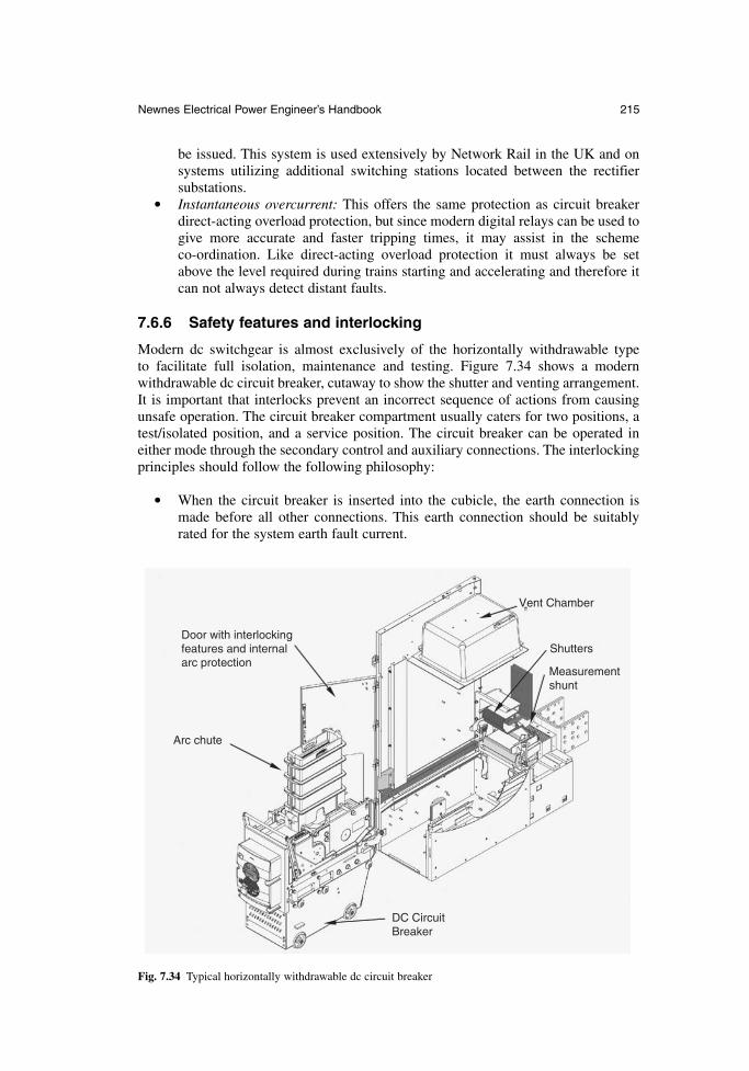
be issued. This system is used extensively by Network Rail in the UK and onsystems utilizing additional switching stations located between the rectifiersubstations.
Instantaneous overcurrent: This offers the same protection as circuit breakerdirect-acting overload protection, but since modern digital relays can be used togive more accurate and faster tripping times, it may assist in the scheme co-ordination. Like direct-acting overload protection it must always be setabove the level required during trains starting and accelerating and therefore itcan not always detect distant faults.
7.6.6 Safety features and interlocking
Modern dc switchgear is almost exclusively of the horizontally withdrawable type to facilitate full isolation, maintenance and testing. Figure 7.34 shows a modern withdrawable dc circuit breaker, cutaway to show the shutter and venting arrangement.It is important that interlocks prevent an incorrect sequence of actions from causingunsafe operation. The circuit breaker compartment usually caters for two positions, atest/isolated position, and a service position. The circuit breaker can be operated ineither mode through the secondary control and auxiliary connections. The interlockingprinciples should follow the following philosophy:
When the circuit breaker is inserted into the cubicle, the earth connection ismade before all other connections. This earth connection should be suitablyrated for the system earth fault current.
Newnes Electrical Power Engineer’s Handbook 215
Arc chute
DC Circuit Breaker
Shutters
Vent Chamber
Door with interlocking features and internal arc protection
Measurement shunt
Fig. 7.34 Typical horizontally withdrawable dc circuit breaker
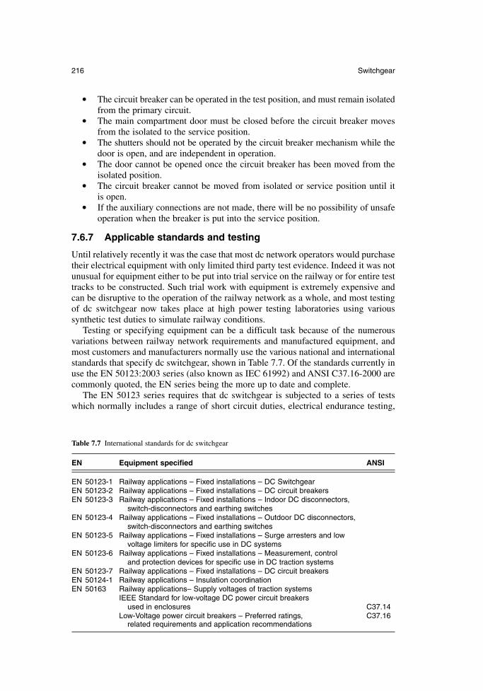
The circuit breaker can be operated in the test position, and must remain isolatedfrom the primary circuit.
The main compartment door must be closed before the circuit breaker movesfrom the isolated to the service position.
The shutters should not be operated by the circuit breaker mechanism while thedoor is open, and are independent in operation.
The door cannot be opened once the circuit breaker has been moved from theisolated position.
The circuit breaker cannot be moved from isolated or service position until it is open.
If the auxiliary connections are not made, there will be no possibility of unsafeoperation when the breaker is put into the service position.
7.6.7 Applicable standards and testing
Until relatively recently it was the case that most dc network operators would purchasetheir electrical equipment with only limited third party test evidence. Indeed it was notunusual for equipment either to be put into trial service on the railway or for entire testtracks to be constructed. Such trial work with equipment is extremely expensive andcan be disruptive to the operation of the railway network as a whole, and most testingof dc switchgear now takes place at high power testing laboratories using various synthetic test duties to simulate railway conditions.
Testing or specifying equipment can be a difficult task because of the numerousvariations between railway network requirements and manufactured equipment, andmost customers and manufacturers normally use the various national and internationalstandards that specify dc switchgear, shown in Table 7.7. Of the standards currently inuse the EN 50123:2003 series (also known as IEC 61992) and ANSI C37.16-2000 arecommonly quoted, the EN series being the more up to date and complete.
The EN 50123 series requires that dc switchgear is subjected to a series of testswhich normally includes a range of short circuit duties, electrical endurance testing,
216 Switchgear
Table 7.7 International standards for dc switchgear
EN Equipment specified ANSI
EN 50123-1 Railway applications – Fixed installations – DC SwitchgearEN 50123-2 Railway applications – Fixed installations – DC circuit breakersEN 50123-3 Railway applications – Fixed installations – Indoor DC disconnectors,
switch-disconnectors and earthing switchesEN 50123-4 Railway applications – Fixed installations – Outdoor DC disconnectors,
switch-disconnectors and earthing switchesEN 50123-5 Railway applications – Fixed installations – Surge arresters and low
voltage limiters for specific use in DC systemsEN 50123-6 Railway applications – Fixed installations – Measurement, control
and protection devices for specific use in DC traction systemsEN 50123-7 Railway applications – Fixed installations – DC circuit breakersEN 50124-1 Railway applications – Insulation coordinationEN 50163 Railway applications– Supply voltages of traction systems
IEEE Standard for low-voltage DC power circuit breakers used in enclosures C37.14
Low-Voltage power circuit breakers – Preferred ratings, C37.16related requirements and application recommendations
temperature rise testing, dielectric testing, ingress protection and mechanicalendurance testing. Each duty or type of test is subject to variation depending on the type of circuit breaker to be tested, the system voltage and the characteristics of thecircuit that is being switched. In particular a considerable amount of testing is undertaken to assess performance under the various fault conditions that may arise atlow or reverse currents.
From an operator’s perspective, testing at maximum energy levels is particularlyimportant because the test can be used to simulate extended electrical endurance causing considerable wear to both the circuit breaker contacts and arc chute.
As with much railway equipment dc switchgear is typically located in remote locations of restricted size, requiring special consideration of mechanical reliabilityand effect of temperature rise within the equipment. Circuit breakers can be subjectedto extended mechanical endurance tests of over 50000 operations without any mainte-nance, often including variations in temperature, humidity and control system voltage.Temperature rise testing is normally undertaken on complete switchgear assemblieswith conditions as close to those in service as possible, particularly if ventilation isrestricted. Such testing sometimes includes operator-defined overload cycles to simulatethe effects of increased numbers of trains on the railway.
References
7A. Ryan, H.M. (ed), High voltage engineering and testing, Peter Peregrinus, 1994.7B. Ryan, H.M. and Jones, G.R. SF6 switchgear, Peter Peregrinus, 1989.7C. Flurscheim, C.H. (ed), Power circuit breaker theory and design, Peter Peregrinus, 1985.
Newnes Electrical Power Engineer’s Handbook 217

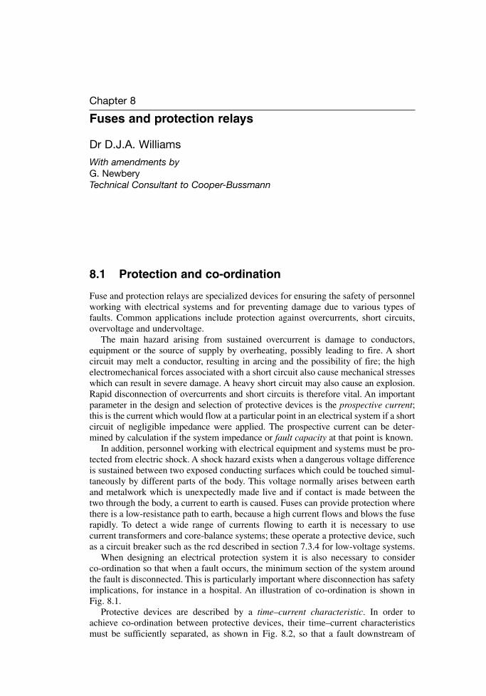
Chapter 8
Fuses and protection relays
Dr D.J.A. Williams
With amendments byG. NewberyTechnical Consultant to Cooper-Bussmann
8.1 Protection and co-ordination
Fuse and protection relays are specialized devices for ensuring the safety of personnelworking with electrical systems and for preventing damage due to various types offaults. Common applications include protection against overcurrents, short circuits,overvoltage and undervoltage.
The main hazard arising from sustained overcurrent is damage to conductors,equipment or the source of supply by overheating, possibly leading to fire. A short circuit may melt a conductor, resulting in arcing and the possibility of fire; the highelectromechanical forces associated with a short circuit also cause mechanical stresseswhich can result in severe damage. A heavy short circuit may also cause an explosion.Rapid disconnection of overcurrents and short circuits is therefore vital. An importantparameter in the design and selection of protective devices is the prospective current;this is the current which would flow at a particular point in an electrical system if a shortcircuit of negligible impedance were applied. The prospective current can be deter-mined by calculation if the system impedance or fault capacity at that point is known.
In addition, personnel working with electrical equipment and systems must be pro-tected from electric shock. A shock hazard exists when a dangerous voltage differenceis sustained between two exposed conducting surfaces which could be touched simul-taneously by different parts of the body. This voltage normally arises between earthand metalwork which is unexpectedly made live and if contact is made between thetwo through the body, a current to earth is caused. Fuses can provide protection wherethere is a low-resistance path to earth, because a high current flows and blows the fuserapidly. To detect a wide range of currents flowing to earth it is necessary to use current transformers and core-balance systems; these operate a protective device, suchas a circuit breaker such as the rcd described in section 7.3.4 for low-voltage systems.
When designing an electrical protection system it is also necessary to consider co-ordination so that when a fault occurs, the minimum section of the system aroundthe fault is disconnected. This is particularly important where disconnection has safetyimplications, for instance in a hospital. An illustration of co-ordination is shown in Fig. 8.1.
Protective devices are described by a time–current characteristic. In order toachieve co-ordination between protective devices, their time–current characteristics must be sufficiently separated, as shown in Fig. 8.2, so that a fault downstream of
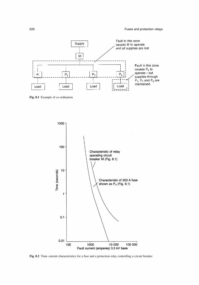
220 Fuses and protection relays
Fig. 8.1 Example of co-ordination
Fig. 8.2 Time–current characteristics for a fuse and a protection relay controlling a circuit breaker
both of them operates only the device nearest to the fault. A variety of shapes oftime–current characteristic for both fuses and protection relays are available for different applications.
Another consideration when designing electrical protection is back-up. In some circuits it is desirable to have a device, such as an mcb (see section 7.3.3) which disconnects lower overcurrents and can be reset. Higher overcurrents, which the mcbcannot disconnect without being damaged, are disconnected by an upstream fuse inseries with the mcb. This arrangement has the advantage that re-closure onto a severefault is less likely, because replacement of the fuse would be necessary in this case aswell as re-closure of the mcb. It is also possible for a protective device to fail, forexample because of mishandling. The effects of a failure can be minimized or avoidedby a back-up protective device which operates under such conditions. In Fig. 8.1, protective device M backs up each of the protective devices P. However, if M operatesas a back-up device, co-ordination is lost because all four branches of the circuit losesupply, not just the faulty branch.
8.2 Fuses
8.2.1 Principles of design and operation
A fuse consists of a replaceable part (the fuselink) and a fuse holder. Examples of fuseholders are shown in Fig. 8.3.
The simplest fuselink is a length of wire. It is mounted by screw connections in aholder which partly encloses it. When an overcurrent or short-circuit current flows, thewire starts to melt and arcing commences at various positions along it. The arc voltagecauses the current to fall and once it has fallen to zero, the arcs are extinguished. The larger the wire cross section, the larger is the current that the fuselink will carry without operating. In the UK, fuses of this type are specified for use at voltages upto 250 V and currents up to 100 A. They are known as semi-enclosed or rewireable fuses.
The most common fuselink is the cartridge type. This consists of a barrel (usuallyof ceramic) containing one or more elements which are connected at each end to capsfitted over the ends of the barrel. The arrangement is shown in Figs 8.4 and 8.5. If ahigh current breaking capacity is required, the cartridge is filled with sand of highchemical purity and controlled grain size. The entire fuselink is replaced after the fusehas operated and a fault has been disconnected. Cartridge fuses are used for a muchwider range of voltages and currents than semi-enclosed fuses.
Fuselinks can be divided into current-limiting and non-current-limiting types. A sand-filled cartridge fuselink is of the current-limiting type; when it operates, it limits the peak current to a value which is substantially lower than the prospective current. A non-current-limiting fuse, such as a semi-enclosed fuse, does not limit thecurrent significantly.
The element shown in Fig. 8.4 is a notched tape. Melting occurs first at the notcheswhen an overcurrent flows and this results in a number of controlled arcs in series. Thevoltage across each arc contributes to the total voltage across the fuse, and this totalvoltage results in the current falling to zero. Because the number of arcs is limited, thefuselink voltage should not be high enough to cause damage elsewhere in the circuit.The characteristic development of current and voltage during the operation of a fuse isshown in Fig. 8.6.
The function of the sand is to absorb energy from the arcs and to assist in quench-ing them; when a high current is disconnected, the sand around the arcs is melted.
Newnes Electrical Power Engineer’s Handbook 221
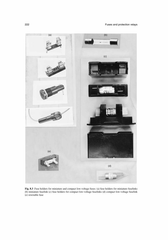
222 Fuses and protection relays
(a)
(e)
(d)
(b)
(c)
Fig. 8.3 Fuse holders for miniature and compact low-voltage fuses: (a) fuse holders for miniature fuselinks(b) miniature fuselink (c) fuse holders for compact low-voltage fuselinks (d) compact low-voltage fuselink(e) rewirable fuse
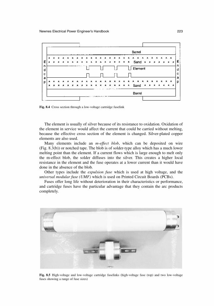
The element is usually of silver because of its resistance to oxidation. Oxidation ofthe element in service would affect the current that could be carried without melting,because the effective cross section of the element is changed. Silver-plated copperelements are also used.
Many elements include an m-effect blob, which can be deposited on wire (Fig. 8.3(b)) or notched tape. The blob is of solder-type alloy which has a much lowermelting point than the element. If a current flows which is large enough to melt onlythe m-effect blob, the solder diffuses into the silver. This creates a higher local resistance in the element and the fuse operates at a lower current than it would havedone in the absence of the blob.
Other types include the expulsion fuse which is used at high voltage, and the universal modular fuse (UMF) which is used on Printed Circuit Boards (PCBs).
Fuses offer long life without deterioration in their characteristics or performance,and cartridge fuses have the particular advantage that they contain the arc productscompletely.
Newnes Electrical Power Engineer’s Handbook 223
Fig. 8.4 Cross section through a low-voltage cartridge fuselink
Fig. 8.5 High-voltage and low-voltage cartridge fuselinks (high-voltage fuse (top) and two low-voltagefuses showing a range of fuse sizes)
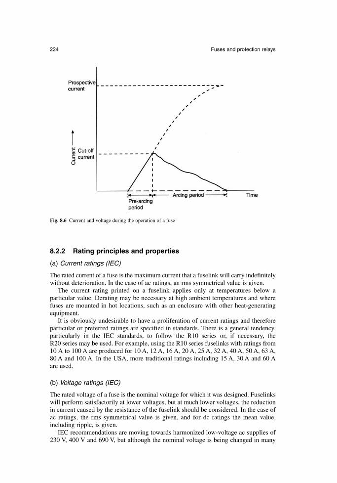
8.2.2 Rating principles and properties
(a) Current ratings (IEC)
The rated current of a fuse is the maximum current that a fuselink will carry indefinitelywithout deterioration. In the case of ac ratings, an rms symmetrical value is given.
The current rating printed on a fuselink applies only at temperatures below a particular value. Derating may be necessary at high ambient temperatures and wherefuses are mounted in hot locations, such as an enclosure with other heat-generatingequipment.
It is obviously undesirable to have a proliferation of current ratings and thereforeparticular or preferred ratings are specified in standards. There is a general tendency,particularly in the IEC standards, to follow the R10 series or, if necessary, the R20 series may be used. For example, using the R10 series fuselinks with ratings from10 A to 100 A are produced for 10 A, 12 A, 16 A, 20 A, 25 A, 32 A, 40 A, 50 A, 63 A,80 A and 100 A. In the USA, more traditional ratings including 15 A, 30 A and 60 A are used.
(b) Voltage ratings (IEC)
The rated voltage of a fuse is the nominal voltage for which it was designed. Fuselinkswill perform satisfactorily at lower voltages, but at much lower voltages, the reductionin current caused by the resistance of the fuselink should be considered. In the case ofac ratings, the rms symmetrical value is given, and for dc ratings the mean value,including ripple, is given.
IEC recommendations are moving towards harmonized low-voltage ac supplies of230 V, 400 V and 690 V, but although the nominal voltage is being changed in many
224 Fuses and protection relays
Fig. 8.6 Current and voltage during the operation of a fuse
countries it will be possible for the voltage to remain at its previous non-harmonizedlevel for several years. In Europe, the nominal voltage is 230 V, and the permitted variations will allow supplies to remain at 240 V and 220 V. Fuselinks marked 230 Vmay have been designed originally for use with higher or lower voltages, and problemsmay therefore arise when replacing fuselinks because a device manufactured for use at220 V would not be safe to use on a 240 V system. A fuselink designed for 240 V couldsafely be used at 220 V. Similar considerations apply where the voltage is changedfrom 415 V to 400 V, or 660 V to 690 V.
(c) Variations in rating principles
The IEC rating principles are used worldwide, except in North America, where UL(Underwriters Laboratory) standards apply.
The rated current to a UL standard is the minimum current required to operate thefuse after many hours, and the current that it will carry indefinitely (the IEC rated current) is approximately 80 per cent of this rating.
The voltage rating marked on a UL fuselink is the maximum voltage at which it canbe used, whereas that marked on an IEC fuselink is the nominal voltage.
These differences must be considered when replacing fuselinks, particularly in the case of miniature cartridge fuselinks which are interchangeable. In general, it ispreferable to replace a fuselink with one of the same rating from the same manu-facturer; this ensures that its characteristics are as similar as possible to those of the previous fuselink.
The IEC and UL ratings of fuse holders also differ. The IEC rating is the highestrated current of a fuselink with which it is intended to be used. A higher rating may begiven in North America, this being related to the maximum current that does not causeoverheating when a link of negligible resistance is used.
(d) Frequency ratings
Fuses are most commonly used in ac circuits with frequencies of 50 Hz or 60 Hz anda fuse designed for one of these frequencies will generally operate satisfactorily at the other. If the arc extinguishes at current zero, then the maximum arcing time on asymmetrical fault will be 10 ms at 50 Hz and 8 ms at 60 Hz.
Fuse manufacturers should be consulted about the suitability of fuses for other frequencies, which may include 17.67 Hz for some railway supplies, 400 Hz for aircraft and higher frequencies for some electronic circuits.
In dc circuits there is no current zero in the normal waveform and the fuselinksdesigned for ac may not operate satisfactorily. Separate current and voltage ratings aregiven for fuselinks tested for use in dc circuits. DC circuits can be more inductive fora given current than ac systems, and since the energy in the inductance is dissipated inthe fuse, it is necessary for the dc voltage rating to be reduced as the time constant(L/R) of a circuit increases.
(e) Breaking capacity
The breaking capacity of a fuse is the current which can be interrupted at the ratedvoltage. The required breaking capacity will depend upon the position of the fuse inthe supply system. For instance, 6 kA may be suitable for domestic and commercialapplications, but 80 kA is necessary at the secondary of a distribution transformer.
Newnes Electrical Power Engineer’s Handbook 225
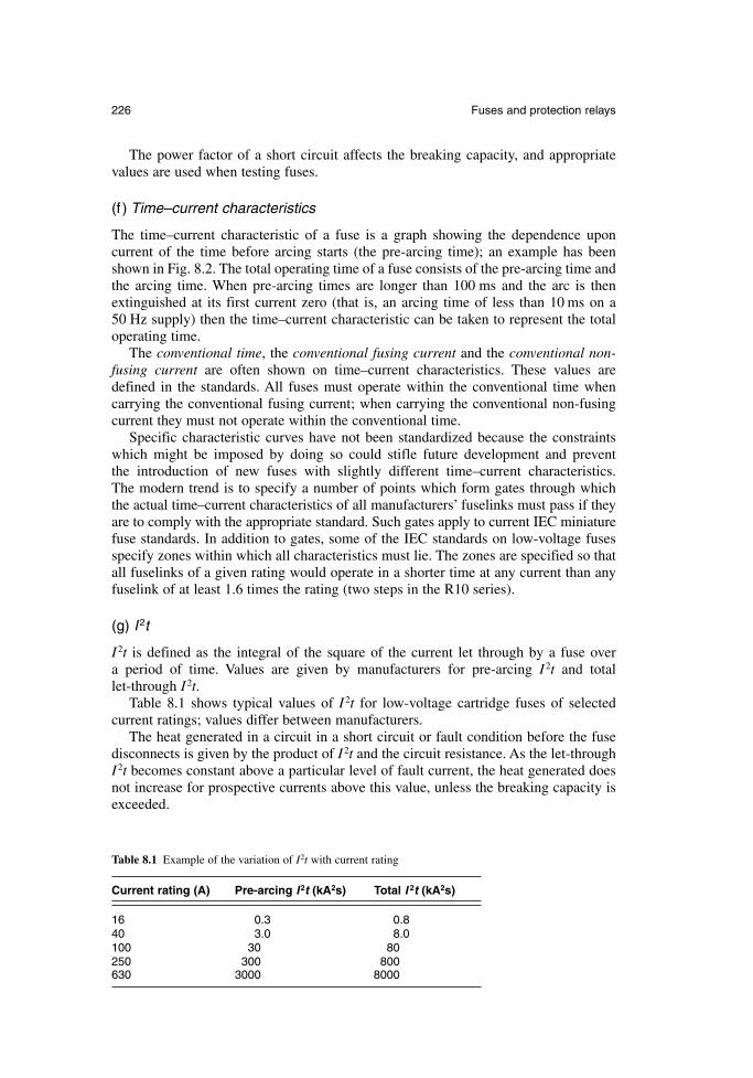
The power factor of a short circuit affects the breaking capacity, and appropriatevalues are used when testing fuses.
(f ) Time–current characteristics
The time–current characteristic of a fuse is a graph showing the dependence upon current of the time before arcing starts (the pre-arcing time); an example has beenshown in Fig. 8.2. The total operating time of a fuse consists of the pre-arcing time andthe arcing time. When pre-arcing times are longer than 100 ms and the arc is thenextinguished at its first current zero (that is, an arcing time of less than 10 ms on a 50 Hz supply) then the time–current characteristic can be taken to represent the totaloperating time.
The conventional time, the conventional fusing current and the conventional non-fusing current are often shown on time–current characteristics. These values aredefined in the standards. All fuses must operate within the conventional time when carrying the conventional fusing current; when carrying the conventional non-fusingcurrent they must not operate within the conventional time.
Specific characteristic curves have not been standardized because the constraintswhich might be imposed by doing so could stifle future development and prevent the introduction of new fuses with slightly different time–current characteristics. The modern trend is to specify a number of points which form gates through which the actual time–current characteristics of all manufacturers’ fuselinks must pass if theyare to comply with the appropriate standard. Such gates apply to current IEC miniaturefuse standards. In addition to gates, some of the IEC standards on low-voltage fusesspecify zones within which all characteristics must lie. The zones are specified so thatall fuselinks of a given rating would operate in a shorter time at any current than anyfuselink of at least 1.6 times the rating (two steps in the R10 series).
(g) I 2t
I 2t is defined as the integral of the square of the current let through by a fuse over a period of time. Values are given by manufacturers for pre-arcing I 2t and total let-through I 2t.
Table 8.1 shows typical values of I 2t for low-voltage cartridge fuses of selected current ratings; values differ between manufacturers.
The heat generated in a circuit in a short circuit or fault condition before the fusedisconnects is given by the product of I 2t and the circuit resistance. As the let-throughI 2t becomes constant above a particular level of fault current, the heat generated doesnot increase for prospective currents above this value, unless the breaking capacity isexceeded.
226 Fuses and protection relays
Table 8.1 Example of the variation of I2t with current rating
Current rating (A) Pre-arcing I 2t (kA2s) Total I 2t (kA2s)
16 0.3 0.840 3.0 8.0100 30 80250 300 800630 3000 8000
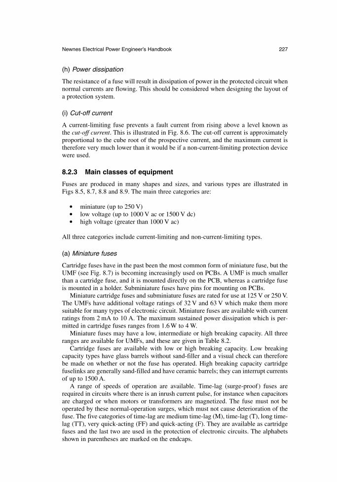
(h) Power dissipation
The resistance of a fuse will result in dissipation of power in the protected circuit whennormal currents are flowing. This should be considered when designing the layout ofa protection system.
(i) Cut-off current
A current-limiting fuse prevents a fault current from rising above a level known as the cut-off current. This is illustrated in Fig. 8.6. The cut-off current is approximatelyproportional to the cube root of the prospective current, and the maximum current istherefore very much lower than it would be if a non-current-limiting protection devicewere used.
8.2.3 Main classes of equipment
Fuses are produced in many shapes and sizes, and various types are illustrated in Figs 8.5, 8.7, 8.8 and 8.9. The main three categories are:
miniature (up to 250 V) low voltage (up to 1000 V ac or 1500 V dc) high voltage (greater than 1000 V ac)
All three categories include current-limiting and non-current-limiting types.
(a) Miniature fuses
Cartridge fuses have in the past been the most common form of miniature fuse, but theUMF (see Fig. 8.7) is becoming increasingly used on PCBs. A UMF is much smallerthan a cartridge fuse, and it is mounted directly on the PCB, whereas a cartridge fuseis mounted in a holder. Subminiature fuses have pins for mounting on PCBs.
Miniature cartridge fuses and subminiature fuses are rated for use at 125 V or 250 V.The UMFs have additional voltage ratings of 32 V and 63 V which make them moresuitable for many types of electronic circuit. Miniature fuses are available with currentratings from 2 mA to 10 A. The maximum sustained power dissipation which is per-mitted in cartridge fuses ranges from 1.6 W to 4 W.
Miniature fuses may have a low, intermediate or high breaking capacity. All threeranges are available for UMFs, and these are given in Table 8.2.
Cartridge fuses are available with low or high breaking capacity. Low breakingcapacity types have glass barrels without sand-filler and a visual check can thereforebe made on whether or not the fuse has operated. High breaking capacity cartridgefuselinks are generally sand-filled and have ceramic barrels; they can interrupt currentsof up to 1500 A.
A range of speeds of operation are available. Time-lag (surge-proof) fuses arerequired in circuits where there is an inrush current pulse, for instance when capacitorsare charged or when motors or transformers are magnetized. The fuse must not beoperated by these normal-operation surges, which must not cause deterioration of thefuse. The five categories of time-lag are medium time-lag (M), time-lag (T), long time-lag (TT), very quick-acting (FF) and quick-acting (F). They are available as cartridgefuses and the last two are used in the protection of electronic circuits. The alphabetsshown in parentheses are marked on the endcaps.
Newnes Electrical Power Engineer’s Handbook 227
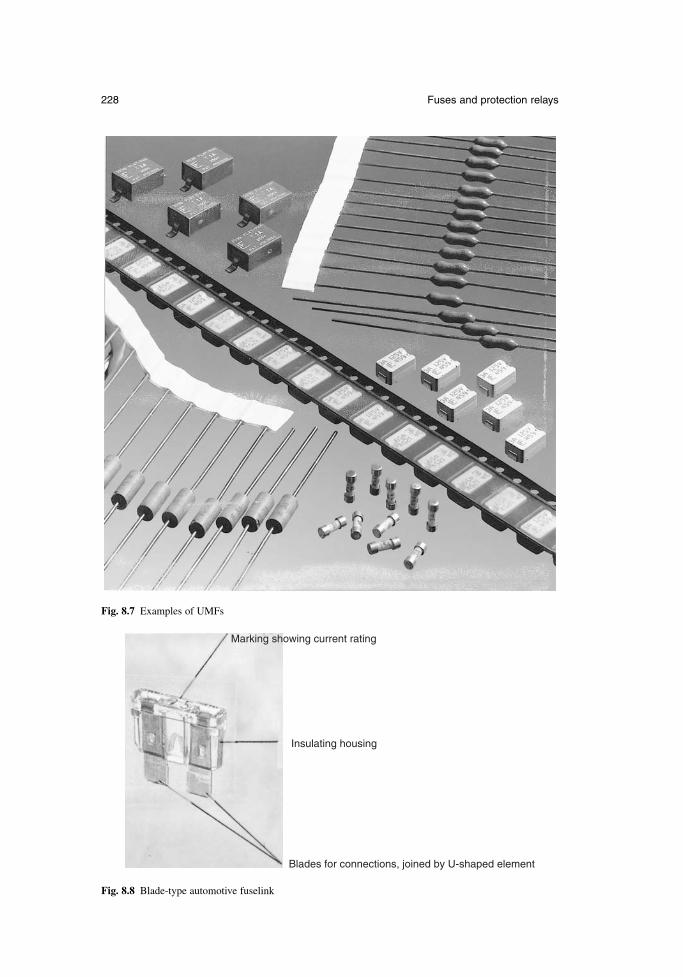
228 Fuses and protection relays
Fig. 8.7 Examples of UMFs
Insulating housing
Blades for connections, joined by U-shaped element
Marking showing current rating
Fig. 8.8 Blade-type automotive fuselink
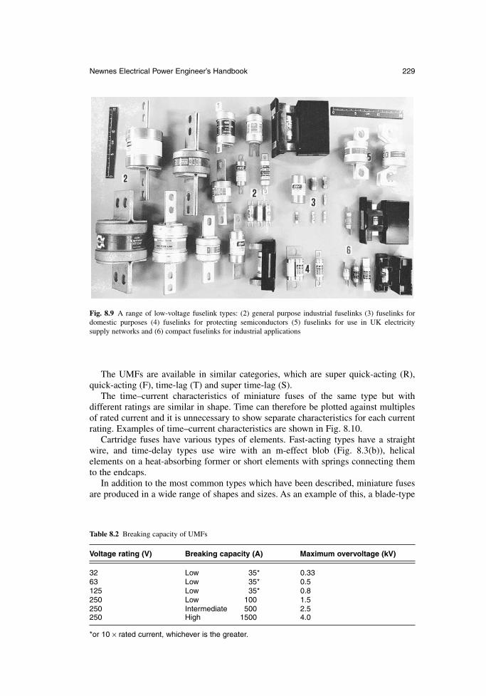
The UMFs are available in similar categories, which are super quick-acting (R),quick-acting (F), time-lag (T) and super time-lag (S).
The time–current characteristics of miniature fuses of the same type but with different ratings are similar in shape. Time can therefore be plotted against multiplesof rated current and it is unnecessary to show separate characteristics for each currentrating. Examples of time–current characteristics are shown in Fig. 8.10.
Cartridge fuses have various types of elements. Fast-acting types have a straightwire, and time-delay types use wire with an m-effect blob (Fig. 8.3(b)), helical elements on a heat-absorbing former or short elements with springs connecting themto the endcaps.
In addition to the most common types which have been described, miniature fusesare produced in a wide range of shapes and sizes. As an example of this, a blade-type
Newnes Electrical Power Engineer’s Handbook 229
Fig. 8.9 A range of low-voltage fuselink types: (2) general purpose industrial fuselinks (3) fuselinks fordomestic purposes (4) fuselinks for protecting semiconductors (5) fuselinks for use in UK electricity supply networks and (6) compact fuselinks for industrial applications
Table 8.2 Breaking capacity of UMFs
Voltage rating (V) Breaking capacity (A) Maximum overvoltage (kV)
32 Low 35* 0.3363 Low 35* 0.5125 Low 35* 0.8250 Low 100 1.5250 Intermediate 500 2.5250 High 1500 4.0
*or 10 × rated current, whichever is the greater.
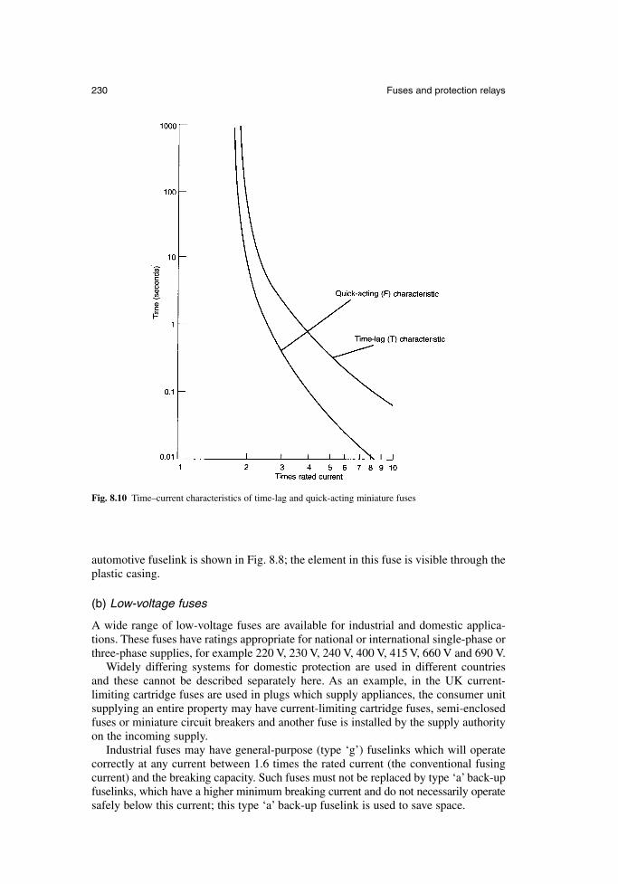
automotive fuselink is shown in Fig. 8.8; the element in this fuse is visible through theplastic casing.
(b) Low-voltage fuses
A wide range of low-voltage fuses are available for industrial and domestic applica-tions. These fuses have ratings appropriate for national or international single-phase orthree-phase supplies, for example 220 V, 230 V, 240 V, 400 V, 415 V, 660 V and 690 V.
Widely differing systems for domestic protection are used in different countries and these cannot be described separately here. As an example, in the UK current-limiting cartridge fuses are used in plugs which supply appliances, the consumer unit supplying an entire property may have current-limiting cartridge fuses, semi-enclosedfuses or miniature circuit breakers and another fuse is installed by the supply authorityon the incoming supply.
Industrial fuses may have general-purpose (type ‘g’) fuselinks which will operatecorrectly at any current between 1.6 times the rated current (the conventional fusingcurrent) and the breaking capacity. Such fuses must not be replaced by type ‘a’ back-upfuselinks, which have a higher minimum breaking current and do not necessarily operatesafely below this current; this type ‘a’ back-up fuselink is used to save space.
230 Fuses and protection relays
Fig. 8.10 Time–current characteristics of time-lag and quick-acting miniature fuses
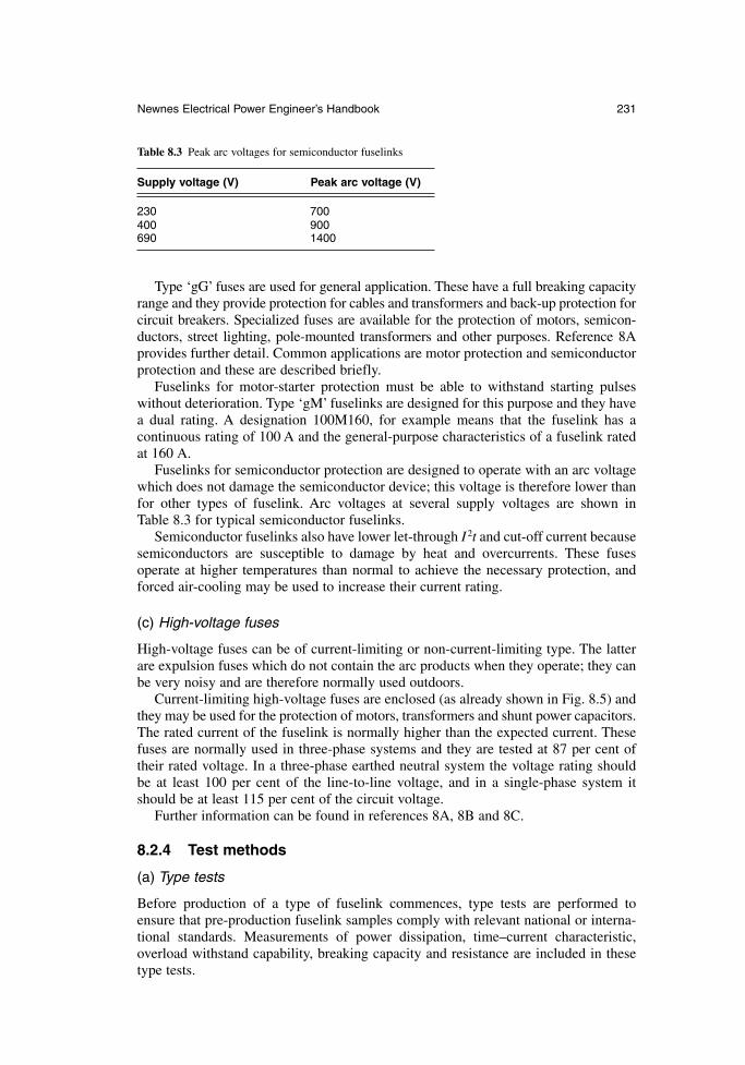
Type ‘gG’ fuses are used for general application. These have a full breaking capacityrange and they provide protection for cables and transformers and back-up protection forcircuit breakers. Specialized fuses are available for the protection of motors, semicon-ductors, street lighting, pole-mounted transformers and other purposes. Reference 8Aprovides further detail. Common applications are motor protection and semiconductorprotection and these are described briefly.
Fuselinks for motor-starter protection must be able to withstand starting pulseswithout deterioration. Type ‘gM’ fuselinks are designed for this purpose and they have a dual rating. A designation 100M160, for example means that the fuselink has a continuous rating of 100 A and the general-purpose characteristics of a fuselink ratedat 160 A.
Fuselinks for semiconductor protection are designed to operate with an arc voltagewhich does not damage the semiconductor device; this voltage is therefore lower thanfor other types of fuselink. Arc voltages at several supply voltages are shown in Table 8.3 for typical semiconductor fuselinks.
Semiconductor fuselinks also have lower let-through I 2t and cut-off current becausesemiconductors are susceptible to damage by heat and overcurrents. These fuses operate at higher temperatures than normal to achieve the necessary protection, andforced air-cooling may be used to increase their current rating.
(c) High-voltage fuses
High-voltage fuses can be of current-limiting or non-current-limiting type. The latterare expulsion fuses which do not contain the arc products when they operate; they canbe very noisy and are therefore normally used outdoors.
Current-limiting high-voltage fuses are enclosed (as already shown in Fig. 8.5) andthey may be used for the protection of motors, transformers and shunt power capacitors.The rated current of the fuselink is normally higher than the expected current. Thesefuses are normally used in three-phase systems and they are tested at 87 per cent oftheir rated voltage. In a three-phase earthed neutral system the voltage rating shouldbe at least 100 per cent of the line-to-line voltage, and in a single-phase system itshould be at least 115 per cent of the circuit voltage.
Further information can be found in references 8A, 8B and 8C.
8.2.4 Test methods
(a) Type tests
Before production of a type of fuselink commences, type tests are performed to ensure that pre-production fuselink samples comply with relevant national or interna-tional standards. Measurements of power dissipation, time–current characteristic,overload withstand capability, breaking capacity and resistance are included in thesetype tests.
Newnes Electrical Power Engineer’s Handbook 231
Table 8.3 Peak arc voltages for semiconductor fuselinks
Supply voltage (V) Peak arc voltage (V)
230 700400 900690 1400
(b) Production tests
Routine testing of many important fuse characteristics is not possible because tests,such as breaking capacity are destructive. Extensive testing in production would alsobe very costly. Fuse manufacturers therefore make production fuselinks as identical aspossible to the samples used for type testing.
The quality of fuselinks depends upon the quality of the components supplied to thefuse manufacturer. Key items, such as barrels, filling material, element material andendcaps are therefore regularly inspected and tested when received.
The dimensions and straightness of barrels are checked and their ability to withstandmechanical and thermal shock and internal pressure is tested. Endcap dimensions arechecked to ensure that they fit closely over the barrel. The moisture content, chemicalcomposition and grain size of the filler are measured. The diameter or thickness of the element wire or tape are checked and its resistance per metre is measured. Whereelements are produced from tape and notched, the dimensions and pitch of the notchesare tightly controlled.
During assembly, checks are made to ensure that the fuselink is completely filledwith sand and that the element resistance is correct. After assembly, the overall dimen-sions are checked and the resistance is once more measured. A visual check includingthe markings is then made.
Other tests are made in the case of specialized fuselinks. For example, the condi-tions of the elements in a high-voltage fuselink is examined using X-ray photography.
In addition to these routine tests, manufacturers may also occasionally take samplefuselinks from production and subject them to some or all of the type tests.
(c) Site checks
Before use, every fuselink should be checked visually for cracks and tightness of endcaps and the resistance should be checked. It should also be checked that the ratings, especially current, voltage, breaking capacity and time–current characteristic,are correct for the application. In the case of semi-enclosed, rewireable fuses, careshould be taken to use the appropriate diameter of fuse wire. Fuse holders should bechecked to ensure that the clips or means of connection are secure and correctlyaligned.
If a fuselink has been dropped onto a hard surface or subjected to other mechanicalstress it should not be used; damage may not be visible but it could cause the fuse tomalfunction with potentially serious results.
If a fault occurs and the fuselink is overloaded, it should be replaced even if it hasnot been operated. This situation arises especially in three-phase systems where one ortwo of the three fuses may operate to clear the fault.
Fuselinks (as opposed to rewireable fuses) cannot be safely repaired; they mustalways be replaced.
8.2.5 Standards
Many national and international standards exist because of the number of differentfuse types.
Tables 8.4, 8.5 and 8.6 summarize the position for miniature, low-voltage and high-voltage fuses, respectively. The IEC recommendations are listed, together with relatedEN and BS standards and North American standards covering the same field.
232 Fuses and protection relays
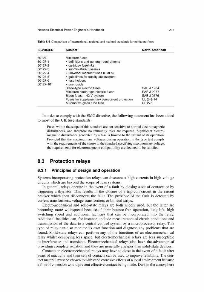
In order to comply with the EMC directive, the following statement has been addedto most of the UK fuse standards:
Fuses within the scope of this standard are not sensitive to normal electromagneticdisturbances, and therefore no immunity tests are required. Significant electro-magnetic disturbance generated by a fuse is limited to the instant of its operation.Provided that the maximum arc voltages during operation in the type test complywith the requirements of the clause in the standard specifying maximum arc voltage,the requirements for electromagnetic compatibility are deemed to be satisfied.
8.3 Protection relays
8.3.1 Principles of design and operation
Systems incorporating protection relays can disconnect high currents in high-voltagecircuits which are beyond the scope of fuse systems.
In general, relays operate in the event of a fault by closing a set of contacts or bytriggering a thyristor. This results in the closure of a trip-coil circuit in the circuitbreaker which then disconnects the fault. The presence of the fault is detected by current transformers, voltage transformers or bimetal strips.
Electromechanical and solid-state relays are both widely used, but the latter arebecoming more widespread because of their bounce-free operation, long life, highswitching speed and additional facilities that can be incorporated into the relay.Additional facilities can, for instance, include measurement of circuit conditions andtransmission of the data to a central control system by a microprocessor relay. Thistype of relay can also monitor its own function and diagnose any problems that arefound. Solid-state relays can perform any of the functions of an electromechanicalrelay whilst occupying less space, but electromechanical relays are less susceptible to interference and transients. Electromechanical relays also have the advantage ofproviding complete isolation and they are generally cheaper than solid-state devices.
Contacts in electromechanical relays may have to close in the event of a fault afteryears of inactivity and twin sets of contacts can be used to improve reliability. The con-tact material must be chosen to withstand corrosive effects of a local environment becausea film of corrosion would prevent effective contact being made. Dust in the atmosphere
Newnes Electrical Power Engineer’s Handbook 233
Table 8.4 Comparison of international, regional and national standards for miniature fuses
IEC/BS/EN Subject North American
60127 Miniature fuses60127-1 • definitions and general requirements60127-2 • cartridge fuselinks60127-3 • subminiature fuselinks60127-4 • universal modular fuses (UMFs)60127-5 • guidelines for quality assessment60127-6 • fuse holders60127-10 • user guide
Blade-type electric fuses SAE J 1284Miniature blade-type electric fuses SAE J 2077Blade fuses – 42 V system SAE J 2576Fuses for supplementary overcurrent protection UL 248-14Automotive glass tube fuse UL 275

can also increase the contact resistance and result in failure. Both corrosion and dustcontamination can be avoided by complete enclosure and sealing of the relay.
The contacts must also withstand arcing during bounce on closure and when opening, but this is usually less important than resisting corrosion. Because of the needfor high reliability, the contacts are usually made of or plated with gold, platinum,rhodium, palladium, silver or various alloys of these metals.
234 Fuses and protection relays
Table 8.5 Comparison of international, regional and national standards for low-voltage fuses
IEC EN/HD BS Subject North American
60269 Low voltage fuses60269-1 EN 60269-1 88-1 (related • general applications
to 1361 and1362)
60269-2 EN 60269-2 88-2.1 • supplementary requirements for fuses for use byauthorized persons
60269-2-1 HD 630.2.1 related to • standardized examples88-2.2 – bolted88-5 – wedge tightening88-6 – offset blade
60269-3 EN 60269-3 • supplementary requirements for fuses for use by unskilled persons
60269-3-1 HD 630.3.1 related to • standardized examples1361 – house service and
consumer unit1362 – plug top
60269-4 EN 60294-4 88-4 • supplementary requirements for the protection of semiconductor devices
60294-4-1 EN 60294-4-1 • standardized examplesTR 61459 – Co-ordination between fuses
and contactors/motor startersTR 61818 Application guide
General requirements UL 248-1Class C fuses UL 248-2Class CA and CB fuses UL 248-3Class CC fuses UL 248-4Class G fuses UL 248-5Class H non-renewable fuses UL 248-6Class H renewable fuses UL 248-7Class J fuses UL 248-8Class K fuses UL 248-9Class L fuses UL 248-10Plug fuses UL 248-11Class R fuses UL 248-12Semiconductor fuses UL 248-13Supplemental fuses UL 248-14Class T fuses UL 248-15Test limiters UL 248-16Fuse holders UL 512Application guide for low-voltage IEEE C37.27ac non-integrally fused power circuit breakers (using separately mounted current-limiting fuses)
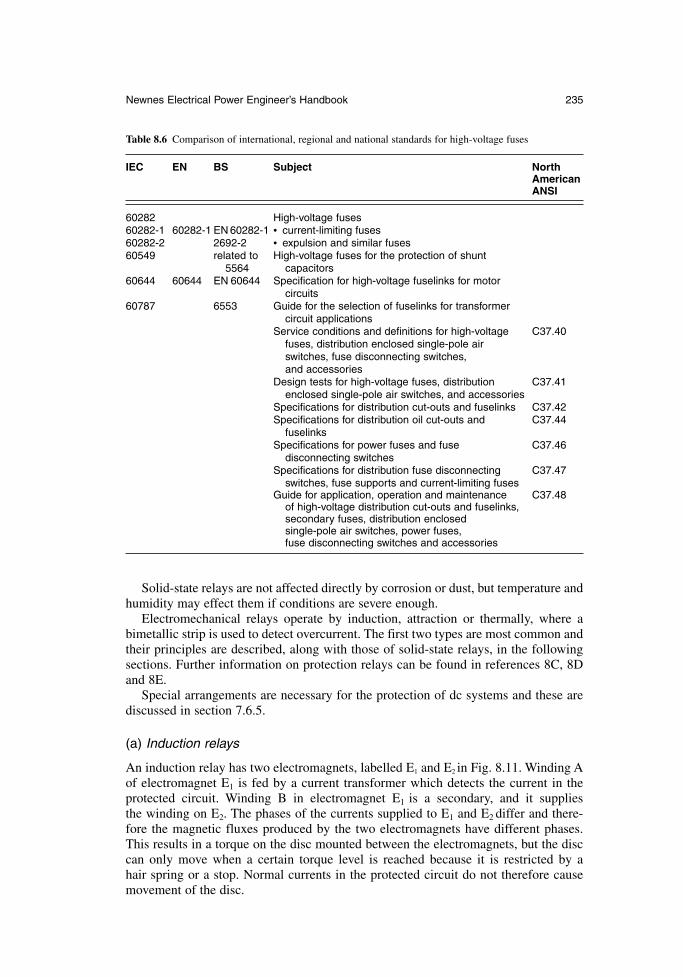
Newnes Electrical Power Engineer’s Handbook 235
Solid-state relays are not affected directly by corrosion or dust, but temperature andhumidity may effect them if conditions are severe enough.
Electromechanical relays operate by induction, attraction or thermally, where abimetallic strip is used to detect overcurrent. The first two types are most common andtheir principles are described, along with those of solid-state relays, in the followingsections. Further information on protection relays can be found in references 8C, 8Dand 8E.
Special arrangements are necessary for the protection of dc systems and these arediscussed in section 7.6.5.
(a) Induction relays
An induction relay has two electromagnets, labelled E1 and E2 in Fig. 8.11. Winding Aof electromagnet E1 is fed by a current transformer which detects the current in the protected circuit. Winding B in electromagnet E1 is a secondary, and it supplies the winding on E2. The phases of the currents supplied to E1 and E2 differ and there-fore the magnetic fluxes produced by the two electromagnets have different phases.This results in a torque on the disc mounted between the electromagnets, but the disccan only move when a certain torque level is reached because it is restricted by a hair spring or a stop. Normal currents in the protected circuit do not therefore causemovement of the disc.
Table 8.6 Comparison of international, regional and national standards for high-voltage fuses
IEC EN BS Subject North AmericanANSI
60282 High-voltage fuses60282-1 60282-1 EN 60282-1 • current-limiting fuses60282-2 2692-2 • expulsion and similar fuses60549 related to High-voltage fuses for the protection of shunt
5564 capacitors60644 60644 EN 60644 Specification for high-voltage fuselinks for motor
circuits60787 6553 Guide for the selection of fuselinks for transformer
circuit applicationsService conditions and definitions for high-voltage C37.40
fuses, distribution enclosed single-pole air switches, fuse disconnecting switches, and accessories
Design tests for high-voltage fuses, distribution C37.41enclosed single-pole air switches, and accessories
Specifications for distribution cut-outs and fuselinks C37.42Specifications for distribution oil cut-outs and C37.44
fuselinksSpecifications for power fuses and fuse C37.46
disconnecting switchesSpecifications for distribution fuse disconnecting C37.47
switches, fuse supports and current-limiting fusesGuide for application, operation and maintenance C37.48
of high-voltage distribution cut-outs and fuselinks,secondary fuses, distribution enclosed single-pole air switches, power fuses, fuse disconnecting switches and accessories
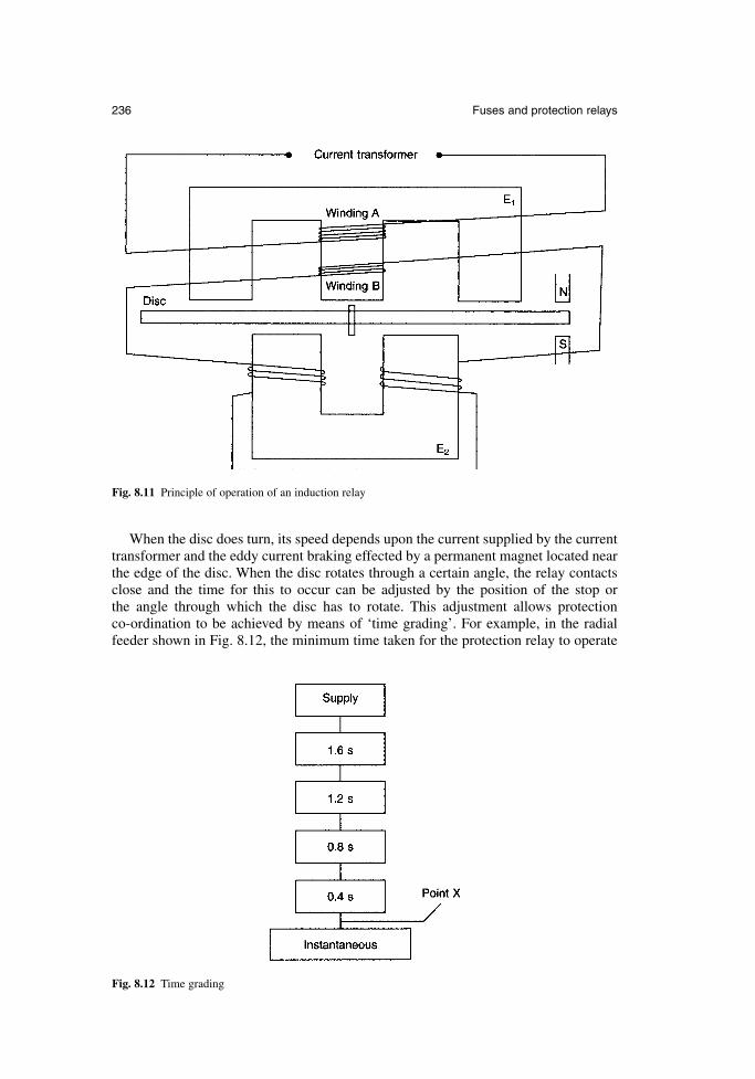
When the disc does turn, its speed depends upon the current supplied by the currenttransformer and the eddy current braking effected by a permanent magnet located nearthe edge of the disc. When the disc rotates through a certain angle, the relay contactsclose and the time for this to occur can be adjusted by the position of the stop or the angle through which the disc has to rotate. This adjustment allows protection co-ordination to be achieved by means of ‘time grading’. For example, in the radialfeeder shown in Fig. 8.12, the minimum time taken for the protection relay to operate
236 Fuses and protection relays
Fig. 8.11 Principle of operation of an induction relay
Fig. 8.12 Time grading
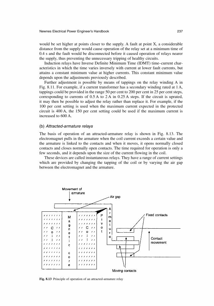
would be set higher at points closer to the supply. A fault at point X, a considerabledistance from the supply would cause operation of the relay set at a minimum time of0.4 s and the fault would be disconnected before it caused operation of relays nearerthe supply, thus preventing the unnecessary tripping of healthy circuits.
Induction relays have Inverse Definite Minimum Time (IDMT) time–current char-acteristics in which the time varies inversely with current at lower fault currents, butattains a constant minimum value at higher currents. This constant minimum valuedepends upon the adjustments previously described.
Further adjustment is possible by means of tappings on the relay winding A in Fig. 8.11. For example, if a current transformer has a secondary winding rated at 1 A,tappings could be provided in the range 50 per cent to 200 per cent in 25 per cent steps,corresponding to currents of 0.5 A to 2 A in 0.25 A steps. If the circuit is uprated, it may then be possible to adjust the relay rather than replace it. For example, if the100 per cent setting is used when the maximum current expected in the protected circuit is 400 A, the 150 per cent setting could be used if the maximum current isincreased to 600 A.
(b) Attracted-armature relays
The basis of operation of an attracted-armature relay is shown in Fig. 8.13. The electromagnet pulls in the armature when the coil current exceeds a certain value andthe armature is linked to the contacts and when it moves, it opens normally closed contacts and closes normally open contacts. The time required for operation is only afew seconds, and it depends upon the size of the current flowing in the coil.
These devices are called instantaneous relays. They have a range of current settingswhich are provided by changing the tapping of the coil or by varying the air gapbetween the electromagnet and the armature.
Newnes Electrical Power Engineer’s Handbook 237
Fig. 8.13 Principle of operation of an attracted-armature relay
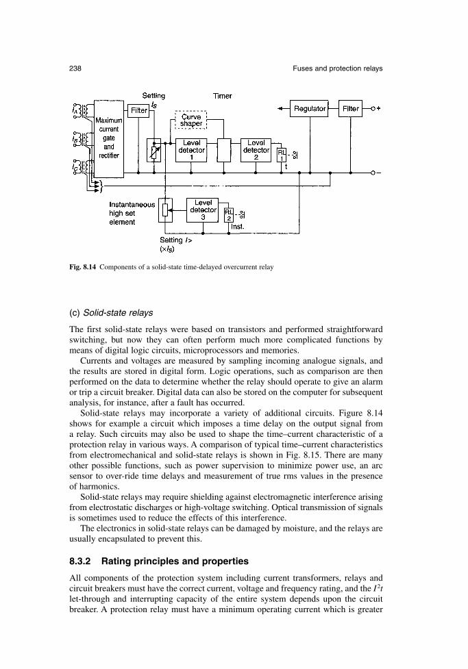
(c) Solid-state relays
The first solid-state relays were based on transistors and performed straightforwardswitching, but now they can often perform much more complicated functions bymeans of digital logic circuits, microprocessors and memories.
Currents and voltages are measured by sampling incoming analogue signals, andthe results are stored in digital form. Logic operations, such as comparison are thenperformed on the data to determine whether the relay should operate to give an alarmor trip a circuit breaker. Digital data can also be stored on the computer for subsequentanalysis, for instance, after a fault has occurred.
Solid-state relays may incorporate a variety of additional circuits. Figure 8.14shows for example a circuit which imposes a time delay on the output signal from a relay. Such circuits may also be used to shape the time–current characteristic of aprotection relay in various ways. A comparison of typical time–current characteristicsfrom electromechanical and solid-state relays is shown in Fig. 8.15. There are manyother possible functions, such as power supervision to minimize power use, an arc sensor to over-ride time delays and measurement of true rms values in the presence of harmonics.
Solid-state relays may require shielding against electromagnetic interference arisingfrom electrostatic discharges or high-voltage switching. Optical transmission of signalsis sometimes used to reduce the effects of this interference.
The electronics in solid-state relays can be damaged by moisture, and the relays areusually encapsulated to prevent this.
8.3.2 Rating principles and properties
All components of the protection system including current transformers, relays andcircuit breakers must have the correct current, voltage and frequency rating, and the I 2tlet-through and interrupting capacity of the entire system depends upon the circuitbreaker. A protection relay must have a minimum operating current which is greater
238 Fuses and protection relays
Fig. 8.14 Components of a solid-state time-delayed overcurrent relay
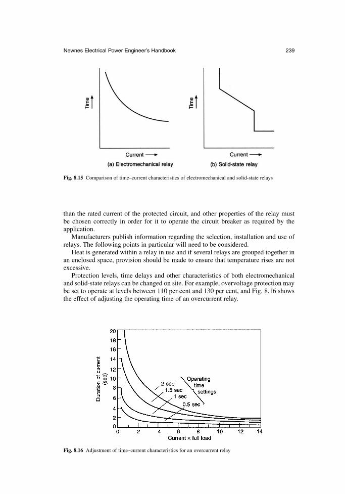
than the rated current of the protected circuit, and other properties of the relay must be chosen correctly in order for it to operate the circuit breaker as required by theapplication.
Manufacturers publish information regarding the selection, installation and use ofrelays. The following points in particular will need to be considered.
Heat is generated within a relay in use and if several relays are grouped together inan enclosed space, provision should be made to ensure that temperature rises are notexcessive.
Protection levels, time delays and other characteristics of both electromechanicaland solid-state relays can be changed on site. For example, overvoltage protection maybe set to operate at levels between 110 per cent and 130 per cent, and Fig. 8.16 showsthe effect of adjusting the operating time of an overcurrent relay.
Newnes Electrical Power Engineer’s Handbook 239
Fig. 8.15 Comparison of time–current characteristics of electromechanical and solid-state relays
Fig. 8.16 Adjustment of time–current characteristics for an overcurrent relay
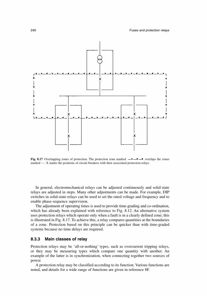
In general, electromechanical relays can be adjusted continuously and solid-staterelays are adjusted in steps. Many other adjustments can be made. For example, DIPswitches in solid-state relays can be used to set the rated voltage and frequency and toenable phase-sequence supervision.
The adjustment of operating times is used to provide time-grading and co-ordination,which has already been explained with reference to Fig. 8.12. An alternative systemuses protection relays which operate only when a fault is in a clearly defined zone; thisis illustrated in Fig. 8.17. To achieve this, a relay compares quantities at the boundariesof a zone. Protection based on this principle can be quicker than with time-graded systems because no time delays are required.
8.3.3 Main classes of relay
Protection relays may be ‘all-or-nothing’ types, such as overcurrent tripping relays, or they may be measuring types which compare one quantity with another. An example of the latter is in synchronization, when connecting together two sources ofpower.
A protection relay may be classified according to its function. Various functions arenoted, and details for a wide range of functions are given in reference 8F.
240 Fuses and protection relays
Fig. 8.17 Overlapping zones of protection. The protection zone marked overlaps the zonesmarked —. X marks the positions of circuit breakers with their associated protection relays
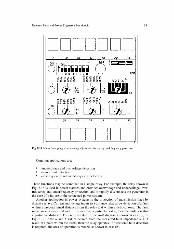
Common applications are:
• undervoltage and overvoltage detection• overcurrent detection• overfrequency and underfrequency detection
These functions may be combined in a single relay. For example, the relay shown inFig. 8.18 is used in power stations and provides overvoltage and undervoltage, over-frequency and underfrequency protection, and it rapidly disconnects the generator inthe case of a failure in the connected power system.
Another application in power systems is the protection of transmission lines by distance relays. Current and voltage inputs to a distance relay allow detection of a faultwithin a predetermined distance from the relay and within a defined zone. The faultimpedance is measured and if it is less than a particular value, then the fault is withina particular distance. This is illustrated in the R–X diagrams shown in case (a) of Fig. 8.19; if the R and X values derived from the measured fault impedance R + iXresult in a point within the circle, then the relay operates. If directional fault detectionis required, the area of operation is moved, as shown in case (b).
Newnes Electrical Power Engineer’s Handbook 241
Fig. 8.18 Mains decoupling relay showing adjustments for voltage and frequency protection
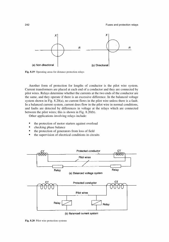
Another form of protection for lengths of conductor is the pilot wire system.Current transformers are placed at each end of a conductor and they are connected bypilot wires. Relays determine whether the currents at the two ends of the conductor arethe same, and they operate if there is an excessive difference. In the balanced voltagesystem shown in Fig. 8.20(a), no current flows in the pilot wire unless there is a fault.In a balanced current system, current does flow in the pilot wire in normal conditions,and faults are detected by differences in voltage at the relays which are connectedbetween the pilot wires; this is shown in Fig. 8.20(b).
Other applications involving relays include:
• the protection of motor starters against overload• checking phase balance• the protection of generators from loss of field• the supervision of electrical conditions in circuits
242 Fuses and protection relays
Fig. 8.19 Operating areas for distance protection relays
Fig. 8.20 Pilot wire protection systems
8.3.4 Test methods
(a) Production tests
Manufacturers of electromechanical relays often produce their own components andinspect them before assembly. Components for solid-state relays are generally boughtin from specialist manufacturers and there is an incoming check to eliminate thosewhich would be subject to early failure or excessive drift. Other characteristics, suchas memory are checked as appropriate.
After assembly, manufacturers test all protection relays to ensure that they complywith relevant national and international standards. The calibration of adjustable set-tings is checked.
Fault conditions that the relays are designed to protect against can be simulated, andtypical inputs to relays from current or voltage transformers can be duplicated by test sets; this can be used to check, for example, the correct functioning of relays forphase comparison and the proper disconnection of overcurrent and earth faults of various impedances. Such tests can be performed by setting up a test circuit or bymeans of a computer-based power system simulator which controls the inputs to therelays. The latter method allows the effect of high-frequency transients and generatorfaults to be investigated, and it is independent of an actual power supply; it may, forexample, be used for the testing of selectable protection schemes in distance relays.
Other tests include the following:
environmental tests are performed to check, for example, the effects on performance of temperature and humidity
impact, vibration and seismic tests are performed on both solid-state andelectromechanical relays, although the latter are more prone to damage fromsuch effects
voltage transients are potentially damaging to solid-state relays, and the relaysare tested to ensure they can withstand a peak voltage of 5 kV with a rise timeof 1.2 µs and a decay time of 50 µs
(b) Site tests
Primary injection tests are applied during initial commissioning and these should showup any malfunction associated with protection relays. Secondary injection tests shouldbe performed if there is a maloperation which may be related to the protection relay.Details of these injections tests are given in reference 8E.
Periodic inspection and testing is necessary throughout the lifetime of a protectionrelay and computerized equipment is available for this purpose. Some relatively complicated protection schemes incorporate automatic checking systems which sendtest signals at regular intervals; the test signals can also be sent manually. Digital relaysmay include continuous self-checking facilities.
8.3.5 Standards
There are many standards covering various types of relay and aspects of their use.Some standards which apply to relays in general are also relevant to protection relaysand some apply specifically to protection relays. The key IEC recommendationstogether with equivalent BS and EN standards and related North American standardsare summarized in Table 8.7.
Newnes Electrical Power Engineer’s Handbook 243
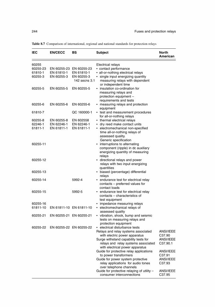
244 Fuses and protection relays
Table 8.7 Comparison of international, regional and national standards for protection relays
IEC EN/CECC BS Subject North American
60255 Electrical relays60255-23 EN 60255-23 EN 60255-23 • contact performance61810-1 EN 61810-1 EN 61810-1 • all-or-nothing electrical relays60255-3 EN 60255-3 EN 60255-3 • single input energizing quantity
142 secns 3.1 measuring relays with dependent or independent time
60255-5 EN 60255-5 EN 60255-5 • insulation co-ordination for measuring relays and protection equipment – requirements and tests
60255-6 EN 60255-6 EN 60255-6 • measuring relays and protection equipment
61810-7 QC 160000-1 • test and measurement procedures for all-or-nothing relays
60255-8 EN 60255-8 EN 602558 • thermal electrical relays62246-1 EN 62246-1 EN 62246-1 • dry reed make contact units61811-1 EN 61811-1 EN 61811-1 • electromechanical non-specified
time all-or-nothing relays of assessed quality.Generic specification
60255-11 • interruptions to alternating component (ripple) in dc auxiliary energizing quantity of measuring relays
60255-12 • directional relays and power relays with two input energizing quantities
60255-13 • biased (percentage) differential relays
60255-14 5992-4 • endurance test for electrical relay contacts – preferred values for contact loads
60255-15 5992-5 • endurance test for electrical relay contacts – characteristics of test equipment
60255-16 • impedance measuring relays61811-10 EN 61811-10 EN 61811-10 • electromechanical relays of
assessed quality60255-21 EN 60255-21 EN 60255-21 • vibration, shock, bump and seismic
tests on measuring relays and protection equipment
60255-22 EN 60255-22 EN 60255-22 • electrical disturbance testsRelays and relay systems associated ANSI/IEEE
with electric power apparatus C37.90Surge withstand capability tests for ANSI/IEEE
relays and relay systems associated C37.90.1with electrical power apparatus
Guide for protective relay applications ANSI/IEEEto power transformers C37.91
Guide for power system protective ANSI/IEEErelay applications for audio tones C37.93over telephone channels
Guide for protective relaying of utility – ANSI/IEEEconsumer interconnections C37.95
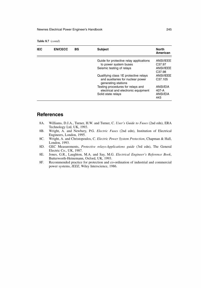
References
8A. Williams, D.J.A., Turner, H.W. and Turner, C. User’s Guide to Fuses (2nd edn), ERATechnology Ltd, UK, 1993.
8B. Wright, A. and Newbery, P.G. Electric Fuses (2nd edn), Institution of ElectricalEngineers, London, 1995.
8C. Wright, A. and Christopoulos, C. Electric Power System Protection, Chapman & Hall,London, 1993.
8D. GEC Measurements, Protective relays-Applications guide (3rd edn), The GeneralElectric Co., UK, 1987.
8E. Jones, G.R., Laughton, M.A. and Say, M.G. Electrical Engineer’s Reference Book,Butterworth-Heinemann, Oxford, UK, 1993.
8F. Recommended practice for protection and co-ordination of industrial and commercialpower systems, IEEE, Wiley Interscience, 1986.
Newnes Electrical Power Engineer’s Handbook 245
Table 8.7 (contd)
IEC EN/CECC BS Subject North American
Guide for protective relay applications ANSI/IEEEto power system buses C37.97
Seismic testing of relays ANSI/IEEEC37.98
Qualifying class 1E protective relays ANSI/IEEEand auxiliaries for nuclear power C37.105generating stations
Testing procedures for relays and ANSI/EIAelectrical and electronic equipment 407-A
Solid state relays ANSI/EIA 443

Chapter 9
Wires and cables
V.A.A. Banks and P.H. Fraser
With amendments byD. GraciasPirelli Cables Ltd
A.J. WillisBrand-Rex Ltd
9.1 Scope
Thousands of cable types are used throughout the world. They are found in applicationsranging from fibre-optic links for data and telecommunication purposes through to EHVunderground power transmission at 275 kV or higher. The scope here is limited to coverthose types of cable which fit within the general subject matter of the pocket book.
This chapter therefore covers cables rated between 300/500 V and 19/33 kV for usein the public supply network, in general industrial systems and in domestic and com-mercial wiring. Optical communication cables are included in a special section.Overhead wires and cables, submarine cables and flexible appliance cords are notincluded.
Even within this relatively limited scope, it has been necessary to restrict the cov-erage of the major metallic cable and wire types to those used in the UK in order togive the cursory appreciation which is the main aim.
9.2 Principles of power cable design
9.2.1 Terminology
The voltage designation used by the cable industry does not always align with thatadopted by users and other equipment manufacturers, so clarification may be helpful.
A cable is given a voltage rating which indicates the maximum circuit voltage forwhich it is designed, not necessarily the voltage at which it will be used. For example,a cable designated 0.6/1 kV is suitable for a circuit operating at 600 V phase-to-earthand 1000 V phase-to-phase. However it would be normal to use such a cable on dis-tribution and industrial circuits operating at 230/400 V in order to provide improvedsafety and increased service life. For light industrial circuits operating at 230/400 V itwould be normal to use cables rated at 450/750 V, and for domestic circuits operatingat 230/400 V, cable rated at 300/500 V would often be used. Guidance on the cablesthat are suitable for use in different locations is given in BS 7540.
The terms LV (Low Voltage), MV (Medium Voltage) and HV (High Voltage) havedifferent meanings in different sectors of the electrical industry. In the power cableindustry, the following bands are generally accepted and these are used in this chapter:
LV – cable rated from 300/500 V to 1.9/3.3 kVMV – cables rated from 3.8/6.6 kV to 19/33 kVHV – cable rated at greater than 19/33 kV
Multi-core cable is used in this chapter to describe power cable having two to fivecores. Control cable having seven to 48 cores is referred to as multi-core control cable.
Cable insulation and sheaths are variously described as thermoplastic, thermo-setting, vulcanized, cross-linked, polymeric or elastomeric. All extruded plastic materi-als applied to cable are polymeric. Those which would re-melt if the temperatureduring use is sufficiently high are termed thermoplastic. Those which are modifiedchemically to prevent them from re-melting are termed thermosetting, cross-linked orvulcanized. Although these materials will not re-melt, they will soften and deform atelevated temperatures, if subjected to excessive pressure. The main materials withinthe two groups are as follows:
thermoplastic– polyethylene (PE)– medium-density polyethylene (MDPE)– polyvinyl chloride (PVC)
thermosetting, cross-linked or vulcanized– cross-linked polyethylene (XLPE)– ethylene-propylene rubber (EPR)
Elastomeric materials are polymeric. They are rubbery in nature, giving a flexible andresilient extrusion. Elastomers such as EPR are normally cross-linked.
9.2.2 General considerations
Certain design principles are common to power cables, whether they are used in theindustrial sector or by the electricity supply industry.
For many cable types the conductors may be of copper or aluminium. The initialdecision made by a purchaser will be based on price, weight, cable diameter, avail-ability, the expertise of the jointers available, cable flexibility and the risk of theft.Once a decision has been made, however, that type of conductor will generally then beretained by that user, without being influenced by the regular changes in relative pricewhich arise from the volatile metals market.
For most power cables the form of conductor will be solid aluminium, stranded alu-minium, solid copper (for small wiring sizes) or stranded copper, although the choicemay be limited in certain cable standards. Solid conductors provide for easier fittingof connectors and setting of the cores at joints and terminations. Cables with strandedconductors are easier to install because of their greater flexibility, and for some indus-trial applications a highly flexible conductor is necessary.
Where cable route lengths are relatively short, a multi-core cable is generallycheaper and more convenient to install than single-core cable. Single-core cables aresometimes used in circuits where high load currents require the use of large conductorsizes, between 500 mm2 and 1200 mm2. In these circumstances, the parallel connec-tion of two or more multi-core cables would be necessary in order to achieve therequired rating and this presents installation difficulties, especially at termination boxes.
248 Wires and cables
Single-core cable might also be preferred where duct sizes are small, where longercable runs are needed between joint bays or where jointing and termination require-ments dictate their use. It is sometimes preferable to use 3-core cable in the main partof the route length, and to use single-core cable to enter the restricted space of a ter-mination box. In this case, a transition from one cable type to the other is achievedusing trifurcating joints which are positioned several metres from the termination box.
Armoured cables are available for applications where the rigours of installation aresevere and where a high degree of external protection against impact during service isrequired. Steel Wire Armour (SWA) cables are commonly available although Steel TapeArmour (STA) cables are also available. Generally, SWA is preferred because it enablesthe cable to be drawn into an installation using a pulling stocking which grips the out-side of the oversheath and transfers all the pulling tension to the SWA. This cannotnormally be done with STA cables because of the risk of dislocating the armour tapesduring the pull. Glanding arrangements for SWA are simpler and they allow full usageof its excellent earth fault capability. In STA, the earth fault capability is much reducedand the retention of this capability at glands is more difficult. The protection offeredagainst a range of real-life impacts is similar for the two types.
9.2.3 Paper-insulated cables
Until the mid-1960s, paper-insulated cables were used worldwide for MV power cir-cuits. There were at that time very few alternatives apart from the occasional trialinstallation or special application using PE or PVC insulation.
The position is now quite different. There has been a worldwide trend towardsXLPE cable and the UK industrial sector has adopted XLPE-insulated or EPR-insulated cable for the majority of MV applications, paper-insulated cable now beingrestricted to minor uses, such as extensions to older circuits or in special industriallocations. The use of paper-insulated cables for LV has been superseded completely bypolymeric cables in all sectors throughout the world.
The success of polymeric-insulated cables has been due to the much easier, cleanerand more reliable jointing and termination methods that they allow. However, becauseof the large amount of paper-insulated cable still in service and its continued specifi-cation in some sectors, such as the regional public supply networks for MV circuits,its coverage here is still appropriate.
Paper-insulated cables comprise copper or aluminium phase conductors which areinsulated with lapped paper tapes, impregnated with insulating compound andsheathed with lead, lead alloy or corrugated aluminium. For mechanical protection,lead or lead alloy sheathed cables are finished off with an armouring of steel tapes orsteel wire and a covering of either bitumenized hessian tapes or an extruded PVC orPE oversheath. Cables which are sheathed with corrugated aluminium need no furthermetallic protection, but they are finished off with a coating of bitumen and an extrudedPVC oversheath. The purpose of the bitumen in this case is to provide additional cor-rosion protection should water penetrate the PVC sheath at joints, in damaged areas orby long-term permeation.
There are, therefore, several basic types of paper-insulated cable and these are speci-fied according to existing custom and practice as much as to meet specific needs andbudgets. Particular features of paper-insulated cables used in the electricity supply indus-try and in industrial applications are described in sections 9.3.1.1 and 9.3.2.1, respectively.
The common element is the paper insulation itself. This is made up of many layersof paper tape, each applied with a slight gap between the turns. The purity and grade
Newnes Electrical Power Engineer’s Handbook 249
of the paper is selected for best electrical properties and the thickness of the tape ischosen to provide the required electrical strength.
In order to achieve acceptable dielectric strength, all moisture and air is removedfrom the insulation and replaced by Mineral Insulating Non-Draining (MIND) com-pound. Its waxy nature prevents any significant migration of the compound during thelifetime of the cable, even at full operating temperature. This is in contrast to oil-filledHV cables, utilizing a lower viscosity impregnant which must be pressurized through-out the cable service life to keep the insulation fully impregnated. Precautions aretaken at joints and terminations to ensure that there is no local displacement of MINDcompound which might cause premature failure at these locations. The paper insula-tion is impregnated with MIND compound during the manufacture of the cable,immediately before the lead or aluminium sheath is applied.
A 3-core construction is preferred in most MV paper-insulated cables. The threecores are used for the three phases of the supply and no neutral conductor is includedin the design. The parallel combination of lead or aluminium sheath and armour canbe used as an earth continuity conductor, provided that circuit calculations prove itsadequacy for this purpose. Conductors of 95 mm2 cross section and greater are sector-shaped so that when insulated they can be laid up in a compact cable construction.Sector-shaped conductors are also used in lower cross sections, down to 35 mm2, 50 mm2 and 70 mm2 for cables rated at 6 kV, 10 kV and 15 kV, respectively.
The 3-core 6.6 kV cables and most 3-core 11 kV cables are of belted design. Thecores are insulated and laid up such that the insulation between conductors is adequatefor the full line-to-line voltage (6.6 kV or 11 kV). The laid-up cores then have an addi-tional layer of insulating paper, known as the belt layer, applied and the assembly isthen lead sheathed. The combination of core insulation and belt insulation is sufficientfor phase-to-earth voltage between core and sheath (3.8 kV or 6.35 kV).
A 15 kV, 22 kV and 33 kV 3-core cables and some 11 kV 3-core cables are ofscreened design. Here each core has a metallic screening tape and the core insulationis adequate for the full phase-to-earth voltage. The screened cores are laid up and thelead or aluminium sheath is then applied so that the screens make contact with eachother and with the sheath.
The bitumenized hessian serving or PVC oversheath is primarily to protect thearmour from corrosion in service and from dislocation during installation. The PVCoversheath is now preferred because of the facility to mark cable details, and its cleansurface gives a better appearance when installed. It also provides a smooth firm surface for glanding and for sealing at joints.
9.2.4 Polymeric cables
PVC and PE cables were being used for LV circuits in the 1950s and they started togain wider acceptance in the 1960s because they were cleaner, lighter, smaller andeasier to install than paper-insulated types. During the 1970s the particular benefits ofXLPE and HEPR insulations were being recognized for LV circuits and today it isthese cross-linked insulations, mainly XLPE, which dominate the LV market withPVC usage in decline for power circuits, although still used widely for low voltagewiring circuits. The LV XLPE cables are more standardized than MV polymeric types,but even so there is a choice of copper or aluminium conductor (circular or shaped),single-core or multi-core, SWA or unarmoured, and PVC or Low Smoke and Fume(LSF) sheathed. A further option is available for LV in which the neutral and/or earthconductor is a layer of wires applied concentrically around the laid-up cores rather
250 Wires and cables
than as an insulated core within the cable. In this case, the concentric earth conductorcan replace the armour layer as the protective metal layer for the cable. This concen-tric wire design is mainly used in the LV electricity distribution network, whereas thearmoured design is primarily used in industrial applications.
Polyethylene and PVC were shown to be unacceptable for use as general MV cableinsulation in the years following the 1960s because their thermoplastic nature resultedin significant temperature limitations. The XLPE and EPR were required in order to give the required properties. They allowed higher operating and short circuit temperatures within the cable, as well as the advantages of easier jointing and termi-nating than for paper-insulated cables. This meant that in some applications a smallerconductor size could be considered than had previously been possible in the paper-insulated case.
The MV polymeric cables comprise copper or aluminium conductors insulated withXLPE or EPR and covered with a thermoplastic sheath of MDPE, PVC or LSF material.Within this general construction there are options of single-core or 3-core types, individual or collective screens of different sizes and armoured or unarmoured construction. Single-core polymeric cables are more widely used than single-corepaper-insulated cables, particularly for electricity supply industry circuits. Unlikepaper-insulated cables, MV polymeric 3-core cables normally have circular-sectioncores. This is mainly because the increases in price and cable diameter are usuallyoutweighed in the polymeric case by simplicity and flexibility of jointing and termi-nation methods using circular cores.
Screening of the cores in MV polymeric cables is necessary for a number of rea-sons, which combine to result in a two-level screening arrangement. This comprisesextruded semiconducting layers immediately under and outside the individual XLPEor EPR insulation layer, and a metallic layer in contact with the outer semiconductinglayer. The semiconducting layers are polymeric materials containing a high proportionof carbon, giving an electrical conductivity well below that of a metallic conductor, butwell above that required for an insulating material.
The two semiconducting layers must be in intimate contact in order to avoid partialdischarge activity at the interfaces, where any minute air cavity in the insulation wouldcause a pulse of charge to transfer to and from the surface of the insulation in eachhalf-cycle of applied voltage. These charge transfers result in erosion of the insulationsurface and premature breakdown. In order to achieve intimate contact, the insulationand screens are extruded during manufacture as an integral triple layer and this isapplied to the individual conductor in the same operation. The inner layer is known asthe conductor screen and the outer layer is known as the core screen or dielectricscreen.
When the cable is energized, the insulation acts as a capacitor and the core screenhas to transfer the associated charging current to the insulation on every half-cycle ofthe voltage. It is therefore necessary to provide a metallic element in contact with thecore screen so that this charging current can be delivered from the supply. Without thismetallic element, the core screen at the supply end of the cable would have to carry asubstantial longitudinal current to charge the capacitance which is distributed along thecomplete cable length, and the screen at the supply end would rapidly overheat as aresult of excessive current density. However the core screen is able to carry the currentdensities relating to the charging of a cable length of say 200 mm, and this allows theuse of a metallic element having an intermittent contact with the core screen, orapplied as a collective element over three laid-up cores. A 0.08-mm thick copper tapeis adequate for this purpose.
Newnes Electrical Power Engineer’s Handbook 251
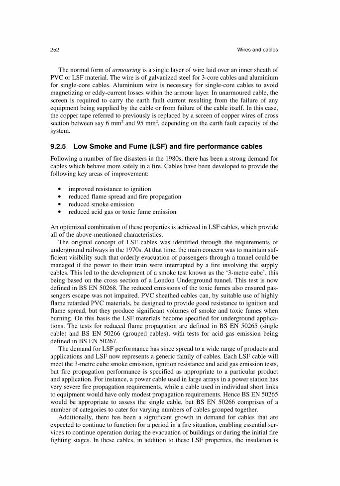
The normal form of armouring is a single layer of wire laid over an inner sheath ofPVC or LSF material. The wire is of galvanized steel for 3-core cables and aluminiumfor single-core cables. Aluminium wire is necessary for single-core cables to avoidmagnetizing or eddy-current losses within the armour layer. In unarmoured cable, thescreen is required to carry the earth fault current resulting from the failure of anyequipment being supplied by the cable or from failure of the cable itself. In this case,the copper tape referred to previously is replaced by a screen of copper wires of crosssection between say 6 mm2 and 95 mm2, depending on the earth fault capacity of thesystem.
9.2.5 Low Smoke and Fume (LSF) and fire performance cables
Following a number of fire disasters in the 1980s, there has been a strong demand forcables which behave more safely in a fire. Cables have been developed to provide thefollowing key areas of improvement:
improved resistance to ignition reduced flame spread and fire propagation reduced smoke emission reduced acid gas or toxic fume emission
An optimized combination of these properties is achieved in LSF cables, which provideall of the above-mentioned characteristics.
The original concept of LSF cables was identified through the requirements ofunderground railways in the 1970s. At that time, the main concern was to maintain suf-ficient visibility such that orderly evacuation of passengers through a tunnel could bemanaged if the power to their train were interrupted by a fire involving the supplycables. This led to the development of a smoke test known as the ‘3-metre cube’, thisbeing based on the cross section of a London Underground tunnel. This test is nowdefined in BS EN 50268. The reduced emissions of the toxic fumes also ensured pas-sengers escape was not impaired. PVC sheathed cables can, by suitable use of highlyflame retarded PVC materials, be designed to provide good resistance to ignition andflame spread, but they produce significant volumes of smoke and toxic fumes whenburning. On this basis the LSF materials become specified for underground applica-tions. The tests for reduced flame propagation are defined in BS EN 50265 (singlecable) and BS EN 50266 (grouped cables), with tests for acid gas emission beingdefined in BS EN 50267.
The demand for LSF performance has since spread to a wide range of products andapplications and LSF now represents a generic family of cables. Each LSF cable willmeet the 3-metre cube smoke emission, ignition resistance and acid gas emission tests,but fire propagation performance is specified as appropriate to a particular product and application. For instance, a power cable used in large arrays in a power station hasvery severe fire propagation requirements, while a cable used in individual short linksto equipment would have only modest propagation requirements. Hence BS EN 50265would be appropriate to assess the single cable, but BS EN 50266 comprises of a number of categories to cater for varying numbers of cables grouped together.
Additionally, there has been a significant growth in demand for cables that areexpected to continue to function for a period in a fire situation, enabling essential ser-vices to continue operation during the evacuation of buildings or during the initial firefighting stages. In these cables, in addition to these LSF properties, the insulation is
252 Wires and cables
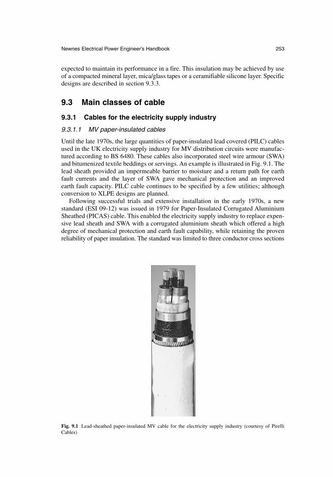
expected to maintain its performance in a fire. This insulation may be achieved by useof a compacted mineral layer, mica/glass tapes or a ceramifiable silicone layer. Specificdesigns are described in section 9.3.3.
9.3 Main classes of cable
9.3.1 Cables for the electricity supply industry
9.3.1.1 MV paper-insulated cables
Until the late 1970s, the large quantities of paper-insulated lead covered (PILC) cablesused in the UK electricity supply industry for MV distribution circuits were manufac-tured according to BS 6480. These cables also incorporated steel wire armour (SWA)and bitumenized textile beddings or servings. An example is illustrated in Fig. 9.1. Thelead sheath provided an impermeable barrier to moisture and a return path for earthfault currents and the layer of SWA gave mechanical protection and an improved earth fault capacity. PILC cable continues to be specified by a few utilities; althoughconversion to XLPE designs are planned.
Following successful trials and extensive installation in the early 1970s, a new standard (ESI 09-12) was issued in 1979 for Paper-Insulated Corrugated AluminiumSheathed (PICAS) cable. This enabled the electricity supply industry to replace expen-sive lead sheath and SWA with a corrugated aluminium sheath which offered a highdegree of mechanical protection and earth fault capability, while retaining the provenreliability of paper insulation. The standard was limited to three conductor cross sections
Newnes Electrical Power Engineer’s Handbook 253
Fig. 9.1 Lead-sheathed paper-insulated MV cable for the electricity supply industry (courtesy of PirelliCables)
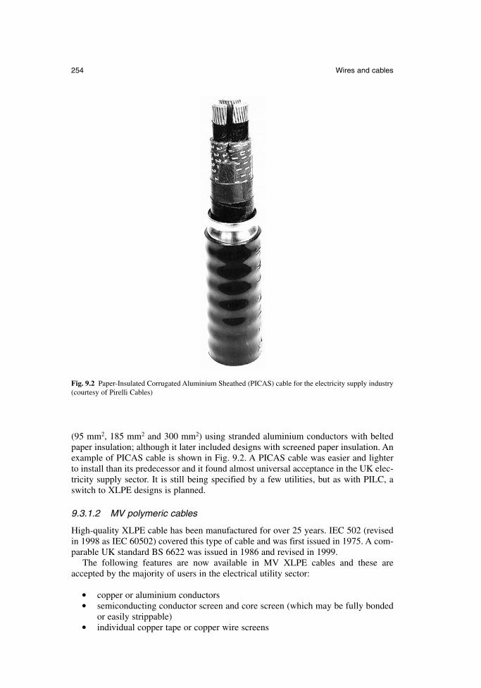
(95 mm2, 185 mm2 and 300 mm2) using stranded aluminium conductors with beltedpaper insulation; although it later included designs with screened paper insulation. Anexample of PICAS cable is shown in Fig. 9.2. A PICAS cable was easier and lighterto install than its predecessor and it found almost universal acceptance in the UK elec-tricity supply sector. It is still being specified by a few utilities, but as with PILC, aswitch to XLPE designs is planned.
9.3.1.2 MV polymeric cables
High-quality XLPE cable has been manufactured for over 25 years. IEC 502 (revisedin 1998 as IEC 60502) covered this type of cable and was first issued in 1975. A com-parable UK standard BS 6622 was issued in 1986 and revised in 1999.
The following features are now available in MV XLPE cables and these areaccepted by the majority of users in the electrical utility sector:
copper or aluminium conductors semiconducting conductor screen and core screen (which may be fully bonded
or easily strippable) individual copper tape or copper wire screens
254 Wires and cables
Fig. 9.2 Paper-Insulated Corrugated Aluminium Sheathed (PICAS) cable for the electricity supply industry(courtesy of Pirelli Cables)
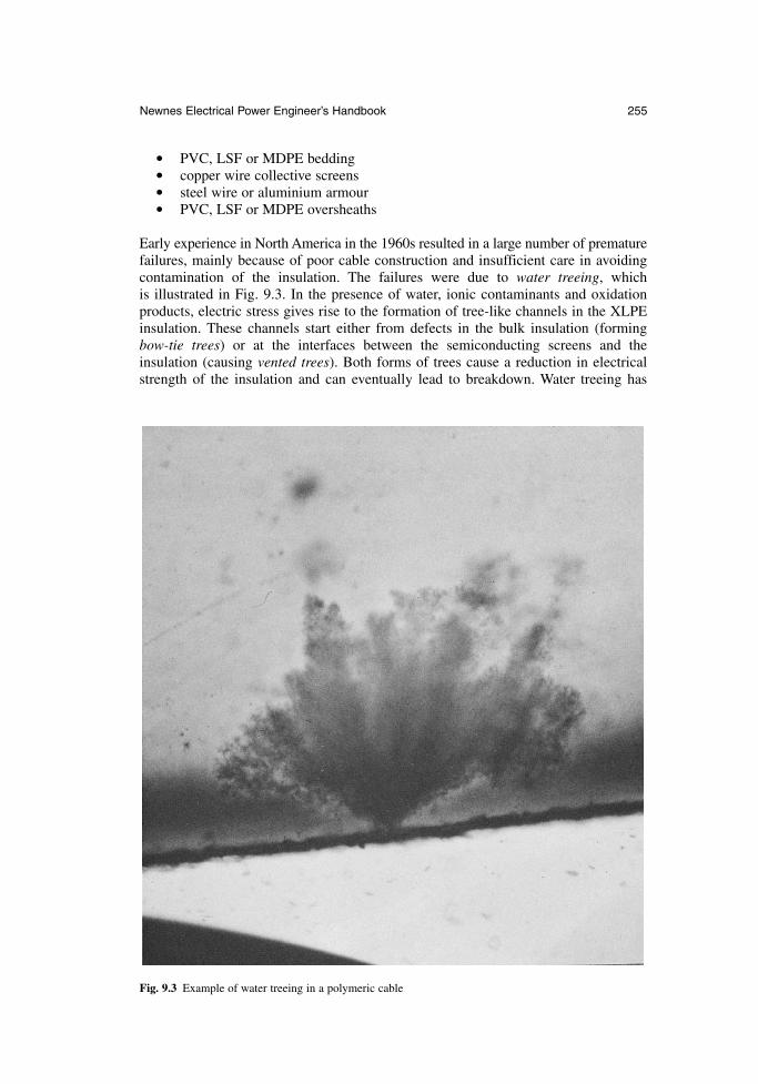
PVC, LSF or MDPE bedding copper wire collective screens steel wire or aluminium armour PVC, LSF or MDPE oversheaths
Early experience in North America in the 1960s resulted in a large number of prematurefailures, mainly because of poor cable construction and insufficient care in avoidingcontamination of the insulation. The failures were due to water treeing, which is illustrated in Fig. 9.3. In the presence of water, ionic contaminants and oxidationproducts, electric stress gives rise to the formation of tree-like channels in the XLPEinsulation. These channels start either from defects in the bulk insulation (formingbow-tie trees) or at the interfaces between the semiconducting screens and the insulation (causing vented trees). Both forms of trees cause a reduction in electricalstrength of the insulation and can eventually lead to breakdown. Water treeing has
Newnes Electrical Power Engineer’s Handbook 255
Fig. 9.3 Example of water treeing in a polymeric cable
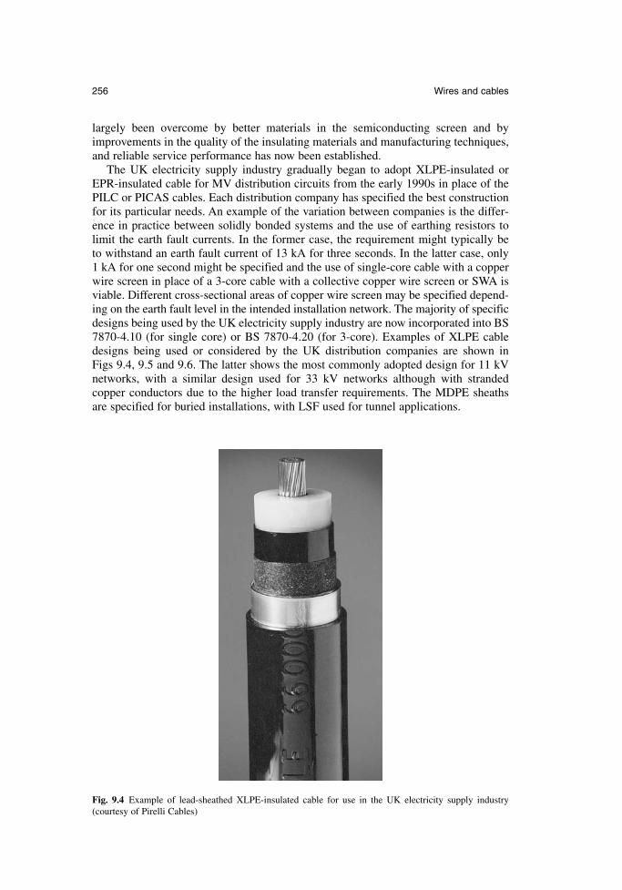
largely been overcome by better materials in the semiconducting screen and byimprovements in the quality of the insulating materials and manufacturing techniques,and reliable service performance has now been established.
The UK electricity supply industry gradually began to adopt XLPE-insulated orEPR-insulated cable for MV distribution circuits from the early 1990s in place of thePILC or PICAS cables. Each distribution company has specified the best constructionfor its particular needs. An example of the variation between companies is the differ-ence in practice between solidly bonded systems and the use of earthing resistors tolimit the earth fault currents. In the former case, the requirement might typically be to withstand an earth fault current of 13 kA for three seconds. In the latter case, only1 kA for one second might be specified and the use of single-core cable with a copperwire screen in place of a 3-core cable with a collective copper wire screen or SWA isviable. Different cross-sectional areas of copper wire screen may be specified depend-ing on the earth fault level in the intended installation network. The majority of specificdesigns being used by the UK electricity supply industry are now incorporated into BS7870-4.10 (for single core) or BS 7870-4.20 (for 3-core). Examples of XLPE cabledesigns being used or considered by the UK distribution companies are shown in Figs 9.4, 9.5 and 9.6. The latter shows the most commonly adopted design for 11 kVnetworks, with a similar design used for 33 kV networks although with stranded copper conductors due to the higher load transfer requirements. The MDPE sheaths are specified for buried installations, with LSF used for tunnel applications.
256 Wires and cables
Fig. 9.4 Example of lead-sheathed XLPE-insulated cable for use in the UK electricity supply industry(courtesy of Pirelli Cables)
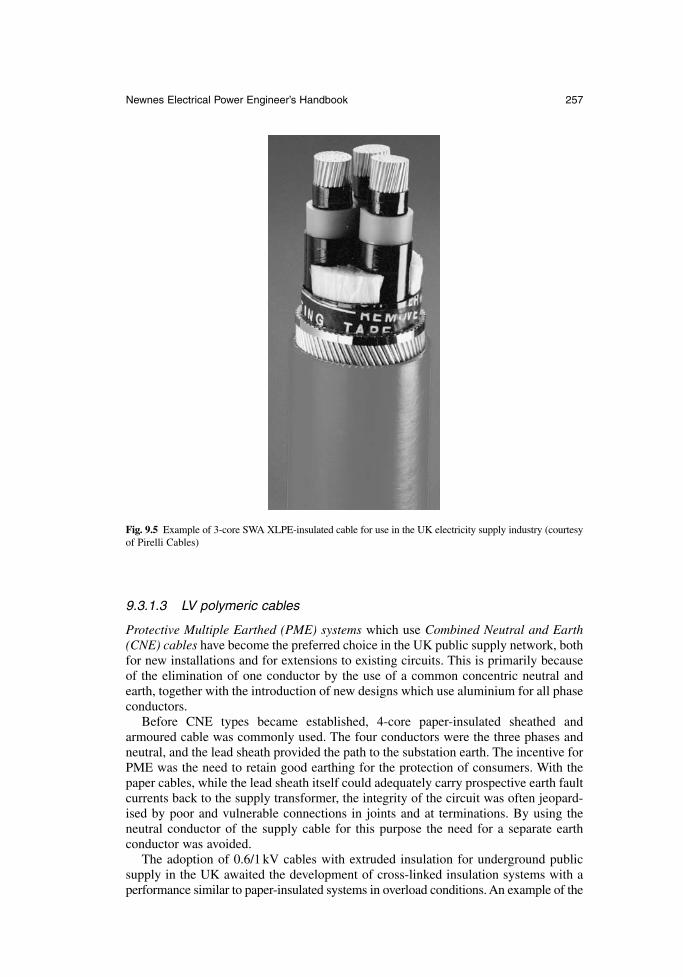
9.3.1.3 LV polymeric cables
Protective Multiple Earthed (PME) systems which use Combined Neutral and Earth(CNE) cables have become the preferred choice in the UK public supply network, bothfor new installations and for extensions to existing circuits. This is primarily becauseof the elimination of one conductor by the use of a common concentric neutral andearth, together with the introduction of new designs which use aluminium for all phaseconductors.
Before CNE types became established, 4-core paper-insulated sheathed andarmoured cable was commonly used. The four conductors were the three phases andneutral, and the lead sheath provided the path to the substation earth. The incentive forPME was the need to retain good earthing for the protection of consumers. With thepaper cables, while the lead sheath itself could adequately carry prospective earth faultcurrents back to the supply transformer, the integrity of the circuit was often jeopard-ised by poor and vulnerable connections in joints and at terminations. By using theneutral conductor of the supply cable for this purpose the need for a separate earth conductor was avoided.
The adoption of 0.6/1 kV cables with extruded insulation for underground publicsupply in the UK awaited the development of cross-linked insulation systems with aperformance similar to paper-insulated systems in overload conditions. An example of the
Newnes Electrical Power Engineer’s Handbook 257
Fig. 9.5 Example of 3-core SWA XLPE-insulated cable for use in the UK electricity supply industry (courtesyof Pirelli Cables)
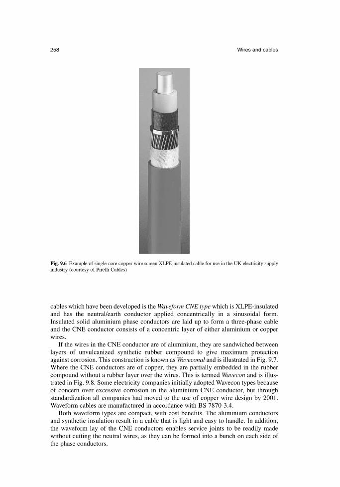
cables which have been developed is the Waveform CNE type which is XLPE-insulatedand has the neutral/earth conductor applied concentrically in a sinusoidal form.Insulated solid aluminium phase conductors are laid up to form a three-phase cableand the CNE conductor consists of a concentric layer of either aluminium or copperwires.
If the wires in the CNE conductor are of aluminium, they are sandwiched betweenlayers of unvulcanized synthetic rubber compound to give maximum protectionagainst corrosion. This construction is known as Waveconal and is illustrated in Fig. 9.7.Where the CNE conductors are of copper, they are partially embedded in the rubbercompound without a rubber layer over the wires. This is termed Wavecon and is illus-trated in Fig. 9.8. Some electricity companies initially adopted Wavecon types becauseof concern over excessive corrosion in the aluminium CNE conductor, but throughstandardization all companies had moved to the use of copper wire design by 2001.Waveform cables are manufactured in accordance with BS 7870-3.4.
Both waveform types are compact, with cost benefits. The aluminium conductorsand synthetic insulation result in a cable that is light and easy to handle. In addition,the waveform lay of the CNE conductors enables service joints to be readily madewithout cutting the neutral wires, as they can be formed into a bunch on each side ofthe phase conductors.
258 Wires and cables
Fig. 9.6 Example of single-core copper wire screen XLPE-insulated cable for use in the UK electricity supplyindustry (courtesy of Pirelli Cables)
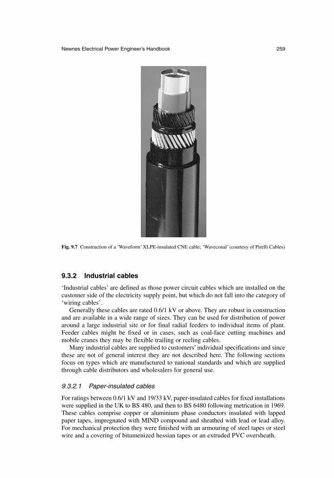
9.3.2 Industrial cables
‘Industrial cables’ are defined as those power circuit cables which are installed on thecustomer side of the electricity supply point, but which do not fall into the category of‘wiring cables’.
Generally these cables are rated 0.6/1 kV or above. They are robust in constructionand are available in a wide range of sizes. They can be used for distribution of poweraround a large industrial site or for final radial feeders to individual items of plant.Feeder cables might be fixed or in cases, such as coal-face cutting machines andmobile cranes they may be flexible trailing or reeling cables.
Many industrial cables are supplied to customers’ individual specifications and sincethese are not of general interest they are not described here. The following sectionsfocus on types which are manufactured to national standards and which are suppliedthrough cable distributors and wholesalers for general use.
9.3.2.1 Paper-insulated cables
For ratings between 0.6/1 kV and 19/33 kV, paper-insulated cables for fixed installationswere supplied in the UK to BS 480, and then to BS 6480 following metrication in 1969.These cables comprise copper or aluminium phase conductors insulated with lappedpaper tapes, impregnated with MIND compound and sheathed with lead or lead alloy.For mechanical protection they were finished with an armouring of steel tapes or steelwire and a covering of bitumenized hessian tapes or an extruded PVC oversheath.
Newnes Electrical Power Engineer’s Handbook 259
Fig. 9.7 Construction of a ‘Waveform’ XLPE-insulated CNE cable; ‘Waveconal’ (courtesy of Pirelli Cables)
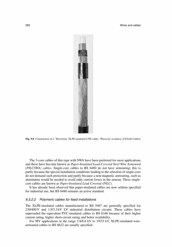
The 3-core cables of this type with SWA have been preferred for most applicationsand these have become known as Paper-Insulated Lead-Covered Steel Wire Armoured(PILCSWA) cables. Single-core cables to BS 6480 do not have armouring; this ispartly because the special installation conditions leading to the selection of single-coredo not demand such protection and partly because a non-magnetic armouring, such asaluminium would be needed to avoid eddy current losses in the armour. These single-core cables are known as Paper-Insulated Lead Covered (PILC).
It has already been observed that paper-insulated cables are now seldom specifiedfor industrial use, but BS 6480 remains an active standard.
9.3.2.2 Polymeric cables for fixed installations
The XLPE-insulated cables manufactured to BS 5467 are generally specified for230/400 V and 1.9/3.3 kV LV industrial distribution circuits. These cables have superseded the equivalent PVC-insulated cables to BS 6346 because of their highercurrent rating, higher short-circuit rating and better availability.
For MV applications in the range 3.8/6.6 kV to 19/33 kV, XLPE-insulated wire-armoured cables to BS 6622 are usually specified.
260 Wires and cables
Fig. 9.8 Construction of a ‘Waveform’ XLPE-insulated CNE cable; ‘Wavecon’ (courtesy of Pirelli Cables)
Multi-core LV and MV cables are normally steel wire armoured. This armouringnot only provides protection against impact damage for these generally bulky andexposed cables, but it is also capable of carrying very large earth fault currents and provides a very effective earth connection.
Single-core cables are generally unarmoured, although aluminium wire armouredversions are available. Single-core cables are usually installed where high currents arepresent (for instance in power stations) and where special precautions will be taken toavoid impact damage. For LV circuits of this type, the most economic approach is touse unarmoured cable with a separate earth conductor, rather than to connect in parallelthe aluminium wire armour of several single-core cables. For MV applications, each unarmoured cable has a screen of copper wires which would together provide aneffective earth connection.
Even in the harsh environment of coal mines, XLPE-insulated types are nowoffered as an alternative to the traditional PVC- and EPR-insulated cables used at LV and MV, respectively. In this application the cables are always multi-core typeshaving a single or double layer of SWA. The armour has to have a specified minimumconductance because of the special safety requirements associated with earth faultsand this demands the substitution of some steel wires by copper wires for certain cablesizes.
Where LSF fire performance is needed, LV wire-armoured cables to BS 6724 are the established choice. These cables are identical in construction and properties to those made to BS 5467 except for the LSF grade of sheathing material and the associated fire performance. Cables meeting all the requirements of BS 6724 and, inaddition, having a measure of fire resistance such that they continue to function in afire are standardized in BS 7846, further details of which are given in section 9.3.3.Similarly, BS 7835 for MV wire-armoured cable, which is identical to BS 6622 apartfrom the LSF sheath and fire performance, was issued in 1996 and revised in 2000.
The only other type of standardized cable used for fixed industrial circuits is multi-core control cable, often referred to as auxiliary cable. Such cable is used to control industrial plant, including equipment in power stations. It is generally wire-armoured and rated 0.6/1 kV. Cables of this type are available with between 5 and 48 cores. The constructions are similar to 0.6/1 kV power cables and they are manu-factured and supplied to the same standards (BS 5467, BS 6346 and BS 6724, asappropriate).
9.3.2.3 Polymeric cables for flexible connections
Flexible connections for both multi-core power cables and multi-core control cablesare often required in industrial locations. The flexing duty varies substantially fromapplication to application. At one extreme a cable may need to be only flexible enoughto allow the connected equipment to be moved occasionally for maintenance. At theother extreme the cable may be needed to supply a mobile crane from a cable reel ora coal-face cutter from cable-handling gear.
Elastomeric-insulated and sheathed cable is used for all such applications. This mayhave flexible stranded conductors (known as ‘class 5’) or highly flexible stranded con-ductors (known as ‘class 6’). Where metallic protection or screening is needed, thiscomprises a braid of fine steel or copper wires. For many flexible applications thecable is required to have a resistance to various chemicals and oils.
Although flexible cables will normally be operated on a 230/400 V supply, it is normal to use 450/750 V rated cables for maximum safety and integrity.
Newnes Electrical Power Engineer’s Handbook 261
A number of cable types have been standardized in order to meet the range of performance requirements and the specification for these is incorporated into BS 6500.Guidance on the use of the cables is provided in this standard and further informationis available in BS 7540.
9.3.3 Wiring cables
The standard cable used in domestic and commercial wiring in the UK since the 1960sis a flat PVC twin-and-earth type, alternatively known as 6242Y cable. This comprisesa flat formation of PVC-insulated live and neutral cores separated by a bare earth conductor, the whole assembly being PVC-sheathed to produce a flat cable rated at300/500 V. Cable is also available with three insulated cores and a bare earth, for useon double-switched lighting circuits. These forms of cable are ideal for installationunder cladding in standard-depth plaster. They are defined in BS 6004, which coversa large size range, only the smaller sizes of which are used in domestic and commer-cial circuits.
There are other cable types included in BS 6004 which have more relevance to non-domestic installations. These include cables in both flat and circular form, similar to the 6242Y type but with an insulated earth conductor. Circular cables designated6183Y are widely used in commercial or light industrial areas, especially where manycircuits are mounted together on cable trays. Also included in BS 6004 are insulatedconductors designated 6491X which are pulled into conduit or trunking in circuitswhere mechanical protection or the facility to re-wire are the key factors.
Of recent years, LSF versions of the twin-and-earth cables and the conduit wireshave become available and are being used in installations where particular emphasison fire performance is required. Such cables are included in BS 7211. These are commonly known as 6242B (for twin flat) or 6491B (for single-core conduit wire).
A significant change occurred in 2004 for all fixed wiring in electrical installationsin the UK. An amendment was published to BS 7671 (the IEE Wiring Regulations)which specified new cable core colours to bring the UK more closely into line with practice in mainland Europe; the term harmonized core colours is often used. Forsingle-phase fixed installations, the red phase and black neutral are replaced by brownphase and blue neutral, as used for many years in flexible cables for appliances. Forthree phase cables, the new phase colours are brown, black and grey instead of red, yellow and blue, with the neutral now blue instead of black. In both cases, the protective conductor is still identified by a green–yellow combination. An alternativefor three-phase cables is for all phase cores to be brown and marking of L1, L2 and L3to be carried out at terminations. The neutral will be blue again in this case. Electricalinstallations commenced after 31 March 2004 may use either the new harmonized corecolours or the pre-existing colours, but not both. New installations after 31 March2006 must only use the harmonized core colours.
An alternative type of cable with outstanding impact and crush strength is mineral-insulated cable (MICC) manufactured to BS EN 60702-1. This is often known by itstrade name, Pyrotenax. In a MICC cable, the copper line and neutral conductors arepositioned inside a copper sheath, the spaces between the copper components beingfilled with heavily compacted mineral powder of insulating grade. Pressure or impactapplied to the cable merely compresses the powder in such a way that the insulationintegrity is maintained. The copper sheath often acts as the circuit earth conductor. Anoversheath is not necessary but is often provided for reasons of appearance or for exter-nal marking. An MICC cable has a relatively small cross section and is easy to install.
262 Wires and cables
In shopping and office complexes or in blocks of flats there may be a need for a distribution sub-main to feed individual supply points or meters. If this sub-main is tobe installed and operated by the owner of the premises, then a 0.6/1 kV split-concentricservice cable to BS 4553 may be used. This comprises a phase conductor insulated inPVC or XLPE, around which is a layer of copper wires and an oversheath. Some ofthe copper wires are bare and these are used as the earth conductor. The remainder arepolymer-covered and they make up the neutral conductor. For larger installations, 3-core versions of this cable are available to manufacturers’ specification.
In circuits supplying equipment for fire detection and alarm, emergency lightingand emergency supplies, regulations dictate that the cables will continue to operateduring a fire. This continued operation could be ensured by measures, such as embed-ding the cable in masonry, but may be achieved by cables which are fire-resistant in themselves. BS 5839-1:2002, the code of practice for fire detection and fire alarmsystems for buildings, recommends the use of fire resisting cables for mains powersupply circuits and all critical signal paths in such systems. Fire-resistance tests forcables are set down in BS 6387, BS 8434-1, BS 8434-2 and EN 50200. The latter threetests are called up in BS 5839-1 although two levels of survival time are specified, 30 minutes for ‘standard’ and 120 minutes for ‘enhanced’. The three types of cable are recognized in the code of practice are to BS EN 60702-1 (as described earlier), BS 7846 and BS 7629 (both as described below).
The MICC cables to BS EN 60702-1 should comply with the ‘enhanced’ perform-ance, since the mineral insulation is unaffected by fire. An MICC cable will only failwhen the copper conductor or sheath melts and where such severe fires might occurthe cable can be sheathed in LSF material to assist in delaying the onset of melting.MICC cable is also categorized CWZ in BS 6387.
A number of alternatives to MICC cables for fire resistance have been developedand standardized. Some rely on a filled silicone rubber insulation which degrades toan insulating char, which continues to provide separation between the conductors so that circuit integrity is maintained during a fire. Other types supplement standard insulation with layers of mica tape so that even if the primary insulation burns com-pletely the mica tape provides essential insulation to maintain supplies during the fire.Both cable types are standardized in BS 7629, and in addition to complying with performance levels up to CWZ of BS 6387, designs also may comply with either the‘standard’ or ‘enhanced’ performance required by BS 5839-1.
Some circuits requiring an equivalent level of fire resistance need to be designedwith larger cables than are found in BS 7629. Such circuits might be for the main emer-gency supply, fire-fighting lifts, sprinkler systems and water pumps, smoke extractionfans, fire shutters or smoke dampers. These larger cables are standardized in BS 7846,which includes the size range and LSF performance of BS 6724, but through the use of layers of mica tape to supplement the insulation these cables can be supplied to theCWZ performance level in BS 6387, and additionally to the ‘standard’ or ‘enhanced’performance levels specified in BS 5839-1. An additional fire test category in BS 7846,called F3, may be considered to be more appropriate for applications where the cablemight be subject to fire, impact and water spray in combination during the fire.
9.4 Parameters and test methods
There are a large number of cable and material properties which are controlled by the manufacturer in order to ensure fitness for purpose and reliable long-term service
Newnes Electrical Power Engineer’s Handbook 263
performance. However, it is the operating parameters of the finished installed cablewhich are of most importance to the user in cable selection. The major parameters ofinterest are as follows:
current rating capacitance inductance voltage drop earth loop impedance symmetrical fault capacity earth fault capacity
These are dealt with in turn in the following sections.
9.4.1 Current rating
The current rating of each individual type of cable could be measured by subjecting a sample to a controlled environment and by increasing the load current passingthrough the cable until the steady-state temperature of the limiting cable componentreached its maximum permissible continuous level. This would be a very costly way of establishing current ratings for all types of cable in all sizes, in all environmentsand in all ambient temperatures. Current ratings are therefore obtained using an internationally-accepted calculation method, published in IEC 60287. The formulaeand reference material properties presented in IEC 60287 have been validated by correlation with data produced from laboratory experiments.
Current ratings are quoted in manufacturers’ literature and they are listed in IEEWiring Regulations (BS 7671) for some industrial, commercial and domestic cables.The ratings are quoted for each cable type and size in air, in masonry, direct-in-groundand in underground ducts. Derating factors are given so that these quoted ratings canbe adjusted for different environmental conditions, such as ambient temperature, soilresistivity or depth of burial.
Information is given in BS 7671 and in the IEE Guidance Notes on the selection ofthe appropriate fuse or mcb to protect the cable from overload and fault conditions, andgeneral background is given in sections 8.2 and 8.3.
9.4.2 Capacitance
The capacitance data in manufacturers’ literature is calculated from the cable dimen-sions and the permittivity of the insulation.
For example, the star capacitance of a 3-core belted armoured cable to BS 6346 is the effective capacitance between a phase conductor and the neutral star point. It iscalculated using the following formula:
(9.1)
where εo = relative permittivity of the cable insulation (8.0 for PVC)d = diameter of the conductor (mm)t1 = thickness of insulation between the conductors (mm)t2 = thickness of insulation between conductor and armour (mm)
Cd t t d
=+ +εo
1 2n[( ) / ]( F / km)
18lµ
264 Wires and cables
Equation 9.1 assumes that the conductors are circular in section. For those cables having shaped conductors, the value of capacitance is obtained by multiplying the figureobtained using eqn 9.1 by an empirical factor of 1.08.
The calculated capacitance tends to be conservative, that is the actual capacitancewill always be lower than the calculated value. However, if an unusual situation arisesin which the cable capacitance is critical, then the manufacturer is able to make ameasurement using a capacitance bridge.
If the measured capacitance between cores and between core and armour is quoted,then the star capacitance can be calculated using eqn 9.2:
(9.2)
where Cx = measured capacitance between one conductor and the othertwo connected together to the armour
Cy = measured capacitance between three conductors connectedtogether and the armour
9.4.3 Inductance
The calculation of cable inductance L for the same example of a 3-core armoured cableto BS 6346 is given by eqn 9.3 as follows:
L = 1.02 × 0.2 × ln[2Y/d] + k (mH/km) (9.3)
where d = diameter of the conductor (mm)Y = axial spacing between conductors (mm)k = a factor which depends on the conductor make-up
(k = 0.064 for 7-wire stranded0.055 for 19-wire stranded0.053 for 37-wire stranded0.050 for solid)
The same value of cable inductance L is used for cables with circular- or sector-shapedconductors.
9.4.4 Voltage drop
BS 7671 specifies that within customer premises the voltage drop in cables is to be amaximum value of 4 per cent. It is therefore necessary to calculate the voltage dropalong a cable.
The cable manufacturer calculates voltage drop assuming that the cable will beloaded with the maximum allowable current which results in the maximum allowableoperating temperature of the conductor. The cable impedance used for calculating thevoltage drop is given by eqn 9.4.
Z = R2 + (2π fL − 1/2π fC)21/2 (Ω/m) (9.4)
where R = ac resistance of the conductor at maximum conductortemperature (Ω/m)
L = inductance (H/m)C = capacitance (F/m)f = supply frequency (Hz)
CC Cx y=
−9
6 ( F/km)µ
Newnes Electrical Power Engineer’s Handbook 265
The voltage drop is then given by eqns 9.5 and 9.6:For single-phase circuits:
voltage drop = 2Z (V/A/m) (9.5)
and for three-phase circuits:
voltage drop = (3)1/2Z (V/A/m) (9.6)
9.4.5 Symmetrical and earth fault capacity
It is necessary that cables used for power circuits are capable of carrying any fault cur-rents that may flow, without damage to the cable; the requirements are specified in BS7671. This assessment demands a knowledge of the maximum prospective fault cur-rents on the circuit, the clearance characteristics of the protective device (as explainedin Chapter 8) and the fault capacity of the relevant elements in the cable. For mostinstallations it is necessary to establish the let-through energy of the protective deviceand to compare this with the adiabatic heating capacity of the conductor (in the case ofsymmetrical and earth faults) or of the steel armour (in the case of earth faults).
The maximum let-through energy (I 2t) of the protective device is explained in Chapter 8. It can be obtained from the protective device manufacturer’s data. In practice the value will be less than that shown by the manufacturer’s informationbecause of the reduction in current during the fault which results from the significantrise in temperature and resistance of the cable conductors.
The fault capacity of the cable conductor and armour can be obtained from information given in BS 7671 and the appropriate BS cable standard, as follows:
k2S2 = adiabatic fault capacity of the cable element (9.7)
where S = the nominal cross section of the conductor orthe nominal cross section of, say, the armour (mm2)
k = a factor reflecting the resistivity, temperature coefficient, allowable temperature rise and specific heat of the metallic cable element(k = 115 for a PVC-insulated copper conductor within the cable
= 176 for an XLPE-insulated copper earth conductor external to the cable
= 46 for the steel armour of an XLPE-insulated cable)In practice it will be found that provided the cable rating is at least equal to the nominal rating of the protective device and the maximum fault duration is less than 5 seconds, the conductors and armour of the cables to BS will easily accommodate thelet-through energy of the protective device.
It is also important that the impedance of the supply cable is not so high that the protective device takes too long to operate during a zero-sequence earth fault onconnected equipment. This is important because of the need to protect any person in contact with the equipment, by limiting the time that the earthed casing of the equip-ment, say, can become energized during an earth fault.
This requirement, which is stated in BS 7671, places restrictions on the length of thecable that can be used on the load side of a protective device, and it therefore demandsknowledge of the earth fault loop impedance of the cable. Some cable manufacturers havecalculated the earth fault impedance for certain cable types and the data are presented inspecialized literature. These calculations take account of the average temperature of eachconductor and the reactance of the cable during the fault. The values are supported by
266 Wires and cables
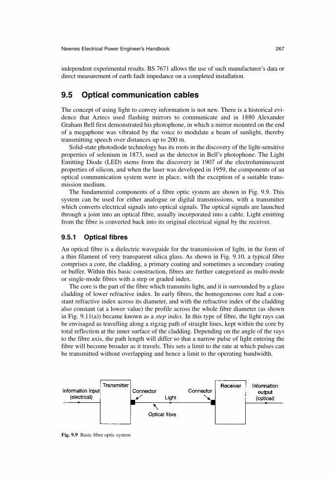
independent experimental results. BS 7671 allows the use of such manufacturer’s data ordirect measurement of earth fault impedance on a completed installation.
9.5 Optical communication cables
The concept of using light to convey information is not new. There is a historical evi-dence that Aztecs used flashing mirrors to communicate and in 1880 AlexanderGraham Bell first demonstrated his photophone, in which a mirror mounted on the endof a megaphone was vibrated by the voice to modulate a beam of sunlight, therebytransmitting speech over distances up to 200 m.
Solid-state photodiode technology has its roots in the discovery of the light-sensitiveproperties of selenium in 1873, used as the detector in Bell’s photophone. The LightEmitting Diode (LED) stems from the discovery in 1907 of the electroluminescentproperties of silicon, and when the laser was developed in 1959, the components of anoptical communication system were in place, with the exception of a suitable trans-mission medium.
The fundamental components of a fibre optic system are shown in Fig. 9.9. Thissystem can be used for either analogue or digital transmissions, with a transmitterwhich converts electrical signals into optical signals. The optical signals are launchedthrough a joint into an optical fibre, usually incorporated into a cable. Light emittingfrom the fibre is converted back into its original electrical signal by the receiver.
9.5.1 Optical fibres
An optical fibre is a dielectric waveguide for the transmission of light, in the form ofa thin filament of very transparent silica glass. As shown in Fig. 9.10, a typical fibrecomprises a core, the cladding, a primary coating and sometimes a secondary coatingor buffer. Within this basic construction, fibres are further categorized as multi-modeor single-mode fibres with a step or graded index.
The core is the part of the fibre which transmits light, and it is surrounded by a glasscladding of lower refractive index. In early fibres, the homogeneous core had a con-stant refractive index across its diameter, and with the refractive index of the claddingalso constant (at a lower value) the profile across the whole fibre diameter (as shownin Fig. 9.11(a)) became known as a step index. In this type of fibre, the light rays canbe envisaged as travelling along a zigzag path of straight lines, kept within the core bytotal reflection at the inner surface of the cladding. Depending on the angle of the raysto the fibre axis, the path length will differ so that a narrow pulse of light entering thefibre will become broader as it travels. This sets a limit to the rate at which pulses canbe transmitted without overlapping and hence a limit to the operating bandwidth.
Newnes Electrical Power Engineer’s Handbook 267
Fig. 9.9 Basic fibre optic system
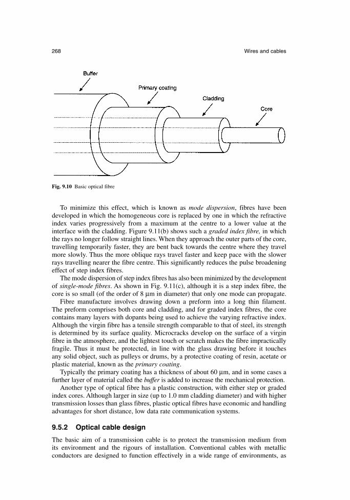
To minimize this effect, which is known as mode dispersion, fibres have been developed in which the homogeneous core is replaced by one in which the refractiveindex varies progressively from a maximum at the centre to a lower value at the interface with the cladding. Figure 9.11(b) shows such a graded index fibre, in whichthe rays no longer follow straight lines. When they approach the outer parts of the core,travelling temporarily faster, they are bent back towards the centre where they travelmore slowly. Thus the more oblique rays travel faster and keep pace with the slowerrays travelling nearer the fibre centre. This significantly reduces the pulse broadeningeffect of step index fibres.
The mode dispersion of step index fibres has also been minimized by the developmentof single-mode fibres. As shown in Fig. 9.11(c), although it is a step index fibre, thecore is so small (of the order of 8 µm in diameter) that only one mode can propagate.
Fibre manufacture involves drawing down a preform into a long thin filament. The preform comprises both core and cladding, and for graded index fibres, the corecontains many layers with dopants being used to achieve the varying refractive index.Although the virgin fibre has a tensile strength comparable to that of steel, its strengthis determined by its surface quality. Microcracks develop on the surface of a virginfibre in the atmosphere, and the lightest touch or scratch makes the fibre impracticallyfragile. Thus it must be protected, in line with the glass drawing before it touches any solid object, such as pulleys or drums, by a protective coating of resin, acetate orplastic material, known as the primary coating.
Typically the primary coating has a thickness of about 60 µm, and in some cases afurther layer of material called the buffer is added to increase the mechanical protection.
Another type of optical fibre has a plastic construction, with either step or gradedindex cores. Although larger in size (up to 1.0 mm cladding diameter) and with highertransmission losses than glass fibres, plastic optical fibres have economic and handlingadvantages for short distance, low data rate communication systems.
9.5.2 Optical cable design
The basic aim of a transmission cable is to protect the transmission medium from its environment and the rigours of installation. Conventional cables with metallic conductors are designed to function effectively in a wide range of environments, as
268 Wires and cables
Fig. 9.10 Basic optical fibre
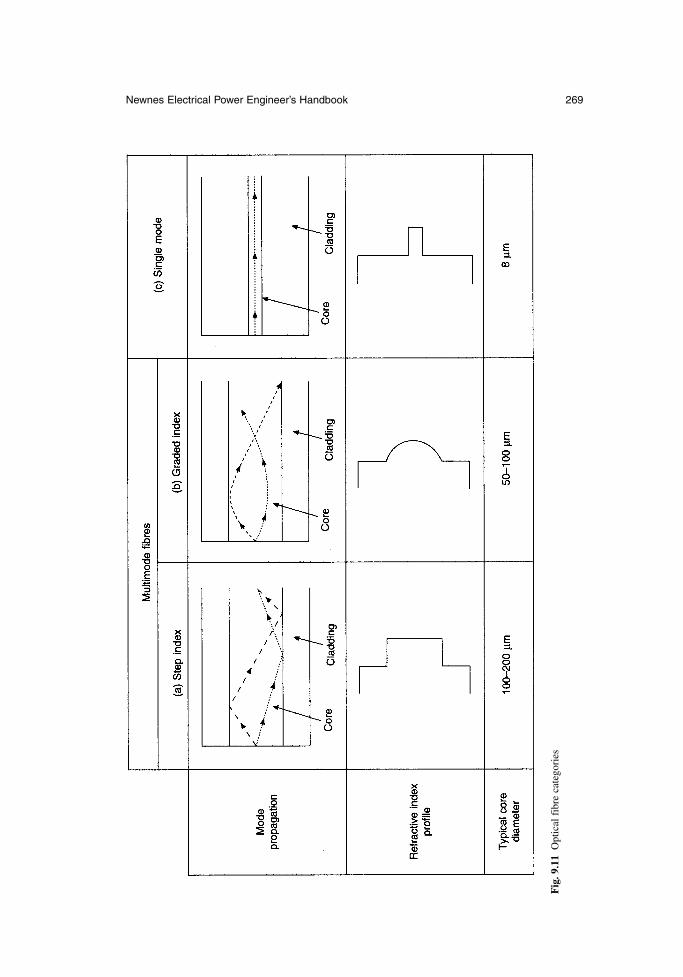
Newnes Electrical Power Engineer’s Handbook 269
Fig
. 9.1
1O
ptic
al f
ibre
cat
egor
ies
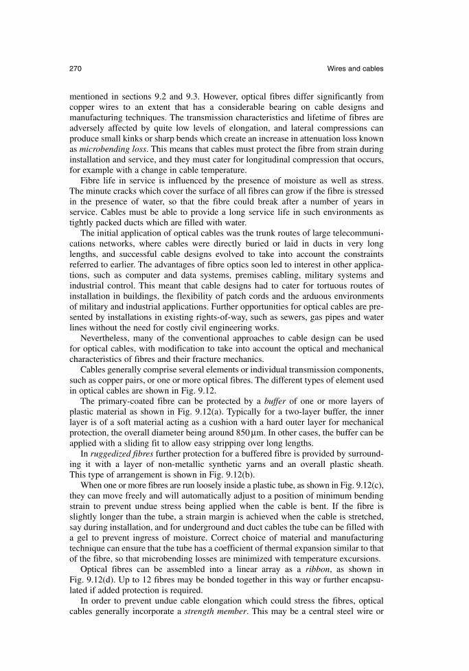
mentioned in sections 9.2 and 9.3. However, optical fibres differ significantly fromcopper wires to an extent that has a considerable bearing on cable designs and manufacturing techniques. The transmission characteristics and lifetime of fibres areadversely affected by quite low levels of elongation, and lateral compressions can produce small kinks or sharp bends which create an increase in attenuation loss knownas microbending loss. This means that cables must protect the fibre from strain duringinstallation and service, and they must cater for longitudinal compression that occurs,for example with a change in cable temperature.
Fibre life in service is influenced by the presence of moisture as well as stress. The minute cracks which cover the surface of all fibres can grow if the fibre is stressedin the presence of water, so that the fibre could break after a number of years in service. Cables must be able to provide a long service life in such environments astightly packed ducts which are filled with water.
The initial application of optical cables was the trunk routes of large telecommuni-cations networks, where cables were directly buried or laid in ducts in very longlengths, and successful cable designs evolved to take into account the constraintsreferred to earlier. The advantages of fibre optics soon led to interest in other applica-tions, such as computer and data systems, premises cabling, military systems andindustrial control. This meant that cable designs had to cater for tortuous routes ofinstallation in buildings, the flexibility of patch cords and the arduous environments of military and industrial applications. Further opportunities for optical cables are pre-sented by installations in existing rights-of-way, such as sewers, gas pipes and waterlines without the need for costly civil engineering works.
Nevertheless, many of the conventional approaches to cable design can be used for optical cables, with modification to take into account the optical and mechanicalcharacteristics of fibres and their fracture mechanics.
Cables generally comprise several elements or individual transmission components,such as copper pairs, or one or more optical fibres. The different types of element usedin optical cables are shown in Fig. 9.12.
The primary-coated fibre can be protected by a buffer of one or more layers of plastic material as shown in Fig. 9.12(a). Typically for a two-layer buffer, the inner layer is of a soft material acting as a cushion with a hard outer layer for mechanicalprotection, the overall diameter being around 850 µm. In other cases, the buffer can beapplied with a sliding fit to allow easy stripping over long lengths.
In ruggedized fibres further protection for a buffered fibre is provided by surround-ing it with a layer of non-metallic synthetic yarns and an overall plastic sheath. This type of arrangement is shown in Fig. 9.12(b).
When one or more fibres are run loosely inside a plastic tube, as shown in Fig. 9.12(c),they can move freely and will automatically adjust to a position of minimum bendingstrain to prevent undue stress being applied when the cable is bent. If the fibre isslightly longer than the tube, a strain margin is achieved when the cable is stretched,say during installation, and for underground and duct cables the tube can be filled witha gel to prevent ingress of moisture. Correct choice of material and manufacturingtechnique can ensure that the tube has a coefficient of thermal expansion similar to thatof the fibre, so that microbending losses are minimized with temperature excursions.
Optical fibres can be assembled into a linear array as a ribbon, as shown in Fig. 9.12(d). Up to 12 fibres may be bonded together in this way or further encapsu-lated if added protection is required.
In order to prevent undue cable elongation which could stress the fibres, opticalcables generally incorporate a strength member. This may be a central steel wire or
270 Wires and cables
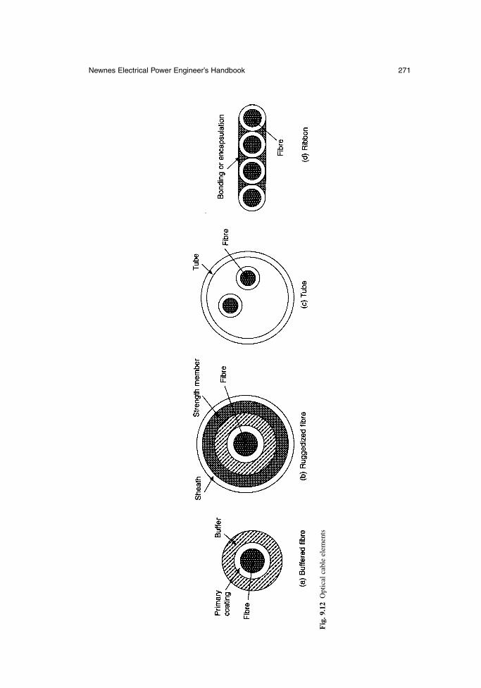
Newnes Electrical Power Engineer’s Handbook 271
Fig
. 9.1
2O
ptic
al c
able
ele
men
ts
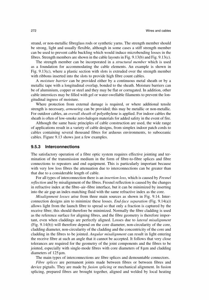
strand, or non-metallic fibreglass rods or synthetic yarns. The strength member shouldbe strong, light and usually flexible, although in some cases a stiff strength membercan be used to prevent cable buckling which would induce microbending losses in thefibres. Strength members are shown in the cable layouts in Fig. 9.13(b) and Fig. 9.13(c).
The strength member can be incorporated in a structural member which is used as a foundation for accommodating the cable elements. An example is shown in Fig. 9.13(c), where a plastic section with slots is extruded over the strength memberwith ribbons inserted into the slots to provide high fibre count cables.
A moisture barrier can be provided either by a continuous metal sheath or by ametallic tape with a longitudinal overlap, bonded to the sheath. Moisture barriers canbe of aluminium, copper or steel and they may be flat or corrugated. In addition, othercable interstices may be filled with gel or water-swellable filaments to prevent the lon-gitudinal ingress of moisture.
Where protection from external damage is required, or where additional tensilestrength is necessary, armouring can be provided; this may be metallic or non-metallic.For outdoor cables, an overall sheath of polyethylene is applied. For indoor cables thesheath is often of low-smoke zero-halogen materials for added safety in the event of fire.
Although the same basic principles of cable construction are used, the wide rangeof applications result in a variety of cable designs, from simplex indoor patch cords tocables containing several thousand fibres for arduous environments, to suboceaniccables. Figure 9.13 shows just a few examples.
9.5.3 Interconnections
The satisfactory operation of a fibre optic system requires effective jointing and ter-mination of the transmission medium in the form of fibre-to-fibre splices and fibreconnections to repeaters and end equipment. This is particularly important becausewith very low loss fibres the attenuation due to interconnections can be greater thanthat due to a considerable length of cable.
For all types of interconnection there is an insertion loss, which is caused by Fresnelreflection and by misalignment of the fibres. Fresnel reflection is caused by the changesin refractive index at the fibre–air–fibre interface, but it can be minimized by insertinginto the air gap an index-matching fluid with the same refractive index as the core.
Misalignment losses arise from three main sources as shown in Fig. 9.14. Inter-connection designs aim to minimize these losses. End-face separation (Fig. 9.14(a))allows light from the launch fibre to spread so that only a fraction is captured by thereceive fibre; this should therefore be minimized. Normally the fibre cladding is usedas the reference surface for aligning fibres, and the fibre geometry is therefore impor-tant, even when claddings are perfectly aligned. Losses due to lateral misalignment(Fig. 9.14(b)) will therefore depend on the core diameter, non-circularity of the core,cladding diameter, non-circularity of the cladding and the concentricity of the core andcladding in the fibres to be jointed. Angular misalignment can result in light enteringthe receive fibre at such an angle that it cannot be accepted. It follows that very closetolerances are required for the geometry of the joint components and the fibres to bejointed, especially with single-mode fibres with core diameters of 8 µm and claddingdiameters of 125 µm.
The main types of interconnections are fibre splices and demountable connectors.Fibre splices are permanent joints made between fibres or between fibres and
device pigtails. They are made by fusion splicing or mechanical alignment. In fusionsplicing, prepared fibres are brought together, aligned and welded by local heating
272 Wires and cables
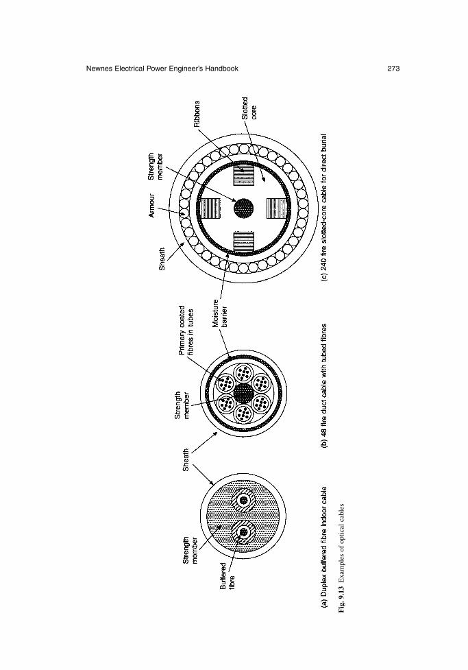
Newnes Electrical Power Engineer’s Handbook 273
Fig
. 9.1
3E
xam
ples
of
optic
al c
able
s
combined with axial pressure. Sophisticated portable equipment is used for fusionsplicing in the field. This accurately aligns the fibres by local light injection and it carries out the electric arc welding process automatically. Nevertheless, a level of skillis required in the preparation of the fibres, stripping the buffers and coatings and cleaving the fibres to achieve a proper end face. There are a number of mechanical techniques for splicing fibres which involve fibre alignment by close tolerance tubes,ferrules and v-grooves, and fixing by crimps, glues or resins. Both fusion and mechani-cal splicing techniques have been developed to allow simultaneous splicing of fibreswhich are particularly suitable for fibre ribbons. For a complete joint, the splices mustbe incorporated into an enclosure which is suitable for a variety of environments, suchas underground chambers or pole tops. The enclosure must also terminate the cablesand organize the fibres and splices, and cassettes are often used where several hundredsplices are to be accommodated.
Demountable connectors provide system flexibility, particularly at and within thetransmission equipment and distribution panels, and they are widely used on patchcords in certain data systems. As with splices, the connector must minimize Fresneland misalignment loss, but it must also allow for repeated connection and disconnec-tion, it must protect the fibre end face and it must cater for mechanical stress, such astension, torsion and bending. There are many designs but in general the toleranceswhich are achievable on the dimensions of the various components result in a higheroptical loss than in a splice. Demountable connectors have also been developed for
274 Wires and cables
Fig. 9.14 Sources of misalignment loss
multiple-fibre simultaneous connection, with array designs being particularly suitablefor fibre ribbons. For connector-intensive systems, such as office data systems, use ismade of factory-predetermined cables and patch cords to reduce the need for on-sitetermination.
9.5.4 Installation
Optical fibre cables are designed so that normal installation practices and equipmentcan be used wherever possible, but as they generally have a lower strain limit thanmetallic cables special care may be needed in certain circumstances and manufacturer’srecommendations regarding tensile loads and bending radii should be followed.
Special care may be required in the following circumstances:
because of their light weight, optical cables can be installed in greater lengthsthan metallic cables. For long underground ducts access may be needed at inter-mediate points for additional winching effort and space should be allowed forlarger ‘figure 8’ cable deployment.
mechanical fuses and controlled winching may be necessary to ensure that therated tensile load is not exceeded
guiding equipment may be necessary to avoid subjecting optical cables to unacceptable bending stresses, particularly when the cable is also under tension
when installing cables in trenches the footing should be free from stones. Thesecould cause microbending losses.
in buildings, and particularly in risers, cleats and fixings should not be overtightened, or appropriate designs should be used to prevent compressionand the resulting microbending losses
indoor cable routes should provide turning points if a large number of bends isinvolved. Routes should be as straight as possible.
excess lengths for jointing and testing of optical cables are normally greater thatthose required for metallic cables
where non-metallic optical cables are buried, consideration of the subsequentlocation may be necessary. Marker posts and the incorporation of a locationwire may be advisable.
Blown fibre systems have been developed as a means of avoiding fibre overstrain forcomplex route installation and of allowing easy system upgrading and future proofing.It results in low initial capital costs and provides for the distribution of subsequentcosts. Initially developed by British Telecom, the network infrastructure is created bythe most appropriate cabling method, being one or a group of empty plastic tubes. Asand when circuit provision is required, one or more fibres can be blown by compressedair into the tubes. Individual tubes can, by means of connectors, be extended withinbuildings up to the fibre terminating equipment. The efficient installation of fibres intothe tube network often requires the use of specially-designed fibres and equipment,such as air supply modules, fibre insertion tools and fibre pay-offs. For installation it isnecessary to follow the instructions provided by the supplier, taking into account therequirements for the use of portable electrical equipment and compressed air, and thehandling, cutting and disposal of optical fibres. A novel variation of this system is a datacable used for structural wiring systems. In a ‘figure-8’ configuration one unit comprisesa 4-pair data cable and the other an empty tube, so that when an upgrade is required toan optical system the appropriate fibre can be blown in without the need for recabling.
Newnes Electrical Power Engineer’s Handbook 275
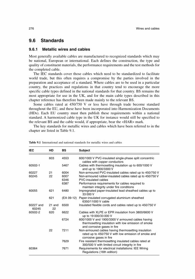
9.6 Standards
9.6.1 Metallic wires and cables
Most generally available cables are manufactured to recognized standards which maybe national, European or international. Each defines the construction, the type andquality of constituent materials, the performance requirements and the test methods forthe completed cable.
The IEC standards cover those cables which need to be standardized to facilitateworld trade, but this often requires a compromise by the parties involved in the preparation and acceptance of a standard. Where cables are to be used in a particularcountry, the practices and regulations in that country tend to encourage the more specific cable types defined in the national standards for that country. BS remains themost appropriate for use in the UK, and for the main cable types described in thischapter reference has therefore been made mainly to the relevant BS.
Some cables rated at 450/750 V or less have through trade become standardthroughout the EU, and these have been incorporated into Harmonization Documents(HDs). Each EU country must then publish these requirements within a national standard. A harmonized cable type in the UK for instance would still be specified tothe relevant BS and the cable would, if appropriate, bear the <HAR> mark.
The key standards for metallic wires and cables which have been referred to in thechapter are listed in Table 9.1.
276 Wires and cables
Table 9.1 International and national standards for metallic wires and cables
IEC HD BS Subject
603 4553 600/1000 V PVC-insulated single-phase split concentric cables with copper conductors
60502-1 5467 Cables with thermosetting insulation up to 600/1000 V and up to 1900/3300 V
60227 21 6004 Non-armoured PVC-insulated cables rated up to 450/750 V60245 22 6007 Non-armoured rubber-insulated cables rated up to 450/750 V
6346 PVC-insulated cables6387 Performance requirements for cables required to
maintain integrity under fire conditions60055 621 6480 Impregnated paper-insulated lead sheathed cables up to
33 000 V621 (EA 09-12) Paper-insulated corrugated aluminium sheathed
6350/11000 V cable60227 and 21 and 6500 Insulated flexible cords and cables rated up to 450/750 V
60245 2260502-2 620 6622 Cables with XLPE or EPR insulation from 3800/6600 V
up to 19 000/33 000 V6724 600/1000 V and 1900/3300 V armoured cables having
thermosetting insulation with low emission of smoke and corrosive gases in fire
22 7211 Non-armoured cables having thermosetting insulation rated up to 450/750 V with low emission of smoke and corrosive gases in fire
7629 Fire resistant thermosetting insulated cables rated at 300/500 V with limited circuit integrity in fire
60364 7671 Requirements for electrical installations: IEE Wiring Regulations (16th edition)
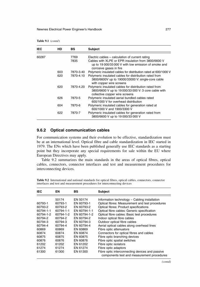
9.6.2 Optical communication cables
For communication systems and their evolution to be effective, standardization mustbe at an international level. Optical fibre and cable standardization in IEC started in1979. The ENs which have been published generally use IEC standards as a startingpoint but they incorporate any special requirements for sale within the EU whereEuropean Directives may apply.
Table 9.2 summarizes the main standards in the areas of optical fibres, opticalcables, connectors, connector interfaces and test and measurement procedures forinterconnecting devices.
Newnes Electrical Power Engineer’s Handbook 277
Table 9.1 (contd )
IEC HD BS Subject
60287 7769 Electric cables – calculation of current rating7835 Cables with XLPE or EPR insulation from 3800/6600 V
up to 19 000/33 000 V with low emission of smoke and corrosive gases in fire
603 7870-3.40 Polymeric insulated cables for distribution rated at 600/1000 V620 7870-4.10 Polymeric insulated cables for distribution rated from
3800/6600V up to 19000/33000 V: single-core cable with copper wire screens
620 7870-4.20 Polymeric insulated cables for distribution rated from 3800/6600 V up to 19 000/33 000 V: 3 core cable with collective copper wire screens
626 7870-5 Polymeric insulated aerial bundled cables rated600/1000 V for overhead distribution
604 7870-6 Polymeric insulated cables for generation rated at 600/1000 V and 1900/3300 V
622 7870-7 Polymeric insulated cables for generation rated from 3800/6600 V up to 19 000/33 000 V
Table 9.2 International and national standards for optical fibres, optical cables, connectors, connectorinterfaces and test and measurement procedures for interconnecting devices
IEC EN BS Subject
50174 EN 50174 Information technology – Cabling installation60793-1 60793-1 EN 60793-1 Optical fibres: Measurement and test procedures60793-2 60793-2 EN 60793-2 Optical fibres: Product specifications60794-1-1 60794-1-1 EN 60794-1-1 Optical fibre cables: Generic specification60794-1-2 60794-1-2 EN 60794-1-2 Optical fibre cables: Basic test procedures60794-2 60794-2 EN 60794-2 Indoor optical fibre cables60794-3 60794-3 EN 60794-3 Outdoor optical fibre cables60794-4 60794-4 EN 60794-4 Aerial optical cables along overhead lines60869 60869 EN 60869 Fibre optic attenuators60874 60874 EN 60874 Connectors for optical fibres and cables60875 60875 EN 60875 Fibre optic branching devices60876 60876 EN 60876 Fibre optic spatial switches61202 61202 EN 61202 Fibre optic isolators61274 61274 EN 61274 Fibre optic adaptors61300 61300 EN 61300 Fibre optic interconnecting devices and passive
components test and measurement procedures
(contd)
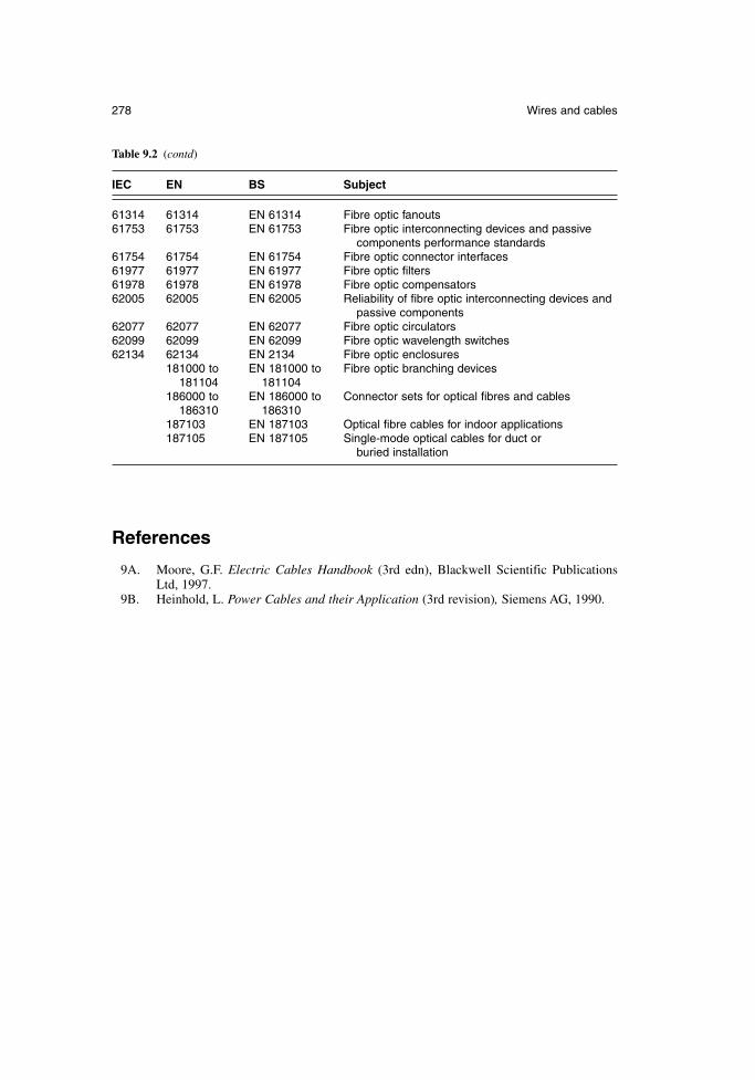
References
9A. Moore, G.F. Electric Cables Handbook (3rd edn), Blackwell Scientific PublicationsLtd, 1997.
9B. Heinhold, L. Power Cables and their Application (3rd revision), Siemens AG, 1990.
278 Wires and cables
Table 9.2 (contd)
IEC EN BS Subject
61314 61314 EN 61314 Fibre optic fanouts61753 61753 EN 61753 Fibre optic interconnecting devices and passive
components performance standards61754 61754 EN 61754 Fibre optic connector interfaces61977 61977 EN 61977 Fibre optic filters61978 61978 EN 61978 Fibre optic compensators62005 62005 EN 62005 Reliability of fibre optic interconnecting devices and
passive components62077 62077 EN 62077 Fibre optic circulators62099 62099 EN 62099 Fibre optic wavelength switches62134 62134 EN 2134 Fibre optic enclosures
181000 to EN 181000 to Fibre optic branching devices181104 181104
186000 to EN 186000 to Connector sets for optical fibres and cables186310 186310
187103 EN 187103 Optical fibre cables for indoor applications187105 EN 187105 Single-mode optical cables for duct or
buried installation
Chapter 10
Motors, motor control and drives
Professor W. DruryControl Techniques, Emerson Industrial Automation
10.1 Introduction
Electric motors can be found in applications from computer disk drives, domestic appli-ances, automobiles to industrial process lines, liquid pumping, conveyors, weavingmachines and many more. Modern building services are heavily reliant upon motorsand drives, which can be found at the heart of air handling and elevator systems. Evenin the world of theatre and film, the electric motor is at the centre of the action, mov-ing scenery and allowing actors to perform death-defying feats in complete safety. Ifit moves, it is reasonable to expect to find that an electric motor is somehow responsible.
The flexibility of power transmission that was introduced by the electric motor hasbeen harnessed and controlled by the application of torque, speed and position controllers, which all fall under the generic term of drives or Variable Speed Drives(VSD). This precision of control has been central to all aspects of industrial automa-tion and has opened up new and demanding applications such as automatic productionand sectional process lines, machine tool axis control, glass engraving, embroiderymachines and precision polishing machines. It has also facilitated considerable reduc-tions in energy consumption by regulation of flow through speed control in fan andpump type loads, where power consumption is proportional to the cube of the speed.This ability to reduce energy consumption continues to be a major stimulus to growthin the variable speed drives market.
Many ac motors operate at fixed speed, being connected directly to the fixed-frequencysupply system, but of the 70 per cent of all electrical power which flows through electricmotors, a significant proportion passes through semiconductor conversion in the form ofdrives. The importance of this technology is self-evident, though the selection of appro-priate equipment is often less clear. It would be a difficult, if not impossible, task to detailevery motor type and associated power conversion circuit available, and the focus herewill be on those of greatest practical importance in the broad base of industries.
All electric motors have a stationary component, the stator, and a moving component,the rotor. In conventional motors, the rotor turns within the stator, but special motors areavailable for applications such as material handling conveyors where the rotor rotatesoutside the stator. In linear motors, the rotor moves along the path of the stator. In allcases, the rotor and stator are separated by an air-gap. The stator and rotor usually havea laminated steel core to reduce the losses arising from time-varying magnetic fields (as explained in section 3.2).
Almost all electric motors adhere to common fundamental principles of operation.This so-called unified theory of electric machines is important in the design and
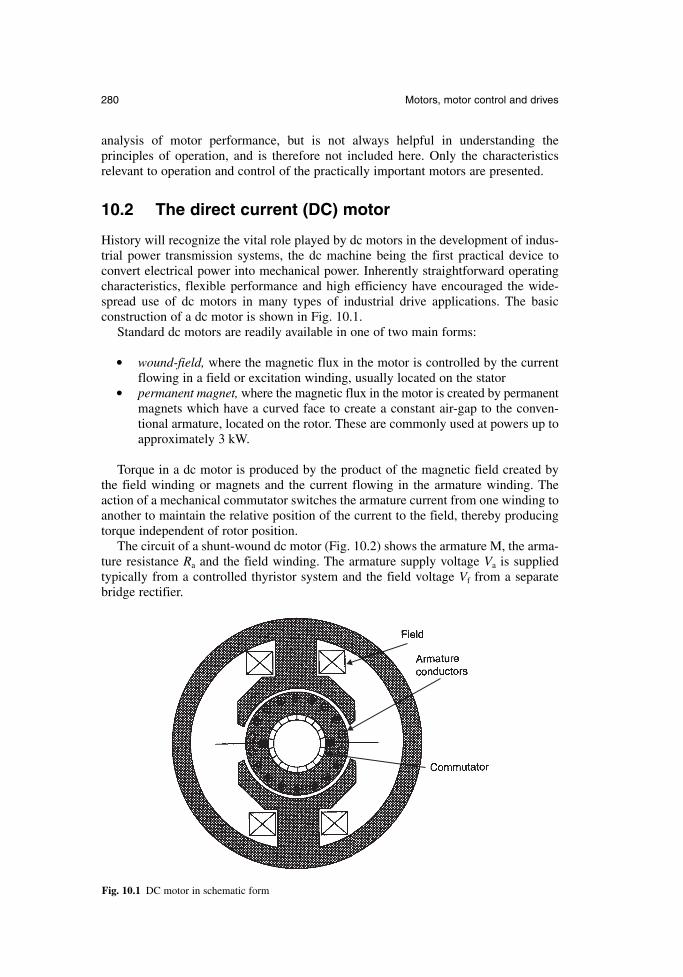
analysis of motor performance, but is not always helpful in understanding the principles of operation, and is therefore not included here. Only the characteristics relevant to operation and control of the practically important motors are presented.
10.2 The direct current (DC) motor
History will recognize the vital role played by dc motors in the development of indus-trial power transmission systems, the dc machine being the first practical device toconvert electrical power into mechanical power. Inherently straightforward operatingcharacteristics, flexible performance and high efficiency have encouraged the wide-spread use of dc motors in many types of industrial drive applications. The basic construction of a dc motor is shown in Fig. 10.1.
Standard dc motors are readily available in one of two main forms:
wound-field, where the magnetic flux in the motor is controlled by the current flowing in a field or excitation winding, usually located on the stator
permanent magnet, where the magnetic flux in the motor is created by permanentmagnets which have a curved face to create a constant air-gap to the conven-tional armature, located on the rotor. These are commonly used at powers up toapproximately 3 kW.
Torque in a dc motor is produced by the product of the magnetic field created bythe field winding or magnets and the current flowing in the armature winding. Theaction of a mechanical commutator switches the armature current from one winding toanother to maintain the relative position of the current to the field, thereby producingtorque independent of rotor position.
The circuit of a shunt-wound dc motor (Fig. 10.2) shows the armature M, the arma-ture resistance Ra and the field winding. The armature supply voltage Va is suppliedtypically from a controlled thyristor system and the field voltage Vf from a separatebridge rectifier.
280 Motors, motor control and drives
Fig. 10.1 DC motor in schematic form
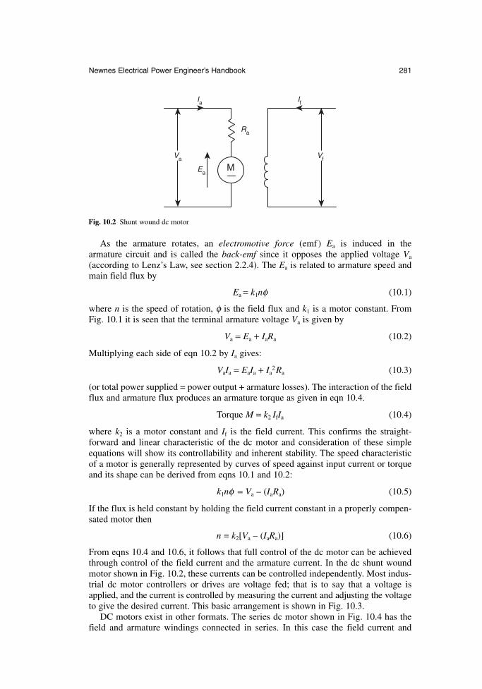
As the armature rotates, an electromotive force (emf) Ea is induced in the armature circuit and is called the back-emf since it opposes the applied voltage Va
(according to Lenz’s Law, see section 2.2.4). The Ea is related to armature speed andmain field flux by
Ea = k1nφ (10.1)
where n is the speed of rotation, φ is the field flux and k1 is a motor constant. FromFig. 10.1 it is seen that the terminal armature voltage Va is given by
Va = Ea + IaRa (10.2)
Multiplying each side of eqn 10.2 by Ia gives:
VaIa = EaIa + Ia2Ra (10.3)
(or total power supplied = power output + armature losses). The interaction of the fieldflux and armature flux produces an armature torque as given in eqn 10.4.
Torque M = k2 IfIa (10.4)
where k2 is a motor constant and If is the field current. This confirms the straight-forward and linear characteristic of the dc motor and consideration of these simpleequations will show its controllability and inherent stability. The speed characteristicof a motor is generally represented by curves of speed against input current or torqueand its shape can be derived from eqns 10.1 and 10.2:
k1nφ = Va – (IaRa) (10.5)
If the flux is held constant by holding the field current constant in a properly compen-sated motor then
n = k2[Va – (IaRa)] (10.6)
From eqns 10.4 and 10.6, it follows that full control of the dc motor can be achievedthrough control of the field current and the armature current. In the dc shunt woundmotor shown in Fig. 10.2, these currents can be controlled independently. Most indus-trial dc motor controllers or drives are voltage fed; that is to say that a voltage isapplied, and the current is controlled by measuring the current and adjusting the voltageto give the desired current. This basic arrangement is shown in Fig. 10.3.
DC motors exist in other formats. The series dc motor shown in Fig. 10.4 has thefield and armature windings connected in series. In this case the field current and
Newnes Electrical Power Engineer’s Handbook 281
Va Vf
Ia If
Ra
EaM
Fig. 10.2 Shunt wound dc motor
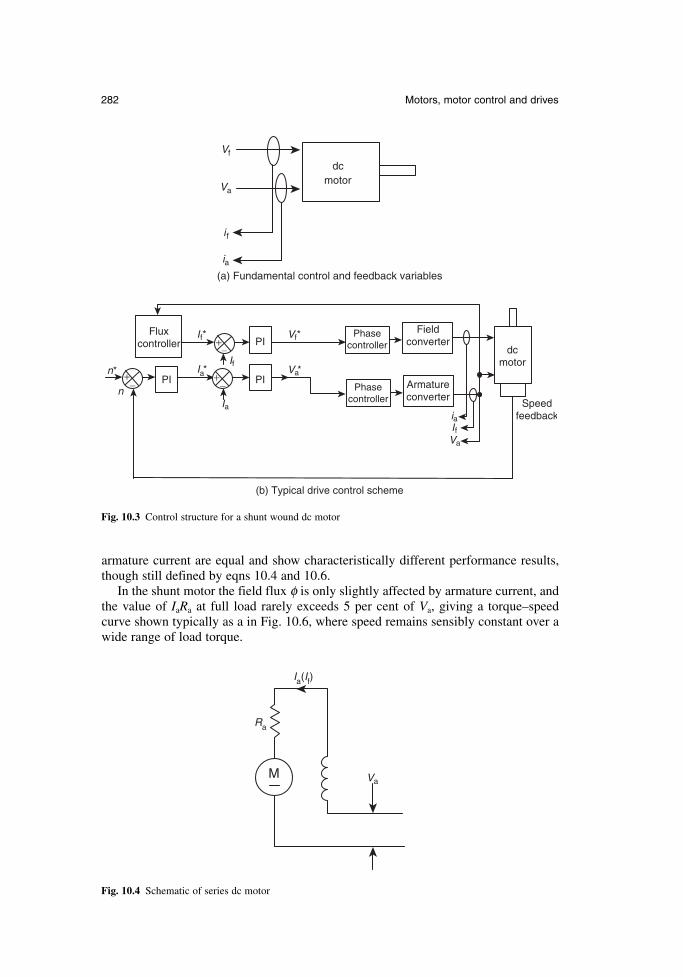
282 Motors, motor control and drives
dcmotor
Vf
Va
i f
ia(a) Fundamental control and feedback variables
Fig. 10.3 Control structure for a shunt wound dc motor
Field converter
Armature converter
dc motor
Flux controller
Phase controller
Phase controller
PI PI
PI
+
+
_n
Speed feedback
_
_
+
Ia
If
If* Vf*
Va*
Va
Ifia
n* Ia*
(b) Typical drive control scheme
Ra
M Va
Ia(If)
Fig. 10.4 Schematic of series dc motor
armature current are equal and show characteristically different performance results,though still defined by eqns 10.4 and 10.6.
In the shunt motor the field flux φ is only slightly affected by armature current, andthe value of IaRa at full load rarely exceeds 5 per cent of Va, giving a torque–speedcurve shown typically as a in Fig. 10.6, where speed remains sensibly constant over awide range of load torque.
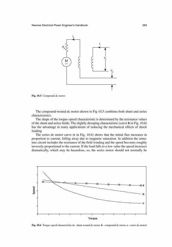
The compound-wound dc motor shown in Fig 10.5 combines both shunt and seriescharacteristics.
The shape of the torque–speed characteristic is determined by the resistance valuesof the shunt and series fields. The slightly drooping characteristic (curve b in Fig. 10.6)has the advantage in many applications of reducing the mechanical effects of shockloading.
The series dc motor curve (c in Fig. 10.6) shows that the initial flux increases inproportion to current, falling away due to magnetic saturation. In addition the arma-ture circuit includes the resistance of the field winding and the speed becomes roughlyinversely proportional to the current. If the load falls to a low value the speed increasesdramatically, which may be hazardous, so, the series motor should not normally be
Newnes Electrical Power Engineer’s Handbook 283
Ra
M
Va
Ia
Vf
If
Fig. 10.5 Compound dc motor
Torque
Sp
eed
a
b
c
Fig. 10.6 Torque–speed characteristic (a - shunt wound dc motor, b - compound dc motor, c - series dc motor)
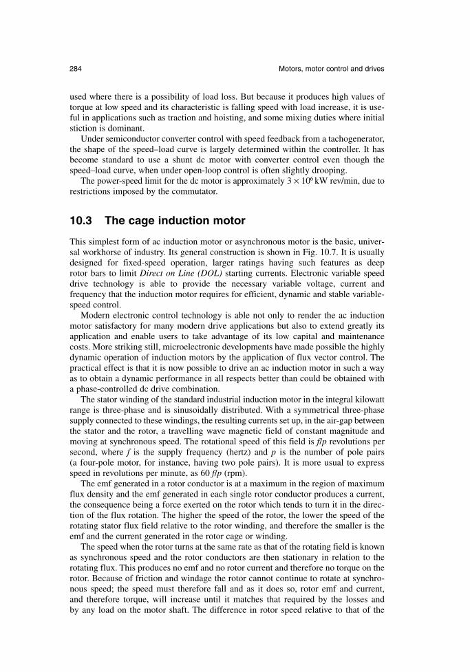
used where there is a possibility of load loss. But because it produces high values oftorque at low speed and its characteristic is falling speed with load increase, it is use-ful in applications such as traction and hoisting, and some mixing duties where initialstiction is dominant.
Under semiconductor converter control with speed feedback from a tachogenerator,the shape of the speed–load curve is largely determined within the controller. It hasbecome standard to use a shunt dc motor with converter control even though thespeed–load curve, when under open-loop control is often slightly drooping.
The power-speed limit for the dc motor is approximately 3 × 10⁶ kW rev/min, due torestrictions imposed by the commutator.
10.3 The cage induction motor
This simplest form of ac induction motor or asynchronous motor is the basic, univer-sal workhorse of industry. Its general construction is shown in Fig. 10.7. It is usuallydesigned for fixed-speed operation, larger ratings having such features as deep rotor bars to limit Direct on Line (DOL) starting currents. Electronic variable speeddrive technology is able to provide the necessary variable voltage, current and frequency that the induction motor requires for efficient, dynamic and stable variable-speed control.
Modern electronic control technology is able not only to render the ac inductionmotor satisfactory for many modern drive applications but also to extend greatly itsapplication and enable users to take advantage of its low capital and maintenancecosts. More striking still, microelectronic developments have made possible the highlydynamic operation of induction motors by the application of flux vector control. Thepractical effect is that it is now possible to drive an ac induction motor in such a wayas to obtain a dynamic performance in all respects better than could be obtained witha phase-controlled dc drive combination.
The stator winding of the standard industrial induction motor in the integral kilowattrange is three-phase and is sinusoidally distributed. With a symmetrical three-phasesupply connected to these windings, the resulting currents set up, in the air-gap betweenthe stator and the rotor, a travelling wave magnetic field of constant magnitude andmoving at synchronous speed. The rotational speed of this field is f/p revolutions persecond, where f is the supply frequency (hertz) and p is the number of pole pairs (a four-pole motor, for instance, having two pole pairs). It is more usual to expressspeed in revolutions per minute, as 60 f/p (rpm).
The emf generated in a rotor conductor is at a maximum in the region of maximumflux density and the emf generated in each single rotor conductor produces a current,the consequence being a force exerted on the rotor which tends to turn it in the direc-tion of the flux rotation. The higher the speed of the rotor, the lower the speed of therotating stator flux field relative to the rotor winding, and therefore the smaller is theemf and the current generated in the rotor cage or winding.
The speed when the rotor turns at the same rate as that of the rotating field is knownas synchronous speed and the rotor conductors are then stationary in relation to therotating flux. This produces no emf and no rotor current and therefore no torque on therotor. Because of friction and windage the rotor cannot continue to rotate at synchro-nous speed; the speed must therefore fall and as it does so, rotor emf and current, and therefore torque, will increase until it matches that required by the losses and by any load on the motor shaft. The difference in rotor speed relative to that of the
284 Motors, motor control and drives
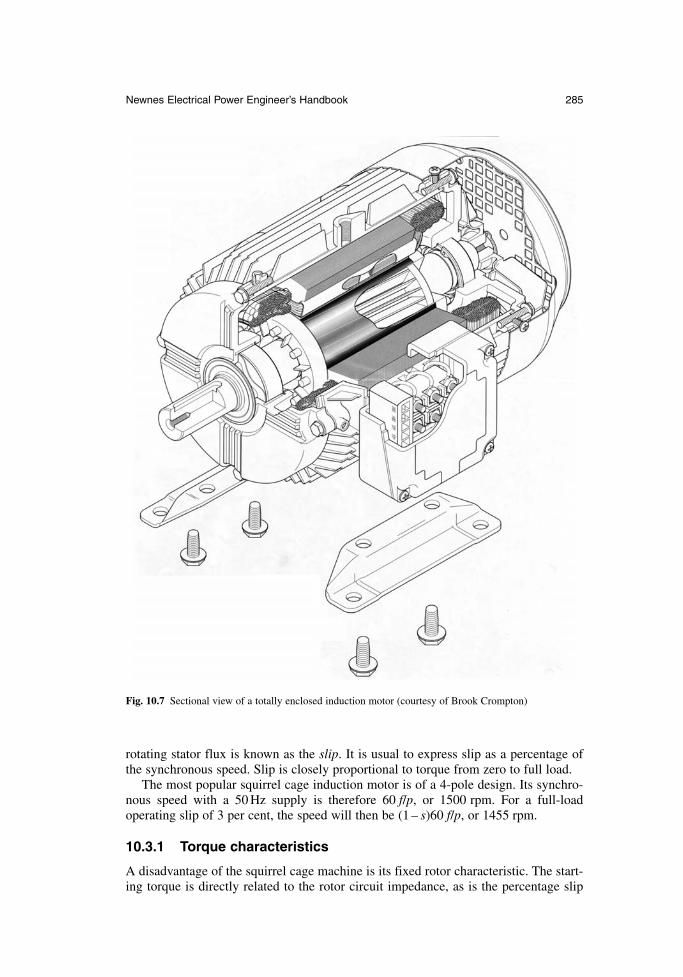
rotating stator flux is known as the slip. It is usual to express slip as a percentage ofthe synchronous speed. Slip is closely proportional to torque from zero to full load.
The most popular squirrel cage induction motor is of a 4-pole design. Its synchro-nous speed with a 50 Hz supply is therefore 60 f/p, or 1500 rpm. For a full-load operating slip of 3 per cent, the speed will then be (1 – s)60 f/p, or 1455 rpm.
10.3.1 Torque characteristics
A disadvantage of the squirrel cage machine is its fixed rotor characteristic. The start-ing torque is directly related to the rotor circuit impedance, as is the percentage slip
Newnes Electrical Power Engineer’s Handbook 285
Fig. 10.7 Sectional view of a totally enclosed induction motor (courtesy of Brook Crompton)
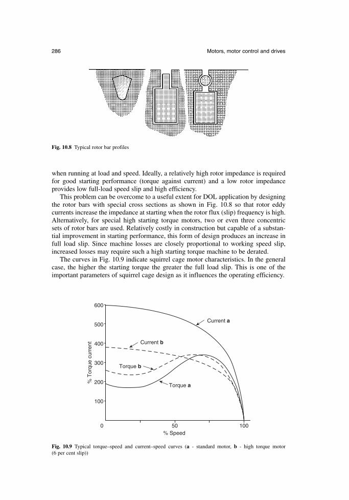
when running at load and speed. Ideally, a relatively high rotor impedance is requiredfor good starting performance (torque against current) and a low rotor impedance provides low full-load speed slip and high efficiency.
This problem can be overcome to a useful extent for DOL application by designingthe rotor bars with special cross sections as shown in Fig. 10.8 so that rotor eddy currents increase the impedance at starting when the rotor flux (slip) frequency is high.Alternatively, for special high starting torque motors, two or even three concentric sets of rotor bars are used. Relatively costly in construction but capable of a substan-tial improvement in starting performance, this form of design produces an increase infull load slip. Since machine losses are closely proportional to working speed slip,increased losses may require such a high starting torque machine to be derated.
The curves in Fig. 10.9 indicate squirrel cage motor characteristics. In the generalcase, the higher the starting torque the greater the full load slip. This is one of theimportant parameters of squirrel cage design as it influences the operating efficiency.
286 Motors, motor control and drives
Fig. 10.8 Typical rotor bar profiles
0 50 100
100
200
300
400
500
600
Current b
Torque b
Torque a
% Speed
% T
orqu
e cu
rren
t
Current a
Fig. 10.9 Typical torque–speed and current–speed curves (a - standard motor, b - high torque motor (6 per cent slip))
10.3.2 Voltage–frequency relationship
To convert a constant speed motor operating direct-on-line to a variable speed driveusing an inverter it is necessary to consider the effect of frequency on flux and torque.The magnitude of the field created by the stator winding is controlled broadly by thevoltage impressed upon the winding by the supply. This is because the resistance ofthe winding results in only a small voltage drop, even at full load current, and there-fore in the steady state the supply voltage must be balanced by the emf induced by therotating field. This induced emf depends on the product of three factors:
the total flux per pole, which is usually determined by the machine designer the total number of turns per phase in the stator winding the rate of field rotation or frequency
For inverter operation the speed of field rotation for which maximum voltage is appro-priate is known as the base speed. The consequence of reducing the supply frequencycan readily be deduced from the aforementioned relationship. For the same flux theinduced emf in the stator winding will be proportional to frequency, hence the voltagesupplied to the machine windings must be correspondingly reduced in order to avoidheavy saturation of the core. This is valid for changes in frequency over a wide range.The voltage–frequency relationship should therefore be linear if a constant flux is tobe maintained within the machine, as the motor designer intended. If flux is constant,so is the motor torque for a given stator current, and the drive therefore has a constant-torque characteristic.
Although constant v/f control is an important underlying principle, it is appropriateto point out departures from it which are essential if a wide speed range is to be covered. First, operation above the base speed is easily achieved by increasing the out-put frequency of the inverter above the normal mains frequency; two or three times thebase speed is easily obtained. The output voltage of an inverter cannot usually be madehigher than its input voltage therefore the v/f characteristic is typically like that shownin Fig. 10.10(a). Since v is constant above base speed, the flux will fall as the fre-quency is increased after the output voltage limit is reached. In Fig. 10.10(b), themachine flux falls in direct proportion to the v/f ratio. Although this greatly reduces thecore losses, the ability of the machine to produce torque is impaired and less mechan-ical load is needed to draw full load current from the inverter. The drive is said to havea constant-power characteristic above base speed. Many applications not requiring fulltorque at high speeds can make use of this extended speed range. Secondly, departurefrom constant v/f is beneficial at very low speeds, where the voltage drop arising fromthe stator resistance becomes significantly large. This voltage drop is at the expense offlux, as shown in Fig. 10.10(b). To maintain a truly constant flux within the machinethe terminal voltage must be increased above the constant v/f value to compensate forthe stator resistance effect. Indeed, as output frequency approaches zero, the optimumvoltage becomes the voltage equal to the stator IR drop. Compensation for stator resist-ance is normally referred to as voltage boost and almost all inverters offer some formof adjustment so that the degree of voltage boost can be matched to the actual windingresistance. It is normal for the boost to be gradually tapered to zero as the frequencyprogresses towards base speed. Figure 10.10(c) shows a typical scheme for taperedboost. It is important to appreciate that the level of voltage boost should increase if ahigh starting torque is required, since in this case the IR drop will be greater by virtueof the increased stator current. In this case automatic load-dependent boost control is
Newnes Electrical Power Engineer’s Handbook 287
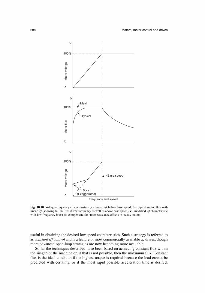
288 Motors, motor control and drives
Base speed
Frequency and speed
Mot
or v
olta
geM
otor
vol
tage
Mot
or fl
ux
Typical
Ideal
Boost (Exaggerated)
V
V
100%
100%
100%
Φ
c
b
a
Fig. 10.10 Voltage–frequency characteristics (a - linear v/f below base speed, b - typical motor flux withlinear v/f (showing fall in flux at low frequency as well as above base speed), c - modified v/f characteristicwith low frequency boost (to compensate for stator resistance effects in steady state))
useful in obtaining the desired low speed characteristics. Such a strategy is referred toas constant v/f control and is a feature of most commercially available ac drives, thoughmore advanced open-loop strategies are now becoming more available.
So far the techniques described have been based on achieving constant flux withinthe air-gap of the machine or, if that is not possible, then the maximum flux. Constantflux is the ideal condition if the highest torque is required because the load cannot bepredicted with certainty, or if the most rapid possible acceleration time is desired.
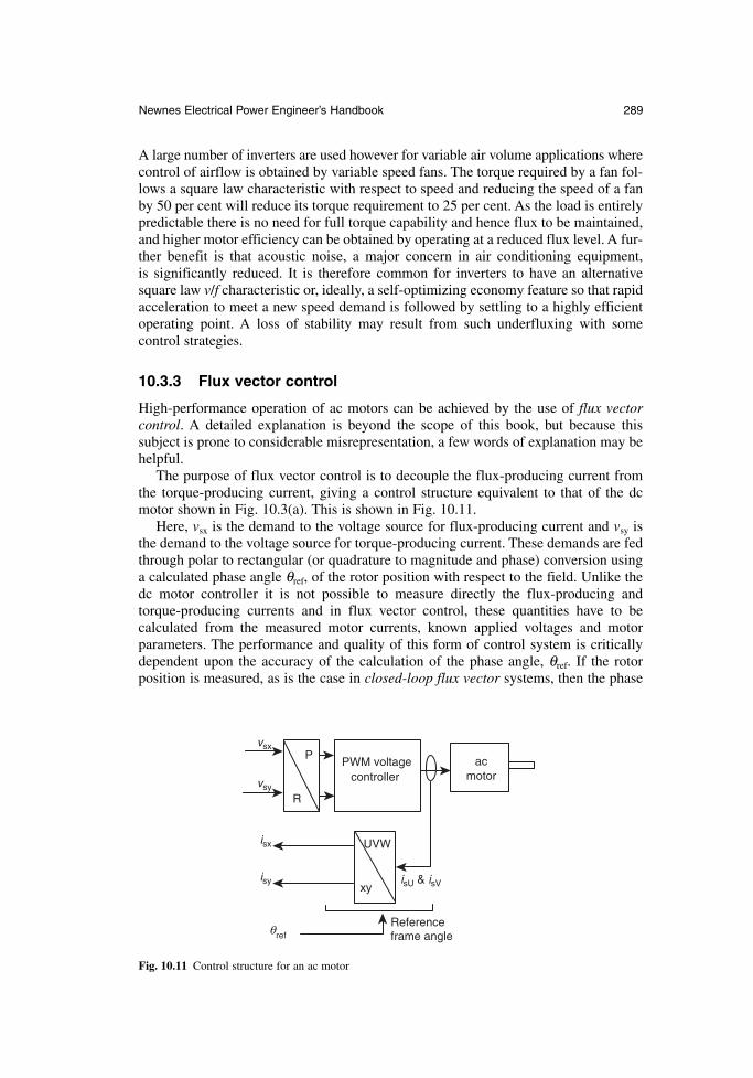
A large number of inverters are used however for variable air volume applications wherecontrol of airflow is obtained by variable speed fans. The torque required by a fan fol-lows a square law characteristic with respect to speed and reducing the speed of a fanby 50 per cent will reduce its torque requirement to 25 per cent. As the load is entirelypredictable there is no need for full torque capability and hence flux to be maintained,and higher motor efficiency can be obtained by operating at a reduced flux level. A fur-ther benefit is that acoustic noise, a major concern in air conditioning equipment, is significantly reduced. It is therefore common for inverters to have an alternativesquare law v/f characteristic or, ideally, a self-optimizing economy feature so that rapidacceleration to meet a new speed demand is followed by settling to a highly efficientoperating point. A loss of stability may result from such underfluxing with some control strategies.
10.3.3 Flux vector control
High-performance operation of ac motors can be achieved by the use of flux vectorcontrol. A detailed explanation is beyond the scope of this book, but because this subject is prone to considerable misrepresentation, a few words of explanation may behelpful.
The purpose of flux vector control is to decouple the flux-producing current fromthe torque-producing current, giving a control structure equivalent to that of the dcmotor shown in Fig. 10.3(a). This is shown in Fig. 10.11.
Here, vsx is the demand to the voltage source for flux-producing current and vsy isthe demand to the voltage source for torque-producing current. These demands are fedthrough polar to rectangular (or quadrature to magnitude and phase) conversion usinga calculated phase angle θref, of the rotor position with respect to the field. Unlike thedc motor controller it is not possible to measure directly the flux-producing andtorque-producing currents and in flux vector control, these quantities have to be calculated from the measured motor currents, known applied voltages and motorparameters. The performance and quality of this form of control system is criticallydependent upon the accuracy of the calculation of the phase angle, θref. If the rotorposition is measured, as is the case in closed-loop flux vector systems, then the phase
Newnes Electrical Power Engineer’s Handbook 289
PWM voltagecontroller
P
R
UVW
xyisU & isV
vsx
vsy
isx
isy
acmotor
Reference frame anglerefθ
Fig. 10.11 Control structure for an ac motor
angle can be calculated very precisely, and excellent flux and torque control is possi-ble at frequencies including 0 Hz. Key performance measures include dynamics,where the performance of dc motors is easily exceeded, and torque linearity, which can be controlled within 2 per cent over the entire operating range in motoring andbraking operation. In open-loop control systems, where there is no rotor speed or posi-tion measurement, the quality of the control system is critically dependent upon theperformance of the phase angle estimator. Modern industrial systems have to balanceperformance with robustness in operation, and robustness when a standard controlleris applied to different industrial motors.
10.4 The slipring induction motor
The wound rotor or slipring ac machine addresses some of the disadvantages of thecage induction motor, but with the handicap of extra cost and the complexity ofbrushes and insulated rotor windings.
With the correct value of (usually) resistance inserted in the rotor circuit, anear-unity relationship between torque and supply current at starting can be achieved,such as 100 per cent full load torque (FLT), with 100 per cent full load current (FLC)and 200 per cent FLT with 200 per cent FLC. This is comparable with the startingcapability of the dc machine. Not only high starting efficiency but also smoothly controlled acceleration historically gave the slipring motor a great popularity for lift,hoist and crane applications. It has had a similar popularity with fan engineers, providing a limited range of air volume control (either 2:1 or 3:1 reduction) at constantload by the use of speed-regulating variable resistances in the rotor circuit. Although afan presents a square-law torque–speed characteristic, so that motor currents fall considerably with speed, losses in the rotor regulator at lower motor speeds are stillrelatively high, severely limiting the useful speed range.
Efficient variable-speed control of slipring motors can be achieved by slip energyrecovery in which the the slip frequency on the rotor is converted to supply frequency.It is possible to retrofit variable frequency inverters to existing slipring motors simply by short-circuiting the slipring terminations (ideally on the rotor thereby eliminating the brushes) and treating the motor as a cage machine.
Variable voltage control of slipring motors has been used extensively, notably incrane and lift applications, though these applications are now largely being met by fluxvector drives.
10.5 The ac synchronous motor
In a synchronous motor, torque can be produced at synchronous speed. This isachieved by a field winding, generally wound on the rotor, and dc excited so that it produces a rotor flux which is stationary relative to the rotor. Torque is producedwhen the rotating three-phase field produced by currents in the stator winding and therotor field are stationary relative to each other, hence there must be physical rotationof the rotor at synchronous speed ns in order that its field travels in step with the stator field axis. At any other speed a rotor pole would approach alternately a stator‘north’ pole field, then a ‘south’ pole field, changing the resulting torque from a posi-tive to a negative value at a frequency related to the speed difference, the mean torquebeing zero.
290 Motors, motor control and drives

A typical inverter for variable speed control automatically regulates the main statorvoltage to be in proportion to motor frequency. It is possible to arrange an excitationcontrol loop which monitors the main stator voltage and increases the excitation fieldvoltage proportionately.
The ac synchronous motor has attractive features for inverter variable speed driveapplications, particularly at ratings of 40 kW and above. Not least is overall cost whencompared with a cage induction motor and inverter, or a dc shunt wound motor withconverter alternatives. In applications requiring a synchronous speed relationshipbetween multiple drives, or precise speed control of single large drives the ac synchro-nous motor with inverter control system appears attractive, freedom from brushgearmaintenance, good working efficiency and power factor being the main considerations.
10.6 The brushless servomotor
A synchronous machine with permanent magnets on the rotor is the heart of the modern brushless servomotor drive. The motor stays in synchronism with the frequency of supply, though there is a limit to the maximum torque which can bedeveloped before the rotor is forced out of synchronism, pull-out torque being typically between 1.5 and 4 times the continuously rated torque. The torque–speedcurve is therefore simply a vertical line.
The industrial application of brushless servomotors has grown significantly for thefollowing reasons:
reduction of price of power conversion products establishment of advanced control of PWM inverters development of new, more powerful and easier to use permanent magnet materials the developing need for highly accurate position control the manufacture of all these components in a very compact form
They are, in principle, easy to control because the torque is generated in proportion tothe current. In addition, they have high efficiency, and high dynamic responses can beachieved.
Brushless servomotors are often called brushless dc servomotors because their struc-ture is different from that of dc servomotors. They rectify current by means of transistorswitching within the associated drive or amplifier, instead of a commutator as used in dcservomotors. Confusingly, they are also called ac servomotors because brushless servo-motors of the synchronous type (with a permanent magnet rotor) detect the position ofthe rotational magnetic field to control the three-phase current of the armature. It is nowwidely recognized that brushless ac refers to a motor with a sinusoidal stator windingdistribution which is designed for use on a sinusoidal or PWM inverter supply voltage.Brushless dc refers to a motor with a trapezoidal stator winding distribution which isdesigned for use on a square wave or block commutation inverter supply voltage.
The brushless servomotor lacks the commutator of the dc motor, and has a device(the drive, sometimes referred to as the amplifier) for making the current flow accord-ing to the rotor position. In the dc motor, increasing the number of commutator seg-ments reduces torque variation. In the brushless motor, torque variation is reduced bymaking the coil three-phase and, in the steady state, by controlling the current of eachphase into a sine wave.
Newnes Electrical Power Engineer’s Handbook 291
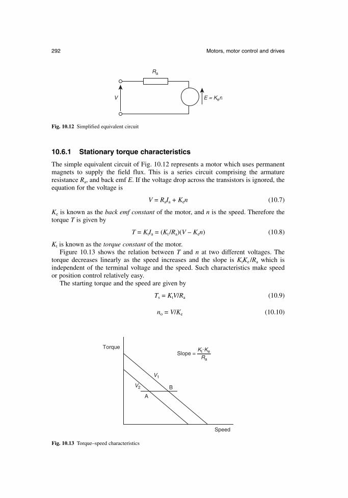
10.6.1 Stationary torque characteristics
The simple equivalent circuit of Fig. 10.12 represents a motor which uses permanentmagnets to supply the field flux. This is a series circuit comprising the armature resistance Ra, and back emf E. If the voltage drop across the transistors is ignored, theequation for the voltage is
V = RaIa + Ken (10.7)
Ke is known as the back emf constant of the motor, and n is the speed. Therefore thetorque T is given by
T = KtIa = (Kt /Ra)(V – Ken) (10.8)
Kt is known as the torque constant of the motor.Figure 10.13 shows the relation between T and n at two different voltages. The
torque decreases linearly as the speed increases and the slope is KtKe /Ra which is independent of the terminal voltage and the speed. Such characteristics make speed or position control relatively easy.
The starting torque and the speed are given by
Ts = KtV/Ra (10.9)
no = V/Ke (10.10)
292 Motors, motor control and drives
Ra
V E = Ken
Fig. 10.12 Simplified equivalent circuit
Torque
Speed
A
B
V1
V2
Ra
Kt.KeSlope =
Fig. 10.13 Torque–speed characteristics
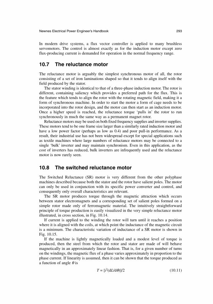
In modern drive systems, a flux vector controller is applied to many brushless servomotors. The control is almost exactly as for the induction motor except zero flux-producing current is demanded for operation in the normal frequency range.
10.7 The reluctance motor
The reluctance motor is arguably the simplest synchronous motor of all, the rotor consisting of a set of iron laminations shaped so that it tends to align itself with thefield produced by the stator.
The stator winding is identical to that of a three-phase induction motor. The rotor isdifferent, containing saliency which provides a preferred path for the flux. This is the feature which tends to align the rotor with the rotating magnetic field, making it aform of synchronous machine. In order to start the motor a form of cage needs to beincorporated into the rotor design, and the motor can then start as an induction motor.Once a higher speed is reached, the reluctance torque ‘pulls in’ the rotor to run synchronously in much the same way as a permanent magnet rotor.
Reluctance motors may be used on both fixed frequency supplies and inverter supplies.These motors tend to be one frame size larger than a similarly rated induction motor andhave a low power factor (perhaps as low as 0.4) and poor pull-in performance. As aresult, their industrial use has not been widespread except for special applications suchas textile machines where large numbers of reluctance motors may be connected to a single ‘bulk’ inverter and may maintain synchronism. Even in this application, as thecost of inverters has reduced, bulk inverters are infrequently used and the reluctancemotor is now rarely seen.
10.8 The switched reluctance motor
The Switched Reluctance (SR) motor is very different from the other polyphasemachines described because both the stator and the rotor have salient poles. The motorcan only be used in conjunction with its specific power converter and control, and consequently only overall characteristics are relevant.
The SR motor produces torque through the magnetic attraction which occursbetween stator electromagnets and a corresponding set of salient poles formed on asimple rotor made only of ferromagnetic material. The intuitively straightforward principle of torque production is easily visualized in the very simple reluctance motorillustrated, in cross section, in Fig. 10.14.
If current is applied to the winding the rotor will turn until it reaches a positionwhere it is aligned with the coils, at which point the inductance of the magnetic circuitis a minimum. The characteristic variation of inductance of a SR motor is shown inFig. 10.15.
If the machine is lightly magnetically loaded and a modest level of torque is produced, then the steel from which the rotor and stator are made of will behave magnetically in an approximately linear fashion. That is, for a given number of turnson the windings, the magnetic flux of a phase varies approximately in proportion to thephase current. If linearity is assumed, then it can be shown that the torque produced asa function of angle θ is
T = [i2(dL/dθ)]/2 (10.11)
Newnes Electrical Power Engineer’s Handbook 293
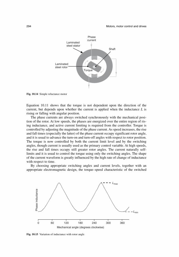
Equation 10.11 shows that the torque is not dependent upon the direction of the current, but depends upon whether the current is applied when the inductance L is rising or falling with angular position.
The phase currents are always switched synchronously with the mechanical posi-tion of the rotor. At low speeds, the phases are energized over the entire region of ris-ing inductance, and active current limiting is required from the controller. Torque iscontrolled by adjusting the magnitude of the phase current. As speed increases, the riseand fall times (especially the latter) of the phase current occupy significant rotor angle,and it is usual to advance the turn-on and turn-off angles with respect to rotor position.The torque is now controlled by both the current limit level and by the switchingangles, though current is usually used as the primary control variable. At high speeds,the rise and fall times occupy still greater rotor angles. The current naturally self-limits and it is usual to control the torque using only the switching angles. The shapeof the current waveform is greatly influenced by the high rate of change of inductancewith respect to time.
By choosing appropriate switching angles and current levels, together with anappropriate electromagnetic design, the torque–speed characteristic of the switched
294 Motors, motor control and drives
Torque
Phasecurrent
Laminatedsteel stator
Laminatedsteel rotor
Shaft
Fig. 10.14 Simple reluctance motor
0 60 120 180 240 300 360
Mechanical angle (degrees clockwise)
Pha
se in
duct
ance
Lmax
Lmin
Fig. 10.15 Variation of inductance with rotor angle
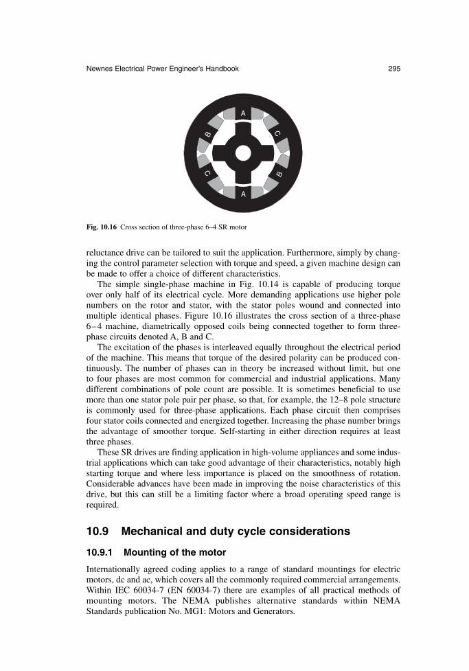
reluctance drive can be tailored to suit the application. Furthermore, simply by chang-ing the control parameter selection with torque and speed, a given machine design canbe made to offer a choice of different characteristics.
The simple single-phase machine in Fig. 10.14 is capable of producing torque over only half of its electrical cycle. More demanding applications use higher polenumbers on the rotor and stator, with the stator poles wound and connected into multiple identical phases. Figure 10.16 illustrates the cross section of a three-phase6–4 machine, diametrically opposed coils being connected together to form three-phase circuits denoted A, B and C.
The excitation of the phases is interleaved equally throughout the electrical periodof the machine. This means that torque of the desired polarity can be produced con-tinuously. The number of phases can in theory be increased without limit, but one to four phases are most common for commercial and industrial applications. Many different combinations of pole count are possible. It is sometimes beneficial to usemore than one stator pole pair per phase, so that, for example, the 12–8 pole structureis commonly used for three-phase applications. Each phase circuit then comprises four stator coils connected and energized together. Increasing the phase number bringsthe advantage of smoother torque. Self-starting in either direction requires at leastthree phases.
These SR drives are finding application in high-volume appliances and some indus-trial applications which can take good advantage of their characteristics, notably highstarting torque and where less importance is placed on the smoothness of rotation.Considerable advances have been made in improving the noise characteristics of thisdrive, but this can still be a limiting factor where a broad operating speed range isrequired.
10.9 Mechanical and duty cycle considerations
10.9.1 Mounting of the motor
Internationally agreed coding applies to a range of standard mountings for electricmotors, dc and ac, which covers all the commonly required commercial arrangements.Within IEC 60034-7 (EN 60034-7) there are examples of all practical methods ofmounting motors. The NEMA publishes alternative standards within NEMAStandards publication No. MG1: Motors and Generators.
Newnes Electrical Power Engineer’s Handbook 295
A
A
B
B
C
C
Fig. 10.16 Cross section of three-phase 6–4 SR motor
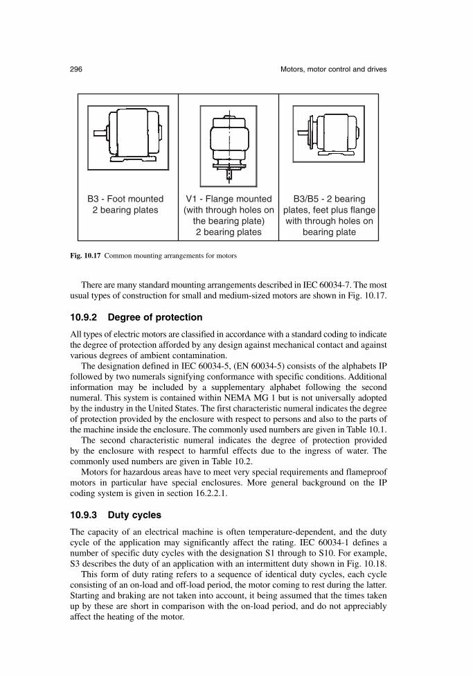
There are many standard mounting arrangements described in IEC 60034-7. The mostusual types of construction for small and medium-sized motors are shown in Fig. 10.17.
10.9.2 Degree of protection
All types of electric motors are classified in accordance with a standard coding to indicatethe degree of protection afforded by any design against mechanical contact and againstvarious degrees of ambient contamination.
The designation defined in IEC 60034-5, (EN 60034-5) consists of the alphabets IPfollowed by two numerals signifying conformance with specific conditions. Additionalinformation may be included by a supplementary alphabet following the secondnumeral. This system is contained within NEMA MG 1 but is not universally adoptedby the industry in the United States. The first characteristic numeral indicates the degreeof protection provided by the enclosure with respect to persons and also to the parts ofthe machine inside the enclosure. The commonly used numbers are given in Table 10.1.
The second characteristic numeral indicates the degree of protection provided by the enclosure with respect to harmful effects due to the ingress of water. The commonly used numbers are given in Table 10.2.
Motors for hazardous areas have to meet very special requirements and flameproofmotors in particular have special enclosures. More general background on the IP coding system is given in section 16.2.2.1.
10.9.3 Duty cycles
The capacity of an electrical machine is often temperature-dependent, and the dutycycle of the application may significantly affect the rating. IEC 60034-1 defines anumber of specific duty cycles with the designation S1 through to S10. For example,S3 describes the duty of an application with an intermittent duty shown in Fig. 10.18.
This form of duty rating refers to a sequence of identical duty cycles, each cycleconsisting of an on-load and off-load period, the motor coming to rest during the latter.Starting and braking are not taken into account, it being assumed that the times takenup by these are short in comparison with the on-load period, and do not appreciablyaffect the heating of the motor.
296 Motors, motor control and drives
B3 - Foot mounted2 bearing plates
V1 - Flange mounted(with through holes on
the bearing plate)2 bearing plates
B3/B5 - 2 bearingplates, feet plus flangewith through holes on
bearing plate
Fig. 10.17 Common mounting arrangements for motors
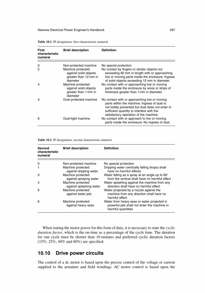
When stating the motor power for this form of duty, it is necessary to state the cyclicduration factor, which is the on-time as a percentage of the cycle time. The durationfor one cycle must be shorter than 10 minutes and preferred cyclic duration factors(15%, 25%, 40% and 60%) are specified.
10.10 Drive power circuits
The control of a dc motor is based upon the precise control of the voltage or currentsupplied to the armature and field windings. AC motor control is based upon the
Newnes Electrical Power Engineer’s Handbook 297
Table 10.1 IP designation: first characteristic numeral
First Brief description Definitioncharacteristic numeral
0 Non-protected machine No special protection2 Machine protected No contact by fingers or similar objects not
against solid objects exceeding 80 mm in length with or approachinggreater than 12 mm in live or moving parts inside the enclosure. Ingress diameter of solid objects exceeding 12 mm in diameter.
4 Machine protected No contact with or approaching live or movingagainst solid objects parts inside the enclosure by wires or strips ofgreater than 1 mm in thickness greater than 1mm in diameter.diameter
5 Dust protected machine No contact with or approaching live or movingparts within the machine. Ingress of dust is not totally prevented but dust does not enter in sufficient quantity to interfere with the satisfactory operation of the machine.
6 Dust-tight machine No contact with or approach to live or movingparts inside the enclosure. No ingress of dust.
Table 10.2 IP designation: second characteristic numeral
Second Brief description Definitioncharacteristic numeral
0 Non-protected machine No special protection1 Machine protected Dripping water (vertically falling drops) shall
against dripping water have no harmful effects3 Machine protected Water falling as a spray at an angle up to 60°
against spraying water from the vertical shall have no harmful effect4 Machine protected Water splashing against the machine from any
against splashing water direction shall have no harmful effect5 Machine protected Water projected by a nozzle against the
against water jets machine from any direction shall have noharmful effect
6 Machine protected Water from heavy seas or water projected inagainst heavy seas powerful jets shall not enter the machine in
harmful quantities
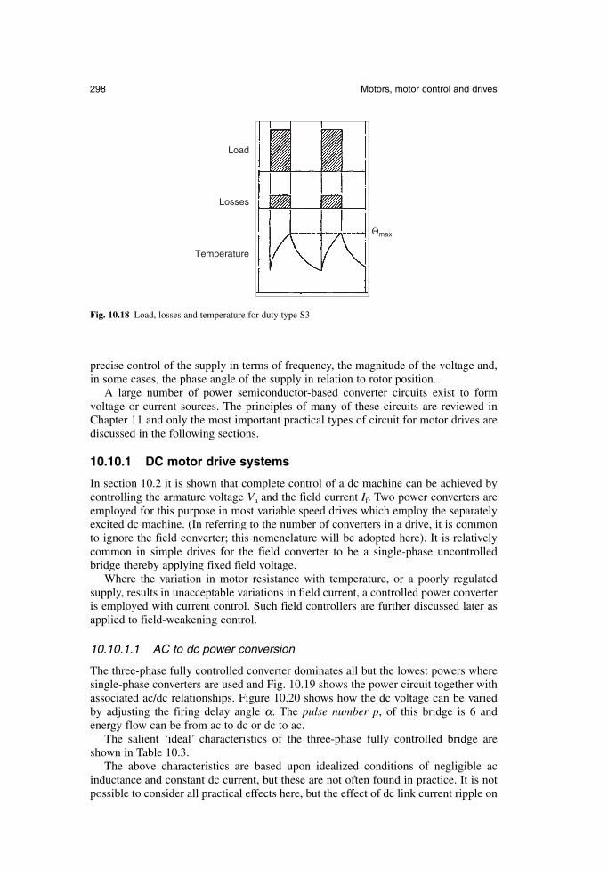
precise control of the supply in terms of frequency, the magnitude of the voltage and,in some cases, the phase angle of the supply in relation to rotor position.
A large number of power semiconductor-based converter circuits exist to form voltage or current sources. The principles of many of these circuits are reviewed inChapter 11 and only the most important practical types of circuit for motor drives arediscussed in the following sections.
10.10.1 DC motor drive systems
In section 10.2 it is shown that complete control of a dc machine can be achieved bycontrolling the armature voltage Va and the field current If. Two power converters areemployed for this purpose in most variable speed drives which employ the separatelyexcited dc machine. (In referring to the number of converters in a drive, it is commonto ignore the field converter; this nomenclature will be adopted here). It is relativelycommon in simple drives for the field converter to be a single-phase uncontrolledbridge thereby applying fixed field voltage.
Where the variation in motor resistance with temperature, or a poorly regulated supply, results in unacceptable variations in field current, a controlled power converteris employed with current control. Such field controllers are further discussed later asapplied to field-weakening control.
10.10.1.1 AC to dc power conversion
The three-phase fully controlled converter dominates all but the lowest powers wheresingle-phase converters are used and Fig. 10.19 shows the power circuit together withassociated ac/dc relationships. Figure 10.20 shows how the dc voltage can be variedby adjusting the firing delay angle α. The pulse number p, of this bridge is 6 andenergy flow can be from ac to dc or dc to ac.
The salient ‘ideal’ characteristics of the three-phase fully controlled bridge areshown in Table 10.3.
The above characteristics are based upon idealized conditions of negligible acinductance and constant dc current, but these are not often found in practice. It is notpossible to consider all practical effects here, but the effect of dc link current ripple on
298 Motors, motor control and drives
Θmax
Temperature
Losses
Load
Fig. 10.18 Load, losses and temperature for duty type S3
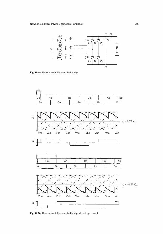
Newnes Electrical Power Engineer’s Handbook 299
S
VasA
Ap Bp CpVd
LOA
D
P id
An Bn Cn
N
B
C
ia
ib
ic
V bs
Vcs
Fig. 10.19 Three-phase fully controlled bridge
α
α
Cp
Bn BnCn
Vba VbaVca VcaVcb VcbVab Vac Vbc
Vba VbaVca VcaVcb VcbVab Vac Vbc
Vd
Vd = 0.75Vdo
Vd = −0.75Vdo
ia
ia
CnAn
Bn BnCn AnAn
Ap ApBp BpCp
Cp Ap ApBp Cp
Fig. 10.20 Three-phase fully controlled bridge: dc voltage control
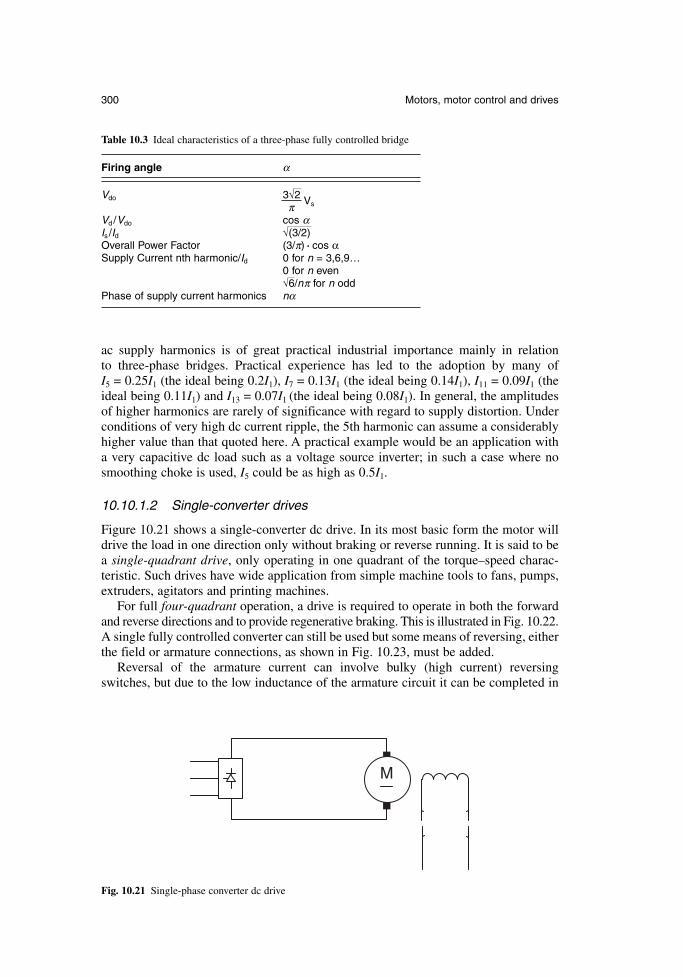
300 Motors, motor control and drives
ac supply harmonics is of great practical industrial importance mainly in relation to three-phase bridges. Practical experience has led to the adoption by many of I5 = 0.25I1 (the ideal being 0.2I1), I7 = 0.13I1 (the ideal being 0.14I1), I11 = 0.09I1 (theideal being 0.11I1) and I13 = 0.07I1 (the ideal being 0.08I1). In general, the amplitudesof higher harmonics are rarely of significance with regard to supply distortion. Underconditions of very high dc current ripple, the 5th harmonic can assume a considerablyhigher value than that quoted here. A practical example would be an application witha very capacitive dc load such as a voltage source inverter; in such a case where nosmoothing choke is used, I5 could be as high as 0.5I1.
10.10.1.2 Single-converter drives
Figure 10.21 shows a single-converter dc drive. In its most basic form the motor willdrive the load in one direction only without braking or reverse running. It is said to bea single-quadrant drive, only operating in one quadrant of the torque–speed charac-teristic. Such drives have wide application from simple machine tools to fans, pumps,extruders, agitators and printing machines.
For full four-quadrant operation, a drive is required to operate in both the forwardand reverse directions and to provide regenerative braking. This is illustrated in Fig. 10.22.A single fully controlled converter can still be used but some means of reversing, eitherthe field or armature connections, as shown in Fig. 10.23, must be added.
Reversal of the armature current can involve bulky (high current) reversingswitches, but due to the low inductance of the armature circuit it can be completed in
M
Fig. 10.21 Single-phase converter dc drive
Table 10.3 Ideal characteristics of a three-phase fully controlled bridge
Firing angle α
Vdo 3√2 VsπVd /Vdo cos αIs /Id √(3/2)Overall Power Factor (3/π) . cos αSupply Current nth harmonic/Id 0 for n = 3,6,9…
0 for n even√6/nπ for n odd
Phase of supply current harmonics nα
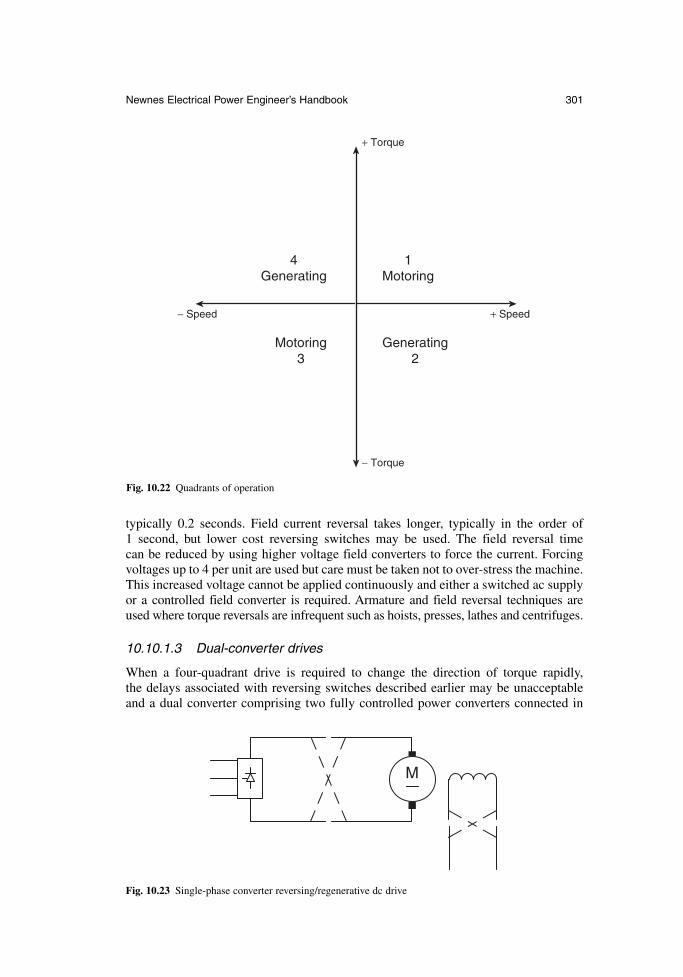
typically 0.2 seconds. Field current reversal takes longer, typically in the order of 1 second, but lower cost reversing switches may be used. The field reversal time can be reduced by using higher voltage field converters to force the current. Forcingvoltages up to 4 per unit are used but care must be taken not to over-stress the machine.This increased voltage cannot be applied continuously and either a switched ac supplyor a controlled field converter is required. Armature and field reversal techniques areused where torque reversals are infrequent such as hoists, presses, lathes and centrifuges.
10.10.1.3 Dual-converter drives
When a four-quadrant drive is required to change the direction of torque rapidly, the delays associated with reversing switches described earlier may be unacceptableand a dual converter comprising two fully controlled power converters connected in
Newnes Electrical Power Engineer’s Handbook 301
+ Torque
− Torque
1Motoring
Motoring3
+ Speed− Speed
Generating2
4Generating
Fig. 10.22 Quadrants of operation
M
Fig. 10.23 Single-phase converter reversing/regenerative dc drive
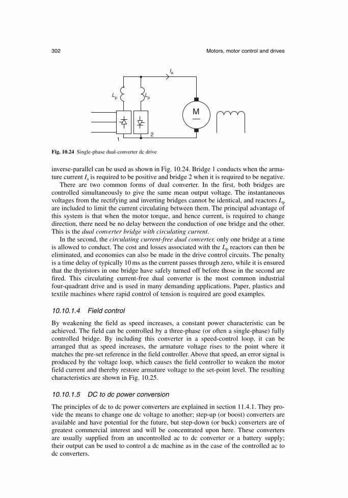
inverse-parallel can be used as shown in Fig. 10.24. Bridge 1 conducts when the arma-ture current Ia is required to be positive and bridge 2 when it is required to be negative.
There are two common forms of dual converter. In the first, both bridges are controlled simultaneously to give the same mean output voltage. The instantaneousvoltages from the rectifying and inverting bridges cannot be identical, and reactors Lp
are included to limit the current circulating between them. The principal advantage ofthis system is that when the motor torque, and hence current, is required to changedirection, there need be no delay between the conduction of one bridge and the other.This is the dual converter bridge with circulating current.
In the second, the circulating current-free dual converter, only one bridge at a timeis allowed to conduct. The cost and losses associated with the Lp reactors can then beeliminated, and economies can also be made in the drive control circuits. The penaltyis a time delay of typically 10 ms as the current passes through zero, while it is ensuredthat the thyristors in one bridge have safely turned off before those in the second arefired. This circulating current-free dual converter is the most common industrialfour-quadrant drive and is used in many demanding applications. Paper, plastics andtextile machines where rapid control of tension is required are good examples.
10.10.1.4 Field control
By weakening the field as speed increases, a constant power characteristic can beachieved. The field can be controlled by a three-phase (or often a single-phase) fullycontrolled bridge. By including this converter in a speed-control loop, it can bearranged that as speed increases, the armature voltage rises to the point where itmatches the pre-set reference in the field controller. Above that speed, an error signal isproduced by the voltage loop, which causes the field controller to weaken the motorfield current and thereby restore armature voltage to the set-point level. The resultingcharacteristics are shown in Fig. 10.25.
10.10.1.5 DC to dc power conversion
The principles of dc to dc power converters are explained in section 11.4.1. They pro-vide the means to change one dc voltage to another; step-up (or boost) converters areavailable and have potential for the future, but step-down (or buck) converters are ofgreatest commercial interest and will be concentrated upon here. These converters are usually supplied from an uncontrolled ac to dc converter or a battery supply; their output can be used to control a dc machine as in the case of the controlled ac todc converters.
302 Motors, motor control and drives
M
Ia
Lp Lp
12
Fig. 10.24 Single-phase dual-converter dc drive
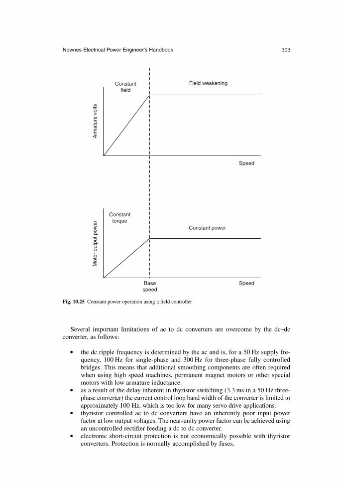
Several important limitations of ac to dc converters are overcome by the dc–dc converter, as follows:
the dc ripple frequency is determined by the ac and is, for a 50 Hz supply fre-quency, 100 Hz for single-phase and 300 Hz for three-phase fully controlledbridges. This means that additional smoothing components are often requiredwhen using high speed machines, permanent magnet motors or other specialmotors with low armature inductance.
as a result of the delay inherent in thyristor switching (3.3 ms in a 50 Hz three-phase converter) the current control loop band width of the converter is limited toapproximately 100 Hz, which is too low for many servo drive applications.
thyristor controlled ac to dc converters have an inherently poor input power factor at low output voltages. The near-unity power factor can be achieved usingan uncontrolled rectifier feeding a dc to dc converter.
electronic short-circuit protection is not economically possible with thyristorconverters. Protection is normally accomplished by fuses.
Newnes Electrical Power Engineer’s Handbook 303
Constant power
Mot
or o
utpu
t pow
erA
rmat
ure
volts
Constant torque
Constant field
Field weakening
Speed
SpeedBase speed
Fig. 10.25 Constant power operation using a field controller
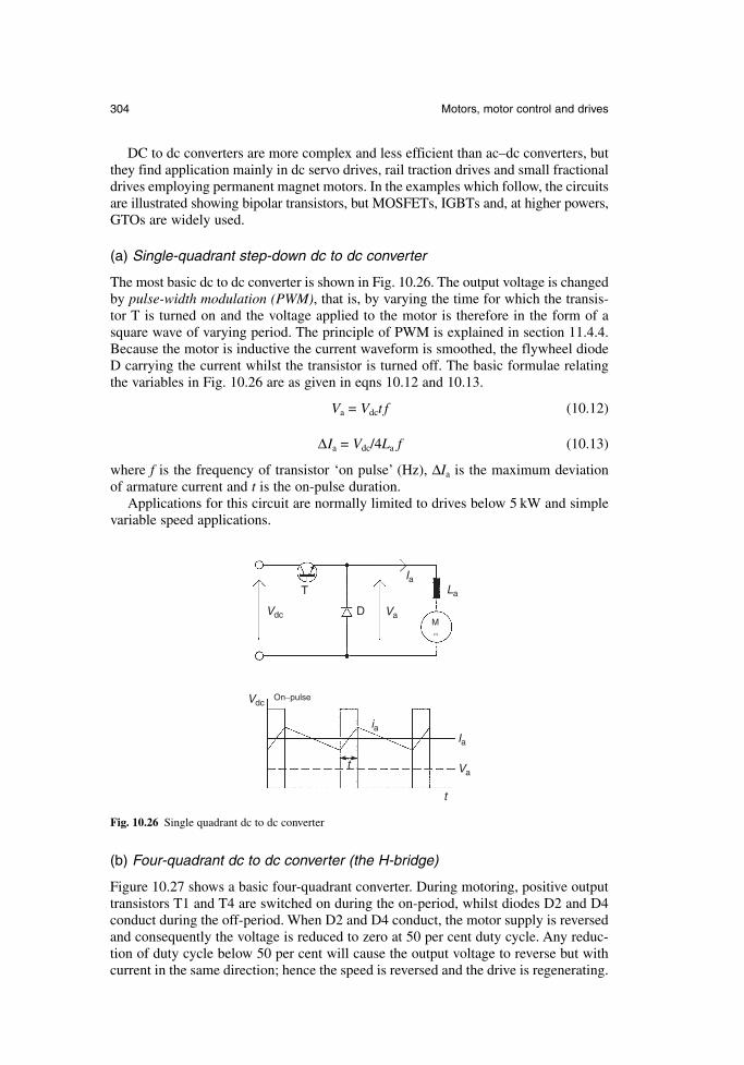
DC to dc converters are more complex and less efficient than ac–dc converters, butthey find application mainly in dc servo drives, rail traction drives and small fractionaldrives employing permanent magnet motors. In the examples which follow, the circuitsare illustrated showing bipolar transistors, but MOSFETs, IGBTs and, at higher powers,GTOs are widely used.
(a) Single-quadrant step-down dc to dc converter
The most basic dc to dc converter is shown in Fig. 10.26. The output voltage is changedby pulse-width modulation (PWM), that is, by varying the time for which the transis-tor T is turned on and the voltage applied to the motor is therefore in the form of asquare wave of varying period. The principle of PWM is explained in section 11.4.4.Because the motor is inductive the current waveform is smoothed, the flywheel diodeD carrying the current whilst the transistor is turned off. The basic formulae relatingthe variables in Fig. 10.26 are as given in eqns 10.12 and 10.13.
Va = Vdct f (10.12)
∆Ia = Vdc/4La f (10.13)
where f is the frequency of transistor ‘on pulse’ (Hz), ∆Ia is the maximum deviation of armature current and t is the on-pulse duration.
Applications for this circuit are normally limited to drives below 5 kW and simplevariable speed applications.
304 Motors, motor control and drives
Vdc
Vdc Va
Va
Ia
t
t
ia
On−pulse
IaLa
D
T
M
Fig. 10.26 Single quadrant dc to dc converter
(b) Four-quadrant dc to dc converter (the H-bridge)
Figure 10.27 shows a basic four-quadrant converter. During motoring, positive outputtransistors T1 and T4 are switched on during the on-period, whilst diodes D2 and D4conduct during the off-period. When D2 and D4 conduct, the motor supply is reversedand consequently the voltage is reduced to zero at 50 per cent duty cycle. Any reduc-tion of duty cycle below 50 per cent will cause the output voltage to reverse but withcurrent in the same direction; hence the speed is reversed and the drive is regenerating.
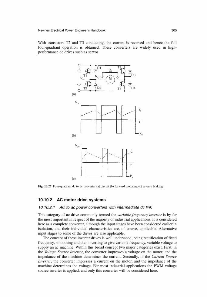
With transistors T2 and T3 conducting, the current is reversed and hence the fullfour-quadrant operation is obtained. These converters are widely used in high-performance dc drives such as servos.
Newnes Electrical Power Engineer’s Handbook 305
Vdc
Vdc
Vdc
T1
D1
D2
D3
D4T2 T4
T3Va
Va
t
ia
t
M
(a)
(b)
(c)Va
ia
Fig. 10.27 Four-quadrant dc to dc converter (a) circuit (b) forward motoring (c) reverse braking
10.10.2 AC motor drive systems
10.10.2.1 AC to ac power converters with intermediate dc link
This category of ac drive commonly termed the variable frequency inverter is by farthe most important in respect of the majority of industrial applications. It is consideredhere as a complete converter, although the input stages have been considered earlier inisolation, and their individual characteristics are, of course, applicable. Alternativeinput stages to some of the drives are also applicable.
The concept of these inverter drives is well understood, being rectification of fixedfrequency, smoothing and then inverting to give variable frequency, variable voltage tosupply an ac machine. Within this broad concept two major categories exist. First, inthe Voltage Source Inverter, the converter impresses a voltage on the motor, and theimpedance of the machine determines the current. Secondly, in the Current SourceInverter, the converter impresses a current on the motor, and the impedance of themachine determines the voltage. For most industrial applications the PWM voltagesource inverter is applied, and only this converter will be considered here.
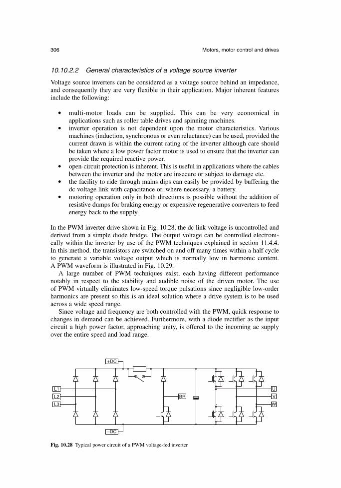
10.10.2.2 General characteristics of a voltage source inverter
Voltage source inverters can be considered as a voltage source behind an impedance,and consequently they are very flexible in their application. Major inherent featuresinclude the following:
multi-motor loads can be supplied. This can be very economical in applications such as roller table drives and spinning machines.
inverter operation is not dependent upon the motor characteristics. Variousmachines (induction, synchronous or even reluctance) can be used, provided thecurrent drawn is within the current rating of the inverter although care shouldbe taken where a low power factor motor is used to ensure that the inverter canprovide the required reactive power.
open-circuit protection is inherent. This is useful in applications where the cablesbetween the inverter and the motor are insecure or subject to damage etc.
the facility to ride through mains dips can easily be provided by buffering thedc voltage link with capacitance or, where necessary, a battery.
motoring operation only in both directions is possible without the addition ofresistive dumps for braking energy or expensive regenerative converters to feedenergy back to the supply.
In the PWM inverter drive shown in Fig. 10.28, the dc link voltage is uncontrolled andderived from a simple diode bridge. The output voltage can be controlled electroni-cally within the inverter by use of the PWM techniques explained in section 11.4.4. In this method, the transistors are switched on and off many times within a half cycleto generate a variable voltage output which is normally low in harmonic content. A PWM waveform is illustrated in Fig. 10.29.
A large number of PWM techniques exist, each having different performancenotably in respect to the stability and audible noise of the driven motor. The use of PWM virtually eliminates low-speed torque pulsations since negligible low-orderharmonics are present so this is an ideal solution where a drive system is to be usedacross a wide speed range.
Since voltage and frequency are both controlled with the PWM, quick response tochanges in demand can be achieved. Furthermore, with a diode rectifier as the inputcircuit a high power factor, approaching unity, is offered to the incoming ac supplyover the entire speed and load range.
306 Motors, motor control and drives
BR
+DC
−DC
L1
L2
L3
U
V
W
Fig. 10.28 Typical power circuit of a PWM voltage-fed inverter
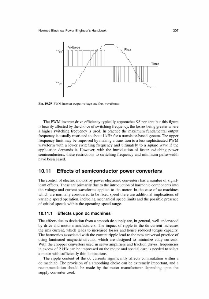
The PWM inverter drive efficiency typically approaches 98 per cent but this figureis heavily affected by the choice of switching frequency, the losses being greater wherea higher switching frequency is used. In practice the maximum fundamental outputfrequency is usually restricted to about 1 kHz for a transistor-based system. The upperfrequency limit may be improved by making a transition to a less sophisticated PWMwaveform with a lower switching frequency and ultimately to a square wave if theapplication demands it. However, with the introduction of faster switching powersemiconductors, these restrictions to switching frequency and minimum pulse-widthhave been eased.
10.11 Effects of semiconductor power converters
The control of electric motors by power electronic converters has a number of signif-icant effects. These are primarily due to the introduction of harmonic components intothe voltage and current waveforms applied to the motor. In the case of ac machineswhich are normally considered to be fixed speed there are additional implications ofvariable speed operation, including mechanical speed limits and the possible presenceof critical speeds within the operating speed range.
10.11.1 Effects upon dc machines
The effects due to deviation from a smooth dc supply are, in general, well understoodby drive and motor manufacturers. The impact of ripple in the dc current increases the rms current, which leads to increased losses and hence reduced torque capacity.The harmonics associated with the current ripple lead to the now universal practice ofusing laminated magnetic circuits, which are designed to minimize eddy currents.With the chopper converters used in servo amplifiers and traction drives, frequenciesin excess of 2 kHz can be impressed on the motor and special care is needed to selecta motor with sufficiently thin laminations.
The ripple content of the dc currents significantly affects commutation within a dc machine. The provision of a smoothing choke can be extremely important, and arecommendation should be made by the motor manufacturer depending upon the supply converter used.
Newnes Electrical Power Engineer’s Handbook 307
VoltageFlux
Time
−Vdc
+Vdc
Fig. 10.29 PWM inverter output voltage and flux waveforms
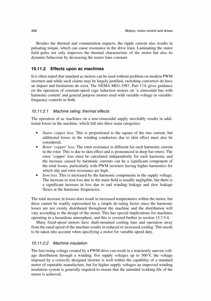
Besides the thermal and commutation impacts, the ripple current also results in pulsating torque, which can cause resonance in the drive train. Laminating the statorfield poles not only improves the thermal characteristic of the motor but also itsdynamic behaviour by decreasing the motor time constant.
10.11.2 Effects upon ac machines
It is often stated that standard ac motors can be used without problem on modern PWMinverters and while such claims may be largely justified, switching converters do havean impact and limitations do exist. The NEMA MG1:1987, Part 17A gives guidanceon the operation of constant-speed cage induction motors on ‘a sinusoidal bus withharmonic content’ and general purpose motors used with variable-voltage or variable-frequency controls or both.
10.11.2.1 Machine rating: thermal effects
The operation of ac machines on a non-sinusoidal supply inevitably results in addi-tional losses in the machine, which fall into three main categories:
Stator copper loss. This is proportional to the square of the rms current, butadditional losses in the winding conductors due to skin effect must also be considered,
Rotor ‘copper’ loss. The rotor resistance is different for each harmonic currentin the rotor. This is due to skin effect and is pronounced in deep bar rotors. Therotor ‘copper’ loss must be calculated independently for each harmonic and the increase caused by harmonic currents can be a significant component of the total losses, particularly with PWM inverters having higher harmonics forwhich slip and rotor resistance are high.
Iron loss. This is increased by the harmonic components in the supply voltage.The increase in iron loss due to the main field is usually negligible, but there isa significant increase in loss due to end winding leakage and slew leakagefluxes at the harmonic frequencies.
The total increase in losses does result in increased temperatures within the motor, butthese cannot be readily represented by a simple de-rating factor since the harmoniclosses are not evenly distributed throughout the machine and the distribution will vary according to the design of the motor. This has special implications for machinesoperating in a hazardous atmosphere, and this is covered further in section 15.7.5.4.
Many fixed-speed motors have shaft-mounted cooling fans and operation awayfrom the rated speed of the machine results in reduced or increased cooling. This needsto be taken into account when specifying a motor for variable-speed duty.
10.11.2.2 Machine insulation
The fast-rising voltage created by a PWM drive can result in a transiently uneven volt-age distribution through a winding. For supply voltages up to 500 V, the voltageimposed by a correctly designed inverter is well within the capability of a standardmotor of reputable manufacture, but for higher supply voltages an improved windinginsulation system is generally required to ensure that the intended working life of themotor is achieved.
308 Motors, motor control and drives
There can also be short-duration voltage over-shoots because of reflection effects inthe motor cable, which is a system effect caused by the combined behaviour of thedrive, cable and motor. The length of the motor cable can increase the peak motor voltage, but in applications with cables of 10 m or less, no special considerations aregenerally required. Output inductors (chokes) or output filters are sometimes used withdrives for reasons such as long-cable driving capability or radio frequency suppres-sion. In such cases no further precautions are required because these devices alsoreduce the peak motor voltage and increase its rise-time.
The IEC 60034-17 gives a profile for the withstand capability of a minimum stan-dard motor, in the form of a graph of peak terminal voltage against voltage rise-time.The standard is based on research on the behaviour of motors constructed with theminimum acceptable level of insulation within the IEC motor standard family. Testsshow that standard PWM drives with cable lengths of 20 m or more produce voltagesoutside the IEC 60034-17 profile. However most motor manufacturers produce, as a standard, machines with a capability substantially exceeding the requirements of IEC 60034-17.
10.11.2.3 Bearing currents
The sum of the three stator currents in an ac motor is ideally zero and there is no fur-ther path of current flow outside the motor, but in practice there are conditions whichresult in currents flowing through the bearings. These conditions include:
Magnetic asymmetry. An asymmetric flux distribution within an electricalmachine can result in an induced voltage from one end of the rotor shaft to theother. If the bearing breakover voltage is exceeded, a current flows through boththe bearings. In some large machines, it is a common practice to fit an insulatedbearing, usually at the non-drive end, to stop such currents.
Supply asymmetry. With PWM inverter supplies, it is impossible to achieve per-fect balance between the phases instantaneously, when pulses of differentwidths are produced. The resulting neutral voltage is not zero with respect toearth, and its presence equates to that of a common mode voltage source. Thisis sometimes referred to as a zero sequence voltage. It is proportional in mag-nitude to the dc link voltage in the inverter (itself proportional to the supplyvoltage), and has a frequency equal to the switching frequency of the inverter.
The risk of bearing currents can be minimized by adopting a grounding strategy whichkeeps all system components grounded at the same potential. This needs to be achievedfor all frequencies and high inductance paths must be avoided, for instance keepingcable runs as short as possible. In addition, a low impedance path should be definedfor the common-mode currents to return to the inverter. As the common-mode currentflows through the three phase conductors in the supply cable, the best return path isthrough a shield around that cable. This could be in the form of a screen. Such meas-ures are well defined by most reputable manufacturers in their EMC guidance and general guidelines are provided in Chapter 14.
10.12 The commercial drive
The block schematic shown in Fig.10.30 illustrates the normal arrangement of an innertorque or current loop with an outer speed loop. Alternatively, where torque control is
Newnes Electrical Power Engineer’s Handbook 309
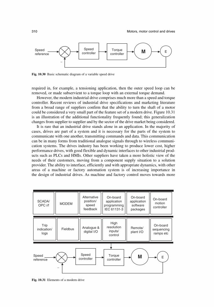
required in, for example, a tensioning application, then the outer speed loop can beremoved, or made subservient to a torque loop with an external torque demand.
However, the modern industrial drive comprises much more than a speed and torquecontroller. Recent reviews of industrial drive specifications and marketing literaturefrom a broad range of suppliers confirm that the ability to turn the shaft of a motorcould be considered a very small part of the feature set of a modern drive. Figure 10.31is an illustration of the additional functionality frequently found; this generalizationchanges from supplier to supplier and by the sector of the drive market being considered.
It is rare that an industrial drive stands alone in an application. In the majority ofcases, drives are part of a system and it is necessary for the parts of the system to communicate with one another, transmitting commands and data. This communicationcan be in many forms from traditional analogue signals through to wireless communi-cation systems. The drives industry has been working to produce lower cost, higherperformance drives, with good flexible and dynamic interfaces to other industrial prod-ucts such as PLCs and HMIs. Other suppliers have taken a more holistic view of theneeds of their customers, moving from a component supply situation to a solutionprovider. The ability to interface, efficiently and with appropriate dynamics, with otherareas of a machine or factory automation system is of increasing importance in the design of industrial drives. As machine and factory control moves towards more
310 Motors, motor control and drives
Speedcontroller
Torquecontroller
Speedreference
−
M E
Fig. 10.30 Basic schematic diagram of a variable speed drive
Speedcontroller
Torquecontroller
Speedreference
−
M E
Remote/plant I/O
Analogue &digital I/O
On-boardapplication
programmingIEC 61131-3
On-boardsequencingramps etc
SCADA/ OPC i/f
Tripindication/
logs
On-boardmotion
controller
On-boardapplicationsoftwarepackages
Alternativeposition/speed
feedback
MODEM
Highresolution
inputs/control
Fieldbus
Fig. 10.31 Elements of a modern drive
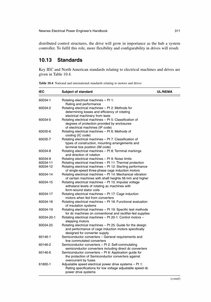
Newnes Electrical Power Engineer’s Handbook 311
distributed control structures, the drive will grow in importance as the hub a systemcontroller. To fulfil this role, more flexibility and configurability in drives will result.
10.13 Standards
Key IEC and North American standards relating to electrical machines and drives aregiven in Table 10.4.
Table 10.4 National and international standards relating to motors and drives
IEC Subject of standard UL/NEMA
60034-1 Rotating electrical machines – Pt 1:Rating and performance
60034-2 Rotating electrical machines – Pt 2: Methods fordetermining losses and efficiency of rotating electrical machinery from tests
60034-5 Rotating electrical machines – Pt 5: Classification of degrees of protection provided by enclosures of electrical machines (IP code)
60035-6 Rotating electrical machines – Pt 6: Methods ofcooling (IC code)
60035-7 Rotating electrical machines – Pt 7: Classification oftypes of construction, mounting arrangements and terminal box position (IM code)
60034-8 Rotating electrical machines – Pt 8: Terminal markings and direction of rotation
60034-9 Rotating electrical machines – Pt 9: Noise limits60034-11 Rotating electrical machines – Pt 11: Thermal protection60034-12 Rotating electrical machines – Pt 12: Starting performance
of single-speed three-phase cage induction motors60034-14 Rotating electrical machines – Pt 14: Mechanical vibration
of certain machines with shaft heights 56 mm and higher60034-15 Rotating electrical machines – Pt 15: Impulse voltage
withstand levels of rotating ac machines withform-wound stator coils
60034-17 Rotating electrical machines – Pt 17: Cage inductionmotors when fed from converters
60034-18 Rotating electrical machines – Pt 18: Functional evaluationof insulation systems
60034-19 Rotating electrical machines – Pt 19: Specific test methods for dc machines on conventional and rectifier-fed supplies
60034-20-1 Rotating electrical machines – Pt 20-1: Control motors – stepping motors
60034-25 Rotating electrical machines – Pt 25: Guide for the designand performance of cage induction motors specificallydesigned for converter supply
60146-1 Semiconductor converters – General requirements and line commutated converters
60146-2 Semiconductor converters – Pt 2: Self-commutatingsemiconductor converters including direct dc converters
60146-6 Semiconductor converters – Pt 6: Application guide forthe protection of Semiconductor converters againstovercurrent by fuses
61800-1 Adjustable speed electrical power drive systems – Pt 1:Rating specifications for low voltage adjustable speed dcpower drive systems
(contd)
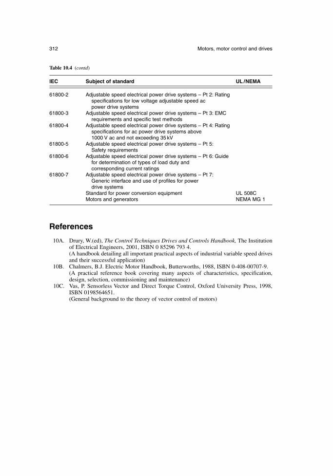
References
10A. Drury, W.(ed), The Control Techniques Drives and Controls Handbook, The Institutionof Electrical Engineers, 2001, ISBN 0 85296 793 4.(A handbook detailing all important practical aspects of industrial variable speed drivesand their successful application)
10B. Chalmers, B.J. Electric Motor Handbook, Butterworths, 1988, ISBN 0-408-00707-9.(A practical reference book covering many aspects of characteristics, specification,design, selection, commissioning and maintenance)
10C. Vas, P. Sensorless Vector and Direct Torque Control, Oxford University Press, 1998,ISBN 0198564651.(General background to the theory of vector control of motors)
312 Motors, motor control and drives
Table 10.4 (contd)
IEC Subject of standard UL /NEMA
61800-2 Adjustable speed electrical power drive systems – Pt 2: Ratingspecifications for low voltage adjustable speed ac power drive systems
61800-3 Adjustable speed electrical power drive systems – Pt 3: EMC requirements and specific test methods
61800-4 Adjustable speed electrical power drive systems – Pt 4: Ratingspecifications for ac power drive systems above 1000 V ac and not exceeding 35 kV
61800-5 Adjustable speed electrical power drive systems – Pt 5:Safety requirements
61800-6 Adjustable speed electrical power drive systems – Pt 6: Guide for determination of types of load duty and corresponding current ratings
61800-7 Adjustable speed electrical power drive systems – Pt 7:Generic interface and use of profiles for power drive systems
Standard for power conversion equipment UL 508CMotors and generators NEMA MG 1
Chapter 11
Power electronic circuits and devices
Professor A.J. ForsythThe University of Manchester
11.1 Introduction
The use of solid-state techniques for the control and conversion of electrical power is now commonplace, with applications ranging from small dc power supplies for electronic devices, through actuator and motor drive systems, to large active filters andstatic power compensators for power transmission and distribution systems.
The aim here is to review the main classes of circuits and devices that are currentlyused, emphasizing the basic operating principles and characteristics. The opening sections cover the traditional diode-based ac–dc converters, starting with the three-pulse circuit and leading to the twelve-pulse configuration, and including the supplycurrent characteristics. Thyristor phase control techniques are also briefly described.The following sections introduce the principal active devices that are in common use,namely the MOSFET and the IGBT (insulated gate bipolar transistor), then, startingwith simple dc–dc converter switching cells, switching and inverter circuits are explained,leading to sinusoidal PWM methods. Finally, there is a short review of high-frequencypower supplies.
11.2 Diode converters
11.2.1 Three-pulse rectifier
The three-pulse rectifier in Fig. 11.1 supplies a resistive load in series with a filterinductor, the inductor being large enough to ensure that the load current is continuousand ripple-free. The circuit is a half-wave rectifier, with each supply line, A, B and C,being connected through a single diode to the top of the load, the neutral wire formingthe return path. The circuit waveforms follow directly from the assumption of acontinuous and smooth load current:
One of the three diodes must always be in conduction to provide a path for theload current.
Only one diode may conduct at once, since otherwise two of the supply lineswould have the same voltage, and this only occurs momentarily as the voltagescross each other.
The diode that conducts at any instant is determined by the supply line with thelargest positive voltage, since this voltage will forward bias the diode in thatline and reverse bias the other two diodes.
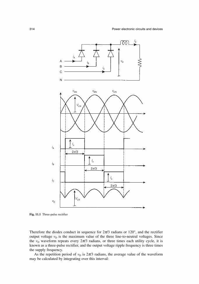
Therefore the diodes conduct in sequence for 2π/3 radians or 120°, and the rectifieroutput voltage vD is the maximum value of the three line-to-neutral voltages. Since the vD waveform repeats every 2π/3 radians, or three times each utility cycle, it isknown as a three-pulse rectifier, and the output voltage ripple frequency is three timesthe supply frequency.
As the repetition period of vD is 2π/3 radians, the average value of the waveformmay be calculated by integrating over this interval:
314 Power electronic circuits and devices
π
I0
vD
iC
iB
Io
Io
Io
iA
iB
iC
vD
vAN
VLN
VLN
vBN vCN
iAA
B
C
N
2 /3
2 /3π
2 /3π
Fig. 11.1 Three-pulse rectifier
(11.1)
where VLL is the amplitude or peak value of the line-to-line supply voltage.Since the circuit only draws a unidirectional current from each supply line, and also
uses the neutral wire for the return current, it is rarely used in practice, but it is simpleto understand, and is helpful in analyzing more complex circuits.
11.2.2 Six-pulse rectifier
Connecting two three-pulse circuits, one operating on the positive half cycle and theother on the negative half cycle, in a back-to-back configuration forms the six-pulserectifier, as shown in Fig. 11.2. The upper three-pulse rectifier here is identical to that described in section 11.2.1, whilst the lower circuit is essentially formed from thefirst by reversing the diodes, enabling it to operate on the negative parts of the supplyvoltage waveform.
Since the average values of vD1 and vD2 are the same, the currents in the two loadresistors will be the same, provided that these have equal values R. Under these conditions, the line currents will consist of 120° pulses of +Io as DA1, DB1 and DC1conduct, and 120° pulses of –Io as DA2, DB2 and DC2 conduct. The negative pulseswill flow between the positive pulses, making the line currents quasi-squarewaves.
Furthermore, since the two resistors carry equal currents, the neutral current will be zero, and the neutral connection may be removed without affecting the circuit operation. This leaves the standard three-wire, six-pulse rectifier of Fig. 11.3, into which the load is simply drawn as a constant current element, representing its highlyinductive nature.
Figure 11.4 shows the detail of the two three-pulse output voltages vD1 and vD2 andthe total output voltage vDD = vD1 + vD2. Since the ripple components in vD1 and vD2 arephase-shifted by π/3 radians, the resultant ripple in vDD is reduced in amplitude and has a repetition interval of π/3 radians, giving six pulses per period of the inputwaveform. The average of vDD is simply twice the average value of the three-pulsewaveforms and from eqn 11.1:
(11.2)
The six-pulse rectifier is widely used for the conversion of ac to dc, for example as the input stage of a variable speed induction motor drive system, described in Chapter 10.
11.2.3 Characteristics of the six-pulse input current
Fourier analysis of the quasi-squarewave currents drawn by the six-pulse rectifiershows that the harmonic amplitudes of the currents are given by eqn 11.3:
(11.3)
where n is the harmonic number. The fundamental component of each line current isin phase with the respective line-to-neutral voltage, as is evident from Fig. 11.2.
harmonic amplitudes sin for odd values of o=
4
3
I
n
nn
ππ
average 2DDLL LLV
V V= =3
2
3
π π
average sin dD LNLN LL
/ /
/ν = = =∫
1
2 3
3 3
2
3
26
5 6
πθ θ
π ππ
πV
V V
Newnes Electrical Power Engineer’s Handbook 315
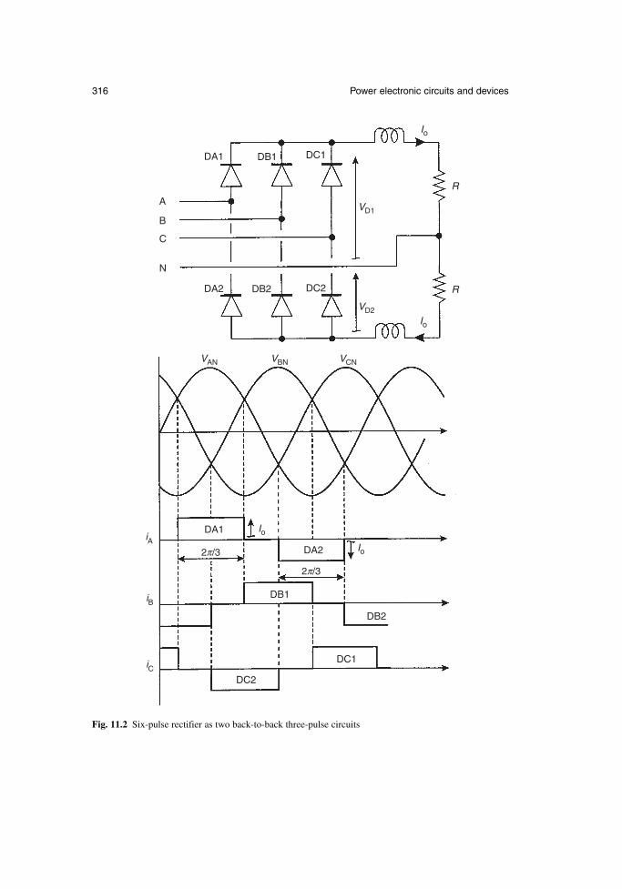
316 Power electronic circuits and devices
DA1
DA2
DA1
DA2
DB2
DC1
DB1
DC2
DB1
DB2
DC1
DC2
A
B
C
N
Io
Io
Io
Io
R
R
VAN
VD2
VD1
VBN VCN
iA
iB
iC
2 /3π
2 /3π
Fig. 11.2 Six-pulse rectifier as two back-to-back three-pulse circuits
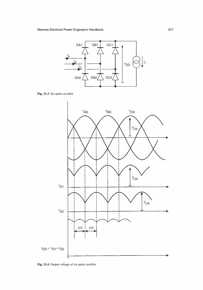
Newnes Electrical Power Engineer’s Handbook 317
DA1 DB1
DB2DA2
DC1
DC2
i
i
iC
B
A
DDv Io
Fig. 11.3 Six-pulse rectifier
vAN vBN vCN
VLN
VLN
vD1
vD2
vDD = vD1+vD2
VLN
/3π /3π
Fig. 11.4 Output voltage of six-pulse rectifier
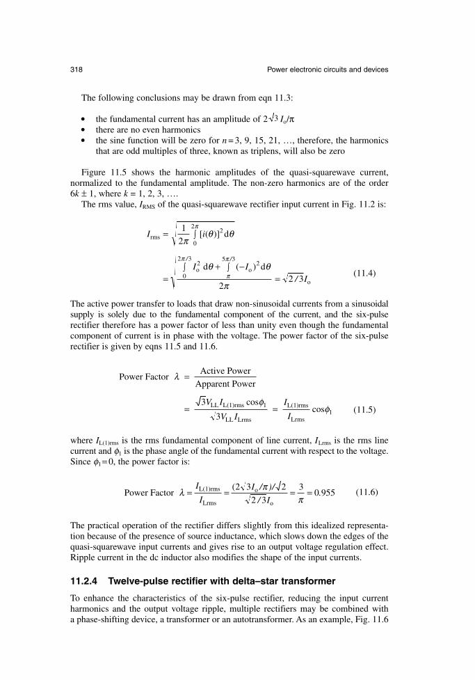
The following conclusions may be drawn from eqn 11.3:
the fundamental current has an amplitude of 2 Io/π there are no even harmonics the sine function will be zero for n = 3, 9, 15, 21, …, therefore, the harmonics
that are odd multiples of three, known as triplens, will also be zero
Figure 11.5 shows the harmonic amplitudes of the quasi-squarewave current, normalized to the fundamental amplitude. The non-zero harmonics are of the order 6k ± 1, where k = 1, 2, 3, ….
The rms value, IRMS of the quasi-squarewave rectifier input current in Fig. 11.2 is:
(11.4)
The active power transfer to loads that draw non-sinusoidal currents from a sinusoidalsupply is solely due to the fundamental component of the current, and the six-pulserectifier therefore has a power factor of less than unity even though the fundamentalcomponent of current is in phase with the voltage. The power factor of the six-pulserectifier is given by eqns 11.5 and 11.6.
(11.5)
where IL(1)rms is the rms fundamental component of line current, ILrms is the rms linecurrent and φ1 is the phase angle of the fundamental current with respect to the voltage.Since φ1= 0, the power factor is:
(11.6)
The practical operation of the rectifier differs slightly from this idealized representa-tion because of the presence of source inductance, which slows down the edges of thequasi-squarewave input currents and gives rise to an output voltage regulation effect.Ripple current in the dc inductor also modifies the shape of the input currents.
11.2.4 Twelve-pulse rectifier with delta–star transformer
To enhance the characteristics of the six-pulse rectifier, reducing the input current harmonics and the output voltage ripple, multiple rectifiers may be combined with a phase-shifting device, a transformer or an autotransformer. As an example, Fig. 11.6
Power Factor L(1)rms
Lrms
/ )/
/.λ π
π= = = =
I
I
I
I
( o
o
2 3 2
2 3
30 955
Power FactorActive Power
Apparent Power
LL L(1)rms
LL Lrms
L(1)rms
Lrms
λ
φφ
=
= =3
31
1
V I
V I
I
I
coscos
I i
I II
rms =
=+ −
=
∫
∫∫
1
2
22 3
2
0
2
25 3
0
2 3
πθ θ
θ θ
π
π
π
ππ
[ ( )] d
d ( ) do o2
o
//
/
3
318 Power electronic circuits and devices
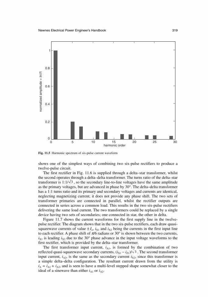
shows one of the simplest ways of combining two six-pulse rectifiers to produce atwelve-pulse circuit.
The first rectifier in Fig. 11.6 is supplied through a delta–star transformer, whilstthe second operates through a delta–delta transformer. The turns ratio of the delta–startransformer is 1:1/ , so the secondary line-to-line voltages have the same amplitudeas the primary voltages, but are advanced in phase by 30°. The delta–delta transformerhas a 1:1 turns ratio and its primary and secondary voltages and currents are identical,neglecting magnetizing current; it does not provide any phase shift. The two sets oftransformer primaries are connected in parallel, whilst the rectifier outputs are connected in series across a common load. This results in the two six-pulse rectifiersdelivering the same load current. The two transformers could be replaced by a singledevice having two sets of secondaries; one connected in star, the other in delta.
Figure 11.7 shows the current waveforms for the first supply line in the twelve-pulse rectifier. The diagram shows that in the two six-pulse rectifiers, each draw quasi-squarewave currents of value ± Io, iX1 and iX2 being the currents in the first input lineto each rectifier. A phase shift of π/6 radians or 30° is shown between the two currents,iX1 is leading iX2 due to the 30° phase advance in the input voltage waveforms to thefirst rectifier, which is provided by the delta–star transformer.
The first transformer input current, iA1, is formed by the combination of tworeflected quasi-squarewave secondary currents, (iX1 − iZ1)/ . The second transformerinput current, iA2, is the same as the secondary current iX2, since this transformer is a simple delta–delta configuration. The resultant current drawn from the utility is iA = iA1 + iA2, and is seen to have a multi-level stepped shape somewhat closer to theideal of a sinewave than either iA1 or iA2.
3
3
Newnes Electrical Power Engineer’s Handbook 319
1
0.8
0.6
0.4
0.2
00 5 10 15 20 25 30
norm
aliz
ed a
mpl
itude
= ln
/I1
harmonic order
Fig. 11.5 Harmonic spectrum of six-pulse current waveform
320 Power electronic circuits and devices
i Ai A
1
i A2
i X2
i X1
VD
D1
VD
D2
I o
Fig
. 11.
6Tw
elve
-pul
se r
ectif
ier
– se
ries
con
nect
ion
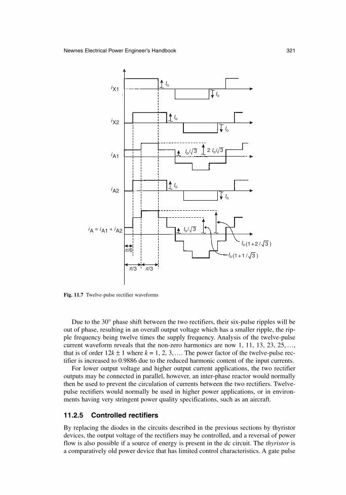
Due to the 30° phase shift between the two rectifiers, their six-pulse ripples will beout of phase, resulting in an overall output voltage which has a smaller ripple, the rip-ple frequency being twelve times the supply frequency. Analysis of the twelve-pulsecurrent waveform reveals that the non-zero harmonics are now 1, 11, 13, 23, 25, …,that is of order 12k ± 1 where k = 1, 2, 3,…. The power factor of the twelve-pulse rec-tifier is increased to 0.9886 due to the reduced harmonic content of the input currents.
For lower output voltage and higher output current applications, the two rectifieroutputs may be connected in parallel, however, an inter-phase reactor would normallythen be used to prevent the circulation of currents between the two rectifiers. Twelve-pulse rectifiers would normally be used in higher power applications, or in environ-ments having very stringent power quality specifications, such as an aircraft.
11.2.5 Controlled rectifiers
By replacing the diodes in the circuits described in the previous sections by thyristordevices, the output voltage of the rectifiers may be controlled, and a reversal of powerflow is also possible if a source of energy is present in the dc circuit. The thyristor isa comparatively old power device that has limited control characteristics. A gate pulse
Newnes Electrical Power Engineer’s Handbook 321
Io
Io
Io
Io
Io
Io
Io/
Io/
3 3
3
2 Io/
Io (1+1 / 3 )
Io
iX1
iX2
iA1
iA2
iA = iA1 + iA2
/3π /3π
/6π(1+2 / 3 )
Fig. 11.7 Twelve-pulse rectifier waveforms
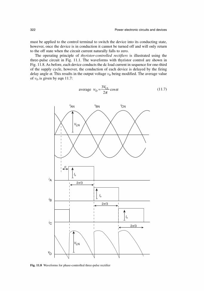
must be applied to the control terminal to switch the device into its conducting state,however, once the device is in conduction it cannot be turned off and will only returnto the off state when the circuit current naturally falls to zero.
The operating principle of thyristor-controlled rectifiers is illustrated using thethree-pulse circuit in Fig. 11.1. The waveforms with thyristor control are shown in Fig. 11.8. As before, each device conducts the dc load current in sequence for one-thirdof the supply cycle, however, the conduction of each device is delayed by the firingdelay angle α. This results in the output voltage vD being modified. The average valueof vD is given by eqn 11.7:
(11.7)average D νπ
α= 3
2
VLL cos
322 Power electronic circuits and devices
VLN
VLN
IoiA
iB
iC
Io
Io
α
2 /3π
2 /3π
2 /3π
Dν
ANν CNνBNν
Fig. 11.8 Waveforms for phase-controlled three-pulse rectifier
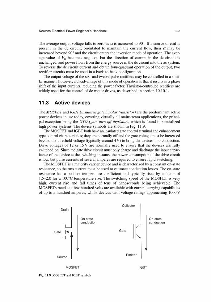
The average output voltage falls to zero as α is increased to 90°. If a source of emf ispresent in the dc circuit, orientated to maintain the current flow, then α may beincreased beyond 90° and the circuit enters the inversion mode of operation. The aver-age value of VD becomes negative, but the direction of current in the dc circuit isunchanged, and power flows from the energy source in the dc circuit into the ac system.To reverse the dc circuit current and obtain four-quadrant operation of the output, tworectifier circuits must be used in a back-to-back configuration.
The output voltage of the six- and twelve-pulse rectifiers may be controlled in a simi-lar manner. However, a disadvantage of this mode of operation is that it results in a phaseshift of the input currents, reducing the power factor. Thyristor-controlled rectifiers arewidely used for the control of dc motor drives, as described in section 10.10.1.
11.3 Active devices
The MOSFET and IGBT (insulated gate bipolar transistor) are the predominant activepower devices in use today, covering virtually all mainstream applications, the princi-pal exception being the GTO (gate turn off thyristor), which is found in specializedhigh power systems. The device symbols are shown in Fig. 11.9.
The MOSFET and IGBT both have an insulated gate control terminal and enhancementtype control characteristics; they are normally off and the gate voltage must be increasedbeyond the threshold voltage (typically around 4 V) to bring the devices into conduction.Drive voltages of 12 or 15 V are normally used to ensure that the devices are fullyswitched on. Since the gate drive circuit must only charge and discharge the input capac-itance of the device at the switching instants, the power consumption of the drive circuitis low, but pulse currents of several amperes are required to ensure rapid switching.
The MOSFET is a majority carrier device and is characterized by a constant on-stateresistance, so the rms current must be used to estimate conduction losses. The on-stateresistance has a positive temperature coefficient and typically rises by a factor of1.5–2.0 for a 100°C temperature rise. The switching speed of the MOSFET is veryhigh, current rise and fall times of tens of nanoseconds being achievable. TheMOSFETs rated at a few hundred volts are available with current carrying capabilitiesof up to a hundred amperes, whilst devices with voltage ratings approaching 1000 V
Newnes Electrical Power Engineer’s Handbook 323
On-stateconduction
On-stateconduction
IGBT
Emitter
Gate
CollectorDrain
Gate
Source
MOSFET
Fig. 11.9 MOSFET and IGBT symbols
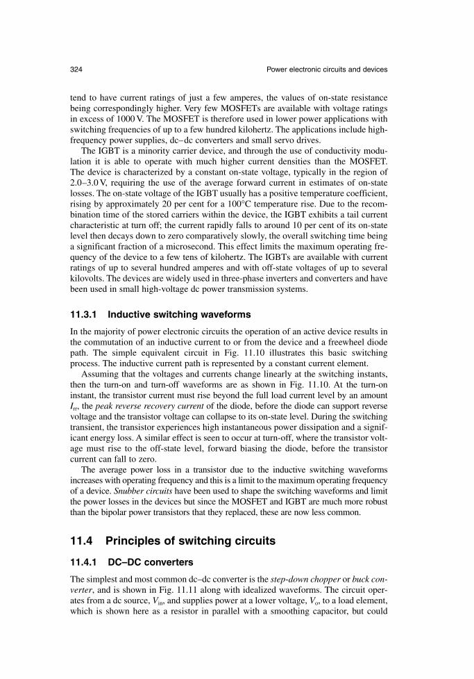
tend to have current ratings of just a few amperes, the values of on-state resistancebeing correspondingly higher. Very few MOSFETs are available with voltage ratingsin excess of 1000 V. The MOSFET is therefore used in lower power applications withswitching frequencies of up to a few hundred kilohertz. The applications include high-frequency power supplies, dc–dc converters and small servo drives.
The IGBT is a minority carrier device, and through the use of conductivity modu-lation it is able to operate with much higher current densities than the MOSFET. The device is characterized by a constant on-state voltage, typically in the region of2.0–3.0 V, requiring the use of the average forward current in estimates of on-statelosses. The on-state voltage of the IGBT usually has a positive temperature coefficient,rising by approximately 20 per cent for a 100°C temperature rise. Due to the recom-bination time of the stored carriers within the device, the IGBT exhibits a tail currentcharacteristic at turn off; the current rapidly falls to around 10 per cent of its on-statelevel then decays down to zero comparatively slowly, the overall switching time beinga significant fraction of a microsecond. This effect limits the maximum operating fre-quency of the device to a few tens of kilohertz. The IGBTs are available with currentratings of up to several hundred amperes and with off-state voltages of up to severalkilovolts. The devices are widely used in three-phase inverters and converters and havebeen used in small high-voltage dc power transmission systems.
11.3.1 Inductive switching waveforms
In the majority of power electronic circuits the operation of an active device results inthe commutation of an inductive current to or from the device and a freewheel diodepath. The simple equivalent circuit in Fig. 11.10 illustrates this basic switchingprocess. The inductive current path is represented by a constant current element.
Assuming that the voltages and currents change linearly at the switching instants,then the turn-on and turn-off waveforms are as shown in Fig. 11.10. At the turn-oninstant, the transistor current must rise beyond the full load current level by an amountIrr, the peak reverse recovery current of the diode, before the diode can support reversevoltage and the transistor voltage can collapse to its on-state level. During the switchingtransient, the transistor experiences high instantaneous power dissipation and a signif-icant energy loss. A similar effect is seen to occur at turn-off, where the transistor volt-age must rise to the off-state level, forward biasing the diode, before the transistorcurrent can fall to zero.
The average power loss in a transistor due to the inductive switching waveformsincreases with operating frequency and this is a limit to the maximum operating frequencyof a device. Snubber circuits have been used to shape the switching waveforms and limitthe power losses in the devices but since the MOSFET and IGBT are much more robustthan the bipolar power transistors that they replaced, these are now less common.
11.4 Principles of switching circuits
11.4.1 DC–DC converters
The simplest and most common dc–dc converter is the step-down chopper or buck con-verter, and is shown in Fig. 11.11 along with idealized waveforms. The circuit oper-ates from a dc source, Vin, and supplies power at a lower voltage, Vo, to a load element,which is shown here as a resistor in parallel with a smoothing capacitor, but could
324 Power electronic circuits and devices
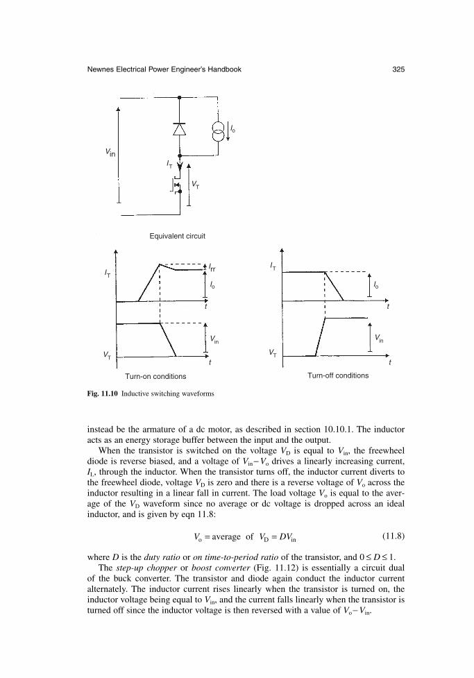
instead be the armature of a dc motor, as described in section 10.10.1. The inductoracts as an energy storage buffer between the input and the output.
When the transistor is switched on the voltage VD is equal to Vin, the freewheeldiode is reverse biased, and a voltage of Vin− Vo drives a linearly increasing current, IL, through the inductor. When the transistor turns off, the inductor current diverts tothe freewheel diode, voltage VD is zero and there is a reverse voltage of Vo across theinductor resulting in a linear fall in current. The load voltage Vo is equal to the aver-age of the VD waveform since no average or dc voltage is dropped across an idealinductor, and is given by eqn 11.8:
(11.8)
where D is the duty ratio or on time-to-period ratio of the transistor, and 0 ≤ D ≤ 1.The step-up chopper or boost converter (Fig. 11.12) is essentially a circuit dual
of the buck converter. The transistor and diode again conduct the inductor current alternately. The inductor current rises linearly when the transistor is turned on, theinductor voltage being equal to Vin, and the current falls linearly when the transistor isturned off since the inductor voltage is then reversed with a value of Vo− Vin.
V V DVo D= =average of in
Newnes Electrical Power Engineer’s Handbook 325
VinIT
ITIrr
VT
Io
VinVin
VTVT
IT
Io Io
Turn-on conditions Turn-off conditions
t t
tt
Equivalent circuit
Fig. 11.10 Inductive switching waveforms
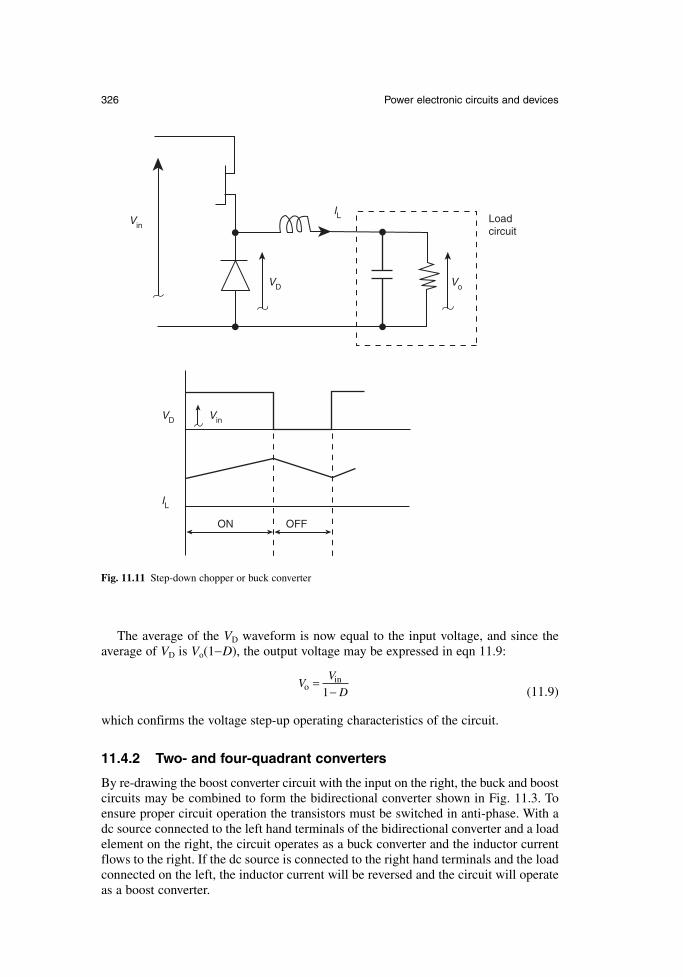
The average of the VD waveform is now equal to the input voltage, and since theaverage of VD is Vo(1−D), the output voltage may be expressed in eqn 11.9:
(11.9)
which confirms the voltage step-up operating characteristics of the circuit.
11.4.2 Two- and four-quadrant converters
By re-drawing the boost converter circuit with the input on the right, the buck and boostcircuits may be combined to form the bidirectional converter shown in Fig. 11.3. Toensure proper circuit operation the transistors must be switched in anti-phase. With adc source connected to the left hand terminals of the bidirectional converter and a loadelement on the right, the circuit operates as a buck converter and the inductor currentflows to the right. If the dc source is connected to the right hand terminals and the loadconnected on the left, the inductor current will be reversed and the circuit will operateas a boost converter.
VV
Do =−in
1
326 Power electronic circuits and devices
Vin
VD Vo
IL Loadcircuit
VinVD
IL
OFFON
Fig. 11.11 Step-down chopper or buck converter
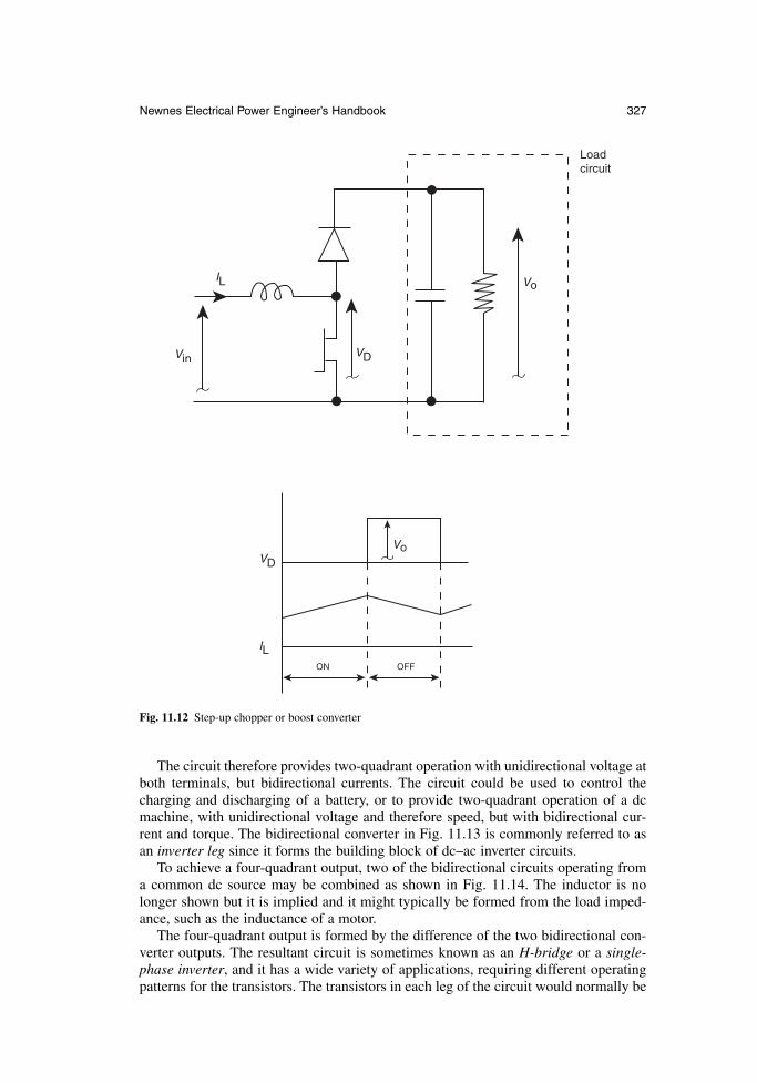
The circuit therefore provides two-quadrant operation with unidirectional voltage atboth terminals, but bidirectional currents. The circuit could be used to control thecharging and discharging of a battery, or to provide two-quadrant operation of a dcmachine, with unidirectional voltage and therefore speed, but with bidirectional cur-rent and torque. The bidirectional converter in Fig. 11.13 is commonly referred to asan inverter leg since it forms the building block of dc–ac inverter circuits.
To achieve a four-quadrant output, two of the bidirectional circuits operating froma common dc source may be combined as shown in Fig. 11.14. The inductor is nolonger shown but it is implied and it might typically be formed from the load imped-ance, such as the inductance of a motor.
The four-quadrant output is formed by the difference of the two bidirectional con-verter outputs. The resultant circuit is sometimes known as an H-bridge or a single-phase inverter, and it has a wide variety of applications, requiring different operatingpatterns for the transistors. The transistors in each leg of the circuit would normally be
Newnes Electrical Power Engineer’s Handbook 327
ON OFF
Vin VD
Vo
VoVD
IL
IL
Loadcircuit
Fig. 11.12 Step-up chopper or boost converter
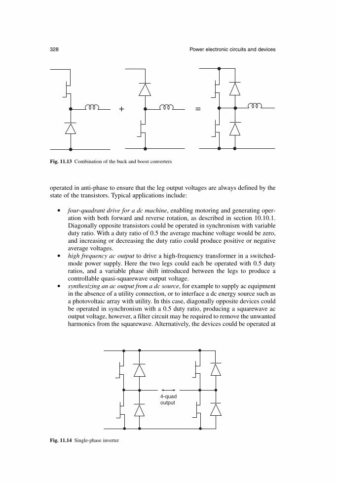
operated in anti-phase to ensure that the leg output voltages are always defined by thestate of the transistors. Typical applications include:
four-quadrant drive for a dc machine, enabling motoring and generating oper-ation with both forward and reverse rotation, as described in section 10.10.1.Diagonally opposite transistors could be operated in synchronism with variableduty ratio. With a duty ratio of 0.5 the average machine voltage would be zero,and increasing or decreasing the duty ratio could produce positive or negativeaverage voltages.
high frequency ac output to drive a high-frequency transformer in a switched-mode power supply. Here the two legs could each be operated with 0.5 dutyratios, and a variable phase shift introduced between the legs to produce a controllable quasi-squarewave output voltage.
synthesizing an ac output from a dc source, for example to supply ac equipmentin the absence of a utility connection, or to interface a dc energy source such asa photovoltaic array with utility. In this case, diagonally opposite devices couldbe operated in synchronism with a 0.5 duty ratio, producing a squarewave acoutput voltage, however, a filter circuit may be required to remove the unwantedharmonics from the squarewave. Alternatively, the devices could be operated at
328 Power electronic circuits and devices
+ =
Fig. 11.13 Combination of the buck and boost converters
4-quadoutput
Fig. 11.14 Single-phase inverter
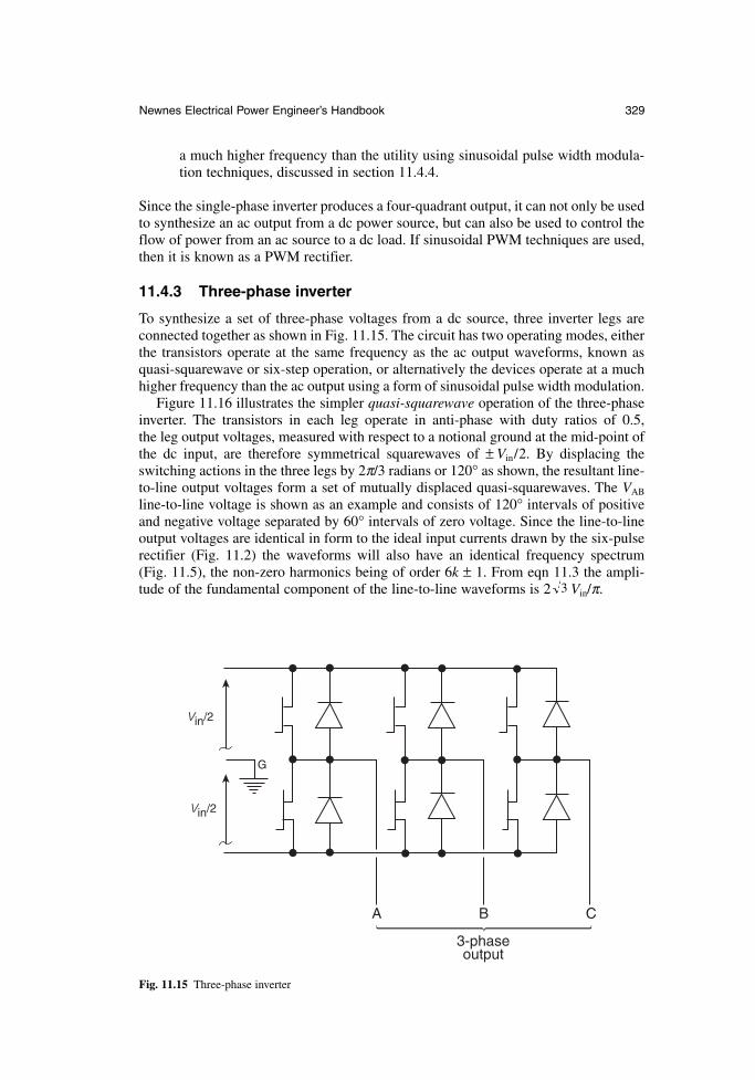
a much higher frequency than the utility using sinusoidal pulse width modula-tion techniques, discussed in section 11.4.4.
Since the single-phase inverter produces a four-quadrant output, it can not only be usedto synthesize an ac output from a dc power source, but can also be used to control theflow of power from an ac source to a dc load. If sinusoidal PWM techniques are used,then it is known as a PWM rectifier.
11.4.3 Three-phase inverter
To synthesize a set of three-phase voltages from a dc source, three inverter legs areconnected together as shown in Fig. 11.15. The circuit has two operating modes, eitherthe transistors operate at the same frequency as the ac output waveforms, known asquasi-squarewave or six-step operation, or alternatively the devices operate at a muchhigher frequency than the ac output using a form of sinusoidal pulse width modulation.
Figure 11.16 illustrates the simpler quasi-squarewave operation of the three-phaseinverter. The transistors in each leg operate in anti-phase with duty ratios of 0.5, the leg output voltages, measured with respect to a notional ground at the mid-point ofthe dc input, are therefore symmetrical squarewaves of ± Vin/2. By displacing theswitching actions in the three legs by 2π/3 radians or 120° as shown, the resultant line-to-line output voltages form a set of mutually displaced quasi-squarewaves. The VAB
line-to-line voltage is shown as an example and consists of 120° intervals of positiveand negative voltage separated by 60° intervals of zero voltage. Since the line-to-lineoutput voltages are identical in form to the ideal input currents drawn by the six-pulserectifier (Fig. 11.2) the waveforms will also have an identical frequency spectrum (Fig. 11.5), the non-zero harmonics being of order 6k ± 1. From eqn 11.3 the ampli-tude of the fundamental component of the line-to-line waveforms is 2 Vin/π.3
Newnes Electrical Power Engineer’s Handbook 329
Vin/2
Vin/2
G
A B C
3-phaseoutput
Fig. 11.15 Three-phase inverter
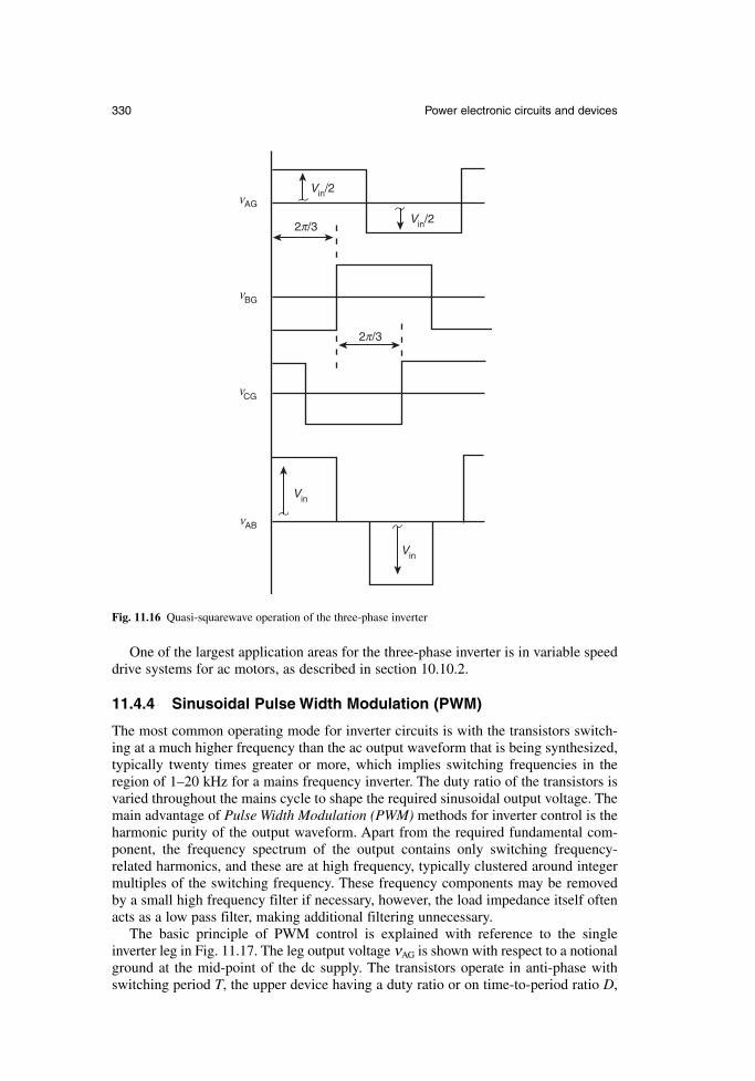
One of the largest application areas for the three-phase inverter is in variable speeddrive systems for ac motors, as described in section 10.10.2.
11.4.4 Sinusoidal Pulse Width Modulation (PWM)
The most common operating mode for inverter circuits is with the transistors switch-ing at a much higher frequency than the ac output waveform that is being synthesized,typically twenty times greater or more, which implies switching frequencies in theregion of 1–20 kHz for a mains frequency inverter. The duty ratio of the transistors isvaried throughout the mains cycle to shape the required sinusoidal output voltage. Themain advantage of Pulse Width Modulation (PWM) methods for inverter control is theharmonic purity of the output waveform. Apart from the required fundamental com-ponent, the frequency spectrum of the output contains only switching frequency-related harmonics, and these are at high frequency, typically clustered around integermultiples of the switching frequency. These frequency components may be removedby a small high frequency filter if necessary, however, the load impedance itself oftenacts as a low pass filter, making additional filtering unnecessary.
The basic principle of PWM control is explained with reference to the singleinverter leg in Fig. 11.17. The leg output voltage νAG is shown with respect to a notionalground at the mid-point of the dc supply. The transistors operate in anti-phase withswitching period T, the upper device having a duty ratio or on time-to-period ratio D,
330 Power electronic circuits and devices
AGν
Vin
Vin
Vin/2
Vin/2
BGν
CGν
ABν
2 /3π
2 /3π
Fig. 11.16 Quasi-squarewave operation of the three-phase inverter
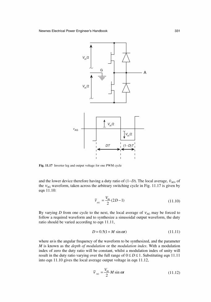
and the lower device therefore having a duty ratio of (1−D). The local average, ν-AG, ofthe νAG waveform, taken across the arbitrary switching cycle in Fig. 11.17 is given byeqn 11.10:
(11.10)
By varying D from one cycle to the next, the local average of νAG may be forced tofollow a required waveform and to synthesize a sinusoidal output waveform, the dutyratio should be varied according to eqn 11.11,
(11.11)
where ω is the angular frequency of the waveform to be synthesized, and the parameterM is known as the depth of modulation or the modulation index. With a modulationindex of zero the duty ratio will be constant, whilst a modulation index of unity willresult in the duty ratio varying over the full range of 0 ≤ D ≤ 1. Substituting eqn 11.11into eqn 11.10 gives the local average output voltage in eqn 11.12,
(11.12)ν ωAGin sin= V
M t2
D M t= +0 5 1. ( sin )ω
vV
DAG
in ( )= −2
2 1
Newnes Electrical Power Engineer’s Handbook 331
Vin/2
Vin/2
Vin/2
Vin/2
AGν
AG
DT (1−D)T
Fig. 11.17 Inverter leg and output voltage for one PWM cycle
which has the required sinusoidal form, the amplitude being (Vin/2)M. The modulationindex therefore controls the amplitude of the synthesized output.
Equation 11.12 shows that with a modulation index of unity the amplitude of the output waveform is limited to Vin/2. A modulation index of greater than unity,known as over-modulation, allows the amplitude of the fundamental component of the output to be increased, although eqn 11.12 breaks down in this region. However,over-modulation has the disadvantage of introducing low-order harmonics in the output spectrum. Alternatively the technique of third harmonic injection may be usedto increase the amplitude of the fundamental component of the output by around 15 per cent without degrading the frequency spectrum. This is achieved by adding asmall amount of third harmonic to the modulating waveform. The addition of the thirdharmonic does not affect the line-to-line output waveforms of a three-phase invertersince the third harmonic is a common mode component in three-phase systems.
A variety of methods have been developed for the practical implementation of sinusoidal PWM and the determination of the required duty ratio variation. Naturallysampled PWM is intuitively the most simple, and involves comparing the sinusoidalmodulating waveform with a triangular carrier signal at the switching frequency. Theanalogue implementation of this technique is fraught with offset and drift problems,and, being analogue in nature, the method does not readily lend itself to digital imple-mentations. Instead, methods such as regularly sampled PWM have been developed,which use sample and hold techniques to simplify the calculations within a processor.Most recently, the method of space vector PWM has become common for three-phaseinverters. This uses a single rotating vector to represent the required three-phase output waveforms, and the transistor switching patterns for each of the three legs arecalculated simultaneously, resulting in a very efficient implementation, furthermorethe third harmonic injection to increase the maximum fundamental output is inherentlyprovided.
11.5 High-frequency power supplies
High-frequency power supplies or switched-mode power supplies are widely used toderive low-voltage dc supplies from the ac utility, and operate by first rectifying the ac input to provide high-voltage dc, which is then converted into high-frequency ac,typically at around 100 kHz, and then passed through a physically small high-frequency transformer, before finally being rectified and smoothed to form the output.Power levels range from a few watts to a few kilowatts.
Traditionally, at these low power levels the input rectifier consists of a single-phasebridge and large smoothing capacitor, however in recent years this arrangement hasbecome unacceptable for all but the very lowest power levels due to the high harmoniccontent of the currents drawn by such a rectifier circuit. The input current to the recti-fier consists of narrow pulses at the peaks of the ac voltage waveform. Instead ofadding large low-frequency filters at the rectifier input, active high-power factor recti-fiers are increasingly being used to provide high-quality, near-sinusoidal input currentsby using high-frequency converter techniques. A common example, based on the boostconverter, is illustrated in Fig. 11.18.
A full-wave rectified voltage waveform is presented as the input to the boost converter, which, through the use of an input current feedback loop, is controlled tooffer a constant input resistance, that is, to draw an input current that follows the full-wave rectified voltage. As a result the input power factor is almost unity. However, a
332 Power electronic circuits and devices
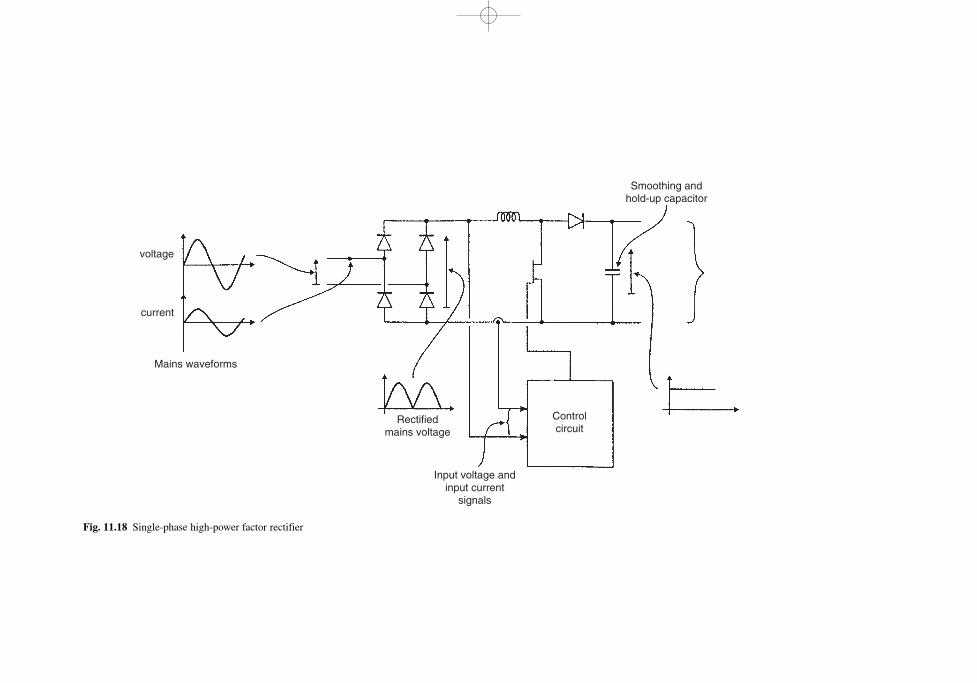
voltage
current
Mains waveforms
Rectified mains voltage
Smoothing and hold-up capacitor
Control circuit
Input voltage and input current
signals
Fig. 11.18 Single-phase high-power factor rectifier
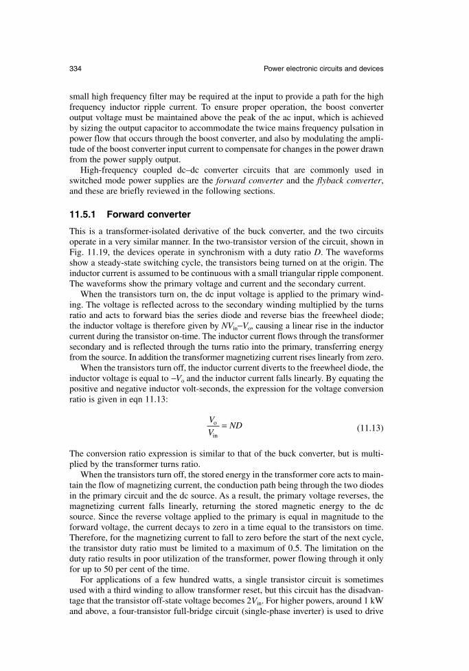
small high frequency filter may be required at the input to provide a path for the highfrequency inductor ripple current. To ensure proper operation, the boost converter output voltage must be maintained above the peak of the ac input, which is achievedby sizing the output capacitor to accommodate the twice mains frequency pulsation inpower flow that occurs through the boost converter, and also by modulating the ampli-tude of the boost converter input current to compensate for changes in the power drawnfrom the power supply output.
High-frequency coupled dc–dc converter circuits that are commonly used inswitched mode power supplies are the forward converter and the flyback converter,and these are briefly reviewed in the following sections.
11.5.1 Forward converter
This is a transformer-isolated derivative of the buck converter, and the two circuitsoperate in a very similar manner. In the two-transistor version of the circuit, shown inFig. 11.19, the devices operate in synchronism with a duty ratio D. The waveformsshow a steady-state switching cycle, the transistors being turned on at the origin. Theinductor current is assumed to be continuous with a small triangular ripple component.The waveforms show the primary voltage and current and the secondary current.
When the transistors turn on, the dc input voltage is applied to the primary wind-ing. The voltage is reflected across to the secondary winding multiplied by the turnsratio and acts to forward bias the series diode and reverse bias the freewheel diode; the inductor voltage is therefore given by NVin−Vo, causing a linear rise in the inductor current during the transistor on-time. The inductor current flows through the transformersecondary and is reflected through the turns ratio into the primary, transferring energyfrom the source. In addition the transformer magnetizing current rises linearly from zero.
When the transistors turn off, the inductor current diverts to the freewheel diode, theinductor voltage is equal to −Vo and the inductor current falls linearly. By equating thepositive and negative inductor volt-seconds, the expression for the voltage conversionratio is given in eqn 11.13:
(11.13)
The conversion ratio expression is similar to that of the buck converter, but is multi-plied by the transformer turns ratio.
When the transistors turn off, the stored energy in the transformer core acts to main-tain the flow of magnetizing current, the conduction path being through the two diodesin the primary circuit and the dc source. As a result, the primary voltage reverses, themagnetizing current falls linearly, returning the stored magnetic energy to the dcsource. Since the reverse voltage applied to the primary is equal in magnitude to theforward voltage, the current decays to zero in a time equal to the transistors on time.Therefore, for the magnetizing current to fall to zero before the start of the next cycle,the transistor duty ratio must be limited to a maximum of 0.5. The limitation on theduty ratio results in poor utilization of the transformer, power flowing through it onlyfor up to 50 per cent of the time.
For applications of a few hundred watts, a single transistor circuit is sometimesused with a third winding to allow transformer reset, but this circuit has the disadvan-tage that the transistor off-state voltage becomes 2Vin. For higher powers, around 1 kWand above, a four-transistor full-bridge circuit (single-phase inverter) is used to drive
V
VNDo
in
=
334 Power electronic circuits and devices
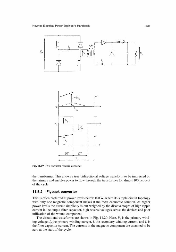
the transformer. This allows a true bidirectional voltage waveform to be impressed onthe primary and enables power to flow through the transformer for almost 100 per centof the cycle.
11.5.2 Flyback converter
This is often preferred at power levels below 100 W, where its simple circuit topologywith only one magnetic component makes it the most economic solution. At higherpower levels the circuit simplicity is out-weighed by the disadvantages of high ripplecurrent in the output filter capacitor, high reverse voltages across the devices and poorutilization of the wound component.
The circuit and waveforms are shown in Fig. 11.20. Here, Vp is the primary wind-ing voltage, Ip the primary winding current, Is the secondary winding current, and Ic isthe filter capacitor current. The currents in the magnetic component are assumed to bezero at the start of the cycle.
Newnes Electrical Power Engineer’s Handbook 335
Ip
IpIM
Is
Is
IL
IL
Vo
Vp
Vin
Vin
VpVin
NIL
DT DT
T
1:N
Fig. 11.19 Two-transistor forward converter
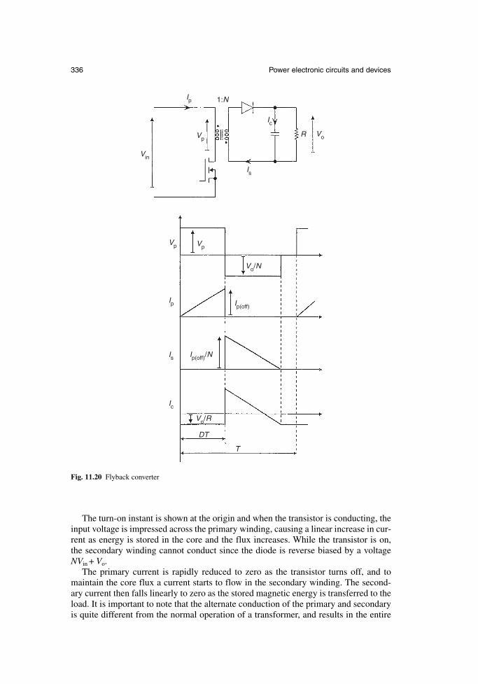
336 Power electronic circuits and devices
Ip
Ic
Vo
Vin
Vp Vp
Ip
Is
Is
Ic
Vp
1:N
R
Ip(off)/N
Ip(off)
Vo/R
Vo/N
DT
T
Fig. 11.20 Flyback converter
The turn-on instant is shown at the origin and when the transistor is conducting, theinput voltage is impressed across the primary winding, causing a linear increase in cur-rent as energy is stored in the core and the flux increases. While the transistor is on,the secondary winding cannot conduct since the diode is reverse biased by a voltageNVin+ Vo.
The primary current is rapidly reduced to zero as the transistor turns off, and tomaintain the core flux a current starts to flow in the secondary winding. The second-ary current then falls linearly to zero as the stored magnetic energy is transferred to theload. It is important to note that the alternate conduction of the primary and secondaryis quite different from the normal operation of a transformer, and results in the entire
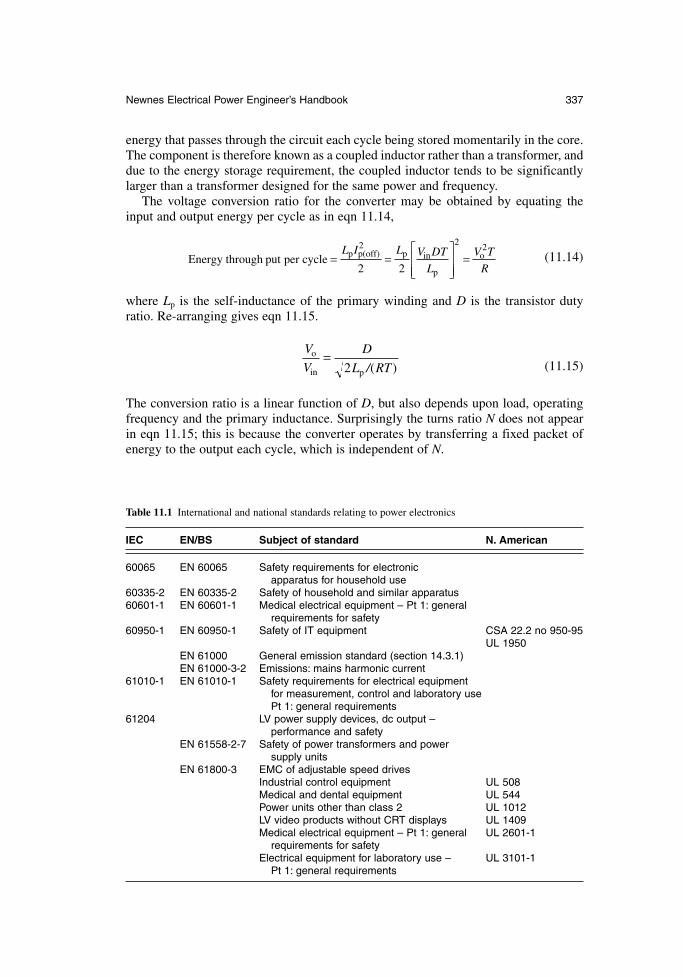
energy that passes through the circuit each cycle being stored momentarily in the core.The component is therefore known as a coupled inductor rather than a transformer, anddue to the energy storage requirement, the coupled inductor tends to be significantlylarger than a transformer designed for the same power and frequency.
The voltage conversion ratio for the converter may be obtained by equating theinput and output energy per cycle as in eqn 11.14,
(11.14)
where Lp is the self-inductance of the primary winding and D is the transistor dutyratio. Re-arranging gives eqn 11.15.
(11.15)
The conversion ratio is a linear function of D, but also depends upon load, operatingfrequency and the primary inductance. Surprisingly the turns ratio N does not appearin eqn 11.15; this is because the converter operates by transferring a fixed packet ofenergy to the output each cycle, which is independent of N.
V
V
D
L RTo
( )in p
=2 /
Energy through put per cycle o= =
=L I L V DT
L
V T
Rp p(off) p in
p2
2 22
2
Newnes Electrical Power Engineer’s Handbook 337
Table 11.1 International and national standards relating to power electronics
IEC EN/BS Subject of standard N. American
60065 EN 60065 Safety requirements for electronicapparatus for household use
60335-2 EN 60335-2 Safety of household and similar apparatus60601-1 EN 60601-1 Medical electrical equipment – Pt 1: general
requirements for safety60950-1 EN 60950-1 Safety of IT equipment CSA 22.2 no 950-95
UL 1950EN 61000 General emission standard (section 14.3.1)EN 61000-3-2 Emissions: mains harmonic current
61010-1 EN 61010-1 Safety requirements for electrical equipmentfor measurement, control and laboratory usePt 1: general requirements
61204 LV power supply devices, dc output –performance and safety
EN 61558-2-7 Safety of power transformers and powersupply units
EN 61800-3 EMC of adjustable speed drivesIndustrial control equipment UL 508Medical and dental equipment UL 544Power units other than class 2 UL 1012LV video products without CRT displays UL 1409Medical electrical equipment – Pt 1: general UL 2601-1
requirements for safetyElectrical equipment for laboratory use – UL 3101-1
Pt 1: general requirements

11.6 Standards
There is a wide range of standards covering the performance of power electronicequipment, particularly with regard to electromagnetic compatibility and safety. Somestandards are generic whilst others apply to specific classes of equipment. Examplesof the most common standards are listed in Table 11.1.
References
11A. Mohan, Undeland and Robbins: Power Electronics: Converters, Applications andDesign, Third Edition, John Wiley, 2003.
338 Power electronic circuits and devices
Chapter 12
Batteries and fuel cells
R.I. DeakinProfessor J.T.S. IrvineThe University of St. Andrews
12.1 Introduction
The battery is at present the most practical and widely used means of storing electri-cal energy. The storage capacity of a battery is usually defined in ampere-hours (Ah);energy is strictly defined in kilowatt-hours (kWh) or joules, but since the voltage of aparticular battery system is normally fixed and known, the Ah definition is more con-venient. The terms battery and cell are often interchanged, although strictly a batteryis a group of cells built together in a single unit.
Batteries can be classified into primary and secondary types.A primary battery stores electrical energy in a chemical form which is introduced
at the manufacturing stage. When it is discharged and this chemically stored energy isdepleted, the battery is no longer serviceable. Applications for primary batteries aregenerally in the low-cost domestic environment, in portable equipment such as torches,calculators, radios and hearing aids.
A secondary or rechargeable battery absorbs electrical energy, stores this in a chemical form and then releases it when required. Once the battery has been discharged and the chemical energy depleted, it can be recharged with a further intakeof electrical energy. Many cycles of charging and discharging can be repeated in a secondary battery. Applications cover a wide range. In the domestic environment secondary batteries are used in portable hand tools, laptop computers and portable telephones. Higher powered applications in industry include use in road and rail vehicles and in standby power applications. The capacity of secondary battery systemsranges from 100 mAh to 2000 Ah. Their useful life ranges from 2 to 20 years; this willdepend, among other things, upon the number of charge–discharge cycles and the typeand construction of battery used.
A fuel cell is an energy conversion device that is closely related to a battery. Bothare electrochemical devices for the conversion of chemical to electrical energy. In abattery the chemical energy is stored internally, whereas in a fuel cell the chemicalenergy (fuel and oxidant) is supplied externally and can be continuously replenished.A semi-fuel cell is an intermediate between these, being a battery where the chemicalenergy can be replenished externally, but not continuously. The energy storage capac-ity of a fuel cell is a function of the fuel cell and its fuel (or possibly oxidant). Areversible fuel cell operates essentially as a secondary battery.
340 Batteries and fuel cells
12.2 Primary cells
The majority of primary cells now in use fall into one of eight types:
zinc carbon alkaline manganese mercury oxide silver oxide zinc air 3 V lithium primary lithium thionyl chloride 1.5 V lithium primary
Each of these is briefly reviewed in the following sections.
12.2.1 Zinc carbon
This battery is based upon Leclanché cells with zinc as negative and MnO2 as theactive positive electrode with carbon as current collector. In its latest form, this hasbeen in use since 1950. The basic cell operates with a voltage range of 1.2 V to 1.6 V,and cells are connected in series to form batteries such as AAA, AA, C, D, PP3 andPP9. Typical construction of a PP9 battery is shown in Fig. 12.1.
Zinc carbon batteries are low in cost, they have an operating temperature rangefrom –10°C to 50°C, and the shelf life at a temperature of 20°C is up to three years.They are ideally suited to applications with intermittent loads, such as radios, torches,toys, clocks and flashing warning lamps.
12.2.2 Alkaline manganese
The alkaline manganese battery differs from the zinc carbon in that the electrolyte is apotassium hydroxide solution as opposed to an ammonium chloride solution and thatthe configuration is inverted with zinc on the outside. A nickel-plated steel can is usedas the positive current collector. The alkaline manganese battery became commerciallyavailable in its present form in the late 1950s. The basic cell operates with a voltagerange of 1.35 V to 1.55 V, and cells are connected in series to form the standard battery sizes N, AAA, AA, C, D and PP3. Typical construction of a single-cell batteryis shown in Fig. 12.2.
Cost is in the medium-low range. The operating temperature range is –15°C to 50°C, and the shelf life at 20°C is up to four years. Alkaline manganese batteries are suited to a current drain of 5 mA to 2 A; this makes them ideally suited to con-tinuous duty applications which can include radios, torches, cd players, toys and cameras.
12.2.3 Mercury oxide
This type has been in commercial use since the 1930s. The single cell operates with anarrow voltage range of 1.2 V to 1.4 V; it is only available as a single button cell, theconstruction of which is illustrated in Fig. 12.3.
Cost is in the medium range. The operating temperature range is 0°C to 50°C, andthe shelf life at 20°C is up to four years. Mercury oxide button cells are suitable forlow current drains of 0.1 mA to 5 mA, with either continuous or intermittent loads.
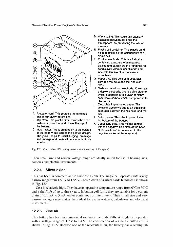
Their small size and narrow voltage range are ideally suited for use in hearing aids,cameras and electric instruments.
12.2.4 Silver oxide
This has been in commercial use since the 1970s. The single cell operates with a verynarrow range from 1.50 V to 1.55 V. Construction of a silver oxide button cell is shownin Fig. 12.4.
Cost is relatively high. They have an operating temperature range from 0°C to 50°Cand a shelf life of up to three years. In button cell form, they are suitable for a currentdrain of 0.1 mA to 5 mA, either continuous or intermittent. Their small size and verynarrow voltage range makes them ideal for use in watches, calculators and electricalinstruments.
12.2.5 Zinc air
This battery has been in commercial use since the mid-1970s. A single cell operateswith a voltage range of 1.2 V to 1.4 V. The construction of a zinc air button cell isshown in Fig. 12.5. Because one of the reactants is air, the battery has a sealing tab
Newnes Electrical Power Engineer’s Handbook 341
Fig. 12.1 Zinc carbon PP9 battery construction (courtesy of Energiser)
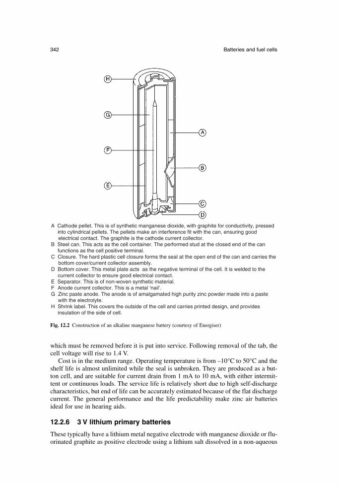
342 Batteries and fuel cells
which must be removed before it is put into service. Following removal of the tab, thecell voltage will rise to 1.4 V.
Cost is in the medium range. Operating temperature is from –10°C to 50°C and theshelf life is almost unlimited while the seal is unbroken. They are produced as a but-ton cell, and are suitable for current drain from 1 mA to 10 mA, with either intermit-tent or continuous loads. The service life is relatively short due to high self-dischargecharacteristics, but end of life can be accurately estimated because of the flat dischargecurrent. The general performance and the life predictability make zinc air batteriesideal for use in hearing aids.
12.2.6 3 V lithium primary batteries
These typically have a lithium metal negative electrode with manganese dioxide or flu-orinated graphite as positive electrode using a lithium salt dissolved in a non-aqueous
A Cathode pellet. This is of synthetic manganese dioxide, with graphite for conductivity, pressed into cylindrical pellets. The pellets make an interference fit with the can, ensuring good electrical contact. The graphite is the cathode current collector.B Steel can. This acts as the cell container. The performed stud at the closed end of the can functions as the cell positive terminal.C Closure. The hard plastic cell closure forms the seal at the open end of the can and carries the bottom cover/current collector assembly.D Bottom cover. This metal plate acts as the negative terminal of the cell. It is welded to the current collector to ensure good electrical contact.E Separator. This is of non-woven synthetic material.F Anode current collector. This is a metal ‘nail’.G Zinc paste anode. The anode is of amalgamated high purity zinc powder made into a paste with the electrolyte.H Shrink label. This covers the outside of the cell and carries printed design, and provides insulation of the side of cell.
Fig. 12.2 Construction of an alkaline manganese battery (courtesy of Energiser)
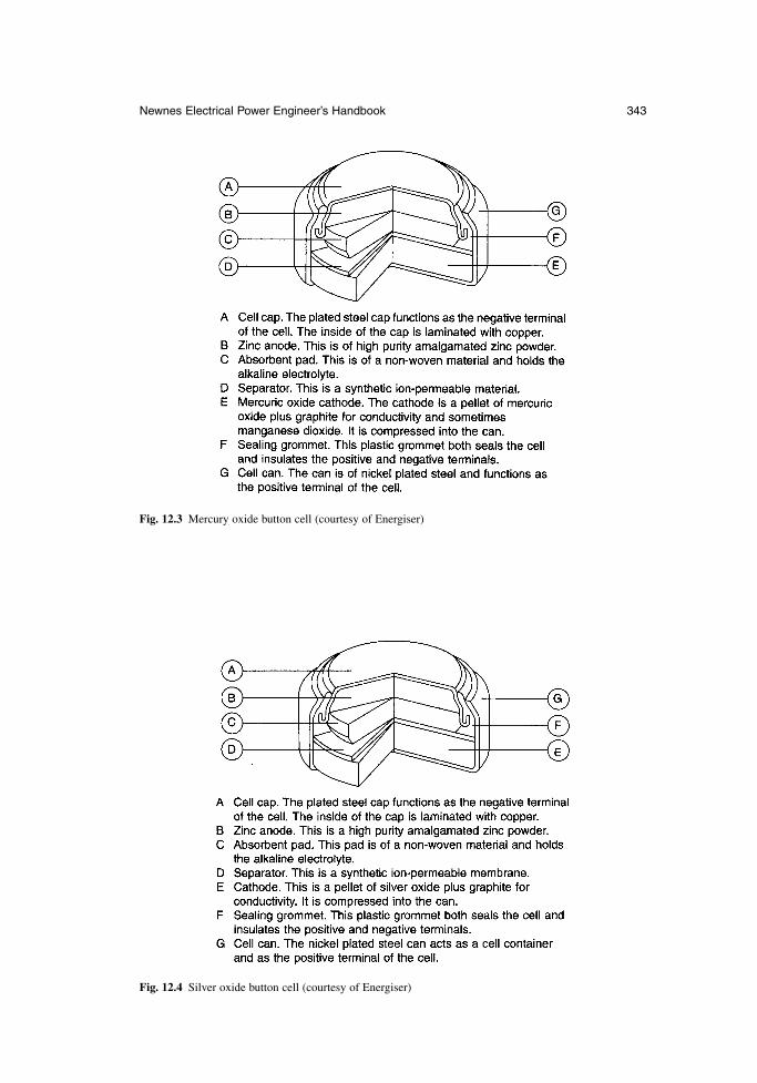
Newnes Electrical Power Engineer’s Handbook 343
Fig. 12.3 Mercury oxide button cell (courtesy of Energiser)
Fig. 12.4 Silver oxide button cell (courtesy of Energiser)
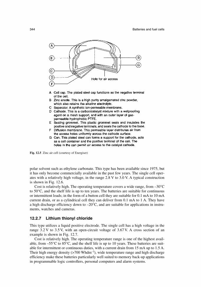
polar solvent such as ethylene carbonate. This type has been available since 1975, butit has only become commercially available in the past few years. The single cell oper-ates with a relatively high voltage, in the range 2.8 V to 3.0 V. A typical constructionis shown in Fig. 12.6.
Cost is relatively high. The operating temperature covers a wide range, from –30°Cto 50°C, and the shelf life is up to ten years. The batteries are suitable for continuousor intermittent loads; in the form of a button cell they are suitable for 0.1 mA to 10 mAcurrent drain, or as a cylindrical cell they can deliver from 0.1 mA to 1 A. They havea high discharge efficiency down to –20°C, and are suitable for applications in instru-ments, watches and cameras.
12.2.7 Lithium thionyl chloride
This type utilizes a liquid positive electrode. The single cell has a high voltage in therange 3.2 V to 3.5 V, with an open-circuit voltage of 3.67 V. A cross section of anexample is shown in Fig. 12.7.
Cost is relatively high. The operating temperature range is one of the highest avail-able, from –55°C to 85°C, and the shelf life is up to 10 years. These batteries are suit-able for intermittent or continuous duties, with a current drain from 15 mA up to 1.5 A.Their high energy density (>700 Whdm−3), wide temperature range and high dischargeefficiency make these batteries particularly well suited to memory back-up applicationsin programmable logic controllers, personal computers and alarm systems.
344 Batteries and fuel cells
Fig. 12.5 Zinc air cell (courtesy of Energiser)
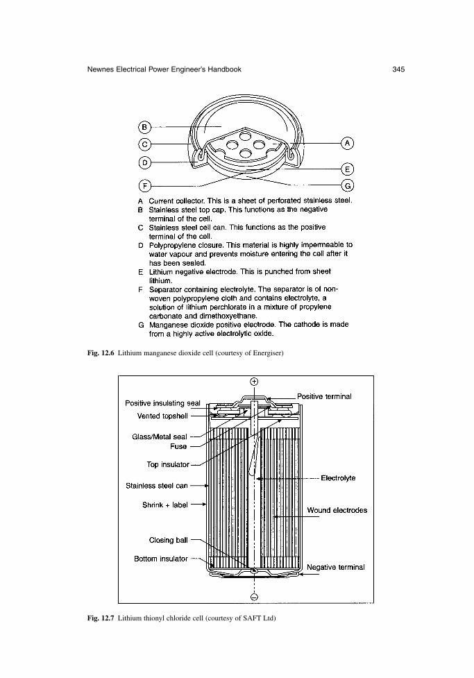
Newnes Electrical Power Engineer’s Handbook 345
Fig. 12.6 Lithium manganese dioxide cell (courtesy of Energiser)
Fig. 12.7 Lithium thionyl chloride cell (courtesy of SAFT Ltd)
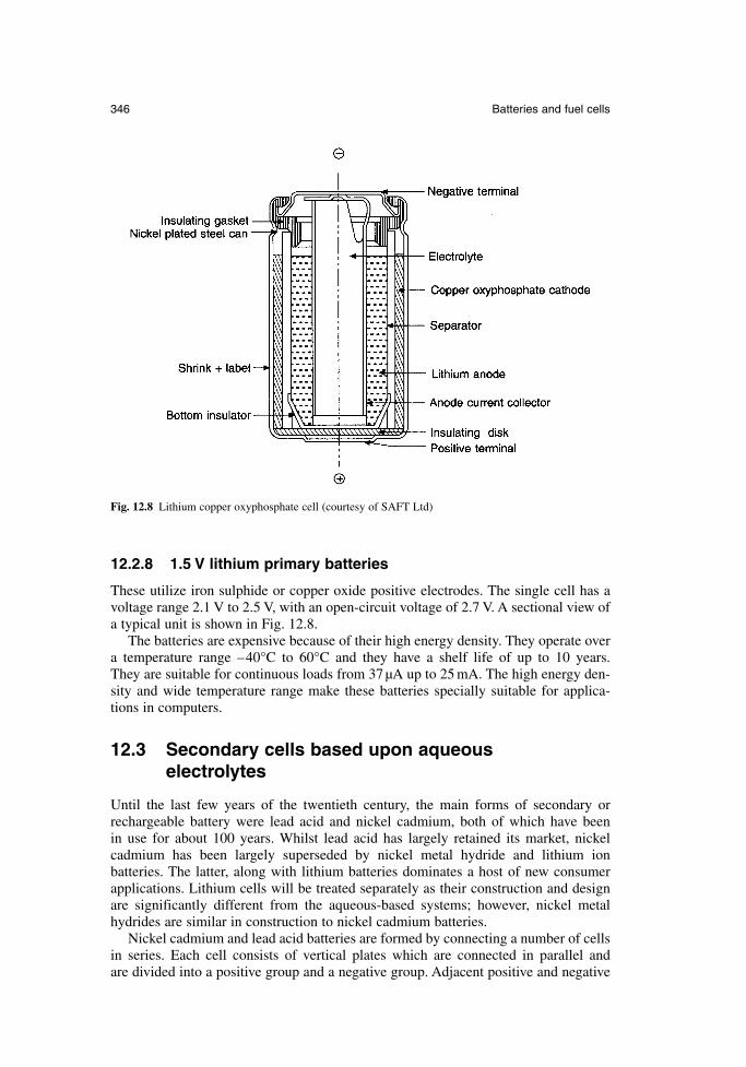
12.2.8 1.5 V lithium primary batteries
These utilize iron sulphide or copper oxide positive electrodes. The single cell has avoltage range 2.1 V to 2.5 V, with an open-circuit voltage of 2.7 V. A sectional view ofa typical unit is shown in Fig. 12.8.
The batteries are expensive because of their high energy density. They operate overa temperature range –40°C to 60°C and they have a shelf life of up to 10 years. They are suitable for continuous loads from 37 µA up to 25 mA. The high energy den-sity and wide temperature range make these batteries specially suitable for applica-tions in computers.
12.3 Secondary cells based upon aqueous electrolytes
Until the last few years of the twentieth century, the main forms of secondary orrechargeable battery were lead acid and nickel cadmium, both of which have been in use for about 100 years. Whilst lead acid has largely retained its market, nickel cadmium has been largely superseded by nickel metal hydride and lithium ion batteries. The latter, along with lithium batteries dominates a host of new consumerapplications. Lithium cells will be treated separately as their construction and designare significantly different from the aqueous-based systems; however, nickel metalhydrides are similar in construction to nickel cadmium batteries.
Nickel cadmium and lead acid batteries are formed by connecting a number of cellsin series. Each cell consists of vertical plates which are connected in parallel and are divided into a positive group and a negative group. Adjacent positive and negative
346 Batteries and fuel cells
Fig. 12.8 Lithium copper oxyphosphate cell (courtesy of SAFT Ltd)
plates are insulated from each other by separators or rod insulators which have to provide the following functions:
obstruct the transfer of ions between the plates as little as possible keep in place the active material enable the escape of charging gases from the electrolyte
All the plates and separators together form a plategroup or element.The insulator in nickel cadmium batteries is formed from vertical plastic rods,
which may be separate or as grids which are inserted between the plates. Corrugatedor perforated PVC is also used as a separator. The active material is kept in place bysteel pockets.
In lead acid batteries, the separators are normally microporous sheets of plastic,which are usually combined with corrugated and perforated spacers; porous rubberseparators are also used. In some designs, the separator completely surrounds the positive or negative plate. The selection of separator is very important, and it dependsupon the plate design and the use for which the battery is intended. In batteriesintended for short discharges, such as the starting of the diesel engine, thin separatorsand spacers are used, whereas batteries designed for long discharges, as in standbypower or emergency lighting, have thick separators and spacers. Batteries that requireextra strength to withstand mechanical stresses often have a glass fibre separatoragainst the positive plates in order to minimize the shedding of active material fromthese plates.
The outermost plates are of the same polarity on both sides. In lead acid batteriesthe outside plates are normally negative; in nickel cadmium batteries they are normallypositive.
The plategroups are mounted in containers which are filled with electrolyte. The electrolyte is dilute sulphuric acid in lead acid batteries, and potassium hydroxide in nickel cadmium batteries. In a fully charged lead acid battery the electrolyte densityis between 1.20 and 1.29. In nickel cadmium batteries it is between 1.18 and 1.30 irrespective of the state of charge.
The containers may house a single cell or they may be of a monoblock type, hous-ing several cells. The top (or lid) may be glued or welded to the container, or it may beformed integrally with the container. In the lid is a hole for the vent, which is normallyflame arresting, and the cells are topped up with electrolyte through the vent hole.
Below the plate there is an empty space which is known as the sludge space. Thisis provided so that shredded active material and corrosion product from the supportingstructure can be deposited without creating any short circuits between the plates. Thesludge space in nickel cadmium batteries is smaller than that in lead acid units becausethere is no corrosion of the supporting steel structure and no shredding of active material; it is usually created by hanging the plategroup from the lid. In lead acid batteries the sludge space may be created by hanging the plates from the lid or container walls (this is common in stationary batteries), by standing the plates on supports from the bottom (this is common for locomotive starting batteries) or byhanging the positive plates with the negative plates standing on supports (this is alsoused for stationary batteries).
From the plates, the current is carried through plate lugs, a connection strap orbridge and a polebolt. The bolts pass through the lid and are sealed against the lid withgaskets. Above the lid, the cells are connected to form the battery. Monoblocks mayhave connectors arranged directly through the side of the partition cell wall, in which
Newnes Electrical Power Engineer’s Handbook 347
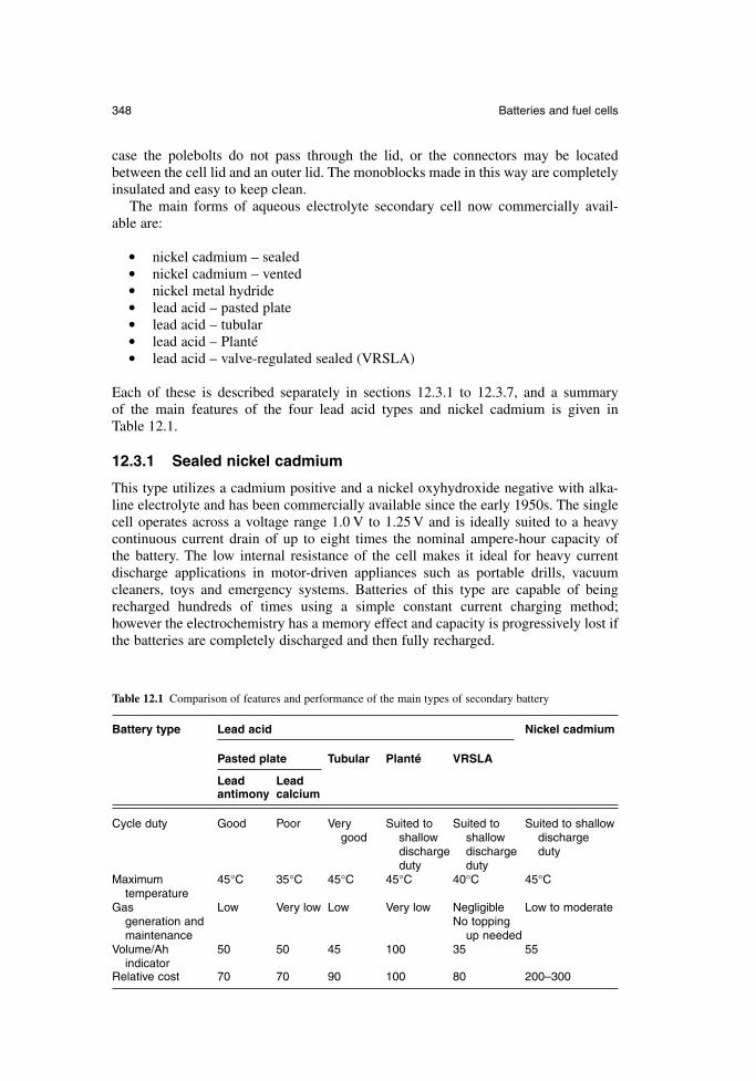
case the polebolts do not pass through the lid, or the connectors may be locatedbetween the cell lid and an outer lid. The monoblocks made in this way are completelyinsulated and easy to keep clean.
The main forms of aqueous electrolyte secondary cell now commercially avail-able are:
nickel cadmium – sealed nickel cadmium – vented nickel metal hydride lead acid – pasted plate lead acid – tubular lead acid – Planté lead acid – valve-regulated sealed (VRSLA)
Each of these is described separately in sections 12.3.1 to 12.3.7, and a summary of the main features of the four lead acid types and nickel cadmium is given in Table 12.1.
12.3.1 Sealed nickel cadmium
This type utilizes a cadmium positive and a nickel oxyhydroxide negative with alka-line electrolyte and has been commercially available since the early 1950s. The singlecell operates across a voltage range 1.0 V to 1.25 V and is ideally suited to a heavycontinuous current drain of up to eight times the nominal ampere-hour capacity of the battery. The low internal resistance of the cell makes it ideal for heavy current discharge applications in motor-driven appliances such as portable drills, vacuumcleaners, toys and emergency systems. Batteries of this type are capable of beingrecharged hundreds of times using a simple constant current charging method; however the electrochemistry has a memory effect and capacity is progressively lost ifthe batteries are completely discharged and then fully recharged.
348 Batteries and fuel cells
Table 12.1 Comparison of features and performance of the main types of secondary battery
Battery type Lead acid Nickel cadmium
Pasted plate Tubular Planté VRSLA
Lead Lead antimony calcium
Cycle duty Good Poor Very Suited to Suited to Suited to shallowgood shallow shallow discharge
discharge discharge dutyduty duty
Maximum 45°C 35°C 45°C 45°C 40°C 45°Ctemperature
Gas Low Very low Low Very low Negligible Low to moderategeneration and No topping maintenance up needed
Volume/Ah 50 50 45 100 35 55indicator
Relative cost 70 70 90 100 80 200–300
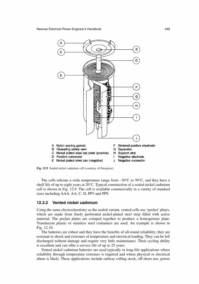
The cells tolerate a wide temperature range from –30°C to 50°C, and they have ashelf life of up to eight years at 20°C. Typical construction of a sealed nickel cadmiumcell is shown in Fig. 12.9. The cell is available commercially in a variety of standardsizes including AAA, AA, C, D, PP3 and PP9.
12.3.2 Vented nickel cadmium
Using the same electrochemistry as the sealed variant, vented cells use ‘pocket’ plates,which are made from finely perforated nickel-plated steel strip filled with active material. The pocket plates are crimped together to produce a homogenous plate.Translucent plastic or stainless steel containers are used. An example is shown in Fig. 12.10.
The batteries are robust and they have the benefits of all-round reliability; they areresistant to shock and extremes of temperature and electrical loading. They can be leftdischarged without damage and require very little maintenance. Their cycling abilityis excellent and can offer a service life of up to 25 years.
Vented nickel cadmium batteries are used typically in long-life applications wherereliability through temperature extremes is required and where physical or electricalabuse is likely. These applications include railway rolling stock, off-shore use, power
Newnes Electrical Power Engineer’s Handbook 349
Fig. 12.9 Sealed nickel cadmium cell (courtesy of Energiser)
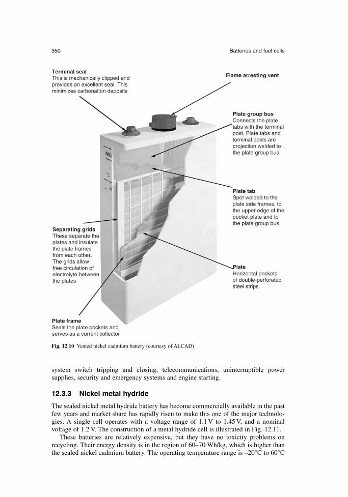
system switch tripping and closing, telecommunications, uninterruptible power supplies, security and emergency systems and engine starting.
12.3.3 Nickel metal hydride
The sealed nickel metal hydride battery has become commercially available in the pastfew years and market share has rapidly risen to make this one of the major technolo-gies. A single cell operates with a voltage range of 1.1 V to 1.45 V, and a nominal voltage of 1.2 V. The construction of a metal hydride cell is illustrated in Fig. 12.11.
These batteries are relatively expensive, but they have no toxicity problems on recycling. Their energy density is in the region of 60–70 Wh/kg, which is higher thanthe sealed nickel cadmium battery. The operating temperature range is –20°C to 60°C
350 Batteries and fuel cells
Terminal seal This is mechanically clipped and provides an excellent seal. This minimizes carbonation deposits
Plate group bus Connects the plate tabs with the terminal post. Plate tabs and terminal posts are projection welded to the plate group bus
Plate tab Spot welded to the plate side frames, to the upper edge of the pocket plate and to the plate group bus
Plate frame Seals the plate pockets and serves as a current collector
Separating grids These separate the plates and insulate the plate frames from each other. The grids allow free circulation of electrolyte between the plates
Plate Horizontal pockets of double-perforated steel strips
Flame arresting vent
Fig. 12.10 Vented nickel cadmium battery (courtesy of ALCAD)
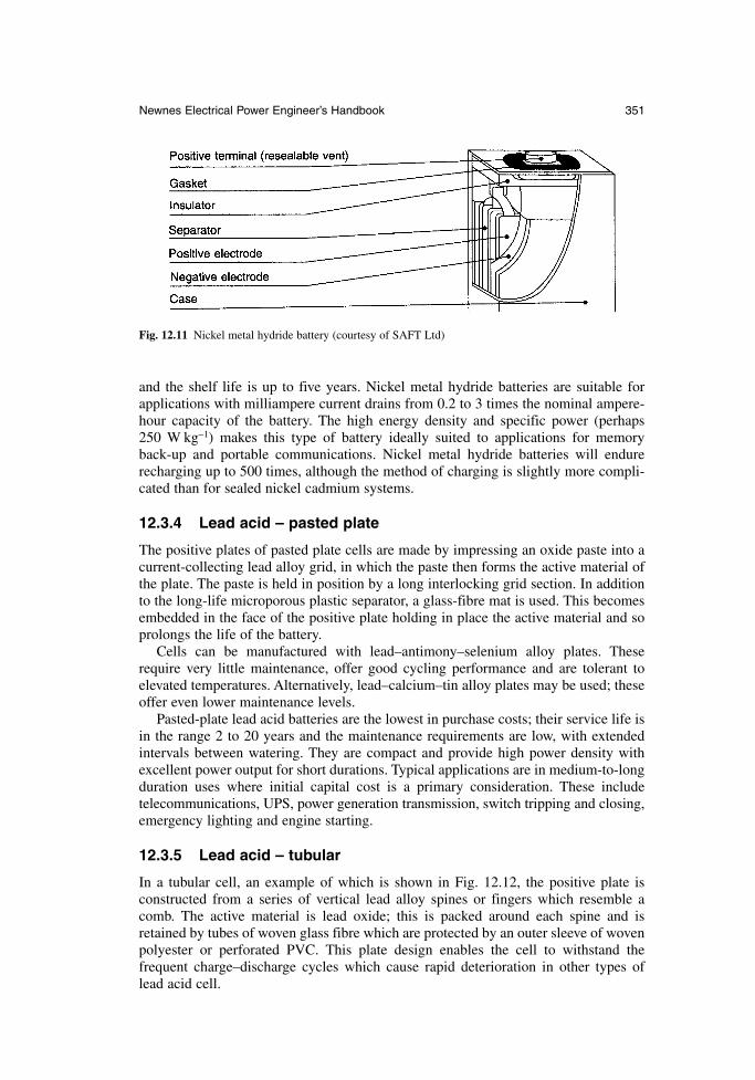
and the shelf life is up to five years. Nickel metal hydride batteries are suitable forapplications with milliampere current drains from 0.2 to 3 times the nominal ampere-hour capacity of the battery. The high energy density and specific power (perhaps 250 W kg−1) makes this type of battery ideally suited to applications for memory back-up and portable communications. Nickel metal hydride batteries will endurerecharging up to 500 times, although the method of charging is slightly more compli-cated than for sealed nickel cadmium systems.
12.3.4 Lead acid – pasted plate
The positive plates of pasted plate cells are made by impressing an oxide paste into acurrent-collecting lead alloy grid, in which the paste then forms the active material ofthe plate. The paste is held in position by a long interlocking grid section. In additionto the long-life microporous plastic separator, a glass-fibre mat is used. This becomesembedded in the face of the positive plate holding in place the active material and soprolongs the life of the battery.
Cells can be manufactured with lead–antimony–selenium alloy plates. Theserequire very little maintenance, offer good cycling performance and are tolerant to elevated temperatures. Alternatively, lead–calcium–tin alloy plates may be used; theseoffer even lower maintenance levels.
Pasted-plate lead acid batteries are the lowest in purchase costs; their service life isin the range 2 to 20 years and the maintenance requirements are low, with extendedintervals between watering. They are compact and provide high power density withexcellent power output for short durations. Typical applications are in medium-to-longduration uses where initial capital cost is a primary consideration. These includetelecommunications, UPS, power generation transmission, switch tripping and closing,emergency lighting and engine starting.
12.3.5 Lead acid – tubular
In a tubular cell, an example of which is shown in Fig. 12.12, the positive plate is constructed from a series of vertical lead alloy spines or fingers which resemble acomb. The active material is lead oxide; this is packed around each spine and isretained by tubes of woven glass fibre which are protected by an outer sleeve of wovenpolyester or perforated PVC. This plate design enables the cell to withstand the frequent charge–discharge cycles which cause rapid deterioration in other types of lead acid cell.
Newnes Electrical Power Engineer’s Handbook 351
Fig. 12.11 Nickel metal hydride battery (courtesy of SAFT Ltd)
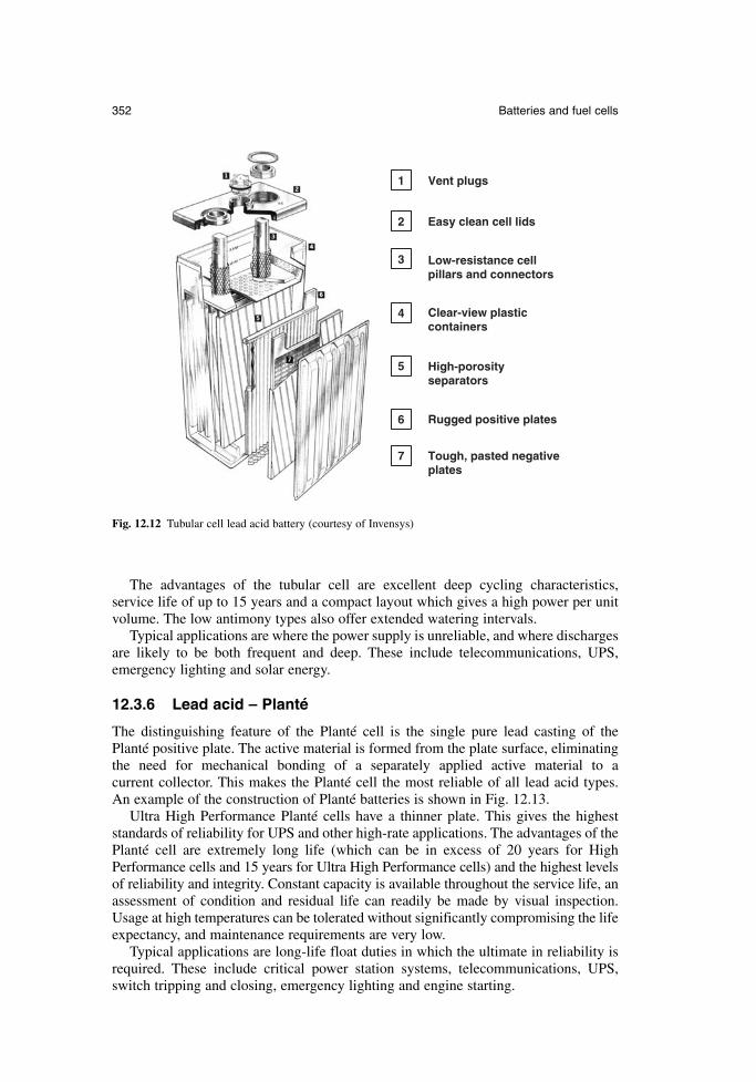
The advantages of the tubular cell are excellent deep cycling characteristics, service life of up to 15 years and a compact layout which gives a high power per unitvolume. The low antimony types also offer extended watering intervals.
Typical applications are where the power supply is unreliable, and where dischargesare likely to be both frequent and deep. These include telecommunications, UPS,emergency lighting and solar energy.
12.3.6 Lead acid – Planté
The distinguishing feature of the Planté cell is the single pure lead casting of the Planté positive plate. The active material is formed from the plate surface, eliminatingthe need for mechanical bonding of a separately applied active material to a current collector. This makes the Planté cell the most reliable of all lead acid types. An example of the construction of Planté batteries is shown in Fig. 12.13.
Ultra High Performance Planté cells have a thinner plate. This gives the higheststandards of reliability for UPS and other high-rate applications. The advantages of thePlanté cell are extremely long life (which can be in excess of 20 years for HighPerformance cells and 15 years for Ultra High Performance cells) and the highest levelsof reliability and integrity. Constant capacity is available throughout the service life, anassessment of condition and residual life can readily be made by visual inspection.Usage at high temperatures can be tolerated without significantly compromising the lifeexpectancy, and maintenance requirements are very low.
Typical applications are long-life float duties in which the ultimate in reliability isrequired. These include critical power station systems, telecommunications, UPS,switch tripping and closing, emergency lighting and engine starting.
352 Batteries and fuel cells
1 Vent plugs
Easy clean cell lids2
Low-resistance cell pillars and connectors
3
Clear-view plastic containers
4
High-porosity separators
5
Rugged positive plates6
Tough, pasted negative plates
7
Fig. 12.12 Tubular cell lead acid battery (courtesy of Invensys)
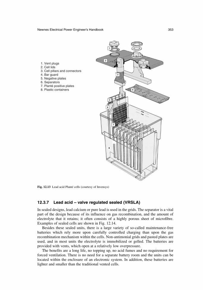
12.3.7 Lead acid – valve regulated sealed (VRSLA)
In sealed designs, lead calcium or pure lead is used in the grids. The separator is a vitalpart of the design because of its influence on gas recombination, and the amount ofelectrolyte that it retains; it often consists of a highly porous sheet of microfibre.Examples of sealed cells are shown in Fig. 12.14.
Besides these sealed units, there is a large variety of so-called maintenance-free batteries which rely more upon carefully controlled charging than upon the gas recombination mechanism within the cells. Non-antimonial grids and pasted plates areused, and in most units the electrolyte is immobilized or gelled. The batteries are provided with vents, which open at a relatively low overpressure.
The benefits are a long life, no topping up, no acid fumes and no requirement forforced ventilation. There is no need for a separate battery room and the units can belocated within the enclosure of an electronic system. In addition, these batteries arelighter and smaller than the traditional vented cells.
Newnes Electrical Power Engineer’s Handbook 353
1. Vent plugs 2. Cell lids 3. Cell pillars and connectors 4. Bar guard 5. Negative plates 6. Separators 7. Planté positive plates 8. Plastic containers
Fig. 12.13 Lead acid Planté cells (courtesy of Invensys)
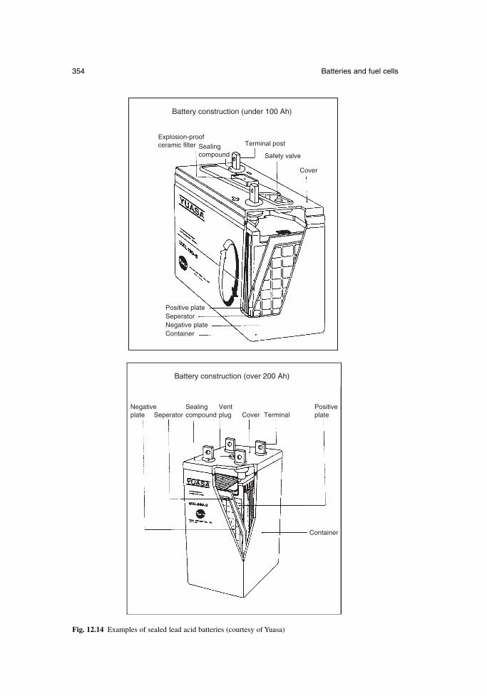
354 Batteries and fuel cells
Battery construction (under 100 Ah)
Battery construction (over 200 Ah)
Explosion-proofceramic filter Sealing
compound
Sealingcompound
Terminal post
Safety valve
Cover
CoverVentplug Terminal
Positive plate
Positiveplate
Seperator
Seperator
Negative plate
Negativeplate
Container
Container
Fig. 12.14 Examples of sealed lead acid batteries (courtesy of Yuasa)
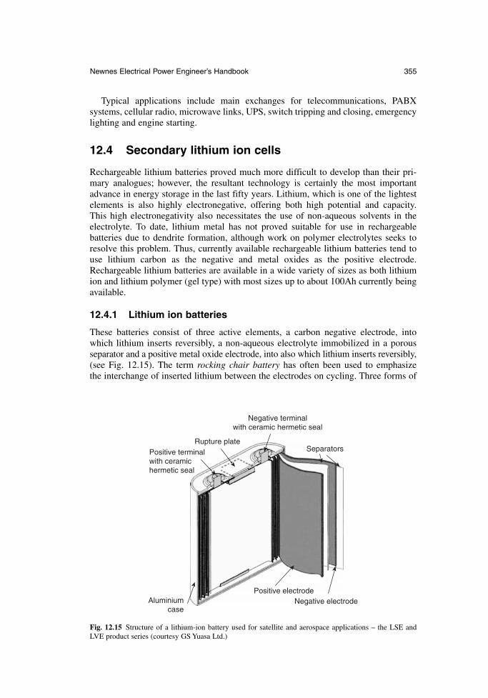
Typical applications include main exchanges for telecommunications, PABX systems, cellular radio, microwave links, UPS, switch tripping and closing, emergencylighting and engine starting.
12.4 Secondary lithium ion cells
Rechargeable lithium batteries proved much more difficult to develop than their pri-mary analogues; however, the resultant technology is certainly the most importantadvance in energy storage in the last fifty years. Lithium, which is one of the lightestelements is also highly electronegative, offering both high potential and capacity. This high electronegativity also necessitates the use of non-aqueous solvents in theelectrolyte. To date, lithium metal has not proved suitable for use in rechargeable batteries due to dendrite formation, although work on polymer electrolytes seeks toresolve this problem. Thus, currently available rechargeable lithium batteries tend touse lithium carbon as the negative and metal oxides as the positive electrode.Rechargeable lithium batteries are available in a wide variety of sizes as both lithiumion and lithium polymer (gel type) with most sizes up to about 100Ah currently beingavailable.
12.4.1 Lithium ion batteries
These batteries consist of three active elements, a carbon negative electrode, intowhich lithium inserts reversibly, a non-aqueous electrolyte immobilized in a porousseparator and a positive metal oxide electrode, into also which lithium inserts reversibly,(see Fig. 12.15). The term rocking chair battery has often been used to emphasize the interchange of inserted lithium between the electrodes on cycling. Three forms of
Newnes Electrical Power Engineer’s Handbook 355
Rupture platePositive terminal with ceramic hermetic seal
Aluminium case
Positive electrodeNegative electrode
Negative terminal with ceramic hermetic seal
Separators
Fig. 12.15 Structure of a lithium-ion battery used for satellite and aerospace applications – the LSE andLVE product series (courtesy GS Yuasa Ltd.)
metal oxide dominate commercial batteries, these being layered lithium cobalt oxides,lithium nickel oxides and spinel lithium manganese oxide. The cobalt oxide was thefirst to achieve commercial success and is still the most widely used. Both nickel andcobalt oxides offer 3.6 V operation in combination with carbon. Although nickel ischeaper than cobalt, its more complex electrochemistry has led to the majority of man-ufactures preferring cobalt, but lithium manganese oxide is now challenging cobaltoxide for the dominant market position. Although the operating cell voltage is lowerat 3.0 V, the considerable advantages in terms of availability, cost and low toxicitymore than compensate.
Lithium ion batteries offer high energy density (125 Whkg−1, 300 Whdm−3), highoperating voltage (3.6 V), high cyclability with up to 1000 cycles being possible anda rapid recharge (e.g. 2 hours) is possible. There is no memory effect on charge/discharge as found in nickel cadmium and the batteries are much safer than lithium primary batteries. Self-discharge on standing is less than 10 per cent per month, whichis acceptable for a rechargeable battery. Although special high-voltage stable non-aqueous electrolytes have been developed, there are still some issues with stability ifcareful control of charging is not maintained, and the top-of-charge voltage isexceeded. Charging is carried out at constant current until top-of-charge is reached atabout 80 per cent of capacity, then voltage is held constant as the current decays to alimiting value. Normally cells are only sold as part of an integrated pack that containscontrol electronics and the protection circuit.
12.4.2 Lithium polymer batteries
Considerable efforts have been made to commercialize lithium polymer batteries uti-lizing a polymer such as polyethylene oxide instead of an organic solvent to dissolvethe lithium salt in the electrolyte. Such systems would be able to safely utilize lithiummetal as an electrode, which would considerably increase capacity. Unfortunately theelectrical resistance of the polymer is still slightly too high for wide-scale commer-cialization, but some important advances are being made. A slightly different com-pound based on a gel electrolyte has been more successful and most commercialpolymer lithium batteries are of this type. Here, a liquid non-aqueous electrolyte isencapsulated in a polymer gel, typically polyvinylidine fluoride or PVDF. Apart fromthe immobilized electrolyte, such gel-based polymer batteries are very similar to moreconventional lithium ion batteries. The polymer construction facilitates a range ofinnovative concepts based upon winding and folding to the various elements.
12.5 Fuel cells
Like a battery, a fuel cell converts the energy of a chemical reaction directly into elec-trical energy. The process here involves the oxidation of an external fuel, which is nor-mally a hydrogen-rich gas, and the reduction of an oxidant, which is usuallyatmospheric oxygen. Electrons are passed from the fuel electrode to the oxidant elec-trode through the externally connected load, and the electrical circuit is completed byions that cross an electrolyte to produce water.
The fuel cell has a number of advantages over the conventional heat engine andshaft-driven generator for the production of electrical power. The generation efficiencyis much higher in a fuel cell at scales even up to several megawatts, it has a higherpower density, lower vibration characteristics, and reduced emission of pollutants. An individual fuel cell operates at a dc voltage of about 1V. Cells must therefore be
356 Batteries and fuel cells
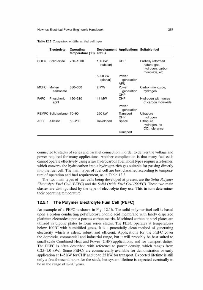
connected to stacks of series and parallel connection in order to deliver the voltage andpower required for many applications. Another complication is that many fuel cellscannot operate effectively using a raw hydrocarbon fuel; most types require a reformer,which converts the hydrocarbon into a hydrogen-rich gas suitable for passing directlyinto the fuel cell. The main types of fuel cell are best classified according to tempera-ture of operation and fuel requirement, as in Table 12.2.
The two main types of fuel cells being developed at present are the Solid PolymerElectrolyte Fuel Cell (PEFC) and the Solid Oxide Fuel Cell (SOFC). These two mainclasses are distinguished by the type of electrolyte they use. This in turn determinestheir operating temperature.
12.5.1 The Polymer Electrolyte Fuel Cell (PEFC)
An example of a PEFC is shown in Fig. 12.16. The solid polymer fuel cell is basedupon a proton conducting polyfluorosulphonic acid membrane with finely dispersedplatinum electrodes upon a porous carbon matrix. Machined carbon or steel plates areutilized as bipolar plates to form series stacks. The PEFC operates at temperaturesbelow 100°C with humidified gases. It is a potentially clean method of generatingelectricity which is silent, robust and efficient. Applications for the PEFC cover the domestic, commercial and industrial range, but it will probably be best suited tosmall-scale Combined Heat and Power (CHP) applications, and for transport duties.The PEFC is often described with reference to power density, which ranges from0.25–1.0 kW/l. Some PEFCs are commercially available for demonstration or earlyapplication at 1–5 kW for CHP and up to 25 kW for transport. Expected lifetime is stillonly a few thousand hours for the stack, but system lifetime is expected eventually tobe in the range of 8–20 years.
Newnes Electrical Power Engineer’s Handbook 357
Table 12.2 Comparison of different fuel cell types
Electrolyte Operating Development Applications Suitable fueltemperature (°C) status
SOFC Solid oxide 750–1000 100 kW CHP Partially reformed(tubular) natural gas,
hydrogen, carbon monoxide, etc
5–50 kW Power (planar) generation
APUMCFC Molten 630–650 2 MW Power Carbon monoxide,
carbonate generation hydrogenCHP
PAFC Phosphoric 190–210 11 MW CHP Hydrogen with traces acid of carbon monoxide
Power generation
PEMFC Solid polymer 70–90 250 kW Transport UltrapureCHP hydrogen
AFC Alkaline 50–200 Developed Space Ultrapurehydrogen, noCO2 tolerance
Transport
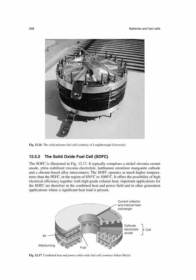
12.5.2 The Solid Oxide Fuel Cell (SOFC)
The SOFC is illustrated in Fig. 12.17. It typically comprises a nickel zirconia cermetanode, yttria stabilized zirconia electrolyte, lanthanum strontium manganite cathodeand a chrome-based alloy interconnect. The SOFC operates at much higher tempera-tures than the PEFC, in the region of 850°C to 1000°C. It offers the possibility of highelectrical efficiency together with high-grade exhaust heat; important applications forthe SOFC are therefore in the combined heat and power field and in other generationapplications where a significant heat load is present.
358 Batteries and fuel cells
Fig. 12.16 The solid polymer fuel cell (courtesy of Loughborough University)
Current collectorand internal heatexchanger
Cathodeelectrolyteanode
Air
AfterburningFuel
Cell
Fig. 12.17 Combined heat and power solid oxide fuel cell (courtesy Sulzer Hexis)
Advantages of the SOFC are very high electrical efficiency, the ability to utilizeconventional fuels such as natural gas with limited processing and the facility to pro-duce steam or hot water from the high temperatures that are available. Typical powerratings are in the range 150–250 kW and life expectancy is 5–20 years, with adequatemaintenance. The first demonstration systems in the range 1–2 kW (electrical output)have recently become commercially available, normally in combined heat and powerwith about 10 kW (thermal output).
12.6 Battery charging
12.6.1 Small commercial batteries (up to 10 Ah)
The rechargeable batteries used in portable equipment are mainly lithium ion, nickelcadmium or nickel metal hydride. Recharging of these batteries can be carried out bythe following methods:
transformer-rectifier switched-mode power supply unit capacity charger
The transformer-rectifier circuit is used to reduce ac mains voltage to a lower dc volt-age. The charge delivered to the battery can be regulated using a constant current, aconstant voltage, constant temperature or a combination of these. The transformer inthis system provides the inherent advantage of isolation between the mains and low-voltage circuits.
In the switched-mode power supply unit, the mains voltage is rectified, switched ata high frequency (between 20 kHz and 1 mHz), converted to low voltage through ahigh-frequency transformer, rectified back to dc, which is then regulated to charge thebattery in a controlled manner. Although more complex than the transformer-rectifiercircuit, this technique results in a smaller and more efficient charging unit.
In a capacity charger the mains is rectified and then series coupled with a mains-voltage capacitor with current regulation directly to the battery packs. This makes fora small and cheap charging unit, but it has to be treated with care, since the capacitoris not isolated from the mains.
In addition to these three methods, several manufacturers have responded to theneed for shorter recharge periods and better battery condition monitoring by designingspecific integrated circuits that provide both the charging control and the monitoring.
12.6.2 Automotive batteries
The main types for recharging automotive batteries are:
single battery, out of the vehicle multiple batteries, out of the vehicle starter charging, battery in vehicle
Transformer/reactance is predominantly used in each of these applications, with eithera ballast in the form of resistance, or resistance to control the charging current. Moresophisticated chargers have constant voltage and current-limiting facilities to suit thecharging of ‘maintenance free’ batteries. A typical circuit is shown in Fig. 12.18.
Newnes Electrical Power Engineer’s Handbook 359
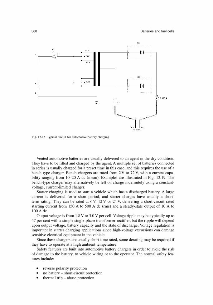
Vented automotive batteries are usually delivered to an agent in the dry condition.They have to be filled and charged by the agent. A multiple set of batteries connectedin series is usually charged for a preset time in this case, and this requires the use of abench-type charger. Bench chargers are rated from 2 V to 72 V, with a current capa-bility ranging from 10–20 A dc (mean). Examples are illustrated in Fig. 12.19. Thebench-type charger may alternatively be left on charge indefinitely using a constant-voltage, current-limited charger.
Starter charging is used to start a vehicle which has a discharged battery. A largecurrent is delivered for a short period, and starter charges have usually a short-term rating. They can be rated at 6 V, 12 V or 24 V, delivering a short-circuit rated starting current from 150 A to 500 A dc (rms) and a steady-state output of 10 A to 100 A dc.
Output voltage is from 1.8 V to 3.0 V per cell. Voltage ripple may be typically up to47 per cent with a simple single-phase transformer-rectifier, but the ripple will dependupon output voltage, battery capacity and the state of discharge. Voltage regulation isimportant in starter charging applications since high-voltage excursions can damagesensitive electrical equipment in the vehicle.
Since these chargers are usually short-time rated, some derating may be required ifthey have to operate at a high ambient temperature.
Safety features are built into automotive battery chargers in order to avoid the riskof damage to the battery, to vehicle wiring or to the operator. The normal safety fea-tures include:
reverse polarity protection no battery – short-circuit protection thermal trip – abuse protection
360 Batteries and fuel cells
Fig. 12.18 Typical circuit for automotive battery charging
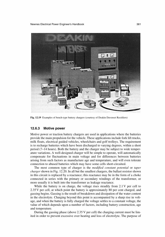
Newnes Electrical Power Engineer’s Handbook 361
Fig. 12.19 Examples of bench-type battery chargers (courtesy of Deakin Davenset Rectifiers)
12.6.3 Motive power
Motive power or traction battery chargers are used in applications where the batteriesprovide the main propulsion for the vehicle. These applications include fork lift trucks,milk floats, electrical guided vehicles, wheelchairs and golf trolleys. The requirementis to recharge batteries which have been discharged to varying degrees, within a shortperiod (7–14 hours). Both the battery and the charger may be subject to wide temper-ature variations. A well-designed charger will be simple to operate, will automaticallycompensate for fluctuations in main voltage and for differences between batteries arising from such factors as manufacture age and temperature, and will even tolerateconnection to abused batteries which may have some cells short-circuited.
The most common type of charger is the modified constant potential or tapercharger shown in Fig. 12.20. In all but the smallest chargers, the ballast resistor shownin this circuit is replaced by a reactance; this reactance may be in the form of a chokeconnected in series with the primary or secondary windings of the transformer, ormore usually it is built into the transformer as leakage reactance.
While the battery is on charge, the voltage rises steadily from 2.1 V per cell to2.35 V per cell, at which point the battery is approximately 80 per cent charged, andgassing begins. Gassing is the result of breakdown and dissipation of the water contentin the electrolyte. Charging beyond this point is accompanied by a sharp rise in volt-age, and when the battery is fully charged the voltage settles to a constant voltage, thevalue of which depends upon a number of factors, including battery construction, ageand temperature.
During the gassing phase (above 2.35 V per cell) the charging current must be lim-ited in order to prevent excessive over heating and loss of electrolyte. The purpose of
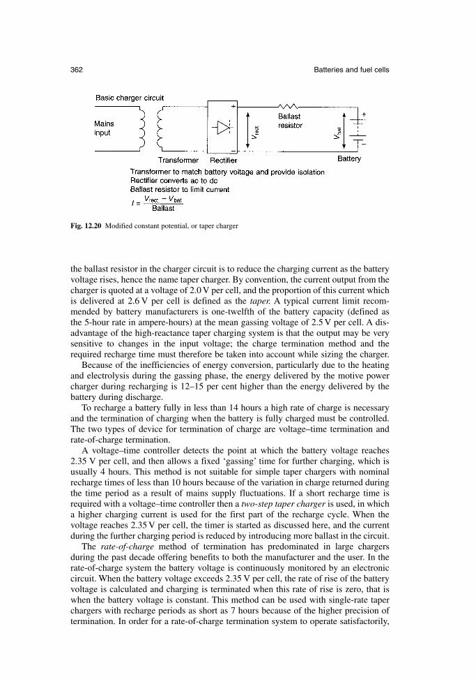
the ballast resistor in the charger circuit is to reduce the charging current as the batteryvoltage rises, hence the name taper charger. By convention, the current output from thecharger is quoted at a voltage of 2.0 V per cell, and the proportion of this current whichis delivered at 2.6 V per cell is defined as the taper. A typical current limit recom-mended by battery manufacturers is one-twelfth of the battery capacity (defined as the 5-hour rate in ampere-hours) at the mean gassing voltage of 2.5 V per cell. A dis-advantage of the high-reactance taper charging system is that the output may be verysensitive to changes in the input voltage; the charge termination method and therequired recharge time must therefore be taken into account while sizing the charger.
Because of the inefficiencies of energy conversion, particularly due to the heatingand electrolysis during the gassing phase, the energy delivered by the motive powercharger during recharging is 12–15 per cent higher than the energy delivered by thebattery during discharge.
To recharge a battery fully in less than 14 hours a high rate of charge is necessaryand the termination of charging when the battery is fully charged must be controlled.The two types of device for termination of charge are voltage–time termination andrate-of-charge termination.
A voltage–time controller detects the point at which the battery voltage reaches2.35 V per cell, and then allows a fixed ‘gassing’ time for further charging, which isusually 4 hours. This method is not suitable for simple taper chargers with nominalrecharge times of less than 10 hours because of the variation in charge returned duringthe time period as a result of mains supply fluctuations. If a short recharge time isrequired with a voltage–time controller then a two-step taper charger is used, in whicha higher charging current is used for the first part of the recharge cycle. When the voltage reaches 2.35 V per cell, the timer is started as discussed here, and the currentduring the further charging period is reduced by introducing more ballast in the circuit.
The rate-of-charge method of termination has predominated in large chargers during the past decade offering benefits to both the manufacturer and the user. In therate-of-charge system the battery voltage is continuously monitored by an electroniccircuit. When the battery voltage exceeds 2.35 V per cell, the rate of rise of the batteryvoltage is calculated and charging is terminated when this rate of rise is zero, that iswhen the battery voltage is constant. This method can be used with single-rate taperchargers with recharge periods as short as 7 hours because of the higher precision oftermination. In order for a rate-of-charge termination system to operate satisfactorily,
362 Batteries and fuel cells
Fig. 12.20 Modified constant potential, or taper charger
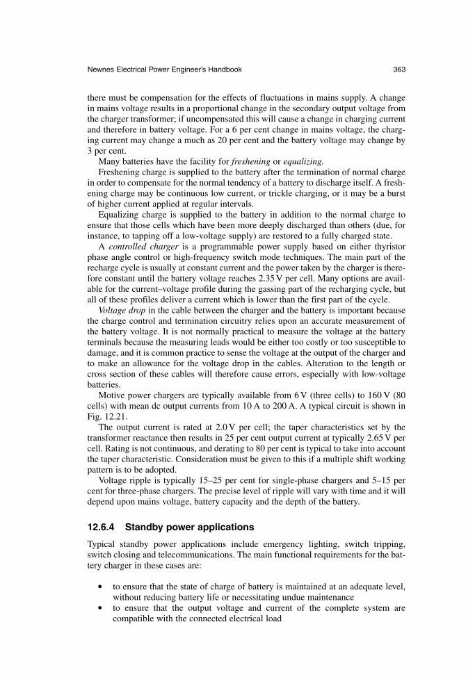
there must be compensation for the effects of fluctuations in mains supply. A changein mains voltage results in a proportional change in the secondary output voltage fromthe charger transformer; if uncompensated this will cause a change in charging currentand therefore in battery voltage. For a 6 per cent change in mains voltage, the charg-ing current may change a much as 20 per cent and the battery voltage may change by3 per cent.
Many batteries have the facility for freshening or equalizing.Freshening charge is supplied to the battery after the termination of normal charge
in order to compensate for the normal tendency of a battery to discharge itself. A fresh-ening charge may be continuous low current, or trickle charging, or it may be a burstof higher current applied at regular intervals.
Equalizing charge is supplied to the battery in addition to the normal charge toensure that those cells which have been more deeply discharged than others (due, forinstance, to tapping off a low-voltage supply) are restored to a fully charged state.
A controlled charger is a programmable power supply based on either thyristorphase angle control or high-frequency switch mode techniques. The main part of therecharge cycle is usually at constant current and the power taken by the charger is there-fore constant until the battery voltage reaches 2.35 V per cell. Many options are avail-able for the current–voltage profile during the gassing part of the recharging cycle, butall of these profiles deliver a current which is lower than the first part of the cycle.
Voltage drop in the cable between the charger and the battery is important becausethe charge control and termination circuitry relies upon an accurate measurement ofthe battery voltage. It is not normally practical to measure the voltage at the batteryterminals because the measuring leads would be either too costly or too susceptible todamage, and it is common practice to sense the voltage at the output of the charger andto make an allowance for the voltage drop in the cables. Alteration to the length orcross section of these cables will therefore cause errors, especially with low-voltagebatteries.
Motive power chargers are typically available from 6 V (three cells) to 160 V (80cells) with mean dc output currents from 10 A to 200 A. A typical circuit is shown inFig. 12.21.
The output current is rated at 2.0 V per cell; the taper characteristics set by the transformer reactance then results in 25 per cent output current at typically 2.65 V percell. Rating is not continuous, and derating to 80 per cent is typical to take into accountthe taper characteristic. Consideration must be given to this if a multiple shift workingpattern is to be adopted.
Voltage ripple is typically 15–25 per cent for single-phase chargers and 5–15 percent for three-phase chargers. The precise level of ripple will vary with time and it willdepend upon mains voltage, battery capacity and the depth of the battery.
12.6.4 Standby power applications
Typical standby power applications include emergency lighting, switch tripping,switch closing and telecommunications. The main functional requirements for the bat-tery charger in these cases are:
to ensure that the state of charge of battery is maintained at an adequate level,without reducing battery life or necessitating undue maintenance
to ensure that the output voltage and current of the complete system are compatible with the connected electrical load
Newnes Electrical Power Engineer’s Handbook 363
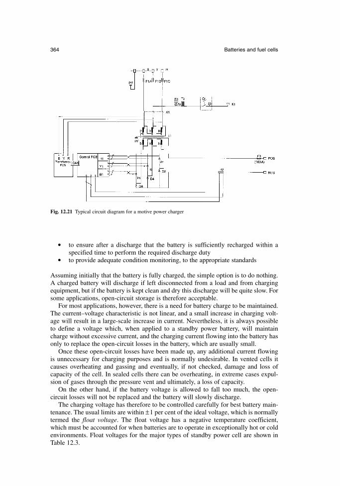
to ensure after a discharge that the battery is sufficiently recharged within aspecified time to perform the required discharge duty
to provide adequate condition monitoring, to the appropriate standards
Assuming initially that the battery is fully charged, the simple option is to do nothing.A charged battery will discharge if left disconnected from a load and from chargingequipment, but if the battery is kept clean and dry this discharge will be quite slow. Forsome applications, open-circuit storage is therefore acceptable.
For most applications, however, there is a need for battery charge to be maintained.The current–voltage characteristic is not linear, and a small increase in charging volt-age will result in a large-scale increase in current. Nevertheless, it is always possibleto define a voltage which, when applied to a standby power battery, will maintaincharge without excessive current, and the charging current flowing into the battery hasonly to replace the open-circuit losses in the battery, which are usually small.
Once these open-circuit losses have been made up, any additional current flowingis unnecessary for charging purposes and is normally undesirable. In vented cells itcauses overheating and gassing and eventually, if not checked, damage and loss ofcapacity of the cell. In sealed cells there can be overheating, in extreme cases expul-sion of gases through the pressure vent and ultimately, a loss of capacity.
On the other hand, if the battery voltage is allowed to fall too much, the open-circuit losses will not be replaced and the battery will slowly discharge.
The charging voltage has therefore to be controlled carefully for best battery main-tenance. The usual limits are within ±1 per cent of the ideal voltage, which is normallytermed the float voltage. The float voltage has a negative temperature coefficient,which must be accounted for when batteries are to operate in exceptionally hot or coldenvironments. Float voltages for the major types of standby power cell are shown inTable 12.3.
364 Batteries and fuel cells
Fig. 12.21 Typical circuit diagram for a motive power charger
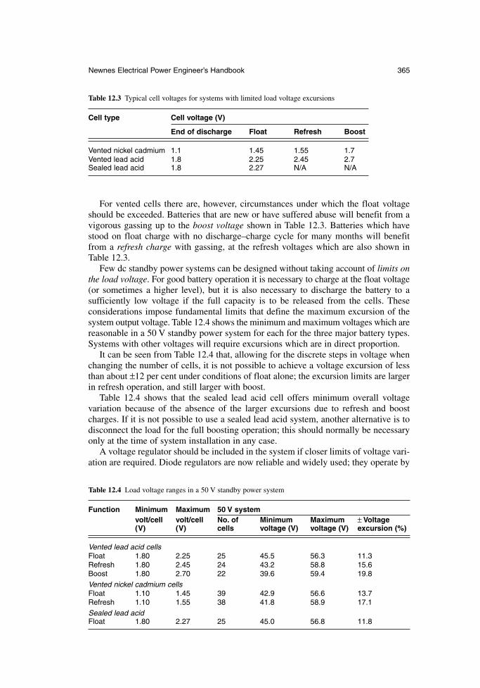
For vented cells there are, however, circumstances under which the float voltageshould be exceeded. Batteries that are new or have suffered abuse will benefit from avigorous gassing up to the boost voltage shown in Table 12.3. Batteries which havestood on float charge with no discharge–charge cycle for many months will benefitfrom a refresh charge with gassing, at the refresh voltages which are also shown inTable 12.3.
Few dc standby power systems can be designed without taking account of limits onthe load voltage. For good battery operation it is necessary to charge at the float voltage(or sometimes a higher level), but it is also necessary to discharge the battery to a sufficiently low voltage if the full capacity is to be released from the cells. These considerations impose fundamental limits that define the maximum excursion of thesystem output voltage. Table 12.4 shows the minimum and maximum voltages which arereasonable in a 50 V standby power system for each for the three major battery types.Systems with other voltages will require excursions which are in direct proportion.
It can be seen from Table 12.4 that, allowing for the discrete steps in voltage whenchanging the number of cells, it is not possible to achieve a voltage excursion of lessthan about ±12 per cent under conditions of float alone; the excursion limits are largerin refresh operation, and still larger with boost.
Table 12.4 shows that the sealed lead acid cell offers minimum overall voltage variation because of the absence of the larger excursions due to refresh and boostcharges. If it is not possible to use a sealed lead acid system, another alternative is todisconnect the load for the full boosting operation; this should normally be necessaryonly at the time of system installation in any case.
A voltage regulator should be included in the system if closer limits of voltage vari-ation are required. Diode regulators are now reliable and widely used; they operate by
Newnes Electrical Power Engineer’s Handbook 365
Table 12.3 Typical cell voltages for systems with limited load voltage excursions
Cell type Cell voltage (V)
End of discharge Float Refresh Boost
Vented nickel cadmium 1.1 1.45 1.55 1.7Vented lead acid 1.8 2.25 2.45 2.7Sealed lead acid 1.8 2.27 N/A N/A
Table 12.4 Load voltage ranges in a 50 V standby power system
Function Minimum Maximum 50 V systemvolt/cell volt/cell No. of Minimum Maximum ± Voltage (V) (V) cells voltage (V) voltage (V) excursion (%)
Vented lead acid cellsFloat 1.80 2.25 25 45.5 56.3 11.3Refresh 1.80 2.45 24 43.2 58.8 15.6Boost 1.80 2.70 22 39.6 59.4 19.8Vented nickel cadmium cellsFloat 1.10 1.45 39 42.9 56.6 13.7Refresh 1.10 1.55 38 41.8 58.9 17.1Sealed lead acidFloat 1.80 2.27 25 45.0 56.8 11.8
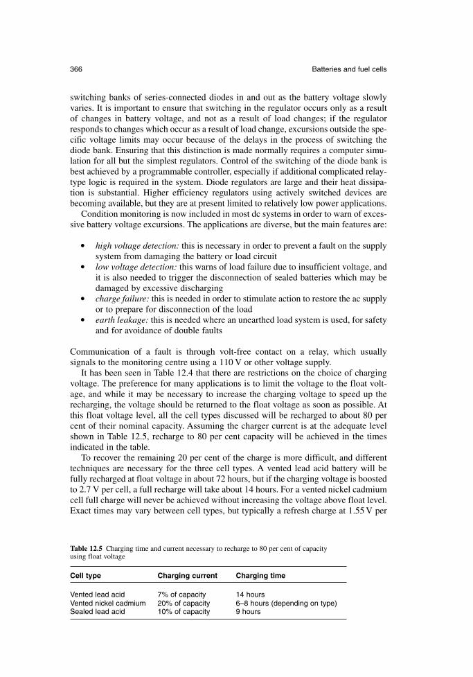
switching banks of series-connected diodes in and out as the battery voltage slowlyvaries. It is important to ensure that switching in the regulator occurs only as a resultof changes in battery voltage, and not as a result of load changes; if the regulatorresponds to changes which occur as a result of load change, excursions outside the spe-cific voltage limits may occur because of the delays in the process of switching thediode bank. Ensuring that this distinction is made normally requires a computer simu-lation for all but the simplest regulators. Control of the switching of the diode bank isbest achieved by a programmable controller, especially if additional complicated relay-type logic is required in the system. Diode regulators are large and their heat dissipa-tion is substantial. Higher efficiency regulators using actively switched devices arebecoming available, but they are at present limited to relatively low power applications.
Condition monitoring is now included in most dc systems in order to warn of exces-sive battery voltage excursions. The applications are diverse, but the main features are:
high voltage detection: this is necessary in order to prevent a fault on the supplysystem from damaging the battery or load circuit
low voltage detection: this warns of load failure due to insufficient voltage, andit is also needed to trigger the disconnection of sealed batteries which may bedamaged by excessive discharging
charge failure: this is needed in order to stimulate action to restore the ac supplyor to prepare for disconnection of the load
earth leakage: this is needed where an unearthed load system is used, for safetyand for avoidance of double faults
Communication of a fault is through volt-free contact on a relay, which usually signals to the monitoring centre using a 110 V or other voltage supply.
It has been seen in Table 12.4 that there are restrictions on the choice of chargingvoltage. The preference for many applications is to limit the voltage to the float volt-age, and while it may be necessary to increase the charging voltage to speed up therecharging, the voltage should be returned to the float voltage as soon as possible. Atthis float voltage level, all the cell types discussed will be recharged to about 80 percent of their nominal capacity. Assuming the charger current is at the adequate levelshown in Table 12.5, recharge to 80 per cent capacity will be achieved in the timesindicated in the table.
To recover the remaining 20 per cent of the charge is more difficult, and differenttechniques are necessary for the three cell types. A vented lead acid battery will befully recharged at float voltage in about 72 hours, but if the charging voltage is boostedto 2.7 V per cell, a full recharge will take about 14 hours. For a vented nickel cadmiumcell full charge will never be achieved without increasing the voltage above float level.Exact times may vary between cell types, but typically a refresh charge at 1.55 V per
366 Batteries and fuel cells
Table 12.5 Charging time and current necessary to recharge to 80 per cent of capacity using float voltage
Cell type Charging current Charging time
Vented lead acid 7% of capacity 14 hoursVented nickel cadmium 20% of capacity 6–8 hours (depending on type)Sealed lead acid 10% of capacity 9 hours

cell will give full charge in about 200 hours on the highest performance cells, andboosting to 1.7 V per cell will reduce this time to 9–10 hours. Sealed lead acid cellswill reach full charge after about 72 hours at float voltage; an increase of charge volt-age to 2.4 V per cell will reduce charging time to about 48 hours, but there is no wayin which this can be significantly reduced further.
If a fast recharge is essential, an alternative is to oversize the battery; for instance if 100 Ah capacity is required with a full recharge within 8 hours, then a battery with125 Ah capacity could be installed.
Most cells will protect themselves from excess charging current, provided that thevoltage is limited to the float voltage, but above this level excessive charging currentcan damage the cell. For vented lead acid cells the 7 per cent of capacity shown inTable 12.5 is recommended as an upper limit. For sealed lead acid cells, the recom-mended upper limit is 50 per cent of capacity. Nickel cadmium cells normally requirea minimum charge current of 20 per cent of capacity, as indicated in Table 12.5, but alower limit of 10 per cent of capacity is recommended when boosting in order to avoidexcessive gassing and electrolyte spray.
Standby power chargers are available in a wide range of capacities to suit manyapplications. Typical dc outputs are 6, 12, 24, 30, 48, 60, 110, 220 and 240 V, with dcmean output current ranging from 1 A to 1000 A. DC output current is rated at 100 percent of the output current at the full specified voltage. Regulation of the output is gen-erally within ±1 per cent for an input voltage change of ±10 per cent and a load cur-rent change of 0–100 per cent. A typical circuit is shown in Fig. 12.22. Althoughstandby power systems are continuously rated, some derating may be necessary foroperation in tropical climates if this was not originally specified.
Differing levels of output smoothing can be incorporated into the charging system,depending upon the application. General applications require a maximum of 5 per centripple, but for telecommunications supplies, specifications are based on CCITTtelecommunications smoothing, which requires 2 mV phosphometrically weighted at800 Hz. The key components of an installation are shown schematically in Fig 12.23.
12.7 Battery monitoring
The monitoring of battery condition is becoming more important as remote operationand reduced maintenance requirements are increasingly specified in standby powersystems. The options which are available are summarized in the following sections.
12.7.1 Load-discharge testing
The basis of this test is to discharge the battery into a selected load for a preset time,after which the battery voltage is checked. In the majority of cases this will require that the battery is taken off line. The load-discharge test is very reliable, but it requiresa special resistance load bank, and it is labour-intensive and time-consuming. Figure 12.24shows an example of the type of equipment that is required.
12.7.2 dV /dt-load testing
The technique here is to connect a fixed known load to the battery for a short periodand record the battery voltage over this period. By comparing the recorded load volt-age with data from the battery manufacturer, estimations can be made regarding thecondition of the battery and its ability to perform.
Newnes Electrical Power Engineer’s Handbook 367
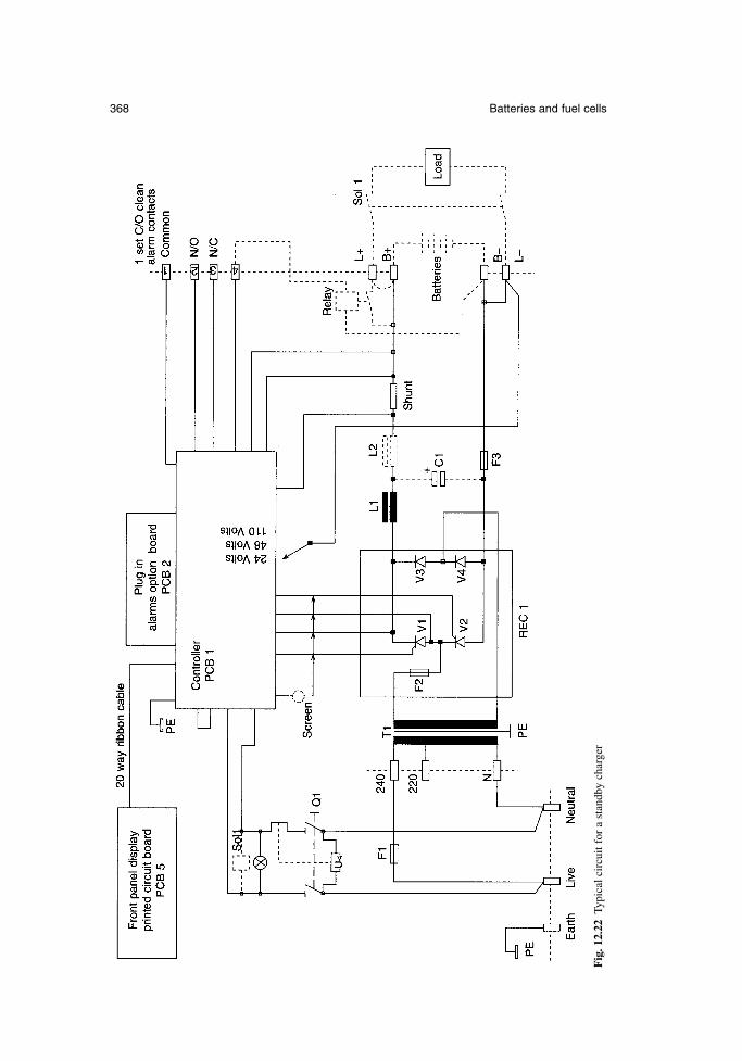
368 Batteries and fuel cells
Fig
. 12.
22Ty
pica
l cir
cuit
for
a st
andb
y ch
arge
r
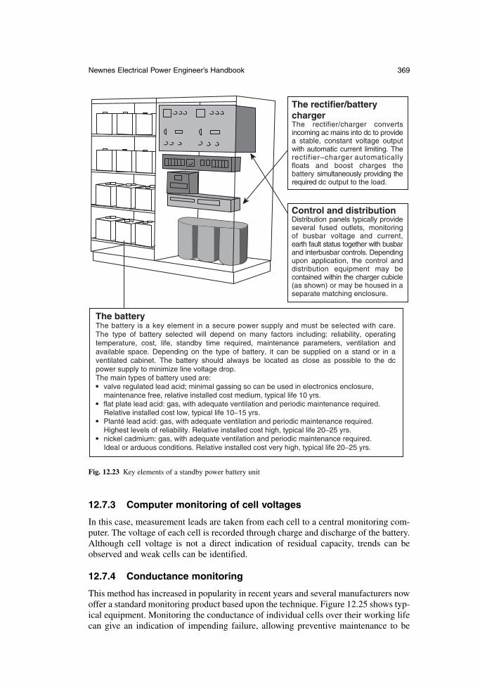
Newnes Electrical Power Engineer’s Handbook 369
12.7.3 Computer monitoring of cell voltages
In this case, measurement leads are taken from each cell to a central monitoring com-puter. The voltage of each cell is recorded through charge and discharge of the battery.Although cell voltage is not a direct indication of residual capacity, trends can beobserved and weak cells can be identified.
12.7.4 Conductance monitoring
This method has increased in popularity in recent years and several manufacturers nowoffer a standard monitoring product based upon the technique. Figure 12.25 shows typ-ical equipment. Monitoring the conductance of individual cells over their working lifecan give an indication of impending failure, allowing preventive maintenance to be
The batteryThe battery is a key element in a secure power supply and must be selected with care. The type of battery selected will depend on many factors including: reliability, operating temperature, cost, life, standby time required, maintenance parameters, ventilation and available space. Depending on the type of battery, it can be supplied on a stand or in a ventilated cabinet. The battery should always be located as close as possible to the dc power supply to minimize line voltage drop. The main types of battery used are: valve regulated lead acid; minimal gassing so can be used in electronics enclosure, maintenance free, relative installed cost medium, typical life 10 yrs. flat plate lead acid: gas, with adequate ventilation and periodic maintenance required. Relative installed cost low, typical life 10−15 yrs. Planté lead acid: gas, with adequate ventilation and periodic maintenance required. Highest levels of reliability. Relative installed cost high, typical life 20−25 yrs. nickel cadmium: gas, with adequate ventilation and periodic maintenance required. Ideal or arduous conditions. Relative installed cost very high, typical life 20−25 yrs.
The rectifier/battery chargerThe rectifier/charger converts incoming ac mains into dc to provide a stable, constant voltage output with automatic current limiting. The rectifier–charger automatically floats and boost charges the battery simultaneously providing the required dc output to the load.
Control and distributionDistribution panels typically provide several fused outlets, monitoring of busbar voltage and current, earth fault status together with busbar and interbusbar controls. Depending upon application, the control and distribution equipment may be contained within the charger cubicle (as shown) or may be housed in a separate matching enclosure.
Fig. 12.23 Key elements of a standby power battery unit
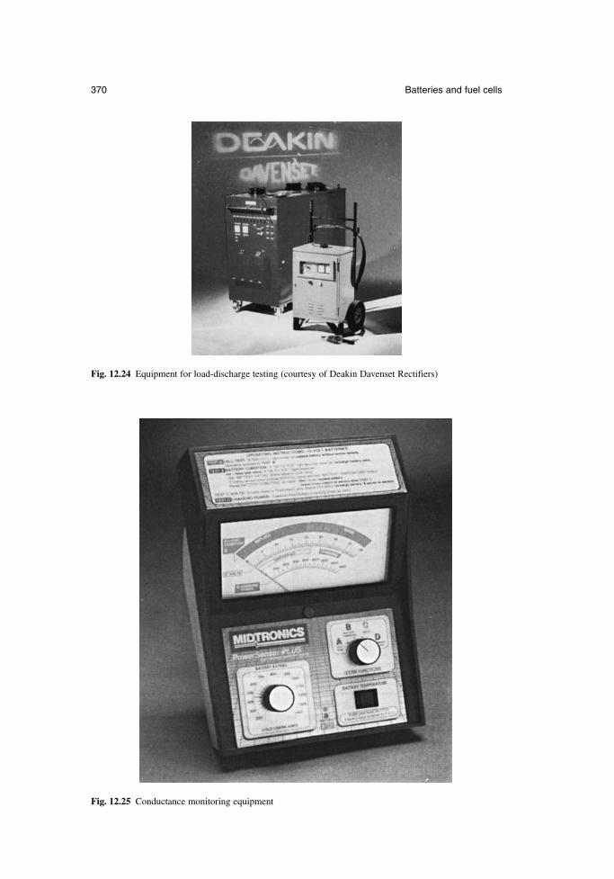
370 Batteries and fuel cells
Fig. 12.24 Equipment for load-discharge testing (courtesy of Deakin Davenset Rectifiers)
Fig. 12.25 Conductance monitoring equipment
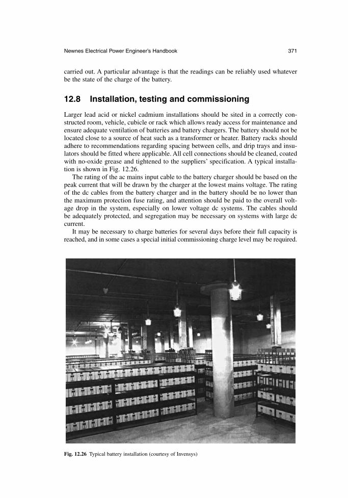
carried out. A particular advantage is that the readings can be reliably used whateverbe the state of the charge of the battery.
12.8 Installation, testing and commissioning
Larger lead acid or nickel cadmium installations should be sited in a correctly con-structed room, vehicle, cubicle or rack which allows ready access for maintenance andensure adequate ventilation of batteries and battery chargers. The battery should not belocated close to a source of heat such as a transformer or heater. Battery racks shouldadhere to recommendations regarding spacing between cells, and drip trays and insu-lators should be fitted where applicable. All cell connections should be cleaned, coatedwith no-oxide grease and tightened to the suppliers’ specification. A typical installa-tion is shown in Fig. 12.26.
The rating of the ac mains input cable to the battery charger should be based on thepeak current that will be drawn by the charger at the lowest mains voltage. The ratingof the dc cables from the battery charger and in the battery should be no lower than the maximum protection fuse rating, and attention should be paid to the overall volt-age drop in the system, especially on lower voltage dc systems. The cables should be adequately protected, and segregation may be necessary on systems with large dccurrent.
It may be necessary to charge batteries for several days before their full capacity isreached, and in some cases a special initial commissioning charge level may be required.
Newnes Electrical Power Engineer’s Handbook 371
Fig. 12.26 Typical battery installation (courtesy of Invensys)
Tests should be set up so that the results enable the operation of the system to becompared with the original specification. For larger systems, the manufacturer shouldpropose a set of witness tests to be performed at the works, followed by final tests toprove capacity and duty on site. A typical test schedule should be designed to establish:
the ability of the battery charger to support the standing load, where applicable the ability of the battery charger to recharge a fully discharged battery in the
required time, whilst simultaneously supporting the standing load, again whereapplicable
the ability of the battery charger to maintain regulation within specified limitsthroughout the required range of load and input conditions
correct operation of the monitoring features and instrumentation the ability of the battery and charger system to supply the load for the required
period during a power failure
12.9 Operation and maintenance
12.9.1 Primary cells
Primary cells cannot be recharged and once their energy is depleted they should be dis-posed off in the manner recommended by the manufacturer. The cells should be exam-ined occasionally during their life for signs of leakage or physical deformation.Chemical hazards can arise if batteries are misused or abused and in extreme cases, ifthere is a risk of fire or explosion.
12.9.2 Secondary cells
Small secondary cells should be examined periodically under both charging and dis-charging conditions. As the battery ages its ability to accept recharge and hold itscapacity will decrease. This ageing is usually shown by the dissipation of heat duringcharging as a result of the inability to accept charge, whilst on discharge a reductionof capacity will be observed. Excessive overcharging will cause leakage of electrolyteor deformation of the cell.
Cells should be handled carefully, with the operator wearing the correct protectiveclothing. When handling vented cells, supplies of saline solution (for eye washing) andclean water should be readily available. If a cell is to be filled, only purified watershould be used when mixing the electrolyte.
The maximum storage time for cells which are filled and nominally charged is 6 months for nickel cadmium, 12 months for valve-regulated lead acid batteries (at20°C) and 8 weeks for vented lead acid batteries. Cells which are stored for longerthan this should be periodically charged and the electrolyte level should be checked,where applicable.
Whether filled or empty, the battery may contain explosive gases, and no smoking,sparks or flames should be permitted in the vicinity of the installation.
Although the voltage at any point in a battery system can be reduced by the removalof inter-cell connectors, the cells are electrically live at all times and cannot be de-energized or isolated in the conventional sense. When connecting cells together,insulated tools should be used wherever possible to avoid accidental short circuits andsparks. Tools should be cleaned before use if they are to be used on both lead acid andnickel cadmium batteries, since acid will destroy a nickel cadmium battery.
372 Batteries and fuel cells
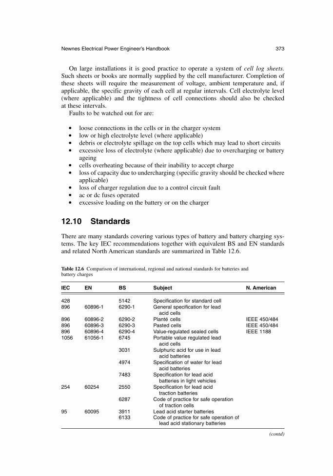
On large installations it is good practice to operate a system of cell log sheets.Such sheets or books are normally supplied by the cell manufacturer. Completion ofthese sheets will require the measurement of voltage, ambient temperature and, ifapplicable, the specific gravity of each cell at regular intervals. Cell electrolyte level(where applicable) and the tightness of cell connections should also be checked at these intervals.
Faults to be watched out for are:
loose connections in the cells or in the charger system low or high electrolyte level (where applicable) debris or electrolyte spillage on the top cells which may lead to short circuits excessive loss of electrolyte (where applicable) due to overcharging or battery
ageing cells overheating because of their inability to accept charge loss of capacity due to undercharging (specific gravity should be checked where
applicable) loss of charger regulation due to a control circuit fault ac or dc fuses operated excessive loading on the battery or on the charger
12.10 Standards
There are many standards covering various types of battery and battery charging sys-tems. The key IEC recommendations together with equivalent BS and EN standardsand related North American standards are summarized in Table 12.6.
Newnes Electrical Power Engineer’s Handbook 373
Table 12.6 Comparison of international, regional and national standards for batteries and battery charges
IEC EN BS Subject N. American
428 5142 Specification for standard cell896 60896-1 6290-1 General specification for lead
acid cells896 60896-2 6290-2 Plante cells IEEE 450/484896 60896-3 6290-3 Pasted cells IEEE 450/484896 60896-4 6290-4 Value-regulated sealed cells IEEE 11881056 61056-1 6745 Portable value regulated lead
acid cells3031 Sulphuric acid for use in lead
acid batteries4974 Specification of water for lead
acid batteries7483 Specification for lead acid
batteries in light vehicles254 60254 2550 Specification for lead acid
traction batteries6287 Code of practice for safe operation
of traction cells95 60095 3911 Lead acid starter batteries
6133 Code of practice for safe operation of lead acid stationary batteries
(contd)
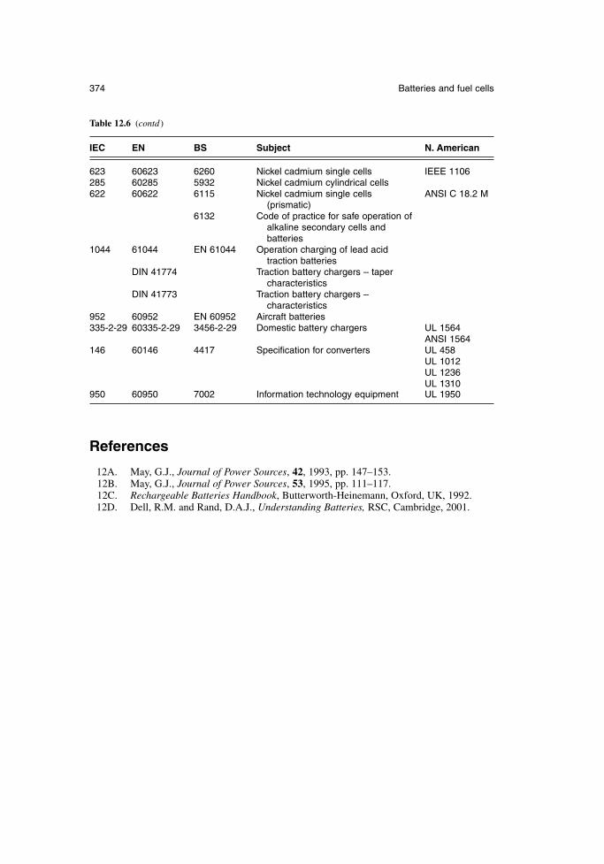
References
12A. May, G.J., Journal of Power Sources, 42, 1993, pp. 147–153.12B. May, G.J., Journal of Power Sources, 53, 1995, pp. 111–117.12C. Rechargeable Batteries Handbook, Butterworth-Heinemann, Oxford, UK, 1992.12D. Dell, R.M. and Rand, D.A.J., Understanding Batteries, RSC, Cambridge, 2001.
374 Batteries and fuel cells
Table 12.6 (contd )
IEC EN BS Subject N. American
623 60623 6260 Nickel cadmium single cells IEEE 1106285 60285 5932 Nickel cadmium cylindrical cells622 60622 6115 Nickel cadmium single cells ANSI C 18.2 M
(prismatic)6132 Code of practice for safe operation of
alkaline secondary cells and batteries
1044 61044 EN 61044 Operation charging of lead acid traction batteries
DIN 41774 Traction battery chargers – taper characteristics
DIN 41773 Traction battery chargers – characteristics
952 60952 EN 60952 Aircraft batteries335-2-29 60335-2-29 3456-2-29 Domestic battery chargers UL 1564
ANSI 1564146 60146 4417 Specification for converters UL 458
UL 1012UL 1236UL 1310
950 60950 7002 Information technology equipment UL 1950
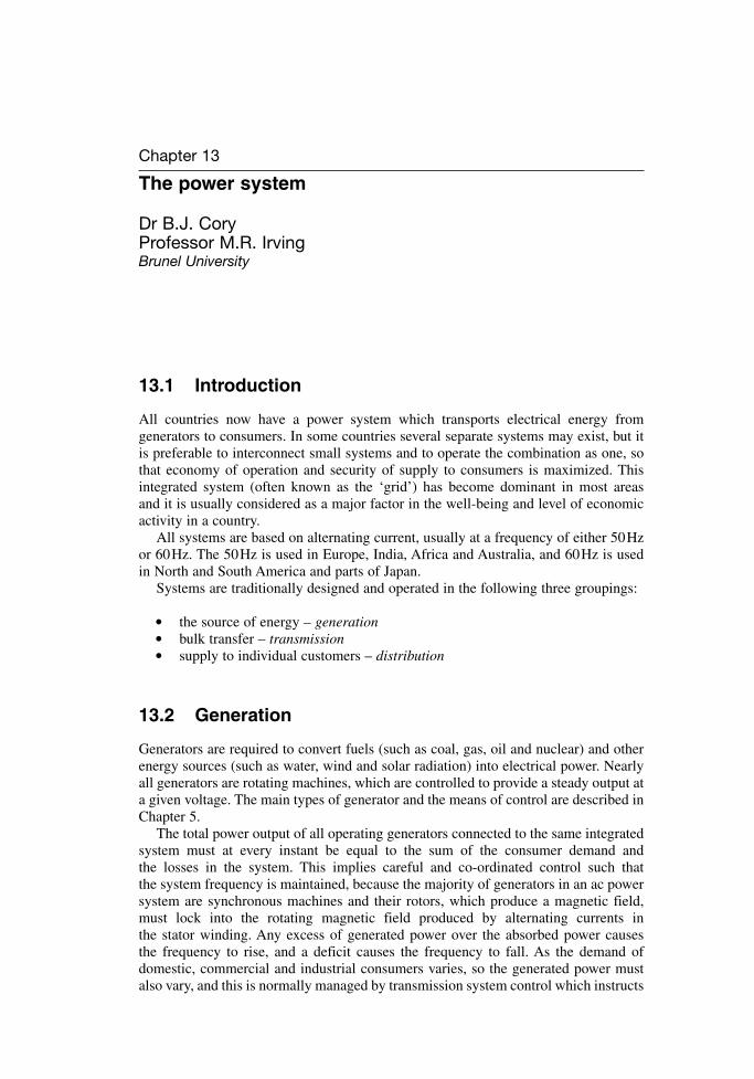
Chapter 13
The power system
Dr B.J. CoryProfessor M.R. IrvingBrunel University
13.1 Introduction
All countries now have a power system which transports electrical energy from generators to consumers. In some countries several separate systems may exist, but itis preferable to interconnect small systems and to operate the combination as one, sothat economy of operation and security of supply to consumers is maximized. Thisintegrated system (often known as the ‘grid’) has become dominant in most areas and it is usually considered as a major factor in the well-being and level of economicactivity in a country.
All systems are based on alternating current, usually at a frequency of either 50Hzor 60Hz. The 50Hz is used in Europe, India, Africa and Australia, and 60Hz is usedin North and South America and parts of Japan.
Systems are traditionally designed and operated in the following three groupings:
the source of energy – generation bulk transfer – transmission supply to individual customers – distribution
13.2 Generation
Generators are required to convert fuels (such as coal, gas, oil and nuclear) and otherenergy sources (such as water, wind and solar radiation) into electrical power. Nearlyall generators are rotating machines, which are controlled to provide a steady output ata given voltage. The main types of generator and the means of control are described inChapter 5.
The total power output of all operating generators connected to the same integratedsystem must at every instant be equal to the sum of the consumer demand and the losses in the system. This implies careful and co-ordinated control such that the system frequency is maintained, because the majority of generators in an ac powersystem are synchronous machines and their rotors, which produce a magnetic field,must lock into the rotating magnetic field produced by alternating currents in the stator winding. Any excess of generated power over the absorbed power causes the frequency to rise, and a deficit causes the frequency to fall. As the demand ofdomestic, commercial and industrial consumers varies, so the generated power mustalso vary, and this is normally managed by transmission system control which instructs
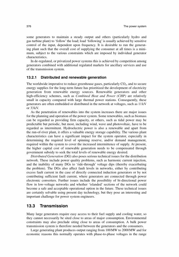
some generators to maintain a steady output and others (particularly hydro and gas turbine plant) to ‘follow’ the load; load ‘following’ is usually achieved by sensitivecontrol of the input, dependent upon frequency. It is desirable to run the generat-ing plant such that the overall cost of supplying the consumer at all times is a mini-mum, subject to the various constraints which are imposed by individual generator characteristics.
In de-regulated, or privatized power systems this is achieved by competition amonggenerators combined with additional regulated markets for ancillary services and useof the transmission system.
13.2.1 Distributed and renewable generation
The worldwide imperative to reduce greenhouse gases, particularly CO2, and to secureenergy supplies for the long-term future has prioritized the development of electricitygeneration from renewable energy sources. Renewable generators and other high-efficiency schemes, such as Combined Heat and Power (CHP) are relativelysmall in capacity compared with large thermal power stations. Consequently, thesegenerators are often embedded or distributed in the network at voltages, such as 11kVor 33kV.
As the penetration of renewables into the system increases there are major issuesfor the planning and operation of the power system. Some renewables, such as biomasscan be regarded as providing firm capacity, or others, such as tidal power may be predictable but periodic, but most, including wind, wave and photovoltaic, have to beregarded as intermittent. Hydroelectric power is also a renewable and apart from the run-of-river plant, it offers a valuable energy storage capability. The various plantcharacteristics can have a significant impact for the system operator, especially indetermining the required level of spinning reserve, and/or demand management,required within the system to cover the increased intermittence of supply. At present,the higher capital cost of renewable generation needs to be compensated through government subsidy to seek the total levels of renewable energy desired.
Distributed Generation (DG) also poses serious technical issues for the distributionnetwork. These include power quality problems, such as harmonic current injection,and the inability of many DGs to ‘ride-through’ voltage dips (thereby exacerbating the problem). The DGs also affect fault levels in networks, either by contributingexcess fault current in the case of directly connected induction generators or by notcontributing sufficient fault current, where generators are connected through powerelectronic converters. Further issues include the possibility of bi-directional powerflow in low-voltage networks and whether ‘islanded’ sections of the network couldbecome a safe and acceptable operational option in the future. These technical issuesare certainly solvable using present day technology, but they pose an interesting andimportant challenge for power system engineers.
13.3 Transmission
Many large generators require easy access to their fuel supply and cooling water, sothey cannot necessarily be sited close to areas of major consumption. Environmentalconstraints may also preclude siting close to areas of consumption. A bulk powertransmission system is therefore needed between the generators and the consumers.
Large generating plant produces output ranging from 100MW to 2000MW and foreconomic reasons this normally operates with phase-to-phase voltages in the range
376 The power system
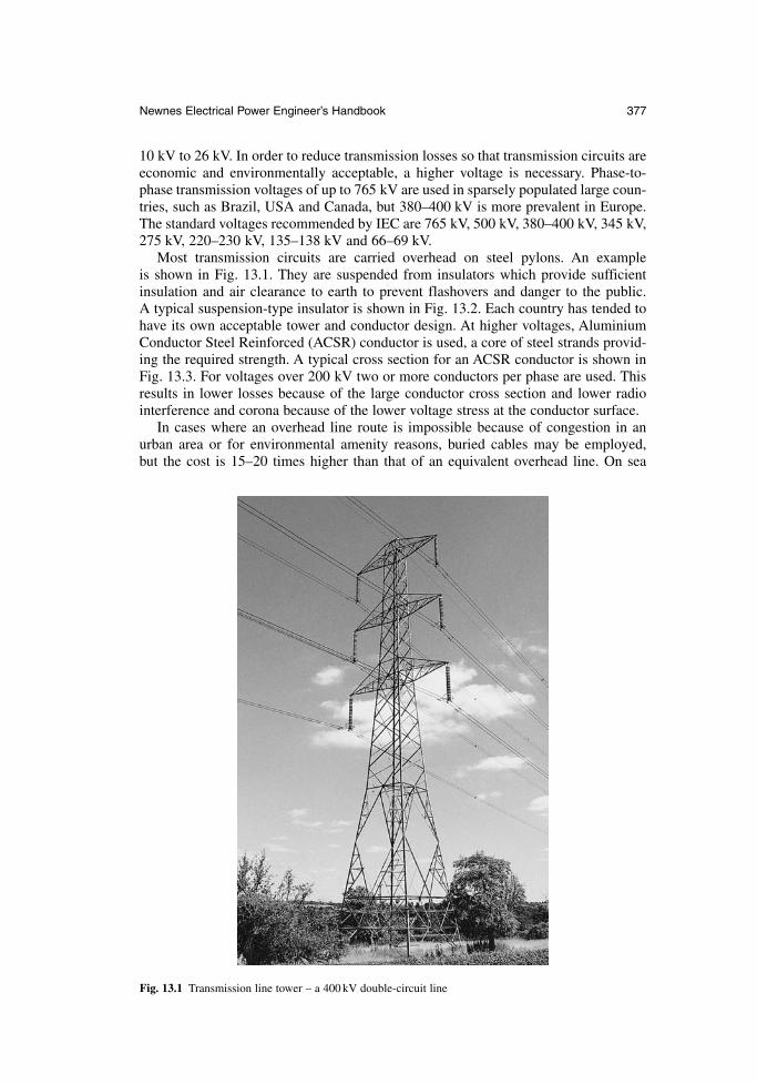
10 kV to 26 kV. In order to reduce transmission losses so that transmission circuits areeconomic and environmentally acceptable, a higher voltage is necessary. Phase-to-phase transmission voltages of up to 765 kV are used in sparsely populated large coun-tries, such as Brazil, USA and Canada, but 380–400 kV is more prevalent in Europe.The standard voltages recommended by IEC are 765 kV, 500 kV, 380–400 kV, 345 kV,275 kV, 220–230 kV, 135–138 kV and 66–69 kV.
Most transmission circuits are carried overhead on steel pylons. An example is shown in Fig. 13.1. They are suspended from insulators which provide sufficientinsulation and air clearance to earth to prevent flashovers and danger to the public. A typical suspension-type insulator is shown in Fig. 13.2. Each country has tended tohave its own acceptable tower and conductor design. At higher voltages, AluminiumConductor Steel Reinforced (ACSR) conductor is used, a core of steel strands provid-ing the required strength. A typical cross section for an ACSR conductor is shown inFig. 13.3. For voltages over 200 kV two or more conductors per phase are used. Thisresults in lower losses because of the large conductor cross section and lower radiointerference and corona because of the lower voltage stress at the conductor surface.
In cases where an overhead line route is impossible because of congestion in anurban area or for environmental amenity reasons, buried cables may be employed, but the cost is 15–20 times higher than that of an equivalent overhead line. On sea
Newnes Electrical Power Engineer’s Handbook 377
Fig. 13.1 Transmission line tower – a 400 kV double-circuit line
crossings an underwater cable is the only solution, but these are often dc, for reasonsexplained in section 13.3.1.1.
A high-voltage transmission system interconnects many large generators with areasof high electricity demand; its reliability is paramount, since a failure could result inloss of supply to many people and to vital industry and services. The system is there-fore arranged as a network so that the loss of one circuit can be tolerated. This is shownin Fig. 13.4. In many countries, three-phase lines are duplicated on one tower, in whichcase a tower failure might still result in a partial blackout. Mixed-voltage systems areoften carried on a single tower, but this is not the practice in the UK.
In order to achieve flexibility of operation, circuits are marshalled at substations.The substations may include transformers to convert from one voltage level to another,
378 The power system
Fig. 13.2 Suspension-type insulator
Fig. 13.3 Typical cross section of an ACSR overhead line conductor
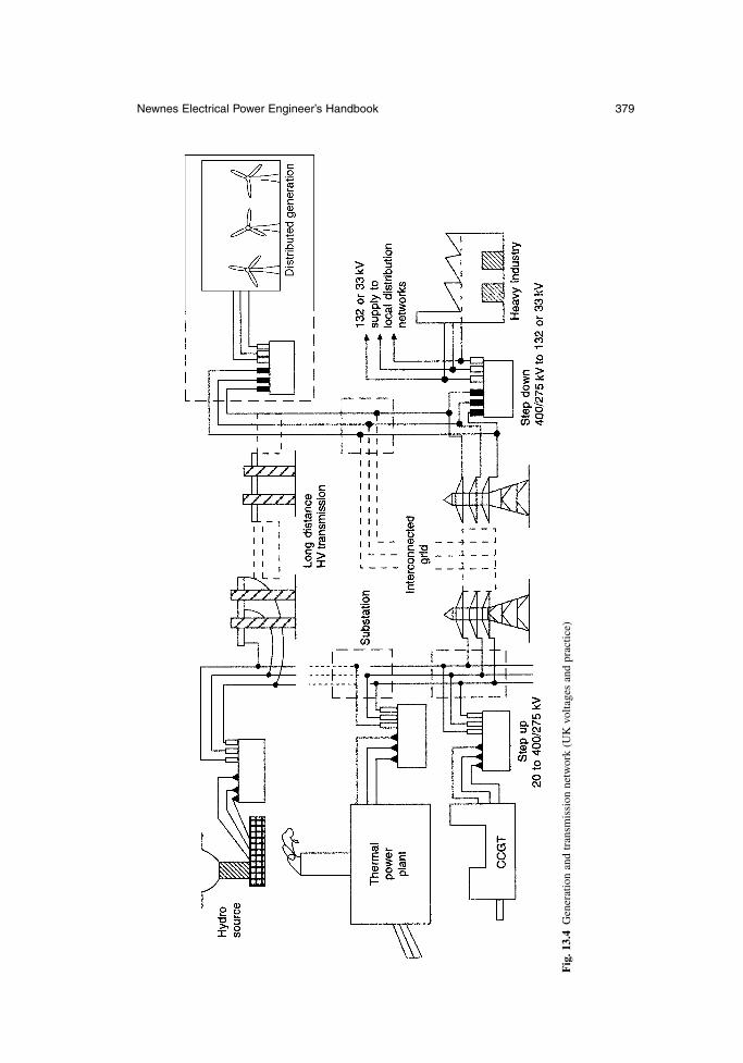
Newnes Electrical Power Engineer’s Handbook 379
Fig
. 13.
4G
ener
atio
n an
d tr
ansm
issi
on n
etw
ork
(UK
vol
tage
s an
d pr
actic
e)

and switchgear to switch circuits and interrupt faults. Substations are normally outdoorsand they occupy an extensive secure area, although compact indoor substations usingSF6 (as described in section 7.5.3.2) have become more prevalent recently because oftheir improved reliability in adverse weather and a more compact layout.
An interconnected transmission network can comprise many substations which areall remotely controlled and monitored to ensure rapid reconnection after a disturbanceor to enable maintenance.
13.3.1 Principles of design
The two main requirements of transmission systems are:
the interconnection of plant and neighbouring systems to provide security, economic operation and the exchange of energy on a buy–sell basis
the transport of electrical energy from remote generation to load centres
These objectives are met by selection of the most economical overhead line design,commensurate with the various constraints imposed by environmental and nationalconsiderations. The design and approval process for new lines can take many years;following public enquiries and judicial proceedings before planning, permission isgranted and line construction begins. Typical objections to new overhead lines, particu-larly in industrialized countries are:
the visual deterioration of open country areas the possibility that electromagnetic field propagation may cause interference
with television, radio and telecommunications, with an increasing awareness ofpublic health issues
emission of noise by corona discharges, particularly at deteriorating conductorsurfaces, joints and insulation surfaces
the danger to low-flying aircraft a preference for alternative energy supply, such as gas and local environment-
friendly generation including solar cells and wind power, or measures forreducing electricity demand, such as better thermal insulation in houses andcommercial premises, lower energy lighting, natural ventilation in place of airconditioning, and even changes of lifestyle
Power system planners are required to show that extensive studies using a range of scenarios and sensitivities have been carried out, and that the most economical andleast environmentally damaging design has been chosen. Impact statements are alsorequired in many countries to address the concerns regarding the many issues raisedby local groups, planning authorities and others.
Technically, the key issues which have to be decided are:
whether to use an overhead line or an underground cable the siting of substations and the size of substation required to contain the
necessary equipment for control of voltage and power flow provision for future expansion, for an increase in demand, and in particular for
the likelihood of tee-off connections to new load centres the availability of services and access to substation sites, including secure
communications for control and monitoring
380 The power system
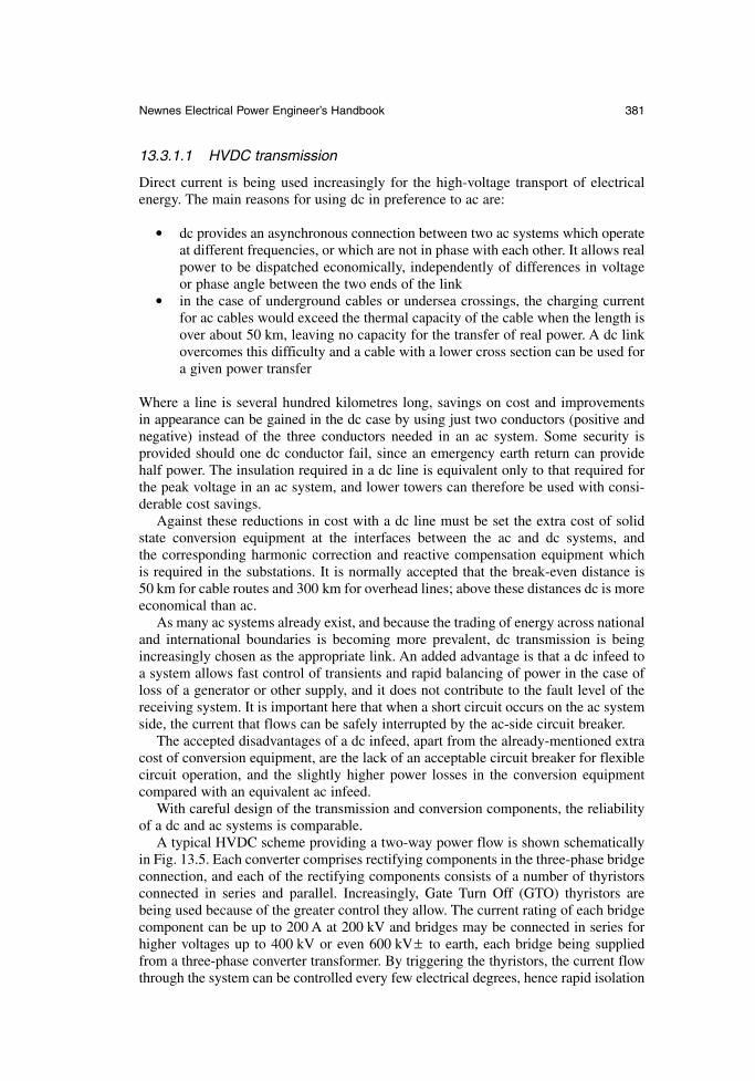
13.3.1.1 HVDC transmission
Direct current is being used increasingly for the high-voltage transport of electricalenergy. The main reasons for using dc in preference to ac are:
dc provides an asynchronous connection between two ac systems which operateat different frequencies, or which are not in phase with each other. It allows realpower to be dispatched economically, independently of differences in voltageor phase angle between the two ends of the link
in the case of underground cables or undersea crossings, the charging currentfor ac cables would exceed the thermal capacity of the cable when the length isover about 50 km, leaving no capacity for the transfer of real power. A dc linkovercomes this difficulty and a cable with a lower cross section can be used fora given power transfer
Where a line is several hundred kilometres long, savings on cost and improvements in appearance can be gained in the dc case by using just two conductors (positive andnegative) instead of the three conductors needed in an ac system. Some security is provided should one dc conductor fail, since an emergency earth return can providehalf power. The insulation required in a dc line is equivalent only to that required forthe peak voltage in an ac system, and lower towers can therefore be used with consi-derable cost savings.
Against these reductions in cost with a dc line must be set the extra cost of solidstate conversion equipment at the interfaces between the ac and dc systems, and the corresponding harmonic correction and reactive compensation equipment which is required in the substations. It is normally accepted that the break-even distance is 50 km for cable routes and 300 km for overhead lines; above these distances dc is moreeconomical than ac.
As many ac systems already exist, and because the trading of energy across nationaland international boundaries is becoming more prevalent, dc transmission is beingincreasingly chosen as the appropriate link. An added advantage is that a dc infeed toa system allows fast control of transients and rapid balancing of power in the case ofloss of a generator or other supply, and it does not contribute to the fault level of thereceiving system. It is important here that when a short circuit occurs on the ac systemside, the current that flows can be safely interrupted by the ac-side circuit breaker.
The accepted disadvantages of a dc infeed, apart from the already-mentioned extracost of conversion equipment, are the lack of an acceptable circuit breaker for flexiblecircuit operation, and the slightly higher power losses in the conversion equipmentcompared with an equivalent ac infeed.
With careful design of the transmission and conversion components, the reliabilityof a dc and ac systems is comparable.
A typical HVDC scheme providing a two-way power flow is shown schematicallyin Fig. 13.5. Each converter comprises rectifying components in the three-phase bridgeconnection, and each of the rectifying components consists of a number of thyristorsconnected in series and parallel. Increasingly, Gate Turn Off (GTO) thyristors arebeing used because of the greater control they allow. The current rating of each bridgecomponent can be up to 200 A at 200 kV and bridges may be connected in series forhigher voltages up to 400 kV or even 600 kV± to earth, each bridge being suppliedfrom a three-phase converter transformer. By triggering the thyristors, the current flowthrough the system can be controlled every few electrical degrees, hence rapid isolation
Newnes Electrical Power Engineer’s Handbook 381
can be achieved in the event of a fault on the system. Similarly, by delay triggering,the current can be easily controlled, the direct voltage being best set by tapchange onthe converter supply transformers. The triggering of the thyristors may be by a lightpulse which provides voltage isolation. Inversion, which enables power flow from thedc system to the ac system, depends on the ac back-emf being available with a mini-mum fault level in the receiving systems, so inversion into an isolated system is notpossible unless devices with turn-off capability are available.
A further feature of dc converter substations is the need for ac transmission filtersto produce an acceptable ac sinusoidal waveform following the infeed or outfeed ofalmost square-wave blocks of current. Such filters for 6n ± 1 harmonics (where n isthe number of bridges and substations) can add 25 per cent to the cost of a substation,although they can also be used to provide some of the VAr generation which is necessary to control the power factor of the inverter.
13.3.1.2 AC system compensation
As ac power systems become more extensive at transmission voltages, it is desirableto make provision for flexible operation with compensation equipment. Such equip-ment not only enables larger power flows to be accommodated in a given rating of accircuit, but also provides a means of routing flows over the interconnected system foreconomic or trading purposes.
Compensation equipment consisting of fixed or variable inductance and capaci-tance can be connected in series with the circuit, in which case it must be rated to carry the circuit current, or it may be connected in shunt, and used to inject or absorb
382 The power system
Fig. 13.5 Complete HVDC scheme, showing converters and dc link
reactive power (VArs) depending upon requirements. In the same way, that real powerinjected into the system must always just balance the load on the system and the sys-tem losses at that instant, so too must the reactive power achieve a balance over regionsof the system.
Transmission circuits absorb VArs because their conductors are inductive, but theyalso generate VArs because they have a stray capacitance between phases and betweenphase and earth. The latter can be particularly important with high-voltage cables. Theabsorption is proportional to I 2X, where I is the current and X is the reactance of the circuit, and the generation is proportional to V 2B, where V is the voltage and B is the susceptance of the circuit. When I 2X is equal to V 2B at all parts of the circuit, it is found that the system voltage is close to the rated value. If V 2B is greaterthan I2X, then the system voltage will be higher than the rated value, and vice versa.Designers therefore need to maintain a balance over the foreseeable range of current asloads vary from minimum to maximum during the day, and over the season and the year.
Compensation may be provided by the following three main methods:
series capacitors connected in each phase to cancel the series inductance of thecircuit. Up to 70 per cent compensation is possible in this way.
shunt inductance to absorb excessive VArs generated by the circuit stray capac-itance or (exceptionally) to compensate for the leading power factor of a load.
shunt capacitance to generate VArs for the compensation of load power factoror excessive VArs absorbed under heavy current flow conditions on short over-head line circuits.
A combination of these arrangements are possible, especially in transmission sub-stations where no generators are connected; generators are able to generate or absorbVArs through excitation control (see section 5.3.2).
13.3.1.3 FACTS devices
Recently, Flexible AC Transmission Systems (FACTS) devices have become available.In these, the amount of VAr absorption by inductors is varied through the control ofthyristors connected in series with the inductor limbs. A typical shunt controllable unitis shown in Fig. 13.6. This is known as a Shunt Variable Compensator (SVC). OtherFACTS devices are variable series capacitors, variable phase-shifters and UniversalPower Controllers (UPC), in which energy is drawn from the system in shunt andinjected back into the system in series at a controlled phase angle by means of GTOthyristors.
The FACTS devices offer instantaneous control over voltage, current and impedance.Reactive power can be generated or absorbed and the flow of real power can be variedbetween alternative paths. The FACTS devices can therefore be used for voltage con-trol, power flow control between parallel paths (particularly following a circuit outage),and by fully utilizing the instantaneous capability they can stabilize intermachine or interarea power oscillations. The disadvantages of FACTS are the additional cost,including filters to reduce the associated injection of undesirable harmonic currentsinto the grid.
Although a wide variety of FACTS devices have been proposed and investigated, atpresent the SVC is the main device which has achieved widespread adoption. The SVCoffers a modern, cost-effective alternative to the rotating synchronous condenser
Newnes Electrical Power Engineer’s Handbook 383
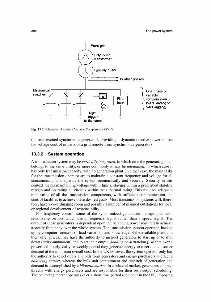
(an over-excited synchronous generator), providing a dynamic reactive power sourcefor voltage control in parts of a grid remote from synchronous generators.
13.3.2 System operation
A transmission system may be vertically integrated, in which case the generating plantbelongs to the same utility, or more commonly it may be unbundled, in which case ithas only transmission capacity, with no generation plant. In either case, the main tasksfor the transmission operator are to maintain a constant frequency and voltage for allconsumers, and to operate the system economically and securely. Security in this context means maintaining voltage within limits, staying within a prescribed stabilitymargin and operating all circuits within their thermal rating. This requires adequatemonitoring of all the transmission components, with sufficient communication andcontrol facilities to achieve these desired goals. Most transmission systems will, there-fore, have a co-ordinating room and possibly a number of manned outstations for localor regional devolvement of responsibility.
For frequency control, some of the synchronized generators are equipped with sensitive governors which use a frequency signal rather than a speed signal. The output of these generators is dependent upon the balancing power required to achievea steady frequency over the whole system. The transmission system operator, backedup by computer forecasts of load variations and knowledge of the available plant andtheir offer prices, may have the authority to instruct generators to start up or to shutdown (unit commitment) and to set their output (loading or dispatching) so that over a prescribed hourly, daily or weekly period they generate energy to meet the consumerdemand at the minimum overall cost. In the UK however, the system operator only hasthe authority to select offers and bids from generators and energy purchasers to effect abalancing market, whereas the bulk unit commitment and dispatch of generation anddemand is accomplished by a bilateral market. In a bilateral market, generators contractdirectly with energy purchasers and are responsible for their own output scheduling.The balancing market operates over a short time period (one hour in the UK) imposing
384 The power system
Fig. 13.6 Schematic of a Shunt Variable Compensator (SVC)
any adjustments necessary to obtain balanced supply and demand and technical satis-faction of any transmission system constraints.
There is a considerable scope for minimization of the losses in an interconnectedsystem through the control of the compensation devices described in section 13.3.1.2.This control is guided by the use of optimal load flow programs, security assessmentsand calculations of transient stability margin. One of the main concerns is to arrangepatterns of generation, including some plant which may otherwise be uneconomic, tomaintain voltage despite outages of circuits and other components for maintenance,extension and repair. Safety of utility personnel and the operation of the system toavoid risk to the public is at all times paramount.
13.4 Distribution
An example of a three-phase distribution system is illustrated in Fig. 13.7. In the UK,voltages of 132 kV, 110 kV, 66 kV, 33 kV and 11 kV are typically used to provide primary distribution, with a 380–415 V three-phase and neutral low-voltage supply to smaller consumers, such as residential or smaller commercial premises, where 220–240V single-phase to neutral is taken off the three-phase supply. Distributionvoltages in continental Europe are typically 110 kV, 69 kV and 20 kV, but practicevaries from country to country. In the USA, voltages of 138 kV, 115 kV, 69 kV,34.5 kV, 13.2 kV and 4.16 kV are employed.
The transformer stepping down from the primary distribution to the low-voltagesupply may be pole-mounted or in a substation, and it is close to the consumers in order to limit the length of the low-voltage connection and the power losses in thelow-voltage circuit. In a national power system, many thousands of transformers andtheir associated circuit breakers or fuses/protective devices are required for distribu-tion to low-voltage circuits, in contrast to high-voltage transmission and primary distribution systems, where the number of substations is in the hundreds.
The progressive introduction of small-scale distributed generation (DG) is now amajor issue for distribution networks. These networks, which have been designed forone-way-traffic of energy from transmission levels down to consumers, may have tobe modified to accept the possibility of reversed flow caused by the DG exceedinglocal demand. This has a significant impact on the protection systems required.
It will be noted from Fig. 13.7 that the primary and low-voltage distribution systemsare connected in a radial configuration. Circuit loops between adjacent substations areavoided because these can lead to circulating currents, which may increase the powerlosses and create difficulty in protection schemes. However, tie circuits between adjacent lines and cables are available to reconfigure the network when a portion of thelow-voltage circuit is out of service for maintenance or because of failure. These tie circuits are controlled by a normally open switch which can be closed manually withina few minutes, although an increasing trend is for automation of this operation bySupervisory Control and Data Acquisition (SCADA) systems.
In urban and suburban areas, much of the primary and low-voltage distribution system is underground, with readily accessible substations sited in cellars or on smallsecure plots. Industrial sites may also have a number of substations incorporated intobuildings or secure areas; these may be controlled by the works engineer or operatedand maintained by an electricity distribution company.
In rural areas and in more dispersed suburban areas, many three-phase overheadlines operating at 10–15 kV or 27–33 kV are supported for many miles on poles which
Newnes Electrical Power Engineer’s Handbook 385
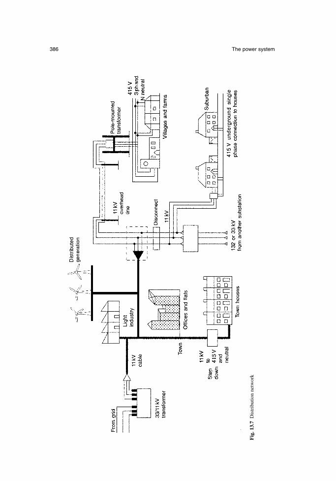
386 The power system
Fig
. 13.
7D
istr
ibut
ion
netw
ork
may be of wood, concrete or steel lattice. The 380–415 V three-phase supply is takenfrom these lines through a small pole-mounted fused input/output transformer. If themaximum load to be taken is below about 50 kW, the supplies for homes or farmsteadsmay be derived from a single-phase 10–15 kV supply. Typically, a rural primary distribution system supplies up to 50 step-down transformers spread over a wideregion. The lines in such a system are vulnerable to damage by tree branches, snowand ice accumulation and lightning strikes and it therefore has lower reliability thanunderground systems in urban areas. Considerable ingenuity has been applied to pro-tection of this type of system with the use of auto-reclosing supply circuit breakers and automatic reconnection switches, which are described in section 7.4.2.2.
It is now a common practice in developed countries to monitor the primary distribution system down to 10–15 kV and to display alarm, voltage and power-flowconditions in a control room; and in the event of an incident, repair crews are despatched quickly. Repairs to the low-voltage system are still dependent, however, onconsumers notifying a loss of supply.
The proper earthing of distribution systems is of prime importance in order thatexcessive voltages do not appear on connections to individual consumers. It is thepractice in UK and some other countries to connect to earth the neutral conductor ofthe four-wire system and the star point of the low-voltage winding on the step-downtransformer, not only at the transformer secondary output but also at every load pointwith a local meter and protective fuse. This is known as the Protective Multiple Earth(PME) system, which is described in relation to cable technology in section 9.3.1.3. It is designed to ensure that all metallic covers and equipment fed from the supplyare bonded so that dangerously high voltages do not hazard lives.
13.4.1 System design
It is essential that a distribution system is economical in operation and easy to repair,and its design should enable reconnection of a consumer through adjacent feeders tosupply substations in the event of failure or outage of part of the system.
Copper or aluminium conductors with a cross section of 150mm2 to 250mm2 aretypically used at the lowest voltages, and these are arranged so that the maximum volt-age drop under the heaviest load conditions is no more than 6 per cent; alternativelythe voltage at the connection to every consumer must not rise more than 6 per centunder light load conditions. Local adjustment is achieved by off-load tapchanging(usually ± 2.5 per cent or ± 5 per cent), and voltage in the primary circuits (usually 11 kV and 33 kV in the UK) is controlled by on-load tapchangers under AutomaticVoltage Control. The construction and operation of tapchangers is described in moredetail in section 6.2.5. Reinforcement or extension on the LV network is usuallyarranged through the installation of a new primary feed point with a transformer, ratherthan by upgrading the LV network.
Primary underground networks now employ cross-linked polyethylene (XLPE)three-phase cables, as described in sections 9.2.4 and 9.3.1.3. The latest designs incor-porate fibre-optic strands for communication purposes. Cables require careful routingand physical protection to minimize the risk of inadvertent damage from road andbuilding works in the vicinity.
Overhead lines are usually of a simple flat three-phase configuration which avoidsconductor clashing in high winds and ice precipitation. An example is shown in Fig. 7.20. Impregnated wood poles are normally used. These provide some degree of
Newnes Electrical Power Engineer’s Handbook 387
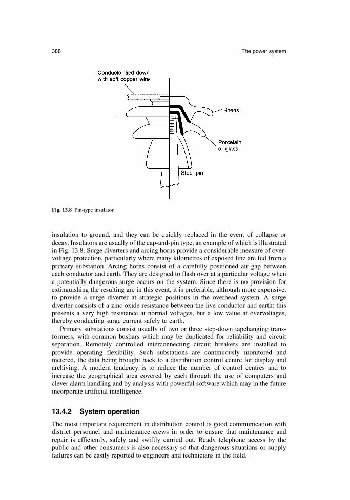
insulation to ground, and they can be quickly replaced in the event of collapse ordecay. Insulators are usually of the cap-and-pin type, an example of which is illustratedin Fig. 13.8. Surge diverters and arcing horns provide a considerable measure of over-voltage protection, particularly where many kilometres of exposed line are fed from aprimary substation. Arcing horns consist of a carefully positioned air gap between each conductor and earth. They are designed to flash over at a particular voltage whena potentially dangerous surge occurs on the system. Since there is no provision forextinguishing the resulting arc in this event, it is preferable, although more expensive,to provide a surge diverter at strategic positions in the overhead system. A surgediverter consists of a zinc oxide resistance between the live conductor and earth; thispresents a very high resistance at normal voltages, but a low value at overvoltages,thereby conducting surge current safely to earth.
Primary substations consist usually of two or three step-down tapchanging trans-formers, with common busbars which may be duplicated for reliability and circuitseparation. Remotely controlled interconnecting circuit breakers are installed to provide operating flexibility. Such substations are continuously monitored andmetered, the data being brought back to a distribution control centre for display andarchiving. A modern tendency is to reduce the number of control centres and toincrease the geographical area covered by each through the use of computers andclever alarm handling and by analysis with powerful software which may in the futureincorporate artificial intelligence.
13.4.2 System operation
The most important requirement in distribution control is good communication withdistrict personnel and maintenance crews in order to ensure that maintenance andrepair is efficiently, safely and swiftly carried out. Ready telephone access by the public and other consumers is also necessary so that dangerous situations or supplyfailures can be easily reported to engineers and technicians in the field.
388 The power system
Fig. 13.8 Pin-type insulator
The main task of the distribution controller is, therefore, to monitor equipmentalarms and to ensure that rapid and effective action is taken. Schedules of equipmentoutages and maintenance have to be planned and effected with the minimum of dis-ruption to consumers.
13.5 De-regulation and privatization
The electrical energy supply sector has undergone dramatic changes since the begin-ning of the 1990s. De-regulation, or privatization, has been adopted throughout theworld as a new market-oriented approach. Before privatization, power systems weregenerally owned by national governments and operated as vertically integrated organi-zations including generation, transmission and distribution. Privatized structures varyconsiderably, with the power system being split geographically and/or vertically intoseparate companies. Competition between generators is always possible, and energysupply contracts to end-users can be open to competition, but the transmission and dis-tribution networks are an inherent monopoly with access and charging for their useoverseen by a government regulator. The private companies have access to capital atprevailing interest rates, avoiding government spending restriction (or encouragement)that is a feature of government-owned utilities. It is generally believed that competi-tion can drive energy efficiency up and electricity prices down. However, there is stillsome debate about how effectively market forces alone can stimulate the correct levelof planning and construction of new generation and other plant at a level which ensuressatisfactory security of supply for the longer term. This difficulty is exacerbated by thetechnical inability to store significant quantities of electrical energy. An area of doubtis therefore whether short-term electricity price fluctuations provide a sufficient eco-nomic signal to drive the long-term decision of a private company to build new plant,based on their analysis of risk and reward. If a de-regulated system does fail to providethe level of energy supply security expected by modern communities it might notalways be clear where the ‘obligation to supply’ rests.
13.6 Future trends
Power systems are continually evolving and with the increasing capability of computersand software, systems are becoming more precisely controlled for economy of opera-tion and security.
The future is certain to include a greater proportion of primary energy from renew-able sources. Generators are likely to be distributed throughout the power system andthere may be a very large number of mass-produced very small generators. The modeof operation of the power system will need to become more flexible and is likely to bebased on local intelligent control. Operation of the distribution network as an activesystem can be anticipated, with routine flow reversal and continued operation underislanded conditions becoming feasible. It is expected that generation and load controllers will need to respond to local network conditions, for example reducing theoutput of relevant generators to cover the period of a circuit outage. This flexibleresponse must be autonomous, to allow unmanned operation, and it would need to becontrolled in a local decentralized manner.
We seem to be at the beginning of a new era of major change in power systemsplant, technology and management. Great challenges and opportunities for electricalengineers lie ahead.
Newnes Electrical Power Engineer’s Handbook 389

References
13A. Weedy, B.M. and Cory, B.J. Electric Power Systems (4th edn), Wiley, 1987.13B. EHV Transmission Line Reference Book, Edison Electric Institute, USA, 1968.13C. Modern Power Station Practice, Volume L, (3rd edn), Pergamon, 1991.13D. Jenkins, N. et al. Embedded Generation, Institution of Electrical Engineers, 2000.
390 The power system
Chapter 14
Power quality and electromagnetic compatibility
G.W.A. McDowell and A.J. MaddocksERA Technology Ltd
14.1 Power quality
14.1.1 Introduction
The term power quality seeks to quantify the condition of the electrical supply. It notonly relates largely to voltage but also deals with current and it is largely the corrupt-ing effect of current disturbances upon voltage. Power quality can be quantified by avery broad range of parameters, some of which have been recognized and studied foras long as electrical power has been utilized. However, the advent of the term itself is more modern and it has created a useful vehicle for discussing and quantifying allfactors that can describe supply quality.
Power quality is yet another means of analysing and expressing electromagneticcompatibility (EMC), but in terms of the frequency spectrum, power quality charac-terizes mainly low-frequency phenomena. Perhaps because of this and because of themanner in which it affects electrical equipment, power quality has largely been dealtwith by engineers with electrical power experience rather than those with an EMCexpertise. In reality, resolving power problems can benefit from all available expertise,particularly since power quality disorders and higher frequency emissions can producesimilar effects.
In 1989, the European Community defined the supply of electricity as a product,and it is therefore closely related to the provisions and protection of the EMC Directive(89/336/EEC), but in drawing a comparison between electricity and other manu-factured product it is essential to recall a significant difference. Electricity is probablyunique in being a product which is manufactured, delivered and used at the same time.An electricity manufacturer cannot institute a batch testing process for example andpull substandard products out of the supply chain. By the time electricity is tested it will have been delivered and used by the customer whether it was of good quality or not.
14.1.2 What determines power quality
Arguably, power quality is not an absolute quantity. Many users of electrical powerwould consider their electrical supply to be of adequate quality, provided the output ofthe process it is used to supply is of a high standard. For example, if the desktop com-puter functions without interruption, temporary resets or voltage-related componentfailures, then the quality of its electrical supply would be considered perfectly accept-able. Industry would not consider a supply voltage with repeated temporary 100 msdips to be of poor quality if it did not have an affect on the manufacturing processes.
So power quality is a perception driven by the tolerance (susceptibility being the moreusual EMC parlance) of the electrical devices that depend upon it. Therefore, thepower quality parameters that have evolved to describe acceptable limits are largely anexpression of equipment tolerance.
Importantly, although utilities may declare the power quality limits, their attemptsto meet this may not be achieved at all times and there is a finite probability that powerquality will sometimes fall outside these limits. If the number of times that a supplyfalls outside the declared power quality limits is more than can be economically toler-ated due to the adverse effects upon plant and equipment, then mitigating measuresshould be taken.
14.1.3 Supply characteristics
The complexity introduced by the length of supply distribution circuits, environmentalfactors, loading characteristics and the natural degradation of the distribution equipmentmeans that power quality can differ significantly with location.
In general, power quality tends to degrade progressively, the greater the distance is from the source of generation. This is because the supply impedance is lowest nearthe terminals of the generating systems or where interconnections exist betweenseveral sources, and from such points the supply impedance increases along lines and cables, and through transformers. In addition, the predominantly radial nature of power distribution means that load current fluctuations tend to have a morepronounced effect closer to where the load is concentrated.
The power quality at the Point of Common Coupling (PCC) with the public elec-tricity supply network defines the quality of the electricity supply to the consumer. Formany years the electricity supply industry in the UK has applied planning limits andset standards through engineering recommendations, such as G5/4 (references 14Aand 14B) for harmonics. In recent years CENELEC has created EN 50160 (reference14C) which defines the standards of power quality that is common in Europe formedium-voltage (less than 35 kV) and low-voltage (less than 1 kV) systems. EN 50160effectively defines the electrical supply environment that European consumers canexpect to experience rather than setting the standards for supply. It has usefully added to the awareness of power quality by encompassing within one document thebroad spectrum of power quality parameters defined in Table 14.1. It has not set tighterstandards, but merely characterized those which already exist.
In order to set immunity levels for equipment, it is first necessary to define the electrical environment. This is defined by IEC 61000-2-2 (reference 14D) which sets the compatibility levels for low-frequency conducted disturbances on low-voltage net-works. These levels are less stringent than EN 50160. Therefore, not surprisingly, themargin between voltage characteristic levels (as defined by EN 50160) with the end-userequipment immunity (as defined by IEC 61000-6-1 and IEC 61000-6-2) shows that thelevel of immunity for most power quality phenomena would be insufficient to protectend-user equipment adequately. In practice, the actual level of disturbance is likely to beequal or less than the immunity levels defined by generic standards, and the likelihoodof a disturbance affecting the compliant end-user equipment is greatly reduced.
14.1.4 Key parameters
The parameters that are commonly used to characterize supplies are listed in Table 14.1 together with the typical tolerance limits which define acceptable norms.Within Europe these power quality limits are defined by the EN 61000 series of
392 Power quality and EMC
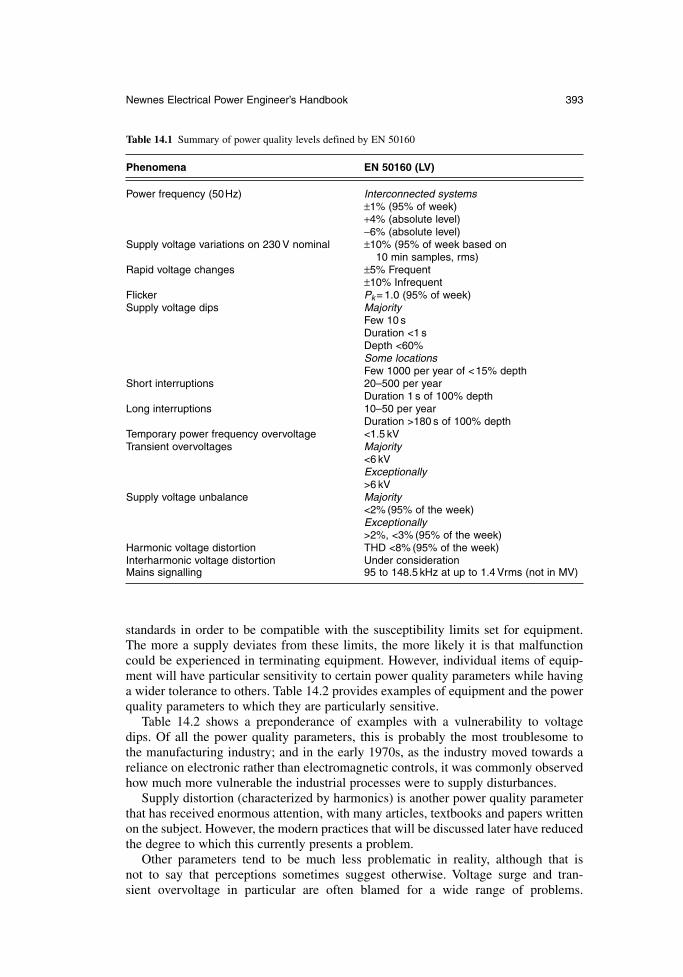
standards in order to be compatible with the susceptibility limits set for equipment.The more a supply deviates from these limits, the more likely it is that malfunctioncould be experienced in terminating equipment. However, individual items of equip-ment will have particular sensitivity to certain power quality parameters while havinga wider tolerance to others. Table 14.2 provides examples of equipment and the powerquality parameters to which they are particularly sensitive.
Table 14.2 shows a preponderance of examples with a vulnerability to voltage dips. Of all the power quality parameters, this is probably the most troublesome to the manufacturing industry; and in the early 1970s, as the industry moved towards areliance on electronic rather than electromagnetic controls, it was commonly observedhow much more vulnerable the industrial processes were to supply disturbances.
Supply distortion (characterized by harmonics) is another power quality parameterthat has received enormous attention, with many articles, textbooks and papers writtenon the subject. However, the modern practices that will be discussed later have reducedthe degree to which this currently presents a problem.
Other parameters tend to be much less problematic in reality, although that is not to say that perceptions sometimes suggest otherwise. Voltage surge and tran-sient overvoltage in particular are often blamed for a wide range of problems.
Newnes Electrical Power Engineer’s Handbook 393
Table 14.1 Summary of power quality levels defined by EN 50160
Phenomena EN 50160 (LV)
Power frequency (50Hz) Interconnected systems±1% (95% of week)+4% (absolute level)−6% (absolute level)
Supply voltage variations on 230 V nominal ±10% (95% of week based on 10 min samples, rms)
Rapid voltage changes ±5% Frequent±10% Infrequent
Flicker Pk = 1.0 (95% of week)Supply voltage dips Majority
Few 10 sDuration <1 sDepth <60%Some locationsFew 1000 per year of <15% depth
Short interruptions 20–500 per yearDuration 1 s of 100% depth
Long interruptions 10–50 per yearDuration >180 s of 100% depth
Temporary power frequency overvoltage <1.5 kVTransient overvoltages Majority
<6 kVExceptionally>6 kV
Supply voltage unbalance Majority<2% (95% of the week)Exceptionally>2%, <3% (95% of the week)
Harmonic voltage distortion THD <8% (95% of the week)Interharmonic voltage distortion Under considerationMains signalling 95 to 148.5 kHz at up to 1.4 Vrms (not in MV)
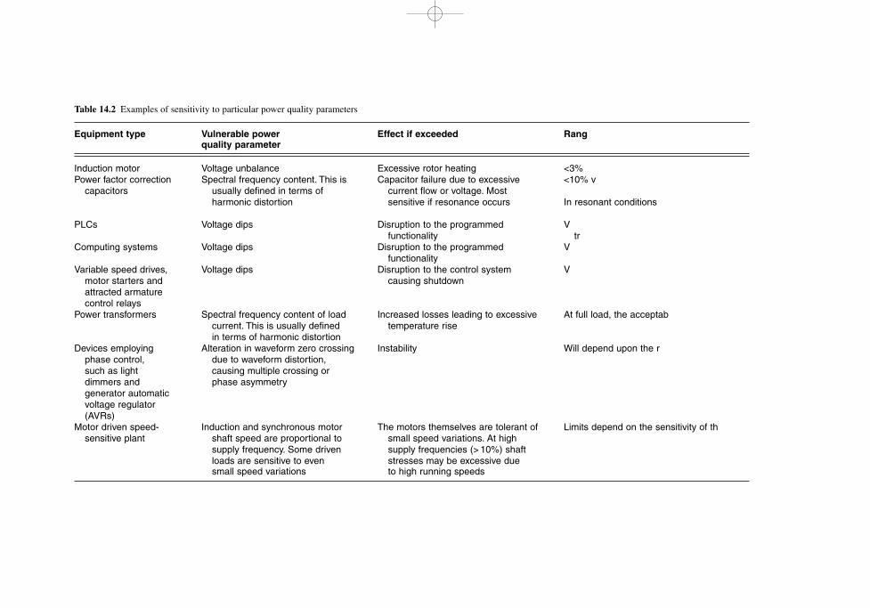
Table 14.2 Examples of sensitivity to particular power quality parameters
Equipment type Vulnerable power Effect if exceeded Rangquality parameter
Induction motor Voltage unbalance Excessive rotor heating <3%Power factor correction Spectral frequency content. This is Capacitor failure due to excessive <10% v
capacitors usually defined in terms of current flow or voltage. Most harmonic distortion sensitive if resonance occurs In resonant conditions
PLCs Voltage dips Disruption to the programmed Vfunctionality tr
Computing systems Voltage dips Disruption to the programmed Vfunctionality
Variable speed drives, Voltage dips Disruption to the control system Vmotor starters and causing shutdownattracted armature control relays
Power transformers Spectral frequency content of load Increased losses leading to excessive At full load, the acceptabcurrent. This is usually defined temperature risein terms of harmonic distortion
Devices employing Alteration in waveform zero crossing Instability Will depend upon the rphase control, due to waveform distortion,such as light causing multiple crossing or dimmers and phase asymmetrygenerator automaticvoltage regulator(AVRs)
Motor driven speed- Induction and synchronous motor The motors themselves are tolerant of Limits depend on the sensitivity of thsensitive plant shaft speed are proportional to small speed variations. At high
supply frequency. Some driven supply frequencies (> 10%) shaftloads are sensitive to even stresses may be excessive duesmall speed variations to high running speeds
However, very often this is a scapegoat when the actual cause cannot be identified.Even when correlation with switching voltage transients is correctly observed, thecoupling introduced by poor wiring installations or bad earth bonding practices can bethe real problem. Unlike the other power quality parameters, voltage transients have ahigh frequency content and will couple readily through stray capacitance and mutualinductance into neighbouring circuits. Coupling into closed conductor loops that inter-face with sensitive circuits such as screens and drain wires can easily lead to spuriousevents.
14.1.5 Common problems
14.1.5.1 Harmonic voltage and current distortion
Equipment which uses power electronic switching techniques to control intake poweris a common source of current distortion. Examples include variable speed drives,uninterruptible power supplies and switch mode power supplies. The dominant frequency components tend to be of low orders with 3rd, 5th ,7th, 11th and 13th beingcommon. The presence of these components in current and voltage waveforms intro-duces additional losses in the conductors and magnetic circuits of cables, transformers,motors and generators. The frequency components can also excite resonance in PowerFactor Correction (PFC) capacitors.
The following mitigating measures can be applied:
specification of frequency content in current loading and applied voltage onpurchase specifications
use of K-factor rated transformers use of detuned PFC banks use of double-rated neutrals (or higher) in systems with high 3rd harmonic
loading use of passive or active filters to reduce harmonic content
Voltage and current waveform distortion is also a consequence of distorting loads.Mitigating measures for waveform distortion include:
specification of waveform distortion tolerance requirements in purchase specifications
use of equipment which does not rely on phase measurement by point-on-wavesuch as zero-crossing detection
use of rms rather than peak sensing use of 3-phase rather than 1-phase sensing for devices such as AVRs use of permanent magnet generators with generator AVRs use of generators with 2/3 pitch windings to help minimize harmonic
impedance and thus minimize voltage distortion
Low frequency harmonic distortion is also often accompanied by high frequency non-harmonic components. These are produced by rapid switching and are a feature ofvirtually all power electronic systems. For this reason, it is important that earthing andbonding be applied in order to minimize impedance. Stranded conductors of largecross-sectional area installed with parallel paths in a mesh arrangement are examplesof good practice.
Newnes Electrical Power Engineer’s Handbook 395
14.1.5.2 Voltage dips
Voltage dip immunity in end-user equipment continues to be a major quality issue in Europe and is only gradually improving with the implementation of IEC and CENELEC standards. As a result, equipment malfunction due to transient voltage dipscontinues to lead to complaints about adverse power quality. In some regions ofEurope it may even be perceived that power quality is reducing due to lack of voltagedip immunity alone. The reality is more likely to be that such perception is influencedby an increase in the numbers of susceptible equipment, or changes in the applicationof equipment, despite the fact that dip immunity complies with present day EMCstandards. However, the IEC and CENELEC standards offer a framework for specifi-cation and testing that could eventually benefit both the electricity supply industry andend users.
The common cause of voltage dips is system faults within public electricity distri-bution networks. Severe voltage dips will also occur during fault clearance on end-userdistribution networks. Thus, although it is common to use circuit protection to isolateon-site faults, the widespread disturbing effect of the accompanying voltage dip isoften overlooked. References 14E and 14F discuss voltage mitigation measures someof which are briefly referred.
Mitigating measures to be applied are:
specification of dip-tolerant equipment at the time of purchase use of mitigation measures based on FACTS techniques, such as the Dynamic
Voltage Restorer (DVR). This can be applied at the PCC to support the supply voltage during network faults. It is expensive but can offer an effectivesolution.
use of constant-voltage transformers to improve voltage regulation without theneed for energy storage
application of battery, diesel rotary or flywheel storage to provide energy ride-through for critical plant
use of mechanically latched rather than electrically held relays and contactorson critical plant
14.1.6 Monitoring
Monitoring is essential when tackling equipment malfunction which is thought to be power quality related. It is also a good policy to benchmark the quality of any newsupply arrangements that support important business processes so that the relevance of power quality conditions, or changing conditions, can be assessed at a later time.There are a large number of power quality monitors available (reference 14G) and theirselection should target the particular power quality parameters of importance. It mustbe decided whether data logging is required, or a more simple detection of power qual-ity parameters that exceed predefined thresholds. Some monitors offer the opportunityto achieve both functions simultaneously and then to examine retrospectively withregard to thresholds or standards. Large data storage capability using hard disk drivesor static memory has made the monitoring activity much easier to apply but can leadto an enormous amount of data to inspect.
Power quality monitors are packaged in portable and fixed patterns. Fixed patternversions are becoming more common and offer the opportunity to collect data andobserve trends throughout the life of the installation. Permanently installed monitors
396 Power quality and EMC
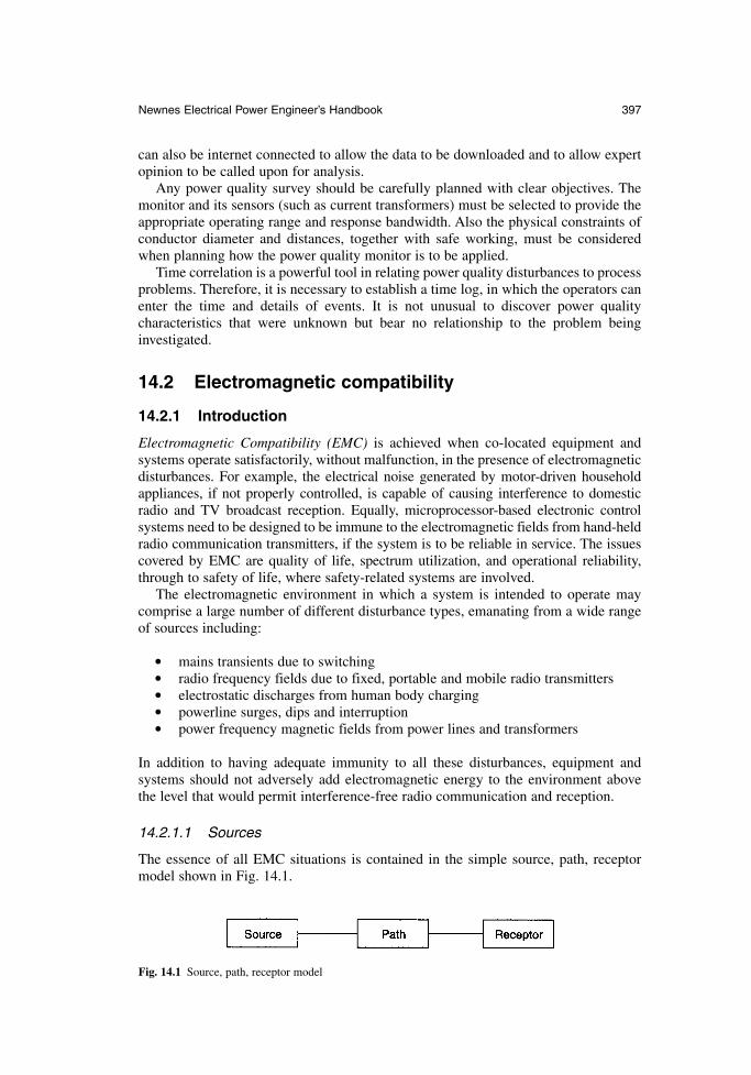
can also be internet connected to allow the data to be downloaded and to allow expertopinion to be called upon for analysis.
Any power quality survey should be carefully planned with clear objectives. Themonitor and its sensors (such as current transformers) must be selected to provide theappropriate operating range and response bandwidth. Also the physical constraints ofconductor diameter and distances, together with safe working, must be consideredwhen planning how the power quality monitor is to be applied.
Time correlation is a powerful tool in relating power quality disturbances to processproblems. Therefore, it is necessary to establish a time log, in which the operators canenter the time and details of events. It is not unusual to discover power quality characteristics that were unknown but bear no relationship to the problem being investigated.
14.2 Electromagnetic compatibility
14.2.1 Introduction
Electromagnetic Compatibility (EMC) is achieved when co-located equipment andsystems operate satisfactorily, without malfunction, in the presence of electromagneticdisturbances. For example, the electrical noise generated by motor-driven householdappliances, if not properly controlled, is capable of causing interference to domesticradio and TV broadcast reception. Equally, microprocessor-based electronic controlsystems need to be designed to be immune to the electromagnetic fields from hand-heldradio communication transmitters, if the system is to be reliable in service. The issuescovered by EMC are quality of life, spectrum utilization, and operational reliability,through to safety of life, where safety-related systems are involved.
The electromagnetic environment in which a system is intended to operate maycomprise a large number of different disturbance types, emanating from a wide rangeof sources including:
mains transients due to switching radio frequency fields due to fixed, portable and mobile radio transmitters electrostatic discharges from human body charging powerline surges, dips and interruption power frequency magnetic fields from power lines and transformers
In addition to having adequate immunity to all these disturbances, equipment andsystems should not adversely add electromagnetic energy to the environment above the level that would permit interference-free radio communication and reception.
14.2.1.1 Sources
The essence of all EMC situations is contained in the simple source, path, receptormodel shown in Fig. 14.1.
Newnes Electrical Power Engineer’s Handbook 397
Fig. 14.1 Source, path, receptor model
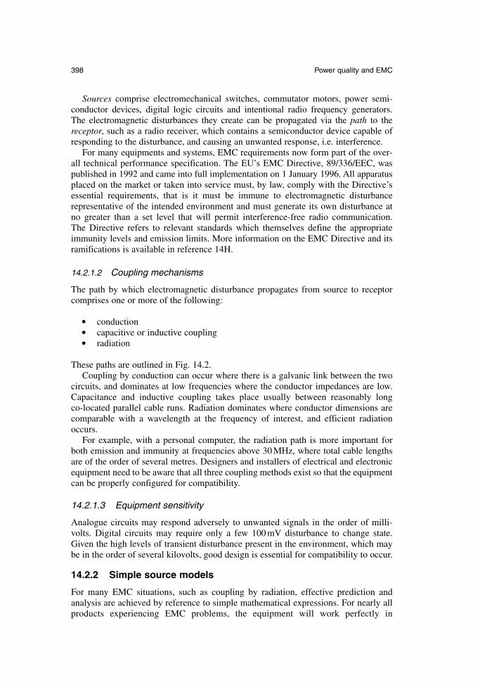
Sources comprise electromechanical switches, commutator motors, power semi-conductor devices, digital logic circuits and intentional radio frequency generators. The electromagnetic disturbances they create can be propagated via the path to thereceptor, such as a radio receiver, which contains a semiconductor device capable ofresponding to the disturbance, and causing an unwanted response, i.e. interference.
For many equipments and systems, EMC requirements now form part of the over-all technical performance specification. The EU’s EMC Directive, 89/336/EEC, waspublished in 1992 and came into full implementation on 1 January 1996. All apparatusplaced on the market or taken into service must, by law, comply with the Directive’sessential requirements, that is it must be immune to electromagnetic disturbancerepresentative of the intended environment and must generate its own disturbance at no greater than a set level that will permit interference-free radio communication. The Directive refers to relevant standards which themselves define the appropriateimmunity levels and emission limits. More information on the EMC Directive and itsramifications is available in reference 14H.
14.2.1.2 Coupling mechanisms
The path by which electromagnetic disturbance propagates from source to receptorcomprises one or more of the following:
conduction capacitive or inductive coupling radiation
These paths are outlined in Fig. 14.2.Coupling by conduction can occur where there is a galvanic link between the two
circuits, and dominates at low frequencies where the conductor impedances are low.Capacitance and inductive coupling takes place usually between reasonably long co-located parallel cable runs. Radiation dominates where conductor dimensions arecomparable with a wavelength at the frequency of interest, and efficient radiationoccurs.
For example, with a personal computer, the radiation path is more important forboth emission and immunity at frequencies above 30 MHz, where total cable lengthsare of the order of several metres. Designers and installers of electrical and electronicequipment need to be aware that all three coupling methods exist so that the equipmentcan be properly configured for compatibility.
14.2.1.3 Equipment sensitivity
Analogue circuits may respond adversely to unwanted signals in the order of milli-volts. Digital circuits may require only a few 100 mV disturbance to change state.Given the high levels of transient disturbance present in the environment, which maybe in the order of several kilovolts, good design is essential for compatibility to occur.
14.2.2 Simple source models
For many EMC situations, such as coupling by radiation, effective prediction andanalysis are achieved by reference to simple mathematical expressions. For nearly allproducts experiencing EMC problems, the equipment will work perfectly in
398 Power quality and EMC
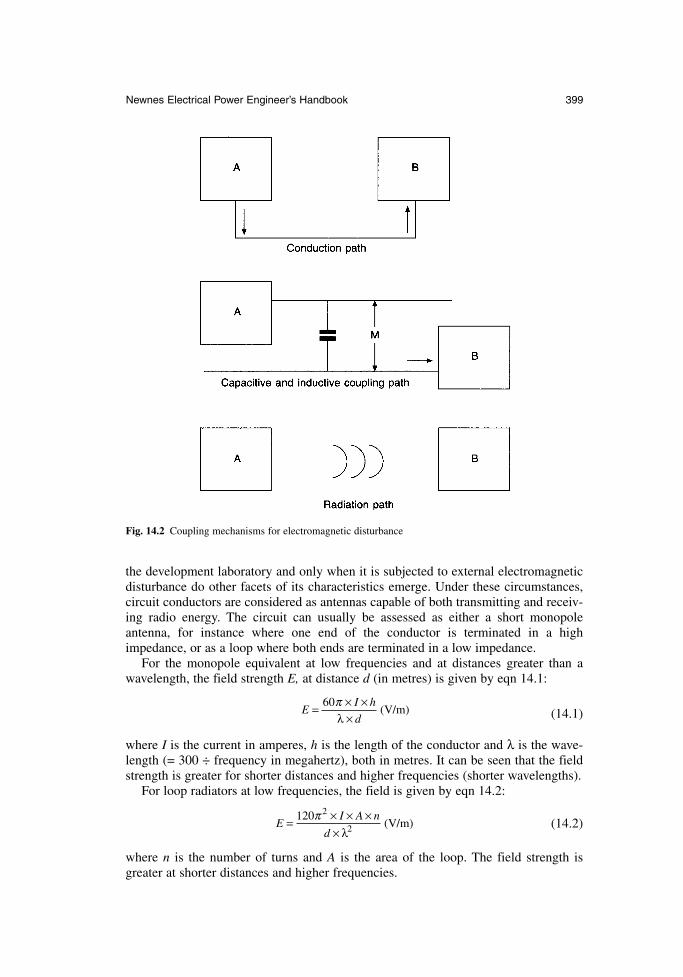
the development laboratory and only when it is subjected to external electromagneticdisturbance do other facets of its characteristics emerge. Under these circumstances,circuit conductors are considered as antennas capable of both transmitting and receiv-ing radio energy. The circuit can usually be assessed as either a short monopoleantenna, for instance where one end of the conductor is terminated in a high impedance, or as a loop where both ends are terminated in a low impedance.
For the monopole equivalent at low frequencies and at distances greater than awavelength, the field strength E, at distance d (in metres) is given by eqn 14.1:
(14.1)
where I is the current in amperes, h is the length of the conductor and λ is the wave-length (= 300 ÷ frequency in megahertz), both in metres. It can be seen that the fieldstrength is greater for shorter distances and higher frequencies (shorter wavelengths).
For loop radiators at low frequencies, the field is given by eqn 14.2:
(14.2)
where n is the number of turns and A is the area of the loop. The field strength isgreater at shorter distances and higher frequencies.
EI A n= × × ×
×120 2
2π
d λ(V m)/
EI h= × ×
×60π
λ d(V m)/
Newnes Electrical Power Engineer’s Handbook 399
Fig. 14.2 Coupling mechanisms for electromagnetic disturbance
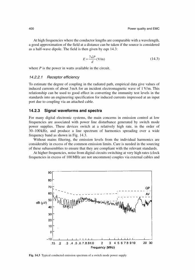
At high frequencies where the conductor lengths are comparable with a wavelength,a good approximation of the field at a distance can be taken if the source is consideredas a half-wave dipole. The field is then given by eqn 14.3:
(14.3)
where P is the power in watts available in the circuit.
14.2.2.1 Receptor efficiency
To estimate the degree of coupling in the radiated path, empirical data give values ofinduced currents of about 3mA for an incident electromagnetic wave of 1 V/m. Thisrelationship can be used to good effect in converting the immunity test levels in thestandards into an engineering specification for induced currents impressed at an inputport due to coupling via an attached cable.
14.2.3 Signal waveforms and spectra
For many digital electronic systems, the main concerns in emission control at low frequencies are associated with power line disturbance generated by switch modepower supplies. These devices switch at a relatively high rate, in the order of30–100kHz, and produce a line spectrum of harmonics spreading over a wide frequency band as shown in Fig. 14.3.
Without mains filtering, the emission levels from the individual harmonics are considerably in excess of the common emission limits. Care is needed in the sourcingof these subassemblies to ensure that they are compliant with the relevant standards.
At higher frequencies, noise from digital circuits switching at very high rates (clockfrequencies in excess of 100 MHz are not uncommon) couples via external cables and
EP
d= 7
( / )V m
400 Power quality and EMC
Fig. 14.3 Typical conducted emission spectrum of a switch mode power supply
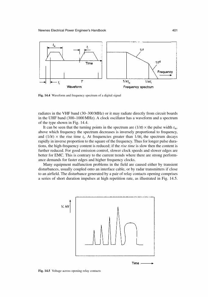
radiates in the VHF band (30–300 MHz) or it may radiate directly from circuit boardsin the UHF band (300–1000 MHz). A clock oscillator has a waveform and a spectrumof the type shown in Fig. 14.4.
It can be seen that the turning points in the spectrum are (1/π) × the pulse width tw,above which frequency the spectrum decreases is inversely proportional to frequency,and (1/π) × the rise time tr. At frequencies greater than 1/πtr the spectrum decaysrapidly in inverse proportion to the square of the frequency. Thus for longer pulse dura-tions, the high-frequency content is reduced; if the rise time is slow then the content isfurther reduced. For good emission control, slower clock speeds and slower edges arebetter for EMC. This is contrary to the current trends where there are strong perform-ance demands for faster edges and higher frequency clocks.
Many equipment malfunction problems in the field are caused either by transientdisturbances, usually coupled onto an interface cable, or by radar transmitters if closeto an airfield. The disturbance generated by a pair of relay contacts opening comprisesa series of short duration impulses at high repetition rate, as illustrated in Fig. 14.5.
Newnes Electrical Power Engineer’s Handbook 401
Fig. 14.4 Waveform and frequency spectrum of a digital signal
Fig. 14.5 Voltage across opening relay contacts
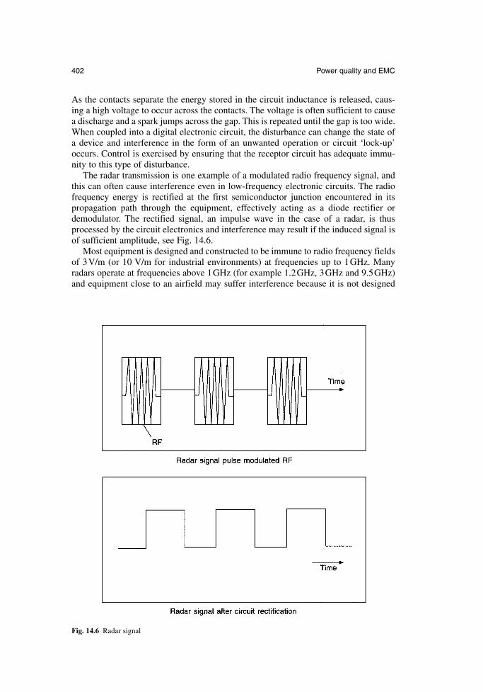
As the contacts separate the energy stored in the circuit inductance is released, caus-ing a high voltage to occur across the contacts. The voltage is often sufficient to causea discharge and a spark jumps across the gap. This is repeated until the gap is too wide.When coupled into a digital electronic circuit, the disturbance can change the state ofa device and interference in the form of an unwanted operation or circuit ‘lock-up’occurs. Control is exercised by ensuring that the receptor circuit has adequate immu-nity to this type of disturbance.
The radar transmission is one example of a modulated radio frequency signal, andthis can often cause interference even in low-frequency electronic circuits. The radiofrequency energy is rectified at the first semiconductor junction encountered in itspropagation path through the equipment, effectively acting as a diode rectifier ordemodulator. The rectified signal, an impulse wave in the case of a radar, is thusprocessed by the circuit electronics and interference may result if the induced signal isof sufficient amplitude, see Fig. 14.6.
Most equipment is designed and constructed to be immune to radio frequency fieldsof 3V/m (or 10 V/m for industrial environments) at frequencies up to 1GHz. Manyradars operate at frequencies above 1GHz (for example 1.2GHz, 3GHz and 9.5GHz)and equipment close to an airfield may suffer interference because it is not designed
402 Power quality and EMC
Fig. 14.6 Radar signal
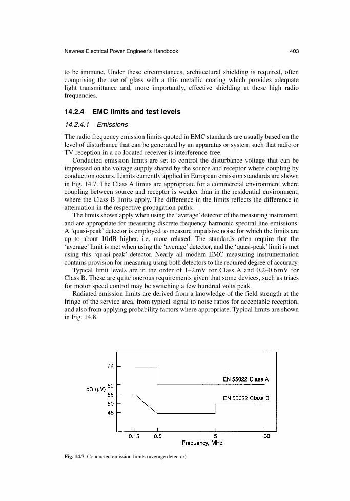
to be immune. Under these circumstances, architectural shielding is required, often comprising the use of glass with a thin metallic coating which provides adequate light transmittance and, more importantly, effective shielding at these high radio frequencies.
14.2.4 EMC limits and test levels
14.2.4.1 Emissions
The radio frequency emission limits quoted in EMC standards are usually based on thelevel of disturbance that can be generated by an apparatus or system such that radio orTV reception in a co-located receiver is interference-free.
Conducted emission limits are set to control the disturbance voltage that can beimpressed on the voltage supply shared by the source and receptor where coupling byconduction occurs. Limits currently applied in European emission standards are shownin Fig. 14.7. The Class A limits are appropriate for a commercial environment wherecoupling between source and receptor is weaker than in the residential environment,where the Class B limits apply. The difference in the limits reflects the difference inattenuation in the respective propagation paths.
The limits shown apply when using the ‘average’detector of the measuring instrument,and are appropriate for measuring discrete frequency harmonic spectral line emissions. A ‘quasi-peak’ detector is employed to measure impulsive noise for which the limits areup to about 10dB higher, i.e. more relaxed. The standards often require that the ‘average’ limit is met when using the ‘average’ detector, and the ‘quasi-peak’ limit is metusing this ‘quasi-peak’ detector. Nearly all modern EMC measuring instrumentationcontains provision for measuring using both detectors to the required degree of accuracy.
Typical limit levels are in the order of 1–2 mV for Class A and 0.2–0.6 mV for Class B. These are quite onerous requirements given that some devices, such as triacsfor motor speed control may be switching a few hundred volts peak.
Radiated emission limits are derived from a knowledge of the field strength at thefringe of the service area, from typical signal to noise ratios for acceptable reception,and also from applying probability factors where appropriate. Typical limits are shownin Fig. 14.8.
Newnes Electrical Power Engineer’s Handbook 403
Fig. 14.7 Conducted emission limits (average detector)
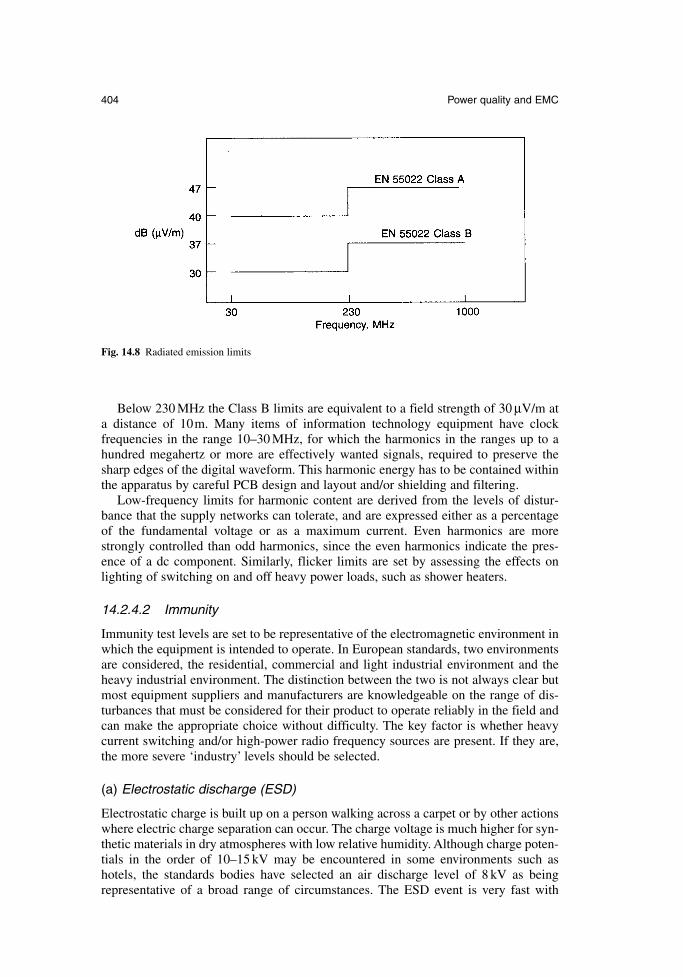
Below 230 MHz the Class B limits are equivalent to a field strength of 30 µV/m at a distance of 10m. Many items of information technology equipment have clock frequencies in the range 10–30 MHz, for which the harmonics in the ranges up to ahundred megahertz or more are effectively wanted signals, required to preserve thesharp edges of the digital waveform. This harmonic energy has to be contained withinthe apparatus by careful PCB design and layout and/or shielding and filtering.
Low-frequency limits for harmonic content are derived from the levels of distur-bance that the supply networks can tolerate, and are expressed either as a percentageof the fundamental voltage or as a maximum current. Even harmonics are morestrongly controlled than odd harmonics, since the even harmonics indicate the pres-ence of a dc component. Similarly, flicker limits are set by assessing the effects onlighting of switching on and off heavy power loads, such as shower heaters.
14.2.4.2 Immunity
Immunity test levels are set to be representative of the electromagnetic environment inwhich the equipment is intended to operate. In European standards, two environmentsare considered, the residential, commercial and light industrial environment and theheavy industrial environment. The distinction between the two is not always clear butmost equipment suppliers and manufacturers are knowledgeable on the range of dis-turbances that must be considered for their product to operate reliably in the field andcan make the appropriate choice without difficulty. The key factor is whether heavycurrent switching and/or high-power radio frequency sources are present. If they are,the more severe ‘industry’ levels should be selected.
(a) Electrostatic discharge (ESD)
Electrostatic charge is built up on a person walking across a carpet or by other actionswhere electric charge separation can occur. The charge voltage is much higher for syn-thetic materials in dry atmospheres with low relative humidity. Although charge poten-tials in the order of 10–15 kV may be encountered in some environments such ashotels, the standards bodies have selected an air discharge level of 8 kV as beingrepresentative of a broad range of circumstances. The ESD event is very fast with
404 Power quality and EMC
Fig. 14.8 Radiated emission limits
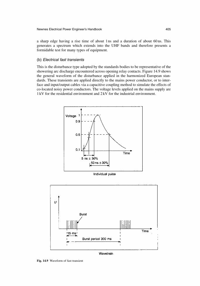
a sharp edge having a rise time of about 1ns and a duration of about 60 ns. Thisgenerates a spectrum which extends into the UHF bands and therefore presents aformidable test for many types of equipment.
(b) Electrical fast transients
This is the disturbance type adopted by the standards bodies to be representative of theshowering arc discharge encountered across opening relay contacts. Figure 14.9 showsthe general waveform of the disturbance applied in the harmonized European stan-dards. These transients are applied directly to the mains power conductor, or to inter-face and input/output cables via a capacitive coupling method to simulate the effects ofco-located noisy power conductors. The voltage levels applied on the mains supply are1 kV for the residential environment and 2 kV for the industrial environment.
Newnes Electrical Power Engineer’s Handbook 405
Fig. 14.9 Waveform of fast transient
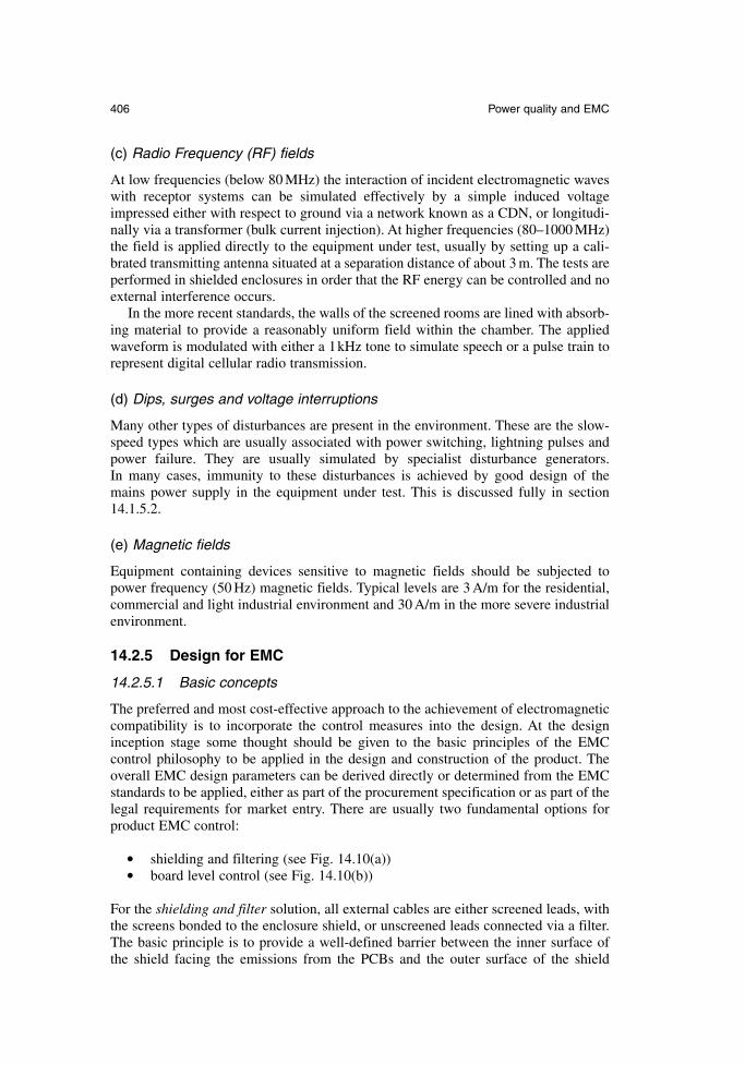
(c) Radio Frequency (RF) fields
At low frequencies (below 80 MHz) the interaction of incident electromagnetic waveswith receptor systems can be simulated effectively by a simple induced voltageimpressed either with respect to ground via a network known as a CDN, or longitudi-nally via a transformer (bulk current injection). At higher frequencies (80–1000 MHz)the field is applied directly to the equipment under test, usually by setting up a cali-brated transmitting antenna situated at a separation distance of about 3 m. The tests areperformed in shielded enclosures in order that the RF energy can be controlled and noexternal interference occurs.
In the more recent standards, the walls of the screened rooms are lined with absorb-ing material to provide a reasonably uniform field within the chamber. The appliedwaveform is modulated with either a 1kHz tone to simulate speech or a pulse train torepresent digital cellular radio transmission.
(d) Dips, surges and voltage interruptions
Many other types of disturbances are present in the environment. These are the slow-speed types which are usually associated with power switching, lightning pulses andpower failure. They are usually simulated by specialist disturbance generators. In many cases, immunity to these disturbances is achieved by good design of the mains power supply in the equipment under test. This is discussed fully in section14.1.5.2.
(e) Magnetic fields
Equipment containing devices sensitive to magnetic fields should be subjected topower frequency (50 Hz) magnetic fields. Typical levels are 3 A/m for the residential,commercial and light industrial environment and 30 A/m in the more severe industrialenvironment.
14.2.5 Design for EMC
14.2.5.1 Basic concepts
The preferred and most cost-effective approach to the achievement of electromagneticcompatibility is to incorporate the control measures into the design. At the designinception stage some thought should be given to the basic principles of the EMC control philosophy to be applied in the design and construction of the product. Theoverall EMC design parameters can be derived directly or determined from the EMCstandards to be applied, either as part of the procurement specification or as part of thelegal requirements for market entry. There are usually two fundamental options forproduct EMC control:
shielding and filtering (see Fig. 14.10(a)) board level control (see Fig. 14.10(b))
For the shielding and filter solution, all external cables are either screened leads, withthe screens bonded to the enclosure shield, or unscreened leads connected via a filter.The basic principle is to provide a well-defined barrier between the inner surface of the shield facing the emissions from the PCBs and the outer surface of the shield
406 Power quality and EMC
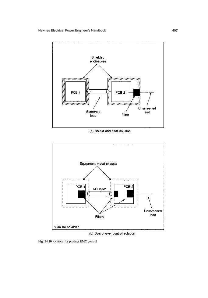
Newnes Electrical Power Engineer’s Handbook 407
Fig. 14.10 Options for product EMC control

interacting with the external environment. This solution requires the use of a metal ormetal-coated enclosure. Where this is not possible, or not preferred, then the boardlevel control option is appropriate, where the PCB design and layout provides inher-ent barriers to the transfer of electromagnetic energy. Filters are required at all thecable interfaces, except where an effective screened interface can be utilized.
14.2.5.2 Shielding
For design purposes, effective shielding of about 30–40dB can be provided at highfrequencies by relatively thin metal sheets or metal coatings on plastic. The maxi-mum shielding achievable is associated with the apertures, slots and discontinuities in the surface of the shield enclosure. These may be excited by electromagnetic energy and can resonate where their physical length is comparable with a wavelength,significantly degrading the performance of the shield. The following basic rules apply:
the maximum length of a slot should be no greater than 1/40 of the wavelengthat the highest frequency of concern
a large number of small holes in the shield gives better performance than asmall number of large holes
the number of points of contact between two mating halves of an enclosureshould be maximized
mains or signal line filters should be bonded to the enclosure at the point ofentry of the cable
14.2.5.3 Cable screens termination
For maximum performance, cable shields should be terminated at both ends with a 360° peripheral (i.e. glanded) bond. This is not always possible and in some cases it is undesirable because of the associated ground loop problem (Fig. 14.11). Noisecurrents, I, in the ground generate a voltage V between the two circuits A and B whichcan drive a high current on the outer surface of the interconnecting screen, thuspermitting energy to be coupled into the internal system conductors.
In many applications involving the use of long conductors in noisy environments, thesimplest solution is to break the ground loop by bonding the screen at one end only, asshown in Fig. 14.12. Here the ground noise voltage is eliminated but the shield protectsonly against electric fields and capacitive coupling. Additional or alternative measures,such as opto-isolation are required if intense magnetic fields are present.
14.2.5.4 PCB design and layout
Control at board level can be achieved by a careful design of the board involvingdevice selection and track layout. As discussed in section 14.2.2, emissions from thePCB tracks may be reduced at high frequencies if the devices are chosen to have slowswitching rates and slow transition (i.e. long rise and fall) times.
Device selection can also improve immunity by bandwidth control. The smaller thebandwidth, the less likely it is that high-frequency disturbances will be encounteredwithin the pass-band of the circuit. Although rectification of the disturbance may occur in the out-of-band region, the conversion process is more inefficient and higherimmunity usually results.
408 Power quality and EMC
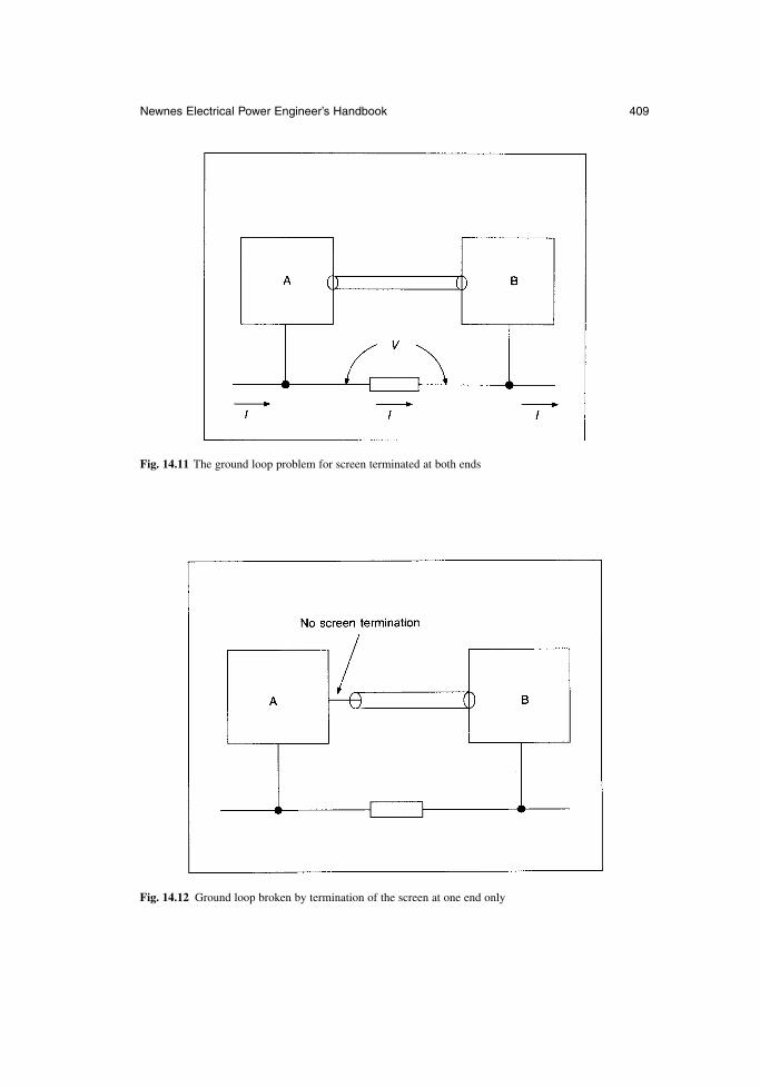
Newnes Electrical Power Engineer’s Handbook 409
Fig. 14.11 The ground loop problem for screen terminated at both ends
Fig. 14.12 Ground loop broken by termination of the screen at one end only
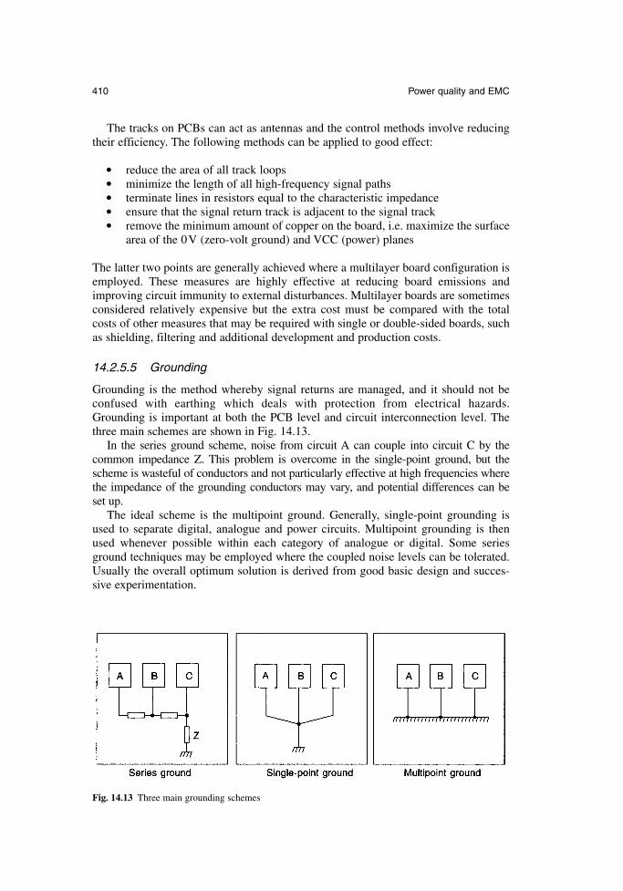
The tracks on PCBs can act as antennas and the control methods involve reducingtheir efficiency. The following methods can be applied to good effect:
reduce the area of all track loops minimize the length of all high-frequency signal paths terminate lines in resistors equal to the characteristic impedance ensure that the signal return track is adjacent to the signal track remove the minimum amount of copper on the board, i.e. maximize the surface
area of the 0V (zero-volt ground) and VCC (power) planes
The latter two points are generally achieved where a multilayer board configuration isemployed. These measures are highly effective at reducing board emissions andimproving circuit immunity to external disturbances. Multilayer boards are sometimesconsidered relatively expensive but the extra cost must be compared with the totalcosts of other measures that may be required with single or double-sided boards, suchas shielding, filtering and additional development and production costs.
14.2.5.5 Grounding
Grounding is the method whereby signal returns are managed, and it should not beconfused with earthing which deals with protection from electrical hazards.Grounding is important at both the PCB level and circuit interconnection level. Thethree main schemes are shown in Fig. 14.13.
In the series ground scheme, noise from circuit A can couple into circuit C by thecommon impedance Z. This problem is overcome in the single-point ground, but thescheme is wasteful of conductors and not particularly effective at high frequencies wherethe impedance of the grounding conductors may vary, and potential differences can be set up.
The ideal scheme is the multipoint ground. Generally, single-point grounding isused to separate digital, analogue and power circuits. Multipoint grounding is thenused whenever possible within each category of analogue or digital. Some seriesground techniques may be employed where the coupled noise levels can be tolerated.Usually the overall optimum solution is derived from good basic design and succes-sive experimentation.
410 Power quality and EMC
Fig. 14.13 Three main grounding schemes
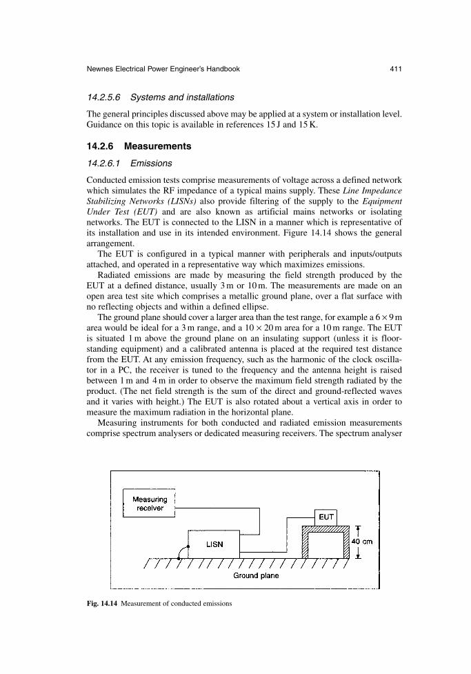
14.2.5.6 Systems and installations
The general principles discussed above may be applied at a system or installation level.Guidance on this topic is available in references 15 J and 15 K.
14.2.6 Measurements
14.2.6.1 Emissions
Conducted emission tests comprise measurements of voltage across a defined networkwhich simulates the RF impedance of a typical mains supply. These Line ImpedanceStabilizing Networks (LISNs) also provide filtering of the supply to the EquipmentUnder Test (EUT) and are also known as artificial mains networks or isolatingnetworks. The EUT is connected to the LISN in a manner which is representative ofits installation and use in its intended environment. Figure 14.14 shows the generalarrangement.
The EUT is configured in a typical manner with peripherals and inputs/outputsattached, and operated in a representative way which maximizes emissions.
Radiated emissions are made by measuring the field strength produced by theEUT at a defined distance, usually 3 m or 10 m. The measurements are made on anopen area test site which comprises a metallic ground plane, over a flat surface withno reflecting objects and within a defined ellipse.
The ground plane should cover a larger area than the test range, for example a 6 × 9 marea would be ideal for a 3 m range, and a 10 × 20 m area for a 10 m range. The EUTis situated 1 m above the ground plane on an insulating support (unless it is floor-standing equipment) and a calibrated antenna is placed at the required test distancefrom the EUT. At any emission frequency, such as the harmonic of the clock oscilla-tor in a PC, the receiver is tuned to the frequency and the antenna height is raisedbetween 1 m and 4 m in order to observe the maximum field strength radiated by theproduct. (The net field strength is the sum of the direct and ground-reflected waves and it varies with height.) The EUT is also rotated about a vertical axis in order tomeasure the maximum radiation in the horizontal plane.
Measuring instruments for both conducted and radiated emission measurementscomprise spectrum analysers or dedicated measuring receivers. The spectrum analyser
Newnes Electrical Power Engineer’s Handbook 411
Fig. 14.14 Measurement of conducted emissions
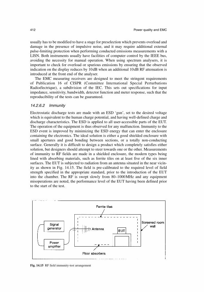
usually has to be modified to have a stage for preselection which prevents overload anddamage in the presence of impulsive noise, and it may require additional externalpulse-limiting protection when performing conducted emissions measurements with aLISN. Both instruments usually have facilities of computer control by the IEEE bus,avoiding the necessity for manual operation. When using spectrum analysers, it isimportant to check for overload or spurious emissions by ensuring that the observedindication on the display reduces by 10dB when an additional 10dB RF attenuation isintroduced at the front end of the analyser.
The EMC measuring receivers are designed to meet the stringent requirements of Publication 16 of CISPR (Committee International Special PerturbationsRadioélectrique), a subdivision of the IEC. This sets out specifications for inputimpedance, sensitivity, bandwidth, detector function and meter response, such that thereproducibility of the tests can be guaranteed.
14.2.6.2 Immunity
Electrostatic discharge tests are made with an ESD ‘gun’, set to the desired voltagewhich is equivalent to the human charge potential, and having well-defined charge anddischarge characteristics. The ESD is applied to all user-accessible parts of the EUT.The operation of the equipment is thus observed for any malfunction. Immunity to theESD event is improved by minimizing the ESD energy that can enter the enclosurecontaining the electronics. The ideal solution is either a good shielded enclosure withsmall apertures and good bonding between sections, or a totally non-conducting surface. Generally it is difficult to design a product which completely satisfies eithersolution, but designers should attempt to steer towards one or the other. Measurementsof immunity to RF fields are made in a shielded enclosure, the modern types beinglined with absorbing materials, such as ferrite tiles on at least five of the six inner surfaces. The EUT is subjected to radiation from an antenna situated in the near vicin-ity as shown in Fig. 14.15. The field is pre-calibrated to the required level of fieldstrength specified in the appropriate standard, prior to the introduction of the EUT into the chamber. The RF is swept slowly from 80–1000MHz and any equipmentmisoperations are noted, the performance level of the EUT having been defined priorto the start of the test.
412 Power quality and EMC
Fig. 14.15 RF field immunity-test arrangement
Transients, surges, dips and interruptions tests are performed with dedicated testinstrumentation which fully satisfies the requirements of the relevant standards.Generally the tests are much quicker to perform than the RF field test, and informationon the EMC performance of the EUT can be gathered rapidly.
For ESD tests and fast transient tests, the equipment should carry on working afterthe application of the disturbance without any loss of data. For the RF field test, thereshould be no loss of performance outside that specified by the manufacturer at any timeduring the test. For dips and surges etc. provided the equipment works satisfactorily,after a manual reset, it will be deemed to have passed the test.
14.3 Standards
The three types of EMC standards in current use in Europe are basic standards, genericstandards and product-specific standards. Basic standards contain the test methods andtest levels at limits but do not specify a product type. Product standards contain com-prehensive details on how the product should be configured and operated during thetest and what parameters should be observed. Generic standards apply in the absenceof a product standard and are relevant to all products which may be operated within adefined environment. Both product standards and generic standards may refer to basicstandards for their test methods. The important standards in current use in Europe arelisted. Those listed in section 14.3.1 and 14.3.2 which are applicable to a particularproduct or system may be applied by the manufacturer to demonstrate compliancewith the EMC Directive.
14.3.1 Generic standards
EN 61000-6-3: Emissions: residential, commercial and light industrial environmentEN 61000-6-4: Emissions: industry environmentEN 61000-6-1: Immunity: residential, commercial and light industrial environmentEN 61000-6-2: Immunity: industrial environment
14.3.2 Important product standards
EN 50011: Emissions: industrial, scientific and medical equipmentEN 50013: Emissions: radio and TV equipmentEN 55020: Immunity: radio and TV equipmentEN 50014-1: Emissions: household appliances and portable toolsEN 55014-2: Immunity: household appliancesEN 50015: Emissions: lighting equipmentEN 61547: Immunity: lighting equipmentEN 50022: Emissions: information technology equipmentEN 55024: Immunity: information technology equipmentEN 50091-2: Uninterruptable Power Supplies (UPS)EN 55103: Professional audio and video equipmentEN 60947: Low-voltage switchgear and controlgearEN 61131-2: Programmable controllersEN 61326: Measurement and control instrumentsEN 61800-3: Electrical power drivesOther product standards are emerging at a high rate which will mean that reliance ongeneric standards will diminish significantly in the future.
Newnes Electrical Power Engineer’s Handbook 413
14.3.3 Basic standards
EN 61000-3-2: Emissions: mains harmonic currentEN 61000-3-3: Emissions: voltage fluctuation and flickerEN 61000-4-2: Immunity: ESDEN 61000-4-3: Immunity: RF fieldsEN 61000-4-4: Immunity: fast transientsEN 61000-4-5: Immunity: surgesEN 61000-4-6: Immunity: conducted RF voltagesEN 61000-4-8: Immunity: magnetic fieldsEN 61000-4-11: Immunity: dips and interruptions
References
14A. Engineering recommendation G5/4. Limits for Harmonics in the United KingdomElectricity Supply System: Electricity Association.
14B. ETR 122 Guide to the application of engineering recommendation G5/44 in theassessment of harmonic voltage distortion and connection of non-linear equipment tothe electricity supply system in the UK; Electricity Association; 2002.
14C. EN50160. Voltage characteristics of electricity supplied by public distribution systems,CENELEC, 2000.
14D. IEC 61000-2-2, Compatibility levels for low-frequency conducted disturbances andsignalling in public low-voltage power supply systems; 2002.
14E. McDowell, G.W.A. Protective measures against transient voltage depressions.Protecting Electrical Networks and Quality of Supply in a De-Regulated IndustryLeatherhead, UK: ERA Technology, 1995. p. 8 (Conference: London, UK, 15–16February 1995).
14F. Greig, E. How to improve voltage dip immunity in industrial and commercial powerdistribution systems. ERA Report 99-0632R, ERA Technology Ltd, 1999.
14G. Lam, D. A review of power quality monitors. ERA Report 2002-0213, ERA TechnologyLtd, 2002.
14H. Marshman, C. The Guide to the EMC Directive 89/336/EEC, EPA Press, 1992, ISBN 095 173623X, 308 pp.
14I. Maddocks, A.J., Duerr, J.H. and Hicks, G.P. Designing for ElectromagneticCompatibility: A Practical Guide, ERA Report 95-0030, ERA Technology Ltd, 1995,ISBN 0700805842, 147 pp.
14J. Goedbloed, J. Electromagnetic Compatibility, Prentice Hall, 1992. ISBN 0132492938,400 pp.
14K. Ott, H.W. Noise Reduction Techniques in Electronic Systems (2nd edn). John Wiley,USA, 1988, ISBN 0471850683, 426 pp.
14L. Paul, C. Electromagnetic Compatibility. John Wiley, USA, 1988, ISBN 0471850683, 426 pp.
414 Power quality and EMC
Chapter 15
Electricity and potentially explosive atmospheres
G. TortoishellAssociate ConsultantSira Safety Compliance
15.1 Introduction
UK legislation has contained requirements for electrical installations in adverse envi-ronments in the Electricity Regulations of the Factories Act since 1908. Over the yearsthese have been given more detail as legislation has been updated. Potentially explo-sive atmospheres, otherwise known as hazardous areas or flammable atmospheres,have been given particular emphasis because of the possible major consequences ofinadvertent ignition. The disasters at Flixborough and Abbeystead are examples of themany incidents which have occurred, and continue to occur, worldwide. There havebeen significant changes to the UK legislation in recent years, largely as a result of EU directives dealing with the safety and health of workers. This chapter concentrateson the specific problem of potentially explosive atmospheres, the legal requirementsand the practices for meeting them.
15.2 EU directives
The two EU directives dealing specifically with potentially explosive atmospheres are1999/92/EC (reference 15A), which deals with the safety and health of workersexposed to potentially explosive atmospheres, and 94/9/EC (reference 15B), whichcovers the equipment for use in such atmospheres. The Chemical Agents 98/24/ECDirective (reference 15C) is also relevant as it contains requirements for flammablematerials.
Directive 1999/92/EC covers the assessment of explosion risks, technical measuresfor explosion protection, organizational measures for explosion protection, coordina-tion duties and explosion protection documentation.
Directive 94/9/EC covers the certification process for hazardous area equipmentand the role of Notified Bodies. It contains Essential Health and Safety Requirements(EHSRs) for the equipment and is intended to allow equipment to cross EU boundarieswithout discrimination on the grounds of safety. It requires CE marking of equipment,unlike earlier directives for hazardous area equipment, which signifies that the equip-ment complies with all relevant directives and it covers all equipment intended for usein hazardous areas. Directive 94/9/EC is a ‘New Style’ directive which, with the intro-duction of the EHSRs, does not require replacement as equipment standards change.
These directives are usually referred to as the ATmosphere EXplosible (ATEX) 137and 100a Directives respectively. Equipment Categories were introduced in the ATEX
100a directive and the corresponding zones of use (see section 15.4) are defined in the ATEX 137 directive.
15.3 UK legislation
The ATEX 137 Directive, along with the parts of the Chemical Agents Directive deal-ing with fire and explosion, were enacted into UK law as the Dangerous Substancesand Explosive Atmosphere Regulations 2002 (DSEAR) (reference 15D), and both theATEX 137 Directive and DSEAR came into force on 1 July 2003. Workplaces whichwere already in use on this date have until 1 July 2006 to comply. A key feature ofDSEAR is area classification, which zones workplaces according to the probability ofa potentially explosive atmosphere being present. The Health and Safety Executive havepublished Codes of Practice (references 15E to 15J) giving guidance on compliancewith DSEAR.
The ATEX 100a Directive was enacted into UK law as the Equipment and ProtectiveSystems Intended for Use in Potentially Explosive Atmospheres Regulations 1996(EPS) (reference 15K). They came into force on 1 July 2003 and compliance wasoptional during the transitional phase between 1996 and 2003. Although DSEAR speci-fies the use of equipment complying with the EPS regulations, there is no requirementto change equipment in workplaces which were already in use on 1 July 2003.
DSEAR is directed at employers and the EPS regulations are directed at equipmentmanufacturers. The link between them is in DSEAR, where the categories of equip-ment defined in the EPS regulations are allocated to the various zones defined inDSEAR.
15.4 Area classification
Area classification defines hazardous areas on the basis of the probability of a flammableatmosphere being present. It is a legal requirement under DSEAR for any employerwhose business involves flammable materials in any form, and it results in the divisionof the workplace into one or more zones. The levels of probability used in area classi-fication are high, medium and low. Historically, dust and gas or vapour were dealt withseparately which is reflected in different nomenclature for their zoning. Zones 0, 1 and2 are for gas, vapour and mist; zones 20, 21 and 22 are for dust. The definitions for gasor vapour zones and dust zones are very similar and are paraphrased here for simplicity:
Zone 0, Zone 20 – High probability (A flammable atmosphere is present continuously, for long periods or frequently)
Zone 1, Zone 21 – Medium probability (A flammable atmosphere is likely innormal operation occasionally)
Zone 2, Zone 22 – Low probability (A flammable atmosphere is unlikely innormal operation and, if it occurs, will exist only for a short time)
The zones do not reflect the ignition properties of the flammable materials; this is dealtwith separately by their ignition characteristics. It should also be noted that the zonesdescribe ‘atmospheres’, which are mixtures of flammable material with air underatmospheric conditions. Any other situations are not part of area classification butrequire consideration as part of the overall safety case for the workplace.
‘Normal operation’ is considered to be the actual, day-to-day operation of the workplace. It is not the idealized operation of the workplace as it was designed, and
416 Electricity and potentially explosive atmospheres
the area classification has to be reviewed regularly to accommodate any changes to theworkplace and the work therein. ‘Not likely in normal operation’ raises the question of how unlikely an event does area classification consider. This is best illustrated byconsidering a pipeline with flanged joints carrying a flammable gas. For a properlydesigned, constructed and maintained pipeline, fracture of the pipeline would not beconsidered; this is considered as a catastrophic failure and dealt with by the overall riskassessment. Leakage at a flanged piping joint would, however, be considered.
There are circumstances where area classification is not appropriate and these willbe revealed by the overall risk assessment. For example, small quantities of flammablematerials in the workplace may represent such a small risk to workers that other controlmeasures may suffice.
15.4.1 Codes of practice for area classification
Codes of practice for area classification usually recommend that area classification is carried out by a team which includes the electrical/control function. Electrical engineers working in industries within the scope of DSEAR should, therefore, havesome familiarity with the process of area classification and its meaning. The codes of practice fall into three broad categories; those which deal with principles, those dealing with industry sectors and those covering specific companies, installations orflammable materials. There are too many codes of practice to include in an exhaustivelist but the more common ones are mentioned here. Dealing with area classificationprinciples are BS EN 60079-10:2003 (reference 15L) for gases and vapours, and BS EN 50281-3:2002 (reference 15M) for combustible dust. One of the most commonindustry codes of practice is the Institute of Petroleum Code (reference 15N) whichcovers gases, vapours and mists. Specific codes of practice include IGE/SR/25 (refer-ence 15O) for natural gas installations and various codes of practice and guidance fromthe British Compressed Gases Association covering the storage, handling and use ofcompressed gases in transportable cylinders.
The process of area classification includes the following:
A. Identify all materials which are capable of forming a potentially explosiveatmosphere in the conditions of use, including both normal and abnormalprocess conditions
B. Identify the actual and potential sources of release of those materialsC. Grade the sources of release according to the probability of the release forming
a potentially explosive atmosphere (see Table 15.1)D. Consider the effect of ventilation on the releases to determine the resulting
zones and their extents (see Table 15.2)E. Document the results in a report and produce area classification drawings (see
Fig. 15.1)
Newnes Electrical Power Engineer’s Handbook 417
Table 15.1 Grading sources of release
Continuous grade release A release which is continuous or is expected to occur frequentlyor for long periods
Primary grade release A release which can be expected to occur periodically or occasionally during normal operation
Secondary grade release A release which is not expected to occur in normal operation and, if it does occur, is likely to do so only infrequently and forshort periods
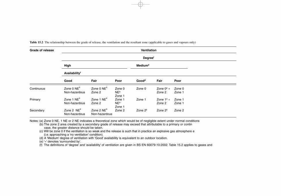
Table 15.2 The relationship between the grade of release, the ventilation and the resultant zone (applicable to gases and vapours only)
Grade of release Ventilation
Degreef
High Mediumd
Availabilityf
Good Fair Poor Goodd Fair Poor
Continuous Zone 0 NEa
Zone 0 NEa
Zone 0 Zone 0 Zone 0e + Zone 0Non-hazardous Zone 2 NEa Zone 2 Zone 1
Zone 1Primary Zone 1 NE
aZone 1 NE
aZone 1 Zone 1 Zone 1e + Zone 1
Non-hazardous Zone 2 NEa Zone 2 Zone 1Zone 1
Secondary Zone 2 NEa
Zone 2 NEa
Zone 2 Zone 2b Zone 2b Zone 2Non-hazardous Non-hazardous
Notes: (a) Zone 0 NE, 1 NE or 2 NE indicates a theoretical zone which would be of negligible extent under normal conditions(b) The zone 2 area created by a secondary grade of release may exceed that attributable to a primary or contin
case, the greater distance should be taken.(c) Will be zone 0 if the ventilation is so weak and the release is such that in practice an explosive gas atmosphere e
(i.e. approaching a ‘no ventilation’ condition).(d) A ‘Medium’ degree of ventilation with ‘Good’ availability is equivalent to an outdoor location.(e) ‘+’ denotes ‘surrounded by’.(f) The definitions of ‘degree’ and ‘availability’ of ventilation are given in BS EN 60079-10:2002. Table 15.2 applies to gases and
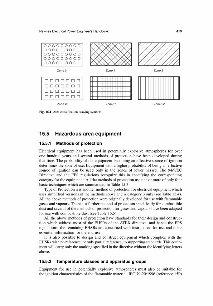
Newnes Electrical Power Engineer’s Handbook 419
Zone 0 Zone 1 Zone 2
Zone 20 Zone 21 Zone 22
Fig. 15.1 Area classification drawing symbols
15.5 Hazardous area equipment
15.5.1 Methods of protection
Electrical equipment has been used in potentially explosive atmospheres for over one hundred years and several methods of protection have been developed during that time. The probability of the equipment becoming an effective source of ignitiondetermines the zone of use. Equipment with a higher probability of being an effectivesource of ignition can be used only in the zones of lower hazard. The 94/9/ECDirective and the EPS regulations recognize this in specifying the corresponding category for the equipment. All the methods of protection use one or more of only fourbasic techniques which are summarized in Table 15.3.
Type of Protection n is another method of protection for electrical equipment whichuses simplified versions of the methods above and is category 3 only (see Table 15.4).All the above methods of protection were originally developed for use with flammablegases and vapours. There is a further method of protection specifically for combustibledust and several of the methods of protection for gases and vapours have been adaptedfor use with combustible dust (see Table 15.5).
All the above methods of protection have standards for their design and construc-tion which address most of the EHSRs of the ATEX directive, and hence the EPS regulations; the remaining EHSRs are concerned with instructions for use and otheressential information for the end-user.
It is also possible to design and construct equipment which complies with theEHSRs with no reference, or only partial reference, to supporting standards. This equip-ment will carry only the marking specified in the directive without the identifying lettersabove.
15.5.2 Temperature classes and apparatus groups
Equipment for use in potentially explosive atmospheres must also be suitable for the ignition characteristics of the flammable material. IEC 79-20:1996 (reference 15P)
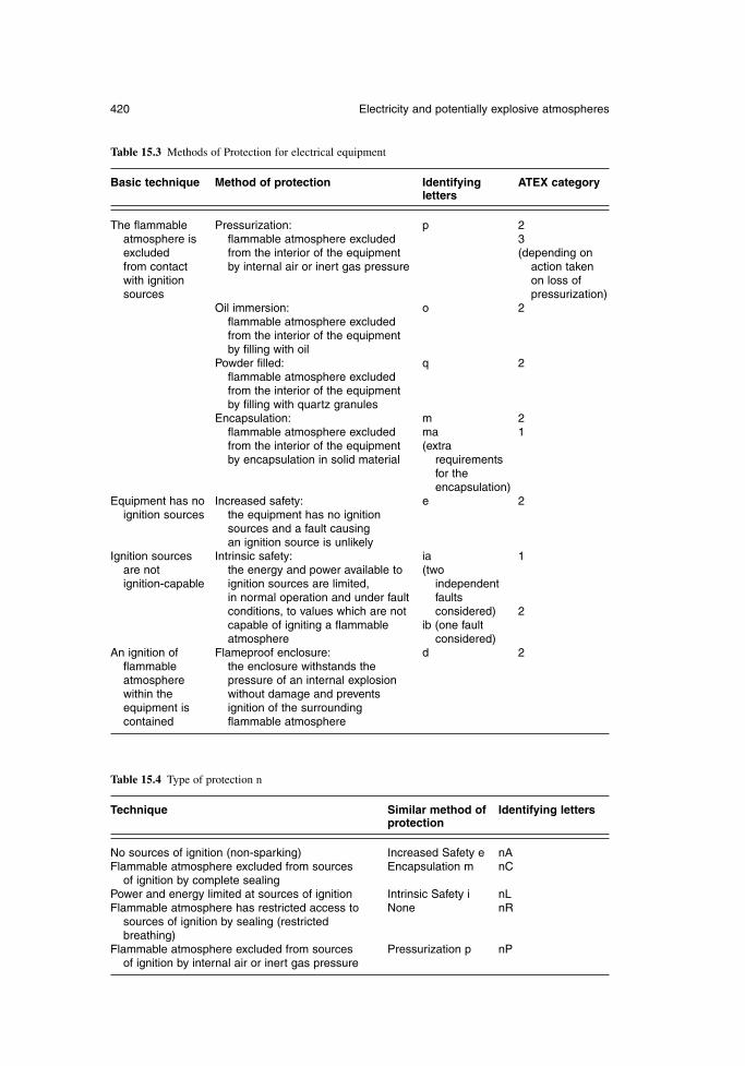
420 Electricity and potentially explosive atmospheres
Table 15.4 Type of protection n
Technique Similar method of Identifying lettersprotection
No sources of ignition (non-sparking) Increased Safety e nAFlammable atmosphere excluded from sources Encapsulation m nC
of ignition by complete sealingPower and energy limited at sources of ignition Intrinsic Safety i nLFlammable atmosphere has restricted access to None nR
sources of ignition by sealing (restricted breathing)
Flammable atmosphere excluded from sources Pressurization p nPof ignition by internal air or inert gas pressure
Table 15.3 Methods of Protection for electrical equipment
Basic technique Method of protection Identifying ATEX categoryletters
The flammable Pressurization: p 2atmosphere is flammable atmosphere excluded 3excluded from the interior of the equipment (depending onfrom contact by internal air or inert gas pressure action taken with ignition on loss ofsources pressurization)
Oil immersion: o 2flammable atmosphere excluded from the interior of the equipment by filling with oil
Powder filled: q 2flammable atmosphere excluded from the interior of the equipmentby filling with quartz granules
Encapsulation: m 2flammable atmosphere excluded ma 1from the interior of the equipment (extraby encapsulation in solid material requirements
for the encapsulation)
Equipment has no Increased safety: e 2ignition sources the equipment has no ignition
sources and a fault causing an ignition source is unlikely
Ignition sources Intrinsic safety: ia 1are not the energy and power available to (two ignition-capable ignition sources are limited, independent
in normal operation and under fault faultsconditions, to values which are not considered) 2capable of igniting a flammable ib (one faultatmosphere considered)
An ignition of Flameproof enclosure: d 2flammable the enclosure withstands the atmosphere pressure of an internal explosion within the without damage and preventsequipment is ignition of the surrounding contained flammable atmosphere
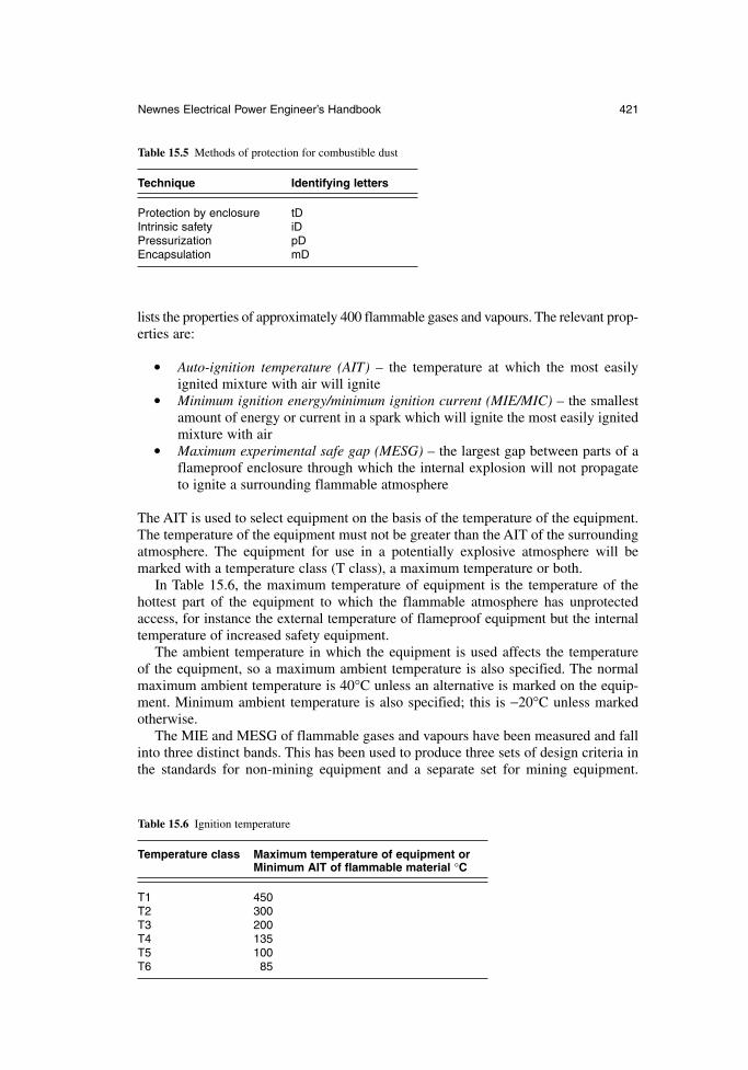
Newnes Electrical Power Engineer’s Handbook 421
lists the properties of approximately 400 flammable gases and vapours. The relevant prop-erties are:
Auto-ignition temperature (AIT) – the temperature at which the most easilyignited mixture with air will ignite
Minimum ignition energy/minimum ignition current (MIE/MIC) – the smallestamount of energy or current in a spark which will ignite the most easily ignitedmixture with air
Maximum experimental safe gap (MESG) – the largest gap between parts of aflameproof enclosure through which the internal explosion will not propagateto ignite a surrounding flammable atmosphere
The AIT is used to select equipment on the basis of the temperature of the equipment.The temperature of the equipment must not be greater than the AIT of the surroundingatmosphere. The equipment for use in a potentially explosive atmosphere will bemarked with a temperature class (T class), a maximum temperature or both.
In Table 15.6, the maximum temperature of equipment is the temperature of thehottest part of the equipment to which the flammable atmosphere has unprotectedaccess, for instance the external temperature of flameproof equipment but the internaltemperature of increased safety equipment.
The ambient temperature in which the equipment is used affects the temperature of the equipment, so a maximum ambient temperature is also specified. The normalmaximum ambient temperature is 40°C unless an alternative is marked on the equip-ment. Minimum ambient temperature is also specified; this is −20°C unless markedotherwise.
The MIE and MESG of flammable gases and vapours have been measured and fallinto three distinct bands. This has been used to produce three sets of design criteria inthe standards for non-mining equipment and a separate set for mining equipment.
Table 15.5 Methods of protection for combustible dust
Technique Identifying letters
Protection by enclosure tDIntrinsic safety iDPressurization pDEncapsulation mD
Table 15.6 Ignition temperature
Temperature class Maximum temperature of equipment orMinimum AIT of flammable material °C
T1 450T2 300T3 200T4 135T5 100T6 85
422 Electricity and potentially explosive atmospheres
These allow equipment to be designated as Group I for underground mining applicationsand Group II elsewhere. Within Group II, apparatus is designated as IIA, IIB or IICaccording to the design criteria used, the IIC design criteria being the most stringentand that of IIA being the least stringent (see Table 15.8). The subgroups A, B and Care important only if the method of protection relies on limitation of energy or current,for instance Intrinsic Safety or Type of Protection nL, or on containment of an explo-sion such as a flameproof enclosure. Otherwise the equipment is allocated to the wholeof Group II.
For convenience IEC 79-20 lists the Group and Temperature Class of equipmentsuitable for each flammable material.
15.5.3 Equipment marking
Prior to the 100a ATEX Directive, hazardous area equipment was marked with a‘Certification Coding’, a certificate number and other information. A typical equipmentlabel would contain:
the manufacturer’s name the name or type of the equipment the ‘Distinctive Community Mark’ a serial number the certification code the certificate number any ‘Special Conditions’ for safe use electrical ratings any other information required by the standards for the equipment
In a typical certification code, say EEx de IIB T3 (Tamb = 50°C), E means certified to European standards, Ex means equipment for a potentially explosive atmosphere, de means methods of protection, IIB means group and subgroup, T3 means tem-perature class and Tamb = 50°C means maximum ambient temperature. If the equipment is marked with a temperature in addition to, or in place of a TemperatureClass, then this is used to denote the minimum ignition temperature of the gas orvapour.
In a typical certificate number such as SIRA01E1987X, SIRA is the name or logo of the certifying body, 01 is the year of certification, E is the revision status of the standards to which certified, 1 means the principal method of protection, 987 is the serial number of the certificate and X means that ‘Special Conditions’ for safe use exist.
The ‘Distinctive Community Mark’ equipment complies with a hazardous areaequipment directive. The 100a ATEX Directive introduces additional marking:
the address of the manufacturer the year of manufacture the CE marking the number of the notified body responsible for quality assurance the ATEX Category
In a typical additional ATEX marking: 0518 II 2 G
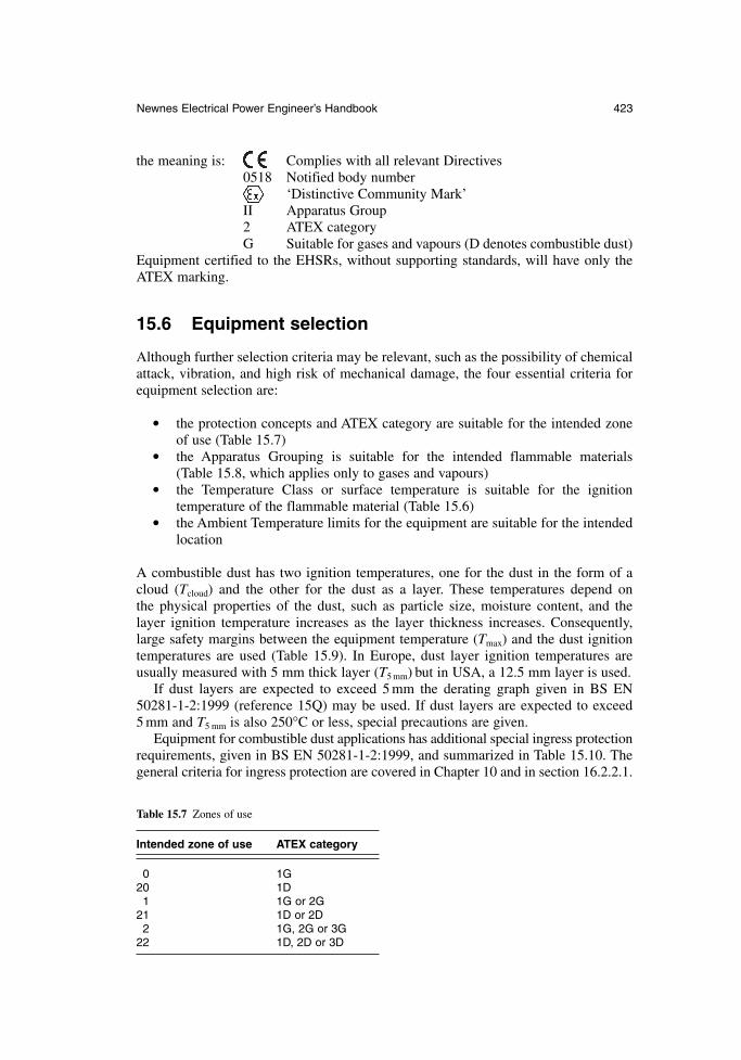
Newnes Electrical Power Engineer’s Handbook 423
the meaning is: Complies with all relevant Directives0518 Notified body number
‘Distinctive Community Mark’II Apparatus Group2 ATEX categoryG Suitable for gases and vapours (D denotes combustible dust)
Equipment certified to the EHSRs, without supporting standards, will have only theATEX marking.
15.6 Equipment selection
Although further selection criteria may be relevant, such as the possibility of chemicalattack, vibration, and high risk of mechanical damage, the four essential criteria forequipment selection are:
the protection concepts and ATEX category are suitable for the intended zoneof use (Table 15.7)
the Apparatus Grouping is suitable for the intended flammable materials (Table 15.8, which applies only to gases and vapours)
the Temperature Class or surface temperature is suitable for the ignition temperature of the flammable material (Table 15.6)
the Ambient Temperature limits for the equipment are suitable for the intendedlocation
A combustible dust has two ignition temperatures, one for the dust in the form of acloud (Tcloud) and the other for the dust as a layer. These temperatures depend on the physical properties of the dust, such as particle size, moisture content, and the layer ignition temperature increases as the layer thickness increases. Consequently,large safety margins between the equipment temperature (Tmax) and the dust ignitiontemperatures are used (Table 15.9). In Europe, dust layer ignition temperatures areusually measured with 5 mm thick layer (T5 mm) but in USA, a 12.5 mm layer is used.
If dust layers are expected to exceed 5 mm the derating graph given in BS EN50281-1-2:1999 (reference 15Q) may be used. If dust layers are expected to exceed5 mm and T5 mm is also 250°C or less, special precautions are given.
Equipment for combustible dust applications has additional special ingress protectionrequirements, given in BS EN 50281-1-2:1999, and summarized in Table 15.10. Thegeneral criteria for ingress protection are covered in Chapter 10 and in section 16.2.2.1.
Table 15.7 Zones of use
Intended zone of use ATEX category
0 1G20 1D1 1G or 2G
21 1D or 2D2 1G, 2G or 3G
22 1D, 2D or 3D
424 Electricity and potentially explosive atmospheres
15.7 Equipment installation
The code of practice for the installation of hazardous area electrical equipment is BS EN 60079-14 (reference 15R). The guidance in this code of practice is additionalto the requirements for non-hazardous area installations. Electrical equipment should,preferably, be located outside a hazardous area or in the lowest risk area available. It should be installed in accordance with its documentation, including any specialrequirements denoted by the letter ‘X’ at the end of the certificate number. It shouldalso be operated within all of its ratings.
The installation should be designed to protect the equipment from adverse environ-mental influences which could jeopardize the method of protection; these include temperature extremes, corrosion, mechanical damage and vibration. Electrical equip-ment, such as pressure transmitters and temperature sensors, connected directly to the process, may become filled with process fluid under failure conditions. The instal-lation of the wiring system should include, for example, impervious barriers to prevent the process material migrating through the wiring system into other areas. The installation should also be designed with regard to ease of inspection and maintenance (see section 15.8). Portable, transportable and temporary equipmentshould also be suitable for the zone of use.
15.7.1 Protection from sparking
Fault currents cause potential differences between different parts of an electrical instal-lation and plant structure. Although non-hazardous area electrical installation practicesminimize these to levels which are not an electrical shock risk, they can be sufficientto create ignition-capable sparking. Consequently equipotential bonding has particularguidance. Only TN-S, TT and IT power distribution systems are recommended forhazardous area use and specific guidance is given for each. SELV and PELV systemsmay also be used (see section 16.2.2.4).
Other equipotential bonding systems such as those provided for lightning protection,control of static charging, electromagnetic compatibility may also exist in, or associ-ated with, hazardous areas. These should be connected together at one point to minimizepotential difference between them. Cathodic protection is not normally suitable for usein hazardous areas.
Table 15.9 Dust ignition temperature
Dust cloud Dust layer
Tmax = (2/3) × Tcloud Tmax = T5 mm – 75 K
Table 15.8 Apparatus grouping
Apparatus group Gas/vapour group
II All Group IIIIA Group IIA onlyIIB Group IIA or IIBIIC Group IIA, IIB or IIC
Newnes Electrical Power Engineer’s Handbook 425
15.7.2 Electrical protection
In most cases the electrical protection provided for the same installation in a non-hazardous area is suitable but there are a number of significant exceptions. Specific guidance is given for rotating electrical machines and transformers which includesoverload protection. Multi-phase equipment should be protected against loss of one ormore phases. Auto-reclosing protection is not recommended.
15.7.3 Means of isolation
Residual neutral voltages may be ignition-capable so, the means of isolation shouldalso isolate the neutral.
15.7.4 Wiring systems
The following aspects of wiring systems have specific guidance:
Aluminium conductors Mechanical damage Non-sheathed single cores Electrical connections Unused openings in enclosures Migration and accumulation of Circuits traversing hazardous areas flammable materials Openings in walls etc. Fortuitous contact Protection of stranded conductor ends Cable jointing Overhead lines Unused cores
Cable surface temperature
Cable types for Zones 1 and 2 are mineral-insulated metal sheathed cables and ther-moplastic, thermosetting or elastomeric sheathed cables. Especially robust cable typesare recommended for portable and transportable equipment, and where flexibility isrequired. Conduit systems may be used and specific guidance is given on stoppingboxes, fault currents, corrosion, non-sheathed single conductors, condensation drainsand IP ratings.
15.7.5 Flameproof equipment
Five additional pieces of guidance are given for flameproof equipment all of which cannullify the method of protection if not carried out.
15.7.5.1 Solid obstacles
The safety of a flameproof enclosure relies on the products of combustion emergingfrom the enclosure not igniting a surrounding flammable atmosphere. The maximum
Table 15.10 IP ratings for combustible dust
Intended zone of use Dust electrically conductive? Required IP rating
20 Both IP 6X21 Both IP 6X22 Yes IP 6X22 No IP 5X
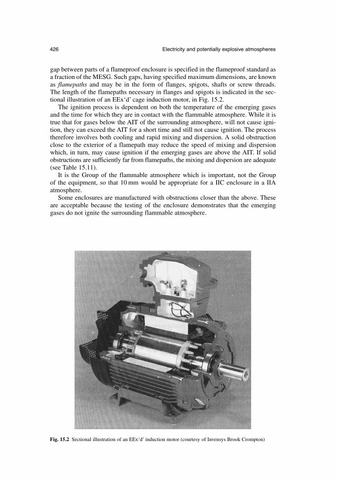
426 Electricity and potentially explosive atmospheres
gap between parts of a flameproof enclosure is specified in the flameproof standard asa fraction of the MESG. Such gaps, having specified maximum dimensions, are knownas flamepaths and may be in the form of flanges, spigots, shafts or screw threads. The length of the flamepaths necessary in flanges and spigots is indicated in the sec-tional illustration of an EEx‘d’ cage induction motor, in Fig. 15.2.
The ignition process is dependent on both the temperature of the emerging gasesand the time for which they are in contact with the flammable atmosphere. While it istrue that for gases below the AIT of the surrounding atmosphere, will not cause igni-tion, they can exceed the AIT for a short time and still not cause ignition. The processtherefore involves both cooling and rapid mixing and dispersion. A solid obstructionclose to the exterior of a flamepath may reduce the speed of mixing and dispersionwhich, in turn, may cause ignition if the emerging gases are above the AIT. If solidobstructions are sufficiently far from flamepaths, the mixing and dispersion are adequate(see Table 15.11).
It is the Group of the flammable atmosphere which is important, not the Group of the equipment, so that 10 mm would be appropriate for a IIC enclosure in a IIAatmosphere.
Some enclosures are manufactured with obstructions closer than the above. Theseare acceptable because the testing of the enclosure demonstrates that the emerginggases do not ignite the surrounding flammable atmosphere.
Fig. 15.2 Sectional illustration of an EEx‘d’ induction motor (courtesy of Invensys Brook Crompton)
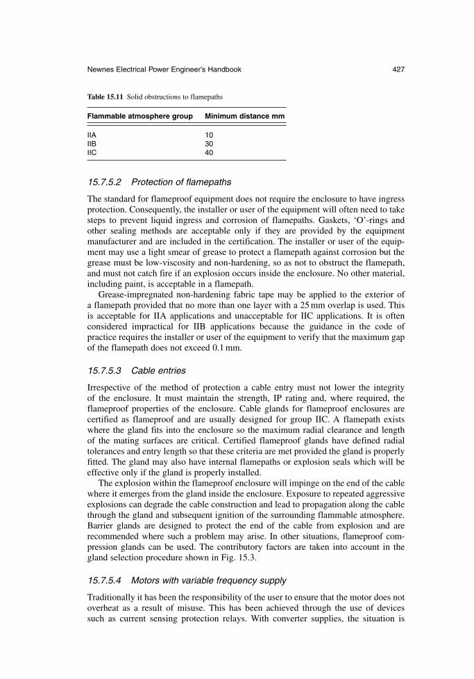
Newnes Electrical Power Engineer’s Handbook 427
15.7.5.2 Protection of flamepaths
The standard for flameproof equipment does not require the enclosure to have ingressprotection. Consequently, the installer or user of the equipment will often need to takesteps to prevent liquid ingress and corrosion of flamepaths. Gaskets, ‘O’-rings andother sealing methods are acceptable only if they are provided by the equipment manufacturer and are included in the certification. The installer or user of the equip-ment may use a light smear of grease to protect a flamepath against corrosion but thegrease must be low-viscosity and non-hardening, so as not to obstruct the flamepath,and must not catch fire if an explosion occurs inside the enclosure. No other material,including paint, is acceptable in a flamepath.
Grease-impregnated non-hardening fabric tape may be applied to the exterior of a flamepath provided that no more than one layer with a 25 mm overlap is used. This is acceptable for IIA applications and unacceptable for IIC applications. It is often considered impractical for IIB applications because the guidance in the code of practice requires the installer or user of the equipment to verify that the maximum gapof the flamepath does not exceed 0.1 mm.
15.7.5.3 Cable entries
Irrespective of the method of protection a cable entry must not lower the integrity of the enclosure. It must maintain the strength, IP rating and, where required, theflameproof properties of the enclosure. Cable glands for flameproof enclosures arecertified as flameproof and are usually designed for group IIC. A flamepath existswhere the gland fits into the enclosure so the maximum radial clearance and length of the mating surfaces are critical. Certified flameproof glands have defined radial tolerances and entry length so that these criteria are met provided the gland is properlyfitted. The gland may also have internal flamepaths or explosion seals which will beeffective only if the gland is properly installed.
The explosion within the flameproof enclosure will impinge on the end of the cablewhere it emerges from the gland inside the enclosure. Exposure to repeated aggressiveexplosions can degrade the cable construction and lead to propagation along the cablethrough the gland and subsequent ignition of the surrounding flammable atmosphere.Barrier glands are designed to protect the end of the cable from explosion and are recommended where such a problem may arise. In other situations, flameproof com-pression glands can be used. The contributory factors are taken into account in thegland selection procedure shown in Fig. 15.3.
15.7.5.4 Motors with variable frequency supply
Traditionally it has been the responsibility of the user to ensure that the motor does notoverheat as a result of misuse. This has been achieved through the use of devices such as current sensing protection relays. With converter supplies, the situation is
Table 15.11 Solid obstructions to flamepaths
Flammable atmosphere group Minimum distance mm
IIA 10IIB 30IIC 40
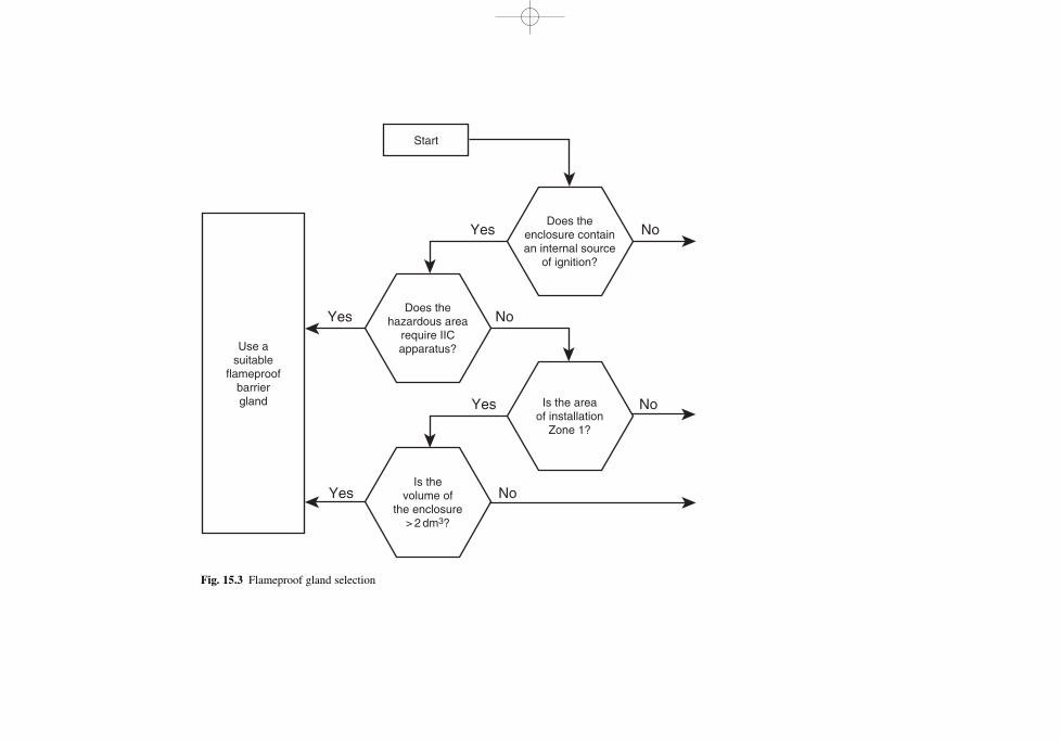
Yes
Yes
Yes
Yes
No
No
No
No
Use asuitable
flameproofbarriergland
Start
Does thehazardous area
require IICapparatus?
Is thevolume of
the enclosure> 2 dm3?
Does theenclosure containan internal source
of ignition?
Is the areaof installation
Zone 1?
Fig. 15.3 Flameproof gland selection
Newnes Electrical Power Engineer’s Handbook 429
somewhat more complex and it is necessary for the motor manufacturer to assume theresponsibility of rating the motor correctly for variable frequency inverter supplies.
These motors should be either type tested with the intended variable speed driveunder the conditions of use or be equipped with internal temperature sensors which arearranged to disconnect the supply before the temperature class is exceeded. Thermistorsensors are usually mounted at critical points in the motor, and used to monitor motortemperature during operation. Trip relays are used to remove the supply from themotor if any one thermistor reaches the tripping temperature.
15.7.5.5 Conduit systems
Conduit should be either solid drawn or seam-welded heavy gauge steel. Specific typesof flexible conduit may also be used. If the conduit is to be screwed directly into aflameproof enclosure, the thread should be of 6 g tolerance class and be long enoughto allow five threads to be fully engaged in the enclosure wall. An explosion stopper isrequired on the enclosure wall or within 50 mm to prevent any explosion propagatingalong the conduit.
15.7.6 Increased safety equipment
Increased safety relies on a high standard of design and construction and the quality ofthe workmanship during installation is equally important. There is a great deal ofdetailed guidance in the manufacturers’ literature and BS EN 60097-14 summarizesthe main features. The three critical areas are cable and conduit entries, wiring termi-nations and temperature limitation.
15.7.6.1 Cable and conduit entries
The primary objective of cable and conduit entry devices is to maintain the strengthand IP rating of the enclosure. One way to achieve this is to use devices certified asincreased safety and to use a sealing device, such as a washer, between the entry deviceand the enclosure. Certain types of standard industrial metal compression glandsexceed the minimum requirements for increased safety and may be used instead of a certified equivalent. Where there is any doubt, and with non-metallic glands, a certi-fied device should always be used.
15.7.6.2 Wiring terminations
The majority of increased safety terminals fall into one of three basic design types,each with its own particular guidance for connection. Rail-mounted and so-called‘chocolate block’ terminals comprise an insulating body through which a metal barpasses. Each end of the metal bar is recessed within the body and carries a wiringclamp. The wiring clamp may be a thin metal tongue which presses the wire onto thebar when the terminal screw is tightened, or it may be a saddle or yolk arrangementwhich is pulled up to the bar when the terminal screw is tightened and likewise presses the wire onto the bar. This type of terminal is designed for one wire at eachend. A further type comprises a metal bar projecting from, or embedded in, the insulation of a component or part of an item of equipment. They are commonly foundmoulded into component parts of increased safety equipment, such as ballasts in luminaires. They have a wiring clamp in the shape of an inverted ‘U’ on top of the metalbar which is pressed onto the bar by a screw passing through both. These are designed
430 Electricity and potentially explosive atmospheres
to accommodate one or two conductors of the same or different sizes. A third commontype of terminal is in the form of a threaded metal pillar with a vertical slot. A metal barmounted inside a screw-on cap presses the conductors down on to the base of the slot.This design of terminal is intended to accommodate one or more conductors.
Conductors should preferably be fitted with compression ferrules before termina-tion in any type of increased safety terminal, especially if they are stranded conductorsor if the terminal is designed for more than one conductor. All strands of a conductorshould be clamped securely and the conductor insulation should continue up to themetal part of the terminal.
15.7.6.3 Wiring within enclosures
The principal source of heat in a terminal box is the wiring. The temperature classifi-cation is based on the rated current of the terminals and is measured with wiring tailsequal in length to the largest internal dimension of the enclosure. It is important thatthis length, the ratings of the terminals and the current rating of the conductors are notexceeded, or the temperature class may be exceeded.
15.7.6.4 Thermal protection of electrical machines
The thermal protection for increased safety of electrical machines is critical for twomain reasons. The temperature in question is the hottest part of the interior, which mayin a cage induction motor be the stator windings or the rotor bars. The temperature during starting and stalled operation is taken into account; on a fixed-frequency supply, the time taken to reach the limiting temperature of the temperature class, start-ing from the normal maximum running temperature, is marked on the rating plate. Thisis called the tE time and the protection must disconnect the motor within this time.Current-sensing protection with an inverse time delay characteristic may suffice if themotor run-up time is shorter than the tE time. Otherwise more sophisticated protectionor embedded thermal sensors will be required.
Soft-start circuits and variable frequency/voltage drives need special attention.
15.7.7 Intrinsic safety equipment
Intrinsic safety is system-based and it has to be preserved throughout the entire installation.The two areas requiring particular care are wiring segregation and earthing. Intrinsicallysafe circuits need to be segregated from all other types of circuits and from each other. In the majority of intrinsically safe circuits only one connection to earth is acceptable.Guidance is given in BS EN 60079-14 in the following areas and should be consulted:
location and installation of apparatus energy storage in cables cable types earthing of screens multiple earthing and electromagnetic compatibility cable armour bonding installation of cables and wiring marking/identification of cables, wiring and terminals multi-core cables unused cores in cables cable and wiring fault considerations
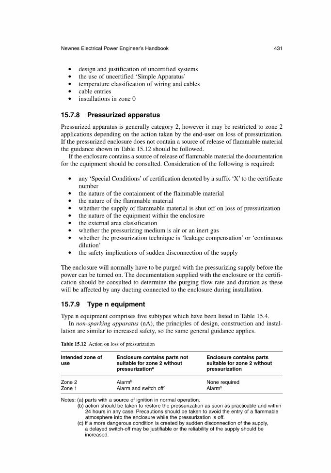
Newnes Electrical Power Engineer’s Handbook 431
design and justification of uncertified systems the use of uncertified ‘Simple Apparatus’ temperature classification of wiring and cables cable entries installations in zone 0
15.7.8 Pressurized apparatus
Pressurized apparatus is generally category 2, however it may be restricted to zone 2applications depending on the action taken by the end-user on loss of pressurization.If the pressurized enclosure does not contain a source of release of flammable materialthe guidance shown in Table 15.12 should be followed.
If the enclosure contains a source of release of flammable material the documentationfor the equipment should be consulted. Consideration of the following is required:
any ‘Special Conditions’ of certification denoted by a suffix ‘X’ to the certificatenumber
the nature of the containment of the flammable material the nature of the flammable material whether the supply of flammable material is shut off on loss of pressurization the nature of the equipment within the enclosure the external area classification whether the pressurizing medium is air or an inert gas whether the pressurization technique is ‘leakage compensation’ or ‘continuous
dilution’ the safety implications of sudden disconnection of the supply
The enclosure will normally have to be purged with the pressurizing supply before thepower can be turned on. The documentation supplied with the enclosure or the certifi-cation should be consulted to determine the purging flow rate and duration as thesewill be affected by any ducting connected to the enclosure during installation.
15.7.9 Type n equipment
Type n equipment comprises five subtypes which have been listed in Table 15.4.In non-sparking apparatus (nA), the principles of design, construction and instal-
lation are similar to increased safety, so the same general guidance applies.
Table 15.12 Action on loss of pressurization
Intended zone of Enclosure contains parts not Enclosure contains partsuse suitable for zone 2 without suitable for zone 2 without
pressurizationa pressurization
Zone 2 Alarmb None requiredZone 1 Alarm and switch offc Alarmb
Notes: (a) parts with a source of ignition in normal operation.(b) action should be taken to restore the pressurization as soon as practicable and within
24 hours in any case. Precautions should be taken to avoid the entry of a flammable atmosphere into the enclosure while the pressurization is off.
(c) if a more dangerous condition is created by sudden disconnection of the supply, a delayed switch-off may be justifiable or the reliability of the supply should beincreased.
In restricted breathing enclosures (nR), the quality of the sealing is critical to theprotection, so cable types and cable entries need careful specification and installation.
Energy-limited apparatus (nL) may be subgrouped like intrinsic safety and thesame selection criteria apply. It may also be system-based rather than apparatus-based.If it is apparatus-based only the normal supply limits are relevant as the cabling is notenergy limited. However, if it is system-based, the cabling will also be energy limited.This means that cable types, segregation, supply characteristics, energy storage in cablesand earthing requirements are similar to those for intrinsic safety.
Simplified pressurization (nP) is similar to pressurization except there are relaxationson purging and action on loss of pressure. The general principles for pressurized instal-lations apply.
Type nC uses one of several protection techniques, which are enclosed break (similarto flameproof), sealing (using gaskets etc.), hermetic sealing (fusion sealed) and encapsulated. It may be subgrouped.
15.7.10 Personal electrical apparatus
Personnel may inadvertently carry personal electrical equipment such as electronicwrist watches, hearing aids, car remote locking devices, key-ring torches, calculatorsand so on into hazardous areas. The risk with wristwatches which have no other functionsuch as a calculator is very small and generally acceptable. No other personal electricalequipment should be permitted in hazardous areas unless it is suitably protected.
15.8 Inspection and maintenance
All equipment installed in hazardous areas and all parts of intrinsically safe, or simi-lar, installations require periodic inspection to verify the continued integrity of themethods of protection. It is possible for installations to become unsafe due to deterio-ration, damage or alteration while the installation remains functional. A programme ofinitial and periodic inspections and, if necessary, remedial action is recommended inBS EN 60079-17 (reference 15S).
Inspections are generally initial, periodic or sample. An initial inspection is recom-mended before a new installation or re-installed equipment is brought into service. The objective is to verify that the equipment is suitable for its location, that it has beencorrectly installed and is in good condition. A periodic inspection is intended to checkthat the equipment continues to be suitable and a sample inspection can be used tocheck the effectiveness of the inspection and maintenance arrangements.
Inspections can also be visual, close or detailed. A visual inspection involves nomore than an examination of the exterior of the equipment and it does not require theuse of tools or the isolation of equipment for electrical safety. A close inspection mayrequire access equipment and basic tools but does not involve opening of equipmentenclosures or isolation for electrical safety. A detailed inspection may be carried outin the field or the equipment may be removed to a workshop; isolation, opening of theenclosure, and a wider range of tools are required, and test equipment may also be usedin a hazardous area if suitably protected, or in a workshop.
15.8.1 Inspection strategy
The inspection strategy is designed for optimum use of resources. At first sight, zerodefects is a desirable target. If this is achieved there is no way to determine if the grade
432 Electricity and potentially explosive atmospheres
and frequency of inspection are excessive. Too many defects indicate that the inspec-tions are not sufficiently frequent or thorough. The strategy, therefore, compares thecurrent results with the previous results and adjusts the frequency and/or grade ofinspections until a small number of minor defects are found at each inspection.Records need not be kept but may be useful in identifying trends.
15.8.2 Inspection schedules
The BS EN 60079-17 contains sample inspection schedules for the various methods ofprotection, depending on whether the inspections are initial or periodic. It may bedesirable to include work instructions, access requirements and recommended tools inthe inspection schedules. A means of prioritizing and recording the findings can alsobe included. It is important to produce schedules which can be practically used in aplant environment. The schedules may also incorporate electrical testing and any statu-tory requirements.
15.8.3 General requirements
15.8.3.1 Withdrawal from service
When equipment is removed from the site, the exposed conductors should be terminatedin a suitable enclosure, or isolated from all sources of supply, insulated and protectedfrom the environment, or isolated from all sources of supply, earthed and protectedfrom the environment.
15.8.3.2 Isolation
Intrinsically safe installations do not normally need to be isolated to protect personnelfrom electric shock or to prevent ignition-capable sparking. Consequently, the follow-ing maintenance activities are permissible in a hazardous area without isolation:
disconnection, removal or replacement of any item of equipment or cabling inan intrinsically safe circuit
adjustment of calibration controls removal or replacement of plug-in assemblies or components use of test equipment or procedures specified in the system documentation
Safety earths must not be disconnected or tested while the associated intrinsically safecircuits are connected into the hazardous area.
All other installations, except type of protection nL, should be isolated, includingthe neutral, before work commences. The documentation supplied with the equipment,or the certificate, should be consulted for isolation requirements for type of protection nL.
15.8.3.3 Fault loop impedance or earth resistance
The standard types of test equipment for these measurements uses voltages and currents which are ignition-capable and should not, therefore, be used in a hazardousarea without an appropriate permit to work. They may also cause ignition-capable currents to flow in a hazardous area even when used in a non-hazardous area, espe-cially if there are faults in the earthing and bonding system. It is preferable to carry outsuch checks before flammable materials are brought into a plant or during a majorshutdown when all flammable materials have been removed from the plant. If such
Newnes Electrical Power Engineer’s Handbook 433
measurements are duplicated by measurements using intrinsically safe test meters,comparisons can be carried out in the intervening period. If there is then evidence thatthe earthing and bonding system is deteriorating, it can be confirmed using standardtest equipment with suitable precautions.
15.8.3.4 Insulation resistance measurements
Insulation resistance measurements pose similar problems because the standard typesof test equipment use voltages which are ignition-capable. A similar procedure to thatfor fault loop impedance or earth resistance measurements can be used.
Intrinsically safe high voltage insulation resistance meters, working at 500 V, areavailable but the energy stored in a few metres of cable is ignition-capable at this volt-age. Such equipment should only be used strictly in accordance with the manufacturer’sinstructions.
15.8.3.5 Overloads
The setting of overloads should be checked to verify if they are set to IN. The charac-teristics of the devices should be checked to verify that they are such that they willoperate in not more than two hours at 1.2 times the set current and will not operatewithin two hours at 1.05 times the set current.
15.8.4 Specific requirements
15.8.4.1 Flameproof equipment
Although the example inspection schedules in BS EN 60079-17 include checkingflamepath dimensions, it is not normally considered necessary to check spigots, spindles, shafts and screw threads and joints which are not normally capable of beingdismantled, unless there is evidence of damage or deterioration.
15.8.4.2 Increased safety
It is recommended that the settings of overload and excess temperature protection arechecked periodically. If experience shows it to be necessary, the tripping characteris-tics should be measured periodically to verify that they are within 20 per cent of theset values.
15.8.4.3 Intrinsic safety
There is extensive guidance in BS EN 60079-17 for intrinsic safety covering documentation, labelling, modifications, intrinsically safe interfaces, cables, earthcontinuity and insulation from earth, connections to earth, and separation and segregation of intrinsically safe circuits from each other and from non-intrinsicallysafe circuits.
15.8.5 Maintenance
Maintenance is defined as a combination of any of the actions carried out to retain anitem in, or restore it to, conditions in which it is able to meet the requirements of thehazardous area installation and perform its required function. Repair, reclamation andoverhaul are not included and are best left to specialist organizations complying with
434 Electricity and potentially explosive atmospheres

BS EN 60079-19. Maintenance should be integrated with the inspection system so thatdefects are rectified in a time commensurate with their priority and so that re-installedequipment receives an initial inspection.
References
15A. 1999/92/EC, Minimum requirements for improving the safety & health protection ofworkers potentially at risk from explosive atmospheres; OJ L23 of 28/01/2000, p. 57.
15B. 94/9/EC, The approximation of the laws of member states concerning equipment andprotective systems intended for use in potentially explosive atmospheres; OJ L100 of19/04/1994, p. 1.
15C. 98/24/EC, The protection of the health and safety of workers from the risks related tochemical agents at work; OJ L131 of 05/05/1998, p. 11.
15D. DSEAR, Statutory Instrument 2002 No. 2776; The Dangerous Substances andExplosive Atmospheres Regulations 2002.
15E. Dangerous Substances and Explosive Atmospheres Regulations 2002, Approved Codeof Practice and Guidance L133 – Unloading of petrol from road tankers; HSE Books,ISBN 0 7176 2197 9.
15F. Dangerous Substances and Explosive Atmospheres Regulations 2002, Approved Codeof Practice and Guidance L134 – Design of plant, equipment and workplaces; HSEBooks, ISBN 0 7176 2199 5.
15G. Dangerous Substances and Explosive Atmospheres Regulations 2002, Approved Codeof Practice and Guidance L135 – Storage of dangerous substances; HSE Books,ISBN 0 7176 2200 2.
15H. Dangerous Substances and Explosive Atmospheres Regulations 2002, Approved Codeof Practice and Guidance L136 – Control and mitigation measures; HSE Books,ISBN 0 7176 2201 0.
15I. Dangerous Substances and Explosive Atmospheres Regulations 2002, Approved Codeof Practice and Guidance L137 – Safe maintenance, repair and cleaning procedures;HSE Books, ISBN 0 7176 2202 9.
15J. Dangerous Substances and Explosive Atmospheres Regulations 2002, Approved Codeof Practice and Guidance L138 – Dangerous substances and explosive atmospheres;HSE Books, ISBN 0 7176 2203 7.
15K. EPS Regulations, Statutory Instrument 1996/192; Equipment and Protective SystemsIntended for Use in Potentially Explosive Atmospheres Regulations 1996.
15L. BS EN 60079-10:2003, Electrical apparatus for explosive gas atmospheres – Part 10:Classification of hazardous areas.
15M. BS EN 50281-3:2002, Equipment for use in the presence of combustible dust – Part3: Classification of areas where combustible dusts are or may be present.
15N. IP Code, 2nd edition Aug 2002, Area classification code for installations handling flammable fluids, Institute of Petroleum, Model Code of Safe Practice, Part 15,ISBN 0 85293 223 5.
15O. IGE/SR/25, The Institution of Gas Engineers, Safety Recommendations IGE/SR/25,Communication 1665, Hazardous Area Classification of Natural Gas Installations.
15P. IEC 79-20, Electrical apparatus for explosive gas atmospheres – Part 20: Data for flammable gases and vapours, relating to the use of electrical apparatus.
15Q. BS EN 50281-1-2:1999, Electrical apparatus for use in the presence of combustible dust – Part 1-2: Electrical apparatus protected by enclosures – Selection, installation and maintenance.
15R. BS EN 60079-14:2003, Electrical apparatus for explosive gas atmospheres – Part 14:Electrical installations in hazardous areas (other than mines).
15S. BS EN 60079-17:2003, Electrical apparatus for explosive gas atmospheres – Part 17:Inspection and maintenance of electrical installations in hazardous areas (other thanmines).
Newnes Electrical Power Engineer’s Handbook 435

Chapter 16
Principles of electrical safety
J.M. MaddenHealth and Safety Executive
16.1 Injuries from electricity
Every year people are injured or killed as a result of hazardous defects in electrical systems or because they adopt unsafe working practices on electrical systems. The most common types of injury are electric shock and burns, with the burn injuriesarising from either current passing through the body or from the effects of arcing and flashovers. In addition to these direct forms of electrical injury, the following secondary types of injury can occur:
burn injuries and the adverse effects of smoke or fume inhalation from fire ofelectrical origin
the effects of an explosion that has an electrical source of ignition physical injuries arising from the reaction to electric shock, such as being
thrown off a ladder as a result of electric shock and suffering impact injuriesfrom the fall
16.1.1 Electric shock
Electric current passing through the body, particularly alternating current at power frequencies of 50 Hz and 60 Hz, may disrupt the nervous system, causing muscularreaction and the painful sensation of electric shock. The most common reaction is tobe thrown off the conductor as a result of the muscular contraction. However, in asmall number of instances, the consequence is death from cardiac arrest, or from ventricular fibrillation (where the heart muscle beats in a spasmodic and irregular fashion) or from respiratory arrest.
The physiological effects are largely determined by the magnitude and frequency ofthe current, the waveform (for example, continuous sine wave, or half wave rectifiedsine wave, or pulsed waveform), its duration, and the path it takes through the body. An authoritative guide on the topic is published in IEC 60479 (see Table 16.2).The following text concentrates on the most common situation of a shock from a continuous power frequency ac waveform.
The magnitude of the current is the applied voltage divided by the impedance of thebody. The overall circuit impedance will comprise the body of the casualty and the other components in the shock circuit, including that of the power source and theinterconnecting cables. For this reason, the voltage applied to the body, which is commonly known as the touch voltage, will often be lower than the source voltage.
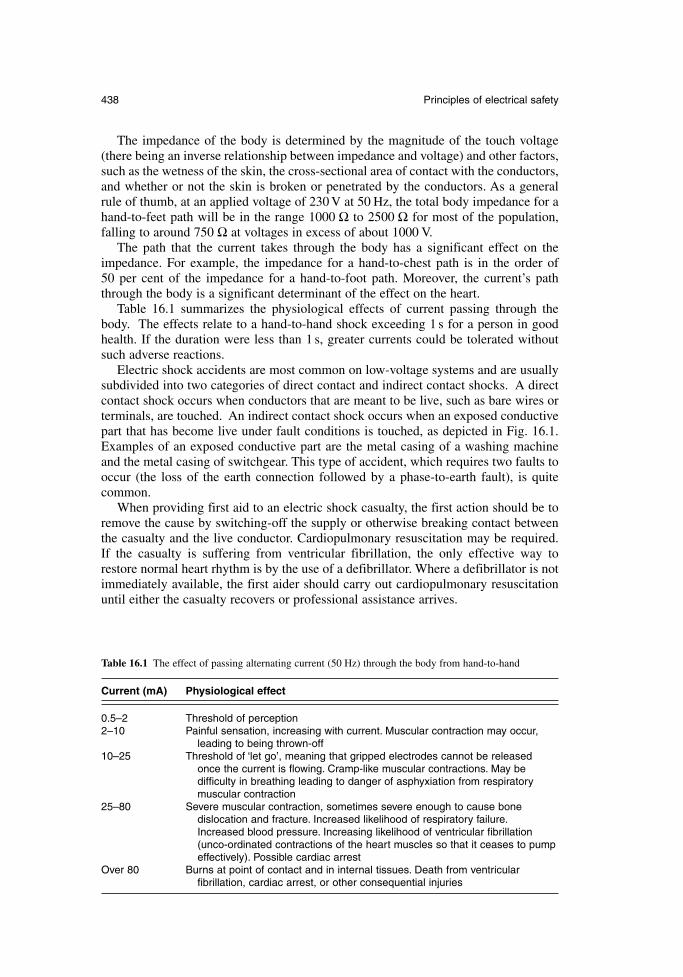
The impedance of the body is determined by the magnitude of the touch voltage(there being an inverse relationship between impedance and voltage) and other factors,such as the wetness of the skin, the cross-sectional area of contact with the conductors,and whether or not the skin is broken or penetrated by the conductors. As a generalrule of thumb, at an applied voltage of 230 V at 50 Hz, the total body impedance for ahand-to-feet path will be in the range 1000 Ω to 2500 Ω for most of the population,falling to around 750 Ω at voltages in excess of about 1000 V.
The path that the current takes through the body has a significant effect on theimpedance. For example, the impedance for a hand-to-chest path is in the order of 50 per cent of the impedance for a hand-to-foot path. Moreover, the current’s paththrough the body is a significant determinant of the effect on the heart.
Table 16.1 summarizes the physiological effects of current passing through thebody. The effects relate to a hand-to-hand shock exceeding 1 s for a person in goodhealth. If the duration were less than 1 s, greater currents could be tolerated withoutsuch adverse reactions.
Electric shock accidents are most common on low-voltage systems and are usuallysubdivided into two categories of direct contact and indirect contact shocks. A directcontact shock occurs when conductors that are meant to be live, such as bare wires orterminals, are touched. An indirect contact shock occurs when an exposed conductivepart that has become live under fault conditions is touched, as depicted in Fig. 16.1.Examples of an exposed conductive part are the metal casing of a washing machineand the metal casing of switchgear. This type of accident, which requires two faults tooccur (the loss of the earth connection followed by a phase-to-earth fault), is quitecommon.
When providing first aid to an electric shock casualty, the first action should be toremove the cause by switching-off the supply or otherwise breaking contact betweenthe casualty and the live conductor. Cardiopulmonary resuscitation may be required.If the casualty is suffering from ventricular fibrillation, the only effective way torestore normal heart rhythm is by the use of a defibrillator. Where a defibrillator is notimmediately available, the first aider should carry out cardiopulmonary resuscitationuntil either the casualty recovers or professional assistance arrives.
438 Principles of electrical safety
Table 16.1 The effect of passing alternating current (50 Hz) through the body from hand-to-hand
Current (mA) Physiological effect
0.5–2 Threshold of perception2–10 Painful sensation, increasing with current. Muscular contraction may occur,
leading to being thrown-off10–25 Threshold of ‘let go’, meaning that gripped electrodes cannot be released
once the current is flowing. Cramp-like muscular contractions. May be difficulty in breathing leading to danger of asphyxiation from respiratory muscular contraction
25–80 Severe muscular contraction, sometimes severe enough to cause bone dislocation and fracture. Increased likelihood of respiratory failure.Increased blood pressure. Increasing likelihood of ventricular fibrillation (unco-ordinated contractions of the heart muscles so that it ceases to pump effectively). Possible cardiac arrest
Over 80 Burns at point of contact and in internal tissues. Death from ventricular fibrillation, cardiac arrest, or other consequential injuries
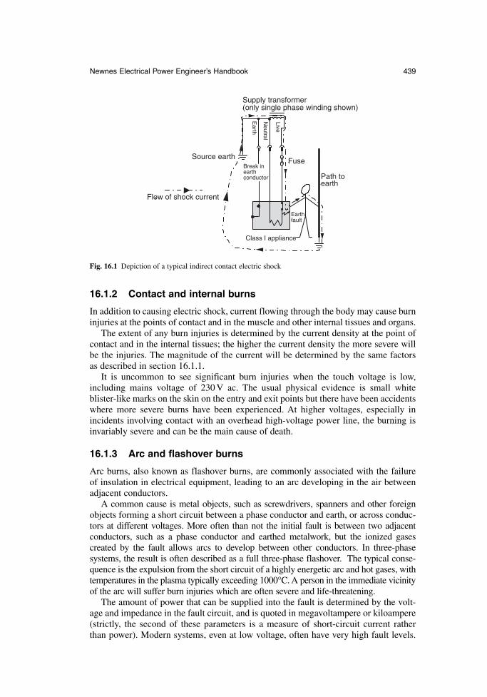
16.1.2 Contact and internal burns
In addition to causing electric shock, current flowing through the body may cause burninjuries at the points of contact and in the muscle and other internal tissues and organs.
The extent of any burn injuries is determined by the current density at the point ofcontact and in the internal tissues; the higher the current density the more severe willbe the injuries. The magnitude of the current will be determined by the same factorsas described in section 16.1.1.
It is uncommon to see significant burn injuries when the touch voltage is low,including mains voltage of 230 V ac. The usual physical evidence is small white blister-like marks on the skin on the entry and exit points but there have been accidentswhere more severe burns have been experienced. At higher voltages, especially inincidents involving contact with an overhead high-voltage power line, the burning isinvariably severe and can be the main cause of death.
16.1.3 Arc and flashover burns
Arc burns, also known as flashover burns, are commonly associated with the failure of insulation in electrical equipment, leading to an arc developing in the air betweenadjacent conductors.
A common cause is metal objects, such as screwdrivers, spanners and other foreignobjects forming a short circuit between a phase conductor and earth, or across conduc-tors at different voltages. More often than not the initial fault is between two adjacent conductors, such as a phase conductor and earthed metalwork, but the ionized gases created by the fault allows arcs to develop between other conductors. In three-phase systems, the result is often described as a full three-phase flashover. The typical conse-quence is the expulsion from the short circuit of a highly energetic arc and hot gases, withtemperatures in the plasma typically exceeding 1000°C. A person in the immediate vicinityof the arc will suffer burn injuries which are often severe and life-threatening.
The amount of power that can be supplied into the fault is determined by the volt-age and impedance in the fault circuit, and is quoted in megavoltampere or kiloampere(strictly, the second of these parameters is a measure of short-circuit current rather than power). Modern systems, even at low voltage, often have very high fault levels.
Newnes Electrical Power Engineer’s Handbook 439
Flow of shock current
Supply transformer (only single phase winding shown)
Break in earth conductor
Earthfault
Path toearth
Earth
Neutral
Live
FuseSource earth
Class I appliance
Fig. 16.1 Depiction of a typical indirect contact electric shock
A typical fault level in a low-voltage domestic installation is 6 kA or 2.4 MVA and inan 11 kV high voltage installation, it can be as high as 13 kA or 250 MVA.
16.1.4 Fire injuries
Electrical systems that are poorly designed, or that have certain fault conditions, may overheat due to excess current flowing to such an extent that adjacent flammablematerials may be ignited. Fires may also be started by arcs and sparks evolved fromshort-circuit faults, most frequently resulting from a breakdown in insulation. Hot spotsin circuits can develop, for example, when poorly made connections have sufficientlyhigh resistance to cause localized heating, which may lead to fire.
Most people caught in fire situations who are killed or seriously harmed areaffected by the smoke and toxic fumes emitted from the burning substances, includingelectrical cables and components, rather than by being burned.
16.1.5 Explosion injuries
If standard electrical equipment is installed in places, called hazardous areas, where aflammable or explosive atmosphere exists, the arcs, sparks, electrostatic discharges orhot surfaces created during normal operation or under fault conditions may haveenough energy for them to act as an ignition source, leading to an explosion. Anybodyin proximity to the explosion may suffer burns and physical injuries, which may beserious enough to be fatal.
16.2 Precautions against electric shock and contact burn injuries
16.2.1 General principles
Shock and contact burn injuries can be prevented first by ensuring that the electricalsystem is designed, installed and maintained in accordance with sound engineeringprinciples and in compliance with accepted and published standards, and secondly by ensuring that any work on the system is carried out in a safe manner. This sectionprovides some detail on the hardware design principles, safe systems of work beingdescribed at the end. Details can be found in reference 16A.
16.2.2 Prevention of direct contact injuries
Direct contact shock and burn injuries are commonly prevented by ensuring that conduc-tors energized at dangerous voltages cannot be touched. There are, however, someinstances where conductors have to be uninsulated and available to touch, such as whenlive testing work is being done or because they need to be exposed for functional reasons,examples being power pick-up rails on fairground rides and overhead travelling cranes.
The most commonly used preventive techniques are listed. The list is not exhaus-tive and there are other less commonly used and specialized techniques available.
16.2.2.1 Insulation and enclosures
Direct contact injuries are most commonly prevented by covering the conductors withsuitably rated insulating material, as in the case of cables, or by placing them inside an enclosure that is constructed so as to prevent access to the live parts.
440 Principles of electrical safety
Insulation must be suitably rated so that it can withstand the applied voltage andmust be selected or protected to withstand external influences, such as impact and abra-sion, high and low temperatures, sunlight, water and corrosive liquids. Information oncable insulation is provided in Chapter 9 and general information on the properties ofinsulating materials and dielectrics is provided in Chapter 3.
Enclosures must be constructed of materials that will withstand the environment inwhich they are installed. They must also prevent access to the internal live parts andprevent the ingress of liquids and dusts that may be present in the operating environ-ment and which may create a hazard if allowed to get into the enclosure.
IEC 60529 (see Table 16.2) defines an Ingress Protection (IP) code that is used todescribe how well an enclosure prevents the ingress of moisture and dust. The codeuses two figures; a third can be added to cover mechanical impact protection but it israrely used. The first figure shows the degree of protection against ingress by solidobjects and the second figure shows the degree of protection against liquid ingress. As an example, IP20 describes an enclosure that will prevent finger access but will notprevent the ingress of moisture – a domestic socket outlet would fall into this category.An enclosure with an IP rating of IP55, such as a halogen lamp for general illumina-tion, would be suitable for external use. The highest rated enclosures, at IP68, will prevent the ingress of dust and can be immersed in water.
Enclosures are often also classified according to the criteria set out in IEC 60536-2 (see Table 16.2). There are two main classifications. Class I equipment has a metal casing that needs to be earthed for safety reasons; metal-clad switchgear is an example.Class II equipment has internal electrical conductive parts on which the basic insula-tion is supplemented by additional insulation to provide an additional insulating barrier; this type of equipment, of which the common plastic-encased power drill is anexample, does not require any metal parts of the casing to be earthed on the groundsthat it would only become live if both layers of insulation were to fail, an event that isvery unlikely to occur.
Another important standard for enclosures is IEC 60439-1 (see Table 16.2). Amongother things, this standard describes ‘forms’ of enclosures according to the protectionagainst contact with live parts belonging to adjacent functional units inside the enclosure,the limitation of the probability of initiating arc faults, and the protection against thepassage of solid foreign bodies from one internal unit to an adjacent unit.
There are many other standards covering the design and configuration of enclosures.
16.2.2.2 Safe by position
Uninsulated conductors energized at dangerous voltages can, in principle, be madesafe by being placed out of reach. For example, high-voltage overhead lines with uninsulated conductors are raised to heights above ground level at which they are safefrom being inadvertently touched or approached so closely by a conducting object(particularly an object with a sharp pointed end) that an arc can develop from the line to the object. Safety is not assured, however, as exemplified by the common occur-rence of direct contact with the conductors by the likes of construction and agriculturevehicles, fishing rods and kites.
16.2.2.3 Reduced voltage
The direct contact hazard can be minimized by reducing the shock voltage. In the UK,the most common reduced voltage system operates at 110 V three-phase or single-phase. In the former, the star point of the supply generator or transformer is earthed
Newnes Electrical Power Engineer’s Handbook 441
and, in the latter, the centre point of the output winding is earthed, reducing the shock voltage between a phase conductor and earth to 55V. Reduced voltage is mostfrequently used to supply Class I and Class II portable tools in work locations, such as construction sites.
16.2.2.4 Extra-low voltage
The two common types of extra-low voltage systems are Safety Extra-Low Voltage(SELV) and Protective Extra-Low Voltage (PELV).
The SELV systems operate at voltages no greater than 25 V ac or 60 V ripple-free dcbetween conductors or between any conductor and earth. These are considered to besafe voltages for most applications, although lower voltages may be needed for workin wet conditions and confined spaces. In an SELV system, any exposed conductiveparts should not be connected to, or be in contact with, the protective conductor ofanother system, nor with extraneous metal which could be energized by another system.A step-down transformer, to provide the safe low voltage, should be a safety trans-former to EN 60742 (see Table 16.2).
PELV differs from SELV only by having its circuits earthed at one point only. Theconductors are usually protected either by barriers or enclosures to at least IP2X orwith insulation capable of withstanding 500 V dc for 60 s. Where the voltage does notexceed 25 V ac or 60 V ripple-free dc in a dry location within the equipotential zone,these additional enclosure precautions are not required, but otherwise the limits are 6Vac or 15 V ripple-free dc.
16.2.2.5 Limitation of energy
Limiting the amount of energy that a system can deliver into the body is a method ofprotection against direct-contact injuries. The electric stock-control fence is one exam-ple. In these systems, the fence wires are energized with pulses, with the peak voltageof each pulse being in the order of 5–10 kV, with a pulse duration in the order of 1 msand pulse repetition frequencies of about 1 Hz. The amount of energy delivered into a500 Ω load is limited to 5 J per pulse, where 500 Ω represents the typical lowest value of human body resistance at the fence operating voltages. Five joules is esti-mated to be below the energy needed to cause cardiac fibrillation effects in the largemajority of the population, but it is high enough to cause sufficient pain to any animalthat may touch the fence wire to deter them from touching it again.
16.2.2.6 Electrical separation
Here the source of supply is usually a safety isolating transformer or its equivalent.The secondary windings are not earthed or otherwise referenced, which explains whysuch systems are commonly known as isolated or unreferenced supplies. The principleis illustrated in Fig. 16.2. A person simultaneously touching one pole of the unrefer-enced supply and earth will not experience an electric shock because there is no complete circuit back to the point of supply, although small amounts of reactive current may flow due to capacitive coupling.
16.2.2.7 Earth leakage protection
Circuit breakers and fuses protect against excess current arising from overload conditions and faults. The most common type of fault is an earth fault, but the current
442 Principles of electrical safety
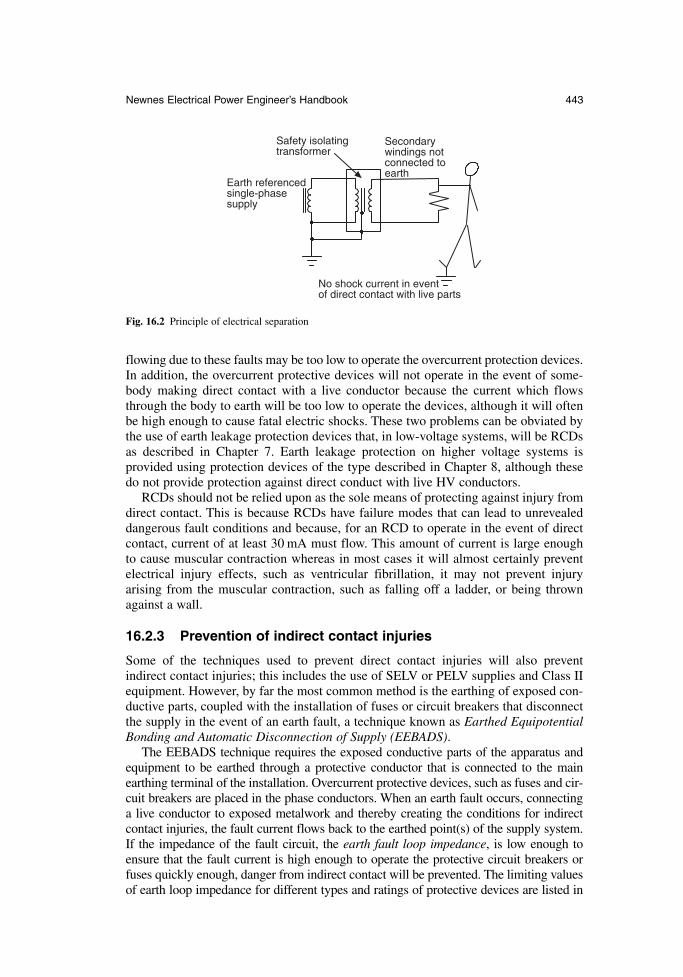
flowing due to these faults may be too low to operate the overcurrent protection devices.In addition, the overcurrent protective devices will not operate in the event of some-body making direct contact with a live conductor because the current which flowsthrough the body to earth will be too low to operate the devices, although it will oftenbe high enough to cause fatal electric shocks. These two problems can be obviated bythe use of earth leakage protection devices that, in low-voltage systems, will be RCDsas described in Chapter 7. Earth leakage protection on higher voltage systems is provided using protection devices of the type described in Chapter 8, although thesedo not provide protection against direct conduct with live HV conductors.
RCDs should not be relied upon as the sole means of protecting against injury fromdirect contact. This is because RCDs have failure modes that can lead to unrevealeddangerous fault conditions and because, for an RCD to operate in the event of directcontact, current of at least 30 mA must flow. This amount of current is large enough to cause muscular contraction whereas in most cases it will almost certainly preventelectrical injury effects, such as ventricular fibrillation, it may not prevent injury arising from the muscular contraction, such as falling off a ladder, or being thrownagainst a wall.
16.2.3 Prevention of indirect contact injuries
Some of the techniques used to prevent direct contact injuries will also prevent indirect contact injuries; this includes the use of SELV or PELV supplies and Class IIequipment. However, by far the most common method is the earthing of exposed con-ductive parts, coupled with the installation of fuses or circuit breakers that disconnectthe supply in the event of an earth fault, a technique known as Earthed EquipotentialBonding and Automatic Disconnection of Supply (EEBADS).
The EEBADS technique requires the exposed conductive parts of the apparatus andequipment to be earthed through a protective conductor that is connected to the mainearthing terminal of the installation. Overcurrent protective devices, such as fuses and cir-cuit breakers are placed in the phase conductors. When an earth fault occurs, connectinga live conductor to exposed metalwork and thereby creating the conditions for indirectcontact injuries, the fault current flows back to the earthed point(s) of the supply system.If the impedance of the fault circuit, the earth fault loop impedance, is low enough toensure that the fault current is high enough to operate the protective circuit breakers orfuses quickly enough, danger from indirect contact will be prevented. The limiting valuesof earth loop impedance for different types and ratings of protective devices are listed in
Newnes Electrical Power Engineer’s Handbook 443
Earth referenced single-phase supply
Safety isolating transformer
No shock current in event of direct contact with live parts
Secondary windings not connected to earth
Fig. 16.2 Principle of electrical separation
BS 7671 (see Table 16.2); this specifies that supplies to hand-held equipment must be disconnected within 0.4 s and those to fixed equipment must be disconnected within 5 sof the fault occurring. In circumstances where sufficiently low values of earth loop imped-ance cannot be achieved the disconnection device may need to be an RCD.
Extraneous conductive parts, being metalwork that does not form part of the instal-lation but which can introduce a potential (usually earth) into the installation, mustalso be bonded together and earthed. This is usually achieved by using suitably sizedbonding conductors to connect water, gas and oil pipes (and any other metallic services)to the installation’s main earthing terminal. Connecting together the exposed and extra-neous conductive parts in this way creates an equipotential zone in which the metalworkis normally held at earth potential; it can raise to higher potentials during fault condi-tions but, since the touchable conductive parts are all connected together, the risk ofelectrical injury is reduced to an acceptable level. In areas of higher risk, such as bath-rooms and swimming pools, supplementary bonding conductors are used to connecttogether all the exposed metalwork.
16.3 Precautions against arc and flashover burn injuries
Most arc and flashover burn injuries occur during live work on electrical systems. Toavoid the hazard, work should be done whenever possible on apparatus that has beenmade dead and isolated. If this is not possible then only competent people shouldundertake the work and precautions must be taken to minimize the risk. Dependingupon the particular circumstances, these may include the use of:
insulating screens or barriers between live parts of different polarity andbetween live parts and earthed metalwork
insulated tools test equipment probes on which only the contact points are bare, with a maximum
length of exposed metal of 4 mm, and the rest of the probe is insulated. Theleads should have protection against short-circuit current, such as integral fusesor current-limiting features in the test equipment
personal protective equipment, such as insulating gloves, and heat-resistant faceshields and clothing
16.4 Precautions against fire
The main precautions against fire of electrical origin are as follows:
each cable must have sufficient current carrying capacity for the load current andmust be protected by an excess current protective device (fuse or circuit breaker)with tripping value set to be below the cable’s maximum current carrying capacity
fuses and circuit breakers must be rated for the system fault level devices with the potential for creating overload conditions, such as motors,
should be protected by excess current protective devices system components must be selected and appropriately protected for use in the
prevailing environmental conditions to prevent degradation that may lead toinsulation failure
the electrical system must be subject to routine preventive maintenance todetect degradation or failures that may otherwise lead to fire.
444 Principles of electrical safety
Enhanced protection against fire and its effects can also be obtained by using cablesthat have low smoke and fume emission properties; more information on these cablesis provided in section 9.2.5.
16.5 Precautions against explosions
The precautions to be taken against electrical ignition of flammable atmospheres aredescribed in Chapter 15.
16.6 Preventive maintenance and safe systems of work
16.6.1 Preventive maintenance
A common cause of the types of accidents described in this chapter is electrical systemswhich are not maintained and which are allowed to degrade into a dangerous condition.Typical examples of dangerous features arising from lack of maintenance are:
enclosures and assemblies that are broken, allowing access to live parts, or inwhich the seals have degraded, allowing the ingress of dusts and liquids
cables with damaged sheathing and basic insulation or with mechanical damagethat compromises the protective conductors or creates the conditions for arcingas a result of insulation failure
corrosion of exposed metallic parts low electrolyte levels in battery-based tripping supplies or uninterruptible power
supplies low levels of insulating oils in switchgear, or insulating oils that have degraded
insulating properties
Advice on the preventive maintenance of low-voltage distribution systems is published inBS 7671. The IEE publishes guidance on the maintenance of electrical equipment, seereferences 16B and 16C. Advice on the preventive maintenance of high-voltage systemsis available in BS 6626 (see Table 16.2). Manufacturers’ literature should also provideinformation on the maintenance strategies for equipment supplied.
16.6.2 Safe systems of work
Safe working practices on electrical systems comprise precautions on equipment thathas been made dead and precautions during live working. These are covered separatelyin the following sections.
16.6.2.1 Safe isolation procedures
Most electrical work should be done on systems that have been made dead and onwhich precautions have been taken to prevent them from being re-energized whilework is going on. The generic safe isolation procedure is as follows:
A. Identify the circuit or apparatus on which work is to be done and all possiblepoints of supply.
Newnes Electrical Power Engineer’s Handbook 445
B. Disconnect the supply and secure the point of isolation, typically by using pad-locks to lock devices in the off position, and post caution notices at the point(s)of isolation to warn that work is being done on the disconnected circuit(s).
C. At the point of work, prove the conductors are dead using a suitable voltageindicator, such as test lamps. The voltage indicator must be proven to be ser-viceable immediately before and after the conductors have been tested forvoltage.
D. For high-voltage equipment, apply earths to the conductors on which work is tobe done.
E. Ensure that the persons carrying out the work on the isolated systems are awareof the scope and limitations of the work to be done.
Safe isolation procedures such as these should only be carried out by competent peo-ple who have been trained to implement them and who are familiar with the equipmentinvolved.
In the cases of high-voltage systems and high fault level low-voltage systems, it is standard practice that the safe isolation procedure is formalized using a safety document, such as a Permit to Work. Where systems that have been isolated under aPermit to Work have to be energized to allow testing to be carried out, the testing isoften authorized and described in a safety document called a Sanction for Test. Detailson safety documents are published in BS 6626 and in reference 16D.
16.6.2.2 Live working practices
Live working is most commonly carried out during fault finding and testing, particu-larly on low-voltage systems. Some more specialized live work is carried out by specialists who have received in-depth training. Live work should normally only becarried out when it can be argued that it is unreasonable to make the conductors dead, and that the risks are acceptable, and only if precautions can be implemented toprevent electrical accidents. Common examples of live working activities are:
live cable jointing and meter changing on low-voltage distribution systems phasing out high-voltage conductors on switchgear, such as circuit breakers and
ring main units ‘rubber glove working’ on 11 kV overhead distribution lines, a technique in which
linesmen wearing insulating gauntlets and working in cradles on insulated boomson mobile elevating work platforms work on live plant that has been coveredwith suitable insulating materials
live line working on the transmission grid overhead lines at voltages from 132 kVupwards, a technique in which the linesman carrying out the work is raised to linepotential
The main hazards during live work are electric shock and burns from direct contactwith live conductors and flashover/arc burns due to insulation failure.
In order to prevent these types of injuries, live work should only be carried out when it is essential and when it is unreasonable for the conductors to be madedead, and when the risks are acceptable. In the event of live work being undertaken,precautions against injury must be adopted.
The most important precaution is to ensure that the live work is carried out by people who are competent for the task or who are being closely supervised by
446 Principles of electrical safety
somebody who is competent. This means that they must have been trained in the taskand been assessed as being competent, and must understand the system on which theyare working and the means of protecting against injury. They must be provided withthe appropriate tools, test equipment and personal protective equipment. Live workshould only be undertaken after a risk assessment has been conducted, the risks identified and the appropriate safety precautions have been determined.
The types of precautions that can be taken are as follows:
A. The area of the work activity should be cordoned off or otherwise delineatedand protected to prevent the workers being distracted or disturbed. Warningsigns should be posted.
B. Only tools and test equipment that are suitable for the job should be used. Test equipment probes should be fused or otherwise protected against short circuit or overload, should have finger guards to stop the fingers slipping downthe probe onto the live conductors, and there should only be 2–4 mm of metalexposed at the tips of the probes. Care should be taken to ensure that the testequipment itself, such as Class I oscilloscopes and signal generators, does notintroduce additional hazards.
C. Where necessary, flexible insulating materials should be used to shroud offmetalwork in the vicinity of the work that may be at other potentials, includingearth.
D. Where it will contribute to risk reduction, the live worker should be accompanied.E. Appropriate and well-maintained personal protective equipment should be worn,
such as antiflash clothing and eye protection where there is a risk of flashover orarcing.
More detailed information of safety during live working is published in references 16Aand 16D.
16.7 Standards
Newnes Electrical Power Engineer’s Handbook 447
Table 16.2 National and international standards relating to electrical safety
IEC EN BS Title/subject
6626 Code of practice for maintenance of electrical switchgear and controlgear for voltages above 1kV and up to and including 36 kV
364 7671 Requirements for electrical installations. IEE Wiring Regulations, Sixteenth edition
60439-1 60439-1 60439-1 Specification for low-voltage switchgear and controlgear assemblies. Type-tested and partially type-tested assemblies
60479 6519-1 Guide to effects of current on human beings and livestock. General aspects
60529 60529 60529 Specification for degrees of protection provided by enclosures (IP code)
60536-2 2754-2 Classification of electrical and electronic equipment with regard to protection against electric shock.Guide to requirements for protection against electric shock
60742 3535-1 Isolating transformers and safety isolating transformers

References
16A. Oldham Smith, K. and Madden, J. Electrical Safety and The Law. (4th edn), BlackwellScience, 2002, 0-632-06001-8.
16B. Code of practice for in-service inspection and testing of electrical equipment, IEE,2003, 0-852-96764-4.
16C. Electrical maintenance. Code of practice, IEE, 2003, 0-852-96769-1.16D. Electricity at work. Safe working practices, HSG85, Health and Safety Executive,
2003, 0-717-62164-2.
448 Principles of electrical safety

Index
Absolute encoder, 82Absolute pressure, 65Acceleration, 92Accelerometer, 93AC circuit, 17Active power, 23AC synchronous motor, 290Admittance, 19Air-blast circuit breaker, 199, 209Air circuit breaker, 175Air-Insulated Switchgear (AIS), 201Aliasing, 100Alkaline manganese cell, 340Alnico, 35Aluminium, 53Aluminium Conductor Steel Reinforced
(ACSR), 377Ampere’s law, 10Amorphous alloy, 33Angular frequency, 17Anti-aliasing filter, 102Arc chute, 177, 180Arcing chamber, 176Arcing contacts, 176, 211Arcing horn, 388Area classification, 416Armature reaction, 113Armouring, 252, 272Asynchronous connection, 381Atmosphere EXplosible (ATEX) directive, 415Auto Ignition Temperature (AIT), 421Automatic Voltage Regulator (AVR), 113, 118Automotive battery, 359Autotransformer, 13, 146Axial-blast arc control, 185
Back emf, 13, 281Back emf constant, 292Back-up protection, 221Balancing market, 384Base, 24
current, 24impedance, 24speed, 287VA rating, 24voltage, 24
Battery, 25, 339automotive, 359lithium ion, 355lithium polymer, 356motive power, 361primary, 339, 340rocking chair, 355secondary, 339, 346standby power, 363VRSLA, 353
Belted cable, 250Bench charger, 360BH loop, 11Bilateral market, 384Bit, 59
Least Significant (LSB), 100Most Significant (MSB), 100
Blown fibre system, 275Blow-out coil, 177, 207Body impedance, 438Bolometer, 77Bonded magnets, 37Boost converter, 302, 325Boost voltage, 365Bourdon tube, 68Branch, 14Brushless ac drive, 291Brushless dc drive, 291Brushless doubly fed induction generator, 125Buck converter, 302, 324Buffer, 268, 270Busbar, 53Bushing, 148
Cable:belted, 250Combined Neutral and Earth (CNE), 257compensating, 77extension, 77Low Smoke and Fume (LSF), 250, 252,
261, 445MICC, 262multi-core, 248paper-insulated, 249PICAS, 254PILC, 265, 260PILSCWA, 260polymeric, 260screened, 250Steel Tape Armoured (STA), 249Steel Wire Armoured (SWA), 249, 253Wavecon, 258Waveconal, 258
Cable insulation, 248Cadmium copper, 51Capability chart, 117Capacitance, 9Capacitor, 18Capacitor excitation, 122Capacity charger, 359Cartridge fuselink, 221, 227Cell, 26
alkaline manganese, 340fuel, 26, 339, 356lithium, 342mercury oxide, 340

Cell (Continued)primary, 26nickel cadmium, 348nickel metal hydride, 350secondary, 26silver oxide, 341zinc air, 341zinc carbon, 340
Central Processing Unit, 58Charge amplifier, 68Charger:
bench, 360capacity, 359controlled, 363modified constant potential, 361taper, 361two-step taper, 361
Chromium copper, 52Circuit breaker, 170
air, 175, 209air-blast, 199miniature, 180moulded case, 175puffer, 185semiconductor, 208
Clock-hour designation, 146CNE cable, 257Coercivity, 30Cold junction compensation, 77Combined Heat and Power (CHP), 359, 376Combustible dust, 423Compensating cable, 77Compound-wound dc motor, 283Conductance, 9Conductivity, 9Conductors, 9Connection, 13
delta, 20, 144series, 13Scott, 148star, 20, 144parallel, 13zig-zag, 144
Constant v/f control, 288Contact potential, 26Continuously Transposed Conductor
(CTC), 141Controlled charger, 363Converter:
boost, 302, 325buck, 302, 324dc–dc, 324flyback, 335forward, 334four-quadrant, 326step-down, 302, 324step-up, 302, 325two-quadrant, 326
Converter transformer, 158Cooling, 128, 154
Copper, 49cadmium, 51chromium, 52silver, 52sulphur, 53tellurium, 52
Core, 126, 139Coriolis effect, 75Coriolis force, 76Cowan rectifier, 81Critical current, 212Critical damping, 64Critical temperature, 59Cross-linked polyethylene (XLPE), 248Cross-sensitivity, 89Current, 7, 94
base, 24critical, 212earth fault, 182peak reverse recovery, 324prospective, 219, 227
Current density, 7Current distortion, 395Current-limiting fuselink, 221Current source inverter, 305Cyclic duration factor, 297Cylindrical-rotor generator, 105
Damper cage, 115Dangerous Substances and Explosive Atmosphere
Regulations (DSEAR), 416DC circuit, 13DC–DC converter, 324DC motor:
compound-wound, 283series-wound, 281shunt-wound, 280permanent magnet, 280wound-field, 280
DC ripple, 303, 307, 363Decimal prefix symbols, 7Delta connection, 20, 144Demountable connector, 274Depth of modulation, 331Dielectric loss, 39Dielectric strength, 40Differential pressure, 65Diode converter, 313Diode regulator, 365Direct-acting overcurrent protection, 214Direct (d-) axis, 114Direct On Line (DOL) starting, 284Disconnector, 169Distortion, 300Distortion factor, 115Distributed generation, 376Distribution, 385Distribution transformer, 155Donor atoms, 55
450 Index

Doppler effect, 74Doppler flowmeter, 74Doppler shift, 93Doubly fed induction generator, 124d–q transform, 115Dry-type transformer, 160Duty ratio, 325Dynamic Voltage Restorer (DVR), 396
Earth fault current, 182Earth fault loop impedance, 443Earthing switch, 170Eddy current braking, 236Eddy current loss, 32, 139Efficiency, 23Elastic limit, 88Electric charge, 5Electric field, 5Electrical steel, 31
fully processed, 33grain-oriented, 31semi-processed, 33
Electrode potential, 25Electrolyte, 25, 347Electromagnetic Compatibility
(EMC), 397Electromagnetic induction, 11Electromotive force, 11, 281, 284Electrostatic potential, 7Emissions, 411Encoder:
absolute, 82incremental, 82shaft, 82
Energy, 22kinetic, 22potential, 22
Energy-limited apparatus, 432Error, 63
span, 63Essential Health and Safety Requirement
(EHSR), 415Ethylene-propylene rubber (EPR), 248Evanohm, 54Exciter, 120
pilot, 121Expulsion fuse, 223Extension cable, 77
FACTS, 383Falling voltage impedance protection, 214Faraday’s law, 12Fault capacity, 219, 266Ferrimagnetism, 30Ferrite, 34, 35Ferromagnetism, 10, 30Fibre:
graded index, 268
ruggedized, 270single-mode, 268
Fibre splice, 272Filter, 19, 309, 382
anti-aliasing, 102Flamepath, 426Flameproof equipment, 425Flammable atmosphere, 415Fleming’s left-hand rule, 10, 186Fleming’s right-hand rule, 11, 110Float voltage, 364Flowmeter, 70Flux vector control, 289Flyback converter, 335Flywheel diode, 304, 325Foil winding, 54Forward converter, 334Fourier analysis, 315Four-quadrant converter, 326Freshening, 363Frequency, 17
angular, 17Fresnel reflection, 272Fuel cell, 26, 339, 356
Polymer Electrolyte (PEFC), 357reversible, 339semi-, 339Solid Oxide (SOFC), 358
Fully processed electrical steel, 33Fuse:
expulsion, 223rewireable, 221semi-enclosed, 221time lag, 227Universal Modular (UMF), 223, 227
Fuse holder, 221Fuselink, 221
cartridge, 221, 227current-limiting, 221non-current limiting, 221
Fuse switch, 170Fusion splice, 272Fundamental interval, 77
Gallium antimonide, 54Garnet, 34Gas-filled transformer, 160Gas-insulated metal-enclosed switchgear, 201Gas Insulated Substation (GIS), 202Gassing, 361, 364Gauge factor, 89Gauge pressure, 65Geiger–Muller tube, 87Generation, 375Generator, 105
brushless doubly fed induction, 125cylindrical-rotor, 105doubly fed induction, 124induction, 106, 123
Index 451

Generator (Continued)salient-pole, 105turbo-, 105
Generator transformer, 157Germanium, 54Graded-index fibre, 268Grain-oriented electrical steel, 31Graphical symbols, 8Gray code, 82Grounding, 410GTO, 160, 304, 323, 381
Half wave rectifier, 313Hall effect, 94Hard magnetic material, 31Harmonics, 307, 318, 395
slot, 115Hazardous area, 415H-bridge, 304, 327Head loss, 70Head pressure, 65Heat sink, 54High Performance Liquid Chromatography
(HPLC), 165High Temperature Superconductor (HTS), 59HVDC transmission, 381Hybrid substation, 203Hysteresis, 63
loop, 11, 31loss, 11, 31, 139
IGBT, 55, 160, 304, 323Immunity, 412Impedance, 18
base, 24Impurity semiconductor, 55Increased safety equipment, 429Incremental encoder, 82Indium, 55Indium arsenide, 54Inductance, 13
leakage, 113mutual, 13self, 13
Induction generator, 106, 123Induction motor, 284
slipring, 290torque characteristic, 285
Inductor, 18Inductor alternator, 106, 125Ingress Protection (IP), 441Injection test, 243Injury, 437Insertion loss, 272Instantaneous overcurrent protection, 214Instantaneous relay, 237Insulation, 39
co-ordination, 205
primary, 41secondary, 41
Insulators, 9Integrated circuit, 58Interrupter:
rotating-arc, 186SF6, 200vacuum, 187
Intrinsic conduction, 54Intrinsic safety equipment, 430Inverse Definite Minimum Time (IDMT)
relay, 237Inverter:
current source, 305leg, 327single-phase, 327variable frequency, 305voltage source, 305, 306
Island mode, 117
Karma, 54Kinetic energy, 22Kirchhoff’s current law, 14Kirchhoff’s voltage law, 14
Large Scale Integration (LSI), 58Leakage flux, 113Leakage inductance, 113Leakage reactance, 136Least Significant Bit (LSB), 100Leclanche cell, 340Lenz’s law, 12, 113, 281Light Emitting Diode (LED), 267Linear Variable Differential Transformer
(LVDT), 68, 82Line Impedance Stabilizing Network (LISN), 411Liquid dielectric, 46Lithium cell, 342Lithium ion battery, 355Lithium polymer battery, 356Load cell, 92Load following, 376Loop, 14Loss:
dielectric, 39eddy current, 32, 139head, 70insertion, 272microbending, 270misalignment, 272stray, 139
Loss angle, 19Loss capitalization, 139LSF cable, 250, 252, 261, 445
Magnetic anisotropy, 34Magnetic circuit, 21
452 Index

Magnetic field, 9Magnetic flux, 10
density, 10linkage, 12
Magnetization loop, 11Magnetomotive force, 10Magnetostriction, 27, 34, 140Manganin, 54Manometer, 65Maximum Experimental Safe Gap
(MESG), 421Measured value, 63Measured variable, 63Measuring span, 63Measuring interval, 63Medium-Density Polyethylene (MDPE), 248m-effect blob, 223, 229Mercury oxide cell, 340Mesh, 14Metallic glass, 33Micapaper, 44MICC cable, 262Microbending loss, 270Mineral Insulating Non-Draining (MIND)
compound, 46, 250Miniature circuit breaker, 180Minimum Ignition Current (MIC), 421Minimum Ignition Energy (MIE), 421Misalignment loss, 272Mode dispersion, 268Modified constant potential charger, 361Modulation index, 331Modulus of elasticity, 88MOSFET, 55, 58, 304, 323Most Significant Bit (MSB), 100Motive power battery, 361Motor, 279
ac synchronous, 290cage induction, 284dc, 280reluctance, 293slipring induction, 290switched reluctance, 293
Moulded case circuit breaker, 175Multi-core cable, 248Mumetal, 34Mutual inductance, 13
Naturally sampled PWM, 332Negative-sequence reactance, 131Newton’s third law of motion, 22Nickel iron, 34Niobium tin, 59Niobium titanium, 59Node, 14Non-current limiting fuselink, 221Norton equivalent circuit, 14n-p-n junction, 57n-type semiconductor, 55
Ohm’s law, 9Open-circuit saturation curve, 114Operating chart, 117Over-modulation, 332
Paper-insulated cable, 249Parallel connection, 13Paramagnetism, 31Peak reverse recovery current, 324Peltier effect, 26Per cent, 25Period, 17Permalloy, 34Permanent magnet dc motor, 280Permeability, 30
free space, 10initial, 30maximum, 30relative, 10
Permeance, 11Permit to work, 446Permittivity, 5
free space, 5relative, 5, 39
Per unit, 24Phase angle, 17, 113Phase-shifting transformer, 158Phasor diagram, 17Phosphorus, 55Photovoltaic effect, 27PICAS cable, 254Piezoelectric effect, 27, 68PILC cable, 256, 260PILCSWA cable, 260Pilot exciter, 121Pilot wire system, 242Piping & Instrumentation Drawing (P&ID), 65, 67Plante cell, 352p-n junction, 56p-n-p junction, 58Point of Common Coupling (PCC), 392Poisson’s ratio, 88Polarizing trip coil, 178, 183Polychlorinated biphenyl (PCB), 46Polyethylene (PE), 248Polymer Electrolyte Fuel Cell (PEFC), 357Polymeric cable, 260Polyvinyl chloride (PVC), 248Positive carrier, 55Potential, 2
contact, 26Potential energy, 22Potentiometer, 80Potier reactance, 131Power, 23
active, 23reactive, 24, 383real, 23
Power factor, 23, 318
Index 453

Power Factor Correction (PFC), 395Power quality, 391Potential gradient, 7Pressure:
absolute, 65differential, 65gauge, 65head, 65
Pressurized apparatus, 431Primary battery, 339, 340Primary insulation, 41Primary winding, 135Process variable, 63Prospective current, 219, 227Protection:
back-up, 221co-ordination, 219direct-acting overcurrent, 214falling-voltage impedance, 214instantaneous overcurrent, 214rate of rise, 214reverse polarity, 360short-circuit, 178time–current, 178, 219, 229, 238undervoltage, 214
Protection zone, 240Protective Extra Low Voltage (PELV), 442Protective Multiple Earth (PME), 257, 387Proximity switch, 85p-type semiconductor, 55Puffer circuit breaker, 185Pull-out torque, 291Pulse number, 298, 313Pulse Width Modulation (PWM), 119, 304, 330
naturally sampled, 332Pyrometer, 77Pyrotenax, 262
Quadrants of operation, 300Quadrature (q-) axis, 114Quadrature booster, 158Quality factor, 19Quasi-peak detector, 403Quasi square wave, 315, 319, 329
Railway transformer, 160Random Access Memory (RAM), 58Range, 63Rare earth alloys, 35, 36Rate of rise protection, 214Reactance, 18
leakage, 136negative-sequence, 131Potier, 131sub-transient, 131synchronous, 131transient, 131zero-sequence, 131, 165
Reactive power, 24, 383Real power, 23Recloser, 192Rectifier:
Cowan, 81half wave, 313six-pulse, 315three-pulse, 313thryristor-controlled, 321twelve-pulse, 318
Rectifier transformer, 160Refresh charge, 365Regulation, 137, 149, 154Relay:
Instantaneous, 237Inverse Definite Minimum Time (IDMT), 237solid state, 233, 238
Reluctance, 11, 21Reluctance motor, 293Remanence, 30Renewable generation, 376Repeatability, 63Residual Current Device (RCD), 182, 443Resin, 43Resistance, 9, 49
temperature coefficient of, 49Resistance thermometer, 77Resistivity, 9
volume, 39Resistor, 17Resolution, 63Resolver, 80Resonant circuit, 19Retro-reflective photocell, 85Reverse polarity protection, 360Reversible fuel cell, 339Rewireable fuse, 221Right-hand corkscrew rule, 9Ring main unit, 192Rocking chair battery, 355Rotating-arc interrupter, 186Ruggedized fibre, 270
Safety Extra Low Voltage (SELV), 442Salient-pole generator, 105Sanction for test, 446Saturation, 30, 287
open-circuit curve, 114Saturation magnetization, 30Scintillation counter, 87Scott connection, 148Screened cable, 250Screening, 251Secondary battery, 339, 346Secondary insulation, 41Secondary winding, 135Seebeck effect, 26, 76Selenium, 54Self inductance, 13
454 Index

Semiconductor, 9impurity, 55n-type, 55p-type, 55
Semiconductor circuit breaker, 208Semi-enclosed fuse, 221Semi-fuel cell, 339Semi-processed electrical steel, 33Sensor, 63Series connection, 13Series-wound dc motor, 281SF6 interrupter, 200Shannon’s sampling theorem, 102Shaft encoder, 82Shielding, 408Short-circuit protection, 178Short pitch, 116Shunt Variable Compensator (SVC), 383Shunt-wound dc motor, 280Silicon, 54Silver copper, 52Silver oxide cell, 341Simplified pressurization, 432Single-mode fibre, 268Single-phase inverter, 327Six-pulse rectifier, 315Slip, 285Slip energy recovery, 124Slot harmonics, 115Snubber circuit, 324Soft magnetic composite, 35Soft magnetic material, 31Solid Oxide Fuel Cell (SOFC), 358Solid-state relay, 233, 238Source-path-receptor model, 397Span error, 63Speed, 92STA cable, 249Standards, 3Standby power battery, 363Star connection, 20, 144Step-down converter, 302, 324Step index, 267Step-up converter, 302, 325Strain, 89Strain gauge, 89Stray loss, 139Stress, 89Substation, 198
Gas Insulated (GIS), 202hybrid, 203
Sub-transient reactance, 131Sulphur copper, 53Sulphur hexafluoride, 47, 185, 200Superposition, 15Supervisory Control and Data Acquisition
(SCADA), 385Supply transformer, 156Surge arrestor, 205, 388Susceptibility, 392
Switched Mode Power Supply (SMPS), 332, 359Switched reluctance motor, 293Symbols, 6
decimal prefix, 7graphical, 8
Synchro, 80Synchronous reactance, 131Synchronous speed, 110, 284, 290SWA cable, 249, 253Switch, 169
earthing, 170Switch disconnector, 174Switch fuse, 170
Tan delta, 19, 39Tapchanger, 149Taper charger, 361Tapered boost, 287Tellurium copper, 52Temperature coefficient of resistance, 49Thermistor, 77Thermocouple, 26, 76Thermopile, 77Thevenin equivalent circuit, 14Three phase, 20, 24, 111
power measurement, 24Three-pulse rectifier, 313Thyristor, 321Thyristor-controlled rectifier, 322Time current protection, 178, 219, 229, 238Time grading, 236Time lag fuse, 227Torque constant, 292Torque speed characteristic, 286, 290Touch voltage, 437Transducer, 63
ultrasonic, 86variable capacitance, 83vibration, 93
Transformer, 135auto-, 13, 146converter, 158distribution, 155dry-type, 160gas-filled, 160generator, 157phase-shifting, 157railway, 160rectifier, 160small, 154supply, 156transmission, 156two-winding, 13
Transient reactance, 131Transient recovery voltage, 171, 196, 198Transmission, 376Transmission transformer, 156Transmitter, 63Triangulation laser, 84
Index 455

Turbo-generator, 105Turndown, 63Twelve-pulse rectifier, 318Two-quadrant converter, 326Two-step taper charger, 361Two-winding transformer, 13Type n equipment, 431
Ultrasonic transducer, 86Undervoltage protection, 214Unit commitment, 384Unit distance code, 82Units, 5Universal Modular Fuse (UMF), 223, 227
Vacuum interrupter, 187Vacuum Pressure Impregnation (VPI), 44Valve Regulated Sealed Lead Acid (VRSLA)
battery, 353Variable:
measured, 63process, 63
Variable capacitance transducer, 83Variable frequency inverter, 305Variable speed drive, 279, 428, 430Variable voltage control, 290Varnish, 43Very Large Scale Integration (VLSI), 58Vibration transducer, 93Voltage, 7
base, 24boost, 365
float, 364line, 20peak-to-peak, 17phase, 20rms, 17touch, 437transient recovery, 171, 196, 198zero-sequence, 309
Voltage boost, 287Voltage dip, 396Voltage source inverter, 305, 306Volume resistivity, 39
Water tree, 255Wavecon cable, 258Waveconal cable, 258Winding:
foil, 54primary, 135secondary, 135
Wound-field dc motor, 280
Young’s modulus, 88
Zero-sequence reactance, 131, 165Zero-sequence voltage, 309Zero shift, 63Zig-zag connection, 144Zinc air cell, 341Zinc carbon cell, 340Zircothal, 54
456 Index