sme mining engineering handbook 2nd edition volume 2 and chemicals brown & root braun
TRANSCRIPT
SME Mining EngineeringHandbook
2nd EditionVolume 2
Senior EditorHoward L. Hartman
Professor Emeritus of Mining EngineeringThe University of Alabama
Associate Editors
Scatt G. BrittonVice President
Tanoma Mining Co.
Danald W. GentryHead, Dept. of Mining Engineering
Colorado School of Mines
Michael KarmisProfessor and Head, Mining Engineering
Virginia Polytechnic Institute andState University
Jan M. MutmanskyProfessor, Dept. of Mineral Engineering
The Pennsylvania State University
w. Joseph SchlittManager of Technology
Minerals, Metals, and ChemicalsBrown & Root Braun
Madan M. Si'nghPresident
Engineers International, Inc.
Cosponsored bySeeley W. Mudd Memorial Fund of AIME
Published bySociety for Mining, Metallurgy, and Exploration, Inc.
LitUeton, Colorado • 1992
Chapter 22.1RAPID EXCAVATION
C.D. BREEDS AND J.J. CONWAY
22.1.1 INTRODUCTION
For the purposes of this section on innovative mining methQds, rapid excavation is defined as underground excavation bymeans faster than conventional methods. However, many of thetechniques and mining methods described below are well provenin civil construction and in a small nUITlber ofUS mines. A majorinnovation would be broader acceptance of these technologiesby the mining industry.
Two major organizations in the United States promote theuse of rapid excavation techniques for civil and mining applications. The Executive Board for Rapid Excavation and TunnelingConferences (RETC) was established in 1971 to disseminatetechnical information in this rapidly advancing field of underground construction. The RETC and its proceedings provide awealth of case study information related to site investigation,groundwater control, design and analysis, equipment, instrumentation, materials handling, and support for rapid excavationprojects in soft ground and hard rock. The more recently established Institute of Shaft Drilling Technology (ISDT) provides aforum for discussing and reporting advances in shaft drilling.Short courses in mining techniques, shaft sinking, and boringtechniques are provided through the ISDT and are highly recommended for engineers and owners planning major shaft projects.
This chapter draws extensively from publications of theseorganizations, field experience in rock cutting and excavationengineering, and input from equipment manufacturers and contractors. Each segment has been written to provide the readerwith a description of the equipment used and an overall appreciation of selection methodology. Emphasis is placed on methodsand equipment used for mine access construction and mine development. Rapid excavation methods associated with development and production mining (e.g., longwall mining, continuousmining, and stoping methods) are discussed elsewhere in theHandbook (see Chapters 17.4, 17.5, 18.1, 18.2, 19.1, and 20.1).
22.1.1.1 Rapid Excavation System Performance
A short section on system performance evaluation is provided for each rapid excavation method described. Simple empirical techniques, which utilize existing case study data and qualitative information, are used to estimate the probable range ofsystem performance. This approach is considered to be applicable at a conceptual level ofproject planning. More detailed analyses, rock cutting experimentation, and equipment/systemperformance predictions are available from equipment manufacturers, but, due to space constraints cannot be adequately dealtwith here.
22.1.1.2 Cost Estimating
Since the inception of mechanized mining, many papers havebeen published which enumerate the absolute cost advantage ofmechanical vs. conventional construction. However, technicaladvancement in equipment design, owner experience, and increasing competition among contractors decreases the utility ofabsolute cost estimates especially when presented in a mediumwith an anticipated useful life of a decade or more. The approach
in this chapter is, therefore, to present a list of the main components importan-t to estimating project costs and to direct thereader to potential unit cost providers.
22.1.2 MECHANICAL ROCK CUTTINGTECHNIQUES AND THEIR APPLICATION TO
MECHANICAL MINING EQUIPMENT
The mechanics of mechanical rock breakage, and the parameters important to determining cuttability and production ratesare presented in Chapter 9.2 of this Handbook. The objective ofthis chapter is to describe five basic cutting methods and theirapplication to mechanical mining equipment.
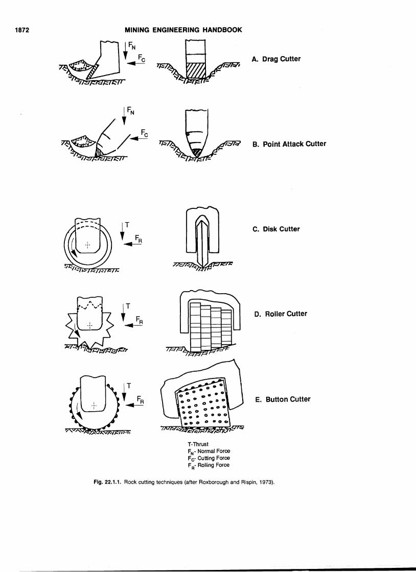
These basic cutting methods, defined in terms of tool type,are illustrated in Fig. 22.1.1 and include:
1. Drag bit cutting.2. Point-attack bit cutting.3. Disk cutting.4. Button cutting.5. Roller cutting.
22.1.2.1 Drag Bit and Point-attack Bit Cutting
The application of both drag bits and point-attack bits issimilar. The tools are inserted in tool holders (or boxes), whichare· integral parts of the cutting head, and may be held in placeby a circlip or spring. Point-attack bits are commonly free torotate in their holders. It has been claimed that this featurepromotes more even tool wear (self sharpening) and better overall tool life, although research by Hurt and Evans (1981) disputesthis. During cutting, the bits are pushed into the rock, developingcutting forces parallel to the direction of head rotation and normal forces parallel to the direction of head thrust. As these forcesbuild up to critical values, a macroscopic failure surface developsahead of the bit, and a piece of rock spalls away. The pick thenmoves ahead into the space left by the spalled chip until a newrock buttress is encountered, and tool forces again build up. Thecutting process is thus a cyclical one with rapid fluctuations intool forces. Adjacent bits produce parallel grooves and interaction between these has an important influence on cutting efficiency.
Roadheaders use drag and point-attack bits almost exclu~ively. These tools also find application on tunnel boring machine(TBM) cutterheads, but in this role they are generally limited tomachines operating in weaker formations.
22.1.2.2 Disk Cutting
Disk cutters (Fig. 22.1.1c) generally consist of solid steelalloy discs with a tapered cutting edge. The disk is mounted ina bearing and is free to roll in response to applied forces actingparallel to the rock surface. These rolling forces are analogousto the cutting forces applied in drag bit cutting.
Thrust and drag forces are applied to the disk through thebearing and act normal and parallel respectively to the rocksurface. Disks used in practice may be of the simple type illus-
1871
1872 MINING ENGINEERING HANDBOOK
A. Drag Cutter
B. Point Attack Cutter
C. Disk Cutter
D. Roller Cutter
E. Button Cutter
T-ThrustFN- Normal ForceFc- Cutting ForceFR- Rolling Force
Fig. 22.1.1. Rock cutting techniques (after Roxborough and Rispin, 1973).
RAPID EXCAVATION 1873trated, or may consist of multi-edge varieties, including typeswith successively smaller disk diameters giving a tapered orconical arrangement. Frequently these multi-row disks employcarbide inserts with chisel points imbedded nearly flush with thecircumference.
Simple disk cutters are used primarily on full face TBMs,and multi-row disks on raise boring machines (RBMs). Thrustforces acting on the cutting head push the cutter into the rockbuilding up stresses which cause local rock failure. Because ofthe translatory motion of the cutting head, the disk rolls forwardcutting a groove in the rock. As in the case of drag cutters,~interaction between adjacent grooves has been shown to have animportant influence on cutting efficiency.
22.1.2.3 Roller or Mill Tooth Cutting
Roller or mill-tooth cutting is similar to disk cutting exceptthat instead of a tapered disc edge, the tool is equipped withcircumferential teeth (Fig. 22.1.1d). As the cutter moves in response to rolling forces, each tooth in turn is pushed into therock, acting like a wedge, and causing local failure.
22.1.2.4 Button Cutting
Button cutters consist of cylindrical or conical tool bodiesinset with tungsten carbide buttons (Fig. 22.1.1e). The tool ismounted in a bearing in the same way as disk cutters or rollercutters and is free to roll in response to applied forces actingparallel to the rock surface. Thrust forces cause high stress concentrations beneath each button as they roll across the rocksurface, resulting in local failure and pulverization of the rock.The area of influence of each button is small and results in afine-grained product. Because the product size is small, specificenergy requirements are high and button cutting is the leastefficient of the rock cutting methods discussed. Button cuttingis used in applications in which high rock strength and abrasivitypreclude the use of other methods. These cutters also find application as reaming cutters used for final profiling on RBMs andTBMs.
22.1.3 BASIC METHODS OF PREDICTINGINSTANTANEOUS CUTTING RATES
22.1.3.1 Introduction
When considering the feasibility or cost effectiveness of employing a mechanical excavation system, the central questionsare (1) Can this machine cut this rock? (2) If so, how fast? and(3) What is the cost of maintaining this performance? Clearlythere is a need for a reliable method of performance prediction.Two aspects of machine performance need to be assessed toanswer the above questions. First, machine performance in termsof cutting rates or penetration rates must be assessed. Second,the overall system performance and reliability, with particularreference to those aspects that impact machine utilization, mustbe assessed. In the following discussion, methods of predictingor estimating cutting rates or penetration rates will be described,while methods of overall system assessment will be addressed insubsequent segments dealing with specific mechanical excavation methods.
Prediction of cutting rates requires information on rock material properties, rock mass properties, and machine characteristics. The link between these three groups of data is providedby what may be termed rock-tool or rock-machine interactionmodels, and the result of applying such a model is an estimate
or prediction of performance. In the following discussion, prediction methods are placed into two broad categories depending onwhether the interaction model is theoretical or empirical.
Before discussing performance prediction, the followingterms must be defined:
Cutting rate (used in conjunction with roadheaders andboom-type tunneling machines) is the rate at which rock is excavated during cutting (volume excavated/cutting time), usuallyexpressed in units of ft3/hr (m3/h). Care must always be takento determine whether quoted "cutting rates" refer to what maybe termed the instantaneous cutting rate (ICR) or the operationalcutting rate (OCR). Cutting rates determined under highly controlled conditions, such as a research field test, in which cuttingtime is recorded as the actual time spent in cutting (determinedfrom instrument measurements of power consumption againsttime) are instantaneous cutting rates. Under typical operationalconditions, cutting time is generally taken as synonymous withutilization. Minor delays resulting, for example, from adjustingthe boom position at the end of each cutting traverse, or reducedrates of production during final profiling, are neglected. Cuttingrates determined using utilization as the cutting time are termedoperational cutting rates. Clearly, performance predictions basedon instantaneous cutting rates, without an appropriate cuttingtime correction, will be overly optimistic. Back analyses suggestthat operational cutting rates commonly have values in the rangeof 0.45 to 0.60 times the instantaneous cutting rate. For finalprofiling, this figure may drop to 0.3, while during bulk production, an experienced operator may achieve a ratio as high as 0.85.
Specific energy is a commonly used measure of cuttabilitythat is defined as the work done to excavate a unit volume ofrock. In the context of rock cutting, specific energy should notbe thought of as a fundamental property of the rock. Rather, itis a function of rock properties, cutting tool design, and cuttingtool interaction, in the same way·as compressive strength is afunction of specimen size, shape, and test conditions. Measuredspecific energies are many times greater than theoretically determined values, the difference being accounted for in energy lostto frictional heating, vibration, and so on.
Penetration rate (used in conjunction with full-face shaft ortunnel boring machines) is the rate of advance measured duringthe cutting cycle, normally expressed in inches or feet (meters)/revolution or feet (meters)/hour. For practical purposes, instantaneous and operational penetration rates are considered equal.
Utilization is the time remaining for excavation whenplanned and unplanned machine stoppages have been accountedfor. Stoppages are required for a variety of reasons includingsupport installation, survey work, pick replacement, routine andnon-routine maintenance, .muck haulage delays, shift changes,and so on.
Advance rate is the rate of tunnel or drift advance, usuallyexpressed in units of feet (meters)/day, feet (meters)/shift, etc.,and is equal to
OCR/face area X utilization or penetration rate X utilization(22.1.1)
22.1.3.2 Theoretical Models of Rock Cutting
Theoretical models have been proposed that attempt to analyze peak forces required, or work done, to excavate a unitvolume of rock, and to relate these to fundamental rock properties such as shear and tensile strengths and internal frictionangles. All these models have certain weaknesses that limit theirusefulness for solving practical problems in machine design andperformance. These weaknesses relate to a poor understanding
1874 MINING ENGINEERING HANDBOOKpredict machine advance per revolution for a given machinepower and tool spacing; a separate calculation of yield per revolution is not required.
Roxborough and Phillips (1975) have presented expressionsfor thrust force Ft and rolling force F" acting on a disk duringunrelieved cutting:
where o-c is unconfined compressive strength (UCS), 8 is diskedge angle, D is disk diameter, and p is depth of penetration.Based on breakage patterns observed during actual cutting tests,they concluded that the failure process is controlled by shearstresses acting on the plane connecting the apices of adjacentgrooves.
Comparison of experimentally determined forces (for Buntersandstone) with calculated values presented by these workersindicated good correlation. Farmer and Glossop (1980) havepresented these equations (slightly modified in the case of Ft),and claim that expressions of this general form are in reasonableagreement with experimentally determIned results.
Roxborough and Phillips (1975) also suggest that the optimum spacing/penetration ratio is given by
where T is shear strength of the rock. Again, good correlationwas demonstrated between calculated and observed Sip ratio forBunter sandstone.
Eqs. 22.1.2 to 22.1.4, however, provide only a partial solutionfor prediction or head design. Using Eq. 22.1.4, the optimumspacing for a given penetration p can be calculated. Using thisvalue of p, it should then be possible to calculate Fr and Ft forindividual tools, using Eqs. 22.1.2 and 22.1.3. The total numberof tools can be determined from the optimum spacing and headdiameter, and hence the total torque and thrust requirementscan be determined. However, these will be overestimated becauseEqs. 22.1.2 and 22.1.3 apply to unrelieved cutting, whereas theactual spacing is selected to minimize tool forces.
Because of the current limitation of theoretical models, practical design approaches use empirical methods, as described in22.1.3.3.
(22.1.4)
(22.1.2)
(22.1.3)F r = 4o-c X p2 X tan 8/2
Ft = 4o-c X tan 8/2 X (Dp3 - p4)O.S
22.1.3.3 Empirical Methods of PredictingInstantaneous Cutting Rates for Roadheader andBoom-type Tunneling Machines
Because of the theoretical difficulties of modeling roadheader cutting performance, approaches to this problem are essentially empirical. It can be claimed that theoretical considerations have shed some light on which material and machineparameters have an important influence on performance, butwhile these parameters appear in many empirical performanceequations, they are always associated with dimensionless constants derived from actual cutting trials or performance data.
The simplest empirical prediction methods are based on theextrapolation of performance records of specific roadheadermodels under specific geotechnical conditions that match thoseof the proposed site. While this approach has the ~dvantage ofsimplicity, it also has a number of weaknesses. It is very difficultto collect high-quality roadheader performance data under otherthan the highly controlled conditions of a research project. Performance data collected under typical operational conditions,
of both the state of stress developed in the rock as a result ofthe applied forces and the mechanics of crack initiation andpropagation. In addition, materials are generally considered tobe homogeneous, and the important influence of pre-existingfractures is ignored.
Even with the simple case of a single cutting tool, a complexthree-dimensional state of stress must exist in the rock aroundthe tool tip. It is generally acknowledged that in the immediatecontact area of the tool, intense crushing of the rock must occur,and that the properties of this crushed material differ markedlyfrom those of the "intact" material. Theoretical approaches generally assume a simplified two-dimensional stress distribution,such as a point or line load, and neglect the properties of thecrushed zone and the important role of this zone in transmittingstresses from the tool to the intact rock. Further, in practicalcutting applications, multiple tools are arranged in a mannerthat promotes interaction between adjacent cuts, which has beenshown to improve the overall efficiency of the system. Thisintroduces a further level of complexity to the three-dimensionalstress distribution that tends to be neglected in theoreticalmodels.
Both brittle and plastic failure modes have been consideredin theoretical rock cutting models, the appropriateness of eachdepending on the initial properties of the rock, and changesinduced during cutting. Even in brittle rock, plastic deformationmay occur in the intensely stressed zone adjacent to the tool tip.Failure criteria based on both tensile and shear stresses has beenapplied to rock cutting, although in practice, failure may beinitiated in one mode and change to the other as the stressdistribution changes during crack propagation. Thus a rigoroustheoretical description of rock cutting must incorporate a sophisticated failure model, which accounts for both localized differences in material behavior and transient responses to a changingstress distribution. However, there can be little justification fordeveloping or applying such a failure model until equally sophisticated three-dimensional stress distribution models areavailable.
ApPLICATION OF THEORETICAL CUTTING MODELS TOROADHEADERS. In the case of roadheaders, the limitations oftheoretical models are compounded by the relatively large number of pick geometries available, the mode of roadheader operation (which involves continually varying normal forces), depthsofcut and mode of cutting [Le., sumping, traversing, etc. (Fowelland McFeat-Smith, 1976)], and a generally less-controlled cutting environment. Cutting theories applicable to roadheaders arenot considered sufficiently developed at this time to be useful asprediction tools and are not discussed further here.
ApPLICATION OF THEORETICAL CUTTING MODELS TOTUNNEL AND SHAFT BORING SYSTEMS. In the case of full-faceexcavation systems, theoretical modeling problems are less acute.Here, variations in cutter geometries are limited to variations indisk diameter and blade width. In addition, the cutting processis more controlled, involving relatively constant penetration rateand depth of cut, and only a single cutting mode. Because of this,some progress has been achieved in the application of theoreticalcutting models, albeit oversimplified, to prediction of the performance of full-face TBMs. The better theoretical models ofTBM performance are widely used as prediction tools, however,occasionally a significant deviation occurs. Whether the problemis in the model or in the ability of the sample or geotechnicaldata to represent the rock mass is not clear.
To be useful, such models must be able to predict thrustforces and rolling forces corresponding to specific depths ofpenetration in relieved cutting. Conversely, the models may predict achievable penetration given machine constraints governingavailable thrust and rolling forces. A model of this type will
RAPID EXCAVATION 1875
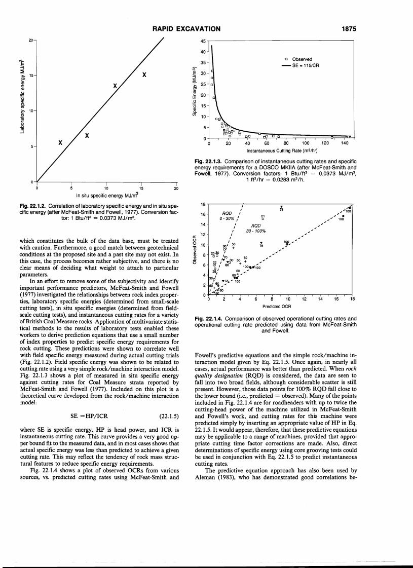
Fig. 22.1.3. Comparison of instantaneous cutting rates and specificenergy requirements for a DOSCO MKIIA (after McFeat-Smith andFowell, 1977). Conversion factors: 1 Btu/ft3 = 0.0373 MJ/m3,
1 ft3/hr = 0.0283 m3/h.
45
40
35M.E 30....,~>.~Cl>c:: 20UJ
~15·0
Cl>C.
Cl)10
5
o Observed
-SE = 115/CR
o
40 60 80 100 120 140
Instantaneous Cutting Rate (m3 /hr)
181614128 10
Predicted OCR
642
14
16
Fig. 22.1.4. Comparison of observed operational cutting rates andoperational cutting rate predicted using data from McFeat-Smith
and Fowell.
Fowell's predictive equations and the simple rock/machine interaction model given by Eq. 22.1.5. Once again, in nearly allcases, actual performance was better than predicted. When rockquality designation (RQD) is considered, the data are seen tofall into two broad fields, although considerable scatter is stillpresent. However, those data points for 100% RQD fall close tothe lower bound (i.e., predicted = observed). Many of the pointsincluded in Fig. 22.1.4 are for roadheaders with up to twice thecutting-head power of the machine utilized in McFeat-Smithand Fowell's work, and cutting rates for this machine werepredicted simply by inserting an appropriate value of HP in Eq.22.1.5. It would appear, therefore, that these predictive equationsmay be applicable to a range of machines, provided that appropriate cutting time factor corrections are made. Also, directdeterminations of specific energy using core grooving tests couldbe used in conjunction with Eq. 22.1.5 to predict instantaneouscutting rates.
The predictive equation approach has also been used byAleman (1983), who has demonstrated good correlations be-
18.....---------"---------------------,,.... ~~
ROD " 75 ~~~100, 21 ~ •
0-30,0,%,./ ROD c ~ ~ •• .,.,.,.,.,.,,, 100
30 - 100% ,,"a: '12
8 ' .... 100 ~~
l 10 2530 :r' s:! 75 • .,.,.,.,.".,
~ 8 00
'70 50 "'0 22 ,"....Jo 5~ + ~~~
6 0, 60 100 ....100
2~' 50 ~ ~4 ' 60+ ~
,309 ....6~ ~~~O
2 ~+~~~, ,.~60
O~__IpL___._____r"-..__....--....._____._____r"-..___r_~____r_____r-..____......__~____r____I
o
20
(22.1.5)SE =HP/ICR
o
where SE is specific energy, HP is head power, and ICR isinstantaneous cutting rate. This curve provides a very good upper bound fit to the measured data, and in most cases shows thatactual specific energy was less than predicted to achieve a givencutting rate. This may reflect the tendency of rock mass structural features to reduce specific energy requirements.
Fig. 22.1.4 shows a plot of observed OCRs from varioussources, vs. predicted cutting rates using McFeat-Smith and
which constitutes the bulk of the data base, must be treatedwith caution. Furthermore, a good match between geotechnicalconditions at the proposed site and a past site may not exist. Inthis case, the process becomes rather subjective, and there is noclear means of deciding what weight to attach to particularparameters.
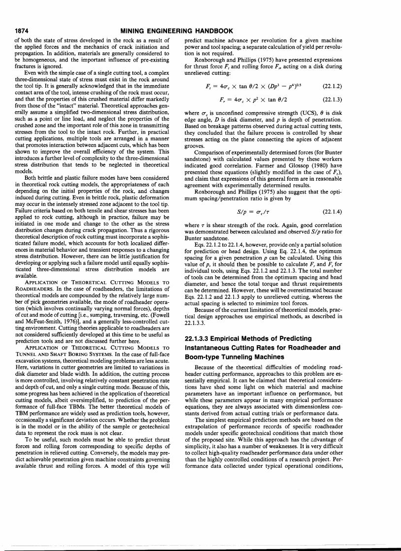
In an effort to remove some of the subjectivity and identifyimportant performance predictors, McFeat-Smith and Fowell(1977) investigated the relationships between rock index properties, laboratory specific energies (determined from small-scalecutting tests), in situ specific energies (determined from fieldscale cutting tests),. and instantaneous cutting rates for a varietyofBritish Coal Measure rocks. Application ofmultivariate statistical methods to the results of laboratory tests enabled theseworkers to derive prediction equations that use a small numberof index properties to predict specific energy requirements forrock cutting. These predictions were shown to correlate wellwith field specific energy measured during actual cutting trials(Fig. 22.1.2). Field specific energy was shown to be related tocutting rate using a very simple rock/machine interaction model.Fig. 22.1.3 shows a plot of measured in situ specific energyagainst cutting rates for Coal Measure strata reported byMcFeat-Smith and Fowell (1977). Included on this plot is atheoretical curve developed from the rock/machine interactionmodel:
10 15
In situ specific energy MJ/m3
Fig.22.1.2. Correlation of laboratory specific energy and in situ speci'fic energy (after McFeat-Smith and Fowell, 1977). Conversion fac-
tor: 1 Btu/ft3 = 0.0373 MJ/m3.
65432
Bits/Foot (e) and Feet/Hour of Machine Cutting p)
O~---,-----,----...,....----...,....-----.-----r--'---'
o
100
Fig. 22.1.6. Roadheader performance vs. rock class, P.21 A Test,2375 Level (after Sandbak, 1985). Conversion factor: 1 ft = 0.3048 m.
o
MINING ENGINEERING HANDBOOK
//
.s//
/
A',"~
/
• ·C •-.~- ---r-../.
/.~~
O~---~I-----rl------'-I---~
123 4
Actual performance nf/kN
1-
2-
3-
1876
Fig.22.1.5. Comparison of observed and predicted roadheader performance using Aleman's method (after Aleman, 1983). Conversion
factor: 1 ft3/lbf = 6.6367 m3/kN.20
O-\--~--r--.,...--r----,--...,-------,--,-...,....----,----,---~----j
o 200 400 600 800 1000 1200
RQ02l3
Rock Mass Cuttability Index kglcm2
(ac • 100 )
Fig. 22.1.7. Relationship between machine advance rate and rockmass cuttability index (after Bilgin et al., 1988). Conversion factors:
1 ft3/hr = 0.02832 m3/h, 1 psi = 0.0703 kg/cm2•
low-strength, heavily fractured rocks corresponding to lowRMR values.
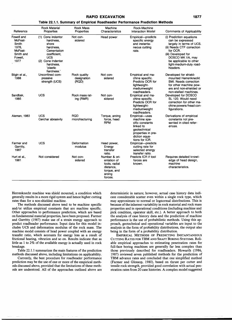
Bilgin et al. (1988) collected detailed data on machine performance (for a Herrenknecht SMl), rock mass properties androck material properties. Statistical analyses showed significantcorrelations between operational cutting rate and the product ofUCS X RQD2/3/100 (or rock-mass cuttability index RMCI, Fig.22.1.7). These workers also investigated the applicability of theRMCI to prediction of cutting rates for a Dosco Mk 2A and aPk 2r at other sites and found a reasonable correlation. Theseresults suggest that the RMCI may be applicable to a variety ofmachines provided that an adequate allowance can be madefor variations in head power. It should also be noted that the
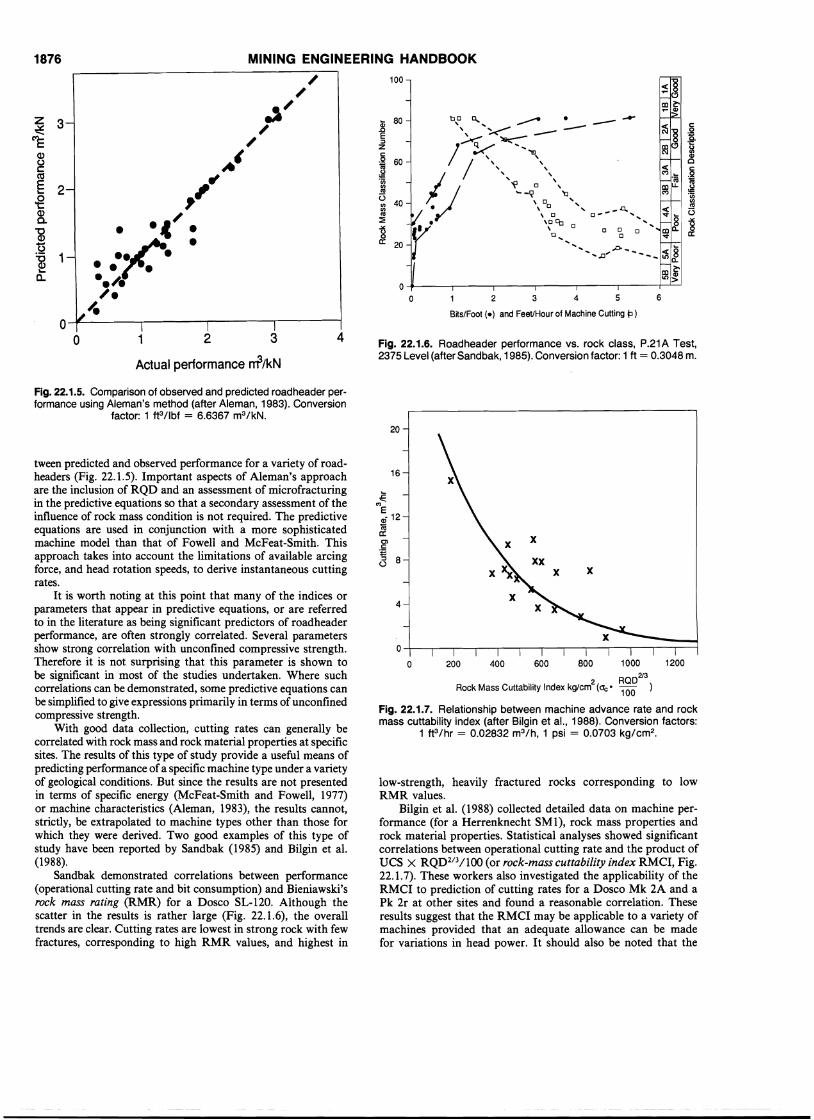
tween predicted and observed performance for a variety of roadheaders (Fig. 22.1.5). Important aspects of Aleman's approachare the inclusion of RQD and an assessment of microfracturingin the predictive equations so that a secondary assessment of theinfluence of rock mass condition is not required. The predictiveequations are used in conjunction with a more sophisticatedmachine model than that of Fowell and McFeat-Smith. Thisapproach takes into account the limitations of available arcingforce, and head rotation speeds, to derive instantaneous cuttingrates.
It is worth noting at this point that many of the indices orparameters that appear in predictive equations, or are referredto in the literature as being significant predictors of roadheaderperformance, are often strongly correlated. Several parametersshow strong correlation with unconfined compressive strength.Therefore it is not surprising that this parameter is shown tobe significant in most of the studies undertaken. Where suchcorrelations can be demonstrated, some predictive equations canbe simplified to give expressions primarily in terms of unconfinedcompressive strength.
With good data collection, cutting rates can generally becorrelated with rock mass and rock material properties at specificsites. The results of this type of study provide a useful means ofpredicting performance ofa specific machine type under a varietyof geological conditions. But since the results are not presentedin terms of specific energy (McFeat-Smith and Fowell, 1977)or machine characteristics (Aleman, 1983), the results cannot,strictly, be extrapolated to machine types other than those forwhich they were derived. Two good examples of this type ofstudy have been reported by Sandbak (1985) and Bilgin et al.(1988).
Sandbak demonstrated correlations between performance(operational cutting rate and bit consumption) and Bieniawski'srock mass rating (RMR) for a Dosco SL-120. Although thescatter in the results is rather large (Fig. 22.1.6), the overalltrends are clear. Cutting rates are lowest in strong rock with fewfractures, corresponding to high RMR values, and highest in
16
€('l)
Ea) 12coCl:0)c:
'=<3 8
4
x
xx
RAPID EXCAVATION 1877Table 22.1.1. Summary of Empirical Roadheader Performance Prediction Methods
Rock Material Rock Mass Machine Rock-MachineReference Properties Properties Characteristics Interaction Model Comments of Applicability
Fowell and (1) Cone indentor Not con- Head power Empirical-predicts (i) Prediction equationsMcFeat- hardness, sidered specific energy can be expressedSmith shore and instanta- largely in terms of UCS.1976, hardness, neous cutting (ii) Needs CTF correctionMcFeat- Cementation rate. for OCR.Smith and coefficient, (iii) Developed forFowell, UCS DOSCO MK IIA, may1977 (2) Cone Indenter be applicable to other
hardness, light-medium-duty road-'plastic headers.hardness.'
Bilgin et al., Unconfined com- Rock quality Not con- Empirical and ma- Developed for shield-1988 pressive designation sidered chine specific. mounted Herrenkneckt
strength (UCS) (RQD) Predicts OCR for SMI. Needs correctionlightweight- for other machine pow-mediumweight ers and non-shielded orroadheaders. non-stelled machines.
Sandbak, UCS Rock mass rat- Not con- Empirical and ma- peveloped for DOSCO1985 ing (RMR) sidered chine specific. SL 120. Would need
Predicts OCR for correction for other ma-lightweight- chine powers/head con-mediumweight figurations.roadheaders.
Aleman, 1983 UCS RQD Torque, arcing Empirical-uses Derivations of empiricalCerchar abrasivity microfracturing force, head machine spe- constants- not pre-
RPM cific constants sented in cited refer-linked to ences.geotechnicalproperties in pre-diction equa-tions for ICR.
Farmer and UCS Deformation Head power, Empirical-predictsGarritty, modulus Energy cutting rate for1987 transfer selected energy
ratio. transfer ratio.Hurt et al., Not considered Not con- Number & ori- Predicts ICR if tool Requires detailed knowl-
1981 sidered entation of forces are edge of head design,tools, radial known. machinedistance, characteristics.torque, andarcingforces.
Herrenknecht machine was shield mounted, a condition whichgenerally results in a more rigid system and hence higher cuttingrates than for a non-shielded machine.
The methods discussed above tend to be machine specificand/or utilize empirical constants that are machine specific.Other approaches to performance prediction, which are basedon fundamental material properties, have been proposed. Farmerand Garritty (1987) make use of a strain energy approach topredict roadheader performance. Input data for this model includes DCS and deformation modulus of the rock mass. Themachine model consists of head power coupled with an energytransfer ratio, which accounts for energy loss as a result offrictional heating, vibration and so on. Results indicate that aslittle as 1 to 2% of the available energy is actually used in rockbreakage.
Table 22.1.1 summarizes the main features of the predictionmethods discussed above, including limitations on applicability.
Currently, the best procedure for roadheader performanceprediction may be the use of one or more of the empirical methods discussed above, provided that the limitations of these methods are understood. All of the approaches outlined above are
deterministic in nature; however, actual case history data indicate considerable scatter even within a single rock type, whichmay approximate to normal or logri.ormal distributions. This isbecause of the inherent variability in rock material and rock massproperties and in operational conditions (including machine andpick condition, operator skill, etc.). A better approach to boththe analysis of case history data and the prediction of machineperformance is the use of probabilistic methods. Using this approach, geotechnical and operational variables are input to theanalysis in the form of probability distributions, the output alsobeing in the form of a probability distribution.
EMPIRICAL METHODS OF PREDICTING INSTANTANEOUSCUTTING RATES FOR TBM AND SHAFT BORING SYSTEMS. Reliable empirical approaches to estimating penetration rates forfull-face boring machines are generally far less complex thanthose previously described for roadheaders. Howarth (1986,1987) reviewed seven published methods for the prediction ofTBM advance rates and concluded that one simplified method(Farmer and Glossop, 1980), based on thrust per cutter andtensile rock strength, provided good correlation with actual penetration rates from 20 case histories. A complex model suggested
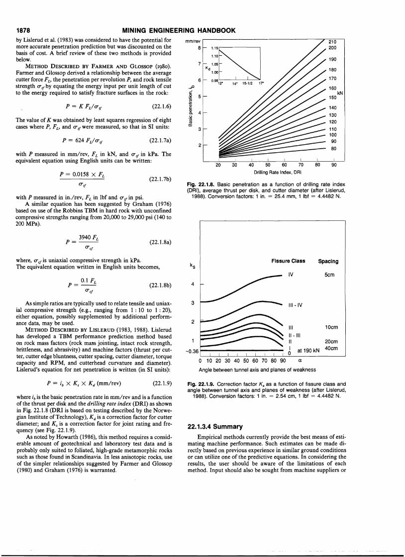
1878 MINING ENGINEERING HANDBOOK
The value of K was obtained by least squares regression of eightcases where P, Fv and erif were measured, so that in SI units:
with P measured in mm/rev, FL in kN, and erif in kPa. Theequivalent equation using English units can be written:
90
190
180
170
160kN
150
140
1301201101009080
210200
1---- I I I I I I
20 30 40 50 60 70 80
Drilling Rate Index, DRI
2
3
Fig. 22.1.8. Basic penetration as a function of drilling rate index(DRI), average thrust per disk, and cutter diameter (after Lislerud,
1988). Conversion factors: 1 in. = 25.4 mm, 1 Ibf = 4.4482 N.
mm/rev8 1.15
1.10
7 1.05Kd
1.00
6 0.9512
"14" 15-1/2 17"
._LJ
C.Q 5~Q;cQ)
4~
(,)·incoco
(22.1.6)
(22.1.7a)
(22.1.7b)P = 0.0158 X FL
by Lislerud et al. (1983) was considered to have the potential formore accurate penetration prediction but was discounted on thebasis of cost. A brief review of these two methods is providedbelow.
METHOD DESCRIBED BY FARMER AND GLOSSOP (1980).Farmer and Glossop derived a relationship between the averagecutter force Fv the penetration per revolution P, and rock tensilestrength erif by equating the energy input per unit length of cutto the energy required to satisfy fracture surfaces in the rock:
with P measured in in./rev, FL in lbf and erif in psi.A similar equation has been suggested by Graham (1976)
based on use of the Robbins TBM in hard rock with unconfinedcompressive strengths ranging from 20,000 to 29,000 psi (140 to200 MPa).
3940FLP=--ere!
(22.1.8a)
where, ere! is uniaxial compressive strength in kPa.The equivalent equation written in English units becomes,
Fissure Class Spacing
As simple ratios are typically used to relate tensile and uniaxial compressive strength (e.g., ranging from 1 : 10 to 1 : 20),either equation, possibly supplemented by additional performance data, may be used.
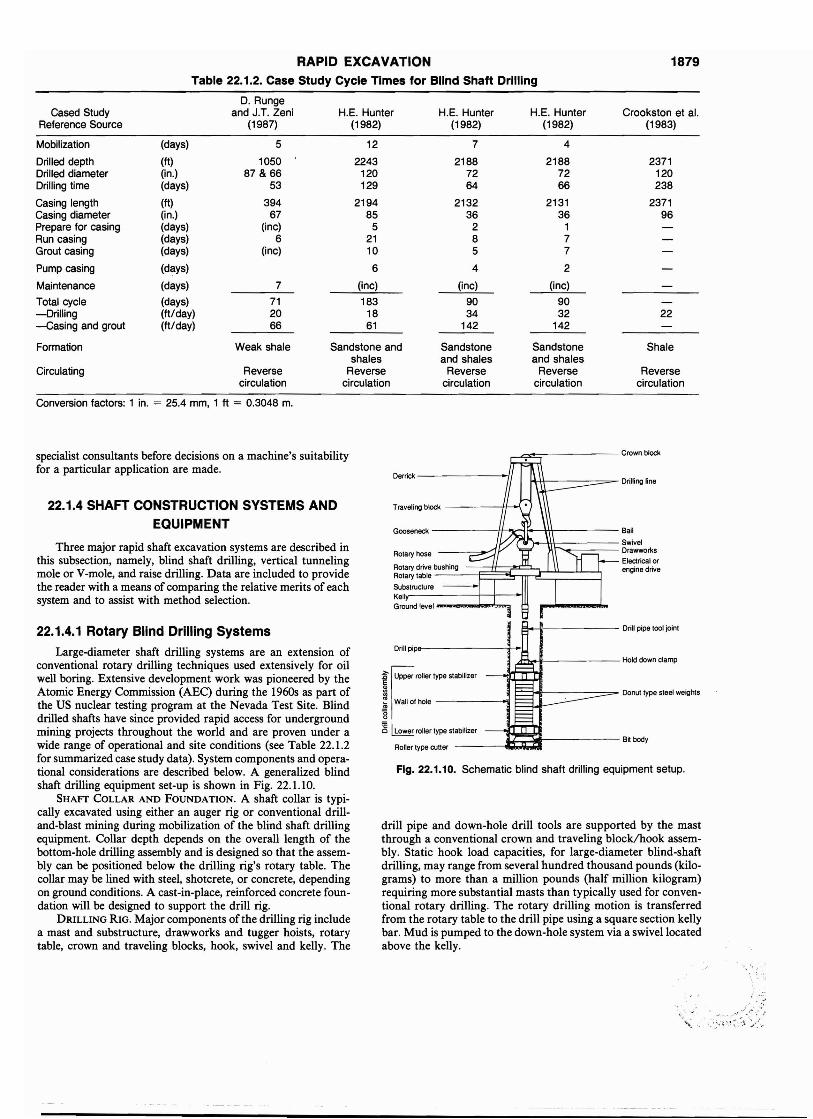
METHOD DESCRIBED BY LISLERUD (1983, 1988). Lislerudhas developed a TBM performance prediction method basedon rock mass factors (rock mass jointing, intact rock strength,brittleness, and abrasivity) and machine factors (thrust per cutter, cutter edge bluntness, cutter spacing, cutter diameter, torquecapacity and RPM, and cutterhead curvature and diameter).Lislerud's equation for net penetration is written (in SI units):
5cm
Ill-IV
IV
2
3
4
III 10cm
II - IIII1 20cm
-0.36 J at 190 kN 40cm
o 10 20 30 40 50 60 70 80 90 a
Angle between tunnel axis and planes of weakness
(22.1.8b)0.1 FLP=--
ere!
(22.1.9)
where ib is the basic penetration rate in mm/rev and is a functionof the thrust per disk and the drilling rate index (DRI) as shownin Fig. 22.1.8 (DRI is based on testing described by the Norwegian Institute of Technology), K d is a correction factor for cutterdiameter; and K s is a correction factor for joint rating and frequency (see Fig. 22.1.9).
As noted by Howarth (1986), this method requires a considerable amount of geotechnical and laboratory test data and isprobably only suited to foliated, high-grade metamorphic rockssuch as those found in Scandinavia. In less anisotopic rocks, useof the simpler relationships suggested by Farmer and Glossop(1980) and Graham (1976) is warranted.
Fig. 22.1.9. Correction factor Ks as a function of fissure class andangle between tunnel axis and planes of weakness (after Lislerud,
1988). Conversion factors: 1 in. = 2.54 cm, 1 Ibf = 4.4482 N.
22.1.3.4 Summary
Empirical methods currently provide the best means of estimating machine performance. Such estimates can be made directly based on previous experience in similar ground conditionsor can utilize one of the predictive equations. In considering theresults, the user should be aware of the limitations of eachmethod. Input should also be sought from machine suppliers or
RAPID EXCAVATION 1879Table 22.1.2. Case Study Cycle Times for Blind Shaft Drilling
D. RungeCased Study and J.T. Zeni H.E. Hunter H.E. Hunter H.E. Hunter Crookston et al.
Reference Source (1987) (1982) (1982) (1982) (1983)
Mobilization (days) 5 12 7 4
Drilled depth (ft) 1050 2243 2188 2188 2371Drilled diameter (in.) 87 & 66 120 72 72 120Drilling time (days) 53 129 64 66 238
Casing length (ft) 394 2194 2132 2131 2371Casing diameter (in.) 67 85 36 36 96Prepare for casing (days) (inc) 5 2 1Run casing (days) 6 21 8 7Grout casing (days) (inc) 10 5 7
Pump casing (days) 6 4 2
Maintenance (days) 7 (inc) (inc) (inc)
Total cycle (days) 71 183 90 90-Drilling (ft/day) 20 18 34 32 22-Casing and grout (ft/day) 66 61 142 142
Formation Weak shale Sandstone and Sandstone Sandstone Shaleshales and shales and shales
Circulating Reverse Reverse Reverse Reverse Reversecirculation circulation circulation circulation circulation
Conversion factors: 1 in. = 25.4 mm, 1 ft = 0.3048 m.
I+\'f-----===- Drilling lin.
e.-+------ Drill pip. tool joint
...::>:!:::"------ Crown block
..d::j~------ Hold down clamp
Rotary hose
Rotary drive bbuu~Sh~in~g-=~$3~~~~~~~Rotary tabl. -
SubstructureK.IIGround l.v.I---....-....."L".,"'lI
D.rrick-------11
Gooseneck ------,~"'""'J_____\_\1r_---- Bail
~r--m::::::;;=;:::::== Swivel"; DrawworksElectrical orengine drive
f Upper roller type stabilizer
~ t::::::::::!--If-------==_ Oonut type steel weightsl;; Wall 01 hole -~---o'fi L.........J.....--
~~o Lower roller type stabilizer
Traveling block -----ti-'~
Drill pip<r-------i-U
Fig. 22.1.10. Schematic blind shaft drilling equipment setup.
____-.tl;;,.~r------B~ bodyRon.r type cutter
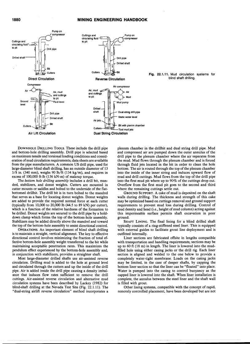
drill pipe and down-hole drill tools are supported by the mastthrough a conventional crown and traveling blocklhook assembly. Static hook load capacities, for large-diameter blind-shaftdrilling, may range from several hundred thousand pounds (kilograms) to more than a million pounds (half million kilogram)requiring more substantial masts than typically used for conventional rotary drilling. The rotary drilling motion is transferredfrom the rotary table to the drill pipe using a square section kellybar. Mud is pumped to the down-hole system via a swivel locatedabove the kelly.
22.1.4 SHAFT CONSTRUCTION SYSTEMS ANDEQUIPMENT
Three major rapid shaft excavation systems are described inthis subsection, namely, blind shaft drilling, vertical tunnelingmole or V-mole, and raise drilling. Data are included to providethe reader with a means of comparing the relative merits of eachsystem and to assist with method selection.
22.1.4.1 Rotary Blind Drilling Systems
Large-diameter shaft drilling systems are an extension ofconventional rotary drilling techniques used extensively for oilwell boring. Extensive development work was pioneered by theAtomic Energy Commission (AEC) during the 19608 as part ofthe US nuclear testing program at the Nevada Test Site. Blinddrilled shafts have since provided rapid access for undergroundmining projects throughout the world and are proven under awide range of operational and site conditions (see Table 22.1.2for summarized case study data). System components and operational considerations are described below. A generalized blindshaft drilling equipment set-up is shown in Fig. 22.1.10.
SHAFT COLLAR AND FOUNDATION. A shaft collar is typically excavated using either an auger rig or conventional drilland-blast mining during mobilization of the blind shaft drillingequipment. Collar depth depends on the overall length of thebottom-hole drilling assembly and is designed so that the assembly can be positioned below the drilling rig's rotary table. Thecollar may be lined with steel, shotcrete, or concrete, dependingon ground conditions. A cast-in-place, reinforced concrete foundation will be designed to support the drill rig.
DRILLING RIG. Major components of the drilling rig includea mast and substructure, drawworks and tugger hoists, rotarytable, crown and traveling blocks, hook, swivel and kelly. The
specialist consultants before decisions on a machine's suitabilityfor a particular application are made.
/..'.,
1880 MINING ENGINEERING HANDBOOK
Reverse Circulation
Pump on" compressor
Cuttings andcirculating f1uicrto pit
Drilled shaft
Direct Circulation
Cuttings andcirculating fluid to pit
Cutters
Pump oncompressor
Fig. 22.1.11. Mud circulation systems forblind shaft drilling.
Compressor
- Mud
Dual string drill pipe
Static water level
Air compressor
Bit with plenim chamber
Tool mud jets
Dual String Circulation
Cutters,--~.=..!
Air jets
Drilledshaft
Air, mudand cuttingsto pit
Air, mud........ and cuttings
to pitFluid level
Cutters
Air Lift Circulation
Ground -~.m II-'~r
level
DOWNHOLE DRILLING TOOLS. These include the drill pipeand bottom-hole drilling assembly. Drill pipe is selected basedon maximum tensile and torsional loading conditions and consideration ofmud circulation requirements; data sheets are availablefrom the pipe manufacturers. A common US drill pipe, used forlarge-diameter blind shaft drilling, has an outside diameter of 133/8 in. (340 mm), weighs 90 Ib/ft (134 kg/m), and requires inexcess of 100,000 ft-lb (136 kN-m) of makeup torque.
The bottom hole drilling assembly includes a drill bit, mandrel, stabilizers, and donut weights. Cutters are mounted incutter mounts or saddles and bolted to the underside of the flatbottomed drillbit. The drill bit is in turn bolted to the mandrelthat serves as a base for locating donut weights. Donut weightsare added to provide the required normal force at each cutter(typically from 10,000 to 20,000 Ib (44.5 to 89 kN) per cutter),which is a function of the relative hardness of the formation tobe drilled. Donut weights are secured to the drill pipe by a holddown clamp which forms the top of the bottom-hole assernbly.Stabilizers may be added directly above the mandrel and towardthe top of the bottom-hole assembly to assist directional control.
OPERATIONS. An important element of blind shaft drillingis to maintain a straight, vertical alignment. The key to effectivedirectional control involves minimizing the fraction of total effective bottom-hole assembly weight transferred to the bit whilemaintaining acceptable penetration rates. This maximizes thependulum effect experienced by the bottom-hole assembly and,in conjunction with stabilizers, provides a straighter shaft.
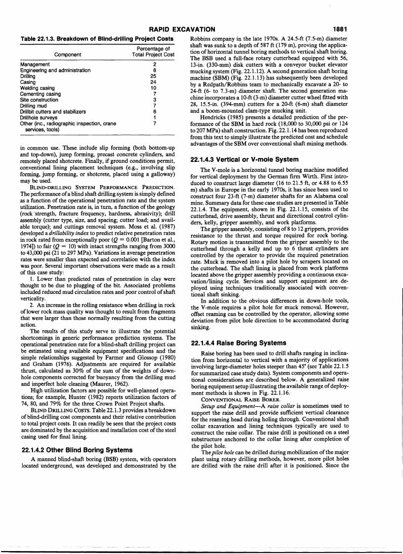
Most large-diameter drilled shafts use air-assisted reversecirculation. Drilling mud is added to the hole at ground leveland circulated through the cutters and up the inside of the drillpipe. Air is added inside the drill pipe causing a density imbalance that induces flow rates sufficient to remove the drillcuttings. Air-assisted reverse circulation and alternative mudcirculation systems have been described by Lackey (1982) forblind-shaft drilling at the Nevada Test Site (Fig. 22.1.11). The"dual-string airlift reverse circulation" method incorporates a
plenum chamber in the drillbit and dual string drill pipe. Mudand compressed air are pumped down the outer annulus of thedrill pipe to the plenum chamber where the air separates fromthe mud. Mud flows through the plenum chamber and is forcedthrough fluid jets located in the bit in order to clean the holebottom. The air is routed through the top of the plenum chamberinto the inside of the inner string and induces upward flow ofmud and drill cuttings. Mud flows from the top of the drill pipeinto the first mud pit where up to 90% of the cuttings drop out.Overflow from the first mud pit goes to the second and thirdwhere the remaining cuttings settle out.
GROUND SUPPORT. A cake of mud is deposited on the shaftwalls during drilling. The thickness and strength of this cakemay be optimized based on cuttings removal and ground supportrequirements to prevent mud loss during drilling. Control ofmud density and head (i.e., height of mud column) acting againstthis impermeable surface permits shaft excavation in poorground.
SHAFT LINING. The final lining for a blind drilled shafttypically consists of a ring-stiffened steel liner. This is equippedwith external guides to facilitate grout line deployment and isoutfitted internally. .
Liner sections are fabricated offsite in lengths compatiblewith transportation and handling requirements; sections may beup to 60 ft (18 m) in length. The liner is lowered into the mudfilled hole using either casing jacks or the drill rig. Each linersection is aligned and welded to the one below to provide acompletely water-tight membrane. Loads on the casing jacksmay be limited, in the case of deeper shafts, by capping thebottom liner section so that the liner can be "floated" into place.Water is pumped into the casing to control buoyancy as thecapped liner is lowered into the shaft. When liner installation iscomplete, the annulus between the steel liner and the shaft wallis filled with grout.
Other lining systems, compatible with the concept of rapid,remotely controlled placement, have been developed but are not
RAPID EXCAVATION 1881
22.1.4.4 Raise Boring Systems
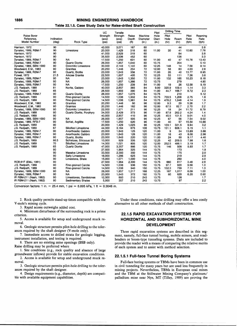
Raise boring has been used to drill shafts ranging in inclination from horizontal to vertical with a majority of applicationsinvolving large-diameter holes steeper than 45° (see Table 22.1.5for summarized case study data). System components and operational considerations are described below. A generalized raiseboring equipment setup illustrating the available range ofdeployment methods is shown in Fig. 22.1.16.
CONVENTIONAL RAISE BORER.Setup and Equipment-A raise collar is sometimes used to
support the raise drill and provide sufficient vertical. clearancefor the reaming head during holing through. ConventIonal shaftcollar excavation and lining techniques typically are used toconstruct the raise collar. The raise drill is positioned on a steelsubstructure anchored to the collar lining after completion ofthe pilot hole. .
Thepilot hole can be drilled during mobilization of~he majorplant using rotary drilling methods, however, more ptlot holesare drilled with the raise drill after it is positioned. Since the
22.1.4.3 Vertical or V-mole System
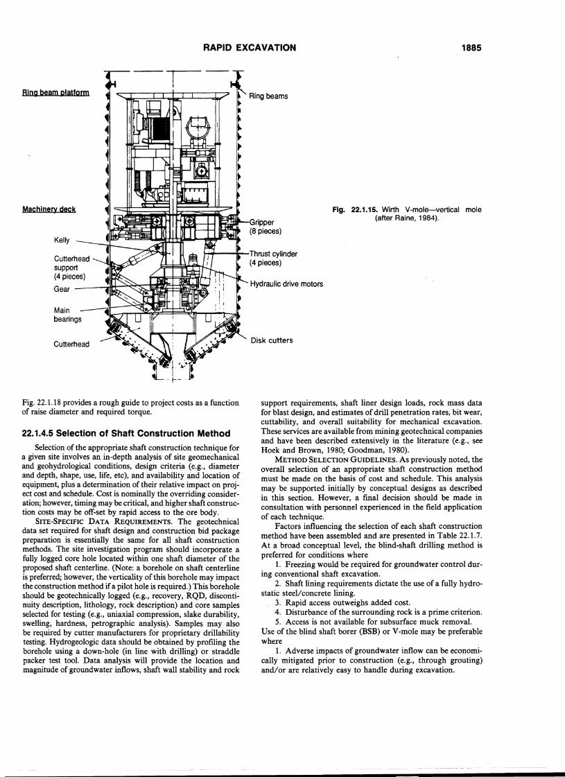
The V-mole is a horizontal tunnel boring machine modifiedfor vertical deployment by the German firm Wirth. First introduced to construct large diameter (16 to 21.5 ft, or 4.88 to 6.55m) shafts in Europe in the early 1970s, it has since been used toconstruct four 23-ft (7-m) diameter shafts for an Alabama coalmine. Summary data for these case studies are presented in Table22.1.4. The equipment, shown in Fig. 22.1.15, consists of thecutterhead, drive assembly, thrust and directional control cylin-ders, kelly, gripper assembly, and work platforms. .
The gripper assembly, consisting of 8 to 12 grippers, prOVIdesresistance to the thrust and torque required for rock boring.Rotary motion is transmitted from the gripper assembly to thecutterhead through a kelly and up to 6 thrust cylinders arecontrolled by the operator to provide the required penetrationrate. Muck is removed into a pilot hole by scrapers located onthe cutterhead. The shaft lining is placed from work platformslocated above the gripper assembly providing a continuous excavationllining cycle. Services and support equipment are deployed using techniques traditionally associated with conventional shaft sinking.
In addition to the obvious differences in down-hole tools,the V-mole requires a pilot hole for muck removal. However,offset reaming can be controlled by the operator, allowing so~e
deviation from pilot hole direction to be accommodated dunngsinking.
Robbins company in the late 1970s~ A 24.5-ft (7.5-m) diam~ter
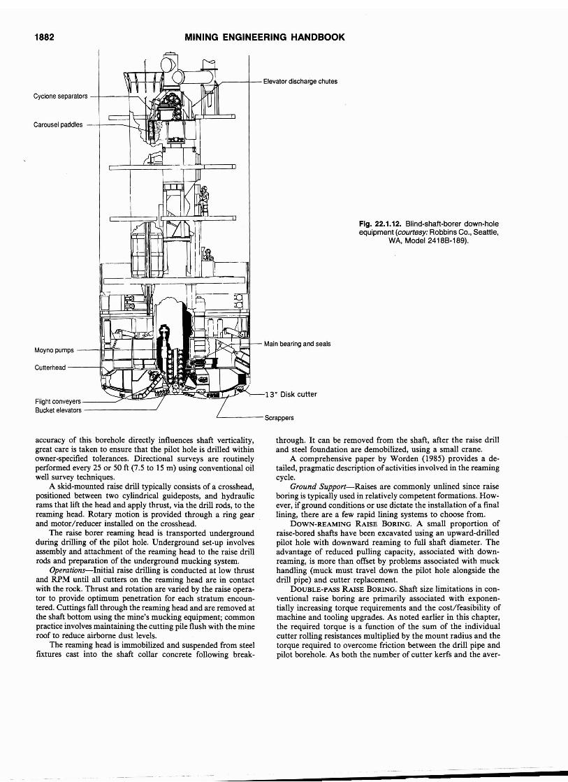
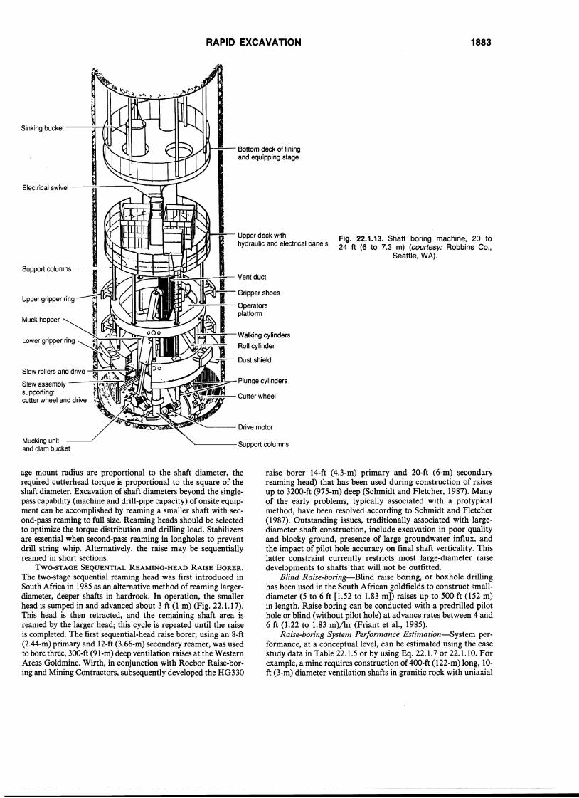
shaft was sunk to a depth of 587 ft (179 m), proving the appltcation of horizontal tunnel boring methods to vertical shaft boring.The BSB used a full-face rotary cutterhead equipped with 56,13-in. (330-mm) disk cutters with a conveyor bucket elevatormucking system (Fig. 22.1.12). A second generation shaft boringmachine (SBM) (Fig. 22.1.13) has subsequently been developedby a RedpathlRobbins team to mechanically excavate a 20- to24-ft (6- to 7.3-m) diameter shaft. The second generation ~a
chine incorporates a 10-ft (3-m) diameter cutter wheel fitted wIth28, 15.5-in. (394-mm) cutters for a 20-ft (6-m) shaft diameterand a boom-mounted clam-type mucking unit.
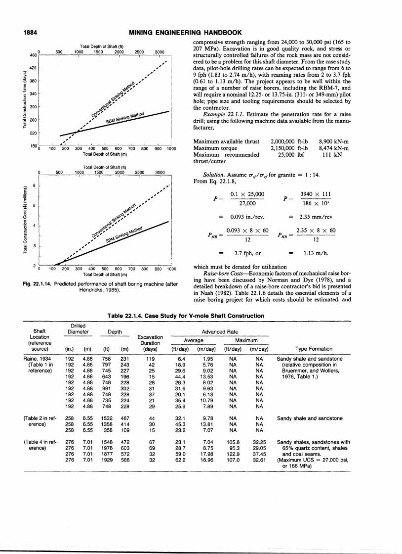
Hendricks (1985) presents a detailed prediction of the performance of the SBM in hard rock (18,000 to 30,000 psi or 124to 207 MPa) shaft construction. Fig. 22.1.14 has been reproducedfrom this text to simply illustrate the predicted cost and scheduleadvantages of the SBM over conventional shaft mining methods.
28
252410
737617
Component
Table 22.1.3. Breakdown of Blind-drilling Project Costs
Percentage ofTotal Project Cost
22.1.4.2 Other Blind Boring SystemsA manned blind-shaft boring (BSB) system, with operators
located underground, was developed and demonstrated by the
in common use. These include slip forming (both bottom-upand top-down), jump forming, precast concrete cylinders, andremotely placed shotcrete. Finally, if ground conditions permit,conventional lining placement techniques (e.g., involving slipforming, jump forming, or shotcrete, placed using a galloway)may be used.
BLIND-DRILLING SYSTEM PERFORMANCE PREDICTION.The performance ofa blind shaft drilling system is simply definedas a function of the operational penetration rate and the systemutilization. Penetration rate is, in turn, a function of the geology(rock 'strength, fracture frequency, hardness, abrasivity); d~ll
assembly (cutter type, size, and spacing; cutter load; and avatlable torque); and cuttings removal system. Moss et al. (1987)developed a drillability index to predict relative penetration ratesin rock rated from exceptionally poor (Q = 0.001 [Barton et al.,1974]) to fair (Q = 10) with intact strengths ranging from 3000to 43,000 psi (21 to 297 MPa). Variations in average penetrationrates were smaller than expected and correlation with the indexwas poor. Several important observations were made as a resultof this case study:
1. Lower than predicted rates of penetration in clay werethought to be due to plugging of the bit. Associated problemsincluded reduced mud circulation rates and poor control of shaftverticality.
2. An increase in the rolling resistance when drilling in rockof lower rock mass quality was thought to result from fragmentsthat were larger than those normally resulting from the cuttingaction.
The results of this study serve to illustrate the potentialshortcomings in generic performance prediction systems. Theoperational penetration rate for a blind-shaft drilling project canbe estimated using available equipment specifications and thesimple relationships suggested by Farmer and Glossop (1980)and Graham (1976). Adjustments are required for availablethrust, calculated as 30% of the sum of the weights of downhole components corrected for buoyancy from the drilling mudand imperfect hole cleaning (Maurer, 1962).
High utilization factors are possible for well-planned operations; for example, Hunter (1982) reports utilization factors of74, 80, and 79% for the three Crown Point Project shafts.
BLIND DRILLING COSTS. Table 22.1.3 provides a breakdownofblind-drilling cost components and their relative contributionto total project costs. It can readily be seen that the project costsare dominated by the acquisition and installation cost of the steelcasing used for final lining.
ManagementEngineering and administrationDrillingCasingWelding casingCementing casingSite constructionDriUing mud[)rillbit cutters and stabilizersDrillhole surveysOther (inc., radiographic inspection, crane
services, tools)
1882 MINING ENGINEERING HANDBOOK
Fig. 22.1.12. Blind-shalt-borer down-holeequipment (courtesy: Robbins Co., Seattle,
WA, Model 2418B-189).
13' Disk cutter
~,.,-1l-if---Main bearing and seals
m-il-t-lHJI _'-.a---=~v---+-Elevator discharge chutes
Flight conveyers __~~~~~~'~~~~~~~l'~Bucket elevators -J
Culterhead---i~1i~~I~U
Moyno pumps ---tH=1i=--1If--tt-.-
Carousel paddles --t----L
Cyclone separators --t-----i_____
'------SCrappers
accuracy of this borehole directly influences shaft verticality,great care is taken to ensure that the pilot hole is drilled withinowner-specified tolerances. Directional surveys are routinelyperformed every 25 or SO ft (7.5 to IS m) using conventional oilwell survey techniques.
A skid-mounted raise drill typically consists of a crosshead,positioned between two cylindrical guideposts, and hydraulicrams that lift the head and apply thrust, via the drill rods, to thereaming head. Rotary motion is provided through a ring gearand motor/reducer installed on the crosshead.
The raise borer reaming head is transported undergroundduring drilling of the pilot hole. Underground set-up involvesassembly and attachment of the reaming head to the raise drillrods and preparation of the underground mucking system.
Operations-Initial raise drilling is conducted at low thrustand RPM until all cutters on the reaming head are in contactwith the rock. Thrust and rotation are varied by the raise operator to provide optimum penetration for each stratum encountered. Cuttings fall through the reaming head and are removed atthe shaft bottom using the mine's mucking equipment; commonpractice involves maintaining the cutting pile flush with the mineroof to reduce airborne dust levels.
The reaming head is immobilized and suspended from steelfixtures cast into the shaft collar concrete following break-
through. It can be removed from the shaft, after the raise drilland steel foundation are demobilized, using a small crane.
A comprehensive paper by Worden (1985) provides a detailed, pragmatic description of activities involved in the reamingcycle.
Ground Support-Raises are commonly unlined since raiseboring is typically used in relatively competent formations. However, if ground conditions or use dictate the installation of a finallining, there are a few rapid lining systems to choose from.
DOWN-REAMING RAISE BORING. A small proportion ofraise-bored shafts have been excavated using an upward-drilledpilot hole with downward reaming to full shaft diameter. Theadvantage of reduced pulling capacity, associated with downreaming, is more than offset by problems associated with muckhandling (muck must travel down the pilot hole alongside thedrill pipe) and cutter replacement.
DOUBLE-PASS RAISE BORING. Shaft size limitations in conventional raise boring are primarily associated with 'exponentially increasing torque requirements and the cost/feasibility ofmachine and tooling upgrades. As noted earlier in this chapter,the required torque is a function of the sum of the individualcutter rolling resistances multiplied by the mount radius and thetorque required to overcome friction between the drill pipe andpilot borehole. As both the number of cutter kerfs and the aver-
--_.--------------
Sinking bucket --~---A-~./
Electrical swivel---...;....----.
Support columns
Slew rollers and drive ~:"""""~~~11f
Slew assemblysupporting:cutter wheel and drive
Mucking unitand clam bucket
RAPID EXCAVATION
••
Bottom deck of liningand equipping stage
Upper deck withhydraulic and electrical panels
""'--------- Support columns
1883
Fig. 22.1.13. Shaft boring machine, 20 to24 ft (6 to 7.3 m) (courtesy: Robbins Co.,
Seattle, WA).
age mount radius are proportional to the shaft diameter, therequired cutterhead torque is proportional to the square of theshaft diameter. Excavation of shaft diameters beyond the singlepass capability (machine and drill-pipe capacity) of onsite equipment can be accomplished by reaming a smaller shaft with second-pass reaming to full size. Reaming heads should be selectedto optimize the torque distribution and drilling load. Stabilizersare essential when second-pass reaming in longholes to preventdrill string whip. Alternatively, the raise may be sequentiallyreamed in short sections.
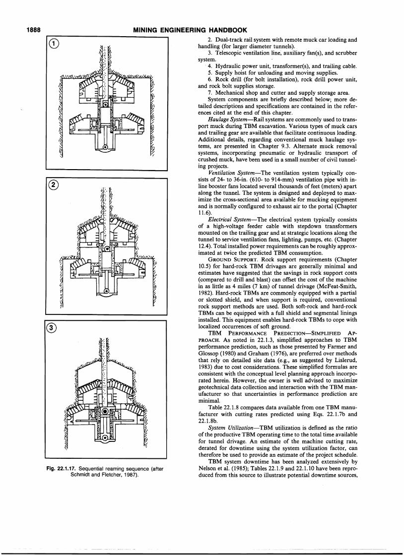
TWO-STAGE SEQUENTIAL REAMING-HEAD RAISE BORER.
The two-stage sequential reaming head was first introduced inSouth Africa in 1985 as an alternative method of reaming largerdiameter, deeper shafts in hardrock. In operation, the smallerhead is sumped in and advanced about 3 ft (1 m) (Fig. 22.1.17).This head is then retracted, and the remaining shaft area isreamed by the larger head; this cycle is repeated until the raiseis completed. The first sequential-head raise borer, using an 8-ft(2.44-m) primary and 12-ft (3.66-m) secondary reamer, was usedto bore three, 3oo-ft (91-m) deep ventilation raises at the WesternAreas Goldmine. Wirth, in conjunction with Rocbor Raise-boring and Mining Contractors, subsequently developed the HG330
raise borer 14-ft (4.3-m) primary and 20-ft (6-m) secondaryreaming head) that has been used during construction of raisesup to 32oo-ft (975-m) deep (Schmidt and Fletcher, 1987). Manyof the early problems, typically associated with a protypicalmethod, have been resolved according to Schmidt and Fletcher(1987). Outstanding issues, traditionally associated with largediameter shaft construction, include excavation in poor qualityand blocky ground, presence of large groundwater influx, andthe impact of pilot hole accuracy on final shaft verticality. Thislatter constraint currently restricts most large-diameter raisedevelopments to shafts that will not be outfitted.
Blind Raise-boring-Blind raise boring, or boxhole drillinghas been used in the South African goldfields to construct smalldiameter (5 to 6 ft [1.52 to 1.83 m]) raises up to 500 ft (152 m)in length. Raise boring can be conducted with a predrilled pilothole or blind (without pilot hole) at advance rates between 4 and6 ft (1.22 to 1.83 m)/hr (Friant et aI., 1985).
Raise-boring System Performance Estimation-System performance, at a conceptual level, can be estimated using the casestudy data in Table 22.1.5 or by using Eq. 22.1.7 or 22.1.10. Forexample, a mine requires construction of400-ft (122-m) long, 10ft (3-m) diameter ventilation shafts in granitic rock with uniaxial
8,900 kN-m8,474 kN-m
111 kN
2,000,000 ft-Ib2,150,000 ft-Ib
25,000 lbf
Maximum available thrustMaximum torqueMaximum recommendedthrust/cutter
MINING ENGINEERING HANDBOOKcompressive strength ranging from 24,000 to 30,000 psi (165 to207 MPa). Excavation is in good quality rock, and stress orstructurally controlled failures of the rock mass are not considered to be a problem for this shaft diameter. From the case studydata, pilot-hole drilling rates can be expected to range from 6 to9 fph (1.83 to 2.74 mlh), with reaming rates from 2 to 3.7 fph(0.61 to 1.13 mlh). The project appears to be well within therange of a number of raise borers, including the RBM-7, andwill require a nominal 12.25- or 13.75-in. (311- or 349-mm) pilothole; pipe size and tooling requirements should be selected bythe contractor.
Example 22.1.1. Estimate the penetration rate for a raisedrill; using the following machine data available from the manufacturer,
180 ° 100 200 300 400 500 600 700 800 900 1000Total Depth of Shaft (m)
Total Depth of Shaft (ft)460°.-__50,-0__1_0,-00__1_50r-0__2_0r-00__2_5,...00__3_0-r-00------,
220
420
1884
Ui'>ca~ 380Q)
E~ 340o·u~ 300co()
ca 260'5I-
0.1 X 25,000 3940 XlIIP= P=
27,000 186 X 103
0.093 in./rev. 2.35 mm/rev
0.093 X 8 X 60 2.35 X 8 X 60PHR =
12PHR =
12
3.7 fph, or 1.13 m/h.
Solution. Assume 0"if/0"cl for granite = 1 : 14.From Eq. 22.1.8,
which must be derated for utilizationRaise-bore Costs-Economic factors ofmechanical raise bor
ing have been discussed by Norman and Dye (1978), and adetailed breakdown of a raise-bore contractor's bid is presentedin Nash (1982). Table 22.1.6 details the essential elements of araise boring project for which costs should be estimated, and
Total Depth of Shaft (ft)1000 1500 2000 2500 3000500°
Ui'6
c~g~ 5
7ii0()
c:0
4·u27iic:0()
ca 3'5I-
20 100 200 300 400 500 600 700 800 900 1000
Total Depth of Shaft (m)
Fig. 22.1.14. Predicted performance of shaft boring machine (afterHendricks, 1985).
Table 22.1.4. Case Study for V-mole Shaft Construction
DrilledShaft Diameter Depth Advanced Rate
Location ExcavationAverage Maximum(reference Duration
source) (in.) (m) (ft) (m) (days) (ft/day) (m/day) (ft/day) (m/day) Type Formation
Raine, 1934 192 4.88 758 231 119 6.4- 1.95 NA NA Sandy shale and sandstone(Table 1 in 192 4.88 797 243 42 18.9 5.76 NA NA (relative composition inreference) 192 4.88 745 227 25 29.6 9.02 NA NA Bruemmer, and Wollers,
192 4.88 643 196 15 44.4 13.53 NA NA 1976, Table 1.)192 4.88 748 228 28 26.3 8.02 NA NA192 4.88 991 302 31 31.6 9.63 NA NA192 4.88 748 228 37 20.1 6.13 NA NA192 4.88 735 224 21 35.4 10.79 NA NA192 4.88 748 228 29 25.9 7.89 NA NA
(Table 2 in ref- 258 6.55 1532 467 44 32.1 9.78 NA NA Sandy shale and sandstoneerence) 258 6.55 1358 414 30 45.3 13.81 NA NA
258 6.55 358 109 15 23.2 7.07 NA NA
(Table 4 in ref- 276 7.01 1548 472 67 23.1 7.04 105.8 32.25 Sandy shales, sandstones witherence) 276 7.01 1978 603 69 28.7 8.75 95.3 29.05 65 % quartz content, shales
276 7.01 1877 572 32 59.0 17.98 122.9 37.45 and coal seams.276 7.01 1929 588 32 62.2 18.96 107.0 32.61 (Maximum UCS = 27,000 psi,
or 186 MPa)
Ring beam platform
Machinery deck
Kelly
Cutterheadsupport(4 pieces)
Gear
Mainbearings
Cutterhead
RAPID EXCAVATION
Ring beams
Gripper(8 pieces)
~l.oo--+--Thrust cylinder(4 pieces)
Hydraulic drive motors
Disk cutters
1885
Fig. 22.1.15. Wirth V-mole-vertical mole(after Raine, 1984).
Fig. 22.1.18 provides a rough guide to project costs as a functionof raise diameter and required torque.
22.1.4.5 Selection of Shaft Construction Method
Selection of the appropriate shaft construction technique fora given site involves an in-depth analysis of site geomechanicaland geohydrological conditions, design criteria (e.g., diameterand depth, shape, use, life, etc), and availability and location ofequipment, plus a determination of their relative impact on project cost and schedule. Cost is nominally the overriding consideration; however, timing may be critical, and higher shaft construction costs may be off-set by rapid access to the ore body.
SITE-SPECIFIC DATA REQUIREMENTS. The geotechnicaldata set required for shaft design and construction bid packagepreparation is essentially the same for all shaft constructionmethods. The site investigation program should incorporate afully logged core hole located within one shaft diameter of theproposed shaft centerline. (Note: a borehole on shaft centerlineis preferred; however, the verticality of this borehole may impactthe construction method ifa pilot hole is required.) This boreholeshould be geotechnically logged (e.g., recovery, RQD, discontinuity description, lithology, rock description) and core samplesselected for testing (e.g., uniaxial compression, slake durability,swelling, hardness, petrographic analysis). Samples may alsobe required by cutter manufacturers for proprietary drillabilitytesting. Hydrogeologic data should be obtained by profiling theborehole using a down-hole (in line with drilling) or straddlepacker test tool. Data analysis will provide the location andmagnitude of groundwater inflows, shaft wall stability and rock
support requirements, shaft liner design loads, rock mass datafor blast design, and estimates of drill penetration rates, bit wear,cuttability, and overall suitability for mechanical excavation.These services are available from mining geotechnical companiesand have been described extensively in the literature (e.g., seeHoek and Brown, 1980; Goodman, 1980).
METHOD SELECTION GUIDELINES. As previously noted, theoverall selection of an appropriate shaft construction methodmust be made on the basis of cost and schedule. This analysismay be supported initially by conceptual designs as describedin this section. However, a final decision should be made inconsultation with personnel experienced in the field applicationof each technique.
Factors influencing the selection of each shaft constructionmethod have been assembled and are presented in Table 22.1.7.At a broad conceptual level, the blind-shaft drilling method ispreferred for conditions where
1. Freezing would be required for groundwater control during conventional shaft excavation.
2. Shaft lining requirements dictate the use of a fully hydro-static. steel/concrete lining.
3. Rapid access outweighs added cost.4. Disturbance of the surrounding rock is a prime criterion.5. Access is not available for subsurface muck removal.
Use of the blind shaft borer (BSB) or V-mole may be preferablewhere
1. Adverse impacts of groundwater inflow can be economically mitigated prior to construction (e.g., through grouting)and/or are relatively easy to handle during excavation.
1886 MINING ENGINEERING HANDBOOKTable 22.1.5. Case Study Data for Raise-drilled Shaft Construction
UC Tensile PilotDrilling Time
Raise Borer Strength Strength Raise Machine Hole Pilot Pilot ReamingReference, Inclination (ave) (ave) Depth Diameter Diam Hole Ream Rate Rate
Model Number (deg) Rock Type (psi) (psi) (ft) (in.) (in.) (hr) (hr) (fph) (fph)
Harrison, 1972 90 43,000 3,071 167 60 44 3.8Dynatec, 1989, RBM-7 90 Limestone 20,000 1,429 318 60 11.00 30 41 10.60 7.76Harrison, 1972 90 41,000 2,929 319 60 84 3.8Harrison, 1972 90 35,500 2,536 452 60 136 3.3Dynatec, 1989, RBM-7 90 NA 17,500 1,250 631 60 11.00 40 47 15.78 13.43
'- Dyantec, 1989, RBM-7 90 Quartz Diorite 26,000 1,857 1,040 60 13.75 204 5.10Dynatec, 1989, SBM-1000 90 Dolomitic Limestone 30,000 2,143 1,122 60 12.25 148 14 7.58 8.14Woodward, E.M., 1983 90 Granites 20,250 1,446 234 72 12.00 58 83 4.03 2.8Dynatec, 1989, RBM-7 90 Quartz, Biotite 23,000 1,643 358 72 11.00 26 40 13.77 8.95Folwel, 1972 21.5 Arkose Granite 22,500 1,607 ·405 72 12.25 55 111 7.36 3.6Dynatec, 1989, RBM-7 90 NA 23,000 1,643 1,350 72 11.00 132 165 10.23 8.18Dynatec, 1989, RBM-7 90 NA 26,000 1,857 1,366 72 13.75 279 4.90Dynatec, 1989, RBM-7 90 NA 17,500 1,250 239 84 11.00 19 26 12.58 9.19J.S. Redpath, 1989 81 Norite, Gabbro 40,000 2,857 365 84 9.00 320.9 109.4 1.14 3.3J.S. Redpath, 1989 65 26,500 1,893 390 84 11.00 44.7 166.7 8.72 2.3Dynatec, 1989, RBM-7 90 Quartz Diorite 26,000 1,857 1,075 84 13.75 210 5.12J.S. Redpath, 1989 90 Fine-grained Calcite 14,500 1,036 1,932 84 13.75 703.5 1,206 2.75 1.6J.S. Redpath, 1989 90 Fine-grained Calcite 14,500 1,036 1,981 84 13.75 478.2 1,048 4.14 1.9Woodward, E.M., 1983 90 Granites 20,250 1,446 50 96 12.00 9.3 29 5.38 1.7Woodward, E.M., 1983 90 Graintes 20,250 1,446 182 96 12.00 67.5 82.7 2.70 2.2Dynatec, 1989, SBM-1000 90 Dolomitic Limestone 22,000 1,571 211 96 12.25 18 24 11.72 8.79J.S. Redpath, 1989 90 Quartz Diorite, Porphyry 34,000 2,429 373 96 11.00 87.9 262.2 4.24 1.4J.S. Redpath, 1989 90 40,000 2,857 410 96 12.25 45.5 101.5 9.01 4.0Dynatec, 1989, SBM-1000 90 NA 26,000 1,857 505 96 12.25 67 56 7.54 9.02Dynatec, 1989, RFB-7 90 Schist, Argillite 17,500 1,250 620 96 11.00 40 57 15.50 1;0.88J.S. Redpath, 1989 90 20,000 1,429 1,025 96 12.25 103.1 321.5 9.94 3.2J.S. Redpath, 1989 67 Silicified Limestone 44,300 3,164 675 108 13.75 131.1 606.1 5.15 1.1Dynatec, 1989, RBM-7 90 Anorthositic Gabbro 23,000 1,643 125 120 11.00 9 34 13.89 3.68Dynatec, 1989, RBM-7 90 Anorthositic Gabbro 23,000 1,643 128 120 11.00 16 43 8.00 2.98Dynatec, 1989, RBM-7 90 Quartz, Biotite 23,000 1,643 220 120 11.00 24 50 9.17 4.40J.S. Redpath, 1989 86.5 Schistose, Siliceous SiI 13,000 929 335 120 12.25 42 209.5 7.98 1.6J.S. Redpath, 1989 70 Silicified Limestone 14,300 1,021 805 120 12.00 252.5 486.1 3.19 1.7J.S. Redpath, 1989 65 Quartz Diorite 47,000 3,357 866 120 13.75 146 508 5.93 1.7
90 27,500 1,964 325 144 13.75 173 1.990 Massive Limestone 33,500 2,393 350 144 13.75 175 2.090 Salty Limestone 18,000 1,286 625 144 13.75 219 2.990 Limestone, Shale 15,000 1,071 1,000 144 13.75 250 4.0
ROB-81F (EMJ, 1981) 90 27,500 1,964 2,300 144 13.75 660 817 3.48 2.8J.S. Redpath, 1989 90 Fine-grained Calcite 14,500 1,036 936 150 13.75 97.7 920 9.58 1.0J.S. Redpath, 1989 90 Fine-grained Calcite 14,500 1,036 940 150 13.75 132.3 739 7.11 1.3Dynatec, 1989, SBM-1000 90 NA 26,000 1,857 1,017 168 12.25 167 1,017 6.09 1.00Dynatec, 1989, RBM-7 90 NA 23,000 1,643 372 192 13.75 60 620 6.20 0.60IR RBM-211 (Nash, 1982) 90 Limestones, Sandstones 12,500 893 210 243 13.75 126 1.7IR RBM-211 (Nash, 1982) 90 Sedimentary Shales 5,000 357 210 243 13.75 97 2.2
Conversion factors: 1 in. = 25.4 mm, 1 psi = 6.895 kPa, 1 ft = 0.3048 m.
2. Rock quality permits stand-up times compatible with the Under these conditions, raise drilling may offer a less costlyV-mole's mining cycle. alternative to all other methods of shaft construction.
3. Rapid access outweighs added cost.4. Minimum disturbance of the surrounding rock is a prime
22.1.5 RAPID EXCAVATION SYSTEMS FORcriterion.5. Access is available for setup and underground muck re- HORIZONTAL AND SUBHORIZONTAL MINE
moval.DEVELOPMENT6. Geologic structure permits pilot-hole drilling to the toler-
ances required by the shaft designer (V-mole only). Three rapid excavation systems are described in this seg-7. Immediate access to drilled strata for geologic logging, ment, namely, full-face tunnel boring, mobile miners, and road-
instrument installation, and testing is required. headers or boom-type tunneling systems. Data are included to8. There are no existing mine openings (BSB only). provide the reader with a means of comparing the relative merits
Raise drilling may be preferred where of each system and to assist with method selection.1. Site conditions (e.g., rock quality and absence of large
groundwater inflows) provide for stable excavation conditions. 22.1.5.1 Full-face Tunnel Boring Systems2. Access is available for setup and underground muck re-moval. Full-face boring systems or TBMs have been in common use
3. Geologic structure permits pilot-hole drilling to the toler- in civil tunneling for many years but are used less' frequently inances required by the shaft designer. mining projects. Nevertheless, TBMs in European coal mines
4. Design requirements (e.g., diameter, depth) are compati- and the TBM at the Stillwater Mining .Company's platinum/ble with available equipment capabilities. palladium mine near Nye, MT (Tilley, 1989) are proving the
RAPID EXCAVATION 1887
Fig. 22.1.16. Alternative raise boring methods(after Friant et al., 1985).
Pilot HoleDown
UpwardReam
Pilot HoleUp
Blind DrillUp
ReamUp
DownwardReam
Note: Vertical raises shown for clarity. Equipment available for most required raise inclinations.
viabilty of TBMs in mine development. These experiences mayspur more widespread acceptance and utilization of this methodof mechanical drivage within the industry. Constant development and improved tooling have resulted in machines that arecapable of advancing large-diameter openings in strong igneousand metamorphic formations at rates that compete favorably,and in many cases exceed, conventional drill and blast methods.Tilley has reported advance rates up to 165 fpd (50 m/day) and700 ft/wk (213 m/wk) for operations at the Stillwater mine.
In addition to high advance rates, TBMs leave a smoothprofile and minimize ground support requirements. A disadvantage of TBMs is their wide turning circle, although a range ofmini-fullface machines are available that have smaller turningradii. The high initial cost of these machines is balanced by lowrunning costs compared to drill and blast excavation systems.Fig. 22.1.19 shows the cutterhead, shields and operator consoleof a hard-rock double-shield machine designed for use inclaystone, mudstone, sandstone and shale excavation. Fig.22.1.20 shows a large-diameter hard-rock TBM equipped witha slotted shield to facilitate support installation. Breakthroughof ~ 20-£1 (6-m) diameter drivage in limestone is also shown.System components and operational considerations are describedbelow. A generalized TBM equipment setup is shown in Fig.22.1.21.
SETUP AND EQUIPMENT. Full-face boring machines consistof a rotating cutting head. fitted with disk cutters, drag bits,button bits, or various combinations of these. Advanced machines are available on which the tool type can be changed andtool spacing varied. These developments have arisen from theneed for machines that can cope with a variety of poor groundconditions. The cutting head may be an open structure withspoke-like cutting arms, or it may completely conceal the faceexcept for muck-removal openings and access ways for toolmaintenance. The open-type head gives better access to the faceand tools, and can be used with a forepoling arrangement.
Cutting forces are provided by the head rotation, while normal forces are provided by the thrust of the machine againstthe tunnel face. Reaction to this thrust is provided by grippersmounted on the TBM body, which in turn react against thetunnel sidewalls. Mucking is performed by buckets mounted on
the periphery of the cutter head, and muck is removed via acentral conveyor system.
OPERATIONS. Preparations for TBM excavation typicallyinvolve portal construction, placement of a concrete pad onwhich the TBM will be assembled, and installation of supportservices and equipment. Careful excavation, including the use ofcontrolled blasting techniques, is usually required to mine thesetup area to the tight tolerances required. Placement of a thin,1- to 2-ft (0.3- to 0.6-m) concrete layer against the start-up faceis recommended to reduce out-of-balance loads. TBM excavationis a continuous process, with cutting, mucking, and supportinstallation proceeding concurrently. As the cutting head rotates,it moves forward, reacting against the grippers. The grippers arerepositioned periodically when they reach the limit of theirtravel. On Wirth and larva TBMs, the grippers are also used tosteer the machine. Robbins and Domag TBMs steer while boringusing a floating main beam.
Mucking in the immediate vicinity of the face is done bybuckets located on the head periphery, and a central conveyorsystem that moves the muck through the body of the machineto a bridge conveyor. The bridge conveyor allows access for tracklaying and service installation without" disrupting the muckingoperation. A variety of mucking systems can be used to haulmuck to the surface, but typically conveyors or shuttle trains areused. Adequate muck removal rates are critical to optimum faceadvance rates.
The orientation of the TBM is controlled by the grippers, inconjunction with a laser beam and microprocessor-controlledguidance system. These allow precise positioning of the machine,but problems may still be encountered in weak or soft ground inwhich the effectiveness of the grippers is greatly reduced. Inthese situations, 3-dimensional orientation control is facilitatedby TBMs, that steer while boring.
SUPPORT SERVICES AND EQUIPMENT. The trailing gear following the TBM provides an interface with the support utilitiesand equipment installed in the. completed tunnel up to 650 £1(200 m) behind the machine. Components, and their configuration, are primarily a function of tunnel size and may include:
1. Bridge conveyor required to transport muck from theTBM to the muck cars.
1888 MINING ENGINEERING HANDBOOK
Fig. 22.1.17. Sequential reaming sequence (afterSchmidt and Fletcher, 1987).
®
®
2. Dual-track rail system with remote muck car loading andhandling (for larger diameter tunnels).
3. Telescopic ventilation line~ auxiliary fan(s), and scrubbersystem.
. 4. Hydraulic power unit, transformer(s), and trailing cable.5. Supply hoist for unloading and moving supplies.6. Rock drill (for bolt installation), rock drill power unit,
and rock bolt supplies storage.7. Mechanical shop and cutter and supply storage area.System components are briefly described below; more de
tailed descriptions and specifications are contained in the references cited at the end of this chapter.
Haulage System-Rail systems are commonly used to transport muck during TBM excavation. Various types of muck carsand trailing gear are available that facilitate continuous loading.Additional details, regarding conventional muck haulage systems, are presented in Chapter 9.3. Alternate muck removalsystems, incorporating pneumatic or hydraulic transport ofcrushed muck, have been used in a small nUITlber of civil tunneling projects.
Ventilation System-The ventilation system typically consists of 24- to 36-in. (610- to 914-mm) ventilation pipe with inline booster fans located several thousands of feet (meters) apartalong the tunnel. The system is designed and deployed to maximize the cross-sectional area available for mucking equipmentand is normally configured to exhaust air to the portal (Chapter11.6).
Electrical System-The electrical system typically consistsof a high-voltage feeder cable with stepdown transformersmounted on the trailing gear and at strategic locations along thetunnel to service ventilation fans, lighting, pumps, etc. (Chapter12.4). Total installed power requirements can be roughly approximated at twice the predicted TBM consumption.
GROUND SUPPORT. Rock support requirements (Chapter10.5) for hard-rock TBM drivages are generally minimal andestimates have suggested that the savings in rock support costs(compared to drill and blast) can offset the cost of the machinein as little as 4 miles (7 km) of tunnel drivage (McFeat-Smith,1982). Hard-rock TBMs are commonly equipped with a partialor slotted shield, and when support is required, conventionalrock support methods are used. Both soft-rock and hard-rockTBMs can be equipped with a full shield and segmental liningsinstalled. This equipment enables hard-rock TBMs to cope withlocalized occurrences of soft ground.
TBM PERFORMANCE PREDICTION-SIMPLIFIED ApPROACH. As noted in 22.1.3, simplified approaches to TBMperformance prediction, such as those presented by Farmer andGlossop (1980) and Graham (1976), are preferred over methodsthat rely on detailed site data (e.g., as suggested by Lislerud,1983) due to cost considerations. These simplified formulas areconsistent with the conceptual level planning approach incorporated herein. However, the owner is well advised to maximizegeotechnical data collection and interaction with the TBM manufacturer so that uncertainties in performance prediction. areminimal.
Table 22.1.8 compares data available from one TBM manufacturer with cutting rates predicted using Eqs. 22.1.7b and22.1.8b.
System Utilization-TBM utilization is defined as the ratioof the productive TBM operating time to the total time availablefor tunnel drivage. An estimate of the machine cutting rate,derated for downtime using the system utilization factor, cantherefore be used to provide an estimate of the project schedule.
TBM system downtime has been analyzed extensively byNelson et al. (1985); Tables 22.1.9 and 22.1.10 have been reproduced from this source to illustrate potential downtime sources,
RAPID EXCAVATIONTable 22.1.6. Raise-bore Project Cost Elements
1889
ItemEstimatedQuantity Unit
UnitPrice
TotalPrice
ApproximatePercentage
of Total
MobilizationSite preparationUnderground setupProduction• Pilot bit cost• Reamer cutter cost• Operating labor
~ • Supplies/maint.
L.S.L.S.L.S.
ftftftft
2-105-202-8
2-820-70
5-105-10
Note: High cutter cost is a function of rock properties (e.g., strength, hardness, abrasivity, bedding, etc.). Risks can be offset by requiringmanufacturers to bid cutter cost on a per foot (meter) basis.
1500
2,280,000Fe = X 0.7 = 28,000Ibf/cutter
57(124.5 kN/cutter)
Determine the overall rate in advance.Solution. Assuming operating thrust/cutter = 70% of ma
chine capability,
5.8 rpm
7.34 m57 X 394 mm
10.14 MN2.68 MN-m1640 kW
5.8 rpm
24 ft 1 in.57 X 15.5 in.2,280,000 lbf1,980,000 ft-Ibf
2200 hp
DiameterNo. Cutters/DiameterThrustTorqueCutterhead Horse-
powerCutterhead Speed
provide data for remediation, and selection of an appropriatelyequipped TBM cannot be overstressed.
TBM PERFORMANCE PREDICTION.Example 22.1.2. The following data apply to the construc
tion of a 24-ft (7.32-nl) diameter tunnel (Kerckhoff No. 2) ingranitic rocks (o-e/ = 20,250 psi or 140 MPa; 0-if = 1450 psi or10 MPa), 25% quartz content.
TBM Data (Robbins 243-217)
Torque 160,000 ft Ib
1250
en::::> 1000~
~
Q)Q.
en0 750 -0
500
250
P
Fe X 0.0158----- = 0.306 in./rev
1450
(7.77 mm/rev)
0.306 X 5.8 X 6012 = 8.9 fph
(2.71 m/h)
Fe X 0.1---- = 0.138 in./rev
20,250
(3.5 mm/rev)
0.138 X 5.8 X 60PHR = = 4.0 fph
12
(1.22 mlh)
2. Grahammethod
1. Farmerand Glossup P
PSYS
= 1.6 to 3.6 fph (0.5 to 1.1 m/h),or 38 to 86 ft/24hr-day (12 to 26.4 m/day)
Assume utilization = 40%.
16 1842
01.----_....L...--_.....J.....-_---L-_---L..-_----l...-_----l.._-...l.__L..-------l
o 6 8 10 12 14
Raise diameter, feet
Fig. 22.1.18. Raise costs as a function of diameter and torque (modified from Engineering and Mining Journal, Anon., 1981). Conversion
factors: 1 ft = 0.3048 m, 1000 ft-Ib = 1.356 N-m.
average TBM utilization factors, and the relative impact of eachmajor downtime component on utilization.
One other major cause of downtime, excluded from the utilization calculation in Table 22.1.10, involves remedial work required when mining through major faults and shear zones. Majorcollapses and large inrushes of mud and water, heavily squeezingground, and gouge that clogs the mucking system are a few of thereasons for significant delays when mining through tectonicallyaltered zones. Case studies involving TBM excavation underadverse ground conditions have been reported by McFeat-Smith(1987) and are reported in summary form in Table 22.1.11. Theimportance ofa carefully executed geotechnical site investigationdesigned to evaluate potential impacts of these features and to
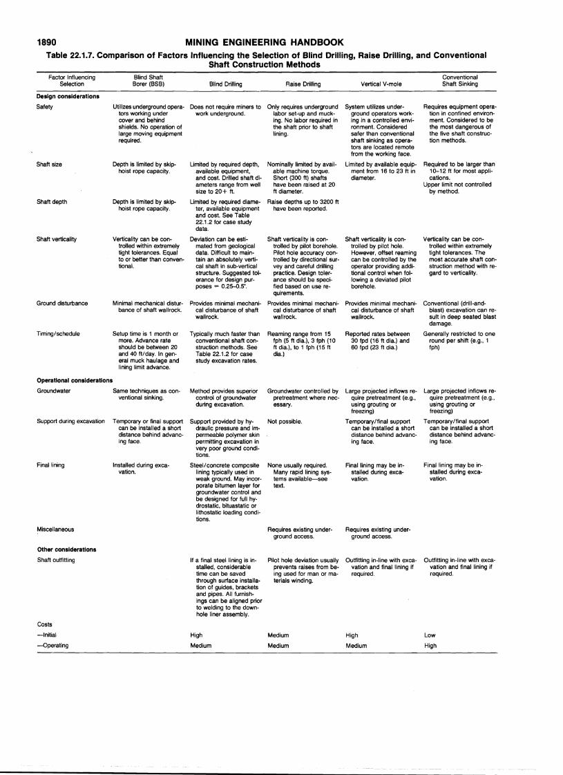
1890 MINING ENGINEERING HANDBOOKTable 22.1.7. Comparison of Factors Influencing the Selection of Blind Drilling, Raise Drilling, and Conventional
Shaft Construction Methods
Factor Influencing Btind Shaft ConventionalSelection Borer (BSB) Blind Drilling Raise Drilling Vertical V-mole Shaft Sinking
Design considerations
Safety Utilizes underground opera- Does not require miners to Only requires underground System utilizes under- Requires equipment opera-tors working under work underground. labor set-up and muck- . ground operators work- tion in confined environ-cover and behind ing. No labor required in ing in a controlled envi- ment. Considered to beshields. No operation of the shaft prior to shaft ronment. Considered the most dangerous oflarge moving equipment lining. safer than conventional the five shaft construc-required. shaft sinking as opera- tion methods.
tors are located remotefrom the working face.
Shaft size Depth is limited by skip- Limited by required depth, Nominally limited by avail- Limited by available equip- Required to be larger thanhoist rope capacity. available equipment, able machine torque. ment from 16 to 23 ft in 10-12 ft for most appli-
and cost. Drilled shaft di- Short (300 ft) shafts diameter. cations.ameters range from well have been raised at 20 Upper limit not controlledsize to 20+ ft. ft diameter. by method.
Shaft depth Depth is limited by skip- Limited by required diame- Raise depths up to 3200 fthoist rope capacity. ter, available equipment have been reported.
and cost. See Table22.1 .2 for case studydata.
Shaft verticality Verticality can be con- Deviation can be esti- Shaft verticality is con- Shaft verticality is con- Verticality can be con-trolled within extremely mated from geological trolled by pilot borehole. trolled by pilot hole. trolled within extremelytight tolerances. Equal data. Difficult to main- Pilot hole accuracy con- However, offset reaming tight tolerances. Theto or better than conven- tain an absolutely verti- trolled by directional sur- can be controlled by the most accurate shaft con-tional. cal shaft in sub-vertical vey and careful drilling operator providing addi-. struction method with re-
structure.. Suggested tol- practice. Design toler- tional control when fol- gard to verticality.erance for design pur- ance should be speci- lowing a deviated pilotposes = 0.25-0.5°. fied based on use re- borehole.
quirements.
Ground disturbance Minimal mechanical distur- Provides minimal mechani- Provides minimal mechani- Provides minimal mechani- Conventional (drill-and-bance of shaft wall rock. cal disturbance of shaft cal disturbance of shaft cal disturbance of shaft blast) excavation can re-
wallrock. wallrock. wallrock. suit in deep seated blastdamage.
Timing/schedule Setup time is 1 month or Typically much faster than Reaming range from 15 Reported rates between Generally restricted to onemore. Advance rate conventional shaft con- fph (5 ft dia.), 3 fph (10 30 fpd (16 ft dia.) and round per shift (e.g., 1should be between 20 struction methods. See ft dia.), to 1 fph (15 ft 60 fpd (23 ft dia.) fph)and 40 ft/day. In gen- Table 22.1.2 for case dia.)eral muck haulage and study excavation rates.lining limit advance.
Operational considerations
Groundwater Same techniques as con- Method provides superior Groundwater controlled by Large projected inflows re- Large projected inflows re-ventional sinking. control of groundwater pretreatment where nec- quire pretreatment (e.g., quire pretreatment (e.g.,
during excavation. essary. using grouting or using grouting orfreezing) freezing)
Support during excavation Temporary or final support Support provided by hy- Not possible. Temporary/final support Temporary/final supportcan be installed a short draulic pressure and im- can be installed a short can be installed a shortdistance behind advanc- permeable polymer skin distance behind advanc- distance behind advanc-ing face. permitting excavation in ing face. ing face.
very poor ground condi-tions.
Final lining Installed during exca- Steel/concrete composite None usually required. Final lining may be in- Final lining may be in-vation. lining typically used in Many rapid lining sys- stalled during exca- stalled during exca-
weak ground. May incor- tems available-see vation. vation.porate bitumen layer for text.groundwater control andbe designed for full hy-drostatic, bituastatic orlithostatic loading condi-tions.
Miscellaneous Requires existing under- Requires existing under-ground access. ground access.
Other considerations
Shaft outfitting If a final steel lining is in- Pilot hole deviation usually Outfitting in-line with exca- Outfitting in-line with exca-stalled, considerable prevents raises from be- vation and final lining if vation and final lining iftime can be saved ing used for man or ma- required. required.through surface installa- terials winding.tion of guides, bracketsand pipes. All furnish-ings can be aligned priorto welding to the down-hole liner assembly.
Costs
-Initial High Medium High Low
-Operating Medium Medium Medium High
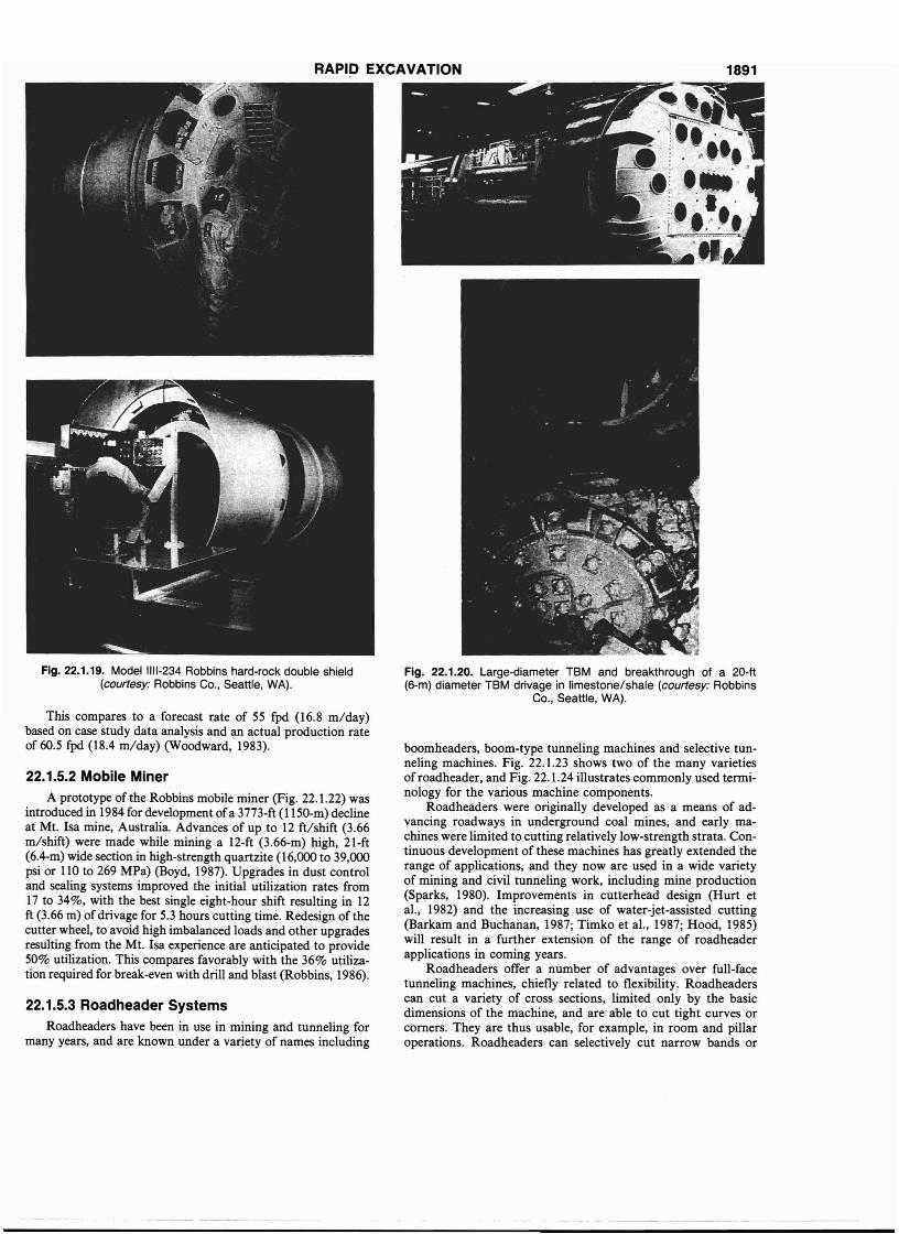
RAPID EXCAVATION 1891
Fig. 22.1.19. Model 1111-234 Robbins hard-rock double shield(courtesy: Robbins Co., Seattle, WA).
This compares to a forecast rate of 55 fpd (16.8 m/day)based on case study data analysis and an actual production rateof 60.5 fpd (18.4 m/day) (Woodward, 1983).
22.1.5.2 Mobile Miner
A prototype of the Robbins mobile miner (Fig. 22.1.22) wasintroduced in 1984 for development ofa 3773-ft (1150-m) declineat M~. Isa mine, Australia. Advances of up to 12 ft/shift (3.66m/shift) were made while mining a 12-ft (3.66-m) high, 21-ft(6.4-m) wide section in high-strength quartzite (16,000 to 39,000psi or 110 to 269 MPa) (Boyd, 1987). Upgrades in dust controland sealing systems improved the initial utilization rates from17 to 34%, with the best single eight-hour shift resulting in 12ft (3.66 m) of drivage for 5.3 hours cutting time. Redesign of thecutter. wheel, to avoid high imbalanced loads and other upgradesresultm~.fro~ the ~t. Isa experience are anticipated to provide50% utilizatIOn. This compares favorably with the 36% utilization required for break-even with drill and blast (Robbins, 1986).
22.1.5.3 Roadheader Systems
Roadheaders have been in use in mining and tunneling formany years, and are known under a variety of names including
Fig. 22.1.20. Large-diameter TBM and breakthrough of a 20-ft(6-m) diameter TBM drivage in limestone/shale (courtesy: Robbins
Co., Seattle, WA).
boomheaders, boom-type tunneling machines and selective tunneling machines. Fig. 22.1.23 shows two of the many varietiesof roadheader, and Fig. 22.1.24 illustrates commonly used terminology for the various machine components.
Roadheaders were originally developed as a means of advancing roadways in underground coal mines, and early machines were limited to cutting relatively low-strength strata. Continuous development of these machines has greatly extended therange of applications, and they now are used in a wide varietyof mining and civil tunneling work, including mine production(Sparks, 1980). Improvements in cutterhead design (Hurt etaI., 1982) and the increasing use of water-jet-assisted cutting(Barkam and Buchanan, 1987; Timko et aI., 1987; Hood, 1985)will result in a further extension of the range of roadheaderapplications in coming years.
Roadheaders offer a number of advantages over full-facetunneling machines, chiefly related to flexibility. Roadheaderscan cut a variety of cross sections, limited only by the basicdimensions of the machine, and are able to cut tight curves orcorners. They are thus usable, for example, in room and pillaroperations. Roadheaders can selectively cut narrow bands or
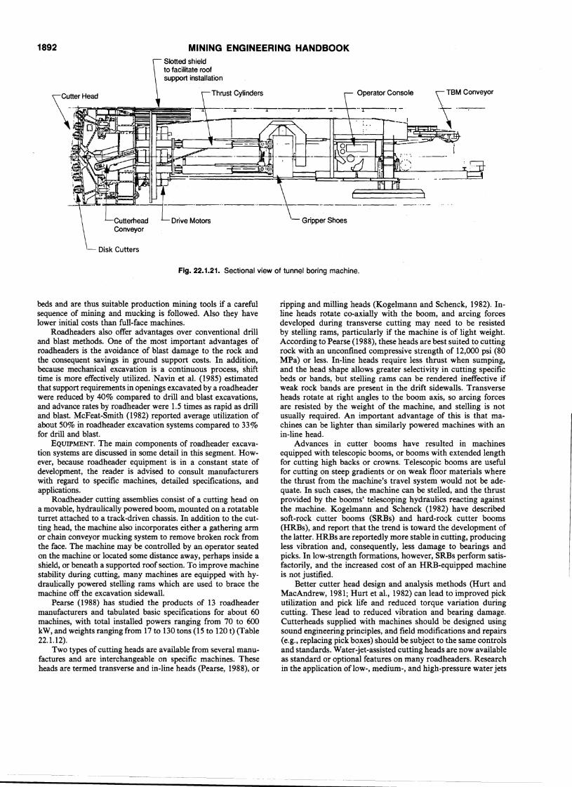
1892
Disk Cutters
MINING ENGINEERING ·HANDBOOK
Operator Console
- Gripper Shoes
Fig. 22.1.21. Sectional view of tunnel boring machine.
beds and are thus suitable production mining tools if a carefulsequence of mining and mucking is followed. Also they havelower initial costs than full-face machines.
Roadheaders also otTer advantages over conventional drilland blast methods. One of the most important advantages ofroadheaders is the avoidance of blast damage to the rock andthe consequent savings in ground support costs. In addition,because mechanical excavation is a continuous process, shifttime is more effectively utilized. Navin et aI. (1985) estimatedthat support requirements in openings excavated by a roadheaderwere reduced by 40% compared to drill and blast excavations,and advance rates by roadheader were 1.5 times as rapid as drilland blast. McFeat-Smith (1982) reported average utilization ofabout 50% in roadheader excavation systems compared to 33%for drill and blast.
EQUIPMENT. The main components of roadheader excavation systems are discussed in some detail in this segment. However, because roadheader equipment is in a constant state ofdevelopment, the reader is advised to consult manufacturerswith regard to specific machines, detailed specifications, andapplications.
Roadheader cutting assemblies consist of a cutting head ona movable, hydraulically powered boom, mounted on a rotatableturret attached to a track-driven chassis. In addition to the cutting head, the machine also incorporates either a gathering armor chain conveyor mucking system to remove broken rock fromthe face. The machine may be controlled by an-operator seatedon the machine or located some distance away, perhaps inside ashield, or beneath a supported roof section. To improve machinestability during cutting, many machines are equipped with hydraulically powered stelling rams which are used to brace themachine otT the excavation sidewall.
Pearse (1988) has studied the products of 13 roadheadermanufacturers and tabulated basic specifications for about 60machines, with total installed powers ranging from 70 to 600kW, and weights ranging from 17 to 130 tons (15 to 120 t) (Table22.1.12).
Two types of cutting heads are available from several manufactures and are interchangeable on specific machines. Theseheads are termed transverse and in-line heads (Pearse, 1988), or
ripping and milling heads (Kogelmann and Schenck, 1982). Inline heads rotate co-axially with the boom, and arcing forcesdeveloped during transverse cutting may need to be resistedby stelling rams, particularly if the machine is of light weight.According to Pearse (1988), these heads are best suited to cuttingrock with an unconfined compressive strength of 12,000 psi (80MPa) or less. In-line heads require less thrust when sumping,and the head shape allows greater selectivity in cutting specificbeds or bands, but stelling rams can be rendered ineffective ifweak rock bands are present in the drift sidewalls. Transverseheads rotate at right angles to the boom axis, so arcing forcesare resisted by the weight of the machine, and stelling is notusually required. An important advantage of this is. that machines can be lighter than similarly powered machines with anin-line head.
Advances in cutter booms have resulted in machinesequipped with telescopic booms, or booms with extended lengthfor cutting high backs or crowns. Telescopic booms are usefulfor cutting on steep gradients or on weak floor materials wherethe thrust from the machine's travel system would not be adequate. In such cases, the machine can be stelled, and the thrustprovided by the booms' telescoping hydraulics reacting againstthe machine. Kogelmann and Schenck (1982) have describedsoft-rock cutter booms (SRBs) and hard-rock cutter booms(HRBs), and report that the trend is toward the development ofthe latter. HRBs are reportedly more stable in cutting, producingless vibration and, consequently, less damage to bearings andpicks. In low-strength formations, however, SRBs perform satisfactorily, and the increased cost of an HRB-equipped machineis not justified.
Better cutter head design and analysis methods (Hurt andMacAndrew, 1981; Hurt et aI., 1982) can lead to improved pickutilization and pick life and reduced torque variation duringcutting. These lead to reduced vibration and bearing damage.Cutterheads supplied with machines should be designed usingsound engineering principles, and field modifications and repairs(e.g., replacing pick boxes) should be subject to the same controlsand standards. Water-jet-assisted cutting heads are now availableas standard or optional features on many roadheaders. Researchin the application of low-, medium-, and high-pressure water jets
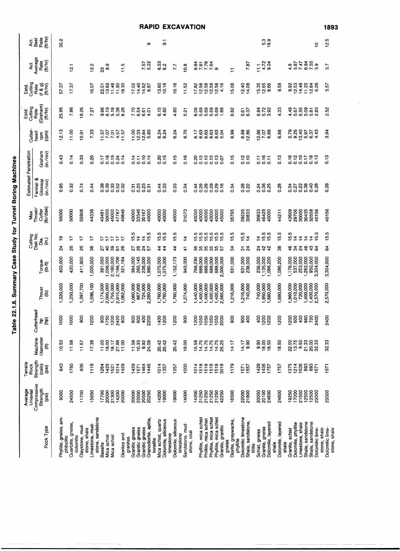
Tab
le22
.1.8
.S
um
mar
yC
ase
Stu
dy
for
Tu
nn
elB
ori
ng
Mac
hin
es
3,30
4,00
064
15.5
238,
000
2414
1,13
5,00
042
15.5
1,08
6,20
04
215
.5
631,
000
34
15.5
631,
000
3115
.523
8,00
024
14
-L
CC
)CD (,
):JJ » :!! c m >< o » < » -I o Z
9 9.1
30.2
12.5
105.3
18.9
Act
.'
Be
stR
ate
(ft/
hr)
6.53
8.2
9.84
7.61
7.78
7.64
97.57
5.22
7.87
7.7
4.8
5.87
7.47
6.94
7.55
5.9
5.7
23 8.9
12.1
12.2
11.5
11.1 4.72
9.04
1110.8Act
.A
vera
ge
Ra
te(f
t/h
r)
5.57
9.58
57.3
7
17.3
7
16.0
7
9.92
12.5
314
.48
11.2
512
.84
6.26
15.3
512
.65
8.66
17.0
214
.46
14.6
28.
87
10.1
6
22.0
113
.69
11.4
611
.90
18.3
0
13.6
010
.16
12.4
014
.08
17.8
212
.58
12.5
812
.58
12.5
84.
16
15.0
8
11.5
2
Est
d.C
utt
ing
Ra
te(f
&g)
(ft/
hr)
7.86
5.21
7.70
6.54
6.61
4.01
4.60
4.33
2.52
7.27
4.49
5.67
6.55
5.09
5.81
2.83
6.15
4.60
6.82
5.61
6.37
6.94
5.72
3.92
9.96
6.19
5.18
5.38
8.28
8.06
5.69
5.69
5.69
5.69
1.88
25.9
5
18.2
6
Est
d.C
utt
ing
Ra
te(G
rah
am
)(f
t/h
r)
3.94
8.99
6.70
7.33
6.88
6.24
6.24
6.24
8.17
8.63
8.63
8.63
8.63
5.04
11.0
0
10.9
1
12.1
3
5.79
9.26
13.4
05.
976.
374.
43
11.0
012
.33
12.8
45.
80
11.5
77.
077.
014.
5711
.57
12.8
67.
076.
88
8.99
12.8
6
Cu
tte
rh
ea
drp
m(r
pm)
0.43
0.13
0.33
0.20
0.14
0.11
0.16
0.11
0.14
0.11
0.10
0.14
0.12
0.10
0.17
0.18
0.15
0.24
0.14
0.15
0.13
0.16
0.12
0.10
0.17
0.18
0.13
0.15
0.20
0.15
0.16
0.20
0.13
0.13
0.13
0.13
0.07
0.32
0.28
0.95
0.74
0.44
0.38
0.39
0.33
0.52
0.32
0.28
0.22
0.24
0.36
0.25
0.28
0.34
0.27
0.22
0.38
0.40
0.28
0.31
0.23
0.23
0.31
0.33
0.44
0.33
0.34
0.44
0.29
0.29
0.29
0.29
0.16
0.34
Est
ima
ted
Pe
ne
tra
tion
Fa
rme
r&
Glo
sso
pG
rah
am
(in
.lre
v)(i
n.l
rev)
4015
6
4000
040
000
4000
040
000
4000
045
000
5000
0
4000
0
5500
0
4348
150
000
4500
047
787
4084
6
5590
8
4000
040
000
4260
929
706
3000
030
435
3255
840
156
3083
346
429
4000
0
4421
1
4433
6
3922
630
833
4000
03
33
46
3016
740
000
3576
5
3107
3
Max
.T
hru
st/
Cu
tte
r(I
b/d
isk)
Cu
ttin
gD
isk
No.
Dia
.(in
.)T
orq
ue
(Ib-
ft)
1,08
6,20
03
815
.5
1,17
6,00
046
15.5
537,
000
34
1425
3,00
024
141,
262,
000
46
1495
0,00
043
143,
304,
000
6415
.5
769,
230
36
15.5
689,
000
35
15.5
689,
000
35
15.5
689,
000
35
15.5
689,
000
35
15.5
2,00
0,00
057
15.5
400,
000
2419
420,
000
2517
41
1,9
00
25
17
1,00
0,00
03
617
381,
050
2717
1,05
6,00
040
172,
160,
000
39
172,
188,
706
6117
321
,184
26
17
384,
000
2715
.526
0,14
526
1423
8,00
024
141,
980,
000
5715
.5
1,07
5,00
044
15.5
1,07
5,00
04
415
.5
1,15
2,17
344
15.5
943,
000
4114
Th
rust
(Ib)
2,57
0,00
0
1,68
0,00
0
1,96
0,00
01,
010,
000
720,
000
1,40
0,00
01,
400,
000
2,57
0,00
0
740,
000
1,95
0,00
01,
680,
000
1,21
6,00
074
0,00
0
1,21
6,00
0
1,32
0,00
0
1,25
0,00
0
1,39
7,70
0
1,59
6,10
0
1,17
4,00
02,
000,
000
1,75
5,00
02,
915,
000
1,06
2,00
0
1,08
0,00
086
7,00
072
4,00
02,
280,
000
1,76
0,00
01,
760,
000
1,76
0,00
0
1,27
4,00
0
1,44
0,00
01,
400,
000
1,40
0,00
01,
400,
000
1,40
0,00
02,
565,
000
900
400
1000
2400
900
900
900
1000
1200
1200
1200
600
400
960
720
2400
80
060
040
022
00 400
1200
1200
900
1750
1200
2420
80
0
1400
1200
1200
1200
1050
1050
'105
010
5020
00
Cu
tte
rhe
ad
hp
(hp)
32.3
3
10.5
0
20.4
2
11.6
7
20.4
220
.42
22.0
013
.75
9.50
21.3
320
.00
32.3
3
11.5
8
18.5
0
9.90
18.0
018
.50
14.1
79.
90
17.3
8
11.0
018
.00
18.1
727
.88
11.0
0
15.5
814
.75
14.7
514
.75
14.7
525
.25
11.5
810
.33
9.92
24.0
8
19.0
0
14.1
7
Ma
chin
eD
iam
ete
r(f
t)
643
836
1571
1750
1757
1429
1436
1757
1375
1214
1536
893
893
1571
1118
1179
1429
1571
1464
1446
1264
1429
1521
1014
1429
1014
1357
1571
1557
1357
1014
1518
1518
1518
1518
3018
1000
Te
nsi
leR
ock
Str
en
gth
(ca
lc)
(psi
)
2450
0
2000
020
100
2460
0
2200
0
2200
021
800
9000
2460
0
1170
0
2000
022
000
2050
020
250
1925
017
000
2150
012
500
1250
022
000
1650
0
1420
021
250
2125
021
250
2125
042
250
1770
020
000
2130
014
200
2000
0
1565
0
1900
0
1420
019
000
1400
0
Ave
rag
eU
niax
ial
Co
mp
ress
ive
Str
en
gth
(psi
)R
ock
Typ
e
Phy
llite
,g
ne
iss,
am
p
hib
olit
eQ
ua
rtzi
te,
gn
eis
s,d
olo
mit
eC
lays
ton
e,
mu
d
sto
ne
,sh
ale
Lim
est
on
e,
mu
d-
sto
ne
,sa
nd
sto
ne
Ba
salt
sM
ica
sch
ist
Mic
asc
his
t
Dio
rite
sa
nd
gra
nit
es
Gra
niti
cg
ne
iss
Gra
niti
cg
ne
iss
Gra
niti
cg
ne
iss
Gra
no
dio
rite
,a
plit
e,
ton
alit
eM
ica
sch
ist,
qu
art
zD
olo
mite
,si
lice
ou
slim
est
on
eD
olo
mite
,si
lice
ou
slim
est
on
eS
an
dst
on
e,
mu
d
sto
ne
,co
al
Phy
llite
,m
ica
sch
ist
Phi
llite
,m
ica
sch
ist
Phy
llite
,m
ica
sch
ist
Phy
llite
,m
ica
sch
ist
Gra
nite
,g
ran
itic
gn
eis
sD
iori
te,
gre
ywa
cke
,p
hyl
lite
Do
lom
itic
lime
sto
ne
Sh
ale
,sa
nd
sto
ne
,til
lite
Sch
ist,
gn
eis
sG
ran
ite,
gn
eis
sD
olo
mite
,la
yere
dsh
ale
Do
lom
ite,
laye
red
sha
leG
ran
ite,
sch
ist
Do
lom
ite,
ph
yllit
eL
ime
sto
ne
,sh
ale
Sh
ale
,sa
nd
sto
ne
Sh
ale
,sa
nd
sto
ne
Do
lom
itic
lime
-st
on
e,
sha
leD
olo
mit
iclim
e
sto
ne
,sh
ale
..... CD U)~
Tab
le22
.1.8
.S
um
mar
yC
ase
Stu
dy
for
Tu
nn
elB
ori
ng
Mac
hin
es(c
on
t.)
Ave
rage
Ten
sile
Est
imat
edP
enet
ratio
nE
std.
Est
d.i:
Uni
axia
l~ROCk
Cut
ting
Max
.C
utte
r-C
uttin
gC
uttin
gA
ct.
Act
.Z
Com
pres
sive
Sre
ng
thM
achi
neC
utte
rhea
dD
isk
No.
Th
rust
!F
arm
er&
head
Rat
eR
ate
Ave
rage
Bes
tS
tren
gth
(cal
c)D
iam
eter
hpT
hrus
tT
orqu
eD
ia.
Cut
ter
Glo
ssop
Gra
ham
rpm
(Gra
ham
)(f
&g)
Rat
eR
ate
ZR
ock
Typ
e(p
si)
(psi
)(f
t)(h
p)(Ib
)(I
b-ft)
(in.)
(Ib
/dis
k)(i
n./
rev)
(in
.lre
v)(r
pm)
(ft/
hr)
(ft/
hr)
(ft/
hr)
(ft/
hr)
Cl rn Z
Sha
le,
limes
tone
,17
500
1250
10.6
750
085
2,00
035
0,00
027
1431
556
0.28
0.13
11.9
37.
5316
.66
6.75
esi
ltsto
neZ
Sha
le,
limes
tone
,25
000
1786
10.6
750
085
2,00
035
0,00
027
1431
556
0.20
0.09
11.9
35.
2711
.66
6.75
rnsi
ltsto
nern
Dol
omiti
clim
e-18
500
1321
35.3
324
002,
760,
000
3,51
0,00
069
15.5
4000
00.
330.
153.
602.
736.
035.
210
~st
one,
shal
eZ
Dol
omiti
cIim
e-18
500
1321
35.3
32
40
02,
760,
000
3,~p,000
6915
.540
000
0.33
0.15
3.60
2.73
6.03
5.1
7C
lst
one,
shal
e%
Dol
omiti
clim
e-21
000
1500
35.2
52
40
02,
760,
000
3,51
0,00
069
15.5
4000
00.
290.
133.
612.
415.
336
J>st
one,
shal
eZ
Lim
esto
ne,
sand
-18
000
1286
14.9
680
02,
702,
900
766,
700
3414
7949
70.
68C
ston
e,sh
ale
m32
500
2321
10.6
750
070
0,00
031
0,00
028
142
50
00
0.12
0.05
11.9
33.
217.
110
Lim
esto
ne,
sand
-29
050
2075
19.0
090
01,
850,
000
1,05
0,00
040
15.5
4625
00.
250.
116.
703.
748.
267
10.4
0st
one
"C
onve
rsio
nfa
ctor
s:1
in.
=25
.4m
m,
1ft
=0.
3048
m,
1ps
i=
6.89
5kP
a,1
Ib=
0.45
36kg
,1
hp=
0.74
57kW
.
Source: Nelson et al. (1985).
to assist cutting has indicated substantial improvements in picklife and dust suppression, and has reduced potential for frictionalignition of methane. In general, machines equipped with waterjets can cut higher-strength formations than equivalent machineswithout water jets.
Roadheader face mucking systems generally consist of anapron with either a scraper chain or gathering arm system (Fig.22.1.25). Scraper chains generally extend around the perimeterof the machine, while gathering arms load muck onto a shortconveyor that passes through the body of the machine~ In eithercase, the muck is generally discharged onto a bridge conveyor.From this point, the muck may be removed by a wide variety ofmethods including shuttle trains, conveyors, LHDs, trucks, and
Scheduled downtimeProbe hole drillingContractual downtimeMoving TBM to new locationShift changes
Cutterhead check and routine maintenanceLube oil systemHydraulic systemCutterhead motorsElectrical systemTMB conveyorTunnel power supplyUtility lines (air, water, fanline)Laser guidance and surveyingTrailing floor conveyorTripper or car passTrain delay-muck bound at headingShaft or portal equipmentInstalling rail and switchesDerailmentsWater inflow rock support installation- bolts
and straps, steel setsGripper/ sidewall supportEquipment clearanceScaling loose materialMuck jams in conveyor and hoppers
TBM maintenanceand repair
Ground conditions
Backup system
RAPID EXCAVATION 1895Table 22.1.9. Downtime Categories for TBM Operations so on. This allows roadheaders to be used in conjunction with
Major Category Individual Downtime Sources an existing mine haulage system, provided that adequate capacityexists. Without adequate capacity, the face will become muckbound and excavation will be delayed. In low-strength formations in which high cutting rates are possible, the mucking systemmay become the limiting factor in controlling advance rates.
Roadheader cutting booms are generally mounted on a custom chassis with track propulsion. Track dimensions controlground pressures and should be carefully assessed in conditionsin which the invert rocks are weak or prone to slurrying. Increasingly, booms are being mounted on a variety of other machines,such as hydraulic breakers, trucks, traveling gantries, and insideshields.
Conventional manual/hydraulic control systems are beingincreasingly superceded by electronic/hydraulic control systemslinked to microprocessor-based guidance and profile control systems. Guidance systems consist of fixed laser sources mountedsome distance behind the roadheader and photoelectric targetsmounted on the roadheader. Deviations of the roadheader fromits desired position and orientation are detected by the targets,and corrections are automatically made. In addition to guidancecontrol, automatic profile control is also available. These systemsconsist of a microprocessor programmed with the required excavation profile, and transducers that continually monitor the position of the cutting boom. The boom hydraulics are controlledelectronically to ensure that the correct profile is cut. Thesedevelopments enable very accurate alignment and profile control, which eliminates overbreak and ensures that the cuttingsequence is optimum; work stoppages to allow time for surveywork are also reduced. Electronic systems are also being usedon roadheaders to monitor the condition of mechanical andhydraulic components, enabling preventative maintenance to bescheduled, reducing unplanned downtime.
OPERATIONS. The excavation cycle commences with sumping or forming a cavity in the rock face to the operating depthof the cutterhead. During this operation, the cutter boom is keptstationary while the cutting head rotates and the whole machineis gradually moved forward on the tracks. When the sump hasbeen formed, it is enlarged by tracking the cutting head acrossthe face to the outer perimeter of the excavation. At the end ofthis arcing cut, the head is moved up or down, and anotherarcing cut is made across the face in the opposite direction tothe first cut. Proceeding in this way, the opening is graduallyenlarged to the full dimensions of the face. When the full cross
Cutter changesOther
Table 22.1.10. TBM Excavation System Utilization and Downtime Percentagesa
Downtime DowntimeTBM Excluding
Maintenance Backup Ground Cutter SpecialProject Tunnel Section Utilizationb and Repair System Conditions" Changes Other C Excluded Special Causes Causes
1C0011 Outbound 39.2 18.3 19.2 16.7 2.8 3.3 Water inflow, stops at 60.8shafts and conrail
Inbound 45.1 8.8 27.4 10.5 2.0 6.2 Water inflow, stop at shaft 54.91C0031 Outbound 35.4 18.8 18.7 19.3 2.2 5.6 Conrail 64.6
Inbound 35.1 26.0 17.2 14.7 2.7 4.3 Stop at shaft, relocate 64.9crane mucking
Culver Goodman Densmore and 41.1 12.0 14.5 13.2 17.1 2.1 Probe hole 58.9Goodman Legs
TARP East Heading 44.4 23.3 21.3 1.3 6.3 3.4 Water inflow, mining past 55.6shafts, relocate TBM
Average for All 40.0 17.9 19.8 12.6 5.5 4.2 60.0Projects
a Time percentages calculated excluding time before trailing floor assembly completed and excluding shift time required for special causes.b TBM operating time, including time required for thrust cylinder reset.C Other includes downtime without explanation, shift changes, probe hole drilling, etc.Source: Nelson et al. (1985).
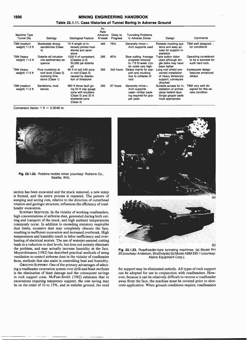
1896 MINING ENGINEERING HANDBOOKTable 22.1.11. Case Histories of Tunnel Boring in Adverse Ground
Av.Rate
Machine Type Advance Delay to Tunneling ProblemsTunnel Dia. Geology Geological Feature It/week Progress in Adverse Zones Design Comments
TBM (medium Moderately strong 75 It length of in· 465 76% Generally minor- Reliable mucking sys· TBM well designed •weight) 11.5 It sandstones (Class tensely jointed mud· Arch supports used tems and easy ac· for conditions
4) stones and sand· cess for support in-stone stallation
TBM (heavy Dolerite sill intrusion 1200 It of competent, 295 60% Slow cutting. Average Triple button disks Operating consideredweight) 11.5 It into sedimentary se- (Classes 2-3) progress reduced used although sin- to be a success for
quence 50,000 psi dolerite to 115 It/week. Cut- gle disks may have such hard rock.sill ter costs very high. been better
TBM (heavy Pure mudstone at 60 It of soil infill zone 295 342 hours Delays mainly for sup- Long roof shield pre· Inadequate designweight) 11.5 It roof level (Class 3) in roof (Class 5) port and mucking vented installation features enhanced
overlying lime- caused by dissolu· due to collapse of of heavy temporary delaysstone (Class 1) tion of limestone roof. support, conveyors
chockedTBM (medium Sandstone, mud· 660 It throw fault giv. 390 67 hours Generally minor- Suitable access for in- TBM very well de-
weight) 11.5 It stones ing 50 It clay gouge Arch supports stallation of arches signed for this se-zone with boulders used-timber pack- close behind face. vere condition(Class 5) and 33 It ing required for grip- Single gripper padsshattered zone per pads most appropriate(Class 4)
Conversion factor: 1 ft = 0.3048 m.
(b)
Fig. 22.1.23. Roadheader-type tunneling machines. (a) Model RH25 (courtesy: Anderson, Strathclyde) (b) Model ABM 330-1 (courtesy:
Alpine Equipment Corp.).
for support may be eliminated entirely. All types of rock supportcan be adopted for use in conjunction with roadheaders. However, because it can be relatively difficult to reverse a roadheaderaway from the face, the machine must be covered prior to shotcrete application. When ground conditions require, roadheaders
Fig. 22.1.22. Robbins mobile miner (courtesy: Robbins Co.,Seattle, WA).
section has been excavated and the muck removed, a new sumpis formed, and the entire process is repeated. The pattern ofsumping and arcing cuts, relative to the direction of cutterheadrotation and geologic structure, influences the efficiency of roadheader excavation.
SUPPORT SERVICES. In the vicinity of working roadheaders,high concentrations of airborne dust, generated during both cutting and transport of the muck, and high ambient temperaturescommonly occur. In addition to exceeding statutory respirabledust limits, excessive dust may completely obscure the face,resulting in inefficient excavation and increased overbreak. Hightemperatures and humidity result in labor inefficiency and overheating of electrical motors. The use of waterjet-assisted cuttingleads to a reduction in dust levels, but does not entirely eliminatethe problem, and may actually increase humidity at the face.Meyeroltmanns (1982) has described practical methods of usingventilation to control airborne dust in the vicinity of roadheaderfaces, methods that also assist in controlling heat and humidity.
GROUND SUPPORT. One ofthe primary advantages of selecting a roadheader excavation system over drill-and-blast methodsis the elimination of blast damage and the consequent savingsin rock support costs. McFeat-Smith (1982) estimates that inexcavations requiring temporary support, the cost saving maybe on the order of 10 to 15%, and in suitable ground, the need
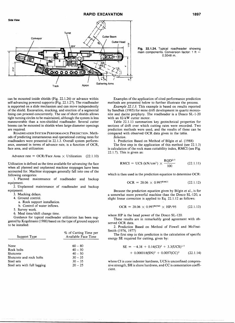
RAPID EXCAVATION 1897
Side View
Track
Turret
.,f.. .;}j
/1/~. ' . Cutter Boom
x~.~
Apron
Fig. 22.1.24. Typical roadheader showingmain components. Conversion factor: 1 ft =
0.3048 m.
can be mounted inside shields (Fig. 22.1.26) or advance withinself-advancing powered supports (Fig. 22.1.27). The roadheaderis supported on a slide mechanism and can move independentlyof the shield. Excavation, mucking, and erection of a segmentallining can proceed concurrently. The use of short shields allowstight turning circles to be maintained, although the system is lessmaneuverable than a non-shielded roadheader. Several cutterbooms can be mounted in shields when large-diameter openingsare required.
ROADHEADER SYSTEM PERFORMANCE PREDICTION. Methods of predicting instantaneous and operational cutting rates forroadheaders were presented in 22.1.3. Overall system performance, assessed in terms of advance rate, is a function of OCR,face area, and utilization:
Advance rate = OCR/Face Area X Utilization (22.1.10)
Examples of the application of cited performance predictionmethods are presented below to further illustrate the process.
Example 22.1.3. This example is based on results reportedby Sandbak (1985) for mine drift development in quartz monzonite and dacite porphyry. The roadheader is a Dosco SL-I-20with an 82-kW cutter motor.
Table 22.1.13 summarizes key geotechnical properties forsections of drift over which cutting rates were recorded. Twoprediction methods were used, and the results of these can becompared with observed OCR data given in the table.
Solution.1. Prediction Based on Method of Bilgin et al. (1988)The first step in the application of this method (see 22.1.3)
is calculation of the rock mass cuttability index, RMCI (see Fig.22.1.7). This is given as:
Utilization is defined as the time available for advancing the facewhen all planned and unplanned machine stoppages have beenaccounted for. Machine stoppages generally fall into one of thefollowing categories:
1. Planned maintenance of roadheader and backupequipment.
2. Unplanned maintenance of roadheader and backupequipment.
3. Mucking delays.4. Ground control.
a. Rock support installation.b. Control of water inflows.
5. Survey work.6. Meal time/shift change time.Guidance for typical roadheader utilization has been sug
gested by Kogelmann (1988) based on the type ofground supportto be installed:
which is then used in the prediction equation to determine OCR:
Because the prediction equation given by Bilgin et aI., is fora somewhat more powerful machine than the Dosco SL-120, aslight linear correction is applied to Eq. 22.1.12 as follows:
where HP is the head power of the Dosco SL-120.These results are in remarkably good agreement with ob
served OCR data.2. Prediction Based on Method of Fowell and McFeat
Smith (1976, 1977)The first step in this prediction is the calculation of specific
energy SE required for cutting, given by:
(22.1.12)
(22.1.13)
(22.1.11 )
OCR = 28.06 X 0.997 RMC1
RQD2/3RMCI = UCS (kN/cm2) X -
lOO
OCR = 28.06 X 0.997 RCM1 X HP/95
% of Cutting Time perAvailable Face TimeSupport Type
NoneRock boltsShotcreteShotcrete and rock boltsSteel setsSteel sets with full lagging
60 - 8040 - 5040 - 5030 - 3530 - 3520 - 25
SE = -4.38 + 0.14(CI)2 + 3.3(UCS)I/3
+ 0.000018(SN)3 + 0.0057(CC)3 (22.1.14)
where Cl is cone indenter hardness, DCS is unconfined compressive strength, SH is shore hardness, and CC is cementation coefficient.
1898 MINING ENGINEERING HANDBOOKTable 22.1.12. Typical Roadheader Specifications
Cutwidth
Head Total Head Cut ht. (one Ground Travel LoadingType Wt drive power type max. position) pressure speed system
kW kW liT m m bar m/min (footnote)
Alpine Equipment Corp., PO Box 132, State College, PA 16804, US.
ABM-40 15 40 90 liT 3.8 4.6 0.6 0.16 D/GA/SWABM-110 24 76/110 190 liT 4.0 5.1 1.0 0.16 D/GA/SWABM-132 34 132 200 liT 3.9 5.2 1.0 0.16 D/GA/SWABM-160 45 160 370 liT 4.1 5.6 1.0 0.16 D/GA/SWABM-200 47 200 410 liT 4.1 5.6 1.1 0.16 D/GA/SWABM-300 70 300 500 liT 6.5 9.1 1.3 0.16 D/GA/SWABM-400 90 400 600 liT 8.0 11.0 1.3 0.16 D/GA/Sw
Anderson Strathclyde plc, 47 Broad Street, Glasgow G40 70W, Scotland.
RH25 25.4 82 157 4.25 6.0 1.2 6.8/13.6 GARH25L 26 82 164 3.8 4.5 1.2 6.8/13.6 GARH22 35 112 187 5/5.3 5.4/6 1.7 2.6/2.8 GARH1/4 66 112 224 6.0 6.4 1.45 0.10 GARH90 90 300 5.0 6.0 new machine GA
Atlas Copco-Eickhoff GmbH, Hunscheidtstr 154, D-4369 Bochum 1, FRG.
ET-110 25-30 110-132 185 liT 4.0 5.3 1.4 0.5 D/GAET-200 40-45 160-200 340 liT 4.7 6.85 1.4 0.15 D/GAET-300 80-90 200-300 460 liT 5.3 7.9 1.7 0-5.6 D/GA/FCET-400 100-110 300-400 560 liT 6.3 2.0 0-8.4 0-5.6 D/GA/FC
Special components for mounting (see text)ETS-110 45* 110 liT 11.0* 8.3 noneETS-200 75* 160 liT 11.0* 8.3 noneETB-110 22 110 t liT to cut TBM tunnel ledges noneETS-200 35 160 t liT to cut TBM tunnel ledges none
* Depending on type of excavator. t Powered from other source.
Dosco Overseas Eng. Ltd., Ollerton Rd., Tuxford, Notts. NG22 OPO, England.
MK IIA 27.7 48.5 123.5 liT 4.1 3.0-5.8 1.5 4.7 ECMD 1000 28.5 50 135 liT 4.2 2.7-5.7 1.2-1.6 7.2 SW/GAMD 1100 31.5 82 157 liT 4.2 2.7-5.7 1.4-1.7 7.2 SW/GASL 120 33 82 165 liT 4.1 2.0-4.3 1.5 13.8 GAMK liB 44 82 194 liT 6.0 3.0-7.4 1.2 8.4 SW/GALH 1300 44 142 254 I 4.1 3.2-5.6 1.5 10.1 SW/GALH1300(H) 45.7 142 285 I 4.1 3.5-6.0 1.5 9.2 SW/GAMK III 83 142 254 I 6.0 4.0-7.1 1.4 5.4 SW/GATB2000 76 119X2 424 I 3.3 4.0-7.7 1.9 9.6 SW/GATB3000 123 250X2 686 I 6.0 4.5-8.9 2.2 12.8 SW/GATM1800 n/a 48.5 104 I 5.2 dia. n/a n/a variousSB 400 n/a 142 198 I 4.7 dia. n/a n/a variousSB 600 n/a 142 198 I 5.8 dia. n/a n/a various
Eimco (GB) Ltd., Team Valley, Gateshead, NE11 OSB, UK.
TM Series: Approx. weight 100 t, 2 X 150 kW motors GA
Herrenknecht GmbH, D-7635 Schwanan-Allmannsweier, FRG.
SM2 n/a 80 95 1.5-2.2.dia. n/a n/a SC/BHSM1 n/a 95 132 2.0-3.0 dia. n/a n/a SC/BH
Mannesmann-Demag, Buscherhofstr 10, 0-4000 Dusseldorf 13, FRG
68 160 180 10 11-12.5 1.0 2.2 nil/FCH55 + 160
*Hydraulic excavator.
Mitsui Miil(e Co. Ltd., 1-1, 2-chome, Nihonbashi Muromachi, Chuo-ku, Tokyo, Japan.
S50,S90, S100, S125
RAPID EXCAVATION 1899
Table 22.1.12. Typical Roadheader Specifications (cont.)
Cutwidth
Head Total Head Cut ht. (one Ground Travel LoadingType Wt drive power type max. position) pressure speed system
kW kW liT m m bar m/min (footnote)
Paurat GmbH, PF 1220, D-4223 Voerde 2 (Friedrichsfeld), FRG.In U.K.: Dowty Mining Equipment Ltd., Tewkesbury, Glos. GL20 8HR.
E169 44 140 225 I 2.3 3.4 1.45 9.3/18.6 FCE195 43 170 263 I 4.2 5.2 1.5 9.3/18.6 GAE134 70 230 353 I 3.05 4.1-6.6 1.7 5.4 FCE200 110 350 512 lIT 6.0 7.6 1.8 4.5 FCE2428 120 300 480 I 7.5 8.9 1.5/1.8 17.6 GA
Salzgitter Maschinenbau GmbH, PF 511640, D-3320 Salzgitter 51, FRG.
STM 100 28 100 200 T 4.0 5.2 1.5 10 GASTM 160 45 160 282 T 4.2-5.0 6.2--6.9 1.3-1.5 10 GASTM 200 75 200 330 T 5.3 7.5 1.6 8 GASTM 300 120 315 509 T 6.1 7.5 1.8 8 GA
TYAZHMASH, 26, 8. Serpukhovskaya UI., 113093 Moscow, USSR.
4PP-5 75 200 14-35m2 area GA
Voest-Alpine AG, PF 2, A-4010 Linz, Austria.
F-6A 12 30-41 60-82 T 3.4-4.0 4.5 1.4 5.0 GAAM50 24 110 170 T 2.0-4.8 4.8 1.3 6.0 GAAM65 32-36 132-175 214-305 T 4.3-4.9 6.9 1.2-1.35 5/13/20 GAAM75 45-52 160-200 290-330 T 4.7-5.1 6.8-7.0 1.2-3.8 4-15 GAAM100 84-96 250-400 450-700 T 5.5--6.4 7.3-7.7 1.8-2.1 3-21 GA
Westfalia Lunen, D-4670 Lunen, FRG.
Fuchs WF-40 9 37 70 T 3.8 4.1 1.0 10 FCalso WF-50 with 50 kW cutter motorDachs 53 13 79 101 T 4.3 5.2 0-95 26.7 FCLuchs 8-110 25 110 200 T 4.1 6.0 1.0 10-31.5 FCalso N-110 and H-110WAY 130 32 130 250 T 4.2 5.3 1.5 10-20 GAWAY 170 45 200 300 T 5.4 6.3 1.7 7.5-26.7 GAWAY 178 73 200 360 T 7.1 8.3 1.6 5.0 GAWAY 178/300 73 300 437 T 7.7 8.9 1.6 5.0 GAWAY 300 90 300 470 T 5.4 7.9 1.6 5.0 FC
BH = Backhoe, D = Disc, FC = Flight chain, GA = Gathering arm, SC = Scroll, SW = Star wheel.
Source: Pearse, 1988.Conversion factors: 1 ft = 0.3048 m, 1 hp = 0.7457 kW, 1 ton = 0.9072 t.
made to Eq. 22.1.5. CTFs for bulk excavations with an experienced operator are estimated to have values in the range 0.65 to0.85, while for final trimming, it may drop to 0.3. Overall valuesfor bulk excavation and final profiling of a face may be in therange of 0.45 to 0.65. In this example, 0.45 was assumed andapplied as follows:
In this example the predicted values are low compared tothe observed cutting rates, and this may be attributable to rockmass factors.
Example 22.1.4. This example is based on results reportedby Bilgin et al. (1988) for drivage of sewer tunnels in Turkeyusing a Herrenkneckt SM1, and coal mine development drivesusing a Dosco MKIIA. Results are presented in Table 22.1.14.
Cone Indenter hardness and Shore hardness have beenshown to be linear functions of unconfined compressive strength(Atkinson et aI., 1986), so that Eq. 22.1.14 can be rewritten interms of USC and CC:
SE = -4.38 + 0.14 (0.0377 UCS + 0.254)2 + 3.30 UCSl;3
+ 0.000018 (0.441 UCS - 8.73)3 + 0.0057CC3 (22.1.15)
Cementation coefficient is based on petrographic descriptions ofthe rock (McFeat-Snlith, 1977).
When SE has been calculated, instantaneous cutting rateICR can then be calculated from Eq. 22.1.5:
ICR = HP/SE
Because the prediction equations use SE based on actualcutting time, a cutting time factor (CTF) correction must be
OCR = HP/SE X CTF or
= ICR X CTF
(22.1.16)
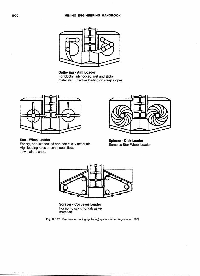
1900 MINING ENGINEERING HANDBOOK
Gathering • Arm LoaderFor blocky, interlocked, wet and stickymaterials. Effective loading on steep slopes.
Star • ,Wheel LoaderFor dry, non-interlocked and non-sticky materials.High loading rates at continuous flow.Low maintenance.
Spinner • Disk LoaderSame as Star-Wheel Loader
Scraper· Conveyer LoaderFor non-blocky, non-abrasivematerials
Fig. 22.1.25. Roadheader loading (gathering) systems (after Kogelmann, 1988).
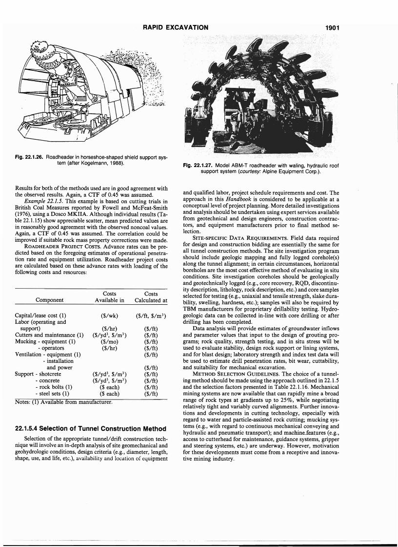
RAPID EXCAVATION 1901
.", :.-
;.::;(':~;..
•; :_~ ·f:..,1r,';':;~:
Fig. 22.1.26. Roadheader in horseshoe-shaped shield support system (after Kogelmann, 1988). Fig. 22.1.27. Model ABM-T roadheader with waling, hydraulic roof
support system (courtesy: Alpine Equipment Corp.).
22.1.5.4 Selection of Tunnel Construction Method
Selection of the appropriate tunnel/drift construction technique will involve an in-depth analysis of site geomechanical andgeohydro10gic conditions, design criteria (e.g., diameter, length,shape, use, and life, etc.), availability and location of equipment
Results for both of the methods used are in good agreement withthe observed results. Again, a CTF of 0.45 was assumed.
Example 22.1.5. This example is based on cutting trials inBritish Coal Measures reported by Fowell and McFeat-Smith(1976), using a Dosco MKIIA. Although individual results (Table 22.1.15) show appreciable scatter, mean predicted values arein reasonably good agreement with the observed noncoal values.Again, a CTF of 0.45 was assumed. The correlation could beimproved if suitable rock mass property corrections were ~ade.
ROADHEADER PROJECT COSTS. Advance rates can be predicted based on the foregoing estimates of operational penetration rate and equipment utilization. Roadheader project costsare calculated based on these advance rates with loading of thefollowing costs and resources:
Notes: (1) Available from manufacturer.
and qualified labor, project schedule requirements and cost. Theapproach in this Handbook is considered to be applicable at aconceptual level ofproject planning. More detailed investigationsand analysis should be undertaken using expert services availablefrom geotechnical and design engineers, construction contractors, and equipment manufacturers prior to final method selection.
SITE-SPECIFIC DATA REQUIREMENTS. Field data requiredfor design and construction bidding are essentially the same forall tunnel construction methods. The site investigation programshould include geologic mapping and fully logged coreho1e(s)along the tunnel alignment; in certain circumstances, horizontalboreholes are the most cost effective method of evaluating in situconditions. Site investigation coreholes should be geologicallyand geotechnically logged (e.g., core recovery, RQD, discontinuity description, lithology, rock description, etc.) and core samplesselected for testing (e.g., uniaxial and tensile strength, slake durability, swelling, hardness, etc.); samples will also be required byTBM manufacturers for proprietary drillability testing. Hydrogeologic data can be collected in-line with core drilling or afterdrilling has been completed.
Data analysis will provide estimates of groundwater inflowsand parameter values that input to the design of grouting programs; rock quality, strength testing, 'and in situ stress will beused to evaluate stability, design rock support or lining systems,and for blast design; laboratory strength and index test data willbe used to estimate drill penetration rates, bit wear, cuttability,and suitability for mechanical excavation.
METHOD SELECTION GUIDELINES. The choice of a tunneling method should be made using the approach outlined in 22.1.5and the selection factors presented in Table 22.1.16. Mechanicalmining systems are now available that can rapidly mine a broadrange of rock types at gradients up to 25%, while negotiatingrelatively tight and variably curved alignments. Further innovations and developments in cutting technology, especially withregard to water and particle-assisted rock cutting; mucking systems (e.g., with regard to continuous mechanical conveying andhydraulic and pneumatic transport); and machine..fe.at.ures (e.g.,access to cutterhead for maintenance, guidance systems, gripperand steering systems, etc.) are underway. However, motivationfor these developments must come from a receptive and innovative mining industry.
($/ft, $/m3)
($/ft)($/ft)($/ft)($/ft)($/ft)
($/ft)($/ft)($/ft)($/ft)($/ft)
CostsCalculated at
($/wk)
CostsAvailable in
($/hr)($/yd3, $/m3 )
($/mo)($/hr)
Component
Capitall1ease cost (1)Labor (operating and
support)Cutters and maintenance (1)Mucking - equipment (1)
- operatorsVentilation - equipment (1)
- installationand power
Support - shotcrete ($/yd3, $/m3 )
- concrete ($/yd3, $/m3 )
- rock bolts (1) ($ each)- steel sets (1) ($ each)
---_. ------ ----
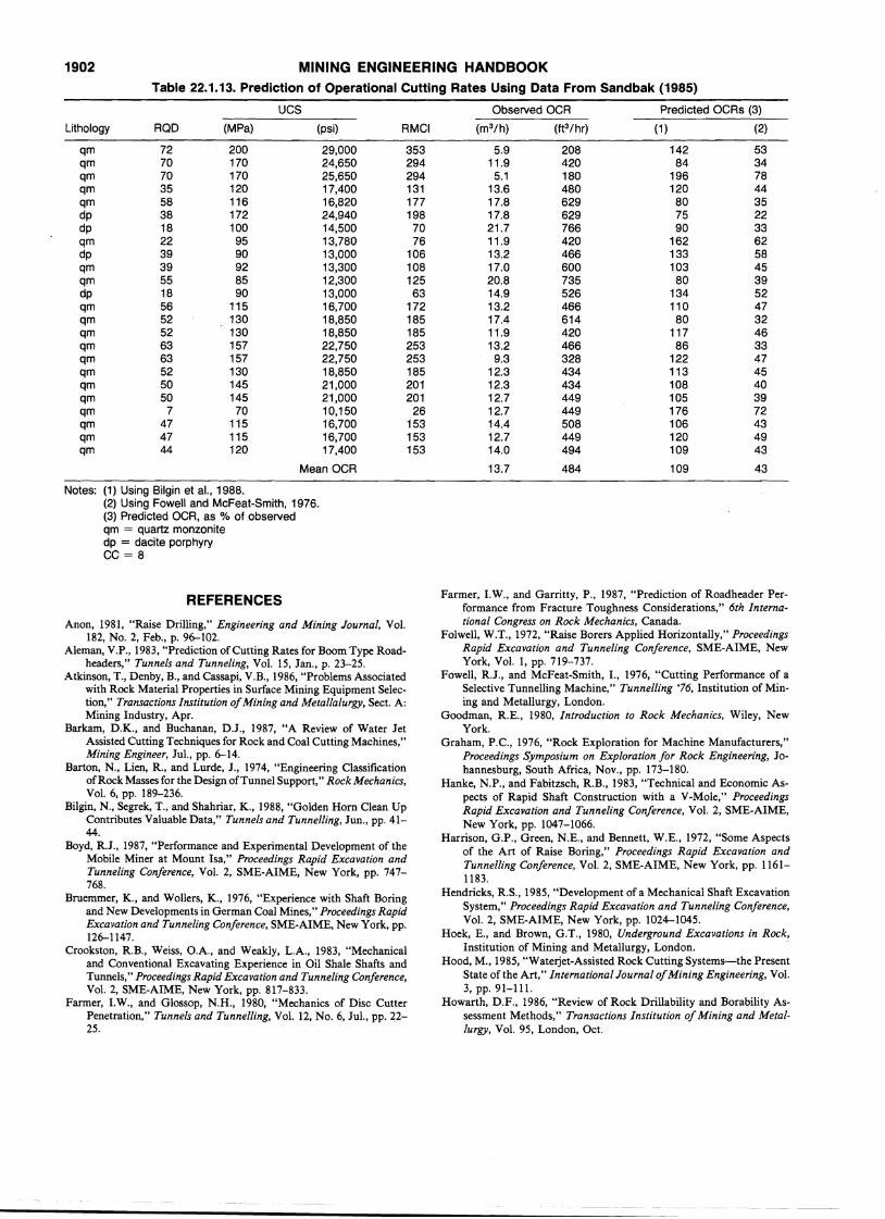
1902 MINING ENGINEERING HANDBOOKTable 22.1.13. Prediction of Operational Cutting Rates Using Data From Sandbak (1985)
UCS Observed OCR Predicted OCRs (3)
Lithology ROD (MPa) (psi) RMCI (m3 /h) (ft3 /hr) (1 ) (2)
qm 72 200 29,000 353 5.9 208 142 53qm 70 170 24,650 294 11.9 420 84 34qm 70 170 25,650 294 5.1 180 196 78qm 35 120 17,400 131 13.6 480 120 44qm 58 116 16,820 177 17.8 629 80 35dp 38 172 24,940 198 17.8 629 75 22dp 18 100 14,500 70 21.7 766 90 33qm 22 95 13,780 76 11.9 420 162 62dp 39 90 13,000 106 13.2 466 133 58qm 39 92 13,300 108 17.0 600 103 45qm 55 85 12,300 125 20.8 735 80 39dp 18 90 13,000 63 14.9 526 134 52qm 56 115 16,700 172 13.2 466 110 47qm 52 130 18,850 185 17.4 614 80 32qm 52 130 18,850 185 11.9 420 117 46qm 63 157 22,750 253 13.2 466 86 33qm 63 157 22,750 253 9.3 328 122 47qm 52 130 18,850 185 12.3 434 113 45qm 50 145 21,000 201 12.3 434 108 40qm 50 145 21,000 201 12.7 449 105 39qm 7 70 10,150 26 12.7 449 176 72qm 47 115 16,700 153 14.4 508 106 43qm 47 115 16,700 153 12.7 449 120 49qm 44 120 17,400 153 14.0 494 109 43
Mean OCR 13.7 484 109 43
Notes: (1) Using Bilgin et al., 1988.(2) Using Fowell and McFeat-Smith, 1976.(3) Predicted OCR, as 010 of observedqm = quartz monzonitedp = dacite porphyryCC = 8
REFERENCES
Anon, 1981, "Raise Drilling," Engineering and Mining Journal, Vol.182, No. 2, Feb., p. 96-102.
Aleman, V.P., 1983, "Prediction of Cutting Rates for Boom Type Roadheaders," Tunnels and Tunneling, VoL 15, Jan., p. 23-25.
Atkinson, T., Denby, B., and Cassapi, V.B., 1986, "Problems Associatedwith Rock Material Properties in Surface Mining Equipment Selection," Transactions Institution ofMining and Metallalurgy,. Sect. A:Mining Industry, Apr.
Barkam, D.K., and Buchanan, D.J., 1987, "A Review of Water JetAssisted Cutting Techniques for Rock and Coal Cutting Machines,"Mining Engineer, Jul., pp. 6-14.
Barton, N., Lien, R., and Lurde, J., 1974, "Engineering ClassificationofRock Masses for the Design ofTunnel Support," Rock Mechanics,V01. 6, pp. 189-236.
Bilgin, N., Segrek, T., and Shahriar, K., 1988, "Golden Horn Clean UpContributes Valuable Data," Tunnels and Tunnelling, Jun., pp. 4144.
Boyd, R.J., 1987, "Performance and Experimental Development of theMobile Miner at Mount Isa," Proceedings Rapid Excavation andTunneling Conference, Vol. 2, SME-AIME, New York, pp. 747768.
Bruemmer, K., and Wollers, K., 1976, "Experience with Shaft Boringand New Developments in German Coal Mines," Proceedings RapidExcavation and Tunneling Conference, SME-AIME, New York, pp.126-1147.
Crookston, R.B., Weiss, O.A., and Weakly, L.A., 1983, "Mechanicaland Conventional Excavating Experience in Oil Shale Shafts andTunnels," Proceedings Rapid Excavation and Tunneling Conference,Vol. 2, SME-AIME, New York, pp. 817-833.
Farmer, I.W., and Glossop, N.H., 1980, "Mechanics of Disc CutterPenetration," Tunnels and Tunnelling, Vol. 12, No. 6, Jul., pp. 2225.
Farmer, I.W., and Garritty, P., 1987, "Prediction of Roadheader Performance from Fracture Toughness Considerations," 6th International Congress on Rock Mechanics, Canada.
Folwell, W.T., 1972, "Raise Borers Applied Horizontally," ProceedingsRapid Excavation and Tunneling Conference, SME-AIME, NewYork, Vol. 1, pp. 719-737.
Fowell, R.J., and McFeat-Smith, I., 1976, "Cutting Performance of aSelective Tunnelling Machine," Tunnelling '76, Institution of Mining and Metallurgy, London.
Goodman, R.E., 1980, Introduction to Rock Mechanics, Wiley, NewYork.
Graham, P.C., 1976, "Rock Exploration for Machine Manufacturers,"Proceedings Symposium on Exploration for Rock Engineering, Johannesburg, South Africa, Nov., pp. 173-180.
Hanke, N.P., and Fabitzsch, R.B., 1983, "Technical and Economic Aspects of Rapid Shaft Construction with a V-Mole," ProceedingsRapid Excavation and Tunneling Conference, Vol. 2, SME-AIME,New York, pp. 1047-1066.
Harrison, G.P., Green, N.E., and Bennett, W.E., 1972, "Some Aspectsof the Art of Raise Boring," Proceedings Rapid Excavation andTunnelling Conference, Vol. 2, SME-AIME, New York, pp. 11611183.
Hendricks, R.S., 1985, "Development of a Mechanical Shaft ExcavationSystem," Proceedings Rapid Excavation and Tunneling Conference,Vol. 2, SME-AIME, New York, pp. 1024-1045.
Hoek, E., and Brown, G.T., 1980, Underground Excavations in Rock,Institution of Mining and Metallurgy, London. -
Hood, M., 1985, "Waterjet-Assisted Rock Cutting Systems-the PresentState of the Art," International Journal ofMining Engineering, Vol.3, pp. 91-111.
Howarth, D.F., 1986, "Review of Rock Drillability and Borability Assessment Methods," Transactions Institution ofMining and Metallurgy, Vol. 95, London, Oct.
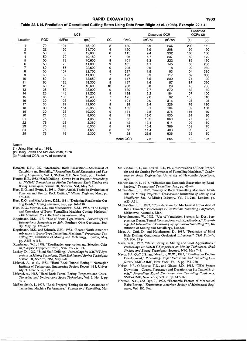
RAPID EXCAVATION 1903Table 22.1.14. Prediction of Operational Cutting Rates Using Data From Bilgin et al. (1988). Example 22.1.4.
PredictedUCS Observed OCR OCRs (3)
Location ROD (MPa) (psi) CC RMCI (m3 /h) (ft3 /hr) (1 ) (2)
1 70 104 15,100 8 180 6.9 244 290 1102 22 150 21,700 9 120 5.9 208 99 903 50 83 12,000 8 115 9.4 332 160 1004 50 70 10,150 7 96 6.7 237 89 1705 50 73 10,600 9 101 6.3 222 89 1506 50 76 11,000 9 105 4.1 145 63 2307 80 156 22,600 9 295 0.5 18 92 9808 50 157 22,750 9 217 1.5 53 104 3309 60 82 11,900 7 128 3.3 117 69 300
10 60 94 13,650 8 147 6.5 230 174 13011 60 126 18,300 9 197 1.6 57 87 39012 60 128 18,600 10 200 0.8 29 45 73013 25 159 23,000 9 139 7.7 272 183 6014 25 146 21,200 9 128 5.2 184 107 10015 65 106 15,400 7 175 2.6 92 105 31016 30 103 15,000 7 101 9.0 318 128 9517 30 89 12,900 9 88 6.4 226 76 13018 30 154 22,350 9 152 3.1 104 89 16019 30 133 19,300 9 131 7.8 275 166 8020 21 55 8,000 8 43 15.0 530 94 8021 75 30 4,350 9 55 10.2 360 77 7522 75 23 3,350 8 42 17.4 614 109 6023 75 43 6,300 8 79 10.4 369 109 7024 75 32 4,650 8 58 11.4 403 90 7025 75 16 2,300 7 28 26.5 936 139 50
Mean OCR 7.5 265 113 105
Notes:(1) Using Bilgin et al., 1988.(2) Using Fowell and McFeat-Smith, 1976(3) Predicted OCR, as % of observed
Howarth, D.F., 1987, "Mechanical Rock Excavation-Assessment ofCuttability and Borability," Proceedings Rapid Excavation and Tunneling Conference, Vol. 1, SME-AIME, New York, pp. 145-164.
Hunter, H.E., 1982, "Shaft Drilling-Crown Point Project," Proceedings1st NMIMT Symposium on Mining Techniques, Shaft Sinking andBoring Techniques, Session Ill, Socorro, NM, May 7-8.
Hurt, K.G., and Evans, I., 1981, "Point Attach Tools: on Evaluation ofFunction and Use for Rock Cutting," Mining Engineer, Mar., pp.673-675.
Hurt, K.G., and MacAndrew, K.M., 1981, "Designing Roadheader Cutting Heads," Mining Engineer, Sep., pp: 167-170.
Hurt, K.G., Morriss, C.J., and MacAndrew, K.M., 1982, "The Designand Operations of Boom Tunnelling Machine Cutting Methods,"14th Canadian Rock Mechanics Symposium, May.
Kogelmann, M.S., 1973, "Use of Boom-Type Miners," Proceedings 4thInternational Symposium on Salt, Northern Ohio Geological Society, May, pp. 471-482.
Kogelmann, M.S., and Schenck, G.K., 1982, "Recent North AmericanAdvances in Boom-Type Tunnelling Machines," Proceedings Tunnelling '82, Institution of Mining and Metallurgy, London, May,pp. A155-A165.
Kogelmann, W.J., 1988, "Roadheader Application and Selection Criteria," Alpine Equipment Corp., State College, PA.
Lackey, D., 1982, "Blind Shaft Drilling," Proceedings 1st NMIMT Symposium on Mining Techniques, Shaft Sinking and Boring Techniques,Session Ill, Socorro, NM, May 7-8.
Lislerud, A., et al., 1983, "Hard Rock Tunnel Boring," NorwegianInstitute of Technology, Engineering Project Report 1-83, University of Trondheim, 159 pp.
Lislerud, A., 1988, "Hard Rock Tunnel Boring: Prognosis and Costs,"Tunneling and Underground Space Technology, Vol. 3, No. 1, pp.9-17.
McFeat-Smith, I., 1977, "Rock Property Testing for the Assessment ofTunnelling Machine Performance," Tunnels and Tunnelling, Mar.
McFeat-Smith, I., and Fowell, R.J., 1977, "Correlation of Rock Properties and the Cutting Performance of Tunnelling Machines," Conference on Rock Engineering, University of Newcastle-Upon-Tyne,Apr.
McFeat-Smith, I., 1978, "Effective and Economic Excavation by Roadheaders," Tunnels and Tunnelling, Jan., pp. 43-44.
McFeat-Smith, I., 1982, "Survey of Rock Tunnelling Machines Available for Mining Projects," Transactions Institution of Mining andMetallurgy, Sec. A: Mining Industry, Vol. 91, Jan., London, pp.A23-A31.
McFeat-Smith, I., 1987, "Consideration for Mechanical Excavation ofRock Tunnels," Proceedings VI Australian Tunneling Conference,Melbourne, Australia, Mar.
Meyeroltmanns, W., 1982, "Use of Ventilation Systems for Dust Suppression During Tunnel Construction with Roadheaders," Proceedings 3rd International Tunnelling Symposium-Tunnelling '82, Institution of Mining and Metallurgy, London.
Moss, A., Zeni, D., and Hutchenson, D., 1987, "Prediction of BlindHole Drilling Conditions: Geological Influences," CIM Bulletin,SO: 904, 33 p.
Nash, W.R., 1982, "Raise Boring in Mining and Civil Applications,"Proceedings 1st NMIMT Symposium on Mining Techniques, ShaftSinking and Boring Techniques, Socorro, NM, May 7-8.
Navin, S.J., Goff, J.S., and Moulton, W.W., 1985, "Roadheader DeclineDevelopment," Proceedings Rapid Excavation and Tunneling Conference, SME-AIME, New York, Vol. 2, pp. 751-770.
Nelson, P.P., O'Rourke, T.D., and Glaser, S.D., 1985, "TBM SystemDowntime-Causes, Frequency and Durations on Six Tunnel Projects," Proceedings Rapid Excavation and Tunneling Conference,SME-AIME, New York, Vol. 2, pp. 847-866.
Norman, N.E., and Dye, J., 1978, "Economic Factors of MechanicalRaise Boring," Transactions American Society ofMechanical Engineers, Vol. 100, Feb.
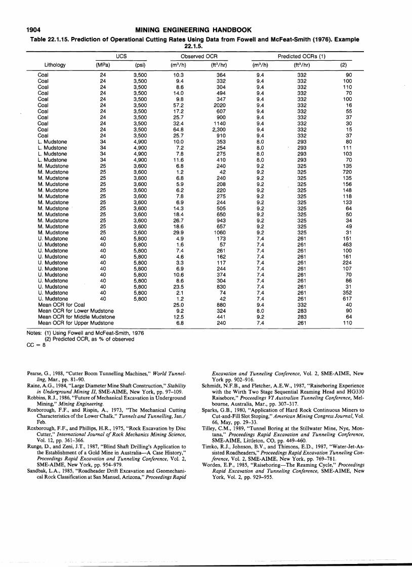
1904 MINING ENGINEERING HANDBOOKTable 22.1.15. Prediction of Operational Cutting Rates Using Data 'from Fowell and McFeat-Smith (1976). Example
22.1.5.
UCS Observed OCR Predicted OCRs (1)
Lithology (MPa) (psi) (m3/h) (ft3 /hr) (m3/h) (ft3 /hr) (2)
Coal 24 3,500 10.3 364 9.4 332 90Coal 24 3,500 9.4 332 9.4 332 100Coal 24 3,500 8.6 304 9.4 332 110Coal 24 3,500 14.0 494 9.4 332 70Coa.l 24 3,500 9.8 347 9.4 332 100Coal 24 3,500 57.2 2020 9.4 332 16Coal 24 3,500 17.2 607 9.4 332 55Coal 24 3,500 25.7 900 9.4 332 37Coal 24 3,500 32.4 1140 9.4 332 30Coal 24 3,500 64.8 2,300 9.4 332 15Coal 24 3,500 25.7 910 9.4 332 37L. Mudstone 34 4,900 10.0 353 8.0 293 80L. Mudstone 34 4,900 7.2 254 8.0 293 111L. Mudstone 34 4,900 7.8 275 8.0 293 103L. Mudstone 34 4,900 11.6 410 8.0 293 70M. Mudstone 25 3,600 6.8 240 9.2 325 135M. Mudstone 25 3,600 1.2 42 9.2 325 720M. Mudstone 25 3,600 6.8 240 9.2 325 135M. Mudstone 25 3,600 5.9 208 9.2 325 156M. Mudstone 25 3,600 6.2 220 9.2 325 148M. Mudstone 25 3,600 7.8 275 9.2 325 118M. Mudstone 25 3,600 6.9 244 9.2 325 133M. Mudstone 25 3,600 14.3 505 9.2 325 64M. Mudstone 25 3,600 18.4 650 9.2 325 50M. Mudstone 25 3,600 26.7 943 9.2 325 34M. Mudstone 25 3,600 18.6 657 9.2 325 49M. Mudstone 25 3,600 29.9 1060 9.2 325 31U. Mudstone 40 5,800 4.9 173 7.4 261 151U. Mudstone 40 5,800 1.6 57 7.4 261 463U. Mudstone 40 5,800 7.4 261 7.4 261 100U. Mudstone 40 5,800 4.6 162 7.4 261 161U. Mudstone 40 5,800 3.3 117 7.4 261 224U. Mudstone 40 5,800 6.9 244 7.4 261 107U. Mudstone 40 5,800 10.6 374 7.4 261 70U. Mudstone 40 5,800 8.6 304 7.4 261 86U. Mudstone 40 5,800 23.5 830 7.4 261 31U. Mudstone 40 5,800 2.1 74 7.4 261 352U. Mudstone 40 5,800 1.2 42 7.4 261 617Mean OCR for Coal 25.0 880 9.4 332 40Mean OCR for Lower Mudstone 9.2 324 8.0 283 90Mean OCR for Middle Mudstone 12.5 441 9.2 283 64Mean OCR for Upper Mudstone 6.8 240 7.4 261 110
Notes: (1) Using Fowell and McFeat-Smith, 1976(2) Predicted OCR, as % of observed
CC = 8
Pearse, G., 1988, "Cutter Boom Tunnelling Machines," World Tunnelling, Mar., pp. 81-90.
Raine, A.G., 1984, "Large Diameter Mine Shaft Construction," Stabilityin Underground Mining II, SME-AIME, New York, pp. 97-109.
Robbins, R.J., 1986, "Future of Mechanical Excavation in UndergroundMining," Mining Engineering.
Roxborough, F.F., and Rispin, A., 1973, "The Mechanical CuttingCharacteristics of the Lower Chalk," Tunnels and Tunnelling, Jan./Feb.
Roxborough, F.F., and Phillips, H.R., 1975, "Rock Excavation by DiscCutter," International Journal of Rock Mechanics Mining Science,Vol. 12, pp. 361-366.
Runge, D., and Zeni, J.T., 1987, "Blind Shaft Drilling's Application tothe Establishment of a Gold Mine in Australia-A Case History,"Proceedings Rapid Excavation and Tunneling Conference, Vol. 2,SME-AIME, New York, pp. 954-979.
Sandbak, L.A., 1985, "Roadheader Drift Excavation and Geomechanica! Rock Classification at San Manuel, Arizona," Proceedings Rapid
Excavation and Tunneling Conference, Vol. 2, SME-AIME, NewYork pp. 902-916.
Schmidt, N.F.B., and Fletcher, A.E.W., 1987, "Raiseboring Experiencewith the Wirth Two Stage Sequential Reaming Head and HG330Raisebore," Proceedings VI Australian Tunneling Conference, Melbourne, Australia, Mar., pp. 307-317.
Sparks, G.B., 1980, "Application of Hard Rock Continuous Miners toCut-and-Fill Slot Stoping," American Mining Congress Journal, Vol.66, May, pp. 29-33.
Tilley, C.M., 1989, "Tunnel Boring at the Stillwater Mine, Nye, Montana," Proceedings Rapid Excavation and Tunneling Conference,SME-AIME, Littleton, CO, pp. 449-460.
Timko, R.J., Johnson, B.V., and Thimons, E.D., 1987, "Water-Jet-Assisted Roadheaders," Proceedings Rapid Excavation Tunneling Conference, Vol. 2, SME-AIME, New York, pp. 769-781.
Worden, E.P., 1985, "Raiseboring-The Reaming Cycle," ProceedingsRapid Excavation and Tunneling Conference, SME-AIME, NewYork, Vol. 2, pp. 929-955.
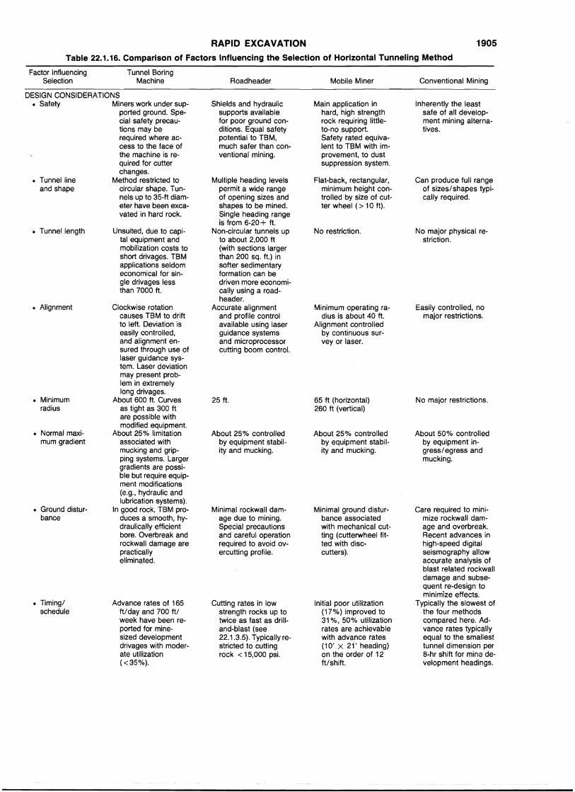
RAPID EXCAVATION 1905
Table 22.1.16. Comparison of Factors Influencing the Selection of Horizontal Tunneling Method
Factor Influencing Tunnel BoringSelection Machine Roadheader Mobile Miner Conventional Mining
DESIGN CONSIDERATIONS• Safety Miners work under sup- Shields and hydraulic Main application in Inherently the least
ported ground. Spe- supports available hard, high strength safe of all develop-cial safety precau- for poor ground con- rock requiring little- ment mining alterna-tions may be ditions. Equal safety to-no support. tives.required where ac- potential to TBM, Safety rated equiva-cess to the face of much safer than con- lent to TBM with im-the machine is re- ventional mining. provement, to dustquired for cutter suppression system.changes.
• Tunnel line Method restricted to Multiple heading levels Flat-back, rectangular, Can produce full rangeand shape circular shape. Tun- permit a wide range minimum height con- of sizes/shapes typi-
nels up to 35-ft diam- of opening sizes and trolled by size of cut- cally required.eter have been exca- shapes to be mined. ter wheel (> 10ft).vated in hard rock. Single heading range
is from 6-20+ ft.• Tunnel length Unsuited, due to capi- Non-circular tunnels up No restriction. No major physical re-
tal equipment and to about 2,000 ft striction.mobilization costs to (with sections largershort drivages. TBM than 200 sq. ft.) inapplications seldom softer sedimentaryeconomical for sin- formation can begle drivages less driven more economi-than 7000 ft. cally using a road-
header.• Alignment Clockwise rotation Accurate alignment Minimum operating ra- Easily controlled, no
causes TBM to drift and profile control dius is about 40 ft. major restrictions.to left. Deviation is available using laser Alignment controlledeasily controlled, guidance systems by continuous sur-and alignment en- and microprocessor vey or laser.sured through use of cutting boom control.laser guidance sys-tem. Laser deviationmay present prob-lem in extremelylong drivages.
• Minimum About 600 ft. Curves 25 ft. 65·ft (horizontal) No major restrictions.radius as tight as 300 ft 260 ft (vertical)
are possible withmodified equipment.
• Normal maxi- About 250/0 limitation About 25% controlled About 25 % controlled About 50 % controlledmum gradient associated with by equipment stabil- by equipment stabil- by equipment in-
mucking and grip- ity and mucking. ity and mucking. gress/egress andping systems. Larger mucking.gradients are possi-ble but require equip-ment modifications(e.g., hydraulic andlubrication systems).
• Ground distur- In good rock, TBM pro- Minimal rockwall dam- Minimal ground distur- Care required to mini-bance duces a smooth, hy- age due to mining. bance associated mize rockwall dam-
draulically efficient Special precautions with mechanical cut- age and overbreak.bore. Overbreak and and careful operation ting (cutterwheel fit- Recent advances inrockwall damage are required to avoid ov- ted with disc- high-speed digitalpractically ercutting profile. cutters). seismography alloweliminated. accurate analysis of
blast related rockwalldamage and subse-quent re-design tominimize effects.
• Timing/ Advance rates of 165 Cutting rates in low Initial poor utilization Typically the slowest ofschedule ft/day and 700 ft/ strength rocks up to (17 %
) improved to the four methodsweek have been re- twice as fast as drill- 31 %, 50 % utilization compared here. Ad-ported for mine- and-blast (see rates are achievable vance rates typicallysized development 22.1.3.5). Typically re- with advance rates equal to the smallestdrivages with moder- stricted to cutting (10' X 21' heading) tunnel dimension perate utilization rock < 15,000 psi. on the order of 12 8-hr shift for mine de-« 35 %
). ft/shift. velopment headings.
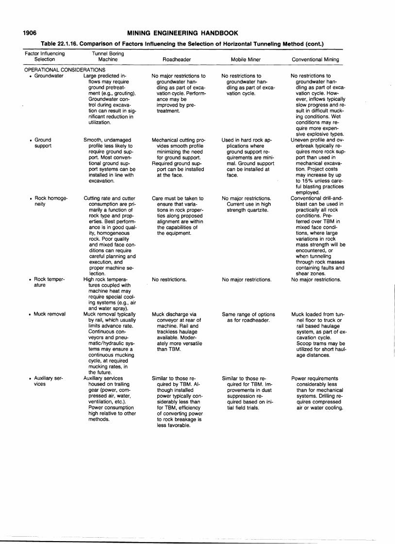
1906 MINING ENGINEERING HANDBOOK
Table 22.1.16. Comparison of Factors Influencing the Selection of Horizontal Tunneling Method (cont.)
Factor Influencing Tunnel BoringSelection Machine Roadheader Mobile Miner Conventional Mining
OPERATIONAL CONSIDERATIONS• Groundwater Large predicted in- No major restrictions to No restrictions to No restrictions to
flows may require groundwater han- groundwater han- groundwater han-ground pretreat- dling as part of exca- dling as part of exca- dling as part of exca-ment (e.g., grouting). vation cycle. Perform- vation cycle. vation cycle. How-Groundwater con- ance may be ever, inflows typicallytrol during excava- improved by pre- slow progress and re-tion can result in sig- treatment. suit in difficult muck-nificant reduction in ing conditions. Wetutilization. conditions may re-
quire more expen-sive explosive types.
• Ground Smooth, undamaged Mechanical cutting pro- Used in hard rock ap- Uneven profile and ov-support profile less likely to vides smooth profile plications where erbreak typically re-
require ground sup- minimizing the need ground support re- quires more rock sup-port. Most conven- for ground support. quirements are mini- port than used intional ground sup- Required ground sup- mal. Ground support mechanical excava-port systems can be port can be installed can be installed at tion. Project costsinstalled in line with at the face. face. may increase by upexcavation. to 15% unless care-
ful blasting practicesemployed.
• Rock homoge- Cutting rate and cutter Care must be taken to No major restrictions. Conventional drill-and-neity consumption are pri- ensure that varia- Current use in high blast can be used in
marily a function of tions in rock proper- strength quartzite. practically all rockrocl{ type and prop- ties along proposed conditions. Pre-erties. Best perform- alignment are within ferred over TBM inance is in good qual- the capabilities of mixed face condi-ity, homogeneous the equipment. tions, where largerock. Poor quality variations in rockand mixed face con- mass strength will beditions can require encountered, orcareful planning and when tunnelingexecution, and through rock massesproper machine se- containing faults andlection. shear zones.
• Rock temper- High rock tempera- No restrictions. No major restrictions. No major restrictions.ature tures coupled with
machine heat mayrequire special cool-ing systems (e.g., airand water spray).
• Muck removal Muck removal typically Muck discharge via Same range of options Muck loaded from tun-by rail, which usually conveyor at rear of as for roadheader. nel floor to truck orlimits advance rate. machine. Rail and rail based haulageContinuous con- trackless haulage system, as part of ex-veyors and pneu- available. Moder- cavation cycle.matic/hydraulic sys- ately more versatile Scoop trams may beterns may ensure a than TBM. utilized for short haul-continuous mucking age distances.cycle, at requiredmucking rates, inthe future.
• Auxiliary ser- Auxiliary services Similar to those re- Similar to those re- Power requirementsvices housed on trailing quired by TBM. AI- quired for TBM. Im- considerably less
gear (power, com- though installed provements in dust than for mechanicalpressed air, water, power typically con- suppression re- systems. Drilling re-ventilation, etc.). siderably less than quired based on ini- quires compressedPower consumption for TBM, efficiency tial field trials. air or water cooling.high relative to other of converting powermethods. to rock breakage is
less favorable.
-- -- -~---------- ------------------
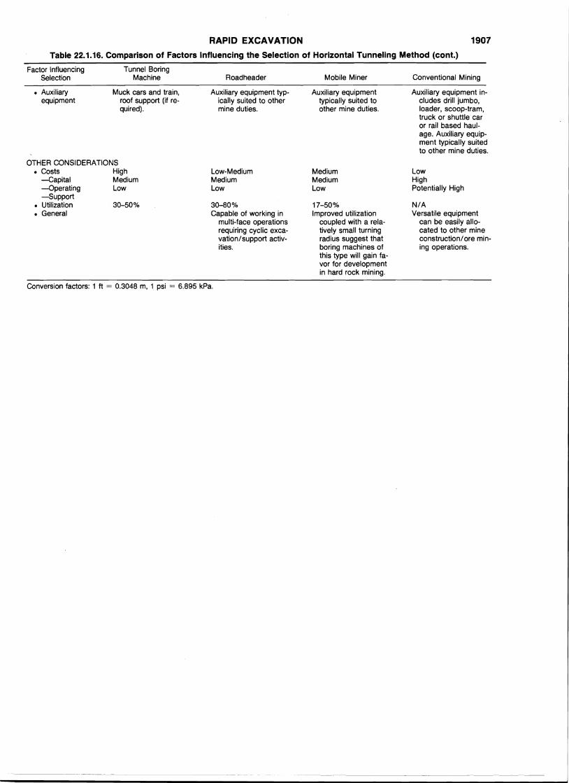
RAPID EXCAVATION
Table 22.1.16. Comparison of Factors Influencing the Selection of Horizontal Tunneling Method (cont.)
1907
Factor InfluencingSelection
• Auxiliaryequipment
Tunnel BoringMachine
Muck cars and train,roof support (if required).
Roadheader
Auxiliary equipment typically suited to othermine duties.
Mobile Miner
Auxiliary equipmenttypically suited toother mine duties.
Conventional Mining
Auxiliary equipment includes drill jumbo,loader, scoop-tram,truck or shuttle caror rail based haulage. Auxiliary equipment typically suitedto other mine duties.
OTHER CONSIDERATIONS• Costs High
-Capital Medium-Operating Low-Support
• Utilization 30-50%• General
Low-MediumMediumLow
30-80%Capable of working in
multi-face operationsrequiring cyclic excavation/support activities.
MediumMediumLow
17-50%Improved utilization
coupled with a relatively small turningradius suggest thatboring machines ofthis type will gain favor for developmentin hard rock mining.
LowHighPotentially High
N/AVersatile equipment
can be easily allocated to other mineconstruction/ore mining operations.
Conversion factors: 1 ft = 0.3048 m, 1 psi = 6.895 kPa.