new catalyst synthesis and multi-functional reactor concepts for emerging technologies in the...
TRANSCRIPT
New Catalyst Synthesis and Multifunctional ReactorConcepts for Emerging Technologies
in the Process Industry
Frits M Dautzenberg
ABB Lummus Global Inc Technology Development Center
Bloomfield New Jersey USA
CONTENTS
ABSTRACT 2
I INTRODUCTION 2
II CATALYST SYNTHESIS 2
A Microengineered Catalysts (MEC) 3
B Dry Zeolite Synthesis 7
C Mesoporous Materials 11
III THE INFLUENCE OF PARTICLE SIZE AND POROSITY ON
CATALYST ACTIVITY 14
IV MULTIFUNCTIONAL REACTORS 21
A Intra-reactor Oxidative Reheat 21
B Catalytic Partial Oxidation of Methane (CPO) 23
C Catalytic Distillation 24
1
DOI 101081CR-200036729 0161-4940 (Print) 1520-5703 (Online)
Copyright 2004 by Marcel Dekker Inc wwwdekkercom
Correspondence Frits M Dautzenberg ABB Lummus Global Inc Technology Q1Development
Center Bloomfield NJ USA
LCTR36729 LCTR_046_3ndash4 Techset Composition Ltd Salisbury UK 9232004
1
2
3
4
5
6
7
8
9
10
11
12
13
14
15
16
17
18
19
20
21
22
23
24
25
26
27
28
29
30
31
32
33
34
35
36
37
38
39
40
41
42
43
44
45
46
47
CATALYSIS REVIEWS
Vol 46 No 3ndash4 pp 1ndash33 2004
V CONCLUSIONS 29
REFERENCES 32
ABSTRACT
Q2
Key Words Please supply Q2
INTRODUCTION
As catalytic processes move through the various development phases (eg con-
ception development commercialization) and evolutionary optimization additional
improvements may eventually require major innovations and breakthroughs In this
paper several approaches are described to show that one can sometimes squeeze higher
performance out of existing processes by revisiting the fundamentals of catalytic
science and engineering Here the overarching theme is to manage and facilitate heat
and mass transfer
There are two elements of this approach in this presentation catalyst synthesis and
multifunctional reactor design As catalysts achieve higher intrinsic activity and as pro-
cesses are pushed to higher conversion both of these elements become increasingly
important Moreover the integration of new catalyst synthesis and reactors can also
improve existing technologies significantly Examples will be cited in both these areas
based on recent advances at ABB Lummus Global
CATALYST SYNTHESIS
Catalysts are developed in the laboratory with extreme care At that scale one strives
in general to get intrinsic activities and takes great care to achieve isothermal conditions
and operation in a kinetically controlled regime[1] However in commercial units cata-
lysts operate in adiabatic reactors and at high conversion under conditions where heat
and mass transfer effects cannot be avoided Consequently catalyst structural
parametersmdashsuch as particle size pore structure ultimate crystal size dispersion
effects active site distribution etcmdashtake on added importance to achieve optimal per-
formance This tailoring of catalysts has been the focal point of many industrial research
organizationsrsquo catalyst synthesis work One could consider this RampD activity to be
ldquocrystal and pore structure architecturerdquo To show the importance of this concept three
specific examples have been selected to demonstrate what can be achieved (1) micro-
engineered catalysts that enable enhanced interphase mass transfer (2) new mesoporous
catalysts with ultra-large pores that accommodate slowly diffusing reactants and (3)
custom-synthesized catalysts with submicron crystals that achieve high effectiveness
factors while still retaining the virtues of shape selectivity Each of these three advanced
LCTR36729 LCTR_046_3ndash4 Techset Composition Ltd Salisbury UK 9232004
48
49
50
51
52
53
54
55
56
57
58
59
60
61
62
63
64
65
66
67
68
69
70
71
72
73
74
75
76
77
78
79
80
81
82
83
84
85
86
87
88
89
90
91
92
93
94
Dautzenberg2
applications plays a different role in facilitating enhanced mass transfer Before we discuss
their catalytic significance and the combined use of these technologies a brief description
of each will be provided
Microengineered Catalysts (MEC)
Fast reactions often become mass transfer limited at conventional catalyst particle
diameters Therefore one is directionally driven toward smaller and smaller catalyst par-
ticles however the reduced catalyst size approach often results in high pressure drop at
commercial conditions Pressure drop problems add to compressor and energy costs in
a ldquoworst caserdquo scenario reactor support beams have been known to buckle and sometimes
fail Lummus has designed Micro Engineered Catalysts (ldquoMECrdquo) for fast reactions where
hydraulic limitations andor external mass transfer effects are important In a typical MEC
structure micron-sized catalyst particles are deposited on fibrous substrates with very high
void fractions (90thorn) Structural flow characteristics are optimized for a particular reac-
tion[2] While many applications have been identified selective catalytic reduction (SCR)
for DeNOx will be described in this paper to illustrate the merits of MEC
A typical DeNOx catalyst resides at the tail end of a combustion process whether it is
an automotive engine or a stationary power plant The objective of these processes is to
produce useful energy and thus it is critical that the back pressure be kept to a
minimum Allowable pressure losses through the catalyst system are as low as 250ndash
500 Pa The necessity for low frictional losses has a deleterious effect on catalyst activity
since the catalyst film resistance becomes controlling at the dilute (ie 1ndash10 ppm) levels
of NOx required at the outlet of the catalyst bed
Other reactor design approaches that have been used include
Using straight-channel monoliths which have been either wash coated or extruded
from catalyst The laminar flow in the channels results in poor mass transfer inef-
fective utilization of catalyst and low overall activity One approach to improve
performance is to use smaller channels but this significantly increases pressure
drop
Using short parallel beds of catalyst particles Here catalyst activity is high within
the beds and initial pressure drops are low However the void space imposed by the
open channels results in a large reactor In addition the catalyst beds are prone to
plugging in dusty atmospheres
MEC is a natural fit elegantly solving the total reactionndashengineering problem Struc-
tured packings are well known for their efficiency and low pressure drop The geometry of
the structured packing can be optimized for available pressure drop while the micron-sized
catalyst particles ensure high effectiveness factors for fast reactions
MEC catalyst formation has evolved over the past several years Steel mesh has been
supplemented by ceramic fibers as a coating substrate Figure 1 shows one of the latest
ceramic structures The use of ceramic rather than steel structures has reduced the
support cost by more than 60 at the same or better catalytic performance
In a ceramic fiber structure the catalyst itself provides mechanical strength At the
same time it is important that the fiber sheets remain porous and that all the catalyst
LCTR36729 LCTR_046_3ndash4 Techset Composition Ltd Salisbury UK 9232004
95
96
97
98
99
100
101
102
103
104
105
106
107
108
109
110
111
112
113
114
115
116
117
118
119
120
121
122
123
124
125
126
127
128
129
130
131
132
133
134
135
136
137
138
139
140
141
Catalyst Synthesis and Multifunctional Reactor Concepts 3
coated onto the microfibers is accessible Lummus has developed specialized coating tech-
niques to ensure that these requirements can be met
While the well known honeycomb monolith exhibits laminar flow MEC is a low-
pressure drop (due to its high void fraction and uniform geometry) turbulent flow struc-
ture This effect is demonstrated in Fig 2 The exponential nature of the pressure drop
versus velocity of a turbulent MEC structure is compared to the linear relationship of a
laminar straight-channel monolith MEC has a clear-cut pressure drop advantage at the
velocities of interest
The geometry of an MEC structure can be easily optimized for minimal pressure drop
and excellent catalyst activity[2] Larger openings and larger angles with respect to flow
direction (with 908 being parallel to flow and 08 being perpendicular to flow) will tend
to decrease pressure drop as well as catalyst activity Figure 3 shows the relationship
between first order rate constant and pressure drop per unit length for typical DeNOx con-
ditions as a function of structure angle in the flow direction
Figure 4 illustrates that MEC is a superior (SCR) DeNOx catalyst compared to a con-
ventional commercial honeycomb system at typical reaction conditions[4] The utilization
of the small catalyst particles in MEC is very high however there are limits as to how
much catalyst can be loaded onto the fibrous support while still maintaining accessibility
At lower temperatures where the reaction tends to be kinetically controlled an MEC
system tends to lose its advantage The kinetic resistance dominates The volumetric
activity of an MEC is the same as the monolith even with only 65 of catalyst loading
Figure 1 Ceramic MEC DeNOx catalyst
LCTR36729 LCTR_046_3ndash4 Techset Composition Ltd Salisbury UK 9232004
142
143
144
145
146
147
148
149
150
151
152
153
154
155
156
157
158
159
160
161
162
163
164
165
166
167
168
169
170
171
172
173
174
175
176
177
178
179
180
181
182
183
184
185
186
187
188
Dautzenberg4
Fig
ure
2
Pre
ssu
relo
ssv
ersu
sv
elo
city
LCTR36729 LCTR_046_3ndash4 Techset Composition Ltd Salisbury UK 9232004
189
190
191
192
193
194
195
196
197
198
199
200
201
202
203
204
205
206
207
208
209
210
211
212
213
214
215
216
217
218
219
220
221
222
223
224
225
226
227
228
229
230
231
232
233
234
235
Catalyst Synthesis and Multifunctional Reactor Concepts 5
Fig
ure
3
ME
Cp
ress
ure
loss
ver
sus
stru
ctu
rean
gle
LCTR36729 LCTR_046_3ndash4 Techset Composition Ltd Salisbury UK 9232004
236
237
238
239
240
241
242
243
244
245
246
247
248
249
250
251
252
253
254
255
256
257
258
259
260
261
262
263
264
265
266
267
268
269
270
271
272
273
274
275
276
277
278
279
280
281
282
Dautzenberg6
Although there is no universal solution to all reaction engineering applications
MEC has solved the size versus pressure drop problem for mass-transfer-limited
reactions
Dry Zeolite Synthesis
A second catalyst advance is our ldquoDry Synthesisrdquo zeolite crystallization called
ldquoDrySynrdquo for shortmdashan entirely new way to make zeolites[5] Unlike conventional
methods where the nutrients are dissolved in a caustic solution DrySyn starts with
solid reagents often silica-alumina microspheres similar in size to FCC catalysts These
silica-alumina microspheres are porous and have their own gross morphology Using
the DrySyn method the pores are filled with water caustic and if needed an organic
directing agent below or at the incipient wetness point The particles appear dry hence
the term ldquodry synthesisrdquo DrySyn has several advantages compared to conventional syn-
thesis routes (a) faster crystallization time (b) smaller crystal size (c) ability to control
porosity based on the preformed particlesrsquo properties (d) improved nutrient utilization
and (e) lower environmental impact
Figure 5 is a schematic representation of DrySyn[6] The starting materialmdasha porous
particle usually silica-aluminamdashhas its own characteristic silica-to-alumina ratio and
porosity In the crystallization process the finished product is comprised of many ultra-
small zeolite crystals Figure 6 shows the finished product of three standard zeolites
ZSM-5 zeolite beta and inorganic mordenite[7]
Figure 4 MEC DeNOx activity versus honeycomb
LCTR36729 LCTR_046_3ndash4 Techset Composition Ltd Salisbury UK 9232004
283
284
285
286
287
288
289
290
291
292
293
294
295
296
297
298
299
300
301
302
303
304
305
306
307
308
309
310
311
312
313
314
315
316
317
318
319
320
321
322
323
324
325
326
327
328
329
Catalyst Synthesis and Multifunctional Reactor Concepts 7
Fig
ure
5
No
vel
zeo
lite
syn
thes
isp
roce
du
re
ldquoDry
-Sy
nth
esis
rdquo
LCTR36729 LCTR_046_3ndash4 Techset Composition Ltd Salisbury UK 9232004
330
331
332
333
334
335
336
337
338
339
340
341
342
343
344
345
346
347
348
349
350
351
352
353
354
355
356
357
358
359
360
361
362
363
364
365
366
367
368
369
370
371
372
373
374
375
376
Dautzenberg8
Fig
ure
6
Co
nv
ersi
on
exam
ple
sfo
rldquoD
ryS
yn
rdquo
LCTR36729 LCTR_046_3ndash4 Techset Composition Ltd Salisbury UK 9232004
377
378
379
380
381
382
383
384
385
386
387
388
389
390
391
392
393
394
395
396
397
398
399
400
401
402
403
404
405
406
407
408
409
410
411
412
413
414
415
416
417
418
419
420
421
422
423
Catalyst Synthesis and Multifunctional Reactor Concepts 9
The finished product also retains the gross morphology of the parent microsphere
thereby imparting mesoporosity to the crystal agglomerates This mesopore effect is
easily seen in Fig 7 where the pore size distribution is compared to a commercial catalyst
While both catalysts have a similar share of smaller pores the DrySyn catalyst has
about 70 of its pores in the 30thorn nm range When one considers the impact of composite
resistances in a catalyst it is easy to see the potential benefits of such a pore structure
One example of DrySyn performance is shown in Fig 8 Two fast reactionsmdash
ethylbenzene (EB) and cumene productionmdashare shown for a commercial zeolite beta cat-
alyst and a comparable DrySyn catalyst Based on first-order rate constants the DrySyn
catalyst has a two-fold activity advantage for EB and a 50 activity advantage for
cumene synthesis Even though these molecules are relatively small the mesoporosity
gives a significant performance boost
The DrySyn zeolite procedure is particularly advantageous for inorganic zeolites like
zeolite Y In a high throughput screening study with Avantium many synthesis variables
(eg temperature time NaOH concentration etc) were examined that should favor the
formation of high quality small crystal zeolite Y Some of the results are shown in
Fig 9 Here each line represents one synthesis experiment and the bars describe the
three products unconverted material (Phase 1) the desired Y (Phase 3) and a second
phase (Phase 2) cancrinite By looking at the Y bars one can quickly zero in on the pre-
ferred synthesis conditions to maximize the production of zeolite Y Of course other
factors are also important such as percent crystallinity surface area hydrocarbon sorp-
tion and ultimate crystal size Figure 10 shows the progress made in driving down the
Figure 7 Pore size distribution of two catalysts
LCTR36729 LCTR_046_3ndash4 Techset Composition Ltd Salisbury UK 9232004
424
425
426
427
428
429
430
431
432
433
434
435
436
437
438
439
440
441
442
443
444
445
446
447
448
449
450
451
452
453
454
455
456
457
458
459
460
461
462
463
464
465
466
467
468
469
470
Dautzenberg10
crystal size While most conventional zeolite Y samples are typically 05 micron in size
the resultant DrySyn crystals are an order of magnitude smaller These unusually small
crystals have excellent activity for many hydrocarbon processes
Mesoporous Materials
An area of growing importance is mesoporous materials Since the discovery of
MCM-41[8 ndash 10] in the late 1980s there has been a myriad of articles and patents in this
field Lummus has also been quite active in this field In collaboration with the Technical
University of Delft (the Netherlands) an entirely new group of materials collectively
known as TUD-1[11 ndash 13] has been synthesized TUD-1 is comprised of random three-
dimensional interconnecting pores Unlike the M41S materials and many other mesopor-
ous materials TUD-1 is amorphous and thus has no planes of symmetry and no space
group
TUD-1rsquos amorphous character is shown in Fig 11 which is an electron micrograph of
TUD-1 alongside a ceramic foam of macroscopic scale To conclusively show that the
pores are interconnected a ldquoreverse imagingrdquo technique was developed Here the pores
of a siliceous TUD-1 were filled with sugar molecules that were then carburized The
silica was then dissolved to leave behind only the carbon pore replica The resultant struc-
ture did not collapse conclusively proving that the pores are interconnected
TUD-1 has another important property the pores have a controllable narrow size
distributionmdashtypically from 40 to 120 A with a surface area from 500 to 1000 m2g
Figure 12 shows the trade-off that can be achieved between pore diameter and surface
area Even at the largest pore size the surface area for this Si-TUD-1 is 500 m2gndash20
to 40 higher than typical silica supports
Figure 8 Aromatics alkylation comparison of catalyst performance
LCTR36729 LCTR_046_3ndash4 Techset Composition Ltd Salisbury UK 9232004
471
472
473
474
475
476
477
478
479
480
481
482
483
484
485
486
487
488
489
490
491
492
493
494
495
496
497
498
499
500
501
502
503
504
505
506
507
508
509
510
511
512
513
514
515
516
517
Catalyst Synthesis and Multifunctional Reactor Concepts 11
Fig
ure
9
Su
mm
ary
of
HT
Ssy
nth
esis
exp
erim
ents
LCTR36729 LCTR_046_3ndash4 Techset Composition Ltd Salisbury UK 9232004
518
519
520
521
522
523
524
525
526
527
528
529
530
531
532
533
534
535
536
537
538
539
540
541
542
543
544
545
546
547
548
549
550
551
552
553
554
555
556
557
558
559
560
561
562
563
564
Dautzenberg12
These combined properties make TUD-1 an attractive viable catalyst or catalyst
support for many reactions While the major focus has been with alumina silica and
silica-alumina TUD-1 has been made in about 20 different chemical variants As seen
in Table 1 Delft scientists have shown that Ti-TUD-1 is five times more active than its
MCM-41 counterpart for epoxidation even though the surface areas are equivalent[1314]
Figure 10 Comparison of conventional and ldquoDrySynrdquo Y crystallites
Figure 11 Ceramic foam versus TUD-1 an analogy
LCTR36729 LCTR_046_3ndash4 Techset Composition Ltd Salisbury UK 9232004
565
566
567
568
569
570
571
572
573
574
575
576
577
578
579
580
581
582
583
584
585
586
587
588
589
590
591
592
593
594
595
596
597
598
599
600
601
602
603
604
605
606
607
608
609
610
611
Catalyst Synthesis and Multifunctional Reactor Concepts 13
THE INFLUENCE OF PARTICLE SIZE AND POROSITY ON
CATALYST ACTIVITY
Catalysts can be custom-tailored for improved performance specifically the well-
known Thiele moduluseffectiveness factor concepts can be applied to demonstrate
mass transfer effects in catalysis The unique features of DrySyn zeolites and TUD-1
are both amenable to this approach
The intrinsic activity [k(o)] can be calculated by measuring the apparent catalyst
activity [k(app)] of a catalyst using two different particle sizes [rp] It follows that
kethappTHORNeth1THORN
kethappTHORNeth2THORNfrac14
heth1THORN
heth2THORNfrac14
3=f1frac121= tanhf1 1=f1
3=f2frac121= tanhf2 1=f2eth1THORN
Figure 12 TUD-1 Trading off pore size and surface area
Table 1 Expoxidation of cyclohexene
Catalysts Surface area m2g Turnover frequency
Ti-MCM-41 921 36
Ti-TUD-1 917 202
LCTR36729 LCTR_046_3ndash4 Techset Composition Ltd Salisbury UK 9232004
612
613
614
615
616
617
618
619
620
621
622
623
624
625
626
627
628
629
630
631
632
633
634
635
636
637
638
639
640
641
642
643
644
645
646
647
648
649
650
651
652
653
654
655
656
657
658
Dautzenberg14
in which
fi frac14 rpethiTHORN
ffiffiffiffiffiffiffiffikethoTHORN
D
reth2THORN
and
hethiTHORN frac14kethappTHORNethiTHORN
kethoTHORNeth3THORN
Through an iterative approximation we establish a value for k(o)D so that Eq (1) is
satisfied For each experimental value of rp we now can calculate f and thus k(o) and
therefore D We subsequently determine k(app) for any value of rp While the effective-
ness factorThiele modulus is usually shown as a log-log plot recasting it on a linear
scale can be quite informative
Figure 13 shows a typical example where this approach has been applied to two differ-
ent zeolite beta catalysts Using ethylbenzene formation as a probe reactive the k(o) of the
DrySyn beta catalyst is 15 higher than the k(o) of the commercial beta catalyst Of indus-
trial importance is the fact that the k(app) for 15 mm DrySyn particles is more than 25
times higher than the k(app) of 15 mm commercial catalyst particles Since the crystal
size of both zeolite beta samples is small (less than 005 micron ultimate crystal size)
the performance difference is probably due to the large number of mesopores in the
DrySyn catalyst which is reflected in the higher value of the effective diffusivity
In addition to altering catalyst activity by different zeolite synthesis routes one can
vary the catalyst support properties for a dramatic impact on catalyst performance This
concept has been shown[1516] to achieve synergistic benefits by combining zeolitic
activity with a mesoporous matrix A specific example is cited here again using the EB
probe reaction Table 2 shows the performance of three alumina-bound commercial Y cata-
lysts and two developmental catalysts using TUD-1 (silica or alumina) as the binding
material (commercial zeolite Y used) The intrinsic activities of the three commercial cata-
lysts reported on a constant zeolite basis are very similar and the intrinsic activities of
the mesoporous Y catalysts are significantly lower However the commercially important
activity is for particles typically greater than 1 mm Figure 14 shows the catalyst activity of
the two types of Y catalysts versus particle size Interestingly although the mesoporous Y
catalyst (here with Si-TUD-1) has a lower intrinsic activity than the commercial Y cata-
lyst the mesoporous Y has triple the activity of the commercial Y catalyst at industrially
relevant particle sizes This activity ldquocross-over effectrdquo is attributable to a tenfold advan-
tage in diffusivity One can quickly see the potential activity advantage that can be
achieved by optimizing the mesoporosity The five catalysts of Table 2 are compared in
Fig 15 Here we see that despite lower intrinsic activities both mesoporous Y catalysts
have superior activity compared to the three commercial Y catalysts at particle size of
15 mm
From the above conclusions one can foresee that another route to raising the overall
catalyst performance is to boost the intrinsic activity of the zeolite itself This concept is
illustrated in Table 3 Again using the EB probe reaction Table 3 shows the performance
of two alumina-bound commercial zeolite beta catalysts and one developmental catalyst
embedded in Si-TUD-1 (commercial zeolite beta used) The second commercial zeolite
beta catalyst (ldquoType IIrdquo) was prepared by a proprietary technique that achieves a
LCTR36729 LCTR_046_3ndash4 Techset Composition Ltd Salisbury UK 9232004
659
660
661
662
663
664
665
666
667
668
669
670
671
672
673
674
675
676
677
678
679
680
681
682
683
684
685
686
687
688
689
690
691
692
693
694
695
696
697
698
699
700
701
702
703
704
705
Catalyst Synthesis and Multifunctional Reactor Concepts 15
Fig
ure
13
P
erfo
rman
ceo
fldquoD
ryS
yn
rdquob
eta
ver
sus
com
mer
cial
bet
a(R
ef
ZS
han
etal
M
icro
po
rou
san
dM
ater
ials
20
014
81
81
)
LCTR36729 LCTR_046_3ndash4 Techset Composition Ltd Salisbury UK 9232004
706
707
708
709
710
711
712
713
714
715
716
717
718
719
720
721
722
723
724
725
726
727
728
729
730
731
732
733
734
735
736
737
738
739
740
741
742
743
744
745
746
747
748
749
750
751
752
Dautzenberg16
Ta
ble
2
Yca
taly
sts
per
form
ance
Ref
C
atal
yst
k(o
)
1s
ec
Eff
D
cm2s
ec
k(a
pp
)in
1s
ecat
par
tsi
zein
mm
Cat
aly
st
effe
ct
at
15
mm
Rel
ran
kin
g
of
k(o
)
Rel
ran
kin
g
of
k(1
5)
02
10
78
12
61
50
1C
om
mer
cial
Y
Ty
pe
I(7
0
)
36
97
8
10
26
15
30
47
03
00
25
68
10
01
00
2C
om
mer
cial
Y
Ty
pe
II(8
0
)
33
11
11
10
26
15
60
50
03
10
26
79
09
01
05
3C
om
mer
ical
Y4
63
19
5
10
26
23
80
77
04
90
41
89
12
51
65
4M
eso
po
rou
sY
Si-
TU
D-1
(45
8
)
24
71
31
0
10
26
23
11
48
10
50
91
36
80
67
36
3
5M
eso
po
rou
sY
11
59
93
10
26
11
00
73
05
30
47
40
40
31
18
6
No
te
Bo
ldfrac14
Ex
per
imen
tal
val
ues
al
lk
val
ues
at1
00
ze
oli
teb
asis
LCTR36729 LCTR_046_3ndash4 Techset Composition Ltd Salisbury UK 9232004
753
754
755
756
757
758
759
760
761
762
763
764
765
766
767
768
769
770
771
772
773
774
775
776
777
778
779
780
781
782
783
784
785
786
787
788
789
790
791
792
793
794
795
796
797
798
799
Catalyst Synthesis and Multifunctional Reactor Concepts 17
Fig
ure
14
E
Bac
tiv
ity
asfu
nct
ion
of
par
ticl
esi
ze
LCTR36729 LCTR_046_3ndash4 Techset Composition Ltd Salisbury UK 9232004
800
801
802
803
804
805
806
807
808
809
810
811
812
813
814
815
816
817
818
819
820
821
822
823
824
825
826
827
828
829
830
831
832
833
834
835
836
837
838
839
840
841
842
843
844
845
846
Dautzenberg18
Fig
ure
15
R
elat
ive
ran
kin
go
fze
oli
teY
cata
lyst
su
sin
gE
Bp
rob
ere
acti
on
LCTR36729 LCTR_046_3ndash4 Techset Composition Ltd Salisbury UK 9232004
847
848
849
850
851
852
853
854
855
856
857
858
859
860
861
862
863
864
865
866
867
868
869
870
871
872
873
874
875
876
877
878
879
880
881
882
883
884
885
886
887
888
889
890
891
892
893
Catalyst Synthesis and Multifunctional Reactor Concepts 19
Ta
ble
3
Bet
aca
taly
sts
per
form
ance
Ref
C
atal
yst
k(o
)
1s
ec
Eff
D
cm2s
ec
k(a
pp
)in
1s
ecat
par
tsi
zein
mm
Cat
aly
st
effe
ct
at
15
mm
Rel
ran
kin
g
of
k(o
)
Rel
ran
kin
g
of
k(1
5)
02
10
78
12
51
50
1C
om
mer
cial
bet
aT
yp
eI
(80
)
08
82
5
10
26
07
40
34
02
30
19
02
11
00
10
0
2C
om
mer
cial
bet
aT
yp
eII
(80
)
18
96
7
10
26
16
40
80
05
40
46
02
52
16
24
7
4M
eso
po
rou
s
bet
aS
i-T
UD
-1
(40
)
10
01
40
0
10
26
09
80
80
06
30
55
05
51
14
29
3
No
te
Bo
ldfrac14
Ex
per
imen
tal
val
ues
al
lk
val
ues
at1
00
ze
oli
teb
asis
M
anu
fact
uri
ng
bas
edo
np
rop
riet
ary
Lu
mm
usrsquo
syn
thes
ism
od
ifica
tio
nm
eth
od
LCTR36729 LCTR_046_3ndash4 Techset Composition Ltd Salisbury UK 9232004
894
895
896
897
898
899
900
901
902
903
904
905
906
907
908
909
910
911
912
913
914
915
916
917
918
919
920
921
922
923
924
925
926
927
928
929
930
931
932
933
934
935
936
937
938
939
940
Dautzenberg20
two- to threefold intrinsic activity boost This intrinsic activity boost is seen when compar-
ing the two commercial catalysts Again the commercially important activity is for par-
ticles typically greater than 1 mm At 125 mm particle size the activity advantage of
the Type II zeolite beta is being maintained More importantly the highest activity catalyst
is the beta in TUD-1 which has the highest effective diffusivity Specifically the activity
here is three times higher than the commercial zeolite beta (ldquoType Irdquo) catalyst These
results were not optimized so it is possible that even larger benefits can be reaped by
further tailoring the mesoporous structure and possibly composition
These performance attributes are shown graphically in Fig 16 which shows the cata-
lyst activity of the three beta catalysts The key observation here is that rankings based on
intrinsic activity can be misleading This is another illustration of the powerful impact that
pore architecture can have on catalyst activity
MULTIFUNCTIONAL REACTORS
Since most industrially relevant reactions are either endothermic or exothermic the
management of heat transfer is usually a key consideration in reaction engineering
design In many cases reactor selection is based on how one is able to remove or add
energy Conventional designs for highly energetic systems are therefore usually based
on fixed bed tubular and fluid bed reactors with internal or external heat exchangers
Intra-reactor process intensification[7] based on combining reaction with heat transfer
may offer a new opportunity to broaden the reactor selection possibilities Three specific
examples are used to describe this new approach (1) intra-reactor oxidative reheat for the
production of styrene by staging endothermic and exothermic reactions in series (2) sim-
ultaneous operation of endothermic dissociative adsorption of methane with exothermic
oxidative removal of carbon during catalytic partial oxidation and (3) catalytic distillation
for the production of ethers ethylbenzene or cumene and the selective hydrogenation of
highly unsaturated components in olefins streams
Intra-reactor Oxidative Reheat
The production of styrene by dehydrogenation of EB is carried out in adiabatic fixed
bed reactors The reaction is highly endothermic and the heat is provided between the reac-
tors by two methods addition of high temperature steam and heat exchange[17] Due to the
high steam-to-EB ratio the combined volumetric flow rate is high and consequently
radial flow fixed bed reactors are chosen to avoid pressure drop limitations Intra-
reactor heat exchange between catalyst beds results in higher overall bed temperatures
and in principle can lead to better spacendashtime yields Unfortunately it is difficult to
install conventional heat exchangers in the radial direction while also assuring acceptable
temperature uniformity keeping the reactor compact and avoiding large thermal zones
To address this problem a new solution was developed employing catalytic combustion
of hydrogen to water This reaction adds heat locally to the system and raises the overall
average reactor temperature thereby boosting the overall conversion Figure 17 illustrates
how endothermic ethylene dehydrogenation can be integrated with the exothermic
combustion of hydrogen This new method of adding heat is shown schematically in
LCTR36729 LCTR_046_3ndash4 Techset Composition Ltd Salisbury UK 9232004
941
942
943
944
945
946
947
948
949
950
951
952
953
954
955
956
957
958
959
960
961
962
963
964
965
966
967
968
969
970
971
972
973
974
975
976
977
978
979
980
981
982
983
984
985
986
987
Catalyst Synthesis and Multifunctional Reactor Concepts 21
Fig
ure
16
R
elat
ive
ran
kin
go
fze
oli
teb
eta
cata
lyst
su
sin
gE
Bp
rob
ere
acti
on
LCTR36729 LCTR_046_3ndash4 Techset Composition Ltd Salisbury UK 9232004
988
989
990
991
992
993
994
995
996
997
998
999
1000
1001
1002
1003
1004
1005
1006
1007
1008
1009
1010
1011
1012
1013
1014
1015
1016
1017
1018
1019
1020
1021
1022
1023
1024
1025
1026
1027
1028
1029
1030
1031
1032
1033
1034
Dautzenberg22
Fig 18 where intra-reactor reheat is employed in stages The new design known as
SMART (Styrene Monomer Advanced Reheat Technology) has already been successfully
commercialized in five plants
Catalytic Partial Oxidation of Methane (CPO)
The intra-reactor reheat principle can also be applied to the production of syngas
(COH2) from methane It is well known that conventional steam reforming of methane
is highly endothermic During CPO methane is dissociatively absorbed on the catalyst
producing hydrogen and a carbonaceous residue This residue is converted into CO and
H2O by oxidation and this reaction generates energy (exothermic) driving the endother-
mic steam reforming reaction that is happening in parallel With an optimized catalyst
ldquocokelessrdquo steam reforming appears to be feasible As a preferred reactor configuration
a reactor concept called ldquoComposite Structured Packingrdquo (CSP) is proposed ideally
suited for high superficial gas velocities as envisioned for CPO
Several noble-metal-containing catalysts have been proposed for CPO Figure 19
compares the temperature-programmed oxidation of Rh Ni and Ni-B upon exposure to
methane decomposition With Rh the resulting carbon residues are removed at relatively
Figure 17 Catalytic cycle for Styrene Monomer Advanced Reheat Technology (SMART)
LCTR36729 LCTR_046_3ndash4 Techset Composition Ltd Salisbury UK 9232004
1035
1036
1037
1038
1039
1040
1041
1042
1043
1044
1045
1046
1047
1048
1049
1050
1051
1052
1053
1054
1055
1056
1057
1058
1059
1060
1061
1062
1063
1064
1065
1066
1067
1068
1069
1070
1071
1072
1073
1074
1075
1076
1077
1078
1079
1080
1081
Catalyst Synthesis and Multifunctional Reactor Concepts 23
low temperature This is not the case with Ni Upon exposure to CH4 graphitic carbon is
deposited upon the Ni catalyst and this can be removed only at high temperature With a
catalyst based on an alloy of Ni and B most of the carbon is removed at a substantially
lower temperature while the amount of carbon needed to be removed at high temperature
is significantly reduced
Figure 20 shows the CPO performance of one of the novel Ni-B catalysts developed
during a collaborative project with the National University of Singapore[18] Note that the
product composition is essentially at equilibrium even at the extremely high space velo-
city applied during the testing In Fig 21 the ldquomethane conversionrdquo versus ldquotime
onstreamrdquo shows that the catalyst is unusually stable no initial deactivation period
occurs consistent with its noncoking behavior Another important benefit of the new
CPO catalyst is the close approach to thermal neutrality thus simplifying heat manage-
ment and improving thermal efficiency This feature is important if one wants to design
ultra-compact hydrogen generators
Catalytic Distillation
As the name implies catalytic distillation (CD)[19 ndash 22] intimately integrates catalytic
reaction and product separation by distillation CD is well suited for processes where the
feed and the product have a significantly different boiling range thereby facilitating
separation and many times enhancing selectivity by applying relatively low reaction temp-
eratures The heat of reaction is used for separation and therefore facilitates heat mana-
gement The predominantly liquid phase also aids catalyst stability Figure 22 illustrates
Figure 18 New reactor system of Styrene Monomer Advanced Reheat Technology (SMART)
LCTR36729 LCTR_046_3ndash4 Techset Composition Ltd Salisbury UK 9232004
1082
1083
1084
1085
1086
1087
1088
1089
1090
1091
1092
1093
1094
1095
1096
1097
1098
1099
1100
1101
1102
1103
1104
1105
1106
1107
1108
1109
1110
1111
1112
1113
1114
1115
1116
1117
1118
1119
1120
1121
1122
1123
1124
1125
1126
1127
1128
Dautzenberg24
one typical application of a CD technology the CDHydrow process for the selective
hydrogenation of benzene in reformate fractions The family of CD technologies has
grown quite extensively and today the number of commercially licensed units is about
150 Table 4 shows some of the CD applications that have been commercialized
One of the major petrochemical processesmdashsteam cracking for the production of
ethylenemdashis often perceived to be strictly thermal in nature However much of the down-
stream separation processes which are both energy and capital intensive can benefit from
catalytic advances In the production of ethylene and propylene through pyrolysis of
various feedstocks several undesirable by-products (eg dienes and acetylenes) are
Figure 19 TPO profiles of carburized CPO catalysts
LCTR36729 LCTR_046_3ndash4 Techset Composition Ltd Salisbury UK 9232004
1129
1130
1131
1132
1133
1134
1135
1136
1137
1138
1139
1140
1141
1142
1143
1144
1145
1146
1147
1148
1149
1150
1151
1152
1153
1154
1155
1156
1157
1158
1159
1160
1161
1162
1163
1164
1165
1166
1167
1168
1169
1170
1171
1172
1173
1174
1175
Catalyst Synthesis and Multifunctional Reactor Concepts 25
Fig
ure
20
T
yp
ical
cata
lyti
cp
arti
alo
xid
atio
nre
sult
s
LCTR36729 LCTR_046_3ndash4 Techset Composition Ltd Salisbury UK 9232004
1176
1177
1178
1179
1180
1181
1182
1183
1184
1185
1186
1187
1188
1189
1190
1191
1192
1193
1194
1195
1196
1197
1198
1199
1200
1201
1202
1203
1204
1205
1206
1207
1208
1209
1210
1211
1212
1213
1214
1215
1216
1217
1218
1219
1220
1221
1222
Dautzenberg26
created As such further processing is required for the separation and removal of the
dienesacetylenes from the primary olefin products Dictated by process economics
most of the C2 and heavier dienesacetylenes must be handled through a combination
of separation and hydrogenation since separation alone would result in excessive loss of
the olefin product
Currently the distillation and hydrogenation take place in several distinct process
steps designed to separate and hydrogenate the C2C3 and C4 compounds independently
(Fig 23) A disadvantage of this widely practiced conventional technology is the large
energy consumption required to generate the high pressures and cryogenic temperatures
to first separate and subsequently remove hydrogen from the cracked gas Additionally
the chemistry of each hydrogenation step (eg C2C3 etc) requires an independent
reactor system thereby driving up the plantrsquos capital cost and complexity
To offset these disadvantages the ldquoFront-End CDHydrordquo process (Fig 24) was devel-
oped as a one-step conversion of all C2ndashC5 and even heavier dienesacetylenes without
hydrogenation of the desired C2C3 olefins[2324] The objective is to Q3simultaneously
(a) consume dilute hydrogen through the elimination of undesirable dienes and acetylenes
thereby reducing refrigeration and compression cost and (b) combine reaction and separa-
tion into one step This new process greatly reduces the unit equipment ldquopiece countrdquo
by eliminating the separate hydrogenation reactors of the C2ndashC4 streams The heat of
Figure 21 CPO combined with steam reforming
LCTR36729 LCTR_046_3ndash4 Techset Composition Ltd Salisbury UK 9232004
1223
1224
1225
1226
1227
1228
1229
1230
1231
1232
1233
1234
1235
1236
1237
1238
1239
1240
1241
1242
1243
1244
1245
1246
1247
1248
1249
1250
1251
1252
1253
1254
1255
1256
1257
1258
1259
1260
1261
1262
1263
1264
1265
1266
1267
1268
1269
Catalyst Synthesis and Multifunctional Reactor Concepts 27
Fig
ure
22
N
ewC
DT
EC
Hb
enze
ne
hy
dro
gen
atio
nte
chn
olo
gy
LCTR36729 LCTR_046_3ndash4 Techset Composition Ltd Salisbury UK 9232004
1270
1271
1272
1273
1274
1275
1276
1277
1278
1279
1280
1281
1282
1283
1284
1285
1286
1287
1288
1289
1290
1291
1292
1293
1294
1295
1296
1297
1298
1299
1300
1301
1302
1303
1304
1305
1306
1307
1308
1309
1310
1311
1312
1313
1314
1315
1316
Dautzenberg28
reaction in the catalytic distillation reactor is used for separation and therefore improves
overall heat management In contrast to conventional fixed bed reactor systems where
dimers and oligomers accumulate and cause catalyst fouling the CD reactor ensures
that these undesirable components are removed by fractionation As a result this
process achieves prolonged catalyst life
The advancements achieved with the ldquoFront End CDHydrordquo process integrated with
several other Lummus innovations represent one of the most significant breakthroughs in
ethylene technology over the past 25 years
CONCLUSIONS
In reviewing the results presented in this paper the following conclusions have been
formulated
The catalyst synthesis examples described in this paper demonstrate that tailoring
the pore architecture of catalysts has several benefits Higher overall reaction rates
and yields can be obtained and in certain cases catalyst stability is also improved
by reducing the formation of catalyst deactivating precursors
The ldquoDrySynrdquo synthesis procedure can be optimized to make zeolite catalysts with
ultra-small crystallites This may benefit the development of catalysts with high
intrinsic activity The synthesis is very effective if mesoporous supports are used
to achieve a high degree of utilization
Inserting Y as well as beta in TUD-1 materials increases catalyst activity for aro-
matics alkylation to levels that have not been achieved with conventional zeolite
catalysts The open three-dimensional pore structure of TUD-1 is a key contributor
to this achievement It is expected that similar performance improvements will be
realized for other reactions that are commercially practiced at conditions imposing
mass transfer limitations
The intra-reactor reheat concept as practiced in SMART should in principle be
applicable to other strongly endothermic dehydrogenation reactions Applied at
the catalyst level as shown in the CPO example it is speculated that intra-
reactor reheat can be used for in-situ catalyst regeneration during operation
Catalytic distillation is a prime example of what can be achieved by process inten-
sification Although the technology has already been applied commercially for
Table 4 Commercial CD applications
dagger Etherification (MTBE TAME and ETBE)
dagger Aromatics alkylation (EB and cumene)
dagger Benzene removal from reformate
dagger Selective desulfurization
dagger Various selective hydrogenations
Demonstration plant at Tianjin China Front-end CDHydrow for
ethylene plants (2003)
LCTR36729 LCTR_046_3ndash4 Techset Composition Ltd Salisbury UK 9232004
1317
1318
1319
1320
1321
1322
1323
1324
1325
1326
1327
1328
1329
1330
1331
1332
1333
1334
1335
1336
1337
1338
1339
1340
1341
1342
1343
1344
1345
1346
1347
1348
1349
1350
1351
1352
1353
1354
1355
1356
1357
1358
1359
1360
1361
1362
1363
Catalyst Synthesis and Multifunctional Reactor Concepts 29
Fig
ure
23
C
on
ven
tio
nal
ole
fin
sp
uri
fica
tio
nte
chn
olo
gy
LCTR36729 LCTR_046_3ndash4 Techset Composition Ltd Salisbury UK 9232004
1364
1365
1366
1367
1368
1369
1370
1371
1372
1373
1374
1375
1376
1377
1378
1379
1380
1381
1382
1383
1384
1385
1386
1387
1388
1389
1390
1391
1392
1393
1394
1395
1396
1397
1398
1399
1400
1401
1402
1403
1404
1405
1406
1407
1408
1409
1410
Dautzenberg30
Fig
ure
24
F
ron
t-en
dC
DH
yd
row
tech
no
log
yfo
ro
lefi
ns
pu
rifi
cati
on
LCTR36729 LCTR_046_3ndash4 Techset Composition Ltd Salisbury UK 9232004
1411
1412
1413
1414
1415
1416
1417
1418
1419
1420
1421
1422
1423
1424
1425
1426
1427
1428
1429
1430
1431
1432
1433
1434
1435
1436
1437
1438
1439
1440
1441
1442
1443
1444
1445
1446
1447
1448
1449
1450
1451
1452
1453
1454
1455
1456
1457
Catalyst Synthesis and Multifunctional Reactor Concepts 31
various processes it is expected that the family will keep growing Tailoring of
existing catalysts may be required to allow operation in the liquid phase at
boiling conditions
The multifunctional reactor examples show that by applying intra-reactor intensi-
fication mature high-volume petrochemical processes can be improved As illus-
trated in the CPO example intra-reactor heat transfer can be applied beneficially
in the development of emerging technologies
To achieve optimum success more multidisciplinary teams are needed to address the
current and future needs of the process industry The teams should contain catalyst syn-
thesis experts as well as knowledgeable reaction engineers Furthermore it is recommend-
able to encourage industryndashuniversity collaborations This can be very synergistic
because the participants can extend and reinforce each otherrsquos efforts taking full advan-
tage of their complementary capabilities
REFERENCES
1 Dautzenberg FM Quality principles for catalyst testing during process development
Combinatorial Catalysis and High Throughput Catalyst Design and Testing Confer-
ence Vilamoura Quarteira (Algarve) Portugal July 19ndash24 1999 NATO Advanced
Study Institute
2 Trubac RE Dautzenberg FM Griffin TA Paikert B Schmidt VR
Overbeek RA Micro-engineered catalyst systems ABBrsquos advancement in struc-
tured catalytic packings Catalysis Today 2001 69 17ndash24
3 Carlborg JA Chang Y-F Murrell LL Trubac RE Overbeek RA
Schmidt VR Yeh CY Schuh L Conversion of Nitrogen Oxides in the Presence
of a Catalyst Supported on a Mesh-like Structure US Patent 6534022 March 18
2003 (assigned to ABB Lummus Global Inc)
4 First International Conference on Structured Catalysts and Reactors Delft The
Netherlands October 21ndash24 2001
5 Murrell LL Overbeek RA Chang Y-F van der Puil N Yeh CY Method of
Making Molecular Sieves and Novel Molecular Sieve Components US 6350429
2002 (assigned to ABB Lummus Global Inc)
6 Dautzenberg FM Angevine PJ Trubac RE Maschmeyer Th Tailoring Indus-
trial Catalyst to Minimize Mass Transfer Limitations 8th International Symposium
Scientific Bases for the Preparation of Heterogeneous Catalysts Louvain-la-Neuve
Belgium September 9ndash12 2002
7 Dautzenberg FM Mukherjee M Process Intensification Using Multifunctional
Reactors 16th International Symposium on Chemical Reaction Engineering
Krakow Poland September 10 2000
8 Beck JS Method for Synthesizing Mesoporous Crystalline Material US Patent
5057296 October 15 1991 (assigned to Mobil Oil Corp)
9 Kresge CT Leonowicz ME Roth WJ Vartuli JC Synthetic Mesoporous Crys-
talline Material US Patent 5098684 March 24 1992 (assigned to Mobil Oil Corp)
LCTR36729 LCTR_046_3ndash4 Techset Composition Ltd Salisbury UK 9232004
1458
1459
1460
1461
1462
1463
1464
1465
1466
1467
1468
1469
1470
1471
1472
1473
1474
1475
1476
1477
1478
1479
1480
1481
1482
1483
1484
1485
1486
1487
1488
1489
1490
1491
1492
1493
1494
1495
1496
1497
1498
1499
1500
1501
1502
1503
1504
Dautzenberg32
10 Kresge CT Leonowicz ME Roth WJ Vartuli JC Composition of Synthetic
Crystalline Material Its Synthesis US Patent 5102643 April 7 1992 (assigned to
Mobil Oil Corp)
11 Shan Z Maschmeyer Th Jansen JC Inorganic Oxides with Mesoporosity or
Combined Meso- and Microporosity and Process for the Preparation Thereof US
Patent 6358486 2002 (assigned to ABB Lummus Global Inc)
12 Jansen JC Shan Z Marchese L Zhou W van der Puil N Maschmeyer Th A
New Templating Method for Three-Dimensional Mesopore Networks Chem
Commun 2001 713ndash714
13 Shan Z Gianotti E Jansen JC Peters JA Marchese L Maschmeyer Th One-
Step Synthesis of a Highly Active Mesoporous Titanium-Containing Silica by Using
Bifunctional Templating Chem Eur J 2001 7 (7) 1437ndash1443
14 Shan Z Jansen JC Marchese L Maschmeyer Th Synthesis Characterization
and Catalytic Testing of a 3-D Mesoporous Titanosilica Ti-TUD-1 Micro Meso
Mater 2001 48 (1ndash3) 181ndash187
15 Shan Z Jansen JC Yeh CY Koegler JH Maschmeyer Th Catalyst Contain-
ing Microporous Zeolite in Mesoporous Support and Method for Making Same US
Patent Application 20020074263 2002 (assigned to ABB Lummus Global Inc)
16 Shan Z Jansen JC Yeh CY Koegler JH Maschmeyer Th Catalyst Contain-
ing Microporous Zeolite in Mesoporous Support and Method for Making Same WO
03045548 2003-06-05 (assigned to ABB Lummus Global Inc)
17 Dautzenberg FM Hydro-and Dehydrogenation of Large Volume Petrochemicals
Paper presented at the 10th Roermond Conference on Catalysis Rolduc-Kerkrade
The Netherlands June 30ndashJuly 5 2002
18 Dautzenberg FM Encouraging Innovation in Catalysis Paper presented at the 3rd
Asia-Pacific Congress on Catalysis Dalian China October 12ndash15 2003
19 Smith LA Jr Catalytic Distillation Structure US Patent 4443559 April 17 1984
(assigned to Chemical Research amp Licensing Company)
20 Sy A Smith L Chen J Dautzenberg FM Catalytic Distillation Route for
Cumene DeWitt Petrochemical Review Houston Texas March 23 1993
21 Rock K Gilbert GR McGuirk T Catalytic distillation extend its reach Chemical
Engineering 1997 78 78ndash84
22 Hearn D Putman HM Hydrodesulfurization Process Utilizing a Distillation
Column Reactor US Patent 5779883 March 17 1998 (assigned to Catalytic Distil-
lation Technologies)
23 Stanley SJ McCarthy FM Sumner C Gildert GR Olefin Plant Recovery
System Employing Catalytic Distillation US Patent 5679241 May 17 1995
(assigned to ABB Lummus Global Inc and Chemical Research amp Licensing
Company)
LCTR36729 LCTR_046_3ndash4 Techset Composition Ltd Salisbury UK 9232004
1505
1506
1507
1508
1509
1510
1511
1512
1513
1514
1515
1516
1517
1518
1519
1520
1521
1522
1523
1524
1525
1526
1527
1528
1529
1530
1531
1532
1533
1534
1535
1536
1537
1538
1539
1540
1541
1542
1543
1544
1545
1546
1547
1548
1549
1550
1551
Catalyst Synthesis and Multifunctional Reactor Concepts 33
Author QueriesJOURNAL LCTR
MANUSCRIPT 200036729
AQ Please check the right-hand running head provided is ok
Q1 Please provide street zipcode E-mail id and fax for corresponding author
Q2 Please supply abstract and keywords
Q3 Reference [24] is not present in the list Please add to the list
LCTR36729 LCTR_046_3ndash4 Techset Composition Ltd Salisbury UK 9232004
1552
1553
1554
1555
1556
1557
1558
1559
1560
1561
1562
1563
1564
1565
1566
1567
1568
1569
1570
1571
1572
1573
1574
1575
1576
1577
1578
1579
1580
1581
1582
1583
1584
1585
1586
1587
1588
1589
1590
1591
1592
1593
1594
1595
1596
1597
1598
Dautzenberg34

Fig
ure
2
Pre
ssu
relo
ssv
ersu
sv
elo
city
LCTR36729 LCTR_046_3ndash4 Techset Composition Ltd Salisbury UK 9232004
189
190
191
192
193
194
195
196
197
198
199
200
201
202
203
204
205
206
207
208
209
210
211
212
213
214
215
216
217
218
219
220
221
222
223
224
225
226
227
228
229
230
231
232
233
234
235
Catalyst Synthesis and Multifunctional Reactor Concepts 5
Fig
ure
3
ME
Cp
ress
ure
loss
ver
sus
stru
ctu
rean
gle
LCTR36729 LCTR_046_3ndash4 Techset Composition Ltd Salisbury UK 9232004
236
237
238
239
240
241
242
243
244
245
246
247
248
249
250
251
252
253
254
255
256
257
258
259
260
261
262
263
264
265
266
267
268
269
270
271
272
273
274
275
276
277
278
279
280
281
282
Dautzenberg6
Although there is no universal solution to all reaction engineering applications
MEC has solved the size versus pressure drop problem for mass-transfer-limited
reactions
Dry Zeolite Synthesis
A second catalyst advance is our ldquoDry Synthesisrdquo zeolite crystallization called
ldquoDrySynrdquo for shortmdashan entirely new way to make zeolites[5] Unlike conventional
methods where the nutrients are dissolved in a caustic solution DrySyn starts with
solid reagents often silica-alumina microspheres similar in size to FCC catalysts These
silica-alumina microspheres are porous and have their own gross morphology Using
the DrySyn method the pores are filled with water caustic and if needed an organic
directing agent below or at the incipient wetness point The particles appear dry hence
the term ldquodry synthesisrdquo DrySyn has several advantages compared to conventional syn-
thesis routes (a) faster crystallization time (b) smaller crystal size (c) ability to control
porosity based on the preformed particlesrsquo properties (d) improved nutrient utilization
and (e) lower environmental impact
Figure 5 is a schematic representation of DrySyn[6] The starting materialmdasha porous
particle usually silica-aluminamdashhas its own characteristic silica-to-alumina ratio and
porosity In the crystallization process the finished product is comprised of many ultra-
small zeolite crystals Figure 6 shows the finished product of three standard zeolites
ZSM-5 zeolite beta and inorganic mordenite[7]
Figure 4 MEC DeNOx activity versus honeycomb
LCTR36729 LCTR_046_3ndash4 Techset Composition Ltd Salisbury UK 9232004
283
284
285
286
287
288
289
290
291
292
293
294
295
296
297
298
299
300
301
302
303
304
305
306
307
308
309
310
311
312
313
314
315
316
317
318
319
320
321
322
323
324
325
326
327
328
329
Catalyst Synthesis and Multifunctional Reactor Concepts 7
Fig
ure
5
No
vel
zeo
lite
syn
thes
isp
roce
du
re
ldquoDry
-Sy
nth
esis
rdquo
LCTR36729 LCTR_046_3ndash4 Techset Composition Ltd Salisbury UK 9232004
330
331
332
333
334
335
336
337
338
339
340
341
342
343
344
345
346
347
348
349
350
351
352
353
354
355
356
357
358
359
360
361
362
363
364
365
366
367
368
369
370
371
372
373
374
375
376
Dautzenberg8
Fig
ure
6
Co
nv
ersi
on
exam
ple
sfo
rldquoD
ryS
yn
rdquo
LCTR36729 LCTR_046_3ndash4 Techset Composition Ltd Salisbury UK 9232004
377
378
379
380
381
382
383
384
385
386
387
388
389
390
391
392
393
394
395
396
397
398
399
400
401
402
403
404
405
406
407
408
409
410
411
412
413
414
415
416
417
418
419
420
421
422
423
Catalyst Synthesis and Multifunctional Reactor Concepts 9
The finished product also retains the gross morphology of the parent microsphere
thereby imparting mesoporosity to the crystal agglomerates This mesopore effect is
easily seen in Fig 7 where the pore size distribution is compared to a commercial catalyst
While both catalysts have a similar share of smaller pores the DrySyn catalyst has
about 70 of its pores in the 30thorn nm range When one considers the impact of composite
resistances in a catalyst it is easy to see the potential benefits of such a pore structure
One example of DrySyn performance is shown in Fig 8 Two fast reactionsmdash
ethylbenzene (EB) and cumene productionmdashare shown for a commercial zeolite beta cat-
alyst and a comparable DrySyn catalyst Based on first-order rate constants the DrySyn
catalyst has a two-fold activity advantage for EB and a 50 activity advantage for
cumene synthesis Even though these molecules are relatively small the mesoporosity
gives a significant performance boost
The DrySyn zeolite procedure is particularly advantageous for inorganic zeolites like
zeolite Y In a high throughput screening study with Avantium many synthesis variables
(eg temperature time NaOH concentration etc) were examined that should favor the
formation of high quality small crystal zeolite Y Some of the results are shown in
Fig 9 Here each line represents one synthesis experiment and the bars describe the
three products unconverted material (Phase 1) the desired Y (Phase 3) and a second
phase (Phase 2) cancrinite By looking at the Y bars one can quickly zero in on the pre-
ferred synthesis conditions to maximize the production of zeolite Y Of course other
factors are also important such as percent crystallinity surface area hydrocarbon sorp-
tion and ultimate crystal size Figure 10 shows the progress made in driving down the
Figure 7 Pore size distribution of two catalysts
LCTR36729 LCTR_046_3ndash4 Techset Composition Ltd Salisbury UK 9232004
424
425
426
427
428
429
430
431
432
433
434
435
436
437
438
439
440
441
442
443
444
445
446
447
448
449
450
451
452
453
454
455
456
457
458
459
460
461
462
463
464
465
466
467
468
469
470
Dautzenberg10
crystal size While most conventional zeolite Y samples are typically 05 micron in size
the resultant DrySyn crystals are an order of magnitude smaller These unusually small
crystals have excellent activity for many hydrocarbon processes
Mesoporous Materials
An area of growing importance is mesoporous materials Since the discovery of
MCM-41[8 ndash 10] in the late 1980s there has been a myriad of articles and patents in this
field Lummus has also been quite active in this field In collaboration with the Technical
University of Delft (the Netherlands) an entirely new group of materials collectively
known as TUD-1[11 ndash 13] has been synthesized TUD-1 is comprised of random three-
dimensional interconnecting pores Unlike the M41S materials and many other mesopor-
ous materials TUD-1 is amorphous and thus has no planes of symmetry and no space
group
TUD-1rsquos amorphous character is shown in Fig 11 which is an electron micrograph of
TUD-1 alongside a ceramic foam of macroscopic scale To conclusively show that the
pores are interconnected a ldquoreverse imagingrdquo technique was developed Here the pores
of a siliceous TUD-1 were filled with sugar molecules that were then carburized The
silica was then dissolved to leave behind only the carbon pore replica The resultant struc-
ture did not collapse conclusively proving that the pores are interconnected
TUD-1 has another important property the pores have a controllable narrow size
distributionmdashtypically from 40 to 120 A with a surface area from 500 to 1000 m2g
Figure 12 shows the trade-off that can be achieved between pore diameter and surface
area Even at the largest pore size the surface area for this Si-TUD-1 is 500 m2gndash20
to 40 higher than typical silica supports
Figure 8 Aromatics alkylation comparison of catalyst performance
LCTR36729 LCTR_046_3ndash4 Techset Composition Ltd Salisbury UK 9232004
471
472
473
474
475
476
477
478
479
480
481
482
483
484
485
486
487
488
489
490
491
492
493
494
495
496
497
498
499
500
501
502
503
504
505
506
507
508
509
510
511
512
513
514
515
516
517
Catalyst Synthesis and Multifunctional Reactor Concepts 11
Fig
ure
9
Su
mm
ary
of
HT
Ssy
nth
esis
exp
erim
ents
LCTR36729 LCTR_046_3ndash4 Techset Composition Ltd Salisbury UK 9232004
518
519
520
521
522
523
524
525
526
527
528
529
530
531
532
533
534
535
536
537
538
539
540
541
542
543
544
545
546
547
548
549
550
551
552
553
554
555
556
557
558
559
560
561
562
563
564
Dautzenberg12
These combined properties make TUD-1 an attractive viable catalyst or catalyst
support for many reactions While the major focus has been with alumina silica and
silica-alumina TUD-1 has been made in about 20 different chemical variants As seen
in Table 1 Delft scientists have shown that Ti-TUD-1 is five times more active than its
MCM-41 counterpart for epoxidation even though the surface areas are equivalent[1314]
Figure 10 Comparison of conventional and ldquoDrySynrdquo Y crystallites
Figure 11 Ceramic foam versus TUD-1 an analogy
LCTR36729 LCTR_046_3ndash4 Techset Composition Ltd Salisbury UK 9232004
565
566
567
568
569
570
571
572
573
574
575
576
577
578
579
580
581
582
583
584
585
586
587
588
589
590
591
592
593
594
595
596
597
598
599
600
601
602
603
604
605
606
607
608
609
610
611
Catalyst Synthesis and Multifunctional Reactor Concepts 13
THE INFLUENCE OF PARTICLE SIZE AND POROSITY ON
CATALYST ACTIVITY
Catalysts can be custom-tailored for improved performance specifically the well-
known Thiele moduluseffectiveness factor concepts can be applied to demonstrate
mass transfer effects in catalysis The unique features of DrySyn zeolites and TUD-1
are both amenable to this approach
The intrinsic activity [k(o)] can be calculated by measuring the apparent catalyst
activity [k(app)] of a catalyst using two different particle sizes [rp] It follows that
kethappTHORNeth1THORN
kethappTHORNeth2THORNfrac14
heth1THORN
heth2THORNfrac14
3=f1frac121= tanhf1 1=f1
3=f2frac121= tanhf2 1=f2eth1THORN
Figure 12 TUD-1 Trading off pore size and surface area
Table 1 Expoxidation of cyclohexene
Catalysts Surface area m2g Turnover frequency
Ti-MCM-41 921 36
Ti-TUD-1 917 202
LCTR36729 LCTR_046_3ndash4 Techset Composition Ltd Salisbury UK 9232004
612
613
614
615
616
617
618
619
620
621
622
623
624
625
626
627
628
629
630
631
632
633
634
635
636
637
638
639
640
641
642
643
644
645
646
647
648
649
650
651
652
653
654
655
656
657
658
Dautzenberg14
in which
fi frac14 rpethiTHORN
ffiffiffiffiffiffiffiffikethoTHORN
D
reth2THORN
and
hethiTHORN frac14kethappTHORNethiTHORN
kethoTHORNeth3THORN
Through an iterative approximation we establish a value for k(o)D so that Eq (1) is
satisfied For each experimental value of rp we now can calculate f and thus k(o) and
therefore D We subsequently determine k(app) for any value of rp While the effective-
ness factorThiele modulus is usually shown as a log-log plot recasting it on a linear
scale can be quite informative
Figure 13 shows a typical example where this approach has been applied to two differ-
ent zeolite beta catalysts Using ethylbenzene formation as a probe reactive the k(o) of the
DrySyn beta catalyst is 15 higher than the k(o) of the commercial beta catalyst Of indus-
trial importance is the fact that the k(app) for 15 mm DrySyn particles is more than 25
times higher than the k(app) of 15 mm commercial catalyst particles Since the crystal
size of both zeolite beta samples is small (less than 005 micron ultimate crystal size)
the performance difference is probably due to the large number of mesopores in the
DrySyn catalyst which is reflected in the higher value of the effective diffusivity
In addition to altering catalyst activity by different zeolite synthesis routes one can
vary the catalyst support properties for a dramatic impact on catalyst performance This
concept has been shown[1516] to achieve synergistic benefits by combining zeolitic
activity with a mesoporous matrix A specific example is cited here again using the EB
probe reaction Table 2 shows the performance of three alumina-bound commercial Y cata-
lysts and two developmental catalysts using TUD-1 (silica or alumina) as the binding
material (commercial zeolite Y used) The intrinsic activities of the three commercial cata-
lysts reported on a constant zeolite basis are very similar and the intrinsic activities of
the mesoporous Y catalysts are significantly lower However the commercially important
activity is for particles typically greater than 1 mm Figure 14 shows the catalyst activity of
the two types of Y catalysts versus particle size Interestingly although the mesoporous Y
catalyst (here with Si-TUD-1) has a lower intrinsic activity than the commercial Y cata-
lyst the mesoporous Y has triple the activity of the commercial Y catalyst at industrially
relevant particle sizes This activity ldquocross-over effectrdquo is attributable to a tenfold advan-
tage in diffusivity One can quickly see the potential activity advantage that can be
achieved by optimizing the mesoporosity The five catalysts of Table 2 are compared in
Fig 15 Here we see that despite lower intrinsic activities both mesoporous Y catalysts
have superior activity compared to the three commercial Y catalysts at particle size of
15 mm
From the above conclusions one can foresee that another route to raising the overall
catalyst performance is to boost the intrinsic activity of the zeolite itself This concept is
illustrated in Table 3 Again using the EB probe reaction Table 3 shows the performance
of two alumina-bound commercial zeolite beta catalysts and one developmental catalyst
embedded in Si-TUD-1 (commercial zeolite beta used) The second commercial zeolite
beta catalyst (ldquoType IIrdquo) was prepared by a proprietary technique that achieves a
LCTR36729 LCTR_046_3ndash4 Techset Composition Ltd Salisbury UK 9232004
659
660
661
662
663
664
665
666
667
668
669
670
671
672
673
674
675
676
677
678
679
680
681
682
683
684
685
686
687
688
689
690
691
692
693
694
695
696
697
698
699
700
701
702
703
704
705
Catalyst Synthesis and Multifunctional Reactor Concepts 15
Fig
ure
13
P
erfo
rman
ceo
fldquoD
ryS
yn
rdquob
eta
ver
sus
com
mer
cial
bet
a(R
ef
ZS
han
etal
M
icro
po
rou
san
dM
ater
ials
20
014
81
81
)
LCTR36729 LCTR_046_3ndash4 Techset Composition Ltd Salisbury UK 9232004
706
707
708
709
710
711
712
713
714
715
716
717
718
719
720
721
722
723
724
725
726
727
728
729
730
731
732
733
734
735
736
737
738
739
740
741
742
743
744
745
746
747
748
749
750
751
752
Dautzenberg16
Ta
ble
2
Yca
taly
sts
per
form
ance
Ref
C
atal
yst
k(o
)
1s
ec
Eff
D
cm2s
ec
k(a
pp
)in
1s
ecat
par
tsi
zein
mm
Cat
aly
st
effe
ct
at
15
mm
Rel
ran
kin
g
of
k(o
)
Rel
ran
kin
g
of
k(1
5)
02
10
78
12
61
50
1C
om
mer
cial
Y
Ty
pe
I(7
0
)
36
97
8
10
26
15
30
47
03
00
25
68
10
01
00
2C
om
mer
cial
Y
Ty
pe
II(8
0
)
33
11
11
10
26
15
60
50
03
10
26
79
09
01
05
3C
om
mer
ical
Y4
63
19
5
10
26
23
80
77
04
90
41
89
12
51
65
4M
eso
po
rou
sY
Si-
TU
D-1
(45
8
)
24
71
31
0
10
26
23
11
48
10
50
91
36
80
67
36
3
5M
eso
po
rou
sY
11
59
93
10
26
11
00
73
05
30
47
40
40
31
18
6
No
te
Bo
ldfrac14
Ex
per
imen
tal
val
ues
al
lk
val
ues
at1
00
ze
oli
teb
asis
LCTR36729 LCTR_046_3ndash4 Techset Composition Ltd Salisbury UK 9232004
753
754
755
756
757
758
759
760
761
762
763
764
765
766
767
768
769
770
771
772
773
774
775
776
777
778
779
780
781
782
783
784
785
786
787
788
789
790
791
792
793
794
795
796
797
798
799
Catalyst Synthesis and Multifunctional Reactor Concepts 17
Fig
ure
14
E
Bac
tiv
ity
asfu
nct
ion
of
par
ticl
esi
ze
LCTR36729 LCTR_046_3ndash4 Techset Composition Ltd Salisbury UK 9232004
800
801
802
803
804
805
806
807
808
809
810
811
812
813
814
815
816
817
818
819
820
821
822
823
824
825
826
827
828
829
830
831
832
833
834
835
836
837
838
839
840
841
842
843
844
845
846
Dautzenberg18
Fig
ure
15
R
elat
ive
ran
kin
go
fze
oli
teY
cata
lyst
su
sin
gE
Bp
rob
ere
acti
on
LCTR36729 LCTR_046_3ndash4 Techset Composition Ltd Salisbury UK 9232004
847
848
849
850
851
852
853
854
855
856
857
858
859
860
861
862
863
864
865
866
867
868
869
870
871
872
873
874
875
876
877
878
879
880
881
882
883
884
885
886
887
888
889
890
891
892
893
Catalyst Synthesis and Multifunctional Reactor Concepts 19
Ta
ble
3
Bet
aca
taly
sts
per
form
ance
Ref
C
atal
yst
k(o
)
1s
ec
Eff
D
cm2s
ec
k(a
pp
)in
1s
ecat
par
tsi
zein
mm
Cat
aly
st
effe
ct
at
15
mm
Rel
ran
kin
g
of
k(o
)
Rel
ran
kin
g
of
k(1
5)
02
10
78
12
51
50
1C
om
mer
cial
bet
aT
yp
eI
(80
)
08
82
5
10
26
07
40
34
02
30
19
02
11
00
10
0
2C
om
mer
cial
bet
aT
yp
eII
(80
)
18
96
7
10
26
16
40
80
05
40
46
02
52
16
24
7
4M
eso
po
rou
s
bet
aS
i-T
UD
-1
(40
)
10
01
40
0
10
26
09
80
80
06
30
55
05
51
14
29
3
No
te
Bo
ldfrac14
Ex
per
imen
tal
val
ues
al
lk
val
ues
at1
00
ze
oli
teb
asis
M
anu
fact
uri
ng
bas
edo
np
rop
riet
ary
Lu
mm
usrsquo
syn
thes
ism
od
ifica
tio
nm
eth
od
LCTR36729 LCTR_046_3ndash4 Techset Composition Ltd Salisbury UK 9232004
894
895
896
897
898
899
900
901
902
903
904
905
906
907
908
909
910
911
912
913
914
915
916
917
918
919
920
921
922
923
924
925
926
927
928
929
930
931
932
933
934
935
936
937
938
939
940
Dautzenberg20
two- to threefold intrinsic activity boost This intrinsic activity boost is seen when compar-
ing the two commercial catalysts Again the commercially important activity is for par-
ticles typically greater than 1 mm At 125 mm particle size the activity advantage of
the Type II zeolite beta is being maintained More importantly the highest activity catalyst
is the beta in TUD-1 which has the highest effective diffusivity Specifically the activity
here is three times higher than the commercial zeolite beta (ldquoType Irdquo) catalyst These
results were not optimized so it is possible that even larger benefits can be reaped by
further tailoring the mesoporous structure and possibly composition
These performance attributes are shown graphically in Fig 16 which shows the cata-
lyst activity of the three beta catalysts The key observation here is that rankings based on
intrinsic activity can be misleading This is another illustration of the powerful impact that
pore architecture can have on catalyst activity
MULTIFUNCTIONAL REACTORS
Since most industrially relevant reactions are either endothermic or exothermic the
management of heat transfer is usually a key consideration in reaction engineering
design In many cases reactor selection is based on how one is able to remove or add
energy Conventional designs for highly energetic systems are therefore usually based
on fixed bed tubular and fluid bed reactors with internal or external heat exchangers
Intra-reactor process intensification[7] based on combining reaction with heat transfer
may offer a new opportunity to broaden the reactor selection possibilities Three specific
examples are used to describe this new approach (1) intra-reactor oxidative reheat for the
production of styrene by staging endothermic and exothermic reactions in series (2) sim-
ultaneous operation of endothermic dissociative adsorption of methane with exothermic
oxidative removal of carbon during catalytic partial oxidation and (3) catalytic distillation
for the production of ethers ethylbenzene or cumene and the selective hydrogenation of
highly unsaturated components in olefins streams
Intra-reactor Oxidative Reheat
The production of styrene by dehydrogenation of EB is carried out in adiabatic fixed
bed reactors The reaction is highly endothermic and the heat is provided between the reac-
tors by two methods addition of high temperature steam and heat exchange[17] Due to the
high steam-to-EB ratio the combined volumetric flow rate is high and consequently
radial flow fixed bed reactors are chosen to avoid pressure drop limitations Intra-
reactor heat exchange between catalyst beds results in higher overall bed temperatures
and in principle can lead to better spacendashtime yields Unfortunately it is difficult to
install conventional heat exchangers in the radial direction while also assuring acceptable
temperature uniformity keeping the reactor compact and avoiding large thermal zones
To address this problem a new solution was developed employing catalytic combustion
of hydrogen to water This reaction adds heat locally to the system and raises the overall
average reactor temperature thereby boosting the overall conversion Figure 17 illustrates
how endothermic ethylene dehydrogenation can be integrated with the exothermic
combustion of hydrogen This new method of adding heat is shown schematically in
LCTR36729 LCTR_046_3ndash4 Techset Composition Ltd Salisbury UK 9232004
941
942
943
944
945
946
947
948
949
950
951
952
953
954
955
956
957
958
959
960
961
962
963
964
965
966
967
968
969
970
971
972
973
974
975
976
977
978
979
980
981
982
983
984
985
986
987
Catalyst Synthesis and Multifunctional Reactor Concepts 21
Fig
ure
16
R
elat
ive
ran
kin
go
fze
oli
teb
eta
cata
lyst
su
sin
gE
Bp
rob
ere
acti
on
LCTR36729 LCTR_046_3ndash4 Techset Composition Ltd Salisbury UK 9232004
988
989
990
991
992
993
994
995
996
997
998
999
1000
1001
1002
1003
1004
1005
1006
1007
1008
1009
1010
1011
1012
1013
1014
1015
1016
1017
1018
1019
1020
1021
1022
1023
1024
1025
1026
1027
1028
1029
1030
1031
1032
1033
1034
Dautzenberg22
Fig 18 where intra-reactor reheat is employed in stages The new design known as
SMART (Styrene Monomer Advanced Reheat Technology) has already been successfully
commercialized in five plants
Catalytic Partial Oxidation of Methane (CPO)
The intra-reactor reheat principle can also be applied to the production of syngas
(COH2) from methane It is well known that conventional steam reforming of methane
is highly endothermic During CPO methane is dissociatively absorbed on the catalyst
producing hydrogen and a carbonaceous residue This residue is converted into CO and
H2O by oxidation and this reaction generates energy (exothermic) driving the endother-
mic steam reforming reaction that is happening in parallel With an optimized catalyst
ldquocokelessrdquo steam reforming appears to be feasible As a preferred reactor configuration
a reactor concept called ldquoComposite Structured Packingrdquo (CSP) is proposed ideally
suited for high superficial gas velocities as envisioned for CPO
Several noble-metal-containing catalysts have been proposed for CPO Figure 19
compares the temperature-programmed oxidation of Rh Ni and Ni-B upon exposure to
methane decomposition With Rh the resulting carbon residues are removed at relatively
Figure 17 Catalytic cycle for Styrene Monomer Advanced Reheat Technology (SMART)
LCTR36729 LCTR_046_3ndash4 Techset Composition Ltd Salisbury UK 9232004
1035
1036
1037
1038
1039
1040
1041
1042
1043
1044
1045
1046
1047
1048
1049
1050
1051
1052
1053
1054
1055
1056
1057
1058
1059
1060
1061
1062
1063
1064
1065
1066
1067
1068
1069
1070
1071
1072
1073
1074
1075
1076
1077
1078
1079
1080
1081
Catalyst Synthesis and Multifunctional Reactor Concepts 23
low temperature This is not the case with Ni Upon exposure to CH4 graphitic carbon is
deposited upon the Ni catalyst and this can be removed only at high temperature With a
catalyst based on an alloy of Ni and B most of the carbon is removed at a substantially
lower temperature while the amount of carbon needed to be removed at high temperature
is significantly reduced
Figure 20 shows the CPO performance of one of the novel Ni-B catalysts developed
during a collaborative project with the National University of Singapore[18] Note that the
product composition is essentially at equilibrium even at the extremely high space velo-
city applied during the testing In Fig 21 the ldquomethane conversionrdquo versus ldquotime
onstreamrdquo shows that the catalyst is unusually stable no initial deactivation period
occurs consistent with its noncoking behavior Another important benefit of the new
CPO catalyst is the close approach to thermal neutrality thus simplifying heat manage-
ment and improving thermal efficiency This feature is important if one wants to design
ultra-compact hydrogen generators
Catalytic Distillation
As the name implies catalytic distillation (CD)[19 ndash 22] intimately integrates catalytic
reaction and product separation by distillation CD is well suited for processes where the
feed and the product have a significantly different boiling range thereby facilitating
separation and many times enhancing selectivity by applying relatively low reaction temp-
eratures The heat of reaction is used for separation and therefore facilitates heat mana-
gement The predominantly liquid phase also aids catalyst stability Figure 22 illustrates
Figure 18 New reactor system of Styrene Monomer Advanced Reheat Technology (SMART)
LCTR36729 LCTR_046_3ndash4 Techset Composition Ltd Salisbury UK 9232004
1082
1083
1084
1085
1086
1087
1088
1089
1090
1091
1092
1093
1094
1095
1096
1097
1098
1099
1100
1101
1102
1103
1104
1105
1106
1107
1108
1109
1110
1111
1112
1113
1114
1115
1116
1117
1118
1119
1120
1121
1122
1123
1124
1125
1126
1127
1128
Dautzenberg24
one typical application of a CD technology the CDHydrow process for the selective
hydrogenation of benzene in reformate fractions The family of CD technologies has
grown quite extensively and today the number of commercially licensed units is about
150 Table 4 shows some of the CD applications that have been commercialized
One of the major petrochemical processesmdashsteam cracking for the production of
ethylenemdashis often perceived to be strictly thermal in nature However much of the down-
stream separation processes which are both energy and capital intensive can benefit from
catalytic advances In the production of ethylene and propylene through pyrolysis of
various feedstocks several undesirable by-products (eg dienes and acetylenes) are
Figure 19 TPO profiles of carburized CPO catalysts
LCTR36729 LCTR_046_3ndash4 Techset Composition Ltd Salisbury UK 9232004
1129
1130
1131
1132
1133
1134
1135
1136
1137
1138
1139
1140
1141
1142
1143
1144
1145
1146
1147
1148
1149
1150
1151
1152
1153
1154
1155
1156
1157
1158
1159
1160
1161
1162
1163
1164
1165
1166
1167
1168
1169
1170
1171
1172
1173
1174
1175
Catalyst Synthesis and Multifunctional Reactor Concepts 25
Fig
ure
20
T
yp
ical
cata
lyti
cp
arti
alo
xid
atio
nre
sult
s
LCTR36729 LCTR_046_3ndash4 Techset Composition Ltd Salisbury UK 9232004
1176
1177
1178
1179
1180
1181
1182
1183
1184
1185
1186
1187
1188
1189
1190
1191
1192
1193
1194
1195
1196
1197
1198
1199
1200
1201
1202
1203
1204
1205
1206
1207
1208
1209
1210
1211
1212
1213
1214
1215
1216
1217
1218
1219
1220
1221
1222
Dautzenberg26
created As such further processing is required for the separation and removal of the
dienesacetylenes from the primary olefin products Dictated by process economics
most of the C2 and heavier dienesacetylenes must be handled through a combination
of separation and hydrogenation since separation alone would result in excessive loss of
the olefin product
Currently the distillation and hydrogenation take place in several distinct process
steps designed to separate and hydrogenate the C2C3 and C4 compounds independently
(Fig 23) A disadvantage of this widely practiced conventional technology is the large
energy consumption required to generate the high pressures and cryogenic temperatures
to first separate and subsequently remove hydrogen from the cracked gas Additionally
the chemistry of each hydrogenation step (eg C2C3 etc) requires an independent
reactor system thereby driving up the plantrsquos capital cost and complexity
To offset these disadvantages the ldquoFront-End CDHydrordquo process (Fig 24) was devel-
oped as a one-step conversion of all C2ndashC5 and even heavier dienesacetylenes without
hydrogenation of the desired C2C3 olefins[2324] The objective is to Q3simultaneously
(a) consume dilute hydrogen through the elimination of undesirable dienes and acetylenes
thereby reducing refrigeration and compression cost and (b) combine reaction and separa-
tion into one step This new process greatly reduces the unit equipment ldquopiece countrdquo
by eliminating the separate hydrogenation reactors of the C2ndashC4 streams The heat of
Figure 21 CPO combined with steam reforming
LCTR36729 LCTR_046_3ndash4 Techset Composition Ltd Salisbury UK 9232004
1223
1224
1225
1226
1227
1228
1229
1230
1231
1232
1233
1234
1235
1236
1237
1238
1239
1240
1241
1242
1243
1244
1245
1246
1247
1248
1249
1250
1251
1252
1253
1254
1255
1256
1257
1258
1259
1260
1261
1262
1263
1264
1265
1266
1267
1268
1269
Catalyst Synthesis and Multifunctional Reactor Concepts 27
Fig
ure
22
N
ewC
DT
EC
Hb
enze
ne
hy
dro
gen
atio
nte
chn
olo
gy
LCTR36729 LCTR_046_3ndash4 Techset Composition Ltd Salisbury UK 9232004
1270
1271
1272
1273
1274
1275
1276
1277
1278
1279
1280
1281
1282
1283
1284
1285
1286
1287
1288
1289
1290
1291
1292
1293
1294
1295
1296
1297
1298
1299
1300
1301
1302
1303
1304
1305
1306
1307
1308
1309
1310
1311
1312
1313
1314
1315
1316
Dautzenberg28
reaction in the catalytic distillation reactor is used for separation and therefore improves
overall heat management In contrast to conventional fixed bed reactor systems where
dimers and oligomers accumulate and cause catalyst fouling the CD reactor ensures
that these undesirable components are removed by fractionation As a result this
process achieves prolonged catalyst life
The advancements achieved with the ldquoFront End CDHydrordquo process integrated with
several other Lummus innovations represent one of the most significant breakthroughs in
ethylene technology over the past 25 years
CONCLUSIONS
In reviewing the results presented in this paper the following conclusions have been
formulated
The catalyst synthesis examples described in this paper demonstrate that tailoring
the pore architecture of catalysts has several benefits Higher overall reaction rates
and yields can be obtained and in certain cases catalyst stability is also improved
by reducing the formation of catalyst deactivating precursors
The ldquoDrySynrdquo synthesis procedure can be optimized to make zeolite catalysts with
ultra-small crystallites This may benefit the development of catalysts with high
intrinsic activity The synthesis is very effective if mesoporous supports are used
to achieve a high degree of utilization
Inserting Y as well as beta in TUD-1 materials increases catalyst activity for aro-
matics alkylation to levels that have not been achieved with conventional zeolite
catalysts The open three-dimensional pore structure of TUD-1 is a key contributor
to this achievement It is expected that similar performance improvements will be
realized for other reactions that are commercially practiced at conditions imposing
mass transfer limitations
The intra-reactor reheat concept as practiced in SMART should in principle be
applicable to other strongly endothermic dehydrogenation reactions Applied at
the catalyst level as shown in the CPO example it is speculated that intra-
reactor reheat can be used for in-situ catalyst regeneration during operation
Catalytic distillation is a prime example of what can be achieved by process inten-
sification Although the technology has already been applied commercially for
Table 4 Commercial CD applications
dagger Etherification (MTBE TAME and ETBE)
dagger Aromatics alkylation (EB and cumene)
dagger Benzene removal from reformate
dagger Selective desulfurization
dagger Various selective hydrogenations
Demonstration plant at Tianjin China Front-end CDHydrow for
ethylene plants (2003)
LCTR36729 LCTR_046_3ndash4 Techset Composition Ltd Salisbury UK 9232004
1317
1318
1319
1320
1321
1322
1323
1324
1325
1326
1327
1328
1329
1330
1331
1332
1333
1334
1335
1336
1337
1338
1339
1340
1341
1342
1343
1344
1345
1346
1347
1348
1349
1350
1351
1352
1353
1354
1355
1356
1357
1358
1359
1360
1361
1362
1363
Catalyst Synthesis and Multifunctional Reactor Concepts 29
Fig
ure
23
C
on
ven
tio
nal
ole
fin
sp
uri
fica
tio
nte
chn
olo
gy
LCTR36729 LCTR_046_3ndash4 Techset Composition Ltd Salisbury UK 9232004
1364
1365
1366
1367
1368
1369
1370
1371
1372
1373
1374
1375
1376
1377
1378
1379
1380
1381
1382
1383
1384
1385
1386
1387
1388
1389
1390
1391
1392
1393
1394
1395
1396
1397
1398
1399
1400
1401
1402
1403
1404
1405
1406
1407
1408
1409
1410
Dautzenberg30
Fig
ure
24
F
ron
t-en
dC
DH
yd
row
tech
no
log
yfo
ro
lefi
ns
pu
rifi
cati
on
LCTR36729 LCTR_046_3ndash4 Techset Composition Ltd Salisbury UK 9232004
1411
1412
1413
1414
1415
1416
1417
1418
1419
1420
1421
1422
1423
1424
1425
1426
1427
1428
1429
1430
1431
1432
1433
1434
1435
1436
1437
1438
1439
1440
1441
1442
1443
1444
1445
1446
1447
1448
1449
1450
1451
1452
1453
1454
1455
1456
1457
Catalyst Synthesis and Multifunctional Reactor Concepts 31
various processes it is expected that the family will keep growing Tailoring of
existing catalysts may be required to allow operation in the liquid phase at
boiling conditions
The multifunctional reactor examples show that by applying intra-reactor intensi-
fication mature high-volume petrochemical processes can be improved As illus-
trated in the CPO example intra-reactor heat transfer can be applied beneficially
in the development of emerging technologies
To achieve optimum success more multidisciplinary teams are needed to address the
current and future needs of the process industry The teams should contain catalyst syn-
thesis experts as well as knowledgeable reaction engineers Furthermore it is recommend-
able to encourage industryndashuniversity collaborations This can be very synergistic
because the participants can extend and reinforce each otherrsquos efforts taking full advan-
tage of their complementary capabilities
REFERENCES
1 Dautzenberg FM Quality principles for catalyst testing during process development
Combinatorial Catalysis and High Throughput Catalyst Design and Testing Confer-
ence Vilamoura Quarteira (Algarve) Portugal July 19ndash24 1999 NATO Advanced
Study Institute
2 Trubac RE Dautzenberg FM Griffin TA Paikert B Schmidt VR
Overbeek RA Micro-engineered catalyst systems ABBrsquos advancement in struc-
tured catalytic packings Catalysis Today 2001 69 17ndash24
3 Carlborg JA Chang Y-F Murrell LL Trubac RE Overbeek RA
Schmidt VR Yeh CY Schuh L Conversion of Nitrogen Oxides in the Presence
of a Catalyst Supported on a Mesh-like Structure US Patent 6534022 March 18
2003 (assigned to ABB Lummus Global Inc)
4 First International Conference on Structured Catalysts and Reactors Delft The
Netherlands October 21ndash24 2001
5 Murrell LL Overbeek RA Chang Y-F van der Puil N Yeh CY Method of
Making Molecular Sieves and Novel Molecular Sieve Components US 6350429
2002 (assigned to ABB Lummus Global Inc)
6 Dautzenberg FM Angevine PJ Trubac RE Maschmeyer Th Tailoring Indus-
trial Catalyst to Minimize Mass Transfer Limitations 8th International Symposium
Scientific Bases for the Preparation of Heterogeneous Catalysts Louvain-la-Neuve
Belgium September 9ndash12 2002
7 Dautzenberg FM Mukherjee M Process Intensification Using Multifunctional
Reactors 16th International Symposium on Chemical Reaction Engineering
Krakow Poland September 10 2000
8 Beck JS Method for Synthesizing Mesoporous Crystalline Material US Patent
5057296 October 15 1991 (assigned to Mobil Oil Corp)
9 Kresge CT Leonowicz ME Roth WJ Vartuli JC Synthetic Mesoporous Crys-
talline Material US Patent 5098684 March 24 1992 (assigned to Mobil Oil Corp)
LCTR36729 LCTR_046_3ndash4 Techset Composition Ltd Salisbury UK 9232004
1458
1459
1460
1461
1462
1463
1464
1465
1466
1467
1468
1469
1470
1471
1472
1473
1474
1475
1476
1477
1478
1479
1480
1481
1482
1483
1484
1485
1486
1487
1488
1489
1490
1491
1492
1493
1494
1495
1496
1497
1498
1499
1500
1501
1502
1503
1504
Dautzenberg32
10 Kresge CT Leonowicz ME Roth WJ Vartuli JC Composition of Synthetic
Crystalline Material Its Synthesis US Patent 5102643 April 7 1992 (assigned to
Mobil Oil Corp)
11 Shan Z Maschmeyer Th Jansen JC Inorganic Oxides with Mesoporosity or
Combined Meso- and Microporosity and Process for the Preparation Thereof US
Patent 6358486 2002 (assigned to ABB Lummus Global Inc)
12 Jansen JC Shan Z Marchese L Zhou W van der Puil N Maschmeyer Th A
New Templating Method for Three-Dimensional Mesopore Networks Chem
Commun 2001 713ndash714
13 Shan Z Gianotti E Jansen JC Peters JA Marchese L Maschmeyer Th One-
Step Synthesis of a Highly Active Mesoporous Titanium-Containing Silica by Using
Bifunctional Templating Chem Eur J 2001 7 (7) 1437ndash1443
14 Shan Z Jansen JC Marchese L Maschmeyer Th Synthesis Characterization
and Catalytic Testing of a 3-D Mesoporous Titanosilica Ti-TUD-1 Micro Meso
Mater 2001 48 (1ndash3) 181ndash187
15 Shan Z Jansen JC Yeh CY Koegler JH Maschmeyer Th Catalyst Contain-
ing Microporous Zeolite in Mesoporous Support and Method for Making Same US
Patent Application 20020074263 2002 (assigned to ABB Lummus Global Inc)
16 Shan Z Jansen JC Yeh CY Koegler JH Maschmeyer Th Catalyst Contain-
ing Microporous Zeolite in Mesoporous Support and Method for Making Same WO
03045548 2003-06-05 (assigned to ABB Lummus Global Inc)
17 Dautzenberg FM Hydro-and Dehydrogenation of Large Volume Petrochemicals
Paper presented at the 10th Roermond Conference on Catalysis Rolduc-Kerkrade
The Netherlands June 30ndashJuly 5 2002
18 Dautzenberg FM Encouraging Innovation in Catalysis Paper presented at the 3rd
Asia-Pacific Congress on Catalysis Dalian China October 12ndash15 2003
19 Smith LA Jr Catalytic Distillation Structure US Patent 4443559 April 17 1984
(assigned to Chemical Research amp Licensing Company)
20 Sy A Smith L Chen J Dautzenberg FM Catalytic Distillation Route for
Cumene DeWitt Petrochemical Review Houston Texas March 23 1993
21 Rock K Gilbert GR McGuirk T Catalytic distillation extend its reach Chemical
Engineering 1997 78 78ndash84
22 Hearn D Putman HM Hydrodesulfurization Process Utilizing a Distillation
Column Reactor US Patent 5779883 March 17 1998 (assigned to Catalytic Distil-
lation Technologies)
23 Stanley SJ McCarthy FM Sumner C Gildert GR Olefin Plant Recovery
System Employing Catalytic Distillation US Patent 5679241 May 17 1995
(assigned to ABB Lummus Global Inc and Chemical Research amp Licensing
Company)
LCTR36729 LCTR_046_3ndash4 Techset Composition Ltd Salisbury UK 9232004
1505
1506
1507
1508
1509
1510
1511
1512
1513
1514
1515
1516
1517
1518
1519
1520
1521
1522
1523
1524
1525
1526
1527
1528
1529
1530
1531
1532
1533
1534
1535
1536
1537
1538
1539
1540
1541
1542
1543
1544
1545
1546
1547
1548
1549
1550
1551
Catalyst Synthesis and Multifunctional Reactor Concepts 33
Author QueriesJOURNAL LCTR
MANUSCRIPT 200036729
AQ Please check the right-hand running head provided is ok
Q1 Please provide street zipcode E-mail id and fax for corresponding author
Q2 Please supply abstract and keywords
Q3 Reference [24] is not present in the list Please add to the list
LCTR36729 LCTR_046_3ndash4 Techset Composition Ltd Salisbury UK 9232004
1552
1553
1554
1555
1556
1557
1558
1559
1560
1561
1562
1563
1564
1565
1566
1567
1568
1569
1570
1571
1572
1573
1574
1575
1576
1577
1578
1579
1580
1581
1582
1583
1584
1585
1586
1587
1588
1589
1590
1591
1592
1593
1594
1595
1596
1597
1598
Dautzenberg34
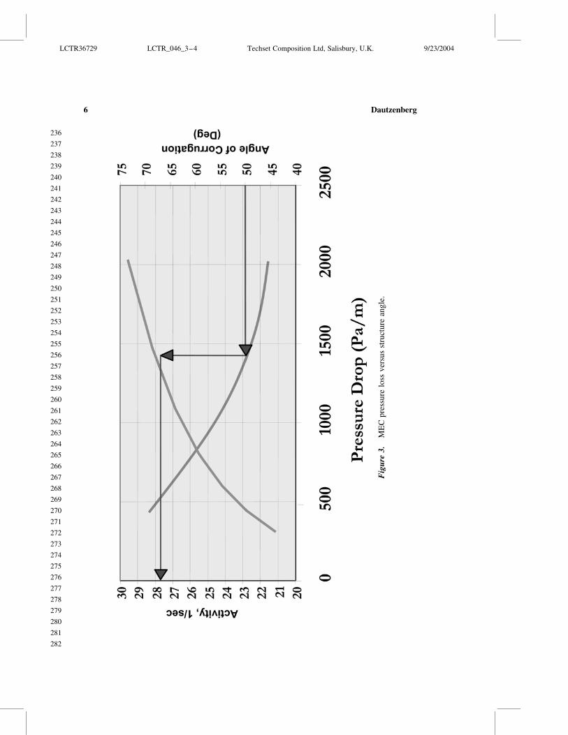
Fig
ure
3
ME
Cp
ress
ure
loss
ver
sus
stru
ctu
rean
gle
LCTR36729 LCTR_046_3ndash4 Techset Composition Ltd Salisbury UK 9232004
236
237
238
239
240
241
242
243
244
245
246
247
248
249
250
251
252
253
254
255
256
257
258
259
260
261
262
263
264
265
266
267
268
269
270
271
272
273
274
275
276
277
278
279
280
281
282
Dautzenberg6
Although there is no universal solution to all reaction engineering applications
MEC has solved the size versus pressure drop problem for mass-transfer-limited
reactions
Dry Zeolite Synthesis
A second catalyst advance is our ldquoDry Synthesisrdquo zeolite crystallization called
ldquoDrySynrdquo for shortmdashan entirely new way to make zeolites[5] Unlike conventional
methods where the nutrients are dissolved in a caustic solution DrySyn starts with
solid reagents often silica-alumina microspheres similar in size to FCC catalysts These
silica-alumina microspheres are porous and have their own gross morphology Using
the DrySyn method the pores are filled with water caustic and if needed an organic
directing agent below or at the incipient wetness point The particles appear dry hence
the term ldquodry synthesisrdquo DrySyn has several advantages compared to conventional syn-
thesis routes (a) faster crystallization time (b) smaller crystal size (c) ability to control
porosity based on the preformed particlesrsquo properties (d) improved nutrient utilization
and (e) lower environmental impact
Figure 5 is a schematic representation of DrySyn[6] The starting materialmdasha porous
particle usually silica-aluminamdashhas its own characteristic silica-to-alumina ratio and
porosity In the crystallization process the finished product is comprised of many ultra-
small zeolite crystals Figure 6 shows the finished product of three standard zeolites
ZSM-5 zeolite beta and inorganic mordenite[7]
Figure 4 MEC DeNOx activity versus honeycomb
LCTR36729 LCTR_046_3ndash4 Techset Composition Ltd Salisbury UK 9232004
283
284
285
286
287
288
289
290
291
292
293
294
295
296
297
298
299
300
301
302
303
304
305
306
307
308
309
310
311
312
313
314
315
316
317
318
319
320
321
322
323
324
325
326
327
328
329
Catalyst Synthesis and Multifunctional Reactor Concepts 7
Fig
ure
5
No
vel
zeo
lite
syn
thes
isp
roce
du
re
ldquoDry
-Sy
nth
esis
rdquo
LCTR36729 LCTR_046_3ndash4 Techset Composition Ltd Salisbury UK 9232004
330
331
332
333
334
335
336
337
338
339
340
341
342
343
344
345
346
347
348
349
350
351
352
353
354
355
356
357
358
359
360
361
362
363
364
365
366
367
368
369
370
371
372
373
374
375
376
Dautzenberg8
Fig
ure
6
Co
nv
ersi
on
exam
ple
sfo
rldquoD
ryS
yn
rdquo
LCTR36729 LCTR_046_3ndash4 Techset Composition Ltd Salisbury UK 9232004
377
378
379
380
381
382
383
384
385
386
387
388
389
390
391
392
393
394
395
396
397
398
399
400
401
402
403
404
405
406
407
408
409
410
411
412
413
414
415
416
417
418
419
420
421
422
423
Catalyst Synthesis and Multifunctional Reactor Concepts 9
The finished product also retains the gross morphology of the parent microsphere
thereby imparting mesoporosity to the crystal agglomerates This mesopore effect is
easily seen in Fig 7 where the pore size distribution is compared to a commercial catalyst
While both catalysts have a similar share of smaller pores the DrySyn catalyst has
about 70 of its pores in the 30thorn nm range When one considers the impact of composite
resistances in a catalyst it is easy to see the potential benefits of such a pore structure
One example of DrySyn performance is shown in Fig 8 Two fast reactionsmdash
ethylbenzene (EB) and cumene productionmdashare shown for a commercial zeolite beta cat-
alyst and a comparable DrySyn catalyst Based on first-order rate constants the DrySyn
catalyst has a two-fold activity advantage for EB and a 50 activity advantage for
cumene synthesis Even though these molecules are relatively small the mesoporosity
gives a significant performance boost
The DrySyn zeolite procedure is particularly advantageous for inorganic zeolites like
zeolite Y In a high throughput screening study with Avantium many synthesis variables
(eg temperature time NaOH concentration etc) were examined that should favor the
formation of high quality small crystal zeolite Y Some of the results are shown in
Fig 9 Here each line represents one synthesis experiment and the bars describe the
three products unconverted material (Phase 1) the desired Y (Phase 3) and a second
phase (Phase 2) cancrinite By looking at the Y bars one can quickly zero in on the pre-
ferred synthesis conditions to maximize the production of zeolite Y Of course other
factors are also important such as percent crystallinity surface area hydrocarbon sorp-
tion and ultimate crystal size Figure 10 shows the progress made in driving down the
Figure 7 Pore size distribution of two catalysts
LCTR36729 LCTR_046_3ndash4 Techset Composition Ltd Salisbury UK 9232004
424
425
426
427
428
429
430
431
432
433
434
435
436
437
438
439
440
441
442
443
444
445
446
447
448
449
450
451
452
453
454
455
456
457
458
459
460
461
462
463
464
465
466
467
468
469
470
Dautzenberg10
crystal size While most conventional zeolite Y samples are typically 05 micron in size
the resultant DrySyn crystals are an order of magnitude smaller These unusually small
crystals have excellent activity for many hydrocarbon processes
Mesoporous Materials
An area of growing importance is mesoporous materials Since the discovery of
MCM-41[8 ndash 10] in the late 1980s there has been a myriad of articles and patents in this
field Lummus has also been quite active in this field In collaboration with the Technical
University of Delft (the Netherlands) an entirely new group of materials collectively
known as TUD-1[11 ndash 13] has been synthesized TUD-1 is comprised of random three-
dimensional interconnecting pores Unlike the M41S materials and many other mesopor-
ous materials TUD-1 is amorphous and thus has no planes of symmetry and no space
group
TUD-1rsquos amorphous character is shown in Fig 11 which is an electron micrograph of
TUD-1 alongside a ceramic foam of macroscopic scale To conclusively show that the
pores are interconnected a ldquoreverse imagingrdquo technique was developed Here the pores
of a siliceous TUD-1 were filled with sugar molecules that were then carburized The
silica was then dissolved to leave behind only the carbon pore replica The resultant struc-
ture did not collapse conclusively proving that the pores are interconnected
TUD-1 has another important property the pores have a controllable narrow size
distributionmdashtypically from 40 to 120 A with a surface area from 500 to 1000 m2g
Figure 12 shows the trade-off that can be achieved between pore diameter and surface
area Even at the largest pore size the surface area for this Si-TUD-1 is 500 m2gndash20
to 40 higher than typical silica supports
Figure 8 Aromatics alkylation comparison of catalyst performance
LCTR36729 LCTR_046_3ndash4 Techset Composition Ltd Salisbury UK 9232004
471
472
473
474
475
476
477
478
479
480
481
482
483
484
485
486
487
488
489
490
491
492
493
494
495
496
497
498
499
500
501
502
503
504
505
506
507
508
509
510
511
512
513
514
515
516
517
Catalyst Synthesis and Multifunctional Reactor Concepts 11
Fig
ure
9
Su
mm
ary
of
HT
Ssy
nth
esis
exp
erim
ents
LCTR36729 LCTR_046_3ndash4 Techset Composition Ltd Salisbury UK 9232004
518
519
520
521
522
523
524
525
526
527
528
529
530
531
532
533
534
535
536
537
538
539
540
541
542
543
544
545
546
547
548
549
550
551
552
553
554
555
556
557
558
559
560
561
562
563
564
Dautzenberg12
These combined properties make TUD-1 an attractive viable catalyst or catalyst
support for many reactions While the major focus has been with alumina silica and
silica-alumina TUD-1 has been made in about 20 different chemical variants As seen
in Table 1 Delft scientists have shown that Ti-TUD-1 is five times more active than its
MCM-41 counterpart for epoxidation even though the surface areas are equivalent[1314]
Figure 10 Comparison of conventional and ldquoDrySynrdquo Y crystallites
Figure 11 Ceramic foam versus TUD-1 an analogy
LCTR36729 LCTR_046_3ndash4 Techset Composition Ltd Salisbury UK 9232004
565
566
567
568
569
570
571
572
573
574
575
576
577
578
579
580
581
582
583
584
585
586
587
588
589
590
591
592
593
594
595
596
597
598
599
600
601
602
603
604
605
606
607
608
609
610
611
Catalyst Synthesis and Multifunctional Reactor Concepts 13
THE INFLUENCE OF PARTICLE SIZE AND POROSITY ON
CATALYST ACTIVITY
Catalysts can be custom-tailored for improved performance specifically the well-
known Thiele moduluseffectiveness factor concepts can be applied to demonstrate
mass transfer effects in catalysis The unique features of DrySyn zeolites and TUD-1
are both amenable to this approach
The intrinsic activity [k(o)] can be calculated by measuring the apparent catalyst
activity [k(app)] of a catalyst using two different particle sizes [rp] It follows that
kethappTHORNeth1THORN
kethappTHORNeth2THORNfrac14
heth1THORN
heth2THORNfrac14
3=f1frac121= tanhf1 1=f1
3=f2frac121= tanhf2 1=f2eth1THORN
Figure 12 TUD-1 Trading off pore size and surface area
Table 1 Expoxidation of cyclohexene
Catalysts Surface area m2g Turnover frequency
Ti-MCM-41 921 36
Ti-TUD-1 917 202
LCTR36729 LCTR_046_3ndash4 Techset Composition Ltd Salisbury UK 9232004
612
613
614
615
616
617
618
619
620
621
622
623
624
625
626
627
628
629
630
631
632
633
634
635
636
637
638
639
640
641
642
643
644
645
646
647
648
649
650
651
652
653
654
655
656
657
658
Dautzenberg14
in which
fi frac14 rpethiTHORN
ffiffiffiffiffiffiffiffikethoTHORN
D
reth2THORN
and
hethiTHORN frac14kethappTHORNethiTHORN
kethoTHORNeth3THORN
Through an iterative approximation we establish a value for k(o)D so that Eq (1) is
satisfied For each experimental value of rp we now can calculate f and thus k(o) and
therefore D We subsequently determine k(app) for any value of rp While the effective-
ness factorThiele modulus is usually shown as a log-log plot recasting it on a linear
scale can be quite informative
Figure 13 shows a typical example where this approach has been applied to two differ-
ent zeolite beta catalysts Using ethylbenzene formation as a probe reactive the k(o) of the
DrySyn beta catalyst is 15 higher than the k(o) of the commercial beta catalyst Of indus-
trial importance is the fact that the k(app) for 15 mm DrySyn particles is more than 25
times higher than the k(app) of 15 mm commercial catalyst particles Since the crystal
size of both zeolite beta samples is small (less than 005 micron ultimate crystal size)
the performance difference is probably due to the large number of mesopores in the
DrySyn catalyst which is reflected in the higher value of the effective diffusivity
In addition to altering catalyst activity by different zeolite synthesis routes one can
vary the catalyst support properties for a dramatic impact on catalyst performance This
concept has been shown[1516] to achieve synergistic benefits by combining zeolitic
activity with a mesoporous matrix A specific example is cited here again using the EB
probe reaction Table 2 shows the performance of three alumina-bound commercial Y cata-
lysts and two developmental catalysts using TUD-1 (silica or alumina) as the binding
material (commercial zeolite Y used) The intrinsic activities of the three commercial cata-
lysts reported on a constant zeolite basis are very similar and the intrinsic activities of
the mesoporous Y catalysts are significantly lower However the commercially important
activity is for particles typically greater than 1 mm Figure 14 shows the catalyst activity of
the two types of Y catalysts versus particle size Interestingly although the mesoporous Y
catalyst (here with Si-TUD-1) has a lower intrinsic activity than the commercial Y cata-
lyst the mesoporous Y has triple the activity of the commercial Y catalyst at industrially
relevant particle sizes This activity ldquocross-over effectrdquo is attributable to a tenfold advan-
tage in diffusivity One can quickly see the potential activity advantage that can be
achieved by optimizing the mesoporosity The five catalysts of Table 2 are compared in
Fig 15 Here we see that despite lower intrinsic activities both mesoporous Y catalysts
have superior activity compared to the three commercial Y catalysts at particle size of
15 mm
From the above conclusions one can foresee that another route to raising the overall
catalyst performance is to boost the intrinsic activity of the zeolite itself This concept is
illustrated in Table 3 Again using the EB probe reaction Table 3 shows the performance
of two alumina-bound commercial zeolite beta catalysts and one developmental catalyst
embedded in Si-TUD-1 (commercial zeolite beta used) The second commercial zeolite
beta catalyst (ldquoType IIrdquo) was prepared by a proprietary technique that achieves a
LCTR36729 LCTR_046_3ndash4 Techset Composition Ltd Salisbury UK 9232004
659
660
661
662
663
664
665
666
667
668
669
670
671
672
673
674
675
676
677
678
679
680
681
682
683
684
685
686
687
688
689
690
691
692
693
694
695
696
697
698
699
700
701
702
703
704
705
Catalyst Synthesis and Multifunctional Reactor Concepts 15
Fig
ure
13
P
erfo
rman
ceo
fldquoD
ryS
yn
rdquob
eta
ver
sus
com
mer
cial
bet
a(R
ef
ZS
han
etal
M
icro
po
rou
san
dM
ater
ials
20
014
81
81
)
LCTR36729 LCTR_046_3ndash4 Techset Composition Ltd Salisbury UK 9232004
706
707
708
709
710
711
712
713
714
715
716
717
718
719
720
721
722
723
724
725
726
727
728
729
730
731
732
733
734
735
736
737
738
739
740
741
742
743
744
745
746
747
748
749
750
751
752
Dautzenberg16
Ta
ble
2
Yca
taly
sts
per
form
ance
Ref
C
atal
yst
k(o
)
1s
ec
Eff
D
cm2s
ec
k(a
pp
)in
1s
ecat
par
tsi
zein
mm
Cat
aly
st
effe
ct
at
15
mm
Rel
ran
kin
g
of
k(o
)
Rel
ran
kin
g
of
k(1
5)
02
10
78
12
61
50
1C
om
mer
cial
Y
Ty
pe
I(7
0
)
36
97
8
10
26
15
30
47
03
00
25
68
10
01
00
2C
om
mer
cial
Y
Ty
pe
II(8
0
)
33
11
11
10
26
15
60
50
03
10
26
79
09
01
05
3C
om
mer
ical
Y4
63
19
5
10
26
23
80
77
04
90
41
89
12
51
65
4M
eso
po
rou
sY
Si-
TU
D-1
(45
8
)
24
71
31
0
10
26
23
11
48
10
50
91
36
80
67
36
3
5M
eso
po
rou
sY
11
59
93
10
26
11
00
73
05
30
47
40
40
31
18
6
No
te
Bo
ldfrac14
Ex
per
imen
tal
val
ues
al
lk
val
ues
at1
00
ze
oli
teb
asis
LCTR36729 LCTR_046_3ndash4 Techset Composition Ltd Salisbury UK 9232004
753
754
755
756
757
758
759
760
761
762
763
764
765
766
767
768
769
770
771
772
773
774
775
776
777
778
779
780
781
782
783
784
785
786
787
788
789
790
791
792
793
794
795
796
797
798
799
Catalyst Synthesis and Multifunctional Reactor Concepts 17
Fig
ure
14
E
Bac
tiv
ity
asfu
nct
ion
of
par
ticl
esi
ze
LCTR36729 LCTR_046_3ndash4 Techset Composition Ltd Salisbury UK 9232004
800
801
802
803
804
805
806
807
808
809
810
811
812
813
814
815
816
817
818
819
820
821
822
823
824
825
826
827
828
829
830
831
832
833
834
835
836
837
838
839
840
841
842
843
844
845
846
Dautzenberg18
Fig
ure
15
R
elat
ive
ran
kin
go
fze
oli
teY
cata
lyst
su
sin
gE
Bp
rob
ere
acti
on
LCTR36729 LCTR_046_3ndash4 Techset Composition Ltd Salisbury UK 9232004
847
848
849
850
851
852
853
854
855
856
857
858
859
860
861
862
863
864
865
866
867
868
869
870
871
872
873
874
875
876
877
878
879
880
881
882
883
884
885
886
887
888
889
890
891
892
893
Catalyst Synthesis and Multifunctional Reactor Concepts 19
Ta
ble
3
Bet
aca
taly
sts
per
form
ance
Ref
C
atal
yst
k(o
)
1s
ec
Eff
D
cm2s
ec
k(a
pp
)in
1s
ecat
par
tsi
zein
mm
Cat
aly
st
effe
ct
at
15
mm
Rel
ran
kin
g
of
k(o
)
Rel
ran
kin
g
of
k(1
5)
02
10
78
12
51
50
1C
om
mer
cial
bet
aT
yp
eI
(80
)
08
82
5
10
26
07
40
34
02
30
19
02
11
00
10
0
2C
om
mer
cial
bet
aT
yp
eII
(80
)
18
96
7
10
26
16
40
80
05
40
46
02
52
16
24
7
4M
eso
po
rou
s
bet
aS
i-T
UD
-1
(40
)
10
01
40
0
10
26
09
80
80
06
30
55
05
51
14
29
3
No
te
Bo
ldfrac14
Ex
per
imen
tal
val
ues
al
lk
val
ues
at1
00
ze
oli
teb
asis
M
anu
fact
uri
ng
bas
edo
np
rop
riet
ary
Lu
mm
usrsquo
syn
thes
ism
od
ifica
tio
nm
eth
od
LCTR36729 LCTR_046_3ndash4 Techset Composition Ltd Salisbury UK 9232004
894
895
896
897
898
899
900
901
902
903
904
905
906
907
908
909
910
911
912
913
914
915
916
917
918
919
920
921
922
923
924
925
926
927
928
929
930
931
932
933
934
935
936
937
938
939
940
Dautzenberg20
two- to threefold intrinsic activity boost This intrinsic activity boost is seen when compar-
ing the two commercial catalysts Again the commercially important activity is for par-
ticles typically greater than 1 mm At 125 mm particle size the activity advantage of
the Type II zeolite beta is being maintained More importantly the highest activity catalyst
is the beta in TUD-1 which has the highest effective diffusivity Specifically the activity
here is three times higher than the commercial zeolite beta (ldquoType Irdquo) catalyst These
results were not optimized so it is possible that even larger benefits can be reaped by
further tailoring the mesoporous structure and possibly composition
These performance attributes are shown graphically in Fig 16 which shows the cata-
lyst activity of the three beta catalysts The key observation here is that rankings based on
intrinsic activity can be misleading This is another illustration of the powerful impact that
pore architecture can have on catalyst activity
MULTIFUNCTIONAL REACTORS
Since most industrially relevant reactions are either endothermic or exothermic the
management of heat transfer is usually a key consideration in reaction engineering
design In many cases reactor selection is based on how one is able to remove or add
energy Conventional designs for highly energetic systems are therefore usually based
on fixed bed tubular and fluid bed reactors with internal or external heat exchangers
Intra-reactor process intensification[7] based on combining reaction with heat transfer
may offer a new opportunity to broaden the reactor selection possibilities Three specific
examples are used to describe this new approach (1) intra-reactor oxidative reheat for the
production of styrene by staging endothermic and exothermic reactions in series (2) sim-
ultaneous operation of endothermic dissociative adsorption of methane with exothermic
oxidative removal of carbon during catalytic partial oxidation and (3) catalytic distillation
for the production of ethers ethylbenzene or cumene and the selective hydrogenation of
highly unsaturated components in olefins streams
Intra-reactor Oxidative Reheat
The production of styrene by dehydrogenation of EB is carried out in adiabatic fixed
bed reactors The reaction is highly endothermic and the heat is provided between the reac-
tors by two methods addition of high temperature steam and heat exchange[17] Due to the
high steam-to-EB ratio the combined volumetric flow rate is high and consequently
radial flow fixed bed reactors are chosen to avoid pressure drop limitations Intra-
reactor heat exchange between catalyst beds results in higher overall bed temperatures
and in principle can lead to better spacendashtime yields Unfortunately it is difficult to
install conventional heat exchangers in the radial direction while also assuring acceptable
temperature uniformity keeping the reactor compact and avoiding large thermal zones
To address this problem a new solution was developed employing catalytic combustion
of hydrogen to water This reaction adds heat locally to the system and raises the overall
average reactor temperature thereby boosting the overall conversion Figure 17 illustrates
how endothermic ethylene dehydrogenation can be integrated with the exothermic
combustion of hydrogen This new method of adding heat is shown schematically in
LCTR36729 LCTR_046_3ndash4 Techset Composition Ltd Salisbury UK 9232004
941
942
943
944
945
946
947
948
949
950
951
952
953
954
955
956
957
958
959
960
961
962
963
964
965
966
967
968
969
970
971
972
973
974
975
976
977
978
979
980
981
982
983
984
985
986
987
Catalyst Synthesis and Multifunctional Reactor Concepts 21
Fig
ure
16
R
elat
ive
ran
kin
go
fze
oli
teb
eta
cata
lyst
su
sin
gE
Bp
rob
ere
acti
on
LCTR36729 LCTR_046_3ndash4 Techset Composition Ltd Salisbury UK 9232004
988
989
990
991
992
993
994
995
996
997
998
999
1000
1001
1002
1003
1004
1005
1006
1007
1008
1009
1010
1011
1012
1013
1014
1015
1016
1017
1018
1019
1020
1021
1022
1023
1024
1025
1026
1027
1028
1029
1030
1031
1032
1033
1034
Dautzenberg22
Fig 18 where intra-reactor reheat is employed in stages The new design known as
SMART (Styrene Monomer Advanced Reheat Technology) has already been successfully
commercialized in five plants
Catalytic Partial Oxidation of Methane (CPO)
The intra-reactor reheat principle can also be applied to the production of syngas
(COH2) from methane It is well known that conventional steam reforming of methane
is highly endothermic During CPO methane is dissociatively absorbed on the catalyst
producing hydrogen and a carbonaceous residue This residue is converted into CO and
H2O by oxidation and this reaction generates energy (exothermic) driving the endother-
mic steam reforming reaction that is happening in parallel With an optimized catalyst
ldquocokelessrdquo steam reforming appears to be feasible As a preferred reactor configuration
a reactor concept called ldquoComposite Structured Packingrdquo (CSP) is proposed ideally
suited for high superficial gas velocities as envisioned for CPO
Several noble-metal-containing catalysts have been proposed for CPO Figure 19
compares the temperature-programmed oxidation of Rh Ni and Ni-B upon exposure to
methane decomposition With Rh the resulting carbon residues are removed at relatively
Figure 17 Catalytic cycle for Styrene Monomer Advanced Reheat Technology (SMART)
LCTR36729 LCTR_046_3ndash4 Techset Composition Ltd Salisbury UK 9232004
1035
1036
1037
1038
1039
1040
1041
1042
1043
1044
1045
1046
1047
1048
1049
1050
1051
1052
1053
1054
1055
1056
1057
1058
1059
1060
1061
1062
1063
1064
1065
1066
1067
1068
1069
1070
1071
1072
1073
1074
1075
1076
1077
1078
1079
1080
1081
Catalyst Synthesis and Multifunctional Reactor Concepts 23
low temperature This is not the case with Ni Upon exposure to CH4 graphitic carbon is
deposited upon the Ni catalyst and this can be removed only at high temperature With a
catalyst based on an alloy of Ni and B most of the carbon is removed at a substantially
lower temperature while the amount of carbon needed to be removed at high temperature
is significantly reduced
Figure 20 shows the CPO performance of one of the novel Ni-B catalysts developed
during a collaborative project with the National University of Singapore[18] Note that the
product composition is essentially at equilibrium even at the extremely high space velo-
city applied during the testing In Fig 21 the ldquomethane conversionrdquo versus ldquotime
onstreamrdquo shows that the catalyst is unusually stable no initial deactivation period
occurs consistent with its noncoking behavior Another important benefit of the new
CPO catalyst is the close approach to thermal neutrality thus simplifying heat manage-
ment and improving thermal efficiency This feature is important if one wants to design
ultra-compact hydrogen generators
Catalytic Distillation
As the name implies catalytic distillation (CD)[19 ndash 22] intimately integrates catalytic
reaction and product separation by distillation CD is well suited for processes where the
feed and the product have a significantly different boiling range thereby facilitating
separation and many times enhancing selectivity by applying relatively low reaction temp-
eratures The heat of reaction is used for separation and therefore facilitates heat mana-
gement The predominantly liquid phase also aids catalyst stability Figure 22 illustrates
Figure 18 New reactor system of Styrene Monomer Advanced Reheat Technology (SMART)
LCTR36729 LCTR_046_3ndash4 Techset Composition Ltd Salisbury UK 9232004
1082
1083
1084
1085
1086
1087
1088
1089
1090
1091
1092
1093
1094
1095
1096
1097
1098
1099
1100
1101
1102
1103
1104
1105
1106
1107
1108
1109
1110
1111
1112
1113
1114
1115
1116
1117
1118
1119
1120
1121
1122
1123
1124
1125
1126
1127
1128
Dautzenberg24
one typical application of a CD technology the CDHydrow process for the selective
hydrogenation of benzene in reformate fractions The family of CD technologies has
grown quite extensively and today the number of commercially licensed units is about
150 Table 4 shows some of the CD applications that have been commercialized
One of the major petrochemical processesmdashsteam cracking for the production of
ethylenemdashis often perceived to be strictly thermal in nature However much of the down-
stream separation processes which are both energy and capital intensive can benefit from
catalytic advances In the production of ethylene and propylene through pyrolysis of
various feedstocks several undesirable by-products (eg dienes and acetylenes) are
Figure 19 TPO profiles of carburized CPO catalysts
LCTR36729 LCTR_046_3ndash4 Techset Composition Ltd Salisbury UK 9232004
1129
1130
1131
1132
1133
1134
1135
1136
1137
1138
1139
1140
1141
1142
1143
1144
1145
1146
1147
1148
1149
1150
1151
1152
1153
1154
1155
1156
1157
1158
1159
1160
1161
1162
1163
1164
1165
1166
1167
1168
1169
1170
1171
1172
1173
1174
1175
Catalyst Synthesis and Multifunctional Reactor Concepts 25
Fig
ure
20
T
yp
ical
cata
lyti
cp
arti
alo
xid
atio
nre
sult
s
LCTR36729 LCTR_046_3ndash4 Techset Composition Ltd Salisbury UK 9232004
1176
1177
1178
1179
1180
1181
1182
1183
1184
1185
1186
1187
1188
1189
1190
1191
1192
1193
1194
1195
1196
1197
1198
1199
1200
1201
1202
1203
1204
1205
1206
1207
1208
1209
1210
1211
1212
1213
1214
1215
1216
1217
1218
1219
1220
1221
1222
Dautzenberg26
created As such further processing is required for the separation and removal of the
dienesacetylenes from the primary olefin products Dictated by process economics
most of the C2 and heavier dienesacetylenes must be handled through a combination
of separation and hydrogenation since separation alone would result in excessive loss of
the olefin product
Currently the distillation and hydrogenation take place in several distinct process
steps designed to separate and hydrogenate the C2C3 and C4 compounds independently
(Fig 23) A disadvantage of this widely practiced conventional technology is the large
energy consumption required to generate the high pressures and cryogenic temperatures
to first separate and subsequently remove hydrogen from the cracked gas Additionally
the chemistry of each hydrogenation step (eg C2C3 etc) requires an independent
reactor system thereby driving up the plantrsquos capital cost and complexity
To offset these disadvantages the ldquoFront-End CDHydrordquo process (Fig 24) was devel-
oped as a one-step conversion of all C2ndashC5 and even heavier dienesacetylenes without
hydrogenation of the desired C2C3 olefins[2324] The objective is to Q3simultaneously
(a) consume dilute hydrogen through the elimination of undesirable dienes and acetylenes
thereby reducing refrigeration and compression cost and (b) combine reaction and separa-
tion into one step This new process greatly reduces the unit equipment ldquopiece countrdquo
by eliminating the separate hydrogenation reactors of the C2ndashC4 streams The heat of
Figure 21 CPO combined with steam reforming
LCTR36729 LCTR_046_3ndash4 Techset Composition Ltd Salisbury UK 9232004
1223
1224
1225
1226
1227
1228
1229
1230
1231
1232
1233
1234
1235
1236
1237
1238
1239
1240
1241
1242
1243
1244
1245
1246
1247
1248
1249
1250
1251
1252
1253
1254
1255
1256
1257
1258
1259
1260
1261
1262
1263
1264
1265
1266
1267
1268
1269
Catalyst Synthesis and Multifunctional Reactor Concepts 27
Fig
ure
22
N
ewC
DT
EC
Hb
enze
ne
hy
dro
gen
atio
nte
chn
olo
gy
LCTR36729 LCTR_046_3ndash4 Techset Composition Ltd Salisbury UK 9232004
1270
1271
1272
1273
1274
1275
1276
1277
1278
1279
1280
1281
1282
1283
1284
1285
1286
1287
1288
1289
1290
1291
1292
1293
1294
1295
1296
1297
1298
1299
1300
1301
1302
1303
1304
1305
1306
1307
1308
1309
1310
1311
1312
1313
1314
1315
1316
Dautzenberg28
reaction in the catalytic distillation reactor is used for separation and therefore improves
overall heat management In contrast to conventional fixed bed reactor systems where
dimers and oligomers accumulate and cause catalyst fouling the CD reactor ensures
that these undesirable components are removed by fractionation As a result this
process achieves prolonged catalyst life
The advancements achieved with the ldquoFront End CDHydrordquo process integrated with
several other Lummus innovations represent one of the most significant breakthroughs in
ethylene technology over the past 25 years
CONCLUSIONS
In reviewing the results presented in this paper the following conclusions have been
formulated
The catalyst synthesis examples described in this paper demonstrate that tailoring
the pore architecture of catalysts has several benefits Higher overall reaction rates
and yields can be obtained and in certain cases catalyst stability is also improved
by reducing the formation of catalyst deactivating precursors
The ldquoDrySynrdquo synthesis procedure can be optimized to make zeolite catalysts with
ultra-small crystallites This may benefit the development of catalysts with high
intrinsic activity The synthesis is very effective if mesoporous supports are used
to achieve a high degree of utilization
Inserting Y as well as beta in TUD-1 materials increases catalyst activity for aro-
matics alkylation to levels that have not been achieved with conventional zeolite
catalysts The open three-dimensional pore structure of TUD-1 is a key contributor
to this achievement It is expected that similar performance improvements will be
realized for other reactions that are commercially practiced at conditions imposing
mass transfer limitations
The intra-reactor reheat concept as practiced in SMART should in principle be
applicable to other strongly endothermic dehydrogenation reactions Applied at
the catalyst level as shown in the CPO example it is speculated that intra-
reactor reheat can be used for in-situ catalyst regeneration during operation
Catalytic distillation is a prime example of what can be achieved by process inten-
sification Although the technology has already been applied commercially for
Table 4 Commercial CD applications
dagger Etherification (MTBE TAME and ETBE)
dagger Aromatics alkylation (EB and cumene)
dagger Benzene removal from reformate
dagger Selective desulfurization
dagger Various selective hydrogenations
Demonstration plant at Tianjin China Front-end CDHydrow for
ethylene plants (2003)
LCTR36729 LCTR_046_3ndash4 Techset Composition Ltd Salisbury UK 9232004
1317
1318
1319
1320
1321
1322
1323
1324
1325
1326
1327
1328
1329
1330
1331
1332
1333
1334
1335
1336
1337
1338
1339
1340
1341
1342
1343
1344
1345
1346
1347
1348
1349
1350
1351
1352
1353
1354
1355
1356
1357
1358
1359
1360
1361
1362
1363
Catalyst Synthesis and Multifunctional Reactor Concepts 29
Fig
ure
23
C
on
ven
tio
nal
ole
fin
sp
uri
fica
tio
nte
chn
olo
gy
LCTR36729 LCTR_046_3ndash4 Techset Composition Ltd Salisbury UK 9232004
1364
1365
1366
1367
1368
1369
1370
1371
1372
1373
1374
1375
1376
1377
1378
1379
1380
1381
1382
1383
1384
1385
1386
1387
1388
1389
1390
1391
1392
1393
1394
1395
1396
1397
1398
1399
1400
1401
1402
1403
1404
1405
1406
1407
1408
1409
1410
Dautzenberg30
Fig
ure
24
F
ron
t-en
dC
DH
yd
row
tech
no
log
yfo
ro
lefi
ns
pu
rifi
cati
on
LCTR36729 LCTR_046_3ndash4 Techset Composition Ltd Salisbury UK 9232004
1411
1412
1413
1414
1415
1416
1417
1418
1419
1420
1421
1422
1423
1424
1425
1426
1427
1428
1429
1430
1431
1432
1433
1434
1435
1436
1437
1438
1439
1440
1441
1442
1443
1444
1445
1446
1447
1448
1449
1450
1451
1452
1453
1454
1455
1456
1457
Catalyst Synthesis and Multifunctional Reactor Concepts 31
various processes it is expected that the family will keep growing Tailoring of
existing catalysts may be required to allow operation in the liquid phase at
boiling conditions
The multifunctional reactor examples show that by applying intra-reactor intensi-
fication mature high-volume petrochemical processes can be improved As illus-
trated in the CPO example intra-reactor heat transfer can be applied beneficially
in the development of emerging technologies
To achieve optimum success more multidisciplinary teams are needed to address the
current and future needs of the process industry The teams should contain catalyst syn-
thesis experts as well as knowledgeable reaction engineers Furthermore it is recommend-
able to encourage industryndashuniversity collaborations This can be very synergistic
because the participants can extend and reinforce each otherrsquos efforts taking full advan-
tage of their complementary capabilities
REFERENCES
1 Dautzenberg FM Quality principles for catalyst testing during process development
Combinatorial Catalysis and High Throughput Catalyst Design and Testing Confer-
ence Vilamoura Quarteira (Algarve) Portugal July 19ndash24 1999 NATO Advanced
Study Institute
2 Trubac RE Dautzenberg FM Griffin TA Paikert B Schmidt VR
Overbeek RA Micro-engineered catalyst systems ABBrsquos advancement in struc-
tured catalytic packings Catalysis Today 2001 69 17ndash24
3 Carlborg JA Chang Y-F Murrell LL Trubac RE Overbeek RA
Schmidt VR Yeh CY Schuh L Conversion of Nitrogen Oxides in the Presence
of a Catalyst Supported on a Mesh-like Structure US Patent 6534022 March 18
2003 (assigned to ABB Lummus Global Inc)
4 First International Conference on Structured Catalysts and Reactors Delft The
Netherlands October 21ndash24 2001
5 Murrell LL Overbeek RA Chang Y-F van der Puil N Yeh CY Method of
Making Molecular Sieves and Novel Molecular Sieve Components US 6350429
2002 (assigned to ABB Lummus Global Inc)
6 Dautzenberg FM Angevine PJ Trubac RE Maschmeyer Th Tailoring Indus-
trial Catalyst to Minimize Mass Transfer Limitations 8th International Symposium
Scientific Bases for the Preparation of Heterogeneous Catalysts Louvain-la-Neuve
Belgium September 9ndash12 2002
7 Dautzenberg FM Mukherjee M Process Intensification Using Multifunctional
Reactors 16th International Symposium on Chemical Reaction Engineering
Krakow Poland September 10 2000
8 Beck JS Method for Synthesizing Mesoporous Crystalline Material US Patent
5057296 October 15 1991 (assigned to Mobil Oil Corp)
9 Kresge CT Leonowicz ME Roth WJ Vartuli JC Synthetic Mesoporous Crys-
talline Material US Patent 5098684 March 24 1992 (assigned to Mobil Oil Corp)
LCTR36729 LCTR_046_3ndash4 Techset Composition Ltd Salisbury UK 9232004
1458
1459
1460
1461
1462
1463
1464
1465
1466
1467
1468
1469
1470
1471
1472
1473
1474
1475
1476
1477
1478
1479
1480
1481
1482
1483
1484
1485
1486
1487
1488
1489
1490
1491
1492
1493
1494
1495
1496
1497
1498
1499
1500
1501
1502
1503
1504
Dautzenberg32
10 Kresge CT Leonowicz ME Roth WJ Vartuli JC Composition of Synthetic
Crystalline Material Its Synthesis US Patent 5102643 April 7 1992 (assigned to
Mobil Oil Corp)
11 Shan Z Maschmeyer Th Jansen JC Inorganic Oxides with Mesoporosity or
Combined Meso- and Microporosity and Process for the Preparation Thereof US
Patent 6358486 2002 (assigned to ABB Lummus Global Inc)
12 Jansen JC Shan Z Marchese L Zhou W van der Puil N Maschmeyer Th A
New Templating Method for Three-Dimensional Mesopore Networks Chem
Commun 2001 713ndash714
13 Shan Z Gianotti E Jansen JC Peters JA Marchese L Maschmeyer Th One-
Step Synthesis of a Highly Active Mesoporous Titanium-Containing Silica by Using
Bifunctional Templating Chem Eur J 2001 7 (7) 1437ndash1443
14 Shan Z Jansen JC Marchese L Maschmeyer Th Synthesis Characterization
and Catalytic Testing of a 3-D Mesoporous Titanosilica Ti-TUD-1 Micro Meso
Mater 2001 48 (1ndash3) 181ndash187
15 Shan Z Jansen JC Yeh CY Koegler JH Maschmeyer Th Catalyst Contain-
ing Microporous Zeolite in Mesoporous Support and Method for Making Same US
Patent Application 20020074263 2002 (assigned to ABB Lummus Global Inc)
16 Shan Z Jansen JC Yeh CY Koegler JH Maschmeyer Th Catalyst Contain-
ing Microporous Zeolite in Mesoporous Support and Method for Making Same WO
03045548 2003-06-05 (assigned to ABB Lummus Global Inc)
17 Dautzenberg FM Hydro-and Dehydrogenation of Large Volume Petrochemicals
Paper presented at the 10th Roermond Conference on Catalysis Rolduc-Kerkrade
The Netherlands June 30ndashJuly 5 2002
18 Dautzenberg FM Encouraging Innovation in Catalysis Paper presented at the 3rd
Asia-Pacific Congress on Catalysis Dalian China October 12ndash15 2003
19 Smith LA Jr Catalytic Distillation Structure US Patent 4443559 April 17 1984
(assigned to Chemical Research amp Licensing Company)
20 Sy A Smith L Chen J Dautzenberg FM Catalytic Distillation Route for
Cumene DeWitt Petrochemical Review Houston Texas March 23 1993
21 Rock K Gilbert GR McGuirk T Catalytic distillation extend its reach Chemical
Engineering 1997 78 78ndash84
22 Hearn D Putman HM Hydrodesulfurization Process Utilizing a Distillation
Column Reactor US Patent 5779883 March 17 1998 (assigned to Catalytic Distil-
lation Technologies)
23 Stanley SJ McCarthy FM Sumner C Gildert GR Olefin Plant Recovery
System Employing Catalytic Distillation US Patent 5679241 May 17 1995
(assigned to ABB Lummus Global Inc and Chemical Research amp Licensing
Company)
LCTR36729 LCTR_046_3ndash4 Techset Composition Ltd Salisbury UK 9232004
1505
1506
1507
1508
1509
1510
1511
1512
1513
1514
1515
1516
1517
1518
1519
1520
1521
1522
1523
1524
1525
1526
1527
1528
1529
1530
1531
1532
1533
1534
1535
1536
1537
1538
1539
1540
1541
1542
1543
1544
1545
1546
1547
1548
1549
1550
1551
Catalyst Synthesis and Multifunctional Reactor Concepts 33
Author QueriesJOURNAL LCTR
MANUSCRIPT 200036729
AQ Please check the right-hand running head provided is ok
Q1 Please provide street zipcode E-mail id and fax for corresponding author
Q2 Please supply abstract and keywords
Q3 Reference [24] is not present in the list Please add to the list
LCTR36729 LCTR_046_3ndash4 Techset Composition Ltd Salisbury UK 9232004
1552
1553
1554
1555
1556
1557
1558
1559
1560
1561
1562
1563
1564
1565
1566
1567
1568
1569
1570
1571
1572
1573
1574
1575
1576
1577
1578
1579
1580
1581
1582
1583
1584
1585
1586
1587
1588
1589
1590
1591
1592
1593
1594
1595
1596
1597
1598
Dautzenberg34

Fig
ure
5
No
vel
zeo
lite
syn
thes
isp
roce
du
re
ldquoDry
-Sy
nth
esis
rdquo
LCTR36729 LCTR_046_3ndash4 Techset Composition Ltd Salisbury UK 9232004
330
331
332
333
334
335
336
337
338
339
340
341
342
343
344
345
346
347
348
349
350
351
352
353
354
355
356
357
358
359
360
361
362
363
364
365
366
367
368
369
370
371
372
373
374
375
376
Dautzenberg8
Fig
ure
6
Co
nv
ersi
on
exam
ple
sfo
rldquoD
ryS
yn
rdquo
LCTR36729 LCTR_046_3ndash4 Techset Composition Ltd Salisbury UK 9232004
377
378
379
380
381
382
383
384
385
386
387
388
389
390
391
392
393
394
395
396
397
398
399
400
401
402
403
404
405
406
407
408
409
410
411
412
413
414
415
416
417
418
419
420
421
422
423
Catalyst Synthesis and Multifunctional Reactor Concepts 9
The finished product also retains the gross morphology of the parent microsphere
thereby imparting mesoporosity to the crystal agglomerates This mesopore effect is
easily seen in Fig 7 where the pore size distribution is compared to a commercial catalyst
While both catalysts have a similar share of smaller pores the DrySyn catalyst has
about 70 of its pores in the 30thorn nm range When one considers the impact of composite
resistances in a catalyst it is easy to see the potential benefits of such a pore structure
One example of DrySyn performance is shown in Fig 8 Two fast reactionsmdash
ethylbenzene (EB) and cumene productionmdashare shown for a commercial zeolite beta cat-
alyst and a comparable DrySyn catalyst Based on first-order rate constants the DrySyn
catalyst has a two-fold activity advantage for EB and a 50 activity advantage for
cumene synthesis Even though these molecules are relatively small the mesoporosity
gives a significant performance boost
The DrySyn zeolite procedure is particularly advantageous for inorganic zeolites like
zeolite Y In a high throughput screening study with Avantium many synthesis variables
(eg temperature time NaOH concentration etc) were examined that should favor the
formation of high quality small crystal zeolite Y Some of the results are shown in
Fig 9 Here each line represents one synthesis experiment and the bars describe the
three products unconverted material (Phase 1) the desired Y (Phase 3) and a second
phase (Phase 2) cancrinite By looking at the Y bars one can quickly zero in on the pre-
ferred synthesis conditions to maximize the production of zeolite Y Of course other
factors are also important such as percent crystallinity surface area hydrocarbon sorp-
tion and ultimate crystal size Figure 10 shows the progress made in driving down the
Figure 7 Pore size distribution of two catalysts
LCTR36729 LCTR_046_3ndash4 Techset Composition Ltd Salisbury UK 9232004
424
425
426
427
428
429
430
431
432
433
434
435
436
437
438
439
440
441
442
443
444
445
446
447
448
449
450
451
452
453
454
455
456
457
458
459
460
461
462
463
464
465
466
467
468
469
470
Dautzenberg10
crystal size While most conventional zeolite Y samples are typically 05 micron in size
the resultant DrySyn crystals are an order of magnitude smaller These unusually small
crystals have excellent activity for many hydrocarbon processes
Mesoporous Materials
An area of growing importance is mesoporous materials Since the discovery of
MCM-41[8 ndash 10] in the late 1980s there has been a myriad of articles and patents in this
field Lummus has also been quite active in this field In collaboration with the Technical
University of Delft (the Netherlands) an entirely new group of materials collectively
known as TUD-1[11 ndash 13] has been synthesized TUD-1 is comprised of random three-
dimensional interconnecting pores Unlike the M41S materials and many other mesopor-
ous materials TUD-1 is amorphous and thus has no planes of symmetry and no space
group
TUD-1rsquos amorphous character is shown in Fig 11 which is an electron micrograph of
TUD-1 alongside a ceramic foam of macroscopic scale To conclusively show that the
pores are interconnected a ldquoreverse imagingrdquo technique was developed Here the pores
of a siliceous TUD-1 were filled with sugar molecules that were then carburized The
silica was then dissolved to leave behind only the carbon pore replica The resultant struc-
ture did not collapse conclusively proving that the pores are interconnected
TUD-1 has another important property the pores have a controllable narrow size
distributionmdashtypically from 40 to 120 A with a surface area from 500 to 1000 m2g
Figure 12 shows the trade-off that can be achieved between pore diameter and surface
area Even at the largest pore size the surface area for this Si-TUD-1 is 500 m2gndash20
to 40 higher than typical silica supports
Figure 8 Aromatics alkylation comparison of catalyst performance
LCTR36729 LCTR_046_3ndash4 Techset Composition Ltd Salisbury UK 9232004
471
472
473
474
475
476
477
478
479
480
481
482
483
484
485
486
487
488
489
490
491
492
493
494
495
496
497
498
499
500
501
502
503
504
505
506
507
508
509
510
511
512
513
514
515
516
517
Catalyst Synthesis and Multifunctional Reactor Concepts 11
Fig
ure
9
Su
mm
ary
of
HT
Ssy
nth
esis
exp
erim
ents
LCTR36729 LCTR_046_3ndash4 Techset Composition Ltd Salisbury UK 9232004
518
519
520
521
522
523
524
525
526
527
528
529
530
531
532
533
534
535
536
537
538
539
540
541
542
543
544
545
546
547
548
549
550
551
552
553
554
555
556
557
558
559
560
561
562
563
564
Dautzenberg12
These combined properties make TUD-1 an attractive viable catalyst or catalyst
support for many reactions While the major focus has been with alumina silica and
silica-alumina TUD-1 has been made in about 20 different chemical variants As seen
in Table 1 Delft scientists have shown that Ti-TUD-1 is five times more active than its
MCM-41 counterpart for epoxidation even though the surface areas are equivalent[1314]
Figure 10 Comparison of conventional and ldquoDrySynrdquo Y crystallites
Figure 11 Ceramic foam versus TUD-1 an analogy
LCTR36729 LCTR_046_3ndash4 Techset Composition Ltd Salisbury UK 9232004
565
566
567
568
569
570
571
572
573
574
575
576
577
578
579
580
581
582
583
584
585
586
587
588
589
590
591
592
593
594
595
596
597
598
599
600
601
602
603
604
605
606
607
608
609
610
611
Catalyst Synthesis and Multifunctional Reactor Concepts 13
THE INFLUENCE OF PARTICLE SIZE AND POROSITY ON
CATALYST ACTIVITY
Catalysts can be custom-tailored for improved performance specifically the well-
known Thiele moduluseffectiveness factor concepts can be applied to demonstrate
mass transfer effects in catalysis The unique features of DrySyn zeolites and TUD-1
are both amenable to this approach
The intrinsic activity [k(o)] can be calculated by measuring the apparent catalyst
activity [k(app)] of a catalyst using two different particle sizes [rp] It follows that
kethappTHORNeth1THORN
kethappTHORNeth2THORNfrac14
heth1THORN
heth2THORNfrac14
3=f1frac121= tanhf1 1=f1
3=f2frac121= tanhf2 1=f2eth1THORN
Figure 12 TUD-1 Trading off pore size and surface area
Table 1 Expoxidation of cyclohexene
Catalysts Surface area m2g Turnover frequency
Ti-MCM-41 921 36
Ti-TUD-1 917 202
LCTR36729 LCTR_046_3ndash4 Techset Composition Ltd Salisbury UK 9232004
612
613
614
615
616
617
618
619
620
621
622
623
624
625
626
627
628
629
630
631
632
633
634
635
636
637
638
639
640
641
642
643
644
645
646
647
648
649
650
651
652
653
654
655
656
657
658
Dautzenberg14
in which
fi frac14 rpethiTHORN
ffiffiffiffiffiffiffiffikethoTHORN
D
reth2THORN
and
hethiTHORN frac14kethappTHORNethiTHORN
kethoTHORNeth3THORN
Through an iterative approximation we establish a value for k(o)D so that Eq (1) is
satisfied For each experimental value of rp we now can calculate f and thus k(o) and
therefore D We subsequently determine k(app) for any value of rp While the effective-
ness factorThiele modulus is usually shown as a log-log plot recasting it on a linear
scale can be quite informative
Figure 13 shows a typical example where this approach has been applied to two differ-
ent zeolite beta catalysts Using ethylbenzene formation as a probe reactive the k(o) of the
DrySyn beta catalyst is 15 higher than the k(o) of the commercial beta catalyst Of indus-
trial importance is the fact that the k(app) for 15 mm DrySyn particles is more than 25
times higher than the k(app) of 15 mm commercial catalyst particles Since the crystal
size of both zeolite beta samples is small (less than 005 micron ultimate crystal size)
the performance difference is probably due to the large number of mesopores in the
DrySyn catalyst which is reflected in the higher value of the effective diffusivity
In addition to altering catalyst activity by different zeolite synthesis routes one can
vary the catalyst support properties for a dramatic impact on catalyst performance This
concept has been shown[1516] to achieve synergistic benefits by combining zeolitic
activity with a mesoporous matrix A specific example is cited here again using the EB
probe reaction Table 2 shows the performance of three alumina-bound commercial Y cata-
lysts and two developmental catalysts using TUD-1 (silica or alumina) as the binding
material (commercial zeolite Y used) The intrinsic activities of the three commercial cata-
lysts reported on a constant zeolite basis are very similar and the intrinsic activities of
the mesoporous Y catalysts are significantly lower However the commercially important
activity is for particles typically greater than 1 mm Figure 14 shows the catalyst activity of
the two types of Y catalysts versus particle size Interestingly although the mesoporous Y
catalyst (here with Si-TUD-1) has a lower intrinsic activity than the commercial Y cata-
lyst the mesoporous Y has triple the activity of the commercial Y catalyst at industrially
relevant particle sizes This activity ldquocross-over effectrdquo is attributable to a tenfold advan-
tage in diffusivity One can quickly see the potential activity advantage that can be
achieved by optimizing the mesoporosity The five catalysts of Table 2 are compared in
Fig 15 Here we see that despite lower intrinsic activities both mesoporous Y catalysts
have superior activity compared to the three commercial Y catalysts at particle size of
15 mm
From the above conclusions one can foresee that another route to raising the overall
catalyst performance is to boost the intrinsic activity of the zeolite itself This concept is
illustrated in Table 3 Again using the EB probe reaction Table 3 shows the performance
of two alumina-bound commercial zeolite beta catalysts and one developmental catalyst
embedded in Si-TUD-1 (commercial zeolite beta used) The second commercial zeolite
beta catalyst (ldquoType IIrdquo) was prepared by a proprietary technique that achieves a
LCTR36729 LCTR_046_3ndash4 Techset Composition Ltd Salisbury UK 9232004
659
660
661
662
663
664
665
666
667
668
669
670
671
672
673
674
675
676
677
678
679
680
681
682
683
684
685
686
687
688
689
690
691
692
693
694
695
696
697
698
699
700
701
702
703
704
705
Catalyst Synthesis and Multifunctional Reactor Concepts 15
Fig
ure
13
P
erfo
rman
ceo
fldquoD
ryS
yn
rdquob
eta
ver
sus
com
mer
cial
bet
a(R
ef
ZS
han
etal
M
icro
po
rou
san
dM
ater
ials
20
014
81
81
)
LCTR36729 LCTR_046_3ndash4 Techset Composition Ltd Salisbury UK 9232004
706
707
708
709
710
711
712
713
714
715
716
717
718
719
720
721
722
723
724
725
726
727
728
729
730
731
732
733
734
735
736
737
738
739
740
741
742
743
744
745
746
747
748
749
750
751
752
Dautzenberg16
Ta
ble
2
Yca
taly
sts
per
form
ance
Ref
C
atal
yst
k(o
)
1s
ec
Eff
D
cm2s
ec
k(a
pp
)in
1s
ecat
par
tsi
zein
mm
Cat
aly
st
effe
ct
at
15
mm
Rel
ran
kin
g
of
k(o
)
Rel
ran
kin
g
of
k(1
5)
02
10
78
12
61
50
1C
om
mer
cial
Y
Ty
pe
I(7
0
)
36
97
8
10
26
15
30
47
03
00
25
68
10
01
00
2C
om
mer
cial
Y
Ty
pe
II(8
0
)
33
11
11
10
26
15
60
50
03
10
26
79
09
01
05
3C
om
mer
ical
Y4
63
19
5
10
26
23
80
77
04
90
41
89
12
51
65
4M
eso
po
rou
sY
Si-
TU
D-1
(45
8
)
24
71
31
0
10
26
23
11
48
10
50
91
36
80
67
36
3
5M
eso
po
rou
sY
11
59
93
10
26
11
00
73
05
30
47
40
40
31
18
6
No
te
Bo
ldfrac14
Ex
per
imen
tal
val
ues
al
lk
val
ues
at1
00
ze
oli
teb
asis
LCTR36729 LCTR_046_3ndash4 Techset Composition Ltd Salisbury UK 9232004
753
754
755
756
757
758
759
760
761
762
763
764
765
766
767
768
769
770
771
772
773
774
775
776
777
778
779
780
781
782
783
784
785
786
787
788
789
790
791
792
793
794
795
796
797
798
799
Catalyst Synthesis and Multifunctional Reactor Concepts 17
Fig
ure
14
E
Bac
tiv
ity
asfu
nct
ion
of
par
ticl
esi
ze
LCTR36729 LCTR_046_3ndash4 Techset Composition Ltd Salisbury UK 9232004
800
801
802
803
804
805
806
807
808
809
810
811
812
813
814
815
816
817
818
819
820
821
822
823
824
825
826
827
828
829
830
831
832
833
834
835
836
837
838
839
840
841
842
843
844
845
846
Dautzenberg18
Fig
ure
15
R
elat
ive
ran
kin
go
fze
oli
teY
cata
lyst
su
sin
gE
Bp
rob
ere
acti
on
LCTR36729 LCTR_046_3ndash4 Techset Composition Ltd Salisbury UK 9232004
847
848
849
850
851
852
853
854
855
856
857
858
859
860
861
862
863
864
865
866
867
868
869
870
871
872
873
874
875
876
877
878
879
880
881
882
883
884
885
886
887
888
889
890
891
892
893
Catalyst Synthesis and Multifunctional Reactor Concepts 19
Ta
ble
3
Bet
aca
taly
sts
per
form
ance
Ref
C
atal
yst
k(o
)
1s
ec
Eff
D
cm2s
ec
k(a
pp
)in
1s
ecat
par
tsi
zein
mm
Cat
aly
st
effe
ct
at
15
mm
Rel
ran
kin
g
of
k(o
)
Rel
ran
kin
g
of
k(1
5)
02
10
78
12
51
50
1C
om
mer
cial
bet
aT
yp
eI
(80
)
08
82
5
10
26
07
40
34
02
30
19
02
11
00
10
0
2C
om
mer
cial
bet
aT
yp
eII
(80
)
18
96
7
10
26
16
40
80
05
40
46
02
52
16
24
7
4M
eso
po
rou
s
bet
aS
i-T
UD
-1
(40
)
10
01
40
0
10
26
09
80
80
06
30
55
05
51
14
29
3
No
te
Bo
ldfrac14
Ex
per
imen
tal
val
ues
al
lk
val
ues
at1
00
ze
oli
teb
asis
M
anu
fact
uri
ng
bas
edo
np
rop
riet
ary
Lu
mm
usrsquo
syn
thes
ism
od
ifica
tio
nm
eth
od
LCTR36729 LCTR_046_3ndash4 Techset Composition Ltd Salisbury UK 9232004
894
895
896
897
898
899
900
901
902
903
904
905
906
907
908
909
910
911
912
913
914
915
916
917
918
919
920
921
922
923
924
925
926
927
928
929
930
931
932
933
934
935
936
937
938
939
940
Dautzenberg20
two- to threefold intrinsic activity boost This intrinsic activity boost is seen when compar-
ing the two commercial catalysts Again the commercially important activity is for par-
ticles typically greater than 1 mm At 125 mm particle size the activity advantage of
the Type II zeolite beta is being maintained More importantly the highest activity catalyst
is the beta in TUD-1 which has the highest effective diffusivity Specifically the activity
here is three times higher than the commercial zeolite beta (ldquoType Irdquo) catalyst These
results were not optimized so it is possible that even larger benefits can be reaped by
further tailoring the mesoporous structure and possibly composition
These performance attributes are shown graphically in Fig 16 which shows the cata-
lyst activity of the three beta catalysts The key observation here is that rankings based on
intrinsic activity can be misleading This is another illustration of the powerful impact that
pore architecture can have on catalyst activity
MULTIFUNCTIONAL REACTORS
Since most industrially relevant reactions are either endothermic or exothermic the
management of heat transfer is usually a key consideration in reaction engineering
design In many cases reactor selection is based on how one is able to remove or add
energy Conventional designs for highly energetic systems are therefore usually based
on fixed bed tubular and fluid bed reactors with internal or external heat exchangers
Intra-reactor process intensification[7] based on combining reaction with heat transfer
may offer a new opportunity to broaden the reactor selection possibilities Three specific
examples are used to describe this new approach (1) intra-reactor oxidative reheat for the
production of styrene by staging endothermic and exothermic reactions in series (2) sim-
ultaneous operation of endothermic dissociative adsorption of methane with exothermic
oxidative removal of carbon during catalytic partial oxidation and (3) catalytic distillation
for the production of ethers ethylbenzene or cumene and the selective hydrogenation of
highly unsaturated components in olefins streams
Intra-reactor Oxidative Reheat
The production of styrene by dehydrogenation of EB is carried out in adiabatic fixed
bed reactors The reaction is highly endothermic and the heat is provided between the reac-
tors by two methods addition of high temperature steam and heat exchange[17] Due to the
high steam-to-EB ratio the combined volumetric flow rate is high and consequently
radial flow fixed bed reactors are chosen to avoid pressure drop limitations Intra-
reactor heat exchange between catalyst beds results in higher overall bed temperatures
and in principle can lead to better spacendashtime yields Unfortunately it is difficult to
install conventional heat exchangers in the radial direction while also assuring acceptable
temperature uniformity keeping the reactor compact and avoiding large thermal zones
To address this problem a new solution was developed employing catalytic combustion
of hydrogen to water This reaction adds heat locally to the system and raises the overall
average reactor temperature thereby boosting the overall conversion Figure 17 illustrates
how endothermic ethylene dehydrogenation can be integrated with the exothermic
combustion of hydrogen This new method of adding heat is shown schematically in
LCTR36729 LCTR_046_3ndash4 Techset Composition Ltd Salisbury UK 9232004
941
942
943
944
945
946
947
948
949
950
951
952
953
954
955
956
957
958
959
960
961
962
963
964
965
966
967
968
969
970
971
972
973
974
975
976
977
978
979
980
981
982
983
984
985
986
987
Catalyst Synthesis and Multifunctional Reactor Concepts 21
Fig
ure
16
R
elat
ive
ran
kin
go
fze
oli
teb
eta
cata
lyst
su
sin
gE
Bp
rob
ere
acti
on
LCTR36729 LCTR_046_3ndash4 Techset Composition Ltd Salisbury UK 9232004
988
989
990
991
992
993
994
995
996
997
998
999
1000
1001
1002
1003
1004
1005
1006
1007
1008
1009
1010
1011
1012
1013
1014
1015
1016
1017
1018
1019
1020
1021
1022
1023
1024
1025
1026
1027
1028
1029
1030
1031
1032
1033
1034
Dautzenberg22
Fig 18 where intra-reactor reheat is employed in stages The new design known as
SMART (Styrene Monomer Advanced Reheat Technology) has already been successfully
commercialized in five plants
Catalytic Partial Oxidation of Methane (CPO)
The intra-reactor reheat principle can also be applied to the production of syngas
(COH2) from methane It is well known that conventional steam reforming of methane
is highly endothermic During CPO methane is dissociatively absorbed on the catalyst
producing hydrogen and a carbonaceous residue This residue is converted into CO and
H2O by oxidation and this reaction generates energy (exothermic) driving the endother-
mic steam reforming reaction that is happening in parallel With an optimized catalyst
ldquocokelessrdquo steam reforming appears to be feasible As a preferred reactor configuration
a reactor concept called ldquoComposite Structured Packingrdquo (CSP) is proposed ideally
suited for high superficial gas velocities as envisioned for CPO
Several noble-metal-containing catalysts have been proposed for CPO Figure 19
compares the temperature-programmed oxidation of Rh Ni and Ni-B upon exposure to
methane decomposition With Rh the resulting carbon residues are removed at relatively
Figure 17 Catalytic cycle for Styrene Monomer Advanced Reheat Technology (SMART)
LCTR36729 LCTR_046_3ndash4 Techset Composition Ltd Salisbury UK 9232004
1035
1036
1037
1038
1039
1040
1041
1042
1043
1044
1045
1046
1047
1048
1049
1050
1051
1052
1053
1054
1055
1056
1057
1058
1059
1060
1061
1062
1063
1064
1065
1066
1067
1068
1069
1070
1071
1072
1073
1074
1075
1076
1077
1078
1079
1080
1081
Catalyst Synthesis and Multifunctional Reactor Concepts 23
low temperature This is not the case with Ni Upon exposure to CH4 graphitic carbon is
deposited upon the Ni catalyst and this can be removed only at high temperature With a
catalyst based on an alloy of Ni and B most of the carbon is removed at a substantially
lower temperature while the amount of carbon needed to be removed at high temperature
is significantly reduced
Figure 20 shows the CPO performance of one of the novel Ni-B catalysts developed
during a collaborative project with the National University of Singapore[18] Note that the
product composition is essentially at equilibrium even at the extremely high space velo-
city applied during the testing In Fig 21 the ldquomethane conversionrdquo versus ldquotime
onstreamrdquo shows that the catalyst is unusually stable no initial deactivation period
occurs consistent with its noncoking behavior Another important benefit of the new
CPO catalyst is the close approach to thermal neutrality thus simplifying heat manage-
ment and improving thermal efficiency This feature is important if one wants to design
ultra-compact hydrogen generators
Catalytic Distillation
As the name implies catalytic distillation (CD)[19 ndash 22] intimately integrates catalytic
reaction and product separation by distillation CD is well suited for processes where the
feed and the product have a significantly different boiling range thereby facilitating
separation and many times enhancing selectivity by applying relatively low reaction temp-
eratures The heat of reaction is used for separation and therefore facilitates heat mana-
gement The predominantly liquid phase also aids catalyst stability Figure 22 illustrates
Figure 18 New reactor system of Styrene Monomer Advanced Reheat Technology (SMART)
LCTR36729 LCTR_046_3ndash4 Techset Composition Ltd Salisbury UK 9232004
1082
1083
1084
1085
1086
1087
1088
1089
1090
1091
1092
1093
1094
1095
1096
1097
1098
1099
1100
1101
1102
1103
1104
1105
1106
1107
1108
1109
1110
1111
1112
1113
1114
1115
1116
1117
1118
1119
1120
1121
1122
1123
1124
1125
1126
1127
1128
Dautzenberg24
one typical application of a CD technology the CDHydrow process for the selective
hydrogenation of benzene in reformate fractions The family of CD technologies has
grown quite extensively and today the number of commercially licensed units is about
150 Table 4 shows some of the CD applications that have been commercialized
One of the major petrochemical processesmdashsteam cracking for the production of
ethylenemdashis often perceived to be strictly thermal in nature However much of the down-
stream separation processes which are both energy and capital intensive can benefit from
catalytic advances In the production of ethylene and propylene through pyrolysis of
various feedstocks several undesirable by-products (eg dienes and acetylenes) are
Figure 19 TPO profiles of carburized CPO catalysts
LCTR36729 LCTR_046_3ndash4 Techset Composition Ltd Salisbury UK 9232004
1129
1130
1131
1132
1133
1134
1135
1136
1137
1138
1139
1140
1141
1142
1143
1144
1145
1146
1147
1148
1149
1150
1151
1152
1153
1154
1155
1156
1157
1158
1159
1160
1161
1162
1163
1164
1165
1166
1167
1168
1169
1170
1171
1172
1173
1174
1175
Catalyst Synthesis and Multifunctional Reactor Concepts 25
Fig
ure
20
T
yp
ical
cata
lyti
cp
arti
alo
xid
atio
nre
sult
s
LCTR36729 LCTR_046_3ndash4 Techset Composition Ltd Salisbury UK 9232004
1176
1177
1178
1179
1180
1181
1182
1183
1184
1185
1186
1187
1188
1189
1190
1191
1192
1193
1194
1195
1196
1197
1198
1199
1200
1201
1202
1203
1204
1205
1206
1207
1208
1209
1210
1211
1212
1213
1214
1215
1216
1217
1218
1219
1220
1221
1222
Dautzenberg26
created As such further processing is required for the separation and removal of the
dienesacetylenes from the primary olefin products Dictated by process economics
most of the C2 and heavier dienesacetylenes must be handled through a combination
of separation and hydrogenation since separation alone would result in excessive loss of
the olefin product
Currently the distillation and hydrogenation take place in several distinct process
steps designed to separate and hydrogenate the C2C3 and C4 compounds independently
(Fig 23) A disadvantage of this widely practiced conventional technology is the large
energy consumption required to generate the high pressures and cryogenic temperatures
to first separate and subsequently remove hydrogen from the cracked gas Additionally
the chemistry of each hydrogenation step (eg C2C3 etc) requires an independent
reactor system thereby driving up the plantrsquos capital cost and complexity
To offset these disadvantages the ldquoFront-End CDHydrordquo process (Fig 24) was devel-
oped as a one-step conversion of all C2ndashC5 and even heavier dienesacetylenes without
hydrogenation of the desired C2C3 olefins[2324] The objective is to Q3simultaneously
(a) consume dilute hydrogen through the elimination of undesirable dienes and acetylenes
thereby reducing refrigeration and compression cost and (b) combine reaction and separa-
tion into one step This new process greatly reduces the unit equipment ldquopiece countrdquo
by eliminating the separate hydrogenation reactors of the C2ndashC4 streams The heat of
Figure 21 CPO combined with steam reforming
LCTR36729 LCTR_046_3ndash4 Techset Composition Ltd Salisbury UK 9232004
1223
1224
1225
1226
1227
1228
1229
1230
1231
1232
1233
1234
1235
1236
1237
1238
1239
1240
1241
1242
1243
1244
1245
1246
1247
1248
1249
1250
1251
1252
1253
1254
1255
1256
1257
1258
1259
1260
1261
1262
1263
1264
1265
1266
1267
1268
1269
Catalyst Synthesis and Multifunctional Reactor Concepts 27
Fig
ure
22
N
ewC
DT
EC
Hb
enze
ne
hy
dro
gen
atio
nte
chn
olo
gy
LCTR36729 LCTR_046_3ndash4 Techset Composition Ltd Salisbury UK 9232004
1270
1271
1272
1273
1274
1275
1276
1277
1278
1279
1280
1281
1282
1283
1284
1285
1286
1287
1288
1289
1290
1291
1292
1293
1294
1295
1296
1297
1298
1299
1300
1301
1302
1303
1304
1305
1306
1307
1308
1309
1310
1311
1312
1313
1314
1315
1316
Dautzenberg28
reaction in the catalytic distillation reactor is used for separation and therefore improves
overall heat management In contrast to conventional fixed bed reactor systems where
dimers and oligomers accumulate and cause catalyst fouling the CD reactor ensures
that these undesirable components are removed by fractionation As a result this
process achieves prolonged catalyst life
The advancements achieved with the ldquoFront End CDHydrordquo process integrated with
several other Lummus innovations represent one of the most significant breakthroughs in
ethylene technology over the past 25 years
CONCLUSIONS
In reviewing the results presented in this paper the following conclusions have been
formulated
The catalyst synthesis examples described in this paper demonstrate that tailoring
the pore architecture of catalysts has several benefits Higher overall reaction rates
and yields can be obtained and in certain cases catalyst stability is also improved
by reducing the formation of catalyst deactivating precursors
The ldquoDrySynrdquo synthesis procedure can be optimized to make zeolite catalysts with
ultra-small crystallites This may benefit the development of catalysts with high
intrinsic activity The synthesis is very effective if mesoporous supports are used
to achieve a high degree of utilization
Inserting Y as well as beta in TUD-1 materials increases catalyst activity for aro-
matics alkylation to levels that have not been achieved with conventional zeolite
catalysts The open three-dimensional pore structure of TUD-1 is a key contributor
to this achievement It is expected that similar performance improvements will be
realized for other reactions that are commercially practiced at conditions imposing
mass transfer limitations
The intra-reactor reheat concept as practiced in SMART should in principle be
applicable to other strongly endothermic dehydrogenation reactions Applied at
the catalyst level as shown in the CPO example it is speculated that intra-
reactor reheat can be used for in-situ catalyst regeneration during operation
Catalytic distillation is a prime example of what can be achieved by process inten-
sification Although the technology has already been applied commercially for
Table 4 Commercial CD applications
dagger Etherification (MTBE TAME and ETBE)
dagger Aromatics alkylation (EB and cumene)
dagger Benzene removal from reformate
dagger Selective desulfurization
dagger Various selective hydrogenations
Demonstration plant at Tianjin China Front-end CDHydrow for
ethylene plants (2003)
LCTR36729 LCTR_046_3ndash4 Techset Composition Ltd Salisbury UK 9232004
1317
1318
1319
1320
1321
1322
1323
1324
1325
1326
1327
1328
1329
1330
1331
1332
1333
1334
1335
1336
1337
1338
1339
1340
1341
1342
1343
1344
1345
1346
1347
1348
1349
1350
1351
1352
1353
1354
1355
1356
1357
1358
1359
1360
1361
1362
1363
Catalyst Synthesis and Multifunctional Reactor Concepts 29
Fig
ure
23
C
on
ven
tio
nal
ole
fin
sp
uri
fica
tio
nte
chn
olo
gy
LCTR36729 LCTR_046_3ndash4 Techset Composition Ltd Salisbury UK 9232004
1364
1365
1366
1367
1368
1369
1370
1371
1372
1373
1374
1375
1376
1377
1378
1379
1380
1381
1382
1383
1384
1385
1386
1387
1388
1389
1390
1391
1392
1393
1394
1395
1396
1397
1398
1399
1400
1401
1402
1403
1404
1405
1406
1407
1408
1409
1410
Dautzenberg30
Fig
ure
24
F
ron
t-en
dC
DH
yd
row
tech
no
log
yfo
ro
lefi
ns
pu
rifi
cati
on
LCTR36729 LCTR_046_3ndash4 Techset Composition Ltd Salisbury UK 9232004
1411
1412
1413
1414
1415
1416
1417
1418
1419
1420
1421
1422
1423
1424
1425
1426
1427
1428
1429
1430
1431
1432
1433
1434
1435
1436
1437
1438
1439
1440
1441
1442
1443
1444
1445
1446
1447
1448
1449
1450
1451
1452
1453
1454
1455
1456
1457
Catalyst Synthesis and Multifunctional Reactor Concepts 31
various processes it is expected that the family will keep growing Tailoring of
existing catalysts may be required to allow operation in the liquid phase at
boiling conditions
The multifunctional reactor examples show that by applying intra-reactor intensi-
fication mature high-volume petrochemical processes can be improved As illus-
trated in the CPO example intra-reactor heat transfer can be applied beneficially
in the development of emerging technologies
To achieve optimum success more multidisciplinary teams are needed to address the
current and future needs of the process industry The teams should contain catalyst syn-
thesis experts as well as knowledgeable reaction engineers Furthermore it is recommend-
able to encourage industryndashuniversity collaborations This can be very synergistic
because the participants can extend and reinforce each otherrsquos efforts taking full advan-
tage of their complementary capabilities
REFERENCES
1 Dautzenberg FM Quality principles for catalyst testing during process development
Combinatorial Catalysis and High Throughput Catalyst Design and Testing Confer-
ence Vilamoura Quarteira (Algarve) Portugal July 19ndash24 1999 NATO Advanced
Study Institute
2 Trubac RE Dautzenberg FM Griffin TA Paikert B Schmidt VR
Overbeek RA Micro-engineered catalyst systems ABBrsquos advancement in struc-
tured catalytic packings Catalysis Today 2001 69 17ndash24
3 Carlborg JA Chang Y-F Murrell LL Trubac RE Overbeek RA
Schmidt VR Yeh CY Schuh L Conversion of Nitrogen Oxides in the Presence
of a Catalyst Supported on a Mesh-like Structure US Patent 6534022 March 18
2003 (assigned to ABB Lummus Global Inc)
4 First International Conference on Structured Catalysts and Reactors Delft The
Netherlands October 21ndash24 2001
5 Murrell LL Overbeek RA Chang Y-F van der Puil N Yeh CY Method of
Making Molecular Sieves and Novel Molecular Sieve Components US 6350429
2002 (assigned to ABB Lummus Global Inc)
6 Dautzenberg FM Angevine PJ Trubac RE Maschmeyer Th Tailoring Indus-
trial Catalyst to Minimize Mass Transfer Limitations 8th International Symposium
Scientific Bases for the Preparation of Heterogeneous Catalysts Louvain-la-Neuve
Belgium September 9ndash12 2002
7 Dautzenberg FM Mukherjee M Process Intensification Using Multifunctional
Reactors 16th International Symposium on Chemical Reaction Engineering
Krakow Poland September 10 2000
8 Beck JS Method for Synthesizing Mesoporous Crystalline Material US Patent
5057296 October 15 1991 (assigned to Mobil Oil Corp)
9 Kresge CT Leonowicz ME Roth WJ Vartuli JC Synthetic Mesoporous Crys-
talline Material US Patent 5098684 March 24 1992 (assigned to Mobil Oil Corp)
LCTR36729 LCTR_046_3ndash4 Techset Composition Ltd Salisbury UK 9232004
1458
1459
1460
1461
1462
1463
1464
1465
1466
1467
1468
1469
1470
1471
1472
1473
1474
1475
1476
1477
1478
1479
1480
1481
1482
1483
1484
1485
1486
1487
1488
1489
1490
1491
1492
1493
1494
1495
1496
1497
1498
1499
1500
1501
1502
1503
1504
Dautzenberg32
10 Kresge CT Leonowicz ME Roth WJ Vartuli JC Composition of Synthetic
Crystalline Material Its Synthesis US Patent 5102643 April 7 1992 (assigned to
Mobil Oil Corp)
11 Shan Z Maschmeyer Th Jansen JC Inorganic Oxides with Mesoporosity or
Combined Meso- and Microporosity and Process for the Preparation Thereof US
Patent 6358486 2002 (assigned to ABB Lummus Global Inc)
12 Jansen JC Shan Z Marchese L Zhou W van der Puil N Maschmeyer Th A
New Templating Method for Three-Dimensional Mesopore Networks Chem
Commun 2001 713ndash714
13 Shan Z Gianotti E Jansen JC Peters JA Marchese L Maschmeyer Th One-
Step Synthesis of a Highly Active Mesoporous Titanium-Containing Silica by Using
Bifunctional Templating Chem Eur J 2001 7 (7) 1437ndash1443
14 Shan Z Jansen JC Marchese L Maschmeyer Th Synthesis Characterization
and Catalytic Testing of a 3-D Mesoporous Titanosilica Ti-TUD-1 Micro Meso
Mater 2001 48 (1ndash3) 181ndash187
15 Shan Z Jansen JC Yeh CY Koegler JH Maschmeyer Th Catalyst Contain-
ing Microporous Zeolite in Mesoporous Support and Method for Making Same US
Patent Application 20020074263 2002 (assigned to ABB Lummus Global Inc)
16 Shan Z Jansen JC Yeh CY Koegler JH Maschmeyer Th Catalyst Contain-
ing Microporous Zeolite in Mesoporous Support and Method for Making Same WO
03045548 2003-06-05 (assigned to ABB Lummus Global Inc)
17 Dautzenberg FM Hydro-and Dehydrogenation of Large Volume Petrochemicals
Paper presented at the 10th Roermond Conference on Catalysis Rolduc-Kerkrade
The Netherlands June 30ndashJuly 5 2002
18 Dautzenberg FM Encouraging Innovation in Catalysis Paper presented at the 3rd
Asia-Pacific Congress on Catalysis Dalian China October 12ndash15 2003
19 Smith LA Jr Catalytic Distillation Structure US Patent 4443559 April 17 1984
(assigned to Chemical Research amp Licensing Company)
20 Sy A Smith L Chen J Dautzenberg FM Catalytic Distillation Route for
Cumene DeWitt Petrochemical Review Houston Texas March 23 1993
21 Rock K Gilbert GR McGuirk T Catalytic distillation extend its reach Chemical
Engineering 1997 78 78ndash84
22 Hearn D Putman HM Hydrodesulfurization Process Utilizing a Distillation
Column Reactor US Patent 5779883 March 17 1998 (assigned to Catalytic Distil-
lation Technologies)
23 Stanley SJ McCarthy FM Sumner C Gildert GR Olefin Plant Recovery
System Employing Catalytic Distillation US Patent 5679241 May 17 1995
(assigned to ABB Lummus Global Inc and Chemical Research amp Licensing
Company)
LCTR36729 LCTR_046_3ndash4 Techset Composition Ltd Salisbury UK 9232004
1505
1506
1507
1508
1509
1510
1511
1512
1513
1514
1515
1516
1517
1518
1519
1520
1521
1522
1523
1524
1525
1526
1527
1528
1529
1530
1531
1532
1533
1534
1535
1536
1537
1538
1539
1540
1541
1542
1543
1544
1545
1546
1547
1548
1549
1550
1551
Catalyst Synthesis and Multifunctional Reactor Concepts 33
Author QueriesJOURNAL LCTR
MANUSCRIPT 200036729
AQ Please check the right-hand running head provided is ok
Q1 Please provide street zipcode E-mail id and fax for corresponding author
Q2 Please supply abstract and keywords
Q3 Reference [24] is not present in the list Please add to the list
LCTR36729 LCTR_046_3ndash4 Techset Composition Ltd Salisbury UK 9232004
1552
1553
1554
1555
1556
1557
1558
1559
1560
1561
1562
1563
1564
1565
1566
1567
1568
1569
1570
1571
1572
1573
1574
1575
1576
1577
1578
1579
1580
1581
1582
1583
1584
1585
1586
1587
1588
1589
1590
1591
1592
1593
1594
1595
1596
1597
1598
Dautzenberg34

Fig
ure
6
Co
nv
ersi
on
exam
ple
sfo
rldquoD
ryS
yn
rdquo
LCTR36729 LCTR_046_3ndash4 Techset Composition Ltd Salisbury UK 9232004
377
378
379
380
381
382
383
384
385
386
387
388
389
390
391
392
393
394
395
396
397
398
399
400
401
402
403
404
405
406
407
408
409
410
411
412
413
414
415
416
417
418
419
420
421
422
423
Catalyst Synthesis and Multifunctional Reactor Concepts 9
The finished product also retains the gross morphology of the parent microsphere
thereby imparting mesoporosity to the crystal agglomerates This mesopore effect is
easily seen in Fig 7 where the pore size distribution is compared to a commercial catalyst
While both catalysts have a similar share of smaller pores the DrySyn catalyst has
about 70 of its pores in the 30thorn nm range When one considers the impact of composite
resistances in a catalyst it is easy to see the potential benefits of such a pore structure
One example of DrySyn performance is shown in Fig 8 Two fast reactionsmdash
ethylbenzene (EB) and cumene productionmdashare shown for a commercial zeolite beta cat-
alyst and a comparable DrySyn catalyst Based on first-order rate constants the DrySyn
catalyst has a two-fold activity advantage for EB and a 50 activity advantage for
cumene synthesis Even though these molecules are relatively small the mesoporosity
gives a significant performance boost
The DrySyn zeolite procedure is particularly advantageous for inorganic zeolites like
zeolite Y In a high throughput screening study with Avantium many synthesis variables
(eg temperature time NaOH concentration etc) were examined that should favor the
formation of high quality small crystal zeolite Y Some of the results are shown in
Fig 9 Here each line represents one synthesis experiment and the bars describe the
three products unconverted material (Phase 1) the desired Y (Phase 3) and a second
phase (Phase 2) cancrinite By looking at the Y bars one can quickly zero in on the pre-
ferred synthesis conditions to maximize the production of zeolite Y Of course other
factors are also important such as percent crystallinity surface area hydrocarbon sorp-
tion and ultimate crystal size Figure 10 shows the progress made in driving down the
Figure 7 Pore size distribution of two catalysts
LCTR36729 LCTR_046_3ndash4 Techset Composition Ltd Salisbury UK 9232004
424
425
426
427
428
429
430
431
432
433
434
435
436
437
438
439
440
441
442
443
444
445
446
447
448
449
450
451
452
453
454
455
456
457
458
459
460
461
462
463
464
465
466
467
468
469
470
Dautzenberg10
crystal size While most conventional zeolite Y samples are typically 05 micron in size
the resultant DrySyn crystals are an order of magnitude smaller These unusually small
crystals have excellent activity for many hydrocarbon processes
Mesoporous Materials
An area of growing importance is mesoporous materials Since the discovery of
MCM-41[8 ndash 10] in the late 1980s there has been a myriad of articles and patents in this
field Lummus has also been quite active in this field In collaboration with the Technical
University of Delft (the Netherlands) an entirely new group of materials collectively
known as TUD-1[11 ndash 13] has been synthesized TUD-1 is comprised of random three-
dimensional interconnecting pores Unlike the M41S materials and many other mesopor-
ous materials TUD-1 is amorphous and thus has no planes of symmetry and no space
group
TUD-1rsquos amorphous character is shown in Fig 11 which is an electron micrograph of
TUD-1 alongside a ceramic foam of macroscopic scale To conclusively show that the
pores are interconnected a ldquoreverse imagingrdquo technique was developed Here the pores
of a siliceous TUD-1 were filled with sugar molecules that were then carburized The
silica was then dissolved to leave behind only the carbon pore replica The resultant struc-
ture did not collapse conclusively proving that the pores are interconnected
TUD-1 has another important property the pores have a controllable narrow size
distributionmdashtypically from 40 to 120 A with a surface area from 500 to 1000 m2g
Figure 12 shows the trade-off that can be achieved between pore diameter and surface
area Even at the largest pore size the surface area for this Si-TUD-1 is 500 m2gndash20
to 40 higher than typical silica supports
Figure 8 Aromatics alkylation comparison of catalyst performance
LCTR36729 LCTR_046_3ndash4 Techset Composition Ltd Salisbury UK 9232004
471
472
473
474
475
476
477
478
479
480
481
482
483
484
485
486
487
488
489
490
491
492
493
494
495
496
497
498
499
500
501
502
503
504
505
506
507
508
509
510
511
512
513
514
515
516
517
Catalyst Synthesis and Multifunctional Reactor Concepts 11
Fig
ure
9
Su
mm
ary
of
HT
Ssy
nth
esis
exp
erim
ents
LCTR36729 LCTR_046_3ndash4 Techset Composition Ltd Salisbury UK 9232004
518
519
520
521
522
523
524
525
526
527
528
529
530
531
532
533
534
535
536
537
538
539
540
541
542
543
544
545
546
547
548
549
550
551
552
553
554
555
556
557
558
559
560
561
562
563
564
Dautzenberg12
These combined properties make TUD-1 an attractive viable catalyst or catalyst
support for many reactions While the major focus has been with alumina silica and
silica-alumina TUD-1 has been made in about 20 different chemical variants As seen
in Table 1 Delft scientists have shown that Ti-TUD-1 is five times more active than its
MCM-41 counterpart for epoxidation even though the surface areas are equivalent[1314]
Figure 10 Comparison of conventional and ldquoDrySynrdquo Y crystallites
Figure 11 Ceramic foam versus TUD-1 an analogy
LCTR36729 LCTR_046_3ndash4 Techset Composition Ltd Salisbury UK 9232004
565
566
567
568
569
570
571
572
573
574
575
576
577
578
579
580
581
582
583
584
585
586
587
588
589
590
591
592
593
594
595
596
597
598
599
600
601
602
603
604
605
606
607
608
609
610
611
Catalyst Synthesis and Multifunctional Reactor Concepts 13
THE INFLUENCE OF PARTICLE SIZE AND POROSITY ON
CATALYST ACTIVITY
Catalysts can be custom-tailored for improved performance specifically the well-
known Thiele moduluseffectiveness factor concepts can be applied to demonstrate
mass transfer effects in catalysis The unique features of DrySyn zeolites and TUD-1
are both amenable to this approach
The intrinsic activity [k(o)] can be calculated by measuring the apparent catalyst
activity [k(app)] of a catalyst using two different particle sizes [rp] It follows that
kethappTHORNeth1THORN
kethappTHORNeth2THORNfrac14
heth1THORN
heth2THORNfrac14
3=f1frac121= tanhf1 1=f1
3=f2frac121= tanhf2 1=f2eth1THORN
Figure 12 TUD-1 Trading off pore size and surface area
Table 1 Expoxidation of cyclohexene
Catalysts Surface area m2g Turnover frequency
Ti-MCM-41 921 36
Ti-TUD-1 917 202
LCTR36729 LCTR_046_3ndash4 Techset Composition Ltd Salisbury UK 9232004
612
613
614
615
616
617
618
619
620
621
622
623
624
625
626
627
628
629
630
631
632
633
634
635
636
637
638
639
640
641
642
643
644
645
646
647
648
649
650
651
652
653
654
655
656
657
658
Dautzenberg14
in which
fi frac14 rpethiTHORN
ffiffiffiffiffiffiffiffikethoTHORN
D
reth2THORN
and
hethiTHORN frac14kethappTHORNethiTHORN
kethoTHORNeth3THORN
Through an iterative approximation we establish a value for k(o)D so that Eq (1) is
satisfied For each experimental value of rp we now can calculate f and thus k(o) and
therefore D We subsequently determine k(app) for any value of rp While the effective-
ness factorThiele modulus is usually shown as a log-log plot recasting it on a linear
scale can be quite informative
Figure 13 shows a typical example where this approach has been applied to two differ-
ent zeolite beta catalysts Using ethylbenzene formation as a probe reactive the k(o) of the
DrySyn beta catalyst is 15 higher than the k(o) of the commercial beta catalyst Of indus-
trial importance is the fact that the k(app) for 15 mm DrySyn particles is more than 25
times higher than the k(app) of 15 mm commercial catalyst particles Since the crystal
size of both zeolite beta samples is small (less than 005 micron ultimate crystal size)
the performance difference is probably due to the large number of mesopores in the
DrySyn catalyst which is reflected in the higher value of the effective diffusivity
In addition to altering catalyst activity by different zeolite synthesis routes one can
vary the catalyst support properties for a dramatic impact on catalyst performance This
concept has been shown[1516] to achieve synergistic benefits by combining zeolitic
activity with a mesoporous matrix A specific example is cited here again using the EB
probe reaction Table 2 shows the performance of three alumina-bound commercial Y cata-
lysts and two developmental catalysts using TUD-1 (silica or alumina) as the binding
material (commercial zeolite Y used) The intrinsic activities of the three commercial cata-
lysts reported on a constant zeolite basis are very similar and the intrinsic activities of
the mesoporous Y catalysts are significantly lower However the commercially important
activity is for particles typically greater than 1 mm Figure 14 shows the catalyst activity of
the two types of Y catalysts versus particle size Interestingly although the mesoporous Y
catalyst (here with Si-TUD-1) has a lower intrinsic activity than the commercial Y cata-
lyst the mesoporous Y has triple the activity of the commercial Y catalyst at industrially
relevant particle sizes This activity ldquocross-over effectrdquo is attributable to a tenfold advan-
tage in diffusivity One can quickly see the potential activity advantage that can be
achieved by optimizing the mesoporosity The five catalysts of Table 2 are compared in
Fig 15 Here we see that despite lower intrinsic activities both mesoporous Y catalysts
have superior activity compared to the three commercial Y catalysts at particle size of
15 mm
From the above conclusions one can foresee that another route to raising the overall
catalyst performance is to boost the intrinsic activity of the zeolite itself This concept is
illustrated in Table 3 Again using the EB probe reaction Table 3 shows the performance
of two alumina-bound commercial zeolite beta catalysts and one developmental catalyst
embedded in Si-TUD-1 (commercial zeolite beta used) The second commercial zeolite
beta catalyst (ldquoType IIrdquo) was prepared by a proprietary technique that achieves a
LCTR36729 LCTR_046_3ndash4 Techset Composition Ltd Salisbury UK 9232004
659
660
661
662
663
664
665
666
667
668
669
670
671
672
673
674
675
676
677
678
679
680
681
682
683
684
685
686
687
688
689
690
691
692
693
694
695
696
697
698
699
700
701
702
703
704
705
Catalyst Synthesis and Multifunctional Reactor Concepts 15
Fig
ure
13
P
erfo
rman
ceo
fldquoD
ryS
yn
rdquob
eta
ver
sus
com
mer
cial
bet
a(R
ef
ZS
han
etal
M
icro
po
rou
san
dM
ater
ials
20
014
81
81
)
LCTR36729 LCTR_046_3ndash4 Techset Composition Ltd Salisbury UK 9232004
706
707
708
709
710
711
712
713
714
715
716
717
718
719
720
721
722
723
724
725
726
727
728
729
730
731
732
733
734
735
736
737
738
739
740
741
742
743
744
745
746
747
748
749
750
751
752
Dautzenberg16
Ta
ble
2
Yca
taly
sts
per
form
ance
Ref
C
atal
yst
k(o
)
1s
ec
Eff
D
cm2s
ec
k(a
pp
)in
1s
ecat
par
tsi
zein
mm
Cat
aly
st
effe
ct
at
15
mm
Rel
ran
kin
g
of
k(o
)
Rel
ran
kin
g
of
k(1
5)
02
10
78
12
61
50
1C
om
mer
cial
Y
Ty
pe
I(7
0
)
36
97
8
10
26
15
30
47
03
00
25
68
10
01
00
2C
om
mer
cial
Y
Ty
pe
II(8
0
)
33
11
11
10
26
15
60
50
03
10
26
79
09
01
05
3C
om
mer
ical
Y4
63
19
5
10
26
23
80
77
04
90
41
89
12
51
65
4M
eso
po
rou
sY
Si-
TU
D-1
(45
8
)
24
71
31
0
10
26
23
11
48
10
50
91
36
80
67
36
3
5M
eso
po
rou
sY
11
59
93
10
26
11
00
73
05
30
47
40
40
31
18
6
No
te
Bo
ldfrac14
Ex
per
imen
tal
val
ues
al
lk
val
ues
at1
00
ze
oli
teb
asis
LCTR36729 LCTR_046_3ndash4 Techset Composition Ltd Salisbury UK 9232004
753
754
755
756
757
758
759
760
761
762
763
764
765
766
767
768
769
770
771
772
773
774
775
776
777
778
779
780
781
782
783
784
785
786
787
788
789
790
791
792
793
794
795
796
797
798
799
Catalyst Synthesis and Multifunctional Reactor Concepts 17
Fig
ure
14
E
Bac
tiv
ity
asfu
nct
ion
of
par
ticl
esi
ze
LCTR36729 LCTR_046_3ndash4 Techset Composition Ltd Salisbury UK 9232004
800
801
802
803
804
805
806
807
808
809
810
811
812
813
814
815
816
817
818
819
820
821
822
823
824
825
826
827
828
829
830
831
832
833
834
835
836
837
838
839
840
841
842
843
844
845
846
Dautzenberg18
Fig
ure
15
R
elat
ive
ran
kin
go
fze
oli
teY
cata
lyst
su
sin
gE
Bp
rob
ere
acti
on
LCTR36729 LCTR_046_3ndash4 Techset Composition Ltd Salisbury UK 9232004
847
848
849
850
851
852
853
854
855
856
857
858
859
860
861
862
863
864
865
866
867
868
869
870
871
872
873
874
875
876
877
878
879
880
881
882
883
884
885
886
887
888
889
890
891
892
893
Catalyst Synthesis and Multifunctional Reactor Concepts 19
Ta
ble
3
Bet
aca
taly
sts
per
form
ance
Ref
C
atal
yst
k(o
)
1s
ec
Eff
D
cm2s
ec
k(a
pp
)in
1s
ecat
par
tsi
zein
mm
Cat
aly
st
effe
ct
at
15
mm
Rel
ran
kin
g
of
k(o
)
Rel
ran
kin
g
of
k(1
5)
02
10
78
12
51
50
1C
om
mer
cial
bet
aT
yp
eI
(80
)
08
82
5
10
26
07
40
34
02
30
19
02
11
00
10
0
2C
om
mer
cial
bet
aT
yp
eII
(80
)
18
96
7
10
26
16
40
80
05
40
46
02
52
16
24
7
4M
eso
po
rou
s
bet
aS
i-T
UD
-1
(40
)
10
01
40
0
10
26
09
80
80
06
30
55
05
51
14
29
3
No
te
Bo
ldfrac14
Ex
per
imen
tal
val
ues
al
lk
val
ues
at1
00
ze
oli
teb
asis
M
anu
fact
uri
ng
bas
edo
np
rop
riet
ary
Lu
mm
usrsquo
syn
thes
ism
od
ifica
tio
nm
eth
od
LCTR36729 LCTR_046_3ndash4 Techset Composition Ltd Salisbury UK 9232004
894
895
896
897
898
899
900
901
902
903
904
905
906
907
908
909
910
911
912
913
914
915
916
917
918
919
920
921
922
923
924
925
926
927
928
929
930
931
932
933
934
935
936
937
938
939
940
Dautzenberg20
two- to threefold intrinsic activity boost This intrinsic activity boost is seen when compar-
ing the two commercial catalysts Again the commercially important activity is for par-
ticles typically greater than 1 mm At 125 mm particle size the activity advantage of
the Type II zeolite beta is being maintained More importantly the highest activity catalyst
is the beta in TUD-1 which has the highest effective diffusivity Specifically the activity
here is three times higher than the commercial zeolite beta (ldquoType Irdquo) catalyst These
results were not optimized so it is possible that even larger benefits can be reaped by
further tailoring the mesoporous structure and possibly composition
These performance attributes are shown graphically in Fig 16 which shows the cata-
lyst activity of the three beta catalysts The key observation here is that rankings based on
intrinsic activity can be misleading This is another illustration of the powerful impact that
pore architecture can have on catalyst activity
MULTIFUNCTIONAL REACTORS
Since most industrially relevant reactions are either endothermic or exothermic the
management of heat transfer is usually a key consideration in reaction engineering
design In many cases reactor selection is based on how one is able to remove or add
energy Conventional designs for highly energetic systems are therefore usually based
on fixed bed tubular and fluid bed reactors with internal or external heat exchangers
Intra-reactor process intensification[7] based on combining reaction with heat transfer
may offer a new opportunity to broaden the reactor selection possibilities Three specific
examples are used to describe this new approach (1) intra-reactor oxidative reheat for the
production of styrene by staging endothermic and exothermic reactions in series (2) sim-
ultaneous operation of endothermic dissociative adsorption of methane with exothermic
oxidative removal of carbon during catalytic partial oxidation and (3) catalytic distillation
for the production of ethers ethylbenzene or cumene and the selective hydrogenation of
highly unsaturated components in olefins streams
Intra-reactor Oxidative Reheat
The production of styrene by dehydrogenation of EB is carried out in adiabatic fixed
bed reactors The reaction is highly endothermic and the heat is provided between the reac-
tors by two methods addition of high temperature steam and heat exchange[17] Due to the
high steam-to-EB ratio the combined volumetric flow rate is high and consequently
radial flow fixed bed reactors are chosen to avoid pressure drop limitations Intra-
reactor heat exchange between catalyst beds results in higher overall bed temperatures
and in principle can lead to better spacendashtime yields Unfortunately it is difficult to
install conventional heat exchangers in the radial direction while also assuring acceptable
temperature uniformity keeping the reactor compact and avoiding large thermal zones
To address this problem a new solution was developed employing catalytic combustion
of hydrogen to water This reaction adds heat locally to the system and raises the overall
average reactor temperature thereby boosting the overall conversion Figure 17 illustrates
how endothermic ethylene dehydrogenation can be integrated with the exothermic
combustion of hydrogen This new method of adding heat is shown schematically in
LCTR36729 LCTR_046_3ndash4 Techset Composition Ltd Salisbury UK 9232004
941
942
943
944
945
946
947
948
949
950
951
952
953
954
955
956
957
958
959
960
961
962
963
964
965
966
967
968
969
970
971
972
973
974
975
976
977
978
979
980
981
982
983
984
985
986
987
Catalyst Synthesis and Multifunctional Reactor Concepts 21
Fig
ure
16
R
elat
ive
ran
kin
go
fze
oli
teb
eta
cata
lyst
su
sin
gE
Bp
rob
ere
acti
on
LCTR36729 LCTR_046_3ndash4 Techset Composition Ltd Salisbury UK 9232004
988
989
990
991
992
993
994
995
996
997
998
999
1000
1001
1002
1003
1004
1005
1006
1007
1008
1009
1010
1011
1012
1013
1014
1015
1016
1017
1018
1019
1020
1021
1022
1023
1024
1025
1026
1027
1028
1029
1030
1031
1032
1033
1034
Dautzenberg22
Fig 18 where intra-reactor reheat is employed in stages The new design known as
SMART (Styrene Monomer Advanced Reheat Technology) has already been successfully
commercialized in five plants
Catalytic Partial Oxidation of Methane (CPO)
The intra-reactor reheat principle can also be applied to the production of syngas
(COH2) from methane It is well known that conventional steam reforming of methane
is highly endothermic During CPO methane is dissociatively absorbed on the catalyst
producing hydrogen and a carbonaceous residue This residue is converted into CO and
H2O by oxidation and this reaction generates energy (exothermic) driving the endother-
mic steam reforming reaction that is happening in parallel With an optimized catalyst
ldquocokelessrdquo steam reforming appears to be feasible As a preferred reactor configuration
a reactor concept called ldquoComposite Structured Packingrdquo (CSP) is proposed ideally
suited for high superficial gas velocities as envisioned for CPO
Several noble-metal-containing catalysts have been proposed for CPO Figure 19
compares the temperature-programmed oxidation of Rh Ni and Ni-B upon exposure to
methane decomposition With Rh the resulting carbon residues are removed at relatively
Figure 17 Catalytic cycle for Styrene Monomer Advanced Reheat Technology (SMART)
LCTR36729 LCTR_046_3ndash4 Techset Composition Ltd Salisbury UK 9232004
1035
1036
1037
1038
1039
1040
1041
1042
1043
1044
1045
1046
1047
1048
1049
1050
1051
1052
1053
1054
1055
1056
1057
1058
1059
1060
1061
1062
1063
1064
1065
1066
1067
1068
1069
1070
1071
1072
1073
1074
1075
1076
1077
1078
1079
1080
1081
Catalyst Synthesis and Multifunctional Reactor Concepts 23
low temperature This is not the case with Ni Upon exposure to CH4 graphitic carbon is
deposited upon the Ni catalyst and this can be removed only at high temperature With a
catalyst based on an alloy of Ni and B most of the carbon is removed at a substantially
lower temperature while the amount of carbon needed to be removed at high temperature
is significantly reduced
Figure 20 shows the CPO performance of one of the novel Ni-B catalysts developed
during a collaborative project with the National University of Singapore[18] Note that the
product composition is essentially at equilibrium even at the extremely high space velo-
city applied during the testing In Fig 21 the ldquomethane conversionrdquo versus ldquotime
onstreamrdquo shows that the catalyst is unusually stable no initial deactivation period
occurs consistent with its noncoking behavior Another important benefit of the new
CPO catalyst is the close approach to thermal neutrality thus simplifying heat manage-
ment and improving thermal efficiency This feature is important if one wants to design
ultra-compact hydrogen generators
Catalytic Distillation
As the name implies catalytic distillation (CD)[19 ndash 22] intimately integrates catalytic
reaction and product separation by distillation CD is well suited for processes where the
feed and the product have a significantly different boiling range thereby facilitating
separation and many times enhancing selectivity by applying relatively low reaction temp-
eratures The heat of reaction is used for separation and therefore facilitates heat mana-
gement The predominantly liquid phase also aids catalyst stability Figure 22 illustrates
Figure 18 New reactor system of Styrene Monomer Advanced Reheat Technology (SMART)
LCTR36729 LCTR_046_3ndash4 Techset Composition Ltd Salisbury UK 9232004
1082
1083
1084
1085
1086
1087
1088
1089
1090
1091
1092
1093
1094
1095
1096
1097
1098
1099
1100
1101
1102
1103
1104
1105
1106
1107
1108
1109
1110
1111
1112
1113
1114
1115
1116
1117
1118
1119
1120
1121
1122
1123
1124
1125
1126
1127
1128
Dautzenberg24
one typical application of a CD technology the CDHydrow process for the selective
hydrogenation of benzene in reformate fractions The family of CD technologies has
grown quite extensively and today the number of commercially licensed units is about
150 Table 4 shows some of the CD applications that have been commercialized
One of the major petrochemical processesmdashsteam cracking for the production of
ethylenemdashis often perceived to be strictly thermal in nature However much of the down-
stream separation processes which are both energy and capital intensive can benefit from
catalytic advances In the production of ethylene and propylene through pyrolysis of
various feedstocks several undesirable by-products (eg dienes and acetylenes) are
Figure 19 TPO profiles of carburized CPO catalysts
LCTR36729 LCTR_046_3ndash4 Techset Composition Ltd Salisbury UK 9232004
1129
1130
1131
1132
1133
1134
1135
1136
1137
1138
1139
1140
1141
1142
1143
1144
1145
1146
1147
1148
1149
1150
1151
1152
1153
1154
1155
1156
1157
1158
1159
1160
1161
1162
1163
1164
1165
1166
1167
1168
1169
1170
1171
1172
1173
1174
1175
Catalyst Synthesis and Multifunctional Reactor Concepts 25
Fig
ure
20
T
yp
ical
cata
lyti
cp
arti
alo
xid
atio
nre
sult
s
LCTR36729 LCTR_046_3ndash4 Techset Composition Ltd Salisbury UK 9232004
1176
1177
1178
1179
1180
1181
1182
1183
1184
1185
1186
1187
1188
1189
1190
1191
1192
1193
1194
1195
1196
1197
1198
1199
1200
1201
1202
1203
1204
1205
1206
1207
1208
1209
1210
1211
1212
1213
1214
1215
1216
1217
1218
1219
1220
1221
1222
Dautzenberg26
created As such further processing is required for the separation and removal of the
dienesacetylenes from the primary olefin products Dictated by process economics
most of the C2 and heavier dienesacetylenes must be handled through a combination
of separation and hydrogenation since separation alone would result in excessive loss of
the olefin product
Currently the distillation and hydrogenation take place in several distinct process
steps designed to separate and hydrogenate the C2C3 and C4 compounds independently
(Fig 23) A disadvantage of this widely practiced conventional technology is the large
energy consumption required to generate the high pressures and cryogenic temperatures
to first separate and subsequently remove hydrogen from the cracked gas Additionally
the chemistry of each hydrogenation step (eg C2C3 etc) requires an independent
reactor system thereby driving up the plantrsquos capital cost and complexity
To offset these disadvantages the ldquoFront-End CDHydrordquo process (Fig 24) was devel-
oped as a one-step conversion of all C2ndashC5 and even heavier dienesacetylenes without
hydrogenation of the desired C2C3 olefins[2324] The objective is to Q3simultaneously
(a) consume dilute hydrogen through the elimination of undesirable dienes and acetylenes
thereby reducing refrigeration and compression cost and (b) combine reaction and separa-
tion into one step This new process greatly reduces the unit equipment ldquopiece countrdquo
by eliminating the separate hydrogenation reactors of the C2ndashC4 streams The heat of
Figure 21 CPO combined with steam reforming
LCTR36729 LCTR_046_3ndash4 Techset Composition Ltd Salisbury UK 9232004
1223
1224
1225
1226
1227
1228
1229
1230
1231
1232
1233
1234
1235
1236
1237
1238
1239
1240
1241
1242
1243
1244
1245
1246
1247
1248
1249
1250
1251
1252
1253
1254
1255
1256
1257
1258
1259
1260
1261
1262
1263
1264
1265
1266
1267
1268
1269
Catalyst Synthesis and Multifunctional Reactor Concepts 27
Fig
ure
22
N
ewC
DT
EC
Hb
enze
ne
hy
dro
gen
atio
nte
chn
olo
gy
LCTR36729 LCTR_046_3ndash4 Techset Composition Ltd Salisbury UK 9232004
1270
1271
1272
1273
1274
1275
1276
1277
1278
1279
1280
1281
1282
1283
1284
1285
1286
1287
1288
1289
1290
1291
1292
1293
1294
1295
1296
1297
1298
1299
1300
1301
1302
1303
1304
1305
1306
1307
1308
1309
1310
1311
1312
1313
1314
1315
1316
Dautzenberg28
reaction in the catalytic distillation reactor is used for separation and therefore improves
overall heat management In contrast to conventional fixed bed reactor systems where
dimers and oligomers accumulate and cause catalyst fouling the CD reactor ensures
that these undesirable components are removed by fractionation As a result this
process achieves prolonged catalyst life
The advancements achieved with the ldquoFront End CDHydrordquo process integrated with
several other Lummus innovations represent one of the most significant breakthroughs in
ethylene technology over the past 25 years
CONCLUSIONS
In reviewing the results presented in this paper the following conclusions have been
formulated
The catalyst synthesis examples described in this paper demonstrate that tailoring
the pore architecture of catalysts has several benefits Higher overall reaction rates
and yields can be obtained and in certain cases catalyst stability is also improved
by reducing the formation of catalyst deactivating precursors
The ldquoDrySynrdquo synthesis procedure can be optimized to make zeolite catalysts with
ultra-small crystallites This may benefit the development of catalysts with high
intrinsic activity The synthesis is very effective if mesoporous supports are used
to achieve a high degree of utilization
Inserting Y as well as beta in TUD-1 materials increases catalyst activity for aro-
matics alkylation to levels that have not been achieved with conventional zeolite
catalysts The open three-dimensional pore structure of TUD-1 is a key contributor
to this achievement It is expected that similar performance improvements will be
realized for other reactions that are commercially practiced at conditions imposing
mass transfer limitations
The intra-reactor reheat concept as practiced in SMART should in principle be
applicable to other strongly endothermic dehydrogenation reactions Applied at
the catalyst level as shown in the CPO example it is speculated that intra-
reactor reheat can be used for in-situ catalyst regeneration during operation
Catalytic distillation is a prime example of what can be achieved by process inten-
sification Although the technology has already been applied commercially for
Table 4 Commercial CD applications
dagger Etherification (MTBE TAME and ETBE)
dagger Aromatics alkylation (EB and cumene)
dagger Benzene removal from reformate
dagger Selective desulfurization
dagger Various selective hydrogenations
Demonstration plant at Tianjin China Front-end CDHydrow for
ethylene plants (2003)
LCTR36729 LCTR_046_3ndash4 Techset Composition Ltd Salisbury UK 9232004
1317
1318
1319
1320
1321
1322
1323
1324
1325
1326
1327
1328
1329
1330
1331
1332
1333
1334
1335
1336
1337
1338
1339
1340
1341
1342
1343
1344
1345
1346
1347
1348
1349
1350
1351
1352
1353
1354
1355
1356
1357
1358
1359
1360
1361
1362
1363
Catalyst Synthesis and Multifunctional Reactor Concepts 29
Fig
ure
23
C
on
ven
tio
nal
ole
fin
sp
uri
fica
tio
nte
chn
olo
gy
LCTR36729 LCTR_046_3ndash4 Techset Composition Ltd Salisbury UK 9232004
1364
1365
1366
1367
1368
1369
1370
1371
1372
1373
1374
1375
1376
1377
1378
1379
1380
1381
1382
1383
1384
1385
1386
1387
1388
1389
1390
1391
1392
1393
1394
1395
1396
1397
1398
1399
1400
1401
1402
1403
1404
1405
1406
1407
1408
1409
1410
Dautzenberg30
Fig
ure
24
F
ron
t-en
dC
DH
yd
row
tech
no
log
yfo
ro
lefi
ns
pu
rifi
cati
on
LCTR36729 LCTR_046_3ndash4 Techset Composition Ltd Salisbury UK 9232004
1411
1412
1413
1414
1415
1416
1417
1418
1419
1420
1421
1422
1423
1424
1425
1426
1427
1428
1429
1430
1431
1432
1433
1434
1435
1436
1437
1438
1439
1440
1441
1442
1443
1444
1445
1446
1447
1448
1449
1450
1451
1452
1453
1454
1455
1456
1457
Catalyst Synthesis and Multifunctional Reactor Concepts 31
various processes it is expected that the family will keep growing Tailoring of
existing catalysts may be required to allow operation in the liquid phase at
boiling conditions
The multifunctional reactor examples show that by applying intra-reactor intensi-
fication mature high-volume petrochemical processes can be improved As illus-
trated in the CPO example intra-reactor heat transfer can be applied beneficially
in the development of emerging technologies
To achieve optimum success more multidisciplinary teams are needed to address the
current and future needs of the process industry The teams should contain catalyst syn-
thesis experts as well as knowledgeable reaction engineers Furthermore it is recommend-
able to encourage industryndashuniversity collaborations This can be very synergistic
because the participants can extend and reinforce each otherrsquos efforts taking full advan-
tage of their complementary capabilities
REFERENCES
1 Dautzenberg FM Quality principles for catalyst testing during process development
Combinatorial Catalysis and High Throughput Catalyst Design and Testing Confer-
ence Vilamoura Quarteira (Algarve) Portugal July 19ndash24 1999 NATO Advanced
Study Institute
2 Trubac RE Dautzenberg FM Griffin TA Paikert B Schmidt VR
Overbeek RA Micro-engineered catalyst systems ABBrsquos advancement in struc-
tured catalytic packings Catalysis Today 2001 69 17ndash24
3 Carlborg JA Chang Y-F Murrell LL Trubac RE Overbeek RA
Schmidt VR Yeh CY Schuh L Conversion of Nitrogen Oxides in the Presence
of a Catalyst Supported on a Mesh-like Structure US Patent 6534022 March 18
2003 (assigned to ABB Lummus Global Inc)
4 First International Conference on Structured Catalysts and Reactors Delft The
Netherlands October 21ndash24 2001
5 Murrell LL Overbeek RA Chang Y-F van der Puil N Yeh CY Method of
Making Molecular Sieves and Novel Molecular Sieve Components US 6350429
2002 (assigned to ABB Lummus Global Inc)
6 Dautzenberg FM Angevine PJ Trubac RE Maschmeyer Th Tailoring Indus-
trial Catalyst to Minimize Mass Transfer Limitations 8th International Symposium
Scientific Bases for the Preparation of Heterogeneous Catalysts Louvain-la-Neuve
Belgium September 9ndash12 2002
7 Dautzenberg FM Mukherjee M Process Intensification Using Multifunctional
Reactors 16th International Symposium on Chemical Reaction Engineering
Krakow Poland September 10 2000
8 Beck JS Method for Synthesizing Mesoporous Crystalline Material US Patent
5057296 October 15 1991 (assigned to Mobil Oil Corp)
9 Kresge CT Leonowicz ME Roth WJ Vartuli JC Synthetic Mesoporous Crys-
talline Material US Patent 5098684 March 24 1992 (assigned to Mobil Oil Corp)
LCTR36729 LCTR_046_3ndash4 Techset Composition Ltd Salisbury UK 9232004
1458
1459
1460
1461
1462
1463
1464
1465
1466
1467
1468
1469
1470
1471
1472
1473
1474
1475
1476
1477
1478
1479
1480
1481
1482
1483
1484
1485
1486
1487
1488
1489
1490
1491
1492
1493
1494
1495
1496
1497
1498
1499
1500
1501
1502
1503
1504
Dautzenberg32
10 Kresge CT Leonowicz ME Roth WJ Vartuli JC Composition of Synthetic
Crystalline Material Its Synthesis US Patent 5102643 April 7 1992 (assigned to
Mobil Oil Corp)
11 Shan Z Maschmeyer Th Jansen JC Inorganic Oxides with Mesoporosity or
Combined Meso- and Microporosity and Process for the Preparation Thereof US
Patent 6358486 2002 (assigned to ABB Lummus Global Inc)
12 Jansen JC Shan Z Marchese L Zhou W van der Puil N Maschmeyer Th A
New Templating Method for Three-Dimensional Mesopore Networks Chem
Commun 2001 713ndash714
13 Shan Z Gianotti E Jansen JC Peters JA Marchese L Maschmeyer Th One-
Step Synthesis of a Highly Active Mesoporous Titanium-Containing Silica by Using
Bifunctional Templating Chem Eur J 2001 7 (7) 1437ndash1443
14 Shan Z Jansen JC Marchese L Maschmeyer Th Synthesis Characterization
and Catalytic Testing of a 3-D Mesoporous Titanosilica Ti-TUD-1 Micro Meso
Mater 2001 48 (1ndash3) 181ndash187
15 Shan Z Jansen JC Yeh CY Koegler JH Maschmeyer Th Catalyst Contain-
ing Microporous Zeolite in Mesoporous Support and Method for Making Same US
Patent Application 20020074263 2002 (assigned to ABB Lummus Global Inc)
16 Shan Z Jansen JC Yeh CY Koegler JH Maschmeyer Th Catalyst Contain-
ing Microporous Zeolite in Mesoporous Support and Method for Making Same WO
03045548 2003-06-05 (assigned to ABB Lummus Global Inc)
17 Dautzenberg FM Hydro-and Dehydrogenation of Large Volume Petrochemicals
Paper presented at the 10th Roermond Conference on Catalysis Rolduc-Kerkrade
The Netherlands June 30ndashJuly 5 2002
18 Dautzenberg FM Encouraging Innovation in Catalysis Paper presented at the 3rd
Asia-Pacific Congress on Catalysis Dalian China October 12ndash15 2003
19 Smith LA Jr Catalytic Distillation Structure US Patent 4443559 April 17 1984
(assigned to Chemical Research amp Licensing Company)
20 Sy A Smith L Chen J Dautzenberg FM Catalytic Distillation Route for
Cumene DeWitt Petrochemical Review Houston Texas March 23 1993
21 Rock K Gilbert GR McGuirk T Catalytic distillation extend its reach Chemical
Engineering 1997 78 78ndash84
22 Hearn D Putman HM Hydrodesulfurization Process Utilizing a Distillation
Column Reactor US Patent 5779883 March 17 1998 (assigned to Catalytic Distil-
lation Technologies)
23 Stanley SJ McCarthy FM Sumner C Gildert GR Olefin Plant Recovery
System Employing Catalytic Distillation US Patent 5679241 May 17 1995
(assigned to ABB Lummus Global Inc and Chemical Research amp Licensing
Company)
LCTR36729 LCTR_046_3ndash4 Techset Composition Ltd Salisbury UK 9232004
1505
1506
1507
1508
1509
1510
1511
1512
1513
1514
1515
1516
1517
1518
1519
1520
1521
1522
1523
1524
1525
1526
1527
1528
1529
1530
1531
1532
1533
1534
1535
1536
1537
1538
1539
1540
1541
1542
1543
1544
1545
1546
1547
1548
1549
1550
1551
Catalyst Synthesis and Multifunctional Reactor Concepts 33
Author QueriesJOURNAL LCTR
MANUSCRIPT 200036729
AQ Please check the right-hand running head provided is ok
Q1 Please provide street zipcode E-mail id and fax for corresponding author
Q2 Please supply abstract and keywords
Q3 Reference [24] is not present in the list Please add to the list
LCTR36729 LCTR_046_3ndash4 Techset Composition Ltd Salisbury UK 9232004
1552
1553
1554
1555
1556
1557
1558
1559
1560
1561
1562
1563
1564
1565
1566
1567
1568
1569
1570
1571
1572
1573
1574
1575
1576
1577
1578
1579
1580
1581
1582
1583
1584
1585
1586
1587
1588
1589
1590
1591
1592
1593
1594
1595
1596
1597
1598
Dautzenberg34
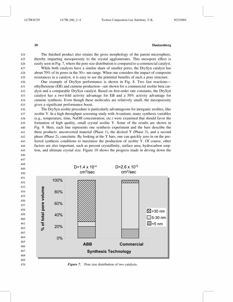

Fig
ure
9
Su
mm
ary
of
HT
Ssy
nth
esis
exp
erim
ents
LCTR36729 LCTR_046_3ndash4 Techset Composition Ltd Salisbury UK 9232004
518
519
520
521
522
523
524
525
526
527
528
529
530
531
532
533
534
535
536
537
538
539
540
541
542
543
544
545
546
547
548
549
550
551
552
553
554
555
556
557
558
559
560
561
562
563
564
Dautzenberg12
These combined properties make TUD-1 an attractive viable catalyst or catalyst
support for many reactions While the major focus has been with alumina silica and
silica-alumina TUD-1 has been made in about 20 different chemical variants As seen
in Table 1 Delft scientists have shown that Ti-TUD-1 is five times more active than its
MCM-41 counterpart for epoxidation even though the surface areas are equivalent[1314]
Figure 10 Comparison of conventional and ldquoDrySynrdquo Y crystallites
Figure 11 Ceramic foam versus TUD-1 an analogy
LCTR36729 LCTR_046_3ndash4 Techset Composition Ltd Salisbury UK 9232004
565
566
567
568
569
570
571
572
573
574
575
576
577
578
579
580
581
582
583
584
585
586
587
588
589
590
591
592
593
594
595
596
597
598
599
600
601
602
603
604
605
606
607
608
609
610
611
Catalyst Synthesis and Multifunctional Reactor Concepts 13
THE INFLUENCE OF PARTICLE SIZE AND POROSITY ON
CATALYST ACTIVITY
Catalysts can be custom-tailored for improved performance specifically the well-
known Thiele moduluseffectiveness factor concepts can be applied to demonstrate
mass transfer effects in catalysis The unique features of DrySyn zeolites and TUD-1
are both amenable to this approach
The intrinsic activity [k(o)] can be calculated by measuring the apparent catalyst
activity [k(app)] of a catalyst using two different particle sizes [rp] It follows that
kethappTHORNeth1THORN
kethappTHORNeth2THORNfrac14
heth1THORN
heth2THORNfrac14
3=f1frac121= tanhf1 1=f1
3=f2frac121= tanhf2 1=f2eth1THORN
Figure 12 TUD-1 Trading off pore size and surface area
Table 1 Expoxidation of cyclohexene
Catalysts Surface area m2g Turnover frequency
Ti-MCM-41 921 36
Ti-TUD-1 917 202
LCTR36729 LCTR_046_3ndash4 Techset Composition Ltd Salisbury UK 9232004
612
613
614
615
616
617
618
619
620
621
622
623
624
625
626
627
628
629
630
631
632
633
634
635
636
637
638
639
640
641
642
643
644
645
646
647
648
649
650
651
652
653
654
655
656
657
658
Dautzenberg14
in which
fi frac14 rpethiTHORN
ffiffiffiffiffiffiffiffikethoTHORN
D
reth2THORN
and
hethiTHORN frac14kethappTHORNethiTHORN
kethoTHORNeth3THORN
Through an iterative approximation we establish a value for k(o)D so that Eq (1) is
satisfied For each experimental value of rp we now can calculate f and thus k(o) and
therefore D We subsequently determine k(app) for any value of rp While the effective-
ness factorThiele modulus is usually shown as a log-log plot recasting it on a linear
scale can be quite informative
Figure 13 shows a typical example where this approach has been applied to two differ-
ent zeolite beta catalysts Using ethylbenzene formation as a probe reactive the k(o) of the
DrySyn beta catalyst is 15 higher than the k(o) of the commercial beta catalyst Of indus-
trial importance is the fact that the k(app) for 15 mm DrySyn particles is more than 25
times higher than the k(app) of 15 mm commercial catalyst particles Since the crystal
size of both zeolite beta samples is small (less than 005 micron ultimate crystal size)
the performance difference is probably due to the large number of mesopores in the
DrySyn catalyst which is reflected in the higher value of the effective diffusivity
In addition to altering catalyst activity by different zeolite synthesis routes one can
vary the catalyst support properties for a dramatic impact on catalyst performance This
concept has been shown[1516] to achieve synergistic benefits by combining zeolitic
activity with a mesoporous matrix A specific example is cited here again using the EB
probe reaction Table 2 shows the performance of three alumina-bound commercial Y cata-
lysts and two developmental catalysts using TUD-1 (silica or alumina) as the binding
material (commercial zeolite Y used) The intrinsic activities of the three commercial cata-
lysts reported on a constant zeolite basis are very similar and the intrinsic activities of
the mesoporous Y catalysts are significantly lower However the commercially important
activity is for particles typically greater than 1 mm Figure 14 shows the catalyst activity of
the two types of Y catalysts versus particle size Interestingly although the mesoporous Y
catalyst (here with Si-TUD-1) has a lower intrinsic activity than the commercial Y cata-
lyst the mesoporous Y has triple the activity of the commercial Y catalyst at industrially
relevant particle sizes This activity ldquocross-over effectrdquo is attributable to a tenfold advan-
tage in diffusivity One can quickly see the potential activity advantage that can be
achieved by optimizing the mesoporosity The five catalysts of Table 2 are compared in
Fig 15 Here we see that despite lower intrinsic activities both mesoporous Y catalysts
have superior activity compared to the three commercial Y catalysts at particle size of
15 mm
From the above conclusions one can foresee that another route to raising the overall
catalyst performance is to boost the intrinsic activity of the zeolite itself This concept is
illustrated in Table 3 Again using the EB probe reaction Table 3 shows the performance
of two alumina-bound commercial zeolite beta catalysts and one developmental catalyst
embedded in Si-TUD-1 (commercial zeolite beta used) The second commercial zeolite
beta catalyst (ldquoType IIrdquo) was prepared by a proprietary technique that achieves a
LCTR36729 LCTR_046_3ndash4 Techset Composition Ltd Salisbury UK 9232004
659
660
661
662
663
664
665
666
667
668
669
670
671
672
673
674
675
676
677
678
679
680
681
682
683
684
685
686
687
688
689
690
691
692
693
694
695
696
697
698
699
700
701
702
703
704
705
Catalyst Synthesis and Multifunctional Reactor Concepts 15
Fig
ure
13
P
erfo
rman
ceo
fldquoD
ryS
yn
rdquob
eta
ver
sus
com
mer
cial
bet
a(R
ef
ZS
han
etal
M
icro
po
rou
san
dM
ater
ials
20
014
81
81
)
LCTR36729 LCTR_046_3ndash4 Techset Composition Ltd Salisbury UK 9232004
706
707
708
709
710
711
712
713
714
715
716
717
718
719
720
721
722
723
724
725
726
727
728
729
730
731
732
733
734
735
736
737
738
739
740
741
742
743
744
745
746
747
748
749
750
751
752
Dautzenberg16
Ta
ble
2
Yca
taly
sts
per
form
ance
Ref
C
atal
yst
k(o
)
1s
ec
Eff
D
cm2s
ec
k(a
pp
)in
1s
ecat
par
tsi
zein
mm
Cat
aly
st
effe
ct
at
15
mm
Rel
ran
kin
g
of
k(o
)
Rel
ran
kin
g
of
k(1
5)
02
10
78
12
61
50
1C
om
mer
cial
Y
Ty
pe
I(7
0
)
36
97
8
10
26
15
30
47
03
00
25
68
10
01
00
2C
om
mer
cial
Y
Ty
pe
II(8
0
)
33
11
11
10
26
15
60
50
03
10
26
79
09
01
05
3C
om
mer
ical
Y4
63
19
5
10
26
23
80
77
04
90
41
89
12
51
65
4M
eso
po
rou
sY
Si-
TU
D-1
(45
8
)
24
71
31
0
10
26
23
11
48
10
50
91
36
80
67
36
3
5M
eso
po
rou
sY
11
59
93
10
26
11
00
73
05
30
47
40
40
31
18
6
No
te
Bo
ldfrac14
Ex
per
imen
tal
val
ues
al
lk
val
ues
at1
00
ze
oli
teb
asis
LCTR36729 LCTR_046_3ndash4 Techset Composition Ltd Salisbury UK 9232004
753
754
755
756
757
758
759
760
761
762
763
764
765
766
767
768
769
770
771
772
773
774
775
776
777
778
779
780
781
782
783
784
785
786
787
788
789
790
791
792
793
794
795
796
797
798
799
Catalyst Synthesis and Multifunctional Reactor Concepts 17
Fig
ure
14
E
Bac
tiv
ity
asfu
nct
ion
of
par
ticl
esi
ze
LCTR36729 LCTR_046_3ndash4 Techset Composition Ltd Salisbury UK 9232004
800
801
802
803
804
805
806
807
808
809
810
811
812
813
814
815
816
817
818
819
820
821
822
823
824
825
826
827
828
829
830
831
832
833
834
835
836
837
838
839
840
841
842
843
844
845
846
Dautzenberg18
Fig
ure
15
R
elat
ive
ran
kin
go
fze
oli
teY
cata
lyst
su
sin
gE
Bp
rob
ere
acti
on
LCTR36729 LCTR_046_3ndash4 Techset Composition Ltd Salisbury UK 9232004
847
848
849
850
851
852
853
854
855
856
857
858
859
860
861
862
863
864
865
866
867
868
869
870
871
872
873
874
875
876
877
878
879
880
881
882
883
884
885
886
887
888
889
890
891
892
893
Catalyst Synthesis and Multifunctional Reactor Concepts 19
Ta
ble
3
Bet
aca
taly
sts
per
form
ance
Ref
C
atal
yst
k(o
)
1s
ec
Eff
D
cm2s
ec
k(a
pp
)in
1s
ecat
par
tsi
zein
mm
Cat
aly
st
effe
ct
at
15
mm
Rel
ran
kin
g
of
k(o
)
Rel
ran
kin
g
of
k(1
5)
02
10
78
12
51
50
1C
om
mer
cial
bet
aT
yp
eI
(80
)
08
82
5
10
26
07
40
34
02
30
19
02
11
00
10
0
2C
om
mer
cial
bet
aT
yp
eII
(80
)
18
96
7
10
26
16
40
80
05
40
46
02
52
16
24
7
4M
eso
po
rou
s
bet
aS
i-T
UD
-1
(40
)
10
01
40
0
10
26
09
80
80
06
30
55
05
51
14
29
3
No
te
Bo
ldfrac14
Ex
per
imen
tal
val
ues
al
lk
val
ues
at1
00
ze
oli
teb
asis
M
anu
fact
uri
ng
bas
edo
np
rop
riet
ary
Lu
mm
usrsquo
syn
thes
ism
od
ifica
tio
nm
eth
od
LCTR36729 LCTR_046_3ndash4 Techset Composition Ltd Salisbury UK 9232004
894
895
896
897
898
899
900
901
902
903
904
905
906
907
908
909
910
911
912
913
914
915
916
917
918
919
920
921
922
923
924
925
926
927
928
929
930
931
932
933
934
935
936
937
938
939
940
Dautzenberg20
two- to threefold intrinsic activity boost This intrinsic activity boost is seen when compar-
ing the two commercial catalysts Again the commercially important activity is for par-
ticles typically greater than 1 mm At 125 mm particle size the activity advantage of
the Type II zeolite beta is being maintained More importantly the highest activity catalyst
is the beta in TUD-1 which has the highest effective diffusivity Specifically the activity
here is three times higher than the commercial zeolite beta (ldquoType Irdquo) catalyst These
results were not optimized so it is possible that even larger benefits can be reaped by
further tailoring the mesoporous structure and possibly composition
These performance attributes are shown graphically in Fig 16 which shows the cata-
lyst activity of the three beta catalysts The key observation here is that rankings based on
intrinsic activity can be misleading This is another illustration of the powerful impact that
pore architecture can have on catalyst activity
MULTIFUNCTIONAL REACTORS
Since most industrially relevant reactions are either endothermic or exothermic the
management of heat transfer is usually a key consideration in reaction engineering
design In many cases reactor selection is based on how one is able to remove or add
energy Conventional designs for highly energetic systems are therefore usually based
on fixed bed tubular and fluid bed reactors with internal or external heat exchangers
Intra-reactor process intensification[7] based on combining reaction with heat transfer
may offer a new opportunity to broaden the reactor selection possibilities Three specific
examples are used to describe this new approach (1) intra-reactor oxidative reheat for the
production of styrene by staging endothermic and exothermic reactions in series (2) sim-
ultaneous operation of endothermic dissociative adsorption of methane with exothermic
oxidative removal of carbon during catalytic partial oxidation and (3) catalytic distillation
for the production of ethers ethylbenzene or cumene and the selective hydrogenation of
highly unsaturated components in olefins streams
Intra-reactor Oxidative Reheat
The production of styrene by dehydrogenation of EB is carried out in adiabatic fixed
bed reactors The reaction is highly endothermic and the heat is provided between the reac-
tors by two methods addition of high temperature steam and heat exchange[17] Due to the
high steam-to-EB ratio the combined volumetric flow rate is high and consequently
radial flow fixed bed reactors are chosen to avoid pressure drop limitations Intra-
reactor heat exchange between catalyst beds results in higher overall bed temperatures
and in principle can lead to better spacendashtime yields Unfortunately it is difficult to
install conventional heat exchangers in the radial direction while also assuring acceptable
temperature uniformity keeping the reactor compact and avoiding large thermal zones
To address this problem a new solution was developed employing catalytic combustion
of hydrogen to water This reaction adds heat locally to the system and raises the overall
average reactor temperature thereby boosting the overall conversion Figure 17 illustrates
how endothermic ethylene dehydrogenation can be integrated with the exothermic
combustion of hydrogen This new method of adding heat is shown schematically in
LCTR36729 LCTR_046_3ndash4 Techset Composition Ltd Salisbury UK 9232004
941
942
943
944
945
946
947
948
949
950
951
952
953
954
955
956
957
958
959
960
961
962
963
964
965
966
967
968
969
970
971
972
973
974
975
976
977
978
979
980
981
982
983
984
985
986
987
Catalyst Synthesis and Multifunctional Reactor Concepts 21
Fig
ure
16
R
elat
ive
ran
kin
go
fze
oli
teb
eta
cata
lyst
su
sin
gE
Bp
rob
ere
acti
on
LCTR36729 LCTR_046_3ndash4 Techset Composition Ltd Salisbury UK 9232004
988
989
990
991
992
993
994
995
996
997
998
999
1000
1001
1002
1003
1004
1005
1006
1007
1008
1009
1010
1011
1012
1013
1014
1015
1016
1017
1018
1019
1020
1021
1022
1023
1024
1025
1026
1027
1028
1029
1030
1031
1032
1033
1034
Dautzenberg22
Fig 18 where intra-reactor reheat is employed in stages The new design known as
SMART (Styrene Monomer Advanced Reheat Technology) has already been successfully
commercialized in five plants
Catalytic Partial Oxidation of Methane (CPO)
The intra-reactor reheat principle can also be applied to the production of syngas
(COH2) from methane It is well known that conventional steam reforming of methane
is highly endothermic During CPO methane is dissociatively absorbed on the catalyst
producing hydrogen and a carbonaceous residue This residue is converted into CO and
H2O by oxidation and this reaction generates energy (exothermic) driving the endother-
mic steam reforming reaction that is happening in parallel With an optimized catalyst
ldquocokelessrdquo steam reforming appears to be feasible As a preferred reactor configuration
a reactor concept called ldquoComposite Structured Packingrdquo (CSP) is proposed ideally
suited for high superficial gas velocities as envisioned for CPO
Several noble-metal-containing catalysts have been proposed for CPO Figure 19
compares the temperature-programmed oxidation of Rh Ni and Ni-B upon exposure to
methane decomposition With Rh the resulting carbon residues are removed at relatively
Figure 17 Catalytic cycle for Styrene Monomer Advanced Reheat Technology (SMART)
LCTR36729 LCTR_046_3ndash4 Techset Composition Ltd Salisbury UK 9232004
1035
1036
1037
1038
1039
1040
1041
1042
1043
1044
1045
1046
1047
1048
1049
1050
1051
1052
1053
1054
1055
1056
1057
1058
1059
1060
1061
1062
1063
1064
1065
1066
1067
1068
1069
1070
1071
1072
1073
1074
1075
1076
1077
1078
1079
1080
1081
Catalyst Synthesis and Multifunctional Reactor Concepts 23
low temperature This is not the case with Ni Upon exposure to CH4 graphitic carbon is
deposited upon the Ni catalyst and this can be removed only at high temperature With a
catalyst based on an alloy of Ni and B most of the carbon is removed at a substantially
lower temperature while the amount of carbon needed to be removed at high temperature
is significantly reduced
Figure 20 shows the CPO performance of one of the novel Ni-B catalysts developed
during a collaborative project with the National University of Singapore[18] Note that the
product composition is essentially at equilibrium even at the extremely high space velo-
city applied during the testing In Fig 21 the ldquomethane conversionrdquo versus ldquotime
onstreamrdquo shows that the catalyst is unusually stable no initial deactivation period
occurs consistent with its noncoking behavior Another important benefit of the new
CPO catalyst is the close approach to thermal neutrality thus simplifying heat manage-
ment and improving thermal efficiency This feature is important if one wants to design
ultra-compact hydrogen generators
Catalytic Distillation
As the name implies catalytic distillation (CD)[19 ndash 22] intimately integrates catalytic
reaction and product separation by distillation CD is well suited for processes where the
feed and the product have a significantly different boiling range thereby facilitating
separation and many times enhancing selectivity by applying relatively low reaction temp-
eratures The heat of reaction is used for separation and therefore facilitates heat mana-
gement The predominantly liquid phase also aids catalyst stability Figure 22 illustrates
Figure 18 New reactor system of Styrene Monomer Advanced Reheat Technology (SMART)
LCTR36729 LCTR_046_3ndash4 Techset Composition Ltd Salisbury UK 9232004
1082
1083
1084
1085
1086
1087
1088
1089
1090
1091
1092
1093
1094
1095
1096
1097
1098
1099
1100
1101
1102
1103
1104
1105
1106
1107
1108
1109
1110
1111
1112
1113
1114
1115
1116
1117
1118
1119
1120
1121
1122
1123
1124
1125
1126
1127
1128
Dautzenberg24
one typical application of a CD technology the CDHydrow process for the selective
hydrogenation of benzene in reformate fractions The family of CD technologies has
grown quite extensively and today the number of commercially licensed units is about
150 Table 4 shows some of the CD applications that have been commercialized
One of the major petrochemical processesmdashsteam cracking for the production of
ethylenemdashis often perceived to be strictly thermal in nature However much of the down-
stream separation processes which are both energy and capital intensive can benefit from
catalytic advances In the production of ethylene and propylene through pyrolysis of
various feedstocks several undesirable by-products (eg dienes and acetylenes) are
Figure 19 TPO profiles of carburized CPO catalysts
LCTR36729 LCTR_046_3ndash4 Techset Composition Ltd Salisbury UK 9232004
1129
1130
1131
1132
1133
1134
1135
1136
1137
1138
1139
1140
1141
1142
1143
1144
1145
1146
1147
1148
1149
1150
1151
1152
1153
1154
1155
1156
1157
1158
1159
1160
1161
1162
1163
1164
1165
1166
1167
1168
1169
1170
1171
1172
1173
1174
1175
Catalyst Synthesis and Multifunctional Reactor Concepts 25
Fig
ure
20
T
yp
ical
cata
lyti
cp
arti
alo
xid
atio
nre
sult
s
LCTR36729 LCTR_046_3ndash4 Techset Composition Ltd Salisbury UK 9232004
1176
1177
1178
1179
1180
1181
1182
1183
1184
1185
1186
1187
1188
1189
1190
1191
1192
1193
1194
1195
1196
1197
1198
1199
1200
1201
1202
1203
1204
1205
1206
1207
1208
1209
1210
1211
1212
1213
1214
1215
1216
1217
1218
1219
1220
1221
1222
Dautzenberg26
created As such further processing is required for the separation and removal of the
dienesacetylenes from the primary olefin products Dictated by process economics
most of the C2 and heavier dienesacetylenes must be handled through a combination
of separation and hydrogenation since separation alone would result in excessive loss of
the olefin product
Currently the distillation and hydrogenation take place in several distinct process
steps designed to separate and hydrogenate the C2C3 and C4 compounds independently
(Fig 23) A disadvantage of this widely practiced conventional technology is the large
energy consumption required to generate the high pressures and cryogenic temperatures
to first separate and subsequently remove hydrogen from the cracked gas Additionally
the chemistry of each hydrogenation step (eg C2C3 etc) requires an independent
reactor system thereby driving up the plantrsquos capital cost and complexity
To offset these disadvantages the ldquoFront-End CDHydrordquo process (Fig 24) was devel-
oped as a one-step conversion of all C2ndashC5 and even heavier dienesacetylenes without
hydrogenation of the desired C2C3 olefins[2324] The objective is to Q3simultaneously
(a) consume dilute hydrogen through the elimination of undesirable dienes and acetylenes
thereby reducing refrigeration and compression cost and (b) combine reaction and separa-
tion into one step This new process greatly reduces the unit equipment ldquopiece countrdquo
by eliminating the separate hydrogenation reactors of the C2ndashC4 streams The heat of
Figure 21 CPO combined with steam reforming
LCTR36729 LCTR_046_3ndash4 Techset Composition Ltd Salisbury UK 9232004
1223
1224
1225
1226
1227
1228
1229
1230
1231
1232
1233
1234
1235
1236
1237
1238
1239
1240
1241
1242
1243
1244
1245
1246
1247
1248
1249
1250
1251
1252
1253
1254
1255
1256
1257
1258
1259
1260
1261
1262
1263
1264
1265
1266
1267
1268
1269
Catalyst Synthesis and Multifunctional Reactor Concepts 27
Fig
ure
22
N
ewC
DT
EC
Hb
enze
ne
hy
dro
gen
atio
nte
chn
olo
gy
LCTR36729 LCTR_046_3ndash4 Techset Composition Ltd Salisbury UK 9232004
1270
1271
1272
1273
1274
1275
1276
1277
1278
1279
1280
1281
1282
1283
1284
1285
1286
1287
1288
1289
1290
1291
1292
1293
1294
1295
1296
1297
1298
1299
1300
1301
1302
1303
1304
1305
1306
1307
1308
1309
1310
1311
1312
1313
1314
1315
1316
Dautzenberg28
reaction in the catalytic distillation reactor is used for separation and therefore improves
overall heat management In contrast to conventional fixed bed reactor systems where
dimers and oligomers accumulate and cause catalyst fouling the CD reactor ensures
that these undesirable components are removed by fractionation As a result this
process achieves prolonged catalyst life
The advancements achieved with the ldquoFront End CDHydrordquo process integrated with
several other Lummus innovations represent one of the most significant breakthroughs in
ethylene technology over the past 25 years
CONCLUSIONS
In reviewing the results presented in this paper the following conclusions have been
formulated
The catalyst synthesis examples described in this paper demonstrate that tailoring
the pore architecture of catalysts has several benefits Higher overall reaction rates
and yields can be obtained and in certain cases catalyst stability is also improved
by reducing the formation of catalyst deactivating precursors
The ldquoDrySynrdquo synthesis procedure can be optimized to make zeolite catalysts with
ultra-small crystallites This may benefit the development of catalysts with high
intrinsic activity The synthesis is very effective if mesoporous supports are used
to achieve a high degree of utilization
Inserting Y as well as beta in TUD-1 materials increases catalyst activity for aro-
matics alkylation to levels that have not been achieved with conventional zeolite
catalysts The open three-dimensional pore structure of TUD-1 is a key contributor
to this achievement It is expected that similar performance improvements will be
realized for other reactions that are commercially practiced at conditions imposing
mass transfer limitations
The intra-reactor reheat concept as practiced in SMART should in principle be
applicable to other strongly endothermic dehydrogenation reactions Applied at
the catalyst level as shown in the CPO example it is speculated that intra-
reactor reheat can be used for in-situ catalyst regeneration during operation
Catalytic distillation is a prime example of what can be achieved by process inten-
sification Although the technology has already been applied commercially for
Table 4 Commercial CD applications
dagger Etherification (MTBE TAME and ETBE)
dagger Aromatics alkylation (EB and cumene)
dagger Benzene removal from reformate
dagger Selective desulfurization
dagger Various selective hydrogenations
Demonstration plant at Tianjin China Front-end CDHydrow for
ethylene plants (2003)
LCTR36729 LCTR_046_3ndash4 Techset Composition Ltd Salisbury UK 9232004
1317
1318
1319
1320
1321
1322
1323
1324
1325
1326
1327
1328
1329
1330
1331
1332
1333
1334
1335
1336
1337
1338
1339
1340
1341
1342
1343
1344
1345
1346
1347
1348
1349
1350
1351
1352
1353
1354
1355
1356
1357
1358
1359
1360
1361
1362
1363
Catalyst Synthesis and Multifunctional Reactor Concepts 29
Fig
ure
23
C
on
ven
tio
nal
ole
fin
sp
uri
fica
tio
nte
chn
olo
gy
LCTR36729 LCTR_046_3ndash4 Techset Composition Ltd Salisbury UK 9232004
1364
1365
1366
1367
1368
1369
1370
1371
1372
1373
1374
1375
1376
1377
1378
1379
1380
1381
1382
1383
1384
1385
1386
1387
1388
1389
1390
1391
1392
1393
1394
1395
1396
1397
1398
1399
1400
1401
1402
1403
1404
1405
1406
1407
1408
1409
1410
Dautzenberg30
Fig
ure
24
F
ron
t-en
dC
DH
yd
row
tech
no
log
yfo
ro
lefi
ns
pu
rifi
cati
on
LCTR36729 LCTR_046_3ndash4 Techset Composition Ltd Salisbury UK 9232004
1411
1412
1413
1414
1415
1416
1417
1418
1419
1420
1421
1422
1423
1424
1425
1426
1427
1428
1429
1430
1431
1432
1433
1434
1435
1436
1437
1438
1439
1440
1441
1442
1443
1444
1445
1446
1447
1448
1449
1450
1451
1452
1453
1454
1455
1456
1457
Catalyst Synthesis and Multifunctional Reactor Concepts 31
various processes it is expected that the family will keep growing Tailoring of
existing catalysts may be required to allow operation in the liquid phase at
boiling conditions
The multifunctional reactor examples show that by applying intra-reactor intensi-
fication mature high-volume petrochemical processes can be improved As illus-
trated in the CPO example intra-reactor heat transfer can be applied beneficially
in the development of emerging technologies
To achieve optimum success more multidisciplinary teams are needed to address the
current and future needs of the process industry The teams should contain catalyst syn-
thesis experts as well as knowledgeable reaction engineers Furthermore it is recommend-
able to encourage industryndashuniversity collaborations This can be very synergistic
because the participants can extend and reinforce each otherrsquos efforts taking full advan-
tage of their complementary capabilities
REFERENCES
1 Dautzenberg FM Quality principles for catalyst testing during process development
Combinatorial Catalysis and High Throughput Catalyst Design and Testing Confer-
ence Vilamoura Quarteira (Algarve) Portugal July 19ndash24 1999 NATO Advanced
Study Institute
2 Trubac RE Dautzenberg FM Griffin TA Paikert B Schmidt VR
Overbeek RA Micro-engineered catalyst systems ABBrsquos advancement in struc-
tured catalytic packings Catalysis Today 2001 69 17ndash24
3 Carlborg JA Chang Y-F Murrell LL Trubac RE Overbeek RA
Schmidt VR Yeh CY Schuh L Conversion of Nitrogen Oxides in the Presence
of a Catalyst Supported on a Mesh-like Structure US Patent 6534022 March 18
2003 (assigned to ABB Lummus Global Inc)
4 First International Conference on Structured Catalysts and Reactors Delft The
Netherlands October 21ndash24 2001
5 Murrell LL Overbeek RA Chang Y-F van der Puil N Yeh CY Method of
Making Molecular Sieves and Novel Molecular Sieve Components US 6350429
2002 (assigned to ABB Lummus Global Inc)
6 Dautzenberg FM Angevine PJ Trubac RE Maschmeyer Th Tailoring Indus-
trial Catalyst to Minimize Mass Transfer Limitations 8th International Symposium
Scientific Bases for the Preparation of Heterogeneous Catalysts Louvain-la-Neuve
Belgium September 9ndash12 2002
7 Dautzenberg FM Mukherjee M Process Intensification Using Multifunctional
Reactors 16th International Symposium on Chemical Reaction Engineering
Krakow Poland September 10 2000
8 Beck JS Method for Synthesizing Mesoporous Crystalline Material US Patent
5057296 October 15 1991 (assigned to Mobil Oil Corp)
9 Kresge CT Leonowicz ME Roth WJ Vartuli JC Synthetic Mesoporous Crys-
talline Material US Patent 5098684 March 24 1992 (assigned to Mobil Oil Corp)
LCTR36729 LCTR_046_3ndash4 Techset Composition Ltd Salisbury UK 9232004
1458
1459
1460
1461
1462
1463
1464
1465
1466
1467
1468
1469
1470
1471
1472
1473
1474
1475
1476
1477
1478
1479
1480
1481
1482
1483
1484
1485
1486
1487
1488
1489
1490
1491
1492
1493
1494
1495
1496
1497
1498
1499
1500
1501
1502
1503
1504
Dautzenberg32
10 Kresge CT Leonowicz ME Roth WJ Vartuli JC Composition of Synthetic
Crystalline Material Its Synthesis US Patent 5102643 April 7 1992 (assigned to
Mobil Oil Corp)
11 Shan Z Maschmeyer Th Jansen JC Inorganic Oxides with Mesoporosity or
Combined Meso- and Microporosity and Process for the Preparation Thereof US
Patent 6358486 2002 (assigned to ABB Lummus Global Inc)
12 Jansen JC Shan Z Marchese L Zhou W van der Puil N Maschmeyer Th A
New Templating Method for Three-Dimensional Mesopore Networks Chem
Commun 2001 713ndash714
13 Shan Z Gianotti E Jansen JC Peters JA Marchese L Maschmeyer Th One-
Step Synthesis of a Highly Active Mesoporous Titanium-Containing Silica by Using
Bifunctional Templating Chem Eur J 2001 7 (7) 1437ndash1443
14 Shan Z Jansen JC Marchese L Maschmeyer Th Synthesis Characterization
and Catalytic Testing of a 3-D Mesoporous Titanosilica Ti-TUD-1 Micro Meso
Mater 2001 48 (1ndash3) 181ndash187
15 Shan Z Jansen JC Yeh CY Koegler JH Maschmeyer Th Catalyst Contain-
ing Microporous Zeolite in Mesoporous Support and Method for Making Same US
Patent Application 20020074263 2002 (assigned to ABB Lummus Global Inc)
16 Shan Z Jansen JC Yeh CY Koegler JH Maschmeyer Th Catalyst Contain-
ing Microporous Zeolite in Mesoporous Support and Method for Making Same WO
03045548 2003-06-05 (assigned to ABB Lummus Global Inc)
17 Dautzenberg FM Hydro-and Dehydrogenation of Large Volume Petrochemicals
Paper presented at the 10th Roermond Conference on Catalysis Rolduc-Kerkrade
The Netherlands June 30ndashJuly 5 2002
18 Dautzenberg FM Encouraging Innovation in Catalysis Paper presented at the 3rd
Asia-Pacific Congress on Catalysis Dalian China October 12ndash15 2003
19 Smith LA Jr Catalytic Distillation Structure US Patent 4443559 April 17 1984
(assigned to Chemical Research amp Licensing Company)
20 Sy A Smith L Chen J Dautzenberg FM Catalytic Distillation Route for
Cumene DeWitt Petrochemical Review Houston Texas March 23 1993
21 Rock K Gilbert GR McGuirk T Catalytic distillation extend its reach Chemical
Engineering 1997 78 78ndash84
22 Hearn D Putman HM Hydrodesulfurization Process Utilizing a Distillation
Column Reactor US Patent 5779883 March 17 1998 (assigned to Catalytic Distil-
lation Technologies)
23 Stanley SJ McCarthy FM Sumner C Gildert GR Olefin Plant Recovery
System Employing Catalytic Distillation US Patent 5679241 May 17 1995
(assigned to ABB Lummus Global Inc and Chemical Research amp Licensing
Company)
LCTR36729 LCTR_046_3ndash4 Techset Composition Ltd Salisbury UK 9232004
1505
1506
1507
1508
1509
1510
1511
1512
1513
1514
1515
1516
1517
1518
1519
1520
1521
1522
1523
1524
1525
1526
1527
1528
1529
1530
1531
1532
1533
1534
1535
1536
1537
1538
1539
1540
1541
1542
1543
1544
1545
1546
1547
1548
1549
1550
1551
Catalyst Synthesis and Multifunctional Reactor Concepts 33
Author QueriesJOURNAL LCTR
MANUSCRIPT 200036729
AQ Please check the right-hand running head provided is ok
Q1 Please provide street zipcode E-mail id and fax for corresponding author
Q2 Please supply abstract and keywords
Q3 Reference [24] is not present in the list Please add to the list
LCTR36729 LCTR_046_3ndash4 Techset Composition Ltd Salisbury UK 9232004
1552
1553
1554
1555
1556
1557
1558
1559
1560
1561
1562
1563
1564
1565
1566
1567
1568
1569
1570
1571
1572
1573
1574
1575
1576
1577
1578
1579
1580
1581
1582
1583
1584
1585
1586
1587
1588
1589
1590
1591
1592
1593
1594
1595
1596
1597
1598
Dautzenberg34

Fig
ure
13
P
erfo
rman
ceo
fldquoD
ryS
yn
rdquob
eta
ver
sus
com
mer
cial
bet
a(R
ef
ZS
han
etal
M
icro
po
rou
san
dM
ater
ials
20
014
81
81
)
LCTR36729 LCTR_046_3ndash4 Techset Composition Ltd Salisbury UK 9232004
706
707
708
709
710
711
712
713
714
715
716
717
718
719
720
721
722
723
724
725
726
727
728
729
730
731
732
733
734
735
736
737
738
739
740
741
742
743
744
745
746
747
748
749
750
751
752
Dautzenberg16
Ta
ble
2
Yca
taly
sts
per
form
ance
Ref
C
atal
yst
k(o
)
1s
ec
Eff
D
cm2s
ec
k(a
pp
)in
1s
ecat
par
tsi
zein
mm
Cat
aly
st
effe
ct
at
15
mm
Rel
ran
kin
g
of
k(o
)
Rel
ran
kin
g
of
k(1
5)
02
10
78
12
61
50
1C
om
mer
cial
Y
Ty
pe
I(7
0
)
36
97
8
10
26
15
30
47
03
00
25
68
10
01
00
2C
om
mer
cial
Y
Ty
pe
II(8
0
)
33
11
11
10
26
15
60
50
03
10
26
79
09
01
05
3C
om
mer
ical
Y4
63
19
5
10
26
23
80
77
04
90
41
89
12
51
65
4M
eso
po
rou
sY
Si-
TU
D-1
(45
8
)
24
71
31
0
10
26
23
11
48
10
50
91
36
80
67
36
3
5M
eso
po
rou
sY
11
59
93
10
26
11
00
73
05
30
47
40
40
31
18
6
No
te
Bo
ldfrac14
Ex
per
imen
tal
val
ues
al
lk
val
ues
at1
00
ze
oli
teb
asis
LCTR36729 LCTR_046_3ndash4 Techset Composition Ltd Salisbury UK 9232004
753
754
755
756
757
758
759
760
761
762
763
764
765
766
767
768
769
770
771
772
773
774
775
776
777
778
779
780
781
782
783
784
785
786
787
788
789
790
791
792
793
794
795
796
797
798
799
Catalyst Synthesis and Multifunctional Reactor Concepts 17
Fig
ure
14
E
Bac
tiv
ity
asfu
nct
ion
of
par
ticl
esi
ze
LCTR36729 LCTR_046_3ndash4 Techset Composition Ltd Salisbury UK 9232004
800
801
802
803
804
805
806
807
808
809
810
811
812
813
814
815
816
817
818
819
820
821
822
823
824
825
826
827
828
829
830
831
832
833
834
835
836
837
838
839
840
841
842
843
844
845
846
Dautzenberg18
Fig
ure
15
R
elat
ive
ran
kin
go
fze
oli
teY
cata
lyst
su
sin
gE
Bp
rob
ere
acti
on
LCTR36729 LCTR_046_3ndash4 Techset Composition Ltd Salisbury UK 9232004
847
848
849
850
851
852
853
854
855
856
857
858
859
860
861
862
863
864
865
866
867
868
869
870
871
872
873
874
875
876
877
878
879
880
881
882
883
884
885
886
887
888
889
890
891
892
893
Catalyst Synthesis and Multifunctional Reactor Concepts 19
Ta
ble
3
Bet
aca
taly
sts
per
form
ance
Ref
C
atal
yst
k(o
)
1s
ec
Eff
D
cm2s
ec
k(a
pp
)in
1s
ecat
par
tsi
zein
mm
Cat
aly
st
effe
ct
at
15
mm
Rel
ran
kin
g
of
k(o
)
Rel
ran
kin
g
of
k(1
5)
02
10
78
12
51
50
1C
om
mer
cial
bet
aT
yp
eI
(80
)
08
82
5
10
26
07
40
34
02
30
19
02
11
00
10
0
2C
om
mer
cial
bet
aT
yp
eII
(80
)
18
96
7
10
26
16
40
80
05
40
46
02
52
16
24
7
4M
eso
po
rou
s
bet
aS
i-T
UD
-1
(40
)
10
01
40
0
10
26
09
80
80
06
30
55
05
51
14
29
3
No
te
Bo
ldfrac14
Ex
per
imen
tal
val
ues
al
lk
val
ues
at1
00
ze
oli
teb
asis
M
anu
fact
uri
ng
bas
edo
np
rop
riet
ary
Lu
mm
usrsquo
syn
thes
ism
od
ifica
tio
nm
eth
od
LCTR36729 LCTR_046_3ndash4 Techset Composition Ltd Salisbury UK 9232004
894
895
896
897
898
899
900
901
902
903
904
905
906
907
908
909
910
911
912
913
914
915
916
917
918
919
920
921
922
923
924
925
926
927
928
929
930
931
932
933
934
935
936
937
938
939
940
Dautzenberg20
two- to threefold intrinsic activity boost This intrinsic activity boost is seen when compar-
ing the two commercial catalysts Again the commercially important activity is for par-
ticles typically greater than 1 mm At 125 mm particle size the activity advantage of
the Type II zeolite beta is being maintained More importantly the highest activity catalyst
is the beta in TUD-1 which has the highest effective diffusivity Specifically the activity
here is three times higher than the commercial zeolite beta (ldquoType Irdquo) catalyst These
results were not optimized so it is possible that even larger benefits can be reaped by
further tailoring the mesoporous structure and possibly composition
These performance attributes are shown graphically in Fig 16 which shows the cata-
lyst activity of the three beta catalysts The key observation here is that rankings based on
intrinsic activity can be misleading This is another illustration of the powerful impact that
pore architecture can have on catalyst activity
MULTIFUNCTIONAL REACTORS
Since most industrially relevant reactions are either endothermic or exothermic the
management of heat transfer is usually a key consideration in reaction engineering
design In many cases reactor selection is based on how one is able to remove or add
energy Conventional designs for highly energetic systems are therefore usually based
on fixed bed tubular and fluid bed reactors with internal or external heat exchangers
Intra-reactor process intensification[7] based on combining reaction with heat transfer
may offer a new opportunity to broaden the reactor selection possibilities Three specific
examples are used to describe this new approach (1) intra-reactor oxidative reheat for the
production of styrene by staging endothermic and exothermic reactions in series (2) sim-
ultaneous operation of endothermic dissociative adsorption of methane with exothermic
oxidative removal of carbon during catalytic partial oxidation and (3) catalytic distillation
for the production of ethers ethylbenzene or cumene and the selective hydrogenation of
highly unsaturated components in olefins streams
Intra-reactor Oxidative Reheat
The production of styrene by dehydrogenation of EB is carried out in adiabatic fixed
bed reactors The reaction is highly endothermic and the heat is provided between the reac-
tors by two methods addition of high temperature steam and heat exchange[17] Due to the
high steam-to-EB ratio the combined volumetric flow rate is high and consequently
radial flow fixed bed reactors are chosen to avoid pressure drop limitations Intra-
reactor heat exchange between catalyst beds results in higher overall bed temperatures
and in principle can lead to better spacendashtime yields Unfortunately it is difficult to
install conventional heat exchangers in the radial direction while also assuring acceptable
temperature uniformity keeping the reactor compact and avoiding large thermal zones
To address this problem a new solution was developed employing catalytic combustion
of hydrogen to water This reaction adds heat locally to the system and raises the overall
average reactor temperature thereby boosting the overall conversion Figure 17 illustrates
how endothermic ethylene dehydrogenation can be integrated with the exothermic
combustion of hydrogen This new method of adding heat is shown schematically in
LCTR36729 LCTR_046_3ndash4 Techset Composition Ltd Salisbury UK 9232004
941
942
943
944
945
946
947
948
949
950
951
952
953
954
955
956
957
958
959
960
961
962
963
964
965
966
967
968
969
970
971
972
973
974
975
976
977
978
979
980
981
982
983
984
985
986
987
Catalyst Synthesis and Multifunctional Reactor Concepts 21
Fig
ure
16
R
elat
ive
ran
kin
go
fze
oli
teb
eta
cata
lyst
su
sin
gE
Bp
rob
ere
acti
on
LCTR36729 LCTR_046_3ndash4 Techset Composition Ltd Salisbury UK 9232004
988
989
990
991
992
993
994
995
996
997
998
999
1000
1001
1002
1003
1004
1005
1006
1007
1008
1009
1010
1011
1012
1013
1014
1015
1016
1017
1018
1019
1020
1021
1022
1023
1024
1025
1026
1027
1028
1029
1030
1031
1032
1033
1034
Dautzenberg22
Fig 18 where intra-reactor reheat is employed in stages The new design known as
SMART (Styrene Monomer Advanced Reheat Technology) has already been successfully
commercialized in five plants
Catalytic Partial Oxidation of Methane (CPO)
The intra-reactor reheat principle can also be applied to the production of syngas
(COH2) from methane It is well known that conventional steam reforming of methane
is highly endothermic During CPO methane is dissociatively absorbed on the catalyst
producing hydrogen and a carbonaceous residue This residue is converted into CO and
H2O by oxidation and this reaction generates energy (exothermic) driving the endother-
mic steam reforming reaction that is happening in parallel With an optimized catalyst
ldquocokelessrdquo steam reforming appears to be feasible As a preferred reactor configuration
a reactor concept called ldquoComposite Structured Packingrdquo (CSP) is proposed ideally
suited for high superficial gas velocities as envisioned for CPO
Several noble-metal-containing catalysts have been proposed for CPO Figure 19
compares the temperature-programmed oxidation of Rh Ni and Ni-B upon exposure to
methane decomposition With Rh the resulting carbon residues are removed at relatively
Figure 17 Catalytic cycle for Styrene Monomer Advanced Reheat Technology (SMART)
LCTR36729 LCTR_046_3ndash4 Techset Composition Ltd Salisbury UK 9232004
1035
1036
1037
1038
1039
1040
1041
1042
1043
1044
1045
1046
1047
1048
1049
1050
1051
1052
1053
1054
1055
1056
1057
1058
1059
1060
1061
1062
1063
1064
1065
1066
1067
1068
1069
1070
1071
1072
1073
1074
1075
1076
1077
1078
1079
1080
1081
Catalyst Synthesis and Multifunctional Reactor Concepts 23
low temperature This is not the case with Ni Upon exposure to CH4 graphitic carbon is
deposited upon the Ni catalyst and this can be removed only at high temperature With a
catalyst based on an alloy of Ni and B most of the carbon is removed at a substantially
lower temperature while the amount of carbon needed to be removed at high temperature
is significantly reduced
Figure 20 shows the CPO performance of one of the novel Ni-B catalysts developed
during a collaborative project with the National University of Singapore[18] Note that the
product composition is essentially at equilibrium even at the extremely high space velo-
city applied during the testing In Fig 21 the ldquomethane conversionrdquo versus ldquotime
onstreamrdquo shows that the catalyst is unusually stable no initial deactivation period
occurs consistent with its noncoking behavior Another important benefit of the new
CPO catalyst is the close approach to thermal neutrality thus simplifying heat manage-
ment and improving thermal efficiency This feature is important if one wants to design
ultra-compact hydrogen generators
Catalytic Distillation
As the name implies catalytic distillation (CD)[19 ndash 22] intimately integrates catalytic
reaction and product separation by distillation CD is well suited for processes where the
feed and the product have a significantly different boiling range thereby facilitating
separation and many times enhancing selectivity by applying relatively low reaction temp-
eratures The heat of reaction is used for separation and therefore facilitates heat mana-
gement The predominantly liquid phase also aids catalyst stability Figure 22 illustrates
Figure 18 New reactor system of Styrene Monomer Advanced Reheat Technology (SMART)
LCTR36729 LCTR_046_3ndash4 Techset Composition Ltd Salisbury UK 9232004
1082
1083
1084
1085
1086
1087
1088
1089
1090
1091
1092
1093
1094
1095
1096
1097
1098
1099
1100
1101
1102
1103
1104
1105
1106
1107
1108
1109
1110
1111
1112
1113
1114
1115
1116
1117
1118
1119
1120
1121
1122
1123
1124
1125
1126
1127
1128
Dautzenberg24
one typical application of a CD technology the CDHydrow process for the selective
hydrogenation of benzene in reformate fractions The family of CD technologies has
grown quite extensively and today the number of commercially licensed units is about
150 Table 4 shows some of the CD applications that have been commercialized
One of the major petrochemical processesmdashsteam cracking for the production of
ethylenemdashis often perceived to be strictly thermal in nature However much of the down-
stream separation processes which are both energy and capital intensive can benefit from
catalytic advances In the production of ethylene and propylene through pyrolysis of
various feedstocks several undesirable by-products (eg dienes and acetylenes) are
Figure 19 TPO profiles of carburized CPO catalysts
LCTR36729 LCTR_046_3ndash4 Techset Composition Ltd Salisbury UK 9232004
1129
1130
1131
1132
1133
1134
1135
1136
1137
1138
1139
1140
1141
1142
1143
1144
1145
1146
1147
1148
1149
1150
1151
1152
1153
1154
1155
1156
1157
1158
1159
1160
1161
1162
1163
1164
1165
1166
1167
1168
1169
1170
1171
1172
1173
1174
1175
Catalyst Synthesis and Multifunctional Reactor Concepts 25
Fig
ure
20
T
yp
ical
cata
lyti
cp
arti
alo
xid
atio
nre
sult
s
LCTR36729 LCTR_046_3ndash4 Techset Composition Ltd Salisbury UK 9232004
1176
1177
1178
1179
1180
1181
1182
1183
1184
1185
1186
1187
1188
1189
1190
1191
1192
1193
1194
1195
1196
1197
1198
1199
1200
1201
1202
1203
1204
1205
1206
1207
1208
1209
1210
1211
1212
1213
1214
1215
1216
1217
1218
1219
1220
1221
1222
Dautzenberg26
created As such further processing is required for the separation and removal of the
dienesacetylenes from the primary olefin products Dictated by process economics
most of the C2 and heavier dienesacetylenes must be handled through a combination
of separation and hydrogenation since separation alone would result in excessive loss of
the olefin product
Currently the distillation and hydrogenation take place in several distinct process
steps designed to separate and hydrogenate the C2C3 and C4 compounds independently
(Fig 23) A disadvantage of this widely practiced conventional technology is the large
energy consumption required to generate the high pressures and cryogenic temperatures
to first separate and subsequently remove hydrogen from the cracked gas Additionally
the chemistry of each hydrogenation step (eg C2C3 etc) requires an independent
reactor system thereby driving up the plantrsquos capital cost and complexity
To offset these disadvantages the ldquoFront-End CDHydrordquo process (Fig 24) was devel-
oped as a one-step conversion of all C2ndashC5 and even heavier dienesacetylenes without
hydrogenation of the desired C2C3 olefins[2324] The objective is to Q3simultaneously
(a) consume dilute hydrogen through the elimination of undesirable dienes and acetylenes
thereby reducing refrigeration and compression cost and (b) combine reaction and separa-
tion into one step This new process greatly reduces the unit equipment ldquopiece countrdquo
by eliminating the separate hydrogenation reactors of the C2ndashC4 streams The heat of
Figure 21 CPO combined with steam reforming
LCTR36729 LCTR_046_3ndash4 Techset Composition Ltd Salisbury UK 9232004
1223
1224
1225
1226
1227
1228
1229
1230
1231
1232
1233
1234
1235
1236
1237
1238
1239
1240
1241
1242
1243
1244
1245
1246
1247
1248
1249
1250
1251
1252
1253
1254
1255
1256
1257
1258
1259
1260
1261
1262
1263
1264
1265
1266
1267
1268
1269
Catalyst Synthesis and Multifunctional Reactor Concepts 27
Fig
ure
22
N
ewC
DT
EC
Hb
enze
ne
hy
dro
gen
atio
nte
chn
olo
gy
LCTR36729 LCTR_046_3ndash4 Techset Composition Ltd Salisbury UK 9232004
1270
1271
1272
1273
1274
1275
1276
1277
1278
1279
1280
1281
1282
1283
1284
1285
1286
1287
1288
1289
1290
1291
1292
1293
1294
1295
1296
1297
1298
1299
1300
1301
1302
1303
1304
1305
1306
1307
1308
1309
1310
1311
1312
1313
1314
1315
1316
Dautzenberg28
reaction in the catalytic distillation reactor is used for separation and therefore improves
overall heat management In contrast to conventional fixed bed reactor systems where
dimers and oligomers accumulate and cause catalyst fouling the CD reactor ensures
that these undesirable components are removed by fractionation As a result this
process achieves prolonged catalyst life
The advancements achieved with the ldquoFront End CDHydrordquo process integrated with
several other Lummus innovations represent one of the most significant breakthroughs in
ethylene technology over the past 25 years
CONCLUSIONS
In reviewing the results presented in this paper the following conclusions have been
formulated
The catalyst synthesis examples described in this paper demonstrate that tailoring
the pore architecture of catalysts has several benefits Higher overall reaction rates
and yields can be obtained and in certain cases catalyst stability is also improved
by reducing the formation of catalyst deactivating precursors
The ldquoDrySynrdquo synthesis procedure can be optimized to make zeolite catalysts with
ultra-small crystallites This may benefit the development of catalysts with high
intrinsic activity The synthesis is very effective if mesoporous supports are used
to achieve a high degree of utilization
Inserting Y as well as beta in TUD-1 materials increases catalyst activity for aro-
matics alkylation to levels that have not been achieved with conventional zeolite
catalysts The open three-dimensional pore structure of TUD-1 is a key contributor
to this achievement It is expected that similar performance improvements will be
realized for other reactions that are commercially practiced at conditions imposing
mass transfer limitations
The intra-reactor reheat concept as practiced in SMART should in principle be
applicable to other strongly endothermic dehydrogenation reactions Applied at
the catalyst level as shown in the CPO example it is speculated that intra-
reactor reheat can be used for in-situ catalyst regeneration during operation
Catalytic distillation is a prime example of what can be achieved by process inten-
sification Although the technology has already been applied commercially for
Table 4 Commercial CD applications
dagger Etherification (MTBE TAME and ETBE)
dagger Aromatics alkylation (EB and cumene)
dagger Benzene removal from reformate
dagger Selective desulfurization
dagger Various selective hydrogenations
Demonstration plant at Tianjin China Front-end CDHydrow for
ethylene plants (2003)
LCTR36729 LCTR_046_3ndash4 Techset Composition Ltd Salisbury UK 9232004
1317
1318
1319
1320
1321
1322
1323
1324
1325
1326
1327
1328
1329
1330
1331
1332
1333
1334
1335
1336
1337
1338
1339
1340
1341
1342
1343
1344
1345
1346
1347
1348
1349
1350
1351
1352
1353
1354
1355
1356
1357
1358
1359
1360
1361
1362
1363
Catalyst Synthesis and Multifunctional Reactor Concepts 29
Fig
ure
23
C
on
ven
tio
nal
ole
fin
sp
uri
fica
tio
nte
chn
olo
gy
LCTR36729 LCTR_046_3ndash4 Techset Composition Ltd Salisbury UK 9232004
1364
1365
1366
1367
1368
1369
1370
1371
1372
1373
1374
1375
1376
1377
1378
1379
1380
1381
1382
1383
1384
1385
1386
1387
1388
1389
1390
1391
1392
1393
1394
1395
1396
1397
1398
1399
1400
1401
1402
1403
1404
1405
1406
1407
1408
1409
1410
Dautzenberg30
Fig
ure
24
F
ron
t-en
dC
DH
yd
row
tech
no
log
yfo
ro
lefi
ns
pu
rifi
cati
on
LCTR36729 LCTR_046_3ndash4 Techset Composition Ltd Salisbury UK 9232004
1411
1412
1413
1414
1415
1416
1417
1418
1419
1420
1421
1422
1423
1424
1425
1426
1427
1428
1429
1430
1431
1432
1433
1434
1435
1436
1437
1438
1439
1440
1441
1442
1443
1444
1445
1446
1447
1448
1449
1450
1451
1452
1453
1454
1455
1456
1457
Catalyst Synthesis and Multifunctional Reactor Concepts 31
various processes it is expected that the family will keep growing Tailoring of
existing catalysts may be required to allow operation in the liquid phase at
boiling conditions
The multifunctional reactor examples show that by applying intra-reactor intensi-
fication mature high-volume petrochemical processes can be improved As illus-
trated in the CPO example intra-reactor heat transfer can be applied beneficially
in the development of emerging technologies
To achieve optimum success more multidisciplinary teams are needed to address the
current and future needs of the process industry The teams should contain catalyst syn-
thesis experts as well as knowledgeable reaction engineers Furthermore it is recommend-
able to encourage industryndashuniversity collaborations This can be very synergistic
because the participants can extend and reinforce each otherrsquos efforts taking full advan-
tage of their complementary capabilities
REFERENCES
1 Dautzenberg FM Quality principles for catalyst testing during process development
Combinatorial Catalysis and High Throughput Catalyst Design and Testing Confer-
ence Vilamoura Quarteira (Algarve) Portugal July 19ndash24 1999 NATO Advanced
Study Institute
2 Trubac RE Dautzenberg FM Griffin TA Paikert B Schmidt VR
Overbeek RA Micro-engineered catalyst systems ABBrsquos advancement in struc-
tured catalytic packings Catalysis Today 2001 69 17ndash24
3 Carlborg JA Chang Y-F Murrell LL Trubac RE Overbeek RA
Schmidt VR Yeh CY Schuh L Conversion of Nitrogen Oxides in the Presence
of a Catalyst Supported on a Mesh-like Structure US Patent 6534022 March 18
2003 (assigned to ABB Lummus Global Inc)
4 First International Conference on Structured Catalysts and Reactors Delft The
Netherlands October 21ndash24 2001
5 Murrell LL Overbeek RA Chang Y-F van der Puil N Yeh CY Method of
Making Molecular Sieves and Novel Molecular Sieve Components US 6350429
2002 (assigned to ABB Lummus Global Inc)
6 Dautzenberg FM Angevine PJ Trubac RE Maschmeyer Th Tailoring Indus-
trial Catalyst to Minimize Mass Transfer Limitations 8th International Symposium
Scientific Bases for the Preparation of Heterogeneous Catalysts Louvain-la-Neuve
Belgium September 9ndash12 2002
7 Dautzenberg FM Mukherjee M Process Intensification Using Multifunctional
Reactors 16th International Symposium on Chemical Reaction Engineering
Krakow Poland September 10 2000
8 Beck JS Method for Synthesizing Mesoporous Crystalline Material US Patent
5057296 October 15 1991 (assigned to Mobil Oil Corp)
9 Kresge CT Leonowicz ME Roth WJ Vartuli JC Synthetic Mesoporous Crys-
talline Material US Patent 5098684 March 24 1992 (assigned to Mobil Oil Corp)
LCTR36729 LCTR_046_3ndash4 Techset Composition Ltd Salisbury UK 9232004
1458
1459
1460
1461
1462
1463
1464
1465
1466
1467
1468
1469
1470
1471
1472
1473
1474
1475
1476
1477
1478
1479
1480
1481
1482
1483
1484
1485
1486
1487
1488
1489
1490
1491
1492
1493
1494
1495
1496
1497
1498
1499
1500
1501
1502
1503
1504
Dautzenberg32
10 Kresge CT Leonowicz ME Roth WJ Vartuli JC Composition of Synthetic
Crystalline Material Its Synthesis US Patent 5102643 April 7 1992 (assigned to
Mobil Oil Corp)
11 Shan Z Maschmeyer Th Jansen JC Inorganic Oxides with Mesoporosity or
Combined Meso- and Microporosity and Process for the Preparation Thereof US
Patent 6358486 2002 (assigned to ABB Lummus Global Inc)
12 Jansen JC Shan Z Marchese L Zhou W van der Puil N Maschmeyer Th A
New Templating Method for Three-Dimensional Mesopore Networks Chem
Commun 2001 713ndash714
13 Shan Z Gianotti E Jansen JC Peters JA Marchese L Maschmeyer Th One-
Step Synthesis of a Highly Active Mesoporous Titanium-Containing Silica by Using
Bifunctional Templating Chem Eur J 2001 7 (7) 1437ndash1443
14 Shan Z Jansen JC Marchese L Maschmeyer Th Synthesis Characterization
and Catalytic Testing of a 3-D Mesoporous Titanosilica Ti-TUD-1 Micro Meso
Mater 2001 48 (1ndash3) 181ndash187
15 Shan Z Jansen JC Yeh CY Koegler JH Maschmeyer Th Catalyst Contain-
ing Microporous Zeolite in Mesoporous Support and Method for Making Same US
Patent Application 20020074263 2002 (assigned to ABB Lummus Global Inc)
16 Shan Z Jansen JC Yeh CY Koegler JH Maschmeyer Th Catalyst Contain-
ing Microporous Zeolite in Mesoporous Support and Method for Making Same WO
03045548 2003-06-05 (assigned to ABB Lummus Global Inc)
17 Dautzenberg FM Hydro-and Dehydrogenation of Large Volume Petrochemicals
Paper presented at the 10th Roermond Conference on Catalysis Rolduc-Kerkrade
The Netherlands June 30ndashJuly 5 2002
18 Dautzenberg FM Encouraging Innovation in Catalysis Paper presented at the 3rd
Asia-Pacific Congress on Catalysis Dalian China October 12ndash15 2003
19 Smith LA Jr Catalytic Distillation Structure US Patent 4443559 April 17 1984
(assigned to Chemical Research amp Licensing Company)
20 Sy A Smith L Chen J Dautzenberg FM Catalytic Distillation Route for
Cumene DeWitt Petrochemical Review Houston Texas March 23 1993
21 Rock K Gilbert GR McGuirk T Catalytic distillation extend its reach Chemical
Engineering 1997 78 78ndash84
22 Hearn D Putman HM Hydrodesulfurization Process Utilizing a Distillation
Column Reactor US Patent 5779883 March 17 1998 (assigned to Catalytic Distil-
lation Technologies)
23 Stanley SJ McCarthy FM Sumner C Gildert GR Olefin Plant Recovery
System Employing Catalytic Distillation US Patent 5679241 May 17 1995
(assigned to ABB Lummus Global Inc and Chemical Research amp Licensing
Company)
LCTR36729 LCTR_046_3ndash4 Techset Composition Ltd Salisbury UK 9232004
1505
1506
1507
1508
1509
1510
1511
1512
1513
1514
1515
1516
1517
1518
1519
1520
1521
1522
1523
1524
1525
1526
1527
1528
1529
1530
1531
1532
1533
1534
1535
1536
1537
1538
1539
1540
1541
1542
1543
1544
1545
1546
1547
1548
1549
1550
1551
Catalyst Synthesis and Multifunctional Reactor Concepts 33
Author QueriesJOURNAL LCTR
MANUSCRIPT 200036729
AQ Please check the right-hand running head provided is ok
Q1 Please provide street zipcode E-mail id and fax for corresponding author
Q2 Please supply abstract and keywords
Q3 Reference [24] is not present in the list Please add to the list
LCTR36729 LCTR_046_3ndash4 Techset Composition Ltd Salisbury UK 9232004
1552
1553
1554
1555
1556
1557
1558
1559
1560
1561
1562
1563
1564
1565
1566
1567
1568
1569
1570
1571
1572
1573
1574
1575
1576
1577
1578
1579
1580
1581
1582
1583
1584
1585
1586
1587
1588
1589
1590
1591
1592
1593
1594
1595
1596
1597
1598
Dautzenberg34

Ta
ble
2
Yca
taly
sts
per
form
ance
Ref
C
atal
yst
k(o
)
1s
ec
Eff
D
cm2s
ec
k(a
pp
)in
1s
ecat
par
tsi
zein
mm
Cat
aly
st
effe
ct
at
15
mm
Rel
ran
kin
g
of
k(o
)
Rel
ran
kin
g
of
k(1
5)
02
10
78
12
61
50
1C
om
mer
cial
Y
Ty
pe
I(7
0
)
36
97
8
10
26
15
30
47
03
00
25
68
10
01
00
2C
om
mer
cial
Y
Ty
pe
II(8
0
)
33
11
11
10
26
15
60
50
03
10
26
79
09
01
05
3C
om
mer
ical
Y4
63
19
5
10
26
23
80
77
04
90
41
89
12
51
65
4M
eso
po
rou
sY
Si-
TU
D-1
(45
8
)
24
71
31
0
10
26
23
11
48
10
50
91
36
80
67
36
3
5M
eso
po
rou
sY
11
59
93
10
26
11
00
73
05
30
47
40
40
31
18
6
No
te
Bo
ldfrac14
Ex
per
imen
tal
val
ues
al
lk
val
ues
at1
00
ze
oli
teb
asis
LCTR36729 LCTR_046_3ndash4 Techset Composition Ltd Salisbury UK 9232004
753
754
755
756
757
758
759
760
761
762
763
764
765
766
767
768
769
770
771
772
773
774
775
776
777
778
779
780
781
782
783
784
785
786
787
788
789
790
791
792
793
794
795
796
797
798
799
Catalyst Synthesis and Multifunctional Reactor Concepts 17
Fig
ure
14
E
Bac
tiv
ity
asfu
nct
ion
of
par
ticl
esi
ze
LCTR36729 LCTR_046_3ndash4 Techset Composition Ltd Salisbury UK 9232004
800
801
802
803
804
805
806
807
808
809
810
811
812
813
814
815
816
817
818
819
820
821
822
823
824
825
826
827
828
829
830
831
832
833
834
835
836
837
838
839
840
841
842
843
844
845
846
Dautzenberg18
Fig
ure
15
R
elat
ive
ran
kin
go
fze
oli
teY
cata
lyst
su
sin
gE
Bp
rob
ere
acti
on
LCTR36729 LCTR_046_3ndash4 Techset Composition Ltd Salisbury UK 9232004
847
848
849
850
851
852
853
854
855
856
857
858
859
860
861
862
863
864
865
866
867
868
869
870
871
872
873
874
875
876
877
878
879
880
881
882
883
884
885
886
887
888
889
890
891
892
893
Catalyst Synthesis and Multifunctional Reactor Concepts 19
Ta
ble
3
Bet
aca
taly
sts
per
form
ance
Ref
C
atal
yst
k(o
)
1s
ec
Eff
D
cm2s
ec
k(a
pp
)in
1s
ecat
par
tsi
zein
mm
Cat
aly
st
effe
ct
at
15
mm
Rel
ran
kin
g
of
k(o
)
Rel
ran
kin
g
of
k(1
5)
02
10
78
12
51
50
1C
om
mer
cial
bet
aT
yp
eI
(80
)
08
82
5
10
26
07
40
34
02
30
19
02
11
00
10
0
2C
om
mer
cial
bet
aT
yp
eII
(80
)
18
96
7
10
26
16
40
80
05
40
46
02
52
16
24
7
4M
eso
po
rou
s
bet
aS
i-T
UD
-1
(40
)
10
01
40
0
10
26
09
80
80
06
30
55
05
51
14
29
3
No
te
Bo
ldfrac14
Ex
per
imen
tal
val
ues
al
lk
val
ues
at1
00
ze
oli
teb
asis
M
anu
fact
uri
ng
bas
edo
np
rop
riet
ary
Lu
mm
usrsquo
syn
thes
ism
od
ifica
tio
nm
eth
od
LCTR36729 LCTR_046_3ndash4 Techset Composition Ltd Salisbury UK 9232004
894
895
896
897
898
899
900
901
902
903
904
905
906
907
908
909
910
911
912
913
914
915
916
917
918
919
920
921
922
923
924
925
926
927
928
929
930
931
932
933
934
935
936
937
938
939
940
Dautzenberg20
two- to threefold intrinsic activity boost This intrinsic activity boost is seen when compar-
ing the two commercial catalysts Again the commercially important activity is for par-
ticles typically greater than 1 mm At 125 mm particle size the activity advantage of
the Type II zeolite beta is being maintained More importantly the highest activity catalyst
is the beta in TUD-1 which has the highest effective diffusivity Specifically the activity
here is three times higher than the commercial zeolite beta (ldquoType Irdquo) catalyst These
results were not optimized so it is possible that even larger benefits can be reaped by
further tailoring the mesoporous structure and possibly composition
These performance attributes are shown graphically in Fig 16 which shows the cata-
lyst activity of the three beta catalysts The key observation here is that rankings based on
intrinsic activity can be misleading This is another illustration of the powerful impact that
pore architecture can have on catalyst activity
MULTIFUNCTIONAL REACTORS
Since most industrially relevant reactions are either endothermic or exothermic the
management of heat transfer is usually a key consideration in reaction engineering
design In many cases reactor selection is based on how one is able to remove or add
energy Conventional designs for highly energetic systems are therefore usually based
on fixed bed tubular and fluid bed reactors with internal or external heat exchangers
Intra-reactor process intensification[7] based on combining reaction with heat transfer
may offer a new opportunity to broaden the reactor selection possibilities Three specific
examples are used to describe this new approach (1) intra-reactor oxidative reheat for the
production of styrene by staging endothermic and exothermic reactions in series (2) sim-
ultaneous operation of endothermic dissociative adsorption of methane with exothermic
oxidative removal of carbon during catalytic partial oxidation and (3) catalytic distillation
for the production of ethers ethylbenzene or cumene and the selective hydrogenation of
highly unsaturated components in olefins streams
Intra-reactor Oxidative Reheat
The production of styrene by dehydrogenation of EB is carried out in adiabatic fixed
bed reactors The reaction is highly endothermic and the heat is provided between the reac-
tors by two methods addition of high temperature steam and heat exchange[17] Due to the
high steam-to-EB ratio the combined volumetric flow rate is high and consequently
radial flow fixed bed reactors are chosen to avoid pressure drop limitations Intra-
reactor heat exchange between catalyst beds results in higher overall bed temperatures
and in principle can lead to better spacendashtime yields Unfortunately it is difficult to
install conventional heat exchangers in the radial direction while also assuring acceptable
temperature uniformity keeping the reactor compact and avoiding large thermal zones
To address this problem a new solution was developed employing catalytic combustion
of hydrogen to water This reaction adds heat locally to the system and raises the overall
average reactor temperature thereby boosting the overall conversion Figure 17 illustrates
how endothermic ethylene dehydrogenation can be integrated with the exothermic
combustion of hydrogen This new method of adding heat is shown schematically in
LCTR36729 LCTR_046_3ndash4 Techset Composition Ltd Salisbury UK 9232004
941
942
943
944
945
946
947
948
949
950
951
952
953
954
955
956
957
958
959
960
961
962
963
964
965
966
967
968
969
970
971
972
973
974
975
976
977
978
979
980
981
982
983
984
985
986
987
Catalyst Synthesis and Multifunctional Reactor Concepts 21
Fig
ure
16
R
elat
ive
ran
kin
go
fze
oli
teb
eta
cata
lyst
su
sin
gE
Bp
rob
ere
acti
on
LCTR36729 LCTR_046_3ndash4 Techset Composition Ltd Salisbury UK 9232004
988
989
990
991
992
993
994
995
996
997
998
999
1000
1001
1002
1003
1004
1005
1006
1007
1008
1009
1010
1011
1012
1013
1014
1015
1016
1017
1018
1019
1020
1021
1022
1023
1024
1025
1026
1027
1028
1029
1030
1031
1032
1033
1034
Dautzenberg22
Fig 18 where intra-reactor reheat is employed in stages The new design known as
SMART (Styrene Monomer Advanced Reheat Technology) has already been successfully
commercialized in five plants
Catalytic Partial Oxidation of Methane (CPO)
The intra-reactor reheat principle can also be applied to the production of syngas
(COH2) from methane It is well known that conventional steam reforming of methane
is highly endothermic During CPO methane is dissociatively absorbed on the catalyst
producing hydrogen and a carbonaceous residue This residue is converted into CO and
H2O by oxidation and this reaction generates energy (exothermic) driving the endother-
mic steam reforming reaction that is happening in parallel With an optimized catalyst
ldquocokelessrdquo steam reforming appears to be feasible As a preferred reactor configuration
a reactor concept called ldquoComposite Structured Packingrdquo (CSP) is proposed ideally
suited for high superficial gas velocities as envisioned for CPO
Several noble-metal-containing catalysts have been proposed for CPO Figure 19
compares the temperature-programmed oxidation of Rh Ni and Ni-B upon exposure to
methane decomposition With Rh the resulting carbon residues are removed at relatively
Figure 17 Catalytic cycle for Styrene Monomer Advanced Reheat Technology (SMART)
LCTR36729 LCTR_046_3ndash4 Techset Composition Ltd Salisbury UK 9232004
1035
1036
1037
1038
1039
1040
1041
1042
1043
1044
1045
1046
1047
1048
1049
1050
1051
1052
1053
1054
1055
1056
1057
1058
1059
1060
1061
1062
1063
1064
1065
1066
1067
1068
1069
1070
1071
1072
1073
1074
1075
1076
1077
1078
1079
1080
1081
Catalyst Synthesis and Multifunctional Reactor Concepts 23
low temperature This is not the case with Ni Upon exposure to CH4 graphitic carbon is
deposited upon the Ni catalyst and this can be removed only at high temperature With a
catalyst based on an alloy of Ni and B most of the carbon is removed at a substantially
lower temperature while the amount of carbon needed to be removed at high temperature
is significantly reduced
Figure 20 shows the CPO performance of one of the novel Ni-B catalysts developed
during a collaborative project with the National University of Singapore[18] Note that the
product composition is essentially at equilibrium even at the extremely high space velo-
city applied during the testing In Fig 21 the ldquomethane conversionrdquo versus ldquotime
onstreamrdquo shows that the catalyst is unusually stable no initial deactivation period
occurs consistent with its noncoking behavior Another important benefit of the new
CPO catalyst is the close approach to thermal neutrality thus simplifying heat manage-
ment and improving thermal efficiency This feature is important if one wants to design
ultra-compact hydrogen generators
Catalytic Distillation
As the name implies catalytic distillation (CD)[19 ndash 22] intimately integrates catalytic
reaction and product separation by distillation CD is well suited for processes where the
feed and the product have a significantly different boiling range thereby facilitating
separation and many times enhancing selectivity by applying relatively low reaction temp-
eratures The heat of reaction is used for separation and therefore facilitates heat mana-
gement The predominantly liquid phase also aids catalyst stability Figure 22 illustrates
Figure 18 New reactor system of Styrene Monomer Advanced Reheat Technology (SMART)
LCTR36729 LCTR_046_3ndash4 Techset Composition Ltd Salisbury UK 9232004
1082
1083
1084
1085
1086
1087
1088
1089
1090
1091
1092
1093
1094
1095
1096
1097
1098
1099
1100
1101
1102
1103
1104
1105
1106
1107
1108
1109
1110
1111
1112
1113
1114
1115
1116
1117
1118
1119
1120
1121
1122
1123
1124
1125
1126
1127
1128
Dautzenberg24
one typical application of a CD technology the CDHydrow process for the selective
hydrogenation of benzene in reformate fractions The family of CD technologies has
grown quite extensively and today the number of commercially licensed units is about
150 Table 4 shows some of the CD applications that have been commercialized
One of the major petrochemical processesmdashsteam cracking for the production of
ethylenemdashis often perceived to be strictly thermal in nature However much of the down-
stream separation processes which are both energy and capital intensive can benefit from
catalytic advances In the production of ethylene and propylene through pyrolysis of
various feedstocks several undesirable by-products (eg dienes and acetylenes) are
Figure 19 TPO profiles of carburized CPO catalysts
LCTR36729 LCTR_046_3ndash4 Techset Composition Ltd Salisbury UK 9232004
1129
1130
1131
1132
1133
1134
1135
1136
1137
1138
1139
1140
1141
1142
1143
1144
1145
1146
1147
1148
1149
1150
1151
1152
1153
1154
1155
1156
1157
1158
1159
1160
1161
1162
1163
1164
1165
1166
1167
1168
1169
1170
1171
1172
1173
1174
1175
Catalyst Synthesis and Multifunctional Reactor Concepts 25
Fig
ure
20
T
yp
ical
cata
lyti
cp
arti
alo
xid
atio
nre
sult
s
LCTR36729 LCTR_046_3ndash4 Techset Composition Ltd Salisbury UK 9232004
1176
1177
1178
1179
1180
1181
1182
1183
1184
1185
1186
1187
1188
1189
1190
1191
1192
1193
1194
1195
1196
1197
1198
1199
1200
1201
1202
1203
1204
1205
1206
1207
1208
1209
1210
1211
1212
1213
1214
1215
1216
1217
1218
1219
1220
1221
1222
Dautzenberg26
created As such further processing is required for the separation and removal of the
dienesacetylenes from the primary olefin products Dictated by process economics
most of the C2 and heavier dienesacetylenes must be handled through a combination
of separation and hydrogenation since separation alone would result in excessive loss of
the olefin product
Currently the distillation and hydrogenation take place in several distinct process
steps designed to separate and hydrogenate the C2C3 and C4 compounds independently
(Fig 23) A disadvantage of this widely practiced conventional technology is the large
energy consumption required to generate the high pressures and cryogenic temperatures
to first separate and subsequently remove hydrogen from the cracked gas Additionally
the chemistry of each hydrogenation step (eg C2C3 etc) requires an independent
reactor system thereby driving up the plantrsquos capital cost and complexity
To offset these disadvantages the ldquoFront-End CDHydrordquo process (Fig 24) was devel-
oped as a one-step conversion of all C2ndashC5 and even heavier dienesacetylenes without
hydrogenation of the desired C2C3 olefins[2324] The objective is to Q3simultaneously
(a) consume dilute hydrogen through the elimination of undesirable dienes and acetylenes
thereby reducing refrigeration and compression cost and (b) combine reaction and separa-
tion into one step This new process greatly reduces the unit equipment ldquopiece countrdquo
by eliminating the separate hydrogenation reactors of the C2ndashC4 streams The heat of
Figure 21 CPO combined with steam reforming
LCTR36729 LCTR_046_3ndash4 Techset Composition Ltd Salisbury UK 9232004
1223
1224
1225
1226
1227
1228
1229
1230
1231
1232
1233
1234
1235
1236
1237
1238
1239
1240
1241
1242
1243
1244
1245
1246
1247
1248
1249
1250
1251
1252
1253
1254
1255
1256
1257
1258
1259
1260
1261
1262
1263
1264
1265
1266
1267
1268
1269
Catalyst Synthesis and Multifunctional Reactor Concepts 27
Fig
ure
22
N
ewC
DT
EC
Hb
enze
ne
hy
dro
gen
atio
nte
chn
olo
gy
LCTR36729 LCTR_046_3ndash4 Techset Composition Ltd Salisbury UK 9232004
1270
1271
1272
1273
1274
1275
1276
1277
1278
1279
1280
1281
1282
1283
1284
1285
1286
1287
1288
1289
1290
1291
1292
1293
1294
1295
1296
1297
1298
1299
1300
1301
1302
1303
1304
1305
1306
1307
1308
1309
1310
1311
1312
1313
1314
1315
1316
Dautzenberg28
reaction in the catalytic distillation reactor is used for separation and therefore improves
overall heat management In contrast to conventional fixed bed reactor systems where
dimers and oligomers accumulate and cause catalyst fouling the CD reactor ensures
that these undesirable components are removed by fractionation As a result this
process achieves prolonged catalyst life
The advancements achieved with the ldquoFront End CDHydrordquo process integrated with
several other Lummus innovations represent one of the most significant breakthroughs in
ethylene technology over the past 25 years
CONCLUSIONS
In reviewing the results presented in this paper the following conclusions have been
formulated
The catalyst synthesis examples described in this paper demonstrate that tailoring
the pore architecture of catalysts has several benefits Higher overall reaction rates
and yields can be obtained and in certain cases catalyst stability is also improved
by reducing the formation of catalyst deactivating precursors
The ldquoDrySynrdquo synthesis procedure can be optimized to make zeolite catalysts with
ultra-small crystallites This may benefit the development of catalysts with high
intrinsic activity The synthesis is very effective if mesoporous supports are used
to achieve a high degree of utilization
Inserting Y as well as beta in TUD-1 materials increases catalyst activity for aro-
matics alkylation to levels that have not been achieved with conventional zeolite
catalysts The open three-dimensional pore structure of TUD-1 is a key contributor
to this achievement It is expected that similar performance improvements will be
realized for other reactions that are commercially practiced at conditions imposing
mass transfer limitations
The intra-reactor reheat concept as practiced in SMART should in principle be
applicable to other strongly endothermic dehydrogenation reactions Applied at
the catalyst level as shown in the CPO example it is speculated that intra-
reactor reheat can be used for in-situ catalyst regeneration during operation
Catalytic distillation is a prime example of what can be achieved by process inten-
sification Although the technology has already been applied commercially for
Table 4 Commercial CD applications
dagger Etherification (MTBE TAME and ETBE)
dagger Aromatics alkylation (EB and cumene)
dagger Benzene removal from reformate
dagger Selective desulfurization
dagger Various selective hydrogenations
Demonstration plant at Tianjin China Front-end CDHydrow for
ethylene plants (2003)
LCTR36729 LCTR_046_3ndash4 Techset Composition Ltd Salisbury UK 9232004
1317
1318
1319
1320
1321
1322
1323
1324
1325
1326
1327
1328
1329
1330
1331
1332
1333
1334
1335
1336
1337
1338
1339
1340
1341
1342
1343
1344
1345
1346
1347
1348
1349
1350
1351
1352
1353
1354
1355
1356
1357
1358
1359
1360
1361
1362
1363
Catalyst Synthesis and Multifunctional Reactor Concepts 29
Fig
ure
23
C
on
ven
tio
nal
ole
fin
sp
uri
fica
tio
nte
chn
olo
gy
LCTR36729 LCTR_046_3ndash4 Techset Composition Ltd Salisbury UK 9232004
1364
1365
1366
1367
1368
1369
1370
1371
1372
1373
1374
1375
1376
1377
1378
1379
1380
1381
1382
1383
1384
1385
1386
1387
1388
1389
1390
1391
1392
1393
1394
1395
1396
1397
1398
1399
1400
1401
1402
1403
1404
1405
1406
1407
1408
1409
1410
Dautzenberg30
Fig
ure
24
F
ron
t-en
dC
DH
yd
row
tech
no
log
yfo
ro
lefi
ns
pu
rifi
cati
on
LCTR36729 LCTR_046_3ndash4 Techset Composition Ltd Salisbury UK 9232004
1411
1412
1413
1414
1415
1416
1417
1418
1419
1420
1421
1422
1423
1424
1425
1426
1427
1428
1429
1430
1431
1432
1433
1434
1435
1436
1437
1438
1439
1440
1441
1442
1443
1444
1445
1446
1447
1448
1449
1450
1451
1452
1453
1454
1455
1456
1457
Catalyst Synthesis and Multifunctional Reactor Concepts 31
various processes it is expected that the family will keep growing Tailoring of
existing catalysts may be required to allow operation in the liquid phase at
boiling conditions
The multifunctional reactor examples show that by applying intra-reactor intensi-
fication mature high-volume petrochemical processes can be improved As illus-
trated in the CPO example intra-reactor heat transfer can be applied beneficially
in the development of emerging technologies
To achieve optimum success more multidisciplinary teams are needed to address the
current and future needs of the process industry The teams should contain catalyst syn-
thesis experts as well as knowledgeable reaction engineers Furthermore it is recommend-
able to encourage industryndashuniversity collaborations This can be very synergistic
because the participants can extend and reinforce each otherrsquos efforts taking full advan-
tage of their complementary capabilities
REFERENCES
1 Dautzenberg FM Quality principles for catalyst testing during process development
Combinatorial Catalysis and High Throughput Catalyst Design and Testing Confer-
ence Vilamoura Quarteira (Algarve) Portugal July 19ndash24 1999 NATO Advanced
Study Institute
2 Trubac RE Dautzenberg FM Griffin TA Paikert B Schmidt VR
Overbeek RA Micro-engineered catalyst systems ABBrsquos advancement in struc-
tured catalytic packings Catalysis Today 2001 69 17ndash24
3 Carlborg JA Chang Y-F Murrell LL Trubac RE Overbeek RA
Schmidt VR Yeh CY Schuh L Conversion of Nitrogen Oxides in the Presence
of a Catalyst Supported on a Mesh-like Structure US Patent 6534022 March 18
2003 (assigned to ABB Lummus Global Inc)
4 First International Conference on Structured Catalysts and Reactors Delft The
Netherlands October 21ndash24 2001
5 Murrell LL Overbeek RA Chang Y-F van der Puil N Yeh CY Method of
Making Molecular Sieves and Novel Molecular Sieve Components US 6350429
2002 (assigned to ABB Lummus Global Inc)
6 Dautzenberg FM Angevine PJ Trubac RE Maschmeyer Th Tailoring Indus-
trial Catalyst to Minimize Mass Transfer Limitations 8th International Symposium
Scientific Bases for the Preparation of Heterogeneous Catalysts Louvain-la-Neuve
Belgium September 9ndash12 2002
7 Dautzenberg FM Mukherjee M Process Intensification Using Multifunctional
Reactors 16th International Symposium on Chemical Reaction Engineering
Krakow Poland September 10 2000
8 Beck JS Method for Synthesizing Mesoporous Crystalline Material US Patent
5057296 October 15 1991 (assigned to Mobil Oil Corp)
9 Kresge CT Leonowicz ME Roth WJ Vartuli JC Synthetic Mesoporous Crys-
talline Material US Patent 5098684 March 24 1992 (assigned to Mobil Oil Corp)
LCTR36729 LCTR_046_3ndash4 Techset Composition Ltd Salisbury UK 9232004
1458
1459
1460
1461
1462
1463
1464
1465
1466
1467
1468
1469
1470
1471
1472
1473
1474
1475
1476
1477
1478
1479
1480
1481
1482
1483
1484
1485
1486
1487
1488
1489
1490
1491
1492
1493
1494
1495
1496
1497
1498
1499
1500
1501
1502
1503
1504
Dautzenberg32
10 Kresge CT Leonowicz ME Roth WJ Vartuli JC Composition of Synthetic
Crystalline Material Its Synthesis US Patent 5102643 April 7 1992 (assigned to
Mobil Oil Corp)
11 Shan Z Maschmeyer Th Jansen JC Inorganic Oxides with Mesoporosity or
Combined Meso- and Microporosity and Process for the Preparation Thereof US
Patent 6358486 2002 (assigned to ABB Lummus Global Inc)
12 Jansen JC Shan Z Marchese L Zhou W van der Puil N Maschmeyer Th A
New Templating Method for Three-Dimensional Mesopore Networks Chem
Commun 2001 713ndash714
13 Shan Z Gianotti E Jansen JC Peters JA Marchese L Maschmeyer Th One-
Step Synthesis of a Highly Active Mesoporous Titanium-Containing Silica by Using
Bifunctional Templating Chem Eur J 2001 7 (7) 1437ndash1443
14 Shan Z Jansen JC Marchese L Maschmeyer Th Synthesis Characterization
and Catalytic Testing of a 3-D Mesoporous Titanosilica Ti-TUD-1 Micro Meso
Mater 2001 48 (1ndash3) 181ndash187
15 Shan Z Jansen JC Yeh CY Koegler JH Maschmeyer Th Catalyst Contain-
ing Microporous Zeolite in Mesoporous Support and Method for Making Same US
Patent Application 20020074263 2002 (assigned to ABB Lummus Global Inc)
16 Shan Z Jansen JC Yeh CY Koegler JH Maschmeyer Th Catalyst Contain-
ing Microporous Zeolite in Mesoporous Support and Method for Making Same WO
03045548 2003-06-05 (assigned to ABB Lummus Global Inc)
17 Dautzenberg FM Hydro-and Dehydrogenation of Large Volume Petrochemicals
Paper presented at the 10th Roermond Conference on Catalysis Rolduc-Kerkrade
The Netherlands June 30ndashJuly 5 2002
18 Dautzenberg FM Encouraging Innovation in Catalysis Paper presented at the 3rd
Asia-Pacific Congress on Catalysis Dalian China October 12ndash15 2003
19 Smith LA Jr Catalytic Distillation Structure US Patent 4443559 April 17 1984
(assigned to Chemical Research amp Licensing Company)
20 Sy A Smith L Chen J Dautzenberg FM Catalytic Distillation Route for
Cumene DeWitt Petrochemical Review Houston Texas March 23 1993
21 Rock K Gilbert GR McGuirk T Catalytic distillation extend its reach Chemical
Engineering 1997 78 78ndash84
22 Hearn D Putman HM Hydrodesulfurization Process Utilizing a Distillation
Column Reactor US Patent 5779883 March 17 1998 (assigned to Catalytic Distil-
lation Technologies)
23 Stanley SJ McCarthy FM Sumner C Gildert GR Olefin Plant Recovery
System Employing Catalytic Distillation US Patent 5679241 May 17 1995
(assigned to ABB Lummus Global Inc and Chemical Research amp Licensing
Company)
LCTR36729 LCTR_046_3ndash4 Techset Composition Ltd Salisbury UK 9232004
1505
1506
1507
1508
1509
1510
1511
1512
1513
1514
1515
1516
1517
1518
1519
1520
1521
1522
1523
1524
1525
1526
1527
1528
1529
1530
1531
1532
1533
1534
1535
1536
1537
1538
1539
1540
1541
1542
1543
1544
1545
1546
1547
1548
1549
1550
1551
Catalyst Synthesis and Multifunctional Reactor Concepts 33
Author QueriesJOURNAL LCTR
MANUSCRIPT 200036729
AQ Please check the right-hand running head provided is ok
Q1 Please provide street zipcode E-mail id and fax for corresponding author
Q2 Please supply abstract and keywords
Q3 Reference [24] is not present in the list Please add to the list
LCTR36729 LCTR_046_3ndash4 Techset Composition Ltd Salisbury UK 9232004
1552
1553
1554
1555
1556
1557
1558
1559
1560
1561
1562
1563
1564
1565
1566
1567
1568
1569
1570
1571
1572
1573
1574
1575
1576
1577
1578
1579
1580
1581
1582
1583
1584
1585
1586
1587
1588
1589
1590
1591
1592
1593
1594
1595
1596
1597
1598
Dautzenberg34

Fig
ure
14
E
Bac
tiv
ity
asfu
nct
ion
of
par
ticl
esi
ze
LCTR36729 LCTR_046_3ndash4 Techset Composition Ltd Salisbury UK 9232004
800
801
802
803
804
805
806
807
808
809
810
811
812
813
814
815
816
817
818
819
820
821
822
823
824
825
826
827
828
829
830
831
832
833
834
835
836
837
838
839
840
841
842
843
844
845
846
Dautzenberg18
Fig
ure
15
R
elat
ive
ran
kin
go
fze
oli
teY
cata
lyst
su
sin
gE
Bp
rob
ere
acti
on
LCTR36729 LCTR_046_3ndash4 Techset Composition Ltd Salisbury UK 9232004
847
848
849
850
851
852
853
854
855
856
857
858
859
860
861
862
863
864
865
866
867
868
869
870
871
872
873
874
875
876
877
878
879
880
881
882
883
884
885
886
887
888
889
890
891
892
893
Catalyst Synthesis and Multifunctional Reactor Concepts 19
Ta
ble
3
Bet
aca
taly
sts
per
form
ance
Ref
C
atal
yst
k(o
)
1s
ec
Eff
D
cm2s
ec
k(a
pp
)in
1s
ecat
par
tsi
zein
mm
Cat
aly
st
effe
ct
at
15
mm
Rel
ran
kin
g
of
k(o
)
Rel
ran
kin
g
of
k(1
5)
02
10
78
12
51
50
1C
om
mer
cial
bet
aT
yp
eI
(80
)
08
82
5
10
26
07
40
34
02
30
19
02
11
00
10
0
2C
om
mer
cial
bet
aT
yp
eII
(80
)
18
96
7
10
26
16
40
80
05
40
46
02
52
16
24
7
4M
eso
po
rou
s
bet
aS
i-T
UD
-1
(40
)
10
01
40
0
10
26
09
80
80
06
30
55
05
51
14
29
3
No
te
Bo
ldfrac14
Ex
per
imen
tal
val
ues
al
lk
val
ues
at1
00
ze
oli
teb
asis
M
anu
fact
uri
ng
bas
edo
np
rop
riet
ary
Lu
mm
usrsquo
syn
thes
ism
od
ifica
tio
nm
eth
od
LCTR36729 LCTR_046_3ndash4 Techset Composition Ltd Salisbury UK 9232004
894
895
896
897
898
899
900
901
902
903
904
905
906
907
908
909
910
911
912
913
914
915
916
917
918
919
920
921
922
923
924
925
926
927
928
929
930
931
932
933
934
935
936
937
938
939
940
Dautzenberg20
two- to threefold intrinsic activity boost This intrinsic activity boost is seen when compar-
ing the two commercial catalysts Again the commercially important activity is for par-
ticles typically greater than 1 mm At 125 mm particle size the activity advantage of
the Type II zeolite beta is being maintained More importantly the highest activity catalyst
is the beta in TUD-1 which has the highest effective diffusivity Specifically the activity
here is three times higher than the commercial zeolite beta (ldquoType Irdquo) catalyst These
results were not optimized so it is possible that even larger benefits can be reaped by
further tailoring the mesoporous structure and possibly composition
These performance attributes are shown graphically in Fig 16 which shows the cata-
lyst activity of the three beta catalysts The key observation here is that rankings based on
intrinsic activity can be misleading This is another illustration of the powerful impact that
pore architecture can have on catalyst activity
MULTIFUNCTIONAL REACTORS
Since most industrially relevant reactions are either endothermic or exothermic the
management of heat transfer is usually a key consideration in reaction engineering
design In many cases reactor selection is based on how one is able to remove or add
energy Conventional designs for highly energetic systems are therefore usually based
on fixed bed tubular and fluid bed reactors with internal or external heat exchangers
Intra-reactor process intensification[7] based on combining reaction with heat transfer
may offer a new opportunity to broaden the reactor selection possibilities Three specific
examples are used to describe this new approach (1) intra-reactor oxidative reheat for the
production of styrene by staging endothermic and exothermic reactions in series (2) sim-
ultaneous operation of endothermic dissociative adsorption of methane with exothermic
oxidative removal of carbon during catalytic partial oxidation and (3) catalytic distillation
for the production of ethers ethylbenzene or cumene and the selective hydrogenation of
highly unsaturated components in olefins streams
Intra-reactor Oxidative Reheat
The production of styrene by dehydrogenation of EB is carried out in adiabatic fixed
bed reactors The reaction is highly endothermic and the heat is provided between the reac-
tors by two methods addition of high temperature steam and heat exchange[17] Due to the
high steam-to-EB ratio the combined volumetric flow rate is high and consequently
radial flow fixed bed reactors are chosen to avoid pressure drop limitations Intra-
reactor heat exchange between catalyst beds results in higher overall bed temperatures
and in principle can lead to better spacendashtime yields Unfortunately it is difficult to
install conventional heat exchangers in the radial direction while also assuring acceptable
temperature uniformity keeping the reactor compact and avoiding large thermal zones
To address this problem a new solution was developed employing catalytic combustion
of hydrogen to water This reaction adds heat locally to the system and raises the overall
average reactor temperature thereby boosting the overall conversion Figure 17 illustrates
how endothermic ethylene dehydrogenation can be integrated with the exothermic
combustion of hydrogen This new method of adding heat is shown schematically in
LCTR36729 LCTR_046_3ndash4 Techset Composition Ltd Salisbury UK 9232004
941
942
943
944
945
946
947
948
949
950
951
952
953
954
955
956
957
958
959
960
961
962
963
964
965
966
967
968
969
970
971
972
973
974
975
976
977
978
979
980
981
982
983
984
985
986
987
Catalyst Synthesis and Multifunctional Reactor Concepts 21
Fig
ure
16
R
elat
ive
ran
kin
go
fze
oli
teb
eta
cata
lyst
su
sin
gE
Bp
rob
ere
acti
on
LCTR36729 LCTR_046_3ndash4 Techset Composition Ltd Salisbury UK 9232004
988
989
990
991
992
993
994
995
996
997
998
999
1000
1001
1002
1003
1004
1005
1006
1007
1008
1009
1010
1011
1012
1013
1014
1015
1016
1017
1018
1019
1020
1021
1022
1023
1024
1025
1026
1027
1028
1029
1030
1031
1032
1033
1034
Dautzenberg22
Fig 18 where intra-reactor reheat is employed in stages The new design known as
SMART (Styrene Monomer Advanced Reheat Technology) has already been successfully
commercialized in five plants
Catalytic Partial Oxidation of Methane (CPO)
The intra-reactor reheat principle can also be applied to the production of syngas
(COH2) from methane It is well known that conventional steam reforming of methane
is highly endothermic During CPO methane is dissociatively absorbed on the catalyst
producing hydrogen and a carbonaceous residue This residue is converted into CO and
H2O by oxidation and this reaction generates energy (exothermic) driving the endother-
mic steam reforming reaction that is happening in parallel With an optimized catalyst
ldquocokelessrdquo steam reforming appears to be feasible As a preferred reactor configuration
a reactor concept called ldquoComposite Structured Packingrdquo (CSP) is proposed ideally
suited for high superficial gas velocities as envisioned for CPO
Several noble-metal-containing catalysts have been proposed for CPO Figure 19
compares the temperature-programmed oxidation of Rh Ni and Ni-B upon exposure to
methane decomposition With Rh the resulting carbon residues are removed at relatively
Figure 17 Catalytic cycle for Styrene Monomer Advanced Reheat Technology (SMART)
LCTR36729 LCTR_046_3ndash4 Techset Composition Ltd Salisbury UK 9232004
1035
1036
1037
1038
1039
1040
1041
1042
1043
1044
1045
1046
1047
1048
1049
1050
1051
1052
1053
1054
1055
1056
1057
1058
1059
1060
1061
1062
1063
1064
1065
1066
1067
1068
1069
1070
1071
1072
1073
1074
1075
1076
1077
1078
1079
1080
1081
Catalyst Synthesis and Multifunctional Reactor Concepts 23
low temperature This is not the case with Ni Upon exposure to CH4 graphitic carbon is
deposited upon the Ni catalyst and this can be removed only at high temperature With a
catalyst based on an alloy of Ni and B most of the carbon is removed at a substantially
lower temperature while the amount of carbon needed to be removed at high temperature
is significantly reduced
Figure 20 shows the CPO performance of one of the novel Ni-B catalysts developed
during a collaborative project with the National University of Singapore[18] Note that the
product composition is essentially at equilibrium even at the extremely high space velo-
city applied during the testing In Fig 21 the ldquomethane conversionrdquo versus ldquotime
onstreamrdquo shows that the catalyst is unusually stable no initial deactivation period
occurs consistent with its noncoking behavior Another important benefit of the new
CPO catalyst is the close approach to thermal neutrality thus simplifying heat manage-
ment and improving thermal efficiency This feature is important if one wants to design
ultra-compact hydrogen generators
Catalytic Distillation
As the name implies catalytic distillation (CD)[19 ndash 22] intimately integrates catalytic
reaction and product separation by distillation CD is well suited for processes where the
feed and the product have a significantly different boiling range thereby facilitating
separation and many times enhancing selectivity by applying relatively low reaction temp-
eratures The heat of reaction is used for separation and therefore facilitates heat mana-
gement The predominantly liquid phase also aids catalyst stability Figure 22 illustrates
Figure 18 New reactor system of Styrene Monomer Advanced Reheat Technology (SMART)
LCTR36729 LCTR_046_3ndash4 Techset Composition Ltd Salisbury UK 9232004
1082
1083
1084
1085
1086
1087
1088
1089
1090
1091
1092
1093
1094
1095
1096
1097
1098
1099
1100
1101
1102
1103
1104
1105
1106
1107
1108
1109
1110
1111
1112
1113
1114
1115
1116
1117
1118
1119
1120
1121
1122
1123
1124
1125
1126
1127
1128
Dautzenberg24
one typical application of a CD technology the CDHydrow process for the selective
hydrogenation of benzene in reformate fractions The family of CD technologies has
grown quite extensively and today the number of commercially licensed units is about
150 Table 4 shows some of the CD applications that have been commercialized
One of the major petrochemical processesmdashsteam cracking for the production of
ethylenemdashis often perceived to be strictly thermal in nature However much of the down-
stream separation processes which are both energy and capital intensive can benefit from
catalytic advances In the production of ethylene and propylene through pyrolysis of
various feedstocks several undesirable by-products (eg dienes and acetylenes) are
Figure 19 TPO profiles of carburized CPO catalysts
LCTR36729 LCTR_046_3ndash4 Techset Composition Ltd Salisbury UK 9232004
1129
1130
1131
1132
1133
1134
1135
1136
1137
1138
1139
1140
1141
1142
1143
1144
1145
1146
1147
1148
1149
1150
1151
1152
1153
1154
1155
1156
1157
1158
1159
1160
1161
1162
1163
1164
1165
1166
1167
1168
1169
1170
1171
1172
1173
1174
1175
Catalyst Synthesis and Multifunctional Reactor Concepts 25
Fig
ure
20
T
yp
ical
cata
lyti
cp
arti
alo
xid
atio
nre
sult
s
LCTR36729 LCTR_046_3ndash4 Techset Composition Ltd Salisbury UK 9232004
1176
1177
1178
1179
1180
1181
1182
1183
1184
1185
1186
1187
1188
1189
1190
1191
1192
1193
1194
1195
1196
1197
1198
1199
1200
1201
1202
1203
1204
1205
1206
1207
1208
1209
1210
1211
1212
1213
1214
1215
1216
1217
1218
1219
1220
1221
1222
Dautzenberg26
created As such further processing is required for the separation and removal of the
dienesacetylenes from the primary olefin products Dictated by process economics
most of the C2 and heavier dienesacetylenes must be handled through a combination
of separation and hydrogenation since separation alone would result in excessive loss of
the olefin product
Currently the distillation and hydrogenation take place in several distinct process
steps designed to separate and hydrogenate the C2C3 and C4 compounds independently
(Fig 23) A disadvantage of this widely practiced conventional technology is the large
energy consumption required to generate the high pressures and cryogenic temperatures
to first separate and subsequently remove hydrogen from the cracked gas Additionally
the chemistry of each hydrogenation step (eg C2C3 etc) requires an independent
reactor system thereby driving up the plantrsquos capital cost and complexity
To offset these disadvantages the ldquoFront-End CDHydrordquo process (Fig 24) was devel-
oped as a one-step conversion of all C2ndashC5 and even heavier dienesacetylenes without
hydrogenation of the desired C2C3 olefins[2324] The objective is to Q3simultaneously
(a) consume dilute hydrogen through the elimination of undesirable dienes and acetylenes
thereby reducing refrigeration and compression cost and (b) combine reaction and separa-
tion into one step This new process greatly reduces the unit equipment ldquopiece countrdquo
by eliminating the separate hydrogenation reactors of the C2ndashC4 streams The heat of
Figure 21 CPO combined with steam reforming
LCTR36729 LCTR_046_3ndash4 Techset Composition Ltd Salisbury UK 9232004
1223
1224
1225
1226
1227
1228
1229
1230
1231
1232
1233
1234
1235
1236
1237
1238
1239
1240
1241
1242
1243
1244
1245
1246
1247
1248
1249
1250
1251
1252
1253
1254
1255
1256
1257
1258
1259
1260
1261
1262
1263
1264
1265
1266
1267
1268
1269
Catalyst Synthesis and Multifunctional Reactor Concepts 27
Fig
ure
22
N
ewC
DT
EC
Hb
enze
ne
hy
dro
gen
atio
nte
chn
olo
gy
LCTR36729 LCTR_046_3ndash4 Techset Composition Ltd Salisbury UK 9232004
1270
1271
1272
1273
1274
1275
1276
1277
1278
1279
1280
1281
1282
1283
1284
1285
1286
1287
1288
1289
1290
1291
1292
1293
1294
1295
1296
1297
1298
1299
1300
1301
1302
1303
1304
1305
1306
1307
1308
1309
1310
1311
1312
1313
1314
1315
1316
Dautzenberg28
reaction in the catalytic distillation reactor is used for separation and therefore improves
overall heat management In contrast to conventional fixed bed reactor systems where
dimers and oligomers accumulate and cause catalyst fouling the CD reactor ensures
that these undesirable components are removed by fractionation As a result this
process achieves prolonged catalyst life
The advancements achieved with the ldquoFront End CDHydrordquo process integrated with
several other Lummus innovations represent one of the most significant breakthroughs in
ethylene technology over the past 25 years
CONCLUSIONS
In reviewing the results presented in this paper the following conclusions have been
formulated
The catalyst synthesis examples described in this paper demonstrate that tailoring
the pore architecture of catalysts has several benefits Higher overall reaction rates
and yields can be obtained and in certain cases catalyst stability is also improved
by reducing the formation of catalyst deactivating precursors
The ldquoDrySynrdquo synthesis procedure can be optimized to make zeolite catalysts with
ultra-small crystallites This may benefit the development of catalysts with high
intrinsic activity The synthesis is very effective if mesoporous supports are used
to achieve a high degree of utilization
Inserting Y as well as beta in TUD-1 materials increases catalyst activity for aro-
matics alkylation to levels that have not been achieved with conventional zeolite
catalysts The open three-dimensional pore structure of TUD-1 is a key contributor
to this achievement It is expected that similar performance improvements will be
realized for other reactions that are commercially practiced at conditions imposing
mass transfer limitations
The intra-reactor reheat concept as practiced in SMART should in principle be
applicable to other strongly endothermic dehydrogenation reactions Applied at
the catalyst level as shown in the CPO example it is speculated that intra-
reactor reheat can be used for in-situ catalyst regeneration during operation
Catalytic distillation is a prime example of what can be achieved by process inten-
sification Although the technology has already been applied commercially for
Table 4 Commercial CD applications
dagger Etherification (MTBE TAME and ETBE)
dagger Aromatics alkylation (EB and cumene)
dagger Benzene removal from reformate
dagger Selective desulfurization
dagger Various selective hydrogenations
Demonstration plant at Tianjin China Front-end CDHydrow for
ethylene plants (2003)
LCTR36729 LCTR_046_3ndash4 Techset Composition Ltd Salisbury UK 9232004
1317
1318
1319
1320
1321
1322
1323
1324
1325
1326
1327
1328
1329
1330
1331
1332
1333
1334
1335
1336
1337
1338
1339
1340
1341
1342
1343
1344
1345
1346
1347
1348
1349
1350
1351
1352
1353
1354
1355
1356
1357
1358
1359
1360
1361
1362
1363
Catalyst Synthesis and Multifunctional Reactor Concepts 29
Fig
ure
23
C
on
ven
tio
nal
ole
fin
sp
uri
fica
tio
nte
chn
olo
gy
LCTR36729 LCTR_046_3ndash4 Techset Composition Ltd Salisbury UK 9232004
1364
1365
1366
1367
1368
1369
1370
1371
1372
1373
1374
1375
1376
1377
1378
1379
1380
1381
1382
1383
1384
1385
1386
1387
1388
1389
1390
1391
1392
1393
1394
1395
1396
1397
1398
1399
1400
1401
1402
1403
1404
1405
1406
1407
1408
1409
1410
Dautzenberg30
Fig
ure
24
F
ron
t-en
dC
DH
yd
row
tech
no
log
yfo
ro
lefi
ns
pu
rifi
cati
on
LCTR36729 LCTR_046_3ndash4 Techset Composition Ltd Salisbury UK 9232004
1411
1412
1413
1414
1415
1416
1417
1418
1419
1420
1421
1422
1423
1424
1425
1426
1427
1428
1429
1430
1431
1432
1433
1434
1435
1436
1437
1438
1439
1440
1441
1442
1443
1444
1445
1446
1447
1448
1449
1450
1451
1452
1453
1454
1455
1456
1457
Catalyst Synthesis and Multifunctional Reactor Concepts 31
various processes it is expected that the family will keep growing Tailoring of
existing catalysts may be required to allow operation in the liquid phase at
boiling conditions
The multifunctional reactor examples show that by applying intra-reactor intensi-
fication mature high-volume petrochemical processes can be improved As illus-
trated in the CPO example intra-reactor heat transfer can be applied beneficially
in the development of emerging technologies
To achieve optimum success more multidisciplinary teams are needed to address the
current and future needs of the process industry The teams should contain catalyst syn-
thesis experts as well as knowledgeable reaction engineers Furthermore it is recommend-
able to encourage industryndashuniversity collaborations This can be very synergistic
because the participants can extend and reinforce each otherrsquos efforts taking full advan-
tage of their complementary capabilities
REFERENCES
1 Dautzenberg FM Quality principles for catalyst testing during process development
Combinatorial Catalysis and High Throughput Catalyst Design and Testing Confer-
ence Vilamoura Quarteira (Algarve) Portugal July 19ndash24 1999 NATO Advanced
Study Institute
2 Trubac RE Dautzenberg FM Griffin TA Paikert B Schmidt VR
Overbeek RA Micro-engineered catalyst systems ABBrsquos advancement in struc-
tured catalytic packings Catalysis Today 2001 69 17ndash24
3 Carlborg JA Chang Y-F Murrell LL Trubac RE Overbeek RA
Schmidt VR Yeh CY Schuh L Conversion of Nitrogen Oxides in the Presence
of a Catalyst Supported on a Mesh-like Structure US Patent 6534022 March 18
2003 (assigned to ABB Lummus Global Inc)
4 First International Conference on Structured Catalysts and Reactors Delft The
Netherlands October 21ndash24 2001
5 Murrell LL Overbeek RA Chang Y-F van der Puil N Yeh CY Method of
Making Molecular Sieves and Novel Molecular Sieve Components US 6350429
2002 (assigned to ABB Lummus Global Inc)
6 Dautzenberg FM Angevine PJ Trubac RE Maschmeyer Th Tailoring Indus-
trial Catalyst to Minimize Mass Transfer Limitations 8th International Symposium
Scientific Bases for the Preparation of Heterogeneous Catalysts Louvain-la-Neuve
Belgium September 9ndash12 2002
7 Dautzenberg FM Mukherjee M Process Intensification Using Multifunctional
Reactors 16th International Symposium on Chemical Reaction Engineering
Krakow Poland September 10 2000
8 Beck JS Method for Synthesizing Mesoporous Crystalline Material US Patent
5057296 October 15 1991 (assigned to Mobil Oil Corp)
9 Kresge CT Leonowicz ME Roth WJ Vartuli JC Synthetic Mesoporous Crys-
talline Material US Patent 5098684 March 24 1992 (assigned to Mobil Oil Corp)
LCTR36729 LCTR_046_3ndash4 Techset Composition Ltd Salisbury UK 9232004
1458
1459
1460
1461
1462
1463
1464
1465
1466
1467
1468
1469
1470
1471
1472
1473
1474
1475
1476
1477
1478
1479
1480
1481
1482
1483
1484
1485
1486
1487
1488
1489
1490
1491
1492
1493
1494
1495
1496
1497
1498
1499
1500
1501
1502
1503
1504
Dautzenberg32
10 Kresge CT Leonowicz ME Roth WJ Vartuli JC Composition of Synthetic
Crystalline Material Its Synthesis US Patent 5102643 April 7 1992 (assigned to
Mobil Oil Corp)
11 Shan Z Maschmeyer Th Jansen JC Inorganic Oxides with Mesoporosity or
Combined Meso- and Microporosity and Process for the Preparation Thereof US
Patent 6358486 2002 (assigned to ABB Lummus Global Inc)
12 Jansen JC Shan Z Marchese L Zhou W van der Puil N Maschmeyer Th A
New Templating Method for Three-Dimensional Mesopore Networks Chem
Commun 2001 713ndash714
13 Shan Z Gianotti E Jansen JC Peters JA Marchese L Maschmeyer Th One-
Step Synthesis of a Highly Active Mesoporous Titanium-Containing Silica by Using
Bifunctional Templating Chem Eur J 2001 7 (7) 1437ndash1443
14 Shan Z Jansen JC Marchese L Maschmeyer Th Synthesis Characterization
and Catalytic Testing of a 3-D Mesoporous Titanosilica Ti-TUD-1 Micro Meso
Mater 2001 48 (1ndash3) 181ndash187
15 Shan Z Jansen JC Yeh CY Koegler JH Maschmeyer Th Catalyst Contain-
ing Microporous Zeolite in Mesoporous Support and Method for Making Same US
Patent Application 20020074263 2002 (assigned to ABB Lummus Global Inc)
16 Shan Z Jansen JC Yeh CY Koegler JH Maschmeyer Th Catalyst Contain-
ing Microporous Zeolite in Mesoporous Support and Method for Making Same WO
03045548 2003-06-05 (assigned to ABB Lummus Global Inc)
17 Dautzenberg FM Hydro-and Dehydrogenation of Large Volume Petrochemicals
Paper presented at the 10th Roermond Conference on Catalysis Rolduc-Kerkrade
The Netherlands June 30ndashJuly 5 2002
18 Dautzenberg FM Encouraging Innovation in Catalysis Paper presented at the 3rd
Asia-Pacific Congress on Catalysis Dalian China October 12ndash15 2003
19 Smith LA Jr Catalytic Distillation Structure US Patent 4443559 April 17 1984
(assigned to Chemical Research amp Licensing Company)
20 Sy A Smith L Chen J Dautzenberg FM Catalytic Distillation Route for
Cumene DeWitt Petrochemical Review Houston Texas March 23 1993
21 Rock K Gilbert GR McGuirk T Catalytic distillation extend its reach Chemical
Engineering 1997 78 78ndash84
22 Hearn D Putman HM Hydrodesulfurization Process Utilizing a Distillation
Column Reactor US Patent 5779883 March 17 1998 (assigned to Catalytic Distil-
lation Technologies)
23 Stanley SJ McCarthy FM Sumner C Gildert GR Olefin Plant Recovery
System Employing Catalytic Distillation US Patent 5679241 May 17 1995
(assigned to ABB Lummus Global Inc and Chemical Research amp Licensing
Company)
LCTR36729 LCTR_046_3ndash4 Techset Composition Ltd Salisbury UK 9232004
1505
1506
1507
1508
1509
1510
1511
1512
1513
1514
1515
1516
1517
1518
1519
1520
1521
1522
1523
1524
1525
1526
1527
1528
1529
1530
1531
1532
1533
1534
1535
1536
1537
1538
1539
1540
1541
1542
1543
1544
1545
1546
1547
1548
1549
1550
1551
Catalyst Synthesis and Multifunctional Reactor Concepts 33
Author QueriesJOURNAL LCTR
MANUSCRIPT 200036729
AQ Please check the right-hand running head provided is ok
Q1 Please provide street zipcode E-mail id and fax for corresponding author
Q2 Please supply abstract and keywords
Q3 Reference [24] is not present in the list Please add to the list
LCTR36729 LCTR_046_3ndash4 Techset Composition Ltd Salisbury UK 9232004
1552
1553
1554
1555
1556
1557
1558
1559
1560
1561
1562
1563
1564
1565
1566
1567
1568
1569
1570
1571
1572
1573
1574
1575
1576
1577
1578
1579
1580
1581
1582
1583
1584
1585
1586
1587
1588
1589
1590
1591
1592
1593
1594
1595
1596
1597
1598
Dautzenberg34

Fig
ure
15
R
elat
ive
ran
kin
go
fze
oli
teY
cata
lyst
su
sin
gE
Bp
rob
ere
acti
on
LCTR36729 LCTR_046_3ndash4 Techset Composition Ltd Salisbury UK 9232004
847
848
849
850
851
852
853
854
855
856
857
858
859
860
861
862
863
864
865
866
867
868
869
870
871
872
873
874
875
876
877
878
879
880
881
882
883
884
885
886
887
888
889
890
891
892
893
Catalyst Synthesis and Multifunctional Reactor Concepts 19
Ta
ble
3
Bet
aca
taly
sts
per
form
ance
Ref
C
atal
yst
k(o
)
1s
ec
Eff
D
cm2s
ec
k(a
pp
)in
1s
ecat
par
tsi
zein
mm
Cat
aly
st
effe
ct
at
15
mm
Rel
ran
kin
g
of
k(o
)
Rel
ran
kin
g
of
k(1
5)
02
10
78
12
51
50
1C
om
mer
cial
bet
aT
yp
eI
(80
)
08
82
5
10
26
07
40
34
02
30
19
02
11
00
10
0
2C
om
mer
cial
bet
aT
yp
eII
(80
)
18
96
7
10
26
16
40
80
05
40
46
02
52
16
24
7
4M
eso
po
rou
s
bet
aS
i-T
UD
-1
(40
)
10
01
40
0
10
26
09
80
80
06
30
55
05
51
14
29
3
No
te
Bo
ldfrac14
Ex
per
imen
tal
val
ues
al
lk
val
ues
at1
00
ze
oli
teb
asis
M
anu
fact
uri
ng
bas
edo
np
rop
riet
ary
Lu
mm
usrsquo
syn
thes
ism
od
ifica
tio
nm
eth
od
LCTR36729 LCTR_046_3ndash4 Techset Composition Ltd Salisbury UK 9232004
894
895
896
897
898
899
900
901
902
903
904
905
906
907
908
909
910
911
912
913
914
915
916
917
918
919
920
921
922
923
924
925
926
927
928
929
930
931
932
933
934
935
936
937
938
939
940
Dautzenberg20
two- to threefold intrinsic activity boost This intrinsic activity boost is seen when compar-
ing the two commercial catalysts Again the commercially important activity is for par-
ticles typically greater than 1 mm At 125 mm particle size the activity advantage of
the Type II zeolite beta is being maintained More importantly the highest activity catalyst
is the beta in TUD-1 which has the highest effective diffusivity Specifically the activity
here is three times higher than the commercial zeolite beta (ldquoType Irdquo) catalyst These
results were not optimized so it is possible that even larger benefits can be reaped by
further tailoring the mesoporous structure and possibly composition
These performance attributes are shown graphically in Fig 16 which shows the cata-
lyst activity of the three beta catalysts The key observation here is that rankings based on
intrinsic activity can be misleading This is another illustration of the powerful impact that
pore architecture can have on catalyst activity
MULTIFUNCTIONAL REACTORS
Since most industrially relevant reactions are either endothermic or exothermic the
management of heat transfer is usually a key consideration in reaction engineering
design In many cases reactor selection is based on how one is able to remove or add
energy Conventional designs for highly energetic systems are therefore usually based
on fixed bed tubular and fluid bed reactors with internal or external heat exchangers
Intra-reactor process intensification[7] based on combining reaction with heat transfer
may offer a new opportunity to broaden the reactor selection possibilities Three specific
examples are used to describe this new approach (1) intra-reactor oxidative reheat for the
production of styrene by staging endothermic and exothermic reactions in series (2) sim-
ultaneous operation of endothermic dissociative adsorption of methane with exothermic
oxidative removal of carbon during catalytic partial oxidation and (3) catalytic distillation
for the production of ethers ethylbenzene or cumene and the selective hydrogenation of
highly unsaturated components in olefins streams
Intra-reactor Oxidative Reheat
The production of styrene by dehydrogenation of EB is carried out in adiabatic fixed
bed reactors The reaction is highly endothermic and the heat is provided between the reac-
tors by two methods addition of high temperature steam and heat exchange[17] Due to the
high steam-to-EB ratio the combined volumetric flow rate is high and consequently
radial flow fixed bed reactors are chosen to avoid pressure drop limitations Intra-
reactor heat exchange between catalyst beds results in higher overall bed temperatures
and in principle can lead to better spacendashtime yields Unfortunately it is difficult to
install conventional heat exchangers in the radial direction while also assuring acceptable
temperature uniformity keeping the reactor compact and avoiding large thermal zones
To address this problem a new solution was developed employing catalytic combustion
of hydrogen to water This reaction adds heat locally to the system and raises the overall
average reactor temperature thereby boosting the overall conversion Figure 17 illustrates
how endothermic ethylene dehydrogenation can be integrated with the exothermic
combustion of hydrogen This new method of adding heat is shown schematically in
LCTR36729 LCTR_046_3ndash4 Techset Composition Ltd Salisbury UK 9232004
941
942
943
944
945
946
947
948
949
950
951
952
953
954
955
956
957
958
959
960
961
962
963
964
965
966
967
968
969
970
971
972
973
974
975
976
977
978
979
980
981
982
983
984
985
986
987
Catalyst Synthesis and Multifunctional Reactor Concepts 21
Fig
ure
16
R
elat
ive
ran
kin
go
fze
oli
teb
eta
cata
lyst
su
sin
gE
Bp
rob
ere
acti
on
LCTR36729 LCTR_046_3ndash4 Techset Composition Ltd Salisbury UK 9232004
988
989
990
991
992
993
994
995
996
997
998
999
1000
1001
1002
1003
1004
1005
1006
1007
1008
1009
1010
1011
1012
1013
1014
1015
1016
1017
1018
1019
1020
1021
1022
1023
1024
1025
1026
1027
1028
1029
1030
1031
1032
1033
1034
Dautzenberg22
Fig 18 where intra-reactor reheat is employed in stages The new design known as
SMART (Styrene Monomer Advanced Reheat Technology) has already been successfully
commercialized in five plants
Catalytic Partial Oxidation of Methane (CPO)
The intra-reactor reheat principle can also be applied to the production of syngas
(COH2) from methane It is well known that conventional steam reforming of methane
is highly endothermic During CPO methane is dissociatively absorbed on the catalyst
producing hydrogen and a carbonaceous residue This residue is converted into CO and
H2O by oxidation and this reaction generates energy (exothermic) driving the endother-
mic steam reforming reaction that is happening in parallel With an optimized catalyst
ldquocokelessrdquo steam reforming appears to be feasible As a preferred reactor configuration
a reactor concept called ldquoComposite Structured Packingrdquo (CSP) is proposed ideally
suited for high superficial gas velocities as envisioned for CPO
Several noble-metal-containing catalysts have been proposed for CPO Figure 19
compares the temperature-programmed oxidation of Rh Ni and Ni-B upon exposure to
methane decomposition With Rh the resulting carbon residues are removed at relatively
Figure 17 Catalytic cycle for Styrene Monomer Advanced Reheat Technology (SMART)
LCTR36729 LCTR_046_3ndash4 Techset Composition Ltd Salisbury UK 9232004
1035
1036
1037
1038
1039
1040
1041
1042
1043
1044
1045
1046
1047
1048
1049
1050
1051
1052
1053
1054
1055
1056
1057
1058
1059
1060
1061
1062
1063
1064
1065
1066
1067
1068
1069
1070
1071
1072
1073
1074
1075
1076
1077
1078
1079
1080
1081
Catalyst Synthesis and Multifunctional Reactor Concepts 23
low temperature This is not the case with Ni Upon exposure to CH4 graphitic carbon is
deposited upon the Ni catalyst and this can be removed only at high temperature With a
catalyst based on an alloy of Ni and B most of the carbon is removed at a substantially
lower temperature while the amount of carbon needed to be removed at high temperature
is significantly reduced
Figure 20 shows the CPO performance of one of the novel Ni-B catalysts developed
during a collaborative project with the National University of Singapore[18] Note that the
product composition is essentially at equilibrium even at the extremely high space velo-
city applied during the testing In Fig 21 the ldquomethane conversionrdquo versus ldquotime
onstreamrdquo shows that the catalyst is unusually stable no initial deactivation period
occurs consistent with its noncoking behavior Another important benefit of the new
CPO catalyst is the close approach to thermal neutrality thus simplifying heat manage-
ment and improving thermal efficiency This feature is important if one wants to design
ultra-compact hydrogen generators
Catalytic Distillation
As the name implies catalytic distillation (CD)[19 ndash 22] intimately integrates catalytic
reaction and product separation by distillation CD is well suited for processes where the
feed and the product have a significantly different boiling range thereby facilitating
separation and many times enhancing selectivity by applying relatively low reaction temp-
eratures The heat of reaction is used for separation and therefore facilitates heat mana-
gement The predominantly liquid phase also aids catalyst stability Figure 22 illustrates
Figure 18 New reactor system of Styrene Monomer Advanced Reheat Technology (SMART)
LCTR36729 LCTR_046_3ndash4 Techset Composition Ltd Salisbury UK 9232004
1082
1083
1084
1085
1086
1087
1088
1089
1090
1091
1092
1093
1094
1095
1096
1097
1098
1099
1100
1101
1102
1103
1104
1105
1106
1107
1108
1109
1110
1111
1112
1113
1114
1115
1116
1117
1118
1119
1120
1121
1122
1123
1124
1125
1126
1127
1128
Dautzenberg24
one typical application of a CD technology the CDHydrow process for the selective
hydrogenation of benzene in reformate fractions The family of CD technologies has
grown quite extensively and today the number of commercially licensed units is about
150 Table 4 shows some of the CD applications that have been commercialized
One of the major petrochemical processesmdashsteam cracking for the production of
ethylenemdashis often perceived to be strictly thermal in nature However much of the down-
stream separation processes which are both energy and capital intensive can benefit from
catalytic advances In the production of ethylene and propylene through pyrolysis of
various feedstocks several undesirable by-products (eg dienes and acetylenes) are
Figure 19 TPO profiles of carburized CPO catalysts
LCTR36729 LCTR_046_3ndash4 Techset Composition Ltd Salisbury UK 9232004
1129
1130
1131
1132
1133
1134
1135
1136
1137
1138
1139
1140
1141
1142
1143
1144
1145
1146
1147
1148
1149
1150
1151
1152
1153
1154
1155
1156
1157
1158
1159
1160
1161
1162
1163
1164
1165
1166
1167
1168
1169
1170
1171
1172
1173
1174
1175
Catalyst Synthesis and Multifunctional Reactor Concepts 25
Fig
ure
20
T
yp
ical
cata
lyti
cp
arti
alo
xid
atio
nre
sult
s
LCTR36729 LCTR_046_3ndash4 Techset Composition Ltd Salisbury UK 9232004
1176
1177
1178
1179
1180
1181
1182
1183
1184
1185
1186
1187
1188
1189
1190
1191
1192
1193
1194
1195
1196
1197
1198
1199
1200
1201
1202
1203
1204
1205
1206
1207
1208
1209
1210
1211
1212
1213
1214
1215
1216
1217
1218
1219
1220
1221
1222
Dautzenberg26
created As such further processing is required for the separation and removal of the
dienesacetylenes from the primary olefin products Dictated by process economics
most of the C2 and heavier dienesacetylenes must be handled through a combination
of separation and hydrogenation since separation alone would result in excessive loss of
the olefin product
Currently the distillation and hydrogenation take place in several distinct process
steps designed to separate and hydrogenate the C2C3 and C4 compounds independently
(Fig 23) A disadvantage of this widely practiced conventional technology is the large
energy consumption required to generate the high pressures and cryogenic temperatures
to first separate and subsequently remove hydrogen from the cracked gas Additionally
the chemistry of each hydrogenation step (eg C2C3 etc) requires an independent
reactor system thereby driving up the plantrsquos capital cost and complexity
To offset these disadvantages the ldquoFront-End CDHydrordquo process (Fig 24) was devel-
oped as a one-step conversion of all C2ndashC5 and even heavier dienesacetylenes without
hydrogenation of the desired C2C3 olefins[2324] The objective is to Q3simultaneously
(a) consume dilute hydrogen through the elimination of undesirable dienes and acetylenes
thereby reducing refrigeration and compression cost and (b) combine reaction and separa-
tion into one step This new process greatly reduces the unit equipment ldquopiece countrdquo
by eliminating the separate hydrogenation reactors of the C2ndashC4 streams The heat of
Figure 21 CPO combined with steam reforming
LCTR36729 LCTR_046_3ndash4 Techset Composition Ltd Salisbury UK 9232004
1223
1224
1225
1226
1227
1228
1229
1230
1231
1232
1233
1234
1235
1236
1237
1238
1239
1240
1241
1242
1243
1244
1245
1246
1247
1248
1249
1250
1251
1252
1253
1254
1255
1256
1257
1258
1259
1260
1261
1262
1263
1264
1265
1266
1267
1268
1269
Catalyst Synthesis and Multifunctional Reactor Concepts 27
Fig
ure
22
N
ewC
DT
EC
Hb
enze
ne
hy
dro
gen
atio
nte
chn
olo
gy
LCTR36729 LCTR_046_3ndash4 Techset Composition Ltd Salisbury UK 9232004
1270
1271
1272
1273
1274
1275
1276
1277
1278
1279
1280
1281
1282
1283
1284
1285
1286
1287
1288
1289
1290
1291
1292
1293
1294
1295
1296
1297
1298
1299
1300
1301
1302
1303
1304
1305
1306
1307
1308
1309
1310
1311
1312
1313
1314
1315
1316
Dautzenberg28
reaction in the catalytic distillation reactor is used for separation and therefore improves
overall heat management In contrast to conventional fixed bed reactor systems where
dimers and oligomers accumulate and cause catalyst fouling the CD reactor ensures
that these undesirable components are removed by fractionation As a result this
process achieves prolonged catalyst life
The advancements achieved with the ldquoFront End CDHydrordquo process integrated with
several other Lummus innovations represent one of the most significant breakthroughs in
ethylene technology over the past 25 years
CONCLUSIONS
In reviewing the results presented in this paper the following conclusions have been
formulated
The catalyst synthesis examples described in this paper demonstrate that tailoring
the pore architecture of catalysts has several benefits Higher overall reaction rates
and yields can be obtained and in certain cases catalyst stability is also improved
by reducing the formation of catalyst deactivating precursors
The ldquoDrySynrdquo synthesis procedure can be optimized to make zeolite catalysts with
ultra-small crystallites This may benefit the development of catalysts with high
intrinsic activity The synthesis is very effective if mesoporous supports are used
to achieve a high degree of utilization
Inserting Y as well as beta in TUD-1 materials increases catalyst activity for aro-
matics alkylation to levels that have not been achieved with conventional zeolite
catalysts The open three-dimensional pore structure of TUD-1 is a key contributor
to this achievement It is expected that similar performance improvements will be
realized for other reactions that are commercially practiced at conditions imposing
mass transfer limitations
The intra-reactor reheat concept as practiced in SMART should in principle be
applicable to other strongly endothermic dehydrogenation reactions Applied at
the catalyst level as shown in the CPO example it is speculated that intra-
reactor reheat can be used for in-situ catalyst regeneration during operation
Catalytic distillation is a prime example of what can be achieved by process inten-
sification Although the technology has already been applied commercially for
Table 4 Commercial CD applications
dagger Etherification (MTBE TAME and ETBE)
dagger Aromatics alkylation (EB and cumene)
dagger Benzene removal from reformate
dagger Selective desulfurization
dagger Various selective hydrogenations
Demonstration plant at Tianjin China Front-end CDHydrow for
ethylene plants (2003)
LCTR36729 LCTR_046_3ndash4 Techset Composition Ltd Salisbury UK 9232004
1317
1318
1319
1320
1321
1322
1323
1324
1325
1326
1327
1328
1329
1330
1331
1332
1333
1334
1335
1336
1337
1338
1339
1340
1341
1342
1343
1344
1345
1346
1347
1348
1349
1350
1351
1352
1353
1354
1355
1356
1357
1358
1359
1360
1361
1362
1363
Catalyst Synthesis and Multifunctional Reactor Concepts 29
Fig
ure
23
C
on
ven
tio
nal
ole
fin
sp
uri
fica
tio
nte
chn
olo
gy
LCTR36729 LCTR_046_3ndash4 Techset Composition Ltd Salisbury UK 9232004
1364
1365
1366
1367
1368
1369
1370
1371
1372
1373
1374
1375
1376
1377
1378
1379
1380
1381
1382
1383
1384
1385
1386
1387
1388
1389
1390
1391
1392
1393
1394
1395
1396
1397
1398
1399
1400
1401
1402
1403
1404
1405
1406
1407
1408
1409
1410
Dautzenberg30
Fig
ure
24
F
ron
t-en
dC
DH
yd
row
tech
no
log
yfo
ro
lefi
ns
pu
rifi
cati
on
LCTR36729 LCTR_046_3ndash4 Techset Composition Ltd Salisbury UK 9232004
1411
1412
1413
1414
1415
1416
1417
1418
1419
1420
1421
1422
1423
1424
1425
1426
1427
1428
1429
1430
1431
1432
1433
1434
1435
1436
1437
1438
1439
1440
1441
1442
1443
1444
1445
1446
1447
1448
1449
1450
1451
1452
1453
1454
1455
1456
1457
Catalyst Synthesis and Multifunctional Reactor Concepts 31
various processes it is expected that the family will keep growing Tailoring of
existing catalysts may be required to allow operation in the liquid phase at
boiling conditions
The multifunctional reactor examples show that by applying intra-reactor intensi-
fication mature high-volume petrochemical processes can be improved As illus-
trated in the CPO example intra-reactor heat transfer can be applied beneficially
in the development of emerging technologies
To achieve optimum success more multidisciplinary teams are needed to address the
current and future needs of the process industry The teams should contain catalyst syn-
thesis experts as well as knowledgeable reaction engineers Furthermore it is recommend-
able to encourage industryndashuniversity collaborations This can be very synergistic
because the participants can extend and reinforce each otherrsquos efforts taking full advan-
tage of their complementary capabilities
REFERENCES
1 Dautzenberg FM Quality principles for catalyst testing during process development
Combinatorial Catalysis and High Throughput Catalyst Design and Testing Confer-
ence Vilamoura Quarteira (Algarve) Portugal July 19ndash24 1999 NATO Advanced
Study Institute
2 Trubac RE Dautzenberg FM Griffin TA Paikert B Schmidt VR
Overbeek RA Micro-engineered catalyst systems ABBrsquos advancement in struc-
tured catalytic packings Catalysis Today 2001 69 17ndash24
3 Carlborg JA Chang Y-F Murrell LL Trubac RE Overbeek RA
Schmidt VR Yeh CY Schuh L Conversion of Nitrogen Oxides in the Presence
of a Catalyst Supported on a Mesh-like Structure US Patent 6534022 March 18
2003 (assigned to ABB Lummus Global Inc)
4 First International Conference on Structured Catalysts and Reactors Delft The
Netherlands October 21ndash24 2001
5 Murrell LL Overbeek RA Chang Y-F van der Puil N Yeh CY Method of
Making Molecular Sieves and Novel Molecular Sieve Components US 6350429
2002 (assigned to ABB Lummus Global Inc)
6 Dautzenberg FM Angevine PJ Trubac RE Maschmeyer Th Tailoring Indus-
trial Catalyst to Minimize Mass Transfer Limitations 8th International Symposium
Scientific Bases for the Preparation of Heterogeneous Catalysts Louvain-la-Neuve
Belgium September 9ndash12 2002
7 Dautzenberg FM Mukherjee M Process Intensification Using Multifunctional
Reactors 16th International Symposium on Chemical Reaction Engineering
Krakow Poland September 10 2000
8 Beck JS Method for Synthesizing Mesoporous Crystalline Material US Patent
5057296 October 15 1991 (assigned to Mobil Oil Corp)
9 Kresge CT Leonowicz ME Roth WJ Vartuli JC Synthetic Mesoporous Crys-
talline Material US Patent 5098684 March 24 1992 (assigned to Mobil Oil Corp)
LCTR36729 LCTR_046_3ndash4 Techset Composition Ltd Salisbury UK 9232004
1458
1459
1460
1461
1462
1463
1464
1465
1466
1467
1468
1469
1470
1471
1472
1473
1474
1475
1476
1477
1478
1479
1480
1481
1482
1483
1484
1485
1486
1487
1488
1489
1490
1491
1492
1493
1494
1495
1496
1497
1498
1499
1500
1501
1502
1503
1504
Dautzenberg32
10 Kresge CT Leonowicz ME Roth WJ Vartuli JC Composition of Synthetic
Crystalline Material Its Synthesis US Patent 5102643 April 7 1992 (assigned to
Mobil Oil Corp)
11 Shan Z Maschmeyer Th Jansen JC Inorganic Oxides with Mesoporosity or
Combined Meso- and Microporosity and Process for the Preparation Thereof US
Patent 6358486 2002 (assigned to ABB Lummus Global Inc)
12 Jansen JC Shan Z Marchese L Zhou W van der Puil N Maschmeyer Th A
New Templating Method for Three-Dimensional Mesopore Networks Chem
Commun 2001 713ndash714
13 Shan Z Gianotti E Jansen JC Peters JA Marchese L Maschmeyer Th One-
Step Synthesis of a Highly Active Mesoporous Titanium-Containing Silica by Using
Bifunctional Templating Chem Eur J 2001 7 (7) 1437ndash1443
14 Shan Z Jansen JC Marchese L Maschmeyer Th Synthesis Characterization
and Catalytic Testing of a 3-D Mesoporous Titanosilica Ti-TUD-1 Micro Meso
Mater 2001 48 (1ndash3) 181ndash187
15 Shan Z Jansen JC Yeh CY Koegler JH Maschmeyer Th Catalyst Contain-
ing Microporous Zeolite in Mesoporous Support and Method for Making Same US
Patent Application 20020074263 2002 (assigned to ABB Lummus Global Inc)
16 Shan Z Jansen JC Yeh CY Koegler JH Maschmeyer Th Catalyst Contain-
ing Microporous Zeolite in Mesoporous Support and Method for Making Same WO
03045548 2003-06-05 (assigned to ABB Lummus Global Inc)
17 Dautzenberg FM Hydro-and Dehydrogenation of Large Volume Petrochemicals
Paper presented at the 10th Roermond Conference on Catalysis Rolduc-Kerkrade
The Netherlands June 30ndashJuly 5 2002
18 Dautzenberg FM Encouraging Innovation in Catalysis Paper presented at the 3rd
Asia-Pacific Congress on Catalysis Dalian China October 12ndash15 2003
19 Smith LA Jr Catalytic Distillation Structure US Patent 4443559 April 17 1984
(assigned to Chemical Research amp Licensing Company)
20 Sy A Smith L Chen J Dautzenberg FM Catalytic Distillation Route for
Cumene DeWitt Petrochemical Review Houston Texas March 23 1993
21 Rock K Gilbert GR McGuirk T Catalytic distillation extend its reach Chemical
Engineering 1997 78 78ndash84
22 Hearn D Putman HM Hydrodesulfurization Process Utilizing a Distillation
Column Reactor US Patent 5779883 March 17 1998 (assigned to Catalytic Distil-
lation Technologies)
23 Stanley SJ McCarthy FM Sumner C Gildert GR Olefin Plant Recovery
System Employing Catalytic Distillation US Patent 5679241 May 17 1995
(assigned to ABB Lummus Global Inc and Chemical Research amp Licensing
Company)
LCTR36729 LCTR_046_3ndash4 Techset Composition Ltd Salisbury UK 9232004
1505
1506
1507
1508
1509
1510
1511
1512
1513
1514
1515
1516
1517
1518
1519
1520
1521
1522
1523
1524
1525
1526
1527
1528
1529
1530
1531
1532
1533
1534
1535
1536
1537
1538
1539
1540
1541
1542
1543
1544
1545
1546
1547
1548
1549
1550
1551
Catalyst Synthesis and Multifunctional Reactor Concepts 33
Author QueriesJOURNAL LCTR
MANUSCRIPT 200036729
AQ Please check the right-hand running head provided is ok
Q1 Please provide street zipcode E-mail id and fax for corresponding author
Q2 Please supply abstract and keywords
Q3 Reference [24] is not present in the list Please add to the list
LCTR36729 LCTR_046_3ndash4 Techset Composition Ltd Salisbury UK 9232004
1552
1553
1554
1555
1556
1557
1558
1559
1560
1561
1562
1563
1564
1565
1566
1567
1568
1569
1570
1571
1572
1573
1574
1575
1576
1577
1578
1579
1580
1581
1582
1583
1584
1585
1586
1587
1588
1589
1590
1591
1592
1593
1594
1595
1596
1597
1598
Dautzenberg34
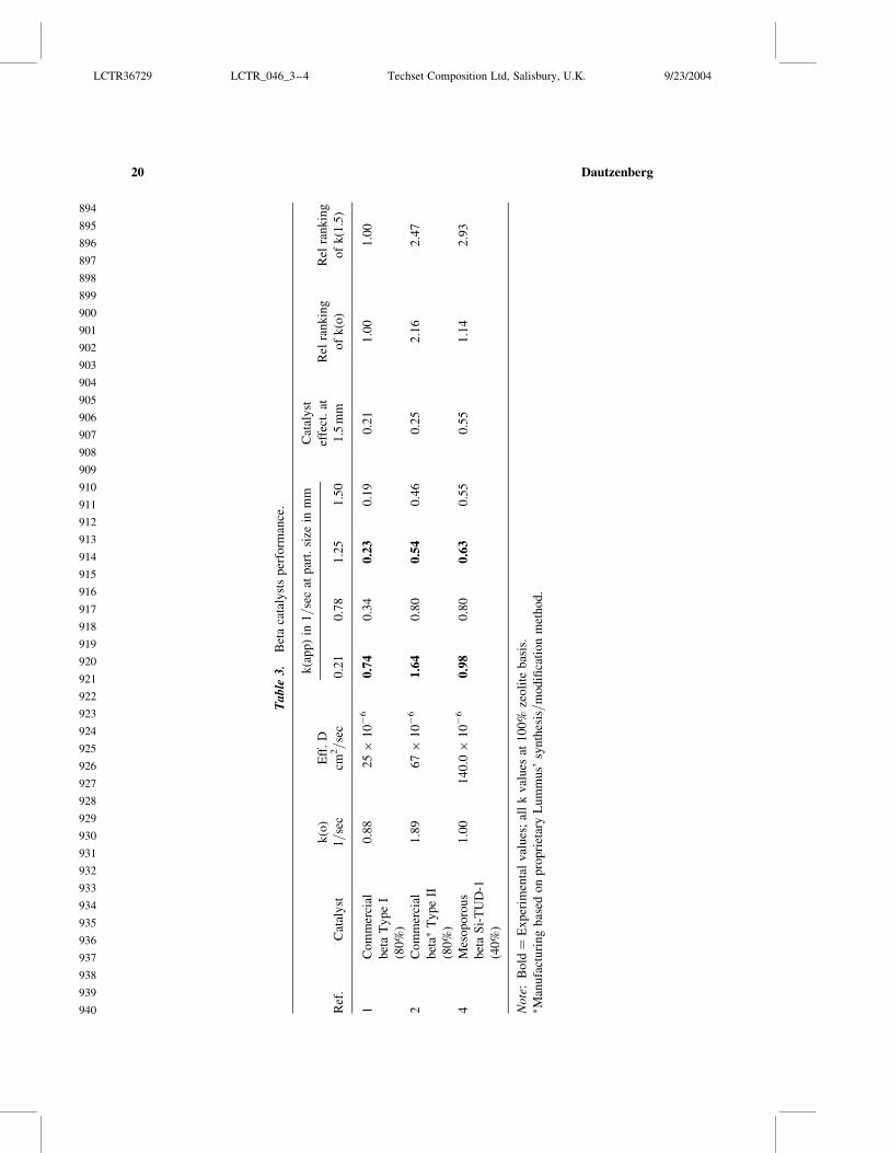

Fig
ure
16
R
elat
ive
ran
kin
go
fze
oli
teb
eta
cata
lyst
su
sin
gE
Bp
rob
ere
acti
on
LCTR36729 LCTR_046_3ndash4 Techset Composition Ltd Salisbury UK 9232004
988
989
990
991
992
993
994
995
996
997
998
999
1000
1001
1002
1003
1004
1005
1006
1007
1008
1009
1010
1011
1012
1013
1014
1015
1016
1017
1018
1019
1020
1021
1022
1023
1024
1025
1026
1027
1028
1029
1030
1031
1032
1033
1034
Dautzenberg22
Fig 18 where intra-reactor reheat is employed in stages The new design known as
SMART (Styrene Monomer Advanced Reheat Technology) has already been successfully
commercialized in five plants
Catalytic Partial Oxidation of Methane (CPO)
The intra-reactor reheat principle can also be applied to the production of syngas
(COH2) from methane It is well known that conventional steam reforming of methane
is highly endothermic During CPO methane is dissociatively absorbed on the catalyst
producing hydrogen and a carbonaceous residue This residue is converted into CO and
H2O by oxidation and this reaction generates energy (exothermic) driving the endother-
mic steam reforming reaction that is happening in parallel With an optimized catalyst
ldquocokelessrdquo steam reforming appears to be feasible As a preferred reactor configuration
a reactor concept called ldquoComposite Structured Packingrdquo (CSP) is proposed ideally
suited for high superficial gas velocities as envisioned for CPO
Several noble-metal-containing catalysts have been proposed for CPO Figure 19
compares the temperature-programmed oxidation of Rh Ni and Ni-B upon exposure to
methane decomposition With Rh the resulting carbon residues are removed at relatively
Figure 17 Catalytic cycle for Styrene Monomer Advanced Reheat Technology (SMART)
LCTR36729 LCTR_046_3ndash4 Techset Composition Ltd Salisbury UK 9232004
1035
1036
1037
1038
1039
1040
1041
1042
1043
1044
1045
1046
1047
1048
1049
1050
1051
1052
1053
1054
1055
1056
1057
1058
1059
1060
1061
1062
1063
1064
1065
1066
1067
1068
1069
1070
1071
1072
1073
1074
1075
1076
1077
1078
1079
1080
1081
Catalyst Synthesis and Multifunctional Reactor Concepts 23
low temperature This is not the case with Ni Upon exposure to CH4 graphitic carbon is
deposited upon the Ni catalyst and this can be removed only at high temperature With a
catalyst based on an alloy of Ni and B most of the carbon is removed at a substantially
lower temperature while the amount of carbon needed to be removed at high temperature
is significantly reduced
Figure 20 shows the CPO performance of one of the novel Ni-B catalysts developed
during a collaborative project with the National University of Singapore[18] Note that the
product composition is essentially at equilibrium even at the extremely high space velo-
city applied during the testing In Fig 21 the ldquomethane conversionrdquo versus ldquotime
onstreamrdquo shows that the catalyst is unusually stable no initial deactivation period
occurs consistent with its noncoking behavior Another important benefit of the new
CPO catalyst is the close approach to thermal neutrality thus simplifying heat manage-
ment and improving thermal efficiency This feature is important if one wants to design
ultra-compact hydrogen generators
Catalytic Distillation
As the name implies catalytic distillation (CD)[19 ndash 22] intimately integrates catalytic
reaction and product separation by distillation CD is well suited for processes where the
feed and the product have a significantly different boiling range thereby facilitating
separation and many times enhancing selectivity by applying relatively low reaction temp-
eratures The heat of reaction is used for separation and therefore facilitates heat mana-
gement The predominantly liquid phase also aids catalyst stability Figure 22 illustrates
Figure 18 New reactor system of Styrene Monomer Advanced Reheat Technology (SMART)
LCTR36729 LCTR_046_3ndash4 Techset Composition Ltd Salisbury UK 9232004
1082
1083
1084
1085
1086
1087
1088
1089
1090
1091
1092
1093
1094
1095
1096
1097
1098
1099
1100
1101
1102
1103
1104
1105
1106
1107
1108
1109
1110
1111
1112
1113
1114
1115
1116
1117
1118
1119
1120
1121
1122
1123
1124
1125
1126
1127
1128
Dautzenberg24
one typical application of a CD technology the CDHydrow process for the selective
hydrogenation of benzene in reformate fractions The family of CD technologies has
grown quite extensively and today the number of commercially licensed units is about
150 Table 4 shows some of the CD applications that have been commercialized
One of the major petrochemical processesmdashsteam cracking for the production of
ethylenemdashis often perceived to be strictly thermal in nature However much of the down-
stream separation processes which are both energy and capital intensive can benefit from
catalytic advances In the production of ethylene and propylene through pyrolysis of
various feedstocks several undesirable by-products (eg dienes and acetylenes) are
Figure 19 TPO profiles of carburized CPO catalysts
LCTR36729 LCTR_046_3ndash4 Techset Composition Ltd Salisbury UK 9232004
1129
1130
1131
1132
1133
1134
1135
1136
1137
1138
1139
1140
1141
1142
1143
1144
1145
1146
1147
1148
1149
1150
1151
1152
1153
1154
1155
1156
1157
1158
1159
1160
1161
1162
1163
1164
1165
1166
1167
1168
1169
1170
1171
1172
1173
1174
1175
Catalyst Synthesis and Multifunctional Reactor Concepts 25
Fig
ure
20
T
yp
ical
cata
lyti
cp
arti
alo
xid
atio
nre
sult
s
LCTR36729 LCTR_046_3ndash4 Techset Composition Ltd Salisbury UK 9232004
1176
1177
1178
1179
1180
1181
1182
1183
1184
1185
1186
1187
1188
1189
1190
1191
1192
1193
1194
1195
1196
1197
1198
1199
1200
1201
1202
1203
1204
1205
1206
1207
1208
1209
1210
1211
1212
1213
1214
1215
1216
1217
1218
1219
1220
1221
1222
Dautzenberg26
created As such further processing is required for the separation and removal of the
dienesacetylenes from the primary olefin products Dictated by process economics
most of the C2 and heavier dienesacetylenes must be handled through a combination
of separation and hydrogenation since separation alone would result in excessive loss of
the olefin product
Currently the distillation and hydrogenation take place in several distinct process
steps designed to separate and hydrogenate the C2C3 and C4 compounds independently
(Fig 23) A disadvantage of this widely practiced conventional technology is the large
energy consumption required to generate the high pressures and cryogenic temperatures
to first separate and subsequently remove hydrogen from the cracked gas Additionally
the chemistry of each hydrogenation step (eg C2C3 etc) requires an independent
reactor system thereby driving up the plantrsquos capital cost and complexity
To offset these disadvantages the ldquoFront-End CDHydrordquo process (Fig 24) was devel-
oped as a one-step conversion of all C2ndashC5 and even heavier dienesacetylenes without
hydrogenation of the desired C2C3 olefins[2324] The objective is to Q3simultaneously
(a) consume dilute hydrogen through the elimination of undesirable dienes and acetylenes
thereby reducing refrigeration and compression cost and (b) combine reaction and separa-
tion into one step This new process greatly reduces the unit equipment ldquopiece countrdquo
by eliminating the separate hydrogenation reactors of the C2ndashC4 streams The heat of
Figure 21 CPO combined with steam reforming
LCTR36729 LCTR_046_3ndash4 Techset Composition Ltd Salisbury UK 9232004
1223
1224
1225
1226
1227
1228
1229
1230
1231
1232
1233
1234
1235
1236
1237
1238
1239
1240
1241
1242
1243
1244
1245
1246
1247
1248
1249
1250
1251
1252
1253
1254
1255
1256
1257
1258
1259
1260
1261
1262
1263
1264
1265
1266
1267
1268
1269
Catalyst Synthesis and Multifunctional Reactor Concepts 27
Fig
ure
22
N
ewC
DT
EC
Hb
enze
ne
hy
dro
gen
atio
nte
chn
olo
gy
LCTR36729 LCTR_046_3ndash4 Techset Composition Ltd Salisbury UK 9232004
1270
1271
1272
1273
1274
1275
1276
1277
1278
1279
1280
1281
1282
1283
1284
1285
1286
1287
1288
1289
1290
1291
1292
1293
1294
1295
1296
1297
1298
1299
1300
1301
1302
1303
1304
1305
1306
1307
1308
1309
1310
1311
1312
1313
1314
1315
1316
Dautzenberg28
reaction in the catalytic distillation reactor is used for separation and therefore improves
overall heat management In contrast to conventional fixed bed reactor systems where
dimers and oligomers accumulate and cause catalyst fouling the CD reactor ensures
that these undesirable components are removed by fractionation As a result this
process achieves prolonged catalyst life
The advancements achieved with the ldquoFront End CDHydrordquo process integrated with
several other Lummus innovations represent one of the most significant breakthroughs in
ethylene technology over the past 25 years
CONCLUSIONS
In reviewing the results presented in this paper the following conclusions have been
formulated
The catalyst synthesis examples described in this paper demonstrate that tailoring
the pore architecture of catalysts has several benefits Higher overall reaction rates
and yields can be obtained and in certain cases catalyst stability is also improved
by reducing the formation of catalyst deactivating precursors
The ldquoDrySynrdquo synthesis procedure can be optimized to make zeolite catalysts with
ultra-small crystallites This may benefit the development of catalysts with high
intrinsic activity The synthesis is very effective if mesoporous supports are used
to achieve a high degree of utilization
Inserting Y as well as beta in TUD-1 materials increases catalyst activity for aro-
matics alkylation to levels that have not been achieved with conventional zeolite
catalysts The open three-dimensional pore structure of TUD-1 is a key contributor
to this achievement It is expected that similar performance improvements will be
realized for other reactions that are commercially practiced at conditions imposing
mass transfer limitations
The intra-reactor reheat concept as practiced in SMART should in principle be
applicable to other strongly endothermic dehydrogenation reactions Applied at
the catalyst level as shown in the CPO example it is speculated that intra-
reactor reheat can be used for in-situ catalyst regeneration during operation
Catalytic distillation is a prime example of what can be achieved by process inten-
sification Although the technology has already been applied commercially for
Table 4 Commercial CD applications
dagger Etherification (MTBE TAME and ETBE)
dagger Aromatics alkylation (EB and cumene)
dagger Benzene removal from reformate
dagger Selective desulfurization
dagger Various selective hydrogenations
Demonstration plant at Tianjin China Front-end CDHydrow for
ethylene plants (2003)
LCTR36729 LCTR_046_3ndash4 Techset Composition Ltd Salisbury UK 9232004
1317
1318
1319
1320
1321
1322
1323
1324
1325
1326
1327
1328
1329
1330
1331
1332
1333
1334
1335
1336
1337
1338
1339
1340
1341
1342
1343
1344
1345
1346
1347
1348
1349
1350
1351
1352
1353
1354
1355
1356
1357
1358
1359
1360
1361
1362
1363
Catalyst Synthesis and Multifunctional Reactor Concepts 29
Fig
ure
23
C
on
ven
tio
nal
ole
fin
sp
uri
fica
tio
nte
chn
olo
gy
LCTR36729 LCTR_046_3ndash4 Techset Composition Ltd Salisbury UK 9232004
1364
1365
1366
1367
1368
1369
1370
1371
1372
1373
1374
1375
1376
1377
1378
1379
1380
1381
1382
1383
1384
1385
1386
1387
1388
1389
1390
1391
1392
1393
1394
1395
1396
1397
1398
1399
1400
1401
1402
1403
1404
1405
1406
1407
1408
1409
1410
Dautzenberg30
Fig
ure
24
F
ron
t-en
dC
DH
yd
row
tech
no
log
yfo
ro
lefi
ns
pu
rifi
cati
on
LCTR36729 LCTR_046_3ndash4 Techset Composition Ltd Salisbury UK 9232004
1411
1412
1413
1414
1415
1416
1417
1418
1419
1420
1421
1422
1423
1424
1425
1426
1427
1428
1429
1430
1431
1432
1433
1434
1435
1436
1437
1438
1439
1440
1441
1442
1443
1444
1445
1446
1447
1448
1449
1450
1451
1452
1453
1454
1455
1456
1457
Catalyst Synthesis and Multifunctional Reactor Concepts 31
various processes it is expected that the family will keep growing Tailoring of
existing catalysts may be required to allow operation in the liquid phase at
boiling conditions
The multifunctional reactor examples show that by applying intra-reactor intensi-
fication mature high-volume petrochemical processes can be improved As illus-
trated in the CPO example intra-reactor heat transfer can be applied beneficially
in the development of emerging technologies
To achieve optimum success more multidisciplinary teams are needed to address the
current and future needs of the process industry The teams should contain catalyst syn-
thesis experts as well as knowledgeable reaction engineers Furthermore it is recommend-
able to encourage industryndashuniversity collaborations This can be very synergistic
because the participants can extend and reinforce each otherrsquos efforts taking full advan-
tage of their complementary capabilities
REFERENCES
1 Dautzenberg FM Quality principles for catalyst testing during process development
Combinatorial Catalysis and High Throughput Catalyst Design and Testing Confer-
ence Vilamoura Quarteira (Algarve) Portugal July 19ndash24 1999 NATO Advanced
Study Institute
2 Trubac RE Dautzenberg FM Griffin TA Paikert B Schmidt VR
Overbeek RA Micro-engineered catalyst systems ABBrsquos advancement in struc-
tured catalytic packings Catalysis Today 2001 69 17ndash24
3 Carlborg JA Chang Y-F Murrell LL Trubac RE Overbeek RA
Schmidt VR Yeh CY Schuh L Conversion of Nitrogen Oxides in the Presence
of a Catalyst Supported on a Mesh-like Structure US Patent 6534022 March 18
2003 (assigned to ABB Lummus Global Inc)
4 First International Conference on Structured Catalysts and Reactors Delft The
Netherlands October 21ndash24 2001
5 Murrell LL Overbeek RA Chang Y-F van der Puil N Yeh CY Method of
Making Molecular Sieves and Novel Molecular Sieve Components US 6350429
2002 (assigned to ABB Lummus Global Inc)
6 Dautzenberg FM Angevine PJ Trubac RE Maschmeyer Th Tailoring Indus-
trial Catalyst to Minimize Mass Transfer Limitations 8th International Symposium
Scientific Bases for the Preparation of Heterogeneous Catalysts Louvain-la-Neuve
Belgium September 9ndash12 2002
7 Dautzenberg FM Mukherjee M Process Intensification Using Multifunctional
Reactors 16th International Symposium on Chemical Reaction Engineering
Krakow Poland September 10 2000
8 Beck JS Method for Synthesizing Mesoporous Crystalline Material US Patent
5057296 October 15 1991 (assigned to Mobil Oil Corp)
9 Kresge CT Leonowicz ME Roth WJ Vartuli JC Synthetic Mesoporous Crys-
talline Material US Patent 5098684 March 24 1992 (assigned to Mobil Oil Corp)
LCTR36729 LCTR_046_3ndash4 Techset Composition Ltd Salisbury UK 9232004
1458
1459
1460
1461
1462
1463
1464
1465
1466
1467
1468
1469
1470
1471
1472
1473
1474
1475
1476
1477
1478
1479
1480
1481
1482
1483
1484
1485
1486
1487
1488
1489
1490
1491
1492
1493
1494
1495
1496
1497
1498
1499
1500
1501
1502
1503
1504
Dautzenberg32
10 Kresge CT Leonowicz ME Roth WJ Vartuli JC Composition of Synthetic
Crystalline Material Its Synthesis US Patent 5102643 April 7 1992 (assigned to
Mobil Oil Corp)
11 Shan Z Maschmeyer Th Jansen JC Inorganic Oxides with Mesoporosity or
Combined Meso- and Microporosity and Process for the Preparation Thereof US
Patent 6358486 2002 (assigned to ABB Lummus Global Inc)
12 Jansen JC Shan Z Marchese L Zhou W van der Puil N Maschmeyer Th A
New Templating Method for Three-Dimensional Mesopore Networks Chem
Commun 2001 713ndash714
13 Shan Z Gianotti E Jansen JC Peters JA Marchese L Maschmeyer Th One-
Step Synthesis of a Highly Active Mesoporous Titanium-Containing Silica by Using
Bifunctional Templating Chem Eur J 2001 7 (7) 1437ndash1443
14 Shan Z Jansen JC Marchese L Maschmeyer Th Synthesis Characterization
and Catalytic Testing of a 3-D Mesoporous Titanosilica Ti-TUD-1 Micro Meso
Mater 2001 48 (1ndash3) 181ndash187
15 Shan Z Jansen JC Yeh CY Koegler JH Maschmeyer Th Catalyst Contain-
ing Microporous Zeolite in Mesoporous Support and Method for Making Same US
Patent Application 20020074263 2002 (assigned to ABB Lummus Global Inc)
16 Shan Z Jansen JC Yeh CY Koegler JH Maschmeyer Th Catalyst Contain-
ing Microporous Zeolite in Mesoporous Support and Method for Making Same WO
03045548 2003-06-05 (assigned to ABB Lummus Global Inc)
17 Dautzenberg FM Hydro-and Dehydrogenation of Large Volume Petrochemicals
Paper presented at the 10th Roermond Conference on Catalysis Rolduc-Kerkrade
The Netherlands June 30ndashJuly 5 2002
18 Dautzenberg FM Encouraging Innovation in Catalysis Paper presented at the 3rd
Asia-Pacific Congress on Catalysis Dalian China October 12ndash15 2003
19 Smith LA Jr Catalytic Distillation Structure US Patent 4443559 April 17 1984
(assigned to Chemical Research amp Licensing Company)
20 Sy A Smith L Chen J Dautzenberg FM Catalytic Distillation Route for
Cumene DeWitt Petrochemical Review Houston Texas March 23 1993
21 Rock K Gilbert GR McGuirk T Catalytic distillation extend its reach Chemical
Engineering 1997 78 78ndash84
22 Hearn D Putman HM Hydrodesulfurization Process Utilizing a Distillation
Column Reactor US Patent 5779883 March 17 1998 (assigned to Catalytic Distil-
lation Technologies)
23 Stanley SJ McCarthy FM Sumner C Gildert GR Olefin Plant Recovery
System Employing Catalytic Distillation US Patent 5679241 May 17 1995
(assigned to ABB Lummus Global Inc and Chemical Research amp Licensing
Company)
LCTR36729 LCTR_046_3ndash4 Techset Composition Ltd Salisbury UK 9232004
1505
1506
1507
1508
1509
1510
1511
1512
1513
1514
1515
1516
1517
1518
1519
1520
1521
1522
1523
1524
1525
1526
1527
1528
1529
1530
1531
1532
1533
1534
1535
1536
1537
1538
1539
1540
1541
1542
1543
1544
1545
1546
1547
1548
1549
1550
1551
Catalyst Synthesis and Multifunctional Reactor Concepts 33
Author QueriesJOURNAL LCTR
MANUSCRIPT 200036729
AQ Please check the right-hand running head provided is ok
Q1 Please provide street zipcode E-mail id and fax for corresponding author
Q2 Please supply abstract and keywords
Q3 Reference [24] is not present in the list Please add to the list
LCTR36729 LCTR_046_3ndash4 Techset Composition Ltd Salisbury UK 9232004
1552
1553
1554
1555
1556
1557
1558
1559
1560
1561
1562
1563
1564
1565
1566
1567
1568
1569
1570
1571
1572
1573
1574
1575
1576
1577
1578
1579
1580
1581
1582
1583
1584
1585
1586
1587
1588
1589
1590
1591
1592
1593
1594
1595
1596
1597
1598
Dautzenberg34

Fig
ure
20
T
yp
ical
cata
lyti
cp
arti
alo
xid
atio
nre
sult
s
LCTR36729 LCTR_046_3ndash4 Techset Composition Ltd Salisbury UK 9232004
1176
1177
1178
1179
1180
1181
1182
1183
1184
1185
1186
1187
1188
1189
1190
1191
1192
1193
1194
1195
1196
1197
1198
1199
1200
1201
1202
1203
1204
1205
1206
1207
1208
1209
1210
1211
1212
1213
1214
1215
1216
1217
1218
1219
1220
1221
1222
Dautzenberg26
created As such further processing is required for the separation and removal of the
dienesacetylenes from the primary olefin products Dictated by process economics
most of the C2 and heavier dienesacetylenes must be handled through a combination
of separation and hydrogenation since separation alone would result in excessive loss of
the olefin product
Currently the distillation and hydrogenation take place in several distinct process
steps designed to separate and hydrogenate the C2C3 and C4 compounds independently
(Fig 23) A disadvantage of this widely practiced conventional technology is the large
energy consumption required to generate the high pressures and cryogenic temperatures
to first separate and subsequently remove hydrogen from the cracked gas Additionally
the chemistry of each hydrogenation step (eg C2C3 etc) requires an independent
reactor system thereby driving up the plantrsquos capital cost and complexity
To offset these disadvantages the ldquoFront-End CDHydrordquo process (Fig 24) was devel-
oped as a one-step conversion of all C2ndashC5 and even heavier dienesacetylenes without
hydrogenation of the desired C2C3 olefins[2324] The objective is to Q3simultaneously
(a) consume dilute hydrogen through the elimination of undesirable dienes and acetylenes
thereby reducing refrigeration and compression cost and (b) combine reaction and separa-
tion into one step This new process greatly reduces the unit equipment ldquopiece countrdquo
by eliminating the separate hydrogenation reactors of the C2ndashC4 streams The heat of
Figure 21 CPO combined with steam reforming
LCTR36729 LCTR_046_3ndash4 Techset Composition Ltd Salisbury UK 9232004
1223
1224
1225
1226
1227
1228
1229
1230
1231
1232
1233
1234
1235
1236
1237
1238
1239
1240
1241
1242
1243
1244
1245
1246
1247
1248
1249
1250
1251
1252
1253
1254
1255
1256
1257
1258
1259
1260
1261
1262
1263
1264
1265
1266
1267
1268
1269
Catalyst Synthesis and Multifunctional Reactor Concepts 27
Fig
ure
22
N
ewC
DT
EC
Hb
enze
ne
hy
dro
gen
atio
nte
chn
olo
gy
LCTR36729 LCTR_046_3ndash4 Techset Composition Ltd Salisbury UK 9232004
1270
1271
1272
1273
1274
1275
1276
1277
1278
1279
1280
1281
1282
1283
1284
1285
1286
1287
1288
1289
1290
1291
1292
1293
1294
1295
1296
1297
1298
1299
1300
1301
1302
1303
1304
1305
1306
1307
1308
1309
1310
1311
1312
1313
1314
1315
1316
Dautzenberg28
reaction in the catalytic distillation reactor is used for separation and therefore improves
overall heat management In contrast to conventional fixed bed reactor systems where
dimers and oligomers accumulate and cause catalyst fouling the CD reactor ensures
that these undesirable components are removed by fractionation As a result this
process achieves prolonged catalyst life
The advancements achieved with the ldquoFront End CDHydrordquo process integrated with
several other Lummus innovations represent one of the most significant breakthroughs in
ethylene technology over the past 25 years
CONCLUSIONS
In reviewing the results presented in this paper the following conclusions have been
formulated
The catalyst synthesis examples described in this paper demonstrate that tailoring
the pore architecture of catalysts has several benefits Higher overall reaction rates
and yields can be obtained and in certain cases catalyst stability is also improved
by reducing the formation of catalyst deactivating precursors
The ldquoDrySynrdquo synthesis procedure can be optimized to make zeolite catalysts with
ultra-small crystallites This may benefit the development of catalysts with high
intrinsic activity The synthesis is very effective if mesoporous supports are used
to achieve a high degree of utilization
Inserting Y as well as beta in TUD-1 materials increases catalyst activity for aro-
matics alkylation to levels that have not been achieved with conventional zeolite
catalysts The open three-dimensional pore structure of TUD-1 is a key contributor
to this achievement It is expected that similar performance improvements will be
realized for other reactions that are commercially practiced at conditions imposing
mass transfer limitations
The intra-reactor reheat concept as practiced in SMART should in principle be
applicable to other strongly endothermic dehydrogenation reactions Applied at
the catalyst level as shown in the CPO example it is speculated that intra-
reactor reheat can be used for in-situ catalyst regeneration during operation
Catalytic distillation is a prime example of what can be achieved by process inten-
sification Although the technology has already been applied commercially for
Table 4 Commercial CD applications
dagger Etherification (MTBE TAME and ETBE)
dagger Aromatics alkylation (EB and cumene)
dagger Benzene removal from reformate
dagger Selective desulfurization
dagger Various selective hydrogenations
Demonstration plant at Tianjin China Front-end CDHydrow for
ethylene plants (2003)
LCTR36729 LCTR_046_3ndash4 Techset Composition Ltd Salisbury UK 9232004
1317
1318
1319
1320
1321
1322
1323
1324
1325
1326
1327
1328
1329
1330
1331
1332
1333
1334
1335
1336
1337
1338
1339
1340
1341
1342
1343
1344
1345
1346
1347
1348
1349
1350
1351
1352
1353
1354
1355
1356
1357
1358
1359
1360
1361
1362
1363
Catalyst Synthesis and Multifunctional Reactor Concepts 29
Fig
ure
23
C
on
ven
tio
nal
ole
fin
sp
uri
fica
tio
nte
chn
olo
gy
LCTR36729 LCTR_046_3ndash4 Techset Composition Ltd Salisbury UK 9232004
1364
1365
1366
1367
1368
1369
1370
1371
1372
1373
1374
1375
1376
1377
1378
1379
1380
1381
1382
1383
1384
1385
1386
1387
1388
1389
1390
1391
1392
1393
1394
1395
1396
1397
1398
1399
1400
1401
1402
1403
1404
1405
1406
1407
1408
1409
1410
Dautzenberg30
Fig
ure
24
F
ron
t-en
dC
DH
yd
row
tech
no
log
yfo
ro
lefi
ns
pu
rifi
cati
on
LCTR36729 LCTR_046_3ndash4 Techset Composition Ltd Salisbury UK 9232004
1411
1412
1413
1414
1415
1416
1417
1418
1419
1420
1421
1422
1423
1424
1425
1426
1427
1428
1429
1430
1431
1432
1433
1434
1435
1436
1437
1438
1439
1440
1441
1442
1443
1444
1445
1446
1447
1448
1449
1450
1451
1452
1453
1454
1455
1456
1457
Catalyst Synthesis and Multifunctional Reactor Concepts 31
various processes it is expected that the family will keep growing Tailoring of
existing catalysts may be required to allow operation in the liquid phase at
boiling conditions
The multifunctional reactor examples show that by applying intra-reactor intensi-
fication mature high-volume petrochemical processes can be improved As illus-
trated in the CPO example intra-reactor heat transfer can be applied beneficially
in the development of emerging technologies
To achieve optimum success more multidisciplinary teams are needed to address the
current and future needs of the process industry The teams should contain catalyst syn-
thesis experts as well as knowledgeable reaction engineers Furthermore it is recommend-
able to encourage industryndashuniversity collaborations This can be very synergistic
because the participants can extend and reinforce each otherrsquos efforts taking full advan-
tage of their complementary capabilities
REFERENCES
1 Dautzenberg FM Quality principles for catalyst testing during process development
Combinatorial Catalysis and High Throughput Catalyst Design and Testing Confer-
ence Vilamoura Quarteira (Algarve) Portugal July 19ndash24 1999 NATO Advanced
Study Institute
2 Trubac RE Dautzenberg FM Griffin TA Paikert B Schmidt VR
Overbeek RA Micro-engineered catalyst systems ABBrsquos advancement in struc-
tured catalytic packings Catalysis Today 2001 69 17ndash24
3 Carlborg JA Chang Y-F Murrell LL Trubac RE Overbeek RA
Schmidt VR Yeh CY Schuh L Conversion of Nitrogen Oxides in the Presence
of a Catalyst Supported on a Mesh-like Structure US Patent 6534022 March 18
2003 (assigned to ABB Lummus Global Inc)
4 First International Conference on Structured Catalysts and Reactors Delft The
Netherlands October 21ndash24 2001
5 Murrell LL Overbeek RA Chang Y-F van der Puil N Yeh CY Method of
Making Molecular Sieves and Novel Molecular Sieve Components US 6350429
2002 (assigned to ABB Lummus Global Inc)
6 Dautzenberg FM Angevine PJ Trubac RE Maschmeyer Th Tailoring Indus-
trial Catalyst to Minimize Mass Transfer Limitations 8th International Symposium
Scientific Bases for the Preparation of Heterogeneous Catalysts Louvain-la-Neuve
Belgium September 9ndash12 2002
7 Dautzenberg FM Mukherjee M Process Intensification Using Multifunctional
Reactors 16th International Symposium on Chemical Reaction Engineering
Krakow Poland September 10 2000
8 Beck JS Method for Synthesizing Mesoporous Crystalline Material US Patent
5057296 October 15 1991 (assigned to Mobil Oil Corp)
9 Kresge CT Leonowicz ME Roth WJ Vartuli JC Synthetic Mesoporous Crys-
talline Material US Patent 5098684 March 24 1992 (assigned to Mobil Oil Corp)
LCTR36729 LCTR_046_3ndash4 Techset Composition Ltd Salisbury UK 9232004
1458
1459
1460
1461
1462
1463
1464
1465
1466
1467
1468
1469
1470
1471
1472
1473
1474
1475
1476
1477
1478
1479
1480
1481
1482
1483
1484
1485
1486
1487
1488
1489
1490
1491
1492
1493
1494
1495
1496
1497
1498
1499
1500
1501
1502
1503
1504
Dautzenberg32
10 Kresge CT Leonowicz ME Roth WJ Vartuli JC Composition of Synthetic
Crystalline Material Its Synthesis US Patent 5102643 April 7 1992 (assigned to
Mobil Oil Corp)
11 Shan Z Maschmeyer Th Jansen JC Inorganic Oxides with Mesoporosity or
Combined Meso- and Microporosity and Process for the Preparation Thereof US
Patent 6358486 2002 (assigned to ABB Lummus Global Inc)
12 Jansen JC Shan Z Marchese L Zhou W van der Puil N Maschmeyer Th A
New Templating Method for Three-Dimensional Mesopore Networks Chem
Commun 2001 713ndash714
13 Shan Z Gianotti E Jansen JC Peters JA Marchese L Maschmeyer Th One-
Step Synthesis of a Highly Active Mesoporous Titanium-Containing Silica by Using
Bifunctional Templating Chem Eur J 2001 7 (7) 1437ndash1443
14 Shan Z Jansen JC Marchese L Maschmeyer Th Synthesis Characterization
and Catalytic Testing of a 3-D Mesoporous Titanosilica Ti-TUD-1 Micro Meso
Mater 2001 48 (1ndash3) 181ndash187
15 Shan Z Jansen JC Yeh CY Koegler JH Maschmeyer Th Catalyst Contain-
ing Microporous Zeolite in Mesoporous Support and Method for Making Same US
Patent Application 20020074263 2002 (assigned to ABB Lummus Global Inc)
16 Shan Z Jansen JC Yeh CY Koegler JH Maschmeyer Th Catalyst Contain-
ing Microporous Zeolite in Mesoporous Support and Method for Making Same WO
03045548 2003-06-05 (assigned to ABB Lummus Global Inc)
17 Dautzenberg FM Hydro-and Dehydrogenation of Large Volume Petrochemicals
Paper presented at the 10th Roermond Conference on Catalysis Rolduc-Kerkrade
The Netherlands June 30ndashJuly 5 2002
18 Dautzenberg FM Encouraging Innovation in Catalysis Paper presented at the 3rd
Asia-Pacific Congress on Catalysis Dalian China October 12ndash15 2003
19 Smith LA Jr Catalytic Distillation Structure US Patent 4443559 April 17 1984
(assigned to Chemical Research amp Licensing Company)
20 Sy A Smith L Chen J Dautzenberg FM Catalytic Distillation Route for
Cumene DeWitt Petrochemical Review Houston Texas March 23 1993
21 Rock K Gilbert GR McGuirk T Catalytic distillation extend its reach Chemical
Engineering 1997 78 78ndash84
22 Hearn D Putman HM Hydrodesulfurization Process Utilizing a Distillation
Column Reactor US Patent 5779883 March 17 1998 (assigned to Catalytic Distil-
lation Technologies)
23 Stanley SJ McCarthy FM Sumner C Gildert GR Olefin Plant Recovery
System Employing Catalytic Distillation US Patent 5679241 May 17 1995
(assigned to ABB Lummus Global Inc and Chemical Research amp Licensing
Company)
LCTR36729 LCTR_046_3ndash4 Techset Composition Ltd Salisbury UK 9232004
1505
1506
1507
1508
1509
1510
1511
1512
1513
1514
1515
1516
1517
1518
1519
1520
1521
1522
1523
1524
1525
1526
1527
1528
1529
1530
1531
1532
1533
1534
1535
1536
1537
1538
1539
1540
1541
1542
1543
1544
1545
1546
1547
1548
1549
1550
1551
Catalyst Synthesis and Multifunctional Reactor Concepts 33
Author QueriesJOURNAL LCTR
MANUSCRIPT 200036729
AQ Please check the right-hand running head provided is ok
Q1 Please provide street zipcode E-mail id and fax for corresponding author
Q2 Please supply abstract and keywords
Q3 Reference [24] is not present in the list Please add to the list
LCTR36729 LCTR_046_3ndash4 Techset Composition Ltd Salisbury UK 9232004
1552
1553
1554
1555
1556
1557
1558
1559
1560
1561
1562
1563
1564
1565
1566
1567
1568
1569
1570
1571
1572
1573
1574
1575
1576
1577
1578
1579
1580
1581
1582
1583
1584
1585
1586
1587
1588
1589
1590
1591
1592
1593
1594
1595
1596
1597
1598
Dautzenberg34

Fig
ure
22
N
ewC
DT
EC
Hb
enze
ne
hy
dro
gen
atio
nte
chn
olo
gy
LCTR36729 LCTR_046_3ndash4 Techset Composition Ltd Salisbury UK 9232004
1270
1271
1272
1273
1274
1275
1276
1277
1278
1279
1280
1281
1282
1283
1284
1285
1286
1287
1288
1289
1290
1291
1292
1293
1294
1295
1296
1297
1298
1299
1300
1301
1302
1303
1304
1305
1306
1307
1308
1309
1310
1311
1312
1313
1314
1315
1316
Dautzenberg28
reaction in the catalytic distillation reactor is used for separation and therefore improves
overall heat management In contrast to conventional fixed bed reactor systems where
dimers and oligomers accumulate and cause catalyst fouling the CD reactor ensures
that these undesirable components are removed by fractionation As a result this
process achieves prolonged catalyst life
The advancements achieved with the ldquoFront End CDHydrordquo process integrated with
several other Lummus innovations represent one of the most significant breakthroughs in
ethylene technology over the past 25 years
CONCLUSIONS
In reviewing the results presented in this paper the following conclusions have been
formulated
The catalyst synthesis examples described in this paper demonstrate that tailoring
the pore architecture of catalysts has several benefits Higher overall reaction rates
and yields can be obtained and in certain cases catalyst stability is also improved
by reducing the formation of catalyst deactivating precursors
The ldquoDrySynrdquo synthesis procedure can be optimized to make zeolite catalysts with
ultra-small crystallites This may benefit the development of catalysts with high
intrinsic activity The synthesis is very effective if mesoporous supports are used
to achieve a high degree of utilization
Inserting Y as well as beta in TUD-1 materials increases catalyst activity for aro-
matics alkylation to levels that have not been achieved with conventional zeolite
catalysts The open three-dimensional pore structure of TUD-1 is a key contributor
to this achievement It is expected that similar performance improvements will be
realized for other reactions that are commercially practiced at conditions imposing
mass transfer limitations
The intra-reactor reheat concept as practiced in SMART should in principle be
applicable to other strongly endothermic dehydrogenation reactions Applied at
the catalyst level as shown in the CPO example it is speculated that intra-
reactor reheat can be used for in-situ catalyst regeneration during operation
Catalytic distillation is a prime example of what can be achieved by process inten-
sification Although the technology has already been applied commercially for
Table 4 Commercial CD applications
dagger Etherification (MTBE TAME and ETBE)
dagger Aromatics alkylation (EB and cumene)
dagger Benzene removal from reformate
dagger Selective desulfurization
dagger Various selective hydrogenations
Demonstration plant at Tianjin China Front-end CDHydrow for
ethylene plants (2003)
LCTR36729 LCTR_046_3ndash4 Techset Composition Ltd Salisbury UK 9232004
1317
1318
1319
1320
1321
1322
1323
1324
1325
1326
1327
1328
1329
1330
1331
1332
1333
1334
1335
1336
1337
1338
1339
1340
1341
1342
1343
1344
1345
1346
1347
1348
1349
1350
1351
1352
1353
1354
1355
1356
1357
1358
1359
1360
1361
1362
1363
Catalyst Synthesis and Multifunctional Reactor Concepts 29
Fig
ure
23
C
on
ven
tio
nal
ole
fin
sp
uri
fica
tio
nte
chn
olo
gy
LCTR36729 LCTR_046_3ndash4 Techset Composition Ltd Salisbury UK 9232004
1364
1365
1366
1367
1368
1369
1370
1371
1372
1373
1374
1375
1376
1377
1378
1379
1380
1381
1382
1383
1384
1385
1386
1387
1388
1389
1390
1391
1392
1393
1394
1395
1396
1397
1398
1399
1400
1401
1402
1403
1404
1405
1406
1407
1408
1409
1410
Dautzenberg30
Fig
ure
24
F
ron
t-en
dC
DH
yd
row
tech
no
log
yfo
ro
lefi
ns
pu
rifi
cati
on
LCTR36729 LCTR_046_3ndash4 Techset Composition Ltd Salisbury UK 9232004
1411
1412
1413
1414
1415
1416
1417
1418
1419
1420
1421
1422
1423
1424
1425
1426
1427
1428
1429
1430
1431
1432
1433
1434
1435
1436
1437
1438
1439
1440
1441
1442
1443
1444
1445
1446
1447
1448
1449
1450
1451
1452
1453
1454
1455
1456
1457
Catalyst Synthesis and Multifunctional Reactor Concepts 31
various processes it is expected that the family will keep growing Tailoring of
existing catalysts may be required to allow operation in the liquid phase at
boiling conditions
The multifunctional reactor examples show that by applying intra-reactor intensi-
fication mature high-volume petrochemical processes can be improved As illus-
trated in the CPO example intra-reactor heat transfer can be applied beneficially
in the development of emerging technologies
To achieve optimum success more multidisciplinary teams are needed to address the
current and future needs of the process industry The teams should contain catalyst syn-
thesis experts as well as knowledgeable reaction engineers Furthermore it is recommend-
able to encourage industryndashuniversity collaborations This can be very synergistic
because the participants can extend and reinforce each otherrsquos efforts taking full advan-
tage of their complementary capabilities
REFERENCES
1 Dautzenberg FM Quality principles for catalyst testing during process development
Combinatorial Catalysis and High Throughput Catalyst Design and Testing Confer-
ence Vilamoura Quarteira (Algarve) Portugal July 19ndash24 1999 NATO Advanced
Study Institute
2 Trubac RE Dautzenberg FM Griffin TA Paikert B Schmidt VR
Overbeek RA Micro-engineered catalyst systems ABBrsquos advancement in struc-
tured catalytic packings Catalysis Today 2001 69 17ndash24
3 Carlborg JA Chang Y-F Murrell LL Trubac RE Overbeek RA
Schmidt VR Yeh CY Schuh L Conversion of Nitrogen Oxides in the Presence
of a Catalyst Supported on a Mesh-like Structure US Patent 6534022 March 18
2003 (assigned to ABB Lummus Global Inc)
4 First International Conference on Structured Catalysts and Reactors Delft The
Netherlands October 21ndash24 2001
5 Murrell LL Overbeek RA Chang Y-F van der Puil N Yeh CY Method of
Making Molecular Sieves and Novel Molecular Sieve Components US 6350429
2002 (assigned to ABB Lummus Global Inc)
6 Dautzenberg FM Angevine PJ Trubac RE Maschmeyer Th Tailoring Indus-
trial Catalyst to Minimize Mass Transfer Limitations 8th International Symposium
Scientific Bases for the Preparation of Heterogeneous Catalysts Louvain-la-Neuve
Belgium September 9ndash12 2002
7 Dautzenberg FM Mukherjee M Process Intensification Using Multifunctional
Reactors 16th International Symposium on Chemical Reaction Engineering
Krakow Poland September 10 2000
8 Beck JS Method for Synthesizing Mesoporous Crystalline Material US Patent
5057296 October 15 1991 (assigned to Mobil Oil Corp)
9 Kresge CT Leonowicz ME Roth WJ Vartuli JC Synthetic Mesoporous Crys-
talline Material US Patent 5098684 March 24 1992 (assigned to Mobil Oil Corp)
LCTR36729 LCTR_046_3ndash4 Techset Composition Ltd Salisbury UK 9232004
1458
1459
1460
1461
1462
1463
1464
1465
1466
1467
1468
1469
1470
1471
1472
1473
1474
1475
1476
1477
1478
1479
1480
1481
1482
1483
1484
1485
1486
1487
1488
1489
1490
1491
1492
1493
1494
1495
1496
1497
1498
1499
1500
1501
1502
1503
1504
Dautzenberg32
10 Kresge CT Leonowicz ME Roth WJ Vartuli JC Composition of Synthetic
Crystalline Material Its Synthesis US Patent 5102643 April 7 1992 (assigned to
Mobil Oil Corp)
11 Shan Z Maschmeyer Th Jansen JC Inorganic Oxides with Mesoporosity or
Combined Meso- and Microporosity and Process for the Preparation Thereof US
Patent 6358486 2002 (assigned to ABB Lummus Global Inc)
12 Jansen JC Shan Z Marchese L Zhou W van der Puil N Maschmeyer Th A
New Templating Method for Three-Dimensional Mesopore Networks Chem
Commun 2001 713ndash714
13 Shan Z Gianotti E Jansen JC Peters JA Marchese L Maschmeyer Th One-
Step Synthesis of a Highly Active Mesoporous Titanium-Containing Silica by Using
Bifunctional Templating Chem Eur J 2001 7 (7) 1437ndash1443
14 Shan Z Jansen JC Marchese L Maschmeyer Th Synthesis Characterization
and Catalytic Testing of a 3-D Mesoporous Titanosilica Ti-TUD-1 Micro Meso
Mater 2001 48 (1ndash3) 181ndash187
15 Shan Z Jansen JC Yeh CY Koegler JH Maschmeyer Th Catalyst Contain-
ing Microporous Zeolite in Mesoporous Support and Method for Making Same US
Patent Application 20020074263 2002 (assigned to ABB Lummus Global Inc)
16 Shan Z Jansen JC Yeh CY Koegler JH Maschmeyer Th Catalyst Contain-
ing Microporous Zeolite in Mesoporous Support and Method for Making Same WO
03045548 2003-06-05 (assigned to ABB Lummus Global Inc)
17 Dautzenberg FM Hydro-and Dehydrogenation of Large Volume Petrochemicals
Paper presented at the 10th Roermond Conference on Catalysis Rolduc-Kerkrade
The Netherlands June 30ndashJuly 5 2002
18 Dautzenberg FM Encouraging Innovation in Catalysis Paper presented at the 3rd
Asia-Pacific Congress on Catalysis Dalian China October 12ndash15 2003
19 Smith LA Jr Catalytic Distillation Structure US Patent 4443559 April 17 1984
(assigned to Chemical Research amp Licensing Company)
20 Sy A Smith L Chen J Dautzenberg FM Catalytic Distillation Route for
Cumene DeWitt Petrochemical Review Houston Texas March 23 1993
21 Rock K Gilbert GR McGuirk T Catalytic distillation extend its reach Chemical
Engineering 1997 78 78ndash84
22 Hearn D Putman HM Hydrodesulfurization Process Utilizing a Distillation
Column Reactor US Patent 5779883 March 17 1998 (assigned to Catalytic Distil-
lation Technologies)
23 Stanley SJ McCarthy FM Sumner C Gildert GR Olefin Plant Recovery
System Employing Catalytic Distillation US Patent 5679241 May 17 1995
(assigned to ABB Lummus Global Inc and Chemical Research amp Licensing
Company)
LCTR36729 LCTR_046_3ndash4 Techset Composition Ltd Salisbury UK 9232004
1505
1506
1507
1508
1509
1510
1511
1512
1513
1514
1515
1516
1517
1518
1519
1520
1521
1522
1523
1524
1525
1526
1527
1528
1529
1530
1531
1532
1533
1534
1535
1536
1537
1538
1539
1540
1541
1542
1543
1544
1545
1546
1547
1548
1549
1550
1551
Catalyst Synthesis and Multifunctional Reactor Concepts 33
Author QueriesJOURNAL LCTR
MANUSCRIPT 200036729
AQ Please check the right-hand running head provided is ok
Q1 Please provide street zipcode E-mail id and fax for corresponding author
Q2 Please supply abstract and keywords
Q3 Reference [24] is not present in the list Please add to the list
LCTR36729 LCTR_046_3ndash4 Techset Composition Ltd Salisbury UK 9232004
1552
1553
1554
1555
1556
1557
1558
1559
1560
1561
1562
1563
1564
1565
1566
1567
1568
1569
1570
1571
1572
1573
1574
1575
1576
1577
1578
1579
1580
1581
1582
1583
1584
1585
1586
1587
1588
1589
1590
1591
1592
1593
1594
1595
1596
1597
1598
Dautzenberg34

Fig
ure
24
F
ron
t-en
dC
DH
yd
row
tech
no
log
yfo
ro
lefi
ns
pu
rifi
cati
on
LCTR36729 LCTR_046_3ndash4 Techset Composition Ltd Salisbury UK 9232004
1411
1412
1413
1414
1415
1416
1417
1418
1419
1420
1421
1422
1423
1424
1425
1426
1427
1428
1429
1430
1431
1432
1433
1434
1435
1436
1437
1438
1439
1440
1441
1442
1443
1444
1445
1446
1447
1448
1449
1450
1451
1452
1453
1454
1455
1456
1457
Catalyst Synthesis and Multifunctional Reactor Concepts 31
various processes it is expected that the family will keep growing Tailoring of
existing catalysts may be required to allow operation in the liquid phase at
boiling conditions
The multifunctional reactor examples show that by applying intra-reactor intensi-
fication mature high-volume petrochemical processes can be improved As illus-
trated in the CPO example intra-reactor heat transfer can be applied beneficially
in the development of emerging technologies
To achieve optimum success more multidisciplinary teams are needed to address the
current and future needs of the process industry The teams should contain catalyst syn-
thesis experts as well as knowledgeable reaction engineers Furthermore it is recommend-
able to encourage industryndashuniversity collaborations This can be very synergistic
because the participants can extend and reinforce each otherrsquos efforts taking full advan-
tage of their complementary capabilities
REFERENCES
1 Dautzenberg FM Quality principles for catalyst testing during process development
Combinatorial Catalysis and High Throughput Catalyst Design and Testing Confer-
ence Vilamoura Quarteira (Algarve) Portugal July 19ndash24 1999 NATO Advanced
Study Institute
2 Trubac RE Dautzenberg FM Griffin TA Paikert B Schmidt VR
Overbeek RA Micro-engineered catalyst systems ABBrsquos advancement in struc-
tured catalytic packings Catalysis Today 2001 69 17ndash24
3 Carlborg JA Chang Y-F Murrell LL Trubac RE Overbeek RA
Schmidt VR Yeh CY Schuh L Conversion of Nitrogen Oxides in the Presence
of a Catalyst Supported on a Mesh-like Structure US Patent 6534022 March 18
2003 (assigned to ABB Lummus Global Inc)
4 First International Conference on Structured Catalysts and Reactors Delft The
Netherlands October 21ndash24 2001
5 Murrell LL Overbeek RA Chang Y-F van der Puil N Yeh CY Method of
Making Molecular Sieves and Novel Molecular Sieve Components US 6350429
2002 (assigned to ABB Lummus Global Inc)
6 Dautzenberg FM Angevine PJ Trubac RE Maschmeyer Th Tailoring Indus-
trial Catalyst to Minimize Mass Transfer Limitations 8th International Symposium
Scientific Bases for the Preparation of Heterogeneous Catalysts Louvain-la-Neuve
Belgium September 9ndash12 2002
7 Dautzenberg FM Mukherjee M Process Intensification Using Multifunctional
Reactors 16th International Symposium on Chemical Reaction Engineering
Krakow Poland September 10 2000
8 Beck JS Method for Synthesizing Mesoporous Crystalline Material US Patent
5057296 October 15 1991 (assigned to Mobil Oil Corp)
9 Kresge CT Leonowicz ME Roth WJ Vartuli JC Synthetic Mesoporous Crys-
talline Material US Patent 5098684 March 24 1992 (assigned to Mobil Oil Corp)
LCTR36729 LCTR_046_3ndash4 Techset Composition Ltd Salisbury UK 9232004
1458
1459
1460
1461
1462
1463
1464
1465
1466
1467
1468
1469
1470
1471
1472
1473
1474
1475
1476
1477
1478
1479
1480
1481
1482
1483
1484
1485
1486
1487
1488
1489
1490
1491
1492
1493
1494
1495
1496
1497
1498
1499
1500
1501
1502
1503
1504
Dautzenberg32
10 Kresge CT Leonowicz ME Roth WJ Vartuli JC Composition of Synthetic
Crystalline Material Its Synthesis US Patent 5102643 April 7 1992 (assigned to
Mobil Oil Corp)
11 Shan Z Maschmeyer Th Jansen JC Inorganic Oxides with Mesoporosity or
Combined Meso- and Microporosity and Process for the Preparation Thereof US
Patent 6358486 2002 (assigned to ABB Lummus Global Inc)
12 Jansen JC Shan Z Marchese L Zhou W van der Puil N Maschmeyer Th A
New Templating Method for Three-Dimensional Mesopore Networks Chem
Commun 2001 713ndash714
13 Shan Z Gianotti E Jansen JC Peters JA Marchese L Maschmeyer Th One-
Step Synthesis of a Highly Active Mesoporous Titanium-Containing Silica by Using
Bifunctional Templating Chem Eur J 2001 7 (7) 1437ndash1443
14 Shan Z Jansen JC Marchese L Maschmeyer Th Synthesis Characterization
and Catalytic Testing of a 3-D Mesoporous Titanosilica Ti-TUD-1 Micro Meso
Mater 2001 48 (1ndash3) 181ndash187
15 Shan Z Jansen JC Yeh CY Koegler JH Maschmeyer Th Catalyst Contain-
ing Microporous Zeolite in Mesoporous Support and Method for Making Same US
Patent Application 20020074263 2002 (assigned to ABB Lummus Global Inc)
16 Shan Z Jansen JC Yeh CY Koegler JH Maschmeyer Th Catalyst Contain-
ing Microporous Zeolite in Mesoporous Support and Method for Making Same WO
03045548 2003-06-05 (assigned to ABB Lummus Global Inc)
17 Dautzenberg FM Hydro-and Dehydrogenation of Large Volume Petrochemicals
Paper presented at the 10th Roermond Conference on Catalysis Rolduc-Kerkrade
The Netherlands June 30ndashJuly 5 2002
18 Dautzenberg FM Encouraging Innovation in Catalysis Paper presented at the 3rd
Asia-Pacific Congress on Catalysis Dalian China October 12ndash15 2003
19 Smith LA Jr Catalytic Distillation Structure US Patent 4443559 April 17 1984
(assigned to Chemical Research amp Licensing Company)
20 Sy A Smith L Chen J Dautzenberg FM Catalytic Distillation Route for
Cumene DeWitt Petrochemical Review Houston Texas March 23 1993
21 Rock K Gilbert GR McGuirk T Catalytic distillation extend its reach Chemical
Engineering 1997 78 78ndash84
22 Hearn D Putman HM Hydrodesulfurization Process Utilizing a Distillation
Column Reactor US Patent 5779883 March 17 1998 (assigned to Catalytic Distil-
lation Technologies)
23 Stanley SJ McCarthy FM Sumner C Gildert GR Olefin Plant Recovery
System Employing Catalytic Distillation US Patent 5679241 May 17 1995
(assigned to ABB Lummus Global Inc and Chemical Research amp Licensing
Company)
LCTR36729 LCTR_046_3ndash4 Techset Composition Ltd Salisbury UK 9232004
1505
1506
1507
1508
1509
1510
1511
1512
1513
1514
1515
1516
1517
1518
1519
1520
1521
1522
1523
1524
1525
1526
1527
1528
1529
1530
1531
1532
1533
1534
1535
1536
1537
1538
1539
1540
1541
1542
1543
1544
1545
1546
1547
1548
1549
1550
1551
Catalyst Synthesis and Multifunctional Reactor Concepts 33
Author QueriesJOURNAL LCTR
MANUSCRIPT 200036729
AQ Please check the right-hand running head provided is ok
Q1 Please provide street zipcode E-mail id and fax for corresponding author
Q2 Please supply abstract and keywords
Q3 Reference [24] is not present in the list Please add to the list
LCTR36729 LCTR_046_3ndash4 Techset Composition Ltd Salisbury UK 9232004
1552
1553
1554
1555
1556
1557
1558
1559
1560
1561
1562
1563
1564
1565
1566
1567
1568
1569
1570
1571
1572
1573
1574
1575
1576
1577
1578
1579
1580
1581
1582
1583
1584
1585
1586
1587
1588
1589
1590
1591
1592
1593
1594
1595
1596
1597
1598
Dautzenberg34