neutral grounding resistors - i-gard
TRANSCRIPT
Neutral Grounding ResistorsHow to size and specify
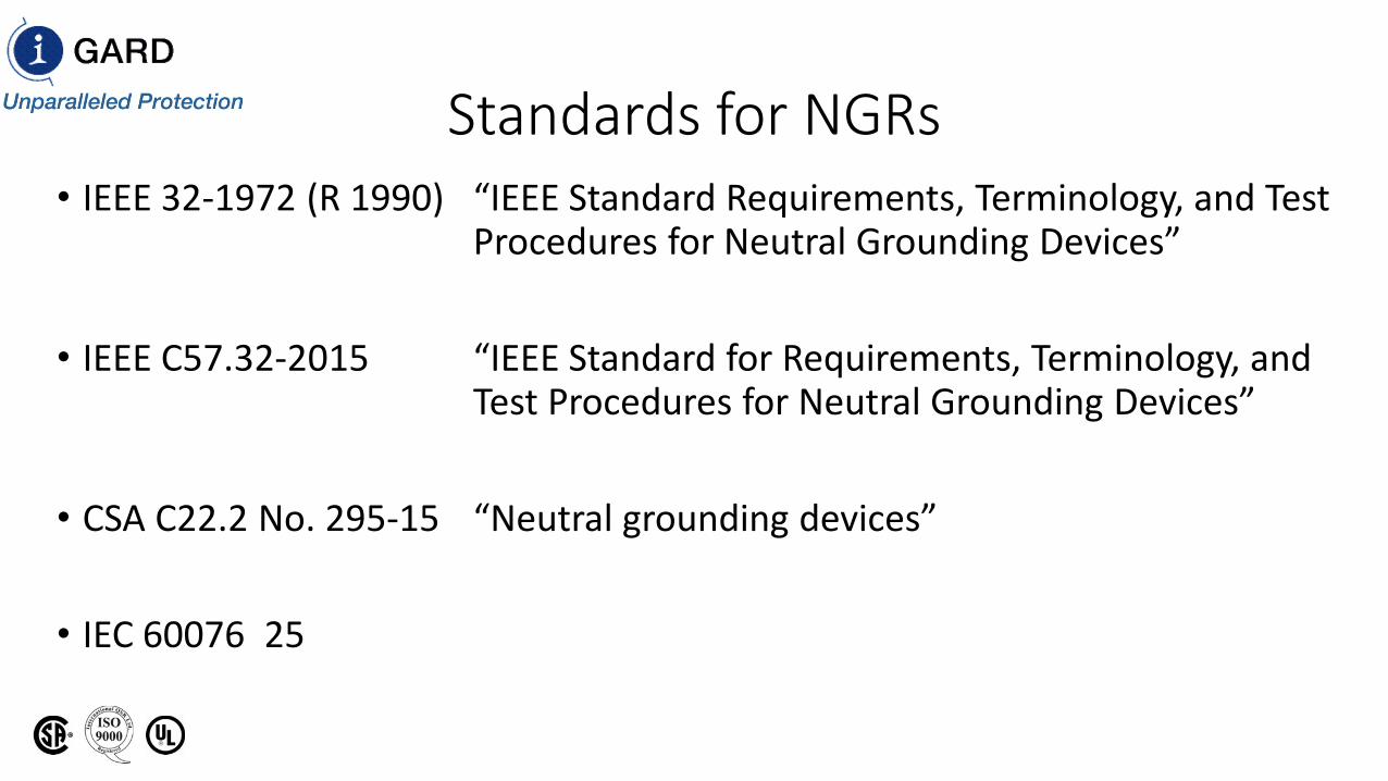
Standards for NGRs• IEEE 32-1972 (R 1990) “IEEE Standard Requirements, Terminology, and Test
Procedures for Neutral Grounding Devices”
• IEEE C57.32-2015 “IEEE Standard for Requirements, Terminology, and Test Procedures for Neutral Grounding Devices”
• CSA C22.2 No. 295-15 “Neutral grounding devices”
• IEC 60076 25
Terminology
• Rated Voltage• Rated Current• Rated Time• Maximum Temperature• Temperature Coefficient of Resistance
Rated Voltage
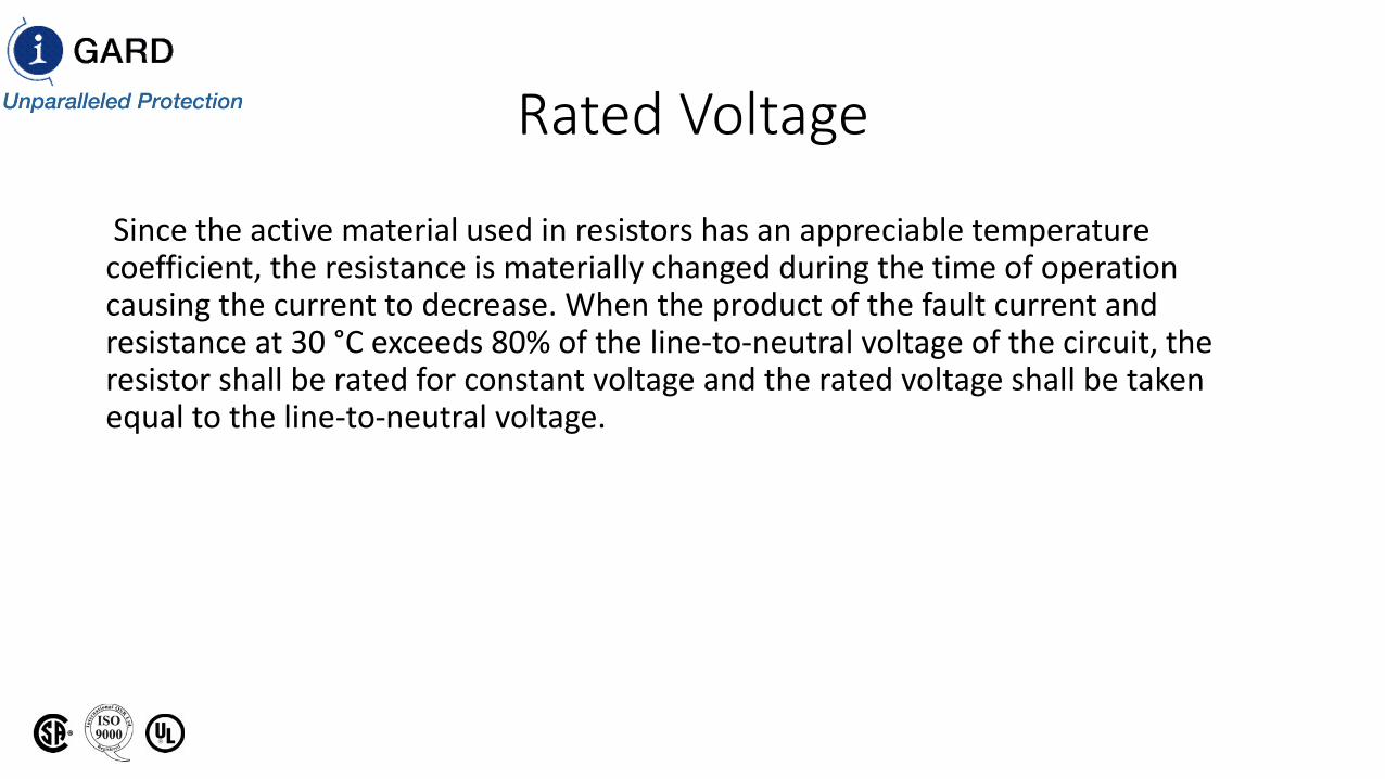
Since the active material used in resistors has an appreciable temperature coefficient, the resistance is materially changed during the time of operation causing the current to decrease. When the product of the fault current and resistance at 30 °C exceeds 80% of the line-to-neutral voltage of the circuit, the resistor shall be rated for constant voltage and the rated voltage shall be taken equal to the line-to-neutral voltage.
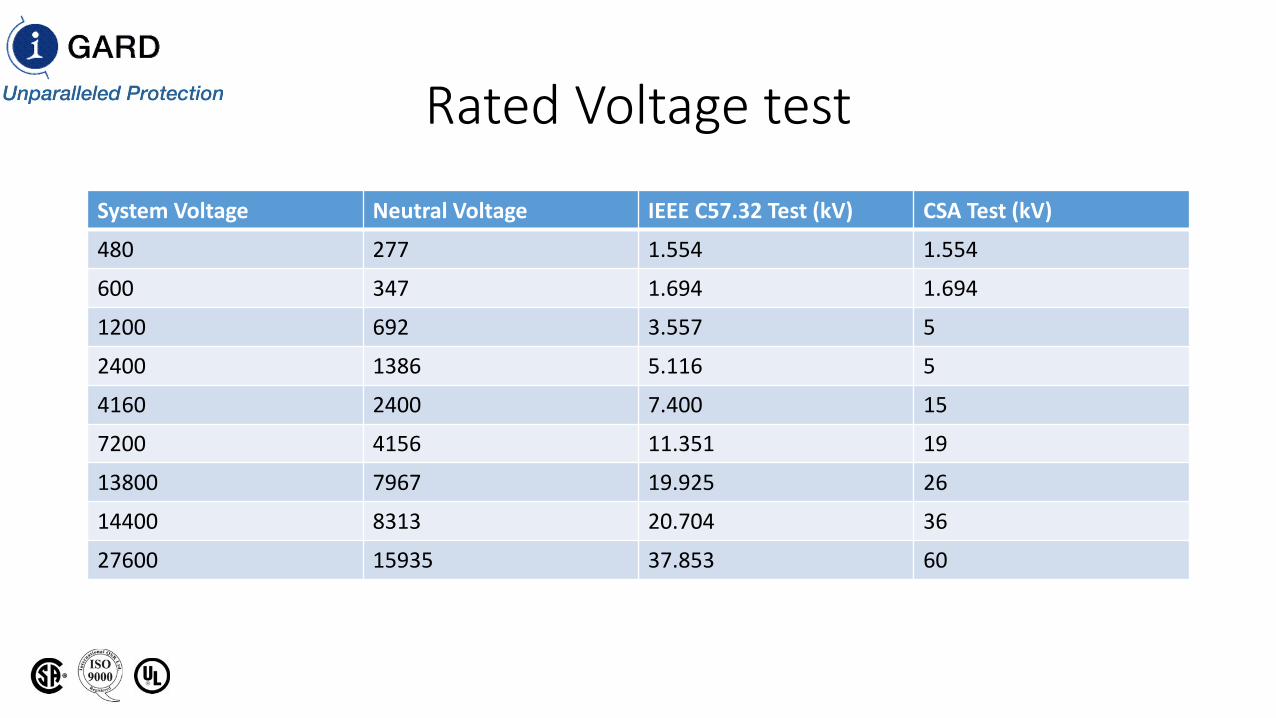
Rated Voltage test
System Voltage Neutral Voltage IEEE C57.32 Test (kV) CSA Test (kV)
480 277 1.554 1.554
600 347 1.694 1.694
1200 692 3.557 5
2400 1386 5.116 5
4160 2400 7.400 15
7200 4156 11.351 19
13800 7967 19.925 26
14400 8313 20.704 36
27600 15935 37.853 60
Rated Current
• The initial current through the resistor.
Rated Time
• Rated time shall be 10 seconds, 1 minute, 10 minutes, extended time, or continuous(steady-state).
• Extended time shall not exceed an average of 90 days per year.
10 s and 1 min. ratings
• The rated-time temperature rise of 10-second and 1-minute devices shall be taken as the sum of the steady-state rise and the additional rise caused by the application of rated voltage for rated time.
Ten-Minute Ratings
• The rated-time temperature rise of 10-minute devices shall be taken as the sum of the steady-state rise, if specified, otherwise 0°C rise if not specified, and the additional rise caused by the application of rated voltage for rated time.
Extended-Time Ratings
• The rated-time temperature rise of extended time devices shall be taken as the temperature rise above ambient resulting from application of rated voltage for rated time.
Steady-State Time Ratings
• The rated temperature rise of a steady-state device shall be taken as the temperature rise above ambient resulting from application of rated voltage for rated time.
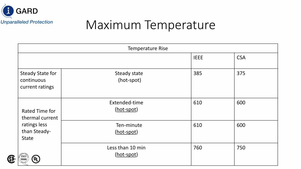
Maximum TemperatureTemperature Rise
IEEE CSA
Steady State for continuous current ratings
Steady state(hot-spot)
385 375
Rated Time forthermal current ratings less than Steady-State
Extended-time(hot-spot)
610 600
Ten-minute(hot-spot)
610 600
Less than 10 min(hot-spot)
760 750
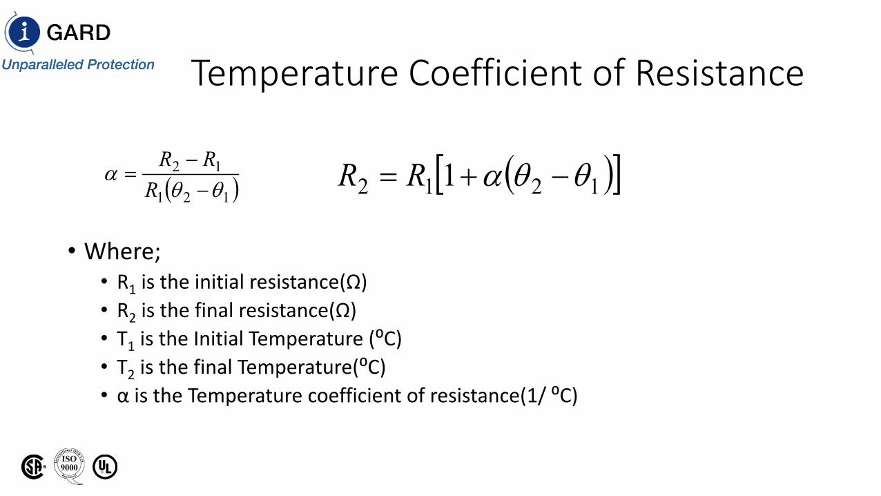
Temperature Coefficient of Resistance
• Where; • R1 is the initial resistance(Ω)• R2 is the final resistance(Ω)• T1 is the Initial Temperature (⁰C)• T2 is the final Temperature(⁰C)• α is the Temperature coefficient of resistance(1/ ⁰C)
( )121
12
θθα
−−
=R
RR ( )[ ]1212 1 θθα −+= RR
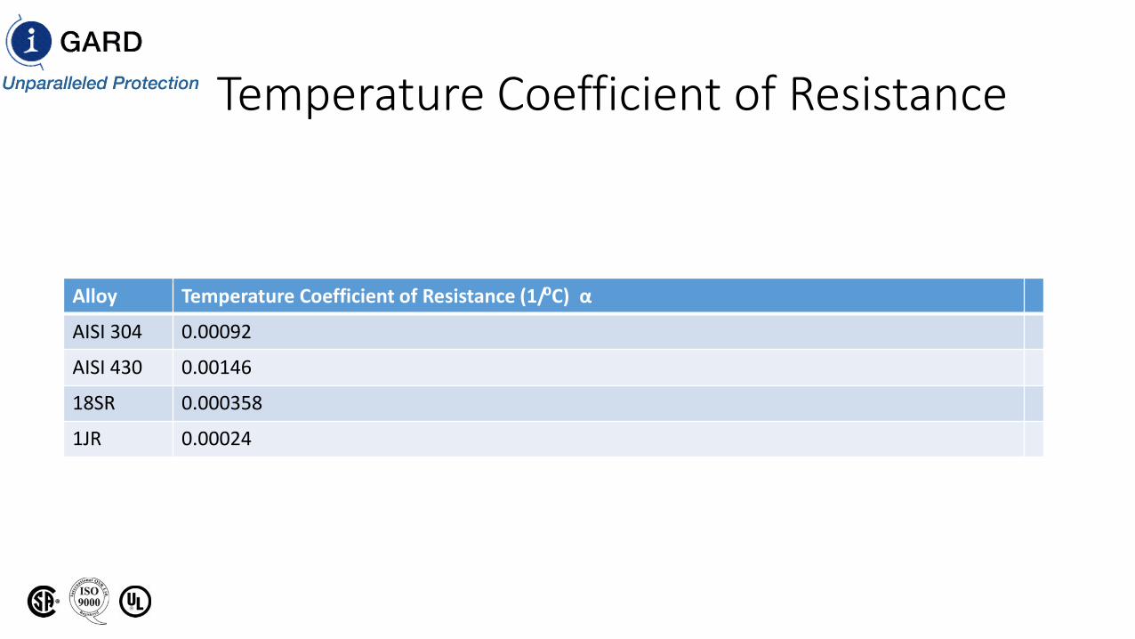
Temperature Coefficient of Resistance
Alloy Temperature Coefficient of Resistance (1/⁰C) α
AISI 304 0.00092
AISI 430 0.00146
18SR 0.000358
1JR 0.00024
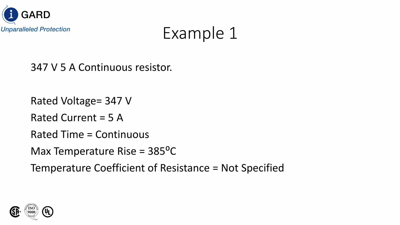
Example 1
347 V 5 A Continuous resistor.
Rated Voltage= 347 VRated Current = 5 ARated Time = ContinuousMax Temperature Rise = 385⁰CTemperature Coefficient of Resistance = Not Specified
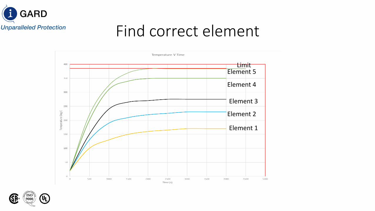
Find correct element
Element 1
Element 2
Element 3
Element 4
Element 5Limit
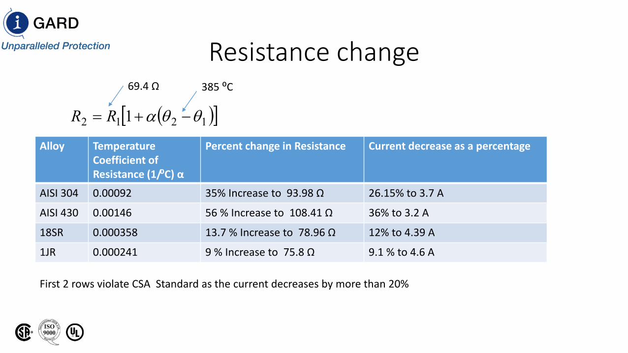
Resistance change
Alloy Temperature Coefficient of Resistance (1/⁰C) α
Percent change in Resistance Current decrease as a percentage
AISI 304 0.00092 35% Increase to 93.98 Ω 26.15% to 3.7 A
AISI 430 0.00146 56 % Increase to 108.41 Ω 36% to 3.2 A
18SR 0.000358 13.7 % Increase to 78.96 Ω 12% to 4.39 A
1JR 0.000241 9 % Increase to 75.8 Ω 9.1 % to 4.6 A
69.4 Ω 385 ⁰C
( )[ ]1212 1 θθα −+= RR
First 2 rows violate CSA Standard as the current decreases by more than 20%
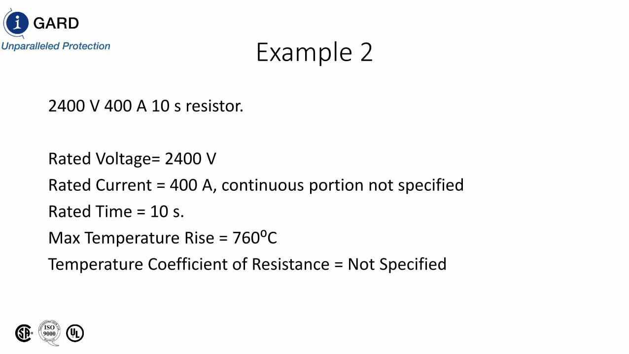
Example 2
2400 V 400 A 10 s resistor.
Rated Voltage= 2400 VRated Current = 400 A, continuous portion not specifiedRated Time = 10 s.Max Temperature Rise = 760⁰CTemperature Coefficient of Resistance = Not Specified
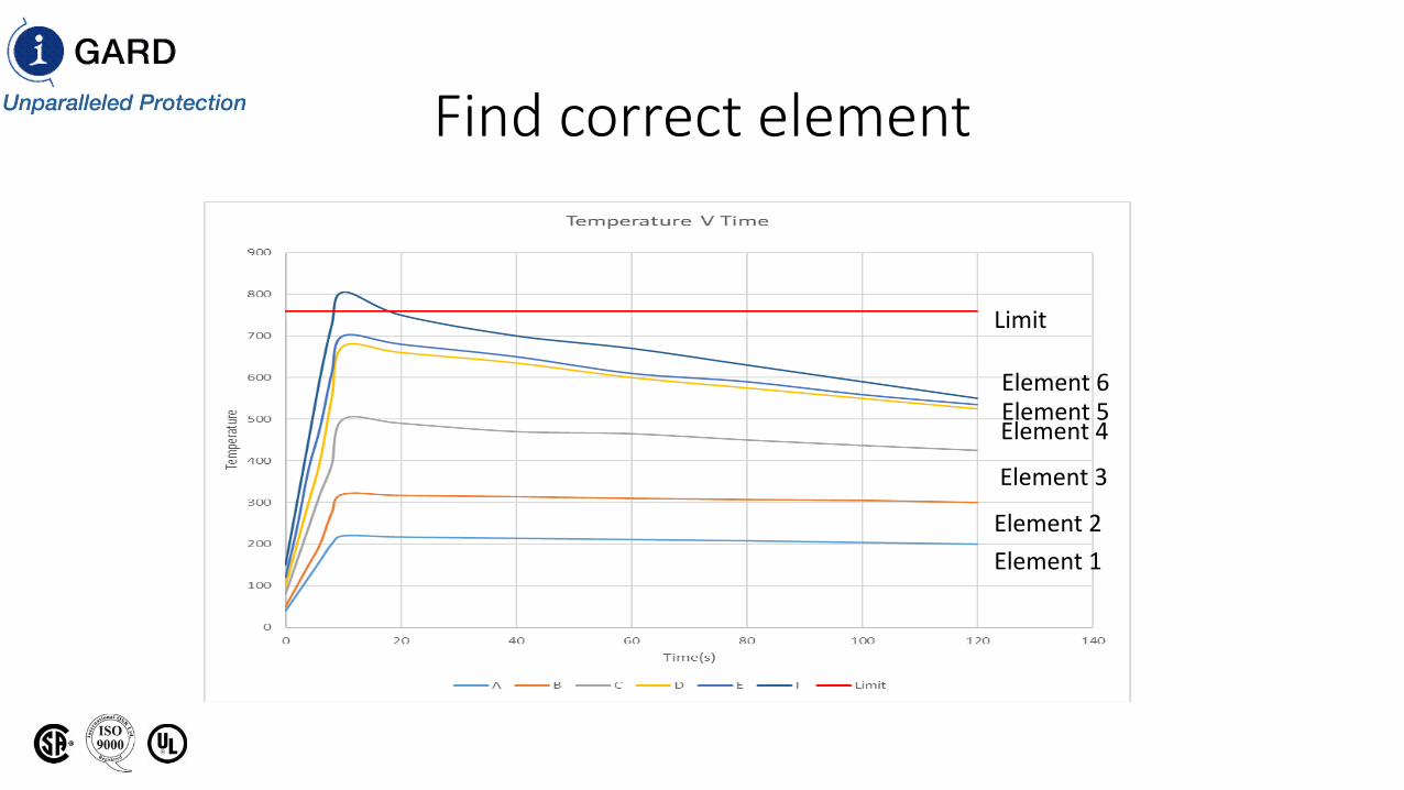
Find correct element
Element 1Element 2
Element 3
Element 4Element 5Element 6
Limit

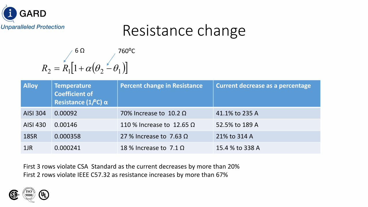
Resistance change
Alloy Temperature Coefficient of Resistance (1/⁰C) α
Percent change in Resistance Current decrease as a percentage
AISI 304 0.00092 70% Increase to 10.2 Ω 41.1% to 235 A
AISI 430 0.00146 110 % Increase to 12.65 Ω 52.5% to 189 A
18SR 0.000358 27 % Increase to 7.63 Ω 21% to 314 A
1JR 0.000241 18 % Increase to 7.1 Ω 15.4 % to 338 A
6 Ω 760⁰C
( )[ ]1212 1 θθα −+= RR
First 3 rows violate CSA Standard as the current decreases by more than 20%First 2 rows violate IEEE C57.32 as resistance increases by more than 67%
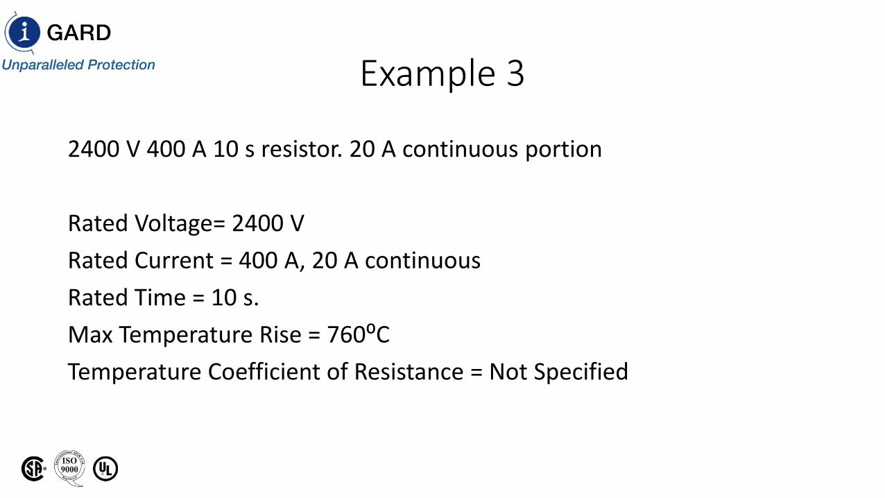
Example 3
2400 V 400 A 10 s resistor. 20 A continuous portion
Rated Voltage= 2400 VRated Current = 400 A, 20 A continuousRated Time = 10 s.Max Temperature Rise = 760⁰CTemperature Coefficient of Resistance = Not Specified
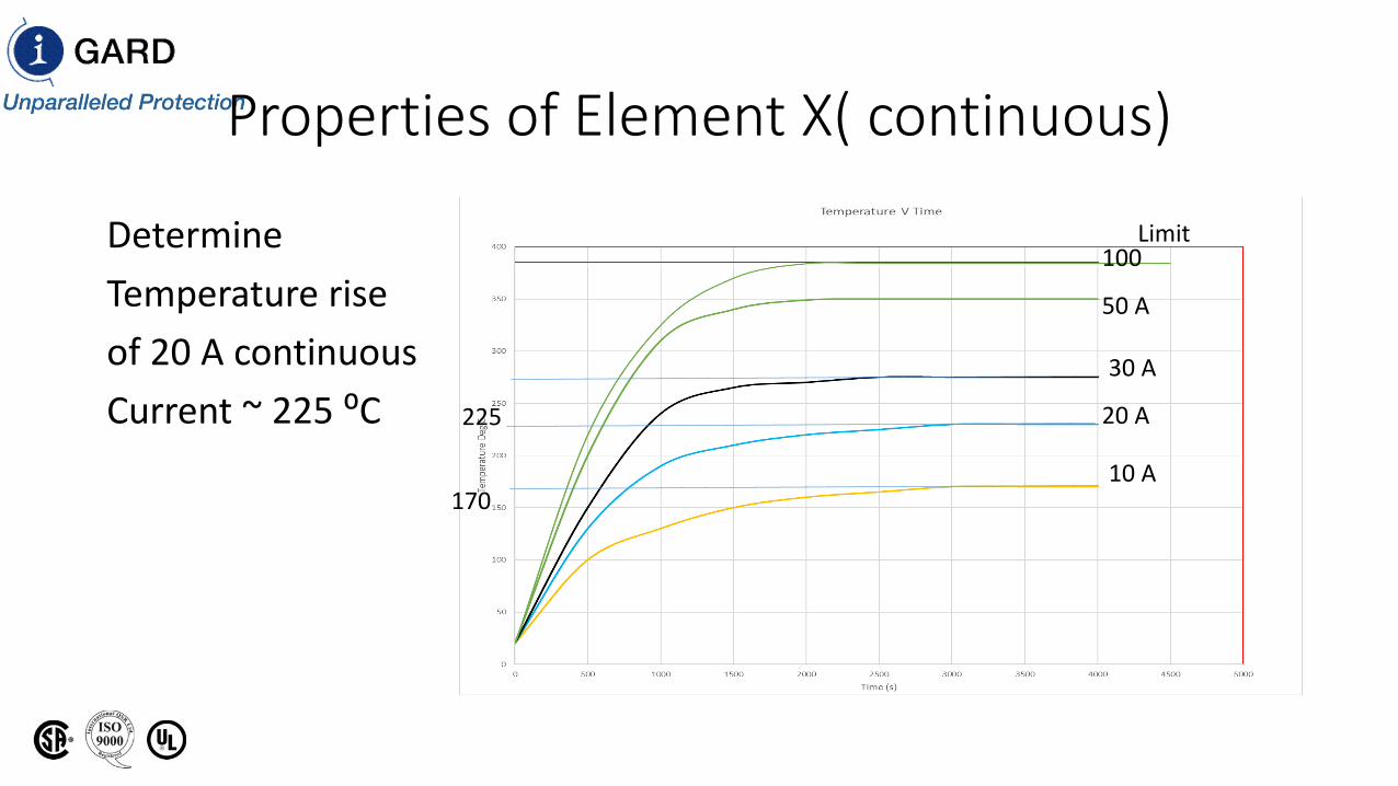
Properties of Element X( continuous)
DetermineTemperature rise of 20 A continuousCurrent ~ 225 ⁰C
10 A
20 A
30 A
50 A
100Limit
170
225
Find new temperature rise
• Max temperature rise of 760 ⁰C
• The initial current of 20 A continuous produces a temperature Rise of 225 ⁰C
• This initial current and temperature limits the temperature rise of a 400 A fault to 760 ⁰C - 225 ⁰C = 535 ⁰C
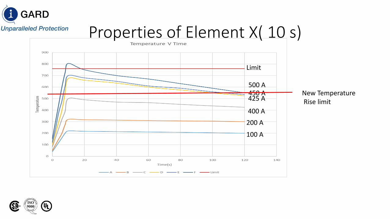
Properties of Element X( 10 s)
100 A
200 A 400 A
425 A450 A500 A
Limit
New TemperatureRise limit
Determine new Temperature rise limit
• The rated-time temperature rise of 10-second and 1-minute devices shall be taken as the sum of the steady-state rise and the additional rise caused by the application of rated voltage for rated time.
• Steady state rise = 225 ⁰C• Fault current for 10 s. = 500 ⁰C• Sum 725 ⁰C < 760 ⁰C
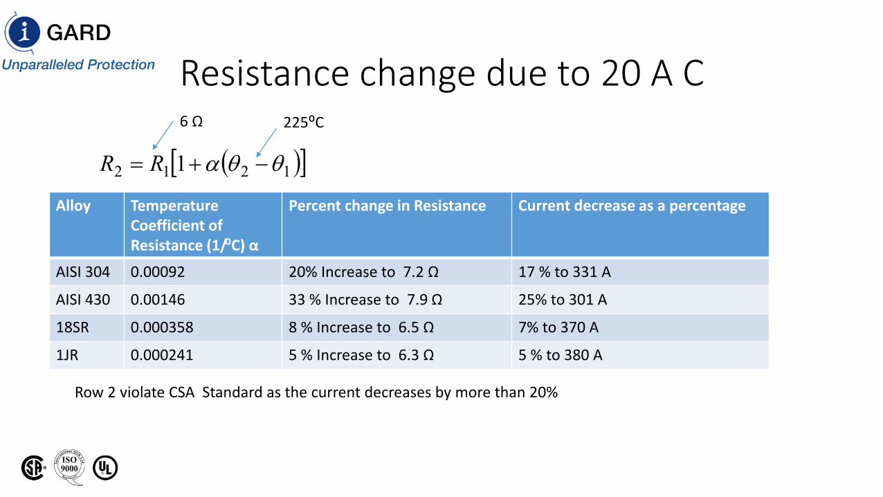
Resistance change due to 20 A C
Alloy Temperature Coefficient of Resistance (1/⁰C) α
Percent change in Resistance Current decrease as a percentage
AISI 304 0.00092 20% Increase to 7.2 Ω 17 % to 331 A
AISI 430 0.00146 33 % Increase to 7.9 Ω 25% to 301 A
18SR 0.000358 8 % Increase to 6.5 Ω 7% to 370 A
1JR 0.000241 5 % Increase to 6.3 Ω 5 % to 380 A
6 Ω 225⁰C
( )[ ]1212 1 θθα −+= RR
Row 2 violate CSA Standard as the current decreases by more than 20%
Resistance change
Alloy Temperature Coefficient of Resistance (1/⁰C) α
Percent change in Resistance Current decrease as a percentage
AISI 304 0.00092 70% Increase to 10.2 Ω 41.1% to 235 A
AISI 430 0.00146 110 % Increase to 12.65 Ω 52.5% to 189 A
18SR 0.000358 27 % Increase to 7.63 Ω 21% to 314 A
1JR 0.000241 18 % Increase to 7.1 Ω 15.4 % to 338 A
6 Ω 760⁰C
( )[ ]1212 1 θθα −+= RR
First 3 rows violate CSA Standard as the current decreases by more than 20%First 2 rows violate IEEE C57.32 as resistance increases by more than 67%
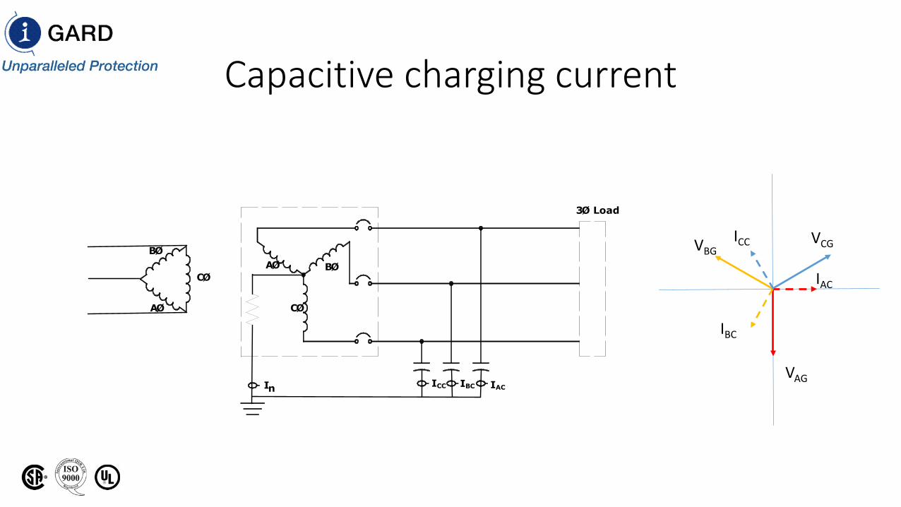
Capacitive charging current
VAG
VBGVCG
IAC
IBC
ICC
ICC
AØ BØ
CØ
3Ø Load
nI IBC IAC
AØ
BØ
CØ
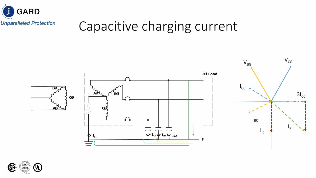
Capacitive charging current
VBGVCG
IBC
ICC
ICC
AØ BØ
CØ
3Ø Load
nI IBC IAC
AØ
BØ
CØ
IF
3IC0
IRIF
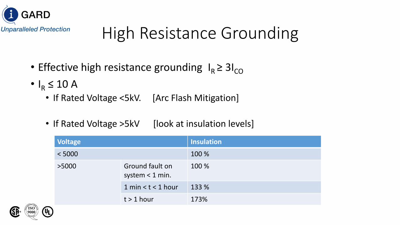
High Resistance Grounding
• Effective high resistance grounding IR ≥ 3ICO
• IR ≤ 10 A• If Rated Voltage <5kV. [Arc Flash Mitigation]
• If Rated Voltage >5kV [look at insulation levels]
Voltage Insulation
< 5000 100 %
>5000 Ground fault on system < 1 min.
100 %
1 min < t < 1 hour 133 %
t > 1 hour 173%
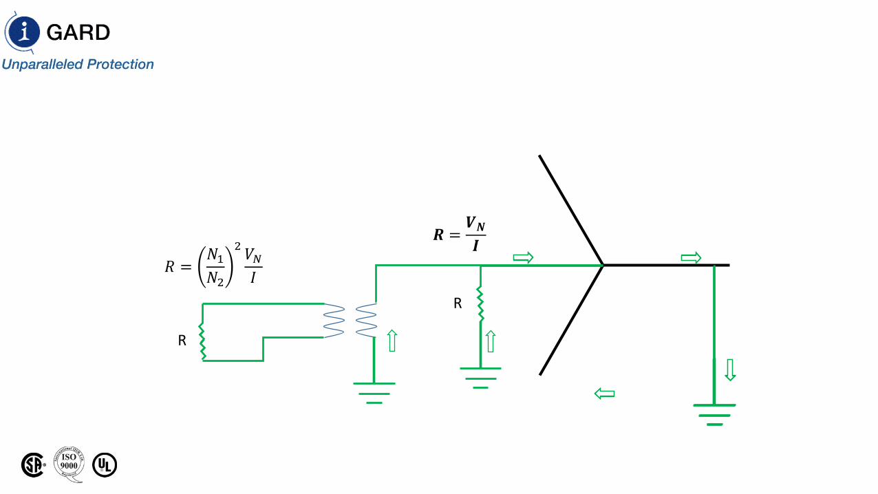
R
𝑅𝑅 =𝑁𝑁1𝑁𝑁2
2 𝑉𝑉𝑁𝑁𝐼𝐼
R
𝑹𝑹 =𝑽𝑽𝑵𝑵𝑰𝑰
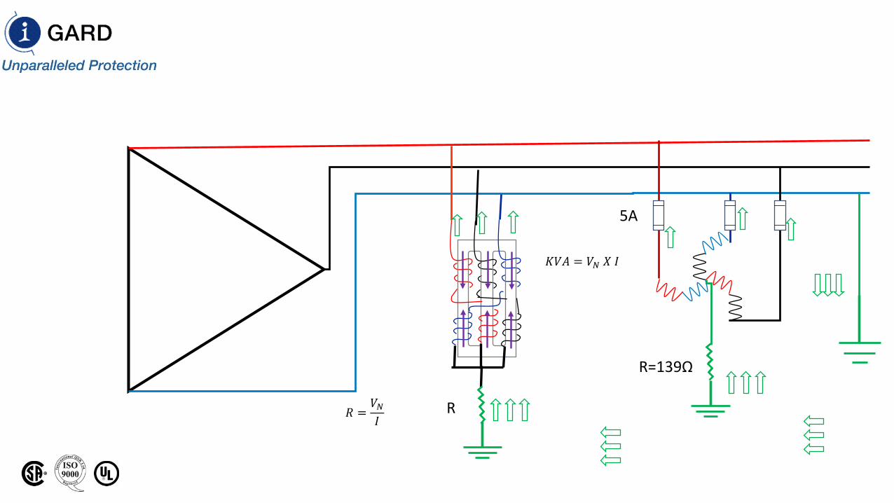
R
R=139Ω
𝑅𝑅 =𝑉𝑉𝑁𝑁𝐼𝐼
𝐾𝐾𝑉𝑉𝐾𝐾 = 𝑉𝑉𝑁𝑁 𝑋𝑋 𝐼𝐼
5A
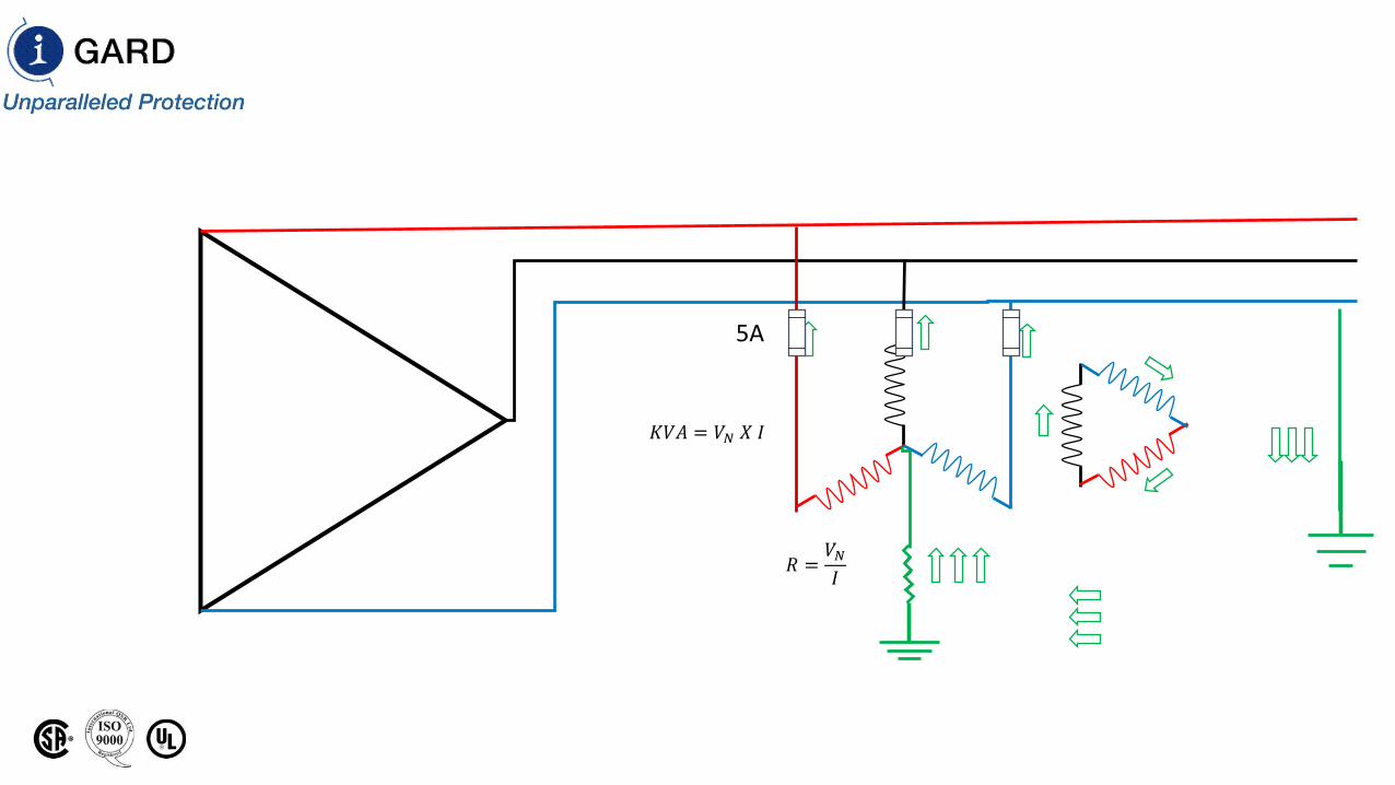
𝑅𝑅 =𝑉𝑉𝑁𝑁𝐼𝐼
𝐾𝐾𝑉𝑉𝐾𝐾 = 𝑉𝑉𝑁𝑁 𝑋𝑋 𝐼𝐼
5A
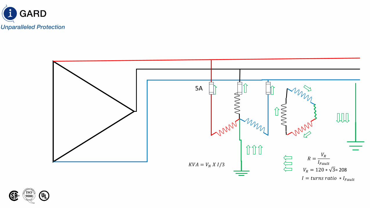
𝑅𝑅 =𝑉𝑉𝑅𝑅
𝐼𝐼𝐹𝐹𝐹𝐹𝐹𝐹𝐹𝐹𝐹𝐹𝐾𝐾𝑉𝑉𝐾𝐾 = 𝑉𝑉𝑁𝑁 𝑋𝑋 𝐼𝐼/3𝑉𝑉𝑅𝑅 = 120 ∗ 3= 208
𝐼𝐼 = 𝑡𝑡𝑡𝑡𝑡𝑡𝑡𝑡𝑡𝑡 𝑡𝑡𝑟𝑟𝑡𝑡𝑟𝑟𝑟𝑟 ∗ 𝐼𝐼𝐹𝐹𝐹𝐹𝐹𝐹𝐹𝐹𝐹𝐹
5A
Low Resistance Grounding
• If Charging Current > 10 A, rule out HRG
• Next step is to determine minimum pickup for ground fault on protection scheme
• Choose a safe value greater than the minimum pickup to set resistor current 3-5 X minimum pickup.
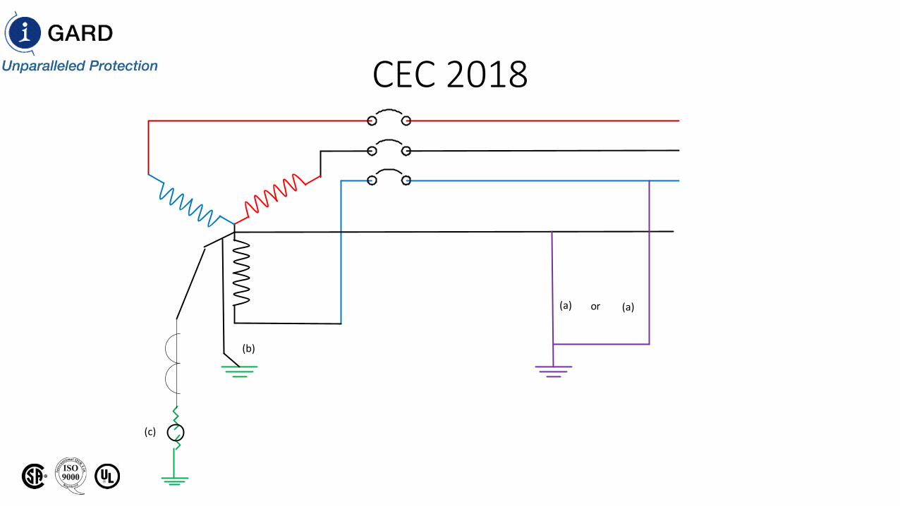
CEC 2018
(a) (a)or
(b)
(c)
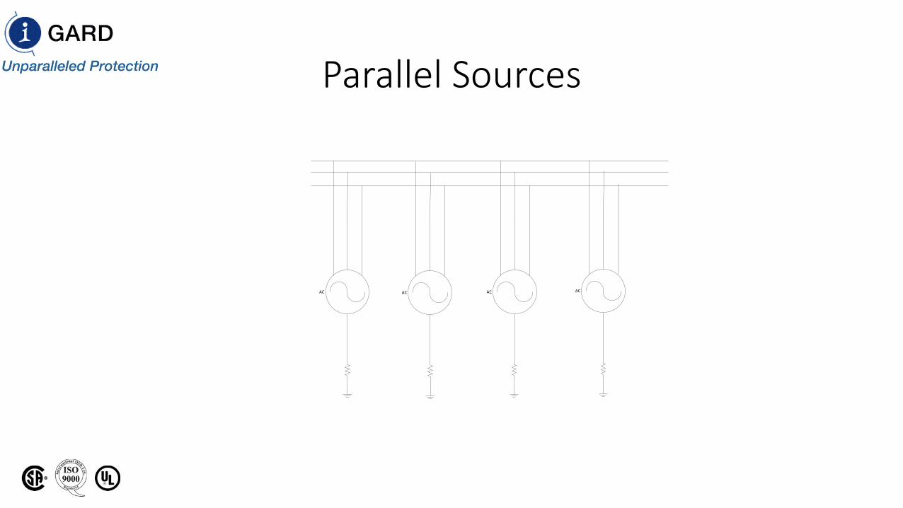
Parallel Sources
AC AC AC AC