network instrumentation modules smart device gateway
TRANSCRIPT
Thank you for purchasing an Azbil Corporation product.
This manual contains information for ensuring the correct use of this product.
Those designing or maintaining equipment that uses this product should first read and understand this manual.
Be sure to keep this manual nearby for handy reference.
No. CP-SP-1422E
Network Instrumentation Modules
Smart Device GatewayModel NX-SVG
User’s Manual

NOTICE
Be sure that the user receives this manual before the product is used.
Copying or duplicating this user’s manual in part or in whole is forbidden. The information and specifications in this manual are subject to change without notice.
Considerable effort has been made to ensure that this manual is free from inaccuracies and omissions. If you should find an error or omission, please contact the azbil Group.
In no event is Azbil Corporation liable to anyone for any indirect, special or consequential damages as a result of using this product.
© 2019-2021 Azbil Corporation. All Rights Reserved.
Modbus™ is a trademark and the property of Schneider Electric SE, its subsidiaries and affiliated companies.
Other company names and product names in this document may be trademarks or registered trademarks of their respective companies.
i
Conventions Used in This Manual
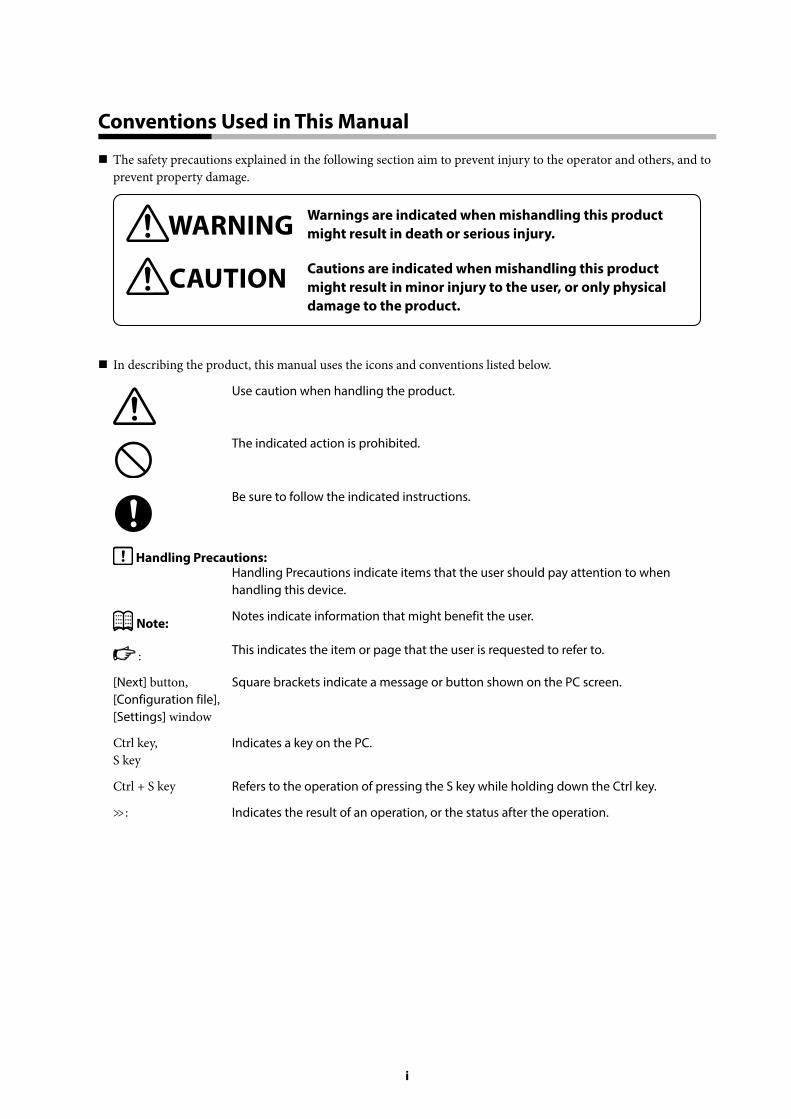
The safety precautions explained in the following section aim to prevent injury to the operator and others, and to prevent property damage.
WARNING Warnings are indicated when mishandling this product might result in death or serious injury.
CAUTION Cautions are indicated when mishandling this product might result in minor injury to the user, or only physical damage to the product.
In describing the product, this manual uses the icons and conventions listed below.
Use caution when handling the product.
The indicated action is prohibited.
Be sure to follow the indicated instructions.
Handling Precautions:Handling Precautions indicate items that the user should pay attention to when handling this device.
Note: Notes indicate information that might benefit the user.
: This indicates the item or page that the user is requested to refer to.
[Next] button, [Configuration file], [Settings] window
Square brackets indicate a message or button shown on the PC screen.
Ctrl key, S key
Indicates a key on the PC.
Ctrl + S key Refers to the operation of pressing the S key while holding down the Ctrl key.
>> : Indicates the result of an operation, or the status after the operation.
ii
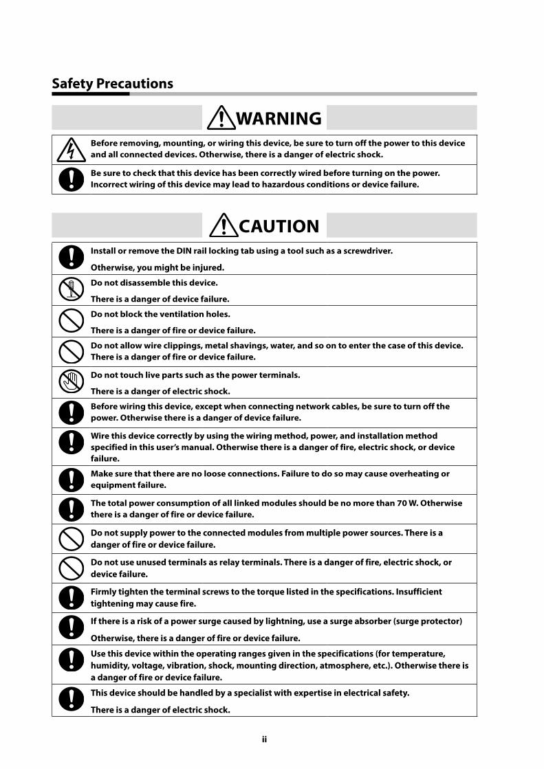
Safety Precautions
WARNINGBefore removing, mounting, or wiring this device, be sure to turn off the power to this device and all connected devices. Otherwise, there is a danger of electric shock.
Be sure to check that this device has been correctly wired before turning on the power. Incorrect wiring of this device may lead to hazardous conditions or device failure.
CAUTIONInstall or remove the DIN rail locking tab using a tool such as a screwdriver.
Otherwise, you might be injured.
Do not disassemble this device.
There is a danger of device failure.
Do not block the ventilation holes.
There is a danger of fire or device failure.
Do not allow wire clippings, metal shavings, water, and so on to enter the case of this device. There is a danger of fire or device failure.
Do not touch live parts such as the power terminals.
There is a danger of electric shock.
Before wiring this device, except when connecting network cables, be sure to turn off the power. Otherwise there is a danger of device failure.
Wire this device correctly by using the wiring method, power, and installation method specified in this user’s manual. Otherwise there is a danger of fire, electric shock, or device failure.
Make sure that there are no loose connections. Failure to do so may cause overheating or equipment failure.
The total power consumption of all linked modules should be no more than 70 W. Otherwise there is a danger of fire or device failure.
Do not supply power to the connected modules from multiple power sources. There is a danger of fire or device failure.
Do not use unused terminals as relay terminals. There is a danger of fire, electric shock, or device failure.
Firmly tighten the terminal screws to the torque listed in the specifications. Insufficient tightening may cause fire.
If there is a risk of a power surge caused by lightning, use a surge absorber (surge protector)
Otherwise, there is a danger of fire or device failure.
Use this device within the operating ranges given in the specifications (for temperature, humidity, voltage, vibration, shock, mounting direction, atmosphere, etc.). Otherwise there is a danger of fire or device failure.
This device should be handled by a specialist with expertise in electrical safety.
There is a danger of electric shock.
iii
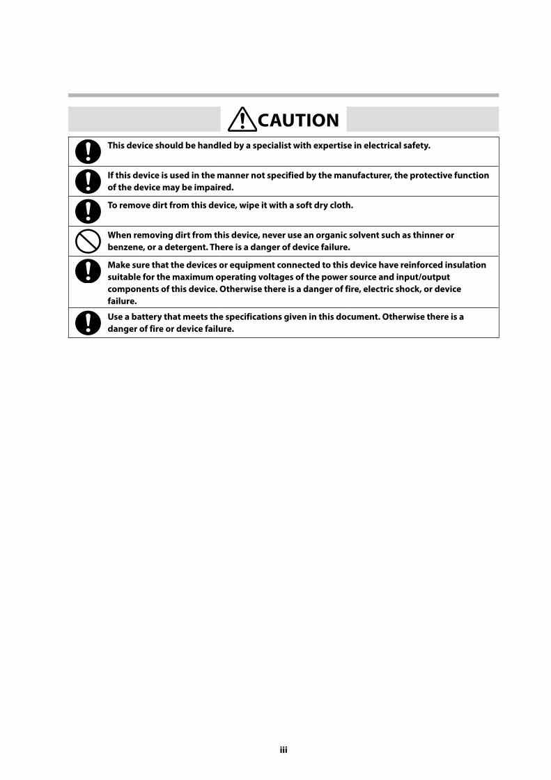
CAUTIONThis device should be handled by a specialist with expertise in electrical safety.
If this device is used in the manner not specified by the manufacturer, the protective function of the device may be impaired.
To remove dirt from this device, wipe it with a soft dry cloth.
When removing dirt from this device, never use an organic solvent such as thinner or benzene, or a detergent. There is a danger of device failure.
Make sure that the devices or equipment connected to this device have reinforced insulation suitable for the maximum operating voltages of the power source and input/output components of this device. Otherwise there is a danger of fire, electric shock, or device failure.
Use a battery that meets the specifications given in this document. Otherwise there is a danger of fire or device failure.
iv
Cautions on Communication Lines
This product cannot be directly connected to the communication lines (including public wireless LANs) of telecommunications carriers (mobile communication companies, fixed-line communication companies, Internet providers, etc.).
Tips for Avoiding Malware and Hacker Cyberattacks
If this product or a computer on the network that is connected to this product becomes infected with malware* or is the target of a cyberattack, this product may malfunction or stop functioning altogether. Please be aware that the normal warranty does not cover restoration work or damage incurred by a malfunction of this product due to malware or a cyberattack. Also, Azbil Corporation will not be liable for compensation to the customer for any loss or damage caused by malware or a cyberattack, including opportunity loss, profit loss, business disruptions, data loss, etc.
To reduce the chances of being infected with malware or being the victim of a cyberattack, please implement measures such as those listed below.
• Before using this product, take security measures such as disconnecting this product or the network to which this product is connected from the business network, or restricting communication with a firewall or the like.
• When you temporarily connect a computer for engineering to this product, confirm that it is not infected with malware using antivirus software or some other means before connection.
• Physically block any unnecessary USB and LAN ports to prevent portable devices from being connected without the security administrator’s permission.
• As a part of maintenance, regularly check for security vulnerabilities such as unnecessary connected equipment that was not included at the design stage or user accounts that are no longer needed.
• Holding IT security training for operators and instrument engineers is beneficial. Regular implementation is recommended.
* A general term used to describe unauthorized and harmful programs that perform operations that are not intended by the user of the computer.
Cautions Regarding Network Security
v
A total of two different manuals are available for the NX-SVG. Read them as necessary for your specific requirements. If a manual you require is not available, contact the azbil Group or its dealer.
Network Instrumentation Modules Smart Device Gateway Model NX-SVG User’s Manual Document No. CP-SP-1422E
This manual.
Personnel who are using the NX-SVG for the first time or who are in charge of hardware design and/or maintenance of a control panel incorporating this product should first read this manual thoroughly.
This manual describes the hardware, gives an overview of the product and other products used with it, explains installation, wiring, and troubleshooting, and gives hardware specifications.
Network Instrumentation Modules Smart Device Gateway Model NX-SVG Installation Manual Document No. CP-UM-5928JE
This manual is supplied with the product.
Those designing or manufacturing equipment that uses the NX-SVG should read this manual thoroughly. The manual covers safety precautions, installation, wiring, and main specifications of the product.
For further information about operation, refer to the user’s manual above (CP-SP-1422E).
The Role of This Manual
vi
Organization of This User’s Manual
This manual is organized as shown below.
Chapter 1. Overview
Device overview, model number selection, names of parts, and functions of this device
Chapter 2. Installation
Operating environment and installation procedures
Chapter 3. Wiring
Wiring procedures and precautions, and connection examples
Chapter 4. Functions
Detailed description of functions
Chapter 5. Smart Loader Package, Model SLP-SVG
Operation of the Smart Loader Package, which is required to use this device
Chapter 6. Configuration
Settings required to operate this device
Chapter 7. Communication Settings for Connected Devices
Communication settings of devices connected to this device
Chapter 8. Specifications
General specifications
Chapter 9. Troubleshooting
How to determine the cause of problems that may occur, and corrective actions for the problems
Chapter 10. Disposal
How to dispose of this device
Chapter 11. Open Source Software
The open source software included in this device
Appendix
This section describes the functions added and the specifications changed for each version of the SLP-SVG.
vii
Contents
Conventions Used in This ManualSafety PrecautionsCautions Regarding Network SecurityThe Role of This ManualOrganization of This User’s Manual
Chapter 1. Overview 1-1
1 - 1 Overview and Features 1-1 Overview 1-1 Features 1-2
1 - 2 Model Selection 1-3 Model NX-SVG 1-3 Separately sold product 1-3
1 - 3 Names and Functions of Parts 1-4 Main unit 1-4 Base unit 1-4 Indicators 1-5 Switches 1-6
1 - 4 Operation Mode 1-7 Operation mode 1-7
Chapter 2. Installation 2-1
Installation location 2-1 Module connection 2-2 Installation method 2-2 Attaching the main unit on the base 2-3 Removing the main unit from the base 2-4 Installing the battery 2-5
Chapter 3. Wiring 3-1
3 - 1 Wiring Precautions 3-1 Wiring precautions 3-2
3 - 2 Cables 3-33 - 3 Connecting Terminals 3-4
Recommended crimp terminal lugs (for RS-485 CH2 and power) 3-4 Recommended ferrules (for RS-485 CH1) 3-5
3 - 4 Connecting the Power 3-6 Connecting the power 3-6 Noise suppression measures 3-7 Power supply design 3-7
3 - 5 Ethernet Communication Connections 3-93 - 6 RS-485 Communication Connections 3-10
RS-485 CH1 connection 3-10
viii
RS-485 CH2 connection 3-103 - 7 USB Host Connector 3-133 - 8 Electrical Noise Sources and Countermeasures 3-143 - 9 Input/Output Isolation 3-153 - 10 System Configuration 3-16
When connecting the host and slave devices to the same network segment 3-16 When connecting 16 or more devices to one NX-SVG 3-17 When connecting the host and slave devices to different network segments 3-17 When connecting more than 128 slave devices to the system 3-18 When connecting slave devices to RS-485 3-20
Chapter 4. Functions 4-1
4 - 1 Gateway Function 4-1 Cyclic data transmission 4-1 Triggered data transmission 4-3 Bit setting 4-6
4 - 2 Device Management Function 4-8 Configuration backup and restoration 4-8 Batch configuration backup and restoration 4-11 IP address assignment 4-12 State notification 4-14 Time setting 4-16
4 - 3 Internal Register 4-184 - 4 Server Function 4-19
Connections 4-19 Keep-alive 4-19 Modbus/TCP specification overview 4-19 Modbus/TCP message structure 4-20 Modbus/TCP exception codes 4-20 Modbus/TCP number of records 4-20 Format of a command for reading multiple data records (0x03) 4-21 Format of a command for writing one data record (0x06) 4-21 Format of a command for writing multiple data records (0x10) 4-22
4 - 5 Settings read-protection function 4-23 Settings read-protection 4-23
4 - 6 Switches on the Front of the Main Unit 4-26 Reset 4-26 Write settings from USB flash drive 4-26 Connected device setup 4-28
Chapter 5. Smart Loader Package, Model SLP-SVG 5-1
5 - 1 Overview of Model SLP-SVG 5-1 Functions 5-1
5 - 2 Installation 5-2 Installing the loader 5-2
ix
Uninstalling the loader 5-4 Loader upgrade and maintenance 5-5
5 - 3 Starting and Exiting the Loader 5-6 Starting the loader 5-6 Exiting the loader 5-6
5 - 4 Operation Flowchart 5-75 - 5 Main Window 5-8
Screen components 5-8 Menu bar and toolbar 5-9 Menu list 5-9 Project view 5-12 Configuration sheet 5-14 Parameter selection 5-16 Information list 5-22
5 - 6 Connecting to Model NX-SVG 5-24 Communication settings for the PC 5-24 Communication status 5-27 Writing the gateway configuration 5-28 Reading the gateway settings 5-28 Checking execution status 5-29 Reading model NX-SVG information 5-30 Managing connected devices 5-37 Setting the time on the NX-SVG 5-40 Resetting the NX-SVG 5-40
5 - 7 Editing MyList 5-41 Screen components 5-41 Menu list 5-42 Adding/deleting MyList 5-43 Editing a MyList 5-43 Exporting and importing MyList 5-44 Communication 5-45
5 - 8 Environment Configuration 5-455 - 9 Updating the System of Model NX-SVG 5-46
Executing system update when writing the configuration 5-46 Executing system update only 5-47
Chapter 6. Configuration 6-1
6 - 1 Creating a Project File 6-1 Project file 6-1
6 - 2 Configuration Sheet Details 6-3 System – General 6-3 System – LAN1/LAN2 6-8 System – COM1/COM2 6-14 Cyclic Transmit 6-18 Trigger Transmit 6-22 Bit Set 6-26
x
Device Management – Backup Restore 6-28 Device Management – IP Address Assignment 6-31 Device Management – Status Notification 6-32 Device Management – DateTime Setting 6-35
Chapter 7. Communication Settings for Connected Devices 7-1
7 - 1 Types of Connected Device 7-2 List of connected device types 7-2 Maximum number of register addresses specifiable for one communication frame 7-4 Available devices 7-6
7 - 2 Azbil Products 7-16 Network Instrumentation Modules 7-16 Burner interlock module, model RX-L90 7-19 Multi-loop controller with multifunction display, model C7G 7-21 Single loop controller, model C15/25/26/35/36 7-23 Single loop controller, model C45/46 7-26 Burner controller, model BC-R15/25/35 7-28 Burner controller, model AUR255 7-30 Flame monitor, model AUR355 7-33 Dynamic self-checking burner controller, model AUR455 7-36 Burner interlock module, model RX-L80 7-39 Compact digital mass flow controller, model F4H 7-41 Digital mass flow controller, model F4Q 7-43 Digital mass flow controller, model MQV 7-46 Panel mount mass flow controller, model MPC 7-48 Air flowmeter, model MCF 7-51 Power controller, model PU21/23 7-53
7 - 3 Mitsubishi PLC 7-56 iQ-R series CPU direct connection 7-56 iQ-R series, Ethernet interface module 7-59 Q series CPU direct connection 7-63 Q series, Ethernet interface module 7-66 iQ-F series, CPU direct connection 7-69
7 - 4 Yokogawa Electric PLC 7-72 CPU direct connection 7-72
7 - 5 Omron PLC 7-74 NJ series, CPU direct connection (FINS/TCP connection) 7-74 NJ series, CPU direct connection (FINS/UDP connection) 7-77 CJ series, CPU direct connection (FINS/TCP connection) 7-80 CJ series, Ethernet module connection (FINS/TCP connection) 7-83 CJ series, CPU direct connection (FINS/UDP connection) 7-85 CJ series, Ethernet module connection (FINS/UDP connection) 7-88
7 - 6 Siemens PLC 7-90 CPU direct connection 7-90
7 - 7 JTEKT PLC 7-93 CPU direct connection 7-93
xi
7 - 8 FANUC CNC 7-97 Modbus/TCP 7-97
7 - 9 Keyence PLC 7-100 CPU direct connection 7-100
7 - 10 Fuji Electric PLC 7-103 MICREX-SX SPH2000 series, CPU direct connection 7-103
7 - 11 Modbus 7-106 Modbus/TCP 7-106 Modbus/RTU 7-108
Chapter 8. Specifications 8-1
Hardware specifications 8-1 External dimensions 8-2
Chapter 9. Troubleshooting 9-1
Diagnosis based on the LEDs 9-1 Diagnosis from the result code of the executed function 9-1
Chapter 10. Disposal 10-1
Disposal of this device 10-1 Disposal of the battery 10-1
Chapter 11. Open Source Software 11-1
Appendix App.-1
Model SLP-SVG version history App.-1

1-1
Overview
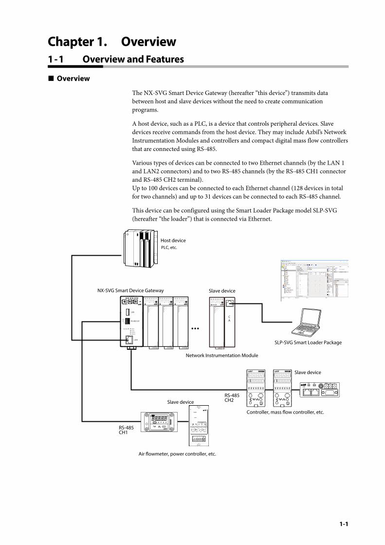
The NX-SVG Smart Device Gateway (hereafter “this device”) transmits data between host and slave devices without the need to create communication programs.
A host device, such as a PLC, is a device that controls peripheral devices. Slave devices receive commands from the host device. They may include Azbil’s Network Instrumentation Modules and controllers and compact digital mass flow controllers that are connected using RS-485.
Various types of devices can be connected to two Ethernet channels (by the LAN 1 and LAN2 connectors) and to two RS-485 channels (by the RS-485 CH1 connector and RS-485 CH2 terminal). Up to 100 devices can be connected to each Ethernet channel (128 devices in total for two channels) and up to 31 devices can be connected to each RS-485 channel.
This device can be configured using the Smart Loader Package model SLP-SVG (hereafter “the loader”) that is connected via Ethernet.
Host device
Slave device
Slave device
Slave device
Controller, mass ow controller, etc.
Network Instrumentation Module
Air owmeter, power controller, etc.
RS-485CH2
RS-485CH1
PLC, etc.
SLP-SVG Smart Loader Package
NX-SVG Smart Device Gateway
...
NX-D25N
PWR RUN MOD COM NST FAIL
F0
F1 F9F5
LOCK
CA
BRATE ×10 ×1NETPWR
F4H
mode
enter
ALEVLL/min
PWR
NX-SVGN
USB
DA(+)
SG
DB(−) RS-485 CH1
RS-485
BATTERY
LINK/ACT
LAN1
FUNCTION ERROR
ID F1 F2
RUN MOD COM NST FAIL
Chapter 1. Overview1 - 1 Overview and Features
1-2
Chapter 1. Overview
Features
• Easy introduction and management With easy parameter setting using the loader, the user can quickly begin operation. It is not necessary to create communication programs.
• Easy setup Because the loader provides a list of parameters for Azbil-made devices, communication settings can be easily configured using parameter names.
• Flexible setup Data for connected devices can be assigned freely to PLC registers.
• Two RS-485 communication channels RS-485 communications are supported in addition to Ethernet communications, so this device can exchange data with RS-485- and Ethernet-capable devices.
• Easy management of connected devices This device can back up and restore settings for Azbil’s Network Instrumentation Modules, which reduces the work required for initial setup in manufacturing equipment and facilitates the replacement of connected devices when doing maintenance.
• Debugging at operation startup As a solution to onsite problems caused by wrong wiring or incorrect parameter settings, the loader monitors the status of communication between this device and connected devices, records communication history, etc.
1-3
Chapter 1. Overview
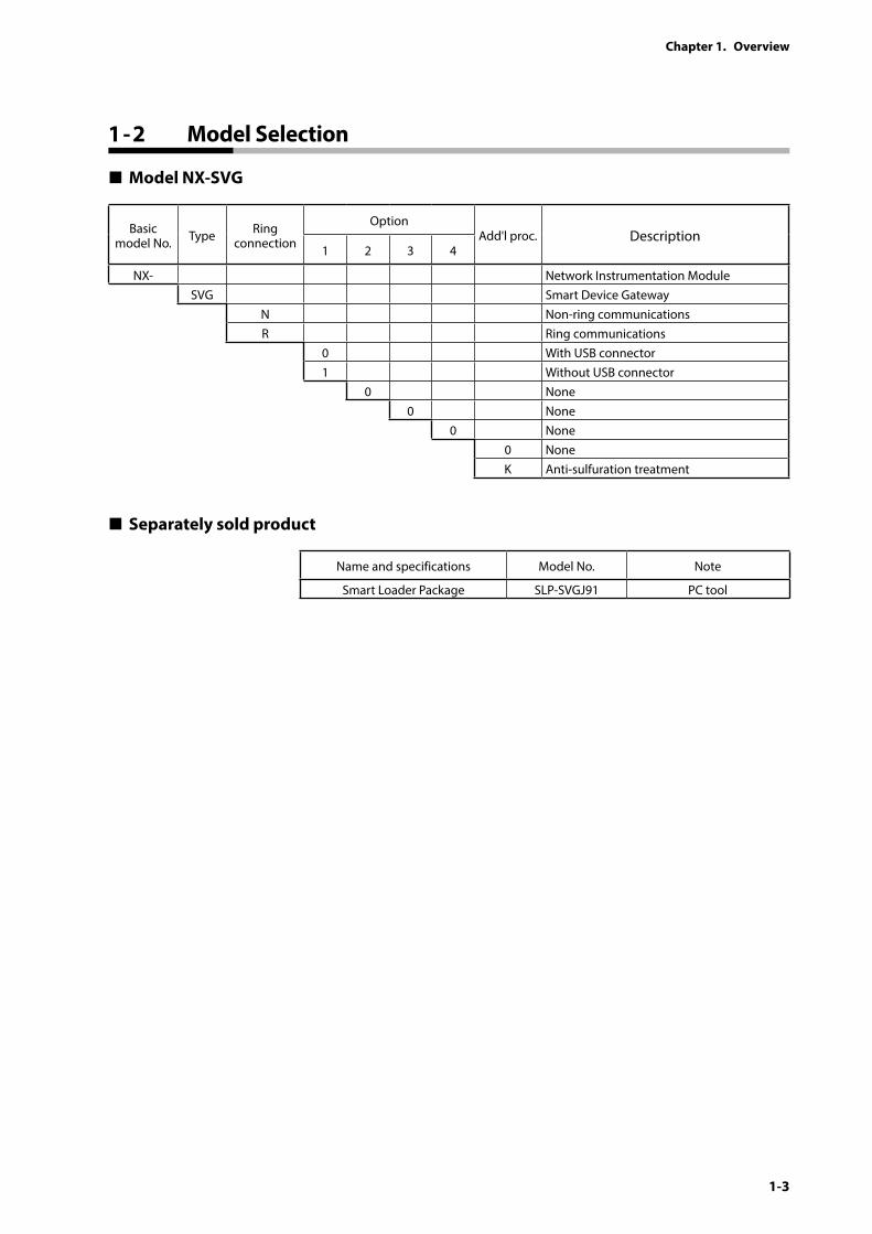
Model NX-SVG
Basic model No. Type Ring
connection
OptionAdd'l proc. Description
1 2 3 4
NX- Network Instrumentation ModuleSVG Smart Device Gateway
N Non-ring communicationsR Ring communications
0 With USB connector1 Without USB connector
0 None0 None
0 None0 NoneK Anti-sulfuration treatment
Separately sold product
Name and specifications Model No. Note
Smart Loader Package SLP-SVGJ91 PC tool
1 - 2 Model Selection
1-4
Chapter 1. Overview
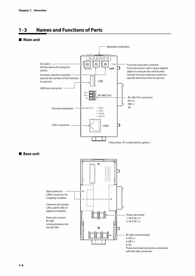
Main unit
PWR
NX-SVGN
USB
DA(+)
SG
DB(−) RS-485 CH1
RS-485
BATTERY
LINK/ACT
LAN1
FUNCTION ERROR
ID F1 F2
RUN MOD COM NST FAIL
ID switchSet the device ID using this switch.
Function indicators
Function execution switchesPress the button with a sharp-tipped object to execute the set function.Use the function selection switch to specify which function to execute.
RS-485 CH1 connectorDA (+)DB (−)SG
LAN1 connector
USB host connector
Function selection switchesSpecify the number of the function to execute.
Operation indicators
* Only when “0” is selected for option 1
Base unit
Side connectorLAN2 connector for coupling modules.
Connects the power, LAN, and RS-485 of adjacent modules.
Does not connect RS-485 communications for the NX-SVG.
Power terminals:1: 24 V DC (+)2: 24 V DC (−)
RS-485 CH2 terminals4: DA (+)5: DB (−)6: SGThese terminals cannot be connected with the side connector.
1 - 3 Names and Functions of Parts
1-5
Chapter 1. Overview
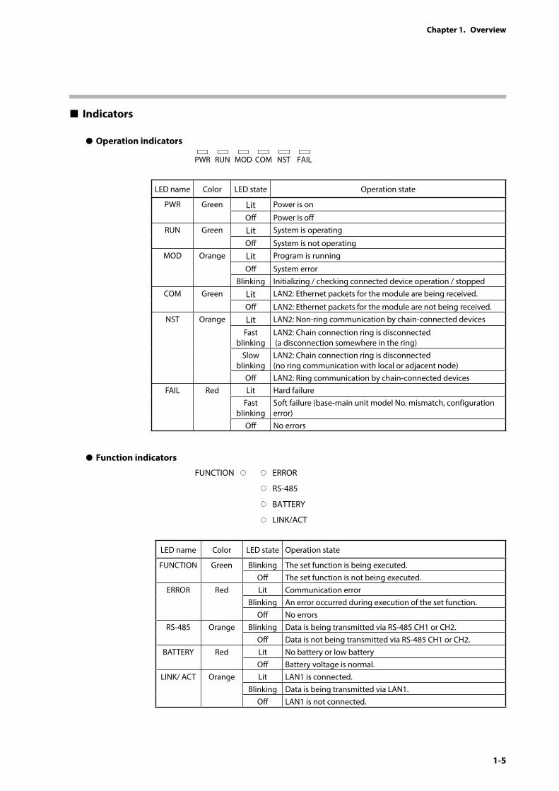
Indicators
z Operation indicators
PWR RUN MOD COM NST FAIL
LED name Color LED state Operation state
PWR Green Lit Power is on
Off Power is offRUN Green Lit System is operating
Off System is not operatingMOD Orange Lit Program is running
Off System errorBlinking Initializing / checking connected device operation / stopped
COM Green Lit LAN2: Ethernet packets for the module are being received.
Off LAN2: Ethernet packets for the module are not being received.NST Orange Lit LAN2: Non-ring communication by chain-connected devices
Fast blinking
LAN2: Chain connection ring is disconnected (a disconnection somewhere in the ring)
Slow blinking
LAN2: Chain connection ring is disconnected (no ring communication with local or adjacent node)
Off LAN2: Ring communication by chain-connected devicesFAIL Red Lit Hard failure
Fast blinking
Soft failure (base-main unit model No. mismatch, configuration error)
Off No errors
z Function indicators
RS-485
BATTERY
LINK/ACT
FUNCTION ERROR
LED name Color LED state Operation state
FUNCTION Green Blinking The set function is being executed.Off The set function is not being executed.
ERROR Red Lit Communication errorBlinking An error occurred during execution of the set function.
Off No errorsRS-485 Orange Blinking Data is being transmitted via RS-485 CH1 or CH2.
Off Data is not being transmitted via RS-485 CH1 or CH2.BATTERY Red Lit No battery or low battery
Off Battery voltage is normal.LINK/ ACT Orange Lit LAN1 is connected.
Blinking Data is being transmitted via LAN1.Off LAN1 is not connected.
1-6
Chapter 1. Overview
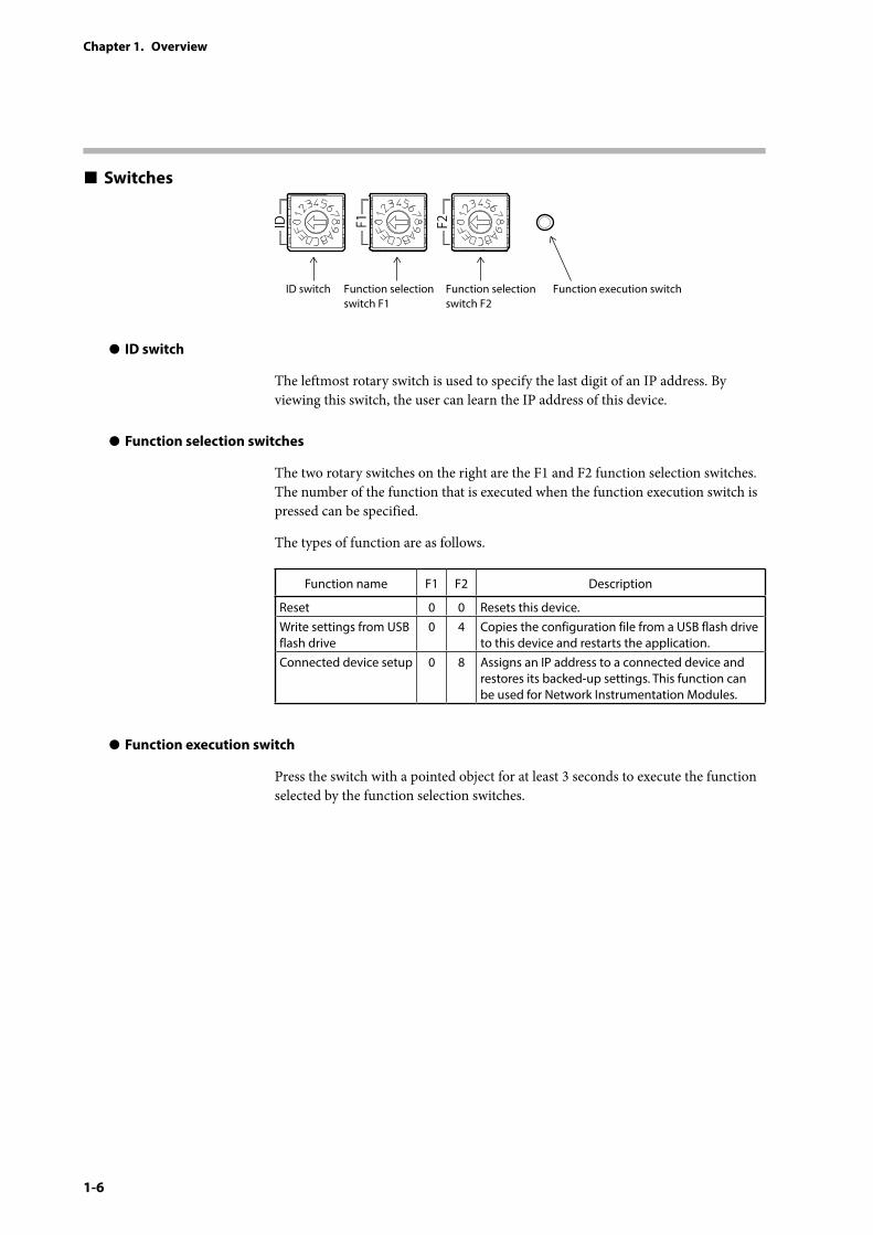
Switches
ID switch Function selection switch F1
Function selection switch F2
Function execution switch
z ID switch
The leftmost rotary switch is used to specify the last digit of an IP address. By viewing this switch, the user can learn the IP address of this device.
z Function selection switches
The two rotary switches on the right are the F1 and F2 function selection switches. The number of the function that is executed when the function execution switch is pressed can be specified.
The types of function are as follows.
Function name F1 F2 Description
Reset 0 0 Resets this device.Write settings from USB flash drive
0 4 Copies the configuration file from a USB flash drive to this device and restarts the application.
Connected device setup 0 8 Assigns an IP address to a connected device and restores its backed-up settings. This function can be used for Network Instrumentation Modules.
z Function execution switch
Press the switch with a pointed object for at least 3 seconds to execute the function selected by the function selection switches.
1-7
Chapter 1. Overview
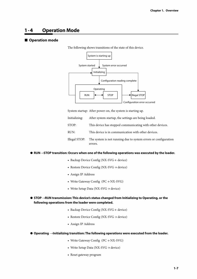
Operation mode
The following shows transitions of the state of this device.
RUN
Initializing
STOP
Operating
Conguration reading complete
System error occurredSystem started
Illegal STOP
Conguration error occurred
System is starting up
System startup: After power-on, the system is starting up.
Initializing: After system startup, the settings are being loaded.
STOP: This device has stopped communicating with other devices.
RUN: This device is in communication with other devices.
Illegal STOP: The system is not running due to system errors or configuration errors.
z RUN→STOP transition: Occurs when one of the following operations was executed by the loader.
• Backup Device Config (NX-SVG ← device)
• Restore Device Config (NX-SVG → device)
• Assign IP Address
• Write Gateway Config (PC → NX-SVG)
• Write Setup Data (NX-SVG → device)
z STOP→RUN transmission: This device’s status changed from Initializing to Operating, or the following operations from the loader were completed.
• Backup Device Config (NX-SVG ← device)
• Restore Device Config (NX-SVG → device)
• Assign IP Address
z Operating →Initializing transition: The following operations were executed from the loader.
• Write Gateway Config (PC → NX-SVG)
• Write Setup Data (NX-SVG → device)
• Reset gateway program
1 - 4 Operation Mode

2-1
WARNINGBefore removing, mounting, or wiring this device, be sure to turn off the power to this device and all connected devices. Otherwise, there is a danger of electric shock.
CAUTIONInstall or remove the DIN rail locking tab using a tool such as a screwdriver. Otherwise, you might be injured.
Do not block the ventilation holes.
There is a danger of fire or device failure.
Do not allow wire clippings, metal shavings, water, etc., to enter the case.
There is a danger of fire or device failure.
If this device is used in the manner not specified by the manufacturer, the protective function of the device may be impaired.
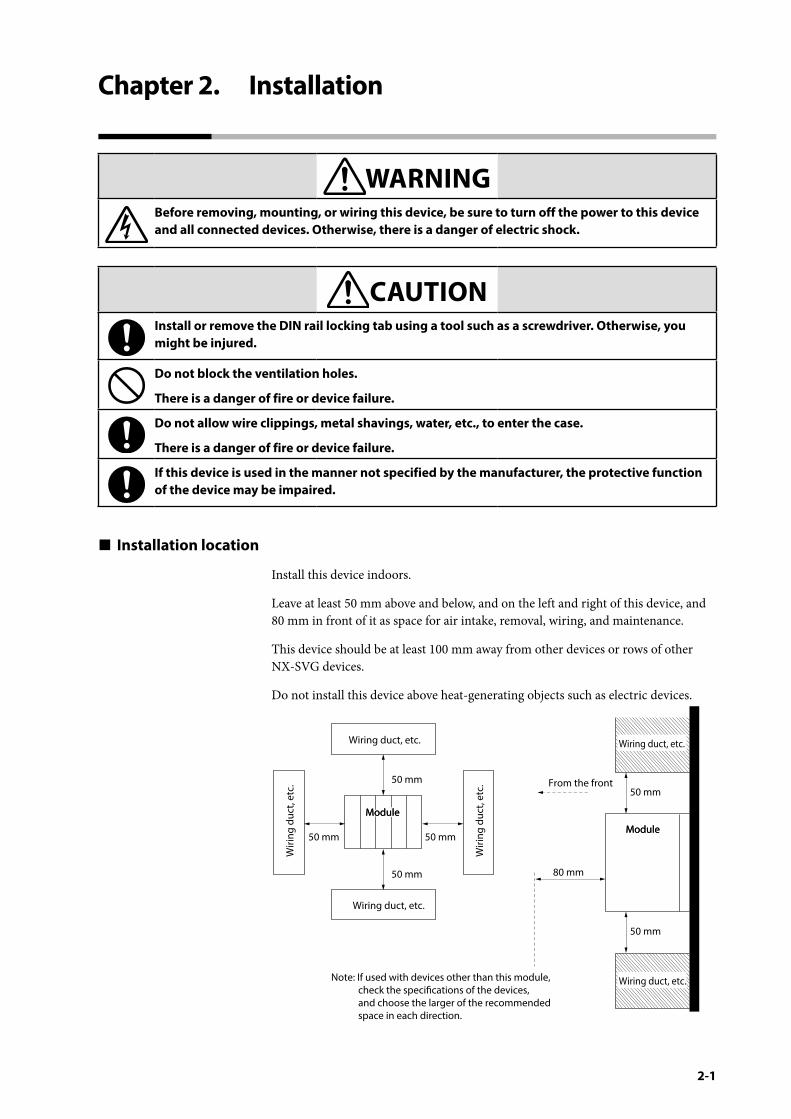
Installation location
Install this device indoors.
Leave at least 50 mm above and below, and on the left and right of this device, and 80 mm in front of it as space for air intake, removal, wiring, and maintenance.
This device should be at least 100 mm away from other devices or rows of other NX-SVG devices.
Do not install this device above heat-generating objects such as electric devices.
Wiring duct, etc.
Wiri
ng d
uct,
etc.
Wiri
ng d
uct,
etc.
80 mm
From the front
Wiring duct, etc.
50 mm
50 mm50 mm
50 mm
50 mm50 mm
Wiring duct, etc.
Wiring duct, etc.
ModuleModule
ModuleModule
Note: If used with devices other than this module, check the specications of the devices, and choose the larger of the recommended space in each direction.
Chapter 2. Installation
2-2
Chapter 2. Installation
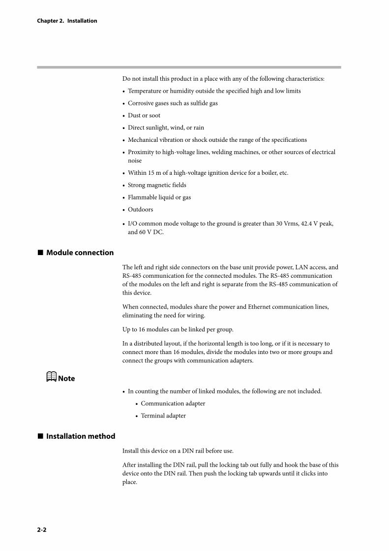
Do not install this product in a place with any of the following characteristics:
• Temperature or humidity outside the specified high and low limits
• Corrosive gases such as sulfide gas
• Dust or soot
• Direct sunlight, wind, or rain
• Mechanical vibration or shock outside the range of the specifications
• Proximity to high-voltage lines, welding machines, or other sources of electrical noise
• Within 15 m of a high-voltage ignition device for a boiler, etc.
• Strong magnetic fields
• Flammable liquid or gas
• Outdoors
• I/O common mode voltage to the ground is greater than 30 Vrms, 42.4 V peak, and 60 V DC.
Module connection
The left and right side connectors on the base unit provide power, LAN access, and RS-485 communication for the connected modules. The RS-485 communication of the modules on the left and right is separate from the RS-485 communication of this device.
When connected, modules share the power and Ethernet communication lines, eliminating the need for wiring.
Up to 16 modules can be linked per group.
In a distributed layout, if the horizontal length is too long, or if it is necessary to connect more than 16 modules, divide the modules into two or more groups and connect the groups with communication adapters.
Note
• In counting the number of linked modules, the following are not included.
• Communication adapter
• Terminal adapter
Installation method
Install this device on a DIN rail before use.
After installing the DIN rail, pull the locking tab out fully and hook the base of this device onto the DIN rail. Then push the locking tab upwards until it clicks into place.
2-3
Chapter 2. Installation
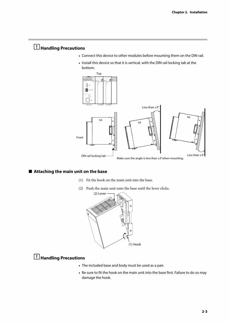
Handling Precautions
• Connect this device to other modules before mounting them on the DIN rail.
• Install this device so that it is vertical, with the DIN rail locking tab at the bottom.
NX-D35N
LOCK
NX-D35N
LOCK
RING
NXNX
NX
Top
Front
Make sure the angle is less than ±3°when mounting.Less than ±3°
Less than ±3°
PWR
NX-SVGN
USB
DA (+)
SG
DB (–) RS-485 CH1
RS-485
BATTERY
LINK/ ACT
LAN1
FUNCTION ERROR
ID F1 F2
RUN MOD COM NST FAIL
DIN rail locking tab
Attaching the main unit on the base
(1) Fit the hook on the main unit into the base.
(2) Push the main unit onto the base until the lever clicks.
(2) Lever
(1) Hook
Handling Precautions
• The included base and body must be used as a pair.
• Be sure to fit the hook on the main unit into the base first. Failure to do so may damage the hook.
2-4
Chapter 2. Installation
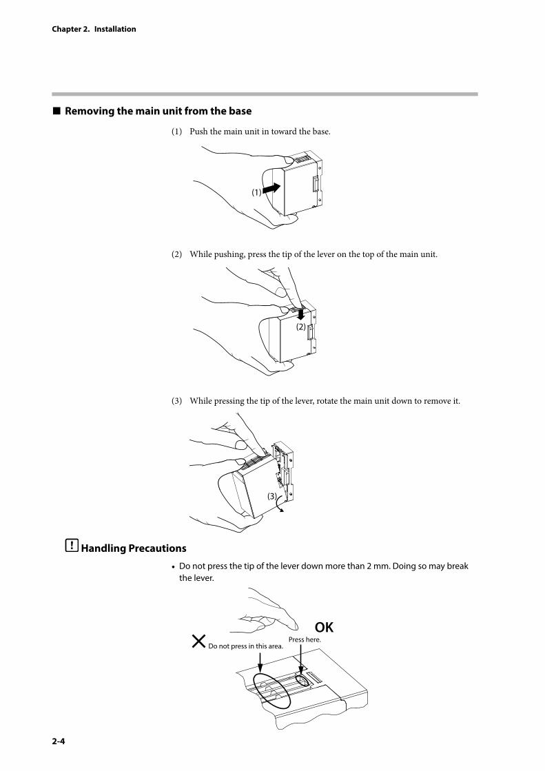
Removing the main unit from the base
(1) Push the main unit in toward the base.
(1)
(2) While pushing, press the tip of the lever on the top of the main unit.
(2)
(3) While pressing the tip of the lever, rotate the main unit down to remove it.
(3)
Handling Precautions
• Do not press the tip of the lever down more than 2 mm. Doing so may break the lever.
Do not press in this area.Press here.
OK
2-5
Chapter 2. Installation
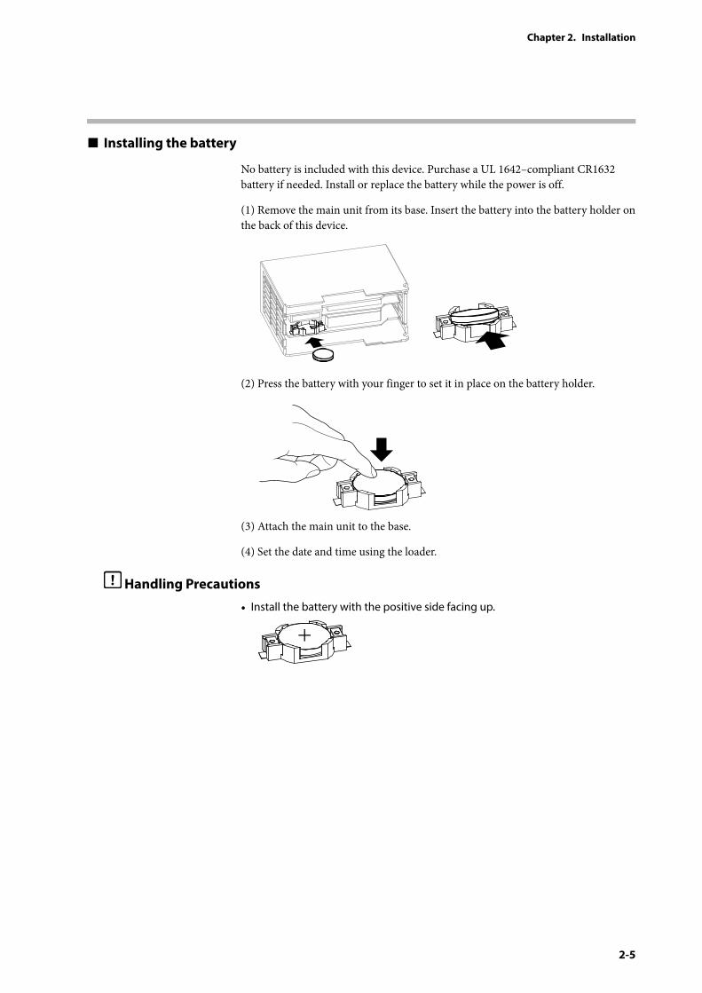
Installing the battery
No battery is included with this device. Purchase a UL 1642–compliant CR1632 battery if needed. Install or replace the battery while the power is off.
(1) Remove the main unit from its base. Insert the battery into the battery holder on the back of this device.
(2) Press the battery with your finger to set it in place on the battery holder.
(3) Attach the main unit to the base.
(4) Set the date and time using the loader.
Handling Precautions
• Install the battery with the positive side facing up.

3-1
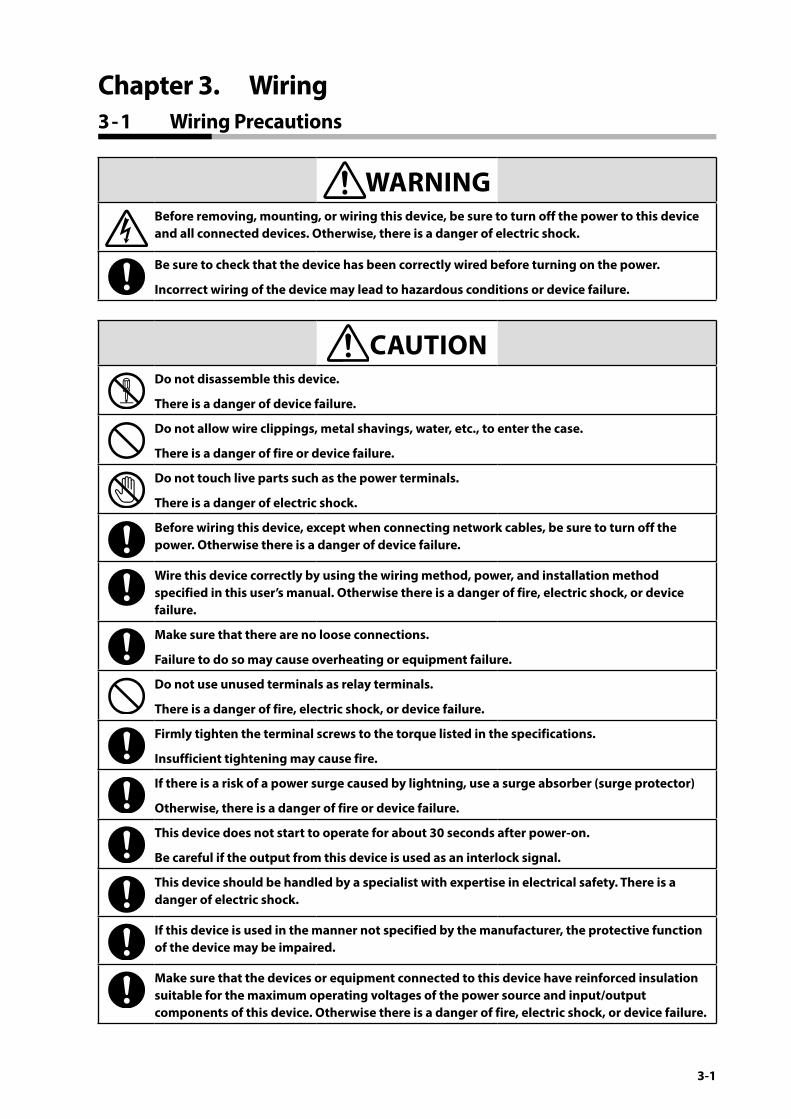
WARNINGBefore removing, mounting, or wiring this device, be sure to turn off the power to this device and all connected devices. Otherwise, there is a danger of electric shock.
Be sure to check that the device has been correctly wired before turning on the power.
Incorrect wiring of the device may lead to hazardous conditions or device failure.
CAUTIONDo not disassemble this device.
There is a danger of device failure.
Do not allow wire clippings, metal shavings, water, etc., to enter the case.
There is a danger of fire or device failure.
Do not touch live parts such as the power terminals.
There is a danger of electric shock.
Before wiring this device, except when connecting network cables, be sure to turn off the power. Otherwise there is a danger of device failure.
Wire this device correctly by using the wiring method, power, and installation method specified in this user’s manual. Otherwise there is a danger of fire, electric shock, or device failure.
Make sure that there are no loose connections.
Failure to do so may cause overheating or equipment failure.
Do not use unused terminals as relay terminals.
There is a danger of fire, electric shock, or device failure.
Firmly tighten the terminal screws to the torque listed in the specifications.
Insufficient tightening may cause fire.
If there is a risk of a power surge caused by lightning, use a surge absorber (surge protector)
Otherwise, there is a danger of fire or device failure.
This device does not start to operate for about 30 seconds after power-on.
Be careful if the output from this device is used as an interlock signal.
This device should be handled by a specialist with expertise in electrical safety. There is a danger of electric shock.
If this device is used in the manner not specified by the manufacturer, the protective function of the device may be impaired.
Make sure that the devices or equipment connected to this device have reinforced insulation suitable for the maximum operating voltages of the power source and input/output components of this device. Otherwise there is a danger of fire, electric shock, or device failure.
Chapter 3. Wiring3 - 1 Wiring Precautions
3-2
Chapter 3. Wiring
Wiring precautions
• When wiring this device, observe local electrotechnical standards.
• Do not run wires outdoors. Doing so may damage the device in the event of a lightning strike.
• Use crimp terminal lugs with insulating sleeves for the power terminals.
• Use crimp terminal lugs compatible with M3 screws for wiring of the power terminals and RS-485 CH2 terminals.
• Be careful not to allow crimp terminal lugs to touch adjacent terminals.
• The signal wires and power lines of this device should be at least 60 cm away from other power lines. Also, do not put these two types of wire in the same conduit or duct.
• Before connecting this device to other instruments in parallel, check their conditions for connection carefully.
• After wiring, check that there are no wiring mistakes before turning the power on.
• To ensure stable operation, this device does not start to operate for about 30 seconds after power-on.
3-3
Chapter 3. Wiring
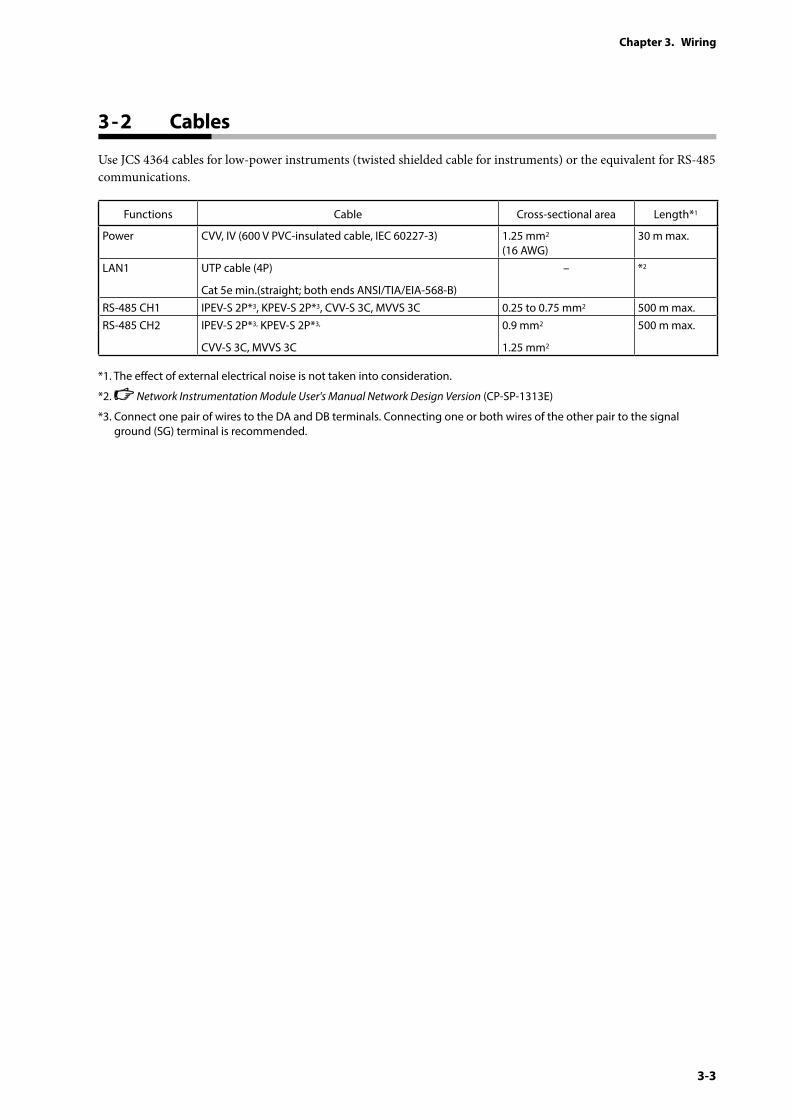
Use JCS 4364 cables for low-power instruments (twisted shielded cable for instruments) or the equivalent for RS-485 communications.
Functions Cable Cross-sectional area Length*1
Power CVV, IV (600 V PVC-insulated cable, IEC 60227-3) 1.25 mm2 (16 AWG)
30 m max.
LAN1 UTP cable (4P)
Cat 5e min.(straight; both ends ANSI/TIA/EIA-568-B)
– *2
RS-485 CH1 IPEV-S 2P*3, KPEV-S 2P*3, CVV-S 3C, MVVS 3C 0.25 to 0.75 mm2 500 m max.RS-485 CH2 IPEV-S 2P*3, KPEV-S 2P*3,
CVV-S 3C, MVVS 3C
0.9 mm2
1.25 mm2
500 m max.
*1. The effect of external electrical noise is not taken into consideration.
*2. Network Instrumentation Module User's Manual Network Design Version (CP-SP-1313E)
*3. Connect one pair of wires to the DA and DB terminals. Connecting one or both wires of the other pair to the signal ground (SG) terminal is recommended.
3 - 2 Cables
3-4
Chapter 3. Wiring
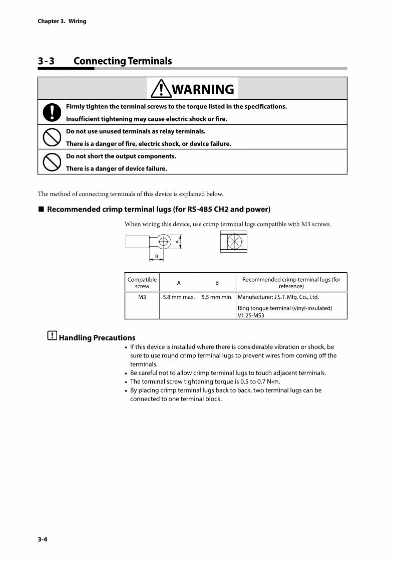
WARNINGFirmly tighten the terminal screws to the torque listed in the specifications.
Insufficient tightening may cause electric shock or fire.
Do not use unused terminals as relay terminals.
There is a danger of fire, electric shock, or device failure.
Do not short the output components.
There is a danger of device failure.
The method of connecting terminals of this device is explained below.
Recommended crimp terminal lugs (for RS-485 CH2 and power)
When wiring this device, use crimp terminal lugs compatible with M3 screws.
A
B
Compatible screw A B Recommended crimp terminal lugs (for
reference)
M3 5.8 mm max. 5.5 mm min. Manufacturer: J.S.T. Mfg. Co., Ltd.
Ring tongue terminal (vinyl-insulated) V1.25-MS3
Handling Precautions• If this device is installed where there is considerable vibration or shock, be
sure to use round crimp terminal lugs to prevent wires from coming off the terminals.
• Be careful not to allow crimp terminal lugs to touch adjacent terminals.• The terminal screw tightening torque is 0.5 to 0.7 N•m.• By placing crimp terminal lugs back to back, two terminal lugs can be
connected to one terminal block.
3 - 3 Connecting Terminals
3-5
Chapter 3. Wiring
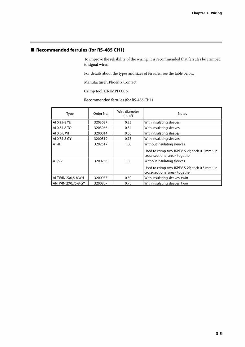
Recommended ferrules (for RS-485 CH1)
To improve the reliability of the wiring, it is recommended that ferrules be crimped to signal wires.
For details about the types and sizes of ferrules, see the table below.
Manufacturer: Phoenix Contact
Crimp tool: CRIMPFOX 6
Recommended ferrules (for RS-485 CH1)
Type Order No. Wire diameter (mm2) Notes
AI 0,25-8 YE 3203037 0.25 With insulating sleevesAI 0,34-8-TQ 3203066 0.34 With insulating sleevesAI 0,5-8 WH 3200014 0.50 With insulating sleevesAI 0,75-8 GY 3200519 0.75 With insulating sleevesA1-8 3202517 1.00 Without insulating sleeves
Used to crimp two JKPEV-S-2P, each 0.5 mm2 (in cross-sectional area), together.
A1,5-7 3200263 1.50 Without insulating sleeves
Used to crimp two JKPEV-S-2P, each 0.5 mm2 (in cross-sectional area), together.
AI-TWIN 2X0,5-8 WH 3200933 0.50 With insulating sleeves, twinAI-TWIN 2X0,75-8 GY 3200807 0.75 With insulating sleeves, twin
3-6
Chapter 3. Wiring
Connecting the power
WARNINGBefore removing, mounting, or wiring this device, be sure to turn off the power to this device and all connected devices. Otherwise, there is a danger of electric shock.
CAUTIONThe total power consumption of all connected modules should be no more than 70 W. Otherwise fire or device failure may result.
Do not supply power to a group of connected modules from multiple power sources. There is a danger of fire or device failure.
Wire this device correctly by using the wiring method, power, and installation method specified in this user’s manual. Otherwise there is a danger of fire, electric shock, or device failure.
Make sure that there are no loose connections. Failure to do so may cause overheating or equipment failure.
Make sure that devices or equipment connected to this device have reinforced insulation suitable for the maximum voltages of this device’s power supply and input/output components. Otherwise there is a danger of fire, electric shock, or device failure.
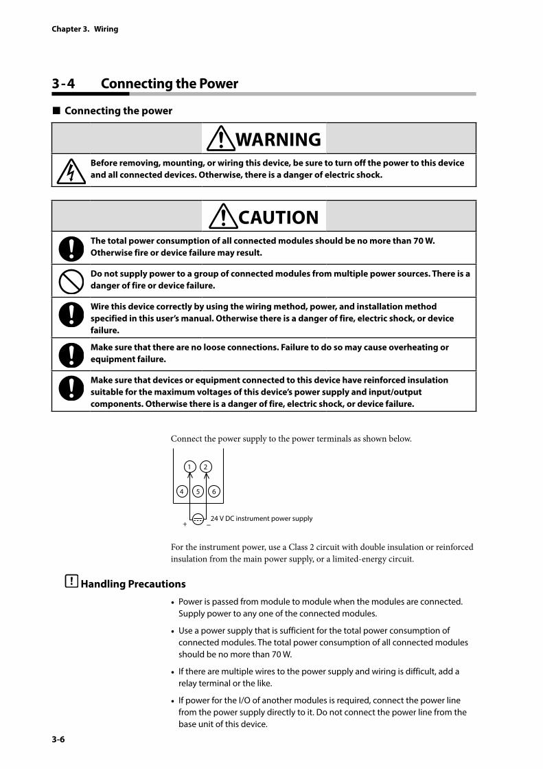
Connect the power supply to the power terminals as shown below.
1 2
24 V DC instrument power supply
4 5 6
+ −
For the instrument power, use a Class 2 circuit with double insulation or reinforced insulation from the main power supply, or a limited-energy circuit.
Handling Precautions
• Power is passed from module to module when the modules are connected. Supply power to any one of the connected modules.
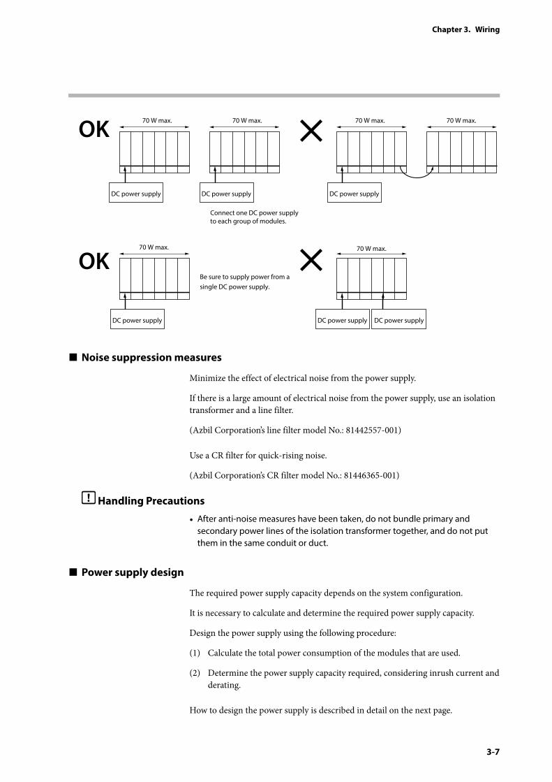
• Use a power supply that is sufficient for the total power consumption of connected modules. The total power consumption of all connected modules should be no more than 70 W.
• If there are multiple wires to the power supply and wiring is difficult, add a relay terminal or the like.
• If power for the I/O of another modules is required, connect the power line from the power supply directly to it. Do not connect the power line from the base unit of this device.
3 - 4 Connecting the Power
3-7
Chapter 3. Wiring
70 W max.
DC power supply
70 W max.
DC power supply DC power supplyDC power supply
DC power supply DC power supply
70 W max.
70 W max. 70 W max.
70 W max.
Be sure to supply power from a single DC power supply.
Connect one DC power supply to each group of modules.
OK
OK
Noise suppression measures
Minimize the effect of electrical noise from the power supply.
If there is a large amount of electrical noise from the power supply, use an isolation transformer and a line filter.
(Azbil Corporation’s line filter model No.: 81442557-001)
Use a CR filter for quick-rising noise.
(Azbil Corporation’s CR filter model No.: 81446365-001)
Handling Precautions
• After anti-noise measures have been taken, do not bundle primary and secondary power lines of the isolation transformer together, and do not put them in the same conduit or duct.
Power supply design
The required power supply capacity depends on the system configuration.
It is necessary to calculate and determine the required power supply capacity.
Design the power supply using the following procedure:
(1) Calculate the total power consumption of the modules that are used.
(2) Determine the power supply capacity required, considering inrush current and derating.
How to design the power supply is described in detail on the next page.
3-8
Chapter 3. Wiring
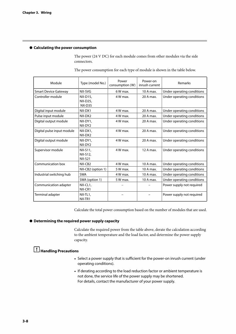
z Calculating the power consumption
The power (24 V DC) for each module comes from other modules via the side connectors.
The power consumption for each type of module is shown in the table below.
Module Type (model No.) Power consumption (W)
Power-on inrush current Remarks
Smart Device Gateway NX-SVG 6 W max. 10 A max. Under operating conditionsController module NX-D15,
NX-D25, NX-D35
4 W max. 20 A max. Under operating conditions
Digital input module NX-DX1 4 W max. 20 A max. Under operating conditionsPulse input module NX-DX2 4 W max. 20 A max. Under operating conditionsDigital output module NX-DY1,
NX-DY24 W max. 20 A max. Under operating conditions
Digital pulse input module NX-DX1, NX-DX2
4 W max. 20 A max. Under operating conditions
Digital output module NX-DY1, NX-DY2
4 W max. 20 A max. Under operating conditions
Supervisor module NX-S11, NX-S12, NX-S21
4 W max. 12 A max. Under operating conditions
Communication box NX-CB2 4 W max. 10 A max. Under operating conditionsNX-CB2 (option 1) 5 W max. 10 A max. Under operating conditions
Industrial switching hub SWA 4 W max. 10 A max. Under operating conditionsSWA (option 1) 5 W max. 10 A max. Under operating conditions
Communication adapter NX-CL1, NX-CR1
– – Power supply not required
Terminal adapter NX-TL1, NX-TR1
– – Power supply not required
Calculate the total power consumption based on the number of modules that are used.
z Determining the required power supply capacity
Calculate the required power from the table above, derate the calculation according to the ambient temperature and the load factor, and determine the power supply capacity.
Handling Precautions
• Select a power supply that is sufficient for the power-on inrush current (under operating conditions).
• If derating according to the load reduction factor or ambient temperature is not done, the service life of the power supply may be shortened. For details, contact the manufacturer of your power supply.

3-9
Chapter 3. Wiring
The LAN1 port is on the front of the main unit. Connect a cable with an RJ-45 connector to the port. 10BASE-T or 100BASE-TX Ethernet can be connected to this device.
Connect the LAN2 port by connecting a side connector on the base unit. To connect a cable with an RJ-45 connector to the side connector, use a communication adapter.
Note
• Section 1-3, “Explanation of Module Features,” and chapter 2, “Configuration of Ethernet Communications,” in Network Instrumentation Module User's Manual: Network Design Version (CP-SP-1313E) (for Ethernet communication connections)
The LAN1 port can have multiple IP addresses, and 192.168.255.253 is preset. This IP address can be used for connecting the loader.
The initial IP address of each port is as follows.
Name Initial IP address
LAN1 port 192.168.0.127 192.168.255.253
LAN2 port 192.168.4.127
z Specifying the IP address using the rotary switch
The IP address for the loader connection is preset for the LAN1 port. The user can set an additional address using the ID switch on the front of the main unit. This function is useful when multiple NX-SVG devices are connected to the network.
ID switch position LAN1 multiple IP addresses
0 192.168.0.127 192.168.255.253
1 192.168.0.127 192.168.255.253 192.168.255.1
2 192.168.0.127 192.168.255.253 192.168.255.2
3 192.168.0.127 192.168.255.253 192.168.255.3
E 192.168.0.127 192.168.255.253 192.168.255.14
F 192.168.0.127 192.168.255.253 192.168.255.15
3 - 5 Ethernet Communication Connections
3-10
Chapter 3. Wiring
Handling Precautions
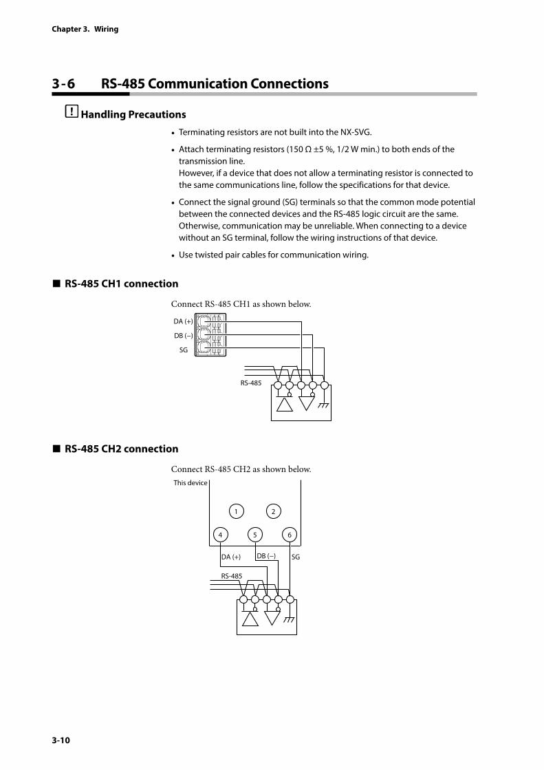
• Terminating resistors are not built into the NX-SVG.
• Attach terminating resistors (150 Ω ±5 %, 1/2 W min.) to both ends of the transmission line. However, if a device that does not allow a terminating resistor is connected to the same communications line, follow the specifications for that device.
• Connect the signal ground (SG) terminals so that the common mode potential between the connected devices and the RS-485 logic circuit are the same. Otherwise, communication may be unreliable. When connecting to a device without an SG terminal, follow the wiring instructions of that device.
• Use twisted pair cables for communication wiring.
RS-485 CH1 connection
Connect RS-485 CH1 as shown below.
DA (+)
DB (−)
SG
RS-485
RS-485 CH2 connection
Connect RS-485 CH2 as shown below.
1 2
DA (+) DB (−) SG
RS-485
This device
4 5 6
3 - 6 RS-485 Communication Connections
3-11
Chapter 3. Wiring
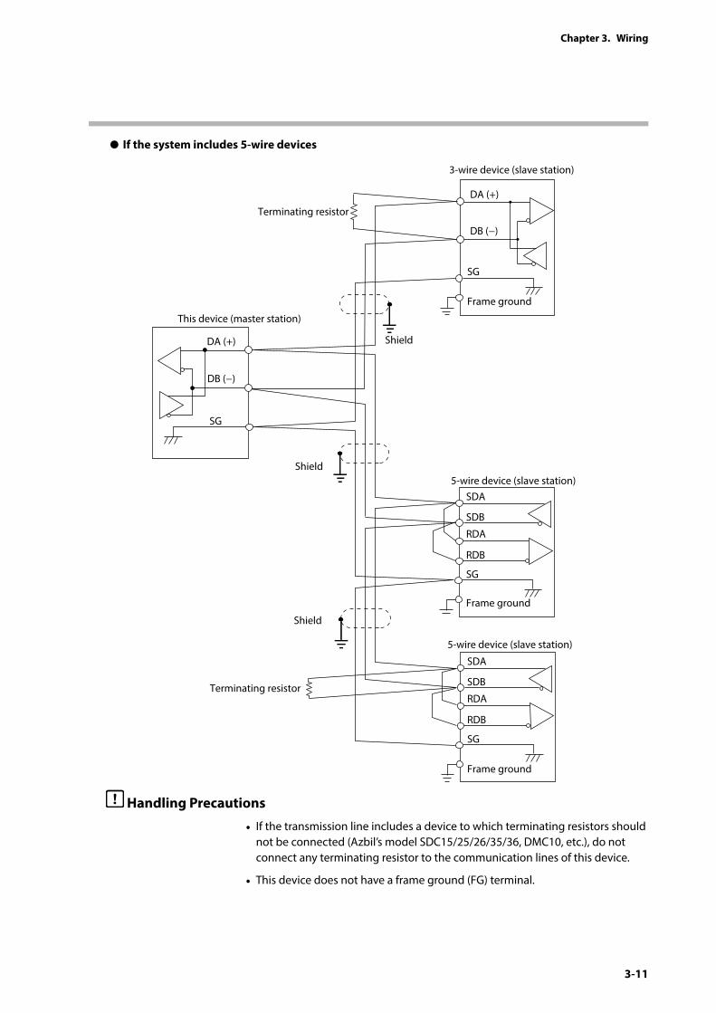
z If the system includes 5-wire devices
SDA
SDB
RDA
RDB
SG
Frame ground
Shield
SG
Frame ground
Shield
Shield
This device (master station)
Terminating resistor
SDA
SDB
RDA
RDB
SG
Frame ground
DA (+)
DB (−)
SG
DA (+)
DB (−)
Terminating resistor
3-wire device (slave station)
5-wire device (slave station)
5-wire device (slave station)
Handling Precautions
• If the transmission line includes a device to which terminating resistors should not be connected (Azbil’s model SDC15/25/26/35/36, DMC10, etc.), do not connect any terminating resistor to the communication lines of this device.
• This device does not have a frame ground (FG) terminal.
3-12
Chapter 3. Wiring
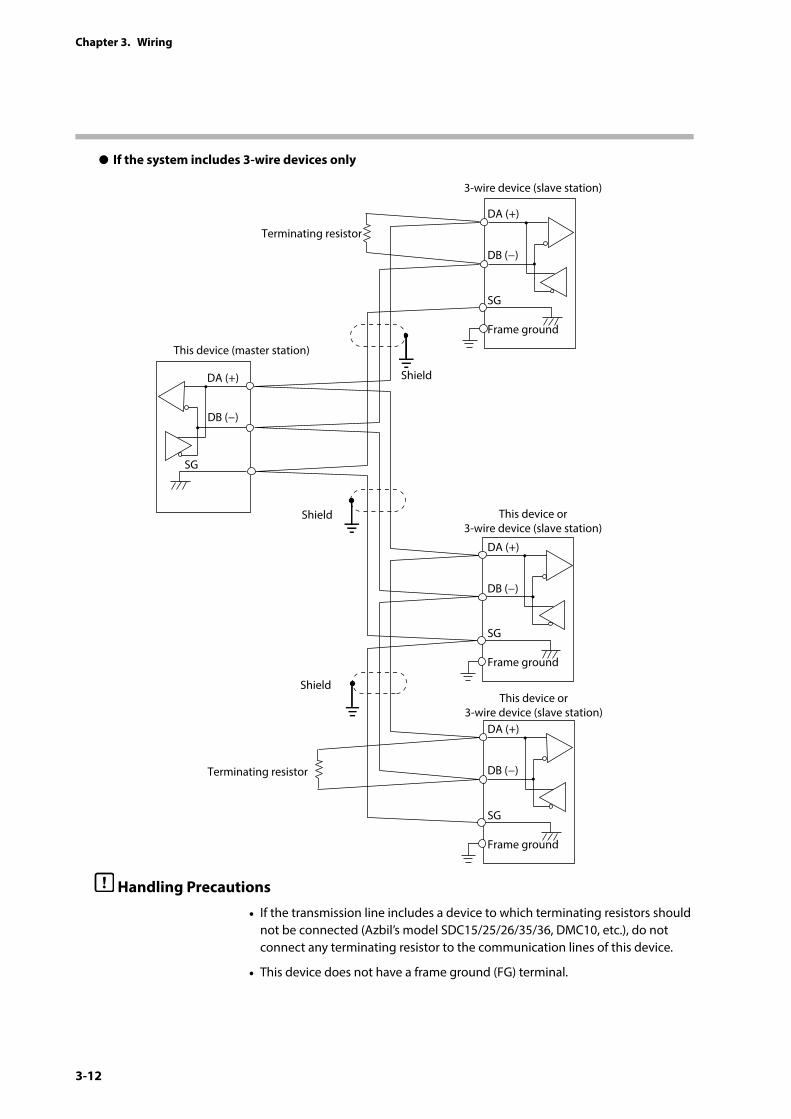
z If the system includes 3-wire devices only
Shield
Shield
Shield
This device (master station)
Terminating resistor
SG
Frame ground
DA (+)
DB (−)
DA (+)
DB (−)
DA (+)
DB (−)
Terminating resistor
SG
SG
Frame ground
SG
Frame ground
3-wire device (slave station)
This device or3-wire device (slave station)
This device or3-wire device (slave station)
DA (+)
DB (−)
Handling Precautions
• If the transmission line includes a device to which terminating resistors should not be connected (Azbil’s model SDC15/25/26/35/36, DMC10, etc.), do not connect any terminating resistor to the communication lines of this device.
• This device does not have a frame ground (FG) terminal.

3-13
Chapter 3. Wiring
Connect a USB flash drive to this connector to save or load data.
Do not connect a device other than a USB flash drive.
Attach the USB dust cover when the USB port is not in use.
3 - 7 USB Host Connector
3-14
Chapter 3. Wiring
The following are typical sources of electrical noise:• Relays and contacts• Solenoid coils and solenoid valves• Power lines (especially 90 V AC or higher)• Inductive loads• Motor commutators• Phase angle control SCRs• Radio communication devices• Welding machines• High-voltage ignition devices
The following are effective countermeasures for electrical noise.
• CR filter for quick-rising noise
Recommended CR filter: Azbil’s model No. 81446365-001
• Varistor for noise with high peak values
Recommended varistor: Azbil’s model No. 81446366-001 (for 100 V), 81446367-001 (for 200 V)
Handling Precautions
• Take great care when using a varistor because it causes a short circuit if it is faulty.
3 - 8 Electrical Noise Sources and Countermeasures
3-15
Chapter 3. Wiring
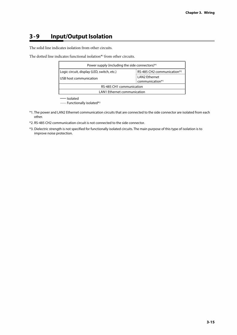
The solid line indicates isolation from other circuits.
The dotted line indicates functional isolation*1 from other circuits.
Power supply (including the side connectors)*1
Logic circuit, display (LED, switch, etc.)
USB host communication
RS-485 CH2 communication*2
LAN2 Ethernet communication*1
RS-485 CH1 communicationLAN1 Ethernet communication
Isolated Functionally isolated*3
*1. The power and LAN2 Ethernet communication circuits that are connected to the side connector are isolated from each other.
*2. RS-485 CH2 communication circuit is not connected to the side connector.
*3. Dielectric strength is not specified for functionally isolated circuits. The main purpose of this type of isolation is to improve noise protection.
3 - 9 Input/Output Isolation
3-16
Chapter 3. Wiring
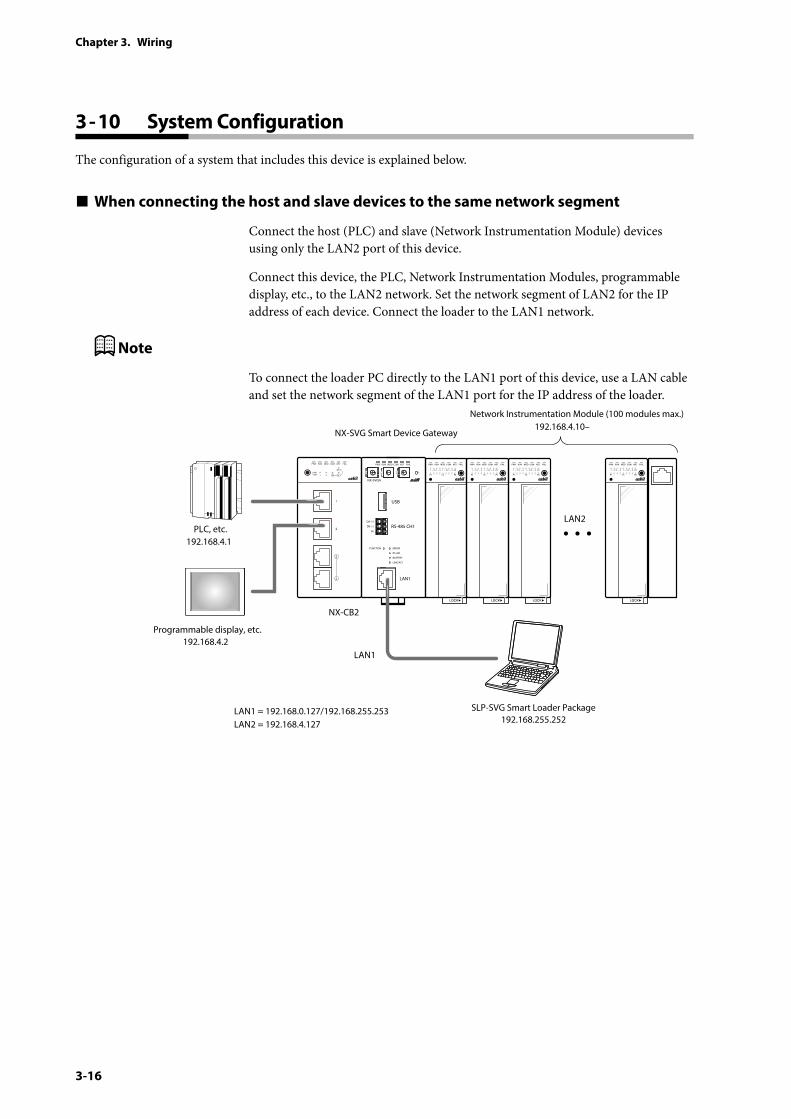
The configuration of a system that includes this device is explained below.
When connecting the host and slave devices to the same network segment
Connect the host (PLC) and slave (Network Instrumentation Module) devices using only the LAN2 port of this device.
Connect this device, the PLC, Network Instrumentation Modules, programmable display, etc., to the LAN2 network. Set the network segment of LAN2 for the IP address of each device. Connect the loader to the LAN1 network.
Note
To connect the loader PC directly to the LAN1 port of this device, use a LAN cable and set the network segment of the LAN1 port for the IP address of the loader.
PWR
NX-SVGN
USB
DA (+)
SG
DB (−) RS-485 CH1
RS-485
BATTERY
LINK/ACT
LAN1
FUNCTION ERROR
ID F1 F2
RUN MOD COM NST FAIL
PLC, etc.
NX-CB2
LAN1
SLP-SVG Smart Loader Package192.168.255.252
LAN1 = 192.168.0.127/192.168.255.253LAN2 = 192.168.4.127
192.168.4.1
NX-SVG Smart Device Gateway
Network Instrumentation Module (100 modules max.)192.168.4.10–
192.168.4.2Programmable display, etc.
LAN2
3 - 10 System Configuration
3-17
Chapter 3. Wiring
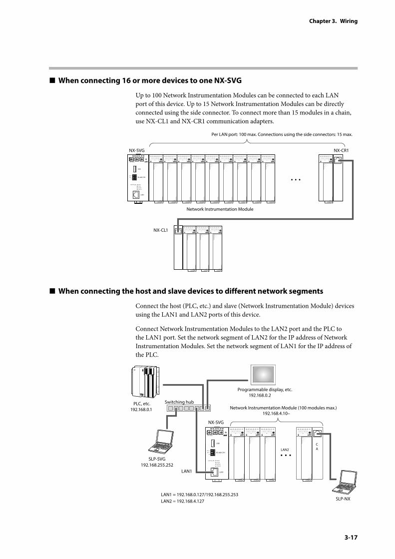
When connecting 16 or more devices to one NX-SVG
Up to 100 Network Instrumentation Modules can be connected to each LAN port of this device. Up to 15 Network Instrumentation Modules can be directly connected using the side connector. To connect more than 15 modules in a chain, use NX-CL1 and NX-CR1 communication adapters.
NX-SVG NX-CR1
Network Instrumentation Module
Per LAN port: 100 max. Connections using the side connectors: 15 max.
NX-CL1
PWR
NX-SVGN
USB
DA (+)
SG
DB (−) RS-485 CH1
RS-485
BATTERY
LINK/ACT
LAN1
FUNCTION ERROR
ID F1 F2
RUN MOD COM NST FAIL
When connecting the host and slave devices to different network segments
Connect the host (PLC, etc.) and slave (Network Instrumentation Module) devices using the LAN1 and LAN2 ports of this device.
Connect Network Instrumentation Modules to the LAN2 port and the PLC to the LAN1 port. Set the network segment of LAN2 for the IP address of Network Instrumentation Modules. Set the network segment of LAN1 for the IP address of the PLC.
PWR
NX-SVGN
USB
DA (+)
SG
DB (−) RS-485 CH1
RS-485
BATTERY
LINK/ACT
LAN1
FUNCTION ERROR
ID F1 F2
RUN MOD COM NST FAIL
LAN2CA
LAN1
SLP-SVG192.168.255.252
LAN1 = 192.168.0.127/192.168.255.253LAN2 = 192.168.4.127
Network Instrumentation Module (100 modules max.)192.168.4.10–
192.168.0.2Programmable display, etc.
PLC, etc.192.168.0.1
NX-SVG
Switching hub
SLP-NX
3-18
Chapter 3. Wiring
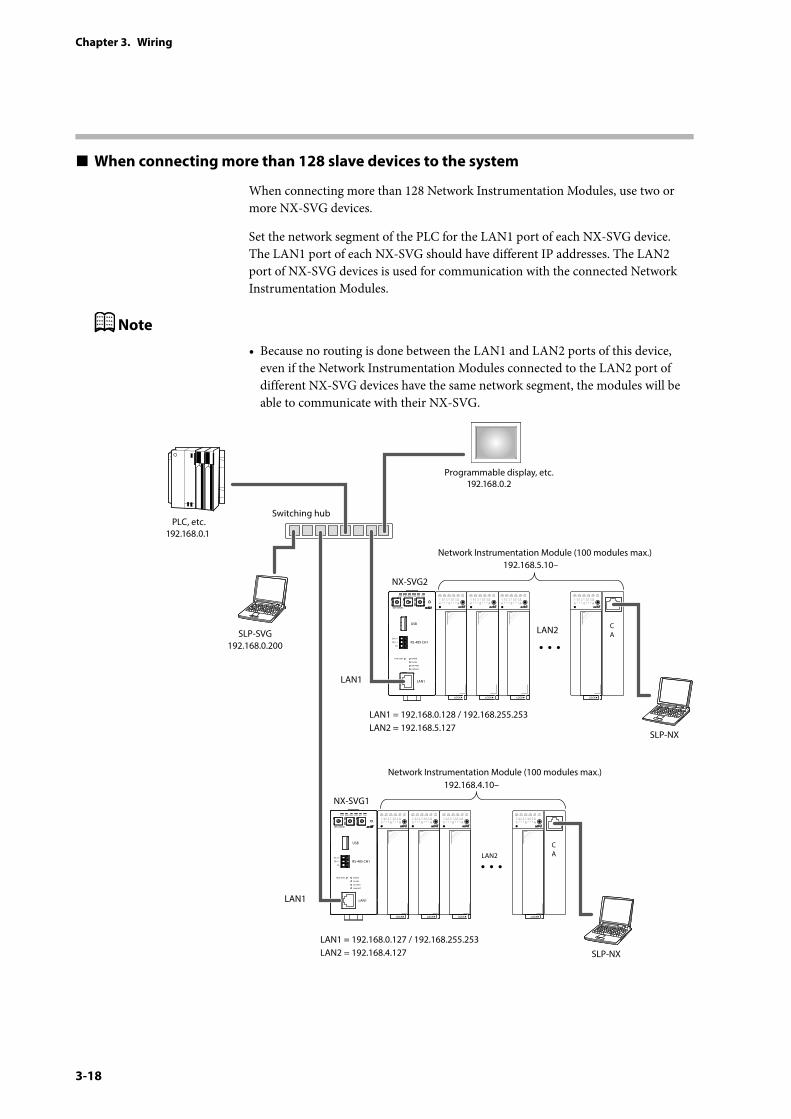
When connecting more than 128 slave devices to the system
When connecting more than 128 Network Instrumentation Modules, use two or more NX-SVG devices.
Set the network segment of the PLC for the LAN1 port of each NX-SVG device. The LAN1 port of each NX-SVG should have different IP addresses. The LAN2 port of NX-SVG devices is used for communication with the connected Network Instrumentation Modules.
Note
• Because no routing is done between the LAN1 and LAN2 ports of this device, even if the Network Instrumentation Modules connected to the LAN2 port of different NX-SVG devices have the same network segment, the modules will be able to communicate with their NX-SVG.
PWR
NX-SVGN
USB
DA (+)
SG
DB (−) RS-485 CH1
RS-485
BATTERY
LINK/ACT
LAN1
FUNCTION ERROR
ID F1 F2
RUN MOD COM NST FAIL
CA
LAN1
LAN2SLP-SVG192.168.0.200
LAN1 = 192.168.0.128 / 192.168.255.253LAN2 = 192.168.5.127
LAN1 = 192.168.0.127 / 192.168.255.253LAN2 = 192.168.4.127
Network Instrumentation Module (100 modules max.)192.168.5.10–
192.168.4.10–
192.168.0.2Programmable display, etc.
PLC, etc.192.168.0.1
NX-SVG2
Switching hub
SLP-NX
PWR
NX-SVGN
USB
DA (+)
SG
DB (−) RS-485 CH1
RS-485
BATTERY
LINK/ACT
LAN1
FUNCTION ERROR
ID F1 F2
RUN MOD COM NST FAIL
LAN2CA
LAN1
Network Instrumentation Module (100 modules max.)
NX-SVG1
SLP-NX
3-19
Chapter 3. Wiring
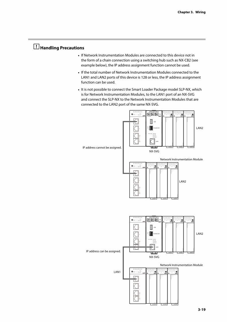
Handling Precautions
• If Network Instrumentation Modules are connected to this device not in the form of a chain connection using a switching hub such as NX-CB2 (see example below), the IP address assignment function cannot be used.
• If the total number of Network Instrumentation Modules connected to the LAN1 and LAN2 ports of this device is 128 or less, the IP address assignment function can be used.
• It is not possible to connect the Smart Loader Package model SLP-NX, which is for Network Instrumentation Modules, to the LAN1 port of an NX-SVG and connect the SLP-NX to the Network Instrumentation Modules that are connected to the LAN2 port of the same NX-SVG.
PWR
NX-SVGN
USB
DA (+)
SG
DB (−) RS-485 CH1
RS-485
BATTERY
LINK/ACT
LAN1
FUNCTION ERROR
ID F1 F2
RUN MOD COM NST FAIL
NX-SVG
LAN2
LAN2
LAN1
Network Instrumentation Module
IP address cannot be assigned.
IP address can be assigned.
PWR
NX-SVGN
USB
DA (+)
SG
DB (−) RS-485 CH1
RS-485
BATTERY
LINK/ACT
LAN1
FUNCTION ERROR
ID F1 F2
RUN MOD COM NST FAIL
NX-SVG
LAN2
Network Instrumentation Module
3-20
Chapter 3. Wiring
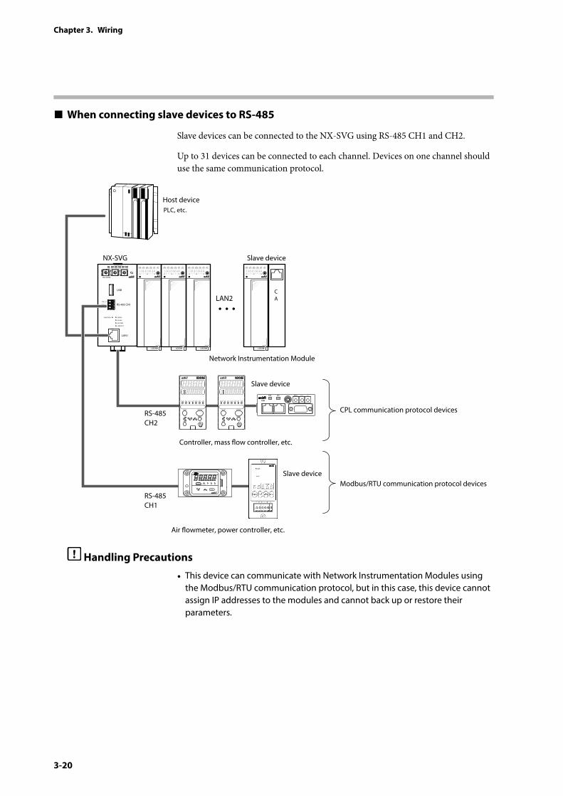
When connecting slave devices to RS-485
Slave devices can be connected to the NX-SVG using RS-485 CH1 and CH2.
Up to 31 devices can be connected to each channel. Devices on one channel should use the same communication protocol.
PWR
NX-SVGN
USB
DA (+)
SG
DB (−) RS-485 CH1
RS-485
BATTERY
LINK/ACT
LAN1
FUNCTION ERROR
ID F1 F2
RUN MOD COM NST FAIL
CA
Host device
Slave device
LAN2
Slave device
CPL communication protocol devices
Modbus/RTU communication protocol devices
Network Instrumentation Module
RS-485CH2
RS-485CH1
PLC, etc.
NX-SVG
Slave device
Controller, mass ow controller, etc.
Air owmeter, power controller, etc.
BRATE × 10 × 1NETPWR
F4H
mode
enter
ALEVLL/min
Handling Precautions
• This device can communicate with Network Instrumentation Modules using the Modbus/RTU communication protocol, but in this case, this device cannot assign IP addresses to the modules and cannot back up or restore their parameters.
4-1
Chapter 4. Functions4 - 1 Gateway Function
This chapter explains the functions of this device.
The gateway function enables data transmission between a host PLC and slave devices such as Network Instrumentation Modules. The gateway has three types of functions: cyclic data transmission, triggered data transmission, and bit setting. Specify transmission settings using the configuration sheet on the loader.
There is a limit on the number of rows that can be processed by each function, which is different depending on the function. The limits are as follows:
Gateway function Max. sheets Max. rows per sheet Maximum processing per function
Cyclic data transmission 500 500 10000 recordsTriggered data transmission 500 500 10000 recordsBit setting 500 500 1000 records
Cyclic data transmission
Data from a slave device is transmitted to the host device periodically. It is also possible to transmit host data to slave devices.
Main purposes:
• Saving slave device information to the PLC
• Monitoring slave device information using the PLC in order to manage equipment
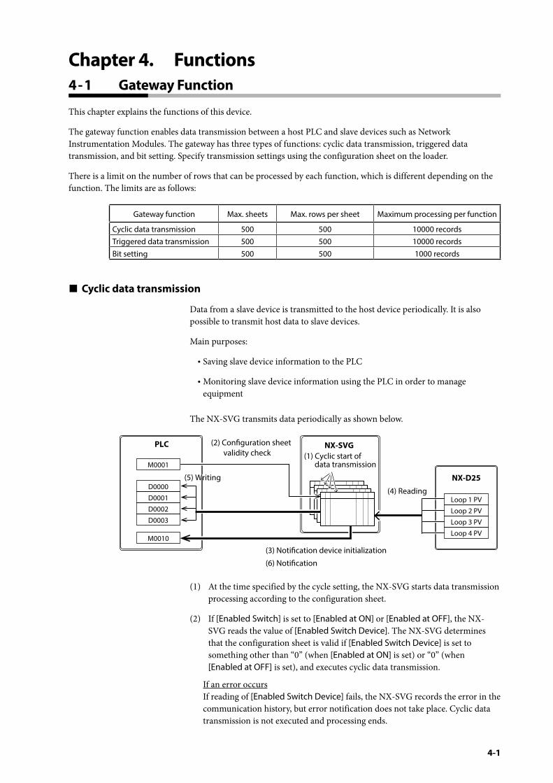
The NX-SVG transmits data periodically as shown below.
NX-SVG
NX-D25
(4) Reading
(1) Cyclic start of data transmission
(2) Conguration sheet validity check
(5) Writing(5) Writing
(3) Notication device initialization
(6) Notication
PLC
Loop 1 PV
Loop 2 PV
Loop 3 PV
Loop 4 PV
D0000
D0001
D0002
D0003
M0010
M0001
(1) At the time specified by the cycle setting, the NX-SVG starts data transmission processing according to the configuration sheet.
(2) If [Enabled Switch] is set to [Enabled at ON] or [Enabled at OFF], the NX-SVG reads the value of [Enabled Switch Device]. The NX-SVG determines that the configuration sheet is valid if [Enabled Switch Device] is set to something other than “0” (when [Enabled at ON] is set) or “0” (when [Enabled at OFF] is set), and executes cyclic data transmission.
If an error occurs If reading of [Enabled Switch Device] fails, the NX-SVG records the error in the communication history, but error notification does not take place. Cyclic data transmission is not executed and processing ends.
4-2
Chapter 4. Functions
(3) If [General] → [Common: Init Notify Device ] is set to [Enabled], the NX-SVG writes “0” to the specified completion notification device and error notification device in order to initialize them. If completion and error notification devices are not set, initialization is not executed.
If an error occurs If initialization of the notification devices fails, the NX-SVG records the error in the communication history, but error notification does not take place and processing continues.
(4) The NX-SVG reads data from the source device.
If an error occurs If a communication error occurs in data reading, the NX-SVG records the error in the communication history and stops processing the row on the sheet.
(5) The NX-SVG writes the data that has been read to the destination device.
If an error occurs If a communication error occurs in data writing, the NX-SVG records the error in the communication history but continues writing for the remaining rows on the sheet.
(6) When transmission of data on the sheet is complete, if there is an error in the processing results and if an error notification device is set on the sheet, the NX-SVG writes “1” to that device. If a completion notification device is set on the sheet, the NX-SVG writes “1” to that device.
If an error occurs If writing to the notification device fails, the NX-SVG records the error in the communication history and continues with the rest of the processing.
Note
• If data that is read from a word device is written to a bit device: If “0” is the setting of the word device, “0” is written to the bit device. If the word device is set to a value other than “0,” “1” is written to the bit device.
4-3
Chapter 4. Functions
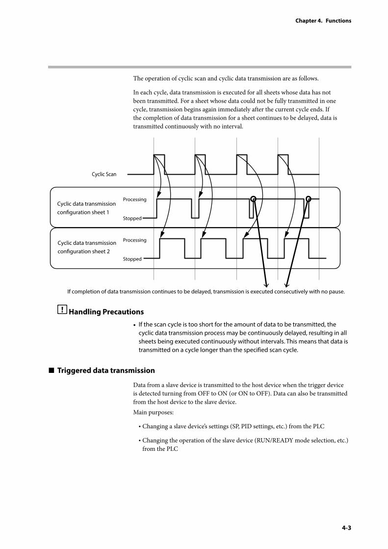
The operation of cyclic scan and cyclic data transmission are as follows.
In each cycle, data transmission is executed for all sheets whose data has not been transmitted. For a sheet whose data could not be fully transmitted in one cycle, transmission begins again immediately after the current cycle ends. If the completion of data transmission for a sheet continues to be delayed, data is transmitted continuously with no interval.
Cyclic Scan
Cyclic data transmission conguration sheet 1
Cyclic data transmission conguration sheet 2
If completion of data transmission continues to be delayed, transmission is executed consecutively with no pause.
Processing
Stopped
Processing
Stopped
Handling Precautions
• If the scan cycle is too short for the amount of data to be transmitted, the cyclic data transmission process may be continuously delayed, resulting in all sheets being executed continuously without intervals. This means that data is transmitted on a cycle longer than the specified scan cycle.
Triggered data transmission
Data from a slave device is transmitted to the host device when the trigger device is detected turning from OFF to ON (or ON to OFF). Data can also be transmitted from the host device to the slave device.Main purposes:
• Changing a slave device’s settings (SP, PID settings, etc.) from the PLC
• Changing the operation of the slave device (RUN/READY mode selection, etc.) from the PLC
4-4
Chapter 4. Functions
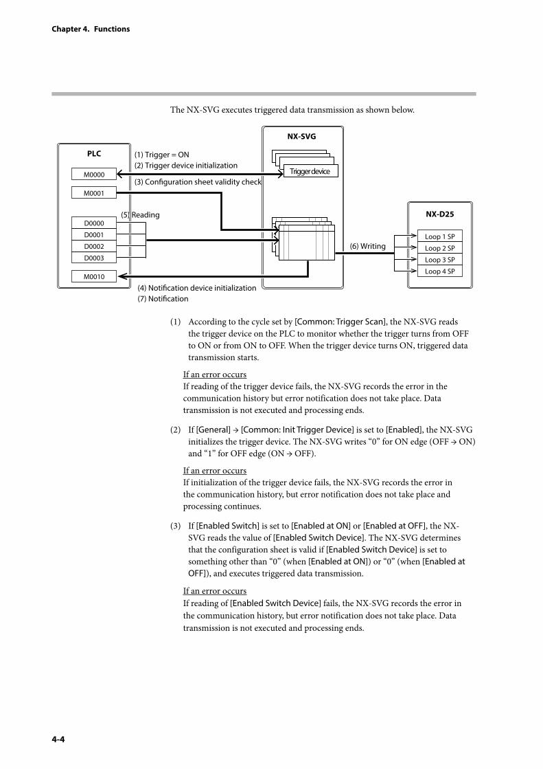
The NX-SVG executes triggered data transmission as shown below.
PLC
NX-SVG
NX-D25(5) Reading(5) Reading
(3) Conguration sheet validity check
(6) Writing
(1) Trigger = ON(2) Trigger device initialization
(4) Notication device initialization(7) Notication
Trigger device
Loop 1 SP
Loop 2 SP
Loop 3 SP
Loop 4 SP
D0000
M0000
D0001
D0002
D0003
M0010
M0001
(1) According to the cycle set by [Common: Trigger Scan], the NX-SVG reads the trigger device on the PLC to monitor whether the trigger turns from OFF to ON or from ON to OFF. When the trigger device turns ON, triggered data transmission starts.
If an error occurs If reading of the trigger device fails, the NX-SVG records the error in the communication history but error notification does not take place. Data transmission is not executed and processing ends.
(2) If [General] → [Common: Init Trigger Device] is set to [Enabled], the NX-SVG initializes the trigger device. The NX-SVG writes “0” for ON edge (OFF → ON) and “1” for OFF edge (ON → OFF).
If an error occurs If initialization of the trigger device fails, the NX-SVG records the error in the communication history, but error notification does not take place and processing continues.
(3) If [Enabled Switch] is set to [Enabled at ON] or [Enabled at OFF], the NX-SVG reads the value of [Enabled Switch Device]. The NX-SVG determines that the configuration sheet is valid if [Enabled Switch Device] is set to something other than “0” (when [Enabled at ON]) or “0” (when [Enabled at OFF]), and executes triggered data transmission.
If an error occurs If reading of [Enabled Switch Device] fails, the NX-SVG records the error in the communication history, but error notification does not take place. Data transmission is not executed and processing ends.
4-5
Chapter 4. Functions
(4) If [General] → [Common: Init Notify Device ] is set to [Enabled], the NX-SVG writes “0” to the specified completion notification device and error notification device in order to initialize them. If completion and error notification devices are not set, initialization is not executed.
If an error occurs If initialization of the notification devices fails, the NX-SVG records the error in the communication history, but error notification does not take place and processing continues.
(5) The NX-SVG reads data from the source device.
If an error occurs If a communication error occurs in data reading, the NX-SVG records the error in the communication history and stops processing the row on the sheet.
(6) The NX-SVG writes the data that has been read to the destination device.
If an error occurs If a communication error occurs in data writing, the NX-SVG records the error in the communication history but continues writing for the remaining rows on the sheet.
(7) When transmission of data on the sheet is complete, if there is an error in the processing results and if an error notification device is set on the sheet, the NX-SVG writes “1” to that device. If a completion notification device is set on the sheet, the NX-SVG writes “1” to that device.
If an error occurs If writing to a notification device fails, the NX-SVG records the error in the communication history and continues with the rest of the processing.
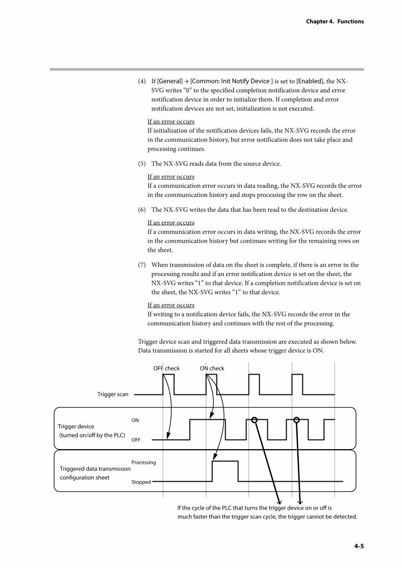
Trigger device scan and triggered data transmission are executed as shown below. Data transmission is started for all sheets whose trigger device is ON.
Trigger scan
OFF check ON check
Trigger device (turned on/o by the PLC)
Triggered data transmission conguration sheet
If the cycle of the PLC that turns the trigger device on or o is much faster than the trigger scan cycle, the trigger cannot be detected.
ON
OFF
Processing
Stopped
4-6
Chapter 4. Functions
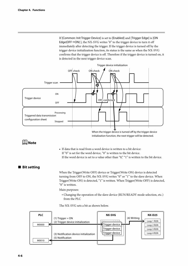
If [Common: Init Trigger Device] is set to [Enabled] and [Trigger Edge] is [ON Edge(OFFON) ], the NX-SVG writes "0” to the trigger device to turn it off immediately after detecting the trigger. If the trigger device is turned off by the trigger device initialization function, its status is the same as when the NX-SVG confirms that the trigger device is off. Therefore if the trigger device is turned on, it is detected in the next trigger device scan.
Trigger scan
OFF check ON check ON check
Trigger device initialization
Trigger device
Triggered data transmission conguration sheet
When the trigger device is turned o by the trigger device initialization function, the next trigger will be detected.
ON
OFF
Processing
Stopped
OFF conrmed
Note
• If data that is read from a word device is written to a bit device: If “0” is set for the word device, “0” is written to the bit device. If the word device is set to a value other than “0,” “1” is written to the bit device.
Bit settingWhen the Trigger(Write OFF) device or Trigger(Write ON) device is detected turning from OFF to ON, the NX-SVG writes “0” or “1” to the slave device. When Trigger(Write ON) is detected, “1” is written. When Trigger(Write OFF) is detected, “0” is written.Main purposes:
• Changing the operation of the slave device (RUN/READY mode selection, etc.) from the PLC
The NX-SVG sets a bit as shown below.
PLC NX-SVG NX-D25(4) Writing(1) Trigger = ON
(2) Trigger device initialization
(3) Notication device initialization(5) Notication
Loop 1 RUN
Loop 2 RUN
Loop 3 RUN
Loop 4 RUN
M0000
M0010
Trigger deviceTrigger deviceTrigger device
4-7
Chapter 4. Functions
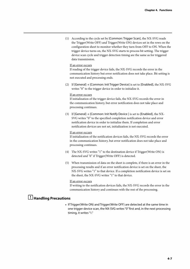
(1) According to the cycle set by [Common: Trigger Scan], the NX-SVG reads the Trigger(Write OFF) and Trigger(Write ON) devices set in the rows on the configuration sheet to monitor whether they turn from OFF to ON. When the trigger device turns on, the NX-SVG starts to process bit setting. The trigger device scan cycle and trigger detection timing are the same as for triggered data transmission.
If an error occurs If reading of the trigger device fails, the NX-SVG records the error in the communication history but error notification does not take place. Bit setting is not executed and processing ends.
(2) If [General] → [Common: Init Trigger Device] is set to [Enabled], the NX-SVG writes “0” to the trigger device in order to initialize it.
If an error occurs If initialization of the trigger device fails, the NX-SVG records the error in the communication history, but error notification does not take place and processing continues.
(3) If [General] → [Common: Init Notify Device ] is set to [Enabled], the NX-SVG writes “0” to the specified completion notification device and error notification device in order to initialize them. If completion and error notification devices are not set, initialization is not executed.
If an error occurs If initialization of the notification devices fails, the NX-SVG records the error in the communication history, but error notification does not take place and processing continues.
(4) The NX-SVG writes “1” to the destination device if Trigger(Write ON) is detected and "0” if Trigger(Write OFF) is detected.
(5) When transmission of data on the sheet is complete, if there is an error in the processing results and if an error notification device is set on the sheet, the NX-SVG writes “1” to that device. If a completion notification device is set on the sheet, the NX-SVG writes “1” to that device.
If an error occurs If writing to the notification devices fails, the NX-SVG records the error in the communication history and continues with the rest of the processing.
Handling Precautions
• If Trigger(Write ON) and Trigger(Write OFF) are detected at the same time in one trigger device scan, the NX-SVG writes “0” first and, in the next processing timing, it writes “1.”
4-8
Chapter 4. Functions
4 - 2 Device Management Function
The device management function is used for maintaining and managing the connected devices. There are four types of device management function: configuration backup and restoration, IP address assignment, status notification, and time setting.
Specify device management settings using the configuration sheet on the loader.
Handling Precautions
• Configuration backup and restoration, and IP address assignment for slave devices, are available only for Azbil-made Network Instrumentation Modules.
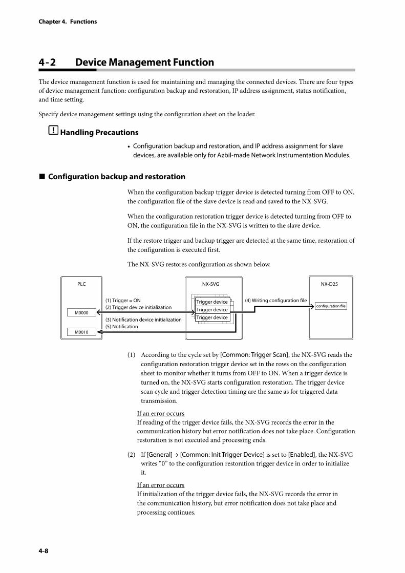
Configuration backup and restoration
When the configuration backup trigger device is detected turning from OFF to ON, the configuration file of the slave device is read and saved to the NX-SVG.
When the configuration restoration trigger device is detected turning from OFF to ON, the configuration file in the NX-SVG is written to the slave device.
If the restore trigger and backup trigger are detected at the same time, restoration of the configuration is executed first.
The NX-SVG restores configuration as shown below.
PLC NX-SVG NX-D25
(4) Writing conguration le(1) Trigger = ON(2) Trigger device initialization
(3) Notication device initialization(5) Notication
M0000
M0010
Trigger deviceTrigger deviceTrigger device
conguration le
(1) According to the cycle set by [Common: Trigger Scan], the NX-SVG reads the configuration restoration trigger device set in the rows on the configuration sheet to monitor whether it turns from OFF to ON. When a trigger device is turned on, the NX-SVG starts configuration restoration. The trigger device scan cycle and trigger detection timing are the same as for triggered data transmission.
If an error occurs If reading of the trigger device fails, the NX-SVG records the error in the communication history but error notification does not take place. Configuration restoration is not executed and processing ends.
(2) If [General] → [Common: Init Trigger Device] is set to [Enabled], the NX-SVG writes “0” to the configuration restoration trigger device in order to initialize it.
If an error occurs If initialization of the trigger device fails, the NX-SVG records the error in the communication history, but error notification does not take place and processing continues.
4-9
Chapter 4. Functions
(3) If [General] → [Common: Init Notify Device ] is set to [Enabled], the NX-SVG writes “0” to the specified completion notification device and error notification device in order to initialize them. If completion and error notification devices are not set, initialization is not executed.
If an error occurs If initialization of the notification devices fails, the NX-SVG records the error in the communication history, but error notification does not take place and processing continues.
(4) The NX-SVG writes the configuration file to the destination device.
(5) When restoration of each row of the configuration file is complete, if [Notify Result] is set for the target device, the NX-SVG writes a result code to that result notification device. If there is an error in the processing and if an error notification device is set, the NX-SVG writes “1” to that device. If a completion notification device is set, the NX-SVG writes “1” to that device.
If an error occurs If writing to the notification devices fails, the NX-SVG records the error in the communication history and continues with the rest of the processing.
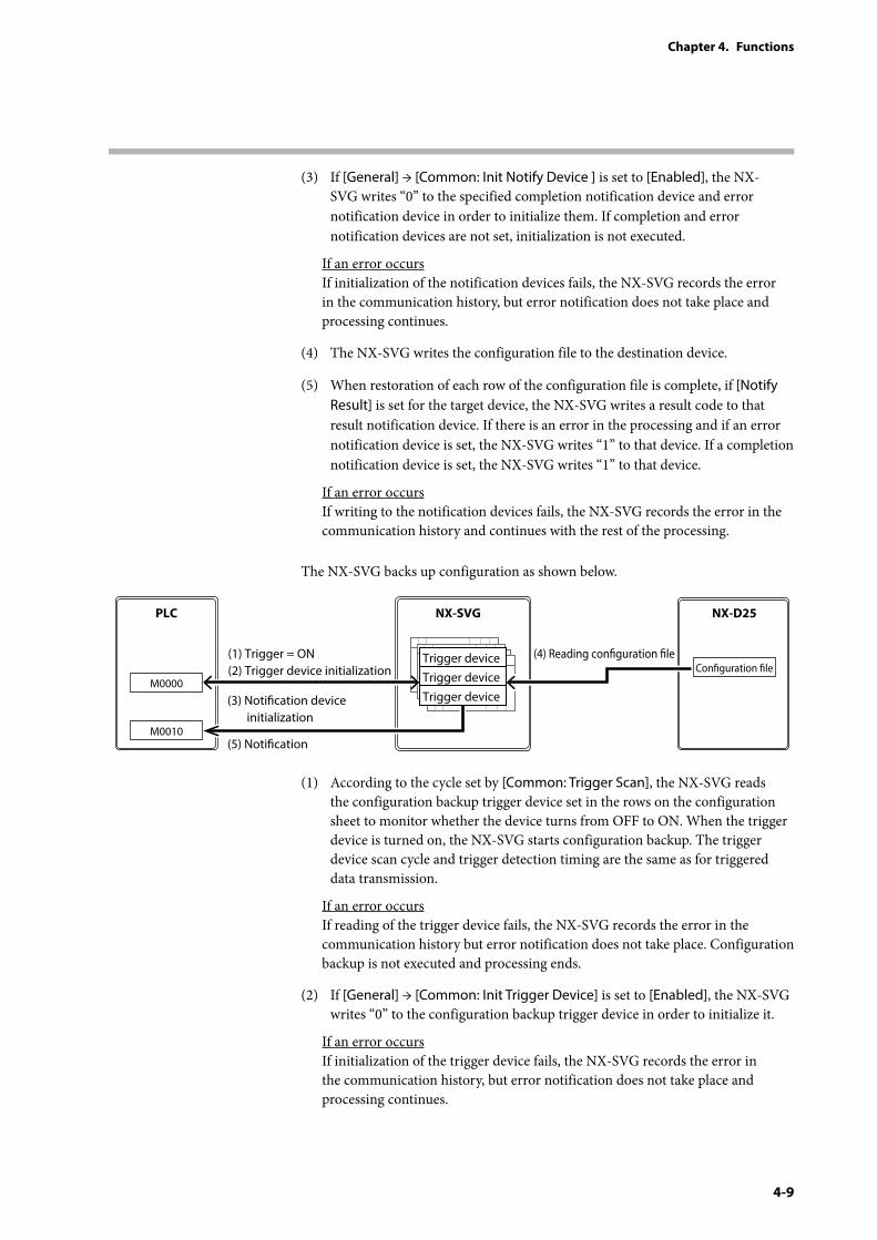
The NX-SVG backs up configuration as shown below.
PLC NX-SVG NX-D25
(4) Reading conguration le
(1) Trigger = ON(2) Trigger device initialization
(3) Notication device initialization
(5) Notication
Conguration le
Trigger deviceTrigger deviceTrigger device
M0000
M0010
(1) According to the cycle set by [Common: Trigger Scan], the NX-SVG reads the configuration backup trigger device set in the rows on the configuration sheet to monitor whether the device turns from OFF to ON. When the trigger device is turned on, the NX-SVG starts configuration backup. The trigger device scan cycle and trigger detection timing are the same as for triggered data transmission.
If an error occurs If reading of the trigger device fails, the NX-SVG records the error in the communication history but error notification does not take place. Configuration backup is not executed and processing ends.
(2) If [General] → [Common: Init Trigger Device] is set to [Enabled], the NX-SVG writes “0” to the configuration backup trigger device in order to initialize it.
If an error occurs If initialization of the trigger device fails, the NX-SVG records the error in the communication history, but error notification does not take place and processing continues.
4-10
Chapter 4. Functions
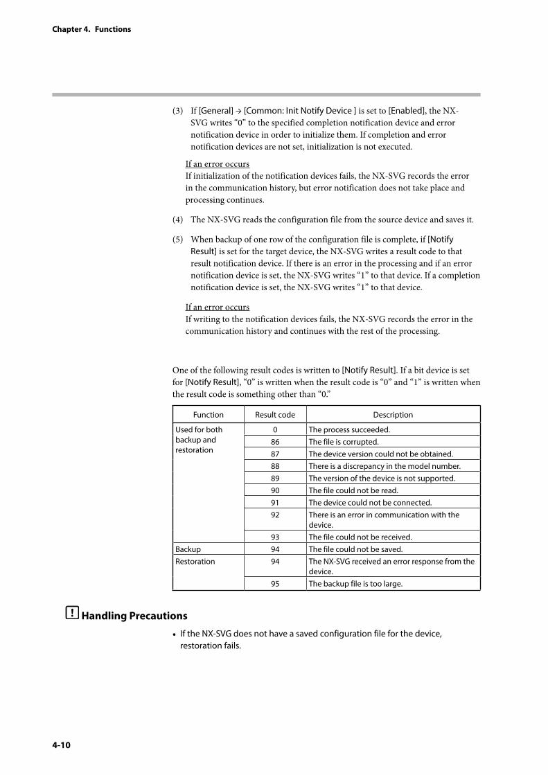
(3) If [General] → [Common: Init Notify Device ] is set to [Enabled], the NX-SVG writes “0” to the specified completion notification device and error notification device in order to initialize them. If completion and error notification devices are not set, initialization is not executed.
If an error occurs If initialization of the notification devices fails, the NX-SVG records the error in the communication history, but error notification does not take place and processing continues.
(4) The NX-SVG reads the configuration file from the source device and saves it.
(5) When backup of one row of the configuration file is complete, if [Notify Result] is set for the target device, the NX-SVG writes a result code to that result notification device. If there is an error in the processing and if an error notification device is set, the NX-SVG writes “1” to that device. If a completion notification device is set, the NX-SVG writes “1” to that device.
If an error occurs If writing to the notification devices fails, the NX-SVG records the error in the communication history and continues with the rest of the processing.
One of the following result codes is written to [Notify Result]. If a bit device is set for [Notify Result], “0” is written when the result code is “0” and “1” is written when the result code is something other than “0.”
Function Result code Description
Used for both backup and restoration
0 The process succeeded.86 The file is corrupted.87 The device version could not be obtained.88 There is a discrepancy in the model number.89 The version of the device is not supported.90 The file could not be read.91 The device could not be connected.92 There is an error in communication with the
device.93 The file could not be received.
Backup 94 The file could not be saved.Restoration 94 The NX-SVG received an error response from the
device.95 The backup file is too large.
Handling Precautions
• If the NX-SVG does not have a saved configuration file for the device, restoration fails.
4-11
Chapter 4. Functions
Batch configuration backup and restoration
If [Backup All Trigger] or [Restore All Trigger] is set, the configuration of all specified devices can be backed up or restored.
This process does not take place for devices for which [Enabled Switch] is set to [Disabled].
When batch configuration backup or restoration is complete, if the [Notify Result], [Notify Complete], or [Notify Error] device is set in the rows on the configuration sheet, a value is written to these devices as applicable. Then, after all the rows are done, if [Notify All Complete Device] or [Notify All Error Device] is set, a value is written to these devices as applicable.
4-12
Chapter 4. Functions
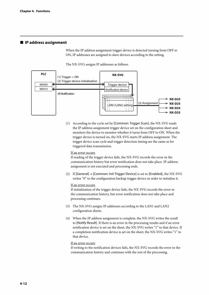
IP address assignment
When the IP address assignment trigger device is detected turning from OFF to ON, IP addresses are assigned to slave devices according to the setting.
The NX-SVG assigns IP addresses as follows.
PLC NX-SVG
(3) Assignment
(1) Trigger = ON(2) Trigger device initialization
(4) Notication
NX-D25NX-D25NX-D25NX-D25
M0000
M0010Trigger device
Notication device
LAN1/LAN2 settingLAN1/LAN2 setting
(1) According to the cycle set by [Common: Trigger Scan], the NX-SVG reads the IP address assignment trigger device set on the configuration sheet and monitors the device to monitor whether it turns from OFF to ON. When the trigger device is turned on, the NX-SVG starts IP address assignment. The trigger device scan cycle and trigger detection timing are the same as for triggered data transmission.
If an error occurs If reading of the trigger device fails, the NX-SVG records the error in the communication history but error notification does not take place. IP address assignment is not executed and processing ends.
(2) If [General] → [Common: Init Trigger Device] is set to [Enabled], the NX-SVG writes “0” to the configuration backup trigger device in order to initialize it.
If an error occurs If initialization of the trigger device fails, the NX-SVG records the error in the communication history, but error notification does not take place and processing continues.
(3) The NX-SVG assigns IP addresses according to the LAN1 and LAN2 configuration sheets.
(4) When the IP address assignment is complete, the NX-SVG writes the result to [Notify Result]. If there is an error in the processing results and if an error notification device is set on the sheet, the NX-SVG writes “1” to that device. If a completion notification device is set on the sheet, the NX-SVG writes “1” to that device.
If an error occurs If writing to the notification devices fails, the NX-SVG records the error in the communication history and continues with the rest of the processing.
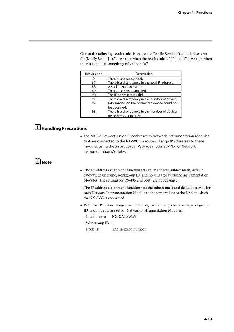
4-13
Chapter 4. Functions
One of the following result codes is written to [Notify Result]. If a bit device is set for [Notify Result], “0” is written when the result code is “0” and “1” is written when the result code is something other than “0.”
Result code Description0 The process succeeded.
87 There is a discrepancy in the local IP address.88 A socket error occurred.89 The process was canceled.90 The IP address is invalid.91 There is a discrepancy in the number of devices.92 Information on the connected device could not
be obtained.93 There is a discrepancy in the number of devices
(IP address verification).
Handling Precautions
• The NX-SVG cannot assign IP addresses to Network Instrumentation Modules that are connected to the NX-SVG via routers. Assign IP addresses to these modules using the Smart Loader Package model SLP-NX for Network Instrumentation Modules.
Note
• The IP address assignment function sets an IP address, subnet mask, default gateway, chain name, workgroup ID, and node ID for Network Instrumentation Modules. The settings for RS-485 and ports are not changed.
• The IP address assignment function sets the subnet mask and default gateway for each Network Instrumentation Module to the same values as the LAN to which the NX-SVG is connected.
• With the IP address assignment function, the following chain name, workgroup ID, and node ID are set for Network Instrumentation Modules.• Chain name: NX GATEWAY• Workgroup ID: 1• Node ID: The assigned number
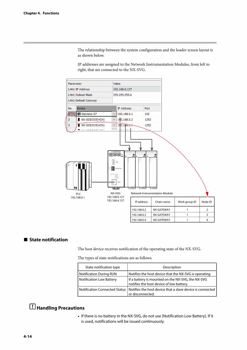
4-14
Chapter 4. Functions
The relationship between the system configuration and the loader screen layout is as shown below.
IP addresses are assigned to the Network Instrumentation Modules, from left to right, that are connected to the NX-SVG.
PLC Network Instrumentation ModuleNX-SVG192.168.0.127192.168.4.127
192.168.0.1
PWR
NX-SVGN
USB
DA (+)
SG
DB (−) RS-485 CH1
RS-485
BATTERY
LINK/ACT
LAN1
FUNCTION ERROR
ID F1 F2
RUN MOD COM NST FAIL
IP address Chain name Work group ID Node ID
192.168.0.2
192.168.0.3
192.168.0.4
NX GATEWAY
NX GATEWAY
NX GATEWAY
1
1
1
2
3
4
State notification
The host device receives notification of the operating state of the NX-SVG.
The types of state notifications are as follows.
State notification type Description
Notification During RUN Notifies the host device that the NX-SVG is operating.Notification Low Battery If a battery is mounted on the NX-SVG, the NX-SVG
notifies the host device of low battery.Notification Connected Status Notifies the host device that a slave device is connected
or disconnected.
Handling Precautions
• If there is no battery in the NX-SVG, do not use [Notification Low Battery]. If it is used, notifications will be issued continuously.
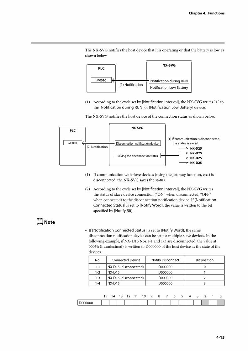
4-15
Chapter 4. Functions
The NX-SVG notifies the host device that it is operating or that the battery is low as shown below.
PLCNX-SVG
(1) NoticationNotication during RUN
Notication Low Battery
M0010
(1) According to the cycle set by [Notification Interval], the NX-SVG writes “1” to the [Notification during RUN] or [Notification Low Battery] device.
The NX-SVG notifies the host device of the connection status as shown below.
PLCNX-SVG
(2) Notication
(1) If communication is disconnected, the status is saved. NX-D25
NX-D25NX-D25NX-D25
Saving the disconnection status
M0010 Disconnection notication device
(1) If communication with slave devices (using the gateway function, etc.) is disconnected, the NX-SVG saves the status.
(2) According to the cycle set by [Notification Interval], the NX-SVG writes the status of slave device connection (“ON” when disconnected, “OFF” when connected) to the disconnection notification device. If [Notification Connected Status] is set to [Notify Word], the value is written to the bit specified by [Notify Bit].
Note
• If [Notification Connected Status] is set to [Notify Word], the same disconnection notification device can be set for multiple slave devices. In the following example, if NX-D15 Nos.1-1 and 1-3 are disconnected, the value at 0005h (hexadecimal) is written to D000000 of the host device as the state of the devices.
No. Connected Device Notify Disconnect Bit position
1-1 NX-D15 (disconnected) D000000 01-2 NX-D15 D000000 11-3 NX-D15 (disconnected) D000000 21-4 NX-D15 D000000 3
15 14 13 12 11 10 9 8 7 6 5 4 3 2 1 0
D000000
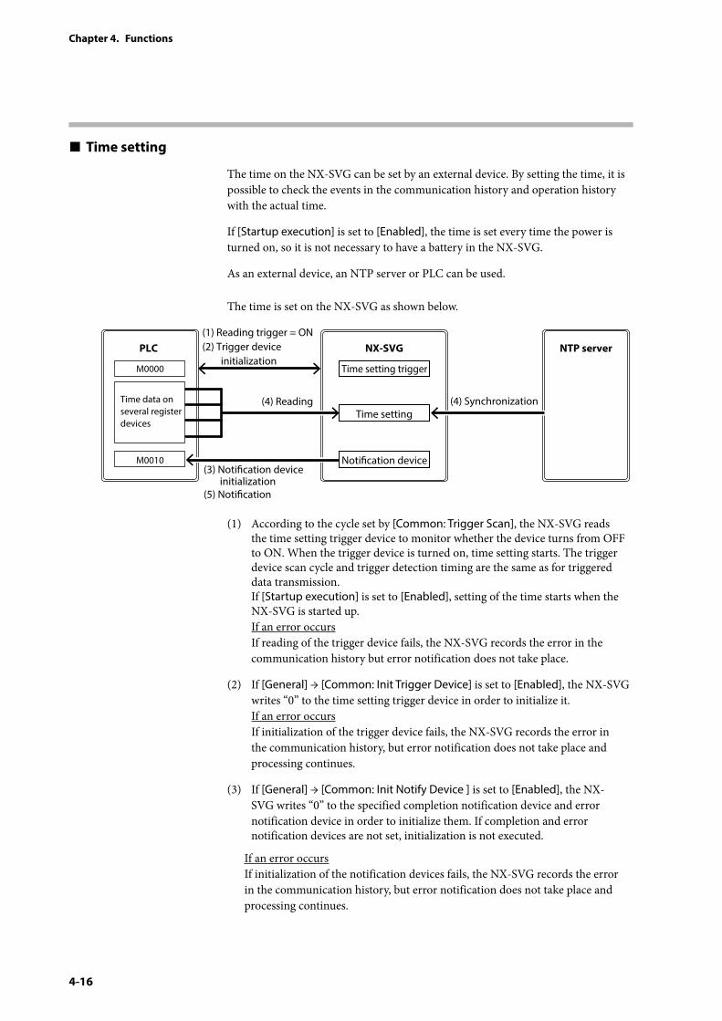
4-16
Chapter 4. Functions
Time setting
The time on the NX-SVG can be set by an external device. By setting the time, it is possible to check the events in the communication history and operation history with the actual time.
If [Startup execution] is set to [Enabled], the time is set every time the power is turned on, so it is not necessary to have a battery in the NX-SVG.
As an external device, an NTP server or PLC can be used.
The time is set on the NX-SVG as shown below.
PLC NTP serverNX-SVG
(4) Reading
(1) Reading trigger = ON(2) Trigger device initialization
(4) Synchronization
(3) Notication device initialization(5) Notication
M0010
M0000
Time data on several register devices
Time setting
Time setting trigger
Notication device
(1) According to the cycle set by [Common: Trigger Scan], the NX-SVG reads the time setting trigger device to monitor whether the device turns from OFF to ON. When the trigger device is turned on, time setting starts. The trigger device scan cycle and trigger detection timing are the same as for triggered data transmission. If [Startup execution] is set to [Enabled], setting of the time starts when the NX-SVG is started up. If an error occurs If reading of the trigger device fails, the NX-SVG records the error in the communication history but error notification does not take place.
(2) If [General] → [Common: Init Trigger Device] is set to [Enabled], the NX-SVG writes “0” to the time setting trigger device in order to initialize it. If an error occurs If initialization of the trigger device fails, the NX-SVG records the error in the communication history, but error notification does not take place and processing continues.
(3) If [General] → [Common: Init Notify Device ] is set to [Enabled], the NX-SVG writes “0” to the specified completion notification device and error notification device in order to initialize them. If completion and error notification devices are not set, initialization is not executed.
If an error occurs If initialization of the notification devices fails, the NX-SVG records the error in the communication history, but error notification does not take place and processing continues.
4-17
Chapter 4. Functions
(4) Based on the setting, the NX-SVG updates its clock by synchronizing it with the time on the NTP server or by obtaining time data from register devices on the PLC.
(5) When time synchronization is complete, the NX-SVG records a time setting event in the operation history. If there is an error in the processing results and if an error notification device is set on the sheet, the NX-SVG writes “1” to that device. If a completion notification device is set on the sheet, the NX-SVG writes “1” to that device.
If an error occurs If writing to the notification device fails, the NX-SVG records the error in the communication history and continues with the rest of the processing.
Handling Precautions
• If time is set by reading PLC registers, a time after 3:14:07 (UTC) on January 19, 2038 cannot be set.
• If time is set using the NTP server, a time after 6:28:15 (UTC) on February 7, 2036 cannot be set.
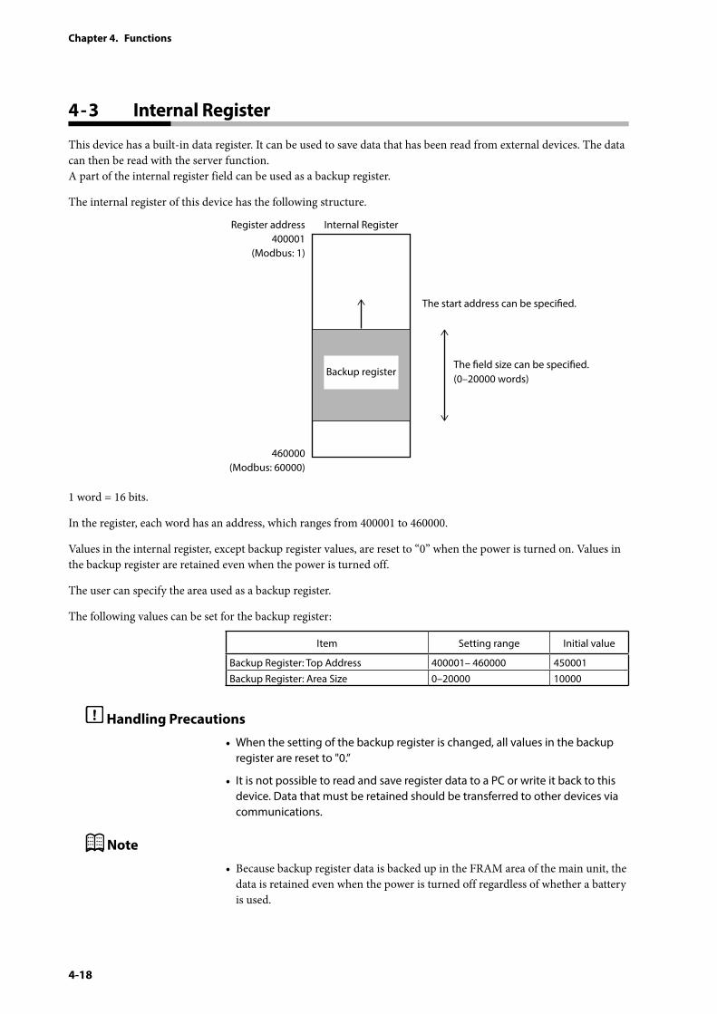
4-18
Chapter 4. Functions
4 - 3 Internal Register
This device has a built-in data register. It can be used to save data that has been read from external devices. The data can then be read with the server function. A part of the internal register field can be used as a backup register.
The internal register of this device has the following structure.
Backup register
The start address can be specied.
The eld size can be specied.(0–20000 words)
Internal RegisterRegister address400001
(Modbus: 1)
460000(Modbus: 60000)
1 word = 16 bits.
In the register, each word has an address, which ranges from 400001 to 460000.
Values in the internal register, except backup register values, are reset to “0” when the power is turned on. Values in the backup register are retained even when the power is turned off.
The user can specify the area used as a backup register.
The following values can be set for the backup register:
Item Setting range Initial value
Backup Register: Top Address 400001– 460000 450001Backup Register: Area Size 0–20000 10000
Handling Precautions
• When the setting of the backup register is changed, all values in the backup register are reset to "0.”
• It is not possible to read and save register data to a PC or write it back to this device. Data that must be retained should be transferred to other devices via communications.
Note
• Because backup register data is backed up in the FRAM area of the main unit, the data is retained even when the power is turned off regardless of whether a battery is used.
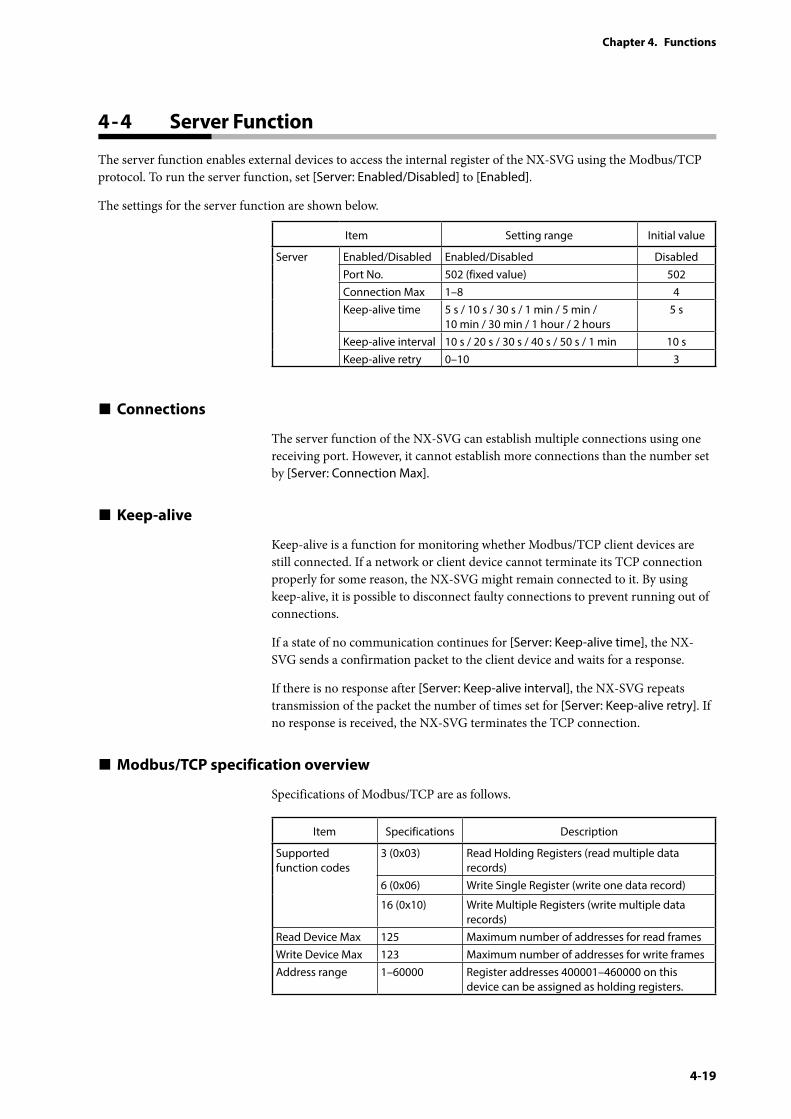
4-19
Chapter 4. Functions
4 - 4 Server Function
The server function enables external devices to access the internal register of the NX-SVG using the Modbus/TCP protocol. To run the server function, set [Server: Enabled/Disabled] to [Enabled].
The settings for the server function are shown below.
Item Setting range Initial value
Server Enabled/Disabled Enabled/Disabled DisabledPort No. 502 (fixed value) 502Connection Max 1–8 4Keep-alive time 5 s / 10 s / 30 s / 1 min / 5 min /
10 min / 30 min / 1 hour / 2 hours5 s
Keep-alive interval 10 s / 20 s / 30 s / 40 s / 50 s / 1 min 10 sKeep-alive retry 0–10 3
Connections
The server function of the NX-SVG can establish multiple connections using one receiving port. However, it cannot establish more connections than the number set by [Server: Connection Max].
Keep-alive
Keep-alive is a function for monitoring whether Modbus/TCP client devices are still connected. If a network or client device cannot terminate its TCP connection properly for some reason, the NX-SVG might remain connected to it. By using keep-alive, it is possible to disconnect faulty connections to prevent running out of connections.
If a state of no communication continues for [Server: Keep-alive time], the NX-SVG sends a confirmation packet to the client device and waits for a response.
If there is no response after [Server: Keep-alive interval], the NX-SVG repeats transmission of the packet the number of times set for [Server: Keep-alive retry]. If no response is received, the NX-SVG terminates the TCP connection.
Modbus/TCP specification overview
Specifications of Modbus/TCP are as follows.
Item Specifications Description
Supported function codes
3 (0x03) Read Holding Registers (read multiple data records)
6 (0x06) Write Single Register (write one data record)
16 (0x10) Write Multiple Registers (write multiple data records)
Read Device Max 125 Maximum number of addresses for read framesWrite Device Max 123 Maximum number of addresses for write framesAddress range 1–60000 Register addresses 400001–460000 on this
device can be assigned as holding registers.
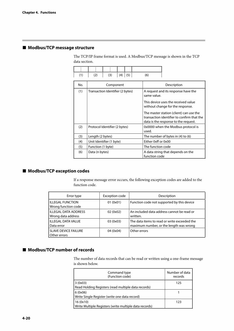
4-20
Chapter 4. Functions
Modbus/TCP message structure
The TCP/IP frame format is used. A Modbus/TCP message is shown in the TCP data section.
(1) (2) (3) (4) (5) (6)
No. Component Description
(1) Transaction Identifier (2 bytes) A request and its response have the same value.
This device uses the received value without change for the response.
The master station (client) can use the transaction identifier to confirm that the data is the response to the request.
(2) Protocol Identifier (2 bytes) 0x0000 when the Modbus protocol is used.
(3) Length (2 bytes) The number of bytes in (4) to (6)(4) Unit Identifier (1 byte) Either 0xff or 0x00(5) Function (1 byte) The function code(6) Data (n bytes) A data string that depends on the
function code
Modbus/TCP exception codes
If a response message error occurs, the following exception codes are added to the function code.
Error type Exception code Description
ILLEGAL FUNCTION Wrong function code
01 (0x01) Function code not supported by this device
ILLEGAL DATA ADDRESS Wrong data address
02 (0x02) An included data address cannot be read or written.
ILLEGAL DATA VALUE Data error
03 (0x03) The data items to read or write exceeded the maximum number, or the length was wrong
SLAVE DEVICE FAILURE Other errors
04 (0x04) Other errors
Modbus/TCP number of records
The number of data records that can be read or written using a one-frame message is shown below.
Command type(Function code)
Number of data records
3 (0x03) Read Holding Registers (read multiple data records)
125
6 (0x06) Write Single Register (write one data record)
1
16 (0x10) Write Multiple Registers (write multiple data records)
123
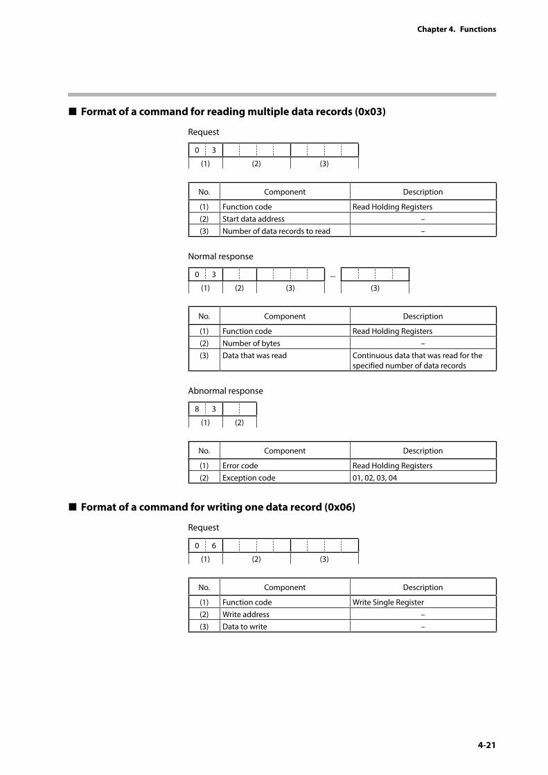
4-21
Chapter 4. Functions
Format of a command for reading multiple data records (0x03)
Request
0 3
(1) (2) (3)
No. Component Description
(1) Function code Read Holding Registers(2) Start data address –(3) Number of data records to read –
Normal response
0 3 ...
(1) (2) (3) (3)
No. Component Description
(1) Function code Read Holding Registers(2) Number of bytes –(3) Data that was read Continuous data that was read for the
specified number of data records
Abnormal response
8 3
(1) (2)
No. Component Description
(1) Error code Read Holding Registers(2) Exception code 01, 02, 03, 04
Format of a command for writing one data record (0x06)
Request
0 6
(1) (2) (3)
No. Component Description
(1) Function code Write Single Register(2) Write address –(3) Data to write –
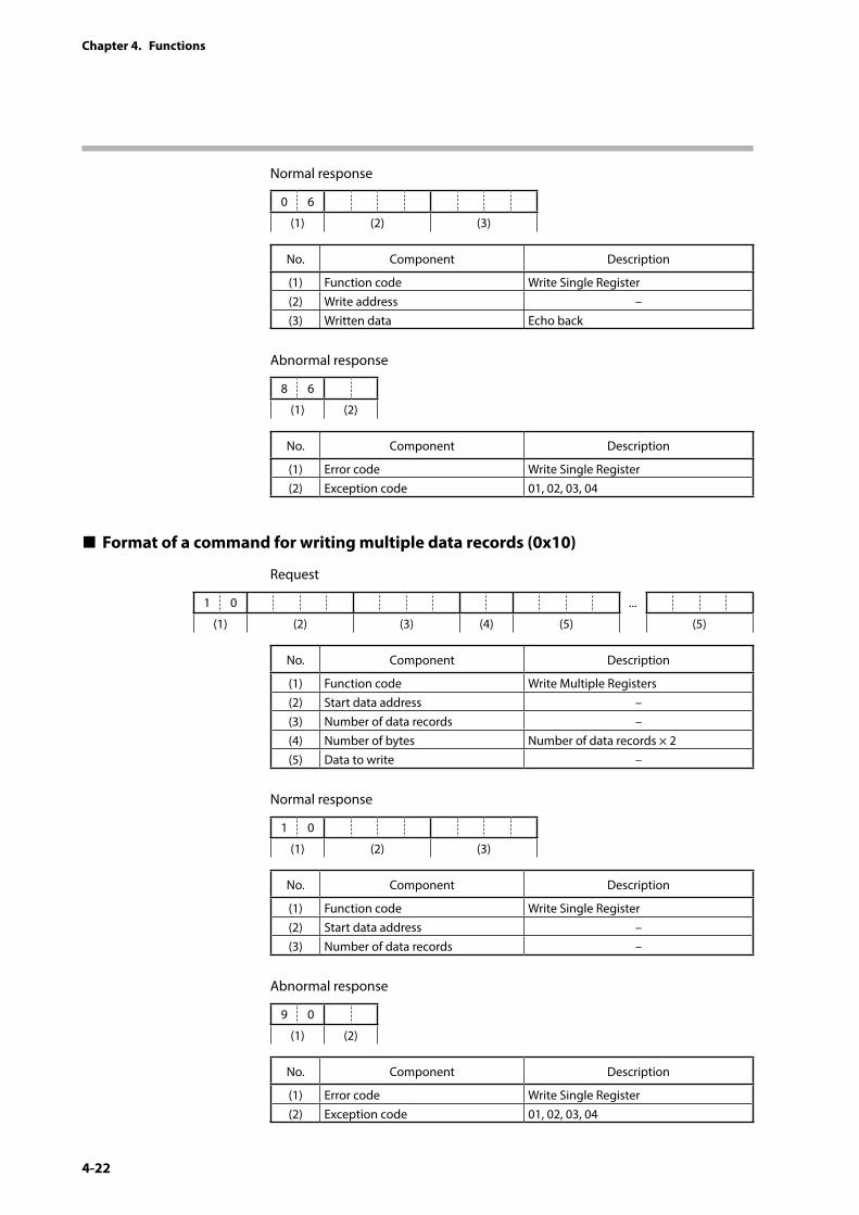
4-22
Chapter 4. Functions
Normal response
0 6
(1) (2) (3)
No. Component Description
(1) Function code Write Single Register(2) Write address –(3) Written data Echo back
Abnormal response
8 6
(1) (2)
No. Component Description
(1) Error code Write Single Register(2) Exception code 01, 02, 03, 04
Format of a command for writing multiple data records (0x10)
Request
1 0 ...
(1) (2) (3) (4) (5) (5)
No. Component Description
(1) Function code Write Multiple Registers(2) Start data address –(3) Number of data records –(4) Number of bytes Number of data records × 2(5) Data to write –
Normal response
1 0
(1) (2) (3)
No. Component Description
(1) Function code Write Single Register(2) Start data address –(3) Number of data records –
Abnormal response
9 0
(1) (2)
No. Component Description
(1) Error code Write Single Register(2) Exception code 01, 02, 03, 04
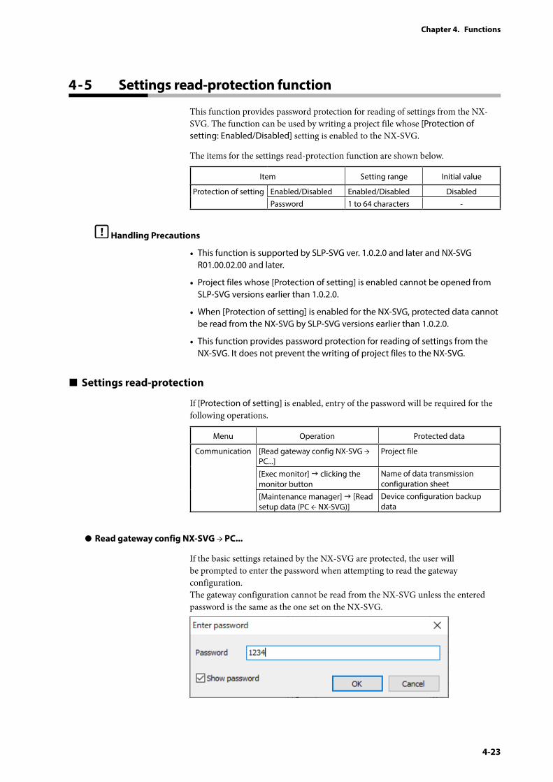
4-23
Chapter 4. Functions
4 - 5 Settings read-protection function
This function provides password protection for reading of settings from the NX-SVG. The function can be used by writing a project file whose [Protection of setting: Enabled/Disabled] setting is enabled to the NX-SVG.
The items for the settings read-protection function are shown below.
Item Setting range Initial value
Protection of setting Enabled/Disabled Enabled/Disabled DisabledPassword 1 to 64 characters -
Handling Precautions
• This function is supported by SLP-SVG ver. 1.0.2.0 and later and NX-SVG R01.00.02.00 and later.
• Project files whose [Protection of setting] is enabled cannot be opened from SLP-SVG versions earlier than 1.0.2.0.
• When [Protection of setting] is enabled for the NX-SVG, protected data cannot be read from the NX-SVG by SLP-SVG versions earlier than 1.0.2.0.
• This function provides password protection for reading of settings from the NX-SVG. It does not prevent the writing of project files to the NX-SVG.
Settings read-protection
If [Protection of setting] is enabled, entry of the password will be required for the following operations.
Menu Operation Protected data
Communication [Read gateway config NX-SVG → PC...]
Project file
[Exec monitor] clicking the monitor button
Name of data transmission configuration sheet
[Maintenance manager] [Read setup data (PC ← NX-SVG)]
Device configuration backup data
z Read gateway config NX-SVG → PC...
If the basic settings retained by the NX-SVG are protected, the user will be prompted to enter the password when attempting to read the gateway configuration. The gateway configuration cannot be read from the NX-SVG unless the entered password is the same as the one set on the NX-SVG.
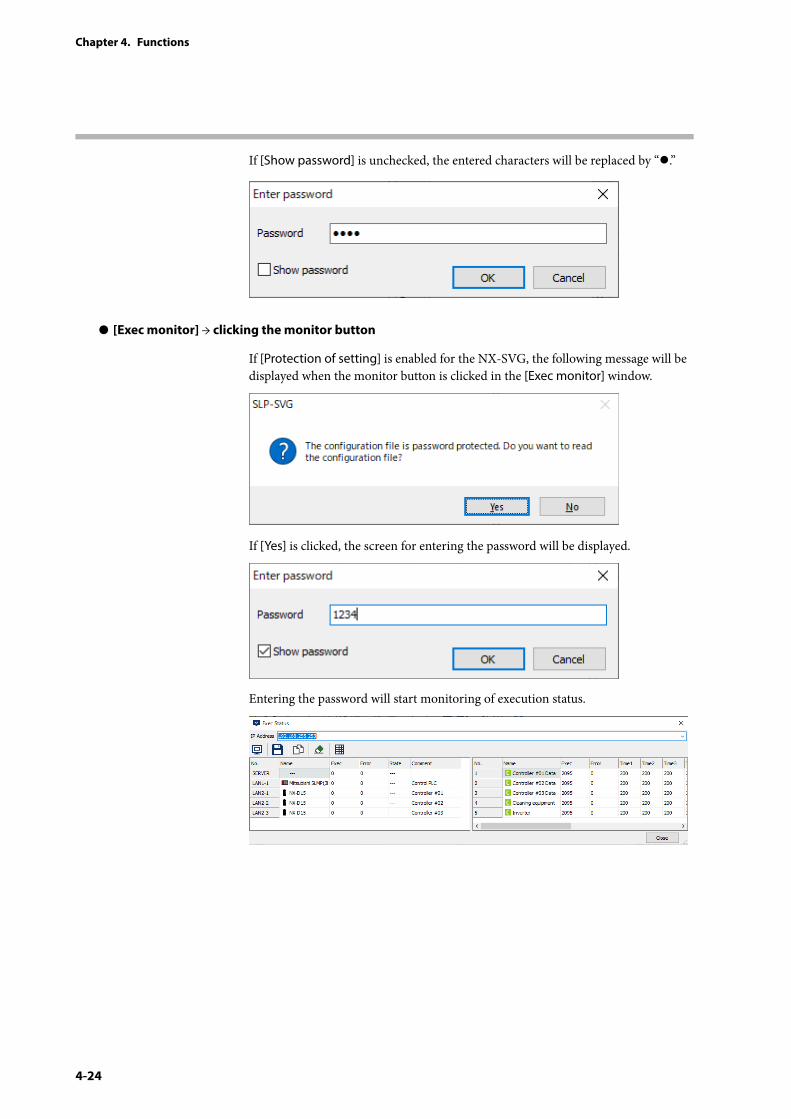
4-24
Chapter 4. Functions
If [Show password] is unchecked, the entered characters will be replaced by “z.”
z [Exec monitor] → clicking the monitor button
If [Protection of setting] is enabled for the NX-SVG, the following message will be displayed when the monitor button is clicked in the [Exec monitor] window.
If [Yes] is clicked, the screen for entering the password will be displayed.
Entering the password will start monitoring of execution status.
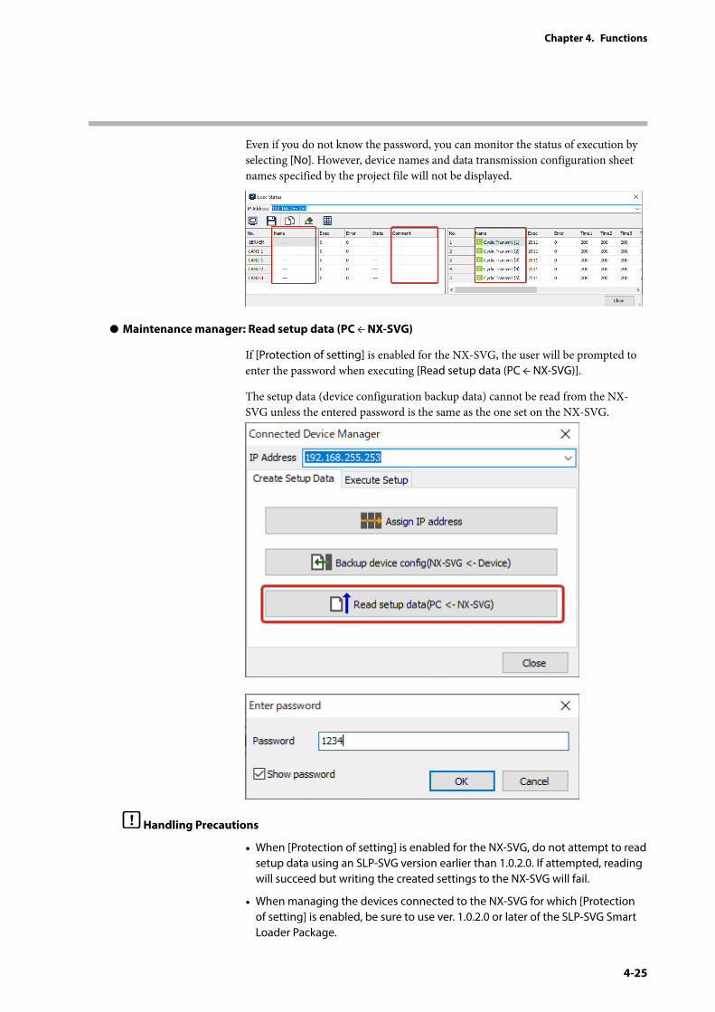
4-25
Chapter 4. Functions
Even if you do not know the password, you can monitor the status of execution by selecting [No]. However, device names and data transmission configuration sheet names specified by the project file will not be displayed.
z Maintenance manager: Read setup data (PC ← NX-SVG)
If [Protection of setting] is enabled for the NX-SVG, the user will be prompted to enter the password when executing [Read setup data (PC ← NX-SVG)].
The setup data (device configuration backup data) cannot be read from the NX-SVG unless the entered password is the same as the one set on the NX-SVG.
Handling Precautions
• When [Protection of setting] is enabled for the NX-SVG, do not attempt to read setup data using an SLP-SVG version earlier than 1.0.2.0. If attempted, reading will succeed but writing the created settings to the NX-SVG will fail.
• When managing the devices connected to the NX-SVG for which [Protection of setting] is enabled, be sure to use ver. 1.0.2.0 or later of the SLP-SVG Smart Loader Package.
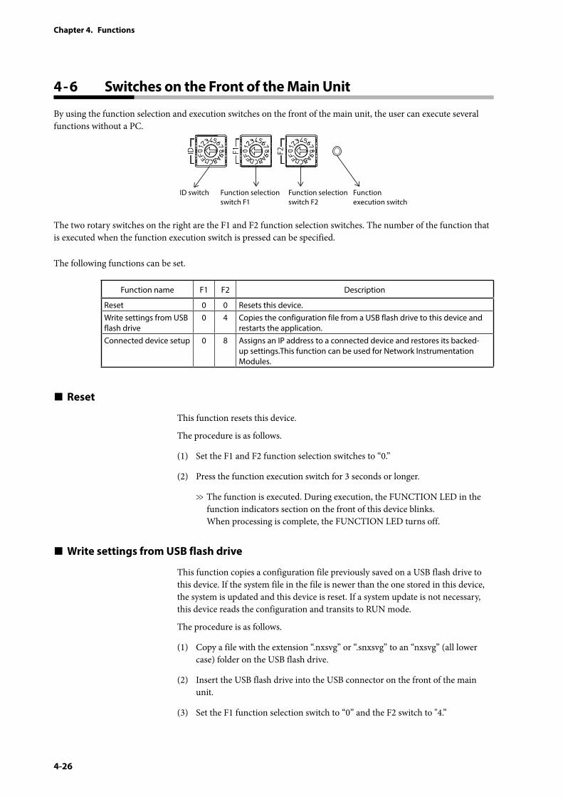
4-26
Chapter 4. Functions
4 - 6 Switches on the Front of the Main Unit
By using the function selection and execution switches on the front of the main unit, the user can execute several functions without a PC.
ID switch Function execution switch
Function selection switch F1
Function selection switch F2
The two rotary switches on the right are the F1 and F2 function selection switches. The number of the function that is executed when the function execution switch is pressed can be specified.
The following functions can be set.
Function name F1 F2 Description
Reset 0 0 Resets this device.Write settings from USB flash drive
0 4 Copies the configuration file from a USB flash drive to this device and restarts the application.
Connected device setup 0 8 Assigns an IP address to a connected device and restores its backed-up settings.This function can be used for Network Instrumentation Modules.
Reset
This function resets this device.
The procedure is as follows.
(1) Set the F1 and F2 function selection switches to “0.”
(2) Press the function execution switch for 3 seconds or longer.
>> The function is executed. During execution, the FUNCTION LED in the function indicators section on the front of this device blinks. When processing is complete, the FUNCTION LED turns off.
Write settings from USB flash drive
This function copies a configuration file previously saved on a USB flash drive to this device. If the system file in the file is newer than the one stored in this device, the system is updated and this device is reset. If a system update is not necessary, this device reads the configuration and transits to RUN mode.
The procedure is as follows.
(1) Copy a file with the extension “.nxsvg” or “.snxsvg” to an “nxsvg” (all lower case) folder on the USB flash drive.
(2) Insert the USB flash drive into the USB connector on the front of the main unit.
(3) Set the F1 function selection switch to “0” and the F2 switch to "4.”
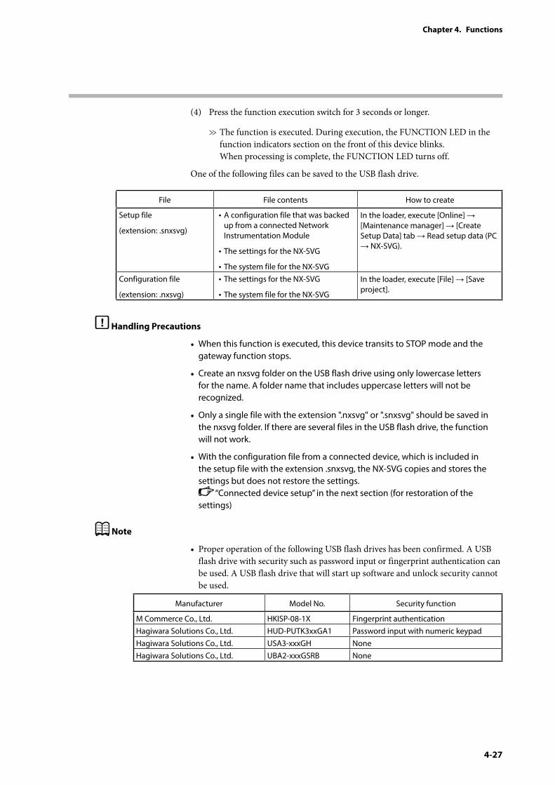
4-27
Chapter 4. Functions
(4) Press the function execution switch for 3 seconds or longer.
>> The function is executed. During execution, the FUNCTION LED in the function indicators section on the front of this device blinks. When processing is complete, the FUNCTION LED turns off.
One of the following files can be saved to the USB flash drive.
File File contents How to create
Setup file
(extension: .snxsvg)
• A configuration file that was backed up from a connected Network Instrumentation Module
• The settings for the NX-SVG
• The system file for the NX-SVG
In the loader, execute [Online] → [Maintenance manager] → [Create Setup Data] tab → Read setup data (PC → NX-SVG).
Configuration file
(extension: .nxsvg)
• The settings for the NX-SVG
• The system file for the NX-SVG
In the loader, execute [File] → [Save project].
Handling Precautions
• When this function is executed, this device transits to STOP mode and the gateway function stops.
• Create an nxsvg folder on the USB flash drive using only lowercase letters for the name. A folder name that includes uppercase letters will not be recognized.
• Only a single file with the extension ".nxsvg" or ".snxsvg" should be saved in the nxsvg folder. If there are several files in the USB flash drive, the function will not work.
• With the configuration file from a connected device, which is included in the setup file with the extension .snxsvg, the NX-SVG copies and stores the settings but does not restore the settings.
“Connected device setup” in the next section (for restoration of the settings)
Note
• Proper operation of the following USB flash drives has been confirmed. A USB flash drive with security such as password input or fingerprint authentication can be used. A USB flash drive that will start up software and unlock security cannot be used.
Manufacturer Model No. Security function
M Commerce Co., Ltd. HKISP-08-1X Fingerprint authenticationHagiwara Solutions Co., Ltd. HUD-PUTK3xxGA1 Password input with numeric keypad Hagiwara Solutions Co., Ltd. USA3-xxxGH NoneHagiwara Solutions Co., Ltd. UBA2-xxxGSRB None
4-28
Chapter 4. Functions
Connected device setup
This function assigns an IP address to the Network Instrumentation Module set as [Connected Device] and restores its settings.
The procedure is as follows.
(1) Set the F1 function selection switch to “0” and the F2 switch to "8.”
(2) Press the function execution switch for 3 seconds or longer.
>> The function is executed. During execution, the FUNCTION LED in the function indicators section on the front of this device blinks. When processing is complete, the FUNCTION LED turns off.
Handling Precautions
• While this function is being executed, this device transits to STOP mode and the gateway function stops.
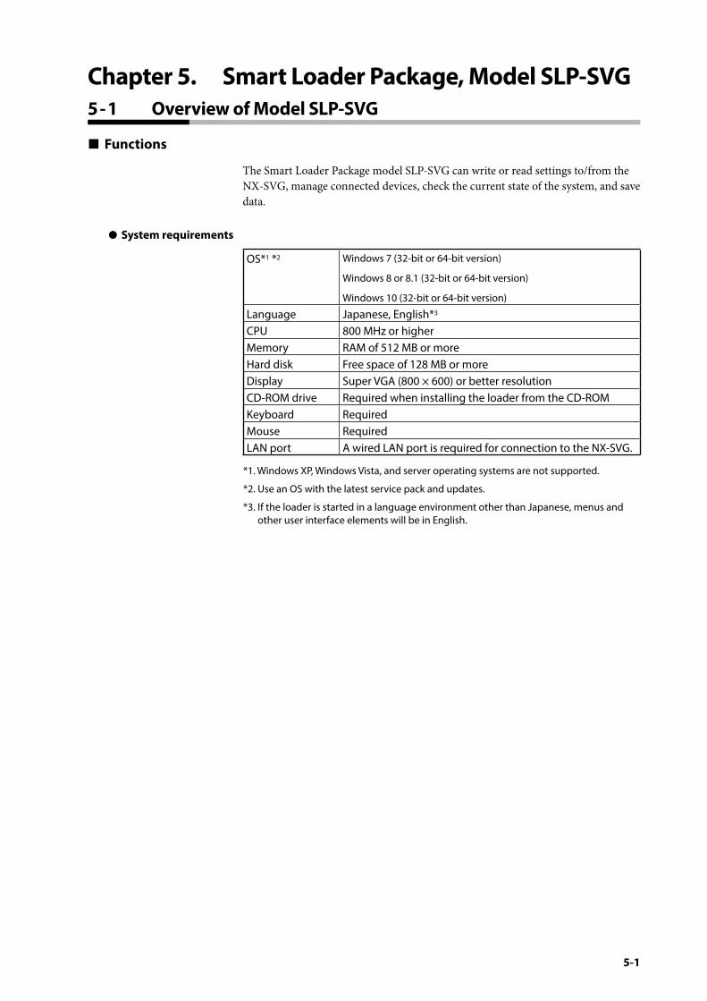
5-1
Chapter 5. Smart Loader Package, Model SLP-SVG5 - 1 Overview of Model SLP-SVG
Functions
The Smart Loader Package model SLP-SVG can write or read settings to/from the NX-SVG, manage connected devices, check the current state of the system, and save data.
z System requirements
OS*1 *2 Windows 7 (32-bit or 64-bit version)
Windows 8 or 8.1 (32-bit or 64-bit version)
Windows 10 (32-bit or 64-bit version)
Language Japanese, English*3
CPU 800 MHz or higherMemory RAM of 512 MB or moreHard disk Free space of 128 MB or moreDisplay Super VGA (800 × 600) or better resolutionCD-ROM drive Required when installing the loader from the CD-ROMKeyboard RequiredMouse RequiredLAN port A wired LAN port is required for connection to the NX-SVG.
*1. Windows XP, Windows Vista, and server operating systems are not supported.
*2. Use an OS with the latest service pack and updates.
*3. If the loader is started in a language environment other than Japanese, menus and other user interface elements will be in English.
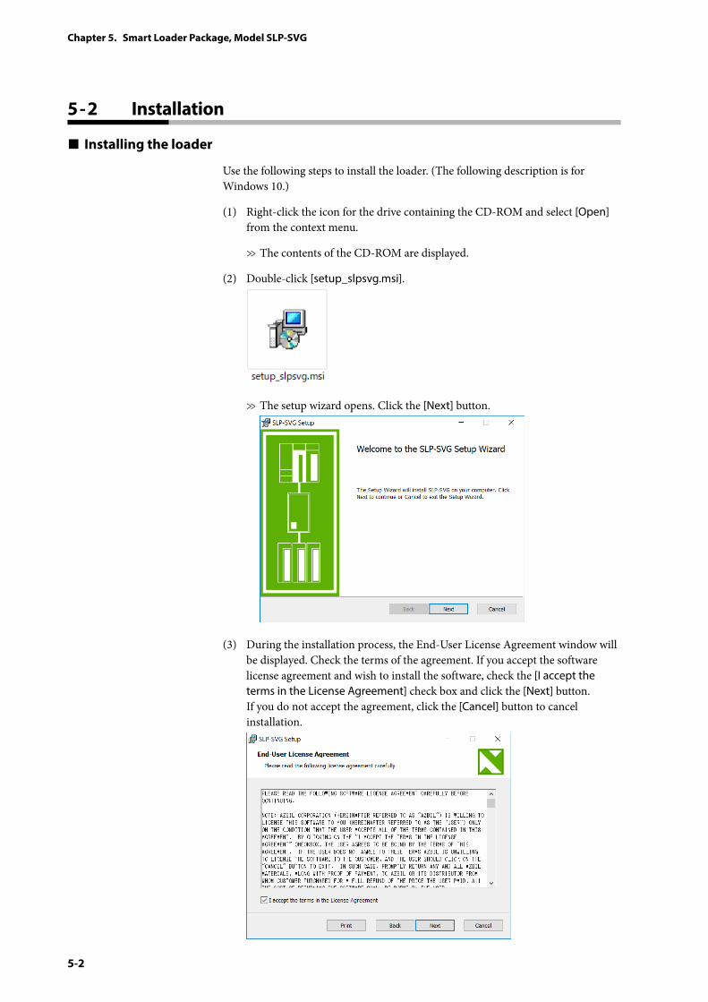
5-2
Chapter 5. Smart Loader Package, Model SLP-SVG
5 - 2 Installation
Installing the loader
Use the following steps to install the loader. (The following description is for Windows 10.)
(1) Right-click the icon for the drive containing the CD-ROM and select [Open] from the context menu.
>> The contents of the CD-ROM are displayed.
(2) Double-click [setup_slpsvg.msi].
>> The setup wizard opens. Click the [Next] button.
(3) During the installation process, the End-User License Agreement window will be displayed. Check the terms of the agreement. If you accept the software license agreement and wish to install the software, check the [I accept the terms in the License Agreement] check box and click the [Next] button. If you do not accept the agreement, click the [Cancel] button to cancel installation.
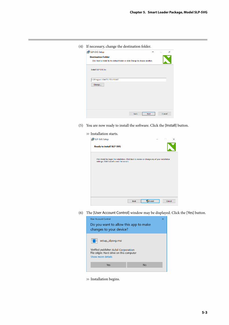
5-3
Chapter 5. Smart Loader Package, Model SLP-SVG
(4) If necessary, change the destination folder.
(5) You are now ready to install the software. Click the [Install] button.
>> Installation starts.
(6) The [User Account Control] window may be displayed. Click the [Yes] button.
>> Installation begins.
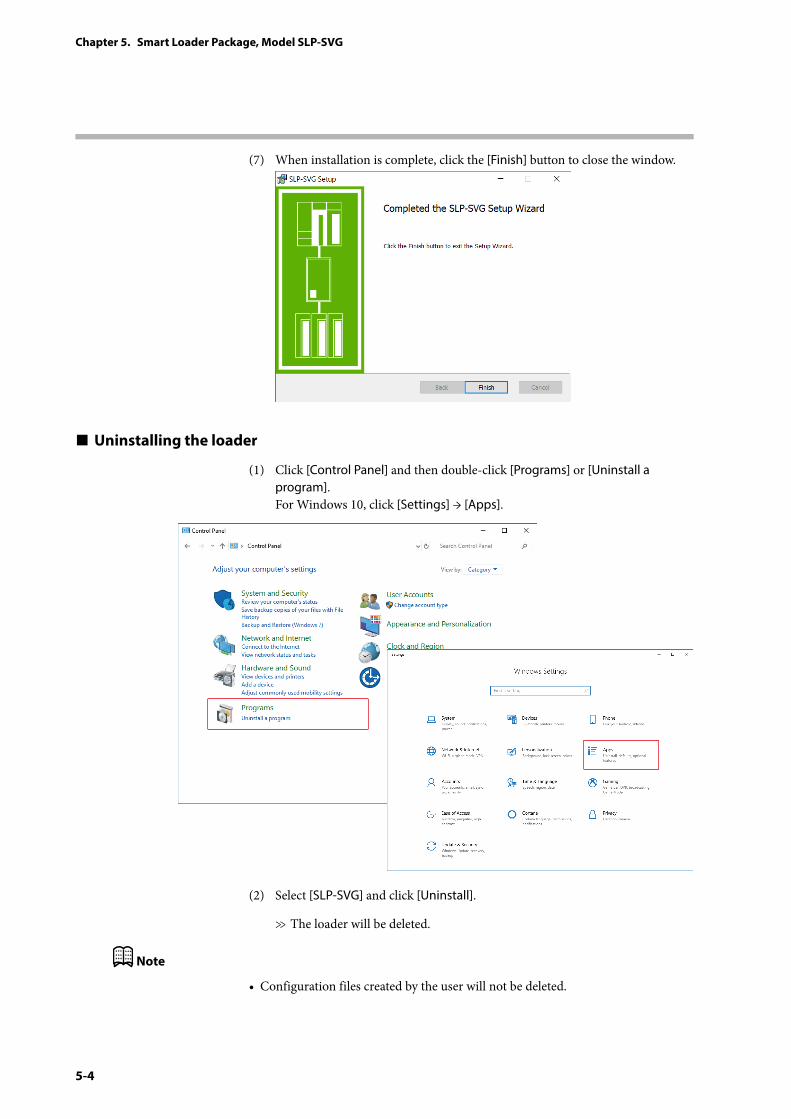
5-4
Chapter 5. Smart Loader Package, Model SLP-SVG
(7) When installation is complete, click the [Finish] button to close the window.
Uninstalling the loader
(1) Click [Control Panel] and then double-click [Programs] or [Uninstall a program]. For Windows 10, click [Settings] → [Apps].
(2) Select [SLP-SVG] and click [Uninstall].
>> The loader will be deleted.
Note
• Configuration files created by the user will not be deleted.
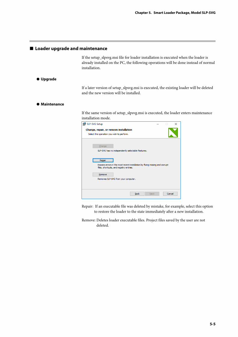
5-5
Chapter 5. Smart Loader Package, Model SLP-SVG
Loader upgrade and maintenance
If the setup_slpsvg.msi file for loader installation is executed when the loader is already installed on the PC, the following operations will be done instead of normal installation.
z Upgrade
If a later version of setup_slpsvg.msi is executed, the existing loader will be deleted and the new version will be installed.
z Maintenance
If the same version of setup_slpsvg.msi is executed, the loader enters maintenance installation mode.
Repair: If an executable file was deleted by mistake, for example, select this option to restore the loader to the state immediately after a new installation.
Remove: Deletes loader executable files. Project files saved by the user are not deleted.
5-6
Chapter 5. Smart Loader Package, Model SLP-SVG
5 - 3 Starting and Exiting the Loader
Starting the loader
From the Start menu, select [SLP] → [SLP-SVG]. For Windows 8, select [Start] → [All Apps]→ [SLP-SVG].
>>The loader starts up and the main window is displayed.
Note
• If the loader is started again from the [Start] menu under these circumstances, another instance of the loader program starts up. (Up to two instances of the loader can run at the same time.) With two instances of the loader running, editing data and copying and pasting is easy.
Exiting the loader
Click the [×] (close) button on the title bar. To exit the loader from the menu, select [File] → [Exit].
>> The loader will shut down.
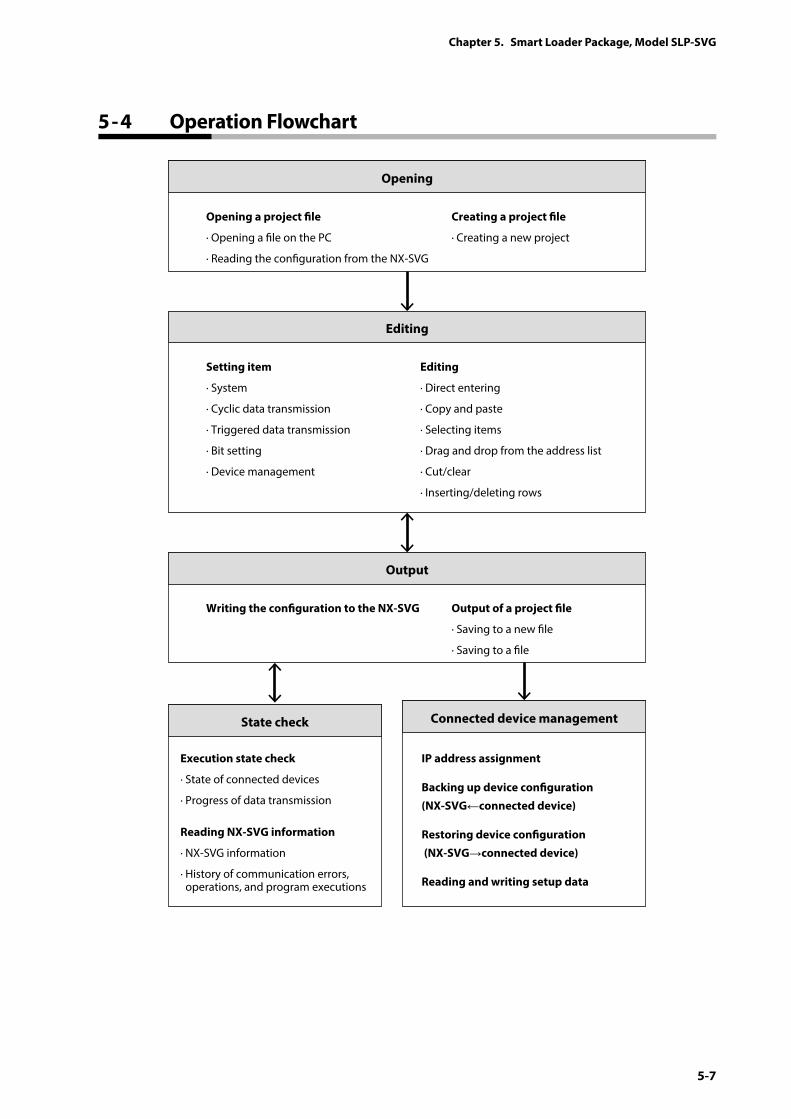
5-7
Chapter 5. Smart Loader Package, Model SLP-SVG
5 - 4 Operation Flowchart
Opening a project le
· Opening a le on the PC
· Reading the conguration from the NX-SVG
Creating a project le
· Creating a new project
Opening
Writing the conguration to the NX-SVG Output of a project le
· Saving to a new le
· Saving to a le
Output
Connected device managementState check
Setting item
· System
· Cyclic data transmission
· Triggered data transmission
· Bit setting
· Device management
Execution state check
· State of connected devices
· Progress of data transmission
IP address assignment
Backing up device conguration (NX-SVG←connected device)
Restoring device conguration (NX-SVG→connected device)
Reading and writing setup data
Reading NX-SVG information
· NX-SVG information
· History of communication errors, operations, and program executions
Editing
· Direct entering
· Copy and paste
· Selecting items
· Drag and drop from the address list
· Cut/clear
· Inserting/deleting rows
Editing
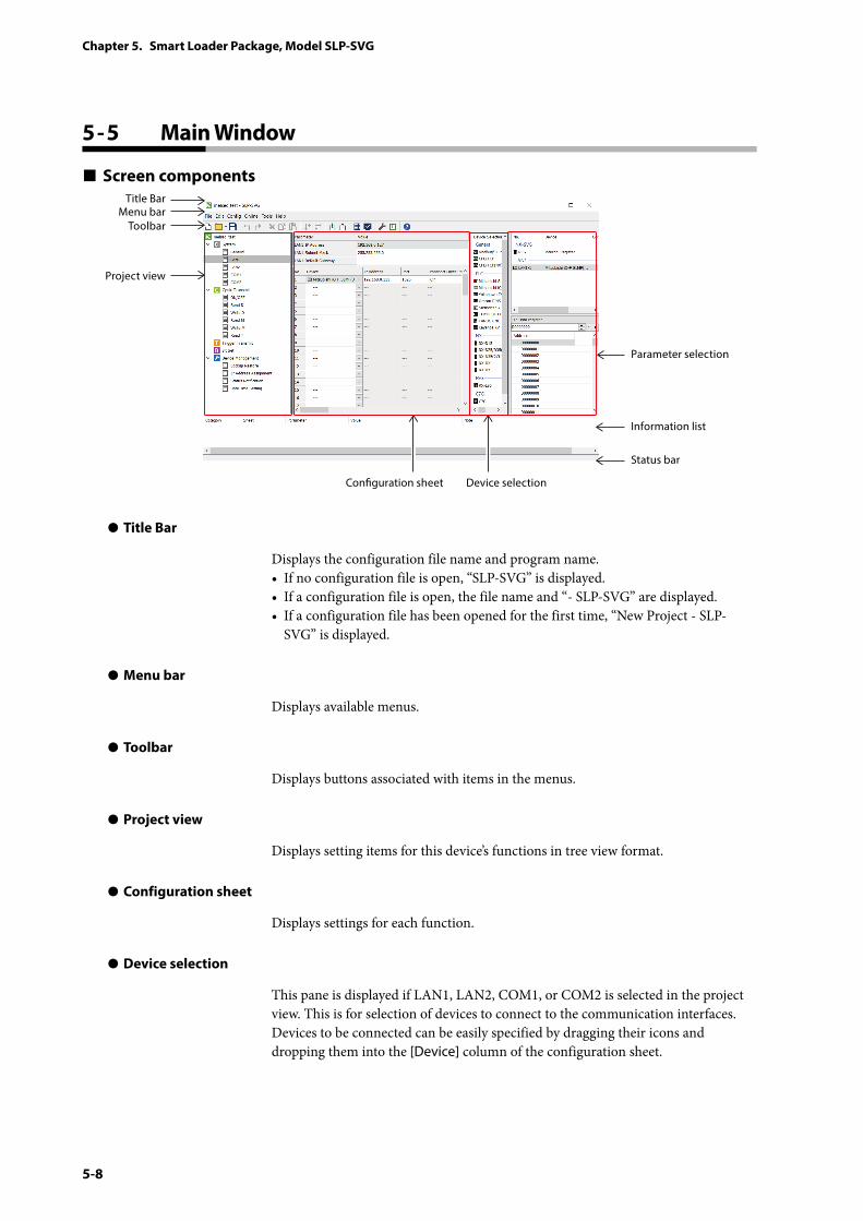
5-8
Chapter 5. Smart Loader Package, Model SLP-SVG
5 - 5 Main Window
Screen components
Menu barTitle Bar
Parameter selection
Conguration sheet
Information list
Status bar
Toolbar
Project view
Device selection
z Title Bar
Displays the configuration file name and program name.• If no configuration file is open, “SLP-SVG” is displayed.• If a configuration file is open, the file name and “- SLP-SVG” are displayed.• If a configuration file has been opened for the first time, “New Project - SLP-
SVG” is displayed.
z Menu bar
Displays available menus.
z Toolbar
Displays buttons associated with items in the menus.
z Project view
Displays setting items for this device’s functions in tree view format.
z Configuration sheet
Displays settings for each function.
z Device selection
This pane is displayed if LAN1, LAN2, COM1, or COM2 is selected in the project view. This is for selection of devices to connect to the communication interfaces. Devices to be connected can be easily specified by dragging their icons and dropping them into the [Device] column of the configuration sheet.
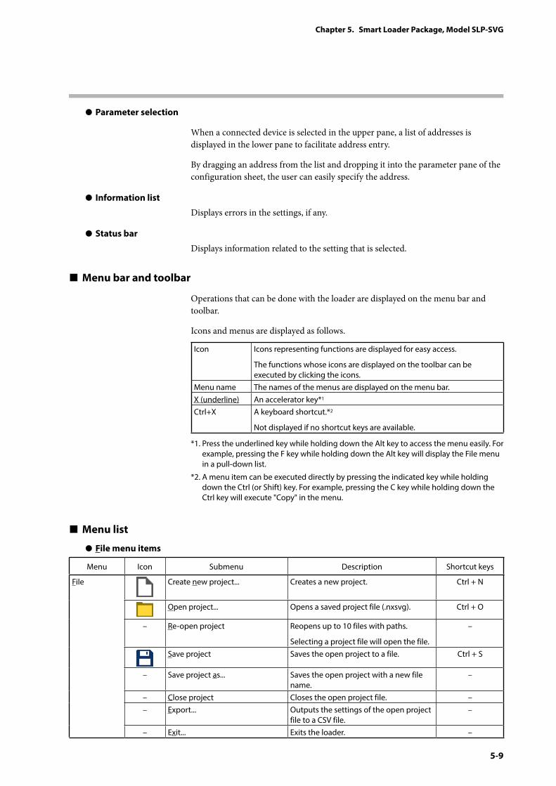
5-9
Chapter 5. Smart Loader Package, Model SLP-SVG
z Parameter selection
When a connected device is selected in the upper pane, a list of addresses is displayed in the lower pane to facilitate address entry.
By dragging an address from the list and dropping it into the parameter pane of the configuration sheet, the user can easily specify the address.
z Information list
Displays errors in the settings, if any.
z Status bar
Displays information related to the setting that is selected.
Menu bar and toolbar
Operations that can be done with the loader are displayed on the menu bar and toolbar.
Icons and menus are displayed as follows.
Icon Icons representing functions are displayed for easy access.
The functions whose icons are displayed on the toolbar can be executed by clicking the icons.
Menu name The names of the menus are displayed on the menu bar.X (underline) An accelerator key*1
Ctrl+X A keyboard shortcut.*2
Not displayed if no shortcut keys are available.
*1. Press the underlined key while holding down the Alt key to access the menu easily. For example, pressing the F key while holding down the Alt key will display the File menu in a pull-down list.
*2. A menu item can be executed directly by pressing the indicated key while holding down the Ctrl (or Shift) key. For example, pressing the C key while holding down the Ctrl key will execute "Copy" in the menu.
Menu list
z File menu items
Menu Icon Submenu Description Shortcut keys
File Create new project... Creates a new project. Ctrl + N
Open project... Opens a saved project file (.nxsvg). Ctrl + O
– Re-open project Reopens up to 10 files with paths.
Selecting a project file will open the file.
–
Save project Saves the open project to a file. Ctrl + S
– Save project as... Saves the open project with a new file name.
–
– Close project Closes the open project file. –– Export... Outputs the settings of the open project
file to a CSV file.–
– Exit... Exits the loader. –
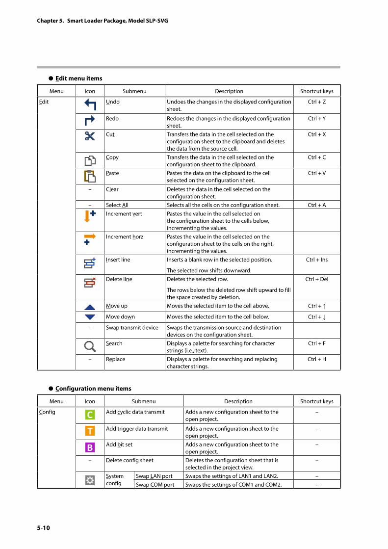
5-10
Chapter 5. Smart Loader Package, Model SLP-SVG
z Edit menu items
Menu Icon Submenu Description Shortcut keys
Edit Undo Undoes the changes in the displayed configuration sheet.
Ctrl + Z
Redo Redoes the changes in the displayed configuration sheet.
Ctrl + Y
Cut Transfers the data in the cell selected on the configuration sheet to the clipboard and deletes the data from the source cell.
Ctrl + X
Copy Transfers the data in the cell selected on the configuration sheet to the clipboard.
Ctrl + C
Paste Pastes the data on the clipboard to the cell selected on the configuration sheet.
Ctrl + V
– Clear Deletes the data in the cell selected on the configuration sheet.
– Select All Selects all the cells on the configuration sheet. Ctrl + AIncrement vert Pastes the value in the cell selected on
the configuration sheet to the cells below, incrementing the values.
Increment horz Pastes the value in the cell selected on the configuration sheet to the cells on the right, incrementing the values.
Insert line Inserts a blank row in the selected position.
The selected row shifts downward.
Ctrl + Ins
Delete line Deletes the selected row.
The rows below the deleted row shift upward to fill the space created by deletion.
Ctrl + Del
Move up Moves the selected item to the cell above. Ctrl + ↑
Move down Moves the selected item to the cell below. Ctrl + ↓
– Swap transmit device Swaps the transmission source and destination devices on the configuration sheet.
Search Displays a palette for searching for character strings (i.e., text).
Ctrl + F
– Replace Displays a palette for searching and replacing character strings.
Ctrl + H
z Configuration menu items
Menu Icon Submenu Description Shortcut keys
Config Add cyclic data transmit Adds a new configuration sheet to the open project.
–
Add trigger data transmit Adds a new configuration sheet to the open project.
–
Add bit set Adds a new configuration sheet to the open project.
–
– Delete config sheet Deletes the configuration sheet that is selected in the project view.
–
System config
Swap LAN port Swaps the settings of LAN1 and LAN2. –Swap COM port Swaps the settings of COM1 and COM2. –
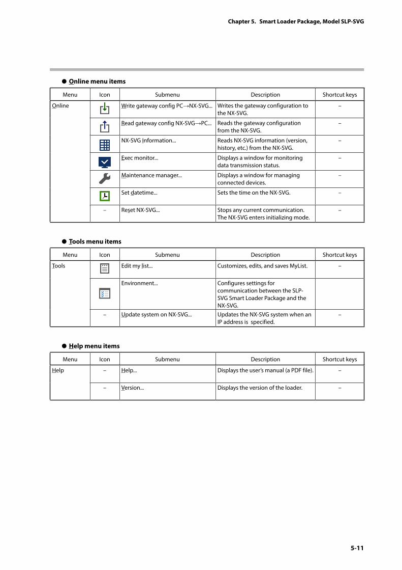
5-11
Chapter 5. Smart Loader Package, Model SLP-SVG
z Online menu items
Menu Icon Submenu Description Shortcut keys
Online Write gateway config PC→NX-SVG... Writes the gateway configuration to the NX-SVG.
–
Read gateway config NX-SVG→PC... Reads the gateway configuration from the NX-SVG.
–
NX-SVG Information... Reads NX-SVG information (version, history, etc.) from the NX-SVG.
–
Exec monitor... Displays a window for monitoring data transmission status.
–
Maintenance manager... Displays a window for managing connected devices.
–
Set datetime... Sets the time on the NX-SVG. –
– Reset NX-SVG... Stops any current communication. The NX-SVG enters initializing mode.
–
z Tools menu items
Menu Icon Submenu Description Shortcut keys
Tools Edit my list... Customizes, edits, and saves MyList. –
Environment... Configures settings for communication between the SLP-SVG Smart Loader Package and the NX-SVG.
– Update system on NX-SVG... Updates the NX-SVG system when an IP address is specified.
–
z Help menu items
Menu Icon Submenu Description Shortcut keys
Help – Help... Displays the user’s manual (a PDF file). –
– Version... Displays the version of the loader. –
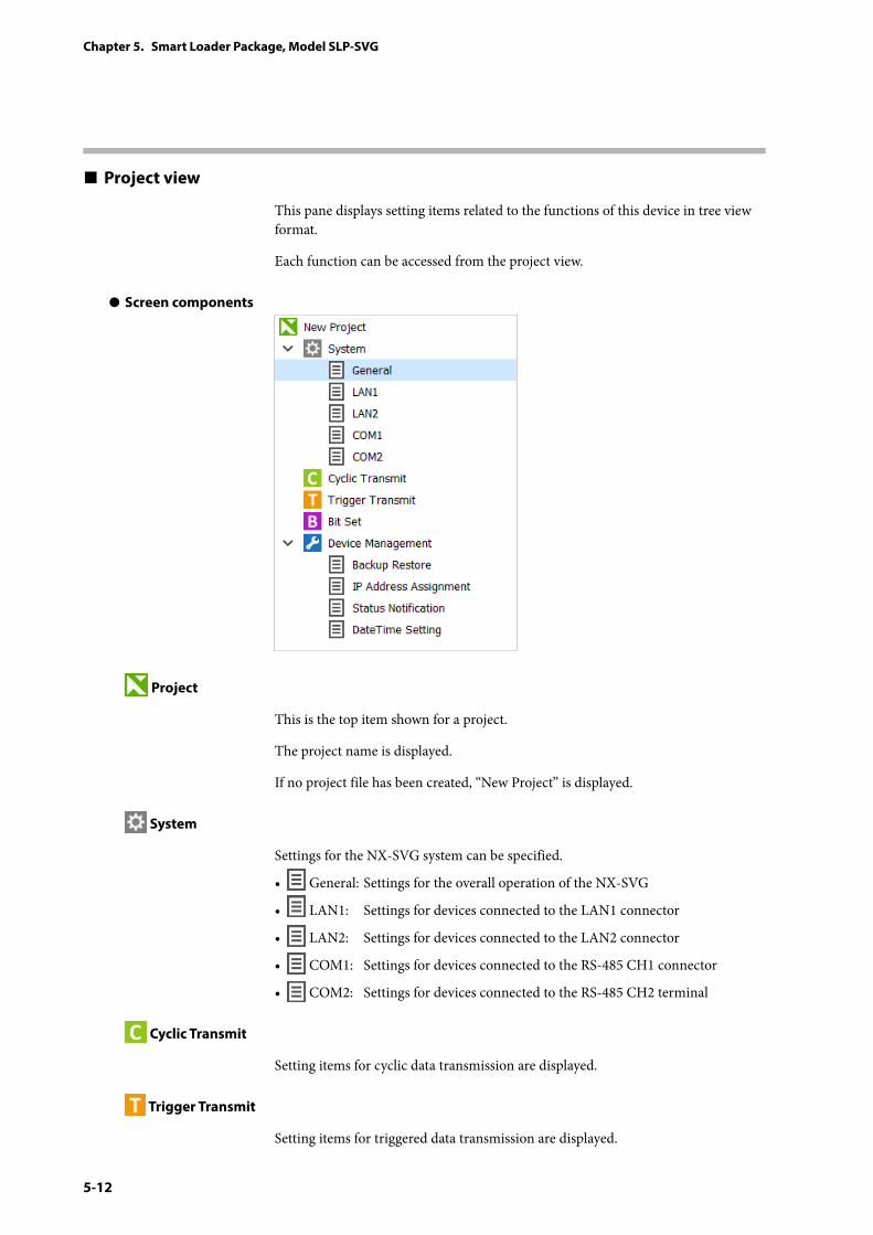
5-12
Chapter 5. Smart Loader Package, Model SLP-SVG
Project view
This pane displays setting items related to the functions of this device in tree view format.
Each function can be accessed from the project view.
z Screen components
Project
This is the top item shown for a project.
The project name is displayed.
If no project file has been created, “New Project” is displayed.
System
Settings for the NX-SVG system can be specified.
• General: Settings for the overall operation of the NX-SVG
• LAN1: Settings for devices connected to the LAN1 connector
• LAN2: Settings for devices connected to the LAN2 connector
• COM1: Settings for devices connected to the RS-485 CH1 connector
• COM2: Settings for devices connected to the RS-485 CH2 terminal
Cyclic Transmit
Setting items for cyclic data transmission are displayed.
Trigger Transmit
Setting items for triggered data transmission are displayed.
5-13
Chapter 5. Smart Loader Package, Model SLP-SVG
Bit Set
Setting items for bit setting are displayed.
Device Management
Setting items for device management are displayed.• Backup Restore: This setting is for backup and restoration of the
configuration file for the connected device.
• IP Address Assignment: This setting is for assigning an IP address to the connected device.
• Status Notification: This setting is for notifying the state of the NX-SVG to the host device.
• DateTime Setting: This setting is for setting the time on the NX-SVG's internal clock.
z Creating a new configuration sheet
New configuration sheets can be created from pop-up menus in the project view. To display a pop-up menu, right-click a function name.
(1) In the project view, right-click the desired function or configuration sheet category.
(2) From the displayed pop-up menu, select [Create config sheet].
A new configuration sheet can also be created from the menu on the menu bar.
(1) Select the [Config] menu.
(2) Select the desired function.
z Editing a configuration sheet
To edit a configuration sheet (cut, copy, or paste data; delete or move a sheet), right-click the sheet in the project view to display a pop-up menu, and execute [Edit]. [Edit] can also be executed from the menu bar.
Note
• It is not possible to select multiple configuration sheets simultaneously. Select and edit one by one.
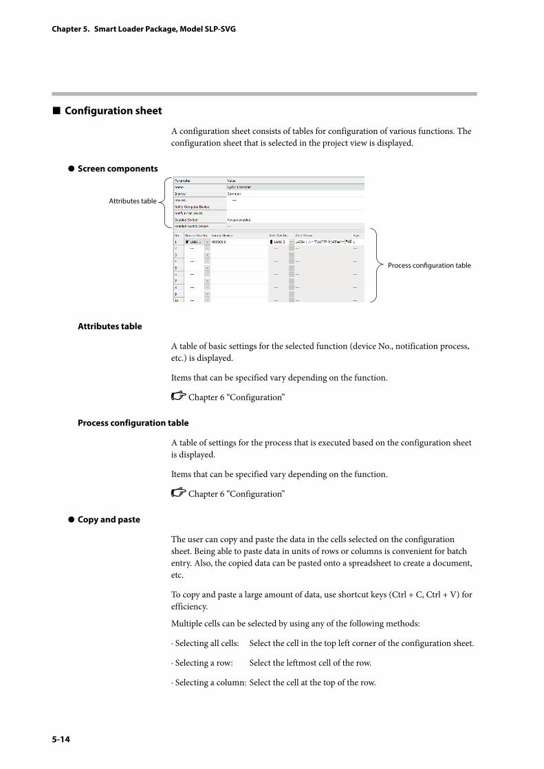
5-14
Chapter 5. Smart Loader Package, Model SLP-SVG
Configuration sheet
A configuration sheet consists of tables for configuration of various functions. The configuration sheet that is selected in the project view is displayed.
z Screen components
Process conguration table
Attributes table
Attributes table
A table of basic settings for the selected function (device No., notification process, etc.) is displayed.
Items that can be specified vary depending on the function.
Chapter 6 “Configuration”
Process configuration table
A table of settings for the process that is executed based on the configuration sheet is displayed.
Items that can be specified vary depending on the function.
Chapter 6 “Configuration”
z Copy and paste
The user can copy and paste the data in the cells selected on the configuration sheet. Being able to paste data in units of rows or columns is convenient for batch entry. Also, the copied data can be pasted onto a spreadsheet to create a document, etc.
To copy and paste a large amount of data, use shortcut keys (Ctrl + C, Ctrl + V) for efficiency.
Multiple cells can be selected by using any of the following methods:
· Selecting all cells: Select the cell in the top left corner of the configuration sheet.
· Selecting a row: Select the leftmost cell of the row.
· Selecting a column: Select the cell at the top of the row.
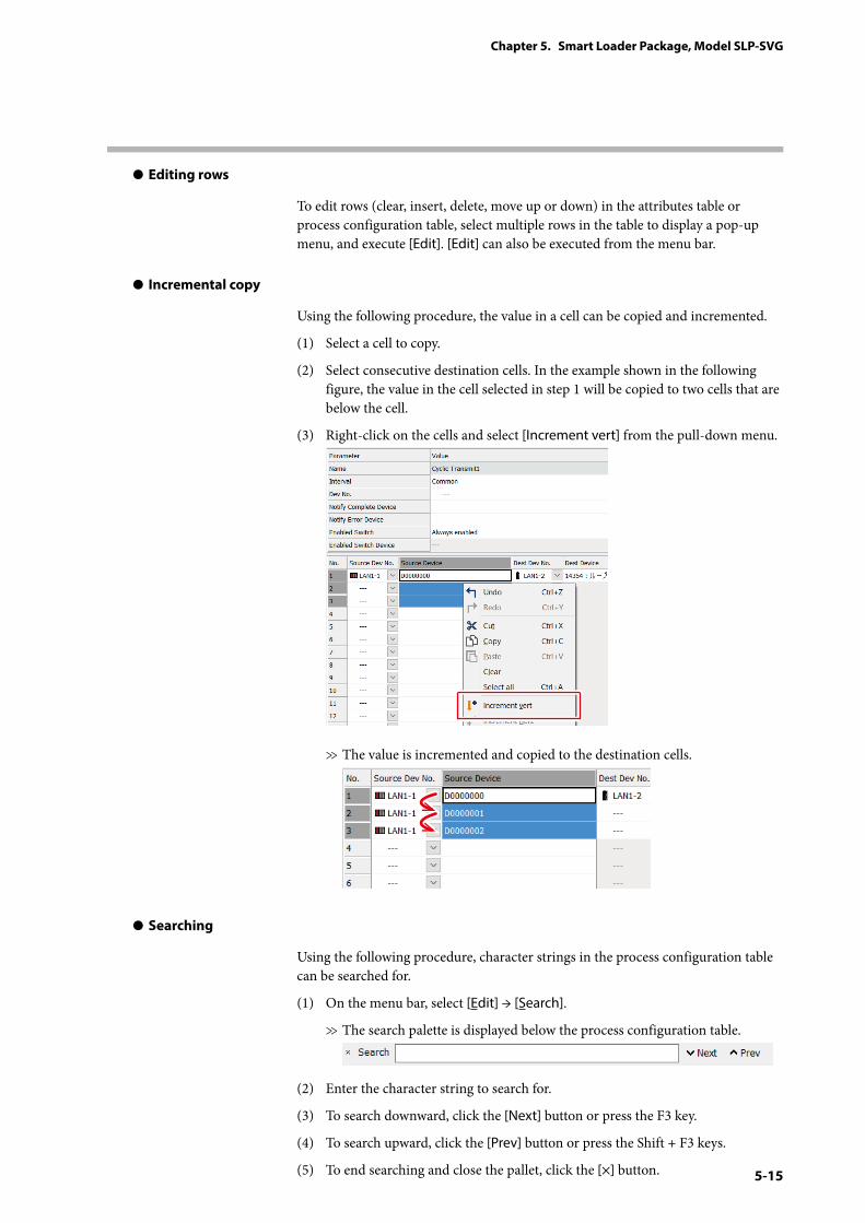
5-15
Chapter 5. Smart Loader Package, Model SLP-SVG
z Editing rows
To edit rows (clear, insert, delete, move up or down) in the attributes table or process configuration table, select multiple rows in the table to display a pop-up menu, and execute [Edit]. [Edit] can also be executed from the menu bar.
z Incremental copy
Using the following procedure, the value in a cell can be copied and incremented.
(1) Select a cell to copy.
(2) Select consecutive destination cells. In the example shown in the following figure, the value in the cell selected in step 1 will be copied to two cells that are below the cell.
(3) Right-click on the cells and select [Increment vert] from the pull-down menu.
>> The value is incremented and copied to the destination cells.
z Searching
Using the following procedure, character strings in the process configuration table can be searched for.
(1) On the menu bar, select [Edit] → [Search].
>> The search palette is displayed below the process configuration table.
(2) Enter the character string to search for.
(3) To search downward, click the [Next] button or press the F3 key.
(4) To search upward, click the [Prev] button or press the Shift + F3 keys.
(5) To end searching and close the pallet, click the [×] button.
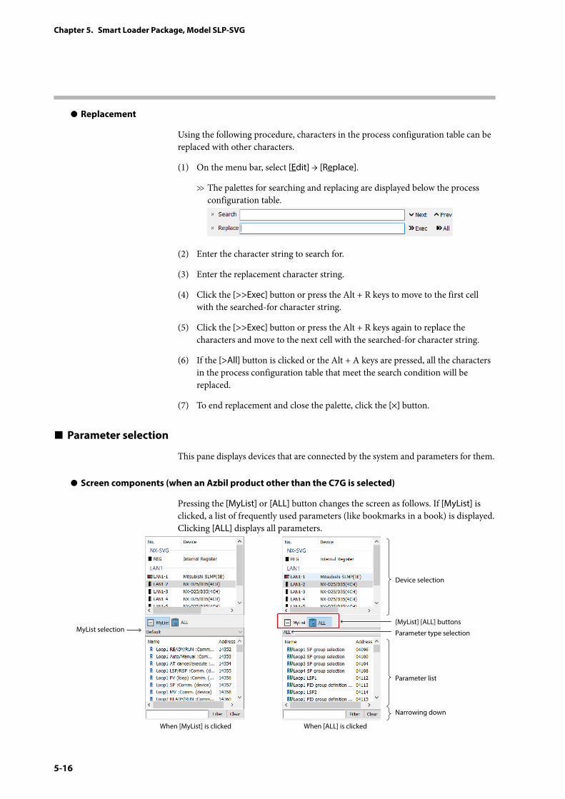
5-16
Chapter 5. Smart Loader Package, Model SLP-SVG
z Replacement
Using the following procedure, characters in the process configuration table can be replaced with other characters.
(1) On the menu bar, select [Edit] → [Replace].
>> The palettes for searching and replacing are displayed below the process configuration table.
(2) Enter the character string to search for.
(3) Enter the replacement character string.
(4) Click the [>>Exec] button or press the Alt + R keys to move to the first cell with the searched-for character string.
(5) Click the [>>Exec] button or press the Alt + R keys again to replace the characters and move to the next cell with the searched-for character string.
(6) If the [>All] button is clicked or the Alt + A keys are pressed, all the characters in the process configuration table that meet the search condition will be replaced.
(7) To end replacement and close the palette, click the [×] button.
Parameter selection
This pane displays devices that are connected by the system and parameters for them.
z Screen components (when an Azbil product other than the C7G is selected)
Pressing the [MyList] or [ALL] button changes the screen as follows. If [MyList] is clicked, a list of frequently used parameters (like bookmarks in a book) is displayed. Clicking [ALL] displays all parameters.
Device selection
[MyList] [ALL] buttons
Parameter type selectionMyList selection
When [MyList] is clicked When [ALL] is clicked
Parameter list
Narrowing down
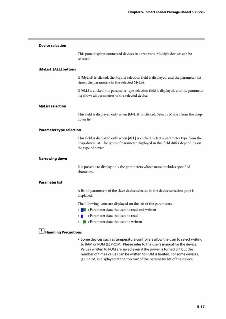
5-17
Chapter 5. Smart Loader Package, Model SLP-SVG
Device selection
This pane displays connected devices in a tree view. Multiple devices can be selected.
[MyList] [ALL] buttons
If [MyList] is clicked, the MyList selection field is displayed, and the parameter list shows the parameters in the selected MyList.
If [ALL] is clicked, the parameter type selection field is displayed, and the parameter list shows all parameters of the selected device.
MyList selection
This field is displayed only when [MyList] is clicked. Select a MyList from the drop-down list.
Parameter type selection
This field is displayed only when [ALL] is clicked. Select a parameter type from the drop-down list. The types of parameter displayed in this field differ depending on the type of device.
Narrowing down
It is possible to display only the parameters whose name includes specified characters.
Parameter list
A list of parameters of the slave device selected in the device selection pane is displayed.
The following icons are displayed on the left of the parameters.• : Parameter data that can be read and written• : Parameter data that can be read• : Parameter data that can be written
Handling Precautions
• Some devices such as temperature controllers allow the user to select writing to RAM or ROM (EEPROM). Please refer to the user's manual for the device. Values written to ROM are saved even if the power is turned off, but the number of times values can be written to ROM is limited. For some devices, [EEPROM] is displayed at the top row of the parameter list of the device.
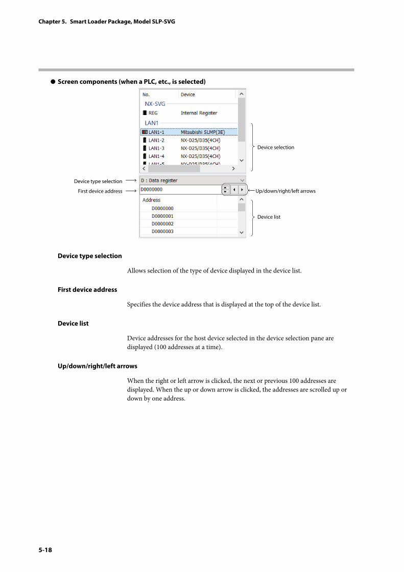
5-18
Chapter 5. Smart Loader Package, Model SLP-SVG
z Screen components (when a PLC, etc., is selected)
Device selection
Up/down/right/left arrows
Device type selection
First device address
Device list
Device type selection
Allows selection of the type of device displayed in the device list.
First device address
Specifies the device address that is displayed at the top of the device list.
Device list
Device addresses for the host device selected in the device selection pane are displayed (100 addresses at a time).
Up/down/right/left arrows
When the right or left arrow is clicked, the next or previous 100 addresses are displayed. When the up or down arrow is clicked, the addresses are scrolled up or down by one address.
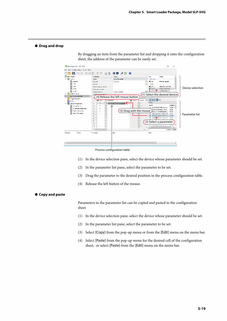
5-19
Chapter 5. Smart Loader Package, Model SLP-SVG
z Drag and drop
By dragging an item from the parameter list and dropping it onto the configuration sheet, the address of the parameter can be easily set.
(1) Select the desired device
(2) Select a parameter
Device selection
Process conguration table
Parameter list(3) Drag with the mouse
(4) Release the left mouse button
(1) In the device selection pane, select the device whose parameter should be set.
(2) In the parameter list pane, select the parameter to be set.
(3) Drag the parameter to the desired position in the process configuration table.
(4) Release the left button of the mouse.
z Copy and paste
Parameters in the parameter list can be copied and pasted to the configuration sheet.
(1) In the device selection pane, select the device whose parameter should be set.
(2) In the parameter list pane, select the parameter to be set.
(3) Select [Copy] from the pop-up menu or from the [Edit] menu on the menu bar.
(4) Select [Paste] from the pop-up menu for the desired cell of the configuration sheet, or select [Paste] from the [Edit] menu on the menu bar.
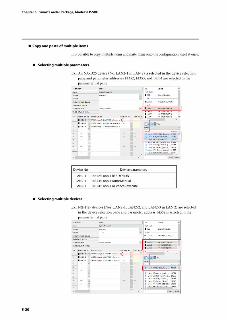
5-20
Chapter 5. Smart Loader Package, Model SLP-SVG
z Copy and paste of multiple items
It is possible to copy multiple items and paste them onto the configuration sheet at once.
z Selecting multiple parameters
Ex.: An NX-D25 device (No. LAN2-1 in LAN 2) is selected in the device selection pane and parameter addresses 14352, 14353, and 14354 are selected in the parameter list pane
Device No. Device parameters
LAN2-1 14352: Loop 1 READY/RUNLAN2-1 14353: Loop 1 Auto/ManualLAN2-1 14354: Loop 1 AT cancel/execute
z Selecting multiple devices
Ex.: NX-D25 devices (Nos. LAN2-1, LAN2-2, and LAN2-3 in LAN 2) are selected in the device selection pane and parameter address 14352 is selected in the parameter list pane
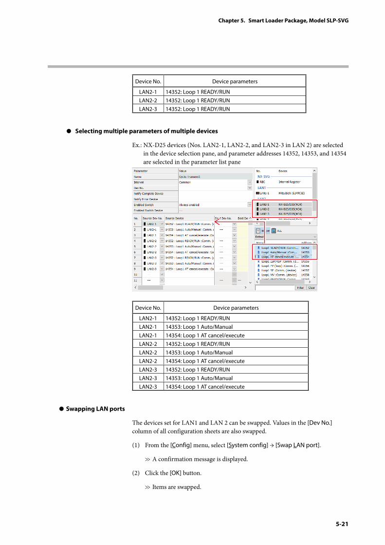
5-21
Chapter 5. Smart Loader Package, Model SLP-SVG
Device No. Device parameters
LAN2-1 14352: Loop 1 READY/RUNLAN2-2 14352: Loop 1 READY/RUNLAN2-3 14352: Loop 1 READY/RUN
z Selecting multiple parameters of multiple devices
Ex.: NX-D25 devices (Nos. LAN2-1, LAN2-2, and LAN2-3 in LAN 2) are selected in the device selection pane, and parameter addresses 14352, 14353, and 14354 are selected in the parameter list pane
Device No. Device parameters
LAN2-1 14352: Loop 1 READY/RUNLAN2-1 14353: Loop 1 Auto/ManualLAN2-1 14354: Loop 1 AT cancel/executeLAN2-2 14352: Loop 1 READY/RUNLAN2-2 14353: Loop 1 Auto/ManualLAN2-2 14354: Loop 1 AT cancel/executeLAN2-3 14352: Loop 1 READY/RUNLAN2-3 14353: Loop 1 Auto/ManualLAN2-3 14354: Loop 1 AT cancel/execute
z Swapping LAN ports
The devices set for LAN1 and LAN 2 can be swapped. Values in the [Dev No.] column of all configuration sheets are also swapped.
(1) From the [Config] menu, select [System config] → [Swap LAN port].
>> A confirmation message is displayed.
(2) Click the [OK] button.
>> Items are swapped.
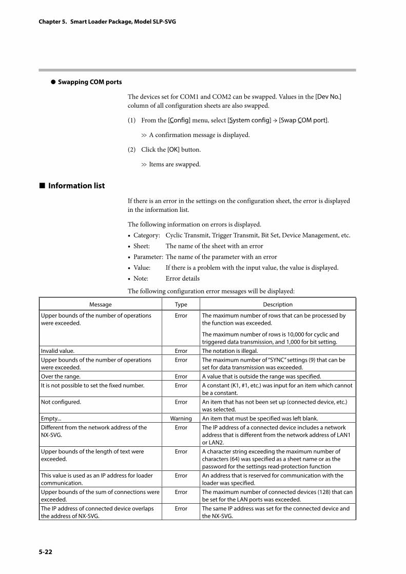
5-22
Chapter 5. Smart Loader Package, Model SLP-SVG
z Swapping COM ports
The devices set for COM1 and COM2 can be swapped. Values in the [Dev No.] column of all configuration sheets are also swapped.
(1) From the [Config] menu, select [System config] → [Swap COM port].
>> A confirmation message is displayed.
(2) Click the [OK] button.
>> Items are swapped.
Information list
If there is an error in the settings on the configuration sheet, the error is displayed in the information list.
The following information on errors is displayed.• Category: Cyclic Transmit, Trigger Transmit, Bit Set, Device Management, etc.• Sheet: The name of the sheet with an error• Parameter: The name of the parameter with an error• Value: If there is a problem with the input value, the value is displayed.• Note: Error details
The following configuration error messages will be displayed:
Message Type Description
Upper bounds of the number of operations were exceeded.
Error The maximum number of rows that can be processed by the function was exceeded.
The maximum number of rows is 10,000 for cyclic and triggered data transmission, and 1,000 for bit setting.
Invalid value. Error The notation is illegal.Upper bounds of the number of operations were exceeded.
Error The maximum number of “SYNC” settings (9) that can be set for data transmission was exceeded.
Over the range. Error A value that is outside the range was specified.It is not possible to set the fixed number. Error A constant (K1, #1, etc.) was input for an item which cannot
be a constant.Not configured. Error An item that has not been set up (connected device, etc.)
was selected.Empty... Warning An item that must be specified was left blank.Different from the network address of the NX-SVG.
Error The IP address of a connected device includes a network address that is different from the network address of LAN1 or LAN2.
Upper bounds of the length of text were exceeded.
Error A character string exceeding the maximum number of characters (64) was specified as a sheet name or as the password for the settings read-protection function
This value is used as an IP address for loader communication.
Error An address that is reserved for communication with the loader was specified.
Upper bounds of the sum of connections were exceeded.
Error The maximum number of connected devices (128) that can be set for the LAN ports was exceeded.
The IP address of connected device overlaps the address of NX-SVG.
Error The same IP address was set for the connected device and the NX-SVG.
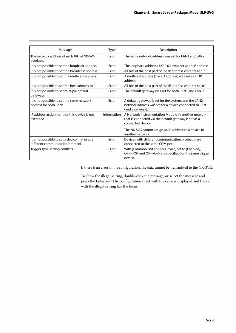
5-23
Chapter 5. Smart Loader Package, Model SLP-SVG
Message Type Description
The network address of each NIC of NX-SVG overlaps.
Error The same network address was set for LAN1 and LAN2.
It is not possible to set the loopback address. Error The loopback address (127.0.0.1) was set as an IP address.It is not possible to set the broadcast address. Error All bits of the host part of the IP address were set to “1.”It is not possible to set the multicast address. Error A multicast address (class D address) was set as an IP
address.It is not possible to set the host address to 0. Error All bits of the host part of the IP address were set to “0.”It is not possible to set multiple default gateways.
Error The default gateway was set for both LAN1 and LAN 2
It is not possible to set the same network address for both LANs.
Error A default gateway is set for the system, and the LAN2 network address was set for a device connected to LAN1 (and vice versa).
IP address assignment for this device is not executed.
Information A Network Instrumentation Module in another network that is connected via the default gateway is set as a connected device.
The NX-SVG cannot assign an IP address to a device in another network.
It is not possible to set a device that uses a different communication protocol.
Error Devices with different communication protocols are connected to the same COM port.
Trigger type setting conflicts. Error With [Common: Init Trigger Device] set to [Enabled], OFF→ON and ON→OFF are specified for the same trigger device.
If there is an error in the configuration, the data cannot be transmitted to the NX-SVG.
To show the illegal setting, double-click the message, or select the message and press the Enter key. The configuration sheet with the error is displayed and the cell with the illegal setting has the focus.
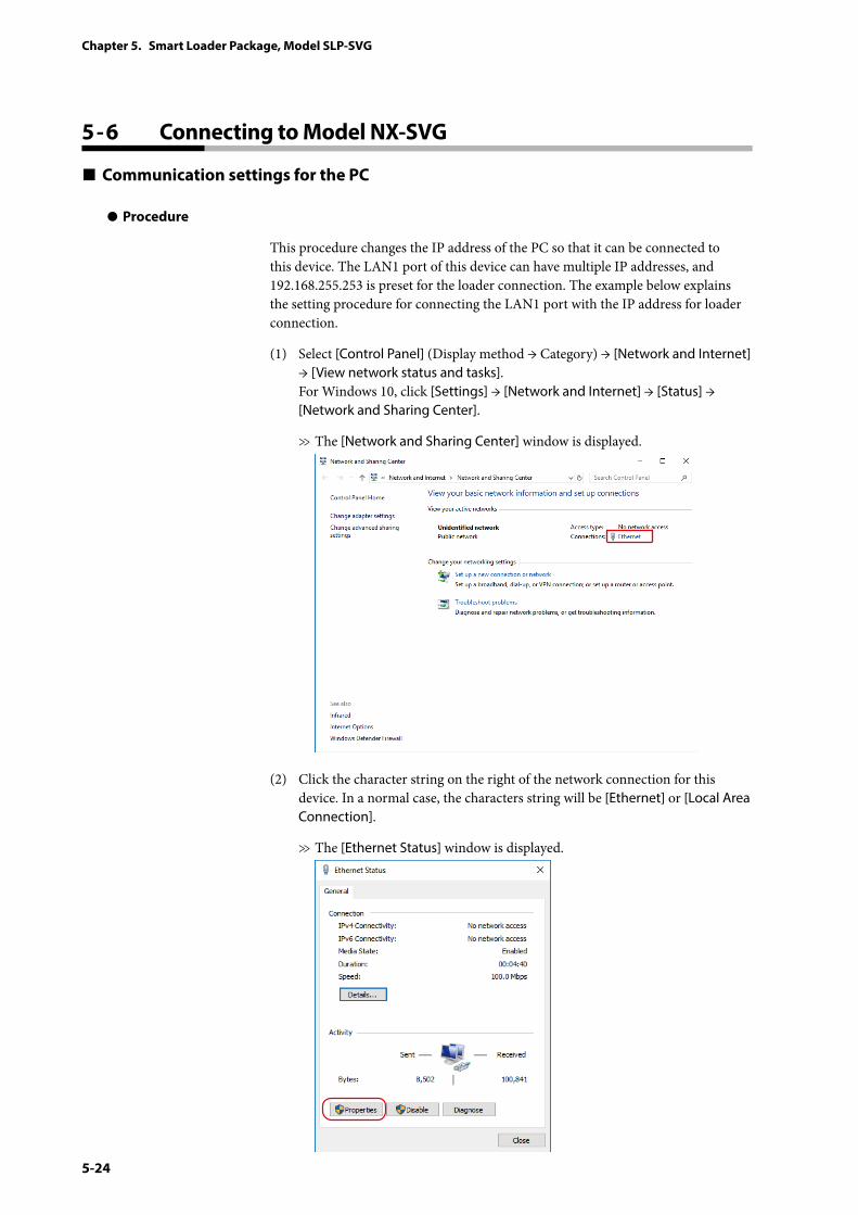
5-24
Chapter 5. Smart Loader Package, Model SLP-SVG
5 - 6 Connecting to Model NX-SVG
Communication settings for the PC
z Procedure
This procedure changes the IP address of the PC so that it can be connected to this device. The LAN1 port of this device can have multiple IP addresses, and 192.168.255.253 is preset for the loader connection. The example below explains the setting procedure for connecting the LAN1 port with the IP address for loader connection.
(1) Select [Control Panel] (Display method → Category) → [Network and Internet] → [View network status and tasks]. For Windows 10, click [Settings] → [Network and Internet] → [Status] → [Network and Sharing Center].
>> The [Network and Sharing Center] window is displayed.
(2) Click the character string on the right of the network connection for this device. In a normal case, the characters string will be [Ethernet] or [Local Area Connection].
>> The [Ethernet Status] window is displayed.
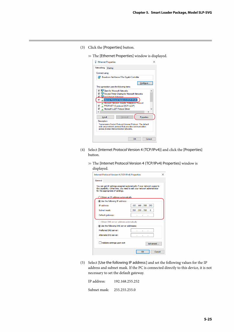
5-25
Chapter 5. Smart Loader Package, Model SLP-SVG
(3) Click the [Properties] button.
>> The [Ethernet Properties] window is displayed.
(4) Select [Internet Protocol Version 4 (TCP/IPv4)] and click the [Properties] button.
>> The [Internet Protocol Version 4 (TCP/IPv4) Properties] window is displayed.
(5) Select [Use the following IP address:] and set the following values for the IP address and subnet mask. If the PC is connected directly to this device, it is not necessary to set the default gateway.
IP address: 192.168.255.252
Subnet mask: 255.255.255.0
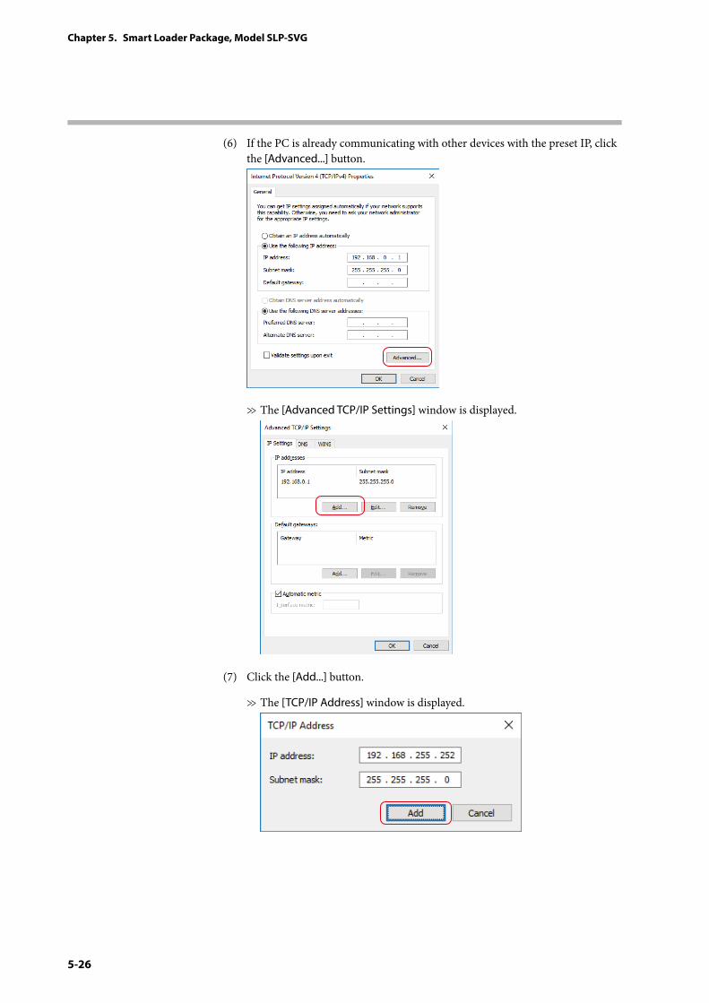
5-26
Chapter 5. Smart Loader Package, Model SLP-SVG
(6) If the PC is already communicating with other devices with the preset IP, click the [Advanced...] button.
>> The [Advanced TCP/IP Settings] window is displayed.
(7) Click the [Add...] button.
>> The [TCP/IP Address] window is displayed.
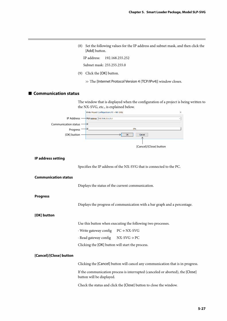
5-27
Chapter 5. Smart Loader Package, Model SLP-SVG
(8) Set the following values for the IP address and subnet mask, and then click the [Add] button.
IP address: 192.168.255.252
Subnet mask: 255.255.255.0
(9) Click the [OK] button.
>> The [Internet Protocol Version 4 (TCP/IPv4)] window closes.
Communication status
The window that is displayed when the configuration of a project is being written to the NX-SVG, etc., is explained below.
IP Address
Communication status
Progress
[Cancel]/[Close] button
[OK] button
IP address setting
Specifies the IP address of the NX-SVG that is connected to the PC.
Communication status
Displays the status of the current communication.
Progress
Displays the progress of communication with a bar graph and a percentage.
[OK] button
Use this button when executing the following two processes.
· Write gateway config PC → NX-SVG
· Read gateway config NX-SVG → PC
Clicking the [OK] button will start the process.
[Cancel]/[Close] button
Clicking the [Cancel] button will cancel any communication that is in progress.
If the communication process is interrupted (canceled or aborted), the [Close] button will be displayed.
Check the status and click the [Close] button to close the window.
5-28
Chapter 5. Smart Loader Package, Model SLP-SVG
Writing the gateway configuration
z Procedure
(1) On the menu bar, select [Online] → [Write gateway config PC → NX-SVG...].
>> The communication status window is displayed.
(2) Specify the IP address of the NX-SVG that is connected to the PC.
(3) Clicking the [OK] button will start the writing of gateway configuration.
>> If the communication is completed properly, the communication status window closes.
z Description
• If a project file is open, the configuration of the project is written to the NX-SVG.
• If there is an error in the project configuration, an error message is displayed. In this case, the configuration file is not downloaded. The version of the system file on the NX-SVG and PC is compared. If the NX-SVG has an older system file, a confirmation message for system update is displayed.
5 - 9 Updating the System of Model NX-SVG (p. 5-46)
• A confirmation message saying that the NX-SVG will enter STOP mode is displayed. If the [OK] button is clicked, the NX-SVG enters STOP mode and starts writing the configuration file. If the [Cancel] button is clicked, the configuration file is not written.
• When writing of the configuration file is complete, the gateway program automatically restarts and the NX-SVG enters RUN mode.
Reading the gateway settings
z Procedure
(1) On the menu bar, select [Online] → [Read gateway config NX-SVG→PC].
>> The window for saving the project is displayed.
(2) Select the project file whose configuration you wish to save.
(3) Click the [OK] button.
>> The window for saving the project closes and the communication status window is displayed.
(4) Specify the IP address of the NX-SVG that is connected to the PC.
(5) Clicking the [OK] button will start the reading of gateway configuration file.
>> If the communication is completed properly, the communication status window closes.
z Description
While the gateway configuration file is being read, the mode will not change.
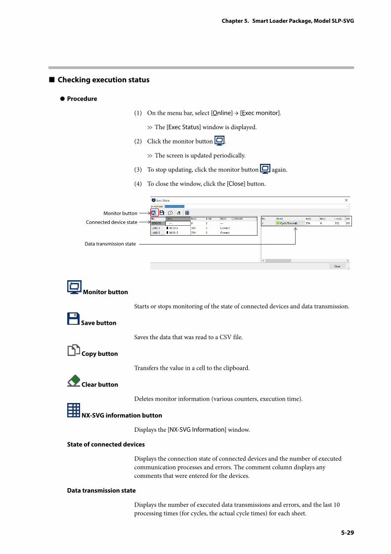
5-29
Chapter 5. Smart Loader Package, Model SLP-SVG
Checking execution status
z Procedure
(1) On the menu bar, select [Online] → [Exec monitor].
>> The [Exec Status] window is displayed.
(2) Click the monitor button .
>> The screen is updated periodically.
(3) To stop updating, click the monitor button again.
(4) To close the window, click the [Close] button.
Connected device state
Data transmission state
Monitor button
Monitor button
Starts or stops monitoring of the state of connected devices and data transmission.
Save button
Saves the data that was read to a CSV file.
Copy button
Transfers the value in a cell to the clipboard.
Clear button
Deletes monitor information (various counters, execution time).
NX-SVG information button
Displays the [NX-SVG Information] window.
State of connected devices
Displays the connection state of connected devices and the number of executed communication processes and errors. The comment column displays any comments that were entered for the devices.
Data transmission state
Displays the number of executed data transmissions and errors, and the last 10 processing times (for cycles, the actual cycle times) for each sheet.
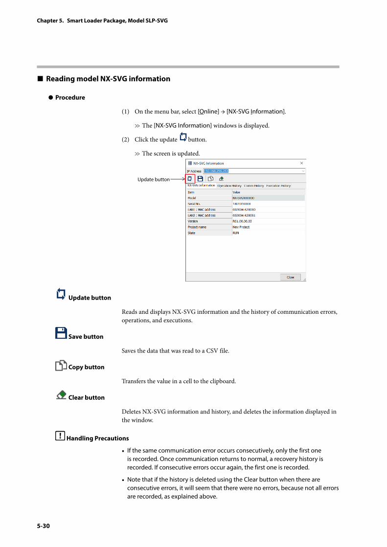
5-30
Chapter 5. Smart Loader Package, Model SLP-SVG
Reading model NX-SVG information
z Procedure
(1) On the menu bar, select [Online] → [NX-SVG Information].
>> The [NX-SVG Information] windows is displayed.
(2) Click the update button.
>> The screen is updated.
Update button
Update button
Reads and displays NX-SVG information and the history of communication errors, operations, and executions.
Save button
Saves the data that was read to a CSV file.
Copy button
Transfers the value in a cell to the clipboard.
Clear button
Deletes NX-SVG information and history, and deletes the information displayed in the window.
Handling Precautions
• If the same communication error occurs consecutively, only the first one is recorded. Once communication returns to normal, a recovery history is recorded. If consecutive errors occur again, the first one is recorded.
• Note that if the history is deleted using the Clear button when there are consecutive errors, it will seem that there were no errors, because not all errors are recorded, as explained above.
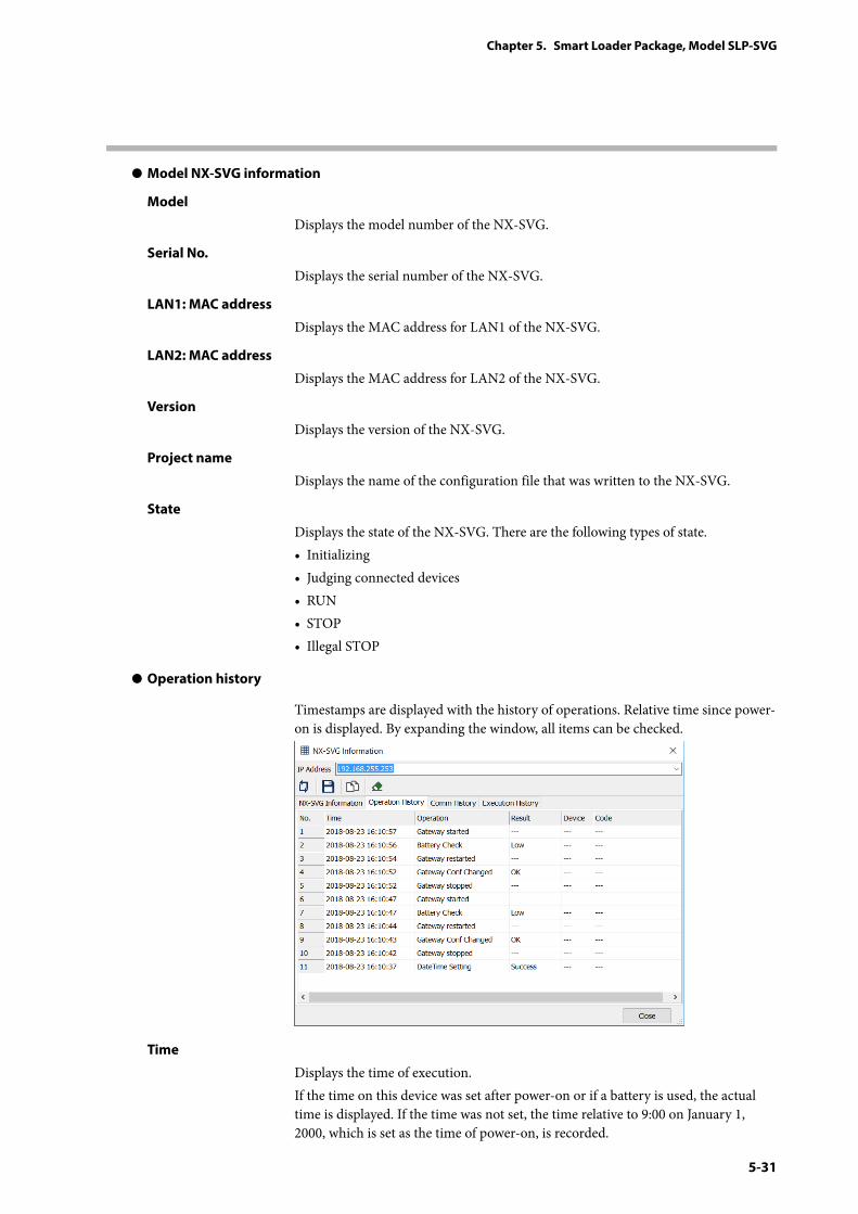
5-31
Chapter 5. Smart Loader Package, Model SLP-SVG
z Model NX-SVG information
Model
Displays the model number of the NX-SVG.
Serial No.
Displays the serial number of the NX-SVG.
LAN1: MAC address
Displays the MAC address for LAN1 of the NX-SVG.
LAN2: MAC address
Displays the MAC address for LAN2 of the NX-SVG.
Version
Displays the version of the NX-SVG.
Project name
Displays the name of the configuration file that was written to the NX-SVG.
State
Displays the state of the NX-SVG. There are the following types of state.• Initializing• Judging connected devices• RUN• STOP• Illegal STOP
z Operation history
Timestamps are displayed with the history of operations. Relative time since power-on is displayed. By expanding the window, all items can be checked.
Time
Displays the time of execution.If the time on this device was set after power-on or if a battery is used, the actual time is displayed. If the time was not set, the time relative to 9:00 on January 1, 2000, which is set as the time of power-on, is recorded.
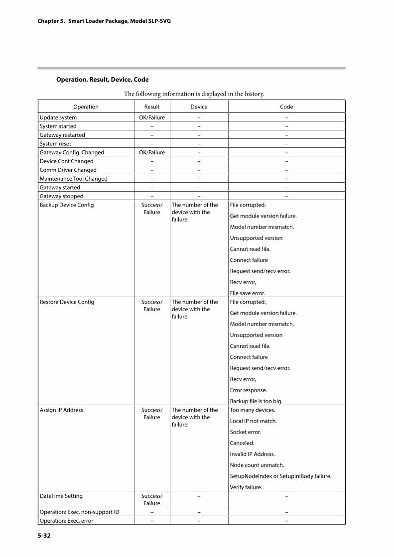
5-32
Chapter 5. Smart Loader Package, Model SLP-SVG
Operation, Result, Device, Code
The following information is displayed in the history.
Operation Result Device Code
Update system OK/Failure – –System started – – –Gateway restarted – – –System reset – – –Gateway Config. Changed OK/Failure – –Device Conf Changed – – –Comm Driver Changed – – –Maintenance Tool Changed – – –Gateway started – – –Gateway stopped – – –Backup Device Config Success/
FailureThe number of the device with the failure.
File corrupted.
Get module version failure.
Model number mismatch.
Unsupported version
Cannot read file.
Connect failure
Request send/recv error.
Recv error,
File save error.Restore Device Config Success/
FailureThe number of the device with the failure.
File corrupted.
Get module version failure.
Model number mismatch.
Unsupported version
Cannot read file.
Connect failure
Request send/recv error.
Recv error,
Error response.
Backup file is too big.Assign IP Address Success/
FailureThe number of the device with the failure.
Too many devices.
Local IP not match.
Socket error.
Canceled.
Invalid IP Address.
Node count unmatch.
SetupNodeIndex or SetupIniBody failure.
Verify failure.DateTime Setting Success/
Failure– –
Operation: Exec. non-support ID – – –Operation: Exec. error – – –
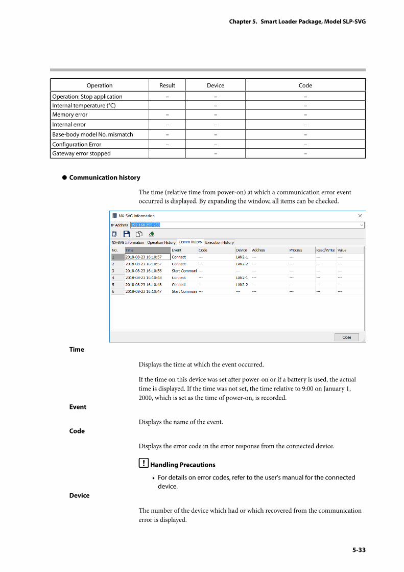
5-33
Chapter 5. Smart Loader Package, Model SLP-SVG
Operation Result Device Code
Operation: Stop application – – –Internal temperature (°C) – –Memory error – – –
Internal error – – –
Base-body model No. mismatch – – –
Configuration Error – – –Gateway error stopped – –
z Communication history
The time (relative time from power-on) at which a communication error event occurred is displayed. By expanding the window, all items can be checked.
Time
Displays the time at which the event occurred.
If the time on this device was set after power-on or if a battery is used, the actual time is displayed. If the time was not set, the time relative to 9:00 on January 1, 2000, which is set as the time of power-on, is recorded.
Event
Displays the name of the event.Code
Displays the error code in the error response from the connected device.
Handling Precautions
• For details on error codes, refer to the user's manual for the connected device.
Device
The number of the device which had or which recovered from the communication error is displayed.
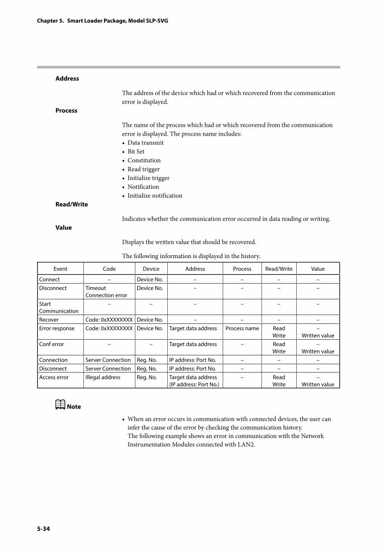
5-34
Chapter 5. Smart Loader Package, Model SLP-SVG
Address
The address of the device which had or which recovered from the communication error is displayed.
Process
The name of the process which had or which recovered from the communication error is displayed. The process name includes:• Data transmit• Bit Set• Constitution• Read trigger• Initialize trigger• Notification• Initialize notification
Read/Write
Indicates whether the communication error occurred in data reading or writing.Value
Displays the written value that should be recovered.
The following information is displayed in the history.
Event Code Device Address Process Read/Write Value
Connect – Device No. – – – –Disconnect Timeout
Connection errorDevice No. – – – –
Start Communication
– – – – – –
Recover Code: 0xXXXXXXXX Device No. – – – –Error response Code: 0xXXXXXXXX Device No. Target data address Process name Read
Write–
Written valueConf error – – Target data address – Read
Write–
Written valueConnection Server Connection Reg. No. IP address: Port No. – – –Disconnect Server Connection Reg. No. IP address: Port No. – – –Access error Illegal address Reg. No. Target data address
(IP address: Port No.)– Read
Write–
Written value
Note
• When an error occurs in communication with connected devices, the user can infer the cause of the error by checking the communication history. The following example shows an error in communication with the Network Instrumentation Modules connected with LAN2.
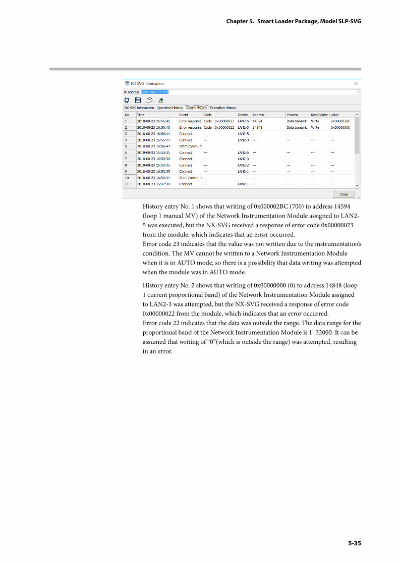
5-35
Chapter 5. Smart Loader Package, Model SLP-SVG
History entry No. 1 shows that writing of 0x000002BC (700) to address 14594 (loop 1 manual MV) of the Network Instrumentation Module assigned to LAN2-5 was executed, but the NX-SVG received a response of error code 0x00000023 from the module, which indicates that an error occurred. Error code 23 indicates that the value was not written due to the instrumentation’s condition. The MV cannot be written to a Network Instrumentation Module when it is in AUTO mode, so there is a possibility that data writing was attempted when the module was in AUTO mode.
History entry No. 2 shows that writing of 0x00000000 (0) to address 14848 (loop 1 current proportional band) of the Network Instrumentation Module assigned to LAN2-3 was attempted, but the NX-SVG received a response of error code 0x00000022 from the module, which indicates that an error occurred. Error code 22 indicates that the data was outside the range. The data range for the proportional band of the Network Instrumentation Module is 1–32000. It can be assumed that writing of “0”(which is outside the range) was attempted, resulting in an error.
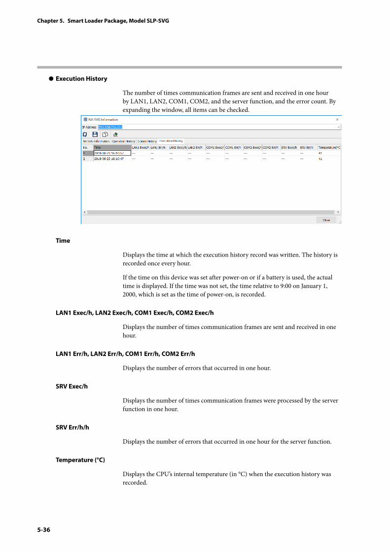
5-36
Chapter 5. Smart Loader Package, Model SLP-SVG
z Execution History
The number of times communication frames are sent and received in one hour by LAN1, LAN2, COM1, COM2, and the server function, and the error count. By expanding the window, all items can be checked.
Time
Displays the time at which the execution history record was written. The history is recorded once every hour.
If the time on this device was set after power-on or if a battery is used, the actual time is displayed. If the time was not set, the time relative to 9:00 on January 1, 2000, which is set as the time of power-on, is recorded.
LAN1 Exec/h, LAN2 Exec/h, COM1 Exec/h, COM2 Exec/h
Displays the number of times communication frames are sent and received in one hour.
LAN1 Err/h, LAN2 Err/h, COM1 Err/h, COM2 Err/h
Displays the number of errors that occurred in one hour.
SRV Exec/h
Displays the number of times communication frames were processed by the server function in one hour.
SRV Err/h/h
Displays the number of errors that occurred in one hour for the server function.
Temperature (°C)
Displays the CPU’s internal temperature (in °C) when the execution history was recorded.
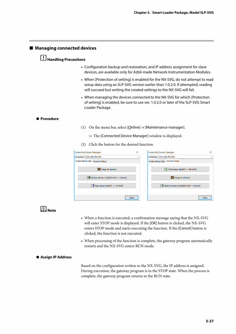
5-37
Chapter 5. Smart Loader Package, Model SLP-SVG
Managing connected devices
Handling Precautions
• Configuration backup and restoration, and IP address assignment for slave devices, are available only for Azbil-made Network Instrumentation Modules.
• When [Protection of setting] is enabled for the NX-SVG, do not attempt to read setup data using an SLP-SVG version earlier than 1.0.2.0. If attempted, reading will succeed but writing the created settings to the NX-SVG will fail.
• When managing the devices connected to the NX-SVG for which [Protection of setting] is enabled, be sure to use ver. 1.0.2.0 or later of the SLP-SVG Smart Loader Package.
z Procedure
(1) On the menu bar, select [Online] → [Maintenance manager].
>> The [Connected Device Manager] window is displayed.
(2) Click the button for the desired function.
Note
• When a function is executed, a confirmation message saying that the NX-SVG will enter STOP mode is displayed. If the [OK] button is clicked, the NX-SVG enters STOP mode and starts executing the function. If the [Cancel] button is clicked, the function is not executed.
• When processing of the function is complete, the gateway program automatically restarts and the NX-SVG enters RUN mode.
z Assign IP Address
Based on the configuration written to the NX-SVG, the IP address is assigned. During execution, the gateway program is in the STOP state. When the process is complete, the gateway program returns to the RUN state.
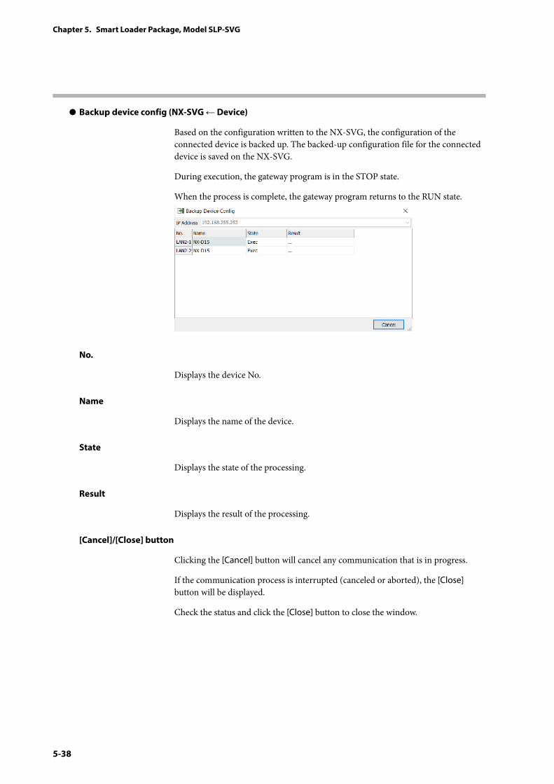
5-38
Chapter 5. Smart Loader Package, Model SLP-SVG
z Backup device config (NX-SVG ← Device)
Based on the configuration written to the NX-SVG, the configuration of the connected device is backed up. The backed-up configuration file for the connected device is saved on the NX-SVG.
During execution, the gateway program is in the STOP state.
When the process is complete, the gateway program returns to the RUN state.
No.
Displays the device No.
Name
Displays the name of the device.
State
Displays the state of the processing.
Result
Displays the result of the processing.
[Cancel]/[Close] button
Clicking the [Cancel] button will cancel any communication that is in progress.
If the communication process is interrupted (canceled or aborted), the [Close] button will be displayed.
Check the status and click the [Close] button to close the window.
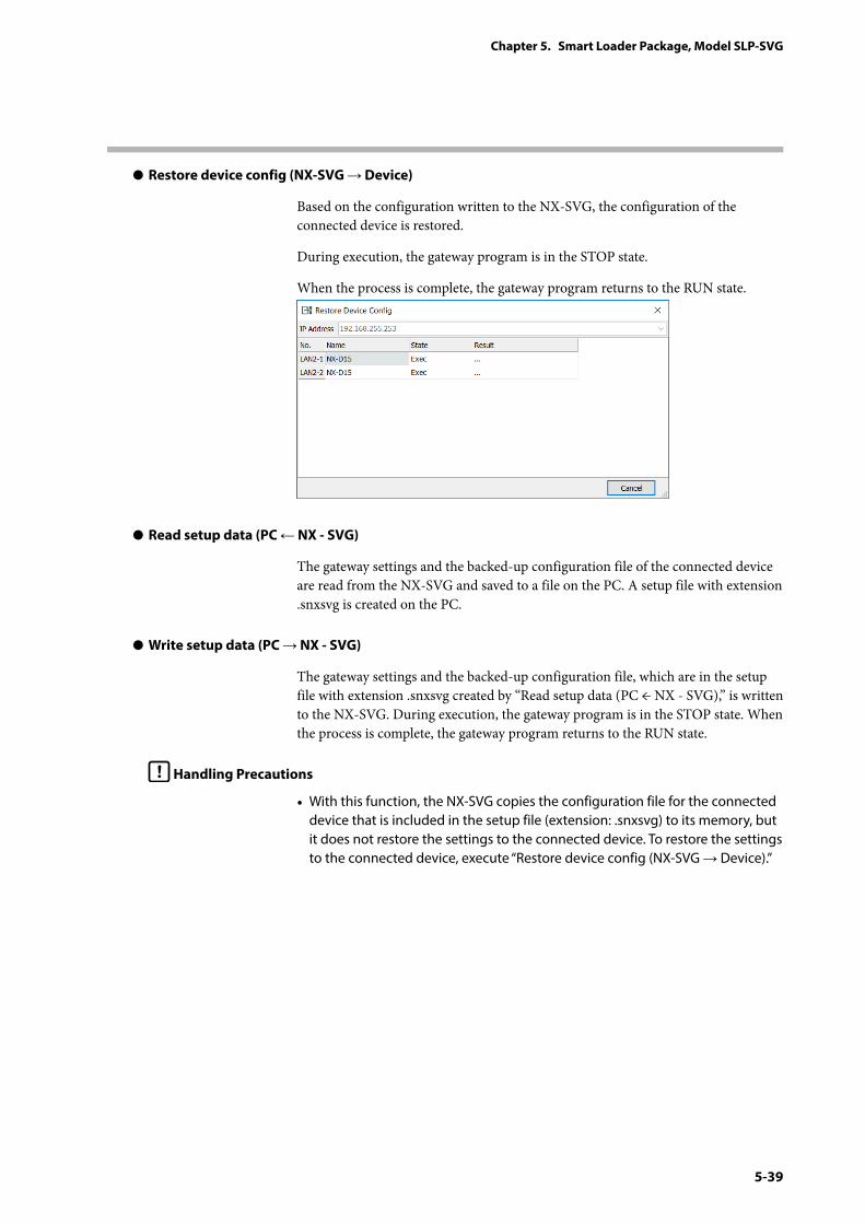
5-39
Chapter 5. Smart Loader Package, Model SLP-SVG
z Restore device config (NX-SVG → Device)
Based on the configuration written to the NX-SVG, the configuration of the connected device is restored.
During execution, the gateway program is in the STOP state.
When the process is complete, the gateway program returns to the RUN state.
z Read setup data (PC ← NX - SVG)
The gateway settings and the backed-up configuration file of the connected device are read from the NX-SVG and saved to a file on the PC. A setup file with extension .snxsvg is created on the PC.
z Write setup data (PC → NX - SVG)
The gateway settings and the backed-up configuration file, which are in the setup file with extension .snxsvg created by “Read setup data (PC ← NX - SVG),” is written to the NX-SVG. During execution, the gateway program is in the STOP state. When the process is complete, the gateway program returns to the RUN state.
Handling Precautions
• With this function, the NX-SVG copies the configuration file for the connected device that is included in the setup file (extension: .snxsvg) to its memory, but it does not restore the settings to the connected device. To restore the settings to the connected device, execute “Restore device config (NX-SVG → Device).”
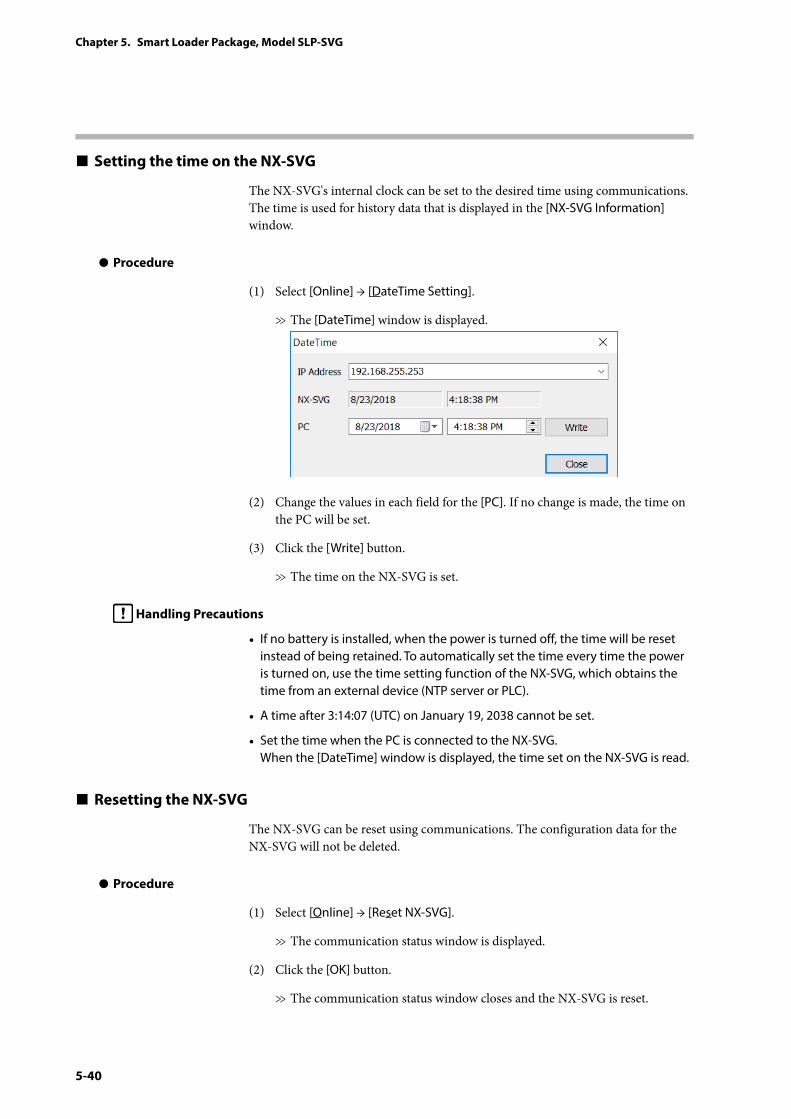
5-40
Chapter 5. Smart Loader Package, Model SLP-SVG
Setting the time on the NX-SVG
The NX-SVG's internal clock can be set to the desired time using communications. The time is used for history data that is displayed in the [NX-SVG Information] window.
z Procedure
(1) Select [Online] → [DateTime Setting].
>> The [DateTime] window is displayed.
(2) Change the values in each field for the [PC]. If no change is made, the time on the PC will be set.
(3) Click the [Write] button.
>> The time on the NX-SVG is set.
Handling Precautions
• If no battery is installed, when the power is turned off, the time will be reset instead of being retained. To automatically set the time every time the power is turned on, use the time setting function of the NX-SVG, which obtains the time from an external device (NTP server or PLC).
• A time after 3:14:07 (UTC) on January 19, 2038 cannot be set.
• Set the time when the PC is connected to the NX-SVG. When the [DateTime] window is displayed, the time set on the NX-SVG is read.
Resetting the NX-SVG
The NX-SVG can be reset using communications. The configuration data for the NX-SVG will not be deleted.
z Procedure
(1) Select [Online] → [Reset NX-SVG].
>> The communication status window is displayed.
(2) Click the [OK] button.
>> The communication status window closes and the NX-SVG is reset.
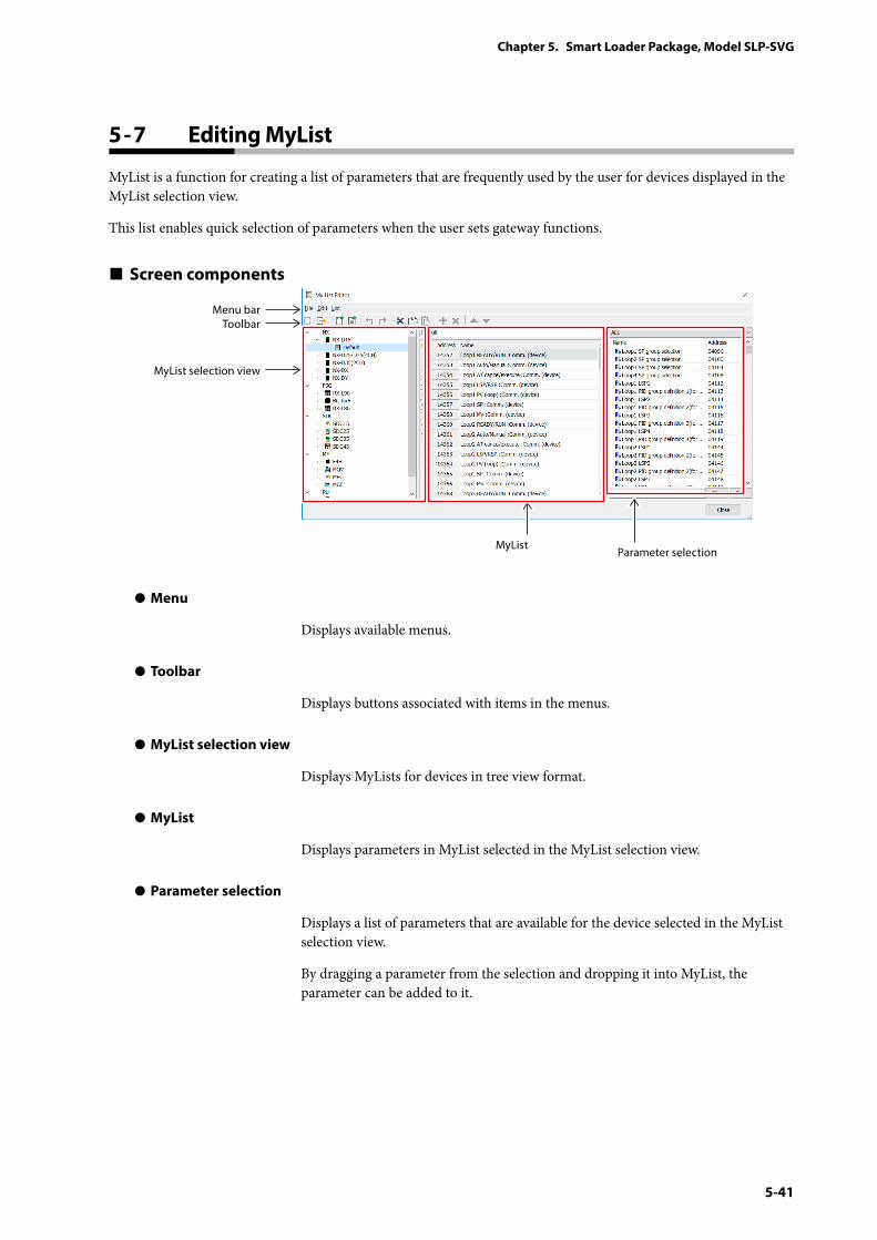
5-41
Chapter 5. Smart Loader Package, Model SLP-SVG
MyList is a function for creating a list of parameters that are frequently used by the user for devices displayed in the MyList selection view.
This list enables quick selection of parameters when the user sets gateway functions.
Screen components
Menu barToolbar
MyList selection view
Parameter selectionMyList
z Menu
Displays available menus.
z Toolbar
Displays buttons associated with items in the menus.
z MyList selection view
Displays MyLists for devices in tree view format.
z MyList
Displays parameters in MyList selected in the MyList selection view.
z Parameter selection
Displays a list of parameters that are available for the device selected in the MyList selection view.
By dragging a parameter from the selection and dropping it into MyList, the parameter can be added to it.
5 - 7 Editing MyList
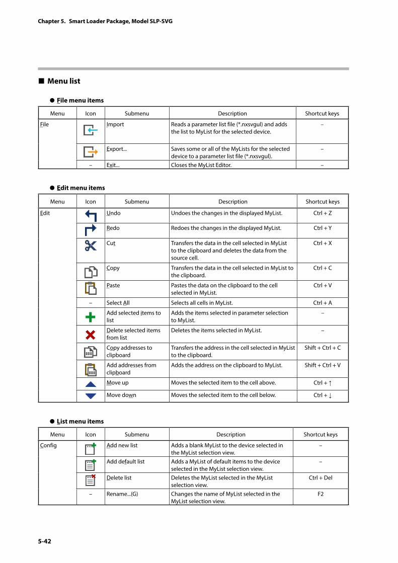
5-42
Chapter 5. Smart Loader Package, Model SLP-SVG
Menu list
z File menu items
Menu Icon Submenu Description Shortcut keys
File Import Reads a parameter list file (*.nxsvgul) and adds the list to MyList for the selected device.
–
Export... Saves some or all of the MyLists for the selected device to a parameter list file (*.nxsvgul).
–
– Exit... Closes the MyList Editor. –
z Edit menu items
Menu Icon Submenu Description Shortcut keys
Edit Undo Undoes the changes in the displayed MyList. Ctrl + Z
Redo Redoes the changes in the displayed MyList. Ctrl + Y
Cut Transfers the data in the cell selected in MyList to the clipboard and deletes the data from the source cell.
Ctrl + X
Copy Transfers the data in the cell selected in MyList to the clipboard.
Ctrl + C
Paste Pastes the data on the clipboard to the cell selected in MyList.
Ctrl + V
– Select All Selects all cells in MyList. Ctrl + A
Add selected items to list
Adds the items selected in parameter selection to MyList.
–
Delete selected items from list
Deletes the items selected in MyList. –
Copy addresses to clipboard
Transfers the address in the cell selected in MyList to the clipboard.
Shift + Ctrl + C
Add addresses from clipboard
Adds the address on the clipboard to MyList. Shift + Ctrl + V
Move up Moves the selected item to the cell above. Ctrl + ↑
Move down Moves the selected item to the cell below. Ctrl + ↓
z List menu items
Menu Icon Submenu Description Shortcut keys
Config Add new list Adds a blank MyList to the device selected in the MyList selection view.
–
Add default list Adds a MyList of default items to the device selected in the MyList selection view.
–
Delete list Deletes the MyList selected in the MyList selection view.
Ctrl + Del
– Rename...(G) Changes the name of MyList selected in the MyList selection view.
F2
5-43
Chapter 5. Smart Loader Package, Model SLP-SVG
Adding/deleting MyList
z Creating a new MyList
(1) In the MyList selection view, select the device whose MyList you wish to create (or select the MyList level above the level where you wish to create the new MyList).
(2) Right-click the selected item and select [Add new list] from the context menu (or from [List] on the menu bar).
To add a MyList of default items, select [Add default list] from the pop-up menu (or from [List] on the menu bar).
z Editing a MyList
To edit (cut, copy, paste, delete, move, rename) a MyList that already exists, select it in the MyList selection view to display a pop-up menu, and execute [Edit]. [Edit] can also be executed from the menu bar.
Note
• It is not possible to select multiple MyLists simultaneously. Select and edit one by one.
Editing a MyList
z Rename
By double-clicking a cell (or pressing the F2 key), the name in the cell can be edited. It is also possible to enter characters directly to change the name.
The user can copy and paste the data in a selected cell.
z Adding parameters to a MyList
In the parameter selection pane, select the parameters to add and select [Add selected items to list] from the pop-up menu (or from [Edit] on the menu bar). The selected parameters will be added to the end of the MyList.
Parameters can be also added by dragging an item from the parameter selection pane and dropping it onto the MyList.
z Copying an address to the clipboard
On MyList, select the rows of the device address to send to the clipboard, and select [Copy addresses to clipboard] from the pop-up menu (or from [Edit] on the menu bar). This will send the device addresses in the selected rows to the clipboard as text items delimited by newline characters.
5-44
Chapter 5. Smart Loader Package, Model SLP-SVG
z Adding an address from the clipboard
On MyList, select [Add addresses from clipboard] from the pop-up menu (or from [Edit] on the menu bar). This will add the device address to MyList via the clipboard as text items delimited by newline characters.
An address that is already in MyList or that is not displayed in the parameter selection pane will not be added to MyList.
z Deleting parameters from MyList
On MyList, select parameters to delete and select [Delete selected items from list] from the pop-up menu (or from [Edit] on the menu bar). The selected parameters are deleted from MyList.
Exporting and importing MyList
In order to use MyList on another PC, it can be saved to a file and imported to the other PC using the loader's MyList Editor on the PC.
z Export
In the MyList selection view, select MyList or the device to output to a file, and select [Export...] from the pop-up menu (or from [File] on the menu bar). The [Save As] window is displayed. Enter the file name and press the [Save] button. A MyList file with the extension .nxsvgul will be created on the PC.
z Import
In the MyList selection view, select the device to which MyList will be imported, and select [Import...] from the pop-up menu (or from [File] on the menu bar). The [Open] window is displayed. Select the .nxsvgul file to import and click the [Open] button.
Note
• If importing MyList for a different model is attempted, an error message saying that there is no valid definition will be displayed, and the import will be canceled.
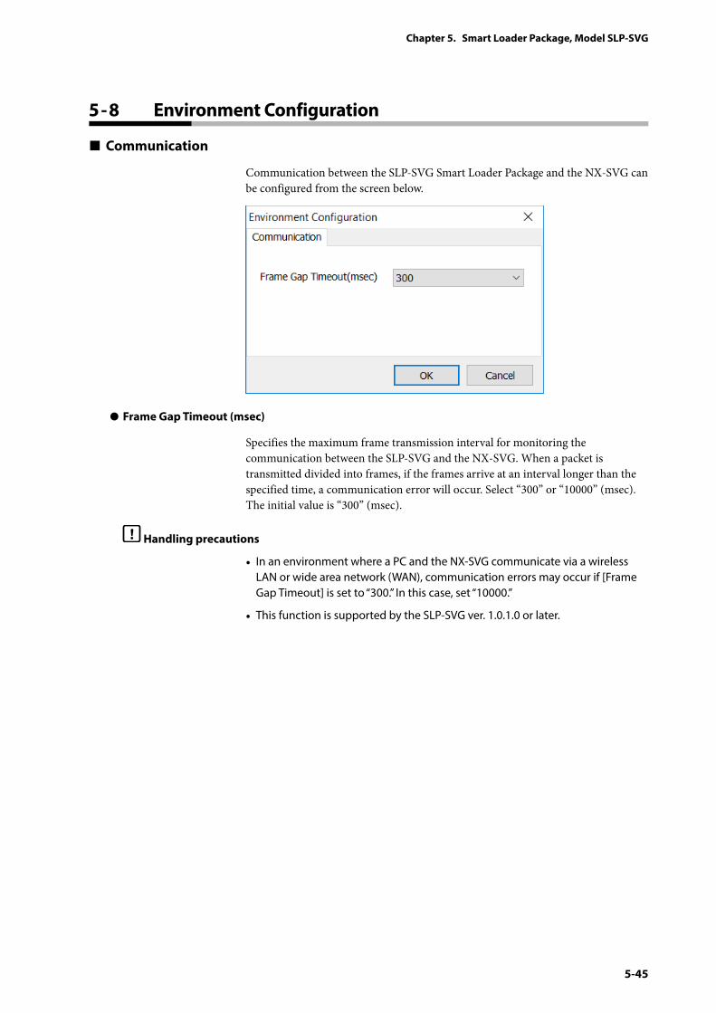
5-45
Chapter 5. Smart Loader Package, Model SLP-SVG
5 - 8 Environment Configuration
Communication
Communication between the SLP-SVG Smart Loader Package and the NX-SVG can be configured from the screen below.
z Frame Gap Timeout (msec)
Specifies the maximum frame transmission interval for monitoring the communication between the SLP-SVG and the NX-SVG. When a packet is transmitted divided into frames, if the frames arrive at an interval longer than the specified time, a communication error will occur. Select “300” or “10000” (msec). The initial value is “300” (msec).
Handling precautions
• In an environment where a PC and the NX-SVG communicate via a wireless LAN or wide area network (WAN), communication errors may occur if [Frame Gap Timeout] is set to “300.” In this case, set “10000.”
• This function is supported by the SLP-SVG ver. 1.0.1.0 or later.
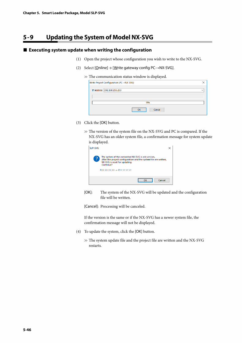
5-46
Chapter 5. Smart Loader Package, Model SLP-SVG
5 - 9 Updating the System of Model NX-SVG
Executing system update when writing the configuration
(1) Open the project whose configuration you wish to write to the NX-SVG.
(2) Select [Online] → [Write gateway config PC→NX-SVG].
>> The communication status window is displayed.
(3) Click the [OK] button.
>> The version of the system file on the NX-SVG and PC is compared. If the NX-SVG has an older system file, a confirmation message for system update is displayed.
[OK]: The system of the NX-SVG will be updated and the configuration file will be written.
[Cancel]: Processing will be canceled.
If the version is the same or if the NX-SVG has a newer system file, the confirmation message will not be displayed.
(4) To update the system, click the [OK] button.
>> The system update file and the project file are written and the NX-SVG restarts.
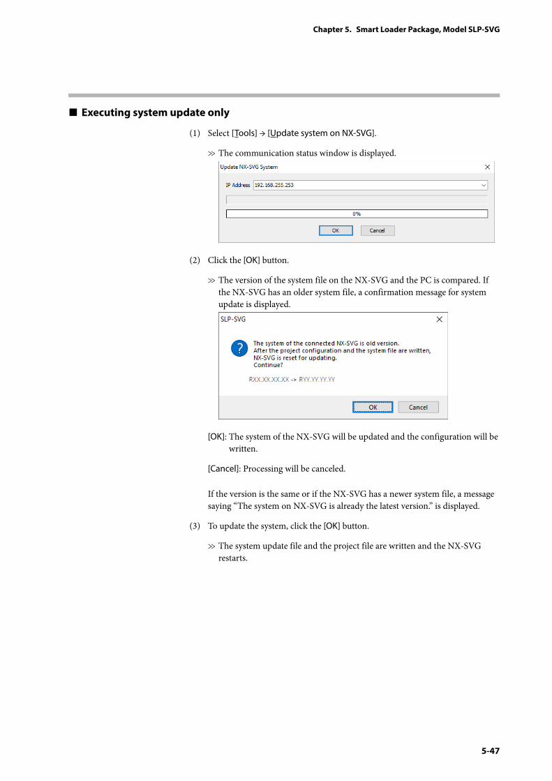
5-47
Chapter 5. Smart Loader Package, Model SLP-SVG
Executing system update only
(1) Select [Tools] → [Update system on NX-SVG].
>> The communication status window is displayed.
(2) Click the [OK] button.
>> The version of the system file on the NX-SVG and the PC is compared. If the NX-SVG has an older system file, a confirmation message for system update is displayed.
[OK]: The system of the NX-SVG will be updated and the configuration will be written.
[Cancel]: Processing will be canceled.
If the version is the same or if the NX-SVG has a newer system file, a message saying “The system on NX-SVG is already the latest version.” is displayed.
(3) To update the system, click the [OK] button.
>> The system update file and the project file are written and the NX-SVG restarts.

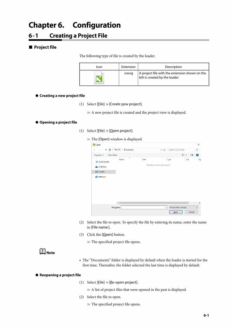
6-1
Chapter 6. Configuration6 - 1 Creating a Project File
Project file
The following type of file is created by the loader.
Icon Extension Description
.nxsvg A project file with the extension shown on the left is created by the loader.
z Creating a new project file
(1) Select [File] → [Create new project].
>> A new project file is created and the project view is displayed.
z Opening a project file
(1) Select [File] → [Open project].
>> The [Open] window is displayed.
(2) Select the file to open. To specify the file by entering its name, enter the name in [File name:].
(3) Click the [Open] button.
>> The specified project file opens.
Note
• The “Documents” folder is displayed by default when the loader is started for the first time. Thereafter, the folder selected the last time is displayed by default.
z Reopening a project file
(1) Select [File] → [Re-open project].
>> A list of project files that were opened in the past is displayed.
(2) Select the file to open.
>> The specified project file opens.
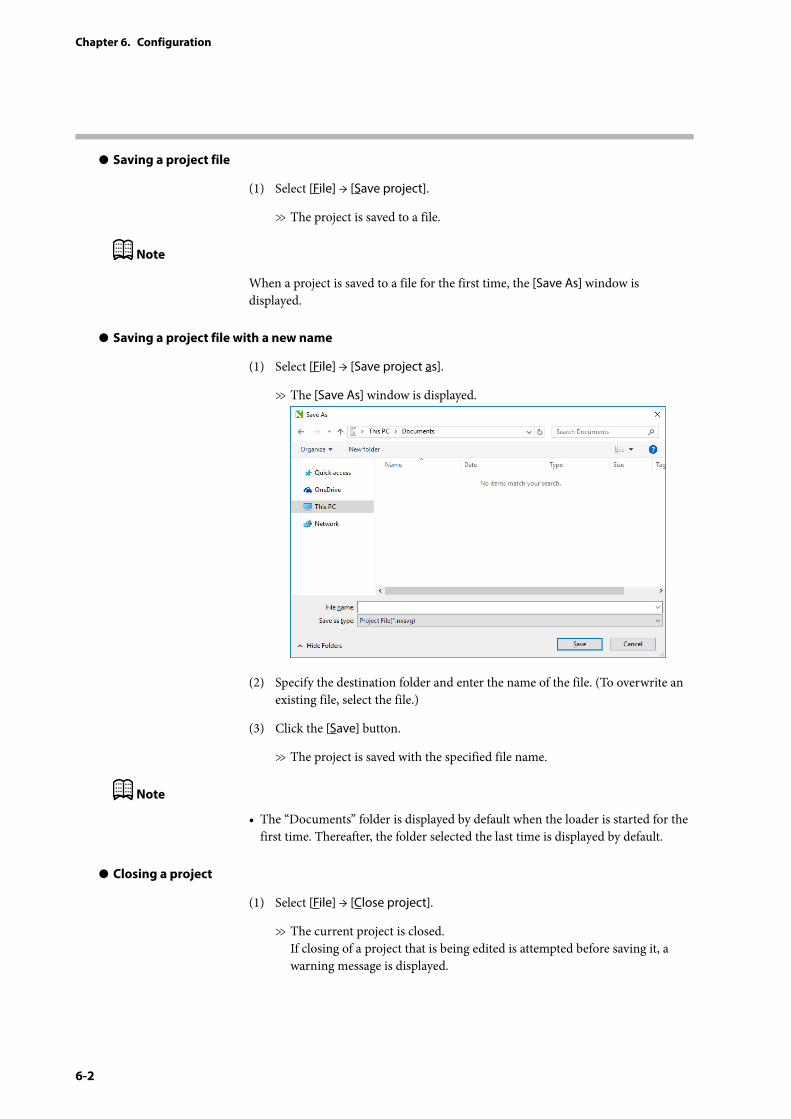
6-2
Chapter 6. Configuration
z Saving a project file
(1) Select [File] → [Save project].
>> The project is saved to a file.
Note
When a project is saved to a file for the first time, the [Save As] window is displayed.
z Saving a project file with a new name
(1) Select [File] → [Save project as].
>> The [Save As] window is displayed.
(2) Specify the destination folder and enter the name of the file. (To overwrite an existing file, select the file.)
(3) Click the [Save] button.
>> The project is saved with the specified file name.
Note
• The “Documents” folder is displayed by default when the loader is started for the first time. Thereafter, the folder selected the last time is displayed by default.
z Closing a project
(1) Select [File] → [Close project].
>> The current project is closed. If closing of a project that is being edited is attempted before saving it, a warning message is displayed.
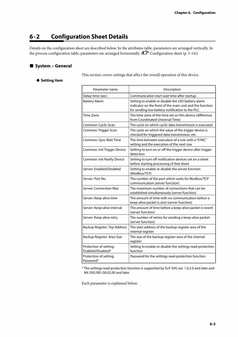
6-3
Chapter 6. Configuration
6 - 2 Configuration Sheet Details
Details on the configuration sheet are described below. In the attributes table, parameters are arranged vertically. In the process configuration table, parameters are arranged horizontally. ( Configuration sheet (p. 5-14))
System – General
This section covers settings that affect the overall operation of this device.z Setting item
Parameter name Description
Delay-time (sec) Communication start wait time after startupBattery Alarm Setting to enable or disable the LED battery alarm
indicator on the front of the main unit and the function for sending low battery notification to the PLC.
Time Zone The time zone of the time set on this device (difference from Coordinated Universal Time)
Common: Cyclic Scan The cycle on which cyclic data transmission is executedCommon: Trigger Scan The cycle on which the value of the trigger device is
checked for triggered data transmission, etc.Common: Sync Wait Time The time between execution of a row with a “SYNC”
setting and the execution of the next rowCommon: Init Trigger Device Setting to turn on or off the trigger device after trigger
detectionCommon: Init Notify Device Setting to turn off notification devices set on a sheet
before starting processing of that sheetServer: Enabled/Disabled Setting to enable or disable the server function
(Modbus/TCP)Server: Port No. The number of the port which waits for Modbus/TCP
communication (server function)Server: Connection Max The maximum number of connections that can be
established simultaneously (server function)Server: Keep-alive time The amount of time with no communication before a
keep-alive packet is sent (server function)Server: Keep-alive interval The amount of time before a keep-alive packet is resent
(server function)Server: Keep-alive retry The number of retries for sending a keep-alive packet
(server function)Backup Register: Top Address The start address of the backup register area of the
internal registerBackup Register: Area Size The size of the backup register area of the internal
registerProtection of setting: Enabled/Disabled*
Setting to enable or disable the settings read-protection function
Protection of setting: Password*
Password for the settings read-protection function
* The settings read-protection function is supported by SLP-SVG ver. 1.0.2.0 and later and NX-SVG R01.00.02.00 and later.
Each parameter is explained below.
6-4
Chapter 6. Configuration
z Delay-time (sec)
Sets the wait time before starting communications after startup of this device is complete. Set this parameter if, when the equipment is powered on, the connected devices will not be ready to communicate by the time the startup of this device is complete. • Range (unit: seconds): 0–60• Default value: 0
Note• It takes about 30 seconds for this device to be ready to communicate after
power-on. For [Delay-time (sec)], specify the wait time before starting communications after this device becomes ready to communicate.
z Battery Alarm
Enables or disables the LED battery alarm indicator on the front of the main unit. If no battery is used, disable this function so that the LED is not turned on. If disabled, the function for sending Notification Low Battery to the PLC is also disabled.• Range: Enabled, Disabled• Default value: Enabled
z Time Zone
Sets the time zone of the time set on this device. Set how many hours this device is behind (minus) or ahead (plus) of Coordinated Universal Time. Less than one hour cannot be specified.• Range: UTC−12 to UTC+14• Default value: UTC+9
z Common: Cyclic Scan
Sets the cycle on which cyclic data transmission is executed. According to the cycle specified by this parameter, this device starts processing cyclic data transmission sheets that have not been executed. To transmit data on a slow cycle exceeding 1 second, set [Interval] for each sheet.• Range: 100 ms to 1 second (select in units of 100 ms)• Default value: 200 ms
z Common: Trigger Scan
The cycle on which the value of the trigger device is checked for triggered data transmission, etc. According to the cycle specified by this parameter, this device starts checking the state of the trigger device for triggered data transmission sheets that have not been executed.• Range: 100 ms to 1 second (select in units of 100 ms)• Default value: 200 ms
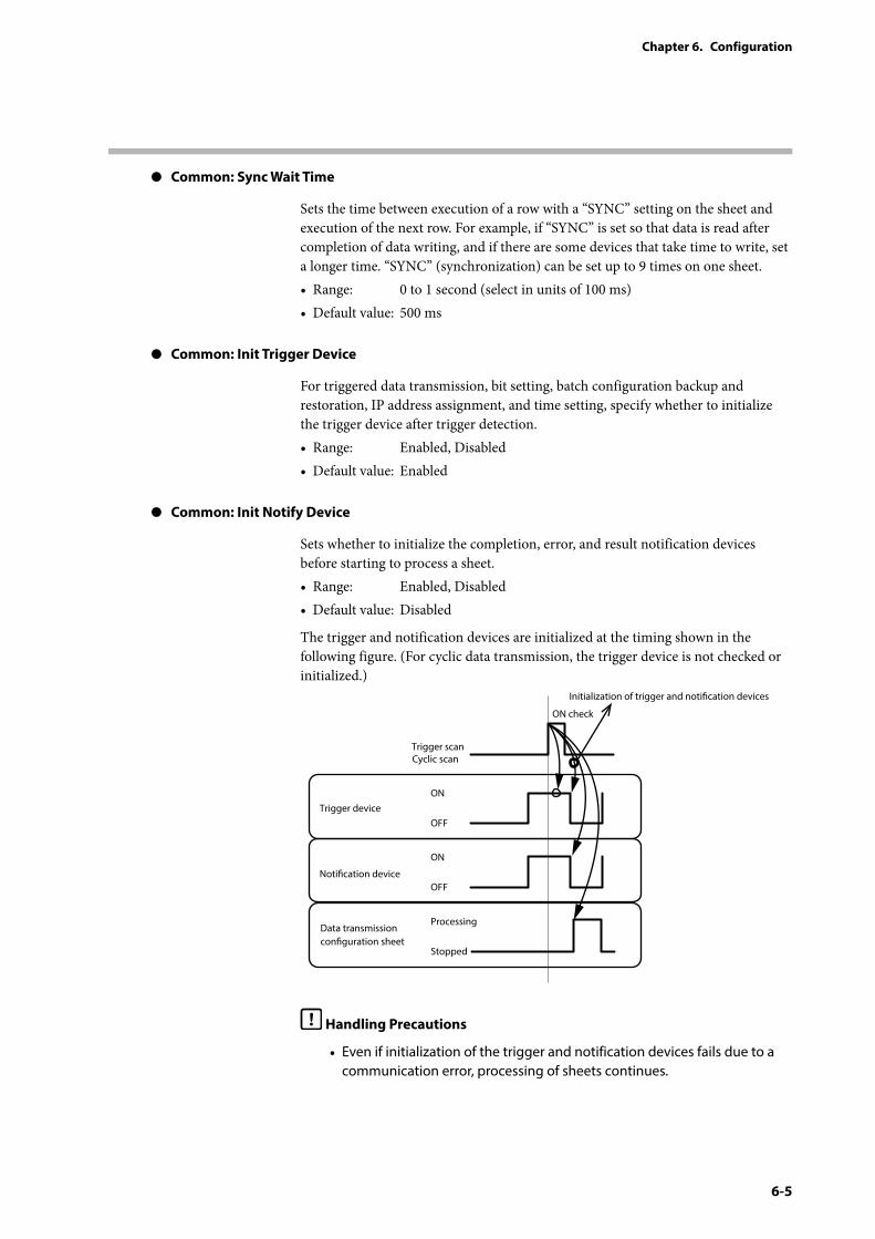
6-5
Chapter 6. Configuration
z Common: Sync Wait Time
Sets the time between execution of a row with a “SYNC” setting on the sheet and execution of the next row. For example, if “SYNC” is set so that data is read after completion of data writing, and if there are some devices that take time to write, set a longer time. “SYNC” (synchronization) can be set up to 9 times on one sheet.• Range: 0 to 1 second (select in units of 100 ms)• Default value: 500 ms
z Common: Init Trigger Device
For triggered data transmission, bit setting, batch configuration backup and restoration, IP address assignment, and time setting, specify whether to initialize the trigger device after trigger detection. • Range: Enabled, Disabled• Default value: Enabled
z Common: Init Notify Device
Sets whether to initialize the completion, error, and result notification devices before starting to process a sheet.• Range: Enabled, Disabled• Default value: Disabled
The trigger and notification devices are initialized at the timing shown in the following figure. (For cyclic data transmission, the trigger device is not checked or initialized.)
Trigger scanCyclic scan
ON check
Notication device
Data transmission conguration sheet
ON
OFF
Trigger device
Initialization of trigger and notication devices
ON
OFF
Processing
Stopped
Handling Precautions
• Even if initialization of the trigger and notification devices fails due to a communication error, processing of sheets continues.
6-6
Chapter 6. Configuration
z Server: Enabled/Disabled
Enables or disables Modbus/TCP communications for the server function. Set “Disabled” if the server function is not necessary.• Range: Enabled, Disabled• Default value: Disabled
z Server: Port No.
Sets the number of the port that waits for Modbus/TCP data with the server function.• Range: 502 (fixed value)• Default value: 502
z Server: Connection Max
Sets the maximum number of Modbus/TCP connections that can be established simultaneously with the server function.• Range: 1 to 8• Default value: 4
z Server: Keep-alive time
Sets the amount of time with no communication before a keep-alive packet is sent by the server function.
Ex.: If 5 seconds is set, and if no Modbus/TCP communication packets are received for 5 seconds even though there is a TCP connection, a keep-alive packet is sent to check that the partner device is still connected.• Range: 5 s / 10 s / 30 s / 1 min / 5 min / 10 min / 30 min / 1 hr / 2 hr• Default value: 5 s
z Server: Keep-alive interval
Sets the time until resending a keep-alive packet with the server function.
Ex.: If it is set to “10 s,” and if no response is received for 10 seconds after a keep-alive packet has been sent, the packet is resent.
• Range: 10 s / 20 s / 30 s / 40 s / 50 s / 1min• Default value: 10 s
z Server: Keep-alive retry
Sets the number of retries for sending a keep-alive packet with the server function.
Ex.: If it is set to "3,” the keep-alive packet is resent three times if there is no response. If the connected device does not respond, the connection is disconnected.
• Range (unit: times): 0 to 10• Default value: 3
6-7
Chapter 6. Configuration
z Backup Register: Top Address
A part of the internal register can be used as a backup register. Set the start address of the backup register area of the internal register.• Range: 400001 to 460000• Default value: 450001
z Backup Register: Area Size
Sets the size of the backup register area of the internal register. If it is set to 0, there is no backup register.• Range: 0 to 20000• Default value: 10000
z Protection of setting: Enabled/Disabled
Enables or disables the settings read-protection function. Projects with this function enabled are subject to the following restrictions:
• Entry of the password is required when reading the configuration of the gateway.
• Entry of the password is required when monitoring the execution status. If the password is not entered, device names and data transmission configuration sheet names specified by the project file will not be displayed.
• Entry of the password is required when reading the setup data from the [Connected Device Manager] window.
• Project files whose [Protection of setting] is enabled cannot be opened using the SLP-SVG that does not support the settings read-protection function (versions earlier than 1.0.2.0) . If the settings read-protection function is not necessary, disable the function.
• Range: Enabled, Disabled
• Default value: Disabled
z Protection of setting: Password
Specify the password for the settings read-protection function.• Range: 64 characters max.• Default value: none
6-8
Chapter 6. Configuration
System – LAN1/LAN2
Sets the devices to communicate via the LAN1 and LAN2 ports of this device.
z Attributes table
The attributes table of the configuration sheet includes the following parameters.
Parameter name Description
IP Address The IP address of the LAN1 and LAN2 ports of this device.Subnet Mask The subnet mask of the network connected to the LAN1
and LAN2 ports of this device.Default Gateway The default gateway for the network connected to the
LAN1 and LAN2 ports of this device.
Each parameter is explained below.
z IP Address
Sets the IP address of this device. Set a different value for the LAN1 and LAN2 ports.• Range: 1.0.0.1 to 223.255.255.255 (excluding 127._ _ _._ _ _._ _ _)• Default value: 192.168.0.127 (LAN1)
192.168.4.127 (LAN2)
Handling Precautions
• Do not set the same network address for LAN1 and LAN2.
• The LAN1 port can have multiple IP addresses, and 192.168.255.253 is preset for loader connection. Also, 192.168.255.252 is preset for the IP address of the loader PC. It is not possible to set 192.168.255.253 or 192.168.255.252 for LAN port devices.
• If 192.168.255._ is set for LAN2, LAN2 cannot be used for the following (use LAN1).• Communication between the NX-SVG and the SLP-SVG (loader
communication)• Communication between a server function–enabled NX-SVG and an
external Modbus/TCP server• Communication between the NX-SVG and the NTP server
z Subnet Mask
Sets the subnet mask for the IP address of this device. Set a different value for the LAN1 and LAN2 ports.• Range: 128.0.0.0 to 255.255.255.252• Default value: 255.255.255.0
Handling Precautions
• If a supernet is set for the subnet mask (e.g., setting the class B subnet mask 255.255.254.0 for a class C network) and IP addresses are assigned to Network Instrumentation Modules, the modules cannot be set up using the Smart loader Package model SLP-NX for Network
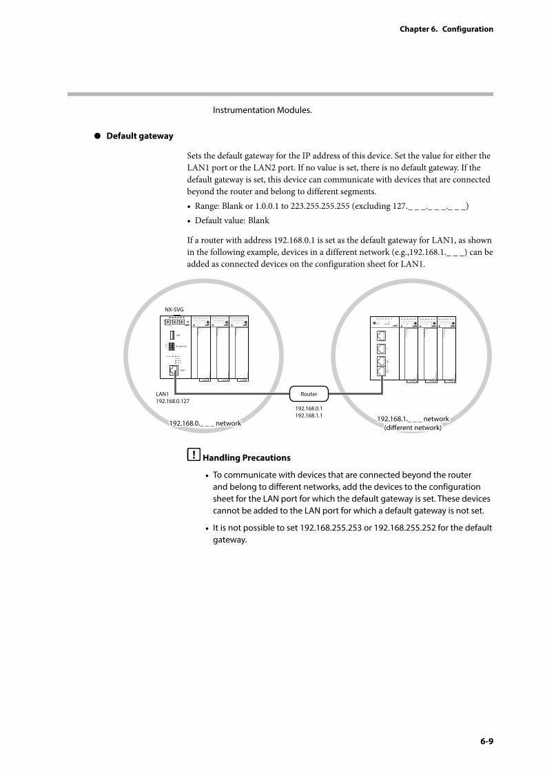
6-9
Chapter 6. Configuration
Instrumentation Modules.
z Default gateway
Sets the default gateway for the IP address of this device. Set the value for either the LAN1 port or the LAN2 port. If no value is set, there is no default gateway. If the default gateway is set, this device can communicate with devices that are connected beyond the router and belong to different segments.• Range: Blank or 1.0.0.1 to 223.255.255.255 (excluding 127._ _ _._ _ _._ _ _)• Default value: Blank
If a router with address 192.168.0.1 is set as the default gateway for LAN1, as shown in the following example, devices in a different network (e.g.,192.168.1._ _ _) can be added as connected devices on the configuration sheet for LAN1.
PWR
NX-SVGN
USB
DA (+)
SG
DB (−) RS-485 CH1
RS-485
BATTERY
LINK/ACT
LAN1
FUNCTION ERROR
F1 F2
RUN MOD COM NST FAIL
NX-SVG
LAN1192.168.0.127
192.168.1._ _ _ network(dierent network)
192.168.1._ _ _ network(dierent network)192.168.0._ _ _ network192.168.0._ _ _ network
192.168.0.1192.168.1.1
Router
Handling Precautions
• To communicate with devices that are connected beyond the router and belong to different networks, add the devices to the configuration sheet for the LAN port for which the default gateway is set. These devices cannot be added to the LAN port for which a default gateway is not set.
• It is not possible to set 192.168.255.253 or 192.168.255.252 for the default gateway.
6-10
Chapter 6. Configuration
z Process configuration table
The process configuration table on the configuration sheet includes the following parameters.
Parameter name Description
Device Connected deviceIP Address IP address of the connected devicePort The number of the connected device’s port that receives dataTransport Layer Protocol TCP or UDPConnections The number of connections that can be established
simultaneouslyOption 1 Optional setting for communicationOption 2 Optional setting for communicationRead Device Max The number of data items that can be requested for reading
by one communication frameWrite Device Max The number of data items that can be requested for writing
by one communication frameSend Delay Time Wait time before starting a transmissionTimeout-time(msec) Time before determining that there is no responseRetry-count Number of retransmissions when there is no responseEnabled Switch Setting of whether to use the configuration for the
connected device set by [Device]Dev No. The No. of the host device whose [Enabled Switch Device] is
read if [Enabled Switch] is set to [Start-up judging]Enabled Switch Device The device for checking configuration sheet validity whose
value is read at NX-SVG startup if [Enabled Switch] is set to [Start-up judging]
Comment Explanatory comments on the device
Each parameter is explained below.
z Device
Sets the type of the device to connect. Settings in one row apply to the device set by this parameter. If the target device is not included in the device selection, select a general-purpose device using a communication protocol such as Modbus/TCP or CPL/TCP.• Range: Mitubishi SLMP (3E)
Mitubishi iQ-F SLMP (3E) Yokogawa FA-M3 Omron FINS Siemens S7 TOYOPUC PC10 (TCP) FANUC CNC Keyence KV Fuji MICREX-SX NX-15, NX-25/D35 (4CH), NX-35 (2CH), NX-DX, NX-DY RX-L90 C7G Modbus/TCP CPL/TCP, CPL/TCP (NX) HNU, etc. (other devices will be added in the future)
• Default value: –
6-11
Chapter 6. Configuration
z IP Address
Sets the IP address of the connected device set by [Device].• Range: Blank or 1.0.0.1 to 223.255.255.255 (excluding 127._ _ _._ _ _._ _ _)• Default value: Blank
Handling Precautions
• The LAN1 port can have multiple IP addresses, and 192.168.255.253 is preset for loader connection. Also, 192.168.255.252 is preset for the IP address of the loader PC. It is not possible to set 192.168.255.253 or 192.168.255.252.
• Set a unique IP address for every device and the loader PC.
• If no default gateway is set, set an IP address belonging to the same subnet of the connected LAN port.
z Port
Sets the port No. of the connected device set by [Device]. This device is the client and the connected device is the server. This device sends data to the port specified by this parameter. To access multiple ports of a single device at the same, add two devices with the same IP address and different port numbers.• Range: 0 to 65535• Default value: Depends on the device
z Transport Layer Protocol
Select the protocol of the communication transport layer for the connected device set by [Device]. Use the protocol set for the connected device. The value is fixed for some devices and cannot be selected.• Range: TCP, UDP• Default value: Depends on the device
z Connections
For a device whose transport layer protocol is TCP, set the number of connections that can be established simultaneously at the communication port set by [Port]. The value is fixed for some devices and cannot be selected.• Range: 1 to 8• Default value: 1
z Option 1 / Option 2
These parameters are for optional settings for communication. For some devices, these parameters cannot be specified.• Range: Depends on the device• Default value: Depends on the device
6-12
Chapter 6. Configuration
z Read Device Max
Sets the number of data items that can be requested for reading by one communication frame. The value depends on the communication protocol and the specifications of the device. The value is fixed for some devices and cannot be selected.• Range: 2 to 512• Default value: Depends on the device
z Write Device Max
Sets the number of data items that can be requested for writing by one communication frame. The value depends on the communication protocol and the specifications of the device. The value is fixed for some devices and cannot be selected.• Range: 2 to 512• Default value: Depends on the device
z Send Delay Time
Sets the time this device waits before starting each transmission. With a heavy communication load, if some data is missed because the connected devices cannot communicate in time or if controllability deteriorates, adjustment can be made with this parameter.• Range (unit: ms): 0 to 1000• Default value: Depends on the device
z Timeout-time(msec)
Sets the timeout value for the connected device set by [Device]. When the set time elapses, this device determines that the connected device is not responding. • Range (unit: ms): 100 to 60000• Default value: Depends on the device
z Retry-count
Sets the number of retries for sending data to the connected device set by [Device]. “Retry” means resending data to a connected device. If this device cannot receive a response from the connected device (if there is no response), this device tries again to send the data. • Range (unit: times): 0 to 10• Default value: 3
z Enabled Switch
Sets whether to use the configuration for the connected device set by [Device]. If [Disabled] is set, the gateway and device management functions are not executed even if communication with the connected device is configured. If [Start-up judging] is selected, the value of [Enabled Switch Device] is read at NX-SVG startup to check if the configuration sheet is valid.• Range: Enabled, Disabled, Start-up judging• Default value: Enabled
6-13
Chapter 6. Configuration
z Dev No.
If [Enabled Switch] is set to [Start-up judging], [Enabled Switch Device] of the device set by this parameter is read.• Range: Select from the preset connected devices• Default value: –
z Enabled Switch Device
Sets the device for checking configuration sheet validity. The value of the device is read at NX-SVG startup if [Enabled Switch] is set to [Start-up judging].• Range: Depends on the device• Default value: Blank
z Comment
Any character string can be entered. This does not affect operation. You can use it as a note to describe the device. • Range: 20 characters• Default value: Blank
6-14
Chapter 6. Configuration
System – COM1/COM2
Sets the devices to communicate via the COM1 and COM2 ports of this device.
z Attributes table
The attributes table of the configuration sheet includes the following parameters.
Parameter name Description
Baudrate The baudrate for serial communication via the COM1 and COM2 ports of this device
Data Length The data length for serial communication via the COM1 and COM2 ports of this device
Parity The parity bit type for serial communication via the COM1 and COM2 ports of this device
Stop Bit The number of stop bits for serial communication via the COM1 and COM2 ports of this device
Each parameter is explained below.
z Baudrate
Sets the baudrate for serial communication of this device. Set the value for the COM1 and COM2 ports individually.• Range: 4800/9600/19200/38400/57600/115200 bps• Default value: 19200 bps
z Data Length
Sets the data length for serial communication of this device. Set the value for the COM1 and COM2 ports individually.• Range: 8 bits, 7 bits• Default value: 8 bits
z Parity
Sets the parity bit type for serial communication of this device. Set the value for the COM1 and COM2 ports individually.• Range: Even, Odd, None• Default value: Even
z Stop Bit
Sets the number of stop bits for serial communication of this device. Set the value for the COM1 and COM2 ports individually.• Range: 1 bit, 2 bits• Default value: 1 bit
6-15
Chapter 6. Configuration
z Process configuration table
The process configuration table on the configuration sheet includes the following parameters.
Parameter name Description
Device Connected deviceDevice ID Station No. of the connected deviceOption 1 Optional setting for communicationOption 2 Optional setting for communicationRead Device Max The number of data items that can be requested for
reading by one communication frameWrite Device Max The number of data items that can be requested for
writing by one communication frameSend Delay Time Wait time before starting a transmissionTimeout-time (msec) Time before determining that there is no responseRetry-count Number of retransmissions when there is no
responseEnabled Switch Setting of whether to use the configuration for the
connected device set by [Device]Dev No. The No. of the host device whose [Enabled Switch
Device] is read if [Enabled Switch] is set to [Start-up judging]
Enabled Switch Device The device for checking configuration sheet validity whose value is read at NX-SVG startup if [Enabled Switch] is set to [Start-up judging]
Comment Explanatory comments on the device
Each parameter is explained below.
z Device
Sets the type of the device to connect. Settings in one row apply to the device set by this parameter. If the target device is not included in the device selection, select a general-purpose device using a communication protocol such as Modbus/RTU or CPL/Serial.• Range: SDC15, SDC25, SDC35, SDC45
BC-Rx5, AUR255, AUR355, AUR455, RX-L80 F4H, F4Q, MQV, MPC, MCF Modbus/RTU, CPL/Serial etc. (other types of device will be added in the future)
• Default value: –
z Device ID
Sets the node address (station No.) of the connected device set by [Device].• Range: 0 to 255• Default value: Blank
z Option 1/ Option 2
These parameters are for optional settings for communication. For some devices, these parameters cannot be specified.• Range: Depends on the device• Default value: Depends on the device
6-16
Chapter 6. Configuration
z Read Device Max
Sets the number of data items that can be requested for reading by one communication frame. The value depends on the communication protocol and the specifications of the device. The value is fixed for some devices and cannot be selected.• Range: 2 to 512• Default value: Depends on the device
z Write Device Max
Sets the number of data items that can be requested for writing by one communication frame. The value depends on the communication protocol and the specifications of the device. The value is fixed for some devices and cannot be selected.
• Range: 2 to 512
• Default value: Depends on the device
z Send Delay Time
Sets the time this device waits before starting a transmission. With a heavy communication load, if some data is missed because the connected devices cannot communicate in time or if controllability deteriorates, adjustments can be made with this parameter.• Range (unit: ms): 10 to 1000
• Default value: Depends on the device
z Timeout-time(msec)
Sets the timeout value for the connected device set by [Device]. When the set time elapses, this device determines that the connected device is not responding.• Range (unit: ms): 100 to 60000• Default value: 2000
z Retry-count
Sets the number of retries for sending data to the connected device set by [Device]. “Retry” means resending data to a connected device. If this device cannot receive a response from the connected device (if there is no response), this device tries again to send the data.
• Range (unit: times): 0 to 10
• Default value: 3
6-17
Chapter 6. Configuration
z Enabled Switch
Sets whether to use the configuration for the connected device set by [Device]. If [Disabled] is set, the gateway and device management functions are not executed even if communication with the connected device is configured. If [Start-up judging] is selected, the value of [Enabled Switch Device] is read at NX-SVG startup to check if the configuration sheet is valid.• Range: Enabled, Disabled, Start-up judging• Default value: Enabled
z Dev No.
If [Enabled Switch] is set to [Start-up judging], [Enabled Switch Device] of the device set by this parameter is read.
• Range: Select from the preset connected devices
• Default value: –
z Enabled Switch Device
Sets the device for checking configuration sheet validity. The value of the device is read at NX-SVG startup if [Enabled Switch] is set to [Start-up judging].
• Range: Depends on the device
• Default value: Blank
z Comment
Any character string can be entered. This does not affect operation. You can use it as a note to describe the device.
• Range: 20 characters
• Default value: Blank
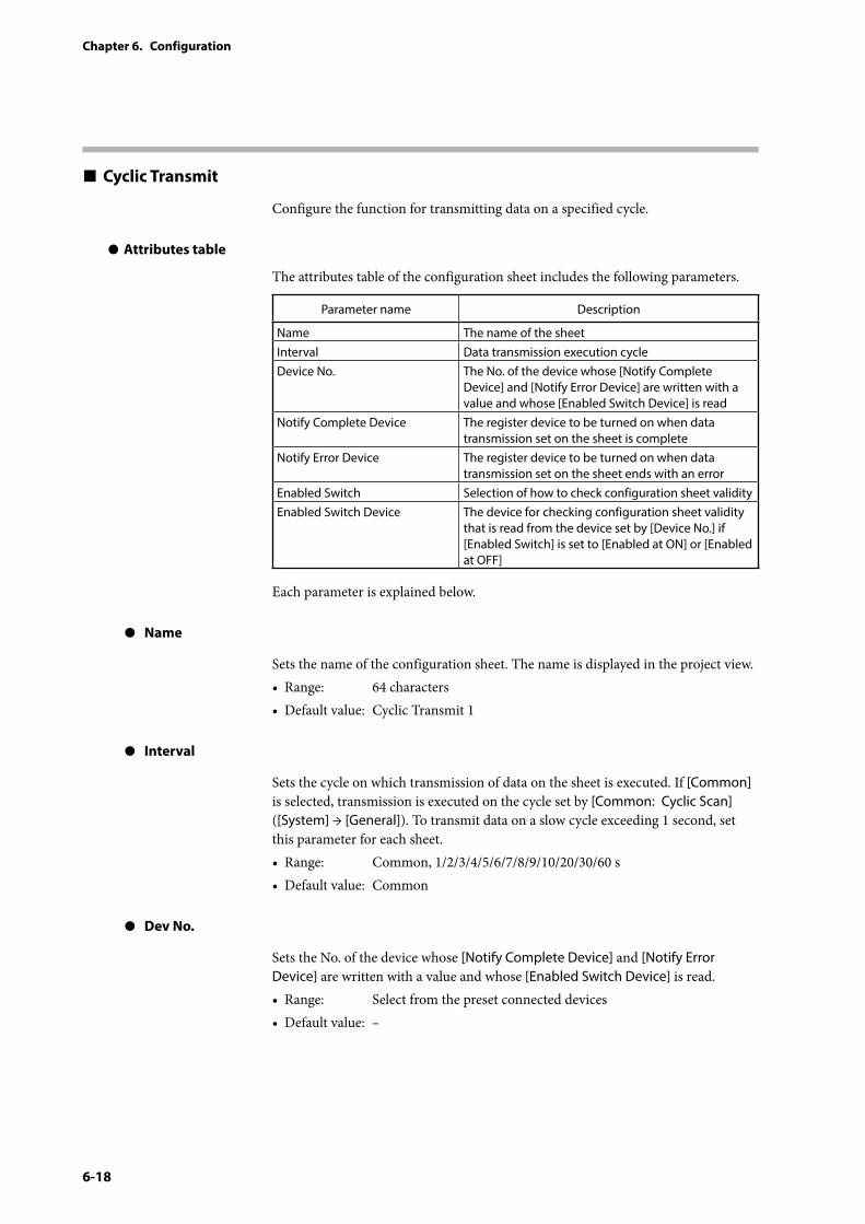
6-18
Chapter 6. Configuration
Cyclic Transmit
Configure the function for transmitting data on a specified cycle.
z Attributes table
The attributes table of the configuration sheet includes the following parameters.
Parameter name Description
Name The name of the sheetInterval Data transmission execution cycleDevice No. The No. of the device whose [Notify Complete
Device] and [Notify Error Device] are written with a value and whose [Enabled Switch Device] is read
Notify Complete Device The register device to be turned on when data transmission set on the sheet is complete
Notify Error Device The register device to be turned on when data transmission set on the sheet ends with an error
Enabled Switch Selection of how to check configuration sheet validityEnabled Switch Device The device for checking configuration sheet validity
that is read from the device set by [Device No.] if [Enabled Switch] is set to [Enabled at ON] or [Enabled at OFF]
Each parameter is explained below.
z Name
Sets the name of the configuration sheet. The name is displayed in the project view.• Range: 64 characters• Default value: Cyclic Transmit 1
z Interval
Sets the cycle on which transmission of data on the sheet is executed. If [Common] is selected, transmission is executed on the cycle set by [Common: Cyclic Scan] ([System] → [General]). To transmit data on a slow cycle exceeding 1 second, set this parameter for each sheet.• Range: Common, 1/2/3/4/5/6/7/8/9/10/20/30/60 s• Default value: Common
z Dev No.
Sets the No. of the device whose [Notify Complete Device] and [Notify Error Device] are written with a value and whose [Enabled Switch Device] is read.• Range: Select from the preset connected devices• Default value: –
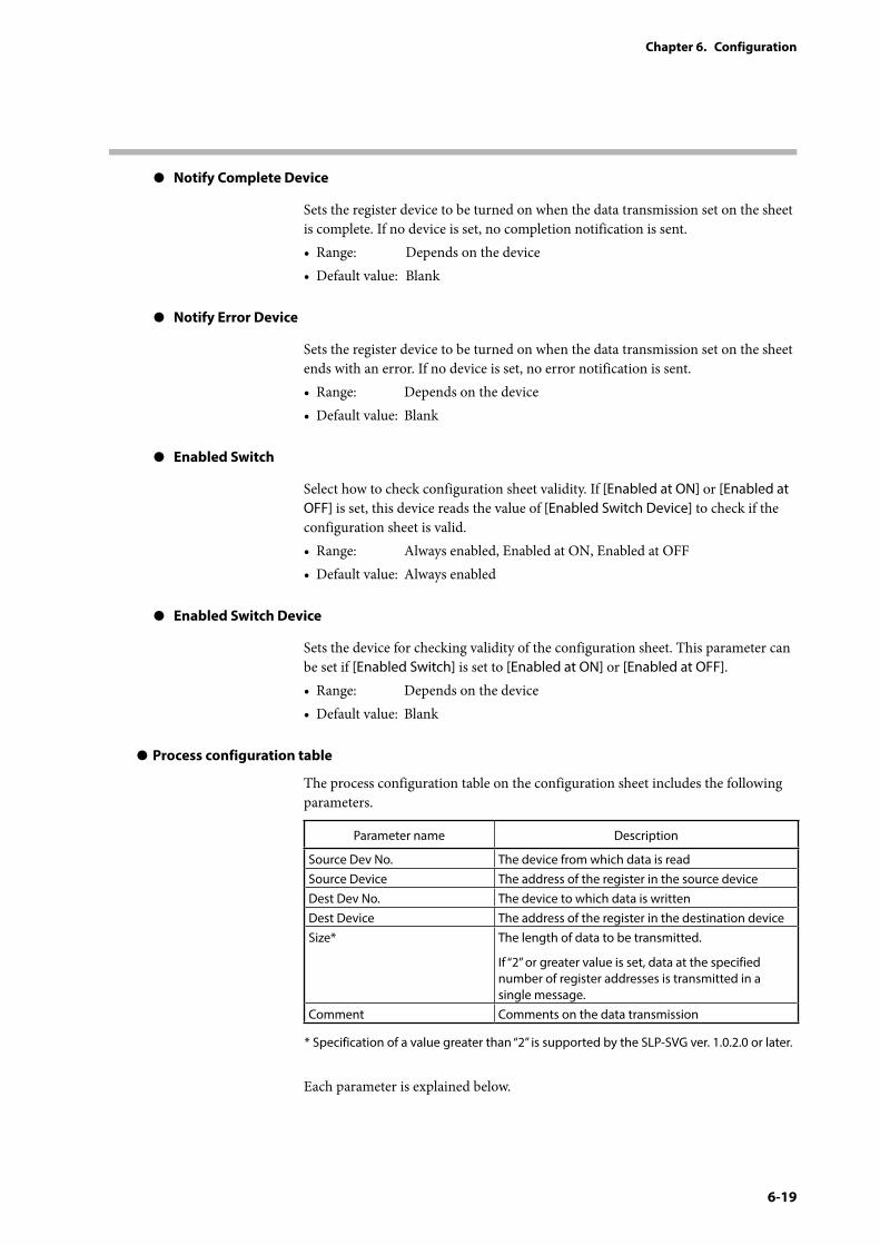
6-19
Chapter 6. Configuration
z Notify Complete Device
Sets the register device to be turned on when the data transmission set on the sheet is complete. If no device is set, no completion notification is sent.• Range: Depends on the device• Default value: Blank
z Notify Error Device
Sets the register device to be turned on when the data transmission set on the sheet ends with an error. If no device is set, no error notification is sent.• Range: Depends on the device• Default value: Blank
z Enabled Switch
Select how to check configuration sheet validity. If [Enabled at ON] or [Enabled at OFF] is set, this device reads the value of [Enabled Switch Device] to check if the configuration sheet is valid.• Range: Always enabled, Enabled at ON, Enabled at OFF• Default value: Always enabled
z Enabled Switch Device
Sets the device for checking validity of the configuration sheet. This parameter can be set if [Enabled Switch] is set to [Enabled at ON] or [Enabled at OFF].• Range: Depends on the device• Default value: Blank
z Process configuration table
The process configuration table on the configuration sheet includes the following parameters.
Parameter name Description
Source Dev No. The device from which data is readSource Device The address of the register in the source deviceDest Dev No. The device to which data is writtenDest Device The address of the register in the destination deviceSize* The length of data to be transmitted.
If “2” or greater value is set, data at the specified number of register addresses is transmitted in a single message.
Comment Comments on the data transmission
* Specification of a value greater than “2” is supported by the SLP-SVG ver. 1.0.2.0 or later.
Each parameter is explained below.
6-20
Chapter 6. Configuration
z Source Dev No.
Sets the device from which data is read.• Range: Connected device, internal register, or SYNC• Default value: –
Note
• If “SYNC” is set, the row will not be processed until the processing of the preceding row is completed. In the following cases, set “SYNC” to communicate data in a desired order: · Mode change is required after configuration is written.· Configuration should be written in a specific order.· Reading should be executed after all writing processes are completed.
z Source Device
Sets the address of the register in the device from which data is read.• Range: Depends on the device• Default value: Blank
z Dest Dev No.
Sets the device to which data is written.• Range: Select from the preset connected devices• Default value: –
z Dest Device
Sets the address of the register in the device to which data is written.• Range: Depends on the device• Default value: Blank
6-21
Chapter 6. Configuration
z Size
Sets the number of data items to transmit. If “1” is set, data at one address is transmitted. If “2” or greater value is set, data at the specified number of register addresses is transmitted in a single message.
The second and later register addresses are consecutive addresses that follow the address set by [Source Device] and [Dest Device].• Range: Depends on the device
The maximum number of register addresses specifiable for one communication frame, which differs depending on the source and destination devices, can be set. Note that [Read Device Max] set for the source device and [Write Device Max] set for the destination device are compared, and the smaller one is the high limit for this item. If [Read Device Max] or [Write Device Max] cannot be specified, or if a constant is set for [Source Device], “2” is the high limit.
• Default value: 1
Note
• Chapter 7. Communication Settings for Connected Devices List of connected device types (p. 7-2) (for the maximum number of register addresses specifiable for one communication frame)
z Comment
Explanatory comments on the data transmission. This does not affect operation.• Range: 32 characters• Default value: Blank
6-22
Chapter 6. Configuration
Trigger Transmit
Configure the function for transmitting data based on the state of the trigger device.
z Attributes table
The attributes table of the configuration sheet includes the following parameters.
Parameter name Description
Name The name of the sheetTrigger Edge Trigger type : ON edge, OFF edgeDev No. The device to connect for sheet data transmissionTrigger Device The trigger device for executing sheet data transmission
(executed when ON) Notify Complete Device The register device to be turned on when data
transmission set on the sheet is completeNotify Error Device The register device to be turned on when data
transmission set on the sheet ends with an errorEnabled Switch Selection of how to check configuration sheet validityEnabled Switch Device The device for checking configuration sheet validity that
is read from the device set by [Device No.] if [Enabled Switch] is set to [Enabled at ON] or [Enabled at OFF]
Each parameter is explained below.
z Description
Sets the name of the configuration sheet. The name is displayed in the project view.• Range: 64 characters• Default value: Trigger Transmit 1
z Trigger Edge
Sets the state of the trigger device that triggers data transmission. If [Trigger Edge] is set to ON edge (OFF → ON) and if the trigger device is ON when this device is started, the trigger condition is satisfied. If [Trigger Edge] is set to OFF edge (ON → OFF) and if the trigger device is OFF when this device is started, the trigger condition is not satisfied.• Range: ON Edge (OFF→ON), OFF Edge (ON→OFF)• Default value: ON Edge (OFF→ON)
z Dev No.
Sets the No. of the device whose [Trigger Device] is read and whose [Notify Complete Device] and [Notify Error Device] are written with a value. • Range: Select from the preset connected devices• Default value: –
z Trigger Device
Sets the trigger device for executing a configuration sheet for triggered data transmission. • Range: Depends on the device• Default value: Blank
6-23
Chapter 6. Configuration
z Notify Complete Device
Sets the register device to be turned on when the data transmission set on the sheet is complete. If no device is set, no completion notification is sent.• Range: Depends on the device• Default value: Blank
z Notify Error Device
Sets the register device to be turned on when the data transmission set on the sheet ends with an error. If no device is set, no error notification is sent.• Range: Depends on the device• Default value: Blank
z Enabled Switch
Select how to check configuration sheet validity. If [Enabled at ON] or [Enabled at OFF] is set, this device reads the value of [Enabled Switch Device] to check if the configuration sheet is valid.• Range: Always enabled, Enabled at ON, Enabled at OFF• Default value: Always enabled
z Enabled Switch Device
Sets the device for checking validity of the configuration sheet. This parameter can be set if [Enabled Switch] is set to [Enabled at ON] or [Enabled at OFF].• Range: Depends on the device• Default value: Blank
z Process configuration table
The process configuration table on the configuration sheet includes the following parameters.
Parameter name Description
Source Dev No. The device from which data is readSource Device The address of the register in the source deviceDest Dev No. The device to which data is writtenDest Device The address of the register in the destination deviceSize* The length of data to be transmitted.
If “2” or greater value is set, data at the specified number of register addresses is transmitted in a single message.
Comment Comments on the data transmission
* Specification of a value greater than “2” is supported by the SLP-SVG ver. 1.0.2.0 or later.
Each parameter is explained below.

6-24
Chapter 6. Configuration
z Source Dev No.
Sets the device from which data is read.• Range: Connected device, internal register, or SYNC• Default value: –
Note
• If “SYNC” is set, the row will not be processed until the processing of the preceding row is completed. In the following cases, set “SYNC” to communicate data in a desired order: · Mode change is required after configuration is written. · Configuration should be written in a specific order. · Reading should be executed after all writing processes are completed.
z Source Device
Sets the address of the register in the device from which data is read.• Range: Depends on the device• Default value: Blank
z Dest Dev No.
Sets the device to which data is written.• Range: Select from the preset connected devices• Default value: –
z Dest Device
Sets the address of the register in the device to which data is written.• Range: Depends on the device• Default value: Blank

6-25
Chapter 6. Configuration
z Size
Sets the number of data items to transmit. If “1” is set, data at one address is transmitted. If “2” or greater value is set, data at the specified number of register addresses is transmitted in a single message.
The second and later register addresses are consecutive addresses that follow the address set by [Source Device] and [Dest Device].• Range: Depends on the device
The maximum number of register addresses specifiable for one communication frame, which differs depending on the source and destination devices, can be set. Note that [Read Device Max] set for the source device and [Write Device Max] set for the destination device are compared, and the smaller one is the high limit for this item. If [Read Device Max] or [Write Device Max] cannot be specified, or if a constant is set for [Source Device], “2” is the high limit.
• Default value: 1
Note
• Chapter 7. Communication Settings for Connected Devices List of connected device types (p. 7-2) (for the maximum number of register addresses specifiable for one communication frame)
z Comment
Explanatory comments on the data transmission. This does not affect operation.• Range: 32 characters• Default value: Blank
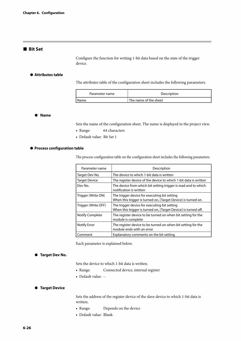
6-26
Chapter 6. Configuration
Bit Set
Configure the function for writing 1-bit data based on the state of the trigger device.
z Attributes table
The attributes table of the configuration sheet includes the following parameters.
Parameter name Description
Name The name of the sheet
z Name
Sets the name of the configuration sheet. The name is displayed in the project view.• Range: 64 characters• Default value: Bit Set 1
z Process configuration table
The process configuration table on the configuration sheet includes the following parameters.
Parameter name Description
Target Dev No. The device to which 1-bit data is writtenTarget Device The register device of the device to which 1-bit data is writtenDev No. The device from which bit setting trigger is read and to which
notification is writtenTrigger (Write ON) The trigger device for executing bit setting
When this trigger is turned on, [Target Device] is turned on. Trigger (Write OFF) The trigger device for executing bit setting
When this trigger is turned on, [Target Device] is turned off.Notify Complete The register device to be turned on when bit setting for the
module is completeNotify Error The register device to be turned on when bit setting for the
module ends with an errorComment Explanatory comments on the bit setting
Each parameter is explained below.
z Target Dev No.
Sets the device to which 1-bit data is written.• Range: Connected device, internal register• Default value: –
z Target Device
Sets the address of the register device of the slave device to which 1-bit data is written.• Range: Depends on the device• Default value: Blank
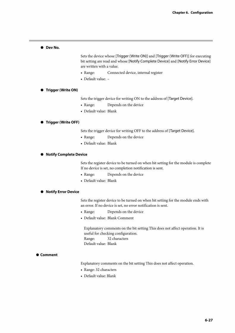
6-27
Chapter 6. Configuration
z Dev No.
Sets the device whose [Trigger (Write ON)] and [Trigger (Write OFF)] for executing bit setting are read and whose [Notify Complete Device] and [Notify Error Device] are written with a value.• Range: Connected device, internal register• Default value: –
z Trigger (Write ON)
Sets the trigger device for writing ON to the address of [Target Device].• Range: Depends on the device• Default value: Blank
z Trigger (Write OFF)
Sets the trigger device for writing OFF to the address of [Target Device].• Range: Depends on the device• Default value: Blank
z Notify Complete Device
Sets the register device to be turned on when bit setting for the module is complete If no device is set, no completion notification is sent.• Range: Depends on the device• Default value: Blank
z Notify Error Device
Sets the register device to be turned on when bit setting for the module ends with an error. If no device is set, no error notification is sent.• Range: Depends on the device• Default value: Blank Comment
Explanatory comments on the bit setting This does not affect operation. It is useful for checking configuration. Range: 32 characters Default value: Blank
z Comment
Explanatory comments on the bit setting This does not affect operation.• Range: 32 characters• Default value: Blank
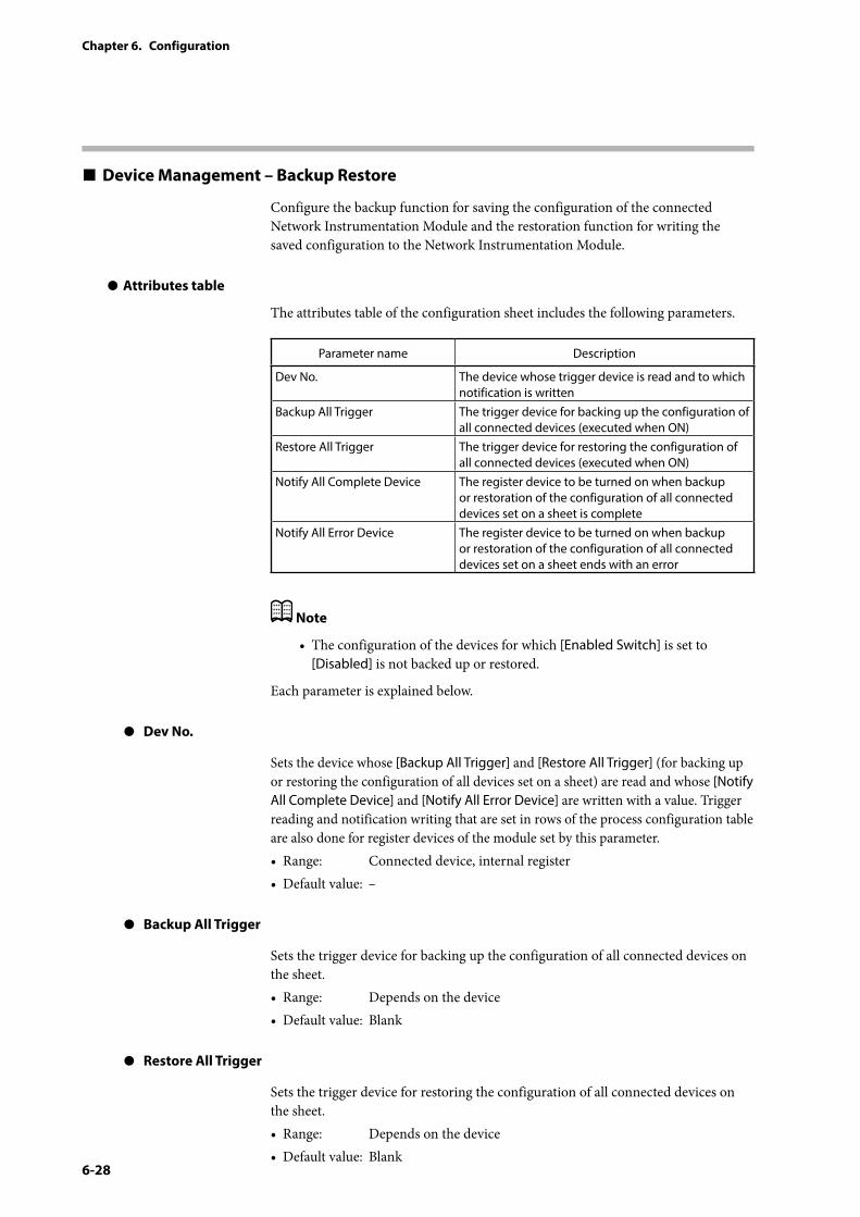
6-28
Chapter 6. Configuration
Device Management – Backup Restore
Configure the backup function for saving the configuration of the connected Network Instrumentation Module and the restoration function for writing the saved configuration to the Network Instrumentation Module.
z Attributes table
The attributes table of the configuration sheet includes the following parameters.
Parameter name Description
Dev No. The device whose trigger device is read and to which notification is written
Backup All Trigger The trigger device for backing up the configuration of all connected devices (executed when ON)
Restore All Trigger The trigger device for restoring the configuration of all connected devices (executed when ON)
Notify All Complete Device The register device to be turned on when backup or restoration of the configuration of all connected devices set on a sheet is complete
Notify All Error Device The register device to be turned on when backup or restoration of the configuration of all connected devices set on a sheet ends with an error
Note
• The configuration of the devices for which [Enabled Switch] is set to [Disabled] is not backed up or restored.
Each parameter is explained below.
z Dev No.
Sets the device whose [Backup All Trigger] and [Restore All Trigger] (for backing up or restoring the configuration of all devices set on a sheet) are read and whose [Notify All Complete Device] and [Notify All Error Device] are written with a value. Trigger reading and notification writing that are set in rows of the process configuration table are also done for register devices of the module set by this parameter.• Range: Connected device, internal register• Default value: –
z Backup All Trigger
Sets the trigger device for backing up the configuration of all connected devices on the sheet.• Range: Depends on the device• Default value: Blank
z Restore All Trigger
Sets the trigger device for restoring the configuration of all connected devices on the sheet.• Range: Depends on the device• Default value: Blank
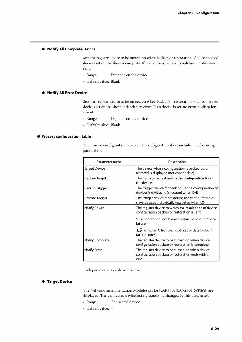
6-29
Chapter 6. Configuration
z Notify All Complete Device
Sets the register device to be turned on when backup or restoration of all connected devices set on the sheet is complete. If no device is set, no completion notification is sent.• Range: Depends on the device• Default value: Blank
z Notify All Error Device
Sets the register device to be turned on when backup or restoration of all connected devices set on the sheet ends with an error. If no device is set, no error notification is sent.• Range: Depends on the device• Default value: Blank
z Process configuration table
The process configuration table on the configuration sheet includes the following parameters.
Parameter name Description
Target Device The device whose configuration is backed up or restored is displayed (not changeable).
Restore Target The items to be restored in the configuration file of the device.
Backup Trigger The trigger device for backing up the configuration of devices individually (executed when ON)
Restore Trigger The trigger device for restoring the configuration of slave devices individually (executed when ON)
Notify Result The register device to which the result code of device configuration backup or restoration is sent
“0” is sent for a success and a failure code is sent for a failure.
Chapter 9. Troubleshooting (for details about failure codes)
Notify Complete The register device to be turned on when device configuration backup or restoration is complete
Notify Error The register device to be turned on when device configuration backup or restoration ends with an error
Each parameter is explained below.
z Target Device
The Network Instrumentation Modules set for [LAN1] or [LAN2] of [System] are displayed. The connected device setting cannot be changed by this parameter.• Range: Connected device• Default value: –
6-30
Chapter 6. Configuration
z Restore Target
Sets the items in the configuration file that should be restored.• Range: Parameter
Parameter + mode Parameter + user definition Parameter + mode + user definition
• Default value: Parameter
Note
• The restored parameter data is the same as the data read or written by the SLP-NX.
z Backup Trigger
Sets the trigger device for backing up the configuration of the devices on the sheet individually. Set the register device of the device set for [Dev No.] in the attributes table.• Range: Depends on the host device• Default value: Blank
z Restore Trigger
Sets the trigger device for restoring the configuration of the devices on the sheet individually. Set the register device of the device set for [Dev No.] in the attributes table.• Range: Depends on the host device• Default value: Blank
z Notify Result
Sets the register device to which the result of device configuration backup or restoration is sent. Set the register device of the device set for [Dev No.] in the attributes table. The result of batch backup or restoration is also sent to this register device. If no device is set, the result is not sent.• Range: Depends on the host device• Default value: Blank
z Notify Complete
Sets the register device to be turned on when configuration backup or restoration is complete. Set the register device of the device set for [Dev No.] in the attributes table. A completion notification of batch backup or restoration is also sent to this register device. If no device is set, no completion notification is sent.• Range: Depends on the host device• Default value: Blank
z Notify Error
Sets the register device to be turned on when configuration backup or restoration ends with an error. Set the register device of the device set for [Dev No.] in the attributes table. An error notification of batch backup or restoration is also sent to this register device. If no device is set, no error notification is sent.• Range: Depends on the host device• Default value: Blank
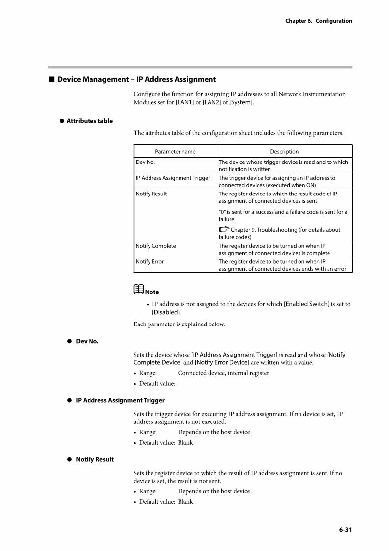
6-31
Chapter 6. Configuration
Device Management – IP Address Assignment
Configure the function for assigning IP addresses to all Network Instrumentation Modules set for [LAN1] or [LAN2] of [System].
z Attributes table
The attributes table of the configuration sheet includes the following parameters.
Parameter name Description
Dev No. The device whose trigger device is read and to which notification is written
IP Address Assignment Trigger The trigger device for assigning an IP address to connected devices (executed when ON)
Notify Result The register device to which the result code of IP assignment of connected devices is sent
“0” is sent for a success and a failure code is sent for a failure.
Chapter 9. Troubleshooting (for details about failure codes)
Notify Complete The register device to be turned on when IP assignment of connected devices is complete
Notify Error The register device to be turned on when IP assignment of connected devices ends with an error
Note
• IP address is not assigned to the devices for which [Enabled Switch] is set to [Disabled].
Each parameter is explained below.
z Dev No.
Sets the device whose [IP Address Assignment Trigger] is read and whose [Notify Complete Device] and [Notify Error Device] are written with a value.• Range: Connected device, internal register• Default value: –
z IP Address Assignment Trigger
Sets the trigger device for executing IP address assignment. If no device is set, IP address assignment is not executed.• Range: Depends on the host device• Default value: Blank
z Notify Result
Sets the register device to which the result of IP address assignment is sent. If no device is set, the result is not sent.• Range: Depends on the host device• Default value: Blank
6-32
Chapter 6. Configuration
z Notify Complete
Sets the register device to be turned on when IP address assignment is complete.• Range: Depends on the host device• Default value: Blank
z Notify Error
Sets the register device to be turned on when IP address assignment ends with an error.• Range: Depends on the host device• Default value: Blank
Device Management – Status Notification
Configure the function for notifying the status of this device or connected devices.
z Attributes table
The attributes table of the configuration sheet includes the following parameters.
Parameter name Description
Notification Interval The cycle on which a value is written to [Notification during RUN], [Notification Low Battery], and [Notification Connected Status]
Dev No. The device to which notification is writtenNotification during RUN The register device that is turned on according to the
cycle set by [Notification Interval] to send notification that this device is operating
Notification Low Battery The register device that is turned on according to the cycle set by [Notification Interval] to send notification that the battery is low
Notification Connected Status
Setting of whether a status notification is sent to a bit device or a specific bit of a word device
Each parameter is explained below.
z Notification Interval
Sets the cycle on which a value is written to [Notification during RUN], [Notification Low Battery], and [Notification Connected Status]. Each function is executed on the same cycle. • Range (unit: seconds): 1 s to 10 s• Default value: 5 s
z Dev No.
Sets the device to whose [Notification during RUN], [Notification Low Battery], and [Notification Connected Status] devices are written with a value.• Range: Connected device, internal register• Default value: –
6-33
Chapter 6. Configuration
z Notification during RUN
This function notifies the host device that this device is operating. Set the register device that is turned on when this device is operating. If no device is set, the status is not notified.• Range: Depends on the host device• Default value: Blank
z Notification Low Battery
This function notifies the host device that the battery is low. Set the register device that is turned on when the battery is low. If no device is set, the status is not notified.• Range: Depends on the host device• Default value: Blank
Note
• The low battery status is also indicated by the BATTERY LED in the function indicators selection on the front of this device. If no battery is used, not using this function and setting [Disabled] for [Battery Alarm] ([System] → [General]) is recommended.
z Notification Connected Status
This function notifies the host device whether slave devices are connected. Set whether to send a status notification to a bit device or a specific bit of a word device.• Range: Notify Bit, Notify Word• Default value: Notify Bit
z Process configuration table
The process configuration table on the configuration sheet includes the following parameters.
Parameter name Description
Connected Device Slave devices connected to LAN1, LAN2, COM1, and COM2 are displayed (not changeable).
Notify Disconnect The register device of the host device that is turned on or off depending on the connection status of slave devices
Bit Position The bit position reckoned from the least significant bit (LSB) of the word device (set this parameter when [Notification Connected Status] is set to [Notify Word])
Each parameter is explained below.
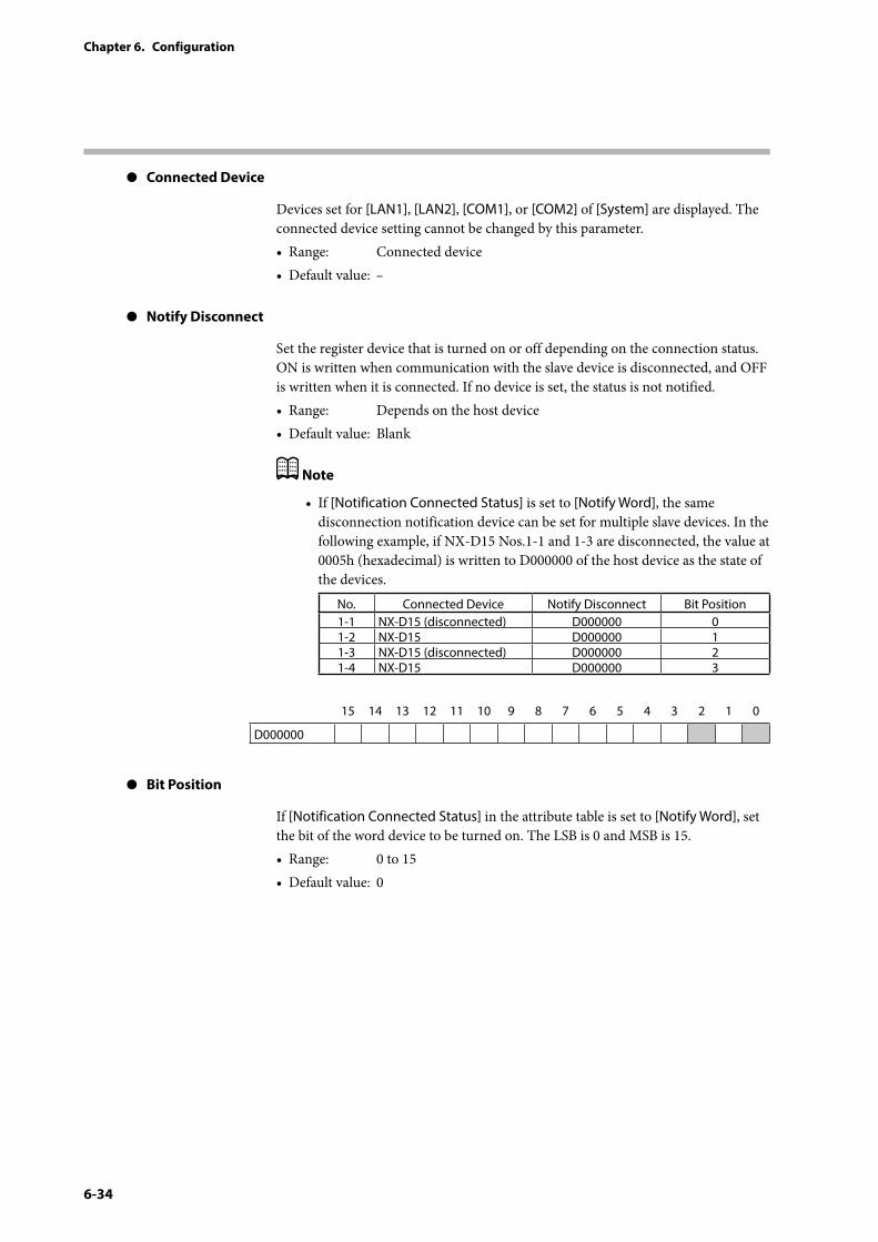
6-34
Chapter 6. Configuration
z Connected Device
Devices set for [LAN1], [LAN2], [COM1], or [COM2] of [System] are displayed. The connected device setting cannot be changed by this parameter.• Range: Connected device• Default value: –
z Notify Disconnect
Set the register device that is turned on or off depending on the connection status. ON is written when communication with the slave device is disconnected, and OFF is written when it is connected. If no device is set, the status is not notified.• Range: Depends on the host device• Default value: Blank
Note
• If [Notification Connected Status] is set to [Notify Word], the same disconnection notification device can be set for multiple slave devices. In the following example, if NX-D15 Nos.1-1 and 1-3 are disconnected, the value at 0005h (hexadecimal) is written to D000000 of the host device as the state of the devices.
No. Connected Device Notify Disconnect Bit Position1-1 NX-D15 (disconnected) D000000 01-2 NX-D15 D000000 11-3 NX-D15 (disconnected) D000000 21-4 NX-D15 D000000 3
15 14 13 12 11 10 9 8 7 6 5 4 3 2 1 0
D000000
z Bit Position
If [Notification Connected Status] in the attribute table is set to [Notify Word], set the bit of the word device to be turned on. The LSB is 0 and MSB is 15.• Range: 0 to 15• Default value: 0
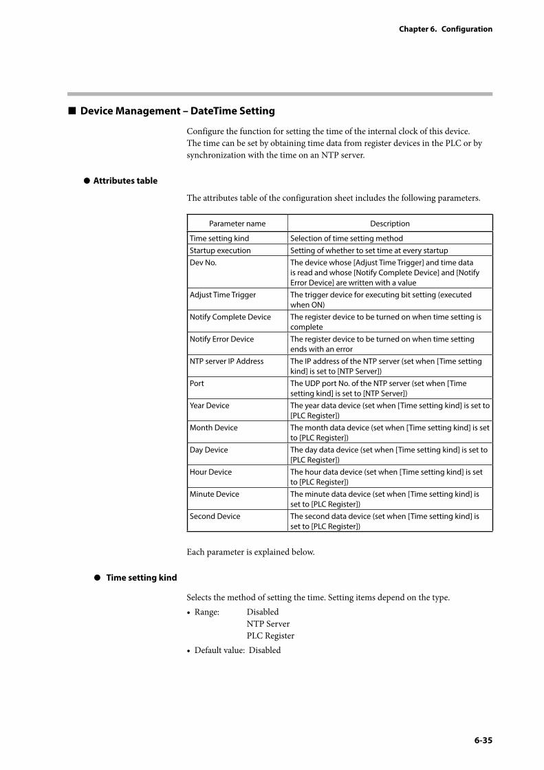
6-35
Chapter 6. Configuration
Device Management – DateTime Setting
Configure the function for setting the time of the internal clock of this device. The time can be set by obtaining time data from register devices in the PLC or by synchronization with the time on an NTP server.
z Attributes table
The attributes table of the configuration sheet includes the following parameters.
Parameter name Description
Time setting kind Selection of time setting methodStartup execution Setting of whether to set time at every startupDev No. The device whose [Adjust Time Trigger] and time data
is read and whose [Notify Complete Device] and [Notify Error Device] are written with a value
Adjust Time Trigger The trigger device for executing bit setting (executed when ON)
Notify Complete Device The register device to be turned on when time setting is complete
Notify Error Device The register device to be turned on when time setting ends with an error
NTP server IP Address The IP address of the NTP server (set when [Time setting kind] is set to [NTP Server])
Port The UDP port No. of the NTP server (set when [Time setting kind] is set to [NTP Server])
Year Device The year data device (set when [Time setting kind] is set to [PLC Register])
Month Device The month data device (set when [Time setting kind] is set to [PLC Register])
Day Device The day data device (set when [Time setting kind] is set to [PLC Register])
Hour Device The hour data device (set when [Time setting kind] is set to [PLC Register])
Minute Device The minute data device (set when [Time setting kind] is set to [PLC Register])
Second Device The second data device (set when [Time setting kind] is set to [PLC Register])
Each parameter is explained below.
z Time setting kind
Selects the method of setting the time. Setting items depend on the type.• Range: Disabled
NTP Server PLC Register
• Default value: Disabled
6-36
Chapter 6. Configuration
z Startup execution
Sets whether to set the time at every startup. By setting [Enabled], the time is set every time the power is turned on, so it is not necessary to put a battery in this device.• Range: Disabled
Enabled• Default value: Disabled
z Dev No.
Sets the device whose [Adjust Time Trigger] and time data is read and whose [Notify Complete Device] and [Notify Error Device] are written with a value.
• Range: Connected device, internal register
• Default value: –
z Adjust Time Trigger
Sets the trigger device for obtaining time data from register devices in the PLC or for synchronizing with the time on an NTP server.
• Range: Depends on the device
• Default value: Blank
z Notify Complete Device
Sets the register device to be turned on when time setting is complete. If no device is set, no completion notification is sent.
• Range: Depends on the device
• Default value: Blank
z Notify Error Device
Sets the register device to be turned on when time setting ends with an error. If no device is set, no error notification is sent.
• Range: Depends on the device
• Default value: Blank
z NTP server IP Address
Sets the IP address of the NTP server.
• Range: 1.0.0.1 to 223.255.255.255 (excluding 127._ _ _._ _ _._ _ _)
• Default value: Blank
z Port
Sets the UDP port number of the NTP server.
• Range: 0 to 65535
• Default value: Depends on the device
6-37
Chapter 6. Configuration
z Year/Month/Day/Hour/Minute/Second Device
Sets the devices of the PLC from which time data is obtained. Sets the year, month, day, hour, minute, and second.
• Range: Depends on the device
• Default value: Blank
Set the time data on the PLC in decimal format.
• Year: 2000–2038• Month: 1–12• Day: 1–31• Hour: 0–23• Minute: 0–59
• Second: 0–59
Handling Precautions
• Time after 3:14:07 (UTC) on January 19, 2038 cannot be set.


7-1
Chapter 7. Communication Settings for Connected Devices
When communicating with a PLC or a controller made by Azbil, this device serves as the master station of communication and transmits communication messages according to the communication protocol of the devices whose connection to LAN1, LAN2, COM1, or COM2 was set up by the loader. The host and slave devices return a response according to the communication message sent by this device.
This chapter describes communication settings for these devices.
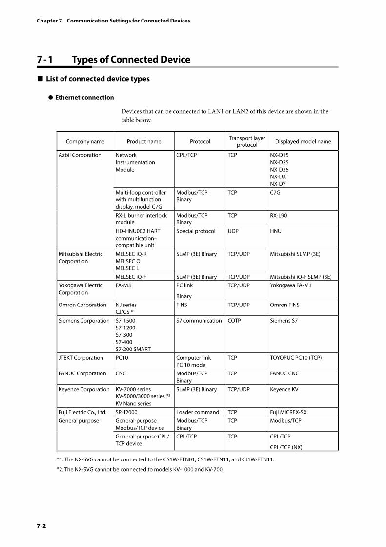
7-2
Chapter 7. Communication Settings for Connected Devices
7 - 1 Types of Connected Device
List of connected device types
z Ethernet connection
Devices that can be connected to LAN1 or LAN2 of this device are shown in the table below.
Company name Product name Protocol Transport layer protocol Displayed model name
Azbil Corporation Network Instrumentation Module
CPL/TCP TCP NX-D15 NX-D25 NX-D35 NX-DX NX-DY
Multi-loop controller with multifunction display, model C7G
Modbus/TCP Binary
TCP C7G
RX-L burner interlock module
Modbus/TCP Binary
TCP RX-L90
HD-HNU002 HART communication–compatible unit
Special protocol UDP HNU
Mitsubishi Electric Corporation
MELSEC iQ-R MELSEC Q MELSEC L
SLMP (3E) Binary TCP/UDP Mitsubishi SLMP (3E)
MELSEC iQ-F SLMP (3E) Binary TCP/UDP Mitsubishi iQ-F SLMP (3E)Yokogawa Electric Corporation
FA-M3 PC link
Binary
TCP/UDP Yokogawa FA-M3
Omron Corporation NJ series CJ/CS *1
FINS TCP/UDP Omron FINS
Siemens Corporation S7-1500 S7-1200 S7-300 S7-400 S7-200 SMART
S7 communication COTP Siemens S7
JTEKT Corporation PC10 Computer link PC 10 mode
TCP TOYOPUC PC10 (TCP)
FANUC Corporation CNC Modbus/TCP Binary
TCP FANUC CNC
Keyence Corporation KV-7000 series KV-5000/3000 series *2 KV Nano series
SLMP (3E) Binary TCP/UDP Keyence KV
Fuji Electric Co., Ltd. SPH2000 Loader command TCP Fuji MICREX-SXGeneral purpose General-purpose
Modbus/TCP deviceModbus/TCP Binary
TCP Modbus/TCP
General-purpose CPL/TCP device
CPL/TCP TCP CPL/TCP
CPL/TCP (NX)
*1. The NX-SVG cannot be connected to the CS1W-ETN01, CS1W-ETN11, and CJ1W-ETN11.
*2. The NX-SVG cannot be connected to models KV-1000 and KV-700.
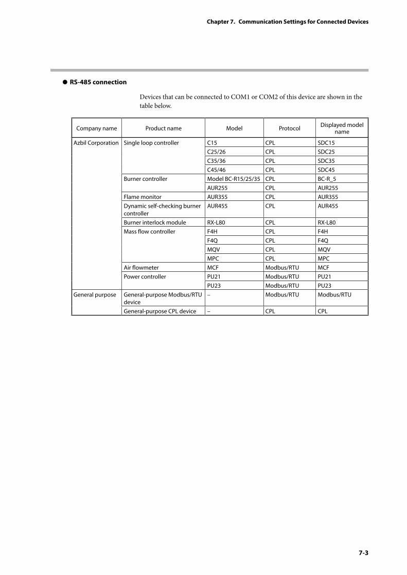
7-3
Chapter 7. Communication Settings for Connected Devices
z RS-485 connection
Devices that can be connected to COM1 or COM2 of this device are shown in the table below.
Company name Product name Model Protocol Displayed model name
Azbil Corporation Single loop controller C15 CPL SDC15C25/26 CPL SDC25C35/36 CPL SDC35C45/46 CPL SDC45
Burner controller Model BC-R15/25/35 CPL BC-R_5AUR255 CPL AUR255
Flame monitor AUR355 CPL AUR355Dynamic self-checking burner controller
AUR455 CPL AUR455
Burner interlock module RX-L80 CPL RX-L80Mass flow controller F4H CPL F4H
F4Q CPL F4QMQV CPL MQVMPC CPL MPC
Air flowmeter MCF Modbus/RTU MCFPower controller PU21 Modbus/RTU PU21
PU23 Modbus/RTU PU23General purpose General-purpose Modbus/RTU
device– Modbus/RTU Modbus/RTU
General-purpose CPL device – CPL CPL
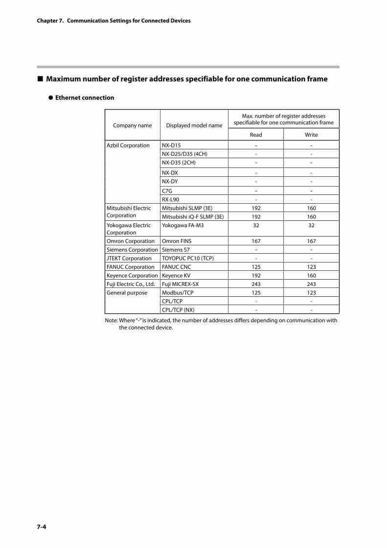
7-4
Chapter 7. Communication Settings for Connected Devices
Maximum number of register addresses specifiable for one communication frame
z Ethernet connection
Company name Displayed model name
Max. number of register addresses specifiable for one communication frame
Read Write
Azbil Corporation NX-D15 - -NX-D25/D35 (4CH) - -NX-D35 (2CH) - -
NX-DX - -NX-DY - -
C7G - -RX-L90 - -
Mitsubishi Electric Corporation
Mitsubishi SLMP (3E) 192 160Mitsubishi iQ-F SLMP (3E) 192 160
Yokogawa Electric Corporation
Yokogawa FA-M3 32 32
Omron Corporation Omron FINS 167 167Siemens Corporation Siemens S7 - -JTEKT Corporation TOYOPUC PC10 (TCP) - -FANUC Corporation FANUC CNC 125 123Keyence Corporation Keyence KV 192 160Fuji Electric Co., Ltd. Fuji MICREX-SX 243 243General purpose Modbus/TCP 125 123
CPL/TCP - -CPL/TCP (NX) - -
Note: Where “-” is indicated, the number of addresses differs depending on communication with the connected device.
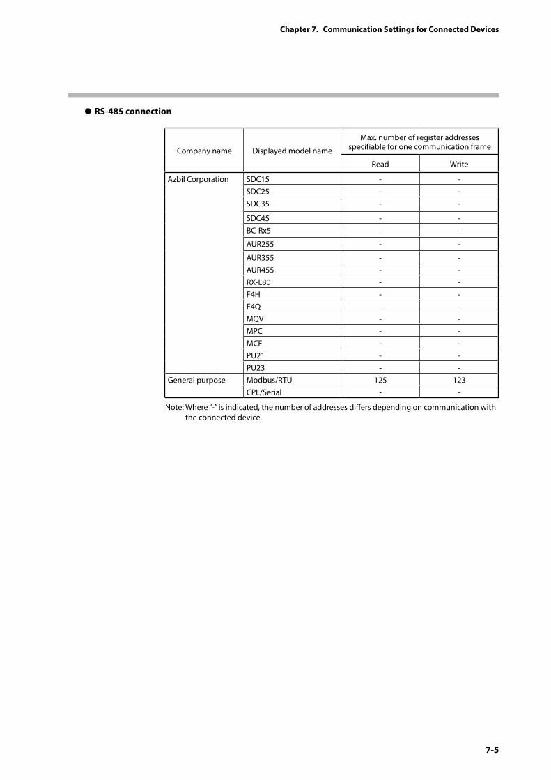
7-5
Chapter 7. Communication Settings for Connected Devices
z RS-485 connection
Company name Displayed model name
Max. number of register addresses specifiable for one communication frame
Read Write
Azbil Corporation SDC15 - -SDC25 - -SDC35 - -
SDC45 - -BC-Rx5 - -
AUR255 - -
AUR355 - -AUR455 - -RX-L80 - -F4H - -F4Q - -MQV - -MPC - -MCF - -PU21 - -PU23 - -
General purpose Modbus/RTU 125 123CPL/Serial - -
Note: Where “-” is indicated, the number of addresses differs depending on communication with the connected device.
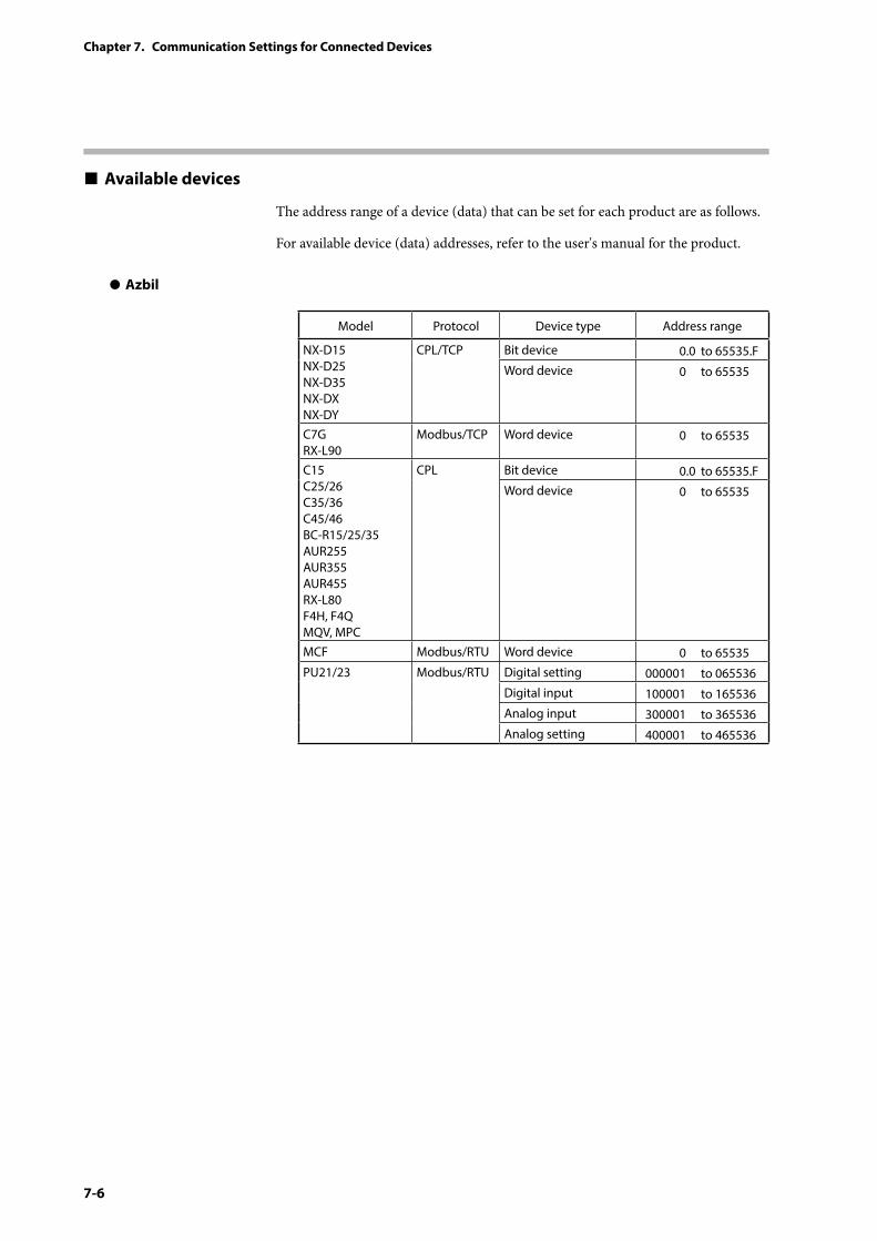
7-6
Chapter 7. Communication Settings for Connected Devices
Available devices
The address range of a device (data) that can be set for each product are as follows.
For available device (data) addresses, refer to the user's manual for the product.
z Azbil
Model Protocol Device type Address range
NX-D15 NX-D25 NX-D35 NX-DX NX-DY
CPL/TCP Bit device 0.0 to 65535.FWord device 0 to 65535
C7G RX-L90
Modbus/TCP Word device 0 to 65535
C15 C25/26 C35/36 C45/46 BC-R15/25/35 AUR255 AUR355 AUR455 RX-L80 F4H, F4Q MQV, MPC
CPL Bit device 0.0 to 65535.FWord device 0 to 65535
MCF Modbus/RTU Word device 0 to 65535PU21/23 Modbus/RTU Digital setting 000001 to 065536
Digital input 100001 to 165536Analog input 300001 to 365536Analog setting 400001 to 465536
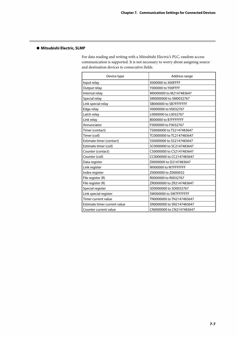
7-7
Chapter 7. Communication Settings for Connected Devices
z Mitsubishi Electric, SLMP
For data reading and writing with a Mitsubishi Electric’s PLC, random access communication is supported. It is not necessary to worry about assigning source and destination devices to consecutive fields.
Device type Address range
Input relay X000000 to X00FFFFOutput relay Y000000 to Y00FFFFInternal relay M0000000 to M2147483647Special relay SM0000000 to SM0032767Link special relay SB000000 to SB7FFFFFFFEdge relay V0000000 to V0032767Latch relay L0000000 to L0032767Link relay B000000 to B7FFFFFFFAnnunciator F0000000 to F0032767Timer (contact) TS0000000 to TS2147483647Timer (coil) TC0000000 to TC2147483647Estimate timer (contact) SS0000000 to SS2147483647Estimate timer (coil) SC0000000 to SC2147483647Counter (contact) CS0000000 to CS2147483647Counter (coil) CC0000000 to CC2147483647Data register D0000000 to D2147483647Link register W000000 to W7FFFFFFFIndex register Z0000000 to Z0000032File register (R) R0000000 to R0032767File register (R) ZR0000000 to ZR2147483647Special register SD0000000 to SD0032767Link special register SW000000 to SW7FFFFFFFTimer current value TN0000000 to TN2147483647Estimate timer current value SN0000000 to SN2147483647Counter current value CN0000000 to CN2147483647
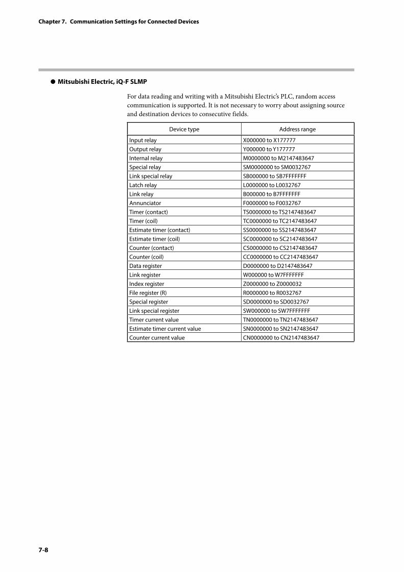
7-8
Chapter 7. Communication Settings for Connected Devices
z Mitsubishi Electric, iQ-F SLMP
For data reading and writing with a Mitsubishi Electric’s PLC, random access communication is supported. It is not necessary to worry about assigning source and destination devices to consecutive fields.
Device type Address range
Input relay X000000 to X177777Output relay Y000000 to Y177777Internal relay M0000000 to M2147483647Special relay SM0000000 to SM0032767Link special relay SB000000 to SB7FFFFFFFLatch relay L0000000 to L0032767Link relay B000000 to B7FFFFFFFAnnunciator F0000000 to F0032767Timer (contact) TS0000000 to TS2147483647Timer (coil) TC0000000 to TC2147483647Estimate timer (contact) SS0000000 to SS2147483647Estimate timer (coil) SC0000000 to SC2147483647Counter (contact) CS0000000 to CS2147483647Counter (coil) CC0000000 to CC2147483647Data register D0000000 to D2147483647Link register W000000 to W7FFFFFFFIndex register Z0000000 to Z0000032File register (R) R0000000 to R0032767Special register SD0000000 to SD0032767Link special register SW000000 to SW7FFFFFFFTimer current value TN0000000 to TN2147483647Estimate timer current value SN0000000 to SN2147483647Counter current value CN0000000 to CN2147483647
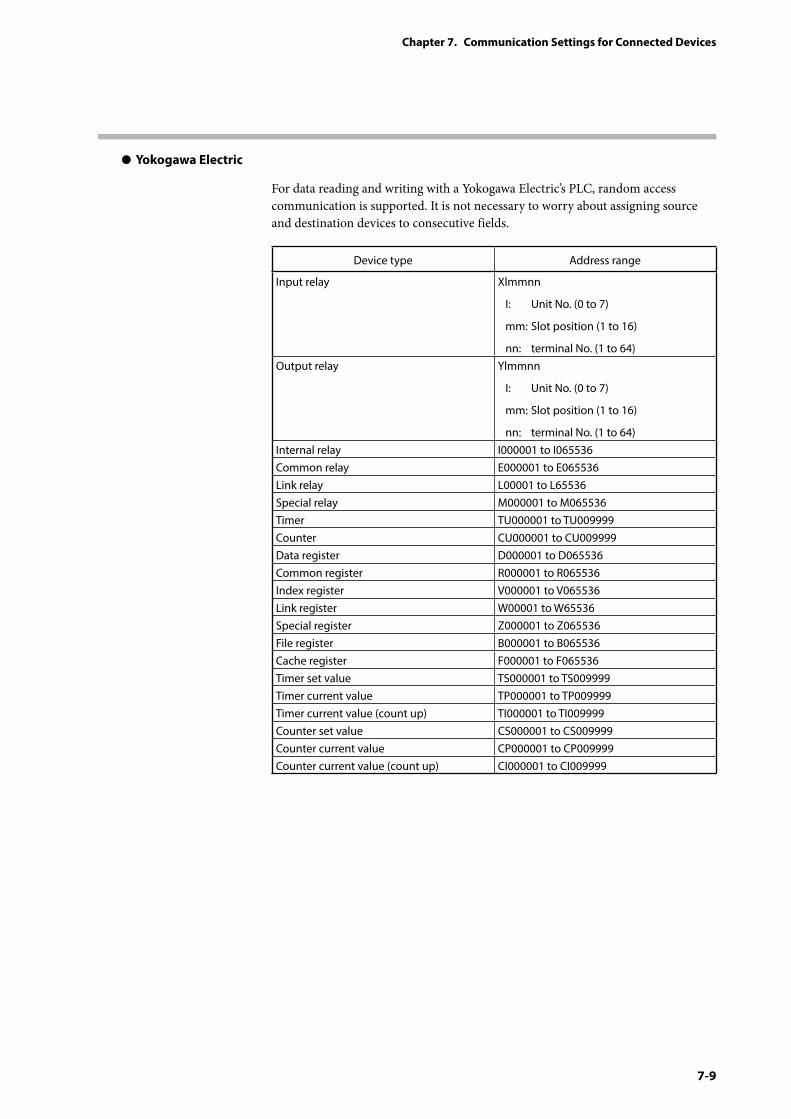
7-9
Chapter 7. Communication Settings for Connected Devices
z Yokogawa Electric
For data reading and writing with a Yokogawa Electric’s PLC, random access communication is supported. It is not necessary to worry about assigning source and destination devices to consecutive fields.
Device type Address range
Input relay Xlmmnn
I: Unit No. (0 to 7)
mm: Slot position (1 to 16)
nn: terminal No. (1 to 64)Output relay Ylmmnn
I: Unit No. (0 to 7)
mm: Slot position (1 to 16)
nn: terminal No. (1 to 64)Internal relay I000001 to I065536Common relay E000001 to E065536Link relay L00001 to L65536Special relay M000001 to M065536Timer TU000001 to TU009999Counter CU000001 to CU009999Data register D000001 to D065536Common register R000001 to R065536Index register V000001 to V065536Link register W00001 to W65536Special register Z000001 to Z065536File register B000001 to B065536Cache register F000001 to F065536Timer set value TS000001 to TS009999Timer current value TP000001 to TP009999Timer current value (count up) TI000001 to TI009999Counter set value CS000001 to CS009999Counter current value CP000001 to CP009999Counter current value (count up) CI000001 to CI009999
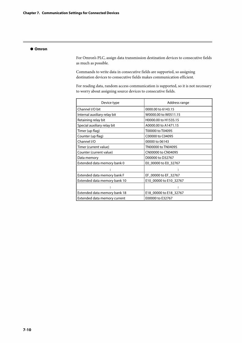
7-10
Chapter 7. Communication Settings for Connected Devices
z Omron
For Omron’s PLC, assign data transmission destination devices to consecutive fields as much as possible.
Commands to write data in consecutive fields are supported, so assigning destination devices to consecutive fields makes communication efficient.
For reading data, random access communication is supported, so it is not necessary to worry about assigning source devices to consecutive fields.
Device type Address range
Channel I/O bit 0000.00 to 6143.15Internal auxiliary relay bit W0000.00 to W0511.15Retaining relay bit H0000.00 to H1535.15Special auxiliary relay bit A0000.00 to A1471.15Timer (up flag) T00000 to T04095Counter (up flag) C00000 to C04095Channel I/O 00000 to 06143Timer (current value) TN00000 to TN04095Counter (current value) CN00000 to CN04095Data memory D00000 to D32767Extended data memory bank 0 E0_00000 to E0_32767
Extended data memory bank F EF_00000 to EF_32767Extended data memory bank 10 E10_00000 to E10_32767
Extended data memory bank 18 E18_00000 to E18_32767Extended data memory current E00000 to E32767
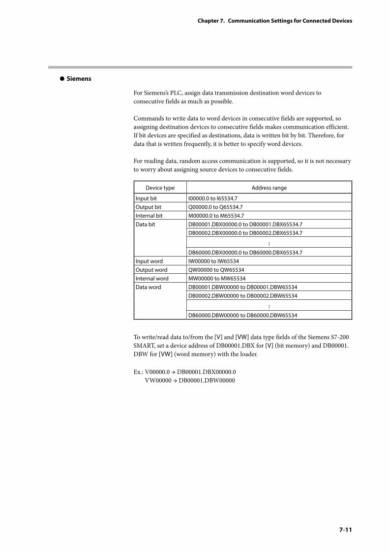
7-11
Chapter 7. Communication Settings for Connected Devices
z Siemens
For Siemens’s PLC, assign data transmission destination word devices to consecutive fields as much as possible. Commands to write data to word devices in consecutive fields are supported, so assigning destination devices to consecutive fields makes communication efficient. If bit devices are specified as destinations, data is written bit by bit. Therefore, for data that is written frequently, it is better to specify word devices. For reading data, random access communication is supported, so it is not necessary to worry about assigning source devices to consecutive fields.
Device type Address range
Input bit I00000.0 to I65534.7Output bit Q00000.0 to Q65534.7Internal bit M00000.0 to M65534.7Data bit DB00001.DBX00000.0 to DB00001.DBX65534.7
DB00002.DBX00000.0 to DB00002.DBX65534.7
DB60000.DBX00000.0 to DB60000.DBX65534.7Input word IW00000 to IW65534Output word QW00000 to QW65534Internal word MW00000 to MW65534Data word DB00001.DBW00000 to DB00001.DBW65534
DB00002.DBW00000 to DB00002.DBW65534
DB60000.DBW00000 to DB60000.DBW65534
To write/read data to/from the [V] and [VW] data type fields of the Siemens S7-200 SMART, set a device address of DB00001.DBX for [V] (bit memory) and DB00001.DBW for [VW] (word memory) with the loader.
Ex.: V00000.0 → DB00001.DBX00000.0 VW00000 → DB00001.DBW00000
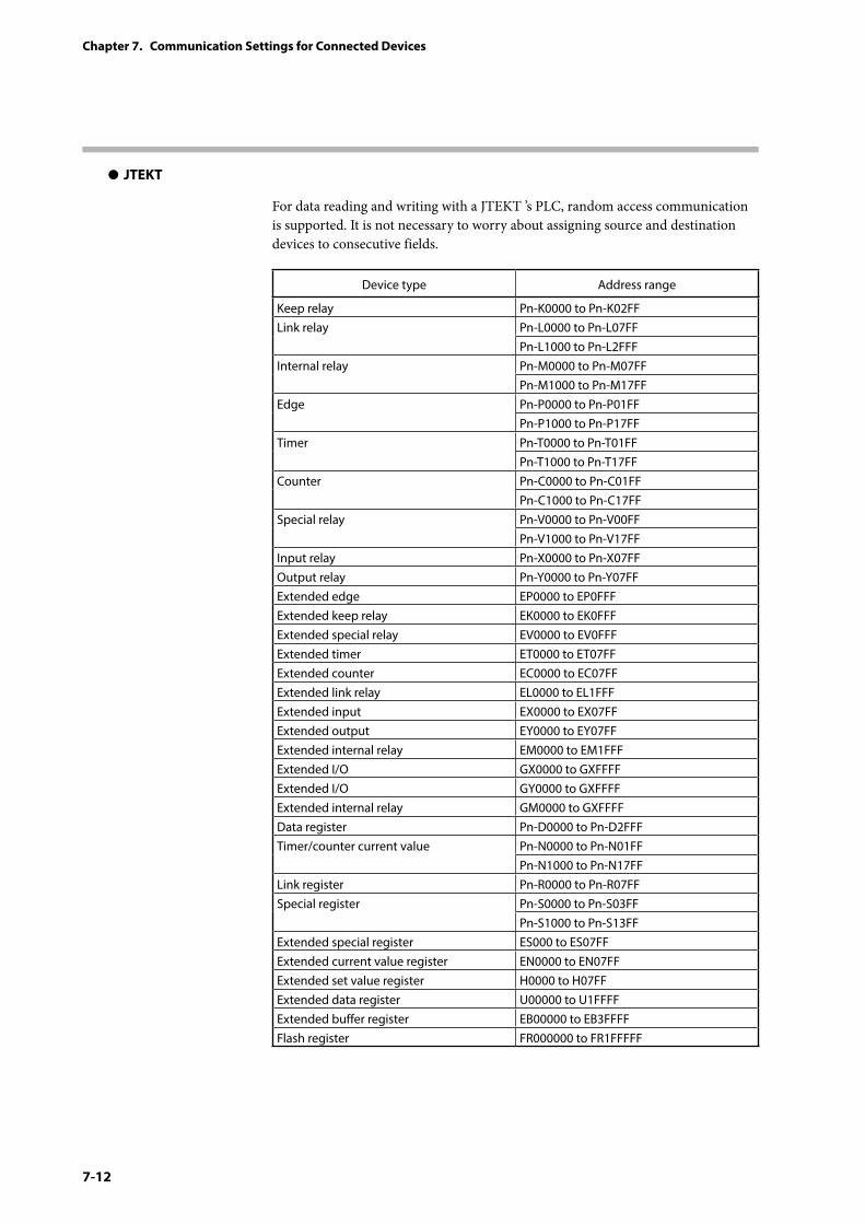
7-12
Chapter 7. Communication Settings for Connected Devices
z JTEKT
For data reading and writing with a JTEKT ’s PLC, random access communication is supported. It is not necessary to worry about assigning source and destination devices to consecutive fields.
Device type Address range
Keep relay Pn-K0000 to Pn-K02FFLink relay Pn-L0000 to Pn-L07FF
Pn-L1000 to Pn-L2FFFInternal relay Pn-M0000 to Pn-M07FF
Pn-M1000 to Pn-M17FFEdge Pn-P0000 to Pn-P01FF
Pn-P1000 to Pn-P17FFTimer Pn-T0000 to Pn-T01FF
Pn-T1000 to Pn-T17FFCounter Pn-C0000 to Pn-C01FF
Pn-C1000 to Pn-C17FFSpecial relay Pn-V0000 to Pn-V00FF
Pn-V1000 to Pn-V17FFInput relay Pn-X0000 to Pn-X07FFOutput relay Pn-Y0000 to Pn-Y07FFExtended edge EP0000 to EP0FFFExtended keep relay EK0000 to EK0FFFExtended special relay EV0000 to EV0FFFExtended timer ET0000 to ET07FFExtended counter EC0000 to EC07FFExtended link relay EL0000 to EL1FFFExtended input EX0000 to EX07FFExtended output EY0000 to EY07FFExtended internal relay EM0000 to EM1FFFExtended I/O GX0000 to GXFFFFExtended I/O GY0000 to GXFFFFExtended internal relay GM0000 to GXFFFFData register Pn-D0000 to Pn-D2FFFTimer/counter current value Pn-N0000 to Pn-N01FF
Pn-N1000 to Pn-N17FFLink register Pn-R0000 to Pn-R07FFSpecial register Pn-S0000 to Pn-S03FF
Pn-S1000 to Pn-S13FFExtended special register ES000 to ES07FFExtended current value register EN0000 to EN07FFExtended set value register H0000 to H07FFExtended data register U00000 to U1FFFFExtended buffer register EB00000 to EB3FFFFFlash register FR000000 to FR1FFFFF
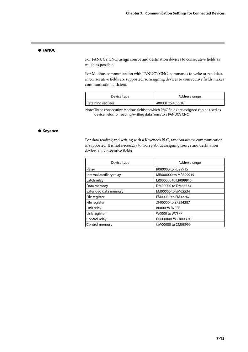
7-13
Chapter 7. Communication Settings for Connected Devices
z FANUC
For FANUC’s CNC, assign source and destination devices to consecutive fields as much as possible.
For Modbus communication with FANUC’s CNC, commands to write or read data in consecutive fields are supported, so assigning devices to consecutive fields makes communication efficient.
Device type Address range
Retaining register 400001 to 465536
Note: Three consecutive Modbus fields to which PMC fields are assigned can be used as device fields for reading/writing data from/to a FANUC’s CNC.
z Keyence
For data reading and writing with a Keyence’s PLC, random access communication is supported. It is not necessary to worry about assigning source and destination devices to consecutive fields.
Device type Address range
Relay R000000 to R099915Internal auxiliary relay MR000000 to MR399915Latch relay LR000000 to LR099915Data memory DM00000 to DM65534Extended data memory EM00000 to EM65534File register FM00000 to FM32767File register ZF00000 to ZF524287Link relay B0000 to B7FFFLink register W0000 to W7FFFControl relay CR000000 to CR008915Control memory CM00000 to CM08999
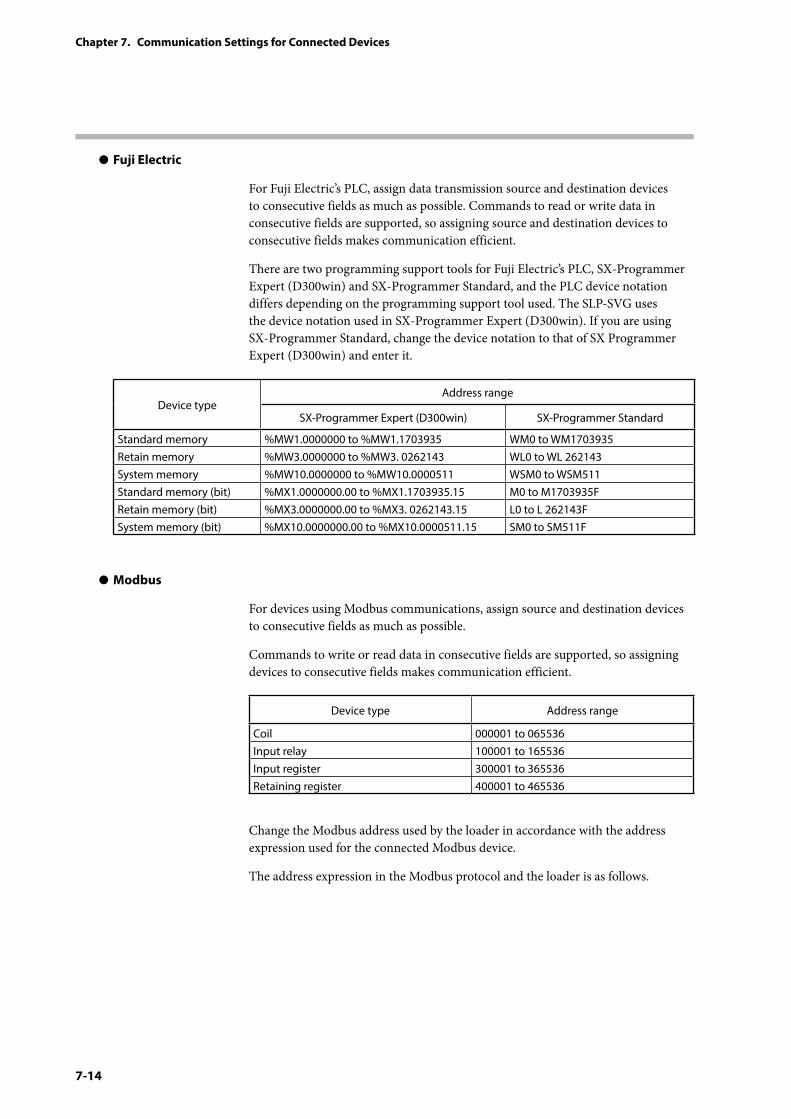
7-14
Chapter 7. Communication Settings for Connected Devices
z Fuji Electric
For Fuji Electric’s PLC, assign data transmission source and destination devices to consecutive fields as much as possible. Commands to read or write data in consecutive fields are supported, so assigning source and destination devices to consecutive fields makes communication efficient.
There are two programming support tools for Fuji Electric’s PLC, SX-Programmer Expert (D300win) and SX-Programmer Standard, and the PLC device notation differs depending on the programming support tool used. The SLP-SVG uses the device notation used in SX-Programmer Expert (D300win). If you are using SX-Programmer Standard, change the device notation to that of SX Programmer Expert (D300win) and enter it.
Device typeAddress range
SX-Programmer Expert (D300win) SX-Programmer Standard
Standard memory %MW1.0000000 to %MW1.1703935 WM0 to WM1703935Retain memory %MW3.0000000 to %MW3. 0262143 WL0 to WL 262143System memory %MW10.0000000 to %MW10.0000511 WSM0 to WSM511Standard memory (bit) %MX1.0000000.00 to %MX1.1703935.15 M0 to M1703935FRetain memory (bit) %MX3.0000000.00 to %MX3. 0262143.15 L0 to L 262143FSystem memory (bit) %MX10.0000000.00 to %MX10.0000511.15 SM0 to SM511F
z Modbus
For devices using Modbus communications, assign source and destination devices to consecutive fields as much as possible.
Commands to write or read data in consecutive fields are supported, so assigning devices to consecutive fields makes communication efficient.
Device type Address range
Coil 000001 to 065536Input relay 100001 to 165536Input register 300001 to 365536Retaining register 400001 to 465536
Change the Modbus address used by the loader in accordance with the address expression used for the connected Modbus device.
The address expression in the Modbus protocol and the loader is as follows.
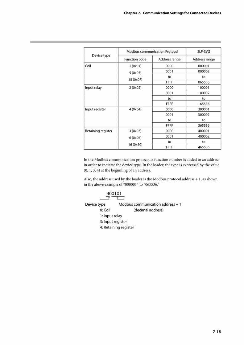
7-15
Chapter 7. Communication Settings for Connected Devices
Device typeModbus communication Protocol SLP-SVG
Function code Address range Address range
Coil 1 (0x01)
5 (0x05)
15 (0x0F)
0000 0000010001 000002
to toFFFF 065536
Input relay 2 (0x02) 0000 1000010001 100002
to toFFFF 165536
Input register 4 (0x04) 0000 3000010001 300002
to toFFFF 365536
Retaining register 3 (0x03)
6 (0x06)
16 (0x10)
0000 4000010001 400002
to toFFFF 465536
In the Modbus communication protocol, a function number is added to an address in order to indicate the device type. In the loader, the type is expressed by the value (0, 1, 3, 4) at the beginning of an address.
Also, the address used by the loader is the Modbus protocol address + 1, as shown in the above example of “000001” to “065536."
400101
Device type 0: Coil 1: Input relay 3: Input register 4: Retaining register
Modbus communication address + 1 (decimal address)
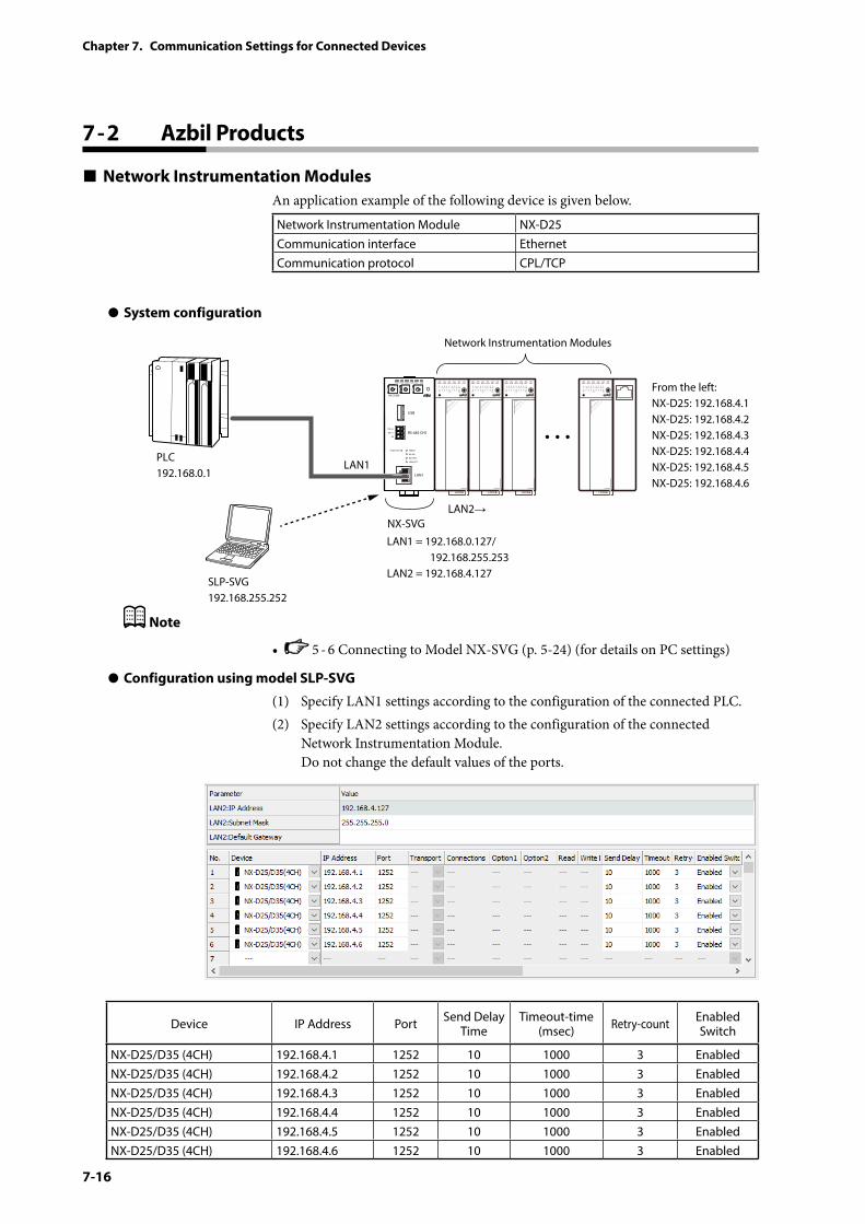
7-16
Chapter 7. Communication Settings for Connected Devices
7 - 2 Azbil Products
Network Instrumentation ModulesAn application example of the following device is given below.
Network Instrumentation Module NX-D25Communication interface EthernetCommunication protocol CPL/TCP
z System configuration
PWR
NX-SVGN
USB
DA (+)
SG
DB (−) RS-485 CH1
RS-485
BATTERY
LINK/ACT
LAN1
FUNCTION ERROR
ID F1 F2
RUN MOD COM NST FAIL
SLP-SVG192.168.255.252
Network Instrumentation Modules
From the left:NX-D25: 192.168.4.1NX-D25: 192.168.4.2NX-D25: 192.168.4.3NX-D25: 192.168.4.4NX-D25: 192.168.4.5NX-D25: 192.168.4.6
LAN1 = 192.168.0.127/ 192.168.255.253LAN2 = 192.168.4.127
LAN1
LAN2→
PLC192.168.0.1
NX-SVG
Note
• 5 - 6 Connecting to Model NX-SVG (p. 5-24) (for details on PC settings)
z Configuration using model SLP-SVG
(1) Specify LAN1 settings according to the configuration of the connected PLC.(2) Specify LAN2 settings according to the configuration of the connected
Network Instrumentation Module. Do not change the default values of the ports.
Device IP Address Port Send Delay Time
Timeout-time (msec) Retry-count Enabled
Switch
NX-D25/D35 (4CH) 192.168.4.1 1252 10 1000 3 EnabledNX-D25/D35 (4CH) 192.168.4.2 1252 10 1000 3 EnabledNX-D25/D35 (4CH) 192.168.4.3 1252 10 1000 3 EnabledNX-D25/D35 (4CH) 192.168.4.4 1252 10 1000 3 EnabledNX-D25/D35 (4CH) 192.168.4.5 1252 10 1000 3 EnabledNX-D25/D35 (4CH) 192.168.4.6 1252 10 1000 3 Enabled
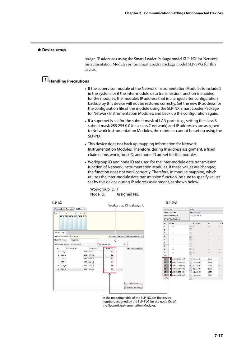
7-17
Chapter 7. Communication Settings for Connected Devices
z Device setup
Assign IP addresses using the Smart Loader Package model SLP-NX for Network Instrumentation Modules or the Smart Loader Package model SLP-SVG for this device.
Handling Precautions
• If the supervisor module of the Network Instrumentation Modules is included in the system, or if the inter-module data transmission function is enabled for the modules, the module’s IP address that is changed after configuration backup by this device will not be restored correctly. Set the new IP address for the configuration file of the module using the SLP-NX Smart Loader Package for Network Instrumentation Modules, and back up the configuration again.
• If a supernet is set for the subnet mask of LAN ports (e.g., setting the class B subnet mask 255.255.0.0 for a class C network) and IP addresses are assigned to Network Instrumentation Modules, the modules cannot be set up using the SLP-NX.
• This device does not back up mapping information for Network Instrumentation Modules. Therefore, during IP address assignment, a fixed chain name, workgroup ID, and node ID are set for the modules.
• Workgroup ID and node ID are used for the inter-module data transmission function of Network Instrumentation Modules. If these values are changed, the function does not work correctly. Therefore, in module mapping, which utilizes the inter-module data transmission function, be sure to specify values set by this device during IP address assignment, as shown below.
Workgroup ID: 1Node ID: Assigned No.
SLP-NX SLP-SVGWorkgroup ID is always 1.
In the mapping table of the SLP-NX, set the device numbers assigned by the SLP-SVG for the node IDs of the Network Instrumentation Modules.

7-18
Chapter 7. Communication Settings for Connected Devices
Note• Typical errors that might occur in communication with Network Instrumentation
Modules include the following.
Error response code Description
0x00000021 Data address error0x00000022 Data range error0x00000023 Writing is prohibited due to the instrument conditions.
Note: For details on errors, refer to the manual for the device.
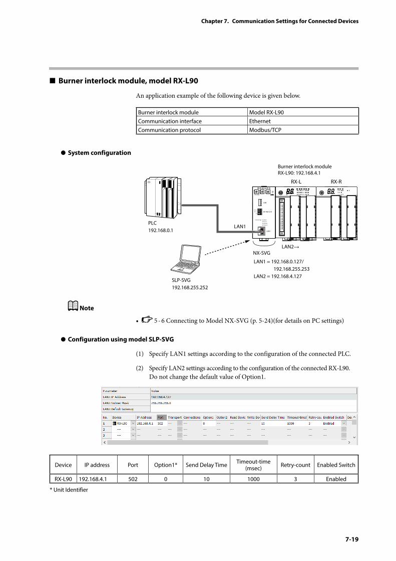
7-19
Chapter 7. Communication Settings for Connected Devices
Burner interlock module, model RX-L90
An application example of the following device is given below.
Burner interlock module Model RX-L90Communication interface EthernetCommunication protocol Modbus/TCP
z System configuration
PWR
NX-SVGN
USB
DA (+)
SG
DB (−) RS-485 CH1
RS-485
BATTERY
LINK/ACT
LAN1
FUNCTION ERROR
ID F1 F2
RUN MOD COM NST FAIL
SLP-SVG192.168.255.252
Burner interlock moduleRX-L90: 192.168.4.1
LAN1 = 192.168.0.127/ 192.168.255.253LAN2 = 192.168.4.127
LAN1
LAN2→
PLC192.168.0.1
RX-L RX-R
NX-SVG
Note
• 5 - 6 Connecting to Model NX-SVG (p. 5-24)(for details on PC settings)
z Configuration using model SLP-SVG
(1) Specify LAN1 settings according to the configuration of the connected PLC.
(2) Specify LAN2 settings according to the configuration of the connected RX-L90. Do not change the default value of Option1.
Device IP address Port Option1* Send Delay Time Timeout-time (msec) Retry-count Enabled Switch
RX-L90 192.168.4.1 502 0 10 1000 3 Enabled
* Unit Identifier
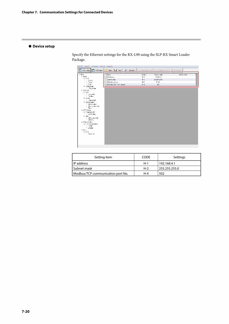
7-20
Chapter 7. Communication Settings for Connected Devices
z Device setup
Specify the Ethernet settings for the RX-L90 using the SLP-RX Smart Loader Package.
Setting item CODE Settings
IP address H-1 192.168.4.1Subnet mask H-2 255.255.255.0Modbus/TCP communication port No. H-4 502
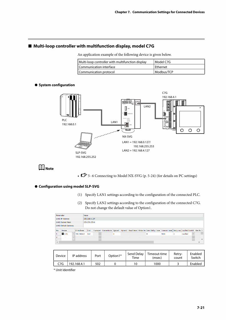
7-21
Chapter 7. Communication Settings for Connected Devices
Multi-loop controller with multifunction display, model C7G
An application example of the following device is given below.
Multi-loop controller with multifunction display Model C7GCommunication interface EthernetCommunication protocol Modbus/TCP
z System configuration
PWR
NX-SVGN
USB
DA (+)
SG
DB (−) RS-485 CH1
RS-485
BATTERY
LINK/ACT
LAN1
FUNCTION ERROR
ID F1 F2
RUN MOD COM NST FAIL
SLP-SVG192.168.255.252
LAN1 = 192.168.0.127/ 192.168.255.253LAN2 = 192.168.4.127
LAN1
LAN2
NX-SVG
C7G192.168.4.1
PLC192.168.0.1
Note
• 5 - 6 Connecting to Model NX-SVG (p. 5-24) (for details on PC settings)
z Configuration using model SLP-SVG
(1) Specify LAN1 settings according to the configuration of the connected PLC.
(2) Specify LAN2 settings according to the configuration of the connected C7G. Do not change the default value of Option1.
Device IP address Port Option1* Send Delay Time
Timeout-time (msec)
Retry-count
Enabled Switch
C7G 192.168.4.1 502 0 10 1000 3 Enabled
* Unit Identifier
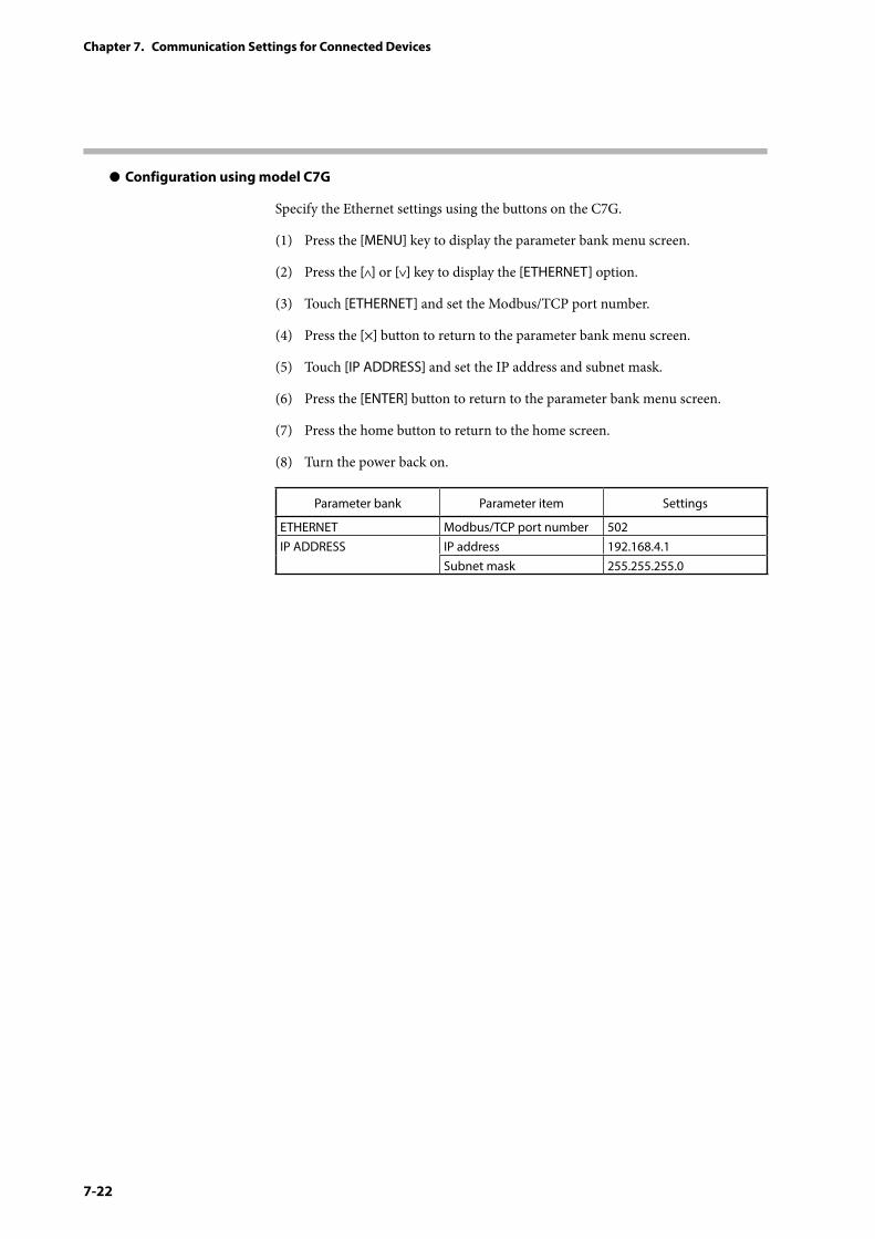
7-22
Chapter 7. Communication Settings for Connected Devices
z Configuration using model C7G
Specify the Ethernet settings using the buttons on the C7G.
(1) Press the [MENU] key to display the parameter bank menu screen.
(2) Press the [ ] or [ ] key to display the [ETHERNET] option.
(3) Touch [ETHERNET] and set the Modbus/TCP port number.
(4) Press the [×] button to return to the parameter bank menu screen.
(5) Touch [IP ADDRESS] and set the IP address and subnet mask.
(6) Press the [ENTER] button to return to the parameter bank menu screen.
(7) Press the home button to return to the home screen.
(8) Turn the power back on.
Parameter bank Parameter item Settings
ETHERNET Modbus/TCP port number 502IP ADDRESS IP address 192.168.4.1
Subnet mask 255.255.255.0
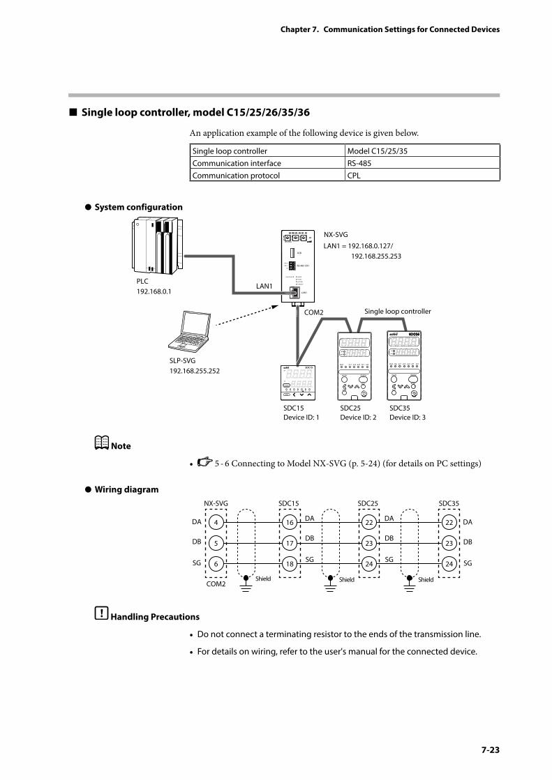
7-23
Chapter 7. Communication Settings for Connected Devices
Single loop controller, model C15/25/26/35/36
An application example of the following device is given below.
Single loop controller Model C15/25/35Communication interface RS-485Communication protocol CPL
z System configuration
PWR
NX-SVGN
USB
DA (+)
SG
DB (−) RS-485 CH1
RS-485
BATTERY
LINK/ACT
LAN1
FUNCTION ERROR
ID F1 F2
RUN MOD COM NST FAIL
SLP-SVG192.168.255.252
LAN1 = 192.168.0.127/ 192.168.255.253
LAN1
COM2
SDC15Device ID: 1
SDC25Device ID: 2
SDC35Device ID: 3
PLC192.168.0.1
NX-SVG
Single loop controller
rdy man ev1 ev2 ev3 ot1 ot2
para
mode
SDC15pv
sp
Note
• 5 - 6 Connecting to Model NX-SVG (p. 5-24) (for details on PC settings)
z Wiring diagram
4
NX-SVG
COM2Shield Shield Shield
SDC15 SDC25 SDC35
5
6
16
17
18
22
23
24
22
23
24
DA
DB
SG
DA
DB
SG
DA
DB
SG
DA
DB
SG
Handling Precautions
• Do not connect a terminating resistor to the ends of the transmission line.
• For details on wiring, refer to the user's manual for the connected device.
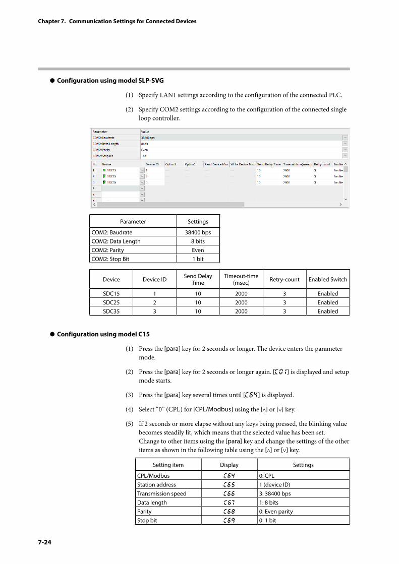
7-24
Chapter 7. Communication Settings for Connected Devices
z Configuration using model SLP-SVG
(1) Specify LAN1 settings according to the configuration of the connected PLC.
(2) Specify COM2 settings according to the configuration of the connected single loop controller.
Parameter Settings
COM2: Baudrate 38400 bpsCOM2: Data Length 8 bitsCOM2: Parity EvenCOM2: Stop Bit 1 bit
Device Device ID Send Delay Time
Timeout-time (msec) Retry-count Enabled Switch
SDC15 1 10 2000 3 EnabledSDC25 2 10 2000 3 EnabledSDC35 3 10 2000 3 Enabled
z Configuration using model C15
(1) Press the [para] key for 2 seconds or longer. The device enters the parameter mode.
(2) Press the [para] key for 2 seconds or longer again. [C0 1] is displayed and setup mode starts.
(3) Press the [para] key several times until [C64] is displayed.
(4) Select “0” (CPL) for [CPL/Modbus] using the [ ] or [ ] key.
(5) If 2 seconds or more elapse without any keys being pressed, the blinking value becomes steadily lit, which means that the selected value has been set. Change to other items using the [para] key and change the settings of the other items as shown in the following table using the [ ] or [ ] key.
Setting item Display Settings
CPL/Modbus C64 0: CPLStation address C65 1 (device ID)Transmission speed C66 3: 38400 bpsData length C67 1: 8 bitsParity C68 0: Even parityStop bit C69 0: 1 bit
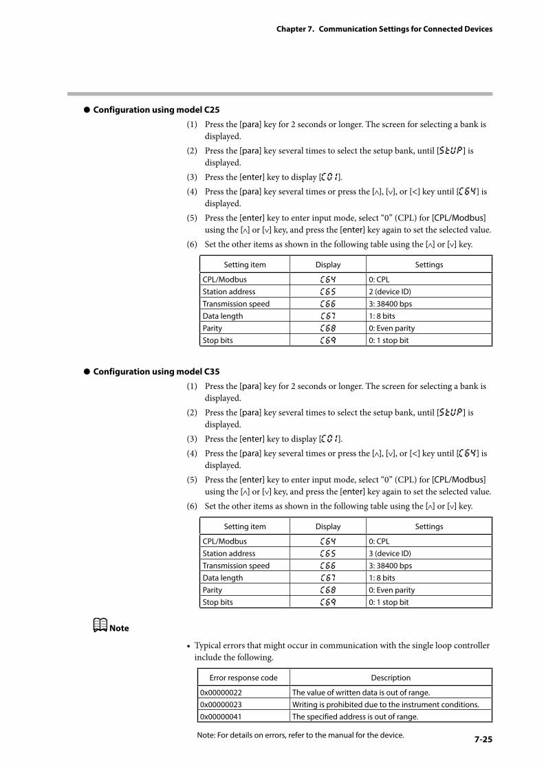
7-25
Chapter 7. Communication Settings for Connected Devices
z Configuration using model C25
(1) Press the [para] key for 2 seconds or longer. The screen for selecting a bank is displayed.
(2) Press the [para] key several times to select the setup bank, until [StUP] is displayed.
(3) Press the [enter] key to display [C0 1].(4) Press the [para] key several times or press the [ ], [ ], or [<] key until [C64] is
displayed.(5) Press the [enter] key to enter input mode, select “0” (CPL) for [CPL/Modbus]
using the [ ] or [ ] key, and press the [enter] key again to set the selected value.(6) Set the other items as shown in the following table using the [ ] or [ ] key.
Setting item Display Settings
CPL/Modbus C64 0: CPLStation address C65 2 (device ID)Transmission speed C66 3: 38400 bpsData length C67 1: 8 bitsParity C68 0: Even parityStop bits C69 0: 1 stop bit
z Configuration using model C35
(1) Press the [para] key for 2 seconds or longer. The screen for selecting a bank is displayed.
(2) Press the [para] key several times to select the setup bank, until [StUP] is displayed.
(3) Press the [enter] key to display [C0 1].(4) Press the [para] key several times or press the [ ], [ ], or [<] key until [C64] is
displayed.(5) Press the [enter] key to enter input mode, select “0” (CPL) for [CPL/Modbus]
using the [ ] or [ ] key, and press the [enter] key again to set the selected value.(6) Set the other items as shown in the following table using the [ ] or [ ] key.
Setting item Display Settings
CPL/Modbus C64 0: CPLStation address C65 3 (device ID)Transmission speed C66 3: 38400 bpsData length C67 1: 8 bitsParity C68 0: Even parityStop bits C69 0: 1 stop bit
Note
• Typical errors that might occur in communication with the single loop controller include the following.
Error response code Description
0x00000022 The value of written data is out of range.0x00000023 Writing is prohibited due to the instrument conditions.0x00000041 The specified address is out of range.
Note: For details on errors, refer to the manual for the device.
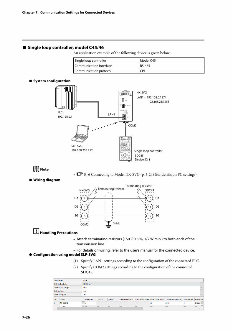
7-26
Chapter 7. Communication Settings for Connected Devices
Single loop controller, model C45/46An application example of the following device is given below.
Single loop controller Model C45Communication interface RS-485Communication protocol CPL
z System configuration
PWR
NX-SVGN
USB
DA (+)
SG
DB (−) RS-485 CH1
RS-485
BATTERY
LINK/ACT
LAN1
FUNCTION ERROR
ID F1 F2
RUN MOD COM NST FAIL
SLP-SVG192.168.255.252
LAN1 = 192.168.0.127/ 192.168.255.253
LAN1
COM2
SDC45Device ID: 1
PLC192.168.0.1
NX-SVG
Single loop controller
Note• 5 - 6 Connecting to Model NX-SVG (p. 5-24) (for details on PC settings)
z Wiring diagram
4
NX-SVG Terminating resistorTerminating resistor
COM2 Shield
5
6
DA
DB
SG
10
SDC45
11
12
DA
DB
SG
Handling Precautions
• Attach terminating resistors (150 Ω ±5 %, 1/2 W min.) to both ends of the transmission line.
• For details on wiring, refer to the user's manual for the connected device.z Configuration using model SLP-SVG
(1) Specify LAN1 settings according to the configuration of the connected PLC.(2) Specify COM2 settings according to the configuration of the connected
SDC45.
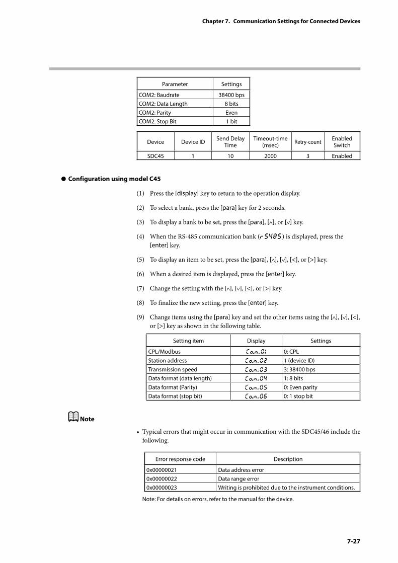
7-27
Chapter 7. Communication Settings for Connected Devices
Parameter Settings
COM2: Baudrate 38400 bpsCOM2: Data Length 8 bitsCOM2: Parity EvenCOM2: Stop Bit 1 bit
Device Device ID Send Delay Time
Timeout-time (msec) Retry-count Enabled
Switch
SDC45 1 10 2000 3 Enabled
z Configuration using model C45
(1) Press the [display] key to return to the operation display.
(2) To select a bank, press the [para] key for 2 seconds.
(3) To display a bank to be set, press the [para], [ ], or [ ] key.
(4) When the RS-485 communication bank (rS485) is displayed, press the [enter] key.
(5) To display an item to be set, press the [para], [ ], [ ], [<], or [>] key.
(6) When a desired item is displayed, press the [enter] key.
(7) Change the setting with the [ ], [ ], [<], or [>] key.
(8) To finalize the new setting, press the [enter] key.
(9) Change items using the [para] key and set the other items using the [ ], [ ], [<], or [>] key as shown in the following table.
Setting item Display Settings
CPL/Modbus Con.01 0: CPLStation address Con.02 1 (device ID)Transmission speed Con.03 3: 38400 bpsData format (data length) Con.04 1: 8 bitsData format (Parity) Con.05 0: Even parityData format (stop bit) Con.06 0: 1 stop bit
Note
• Typical errors that might occur in communication with the SDC45/46 include the following.
Error response code Description
0x00000021 Data address error0x00000022 Data range error0x00000023 Writing is prohibited due to the instrument conditions.
Note: For details on errors, refer to the manual for the device.
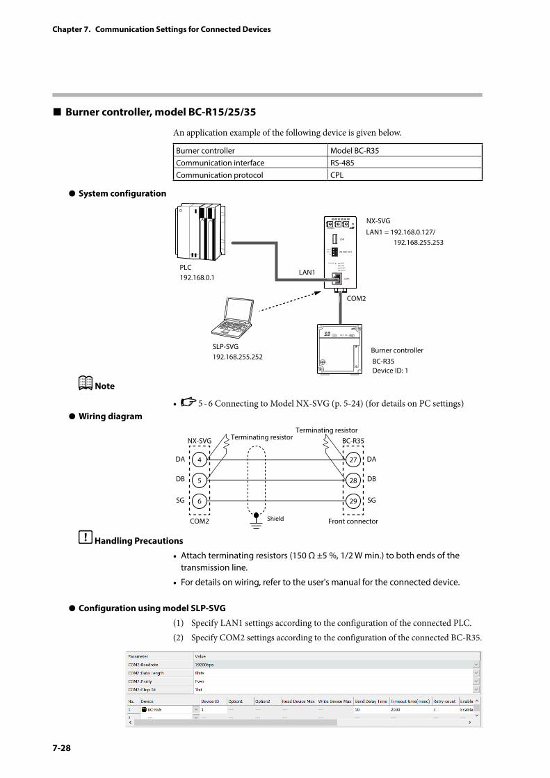
7-28
Chapter 7. Communication Settings for Connected Devices
Burner controller, model BC-R15/25/35
An application example of the following device is given below.
Burner controller Model BC-R35Communication interface RS-485Communication protocol CPL
z System configuration
PWR
NX-SVGN
USB
DA (+)
SG
DB (−) RS-485 CH1
RS-485
BATTERY
LINK/ACT
LAN1
FUNCTION ERROR
ID F1 F2
RUN MOD COM NST FAIL
SLP-SVG192.168.255.252
LAN1 = 192.168.0.127/ 192.168.255.253
LAN1
COM2
BC-R35Device ID: 1
PLC192.168.0.1
NX-SVG
Burner controller
Note
• 5 - 6 Connecting to Model NX-SVG (p. 5-24) (for details on PC settings)z Wiring diagram
4
NX-SVG Terminating resistorTerminating resistor
COM2 Shield
5
6
DA
DB
SG
27
BC-R35
28
29
DA
DB
SG
Front connector
Handling Precautions
• Attach terminating resistors (150 Ω ±5 %, 1/2 W min.) to both ends of the transmission line.
• For details on wiring, refer to the user's manual for the connected device.
z Configuration using model SLP-SVG
(1) Specify LAN1 settings according to the configuration of the connected PLC.(2) Specify COM2 settings according to the configuration of the connected BC-R35.
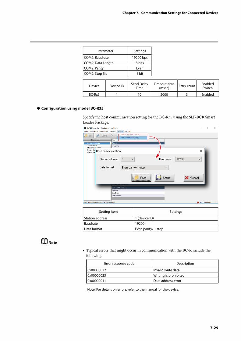
7-29
Chapter 7. Communication Settings for Connected Devices
Parameter Settings
COM2: Baudrate 19200 bpsCOM2: Data Length 8 bitsCOM2: Parity EvenCOM2: Stop Bit 1 bit
Device Device ID Send Delay Time
Timeout-time (msec) Retry-count Enabled
Switch
BC-Rx5 1 10 2000 3 Enabled
z Configuration using model BC-R35
Specify the host communication setting for the BC-R35 using the SLP-BCR Smart Loader Package.
Setting item Settings
Station address 1 (device ID)Baudrate 19200Data format Even parity/ 1 stop
Note
• Typical errors that might occur in communication with the BC-R include the following.
Error response code Description
0x00000022 Invalid write data0x00000023 Writing is prohibited.0x00000041 Data address error
Note: For details on errors, refer to the manual for the device.
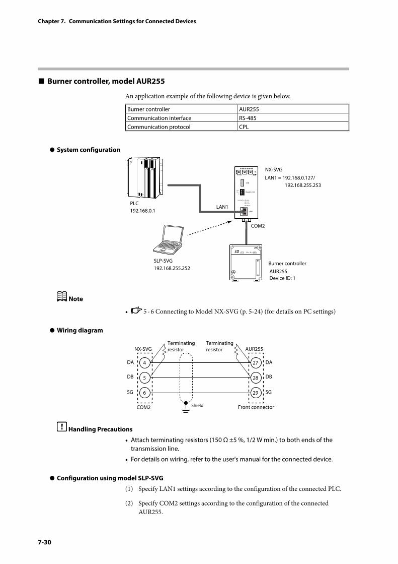
7-30
Chapter 7. Communication Settings for Connected Devices
Burner controller, model AUR255
An application example of the following device is given below.
Burner controller AUR255Communication interface RS-485Communication protocol CPL
z System configuration
PWR
NX-SVGN
USB
DA (+)
SG
DB (−) RS-485 CH1
RS-485
BATTERY
LINK/ACT
LAN1
FUNCTION ERROR
ID F1 F2
RUN MOD COM NST FAIL
SLP-SVG192.168.255.252
LAN1 = 192.168.0.127/ 192.168.255.253
LAN1
COM2
AUR255Device ID: 1
PLC192.168.0.1
NX-SVG
Burner controller
Note
• 5 - 6 Connecting to Model NX-SVG (p. 5-24) (for details on PC settings)
z Wiring diagram
4
NX-SVGTerminating resistor
Terminating resistor
COM2 Shield
5
6
DA
DB
SG
27
AUR255
Front connector
28
29
DA
DB
SG
Handling Precautions
• Attach terminating resistors (150 Ω ±5 %, 1/2 W min.) to both ends of the transmission line.
• For details on wiring, refer to the user's manual for the connected device.
z Configuration using model SLP-SVG
(1) Specify LAN1 settings according to the configuration of the connected PLC.
(2) Specify COM2 settings according to the configuration of the connected AUR255.
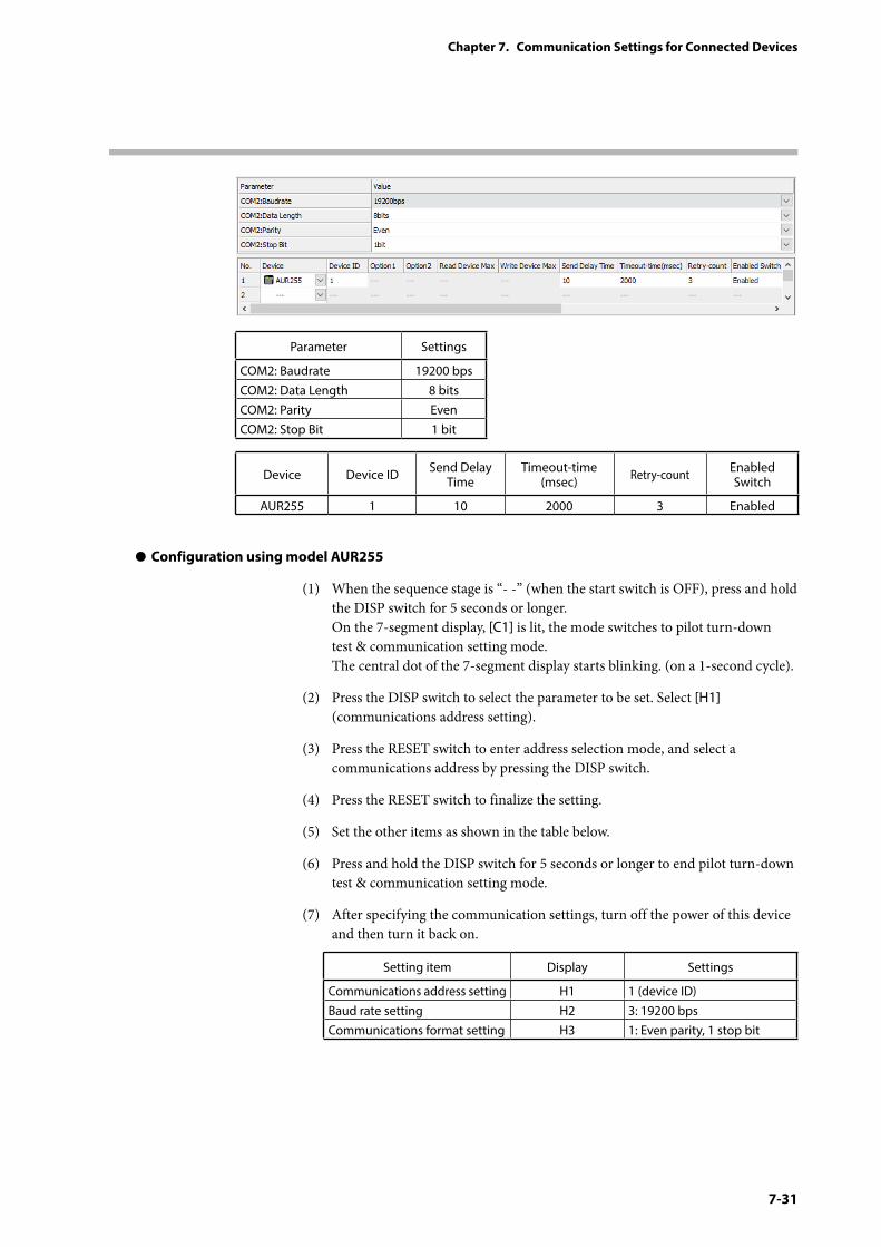
7-31
Chapter 7. Communication Settings for Connected Devices
Parameter Settings
COM2: Baudrate 19200 bpsCOM2: Data Length 8 bitsCOM2: Parity EvenCOM2: Stop Bit 1 bit
Device Device ID Send Delay Time
Timeout-time (msec) Retry-count Enabled
Switch
AUR255 1 10 2000 3 Enabled
z Configuration using model AUR255
(1) When the sequence stage is “- -” (when the start switch is OFF), press and hold the DISP switch for 5 seconds or longer. On the 7-segment display, [C1] is lit, the mode switches to pilot turn-down test & communication setting mode. The central dot of the 7-segment display starts blinking. (on a 1-second cycle).
(2) Press the DISP switch to select the parameter to be set. Select [H1] (communications address setting).
(3) Press the RESET switch to enter address selection mode, and select a communications address by pressing the DISP switch.
(4) Press the RESET switch to finalize the setting.
(5) Set the other items as shown in the table below.
(6) Press and hold the DISP switch for 5 seconds or longer to end pilot turn-down test & communication setting mode.
(7) After specifying the communication settings, turn off the power of this device and then turn it back on.
Setting item Display Settings
Communications address setting H1 1 (device ID)Baud rate setting H2 3: 19200 bpsCommunications format setting H3 1: Even parity, 1 stop bit

7-32
Chapter 7. Communication Settings for Connected Devices
Note
• Typical errors that might occur in communication with the AUR255 include the following.
Error response code Description
0x00000041 Data address error0x00000043 Writing is prohibited.
Note: For details on errors, refer to the user’s manual for the device.
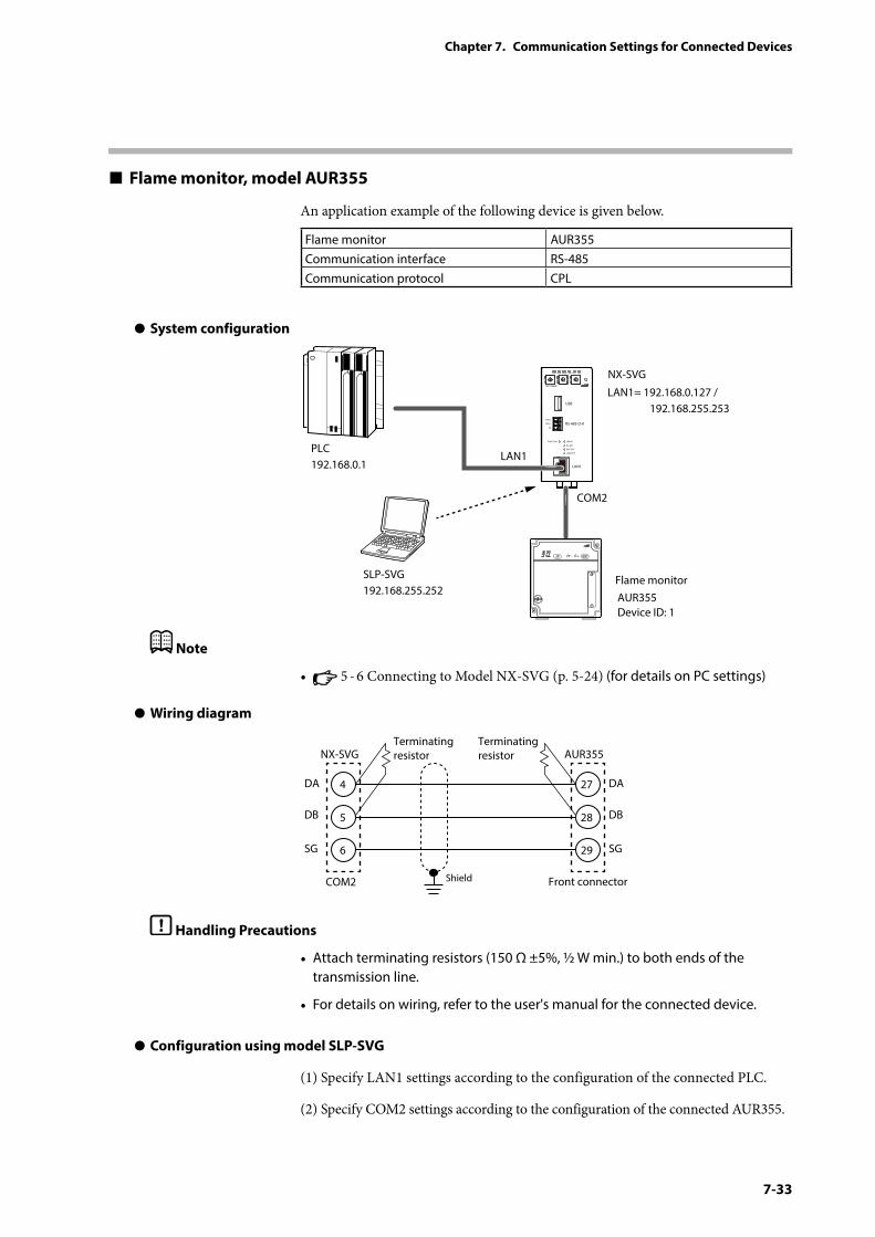
7-33
Chapter 7. Communication Settings for Connected Devices
Flame monitor, model AUR355
An application example of the following device is given below.
Flame monitor AUR355Communication interface RS-485Communication protocol CPL
z System configuration
PWR
NX-SVGN
USB
DA(+)
SG
DB(−) RS-485 CH1
RS-485
BATTERY
LINK/ACT
LAN1
FUNCTION ERROR
ID F1 F2
RUN MOD COM NST FAIL
SLP-SVG192.168.255.252
LAN1= 192.168.0.127 / 192.168.255.253
LAN1
COM2
AUR355Device ID: 1
PLC192.168.0.1
NX-SVG
Flame monitor
Note
• 5 - 6 Connecting to Model NX-SVG (p. 5-24) (for details on PC settings)
z Wiring diagram
4
NX-SVGTerminating resistor
Terminating resistor
COM2 Shield
5
6
DA
DB
SG
27
AUR355
Front connector
28
29
DA
DB
SG
Handling Precautions
• Attach terminating resistors (150 Ω ±5%, ½ W min.) to both ends of the transmission line.
• For details on wiring, refer to the user's manual for the connected device.
z Configuration using model SLP-SVG
(1) Specify LAN1 settings according to the configuration of the connected PLC.
(2) Specify COM2 settings according to the configuration of the connected AUR355.
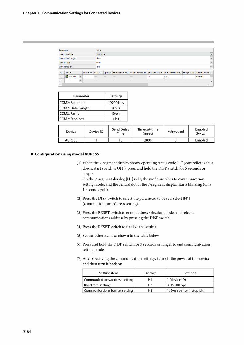
7-34
Chapter 7. Communication Settings for Connected Devices
Parameter Settings
COM2: Baudrate 19200 bpsCOM2: Data Length 8 bitsCOM2: Parity EvenCOM2: Stop bits 1 bit
Device Device ID Send Delay Time
Timeout-time (msec) Retry-count Enabled
Switch
AUR355 1 10 2000 3 Enabled
z Configuration using model AUR355
(1) When the 7-segment display shows operating status code “--” (controller is shut down, start switch is OFF), press and hold the DISP switch for 5 seconds or longer. On the 7-segment display, [H1] is lit, the mode switches to communication setting mode, and the central dot of the 7-segment display starts blinking (on a 1-second cycle).
(2) Press the DISP switch to select the parameter to be set. Select [H1] (communications address setting).
(3) Press the RESET switch to enter address selection mode, and select a communications address by pressing the DISP switch.
(4) Press the RESET switch to finalize the setting.
(5) Set the other items as shown in the table below.
(6) Press and hold the DISP switch for 5 seconds or longer to end communication setting mode.
(7) After specifying the communication settings, turn off the power of this device and then turn it back on.
Setting item Display Settings
Communications address setting H1 1 (device ID)Baud rate setting H2 3: 19200 bpsCommunications format setting H3 1: Even parity, 1 stop bit

7-35
Chapter 7. Communication Settings for Connected Devices
Note
• Typical errors that might occur in communication with the AUR355 include the following.
Error response code Description
0x00000041 Data address error0x00000042 Data range error0x00000043 Writing is prohibited.
Note: For details on errors, refer to the user’s manual for the device.
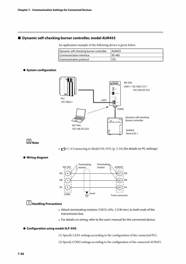
7-36
Chapter 7. Communication Settings for Connected Devices
Dynamic self-checking burner controller, model AUR455
An application example of the following device is given below.
Dynamic self-checking burner controller AUR455Communication interface RS-485Communication protocol CPL
z System configuration
PWR
NX-SVGN
USB
DA(+)
SG
DB(−) RS-485 CH1
RS-485
BATTERY
LINK/ACT
LAN1
FUNCTION ERROR
ID F1 F2
RUN MOD COM NST FAIL
SLP-SVG192.168.255.252
LAN1= 192.168.0.127 / 192.168.255.253
LAN1
COM2
AUR455Device ID: 1
PLC192.168.0.1
NX-SVG
Dynamic self-checking burner controller
Note
• 5 - 6 Connecting to Model NX-SVG (p. 5-24) (for details on PC settings)
z Wiring diagram
4
NX-SVGTerminating resistor
Terminating resistor
COM2 Shield
5
6
DA
DB
SG
27
AUR455
Front connector
28
29
DA
DB
SG
Handling Precautions
• Attach terminating resistors (150 Ω ±5%, 1/2 W min.) to both ends of the transmission line.
• For details on wiring, refer to the user's manual for the connected device.
z Configuration using model SLP-SVG
(1) Specify LAN1 settings according to the configuration of the connected PLC.
(2) Specify COM2 settings according to the configuration of the connected AUR455.
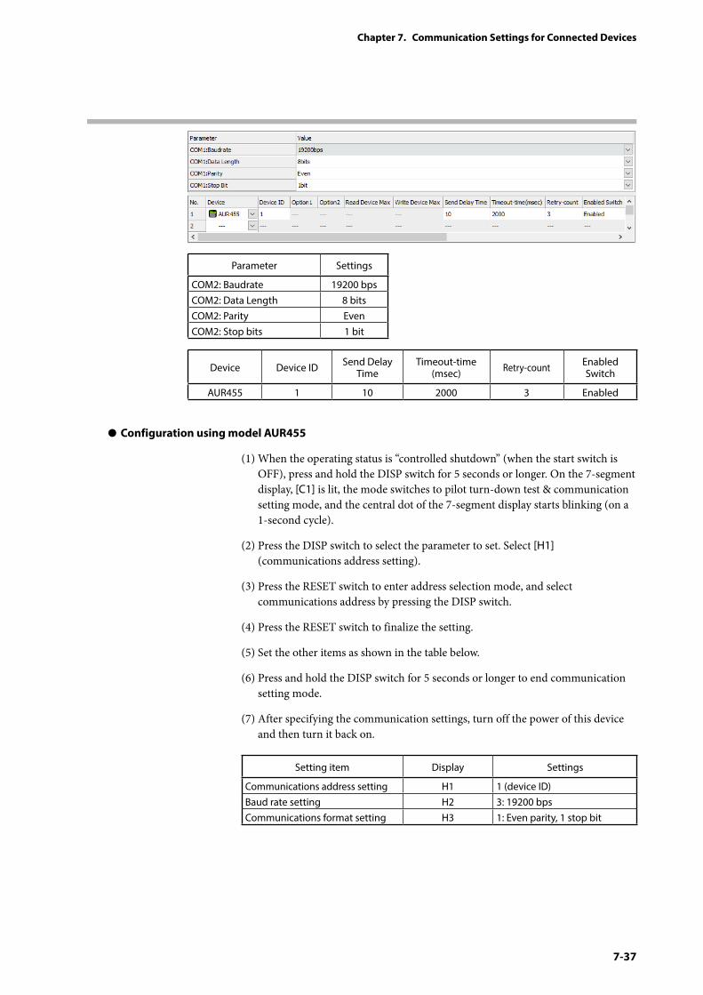
7-37
Chapter 7. Communication Settings for Connected Devices
Parameter Settings
COM2: Baudrate 19200 bpsCOM2: Data Length 8 bitsCOM2: Parity EvenCOM2: Stop bits 1 bit
Device Device ID Send Delay Time
Timeout-time (msec) Retry-count Enabled
Switch
AUR455 1 10 2000 3 Enabled
z Configuration using model AUR455
(1) When the operating status is “controlled shutdown” (when the start switch is OFF), press and hold the DISP switch for 5 seconds or longer. On the 7-segment display, [C1] is lit, the mode switches to pilot turn-down test & communication setting mode, and the central dot of the 7-segment display starts blinking (on a 1-second cycle).
(2) Press the DISP switch to select the parameter to set. Select [H1] (communications address setting).
(3) Press the RESET switch to enter address selection mode, and select communications address by pressing the DISP switch.
(4) Press the RESET switch to finalize the setting.
(5) Set the other items as shown in the table below.
(6) Press and hold the DISP switch for 5 seconds or longer to end communication setting mode.
(7) After specifying the communication settings, turn off the power of this device and then turn it back on.
Setting item Display Settings
Communications address setting H1 1 (device ID)Baud rate setting H2 3: 19200 bpsCommunications format setting H3 1: Even parity, 1 stop bit

7-38
Chapter 7. Communication Settings for Connected Devices
Note
• Typical errors that might occur in communication with the AUR455 include the following.
Error response code Description
0x00000041 Data address error0x00000042 Data range error0x00000043 Writing is prohibited.Note: For details on errors, refer to the user’s manual for the device.
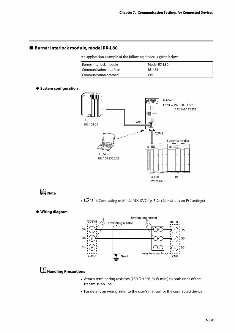
7-39
Chapter 7. Communication Settings for Connected Devices
Burner interlock module, model RX-L80
An application example of the following device is given below.
Burner interlock module Model RX-L80Communication interface RS-485Communication protocol CPL
z System configuration
PWR
NX-SVGN
USB
DA (+)
SG
DB (−) RS-485 CH1
RS-485
BATTERY
LINK/ACT
LAN1
FUNCTION ERROR
ID F1 F2
RUN MOD COM NST FAIL
SLP-SVG192.168.255.252
LAN1 = 192.168.0.127/ 192.168.255.253
LAN1
COM2
RX-L80Device ID: 1
RX-R
PLC192.168.0.1
NX-SVG
Burner controller
Note
• 5 - 6 Connecting to Model NX-SVG (p. 5-24) (for details on PC settings)
z Wiring diagram
4
NX-SVG Terminating resistor
Terminating resistor
COM2 CN8Shield
5
6
DA
DB
SG
1
RX-L80
Relay terminal block
2
3
DA
DB
SG
Handling Precautions
• Attach terminating resistors (150 Ω ±5 %, ½ W min.) to both ends of the transmission line.
• For details on wiring, refer to the user's manual for the connected device.
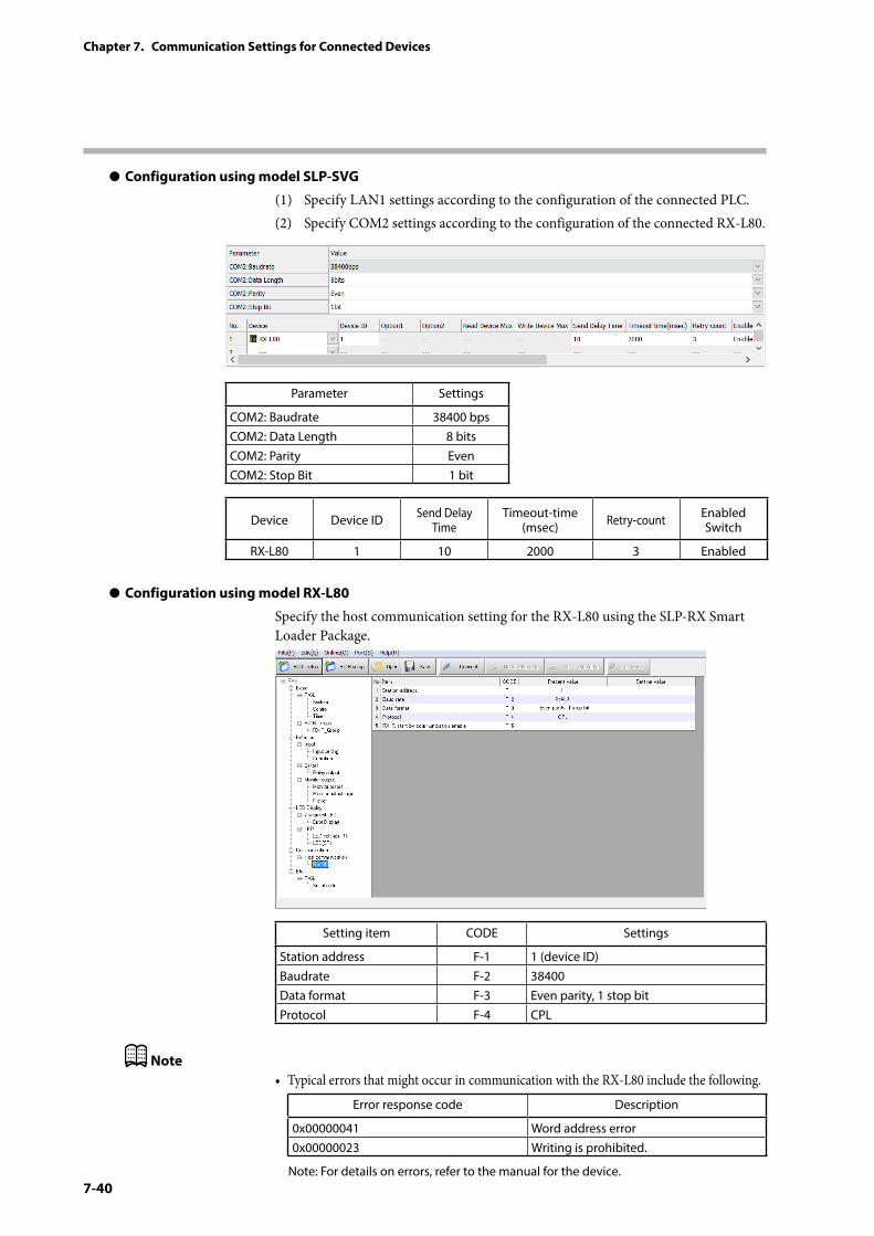
7-40
Chapter 7. Communication Settings for Connected Devices
z Configuration using model SLP-SVG
(1) Specify LAN1 settings according to the configuration of the connected PLC.(2) Specify COM2 settings according to the configuration of the connected RX-L80.
Parameter Settings
COM2: Baudrate 38400 bpsCOM2: Data Length 8 bitsCOM2: Parity EvenCOM2: Stop Bit 1 bit
Device Device ID Send Delay Time
Timeout-time (msec) Retry-count Enabled
Switch
RX-L80 1 10 2000 3 Enabled
z Configuration using model RX-L80
Specify the host communication setting for the RX-L80 using the SLP-RX Smart Loader Package.
Setting item CODE Settings
Station address F-1 1 (device ID)Baudrate F-2 38400Data format F-3 Even parity, 1 stop bitProtocol F-4 CPL
Note• Typical errors that might occur in communication with the RX-L80 include the following.
Error response code Description
0x00000041 Word address error0x00000023 Writing is prohibited.
Note: For details on errors, refer to the manual for the device.
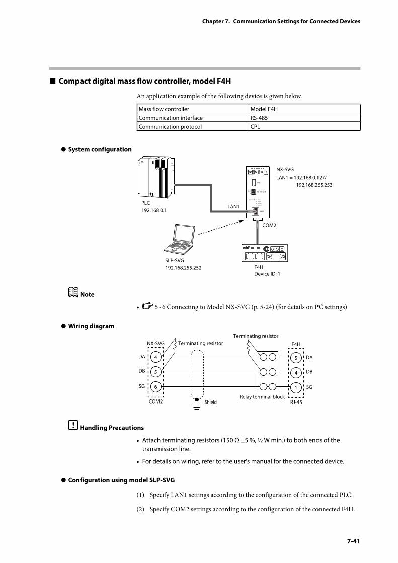
7-41
Chapter 7. Communication Settings for Connected Devices
Compact digital mass flow controller, model F4H
An application example of the following device is given below.
Mass flow controller Model F4HCommunication interface RS-485Communication protocol CPL
z System configuration
PWR
NX-SVGN
USB
DA (+)
SG
DB (−) RS-485 CH1
RS-485
BATTERY
LINK/ACT
LAN1
FUNCTION ERROR
ID F1 F2
RUN MOD COM NST FAIL
SLP-SVG192.168.255.252
LAN1 = 192.168.0.127/ 192.168.255.253
LAN1
COM2
F4HDevice ID: 1
PLC192.168.0.1
NX-SVG
Note
• 5 - 6 Connecting to Model NX-SVG (p. 5-24) (for details on PC settings)
z Wiring diagram
4
NX-SVG Terminating resistorTerminating resistor
COM2 RJ-45Shield
5
6
DA
DB
SG
5
F4H
Relay terminal block
4
1
DA
DB
SG
Handling Precautions
• Attach terminating resistors (150 Ω ±5 %, ½ W min.) to both ends of the transmission line.
• For details on wiring, refer to the user's manual for the connected device.
z Configuration using model SLP-SVG
(1) Specify LAN1 settings according to the configuration of the connected PLC.
(2) Specify COM2 settings according to the configuration of the connected F4H.
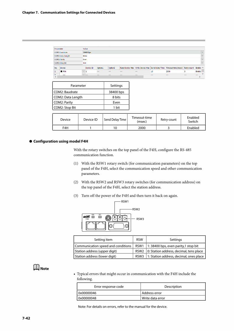
7-42
Chapter 7. Communication Settings for Connected Devices
Parameter Settings
COM2: Baudrate 38400 bpsCOM2: Data Length 8 bitsCOM2: Parity EvenCOM2: Stop Bit 1 bit
Device Device ID Send Delay Time Timeout-time (msec) Retry-count Enabled
Switch
F4H 1 10 2000 3 Enabled
z Configuration using model F4H
With the rotary switches on the top panel of the F4H, configure the RS-485 communication function.
(1) With the RSW1 rotary switch (for communication parameters) on the top panel of the F4H, select the communication speed and other communication parameters.
(2) With the RSW2 and RSW3 rotary switches (for communication address) on the top panel of the F4H, select the station address.
(3) Turn off the power of the F4H and then turn it back on again.
RSW1
RSW2
RSW3
BRATE × 10 × 1NETPWR
F4H
Setting item RSW Settings
Communication speed and conditions RSW1 1: 38400 bps, even parity,1 stop bitStation address (upper digit) RSW2 0: Station address, decimal, tens placeStation address (lower digit) RSW3 1: Station address, decimal, ones place
Note• Typical errors that might occur in communication with the F4H include the
following.
Error response code Description
0x00000046 Address error0x00000048 Write data error
Note: For details on errors, refer to the manual for the device.
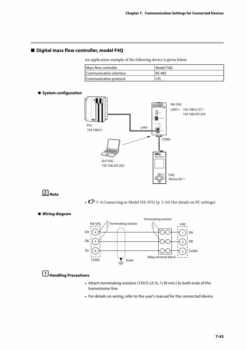
7-43
Chapter 7. Communication Settings for Connected Devices
Digital mass flow controller, model F4Q
An application example of the following device is given below.
Mass flow controller Model F4QCommunication interface RS-485Communication protocol CPL
z System configuration
PWR
NX-SVGN
USB
DA(+)
SG
DB(−) RS-485 CH1
RS-485
BATTERY
LINK/ACT
LAN1
FUNCTION ERROR
ID F1 F2
RUN MOD COM NST FAIL
SLP-SVG192.168.255.252
LAN1= 192.168.0.127 / 192.168.255.253
LAN1
COM2
F4QDevice ID: 1
PLC192.168.0.1
NX-SVG
Note
• 5 - 6 Connecting to Model NX-SVG (p. 5-24) (for details on PC settings)
z Wiring diagram
4
NX-SVG Terminating resistorTerminating resistor
COM2 Shield
5
6
DA
DB
SG
1
F4Q
Relay terminal block
2
3
DA
DB
S.GND
Handling Precautions
• Attach terminating resistors (150 Ω ±5 %, ½ W min.) to both ends of the transmission line.
• For details on wiring, refer to the user's manual for the connected device.
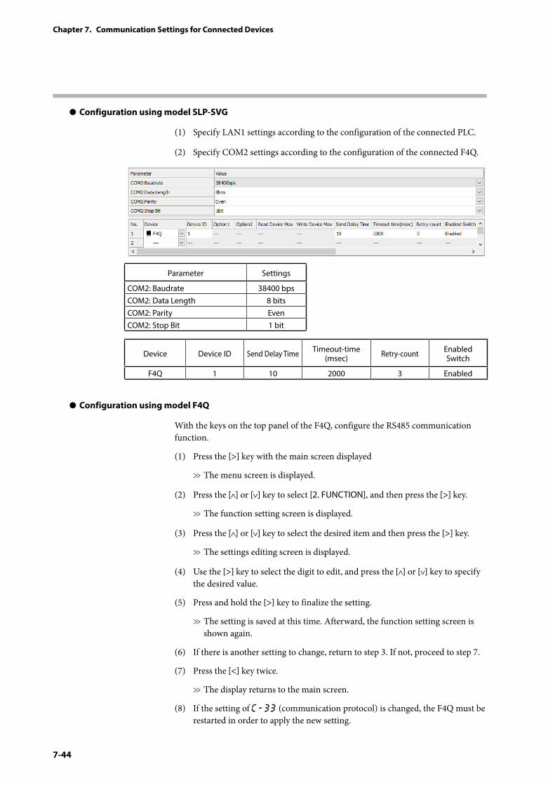
7-44
Chapter 7. Communication Settings for Connected Devices
z Configuration using model SLP-SVG
(1) Specify LAN1 settings according to the configuration of the connected PLC.
(2) Specify COM2 settings according to the configuration of the connected F4Q.
Parameter Settings
COM2: Baudrate 38400 bpsCOM2: Data Length 8 bitsCOM2: Parity EvenCOM2: Stop Bit 1 bit
Device Device ID Send Delay Time Timeout-time (msec) Retry-count Enabled
Switch
F4Q 1 10 2000 3 Enabled
z Configuration using model F4Q
With the keys on the top panel of the F4Q, configure the RS485 communication function.
(1) Press the [>] key with the main screen displayed
>> The menu screen is displayed.
(2) Press the [ ] or [ ] key to select [2. FUNCTION], and then press the [>] key.
>> The function setting screen is displayed.
(3) Press the [ ] or [ ] key to select the desired item and then press the [>] key.
>> The settings editing screen is displayed.
(4) Use the [>] key to select the digit to edit, and press the [ ] or [ ] key to specify the desired value.
(5) Press and hold the [>] key to finalize the setting.
>> The setting is saved at this time. Afterward, the function setting screen is shown again.
(6) If there is another setting to change, return to step 3. If not, proceed to step 7.
(7) Press the [<] key twice.
>> The display returns to the main screen.
(8) If the setting of C-33 (communication protocol) is changed, the F4Q must be restarted in order to apply the new setting.
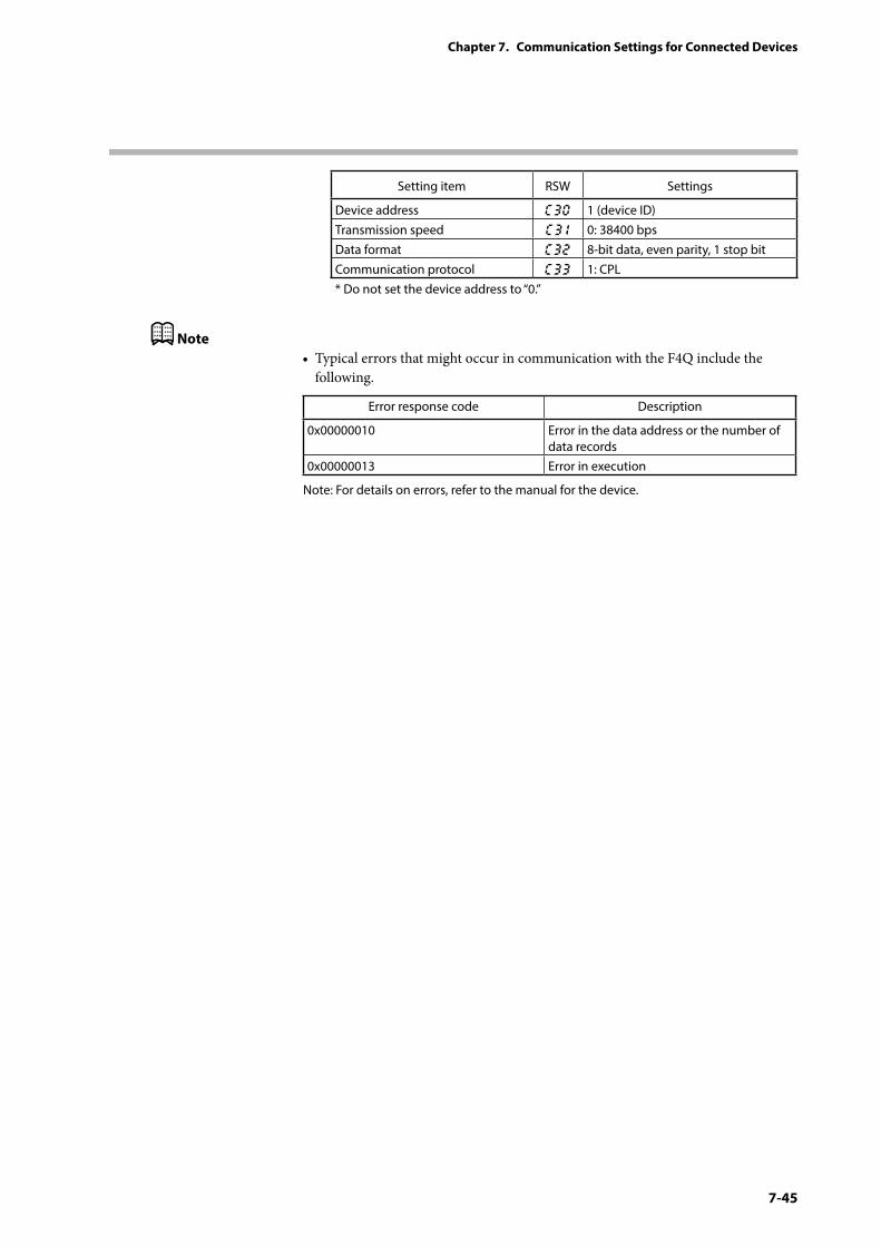
7-45
Chapter 7. Communication Settings for Connected Devices
Setting item RSW Settings
Device address C30 1 (device ID)Transmission speed C3 1 0: 38400 bpsData format C32 8-bit data, even parity, 1 stop bitCommunication protocol C33 1: CPL* Do not set the device address to “0.”
Note• Typical errors that might occur in communication with the F4Q include the
following.
Error response code Description
0x00000010 Error in the data address or the number of data records
0x00000013 Error in execution
Note: For details on errors, refer to the manual for the device.
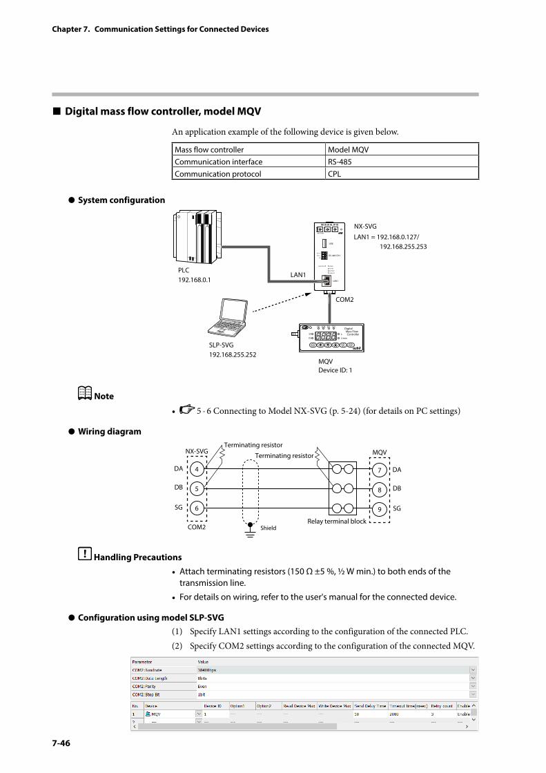
7-46
Chapter 7. Communication Settings for Connected Devices
Digital mass flow controller, model MQV
An application example of the following device is given below.
Mass flow controller Model MQVCommunication interface RS-485Communication protocol CPL
z System configuration
PWR
NX-SVGN
USB
DA (+)
SG
DB (−) RS-485 CH1
RS-485
BATTERY
LINK/ACT
LAN1
FUNCTION ERROR
ID F1 F2
RUN MOD COM NST FAIL
SLP-SVG192.168.255.252
LAN1 = 192.168.0.127/ 192.168.255.253
LAN1
COM2
MQVDevice ID: 1
PLC192.168.0.1
NX-SVG
OK
SP
PV
L
Digital Mass Flow Controller
L/min
ALM EV1 EV2
RUN ENT DISP
Note
• 5 - 6 Connecting to Model NX-SVG (p. 5-24) (for details on PC settings)
z Wiring diagram
4
NX-SVGTerminating resistor
Terminating resistor
COM2 Shield
5
6
DA
DB
SG
7
MQV
Relay terminal block
8
9
DA
DB
SG
Handling Precautions• Attach terminating resistors (150 Ω ±5 %, ½ W min.) to both ends of the
transmission line.
• For details on wiring, refer to the user's manual for the connected device.
z Configuration using model SLP-SVG(1) Specify LAN1 settings according to the configuration of the connected PLC.(2) Specify COM2 settings according to the configuration of the connected MQV.
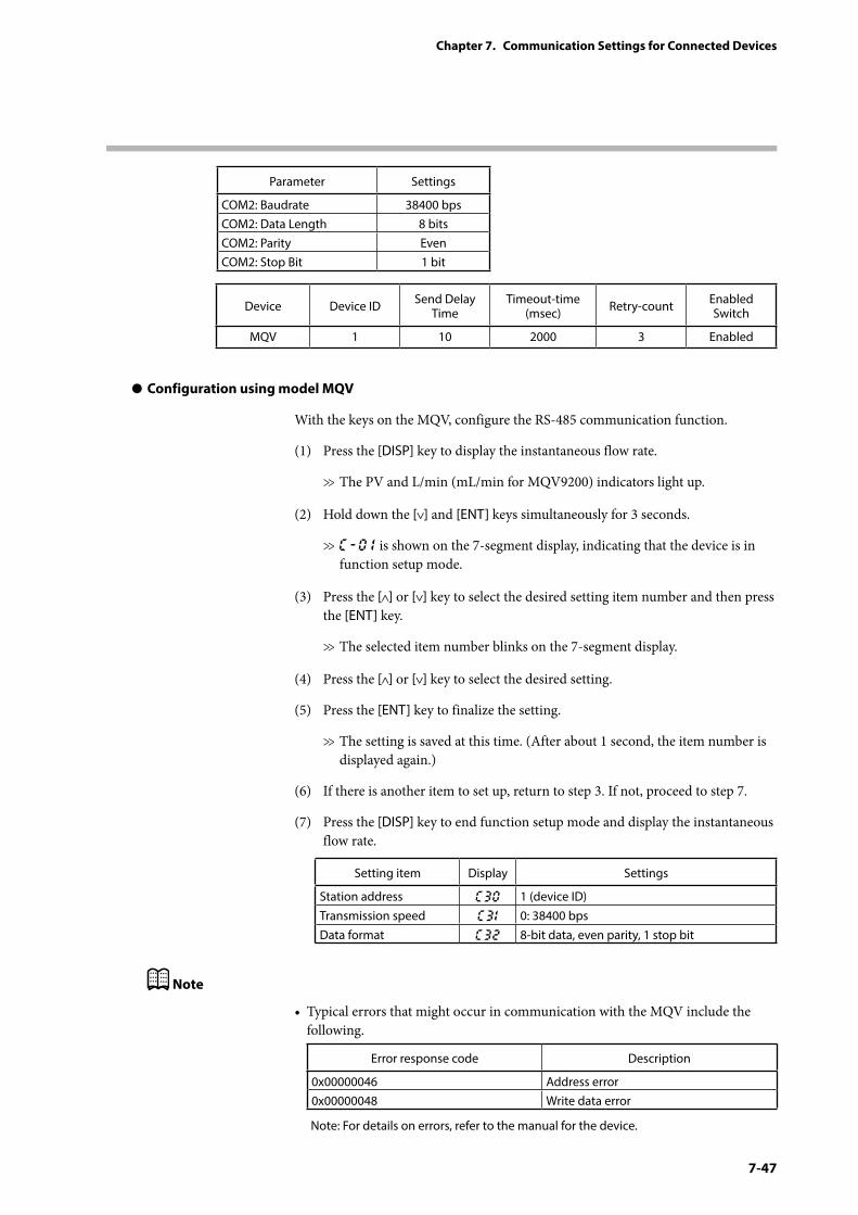
7-47
Chapter 7. Communication Settings for Connected Devices
Parameter Settings
COM2: Baudrate 38400 bpsCOM2: Data Length 8 bitsCOM2: Parity EvenCOM2: Stop Bit 1 bit
Device Device ID Send Delay Time
Timeout-time (msec) Retry-count Enabled
Switch
MQV 1 10 2000 3 Enabled
z Configuration using model MQV
With the keys on the MQV, configure the RS-485 communication function.
(1) Press the [DISP] key to display the instantaneous flow rate.
>> The PV and L/min (mL/min for MQV9200) indicators light up.
(2) Hold down the [ ] and [ENT] keys simultaneously for 3 seconds.
>> C-0 1 is shown on the 7-segment display, indicating that the device is in function setup mode.
(3) Press the [ ] or [ ] key to select the desired setting item number and then press the [ENT] key.
>> The selected item number blinks on the 7-segment display.
(4) Press the [ ] or [ ] key to select the desired setting.
(5) Press the [ENT] key to finalize the setting.
>> The setting is saved at this time. (After about 1 second, the item number is displayed again.)
(6) If there is another item to set up, return to step 3. If not, proceed to step 7.
(7) Press the [DISP] key to end function setup mode and display the instantaneous flow rate.
Setting item Display Settings
Station address C30 1 (device ID)Transmission speed C31 0: 38400 bpsData format C32 8-bit data, even parity, 1 stop bit
Note
• Typical errors that might occur in communication with the MQV include the following.
Error response code Description
0x00000046 Address error0x00000048 Write data error
Note: For details on errors, refer to the manual for the device.
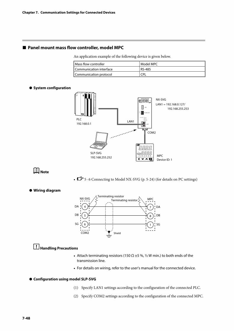
7-48
Chapter 7. Communication Settings for Connected Devices
Panel mount mass flow controller, model MPC
An application example of the following device is given below.
Mass flow controller Model MPCCommunication interface RS-485Communication protocol CPL
z System configuration
PWR
NX-SVGN
USB
DA (+)
SG
DB (−) RS-485 CH1
RS-485
BATTERY
LINK/ACT
LAN1
FUNCTION ERROR
ID F1 F2
RUN MOD COM NST FAIL
SLP-SVG192.168.255.252
LAN1 = 192.168.0.127/ 192.168.255.253
LAN1
COM2
MPCDevice ID: 1
PLC192.168.0.1
NX-SVG
L OK SP1 SP2 SP3 EV1 EV2
DISP
PV
SP
ENT
Note
• 5 - 6 Connecting to Model NX-SVG (p. 5-24) (for details on PC settings)
z Wiring diagram
4
NX-SVGTerminating resistor
Terminating resistor
COM2 Shield
5
6
DA
DB
SG
7
MPC
8
1
DA
DB
SG
Handling Precautions
• Attach terminating resistors (150 Ω ±5 %, ½ W min.) to both ends of the transmission line.
• For details on wiring, refer to the user's manual for the connected device.
z Configuration using model SLP-SVG
(1) Specify LAN1 settings according to the configuration of the connected PLC.
(2) Specify COM2 settings according to the configuration of the connected MPC.
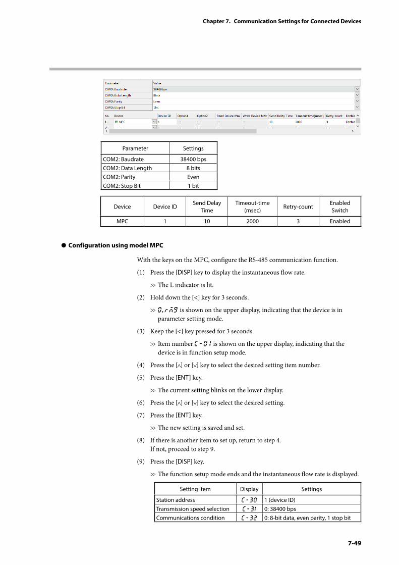
7-49
Chapter 7. Communication Settings for Connected Devices
Parameter Settings
COM2: Baudrate 38400 bpsCOM2: Data Length 8 bitsCOM2: Parity EvenCOM2: Stop Bit 1 bit
Device Device IDSend Delay
TimeTimeout-time
(msec)Retry-count
Enabled Switch
MPC 1 10 2000 3 Enabled
z Configuration using model MPC
With the keys on the MPC, configure the RS-485 communication function.
(1) Press the [DISP] key to display the instantaneous flow rate.
>> The L indicator is lit.
(2) Hold down the [<] key for 3 seconds.
>> 0.rMG is shown on the upper display, indicating that the device is in parameter setting mode.
(3) Keep the [<] key pressed for 3 seconds.
>> Item number C-0 1 is shown on the upper display, indicating that the device is in function setup mode.
(4) Press the [ ] or [ ] key to select the desired setting item number.
(5) Press the [ENT] key.
>> The current setting blinks on the lower display.
(6) Press the [ ] or [ ] key to select the desired setting.
(7) Press the [ENT] key.
>> The new setting is saved and set.
(8) If there is another item to set up, return to step 4. If not, proceed to step 9.
(9) Press the [DISP] key.
>> The function setup mode ends and the instantaneous flow rate is displayed.
Setting item Display Settings
Station address C-30 1 (device ID)Transmission speed selection C-31 0: 38400 bpsCommunications condition C-32 0: 8-bit data, even parity, 1 stop bit

7-50
Chapter 7. Communication Settings for Connected Devices
Note• Typical errors that might occur in communication with the MPC include the
following.
Error response code Description
0x00000046 Address error0x00000048 Write data error
Note: For details on errors, refer to the manual for the device.
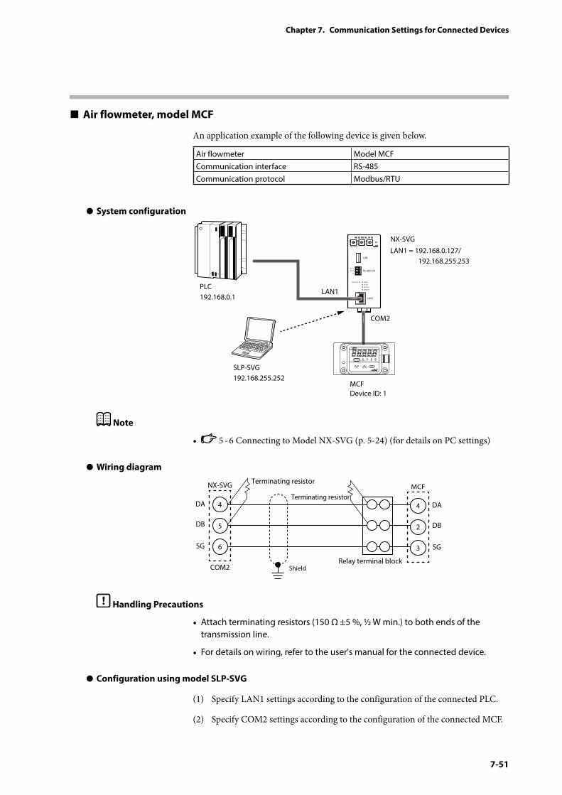
7-51
Chapter 7. Communication Settings for Connected Devices
Air flowmeter, model MCF
An application example of the following device is given below.
Air flowmeter Model MCFCommunication interface RS-485Communication protocol Modbus/RTU
z System configuration
PWR
NX-SVGN
USB
DA (+)
SG
DB (−) RS-485 CH1
RS-485
BATTERY
LINK/ACT
LAN1
FUNCTION ERROR
ID F1 F2
RUN MOD COM NST FAIL
SLP-SVG192.168.255.252
LAN1 = 192.168.0.127/ 192.168.255.253
LAN1
COM2
MCFDevice ID: 1
PLC192.168.0.1
NX-SVG
mode
enter
ALEVLL/min
Note
• 5 - 6 Connecting to Model NX-SVG (p. 5-24) (for details on PC settings)
z Wiring diagram
4
NX-SVG Terminating resistor
Terminating resistor
COM2 Shield
5
6
DA
DB
SG
4
MCF
Relay terminal block
2
3
DA
DB
SG
Handling Precautions
• Attach terminating resistors (150 Ω ±5 %, ½ W min.) to both ends of the transmission line.
• For details on wiring, refer to the user's manual for the connected device.
z Configuration using model SLP-SVG
(1) Specify LAN1 settings according to the configuration of the connected PLC.
(2) Specify COM2 settings according to the configuration of the connected MCF.
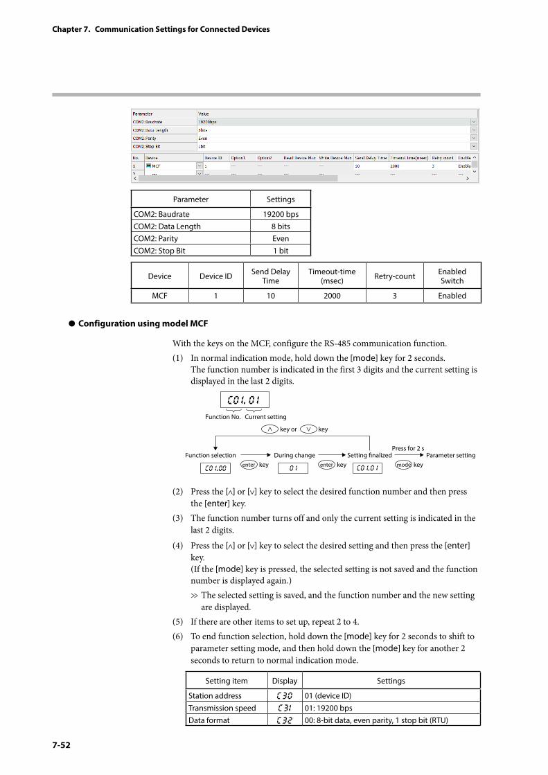
7-52
Chapter 7. Communication Settings for Connected Devices
Parameter Settings
COM2: Baudrate 19200 bpsCOM2: Data Length 8 bitsCOM2: Parity EvenCOM2: Stop Bit 1 bit
Device Device ID Send Delay Time
Timeout-time (msec) Retry-count Enabled
Switch
MCF 1 10 2000 3 Enabled
z Configuration using model MCF
With the keys on the MCF, configure the RS-485 communication function.(1) In normal indication mode, hold down the [mode] key for 2 seconds.
The function number is indicated in the first 3 digits and the current setting is displayed in the last 2 digits.
C0 1. 0 1
C0 1.00 C0 1.0 10 1
Function No. Current setting
key or key
Function selectionPress for 2 s
During change Setting nalized Parameter settingkeyenter keyenter keymode
(2) Press the [ ] or [ ] key to select the desired function number and then press the [enter] key.
(3) The function number turns off and only the current setting is indicated in the last 2 digits.
(4) Press the [ ] or [ ] key to select the desired setting and then press the [enter] key. (If the [mode] key is pressed, the selected setting is not saved and the function number is displayed again.)>> The selected setting is saved, and the function number and the new setting
are displayed.(5) If there are other items to set up, repeat 2 to 4.(6) To end function selection, hold down the [mode] key for 2 seconds to shift to
parameter setting mode, and then hold down the [mode] key for another 2 seconds to return to normal indication mode.
Setting item Display Settings
Station address C30 01 (device ID)Transmission speed C31 01: 19200 bpsData format C32 00: 8-bit data, even parity, 1 stop bit (RTU)
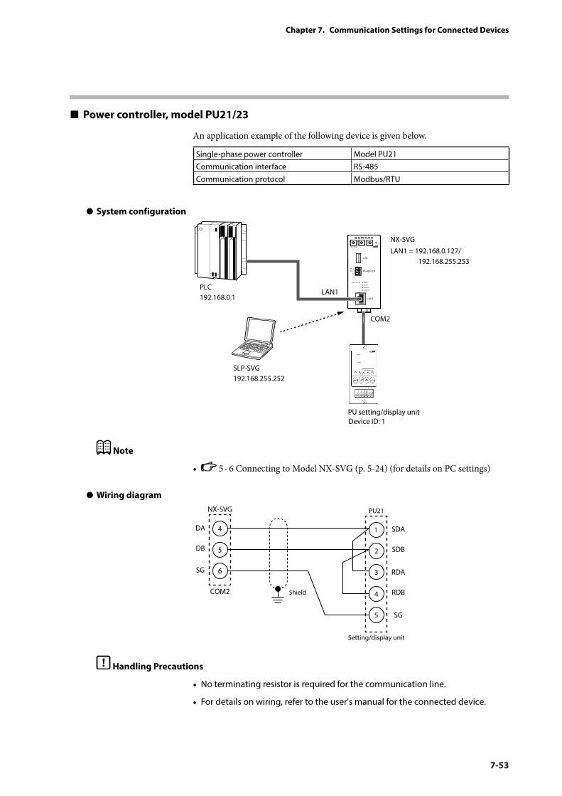
7-53
Chapter 7. Communication Settings for Connected Devices
Power controller, model PU21/23
An application example of the following device is given below.
Single-phase power controller Model PU21Communication interface RS-485Communication protocol Modbus/RTU
z System configuration
PWR
NX-SVGN
USB
DA (+)
SG
DB (−) RS-485 CH1
RS-485
BATTERY
LINK/ACT
LAN1
FUNCTION ERROR
ID F1 F2
RUN MOD COM NST FAIL
SLP-SVG192.168.255.252
LAN1 = 192.168.0.127/ 192.168.255.253
LAN1
COM2
Device ID: 1PU setting/display unit
PLC192.168.0.1
NX-SVG
Note
• 5 - 6 Connecting to Model NX-SVG (p. 5-24) (for details on PC settings)
z Wiring diagram
SG
4
NX-SVG
COM2 Shield
5
6
DA
DB
SG
1
PU21
Setting/display unit
2
3
4
5
SDA
SDB
RDA
RDB
Handling Precautions
• No terminating resistor is required for the communication line.
• For details on wiring, refer to the user's manual for the connected device.
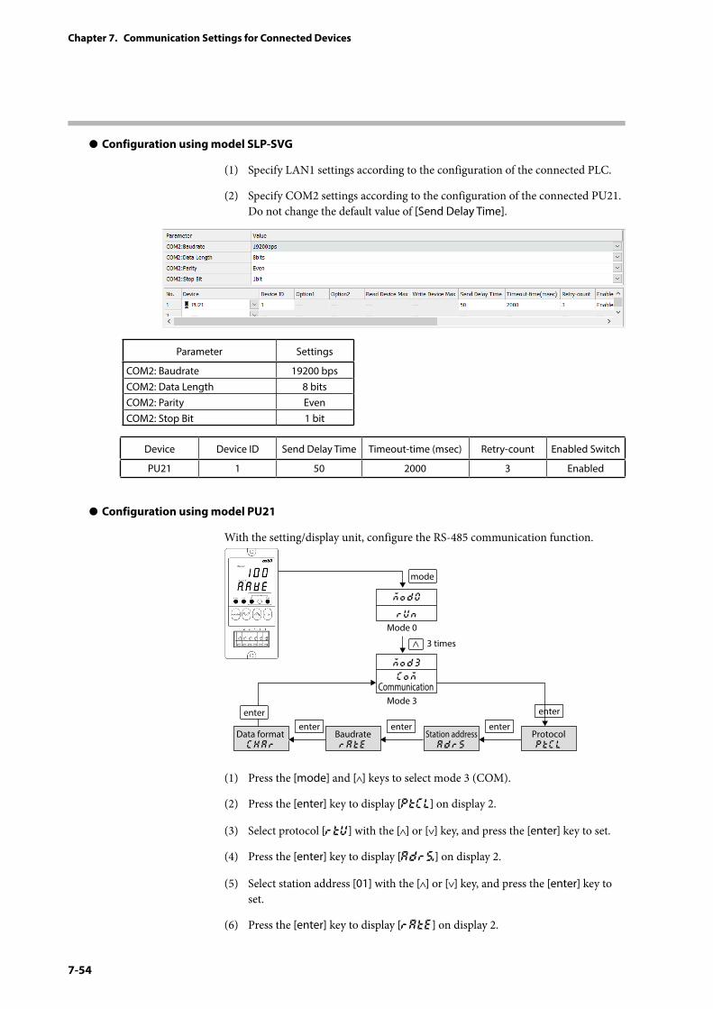
7-54
Chapter 7. Communication Settings for Connected Devices
z Configuration using model SLP-SVG
(1) Specify LAN1 settings according to the configuration of the connected PLC.
(2) Specify COM2 settings according to the configuration of the connected PU21. Do not change the default value of [Send Delay Time].
Parameter Settings
COM2: Baudrate 19200 bpsCOM2: Data Length 8 bitsCOM2: Parity EvenCOM2: Stop Bit 1 bit
Device Device ID Send Delay Time Timeout-time (msec) Retry-count Enabled Switch
PU21 1 50 2000 3 Enabled
z Configuration using model PU21
With the setting/display unit, configure the RS-485 communication function.
mode
Mode 0
CommunicationMode 3
3 times
MOd0
MOd3
rUn
COM
Data format ChAr
BaudraterAte
Station addressAdrS
ProtocolPTcl
enterenter enter enter
enter
(1) Press the [mode] and [ ] keys to select mode 3 (COM).
(2) Press the [enter] key to display [PtCL] on display 2.
(3) Select protocol [rtu] with the [ ] or [ ] key, and press the [enter] key to set.
(4) Press the [enter] key to display [Adrs] on display 2.
(5) Select station address [01] with the [ ] or [ ] key, and press the [enter] key to set.
(6) Press the [enter] key to display [rAtE] on display 2.
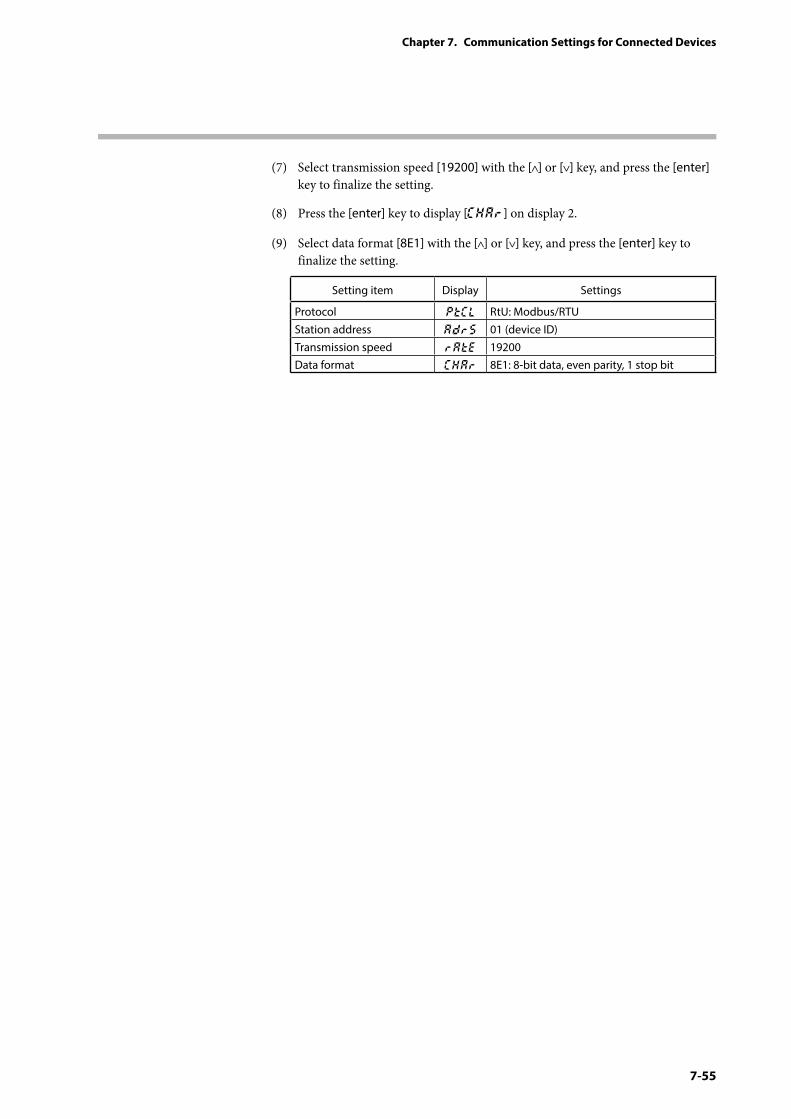
7-55
Chapter 7. Communication Settings for Connected Devices
(7) Select transmission speed [19200] with the [ ] or [ ] key, and press the [enter] key to finalize the setting.
(8) Press the [enter] key to display [CHAr] on display 2.
(9) Select data format [8E1] with the [ ] or [ ] key, and press the [enter] key to finalize the setting.
Setting item Display Settings
Protocol PtCL RtU: Modbus/RTU Station address AdrS 01 (device ID)Transmission speed RAtE 19200Data format CHAr 8E1: 8-bit data, even parity, 1 stop bit
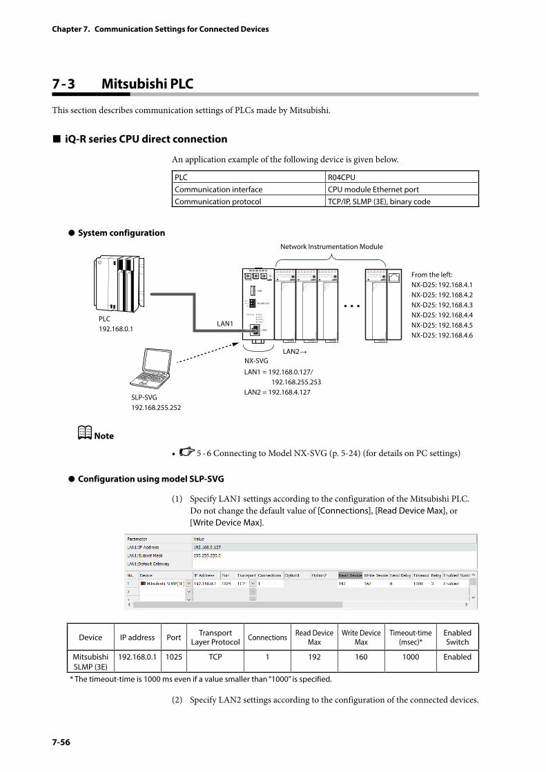
7-56
Chapter 7. Communication Settings for Connected Devices
7 - 3 Mitsubishi PLC
This section describes communication settings of PLCs made by Mitsubishi.
iQ-R series CPU direct connection
An application example of the following device is given below.
PLC R04CPUCommunication interface CPU module Ethernet portCommunication protocol TCP/IP, SLMP (3E), binary code
z System configuration
PWR
NX-SVGN
USB
DA (+)
SG
DB (−) RS-485 CH1
RS-485
BATTERY
LINK/ACT
LAN1
FUNCTION ERROR
ID F1 F2
RUN MOD COM NST FAIL
SLP-SVG192.168.255.252
Network Instrumentation Module
From the left:NX-D25: 192.168.4.1NX-D25: 192.168.4.2NX-D25: 192.168.4.3NX-D25: 192.168.4.4NX-D25: 192.168.4.5NX-D25: 192.168.4.6
LAN1 = 192.168.0.127/ 192.168.255.253LAN2 = 192.168.4.127
LAN1
LAN2→
PLC192.168.0.1
NX-SVG
Note
• 5 - 6 Connecting to Model NX-SVG (p. 5-24) (for details on PC settings)
z Configuration using model SLP-SVG
(1) Specify LAN1 settings according to the configuration of the Mitsubishi PLC. Do not change the default value of [Connections], [Read Device Max], or [Write Device Max].
Device IP address Port Transport Layer Protocol Connections Read Device
MaxWrite Device
MaxTimeout-time
(msec)*Enabled Switch
Mitsubishi SLMP (3E)
192.168.0.1 1025 TCP 1 192 160 1000 Enabled
* The timeout-time is 1000 ms even if a value smaller than “1000” is specified.
(2) Specify LAN2 settings according to the configuration of the connected devices.
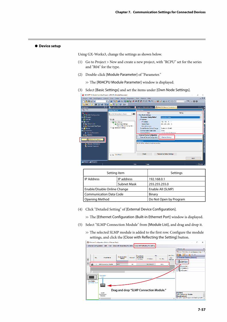
7-57
Chapter 7. Communication Settings for Connected Devices
z Device setup
Using GX-Works3, change the settings as shown below.
(1) Go to Project > New and create a new project, with "RCPU" set for the series and "R04" for the type.
(2) Double-click [Module Parameter] of "Parameter."
>> The [R04CPU Module Parameter] window is displayed.
(3) Select [Basic Settings] and set the items under [Own Node Settings].
Setting item Settings
IP Address IP address 192.168.0.1Subnet Mask 255.255.255.0
Enable/Disable Online Change Enable All (SLMP)Communication Data Code BinaryOpening Method Do Not Open by Program
(4) Click "Detailed Setting" of [External Device Configuration].
>> The [Ethernet Configuration (Built-in Ethernet Port] window is displayed.
(5) Select "SLMP Connection Module" from [Module List], and drag and drop it.
>> The selected SLMP module is added to the first row. Configure the module settings, and click the [Close with Reflecting the Setting] button.
Drag and drop “SLMP Connection Module.”SLMP
Connection Module
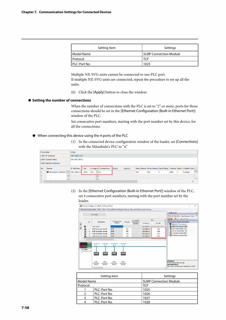
7-58
Chapter 7. Communication Settings for Connected Devices
Setting item Settings
Model Name SLMP Connection ModuleProtocol TCPPLC: Port No. 1025
Multiple NX-SVG units cannot be connected to one PLC port. If multiple NX-SVG units are connected, repeat the procedure to set up all the units.
(6) Click the [Apply] button to close the window.
z Setting the number of connectionsWhen the number of connections with the PLC is set to "2” or more, ports for those connections should be set in the [Ethernet Configuration (Built-in Ethernet Port)] window of the PLC.Set consecutive port numbers, starting with the port number set by this device, for all the connections.
z When connecting this device using the 4 ports of the PLC
(1) In the connected device configuration window of the loader, set [Connections] with the Mitsubishi's PLC to “4.”
(2) In the [Ethernet Configuration (Built-in Ethernet Port)] window of the PLC, set 4 consecutive port numbers, starting with the port number set by the loader.
SLMP Connection
Module
SLMP Connection
Module
SLMP Connection
Module
SLMP Connection
Module
Setting item Settings
Model Name SLMP Connection ModuleProtocol TCP
1 PLC: Port No. 10252 PLC: Port No. 10263 PLC: Port No. 10274 PLC: Port No. 1028
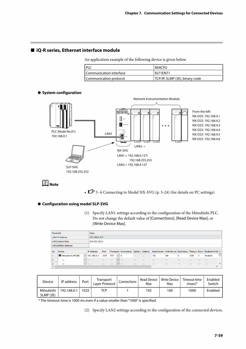
7-59
Chapter 7. Communication Settings for Connected Devices
iQ-R series, Ethernet interface module
An application example of the following device is given below.
PLC R04CPUCommunication interface RJ71EN71Communication protocol TCP/IP, SLMP (3E), binary code
z System configuration
PWR
NX-SVGN
USB
DA (+)
SG
DB (−) RS-485 CH1
RS-485
BATTERY
LINK/ACT
LAN1
FUNCTION ERROR
ID F1 F2
RUN MOD COM NST FAIL
SLP-SVG192.168.255.252
Network Instrumentation Module
From the left:NX-D25: 192.168.4.1NX-D25: 192.168.4.2NX-D25: 192.168.4.3NX-D25: 192.168.4.4NX-D25: 192.168.4.5NX-D25: 192.168.4.6
LAN1 = 192.168.0.127/ 192.168.255.253LAN2 = 192.168.4.127
LAN1
LAN2→
PLC (Node No.01)192.168.0.1
NX-SVG
Note
• 5 - 6 Connecting to Model NX-SVG (p. 5-24) (for details on PC settings)
z Configuration using model SLP-SVG
(1) Specify LAN1 settings according to the configuration of the Mitsubishi PLC. Do not change the default value of [Connections], [Read Device Max], or [Write Device Max].
Device IP address Port Transport Layer Protocol Connections Read Device
MaxWrite Device
MaxTimeout-time
(msec)*Enabled Switch
Mitsubishi SLMP (3E)
192.168.0.1 1025 TCP 1 192 160 1000 Enabled
* The timeout-time is 1000 ms even if a value smaller than “1000” is specified.
(2) Specify LAN2 settings according to the configuration of the connected devices.
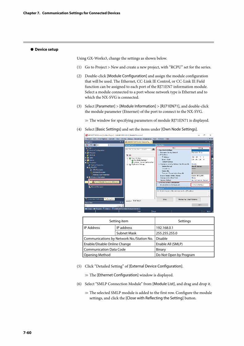
7-60
Chapter 7. Communication Settings for Connected Devices
z Device setup
Using GX-Works3, change the settings as shown below.
(1) Go to Project > New and create a new project, with “RCPU” set for the series.
(2) Double-click [Module Configuration] and assign the module configuration that will be used. The Ethernet, CC-Link IE Control, or CC-Link IE Field function can be assigned to each port of the RJ71EN7 information module. Select a module connected to a port whose network type is Ethernet and to which the NX-SVG is connected.
(3) Select [Parameter] > [Module Information] > [RJ71EN71], and double-click the module parameter (Etnernet) of the port to connect to the NX-SVG.
>> The window for specifying parameters of module RJ71EN71 is displayed.
(4) Select [Basic Settings] and set the items under [Own Node Settings].
Setting item Settings
IP Address IP address 192.168.0.1Subnet Mask 255.255.255.0
Communications by Network No./Station No. DisableEnable/Disable Online Change Enable All (SMLP)Communication Data Code BinaryOpening Method Do Not Open by Program
(5) Click “Detailed Setting” of [External Device Configuration].
>> The [Ethernet Configuration] window is displayed.
(6) Select “SMLP Connection Module” from [Module List], and drag and drop it.
>> The selected SMLP module is added to the first row. Configure the module settings, and click the [Close with Reflecting the Setting] button.
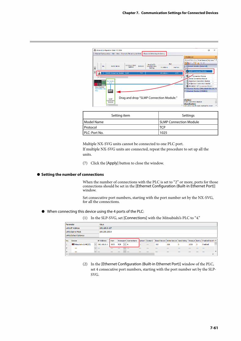
7-61
Chapter 7. Communication Settings for Connected Devices
Drag and drop “SLMP Connection Module.”SLMP Connection
Module
Host Station
Setting item Settings
Model Name SLMP Connection ModuleProtocol TCPPLC: Port No. 1025
Multiple NX-SVG units cannot be connected to one PLC port. If multiple NX-SVG units are connected, repeat the procedure to set up all the units.
(7) Click the [Apply] button to close the window.
z Setting the number of connections
When the number of connections with the PLC is set to “2” or more, ports for those connections should be set in the [Ethernet Configuration (Built-in Ethernet Port)] window.
Set consecutive port numbers, starting with the port number set by the NX-SVG, for all the connections.
z When connecting this device using the 4 ports of the PLC:
(1) In the SLP-SVG, set [Connections] with the Mitsubishi’s PLC to “4.”
(2) In the [Ethernet Configuration (Built-in Ethernet Port)] window of the PLC, set 4 consecutive port numbers, starting with the port number set by the SLP-SVG.
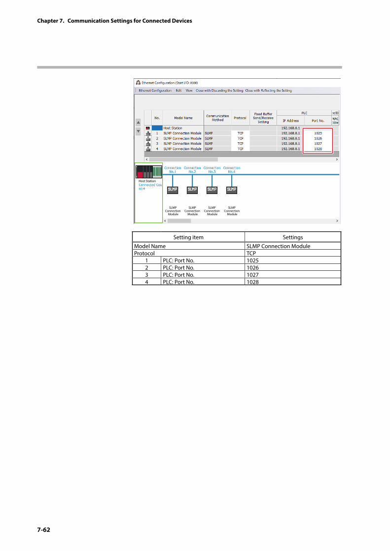
7-62
Chapter 7. Communication Settings for Connected Devices
SLMP Connection
Module
SLMP Connection
Module
SLMP Connection
Module
SLMP Connection
Module
Host Station
Setting item Settings
Model Name SLMP Connection ModuleProtocol TCP
1 PLC: Port No. 10252 PLC: Port No. 10263 PLC: Port No. 10274 PLC: Port No. 1028
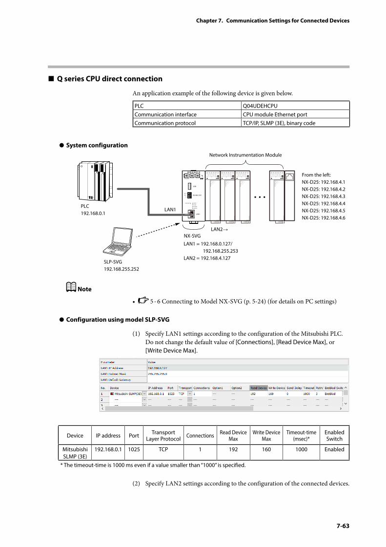
7-63
Chapter 7. Communication Settings for Connected Devices
Q series CPU direct connection
An application example of the following device is given below.
PLC Q04UDEHCPUCommunication interface CPU module Ethernet portCommunication protocol TCP/IP, SLMP (3E), binary code
z System configuration
PWR
NX-SVGN
USB
DA (+)
SG
DB (−) RS-485 CH1
RS-485
BATTERY
LINK/ACT
LAN1
FUNCTION ERROR
ID F1 F2
RUN MOD COM NST FAIL
SLP-SVG192.168.255.252
Network Instrumentation Module
From the left:NX-D25: 192.168.4.1NX-D25: 192.168.4.2NX-D25: 192.168.4.3NX-D25: 192.168.4.4NX-D25: 192.168.4.5NX-D25: 192.168.4.6
LAN1 = 192.168.0.127/ 192.168.255.253LAN2 = 192.168.4.127
LAN1
LAN2→
PLC192.168.0.1
NX-SVG
Note
• 5 - 6 Connecting to Model NX-SVG (p. 5-24) (for details on PC settings)
z Configuration using model SLP-SVG
(1) Specify LAN1 settings according to the configuration of the Mitsubishi PLC. Do not change the default value of [Connections], [Read Device Max], or [Write Device Max].
Device IP address Port Transport Layer Protocol Connections Read Device
MaxWrite Device
MaxTimeout-time
(msec)*Enabled Switch
Mitsubishi SLMP (3E)
192.168.0.1 1025 TCP 1 192 160 1000 Enabled
* The timeout-time is 1000 ms even if a value smaller than “1000” is specified.
(2) Specify LAN2 settings according to the configuration of the connected devices.
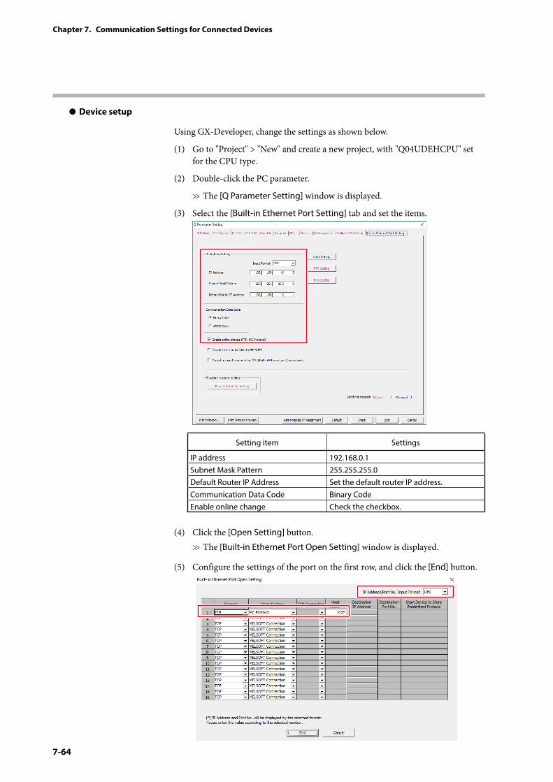
7-64
Chapter 7. Communication Settings for Connected Devices
z Device setup
Using GX-Developer, change the settings as shown below.
(1) Go to "Project" > "New" and create a new project, with "Q04UDEHCPU" set for the CPU type.
(2) Double-click the PC parameter.
>> The [Q Parameter Setting] window is displayed.
(3) Select the [Built-in Ethernet Port Setting] tab and set the items.
Setting item Settings
IP address 192.168.0.1Subnet Mask Pattern 255.255.255.0Default Router IP Address Set the default router IP address.Communication Data Code Binary CodeEnable online change Check the checkbox.
(4) Click the [Open Setting] button.>> The [Built-in Ethernet Port Open Setting] window is displayed.
(5) Configure the settings of the port on the first row, and click the [End] button.
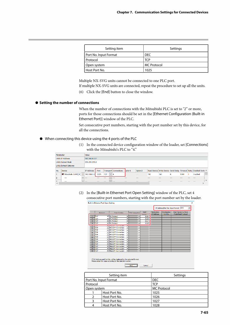
7-65
Chapter 7. Communication Settings for Connected Devices
Setting item Settings
Port No. Input Format DECProtocol TCPOpen system MC ProtocolHost Port No. 1025
Multiple NX-SVG units cannot be connected to one PLC port. If multiple NX-SVG units are connected, repeat the procedure to set up all the units.(6) Click the [End] button to close the window.
z Setting the number of connections
When the number of connections with the Mitsubishi PLC is set to "2” or more, ports for those connections should be set in the [Ethernet Configuration (Built-in Ethernet Port)] window of the PLC.Set consecutive port numbers, starting with the port number set by this device, for all the connections.
z When connecting this device using the 4 ports of the PLC
(1) In the connected device configuration window of the loader, set [Connections] with the Mitsubishi's PLC to “4.”
(2) In the [Built-in Ethernet Port Open Setting] window of the PLC, set 4 consecutive port numbers, starting with the port number set by the loader.
Setting item SettingsPort No. Input Format DECProtocol TCPOpen system MC Protocol
1 Host Port No. 10252 Host Port No. 10263 Host Port No. 10274 Host Port No. 1028
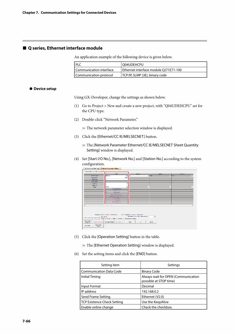
7-66
Chapter 7. Communication Settings for Connected Devices
Q series, Ethernet interface module
An application example of the following device is given below.
PLC Q04UDEHCPUCommunication interface Ethernet interface module QJ71E71-100Communication protocol TCP/IP, SLMP (3E), binary code
z Device setup
Using GX-Developer, change the settings as shown below.
(1) Go to Project > New and create a new project, with "Q04UDEHCPU" set for the CPU type.
(2) Double-click “Network Parameter.”
>> The network parameter selection window is displayed.
(3) Click the [Ethernet/CC IE/MELSECNET] button.
>> The [Network Parameter Ethernet/CC IE/MELSECNET Sheet Quantity Setting] window is displayed.
(4) Set [Start I/O No.], [Network No.] and [Station No.] according to the system configuration.
(5) Click the [Operation Setting] button in the table.
>> The [Ethernet Operation Setting] window is displayed.
(6) Set the setting items and click the [END] button.
Setting item Settings
Communication Data Code Binary CodeInitial Timing Always wait for OPEN (Communication
possible at STOP time)Input Format DecimalIP address 192.168.0.2Send Frame Setting Ethernet (V2.0)TCP Existence Check Setting Use the KeepAliveEnable online change Check the checkbox.
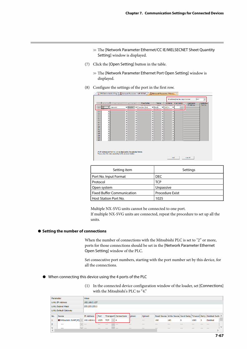
7-67
Chapter 7. Communication Settings for Connected Devices
>> The [Network Parameter Ethernet/CC IE/MELSECNET Sheet Quantity Setting] window is displayed.
(7) Click the [Open Setting] button in the table.
>> The [Network Parameter Ethernet Port Open Setting] window is displayed.
(8) Configure the settings of the port in the first row.
Setting item Settings
Port No. Input Format DECProtocol TCPOpen system UnpassiveFixed Buffer Communication Procedure ExistHost Station Port No. 1025
Multiple NX-SVG units cannot be connected to one port. If multiple NX-SVG units are connected, repeat the procedure to set up all the units.
z Setting the number of connections
When the number of connections with the Mitsubishi PLC is set to "2” or more, ports for those connections should be set in the [Network Parameter Ethernet Open Setting] window of the PLC.
Set consecutive port numbers, starting with the port number set by this device, for all the connections.
z When connecting this device using the 4 ports of the PLC
(1) In the connected device configuration window of the loader, set [Connections] with the Mitsubishi's PLC to “4.”
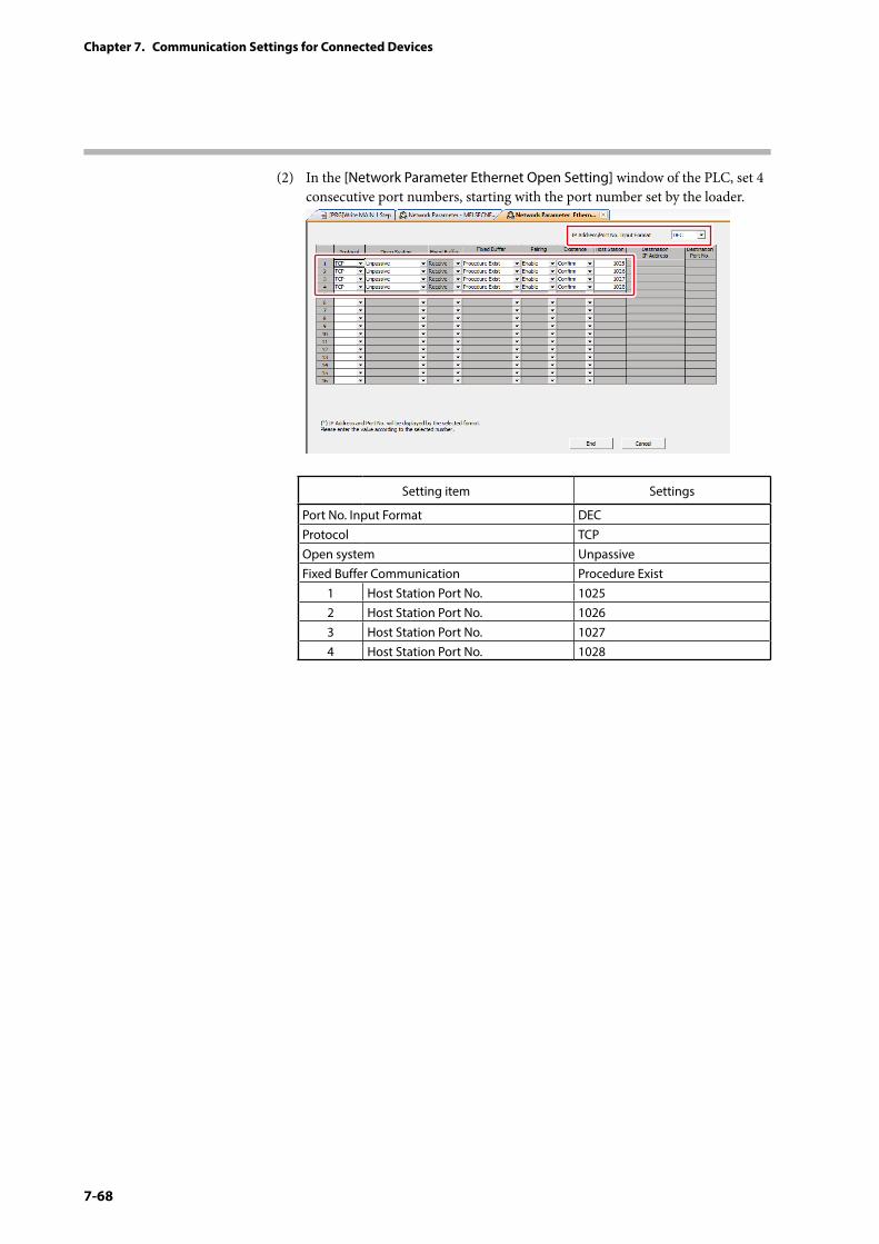
7-68
Chapter 7. Communication Settings for Connected Devices
(2) In the [Network Parameter Ethernet Open Setting] window of the PLC, set 4 consecutive port numbers, starting with the port number set by the loader.
Setting item Settings
Port No. Input Format DECProtocol TCPOpen system UnpassiveFixed Buffer Communication Procedure Exist
1 Host Station Port No. 10252 Host Station Port No. 10263 Host Station Port No. 10274 Host Station Port No. 1028
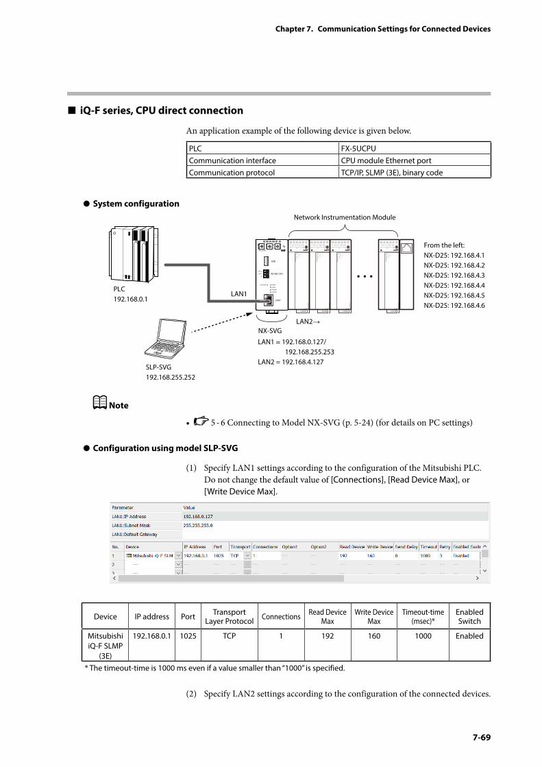
7-69
Chapter 7. Communication Settings for Connected Devices
iQ-F series, CPU direct connection
An application example of the following device is given below.
PLC FX-5UCPUCommunication interface CPU module Ethernet portCommunication protocol TCP/IP, SLMP (3E), binary code
z System configuration
PWR
NX-SVGN
USB
DA (+)
SG
DB (−) RS-485 CH1
RS-485
BATTERY
LINK/ACT
LAN1
FUNCTION ERROR
ID F1 F2
RUN MOD COM NST FAIL
SLP-SVG192.168.255.252
Network Instrumentation Module
From the left:NX-D25: 192.168.4.1NX-D25: 192.168.4.2NX-D25: 192.168.4.3NX-D25: 192.168.4.4NX-D25: 192.168.4.5NX-D25: 192.168.4.6
LAN1 = 192.168.0.127/ 192.168.255.253LAN2 = 192.168.4.127
LAN1
LAN2→
PLC192.168.0.1
NX-SVG
Note
• 5 - 6 Connecting to Model NX-SVG (p. 5-24) (for details on PC settings)
z Configuration using model SLP-SVG
(1) Specify LAN1 settings according to the configuration of the Mitsubishi PLC. Do not change the default value of [Connections], [Read Device Max], or [Write Device Max].
Device IP address Port Transport Layer Protocol Connections Read Device
MaxWrite Device
MaxTimeout-time
(msec)*Enabled Switch
Mitsubishi iQ-F SLMP
(3E)
192.168.0.1 1025 TCP 1 192 160 1000 Enabled
* The timeout-time is 1000 ms even if a value smaller than “1000” is specified.
(2) Specify LAN2 settings according to the configuration of the connected devices.
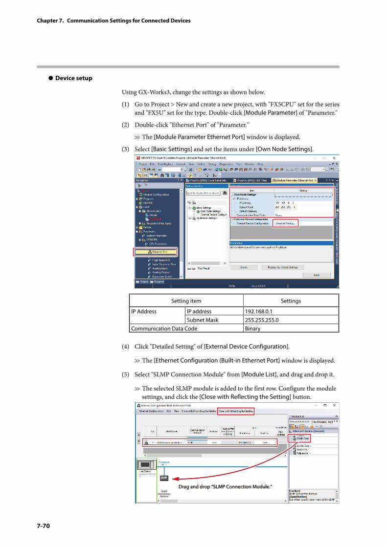
7-70
Chapter 7. Communication Settings for Connected Devices
z Device setup
Using GX-Works3, change the settings as shown below.
(1) Go to Project > New and create a new project, with "FX5CPU" set for the series and "FX5U" set for the type. Double-click [Module Parameter] of "Parameter."
(2) Double-click "Ethernet Port" of "Parameter."
>> The [Module Parameter Ethernet Port] window is displayed.
(3) Select [Basic Settings] and set the items under [Own Node Settings].
Setting item Settings
IP Address IP address 192.168.0.1Subnet Mask 255.255.255.0
Communication Data Code Binary
(4) Click "Detailed Setting" of [External Device Configuration].
>> The [Ethernet Configuration (Built-in Ethernet Port] window is displayed.
(5) Select "SLMP Connection Module" from [Module List], and drag and drop it.
>> The selected SLMP module is added to the first row. Configure the module settings, and click the [Close with Reflecting the Setting] button.
Drag and drop “SLMP Connection Module.”SLMP
Connection Module
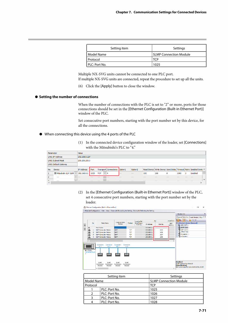
7-71
Chapter 7. Communication Settings for Connected Devices
Setting item Settings
Model Name SLMP Connection ModuleProtocol TCPPLC: Port No. 1025
Multiple NX-SVG units cannot be connected to one PLC port. If multiple NX-SVG units are connected, repeat the procedure to set up all the units.
(6) Click the [Apply] button to close the window.
z Setting the number of connections
When the number of connections with the PLC is set to "2” or more, ports for those connections should be set in the [Ethernet Configuration (Built-in Ethernet Port)] window of the PLC.
Set consecutive port numbers, starting with the port number set by this device, for all the connections.
z When connecting this device using the 4 ports of the PLC
(1) In the connected device configuration window of the loader, set [Connections] with the Mitsubishi's PLC to “4.”
(2) In the [Ethernet Configuration (Built-in Ethernet Port)] window of the PLC, set 4 consecutive port numbers, starting with the port number set by the loader.
SLMP Connection
Module
SLMP Connection
Module
SLMP Connection
Module
SLMP Connection
Module
Setting item SettingsModel Name SLMP Connection ModuleProtocol TCP
1 PLC: Port No. 10252 PLC: Port No. 10263 PLC: Port No. 10274 PLC: Port No. 1028
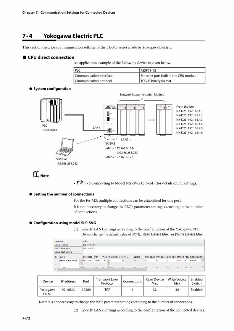
7-72
Chapter 7. Communication Settings for Connected Devices
7 - 4 Yokogawa Electric PLC
This section describes communication settings of the FA-M3 series made by Yokogawa Electric.
CPU direct connectionAn application example of the following device is given below.
PLC F3SP71-4SCommunication interface Ethernet port built in the CPU moduleCommunication protocol TCP/IP, binary format
z System configuration
PWR
NX-SVGN
USB
DA (+)
SG
DB (−) RS-485 CH1
RS-485
BATTERY
LINK/ACT
LAN1
FUNCTION ERROR
ID F1 F2
RUN MOD COM NST FAIL
SLP-SVG192.168.255.252
Network Instrumentation Module
From the left:NX-D25: 192.168.4.1NX-D25: 192.168.4.2NX-D25: 192.168.4.3NX-D25: 192.168.4.4NX-D25: 192.168.4.5NX-D25: 192.168.4.6
LAN1 = 192.168.0.127/ 192.168.255.253LAN2 = 192.168.4.127
LAN1
LAN2→
PLC192.168.0.1
NX-SVG
Note
• 5 - 6 Connecting to Model NX-SVG (p. 5-24) (for details on PC settings)
z Setting the number of connections
For the FA-M3, multiple connections can be established for one port.It is not necessary to change the PLC’s parameter settings according to the number of connections.
z Configuration using model SLP-SVG
(1) Specify LAN1 settings according to the configuration of the Yokogawa PLC. Do not change the default value of [Port], [Read Device Max], or [Write Device Max].
Device IP address Port Transport Layer Protocol Connections Read Device
MaxWrite Device
MaxEnabled Switch
Yokogawa FA-M3
192.168.0.1 12289 TCP 1 32 32 Enabled
Note: It is not necessary to change the PLC’s parameter settings according to the number of connections.
(2) Specify LAN2 settings according to the configuration of the connected devices.
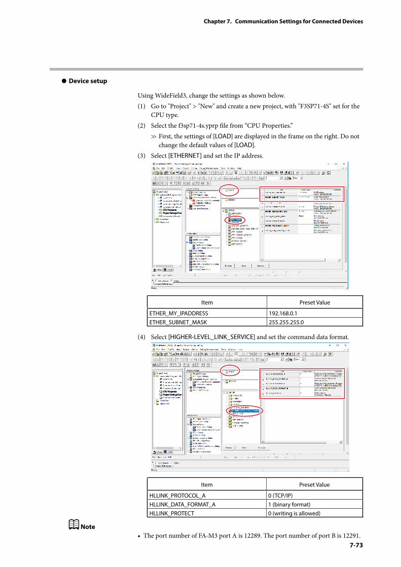
7-73
Chapter 7. Communication Settings for Connected Devices
z Device setup
Using WideField3, change the settings as shown below.(1) Go to "Project" > "New" and create a new project, with "F3SP71-4S" set for the
CPU type.(2) Select the f3sp71-4s.yprp file from “CPU Properties.”
>> First, the settings of [LOAD] are displayed in the frame on the right. Do not change the default values of [LOAD].
(3) Select [ETHERNET] and set the IP address.
Item Preset Value
ETHER_MY_IPADDRESS 192.168.0.1ETHER_SUBNET_MASK 255.255.255.0
(4) Select [HIGHER-LEVEL_LINK_SERVICE] and set the command data format.
Item Preset Value
HLLINK_PROTOCOL_A 0 (TCP/IP)HLLINK_DATA_FORMAT_A 1 (binary format)HLLINK_PROTECT 0 (writing is allowed)
Note• The port number of FA-M3 port A is 12289. The port number of port B is 12291.
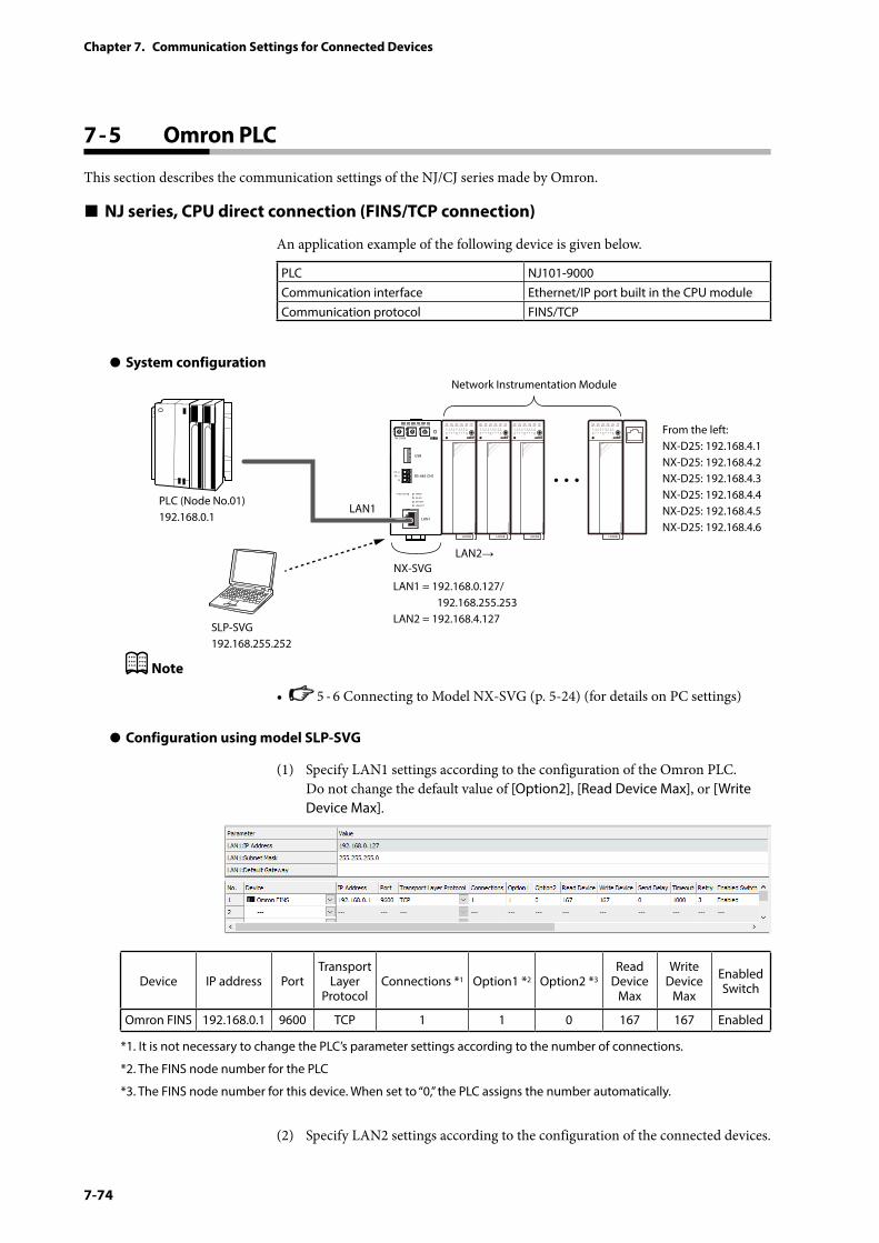
7-74
Chapter 7. Communication Settings for Connected Devices
7 - 5 Omron PLC
This section describes the communication settings of the NJ/CJ series made by Omron.
NJ series, CPU direct connection (FINS/TCP connection)
An application example of the following device is given below.
PLC NJ101-9000Communication interface Ethernet/IP port built in the CPU moduleCommunication protocol FINS/TCP
z System configuration
PWR
NX-SVGN
USB
DA (+)
SG
DB (−) RS-485 CH1
RS-485
BATTERY
LINK/ACT
LAN1
FUNCTION ERROR
ID F1 F2
RUN MOD COM NST FAIL
SLP-SVG192.168.255.252
Network Instrumentation Module
From the left:NX-D25: 192.168.4.1NX-D25: 192.168.4.2NX-D25: 192.168.4.3NX-D25: 192.168.4.4NX-D25: 192.168.4.5NX-D25: 192.168.4.6
LAN1 = 192.168.0.127/ 192.168.255.253LAN2 = 192.168.4.127
LAN1
LAN2→
PLC (Node No.01)192.168.0.1
NX-SVG
Note
• 5 - 6 Connecting to Model NX-SVG (p. 5-24) (for details on PC settings)
z Configuration using model SLP-SVG
(1) Specify LAN1 settings according to the configuration of the Omron PLC. Do not change the default value of [Option2], [Read Device Max], or [Write Device Max].
Device IP address PortTransport
Layer Protocol
Connections *1 Option1 *2 Option2 *3Read
Device Max
Write Device
Max
Enabled Switch
Omron FINS 192.168.0.1 9600 TCP 1 1 0 167 167 Enabled
*1. It is not necessary to change the PLC’s parameter settings according to the number of connections.
*2. The FINS node number for the PLC
*3. The FINS node number for this device. When set to “0,” the PLC assigns the number automatically.
(2) Specify LAN2 settings according to the configuration of the connected devices.
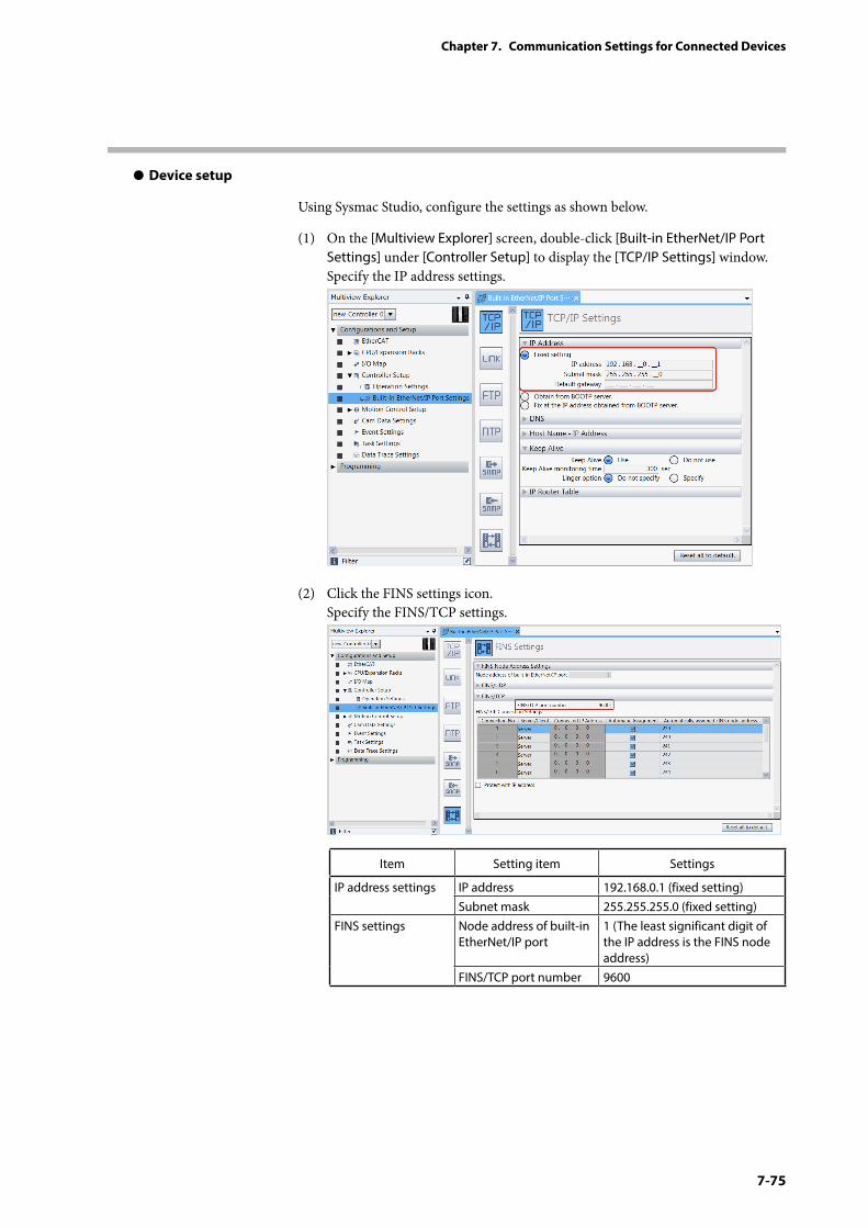
7-75
Chapter 7. Communication Settings for Connected Devices
z Device setup
Using Sysmac Studio, configure the settings as shown below.
(1) On the [Multiview Explorer] screen, double-click [Built-in EtherNet/IP Port Settings] under [Controller Setup] to display the [TCP/IP Settings] window. Specify the IP address settings.
(2) Click the FINS settings icon. Specify the FINS/TCP settings.
Item Setting item Settings
IP address settings IP address 192.168.0.1 (fixed setting)Subnet mask 255.255.255.0 (fixed setting)
FINS settings Node address of built-in EtherNet/IP port
1 (The least significant digit of the IP address is the FINS node address)
FINS/TCP port number 9600
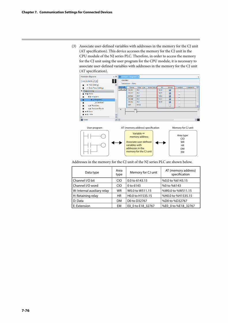
7-76
Chapter 7. Communication Settings for Connected Devices
(3) Associate user-defined variables with addresses in the memory for the CJ unit (AT specification). This device accesses the memory for the CJ unit in the CPU module of the NJ series PLC. Therefore, in order to access the memory for the CJ unit using the user program for the CPU module, it is necessary to associate user-defined variables with addresses in the memory for the CJ unit (AT specification).
User program AT (memory address) specication
Associate user-dened variables with addresses in the memory for the CJ unit
Variable memory address
Memory for CJ unit
Area typeCIOWRHRDMEM
Addresses in the memory for the CJ unit of the NJ series PLC are shown below.
Data type Area type Memory for CJ unit AT (memory address)
specification
Channel I/O bit CIO 0.0 to 6143.15 %0.0 to %6143.15Channel I/O word CIO 0 to 6143 %0 to %6143W: Internal auxiliary relay WR W0.0 to W511.15 %W0.0 to %W511.15H: Retaining relay HR H0.0 to H1535.15 %H0.0 to %H1535.15D: Data DM D0 to D32767 %D0 to %D32767E: Extension EM E0_0 to E18_32767 %E0_0 to %E18_32767
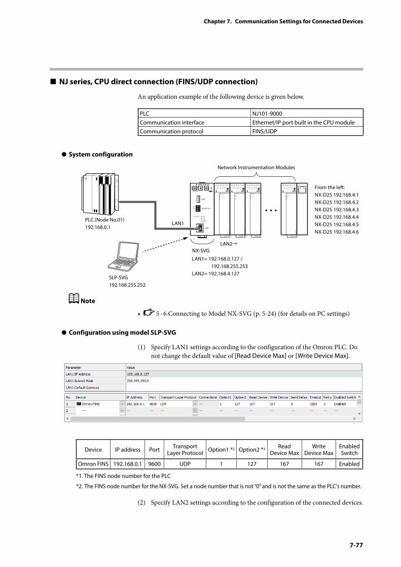
7-77
Chapter 7. Communication Settings for Connected Devices
NJ series, CPU direct connection (FINS/UDP connection)
An application example of the following device is given below.
PLC NJ101-9000Communication interface Ethernet/IP port built in the CPU moduleCommunication protocol FINS/UDP
z System configuration
PWR
NX-SVGN
USB
DA(+)
SG
DB(−) RS-485 CH1
RS-485
BATTERY
LINK/ACT
LAN1
FUNCTION ERROR
ID F1 F2
RUN MOD COM NST FAIL
SLP-SVG192.168.255.252
Network Instrumentation Modules
From the left:NX-D25 192.168.4.1NX-D25 192.168.4.2NX-D25 192.168.4.3NX-D25 192.168.4.4NX-D25 192.168.4.5NX-D25 192.168.4.6
LAN1= 192.168.0.127 / 192.168.255.253LAN2= 192.168.4.127
LAN1
LAN2
PLC (Node No.01)192.168.0.1
NX-SVG
Note
• 5 - 6 Connecting to Model NX-SVG (p. 5-24) (for details on PC settings)
z Configuration using model SLP-SVG
(1) Specify LAN1 settings according to the configuration of the Omron PLC. Do not change the default value of [Read Device Max] or [Write Device Max].
Device IP address Port Transport Layer Protocol Option1 *2 Option2 *3 Read
Device MaxWrite
Device MaxEnabled Switch
Omron FINS 192.168.0.1 9600 UDP 1 127 167 167 Enabled
*1. The FINS node number for the PLC
*2. The FINS node number for the NX-SVG. Set a node number that is not “0” and is not the same as the PLC's number.
(2) Specify LAN2 settings according to the configuration of the connected devices.
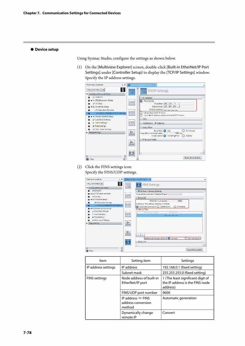
7-78
Chapter 7. Communication Settings for Connected Devices
z Device setup
Using Sysmac Studio, configure the settings as shown below.
(1) On the [Multiview Explorer] screen, double-click [Built-in EtherNet/IP Port Settings] under [Controller Setup] to display the [TCP/IP Settings] window. Specify the IP address settings.
(2) Click the FINS settings icon. Specify the FINS/UDP settings.
Item Setting item Settings
IP address settings IP address 192.168.0.1 (fixed setting)Subnet mask 255.255.255.0 (fixed setting)
FINS settings Node address of built-in EtherNet/IP port
1 (The least significant digit of the IP address is the FINS node address)
FINS/UDP port number 9600
IP address FINS address conversion method
Automatic generation
Dynamically change remote IP
Convert
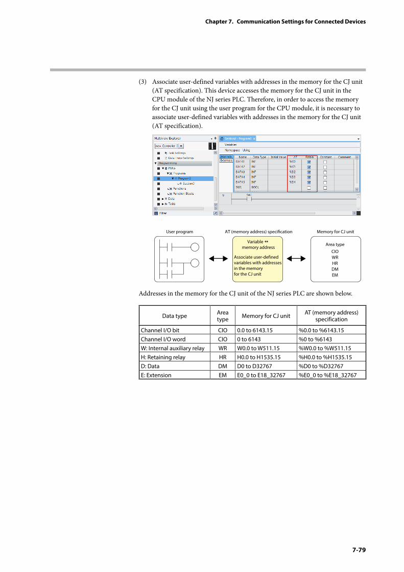
7-79
Chapter 7. Communication Settings for Connected Devices
(3) Associate user-defined variables with addresses in the memory for the CJ unit (AT specification). This device accesses the memory for the CJ unit in the CPU module of the NJ series PLC. Therefore, in order to access the memory for the CJ unit using the user program for the CPU module, it is necessary to associate user-defined variables with addresses in the memory for the CJ unit (AT specification).
User program AT (memory address) specication
Associate user-dened variables with addresses in the memory for the CJ unit
Variable memory address
Memory for CJ unit
Area typeCIOWRHRDMEM
Addresses in the memory for the CJ unit of the NJ series PLC are shown below.
Data type Area type Memory for CJ unit AT (memory address)
specification
Channel I/O bit CIO 0.0 to 6143.15 %0.0 to %6143.15Channel I/O word CIO 0 to 6143 %0 to %6143W: Internal auxiliary relay WR W0.0 to W511.15 %W0.0 to %W511.15H: Retaining relay HR H0.0 to H1535.15 %H0.0 to %H1535.15D: Data DM D0 to D32767 %D0 to %D32767E: Extension EM E0_0 to E18_32767 %E0_0 to %E18_32767
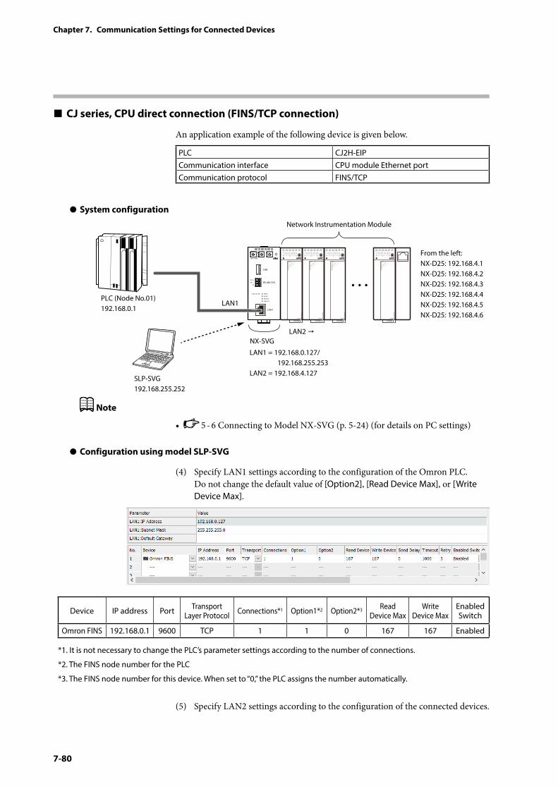
7-80
Chapter 7. Communication Settings for Connected Devices
CJ series, CPU direct connection (FINS/TCP connection)
An application example of the following device is given below.
PLC CJ2H-EIPCommunication interface CPU module Ethernet portCommunication protocol FINS/TCP
z System configuration
PWR
NX-SVGN
USB
DA (+)
SG
DB (−) RS-485 CH1
RS-485
BATTERY
LINK/ACT
LAN1
FUNCTION ERROR
ID F1 F2
RUN MOD COM NST FAIL
SLP-SVG192.168.255.252
Network Instrumentation Module
From the left:NX-D25: 192.168.4.1NX-D25: 192.168.4.2NX-D25: 192.168.4.3NX-D25: 192.168.4.4NX-D25: 192.168.4.5NX-D25: 192.168.4.6
LAN1 = 192.168.0.127/ 192.168.255.253LAN2 = 192.168.4.127
LAN1
LAN2
PLC (Node No.01)192.168.0.1
NX-SVG
Note
• 5 - 6 Connecting to Model NX-SVG (p. 5-24) (for details on PC settings)
z Configuration using model SLP-SVG
(4) Specify LAN1 settings according to the configuration of the Omron PLC. Do not change the default value of [Option2], [Read Device Max], or [Write Device Max].
Device IP address Port Transport Layer Protocol Connections*1 Option1*2 Option2*3 Read
Device MaxWrite
Device MaxEnabled Switch
Omron FINS 192.168.0.1 9600 TCP 1 1 0 167 167 Enabled
*1. It is not necessary to change the PLC’s parameter settings according to the number of connections.
*2. The FINS node number for the PLC
*3. The FINS node number for this device. When set to “0,” the PLC assigns the number automatically.
(5) Specify LAN2 settings according to the configuration of the connected devices.
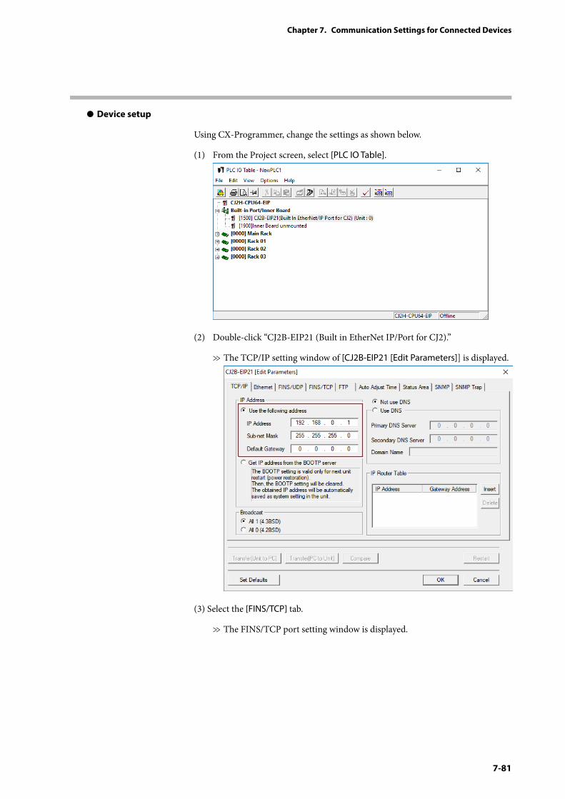
7-81
Chapter 7. Communication Settings for Connected Devices
z Device setup
Using CX-Programmer, change the settings as shown below.
(1) From the Project screen, select [PLC IO Table].
(2) Double-click “CJ2B-EIP21 (Built in EtherNet IP/Port for CJ2).”
>> The TCP/IP setting window of [CJ2B-EIP21 [Edit Parameters]] is displayed.
(3) Select the [FINS/TCP] tab.
>> The FINS/TCP port setting window is displayed.
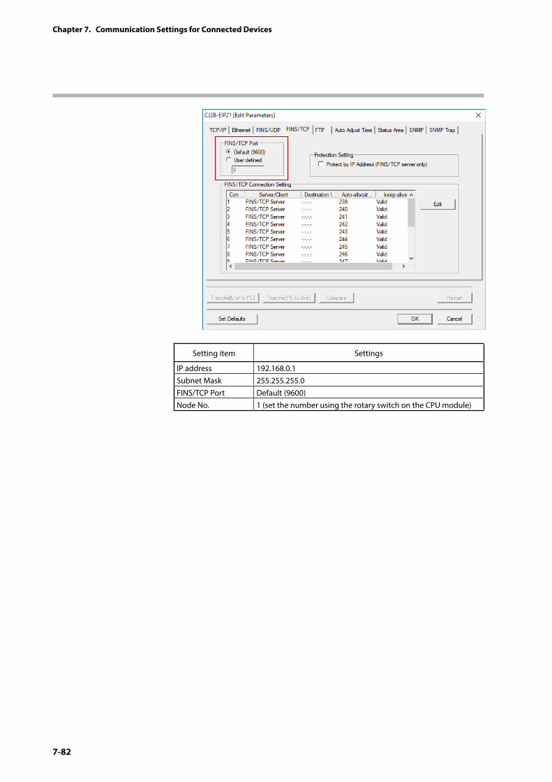
7-82
Chapter 7. Communication Settings for Connected Devices
Setting item Settings
IP address 192.168.0.1Subnet Mask 255.255.255.0FINS/TCP Port Default (9600)Node No. 1 (set the number using the rotary switch on the CPU module)
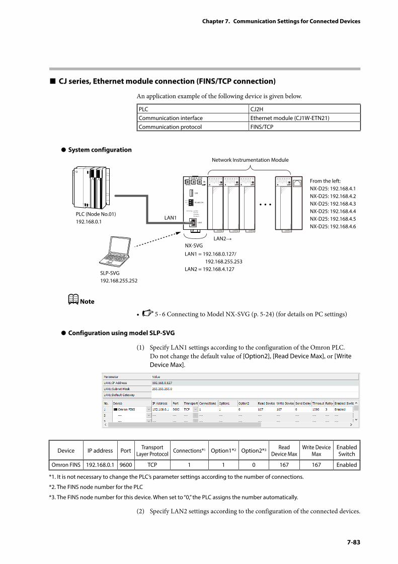
7-83
Chapter 7. Communication Settings for Connected Devices
CJ series, Ethernet module connection (FINS/TCP connection)
An application example of the following device is given below.
PLC CJ2HCommunication interface Ethernet module (CJ1W-ETN21)Communication protocol FINS/TCP
z System configuration
PWR
NX-SVGN
USB
DA (+)
SG
DB (−) RS-485 CH1
RS-485
BATTERY
LINK/ACT
LAN1
FUNCTION ERROR
ID F1 F2
RUN MOD COM NST FAIL
SLP-SVG192.168.255.252
Network Instrumentation Module
From the left:NX-D25: 192.168.4.1NX-D25: 192.168.4.2NX-D25: 192.168.4.3NX-D25: 192.168.4.4NX-D25: 192.168.4.5NX-D25: 192.168.4.6
LAN1 = 192.168.0.127/ 192.168.255.253LAN2 = 192.168.4.127
LAN1
LAN2→
PLC (Node No.01)192.168.0.1
NX-SVG
Note
• 5 - 6 Connecting to Model NX-SVG (p. 5-24) (for details on PC settings)
z Configuration using model SLP-SVG
(1) Specify LAN1 settings according to the configuration of the Omron PLC. Do not change the default value of [Option2], [Read Device Max], or [Write Device Max].
Device IP address Port Transport Layer Protocol Connections*1 Option1*2 Option2*3 Read
Device MaxWrite Device
MaxEnabled Switch
Omron FINS 192.168.0.1 9600 TCP 1 1 0 167 167 Enabled
*1. It is not necessary to change the PLC’s parameter settings according to the number of connections.
*2. The FINS node number for the PLC
*3. The FINS node number for this device. When set to “0,” the PLC assigns the number automatically.
(2) Specify LAN2 settings according to the configuration of the connected devices.
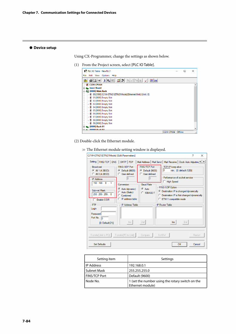
7-84
Chapter 7. Communication Settings for Connected Devices
z Device setup
Using CX-Programmer, change the settings as shown below.
(1) From the Project screen, select [PLC IO Table].
(2) Double-click the Ethernet module.
>> The Ethernet module setting window is displayed.
Setting item Settings
IP Address 192.168.0.1Subnet Mask 255.255.255.0FINS/TCP Port Default (9600)Node No. 1 (set the number using the rotary switch on the
Ethernet module)
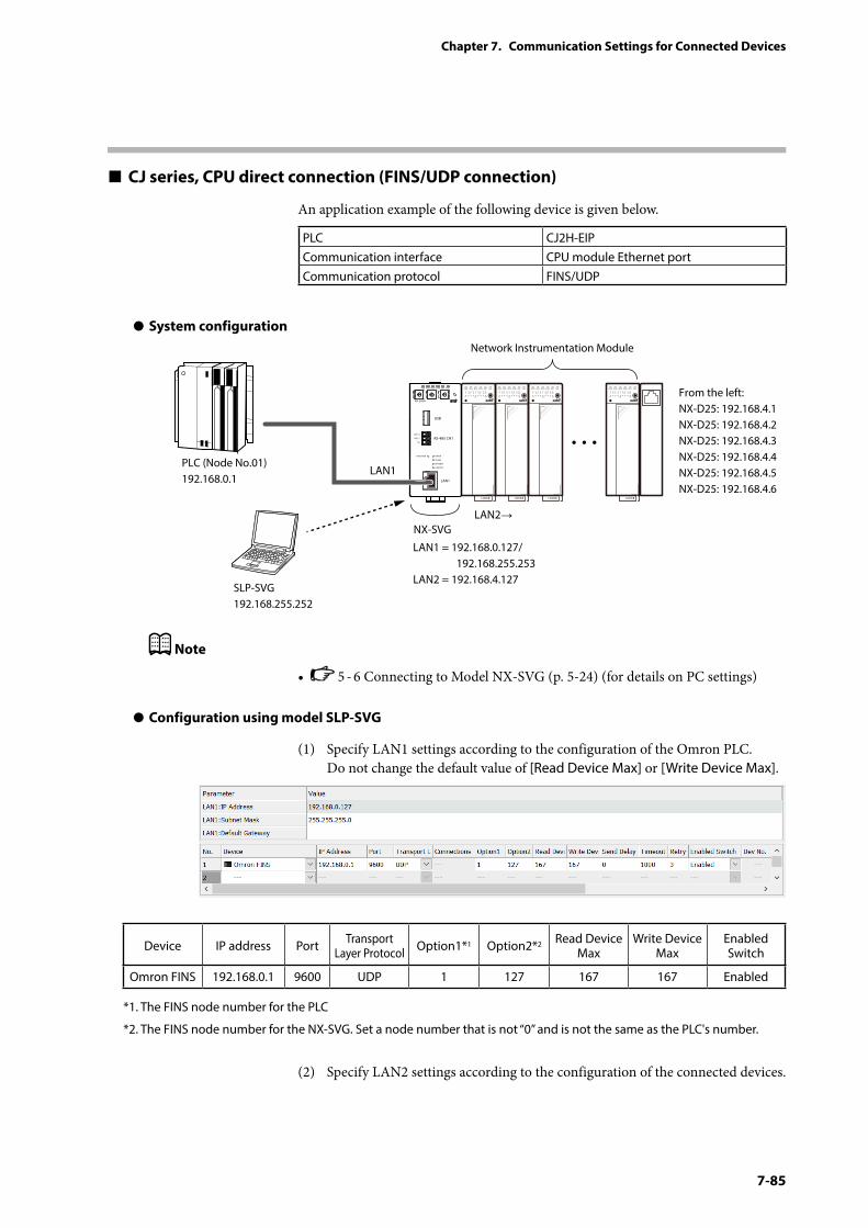
7-85
Chapter 7. Communication Settings for Connected Devices
CJ series, CPU direct connection (FINS/UDP connection)
An application example of the following device is given below.
PLC CJ2H-EIPCommunication interface CPU module Ethernet portCommunication protocol FINS/UDP
z System configuration
PWR
NX-SVGN
USB
DA (+)
SG
DB (−) RS-485 CH1
RS-485
BATTERY
LINK/ACT
LAN1
FUNCTION ERROR
ID F1 F2
RUN MOD COM NST FAIL
SLP-SVG192.168.255.252
Network Instrumentation Module
From the left:NX-D25: 192.168.4.1NX-D25: 192.168.4.2NX-D25: 192.168.4.3NX-D25: 192.168.4.4NX-D25: 192.168.4.5NX-D25: 192.168.4.6
LAN1 = 192.168.0.127/ 192.168.255.253LAN2 = 192.168.4.127
LAN1
LAN2→
PLC (Node No.01)192.168.0.1
NX-SVG
Note
• 5 - 6 Connecting to Model NX-SVG (p. 5-24) (for details on PC settings)
z Configuration using model SLP-SVG
(1) Specify LAN1 settings according to the configuration of the Omron PLC. Do not change the default value of [Read Device Max] or [Write Device Max].
Device IP address Port Transport Layer Protocol Option1*1 Option2*2 Read Device
MaxWrite Device
MaxEnabled Switch
Omron FINS 192.168.0.1 9600 UDP 1 127 167 167 Enabled
*1. The FINS node number for the PLC
*2. The FINS node number for the NX-SVG. Set a node number that is not “0” and is not the same as the PLC's number.
(2) Specify LAN2 settings according to the configuration of the connected devices.
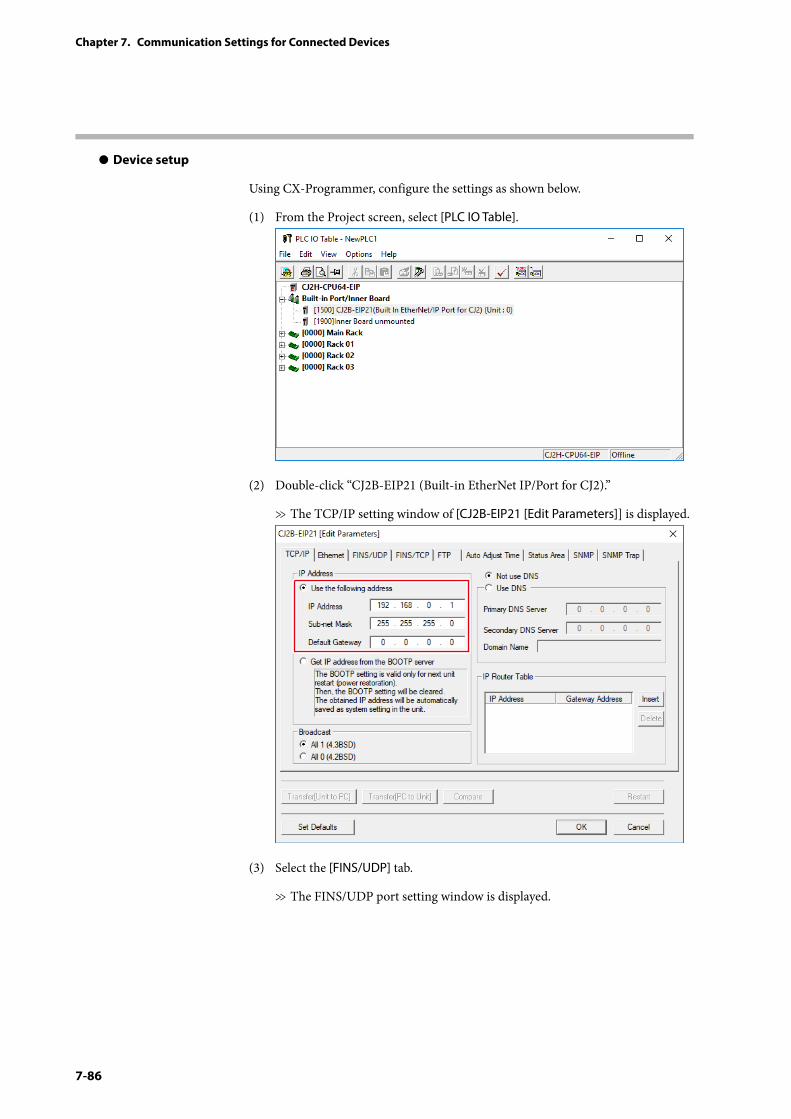
7-86
Chapter 7. Communication Settings for Connected Devices
z Device setup
Using CX-Programmer, configure the settings as shown below.
(1) From the Project screen, select [PLC IO Table].
(2) Double-click “CJ2B-EIP21 (Built-in EtherNet IP/Port for CJ2).”
>> The TCP/IP setting window of [CJ2B-EIP21 [Edit Parameters]] is displayed.
(3) Select the [FINS/UDP] tab.
>> The FINS/UDP port setting window is displayed.
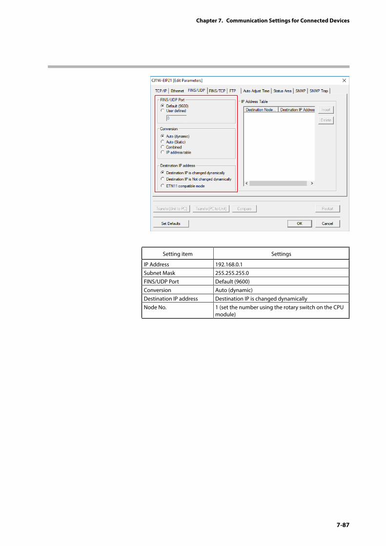
7-87
Chapter 7. Communication Settings for Connected Devices
Setting item Settings
IP Address 192.168.0.1Subnet Mask 255.255.255.0FINS/UDP Port Default (9600)Conversion Auto (dynamic)Destination IP address Destination IP is changed dynamicallyNode No. 1 (set the number using the rotary switch on the CPU
module)
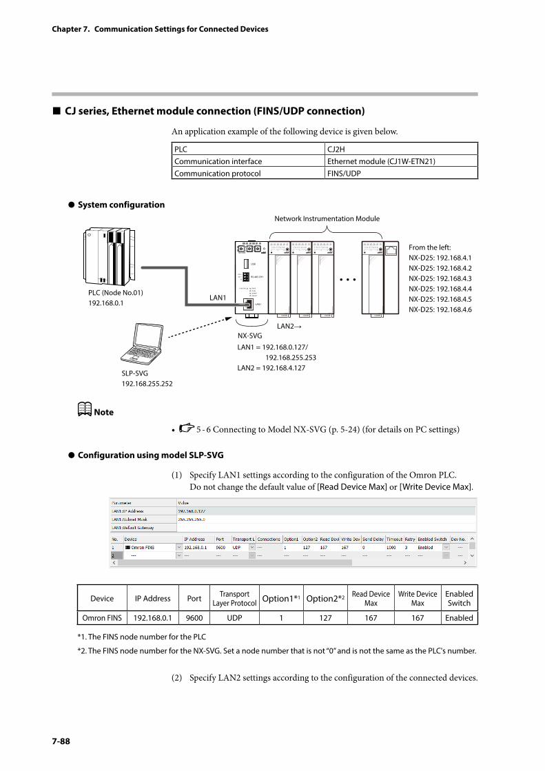
7-88
Chapter 7. Communication Settings for Connected Devices
CJ series, Ethernet module connection (FINS/UDP connection)
An application example of the following device is given below.
PLC CJ2HCommunication interface Ethernet module (CJ1W-ETN21)Communication protocol FINS/UDP
z System configuration
PWR
NX-SVGN
USB
DA (+)
SG
DB (−) RS-485 CH1
RS-485
BATTERY
LINK/ACT
LAN1
FUNCTION ERROR
ID F1 F2
RUN MOD COM NST FAIL
SLP-SVG192.168.255.252
Network Instrumentation Module
From the left:NX-D25: 192.168.4.1NX-D25: 192.168.4.2NX-D25: 192.168.4.3NX-D25: 192.168.4.4NX-D25: 192.168.4.5NX-D25: 192.168.4.6
LAN1 = 192.168.0.127/ 192.168.255.253LAN2 = 192.168.4.127
LAN1
LAN2→
PLC (Node No.01)192.168.0.1
NX-SVG
Note
• 5 - 6 Connecting to Model NX-SVG (p. 5-24) (for details on PC settings)
z Configuration using model SLP-SVG
(1) Specify LAN1 settings according to the configuration of the Omron PLC. Do not change the default value of [Read Device Max] or [Write Device Max].
Device IP Address Port Transport Layer Protocol Option1*1 Option2*2 Read Device
MaxWrite Device
MaxEnabled Switch
Omron FINS 192.168.0.1 9600 UDP 1 127 167 167 Enabled
*1. The FINS node number for the PLC
*2. The FINS node number for the NX-SVG. Set a node number that is not “0” and is not the same as the PLC's number.
(2) Specify LAN2 settings according to the configuration of the connected devices.
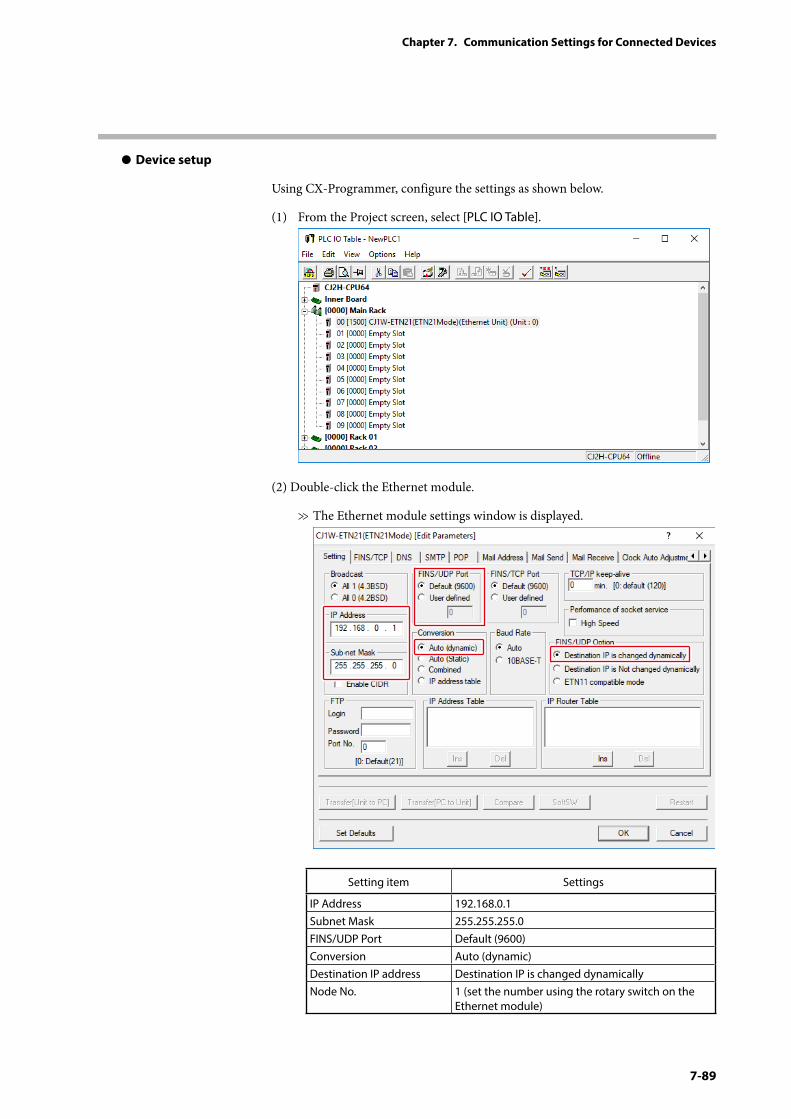
7-89
Chapter 7. Communication Settings for Connected Devices
z Device setup
Using CX-Programmer, configure the settings as shown below.
(1) From the Project screen, select [PLC IO Table].
(2) Double-click the Ethernet module.
>> The Ethernet module settings window is displayed.
Setting item Settings
IP Address 192.168.0.1Subnet Mask 255.255.255.0FINS/UDP Port Default (9600)Conversion Auto (dynamic)Destination IP address Destination IP is changed dynamicallyNode No. 1 (set the number using the rotary switch on the
Ethernet module)
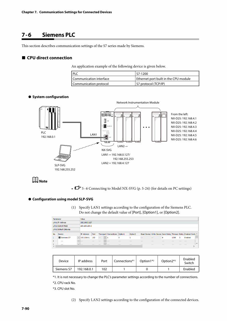
7-90
Chapter 7. Communication Settings for Connected Devices
7 - 6 Siemens PLC
This section describes communication settings of the S7 series made by Siemens.
CPU direct connection
An application example of the following device is given below.
PLC S7-1200Communication interface Ethernet port built in the CPU moduleCommunication protocol S7 protocol (TCP/IP)
z System configuration
PWR
NX-SVGN
USB
DA (+)
SG
DB (−) RS-485 CH1
RS-485
BATTERY
LINK/ACT
LAN1
FUNCTION ERROR
ID F1 F2
RUN MOD COM NST FAIL
SLP-SVG192.168.255.252
Network Instrumentation Module
From the left:NX-D25: 192.168.4.1NX-D25: 192.168.4.2NX-D25: 192.168.4.3NX-D25: 192.168.4.4NX-D25: 192.168.4.5NX-D25: 192.168.4.6
LAN1 = 192.168.0.127/ 192.168.255.253LAN2 = 192.168.4.127
LAN1
LAN2→
PLC192.168.0.1
NX-SVG
Note
• 5 - 6 Connecting to Model NX-SVG (p. 5-24) (for details on PC settings)
z Configuration using model SLP-SVG
(1) Specify LAN1 settings according to the configuration of the Siemens PLC. Do not change the default value of [Port], [Option1], or [Option2].
Device IP address Port Connections*1 Option1*2 Option2*3 Enabled Switch
Siemens S7 192.168.0.1 102 1 0 1 Enabled
*1. It is not necessary to change the PLC’s parameter settings according to the number of connections.
*2. CPU rack No.
*3. CPU slot No.
(2) Specify LAN2 settings according to the configuration of the connected devices.
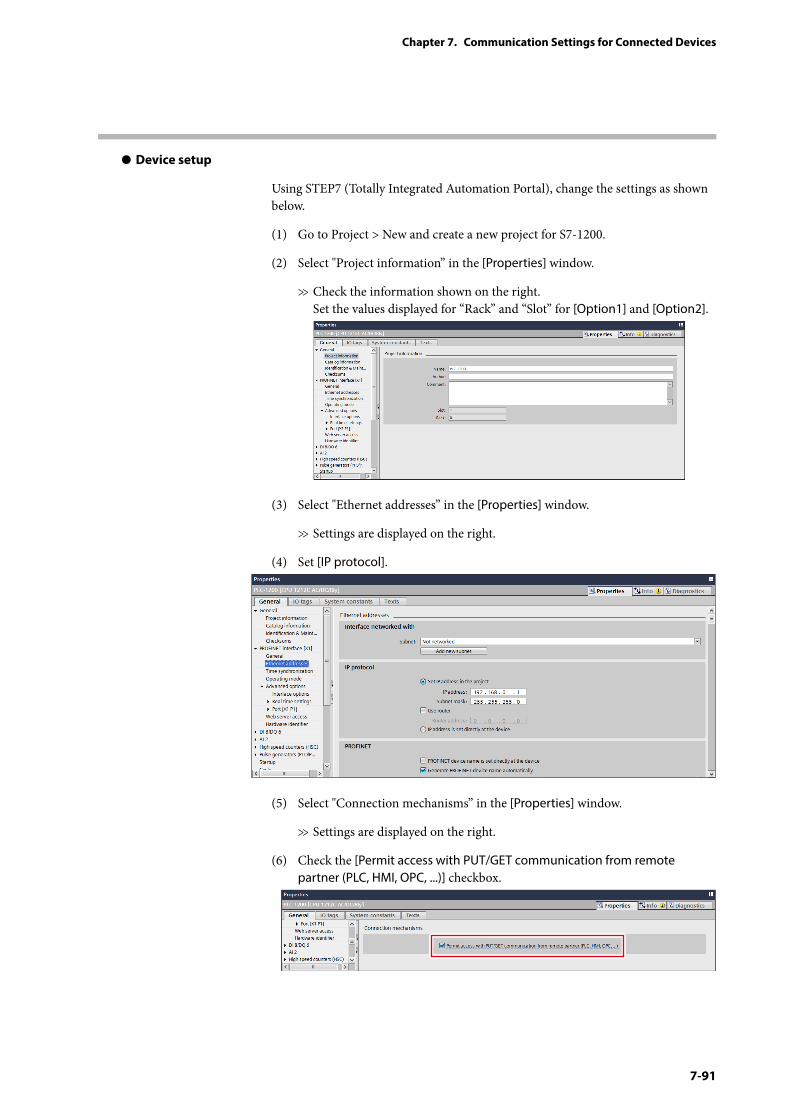
7-91
Chapter 7. Communication Settings for Connected Devices
z Device setup
Using STEP7 (Totally Integrated Automation Portal), change the settings as shown below.
(1) Go to Project > New and create a new project for S7-1200.
(2) Select "Project information” in the [Properties] window.
>> Check the information shown on the right. Set the values displayed for “Rack” and “Slot” for [Option1] and [Option2].
(3) Select "Ethernet addresses” in the [Properties] window.
>> Settings are displayed on the right.
(4) Set [IP protocol].
(5) Select "Connection mechanisms” in the [Properties] window.
>> Settings are displayed on the right.
(6) Check the [Permit access with PUT/GET communication from remote partner (PLC, HMI, OPC, ...)] checkbox.
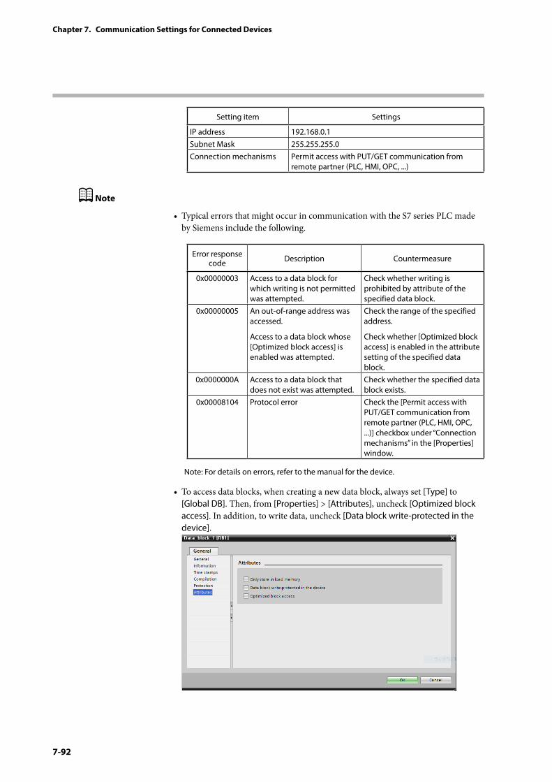
7-92
Chapter 7. Communication Settings for Connected Devices
Setting item Settings
IP address 192.168.0.1Subnet Mask 255.255.255.0Connection mechanisms Permit access with PUT/GET communication from
remote partner (PLC, HMI, OPC, ...)
Note
• Typical errors that might occur in communication with the S7 series PLC made by Siemens include the following.
Error response code Description Countermeasure
0x00000003 Access to a data block for which writing is not permitted was attempted.
Check whether writing is prohibited by attribute of the specified data block.
0x00000005 An out-of-range address was accessed.
Access to a data block whose [Optimized block access] is enabled was attempted.
Check the range of the specified address.
Check whether [Optimized block access] is enabled in the attribute setting of the specified data block.
0x0000000A Access to a data block that does not exist was attempted.
Check whether the specified data block exists.
0x00008104 Protocol error Check the [Permit access with PUT/GET communication from remote partner (PLC, HMI, OPC, ...)] checkbox under “Connection mechanisms” in the [Properties] window.
Note: For details on errors, refer to the manual for the device.
• To access data blocks, when creating a new data block, always set [Type] to [Global DB]. Then, from [Properties] > [Attributes], uncheck [Optimized block access]. In addition, to write data, uncheck [Data block write-protected in the device].
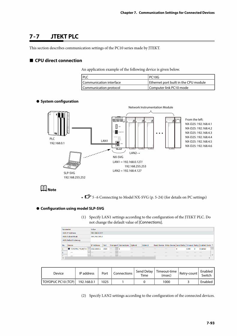
7-93
Chapter 7. Communication Settings for Connected Devices
7 - 7 JTEKT PLC
This section describes communication settings of the PC10 series made by JTEKT.
CPU direct connection
An application example of the following device is given below.
PLC PC10GCommunication interface Ethernet port built in the CPU moduleCommunication protocol Computer link PC10 mode
z System configuration
PWR
NX-SVGN
USB
DA (+)
SG
DB (−) RS-485 CH1
RS-485
BATTERY
LINK/ACT
LAN1
FUNCTION ERROR
ID F1 F2
RUN MOD COM NST FAIL
SLP-SVG192.168.255.252
Network Instrumentation Module
From the left:NX-D25: 192.168.4.1NX-D25: 192.168.4.2NX-D25: 192.168.4.3NX-D25: 192.168.4.4NX-D25: 192.168.4.5NX-D25: 192.168.4.6
LAN1 = 192.168.0.127/ 192.168.255.253LAN2 = 192.168.4.127
LAN1
LAN2→
PLC 192.168.0.1
NX-SVG
Note
• 5 - 6 Connecting to Model NX-SVG (p. 5-24) (for details on PC settings)
z Configuration using model SLP-SVG
(1) Specify LAN1 settings according to the configuration of the JTEKT PLC. Do not change the default value of [Connections].
Device IP address Port Connections Send Delay Time
Timeout-time (msec) Retry-count Enabled
Switch
TOYOPUC PC10 (TCP) 192.168.0.1 1025 1 0 1000 3 Enabled
(2) Specify LAN2 settings according to the configuration of the connected devices.
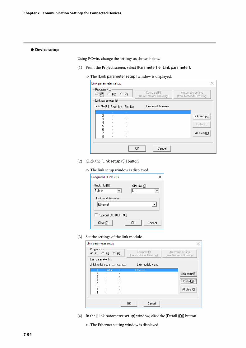
7-94
Chapter 7. Communication Settings for Connected Devices
z Device setup
Using PCwin, change the settings as shown below.
(1) From the Project screen, select [Parameter] → [Link parameter].
>> The [Link parameter setup] window is displayed.
(2) Click the [Link setup (S)] button.
>> The link setup window is displayed.
(3) Set the settings of the link module.
(4) In the [Link parameter setup] window, click the [Detail (D)] button.
>> The Ethernet setting window is displayed.
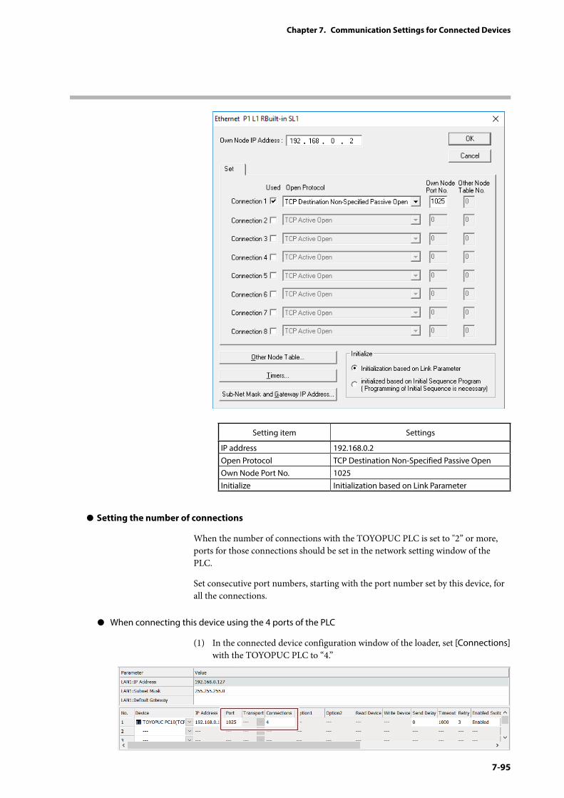
7-95
Chapter 7. Communication Settings for Connected Devices
Setting item Settings
IP address 192.168.0.2Open Protocol TCP Destination Non-Specified Passive OpenOwn Node Port No. 1025Initialize Initialization based on Link Parameter
z Setting the number of connections
When the number of connections with the TOYOPUC PLC is set to "2” or more, ports for those connections should be set in the network setting window of the PLC.
Set consecutive port numbers, starting with the port number set by this device, for all the connections.
z When connecting this device using the 4 ports of the PLC
(1) In the connected device configuration window of the loader, set [Connections] with the TOYOPUC PLC to “4.”
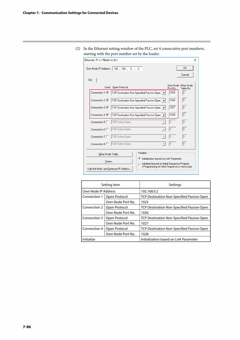
7-96
Chapter 7. Communication Settings for Connected Devices
(2) In the Ethernet setting window of the PLC, set 4 consecutive port numbers, starting with the port number set by the loader.
Setting item Settings
Own Node IP Address 192.168.0.2Connection 1 Open Protocol TCP Destination Non-Specified Passive Open
Own Node Port No. 1025Connection 2 Open Protocol TCP Destination Non-Specified Passive Open
Own Node Port No. 1026Connection 3 Open Protocol TCP Destination Non-Specified Passive Open
Own Node Port No. 1027Connection 4 Open Protocol TCP Destination Non-Specified Passive Open
Own Node Port No. 1028Initialize Initialization based on Link Parameter
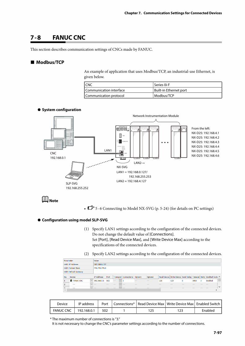
7-97
Chapter 7. Communication Settings for Connected Devices
7 - 8 FANUC CNC
This section describes communication settings of CNCs made by FANUC.
Modbus/TCP
An example of application that uses Modbus/TCP, an industrial-use Ethernet, is given below.
CNC Series 0i-FCommunication interface Built-in Ethernet portCommunication protocol Modbus/TCP
z System configuration
PWR
NX-SVGN
USB
DA (+)
SG
DB (−) RS-485 CH1
RS-485
BATTERY
LINK/ACT
LAN1
FUNCTION ERROR
ID F1 F2
RUN MOD COM NST FAIL
SLP-SVG192.168.255.252
Network Instrumentation Module
From the left:NX-D25: 192.168.4.1NX-D25: 192.168.4.2NX-D25: 192.168.4.3NX-D25: 192.168.4.4NX-D25: 192.168.4.5NX-D25: 192.168.4.6
LAN1 = 192.168.0.127/ 192.168.255.253LAN2 = 192.168.4.127
LAN1
LAN2→
CNC192.168.0.1
NX-SVG
Note
• 5 - 6 Connecting to Model NX-SVG (p. 5-24) (for details on PC settings)
z Configuration using model SLP-SVG
(1) Specify LAN1 settings according to the configuration of the connected devices. Do not change the default value of [Connections]. Set [Port], [Read Device Max], and [Write Device Max] according to the specifications of the connected devices.
(2) Specify LAN2 settings according to the configuration of the connected devices.
Device IP address Port Connections* Read Device Max Write Device Max Enabled Switch
FANUC CNC 192.168.0.1 502 1 125 123 Enabled
* The maximum number of connections is "3.” It is not necessary to change the CNC’s parameter settings according to the number of connections.
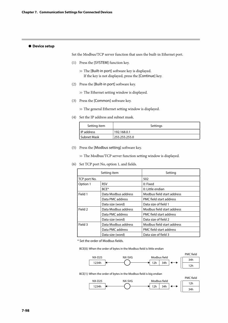
7-98
Chapter 7. Communication Settings for Connected Devices
z Device setup
Set the Modbus/TCP server function that uses the built-in Ethernet port.
(1) Press the [SYSTEM] function key.
>> The [Built-in port] software key is displayed. If the key is not displayed, press the [Continue] key.
(2) Press the [Built-in port] software key.
>> The Ethernet setting window is displayed.
(3) Press the [Common] software key.
>> The general Ethernet setting window is displayed.
(4) Set the IP address and subnet mask.
Setting item Settings
IP address 192.168.0.1Subnet Mask 255.255.255.0
(5) Press the [Modbus setting] software key.
>> The Modbus/TCP server function setting window is displayed.
(6) Set TCP port No, option 1, and fields.
Setting item Setting
TCP port No. 502Option 1 RSV 0: Fixed
BCE* 0: Little endianField 1 Data Modbus address Modbus field start address
Data PMC address PMC field start addressData size (word) Data size of field 1
Field 2 Data Modbus address Modbus field start addressData PMC address PMC field start addressData size (word) Data size of field 2
Field 3 Data Modbus address Modbus field start addressData PMC address PMC field start addressData size (word) Data size of field 3
* Set the order of Modbus fields.
BCE[0]: When the order of bytes in the Modbus eld is little endian
BCE[1]: When the order of bytes in the Modbus eld is big endian
1234h
NX-D25 NX-SVG Modbus eldPMC eld
12h 34h34h
12h
1234h
NX-D25 NX-SVG Modbus eldPMC eld
12h 34h12h
34h
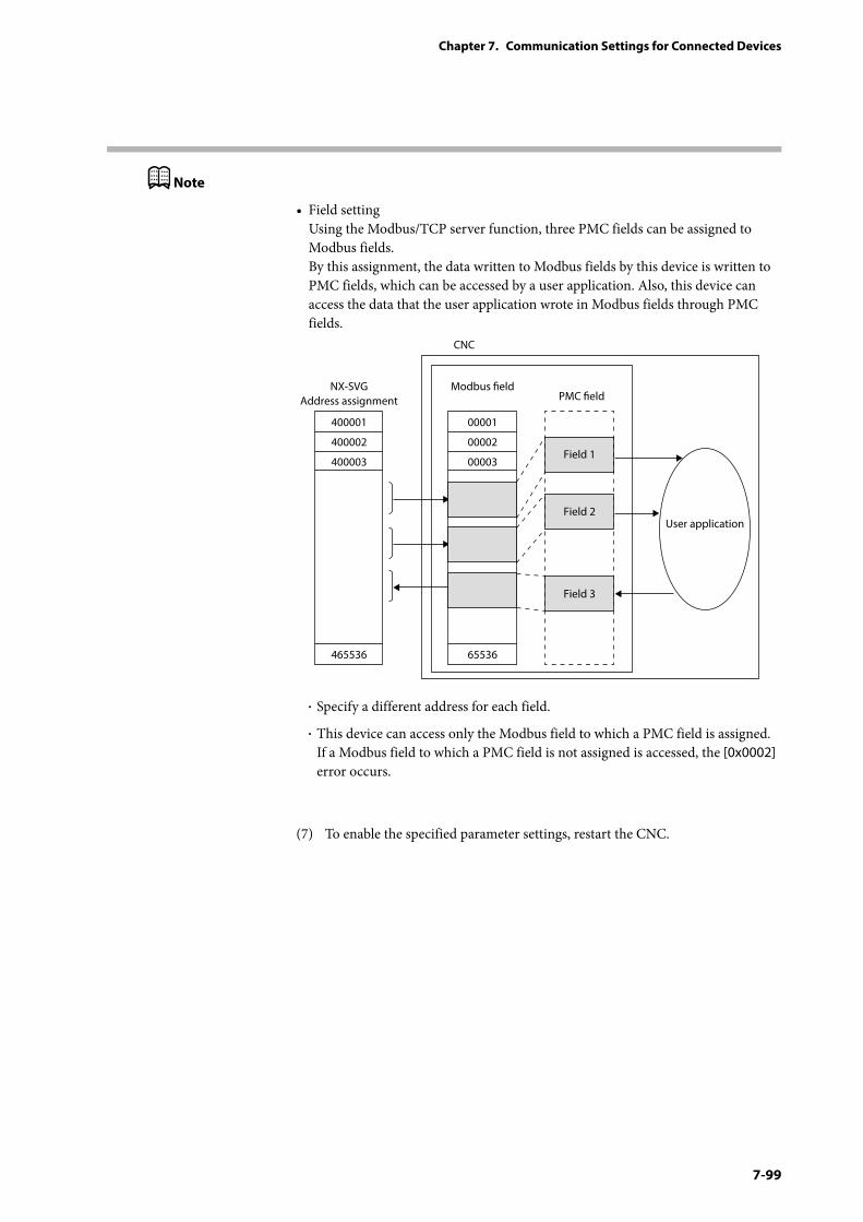
7-99
Chapter 7. Communication Settings for Connected Devices
Note
• Field setting Using the Modbus/TCP server function, three PMC fields can be assigned to Modbus fields. By this assignment, the data written to Modbus fields by this device is written to PMC fields, which can be accessed by a user application. Also, this device can access the data that the user application wrote in Modbus fields through PMC fields.
400001
NX-SVGAddress assignment
400002
400003
465536
00001
Modbus eld
00002
00003Field 1
Field 2
Field 3
User application
65536
PMC eld
CNC
• Specify a different address for each field.
• This device can access only the Modbus field to which a PMC field is assigned. If a Modbus field to which a PMC field is not assigned is accessed, the [0x0002] error occurs.
(7) To enable the specified parameter settings, restart the CNC.
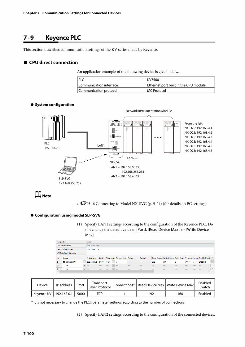
7-100
Chapter 7. Communication Settings for Connected Devices
7 - 9 Keyence PLC
This section describes communication settings of the KV series made by Keyence.
CPU direct connection
An application example of the following device is given below.
PLC KV7500Communication interface Ethernet port built in the CPU moduleCommunication protocol MC Protocol
z System configuration
PWR
NX-SVGN
USB
DA (+)
SG
DB (−) RS-485 CH1
RS-485
BATTERY
LINK/ACT
LAN1
FUNCTION ERROR
ID F1 F2
RUN MOD COM NST FAIL
SLP-SVG192.168.255.252
Network Instrumentation Module
From the left:NX-D25: 192.168.4.1NX-D25: 192.168.4.2NX-D25: 192.168.4.3NX-D25: 192.168.4.4NX-D25: 192.168.4.5NX-D25: 192.168.4.6
LAN1 = 192.168.0.127/ 192.168.255.253LAN2 = 192.168.4.127
LAN1
LAN2→
PLC 192.168.0.1
NX-SVG
Note
• 5 - 6 Connecting to Model NX-SVG (p. 5-24) (for details on PC settings)
z Configuration using model SLP-SVG
(1) Specify LAN1 settings according to the configuration of the Keyence PLC. Do not change the default value of [Port], [Read Device Max], or [Write Device Max].
Device IP address Port Transport Layer Protocol Connections* Read Device Max Write Device Max Enabled
Switch
Keyence KV 192.168.0.1 5000 TCP 1 192 160 Enabled
* It is not necessary to change the PLC’s parameter settings according to the number of connections.
(2) Specify LAN2 settings according to the configuration of the connected devices.
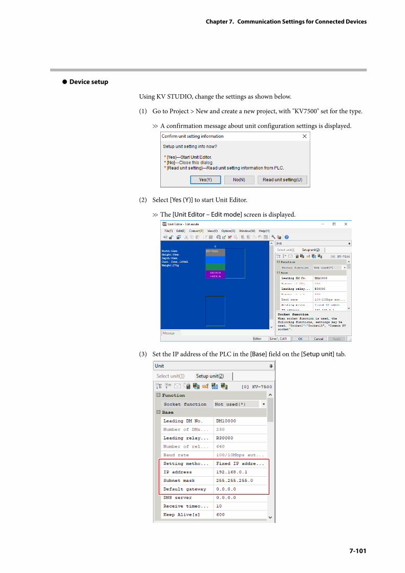
7-101
Chapter 7. Communication Settings for Connected Devices
z Device setup
Using KV STUDIO, change the settings as shown below.
(1) Go to Project > New and create a new project, with "KV7500" set for the type.
>> A confirmation message about unit configuration settings is displayed.
(2) Select [Yes (Y)] to start Unit Editor.
>> The [Unit Editor – Edit mode] screen is displayed.
(3) Set the IP address of the PLC in the [Base] field on the [Setup unit] tab.
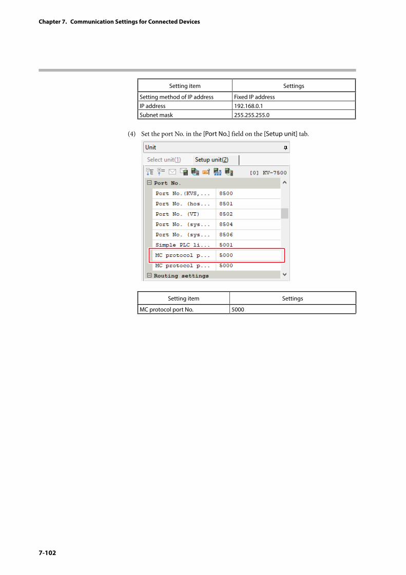
7-102
Chapter 7. Communication Settings for Connected Devices
Setting item Settings
Setting method of IP address Fixed IP addressIP address 192.168.0.1Subnet mask 255.255.255.0
(4) Set the port No. in the [Port No.] field on the [Setup unit] tab.
Setting item Settings
MC protocol port No. 5000
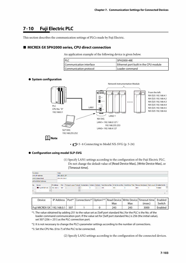
7-103
Chapter 7. Communication Settings for Connected Devices
7 - 10 Fuji Electric PLC
This section describes the communication settings of PLCs made by Fuji Electric.
MICREX-SX SPH2000 series, CPU direct connection
An application example of the following device is given below.
PLC SPH2000-48ECommunication interface Ethernet port built in the CPU moduleCommunication protocol Loader command
z System configuration
PWR
NX-SVGN
USB
DA(+)
SG
DB(−) RS-485 CH1
RS-485
BATTERY
LINK/ACT
LAN1
FUNCTION ERROR
ID F1 F2
RUN MOD COM NST FAIL
SLP-SVG192.168.255.252
Network Instrumentation Module
From the left:NX-D25 192.168.4.1NX-D25 192.168.4.2NX-D25 192.168.4.3NX-D25 192.168.4.4NX-D25 192.168.4.5NX-D25 192.168.4.6
LAN1= 192.168.0.127 / 192.168.255.253LAN2= 192.168.4.127
LAN1
LAN2
PLCCPU No. “0“192.168.0.1
NX-SVG
Note
• 5 - 6 Connecting to Model NX-SVG (p. 5-24)
z Configuration using model SLP-SVG
(1) Specify LAN1 settings according to the configuration of the Fuji Electric PLC. Do not change the default value of [Read Device Max], [Write Device Max], or [Timeout-time].
Device IP Address Port*1 Connections*2 Option1*3 Read Device Max
Write Device Max
Timeout-time (msec)
Enabled Switch
Fuji MICREX-SX 192.168.0.1 507 1 0 243 243 3000 Enabled
*1. The value obtained by adding 251 to the value set as [Self port standard No.] for the PLC is the No. of the loader command communication port. If the value set for [Self port standard No.] is 256 (the initial value), set 507 (256 + 251) as the PLC connection port.
*2. It is not necessary to change the PLC’s parameter settings according to the number of connections.
*3. Set the CPU No. (0 to 7) of the PLC to be connected.
(2) Specify LAN2 settings according to the configuration of the connected devices.
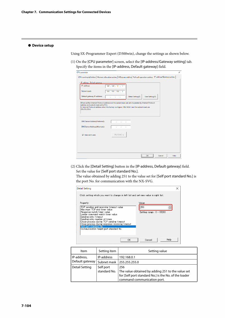
7-104
Chapter 7. Communication Settings for Connected Devices
z Device setup
Using SX-Programmer Expert (D300win), change the settings as shown below.
(1) On the [CPU parameter] screen, select the [IP-address/Gateway setting] tab. Specify the items in the [IP-address, Default gateway] field.
(2) Click the [Detail Setting] button in the [IP-address, Default gateway] field. Set the value for [Self port standard No.]. The value obtained by adding 251 to the value set for [Self port standard No.] is the port No. for communication with the NX-SVG.
Item Setting item Setting value
IP-address, Default gateway
IP-address 192.168.0.1Subnet mask 255.255.255.0
Detail Setting Self port standard No.
256 The value obtained by adding 251 to the value set for [Self port standard No.] is the No. of the loader command communication port.
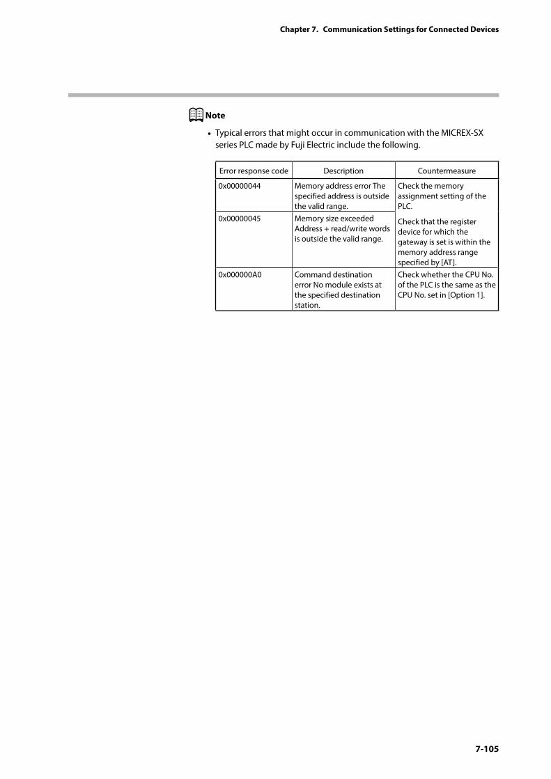
7-105
Chapter 7. Communication Settings for Connected Devices
Note
• Typical errors that might occur in communication with the MICREX-SX series PLC made by Fuji Electric include the following.
Error response code Description Countermeasure
0x00000044 Memory address error The specified address is outside the valid range.
Check the memory assignment setting of the PLC.
Check that the register device for which the gateway is set is within the memory address range specified by [AT].
0x00000045 Memory size exceeded Address + read/write words is outside the valid range.
0x000000A0 Command destination error No module exists at the specified destination station.
Check whether the CPU No. of the PLC is the same as the CPU No. set in [Option 1].
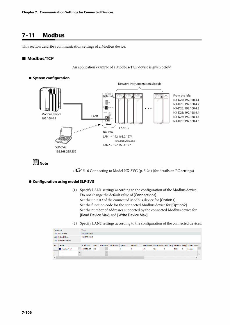
7-106
Chapter 7. Communication Settings for Connected Devices
7 - 11 Modbus
This section describes communication settings of a Modbus device.
Modbus/TCP
An application example of a Modbus/TCP device is given below.
z System configuration
PWR
NX-SVGN
USB
DA (+)
SG
DB (−) RS-485 CH1
RS-485
BATTERY
LINK/ ACT
LAN1
FUNCTION ERROR
ID F1 F2
RUN MOD COM NST FAIL
SLP-SVG192.168.255.252
Network Instrumentation Module
From the left:NX-D25: 192.168.4.1NX-D25: 192.168.4.2NX-D25: 192.168.4.3NX-D25: 192.168.4.4NX-D25: 192.168.4.5NX-D25: 192.168.4.6
LAN1 = 192.168.0.127/ 192.168.255.253LAN2 = 192.168.4.127
LAN1
LAN2→
Modbus device192.168.0.1
NX-SVG
Note
• 5 - 6 Connecting to Model NX-SVG (p. 5-24) (for details on PC settings)
z Configuration using model SLP-SVG
(1) Specify LAN1 settings according to the configuration of the Modbus device. Do not change the default value of [Connections]. Set the unit ID of the connected Modbus device for [Option1]. Set the function code for the connected Modbus device for [Option2]. Set the number of addresses supported by the connected Modbus device for [Read Device Max] and [Write Device Max].
(2) Specify LAN2 settings according to the configuration of the connected devices.
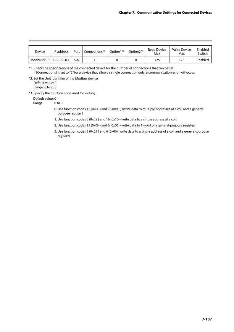
7-107
Chapter 7. Communication Settings for Connected Devices
Device IP address Port Connections*1 Option1*2 Option2*3 Read Device Max
Write Device Max
Enabled Switch
Modbus/TCP 192.168.0.1 502 1 0 0 125 123 Enabled
*1. Check the specifications of the connected device for the number of connections that can be set. If [Connections] is set to "2” for a device that allows a single connection only, a communication error will occur.
*2. Set the Unit Identifier of the Modbus device. Default value: 0 Range: 0 to 255
*3. Specify the function code used for writing.
Default value: 0 Range: 0 to 3
0: Use function codes 15 (0x0F ) and 16 (0x10) (write data to multiple addresses of a coil and a general-purpose register)
1: Use function codes 5 (0x05 ) and 16 (0x10) (write data to a single address of a coil)
2: Use function codes 15 (0x0F ) and 6 (0x06) (write data to 1 word of a general-purpose register)
3: Use function codes 5 (0x05 ) and 6 (0x06) (write data to a single address of a coil and a general-purpose register)
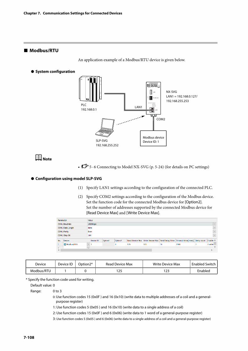
7-108
Chapter 7. Communication Settings for Connected Devices
Modbus/RTU
An application example of a Modbus/RTU device is given below.
z System configuration
PWR
NX-SVGN
USB
DA (+)
SG
DB (−) RS-485 CH1
RS-485
BATTERY
LINK/ACT
LAN1
FUNCTION ERROR
ID F1 F2
RUN MOD COM NST FAIL
SLP-SVG192.168.255.252
NX-SVGLAN1 = 192.168.0.127/192.168.255.253
LAN1PLC192.168.0.1
COM2
Modbus deviceDevice ID: 1
Note
• 5 - 6 Connecting to Model NX-SVG (p. 5-24) (for details on PC settings)
z Configuration using model SLP-SVG
(1) Specify LAN1 settings according to the configuration of the connected PLC.
(2) Specify COM2 settings according to the configuration of the Modbus device. Set the function code for the connected Modbus device for [Option2]. Set the number of addresses supported by the connected Modbus device for [Read Device Max] and [Write Device Max].
Device Device ID Option2* Read Device Max Write Device Max Enabled Switch
Modbus/RTU 1 0 125 123 Enabled
* Specify the function code used for writing.
Default value: 0
Range: 0 to 3
0: Use function codes 15 (0x0F ) and 16 (0x10) (write data to multiple addresses of a coil and a general-purpose register)
1: Use function codes 5 (0x05 ) and 16 (0x10) (write data to a single address of a coil)
2: Use function codes 15 (0x0F ) and 6 (0x06) (write data to 1 word of a general-purpose register)
3: Use function codes 5 (0x05 ) and 6 (0x06) (write data to a single address of a coil and a general-purpose register)
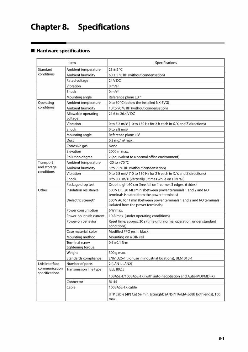
8-1
Chapter 8. Specifications
Hardware specifications
Item Specifications
Standard conditions
Ambient temperature 23 ± 2 °CAmbient humidity 60 ± 5 % RH (without condensation)Rated voltage 24 V DCVibration 0 m/s2
Shock 0 m/s2
Mounting angle Reference plane ±3 °Operating conditions
Ambient temperature 0 to 50 °C (below the installed NX-SVG)Ambient humidity 10 to 90 % RH (without condensation)Allowable operating voltage
21.6 to 26.4 V DC
Vibration 0 to 3.2 m/s2 (10 to 150 Hz for 2 h each in X, Y, and Z directions)Shock 0 to 9.8 m/s2
Mounting angle Reference plane ±3°Dust 0.3 mg/m3 max.Corrosive gas NoneElevation 2000 m max.Pollution degree 2 (equivalent to a normal office environment)
Transport and storage conditions
Ambient temperature -20 to +70 °CAmbient humidity 5 to 95 % RH (without condensation)Vibration 0 to 9.8 m/s2 (10 to 150 Hz for 2 h each in X, Y, and Z directions)Shock 0 to 300 m/s2 (vertically 3 times while on DIN rail)Package drop test Drop height 60 cm (free fall on 1 corner, 3 edges, 6 sides)
Other Insulation resistance 500 V DC, 20 MΩ min. (between power terminals 1 and 2 and I/O terminals isolated from the power terminals)
Dielectric strength 500 V AC for 1 min (between power terminals 1 and 2 and I/O terminals isolated from the power terminals)
Power consumption 6 W max.Power-on inrush current 10 A max. (under operating conditions)Power-on behavior Reset time: approx. 30 s (time until normal operation, under standard
conditions)Case material, color Modified PPO resin, blackMounting method Mounting on a DIN railTerminal screw tightening torque
0.6 ±0.1 N·m
Weight 300 g max.Standards compliance EN61326-1 (For use in industrial locations), UL61010-1
LAN interface communication specifications
Number of ports 2 (LAN1, LAN2)Transmission line type IEEE 802.3
10BASE-T/100BASE-TX (with auto-negotiation and Auto-MDI/MDI-X)Connector RJ-45Cable 100BASE-TX cable
UTP cable (4P) Cat 5e min. (straight) (ANSI/TIA/EIA-568B both ends), 100 max.
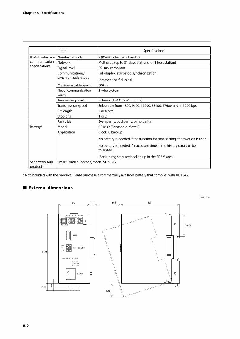
8-2
Chapter 8. Specifications
Item Specifications
RS-485 interface communication specifications
Number of ports 2 (RS-485 channels 1 and 2)Network Multidrop (up to 31 slave stations for 1 host station)Signal level RS-485-compliantCommunications/synchronization type
Full-duplex, start-stop synchronization
(protocol: half-duplex)Maximum cable length 500 mNo. of communication wires
3-wire system
Terminating resistor External (150 Ω ½ W or more)Transmission speed Selectable from 4800, 9600, 19200, 38400, 57600 and 115200 bpsBit length 7 or 8 bitsStop bits 1 or 2Parity bit Even parity, odd parity, or no parity
Battery* Model CR1632 (Panasonic, Maxell)Application Clock IC backup
No battery is needed if the function for time setting at power-on is used.
No battery is needed if inaccurate time in the history data can be tolerated.
(Backup registers are backed up in the FRAM area.)Separately sold product
Smart Loader Package, model SLP-SVG
* Not included with the product. Please purchase a commercially available battery that complies with UL 1642.
External dimensions
Unit: mm
(20)
840.3
32.3
845
(10) 5
100
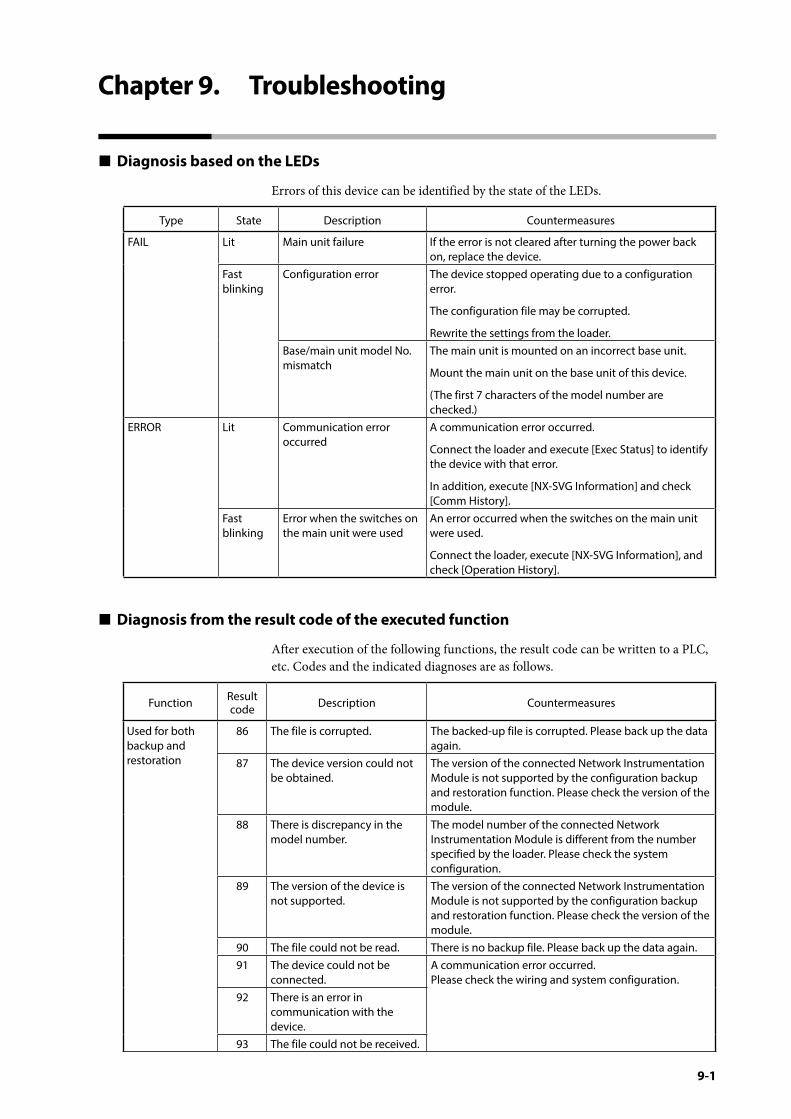
9-1
Chapter 9. Troubleshooting
Diagnosis based on the LEDs
Errors of this device can be identified by the state of the LEDs.
Type State Description Countermeasures
FAIL Lit Main unit failure If the error is not cleared after turning the power back on, replace the device.
Fast blinking
Configuration error The device stopped operating due to a configuration error.
The configuration file may be corrupted.
Rewrite the settings from the loader.Base/main unit model No. mismatch
The main unit is mounted on an incorrect base unit.
Mount the main unit on the base unit of this device.
(The first 7 characters of the model number are checked.)
ERROR Lit Communication error occurred
A communication error occurred.
Connect the loader and execute [Exec Status] to identify the device with that error.
In addition, execute [NX-SVG Information] and check [Comm History].
Fast blinking
Error when the switches on the main unit were used
An error occurred when the switches on the main unit were used.
Connect the loader, execute [NX-SVG Information], and check [Operation History].
Diagnosis from the result code of the executed function
After execution of the following functions, the result code can be written to a PLC, etc. Codes and the indicated diagnoses are as follows.
Function Result code Description Countermeasures
Used for both backup and restoration
86 The file is corrupted. The backed-up file is corrupted. Please back up the data again.
87 The device version could not be obtained.
The version of the connected Network Instrumentation Module is not supported by the configuration backup and restoration function. Please check the version of the module.
88 There is discrepancy in the model number.
The model number of the connected Network Instrumentation Module is different from the number specified by the loader. Please check the system configuration.
89 The version of the device is not supported.
The version of the connected Network Instrumentation Module is not supported by the configuration backup and restoration function. Please check the version of the module.
90 The file could not be read. There is no backup file. Please back up the data again.91 The device could not be
connected.A communication error occurred. Please check the wiring and system configuration.
92 There is an error in communication with the device.
93 The file could not be received.
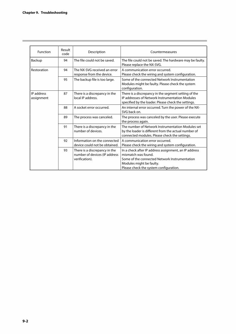
9-2
Chapter 9. Troubleshooting
Function Result code Description Countermeasures
Backup 94 The file could not be saved. The file could not be saved. The hardware may be faulty. Please replace the NX-SVG.
Restoration 94 The NX-SVG received an error response from the device.
A communication error occurred. Please check the wiring and system configuration.
95 The backup file is too large. Some of the connected Network Instrumentation Modules might be faulty. Please check the system configuration.
IP address assignment
87 There is a discrepancy in the local IP address.
There is a discrepancy in the segment setting of the IP addresses of Network Instrumentation Modules specified by the loader. Please check the settings.
88 A socket error occurred. An internal error occurred. Turn the power of the NX-SVG back on.
89 The process was canceled. The process was canceled by the user. Please execute the process again.
91 There is a discrepancy in the number of devices.
The number of Network Instrumentation Modules set by the loader is different from the actual number of connected modules. Please check the settings.
92 Information on the connected device could not be obtained.
A communication error occurred. Please check the wiring and system configuration.
93 There is a discrepancy in the number of devices (IP address verification).
In a check after IP address assignment, an IP address mismatch was found. Some of the connected Network Instrumentation Modules might be faulty. Please check the system configuration.
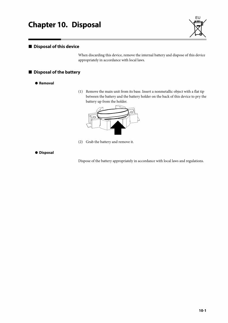
10-1
Chapter 10. DisposalEU
Disposal of this device
When discarding this device, remove the internal battery and dispose of this device appropriately in accordance with local laws.
Disposal of the battery
z Removal
(1) Remove the main unit from its base. Insert a nonmetallic object with a flat tip between the battery and the battery holder on the back of this device to pry the battery up from the holder.
(2) Grab the battery and remove it.
z Disposal
Dispose of the battery appropriately in accordance with local laws and regulations.

11-1
Chapter 11. Open Source Software
This device uses the following open source software. For the license statement of this software, please download Open Source Software License (CP-SP-1438E) from [Software download] on Azbil’s Compo Club website.
The source code of each piece of software may be reproduced, distributed or modified in accordance with the conditions stipulated in the license terms of the software. The source code can be downloaded from [Software download] on Azbil’s Compo Club website. The copyright of each piece of software belongs to the copyright holder described in the source code.
Regarding “Terms and Conditions,” for the open source part of our product, the license terms of the open source software take precedence.
The disclaimer for open source software is as described in its license, but it does not affect the warranty terms of this product. In addition, we cannot answer questions about the content and handling of source code.
Software name Version License
u-boot 2016.05 GPLv2Linux 4.4 GPLv2binutils 2.25.1 GPLv2bison 3.0.4 GPLv3busybox 1.25.1 GPLv2db 4.7.25 BSDdropbear 2017.75 MITexpat 2.2.0 BSDflex 2.6.0 BSDgcc 4.9.4 GPLv2gdbserver 7.10.1 GPLv3glibc 2.19 GPLv2gmock 1.4.0 BSDgmp 6.1.1 GPLv3gtest 1.4.0 BSDiproute2 3.18.0 GPLv2iptables 1.6.1 GPLv2libelf 0.8.13 LGPLlibxml2 2.9.4 MITlighttpd 1.4.44 BSDm4 1.4.17 GPLv2mmc-utils 20160623-a3d3331 GPLv2mpc 1.0.3 LGPLv3mpfr 3.1.3 LGPLv3ncurses 6.0 MITopenssl 1.0.2k OpenSSLpam 1.3.0 GPLv2/BSDpcre 8.39 BSDphp 5.6.30 PHP License, version 3.01sqlite3 3140200 Public Domainstressapptest 1.0.8 Apache License 2.0tzdata 2016e Public Domain, LGPzlib 1.2.8 BSDzip 3.0 BSD

This product includes PHP software, freely available from <http://www.php.net/software/>
This product includes software developed by the OpenSSL Project for use in the OpenSSL Toolkit (http://www.openssl.org/)
This product includes cryptographic software written by Eric Young ([email protected])
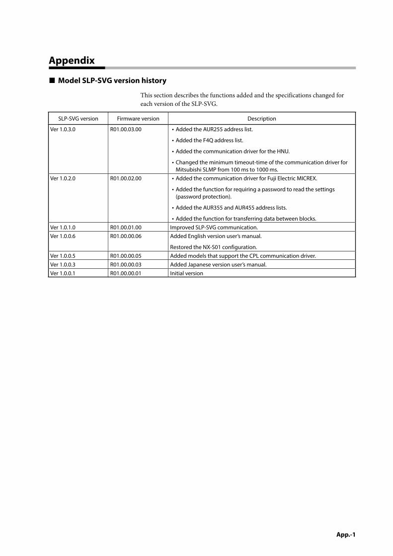
App.-1
Appendix
Model SLP-SVG version history
This section describes the functions added and the specifications changed for each version of the SLP-SVG.
SLP-SVG version Firmware version Description
Ver 1.0.3.0 R01.00.03.00 • Added the AUR255 address list.
• Added the F4Q address list.
• Added the communication driver for the HNU.
• Changed the minimum timeout-time of the communication driver for Mitsubishi SLMP from 100 ms to 1000 ms.
Ver 1.0.2.0 R01.00.02.00 • Added the communication driver for Fuji Electric MICREX.
• Added the function for requiring a password to read the settings (password protection).
• Added the AUR355 and AUR455 address lists.
• Added the function for transferring data between blocks.Ver 1.0.1.0 R01.00.01.00 Improved SLP-SVG communication.Ver 1.0.0.6 R01.00.00.06 Added English version user’s manual.
Restored the NX-S01 configuration.Ver 1.0.0.5 R01.00.00.05 Added models that support the CPL communication driver.Ver 1.0.0.3 R01.00.00.03 Added Japanese version user’s manual.Ver 1.0.0.1 R01.00.00.01 Initial version

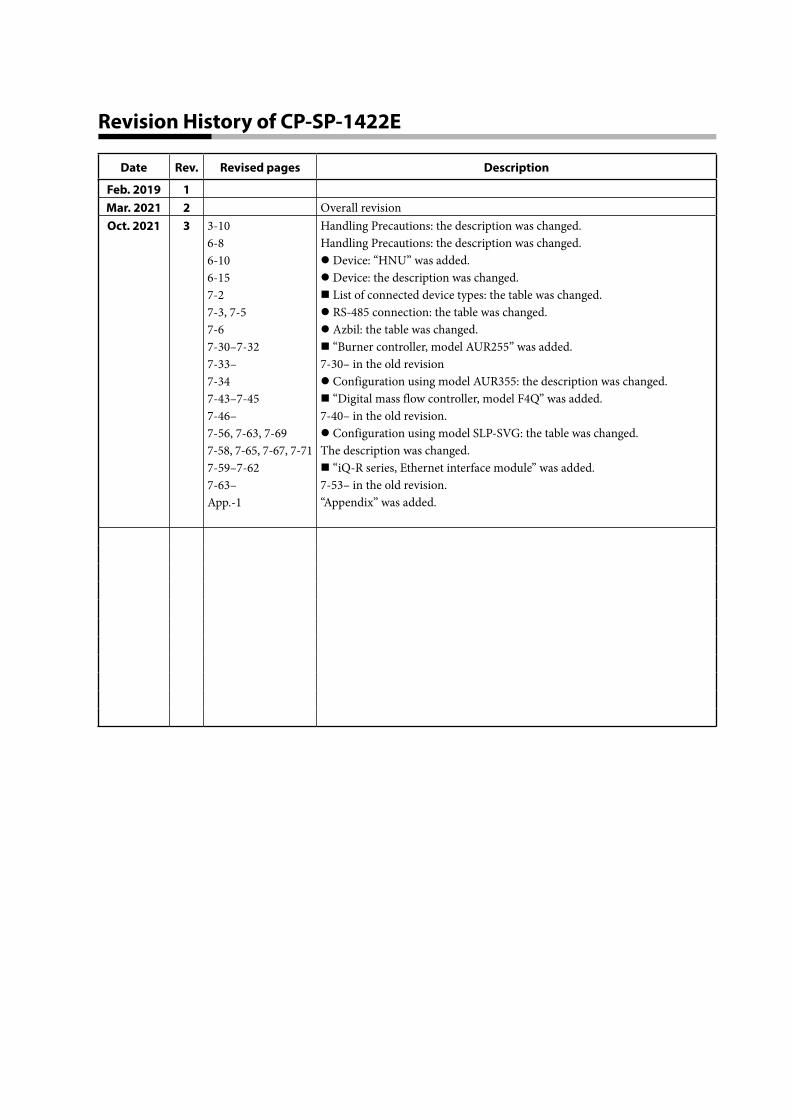
Revision History of CP-SP-1422E
Date Rev. Revised pages Description
Feb. 2019 1Mar. 2021 2 Overall revisionOct. 2021 3 3-10
6-86-106-157-27-3, 7-57-67-30–7-327-33–7-347-43–7-457-46–7-56, 7-63, 7-697-58, 7-65, 7-67, 7-717-59–7-627-63–App.-1
Handling Precautions: the description was changed.Handling Precautions: the description was changed.z Device: “HNU” was added.z Device: the description was changed. List of connected device types: the table was changed.z RS-485 connection: the table was changed.z Azbil: the table was changed. “Burner controller, model AUR255” was added.7-30– in the old revisionz Configuration using model AUR355: the description was changed. “Digital mass flow controller, model F4Q” was added.7-40– in the old revision.z Configuration using model SLP-SVG: the table was changed.The description was changed. “iQ-R series, Ethernet interface module” was added.7-53– in the old revision.“Appendix” was added.
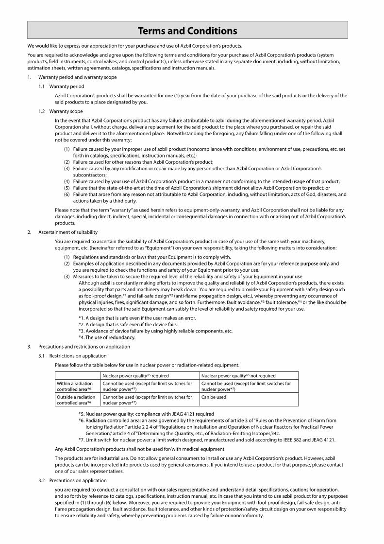
We would like to express our appreciation for your purchase and use of Azbil Corporation’s products.
You are required to acknowledge and agree upon the following terms and conditions for your purchase of Azbil Corporation’s products (system products, field instruments, control valves, and control products), unless otherwise stated in any separate document, including, without limitation, estimation sheets, written agreements, catalogs, specifications and instruction manuals.
1. Warranty period and warranty scope
1.1 Warranty period
Azbil Corporation’s products shall be warranted for one (1) year from the date of your purchase of the said products or the delivery of the said products to a place designated by you.
1.2 Warranty scope
In the event that Azbil Corporation’s product has any failure attributable to azbil during the aforementioned warranty period, Azbil Corporation shall, without charge, deliver a replacement for the said product to the place where you purchased, or repair the said product and deliver it to the aforementioned place. Notwithstanding the foregoing, any failure falling under one of the following shall not be covered under this warranty:
(1) Failure caused by your improper use of azbil product (noncompliance with conditions, environment of use, precautions, etc. set forth in catalogs, specifications, instruction manuals, etc.);
(2) Failure caused for other reasons than Azbil Corporation’s product;(3) Failure caused by any modification or repair made by any person other than Azbil Corporation or Azbil Corporation’s
subcontractors; (4) Failure caused by your use of Azbil Corporation’s product in a manner not conforming to the intended usage of that product; (5) Failure that the state-of-the-art at the time of Azbil Corporation’s shipment did not allow Azbil Corporation to predict; or (6) Failure that arose from any reason not attributable to Azbil Corporation, including, without limitation, acts of God, disasters, and
actions taken by a third party.
Please note that the term “warranty” as used herein refers to equipment-only-warranty, and Azbil Corporation shall not be liable for any damages, including direct, indirect, special, incidental or consequential damages in connection with or arising out of Azbil Corporation’s products.
2. Ascertainment of suitability
You are required to ascertain the suitability of Azbil Corporation’s product in case of your use of the same with your machinery, equipment, etc. (hereinafter referred to as “Equipment”) on your own responsibility, taking the following matters into consideration:
(1) Regulations and standards or laws that your Equipment is to comply with.(2) Examples of application described in any documents provided by Azbil Corporation are for your reference purpose only, and
you are required to check the functions and safety of your Equipment prior to your use. (3) Measures to be taken to secure the required level of the reliability and safety of your Equipment in your use
Although azbil is constantly making efforts to improve the quality and reliability of Azbil Corporation’s products, there exists a possibility that parts and machinery may break down. You are required to provide your Equipment with safety design such as fool-proof design,*1 and fail-safe design*2 (anti-flame propagation design, etc.), whereby preventing any occurrence of physical injuries, fires, significant damage, and so forth. Furthermore, fault avoidance,*3 fault tolerance,*4 or the like should be incorporated so that the said Equipment can satisfy the level of reliability and safety required for your use.
*1. A design that is safe even if the user makes an error. *2. A design that is safe even if the device fails. *3. Avoidance of device failure by using highly reliable components, etc. *4. The use of redundancy.
3. Precautions and restrictions on application
3.1 Restrictions on application
Please follow the table below for use in nuclear power or radiation-related equipment.
Nuclear power quality*5 required Nuclear power quality*5 not required
Within a radiation controlled area*6
Cannot be used (except for limit switches for nuclear power*7)
Cannot be used (except for limit switches for nuclear power*7)
Outside a radiation controlled area*6
Cannot be used (except for limit switches for nuclear power*7)
Can be used
*5. Nuclear power quality: compliance with JEAG 4121 required*6. Radiation controlled area: an area governed by the requirements of article 3 of “Rules on the Prevention of Harm from
Ionizing Radiation,” article 2 2 4 of “Regulations on Installation and Operation of Nuclear Reactors for Practical Power Generation,” article 4 of “Determining the Quantity, etc., of Radiation-Emitting Isotopes,”etc.
*7. Limit switch for nuclear power: a limit switch designed, manufactured and sold according to IEEE 382 and JEAG 4121.
Any Azbil Corporation’s products shall not be used for/with medical equipment.
The products are for industrial use. Do not allow general consumers to install or use any Azbil Corporation’s product. However, azbil products can be incorporated into products used by general consumers. If you intend to use a product for that purpose, please contact one of our sales representatives.
3.2 Precautions on application
you are required to conduct a consultation with our sales representative and understand detail specifications, cautions for operation, and so forth by reference to catalogs, specifications, instruction manual, etc. in case that you intend to use azbil product for any purposes specified in (1) through (6) below. Moreover, you are required to provide your Equipment with fool-proof design, fail-safe design, anti-flame propagation design, fault avoidance, fault tolerance, and other kinds of protection/safety circuit design on your own responsibility to ensure reliability and safety, whereby preventing problems caused by failure or nonconformity.
Terms and Conditions
(1) For use under such conditions or in such environments as not stated in technical documents, including catalogs, specification, and instruction manuals
(2) For use of specific purposes, such as: * Nuclear energy/radiation related facilities
[When used outside a radiation controlled area and where nuclear power quality is not required] [When the limit switch for nuclear power is used]
* Machinery or equipment for space/sea bottom * Transportation equipment [Railway, aircraft, vessels, vehicle equipment, etc.] * Antidisaster/crime-prevention equipment * Burning appliances * Electrothermal equipment * Amusement facilities * Facilities/applications associated directly with billing
(3) Supply systems such as electricity/gas/water supply systems, large-scale communication systems, and traffic/air traffic control systems requiring high reliability
(4) Facilities that are to comply with regulations of governmental/public agencies or specific industries (5) Machinery or equipment that may affect human lives, human bodies or properties (6) Other machinery or equipment equivalent to those set forth in items (1) to (5) above which require high reliability and safety
4. Precautions against long-term use
Use of Azbil Corporation’s products, including switches, which contain electronic components, over a prolonged period may degrade insulation or increase contact-resistance and may result in heat generation or any other similar problem causing such product or switch to develop safety hazards such as smoking, ignition, and electrification. Although acceleration of the above situation varies depending on the conditions or environment of use of the products, you are required not to use any Azbil Corporation’s products for a period exceeding ten (10) years unless otherwise stated in specifications or instruction manuals.
5. Recommendation for renewal
Mechanical components, such as relays and switches, used for Azbil Corporation’s products will reach the end of their life due to wear by repetitious open/close operations.
In addition, electronic components such as electrolytic capacitors will reach the end of their life due to aged deterioration based on the conditions or environment in which such electronic components are used. Although acceleration of the above situation varies depending on the conditions or environment of use, the number of open/close operations of relays, etc. as prescribed in specifications or instruction manuals, or depending on the design margin of your machine or equipment, you are required to renew any Azbil Corporation’s products every 5 to 10 years unless otherwise specified in specifications or instruction manuals. System products, field instruments (sensors such as pressure/flow/level sensors, regulating valves, etc.) will reach the end of their life due to aged deterioration of parts. For those parts that will reach the end of their life due to aged deterioration, recommended replacement cycles are prescribed. You are required to replace parts based on such recommended replacement cycles.
6. Other precautions
Prior to your use of Azbil Corporation’s products, you are required to understand and comply with specifications (e.g., conditions and environment of use), precautions, warnings/cautions/notices as set forth in the technical documents prepared for individual Azbil Corporation’s products, such as catalogs, specifications, and instruction manuals to ensure the quality, reliability, and safety of those products.
7. Changes to specifications
Please note that the descriptions contained in any documents provided by azbil are subject to change without notice for improvement or for any other reason. For inquires or information on specifications as you may need to check, please contact our branch offices or sales offices, or your local sales agents.
8. Discontinuance of the supply of products/parts
Please note that the production of any Azbil Corporation’s product may be discontinued without notice. After manufacturing is discontinued, we may not be able to provide replacement products even within the warranty period.
For repairable products, we will, in principle, undertake repairs for five (5) years after the discontinuance of those products. In some cases, however, we cannot undertake such repairs for reasons, such as the absence of repair parts. For system products, field instruments, we may not be able to undertake parts replacement for similar reasons.
9. Scope of services
Prices of Azbil Corporation’s products do not include any charges for services such as engineer dispatch service. Accordingly, a separate fee will be charged in any of the following cases:
(1) Installation, adjustment, guidance, and attendance at a test run (2) Maintenance, inspection, adjustment, and repair(3) Technical guidance and technical education (4) Special test or special inspection of a product under the conditions specified by you
Please note that we cannot provide any services as set forth above in a nuclear energy controlled area (radiation controlled area) or at a place where the level of exposure to radiation is equivalent to that in a nuclear energy controlled area.
AAS-511A-014-10

(11)Specifications are subject to change without notice.
1-12-2 Kawana, FujisawaKanagawa 251-8522 Japan
https://www.azbil.com1st edition: Feb. 2019 (V)3rd edition: Oct. 2021 (S)