navigation sensors and systems in gnss degraded and
TRANSCRIPT
STO-EN-SET-197 1 - 1
Navigation Sensors and Systems in GNSS Degraded and Denied
Environments
George T. Schmidt Consultant
10 Goffe Road
Lexington, MA 02421
USA
ABSTRACT
Position, velocity, and timing (PVT) signals from the Global Positioning System (GPS) are used throughout the
world but the availability and reliability of these signals in all environments has become a subject of concern for
both military and civilian applications. International news reports about a successful spoofing attack on a
civilian UAV at the White Sands Missile Range in New Mexico, USA have increased concerns over the planned
use of UAVs in the national airspace and safety of flight in general. Other examples of the effects of GPS
interference and jamming are illustrated in this presentation. This is a particularly difficult problem that
requires new and innovative ideas to fill the PVT gap when the data are degraded or unavailable. One solution
is to use inertial and/ or other sensors to bridge the gap in navigation information. This presentation summarizes
recent advances in navigation sensor technology, including GPS, inertial, and other navigation aids. This
presentation also describes recent advances in sensor integration technology and the synergistic benefits are
explored. Expected technology improvements to system robustness are also described. Applications being made
possible by this advanced performance include personal navigation systems, robotic navigation, and
autonomous systems with unprecedented low-cost and accuracy.
1.0 INTRODUCTION
The Global Positioning System (GPS) is the most developed and widely used Global Navigation Satellite
System (GNSS). GPS signals are part of the national infrastructure that is used in transportation (navigation),
communications (timing), banking and finance (timing), and energy distribution (timing). In February 2012,
the United States Congress passed the Federal Aviation Agency (FAA) Modernization and Reform Act which
requires the FAA to develop a “comprehensive plan for safely accelerating the integration of civil UAVs into
the national airspace system by 2015.” Presumably those UAVs would be navigated using the C/A signal of
the GPS. Shortly thereafter, a University of Texas “spoofing” demonstration was conducted at the request of
the Department of Homeland Security and it was demonstrated that false GPS information could be
introduced into the UAV onboard navigation system [1]. This demonstration certainly increased the concern
over the use of UAVs in the national airspace and in safety of flight, in general when using, civil GPS.
Navigation Sensors and Systems in GNSS Degraded and Denied Environments
1 - 2 STO-EN-SET-197
Another notable incident with civil GPS occurred when the Local-Area Augmentation System (LAAS)
installed its first Ground-Based Augmentation System (GBAS) at Newark airport in November 2009 [2].
Within the first days of its installation, radio-frequency interference (RFI) was found to be causing errors in
GBAS processing. The source of the RFI could not be immediately determined. The FAA started an
investigation involving detection and characterization of the RFI. After equipment was deployed on January
20, 2010, in one day more than 25 separate instances of RFI interference in the GPS L1 band were detected.
Some of the RFI events were strong enough to result in the WAAS receiver loosing tracking of lower
elevation GPS satellites. It was many months before the cause was determined to be from various kinds of
“personal privacy” devices in vehicles moving along the New Jersey Turnpike adjacent to the airport. In 2010
the Federal Communications Commission Enforcement Bureau filed 21 actions against on-line retailers in 12
states for illegally marketing more than 215 models of wireless jammers nearly 80 of which could jam GPS
signals, but such devices are likely still available.[3]
Military uses of GPS also include navigation and timing applications and interference in the GPS frequency
bands is of great concern. The GPS signal on Earth (which has frequently been likened to a 25-watt light bulb
shining on Earth from 12,500 miles away) is very weak (about 1.6 x 10⁻¹⁶
watts) by the time it reaches Earth.
One measure of a receiver’s ability to acquire and lock-on to the signal from a GPS satellite in the presence of
background noise is the maximum ratio of the strength of the background noise, or jamming signal (J), to the
strength of the signal from the satellite (S) at which the receiver can continue to process the GPS signal. That
ratio, often called the jammer-to-signal (J/S) ratio, is significantly greater than 1.
The maximum J/S for a typical military receiver acquiring the civilian GPS signal is 250; for acquiring the
military GPS signal the maximum J/S is much larger, up to 2500. Once the receiver has acquired a military
GPS signal, it can lock-on to it in the presence of jamming signals up to 12,600 times stronger than the GPS
signal. However, jammers anywhere near the receiver present a clear and present danger to loosing
navigation capability because the jammer need only be greater than approximately 2 x 10-12
watts [4, p.6].
Personal protection devices and jammers can easily exceed that power level.
Thus GPS may not be available in a jamming or disturbed environment. GPS may also be degraded or denied
in challenging environments such as deep valleys, indoors, or underwater. More sensitive GPS receivers might
be required [5]. Pseudolites, beacons, and signals of opportunity might be used to create navigation
information [6]. There are many situations that then require additional sensors to augment GPS or entire
stand-alone navigation devices to integrate with GPS, such as inertial systems [7,8] or 3-axis magnetometers
matching a magnetic field map [9]. New integration techniques may be required [10,11] and possibly real-
time kinematic navigation [12]. These subjects are discussed in companion papers to this one. This paper will
describe GPS status and plans, interference, inertial systems, integration techniques, and some system
simulations.
2.0 GPS STATUS AND PLANS
The Department of Defense (DoD) is continually modernizing the GPS by purchasing new satellites and
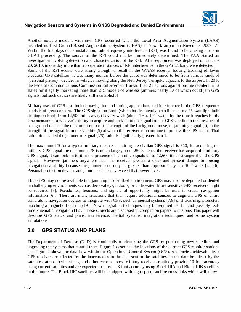
upgrading the systems that control them. Figure 1 describes the locations of the current GPS monitor stations
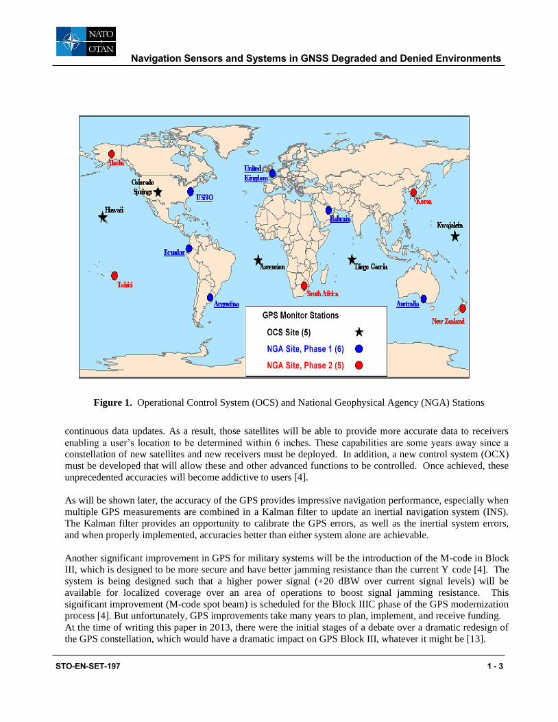
and Figure 2 shows the data flow within the Operational Control System (OCS). Accuracies achievable by a
GPS receiver are affected by the inaccuracies in the data sent to the satellites, in the data broadcast by the
satellites, atmospheric effects, and other error sources. Military receivers routinely provide 10 foot accuracy
using current satellites and are expected to provide 3 foot accuracy using Block IIIA and Block IIIB satellites
in the future. The Block IIIC satellites will be equipped with high-speed satellite cross-links which will allow
Navigation Sensors and Systems in GNSS Degraded and Denied Environments
STO-EN-SET-197 1 - 3
2.0
3.0
4.0
5.0
6.0
7.0
8.0
9.0
10.0
Figure 1. Operational Control System (OCS) and National Geophysical Agency (NGA) Stations
continuous data updates. As a result, those satellites will be able to provide more accurate data to receivers
enabling a user’s location to be determined within 6 inches. These capabilities are some years away since a
constellation of new satellites and new receivers must be deployed. In addition, a new control system (OCX)
must be developed that will allow these and other advanced functions to be controlled. Once achieved, these
unprecedented accuracies will become addictive to users [4].
As will be shown later, the accuracy of the GPS provides impressive navigation performance, especially when
multiple GPS measurements are combined in a Kalman filter to update an inertial navigation system (INS).
The Kalman filter provides an opportunity to calibrate the GPS errors, as well as the inertial system errors,
and when properly implemented, accuracies better than either system alone are achievable.
Another significant improvement in GPS for military systems will be the introduction of the M-code in Block
III, which is designed to be more secure and have better jamming resistance than the current Y code [4]. The
system is being designed such that a higher power signal (+20 dBW over current signal levels) will be
available for localized coverage over an area of operations to boost signal jamming resistance. This
significant improvement (M-code spot beam) is scheduled for the Block IIIC phase of the GPS modernization
process [4]. But unfortunately, GPS improvements take many years to plan, implement, and receive funding.
At the time of writing this paper in 2013, there were the initial stages of a debate over a dramatic redesign of
the GPS constellation, which would have a dramatic impact on GPS Block III, whatever it might be [13].
Navigation Sensors and Systems in GNSS Degraded and Denied Environments
1 - 4 STO-EN-SET-197
Figure 2. Operational Control System Data Flow
3.0 GPS INTERFERENCE AND ATTENUATION ISSUES
Interference to the reception of GPS signals can be due to many causes such as telecommunication devices,
local interference from signals or oscillators on the same platform, or possibly radar signals in nearby
frequency bands. Attenuation of the GPS signal can be caused by trees, buildings, or antenna orientation, and
result in reduced signal/noise ratio even without interference. This loss of signal can result in an increase in
effective jammer/signal (J/S) level even without intentional jamming or interference.
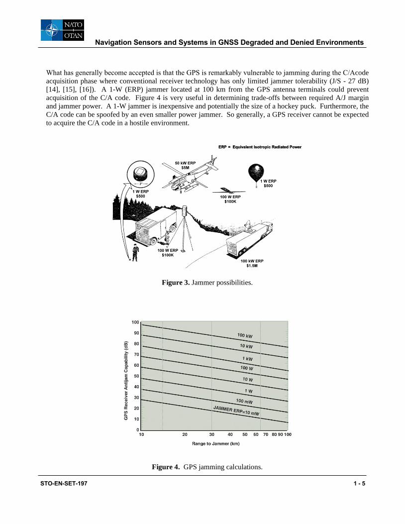
Military receivers are at risk due to intentional jamming. Jammers as small as 1 Watt located at 100 km from
the receiver can possibly prevent a military receiver from acquiring the satellite signals and “locking-on” to
C/A code. Representative jammers are shown in Figure 3 [Ref.4]. Larger jammers are good targets to find
and to attack because of their large radiated power. Smaller jammers, which are hard to find, need to be
defended against by improved anti-jam (A/J) technologies within the receiver, improved antennas, or by
integration with an inertial navigation system or other devices. Proponents of high-accuracy inertial systems
will generally argue that a high anti-jam GPS receiver is not required, while receiver proponents will argue
that using a higher A/J receiver will substantially reduce inertial system accuracy requirements and cost. Both
arguments depend entirely on the usually ill-defined mission and jamming scenario.
Navigation Sensors and Systems in GNSS Degraded and Denied Environments
STO-EN-SET-197 1 - 5
What has generally become accepted is that the GPS is remarkably vulnerable to jamming during the C/Acode
acquisition phase where conventional receiver technology has only limited jammer tolerability (J/S - 27 dB)
[14], [15], [16]). A 1-W (ERP) jammer located at 100 km from the GPS antenna terminals could prevent
acquisition of the C/A code. Figure 4 is very useful in determining trade-offs between required A/J margin
and jammer power. A 1-W jammer is inexpensive and potentially the size of a hockey puck. Furthermore, the
C/A code can be spoofed by an even smaller power jammer. So generally, a GPS receiver cannot be expected
to acquire the C/A code in a hostile environment.
EERRPP == E Eqquuivivalalenentt IIsosottrrooppicic R Raaddiaiatteded P Poowwerer
Figure 3. Jammer possibilities.
Figure 4. GPS jamming calculations.
Navigation Sensors and Systems in GNSS Degraded and Denied Environments
1 - 6 STO-EN-SET-197
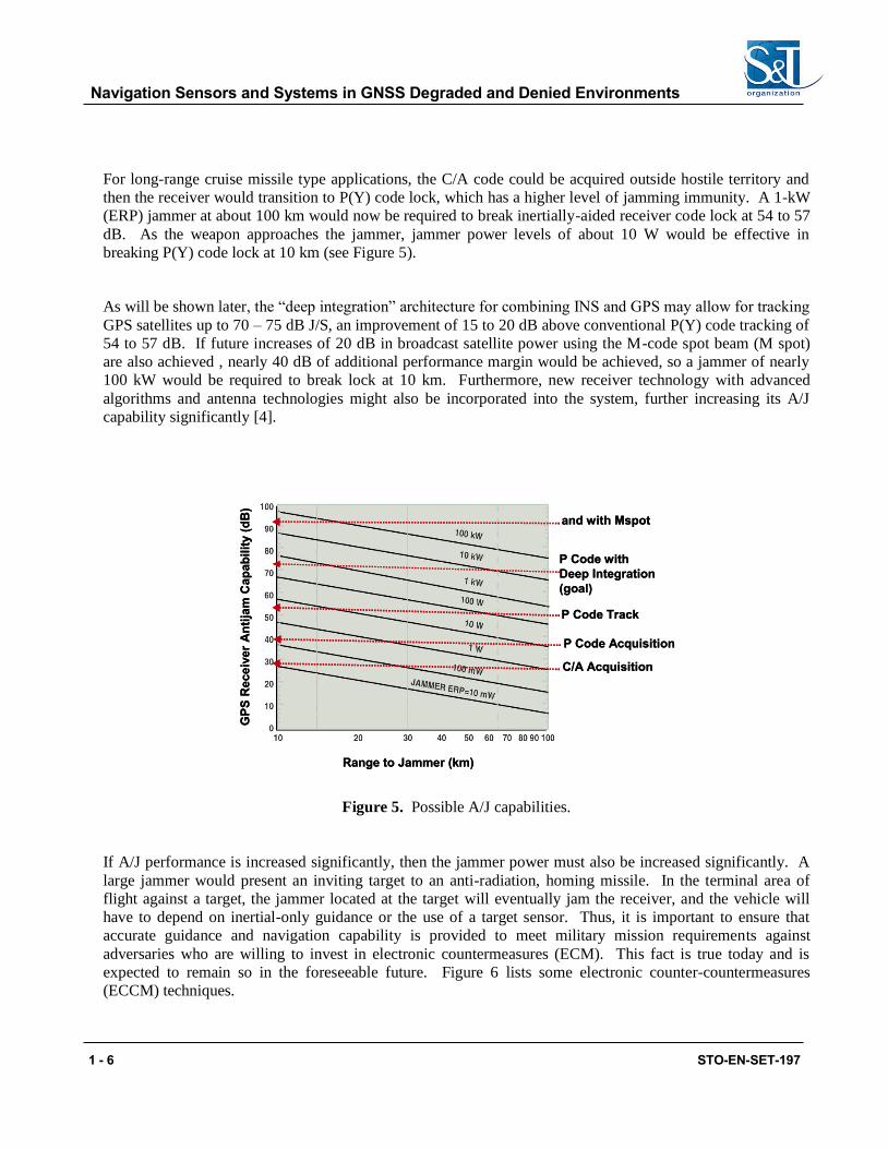
For long-range cruise missile type applications, the C/A code could be acquired outside hostile territory and
then the receiver would transition to P(Y) code lock, which has a higher level of jamming immunity. A 1-kW
(ERP) jammer at about 100 km would now be required to break inertially-aided receiver code lock at 54 to 57
dB. As the weapon approaches the jammer, jammer power levels of about 10 W would be effective in
breaking P(Y) code lock at 10 km (see Figure 5).
As will be shown later, the “deep integration” architecture for combining INS and GPS may allow for tracking
GPS satellites up to 70 – 75 dB J/S, an improvement of 15 to 20 dB above conventional P(Y) code tracking of
54 to 57 dB. If future increases of 20 dB in broadcast satellite power using the M-code spot beam (M spot)
are also achieved , nearly 40 dB of additional performance margin would be achieved, so a jammer of nearly
100 kW would be required to break lock at 10 km. Furthermore, new receiver technology with advanced
algorithms and antenna technologies might also be incorporated into the system, further increasing its A/J
capability significantly [4].
anand d wwiitthh MspoMspott
PP CCodode e wwiitthh
DDeeeep Ip Integratintegrationon
((gogoal)al)
PP CCodode Tracke Track
CC//AA AAcqcquisiuisittiionon
PP CCodode e AAcqcquisiuisittiionon
RRanangege ttoo JaJammermmer ((km)km)
GP
SG
PS
RRe
ce
ce
ie
ivve
r e
r AA
nti
nti
jjam
am
CCa
pa
pa
ba
biill
iittyy ((
dB
dB
))
Figure 5. Possible A/J capabilities.
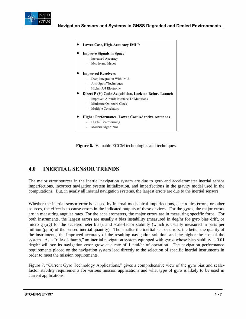
If A/J performance is increased significantly, then the jammer power must also be increased significantly. A
large jammer would present an inviting target to an anti-radiation, homing missile. In the terminal area of
flight against a target, the jammer located at the target will eventually jam the receiver, and the vehicle will
have to depend on inertial-only guidance or the use of a target sensor. Thus, it is important to ensure that
accurate guidance and navigation capability is provided to meet military mission requirements against
adversaries who are willing to invest in electronic countermeasures (ECM). This fact is true today and is
expected to remain so in the foreseeable future. Figure 6 lists some electronic counter-countermeasures
(ECCM) techniques.
Navigation Sensors and Systems in GNSS Degraded and Denied Environments
STO-EN-SET-197 1 - 7
Lower Cost, High-Accuracy IMU’s
Improve Signals in Space
– Increased Accuracy
– Mcode and Mspot
Improved Receivers
– Deep Integration With IMU
– Anti-Spoof Techniques
– Higher A/J Electronic
Direct P (Y) Code Acquisition, Lock-on Before Launch
– Improved Aircraft Interface To Munitions
– Miniature On-board Clock
– Multiple Correlators
Higher Performance, Lower Cost Adaptive Antennas
– Digital Beamforming
– Modern Algorithms
Figure 6. Valuable ECCM technologies and techniques.
4.0 INERTIAL SENSOR TRENDS
The major error sources in the inertial navigation system are due to gyro and accelerometer inertial sensor
imperfections, incorrect navigation system initialization, and imperfections in the gravity model used in the
computations. But, in nearly all inertial navigation systems, the largest errors are due to the inertial sensors.
Whether the inertial sensor error is caused by internal mechanical imperfections, electronics errors, or other
sources, the effect is to cause errors in the indicated outputs of these devices. For the gyros, the major errors
are in measuring angular rates. For the accelerometers, the major errors are in measuring specific force. For
both instruments, the largest errors are usually a bias instability (measured in deg/hr for gyro bias drift, or
micro g (g) for the accelerometer bias), and scale-factor stability (which is usually measured in parts per
million (ppm) of the sensed inertial quantity). The smaller the inertial sensor errors, the better the quality of
the instruments, the improved accuracy of the resulting navigation solution, and the higher the cost of the
system. As a “rule-of-thumb,” an inertial navigation system equipped with gyros whose bias stability is 0.01
deg/hr will see its navigation error grow at a rate of 1 nmi/hr of operation. The navigation performance
requirements placed on the navigation system lead directly to the selection of specific inertial instruments in
order to meet the mission requirements.
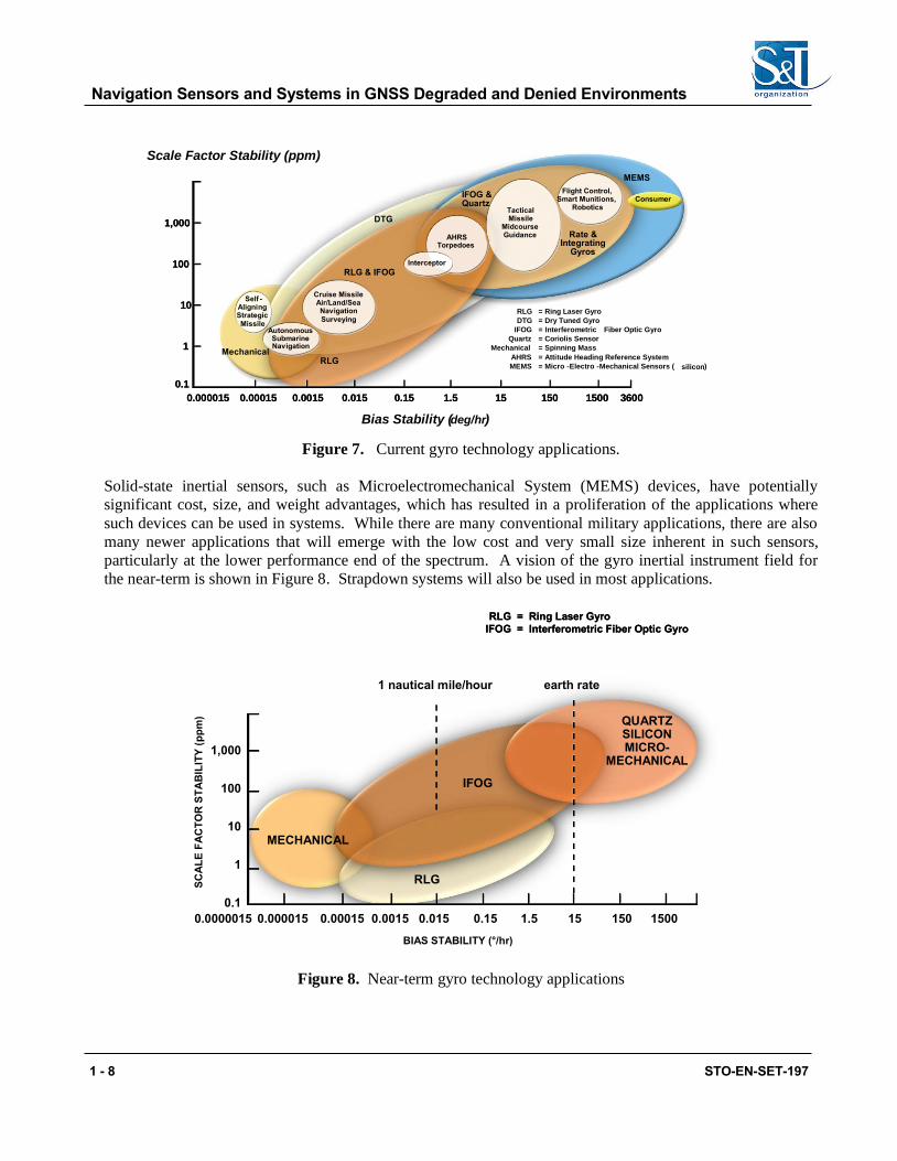
Figure 7, “Current Gyro Technology Applications,” gives a comprehensive view of the gyro bias and scale-
factor stability requirements for various mission applications and what type of gyro is likely to be used in
current applications.
Navigation Sensors and Systems in GNSS Degraded and Denied Environments
1 - 8 STO-EN-SET-197
Figure 7. Current gyro technology applications.
Solid-state inertial sensors, such as Microelectromechanical System (MEMS) devices, have potentially
significant cost, size, and weight advantages, which has resulted in a proliferation of the applications where
such devices can be used in systems. While there are many conventional military applications, there are also
many newer applications that will emerge with the low cost and very small size inherent in such sensors,
particularly at the lower performance end of the spectrum. A vision of the gyro inertial instrument field for
the near-term is shown in Figure 8. Strapdown systems will also be used in most applications.
1,000
100
10
1
0.1
0.0000015 0.000015 0.00015 0.0015 0.015 0.15 1.5 15 150 1500
SC
AL
E F
AC
TO
R S
TA
BIL
ITY
(p
pm
)
MECHANICAL
RLG
IFOG
QUARTZSILICONMICRO-
MECHANICAL
1 nautical mile/hour earth rate
BIAS STABILITY (°/hr)
RRLLGG
IFIFOGOG
= R= Riningg L Laasseerr G Gyyrroo
== InIntteerrffeerroomemettrricic FFibibeerr O Opptticic G Gyyrroo
Figure 8. Near-term gyro technology applications
RLG & IFOG
Rate & Integrating
Gyros
MEMS
Self -Aligning Strategic Missile
Consumer
RLG
Autonomous Submarine Navigation
TacticalMissile
MidcourseGuidance
Cruise MissileAir/Land/SeaNavigationSurveying
AHRSTorped oes
Flight Control, Smart Munitions,
Robotics
IFOG & Quartz
DTG
Bias Stability ( deg/hr )
11,,000000
100100
1010
11
00..11
00..000000115500..000000001155 00..00001155 00..001155 00..1155 11..55 1515 11550000150150 33660000
Mechanical
RLG = Ring Laser Gyro
DTG = Dry Tuned Gyro
IFOG = Interferometric Fiber Optic Gyro
Quartz = Coriolis Sensor
Mechanical = Spinning Mass
AHRS = Attitude Heading Reference System
MEMS = Micro - Electro - Mechanical Sensors ( silicon )
Interceptor
Scale Factor Stability (ppm)

Navigation Sensors and Systems in GNSS Degraded and Denied Environments
STO-EN-SET-197 1 - 9
The MEMS and Interferometric Fiber-Optic (IFOG) technologies are expected to replace many of the current
systems using Ring Laser Gyros (RLGs) and mechanical instruments. However, one particular area where the
RLG is expected to retain its superiority over the IFOG is in applications requiring extremely high scale-factor
stability. The change to all-MEMS technology hinges primarily on MEMS gyro development. The
performance of MEMS instruments is continually improving, and they are currently being developed for many
applications. This low cost can only be attained by leveraging off the consumer industry, which will provide
the infrastructure for supplying the MEMS sensors in extremely large quantities (millions). The use of these
techniques will result in low-cost, high-reliability, small-size, and lightweight inertial sensors and the systems
into which they are integrated. The tactical (lower) performance end of the application spectrum will likely be
dominated by micromechanical inertial sensors. The military market will push the development of these
sensors for applications such as “competent” and “smart” munitions, aircraft and missile autopilots, short-
time-of-flight tactical missile guidance, fire control systems, radar antenna motion compensation, “smart
skins” using embedded inertial sensors, multiple intelligent small projectiles such as flechettes or even
“bullets,” and wafer-scale INS/GPS systems.
Figure 9 shows how the gyro technology may possibly be applied to new applications in the far term. The
figure shows that the MEMS and integrated-optics (IO) systems technology may dominate the entire low- and
medium-performance range. The rationale behind this projection is based on two premises. The first is that
gains in performance in the MEMS devices will continue with similar progression to the orders-of-magnitude
improvement that has already been accomplished in the last decades. That further improvements are likely is
not unreasonable since the designers are beginning to understand the effects of geometry, size, electronics,
and packaging on performance and reliability. Second, efforts have already demonstrated how to put all six
sensors on one (or two) chips, which is the only way to reach a possible cost goal of less than $1000 per
INS/GPS system. In addition, since many of the MEMS devices are vibrating structures with a capacitive
readout, this may restrict the performance gains. It is in this area that the integrated optics technology is most
likely to be required to provide a true solid-state micromechanical gyro with optical readout. At this time, the
technology to make a very small, accurate gyro does not exist, but advances in integrated optics are already
under development in the communications industry. For the strategic application, the IFOG could become the
dominant gyro. Work is underway now to develop radiation-hard IFOGs as well as super-high-performance
IFOGs.
A potentially promising technology, which is in its infancy stages, is inertial sensing based upon cold atom
interferometry [17,18]. A typical atom de Broglie wavelength is many times smaller than an optical
wavelength, and because atoms have mass and internal structure, cold atom interferometers are extremely
sensitive. Accelerations, rotations, electromagnetic fields, and interactions with other atoms change the atom
interferometric fringes. This means that atom interferometers could make the most accurate gyroscopes,
accelerometers, gravity gradiometers, and precision clocks, by orders of magnitude. If this far-term
technology can be developed, then it could result in a 2 to 5-meter/hour navigation system without GPS, in
which the accelerometers are also measuring gravity gradients.
Navigation Sensors and Systems in GNSS Degraded and Denied Environments
1 - 10 STO-EN-SET-197
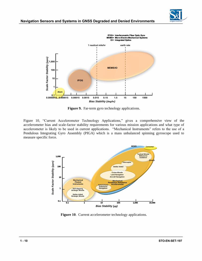
Figure 9. Far-term gyro technology applications.
Figure 10, “Current Accelerometer Technology Applications,” gives a comprehensive view of the
accelerometer bias and scale-factor stability requirements for various mission applications and what type of
accelerometer is likely to be used in current applications. “Mechanical Instruments” refers to the use of a
Pendulous Integrating Gyro Assembly (PIGA) which is a mass unbalanced spinning gyroscope used to
measure specific force.
MechanicalFloated
Instruments
Self-AligningStrategic Missile
Stellar-AidedStrategic Missile
AutonomousSubmarineNavigation
Cruise Missile
Land Navigation
Aircraft Navigation
Stellar-Aided
Interceptor
Tactical MissileMidcourseGuidance
Quartz
Mechanical Pendulous Rebalance
Accelerometer
MEMS
11,0,00000
110000
1010
11
00.1.100.1.1 11 110000 11,0,00000 1100,0,000001010
Bias Stability (g)
Sc
ale
Fa
cto
r S
tab
ilit
y (
pp
m)
Consumer
Figure 10. Current accelerometer technology applications.
1,000
100
10
1
0.10.0000015 0.000015 0.00015 0.0015 0.015 0.15 1.5 15 150 1500
Sc
ale
Fa
cto
r S
tab
ilit
y (
pp
m)
IFOG
Bias Stabilit y (deg/hr)
IFOGIFOG
MMEMEMSS
IOIO
== IntInterferferomerometetricric FibFiber Opter Optic ic GGyyroro
== M Microicro--ElecElecttroro--MMeecchanhanicaical Syl Systemstemss
== Int Integrategrated Oped Optticsics
MEMS/IO
1 nautical mile/hr earth rate
Atom
Navigation Sensors and Systems in GNSS Degraded and Denied Environments
STO-EN-SET-197 1 - 11
Current applications are still dominated by electromechanical sensors, not only because they are generally low-cost for the performance required, but also because no challenging alternative technology has succeeded,except for quartz resonators, which are used in the lower-grade tactical and commercial
applications. MEMS inertial sensors have not yet seriously broached the market, although they are on the
verge of so doing, especially in consumer applications.
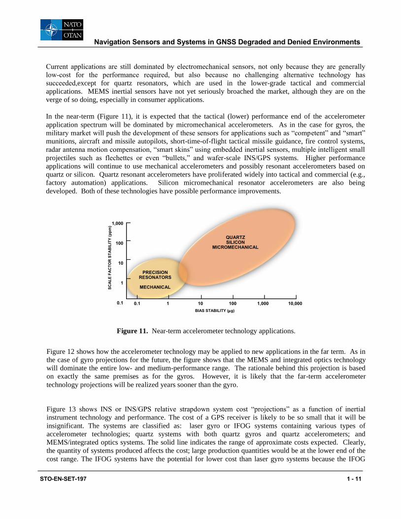
In the near-term (Figure 11), it is expected that the tactical (lower) performance end of the accelerometer
application spectrum will be dominated by micromechanical accelerometers. As in the case for gyros, the
military market will push the development of these sensors for applications such as “competent” and “smart”
munitions, aircraft and missile autopilots, short-time-of-flight tactical missile guidance, fire control systems,
radar antenna motion compensation, “smart skins” using embedded inertial sensors, multiple intelligent small
projectiles such as flechettes or even “bullets,” and wafer-scale INS/GPS systems. Higher performance
applications will continue to use mechanical accelerometers and possibly resonant accelerometers based on
quartz or silicon. Quartz resonant accelerometers have proliferated widely into tactical and commercial (e.g.,
factory automation) applications. Silicon micromechanical resonator accelerometers are also being
developed. Both of these technologies have possible performance improvements.
1,000
100
10
1
0.1 0.1 1 10 100 1,000 10,000
SC
AL
E F
AC
TO
R S
TA
BIL
ITY
(p
pm
)
BIAS STABILITY (g)
PRECISIONRESONATORS
MECHANICAL
QUARTZSILICON
MICROMECHANICAL
Figure 11. Near-term accelerometer technology applications.
Figure 12 shows how the accelerometer technology may be applied to new applications in the far term. As in
the case of gyro projections for the future, the figure shows that the MEMS and integrated optics technology
will dominate the entire low- and medium-performance range. The rationale behind this projection is based
on exactly the same premises as for the gyros. However, it is likely that the far-term accelerometer
technology projections will be realized years sooner than the gyro.
Figure 13 shows INS or INS/GPS relative strapdown system cost “projections” as a function of inertial
instrument technology and performance. The cost of a GPS receiver is likely to be so small that it will be
insignificant. The systems are classified as: laser gyro or IFOG systems containing various types of
accelerometer technologies; quartz systems with both quartz gyros and quartz accelerometers; and
MEMS/integrated optics systems. The solid line indicates the range of approximate costs expected. Clearly,
the quantity of systems produced affects the cost; large production quantities would be at the lower end of the
cost range. The IFOG systems have the potential for lower cost than laser gyro systems because the IFOG

Navigation Sensors and Systems in GNSS Degraded and Denied Environments
1 - 12 STO-EN-SET-197
should be well below the cost of an RLG. However, this has not happened to date, primarily because the RLG
is in relatively large-volume production in well-facilitated factories and the IFOG is not yet manufactured in
similar production quantities. Clearly, the MEMS/integrated optics INS/GPS systems offer the lowest cost.
The ultimate low cost only becomes feasible in quantities of millions. This can be achieved only with multi-
axis instrument clusters and on-chip or adjacent-chip electronics and batch packaging.
1,000
100
10
1
0.1
0.1 1 100 1,000 10,000
Sc
ale
Fac
tor
Sta
bil
ity
(p
pm
)
10
Bias Stability (g)
MECH.SILICONQUARTZ
MEMS/IO
MMEMSEMS
IOIO
== Micro Micro--EleElectroctro--MMeecchanichanicalal Sy Systemstemss
== Int Integraegratted Opticsed Optics
Atom
Figure 12. Far-term accelerometer technology applications.
Co
st
$
100100,0,00000
5050,00,0000
1010,00,0000
1,1,000000
100100
1010
.001°/hr .01°/hr 0.1°/hr 1°/hr
1 g 25 g 500 g 1 mg
10°/hr 100°/hr 1000°/hr
10 mg 100 mg 1000 mg
Performance
MEMS/IO
IFOG
LASER
QUARTZ
IFOGIFOG
MMEMEMSS
IOIO
QUQUAARRTTZZ
== IntInterferometerferometricric FibFiber Oer Optptic Gic Gyyroro
== M Microicro--ElecElecttroro--MMeecchanhanicaical Syl Systemstemss
== Int Integratedegrated Opt Opticsics
== CCoriooriolislis SensorSensor
Figure 13. Strapdown INS cost as a function of instrument technology.
Navigation Sensors and Systems in GNSS Degraded and Denied Environments
STO-EN-SET-197 1 - 13
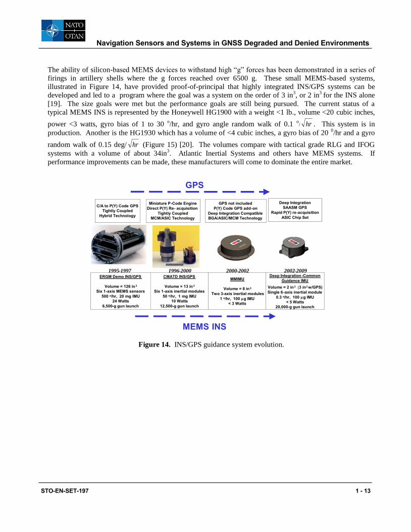
The ability of silicon-based MEMS devices to withstand high “g” forces has been demonstrated in a series of
firings in artillery shells where the g forces reached over 6500 g. These small MEMS-based systems,
illustrated in Figure 14, have provided proof-of-principal that highly integrated INS/GPS systems can be
developed and led to a program where the goal was a system on the order of 3 in3, or 2 in
3 for the INS alone
[19]. The size goals were met but the performance goals are still being pursued. The current status of a
typical MEMS INS is represented by the Honeywell HG1900 with a weight <1 lb., volume <20 cubic inches,
power <3 watts, gyro bias of 1 to 30 o/hr, and gyro angle random walk of 0.1
o/ hr . This system is in
production. Another is the HG1930 which has a volume of <4 cubic inches, a gyro bias of 20 0/hr and a gyro
random walk of 0.15 deg/ hr (Figure 15) [20]. The volumes compare with tactical grade RLG and IFOG
systems with a volume of about 34in3. Atlantic Inertial Systems and others have MEMS systems. If
performance improvements can be made, these manufacturers will come to dominate the entire market.
Figure 14. INS/GPS guidance system evolution.
ERGM Demo INS/GPS
Volume = 126 in 3 Six 1 - axis MEMS sensors
500 o /hr, 20 mg IMU 24 Watts
6,500 - g gun launch
C/A to P(Y) Code GPS
Tightly Coupled Hybrid Technology
CMATD INS/GPS
Volume = 13 in 3 Six 1 - axis inertial modules
50 o /hr, 1 mg IMU 10 Watts
12,500 - g gun launch
Miniature P - Code Engine Direct P(Y) Re - acquisition
Tightly Coupled MCM/ASIC Technology
MMIMU
Volume = 8 in 3 Two 3 - axis inertial modules
1 o /hr, 100 g IMU < 3 Watts
GPS not included P(Y) Code GPS add - on
Deep Integration Compatible
BGA/ASIC/MCM Technology
2002- 2009Deep Integration - Common
Guidance IMU Volume = 2 in 3 ( 3 in 3 w/GPS) Single 6 - axis inertial module
0.3 o /hr, 100 g IMU < 5 Watts
20,000 - g gun launch
Deep Integration SAASM GPS
Rapid P(Y) re - acquisition
ASIC Chip Set
1995- 1997 1996- 2000 2000- 2002
MEMS INS
GPS

Navigation Sensors and Systems in GNSS Degraded and Denied Environments
1 - 14 STO-EN-SET-197
Figure 15. Honeywell MEMS IMUs [20].
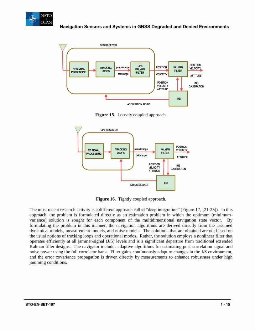
5.0 INS/GPS INTEGRATION
Many military inertial navigation systems could be replaced with less accurate inertial systems if it were
guaranteed that GPS would be continuously available to update the inertial system to limit its error growth. A
less accurate inertial system usually means a less costly system. However, given the uncertainty in the
continuous availability of GPS in most military scenarios, an alternate way to reduce the avionics system cost
is to attack the cost issue directly by developing lower-cost inertial sensors while improving their accuracy
and low noise levels, as described in the “Inertial Sensor Trends” section. For applications without an
interference threat, in the future, GPS updating is expected to provide better than 1-m navigation accuracy
(CEP) when used in conjunction with an INS. The benefits and issues in using INS augmented with GPS
updates, including a discussion of interference issues, have been presented in many references. Systems
currently in use tend to be classified as either “the loosely coupled approach” or “the tightly coupled
approach” (Figures 15 and 16 and Ref. 21).
< 20 cubic inches
< 1 lb
< 3 watts
Gyro bias 1 to 30 deg/hr
Gyro random walk 0.1 deg/ SQRT (hr)
< 4 cubic inches
< 0.35 lb
< 3 watts
Gyro bias 20 deg/hr
Gyro random walk 0.15 deg/SQRT ( hr)
Navigation Sensors and Systems in GNSS Degraded and Denied Environments
STO-EN-SET-197 1 - 15
KAKALMANLMAN
FFILILTTERER
INSINS
RFRFRFRF SIG SIG SIG SIGNALNALNALNAL
PROPROPROPROCESSCESSCESSCESSININININGGGG
TTRACKINRACKINGG
LOLOOOPSPS
GGPSPS
KAKALMANLMAN
FFILILTTERER
pspseudeudororangangee
deldeltatarrangangee
POPOSITSITIOIONN
VEVELOLOCICITTYY
POPOSITSITIOIONN
VEVELOLOCICITTYY
ATTATTITITUDUDEE
POPOSITSITIOIONN
VEVELOLOCICITTYY
ATTATTITITUDUDEE
INSINS
CALIBRATCALIBRATIOIONN
GGPSPS R RECEIVECEIVERER
ACQACQUIUISITSITIOION N AIDIAIDINGNG
Figure 15. Loosely coupled approach.
KAKALMALMANN
FILTFILTERER
INSINS
RF SIGRF SIGRF SIGRF SIGNALNALNALNAL
PROCESPROCESPROCESPROCESSINGSINGSINGSING
TRACKTRACKINGING
LOLOOOPSPS
pspseudorangeeudorange
deldeltartarangeange
POSITIPOSITIOONN
VEVELOLOCITYCITY
ATTITATTITUDEUDE
POSITIPOSITIOONN
VEVELOLOCITYCITY
ATTITATTITUDEUDE
INSINS
CALCALIBRAIBRATIOTIONN
GGPSPS RECE RECEIVEIVERR
AIDINGAIDING SIG SIGNALNALSS
Figure 16. Tightly coupled approach.
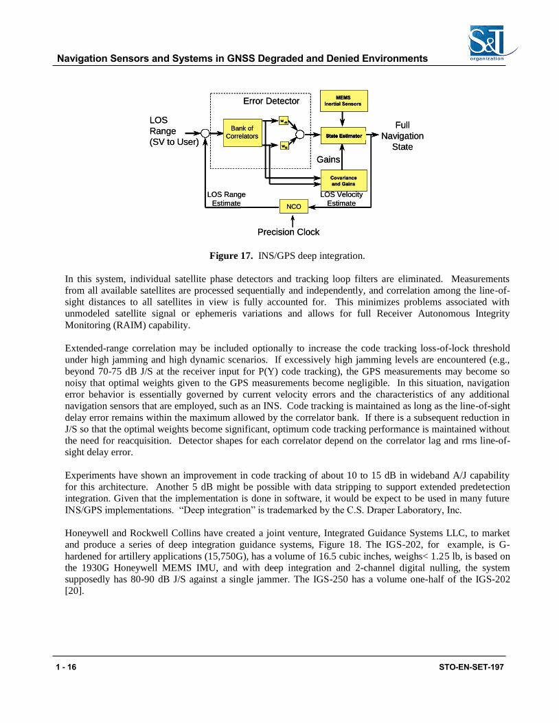
The most recent research activity is a different approach called “deep integration” (Figure 17, [21-25]). In this
approach, the problem is formulated directly as an estimation problem in which the optimum (minimum-
variance) solution is sought for each component of the multidimensional navigation state vector. By
formulating the problem in this manner, the navigation algorithms are derived directly from the assumed
dynamical models, measurement models, and noise models. The solutions that are obtained are not based on
the usual notions of tracking loops and operational modes. Rather, the solution employs a nonlinear filter that
operates efficiently at all jammer/signal (J/S) levels and is a significant departure from traditional extended
Kalman filter designs. The navigator includes adaptive algorithms for estimating post-correlation signal and
noise power using the full correlator bank. Filter gains continuously adapt to changes in the J/S environment,
and the error covariance propagation is driven directly by measurements to enhance robustness under high
jamming conditions.
Navigation Sensors and Systems in GNSS Degraded and Denied Environments
1 - 16 STO-EN-SET-197
LLOSOS
RRaannggee
((SSVV ttoo UUseserr))
GaiGainnss
FFuullll
NNaavviiggaattiioonn
SSttaattee
LLOOS VS Veelloocciityty
EsEstitimmaatete
EErrrroorr DDeetteeccttoorr
NCONCO
SSSSttttatatatate e e e EEEEststststimimimimatatatatoooorrrr
BBaannkk ooff
CCoorrrreelalattoorrss
CCoovvaarriaianncece
anandd Ga Gaininss
MMEEMMSS
IInneerrttiaial Sl Senensosorrss
wwNN
ww--NN
PPrreecicisisioonn CClloockck
LLOOS RS Raannggee
EsEstitimmaatete
Figure 17. INS/GPS deep integration.
In this system, individual satellite phase detectors and tracking loop filters are eliminated. Measurements
from all available satellites are processed sequentially and independently, and correlation among the line-of-
sight distances to all satellites in view is fully accounted for. This minimizes problems associated with
unmodeled satellite signal or ephemeris variations and allows for full Receiver Autonomous Integrity
Monitoring (RAIM) capability.
Extended-range correlation may be included optionally to increase the code tracking loss-of-lock threshold
under high jamming and high dynamic scenarios. If excessively high jamming levels are encountered (e.g.,
beyond 70-75 dB J/S at the receiver input for P(Y) code tracking), the GPS measurements may become so
noisy that optimal weights given to the GPS measurements become negligible. In this situation, navigation
error behavior is essentially governed by current velocity errors and the characteristics of any additional
navigation sensors that are employed, such as an INS. Code tracking is maintained as long as the line-of-sight
delay error remains within the maximum allowed by the correlator bank. If there is a subsequent reduction in
J/S so that the optimal weights become significant, optimum code tracking performance is maintained without
the need for reacquisition. Detector shapes for each correlator depend on the correlator lag and rms line-of-
sight delay error.
Experiments have shown an improvement in code tracking of about 10 to 15 dB in wideband A/J capability
for this architecture. Another 5 dB might be possible with data stripping to support extended predetection
integration. Given that the implementation is done in software, it would be expect to be used in many future
INS/GPS implementations. “Deep integration” is trademarked by the C.S. Draper Laboratory, Inc.
Honeywell and Rockwell Collins have created a joint venture, Integrated Guidance Systems LLC, to market
and produce a series of deep integration guidance systems, Figure 18. The IGS-202, for example, is G-
hardened for artillery applications (15,750G), has a volume of 16.5 cubic inches, weighs< 1.25 lb, is based on
the 1930G Honeywell MEMS IMU, and with deep integration and 2-channel digital nulling, the system
supposedly has 80-90 dB J/S against a single jammer. The IGS-250 has a volume one-half of the IGS-202
[20].

Navigation Sensors and Systems in GNSS Degraded and Denied Environments
STO-EN-SET-197 1 - 17
Figure 18. IGS-202 and IGS-250 Deeply Integrated Guidance Systems [20]
6.0 SIMULATIONS
In this section two specific scenarios are simulated. The first is to show the significant payoff in performance
when Doppler velocity measurements are added to a GPS/INS system that is subjected to jamming.
The second scenario is to show the advantages of deep integration in a jamming scenario of a precision guided
munition. Both scenarios are described in full detail in [21].
6.1 Helicopter Performance in Jammer Vicinity
This scenario is meant to depict a helicopter on a scouting mission with and without Doppler velocity aiding..
The helicopter closely follows the terrain in order to avoid detection. The resulting flight profile has high
levels of acceleration and jerk, which caused occasional momentary loss of carrier lock. No effect on mission
performance can be seen.
The jamming scenario is as follows for this mission. GPS measurements were available until on-board
estimates of IMU calibration and alignment had reached steady state. At that point, GPS was assumed to be
jammed. The mission continued for another 19 min. The navigation system of the helicopter was augmented
with ground speed Doppler measurements. These Doppler measurements yield velocity in body coordinates.
It will be seen that these measurements make a considerable difference in navigation performance after GPS is
lost. The error model for the Doppler measurements is given in Table 1.
16.5 cubic inches 2 channel digital nulling < 5 meter CEP
SAASM L1/L2 All In View (12 satellites)A/J > 88 db Broadband (tracking)
> 59 db broadband (Direct Y “acquisition”)
7.8 cubic inches 2 channel digital nulling < 4 meter CEP

Navigation Sensors and Systems in GNSS Degraded and Denied Environments
1 - 18 STO-EN-SET-197
Table 1. Error Model for Doppler Ground Speed Measurements
.
Error Source Vertical (1) Horizontal (1) (two
components)
Bias 0.05 nmi/h 0.1 nmi/h
Scale factor 0.1% 0.25%
Misalignment 2.0 mrad 2.0 mrad
Near the end of the mission, the task of the helicopter is to define coordinates of a target at some distance (8
km) from its own position. The error in target coordinates, rtgt, is thus due to a combination of helicopter
location error, rhelicopter, and actual IMU misalignment pointing error, .
rtgt = rhelicopter + r
where r is the vector from helicopter to target.
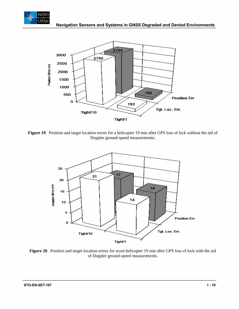
Figure 19 shows the error in helicopter position and target location as a function of the errors in two tightly-
coupled GPS/INS systems when no ground-speed Doppler measurements are included in the navigation
solution. The INS system errors modelled are representative of either a 10 or 1 nmi error growth rate inertial
system. ( See [21] for full details.) The pointing error is negligible compared with the position error so that
the target location errors and the aircraft position errors are essentially the same for both inertial system
models..
Figure 20 shows the same errors when the navigation system is aided with ground-speed Doppler
measurements. Results for both a 10 nni/h and 1 nmi/h inertial systems are shown. As expected, the Doppler
ground-speed measurements slow the error growth that is seen with the free inertial system. These errors in
these velocity measurements integrate into growing position errors so they are not equivalent to GPS, which
provides position as well as velocity. But they provide much better results than the inertial instruments whose
measurements must be integrated twice before yielding position. The improvement with the Doppler ground-
speed sensor is dramatic. Note that when aided by these measurements, the performance of the 10-nmi/h
system is nearly the same as that of the 1-nmi/h system.
Navigation Sensors and Systems in GNSS Degraded and Denied Environments
STO-EN-SET-197 1 - 19
Figure 19. Position and target location errors for a helicopter 19 min after GPS loss of lock without the aid of
Doppler ground-speed measurements.
Figure 20. Position and target location errors for scout helicopter 19 min after GPS loss of lock with the aid
of Doppler ground-speed measurements.
Navigation Sensors and Systems in GNSS Degraded and Denied Environments
1 - 20 STO-EN-SET-197
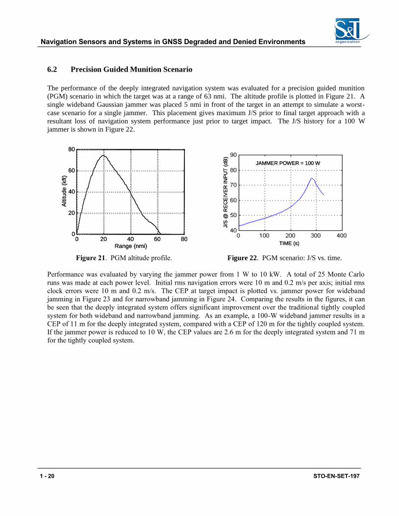
6.2 Precision Guided Munition Scenario
The performance of the deeply integrated navigation system was evaluated for a precision guided munition
(PGM) scenario in which the target was at a range of 63 nmi. The altitude profile is plotted in Figure 21. A
single wideband Gaussian jammer was placed 5 nmi in front of the target in an attempt to simulate a worst-
case scenario for a single jammer. This placement gives maximum J/S prior to final target approach with a
resultant loss of navigation system performance just prior to target impact. The J/S history for a 100 W
jammer is shown in Figure 22.
00 2020 4040 6060 808000
2020
4040
6060
8080
Al
Altititutu
de
de
( (kkftft
))
TITIMME E ((ss))
JJAMAMMMERER POPOWWEERR = 10= 1000 WW
JJ//S
S
@ R
@ R
EC
EC
EI
EIV
EV
ERR
IINN
PU
PU
T
T ((
ddB
)B
)
RangRange e ((nmnmii))
Figure 21. PGM altitude profile. Figure 22. PGM scenario: J/S vs. time.
Performance was evaluated by varying the jammer power from 1 W to 10 kW. A total of 25 Monte Carlo
runs was made at each power level. Initial rms navigation errors were 10 m and 0.2 m/s per axis; initial rms
clock errors were 10 m and 0.2 m/s. The CEP at target impact is plotted vs. jammer power for wideband
jamming in Figure 23 and for narrowband jamming in Figure 24. Comparing the results in the figures, it can
be seen that the deeply integrated system offers significant improvement over the traditional tightly coupled
system for both wideband and narrowband jamming. As an example, a 100-W wideband jammer results in a
CEP of 11 m for the deeply integrated system, compared with a CEP of 120 m for the tightly coupled system.
If the jammer power is reduced to 10 W, the CEP values are 2.6 m for the deeply integrated system and 71 m
for the tightly coupled system.

Navigation Sensors and Systems in GNSS Degraded and Denied Environments
STO-EN-SET-197 1 - 21
Figure 23. CEP vs. wideband jammer. Figure 24. CEP vs. narrowband jammer.
A/J improvement capability may be quantified by comparing jammer power at a constant value of CEP. The
resulting improvement in A/J capability due to deep integration can be seen in Figure 25. For wideband
jamming, improvements of at least 15 dB are seen for CEP values ranging from 6 to 120 m. For narrowband
jamming, improvements of at least 15 dB are seen for CEP values ranging from 4 to 80 m. Improvement is
seen to decrease as the CEP decreases below 10 m. In this case, the decrease in CEP results from a decrease
in jammer power, and the tightly coupled system tends to maintain lock with higher probability as the jammer
power decreases. In the limit as the jammer power approaches zero, the tightly coupled system approaches
efficient operation, and both systems give comparable performance. The improvement is also seen to
decrease as the CEP increases beyond 100 m. In this case, the increase in CEP results from an increase in
jammer power and the tracking quality of the deeply integrated system begins to degrade. In the limit as the
jammer power increases without bound, the deeply integrated system can no longer maintain lock, and both
systems are operating in a free inertial mode where the CEP is determined solely by initial navigation errors
and inertial sensor errors.
CCCCEPEPEPEP ((((m)m)m)m)
63636363----nnnnmmmmi i i i PGPGPGPGMMMM
MMMMEMEMEMEMS:S:S:S: 1111999999998888
2525
AA//J
IJ Imm
pproro
vveemm
eenntt (d(d
BB))
2020
1515
1010
55101000 101011 101033101022
WBWB
NBNB
CCEEPP (m(m))
Figure 25. A/J improvement due to deep integration.
Navigation Sensors and Systems in GNSS Degraded and Denied Environments
1 - 22 STO-EN-SET-197
7.0 CONCLUSIONS
Recent progress in INS/GPS technology has accelerated the potential use of these integrated systems, while
awareness has also increased concerning GPS vulnerabilities to interference. Accuracy in the broadcast GPS
signals will allow 1 meter INS/GPS accuracy. Many uses will be found for this high accuracy. In parallel,
lower-cost inertial components will be developed and they will also have improved accuracy. Highly
integrated A/J architectures for INS/GPS systems will become common, replacing avionics architectures
based on functional black boxes where receivers and inertial systems are treated as stand-alone systems.
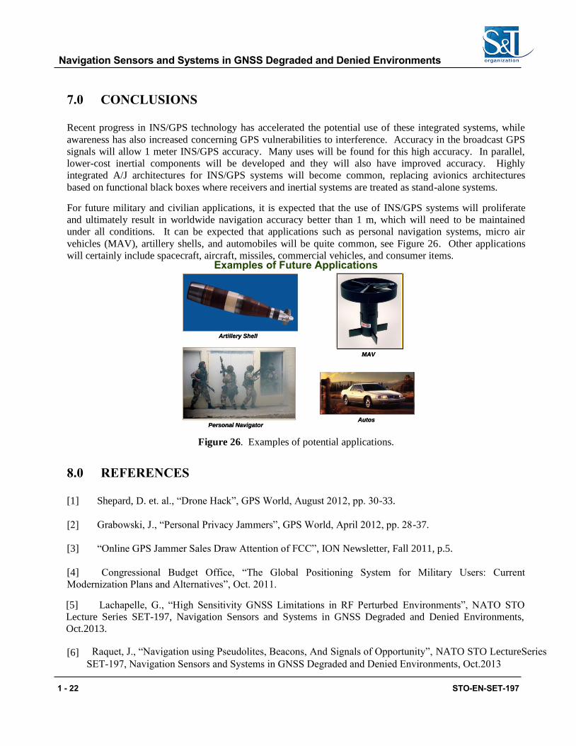
For future military and civilian applications, it is expected that the use of INS/GPS systems will proliferate
and ultimately result in worldwide navigation accuracy better than 1 m, which will need to be maintained
under all conditions. It can be expected that applications such as personal navigation systems, micro air
vehicles (MAV), artillery shells, and automobiles will be quite common, see Figure 26. Other applications
will certainly include spacecraft, aircraft, missiles, commercial vehicles, andExamples of Future Applications
consumer items.
AAutosutos
AArtirtilllleryery Sh Shellell
MAMAVV
PPersersononal Naal Navigavigatortor
Figure 26. Examples of potential applications.
8.0 REFERENCES
[1] Shepard, D. et. al., “Drone Hack”, GPS World, August 2012, pp. 30-33.
[2] Grabowski, J., “Personal Privacy Jammers”, GPS World, April 2012, pp. 28-37.
[3] “Online GPS Jammer Sales Draw Attention of FCC”, ION Newsletter, Fall 2011, p.5.
[4] Congressional Budget Office, “The Global Positioning System for Military Users: Current
Modernization Plans and Alternatives”, Oct. 2011.
[5] Lachapelle, G., “High Sensitivity GNSS Limitations in RF Perturbed Environments”, NATO STO
Lecture Series SET-197, Navigation Sensors and Systems in GNSS Degraded and Denied Environments,
Oct.2013.
[6] Raquet, J., “Navigation using Pseudolites, Beacons, And Signals of Opportunity”, NATO STO LectureSeries SET-197, Navigation Sensors and Systems in GNSS Degraded and Denied Environments, Oct.2013
Navigation Sensors and Systems in GNSS Degraded and Denied Environments
STO-EN-SET-197 1 - 23
[7] Hopkins, R. et. al., “Contemporary and Emerging Inertial Sensor Technologies”, NATO STO Lecture
Series SET-197, Navigation Sensors and Systems in GNSS Degraded and Denied Environments, Oct.2013.
[8] Hopkins, R. et. al., “Miniature Augmentation Sensors in GNSS Denied Navigation Applications”,
NATO STO Lecture Series SET-197, Navigation Sensors and Systems in GNSS Degraded and Denied
Environments, Oct.2013.
[9] Raquet, J., “Determining Absolute Position Using 3-Axis Magnetometers and the Need for Self-
Building World Models”, NATO STO Lecture Series SET-197, Navigation Sensors and Systems in GNSS
Degraded and Denied Environments, Oct.2013.
[10] Veth, M., “Nonlinear Estimation Techniques for Navigation”, NATO STO Lecture Series SET-197,
Navigation Sensors and Systems in GNSS Degraded and Denied Environments, Oct.2013.
[11] Veth, M., “Statistical Predictive Rendering for Robust Passive Relative Navigation”, NATO STO
Lecture Series SET-197, Navigation Sensors and Systems in GNSS Degraded and Denied Environments,
Oct.2013.
[12] Lachapelle, G., “High Precision GNSS RTK Navigation for Soldiers and Other Military Assets”,
NATO STO Lecture Series SET-197, Navigation Sensors and Systems in GNSS Degraded and Denied
Environments, Oct.2013.
[13] Divis, D., “Air Force Proposes Dramatic Redesign for GPS Constellation”, Inside GNSS, May/June
2013, pp. 20-24.
[14] NAVSTAR-GPS Joint Program Office, NAVSTAR GPS User Equipment, February 1991.
[15] Mahmood, S. et. al., “Analysis of Differential Global Positioning System (DGPS) Techniques and
GPS Jamming on Precision Guided Munition (PGM) Performance,” NATO/AGARD MSP Meeting,
Technologies for Precision Air Strike Operations in Rapid Reaction and Localized Conflict Scenarios, Seville,
Spain, October 1995.
[16] Sklar, J., “GPS Capability Projections” in Defense Science Board 1996 Summer Study Task Force on
Tactics and Technology for 21st Century Military Superiority, Vol. 3, October 1996, III.43-III.53.
[17] Kasevich, M. and Salomon, C.-Editors, “Special Issue: Quantum Mechanics for Space Applications:
from Quantum Optics to Atom Optics and General Relativity”, Applied Physics B, Vol. 84, August 2006.
[18] Zatezalo, A. et. al., “Bose Einstein Interferometry and Its Applications to Precision Undersea
Navigation”, IEEE 2008, 1-4244-1537-3.
[19] Barbour, N. et. al., “Inertial Navigation Sensors” and “Inertial MEMS Systems and Applications,”
NATO Lecture series, RTO-EN-SET-116, Low-Cost Navigation Sensors and Integration Technology, March
2011.
Navigation Sensors and Systems in GNSS Degraded and Denied Environments
1 - 24 STO-EN-SET-197
[20] Honeywell, Inc., “HG1900 MEMS IMU,” DFOISR # 05-S-0725 and “HG1930 MEMS IMU,”
DFOISR 05-S-0723; and Integrated Guidance Systems LLC, “IGS-2xx series, deeply integrated guidance
family,” on www.igsllc.com. Cited 9 April 2010.
[21] Schmidt, G. and Phillips, R., “INS/GPS Integration Architectures,” and “INS/GPS Integration
Architecture Performance Comparisons” NATO RTO Lecture Series, RTO-EN-SET-116, Low-Cost
Navigation Sensors and Integration Technology, March 2011.
[22] Gustafson, D. et. al., “A Nonlinear Code Tracking Filter for GPS-Based Navigation,” IEEE Journal of
Selected Topics in Signal Processing, Vol. 3, No. 4. Aug. 2009, pp 627-638. Also, see U.S. Patent 6,331,835
B1, December 18, 2001.
[23] Gustafson, D. and Dowdle J., “Deeply Integrated Code Tracking: Comparative Performance
Analysis,” Institute of Navigation GPS/GNSS 2003, Portland, OR, September 2003. Also Draper Laboratory
Report P-4159.
[24] Gustafson, D. et al., A Deeply Integrated Adaptive GPS-Based Navigator with Extended Range Code
Tracking, Draper Laboratory Report P-3791, Cambridge, MA, January 2000. Also, IEEE PLANS Conference,
San Diego, CA March 2000.
[25] Gustafson, D. et al., A High Antijam GPS-Based Navigator, Draper Laboratory Report P-3776,
Cambridge, MA, January 2000. Also, Institute of Navigation National Technical Meeting, Anaheim, CA, 2000.