nature's batik: a computer evolution model of diatom valve morphogenesis
TRANSCRIPT
RESEARCHARTICLE
Copyright © 2005 American Scientific PublishersAll rights of reservedPrinted in the United States of America
Journal ofNanoscience and Nanotechnology
Vol. 5, 1–10, 2005
Nature’s Batik: A Computer Evolution Model ofDiatom Valve Morphogenesis
Katie Bentley,1�∗ Eileen J. Cox,2 and Peter. J Bentley11Department of Computer Science, University College London, London, UK
2Department of Botany, The Natural History Museum, London, UK
This paper describes a novel computer simulation that uses evolution to design functioning raphidpennate diatom valves. The model of valve morphogenesis used is based on current theoriesthat highlight the importance of cytoskeletal elements in valve development. An “organic” negativeimprint is grown in a grid-based system, using both local and global rules to dictate grid cell states.Silica then diffuses out into all remaining grid cells. This model is shown to generate raphid pennatediatom valves capable of functioning as cell walls. At every stage of development the generatedvalves are consistent with observations of real diatom valve growth. This model of diatom valvemorphogenesis is interestingly similar to the negative technique used by artists in batik painting.
Keywords: Morphogenesis, Raphid Diatom, Computer Simulation, Genetic Algorithm.
1. INTRODUCTION
Natural evolution uses processes of development to growhighly adapted organisms. Understanding morphogenesis,the generation of form, will therefore aid the developmentof well-designed, well-adapted, efficient devices, such asrobots, processors, and circuits. Organisms that incorpo-rate inorganic material into their morphology offer a rareand exciting opportunity to learn, from nature, efficientmechanisms for the manipulation of materials for ourtechnology.
Diatoms are single celled photosynthetic protists thatthrive in many environments such as seas, lakes, and dampsoils. With over 200 000 species, they are the second mostdiverse group of photosynthetic organisms and produceapproximately 20% of the world’s carbon fixation.1�2 Mostinterestingly they possess an external shell or frustule ofamorphous silica that functions as a cell wall. This frus-tule is made up of two halves, each comprising a valveand a number of girdle bands. Diatom valves are oftenbeautifully patterned, with regularly arranged pores per-forating the valves.3 As a cell wall, the frustule is struc-turally very strong and resistant to enzyme attack andalso functions as a defense against grazing and infection.
∗Author to whom correspondence should be addressed.
However, some diatoms are susceptible to parasitism bychytrids, oomycetes, and protozoa and infraspecific vari-ation in susceptibility has been observed.4–7 Although itis unclear whether there is a consistent point of entryfor the parasites. Diatom cell walls confer rigidity andprecise shape to the enclosed protoplasts. However, theymust also allow the transport of small molecules to andfrom the protoplast and allow for its expansion during themitotic cell cycle.8
Despite a variety of studies over the last few decades,9
the fine control of nanometer to micrometer scale pat-tern during diatom valve morphogenesis remains poorlyunderstood. Transmission electron microscopical (TEM)studies reveal that the cytoskeleton (the network of cyto-plasmic structural components, including actin filamentsand microtubules9) is intimately involved in valve pat-terning and may also incorporate the use of cytoplasmicorganelles or other inclusions as moulds for different val-var components.10–12 Schmid13 suggested that the processof using material to block the deposition of silica is com-parable to the negative technique used in batik, where theoutline of an image is drawn with wax and the dye onlysoaks into the cloth where there is no wax. Thus color isincorporated where wax is absent.
Our model is only concerned with the morphogene-sis of raphid pennate diatoms, which are of particular
J. Nanosci. Nanotech. 2005, Vol. 5, No. 1 © 2005 by American Scientific Publishers 1533-4880/2005/01/001/010/$17.00+.25 doi:10.1166/jnn.2005.d 1

RESEARCHARTICLE
Bentley et al./A Computer Evolution Model of Diatom Valve Morphogenesis J. Nanosci. Nanotech. 2005, 5, 1–10
biological interest to one of us (E.J.C.) and have not pre-viously been the subject of computer models. It is basedon the premise that silica is deposited around organi-cally produced templates, the protoplast effectively gener-ating a negative imprint of the valve pattern.13 This paperexplores the evolution of a negative space mechanism forthe manipulation of silica, to produce a functional, pat-terned shape, similar in form to a raphid pennate diatomvalve. Parkinson and co-workers presented a theoreti-cal model, based on diffusion-limited aggregation (DLA),which produced centriclike patterns,14 although cell biolo-gists would argue that observed patterns are not explicableby the physics of diffusion alone,8�13�16–18 but that cyto-plasmic components and processes are modulating valvemorphogenesis.
1.1. Valve Morphogenesis in Raphid Diatoms
Two major symmetry groups of diatoms can be rec-ognized, centric and pennate. Centric diatoms usuallyexhibit radially symmetrical valves, with an annular pat-tern center, whereas pennate diatoms have approximatelybilateral symmetry and an elongate pattern center.3 Withinthe pennate group, raphid diatoms are characterized by thepossession of a double-slit (raphe) system, which is theelongate pattern center and has an intrinsically asymmet-rical mode of development.18
Diatoms reproduce predominantly by mitosis, eachdaughter cell producing one new valve (the hypovalve)after cytokinesis but retaining one of the parent valves asthe older valve (epivalve) of each daughter. Because thenew valves are formed within (and are constrained by)the parent frustule, there is often (but not invariably) agradual decrease in average cell size over a series ofmitotic divisions.19�20 Within a certain critical size range,diatoms can be induced to reproduce sexually and therebyto restore the maximum size for that species.7
During formation of the valves, silica is transported tothe silica deposition vesicle (SDV) where it diffuses inand adheres to already consolidated silica in an accretivemanner.13 Valve formation occurs in a series of stages(Figs. 1–6) that always occur in the same order, althoughtaxon specific patterns are also observed.21 (The variationin valve morphology between species and the consistencyof morphology within species together indicate that mor-phology is genetically controlled.) Silicification beginswith the raphe sternum, first forming a longitudinal
Fig. 1. Craspedostauros australis. Raphe slit showing very early virgadevelopment. Valve center to right hand side of picture. Scale bars rep-resent 2 �m.
Fig. 2. Craspedostauros australis. Detail of other end of raphe system.Point where secondary side of raphe is completed indicated by arrow-head. Scale bars represent 2 �m.
Fig. 3. Craspedostauros australis. Early raphe overlying part of maturevalve, showing identical spacing of forming virgae and mature striae.Scale bars represent 2 �m.
Fig. 4. Craspedostauros australis. Vimines beginning to form nearraphe slit. Scale bars represent 2 �m.
Raphe slit
Forming Pores within Stria
Virga
Vimines
Fig. 5. Craspedostauros australis. Slightly later stage with longer vir-gae and more vimines. Scale bars represent 2 �m.
2

RESEARCHARTICLE
J. Nanosci. Nanotech. 2005, 5, 1–10 Bentley et al./A Computer Evolution Model of Diatom Valve Morphogenesis
Fig. 6. Craspedostauros australis. External view of almost completevalve. Scale bars represent 10 �m.
rib that curls around as it approaches the cell apicesand meets the extending shorter ribs on the secondaryside.3�9�18 The initial position of the SDV and of the raphesystem seems to be controlled by the position of themicrotubule center (MC),13�18 whose orientation also setsthat of the valve pattern.13 After enclosure of the rapheslits, ribs of silica (virgae) that will ultimately lie betweenthe striae grow out in a transapical direction, with thecross connections (vimines) developing later to define thepores (Fig. 5)18�22�23 (often between 0.1 and 0.5 �m indiameter). As silica polymerizes onto the enclosed form-ing valve the SDV expands apically and transapically.24
The sequential formation of virgae, vimines, and finepore occlusions suggests that areas where silicificationis initially prevented by the presence of organic mate-rial, e.g., between forming virgae, must subsequently beopened up to allow silicification of the vimines.8 Tubu-lin and actin have been implicated in pattern formation,as microtubules and microfilaments are variously asso-ciated with the SDV during morphogenesis,10�24�25 andtheir inhibition affects the raphe position and pore spacingrespectively.13�26�27
1.2. Cellular Automata
A cellular automaton (CA) is a grid-based, discrete com-putational system in which every grid cell can be in oneof a set of states. A cell’s state is changed in accordancewith a finite set of rules, relating to the states of thecell’s local neighbors, within a given radius (Fig. 7). Thestate of every cell in the grid is iteratively updated everytime step. For a more thorough introduction to CA’s, see
r = 1
r = 2
r = 3
Fig. 7. A grid cell (shown in black) and its local neighbors of radius1, 2, and 3.
Wuensche.28 CA’s have been used to model pattern forma-tion in many domains, such as mammalian coat patterns,29
microstructures,30 seashell patterns,31 embryological pat-tern formation,32 and aesthetic pattern formation,33 mainlybecause of CA’s general property of local interactions pro-ducing global, emergent phenomena.
1.3. Genetic Algorithm
The genetic algorithm is an evolutionary algorithm usedfor problem solving (e.g., design34�35) or for modelingnatural evolution. Populations of individuals, each indi-vidual comprising a genotype and a corresponding phe-notype, are maintained by the computer. The fitness ofeach individual is measured by using a fitness function toassess the quality of the phenotype with respect to someobjective or environment. “Better-adapted” individuals areselected as parents that then give rise to the next gener-ation of offspring, inheriting their parents’ genes throughrandom crossover and mutation operators. Over a numberof generations, the evolutionary algorithm creates indi-viduals with higher fitnesses. For a good introduction toGA’s, see Holland.36
2. MATERIALS AND METHODS
The model was programmed in C++ and all experimentswere performed on a standard 1.8-GHz PC workstationwith graphics programmed in openGL. In the model, thevalve is grown in several distinct stages, employing bothlocal and global rules. The parameters involved in thesestages, which ultimately govern the shape and patterningof the valve, are evolved to improve the valve’s function-ality as a cell wall. The model is highly abstracted, the CAhaving only seven possible states during growth. Thesestates are classed as either “organic” or “siliceous” andso, once the valve has grown, it can be further reducedto a two-state system. The possible states and the class towhich they belong are detailed in Table I. All parametersof the model discussed in this section are shown in italics
3

RESEARCHARTICLE
Bentley et al./A Computer Evolution Model of Diatom Valve Morphogenesis J. Nanosci. Nanotech. 2005, 5, 1–10
Table I. Possible states for grid cells and their classes.
MaterialCell state represented Class (0 = organic, 1 = siliceous)
0 Nothing —1 Raphe 02 Silica 13 Epitheca 14 Striae 05 Pore center 06 Pore 0
in parentheses and relate either to initial model settingsor to genes (Tables II and III).
2.1. Valve Growth
The valve is grown on a grid of size 2xMAX×2yMAX,where xMAX and yMAX are set at the beginning of eachexperiment. The CA grid has all cells initialized in state 0,meaning “nothing present.” This is shown in Figure 8a,where xMAX and yMAX equal 5.
2.1.1. Defining Epitheca Shape
Hypovalve growth in diatoms is almost invariablyrestricted by the shape of the epitheca, as shown by SEMobservations of developing virgae. Virgae are forced tocurve and thus form the valve mantle when they impingeupon the epitheca.21 Epitheca shape must therefore first bedefined, although for the purposes of the model an arbi-trary shape can be chosen. In order to model the epithecasimply and effectively, epitheca shape is described by anumber of points (controlpoints), between which lines aredrawn, analogous to placing a rubber band around a set ofpins. A more complex shape can be generated by the useof more points. Because many raphid pennate diatoms areboth isopolar and bilaterally symmetrical, only the con-trolpoints in the bottom left quadrant of the grid needto be specified in the genotype. These are then reflectedin the x- and y-axes by a translation algorithm enforc-ing symmetry, to produce the full epitheca outline. Theparameter xMIN determines where the x-coordinate of acontrol point can lie; for example, in Figure 8b this is 5.The first and last third of the control points lie between,but not including, 0 and xMIN/2. Thus xMIN constrains
Table II. Static parameters and their usual setting in experiments.
Static parameters Setting
xMAX 40yMAX 160controlpoints 10MC�x� y� (0,0)PRADIUS 2.1MRADIUS 1.2MTIME 5MRATEf 0.4MRATEi 20
Table III. Genes, their order in the genotype, and the possibleranges for each.
Possible range forGene gene G
0 packinDist 0 <G< xMAX−11 xMIN 0 <G< xMAX−12 RapheWidth 0 <G< xMAX−13 StriaeRapheGap 0 <G< xMAX−14 Striae 0 <G< yMAX/45 striaeWidth 0 <G< 2yMAX6 RapheGap 0 <G< yMAX7 radiusIdeal 000 ≤G< 10008 controlpoint0(x) 000 ≤G< 1009 controlpoint0(y) 000 ≤G< 100
10 controlpoint1(x) 000 ≤G< 10011 controlpoint1(y) 000 ≤G< 10012 controlpoint2(x) 000 ≤G< 10013 controlpoint2(y) 000 ≤G< 10014 controlpoint3(x) 000 ≤G< 10015 controlpoint3(y) 000 ≤G< 10016 controlpoint4(x) 000 ≤G< 10017 Controlpoint4(y) 000 ≤G< 100
the width of the epitheca and also prevents the epithecahaving tapered-out ends. The y-axis is divided into equalsegments according to the number of control points. Thecontrol points each lie in one of these segments. This isessentially a way of generating endlessly different ellipti-cal shapes. In practice, the specific locations of the x- andy-coordinates are given by a decimal value between 0 and1, specifying, when scaled to the size of the segment, howfar from the bottom and away from the y-axis the pointlies within the segment. For example (Fig. 8b), the firstcontrol point is specified by (0.6666, 0.6666) in the geno-type which, given that the segment is sized 3× 3, trans-lates as (2, 2) within that segment. Due to the position ofthe segment, this translates finally as �−2�−9�.
2.1.2. Setting the Position of the Raphe
It has been suggested that the presence of a raphe fiberprevents silicification where the raphe slit is forming.13
The model therefore postulates that raphe slit material(≡ raphe fiber) grows along the y-axis in both directions,starting a certain distance (RapheGap) from a given startpoint (MC) and within a given width (RapheWidth). Cellswithin this area with no radius 1 neighbors of state 3 (i.e.,not close to the epitheca) have their state changed to 1meaning “raphe slit material” (Fig. 8c).
2.1.3. Simulation of SDV Growth andSilica Deposition
All silica deposition occurs within the SDV, and the SDVexpands as silica diffuses in and is accreted.8�9�13 For ourmodel, the SDV is modeled simply as a rectangle withinitial corner vertices defined by Eq. (1), where the ver-tices are labeled a to d clockwise from the top left hand
4

RESEARCHARTICLE
J. Nanosci. Nanotech. 2005, 5, 1–10 Bentley et al./A Computer Evolution Model of Diatom Valve Morphogenesis
xMAX
yMAX
–xMAX
–yMAX
0,0
(a)
–5
5
0
–10
10
xMIN–xMIN–xMIN/2 xMIN/2
0,0
(b) (c)
Fig. 8. (a) Initial grid, all cell states set to 0, shown in white. (b) Control points shown in black, there are four on the left, which are mirrored on theright. Control points and the cells joining them shown in grey, are denoted by state 3 meaning “epitheca”. (c) Raphe slit material is denoted by state1 and shown in dark grey.
corner. Only cells of state 0 within the SDV box can bechanged to state 2 (silica), i.e., class 0 and 1 material(organic and siliceous) in a CA cell within the SDV pre-vent silica deposition. State 0 cells within the SDV canonly become state 2 if there is a state 2 cell in its radius 1neighborhood. The SDV is initiated with all state 0 cellschanged to state 2, i.e. full of silica. The SDV increasesin size if 70% of the empty cells in the SDV have beenfilled with silica. The SDV expands along the y-axis untilit reaches the epitheca, then along the x-axis, until it abutsthe epitheca laterally.
a= �MCx−2×RapheWidth�MCy+RapheGap�b= �MCx�MCy+RapheGap�c= �MCx�MCy−RapheGap�d= �MCx−2×RapheWidth�MCy−RapheGap�
(1)
2.1.4. Delimitation of Striae
The scenario presented by Schmid8 invokes the use ofspacer vesicles and organic matter to set the positionand form of pores that form striae. A certain number(Striae) of blocks of material that mark out the striaeare placed at a certain distance (StriaeRapheGap) fromthe raphe slit and are grown outward from the Striae-RapheGap (≡ sternum) along specific trajectories. Thiswas based on the observation that many pennates haveparallel to radiate striae. These trajectories are calculatedas follows: start points �x1� y1� of the stria trajectorylines are equally spaced along the y-axis at a given dis-tance from the raphe slit (StriaeRapheGap) on both sides.The end points: �x2� y2� are calculated in polar coor-dinates �r� ��, where r equals 300 for all experiments.� is calculated for each stria by dividing the given 2�radians into Striae equal segments. Then x2 = r cos�,y2 = r sin �.
Stria material is grown at a given thickness (Striae-Width) along each line between the respective �x1� y1�
and �x2� y2� until neighbors of radius 2 contain a cellof state 3 (it approaches the epitheca)(Fig. 9a). Forthe model, this process has to be initiated almost simul-taneously with the SDV to ensure the formation ofstriae.
2.1.5. Delimitation of Pores within Striae
Pores are defined within striae by the outgrowth ofvimines, once the virgae have reached a particular length,depending on the species.21 For each diatom taxon,mature pore diameter falls within a particular range andpores show consistent spacing along a stria. For the pur-poses of the model, pore centers are set using a simpli-fied packing algorithm, to generate pore position as inFigure 10. The pore centers are placed at a given dis-tance (PackingDist) from each other along the first ver-tical line nearest the y-axis of cells in all striae, then atequal PackingDist and PackingDist/2 intervals from thosealong the stria trajectory gradient. Similarly, to attain aconsistent size for each taxon, pores are assumed to havean ideal radius (radiusIdeal) as the end point of theirdevelopmental trajectory. Pores are initialized with sizeradiusMAX = radiusIdeal+ 10, for all experiments, andpore radius decreases as the amount of silica in the cell’s
(a) (b)
Fig. 9. (a) Radiating striae. (b) Pore centers placed within striae.
5

RESEARCHARTICLE
Bentley et al./A Computer Evolution Model of Diatom Valve Morphogenesis J. Nanosci. Nanotech. 2005, 5, 1–10
Fig. 10. Gomphonema truncatum Vimines fusion creating offset poreswithin the striae. Scale bar represents 2 �m.
local neighborhood increases. The number of cells N ofstate 2 in the neighborhood of a pore center with radiusr = 2× radiusMAX is calculated every third time step (tosave on computation time). This specifies by how muchthe pore material reduces at each assessment in accor-dance with Eq. (2).
r =
radiusIdeal+ 50× �packingDist×01��1+N�
if N > RadiusMAX/4
radiusMAX otherwise
(2)
Once all pore radii are calculated, any cell within thestria that is situated within a pore radius is set to state 6(pore material). Pore centers, however, remain as state 5.To aid calculation at the next evaluation, remaining state4 cells (≡ stria material) are reset to 0. This means thathalf pores can occur, where the center is within the striaboundary but the radius traverses it. The conversion fromdecimal distance calculations to integer cell state changesincurs a nonperfect pore arrangement, tantamount to noise(Fig. 9b).
2.2. Computer Evolution of Valve Morphologies
A standard generational GA is used to evolve parametersof the model diatom. Genotypes are initialized randomly,with evolution running for 100 generations using popula-tion sizes of 100. Each genotype consists of the 18 genesshown in Table III, relating directly to the parameters forgrowth shown. Each member of the population is grownand then assessed by the fitness function described inSection 2.2.1. The top 10% of the population becomethe parents of the next generation. The highest scoringmember genotype is transferred unchanged into the nextgeneration (elitism). The other 99 members of the nextgeneration are produced using crossover at a random pointin the genotype of two randomly chosen parents (withreplacement). All 99 are then subject to creep mutationwith a probability of 0.088 88. On average 1.6 genes aremutated per member of the population, which is usualfor a standard GA. MRATEi is the creep value subtractedfrom integer genes. MRATEf is the creep value subtractedfrom decimal encoded genes (Table II).
2.2.1. Fitness Function
Diatom cell walls, while protecting the enclosed protoplastagainst infection, must also allow molecular exchangewith the external environment. Circular moleculesand pathogens with radii MRADIUS and PRADIUS,respectively, are placed with their centers in each CA cellon the valve. Molecules are allowed to move randomlya set number of times (MTIME), whereas the pathogensremain static. This is to reflect the probability ofmolecules moving along concentration gradients and dif-fusing through pores, while pathogen attacks usually occurat much lower frequencies. If no class 1 material (silica)or state 0 (nothing) in all the CA cells in its radius isencountered, passage through the valve is permitted. (Therule about state 0 precludes the formation of impossiblevalves.) Points, m for a molecule or p for a pathogen, arethen awarded.
The fitness is a function of the two processes shownin Eq 3. Fitness is thus higher for a valve that doesnot allow pathogen entry but still allows the maximumamount of molecular movement. This is a highly simpli-fied model of cell wall function but is used so that theresulting pattern emerges from the interaction of two nec-essary functions of the valve. It precludes enforcing orunwittingly “pre-programming” the pattern by selectingfor a certain arrangement and size of raphe, striae, andpores.
The penalty conditions that set fitness to −20 000 000are set in order to ensure that impossible valves donot grow or propagate through subsequent generations.To save on computation time, if these penalty conditionsare met, valve growth is not allowed to start, analagous toan organism possessing an expressed lethal gene Eq. (3).
fitness=
−20000000if packingDist<radiusIdeal×2
−20000000if radiusIdeal>striaeWidth/2
−20000000if Striae×striaeWidth
>ValveLength
moved−attacked otherwise
(3)
moved=∑m
attacked=∑�p�PRADIUS2�
3. RESULTS AND DISCUSSION
In 15 evolutionary runs of the model to maximize the fit-ness function, the static parameters were set as in Table II(type A runs). The mean fitness was 2093, with stan-dard deviation of 892.13. In a further 10 runs (type Bruns), MRATEi was set to a random integer between 1and 100 and MRATEf was set to a random decimal
6

RESEARCHARTICLE
J. Nanosci. Nanotech. 2005, 5, 1–10 Bentley et al./A Computer Evolution Model of Diatom Valve Morphogenesis
a b c d e f
Fig. 11. Evolved valves. Valve a is an example of a highly unfit valve,it was the highest scoring valve in the first generation of a type B run.The wide raphe leaves it open to attack by pathogens. Valves b, c, and d
are final generation valves from type A runs. The lower scoring ones arethinner (xMIN being smaller) and have not grown an effective raphe slit.Valve d has a better score as it has a larger surface area due to a greaterxMIN value; it has also grown pores that allow molecular movementbut not attack by pathogens (radiusIdeal is between 1.2 and 2.1). Valvese and f are both final generation valves of type B runs. They have farhigher scores as the surface area has been maximized while pore sizeand raphe slit width have been minimized. The number and width ofstriae is also maximized, while gaps between striae and raphe have beenminimized.
between 0 and 1. Mean fitness rose to 5184, with astandard deviation of 1740. Improving the mutation oper-ators allowed populations to reach a higher fitness. A typ-ical evolutionary run took 8–12 h.
3.1. Evolved Valves
A cross-section of evolved valves is shown in Figure 11,and their respective genes and fitnesses are given inTable IV. Both high and poor scoring (low fitness) valvesare shown to illustrate the full effects of the evolutionaryalgorithm.
Table IV. Sample of evolved valve’s fitnesses and genotypes.
Valve a b c d e f
Fitness −40_718 1843 2136 4038 6258 6685packinDist 38 4 6 6 7 8xMIN 23 16 13 32 37 37RapheWidth 31 3 15 3 2 3StriaeRapheGap 18 20 8 3 2 2Striae 18 16 20 16 14 18StriaeWidth 19 15 10 17 22 17RapheGap 8 12 154 6 4 2radiusIdeal 9.265_175 1.198_767 1.786_889 1.214_118 1.587_725 1.779_229controlpoint0(x) 0.179_052 0.267_885 0.066_463 0.239_570 0.278_939 0.539_293controlpoint0(y) 0.447_951 0.012_336 0.512_589 0.385_418 0.194_739 0.568_163controlpoint1(x) 0.853_450 0.190_313 0.641_316 0.885_647 0.442_885 0.593_188controlpoint1(y) 0.189_459 0.486_837 0.682_882 0.454_176 0.661_061 0.598_743controlpoint2(x) 0.457_076 0.547__197 0.499_161 0.394_147 0.814_783 0.533_769controlpoint2(y) 0.527_757 0.107_358 0.345_067 0.168_523 0.150_304 0.117_862controlpoint3(x) 0.093_081 0.048_347 0.009_485 0.023_353 0.058_443 0.265_664controlpoint3(y) 0.371_258 0.189_740 0.080_178 0.001_025 0.542_070 0.591_907controlpoint4(x) 0.195_929 0.085_885 0.214_515 0.628_376 0.262_612 0.093_600controlpoint4(y) 0.499_649 0.498_434 0.502_548 0.157_860 0.524_644 0.018_738
3.2. Growth Patterns
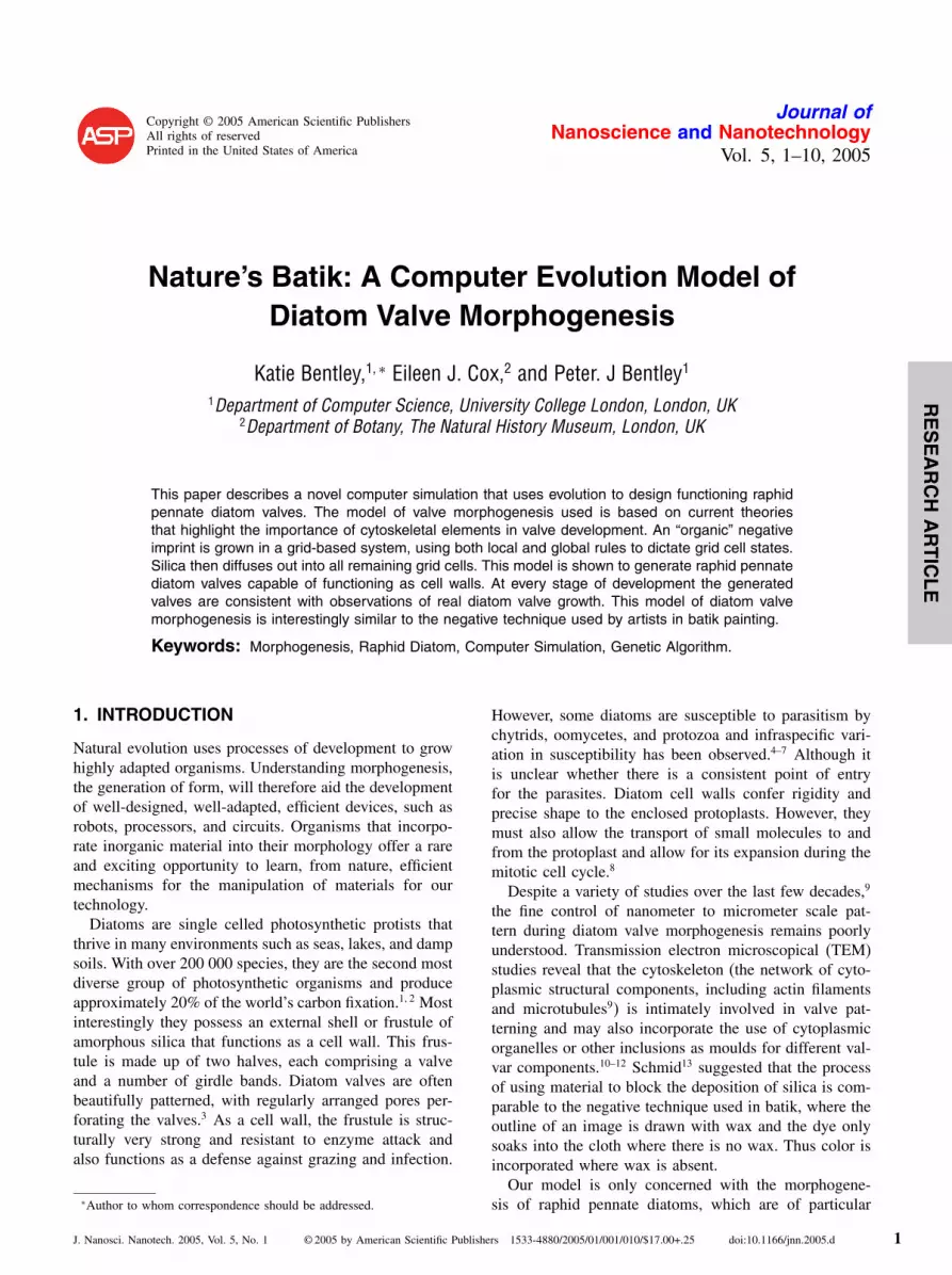
Setting the initial SDV box slightly to the left of the MCmeant that the growth of the primary silica rib (Fig. 12)was consistent with EM observations. This emerged fromthe interaction of silica diffusion local rules, the SDVinitial box placement, and the prior placement of raphematerial. Gradual decrease in the size of the pore mate-rial within the striae allowed the characteristic sequenceof virga growth followed by vimen growth to occur.Figure 12 shows the growth of the virgae and vimines,while Figure 13 shows the decrease in size of pore mate-rial as silica accumulates around it. An enlarged section(Fig. 14) shows the pore size decrease in more detail. Themodel has produced growth patterns comparable to thoseobserved in raphid diatoms by EM (Figs. 1–6).
3.3. Areas for Improvement of the Model
This model is in its early stages and would thereforebenefit from further exploration and development. Therewas no realistic selection pressure on valve outline so thefittest shape for the epitheca was a rectangle, which isvery rarely seen in nature. However, an extra componentcould be added to the fitness function to reward for sheardrop shapes, which would cope better with flow.37 Morestreamlined shapes may also favor moving over surfacesor through sediments, the typical habitats of most raphiddiatoms. Stria trajectories and pore arrangements weresimilarly oversimplified. They failed to account for theoccurrence of parallel, or intercalated, shorter striae andfor the uniseriate rows of pores within striae, seen in manyraphid diatoms. This could be overcome by the use ofa variety of packing algorithms, for example, that newstriae could emerge where there is space, rather than beingglobally positioned. Our CA model would also allow the
7
RESEARCHARTICLE
Bentley et al./A Computer Evolution Model of Diatom Valve Morphogenesis J. Nanosci. Nanotech. 2005, 5, 1–10
Fig. 12. Frames showing the growth of valve d.
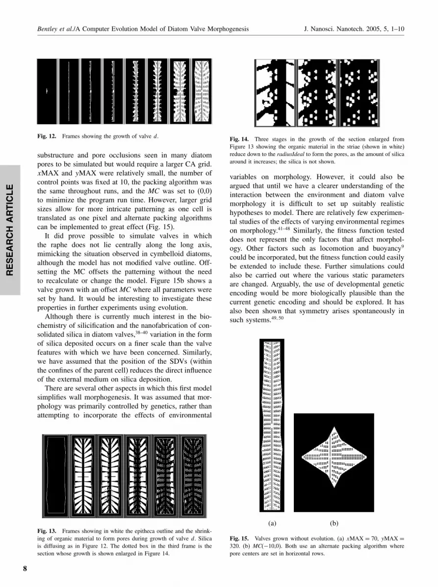
substructure and pore occlusions seen in many diatompores to be simulated but would require a larger CA grid.xMAX and yMAX were relatively small, the number ofcontrol points was fixed at 10, the packing algorithm wasthe same throughout runs, and the MC was set to (0,0)to minimize the program run time. However, larger gridsizes allow for more intricate patterning as one cell istranslated as one pixel and alternate packing algorithmscan be implemented to great effect (Fig. 15).
It did prove possible to simulate valves in whichthe raphe does not lie centrally along the long axis,mimicking the situation observed in cymbelloid diatoms,although the model has not modified valve outline. Off-setting the MC offsets the patterning without the needto recalculate or change the model. Figure 15b shows avalve grown with an offset MC where all parameters wereset by hand. It would be interesting to investigate theseproperties in further experiments using evolution.
Although there is currently much interest in the bio-chemistry of silicification and the nanofabrication of con-solidated silica in diatom valves,38–40 variation in the formof silica deposited occurs on a finer scale than the valvefeatures with which we have been concerned. Similarly,we have assumed that the position of the SDVs (withinthe confines of the parent cell) reduces the direct influenceof the external medium on silica deposition.
There are several other aspects in which this first modelsimplifies wall morphogenesis. It was assumed that mor-phology was primarily controlled by genetics, rather thanattempting to incorporate the effects of environmental
Fig. 13. Frames showing in white the epitheca outline and the shrink-ing of organic material to form pores during growth of valve d. Silicais diffusing as in Figure 12. The dotted box in the third frame is thesection whose growth is shown enlarged in Figure 14.
Fig. 14. Three stages in the growth of the section enlarged fromFigure 13 showing the organic material in the striae (shown in white)reduce down to the radiusIdeal to form the pores, as the amount of silicaaround it increases; the silica is not shown.
variables on morphology. However, it could also beargued that until we have a clearer understanding of theinteraction between the environment and diatom valvemorphology it is difficult to set up suitably realistichypotheses to model. There are relatively few experimen-tal studies of the effects of varying environmental regimeson morphology.41–48 Similarly, the fitness function testeddoes not represent the only factors that affect morphol-ogy. Other factors such as locomotion and buoyancy9
could be incorporated, but the fitness function could easilybe extended to include these. Further simulations couldalso be carried out where the various static parametersare changed. Arguably, the use of developmental geneticencoding would be more biologically plausible than thecurrent genetic encoding and should be explored. It hasalso been shown that symmetry arises spontaneously insuch systems.49�50
(a) (b)
Fig. 15. Valves grown without evolution. (a) xMAX = 70, yMAX =320. (b) MC(−10,0). Both use an alternate packing algorithm wherepore centers are set in horizontal rows.
8

RESEARCHARTICLE
J. Nanosci. Nanotech. 2005, 5, 1–10 Bentley et al./A Computer Evolution Model of Diatom Valve Morphogenesis
4. CONCLUSIONS
This model has generated raphid pennate diatom valvesexhibiting some of the functions of cell walls. At eachstage of development the generated valves were consistentwith observations on real diatom valve growth.
Simulated models are extremely useful for investigat-ing, visualizing, and developing theories of morphogen-esis. It is the intention of this paper to inspire furthermodel-based experiments and to try to bridge the gapbetween the disparate fields of computer science and biol-ogy for the exploration of morphogenesis.
The results of this work suggest that nature couldmanipulate silica in a way similar to how aesthetic pat-terns are created with Batik.
Acknowledgments: This work was funded by ScienceApplications International Corporation (SAIC). SEM wascarried out at The Natural History Museum, London, andthe support of Alex Ball and Chris Jones is acknowledged.
References and Notes
1. H. du Buf, M. Bayer, S. Droop, R. Head, S. Juggins, S. Fisher,H. Bunke, M. Wilkinson, J. Roerdink, G. P. Cristobal, H. Shah-bazkia, and A. Ciobanu, Diatom identification: A double challengecalled ADIAC. Proceedings of the 10th International Conference onImage Analysis and Processing, Venice, Italy (1999), pp. 734–739.
2. D. G. Mann and S. J. M. Droop, Biodiversity, biogeographyand conservation of diatoms. In Biogeography of FreshwaterAlgae, edited by Jørgen Kristiansen, Developments in Hydrobiol-ogy, Kluwer Academic Publishers (1996), Vol. 118, pp. 19–32.
3. F. E. Round, R. M. Crawford, and D. G. Mann. The Diatoms: Biol-ogy and Morphology of the Genera, Cambridge Univ Press, MA(1990).
4. H. M. Canter, Fungal and protozoan parasites and their importancein the ecology of the phytoplankton. Annu. Rep., Freshwater Biol.Assoc. 47, 43 (1979).
5. H. M. Canter and G. H. M. Jaworski, Some observations on thealga Fragilaria crotonensis kitton and its parasitism by two chytri-daceous fungi. Ann. Bot. 49, 429 (1982).
6. H. M. Canter and G. H. M. Jaworski, A further study on parasitismof the diatom Fragilaria crotonensis Kitton by chytridaceous fungiin culture. Ann. Bot. 52, 549 (1983).
7. D. G. Mann, The species concept in diatoms. Phycologia 38, 437(1999).
8. A.-M. M. Schmid, Wall morphogenesis in Coscinodiscus wailesiiGran et Angst. II. Cytoplasmic events of valve morphogenesis. InProceedings of the 8th Diatom Symposium, Paris 1984, edited byM. Ricard (1986), pp. 293–314.
9. J. Pickett-Heaps, A.-M. M. Schmid, and L. A. Edgar, The cell biol-ogy of diatom valve formation. Prog. Phycol. Res. 7, 1 ( 1990).
10. L. A. Edgar and J. D. Pickett-Heaps, Valve morphogenesis in thepenante diatom Navicula cuspidata. J. Phycol. 20, 47 (1984).
11. L. A. Edgar, Fine structure of Caloneis amphisbaena (Bacillario-phyceae). J. Phycol. 16, 62 (1980).
12. E. J. Cox and G. M. Kennaway, Studies of valve morphogenesis inpennate diatoms: Investigating aspects of cell biology in a system-atic context. In Proceedings of the 17th Int. Diatom Symp., Ottawa2002, edited by M. Poulin (in press).
13. A.-M. M. Schmid, Valve morphogenesis in diatoms: A pattern-related filamentous system in pennates and the effect of APM,colchcine and osmotic pressure. Nova Hedwigia 33, 811 (1980).
14. J. Parkinson, Y. Brechet, and R. Gordon, Centric diatom morpho-genesis: A model based on a DLA algorithm investigating thepotential role of microtubules. Biochim. Biophys. Acta 1452, 89(1999).
15. J. D. Pickett-Heaps, Morphogenesis of the labiate process in thearaphid diatom Diatoma vulgare. J. Phycol. 25, 79 (1989).
16. J. D. Pickett-Heaps, D. H. Tippit, and J. A. Andreozzi, Cell divisionin the pennate diatom Pinnularia. IV. Valve morphogenesis. Biol.Cell. 35, 295 (1979).
17. J. D.Pickett-Heaps, S. Cohn, A.-M. M. Schmid, and D. H. Tippit,Valve morphogenesis in Suirella. J. Phycol. 24, 35 (1988).
18. E. J. Cox, Diatoms: The evolution of morphogenetic complexity insingle celled plants. In Developmental Genetics and Plant Evolu-tion, edited by Q. C. B. Cronk, R. M. Bateman, and J. A.Hawkins,Taylor and Francis (Philadelphia), Bristol, PA (2002) pp. 459–492.
19. J. D. MacDonald, On the structure of the diatomaceous frustule,and its genetic cycle. Ann. Mag. Nat. Hist., Ser. 4 3, 1 (1869).
20. E. Pfitzer, Über den bau und die zellteilung der diatomeen. Bot.Zeitung, 27, 774 (1869).
21. E. J. Cox, Variation in patterns of valve morphogenesis betweenrepresentatives of six biraphid diatom genera (Bacillariophyceae).J. Phycol. 35, 1297 (1999).
22. E. J. Cox and R. Ross, The striae of pennate diatoms. Proceedingsof the 6th Symposium on Recent and Fossil Diatoms, edited byR. Ross, (1980), pp. 267–278.
23. C. Brett and K. Waldron, Physiology and Biochemistry of PlantCell Walls, Chapman and Hall, London (1996).
24. C. W. Li and B. E. Volcani, Morphogenesis of the labiate process incentric diatoms. Protoplasma 124, 10–29, 30–41, 147–156 (1985).
25. M. L. Chiappino and B. E. Volcani, Studies on the biochemistry andfine structure of silica shell formation in diatoms. VII. Sequentialcell wall development in the pennate Navicula pelliculosa. Proto-plasma 93, 191 (1977).
26. G. S. Blank and C. W. Sullivan, Diatom mineralization of silicicacid. VII. Influence of microtubule drugs on symmetry and patternformation in valves of Navicula saprophila during morphogenesis.J. Phycol. 19, 294 (1983).
27. S. A. Cohn, J. Nash, and J. D. Pickett-Heaps, The effect of drugson diatom valve morphogenesis. Protoplasma 149, 130 (1989).
28. A. Wuensche and M. J. Lesser, The Global Dynamics of Cel-lular Automata; An Atlas of Basin of Attraction Fields of One-Dimensional Cellular Automata, Santa Fe Institute Studies in theSciences of Complexity, Addison-Wesley, Reading, MA (1992).
29. E. Bonabeau, From classical models of morphogenesis to agent-based models of pattern formation. In Proceedings of the 3rd Con-ference on Artificial Life, edited by C. Langton (1997), pp. 191–211.
30. B. Basanta, P. J. Bentley, M. A. Miodownik, and E. A. Holm, Evolv-ing cellular automata to grow microstructures. Proceedings of the6th European Conference on Genetic Programming (EuroGP 2003),14–16 April, 2003.
31. M. Markus and I. Kushc, CA for modelling the shell pigmentationof moluscs. J. Biol. Syst. 3, 999 (1995).
32. S. Kumar and P. J. Bentley, The ABCs of evolutionary design:Investigating the evolvability of embryogenies for morphogenesis. InGenetic and Evolutionary Computation Conference (GECCO ’99),July 14–17, 1999, Orlando, FL, USA (1999), pp. 164–170.
33. K. Bentley, Exploring aesthetic pattern formation. In Proceedingsof the 5th Annual International Conference on Generative Art(GA2002), Milan (2002), Section 20.1.
34. Creative Evolutionary Systems, contributing editors P. J. Bentleyand D. W Corne, Morgan Kaufmann Publishers (2001).
35. Evolutionary Design by Computers, contributing editor P. J.Bentley, Morgan Kaufmann (1999).
36. J. A. Holland, Adaptation in Natural and Artificial Systems, MITPress, Cambridge, MA (1975).
37. R. Gordon, N. K. Björklund, G. G. C. Robinson, and H. J. Kling,Sheared drops and pennate diatoms. Nova Hedwigia 112, 289(1996).
9

RESEARCHARTICLE
Bentley et al./A Computer Evolution Model of Diatom Valve Morphogenesis J. Nanosci. Nanotech. 2005, 5, 1–10
38. N. Kröger, R. Deutzmann, C. Bergsdorf, and M. Sumper, Species-specific polyamines from diatoms control silica morphology. Proc.Nat. Acad. Sci. U.S.A. 97, 14 133 (2000).
39. N. Kröger and M. Sumper, Diatom cell wall proteins and the cellbiology of silica biomineralization. Protist 149, 213 (1998).
40. W. H. van de Poll, E. G. Vrieling, and W. W. C. Gieskes, Locationand expression of frustulins in the pennate diatoms Cylindrothecafusiformis, Navicula pelliculosa, and Navicula salinarum (Bacillar-iophyceae). J. Phycol. 35, 1044 (1999).
41. M. E. Schultz, Salinity-related polymorphism in the brackish-waterdiatom Cyclotella cryptica. Can. J. Bot. 49, 1285 (1971).
42. E. J. Cox, Morphological variation in widely distributed diatom taxa:Taxonomic and ecological implications. In Proceedings of the 13thInternational Diatom Symposium, Italy 1994, edited by D. Marinoand M. Montressor, Koeltz, Koenigstein (1995), pp. 335–345.
43. R. Trobajo, E. J. Cox, and X. D. Quintana, The effects of someenvironmental variables on the morphology of Nitzschia frustulum(Bacillariophyta), in relation its use as a bioindicator. Nova Hed-wigia (in press).
44. U. Geissler, Die Variabilität der Schalenmerkmale bei denDiatomeen. Nova Hedwigia 19, 623 (1970a).
45. U. Geissler, Die Schalenmerkmale der diatomeen—Ursachen ihrervariabilität und bedeutung für die taxonomie. Nova Hedwigia, Beih.31, 511 (1970b).
46. U. Geissler, Experimentelle untersuchungen zur variabilität derschalenmerkmale bei einigen zentrischen Sü�wasser-diatomeen. 1.Der einflu� unterschiedlicher salzkonzentrationen auf den valva-durchmesser von Stephanodiscus hantzschii grunow. Nova Hed-wigia, Beih. 73, 211 (1982).
47. U. Geissler, Experimental investigations on the variability of frus-tule characteristics of several freshwater diatoms. 2. The influenceof different salt concentrations on some valve structures of Stephan-odiscus hantzschii grunow. In Proceedings of the 8th Interna-tional Diatom Symposium, Paris 1984, edited by M. Ricard Koeltz,Koenigstein (1986), pp. 59–66.
48. A.-M. Schmid, Morphologische und physiologische untersuchungenan diatomeen des neusiedlerSees: II. Licht- und rasterelektronen-emikroskopische schalenanalyse der umweltabhängigen zyklomor-phose von Anomoeoneis sphaerophora (KG.) Pfitzer. Nova Hed-wigia 28, 309 (1976).
49. F. Dellaert and R. Beer, A developmental model for the evolutionof complete autonomous agents. In Proceedings of the Simulationof Adaptive Behaviour (SAB ‘96) (1996).
50. F. Dellaert and R. Beer, Towards an evolvable model of devel-opment for autonomous agent synthesis. In Artificial Life IV,Proceedings of the 4th International Workshop on the Synthesisand Simulation of Living Systems, MIT Press, Cambridge, MA(1994).
10