national fire protection association report
TRANSCRIPT
Public Comment No. 42-NFPA 850-2018 [ Global Input ]
Background and experience with NFPA 850
In our experience we see NFPA 850 as a source of some confusion in contract bidding and negotiations.We see it routinely misunderstood and misapplied in new power generation projects from a variety ofpotential customers. It is common to have this recommended practice called out as a requirement in acustomer specification included with a Request For Proposal. We have had several rounds of follow-upquestions regarding compliance with it. In one case a potential customer said their insurance carrier wasrequiring it in the contract.
NFPA 850 is a “Recommended Practice” which, per sections 3.2.5 and 3.2.6, "contains only nonmandatoryprovisions" and recommendations "which are advised but not required". Compliance to a "RecommendedPractice" document alone with non-mandatory provisions is quite easy - there are no mandatory "shalls" sothere is nothing explicitly to comply with. Requiring compliance to NFPA 850 does not make sense in theseterms.
Some specification writers are under the impression that requiring compliance means that all the listedrecommendations will be applied to their project. We don’t believe that the committee or document intendsfor all recommendations to be carried out in every plant. It seems impossible to do so. The document isintended to be used as a guide as project stakeholders go through the design basis process themselvesand prepare a Design Basis Document (DBD) – through the process in Chapter 4. The document containsnumerous good recommendations to support the team as they assess risks and determine the desiredspecific mitigating design requirements for their specific project. Most of the recommendations have acorresponding cost, and the decision process will weigh the costs and risks for the best solution for theproject and customer.
For projects and customers' specifications referencing NFPA 850, you could easily assume that the DBDprocess has been completed and that the results are integrated into the customer design specifications. Bycomplying with the customer design specs you should also comply with their selected recommendationsfrom NFPA 850. However, in our experience potential customers may not have gone through the FireProtection Design Process or developed the DBD. So without clarifying during the bidding process you mayend up with customer expectations that are not met based on a misunderstanding of the document andprocess.
Recommendation for the next revision
The driving recommendation that should be considered before all else is the Fire Protection DesignProcess resulting in a Design Basis Document, detailed in Chapter 4. Please consider revising the format ofthe document to make it more fool proof in this interpretation. This may include making this a Standard withChapter 4 only as mandatory and all other content in the nonmandatory appendix, as may have alreadybeen raised by some on the committee as a possible change. I think this would help remarkably to clarifythe intent and use of the document.
In addition, if the committee would consider it, a short NFPA webinar on the document and process mayalso help to clarify the use of the document. That would be something you could point a customer or otherstakeholder to before or during a negotiation.
Thank you for your consideration.
Statement of Problem and Substantiation for Public Comment
We see NFPA 850 routinely misunderstood and misapplied in new power generation projects from a variety of potential customers. It is common to have this recommended practice called out as a requirement in a customer specification included with a Request For Proposal without a corresponding DBD. This results in confusion during bidding and customer oversight of important system risks during project design.
Related Item
• First Draft Report
Submitter Information Verification
Submitter Full Name: Matthew Taylor
National Fire Protection Association Report https://submittals.nfpa.org/TerraViewWeb/ContentFetcher?commentPar...
1 of 58 7/9/2019, 4:55 PM
Organization: Mitsubishi Hitachi Power Systems
Street Address:
City:
State:
Zip:
Submittal Date: Tue Nov 27 16:01:19 EST 2018
Committee: ECG-AAA
Committee Statement
CommitteeAction:
Rejected
Resolution: As stated in section 1.3.3 these facilities have unique hazards based on the actual installationrequirements of the locality. The contracts and specifications for the facility should attempt to addressas many specifics as possibly prior to the development of the DBD. Making NFPA 850 a standardwouldn't address the issue of the document being enforced as intended. Section 1.3.3 would suggestthat an initial DBD be developed during the Front End Engineering and Design (FEED) or pre-FEEDprocess and ultimately made part of the contract. 1.3.3 It should be recognized that rigid uniformity ofgenerating station design and operating procedures does not exist and that each facility will have itsown special conditions that impact on the nature of the installation. Many of the specificrecommendations herein might require modification after due consideration of all applicable factorsinvolved. This modification should be made only after following the methodology described inChapter 4 and documented in the Fire Protection Design Basis document.
National Fire Protection Association Report https://submittals.nfpa.org/TerraViewWeb/ContentFetcher?commentPar...
2 of 58 7/9/2019, 4:55 PM

Public Comment No. 3-NFPA 850-2018 [ Section No. 9.6 ]
9.6 Turbine-Generator.
9.6.1 Hydrogen System.
9.6.1.1 * General.
9.6.1.1.1
Bulk hydrogen systems supplying one or more generators should have automatic valves located at thesupply and operable either by “dead man” type controls at the generator fill point(s) or operable from thecontrol room. This would minimize the potential for a major discharge of hydrogen in the event of a leakfrom piping inside the plant. Alternatively, vented guard piping can be used in the building to protect runs ofhydrogen piping.
9.6.1.1.2
Routing of hydrogen piping should avoid hazardous areas and areas containing critical equipment.
9.6.1.1.3
Hydrogen cylinders and generator hydrogen fill and purge manifold should be located remote from theturbine generator.
9.6.1.1.4
For electrical equipment in the vicinity of the hydrogen handling equipment, see Article 500 of NFPA 70and Section 127 of IEEE C2, National Electrical Safety Code .
9.6.1.2 Hydrogen Seal Oil Pumps.
9.6.1.2.1
Redundant hydrogen seal oil pumps with separate power supplies should be provided for adequatereliability of seal oil supply.
9.6.1.2.2
Where feasible, electrical circuits to redundant pumps should be run in buried conduit or provided with fire-retardant coating if exposed in the area of the turbine generator to minimize possibility of loss of bothpumps as a result of a turbine generator fire.
9.6.1.3
Curbing or drainage or both should be provided for the hydrogen seal oil unit in accordance withSection 6.5 .
9.6.1.4
A flanged spool piece or equivalent arrangement should be provided to facilitate the separation ofhydrogen supply where the generator is opened for maintenance.
9.6.1.5
For electrical equipment in the vicinity of the hydrogen handling equipment, including detraining equipment,seal oil pumps, valves, and so forth, see Article 500 of NFPA 70 and Section 127 of IEEE C2, NationalElectrical Safety Code .
9.6.1.6
Control room alarms should be provided to indicate abnormal gas pressure, temperature, and percentageof hydrogen in the generator.
9.6.1.7
Hydrogen lines should not be piped into the control room.
9.6.1.8
The generator hydrogen dump valve and hydrogen detraining equipment should be arranged to ventdirectly to a safe outside location. The dump valve should be remotely operable from the control room oran area accessible during a machine fire.
9.6.2 Fire Protection.
National Fire Protection Association Report https://submittals.nfpa.org/TerraViewWeb/ContentFetcher?commentPar...
3 of 58 7/9/2019, 4:55 PM
9.6.2.1 *
All areas beneath the turbine-generator operating floor that are subject to oil flow, oil spray, or oilaccumulation should be protected by an automatic sprinkler or foam-water sprinkler system. This coveragenormally includes all areas beneath the operating floor in the turbine building. The sprinkler systembeneath the turbine-generator should take into consideration obstructions from structural members and
piping and should be designed to a density of 0.30 gpm/ft 2 (12.2 mm/min) over a minimum application of
5000 ft 2 (464 m 2 ).
9.6.2.2
Lubricating oil lines above the turbine operating floor should be protected with an automatic sprinklersystem covering those areas subject to oil accumulation including the area within the turbine lagging (skirt).
The automatic sprinkler system should be designed to a density of 0.30 gpm/ft 2 (12.2 mm/min).
9.6.2.3 *
Protection for pedestal-mounted turbine generators with no operating floor can be provided byrecommendations 9.6.2 and by containing and drainage of oil spills and providing local automaticprotection systems for the containment areas. In this type of layout, spray fires from lube oil and hydrogenseal oil conditioning equipment and from control oil systems using mineral oil, if released, could exposebuilding steel or critical generating equipment. Additional protection such as enclosing the hazard, installinga noncombustible barrier between the hazard and critical equipment, or use of a water spray system overthe hazard should be considered.
9.6.2.4 *
Foam-water sprinkler systems installed in place of automatic sprinklers described in Chapter 9 should bedesigned in accordance with NFPA 16, including the design densities specified in Chapter 9 .
9.6.2.5
Electrical equipment in the area covered by a water or foam-water system should be of the enclosed typeor otherwise protected to minimize water damage in the event of system operation.
9.6.2.6 * Turbine-Generator Bearings.
9.6.2.6.1 *
Turbine-generator bearings should be protected with an automatic closed-head sprinkler system utilizingdirectional nozzles or water spray or water mist systems. Automatic actuation is more reliable than manualaction. Water spray and sprinkler systems for turbine-generator bearings should be designed for a density
of 0.25 gpm/ft 2 (10.2 mm/min) over the protected area of all bearings.
9.6.2.6.2
Where enclosures are provided, compressed air foam systems and hybrid fire-extinguishing systems canbe considered.
9.6.2.6.3 *
Accidental water discharge on bearing points and hot turbine parts should be considered. If necessary,these areas can be permitted to be protected by shields and encasing insulation with metal covers.
9.6.2.7 Exciter.
The area inside a directly connected exciter housing should be protected with a total flooding automaticcarbon dioxide system.
9.6.2.8 Hydrogen Seal Oil.
Hydrogen seal oil units should be protected in accordance with 9.6.2 .
Statement of Problem and Substantiation for Public Comment
The Section 9.6 text is being incorporated to chapter 10 so as to consolidate guidance related to turbines (steam and gas) thereby providing a single location of the information applicable to a combined cycle power plant. This eliminates duplication / cross referencing of information common to both types of machines that was previously located in two separate chapters. This is a follow-on reorganization in the spirit of the First Revision 12 effort.
Related Item
• First Revision No. 12-NFPA 850-2018 [ Global Input ]
Submitter Information Verification
National Fire Protection Association Report https://submittals.nfpa.org/TerraViewWeb/ContentFetcher?commentPar...
4 of 58 7/9/2019, 4:55 PM

Submitter Full Name: Larry Danner
Organization: Ge Power & Water
Street Address:
City:
State:
Zip:
Submittal Date: Wed Nov 07 08:04:02 EST 2018
Committee: ECG-AAA
Committee Statement
CommitteeAction:
Rejected but see related SR
Resolution: SR-73-NFPA 850-2019
Statement: This change is part of the document-wide reorganization effort. This change will help users beable to better navigate the standard and have a better overall organization of the document.
National Fire Protection Association Report https://submittals.nfpa.org/TerraViewWeb/ContentFetcher?commentPar...
5 of 58 7/9/2019, 4:55 PM
Public Comment No. 4-NFPA 850-2018 [ Section No. 9.8 ]
9.8 Lubricating Oil Systems.
9.8.1 *
Use of a listed fire-resistant (i.e., less hazardous or less flammable) lubricating oil should be considered.The use of a listed fire-resistant fluid as a turbine-generator lubricating oil (see 7.8.2) could eliminate theneed for fire protection beneath the operating floor and at lubricating oil lines, lubricating oil reservoirs, andturbine-generator bearings to mitigate the hazard posed solely by pool and three-dimensional firesinvolving lubrication oil. Protection against pool and three-dimensional fires in accordance with 7.13.4.1should be installed if the hydrogen seal oil system does not use listed fire-resistant fluids. Generatorbearings for seal oil systems not using listed fire-resistant fluids should be protected in accordance with9.6.2.6 . Stakeholders should be involved in the decision-making process before eliminating fire protectionfor the turbine lubrication oil hazard.
9.8.2
Lubricating oil storage, pumping facilities, and associated piping should comply with NFPA 30.
9.8.3
Lubricating oil reservoirs should be provided with a vapor extractor vented to a safe outside location.
9.8.4
Curbing or drainage or both should be provided for the turbine lubricating oil reservoir in accordance withSection 6.5 .
9.8.5
All oil piping serving the turbine-generator should be designed and installed to minimize the possibility ofan oil fire in the event of severe turbine vibration. (See NFPA 30 .)
9.8.6 *
Piping design and installation should consider the following protective measures:
(1) Welded construction
(2) Guard pipe construction with the pressure feed line located inside the return line or in a separateshield pipe drained to the oil reservoir and sized to handle the flow from all oil pumps operating at thesame time
(3) Route oil piping so as to be clear of, shielded from, or below steam piping, hot metal parts, electricalequipment, or other sources of ignition
(4) Insulation with impervious lagging for steam piping or hot metal parts under or near oil piping orturbine bearing points
(5) Noncombustible coverings (e.g., flange guards) around the flange to reduce the possibility of oilspraying onto a hot surface
9.8.7
Remote operation from the control room of the condenser vacuum break valve and shutdown of thelubricating oil pumps should be provided. Breaking the condenser vacuum markedly reduces the rundowntime for the machine and thus limits oil discharge in the event of a leak. See the discussion in 5.4.6.1 onfire emergency planning involving turbine lubricating oil fires.
9.8.8
Cable for operation of lube oil pumps should be protected from fire exposure. Protection can consist ofseparation of cable for ac and dc oil pumps or 1-hour fire resistive coating (derating of cable should beconsidered).
9.8.9 Fire Protection.
National Fire Protection Association Report https://submittals.nfpa.org/TerraViewWeb/ContentFetcher?commentPar...
6 of 58 7/9/2019, 4:55 PM
9.8.9.1 *
Lubricating oil reservoirs and handling equipment should be protected in accordance with 9.6.2.1 . If thelubricating oil equipment is in a separate room enclosure, protection can be provided by a total floodinggaseous extinguishing system or a hybrid fire-extinguishing system.
Statement of Problem and Substantiation for Public Comment
The Section 9.8 text is being incorporated to chapter 10 so as to consolidate guidance related to turbines (steam and gas) thereby providing a single location of the information applicable to a combined cycle power plant. This eliminates duplication / cross referencing of information common to both types of machines that was previously located in two separate chapters. This is a follow-on reorganization in the spirit of the First Revision 12 effort.
Related Item
• First Revision No. 12-NFPA 850-2018 [ Global Input ]
Submitter Information Verification
Submitter Full Name: Larry Danner
Organization: Ge Power & Water
Street Address:
City:
State:
Zip:
Submittal Date: Wed Nov 07 08:24:32 EST 2018
Committee: ECG-AAA
Committee Statement
CommitteeAction:
Rejected but see related SR
Resolution: SR-73-NFPA 850-2019
Statement: This change is part of the document-wide reorganization effort. This change will help users beable to better navigate the standard and have a better overall organization of the document.
National Fire Protection Association Report https://submittals.nfpa.org/TerraViewWeb/ContentFetcher?commentPar...
7 of 58 7/9/2019, 4:55 PM
Public Comment No. 5-NFPA 850-2018 [ Section No. 9.9.11 ]
9.9.11 Emergency Generators.
9.9.11.1
The installation and operation of emergency generators should be in accordance with NFPA 37.
9.9.11.2 Fire Protection.
9.9.11.2.1
Emergency generators located within main plant structures should be protected in accordance withNFPA 37.
9.9.11.2.2
Where gaseous suppression systems are used on combustion engines that can be required to operateduring the system discharges, consideration should be given to the supply of engine combustion air andoutside air for equipment cooling.
Statement of Problem and Substantiation for Public Comment
The Section 9.9.11 text is being incorporated to chapter 10 so as to consolidate guidance related to Internal Combustion Engines (ICEs) thereby providing a single location of the information applicable to this class of equipment. This eliminates duplication / cross referencing of information that was previously located in two separate chapters. This is a follow-on reorganization in the spirit of the First Revision 12 effort.
Related Item
• First Revision No. 12-NFPA 850-2018 [ Global Input ]
Submitter Information Verification
Submitter Full Name: Larry Danner
Organization: Ge Power & Water
Street Address:
City:
State:
Zip:
Submittal Date: Wed Nov 07 08:26:57 EST 2018
Committee: ECG-AAA
Committee Statement
CommitteeAction:
Accepted
Resolution: SR-66-NFPA 850-2019
Statement: The Section 9.9.11 text is being incorporated to chapter 10 so as to consolidate guidance related toInternal Combustion Engines (ICEs) thereby providing a single location of the information applicableto this class of equipment. This eliminates duplication / cross referencing of information that waspreviously located in two separate chapters. This is a follow-on reorganization in the spirit of theFirst Revision 12 effort.
National Fire Protection Association Report https://submittals.nfpa.org/TerraViewWeb/ContentFetcher?commentPar...
8 of 58 7/9/2019, 4:55 PM
Public Comment No. 6-NFPA 850-2018 [ Section No. 10.1.1 ]
10.1.1
Chapter 10 identifies fire and explosion hazards of combustion turbine (CT), steam turbine (ST) andinternal combustion engine (ICE) electric generating units and specifies recommended protection criteria.
Statement of Problem and Substantiation for Public Comment
Modifying the text to reflect the incorporation of Steam Turbine information in to chapter 10 so as to consolidate guidance related to gas and steam turbines thereby providing a single location of the information applicable to this class of equipment. This eliminates duplication / cross referencing of information that was previously located in two separate chapters. This is a follow-on reorganization in the spirit of the First Revision 12 effort.
Related Item
• First Revision No. 12-NFPA 850-2018 [ Global Input ]
Submitter Information Verification
Submitter Full Name: Larry Danner
Organization: Ge Power & Water
Street Address:
City:
State:
Zip:
Submittal Date: Wed Nov 07 08:55:01 EST 2018
Committee: ECG-AAA
Committee Statement
CommitteeAction:
Rejected but see related SR
Resolution: SR-73-NFPA 850-2019
Statement: This change is part of the document-wide reorganization effort. This change will help users beable to better navigate the standard and have a better overall organization of the document.
National Fire Protection Association Report https://submittals.nfpa.org/TerraViewWeb/ContentFetcher?commentPar...
9 of 58 7/9/2019, 4:55 PM
Public Comment No. 7-NFPA 850-2018 [ New Section after 10.1.2 ]
10.1.3
ST generating facilities consist of turbine assemblies and auxiliary equipment whereinconstruction consists of incorporating these items into a boiler or HRSG steam system. Althoughthe typical installation is in an open area within a dedicated turbine building, outdoor installationswith weather enclosures for the turbine are known and acoustic enclosures may be incorporatedfor indoor units. As for the CT installations, some recommendations might be more suitable for onetype of plant than another.
Statement of Problem and Substantiation for Public Comment
Adding a discussion of Steam Turbines (similar to that for CTs and ICEs) in recognition of the incorporation of ST information in to chapter 10. This is a follow-on reorganization in the spirit of the First Revision 12 effort.
Related Item
• First Revision No. 12-NFPA 850-2018 [ Global Input ]
Submitter Information Verification
Submitter Full Name: Larry Danner
Organization: Ge Power & Water
Street Address:
City:
State:
Zip:
Submittal Date: Wed Nov 07 08:56:31 EST 2018
Committee: ECG-AAA
Committee Statement
CommitteeAction:
Rejected but see related SR
Resolution: SR-73-NFPA 850-2019
Statement: This change is part of the document-wide reorganization effort. This change will help users beable to better navigate the standard and have a better overall organization of the document.
National Fire Protection Association Report https://submittals.nfpa.org/TerraViewWeb/ContentFetcher?commentPar...
10 of 58 7/9/2019, 4:55 PM
Public Comment No. 25-NFPA 850-2018 [ Section No. 10.1.3 ]
10.1.3 4 *
Modern ICE generating equipment is typically provided as a complete package requiring only a fuel sourceand electrical connections to the system to be powered. The installations should be either fixed/permanentor installed as a portable/temporary power source. The recommendations of this chapter should be appliedto fixed nonresidential installations only.
Statement of Problem and Substantiation for Public Comment
The paragraph number is changed as part of the follow-on reorganization effort that combines Steam Turbine and Generator information from Chapter 9 into Chapter 10. This reorganization is in the spirit of the First Revision 12 effort.
Related Item
• First Revision No. 12-NFPA 850-2018 [ Global Input ]
Submitter Information Verification
Submitter Full Name: Larry Danner
Organization: Ge Power & Water
Street Address:
City:
State:
Zip:
Submittal Date: Wed Nov 07 13:24:52 EST 2018
Committee: ECG-AAA
Committee Statement
CommitteeAction:
Rejected but see related SR
Resolution: SR-73-NFPA 850-2019
Statement: This change is part of the document-wide reorganization effort. This change will help users beable to better navigate the standard and have a better overall organization of the document.
National Fire Protection Association Report https://submittals.nfpa.org/TerraViewWeb/ContentFetcher?commentPar...
11 of 58 7/9/2019, 4:55 PM
Public Comment No. 24-NFPA 850-2018 [ Section No. 10.1.4 ]
10.1.4 5
Compressors and regulating stations installed on-site should be protected in accordance with therecommendations of Chapter 10.
Statement of Problem and Substantiation for Public Comment
The paragraph number is revised as part of the follow-on reorganization effort that combines Steam Turbine and Generator information from Chapter 9 into Chapter 10. This reorganization is in the spirit of the First Revision 12 effort.
Related Item
• First Revision No. 12-NFPA 850-2018 [ Global Input ]
Submitter Information Verification
Submitter Full Name: Larry Danner
Organization: Ge Power & Water
Street Address:
City:
State:
Zip:
Submittal Date: Wed Nov 07 13:24:23 EST 2018
Committee: ECG-AAA
Committee Statement
CommitteeAction:
Rejected but see related SR
Resolution: SR-73-NFPA 850-2019
Statement: This change is part of the document-wide reorganization effort. This change will help users beable to better navigate the standard and have a better overall organization of the document.
National Fire Protection Association Report https://submittals.nfpa.org/TerraViewWeb/ContentFetcher?commentPar...
12 of 58 7/9/2019, 4:55 PM
Public Comment No. 8-NFPA 850-2018 [ Section No. 10.2 ]
10.2 Application of Chapters 4 through 10 9 .
The recommendations contained in Chapters 4 through 13 9 can apply to turbine and internalcombustion turbine engine electric generating units. The Fire Protection Design Basis Document willdetermine which recommendations apply to any specific CT, ST and ICE electric generating units. Thisdetermination is done by evaluating the specific hazards that exist in the facility and evaluating the level ofacceptable risk for the facility. For large CT or ST units, or combined cycle plants, it is expected that mostof the recommendations will apply, but for individually packaged CT and ICE units, many of therecommendations will not apply since the hazards described might not exist (e.g., small units might nothave a cable spreading room or a warehouse).
Statement of Problem and Substantiation for Public Comment
Modifying the text to reflect the incorporation of Steam Turbine information in to chapter 10 so as to consolidate guidance related to gas and steam turbines thereby providing a single location of the information applicable to this class of equipment. This eliminates duplication / cross referencing of information that was previously located in two separate chapters. This is a follow-on reorganization in the spirit of the First Revision 12 effort.
Also, corrected the chapter references consistent with other chapters.
Related Item
• First Revision No. 12-NFPA 850-2018 [ Global Input ]
Submitter Information Verification
Submitter Full Name: Larry Danner
Organization: Ge Power & Water
Street Address:
City:
State:
Zip:
Submittal Date: Wed Nov 07 09:04:02 EST 2018
Committee: ECG-AAA
Committee Statement
CommitteeAction:
Rejected but see related SR
Resolution: SR-73-NFPA 850-2019
Statement: This change is part of the document-wide reorganization effort. This change will help users beable to better navigate the standard and have a better overall organization of the document.
National Fire Protection Association Report https://submittals.nfpa.org/TerraViewWeb/ContentFetcher?commentPar...
13 of 58 7/9/2019, 4:55 PM
Public Comment No. 9-NFPA 850-2018 [ Section No. 10.3 ]
10.3 Combustion Turbine and Internal Combustion Engine Generators.
10.3.1 General.
10.3.1.1
The installation and operation of CT and ICE generators should be in accordance with this chapter andNFPA 37.
10.3.1.2
Site-specific design considerations or manufacturer's typical design will govern what equipment hasenclosures or how many separate enclosures will be provided for the CTs or the ICEs. The CT generator isfrequently supplied as a complete power plant package with equipment mounted on skids or pads andprovided with metal enclosures forming an all-weather housing. In addition to being weathertight, theenclosures are designed to provide thermal and acoustical insulation. Smaller ICE plants might involveenclosures for equipment, but more commonly engine generators are installed in a row in an open room orhall.
10.3.1.3*
The fire and explosion hazards associated with CT and ICE electric generator units are as follows:
(1) Flammable and combustible fuels
(2) Hydraulic and lubricating oils
(3) Electrical and control equipment
(4) Filter media
(5) Combustible enclosure insulation
(6) Internal explosions in CTs
(7) Crankcase explosions in ICEs
10.3.1.4
In the event of a problem with older ICEs, shutdown might be difficult. Several different methods, operatingindependently, should be provided. These methods can include centrifugally tripped (overspeed condition)spring-operated fuel rack closure, governor fuel rack closure, electropneumatic fuel rack closure, or air inletguillotine–type air shutoff.
10.3.2 Prevention of Internal Explosions in Combustion Turbines.
10.3.2.1*
Combustion turbines should have a proof-of-flame detection system in the combustion section to detectflameout during operation or ignition failure during startup. In the case of flameout, the fuel should berapidly shut off. If ignition is not achieved within a normal startup time, then the control system should abortthe startup and close the fuel valves.
10.3.2.2
Two safety shutoff valves in series on the main fuel line should be used to minimize the likelihood of fuelleaking into the engine. On gas systems an automatic vent to the outside atmosphere should be providedbetween the two valves.
10.3.3 Prevention of External Fires.
National Fire Protection Association Report https://submittals.nfpa.org/TerraViewWeb/ContentFetcher?commentPar...
14 of 58 7/9/2019, 4:55 PM
10.3.3.1
Piping systems supplying flammable and combustible liquids and gases should be designed to minimize oiland fuel piping failures as follows:
(1) If rigid metal piping is used, it should be designed with freedom to deflect with the unit, in any direction.This recommendation also should apply to hydraulic lines that are connected to accessory gearboxesor actuators mounted directly on the unit. Properly designed metallic hose is an alternative for fuel,hydraulic, and lube oil lines in high vibration areas, between rigid pipe supply lines and manifolds inand at the points of entry at the engine interface.
(2) Rigid piping connected directly to the unit should be supported such that failures will not occur due tothe natural frequency of the piping coinciding with the rotational speed of the machine. Care should betaken in the design of pipe supports to avoid vibrations induced by other equipment that can excite itsnatural frequency.
(3) Welded pipe joints should be used where practical. Threaded couplings and flange bolts in fuel and oilpiping should be assembled using a torque wrench and torqued to the manufacturer's requirements.Couplings should have a positive locking device to prevent unscrewing.
(4) Instrumentation tubing, piping, and gauges should be protected from accidental mechanical damage.Liquid level indicators should be listed and protected from impact.
(5) Where practical, lubricating oil lines should use guarded pipe construction with the pressure feed linelocated inside the return line. If this is not practical, piping sleeves and/or tubing and flange guardsshould be used to reduce the possibility of oil atomization with subsequent spray fires.
(6) If practical, fluid piping should not be routed above electrical equipment to preclude leaked fluiddripping on the equipment.
10.3.3.2*
In many units the lubricating oil is used for both lubrication and hydraulic control. For combined systems, alisted fire-resistant fluid should be considered. If separate systems are used, the hydraulic control systemshould use a listed fire-resistive hydraulic fluid, and a listed fire-resistant fluid should be considered for thelubricating system.
10.3.3.3
Combustible gas detector(s) should be considered for the CT and ICE enclosures.
10.3.3.4
For recommendations regarding containment and drainage of liquids, see Section 6.5.
10.3.3.5
In order to prevent conditions that could cause a fire while the unit is operating, control packages shouldinclude the parameter monitoring and shutdown capabilities described in Chapter 9 of NFPA 37.
10.3.4 Fire Protection for Combustion Turbines and Internal Combustion Electrical Generators.
10.3.4.1
Determination of the need for fire suppression for the combustion turbine engine should be based onconsideration of the value of the unit, consequences of loss of the unit, and vulnerability of adjacentstructures and equipment to damage.
10.3.4.1.1
Fire system operation should be arranged to close the fuel valves except for ICE emergency power supplysystems (e.g., hospital emergency power).
10.3.5 Inlet Air System.
10.3.5.1*
Air filters and evaporative cooling media should be constructed from less flammable materials wheneverpractical. ANSI/UL 900, Standard for Safety Test Performance of Air Filters, can be used as guidance.
10.3.5.2
Manual fire-fighting equipment should be available to personnel performing maintenance on air filters.
10.3.5.3
Access doors or hatches should be provided for manual fire fighting on large air filter structures.
10.3.6 Generators.
National Fire Protection Association Report https://submittals.nfpa.org/TerraViewWeb/ContentFetcher?commentPar...
15 of 58 7/9/2019, 4:55 PM
10.3.6.1
Hydrogen systems should comply with recommendations in 9.6.1 and 9.6.2.8.
10.3.6.2
Fire protection should be provided in accordance with 10.3.4 for generator bearings and oil piping or anyarea where oil can flow, accumulate, or spray.
10.3.6.3*
Air-cooled generators should be tightly sealed against the ingress of moisture in the event of discharge(accidental or otherwise) of a water spray system. Sealing should be positive, such as by a gasket orgrouting, all around the generator housing.
10.3.7 Starting Equipment for CTs.
Where ICEs or torque converters are used, fire protection should be provided based on consideration of thefactors in 10.3.4.1.
Statement of Problem and Substantiation for Public Comment
Modifying the title to reflect the incorporation of Steam Turbine information in to chapter 10. This is a follow-on reorganization in the spirit of the First Revision 12 effort.
Related Item
• First Revision No. 12-NFPA 850-2018 [ Global Input ]
Submitter Information Verification
Submitter Full Name: Larry Danner
Organization: Ge Power & Water
Street Address:
City:
State:
Zip:
Submittal Date: Wed Nov 07 09:13:49 EST 2018
Committee: ECG-AAA
Committee Statement
CommitteeAction:
Rejected but see related SR
Resolution: SR-28-NFPA 850-2019
Statement: Modifying the title to reflect the incorporation of Steam Turbine information in to chapter 10. Thisis a follow-on reorganization in the spirit of the First Revision 12 effort.
National Fire Protection Association Report https://submittals.nfpa.org/TerraViewWeb/ContentFetcher?commentPar...
16 of 58 7/9/2019, 4:55 PM
Public Comment No. 10-NFPA 850-2018 [ Section No. 10.3.1.2 ]
10.3.1.2
Site-specific design considerations or manufacturer's typical design will govern what equipment hasenclosures or how many separate enclosures will be provided for the CTs, STs or the ICEs. The CTgenerator is frequently supplied as a complete power plant package with equipment mounted on skids orpads and provided with metal enclosures forming an all-weather housing. In addition to being weathertight,the enclosures are designed to provide thermal and acoustical insulation. ST generators are typicallysupplied as components that are incorporated into the power plant design and installed in an open room orseparate building. Metal acoustic enclosures are available as options for some ST generators. SmallerICE plants might involve enclosures for equipment, but more commonly engine generators are installed in arow in an open room or hall.
Statement of Problem and Substantiation for Public Comment
Modifying the text to reflect the incorporation of Steam Turbine information in to chapter 10 so as to consolidate guidance related to gas and steam turbines thereby providing a single location of the information applicable to this class of equipment. This eliminates duplication / cross referencing of information that was previously located in two separate chapters. This is a follow-on reorganization in the spirit of the First Revision 12 effort.
Related Item
• First Revision No. 12-NFPA 850-2018 [ Global Input ]
Submitter Information Verification
Submitter Full Name: Larry Danner
Organization: Ge Power & Water
Street Address:
City:
State:
Zip:
Submittal Date: Wed Nov 07 09:16:34 EST 2018
Committee: ECG-AAA
Committee Statement
CommitteeAction:
Rejected but see related SR
Resolution: SR-73-NFPA 850-2019
Statement: This change is part of the document-wide reorganization effort. This change will help users beable to better navigate the standard and have a better overall organization of the document.
National Fire Protection Association Report https://submittals.nfpa.org/TerraViewWeb/ContentFetcher?commentPar...
17 of 58 7/9/2019, 4:55 PM
Public Comment No. 11-NFPA 850-2018 [ Section No. 10.3.1.3 ]
10.3.1.3*
The fire and explosion hazards associated with CT, ST and ICE electric generator units are as follows:
(1) Flammable and combustible fuels
(2) Hydraulic and lubricating oils
(3) Electrical and control equipment
(4) Filter media
(5) Combustible enclosure insulation
(6) Internal explosions in CTs
(7) Crankcase explosions in ICEs
Statement of Problem and Substantiation for Public Comment
Modifying the text to reflect the incorporation of Steam Turbine information in to chapter 10 so as to consolidate guidance related to gas and steam turbines thereby providing a single location of the information applicable to this class of equipment. This eliminates duplication / cross referencing of information that was previously located in two separate chapters. This is a follow-on reorganization in the spirit of the First Revision 12 effort.
Related Item
• First Revision No. 12-NFPA 850-2018 [ Global Input ]
Submitter Information Verification
Submitter Full Name: Larry Danner
Organization: Ge Power & Water
Street Address:
City:
State:
Zip:
Submittal Date: Wed Nov 07 09:20:52 EST 2018
Committee: ECG-AAA
Committee Statement
CommitteeAction:
Rejected but see related SR
Resolution: SR-73-NFPA 850-2019
Statement: This change is part of the document-wide reorganization effort. This change will help users beable to better navigate the standard and have a better overall organization of the document.
National Fire Protection Association Report https://submittals.nfpa.org/TerraViewWeb/ContentFetcher?commentPar...
18 of 58 7/9/2019, 4:55 PM
Public Comment No. 12-NFPA 850-2018 [ Section No. 10.3.1.4 ]
10.3.1 4 .4
In the event of a problem with older ICEs, shutdown might be difficult. Several different methods, operatingindependently, should be provided. These methods can include centrifugally tripped (overspeed condition)spring-operated fuel rack closure, governor fuel rack closure, electropneumatic fuel rack closure, or air inletguillotine–type air shutoff.
Statement of Problem and Substantiation for Public Comment
Modifying the location of the text to consolidate with other ICE guidance andto fit with the incorporation of Steam Turbine information in to chapter 10. This is a follow-on reorganization in the spirit of the First Revision 12 effort.
Related Item
• First Revision No. 12-NFPA 850-2018 [ Global Input ]
Submitter Information Verification
Submitter Full Name: Larry Danner
Organization: Ge Power & Water
Street Address:
City:
State:
Zip:
Submittal Date: Wed Nov 07 09:29:11 EST 2018
Committee: ECG-AAA
Committee Statement
CommitteeAction:
Rejected but see related SR
Resolution: SR-73-NFPA 850-2019
Statement: This change is part of the document-wide reorganization effort. This change will help users beable to better navigate the standard and have a better overall organization of the document.
National Fire Protection Association Report https://submittals.nfpa.org/TerraViewWeb/ContentFetcher?commentPar...
19 of 58 7/9/2019, 4:55 PM
Public Comment No. 13-NFPA 850-2018 [ Section No. 10.3.2 ]
10.3.2 .3 Prevention of Internal Explosions in Combustion Turbines.
10.3.2.3. 1*
Combustion turbines should have a proof-of-flame detection system in the combustion section to detectflameout during operation or ignition failure during startup. In the case of flameout, the fuel should berapidly shut off. If ignition is not achieved within a normal startup time, then the control system should abortthe startup and close the fuel valves.
10.3.2.3. 2
Two safety shutoff valves in series on the main fuel line should be used to minimize the likelihood of fuelleaking into the engine. On gas systems an automatic vent to the outside atmosphere should be providedbetween the two valves.
Statement of Problem and Substantiation for Public Comment
Modifying the location of the text to provide a better flow considering the incorporation of moved information from chapter 9 into the section renumbered as 10.3.1.4. This is a follow-on reorganization in the spirit of the First Revision 12 effort.
Related Item
• First Revision No. 12-NFPA 850-2018 [ Global Input ]
Submitter Information Verification
Submitter Full Name: Larry Danner
Organization: Ge Power & Water
Street Address:
City:
State:
Zip:
Submittal Date: Wed Nov 07 09:36:08 EST 2018
Committee: ECG-AAA
Committee Statement
CommitteeAction:
Rejected but see related SR
Resolution: SR-73-NFPA 850-2019
Statement: This change is part of the document-wide reorganization effort. This change will help users beable to better navigate the standard and have a better overall organization of the document.
National Fire Protection Association Report https://submittals.nfpa.org/TerraViewWeb/ContentFetcher?commentPar...
20 of 58 7/9/2019, 4:55 PM
Public Comment No. 15-NFPA 850-2018 [ Section No. 10.3.3 ]
10.3.3 1.4 Prevention of External Fires.
10.3.3 1 .4. 1
Piping systems supplying flammable and combustible liquids and gases should be designed to minimize oiland fuel piping failures as follows:
(1) If rigid metal piping is used, it should be designed with freedom to deflect with the unit, in any direction.This recommendation also should apply to hydraulic lines that are connected to accessory gearboxesor actuators mounted directly on the unit. Properly designed metallic hose is an alternative for fuel,hydraulic, and lube oil lines in high vibration areas, between rigid pipe supply lines and manifolds inand at the points of entry at the engine interface.
(2) Rigid piping connected directly to the unit should be supported such that failures will not occur due tothe natural frequency of the piping coinciding with the rotational speed of the machine. Care should betaken in the design of pipe supports to avoid vibrations induced by other equipment that can excite itsnatural frequency.
(3) Welded pipe joints should be used where practical. Threaded couplings and flange bolts in fuel and oilpiping should be assembled using a torque wrench and torqued to the manufacturer's requirements.Couplings should have a positive locking device to prevent unscrewing.
(4) Instrumentation tubing, piping, and gauges should be protected from accidental mechanical damage.Liquid level indicators should be listed and protected from impact.
(5) Where practical, lubricating oil lines should use guarded pipe construction with the pressure feed linelocated inside the return line or in a separate shield pipe drained to the oil reservoir and sized tohandle the flow from all oil pumps operating at the same time . If this is not practical, noncombustiblecoverings (e.g., piping sleeves and/or tubing and flange guards) should be used to reduce thepossibility of oil atomization and contact with hot surfaces with subsequent spray fires.
(6) If practical, fluid piping should not be routed above electrical equipment clear of, shielded from orrouted below steam piping, hot metal parts, electrical equipment or other sources of ignition topreclude leaked fluid dripping on the equipment.
(7) Insulation with impervious lagging for steam piping or hot metal parts under or near oil piping orturbine bearing points
National Fire Protection Association Report https://submittals.nfpa.org/TerraViewWeb/ContentFetcher?commentPar...
21 of 58 7/9/2019, 4:55 PM
10.3. 1.4.2*
All areas beneath the turbine-generator operating floor that are subject to oil flow, oil spray, or oilaccumulation should be protected by an automatic sprinkler or foam-water sprinkler system. This coveragenormally includes all areas beneath the operating floor in the turbine building. The sprinkler systembeneath the turbine-generator should take into consideration obstructions from structural members andpiping and should be designed to a density of 0.30 gpm/ft2 (12.2 mm/min) over a minimum application of5000 ft2 (464 m2).
10. 3. 1.4.3
Lubricating oil lines above the turbine operating floor should be protected with an automatic sprinklersystem covering those areas subject to oil accumulation including the area within the turbine lagging(skirt). The automatic sprinkler system should be designed to a density of 0.30 gpm/ft2 (12. 2 mm/min).
10.3.1.4.4 *
Protection for pedestal-mounted turbine generators with no operating floor can be provided byrecommendations 10.3.1.4 and by containing and drainage of oil spills and providing local automaticprotection systems for the containment areas. In this type of layout, spray fires from lube oil and hydrogenseal oil conditioning equipment and from control oil systems using mineral oil, if released, could exposebuilding steel or critical generating equipment. Additional protection such as enclosing the hazard,installing a noncombustible barrier between the hazard and critical equipment, or use of a water spraysystem over the hazard should be considered.
10.3.1.4.5
Foam-water sprinkler systems installed in place of automatic sprinklers should be designed in accordancewith NFPA 16, including the design densities specified in Chapter 9
10.3.1.4.6
Electrical equipment in the area covered by a water or foam-water system should be of the enclosed typeor otherwise protected to minimize water damage in the event of system operation.
10.3.1.4.7 *
In many units the lubricating oil is used for both lubrication and hydraulic control. For combined systems, alisted fire-resistant fluid should be considered. If separate systems are used, the hydraulic control systemshould use a listed fire-resistive hydraulic fluid, and a listed fire-resistant fluid should be considered for thelubricating system.
10.3.3.4
10.3.3.3
Combustible gas detector(s) should be considered for the CT and ICE enclosures.
1.4.8
For recommendations regarding containment and drainage of liquids, see Section 6.5.
National Fire Protection Association Report https://submittals.nfpa.org/TerraViewWeb/ContentFetcher?commentPar...
22 of 58 7/9/2019, 4:55 PM
10.3.3.5 1.4.9
In order to prevent conditions that could cause a fire while the unit is operating, control packages shouldinclude the parameter monitoring and shutdown capabilities described in Chapter 9 of NFPA 37.
10.3.1.5 Lubricating Oil Systems.
10.3.1.5.1
Use of a listed fire resistant (i.e., less hazardous or less flammable) lubricating oil should be considered.The use of a listed fire-resistant fluid as a turbine-generator lubricating oil (see 7.8.2) could eliminate theneed for fire protection beneath the operating floor, at lubricating oil lines, lubricating oil reservoir, andturbine-generator bearings to mitigate the hazard posed solely by pool and three-dimensional firesinvolving lubrication oil. Protection against pool and three-dimensional fires in accordance with 7.13.4.1should be installed if the hydrogen seal oil system does not use listed fire-resistant fluids. Generatorbearings for seal oil systems not using listed fire-resistant fluids should be protected in accordance with10.3.3.1. Stakeholders should be involved in the decision making process before eliminating fire protectionfor the turbine lubrication oil hazard.
10.3.1.5.2
Lubricating oil storage, pumping facilities, and associated piping should comply with NFPA 30.
10.3.1.5.3
Lubricating oil reservoirs should be provided with and ICE added to a vapor extractor, vented to a safeoutside location.
10.3.1.5.4
Curbing or drainage or both should be provided for the lubricating oil reservoir in accordance with Section6.5.
10.3.1.5.5
All oil piping serving the turbine, ICE or generator should be designed and installed to minimize thepossibility of an oil fire in the event of severe turbine vibration. ( See NFPA 30 .)
10.3.1.5.6
Remote operation from the control room of the condenser vacuum break valve and shutdown of thelubricating oil pumps should be provided. Breaking the condenser vacuum markedly reduces the rundowntime for the machine and thus limits oil discharge in the event of a leak. See the discussion in 5.4.6.1 onfire emergency planning involving turbine lubricating oil fires.
10.3.1.5.7
Cable for operation of lube oil pumps should be protected from fire exposure. Protection can consist ofseparation of cable for ac and dc oil pumps or 1-hour fire resistive coating (derating of cable should beconsidered).
10.3.1.5.8 Fire Protection.
10.3.1.5.8 .1
Lubricating oil reservoirs and handling equipment should be protected in accordance with 10.3.1.4.2 . If thelubricating oil equipment is in a separate room enclosure, protection can be provided by a total floodinggaseous extinguishing system or a hybrid fire extinguishing system.
Statement of Problem and Substantiation for Public Comment
Modifying the text to reflect the incorporation of Steam Turbine information in to chapter 10 so as to consolidate guidance related to gas and steam turbines thereby providing a single location of the information applicable to this class of equipment. This eliminates duplication / cross referencing of information that was previously located in two separate chapters. This is a follow-on reorganization in the spirit of the First Revision 12 effort.
Specific sections of Chapter 9 incorporated into this section include: • 9.8.6 (incorporated into existing text now numbered as 10.3.1.4.1)• 9.6.2.1 (as 10.3.1.4.2)• 9.6.2.2 (as 10.3.1.4.3)• 9.6.2.3 (as 10.3.1.4.4)• 9.6.2.4 (as 10.3.1.4.5)• 9.6.2.5 (as 10.3.1.4.6)• 9.8 except for 9.8.6 as stated above (as 10.3.1.5) and ICE added to 10.3.1.5.5 as that is also applicable
Related Item
National Fire Protection Association Report https://submittals.nfpa.org/TerraViewWeb/ContentFetcher?commentPar...
23 of 58 7/9/2019, 4:55 PM
• First Revision No. 12-NFPA 850-2018 [ Global Input ]
Submitter Information Verification
Submitter Full Name: Larry Danner
Organization: Ge Power & Water
Street Address:
City:
State:
Zip:
Submittal Date: Wed Nov 07 09:48:31 EST 2018
Committee: ECG-AAA
Committee Statement
CommitteeAction:
Rejected but see related SR
Resolution: SR-73-NFPA 850-2019
Statement: This change is part of the document-wide reorganization effort. This change will help users beable to better navigate the standard and have a better overall organization of the document.
National Fire Protection Association Report https://submittals.nfpa.org/TerraViewWeb/ContentFetcher?commentPar...
24 of 58 7/9/2019, 4:55 PM
Public Comment No. 18-NFPA 850-2018 [ Section No. 10.3.3.3 ]
10.3. 2 Combustion Turbines
10. 3.
3
2.1
Combustible gas detector(s) should be considered for the CT and ICE enclosures.
Statement of Problem and Substantiation for Public Comment
Modifying the location of the text to provide a better flow considering the incorporation of information from chapter 9. This is a follow-on reorganization in the spirit of the First Revision 12 effort.
Related Item
• First Revision No. 12-NFPA 850-2018 [ Global Input ]
Submitter Information Verification
Submitter Full Name: Larry Danner
Organization: Ge Power & Water
Street Address:
City:
State:
Zip:
Submittal Date: Wed Nov 07 11:07:49 EST 2018
Committee: ECG-AAA
Committee Statement
CommitteeAction:
Rejected but see related SR
Resolution: SR-73-NFPA 850-2019
Statement: This change is part of the document-wide reorganization effort. This change will help users beable to better navigate the standard and have a better overall organization of the document.
National Fire Protection Association Report https://submittals.nfpa.org/TerraViewWeb/ContentFetcher?commentPar...
25 of 58 7/9/2019, 4:55 PM
Public Comment No. 19-NFPA 850-2018 [ Section No. 10.3.4 ]
10.3.4 2.2 Fire Protection for Combustion Turbines and Internal Combustion Electrical Generators.
10.3.4 2 .2. 1
Determination of the need for fire suppression for the combustion turbine engine turbines should bebased on consideration of the value of the unit, consequences of loss of the unit, and vulnerability ofadjacent structures and equipment to damage. See Chapter 7 for general fire protection methodsguidance.
10.3.4 2 .2. 1.1
Fire system operation should be arranged to close the fuel valves except for ICE emergency power supplysystems (e .g., hospital emergency power).
Statement of Problem and Substantiation for Public Comment
Modifying the location and text to reflect the incorporation of Steam Turbine information in to chapter 10 and collect CT specific information in a single location. This is a follow-on reorganization in the spirit of the First Revision 12 effort.
Related Item
• First Revision No. 12-NFPA 850-2018 [ Global Input ]
Submitter Information Verification
Submitter Full Name: Larry Danner
Organization: Ge Power & Water
Street Address:
City:
State:
Zip:
Submittal Date: Wed Nov 07 11:11:56 EST 2018
Committee: ECG-AAA
Committee Statement
CommitteeAction:
Rejected but see related SR
Resolution: SR-73-NFPA 850-2019
Statement: This change is part of the document-wide reorganization effort. This change will help users beable to better navigate the standard and have a better overall organization of the document.
National Fire Protection Association Report https://submittals.nfpa.org/TerraViewWeb/ContentFetcher?commentPar...
26 of 58 7/9/2019, 4:55 PM
Public Comment No. 16-NFPA 850-2018 [ Section No. 10.3.5 ]
10.3.5 1.6 Inlet Air System.
10.3.5 1 .6. 1*
Air filters and evaporative cooling media should be constructed from less flammable materials wheneverpractical. ANSI/UL 900, Standard for Safety Test Performance of Air Filters, can be used as guidance.
10.3.5 1 .6. 2
Manual fire-fighting equipment should be available to personnel performing maintenance on air filters.
10.3.5 1 .6. 3
Access doors or hatches should be provided for manual fire fighting on large air filter structures.
Statement of Problem and Substantiation for Public Comment
Modifying the location of the text to provide a better flow considering the incorporation of information from chapter 9. This is a follow-on reorganization in the spirit of the First Revision 12 effort.
Related Item
• First Revision No. 12-NFPA 850-2018 [ Global Input ]
Submitter Information Verification
Submitter Full Name: Larry Danner
Organization: Ge Power & Water
Street Address:
City:
State:
Zip:
Submittal Date: Wed Nov 07 10:55:04 EST 2018
Committee: ECG-AAA
Committee Statement
CommitteeAction:
Rejected but see related SR
Resolution: SR-73-NFPA 850-2019
Statement: This change is part of the document-wide reorganization effort. This change will help users beable to better navigate the standard and have a better overall organization of the document.
National Fire Protection Association Report https://submittals.nfpa.org/TerraViewWeb/ContentFetcher?commentPar...
27 of 58 7/9/2019, 4:55 PM

Public Comment No. 22-NFPA 850-2018 [ Section No. 10.3.6 ]
10.3.6 5 Generators.
National Fire Protection Association Report https://submittals.nfpa.org/TerraViewWeb/ContentFetcher?commentPar...
28 of 58 7/9/2019, 4:55 PM
10.3.
6
5 .1
Hydrogen systems should comply with recommendations in 9.6.1 and 9.6.2.8 .
10.3.6.2
Fire protection should be provided in accordance with 10.3.4 for generator bearings and
Hydrogen Cooled Generators
10.3.5.1.1*
Bulk hydrogen systems supplying one or more generators should have automatic valves located at thesupply and operable either by “dead man” type controls at the generator fill point(s) or operable from thecontrol room. This would minimize the potential for a major discharge of hydrogen in the event of a leakfrom piping inside the plant. Alternatively, vented guard piping can be used in the building to protect runs ofhydrogen piping.
10.3.5.1.2
Routing of hydrogen piping should avoid hazardous areas and areas containing critical equipment.
10.3.5.1.3
Hydrogen cylinders and generator hydrogen fill and purge manifold should be located remote from theturbine generator.
10.3.5.1.4
For electrical equipment in the vicinity of the hydrogen handling equipment, see Article 500 of NFPA 70 andSection 127 of IEEE C2, National Electrical Safety Code .
10.3.5.2 Hydrogen Seal Oil System
10.3.5.2.1
Redundant hydrogen seal oil pumps with separate power supplies should be provided for adequatereliability of seal oil supply.
10.3.5.2.2
Where feasible, electrical circuits to redundant pumps should be run in buried conduit or provided with fire-retardant coating if exposed in the area of the turbine generator to minimize possibility of loss of bothpumps as a result of a turbine generator fire.
10.3.5.2.3
Hydrogen seal oil units should be protected in accordance with an appropriate method selected fromSection 7.6 and considering the guidance provided in 10.3.1.4.2 through 10.3.1.4.6.
10.3.5.3
Curbing or drainage or both should be provided for the hydrogen seal oil unit in accordance with Section6.5.
10.3.5.4
A flanged spool piece or equivalent arrangement should be provided to facilitate the separation of hydrogensupply where the generator is opened for maintenance.
10.3.5.5
For electrical equipment in the vicinity of the hydrogen handling equipment, including detraining equipment,seal oil pumps, valves, and so forth, see Article 500 of NFPA 70 and Section 127 of IEEE C2, NationalElectrical Safety Code .
10.3.5.6
Control room alarms should be provided to indicate abnormal gas pressure, temperature, and percentageof hydrogen in the generator.
10.3.5.7
Hydrogen lines should not be piped into the control room.
10.3.5.7
The generator hydrogen dump valve and hydrogen detraining equipment should be arranged to vent
National Fire Protection Association Report https://submittals.nfpa.org/TerraViewWeb/ContentFetcher?commentPar...
29 of 58 7/9/2019, 4:55 PM
directly to a safe outside location. The dump valve should be remotely operable from the control room or anarea accessible during a machine fire.
10.3.5.9
Fire protection should be provided in accordance with an appropriate method selected from Section 7.6and considering the guidance provided in 10.3.3.1 for turbine bearings and 10.3.1.4.2 through10.3.1.4.5 for oil piping or any area where oil can flow, accumulate, or spray.
10.3.
6.3
5.9 .1
Exciter. The area inside a directly connected exciter housing should be protected with a total floodingautomatic carbon dioxide system.
10.3.3.5.10 *
Air-cooled generators should be tightly sealed against the ingress of moisture in the event of discharge(accidental or otherwise) of a water spray system. Sealing should be positive, such as by a gasket orgrouting, all around the generator housing.
Statement of Problem and Substantiation for Public Comment
Modifying the text to reflect the incorporation of Steam Turbine - Generator information in to chapter 10 so as to consolidate guidance related to gas and steam turbine generators thereby providing a single location of the information applicable to this class of equipment. This eliminates duplication / cross referencing of information that was previously located in two separate chapters. This is a follow-on reorganization in the spirit of the First Revision 12 effort.
Specific sections of Chapter 9 incorporated into this section include: • 9.6.1 (as 10.3.5.1)• 9.6.1.1.1/2/3/4 (as 10.3.5.1.1/2/3/4)• 9.6.1.2 (as 10.3.5.2)• 9.6.2.8 (as 10.3.5.2.3)• 9.6.1.3 (as 10.3.5.3) • 9.6.1.4 (as 10.3.5.4)• 9.6.1.5 (as 10.3.5.5)• 9.6.1.6 (as 10.3.5.6)• 9.6.1.7 (as 10.3.5.7)• 9.6.1.8 (as 10.3.5.8)• 9.6.2.7 (as 10.3.5.9.1)
Related Item
• First Revision No. 12-NFPA 850-2018 [ Global Input ]
Submitter Information Verification
Submitter Full Name: Larry Danner
Organization: Ge Power & Water
Street Address:
City:
State:
Zip:
Submittal Date: Wed Nov 07 12:03:09 EST 2018
Committee: ECG-AAA
Committee Statement
CommitteeAction:
Rejected but see related SR
Resolution: SR-73-NFPA 850-2019
National Fire Protection Association Report https://submittals.nfpa.org/TerraViewWeb/ContentFetcher?commentPar...
30 of 58 7/9/2019, 4:55 PM

Statement: This change is part of the document-wide reorganization effort. This change will help users beable to better navigate the standard and have a better overall organization of the document.
National Fire Protection Association Report https://submittals.nfpa.org/TerraViewWeb/ContentFetcher?commentPar...
31 of 58 7/9/2019, 4:55 PM
Public Comment No. 23-NFPA 850-2018 [ New Section after 10.3.6.3 ]
10.3.6 Emergency Generators.
10.3.6.1
The installation and operation of emergency generators should be in accordance with NFPA 37.
10.3.6.2 Fire Protection.
10.3.6.2.1
Emergency generators located within main plant structures should be protected in accordance with NFPA37.
10.3.6.2.2
Where gaseous suppression systems are used on combustion engines that can be required to operateduring the system discharges, consideration should be given to the supply of engine combustion air andoutside air for equipment cooling.
Statement of Problem and Substantiation for Public Comment
Moving the text from Chapter 9 where it was somewhat unrelated to the section to Chapter 10 section on generators thereby consolidating generator information. This is a follow-on reorganization in the spirit of the First Revision 12 effort.
Related Item
• First Revision No. 12-NFPA 850-2018 [ Global Input ]
Submitter Information Verification
Submitter Full Name: Larry Danner
Organization: Ge Power & Water
Street Address:
City:
State:
Zip:
Submittal Date: Wed Nov 07 13:13:23 EST 2018
Committee: ECG-AAA
Committee Statement
CommitteeAction:
Rejected but see related SR
Resolution: SR-73-NFPA 850-2019
Statement: This change is part of the document-wide reorganization effort. This change will help users beable to better navigate the standard and have a better overall organization of the document.
National Fire Protection Association Report https://submittals.nfpa.org/TerraViewWeb/ContentFetcher?commentPar...
32 of 58 7/9/2019, 4:55 PM
Public Comment No. 17-NFPA 850-2018 [ Section No. 10.3.7 ]
10.3.1. 7 Starting Equipment for CTs.
Where ICEs or torque converters are used, fire protection should be provided based on consideration of thefactors in 10.3.4.1.
Statement of Problem and Substantiation for Public Comment
Modifying the location of the text to provide a better flow considering the incorporation of information from chapter 9. This is a follow-on reorganization in the spirit of the First Revision 12 effort.
Related Item
• First Revision No. 12-NFPA 850-2018 [ Global Input ]
Submitter Information Verification
Submitter Full Name: Larry Danner
Organization: Ge Power & Water
Street Address:
City:
State:
Zip:
Submittal Date: Wed Nov 07 10:58:58 EST 2018
Committee: ECG-AAA
Committee Statement
CommitteeAction:
Rejected but see related SR
Resolution: SR-73-NFPA 850-2019
Statement: This change is part of the document-wide reorganization effort. This change will help users beable to better navigate the standard and have a better overall organization of the document.
National Fire Protection Association Report https://submittals.nfpa.org/TerraViewWeb/ContentFetcher?commentPar...
33 of 58 7/9/2019, 4:55 PM
Public Comment No. 21-NFPA 850-2018 [ New Section after 10.4.2 ]
10.3.4 Internal Combustion Engines.
10.3.4.1
Combustible gas detector(s) should be considered for the ICE enclosures.
10.3.4.2
Determination of the need for fire suppression for the internal combustion engine should be based onconsideration of the value of the unit, consequences of loss of the unit, and vulnerability of adjacentstructures and equipment to damage. See Chapter 7 for general fire protection methods guidance.
10.3.4.3
Fire system operation should be arranged to close the fuel valves except for ICE emergency power supplysystems (e.g., hospital emergency power).
Statement of Problem and Substantiation for Public Comment
Creating the ICE Specific guidance by separating it from the combustion turbine information and combining with other ICE specific and unique information in the chapter to provide the consolidated information in a single location. This is a follow-on reorganization in the spirit of the First Revision 12 effort.
Related Item
• First Revision No. 12-NFPA 850-2018 [ Global Input ]
Submitter Information Verification
Submitter Full Name: Larry Danner
Organization: Ge Power & Water
Street Address:
City:
State:
Zip:
Submittal Date: Wed Nov 07 11:47:02 EST 2018
Committee: ECG-AAA
Committee Statement
CommitteeAction:
Rejected but see related SR
Resolution: SR-73-NFPA 850-2019
Statement: This change is part of the document-wide reorganization effort. This change will help users beable to better navigate the standard and have a better overall organization of the document.
National Fire Protection Association Report https://submittals.nfpa.org/TerraViewWeb/ContentFetcher?commentPar...
34 of 58 7/9/2019, 4:55 PM
Public Comment No. 20-NFPA 850-2018 [ Section No. 10.4.2 ]
10.4 3 .2 3 Steam Turbines.
Steam turbines, generators, and their associated hazards should be designed and protected in accordancewith Section 9 an appropriate method selected from Section 7 .6 and considering the guidance providedin 10 . 3.1.4.2 through 10.3.1.4.8.
10.3.3.1 Bearings
10.3.3.1.1
Turbine bearings should be protected with an automatic closed-head sprinkler system utilizing directionalnozzles or water spray or water mist systems. Automatic actuation is more reliable than manual action. Water spray and sprinkler systems for turbine-generator bearings should be designed for a density of 0.25gpm/ft2 (10.2 mm/min) over the protected area of all bearings.
10.3.3.1.2
Where enclosures are provided, compressed air foam systems and hybrid fire-extinguishing systems canbe considered.
10.3.3.1.3
Accidental water discharge on bearing points and hot turbine parts should be considered. If necessary,these areas can be permitted to be protected by shields and encasing insulation with metal covers.
Statement of Problem and Substantiation for Public Comment
Modifying the text to reflect the incorporation of Steam Turbine information in to chapter 10 so as to consolidate guidance related to gas and steam turbines thereby providing a single location of the information applicable to this class of equipment. This eliminates duplication / cross referencing of information that was previously located in two separate chapters. This is a follow-on reorganization in the spirit of the First Revision 12 effort.
Specific sections of Chapter 9 incorporated into this section include: • 9.6.2.6 (as 10.3.3.1)
Related Item
• First Revision No. 12-NFPA 850-2018 [ Global Input ]
Submitter Information Verification
Submitter Full Name: Larry Danner
Organization: Ge Power & Water
Street Address:
City:
State:
Zip:
Submittal Date: Wed Nov 07 11:23:24 EST 2018
Committee: ECG-AAA
Committee Statement
CommitteeAction:
Rejected but see related SR
Resolution: SR-73-NFPA 850-2019
Statement: This change is part of the document-wide reorganization effort. This change will help users beable to better navigate the standard and have a better overall organization of the document.
National Fire Protection Association Report https://submittals.nfpa.org/TerraViewWeb/ContentFetcher?commentPar...
35 of 58 7/9/2019, 4:55 PM
Public Comment No. 2-NFPA 850-2018 [ Section No. A.6.1.4.2(9) ]
A.6.1.4.2(9)
Oil-filled transformer explosions and fires can be prevented in some cases by the installation of a passivemechanical system designed to depressurize the transformer a few milliseconds after the occurrence of anelectrical fault. An example is provided in D.2.14. This fast depressurization can be achieved by a quick oilevacuation triggered by the dynamic transient pressure peak generated by the short circuit. The protectiontechnology activates within milliseconds before static pressure increases, therefore preventing transformerexplosion and subsequent fire. However, because these devices do not eliminate a fire potential resultingfrom all forms of transformer failure (e.g., transformer bushing failure), they should be considered as apossible supplement to passive protection features such as physical barriers or spatial separation, not asan alternative to these features. The systems can include outflow devices that are located directly on thehigh-risk areas of the bushing turrets and oil-bushing cable boxes.
Statement of Problem and Substantiation for Public Comment
Dynamic pressure is a vague terminology. Replacing it with the term "transient" would help the reader understand and interpret the standard better.
Related Item
•
Submitter Information Verification
Submitter Full Name: William Kendrick
Organization: Sentry Depressurization System
Street Address:
City:
State:
Zip:
Submittal Date: Thu Nov 01 15:50:32 EDT 2018
Committee: ECG-AAA
Committee Statement
CommitteeAction:
Accepted
Resolution: SR-1-NFPA 850-2019
Statement: Dynamic pressure is a vague terminology. Replacing it with the term "transient" would help thereader understand and interpret the standard better.
National Fire Protection Association Report https://submittals.nfpa.org/TerraViewWeb/ContentFetcher?commentPar...
36 of 58 7/9/2019, 4:55 PM

Public Comment No. 1-NFPA 850-2018 [ Section No. A.9.5.2.6 ]
National Fire Protection Association Report https://submittals.nfpa.org/TerraViewWeb/ContentFetcher?commentPar...
37 of 58 7/9/2019, 4:55 PM

A.9.5.2.6
National Fire Protection Association Report https://submittals.nfpa.org/TerraViewWeb/ContentFetcher?commentPar...
38 of 58 7/9/2019, 4:55 PM

All signs of spontaneous combustion and fire must be eliminated prior to the movement of coal.
Manual Fire Suppression. Fire fighting in coal silos is a long and difficult activity. Some firefightingoperations have taken several days to completely extinguish a fire.
Smoldering >Smoldering coal in a coal bin, bunker, or silo is a potentially dangerous situation thatdepends on the location of the smoldering coal. There is a risk of a flash fire or explosion if the smolderingcoal is disturbed. This risk should be considered in preplanning. Personnel responding to a coal fire shouldhave proper personal protective equipment, including SCBA and turnout gear, and training in this hazard.
The area surrounding the smoldering coal should also be considered. The potential of developing animmediately dangerous to life and health (IDLH) atmosphere is possible. This should also be considered inpreplanning.<
General: My input regards a safety issue.
Electrostatic discharges are generated when liquid CO2 is released. It's a known source of ignition, e.g. inNFPA 77.
This is not problem for fighting a fire with flames. But a hot spot may have filled the headspace withflammable pyrolysis gases. If ignited due to CO2 injection, a confined explosion will result.
Problem: NFPA 850 does not mention this hazard.
For further info, please refer to this article on an explosion caused by injection of CO2 Hedlund (2018)Carbon dioxide not suitable for extinguishment of smouldering silo fires: static electricity may cause siloexplosion. Biomass and Bioenergy. 108:113-119. https://doi.org/10.1016/j.biombioe.2017.11.009
This is merely a friendly service message. I'm not a US citizen and have no means to enter a lengthycomments procedure for a US standard. Unfortunately, I cannot take this issue further with NFPA.
Depending on the strategy selected, resource demands will be varied but challenging. Prefire planning is animportant element in successful silo fire control and should be included in the Fire Protection Design BasisDocument(see Chapter 4) and the fire emergency plan (see 5.4.4). Control room operators should beinvolved with the preplanning.
Use of Water Additives. Use of water additives has been successful in recent years, especially for sub-bituminous coal fires. Application of water additives is the preferred fire suppression method of the PRBCoal Users' Group for bunker, hopper, and silo fire protection (see the PRB Coal Users' GroupRecommended Practice, Coal Bunker, Hopper & Silo Fire Protection Guidelines).
Baseline guides and procedures for preplanning and applying water additives to these fires are included inthe PRB Coal Users' Group document. These guides and procedures can be used as a starting point by theowner's structural fire brigade and local fire department to customize the approach for the specific facility.These fire-fighting activities are inherently dangerous and should not be performed by incipient fire brigadesor other personnel. The document is available to members of the PRB Coal Users' Group online atwww.prbcoals.com.
The application of water additives can be enhanced by using an infrared camera to search for hot spots,either on the sides or top of the silo, to facilitate injection as close as possible to the fire area. The infraredimagery can be used to evaluate performance and monitor progress of the attack. The solution mustpenetrate to the seat of combustion to be effective. This penetration can be affected by the degree ofcompaction, voids, rate of application, evaporation rate, and so forth. Runoff must be drained throughfeeder pipe and will require collection, cleanup, and disposal.
Use of Class A Foams and Penetrants. Use of Class A foams and penetrants has had some success, but ithas been difficult to predict the resources required for successful fire control. The agents generally requiremixing with water prior to application, usually in the range of 1 percent by volume, mixed in a mannersimilar to Class B agents. While the typical application of Class A foam is to fight wildland fires at 1 percent,many plants have reported success with using Class A foams at 0.1 percent. This causes the agent to actas a surfactant. Higher proportions have caused excessive bubble accumulation that impedes penetrationinto the coal.
The application of foams and penetrants can be enhanced by using an infrared camera to search for hotspots, either on the sides or top of the silo, to facilitate injection of the agent as close as possible to the firearea. The infrared imagery can be used to evaluate performance and monitor progress of the attack. Thewater/agent solution must penetrate to the seat of combustion to be effective. This penetration can beaffected by the degree of compaction, voids, rate of application, evaporation rate, and so forth. Runoff mustbe drained through feeder pipe and will require collection, cleanup, and disposal.
Use of Inerting Gas. Carbon dioxide and nitrogen have been used successfully as gaseous inertingsystems. Carbon dioxide vapor, with a density of 1.5 times that of air, has proven to be effective in quicklyestablishing an inert atmosphere in the space above the coal, which prevents the creation of an explosive
National Fire Protection Association Report https://submittals.nfpa.org/TerraViewWeb/ContentFetcher?commentPar...
39 of 58 7/9/2019, 4:55 PM
atmosphere in that space.
At the same time the CO2 vapor can be injected into the stored coal from the lower part of the silo, wherefires are most likely to originate. This CO2 inerts the voids between the coal pieces while filling the silo fromthe bottom up with CO2 vapor. The CO2 vapor injection rate is that needed to exceed any losses at thebottom of the silo while pushing the inert gas up through the coal at a reasonable rate. (Very tall silosrequire intermediate injection points for the CO2 vapor between the top and bottom of the silo.)
Since >Since carbon dioxide is stored as a compressed liquified gas, it must be vaporized before injectioninto the silo. External vaporizers are used and sized to handle the maximum anticipated CO2 vapor flowrates.<
My comment: It is not clearly stated, that vaporization is required to avoid electrostatic discharges, not justbecause CO2 is a "liquefied gas"
It is common practice to monitor the carbon monoxide (CO) level while inerting with CO2. If the CO leveldoes not decrease, the controls on the CO2 system are designed to allow for increasing the inerting rate.The flow can also be reduced to conserve the CO2 supply once fire control has been established.
A large imbedded coal fire provides a heated mass that will be extremely difficult to extinguish with CO2alone. It is, however, important that supplemental fire fighting be done in an inert environment. The CO2system's primary mission is to prevent the large fire from occurring by detecting the fire early by the COdetectors while it is still small and then inerting to contain and extinguish.
Bulk >Bulk liquid CO2 units are generally used, but cylinders can be used for inerting smaller silos. (Thebulk CO2 supply is frequently used for other applications such as pulverizer inerting, generator hydrogenpurge, and some fire suppression system applications in the turbine building.) The bulk CO2 units have thecapability of being refilled while they are being used. For the smaller silos, CO2 vapor is withdrawn frommanifolded cylinders without siphon tubes.<
My comment: That CO2 can be safely drawn from a CO2 cylinder " without siphon tubes" appears to be ahighly problematic statement. I suggest to at least notify the reader of the hazard of electrostatic dischargegeneration.
Carbon dioxide inerting has a beneficial effect as soon as it reaches the oxidizing coal. As the supportingoxygen level drops, less heat is generated, helping to limit fire spread. But to totally extinguish any largeburning coal mass can require a very high CO2 concentration held for a long time since the coolingcapacity of the CO2 is relatively small and the coal itself tends to retain heat.
The CO2 system should be considered as a fire prevention/fire containment system. The system can beoperated from a dedicated manual release station or by the plant programmable logic controller (PLC) fromthe control room. Plant personnel need not be involved except to adjust the CO2 flow rates as needed tomanage the inerting or fire suppression.
When carbon dioxide is used, there is a risk of oxygen depletion in the area above, around, or below a silo,bin, or bunker. Areas where gas could collect and deplete oxygen, which might include the tripper room andareas below the discharge feeder gate, should be identified with appropriate barriers and warning signs.
Nitrogen has been used successfully to inert silo fires. It is applied in a manner very similar to carbondioxide. A notable difference is that nitrogen has about the same density as air (whereas carbon dioxide issignificantly more dense). Therefore, it must be applied at numerous injection points around the silo toensure that it displaces available oxygen, which results in the need for more injection equipment and alarger quantity of agent.
Emptying the Silo. The silo can be unloaded through the feeder pipe, but it is a dirty, messy operation. It isnecessary to bypass the feeder belt and to dump the coal onto the floor of the power house at the feederelevation. A hose crew should be available to extinguish burning coal as it is discharged from the silo.There is a risk that dust raised during this activity can ignite explosively. High-expansion foam can beapplied.
Carbon monoxide produced during the combustion process will also tend to settle in the lower elevationand can be a hazard to the hose crew. Once spilled and extinguished, it is usually necessary to shovel thecoal into a dump truck for transport back to the coal pile.
Manual Fire-Fighting. Regardless of the type of suppression approach selected, prefire planning is animportant element of successful fire control and extinguishment. All necessary resources should beidentified and in place prior to beginning fire suppression activities. If necessary materials are not stockpiledon-site, suppliers should be contacted in advance to ensure that equipment and supplies are available onrelatively short notice.
The personnel requirements for this fire-fighting activity should be identified in advance. Personnel should
National Fire Protection Association Report https://submittals.nfpa.org/TerraViewWeb/ContentFetcher?commentPar...
40 of 58 7/9/2019, 4:55 PM
be trained and qualified for fire-fighting in the hot, smoky environment that might accompany a silo fire. Thistraining includes the use of self-contained breathing apparatus and personal protective equipment.Personnel engaged in this activity should be minimally trained and equipped to the structural fire brigadelevel as defined in NFPA 600. If station personnel are not trained in use of self-contained breathingapparatus, it will be necessary for the public fire department to perform fire-fighting in these areas. Stationpersonnel are still needed to assist with operational advice and guidance. The public fire-fighting agencythat responds to a fire at the facility should be involved in preplanning fire-fighting activities for silo fires.The public fire service might need specific instruction concerning operation and potential hazardsassociated with coal silo fires as well as operation in the power plant environment. It is important that theresponding fire service be supplied information and guidance at every opportunity.
The resources of the station and the local fire service need to work in concert, including working withcontrol room operators and keeping them apprised of fire control operations. Preplanning should includeadministrative details such as chain of command, access, and so forth. Operations should be coordinatedby an established incident command system in conformance with NFPA 1561. All personnel should befamiliar with and practice this system prior to the event.
Statement of Problem and Substantiation for Public Comment
NFPA 850 - silent on electrostatic hazard of CO2 injection, potentially leading to explosionComment to Annex A, section A.9.5.2.6
General: My input concerns a safety issue.Electrostatic discharges are generated when liquid CO2 is released. It's a known source of ignition, e.g. in NFPA 77. This is not problem for fighting a fire with flames. But a hot spot may have filled the headspace with flammable pyrolysis gases. If ignited due to CO2 injection, a confined explosion will result. Problem: NFPA 850 does not mention this hazard.For further info, please refer to this article on an explosion caused by injection of CO2 Hedlund (2018) Carbon dioxide not suitable for extinguishment of smouldering silo fires: static electricity may cause silo explosion. Biomass and Bioenergy. 108:113-119. https://doi.org/10.1016/j.biombioe.2017.11.009This is merely a friendly service message. I'm not a US citizen and have no means to enter a lengthy comments procedure for a US standard. Unfortunately, I cannot take this issue further with NFPA. regards,Frank H Hedlund, Denmark
Related Item
• First draft report, Annex A
Submitter Information Verification
Submitter Full Name: Frank Hedlund
Organization: Cowi
Street Address:
City:
State:
Zip:
Submittal Date: Sat Sep 29 16:19:22 EDT 2018
Committee: ECG-AAA
Committee Statement
CommitteeAction:
Rejected
Resolution: Section A.7.4.2.6 Use of Inerting Gas defines a fixed system utilizing piping having direct path toearth ground minimizing the possibility of static at the injection point. The study cited in publiccomment no.1 CO2 injection refers to the article “Explosion Caused by Injection of CO-2” byHedlund where they are utilizing portable equipment which is not covered by this recommendedpractice. NFPA 10, Standard on Portable Fire Extinguishers, covers requirements for portable fireextinguishers and the committee would not recommend the use of portable extinguishers in a firesituation such as the one described.
National Fire Protection Association Report https://submittals.nfpa.org/TerraViewWeb/ContentFetcher?commentPar...
41 of 58 7/9/2019, 4:55 PM
Public Comment No. 39-NFPA 850-2018 [ Section No. A.9.6.1.1 ]
A.9 10 .6 3 .5. 1.1
For hydrogen storage systems, see NFPA 2.
Statement of Problem and Substantiation for Public Comment
Annex material moved from Chapter 9 to follow the source reference material as part of the follow-on reorganization effort that combines Steam Turbine and Generator information from Chapter 9 into Chapter 10. This reorganization is in the spirit of the First Revision 12 effort.
Related Item
• First Revision No. 12-NFPA 850-2018 [ Global Input ]
Submitter Information Verification
Submitter Full Name: Larry Danner
Organization: Ge Power & Water
Street Address:
City:
State:
Zip:
Submittal Date: Wed Nov 07 14:37:17 EST 2018
Committee: ECG-AAA
Committee Statement
CommitteeAction:
Accepted
Resolution: SR-37-NFPA 850-2019
Statement: Annex material moved from Chapter 9 to follow the source reference material as part of the follow-on reorganization effort that combines Steam Turbine and Generator information from Chapter 9into Chapter 10. This reorganization is in the spirit of the First Revision 12 effort.
National Fire Protection Association Report https://submittals.nfpa.org/TerraViewWeb/ContentFetcher?commentPar...
42 of 58 7/9/2019, 4:55 PM
Public Comment No. 28-NFPA 850-2018 [ Section No. A.9.6.2.1 ]
A.9 10 .6 3 .2.1 1.4.2
To avoid water application to hot parts or other water sensitive areas and to provide adequate coverage,designs that incorporate items such as fusible element operated directional spray nozzles can benecessary.
Statement of Problem and Substantiation for Public Comment
Annex material moved from Chapter 9 to follow the source reference material as part of the follow-on reorganization effort that combines Steam Turbine and Generator information from Chapter 9 into Chapter 10. This reorganization is in the spirit of the First Revision 12 effort.
Related Item
• First Revision No. 12-NFPA 850-2018 [ Global Input ]
Submitter Information Verification
Submitter Full Name: Larry Danner
Organization: Ge Power & Water
Street Address:
City:
State:
Zip:
Submittal Date: Wed Nov 07 13:52:43 EST 2018
Committee: ECG-AAA
Committee Statement
CommitteeAction:
Accepted
Resolution: SR-38-NFPA 850-2019
Statement: Annex material moved from Chapter 9 to follow the source reference material as part of the follow-on reorganization effort that combines Steam Turbine and Generator information from Chapter 9into Chapter 10. This reorganization is in the spirit of the First Revision 12 effort.
National Fire Protection Association Report https://submittals.nfpa.org/TerraViewWeb/ContentFetcher?commentPar...
43 of 58 7/9/2019, 4:55 PM
Public Comment No. 29-NFPA 850-2018 [ Section No. A.9.6.2.3 ]
A.9 10 .6 3 .2.3 1.4.4
Above the operating floor, ceiling level sprinkler systems might not be effective to protect floor levelequipment and components from oil fires because of the high ceilings [typically in excess of 40 ft (12 m)].
A spray fire can blow past conventional automatic sprinkler protection without operating the system and canexpose structural steel or critical components of the turbine generator. The concern is that fire exposure tothe roof for the rundown time of the turbine could bring down building steel and result in damage to longlead time equipment critical to operation of the turbine or that the fire could directly expose criticalequipment such as the generator. Where possible, one of the following protection measures should beused:
(1) Enclosure of the hazard. An example would be location within a room of noncombustible constructionprotected with automatic sprinkler protection.
(2) Use of a barrier. A metal barrier could be installed between the hazard and critical equipment or theroof of the building with automatic sprinklers installed under the barrier.
(3) Water spray protection. Tests have shown that deluge sprinklers over the hazard can reduce the size ofan oil spray fire. The tests were conducted with pendant sprinklers spaced 5 ft × 5 ft (1.5 m × 1.5 m)apart, with an orifice coefficient of K-8.0 (115) and an end head pressure of 50 psi (3.9 bar) located 6 ft(1.8 m) over the hazard. The system should be automatically activated by a listed line type heatdetection or flame detection system.
Statement of Problem and Substantiation for Public Comment
Annex material moved from Chapter 9 to follow the source reference material as part of the follow-on reorganization effort that combines Steam Turbine and Generator information from Chapter 9 into Chapter 10. This reorganization is in the spirit of the First Revision 12 effort.
Related Item
• First Revision No. 12-NFPA 850-2018 [ Global Input ]
Submitter Information Verification
Submitter Full Name: Larry Danner
Organization: Ge Power & Water
Street Address:
City:
State:
Zip:
Submittal Date: Wed Nov 07 14:07:46 EST 2018
Committee: ECG-AAA
Committee Statement
CommitteeAction:
Rejected but see related SR
Resolution: SR-39-NFPA 850-2019
Statement: Annex material moved from Chapter 9 to follow the source reference material as part of the follow-on reorganization effort that combines Steam Turbine and Generator information from Chapter 9into Chapter 10. This reorganization is in the spirit of the First Revision 12 effort.
National Fire Protection Association Report https://submittals.nfpa.org/TerraViewWeb/ContentFetcher?commentPar...
44 of 58 7/9/2019, 4:55 PM
Public Comment No. 30-NFPA 850-2018 [ Section No. A.9.6.2.4 ]
A.9 10 .6 3 .2 1 .4 .5
Protein and aqueous film-forming foams (AFFF) are effective in control of flammable liquid pool fires in highbay buildings. FM Global conducted tests for the Air Force at the Test Campus in 1975. Flammable liquid
pool fires 900 ft2 (83.6 m2) in area were used. Foam was applied from nozzles at ceiling level 60 ft (18.3 m)above the floor. Foam reduced the fire area by 90 percent less than 5 minutes after application started. It iseffective on high flashpoint liquid fires such as mineral oil. Tests have also been conducted using foam forthe protection of chemical process structures. The tests involved a three-dimensional spill of flammableliquid from a process vessel 20 ft (6.1 m) above the floor onto grade level. The process structure was 40 ft(12.2 m) high. Foam protection was provided at each floor elevation. Foam limited the size of the pool firebut had no effect on the three-dimensional spill fire.
Micelle-encapsulating agents can enhance open head water spray systems for pool fires. Research hasbeen conducted for use of this agent on some hydrocarbon pool fires, although turbine lubricating oil hasnot been tested. In addition, testing has not been performed for three-dimensional fire scenarios that canoccur during a turbine lubricating oil spray fire. See A.9.5.2.6 for additional information on micelle-encapsulating agents.
Statement of Problem and Substantiation for Public Comment
Annex material moved from Chapter 9 to follow the source reference material as part of the follow-on reorganization effort that combines Steam Turbine and Generator information from Chapter 9 into Chapter 10. This reorganization is in the spirit of the First Revision 12 effort.
Related Item
• First Revision No. 12-NFPA 850-2018 [ Global Input ]
Submitter Information Verification
Submitter Full Name: Larry Danner
Organization: Ge Power & Water
Street Address:
City:
State:
Zip:
Submittal Date: Wed Nov 07 14:09:26 EST 2018
Committee: ECG-AAA
Committee Statement
CommitteeAction:
Accepted
Resolution: SR-40-NFPA 850-2019
Statement: Annex material moved from Chapter 9 to follow the source reference material as part of the follow-on reorganization effort that combines Steam Turbine and Generator information from Chapter 9into Chapter 10. This reorganization is in the spirit of the First Revision 12 effort.
National Fire Protection Association Report https://submittals.nfpa.org/TerraViewWeb/ContentFetcher?commentPar...
45 of 58 7/9/2019, 4:55 PM
Public Comment No. 35-NFPA 850-2018 [ Section No. A.9.6.2.6 ]
A.9 10 .6 3 .2 1 .6 1
Additional information concerning turbine-generator fire protection can be found in EPRI Research Project1843-2 report, Turbine Generator Fire Protection by Sprinkler System.
In February 1997 the National Institute of Standards and Technology published NIST Report Technical Note1423, “Analysis of High Bay Hanger Facilities for Fire Detector Sensitivity and Placement.” This reportprovides design recommendations for sprinkler and detection systems (protecting fuel pool fires) at thosefacilities, which can provide some design guidance if sprinkler systems are installed at the ceiling level ofthe turbine building.
However, turbine building hazards include pool fires and three-dimensional and spray fires. Without furthertesting, such systems should not be considered to provide equivalent protection to the turbine buildingsystems recommended in the body of NFPA 850. If used in addition to those recommended systems, aproperly designed ceiling level sprinkler system can provide additional protection for the turbine buildingroof if exposure to a large fire on the operating floor is a concern.
Statement of Problem and Substantiation for Public Comment
Annex material moved from Chapter 9 to follow the source reference material as part of the follow-on reorganization effort that combines Steam Turbine and Generator information from Chapter 9 into Chapter 10. This reorganization is in the spirit of the First Revision 12 effort.
Related Item
• First Revision No. 12-NFPA 850-2018 [ Global Input ]
Submitter Information Verification
Submitter Full Name: Larry Danner
Organization: Ge Power & Water
Street Address:
City:
State:
Zip:
Submittal Date: Wed Nov 07 14:24:24 EST 2018
Committee: ECG-AAA
Committee Statement
CommitteeAction:
Accepted
Resolution: SR-41-NFPA 850-2019
Statement: Annex material moved from Chapter 9 to follow the source reference material as part of the follow-on reorganization effort that combines Steam Turbine and Generator information from Chapter 9into Chapter 10. This reorganization is in the spirit of the First Revision 12 effort.
National Fire Protection Association Report https://submittals.nfpa.org/TerraViewWeb/ContentFetcher?commentPar...
46 of 58 7/9/2019, 4:55 PM
Public Comment No. 36-NFPA 850-2018 [ Section No. A.9.6.2.6.1 ]
A.9 10 .6 3 .2 3 .6 1 .1
Automatically actuated systems have proven to actuate properly under fire conditions and are not prone tospurious actuation. If a manually operated water system is installed, consideration should be given to asupplemental automatic gaseous fire extinguishing system.
Statement of Problem and Substantiation for Public Comment
Annex material moved from Chapter 9 to follow the source reference material as part of the follow-on reorganization effort that combines Steam Turbine and Generator information from Chapter 9 into Chapter 10. This reorganization is in the spirit of the First Revision 12 effort.
Related Item
• First Revision No. 12-NFPA 850-2018 [ Global Input ]
Submitter Information Verification
Submitter Full Name: Larry Danner
Organization: Ge Power & Water
Street Address:
City:
State:
Zip:
Submittal Date: Wed Nov 07 14:26:07 EST 2018
Committee: ECG-AAA
Committee Statement
CommitteeAction:
Accepted
Resolution: SR-42-NFPA 850-2019
Statement: Annex material moved from Chapter 9 to follow the source reference material as part of the follow-on reorganization effort that combines Steam Turbine and Generator information from Chapter 9into Chapter 10. This reorganization is in the spirit of the First Revision 12 effort.
National Fire Protection Association Report https://submittals.nfpa.org/TerraViewWeb/ContentFetcher?commentPar...
47 of 58 7/9/2019, 4:55 PM
Public Comment No. 37-NFPA 850-2018 [ Section No. A.9.6.2.6.3 ]
A.9 10 .6 3 .2 3 .6 1 .3
The 2000 edition of NFPA 850 allowed manual operation of bearing protection systems. In most incidentsinvolving bearing oil releases this would be adequate. In some types of release, such as seal oil failures,that might not allow the operator time to activate the system. There are some turbine buildings where thecontrol room is not located in the turbine building, which would also delay response.
If turbine-generator bearings are protected with a manually operated sprinkler system, the following shouldbe provided:
(1) Manual activation should be from the control room or a readily accessible location not exposing theoperator to the fire condition. Staffing of plant should be sufficient to promptly handle this function aswell as other responsibilities during an emergency of this nature.
(2) Automatic fire detection should be provided over the area of each bearing and within the skirting of theturbine where a potential for oil to pool can alert operators to a fire condition.
(3) Documented procedures should be in place with authorized approval given to operators to activate thesystem if necessary in a fire condition.
(4) Periodic training should be given to operators regarding the need for prompt operation of the system.
Statement of Problem and Substantiation for Public Comment
Annex material moved from Chapter 9 to follow the source reference material as part of the follow-on reorganization effort that combines Steam Turbine and Generator information from Chapter 9 into Chapter 10. This reorganization is in the spirit of the First Revision 12 effort.
Related Item
• First Revision No. 12-NFPA 850-2018 [ Global Input ]
Submitter Information Verification
Submitter Full Name: Larry Danner
Organization: Ge Power & Water
Street Address:
City:
State:
Zip:
Submittal Date: Wed Nov 07 14:27:17 EST 2018
Committee: ECG-AAA
Committee Statement
CommitteeAction:
Accepted
Resolution: SR-43-NFPA 850-2019
Statement: Annex material moved from Chapter 9 to follow the source reference material as part of the follow-on reorganization effort that combines Steam Turbine and Generator information from Chapter 9into Chapter 10. This reorganization is in the spirit of the First Revision 12 effort.
National Fire Protection Association Report https://submittals.nfpa.org/TerraViewWeb/ContentFetcher?commentPar...
48 of 58 7/9/2019, 4:55 PM
Public Comment No. 32-NFPA 850-2018 [ Section No. A.9.8.1 ]
A.9 10 .8 3 .1 .5.1
There is limited information available detailing industry experience with fire-resistant fluids as turbinelubrication oils or in seal oil systems. The use of fire-resistant fluids in hydraulic systems is common in theutility industry. Literature is available documenting use of these fluids in Europe. Information detailingoperational experience using fire-resistant fluids on lubrication oil systems on turbine-generators in NorthAmerica is limited.
Utilizing a listed fire-resistant turbine lubricating oil potentially reduces the hazard associated with thelubricating oil system, but the remaining hazards still need to be addressed in determining the appropriatesuppression systems and design densities needed in these areas (i.e., grouped cables and other mineraloil–based lubricating systems).
Given the fact that fire-resistant fluid still has the ability to burn, care should be exercised in selecting thefluid. When selecting the fluid, consideration should be given to the fluid’s heat release rate, fire point, andability to sustain a spray or cascading fire once the ignition source is removed. The autoignitiontemperature of the fluid used should be sufficient to minimize the potential for a fire based on commonignition and heat sources located in the turbine generator area.
Statement of Problem and Substantiation for Public Comment
Annex material moved from Chapter 9 to follow the source reference material as part of the follow-on reorganization effort that combines Steam Turbine and Generator information from Chapter 9 into Chapter 10. This reorganization is in the spirit of the First Revision 12 effort.
Related Item
• First Revision No. 12-NFPA 850-2018 [ Global Input ]
Submitter Information Verification
Submitter Full Name: Larry Danner
Organization: Ge Power & Water
Street Address:
City:
State:
Zip:
Submittal Date: Wed Nov 07 14:13:42 EST 2018
Committee: ECG-AAA
Committee Statement
CommitteeAction:
Accepted
Resolution: SR-44-NFPA 850-2019
Statement: Annex material moved from Chapter 9 to follow the source reference material as part of the follow-on reorganization effort that combines Steam Turbine and Generator information from Chapter 9into Chapter 10. This reorganization is in the spirit of the First Revision 12 effort.
National Fire Protection Association Report https://submittals.nfpa.org/TerraViewWeb/ContentFetcher?commentPar...
49 of 58 7/9/2019, 4:55 PM
Public Comment No. 40-NFPA 850-2018 [ Section No. A.9.8.6 ]
A.9 10 .8.6 3.1.4.1
On some turbine-generators employing the guard pipe principle, the guard piping arrangement terminatesunder the machine housing where feed and return piping run to pairs of bearings. Such locations arevulnerable to breakage with attendant release of oil in the event of excessive machine vibration and shouldbe protected.
Lubricating oil system designs should reflect a design objective to minimize the amount of oil needed andthe amount of piping and associated components necessary.
Statement of Problem and Substantiation for Public Comment
Annex material moved from Chapter 9 to follow the source reference material as part of the follow-on reorganization effort that combines Steam Turbine and Generator information from Chapter 9 into Chapter 10. This reorganization is in the spirit of the First Revision 12 effort.
Related Item
• First Revision No. 12-NFPA 850-2018 [ Global Input ]
Submitter Information Verification
Submitter Full Name: Larry Danner
Organization: Ge Power & Water
Street Address:
City:
State:
Zip:
Submittal Date: Wed Nov 07 14:41:40 EST 2018
Committee: ECG-AAA
Committee Statement
CommitteeAction:
Accepted
Resolution: SR-45-NFPA 850-2019
Statement: Annex material moved from Chapter 9 to follow the source reference material as part of the follow-on reorganization effort that combines Steam Turbine and Generator information from Chapter 9into Chapter 10. This reorganization is in the spirit of the First Revision 12 effort.
National Fire Protection Association Report https://submittals.nfpa.org/TerraViewWeb/ContentFetcher?commentPar...
50 of 58 7/9/2019, 4:55 PM
Public Comment No. 33-NFPA 850-2018 [ Section No. A.9.8.9.1 ]
A.9. 10.3.1.5. 8.9. 1
If the lubricating oil reservoir is elevated, sprinkler protection should be extended to protect the areabeneath the reservoir.
If the lubricating oil reservoirs and handling equipment are located on the turbine operating floor and notenclosed in a separate fire area, then all areas subject to oil flow or oil accumulation should be protected byan automatic sprinkler or deluge system.
Statement of Problem and Substantiation for Public Comment
Annex material moved from Chapter 9 to follow the source reference material as part of the follow-on reorganization effort that combines Steam Turbine and Generator information from Chapter 9 into Chapter 10. This reorganization is in the spirit of the First Revision 12 effort.
Related Item
• First Revision No. 12-NFPA 850-2018 [ Global Input ]
Submitter Information Verification
Submitter Full Name: Larry Danner
Organization: Ge Power & Water
Street Address:
City:
State:
Zip:
Submittal Date: Wed Nov 07 14:17:33 EST 2018
Committee: ECG-AAA
Committee Statement
CommitteeAction:
Accepted
Resolution: SR-46-NFPA 850-2019
Statement: Annex material moved from Chapter 9 to follow the source reference material as part of the follow-on reorganization effort that combines Steam Turbine and Generator information from Chapter 9into Chapter 10. This reorganization is in the spirit of the First Revision 12 effort.
National Fire Protection Association Report https://submittals.nfpa.org/TerraViewWeb/ContentFetcher?commentPar...
51 of 58 7/9/2019, 4:55 PM
Public Comment No. 26-NFPA 850-2018 [ Section No. A.10.1.3 ]
A.10.1.3 4
Although it is intended that these recommendations are to be applied to fixed, non-residential ICEs only,larger portable units (often trailer mounted) can include fire detection and suppression systems to limitdamage from fire. The recommendations of this chapter can be used as guidance for these units as well.
Statement of Problem and Substantiation for Public Comment
Annex material changed as part of the follow-on reorganization effort that combines Steam Turbine and Generator information from Chapter 9 into Chapter 10 which moved the reference material location. This reorganization is in the spirit of the First Revision 12 effort.
Related Item
• First Revision No. 12-NFPA 850-2018 [ Global Input ]
Submitter Information Verification
Submitter Full Name: Larry Danner
Organization: Ge Power & Water
Street Address:
City:
State:
Zip:
Submittal Date: Wed Nov 07 13:44:46 EST 2018
Committee: ECG-AAA
Committee Statement
CommitteeAction:
Accepted
Resolution: SR-47-NFPA 850-2019
Statement: Annex material changed as part of the follow-on reorganization effort that combines Steam Turbineand Generator information from Chapter 9 into Chapter 10 which moved the reference materiallocation. This reorganization is in the spirit of the First Revision 12 effort.
National Fire Protection Association Report https://submittals.nfpa.org/TerraViewWeb/ContentFetcher?commentPar...
52 of 58 7/9/2019, 4:55 PM

Public Comment No. 14-NFPA 850-2018 [ Section No. A.10.3.2.1 ]
A.10.3.2.3. 1
When a flameout occurs, fuel valves should close as rapidly as possible to preclude the accumulation ofunburned fuel in the combustion chamber. Loss experience documents that fires or explosions haveoccurred in systems where the fuel isolation was not achieved within 3 seconds.
Statement of Problem and Substantiation for Public Comment
Complimentary change to Public Comment 13 that modified the location of the primary text. This is a follow-on reorganization in the spirit of the First Revision 12 effort.
Related Item
• First Revision No. 12-NFPA 850-2018 [ Global Input ]
Submitter Information Verification
Submitter Full Name: Larry Danner
Organization: Ge Power & Water
Street Address:
City:
State:
Zip:
Submittal Date: Wed Nov 07 09:43:41 EST 2018
Committee: ECG-AAA
Committee Statement
CommitteeAction:
Accepted
Resolution: SR-48-NFPA 850-2019
Statement: Complimentary change to Public Comment 13 that modified the location of the primary text. Thisis a follow-on reorganization in the spirit of the First Revision 12 effort.
National Fire Protection Association Report https://submittals.nfpa.org/TerraViewWeb/ContentFetcher?commentPar...
53 of 58 7/9/2019, 4:55 PM
Public Comment No. 31-NFPA 850-2018 [ Section No. A.10.3.3.2 ]
A.10.3.3.2 1.4.7
Internal combustion engines do not normally have any hydraulic systems.
Statement of Problem and Substantiation for Public Comment
Annex material location changed as part of the follow-on reorganization effort that combines Steam Turbine and Generator information from Chapter 9 into Chapter 10 which moved the reference material location. This reorganization is in the spirit of the First Revision 12 effort.
Related Item
• First Revision No. 12-NFPA 850-2018 [ Global Input ]
Submitter Information Verification
Submitter Full Name: Larry Danner
Organization: Ge Power & Water
Street Address:
City:
State:
Zip:
Submittal Date: Wed Nov 07 14:11:38 EST 2018
Committee: ECG-AAA
Committee Statement
CommitteeAction:
Accepted
Resolution: SR-49-NFPA 850-2019
Statement: Annex material location changed as part of the follow-on reorganization effort that combines SteamTurbine and Generator information from Chapter 9 into Chapter 10 which moved the referencematerial location. This reorganization is in the spirit of the First Revision 12 effort.
National Fire Protection Association Report https://submittals.nfpa.org/TerraViewWeb/ContentFetcher?commentPar...
54 of 58 7/9/2019, 4:55 PM
Public Comment No. 34-NFPA 850-2018 [ Section No. A.10.3.5.1 ]
A.10.3.5 1 .6. 1
The use of less flammable filter or media in the CT air inlet is recommended where not constrained by otherengineering needs (such as pressure loss across the elements) and cost considerations associated withUL 900 Class I (do not contribute fuel) versus Class II fire-resistant elements.
Statement of Problem and Substantiation for Public Comment
Annex material location changed as part of the follow-on reorganization effort that combines Steam Turbine and Generator information from Chapter 9 into Chapter 10 which moved the reference material location. This reorganization is in the spirit of the First Revision 12 effort.
Related Item
• First Revision No. 12-NFPA 850-2018 [ Global Input ]
Submitter Information Verification
Submitter Full Name: Larry Danner
Organization: Ge Power & Water
Street Address:
City:
State:
Zip:
Submittal Date: Wed Nov 07 14:19:38 EST 2018
Committee: ECG-AAA
Committee Statement
CommitteeAction:
Accepted
Resolution: SR-50-NFPA 850-2019
Statement: Annex material location changed as part of the follow-on reorganization effort that combines SteamTurbine and Generator information from Chapter 9 into Chapter 10 which moved the referencematerial location. This reorganization is in the spirit of the First Revision 12 effort.
National Fire Protection Association Report https://submittals.nfpa.org/TerraViewWeb/ContentFetcher?commentPar...
55 of 58 7/9/2019, 4:55 PM
Public Comment No. 38-NFPA 850-2018 [ Section No. A.10.3.6.3 ]
A.10.3.6 5 .3 10
ICE-powered generators are normally provided with an open drip-proof enclosure. Shielding might beneeded when a water-based fire protection system is used.
Statement of Problem and Substantiation for Public Comment
Annex material location changed as part of the follow-on reorganization effort that combines Steam Turbine and Generator information from Chapter 9 into Chapter 10 which moved the reference material location. This reorganization is in the spirit of the First Revision 12 effort.
Related Item
• First Revision No. 12-NFPA 850-2018 [ Global Input ]
Submitter Information Verification
Submitter Full Name: Larry Danner
Organization: Ge Power & Water
Street Address:
City:
State:
Zip:
Submittal Date: Wed Nov 07 14:29:22 EST 2018
Committee: ECG-AAA
Committee Statement
CommitteeAction:
Accepted
Resolution: SR-51-NFPA 850-2019
Statement: Annex material location changed as part of the follow-on reorganization effort that combines SteamTurbine and Generator information from Chapter 9 into Chapter 10 which moved the referencematerial location. This reorganization is in the spirit of the First Revision 12 effort.
National Fire Protection Association Report https://submittals.nfpa.org/TerraViewWeb/ContentFetcher?commentPar...
56 of 58 7/9/2019, 4:55 PM
Public Comment No. 41-NFPA 850-2018 [ New Section after D.2 ]
Coal Plant - Flue Gas Desulfurization System
Three cases have been reported, where a large power station fire originating in the FGD system affected aborosilicate glass block lined steel chimney or steel chimney flue. The three fires have the following factorsin common: (1) the fires occurred during a maintenance outage or during initial construction, (b) the firesresulted in very high temperatures within the steel chimney (flue) and (c) the borosilicate glass block lining,while itself heavily damaged, was successful in protecting the steel chimney (flue) against overheating andcollapse.
Fire No. 1. This fire occurred in the FGD system of a coal fired power plant. As the fire erupted, very hotcombustion gases entered into the stack, which was a 250 ft high, free standing steel stack internally linedwith a lining of 1.5” thick borosilicate glass blocks. It was reported by power plant personnel that during thefire, flames erupted 10 to 15 feet above the top of the stack. Following the fire, it was established that thelining had been seriously damaged and needed partial replacement. The stack itself did not sustainstructural damage.
Fire No. 2. This fire occurred in the FGD system of an oil fired power plant. The plant operates a 410 fthigh concrete stack with three flues. The steel flue connected to the burning FGD system was internallyprotected by a lining of 1.5” thick borosilicate glass blocks. The heat entering this steel flue during the FGDfire was exacerbated by the fire in the fiberglass-reinforced plastic outlet duct connecting the FGD systemto the stack. Following the fire, it was established that the lining had been irreparably damaged andneeded complete replacement. The steel flue and the stack itself did not sustain structural damage.
Fire No. 3. This fire occurred in the FGD system of a coal fired power plant that was under (nearlycomplete) construction. The plant has a 689 ft high concrete stack with two flues. The steel flue connectedto the burning FGD system was internally protected by a lining of 1.5” thick borosilicate glass blocks.During the fire, the steel flue was exposed to very hot combustion gases, with flames shooting out of thetop of the stack. Following the fire, it was established that the lining had been irreparably damaged andneeded complete replacement. The steel flue and the stack itself did not sustain structural damage.
Additional Proposed Changes
File Name Description Approved
Exponent_-_Chimney_fire_study.pdfExponent Study on large power plant fires
I.R._01_131_-_Vasilikos_Power_Station_14.06.43.pdf Vasilikos Power Station fire study
I.R._01_132_-_Vinh_Tan_4_Power_Station_14.06.45.pdf
Vinh Tan 4 Power Station fire study
Statement of Problem and Substantiation for Public Comment
The purpose for this informational inclusion is to provide historical data pertaining to past events and experiences for the reader of NFPA-850. By contributing these fire loss examples we can better educate the reader in real world situations which can and have occurred in the past. It is our hope that with this information it would help the reader in further assessing their current situation and also assist them in preparing for any potential future concerns.
Related Item
• FR-5-NFPA 850-2018 • C.5.3
Submitter Information Verification
Submitter Full Name: Gary Gerba
Organization: Hadek Protective Systems
Street Address:
City:
State:
National Fire Protection Association Report https://submittals.nfpa.org/TerraViewWeb/ContentFetcher?commentPar...
57 of 58 7/9/2019, 4:55 PM

Zip:
Submittal Date: Tue Nov 27 13:10:37 EST 2018
Committee: ECG-AAA
Committee Statement
CommitteeAction:
Rejected
Resolution: This Public Input is commercial in nature and the topic is covered in the recommendedpractice already.
National Fire Protection Association Report https://submittals.nfpa.org/TerraViewWeb/ContentFetcher?commentPar...
58 of 58 7/9/2019, 4:55 PM

Failure Analysis Associates
Performance of Different Chimney Flue Designs During Large Power Plant Fires
Doc. no. OC10720.000 C0T0 0105 JB06
Exponent 320 Goddard Way Suite 200 Irvine, CA 92618 telephone 949-341-6000 facsimile 949-341-6059 www.exponent.com
Performance of Different Chimney Flue Designs During Large Power Plant Fires Prepared for Hadek Protective Systems, Inc. Foster Plaza Center 651 Holiday Drive, Suite 300 Pittsburgh, Pennsylvania 15220 Prepared by Jacques J. Bélanger, Ph.D., P.E. Richard J. Martin, Ph.D., P.E. Wenjun Qin, Ph.D. Exponent, Inc. 320 Goddard, Suite 200 Irvine, CA 92618 January 2005
Contents
Page
List of Figures ii
List of Tables iii
Acronyms and Abbreviations iv
About the Authors v
Executive Summary vi
1. Introduction 1
2. Power Plant Chimney Flue Fires 3
3. Pennguard Lining System Fire Exposure Tests 5
3.1 ASTM E-119 Standard Test 5
3.2 Fire Propagation Test 10
4. Fire Modeling Results 13
5. Discussion 16
OC10720.000 C0T0 0105 JB06 i
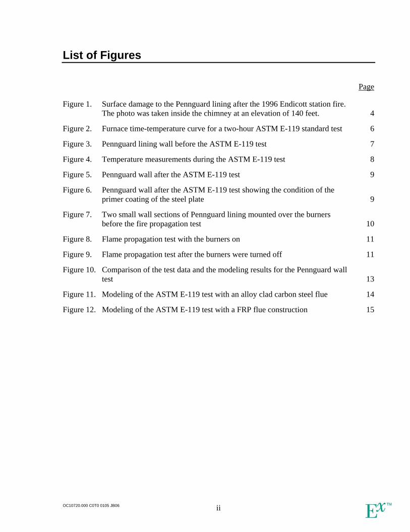
List of Figures
Page
Figure 1. Surface damage to the Pennguard lining after the 1996 Endicott station fire. The photo was taken inside the chimney at an elevation of 140 feet. 4
Figure 2. Furnace time-temperature curve for a two-hour ASTM E-119 standard test 6
Figure 3. Pennguard lining wall before the ASTM E-119 test 7
Figure 4. Temperature measurements during the ASTM E-119 test 8
Figure 5. Pennguard wall after the ASTM E-119 test 9
Figure 6. Pennguard wall after the ASTM E-119 test showing the condition of the primer coating of the steel plate 9
Figure 7. Two small wall sections of Pennguard lining mounted over the burners before the fire propagation test 10
Figure 8. Flame propagation test with the burners on 11
Figure 9. Flame propagation test after the burners were turned off 11
Figure 10. Comparison of the test data and the modeling results for the Pennguard wall test 13
Figure 11. Modeling of the ASTM E-119 test with an alloy clad carbon steel flue 14
Figure 12. Modeling of the ASTM E-119 test with a FRP flue construction 15
OC10720.000 C0T0 0105 JB06 ii

List of Tables
Page
Table 1. Summary of flame propagation test results 12
OC10720.000 C0T0 0105 JB06 iii
Acronyms and Abbreviations
ASTM American Society for Testing and Materials FaAA Failure Analysis Associates FGD Flue Gas Desulphurisation FRP Fiberglass Reinforced Plastic KCPL Kansas City Power & Light MSCPA Michigan South Central Power Agency NFIRS National Fire Incident Reporting System Tg Temperature of glass transition
OC10720.000 C0T0 0105 JB06 iv

About the Authors
Jacques J. Bélanger, Ph.D., P.E. Dr. Jacques Bélanger is a Managing Engineer in Exponent’s Thermal Sciences practice. Dr. Bélanger performs investigation and analysis related to fires and explosions. His expertise in those areas includes large-scale testing and computational simulation. He also works in the field of heat transfer, thermodynamics, and gas dynamics associated with gas releases and combustion processes. Dr. Bélanger has been involved in a number of investigations related to the flammability of fiberglass reinforced plastics used in different industrial applications. He is a registered professional mechanical engineer in the state of California. Richard J. Martin, Ph.D., P.E. Dr. Rick Martin is a Senior Managing Engineer in Exponent’s Thermal Sciences practice. He specializes in the investigation of thermal and combustion related failures, including explosions, fires, and hazardous material releases. He analyzes environmental technologies, including those that treat hazardous wastes or abate volatile organic compounds, nitrogen oxides, particulate matter, and dioxins. Dr. Martin is a Registered Professional Mechanical Engineer in the states of California, Arizona, Montana, and Indiana. He is also a member of the National Fire Protection Association Technical Committee 86, in charge of overseeing rules for safe design, installation, operation, and maintenance of ovens and furnaces. Wenjun Qin, Ph.D. Dr. Wenjun Qin is an Engineer in Exponent’s Thermal Sciences practice. He performs thermal, fluid flow, and chemical-related failure analyses and experimental investigations. Dr. Qin has experience in design, operation, and analysis of chemical processes, and has conducted flow, temperature, and species measurements in combustion processes. His specialties include landfill gas utilization, semiconductor waste gas combustion, and heat transfer in chimneys.
OC10720.000 C0T0 0105 JB06 v
Executive Summary
This investigation was performed to evaluate the performance of different chimney flue designs when exposed to various fire conditions. The investigation involves both experimental testing and numerical modeling. The testing was performed to evaluate the performance of the Pennguard chimney flue lining system when exposed to different fire conditions. The numerical modeling was then used to reproduce the Pennguard lining behavior and compare its performance with other types of chimney flue designs. The motivation for the investigation came from the realization that very little information is available regarding the fire behavior of the different types of chimney flue designs used today. In the last 20 years, a number of power plant chimneys have suffered severe fire damage, and in one case, in 1995, the fire caused partial collapse of the chimney flue. In another major fire in 1996, where a Pennguard lining system was used, the structural steel frame of the flue ended up being well protected by the lining and the fire resulted in no structural damage. With an average of about 60 structural fires per year in power plants reported by the National Fire Incident Reporting System (NFIRS) in the United States, the risk of chimney fire is real. The first test performed follows the protocol described in the ASTM E-119 Standard Test Methods for Fire Tests of Building Construction and Materials. The test was run for more than two hours with the Pennguard blocks exposed to temperatures in excess of 1000oC (1832oF) in the latter part of the test. The test demonstrated the excellent thermal protection properties of the blocks at those high temperatures. Superficial melting of the exposed surface occurred, but the integrity of the wall behind the lining was never compromised. With the structural steel temperature never exceeding 240oC (464oF), it is clear that the blocks were able to protect the steel from heat damage for the entire duration of the two-hour test. The second set of tests was demonstrative in nature and designed to evaluate the fire propagation properties of the adhesive used in the joints between the Pennguard blocks. The results of this set of tests indicated that a localized ignition of the Pennguard adhesive on a vertical wall would not propagate away from the initial location of the flames. Furthermore, a few squirts of a water spray bottle were sufficient to extinguish the flaming joints. The numerical model showed good agreement with the experimental measurements indicating that the thermal properties of the Pennguard wall are well known even at high temperatures encountered during fires. The model was also used to investigate two commonly used flue construction types in fire conditions; one built with a C276 alloy cladding and the other one made of Fiberglass Reinforced Plastic (FRP). The model demonstrated the weaknesses of these two modern chimney flue designs with respect to fire-protection of the structural components of the flue.
OC10720.000 C0T0 0105 JB06 vi
1. Introduction
This report presents the results of an investigation into the performance of different chimney flue designs when exposed to various fire conditions. The investigation involved both experimental testing and numerical modeling. The testing was performed to evaluate the performance of the Pennguard chimney flue lining system when exposed to different fire conditions. The numerical modeling was then used to reproduce the Pennguard lining behavior and compare its performance with other types of chimney flue designs. The motivation for the investigation came from the realization that very little information is available regarding the fire behavior of these different types of chimney flue designs. This is regardless of the fact that power plant fires can cause severe chimney damage and in at least one case, in July 1995, a fire caused a chimney flue partial collapse1,2. In another major fire in April 1996, where a foamed borosilicate lining system was used, the structural steel frame of the flue was sufficiently protected by the lining and the fire resulted in no structural damage3,4. In that incident, only partial replacement of the lining turned out to be necessary. Different types of chimney flue lining systems can be used in power plants to protect the structural components of the chimney against heat and corrosive gases present in the exhaust stream. This corrosion protective lining is particularly important in coal burning power plants using flue gas desulfurization (FGD) systems. These FGD systems are used to remove sulfur dioxide from the exhaust stream, but usually create a stream that can generate very corrosive condensates. Furthermore, these systems are usually located immediately upstream of the chimney and contain sufficient amounts of combustible construction materials to generate major fires. One of the chimney flue lining systems used in power plants to protect against both the heat and the corrosive effects of the exhaust stream is the Pennguard lining system. The foamed borosilicate glass used to manufacture the Pennguard blocks provides both corrosion protection and thermal insulating properties. In theory, these combined properties should provide protection to the structural components of the chimney in case of a fire. However, prior to the present effort, the lining system had never undergone laboratory testing in actual fire conditions. Exponent was asked to perform the testing and use the data to compare the Pennguard system with other commonly used chimney flue linings. Two commonly used alternative systems include a chimney flue made entirely of fiberglass reinforced plastic (FRP) and a system where a structural carbon steel flue is covered internally with a cladding of corrosion resistant Nickel alloy (C-276 or C-22). Neither one of these lining
1 National Fire Incident Reporting System (NFIRS) data related to the incident. 2 Private communication with Mr. James Krumm, retired Kansas City Power & Light (KCPL) La Cygne Station
employee. 3 Private communication with Mr. John Novak, the Power Production Superintendent at the plant at the time of the
fire. 4 Chimney inspection report, “Michigan South Central Power Agency Litchfield, Michigan”, International
Chimney Corporation, May 28, 1996.
OC10720.000 C0T0 1204 JB06 1

systems are designed to provide significant thermal protection to the structural components of the chimney. The objective of this work was to quantify the fire protection provided by the Pennguard system and compare it to the other two alternatives. A standard fire test was selected as the preferred method of evaluating this characteristic. The chosen test is the ASTM E-119 Standard Test Methods for Fire Tests of Building Construction and Materials. Following the test, numerical modeling of the heat flux through the Pennguard lining was performed and validated using the experimental data. The model was subsequently used to compare the Pennguard lining with the other two systems. The report is divided into four sections. The first section looks at historical data related to fires in power plant chimney flues. The section provides selected details about incidents directly related to the present investigation. The second section presents the laboratory fire exposure test results. The third section presents the modeling validation results and the comparison done with other types of chimney flue construction. The last section is a general discussion of the results with overall conclusions.
OC10720.000 C0T0 1204 JB06 2
2. Power Plant Chimney Flue Fires
More than a thousand structural fires in power plants were reported in the United States by the National Fire Incident Reporting System (NFIRS) between 1983 and 19985. This represents an average of about 60 structural fires in power plants in the United States per year during that period. A number of those structural fires resulted in chimney damage and in at least one case, at the Kansas City Power & Light (KCPL) La Cygne Station fire on July 1, 1995, the fire caused a partial collapse of the chimney flue. According to the NFIRS database, the La Cygne Station fire and six other fires during that 1983 to 1998 period were determined to have originated in the area of the chimney of the power plant. Because of the voluntary and often incomplete nature of the collection of NFIRS data, these seven incidents likely represent an incomplete listing of the total number of power plant fires that involved chimney flues over that same time period. According to the information available, the fire at the La Cygne Station started in the FGD system. The FGD outlet duct and steel chimney flue were internally lined with an organic coating system. The coating system is believed to have caught fire, generating enough heat in the chimney flue to weaken the steel. As a result of the weakening of the steel, the 720 feet tall steel flue buckled at approximately the 230 feet level causing a partial collapse of the flue. Replacement of the lower 400 ft of the chimney flue was required. The chimney repair ended up being the most time consuming part of the repair project. It took 12 weeks of around the clock work to refurbish the chimney. On April 27, 1996, less than a year after the La Cygne fire, another major fire in an FGD system occurred at the Endicott station in Michigan. At one point during the fire, Rob Morris, a Michigan South Central Power Agency (MSCPA) employee, reported flames 10 to 15 feet above the cone on the top of the 250 feet chimney6. Because of the height, design, and layout of the FGD unit and ductwork, the fire department was unable to effectively fight the fire and focused instead on protecting the other nearby structures7. The fire was finally extinguished by restricting airflow into the FGD unit, but not before most of the combustible material inside the FGD unit had been consumed by the fire8. In that case, the chimney flue was protected by a Pennguard lining system, and although the lining suffered damage due to the heat of the fire, the chimney survived. Figure 1 shows typical surface damage to the Pennguard lining after the fire. As a result of the thermal protection provided by the lining, the chimney did not collapse and significant savings of time and money during the repair of the power plant were realized.
5 The last year for which data are available. 6 Triodyne Fire & Explosion Engineers, Inc. fire cause and origin report dated July 19, 1996, pg 4. 7 Private communication with Mr. John Novak, the Power Production Superintendent at the plant at the time of the
fire. 8 Triodyne Fire & Explosion Engineers, Inc. fire cause and origin report dated July 19, 1996, pg 4.
OC10720.000 C0T0 1204 JB06 3
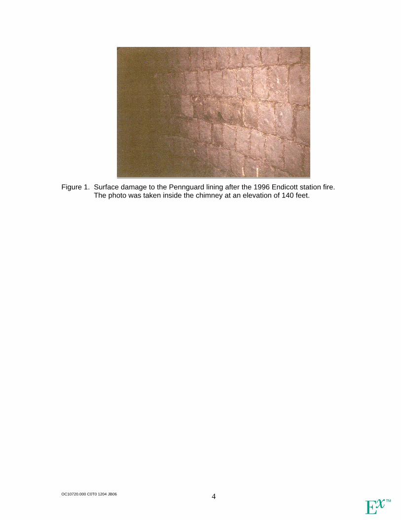
Figure 1. Surface damage to the Pennguard lining after the 1996 Endicott station fire.
The photo was taken inside the chimney at an elevation of 140 feet.
OC10720.000 C0T0 1204 JB06 4
3. Pennguard Lining System Fire Exposure Tests
Two sets of tests were performed to determine the behavior and endurance of the Pennguard lining system in different fire exposure situations. The first test involves exposing a wall section to a pre-determined set of fire exposure conditions, in order to simulate the effect of a fire on the underlying structural material. The test performed follows the protocol described in the ASTM E-119 Standard Test Methods for Fire Tests of Building Construction and Materials. The test was run for two hours with the Pennguard blocks exposed to temperatures in excess of 1000oC in the latter part of the test. A description of the test and a discussion of the results are presented in the following section. The second set of tests was demonstrative in nature and particularly designed to determine fire propagation properties of the exposed surface of the Pennguard lining system. The Pennguard blocks themselves are made of borosilicate glass and do not burn or propagate fire, but the adhesive used in the joints between the blocks is made of a combination of petroleum and plastic products that are combustible. The goal was to determine if a small fire capable of igniting the adhesive could propagate along the joints and result in a major fire inside a chimney flue covered with Pennguard lining. This type of testing would be representative of an accident where hot work performed near or inside the flue accidentally ignites the adhesive in a localized area. The results of these demonstrative tests are discussed in the section that follows the ASTM E-119 test results discussion.
3.1 ASTM E-119 Standard Test
This standard test is used by the building industry to officially determine the time for which a wall assembly could contain a fire and retain its structural integrity. The test performed in the present investigation involves a wall section of the Pennguard lining system mounted on a ¼-inch carbon steel plate according to typical installation procedures. During the test, the wall was exposed to a standard time-temperature curve reproduced in Figure 2. This time-temperature curve represents a severe fire condition with air temperature inside the furnace exceeding 500oC (932oF) less than 5 minutes into the test and 1000oC (1832oF) just before the end of the test. This temperature at the end of the test is sufficient to melt most copper alloys, a condition that is not often met even in actual large-scale fires.
OC10720.000 C0T0 1204 JB06 5
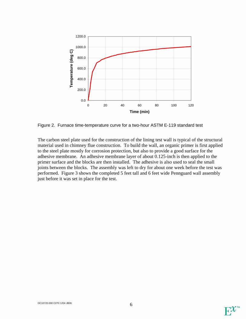
0.0
200.0
400.0
600.0
800.0
1000.0
1200.0
0 20 40 60 80 100 120
Time (min)
Tem
pera
ture
(deg
C)
Figure 2. Furnace time-temperature curve for a two-hour ASTM E-119 standard test The carbon steel plate used for the construction of the lining test wall is typical of the structural material used in chimney flue construction. To build the wall, an organic primer is first applied to the steel plate mostly for corrosion protection, but also to provide a good surface for the adhesive membrane. An adhesive membrane layer of about 0.125-inch is then applied to the primer surface and the blocks are then installed. The adhesive is also used to seal the small joints between the blocks. The assembly was left to dry for about one week before the test was performed. Figure 3 shows the completed 5 feet tall and 6 feet wide Pennguard wall assembly just before it was set in place for the test.
OC10720.000 C0T0 1204 JB06 6
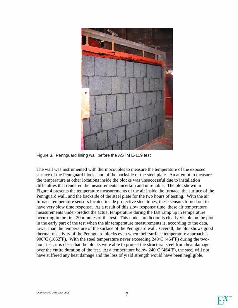
Figure 3. Pennguard lining wall before the ASTM E-119 test The wall was instrumented with thermocouples to measure the temperature of the exposed surface of the Pennguard blocks and of the backside of the steel plate. An attempt to measure the temperature at other locations inside the blocks was unsuccessful due to installation difficulties that rendered the measurements uncertain and unreliable. The plot shown in Figure 4 presents the temperature measurements of the air inside the furnace, the surface of the Pennguard wall, and the backside of the steel plate for the two hours of testing. With the air furnace temperature sensors located inside protective steel tubes, these sensors turned out to have very slow time response. As a result of this slow response time, these air temperature measurements under-predict the actual temperature during the fast ramp up in temperature occurring in the first 20 minutes of the test. This under-prediction is clearly visible on the plot in the early part of the test when the air temperature measurements is, according to the data, lower than the temperature of the surface of the Pennguard wall. Overall, the plot shows good thermal resistivity of the Pennguard blocks even when their surface temperature approaches 900oC (1652oF). With the steel temperature never exceeding 240oC (464oF) during the two-hour test, it is clear that the blocks were able to protect the structural steel from heat damage over the entire duration of the test. At a temperature below 240oC (464oF), the steel will not have suffered any heat damage and the loss of yield strength would have been negligible.
OC10720.000 C0T0 1204 JB06 7
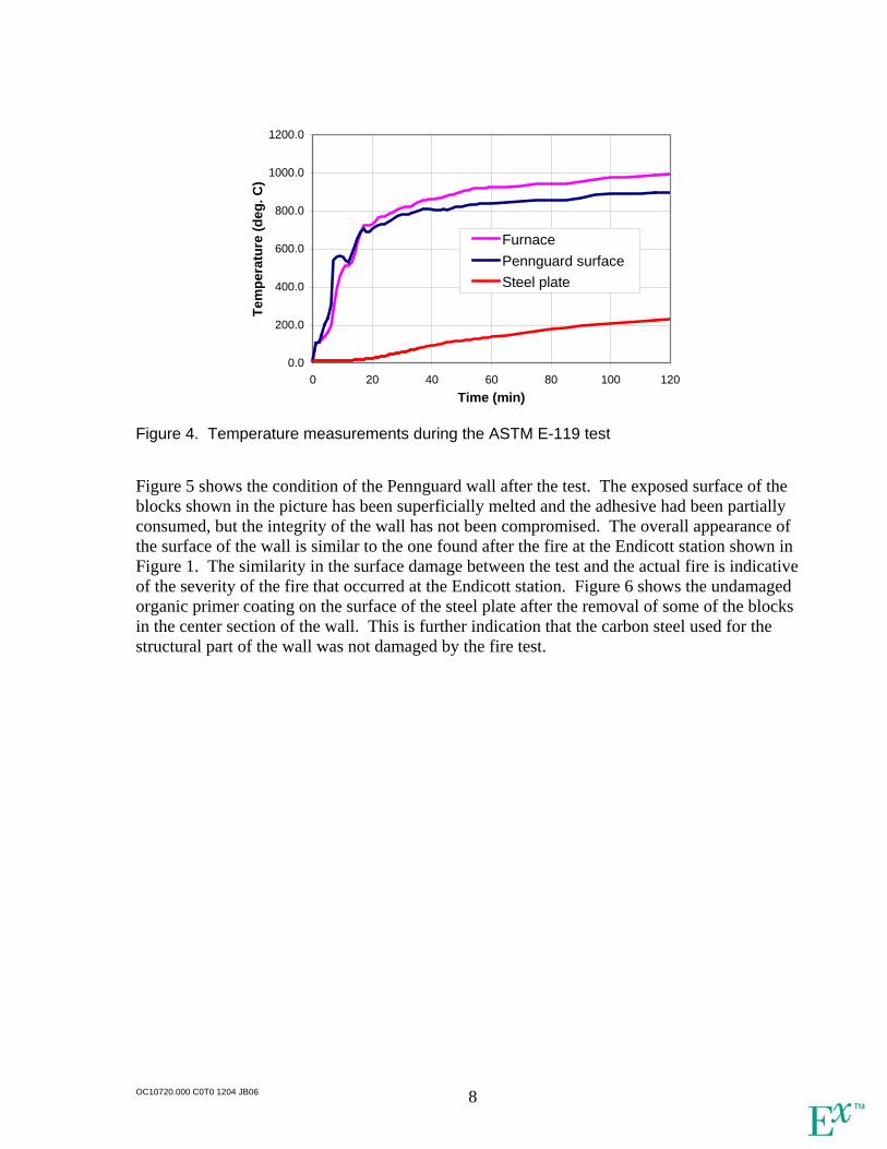
0.0
200.0
400.0
600.0
800.0
1000.0
1200.0
0 20 40 60 80 100 120Time (min)
Tem
pera
ture
(deg
. C)
Furnace Pennguard surface Steel plate
Figure 4. Temperature measurements during the ASTM E-119 test Figure 5 shows the condition of the Pennguard wall after the test. The exposed surface of the blocks shown in the picture has been superficially melted and the adhesive had been partially consumed, but the integrity of the wall has not been compromised. The overall appearance of the surface of the wall is similar to the one found after the fire at the Endicott station shown in Figure 1. The similarity in the surface damage between the test and the actual fire is indicative of the severity of the fire that occurred at the Endicott station. Figure 6 shows the undamaged organic primer coating on the surface of the steel plate after the removal of some of the blocks in the center section of the wall. This is further indication that the carbon steel used for the structural part of the wall was not damaged by the fire test.
OC10720.000 C0T0 1204 JB06 8
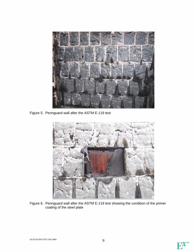
Figure 5. Pennguard wall after the ASTM E-119 test
Figure 6. Pennguard wall after the ASTM E-119 test showing the condition of the primer
coating of the steel plate
OC10720.000 C0T0 1204 JB06 9
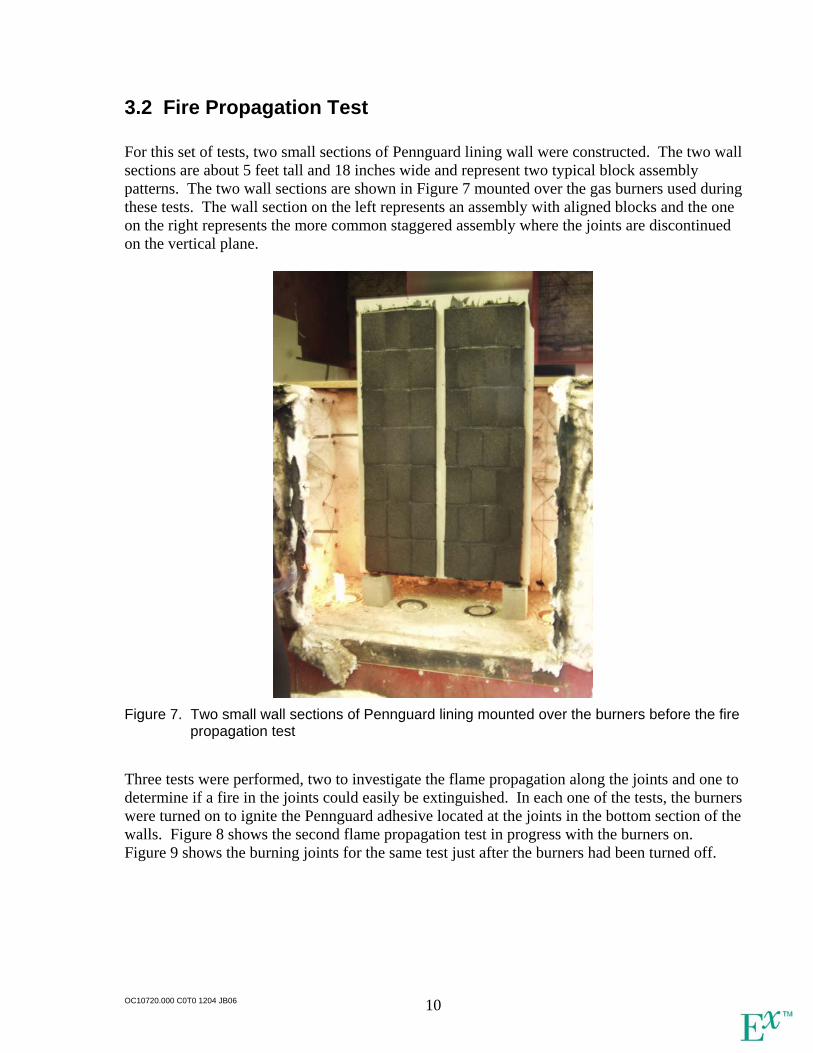
3.2 Fire Propagation Test
For this set of tests, two small sections of Pennguard lining wall were constructed. The two wall sections are about 5 feet tall and 18 inches wide and represent two typical block assembly patterns. The two wall sections are shown in Figure 7 mounted over the gas burners used during these tests. The wall section on the left represents an assembly with aligned blocks and the one on the right represents the more common staggered assembly where the joints are discontinued on the vertical plane.
Figure 7. Two small wall sections of Pennguard lining mounted over the burners before the fire
propagation test Three tests were performed, two to investigate the flame propagation along the joints and one to determine if a fire in the joints could easily be extinguished. In each one of the tests, the burners were turned on to ignite the Pennguard adhesive located at the joints in the bottom section of the walls. Figure 8 shows the second flame propagation test in progress with the burners on. Figure 9 shows the burning joints for the same test just after the burners had been turned off.
OC10720.000 C0T0 1204 JB06 10
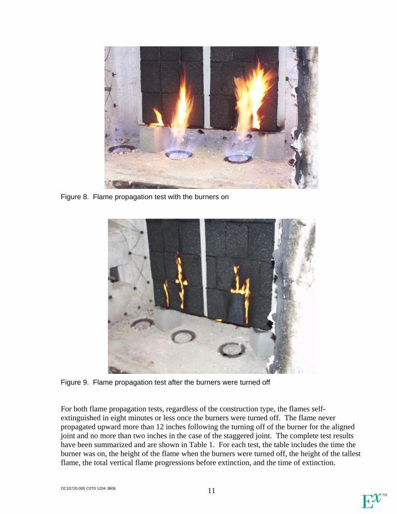
Figure 8. Flame propagation test with the burners on
Figure 9. Flame propagation test after the burners were turned off For both flame propagation tests, regardless of the construction type, the flames self-extinguished in eight minutes or less once the burners were turned off. The flame never propagated upward more than 12 inches following the turning off of the burner for the aligned joint and no more than two inches in the case of the staggered joint. The complete test results have been summarized and are shown in Table 1. For each test, the table includes the time the burner was on, the height of the flame when the burners were turned off, the height of the tallest flame, the total vertical flame progressions before extinction, and the time of extinction.
OC10720.000 C0T0 1204 JB06 11

Table 1. Summary of flame propagation test results
Construction Method Aligned Joints Staggered Joints
Test No. 1 2 1 2
Burner on (sec) 45 180 45 180
Initial flame height when burner turned off (in) 10 20 8 18
Maximum flame height (in) 15 32 10 18
Flame height progression (in) 5 12 2 0
Time of extinction (min) 4 8 5 7
The last test performed was done to determine how difficult it is to extinguish a joint fire. A simple hand pumped spray bottle was used for the experiment. It took only a few squirts of the spray bottle to extinguish the flaming joints. The test demonstrated that many types of suppression techniques could be used to control such joint adhesive fires, if they occur. The results of this set of tests on flame propagation indicate that a localized ignition of the Pennguard adhesive on a vertical wall would not propagate away from the initial location of the flames. This is true even in the case where the wall has a continuous vertical joint. Furthermore, the application of nearly any available suppression technique would be sufficient to extinguish the flaming joints.
OC10720.000 C0T0 1204 JB06 12
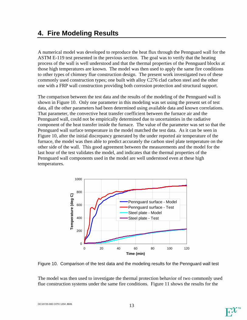
4. Fire Modeling Results
A numerical model was developed to reproduce the heat flux through the Pennguard wall for the ASTM E-119 test presented in the previous section. The goal was to verify that the heating process of the wall is well understood and that the thermal properties of the Pennguard blocks at those high temperatures are known. The model was then used to apply the same fire conditions to other types of chimney flue construction design. The present work investigated two of these commonly used construction types; one built with alloy C276 clad carbon steel and the other one with a FRP wall construction providing both corrosion protection and structural support. The comparison between the test data and the results of the modeling of the Pennguard wall is shown in Figure 10. Only one parameter in this modeling was set using the present set of test data, all the other parameters had been determined using available data and known correlations. That parameter, the convective heat transfer coefficient between the furnace air and the Pennguard wall, could not be empirically determined due to uncertainties in the radiative component of the heat transfer inside the furnace. The value of the parameter was set so that the Pennguard wall surface temperature in the model matched the test data. As it can be seen in Figure 10, after the initial discrepancy generated by the under reported air temperature of the furnace, the model was then able to predict accurately the carbon steel plate temperature on the other side of the wall. This good agreement between the measurements and the model for the last hour of the test validates the model, and indicates that the thermal properties of the Pennguard wall components used in the model are well understood even at these high temperatures.
0
200
400
600
800
1000
0 20 40 60 80 100 120Time (min)
Tem
pera
ture
(deg
C)
Pennguard surface - ModelPennguard surface - TestSteel plate - ModelSteel plate - Test
Figure 10. Comparison of the test data and the modeling results for the Pennguard wall test The model was then used to investigate the thermal protection behavior of two commonly used flue construction systems under the same fire conditions. Figure 11 shows the results for the
OC10720.000 C0T0 1204 JB06 13
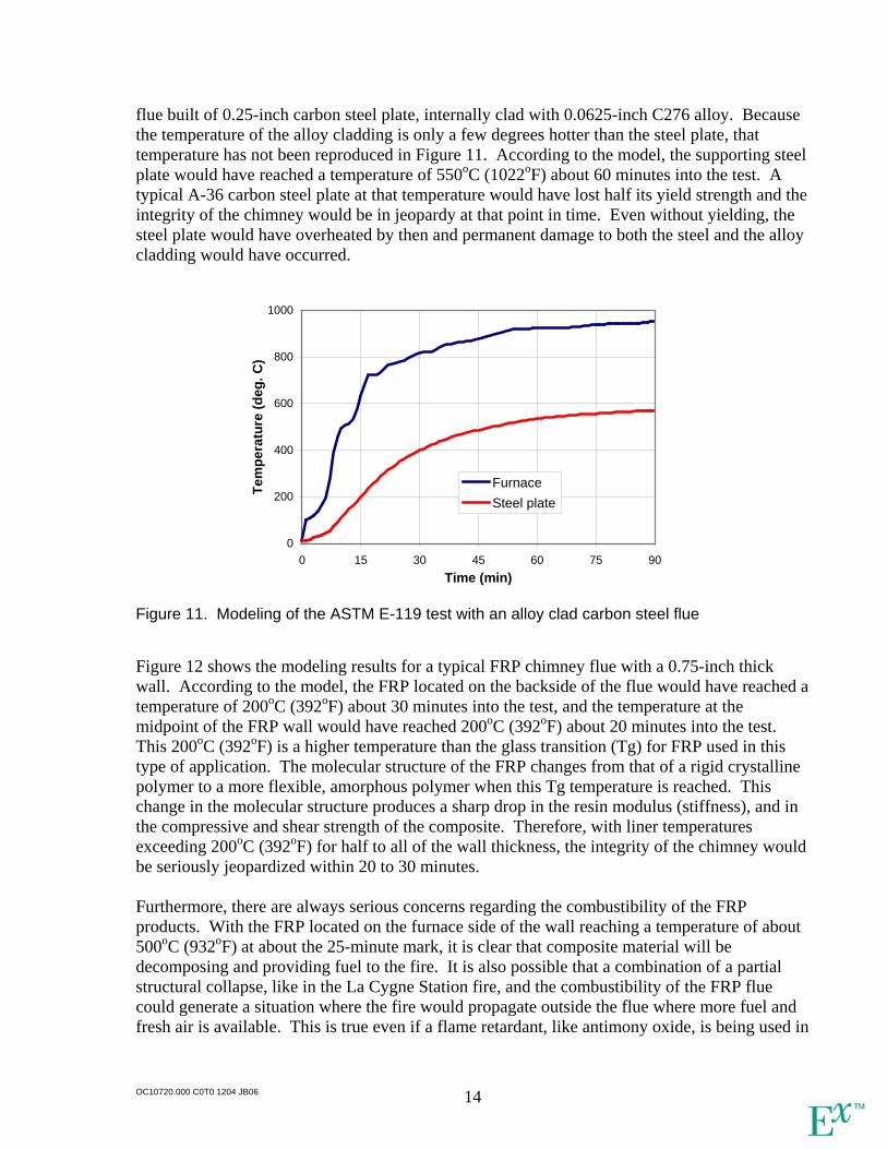
flue built of 0.25-inch carbon steel plate, internally clad with 0.0625-inch C276 alloy. Because the temperature of the alloy cladding is only a few degrees hotter than the steel plate, that temperature has not been reproduced in Figure 11. According to the model, the supporting steel plate would have reached a temperature of 550oC (1022oF) about 60 minutes into the test. A typical A-36 carbon steel plate at that temperature would have lost half its yield strength and the integrity of the chimney would be in jeopardy at that point in time. Even without yielding, the steel plate would have overheated by then and permanent damage to both the steel and the alloy cladding would have occurred.
0
200
400
600
800
1000
0 15 30 45 60 75 90Time (min)
Tem
pera
ture
(deg
. C)
FurnaceSteel plate
Figure 11. Modeling of the ASTM E-119 test with an alloy clad carbon steel flue Figure 12 shows the modeling results for a typical FRP chimney flue with a 0.75-inch thick wall. According to the model, the FRP located on the backside of the flue would have reached a temperature of 200oC (392oF) about 30 minutes into the test, and the temperature at the midpoint of the FRP wall would have reached 200oC (392oF) about 20 minutes into the test. This 200oC (392oF) is a higher temperature than the glass transition (Tg) for FRP used in this type of application. The molecular structure of the FRP changes from that of a rigid crystalline polymer to a more flexible, amorphous polymer when this Tg temperature is reached. This change in the molecular structure produces a sharp drop in the resin modulus (stiffness), and in the compressive and shear strength of the composite. Therefore, with liner temperatures exceeding 200oC (392oF) for half to all of the wall thickness, the integrity of the chimney would be seriously jeopardized within 20 to 30 minutes. Furthermore, there are always serious concerns regarding the combustibility of the FRP products. With the FRP located on the furnace side of the wall reaching a temperature of about 500oC (932oF) at about the 25-minute mark, it is clear that composite material will be decomposing and providing fuel to the fire. It is also possible that a combination of a partial structural collapse, like in the La Cygne Station fire, and the combustibility of the FRP flue could generate a situation where the fire would propagate outside the flue where more fuel and fresh air is available. This is true even if a flame retardant, like antimony oxide, is being used in
OC10720.000 C0T0 1204 JB06 14
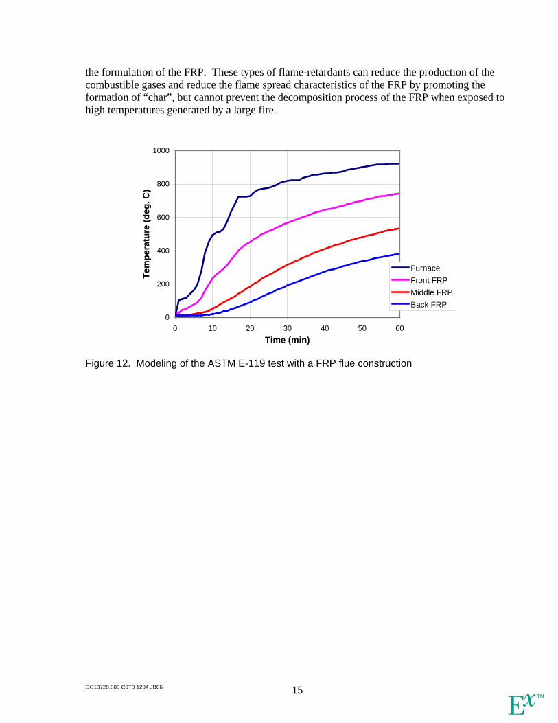
the formulation of the FRP. These types of flame-retardants can reduce the production of the combustible gases and reduce the flame spread characteristics of the FRP by promoting the formation of “char”, but cannot prevent the decomposition process of the FRP when exposed to high temperatures generated by a large fire.
0
200
400
600
800
1000
0 10 20 30 40 50 60Time (min)
Tem
pera
ture
(deg
. C)
FurnaceFront FRPMiddle FRPBack FRP
Figure 12. Modeling of the ASTM E-119 test with a FRP flue construction
OC10720.000 C0T0 1204 JB06 15
5. Discussion
The present investigation demonstrated the following:
• The Pennguard lining system provided excellent thermal protection of the structural steel outer wall under the conditions of the ASTM E-119 Standard Test Methods for Fire Tests of Building Construction and Materials.
• During the two-hour ASTM E-119 test, the structural steel temperature never exceeded 240oC (464oF), which clearly indicates that the Pennguard lining was able to protect the steel from heat damage over the entire duration of the test.
• The fire propagation tests indicate that a localized ignition of the Pennguard adhesive on a vertical wall would not propagate away from the initial location of the flames.
• The flame-extinguishing test, wherein only a few squirts of the spray bottle led to extinguishment, demonstrated that many types of suppression techniques could be used to control joint adhesive fires, if they occur.
• The numerical model shows good agreement with the experimental measurements indicating that the thermal properties of the Pennguard wall are well known even at high temperatures encountered during fires.
• The model was used to investigate the thermal protection behavior of two commonly used flue construction systems, one built with a C276 alloy cladding and the other one made of Fiberglass Reinforced Plastic (FRP). The modeling results demonstrated that these two chimney flue designs are ineffective at protecting the structural components of the flue in case of a fire.
OC10720.000 C0T0 1204 JB06 16
Hadek Protective Systems b.v.P.O.Box 30139
3001 DC RotterdamThe Netherlands
Tel. +31 (0)10 405 1461Fax +31 (0)10 405 5011
E-mail: [email protected]:http://www.hadek.com
Supervised by: E. Palmen
Report by: E. Palmen
Inspection report 01 131EAC Vasilikos Power Station, CyprusPennguard Block Lining System in Unit 3 chimney flue
Rev.No.:
/
Datepublished:14-03-17
Reference:Original
By:Initials:
ErPDate:
14-03-17Paraph: Initials:
AdK
Approved:Date:
14-03-17Paraph:
Content:Chap-
ter:1.
Description:Introduction
Pageno.:2
2. Design & construction
2.1 Substrate
2.2
2.3
Lay out and dimensions
Lining specifications
4
4
4
4
3.
4
Operating conditions
Set up for inspection
4.1
4.2
Access
Safety
5.
6.
7.
8.
Inspection of the flue
General observations
Experience by the customer
Conclusion and recommendations
6
7
7
8
9
15
16
17
Page 1 / 17
Quality systemcertified ISO
9001 by TUV
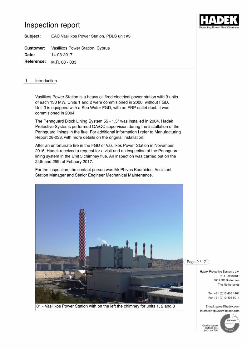
1 Introduction
Vasilikos Power Station is a heavy oil fired electrical power station with 3 unitsof each 130 MW. Units 1 and 2 were commisioned in 2000, without FGD. Unit 3 is equipped with a Sea Water FGD, with an FRP outlet duct. It was commisioned in 2004
The Pennguard Block Lining System 55 - 1,5" was installed in 2004. HadekProtective Systems performed QA/QC supervision during the installation of thePennguard linings in the flue. For additional information I refer to ManufacturingReport 08-033, with more details on the original installation.
After an unfortunate fire in the FGD of Vasilikos Power Station in November2016, Hadek received a request for a visit and an inspection of the Pennguardlining system in the Unit 3 chimney flue. An inspection was carried out on the24th and 25th of Febuary 2017.
For the inspection, the contact person was Mr Phivos Koumides, Assistant Station Manager and Senior Engineer Mechanical Maintenance.
Inspection reportSubject:
Customer:Date:Reference:
EAC Vasilikos Power Station, PBLS unit #3
Vasilikos Power Station, Cyprus14-03-2017
M.R. 08 - 033
Hadek Protective Systems b.v.P.O.Box 30139
3001 DC RotterdamThe Netherlands
Tel. +31 (0)10 405 1461Fax +31 (0)10 405 5011
E-mail: [email protected]:http://www.hadek.com
Page 2 / 17
Quality systemcertified ISO
9001 by TUV
01 - Vasilikos Power Station with on the left the chimney for units 1, 2 and 3
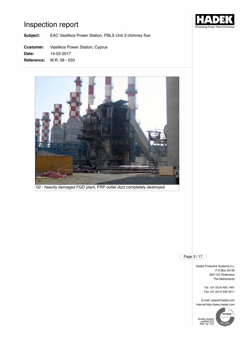
Inspection reportSubject:
Customer:Date:Reference:
EAC Vasilikos Power Station, PBLS Unit 3 chimney flue
Vasilikos Power Station, Cyprus14-03-2017M.R. 08 - 033
Hadek Protective Systems b.v.P.O.Box 30139
3001 DC RotterdamThe Netherlands
Tel. +31 (0)10 405 1461Fax +31 (0)10 405 5011
E-mail: [email protected]:http://www.hadek.com
Page 3 / 17
Quality systemcertified ISO
9001 by TUV
02 - heavily damaged FGD plant, FRP outlet duct completely destroyed
2 Design & construction
2.1 Substrate
The flue has a lenght of approximately 117 meters inlcuding bend. The flue andthe bend are made out of Corten steel . The upper 6 meters of the flue, whichprotrude above the concrete windshield, are made out of 6 mm thick stainlesssteel, internally Pennguard lined.
2.3 Layout and dimensions
The chimney has a concrete windshield with a lenght of approximately 120 mabove ground level, equipped with 3 flues which all protrude 6 meter above thewindshield.
Only one flue, used for Unit 3, is lined with Pennguard Block Lining System. Asfor all Pennguard lined steel flues, the Unit 3 flue has NO external insulation.
Drawing 1 shows the dimensions of the chimney.
2.2 Lining specifications
The Pennguard Block Lining System, as installed in 2004, is shown in Table 1.
Inspection reportSubject:
Customer:Date:Reference:
EAC Vasilikos Power Station, PBLS Unit 3 chimney flue
Vasilikos Power Station, Cyprus14-03-2017M.R. 08 - 033
Hadek Protective Systems b.v.P.O.Box 30139
3001 DC RotterdamThe Netherlands
Tel. +31 (0)10 405 1461Fax +31 (0)10 405 5011
E-mail: [email protected]:http://www.hadek.com
Page 4 / 17
Quality systemcertified ISO
9001 by TUV
Table 1: lining specification
No.: Section Lining specification12
Vertical flueElbow
Pennguard 55 - 1.5"Pennguard 55 - 1.5"
Area in m21.032
78
Total installed Pennguard 55 - 1.5" 1.110
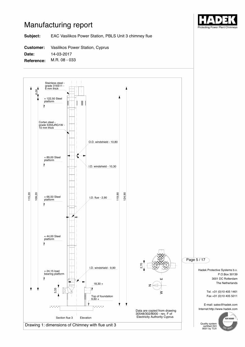
N
EW
Data are copied from drawing 30548/302/8000 - rev. F of Electricity Authority CyprusSection flue 3 Elevation
Top of foundation 9,60 +
124,
90
119,
90
18,30 +
O.D. windshield - 10,80
I.D. windshield - 9,90
I.D. flue - 2,90
I.D. windshield - 10,30
6,00
115,
20
109,
20
Corten steel - grade S355JRG1W - 10 mm thick
Stainless steel - grade 316S11 - 6 mm thick
3,33
+ 122,50 Steel platform
+ 89,00 Steel platform
+ 66,50 Steel platform
+ 44,00 Steel platform
+ 24,15 load bearing platform
3
2
1
2,70
Manufacturing reportSubject:
Customer:Date:Reference:
EAC Vasilikos Power Station, PBLS Unit 3 chimney flue
Vasilikos Power Station, Cyprus14-03-2017M.R. 08 - 033
Hadek Protective Systems b.v.P.O.Box 30139
3001 DC RotterdamThe Netherlands
Tel. +31 (0)10 405 1461Fax +31 (0)10 405 5011
E-mail: [email protected]:http://www.hadek.com
Drawing 1: dimensions of Chimney with flue unit 3
Page 5 / 17
Quality systemcertified ISO
9001 by TUV
3 Operating conditions
Normal operation :
- Flue gas tempearture leaving the FGD 90°C, approximately 83 °C in the flue.
- By-pass temperature between 120 °C and 125 °C, to a maximum of 130°C.
Between the installation in 2004 and November 2016, Unit 3 has been in service for approximately 74000 hours.
Inspection reportSubject:
Customer:Date:Reference:
EAC Vasilikos Power Station, PBLS Unit 3 chimney flue
Vasilikos Power Station, Cyprus14-03-2017M.R. 08 - 033
Hadek Protective Systems b.v.P.O.Box 30139
3001 DC RotterdamThe Netherlands
Tel. +31 (0)10 405 1461Fax +31 (0)10 405 5011
E-mail: [email protected]:http://www.hadek.com
Page 6 / 17
Quality systemcertified ISO
9001 by TUV
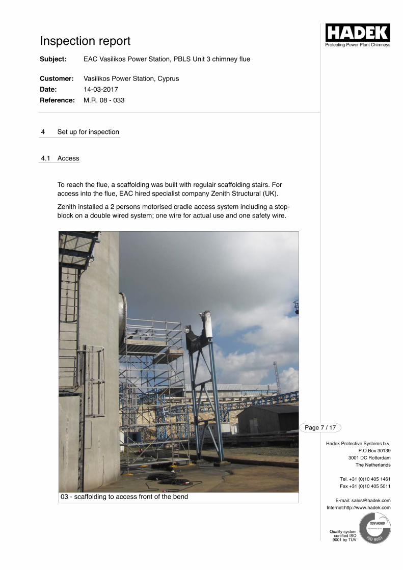
4 Set up for inspection
4.1 Access
To reach the flue, a scaffolding was built with regulair scaffolding stairs. For access into the flue, EAC hired specialist company Zenith Structural (UK).
Zenith installed a 2 persons motorised cradle access system including a stop-block on a double wired system; one wire for actual use and one safety wire.
Inspection reportSubject:
Customer:Date:Reference:
EAC Vasilikos Power Station, PBLS Unit 3 chimney flue
Vasilikos Power Station, Cyprus14-03-2017M.R. 08 - 033
Hadek Protective Systems b.v.P.O.Box 30139
3001 DC RotterdamThe Netherlands
Tel. +31 (0)10 405 1461Fax +31 (0)10 405 5011
E-mail: [email protected]:http://www.hadek.com
Page 7 / 17
Quality systemcertified ISO
9001 by TUV
03 - scaffolding to access front of the bend
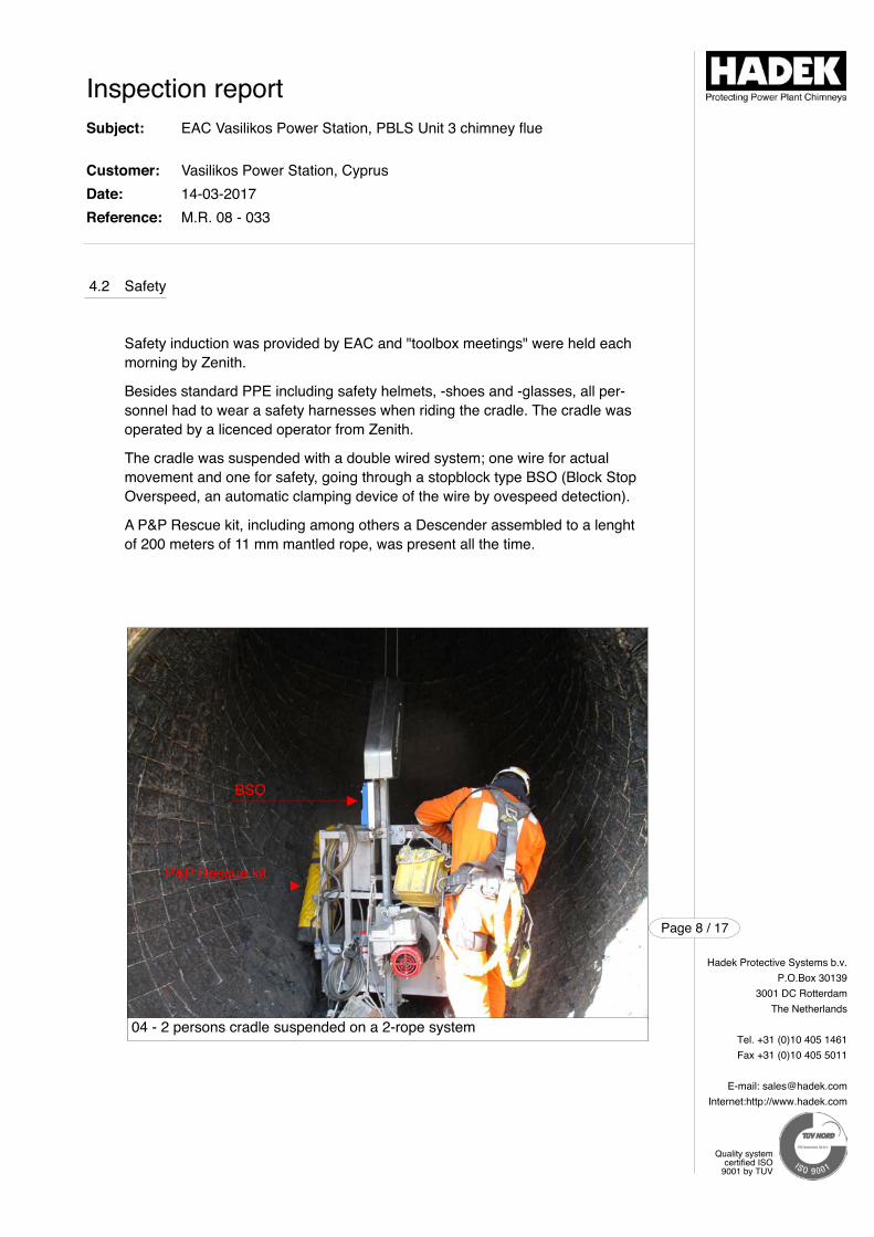
4.2 Safety
Safety induction was provided by EAC and "toolbox meetings" were held eachmorning by Zenith.
Besides standard PPE including safety helmets, -shoes and -glasses, all per-sonnel had to wear a safety harnesses when riding the cradle. The cradle wasoperated by a licenced operator from Zenith.
The cradle was suspended with a double wired system; one wire for actual movement and one for safety, going through a stopblock type BSO (Block StopOverspeed, an automatic clamping device of the wire by ovespeed detection).
A P&P Rescue kit, including among others a Descender assembled to a lenghtof 200 meters of 11 mm mantled rope, was present all the time.
Inspection reportSubject:
Customer:Date:Reference:
EAC Vasilikos Power Station, PBLS Unit 3 chimney flue
Vasilikos Power Station, Cyprus14-03-2017M.R. 08 - 033
Hadek Protective Systems b.v.P.O.Box 30139
3001 DC RotterdamThe Netherlands
Tel. +31 (0)10 405 1461Fax +31 (0)10 405 5011
E-mail: [email protected]:http://www.hadek.com
Page 8 / 17
Quality systemcertified ISO
9001 by TUV
04 - 2 persons cradle suspended on a 2-rope system
BSO
P&P Rescue kit
5 Inspection of the flue
The flue was visually inspected by two Hadek inspectors. The inside andoutside surfaces were inspected simultaneously to identify and analyze anyabnormality on either side of the steel flue.
The inspection was carried out firstly to establish the current condition of thePennguard Block Lining System, following exposure to the fire and heat. Theinspection was also aimed at checking for any impact on the integrity of thesteel flue, and to determine whether more inspections would be needed.
The Pennguard Block Lining System was strongly affected by the fire and based on the information provided, and on the state of the Pennguard lining, itis believed that the fire in the FRP outlet duct was a major heat source.
The temperature to which the Pennguard Block Lining System was exposed isestimated to have reached 1300 °C. After the FRP duct collapsed, the tempe-rature quickly lowered below the glass melting temperature and melting of thePennguard Blocks came to a halt.
The Pennguard Blocks have been affected over the full height of the flue. Thesurface of all blocks has molten and flowed together and the integrity of blockshas been reduced. This could be easy established when cutting out PennguardBlocks, which were very brittle.
The Pennguard Adhesive Membrane (PAM) side joints had been charred overalmost the entire thickness of the Pennguard Blocks, almost to the back joint.The PAM behind the Pennguard Block, i.e. the back joint, was however in astate still moderately flexible.
The Pennguard Block Primer behind the PAM had not burned, and had notbeen affected in any other way, on any of the spot checks that were taken.
Inspection of the outside of flue, where extra attention was given to the supportof the flue, did not reveal any visual abnormality. Hadek did not perform anyNDT (Non Destructive Testing) on welds.
Inspection reportSubject:
Customer:Date:Reference:
EAC Vasilikos Power Station, PBLS Unit 3 chimney flue
Vasilikos Power Station, Cyprus14-03-2017M.R. 08 - 033
Hadek Protective Systems b.v.P.O.Box 30139
3001 DC RotterdamThe Netherlands
Tel. +31 (0)10 405 1461Fax +31 (0)10 405 5011
E-mail: [email protected]:http://www.hadek.com
Page 9 / 17
Quality systemcertified ISO
9001 by TUV
Inspection reportSubject:
Customer:Date:Reference:
EAC Vasilikos Power Station, PBLS Unit 3 chimney flue
Vasilikos Power Station, Cyprus14-03-2017M.R. 08 - 033
Hadek Protective Systems b.v.P.O.Box 30139
3001 DC RotterdamThe Netherlands
Tel. +31 (0)10 405 1461Fax +31 (0)10 405 5011
E-mail: [email protected]:http://www.hadek.com
Page 10 / 17
Quality systemcertified ISO
9001 by TUV
06 - Pennguard lining at level of sample ports
05 - upwards view taken from lower part of the flue
Inspection reportSubject:
Customer:Date:Reference:
EAC Vasilikos Power Station, PBLS Unit 3 chimney flue
Vasilikos Power Station, Cyprus14-03-2017M.R. 08 - 033
Hadek Protective Systems b.v.P.O.Box 30139
3001 DC RotterdamThe Netherlands
Tel. +31 (0)10 405 1461Fax +31 (0)10 405 5011
E-mail: [email protected]:http://www.hadek.com
Page 11 / 17
Quality systemcertified ISO
9001 by TUV
08 - spot check at +60 meters with intact back joint Membrane and Primer
07 - spot check at +30 meters
Inspection reportSubject:
Customer:Date:Reference:
EAC Vasilikos Power Station, PBLS Unit 3 chimney flue
Vasilikos Power Station, Cyprus14-03-2017M.R. 08 - 033
Hadek Protective Systems b.v.P.O.Box 30139
3001 DC RotterdamThe Netherlands
Tel. +31 (0)10 405 1461Fax +31 (0)10 405 5011
E-mail: [email protected]:http://www.hadek.com
Page 12 / 17
Quality systemcertified ISO
9001 by TUV
10 - spot check at the top
09 - view upwards halfway up the flue, with molten Pennguard Blocks
Inspection reportSubject:
Customer:Date:Reference:
EAC Vasilikos Power Station, PBLS Unit 3 chimney flue
Vasilikos Power Station, Cyprus14-03-2017M.R. 08 - 033
Hadek Protective Systems b.v.P.O.Box 30139
3001 DC RotterdamThe Netherlands
Tel. +31 (0)10 405 1461Fax +31 (0)10 405 5011
E-mail: [email protected]:http://www.hadek.com
Page 13 / 17
Quality systemcertified ISO
9001 by TUV
12 - view bottom flue / bend with drainage
11 - outside of the 3 flues. On the left, without insulation, the Unit 3 flue.
Inspection reportSubject:
Customer:Date:Reference:
EAC Vasilikos Power Station, PBLS Unit 3 chimney flue
Vasilikos Power Station, Cyprus14-03-2017M.R. 08 - 033
Hadek Protective Systems b.v.P.O.Box 30139
3001 DC RotterdamThe Netherlands
Tel. +31 (0)10 405 1461Fax +31 (0)10 405 5011
E-mail: [email protected]:http://www.hadek.com
Page 14 / 17
Quality systemcertified ISO
9001 by TUV
14 - outside of flue 3, half way up
13 - close-up of a support of the flue
6 General observations
The FGD installation has burnt out completely and the FRP outlet duct to thechimney, which connected the FGD absorber and the chimney, has collapsedduring the fire.
After the FRP duct had collapsed, its remaining parts caused some damage ona chimney entrance below. The steel support structure for the duct is still present and intact.
On the portion of the steel chimney flue that protrudes above the concretewindshield, the coloured warning stripes are still present, indicating that the insulating effect of the Pennguard lining has protected the paint system fromoverheating during the fire.
Inspection reportSubject:
Customer:Date:Reference:
EAC Vasilikos Power Station, PBLS Unit 3 chimney flue
Vasilikos Power Station, Cyprus14-03-2017M.R. 08 - 033
Hadek Protective Systems b.v.P.O.Box 30139
3001 DC RotterdamThe Netherlands
Tel. +31 (0)10 405 1461Fax +31 (0)10 405 5011
E-mail: [email protected]:http://www.hadek.com
Page 15 / 17
Quality systemcertified ISO
9001 by TUV
13 - red-white warning stripes on the outside of the flue Unit 3 flue still present
7 Experience by the customer
The Pennguard lining system in the Vasilikos Unit 3 chimney flue has functioned well, and without any maintenance, since its installation in 2004 and consequently, the customer had "forgotten" about the system.
Following the fire, it has been recognized that the Pennguard lining hasplayed an important role in protecting the flue from any structural damage, through avoiding overheating and collapse.
It is important to note that a collapse of the Unit 3 flue would inevitably havedamaged the Unit 1 and Unit 2 flues as well, possibly resulting in extendednon-availability of all three units.
Inspection reportSubject:
Customer:Date:Reference:
EAC Vasilikos Power Station, PBLS Unit 3 chimney flue
Vasilikos Power Station, Cyprus14-03-2017M.R. 08 - 033
Hadek Protective Systems b.v.P.O.Box 30139
3001 DC RotterdamThe Netherlands
Tel. +31 (0)10 405 1461Fax +31 (0)10 405 5011
E-mail: [email protected]:http://www.hadek.com
Page 16 / 17
Quality systemcertified ISO
9001 by TUV
8 Conclusion and recommendations
The fire in the FGD system, including the burst of heat caused by the fire of theFRP outlet duct, has caused severe damage to the Pennguard Block LiningSystem inside the Unit 3 chimney flue. The Pennguard Block Lining System has been affected to an extent that it is no longer a reliable corrosion protection and it needs to be replaced.
The Unit 3 steel chimney flue, however has survived intact as it was completelyprotected by the insulating capacity of the Pennguard lining system.
The owner wishes to have Unit 3 back in service as soon as possible, prior tothe commissioning of a new FGD. After resuming operation without FGD, thechimney flue will be exposed to flue gas of around 125 °C. A new PennguardBlock Lining System must be installed prior to renewed use of the flue, with gastemperatures of approximately 125 °C.
The original Pennguard lining, which used 38 mm thick Pennguard Block 55,was exposed to FGD Bypass temperatures only short periods at a time. In thenew, temporary situation when Unit 3 operates without FGD, the power generating unit will be connected straight to the flue and will expose the protective lining to a constant flue gas temperature of around 125 °C overlonger periods of time. To protect the steel chimney flue under these conditionsthe owner has been advised to install a Pennguard lining using 51 mm thickPennguard Block 55, with the additional thickness providing sufficient liningsystem durability under high temperature conditions.
Rotterdam, 14 March 2017
Erik Palmen
Inspection reportSubject:
Customer:Date:Reference:
EAC Vasilikos Power Station, PBLS Unit 3 chimney flue
Vasilikos Power Station, Cyprus14-03-2017M.R. 08 - 033
Hadek Protective Systems b.v.P.O.Box 30139
3001 DC RotterdamThe Netherlands
Tel. +31 (0)10 405 1461Fax +31 (0)10 405 5011
E-mail: [email protected]:http://www.hadek.com
Page 17 / 17
Quality systemcertified ISO
9001 by TUV
Hadek Protective Systems b.v.
P.O.Box 30139
3001 DC Rotterdam
The Netherlands
Tel. +31 (0)10 405 1461
Fax +31 (0)10 405 5011
E-mail: [email protected]
Internet:http://www.hadek.com
Supervised by: S. Chan
Report by: S. Chan
Inspection report 01 132Inspection of Pennguard™ Block Lining System on the steel chimney flue of Unit 1 at Vinh Tan 4 Power Station, Vietnam
Rev.No.:
/
Datepublished:
30-03-17
Reference:
Original
By:Initials:
StC
Date:
30-03-17
Paraph: Initials:
CeV
Approved:Date:
30-03-17
Paraph:
Content:Chap-
ter:
1.
Description:
Introduction
Pageno.:
2
2. Design & construction
2.1 General
2.2
2.3
Substrate
Lining specifications
4
4
4
4
3.
4
2.4
Operating conditions
Layout and dimensions
Set up for inspection
4.1 Access
5.
6.
7.
4.2
Inspection of the flue
Safety
General observations
Experience by the customer
5
6
7
7
9
10
17
18
8. Conclusion and recommendations 19
Page 1 / 19
Quality systemcertified ISO
9001 by TUV
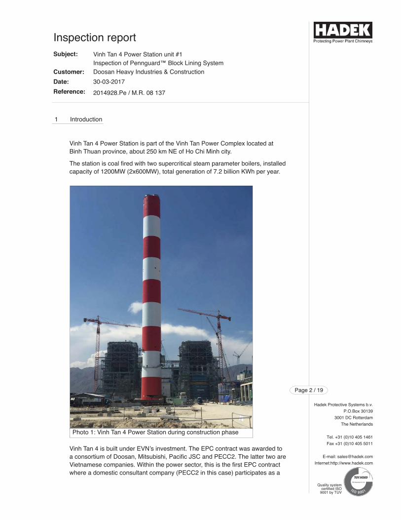
1 Introduction
Vinh Tan 4 Power Station is part of the Vinh Tan Power Complex located atBinh Thuan province, about 250 km NE of Ho Chi Minh city.
The station is coal fired with two supercritical steam parameter boilers, installedcapacity of 1200MW (2x600MW), total generation of 7.2 billion KWh per year.
Vinh Tan 4 is built under EVN’s investment. The EPC contract was awarded toa consortium of Doosan, Mitsubishi, Pacific JSC and PECC2. The latter two areVietnamese companies. Within the power sector, this is the first EPC contractwhere a domestic consultant company (PECC2 in this case) participates as a
Inspection reportSubject:
Customer:
Date:
Reference:
Vinh Tan 4 Power Station unit #1Inspection of Pennguard™ Block Lining SystemDoosan Heavy Industries & Construction
30-03-2017
2014928.Pe / M.R. 08 137
Hadek Protective Systems b.v.
P.O.Box 30139
3001 DC Rotterdam
The Netherlands
Tel. +31 (0)10 405 1461
Fax +31 (0)10 405 5011
E-mail: [email protected]
Internet:http://www.hadek.com
Page 2 / 19
Quality systemcertified ISO
9001 by TUV
Photo 1: Vinh Tan 4 Power Station during construction phase
member of a Consortium of Contractors. Another EVN consulting company,PECC3, has been appointed as the Consultant for the Investor, in collaborationwith foreign auxiliary consulting companies.
December 2014, Hadek received the original signed contract of CRI for the delivery of materials for Vinh Tan 4 Power Station, Vietnam. The purchase order for the supply of technical assistance was received on 2 November 2015.
The installation of the Pennguard Block Lining System started on 12 November2015 and was finished on 27 April 2016.
On 7 March 2017 an intensive fire occurred in the Unit 1 FGD (Flue Gas Desul-phurisation) plant. The fire spread itself downstream of the FGD towards thePennguard lined steel flue. The exact cause of the fire in the FGD is unknown.Hadek representative Steve Chan inspected the Pennguard lining on 16 March2017.
This inspection report describes the technical performance and appearance ofthe Pennguard Block Lining System after the inferno. Several destructive testswere executed on Pennguard lining to verify the status.
Hadek Protective Systems b.v.
P.O.Box 30139
3001 DC Rotterdam
The Netherlands
Tel. +31 (0)10 405 1461
Fax +31 (0)10 405 5011
E-mail: [email protected]
Internet:http://www.hadek.com
Page 3 / 19
Quality systemcertified ISO
9001 by TUV
Inspection reportSubject:
Customer:
Date:
Reference:
Vinh Tan 4 Power Station unit #1Inspection of Pennguard™ Block Lining SystemDoosan Heavy Industries & Construction
30-03-2017
2014928.Pe / M.R. 08 137
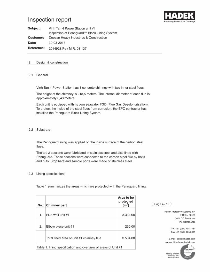
2 Design & construction
2.1 General
Vinh Tan 4 Power Station has 1 concrete chimney with two inner steel flues.
The height of the chimney is 213,5 meters. The internal diameter of each flue isapproximately 6,43 meters.
Each unit is equipped with its own seawater FGD (Flue Gas Desulphurisation).To protect the inside of the steel flues from corrosion, the EPC contractor hasinstalled the Pennguard Block Lining System.
2.2 Substrate
The Pennguard lining was applied on the inside surface of the carbon steel flues.
The top 2 sections were fabricated in stainless steel and also lined with Pennguard. These sections were connected to the carbon steel flue by boltsand nuts. Stop bars and sample ports were made of stainless steel.
2.3 Lining specifications
Table 1 summarizes the areas which are protected with the Pennguard lining.
Hadek Protective Systems b.v.
P.O.Box 30139
3001 DC Rotterdam
The Netherlands
Tel. +31 (0)10 405 1461
Fax +31 (0)10 405 5011
E-mail: [email protected]
Internet:http://www.hadek.com
Page 4 / 19
Quality systemcertified ISO
9001 by TUV
Inspection reportSubject:
Customer:
Date:
Reference:
Vinh Tan 4 Power Station unit #1Inspection of Pennguard™ Block Lining SystemDoosan Heavy Industries & Construction
30-03-2017
2014928.Pe / M.R. 08 137
No.: Chimney part
Area to beprotected
(m2)
1.
2.
Flue wall unit #1
Elbow piece unit #1
3.334,00
250,00
Table 1: lining specification and overview of areas of Unit #1
Total lined area of unit #1 chimney flue 3.584,00
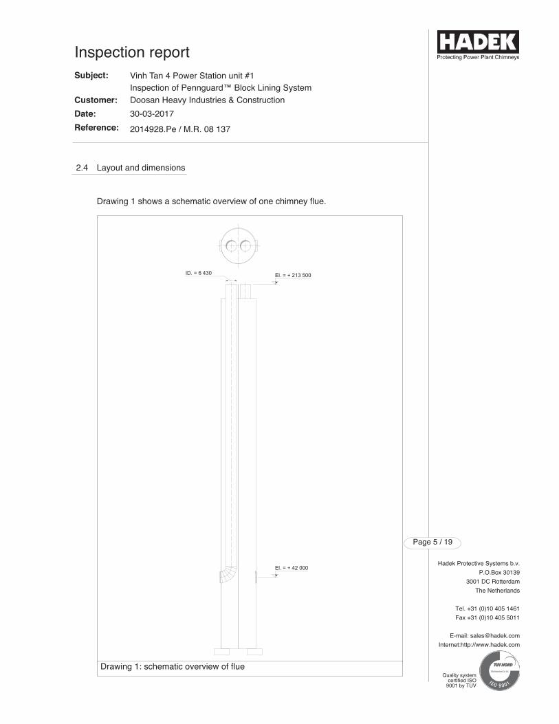
Hadek Protective Systems b.v.
P.O.Box 30139
3001 DC Rotterdam
The Netherlands
Tel. +31 (0)10 405 1461
Fax +31 (0)10 405 5011
E-mail: [email protected]
Internet:http://www.hadek.com
Page 5 / 19
Quality systemcertified ISO
9001 by TUV
Inspection reportSubject:
Customer:
Date:
Reference:
Vinh Tan 4 Power Station unit #1Inspection of Pennguard™ Block Lining SystemDoosan Heavy Industries & Construction
30-03-2017
2014928.Pe / M.R. 08 137
2.4 Layout and dimensions
Drawing 1 shows a schematic overview of one chimney flue.
Drawing 1: schematic overview of flue
3 Operating conditions
Firing of the Unit 1 boiler with Light Diesel Oil (LDO) was completed successfully before the accident. Coal firing was planned for 31 March 2017.
Hadek Protective Systems b.v.
P.O.Box 30139
3001 DC Rotterdam
The Netherlands
Tel. +31 (0)10 405 1461
Fax +31 (0)10 405 5011
E-mail: [email protected]
Internet:http://www.hadek.com
Page 6 / 19
Quality systemcertified ISO
9001 by TUV
Inspection reportSubject:
Customer:
Date:
Reference:
Vinh Tan 4 Power Station unit #1Inspection of Pennguard™ Block Lining SystemDoosan Heavy Industries & Construction
30-03-2017
2014928.Pe / M.R. 08 137
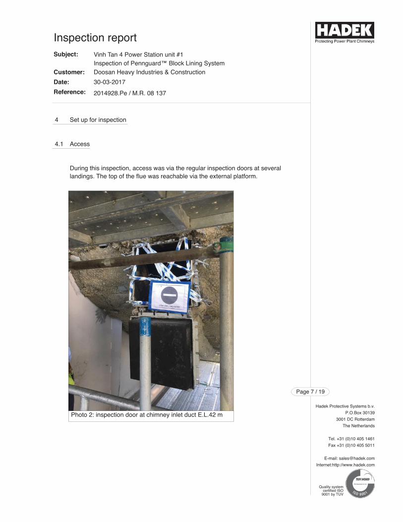
4 Set up for inspection
4.1 Access
During this inspection, access was via the regular inspection doors at severallandings. The top of the flue was reachable via the external platform.
Hadek Protective Systems b.v.
P.O.Box 30139
3001 DC Rotterdam
The Netherlands
Tel. +31 (0)10 405 1461
Fax +31 (0)10 405 5011
E-mail: [email protected]
Internet:http://www.hadek.com
Page 7 / 19
Quality systemcertified ISO
9001 by TUV
Inspection reportSubject:
Customer:
Date:
Reference:
Vinh Tan 4 Power Station unit #1Inspection of Pennguard™ Block Lining SystemDoosan Heavy Industries & Construction
30-03-2017
2014928.Pe / M.R. 08 137
Photo 2: inspection door at chimney inlet duct E.L.42 m
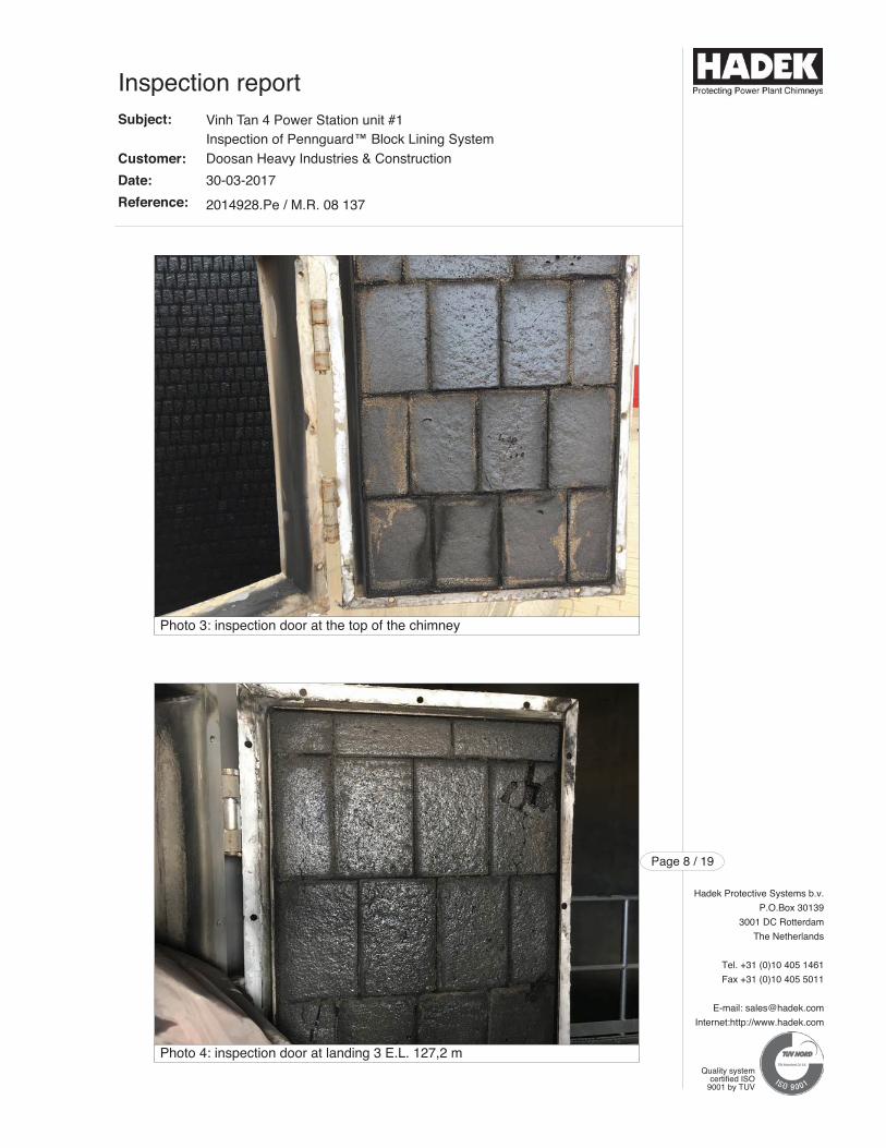
Hadek Protective Systems b.v.
P.O.Box 30139
3001 DC Rotterdam
The Netherlands
Tel. +31 (0)10 405 1461
Fax +31 (0)10 405 5011
E-mail: [email protected]
Internet:http://www.hadek.com
Page 8 / 19
Quality systemcertified ISO
9001 by TUV
Inspection reportSubject:
Customer:
Date:
Reference:
Vinh Tan 4 Power Station unit #1Inspection of Pennguard™ Block Lining SystemDoosan Heavy Industries & Construction
30-03-2017
2014928.Pe / M.R. 08 137
Photo 3: inspection door at the top of the chimney
Photo 4: inspection door at landing 3 E.L. 127,2 m
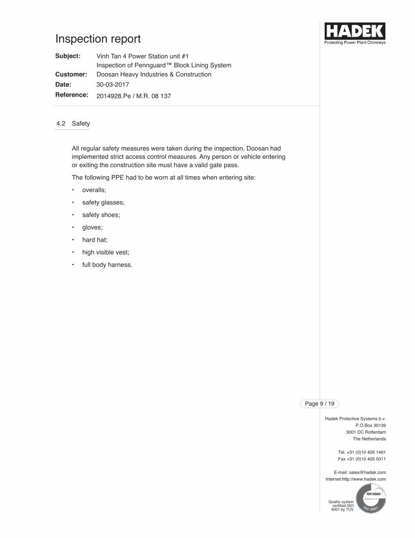
4.2 Safety
All regular safety measures were taken during the inspection. Doosan had implemented strict access control measures. Any person or vehicle entering or exiting the construction site must have a valid gate pass.
The following PPE had to be worn at all times when entering site:
• overalls;
• safety glasses;
• safety shoes;
• gloves;
• hard hat;
• high visible vest;
• full body harness.
Hadek Protective Systems b.v.
P.O.Box 30139
3001 DC Rotterdam
The Netherlands
Tel. +31 (0)10 405 1461
Fax +31 (0)10 405 5011
E-mail: [email protected]
Internet:http://www.hadek.com
Page 9 / 19
Quality systemcertified ISO
9001 by TUV
Inspection reportSubject:
Customer:
Date:
Reference:
Vinh Tan 4 Power Station unit #1Inspection of Pennguard™ Block Lining SystemDoosan Heavy Industries & Construction
30-03-2017
2014928.Pe / M.R. 08 137
5 Inspection of the flue
The flue was inspected visually and by means of destructive testing to determine the actual status of the Pennguard Block Lining System after the fire accident in the FGD. Doosan staff assisted Hadek's inspector for this inspection during all times.
The fire started in the FGD, therefore the flue inlet was inspected first. After entering the inspection door of the flue inlet duct, it was evident that the intensefire had affected all the lining materials. All combustible materials in the FGDwere burned completely.
Hadek Protective Systems b.v.
P.O.Box 30139
3001 DC Rotterdam
The Netherlands
Tel. +31 (0)10 405 1461
Fax +31 (0)10 405 5011
E-mail: [email protected]
Internet:http://www.hadek.com
Page 10 / 19
Quality systemcertified ISO
9001 by TUV
Inspection reportSubject:
Customer:
Date:
Reference:
Vinh Tan 4 Power Station unit #1Inspection of Pennguard™ Block Lining SystemDoosan Heavy Industries & Construction
30-03-2017
2014928.Pe / M.R. 08 137
The Pennguard Blocks in the elbow had a molten/ glazed appearance. ThePennguard Adhesive Membrane in the joints was charred over 50% of the thickness of the lining system. No detached Pennguard Blocks were found inthe bottom of the elbow.
The temperature to which the Pennguard Block Lining System was exposed isestimated to be 1000°C. Due to the burned holes in the expansion joint a hugeamount of air was available to feed the fire in the FGD. After all combustiblematerials in the FGD were burned the fire inside the Pennguard lined flue,extinguished itself. Although the fire in the FGD lasted for approximately 20 minutes, the damages are severe.
The temperature inside the steel flue has reached temperatures far above thethreshold of the CEMS (Continuos Emission Monitoring System) during the fire,that is why no clear data is available.
Destructive testing was executed to verify the condition of the Pennguard BlockLining System. In order to find out which part of the lining was still intact the focus was on Pennguard Blocks, Pennguard Adhesive Membrane (PAM) and Pennguard HP Epoxy Primer.
All the Pennguard Blocks in the entire flue are affected. The surface of allblocks has molten. The heat of the fire affected the strength and structure of theBlocks negatively. Blocks were cut out at several heights.
The PAM of the exposed joints had been charred to the inside, for over 50% ofthe thickness of the Pennguard Blocks. The PAM behind the Pennguard Block,i.e. the back joint, was in good condition. No loss of flexibility or adhesion pro-perties were observed.
The Pennguard HP Epoxy Primer on the steel substrate was in good conditionin areas where sampling was conducted. No discolorations by heat or detachment of the primer was noted.
Although the heat melted the Pennguard Blocks and charred the joints on theexposed side, the insulating properties of the Pennguard Blocks minimized theheat transfer to the back joint. The flexible Pennguard Adhesive Membrane onthe back joint and unaffected Pennguard HP Epoxy Primer double confirms thatthe steel flue was well protected during the fire accident.
Inspection of the outside of the flue, where extra attention was given to the support of the flue, did not reveal any visual abnormality. Hadek did not performany NDT (Non Destructive Testing) on welds. On all areas where the Pennguard Block Lining System was installed, no burning/ heat marks werefound on the external paint. Further, no damages were found to equipment onthe landings inside the windshield. On the top of the chimney some equipmentwas damaged due to the radiation heat of the open flames.
Hadek Protective Systems b.v.
P.O.Box 30139
3001 DC Rotterdam
The Netherlands
Tel. +31 (0)10 405 1461
Fax +31 (0)10 405 5011
E-mail: [email protected]
Internet:http://www.hadek.com
Page 11 / 19
Quality systemcertified ISO
9001 by TUV
Inspection reportSubject:
Customer:
Date:
Reference:
Vinh Tan 4 Power Station unit #1Inspection of Pennguard™ Block Lining SystemDoosan Heavy Industries & Construction
30-03-2017
2014928.Pe / M.R. 08 137
Hadek Protective Systems b.v.
P.O.Box 30139
3001 DC Rotterdam
The Netherlands
Tel. +31 (0)10 405 1461
Fax +31 (0)10 405 5011
E-mail: [email protected]
Internet:http://www.hadek.com
Page 12 / 19
Quality systemcertified ISO
9001 by TUV
Photo 6: molten and cracked Blocks in the elbow
Photo 5: Pennguard lining at drainbox, loose blocks due to traffic
Inspection reportSubject:
Customer:
Date:
Reference:
Vinh Tan 4 Power Station unit #1Inspection of Pennguard™ Block Lining SystemDoosan Heavy Industries & Construction
30-03-2017
2014928.Pe / M.R. 08 137
Hadek Protective Systems b.v.
P.O.Box 30139
3001 DC Rotterdam
The Netherlands
Tel. +31 (0)10 405 1461
Fax +31 (0)10 405 5011
E-mail: [email protected]
Internet:http://www.hadek.com
Page 13 / 19
Quality systemcertified ISO
9001 by TUV
Photo 8: close up spot check target wall
Photo 7: spot check target wall
Inspection reportSubject:
Customer:
Date:
Reference:
Vinh Tan 4 Power Station unit #1Inspection of Pennguard™ Block Lining SystemDoosan Heavy Industries & Construction
30-03-2017
2014928.Pe / M.R. 08 137
Hadek Protective Systems b.v.
P.O.Box 30139
3001 DC Rotterdam
The Netherlands
Tel. +31 (0)10 405 1461
Fax +31 (0)10 405 5011
E-mail: [email protected]
Internet:http://www.hadek.com
Page 14 / 19
Quality systemcertified ISO
9001 by TUV
Photos 10: destructive testing of lining at inspection door of chimney flue
Photo 9: elbow of unit #1 on the left, no discoloration of external paint
Inspection reportSubject:
Customer:
Date:
Reference:
Vinh Tan 4 Power Station unit #1Inspection of Pennguard™ Block Lining SystemDoosan Heavy Industries & Construction
30-03-2017
2014928.Pe / M.R. 08 137
Hadek Protective Systems b.v.
P.O.Box 30139
3001 DC Rotterdam
The Netherlands
Tel. +31 (0)10 405 1461
Fax +31 (0)10 405 5011
E-mail: [email protected]
Internet:http://www.hadek.com
Page 15 / 19
Quality systemcertified ISO
9001 by TUV
Photo 12: top Stopbar unit #1 (front), top section unit #2 (back)
Photo 11: general overview of molten PBLS at top section
Inspection reportSubject:
Customer:
Date:
Reference:
Vinh Tan 4 Power Station unit #1Inspection of Pennguard™ Block Lining SystemDoosan Heavy Industries & Construction
30-03-2017
2014928.Pe / M.R. 08 137
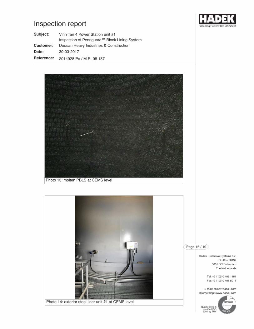
Hadek Protective Systems b.v.
P.O.Box 30139
3001 DC Rotterdam
The Netherlands
Tel. +31 (0)10 405 1461
Fax +31 (0)10 405 5011
E-mail: [email protected]
Internet:http://www.hadek.com
Page 16 / 19
Quality systemcertified ISO
9001 by TUV
Photo 14: exterior steel liner unit #1 at CEMS level
Photo 13: molten PBLS at CEMS level
Inspection reportSubject:
Customer:
Date:
Reference:
Vinh Tan 4 Power Station unit #1Inspection of Pennguard™ Block Lining SystemDoosan Heavy Industries & Construction
30-03-2017
2014928.Pe / M.R. 08 137
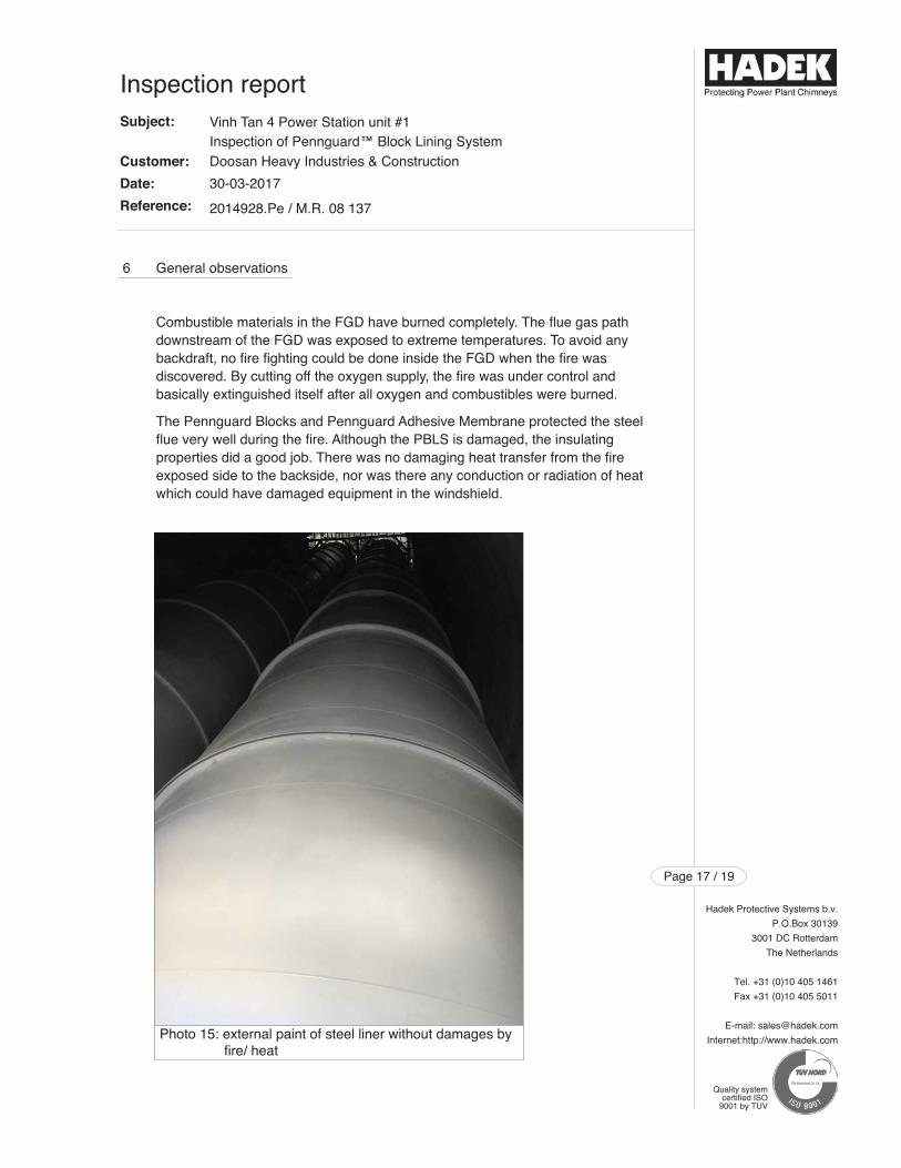
6 General observations
Combustible materials in the FGD have burned completely. The flue gas pathdownstream of the FGD was exposed to extreme temperatures. To avoid anybackdraft, no fire fighting could be done inside the FGD when the fire was discovered. By cutting off the oxygen supply, the fire was under control and basically extinguished itself after all oxygen and combustibles were burned.
The Pennguard Blocks and Pennguard Adhesive Membrane protected the steelflue very well during the fire. Although the PBLS is damaged, the insulating properties did a good job. There was no damaging heat transfer from the fireexposed side to the backside, nor was there any conduction or radiation of heatwhich could have damaged equipment in the windshield.
Hadek Protective Systems b.v.
P.O.Box 30139
3001 DC Rotterdam
The Netherlands
Tel. +31 (0)10 405 1461
Fax +31 (0)10 405 5011
E-mail: [email protected]
Internet:http://www.hadek.com
Page 17 / 19
Quality systemcertified ISO
9001 by TUV
Inspection reportSubject:
Customer:
Date:
Reference:
Vinh Tan 4 Power Station unit #1Inspection of Pennguard™ Block Lining SystemDoosan Heavy Industries & Construction
30-03-2017
2014928.Pe / M.R. 08 137
Photo 15: external paint of steel liner without damages by fire/ heat
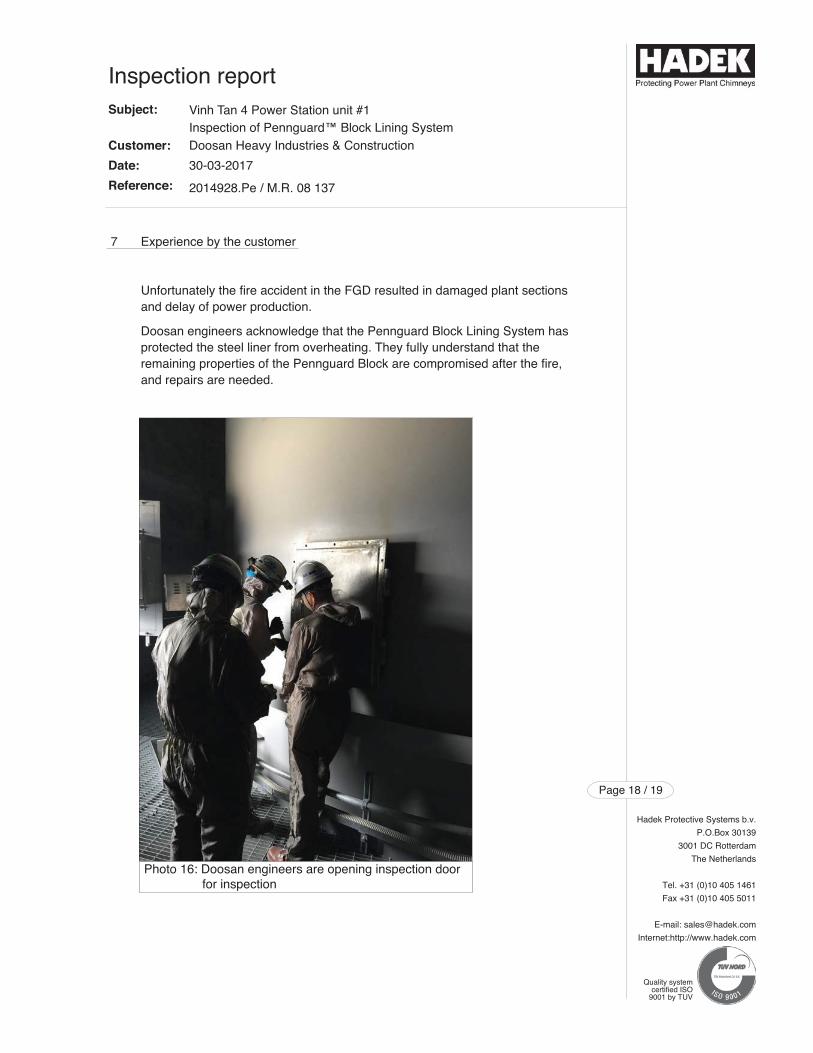
7 Experience by the customer
Unfortunately the fire accident in the FGD resulted in damaged plant sectionsand delay of power production.
Doosan engineers acknowledge that the Pennguard Block Lining System hasprotected the steel liner from overheating. They fully understand that the remaining properties of the Pennguard Block are compromised after the fire,and repairs are needed.
Hadek Protective Systems b.v.
P.O.Box 30139
3001 DC Rotterdam
The Netherlands
Tel. +31 (0)10 405 1461
Fax +31 (0)10 405 5011
E-mail: [email protected]
Internet:http://www.hadek.com
Page 18 / 19
Quality systemcertified ISO
9001 by TUV
Inspection reportSubject:
Customer:
Date:
Reference:
Vinh Tan 4 Power Station unit #1Inspection of Pennguard™ Block Lining SystemDoosan Heavy Industries & Construction
30-03-2017
2014928.Pe / M.R. 08 137
Photo 16: Doosan engineers are opening inspection door for inspection
8 Conclusion and recommendations
The fire accident in Vinh Tan 4 unit #1 FGD has damaged the Pennguard BlockLining System in the steel flue. Destructive spot check testing of the PennguardBlock Lining System has shown that the Pennguard Blocks lost their original properties and structure.
It is obvious that the Pennguard Block Lining System has done a great job protecting the steel flue during the fire. However the Pennguard Block andPennguard Adhesve Membrane have been irreversibly damaged and must bereplaced.
We recommend an inspection of the top section of unit #2 to verify that exposure to heat from the external fire at the top of unit #1, has not locally affected the Pennguard lining of the top of this unit.
Since it is unclear what caused the fire in the FGD no recommendations can begiven to avoid this from happening again. We would like to thank Doosan's VinhTan 4 site personnel for their support during this inspection.
Rotterdam, 30 March 2017
Steve Chan
Hadek Protective Systems b.v.
P.O.Box 30139
3001 DC Rotterdam
The Netherlands
Tel. +31 (0)10 405 1461
Fax +31 (0)10 405 5011
E-mail: [email protected]
Internet:http://www.hadek.com
Page 19 / 19
Quality systemcertified ISO
9001 by TUV
Inspection reportSubject:
Customer:
Date:
Reference:
Vinh Tan 4 Power Station unit #1Inspection of Pennguard™ Block Lining SystemDoosan Heavy Industries & Construction
30-03-2017
2014928.Pe / M.R. 08 137