fire protection, amendments no. 1, edition july 2022
TRANSCRIPT
RULES
FOR THE CLASSIFICATION OF
SHIPS
Part 17 – FIRE PROTECTION
January 2022
Amendments No. 1
July 2022
CROATIAN REGISTER OF SHIPPING
Hrvatska (Croatia) • 21000 Split • Marasovića 67 • P.O.B. 187
Tel.: (...) 385 (0)21 40 81 11
Fax.: (...) 385 (0)21 35 81 59
E-mail: [email protected]
web site: www.crs.hr
By the decision of the General Committee of Croatian Register of Shipping,
Amendments No. 1 to the
RULES FOR THE CLASSIFICATION OF SHIPS
Part 17 – FIRE PROTECTION
have been adopted on 27th June and shall enter into force on 1st July 2022
RULES FOR THE CLASSIFICATION OF SHIPS
PART 17
AMENDMENTS No. 1
INTRODUCTORY NOTES
These amendments shall be read together with the requirements in the Rules for the Classification of Ships,
Part 17 – Fire Protection, edition January 2022.
Table 1 contains review of amendments, where items changed or added in relating to previous edition are
given, with short description of each modification or addition. All major changes throughout the text are shaded.
RULES FOR THE CLASSIFICATION OF SHIPS
PART 17
AMENDMENTS No. 1
This Part of the Rules for the classification of ships includes the requirements of the following international Organisations:
International Maritime Organization (IMO)
Conventions: International Convention for the Safety of Life at Sea, 1974 (SOLAS 74) and all subsequent amendments up to
and including the 2018 amendments (MSC.437(99)).
Protocol of 1988 relating to the International Convention for the Safety of Life at Sea, 1974, as
amended (SOLAS PROT 1988).
Resolutions: A.123(V), A.567(14), A.654(16), A.752(18), A.756(18), A.800(19), A.951(23), A.952(23), A.1021(26) and
A.1116(30); MSC.62(67)/Rev.1; MSC.98(73), MSC.206(81), MSC.217(82), MSC.256(84), MSC.265(84),
MSC.266(84), MSC.269(85), MSC.284(86), MSC.291(87), MSC.292(87), MSC.307(88), MSC.308(88),
MSC.311(88), MSC.327(90), MSC.338(91), MSC.339(91), MSC.365(93), MSC.367(93), MSC.380(94),
MSC.392(95), MSC.403(96), MSC.404(96), MSC.408(96), MSC.409(97), MSC.410(97), MSC.421(98) and
MSC.437(99).
Circulars: MSC/Circ.353, MSC/Circ.387, MSC/Circ.451, MSC/Circ.474, MSC/Circ.485, MSC/Circ.553, MSC/Circ.606,
MSC/Circ.608 Rev.1 , MSC/Circ.670, MSC/Circ.677, MSC/Circ.730, MSC/Circ.731, MSC/Circ.777,
MSC/Circ.798, MSC/Circ.808, MSC/Circ.848, MSC/Circ.849, MSC/Circ.858, MSC/Circ.910, MSC/Circ.917,
MSC/Circ.917/Corr.1,MSC/Circ.1002, MSC/Circ.1003, MSC/Circ.1005, MSC/Circ.1009, MSC/Circ.1035,
MSC/Circ.1036, MSC/Circ.1037, MSC/Circ.1050, MSC/Circ.1081, MSC/Circ.1082, MSC/Circ.1084,
MSC/Circ.1085, MSC/Circ.1086, MSC/Circ.1087, MSC/Circ.1120, MSC/Circ.1129,
MSC/Circ.1142,MSC/Circ.1165, MSC/Circ.1167 and MSC/Circ.1168;
MSC.1/Circ.1002/Corr.1, MSC.1/Circ.1002/Corr.2, MSC.1/Circ.1120/Corr.1, MSC.1/Circ.1203,
MSC.1/Circ.1237, MSC.1/Circ.1240, MSC.1/Circ.1242, MSC.1/Circ.1266, MSC.1/Circ.1267,
MSC.1/Circ.1268, MSC.1/Circ.1269, MSC.1/Circ.1270, MSC.1/Circ.1270/Corr.1, MSC.1/Circ.1275,
MSC.1/Circ.1275/Corr.1,MSC.1/Circ.1276, MSC.1/Circ.1312, MSC.1/Circ.1312/Corr.1, MSC.1/Circ.1314,
MSC.1/Circ.1316,MSC.1/Circ.1317, MSC.1/Circ.1319, MSC.1/Circ.1320, MSC.1/Circ.1322,
MSC.1/Circ.1324, MSC.1/Circ.1368,MSC.1/Circ.1369/Add.1, MSC.1/Circ.1370, MSC.1/Circ.1384,
MSC.1/Circ.1385, MSC.1/Circ.1386, MSC.1/Circ.1387, MSC.1/Circ.1388, MSC.1/Circ.1395/Rev.4,
MSC.1/Circ.1422, MSC.1/Circ.1430/Rev.2, MSC.1/Circ.1431, MSC.1/Circ.1432, MSC.1/Circ.1433,
MSC.1/Circ.1434, MSC.1/Circ.1435, MSC.1/Circ.1436, MSC.1/Circ.1437, MSC.1/Circ.1456,
MSC.1/Circ.1458, MSC.1/Circ.1459, MSC.1/Circ.1471, MSC.1/Circ.1472, MSC.1/Circ.1480,
MSC.1/Circ.1487, MSC.1/Circ.1488, MSC.1/Circ.1491, MSC.1/Circ.1492, MSC.1/Circ.1499,
MSC.1/Circ.1501, MSC.1/Circ.1505, MSC.1/Circ.1510, MSC.1/Circ.1511, MSC.1/Circ.1514,
MSC.1/Circ.1515, MSC.1/Circ.1516, MSC.1/Circ.1527, MSC.1/Circ.1528, MSC.1/Circ.1533, Circ.1539/Rev.1,
MSC.1/Circ.1550, MSC.1/Circ.1552, MSC.1/Circ.1554, MSC.1/Circ.1555, MSC.1/Circ.1556,
MSC.1/Circ.1573, MSC.1/Circ.1581, MSC.1/Circ.1582/Rev.1, MSC.1/Circ.1616, MSC.1/Circ.1634;
BLG.1/Circ.23
International Association of Classification Societies (IACS)
Unified requirements (UR):
F1(2002), F2(2012), F3(1971), F5(1973), F6(1996), F7 (rev. 3, June 2020; corr. 1 Nov. 2020),
F13(1977),F16(2000), F20(2015), F21(1974), F26(2004), F27(1978), F29(2005), F32(1976), F33(1981),
F35(2005), F41(1993), F42(1995), F43(2002), F44(2010); F45(2021) and F46 (2021)
Unified Interpretations (UI):
SC16(2006), SC17(2020), SC25(2005), SC30(2005), SC32(2005), SC35(2013), SC39(2005), SC41(2005),
SC42(2021), SC43(2021), SC45(2005), SC46(2005), SC48(2005), SC49(2021), SC52(2005), SC54(2005),
SC55(2005), SC57(2021), SC58(2005), SC60(2005), SC62(2020), SC64(2021), SC70(2021), SC73(2005),
SC75(2005), SC79(2021), SC84(2005),SC85(2021), SC87(2021),SC89(2018), SC90(2005),
SC91(2020),SC92(2005),SC97(2005),SC98(2005),SC99(2014),SC100(2014), SC101(2005), SC102(2005),
SC103(2005), SC106(2005), SC107(2005), SC108(2005), SC109(2005), SC110(2005), SC111(2005),
SC114(2005), SC118(2015), SC119(2005), SC120(2006), SC121(2005), SC125(2020), SC126(2021),
SC127(2005), SC129(2005), SC130(2005), SC132(2013), SC140(2011), SC146(2021), SC147(2021),
SC148(2015), SC149(2012), SC150(2005), SC158(2005), SC159(2021), SC160(2005), SC162(2005),
SC163(2009), SC164(2005), SC166(2005), SC167(2021), SC168(2005), SC169(2003), SC172(2005),
SC173(2003), SC174(2006), SC175(2003), SC176(2004), SC178(2011), SC188(2015), SC192(2004),
SC196(2005), SC197(2021), SC198(2005), SC199(2005), SC200(2022), SC201(2022), SC204(2022),

RULES FOR THE CLASSIFICATION OF SHIPS
PART 17
AMENDMENTS No. 1
2022
SC205(2006), SC211(2007), SC214(2006), SC217(2007), SC218(2007), SC219(2007), SC239(2010),
SC240(2011), SC241(2010), SC243(2012), SC245(2012), SC247(2011), SC250(2012), SC252(2011),
SC253(2016), SC260(2015), SC262(2015), SC264(2013), SC268(2014), SC269(2016), SC270(2015),
SC271(2015), SC272(2015), SC273(2015), SC275(2016), SC276(2016), SC277(2016), SC278(2016),
SC282(2016), SC284(2018), SC285(2018), SC286(2018), SC287(2018), SC288(2018), SC291(2018) and
SC294(2018);
FTP2(2000), FTP3(2021), FTP4(2006), FTP5(2010) and FTP6(2015)
Recommendations (Rec.):
No.123 (2012), No.131(2013) and No.135(2014)
RULES FOR THE CLASSIFICATION OF SHIPS
PART 17
AMENDMENTS No. 1
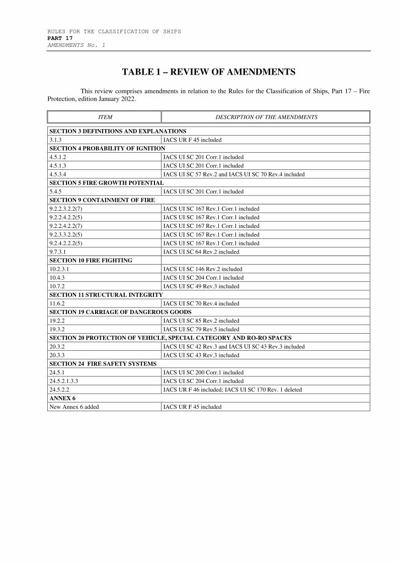
TABLE 1 – REVIEW OF AMENDMENTS
This review comprises amendments in relation to the Rules for the Classification of Ships, Part 17 – Fire
Protection, edition January 2022.
ITEM DESCRIPTION OF THE AMENDMENTS
SECTION 3 DEFINITIONS AND EXPLANATIONS
3.1.3 IACS UR F 45 included
SECTION 4 PROBABILITY OF IGNITION
4.5.1.2 IACS UI SC 201 Corr.1 included
4.5.1.3 IACS UI SC 201 Corr.1 included
4.5.3.4 IACS UI SC 57 Rev.2 and IACS UI SC 70 Rev.4 included
SECTION 5 FIRE GROWTH POTENTIAL
5.4.5 IACS UI SC 201 Corr.1 included
SECTION 9 CONTAINMENT OF FIRE
9.2.2.3.2.2(7) IACS UI SC 167 Rev.1 Corr.1 included
9.2.2.4.2.2(5) IACS UI SC 167 Rev.1 Corr.1 included
9.2.2.4.2.2(7) IACS UI SC 167 Rev.1 Corr.1 included
9.2.3.3.2.2(5) IACS UI SC 167 Rev.1 Corr.1 included
9.2.4.2.2.2(5) IACS UI SC 167 Rev.1 Corr.1 included
9.7.3.1 IACS UI SC 64 Rev.2 included
SECTION 10 FIRE FIGHTING
10.2.3.1 IACS UI SC 146 Rev.2 included
10.4.3 IACS UI SC 204 Corr.1 included
10.7.2 IACS UI SC 49 Rev.3 included
SECTION 11 STRUCTURAL INTEGRITY
11.6.2 IACS UI SC 70 Rev.4 included
SECTION 19 CARRIAGE OF DANGEROUS GOODS
19.2.2 IACS UI SC 85 Rev.2 included
19.3.2 IACS UI SC 79 Rev.5 included
SECTION 20 PROTECTION OF VEHICLE, SPECIAL CATEGORY AND RO-RO SPACES
20.3.2 IACS UI SC 42 Rev.3 and IACS UI SC 43 Rev.3 included
20.3.3 IACS UI SC 43 Rev.3 included
SECTION 24 FIRE SAFETY SYSTEMS
24.5.1 IACS UI SC 200 Corr.1 included
24.5.2.1.3.3 IACS UI SC 204 Corr.1 included
24.5.2.2 IACS UR F 46 included; IACS UI SC 170 Rev. 1 deleted
ANNEX 6
New Annex 6 added IACS UR F 45 included

RULES FOR THE CLASSIFICATION OF SHIPS 1
PART 17
AMENDMENTS No. 1
2022
3 DEFINITIONS AND EXPLANATIONS
Head 3.1 DEFINITIONS, item 3.1.3 has been changed and should be read as
follows:
3.1.3 For the purpose of this Part of the Rules the following additional definitions are adopted:
.1 Non-sparking fan - a fan that complies with the requirements of IACS UR F 29 Rev. 6.
.2 Ballast Water Management System (BWMS) – a system for treatment of ballast water. Additional fire safety
measures when BWMS is installed on board ship shall be in compliance with the requirements of Annex VI
(IACS UR F 45).
2 RULES FOR THE CLASSIFICATION OF SHIPS
PART 17
AMENDMENTS No. 1
2022
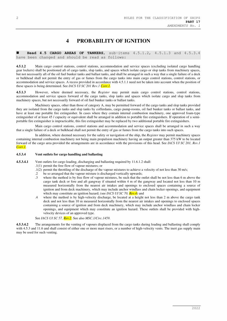
4 PROBABILITY OF IGNITION
Head 4.5 CARGO AREAS OF TANKERS, sub-items 4.5.1.2, 4.5.1.3 and 4.5.3.4
have been changed and should be read as follows:
4.5.1.2 Main cargo control stations, control stations, accommodation and service spaces (excluding isolated cargo handling
gear lockers) shall be positioned aft of cargo tanks, slop tanks, and spaces which isolate cargo or slop tanks from machinery spaces,
but not necessarily aft of the oil fuel bunker tanks and ballast tanks, and shall be arranged in such a way that a single failure of a deck
or bulkhead shall not permit the entry of gas or fumes from the cargo tanks into main cargo control stations, control stations, or
accommodation and service spaces. A recess provided in accordance with 4.5.1.1 need not be taken into account when the position of
these spaces is being determined. See IACS UI SC 201 Rev.1 Corr.1.
4.5.1.3 However, where deemed necessary, the Register may permit main cargo control stations, control stations,
accommodation and service spaces forward of the cargo tanks, slop tanks and spaces which isolate cargo and slop tanks from
machinery spaces, but not necessarily forward of oil fuel bunker tanks or ballast tanks.
Machinery spaces, other than those of category A, may be permitted forward of the cargo tanks and slop tanks provided
they are isolated from the cargo tanks and slop tanks by cofferdams, cargo pump-rooms, oil fuel bunker tanks or ballast tanks, and
have at least one portable fire extinguisher. In cases where they contain internal combustion machinery, one approved foam-type
extinguisher of at least 45 l capacity or equivalent shall be arranged in addition to portable fire extinguishers. If operation of a semi-
portable fire extinguisher is impracticable, this fire extinguisher may be replaced by two additional portable fire extinguishers.
Main cargo control stations, control stations and accommodation and service spaces shall be arranged in such a way
that a single failure of a deck or bulkhead shall not permit the entry of gas or fumes from the cargo tanks into such spaces.
In addition, where deemed necessary for the safety or navigation of the ship, the Register may permit machinery spaces
containing internal combustion machinery not being main propulsion machinery having an output greater than 375 kW to be located
forward of the cargo area provided the arrangements are in accordance with the provisions of this head. See IACS UI SC 201, Rev.1
Corr.1.
4.5.3.4 Vent outlets for cargo handling and ballasting
4.5.3.4.1 Vent outlets for cargo loading, discharging and ballasting required by 11.6.1.2 shall:
.1(1) permit the free flow of vapour mixtures; or
.1(2) permit the throttling of the discharge of the vapour mixtures to achieve a velocity of not less than 30 m/s;
.2 be so arranged that the vapour mixture is discharged vertically upwards;
.3 where the method is by free flow of vapour mixtures, be such that the outlet shall be not less than 6 m above the
cargo tank deck or fore and aft gangway if situated within 4 m of the gangway and located not less than 10 m
measured horizontally from the nearest air intakes and openings to enclosed spaces containing a source of
ignition and from deck machinery, which may include anchor windlass and chain locker openings, and equipment
which may constitute an ignition hazard; (see IACS UI SC 70, Rev.4) and
.4 where the method is by high-velocity discharge, be located at a height not less than 2 m above the cargo tank
deck and not less than 10 m measured horizontally from the nearest air intakes and openings to enclosed spaces
containing a source of ignition and from deck machinery, which may include anchor windlass and chain locker
openings, and equipment which may constitute an ignition hazard. These outlets shall be provided with high-
velocity devices of an approved type.
See IACS UI SC 57, Rev.2. See also MSC.1/Circ.1459.
4.5.3.4.2 The arrangements for the venting of vapours displaced from the cargo tanks during loading and ballasting shall comply
with 4.5.3 and 11.6 and shall consist of either one or more mast risers, or a number of high-velocity vents. The inert gas supply main
may be used for such venting.
RULES FOR THE CLASSIFICATION OF SHIPS 3
PART 17
AMENDMENTS No. 1
2022
5 FIRE GROWTH POTENTIAL
Head 5.4 STORE-ROOMS FOR FLAMMABLE LIQUIDS AND READILY COMBUSTIBLE
MATERIALS, item 5.4.5 has been changed and should be read as follows:
5.4.5 Paint stores shall be not situated in the cargo area of tankers (< 60°C) and chemical tankers, see IACS UI SC 201, Rev.1
Corr.1.
4 RULES FOR THE CLASSIFICATION OF SHIPS
PART 17
AMENDMENTS No. 1
2022
9 CONTAINMENT OF FIRE
Head 9.2 THERMAL AND STRUCTURAL BOUNDARIES, sub-items 9.2.2.3.2.2(7),
9.2.2.4.2.2(5), 9.2.2.4.2.2(7), 9.2.3.3.2.2(5) and 9.2.4.2.2.2(5) have been
changed and should be read as follows:
9.2.2.3.2 The following requirements shall govern application of the tables:
…
.2 For determining the appropriate fire integrity standards to be applied to boundaries between adjacent spaces, such
spaces are classified according to their fire risk as shown in categories (1) to (14) below. Where the contents and
use of a space are such that there is a doubt as to its classification for the purpose of this Section, or where it is
possible to assign two or more classifications to a space, it shall be treated as a space within the relevant category
having the most stringent boundary requirements. Smaller, enclosed rooms within a space that have less than 30%
communicating openings to that space are considered separate spaces. The fire integrity of the boundary
bulkheads and decks of such smaller rooms shall be as prescribed in tables 9.1 and 9.2. The title of each category
is intended to be typical rather than restrictive. The number in parentheses preceding each category refers to the
applicable column or row in the tables.
…
(7) Accommodation spaces of moderate fire risk:
Spaces as in category (6) above but containing furniture and furnishings of other than restricted fire risk.
Public spaces containing furniture and furnishings of restricted fire risk and having a deck area of 50 m2 or
more.
Isolated lockers and small store-rooms in accommodation spaces having areas less than 4 m2 (in which
flammable liquids are not stowed).
Motion picture projection and film stowage rooms.
Diet kitchens (containing no open flame).
Cleaning gear lockers (in which flammable liquids are not stowed).
Laboratories (in which flammable liquids are not stowed).
Pharmacies.
Small drying rooms (having a deck area of 4m2 or less).
Specie rooms.
Operating rooms.
See IACS UI SC 167, Rev.1 Corr.1.
…
9.2.2.4.2 The following requirements shall govern application of the tables:
…
.2 For determining the appropriate fire integrity standards to be applied to divisions between adjacent spaces, such
spaces are classified according to their fire risk as shown in categories (1) to (11) below. Where the contents and
use of a space are such that there is a doubt as to its classification for the purpose of this Section, or where it is
possible to assign two or more classifications to a space, it shall be treated as a space within the relevant category
having the most stringent boundary requirements. Smaller, enclosed rooms within a space that have less than 30%
communicating openings to that space are considered separate spaces. The fire integrity of the boundary
bulkheads and decks of such smaller rooms shall be as prescribed in tables 9.3 and 9.4. The title of each category
is intended to be typical rather than restrictive. The number in parentheses preceding each category refers to the
applicable column or row in the tables. See MSC.1/Circ.1581.
…
(5) Service spaces (low fire risk):
Lockers and store-rooms not having provisions for the storage of flammable liquids and having areas of less
than 4 m2 and drying rooms and laundries.
See IACS UI SC 167, Rev.1 Corr.1.
…
(7) Other machinery spaces:
Electrical equipment rooms (see the Rules for the classification of ships, Part 12 – Electrical Equipment,
1.2.7), auto-telephone exchange and air-conditioning duct spaces.
Spaces as defined in 3.1.2.30, excluding machinery spaces of category A.
See MSC.1/Circ.1616.
See IACS UI SC 294.
…

RULES FOR THE CLASSIFICATION OF SHIPS 5
PART 17
AMENDMENTS No. 1
2022
9.2.3.3.2 The following requirements shall govern application of the tables:
…
.2 For determining the appropriate fire integrity standards to be applied to divisions between adjacent spaces, such
spaces are classified according to their fire risk as shown in categories (1) to (11) below. Where the contents and
use of a space are such that there is a doubt as to its classifi
…
(5) Service spaces (low risk):
Lockers and store-rooms not having provisions for the storage of flammable liquids and having areas less
than 4 m2 and drying rooms and laundries.
See IACS UI SC 167, Rev.1 Corr.1.
…
9.2.4.2.2 The following requirements shall govern application of the tables:
.2 For determining the appropriate fire integrity standards to be applied to divisions between adjacent spaces, such
spaces are classified according to their fire risk as shown in categories (1) to (10) below. Where the contents and
use of a space are such that there is a doubt as to its classification for the purpose of this Section, or where it is
possible to assign two or more classifications to a space, it shall be treated as a space within the relevant category
having the most stringent boundary requirements. Smaller, enclosed areas within a space that have less than 30%
communicating openings to that space are considered separate areas. The fire integrity of the boundary bulkheads
and decks of such smaller spaces shall be as prescribed in tables 9.7 and 9.8. The title of each category is intended
to be typical rather than restrictive. The number in parentheses preceding each category refers to the applicable
column or row in the tables. See IACS UI SC45 Rev.1 and MSC.1/Circ.1581.
…
(5) Service spaces (low risk)
Lockers and store-rooms not having provisions for the storage of flammable liquids and having areas less
than 4 m2 and drying rooms and laundries.
See IACS UI SC 167, Rev.1 Corr.1.
Head 9.7 VENTILATION SYSTEMS, sub-item 9.7.3.1 has been changed and should
be read as follows:
9.7.3.1 Ducts passing through "A" class divisions shall meet the following requirements:
.1 where a thin plated duct with a free cross sectional area equal to, or less than, 0.02 m2 passes through "A" class
divisions, the opening shall be fitted with a steel sheet sleeve having a thickness of at least 3 mm and a length of
at least 200 mm, divided preferably into 100 mm on each side of a bulkhead or, in the case of a deck, wholly laid
on the lower side of the decks penetrated;
.2 where ventilation ducts with a free cross-sectional area exceeding 0.02 m2, but not more than 0.075 m2, pass
through "A" class divisions, the openings shall be lined with steel sheet sleeves. The ducts and sleeves shall have
a thickness of at least 3 mm and a length of at least 900 mm. When passing through bulkheads, this length shall
be divided preferably into 450 mm on each side of the bulkhead. These ducts, or sleeves lining such ducts, shall
be provided with fire insulation. The insulation shall have at least the same fire integrity as the division through
which the duct passes; and
.3 automatic fire dampers shall be fitted in all ducts with a free cross-sectional area exceeding 0.075 m2 that pass
through "A" class divisions. Each damper shall be fitted close to the division penetrated and the duct between the
damper and the division penetrated shall be constructed of steel in accordance with 9.7.2.4.2.1 and 9.7.2.4.2.2.
The fire damper shall operate automatically, but shall also be capable of being closed manually from both sides of
the division. The damper shall be fitted with a visible indicator which shows the operating position of the damper.
Fire dampers are not required, however, where ducts pass through spaces surrounded by "A" class divisions,
without serving those spaces, provided those ducts have the same fire integrity as the divisions which they
penetrate. A duct of cross-sectional area exceeding 0.075 m2 shall not be divided into smaller ducts at the
penetration of an "A" class division and then recombined into the original duct once through the division to avoid
installing the damper required by this provision.
See IACS UI SC 64, Rev. 2.
6 RULES FOR THE CLASSIFICATION OF SHIPS
PART 17
AMENDMENTS No. 1
2022
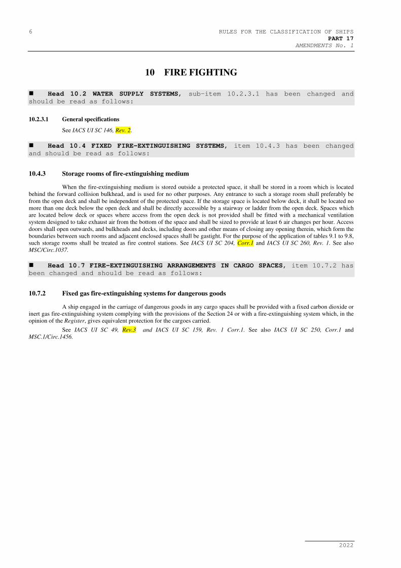
10 FIRE FIGHTING
Head 10.2 WATER SUPPLY SYSTEMS, sub-item 10.2.3.1 has been changed and
should be read as follows:
10.2.3.1 General specifications
See IACS UI SC 146, Rev. 2.
Head 10.4 FIXED FIRE-EXTINGUISHING SYSTEMS, item 10.4.3 has been changed
and should be read as follows:
10.4.3 Storage rooms of fire-extinguishing medium
When the fire-extinguishing medium is stored outside a protected space, it shall be stored in a room which is located
behind the forward collision bulkhead, and is used for no other purposes. Any entrance to such a storage room shall preferably be
from the open deck and shall be independent of the protected space. If the storage space is located below deck, it shall be located no
more than one deck below the open deck and shall be directly accessible by a stairway or ladder from the open deck. Spaces which
are located below deck or spaces where access from the open deck is not provided shall be fitted with a mechanical ventilation
system designed to take exhaust air from the bottom of the space and shall be sized to provide at least 6 air changes per hour. Access
doors shall open outwards, and bulkheads and decks, including doors and other means of closing any opening therein, which form the
boundaries between such rooms and adjacent enclosed spaces shall be gastight. For the purpose of the application of tables 9.1 to 9.8,
such storage rooms shall be treated as fire control stations. See IACS UI SC 204, Corr.1 and IACS UI SC 260, Rev. 1. See also
MSC/Circ.1037.
Head 10.7 FIRE-EXTINGUISHING ARRANGEMENTS IN CARGO SPACES, item 10.7.2 has
been changed and should be read as follows:
10.7.2 Fixed gas fire-extinguishing systems for dangerous goods
A ship engaged in the carriage of dangerous goods in any cargo spaces shall be provided with a fixed carbon dioxide or
inert gas fire-extinguishing system complying with the provisions of the Section 24 or with a fire-extinguishing system which, in the
opinion of the Register, gives equivalent protection for the cargoes carried.
See IACS UI SC 49, Rev.3 and IACS UI SC 159, Rev. 1 Corr.1. See also IACS UI SC 250, Corr.1 and
MSC.1/Circ.1456.
RULES FOR THE CLASSIFICATION OF SHIPS 7
PART 17
AMENDMENTS No. 1
2022
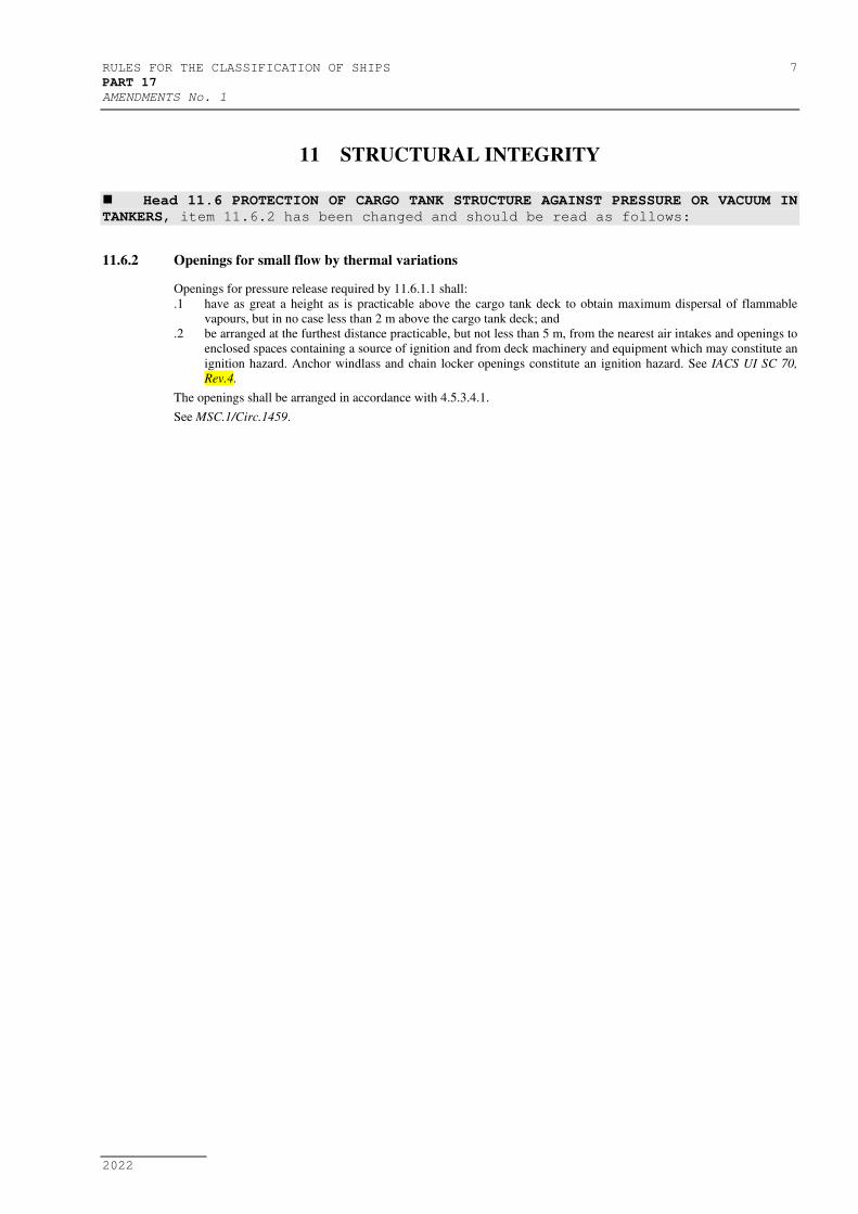
11 STRUCTURAL INTEGRITY
Head 11.6 PROTECTION OF CARGO TANK STRUCTURE AGAINST PRESSURE OR VACUUM IN
TANKERS, item 11.6.2 has been changed and should be read as follows:
11.6.2 Openings for small flow by thermal variations
Openings for pressure release required by 11.6.1.1 shall:
.1 have as great a height as is practicable above the cargo tank deck to obtain maximum dispersal of flammable
vapours, but in no case less than 2 m above the cargo tank deck; and
.2 be arranged at the furthest distance practicable, but not less than 5 m, from the nearest air intakes and openings to
enclosed spaces containing a source of ignition and from deck machinery and equipment which may constitute an
ignition hazard. Anchor windlass and chain locker openings constitute an ignition hazard. See IACS UI SC 70,
Rev.4.
The openings shall be arranged in accordance with 4.5.3.4.1.
See MSC.1/Circ.1459.
8 RULES FOR THE CLASSIFICATION OF SHIPS
PART 17
AMENDMENTS No. 1
2022
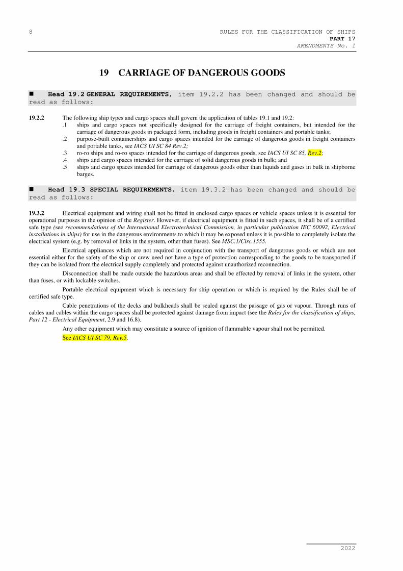
19 CARRIAGE OF DANGEROUS GOODS
Head 19.2 GENERAL REQUIREMENTS, item 19.2.2 has been changed and should be
read as follows:
19.2.2 The following ship types and cargo spaces shall govern the application of tables 19.1 and 19.2:
.1 ships and cargo spaces not specifically designed for the carriage of freight containers, but intended for the
carriage of dangerous goods in packaged form, including goods in freight containers and portable tanks;
.2 purpose-built containerships and cargo spaces intended for the carriage of dangerous goods in freight containers
and portable tanks, see IACS UI SC 84 Rev.2;
.3 ro-ro ships and ro-ro spaces intended for the carriage of dangerous goods, see IACS UI SC 85, Rev.2;
.4 ships and cargo spaces intended for the carriage of solid dangerous goods in bulk; and
.5 ships and cargo spaces intended for carriage of dangerous goods other than liquids and gases in bulk in shipborne
barges.
Head 19.3 SPECIAL REQUIREMENTS, item 19.3.2 has been changed and should be
read as follows:
19.3.2 Electrical equipment and wiring shall not be fitted in enclosed cargo spaces or vehicle spaces unless it is essential for
operational purposes in the opinion of the Register. However, if electrical equipment is fitted in such spaces, it shall be of a certified
safe type (see recommendations of the International Electrotechnical Commission, in particular publication IEC 60092, Electrical
installations in ships) for use in the dangerous environments to which it may be exposed unless it is possible to completely isolate the
electrical system (e.g. by removal of links in the system, other than fuses). See MSC.1/Circ.1555.
Electrical appliances which are not required in conjunction with the transport of dangerous goods or which are not
essential either for the safety of the ship or crew need not have a type of protection corresponding to the goods to be transported if
they can be isolated from the electrical supply completely and protected against unauthorized reconnection.
Disconnection shall be made outside the hazardous areas and shall be effected by removal of links in the system, other
than fuses, or with lockable switches.
Portable electrical equipment which is necessary for ship operation or which is required by the Rules shall be of
certified safe type.
Cable penetrations of the decks and bulkheads shall be sealed against the passage of gas or vapour. Through runs of
cables and cables within the cargo spaces shall be protected against damage from impact (see the Rules for the classification of ships,
Part 12 - Electrical Equipment, 2.9 and 16.8).
Any other equipment which may constitute a source of ignition of flammable vapour shall not be permitted.
See IACS UI SC 79, Rev.5.
RULES FOR THE CLASSIFICATION OF SHIPS 9
PART 17
AMENDMENTS No. 1
2022
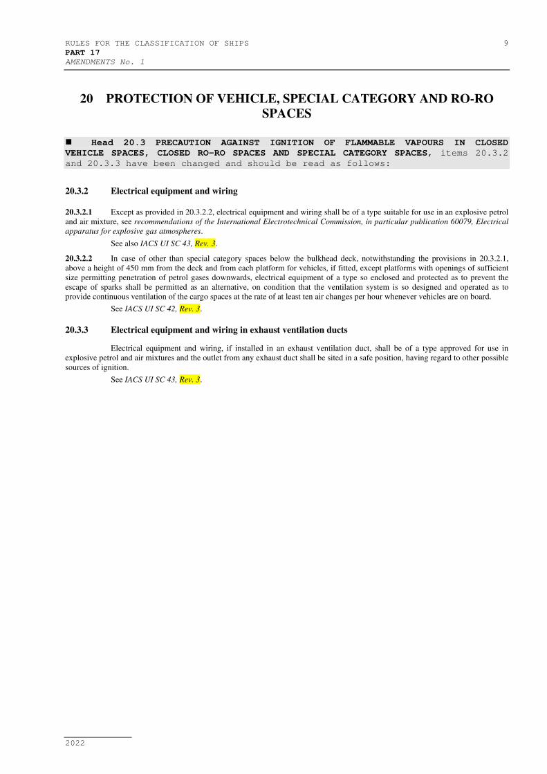
20 PROTECTION OF VEHICLE, SPECIAL CATEGORY AND RO-RO
SPACES
Head 20.3 PRECAUTION AGAINST IGNITION OF FLAMMABLE VAPOURS IN CLOSED
VEHICLE SPACES, CLOSED RO-RO SPACES AND SPECIAL CATEGORY SPACES, items 20.3.2
and 20.3.3 have been changed and should be read as follows:
20.3.2 Electrical equipment and wiring
20.3.2.1 Except as provided in 20.3.2.2, electrical equipment and wiring shall be of a type suitable for use in an explosive petrol
and air mixture, see recommendations of the International Electrotechnical Commission, in particular publication 60079, Electrical
apparatus for explosive gas atmospheres.
See also IACS UI SC 43, Rev. 3.
20.3.2.2 In case of other than special category spaces below the bulkhead deck, notwithstanding the provisions in 20.3.2.1,
above a height of 450 mm from the deck and from each platform for vehicles, if fitted, except platforms with openings of sufficient
size permitting penetration of petrol gases downwards, electrical equipment of a type so enclosed and protected as to prevent the
escape of sparks shall be permitted as an alternative, on condition that the ventilation system is so designed and operated as to
provide continuous ventilation of the cargo spaces at the rate of at least ten air changes per hour whenever vehicles are on board.
See IACS UI SC 42, Rev. 3.
20.3.3 Electrical equipment and wiring in exhaust ventilation ducts
Electrical equipment and wiring, if installed in an exhaust ventilation duct, shall be of a type approved for use in
explosive petrol and air mixtures and the outlet from any exhaust duct shall be sited in a safe position, having regard to other possible
sources of ignition.
See IACS UI SC 43, Rev. 3.
10 RULES FOR THE CLASSIFICATION OF SHIPS
PART 17
AMENDMENTS No. 1
2022
24 FIRE SAFETY SYSTEMS
Head 24.5 FIXED GAS FIRE-EXTINGUISHING SYSTEMS, item 24.5.1 and sub-items
24.5.2.1.3.3 and 24.5.2.2 have been changed and should be read as follows:
24.5.1 Application
This head details the specifications for fixed gas fire-extinguishing systems as required by Sections in this Part of the
Rules. See IACS UI SC 200, Corr. 1 (taking into account 24.1.1.1).
24.5.2.1.3.3 The means of control of any fixed gas fire-extinguishing system shall be readily accessible, simple to operate and shall
be grouped together in as few locations as possible at positions not likely to be cut off by a fire in a protected space. At each location
there shall be clear instructions relating to the operation of the system having regard to the safety of personnel. See MSC.1/Circ.1240.
See IACS UI SC 204, Corr. 1 (taking into account 24.1.1.1).
24.5.2.2 Carbon dioxide systems
Where a low-pressure CO2 system is fitted, the piping system is to be designed in such a way that the CO2 pressure at
the nozzles should not be less than 1 N/mm2.
24.5.2.2.1 Quantity of fire-extinguishing medium
.1 For cargo spaces, the quantity of carbon dioxide available shall, unless otherwise provided, be sufficient to give a
minimum volume of free gas equal to 30% of the gross volume of the largest cargo space to be protected in the
ship.
.2 For vehicle spaces and ro-ro spaces which are not special category spaces, the quantity of carbon dioxide
available shall be at least sufficient to give a minimum volume of free gas equal to 45% of the gross volume of
the largest such cargo space which is capable of being sealed, and the arrangements shall be such as to ensure that
at least two thirds of the gas required for the relevant space shall be introduced within 10 min. Carbon dioxide
systems shall not be used for the protection of special category spaces.
.3 For machinery spaces, the quantity of carbon dioxide carried shall be sufficient to give a minimum volume of free
gas equal to the larger of the following volumes, either:
(1) 40% of the gross volume of the largest machinery space so protected, the volume to exclude that part of the
casing above the level at which the horizontal area of the casing is 40% or less of the horizontal area of the
space concerned taken midway between the tank top and the lowest part of the casing; or
(2) 35% of the gross volume of the largest machinery space protected, including the casing.
.4 The percentages specified in 24.5.2.2.1.3 above may be reduced to 35% and 30%, respectively, for cargo ships of
less than 2,000 gross tonnage where two or more machinery spaces, which are not entirely separate, are
considered as forming one space.
.5 For the purpose of this Section the volume of free carbon dioxide shall be calculated at 0.56 m3/kg.
.6 For machinery spaces, the fixed piping system shall be such that 85% of the gas can be discharged into the space
within 2 min.
.7 For container and general cargo spaces (primarily intended to carry a variety of cargoes separately secured or
packed), the fixed piping system shall be such that at least two thirds of the gas can be discharged into the space
within 10 min. For solid bulk cargo spaces, the fixed piping system shall be such that at least two thirds of the gas
can be discharged into the space within 20 min. The system controls shall be arranged to allow one third, two
thirds or the entire quantity of gas to be discharged based on the loading condition of the hold. See
MSC.1/Circ.1528.
.8 In containerships, for container cargo spaces fitted with partially weathertight hatchway covers the quantity of
carbon dioxide available for the cargo space shall be increased as specified in MSC/Circ.1087.
24.5.2.2.2 Controls
Carbon dioxide systems for the protection of ro-ro spaces, container holds equipped with integral reefer containers,
spaces accessible by doors or hatches, and other spaces in which personnel normally work or to which they have access shall comply
with the following requirements:
.1 two separate controls shall be provided for releasing carbon dioxide into a protected space and to ensure the
activation of the alarm. One control shall be used for opening the valve of the piping which conveys the gas into
the protected space and a second control shall be used to discharge the gas from its storage containers. Positive
means shall be provided so they can only be operated in that order; and
.2 the two controls shall be located inside a release box clearly identified for the particular space. If the box
containing the controls is to be locked, a key to the box shall be in a break-glass-type enclosure conspicuously
located adjacent to the box.
See IACS UI SC 132, Rev. 4 and IACS UI SC 252 (taking into account 24.1.1.1). See also MSC.1/Circ.1456.
RULES FOR THE CLASSIFICATION OF SHIPS 11
PART 17
AMENDMENTS No. 1
2022
24.5.2.2.3 Testing of the installation
When the system has been installed, pressure-tested and inspected, the following shall be carried out:
.1 a test of the free air flow in all pipes and nozzles; and
.2 a functional test of the alarm equipment.
24.5.2.2.4 Low-pressure CO2 systems
Where a low pressure CO2 system is fitted to comply with this regulation, the following applies.
.1 The system control devices and the refrigerating plants shall be located within the same room where the pressure
vessels are stored.
.2 The rated amount of liquid carbon dioxide shall be stored in vessel(s) under the working pressure in the range of
1.8 N/mm2 to 2.2 N/mm2. The normal liquid charge in the container shall be limited to provide sufficient vapour
space to allow for expansion of the liquid under the maximum storage temperatures than can be obtained
corresponding to the setting of the pressure relief valves but shall not exceed 95% of the volumetric capacity of
the container.
.3 Provision shall be made for:
(1) pressure gauge;
(2) high pressure alarm: not more than setting of the relief valve;
(3) low pressure alarm: not less than 1.8 N/mm2;
(4) branch pipes with stop valves for filling the vessel;
(5) discharge pipes;
(6) liquid CO2 level indicator, fitted on the vessel(s); and
(7) two safety valves.
.4 The two safety relief valves shall be arranged so that either valve can be shut off while the other is connected to
the vessel. The setting of the relief valves shall not be less than 1.1 times the working pressure. The capacity of
each valve shall be such that the vapours generated under fire conditions can be discharged with a pressure rise
not more than 20% above the setting pressure. The discharge from the safety valves shall be led to the open.
.5 The vessel(s) and outgoing pipes permanently filled with carbon dioxide shall have thermal insulation preventing
the operation of the safety valve in 24 h after de-energizing the plant, at ambient temperature of 45°C and an
initial pressure equal to the starting pressure of the refrigeration unit.
.6 The vessel(s) shall be serviced by two automated completely independent refrigerating units solely intended for
this purpose, each comprising a compressor and the relevant prime mover, evaporator and condenser.
.7 The refrigerating capacity and the automatic control of each unit shall be so as to maintain the required
temperature under conditions of continuous operation during 24 h at sea temperatures up to 32°C and ambient air
temperatures up to 45°C.
.8 Each electric refrigerating unit shall be supplied from the main switchboard busbars by a separate feeder.
.9 Cooling water supply to the refrigerating plant (where required) shall be provided from at least two circulating
pumps one of which being used as a stand-by. The stand-by pump may be a pump used for other services so long
as its use for cooling would not interfere with any other essential service of the ship. Cooling water shall be taken
from not less than two sea connections, preferably one port and one starboard.
.10 Safety relief devices shall be provided in each section of pipe that may be isolated by block valves and in which
there could be a buildup of pressure in excess of the design pressure of any of the components.
.11 Audible and visual alarms shall be given in a central control station or where a central control station is not
provided, when:
(1) the pressure in the vessel(s) reaches the low and high values according to 24.5.2.2.4.2;
(2) any one of the refrigerating units fails to operate; or
(3) the lowest permissible level of the liquid in the vessels is reached.
.12 If the system serves more than one space, means for control of discharge quantities of CO2 shall be provided, e.g.
automatic timer or accurate level indicators located at the control position(s).
.13 If a device is provided which automatically regulates the discharge of the rated quantity of carbon dioxide into the
protected spaces, it shall be also possible to regulate the discharge manually.
12 RULES FOR THE CLASSIFICATION OF SHIPS
PART 17
AMENDMENTS No. 1
2022
New Annex 6 - FIRE PROTECTION REQUIREMENTS OF INSTALLATION OF BWMS ON-BOARD
SHIPS (IACS UR F 45), item 24.5.1 and sub-items 24.5.2.1.3.3 and 24.5.2.2 has
been added and should be read as follows:
ANNEX 6 FIRE PROTECTION REQUIREMENTS OF INSTALLATION OF
BWMS ON-BOARD SHIPS (IACS UR F 45)
1 GENERAL
1.1 Application
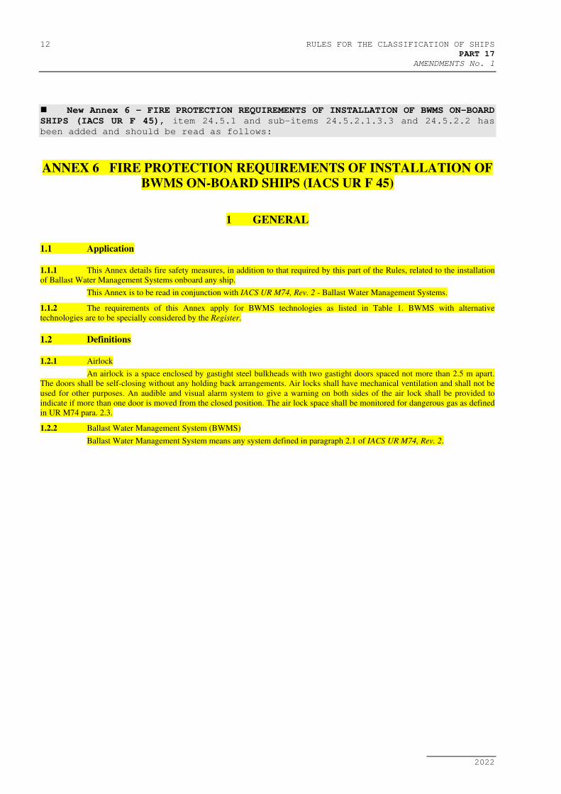
1.1.1 This Annex details fire safety measures, in addition to that required by this part of the Rules, related to the installation
of Ballast Water Management Systems onboard any ship.
This Annex is to be read in conjunction with IACS UR M74, Rev. 2 - Ballast Water Management Systems.
1.1.2 The requirements of this Annex apply for BWMS technologies as listed in Table 1. BWMS with alternative
technologies are to be specially considered by the Register.
1.2 Definitions
1.2.1 Airlock
An airlock is a space enclosed by gastight steel bulkheads with two gastight doors spaced not more than 2.5 m apart.
The doors shall be self-closing without any holding back arrangements. Air locks shall have mechanical ventilation and shall not be
used for other purposes. An audible and visual alarm system to give a warning on both sides of the air lock shall be provided to
indicate if more than one door is moved from the closed position. The air lock space shall be monitored for dangerous gas as defined
in UR M74 para. 2.3.
1.2.2 Ballast Water Management System (BWMS)
Ballast Water Management System means any system defined in paragraph 2.1 of IACS UR M74, Rev. 2.
RULES FOR THE CLASSIFICATION OF SHIPS 13
PART 17
AMENDMENTS No. 1
2022
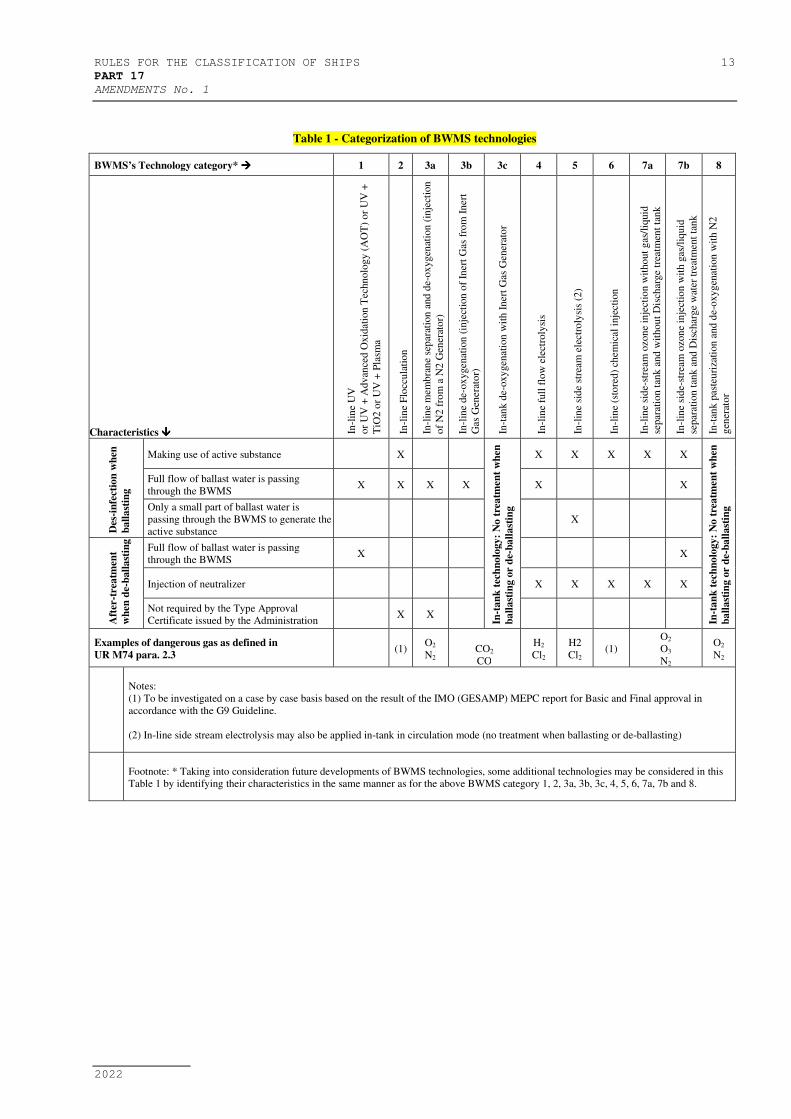
Table 1 - Categorization of BWMS technologies
BWMS’s Technology category* 1 2 3a 3b 3c 4 5 6 7a 7b 8
Characteristics In-l
ine
UV
or
UV
+ A
dv
ance
d O
xid
atio
n T
echn
olo
gy (
AO
T)
or
UV
+
TiO
2 o
r U
V +
Pla
sma
In-l
ine
Flo
ccula
tio
n
In-l
ine
mem
bra
ne
sep
arat
ion
and
de-
ox
yg
enat
ion
(in
ject
ion
of
N2 f
rom
a N
2 G
ener
ato
r)
In-l
ine
de-
ox
ygen
atio
n (
inje
ctio
n o
f In
ert
Gas
fro
m I
ner
t
Gas
Gen
erat
or)
In-t
ank d
e-oxy
gen
atio
n w
ith
In
ert
Gas
Gen
erat
or
In-l
ine
full
flo
w e
lect
roly
sis
In-l
ine
sid
e st
ream
ele
ctro
lysi
s (2
)
In-l
ine
(sto
red
) ch
emic
al i
nje
ctio
n
In-l
ine
sid
e-st
ream
ozo
ne
inje
ctio
n w
itho
ut
gas
/liq
uid
separ
atio
n t
ank
and
wit
hou
t D
isch
arge
trea
tmen
t ta
nk
In-l
ine
sid
e-st
ream
ozo
ne
inje
ctio
n w
ith
gas
/liq
uid
separ
atio
n t
ank
and
Dis
char
ge
wat
er t
reat
men
t ta
nk
In-t
ank p
aste
uri
zati
on
and
de-
oxyg
enat
ion
wit
h N
2
gen
erat
or
Des
-in
fect
ion
wh
en
ba
lla
stin
g
Making use of active substance X
In-t
an
k t
ech
no
logy
: N
o t
rea
tmen
t w
hen
ba
lla
stin
g o
r d
e-b
all
ast
ing
X X X X X
In-t
an
k t
ech
no
logy
: N
o t
rea
tmen
t w
hen
ba
lla
stin
g o
r d
e-b
all
ast
ing
Full flow of ballast water is passing
through the BWMS X X X X X X
Only a small part of ballast water is
passing through the BWMS to generate the
active substance
X
Aft
er-t
rea
tmen
t
wh
en d
e-b
all
ast
ing
Full flow of ballast water is passing
through the BWMS X X
Injection of neutralizer X X X X X
Not required by the Type Approval
Certificate issued by the Administration X X
Examples of dangerous gas as defined in
UR M74 para. 2.3 (1)
O2
N2
CO2
CO
H2
Cl2
H2
Cl2 (1)
O2
O3
N2
O2
N2
Notes:
(1) To be investigated on a case by case basis based on the result of the IMO (GESAMP) MEPC report for Basic and Final approval in
accordance with the G9 Guideline.
(2) In-line side stream electrolysis may also be applied in-tank in circulation mode (no treatment when ballasting or de-ballasting)
Footnote: * Taking into consideration future developments of BWMS technologies, some additional technologies may be considered in this
Table 1 by identifying their characteristics in the same manner as for the above BWMS category 1, 2, 3a, 3b, 3c, 4, 5, 6, 7a, 7b and 8.

14 RULES FOR THE CLASSIFICATION OF SHIPS
PART 17
AMENDMENTS No. 1
2022
1.2.3 Ballast Water Management Room (BWMR)
A Ballast Water Management Room is any space containing equipment belonging to the Ballast Water Management
System. A space containing remote controls for the BWMS or a space dedicated to the storage of liquid or solid chemicals for
BWMS need not be considered as a BWMR for the purposes of this Annex.
1.2.4 BWMS storing, introducing or generating chemicals
In general, BWMS storing, introducing or generating chemicals refer to:
- In-line flocculation (category 2 as per Table 1),
- Chemical injection (category 6 as per Table 1) and
- BWM technologies using neutralizers injection (category 4, 5, 6 and 7 as per Table 1)
BWMS that do not store, introduce or generate toxic or flammable chemicals may be specially considered as detailed in
Table below.
Table 2: Requirements that may be reduced for BWMS storing, introducing or generating chemicals depending on the
chemicals
Requirement Conditions to be met before reducing the requirement
2.3.4 The stored chemicals are neither toxic nor flammable
3.1.1 The BWMS does not use any flammable or toxic chemical substances
3.3.1 No dangerous gas as defined in UR M74 para. 2.3 will be generated by the BWMS
6.1.1 No toxic chemical is stored and no toxic gas will be generated by the BWMS
7.1.1
7.1.3
7.1.6
No toxic chemical is used or will be generated by the BWMS
The IMO reports issued during the basic and final approval procedures of the BWMS that make use of active substances (G9
Guidelines) and ‘’safety hazard’’ as listed in Ch. 17 of IMO IBC Code are to be considered for this purpose.
NOTE: Chemicals include additives for BWMS.

RULES FOR THE CLASSIFICATION OF SHIPS 15
PART 17
AMENDMENTS No. 1
2022
2 FIRE CATEGORIZATION
2.1 General
BWMR shall be classified as follows for the purpose of applying the requirements of SOLAS Chapter II-2:
BWMR containing oil-fired inert gas generators (i.e. BWMS category 3b and 3c as per Table 1) shall be treated as
machinery spaces of category A
Other BWMR shall be considered as other machinery spaces and shall be categorized, depending on the ship type (10)
or (11) according to SOLAS II-2/9.2.2.3 or (7) according to SOLAS II-2/9.2.2.4, II-2/9.2.3 and II-2/9.2.4
2.2 BWMS located in the cargo area of tankers
Notwithstanding the above, where a BWMS is located in the cargo area of a tanker as allowed by UR M74, the BWMR
shall be categorized as (8), a cargo pump-room, according to SOLAS II-2/9.2.4.2.2 for determining the extent of fire protection to be
provided.
NOTE: The cargo area of a tanker is defined in para 2.2 of UR M74, Rev.2.
2.3 Storage of chemicals
2.3.1 Spaces where the storage of liquid or solid chemicals for BWMS is intended shall be categorized as store-rooms for the
purpose of applying the requirements of SOLAS Chapter II-2, i.e.:
On passenger ships carrying more than 36 passengers:
- “Other spaces in which flammable liquids are stowed” as defined in SOLAS II-2/9.2.2.3.2.2(14), if flammable
products are stored
- “Store-rooms, workshops, pantries, etc.” as defined in SOLAS II-2/9.2.2.3.2.2(13) otherwise
On other ships:
- “Cargo pump-rooms” as defined in SOLAS II-2/9.2.4.2.2.2(8) if located in the cargo area of a tanker
- “Service spaces (low risk)” as defined in SOLAS II-2/9.2.2.4.2.2(5), SOLAS II-2/9.2.3.3.2.2(5) or II-
2/9.2.4.2.2.2(5) if the surface area is less than 4m2 and if no flammable products are stored
- “Service spaces (high risk)” as defined in SOLAS II-2/9.2.2.4.2.2(9), SOLAS II-2/9.2.3.3.2.2(9) or II-
2/9.2.4.2.2.2(9) otherwise.
NOTE: It is understood that only chemical injection (category 6 as per Table 1), in-line flocculation (category 2 as per
Table 1) and technologies using neutralizer injection (category 4, 5, 6 and 7 as per Table 1) will require chemical or additive storage.
2.3.2 Where the storage of chemicals is foreseen in the same room as the ballast water management machinery, this room
shall be considered both as a store-room and as a machinery space in line with 2.1.
2.3.3 When the chemical substances are stored inside integral tanks, the ship's shell plating shall not form any boundary of
the tank.
2.3.4 Tanks containing chemicals shall be segregated from accommodation, service spaces, control stations, machinery
spaces not related to the BWMS and from drinking water and stores for human consumption by means of a cofferdam, void space,
cargo pump-room, empty tank, oil fuel storage tank, BWMR or other similar space. On-deck stowage of permanently attached deck
tanks or installation of independent tanks in otherwise empty hold spaces should be considered as satisfying this provision.
3 BWMR LOCATION AND BOUNDARIES
3.1 BWMS using chemical substances
3.1.1 For BWMS storing, introducing or generating chemicals, the BWMR and chemical substance storage rooms are not to
be located in the accommodation area. Any ventilation exhaust or other openings from these rooms shall be located not less than 3m
from entrances, air inlets and openings to accommodation spaces.
This requirement need not apply in case the BWMS is located in the engine room.
3.2 Ozone-based BWMS
3.2.1 Ozone-based BWMS – i.e. category 7a and 7b - shall be located in dedicated compartment, separated from any other
space by gastight boundaries. Access to the BWMR from any other enclosed space shall be through airlock only, except if the only
access to that space is from the open deck.

16 RULES FOR THE CLASSIFICATION OF SHIPS
PART 17
AMENDMENTS No. 1
2022
Access to the ozone based BWMR may be provided through the engine room only provided:
- Access from the engine room to the BWMR is through airlock and,
- An alarm repeater is provided in the BWMR, which will repeat any alarm activated in the engine room.
3.2.2 A sign shall be affixed on the door providing personnel with a warning that ozone may be present and with the
necessary instructions to be followed before entering the room
3.3 General
3.3.1 BWMR containing equipment for BWMS of the following types shall be equipped with tested gastight and self-closing
doors without any holding back arrangements:
- BWMS storing, introducing or generating chemical substances
- De-oxygenation based on inert gas generator
- Electrolysis
- Ozone injection
Doors leading to the open deck need however not to be self-closing.
4 FIRE FIGHTING
4.1 Fixed fire-extinguishing system
4.1.1 Where fitted, fixed fire extinguishing systems shall comply with the relevant provisions of the Fire Safety Systems
Code.
4.1.2 Ozone-based BWMS
BWMR containing equipment related to ozone-based BWMS shall be provided with a fixed fire extinguishing system
suitable for category A machinery spaces and capable of manual release.
4.1.3 Where a fixed fire-extinguishing system is provided in the BWMR, it should be compatible with the BWMS and the
chemical products that are used, produced or stored in the BWMR. Specific attention shall be paid to potential chemical reactions
between the fire extinguishing medium and chemical products used for water treatment.
Especially, water-based fire-extinguishing systems should be avoided in case of sulfuric acid storage.
4.1.4 Foam fixed fire-extinguishing system
For all kinds of BWMS, in case a foam fire extinguishing system is installed in the BWMR, its efficiency shall not be
impaired by chemicals used by the BWMS where relevant.
4.1.5 Where a fixed fire-extinguishing system is installed in the BWMR, automatic shutdown of the BWMS upon release of
the fixed fire extinguishing system shall be arranged. Any need for cooldown necessary for safe shutdown to be considered in the
shutdown sequence.
4.1.6 Where BWMS that includes air or O2 storage is located in a room covered by a fixed gas fire-extinguishing system, air
or O2 storage shall be taken into account for the gas capacity calculation, unless the discharge pipe from safety valves for air or O2
storage are led directly to outside the room.
4.2 Portable fire-fighting equipment
4.2.1 There shall be at least one portable fire extinguisher that complies with the provisions of the Fire Safety Systems Code
and suitable for electrical fires in the BWMR containing UV-type BWMS.
5 FIRE PREVENTION
5.1 Equipment protection
5.1.1 Overcurrent or overvoltage protection is to be installed to protect UV type BWMS.
5.1.2 Electrolysis reactors are to be provided with at least with two independent means of monitoring operation. The
monitoring system shall initiate audible and visual alarms and automatic shutdown of the BWMS in the event that an anomaly is
detected. Requirements for shutdown arrangement are clarified in UR M74. 3.1.9.
NOTE: If a pressure relief valve is also provided, the vent of this valve is to be led to a safe location on the open deck,
as clarified in UR M74. The valve should be positioned to optimally remove gas from the electrolysis reactor.
RULES FOR THE CLASSIFICATION OF SHIPS 17
PART 17
AMENDMENTS No. 1
2022
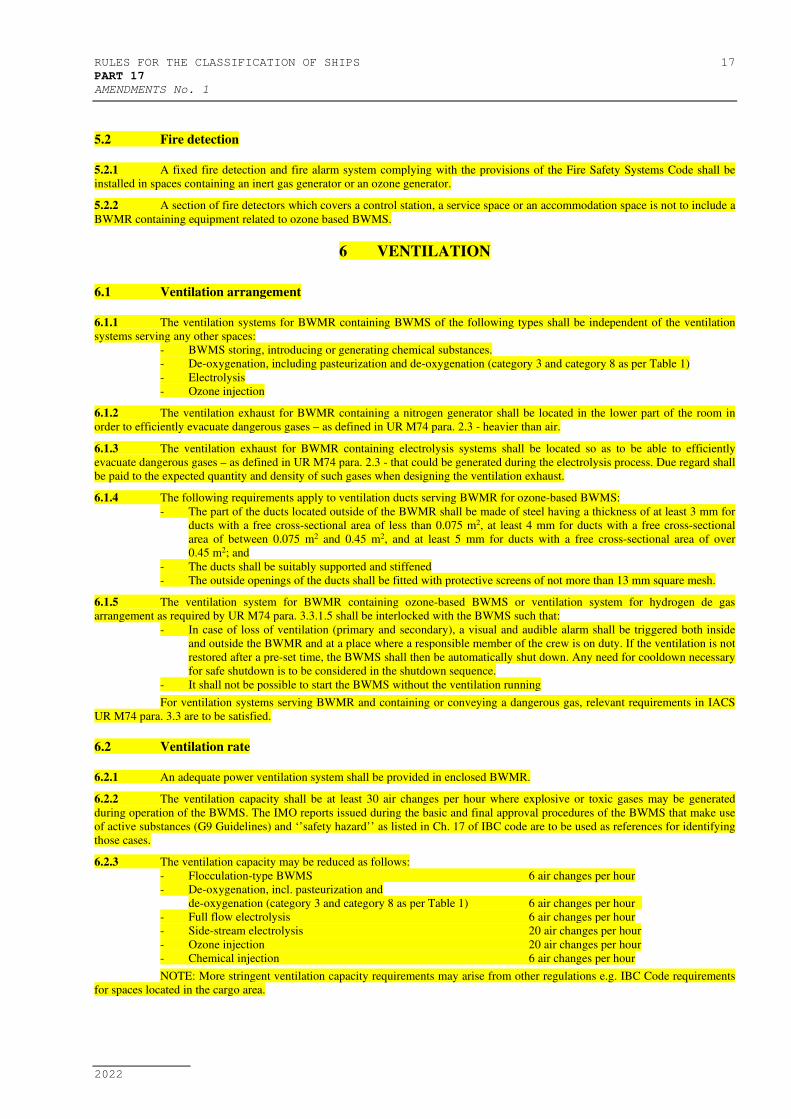
5.2 Fire detection
5.2.1 A fixed fire detection and fire alarm system complying with the provisions of the Fire Safety Systems Code shall be
installed in spaces containing an inert gas generator or an ozone generator.
5.2.2 A section of fire detectors which covers a control station, a service space or an accommodation space is not to include a
BWMR containing equipment related to ozone based BWMS.
6 VENTILATION
6.1 Ventilation arrangement
6.1.1 The ventilation systems for BWMR containing BWMS of the following types shall be independent of the ventilation
systems serving any other spaces:
- BWMS storing, introducing or generating chemical substances.
- De-oxygenation, including pasteurization and de-oxygenation (category 3 and category 8 as per Table 1)
- Electrolysis
- Ozone injection
6.1.2 The ventilation exhaust for BWMR containing a nitrogen generator shall be located in the lower part of the room in
order to efficiently evacuate dangerous gases – as defined in UR M74 para. 2.3 - heavier than air.
6.1.3 The ventilation exhaust for BWMR containing electrolysis systems shall be located so as to be able to efficiently
evacuate dangerous gases – as defined in UR M74 para. 2.3 - that could be generated during the electrolysis process. Due regard shall
be paid to the expected quantity and density of such gases when designing the ventilation exhaust.
6.1.4 The following requirements apply to ventilation ducts serving BWMR for ozone-based BWMS:
- The part of the ducts located outside of the BWMR shall be made of steel having a thickness of at least 3 mm for
ducts with a free cross-sectional area of less than 0.075 m2, at least 4 mm for ducts with a free cross-sectional
area of between 0.075 m2 and 0.45 m2, and at least 5 mm for ducts with a free cross-sectional area of over
0.45 m2; and
- The ducts shall be suitably supported and stiffened
- The outside openings of the ducts shall be fitted with protective screens of not more than 13 mm square mesh.
6.1.5 The ventilation system for BWMR containing ozone-based BWMS or ventilation system for hydrogen de gas
arrangement as required by UR M74 para. 3.3.1.5 shall be interlocked with the BWMS such that:
- In case of loss of ventilation (primary and secondary), a visual and audible alarm shall be triggered both inside
and outside the BWMR and at a place where a responsible member of the crew is on duty. If the ventilation is not
restored after a pre-set time, the BWMS shall then be automatically shut down. Any need for cooldown necessary
for safe shutdown is to be considered in the shutdown sequence.
- It shall not be possible to start the BWMS without the ventilation running
For ventilation systems serving BWMR and containing or conveying a dangerous gas, relevant requirements in IACS
UR M74 para. 3.3 are to be satisfied.
6.2 Ventilation rate
6.2.1 An adequate power ventilation system shall be provided in enclosed BWMR.
6.2.2 The ventilation capacity shall be at least 30 air changes per hour where explosive or toxic gases may be generated
during operation of the BWMS. The IMO reports issued during the basic and final approval procedures of the BWMS that make use
of active substances (G9 Guidelines) and ‘’safety hazard’’ as listed in Ch. 17 of IBC code are to be used as references for identifying
those cases.
6.2.3 The ventilation capacity may be reduced as follows:
- Flocculation-type BWMS 6 air changes per hour
- De-oxygenation, incl. pasteurization and
de-oxygenation (category 3 and category 8 as per Table 1) 6 air changes per hour
- Full flow electrolysis 6 air changes per hour
- Side-stream electrolysis 20 air changes per hour
- Ozone injection 20 air changes per hour
- Chemical injection 6 air changes per hour
NOTE: More stringent ventilation capacity requirements may arise from other regulations e.g. IBC Code requirements
for spaces located in the cargo area.
18 RULES FOR THE CLASSIFICATION OF SHIPS
PART 17
AMENDMENTS No. 1
2022
7 PERSONAL EQUIPMENT
7.1.1 Suitable protection equipment shall be available onboard for the protection of the crew members who are engaged in
the servicing, maintenance and repair of BWMS storing, introducing or generating chemicals, as recommended by the product
manufacturers. The protection equipment shall consist of large aprons, special gloves with long sleeves, suitable footwear, coveralls
of chemical-resistant materials, and tight fitting goggles or face shields or both. The protective clothing and equipment shall cover all
skin so that no part of the body is unprotected. This protection equipment is to be provided separately without taking into account
equipment required by other mandatory requirements.
7.1.2 Work clothes and protective equipment shall be kept in easily accessible places and in special lockers. Such equipment
shall not be kept within accommodation spaces, with the exception of new, unused equipment and equipment which has not been
used since undergoing a thorough cleaning process. Notwithstanding the above, storage rooms for such equipment within
accommodation spaces if adequately segregated from living spaces such as cabins, passageways, dining rooms, bathrooms, etc.
7.1.3 When a BWMS storing, introducing or generating chemicals is installed on board, suitably marked decontamination
showers and an eyewash shall be available in a convenient location in close proximately to the BWMS and the chemical store
room(s).
7.1.4 An emergency escape breathing apparatus (EEBD) is to be provided in the BWMR. This emergency escape breathing
apparatus may be one of the EEBDs provided in accordance with the requirements of SOLAS II-2/13.
An EEBD need not be required for BWMS of category 1 as per Table 1.
7.1.5 A personal ozone detector, calibrated as per the manufacturer’s specifications, shall be provided for each person
engaged in the servicing, maintenance and repair of BWMS utilizing ozone.
7.1.6 A two-way portable radiotelephone apparatus dedicated for the BWMS service, maintenance and repair shall be
provided, in addition to those required by SOLAS for fire-fighting purposes. This two-way radiotelephone apparatus is to be properly
identified in order to avoid mix-up with the apparatus intended for fire-fighting operations. Where the BWMS may release explosive
gases, this two-way radiotelephone apparatus shall be of a certified safe type suitable for use in zone 1 hazardous areas, as defined in
IEC Publication 60079. Where the BWMS stores, utilizes or introduces chemicals, the apparatus shall undergo deep cleaning or de-
contamination after use.
A two-way portable radiotelephone apparatus need not be required for BWMS of category 1 as per Table 1.