nasa's role in development of composite materials - core
TRANSCRIPT
April 2019
NASA/CR–2019-220267 Volume I
Structural Framework for Flight I: NASA’s Role in Development of Advanced Composite Materials for Aircraft and Space StructuresFinal Report
Darrel R. Tenney and John G. Davis, Jr. Analytical Services & Materials, Inc., Hampton, Virginia
Norman J. Johnston Technical Consultant, Buena Vista, Colorado
R. Byron PipesPurdue University, West Lafayette, Indiana
Jack F. McGuire Technical Consultant, Seattle, Washington
https://ntrs.nasa.gov/search.jsp?R=20190002561 2019-08-30T21:33:55+00:00Z
NASA STI Program . . . in Profile
Since its founding, NASA has been dedicated to the advancement of aeronautics and space science. The NASA scientific and technical information (STI) program plays a key part in helping NASA maintain this important role.
The NASA STI program operates under the auspices of the Agency Chief Information Officer. It collects, organizes, provides for archiving, and disseminates NASA’s STI. The NASA STI program provides access to the NTRS Registered and its public interface, the NASA Technical Reports Server, thus providing one of the largest collections of aeronautical and space science STI in the world. Results are published in both non-NASA channels and by NASA in the NASA STI Report Series, which includes the following report types:
• TECHNICAL PUBLICATION. Reports ofcompleted research or a major significant phase ofresearch that present the results of NASAPrograms and include extensive data or theoreticalanalysis. Includes compilations of significantscientific and technical data and informationdeemed to be of continuing reference value.NASA counter-part of peer-reviewed formalprofessional papers but has less stringentlimitations on manuscript length and extent ofgraphic presentations.
• TECHNICAL MEMORANDUM.Scientific and technical findings that arepreliminary or of specialized interest,e.g., quick release reports, workingpapers, and bibliographies that contain minimalannotation. Does not contain extensive analysis.
• CONTRACTOR REPORT. Scientific andtechnical findings by NASA-sponsoredcontractors and grantees.
• CONFERENCE PUBLICATION.Collected papers from scientific and technicalconferences, symposia, seminars, or othermeetings sponsored or co-sponsored by NASA.
• SPECIAL PUBLICATION. Scientific,technical, or historical information from NASAprograms, projects, and missions, oftenconcerned with subjects having substantialpublic interest.
• TECHNICAL TRANSLATION.English-language translations of foreignscientific and technical material pertinent toNASA’s mission.
Specialized services also include organizing and publishing research results, distributing specialized research announcements and feeds, providing information desk and personal search support, and enabling data exchange services.
For more information about the NASA STI program, see the following:
• Access the NASA STI program home page athttp://www.sti.nasa.gov
• E-mail your question to [email protected]
• Phone the NASA STI Information Desk at757-864-9658
• Write to:NASA STI Information DeskMail Stop 148NASA Langley Research CenterHampton, VA 23681-2199
Langley Research Center Prepared for Langley Research Center Hampton, Virginia 23681-2199 under Contract NNL09AA1Z
April 2019
NASA/CR–2019-220267 Volume I
Structural Framework for Flight I: NASA’s Role in Development of Advanced Composite Materials for Aircraft and Space StructuresFinal Report
Darrel R. Tenney and John G. Davis, Jr. Analytical Services & Materials, Inc., Hampton, Virginia
Norman J. Johnston Technical Consultant, Buena Vista, Colorado
R. Byron PipesPurdue University, West Lafayette, Indiana
Jack F. McGuire Technical Consultant, Seattle, Washington
National Aeronautics and Space Administration

Available from:
NASA STI Program / Mail Stop 148 NASA Langley Research Center
Hampton, VA 23681-2199 Fax: 757-864-6500
The use of trademarks or names of manufacturers in this report is for accurate reporting and does not constitute an official endorsement, either expressed or implied, of such products or manufacturers by the National Aeronautics and Space Administration.
Copyright © 2017The U.S. Government, and others acting on its behalf, has a paid-up, nonexclusive, irrevocable, worldwide license to reproduce, prepare derivative works, distribute copies to the public, and perform publicly and display publicly by or on behalf of the Government.
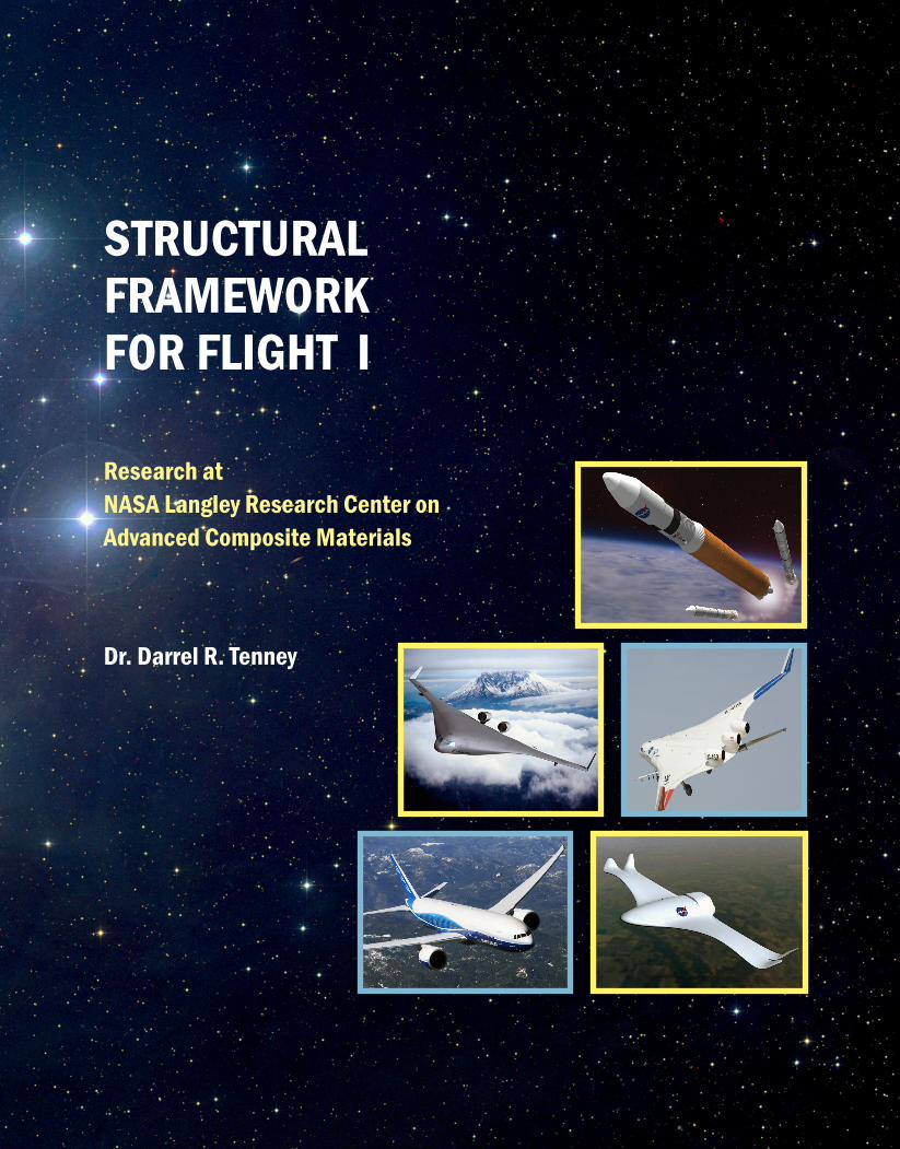
STRUCTURALFRAMEWORKFOR FLIGHT I
STRUCTURAL FRAMEW
ORK FOR FLIGHT I
Research at NASA Langley Research Center onAdvanced Composite Materials
Dr. Darrel R. Tenney
Composite M
aterials
Structural Framework for Flight I: NASA’s Role in Development of Advanced Composite Materials
For Aircraft and Space Structures
By
Dr. Darrel R. Tenney, Dr. John G. Davis, Jr., Dr. Norman Johnston,
Dr. R. Byron Pipes, and Mr. Jack F. McGuire
Structural Framework for Flight ii
A C K N O W L E D G E M E N T S The authors acknowledge the NASA Langley Research Center for its support of this effort. A special thanks to Dr. Charles E. Harris, Dr. Richard D. Young, and Karen S. Whitley of Langley Research Center for their support, critique, helpful suggestions, and technical input. A special thanks also to Ms. Jean Lankes of AS&M for her dedicated support in preparing this Monograph. Also, a special thanks to Dr. Jalaiah Unnam President of Analytical Services and Materials for his support and help in this effort. A special thanks also to Dr. Joseph Heyman for drafting the NDE section and to Dr. William H. Prosser for his support of the effort to draft the NDE Section. Also, we acknowledge and thank Dr. Philip Young for his contributions to the chemical characterization parts of this monograph. Appreciation is also expressed to Mr. Kenneth Matthew Tappan for the excellent work and support he provided during the literature research phase of this effort. I also want to acknowledge the dedicated support and hard work of the AS&M technical team that labored many hours to research and draft the different sections of this monograph. Team member included Dr. Darrel R. Tenney, Dr. John G. Davis, Dr. Norman Johnston, Dr. Byron Pipes and Mr. Jack McGuire. I want to especially express thanks to Dr. Norm Johnston for his many hours of work to document the excellent contributions made by the outstanding polymer chemist and processing engineers that pioneered the development of numerous innovations in resin and composite development. Finally a tribute is given to all the NASA Langley Materials and Structures Scientist and Engineers, Aerospace Industry Contractors, and University Faculty and Students who contributed to the development of advanced composites in support of National Aeronautics and Space Administration Programs. Recognition also goes to the technicians who performed much of the experimental work, and to the shop personnel at Langley that fabricated composite test specimens and fixtures over the past four decades of composite development at NASA Langley Research Center. Dr. Darrel R. Tenney Hampton, Virginia February 9, 2017 Copyright © 2017 The use of trademarks or names of manufacturers in this publication is for accurate reporting and does not constitute an official endorsement, either expressed or implied, of such products or manufacturers by Analytical Services & Materials, Inc., or the National Aeronautics and Space Administration. Boeing photos on cover used with permission.
Preface
Structural Framework for Flight iii
P R E FA C E This document is intended to serve several purposes. First, as a source of collated information on Composite Research over the past four decades at National Aeronautics and Space Administration (NASA) Langley Research Center, it serves as a key reference for readers wishing to grasp the underlying principles and challenges associated with developing and applying advanced composite materials to new aerospace vehicle concepts. Second, it identifies the major obstacles encountered in developing and applying composites on advanced flight vehicles, as well as lessons learned in overcoming these obstacles. Third, it points out current barriers and challenges to further application of composites to planned and future vehicles. This is extremely valuable for steering research in the future, when new breakthroughs in new materials or processing science may eliminate/minimize some of the critical barriers that have traditionally blocked the expanded application of composite to new structural or revolutionary vehicle concepts. Finally, a review of past work and identification of future challenges will hopefully inspire new research opportunities and development of revolutionary materials and structural concepts to revolutionize future flight vehicles. The specific objectives of this Structural Framework for Flight: NASA’s Role in Development of Composite Materials for Aircraft and Space Structures monograph are:
1. Knowledge Capture – The intent is to capture and distill into one document, selected examples of the major advancements made to the composite materials knowledge base, generated in the nearly four decades of research performed at the Langley Research Center or under Langley-sponsored grants and contracts. From 1970 through 2010, NASA’s Structures and Materials research on composites was aimed at developing the foundational technologies required to mature composite materials to the point where they could be certified for primary load-carrying aircraft and spacecraft structures. The goal was to improve performance and reduce weight and cost of aerospace vehicles and spacecraft. Thousands of technical reports on the results of NASA’s research were published in the open literature, and many thousands of technical talks were presented at national and international meetings. These reports and talks were authored by: NASA researchers, academic researchers working on NASA-sponsored grants and cooperative agreements, research partners in other government research laboratories, and industry researchers working on NASA-sponsored contracts. Although several books have been published on NASA’s contributions to Aerodynamics and Flight Systems, this is the first attempt at performing and documenting a comprehensive knowledge capture of the Structures and Materials Research on Advanced Composite Materials performed and/or sponsored by Langley.
2. Lessons Learned – During the course of these forty years of research on composite,
many lessons were learned on both the methods and approaches used in the conduct of the research, and the principal findings coming from this research. In this study, emphasis was placed on both identification of the lessons learned and on identifying the primary
Preface
Structural Framework for Flight iv
factors which either contributed to successful completion of research objectives or failure to meet planned milestones.
3. Assessment of Technology Readiness – The study assessed the technology
readiness of composites for application to innovative new vehicle concept, and potential new uses for space exploration or new space science instruments. This information is valuable for selection of highest payoff projects for funding.
4. Identification of Grand Challenges for the Future – This study identified the
major technical challenges remaining to be solved for expanded use of lightweight composite structures for future advanced concept air vehicles, advanced space launch vehicles, and high-performance space hardware for space science and space exploration missions.
This monograph is organized to look at: the successful application of composites on aircraft and space launch vehicles, the role of NASA in enabling these applications for each different class of flight vehicles, and a discussion of the major advancements made in discipline areas of research. In each section, key personnel and selected references are included. These references are intended to provide additional information for technical specialists and others who desire a more in-depth discussion of the contributions. Also in each section, lessons learned and future challenges are highlighted to help guide technical personnel either in the conduct or management of current and future research projects related to advanced composite materials.
Note: An electronic version of this publication is available from NASA and contains (1) hyperlinks to key articles and (2) additional information not included in this printed version due to page limitations.
Executive Summary of Composite Research at NASA Langley
Structural Framework for Flight v
E X E C U T I V E S U M M A R Y O F C O M P O S I T E R E S E A R C H AT NASA L A N G L E Y
By all accounts the composite research conducted at Langley Research Center over the past four decades has been judged to be outstanding in its contributions to the application of advanced composite materials to aerospace systems and to the fundamental understanding that has enhanced application of composites to non-aerospace applications. In this document, the authors have attempted to identify the major contributions and lessons learned in the conduct of both focused and base research on composite materials and structures at Langley Research Center. Although this has been a daunting task, they have captured and distilled valuable information on the composites research programs implemented and the impact of this research. Some of this information comes from the collective experience of the authors, who spent much of their professional career either directly conducting research on composites or managing composite-related research projects and/or programs. Much additional insight was gained from an exhaustive study of the literature and contract reports generated on Langley-funded research projects. Also, valuable information and crucial insight was provided by retired and current researchers engaged in projects where composite structure was a key technology area. The lessons learned in this section are presented in more detail in the different sections of the document. In most cases, the authors have attempted to synthesize the multiple lessons learned from all the different sections of this monograph into a higher-level look at the key knowledge gained from this study. However, these top-level comments are not intended to supplant the more detailed comments presented at the end of each section. Based on the results of this examination of the composite materials and structures research, the grand challenges for the expanded utilization of advanced composites in near term vehicle applications and the longer-term application of advanced composite structures to revolutionary new aircraft and launch vehicle concepts, have been identified. These challenges are based upon lessons learned, and are intended to provide guidance to technical personnel and management in the planning and execution of current and future research projects related to advanced composite materials. Major Contributions
1. Flight Service – Langley provided leadership and stimulus to the commercial aircraft industry, airline operators, and the Federal Aviation Administration (FAA) for the application of advanced composites on commercial aircraft. This was accomplished through the building and long-term flight-testing of secondary structural components. A key element of this success was building a strong partnership between NASA, industry, and the FAA in the conduct of the research, and the validation of the flight-worthiness of composite structures in real flight service.

Executive Summary of Composite Research at NASA Langley
Structural Framework for Flight vi
2. Educated Workforce – Langley proactively worked with universities to develop composite education programs at the graduate level to provide an educated workforce in the emerging disciplines necessary to advance composite technologies. Graduates of these programs were hired by NASA, industry, and other government agencies, and became major contributors to the development of composites. A specific example of the success of this effort is the NASA-Virginia Tech Composites Program.
3. Foundational Technology Base – Langley Research and Development (R&D) Base and Focused programs were the primary source of the foundational technology base required to commit to the use of composites in aircraft and space launch vehicle primary structures. This included a fundamental understanding of materials behavior, fabrication technologies, test methods, inspection methodologies, structural analyses, and environmental effects. Testing articles ranged from coupons to built-up structural components as large as the 40-ft. semi-span wing.
4. Support for Development of Airworthiness – Solutions to technical problems that posed an issue for flight safety were developed by Langley in close cooperation with the FAA. This included development of test standards, inspection criteria, analyses codes, and other methodologies to insure airworthiness of composite structures. FAA composite specialists were included on NASA’s advisory committees and in working groups.
5. Methodology to Predict Failure – Langley pioneered development of global/local analysis procedures combined with a “building block” approach to understand and predict the initiation and propagation of damage in composites. The scope of this work ranged from molecular-level modeling to finite element modeling of stress gradients in large built-up structural components.
6. Damage Tolerance – Langley developed a fundamental understanding of the relations between impact events and residual strength of composites. The importance of non-visible impact damage on compression strength led to the development of toughened resin systems which are in use today. The transition from brittle epoxies to toughened resins systems overcame a major barrier to the utilization of composite in primary aircraft structures. Also, Langley’s pioneering work on stitching demonstrated that the damage tolerance of built-up structure could be significantly improved by utilizing through-the-thickness stitching to suppress delamination and stiffener pull-off.
7. Environmental Effects – Langley R&D Base and Focused Programs were a primary source of the foundational technology base required to predict the effects of moisture, fuels, fluids, UV, and lightening on composites. The scope of this research included short-term and multiyear exposure to ground, flight and space (LDEF) experiments, residual strength tests, and development of analytical models to predict effects on material properties.
8. Synthesis of High-temperature Resins and Adhesives – Langley pioneered development of resins and adhesives for potential application to space vehicles, supersonic and high-speed aircraft. The research included molecular modeling, formulation, processing studies, and characterization. Numerous formulations have been registered under LARC™ and several of the phenylethynyl-terminated imide (PETI) series are available from commercial sources.

Executive Summary of Composite Research at NASA Langley
Structural Framework for Flight vii
9. Crashworthiness – Langley, in conjunction with the U.S. Army-Aerostructures Directorate, led the research on energy absorption of composite structures in aircraft and rotorcraft. Fundamental failure and crushing modes for subfloor structure were identified and graphite/epoxy structures were shown to be more efficient energy absorbers than aluminum. Crash qualification tests of the Bell and Sikorsky Advanced Composite Airframe Program (ACAP) helicopters and several all-composite general aviation aircraft were conducted in the NASA Langley Research Center Impact Dynamics Research Facility.
10. Automated Fabrication – NASA Langley provided leadership and support in the development and/or utilization of processes that lowered the costs and improved quality of composite structures. Major contributions included: development of the advanced stitching machine for the semi-span wing, use of textile weaving and braiding machines to build frames and panel inserts, modification of resin formulations to accommodate tow placement, and modeling of resin infusion processes. Methods used to fabricate parts of the B787 and A380 can be traced to these advancements.
11. Quantitative Nondestructive Evaluation (NDE) – Langley has been a leader in this technical area and worked with Industry and the FAA to identify the appropriate NDE techniques to establish airworthiness of aircraft composite components. Langley pioneered the development of physics based modeling to enable predictive capability of NDE technologies in the fields of radiography, ultrasonics, thermography, electromagnetics, and optics. Langley established a microfocus X-ray CT system with 12.5µm pixel resolution for imaging and quantifying porosity, stitching materials, inclusion, debonding, material loss and other microscopic flaws.
12. Graphite Fiber Risk Analyses – Langley led a national program to assess the potential impact of graphite fibers that could be released from a civil aircraft accident. The potential commercial, legal, and military effects were thought to be enormous and had the potential to prevent the future application of composites to civil aircraft. Langley staff conducted a three-year analytical and experimental investigation that provided sound scientific bases which indicated that the threat was not a problem.
Major Lessons Learned Langley conducted an extremely productive R&D program on advanced composite materials over the past forty years. Following are the major lessons learned.
1. Leadership – Key leaders at Langley (Richard Heldenfels) and NASA Headquarters (Allen Lovelace) had the foresight to recognize that in 1970, composites was a revolutionary new technology (a new S Curve) with the potential to significantly improve the performance of aerospace structures. They also made a commitment of a critical mass of personnel and resources to a new emerging technology. Both of these actions were essential to making significant contributions in a timely manner.
Executive Summary of Composite Research at NASA Langley
Structural Framework for Flight viii
2. Sustained Commitment – Langley was able to sustain a healthy R&D program in composites for nearly four decades by: a) Having an excellence in research and a long track record of positive
accomplishments b) Engaging in industry, universities and other government agencies as partners in
planning and implementing the research c) Practicing excellent project management: meeting milestones and deliverables on
time and within budget d) Working with NASA-level advisory committees to achieve agency budget
priority and technical level advisory committees for guidance and technical critique of work
3. Model for Success – An implementation model for success was a sustaining
Research and Technology (R&T) base program combined with focused technology projects. The combination of base and focused projects allowed the long-term problems to be addressed in the base program and the near-term higher Technology Readiness Level (TRL) R&D to be implemented with industry in the focused programs. The combination promoted an efficient use of funding, facilities, and personnel.
4. Proactive Education and Training – A proactive education (NASA-Virginia Tech
Composites Program plus others) and training thrust was a critical ingredient in advancing a new technology area. Langley personnel actively engaged in the formation and execution of new technical societies and technical subgroups to advance discipline-specific areas.
5. Multidisciplinary Research – A multidisciplinary approach was used to solve tough
technical issues typically beyond the scope of any single discipline. In particular, the interaction between polymer chemistry and structural mechanics proved to be very successful in solving damage tolerance issues.
6. Building Block Approach – This approach was used to accurately predict failure of
complex built up structure. The combination of analytical modeling to predict failure and experimental validation tests was a critical ingredient in the success of the building block approach championed by Langley.
7. Structural Analyses – Development of new analyses codes and capabilities were a
critical ingredient in gaining new insights and fundamental understanding of new phenomena in a new technology area. Executing existing codes was no longer sufficient. Projected future increases in computational power and speed will enable development of new analyses codes to address ever more complex stress states.
8. Bridging Technologies – Synergy with neighboring disciplines proved to be a
successful approach for integrating new ideas and solutions into the composite research. Specific examples include the use of algorithms developed by the pharmaceutical industry for molecular modeling and the use of technologies

Executive Summary of Composite Research at NASA Langley
Structural Framework for Flight ix
developed by the textile industry for the weaving, braiding, and stitching of graphite preforms.
9. Uncertainty Planning – None of the composite projects were fully funded to the
original plan. Major intermediate milestones need to be planned with this in mind so that major accomplishments can still be made if the projects gets re-planned or terminated. These accomplishments can provide a basis for future planning and advocating for additional funding.
10. Archiving Data – A plan and process to secure and archive key data needs to be an
integral part of any project plan. The common practice of “handing off” key data, test procedures, or other critical information to the next researcher on the project was not effective for archiving data. Changes in personnel assignments, transfers, and periodic “building clean-up” lead to loss of data, test specimens, and in some cases, test fixtures.
11. Personnel Mobility – An environment that encourages movement of researchers to
and from base and focused R&D programs without prejudice is needed. 12. New Challenges – Langley must reenergize the structures and materials research
disciplines to meet future challenges and opportunities associated with the stringent performance and safety requirements of tomorrow’s revolutionary vehicle concepts. A “Grand Challenges” planning team needs to search out new technologies for the next “S Curve” opportunity and identify payoff necessary to advocate for new initiatives.
Grand Challenges Section 18 of this monograph contains a discussion of nine different “Grand Challenges” which include:
1. Certification by analyses 2. Materials by design: multi-scale modeling and measurements 3. High fidelity failure prediction: micro and nanoscopic mechanisms 4. Realize benefits of nanocomposites: multifunctional materials systems 5. Intelligent materials and structures: larger, more integrated structure 6. Pervasive composite knowledge and learning: isotropic plasticity thinking 7. Reliability-based design 8. Non-autoclave, low pressure material systems 9. Research in the “Google Age”
Additional study of these challenges is recommended to identify the highest priority for advocating a new initiative in Structures and Materials. This initiative needs to be bold and offer a revolutionary advancement in structures for tomorrow’s air and space vehicles. A funding level of $40-50M/yr is required to aggressively pursue revolutionary new technology advancements with a critical mass of personnel and facilities.
Executive Summary of Composite Research at NASA Langley
Structural Framework for Flight x
Having stated that additional study is required on each of the above Grand Challenges, it is the belief of our team that Intelligent Nanoreinforced Composites is a strong candidate for the next major advancement in composites technology. Nanoreinforcement has the potential to increase mechanical properties by orders of magnitude. Nanoelectronics is an emerging new area and molecular computation is on the horizon. It is envisioned that the polymer matrix could contain “smart segments” that are capable of sensing, feeling, thinking, storing data, and reacting to changes in the environment. Composites could have smart skins that are capable of detecting even the slightest impact event and could record the magnitude of the event and transmit this data to an onboard smart system if significant damage begins to initiate and propagate from the impact site. The composite is not only a load carrying structure, it is a smart-sensing, responding structural system that enhances the performance and safety of the system as a whole. The leap from composites as we know them today to intelligent nanoreinforced composites is a new technology “S Curve” that Langley is well positioned to advocate and champion. This would reenergize the materials and structures disciplines in a way that is reminiscent of the radical transformation that occurred when Langley stopped work on aluminum structures to launch a major new effort to exploit the potential of graphite-reinforced resins in the early 1970s.
Note: An electronic version of this publication is available from NASA and contains (1) hyperlinks to key articles and (2) additional information not included in this printed version due to page limitations.
Contents
Structural Framework for Flight xi
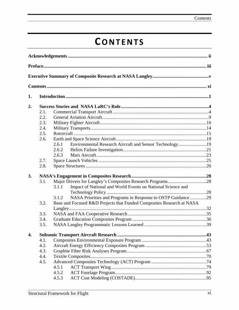
C O N T E N T S Acknowledgements ....................................................................................................................... ii
Preface ........................................................................................................................................... iii
Executive Summary of Composite Research at NASA Langley ................................................v
Contents ........................................................................................................................................ xi
1. Introduction ..........................................................................................................................1
2. Success Stories and NASA LaRC’s Role ...........................................................................4 2.1. Commercial Transport Aircraft ..................................................................................4 2.2. General Aviation Aircraft ...........................................................................................9 2.3. Military Fighter Aircraft ...........................................................................................10 2.4. Military Transports ...................................................................................................14 2.5. Rotorcraft .................................................................................................................15 2.6. Earth and Space Science Aircraft .............................................................................19
2.6.1 Environmental Research Aircraft and Sensor Technology ........................19 2.6.2 Helios Failure Investigation .......................................................................21 2.6.3 Mars Aircraft ..............................................................................................23
2.7. Space Launch Vehicles ............................................................................................25 2.8. Space Structures .......................................................................................................26
3. NASA’s Engagement in Composites Research ................................................................28 3.1. Major Drivers for Langley’s Composites Research Programs .................................28
3.1.1 Impact of National and World Events on National Science and Technology Policy .....................................................................................28
3.1.2 NASA Priorities and Programs in Response to OSTP Guidance ..............29 3.2. Base and Focused R&D Projects that Funded Composites Research at NASA
Langley .....................................................................................................................32 3.3. NASA and FAA Cooperative Research ...................................................................35 3.4. Graduate Education Composites Program ...............................................................36 3.5. NASA Langley Programmatic Lessons Learned .....................................................39
4. Subsonic Transport Aircraft Research ............................................................................43 4.1. Composites Environmental Exposure Program .......................................................43 4.2. Aircraft Energy Efficiency Composites Program ....................................................53 4.3. Graphite Fiber Risk Analyses Program ....................................................................67 4.4. Textile Composites ...................................................................................................70 4.5. Advanced Composites Technology (ACT) Program ...............................................74
4.5.1 ACT Transport Wing .................................................................................79 4.5.2 ACT Fuselage Program..............................................................................92 4.5.3 ACT Cost Modeling (COSTADE).............................................................95
Contents
Structural Framework for Flight xii
4.5.4 Recent Advancement in Stitched Composites ...........................................96 4.6. Structures Investigation of the American Airlines Flight 587 Accident ................102
4.6.1 Introduction ..............................................................................................102 4.6.2 Review of Airbus A300-600 Certification ...............................................103 4.6.3 Model Development and Validation ........................................................104 4.6.4 Failure Scenario Development and Validation ........................................105 4.6.5 Confirmation of Most Likely Failure Scenario ........................................114 4.6.6 Failure Sequence Analysis .......................................................................118 4.6.7 Conclusions ..............................................................................................121
4.7. Lessons Learned and Future Direction ...................................................................122
5. Commercial Transport Application of Composite Materials ......................................124 5.1. Lessons Learned .....................................................................................................124
5.1.1 Design ......................................................................................................124 5.1.2 Manufacturing ..........................................................................................124 5.1.3 Airline Operations ....................................................................................124
5.2. Major Recent Advancements .................................................................................124 5.3. Emerging Challenges .............................................................................................124 5.4. Future Directions ....................................................................................................124
6. Supersonic Transport Research ......................................................................................125 6.1. Historical Background ............................................................................................125 6.2. SCAR Program .......................................................................................................129 6.3. High Speed Research (HSR) Program ...................................................................138
6.3.1 Introduction ..............................................................................................139 6.3.2 Resin/Composite Development ...............................................................140 6.3.3 Scale-up Application and Test .................................................................141 6.3.4 Aging Studies ...........................................................................................142 6.3.5 Structures .................................................................................................148
6.4. Fundamental Aero Supersonic Project ...................................................................154 6.5. Lessons Learned and Future Direction ...................................................................157
7. General Aviation ..............................................................................................................158 7.1. Beech Starship ........................................................................................................158 7.2. Advanced General Aviation Transport Experiments Composites .........................159 7.3. Lesson Learned and Future Direction ....................................................................168
8. Rotorcraft ..........................................................................................................................169 8.1. Crashworthiness .....................................................................................................169 8.2. Energy Absorption Materials and Concepts ...........................................................171 8.3. Lessons Learned and Future Direction ...................................................................176
9. Launch Vehicles ................................................................................................................177 9.1. Shuttle Cargo Bay Doors ........................................................................................178 9.2. Composite for Advanced Space Transportation Systems (CASTS) ......................179 9.3. Composite Cryotanks .............................................................................................183
Contents
Structural Framework for Flight xiii
9.3.1 State-of-the-Art USAF DC-X and NASA Contributions with the DC-XA .....................................................................................................184
9.3.2 NASA Technology Development Structural Tests Related to Use of Composites on a Future RLV ..................................................................184
9.3.3 The NASA X-33 Vehicle and Composite Cryotanks ..............................186 9.3.4 Failure of the Composite Cryotank: Microcracking and Other
Causes ......................................................................................................189 9.4. Ares I and Ares V Launch Vehicles .......................................................................194 9.5. Composite Crew Module .......................................................................................199 9.6. Lessons Learned and Future Direction ...................................................................202
10. Space Materials and Structures ......................................................................................204 10.1. Space Materials Development ................................................................................204 10.2. Space Structures .....................................................................................................205 10.3. Space Environmental Effects .................................................................................206 10.4. Dimensional Stability of Composites .....................................................................208 10.5. The Long Duration Exposure Facility (LDEF) ......................................................210 10.6. Lessons Learned and Future Direction ...................................................................215
11. High-Temperature Polymer Technology Developed at NASA Langley .....................216 11.1. Fiber and Resin Development Timelines ...............................................................217 11.2. Early Days and the Building of a New Group .......................................................219 11.3. Background in High-temperature Polymers ...........................................................222 11.4. Pursuit of Thermally Stable Polymers at LaRC: The Start ....................................226 11.5. Composite Matrix Research: Successes and Failures! The Continuation ..............229
11.5.1 Linear Thermoplastics .............................................................................229 11.5.2 Lightly Cross-Linked Thermoplastics .....................................................240 11.5.3 Heavily Cross-linked Thermosets ............................................................242
11.6. High Speed Research Program: Resins and Composite Development: The Fulfillment ..............................................................................................................245 11.6.1 Introduction and Target Properties ..........................................................245 11.6.2 Initial Candidates and Screening Protocol ...............................................247 11.6.3 The Early PETI Candidates: LARC™-PETI-1 and LARC™-PETI-2 ....249 11.6.4 The Candidates: LARC™-PETI-4, LARC™-8515, and LARC™-
PETI-5 ......................................................................................................250 11.6.5 Fabrication Processes for LARC™-PETI-5. ...........................................256 11.6.6 HSR Adhesives ........................................................................................259 11.6.7 HSR Databases .........................................................................................262
11.7. Adhesives and Other Applications .........................................................................263 11.8. Polymer Characterization: 1962-1995 ...................................................................265 11.9. Lessons Learned and Future Direction ...................................................................271
11.9.1 Lessons Learned .......................................................................................271 11.9.2 Future Activities .......................................................................................272
12. Composite Fabrication Technology ................................................................................284 12.1. Fabrication Technology Timeline and Overview ...................................................284 12.2. Variables in the Fabrication of High-performance Composites .............................285
Contents
Structural Framework for Flight xiv
12.3. Liquid Molding or Resin Infusion Processes for Epoxies ......................................286 12.4. Placement Methods for Prepregging Continuous Fiber .........................................286 12.5. Out-of-Autoclave Placement Methods: Robotic Dry Tape/Tow Placement ..........288 12.6. Powder-Coating[34-64] ..............................................................................................294 12.7. Powder-coated Textile Forms[65-72] ........................................................................298 12.8. Ribbonizing[82-102] ...................................................................................................300 12.9. E-beam Curing With Automated Tow Placement[103-105] .......................................304 12.10. Induction Heating[108-114] ........................................................................................307 12.11. Cost Factors in ATP ...............................................................................................309 12.12. Miscellaneous Processing Techniques ...................................................................311 12.13. Resin Infusion Processing of Polyimides ...............................................................312
12.13.1 Background, Tooling, and Resin Requirements ......................................312 12.13.2 Initial Research ........................................................................................315 12.13.3 New HT-VARTM Resins ........................................................................315
12.14. Fiber Metal Laminates ...........................................................................................319 12.15. Lessons Learned and Future Directions .................................................................320
13. Nanotechnology ................................................................................................................329 13.1. Nanoreinforced Composites ...................................................................................329 13.2. Nanoreinforced Composites ...................................................................................330 13.3. Boron-nitride Nanotechnology – Recent Advancements .......................................339 13.4. Lesson Learned and Future Direction ....................................................................341
14. Non-Destructive Inspection .............................................................................................344 14.1. Evolution of Non-Destructive Investigation of Composites ..................................344 14.2. NDE Research at NASA Langley ..........................................................................346
14.2.1 Development of the Nondestructive Evaluation Science Branch ............346 14.2.2 LaRC Contributions to Quantitative NDE ...............................................347 14.2.3 Recent NDE Programs .............................................................................353
14.3. Lessons Learned and Future Directions .................................................................355
15. Damage Tolerance ............................................................................................................358 15.1. Understanding Damage Tolerance .........................................................................358 15.2. Damage Tolerance Research at Langley Research Center .....................................361
15.2.1 Effect of Impact on Compression Strength ..............................................361 15.2.2 Role of Resin Modulus; Desired Properties.............................................371
15.3. Delamination Mechanics ........................................................................................373 15.4. Progressive Failure Analyses Methodology ...........................................................379 15.5. Lessons Learned and Future Directions .................................................................379
16. Materials and Structural Mechanics ..............................................................................383 16.1. Historical Perspective of Composite Failure Analyses ..........................................383 16.2. Multi-scale Modeling .............................................................................................389 16.3. Buckling and Post-buckling Behavior ....................................................................391 16.4. Lessons Learned and Future Direction ...................................................................398
17. Structural Analyses ..........................................................................................................400
Contents
Structural Framework for Flight xv
17.1. Finite Element Methods .........................................................................................400 17.2. Tribute to Dr. James H. Starnes, Jr. .......................................................................404 17.3. Lessons Learned and Future Direction ...................................................................405
18. Grand Challenges in High-Performance Composite Materials and Structures Technology ........................................................................................................................408 18.1. Certification by Analyses .......................................................................................408 18.2. Materials by Design: Multi-scale Modeling and Measurements ...........................408 18.3. High-fidelity Failure Prediction: Micro and Nanoscopic Mechanisms..................409 18.4. Realize Benefits of Nanocomposites: Multifunctional Materials System .............411 18.5. Intelligent Materials and Structures: Larger, More Integrated Structure ...............413 18.6. Pervasive Composites Knowledge and Learning: Isotropic Plasticity
Thinking .................................................................................................................414 18.7. Reliability-based Design ........................................................................................416 18.8. Non-autoclave, Low Pressure Material Systems ....................................................417 18.9. Research in the “Google” Age ...............................................................................417
19. About The Authors ...........................................................................................................419
20. Appendix (Available in Electronic Version) ..................................................................422
Introduction
Structural Framework for Flight 1
1. I N T R O D U C T I O N
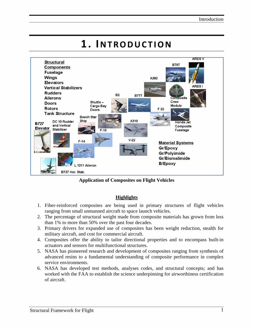
Application of Composites on Flight Vehicles
Highlights
1. Fiber-reinforced composites are being used in primary structures of flight vehicles ranging from small unmanned aircraft to space launch vehicles.
2. The percentage of structural weight made from composite materials has grown from less than 1% to more than 50% over the past four decades.
3. Primary drivers for expanded use of composites has been weight reduction, stealth for military aircraft, and cost for commercial aircraft.
4. Composites offer the ability to tailor directional properties and to encompass built-in actuators and sensors for multifunctional structures.
5. NASA has pioneered research and development of composites ranging from synthesis of advanced resins to a fundamental understanding of composite performance in complex service environments.
6. NASA has developed test methods, analyses codes, and structural concepts; and has worked with the FAA to establish the science underpinning for airworthiness certification of aircraft.
Introduction
Structural Framework for Flight 2
Composite materials have emerged as the materials of choice for increasing the performance and reducing the weight and cost of military aircraft, general aviation aircraft, transport aircraft, and space launch vehicles. Major advancements have been made in the ability to design, fabricate, and analyze large complex aerospace structures. Many different organizations worldwide have conducted research on composites over the past several decades. In the United States, research on composites has been a combined effort of government laboratories, universities, and industry. The development of high-performance composites for aerospace applications has been spearheaded by the major airframe companies (Boeing, Lockheed, Northrop Grumman, McDonald Douglass (now Boeing), General Dynamics, and others), and by NASA and DOD, with the FAA playing a critical role in the certification requirements for composite flight structures. Within NASA, Langley Research Center had the lead role for development of composites for airframe applications, and NASA Glenn had the lead role for development of high-temperature composites for aircraft engine applications. Development of composites for space structures has been worked by Langley, Glenn, Marshall Space Flight Center, Johnson Space Flight Center, Jet Propulsion Laboratory (JPL), and Goddard Space Flight Center. For space launch vehicles, Marshall, Langley, Glenn, Johnson Space Center (JSC), and Stennis Space Center have all participated in different aspects of the programs. However, in all of these programs, Langley had the lead role in the development of foundational composites technologies required to mature and identify high payoff applications for composites in air vehicle structures. The majority of this foundational technology development work was funded by the aeronautics program because of the demand to reduce both weight and cost of airframe structures for all classes of flight vehicles. The highlights of this research, along with selected examples to illustrate the major accomplishments, are presented in this monograph. Before discussing the NASA composite projects and the major accomplishments of those projects, a brief synopsis of different uses of composites in the aerospace sector are presented. The examples in the following section are for the purpose of illustrating the many successful applications of composites in commercial aircraft and space launch vehicles that were enabled in part by outstanding research performed by NASA Langley Research Center and its partners. The use of composites, to reduce the weight and cost of commercial aircraft structures and to improve the performance of military aircraft, is a great success story.

Introduction
Structural Framework for Flight 3
NASA Composite Pioneers
Benson Dexter
Elliot CramerHerman Bohon
James Starnes
Bryan Jenson
Mike Card Steve Scotti Bill WinfreeCharlie Blankenship Terry St. Clair
Charlie Harris George Brooks Sam Venneri Marvin Dow
Darrel Tenney Karen Jackson
Joe Heyman
John Davis
Lou Vosteen
Paul HergenrotherNorm Johnston
Dawn Jegley
Tom Gates Damodar AmburRob Bryant
Ivatury Raju
Kevin O’Brien
Mark Shuart
Vernon Bell
Martin Mikulas John Connell
Clarence Poe
Some of the structures and materials engineers and scientist who made major contributors to the development of composite materials at NASA Langley Research Center are shown in this chart. Many others also made major contributors to the successful development of composite materials and structures at NASA but are not shown because of the limited space available. However, the numerous references cited in this monograph recognize the importance of all of the NASA personnel that conducted research on composites.
Success Stories and NASA LaRC’s Role
Structural Framework for Flight 4
2. S U C C E S S S TO R I E S A N D NASA L A RC ’ S R O L E
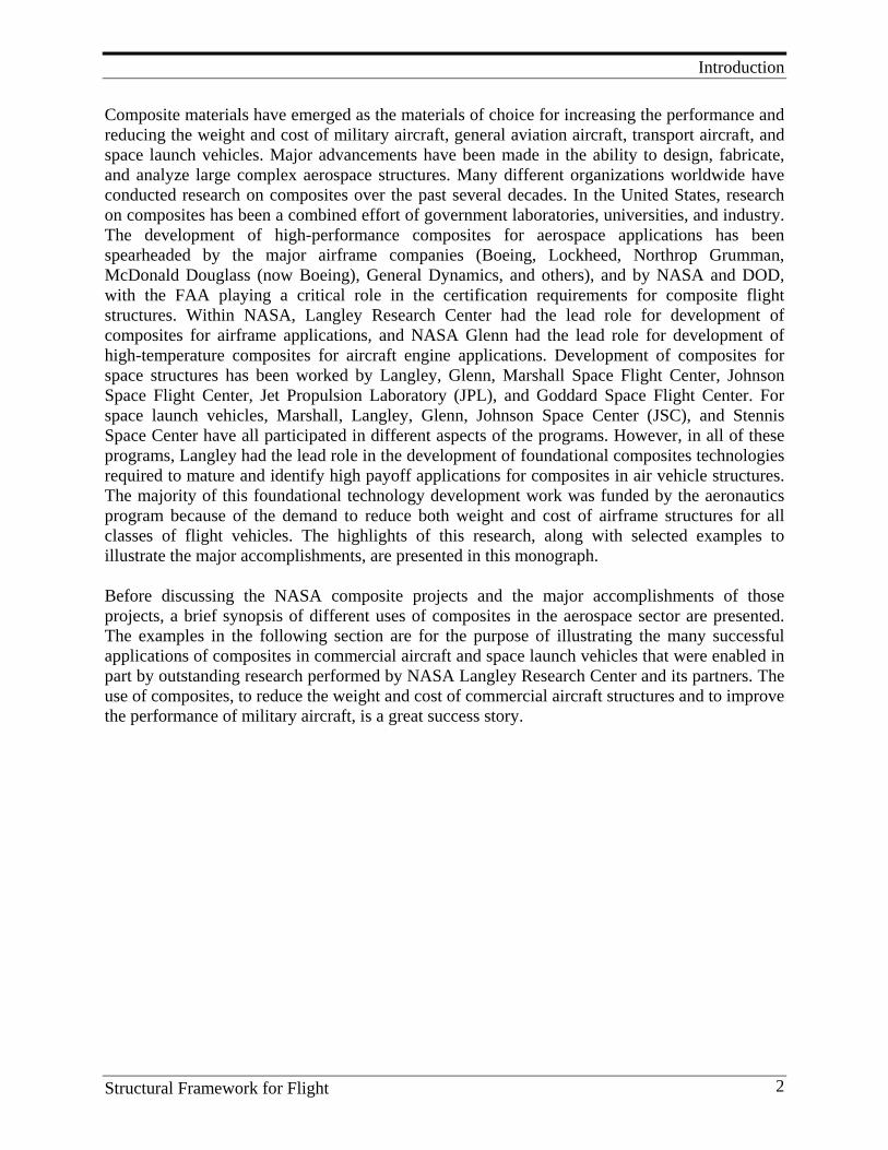
2.1. Commercial Transport Aircraft The recent efforts by Boeing and Airbus to incorporate composites into primary load-carrying structures of large commercial transports and to certify the airworthiness of these structures is evidence of the significant advancements made in the understanding and use of these materials in real world aircraft. The weight fraction of the structure made with composites is 50% for the new Boeing 787 – 100% composite on the “wet” or outer windswept surface. Figure 2.1-1 shows the percent of the structural weight built with composites for commercial transport aircraft.
Figure 2.1-1: Composites in Commercial Transport Aircraft
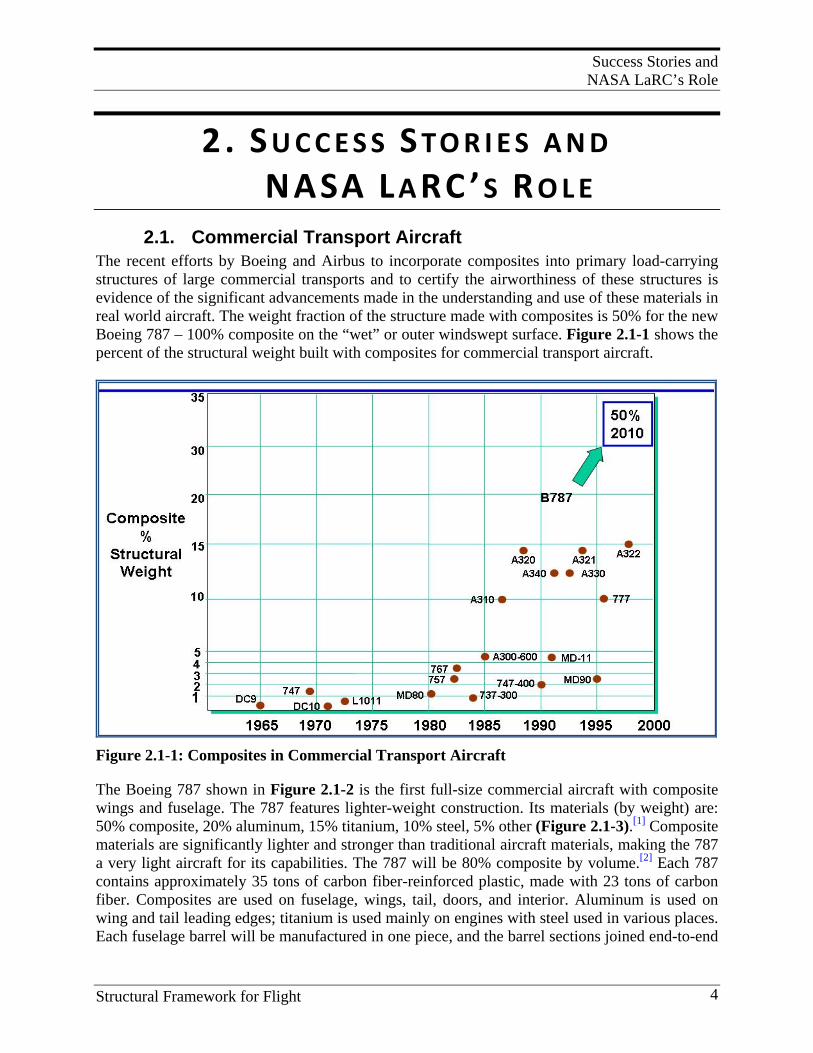
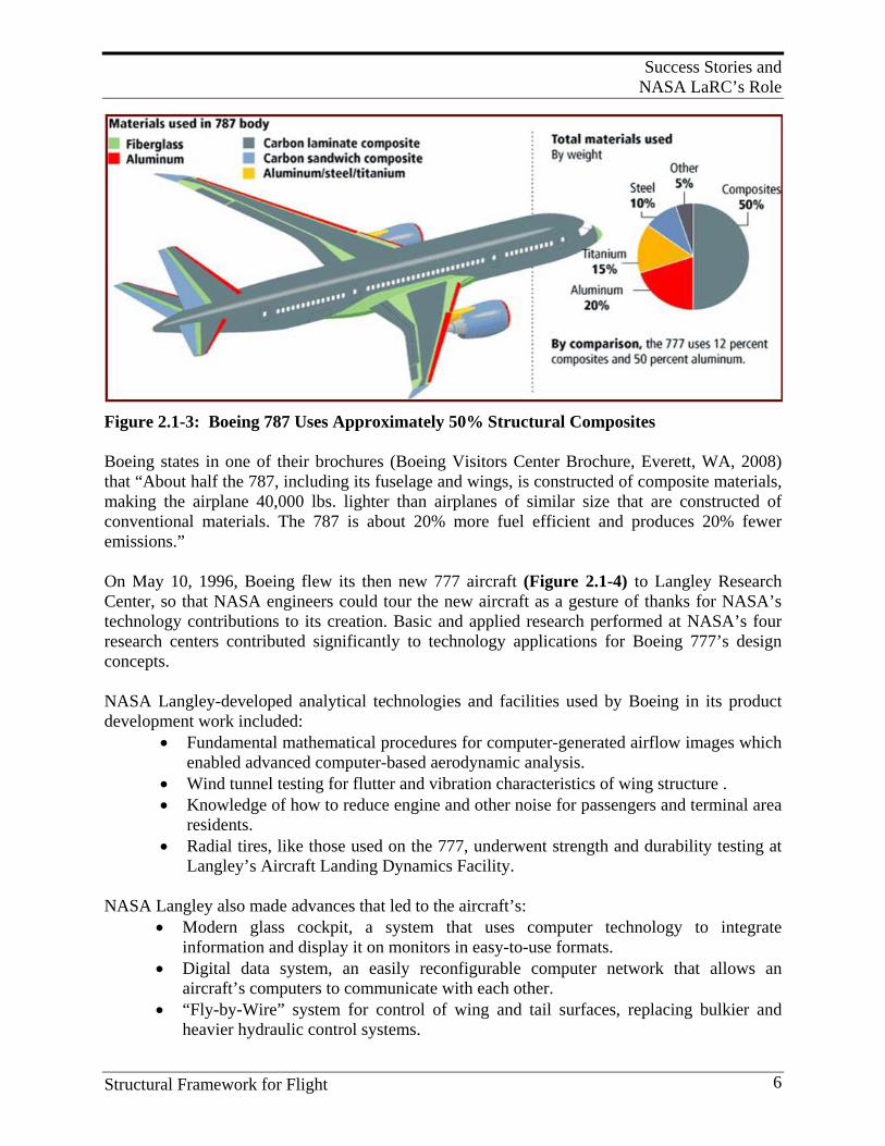
The Boeing 787 shown in Figure 2.1-2 is the first full-size commercial aircraft with composite wings and fuselage. The 787 features lighter-weight construction. Its materials (by weight) are: 50% composite, 20% aluminum, 15% titanium, 10% steel, 5% other (Figure 2.1-3).[1] Composite materials are significantly lighter and stronger than traditional aircraft materials, making the 787 a very light aircraft for its capabilities. The 787 will be 80% composite by volume.[2] Each 787 contains approximately 35 tons of carbon fiber-reinforced plastic, made with 23 tons of carbon fiber. Composites are used on fuselage, wings, tail, doors, and interior. Aluminum is used on wing and tail leading edges; titanium is used mainly on engines with steel used in various places. Each fuselage barrel will be manufactured in one piece, and the barrel sections joined end-to-end
Success Stories and NASA LaRC’s Role
Structural Framework for Flight 5
to form the fuselage. This will eliminate the need for about 50,000 fasteners used in conventional airplane building. According to the manufacturer, the composite is also stronger than aluminum, allowing a higher cabin pressure during flight at a lower weight.
Figure 2.1-2: Boeing 787 Commercial Transport Aircraft
When built, the 787-8 Dreamliner will carry 210-250 passengers on routes of 7,650 to 8,200 nautical miles (14,200 to 15,200 kilometers), while the 787-9 Dreamliner will carry 250-290 passengers on routes of 8,000 to 8,500 nautical miles (14,800 to 15,750 kilometers). A third 787 family member, the 787-3 Dreamliner, will accommodate 290-330 passengers and is optimized for routes of 2,500 to 3,050 nautical miles (4,600 to 5,650 kilometers).
Success Stories and NASA LaRC’s Role
Structural Framework for Flight 6
Figure 2.1-3: Boeing 787 Uses Approximately 50% Structural Composites Boeing states in one of their brochures (Boeing Visitors Center Brochure, Everett, WA, 2008) that “About half the 787, including its fuselage and wings, is constructed of composite materials, making the airplane 40,000 lbs. lighter than airplanes of similar size that are constructed of conventional materials. The 787 is about 20% more fuel efficient and produces 20% fewer emissions.” On May 10, 1996, Boeing flew its then new 777 aircraft (Figure 2.1-4) to Langley Research Center, so that NASA engineers could tour the new aircraft as a gesture of thanks for NASA’s technology contributions to its creation. Basic and applied research performed at NASA’s four research centers contributed significantly to technology applications for Boeing 777’s design concepts. NASA Langley-developed analytical technologies and facilities used by Boeing in its product development work included:
• Fundamental mathematical procedures for computer-generated airflow images which enabled advanced computer-based aerodynamic analysis.
• Wind tunnel testing for flutter and vibration characteristics of wing structure . • Knowledge of how to reduce engine and other noise for passengers and terminal area
residents. • Radial tires, like those used on the 777, underwent strength and durability testing at
Langley’s Aircraft Landing Dynamics Facility.
NASA Langley also made advances that led to the aircraft’s: • Modern glass cockpit, a system that uses computer technology to integrate
information and display it on monitors in easy-to-use formats. • Digital data system, an easily reconfigurable computer network that allows an
aircraft’s computers to communicate with each other. • “Fly-by-Wire” system for control of wing and tail surfaces, replacing bulkier and
heavier hydraulic control systems.
Success Stories and NASA LaRC’s Role
Structural Framework for Flight 7
• Increased use of lightweight aerospace composite structures for increased fuel efficiency and range
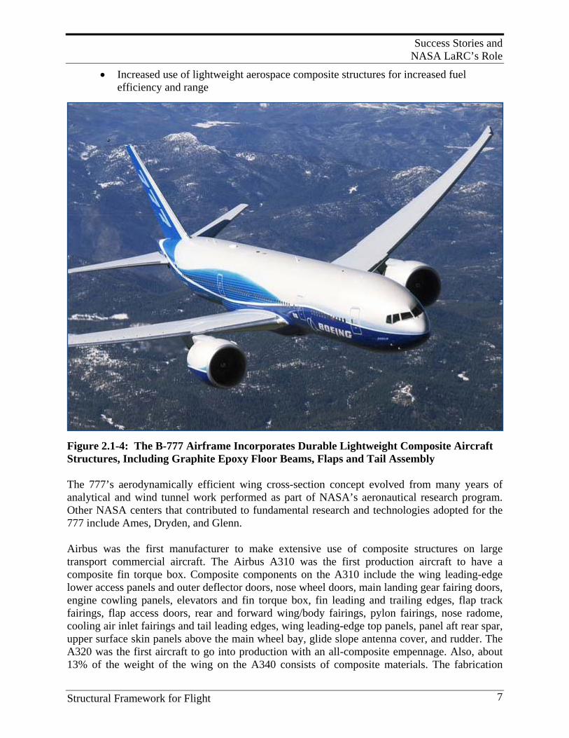
Figure 2.1-4: The B-777 Airframe Incorporates Durable Lightweight Composite Aircraft Structures, Including Graphite Epoxy Floor Beams, Flaps and Tail Assembly The 777’s aerodynamically efficient wing cross-section concept evolved from many years of analytical and wind tunnel work performed as part of NASA’s aeronautical research program. Other NASA centers that contributed to fundamental research and technologies adopted for the 777 include Ames, Dryden, and Glenn. Airbus was the first manufacturer to make extensive use of composite structures on large transport commercial aircraft. The Airbus A310 was the first production aircraft to have a composite fin torque box. Composite components on the A310 include the wing leading-edge lower access panels and outer deflector doors, nose wheel doors, main landing gear fairing doors, engine cowling panels, elevators and fin torque box, fin leading and trailing edges, flap track fairings, flap access doors, rear and forward wing/body fairings, pylon fairings, nose radome, cooling air inlet fairings and tail leading edges, wing leading-edge top panels, panel aft rear spar, upper surface skin panels above the main wheel bay, glide slope antenna cover, and rudder. The A320 was the first aircraft to go into production with an all-composite empennage. Also, about 13% of the weight of the wing on the A340 consists of composite materials. The fabrication
Success Stories and NASA LaRC’s Role
Structural Framework for Flight 8
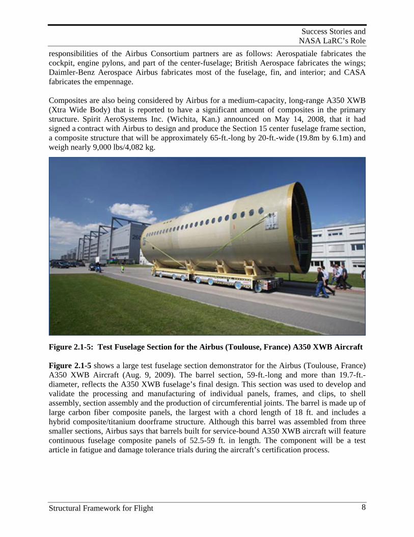
responsibilities of the Airbus Consortium partners are as follows: Aerospatiale fabricates the cockpit, engine pylons, and part of the center-fuselage; British Aerospace fabricates the wings; Daimler-Benz Aerospace Airbus fabricates most of the fuselage, fin, and interior; and CASA fabricates the empennage. Composites are also being considered by Airbus for a medium-capacity, long-range A350 XWB (Xtra Wide Body) that is reported to have a significant amount of composites in the primary structure. Spirit AeroSystems Inc. (Wichita, Kan.) announced on May 14, 2008, that it had signed a contract with Airbus to design and produce the Section 15 center fuselage frame section, a composite structure that will be approximately 65-ft.-long by 20-ft.-wide (19.8m by 6.1m) and weigh nearly 9,000 lbs/4,082 kg.
Figure 2.1-5: Test Fuselage Section for the Airbus (Toulouse, France) A350 XWB Aircraft Figure 2.1-5 shows a large test fuselage section demonstrator for the Airbus (Toulouse, France) A350 XWB Aircraft (Aug. 9, 2009). The barrel section, 59-ft.-long and more than 19.7-ft.-diameter, reflects the A350 XWB fuselage’s final design. This section was used to develop and validate the processing and manufacturing of individual panels, frames, and clips, to shell assembly, section assembly and the production of circumferential joints. The barrel is made up of large carbon fiber composite panels, the largest with a chord length of 18 ft. and includes a hybrid composite/titanium doorframe structure. Although this barrel was assembled from three smaller sections, Airbus says that barrels built for service-bound A350 XWB aircraft will feature continuous fuselage composite panels of 52.5-59 ft. in length. The component will be a test article in fatigue and damage tolerance trials during the aircraft’s certification process.
Success Stories and NASA LaRC’s Role
Structural Framework for Flight 9
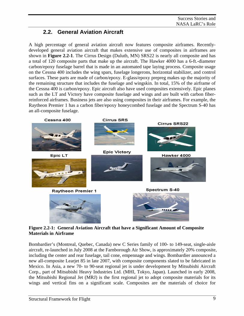
2.2. General Aviation Aircraft A high percentage of general aviation aircraft now features composite airframes. Recently- developed general aviation aircraft that makes extensive use of composites in airframes are shown in Figure 2.2-1. The Cirrus Design (Duluth, MN) SRS22 is nearly all composite and has a total of 120 composite parts that make up the aircraft. The Hawker 4000 has a 6-ft.-diameter carbon/epoxy fuselage barrel that is made in an automated tape laying process. Composite usage on the Cessna 400 includes the wing spars, fuselage longerons, horizontal stabilizer, and control surfaces. These parts are made of carbon/epoxy. E-glass/epoxy prepreg makes up the majority of the remaining structure that includes the fuselage and wingskin. In total, 15% of the airframe of the Cessna 400 is carbon/epoxy. Epic aircraft also have used composites extensively. Epic planes such as the LT and Victory have composite fuselage and wings and are built with carbon fiber-reinforced airframes. Business jets are also using composites in their airframes. For example, the Raytheon Premier 1 has a carbon fiber/epoxy honeycombed fuselage and the Spectrum S-40 has an all-composite fuselage.
Figure 2.2-1: General Aviation Aircraft that have a Significant Amount of Composite Materials in Airframe Bombardier’s (Montreal, Quebec, Canada) new C Series family of 100- to 149-seat, single-aisle aircraft, re-launched in July 2008 at the Farnborough Air Show, is approximately 20% composite, including the center and rear fuselage, tail cone, empennage and wings. Bombardier announced a new all-composite Learjet 85 in late 2007, with composite components slated to be fabricated in Mexico. In Asia, a new 70- to 90-seat regional jet is under development by Mitsubishi Aircraft Corp., part of Mitsubishi Heavy Industries Ltd. (MHI, Tokyo, Japan). Launched in early 2008, the Mitsubishi Regional Jet (MRJ) is the first regional jet to adopt composite materials for its wings and vertical fins on a significant scale. Composites are the materials of choice for
Success Stories and NASA LaRC’s Role
Structural Framework for Flight 10
unmanned aerial vehicle (UAV) airframes, regardless of the size. UAV wingspans range from commercial airliner-size down to palm-size micro flyers that support intelligence, surveillance, and reconnaissance (ISR). High strength-to-weight ratio, limited radar signature and signal transparency are the main drivers for selecting composites for UAVs. NASA made very significant contributions to the application of composites on general aviation (GA) aircraft through the Advanced General Aviation Transport Experiments program (AGATE) . NASA started the AGATE program to revitalize the general aviation industry. The AGATE Materials Working Group made a major contribution to the application of composites on small aircraft by developing a more efficient composite material qualification and property data acquisition process. The AGATE shared database process was developed in close coordination with the FAA. The process, published in DOT/FAA/AR-03/19, allows aircraft companies to share basic material properties and specifications similar to the shared database process that exists for the metals industry. The AGATE shared database process has been recognized as an acceptable means of compliance by FAA Small Airplane Directorate Policy Memorandum PS-ACE 100-2002-006 entitled, “Material Qualification and Equivalency for Polymer Matrix Composite Material Systems.” NASA scientists also realized that the AGATE process should be extended beyond the general aviation segment to the entire aerospace industry. In 2005, NASA Langley established the National Center for Advanced Materials Performance (NCAMP) specifically for the purpose of refining and enhancing the AGATE composite material property shared database process to a self-sustaining level in partnership with the Composite Materials Handbook 17 or CMH-17 (formerly known as MIL-HDBK-17) and FAA. Unlike AGATE, which was a “program” designed to end in the year 2001, NCAMP has been set up as a permanent national center within National Institute for Aviation Research (NIAR), and operates independently of other NIAR laboratories and research initiatives. Additional details of this work are found in a later section dealing with general aviation aircraft.
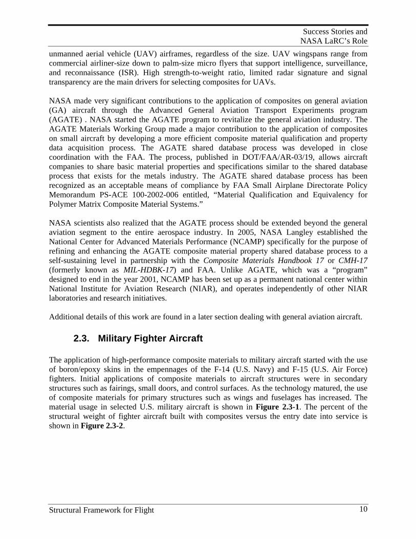
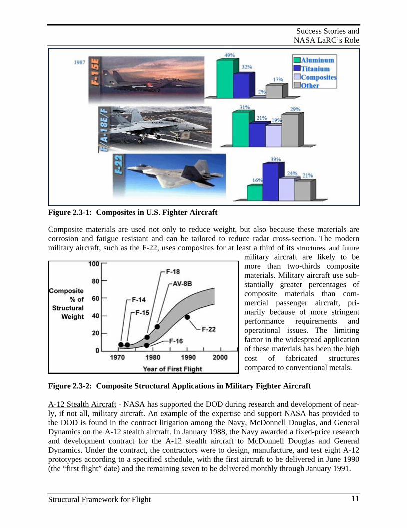
2.3. Military Fighter Aircraft The application of high-performance composite materials to military aircraft started with the use of boron/epoxy skins in the empennages of the F-14 (U.S. Navy) and F-15 (U.S. Air Force) fighters. Initial applications of composite materials to aircraft structures were in secondary structures such as fairings, small doors, and control surfaces. As the technology matured, the use of composite materials for primary structures such as wings and fuselages has increased. The material usage in selected U.S. military aircraft is shown in Figure 2.3-1. The percent of the structural weight of fighter aircraft built with composites versus the entry date into service is shown in Figure 2.3-2.
Success Stories and NASA LaRC’s Role
Structural Framework for Flight 11
Figure 2.3-1: Composites in U.S. Fighter Aircraft
Composite materials are used not only to reduce weight, but also because these materials are corrosion and fatigue resistant and can be tailored to reduce radar cross-section. The modern military aircraft, such as the F-22, uses composites for at least a third of its structures, and future
military aircraft are likely to be more than two-thirds composite materials. Military aircraft use sub-stantially greater percentages of composite materials than com-mercial passenger aircraft, pri-marily because of more stringent performance requirements and operational issues. The limiting factor in the widespread application of these materials has been the high cost of fabricated structures compared to conventional metals.
Figure 2.3-2: Composite Structural Applications in Military Fighter Aircraft A-12 Stealth Aircraft - NASA has supported the DOD during research and development of near-ly, if not all, military aircraft. An example of the expertise and support NASA has provided to the DOD is found in the contract litigation among the Navy, McDonnell Douglas, and General Dynamics on the A-12 stealth aircraft. In January 1988, the Navy awarded a fixed-price research and development contract for the A-12 stealth aircraft to McDonnell Douglas and General Dynamics. Under the contract, the contractors were to design, manufacture, and test eight A-12 prototypes according to a specified schedule, with the first aircraft to be delivered in June 1990 (the “first flight” date) and the remaining seven to be delivered monthly through January 1991.
Success Stories and NASA LaRC’s Role
Structural Framework for Flight 12
However, from the start, the contractors encountered difficulties in performing the contract, including meeting the contract schedule and keeping the aircraft weight within specifications. Two weeks before the first flight date, the contractors reported to the Navy that the projected first flight date would be July-September 1991, instead of June 1990 as originally agreed, and the remainder of the contract work would be delayed a corresponding twelve to fourteen months. They also predicted that the cost of completing the contract would exceed the ceiling price so substantially that it would be “unacceptable” to the Navy. The contractors asserted that a fundamental problem with the full-scale development (FSD) contract was its fixed-price structure and proposed that the contract be modified. The contractors’ continued difficulties in performing the contract led the DOD and the Navy to question the viability of the project. On Friday, December 14, 1990, then-Secretary of Defense Dick Cheney directed the Secretary of the Navy to show cause, by January 4, 1991, why the A-12 program should not be terminated. The following Monday, December 17, the Navy issued a cure notice to the contractors, stating that the government considered the contractors’ performance under the contract “unsatisfactory.” On January 7, 1991, the Navy issued a termination letter to the contractors stating that the government was terminating the A-12 contract due to the contractors’ default. A few weeks later, the Navy sent a letter to the contractors demanding the return of approximately $1.35 billion in unliquidated progress payments under the terminated contract. In effect, in 1991, the Navy canceled the $4 billion contract for being over-budget and behind schedule, according to the Justice Department. The two contractors then filed a legal complaint claiming that the project was wrongfully canceled. During the early stages of this lawsuit, and prior to the court’s initial decision, Dr. Norm Johnston and Dr. Jim Starnes, NASA Langley employees, were sought by the Navy to provide expert advice concerning composite fabrication of selected airframe structural components. Starnes and Johnston made many trips to the hastily established offices of the Navy/DOJ in Crystal City, VA, to address the validity of literally thousands of “claims” submitted by the two contractors. Before this activity was concluded, the judge in the case, without hearing technical witnesses and associated testimony, found for the contractors. The D.C. court decided that the contract was indeed wrongfully canceled, but the Navy then appealed, believing that the decision was setting an undesirable precedent for failing projects. After a year layoff, many consultants were recalled, including Johnston and Starnes, to help build a technical case for the Navy/DOJ to present to the Appellate Court. Problems addressed included the selection of the 8551-7 resin system and the level of properties that could be achieved with this resin. Another key technology had to do with the use of steel tooling for the fabrication of composite parts and the quality of finished parts. Dr. Starnes provided expert advice on damage tolerance and the adequacy of structural properties from the types of composite structures being fabricated. Johnston, in particular, was responsible for finding and preparing a witness who knew composite technology and could explain to the court in clear, easily understood language the issues involved in resin matrix modification, and especially the dependency of high-quality fabrication on proper resin formulation. Johnston also provided this testifier with specific technical information on the 8551-7 resin formulation critical to its behavior in any sound fabrication
Success Stories and NASA LaRC’s Role
Structural Framework for Flight 13
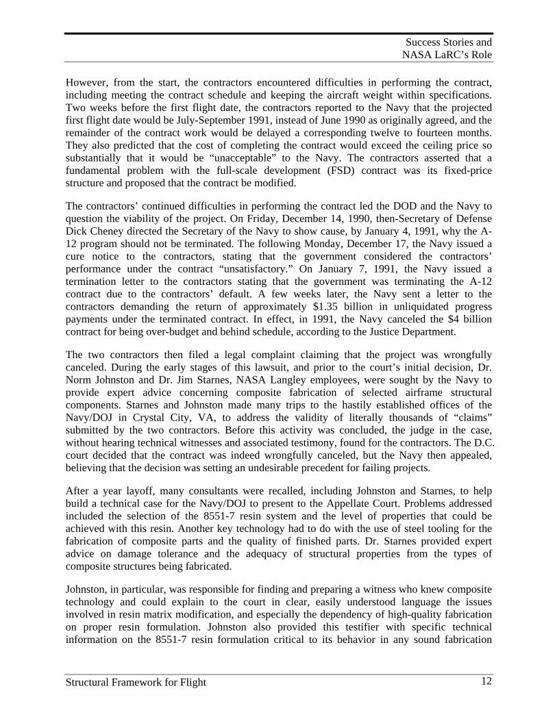
process which was so difficult to achieve by the contractors and the resin supplier. Over a period, the presentations of many technical witnesses were reviewed and edited before the Appellate Court gave its decision. After two appeals, a federal judge ruled in the Navy’s favor. The dispute over the canceled contract, for McDonnell Douglas and General Dynamics to build the jet fighter for the U.S. Navy, has dragged on for nearly two decades, through Boeing’s acquisition of McDonnell Douglas in 1997. In June, the US Court of Appeals for the Federal Circuit ruled that Boeing and General Dynamics must pay the government $2.8 billion to settle the dispute. On Tuesday, Nov. 24, 2009, the court refused to rehear an appeal from the two companies to review the June decision. As of Nov. 2009, General Dynamics and Boeing plan to take their case to the Supreme Court. This specific case is just one example of the many different ways Langley personnel assisted other government agencies with issues related to composite materials. For aircraft such as the B-2 stealth bomber, minimization of the radar cross-section was the primary reason for the extensive use of carbon fiber composites. The Northrop Grumman B-2 stealth bomber, shown in Figure 2.3-3, is constructed of almost all composite materials.[4] The suite of revolutionary aerospace technologies used on the B-2 give it
the distinction of being the world’s most advanced aircraft. With its unique flying wing configuration, it is a highly versatile multi-role bomber. Its design is reminiscent of the B-35, developed by Northrop during the 1940s. Development of the B-2 began in the late 1970s. The first B-2 rolled out of the bomber’s final assem-bly facility in Palmdale, California, in November 1988, and it flew for the first time on July 17, 1989.
Figure 2.3-3: B-2 Primary Structure is Almost All Composite Materials The wing is almost as large as the Boeing B-747 with a span of 172-ft. and surface area of 5,140-ft.2The wing is mostly graphite/epoxy material with honeycomb skins and internal structure. The fuselage also makes extensive use of composite materials. The outer skin is constructed of materials and coatings that are designed to reduce radar reflection and heat radiation. Northrop Grumman produced the forward center-sections of the fuselage including the cockpit. Boeing Military Airplanes produced the wings, the aft center fuselage section, landing gears, fuel system and weapons delivery system. At its peak in 1991, the B-2 was the largest military program at
Success Stories and NASA LaRC’s Role
Structural Framework for Flight 14
Boeing, employing about 10,000 people. Boeing completed the outboard wing section of the twenty-first and final aircraft on May 3, 1994.
That same year, the National Aeronautic Association of the U.S.A. awarded the B-2 design team the Collier Trophy for the greatest achievement in aeronautics or astronautics in America, demonstrated in actual use.
NASA has made many contributions to the application of composites to military aircraft and has worked in partnership with the U.S. Air Force and Navy on composites projects that have ranged from fundamental understanding of composite failure criteria to composites affordability initiatives. NASA and the DOD have cooperated on jointly funded programs and have joined forces to co-sponsor technical conferences such as the DOD/NASA/FAA Conference on Fibrous Composites in Structural Design. NASA and the DOD have also worked jointly to develop composite test standards through organizations such as American Society for Testing and Materials (ASTM). Engineers from both organizations have worked together on committees such as the ASTM Committee D30 on Composite Materials, which was formed in 1964. NASA has also contributed to the development of numerous other test standards for composite materials including test standards for: Constituent/Precursor Properties, Editorial and Resource Standards, Interlaminar Properties, Lamina and Laminate Test Methods, Sandwich Construction, and Structural Test Methods.
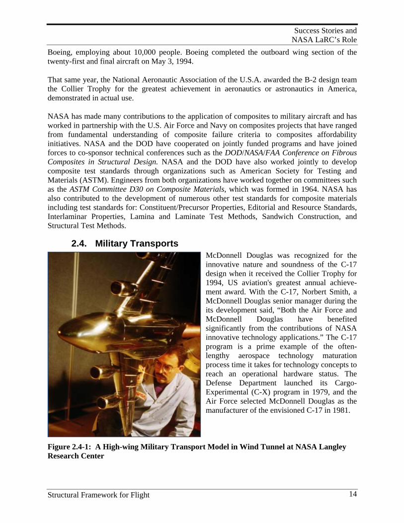
2.4. Military Transports McDonnell Douglas was recognized for the innovative nature and soundness of the C-17 design when it received the Collier Trophy for 1994, US aviation's greatest annual achieve-ment award. With the C-17, Norbert Smith, a McDonnell Douglas senior manager during the its development said, “Both the Air Force and McDonnell Douglas have benefited significantly from the contributions of NASA innovative technology applications.” The C-17 program is a prime example of the often-lengthy aerospace technology maturation process time it takes for technology concepts to reach an operational hardware status. The Defense Department launched its Cargo-Experimental (C-X) program in 1979, and the Air Force selected McDonnell Douglas as the manufacturer of the envisioned C-17 in 1981.
Figure 2.4-1: A High-wing Military Transport Model in Wind Tunnel at NASA Langley Research Center
Success Stories and NASA LaRC’s Role
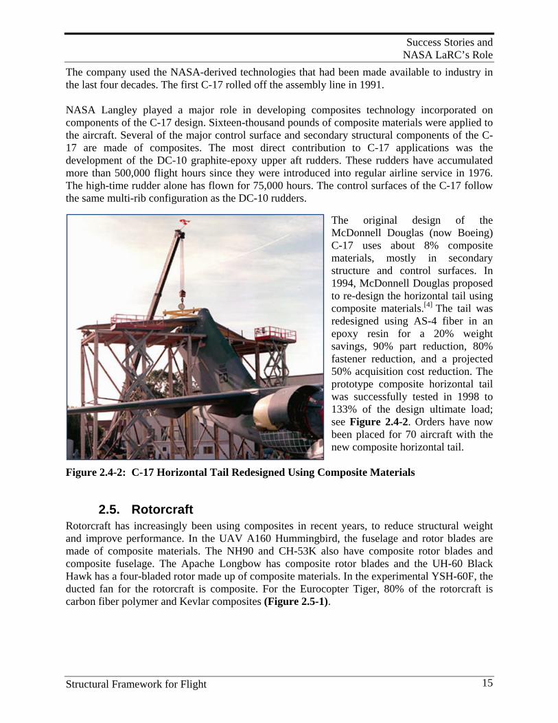
Structural Framework for Flight 15
The company used the NASA-derived technologies that had been made available to industry in the last four decades. The first C-17 rolled off the assembly line in 1991. NASA Langley played a major role in developing composites technology incorporated on components of the C-17 design. Sixteen-thousand pounds of composite materials were applied to the aircraft. Several of the major control surface and secondary structural components of the C-17 are made of composites. The most direct contribution to C-17 applications was the development of the DC-10 graphite-epoxy upper aft rudders. These rudders have accumulated more than 500,000 flight hours since they were introduced into regular airline service in 1976. The high-time rudder alone has flown for 75,000 hours. The control surfaces of the C-17 follow the same multi-rib configuration as the DC-10 rudders.
The original design of the McDonnell Douglas (now Boeing) C-17 uses about 8% composite materials, mostly in secondary structure and control surfaces. In 1994, McDonnell Douglas proposed to re-design the horizontal tail using composite materials.[4] The tail was redesigned using AS-4 fiber in an epoxy resin for a 20% weight savings, 90% part reduction, 80% fastener reduction, and a projected 50% acquisition cost reduction. The prototype composite horizontal tail was successfully tested in 1998 to 133% of the design ultimate load; see Figure 2.4-2. Orders have now been placed for 70 aircraft with the new composite horizontal tail.
Figure 2.4-2: C-17 Horizontal Tail Redesigned Using Composite Materials
2.5. Rotorcraft Rotorcraft has increasingly been using composites in recent years, to reduce structural weight and improve performance. In the UAV A160 Hummingbird, the fuselage and rotor blades are made of composite materials. The NH90 and CH-53K also have composite rotor blades and composite fuselage. The Apache Longbow has composite rotor blades and the UH-60 Black Hawk has a four-bladed rotor made up of composite materials. In the experimental YSH-60F, the ducted fan for the rotorcraft is composite. For the Eurocopter Tiger, 80% of the rotorcraft is carbon fiber polymer and Kevlar composites (Figure 2.5-1).
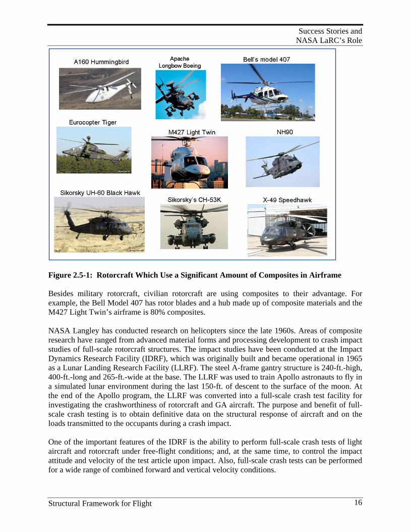
Success Stories and NASA LaRC’s Role
Structural Framework for Flight 16
Figure 2.5-1: Rotorcraft Which Use a Significant Amount of Composites in Airframe Besides military rotorcraft, civilian rotorcraft are using composites to their advantage. For example, the Bell Model 407 has rotor blades and a hub made up of composite materials and the M427 Light Twin’s airframe is 80% composites. NASA Langley has conducted research on helicopters since the late 1960s. Areas of composite research have ranged from advanced material forms and processing development to crash impact studies of full-scale rotorcraft structures. The impact studies have been conducted at the Impact Dynamics Research Facility (IDRF), which was originally built and became operational in 1965 as a Lunar Landing Research Facility (LLRF). The steel A-frame gantry structure is 240-ft.-high, 400-ft.-long and 265-ft.-wide at the base. The LLRF was used to train Apollo astronauts to fly in a simulated lunar environment during the last 150-ft. of descent to the surface of the moon. At the end of the Apollo program, the LLRF was converted into a full-scale crash test facility for investigating the crashworthiness of rotorcraft and GA aircraft. The purpose and benefit of full-scale crash testing is to obtain definitive data on the structural response of aircraft and on the loads transmitted to the occupants during a crash impact. One of the important features of the IDRF is the ability to perform full-scale crash tests of light aircraft and rotorcraft under free-flight conditions; and, at the same time, to control the impact attitude and velocity of the test article upon impact. Also, full-scale crash tests can be performed for a wide range of combined forward and vertical velocity conditions.
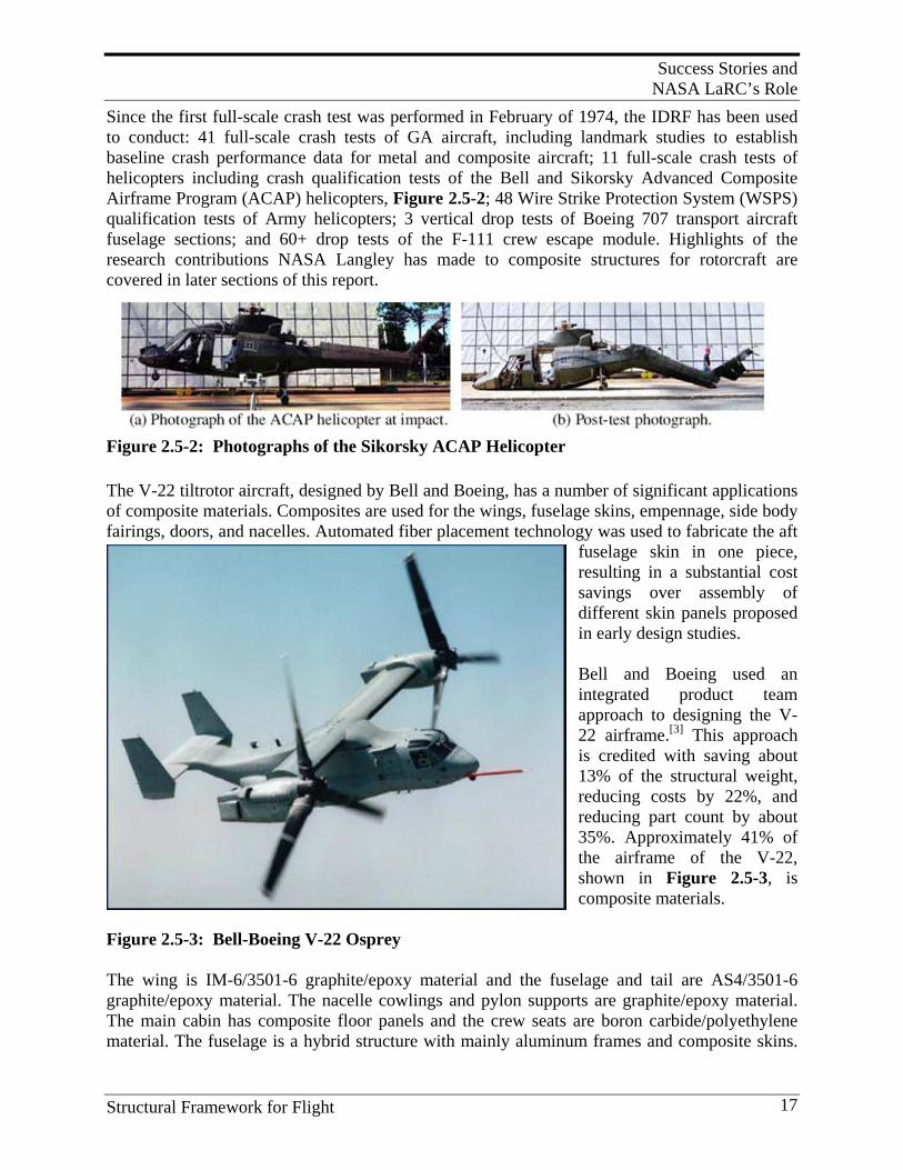
Success Stories and NASA LaRC’s Role
Structural Framework for Flight 17
Since the first full-scale crash test was performed in February of 1974, the IDRF has been used to conduct: 41 full-scale crash tests of GA aircraft, including landmark studies to establish baseline crash performance data for metal and composite aircraft; 11 full-scale crash tests of helicopters including crash qualification tests of the Bell and Sikorsky Advanced Composite Airframe Program (ACAP) helicopters, Figure 2.5-2; 48 Wire Strike Protection System (WSPS) qualification tests of Army helicopters; 3 vertical drop tests of Boeing 707 transport aircraft fuselage sections; and 60+ drop tests of the F-111 crew escape module. Highlights of the research contributions NASA Langley has made to composite structures for rotorcraft are covered in later sections of this report.
Figure 2.5-2: Photographs of the Sikorsky ACAP Helicopter The V-22 tiltrotor aircraft, designed by Bell and Boeing, has a number of significant applications of composite materials. Composites are used for the wings, fuselage skins, empennage, side body fairings, doors, and nacelles. Automated fiber placement technology was used to fabricate the aft
fuselage skin in one piece, resulting in a substantial cost savings over assembly of different skin panels proposed in early design studies. Bell and Boeing used an integrated product team approach to designing the V-22 airframe.[3] This approach is credited with saving about 13% of the structural weight, reducing costs by 22%, and reducing part count by about 35%. Approximately 41% of the airframe of the V-22, shown in Figure 2.5-3, is composite materials.
Figure 2.5-3: Bell-Boeing V-22 Osprey The wing is IM-6/3501-6 graphite/epoxy material and the fuselage and tail are AS4/3501-6 graphite/epoxy material. The nacelle cowlings and pylon supports are graphite/epoxy material. The main cabin has composite floor panels and the crew seats are boron carbide/polyethylene material. The fuselage is a hybrid structure with mainly aluminum frames and composite skins.
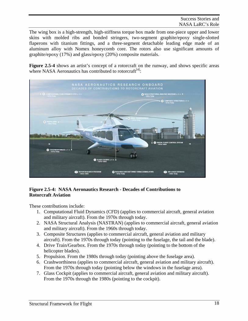
Success Stories and NASA LaRC’s Role
Structural Framework for Flight 18
The wing box is a high-strength, high-stiffness torque box made from one-piece upper and lower skins with molded ribs and bonded stringers, two-segment graphite/epoxy single-slotted flaperons with titanium fittings, and a three-segment detachable leading edge made of an aluminum alloy with Nomex honeycomb core. The rotors also use significant amounts of graphite/epoxy (17%) and glass/epoxy (20%) composite materials. Figure 2.5-4 shows an artist’s concept of a rotorcraft on the runway, and shows specific areas where NASA Aeronautics has contributed to rotorcraft[4]:
Figure 2.5-4: NASA Aeronautics Research - Decades of Contributions to Rotorcraft Aviation These contributions include:
1. Computational Fluid Dynamics (CFD) (applies to commercial aircraft, general aviation and military aircraft). From the 1970s through today.
2. NASA Structural Analysis (NASTRAN) (applies to commercial aircraft, general aviation and military aircraft). From the 1960s through today.
3. Composite Structures (applies to commercial aircraft, general aviation and military aircraft). From the 1970s through today (pointing to the fuselage, the tail and the blade).
4. Drive Train/Gearbox. From the 1970s through today (pointing to the bottom of the helicopter blades).
5. Propulsion. From the 1980s through today (pointing above the fuselage area). 6. Crashworthiness (applies to commercial aircraft, general aviation and military aircraft).
From the 1970s through today (pointing below the windows in the fuselage area). 7. Glass Cockpit (applies to commercial aircraft, general aviation and military aircraft).
From the 1970s through the 1980s (pointing to the cockpit).
Success Stories and NASA LaRC’s Role
Structural Framework for Flight 19
8. Digital Flight Control Systems. From the 1970s through the 1980s (pointing to the cockpit area).
9. Rotor Research Program. From the 1950s through the 1990s. 10. Research Aircraft/Wind Tunnels/Simulators. From the 1970s through today. 11. Air Loads Database. From the 1980s through today.
NASA first partnered with industry during the 1970s to conduct research on how to develop high-strength, nonmetallic materials that could replace heavier metals on aircraft. Gradually, composite materials have replaced metals in helicopter fuselages and rotor blades, and have become critical for reducing the weight of vertical-flight vehicles. NASA research also identified new ways to detect fuselage damage. In the area of crashworthiness, NASA has used its special gantry/swing cable facility adapted from the Apollo program to test the performance and durability of rotorcraft fuselage and components. The vertical drop tests or horizontal swing tests measure the survivability potential for occupants, structures, and new composite materials. A more detailed discussion of the work on energy-absorbing materials and structural concepts is presented in Section 8.2 dealing with joint R&D projects conducted with the Army.
2.6. Earth and Space Science Aircraft
2.6.1 Environmental Research Aircraft and Sensor Technology
The Environmental Research Aircraft and Sensor Technology (ERAST) program was a joint NASA/industry initiative to develop and demonstrate technologies that would lead to remotely, or autonomously, operated uninhabited aerial vehicles capable of carrying out long-duration Earth science and environmental missions at high altitudes. ERAST is aimed at developing technologies that allow companies to build unmanned aircraft that can carry out the dull, dirty or dangerous missions that would be impossible or impractical for manned aircraft. Through ERAST, many new propulsion, materials, control, instrumentation, and sensor technologies were pioneered which could enable the future development of a fleet of high-flying uninhabited aircraft that could conduct a wide variety of Earth and atmospheric science missions. Flying autonomously with mission-oriented payloads and instrumentation, these ultra-high flyers could carry out storm tracking studies, atmospheric sampling, spectral imaging for agricultural, natural resources monitoring, and pipeline monitoring. They could also serve as relay platforms for telecommunications systems. The NASA Pathfinder and Helios aircraft were part of a series of solar- and fuel cell system-powered UAVs which AeroVironment, Inc. developed under the ERAST program. Pathfinder, which was designed and built by AeroVironment, is essentially a flying wing with a 99-ft. span. Solar photovoltaic cells mounted on the top of the wing produce up to 7,200 watts, powering the aircraft’s six electric-driven propellers, as well as a suite of scientific instruments. Backup batteries store solar energy to power the aircraft at night. The Helios Prototype, shown in Figure 2.6-1, is a remotely-piloted flying wing aircraft devel-oped under NASA’s ERAST project. The two primary goals of the Helios Prototype devel-opment are to demonstrate sustained flight at an altitude near 100,000-ft. and flying non-stop for
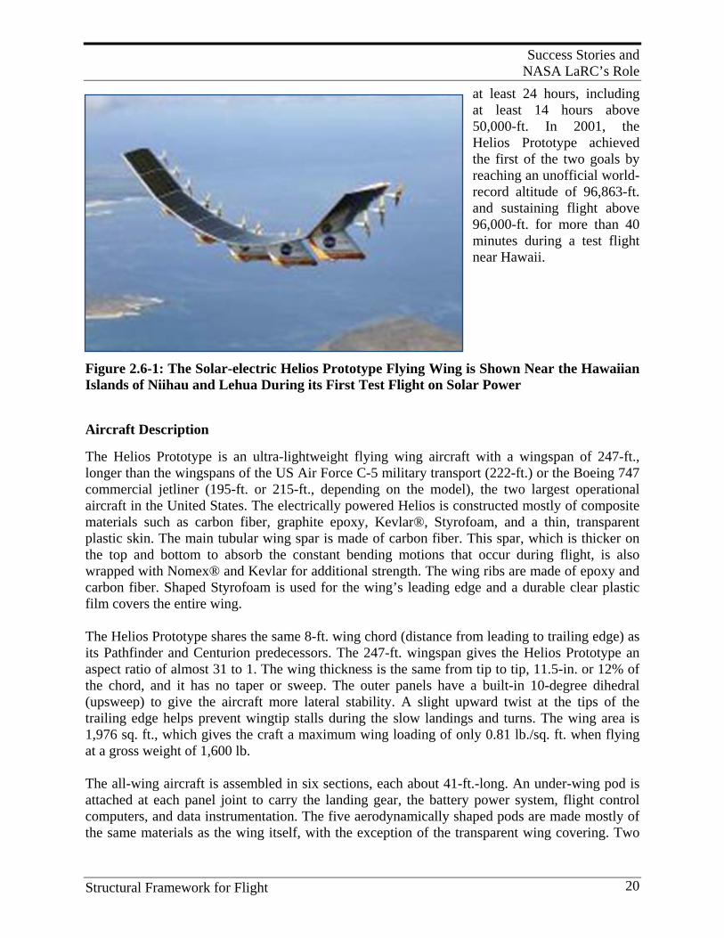
Success Stories and NASA LaRC’s Role
Structural Framework for Flight 20
at least 24 hours, including at least 14 hours above 50,000-ft. In 2001, the Helios Prototype achieved the first of the two goals by reaching an unofficial world-record altitude of 96,863-ft. and sustaining flight above 96,000-ft. for more than 40 minutes during a test flight near Hawaii.
Figure 2.6-1: The Solar-electric Helios Prototype Flying Wing is Shown Near the Hawaiian Islands of Niihau and Lehua During its First Test Flight on Solar Power Aircraft Description The Helios Prototype is an ultra-lightweight flying wing aircraft with a wingspan of 247-ft., longer than the wingspans of the US Air Force C-5 military transport (222-ft.) or the Boeing 747 commercial jetliner (195-ft. or 215-ft., depending on the model), the two largest operational aircraft in the United States. The electrically powered Helios is constructed mostly of composite materials such as carbon fiber, graphite epoxy, Kevlar®, Styrofoam, and a thin, transparent plastic skin. The main tubular wing spar is made of carbon fiber. This spar, which is thicker on the top and bottom to absorb the constant bending motions that occur during flight, is also wrapped with Nomex® and Kevlar for additional strength. The wing ribs are made of epoxy and carbon fiber. Shaped Styrofoam is used for the wing’s leading edge and a durable clear plastic film covers the entire wing. The Helios Prototype shares the same 8-ft. wing chord (distance from leading to trailing edge) as its Pathfinder and Centurion predecessors. The 247-ft. wingspan gives the Helios Prototype an aspect ratio of almost 31 to 1. The wing thickness is the same from tip to tip, 11.5-in. or 12% of the chord, and it has no taper or sweep. The outer panels have a built-in 10-degree dihedral (upsweep) to give the aircraft more lateral stability. A slight upward twist at the tips of the trailing edge helps prevent wingtip stalls during the slow landings and turns. The wing area is 1,976 sq. ft., which gives the craft a maximum wing loading of only 0.81 lb./sq. ft. when flying at a gross weight of 1,600 lb. The all-wing aircraft is assembled in six sections, each about 41-ft.-long. An under-wing pod is attached at each panel joint to carry the landing gear, the battery power system, flight control computers, and data instrumentation. The five aerodynamically shaped pods are made mostly of the same materials as the wing itself, with the exception of the transparent wing covering. Two
Success Stories and NASA LaRC’s Role
Structural Framework for Flight 21
wheels on each pod make up the fixed landing gear—rugged mountain bike wheels on the rear and smaller scooter wheels on the front. The Helios Prototype is powered by 14 brushless direct-current electric motors mounted across the wing’s entire span. The motors are rated at 2 hp. (1.5 kW) each, and drive lightweight two-blade propellers of 79-in.-diameter. The propellers are made from advanced composite materials and a laminar-flow design for efficiency at high altitudes. The cruising speed of Helios ranges from 19-27 mph, with takeoff and landing equating to the average speed of a bicycle. For the initial flight tests at Dryden in 1999, the Helios Prototype was powered by lithium battery packs carried in the underwing pods. More than 62,000 solar cells were installed on the entire upper surface of the wing during 2000. For eventual long-duration missions, the solar cells will be assisted by an onboard fuel-cell-based energy storage system now in development that will power the motors and aircraft systems through the night. The only flight control surfaces used on the Helios Prototype are 72 trailing-edge elevators that provide pitch control. Spanning the entire wing, they are operated by tiny servomotors linked to the aircraft’s fight control computer. To turn the aircraft in flight, yaw control is applied by applying differential power on the motors – speeding up the motors on one outer wing panel while slowing down motors on the other outer panel. The Helios Prototype weighs in at only 1,322 lbs. empty. During the 1999 development flights, the aircraft carried payloads of up to 626 lbs. – a combination of ballast and instrumentation, with the amount on each flight determined by the flight objectives. During the 2001 flights, the Helios Prototype flew at a weight of about 1,600 lbs., including its flight test instrumentation. The ultimate objective of the Helios design is to carry a payload of scientific instruments or telecommunications relay equipment averaging about 200 lbs. to high altitudes for missions lasting from several days to several months. The Helios Prototype is controlled remotely by a pilot on the ground, either from a mobile control van or from a fixed ground station that is equipped with a full-flight control station and consoles for systems monitoring. A flight termination system, required on remotely piloted aircraft flown in military restricted airspace, includes a parachute system deployed on command, plus a homing beacon to aid in the aircraft’s location. In case of loss of control or other contingency, the system is designed to bring the aircraft down within the restricted airspace area to avoid any potential damage or injuries to fixed assets or personnel on the ground.
2.6.2 Helios Failure Investigation
The Helios was in Hawaii to test a fuel cell to power it at night, part of an effort to create aircraft capable of staying aloft for weeks or even months. Such craft could operate essentially as low-flying satellites, relaying communications signals or studying the environment. However, on June 26, 2003, during a checkout flight over a US Navy test range off Kauai, the Helios Prototype broke apart and crashed into the ocean. The aircraft was flying at about 3,000-ft.-altitude. The crash occurred as atmospheric turbulence caused the outer wingtips of the highly flexible aircraft to bow abnormally high upward, causing the aircraft to become unstable. The
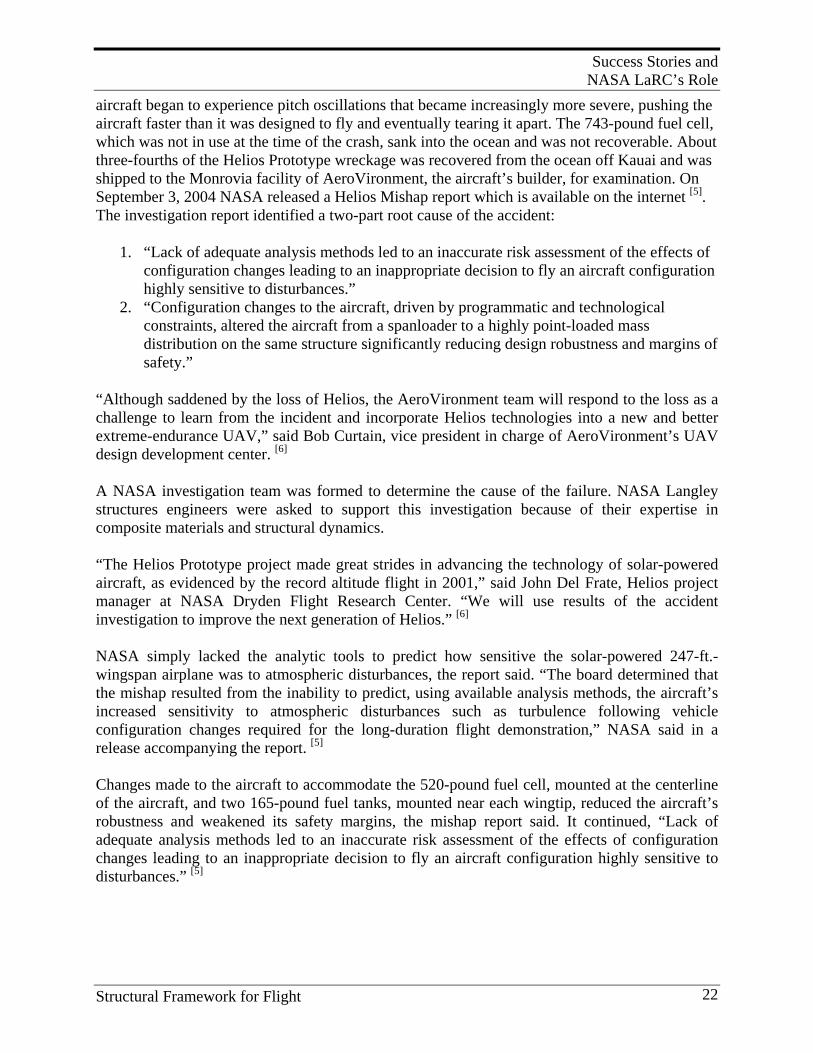
Success Stories and NASA LaRC’s Role
Structural Framework for Flight 22
aircraft began to experience pitch oscillations that became increasingly more severe, pushing the aircraft faster than it was designed to fly and eventually tearing it apart. The 743-pound fuel cell, which was not in use at the time of the crash, sank into the ocean and was not recoverable. About three-fourths of the Helios Prototype wreckage was recovered from the ocean off Kauai and was shipped to the Monrovia facility of AeroVironment, the aircraft’s builder, for examination. On September 3, 2004 NASA released a Helios Mishap report which is available on the internet [5]. The investigation report identified a two-part root cause of the accident:
1. “Lack of adequate analysis methods led to an inaccurate risk assessment of the effects of configuration changes leading to an inappropriate decision to fly an aircraft configuration highly sensitive to disturbances.”
2. “Configuration changes to the aircraft, driven by programmatic and technological constraints, altered the aircraft from a spanloader to a highly point-loaded mass distribution on the same structure significantly reducing design robustness and margins of safety.”
“Although saddened by the loss of Helios, the AeroVironment team will respond to the loss as a challenge to learn from the incident and incorporate Helios technologies into a new and better extreme-endurance UAV,” said Bob Curtain, vice president in charge of AeroVironment’s UAV design development center. [6] A NASA investigation team was formed to determine the cause of the failure. NASA Langley structures engineers were asked to support this investigation because of their expertise in composite materials and structural dynamics. “The Helios Prototype project made great strides in advancing the technology of solar-powered aircraft, as evidenced by the record altitude flight in 2001,” said John Del Frate, Helios project manager at NASA Dryden Flight Research Center. “We will use results of the accident investigation to improve the next generation of Helios.” [6] NASA simply lacked the analytic tools to predict how sensitive the solar-powered 247-ft.-wingspan airplane was to atmospheric disturbances, the report said. “The board determined that the mishap resulted from the inability to predict, using available analysis methods, the aircraft’s increased sensitivity to atmospheric disturbances such as turbulence following vehicle configuration changes required for the long-duration flight demonstration,” NASA said in a release accompanying the report. [5] Changes made to the aircraft to accommodate the 520-pound fuel cell, mounted at the centerline of the aircraft, and two 165-pound fuel tanks, mounted near each wingtip, reduced the aircraft’s robustness and weakened its safety margins, the mishap report said. It continued, “Lack of adequate analysis methods led to an inaccurate risk assessment of the effects of configuration changes leading to an inappropriate decision to fly an aircraft configuration highly sensitive to disturbances.” [5]
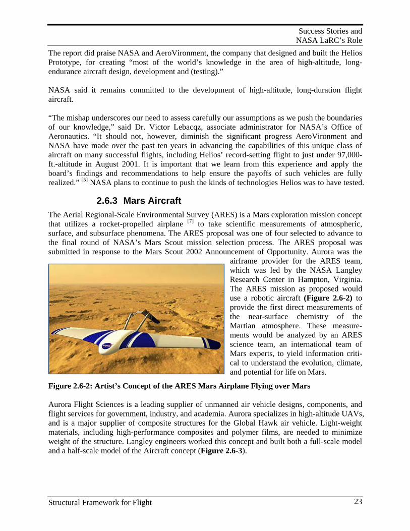
Success Stories and NASA LaRC’s Role
Structural Framework for Flight 23
The report did praise NASA and AeroVironment, the company that designed and built the Helios Prototype, for creating “most of the world’s knowledge in the area of high-altitude, long-endurance aircraft design, development and (testing).” NASA said it remains committed to the development of high-altitude, long-duration flight aircraft. “The mishap underscores our need to assess carefully our assumptions as we push the boundaries of our knowledge,” said Dr. Victor Lebacqz, associate administrator for NASA’s Office of Aeronautics. “It should not, however, diminish the significant progress AeroVironment and NASA have made over the past ten years in advancing the capabilities of this unique class of aircraft on many successful flights, including Helios’ record-setting flight to just under 97,000-ft.-altitude in August 2001. It is important that we learn from this experience and apply the board’s findings and recommendations to help ensure the payoffs of such vehicles are fully realized.” [5] NASA plans to continue to push the kinds of technologies Helios was to have tested.
2.6.3 Mars Aircraft The Aerial Regional-Scale Environmental Survey (ARES) is a Mars exploration mission concept that utilizes a rocket-propelled airplane [7] to take scientific measurements of atmospheric, surface, and subsurface phenomena. The ARES proposal was one of four selected to advance to the final round of NASA’s Mars Scout mission selection process. The ARES proposal was submitted in response to the Mars Scout 2002 Announcement of Opportunity. Aurora was the
airframe provider for the ARES team, which was led by the NASA Langley Research Center in Hampton, Virginia. The ARES mission as proposed would use a robotic aircraft (Figure 2.6-2) to provide the first direct measurements of the near-surface chemistry of the Martian atmosphere. These measure-ments would be analyzed by an ARES science team, an international team of Mars experts, to yield information criti-cal to understand the evolution, climate, and potential for life on Mars.
Figure 2.6-2: Artist’s Concept of the ARES Mars Airplane Flying over Mars Aurora Flight Sciences is a leading supplier of unmanned air vehicle designs, components, and flight services for government, industry, and academia. Aurora specializes in high-altitude UAVs, and is a major supplier of composite structures for the Global Hawk air vehicle. Light-weight materials, including high-performance composites and polymer films, are needed to minimize weight of the structure. Langley engineers worked this concept and built both a full-scale model and a half-scale model of the Aircraft concept (Figure 2.6-3).
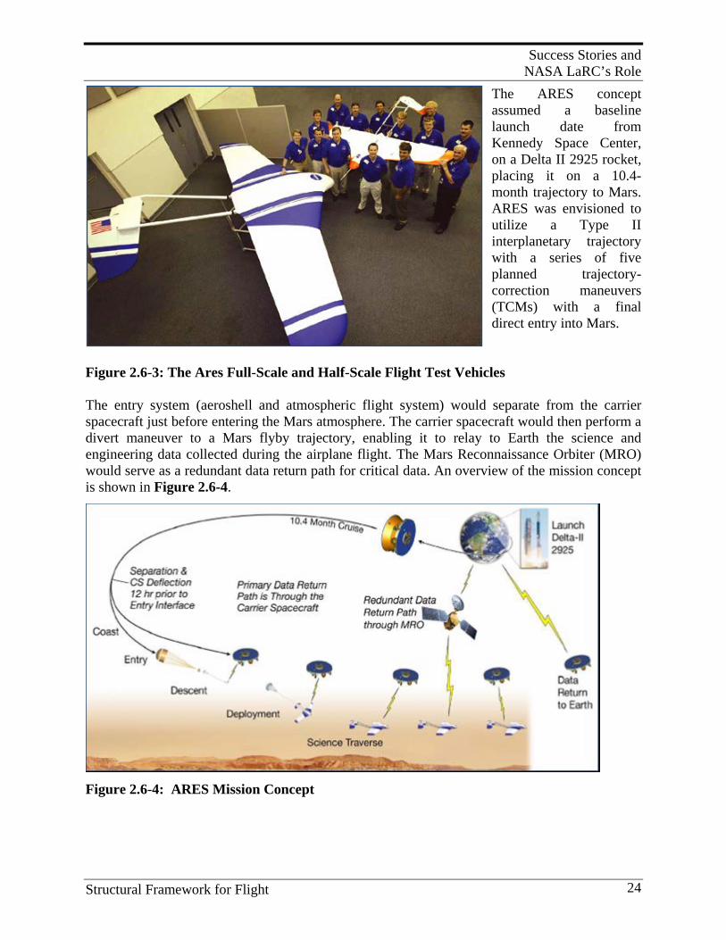
Success Stories and NASA LaRC’s Role
Structural Framework for Flight 24
The ARES concept assumed a baseline launch date from Kennedy Space Center, on a Delta II 2925 rocket, placing it on a 10.4-month trajectory to Mars. ARES was envisioned to utilize a Type II interplanetary trajectory with a series of five planned trajectory-correction maneuvers (TCMs) with a final direct entry into Mars.
Figure 2.6-3: The Ares Full-Scale and Half-Scale Flight Test Vehicles The entry system (aeroshell and atmospheric flight system) would separate from the carrier spacecraft just before entering the Mars atmosphere. The carrier spacecraft would then perform a divert maneuver to a Mars flyby trajectory, enabling it to relay to Earth the science and engineering data collected during the airplane flight. The Mars Reconnaissance Orbiter (MRO) would serve as a redundant data return path for critical data. An overview of the mission concept is shown in Figure 2.6-4.
Figure 2.6-4: ARES Mission Concept
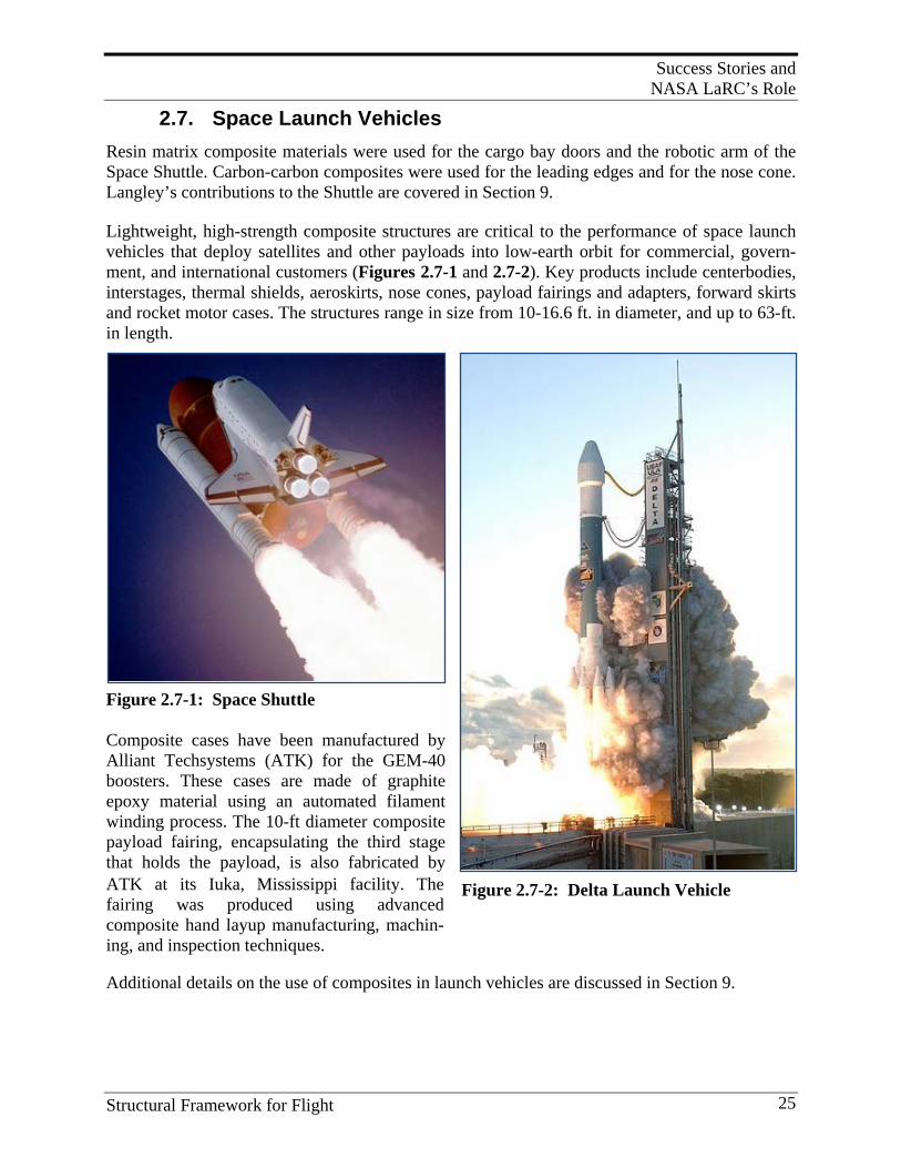
Success Stories and NASA LaRC’s Role
Structural Framework for Flight 25
Figure 2.7-2: Delta Launch Vehicle
2.7. Space Launch Vehicles
Resin matrix composite materials were used for the cargo bay doors and the robotic arm of the Space Shuttle. Carbon-carbon composites were used for the leading edges and for the nose cone. Langley’s contributions to the Shuttle are covered in Section 9. Lightweight, high-strength composite structures are critical to the performance of space launch vehicles that deploy satellites and other payloads into low-earth orbit for commercial, govern-ment, and international customers (Figures 2.7-1 and 2.7-2). Key products include centerbodies, interstages, thermal shields, aeroskirts, nose cones, payload fairings and adapters, forward skirts and rocket motor cases. The structures range in size from 10-16.6 ft. in diameter, and up to 63-ft. in length.
Figure 2.7-1: Space Shuttle Composite cases have been manufactured by Alliant Techsystems (ATK) for the GEM-40 boosters. These cases are made of graphite epoxy material using an automated filament winding process. The 10-ft diameter composite payload fairing, encapsulating the third stage that holds the payload, is also fabricated by ATK at its Iuka, Mississippi facility. The fairing was produced using advanced composite hand layup manufacturing, machin-ing, and inspection techniques. Additional details on the use of composites in launch vehicles are discussed in Section 9.
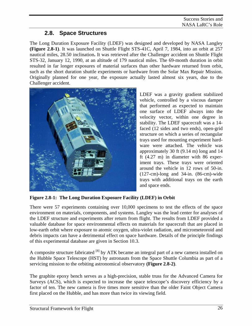
Success Stories and NASA LaRC’s Role
Structural Framework for Flight 26
2.8. Space Structures
The Long Duration Exposure Facility (LDEF) was designed and developed by NASA Langley (Figure 2.8-1). It was launched on Shuttle Flight STS-41C, April 7, 1984, into an orbit at 257 nautical miles, 28.50 inclination. It was retrieved after the Challenger accident on Shuttle Flight STS-32, January 12, 1990, at an altitude of 179 nautical miles. The 69-month duration in orbit resulted in far longer exposures of material surfaces than other hardware returned from orbit, such as the short duration shuttle experiments or hardware from the Solar Max Repair Mission. Originally planned for one year, the exposure actually lasted almost six years, due to the Challenger accident.
LDEF was a gravity gradient stabilized vehicle, controlled by a viscous damper that performed as expected to maintain one surface of LDEF always into the velocity vector, within one degree in stability. The LDEF spacecraft was a 14-faced (12 sides and two ends), open-grid structure on which a series of rectangular trays used for mounting experiment hard-ware were attached. The vehicle was approximately 30 ft (9.14 m) long and 14 ft (4.27 m) in diameter with 86 exper-iment trays. These trays were oriented around the vehicle in 12 rows of 50-in. (127-cm)-long and 34-in. (86-cm)-wide trays with additional trays on the earth and space ends.
Figure 2.8-1: The Long Duration Exposure Facility (LDEF) in Orbit There were 57 experiments containing over 10,000 specimens to test the effects of the space environment on materials, components, and systems. Langley was the lead center for analyses of the LDEF structure and experiments after return from flight. The results from LDEF provided a valuable database for space environmental effects on materials for spacecraft that are placed in low-earth orbit where exposure to atomic oxygen, ultra-violet radiation, and micrometeoroid and debris impacts can have a detrimental effect on space hardware. Details of the principle findings of this experimental database are given in Section 10.3. A composite structure fabricated [8] by ATK became an integral part of a new camera installed on the Hubble Space Telescope (HST) by astronauts from the Space Shuttle Columbia as part of a servicing mission to the orbiting astronomical observatory (Figure 2.8-2). The graphite epoxy bench serves as a high-precision, stable truss for the Advanced Camera for Surveys (ACS), which is expected to increase the space telescope’s discovery efficiency by a factor of ten. The new camera is five times more sensitive than the older Faint Object Camera first placed on the Hubble, and has more than twice its viewing field.
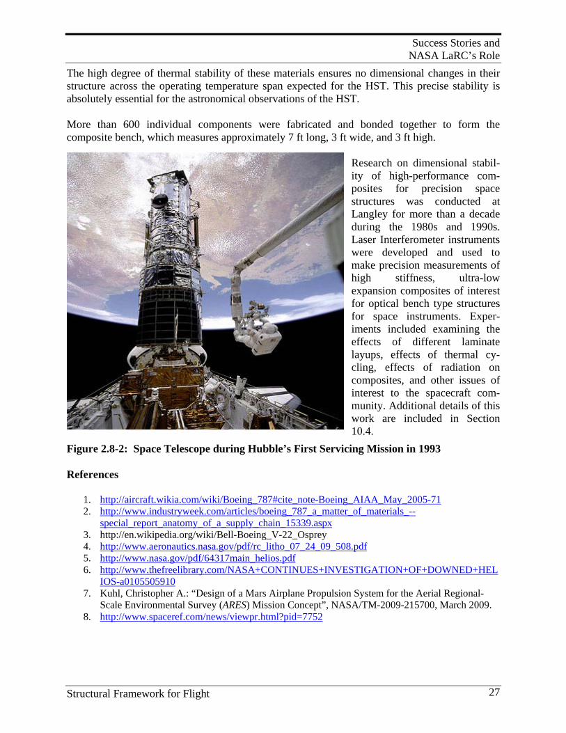
Success Stories and NASA LaRC’s Role
Structural Framework for Flight 27
The high degree of thermal stability of these materials ensures no dimensional changes in their structure across the operating temperature span expected for the HST. This precise stability is absolutely essential for the astronomical observations of the HST.
More than 600 individual components were fabricated and bonded together to form the composite bench, which measures approximately 7 ft long, 3 ft wide, and 3 ft high.
Research on dimensional stabil-ity of high-performance com-posites for precision space structures was conducted at Langley for more than a decade during the 1980s and 1990s. Laser Interferometer instruments were developed and used to make precision measurements of high stiffness, ultra-low expansion composites of interest for optical bench type structures for space instruments. Exper-iments included examining the effects of different laminate layups, effects of thermal cy-cling, effects of radiation on composites, and other issues of interest to the spacecraft com-munity. Additional details of this work are included in Section 10.4.
Figure 2.8-2: Space Telescope during Hubble’s First Servicing Mission in 1993
References
1. http://aircraft.wikia.com/wiki/Boeing_787#cite_note-Boeing_AIAA_May_2005-71 2. http://www.industryweek.com/articles/boeing_787_a_matter_of_materials_--
special_report_anatomy_of_a_supply_chain_15339.aspx 3. http://en.wikipedia.org/wiki/Bell-Boeing_V-22_Osprey 4. http://www.aeronautics.nasa.gov/pdf/rc_litho_07_24_09_508.pdf 5. http://www.nasa.gov/pdf/64317main_helios.pdf 6. http://www.thefreelibrary.com/NASA+CONTINUES+INVESTIGATION+OF+DOWNED+HEL
IOS-a0105505910 7. Kuhl, Christopher A.: “Design of a Mars Airplane Propulsion System for the Aerial Regional-
Scale Environmental Survey (ARES) Mission Concept”, NASA/TM-2009-215700, March 2009. 8. http://www.spaceref.com/news/viewpr.html?pid=7752
NASA’s Engagement in Composites Research
Structural Framework for Flight 28
3. NASA’ S E N G A G E M E N T I N C O M P O S I T E S R E S E A R C H
3.1. Major Drivers for Langley’s Composites Research Programs
The composites research programs, conducted at Langley over the past forty years, were driven by world events to which the U.S. reacted for security or economic reasons. Policies for federal agencies are set by the administration working with Congress. These policies are drafted by the Office of Science and Technology Policy (OSTP) with technical input from industry and studies conducted by research committees, generally under the purview of organizations such as the National Academy of Engineering and the National Academy of Science. These agencies then turn this guidance into agency plans, which become the basis for planning and executing the programs.
3.1.1 Impact of National and World Events on National Science and Technology Policy
History teaches us that, at least in the U.S., national policy is driven by major world events. These events have ranged from wars (e.g., world wars, Vietnam War, Cold War, Gulf War, etc.), raw material supply shortages, such as occurred during the Arab Oil Embargo of the early 1970s, and the economic/trade crises of today. The National Advisory Committee for Aeronautics (NACA) was formed as a direct result of World War I and the development of the aircraft in hostile nations. NACA was first driven by military need, and then shifted emphasis to technologies critical to development of civilian aircraft for air travel. Its major focus was the development of practical solutions to the problems of flight. The NACA approach – “Build an industry, not a program,” was very successful. The development of launch vehicles started after World War II, as missiles for defense needs became a national priority. Redstone Arsenal in Alabama was the forerunner of Marshall Space Flight Center, which was formed to address launch vehicles for NASA civilian use. The birth of NASA in 1957, was a direct result of the Russian launch of Sputnik. Other examples include the NASP and X-33 projects which were driven by Cold War considerations. NASA’s major past accomplishments, in combination with worldwide exposure, has resulted in NASA being viewed by many as the technology-marketing icon of America’s advanced technology society. NASA has given the U.S. national prestige for being a leader in advanced technologies. Its research thrust has traditionally been the development of new technologies to open new frontiers and markets. NASA’s history of undertaking bold new initiatives and its
NASA’s Engagement in Composites Research
Structural Framework for Flight 29
willingness to take risks, where the potential benefits outweigh the risk of failure, has been viewed as “game changing” in the world. The 21st century vision for U.S. human space flight is being much debated in this time of financial crisis. The one theme that seems to resonate with most people is the goal of “Living in Space.” This ultimately means living on Mars. A lesser goal of staying in near-earth orbit is viewed as not being bold enough to inspire the world and could result in NASA losing prestige as a valuable technology-marketing agent for U.S. society.
3.1.2 NASA Priorities and Programs in Response to OSTP Guidance
The National Aeronautics and Space Act of 1958 directs that government-sponsored aeronautical activities be conducted to contribute materially to specific objectives, including the following:
• Improvement of the usefulness, performance, speed, safety, and efficiency of aeronautical … vehicles
• Long-range studies of the problems involved in the utilization of aeronautical … activities for peaceful purposes, and
• Preservation of the role of the United States as a leader in aeronautical … technology.
In executing this charter, NASA must work closely, and partner, with the DOD, the Department of Transportation (DOT), the FAA, academia, and industry to ensure that the research that NASA pursues finds its way into useful and timely products and processes. Throughout the history of flight, the U.S. government has played a leading role in advancing the fundamental scientific principles and technologies on which modern aviation is built. However, there has never been a unifying federal policy to focus and guide its research and development efforts. Entering the second century of flight, improved coordination, cooperation, and planning will be needed across the federal government to continue to meet new challenges through technology as aeronautics continues to become an ever more integral part of American life. A number of recent studies and reports have looked to address this issue, including the 2002 report from the Commission on the Future of the United States Aerospace Industry and several recent studies from the National Research Council, including its 2003 report--Securing the Future of U.S. Air Transportation, and its 2006 Decadal Survey of Civil Aeronautics. In addition, focus on a national aeronautics R&D policy was magnified by the National Aeronautics and Space Administration Authorization Act of 2005, and the Science, State, Justice, Commerce, and Related Agencies Appropriations Act of 2006, which called for the development of a national policy to guide federal aeronautics’ R&D programs through 2020. Accordingly, the National Science and Technology Council’s (NSTC) Committee on Technology (COT) established an Aeronautics Science and Technology Subcommittee (ASTS) to undertake this effort. This policy reflects the result of that effort, and includes recommendations to clarify, focus, and coordinate the federal government’s aeronautics R&D activities to help meet these challenges and advance aeronautics well into the century. The U.S. government plays a unique role in long-term, fundamental aeronautics research that provides the foundation for future technology development. Executive departments and agencies perform this role through direct federal investment and indirectly through policies and
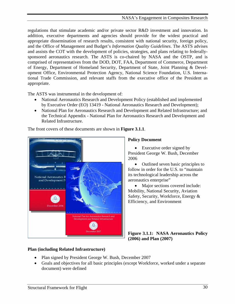
NASA’s Engagement in Composites Research
Structural Framework for Flight 30
regulations that stimulate academic and/or private sector R&D investment and innovation. In addition, executive departments and agencies should provide for the widest practical and appropriate dissemination of research results, consistent with national security, foreign policy, and the Office of Management and Budget’s Information Quality Guidelines. The ASTS advises and assists the COT with the development of policies, strategies, and plans relating to federally-sponsored aeronautics research. The ASTS is co-chaired by NASA and the OSTP, and is comprised of representatives from the DOD, DOT, FAA, Department of Commerce, Department of Energy, Department of Homeland Security, Department of State, Joint Planning & Devel-opment Office, Environmental Protection Agency, National Science Foundation, U.S. Interna-tional Trade Commission, and relevant staffs from the executive office of the President as appropriate. The ASTS was instrumental in the development of:
• National Aeronautics Research and Development Policy (established and implemented by Executive Order (EO) 13419 - National Aeronautics Research and Development);
• National Plan for Aeronautics Research and Development and Related Infrastructure; and the Technical Appendix - National Plan for Aeronautics Research and Development and Related Infrastructure.
The front covers of these documents are shown in Figure 3.1.1.
Policy Document
• Executive order signed by President George W. Bush, December 2006
• Outlined seven basic principles to follow in order for the U.S. to “maintain its technological leadership across the aeronautics enterprise”
• Major sections covered include: Mobility, National Security, Aviation Safety, Security, Workforce, Energy & Efficiency, and Environment Figure 3.1.1: NASA Aeronautics Policy (2006) and Plan (2007)
Plan (including Related Infrastructure)
• Plan signed by President George W. Bush, December 2007 • Goals and objectives for all basic principles (except Workforce, worked under a separate
document) were defined
NASA’s Engagement in Composites Research
Structural Framework for Flight 31
• Summary of challenges in each area, as well as the facilities needed to support related R&D, were identified
• Specific quantitative targets where appropriate were stated • A more detailed document/version was published in 2008
NASA also receives planning help and support through the National Research Council (NRC). The NRC functions under the auspices of the National Academy of Sciences (NAS), the National Academy of Engineering (NAE), and the Institute of Medicine (IOM). The NAS, NAE, IOM, and NRC are part of a private, nonprofit institution that provides science, technology, and health policy advice under a congressional charter signed by President Abraham Lincoln, which was originally granted to the NAS in 1863. Under this charter, the NRC was established in 1916, the NAE in 1964, and the IOM in 1970. The four organizations are collectively referred to as the National Academies. The mission of the NRC is to improve government decision-making and public policy, increase public education and understanding, and promote the acquisition and dissemination of knowledge in matters involving science, engineering, technology, and health. The institution works to inform policies and actions that have the power to improve the lives of people in the U.S. and around the world. The core services of NRC involve collecting, analyzing, and sharing information/knowledge. The independence of the institution, combined with its unique ability to convene experts, allows it to be responsive to a host of requests. The Space Studies Board (SSB) and the Aeronautics and Space Engineering Board (ASEB) perform studies for, and issue reports to provide guidance to, NASA in planning and implementing R&D strategies and programs. Some of the recent reports published, that have a bearing on projects and programs which involve composite research, are listed below:
1. Approaches to Future Space Cooperation and Competition in a Globalizing World: Summary of a Workshop (SSB and ASEB, 2009)
2. Assessing the Research and Development Plan for the Next Generation Air Transportation System: Summary of a Workshop (ASEB, 2008)
3. A Constrained Space Exploration Technology Program: A Review of NASA’s Exploration Technology Development Program (ASEB, 2008)
4. Managing Space Radiation Risk in the New Era of Space Exploration (ASEB, 2008) 5. NASA Aeronautics Research: An Assessment (ASEB, 2008) 6. Opening New Frontiers in Space: Choices for the Next New Frontiers Announcement of
Opportunity (SSB, 2008) 7. United States Civil Space Policy: Summary of a Workshop (SSB with ASEB, 2008) 8. National Vision for Space Exploration (SSB with ASEB, 2007) 9. Decadal Science Strategy Surveys: Report of a Workshop (SSB, 2007)
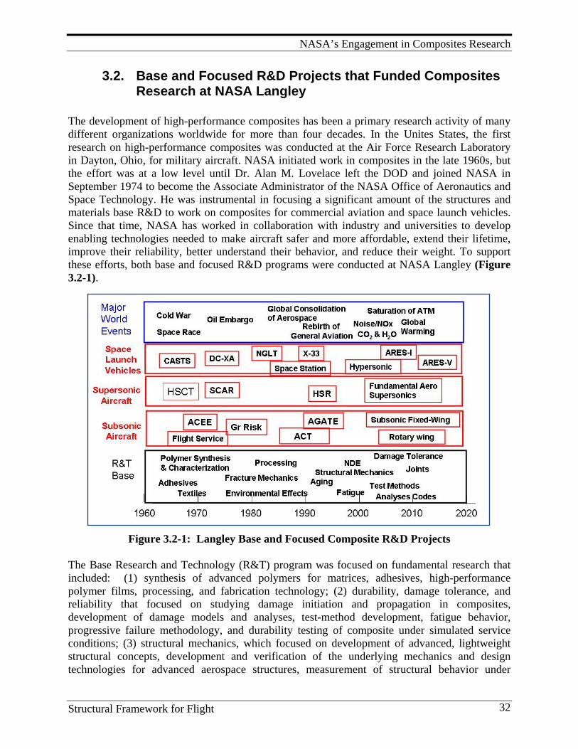
NASA’s Engagement in Composites Research
Structural Framework for Flight 32
3.2. Base and Focused R&D Projects that Funded Composites Research at NASA Langley
The development of high-performance composites has been a primary research activity of many different organizations worldwide for more than four decades. In the Unites States, the first research on high-performance composites was conducted at the Air Force Research Laboratory in Dayton, Ohio, for military aircraft. NASA initiated work in composites in the late 1960s, but the effort was at a low level until Dr. Alan M. Lovelace left the DOD and joined NASA in September 1974 to become the Associate Administrator of the NASA Office of Aeronautics and Space Technology. He was instrumental in focusing a significant amount of the structures and materials base R&D to work on composites for commercial aviation and space launch vehicles. Since that time, NASA has worked in collaboration with industry and universities to develop enabling technologies needed to make aircraft safer and more affordable, extend their lifetime, improve their reliability, better understand their behavior, and reduce their weight. To support these efforts, both base and focused R&D programs were conducted at NASA Langley (Figure 3.2-1).
Figure 3.2-1: Langley Base and Focused Composite R&D Projects The Base Research and Technology (R&T) program was focused on fundamental research that included: (1) synthesis of advanced polymers for matrices, adhesives, high-performance polymer films, processing, and fabrication technology; (2) durability, damage tolerance, and reliability that focused on studying damage initiation and propagation in composites, development of damage models and analyses, test-method development, fatigue behavior, progressive failure methodology, and durability testing of composite under simulated service conditions; (3) structural mechanics, which focused on development of advanced, lightweight structural concepts, development and verification of the underlying mechanics and design technologies for advanced aerospace structures, measurement of structural behavior under
NASA’s Engagement in Composites Research
Structural Framework for Flight 33
combined loads, damage tolerance methodologies, buckling and post-buckling behavior, advanced analysis methods and design, analyses validation by tests of subcomponents and large-scale structures; and (4) non-destructive analyses (NDE) that focused on physics of measurement science, sensor and detectors development, new technique development, inspection methodologies, modifying the technology for specific applications and testing/validating, standards development, and application of inspection techniques to composite coupons and built-up structural elements. Focused technology programs that supported composite research and development included: Composite Flight Service, Supersonic Cruise Research (SCR), Aircraft Energy Efficiency (ACEE), Composite for Advanced Space Transportation Systems (CASTS), Advanced Composite Technology (ACT), Graphite Fiber Risk Analyses, High Speed Research (HSR), Advanced General Aviation Transport Experiments, Next Generation Launch Technology (NGLT), Access to Space (X-33), Advanced Launch System (ALS), National Launch System (NLS), National AeroSpace Plane (NASP), Single Stage To Orbit (SSTO), Delta Clipper Experimental (DC-XA), Ares V, Ares I, and the NESC (NASA Engineering and Safety Center) Composite Crew Module. The technical accomplishments and lessons learned in these programs will be discussed in the following sections. Each program contained specific, focused R&D efforts that generally included: (a) selection of most promising material system and processing approach; (b) experimentation and analysis of small samples to characterize the system and quantify behavior in the presence of defects like damage and imperfections; (c) testing structural subelements to examine buckling behavior, combined loadings, and built-up structures; and (d) testing complicated subcomponents leading up to tests of full-scale, or nearly full-scale, components. Detailed analysis, including tool development, was performed to prove that the behavior of these structures was well understood and predictable. This approach for developing technology became known as the “building block” approach and was used successfully in programs such as the ACT program and the HSR program. Analysis techniques included closed-form solutions where possible, finite elements modeling and a host of specialized codes developed to model processing or damage growth under cyclic loading conditions. The intent was to validate analysis predictions with experiments to ensure that damage initiation, propagation and failure modes were adequately understood.
Technology Readiness Level (TRL) is a measure used by NASA, DOD and many of the world’s major companies and agencies, to assess the maturity of evolving technologies prior to incorporating that technology into a system or subsystem. Generally speaking, when a new technology is first invented or conceptualized, it is not suitable for immediate application. Instead, new technologies are usually subjected to experimentation, refinement, and increasingly realistic testing. Once the technology is sufficiently proven, it can be incorporated into a system/subsystem. In 1995, John C. Mankins, NASA, wrote a “White Paper on Technology Readiness Levels,” that discussed NASA’s use of TRLs and proposed descriptions for each TRL. The basic features of the TRL levels recognized by NASA are shown in Figure 3.2-2. NASA’s work on this focuses on technologies to mature the use of composite structures and materials for advanced aircraft, launch vehicles, and other space hardware applications. NASA Langley has had a balanced TRL
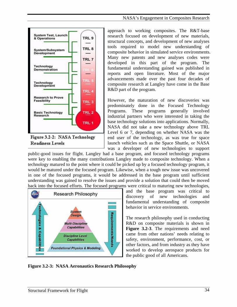
NASA’s Engagement in Composites Research
Structural Framework for Flight 34
approach to working composites. The R&T-base research focused on development of new materials, structural concepts, and development of new analyses tools required to model new understanding of composite behavior in simulated service environments. Many new patents and new analyses codes were developed in this part of the program. The fundamental understanding gained was published in reports and open literature. Most of the major advancements made over the past four decades of composite research at Langley have come in the Base R&D part of the program. However, the maturation of new discoveries was predominately done in the Focused Technology Programs. These programs generally involved industrial partners who were interested in taking the base technology solutions into applications. Normally, NASA did not take a new technology above TRL Level 6 or 7, depending on whether NASA was the end user of the technology, as was true for space launch vehicles such as the Space Shuttle, or NASA was a developer of new technologies to support
public-good issues for flight. Langley had a base program, and focused technology programs were key to enabling the many contributions Langley made to composite technology. When a technology matured to the point where it could be picked up by a focused technology program, it would be matured under the focused program. Likewise, when a tough new issue was uncovered in one of the focused programs, it would be addressed in the base program until sufficient understanding was gained to resolve the issues and provide a solution that could then be moved back into the focused efforts. The focused programs were critical to maturing new technologies,
and the base program was critical to discovery of new technologies and fundamental understanding of composite behavior in service environments. The research philosophy used in conducting R&D on composite materials is shown in Figure 3.2-3. The requirements and need came from other nations’ needs relating to safety, environment, performance, cost, or other factors, and from industry as they have worked to develop aerospace products for the public good of all Americans.
Figure 3.2-3: NASA Aeronautics Research Philosophy
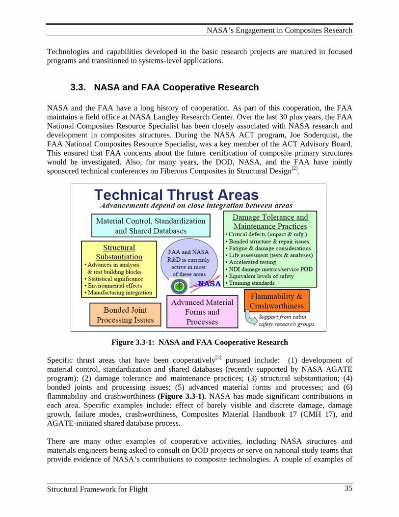
NASA’s Engagement in Composites Research
Structural Framework for Flight 35
Technologies and capabilities developed in the basic research projects are matured in focused programs and transitioned to systems-level applications.
3.3. NASA and FAA Cooperative Research
NASA and the FAA have a long history of cooperation. As part of this cooperation, the FAA maintains a field office at NASA Langley Research Center. Over the last 30 plus years, the FAA National Composites Resource Specialist has been closely associated with NASA research and development in composites structures. During the NASA ACT program, Joe Soderquist, the FAA National Composites Resource Specialist, was a key member of the ACT Advisory Board. This ensured that FAA concerns about the future certification of composite primary structures would be investigated. Also, for many years, the DOD, NASA, and the FAA have jointly sponsored technical conferences on Fiberous Composites in Structural Design[2].
Figure 3.3-1: NASA and FAA Cooperative Research Specific thrust areas that have been cooperatively[3] pursued include: (1) development of material control, standardization and shared databases (recently supported by NASA AGATE program); (2) damage tolerance and maintenance practices; (3) structural substantiation; (4) bonded joints and processing issues; (5) advanced material forms and processes; and (6) flammability and crashworthiness (Figure 3.3-1). NASA has made significant contributions in each area. Specific examples include: effect of barely visible and discrete damage, damage growth, failure modes, crashworthiness, Composites Material Handbook 17 (CMH 17), and AGATE-initiated shared database process. There are many other examples of cooperative activities, including NASA structures and materials engineers being asked to consult on DOD projects or serve on national study teams that provide evidence of NASA’s contributions to composite technologies. A couple of examples of
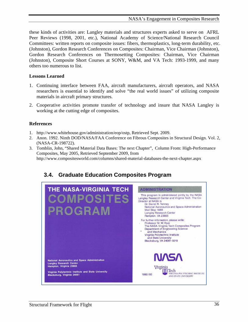
NASA’s Engagement in Composites Research
Structural Framework for Flight 36
these kinds of activities are: Langley materials and structures experts asked to serve on AFRL Peer Reviews (1998, 2001, etc.), National Academy of Science/National Research Council Committees: written reports on composite issues: fibers, thermoplastics, long-term durability, etc. (Johnston), Gordon Research Conferences on Composites: Chairman, Vice Chairman (Johnston), Gordon Research Conferences on Thermosetting Composites: Chairman, Vice Chairman (Johnston), Composite Short Courses at SONY, W&M, and VA Tech: 1993-1999, and many others too numerous to list. Lessons Learned 1. Continuing interface between FAA, aircraft manufacturers, aircraft operators, and NASA
researchers is essential to identify and solve “the real world issues” of utilizing composite materials in aircraft primary structures.
2. Cooperative activities promote transfer of technology and insure that NASA Langley is working at the cutting edge of composites.
References 1. http://www.whitehouse.gov/administration/eop/ostp, Retrieved Sept. 2009. 2. Anon. 1992. Ninth DOD/NASA/FAA Conference on Fibrous Composites in Structural Design. Vol. 2,
(NASA-CR-198722). 3. Tomblin, John, “Shared Material Data Bases: The next Chapter”, Column From: High-Performance
Composites, May 2005, Retrieved September 2009, from http://www.compositesworld.com/columns/shared-material-databases-the-next-chapter.aspx
3.4. Graduate Education Composites Program
NASA’s Engagement in Composites Research
Structural Framework for Flight 37
Highlights
1. NASA funded grants and cooperative programs with dozens of universities across the United States.
2. Hundreds of engineers and scientists conducted research under these grants and strengthened NASA’s composite research program.
3. A whole new generation of highly trained graduates entered the workforce with excellent credentials to work in the emerging new field of composite materials and structures.
4. Notable graduates from these programs, hired by NASA Langley, include: John M. Kennedy, Gary L. Farley, Mark J. Shuart, David A. O’Brien, Ramon Garcia, David E. Bowles, Michael P. Nemeth, William B. Avery, Edward H. Glaessgen, Richard D. Young.
5. The inclusion of universities in the NASA programs resulted in very productive interactions between university faculty and engineers from NASA and Industry.
6. NASA-Virginia Tech Composites Program was funded from January 1974 through September 1996. During this period, 91 M.S. and Ph.D. degrees were awarded. More than 210 formal publications resulted from work sponsored under this grant.
A key factor in the success of composites R&D at Langley Research Center was the strong involvement of universities in the program. The education and training that students received under NASA-sponsored grants and cooperative agreements was a major factor in the training of a highly skilled composite workforce for industry. Charles Blankenship, who was Head of the Structures Directorate at Langley during the 1980s and 1990s, stated recently “one of the most significant contributions to the country coming out of Langley’s composites research was the training of an expert workforce that enabled industry to capitalize on performance benefits of composites.” As a general rule, approximately 20% of the base R&D funds was devoted to funding university grants all over the country. Grants and cooperative agreements with universities were also funded under the focused programs to address key technologies critical to those program objectives. These grants promoted new ideas and concepts. Langley funded cooperative research at Virginia Tech, University of Delaware, Old Dominion University, and several other universities. Space does not permit coverage of all the excellent work done at universities. However, the following section presents highlights on the NASA-Virginia Tech Composites Program because of the tremendous importance of this program to the success of Langley’s composite research. NASA-Virginia Tech Composites Program Virginia Tech and the NASA Langley Research Center jointly instituted a cooperative effort in graduate education and research in the field of composite materials in January 1974. The purpose of the program was twofold: to prepare qualified students for careers in research, development, design, and teaching; and to conduct research on current problems. The program combined the teaching and research expertise of the university community with that of a national research laboratory to provide the student with an outstanding graduate program which encompassed the practical aspects of engineering research, as well as academic pursuits. The research activities focused on processing, fabrication, fundamental material behavior, and structural applications of advanced composite materials. A unique feature of the program was that the student normally
NASA’s Engagement in Composites Research
Structural Framework for Flight 38
completed a research residency at Langley Research Center as an integral part of his or her graduate program. While at the Center, the student continued his or her thesis or dissertation research. During this time, the student worked closely with a NASA engineer and had access to essentially all NASA facilities. Close coordination with the on-campus faculty advisor was maintained during this residency period. The experience gained at the Center provided an added dimension to the student's graduate program. This experience proved most valuable to the professional growth of the student, and was a distinct asset to his or her record in the eyes of prospective employers. Because of the strong reputation of the Langley Research Center and Virginia Tech, the program was able to recruit top students from throughout the country. As a line item in the budget, the program was advertised annually at a number of universities, and in the late ’80s more than 500 information packets per year were sent to interested students. Anywhere from 30-40 students per year applied to the program. Application consisted of the usual application forms for Virginia Tech, plus an essay and scores from the Graduate Record Exam (GRE) (which were not a requirement for Virginia Tech). Good communication between NASA personnel, the student, and the faculty advisor was assured by travel to the Langley Research Center three or four times per year, and by frequent telephone conversations. These travel funds were also a line item in the budget. Because of the recruitment activities and the strong communication with Langley personnel, the program was an undisputed success. Several other graduate student research programs on campus have been modeled after the NASA-Virginia Tech Composites Program. By way of summarizing the research activities, a list of all students who participated in the program is included in Appendix 4(Electronic Version). Listed are each student’s date of admission, graduate degree sought, degree completion date, period of Langley residency, title of his or her thesis in the case of an M.S., or dissertation in the case of a Ph.D., the members of the NASA-university team associated with the research, and initial employer. The research efforts of each student have been disseminated by way of technical reports, archival scientific papers, and papers and oral presentations at national technical conferences. The NASA-Virginia Tech Composites Program began in 1974 as a relatively modest effort under grant number NCC1-15. In 1983, the program became part of the broader activities of NAG-1-343. For completeness, the list to follow covers the entire history of the NASA-Virginia Tech Composites Program. The Composites Program at Langley Research Center was supported by the Materials Division, Structural Mechanics Division, and Structural Dynamics Division at Langley. The research in composite materials within these divisions was primarily concerned with chemical synthesis, material behavior, test methods, and application of composites materials to aircraft and space vehicles. Langley research facilities include the most modern equipment for experimental studies as well as a modern computing center. The Composites Program at Virginia Tech was administered through the Department of Engineering Science and Mechanics and participants include both students and faculty from that department and the departments of Aerospace and Ocean Engineering, and Materials Science and Engineering. The Department of Engineering Science and Mechanics offers a broad selection of courses in solid mechanics, fluid mechanics, dynamics, mechanics of materials, and applied mathematics. It has excellent facilities for experimental research, and the faculty is noted
NASA’s Engagement in Composites Research
Structural Framework for Flight 39
for its outstanding teaching and research. Research related to composite materials has been a particularly strong point since the early 1970s. Key leaders of the NASA-Virginia Tech Composites program were Professor Carl T. Herakovich and Professor Michael W. Hyer, for Virginia Tech, and Dr. John G. Davis and Dr. Darrel R. Tenney for NASA Langley. The university faculty that served as advisors for the students included: Dr. O. H. Griffin, Dr. Z. Gurdal, Dr. R. T. Haftka, Dr. C. T. Herakovich, Dr. E. Dr. G. Henneke, Dr. M. W. Hyer, Dr. E. R. Johnson, Dr. M. P. Kamat, Dr. A. Loos, Dr. D. H. Morris, Dr. J. Morton, Dr. M. J. Pindera, Dr. D. Post, Dr. W. W. Stinchcomb, and Dr. T. A. Weisshaar. At NASA, the advisors included: D. J. Baker, D. E. Bowles, R. L. Boitnott, H. D. Carden, P. A. Cooper, Dr. J. G. Davis, J. W. Deaton, H. B. Dexter, M. B. Dow, W. T. Freeman, Jr., E. R. Long, Dr. H. G. Maahs, Dr. C. E. Harris, M. P. Nemeth, C. C. Poe, Jr., J. W. Sawyer, Dr. M. J. Shuart, W. S. Slemp, Dr. J. H. Starnes, M. Stein, Dr. T. L. St. Clair, G. F. Sykes, Dr. D. R. Tenney, Dr. S. S. Tompkins, Dr. J. G. Williams. The combination of a top-notch national lab and a solid college of engineering resulted in the ability to advance the state-of-the-art in understanding composite materials.. The topics investigated had applications to aeronautics and space, and all topics were the subject of either an M.S. thesis or a Ph.D. dissertation. A sampling of the type of research being conducted under this program is illustrated by the abstract of the final report for year 1980: Composite Materials Research and Education Program: the NASA-Virginia Tech Composites Program. Final Report Herakovich, C. T.: N80-16101; NASA-CR-162719, 18 pp, Feb. 1980. Abstract: “Major areas of study include: edge effects in finite width laminated composites subjected to mechanical, thermal and hygroscopic loading with temperature dependent material properties and the influence of edge effects on the initiation of failure; shear and compression testing of composite materials at room and elevated temperatures; optical techniques for precise measurement of coefficients of thermal expansion of composites; models for the nonlinear behavior of composites including material nonlinearity and damage accumulation and verification of the models under biaxial loading; compressive failure of graphite/epoxy plates with circular holes and the buckling of composite cylinders under combined compression and torsion; nonlinear mechanical properties of borsic/Al, graphite/ polyimide and boron/Al; the strength characteristics of spliced sandwich panels; and curved graphite/epoxy panels subjected to internal pressure.” (A complete listing of all the research projects investigated under this Cooperative Research Program and included in the Appendix in the electronic version of this Monograph.)
3.5. NASA Langley Programmatic Lessons Learned
Composite technologies have matured over the past 40 years to the point where high-performance composites are being used to enhance the performance of nearly every new flight vehicle. Primary load-carrying structures on both military and commercial aircraft have proven to be environmentally durable and to perform well in real-world service environments. Standard test methods have been established for test and evaluation of composites made from many different material combination forms and by a host of different fabrication approaches.
NASA’s Engagement in Composites Research
Structural Framework for Flight 40
Fabrication technology has evolved from hand layup to automated processes capable of producing large, complex, integral-stiffened structures. Damage-tolerant designs have evolved and progressive damage analyses codes are being used to predict, reasonably well, failure loads in parts with substantial damage. NASA has played a significant role in advancing composite technologies for aircraft and launch vehicles. The work at NASA provided important contributions to the foundational technologies underpinning the design, analyses, and certification of airworthy flight composite structures. Major elements of those contributions can be found in the open literature on almost any topic or area that involves composites. From this research, lessons have been learned and many of these are noted in this paper. Some additional and more global observations from NASA research are included here for future guidance to the next generation of composite engineers, who will have even more opportunities to advance the science of flight by designing and building ever more capable flying machines. Overall Lessons Learned from NASA Langley’s Composite R&D
1. There are no single discipline problems; there are only multidiscipline problems. The intersection of disciplines is a fertile ground for new breakthroughs. Many seemingly “discipline issues” have their genesis in a neighboring discipline and understanding the requirements in all neighboring disciplines is essential to solving real-world problems.
2. Boundaries to problems are defined by laws of physics, economics, and time. All must be considered when searching for solutions.
3. Processing, fabrication, and manufacturing considerations need to be part of early design process.
4. Processing studies need to be an integral part of all new materials development research from the start. It does no good to synthesize a new polymer that cannot be processed into useful engineering shapes and product forms. Resin formulations have commonly been based on optimization of mechanical and physical properties. Changes to enable fabrication of large structural components have typically led to compromises in early properties databases (examples are found in the CAST and HSR programs).
5. “Building Block” approach proved to be invaluable for fundamental understanding of failure mechanisms and accurate prediction of failure loads in complex built-up structure, and will continue to be useful as more complex hybrid composite structures are designed for revolutionary new concept vehicles.
6. Similar R&D in different sectors can be a rich area for cross-fertilization. A good example is the transport of algorithms from the pharmaceutical industry into the field of high-performance polymers for molecular level modeling.
7. Over the past four decades, composite materials have enabled a new S Curve for flight- weight structures. We did not know how to: process, characterize, predict properties, predict cost, evaluate environmental durability, analyze joints, predict load transfers in built-up structure, predict structural failure, or certify airworthiness of flight vehicle structures. Many of these barriers have been overcome. However, the degree of variability and uncertainty in composite structural properties still results in safety factors larger than commonly acceptable values for metallic structures. Increasing reliability of composites by reducing uncertainty factors and variability in properties can result in additional weight savings in flight-weight structures.
NASA’s Engagement in Composites Research
Structural Framework for Flight 41
8. Multifunctional composites, that sense, compute, and react, represent a new and emerging S Curve for structural materials. With built-in sensing, computing, and actuating, there are emerging new frontiers for structures that self-tailor their properties for changing flight conditions. Imbedded devices that carry loads and do not weaken the structure by serving as incubation sites for damage initiation is one of the major challenges to be overcome.
9. NASA research has focused on technologies for public good and the potential to provide public good should remain a key criterion for advocating new projects. (To insure safety, protect the environment, improve efficiency, and enhance capability of air travel and space missions (launch, space science, communications, etc.) )
10. NASA has become risk adverse. To achieve bold new challenges and push the boundaries of space and aeronautics, NASA must reinvent the risk-taking R&D environment required to develop high payoff technologies which characterized the highly productive early years of NASA.
11. Organizational principles that promote excellence include, but are not limited to: a) Interdisciplinary research b) Cross-sector interactions c) Career growth assignments d) Archive R&D discoveries and raw test data e) Rewards system that encourages completion and documentation of results
12. Highly productive R&D organizations have a well-understood set of research principles and values that are known and followed. These include:
a) Shared commitment to: excellence, good scientific principles, integrity, search for truth
b) Peer interaction to insure relevance and excellence c) Systematic and sustained interface with neighboring disciplines d) Highly skilled and trained staff e) Cutting edge facilities and equipment f) State-of-the art computational capability g) Selection of the “right problems” to work h) Versatility and ability to change rapidly i) Teaming (within the discipline and across disciplines)
13. NASA R&D programs are rarely completed as originally planned (likely a reality for any government agency)
a) When planning a 10-year program, there should be a 4-year major deliverable that qualifies as a “Benchmark Milestone” that can serve as the building block for a program “re-plan,” or as the basis for developing a follow-on new initiative.
b) There are no open-ended R&D programs. Every research activity must have a specific goal and time schedule.
c) Do the most important things first. d) Anticipate redirection when there are changes in administration, e.g., NASA
Administrator, Associate Administrator for Aeronautics, or Center Director. e) Budget cuts are the norm – plan for them. f) Project reserve essential for unanticipated expenses.
14. Selected criteria for successful project planning: a) Select an experienced project manager and a champion - different roles. b) Select best leaders for technical teams.
NASA’s Engagement in Composites Research
Structural Framework for Flight 42
c) Build multidisciplinary teams and perform systems analyses at all stages of project.
d) Bring procurement and legal into the initial planning stage; flexible procurement mechanisms critical to timely program implementation.
e) Engage other government agencies as partners. f) Form an advisory committee - industry/universities/government. g) Allocate 15-20% for universities to directly support the program. h) Invest in R&D infrastructure modernization – cutting edge facilities foster
excellence in research. 15. Programs continue for a variety of reasons
a) National agenda b) Resolution of important technical problems c) Momentum d) Lingering Cold War mentality e) Culture of “progress” f) Maintenance of competitive capabilities
16. Public perception of technology in decisions regarding massive development projects, is critical to the success or failure of these projects.
a) Lack of focusing vision inhibits public support. b) Apathetic attitude towards large-scale government projects. c) Political influence of interest groups over time. d) Imbalance of costs and benefits, both economic and social.
17. National vision, political agendas, and social contexts drive and inhibit development of large-scale projects.
a) Though another focus of Cold War competition, U.S. and Soviet priorities diverged on SST.
b) The success of the TU-144 program was less significant in the face of other, more intense technological competitions between the superpowers.
c) Social interest groups in the U.S. gain influence as environmental and economic concerns become more prominent and well defined.
d) French national identity was strong during postwar period, and exploited by government in large-scale technological projects.
e) Both France and Britain had political stakes in maintaining technological independence from the U.S., justifying public spending by continuing the Concord Program and the emergence of Airbus
Subsonic Transport Aircraft Research
Structural Framework for Flight 43
4. S U B S O N I C T R A N S P O R T A I R C R A F T R E S E A R C H
The NASA Langley Research Center has been actively involved in the research and development of composite materials and structures for the past forty years. In the 1970s, the research focus at NASA Langley was on hand layup fabrication processes, structural performance and flight demonstrations of secondary composite structures for transport aircraft. In the 1980s, the research focus changed to damage-tolerant design concepts, toughened-epoxy and thermoplastic resin development, advanced tape placement machines, and the further development of secondary composite structures for transport aircraft. In the 1990s, the research focus changed to cost effective and damage-tolerant primary composite structures for transport aircraft. This change in research focus led to the development of automated fiber placement machines, damage-tolerant textile material forms and liquid molding processes, such as the resin transfer molding (RTM), resin film infusion (RFI), and vacuum-assisted resin transfer molding (VARTM) processes. In the 2000s, increased emphasis has been given to high-speed automated and robotic material-placement processes and low-cost out-of-autoclave tooling and processing concepts to address future economic challenges. Structural analysis and design methods are also being developed that reliably predict the response and failure characteristics of the composite structures fabricated by these advanced low-cost fabrication processes.
4.1. Composites Environmental Exposure Program
Highlights
1. Fifteen different types of components were built, FAA flight-worthiness certification obtained and installed on commercial and/or military aircraft.
2. Three hundred fifty components flown over 15-year period (108 B737 spoilers, 40 shipsets of Bell 206L fairings, doors, vertical fins, etc.).
3. Over five million flight hours accumulated (high-time component flew over 58,000 hours).
4. Less maintenance problems than metal components (fewer fatigue and corrosion problems).
5. Five components experienced lightning strikes. 6. Moisture absorption leveled out after three years. 7. Only modest decrease in compression and short-beam shear strength measured. 8. Correlation between ground tests and flight exposure was excellent (nothing was learned
from exposing materials on the aircraft that could not have been learned from ground-based exposure).
9. Provided confidence for aircraft manufactures and operators to commit to expanded use of composite structures.
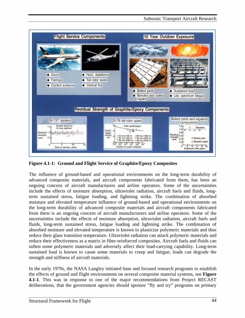
Subsonic Transport Aircraft Research
Structural Framework for Flight 44
Figure 4.1-1: Ground and Flight Service of Graphite/Epoxy Composites The influence of ground-based and operational environments on the long-term durability of advanced composite materials, and aircraft components fabricated from them, has been an ongoing concern of aircraft manufacturers and airline operators. Some of the uncertainties include the effects of moisture absorption, ultraviolet radiation, aircraft fuels and fluids, long-term sustained stress, fatigue loading, and lightning strike. The combination of absorbed moisture and elevated temperature influence of ground-based and operational environments on the long-term durability of advanced composite materials and aircraft components fabricated from them is an ongoing concern of aircraft manufacturers and airline operators. Some of the uncertainties include the effects of moisture absorption, ultraviolet radiation, aircraft fuels and fluids, long-term sustained stress, fatigue loading and lightning strike. The combination of absorbed moisture and elevated temperature is known to plasticize polymeric materials and thus reduce their glass transition temperature. Ultraviolet radiation can attack polymeric materials and reduce their effectiveness as a matrix in fiber-reinforced composites. Aircraft fuels and fluids can soften some polymeric materials and adversely affect their load-carrying capability. Long-term sustained load is known to cause some materials to creep and fatigue; loads can degrade the strength and stiffness of aircraft materials. In the early 1970s, the NASA Langley initiated base and focused research programs to establish the effects of ground and flight environments on several composite material systems, see Figure 4.1-1. This was in response to one of the major recommendations from Project RECAST deliberations, that the government agencies should sponsor “fly and try” programs on primary
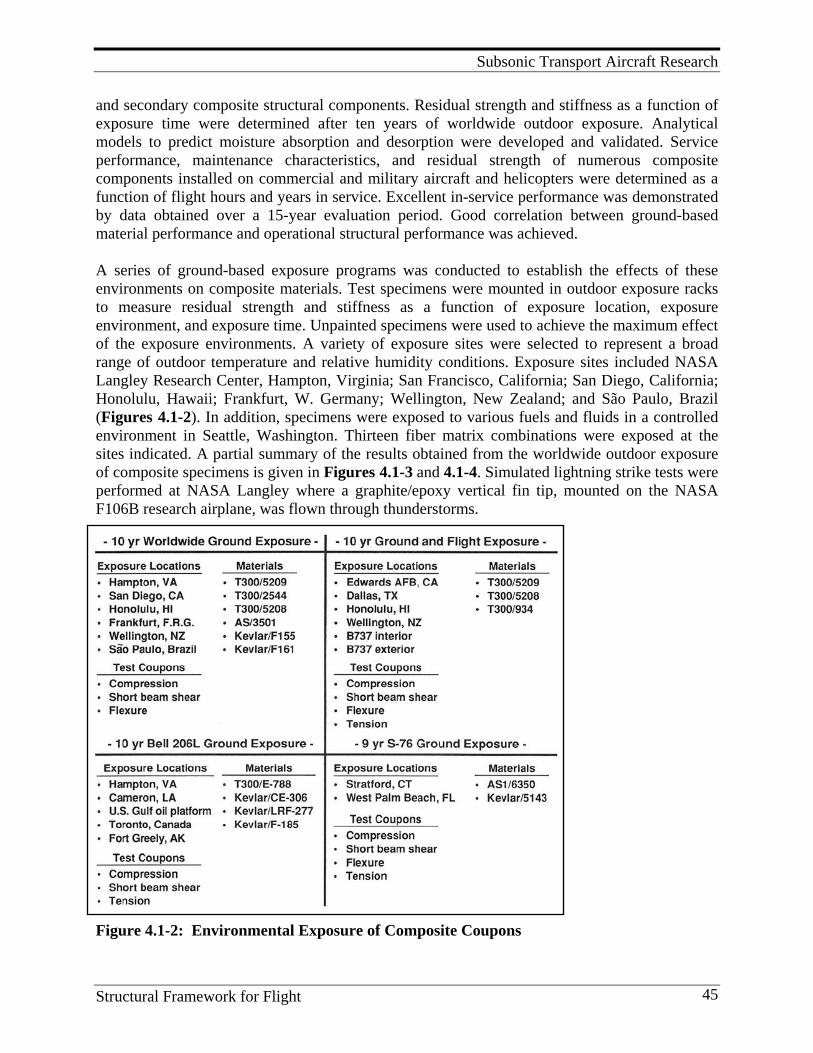
Subsonic Transport Aircraft Research
Structural Framework for Flight 45
and secondary composite structural components. Residual strength and stiffness as a function of exposure time were determined after ten years of worldwide outdoor exposure. Analytical models to predict moisture absorption and desorption were developed and validated. Service performance, maintenance characteristics, and residual strength of numerous composite components installed on commercial and military aircraft and helicopters were determined as a function of flight hours and years in service. Excellent in-service performance was demonstrated by data obtained over a 15-year evaluation period. Good correlation between ground-based material performance and operational structural performance was achieved. A series of ground-based exposure programs was conducted to establish the effects of these environments on composite materials. Test specimens were mounted in outdoor exposure racks to measure residual strength and stiffness as a function of exposure location, exposure environment, and exposure time. Unpainted specimens were used to achieve the maximum effect of the exposure environments. A variety of exposure sites were selected to represent a broad range of outdoor temperature and relative humidity conditions. Exposure sites included NASA Langley Research Center, Hampton, Virginia; San Francisco, California; San Diego, California; Honolulu, Hawaii; Frankfurt, W. Germany; Wellington, New Zealand; and São Paulo, Brazil (Figures 4.1-2). In addition, specimens were exposed to various fuels and fluids in a controlled environment in Seattle, Washington. Thirteen fiber matrix combinations were exposed at the sites indicated. A partial summary of the results obtained from the worldwide outdoor exposure of composite specimens is given in Figures 4.1-3 and 4.1-4. Simulated lightning strike tests were performed at NASA Langley where a graphite/epoxy vertical fin tip, mounted on the NASA F106B research airplane, was flown through thunderstorms.
Figure 4.1-2: Environmental Exposure of Composite Coupons
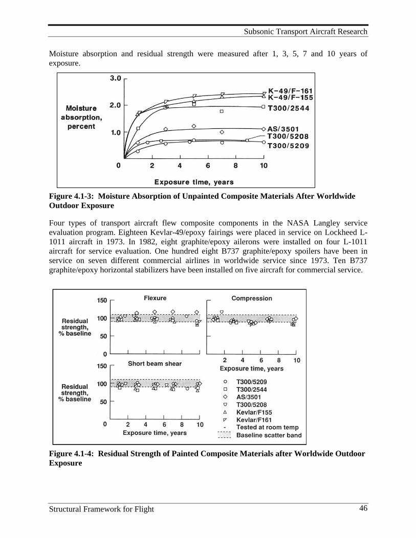
Subsonic Transport Aircraft Research
Structural Framework for Flight 46
Moisture absorption and residual strength were measured after 1, 3, 5, 7 and 10 years of exposure.
Figure 4.1-3: Moisture Absorption of Unpainted Composite Materials After Worldwide Outdoor Exposure
Four types of transport aircraft flew composite components in the NASA Langley service evaluation program. Eighteen Kevlar-49/epoxy fairings were placed in service on Lockheed L-1011 aircraft in 1973. In 1982, eight graphite/epoxy ailerons were installed on four L-1011 aircraft for service evaluation. One hundred eight B737 graphite/epoxy spoilers have been in service on seven different commercial airlines in worldwide service since 1973. Ten B737 graphite/epoxy horizontal stabilizers have been installed on five aircraft for commercial service.
Figure 4.1-4: Residual Strength of Painted Composite Materials after Worldwide Outdoor Exposure
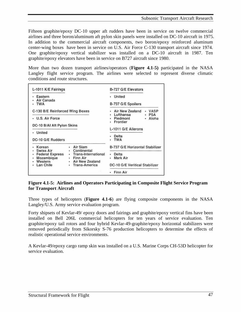
Subsonic Transport Aircraft Research
Structural Framework for Flight 47
Fifteen graphite/epoxy DC-10 upper aft rudders have been in service on twelve commercial airlines and three boron/aluminum aft pylon skin panels were installed on DC-10 aircraft in 1975. In addition to the commercial aircraft components, two boron/epoxy reinforced aluminum center-wing boxes have been in service on U.S. Air Force C-130 transport aircraft since 1974. One graphite/epoxy vertical stabilizer was installed on a DC-10 aircraft in 1987. Ten graphite/epoxy elevators have been in service on B727 aircraft since 1980. More than two dozen transport airlines/operators (Figure 4.1-5) participated in the NASA Langley flight service program. The airlines were selected to represent diverse climatic conditions and route structures.
Figure 4.1-5: Airlines and Operators Participating in Composite Flight Service Program for Transport Aircraft Three types of helicopters (Figure 4.1-6) are flying composite components in the NASA Langley/U.S. Army service evaluation program.
Forty shipsets of Kevlar-49/ epoxy doors and fairings and graphite/epoxy vertical fins have been installed on Bell 206L commercial helicopters for ten years of service evaluation. Ten graphite/epoxy tail rotors and four hybrid Kevlar-49-graphite/epoxy horizontal stabilizers were removed periodically from Sikorsky S-76 production helicopters to determine the effects of realistic operational service environments.
A Kevlar-49/epoxy cargo ramp skin was installed on a U.S. Marine Corps CH-53D helicopter for service evaluation.
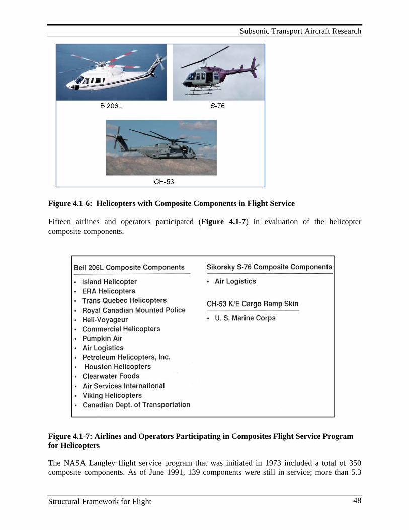
Subsonic Transport Aircraft Research
Structural Framework for Flight 48
Figure 4.1-6: Helicopters with Composite Components in Flight Service Fifteen airlines and operators participated (Figure 4.1-7) in evaluation of the helicopter composite components.
Figure 4.1-7: Airlines and Operators Participating in Composites Flight Service Program for Helicopters
The NASA Langley flight service program that was initiated in 1973 included a total of 350 composite components. As of June 1991, 139 components were still in service; more than 5.3
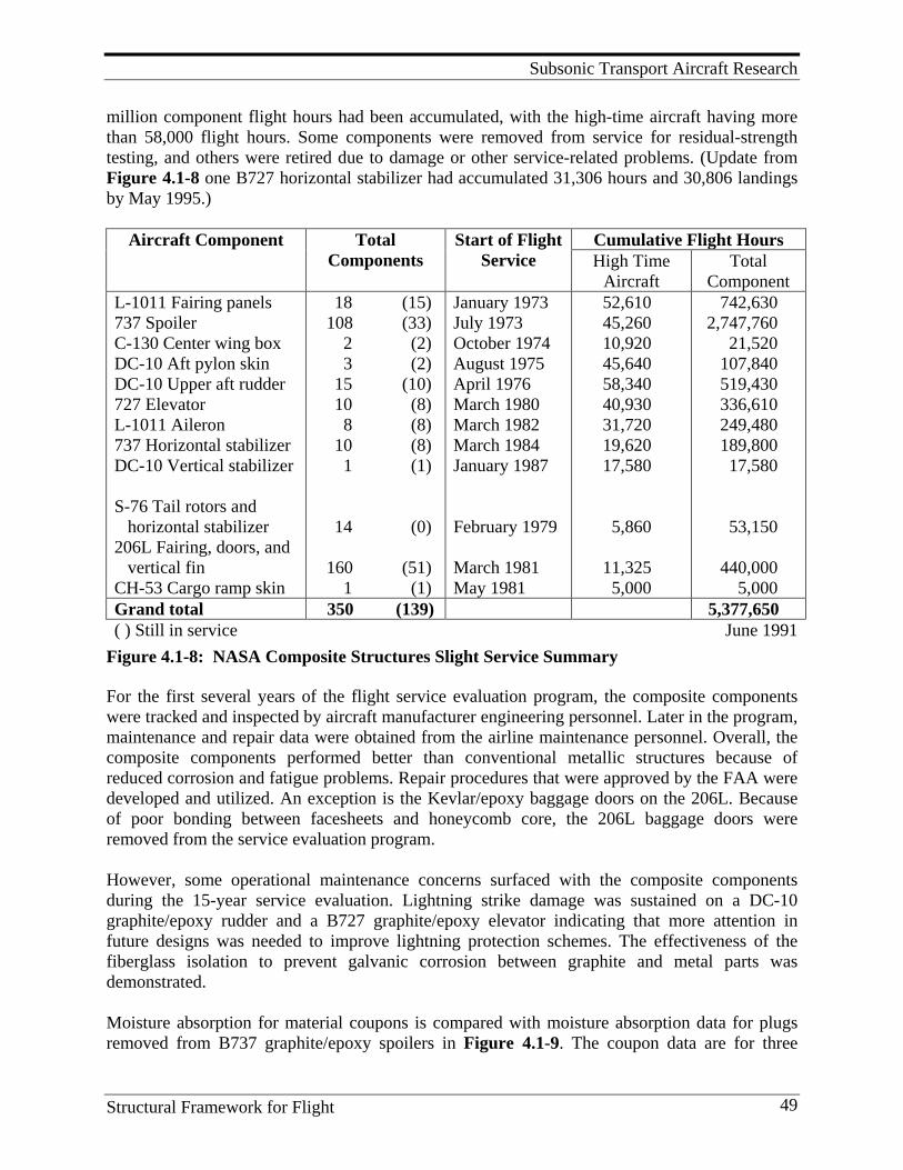
Subsonic Transport Aircraft Research
Structural Framework for Flight 49
million component flight hours had been accumulated, with the high-time aircraft having more than 58,000 flight hours. Some components were removed from service for residual-strength testing, and others were retired due to damage or other service-related problems. (Update from Figure 4.1-8 one B727 horizontal stabilizer had accumulated 31,306 hours and 30,806 landings by May 1995.)
Aircraft Component Total Components
Start of Flight Service
Cumulative Flight Hours High Time
Aircraft Total
Component L-1011 Fairing panels 737 Spoiler C-130 Center wing box DC-10 Aft pylon skin DC-10 Upper aft rudder 727 Elevator L-1011 Aileron 737 Horizontal stabilizer DC-10 Vertical stabilizer S-76 Tail rotors and horizontal stabilizer 206L Fairing, doors, and vertical fin CH-53 Cargo ramp skin
18 (15) 108 (33) 2 (2) 3 (2) 15 (10) 10 (8) 8 (8) 10 (8) 1 (1) 14 (0) 160 (51) 1 (1)
January 1973 July 1973 October 1974 August 1975 April 1976 March 1980 March 1982 March 1984 January 1987 February 1979 March 1981 May 1981
52,610 45,260 10,920 45,640 58,340 40,930 31,720 19,620 17,580 5,860 11,325 5,000
742,630 2,747,760 21,520 107,840 519,430 336,610 249,480 189,800 17,580 53,150 440,000 5,000
Grand total 350 (139) 5,377,650 ( ) Still in service June 1991
Figure 4.1-8: NASA Composite Structures Slight Service Summary
For the first several years of the flight service evaluation program, the composite components were tracked and inspected by aircraft manufacturer engineering personnel. Later in the program, maintenance and repair data were obtained from the airline maintenance personnel. Overall, the composite components performed better than conventional metallic structures because of reduced corrosion and fatigue problems. Repair procedures that were approved by the FAA were developed and utilized. An exception is the Kevlar/epoxy baggage doors on the 206L. Because of poor bonding between facesheets and honeycomb core, the 206L baggage doors were removed from the service evaluation program. However, some operational maintenance concerns surfaced with the composite components during the 15-year service evaluation. Lightning strike damage was sustained on a DC-10 graphite/epoxy rudder and a B727 graphite/epoxy elevator indicating that more attention in future designs was needed to improve lightning protection schemes. The effectiveness of the fiberglass isolation to prevent galvanic corrosion between graphite and metal parts was demonstrated. Moisture absorption for material coupons is compared with moisture absorption data for plugs removed from B737 graphite/epoxy spoilers in Figure 4.1-9. The coupon data are for three
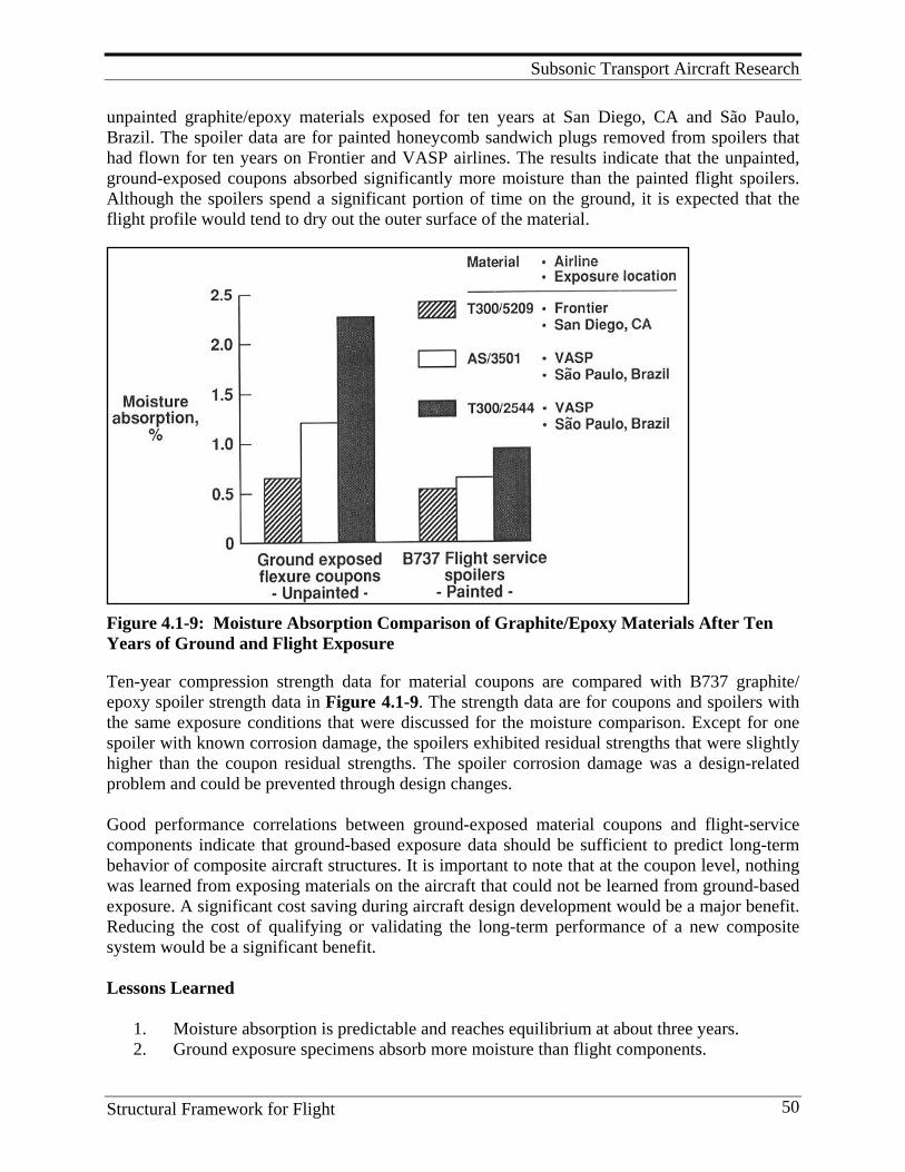
Subsonic Transport Aircraft Research
Structural Framework for Flight 50
unpainted graphite/epoxy materials exposed for ten years at San Diego, CA and São Paulo, Brazil. The spoiler data are for painted honeycomb sandwich plugs removed from spoilers that had flown for ten years on Frontier and VASP airlines. The results indicate that the unpainted, ground-exposed coupons absorbed significantly more moisture than the painted flight spoilers. Although the spoilers spend a significant portion of time on the ground, it is expected that the flight profile would tend to dry out the outer surface of the material.
Figure 4.1-9: Moisture Absorption Comparison of Graphite/Epoxy Materials After Ten Years of Ground and Flight Exposure
Ten-year compression strength data for material coupons are compared with B737 graphite/ epoxy spoiler strength data in Figure 4.1-9. The strength data are for coupons and spoilers with the same exposure conditions that were discussed for the moisture comparison. Except for one spoiler with known corrosion damage, the spoilers exhibited residual strengths that were slightly higher than the coupon residual strengths. The spoiler corrosion damage was a design-related problem and could be prevented through design changes. Good performance correlations between ground-exposed material coupons and flight-service components indicate that ground-based exposure data should be sufficient to predict long-term behavior of composite aircraft structures. It is important to note that at the coupon level, nothing was learned from exposing materials on the aircraft that could not be learned from ground-based exposure. A significant cost saving during aircraft design development would be a major benefit. Reducing the cost of qualifying or validating the long-term performance of a new composite system would be a significant benefit. Lessons Learned
1. Moisture absorption is predictable and reaches equilibrium at about three years. 2. Ground exposure specimens absorb more moisture than flight components.
Subsonic Transport Aircraft Research
Structural Framework for Flight 51
3. Kevlar fiber-reinforced composites absorb more moisture than graphite fiber-reinforced composites.
4. Moisture effects on hot/wet strength must be included in design. 5. Common selected 350°F cure epoxy matrix composites are not significantly affected by
exposure to aircraft fuel and fluids. 6. UV radiation is not a problem for painted composites. 7. Ground-based exposure data should be sufficient to predict long-term behavior of
composite aircraft structures. Nothing was learned from exposing materials on the aircraft that could not have been learned from ground-based exposure.
8. Service experience demonstrated that composite structures performed better than con-ventional metallic structures.
9. Fewer corrosion and fatigue problems were observed for composite structures relative to conventional metallic structures.
10. Special attention is warranted in design and installation of lightning protection schemes. 11. Properly designed and manufactured composite structures performed well, even after
long-term airline service. 12. Both short-term metallic and long-term (composite or metallic) repairs are needed to
accommodate a wide range of accidents and site locations.
Future Direction Continue to develop accelerated test methods and analyses to predict aging effects on new composite materials. This could be particularly important in the future, as hybrid systems are developed for multifunctional structures. Program Significance
1. Database on effects of long-term exposure to moisture and fluids on graphite/epoxy and Kevlar/epoxy composites.
2. Confidence that properly designed and manufactured composite structures can withstand long-term airline operational and environmental exposure has been demonstrated. Since fewer corrosion and fatigue problems are anticipated, maintenance expense is expected to be less than cost for similar metal structures. United States and European manufactures of transport, general aviation, and rotorcraft continue to increase their commitment to expanded use of composites. In 1970 composite structure was about 2% of the total structural weight. In 2010 composite structure is reported to be 50% of the total structural weight in the new Boeing 787. A number of transport, general aviation, and rotorcraft have been certified to FAA regulations on lightning strike and prepreg suppliers offer metallic screen or mesh protection schemes.
Key Personnel Early leaders in establishing the long term environmental effects on composites aircraft structures included: Richard R Heldenfels, George W. Brooks, William A. Brooks, Jr., Eldon Mathauser, and Richard A. Pride. Key researchers included Marvin B. Dow, H. Benson Dexter, Darrel Tenney, Edward Long, Steve Tompkins, and William Howell.
Subsonic Transport Aircraft Research
Structural Framework for Flight 52
References
1. Brooks, W. A., and M. B. Dow. 1973. Service Evaluation of Aircraft Composite Structural Components. (NASA TM X – 71944).
2. Unnam, J., and D. R. Tenney. 1977. Analytical Prediction of Moisture Absorption/Desorption in
Resin Matrix Composites Exposed to Aircraft Environments. (AIAA Paper 77-400).
3. Tompkins, S. S. 1977. Analytical Study of Effects of Surface and Environmental Thermal Properties on Moisture of Composites. (NASA TM X – 3562).
4. Long, E. R. 1979. Moisture Diffusion Parameter Characteristics for Epoxy Composites and Neat
Resins. (NASA TP-1474).
5. Tanimoto, E. Y. 1981. Effects of Long-term Exposure to Fuels and Fluids on Behavior of Advanced Composite Materials. (NASA CR – 165763).
6. Howell, W. E. and B. D. Fisher. 1983. Observations of Severe In-flight Environments on
Airplane Composite Structural Components. Paper presented at the Business Aircraft Meeting and Exposition of the Society of Automotive Engineers, Wichita, KS.
7. Dexter, H. B. 1987. Long-term Environmental Effects and Flight Service Evaluation of
Composite Materials. (NASA TM – 89067).
8. Coggeshall, R. L. 1989. Boeing/NASA Composite Components Flight Service Evaluation. (NASA CR – 181898).
9. Dexter, H. B., and D. J. Baker. 1991. Flight Service Environmental Effects on Composite
Materials and Structures. AGARD Report 785.
10. Gardiner, G. 2006. Lightning Strike Protection for Composite Structures. CompositesWorld: High-performance Composites, July 1. http://www.compositesworld.com/articles/lightning-strike-protection-for-composite-structures.
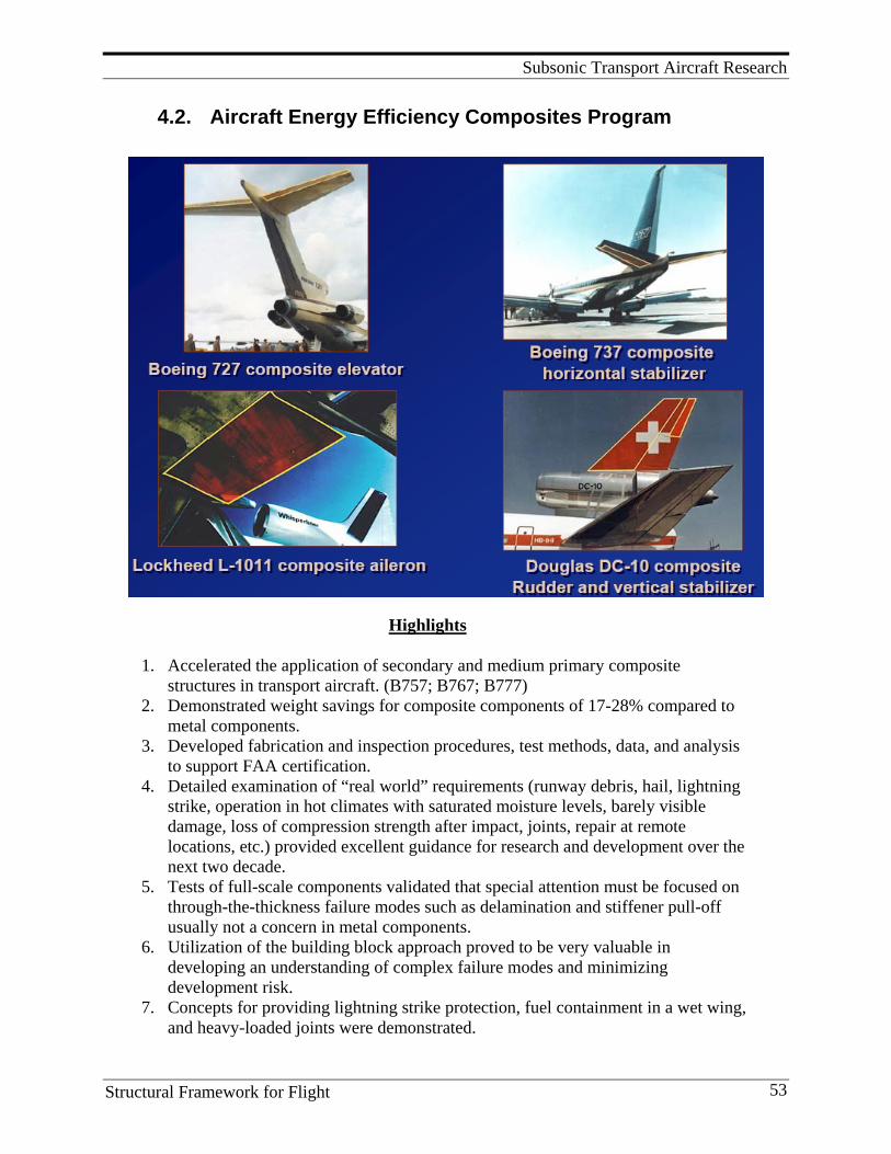
Subsonic Transport Aircraft Research
Structural Framework for Flight 53
4.2. Aircraft Energy Efficiency Composites Program
Highlights
1. Accelerated the application of secondary and medium primary composite structures in transport aircraft. (B757; B767; B777)
2. Demonstrated weight savings for composite components of 17-28% compared to metal components.
3. Developed fabrication and inspection procedures, test methods, data, and analysis to support FAA certification.
4. Detailed examination of “real world” requirements (runway debris, hail, lightning strike, operation in hot climates with saturated moisture levels, barely visible damage, loss of compression strength after impact, joints, repair at remote locations, etc.) provided excellent guidance for research and development over the next two decade.
5. Tests of full-scale components validated that special attention must be focused on through-the-thickness failure modes such as delamination and stiffener pull-off usually not a concern in metal components.
6. Utilization of the building block approach proved to be very valuable in developing an understanding of complex failure modes and minimizing development risk.
7. Concepts for providing lightning strike protection, fuel containment in a wet wing, and heavy-loaded joints were demonstrated.
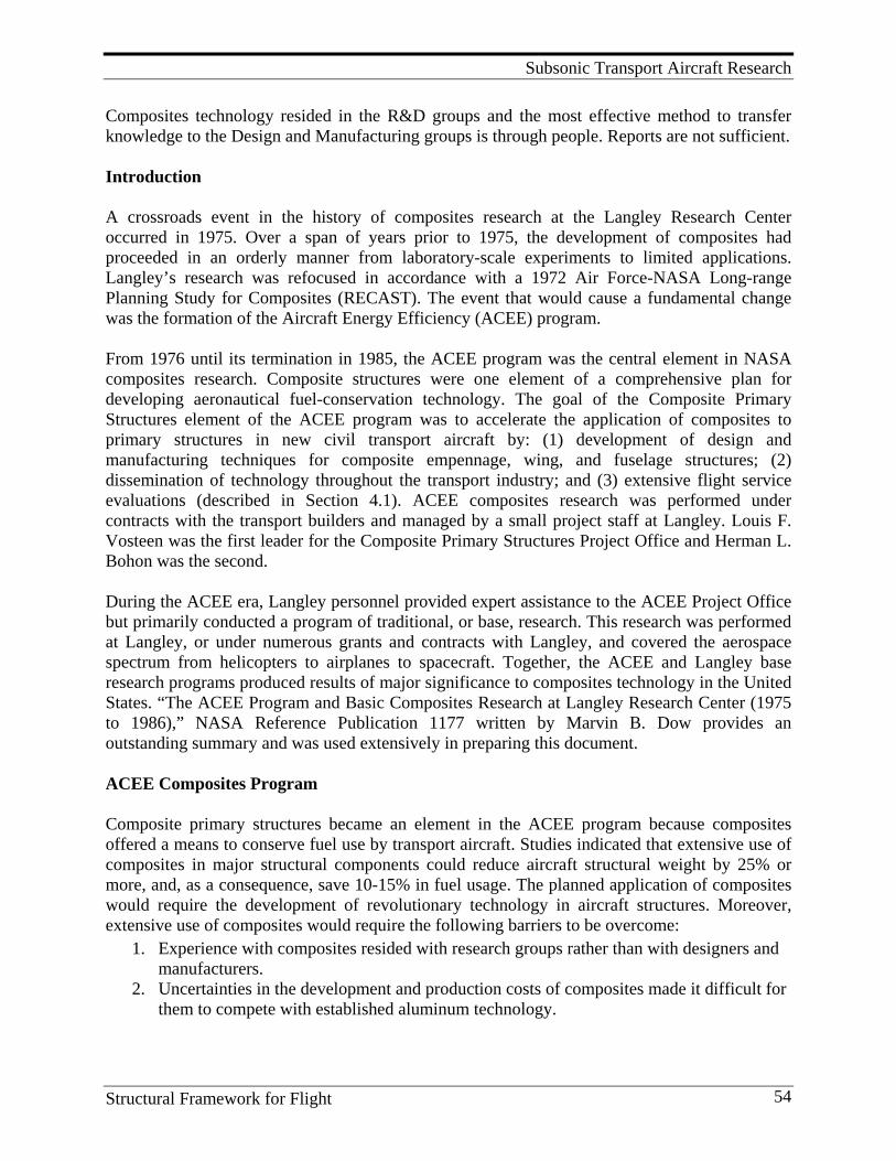
Subsonic Transport Aircraft Research
Structural Framework for Flight 54
Composites technology resided in the R&D groups and the most effective method to transfer knowledge to the Design and Manufacturing groups is through people. Reports are not sufficient. Introduction A crossroads event in the history of composites research at the Langley Research Center occurred in 1975. Over a span of years prior to 1975, the development of composites had proceeded in an orderly manner from laboratory-scale experiments to limited applications. Langley’s research was refocused in accordance with a 1972 Air Force-NASA Long-range Planning Study for Composites (RECAST). The event that would cause a fundamental change was the formation of the Aircraft Energy Efficiency (ACEE) program. From 1976 until its termination in 1985, the ACEE program was the central element in NASA composites research. Composite structures were one element of a comprehensive plan for developing aeronautical fuel-conservation technology. The goal of the Composite Primary Structures element of the ACEE program was to accelerate the application of composites to primary structures in new civil transport aircraft by: (1) development of design and manufacturing techniques for composite empennage, wing, and fuselage structures; (2) dissemination of technology throughout the transport industry; and (3) extensive flight service evaluations (described in Section 4.1). ACEE composites research was performed under contracts with the transport builders and managed by a small project staff at Langley. Louis F. Vosteen was the first leader for the Composite Primary Structures Project Office and Herman L. Bohon was the second. During the ACEE era, Langley personnel provided expert assistance to the ACEE Project Office but primarily conducted a program of traditional, or base, research. This research was performed at Langley, or under numerous grants and contracts with Langley, and covered the aerospace spectrum from helicopters to airplanes to spacecraft. Together, the ACEE and Langley base research programs produced results of major significance to composites technology in the United States. “The ACEE Program and Basic Composites Research at Langley Research Center (1975 to 1986),” NASA Reference Publication 1177 written by Marvin B. Dow provides an outstanding summary and was used extensively in preparing this document. ACEE Composites Program Composite primary structures became an element in the ACEE program because composites offered a means to conserve fuel use by transport aircraft. Studies indicated that extensive use of composites in major structural components could reduce aircraft structural weight by 25% or more, and, as a consequence, save 10-15% in fuel usage. The planned application of composites would require the development of revolutionary technology in aircraft structures. Moreover, extensive use of composites would require the following barriers to be overcome:
1. Experience with composites resided with research groups rather than with designers and manufacturers.
2. Uncertainties in the development and production costs of composites made it difficult for them to compete with established aluminum technology.
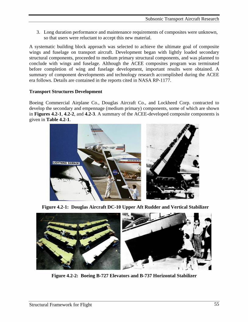
Subsonic Transport Aircraft Research
Structural Framework for Flight 55
3. Long duration performance and maintenance requirements of composites were unknown, so that users were reluctant to accept this new material.
A systematic building block approach was selected to achieve the ultimate goal of composite wings and fuselage on transport aircraft. Development began with lightly loaded secondary structural components, proceeded to medium primary structural components, and was planned to conclude with wings and fuselage. Although the ACEE composites program was terminated before completion of wing and fuselage development, important results were obtained. A summary of component developments and technology research accomplished during the ACEE era follows. Details are contained in the reports cited in NASA RP-1177. Transport Structures Development Boeing Commercial Airplane Co., Douglas Aircraft Co., and Lockheed Corp. contracted to develop the secondary and empennage (medium primary) components, some of which are shown in Figures 4.2-1, 4.2-2, and 4.2-3. A summary of the ACEE-developed composite components is given in Table 4.2-1.
Figure 4.2-2: Boeing B-727 Elevators and B-737 Horizontal Stabilizer
Figure 4.2-1: Douglas Aircraft DC-10 Upper Aft Rudder and Vertical Stabilizer

Subsonic Transport Aircraft Research
Structural Framework for Flight 56
Figure 4.2-3: Lockheed L-1011 Aileron and Vertical Fin
Table 4.2-1: ACEE Developed Composite Components
Secondary Empennage DC-10 B737 L-1011 DC-10 B727 L-1011 Vertical Horizontal Vertical Component Rudder Elevator Aileron Stabilizer Stabilizer Fin Size(root x span),ft. 3.2x13.2 3.4x17.4 4.3x7.7 6.8x22.8 4.3x16.7 8.9x25 Metal design wt., lb. 91 130 140 1005 262 858 Composite design wt., lb. 67 98 107 834 204 622 Weight reduction,% 26 25 24 17 22 28 No. of Production Units 20 11 12 3 11 2 Start Flight Service 4/76 3/80 3/82 1/87 3/84 -
The weight savings indicated for each component is based on comparison with the weight of the original aluminum alloy component. Although different in detail, each contract encompassed the elements shown in Figure 4.2-4 and each incorporated cost-sharing provisions.
Figure 4.2-4: Elements of Typical Component Development Contracts
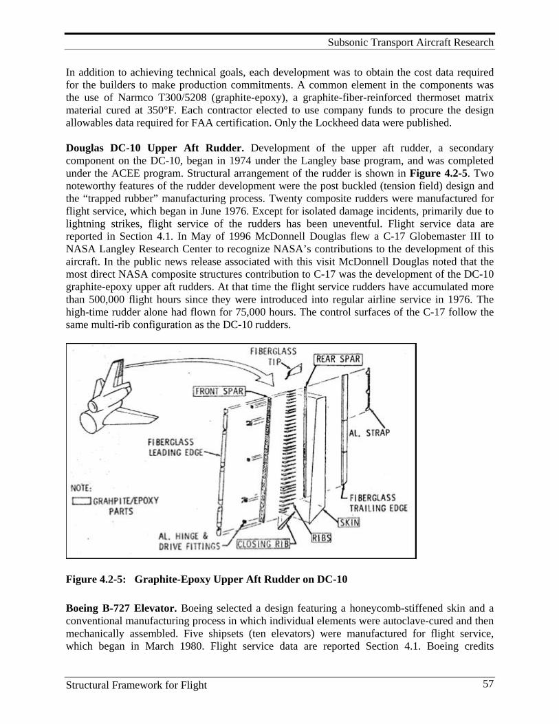
Subsonic Transport Aircraft Research
Structural Framework for Flight 57
In addition to achieving technical goals, each development was to obtain the cost data required for the builders to make production commitments. A common element in the components was the use of Narmco T300/5208 (graphite-epoxy), a graphite-fiber-reinforced thermoset matrix material cured at 350°F. Each contractor elected to use company funds to procure the design allowables data required for FAA certification. Only the Lockheed data were published. Douglas DC-10 Upper Aft Rudder. Development of the upper aft rudder, a secondary component on the DC-10, began in 1974 under the Langley base program, and was completed under the ACEE program. Structural arrangement of the rudder is shown in Figure 4.2-5. Two noteworthy features of the rudder development were the post buckled (tension field) design and the “trapped rubber” manufacturing process. Twenty composite rudders were manufactured for flight service, which began in June 1976. Except for isolated damage incidents, primarily due to lightning strikes, flight service of the rudders has been uneventful. Flight service data are reported in Section 4.1. In May of 1996 McDonnell Douglas flew a C-17 Globemaster III to NASA Langley Research Center to recognize NASA’s contributions to the development of this aircraft. In the public news release associated with this visit McDonnell Douglas noted that the most direct NASA composite structures contribution to C-17 was the development of the DC-10 graphite-epoxy upper aft rudders. At that time the flight service rudders have accumulated more than 500,000 flight hours since they were introduced into regular airline service in 1976. The high-time rudder alone had flown for 75,000 hours. The control surfaces of the C-17 follow the same multi-rib configuration as the DC-10 rudders.
Figure 4.2-5: Graphite-Epoxy Upper Aft Rudder on DC-10
Boeing B-727 Elevator. Boeing selected a design featuring a honeycomb-stiffened skin and a conventional manufacturing process in which individual elements were autoclave-cured and then mechanically assembled. Five shipsets (ten elevators) were manufactured for flight service, which began in March 1980. Flight service data are reported Section 4.1. Boeing credits

Subsonic Transport Aircraft Research
Structural Framework for Flight 58
successful development of the elevator with providing the confidence and experience needed to use composite components on the B-757 and B-767 transports (Figure 4.2-6).
Figure 4.2-6: Use of Composite Materials on Boeing 767 Aircraft
Figure 4.2-7: Graphite-Epoxy Inboard Aileron on L-1011 Lockheed L-1011 Inboard Aileron. The aileron structure is located behind the wing engines on the L-1011 and has the structural arrangement shown in Figure 4.2-7. Aileron manufacture and assembly were performed by AVCO Corporation under subcontract to Lockheed. This con-tractual arrangement was similar to that for the L-1011 metal wing structure. The composite
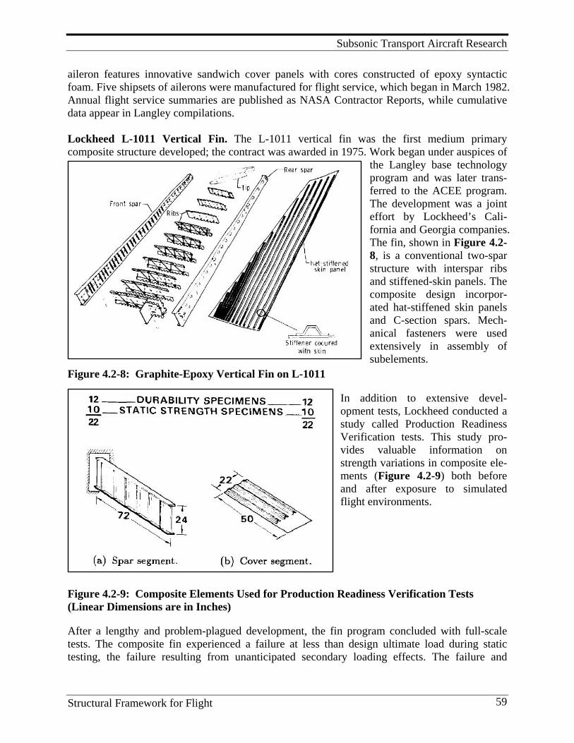
Subsonic Transport Aircraft Research
Structural Framework for Flight 59
aileron features innovative sandwich cover panels with cores constructed of epoxy syntactic foam. Five shipsets of ailerons were manufactured for flight service, which began in March 1982. Annual flight service summaries are published as NASA Contractor Reports, while cumulative data appear in Langley compilations. Lockheed L-1011 Vertical Fin. The L-1011 vertical fin was the first medium primary composite structure developed; the contract was awarded in 1975. Work began under auspices of
the Langley base technology program and was later trans-ferred to the ACEE program. The development was a joint effort by Lockheed’s Cali-fornia and Georgia companies. The fin, shown in Figure 4.2-8, is a conventional two-spar structure with interspar ribs and stiffened-skin panels. The composite design incorpor-ated hat-stiffened skin panels and C-section spars. Mech-anical fasteners were used extensively in assembly of subelements.
Figure 4.2-8: Graphite-Epoxy Vertical Fin on L-1011
In addition to extensive devel-opment tests, Lockheed conducted a study called Production Readiness Verification tests. This study pro-vides valuable information on strength variations in composite ele-ments (Figure 4.2-9) both before and after exposure to simulated flight environments.
Figure 4.2-9: Composite Elements Used for Production Readiness Verification Tests (Linear Dimensions are in Inches)
After a lengthy and problem-plagued development, the fin program concluded with full-scale tests. The composite fin experienced a failure at less than design ultimate load during static testing, the failure resulting from unanticipated secondary loading effects. The failure and
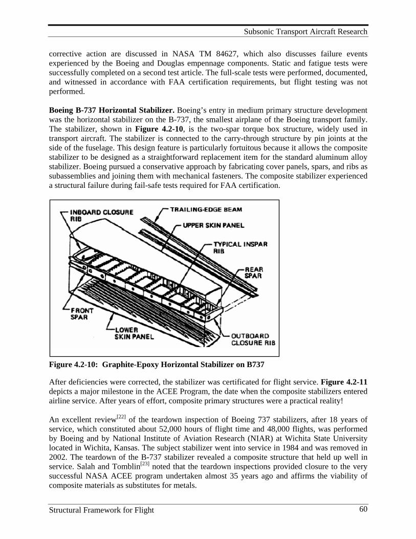
Subsonic Transport Aircraft Research
Structural Framework for Flight 60
corrective action are discussed in NASA TM 84627, which also discusses failure events experienced by the Boeing and Douglas empennage components. Static and fatigue tests were successfully completed on a second test article. The full-scale tests were performed, documented, and witnessed in accordance with FAA certification requirements, but flight testing was not performed. Boeing B-737 Horizontal Stabilizer. Boeing’s entry in medium primary structure development was the horizontal stabilizer on the B-737, the smallest airplane of the Boeing transport family. The stabilizer, shown in Figure 4.2-10, is the two-spar torque box structure, widely used in transport aircraft. The stabilizer is connected to the carry-through structure by pin joints at the side of the fuselage. This design feature is particularly fortuitous because it allows the composite stabilizer to be designed as a straightforward replacement item for the standard aluminum alloy stabilizer. Boeing pursued a conservative approach by fabricating cover panels, spars, and ribs as subassemblies and joining them with mechanical fasteners. The composite stabilizer experienced a structural failure during fail-safe tests required for FAA certification.
Figure 4.2-10: Graphite-Epoxy Horizontal Stabilizer on B737
After deficiencies were corrected, the stabilizer was certificated for flight service. Figure 4.2-11 depicts a major milestone in the ACEE Program, the date when the composite stabilizers entered airline service. After years of effort, composite primary structures were a practical reality! An excellent review[22] of the teardown inspection of Boeing 737 stabilizers, after 18 years of service, which constituted about 52,000 hours of flight time and 48,000 flights, was performed by Boeing and by National Institute of Aviation Research (NIAR) at Wichita State University located in Wichita, Kansas. The subject stabilizer went into service in 1984 and was removed in 2002. The teardown of the B-737 stabilizer revealed a composite structure that held up well in service. Salah and Tomblin[23] noted that the teardown inspections provided closure to the very successful NASA ACEE program undertaken almost 35 years ago and affirms the viability of composite materials as substitutes for metals.
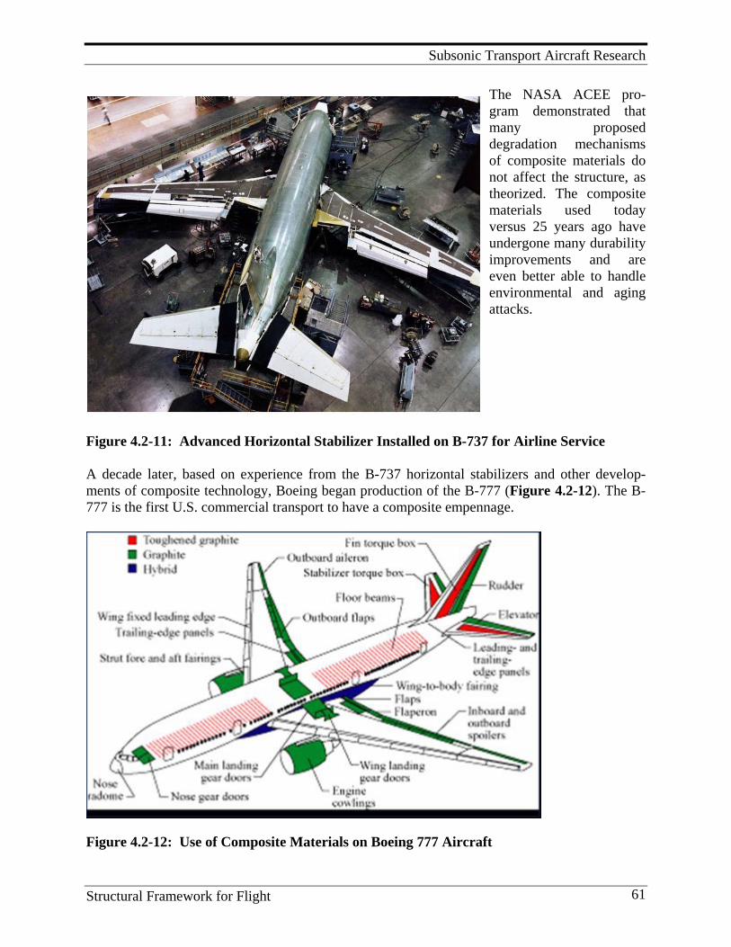
Subsonic Transport Aircraft Research
Structural Framework for Flight 61
The NASA ACEE pro-gram demonstrated that many proposed degradation mechanisms of composite materials do not affect the structure, as theorized. The composite materials used today versus 25 years ago have undergone many durability improvements and are even better able to handle environmental and aging attacks.
Figure 4.2-11: Advanced Horizontal Stabilizer Installed on B-737 for Airline Service A decade later, based on experience from the B-737 horizontal stabilizers and other develop-ments of composite technology, Boeing began production of the B-777 (Figure 4.2-12). The B-777 is the first U.S. commercial transport to have a composite empennage.
Figure 4.2-12: Use of Composite Materials on Boeing 777 Aircraft
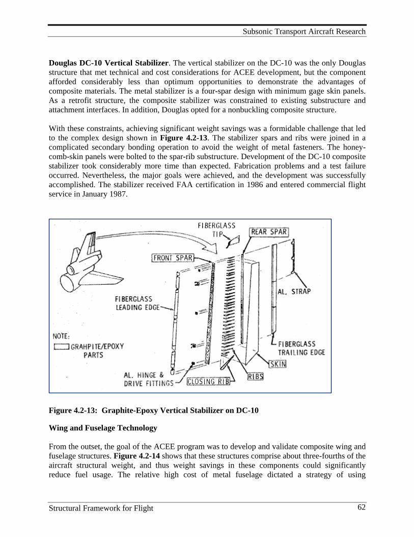
Subsonic Transport Aircraft Research
Structural Framework for Flight 62
Douglas DC-10 Vertical Stabilizer. The vertical stabilizer on the DC-10 was the only Douglas structure that met technical and cost considerations for ACEE development, but the component afforded considerably less than optimum opportunities to demonstrate the advantages of composite materials. The metal stabilizer is a four-spar design with minimum gage skin panels. As a retrofit structure, the composite stabilizer was constrained to existing substructure and attachment interfaces. In addition, Douglas opted for a nonbuckling composite structure. With these constraints, achieving significant weight savings was a formidable challenge that led to the complex design shown in Figure 4.2-13. The stabilizer spars and ribs were joined in a complicated secondary bonding operation to avoid the weight of metal fasteners. The honey-comb-skin panels were bolted to the spar-rib substructure. Development of the DC-10 composite stabilizer took considerably more time than expected. Fabrication problems and a test failure occurred. Nevertheless, the major goals were achieved, and the development was successfully accomplished. The stabilizer received FAA certification in 1986 and entered commercial flight service in January 1987.
Figure 4.2-13: Graphite-Epoxy Vertical Stabilizer on DC-10
Wing and Fuselage Technology From the outset, the goal of the ACEE program was to develop and validate composite wing and fuselage structures. Figure 4.2-14 shows that these structures comprise about three-fourths of the aircraft structural weight, and thus weight savings in these components could significantly reduce fuel usage. The relative high cost of metal fuselage dictated a strategy of using
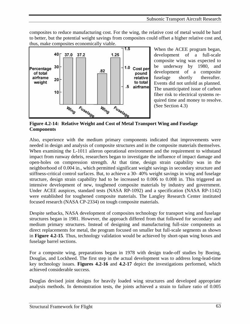
Subsonic Transport Aircraft Research
Structural Framework for Flight 63
composites to reduce manufacturing cost. For the wing, the relative cost of metal would be hard to better, but the potential weight savings from composites could offset a higher relative cost and, thus, make composites economically viable.
When the ACEE program began, development of a full-scale composite wing was expected to be underway by 1980, and development of a composite fuselage shortly thereafter. Events did not unfold as planned. The unanticipated issue of carbon fiber risk to electrical systems re-quired time and money to resolve. (See Section 4.3)
Figure 4.2-14: Relative Weight and Cost of Metal Transport Wing and Fuselage Components
Also, experience with the medium primary components indicated that improvements were needed in design and analysis of composite structures and in the composite materials themselves. When examining the L-1011 aileron operational environment and the requirement to withstand impact from runway debris, researchers began to investigate the influence of impact damage and open-holes on compression strength. At that time, design strain capability was in the neighborhood of 0.004 in., which permitted significant weight savings in secondary structure and stiffness-critical control surfaces. But, to achieve a 30- 40% weight savings in wing and fuselage structure, design strain capability had to be increased to 0.006 to 0.008 in. This triggered an intensive development of new, toughened composite materials by industry and government. Under ACEE auspices, standard tests (NASA RP-1092) and a specification (NASA RP-1142) were established for toughened composite materials. The Langley Research Center instituted focused research (NASA CP-2334) on tough composite materials. Despite setbacks, NASA development of composites technology for transport wing and fuselage structures began in 1981. However, the approach differed from that followed for secondary and medium primary structures. Instead of designing and manufacturing full-size components as direct replacements for metal, the program focused on smaller but full-scale segments as shown in Figure 4.2-15. Thus, technology validation would be achieved by short-span wing boxes and fuselage barrel sections. For a composite wing, preparations began in 1978 with design trade-off studies by Boeing, Douglas, and Lockheed. The first step in the actual development was to address long-lead-time key technology issues. Figures 4.2-16 and 4.2-17 depict the investigations performed, which achieved considerable success. Douglas devised joint designs for heavily loaded wing structures and developed appropriate analysis methods. In demonstration tests, the joints achieved a strain to failure ratio of 0.005
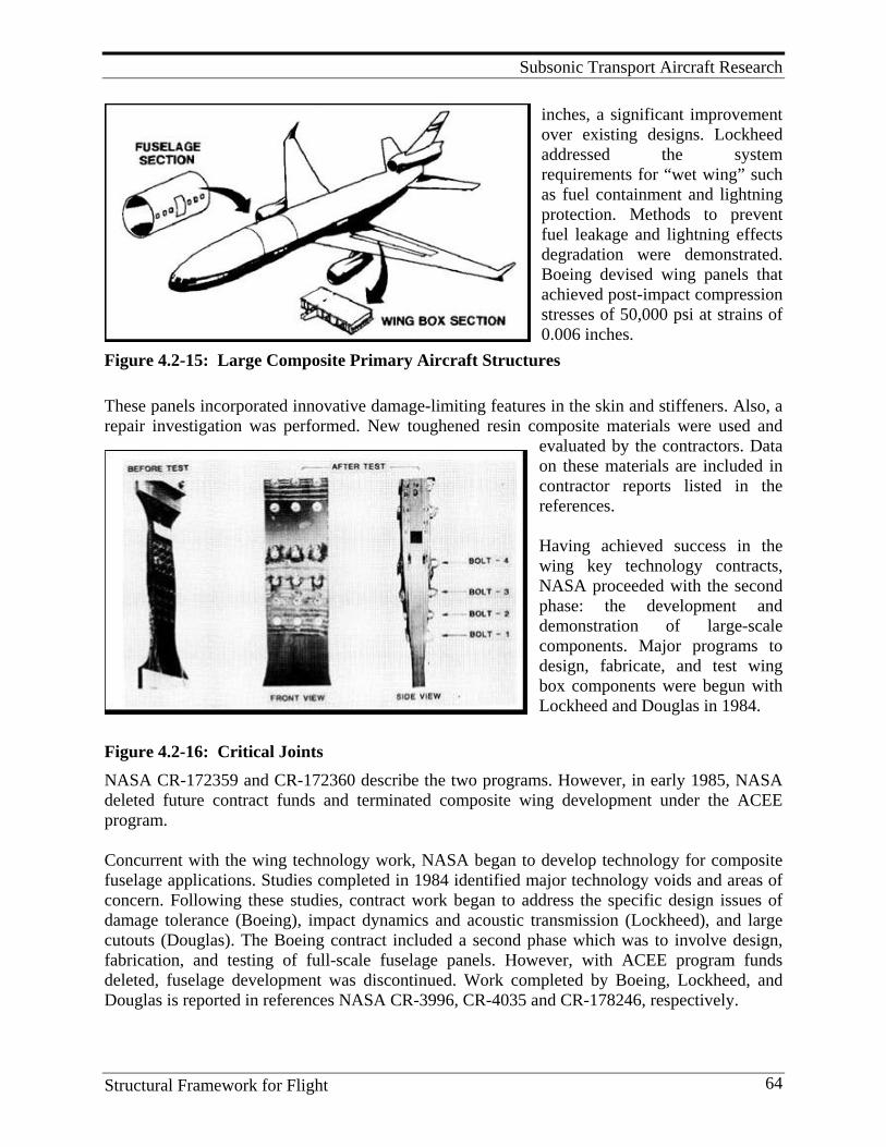
Subsonic Transport Aircraft Research
Structural Framework for Flight 64
inches, a significant improvement over existing designs. Lockheed addressed the system requirements for “wet wing” such as fuel containment and lightning protection. Methods to prevent fuel leakage and lightning effects degradation were demonstrated. Boeing devised wing panels that achieved post-impact compression stresses of 50,000 psi at strains of 0.006 inches.
Figure 4.2-15: Large Composite Primary Aircraft Structures These panels incorporated innovative damage-limiting features in the skin and stiffeners. Also, a repair investigation was performed. New toughened resin composite materials were used and
evaluated by the contractors. Data on these materials are included in contractor reports listed in the references. Having achieved success in the wing key technology contracts, NASA proceeded with the second phase: the development and demonstration of large-scale components. Major programs to design, fabricate, and test wing box components were begun with Lockheed and Douglas in 1984.
Figure 4.2-16: Critical Joints NASA CR-172359 and CR-172360 describe the two programs. However, in early 1985, NASA deleted future contract funds and terminated composite wing development under the ACEE program. Concurrent with the wing technology work, NASA began to develop technology for composite fuselage applications. Studies completed in 1984 identified major technology voids and areas of concern. Following these studies, contract work began to address the specific design issues of damage tolerance (Boeing), impact dynamics and acoustic transmission (Lockheed), and large cutouts (Douglas). The Boeing contract included a second phase which was to involve design, fabrication, and testing of full-scale fuselage panels. However, with ACEE program funds deleted, fuselage development was discontinued. Work completed by Boeing, Lockheed, and Douglas is reported in references NASA CR-3996, CR-4035 and CR-178246, respectively.

Subsonic Transport Aircraft Research
Structural Framework for Flight 65
Figure 4.2-17: Fuel Containment and Damage Tolerance Lessons Learned
1. All operational, environmental, and design requirements should be defined before material selection.
2. All disciplines (design, manufacturing, costs, operators, etc.) should be included on the development team at project initiation.
3. Utilization of the building block approach proved to be very valuable in developing an understanding of complex failure modes and minimizing development risk.
4. Tests of full-scale components validated that special attention must be focused on through-the-thickness failure modes such as delamination and stiffener pull-off, usually not a concern in metal components. (All ACEE medium primary components experienced these modes of failure.)
5. Scale-up of the manufacturing processes should be completed early in the development schedule.
6. Composites technology resided in the R&D groups and the most effective method to transfer knowledge to the Design and Manufacturing groups is by people. Reports are not sufficient.
Future Direction Development of innovative designs, improved analyses tools, and automated manufacturing procedures are needed to reduce the cost of developing and certifying new composite structures. Program Significance This body of work provided confidence to aircraft manufactures and operators to utilize composite structures and to exploit their benefits of saving fuel, lower noise, and fewer maintenance problems.
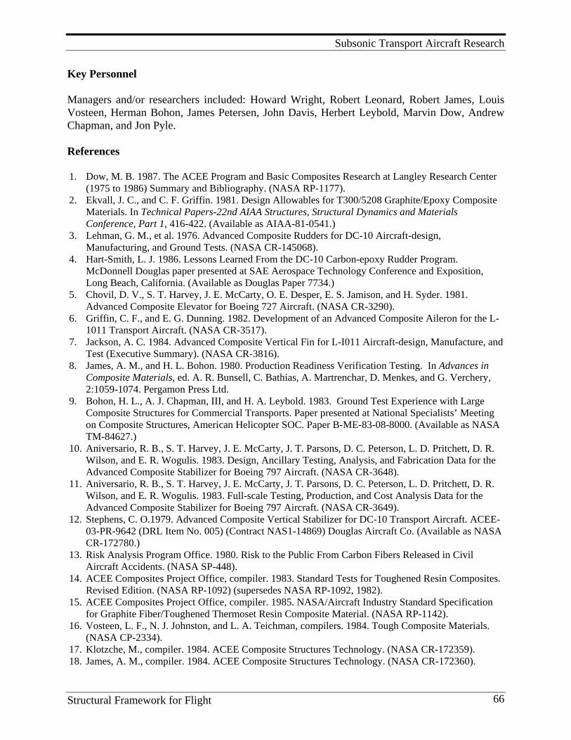
Subsonic Transport Aircraft Research
Structural Framework for Flight 66
Key Personnel Managers and/or researchers included: Howard Wright, Robert Leonard, Robert James, Louis Vosteen, Herman Bohon, James Petersen, John Davis, Herbert Leybold, Marvin Dow, Andrew Chapman, and Jon Pyle. References 1. Dow, M. B. 1987. The ACEE Program and Basic Composites Research at Langley Research Center
(1975 to 1986) Summary and Bibliography. (NASA RP-1177). 2. Ekvall, J. C., and C. F. Griffin. 1981. Design Allowables for T300/5208 Graphite/Epoxy Composite
Materials. In Technical Papers-22nd AIAA Structures, Structural Dynamics and Materials Conference, Part 1, 416-422. (Available as AIAA-81-0541.)
3. Lehman, G. M., et al. 1976. Advanced Composite Rudders for DC-10 Aircraft-design, Manufacturing, and Ground Tests. (NASA CR-145068).
4. Hart-Smith, L. J. 1986. Lessons Learned From the DC-10 Carbon-epoxy Rudder Program. McDonnell Douglas paper presented at SAE Aerospace Technology Conference and Exposition, Long Beach, California. (Available as Douglas Paper 7734.)
5. Chovil, D. V., S. T. Harvey, J. E. McCarty, O. E. Desper, E. S. Jamison, and H. Syder. 1981. Advanced Composite Elevator for Boeing 727 Aircraft. (NASA CR-3290).
6. Griffin, C. F., and E. G. Dunning. 1982. Development of an Advanced Composite Aileron for the L-1011 Transport Aircraft. (NASA CR-3517).
7. Jackson, A. C. 1984. Advanced Composite Vertical Fin for L-I011 Aircraft-design, Manufacture, and Test (Executive Summary). (NASA CR-3816).
8. James, A. M., and H. L. Bohon. 1980. Production Readiness Verification Testing. In Advances in Composite Materials, ed. A. R. Bunsell, C. Bathias, A. Martrenchar, D. Menkes, and G. Verchery, 2:1059-1074. Pergamon Press Ltd.
9. Bohon, H. L., A. J. Chapman, III, and H. A. Leybold. 1983. Ground Test Experience with Large Composite Structures for Commercial Transports. Paper presented at National Specialists’ Meeting on Composite Structures, American Helicopter SOC. Paper B-ME-83-08-8000. (Available as NASA TM-84627.)
10. Aniversario, R. B., S. T. Harvey, J. E. McCarty, J. T. Parsons, D. C. Peterson, L. D. Pritchett, D. R. Wilson, and E. R. Wogulis. 1983. Design, Ancillary Testing, Analysis, and Fabrication Data for the Advanced Composite Stabilizer for Boeing 797 Aircraft. (NASA CR-3648).
11. Aniversario, R. B., S. T. Harvey, J. E. McCarty, J. T. Parsons, D. C. Peterson, L. D. Pritchett, D. R. Wilson, and E. R. Wogulis. 1983. Full-scale Testing, Production, and Cost Analysis Data for the Advanced Composite Stabilizer for Boeing 797 Aircraft. (NASA CR-3649).
12. Stephens, C. O.1979. Advanced Composite Vertical Stabilizer for DC-10 Transport Aircraft. ACEE-03-PR-9642 (DRL Item No. 005) (Contract NAS1-14869) Douglas Aircraft Co. (Available as NASA CR-172780.)
13. Risk Analysis Program Office. 1980. Risk to the Public From Carbon Fibers Released in Civil Aircraft Accidents. (NASA SP-448).
14. ACEE Composites Project Office, compiler. 1983. Standard Tests for Toughened Resin Composites. Revised Edition. (NASA RP-1092) (supersedes NASA RP-1092, 1982).
15. ACEE Composites Project Office, compiler. 1985. NASA/Aircraft Industry Standard Specification for Graphite Fiber/Toughened Thermoset Resin Composite Material. (NASA RP-1142).
16. Vosteen, L. F., N. J. Johnston, and L. A. Teichman, compilers. 1984. Tough Composite Materials. (NASA CP-2334).
17. Klotzche, M., compiler. 1984. ACEE Composite Structures Technology. (NASA CR-172359). 18. James, A. M., compiler. 1984. ACEE Composite Structures Technology. (NASA CR-172360).

Subsonic Transport Aircraft Research
Structural Framework for Flight 67
19. Smith, P. J., L. W. Thomson, and R. D. Wilson. 1986. Development of Pressure Containment and Damage Tolerance Technology for Composite Fuselage Structures in Large Transport Aircraft. (NASA CR-3996).
20. Jackson, A. C., F. J. Balena, W. L. LaBarge, G. Pei, W. A. Pitman, and G. Wittlin. 1986. Transport Composite Fuselage Technology-impact Dynamics and Acoustic Transmission. (NASA CR-4035).
21. Sumida, P., et al.. 1987. Test Results for Composite Specimens and Elements Containing Joints and Cutouts. (NASA CR- 178246).
22. Tomblin, J., and L. Salah. 2008. Aging of Composite Aircraft Structures Beechcraft Starship and B-737 Horizontal Stabilizer. Paper presented at the 4th annual Joint Advanced Materials & Structures Technical Review Meeting, Everett, WA. http://www.jams-coe.org/docs/JAMS08_presentations/1.salah.pdf.
23. Tomblin, J., L. Salah, and C. Davies. Aging Effects Evaluation of a Decommissioned Boeing CFRP 737-200 Horizontal Stabilizer (Phase II). Retrieved Sept. 2009 from http://citeseerx.ist.psu.edu/viewdoc/download?doi=10.1.1.116.1259&rep=rep1&type=pdf .
24. NASA Fact Sheet, “NASA Contributions to the C-17 Globemaster III”, FS-1996-05-06-LaRC, May 1996.Taken Sept. 2009 from http://www.nasa.gov/centers/langley/news/factsheets/C-17.html
4.3. Graphite Fiber Risk Analyses Program
Background Several crashes involving U.S. military aircraft with composite parts built of nonconductive boron fibers demonstrated the likelihood that similar crashes and subsequent fire events involving aircraft with carbon fiber composites might release free carbon fibers into the atmosphere after the restraining influence of the resin matrix was removed from the composites through oxidation by the fire. Thus, an emerging major issue, regarding the large-scale application of composites in the early 1970s, was the potential adverse effect of carbon fiber on electrical components. Laboratory tests and the accidental release of long free fibers from a carbon fiber plant had caused widespread concern that the properties of carbon fibers could have a unique adverse economic impact on the nation. Carbon fibers are electrical conductors, and free fibers in contact with an unprotected electrical circuit can cause shorts, electrical arcing, and resistive loading. Fibers that are confined in a plastic matrix do not pose any electrical hazard. However, concern existed over ways by which free carbon fibers could be released into the atmosphere in the aftermath of an aircraft crash and fire. The uncontrolled release of carbon fibers might occur if the binding matrix material was burned away cleanly and the fibers became airborne following a crash. Concern over the potentially disastrous effects of free graphite fibers reached the highest national levels, and the future of composite graphite structures was suddenly examined with intensity. In view of the widespread applications and plans for greatly expanded uses of composites within the aviation, automotive, housing, leisure, and other industries, this issue posed a threat that could have terminated any large-scale application of composites. In July 1977, the OSTP dir-ected that several government agencies undertake immediate studies to justify or disprove the serious concerns regarding graphite-fiber-reinforced composites.
Subsonic Transport Aircraft Research
Structural Framework for Flight 68
Research Program A national program on carbon fiber effects was established in 1978, and responsibilities for activities in the program were delegated to nine individual agencies for specific application areas – for example, the Department of Transportation was assigned responsibility for automotive issues, the Department of Energy was responsible for the vulnerability and protection of power generation, and NASA was charged with responsibility to determine the impact of graphite fibers released from civil aircraft. NASA was also charged with management support to OSTP for the program. This research program was classified, and the findings were withheld from the public until the completion of the investigation. Responsibility for conducting the NASA study was assigned to the Langley Research Center under its Director, Donald P. Hearth. Richard R. Heldenfels, Director for Structures, then appointed Robert J. Huston as program manager of the Graphite Fibers Risk Analysis Program Office. Under Huston’s leadership, a team of about twenty researchers worked for three years; they ultimately determined that the issue was not a problem. The Langley program investigated the problem in two areas. The first area was to quantify the potential problem of using composites on civil aircraft. The work included defining the ways by which carbon fibers could be released in the event of an aircraft crash and subsequent fire, the propagation of extremely fine fibers away from the fire site, and the vulnerability of electrical components, especially in other aircraft and in the surrounding area. The second research area, in parallel with this activity, was to develop materials that alleviate or eliminate the electrical hazard. The materials studies included modifications or changes in the binding system which would prevent the release of fiber following a fire and the development of nonconductive fibers to replace graphite. Huston was assisted by deputy program manager Thomas A. Bartron, and technical element leaders Wolf Elber, Israel Taback, Vernon L. Bell, Jr., Richard A. Pride, Arthur L. Newcomb, Ansel J. Butterfield, Jerry L. Humble, and Karen R. Credeur. The Program Office sponsored and coordinated 19 studies conducted by NASA centers, private contractors, the aviation industry (including Boeing, Lockheed, and Douglas), and other government agencies. The responsibility of the industry was to provide data for the analysis with the unstated objective of ensuring they were fully briefed on progress and analysis. Langley contracts required industry to deliver detailed crash data on every jet transport crash worldwide. One of the companies (Lockheed) then turned the data into statistical rates on the probabilities of a crash burn incident, including where (in route, x miles from a major airport, etc.), when (time of day, takeoff or landing), how (crash burn, fraction of structure consumed), and what (size of aircraft, fuel load). The Langley team then used the supplied data in its analysis. In addition to its technical leadership, NASA contributed the major funding required (about $10 million) for the in-house and contracted studies from its own research funds. Results The results of the studies were reported in over 50 technical reports by NASA and other agencies. The scope of activities included probability and risk analyses, outdoor experiments, modeling of events, visits to potentially susceptible sites including hospitals, and nuclear power plants. In one study, for example, Pride directed an investigation of the realistic release of carbon fibers by burning about 45 kg of carbon fiber composite aircraft structural components in five individual,
Subsonic Transport Aircraft Research
Structural Framework for Flight 69
large-scale, outdoor aviation jet fuel fire tests that included detailed measurements of the fiber physical and release characteristics. The study concluded that the amounts of fiber expected to be released were lower than initially supposed. Footprints of carbon fibers determined from dispersion models were found to be much larger than originally estimated, but were much lower in fiber concentrations. The Langley investigation projected a dramatic increase in the use of carbon composites in civil aircraft and developed technical data to support the risk assessment. Personal injury was found to be extremely unlikely. In 1993, the year chosen as a focus for the study, the expected annual cost of damage caused by released carbon fibers was only about $1,000. Even the worst-case carbon fiber incident simulated (costing $178,000 once in 34,000 years) was relatively low-cost compared with the cost of a typical air transport accident. With regard to potential power distri-bution outages, one outage induced by carbon fiber was expected to occur for every 200,000 to 1,000,000 outages caused by lightning or tree contact. On the basis of these projections, the NASA study concluded that the issue was a non problem—exploitation of composites should continue, additional protection of avionics was unnecessary, and development of alternate materials specifically to overcome this problem was not justified. Three independent assessments of the risk all predicted very low value damage to the public and local governments (relative to the cost of the crashed airplane itself). All three cost projections were three or four orders of magnitude under a risk level that would cause concern. The results of the study, presented in 1980 and 1981, in three public hearings, a formal NASA publication for OSTP (see references), and a presentation to the Director of the Civil Preparedness Agency (now the Federal Emergency Management Agency), are regarded as a pivotal and extremely significant contribution to the nation’s application of composite materials to civil aircraft of the 1990s. The final OSTP report concluded, “The economic loss risk from the accidental release of carbon fibers is so low as to be clearly acceptable on a national basis and does not justify follow-on work to develop alternate materials.” The Langley Research Center clearly played a key role in eliminating one of the most serious obstacles to the growth and use of composite materials. Lessons Learned
1. The amounts of fiber expected to be released were lower than initially supposed. 2. Footprints of carbon fibers determined from dispersion models were found to be much
larger than originally estimated, but were much lower in fiber concentrations. 3. NASA should always maintain core of personnel with competent research skills that are
needed to address problems of national significance. Program Significance Provided scientific data to prove the threat was not a problem, and allowed the continued development and exploitation of advanced composite structures. References
1. Anon. 1980. “Risk to the Public From Carbon Fibers Released in Civil Aircraft Accidents”, (NASA SP-448).
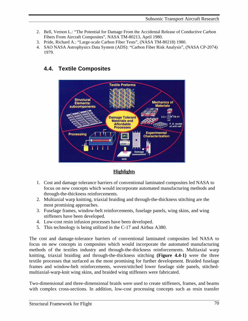
Subsonic Transport Aircraft Research
Structural Framework for Flight 70
2. Bell, Vernon L.: “The Potential for Damage From the Accidental Release of Conductive Carbon Fibers From Aircraft Composites”, NASA TM-80213, April 1980.
3. Pride, Richard A.: “Large-scale Carbon Fiber Tests”, (NASA TM-80218) 1980. 4. SAO NASA Astrophysics Data System (ADS): “Carbon Fiber Risk Analysis”, (NASA CP-2074)
1979.
4.4. Textile Composites
Highlights
1. Cost and damage tolerance barriers of conventional laminated composites led NASA to
focus on new concepts which would incorporate automated manufacturing methods and through-the-thickness reinforcements.
2. Multiaxial warp knitting, triaxial braiding and through-the-thickness stitching are the most promising approaches.
3. Fuselage frames, window-belt reinforcements, fuselage panels, wing skins, and wing stiffeners have been developed.
4. Low-cost resin infusion processes have been developed. 5. This technology is being utilized in the C-17 and Airbus A380.
The cost and damage-tolerance barriers of conventional laminated composites led NASA to focus on new concepts in composites which would incorporate the automated manufacturing methods of the textiles industry and through-the-thickness reinforcements. Multiaxial warp knitting, triaxial braiding and through-the-thickness stitching (Figure 4.4-1) were the three textile processes that surfaced as the most promising for further development. Braided fuselage frames and window-belt reinforcements, woven/stitched lower fuselage side panels, stitched-multiaxial-warp-knit wing skins, and braided wing stiffeners were fabricated. Two-dimensional and three-dimensional braids were used to create stiffeners, frames, and beams with complex cross-sections. In addition, low-cost processing concepts such as resin transfer
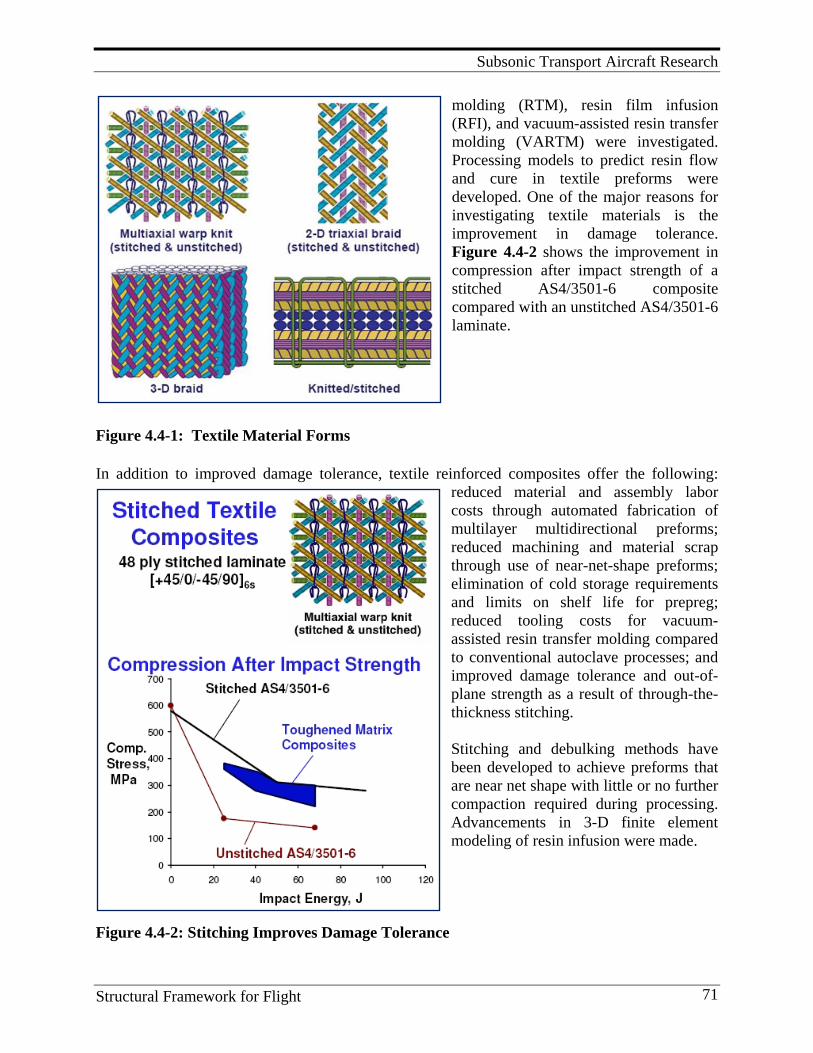
Subsonic Transport Aircraft Research
Structural Framework for Flight 71
molding (RTM), resin film infusion (RFI), and vacuum-assisted resin transfer molding (VARTM) were investigated. Processing models to predict resin flow and cure in textile preforms were developed. One of the major reasons for investigating textile materials is the improvement in damage tolerance. Figure 4.4-2 shows the improvement in compression after impact strength of a stitched AS4/3501-6 composite compared with an unstitched AS4/3501-6 laminate.
Figure 4.4-1: Textile Material Forms
In addition to improved damage tolerance, textile reinforced composites offer the following: reduced material and assembly labor costs through automated fabrication of multilayer multidirectional preforms; reduced machining and material scrap through use of near-net-shape preforms; elimination of cold storage requirements and limits on shelf life for prepreg; reduced tooling costs for vacuum-assisted resin transfer molding compared to conventional autoclave processes; and improved damage tolerance and out-of-plane strength as a result of through-the-thickness stitching. Stitching and debulking methods have been developed to achieve preforms that are near net shape with little or no further compaction required during processing. Advancements in 3-D finite element modeling of resin infusion were made.
Figure 4.4-2: Stitching Improves Damage Tolerance
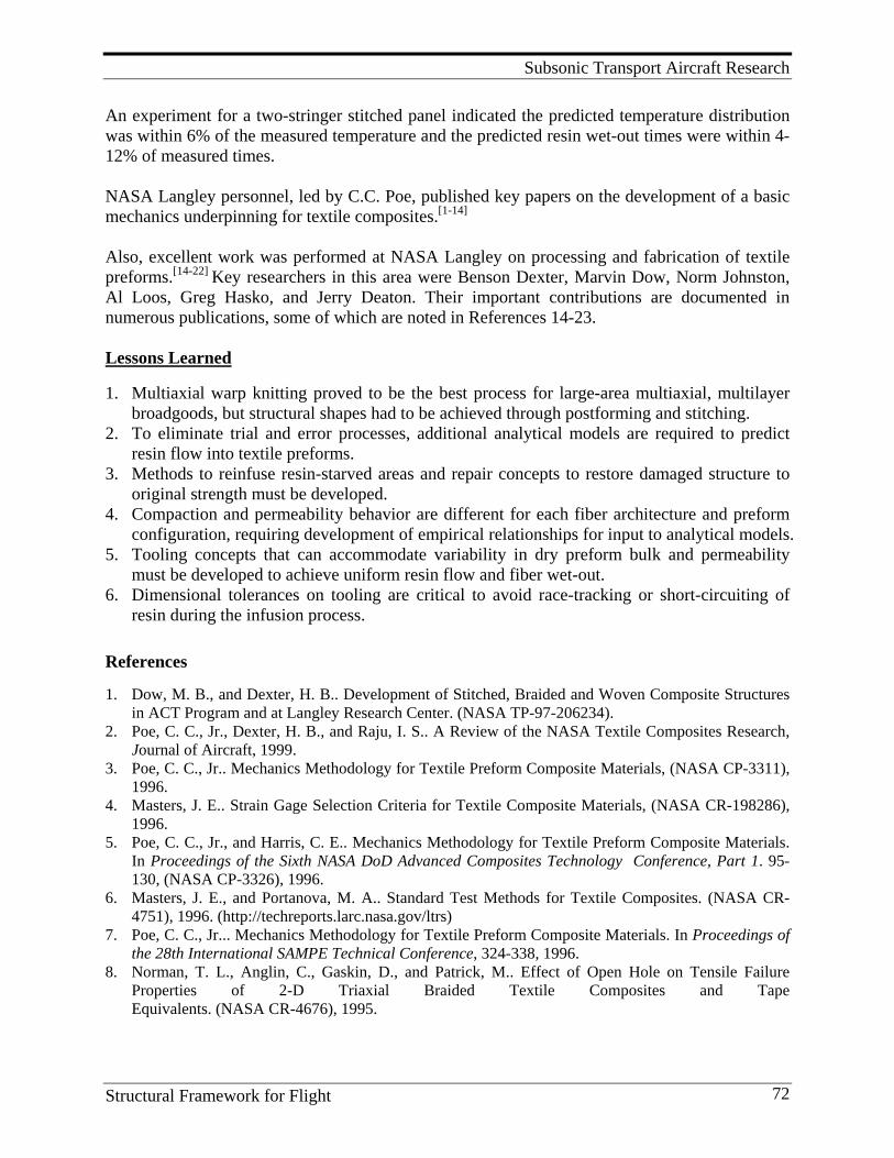
Subsonic Transport Aircraft Research
Structural Framework for Flight 72
An experiment for a two-stringer stitched panel indicated the predicted temperature distribution was within 6% of the measured temperature and the predicted resin wet-out times were within 4-12% of measured times. NASA Langley personnel, led by C.C. Poe, published key papers on the development of a basic mechanics underpinning for textile composites.[1-14] Also, excellent work was performed at NASA Langley on processing and fabrication of textile preforms.[14-22] Key researchers in this area were Benson Dexter, Marvin Dow, Norm Johnston, Al Loos, Greg Hasko, and Jerry Deaton. Their important contributions are documented in numerous publications, some of which are noted in References 14-23. Lessons Learned 1. Multiaxial warp knitting proved to be the best process for large-area multiaxial, multilayer
broadgoods, but structural shapes had to be achieved through postforming and stitching. 2. To eliminate trial and error processes, additional analytical models are required to predict
resin flow into textile preforms. 3. Methods to reinfuse resin-starved areas and repair concepts to restore damaged structure to
original strength must be developed. 4. Compaction and permeability behavior are different for each fiber architecture and preform
configuration, requiring development of empirical relationships for input to analytical models. 5. Tooling concepts that can accommodate variability in dry preform bulk and permeability
must be developed to achieve uniform resin flow and fiber wet-out. 6. Dimensional tolerances on tooling are critical to avoid race-tracking or short-circuiting of
resin during the infusion process. References 1. Dow, M. B., and Dexter, H. B.. Development of Stitched, Braided and Woven Composite Structures
in ACT Program and at Langley Research Center. (NASA TP-97-206234). 2. Poe, C. C., Jr., Dexter, H. B., and Raju, I. S.. A Review of the NASA Textile Composites Research,
Journal of Aircraft, 1999. 3. Poe, C. C., Jr.. Mechanics Methodology for Textile Preform Composite Materials, (NASA CP-3311),
1996. 4. Masters, J. E.. Strain Gage Selection Criteria for Textile Composite Materials, (NASA CR-198286),
1996. 5. Poe, C. C., Jr., and Harris, C. E.. Mechanics Methodology for Textile Preform Composite Materials.
In Proceedings of the Sixth NASA DoD Advanced Composites Technology Conference, Part 1. 95-130, (NASA CP-3326), 1996.
6. Masters, J. E., and Portanova, M. A.. Standard Test Methods for Textile Composites. (NASA CR-4751), 1996. (http://techreports.larc.nasa.gov/ltrs)
7. Poe, C. C., Jr... Mechanics Methodology for Textile Preform Composite Materials. In Proceedings of the 28th International SAMPE Technical Conference, 324-338, 1996.
8. Norman, T. L., Anglin, C., Gaskin, D., and Patrick, M.. Effect of Open Hole on Tensile Failure Properties of 2-D Triaxial Braided Textile Composites and Tape Equivalents. (NASA CR-4676), 1995.
Subsonic Transport Aircraft Research
Structural Framework for Flight 73
9. Poe, C. C., Jr., and Harris, C. E... Mechanics of Textile Composites Conference. (NASA CP-3311), 1995.
10. Jackson, W. C., and Ifju, P.G... Through-the-thickness Tensile Strength of Textile Composites. In Composite Materials Testing and Design, ed. R. B. Deo and C. R. Saff, 12:218-38. American Society for Testing and Materials, 1996.
11. Jackson, W. C. and Poe, C. C., Jr. 1993. The Use of Impact Force as a Scale Parameter for the Impact Response of Composite Laminates. Journal of Composites Technology Research 15 (Winter):282-289.
12. Jackson, W. C., and Portanova, M. A.. 1996. Impact Damage Resistance of Textile Composites, In Proceedings of the 28th International SAMPE Technical Conference, 339-350.
13. Portanova, M.A.. Impact Damage Tolerance of Textile Composites. In Proceedings of the 28th International SAMPE Technical Conference, 351-362, 1996
14. Cox, B. N., and Flanagan, G.. Handbook of Analytical Methods for Textile Composites. (NASA CR-4750), 1997. (available at http://techreports.larc.nasa.gov/ltrs).
15. Reeder, J. R.. Comparison of the Compressive Strength for Stitched and Toughened Composite Systems. (NASA TM-109108), 1994.
16. Dexter, H. B. An Overview of the NASA Textile Composites Program. Paper presented at the Sixth Conference on Advanced Engineering Fibers and Textile Structures for Composites.
17. Dexter, H. B.. Development of Textile Reinforced Composites for Aircraft Structures. Paper presented at the 4th International Symposium for Textile Composites. Kyoto, Japan, 1998.
18. Dexter, H. B.. Innovative Textile Reinforced Composite Materials for Aircraft Structures. Society for the Advancement of Material and Process 404-416, 1996.
19. Shuart, M. J., Johnston, N. J., Dexter, H. B., Marchello, J. M., and Grenoble, R. W., Automated Fabrication Technologies for High-performance Polymer Composites. Composite Fabrication 14 (August): 24-30, 1998.
20. Loos, A. C.. Low-cost Fabrication of Advanced Polymeric Composites by Resin Infusion Processes. Paper presented at the first ACT Conference on Advanced Composite Materials. (NASA CP-3104), 2001.
21. Dexter, H. B., and Hasko, G. H... Performance of Resin Transfer Molded Multiaxial Warp Knit Composites. Third NASA Advanced Composites Technology Conference, Volume 1, Part 1, p 231-261, Jan 1, 1993.
22. Deaton, J. W., and Dexter, H. B.. Evaluation of Braided Stiffener Concepts for Transport Aircraft Wing Structure Applications. Mechanics of Textile Composites Conference p 61-97 (SEE N96-25071 09- 24), 1995.
23. Dexter, H. B., Harris, C., and Johnston, N.. Recent Progress in NASA Langley Textile Reinforced Composites Program. Composites in Structural Design, 1992.
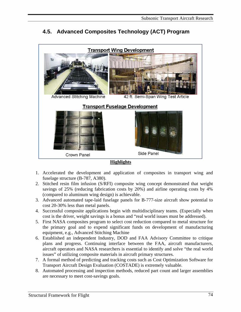
Subsonic Transport Aircraft Research
Structural Framework for Flight 74
4.5. Advanced Composites Technology (ACT) Program
Highlights
1. Accelerated the development and application of composites in transport wing and fuselage structure (B-787, A380).
2. Stitched resin film infusion (S/RFI) composite wing concept demonstrated that weight savings of 25% (reducing fabrication costs by 20%) and airline operating costs by 4% (compared to aluminum wing design) is achievable.
3. Advanced automated tape-laid fuselage panels for B-777-size aircraft show potential to cost 20-30% less than metal panels.
4. Successful composite applications begin with multidisciplinary teams. (Especially when cost is the driver, weight savings is a bonus and “real world issues must be addressed).
5. First NASA composites program to select cost reduction compared to metal structure for the primary goal and to expend significant funds on development of manufacturing equipment, e.g., Advanced Stitching Machine
6. Established an independent Industry, DOD and FAA Advisory Committee to critique plans and progress. Continuing interface between the FAA, aircraft manufacturers, aircraft operators and NASA researchers is essential to identify and solve “the real world issues” of utilizing composite materials in aircraft primary structures.
7. A formal method of predicting and tracking costs such as Cost Optimization Software for Transport Aircraft Design Evaluation (COSTADE) is extremely valuable.
8. Automated processing and inspection methods, reduced part count and larger assemblies are necessary to meet cost-savings goals.
Subsonic Transport Aircraft Research
Structural Framework for Flight 75
9. Utilization of the building block approach to reduce risk in development of complex structural components is essential for maturing new processes and analyses methods.
10. Utilized a National Research Announcement to solicit innovative ideas at program start-up.
11. Focused efforts enhanced interaction with DOD and FAA and provided a forum for technology exchange.
Background By 1985, despite the achievements made in composites technology, the rate of application of advanced composites in wing and fuselage primary structures of U.S. aircraft was disappointingly slow. Cost-effective use of composites in these critical areas required major technology advances in structural concepts, materials, and fabrication processes. Potential gains in performance from composite primary structures included weight reductions of 35-50%, longer life, better corrosion resistance, and more efficient aerodynamic shapes. However, acquisition cost, relative to metallic structure, was the major obstacle. As a result, the NASA Office of Aeronautics and Space Technology (OAST) requested the ASEB of the National Research Council to form a committee chartered to assess the status and viability of organic composites technology for aircraft structures. From 1985-87, this ASEB committee conducted an assessment of composites technology in the U.S. The committee provided recommendations for federally sponsored research and technology development programs that could produce a more rapid and timely translation of the potential of composite materials into production aircraft. The committee recommended that the government establish a bold new program, with significantly increased funding, to develop an integrated composites database with verified and demonstrated “affordable" technology. This new program addressed the subsonic goals identified by the OSTP to maintain the nation's premier leadership in aeronautics through new technology, affordable aircraft, a modernized air space system, and key technology advances, for mid 1990s readiness. The findings of the ASEB committee are included in the document “Advanced Organic Composite Materials for Aircraft Structures-Future Program,” the National Academy Press, 1987. In 1987, funds were available for a modest expansion of the Langley base composites program. A NASA Research Announcement (NRA) was issued seeking proposals for innovative approaches to cost-effective fabrication, enhanced damage-tolerance designs, and improved analysis methods. Forty-eight proposals were submitted by companies and universities, and 15 proposals were selected for contracts. Then, in 1988, based on the knowledge learned from NASA’s ACEE Composites Program, NASA’s Base Research Program, the U.S. Air Force ManTech Program, the FAA, and industry and university R&D; NASA launched the Advanced Composites Technology (ACT) Program to develop composite wing and fuselage primary structures. The program incorporated the existing NRA contracts with significant increases in funding for wing and fuselage hardware developments. A Structures Technology Program Office at Langley provided management for the ACT program. Under the direction of Charles P. Blankenship, John G. Davis, Jr. was the Program Manager of ACT, and leading researchers included James H. Starnes, Jr., Marvin B. Dow, H. Benson Dexter, and Norman J. Johnston. The 15 previously mentioned contracts were awarded by Langley in
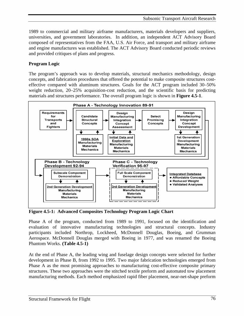
Subsonic Transport Aircraft Research
Structural Framework for Flight 76
1989 to commercial and military airframe manufacturers, materials developers and suppliers, universities, and government laboratories. In addition, an independent ACT Advisory Board composed of representatives from the FAA, U.S. Air Force, and transport and military airframe and engine manufactures was established. The ACT Advisory Board conducted periodic reviews and provided critiques of plans and progress. Program Logic The program’s approach was to develop materials, structural mechanics methodology, design concepts, and fabrication procedures that offered the potential to make composite structures cost-effective compared with aluminum structures. Goals for the ACT program included 30–50% weight reduction, 20–25% acquisition-cost reduction, and the scientific basis for predicting materials and structures performance. The overall program logic is shown in Figure 4.5-1.
Figure 4.5-1: Advanced Composites Technology Program Logic Chart Phase A of the program, conducted from 1989 to 1991, focused on the identification and evaluation of innovative manufacturing technologies and structural concepts. Industry participants included Northrop, Lockheed, McDonnell Douglas, Boeing, and Grumman Aerospace. McDonnell Douglas merged with Boeing in 1977, and was renamed the Boeing Phantom Works. (Table 4.5-1) At the end of Phase A, the leading wing and fuselage design concepts were selected for further development in Phase B, from 1992 to 1995. Two major fabrication technologies emerged from Phase A as the most promising approaches to manufacturing cost-effective composite primary structures. These two approaches were the stitched textile preform and automated tow placement manufacturing methods. Each method emphasized rapid fiber placement, near-net-shape preform
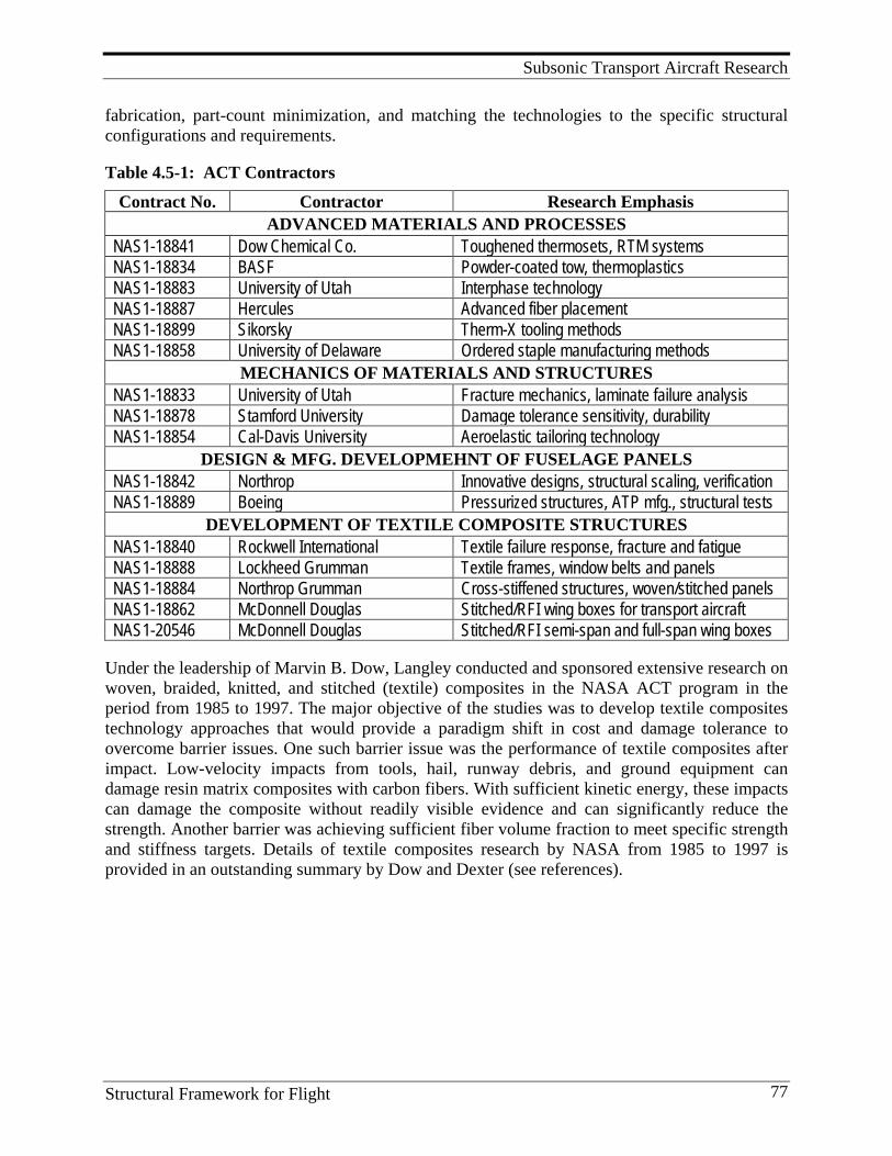
Subsonic Transport Aircraft Research
Structural Framework for Flight 77
fabrication, part-count minimization, and matching the technologies to the specific structural configurations and requirements. Table 4.5-1: ACT Contractors
Contract No. Contractor Research Emphasis ADVANCED MATERIALS AND PROCESSES
NAS1-18841 Dow Chemical Co. Toughened thermosets, RTM systems NAS1-18834 BASF Powder-coated tow, thermoplastics NAS1-18883 University of Utah Interphase technology NAS1-18887 Hercules Advanced fiber placement NAS1-18899 Sikorsky Therm-X tooling methods NAS1-18858 University of Delaware Ordered staple manufacturing methods
MECHANICS OF MATERIALS AND STRUCTURES NAS1-18833 University of Utah Fracture mechanics, laminate failure analysis NAS1-18878 Stamford University Damage tolerance sensitivity, durability NAS1-18854 Cal-Davis University Aeroelastic tailoring technology
DESIGN & MFG. DEVELOPMEHNT OF FUSELAGE PANELS NAS1-18842 Northrop Innovative designs, structural scaling, verification NAS1-18889 Boeing Pressurized structures, ATP mfg., structural tests
DEVELOPMENT OF TEXTILE COMPOSITE STRUCTURES NAS1-18840 Rockwell International Textile failure response, fracture and fatigue NAS1-18888 Lockheed Grumman Textile frames, window belts and panels NAS1-18884 Northrop Grumman Cross-stiffened structures, woven/stitched panels NAS1-18862 McDonnell Douglas Stitched/RFI wing boxes for transport aircraft NAS1-20546 McDonnell Douglas Stitched/RFI semi-span and full-span wing boxes
Under the leadership of Marvin B. Dow, Langley conducted and sponsored extensive research on woven, braided, knitted, and stitched (textile) composites in the NASA ACT program in the period from 1985 to 1997. The major objective of the studies was to develop textile composites technology approaches that would provide a paradigm shift in cost and damage tolerance to overcome barrier issues. One such barrier issue was the performance of textile composites after impact. Low-velocity impacts from tools, hail, runway debris, and ground equipment can damage resin matrix composites with carbon fibers. With sufficient kinetic energy, these impacts can damage the composite without readily visible evidence and can significantly reduce the strength. Another barrier was achieving sufficient fiber volume fraction to meet specific strength and stiffness targets. Details of textile composites research by NASA from 1985 to 1997 is provided in an outstanding summary by Dow and Dexter (see references).
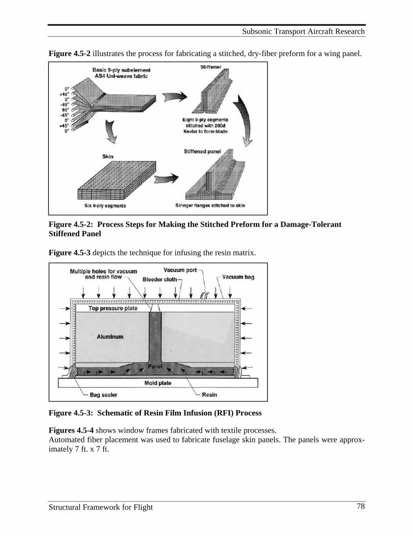
Subsonic Transport Aircraft Research
Structural Framework for Flight 78
Figure 4.5-2 illustrates the process for fabricating a stitched, dry-fiber preform for a wing panel.
Figure 4.5-2: Process Steps for Making the Stitched Preform for a Damage-Tolerant Stiffened Panel
Figure 4.5-3 depicts the technique for infusing the resin matrix.
Figure 4.5-3: Schematic of Resin Film Infusion (RFI) Process
Figures 4.5-4 shows window frames fabricated with textile processes. Automated fiber placement was used to fabricate fuselage skin panels. The panels were approx-imately 7 ft. x 7 ft.
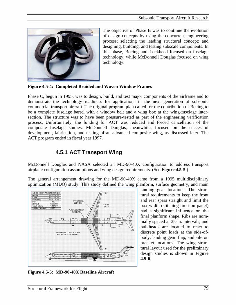
Subsonic Transport Aircraft Research
Structural Framework for Flight 79
The objective of Phase B was to continue the evolution of design concepts by using the concurrent engineering process; selecting the leading structural concept; and designing, building, and testing subscale components. In this phase, Boeing and Lockheed focused on fuselage technology, while McDonnell Douglas focused on wing technology.
Figure 4.5-4: Completed Braided and Woven Window Frames
Phase C, begun in 1995, was to design, build, and test major components of the airframe and to demonstrate the technology readiness for applications in the next generation of subsonic commercial transport aircraft. The original program plan called for the contribution of Boeing to be a complete fuselage barrel with a window belt and a wing box at the wing-fuselage inter-section. The structure was to have been pressure-tested as part of the engineering verification process. Unfortunately, the funding for ACT was reduced and forced cancellation of the composite fuselage studies. McDonnell Douglas, meanwhile, focused on the successful development, fabrication, and testing of an advanced composite wing, as discussed later. The ACT program ended in fiscal year 1997.
4.5.1 ACT Transport Wing McDonnell Douglas and NASA selected an MD-90-40X configuration to address transport airplane configuration assumptions and wing design requirements. (See Figure 4.5-5.) The general arrangement drawing for the MD-90-40X came from a 1995 multidisciplinary optimization (MDO) study. This study defined the wing planform, surface geometry, and main
landing gear locations. The struc-tural requirements to keep the front and rear spars straight and limit the box width (stitching limit on panel) had a significant influence on the final planform shape. Ribs are nom-inally spaced at 35-in. intervals, and bulkheads are located to react to discrete point loads at the side-of-body, landing gear, flap, and aileron bracket locations. The wing struc-tural layout used for the preliminary design studies is shown in Figure 4.5-6.
Figure 4.5-5: MD-90-40X Baseline Aircraft
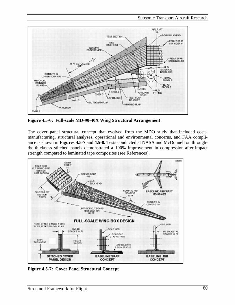
Subsonic Transport Aircraft Research
Structural Framework for Flight 80
Figure 4.5-6: Full-scale MD-90-40X Wing Structural Arrangement
The cover panel structural concept that evolved from the MDO study that included costs, manufacturing, structural analyses, operational and environmental concerns, and FAA compli-ance is shown in Figures 4.5-7 and 4.5-8. Tests conducted at NASA and McDonnell on through-the-thickness stitched panels demonstrated a 100% improvement in compression-after-impact strength compared to laminated tape composites (see References).
Figure 4.5-7: Cover Panel Structural Concept
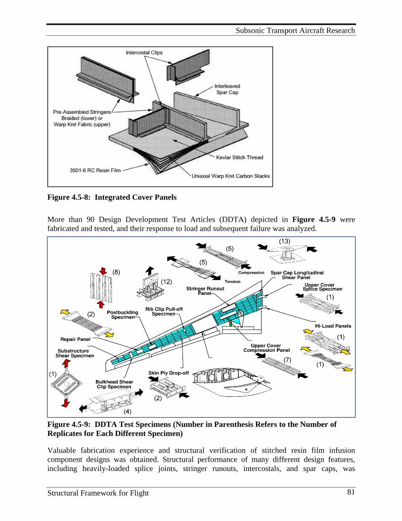
Subsonic Transport Aircraft Research
Structural Framework for Flight 81
Figure 4.5-8: Integrated Cover Panels
More than 90 Design Development Test Articles (DDTA) depicted in Figure 4.5-9 were fabricated and tested, and their response to load and subsequent failure was analyzed.
Figure 4.5-9: DDTA Test Specimens (Number in Parenthesis Refers to the Number of Replicates for Each Different Specimen)
Valuable fabrication experience and structural verification of stitched resin film infusion component designs was obtained. Structural performance of many different design features, including heavily-loaded splice joints, stringer runouts, intercostals, and spar caps, was
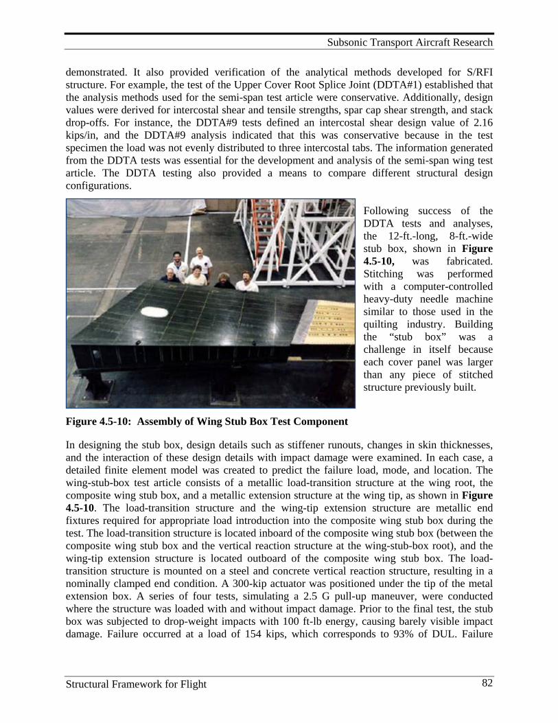
Subsonic Transport Aircraft Research
Structural Framework for Flight 82
demonstrated. It also provided verification of the analytical methods developed for S/RFI structure. For example, the test of the Upper Cover Root Splice Joint (DDTA#1) established that the analysis methods used for the semi-span test article were conservative. Additionally, design values were derived for intercostal shear and tensile strengths, spar cap shear strength, and stack drop-offs. For instance, the DDTA#9 tests defined an intercostal shear design value of 2.16 kips/in, and the DDTA#9 analysis indicated that this was conservative because in the test specimen the load was not evenly distributed to three intercostal tabs. The information generated from the DDTA tests was essential for the development and analysis of the semi-span wing test article. The DDTA testing also provided a means to compare different structural design configurations.
Following success of the DDTA tests and analyses, the 12-ft.-long, 8-ft.-wide stub box, shown in Figure 4.5-10, was fabricated. Stitching was performed with a computer-controlled heavy-duty needle machine similar to those used in the quilting industry. Building the “stub box” was a challenge in itself because each cover panel was larger than any piece of stitched structure previously built.
Figure 4.5-10: Assembly of Wing Stub Box Test Component
In designing the stub box, design details such as stiffener runouts, changes in skin thicknesses, and the interaction of these design details with impact damage were examined. In each case, a detailed finite element model was created to predict the failure load, mode, and location. The wing-stub-box test article consists of a metallic load-transition structure at the wing root, the composite wing stub box, and a metallic extension structure at the wing tip, as shown in Figure 4.5-10. The load-transition structure and the wing-tip extension structure are metallic end fixtures required for appropriate load introduction into the composite wing stub box during the test. The load-transition structure is located inboard of the composite wing stub box (between the composite wing stub box and the vertical reaction structure at the wing-stub-box root), and the wing-tip extension structure is located outboard of the composite wing stub box. The load-transition structure is mounted on a steel and concrete vertical reaction structure, resulting in a nominally clamped end condition. A 300-kip actuator was positioned under the tip of the metal extension box. A series of four tests, simulating a 2.5 G pull-up maneuver, were conducted where the structure was loaded with and without impact damage. Prior to the final test, the stub box was subjected to drop-weight impacts with 100 ft-lb energy, causing barely visible impact damage. Failure occurred at a load of 154 kips, which corresponds to 93% of DUL. Failure
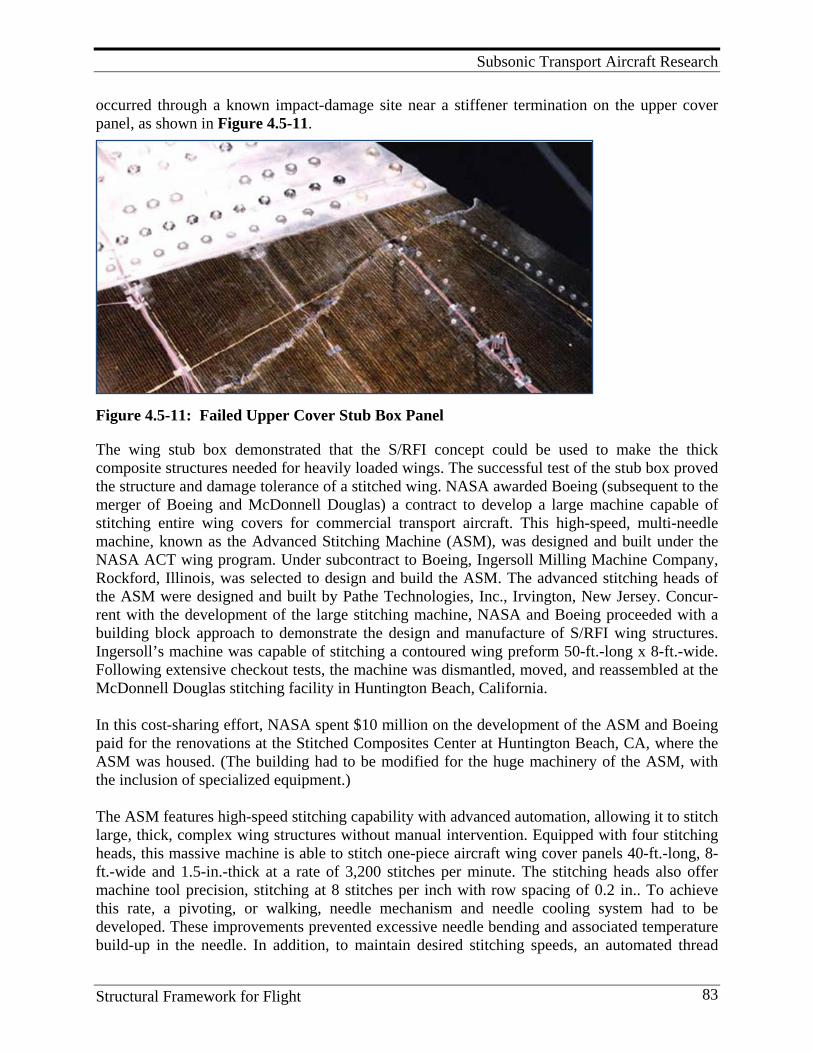
Subsonic Transport Aircraft Research
Structural Framework for Flight 83
occurred through a known impact-damage site near a stiffener termination on the upper cover panel, as shown in Figure 4.5-11.
Figure 4.5-11: Failed Upper Cover Stub Box Panel
The wing stub box demonstrated that the S/RFI concept could be used to make the thick composite structures needed for heavily loaded wings. The successful test of the stub box proved the structure and damage tolerance of a stitched wing. NASA awarded Boeing (subsequent to the merger of Boeing and McDonnell Douglas) a contract to develop a large machine capable of stitching entire wing covers for commercial transport aircraft. This high-speed, multi-needle machine, known as the Advanced Stitching Machine (ASM), was designed and built under the NASA ACT wing program. Under subcontract to Boeing, Ingersoll Milling Machine Company, Rockford, Illinois, was selected to design and build the ASM. The advanced stitching heads of the ASM were designed and built by Pathe Technologies, Inc., Irvington, New Jersey. Concur-rent with the development of the large stitching machine, NASA and Boeing proceeded with a building block approach to demonstrate the design and manufacture of S/RFI wing structures. Ingersoll’s machine was capable of stitching a contoured wing preform 50-ft.-long x 8-ft.-wide. Following extensive checkout tests, the machine was dismantled, moved, and reassembled at the McDonnell Douglas stitching facility in Huntington Beach, California. In this cost-sharing effort, NASA spent $10 million on the development of the ASM and Boeing paid for the renovations at the Stitched Composites Center at Huntington Beach, CA, where the ASM was housed. (The building had to be modified for the huge machinery of the ASM, with the inclusion of specialized equipment.) The ASM features high-speed stitching capability with advanced automation, allowing it to stitch large, thick, complex wing structures without manual intervention. Equipped with four stitching heads, this massive machine is able to stitch one-piece aircraft wing cover panels 40-ft.-long, 8-ft.-wide and 1.5-in.-thick at a rate of 3,200 stitches per minute. The stitching heads also offer machine tool precision, stitching at 8 stitches per inch with row spacing of 0.2 in.. To achieve this rate, a pivoting, or walking, needle mechanism and needle cooling system had to be developed. These improvements prevented excessive needle bending and associated temperature build-up in the needle. In addition, to maintain desired stitching speeds, an automated thread
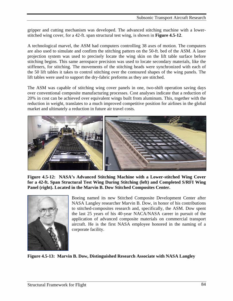
Subsonic Transport Aircraft Research
Structural Framework for Flight 84
gripper and cutting mechanism was developed. The advanced stitching machine with a lower-stitched wing cover, for a 42-ft. span structural test wing, is shown in Figure 4.5-12. A technological marvel, the ASM had computers controlling 38 axes of motion. The computers are also used to simulate and confirm the stitching pattern on the 50-ft. bed of the ASM. A laser projection system was used to precisely locate the wing skin on the lift table surface before stitching begins. This same aerospace precision was used to locate secondary materials, like the stiffeners, for stitching. The movements of the stitching heads were synchronized with each of the 50 lift tables it takes to control stitching over the contoured shapes of the wing panels. The lift tables were used to support the dry-fabric preforms as they are stitched.
The ASM was capable of stitching wing cover panels in one, two-shift operation saving days over conventional composite manufacturing processes. Cost analyses indicate that a reduction of 20% in cost can be achieved over equivalent wings built from aluminum. This, together with the reduction in weight, translates to a much improved competitive position for airlines in the global market and ultimately a reduction in future air travel costs.
Figure 4.5-12: NASA’s Advanced Stitching Machine with a Lower-stitched Wing Cover for a 42-ft. Span Structural Test Wing During Stitching (left) and Completed S/RFI Wing Panel (right). Located in the Marvin B. Dow Stitched Composites Center.
Boeing named its new Stitched Composite Development Center after NASA Langley researcher Marvin B. Dow, in honor of his contributions to stitched-composites research and, specifically, the ASM. Dow spent the last 25 years of his 40-year NACA/NASA career in pursuit of the application of advanced composite materials on commercial transport aircraft. He is the first NASA employee honored in the naming of a corporate facility.
Figure 4.5-13: Marvin B. Dow, Distinguished Research Associate with NASA Langley
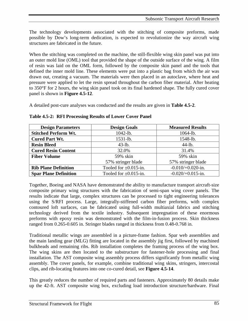
Subsonic Transport Aircraft Research
Structural Framework for Flight 85
The technology developments associated with the stitching of composite preforms, made possible by Dow’s long-term dedication, is expected to revolutionize the way aircraft wing structures are fabricated in the future. When the stitching was completed on the machine, the still-flexible wing skin panel was put into an outer mold line (OML) tool that provided the shape of the outside surface of the wing. A film of resin was laid on the OML form, followed by the composite skin panel and the tools that defined the inner mold line. These elements were put into a plastic bag from which the air was drawn out, creating a vacuum. The materials were then placed in an autoclave, where heat and pressure were applied to let the resin spread throughout the carbon fiber material. After heating to 350°F for 2 hours, the wing skin panel took on its final hardened shape. The fully cured cover panel is shown in Figure 4.5-12.
A detailed post-cure analyses was conducted and the results are given in Table 4.5-2. Table 4.5-2: RFI Processing Results of Lower Cover Panel
Design Parameters Design Goals Measured Results Stitched Perform Wt. 1042-lb. 1064-lb. Cured Part Wt. 1531-lb. 1548-lb. Resin Bleed 43-lb. 44-lb. Cured Resin Content 32.0% 31.4% Fiber Volume 59% skin
57% stringer blade 59% skin
57% stringer blade Rib Plane Definition Tooled for ±0.015-in. -0.010/+0.020-in. Spar Plane Definition Tooled for ±0.015-in. -0.020/+0.015-in.
Together, Boeing and NASA have demonstrated the ability to manufacture transport aircraft-size composite primary wing structures with the fabrication of semi-span wing cover panels. The results indicate that large, complex structures can be processed to tight engineering tolerances using the S/RFI process. Large, integrally-stiffened carbon fiber preforms, with complex contoured loft surfaces, can be fabricated using full-width multiaxial fabrics and stitching technology derived from the textile industry. Subsequent impregnation of these enormous preforms with epoxy resin was demonstrated with the film-in-fusion process. Skin thickness ranged from 0.265-0.605 in. Stringer blades ranged in thickness from 0.48-0.768 in. Traditional metallic wings are assembled in a picture-frame fashion. Spar web assemblies and the main landing gear (MLG) fitting are located in the assembly jig first, followed by machined bulkheads and remaining ribs. Rib installation completes the framing process of the wing box. The wing skins are then located to the substructure for fastener-hole processing and final installation. The AST composite wing assembly process differs significantly from metallic wing assembly. The cover panels, for example, combine traditional wing skins, stringers, intercostal clips, and rib-locating features into one co-cured detail, see Figure 4.5-14. This greatly reduces the number of required parts and fasteners. Approximately 80 details make up the 42-ft. AST composite wing box, excluding load introduction structure/hardware. Final
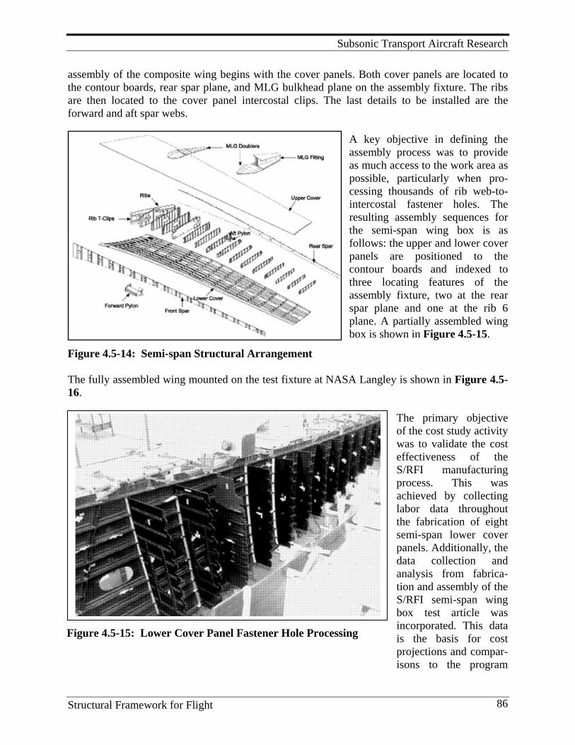
Subsonic Transport Aircraft Research
Structural Framework for Flight 86
Figure 4.5-15: Lower Cover Panel Fastener Hole Processing
assembly of the composite wing begins with the cover panels. Both cover panels are located to the contour boards, rear spar plane, and MLG bulkhead plane on the assembly fixture. The ribs are then located to the cover panel intercostal clips. The last details to be installed are the forward and aft spar webs.
A key objective in defining the assembly process was to provide as much access to the work area as possible, particularly when pro-cessing thousands of rib web-to-intercostal fastener holes. The resulting assembly sequences for the semi-span wing box is as follows: the upper and lower cover panels are positioned to the contour boards and indexed to three locating features of the assembly fixture, two at the rear spar plane and one at the rib 6 plane. A partially assembled wing box is shown in Figure 4.5-15.
Figure 4.5-14: Semi-span Structural Arrangement The fully assembled wing mounted on the test fixture at NASA Langley is shown in Figure 4.5-16.
The primary objective of the cost study activity was to validate the cost effectiveness of the S/RFI manufacturing process. This was achieved by collecting labor data throughout the fabrication of eight semi-span lower cover panels. Additionally, the data collection and analysis from fabrica-tion and assembly of the S/RFI semi-span wing box test article was incorporated. This data is the basis for cost projections and compar-isons to the program
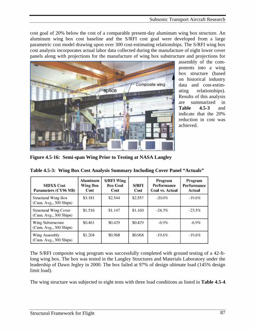
Subsonic Transport Aircraft Research
Structural Framework for Flight 87
cost goal of 20% below the cost of a comparable present-day aluminum wing box structure. An aluminum wing box cost baseline and the S/RFI cost goal were developed from a large parametric cost model drawing upon over 300 cost-estimating relationships. The S/RFI wing box cost analysis incorporates actual labor data collected during the manufacture of eight lower cover panels along with projections for the manufacture of wing box substructure and projections for
assembly of the com-ponents into a wing box structure (based on historical industry data and cost-estim-ating relationships). Results of this analysis are summarized in Table 4.5-3 and indicate that the 20% reduction in cost was achieved.
Figure 4.5-16: Semi-span Wing Prior to Testing at NASA Langley
Table 4.5-3: Wing Box Cost Analysis Summary Including Cover Panel “Actuals”
The S/RFI composite wing program was successfully completed with ground testing of a 42-ft-long wing box. The box was tested in the Langley Structures and Materials Laboratory under the leadership of Dawn Jegley in 2000. The box failed at 97% of design ultimate load (145% design limit load). The wing structure was subjected to eight tests with three load conditions as listed in Table 4.5-4.
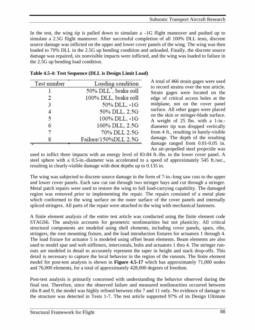
Subsonic Transport Aircraft Research
Structural Framework for Flight 88
In the test, the wing tip is pulled down to simulate a –1G flight maneuver and pushed up to simulate a 2.5G flight maneuver. After successful completion of all 100% DLL tests, discrete source damage was inflicted on the upper and lower cover panels of the wing. The wing was then loaded to 70% DLL in the 2.5G up bending condition and unloaded. Finally, the discrete source damage was repaired, six nonvisible impacts were inflicted, and the wing was loaded to failure in the 2.5G up bending load condition. Table 4.5-4: Test Sequence (DLL is Design Limit Load)
A total of 466 strain gages were used to record strains over the test article. Strain gages were located on the edge of critical access holes at the midplane, not on the cover panel surface. All other gages were placed on the skin or stringer-blade surface. A weight of 25 lbs. with a 1-in.-diameter tip was dropped vertically from 4 ft., resulting in barely-visible damage. The depth of the resulting damage ranged from 0.01-0.05 in. An air-propelled steel projectile was
used to inflict three impacts with an energy level of 83-84 ft.-lbs. to the lower cover panel. A steel sphere with a 0.5-in.-diameter was accelerated to a speed of approximately 545 ft./sec., resulting in clearly-visible damage with dent depths up to 0.135 in. The wing was subjected to discrete source damage in the form of 7-in.-long saw cuts to the upper and lower cover panels. Each saw cut ran through two stringer bays and cut through a stringer. Metal patch repairs were used to restore the wing to full load-carrying capability. The damaged region was removed prior to implementing the repair. The repairs consisted of a metal plate which conformed to the wing surface on the outer surface of the cover panels and internally spliced stringers. All parts of the repair were attached to the wing with mechanical fasteners. A finite element analysis of the entire test article was conducted using the finite element code STAGS6. The analysis accounts for geometric nonlinearities but not plasticity. All critical structural components are modeled using shell elements, including cover panels, spars, ribs, stringers, the root mounting fixture, and the load introduction fixtures for actuators 1 through 4. The load fixture for actuator 5 is modeled using offset beam elements. Beam elements are also used to model spar and web stiffeners, intercostals, bolts and actuators 1 thru 4. The stringer run-outs are modeled in detail to accurately represent the taper in height and stack drop-offs. This detail is necessary to capture the local behavior in the region of the runouts. The finite element model for post-test analysis is shown in Figure 4.5-17 which has approximately 71,000 nodes and 76,000 elements, for a total of approximately 428,000 degrees of freedom. Post-test analysis is primarily concerned with understanding the behavior observed during the final test. Therefore, since the observed failure and measured nonlinearities occurred between ribs 8 and 9, the model was highly refined between ribs 7 and 11 only. No evidence of damage to the structure was detected in Tests 1-7. The test article supported 97% of its Design Ultimate
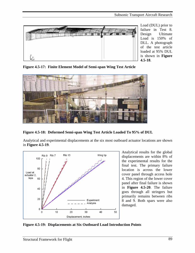
Subsonic Transport Aircraft Research
Structural Framework for Flight 89
Load (DUL) prior to failure in Test 8. Design Ultimate Load is 150% of DLL. A photograph of the test article loaded at 95% DUL is shown in Figure 4.5-18.
Figure 4.5-17: Finite Element Model of Semi-span Wing Test Article
Figure 4.5-18: Deformed Semi-span Wing Test Article Loaded To 95% of DUL
Analytical and experimental displacements at the six most outboard actuator locations are shown in Figure 4.5-19.
Analytical results for the global displacements are within 8% of the experimental results for the final test. The primary failure location is across the lower cover panel through access hole 4. This region of the lower cover panel after final failure is shown in Figure 4.5-20. The failure goes through all stringers but primarily remains between ribs 8 and 9. Both spars were also damaged.
Figure 4.5-19: Displacements at Six Outboard Load Introduction Points
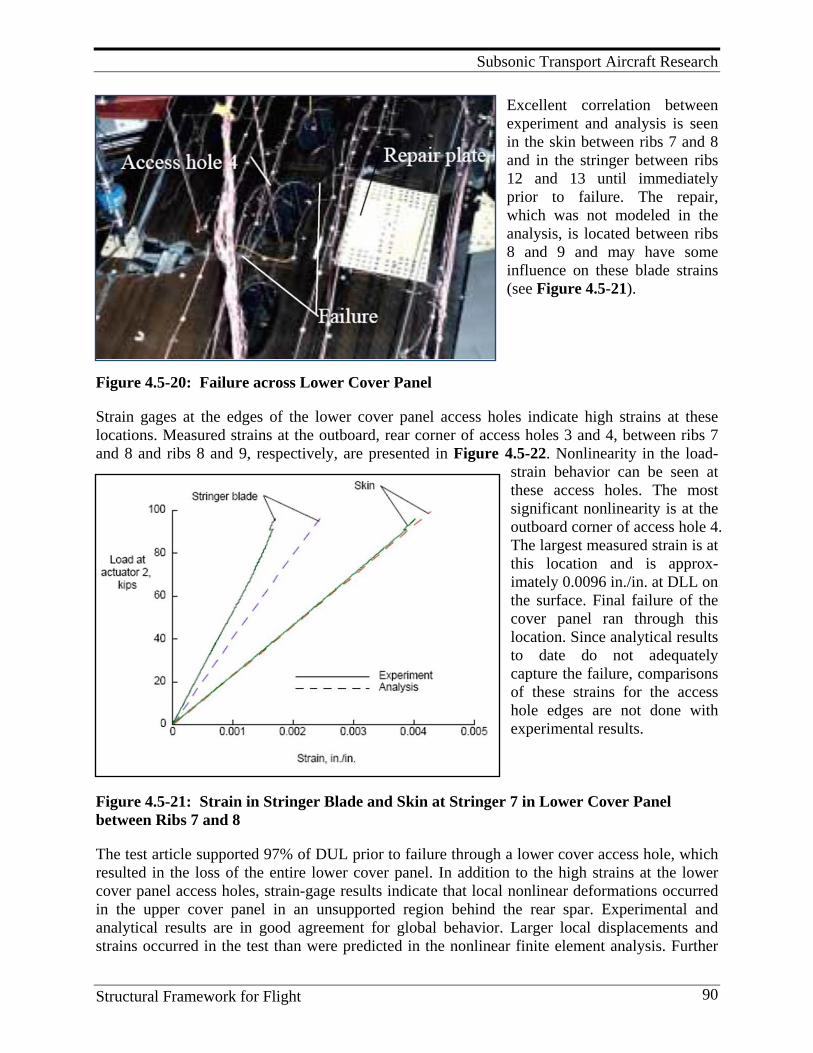
Subsonic Transport Aircraft Research
Structural Framework for Flight 90
Excellent correlation between experiment and analysis is seen in the skin between ribs 7 and 8 and in the stringer between ribs 12 and 13 until immediately prior to failure. The repair, which was not modeled in the analysis, is located between ribs 8 and 9 and may have some influence on these blade strains (see Figure 4.5-21).
Figure 4.5-20: Failure across Lower Cover Panel
Strain gages at the edges of the lower cover panel access holes indicate high strains at these locations. Measured strains at the outboard, rear corner of access holes 3 and 4, between ribs 7 and 8 and ribs 8 and 9, respectively, are presented in Figure 4.5-22. Nonlinearity in the load-
strain behavior can be seen at these access holes. The most significant nonlinearity is at the outboard corner of access hole 4. The largest measured strain is at this location and is approx-imately 0.0096 in./in. at DLL on the surface. Final failure of the cover panel ran through this location. Since analytical results to date do not adequately capture the failure, comparisons of these strains for the access hole edges are not done with experimental results.
Figure 4.5-21: Strain in Stringer Blade and Skin at Stringer 7 in Lower Cover Panel between Ribs 7 and 8
The test article supported 97% of DUL prior to failure through a lower cover access hole, which resulted in the loss of the entire lower cover panel. In addition to the high strains at the lower cover panel access holes, strain-gage results indicate that local nonlinear deformations occurred in the upper cover panel in an unsupported region behind the rear spar. Experimental and analytical results are in good agreement for global behavior. Larger local displacements and strains occurred in the test than were predicted in the nonlinear finite element analysis. Further
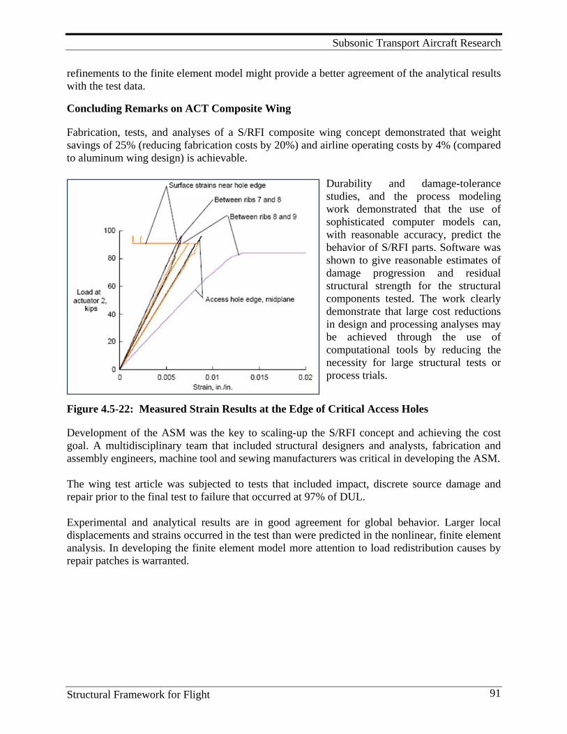
Subsonic Transport Aircraft Research
Structural Framework for Flight 91
refinements to the finite element model might provide a better agreement of the analytical results with the test data.
Concluding Remarks on ACT Composite Wing
Fabrication, tests, and analyses of a S/RFI composite wing concept demonstrated that weight savings of 25% (reducing fabrication costs by 20%) and airline operating costs by 4% (compared to aluminum wing design) is achievable.
Durability and damage-tolerance studies, and the process modeling work demonstrated that the use of sophisticated computer models can, with reasonable accuracy, predict the behavior of S/RFI parts. Software was shown to give reasonable estimates of damage progression and residual structural strength for the structural components tested. The work clearly demonstrate that large cost reductions in design and processing analyses may be achieved through the use of computational tools by reducing the necessity for large structural tests or process trials.
Figure 4.5-22: Measured Strain Results at the Edge of Critical Access Holes
Development of the ASM was the key to scaling-up the S/RFI concept and achieving the cost goal. A multidisciplinary team that included structural designers and analysts, fabrication and assembly engineers, machine tool and sewing manufacturers was critical in developing the ASM. The wing test article was subjected to tests that included impact, discrete source damage and repair prior to the final test to failure that occurred at 97% of DUL. Experimental and analytical results are in good agreement for global behavior. Larger local displacements and strains occurred in the test than were predicted in the nonlinear, finite element analysis. In developing the finite element model more attention to load redistribution causes by repair patches is warranted.

Subsonic Transport Aircraft Research
Structural Framework for Flight 92
4.5.2 ACT Fuselage Program
The primary objective of the ACT fuselage program was to develop composite primary structure for commercial airplanes with 20-25% less cost and 30-50% less weight than equivalent metallic structure. In order to develop advanced struc-tural concepts for aircraft fuselage, a pressurized aft fuselage section of a generic wide-body airplane with a diameter of 244 in. was chosen as the area of study for development of composite fuselage structural concepts. This section was chosen since it contained most of the structural details and critical manu-facturing issues present in fuselage structures. The fuselage section was divided into four circumfer-ential quadrants, the crown, the left and right sides, and keel. Details of the aft fuselage section are shown in Figure 4.5-23.
Figure 4.5-23: Transport Aircraft Wide-body Fuselage
A three-step approach was used to identify and evaluate structural concepts for each quadrant of the fuselage section. First, the baseline concept selection was determined to be the concept that was judged to have the greatest potential for cost and weight savings with considerations for
acceptable risk. Second, a global evaluation was con-ducted to develop preliminary designs in sufficient detail such that cost and weight differences between the baseline concept and other low-cost/low-weight con-cepts could be developed. The final step involved selecting the concepts with the largest weight-saving potential for local optimization. This step involved optimizing the design elements while considering the impact of any design changes on overall cost. This approach resulted in a skin/stringer configuration for the crown quadrant and sandwich construction for the keel and side quadrants (see Figure 4.5-24).
Figure 4.5-24: Honeycomb-Stiffened Fuselage Side Panel with Constant-section Braided Frames
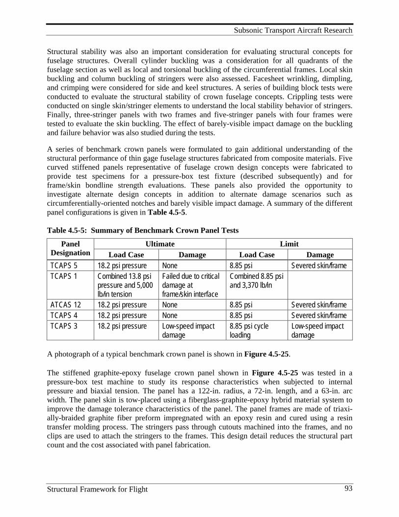
Subsonic Transport Aircraft Research
Structural Framework for Flight 93
Structural stability was also an important consideration for evaluating structural concepts for fuselage structures. Overall cylinder buckling was a consideration for all quadrants of the fuselage section as well as local and torsional buckling of the circumferential frames. Local skin buckling and column buckling of stringers were also assessed. Facesheet wrinkling, dimpling, and crimping were considered for side and keel structures. A series of building block tests were conducted to evaluate the structural stability of crown fuselage concepts. Crippling tests were conducted on single skin/stringer elements to understand the local stability behavior of stringers. Finally, three-stringer panels with two frames and five-stringer panels with four frames were tested to evaluate the skin buckling. The effect of barely-visible impact damage on the buckling and failure behavior was also studied during the tests. A series of benchmark crown panels were formulated to gain additional understanding of the structural performance of thin gage fuselage structures fabricated from composite materials. Five curved stiffened panels representative of fuselage crown design concepts were fabricated to provide test specimens for a pressure-box test fixture (described subsequently) and for frame/skin bondline strength evaluations. These panels also provided the opportunity to investigate alternate design concepts in addition to alternate damage scenarios such as circumferentially-oriented notches and barely visible impact damage. A summary of the different panel configurations is given in Table 4.5-5. Table 4.5-5: Summary of Benchmark Crown Panel Tests
Panel Designation
Ultimate Limit Load Case Damage Load Case Damage
TCAPS 5 18.2 psi pressure None 8.85 psi Severed skin/frame TCAPS 1 Combined 13.8 psi
pressure and 5,000 lb/in tension
Failed due to critical damage at frame/skin interface
Combined 8.85 psi and 3,370 lb/in
ATCAS 12 18.2 psi pressure None 8.85 psi Severed skin/frame TCAPS 4 18.2 psi pressure None 8.85 psi Severed skin/frame TCAPS 3 18.2 psi pressure Low-speed impact
damage 8.85 psi cycle loading
Low-speed impact damage
A photograph of a typical benchmark crown panel is shown in Figure 4.5-25.
The stiffened graphite-epoxy fuselage crown panel shown in Figure 4.5-25 was tested in a pressure-box test machine to study its response characteristics when subjected to internal pressure and biaxial tension. The panel has a 122-in. radius, a 72-in. length, and a 63-in. arc width. The panel skin is tow-placed using a fiberglass-graphite-epoxy hybrid material system to improve the damage tolerance characteristics of the panel. The panel frames are made of triaxi-ally-braided graphite fiber preform impregnated with an epoxy resin and cured using a resin transfer molding process. The stringers pass through cutouts machined into the frames, and no clips are used to attach the stringers to the frames. This design detail reduces the structural part count and the cost associated with panel fabrication.
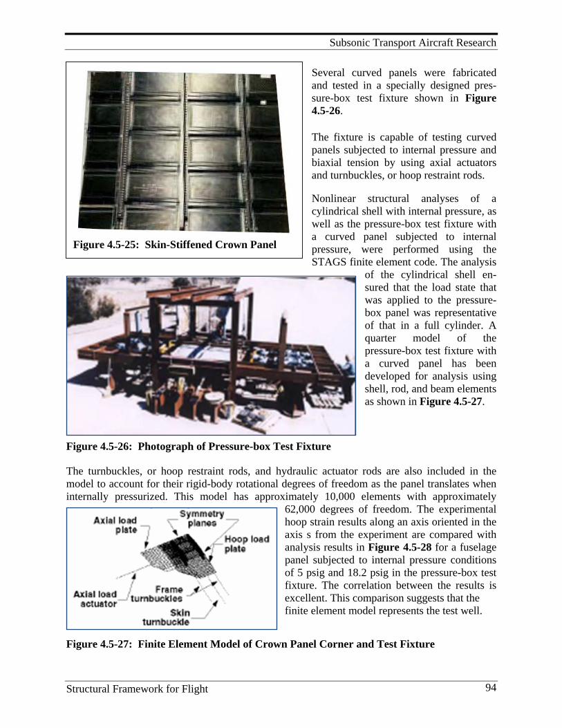
Subsonic Transport Aircraft Research
Structural Framework for Flight 94
Figure 4.5-25: Skin-Stiffened Crown Panel
Several curved panels were fabricated and tested in a specially designed pres-sure-box test fixture shown in Figure 4.5-26.
The fixture is capable of testing curved panels subjected to internal pressure and biaxial tension by using axial actuators and turnbuckles, or hoop restraint rods. Nonlinear structural analyses of a cylindrical shell with internal pressure, as well as the pressure-box test fixture with a curved panel subjected to internal pressure, were performed using the STAGS finite element code. The analysis
of the cylindrical shell en-sured that the load state that was applied to the pressure-box panel was representative of that in a full cylinder. A quarter model of the pressure-box test fixture with a curved panel has been developed for analysis using shell, rod, and beam elements as shown in Figure 4.5-27.
Figure 4.5-26: Photograph of Pressure-box Test Fixture
The turnbuckles, or hoop restraint rods, and hydraulic actuator rods are also included in the model to account for their rigid-body rotational degrees of freedom as the panel translates when internally pressurized. This model has approximately 10,000 elements with approximately
62,000 degrees of freedom. The experimental hoop strain results along an axis oriented in the axis s from the experiment are compared with analysis results in Figure 4.5-28 for a fuselage panel subjected to internal pressure conditions of 5 psig and 18.2 psig in the pressure-box test fixture. The correlation between the results is excellent. This comparison suggests that the finite element model represents the test well.
Figure 4.5-27: Finite Element Model of Crown Panel Corner and Test Fixture
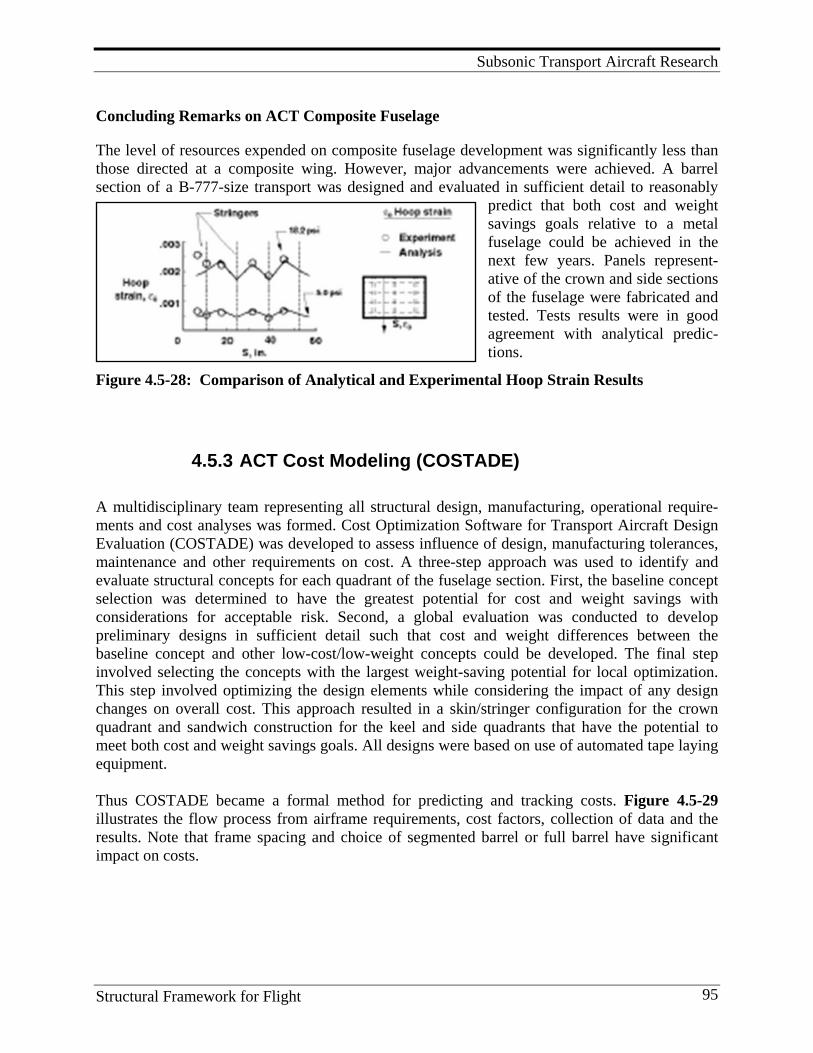
Subsonic Transport Aircraft Research
Structural Framework for Flight 95
Concluding Remarks on ACT Composite Fuselage
The level of resources expended on composite fuselage development was significantly less than those directed at a composite wing. However, major advancements were achieved. A barrel section of a B-777-size transport was designed and evaluated in sufficient detail to reasonably
predict that both cost and weight savings goals relative to a metal fuselage could be achieved in the next few years. Panels represent-ative of the crown and side sections of the fuselage were fabricated and tested. Tests results were in good agreement with analytical predic-tions.
Figure 4.5-28: Comparison of Analytical and Experimental Hoop Strain Results
4.5.3 ACT Cost Modeling (COSTADE) A multidisciplinary team representing all structural design, manufacturing, operational require-ments and cost analyses was formed. Cost Optimization Software for Transport Aircraft Design Evaluation (COSTADE) was developed to assess influence of design, manufacturing tolerances, maintenance and other requirements on cost. A three-step approach was used to identify and evaluate structural concepts for each quadrant of the fuselage section. First, the baseline concept selection was determined to have the greatest potential for cost and weight savings with considerations for acceptable risk. Second, a global evaluation was conducted to develop preliminary designs in sufficient detail such that cost and weight differences between the baseline concept and other low-cost/low-weight concepts could be developed. The final step involved selecting the concepts with the largest weight-saving potential for local optimization. This step involved optimizing the design elements while considering the impact of any design changes on overall cost. This approach resulted in a skin/stringer configuration for the crown quadrant and sandwich construction for the keel and side quadrants that have the potential to meet both cost and weight savings goals. All designs were based on use of automated tape laying equipment. Thus COSTADE became a formal method for predicting and tracking costs. Figure 4.5-29 illustrates the flow process from airframe requirements, cost factors, collection of data and the results. Note that frame spacing and choice of segmented barrel or full barrel have significant impact on costs.
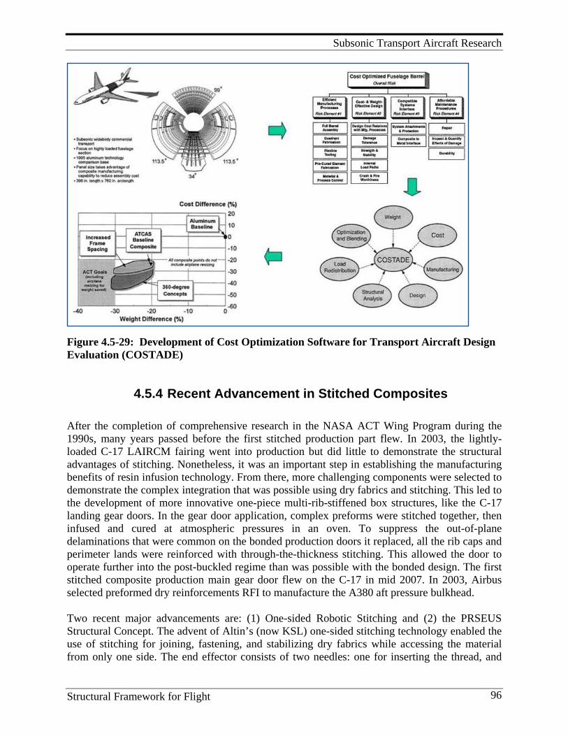
Subsonic Transport Aircraft Research
Structural Framework for Flight 96
Figure 4.5-29: Development of Cost Optimization Software for Transport Aircraft Design Evaluation (COSTADE)
4.5.4 Recent Advancement in Stitched Composites After the completion of comprehensive research in the NASA ACT Wing Program during the 1990s, many years passed before the first stitched production part flew. In 2003, the lightly-loaded C-17 LAIRCM fairing went into production but did little to demonstrate the structural advantages of stitching. Nonetheless, it was an important step in establishing the manufacturing benefits of resin infusion technology. From there, more challenging components were selected to demonstrate the complex integration that was possible using dry fabrics and stitching. This led to the development of more innovative one-piece multi-rib-stiffened box structures, like the C-17 landing gear doors. In the gear door application, complex preforms were stitched together, then infused and cured at atmospheric pressures in an oven. To suppress the out-of-plane delaminations that were common on the bonded production doors it replaced, all the rib caps and perimeter lands were reinforced with through-the-thickness stitching. This allowed the door to operate further into the post-buckled regime than was possible with the bonded design. The first stitched composite production main gear door flew on the C-17 in mid 2007. In 2003, Airbus selected preformed dry reinforcements RFI to manufacture the A380 aft pressure bulkhead. Two recent major advancements are: (1) One-sided Robotic Stitching and (2) the PRSEUS Structural Concept. The advent of Altin’s (now KSL) one-sided stitching technology enabled the use of stitching for joining, fastening, and stabilizing dry fabrics while accessing the material from only one side. The end effector consists of two needles: one for inserting the thread, and
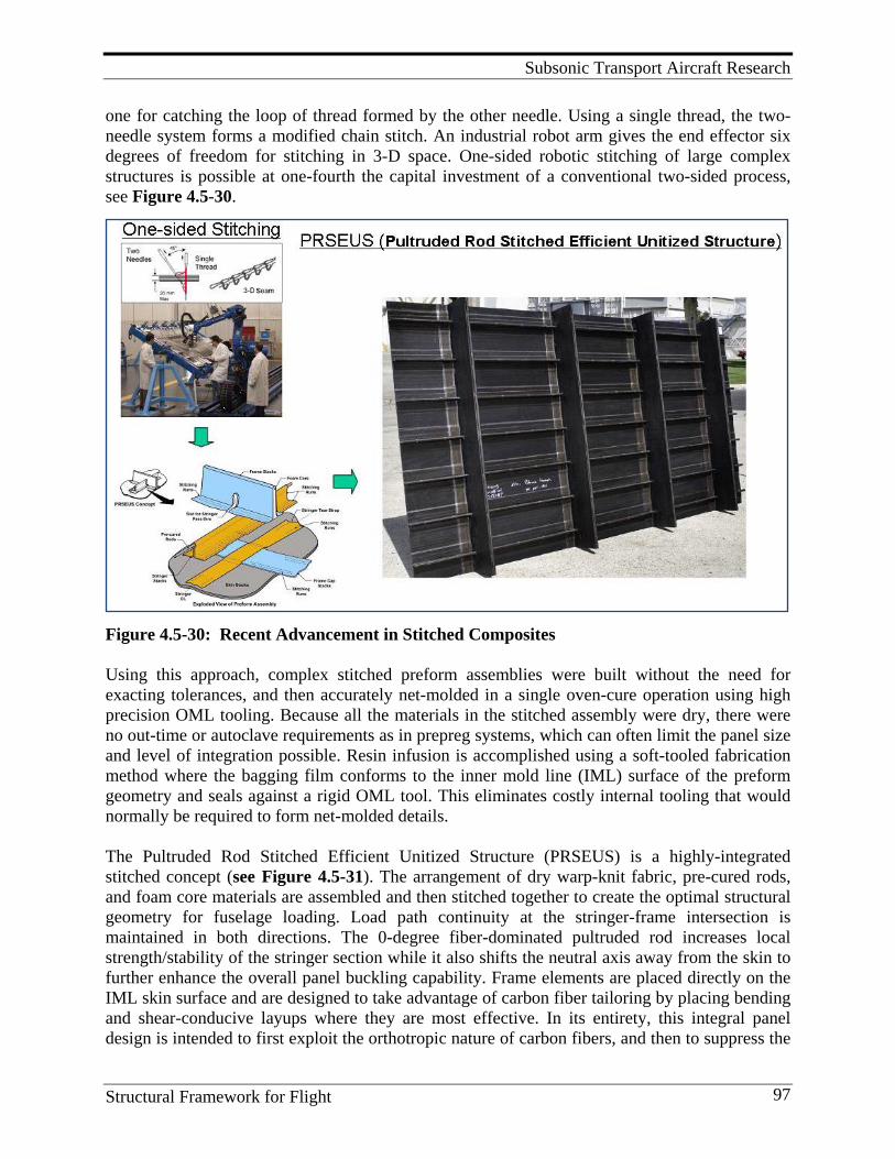
Subsonic Transport Aircraft Research
Structural Framework for Flight 97
one for catching the loop of thread formed by the other needle. Using a single thread, the two-needle system forms a modified chain stitch. An industrial robot arm gives the end effector six degrees of freedom for stitching in 3-D space. One-sided robotic stitching of large complex structures is possible at one-fourth the capital investment of a conventional two-sided process, see Figure 4.5-30.
Figure 4.5-30: Recent Advancement in Stitched Composites Using this approach, complex stitched preform assemblies were built without the need for exacting tolerances, and then accurately net-molded in a single oven-cure operation using high precision OML tooling. Because all the materials in the stitched assembly were dry, there were no out-time or autoclave requirements as in prepreg systems, which can often limit the panel size and level of integration possible. Resin infusion is accomplished using a soft-tooled fabrication method where the bagging film conforms to the inner mold line (IML) surface of the preform geometry and seals against a rigid OML tool. This eliminates costly internal tooling that would normally be required to form net-molded details. The Pultruded Rod Stitched Efficient Unitized Structure (PRSEUS) is a highly-integrated stitched concept (see Figure 4.5-31). The arrangement of dry warp-knit fabric, pre-cured rods, and foam core materials are assembled and then stitched together to create the optimal structural geometry for fuselage loading. Load path continuity at the stringer-frame intersection is maintained in both directions. The 0-degree fiber-dominated pultruded rod increases local strength/stability of the stringer section while it also shifts the neutral axis away from the skin to further enhance the overall panel buckling capability. Frame elements are placed directly on the IML skin surface and are designed to take advantage of carbon fiber tailoring by placing bending and shear-conducive layups where they are most effective. In its entirety, this integral panel design is intended to first exploit the orthotropic nature of carbon fibers, and then to suppress the

Subsonic Transport Aircraft Research
Structural Framework for Flight 98
out-of-plane failure modes with through-the-thickness stitching. Taken together, these two features enable the application of a new damage-arrest design approach for composite structures. See Figures 4.5-30 and 4.5-31.
Figure 4.5-31: Advanced Composite Concepts -- PRSEUS The first large panels were fabricated and tested in 2006 under an Air Force research contract[19]. A recent investigation indicates that the PRSEUS concept would be 10.3% lighter weight than honeycomb sandwich construction in the pressure cabin of a large blended wing body (BWB) aircraft. By utilizing the capability of stitching to arrest damage propagation, a “fail safe” rather than a “safe-life” (no growth) design method can be pursued for composite structures such as the PRSEUS approach[26, 27]; see Figure 4.5-31. NASA’s environmentally responsible aviation project, or ERA, is part of its integrated systems research into system-level concepts and technologies to cut fuel burn, noise, and emissions [28-29]. The ERA project, begun following recommendations from the U.S. National Research Council, the Executive Office of the U.S. President, the U.S. Congress and NASA’s own advisory council, has a budget of $83 million for fiscal year 2011, rising to $85 million in FY2012 and then scaling down to $77 million by 2015. Propulsion concepts and technologies for a BWB aircraft type, referred to by NASA as the N+2 vehicle, are of particular focus. The work will also assess technologies in relation to safety improvements.
Subsonic Transport Aircraft Research
Structural Framework for Flight 99
Structurally, BWBs pose new challenges compared with conventional tube fuselages and will rely on composites. Composites are needed to reduce the weight of a BWB compared with a metal version, and also should enable construction of a non-circular fuselage. A stitching technique called PRSEUS is being evaluated for the fuselage structure. The ERA plan calls for a structural test of a full-scale pressurized non-circular PRSEUS composite fuselage section in 2012.
Lessons Learned for the ACT Program
1. Successful composite applications begin with multidisciplinary teams (especially when cost is the driver, weight savings is a bonus and “real world issues” must be addressed).
2. Durability and damage tolerance studies and the process modeling work demonstrated that the use of sophisticated computer models can, with reasonable accuracy, predict the behavior of S/RFI parts.
3. Software was shown to give reasonable estimates of damage progression and residual structural strength for the structural components tested.
4. Although these tools need further refinement, they clearly demonstrate that large-cost reductions in design and processing analyses may be achieved through the use of these computational tools by reducing the necessity for large structural tests or process trials.
5. Development of the ASM was the key to scaling up the S/RFI concept and achieving the cost goal. A multidisciplinary team, that included structural designers and analysts, fabrication and assembly engineers, machine tool and sewing manufacturers, was critical in developing the ASM.
6. The wing test article was subjected to tests that included impact, discrete source damage and repair prior to the final test to failure that occurred at 97% of DUL. Thus, the need was again demonstrated to continue to utilize the building block approach until more knowledge is obtained on failure modes and damage growth.
7. Experimental and analytical results are in good agreement for global behavior. Larger local displacements and strains occurred in the test than were predicted in the nonlinear finite element analysis.
8. Further refinements to the finite element model might provide a better agreement of the analytical results with the test data.
9. More attention to load redistribution causes by repair patches is warranted. 10. Successful development of complex structural components is essential for maturing new
processes and analyses methods. 11. A formal method of predicting and tracking costs, such as COSTADE, is extremely
valuable. 12. Dry-stitched fiber-reinforced RFI or VARTM manufacturing applications are increasing. 13. Development and/or application of advanced stitching equipment will continue to reduce
costs and expand the structural shapes that can be fabricated. 14. In a recent article about the use of composites on the Airbus A380, printed in High-
performance Composites May 2003[31], Sara Black, the author, noted that the rear pressure bulkhead for the Airbus A380 employs resin film infusion. According to an Airbus spokesman, the RFI process “had matured sufficiently” to make the cut for the A380. The article goes on to state “RFI garnered a lot of industry attention about five years ago, when The Boeing Co. demonstrated the method’s ability to create a complete wing structure as part of a NASA program.” The program was the NASA ACT program.

Subsonic Transport Aircraft Research
Structural Framework for Flight 100
Program Significance
Data, experience, and knowledge from the ACT program played a major role in composite structures being selected for the Boeing 787. The S/RFI process was subsequently selected for fabricating the Airbus A380 aft pressure bulkhead and USAF C-17 cargo doors. The potential of through-the-thickness stitching for improved damage tolerance and fabrication of large complex components are major technology advancements.
Key Personnel
Managers and/or researchers included: Charles Blankenship, John Davis, Darrel Tenney, Mike Card, Irving Abel, Jim Starnes, Norm Johnston, Mark Shuart, Charlie Harris, Benson Dexter, Marvin Dow, Tom Freeman, Kevin O’Brien, Dawn Jegley, Marshall Rouse, Damodar Ambur, Jerry Deaton, Roberto Cano, Clarence Poe, Harold Bush, plus many others.
References
1. Karal, M. AST Composite Wing Program – Executive Summary. (NASA CR-2001-210650). 2. Ilcewicz, L. B., et al. 1997. Advanced Technology Composite Fuselage – Program Overview. (NASA
CR-4734). 3. Dow, M. B., and H. B. Dexter. Development of Stitched, Braided and Woven Composite Structures
in the ACT Program and at Langley Research Center (1985 to 1997). (NASA TP-97-206234). 4. Jegley, D. C., H. G. Bush, and A. E. Lovejoy. 2003. Structural Response and Failure of a Full-scale
Stitched Graphite–epoxy Wing. Journal Of Aircraft 40 (November–December). 5. Rouse, M., et al. 2005. Utilization of the Building-block-approach in Structural Mechanics Research.
Paper presented at the 46th AIAA/ASME/ASCE/AHS/ASC Structures, Structural Dynamics & Materials Conference. Austin, Texas. (Available as AIAA Paper 2005-1874.)
6. Ambur, D. R., and M. Rouse. Design and Evaluation of Composite Fuselage Panels Subjected to Combined Loading Conditions. (AIAA-97-1303).
7. NASA - Advanced Stitching Machine: Making Composite Wing Structures of the Future. (NASA FS-1997-08-31-LaRC). http://www.nasa.gov/centers/langley/news/factsheets/ASM.html
8. Black, S. 2003. An Elegant Solution for a Big Composite Part. CompositesWorld: High-performance Composites, May 1. http://www.compositesworld.com/articles/an-elegant-solution-for-a-big-composite-part.aspx.
9. Davis, J. G., Jr. 1992. Overview of the ACT Program. In Ninth DOD/NASA/FAA Conference on Fibrous Composites in Structural Design, Joseph R. Soderquist, Lawrence M. Neri, and Herman L. Bohon, compilers, 2:577-99. (NASA CR-198722).
10. Davis, J. G., Jr.; J. H. Starnes, Jr., and N. J. Johnston. 1990. Advanced Composites Research and Development for Transport Aircraft. 17th ICAS Congress, 1:XLV–LIV.
11. Dexter, H. B., C. E. Harris, and N. J. Johnston. 1992. Recent Progress in NASA Langley Research Center Textile Reinforced Composites Program. Second NASA Advanced Composites Technology Conference, John G. Davis, Jr., and Herman L. Bohon, compilers, 295–323. (NASA CP-3154).
12. Harris, C. E., J. H. Starnes, Jr., and M. J. Shuart. 2001. An Assessment of the State-of-the-art in the Design and Manufacturing of Large Composite Structures for Aerospace Vehicles. (NASA TM-2001-210844).
13. Hawley, A. V. 1996. Detail Design Development of a Transport Aircraft Composite Wing Proceedings of the Sixth NASA/DoD ACT Conference 1:131-154. (NASA CP 3326).
14. Vosteen, L. F., and R. N. Hadcock. 1994. Composite Chronicles: A Study of the Lessons Learned in the Development, Production, and Service of Composite Structures. (NASA CR 4620).
Subsonic Transport Aircraft Research
Structural Framework for Flight 101
15. Starnes, J. H., Jr., H. B. Dexter, N. J. Johnston, D. R. Ambur, and R. J. Cano. 2001. Composite Structures and Materials Research at NASA Langley Research Center. Paper presented at the NATO Research and Technology Agency Applied Vehicle Technical Panel Specialists' Meeting on Low Cost Composite Structures Loen, Norway.
16. Air Vehicle Technology Integration Program (AVTIP), Delivery Order 0059: Multi-role Bomber Structural Analysis. Final Report for 14 December 2004 – 08, May 2006. (AFRL-VA-WP-TR-2006-3067).
17. Velicki, A., and P. Thrash. 2008. Advanced Structural Concept Development Using Stitched Composites. Paper presented at the 49th AIAA/ASME/ASCE/AHS/ASC Structures, Structural Dynamics, and Materials Conference. Schaumburg, IL.
18. Li, V., and A. Velicki. 2008. Advanced PRSEUS Structural Concept Design and Optimization. Paper presented at the 12th AIAA/ISSMO Multidisciplinary Analysis and Optimization Conference. Victoria, British Columbia, Canada.
19. Velecki, A. 2009. Damage Arresting Composites for Shaped Vehicles. (NASA CR-2009-215932). 20. Jegley, D. C. Experimental Behavior of Fatigued Single Stiffener PRSEUS Specimens. (NASA TM-
20009-215955). 21. Velicki, A. 2008. Advanced Structural Concept Development Using Stitched Composites. Paper
presented at the 49th AIAA/ASME/ASCD/AHS/ASC Structures, Structural Dynamics and Materials Conference. Chicago, IL.
22. Jegley, D. C., A. Velicki, and D. A. Hansen. 2008. Structural Efficiency of Stitched Rod-stiffened Composite Panels with Stiffener Crippling. Paper presented at the 49th AIAA/ASME/ ASCE/AHS/ASC Structures, Structural Dynamics and Materials Conference. Chicago, IL.
23. Velicki, A. 2009. Luncheon Presentation: Boeing/NASA Program for Next Generation Aircraft, Aging Aircraft. 2009 Conference. Kansas City, MO.
24. Young, R. 2009. NASA Perspectives on Composite Airframe Structural Substantiation: Past Support and Future Developments. Paper presented at the FAA/EASA/Industry Composite Damage Tolerance and Maintenance Workshop. Tokyo, Japan.
25. Yovanof, N. P., A. Velicki, and V. Li. 2009. Advanced Structural Stability Analyses of a Noncircular, BWB-shaped Vehicle. Paper presented at the 50th AIAA/ASME/ASCE/AHS/ ASC Conference.
26. Wahls, R. 2009. Environmentally Responsible Aviation Technology Overview. Paper presented at the Meeting of Experts, Aeronautics and Space Engineering Board. National Research Council, Washington, DC. http://www.aeronautics.nasa.gov/pdf/ 2009_05_14_nrc_rich_wahls_508.pdf
27. Washburn, A. 2010. NASA’s Current Plans for ERA Airframe Technology. Paper presented at the 48th AIAA Aerospace Sciences Meeting. Orlando, FL.
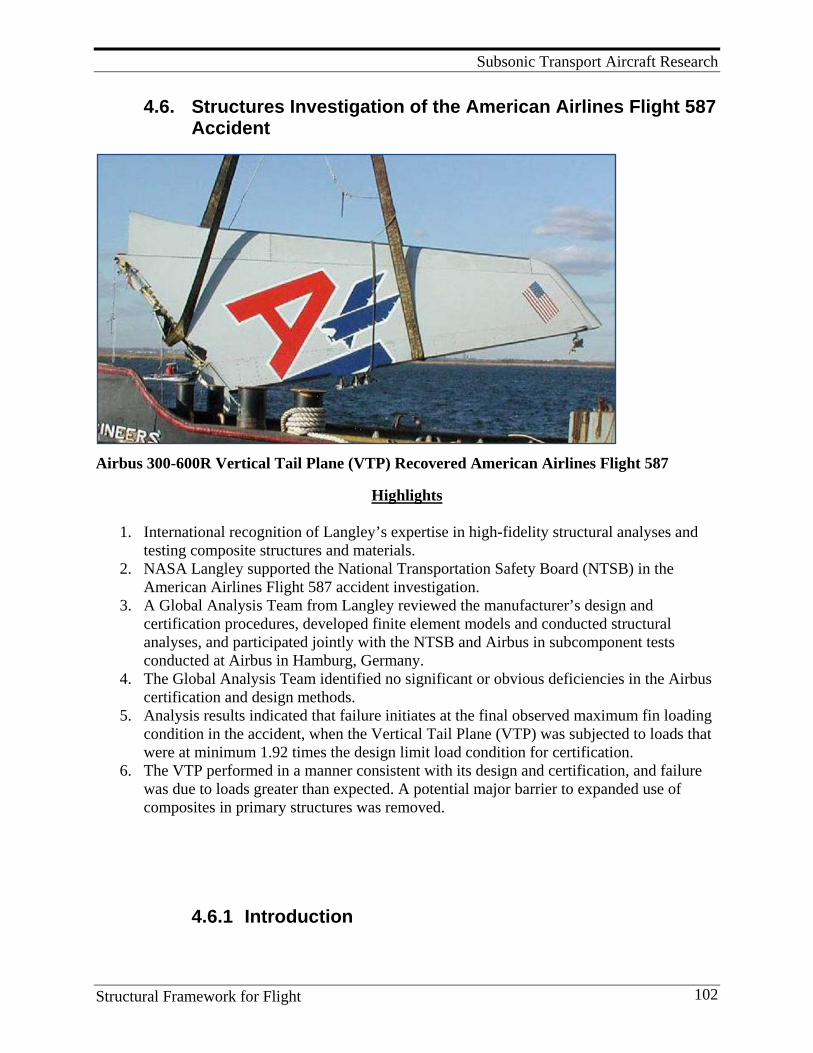
Subsonic Transport Aircraft Research
Structural Framework for Flight 102
4.6. Structures Investigation of the American Airlines Flight 587 Accident
Airbus 300-600R Vertical Tail Plane (VTP) Recovered American Airlines Flight 587
Highlights
1. International recognition of Langley’s expertise in high-fidelity structural analyses and testing composite structures and materials.
2. NASA Langley supported the National Transportation Safety Board (NTSB) in the American Airlines Flight 587 accident investigation.
3. A Global Analysis Team from Langley reviewed the manufacturer’s design and certification procedures, developed finite element models and conducted structural analyses, and participated jointly with the NTSB and Airbus in subcomponent tests conducted at Airbus in Hamburg, Germany.
4. The Global Analysis Team identified no significant or obvious deficiencies in the Airbus certification and design methods.
5. Analysis results indicated that failure initiates at the final observed maximum fin loading condition in the accident, when the Vertical Tail Plane (VTP) was subjected to loads that were at minimum 1.92 times the design limit load condition for certification.
6. The VTP performed in a manner consistent with its design and certification, and failure was due to loads greater than expected. A potential major barrier to expanded use of composites in primary structures was removed.
4.6.1 Introduction
Subsonic Transport Aircraft Research
Structural Framework for Flight 103
In November 12, 2001, an Airbus 300-600R operated as American Airlines Flight 587 crashed soon after takeoff from John F. Kennedy airport in New York City, killing all 260 persons aboard and 5 on the ground. The plane’s composite vertical stabilizer and rudder (referred to as the Vertical Tail Plane or VTP) separated from the aircraft before it impacted the ground. Initial analyses indicated that this accident was the first commercial aircraft crash that involved the failure of a primary structure made from composite materials. NASA Langley was requested by the NTSB to support the accident investigation because of Langley’s expertise in high-fidelity structural analysis and testing of composite structures and materials. In coordination with the NTSB, and under the technical guidance of Dr. James H. Starnes, Jr., technical expertise was provided for several aspects of the investigation that included global analysis of the composite vertical tail fin and rudder. A summary of the NASA AA587 Global Analysis Team results for the American Airlines Flight 587 accident investigation are reported in Reference 1. The charter established by the NTSB for the NASA Global Analysis Team was as follows: The team shall address the following objectives:
• Review of Airbus certification process: testing, analysis and design procedures • Develop and interrogate failure scenarios • Provide loads to Local Analysis Team to perform strength analyses • Conduct failure sequence analyses for most likely failure scenario (and correlate
predicted damage with the physical evidence) • Provide evidence to assess whether the structure performed as intended
4.6.2 Review of Airbus A300-600 Certification NASA’s examination of the Airbus design allowable and reserve factor processes determined that the Airbus analysis, design and testing procedures were complete and comprehensive, utilizing a well-defined building block approach. Because no significant or obvious deficiencies were identified, the NASA team felt confident using the design allowables, failure calculations and reserve factor calculations to conduct the accident investigation. However, during the review process, two items of concern with the certification process were identified that were subsequently addressed within the investigation. These certification concerns were:
1. The validity of the full-scale fin certification test was questioned as to whether the loading applied in that test was representative of the actual aircraft loading. The test was conducted with the fin off the aircraft and the distribution of applied loads was prescribed exactly from the analysis. Thus, the validity of the test loading was dependent on the validity of the global finite element model. In addition, the load-introduction structure may have introduced bending moments at the main-attachment fittings, or lugs, that are different than what the fuselage frames would have introduced.
2. The lug-strength allowables applied during design and certification were resultant forces, and did not take into consideration directly the effect of bending moments on the strength of the fin-to-fuselage attachments. The certification analyses were
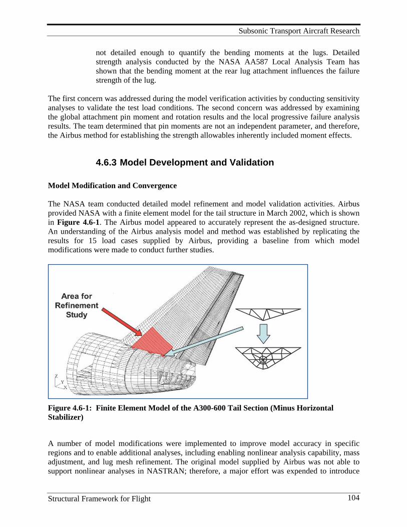
Subsonic Transport Aircraft Research
Structural Framework for Flight 104
not detailed enough to quantify the bending moments at the lugs. Detailed strength analysis conducted by the NASA AA587 Local Analysis Team has shown that the bending moment at the rear lug attachment influences the failure strength of the lug.
The first concern was addressed during the model verification activities by conducting sensitivity analyses to validate the test load conditions. The second concern was addressed by examining the global attachment pin moment and rotation results and the local progressive failure analysis results. The team determined that pin moments are not an independent parameter, and therefore, the Airbus method for establishing the strength allowables inherently included moment effects.
4.6.3 Model Development and Validation Model Modification and Convergence The NASA team conducted detailed model refinement and model validation activities. Airbus provided NASA with a finite element model for the tail structure in March 2002, which is shown in Figure 4.6-1. The Airbus model appeared to accurately represent the as-designed structure. An understanding of the Airbus analysis model and method was established by replicating the results for 15 load cases supplied by Airbus, providing a baseline from which model modifications were made to conduct further studies.
Figure 4.6-1: Finite Element Model of the A300-600 Tail Section (Minus Horizontal Stabilizer)
A number of model modifications were implemented to improve model accuracy in specific regions and to enable additional analyses, including enabling nonlinear analysis capability, mass adjustment, and lug mesh refinement. The original model supplied by Airbus was not able to support nonlinear analyses in NASTRAN; therefore, a major effort was expended to introduce
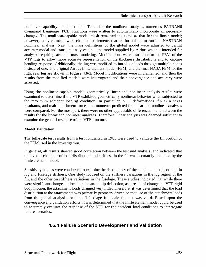
Subsonic Transport Aircraft Research
Structural Framework for Flight 105
nonlinear capability into the model. To enable the nonlinear analysis, numerous PATRAN6 Command Language (PCL) functions were written to automatically incorporate all necessary changes. The nonlinear-capable model mesh remained the same as that for the linear model; however, many elements were changed to elements that are formulated to run in a NASTRAN nonlinear analysis. Next, the mass definitions of the global model were adjusted to permit accurate modal and transient analyses since the model supplied by Airbus was not intended for analyses requiring accurate mass modeling. Modifications were also made to the FEM of the VTP lugs to allow more accurate representation of the thickness distributions and to capture bending response. Additionally, the lug was modified to introduce loads through multiple nodes instead of one. The original Airbus finite element model (FEM) and the final NASA FEM for the right rear lug are shown in Figure 4.6-1. Model modifications were implemented, and then the results from the modified models were interrogated and their convergence and accuracy were assessed. Using the nonlinear-capable model, geometrically linear and nonlinear analysis results were examined to determine if the VTP exhibited geometrically nonlinear behavior when subjected to the maximum accident loading condition. In particular, VTP deformations, fin skin stress resultants, and main attachment forces and moments predicted for linear and nonlinear analyses were compared. For the most part, there were no other appreciable differences found between the results for the linear and nonlinear analyses. Therefore, linear analysis was deemed sufficient to examine the general response of the VTP structure. Model Validation The full-scale test results from a test conducted in 1985 were used to validate the fin portion of the FEM used in the investigation. In general, all results showed good correlation between the test and analysis, and indicated that the overall character of load distribution and stiffness in the fin was accurately predicted by the finite element model. Sensitivity studies were conducted to examine the dependency of the attachment loads on the fin lug and fuselage stiffness. One study focused on the stiffness variations in the lug region of the fin, and the other on stiffness variations in the fuselage. These studies indicated that while there were significant changes in local strains and in tip deflection, as a result of changes in VTP rigid body motion, the attachment loads changed very little. Therefore, it was determined that the load distribution at the attachments was primarily geometry driven so that use of the attachment loads from the global analysis for the off-fuselage full-scale fin test was valid. Based upon the convergence and validation efforts, it was determined that the finite element model could be used to accurately evaluate the response of the VTP for the accident load conditions to interrogate failure scenarios.
4.6.4 Failure Scenario Development and Validation
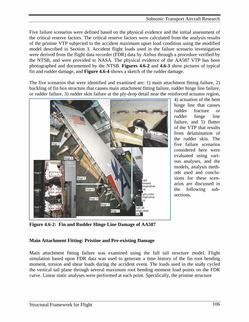
Subsonic Transport Aircraft Research
Structural Framework for Flight 106
Five failure scenarios were defined based on the physical evidence and the initial assessment of the critical reserve factors. The critical reserve factors were calculated from the analysis results of the pristine VTP subjected to the accident maximum upset load condition using the modified model described in Section 3. Accident flight loads used in the failure scenario investigation were derived from the flight data recorder (FDR) data by Airbus through a procedure verified by the NTSB, and were provided to NASA. The physical evidence of the AA587 VTP has been photographed and documented by the NTSB. Figures 4.6-2 and 4.6-3 show pictures of typical fin and rudder damage, and Figure 4.6-4 shows a sketch of the rudder damage. The five scenarios that were identified and examined are: 1) main attachment fitting failure, 2) buckling of fin box structure that causes main attachment fitting failure, rudder hinge line failure, or rudder failure, 3) rudder skin failure at the ply-drop detail near the reinforced actuator region,
4) actuation of the bent hinge line that causes rudder fracture or rudder hinge line failure, and 5) flutter of the VTP that results from delamination of the rudder skin. The five failure scenarios considered here were evaluated using vari-ous analyses, and the models, analysis meth-ods used and conclu-sions for these scen-arios are discussed in the following sub-sections.
Figure 4.6-2: Fin and Rudder Hinge Line Damage of AA587
Main Attachment Fitting: Pristine and Pre-existing Damage Main attachment fitting failure was examined using the full tail structure model. Flight simulation based upon FDR data was used to generate a time history of the fin root bending moment, torsion and shear loads during the accident event. The loads used in the study cycled the vertical tail plane through several maximum root bending moment load points on the FDR curve. Linear static analyses were performed at each point. Specifically, the pristine structure
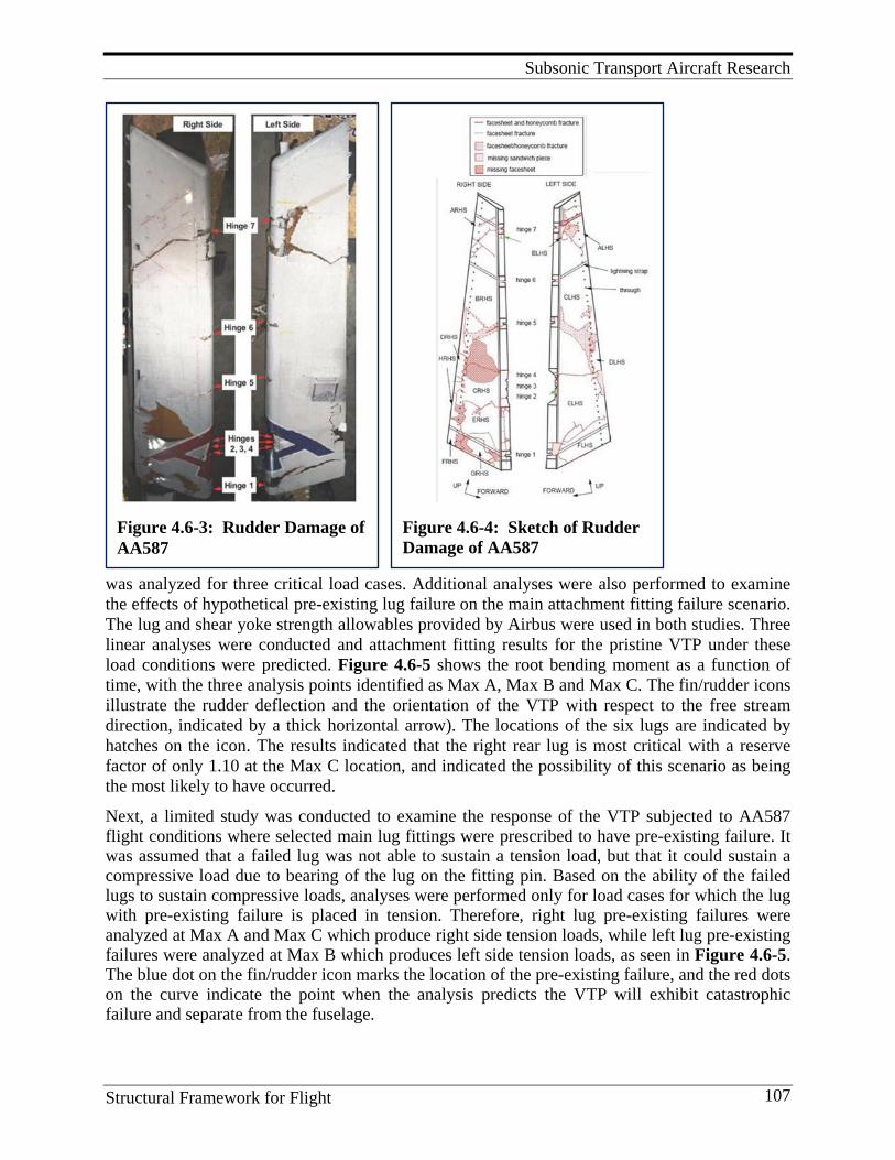
Subsonic Transport Aircraft Research
Structural Framework for Flight 107
Figure 4.6-3: Rudder Damage of AA587
Figure 4.6-4: Sketch of Rudder Damage of AA587
was analyzed for three critical load cases. Additional analyses were also performed to examine the effects of hypothetical pre-existing lug failure on the main attachment fitting failure scenario. The lug and shear yoke strength allowables provided by Airbus were used in both studies. Three linear analyses were conducted and attachment fitting results for the pristine VTP under these load conditions were predicted. Figure 4.6-5 shows the root bending moment as a function of time, with the three analysis points identified as Max A, Max B and Max C. The fin/rudder icons illustrate the rudder deflection and the orientation of the VTP with respect to the free stream direction, indicated by a thick horizontal arrow). The locations of the six lugs are indicated by hatches on the icon. The results indicated that the right rear lug is most critical with a reserve factor of only 1.10 at the Max C location, and indicated the possibility of this scenario as being the most likely to have occurred.
Next, a limited study was conducted to examine the response of the VTP subjected to AA587 flight conditions where selected main lug fittings were prescribed to have pre-existing failure. It was assumed that a failed lug was not able to sustain a tension load, but that it could sustain a compressive load due to bearing of the lug on the fitting pin. Based on the ability of the failed lugs to sustain compressive loads, analyses were performed only for load cases for which the lug with pre-existing failure is placed in tension. Therefore, right lug pre-existing failures were analyzed at Max A and Max C which produce right side tension loads, while left lug pre-existing failures were analyzed at Max B which produces left side tension loads, as seen in Figure 4.6-5. The blue dot on the fin/rudder icon marks the location of the pre-existing failure, and the red dots on the curve indicate the point when the analysis predicts the VTP will exhibit catastrophic failure and separate from the fuselage.
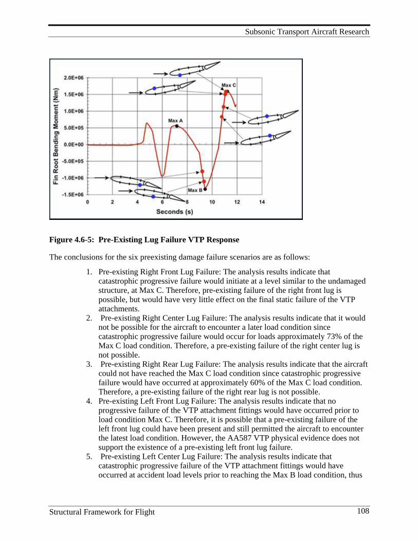
Subsonic Transport Aircraft Research
Structural Framework for Flight 108
Figure 4.6-5: Pre-Existing Lug Failure VTP Response
The conclusions for the six preexisting damage failure scenarios are as follows:
1. Pre-existing Right Front Lug Failure: The analysis results indicate that catastrophic progressive failure would initiate at a level similar to the undamaged structure, at Max C. Therefore, pre-existing failure of the right front lug is possible, but would have very little effect on the final static failure of the VTP attachments.
2. Pre-existing Right Center Lug Failure: The analysis results indicate that it would not be possible for the aircraft to encounter a later load condition since catastrophic progressive failure would occur for loads approximately 73% of the Max C load condition. Therefore, a pre-existing failure of the right center lug is not possible.
3. Pre-existing Right Rear Lug Failure: The analysis results indicate that the aircraft could not have reached the Max C load condition since catastrophic progressive failure would have occurred at approximately 60% of the Max C load condition. Therefore, a pre-existing failure of the right rear lug is not possible.
4. Pre-existing Left Front Lug Failure: The analysis results indicate that no progressive failure of the VTP attachment fittings would have occurred prior to load condition Max C. Therefore, it is possible that a pre-existing failure of the left front lug could have been present and still permitted the aircraft to encounter the latest load condition. However, the AA587 VTP physical evidence does not support the existence of a pre-existing left front lug failure.
5. Pre-existing Left Center Lug Failure: The analysis results indicate that catastrophic progressive failure of the VTP attachment fittings would have occurred at accident load levels prior to reaching the Max B load condition, thus
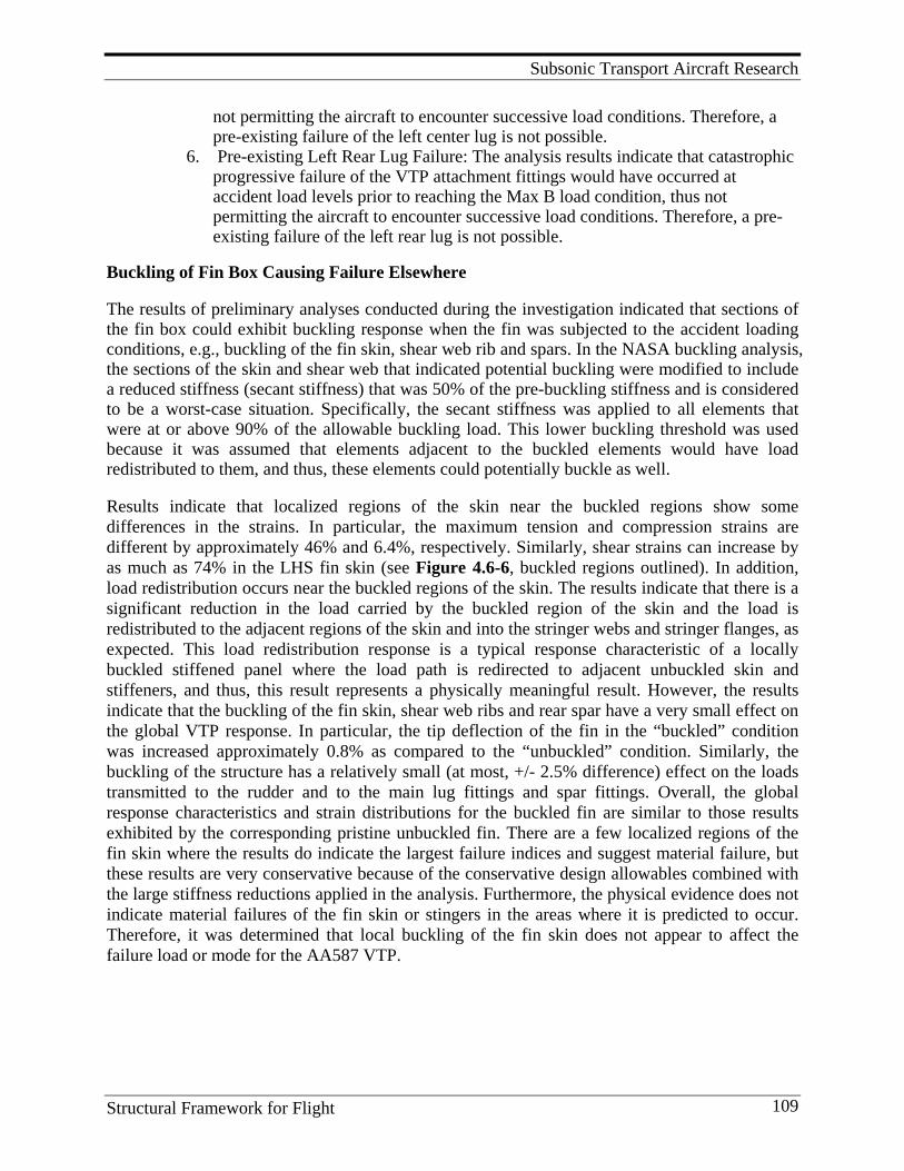
Subsonic Transport Aircraft Research
Structural Framework for Flight 109
not permitting the aircraft to encounter successive load conditions. Therefore, a pre-existing failure of the left center lug is not possible.
6. Pre-existing Left Rear Lug Failure: The analysis results indicate that catastrophic progressive failure of the VTP attachment fittings would have occurred at accident load levels prior to reaching the Max B load condition, thus not permitting the aircraft to encounter successive load conditions. Therefore, a pre-existing failure of the left rear lug is not possible.
Buckling of Fin Box Causing Failure Elsewhere The results of preliminary analyses conducted during the investigation indicated that sections of the fin box could exhibit buckling response when the fin was subjected to the accident loading conditions, e.g., buckling of the fin skin, shear web rib and spars. In the NASA buckling analysis, the sections of the skin and shear web that indicated potential buckling were modified to include a reduced stiffness (secant stiffness) that was 50% of the pre-buckling stiffness and is considered to be a worst-case situation. Specifically, the secant stiffness was applied to all elements that were at or above 90% of the allowable buckling load. This lower buckling threshold was used because it was assumed that elements adjacent to the buckled elements would have load redistributed to them, and thus, these elements could potentially buckle as well. Results indicate that localized regions of the skin near the buckled regions show some differences in the strains. In particular, the maximum tension and compression strains are different by approximately 46% and 6.4%, respectively. Similarly, shear strains can increase by as much as 74% in the LHS fin skin (see Figure 4.6-6, buckled regions outlined). In addition, load redistribution occurs near the buckled regions of the skin. The results indicate that there is a significant reduction in the load carried by the buckled region of the skin and the load is redistributed to the adjacent regions of the skin and into the stringer webs and stringer flanges, as expected. This load redistribution response is a typical response characteristic of a locally buckled stiffened panel where the load path is redirected to adjacent unbuckled skin and stiffeners, and thus, this result represents a physically meaningful result. However, the results indicate that the buckling of the fin skin, shear web ribs and rear spar have a very small effect on the global VTP response. In particular, the tip deflection of the fin in the “buckled” condition was increased approximately 0.8% as compared to the “unbuckled” condition. Similarly, the buckling of the structure has a relatively small (at most, +/- 2.5% difference) effect on the loads transmitted to the rudder and to the main lug fittings and spar fittings. Overall, the global response characteristics and strain distributions for the buckled fin are similar to those results exhibited by the corresponding pristine unbuckled fin. There are a few localized regions of the fin skin where the results do indicate the largest failure indices and suggest material failure, but these results are very conservative because of the conservative design allowables combined with the large stiffness reductions applied in the analysis. Furthermore, the physical evidence does not indicate material failures of the fin skin or stingers in the areas where it is predicted to occur. Therefore, it was determined that local buckling of the fin skin does not appear to affect the failure load or mode for the AA587 VTP.
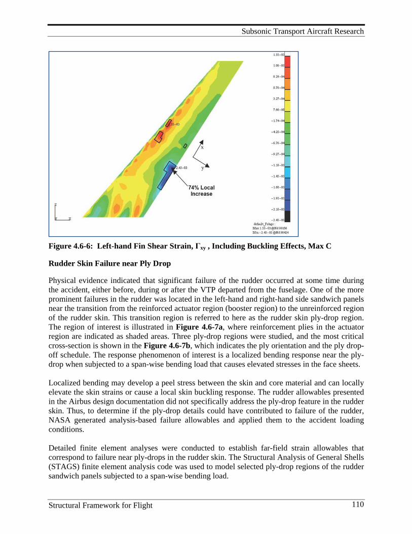
Subsonic Transport Aircraft Research
Structural Framework for Flight 110
Figure 4.6-6: Left-hand Fin Shear Strain, Γxy , Including Buckling Effects, Max C
Rudder Skin Failure near Ply Drop Physical evidence indicated that significant failure of the rudder occurred at some time during the accident, either before, during or after the VTP departed from the fuselage. One of the more prominent failures in the rudder was located in the left-hand and right-hand side sandwich panels near the transition from the reinforced actuator region (booster region) to the unreinforced region of the rudder skin. This transition region is referred to here as the rudder skin ply-drop region. The region of interest is illustrated in Figure 4.6-7a, where reinforcement plies in the actuator region are indicated as shaded areas. Three ply-drop regions were studied, and the most critical cross-section is shown in the Figure 4.6-7b, which indicates the ply orientation and the ply drop-off schedule. The response phenomenon of interest is a localized bending response near the ply-drop when subjected to a span-wise bending load that causes elevated stresses in the face sheets. Localized bending may develop a peel stress between the skin and core material and can locally elevate the skin strains or cause a local skin buckling response. The rudder allowables presented in the Airbus design documentation did not specifically address the ply-drop feature in the rudder skin. Thus, to determine if the ply-drop details could have contributed to failure of the rudder, NASA generated analysis-based failure allowables and applied them to the accident loading conditions. Detailed finite element analyses were conducted to establish far-field strain allowables that correspond to failure near ply-drops in the rudder skin. The Structural Analysis of General Shells (STAGS) finite element analysis code was used to model selected ply-drop regions of the rudder sandwich panels subjected to a span-wise bending load.
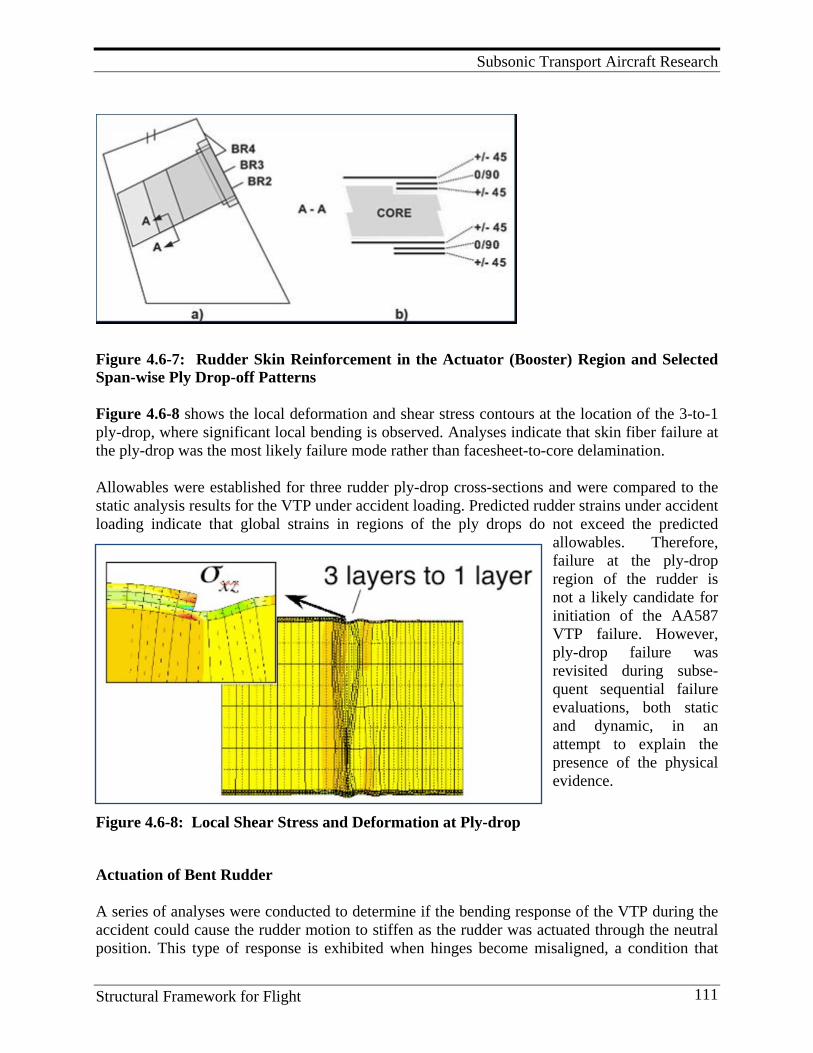
Subsonic Transport Aircraft Research
Structural Framework for Flight 111
Figure 4.6-7: Rudder Skin Reinforcement in the Actuator (Booster) Region and Selected Span-wise Ply Drop-off Patterns Figure 4.6-8 shows the local deformation and shear stress contours at the location of the 3-to-1 ply-drop, where significant local bending is observed. Analyses indicate that skin fiber failure at the ply-drop was the most likely failure mode rather than facesheet-to-core delamination. Allowables were established for three rudder ply-drop cross-sections and were compared to the static analysis results for the VTP under accident loading. Predicted rudder strains under accident loading indicate that global strains in regions of the ply drops do not exceed the predicted
allowables. Therefore, failure at the ply-drop region of the rudder is not a likely candidate for initiation of the AA587 VTP failure. However, ply-drop failure was revisited during subse-quent sequential failure evaluations, both static and dynamic, in an attempt to explain the presence of the physical evidence.
Figure 4.6-8: Local Shear Stress and Deformation at Ply-drop
Actuation of Bent Rudder A series of analyses were conducted to determine if the bending response of the VTP during the accident could cause the rudder motion to stiffen as the rudder was actuated through the neutral position. This type of response is exhibited when hinges become misaligned, a condition that
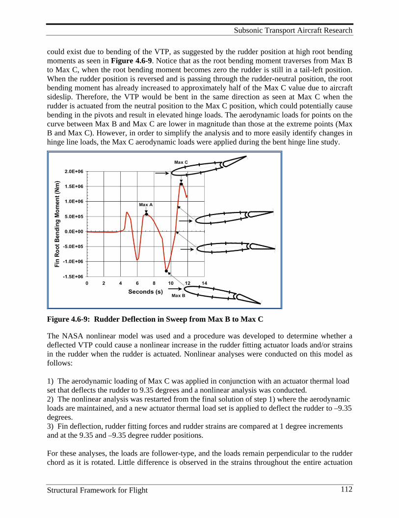
Subsonic Transport Aircraft Research
Structural Framework for Flight 112
could exist due to bending of the VTP, as suggested by the rudder position at high root bending moments as seen in Figure 4.6-9. Notice that as the root bending moment traverses from Max B to Max C, when the root bending moment becomes zero the rudder is still in a tail-left position. When the rudder position is reversed and is passing through the rudder-neutral position, the root bending moment has already increased to approximately half of the Max C value due to aircraft sideslip. Therefore, the VTP would be bent in the same direction as seen at Max C when the rudder is actuated from the neutral position to the Max C position, which could potentially cause bending in the pivots and result in elevated hinge loads. The aerodynamic loads for points on the curve between Max B and Max C are lower in magnitude than those at the extreme points (Max B and Max C). However, in order to simplify the analysis and to more easily identify changes in hinge line loads, the Max C aerodynamic loads were applied during the bent hinge line study.
Figure 4.6-9: Rudder Deflection in Sweep from Max B to Max C
The NASA nonlinear model was used and a procedure was developed to determine whether a deflected VTP could cause a nonlinear increase in the rudder fitting actuator loads and/or strains in the rudder when the rudder is actuated. Nonlinear analyses were conducted on this model as follows: 1) The aerodynamic loading of Max C was applied in conjunction with an actuator thermal load set that deflects the rudder to 9.35 degrees and a nonlinear analysis was conducted. 2) The nonlinear analysis was restarted from the final solution of step 1) where the aerodynamic loads are maintained, and a new actuator thermal load set is applied to deflect the rudder to –9.35 degrees. 3) Fin deflection, rudder fitting forces and rudder strains are compared at 1 degree increments and at the 9.35 and –9.35 degree rudder positions. For these analyses, the loads are follower-type, and the loads remain perpendicular to the rudder chord as it is rotated. Little difference is observed in the strains throughout the entire actuation
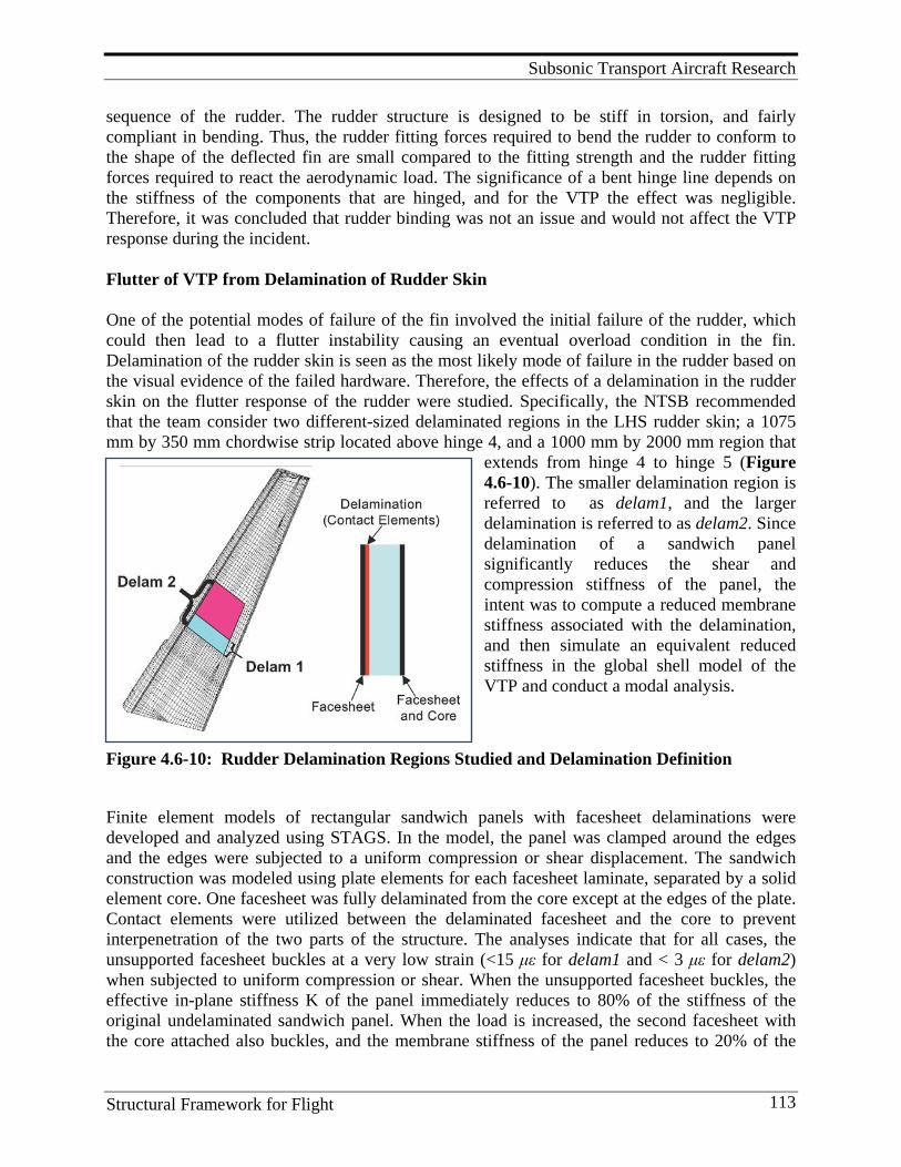
Subsonic Transport Aircraft Research
Structural Framework for Flight 113
sequence of the rudder. The rudder structure is designed to be stiff in torsion, and fairly compliant in bending. Thus, the rudder fitting forces required to bend the rudder to conform to the shape of the deflected fin are small compared to the fitting strength and the rudder fitting forces required to react the aerodynamic load. The significance of a bent hinge line depends on the stiffness of the components that are hinged, and for the VTP the effect was negligible. Therefore, it was concluded that rudder binding was not an issue and would not affect the VTP response during the incident. Flutter of VTP from Delamination of Rudder Skin One of the potential modes of failure of the fin involved the initial failure of the rudder, which could then lead to a flutter instability causing an eventual overload condition in the fin. Delamination of the rudder skin is seen as the most likely mode of failure in the rudder based on the visual evidence of the failed hardware. Therefore, the effects of a delamination in the rudder skin on the flutter response of the rudder were studied. Specifically, the NTSB recommended that the team consider two different-sized delaminated regions in the LHS rudder skin; a 1075 mm by 350 mm chordwise strip located above hinge 4, and a 1000 mm by 2000 mm region that
extends from hinge 4 to hinge 5 (Figure 4.6-10). The smaller delamination region is referred to as delam1, and the larger delamination is referred to as delam2. Since delamination of a sandwich panel significantly reduces the shear and compression stiffness of the panel, the intent was to compute a reduced membrane stiffness associated with the delamination, and then simulate an equivalent reduced stiffness in the global shell model of the VTP and conduct a modal analysis.
Figure 4.6-10: Rudder Delamination Regions Studied and Delamination Definition
Finite element models of rectangular sandwich panels with facesheet delaminations were developed and analyzed using STAGS. In the model, the panel was clamped around the edges and the edges were subjected to a uniform compression or shear displacement. The sandwich construction was modeled using plate elements for each facesheet laminate, separated by a solid element core. One facesheet was fully delaminated from the core except at the edges of the plate. Contact elements were utilized between the delaminated facesheet and the core to prevent interpenetration of the two parts of the structure. The analyses indicate that for all cases, the unsupported facesheet buckles at a very low strain (<15 με for delam1 and < 3 με for delam2) when subjected to uniform compression or shear. When the unsupported facesheet buckles, the effective in-plane stiffness K of the panel immediately reduces to 80% of the stiffness of the original undelaminated sandwich panel. When the load is increased, the second facesheet with the core attached also buckles, and the membrane stiffness of the panel reduces to 20% of the
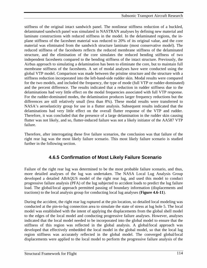
Subsonic Transport Aircraft Research
Structural Framework for Flight 114
stiffness of the original intact sandwich panel. The nonlinear stiffness reduction of a buckled, delaminated sandwich panel was simulated in NASTRAN analyses by defining new material and laminate constructions with reduced stiffness in the model. In the delaminated regions, the in-plane stiffness of the facesheet material was reduced to 20% of its original value, and the core material was eliminated from the sandwich structure laminate (most conservative model). The reduced stiffness of the facesheets reflects the reduced membrane stiffness of the delaminated structure, and the elimination of the core simulates the reduced bending stiffness of two independent facesheets compared to the bending stiffness of the intact structure. Previously, the Airbus approach to simulating a delamination has been to eliminate the core, but to maintain full membrane stiffness of the facesheets. A set of modal analyses have were conducted using the global VTP model. Comparison was made between the pristine structure and the structure with a stiffness reduction incorporated into the left-hand-side rudder skin. Modal results were compared for the two models, and included the frequency, the type of mode (full VTP or rudder-dominated) and the percent difference. The results indicated that a reduction in rudder stiffness due to the delaminations had very little effect on the modal frequencies associated with full VTP response. For the rudder-dominated modes, the delamination produces larger frequency reductions but the differences are still relatively small (less than 8%). These modal results were transferred to NASA’s aeroelasticity group for use in a flutter analysis. Subsequent results indicated that the delaminations had very little effect on the overall flutter response of the VTP and rudder. Therefore, it was concluded that the presence of a large delamination in the rudder skin causing flutter was not likely, and so, flutter-induced failure was not a likely initiator of the AA587 VTP failure. Therefore, after interrogating these five failure scenarios, the conclusion was that failure of the right rear lug was the most likely failure scenario. This most likely failure scenario is studied further in the following section.
4.6.5 Confirmation of Most Likely Failure Scenario Failure of the right rear lug was determined to be the most probable failure scenario, and thus, more detailed analyses of the lug was undertaken. The NASA Local Lug Analysis Group developed a detailed ABAQUS model of the right rear lug, and used this model to conduct progressive failure analysis (PFA) of the lug subjected to accident loads to predict the lug failure load. The global/local approach permitted passing of boundary information (displacements and tractions) to the local analysis group for conducting local lug analyses (Figure 4.6-11). During the accident, the right rear lug ruptured at the pin location, so detailed local modeling was conducted at the pin-to-lug connection area to simulate the state of stress at lug hole 5. The local model was established with the intent of applying the displacements from the global shell model to the edges of the local model and conducting progressive failure analyses. However, analyses indicated that the local model needed to be incorporated into the global model to ensure that the stiffness of this region was reflected in the global analysis. A global/local approach was developed that effectively embedded the local model in the global model, so that the local lug region stiffness was accurately reflected in the global model. The converged global/local displacements were applied to the local model to perform the progressive failure analysis of the
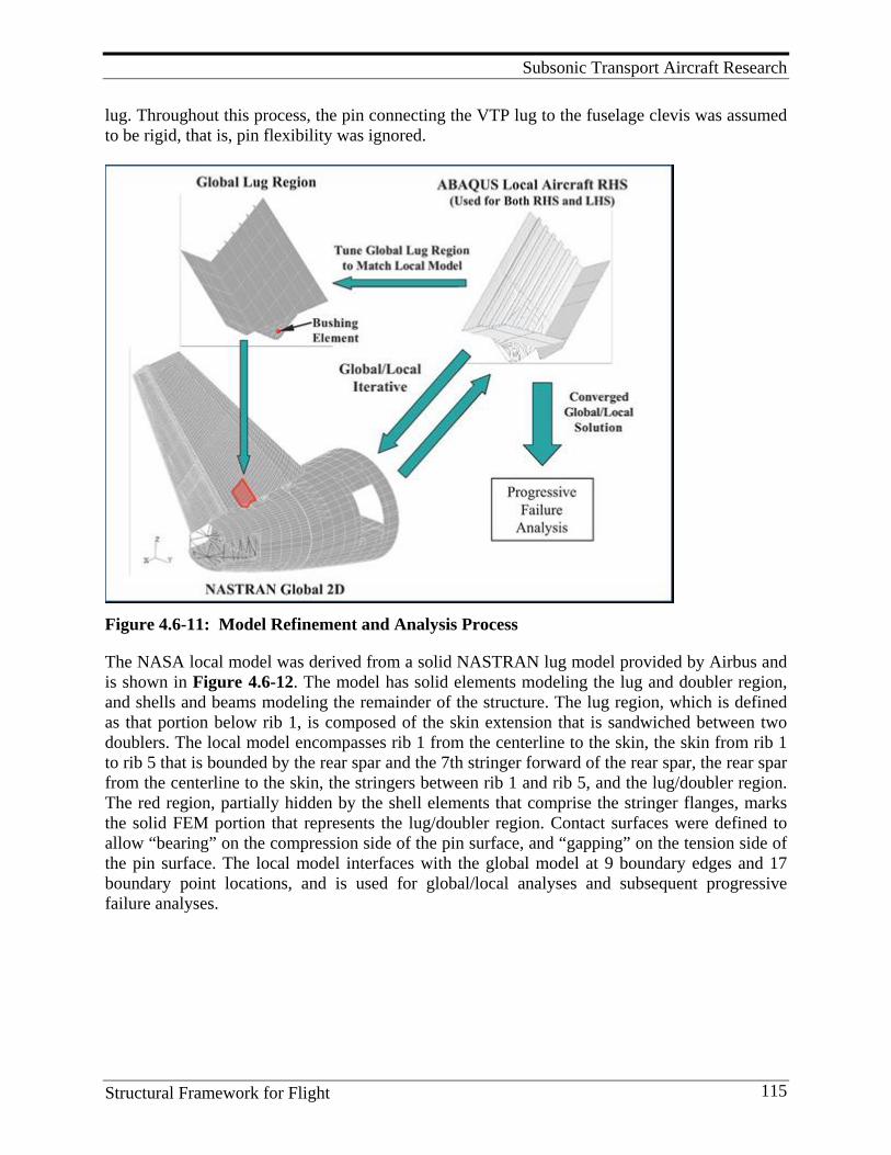
Subsonic Transport Aircraft Research
Structural Framework for Flight 115
lug. Throughout this process, the pin connecting the VTP lug to the fuselage clevis was assumed to be rigid, that is, pin flexibility was ignored.
Figure 4.6-11: Model Refinement and Analysis Process
The NASA local model was derived from a solid NASTRAN lug model provided by Airbus and is shown in Figure 4.6-12. The model has solid elements modeling the lug and doubler region, and shells and beams modeling the remainder of the structure. The lug region, which is defined as that portion below rib 1, is composed of the skin extension that is sandwiched between two doublers. The local model encompasses rib 1 from the centerline to the skin, the skin from rib 1 to rib 5 that is bounded by the rear spar and the 7th stringer forward of the rear spar, the rear spar from the centerline to the skin, the stringers between rib 1 and rib 5, and the lug/doubler region. The red region, partially hidden by the shell elements that comprise the stringer flanges, marks the solid FEM portion that represents the lug/doubler region. Contact surfaces were defined to allow “bearing” on the compression side of the pin surface, and “gapping” on the tension side of the pin surface. The local model interfaces with the global model at 9 boundary edges and 17 boundary point locations, and is used for global/local analyses and subsequent progressive failure analyses.

Subsonic Transport Aircraft Research
Structural Framework for Flight 116
The global model was modified to more accurately represent the local model stiffness. Speci-fically, because the global shell model is stiffer than the refined local model that utilizes solid elements and transfers load via a contact surface, modifications were made to the global shell model to reduce the stiffness of the lug region. The global model was “tuned” to the local model by reducing the effective stiffnesses of the rear lug regions through the use of NASTRAN bushing elements. Tuning resulted in less stiffness on the tension side, which was reflected by the lower stiffness values assigned to the bushing element.
Figure 4.6-12: Local Right Rear Lug Element Model
Although the global model was modified to more accurately represent the stiffness of the local lug model, it was found that when the boundary and pin displacements were applied to the local model, the pin reactions and boundary forces from the local model were not completely consistent with the pin reactions and boundary forces from the global model. That is, the local model was not in equilibrium with the global model. Therefore, an iterative global/local approach was developed by which a refined local lug representation was effectively embedded in the global model. The global/local process was necessary because the pin/lug interaction (specifically, force transfer) was modeled with a contact surface in the local model and is analyzed using ABAQUS. The global model was analyzed using NASTRAN, so a direct connection of the coarse (global) model and the refined (local) model was not possible.
The global/local procedure depicted in Figure 4.6-13, was implemented for both the right and left rear lugs, and is defined as follows:
1) An initial global analysis is performed and displacements are extracted along the global/local interface boundary to act as input boundary conditions for the local model. Additionally, aerodynamic loads within the local region are also passed to the local model.
2) The local model is analyzed and the boundary reaction loads (forces/moments) are computed at the global boundary points.
3) The boundary load residual is computed by subtracting the boundary reaction loads of the local model from boundary reaction loads of the global model.
4) The boundary load residual is calculated and the solution is checked for convergence. If convergence has been obtained, the process is complete.
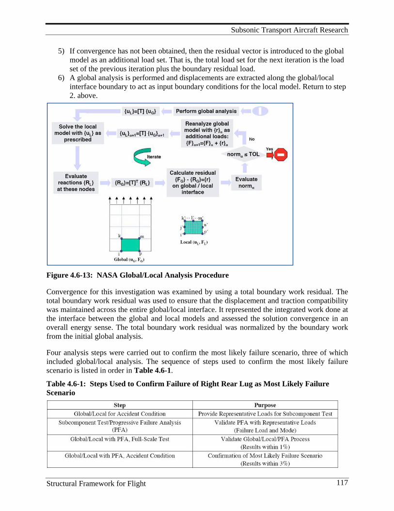
Subsonic Transport Aircraft Research
Structural Framework for Flight 117
5) If convergence has not been obtained, then the residual vector is introduced to the global model as an additional load set. That is, the total load set for the next iteration is the load set of the previous iteration plus the boundary residual load.
6) A global analysis is performed and displacements are extracted along the global/local interface boundary to act as input boundary conditions for the local model. Return to step 2. above.
Figure 4.6-13: NASA Global/Local Analysis Procedure
Convergence for this investigation was examined by using a total boundary work residual. The total boundary work residual was used to ensure that the displacement and traction compatibility was maintained across the entire global/local interface. It represented the integrated work done at the interface between the global and local models and assessed the solution convergence in an overall energy sense. The total boundary work residual was normalized by the boundary work from the initial global analysis. Four analysis steps were carried out to confirm the most likely failure scenario, three of which included global/local analysis. The sequence of steps used to confirm the most likely failure scenario is listed in order in Table 4.6-1.
Table 4.6-1: Steps Used to Confirm Failure of Right Rear Lug as Most Likely Failure Scenario
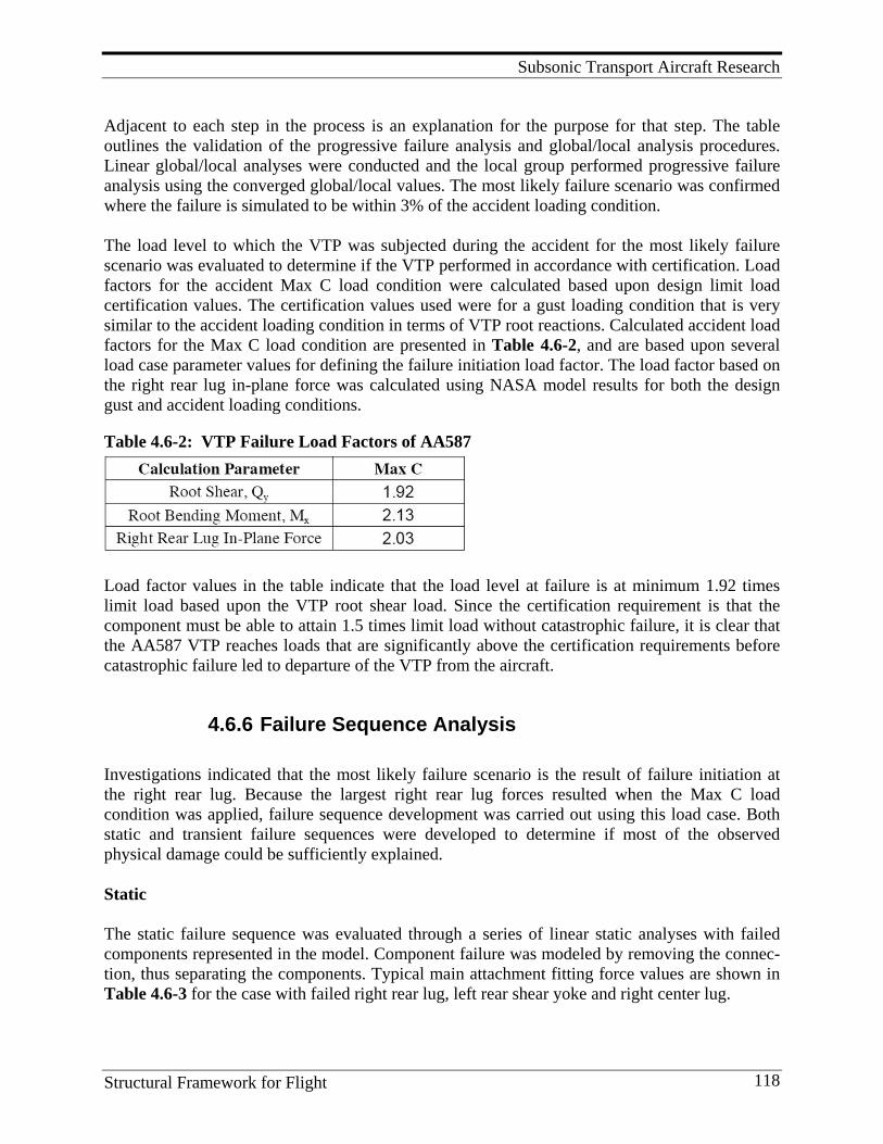
Subsonic Transport Aircraft Research
Structural Framework for Flight 118
Adjacent to each step in the process is an explanation for the purpose for that step. The table outlines the validation of the progressive failure analysis and global/local analysis procedures. Linear global/local analyses were conducted and the local group performed progressive failure analysis using the converged global/local values. The most likely failure scenario was confirmed where the failure is simulated to be within 3% of the accident loading condition. The load level to which the VTP was subjected during the accident for the most likely failure scenario was evaluated to determine if the VTP performed in accordance with certification. Load factors for the accident Max C load condition were calculated based upon design limit load certification values. The certification values used were for a gust loading condition that is very similar to the accident loading condition in terms of VTP root reactions. Calculated accident load factors for the Max C load condition are presented in Table 4.6-2, and are based upon several load case parameter values for defining the failure initiation load factor. The load factor based on the right rear lug in-plane force was calculated using NASA model results for both the design gust and accident loading conditions. Table 4.6-2: VTP Failure Load Factors of AA587
Load factor values in the table indicate that the load level at failure is at minimum 1.92 times limit load based upon the VTP root shear load. Since the certification requirement is that the component must be able to attain 1.5 times limit load without catastrophic failure, it is clear that the AA587 VTP reaches loads that are significantly above the certification requirements before catastrophic failure led to departure of the VTP from the aircraft.
4.6.6 Failure Sequence Analysis Investigations indicated that the most likely failure scenario is the result of failure initiation at the right rear lug. Because the largest right rear lug forces resulted when the Max C load condition was applied, failure sequence development was carried out using this load case. Both static and transient failure sequences were developed to determine if most of the observed physical damage could be sufficiently explained. Static The static failure sequence was evaluated through a series of linear static analyses with failed components represented in the model. Component failure was modeled by removing the connec-tion, thus separating the components. Typical main attachment fitting force values are shown in Table 4.6-3 for the case with failed right rear lug, left rear shear yoke and right center lug.
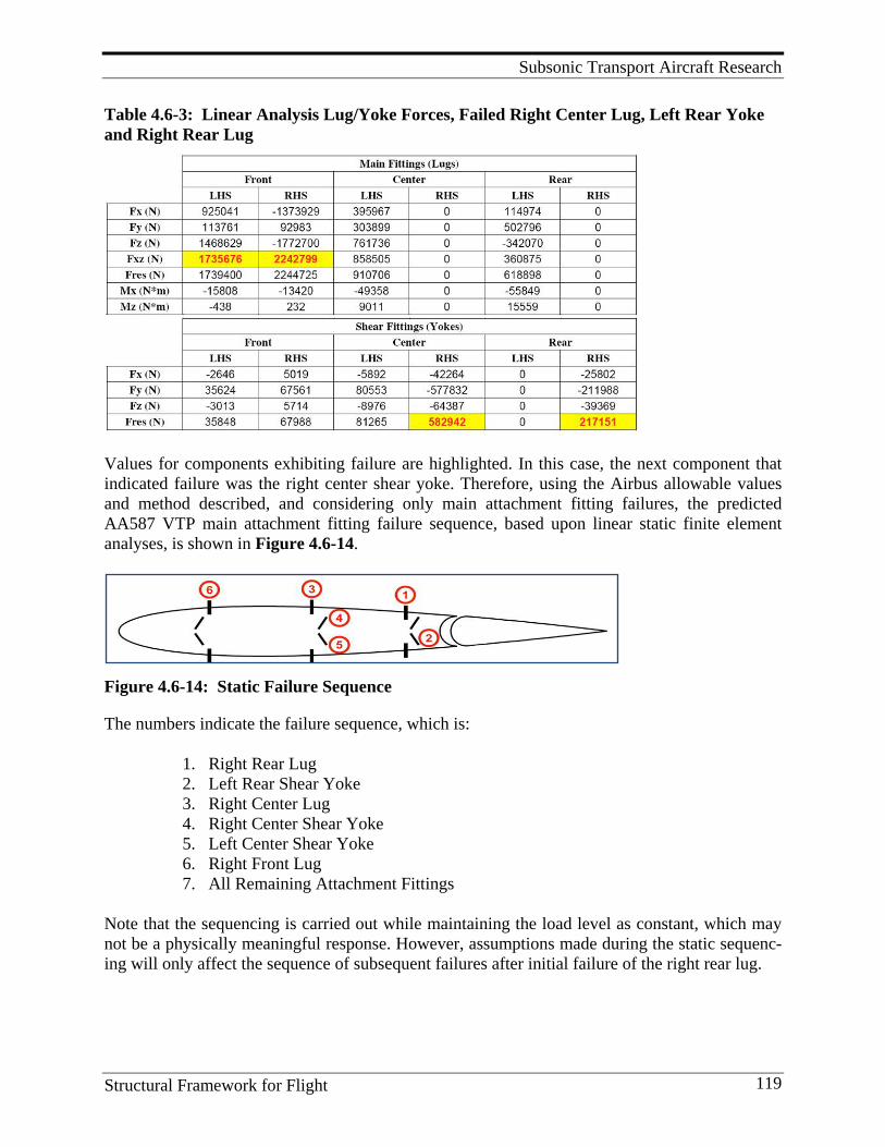
Subsonic Transport Aircraft Research
Structural Framework for Flight 119
Table 4.6-3: Linear Analysis Lug/Yoke Forces, Failed Right Center Lug, Left Rear Yoke and Right Rear Lug
Values for components exhibiting failure are highlighted. In this case, the next component that indicated failure was the right center shear yoke. Therefore, using the Airbus allowable values and method described, and considering only main attachment fitting failures, the predicted AA587 VTP main attachment fitting failure sequence, based upon linear static finite element analyses, is shown in Figure 4.6-14.
Figure 4.6-14: Static Failure Sequence
The numbers indicate the failure sequence, which is:
1. Right Rear Lug 2. Left Rear Shear Yoke 3. Right Center Lug 4. Right Center Shear Yoke 5. Left Center Shear Yoke 6. Right Front Lug 7. All Remaining Attachment Fittings
Note that the sequencing is carried out while maintaining the load level as constant, which may not be a physically meaningful response. However, assumptions made during the static sequenc-ing will only affect the sequence of subsequent failures after initial failure of the right rear lug.
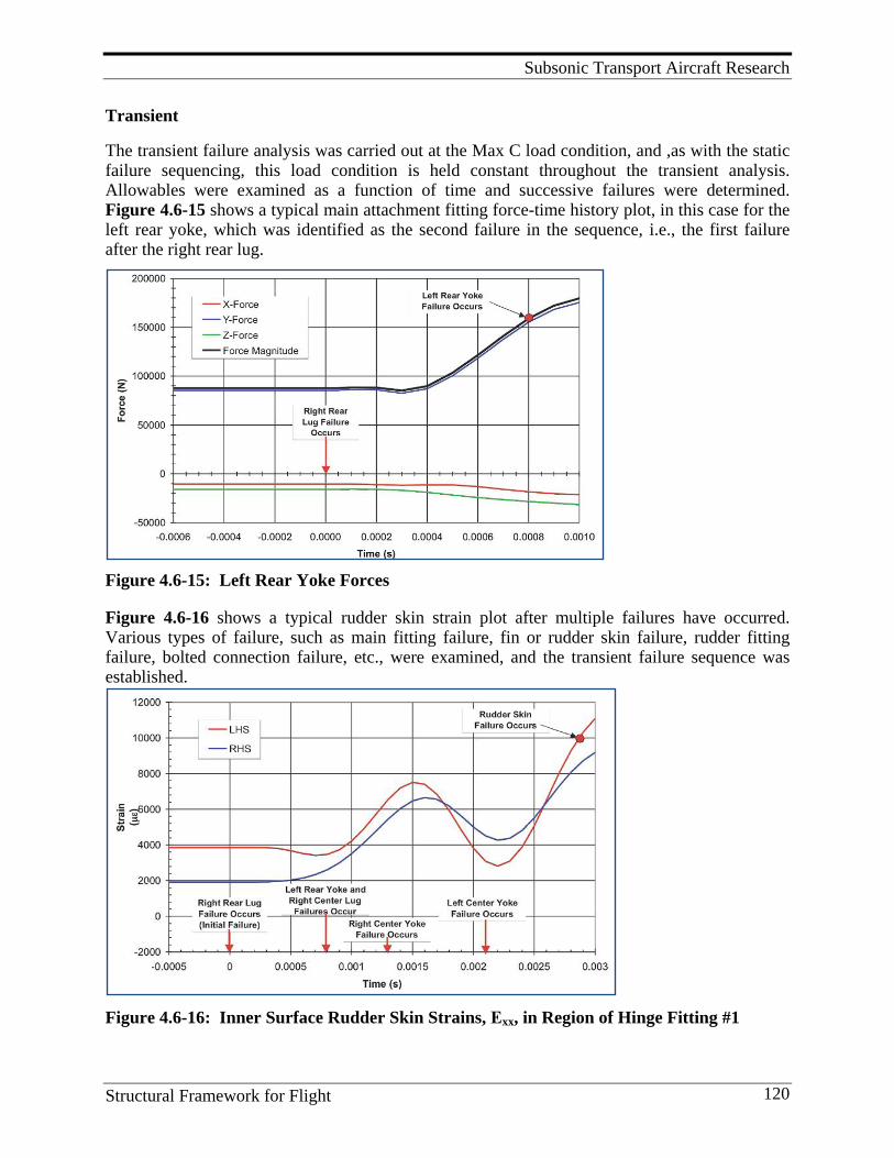
Subsonic Transport Aircraft Research
Structural Framework for Flight 120
Transient The transient failure analysis was carried out at the Max C load condition, and ,as with the static failure sequencing, this load condition is held constant throughout the transient analysis. Allowables were examined as a function of time and successive failures were determined. Figure 4.6-15 shows a typical main attachment fitting force-time history plot, in this case for the left rear yoke, which was identified as the second failure in the sequence, i.e., the first failure after the right rear lug.
Figure 4.6-15: Left Rear Yoke Forces
Figure 4.6-16 shows a typical rudder skin strain plot after multiple failures have occurred. Various types of failure, such as main fitting failure, fin or rudder skin failure, rudder fitting failure, bolted connection failure, etc., were examined, and the transient failure sequence was established.
Figure 4.6-16: Inner Surface Rudder Skin Strains, Εxx, in Region of Hinge Fitting #1
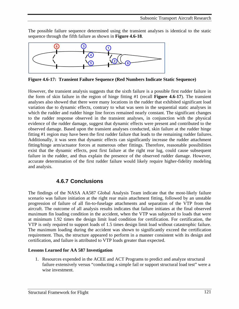
Subsonic Transport Aircraft Research
Structural Framework for Flight 121
The possible failure sequence determined using the transient analyses is identical to the static sequence through the fifth failure as shown in Figure 4.6-18.
Figure 4.6-17: Transient Failure Sequence (Red Numbers Indicate Static Sequence)
However, the transient analysis suggests that the sixth failure is a possible first rudder failure in the form of skin failure in the region of hinge fitting #1 (recall Figure 4.6-17). The transient analyses also showed that there were many locations in the rudder that exhibited significant load variation due to dynamic effects, contrary to what was seen in the sequential static analyses in which the rudder and rudder hinge line forces remained nearly constant. The significant changes to the rudder response observed in the transient analyses, in conjunction with the physical evidence of the rudder damage, suggest that dynamic effects were present and contributed to the observed damage. Based upon the transient analyses conducted, skin failure at the rudder hinge fitting #1 region may have been the first rudder failure that leads to the remaining rudder failures. Additionally, it was seen that dynamic effects can significantly increase the rudder attachment fitting/hinge arm/actuator forces at numerous other fittings. Therefore, reasonable possibilities exist that the dynamic effects, post first failure at the right rear lug, could cause subsequent failure in the rudder, and thus explain the presence of the observed rudder damage. However, accurate determination of the first rudder failure would likely require higher-fidelity modeling and analysis.
4.6.7 Conclusions The findings of the NASA AA587 Global Analysis Team indicate that the most-likely failure scenario was failure initiation at the right rear main attachment fitting, followed by an unstable progression of failure of all fin-to-fuselage attachments and separation of the VTP from the aircraft. The outcome of all analysis results indicates that failure initiates at the final observed maximum fin loading condition in the accident, when the VTP was subjected to loads that were at minimum 1.92 times the design limit load condition for certification. For certification, the VTP is only required to support loads of 1.5 times design limit load without catastrophic failure. The maximum loading during the accident was shown to significantly exceed the certification requirement. Thus, the structure appeared to perform in a manner consistent with its design and certification, and failure is attributed to VTP loads greater than expected. Lessons Learned for AA 587 Investigation
1. Resources expended in the ACEE and ACT Programs to predict and analyze structural failure extensively versus “conducting a simple fail or support structural load test” were a wise investment.
Subsonic Transport Aircraft Research
Structural Framework for Flight 122
2. NASA technical knowledge gained through use of “the building block approach” and “global local progressive failure analysis” is key to understanding failure of complex composite structures.
3. NASA proved that it can successfully function as an independent party that is focused on discovering the facts without bias. The fact that the NASA analyses results were accepted by the NTSB, Airbus, and American Airlines, is a tribute to the professional work and integrity of the NASA team.
Program Significance At the time of the accident, and during the period of the investigation, transport manufactures were developing new aircraft with composite wing and fuselage structure. Findings of this investigation showed that the structure appeared to perform in a manner consistent with its design and certification, and failure was attributed to loads greater than expected. Thus, a potential barrier to increased utilization of composite primary structures was overcome. Key Personnel Manager and/or researchers included: James H. Starnes, Mark J. Shuart, Charles E. Harris, Richard. D. Young, Andrew E. Lovejoy, Mark W. Hilburger, David F. Moore, I. S. Raju, C. G. Davila, E. H. Glaessgen, T. Krishnamurthy, and B. H. Mason. References 1. Young, R. D., A. E. Lovejoy, M. W. Hilburger, and D. F. Moore. 2005. NASA Structural Analysis
Report for the American Airlines Flight 587 Accident Investigation – Global Analysis. Paper presented at the 46th AIAA/ASME/ASCE/AHS/ASC Structures, Structural Dynamics & Materials Conference. Austin, Texas. (Available as AIAA Paper 2005-2254).
2. Young, R. D., A. E. Lovejoy, M. W. Hilburger, and D. F. Moore. 2005. NASA Structural Analysis Report for the American Airlines Flight 587 Accident Investigation: Part 2 – Global Fin/Rudder Structural Analysis and Assessment. (NASA/TM 2005-213744).
3. MSC.NASTRAN 2001 Reference Manual, 2002. 4. Materials Specialists’ Submission - Selected Photographs and Drawings of the Damage Areas on the
Vertical Stabilizer and Rudder, Docket No. SA-522, Exhibit No. 15-A. 5. Structures Group Chairman’s Factual Report DCA02MA001. 6. Raju, I. S., C. G. Davila, E. H. Glaessgen, T. Krishnamurthy, and B. H. Mason. 2005. NASA
Structural Analysis Report for the American Airlines Flight 587 Accident Investigation: Part 3 – Local Analysis of the Right Rear Lug. (NASA/TM 2005-213745).
7. MSC.PATRAN 2001 Reference Manual, 2001. 8. Rankin, C. C., F. A. Brogan, W. A. Loden, and H. D. Cabiness. 2003. Stags User Manual, Version
5.0.
4.7. Lessons Learned and Future Direction 1. NASA should always maintain a core of personnel with competent research skills that are
needed to address problems of national significance (for examples, Carbon Fiber Risk, ACEE, ACT and AA587 investigation).
Subsonic Transport Aircraft Research
Structural Framework for Flight 123
2. Ground-based environmental exposure data should be sufficient to predict long-term environmental effects of composite aircraft structures.
3. Service experience of composite structures is superior to that of conventional metallic structures. Fewer corrosion and fatigue problems can be expected.
4. Successful composite applications begin with multidisciplinary teams (especially when cost is the driver, weight savings is a bonus and “real world issues” must be addressed). A formal method of predicting and tracking costs, such as COSTADE, is extremely valuable.
5. Development and/or utilization of automated processing equipment, such as Automated Tow Placement Machines, Advanced Stitching Machines, textile weaving and braiding machines, and resin infusion methods, are key to reducing costs and improving through-the-thickness strength (reducing stiffener pull-off and delamination problems).
6. Scale-up of the manufacturing processes should be completed early in the development schedule of major programs to avoid very costly mistakes.
7. Until a thorough understanding of local failure modes and damage growth is developed, utilization of the building block approach is required to minimizing development risk (approach used in both ACEE and ACT).
8. Continued development of advanced structural concepts employing stitching is a promising approach to reducing cost and improving performance as evidenced by the recent development of: A Pultruded Rod Stitched Efficient Unitized Structure (PRSEUS) concept. This concept is currently being evaluated by NASA and Boeing and initial testing shows significant advantages over conventional concepts.
Commercial Transport Application of Composite Materials
Structural Framework for Flight 124
5. C O M M E R C I A L T R A N S P O R T A P P L I C AT I O N O F C O M P O S I T E
M AT E R I A L S This chapter contains lessons learned on composite primary structure from a primary Airframe Company point of view. The material is from interviews conducted by Jack McGuire and relates to the practical application of composites to commercial transports.
5.1. Lessons Learned
5.1.1 Design
5.1.2 Manufacturing
5.1.3 Airline Operations
5.2. Major Recent Advancements
5.3. Emerging Challenges
5.4. Future Directions
Note: Because of overall page limitation this chapter is not included in this book. However, it is in the electronic version of this monograph.
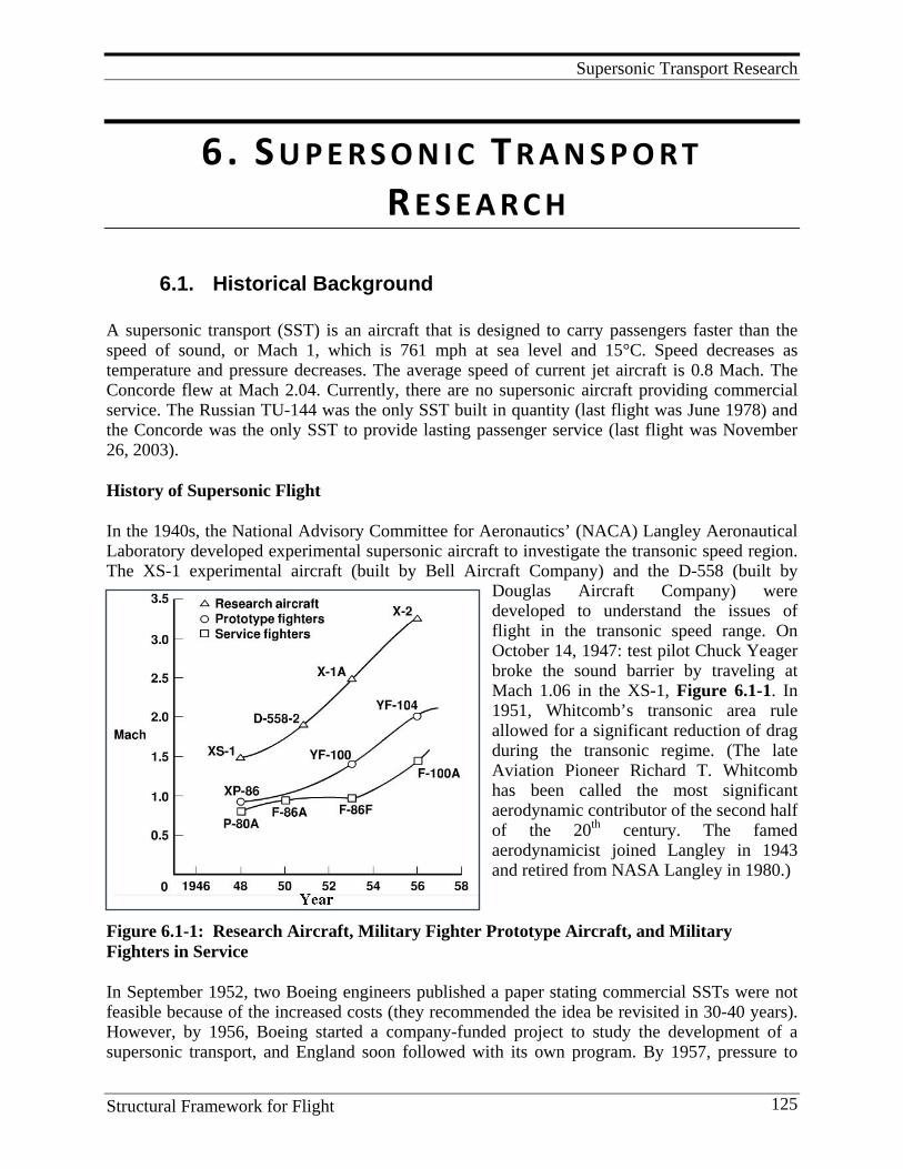
Supersonic Transport Research
Structural Framework for Flight 125
6. S U P E R S O N I C T R A N S P O R T R E S E A R C H
6.1. Historical Background A supersonic transport (SST) is an aircraft that is designed to carry passengers faster than the speed of sound, or Mach 1, which is 761 mph at sea level and 15°C. Speed decreases as temperature and pressure decreases. The average speed of current jet aircraft is 0.8 Mach. The Concorde flew at Mach 2.04. Currently, there are no supersonic aircraft providing commercial service. The Russian TU-144 was the only SST built in quantity (last flight was June 1978) and the Concorde was the only SST to provide lasting passenger service (last flight was November 26, 2003). History of Supersonic Flight
In the 1940s, the National Advisory Committee for Aeronautics’ (NACA) Langley Aeronautical Laboratory developed experimental supersonic aircraft to investigate the transonic speed region. The XS-1 experimental aircraft (built by Bell Aircraft Company) and the D-558 (built by
Douglas Aircraft Company) were developed to understand the issues of flight in the transonic speed range. On October 14, 1947: test pilot Chuck Yeager broke the sound barrier by traveling at Mach 1.06 in the XS-1, Figure 6.1-1. In 1951, Whitcomb’s transonic area rule allowed for a significant reduction of drag during the transonic regime. (The late Aviation Pioneer Richard T. Whitcomb has been called the most significant aerodynamic contributor of the second half of the 20th century. The famed aerodynamicist joined Langley in 1943 and retired from NASA Langley in 1980.)
Figure 6.1-1: Research Aircraft, Military Fighter Prototype Aircraft, and Military Fighters in Service In September 1952, two Boeing engineers published a paper stating commercial SSTs were not feasible because of the increased costs (they recommended the idea be revisited in 30-40 years). However, by 1956, Boeing started a company-funded project to study the development of a supersonic transport, and England soon followed with its own program. By 1957, pressure to
Supersonic Transport Research
Structural Framework for Flight 126
fund commercial SST research and development was mounting and a general belief that such a technology would be widely available within 10 to 15 years was spreading. The general con-sensus was that the project would need to be government-funded since U.S. manufacturers were hurting from producing the jet aircraft, and did not have the resources for another large-scale development project. In 1956, Alfred J. Eggers developed the “supersonic wedge principle”. By placing the body of the aircraft entirely under the wing, the shockwave produced by the body would create pressure on the bottom of the wing adding lift, increasing aerodynamic efficiency at Mach 3 by 20-30% (this would make cruising at supersonic speeds possible). Later that year, the Air Force propulsion laboratory showed that blade-cooling techniques could be safely applied to engines improving the supersonic efficiency. Then in October, the Air Force redirected the WS-100 program toward sustained supersonic flight. Finally, in November 1956, the first flight of ConvairB-58 Hustler (a Mach 2 capable bomber) took place. This aircraft was capable of achieving supersonic flight but for only a short duration (minutes). In 1957, Boeing and North American submitted proposals to the Air Force for new supersonic aircraft. During the 1960s, the United Kingdom, Soviet Union, France, and the U.S. all funded SST programs. In their view they were competing for continued balance of trade, technological parity or superiority, and national prestige. It was believed that a commercial SST would make the subsonic jet aircraft obsolete. This development was conducted in a setting where increased speed was considered a virtue (good in its own right). The pre- and postwar cultural enthusiasm for technology was a major driver at that time. Faster transport and ways of doing business promised increased profits and a stronger economy. In aviation, progress came to be defined as higher speeds and altitudes. United Stated In July 1961, an SST steering group (FAA, NASA, and DOD) was formed in the U.S. In August 1961, Congress approved $11m for FAA SST research. Congress appropriated $100M in the fiscal 1964 budget toward the development of the American SST and in October 1963, TWA and Pan Am stepped forward with $2.1M towards the purchase of 21 SSTs. The question then became, who would build it? North American already had a remarkable military SST known as the Valkyrie, but Boeing beat out the Lockheed L-2000 and the North American NAC-60 (Douglas was too strapped for cash to compete) for the contract. Congress cancelled the U.S. Supersonic Transport program in March 1971. Cancellation justification was based on both environmental and performance issues. Environmentally, many countries outlawed supersonic flight overland because of the sonic boom, thus severely restricting projected market penetration; atmospheric scientists predicted catastrophic reductions of ozone from engine emissions severely restricting fleet size; aircraft regulators wanted the engines that were designed for supersonic flight to meet subsonic noise certification standards; and health officials were concerned about the effects of high-altitude atmospheric radiation. In addition, performance issues that were cited for the cancellation included the need for more efficient lift-to-drag ratio for both subsonic and supersonic flight; sufficient thrust from propulsion at both supersonic and subsonic speeds with low noise and efficient fuel consumption;
Supersonic Transport Research
Structural Framework for Flight 127
airframe structures and materials with greater strength with less weight, and system integration techniques to maximize airplane efficiency. Soviet Union In June 1965, the Russian-built TU-144 model was shown at the Paris Air Show. The first flight of a prototype of the TU-144 took place in December 1968. Although the last commercial passenger flight was in 1978, production of the Tu-144 did not cease until six years later, in 1984, when construction of the partially complete Tu-144D reg 77116 airframe was stopped. During the 1980s the last two production aircraft to fly were used for airborne laboratory testing, including research into ozone depletion at high altitudes. In the early 1990s, IBP Aerospace negotiated an agreement with Tupolev and NASA to use a Tu-144 as a testbed for the High Speed Civil Transport Program. In 1995, Tu-144D built in 1981 (but with only 82 hours and 40 minutes total flight time) was taken out of storage and after extensive modification at a total cost of US$350 million was designated the Tu-144LL. It made a total of 27 flights in 1996 and 1997. In 1999, though regarded as a technical success, the project was cancelled for lack of funding. France and the United Kingdom In November 1962, the U.K. and French governments signed an agreement to produce an SST (Concorde). These contracts locked both French and British governments into development of an SST aircraft. The SST program was more of a treaty rather than a commercial contract. Other countries were interested at first, but pulled out prior to completion of the first commercial aircraft. The British and French governments pumped vast sums into their SST program. Economic motivations included a desire to compete with aircraft production market, then dominated by the U.S., which ultimately led to the birth of Airbus Consortium. The first flight of a prototype took place in 1969. Commercial flights began in1977. However, by April 2003, British Airways and Air France announced retirement of Concorde. The last flight of the Concorde took place in November 2003. The principal factors that killed the Concorde were: high cost of operation, and environmental and political objections. Round-trip flights on the Concorde could cost as much as $12,000. The small number of aircraft made volume profits impossible and the limited number of available airports (and limited fuel carrying capacity) reduced possible travel routes. Environmental objections centered on upper-atmospheric pollution (ozone hole was discovered), incredible noise pollution, and political objections driven by community noise objections. The Concorde was seen as another toy for the rich that negatively impacted the poor. Perhaps the final factor that ended the flight of Concorde was the July 2000 crash. This accident shed light on safety concerns and revealed previous questionable handling of problems. Very similar problems had occurred before but with no accidents. Grounding of Concords for more than a year cost British Airways and Air France vast sums of money. Return to flight was announced on September 5, 2001. However, the use of aircraft to carry out the terrorist attack of September 11, 2001 made an already-difficult financial situation for the commercial aviation industry even worse.
Supersonic Transport Research
Structural Framework for Flight 128
Opposition to U.S. SST Various groups and individuals spoke out against SST development from the early stages. Their principal arguments against the SST were made primarily on economic grounds, and some took issue with the amount of government support. However, during the 1960s, the main attack against the SST in the U.S. came from the growing environmental movement. The movement was picking up speed at this time, and targeting technology and industrial development was out of control and irresponsible. The SST was singled out as symbolic of technology being put before environment. Also, tests of sonic boom tolerance increased awareness of the noise issues associated with an SST. Questions regarding upper atmosphere emissions were also being discussed. While the political decision to cancel the SST program was highly motivated by the environ-mental outcry, the SST program would have most likely died anyway. After the B747 was introduced, the government began developing noise requirements for subsonic flights. It was decided that these standards needed to apply to the supersonic aircraft as well. This in turn meant that a new engine must be developed, drastically increasing the costs of SST development and production. NASA’s Involvement in Supersonic Research after the Cancellation of the SST Program in 1971 From late 1972 through 1981, NASA funded a relatively small program called the Supersonic Cruise Aircraft Research (SCAR). One of the key technologies worked under this program was Composite Fuselage. In 1989, NASA won approval of a third SST research program named High Speed Civil Transport (HSCT), which was funded through 1998. During the mid-1990s, Boeing forecasted that 800-1,200 SSTs could be in use by 2020. The estimated cost for development of this aircraft was $30 billion. Boeing never launched this aircraft program. In 1990, NASA was funded by congress to, again address the long lead technology issues associated with the development of an economically-viable and environmentally-responsible supersonic aircraft. This program was the High Speed Research (HSR) program. A major technology worked at Langley Research Center was the development of high-temperature composites for the airframe. Major contributions made under this research effort are discussed in a later section. In 2002, Supersonic research was a focused R&D project in NASA’s Vehicle Systems program. Research was focused on analyses and modeling of sonic booms from new aircraft configur-ations. This effort continues through today (2010), currently a funded element of the NASA Aeronautics Fundamental Aero program. Selected highlights of this work are covered in a later section. References
1. Saltzman, Edwin J. and Avers, Theodore G.: Selected Examples of NACA/NASA Supersonic Flight Research. NASA Special Publication 1995.
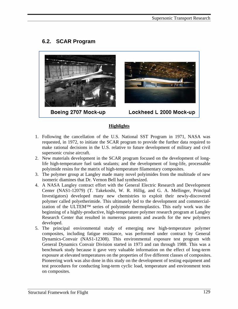
Supersonic Transport Research
Structural Framework for Flight 129
6.2. SCAR Program
Highlights
1. Following the cancellation of the U.S. National SST Program in 1971, NASA was requested, in 1972, to initiate the SCAR program to provide the further data required to make rational decisions in the U.S. relative to future development of military and civil supersonic cruise aircraft.
2. New materials development in the SCAR program focused on the development of long-life high-temperature fuel tank sealants; and the development of long-life, processable polyimide resins for the matrix of high-temperature filamentary composites.
3. The polymer group at Langley made many novel polyimides from the multitude of new isomeric diamines that Dr. Vernon Bell had synthesized.
4. A NASA Langley contract effort with the General Electric Research and Development Center (NAS1-12079) (T. Takekoshi, W. R. Hillig, and G. A. Mellinger, Principal Investigators) developed many new chemistries to exploit their newly-discovered polymer called polyetherimide. This ultimately led to the development and commercial-ization of the ULTEM™ series of polyimide thermoplastics. This early work was the beginning of a highly-productive, high-temperature polymer research program at Langley Research Center that resulted in numerous patents and awards for the new polymers developed.
5. The principal environmental study of emerging new high-temperature polymer composites, including fatigue resistance, was performed under contract by General Dynamics-Convair (NAS1-12308). This environmental exposure test program with General Dynamics Convair Division started in 1973 and ran through 1988. This was a benchmark study because it gave very valuable information on the effect of long-term exposure at elevated temperatures on the properties of five different classes of composites. Pioneering work was also done in this study on the development of testing equipment and test procedures for conducting long-term cyclic load, temperature and environment tests on composites.
Supersonic Transport Research
Structural Framework for Flight 130
Introduction Following the cancellation of the U.S. National SST Program in 1971, NASA was requested in 1972 to initiate the SCAR program to provide the further data required to make rational decisions in the U.S. relative to future development of military and civil supersonic cruise aircraft. In addition to the environmental and economic questions that still remained when the National SST Program was cancelled, the major unresolved structures problems were related to the poor flutter characteristics of the aircraft and the high-operating empty weight fraction, which adversely affected the economics of the airplane. The Department of Transportation funded a follow-on technology program to complete selected tasks in the areas of flutter, titanium honeycomb panel development, and fuel tank sealants. Advanced structural concepts or high-temperature composite materials were not included initially, but were added a year later. The SCAR structures and materials subprogram emphasized technology advances for achieving major reductions in the airframe structural weight of large, flexible, high-temperature, long-life supersonic aircraft. The research and developmental efforts were formulated to address critical technical problems in the areas of advanced structural concepts, structural design procedures, aeroelastic loads and response, and materials applications. In the main, the research programs were independent of specific aircraft configurations. Because of limited resources available under the SCAR program in both funds and manpower, only those research areas with long-term potential for high payoff were identified and pursued. No attempt was made to investigate all structural problem areas which would be encountered in the design and manufacture of advanced supersonic cruise aircraft. Furthermore, the modest funding level for structures and materials research, which averaged less than three million dollars per year in 1972 through 1976, allowed for the testing of small structural components only, and could not support any sizeable structural development activity. Fundamental research applicable to supersonic cruise aircraft in Structures and Materials was conducted principally by Langley with contributions from: Flight Research Center on ground and flight tests of structures, Ames Research Center on fuel tank sealants, and Lewis Research Center on high-temperature polymers for use as matrix materials in advanced resin/fiber composites. Primary emphasis was placed on the design and development of advanced structural concepts applicable to high-performance, supersonic, cruise aircraft and to the development, manufacture, and proof test of advanced titanium and composite components for application in both primary and secondary structures. In the area of aeroelasticity, primary emphasis was given to the development of both steady and unsteady loads calculation and flutter calculation methodology for large, highly flexible aircraft with emphasis in the transonic flight regime and to the experimental evaluation of long-wave-length atmospheric turbulence characteristics expected to influence supersonic cruise aircraft design. Advanced Composite Applications Boeing was awarded a contract to provide an in-depth evaluation of mass reductions that might be achieved by utilization of advanced composite materials and structural concepts that could be
Supersonic Transport Research
Structural Framework for Flight 131
available in the 1980s. Previous studies had indicated that a reduction in operating empty mass of about 9% could be achieved through a potential reduction of 18% in structural mass. It was generally believed that further refinement and/or substantiation of this estimate, by application of the integrated analysis and design tools that were used in the design studies, would provide guidelines for research planning on advanced materials applications and concept development. Detail design and concept studies focused on representative sections of major components of the baseline structure so that results of the study could be directly comparable to those obtained based on the 1975 technology baseline titanium structure. Materials Application At that time, it was believed that the use of new materials had the greatest potential for reducing the structural weight of supersonic cruise aircraft. It was postulated that if advanced composite materials could be used extensively, structural weight reductions up to 25% could be achieved compared to a similar titanium structure. Successful applications of new materials, however, require extensive and detailed data on material performance under the long-time, high-temperature environment of supersonic cruise flight and the development of economical and reliable manufacturing methods. In this program, some new materials, particularly fuel tank sealants, were undergoing development and environmental testing. Fatigue and fracture testing and advanced fabrication and joining process development for titanium and advanced composite materials were initiated. The manufacturing technology program was focused on small wing skin panels (for the YF-12 airplane). These panels were subjected to extensive ground tests and limited flight service evaluations. Advanced composite materials are very attractive for all structural applications because of their low density, high strength, and stiffness. Very little data was available at the initiation of the SCAR program on the suitability of these materials for supersonic cruise applications. Therefore, investigations of the environmental resistance of representative fiber-matrix combinations under simulated supersonic transport environments were initiated to establish time, temperature, and stress capabilities. In addition, some development of new resin matrices was supported in the SCAR program. The materials application program investigated both titanium alloys and advanced composites initially and then shifted focus to resin and metal matrix composites.
New Materials
Two areas of new material development were (1) the development of long-life high-temperature fuel tank sealants; and (2) the development of long-life, processable polyimide resins for the matrix of high-temperature filamentary composites. The objective of the fuel tank sealant program was to provide flight-proof, fully characterized, predictable fuel tank sealants. It included the synthesis, characterization, formulation and curing of the new elastomer candidates (NAS 2-7331, NAS 7-100, NAS 2-7112, NAS 2-7981, NAS 2-8103). The sealants program is described in NASA TM X-62401.

Supersonic Transport Research
Structural Framework for Flight 132
One of the most promising class of resins for high-temperature composite structures was found to be polyimides. These materials were judged to have the potential of performing satisfactorily for long periods at temperatures in the 450°F to 600°F range. However, considerable difficulty was encountered in the application of these materials because of variable properties and complex processing manufacturing problems. No large-scale application of polyimide-type composites had been demonstrated successfully at that time in an aerospace application. Because of the difficulties associated with the application of polyimides, a contract effort was undertaken by Langley, along with the General Electric R&D Center (NAS1-12079) (T. Takekoshi, W. R. Hillig and G. A. Mellinger, Principal Investigators) to exploit their newly-discovered polymer called polyetherimide. The contract called for GE to prepare 14 new ether dianhydride monomers from the novel nitro displacement reaction of nitrophthalimides with various bisphenols. This interesting reaction ultimately led to the development and commercialization of the ULTEM™ series of polyimide thermoplastics which used bisphenol A as one of its monomers. The 14 dianhydride monomers were used to synthesize 42 new polyetherimides and several soluble ether-pyrrones. While none were of ultimate use in the HSR program, they provided an interesting series of polyetherimide structures for evaluation. Of most interest, however, were the new dianhydrides that allowed the polymer group at Langley to make many novel polyimides from the multitude of new isomeric diamines that Dr. Vernon Bell had synthesized. The GE contract led to a number of very interesting publications. A promising new high-temperature polyetherimide resin was prepared that appeared (at that time) to warrant further optimization and thorough evaluation on graphite fiber. Also, the cure reactions developed in the latter phase could be effectively used with polyphenylquinoxalines and other polymers such as polyethersulfones whose weak point is their thermoplastic nature at elevated temperature. Studies on high-temperature resin development were also undertaken by the Lewis Research Center with the hope of improving processability and retaining useful mechanical properties to 600° F. Emphasis was placed on development of autoclavable polyimides and polyphenyl-quinoxalines (NAS3-16799, NAS3-17770, NAS3-17824). In-house studies at Lewis Research Center resulted in the development of a class of highly processable, high-temperature resistant polyimides, known as Polymerization of Monomer Reactants (PMR). Tests of the 600°F flexural strengths of HTS graphite fiber composites fabricated with a PMR polyimide showed that, after 600 hours of exposure in air at 600°F, the flexural strength of the PMR composite was 50% higher than that of a composite made with a commercial polyimide. Of even greater significance was the broad applicability of the concepts embodied in PMR polyimides to other polymer systems. The PMR polyimide was investigated for possible application to structural panels for the YF-12 aircraft panel program. Environmental Effects The resistance of structural materials to long-time service at elevated temperatures is a vital factor in selecting materials for a supersonic cruise aircraft. Extensive testing of titanium alloys was conducted during the National SST Program and some of this work continued under the
Supersonic Transport Research
Structural Framework for Flight 133
SCAR program. Similar research and testing on advanced composite materials that could be used on a supersonic transport was initiated under SCAR. The principal environmental study, including fatigue resistance, of available composites materials was performed under contract by General Dynamics-Convair (NAS1-12308). In a two-phase effort, phase I evaluated existing data for the baseline material in each of five classes of composites and conducted environmental simulation or cumulative exposure to 10,000 hours followed by mechanical property tests and material evaluations to determine exposure effects. In phase II, the experimental and analytical characterizations were extended to cumulative exposure up to 50,000 hours. The filaments and matrices selected as baseline for the five material classes were: 4-mil boron/5505 epoxy B/E; AS graphite/3501 epoxy (G/E); 5.6-mil boron/P 105A polyimide (B/PI; HTS graphite/710 polyimide (G/PI); 5.6- mil boron/6061 aluminum alloy, diffusion bonded. Later the B/PI material was removed from the program because of excessive variability of matrix-controlled properties and rapid degradation of B/PI specimens during short time exposures. The complex flight simulation equipment, in which both accelerated and real time tests were conducted, applied random load spectra on a flight-by-flight basis and programmed temperature histories with independent load and temperature levels for each of the materials systems under test. Up to 100 specimens were tested simultaneously. The static exposure and accelerated flight simulation data were used in analyses based on modified wear-out concepts to predict materials behavior after long flight simulation exposures. It was proposed that if the 50,000-hour exposure data correlated with these predictions, a significant advance would have been made toward efficient design of advanced composite components for long-time, elevated-temperature aircraft service. Aging of B/E at 350°F and 1-atm pressure for 10,000 hours produced a sizable decrease in 350°F tensile strength. Similar exposures at 250°F, 1-atm pressure, and at 350°F, 2 psi air, had no effect on 350°F tensile strength. The tensile strength degradation was caused by absorption of moisture by the epoxy systems which caused a significant decrease in short-time elevated-temperature strength. In a report by Cooper and Heldenfels, (NASA TM X-72790) the authors stated that “the results point out the need for a moisture-proof coating when these materials are subjected to long periods in ambient environments. Similar behavior was experienced by the G/E material system.” At that time, the effects of moisture absorption on hot wet compression properties was not well understood. Later research would show that moisture absorption has the effect of plasticizing the matrix; all epoxies and polyimide resins absorb moisture, and no effective barrier coating has been developed to prevent moisture absorption. The approach used today is to design for the knockdown due to moisture and not try to use a “moisture-proof coating.” Static thermal aging of G/PI at 550°F in air for 5,000 hours produced a decrease in 550°F tensile strength of unidirectional material, but no effect on cross-ply material. Similar exposures of G/PI at 450°F produced no significant changes in tensile strength. Based on these and other test results the principle investigators (J. R. Kerr and J. F. Haskins) concluded that the polyimide systems they tested should be limited to a maximum upper-use temperature of 450°F for exposure times longer than 10,000 hours. The primary degradation mechanism was matrix degradation due to matrix oxidation. They also noted a loss of residual strength, primarily matrix dominated, during

Supersonic Transport Research
Structural Framework for Flight 134
flight simulation exposure (due to combined compressive and thermal stressing in conjunction with oxidation-induced matrix degradation).This study started in 1973 and ran through 1988. For the G/E system, thermal aging at 250°F and 1-atm pressure produced no effects for the first 10,000 hours. Matrix degradation began between 10,000 and 25,000 hours, and was severe after 50,000 hours. The fiber-controlled tensile properties, however, showed almost no change. Aging at 350°F and 1-atm pressure was more damaging, with matrix degradation beginning between 1,000 and 5,000 hours. After 5,000 hours, the matrix was severely embrittled and crumbled away during tensile testing, leaving many bare fibers. Tensile properties were considerably reduced for aging times of 5,000 hours or longer. Reduced pressure exposures at 350°F delayed the effects, but did not eliminate them. The G/PI system survived 25,000 hours of thermal aging at 450°F and 1-atm pressure with no effects. Some decrease in tensile strength was measured after 50,000 hours, but matrix degradation was not observed. At 1-atm pressure, raising the aging temperature to 550°F reduced the time at which tensile strength decreases were observed to 10,000 hours. In like manner to the 450°F exposures, this initial fall-off in tensile strength was not accompanied by matrix embrittlement. After 25,000 hours, the material was partially delaminated and showed high weight loss. The tensile strength was greatly reduced and severe matrix embrittlement had occurred. Degradation after 50,000 hours was such that the specimens could not be tested. Again, aging effects were less severe for exposures conducted in a reduced pressure environment. Matrix degradation by oxidation was shown to be the primary cause of mechanical property losses during thermal aging. For G/E, the extent of oxidation could readily be detected by metallographic techniques, especially with the SEM. Similar studies of G/PI revealed increased porosity and fiber-matrix separation accompanied by numerous fine cracks at the fiber-matrix interface. However, visual effects starting at the edges and moving inward, as seen in the G/E system, were not observed for the G/PI system. The results of this program showed that the loss in mechanical properties of G/E and G/PI advanced composites during thermal aging were related to both degradation of the resin matrix and, to a less extent, the graphite-reinforcing fiber. Since tensile strength is a fiber-dominated property, a post-exposure tensile test was probably not the best choice for evaluating the effects of thermal aging. The relatively high residual tensile strengths obtained after many of the exposures, were somewhat misleading as to the actual quality of the material. A test that measured the matrix strength would undoubtedly have given results more indicative of the degree of material degradation. The exposure program funded by NASA Langley and conducted at General Dynamics was a benchmark study because it provided very valuable information on the effect of long-term expose at elevated temperature on the properties of five different classes of composites. Pioneering work was also done in this study on the development of testing equipment and test procedures for conducting long-term cyclic load, temperature and environment tests on composites. One of the major challenges had to do with developing the simulation equipment that would reliably operate for thousands of hours.
Supersonic Transport Research
Structural Framework for Flight 135
The information gained from this research provided valuable insight into damage mechanisms that were invaluable in developing new resins that have better oxidation resistance and improved durability at elevated temperatures. Fatigue and Fracture The unknown effects of aerodynamic heating and long cruise times are a primary concern in structural fatigue resistance of supersonic transport materials and structures. For subsonic airplanes, structural fatigue strength is usually verified by a full-scale fatigue test. However, a full-scale fatigue test of a supersonic transport would be very expensive and time consuming since the cyclic thermal environment can be duplicated only in real time. Consequently, development of test-acceleration procedures was considered necessary. Two of the objectives on the fatigue studies in the SCAR program focused on the determination of real time and thermal exposure effects on fatigue strengths of candidate materials and structures and on development of procedures which would permit performance of accelerated fatigue tests. Two programs were undertaken to determine the governing fatigue parameters. Design methods and structural concepts were investigated to make composite structures that could tolerate significant amounts of damage without failing catastrophically. These developments were aimed to make composite structures “failsafe” like metal structures in current transport aircraft. The approach to achieving these objectives contained two major activities: (1) development of a fracture theory for cross-plied laminates that could be used to predict the strength of damaged laminates and (2) development of methods of analysis that could be used to predict the influence of softening strips, stringers, and other damage tolerant features on the residual strength of damaged structures. Under Contract NAS1-12675, several graphite/epoxy laminates of the (0/±45/90) family and several boron/aluminum laminates of the (0/±45) family were fabricated for testing at the NASA Langley Research Center to obtain predictions in the reduction in strength of cross-plied laminates due to crack-like flaws. Tests were conducted at both room and elevated temperatures. The effects of fatigue loads on fracture toughness were evaluated and the mechanism of fatigue-crack growth identified. The resulting experimental data was analyzed to evaluate the applicability of existing theories for the estimation of the fracture toughness of various laminates. Manufacturing Technology One of the major areas of technology improvement investigated in the SCAR program was the development of economical and reliable manufacturing methods for metal and composite aircraft structures. Both in-house and contractual efforts were undertaken with the principal activity focused on wing surface panels for the YF-12 airplane. Advanced fabrication and joining processes for titanium and high-temperature composite materials were investigated with Lockheed-ADP as the prime contractor (AF Contract F0 4606-73-C-0013) and under Contract NAS1-13095. Full-scale structural panels were designed and fabricated to replace an existing integrally stiffened shear panel in the upper wing surface of the NASA YF-12 aircraft. The program included ground testing and Mach 3 flight testing of five
Supersonic Transport Research
Structural Framework for Flight 136
types of full-scale structural panels and laboratory testing of representative structural element specimens. Most of the work was focused on titanium panels made by either weldbrazing (skin stringer panel) or by titanium honeycomb panels made by a liquid interface diffusion process. However, three composite panel concepts were also investigated. McDonnell Douglas Astronautics Company-East studied brazing and manufacturing methods for panels with boron/aluminum face sheets and a titanium honeycomb-core. NASA Langley studied fabrication methods for borsic/aluminum panels with titanium honeycomb-core, as well as panels with graphite/ polyimide facesheets and glass/polyimide honeycomb-core. Weight-saving estimates for the composite panel designs compared to the original YF-12 titanium panel varied from 30% for the metal-matrix designs to 55% for the graphite/polyimide design. Fabrication processes for these panels were developed. Lessons Learned
1. Determining the long-term durability of any material system is difficult and requires a long-term commitment to a multiyear testing program.
2. Establishing an accelerated test methodology requires careful planning and an under-standing of damage mechanisms. If the failure mechanisms change between real time and accelerated testing, then the accelerated test methodology cannot be trusted to represent service life.
3. The candidate material systems tested in this program were no longer considered to be viable at the end of the testing program. This points out one of the real issues with long- term durability testing. If the objective of the testing is to validate the durability of leading candidate materials for a particular flight vehicle, the program will likely not succeed because the material systems will likely be modified during the course of the program to improve processability, impact damage tolerance, or some other property judged to be important to the hardware program. Minor modifications of the resin to improve one property can sometimes adversely affect other properties and may change long-term durability at elevated service temperatures.
4. Long-term exposure programs are best designed to (a) establish accelerated test methodology, and (2) determine damage mechanisms in systems where the chemistry is well understood. Then if minor formulations in the chemistry are made later on to optimize some property judged to be necessary for particular vehicle application there is a basis for estimating whether there is likely any potential impact on long-term durability.
5. Extensive testing and analyses are required to establish the fatigue and fracture behavior of composites, under complex service conditions, representative of supersonic flight. NDE needs to be an integral element of such studies to document the initiation and growth of damage with time, temperature, and stress cycling.
6. Processing and fabrication development needs to be a research focus in any polymer composite R&D program to optimize chemistry, such that practical engineering structures can be fabricated.
Supersonic Transport Research
Structural Framework for Flight 137
References
1. Cooper, P. A., and R. R. Heldenfels. NASA Research on Structures and Materials for Supersonic Cruise Aircraft. (NASA TMX-72790).
2. Kerr, J. R., and J. F. Haskins. Time-temperature-stress Capabilities of Composite Materials for Advanced Supersonic Technology Application, Phase 1. GDC-MAP-80-001. (NASA-CR-159267).
3. Kerr, J. R. and J. F. Haskins. 1984. Effects of 50,000 h of Thermal Aging on Graphite/Epoxy and Graphite/Polyimide Composites. AIAA Journal 22:96-102.
4. Haskins, J. F and J. R. Kerr. Effects of Real-time Thermal Aging on Graphite/Polyimide Composites. NASA Lewis Research Center High Temp. Polymer Matrix Composites 315-327. (SEE N86-11260 02-24).
5. Haskins, J. F., J. R. Kerr, and B. A. Stein. Time-temperature-stress Capabilities of Composites for Supersonic Cruise Aircraft Applications. In its Proc. on the SCAR Conf., Pt. 2, 30 p (SEE N77-18019 09-01).
6. Haskins, J. F., J. R. Kerr, and B. A. Stein. Flight Simulation Testing of Advanced Composites for Supersonic Cruise Aircraft Applications. AIAA PAPER 77-401.
7. Takekoshi, T., W. R. Hillig, G. A. Mellinger, J. E. Kochanowski, J. S. Manello, M. J. Webber, R. W. Bulson, and J. W. Nehrich. 1975. Study of Improved Resins for Advanced Supersonic Technology Composites: Part I. Heteroaromatic Polymers Containing Ether Groups: Part II. Curing Chemistry of Aromatic Polymers and Composite Studies. (NASA CR-145007).
8. Takekoshi, T., G. A. Mellinger, R. W. Bulson, J. R. Ladd, and M. J. Webber. 1977. Study of Improved Resins for Advanced Supersonic Technology Composites: Part III. Phthalonitrile-capped Polyetherimides as Matrix Resin for Graphite Fiber Composites. (NASA CR-145237).
9. Takekoshi, T., J. G. Wirth, D. R. Heath, J. E. Kochanowski, J. S. Manello, and M. J. Webber. 1980. J. Polymer. Sci. Polymer. Chem. Ed, 18:3069.
10. White, D. M., T. Takekoshi, F. J. Williams, H. M. Relles, P. E. Donahue, H. J. Klopfer, G. R. Loucks, J. S. Manello, R. O. Matthews, and R. W. Schluenz. 1981. J. Polymer. Sci. Polymer. Chem. Ed. 19:1635.
11. Takekoshi, T., J. E. Kochanowski, J. S. Manello, and M. J. Webber. 1985. J. Polymer. Sci. Polym. Chem. Ed. 23:1759.
12. Takekoshi, T., J. E. Kochanowski, J. S. Manello, and M. J. Webber. 1986. J. Polymer. Sci. Polymer. Symposium 74, 93.
13. Takekoshi, T. 1990. Synthesis of Polyetherimides by Transimidization Reaction. Paper presented at The Interdisciplinary Symposium on Recent Advances in Polyimides and Other High-performance Polymers. Sponsored by the Division of Polymer Chemistry, American Chemical Society. San Diego, CA.
14. Takekoshi, T. 1990. Polyamides. In Advances in Polymer Science, New Polymer Materials, Springer Berlin/Heidelberg, 94, 1.
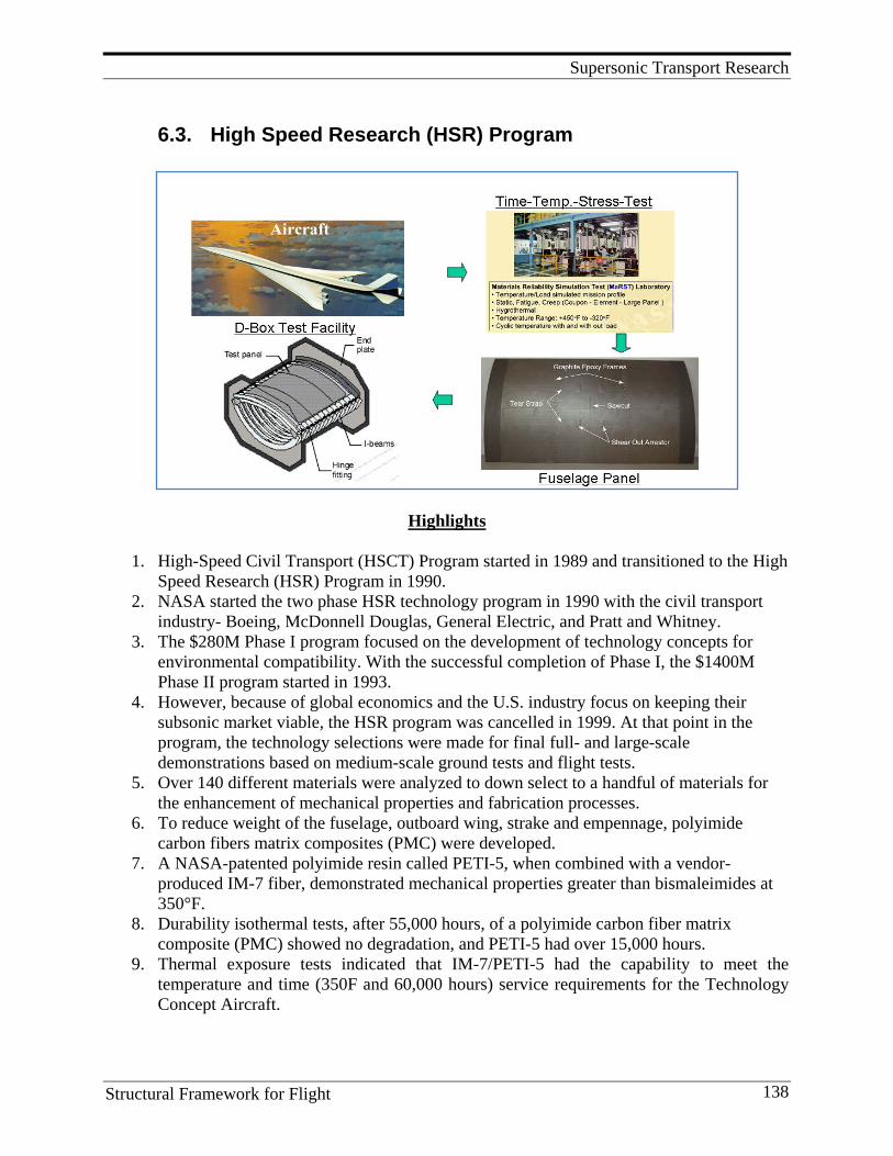
Supersonic Transport Research
Structural Framework for Flight 138
6.3. High Speed Research (HSR) Program
Highlights
1. High-Speed Civil Transport (HSCT) Program started in 1989 and transitioned to the High Speed Research (HSR) Program in 1990.
2. NASA started the two phase HSR technology program in 1990 with the civil transport industry- Boeing, McDonnell Douglas, General Electric, and Pratt and Whitney.
3. The $280M Phase I program focused on the development of technology concepts for environmental compatibility. With the successful completion of Phase I, the $1400M Phase II program started in 1993.
4. However, because of global economics and the U.S. industry focus on keeping their subsonic market viable, the HSR program was cancelled in 1999. At that point in the program, the technology selections were made for final full- and large-scale demonstrations based on medium-scale ground tests and flight tests.
5. Over 140 different materials were analyzed to down select to a handful of materials for the enhancement of mechanical properties and fabrication processes.
6. To reduce weight of the fuselage, outboard wing, strake and empennage, polyimide carbon fibers matrix composites (PMC) were developed.
7. A NASA-patented polyimide resin called PETI-5, when combined with a vendor- produced IM-7 fiber, demonstrated mechanical properties greater than bismaleimides at 350°F.
8. Durability isothermal tests, after 55,000 hours, of a polyimide carbon fiber matrix composite (PMC) showed no degradation, and PETI-5 had over 15,000 hours.
9. Thermal exposure tests indicated that IM-7/PETI-5 had the capability to meet the temperature and time (350F and 60,000 hours) service requirements for the Technology Concept Aircraft.
Supersonic Transport Research
Structural Framework for Flight 139
10. Over 1,000 lbs. of prepreg was commercially made during the HSR activity and led to the fabrication of 6-ft. by 10-ft. skin-stringer and sandwich panels.
11. NASA’s HSR program was on track to meet all of the environmental and economic goals established for the program. Technology was demonstrated in medium scale ground tests and flight tests.
12. However, the program was cancelled in 1999 before the large scale demonstration test articles were developed and tested.
6.3.1 Introduction Beginning in 1989, NASA and industry investigated the potential of an HSCT, the airplane specifications, and required technologies. The system trade studies concluded that an airplane launched in the early 21st century should be compatible with current airports, use jet fuel, and be within a 10- to 15-year technology reach. Both Boeing and McDonnell Douglas converged on a Mach 2.4, 300 passengers, and 5,000 nautical mile airplane as a focus for technology development. Based on the market and technology projections of an HSCT, NASA started the two-phase HSR technology program in 1990 with the civil transport industry: Boeing, McDonnell Douglas, General Electric, and Pratt and Whitney. The $280M Phase I program focused on the development of technology concepts for environmental compatibility. With the successful completion of Phase I, the $1400M Phase II program started in 1993. This phase was to demonstrate the environmental technologies, and define and demonstrate selected high-risk technologies for economic viability. However, because of global economics and the U.S. industry focus on keeping their subsonic market viable, the HSR program was cancelled in 1999. At this point in the program, the technology selections were made for final full- and large-scale demonstrations based on medium-scale ground tests and flight tests. Materials and Structures The fraction of the operating empty weight for airframe structure is much smaller for a supersonic transport than for conventional subsonic commercial vehicles. This requires the use of innovative structural concepts and advanced materials to satisfy this stringent weight requirement. The operating environment is also more severe because of the high temperatures associated with the aerodynamic friction heating caused by supersonic cruise speeds. The Mach 2.4, economically-viable HSCT drives the materials and structures technology development with 60,000 hour durability at a cycled 350°F skin temperature and a 30% reduction in weight relative to the Concorde. Conventional airplane materials, such as aluminum, and thermoset composites, such as bismaleimides, do not have the temperature capability, and titanium alloys are too heavy for the entire airframe. Over 140 different materials were analyzed to down select to a handful of materials for the enhancement of mechanical properties and fabrication processes.
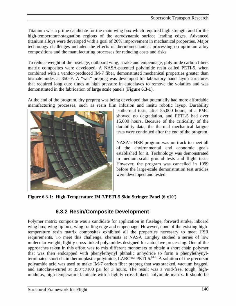
Supersonic Transport Research
Structural Framework for Flight 140
Titanium was a prime candidate for the main wing box which required high strength and for the high-temperature-stagnation regions of the aerodynamic surface leading edges. Advanced titanium alloys were developed with a goal of 20% improvement in mechanical properties. Major technology challenges included the effects of thermomechanical processing on optimum alloy compositions and the manufacturing processes for reducing costs and risks. To reduce weight of the fuselage, outboard wing, strake and empennage, polyimide carbon fibers matrix composites were developed. A NASA-patented polyimide resin called PETI-5, when combined with a vendor-produced IM-7 fiber, demonstrated mechanical properties greater than bismaleimides at 350°F. A “wet” prepreg was developed for laboratory hand layup structures that required long cure times at high pressure in autoclaves to remove the volatiles and was demonstrated in the fabrication of large scale panels (Figure 6.3-1). At the end of the program, dry prepreg was being developed that potentially had more affordable manufacturing processes, such as resin film infusion and insitu robotic layup. Durability
isothermal tests, after 55,000 hours, of a PMC showed no degradation, and PETI-5 had over 15,000 hours. Because of the criticality of the durability data, the thermal mechanical fatigue tests were continued after the end of the program. NASA’s HSR program was on track to meet all of the environmental and economic goals established for it. Technology was demonstrated in medium-scale ground tests and flight tests. However, the program was cancelled in 1999 before the large-scale demonstration test articles were developed and tested.
Figure 6.3-1: High-Temperature IM-7/PETI-5 Skin Stringer Panel (6'x10')
6.3.2 Resin/Composite Development Polymer matrix composite was a candidate for application in fuselage, forward strake, inboard wing box, wing tip box, wing trailing edge and empennage. However, none of the existing high- temperature resin matrix composites exhibited all the properties necessary to meet HSR requirements. To meet this challenge, chemists at NASA Langley studied a series of low molecular-weight, lightly cross-linked polyamides designed for autoclave processing. One of the approaches taken in this effort was to mix different monomers to obtain a short chain polymer that was then endcapped with phenylethynyl phthalic anhydride to form a phenylethynyl-terminated short chain thermoplastic polyimide, LARC™-PETI-5.[4-6] A solution of the precursor polyamide acid was used to make IM-7 carbon fiber prepreg that was stacked, vacuum bagged, and autoclave-cured at 350°C/100 psi for 3 hours. The result was a void-free, tough, high- modulus, high-temperature laminate with a lightly cross-linked, polyimide matrix. It should be
Supersonic Transport Research
Structural Framework for Flight 141
pointed out that hundreds of polymer compositions were screened during the HSR program before this particular combination of monomers was selected for scale-up. Thermal exposure tests indicated that IM-7/PETI-5 had the capability to meet the temperature and time (350oF and 60,000 hours) service requirements for the TCA. Over 1,000 lbs. of prepreg was commercially made during the HSR activity and led to the fabrication of 6-ft. by 10-ft. skin-stringer and sandwich panels. A photograph of the former, fabricated at Boeing St. Louis, is shown in Figure 6.3-1. Details of the high-temperature polymers research leading up to the development of PETI-5 are given in Section 11.7.
6.3.3 Scale-up Application and Test A large PETI-5/IM-7 fuselage panel was built and subjected to combined-loads testing using the D-box test fixture in the Combined Loads Test System (COLTS) located at NASA Langley. A curved sandwich fuselage panel with a centrally located circumferential saw cut through the facesheet and honeycomb core of the panel was subjected to internal pressure, shear and axial loading. The sandwich facesheets were autoclave-fabricated from IM-7/PETI-5 uni-directional tape and contained longitudinal tear straps; the core was a titanium honeycomb. A 12-in.-long notch was machined through the longitudinal tear strap at the center of the panel to simulate discrete-source damage in the panel prior to testing. Mechanical and internal pressure loads were applied to the test panel. The panel was initially loaded to 7.2 psi internal pressure followed by axial and shear loading. The damage initiated at the tip of the notch and propagated at a 40° path toward the adjacent tear straps. The damage progressed beyond the doublers at an applied 7.2 psi internal pressure, 3,900 lb/in. axial load, and 888 lb/in. shear load. In the HSR structures test program, two 40 in. x 80 in. panels were subjected to more than 400,000 lbs. of force before they cracked. “We are testing these panels to study the effects of damage from foreign objects that may penetrate through an aircraft structure,” said David McGowan, a NASA aerospace engineer in charge of the tests. “The structure must be able to support the proper amount of load with this type of damage to receive FAA certification. The tests we perform determine if the structure can meet these design requirements, which it did in both cases.” The two test panels were built by Boeing in St. Louis, MO with a new material called PETI-5, developed at NASA Langley. LARC™-PETI-5 is a resin material that is combined with graphite fibers to make prepreg tape. Many layers of this tape are then heated under pressure to form a piece of composite structure. “It was necessary to develop a new [composite] material under NASA’s High-Speed Research Program because no material existed that met the temperature and durability requirements,” said Rodney Ricketts, manager of the HSR Structures and Materials program. “In the HSR Program we have developed resin and adhesive materials that meet the requirements for the high-temperature composite structures. NASA started with test-tube quantities in the laboratory just three years ago, and now commercial material suppliers are producing 1,000 lb. quantities for Boeing, Northrop-Grumman and Lockheed,” Ricketts said.
Supersonic Transport Research
Structural Framework for Flight 142
“Since 1990, NASA and its industry partners have been working to develop technologies for a future supersonic passenger jet. The jet conceived by NASA’s High-Speed Research Program would carry 300 passengers across the Pacific Ocean in just four hours, at ticket prices only 20% over comparable, slower flights. “During earlier parts of the program, we studied many different structural concepts,” Ricketts said. “Now, after much design, analysis and testing, we have selected two. This has allowed us to focus on the lightest weight, highest performance designs and move from testing small coupons and elements to testing large panels such as this. Eventually, we will test a large section of a fuselage, approximately 15-ft.-diameter and 30-ft.- length.” “We have an entire series of tests planned at NASA Langley to evaluate skin panels with foreign object damage,” McGowan said. “We will be repeating the first two tension tests on other panels, and we will also be testing a series of flat and curved panels using compression. All of these tests are leading up to the tests of a full section of the fuselage.” “These [recent] tests also give us much needed data to determine if our analytical models are capable of predicting what will happen when the panel is loaded with [foreign object] damage,” McGowan said. “The predictions for the ultimate failure loads of the panels that we obtained from our analyses were very close to the actual values. We’ve realized though, that there are parts of our analyses that need to be refined to better predict certain aspects of the structural response. We are addressing that right now, and we're confident that we’ll have even better predictions for the next series of tests. The confidence in our analytical models to predict the behavior of these panels lets us reduce the number of expensive tests to be performed in the future.” The program was cancelled in 1999 and many of the structural tests were not completed.
6.3.4 Aging Studies The concept vehicle designated HSCT was targeted to carry over 300 passengers at speeds in excess of Mach 2, and was to have a useful lifetime of over 60,000 flight hours. During a typical flight, skin temperatures could reach up to 200°C. To meet the weight requirements imposed by such design criteria, PMC materials were studied for both primary and secondary structures. One potential difficulty associated with using PMCs in such a vehicle is the task of predicting the changes in material properties due to aging of the PMC after long-term exposure at temperature. These changes in the composite’s strength and stiffness will be due primarily to changes in the mechanical properties of the matrix material. The aging of a polymer matrix may be due to some combination of physical aging, chemical aging, and damage accumulation. Physical aging which is considered to be a thermo reversible process will cause changes in mechanical properties brought about by the volume recovery in the polymer upon cooling from above the glass transition (Tg) temperature. During aging, the polymer moves towards a state of equilibrium. This state of equilibrium, defined as the point of minimum volume change, is approached asymptotically.
Supersonic Transport Research
Structural Framework for Flight 143
Physical aging in polymers is a well-known phenomenon that is known to influence directly the short- and long-term creep compliance of composites and other parameters, such as Mode I strain energy release rate, damage initiation force, and propagation energy decreased with increases in the aging temperature and time. Gates and Feldman experimentally measured the short-term elevated temperature creep compliance in IM-7/8320, a graphite/thermoplastic, to determine the effects of stress and physical aging on the matrix-dominated compliance. These types of studies performed under the HSCT project provided a source of durability analysis tools and accelerated test methods for HSCT materials development. The long-term exposure of aerospace, polymeric composite materials to the use-environment will eventually result in change(s) in the original properties of the material. This process is loosely referred to as “aging.” This material aging may translate to structural changes in mission-critical components which for an aerospace platform can have a potentially catastrophic effect on both the vehicle and its payload. Therefore, studying and understanding the aging process in high- performance aerospace materials is critical to their proper design, construction and safe operation. Verified accelerated aging methods are needed to provide guidance for materials selection and to accurately assess aging of new materials. The concept of accelerated aging can be interpreted many different ways and it is, therefore, important that a common definition of some important terms be established before going into further detail. Three terms are of particular importance: environmental stress factor, critical degradation mode, and accelerated aging. Environmental stress factor is the general term for specific use-environment conditions; i.e., heat, moisture, mechanical load, etc. are all environmental stress factors. Critical degradation mode, or mechanism, refers to the fact that all polymer systems are more susceptible to attack by a specific set of environmental stress factors. The degradation mechanism that results in a significant loss in any important bulk physical property of the material system when exposed to environmental stress factors inside the limits of the use-environment is the critical degradation mechanism. Accelerated aging is defined as the process, or processes, required to accelerate a specific mechanism, or mechanisms, relative to a baseline aging condition; thereby resulting in the material reaching the same aged end-state as a real-time aged material, but in less time. Only by understanding how each aging mechanism affects a given material system can it be determined if that aging mechanism can be properly accelerated. In the simplest case, aging is associated with a single mechanism, in which case acceleration of this mechanism will allow meaningful accelerated aging methods to be developed. More likely, the aging process involves several different mechanisms that may, or may not, act synergistically, complicating the problem significantly. Irrespective of these difficulties, it is critical that the mechanisms underlying aging in high-performance material systems be studied and explored. Without an understanding of these underlying processes, there is little hope that accelerated aging studies will be of much use in the materials science community. The highly empirical approaches taken for the majority of accelerated aging studies dictate that the primary objective of an accelerated aging method is to screen and characterize new material systems. Material testing is a costly process that often involves many materials-related disciplines and a wide variety of laboratory equipment. It is recognized that while long-term, real-time testing is required to fully assess the durability of materials, accelerated aging may
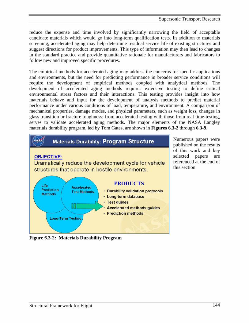
Supersonic Transport Research
Structural Framework for Flight 144
reduce the expense and time involved by significantly narrowing the field of acceptable candidate materials which would go into long-term qualification tests. In addition to materials screening, accelerated aging may help determine residual service life of existing structures and suggest directions for product improvements. This type of information may then lead to changes in the standard practice and provide quantitative rationale for manufacturers and fabricators to follow new and improved specific procedures. The empirical methods for accelerated aging may address the concerns for specific applications and environments, but the need for predicting performance in broader service conditions will require the development of empirical methods coupled with analytical methods. The development of accelerated aging methods requires extensive testing to define critical environmental stress factors and their interactions. This testing provides insight into how materials behave and input for the development of analysis methods to predict material performance under various conditions of load, temperature, and environment. A comparison of mechanical properties, damage modes, and physical parameters, such as weight loss, changes in glass transition or fracture toughness; from accelerated testing with those from real time-testing, serves to validate accelerated aging methods. The major elements of the NASA Langley materials durability program, led by Tom Gates, are shown in Figures 6.3-2 through 6.3-9.
Numerous papers were published on the results of this work and key selected papers are referenced at the end of this section.
Figure 6.3-2: Materials Durability Program
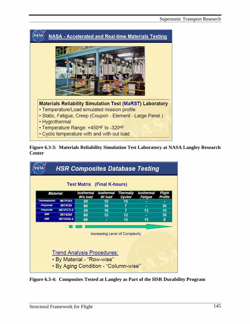
Supersonic Transport Research
Structural Framework for Flight 145
Figure 6.3-3: Materials Reliability Simulation Test Laboratory at NASA Langley Research Center
Figure 6.3-4: Composites Tested at Langley as Part of the HSR Durability Program
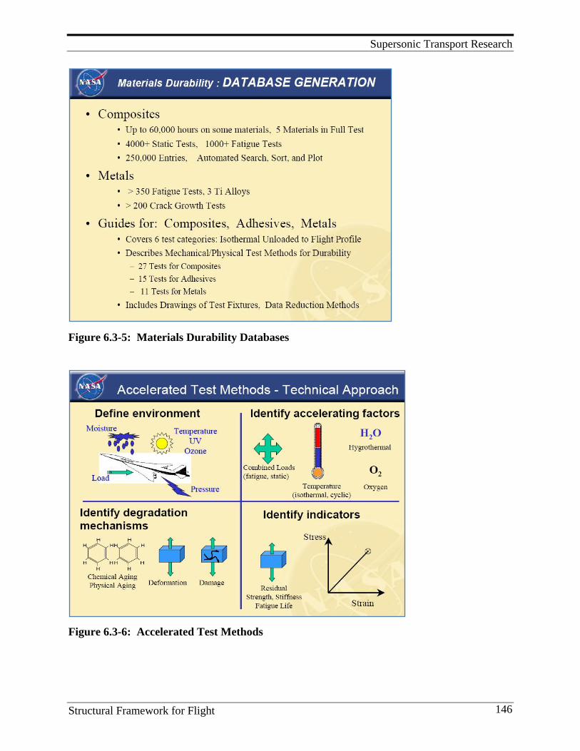
Supersonic Transport Research
Structural Framework for Flight 146
Figure 6.3-5: Materials Durability Databases
Figure 6.3-6: Accelerated Test Methods
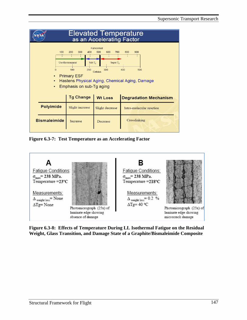
Supersonic Transport Research
Structural Framework for Flight 147
Figure 6.3-7: Test Temperature as an Accelerating Factor
Figure 6.3-8: Effects of Temperature During LL Isothermal Fatigue on the Residual Weight, Glass Transition, and Damage State of a Graphite/Bismaleimide Composite
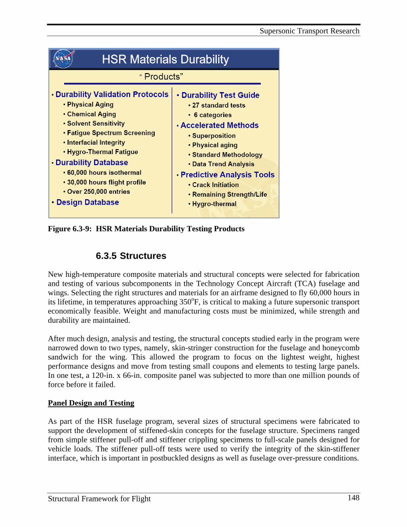
Supersonic Transport Research
Structural Framework for Flight 148
Figure 6.3-9: HSR Materials Durability Testing Products
6.3.5 Structures
New high-temperature composite materials and structural concepts were selected for fabrication and testing of various subcomponents in the Technology Concept Aircraft (TCA) fuselage and wings. Selecting the right structures and materials for an airframe designed to fly 60,000 hours in its lifetime, in temperatures approaching 350oF, is critical to making a future supersonic transport economically feasible. Weight and manufacturing costs must be minimized, while strength and durability are maintained. After much design, analysis and testing, the structural concepts studied early in the program were narrowed down to two types, namely, skin-stringer construction for the fuselage and honeycomb sandwich for the wing. This allowed the program to focus on the lightest weight, highest performance designs and move from testing small coupons and elements to testing large panels. In one test, a 120-in. x 66-in. composite panel was subjected to more than one million pounds of force before it failed. Panel Design and Testing As part of the HSR fuselage program, several sizes of structural specimens were fabricated to support the development of stiffened-skin concepts for the fuselage structure. Specimens ranged from simple stiffener pull-off and stiffener crippling specimens to full-scale panels designed for vehicle loads. The stiffener pull-off tests were used to verify the integrity of the skin-stiffener interface, which is important in postbuckled designs as well as fuselage over-pressure conditions.
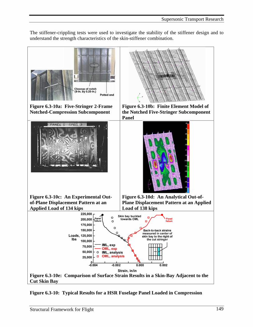
Supersonic Transport Research
Structural Framework for Flight 149
The stiffener-crippling tests were used to investigate the stability of the stiffener design and to understand the strength characteristics of the skin-stiffener combination.
Figure 6.3-10a: Five-Stringer 2-Frame Notched-Compression Subcomponent
Figure 6.3-10b: Finite Element Model of the Notched Five-Stringer Subcomponent Panel
Figure 6.3-10c: An Experimental Out-of-Plane Displacement Pattern at an Applied Load of 134 kips
Figure 6.3-10d: An Analytical Out-of-Plane Displacement Pattern at an Applied Load of 138 kips
Figure 6.3-10e: Comparison of Surface Strain Results in a Skin-Bay Adjacent to the Cut Skin Bay Figure 6.3-10: Typical Results for a HSR Fuselage Panel Loaded in Compression
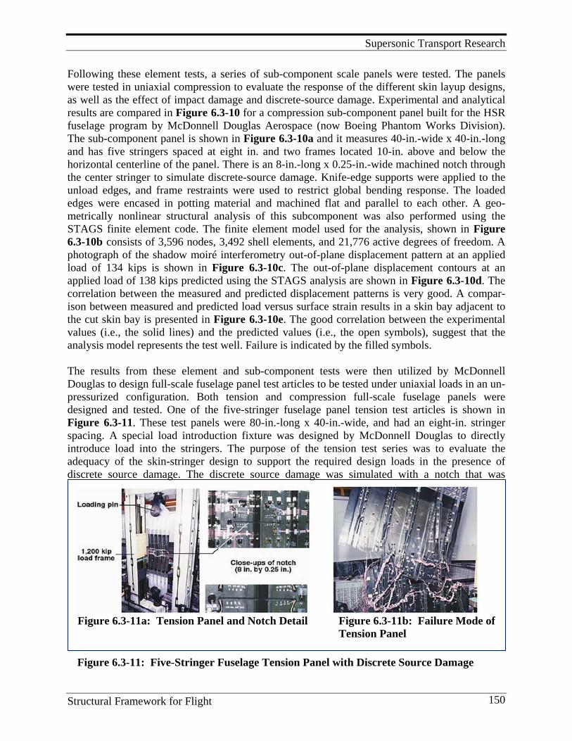
Supersonic Transport Research
Structural Framework for Flight 150
Figure 6.3-11a: Tension Panel and Notch Detail Figure 6.3-11b: Failure Mode of Tension Panel
Figure 6.3-11: Five-Stringer Fuselage Tension Panel with Discrete Source Damage
Following these element tests, a series of sub-component scale panels were tested. The panels were tested in uniaxial compression to evaluate the response of the different skin layup designs, as well as the effect of impact damage and discrete-source damage. Experimental and analytical results are compared in Figure 6.3-10 for a compression sub-component panel built for the HSR fuselage program by McDonnell Douglas Aerospace (now Boeing Phantom Works Division). The sub-component panel is shown in Figure 6.3-10a and it measures 40-in.-wide x 40-in.-long and has five stringers spaced at eight in. and two frames located 10-in. above and below the horizontal centerline of the panel. There is an 8-in.-long x 0.25-in.-wide machined notch through the center stringer to simulate discrete-source damage. Knife-edge supports were applied to the unload edges, and frame restraints were used to restrict global bending response. The loaded edges were encased in potting material and machined flat and parallel to each other. A geo-metrically nonlinear structural analysis of this subcomponent was also performed using the STAGS finite element code. The finite element model used for the analysis, shown in Figure 6.3-10b consists of 3,596 nodes, 3,492 shell elements, and 21,776 active degrees of freedom. A photograph of the shadow moiré interferometry out-of-plane displacement pattern at an applied load of 134 kips is shown in Figure 6.3-10c. The out-of-plane displacement contours at an applied load of 138 kips predicted using the STAGS analysis are shown in Figure 6.3-10d. The correlation between the measured and predicted displacement patterns is very good. A compar-ison between measured and predicted load versus surface strain results in a skin bay adjacent to the cut skin bay is presented in Figure 6.3-10e. The good correlation between the experimental values (i.e., the solid lines) and the predicted values (i.e., the open symbols), suggest that the analysis model represents the test well. Failure is indicated by the filled symbols. The results from these element and sub-component tests were then utilized by McDonnell Douglas to design full-scale fuselage panel test articles to be tested under uniaxial loads in an un-pressurized configuration. Both tension and compression full-scale fuselage panels were designed and tested. One of the five-stringer fuselage panel tension test articles is shown in Figure 6.3-11. These test panels were 80-in.-long x 40-in.-wide, and had an eight-in. stringer spacing. A special load introduction fixture was designed by McDonnell Douglas to directly introduce load into the stringers. The purpose of the tension test series was to evaluate the adequacy of the skin-stringer design to support the required design loads in the presence of discrete source damage. The discrete source damage was simulated with a notch that was
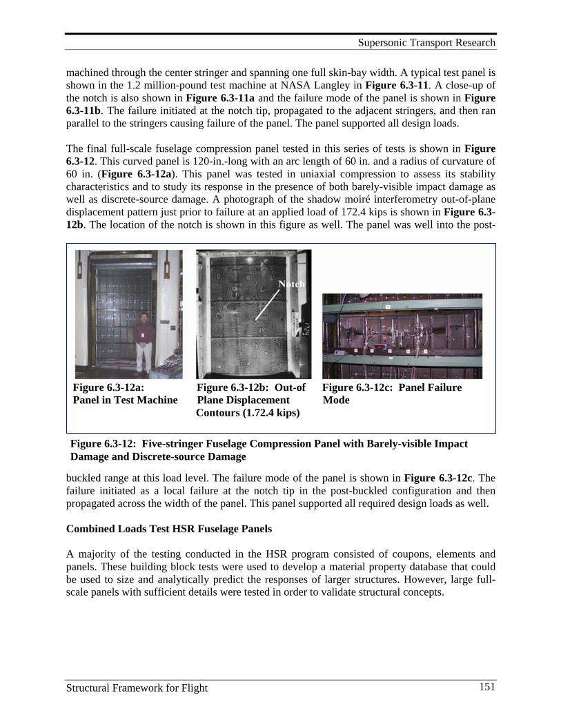
Supersonic Transport Research
Structural Framework for Flight 151
Figure 6.3-12a: Figure 6.3-12b: Out-of Figure 6.3-12c: Panel Failure Panel in Test Machine Plane Displacement Mode Contours (1.72.4 kips)
Figure 6.3-12: Five-stringer Fuselage Compression Panel with Barely-visible Impact Damage and Discrete-source Damage
machined through the center stringer and spanning one full skin-bay width. A typical test panel is shown in the 1.2 million-pound test machine at NASA Langley in Figure 6.3-11. A close-up of the notch is also shown in Figure 6.3-11a and the failure mode of the panel is shown in Figure 6.3-11b. The failure initiated at the notch tip, propagated to the adjacent stringers, and then ran parallel to the stringers causing failure of the panel. The panel supported all design loads. The final full-scale fuselage compression panel tested in this series of tests is shown in Figure 6.3-12. This curved panel is 120-in.-long with an arc length of 60 in. and a radius of curvature of 60 in. (Figure 6.3-12a). This panel was tested in uniaxial compression to assess its stability characteristics and to study its response in the presence of both barely-visible impact damage as well as discrete-source damage. A photograph of the shadow moiré interferometry out-of-plane displacement pattern just prior to failure at an applied load of 172.4 kips is shown in Figure 6.3-12b. The location of the notch is shown in this figure as well. The panel was well into the post-
buckled range at this load level. The failure mode of the panel is shown in Figure 6.3-12c. The failure initiated as a local failure at the notch tip in the post-buckled configuration and then propagated across the width of the panel. This panel supported all required design loads as well. Combined Loads Test HSR Fuselage Panels A majority of the testing conducted in the HSR program consisted of coupons, elements and panels. These building block tests were used to develop a material property database that could be used to size and analytically predict the responses of larger structures. However, large full-scale panels with sufficient details were tested in order to validate structural concepts.
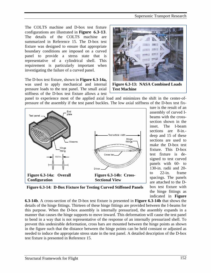
Supersonic Transport Research
Structural Framework for Flight 152
Figure 6.3-13: NASA Combined Loads Test Machine
Figure 6.3-14a: Overall Figure 6.3-14b: Cross- Configuration Sectional View Figure 6.3-14: D-Box Fixture for Testing Curved Stiffened Panels
The COLTS machine and D-box test fixture configurations are illustrated in Figure 6.3-13. The details of the COLTS machine are summarized in Reference 15. The D-box test fixture was designed to ensure that appropriate boundary conditions are imposed on a curved panel to provide a stress state that is representative of a cylindrical shell. This requirement is particularly important when investigating the failure of a curved panel. The D-box test fixture, shown in Figure 6.3-14a, was used to apply mechanical and internal pressure loads to the test panel. The small axial stiffness of the D-box test fixture allows a test panel to experience most of the applied axial load and minimizes the shift in the center-of-pressure of the assembly if the test panel buckles. The low axial stiffness of the D-box test fix-
ture is the result of an assembly of curved I-beams with the cross-section shown in the inset. The I-beam sections are 8-in.-deep and 15 of these sections are used to make the D-box test fixture. This D-box test fixture is de-signed to test curved panels with 60- to 130-in. radii and 20- to 22-in. frame spacings. The panels are attached to the D-box test fixture with the hinge fittings as indicated in Figure
6.3-14b. A cross-section of the D-box test fixture is presented in Figure 6.3-14b that shows the details of the hinge fittings. Thirteen of these hinge fittings are provided between the I-beams for this purpose. When the D-box assembly is internally pressurized, the assembly expands in a manner that causes the hinge supports to move inward. This deformation will cause the test panel to bend in a way that is not representative of the response of an internally pressurized shell. To prevent this undesirable deformation, cross bars are mounted between the hinge points as shown in the figure such that the distance between the hinge points can be held constant or adjusted as needed to induce the appropriate stress state in the test panel. A detailed description of the D-box test fixture is presented in Reference 15.
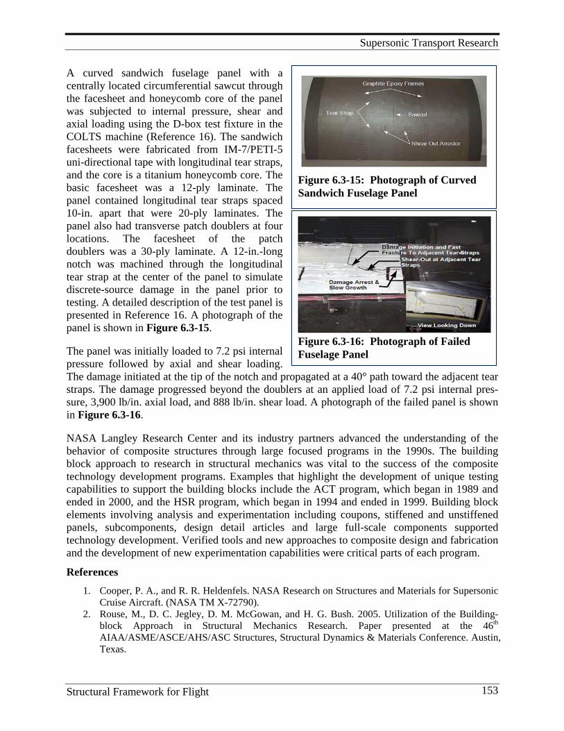
Supersonic Transport Research
Structural Framework for Flight 153
Figure 6.3-15: Photograph of Curved Sandwich Fuselage Panel
Figure 6.3-16: Photograph of Failed Fuselage Panel
A curved sandwich fuselage panel with a centrally located circumferential sawcut through the facesheet and honeycomb core of the panel was subjected to internal pressure, shear and axial loading using the D-box test fixture in the COLTS machine (Reference 16). The sandwich facesheets were fabricated from IM-7/PETI-5 uni-directional tape with longitudinal tear straps, and the core is a titanium honeycomb core. The basic facesheet was a 12-ply laminate. The panel contained longitudinal tear straps spaced 10-in. apart that were 20-ply laminates. The panel also had transverse patch doublers at four locations. The facesheet of the patch doublers was a 30-ply laminate. A 12-in.-long notch was machined through the longitudinal tear strap at the center of the panel to simulate discrete-source damage in the panel prior to testing. A detailed description of the test panel is presented in Reference 16. A photograph of the panel is shown in Figure 6.3-15. The panel was initially loaded to 7.2 psi internal pressure followed by axial and shear loading. The damage initiated at the tip of the notch and propagated at a 40° path toward the adjacent tear straps. The damage progressed beyond the doublers at an applied load of 7.2 psi internal pres-sure, 3,900 lb/in. axial load, and 888 lb/in. shear load. A photograph of the failed panel is shown in Figure 6.3-16. NASA Langley Research Center and its industry partners advanced the understanding of the behavior of composite structures through large focused programs in the 1990s. The building block approach to research in structural mechanics was vital to the success of the composite technology development programs. Examples that highlight the development of unique testing capabilities to support the building blocks include the ACT program, which began in 1989 and ended in 2000, and the HSR program, which began in 1994 and ended in 1999. Building block elements involving analysis and experimentation including coupons, stiffened and unstiffened panels, subcomponents, design detail articles and large full-scale components supported technology development. Verified tools and new approaches to composite design and fabrication and the development of new experimentation capabilities were critical parts of each program.
References 1. Cooper, P. A., and R. R. Heldenfels. NASA Research on Structures and Materials for Supersonic
Cruise Aircraft. (NASA TM X-72790). 2. Rouse, M., D. C. Jegley, D. M. McGowan, and H. G. Bush. 2005. Utilization of the Building-
block Approach in Structural Mechanics Research. Paper presented at the 46th AIAA/ASME/ASCE/AHS/ASC Structures, Structural Dynamics & Materials Conference. Austin, Texas.
Supersonic Transport Research
Structural Framework for Flight 154
3. Anon. 2001. The Material with a Need for Speed. http://www.sti.nasa.gov/tto/ spinoff2001/ip9.html
4. Bryant, R. G., B. J. Jensen, and P. M. Hergenrother. 1993. Synthesis and Properties of Phenylethynyl-terminated Polyamides. Polymer Preprints, 34 (1), 566.
5. Havens, S. J., R. G. Bryant, B. J. Jensen, and P. M. Hergenrother. 1994. Phenylethynyl-terminated Imide Oligomers and Polymers Therefrom. Polymer Preprints, 35 (1), 553.
6. Hergenrother, P. M., R. G. Bryant, B. J. Jensen, J. G. Smith, and S. P. Wilkinson. 1994. Chemistry and Properties of Phenylethynyl-terminated Imide Oligomers and Their Cured Polymers. Science of Advanced Materials and Process Engineering Series 39:961.
7. Gates, T. S., and M. Feldman. 1995. Time-dependent Behavior of a Graphite/Thermoplastic Composite and the Effects of Stress and Physical Aging. Journal of Composites Technology & Research 17 (January):33-42.
8. Struik, L. C. E. 1978. Physical Aging in Amorphous Polymers and Other Materials. Elsevier Scientific Publishing Company, New York.
9. Sullivan, J. L. 1990. Creep and Physical Aging of Composites. Composites Science and Technology 39:207-232.
10. Hastie, R. L., and D. H. Morris. 1992. The Effect of Physical Aging on the Creep Response of a Thermoplastic Composite. High Temperature and Environmental Effects in Polymer Matrix Composites, ed. C. Harris and T. Gates, 163-185. American Society for Testing and Materials.
11. Chen-Chi, M., C. Lee, M. Chang, and N. Tai. Effect of Physical Aging on the Toughness of Carbon Fiber-reinforced Poly(ether etherketone) and Poly (phenylene sulfide) Composites.” I. Polym. Comp. 13(6), 441-447, 1992.
12. Gates, T. S. 1993. Matrix Dominated Stress/Strain Behavior in Polymeric Composites: Effects of Hold Time, Nonlinearity, and Rate Dependency. Composite Materials: Testing and Design (Eleventh Volume), ASTM STP 1206, ed. E. T. Camponeschi, Jr., 177-189. American Society for Testing and Materials.
13. Johnson, T. F., and T. S. Gates. High-temperature Polyimide Materials in Extreme Temperature Environments. Document ID: 20010071334; Report Number: AIAA Paper 2001-1214.
14. Ambur, D. R., J. A. Cerro, and J. Dickson. 1994. Analysis of a D-box Fixture for Testing Curved Stiffened Aircraft Fuselage Panels in Axial Compression and Internal Pressure. (AIAA-94-1345-CP).
15. Mahler, M., R. Ley, S. Chandu, and L. Weichuan. 2000. Propagation and Control of Crack-line Damage in Curved Composite Panels Under Combined Loads. (AIAA-2000-1534).
6.4. Fundamental Aero Supersonic Project Although the HSR project was phased out in 2000, a low level of research on high-speed flight continues in the Aeronautics Base R&T Program, Figures 6.4-1 and 6.4-2. A supersonic focus was funded in the Vehicles Systems Program and then transitioned to the Fundamental Aero Supersonic Project, currently (FY-2010) funded by the NASA Aeronautics Research Mission Directorate. The long-term goal of the Supersonics Project is to enable supersonic cruise by eliminating current efficiency, environmental, and performance barriers. Research emphasis has been placed on development of multidisciplinary, physics-based predictive design, analysis, and optimization capabilities for supersonic vehicles. The project goals are to validate these new capabilities at the foundational, discipline, and systems levels.
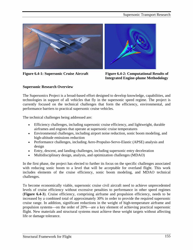
Supersonic Transport Research
Structural Framework for Flight 155
Figure 6.4-1: Supersonic Cruise Aircraft Figure 6.4-2: Computational Results of Integrated Engine-plume Methodology
Supersonic Research Overview
The Supersonics Project is a broad-based effort designed to develop knowledge, capabilities, and technologies in support of all vehicles that fly in the supersonic speed regime. The project is currently focused on the technical challenges that form the efficiency, environmental, and performance barriers to practical supersonic cruise vehicles.
The technical challenges being addressed are:
• Efficiency challenges, including supersonic cruise efficiency, and lightweight, durable airframes and engines that operate at supersonic cruise temperatures
• Environmental challenges, including airport noise reduction, sonic boom modeling, and high-altitude emissions reduction
• Performance challenges, including Aero-Propulso-Servo-Elastic (APSE) analysis and design
• Entry, descent, and landing challenges, including supersonic entry deceleration • Multidisciplinary design, analysis, and optimization challenges (MDAO)
In the first phase, the project has elected to further its focus on the specific challenges associated with reducing sonic boom to a level that will be acceptable for overland flight. This work includes elements of the cruise efficiency, sonic boom modeling, and MDAO technical challenges.
To become economically viable, supersonic cruise civil aircraft need to achieve unprecedented levels of cruise efficiency without excessive penalties to performance in other speed regimes (Figure 6.4-3). Cruise efficiency, comprising airframe and propulsion efficiency, needs to be increased by a combined total of approximately 30% in order to provide the required supersonic cruise range. In addition, significant reductions in the weight of high-temperature airframe and propulsion systems—on the order of 20%—are a key element of achieving practical supersonic flight. New materials and structural systems must achieve these weight targets without affecting life or damage tolerance.
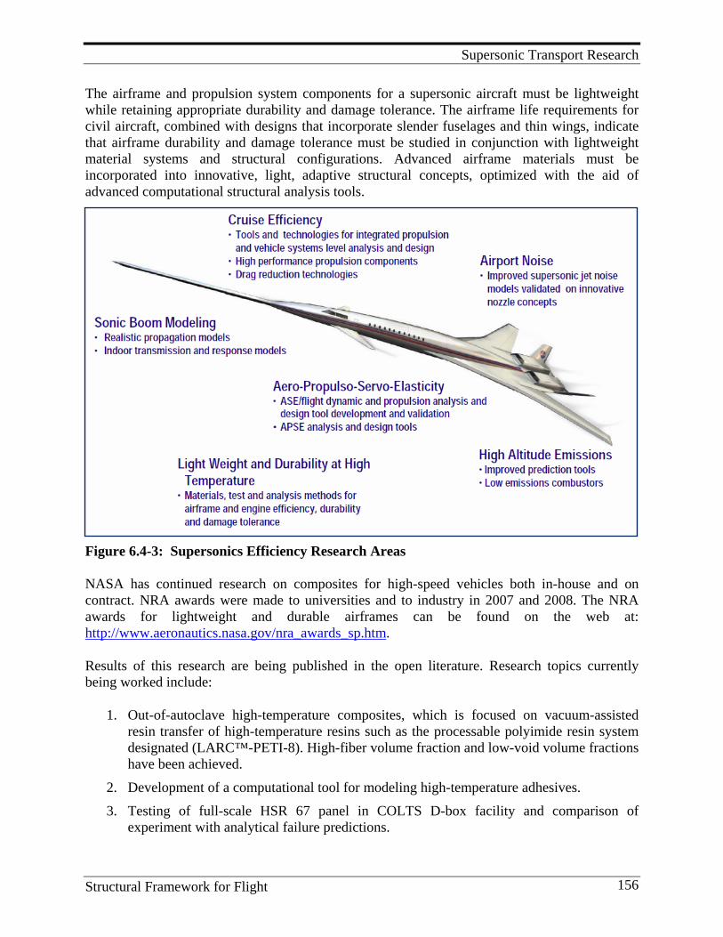
Supersonic Transport Research
Structural Framework for Flight 156
The airframe and propulsion system components for a supersonic aircraft must be lightweight while retaining appropriate durability and damage tolerance. The airframe life requirements for civil aircraft, combined with designs that incorporate slender fuselages and thin wings, indicate that airframe durability and damage tolerance must be studied in conjunction with lightweight material systems and structural configurations. Advanced airframe materials must be incorporated into innovative, light, adaptive structural concepts, optimized with the aid of advanced computational structural analysis tools.
Figure 6.4-3: Supersonics Efficiency Research Areas
NASA has continued research on composites for high-speed vehicles both in-house and on contract. NRA awards were made to universities and to industry in 2007 and 2008. The NRA awards for lightweight and durable airframes can be found on the web at: http://www.aeronautics.nasa.gov/nra_awards_sp.htm.
Results of this research are being published in the open literature. Research topics currently being worked include:
1. Out-of-autoclave high-temperature composites, which is focused on vacuum-assisted resin transfer of high-temperature resins such as the processable polyimide resin system designated (LARC™-PETI-8). High-fiber volume fraction and low-void volume fractions have been achieved.
2. Development of a computational tool for modeling high-temperature adhesives. 3. Testing of full-scale HSR 67 panel in COLTS D-box facility and comparison of
experiment with analytical failure predictions.
Supersonic Transport Research
Structural Framework for Flight 157
4. Continued development of a multi-scale analysis tool capable of accurately predicting damage evolution and failure in advanced fiber- reinforced composite structures.
5. Determination of strain-rate effects on crack growth in composites with stiffeners.
Peter Coen is the leader of the Supersonic Project and Phil Bogert is lead for the Lightweight Durable Airframe element of this project.
6.5. Lessons Learned and Future Direction Lessons Learned 1. Polymer synthesis to meet a serious challenge, such as making a new matrix resin for com-
posites used on future high-speed civil transports, is a very complex, difficult job. Composite properties need to be established that meet structural needs. The effort requires the whole-hearted cooperation of materials and structures personnel and analysts. First, a theoretical list of the required composite properties must be established. This list has to be supplied by the aero-analysts. The chemists, along with structures personnel, have to reduce these structural property needs into fundamental lamina and laminate requirements. Then, the chemists use these to determine the polymer matrix and fiber properties to develop the appropriate matrix/ composite. Two relationships are needed to do this. First, the chemist must have, or develop, a fundamental understanding of the relationships between polymer properties and polymer molecular structure. Second, the chemist must have, or develop, relationships between polymer properties and experimental composite properties.
2. Fabrication of composites by whatever process must yield void-free laminates to achieve use-ful engineering properties. High flow matrices at whatever processing temperature are required.
3. Results achieved indicated that high-quality structure could be fabricated with high-tempera-ture resins. Comparisons between mechanical test results and analysis predictions were good.
4. COLTS can be used to simulate the internal pressure, bending and shear loads in curved fuselage panels in a relatively inexpensive manner.
Future Direction 1. Focus on development of high-temperature matrix resins that can be processed by a non-
autoclave technology such as VARTM. 2. Determine the best intermediate temperature matrices for use with a future supersonic
business jet. Reference 1. Coen, Peter, Pouinelli, L., Civinskas, K, 2008. Supersonic Project Overview. Paper presented at the
Fundamental Aeronautics Annual Meeting. Atlanta, GA,. Retrieved May, 2010 from http://www.aeronautics.nasa.gov/fap/PowerPoints/SUP_ATL_Overview.pdf
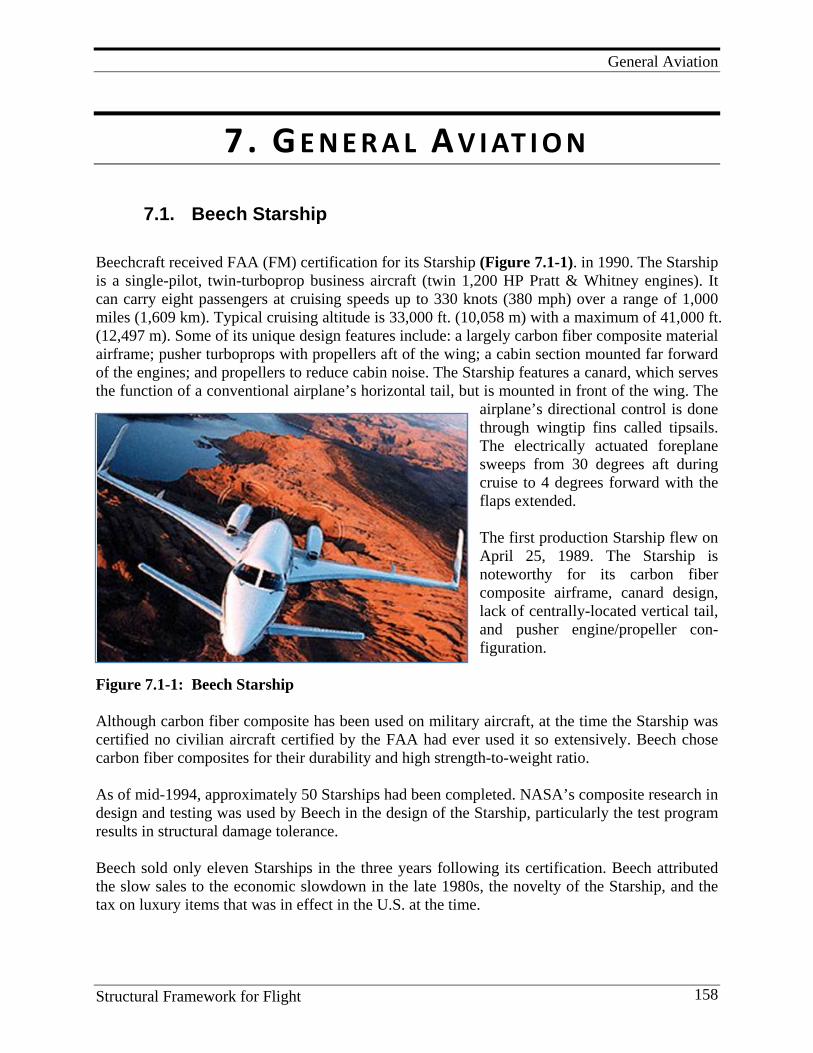
General Aviation
Structural Framework for Flight 158
7. G E N E R A L A V I AT I O N
7.1. Beech Starship
Beechcraft received FAA (FM) certification for its Starship (Figure 7.1-1). in 1990. The Starship is a single-pilot, twin-turboprop business aircraft (twin 1,200 HP Pratt & Whitney engines). It can carry eight passengers at cruising speeds up to 330 knots (380 mph) over a range of 1,000 miles (1,609 km). Typical cruising altitude is 33,000 ft. (10,058 m) with a maximum of 41,000 ft. (12,497 m). Some of its unique design features include: a largely carbon fiber composite material airframe; pusher turboprops with propellers aft of the wing; a cabin section mounted far forward of the engines; and propellers to reduce cabin noise. The Starship features a canard, which serves the function of a conventional airplane’s horizontal tail, but is mounted in front of the wing. The
airplane’s directional control is done through wingtip fins called tipsails. The electrically actuated foreplane sweeps from 30 degrees aft during cruise to 4 degrees forward with the flaps extended. The first production Starship flew on April 25, 1989. The Starship is noteworthy for its carbon fiber composite airframe, canard design, lack of centrally-located vertical tail, and pusher engine/propeller con-figuration.
Figure 7.1-1: Beech Starship Although carbon fiber composite has been used on military aircraft, at the time the Starship was certified no civilian aircraft certified by the FAA had ever used it so extensively. Beech chose carbon fiber composites for their durability and high strength-to-weight ratio. As of mid-1994, approximately 50 Starships had been completed. NASA’s composite research in design and testing was used by Beech in the design of the Starship, particularly the test program results in structural damage tolerance. Beech sold only eleven Starships in the three years following its certification. Beech attributed the slow sales to the economic slowdown in the late 1980s, the novelty of the Starship, and the tax on luxury items that was in effect in the U.S. at the time.
General Aviation
Structural Framework for Flight 159
The last Starship, NC-53, was produced in 1995. In 2003, Beechcraft determined that supporting such a small fleet of airplanes was cost-prohibitive and began scrapping and incinerating the aircraft under its control. Beech worked with owners of privately-owned Starships to replace their airplanes with other Beech aircraft such as the Premier I jet. In 2004, Raytheon sold its entire inventory of Starship parts to a Starship owner, for a fraction of its retail value.
7.2. Advanced General Aviation Transport Experiments Composites
Overview of AGATE program
Figure 7.2-1: The AGATE program The creation of the AGATE Consortium (Figure 7.2-1) in 1994 changed the face of general aviation-related aerospace. The NASA-led consortium, born out of an effort to stem the gradual decline of general aviation in this country, played an instrumental role in the forging of new alliances between government and interested parties, including vital non-profit contributors. The AGATE Consortium was a unique partnership between government, industry, and academia established to develop new ways of reviving the troubled general aviation industry. The partner-ship was the product of two years of government-industry collaboration. The consortium, comprised of representatives from each partnership sector, was formed to give the revitalization effort formal structure. It also leveraged and focused resources for higher-risk efforts with higher payoffs. The AGATE Consortium consisted of three categories of members from 31 states, 40 principal members from industry, 6 associate members from industry and universities, and 30 supporting members from universities, industry and non-profit organizations. A total of 10 universities joined AGATE. It was one of the larger membership consortia in the United States. (Figure 7.2-2).
General Aviation
Structural Framework for Flight 160
Figure 7.2-2: Members of the AGATE Program in 1996 The purpose of AGATE was to enable market growth for inter-city transportation in small aircraft. AGATE aimed to make single-pilot, light airplanes safer, more affordable and available as a viable part of the nation’s transportation system. AGATE targeted trips of 150 to 700 miles – round trips that were too far to complete in a day and too short to efficiently use the hub-and-spoke system. AGATE management, as a joint government industry effort, was initiated in response to the Clinton Administration and Congress’ commitment to “reinventing government.” The AGATE members shared resources and risks to make the market “pie” bigger for everyone. Leadership was also shared. Costs were shared 50/50 between government and industry. The
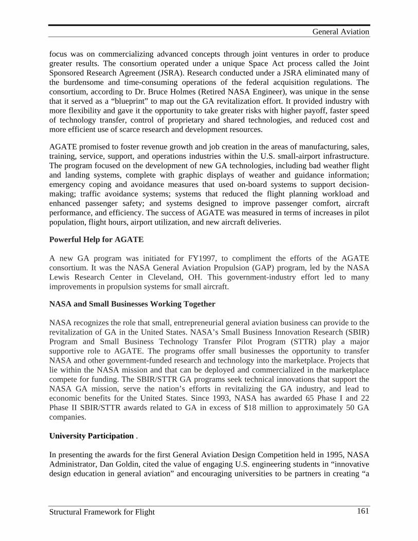
General Aviation
Structural Framework for Flight 161
focus was on commercializing advanced concepts through joint ventures in order to produce greater results. The consortium operated under a unique Space Act process called the Joint Sponsored Research Agreement (JSRA). Research conducted under a JSRA eliminated many of the burdensome and time-consuming operations of the federal acquisition regulations. The consortium, according to Dr. Bruce Holmes (Retired NASA Engineer), was unique in the sense that it served as a “blueprint” to map out the GA revitalization effort. It provided industry with more flexibility and gave it the opportunity to take greater risks with higher payoff, faster speed of technology transfer, control of proprietary and shared technologies, and reduced cost and more efficient use of scarce research and development resources. AGATE promised to foster revenue growth and job creation in the areas of manufacturing, sales, training, service, support, and operations industries within the U.S. small-airport infrastructure. The program focused on the development of new GA technologies, including bad weather flight and landing systems, complete with graphic displays of weather and guidance information; emergency coping and avoidance measures that used on-board systems to support decision-making; traffic avoidance systems; systems that reduced the flight planning workload and enhanced passenger safety; and systems designed to improve passenger comfort, aircraft performance, and efficiency. The success of AGATE was measured in terms of increases in pilot population, flight hours, airport utilization, and new aircraft deliveries. Powerful Help for AGATE A new GA program was initiated for FY1997, to compliment the efforts of the AGATE consortium. It was the NASA General Aviation Propulsion (GAP) program, led by the NASA Lewis Research Center in Cleveland, OH. This government-industry effort led to many improvements in propulsion systems for small aircraft. NASA and Small Businesses Working Together NASA recognizes the role that small, entrepreneurial general aviation business can provide to the revitalization of GA in the United States. NASA’s Small Business Innovation Research (SBIR) Program and Small Business Technology Transfer Pilot Program (STTR) play a major supportive role to AGATE. The programs offer small businesses the opportunity to transfer NASA and other government-funded research and technology into the marketplace. Projects that lie within the NASA mission and that can be deployed and commercialized in the marketplace compete for funding. The SBIR/STTR GA programs seek technical innovations that support the NASA GA mission, serve the nation’s efforts in revitalizing the GA industry, and lead to economic benefits for the United States. Since 1993, NASA has awarded 65 Phase I and 22 Phase II SBIR/STTR awards related to GA in excess of $18 million to approximately 50 GA companies. University Participation . In presenting the awards for the first General Aviation Design Competition held in 1995, NASA Administrator, Dan Goldin, cited the value of engaging U.S. engineering students in “innovative design education in general aviation” and encouraging universities to be partners in creating “a
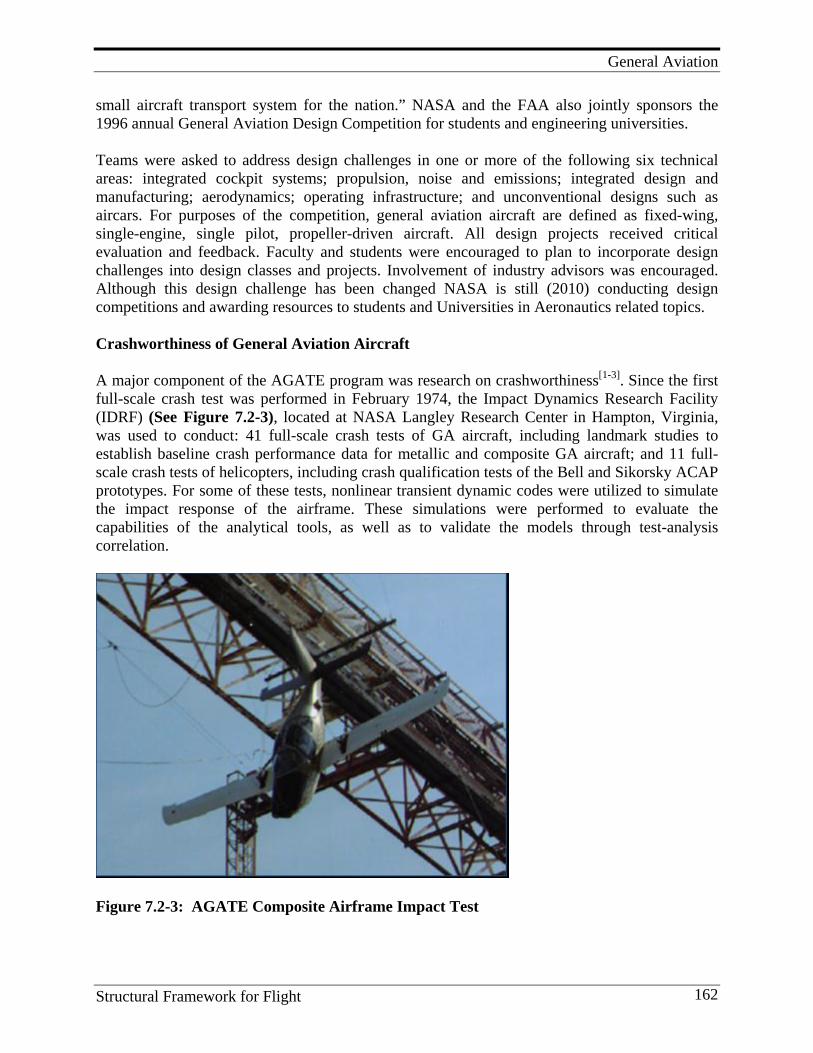
General Aviation
Structural Framework for Flight 162
small aircraft transport system for the nation.” NASA and the FAA also jointly sponsors the 1996 annual General Aviation Design Competition for students and engineering universities. Teams were asked to address design challenges in one or more of the following six technical areas: integrated cockpit systems; propulsion, noise and emissions; integrated design and manufacturing; aerodynamics; operating infrastructure; and unconventional designs such as aircars. For purposes of the competition, general aviation aircraft are defined as fixed-wing, single-engine, single pilot, propeller-driven aircraft. All design projects received critical evaluation and feedback. Faculty and students were encouraged to plan to incorporate design challenges into design classes and projects. Involvement of industry advisors was encouraged. Although this design challenge has been changed NASA is still (2010) conducting design competitions and awarding resources to students and Universities in Aeronautics related topics. Crashworthiness of General Aviation Aircraft A major component of the AGATE program was research on crashworthiness[1-3]. Since the first full-scale crash test was performed in February 1974, the Impact Dynamics Research Facility (IDRF) (See Figure 7.2-3), located at NASA Langley Research Center in Hampton, Virginia, was used to conduct: 41 full-scale crash tests of GA aircraft, including landmark studies to establish baseline crash performance data for metallic and composite GA aircraft; and 11 full-scale crash tests of helicopters, including crash qualification tests of the Bell and Sikorsky ACAP prototypes. For some of these tests, nonlinear transient dynamic codes were utilized to simulate the impact response of the airframe. These simulations were performed to evaluate the capabilities of the analytical tools, as well as to validate the models through test-analysis correlation.
Figure 7.2-3: AGATE Composite Airframe Impact Test
General Aviation
Structural Framework for Flight 163
Energy absorption is the critical structural characteristic for meeting crashworthiness requirements. Metal structures typically buckle, wrinkle, and undergo plastic deformation as their energy absorption mechanism. However, composites are brittle and absorb energy by a crushing type of behavior involving matrix cracking, matrix delamination, and fiber breakage. This requires that the composite crush and/or have designed failure modes that cause buckling/wrinkling/delamination etc. followed by crushing to absorb energy. A general aviation aircraft was crash tested at the NASA Langley IDRF as part of the AGATE program Figure 7.2-4. The test was conducted to measure the crashworthiness performance of a composite aircraft that incorporated a number of accident mitigation technologies in its design. The test article was a highly modified Lancair Columbia 300 aircraft. The modifications included a crashworthy engine mount and cowl, an energy-absorbing subfloor, and a non-scooping firewall. A systems approach to crashworthiness was used to integrate these technologies into the final design. The test article was equipped with crashworthy seats and restraint systems that had been certified to the requirements of 14 CFR 23.562. Test measurements included airframe accelerations, anthropomorphic test device responses, and high-speed film coverage. The drop test conditions were specified as a hard surface impact at Vso (57 knots), and a -30º flight-path angle as well as a -30º pitch angle, with no roll and no yaw.
Figure 7.2-4: AGATE - Advanced General Aviation Technology Experiments The impact conditions of this test represented a much higher velocity change and possessed more than five times the impact energy compared to the current FAA requirements for dynamically certified seats and restraint systems. The demonstration was successful since a survivable cabin volume was retained, and the measured G loads in instrument dummies indicated that passengers could have survived the test.
General Aviation
Structural Framework for Flight 164
The crashworthy technologies employed in this design included an energy-absorbing engine mount, a reinforced cowl, a non-scooping ramp at the bottom of the firewall, a reinforced fuselage, and an energy-absorbing subfloor. The results of this and other tests demonstrated that energy management through application of the impulse/momentum equation might be a better strategy than energy absorption for general aviation designs that possess only limited space in which to locate energy-absorbing technologies. It was particularly notable that seat/restraint systems designed to the requirements of 14 CFR 23.562 performed well in the drop test by successfully mitigating a sequence of two-to-three successive impulses. The secondary structural bonds used to join structural reinforcements to the forward fuselage performed well during this test without being reinforced by mechanical fasteners. This performance is largely attributed to the knowledge, skill, and attention to detail provided by the personnel who fabricated these modifications. However, the fact that the airframe strength was adequate for the hard-surface impact does not show that this design is adequate or that the 50-G loads are representative of those developed during a severe soft-soil impact. Additional testing is required to establish this. The structural design methodology developed during this research represents an additional 50-G crash load condition, not currently required by the FAA, which can be largely addressed using traditional airframe design techniques. The improvements in crashworthiness performance were achieved without significant cost or weight penalties. Lesson Learned: 1. Energy management through application of the impulse/momentum equation might be a
better strategy than energy absorption for general aviation designs that possess only limited space in which to locate energy-absorbing technologies.
Composite Database Development In 1995, NASA started the AGATE program to revitalize the general aviation industry. The National Institute for Aviation Research (NIAR), located at Wichita State University, was put in charge of the AGATE Materials Working Group to develop a more efficient composite material qualification and property data acquisition process. The AGATE-shared database process was developed as a result of close coordination with the FAA. The process, published in DOT/FAA/AR-03/19, allows aircraft companies to share basic material properties and specifications similar to the shared database process that exists for the metals industry. After a multibatch material qualification program, the material property data, material and process specifications, and other necessary pedigree information, are included in the shared database. An equivalency process, which involves one batch of material only, is a fast and low-cost sampling process that is designed to show that a follow-on company can use the material and process specifications to reproduce the original material properties. This is necessary because the fabrication of composite parts, unlike that of aluminum parts, involves operations such as layup, bagging and curing, where process parameters could influence basic material properties.
General Aviation
Structural Framework for Flight 165
The AGATE-shared database[4] process was recognized as an acceptable means of compliance by FAA Small Airplane Directorate Policy Memorandum PS-ACE 100-2002-006 entitled, “Material Qualification and Equivalency for Polymer Matrix Composite Material Systems.” After the AGATE program ended in 2001, the FAA and NIAR continued to support the shared database process by producing additional guidance materials, such as recommendations for developing material and process specifications. The FAA also continued to support efforts to add more materials property data to the AGATE database, as evidenced by the generation of laminate properties for Toray Composites America’s (Tacoma, Wash.) 2510 and Park Electrochemical Corp.’s (Melville, N.Y.) Nelcote E765. The industry also continued to support the effort. The material user base for materials qualified using the AGATE process continued to grow, and companies that were not originally in the AGATE program began using the AGATE process. For example, Advanced Composites Group Inc. (ACG, Tulsa, Okla.) generated properties for its MTM45 and MTM45-1 prepregs. For more than a decade, NASA, FAA, industry, and academia have been working toward the goal of creating a centralized composite material property database similar to that for metals. Their efforts, while productive, have not come with the war-like strength that the standardization of metals did. The composites industry is guided by Composite Materials Handbook 17 (CMH-17 formerly known as MIL-HDBK-17). Many regard CMH-17 as the equivalent of the metals industry standards organization guide, MMPDS (formerly known as MIL-HDBK-5). However, MMPDS remains the only U.S. government-recognized public source of published design-allowable properties for commercial and military aircraft structures and mechanically fastened joints. The composite material allowables published in CMH-17 generally are not accepted by the FAA or the U.S. Department of Defense for aircraft certification and airworthiness without additional substantiating evidence. But CMH-17 leadership, in partnership with the National Center for Advanced Materials Performance, is committed to changing this. As witness to this, the upcoming (due 2010) CMH-17 revision G Complete Documentation datasets are designed to meet the rigors of U.S. government requirements for commercial and military aircraft structures. The material property shared database approach, adopted for CMH-17 revision G Complete Documentation datasets, contains many new requirements. Data submitters must now provide material and process specifications along with the dataset. In addition, the material supplier must produce the material under a process control document (PCD). The specifications and PCD are designed to ensure that material properties are stable over time and must be prepared and maintained in accordance with FAA Advisory Circular 23-20. The new (2009-2010) requirements encompass the entire material property data acquisition and qualification process, including detailed documentation of everything from the materials to the test panel fabrication, and inspection and data analysis. National Center for Advanced Materials Performance (NCAMP) and Beyond NASA scientists realized that the AGATE process should be extended beyond the general aviation segment to the entire aerospace industry. In 2005, NASA Langley established NCAMP specifically for this purpose: to refine and enhance the AGATE composite material property
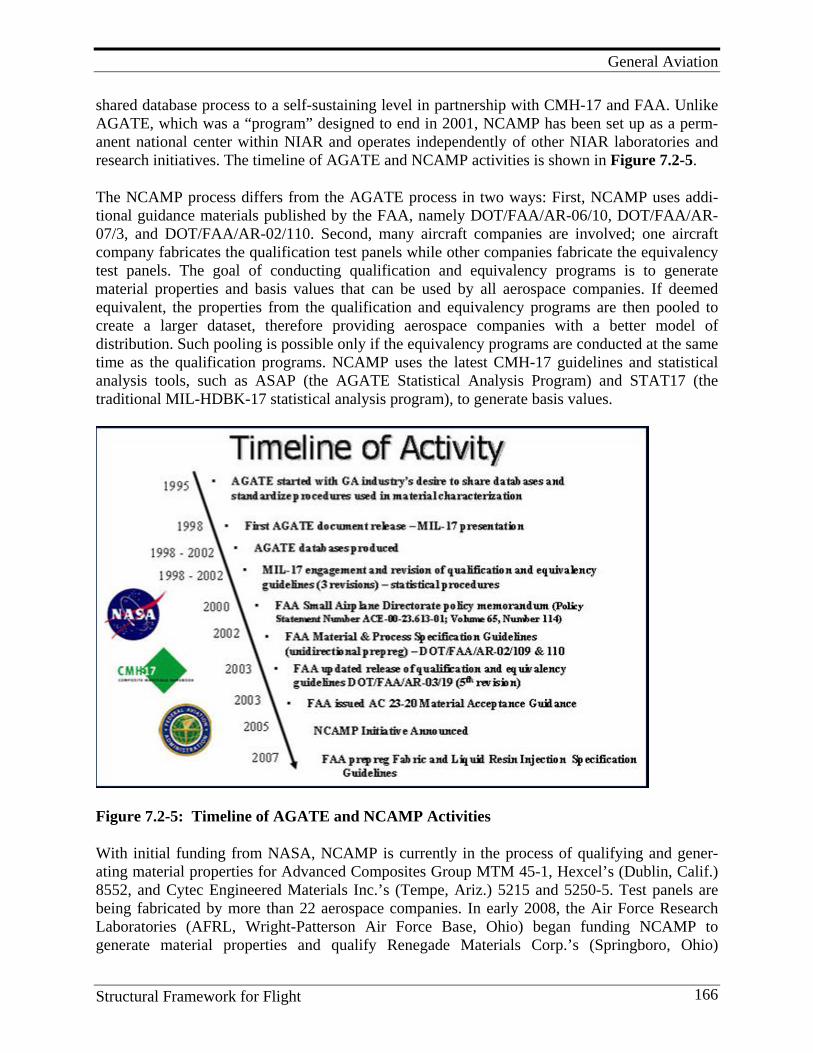
General Aviation
Structural Framework for Flight 166
shared database process to a self-sustaining level in partnership with CMH-17 and FAA. Unlike AGATE, which was a “program” designed to end in 2001, NCAMP has been set up as a perm-anent national center within NIAR and operates independently of other NIAR laboratories and research initiatives. The timeline of AGATE and NCAMP activities is shown in Figure 7.2-5.
The NCAMP process differs from the AGATE process in two ways: First, NCAMP uses addi-tional guidance materials published by the FAA, namely DOT/FAA/AR-06/10, DOT/FAA/AR-07/3, and DOT/FAA/AR-02/110. Second, many aircraft companies are involved; one aircraft company fabricates the qualification test panels while other companies fabricate the equivalency test panels. The goal of conducting qualification and equivalency programs is to generate material properties and basis values that can be used by all aerospace companies. If deemed equivalent, the properties from the qualification and equivalency programs are then pooled to create a larger dataset, therefore providing aerospace companies with a better model of distribution. Such pooling is possible only if the equivalency programs are conducted at the same time as the qualification programs. NCAMP uses the latest CMH-17 guidelines and statistical analysis tools, such as ASAP (the AGATE Statistical Analysis Program) and STAT17 (the traditional MIL-HDBK-17 statistical analysis program), to generate basis values.
Figure 7.2-5: Timeline of AGATE and NCAMP Activities
With initial funding from NASA, NCAMP is currently in the process of qualifying and gener-ating material properties for Advanced Composites Group MTM 45-1, Hexcel’s (Dublin, Calif.) 8552, and Cytec Engineered Materials Inc.’s (Tempe, Ariz.) 5215 and 5250-5. Test panels are being fabricated by more than 22 aerospace companies. In early 2008, the Air Force Research Laboratories (AFRL, Wright-Patterson Air Force Base, Ohio) began funding NCAMP to generate material properties and qualify Renegade Materials Corp.’s (Springboro, Ohio)
General Aviation
Structural Framework for Flight 167
FreeForm14 polyimide. In the NASA- and AFRL-sponsored programs, NCAMP is only funded for coordination and testing costs. Material suppliers provide the material directly to parti-cipating aerospace companies where they fabricate panels. The aerospace companies that fabri-cate the qualification test panels benefit in that they may use the dataset to fulfill coupon-level substantiation requirements. Those fabricating equivalency test panels also may benefit if equi-valency can be demonstrated. FAA provides oversight and helps create pedigrees through conformity inspection and test witnessing. Several industry-funded NCAMP qualification programs are underway, including TenCate Advanced Composites USA’s (Morgan Hill, Calif.) TC250, Newport Adhesives and Composites’ (Irvine, Calif.) NCT4708, ACG’s MTM46, and Park Electrochemical’s Nelcote E752. All NCAMP-generated data will meet the upcoming CMH-17 revision G requirement for Complete Documentation.
As they bear the cost of generating basic material properties, material suppliers are freeing their customers from having to repeatedly regenerate the basic properties. Customers can focus more on process modeling and the testing and analysis of higher-level building blocks, such as joints and detail element properties, which, in most cases, are more relevant to safety and structural efficiency. There will be fewer material specifications covering the same materials, so there will be less material waste at material supplier, part fabricator and maintenance facilities. Material availability will increase because many customers will buy to the same specifications.
Ultimately, the success of this concept depends on aircraft manufacturers. If they use the qualified materials, the material suppliers will realize the value of the shared database and qualify more materials into it. The resulting standardization and greater availability of property data will lead to production of more fuel-efficient, less costly air transportation systems. Key Personnel Managers and/or researchers included: Dr. Bruce J. Holmes, William T. Freeman, Karen Jackson, and Hank W. Jarrett. References 1. Jackson, K. E., R. L. Boitnott, E. L. Fasanella, L. E. Jones, and K. H. Lyle. 2004. A History of Full-
scale Aircraft and Rotorcraft Crash Testing and Simulation at NASA Langley Research Center. Paper presented at the 4th Triennial International Aircraft and Cabin Safety Research Conference. Lisbon, Portugal. (Document ID: 20040191337.)
2. Farley, G. L., and R. M. Jones. 1989. Energy-absorption Capability of Composite Tubes and Beams. (NASA TM-101634).
3. Henderson, M., S. J. Hooper, and K. Lyle. 2002. AGATE Composite Airframe Impact Test Results. AGATE-WP3.4-034026-088, Rev. A, Work Package Title: WBS3.0 Integrated Design and Manufacturing, Date of General Release: March 1, 2002.
4. Tomblin, J., Yeow Ng, and K. Marlett. 2008. Shared Composite Material Property Databases. CompositesWorld: High-performance Composites, October 10. http://www.compositesworld.com/columns/shared-composite-material-property-databases.aspx
General Aviation
Structural Framework for Flight 168
7.3. Lesson Learned and Future Direction
1. AGATE was an excellent example of how a public/private partnership can work for the good of all parties involved.
2. The agreement of the companies to work together to develop a common composite database proved to be a major success of the AGATE program.
3. Composites are being used in new GA aircraft because they offer reduced cost and higher performance for many airframe components.
4. AGATE and NCAMP are excellent examples of focused R&D activities, which produce results that benefit the whole general aviation industry sector.
5. One of the key ingredients in the success of NASA GA research was the leadership provided by Dr. Bruce Holmes. Dr. Holmes was a champion for reinventing the way NASA and industry worked together to bring new technology solutions to a new generation of modern aircraft.
6. Tom Freeman was a champion for advancing composite for GA aircraft and deserves credit for promoting a common shared property database and for promoting advanced processing technology to lower cost and improve performance of composite airframes.
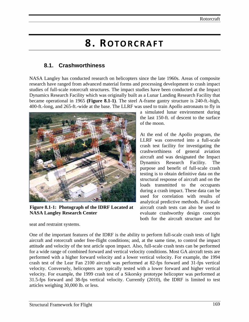
Rotorcraft
Structural Framework for Flight 169
Figure 8.1-1: Photograph of the IDRF Located at NASA Langley Research Center
8. R OTO R C R A F T
8.1. Crashworthiness NASA Langley has conducted research on helicopters since the late 1960s. Areas of composite research have ranged from advanced material forms and processing development to crash impact studies of full-scale rotorcraft structures. The impact studies have been conducted at the Impact Dynamics Research Facility which was originally built as a Lunar Landing Research Facility that became operational in 1965 (Figure 8.1-1). The steel A-frame gantry structure is 240-ft.-high, 400-ft.-long, and 265-ft.-wide at the base. The LLRF was used to train Apollo astronauts to fly in
a simulated lunar environment during the last 150-ft. of descent to the surface of the moon. At the end of the Apollo program, the LLRF was converted into a full-scale crash test facility for investigating the crashworthiness of general aviation aircraft and was designated the Impact Dynamics Research Facility. The purpose and benefit of full-scale crash testing is to obtain definitive data on the structural response of aircraft and on the loads transmitted to the occupants during a crash impact. These data can be used for correlation with results of analytical predictive methods. Full-scale aircraft crash tests can also be used to evaluate crashworthy design concepts both for the aircraft structure and for
seat and restraint systems.
One of the important features of the IDRF is the ability to perform full-scale crash tests of light aircraft and rotorcraft under free-flight conditions; and, at the same time, to control the impact attitude and velocity of the test article upon impact. Also, full-scale crash tests can be performed for a wide range of combined forward and vertical velocity conditions. Most GA aircraft tests are performed with a higher forward velocity and a lower vertical velocity. For example, the 1994 crash test of the Lear Fan 2100 aircraft was performed at 82-fps forward and 31-fps vertical velocity. Conversely, helicopters are typically tested with a lower forward and higher vertical velocity. For example, the 1999 crash test of a Sikorsky prototype helicopter was performed at 31.5-fps forward and 38-fps vertical velocity. Currently (2010), the IDRF is limited to test articles weighing 30,000 lb. or less.
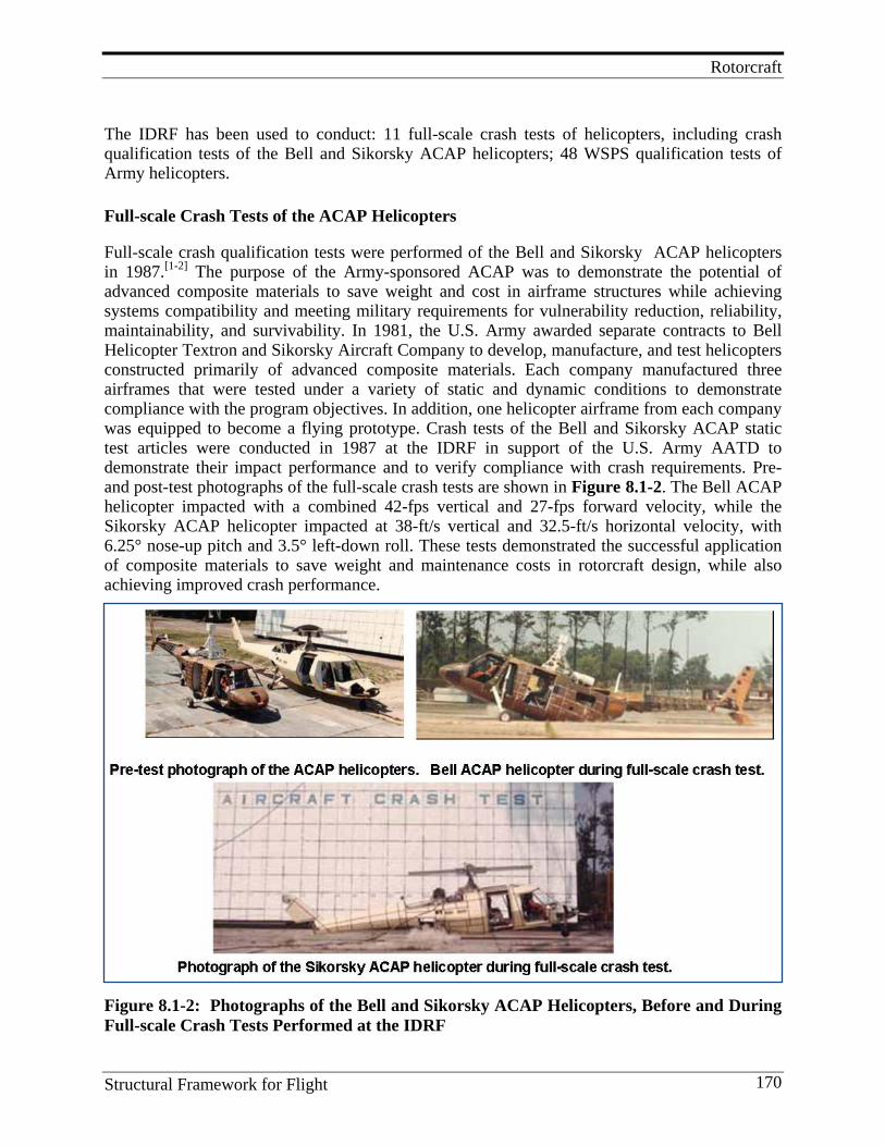
Rotorcraft
Structural Framework for Flight 170
The IDRF has been used to conduct: 11 full-scale crash tests of helicopters, including crash qualification tests of the Bell and Sikorsky ACAP helicopters; 48 WSPS qualification tests of Army helicopters.
Full-scale Crash Tests of the ACAP Helicopters Full-scale crash qualification tests were performed of the Bell and Sikorsky ACAP helicopters in 1987.[1-2] The purpose of the Army-sponsored ACAP was to demonstrate the potential of advanced composite materials to save weight and cost in airframe structures while achieving systems compatibility and meeting military requirements for vulnerability reduction, reliability, maintainability, and survivability. In 1981, the U.S. Army awarded separate contracts to Bell Helicopter Textron and Sikorsky Aircraft Company to develop, manufacture, and test helicopters constructed primarily of advanced composite materials. Each company manufactured three airframes that were tested under a variety of static and dynamic conditions to demonstrate compliance with the program objectives. In addition, one helicopter airframe from each company was equipped to become a flying prototype. Crash tests of the Bell and Sikorsky ACAP static test articles were conducted in 1987 at the IDRF in support of the U.S. Army AATD to demonstrate their impact performance and to verify compliance with crash requirements. Pre- and post-test photographs of the full-scale crash tests are shown in Figure 8.1-2. The Bell ACAP helicopter impacted with a combined 42-fps vertical and 27-fps forward velocity, while the Sikorsky ACAP helicopter impacted at 38-ft/s vertical and 32.5-ft/s horizontal velocity, with 6.25° nose-up pitch and 3.5° left-down roll. These tests demonstrated the successful application of composite materials to save weight and maintenance costs in rotorcraft design, while also achieving improved crash performance.
Figure 8.1-2: Photographs of the Bell and Sikorsky ACAP Helicopters, Before and During Full-scale Crash Tests Performed at the IDRF

Rotorcraft
Structural Framework for Flight 171
Key Personnel Karen E. Jackson, Robert G. Thomson, Huey D. Carden, and Robert J. Hayduk, Richard L Boitnott, Edwin L Fasanella, Lisa E. Jones, Karen H. Lyle, Gary L. Farley References
1. Jackson, K. E., R. L. Boitnott, E. L. Fasanella, L. E. Jones, K. H. Lyle. 2004. A History of Full-scale Aircraft and Rotorcraft Crash Testing and Simulation at NASA Langley Research Center. (NTRS: 2007-03-22, Document ID: 20040191337).
2. Thomson, R. G., H. D. Carden, and R. J. Hayduk. Survey of NASA Research on Crash Dynamics. (NASA technical paper; 2298, 1884).
8.2. Energy Absorption Materials and Concepts Through the U.S. Army-Aerostructures Directorate/NASA-Langley Research Center joint program on helicopter crashworthiness, an in-depth understanding was developed on the cause/effect relationships between material and architectural variables and the energy-absorption capability of composite material and structure. Composite materials were found to be efficient energy absorbers. Graphite/epoxy subfloor structures were more efficient energy absorbers than comparable structures fabricated from Kevlar or aluminum. An accurate method predicting the energy-absorption capability of beams was developed. The types of floor beams investigated and analyzed are shown in Figure 8.2–1.
Many variables were found to affect the crushing process of composite structures, such as the constituent materials' mechanical properties, specimen geometry, and crushing speed. A comprehensive experimental evaluation of tube specimens was conducted to develop insight into how composite structural elements crush and what are the controlling mechanisms. Specimen geometries included are shown in Figure 8.2-2.
Figure 8.2-1: Typical Floor Beam Configurations Investigated
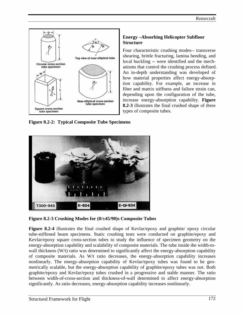
Rotorcraft
Structural Framework for Flight 172
Energy –Absorbing Helicopter Subfloor Structure
Four characteristic crushing modes-- transverse shearing, brittle fracturing, lamina bending, and local buckling -- were identified and the mech-anisms that control the crushing process defined. An in-depth understanding was developed of how material properties affect energy-absorp-tion capability. For example, an increase in fiber and matrix stiffness and failure strain can, depending upon the configuration of the tube, increase energy-absorption capability. Figure 8.2-3 illustrates the final crushed shape of three types of composite tubes.
Figure 8.2-2: Typical Composite Tube Specimens
Figure 8.2-3 Crushing Modes for (0/±45/90)s Composite Tubes Figure 8.2-4 illustrates the final crushed shape of Kevlar/epoxy and graphite/ epoxy circular tube-stiffened beam specimens. Static crushing tests were conducted on graphite/epoxy and Kevlar/epoxy square cross-section tubes to study the influence of specimen geometry on the energy-absorption capability and scalability of composite materials. The tube inside the width-to-wall thickness (W/t) ratio was determined to significantly affect the energy-absorption capability of composite materials. As W/t ratio decreases, the energy-absorption capability increases nonlinearly. The energy-absorption capability of Kevlar/epoxy tubes was found to be geo-metrically scalable, but the energy-absorption capability of graphite/epoxy tubes was not. Both graphite/epoxy and Kevlar/epoxy tubes crushed in a progressive and stable manner. The ratio between width-of-cross-section and thickness-of-wall determined to affect energy-absorption significantly. As ratio decreases, energy-absorption capability increases nonlinearly.
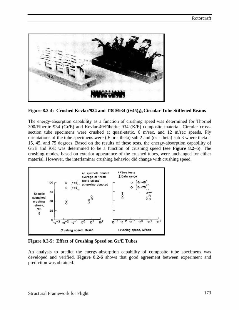
Rotorcraft
Structural Framework for Flight 173
Figure 8.2-4: Crushed Kevlar/934 and T300/934 ((±45)4)s Circular Tube Stiffened Beams The energy-absorption capability as a function of crushing speed was determined for Thornel 300/Fiberite 934 (Gr/E) and Kevlar-49/Fiberite 934 (K/E) composite material. Circular cross- section tube specimens were crushed at quasi-static, 6 m/sec, and 12 m/sec speeds. Ply orientations of the tube specimens were (0/ or - theta) sub 2 and (or - theta) sub 3 where theta = 15, 45, and 75 degrees. Based on the results of these tests, the energy-absorption capability of Gr/E and K/E was determined to be a function of crushing speed (see Figure 8.2–5). The crushing modes, based on exterior appearance of the crushed tubes, were unchanged for either material. However, the interlaminar crushing behavior did change with crushing speed.
Figure 8.2-5: Effect of Crushing Speed on Gr/E Tubes An analysis to predict the energy-absorption capability of composite tube specimens was developed and verified. Figure 8.2-6 shows that good agreement between experiment and prediction was obtained.
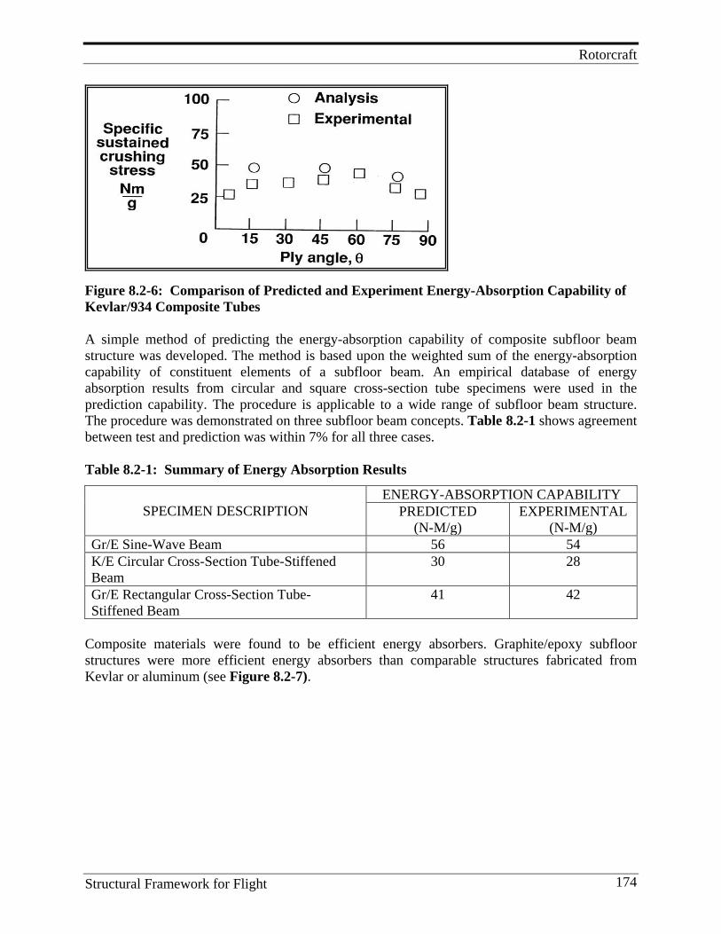
Rotorcraft
Structural Framework for Flight 174
Figure 8.2-6: Comparison of Predicted and Experiment Energy-Absorption Capability of Kevlar/934 Composite Tubes A simple method of predicting the energy-absorption capability of composite subfloor beam structure was developed. The method is based upon the weighted sum of the energy-absorption capability of constituent elements of a subfloor beam. An empirical database of energy absorption results from circular and square cross-section tube specimens were used in the prediction capability. The procedure is applicable to a wide range of subfloor beam structure. The procedure was demonstrated on three subfloor beam concepts. Table 8.2-1 shows agreement between test and prediction was within 7% for all three cases. Table 8.2-1: Summary of Energy Absorption Results
SPECIMEN DESCRIPTION ENERGY-ABSORPTION CAPABILITY
PREDICTED (N-M/g)
EXPERIMENTAL (N-M/g)
Gr/E Sine-Wave Beam 56 54 K/E Circular Cross-Section Tube-Stiffened Beam
30 28
Gr/E Rectangular Cross-Section Tube-Stiffened Beam
41 42
Composite materials were found to be efficient energy absorbers. Graphite/epoxy subfloor structures were more efficient energy absorbers than comparable structures fabricated from Kevlar or aluminum (see Figure 8.2-7).
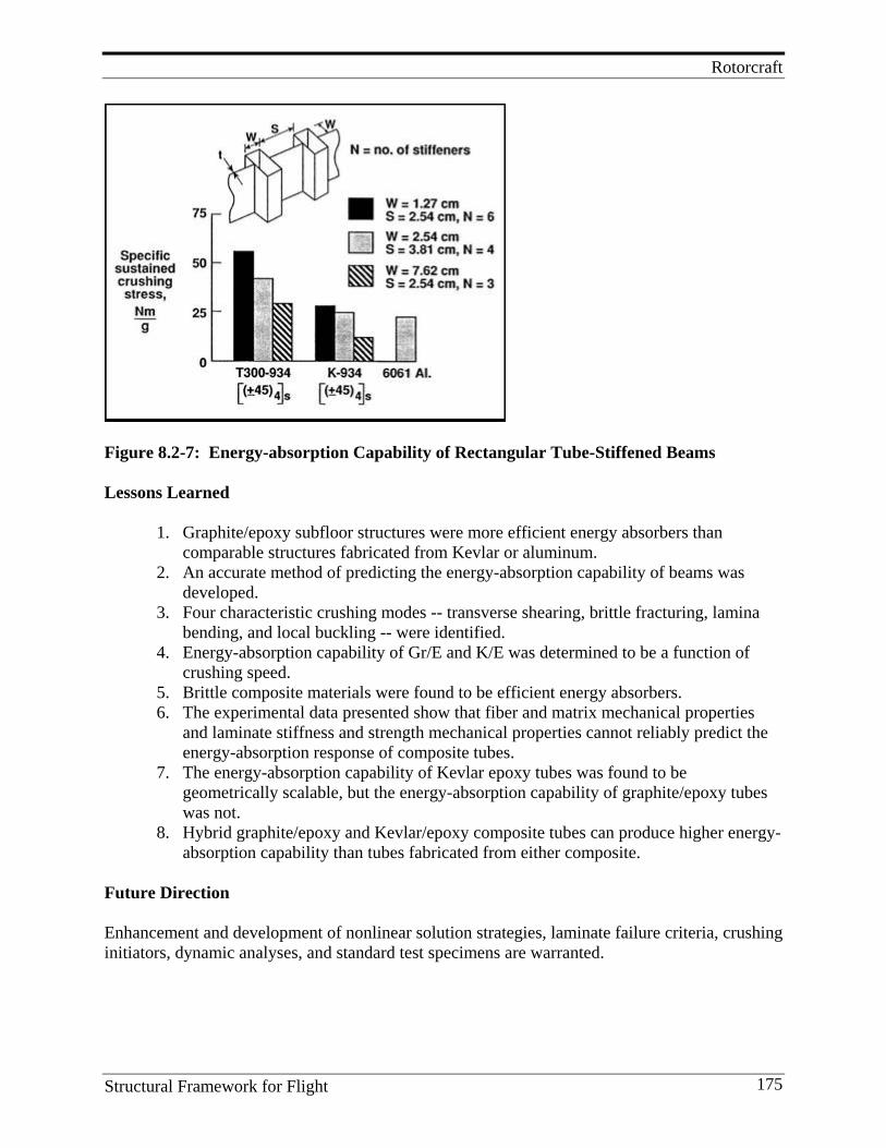
Rotorcraft
Structural Framework for Flight 175
Figure 8.2-7: Energy-absorption Capability of Rectangular Tube-Stiffened Beams Lessons Learned
1. Graphite/epoxy subfloor structures were more efficient energy absorbers than
comparable structures fabricated from Kevlar or aluminum. 2. An accurate method of predicting the energy-absorption capability of beams was
developed. 3. Four characteristic crushing modes -- transverse shearing, brittle fracturing, lamina
bending, and local buckling -- were identified. 4. Energy-absorption capability of Gr/E and K/E was determined to be a function of
crushing speed. 5. Brittle composite materials were found to be efficient energy absorbers. 6. The experimental data presented show that fiber and matrix mechanical properties
and laminate stiffness and strength mechanical properties cannot reliably predict the energy-absorption response of composite tubes.
7. The energy-absorption capability of Kevlar epoxy tubes was found to be geometrically scalable, but the energy-absorption capability of graphite/epoxy tubes was not.
8. Hybrid graphite/epoxy and Kevlar/epoxy composite tubes can produce higher energy-absorption capability than tubes fabricated from either composite.
Future Direction Enhancement and development of nonlinear solution strategies, laminate failure criteria, crushing initiators, dynamic analyses, and standard test specimens are warranted.
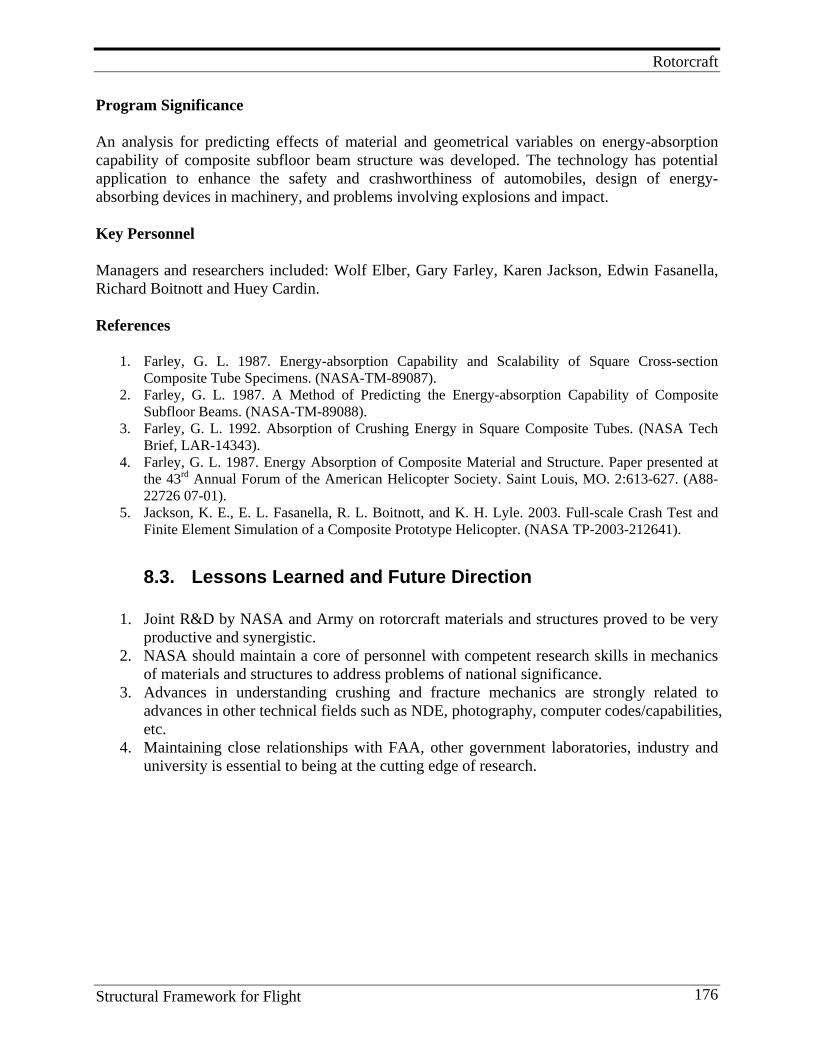
Rotorcraft
Structural Framework for Flight 176
Program Significance An analysis for predicting effects of material and geometrical variables on energy-absorption capability of composite subfloor beam structure was developed. The technology has potential application to enhance the safety and crashworthiness of automobiles, design of energy-absorbing devices in machinery, and problems involving explosions and impact. Key Personnel Managers and researchers included: Wolf Elber, Gary Farley, Karen Jackson, Edwin Fasanella, Richard Boitnott and Huey Cardin. References
1. Farley, G. L. 1987. Energy-absorption Capability and Scalability of Square Cross-section Composite Tube Specimens. (NASA-TM-89087).
2. Farley, G. L. 1987. A Method of Predicting the Energy-absorption Capability of Composite Subfloor Beams. (NASA-TM-89088).
3. Farley, G. L. 1992. Absorption of Crushing Energy in Square Composite Tubes. (NASA Tech Brief, LAR-14343).
4. Farley, G. L. 1987. Energy Absorption of Composite Material and Structure. Paper presented at the 43rd Annual Forum of the American Helicopter Society. Saint Louis, MO. 2:613-627. (A88-22726 07-01).
5. Jackson, K. E., E. L. Fasanella, R. L. Boitnott, and K. H. Lyle. 2003. Full-scale Crash Test and Finite Element Simulation of a Composite Prototype Helicopter. (NASA TP-2003-212641).
8.3. Lessons Learned and Future Direction
1. Joint R&D by NASA and Army on rotorcraft materials and structures proved to be very productive and synergistic.
2. NASA should maintain a core of personnel with competent research skills in mechanics of materials and structures to address problems of national significance.
3. Advances in understanding crushing and fracture mechanics are strongly related to advances in other technical fields such as NDE, photography, computer codes/capabilities, etc.
4. Maintaining close relationships with FAA, other government laboratories, industry and university is essential to being at the cutting edge of research.

Launch Vehicles
Structural Framework for Flight 177
9. L A U N C H V E H I C L E S
Highlights
1. Composite materials are used on the space shuttle to reduce weight and are being
investigated for weight reduction of the Ares I and Ares V launch vehicles under development ( through Fiscal Year 2010).
2. Composite trade studies for shuttle components indicated significant weight-saving potential.
3. Langley fabricated and tested segment of graphite polyimide aft body flap. 4. Langley provided expertise to cryotank investigation. 5. Langley conducted composite trade studies for constellation program including Ares I
and V. 6. Langley safety engineering center led the engineering and development of a prototype
composite crew module. 7. NASA Langley leading trade studies of heavily-loaded composite barrel concepts for
interstage applications on the Ares V launch vehicle.
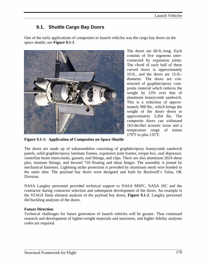
Launch Vehicles
Structural Framework for Flight 178
9.1. Shuttle Cargo Bay Doors One of the early applications of composites to launch vehicles was the cargo bay doors on the space shuttle; see Figure 9.1-1.
The doors are 60-ft.-long. Each consists of five segments inter-connected by expansion joints. The chord of each half of these curved doors is approximately 10-ft., and the doors are 15-ft.- diameter. The doors are con-structed of graphite/epoxy com-posite material which reduces the weight by 23% over that of aluminum honeycomb sandwich. This is a reduction of approx-imately 900 lbs., which brings the weight of the doors down to approximately 3,264 lbs. The composite doors can withstand 163-decibel acoustic noise and a temperature range of minus 170oF to plus 135oF.
Figure 9.1-1: Application of Composites on Space Shuttle The doors are made up of subassemblies consisting of graphite/epoxy honeycomb sandwich panels, solid graphite/epoxy laminate frames, expansion joint frames, torque box, seal depressor, centerline beam intercostals, gussets, end fittings, and clips. There are also aluminum 2024 shear pins, titanium fittings, and Inconel 718 floating and shear hinges. The assembly is joined by mechanical fasteners. Lightning strike protection is provided by aluminum mesh wire bonded to the outer skin. The payload bay doors were designed and built by Rockwell’s Tulsa, OK Division. NASA Langley personnel provided technical support to NASA MSFC, NASA JSC and the contractor during contractor selection and subsequent development of the doors. An example is the STAGS finite element analysis of the payload bay doors, Figure 9.1-2. Langley personnel did buckling analyses of the doors. Future Direction Technical challenges for future generation of launch vehicles will be greater. Thus continued research and development of lighter-weight materials and structures, and higher fidelity analyses codes are required.
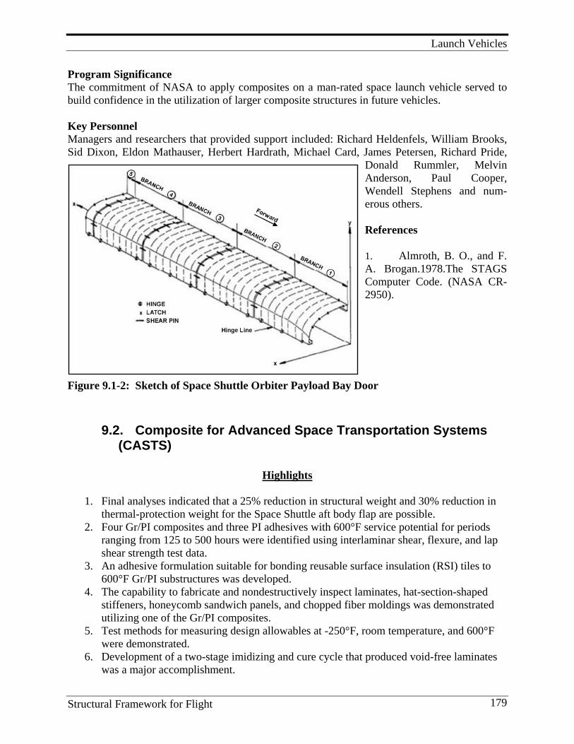
Launch Vehicles
Structural Framework for Flight 179
Program Significance The commitment of NASA to apply composites on a man-rated space launch vehicle served to build confidence in the utilization of larger composite structures in future vehicles. Key Personnel Managers and researchers that provided support included: Richard Heldenfels, William Brooks, Sid Dixon, Eldon Mathauser, Herbert Hardrath, Michael Card, James Petersen, Richard Pride,
Donald Rummler, Melvin Anderson, Paul Cooper, Wendell Stephens and num-erous others. References 1. Almroth, B. O., and F. A. Brogan.1978.The STAGS Computer Code. (NASA CR- 2950).
Figure 9.1-2: Sketch of Space Shuttle Orbiter Payload Bay Door
9.2. Composite for Advanced Space Transportation Systems (CASTS)
Highlights
1. Final analyses indicated that a 25% reduction in structural weight and 30% reduction in
thermal-protection weight for the Space Shuttle aft body flap are possible. 2. Four Gr/PI composites and three PI adhesives with 600°F service potential for periods
ranging from 125 to 500 hours were identified using interlaminar shear, flexure, and lap shear strength test data.
3. An adhesive formulation suitable for bonding reusable surface insulation (RSI) tiles to 600°F Gr/PI substructures was developed.
4. The capability to fabricate and nondestructively inspect laminates, hat-section-shaped stiffeners, honeycomb sandwich panels, and chopped fiber moldings was demonstrated utilizing one of the Gr/PI composites.
5. Test methods for measuring design allowables at -250°F, room temperature, and 600°F were demonstrated.
6. Development of a two-stage imidizing and cure cycle that produced void-free laminates was a major accomplishment.
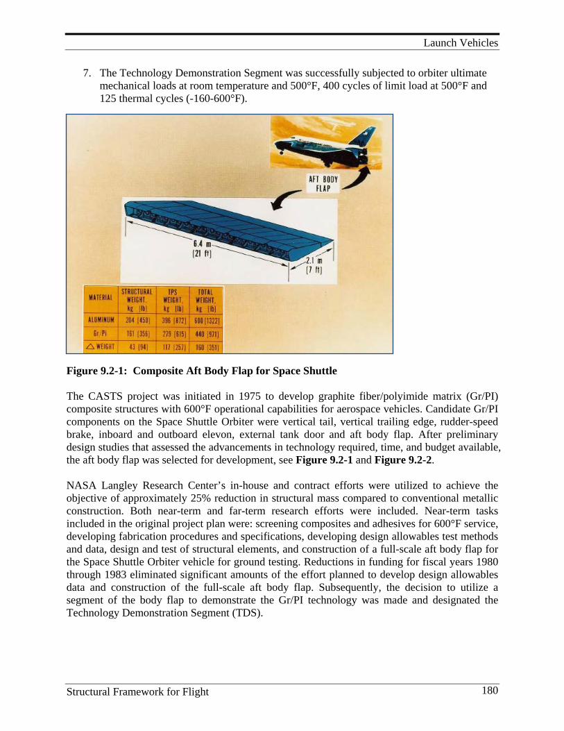
Launch Vehicles
Structural Framework for Flight 180
7. The Technology Demonstration Segment was successfully subjected to orbiter ultimate mechanical loads at room temperature and 500°F, 400 cycles of limit load at 500°F and 125 thermal cycles (-160-600°F).
Figure 9.2-1: Composite Aft Body Flap for Space Shuttle The CASTS project was initiated in 1975 to develop graphite fiber/polyimide matrix (Gr/PI) composite structures with 600°F operational capabilities for aerospace vehicles. Candidate Gr/PI components on the Space Shuttle Orbiter were vertical tail, vertical trailing edge, rudder-speed brake, inboard and outboard elevon, external tank door and aft body flap. After preliminary design studies that assessed the advancements in technology required, time, and budget available, the aft body flap was selected for development, see Figure 9.2-1 and Figure 9.2-2. NASA Langley Research Center’s in-house and contract efforts were utilized to achieve the objective of approximately 25% reduction in structural mass compared to conventional metallic construction. Both near-term and far-term research efforts were included. Near-term tasks included in the original project plan were: screening composites and adhesives for 600°F service, developing fabrication procedures and specifications, developing design allowables test methods and data, design and test of structural elements, and construction of a full-scale aft body flap for the Space Shuttle Orbiter vehicle for ground testing. Reductions in funding for fiscal years 1980 through 1983 eliminated significant amounts of the effort planned to develop design allowables data and construction of the full-scale aft body flap. Subsequently, the decision to utilize a segment of the body flap to demonstrate the Gr/PI technology was made and designated the Technology Demonstration Segment (TDS).
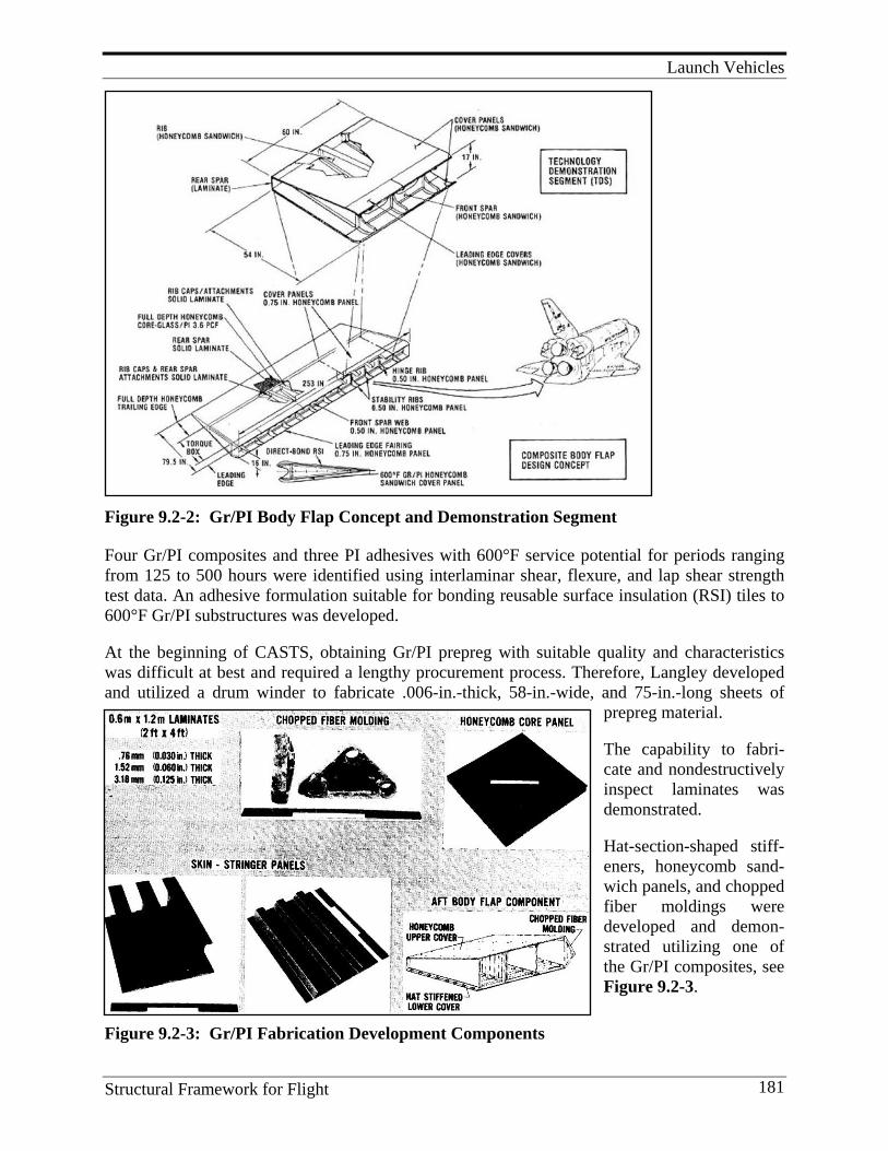
Launch Vehicles
Structural Framework for Flight 181
Figure 9.2-2: Gr/PI Body Flap Concept and Demonstration Segment Four Gr/PI composites and three PI adhesives with 600°F service potential for periods ranging from 125 to 500 hours were identified using interlaminar shear, flexure, and lap shear strength test data. An adhesive formulation suitable for bonding reusable surface insulation (RSI) tiles to 600°F Gr/PI substructures was developed. At the beginning of CASTS, obtaining Gr/PI prepreg with suitable quality and characteristics was difficult at best and required a lengthy procurement process. Therefore, Langley developed and utilized a drum winder to fabricate .006-in.-thick, 58-in.-wide, and 75-in.-long sheets of
prepreg material. The capability to fabri-cate and nondestructively inspect laminates was demonstrated. Hat-section-shaped stiff-eners, honeycomb sand-wich panels, and chopped fiber moldings were developed and demon-strated utilizing one of the Gr/PI composites, see Figure 9.2-3.
Figure 9.2-3: Gr/PI Fabrication Development Components
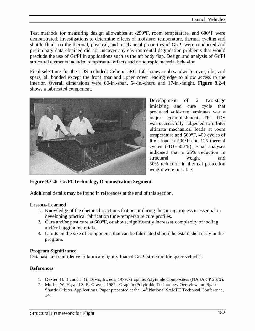
Launch Vehicles
Structural Framework for Flight 182
Test methods for measuring design allowables at -250°F, room temperature, and 600°F were demonstrated. Investigations to determine effects of moisture, temperature, thermal cycling and shuttle fluids on the thermal, physical, and mechanical properties of Gr/PI were conducted and preliminary data obtained did not uncover any environmental degradation problems that would preclude the use of Gr/PI in applications such as the aft body flap. Design and analysis of Gr/PI structural elements included temperature effects and orthotropic material behavior. Final selections for the TDS included: Celion/LaRC 160, honeycomb sandwich cover, ribs, and spars, all bonded except the front spar and upper cover leading edge to allow access to the interior. Overall dimensions were 60-in.-span, 54-in.-chord and 17-in.-height. Figure 9.2-4 shows a fabricated component.
Development of a two-stage imidizing and cure cycle that produced void-free laminates was a major accomplishment. The TDS was successfully subjected to orbiter ultimate mechanical loads at room temperature and 500°F, 400 cycles of limit load at 500°F and 125 thermal cycles (-160-600°F). Final analyses indicated that a 25% reduction in structural weight and 30% reduction in thermal protection weight were possible.
Figure 9.2-4: Gr/PI Technology Demonstration Segment Additional details may be found in references at the end of this section. Lessons Learned
1. Knowledge of the chemical reactions that occur during the curing process is essential in developing practical fabrication time-temperature cure profiles.
2. Cure and/or post cure at 600°F, or above, significantly increases complexity of tooling and/or bagging materials.
3. Limits on the size of components that can be fabricated should be established early in the program.
Program Significance Database and confidence to fabricate lightly-loaded Gr/PI structure for space vehicles. References
1. Dexter, H. B., and J. G. Davis, Jr., eds. 1979. Graphite/Polyimide Composites. (NASA CP 2079). 2. Morita, W. H., and S. R. Graves. 1982. Graphite/Polyimide Technology Overview and Space
Shuttle Orbiter Applications. Paper presented at the 14th National SAMPE Technical Conference, 14.

Launch Vehicles
Structural Framework for Flight 183
9.3. Composite Cryotanks
Figure 9.3-1: USAF DC-X and NASA DC-XA Experimental Flight Vehicle and Photos of Two Advanced Technology Composite Parts Installed in the DC-XA
Highlights
1. Liquid hydrogen cryotank was fabricated from graphite/epoxy composites. 2. Cryogenic composite tanks were in an early stage of development and additional testing
was planned as part of the development program, but the Technology Maturation program was not approved.
3. A full-scale segment of a reusable launch vehicle prototype wing was fabricated as a test article to demonstrate the integration of the thermal protection system (TPS) with large composite structural components and to validate the fabrication, design, and analysis methods for this wing.
4. While the wing box was not subjected to an elevated-temperature test condition, three different types of TPS were installed on the upper skin to demonstrate the load-carrying capability of the integrated structure. The test was conducted at NASA Langley Research Center. The wing box was loaded to DLL and to DUL with both up-bending and down-bending loading conditions. The box was then loaded to failure with the up-bending loading condition and the results were in excellent agreement with the values calculated by the finite element analysis.
5. On July 2, 1996, NASA selected Lockheed Martin to design, build, and fly the X-33 Advanced Technology Demonstrator test vehicle. The X-33 was designed to be a quarter-
Launch Vehicles
Structural Framework for Flight 184
scale unpiloted prototype of a potential future single-stage-to-orbit reusable launch vehicle .
6. In the fall of 1999, at Marshall Space Flight Center in Huntsville, AL, two LN2 pressure proof tests of the prototype X-33 composite tank were held, followed by a third LH2 protoflight test during which the tank failed.
7. Langley composite experts were requested to support the failure investigation: X-33 Oversight Committee (Starnes, Johnston, Harris); X-33 LH2 Composite Tank Test Investigation Team (Starnes, Johnston, Harris); X-33 LH2 Composite Tank Recovery Program (Starnes, Johnston, Harris).
9.3.1 State-of-the-Art USAF DC-X and NASA Contributions with the DC-XA
From 1992 through 1996, two unmanned experimental aircraft, the USAF DC-X and the subsequent NASA DC-XA, were developed to demonstrate the viability of building a single-stage-to-orbit (SSTO) spacecraft.[1, 2, 3] In essence, their purpose was to implement and successfully demonstrate important advanced enabling technologies for building a reusable launch vehicle (RLV). The DC-X/DC-XA vehicle is shown in Figure 9.3-1, along with technologies the DC-X successfully demonstrated in seven flights. After NASA assumed responsibility for the DC-X program, from the USAF, it installed more advanced technologies that were successfully demonstrated in the next four flights. Two of these, a composite LH2 cryotank and a composite shell intertank, are shown in Figure 9.3-1. The intertank was comprised of two semi-cylindrical half shells joined by aluminum attachment rings.[1] The shells were made from 4-ply fabric carbon fiber/bismaleimide facesheets bonded to an aluminum flex-core. The cryotank was constructed in two cylindrical shell pieces joined together by a “belly wrap” bonded splice joint.[1] The shell was a 24-ply graphite/toughened-epoxy laminate attached to internal 3-D reinforced urethane foam. The DC-XA was the first successful demonstration of a leak-free composite LH2 cryotank. The program ended when one of the landing struts failed during decent and the vehicle crashed.
9.3.2 NASA Technology Development Structural Tests Related to Use of Composites on a Future RLV
A full-scale segment of an RLV prototype wing was fabricated as a test article and successfully tested at LaRC.[2, 3, 4] It demonstrated the integration of TPS with large composite structural components, validated fabrication, design, and analysis methods, and proved that composite structures technology could be used for primary RLV structure..[6,18 A honeycomb-sandwich construction was selected to provide broader design and fabrication experience. The upper and lower skin panels were fabricated using a graphite/bismaleimide (IM-7/5250-4) material system. This material system was selected because it has good fracture toughness and good mechanical properties at elevated temperatures up to 350oF. The honeycomb core was glass/polyimide HRH-327 with a 3/16-in. cell size and a 4.5 lbs/ft.3 density. The wing box was approximately 10-ft.- long, 5-ft.-wide, and 43-in.-deep with three ribs and three spars. While the wing box was not subjected to an elevated temperature test condition, three different types of TPS were installed on the upper skin to demonstrate the load carrying capability of the integrated structure. The test
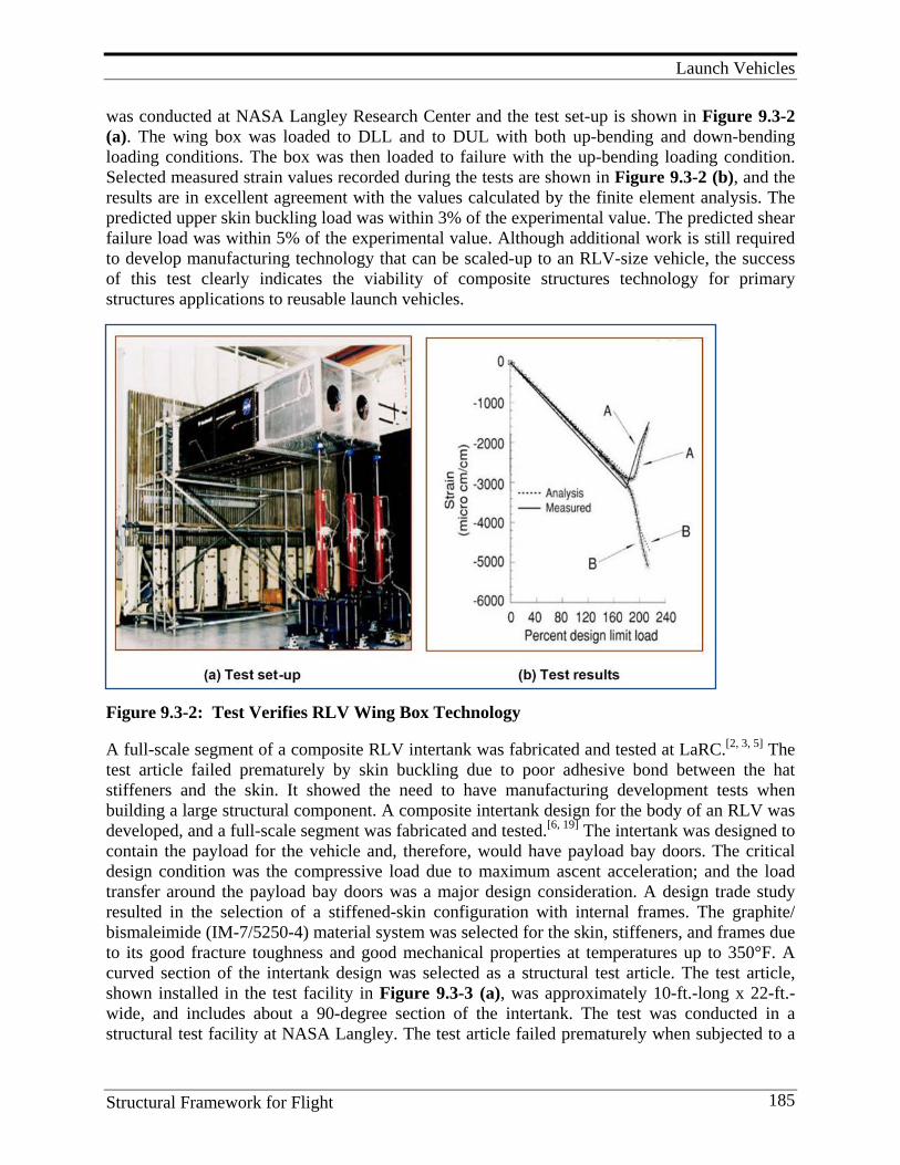
Launch Vehicles
Structural Framework for Flight 185
was conducted at NASA Langley Research Center and the test set-up is shown in Figure 9.3-2 (a). The wing box was loaded to DLL and to DUL with both up-bending and down-bending loading conditions. The box was then loaded to failure with the up-bending loading condition. Selected measured strain values recorded during the tests are shown in Figure 9.3-2 (b), and the results are in excellent agreement with the values calculated by the finite element analysis. The predicted upper skin buckling load was within 3% of the experimental value. The predicted shear failure load was within 5% of the experimental value. Although additional work is still required to develop manufacturing technology that can be scaled-up to an RLV-size vehicle, the success of this test clearly indicates the viability of composite structures technology for primary structures applications to reusable launch vehicles.
Figure 9.3-2: Test Verifies RLV Wing Box Technology A full-scale segment of a composite RLV intertank was fabricated and tested at LaRC.[2, 3, 5] The test article failed prematurely by skin buckling due to poor adhesive bond between the hat stiffeners and the skin. It showed the need to have manufacturing development tests when building a large structural component. A composite intertank design for the body of an RLV was developed, and a full-scale segment was fabricated and tested.[6, 19] The intertank was designed to contain the payload for the vehicle and, therefore, would have payload bay doors. The critical design condition was the compressive load due to maximum ascent acceleration; and the load transfer around the payload bay doors was a major design consideration. A design trade study resulted in the selection of a stiffened-skin configuration with internal frames. The graphite/ bismaleimide (IM-7/5250-4) material system was selected for the skin, stiffeners, and frames due to its good fracture toughness and good mechanical properties at temperatures up to 350°F. A curved section of the intertank design was selected as a structural test article. The test article, shown installed in the test facility in Figure 9.3-3 (a), was approximately 10-ft.-long x 22-ft.-wide, and includes about a 90-degree section of the intertank. The test was conducted in a structural test facility at NASA Langley. The test article failed prematurely when subjected to a
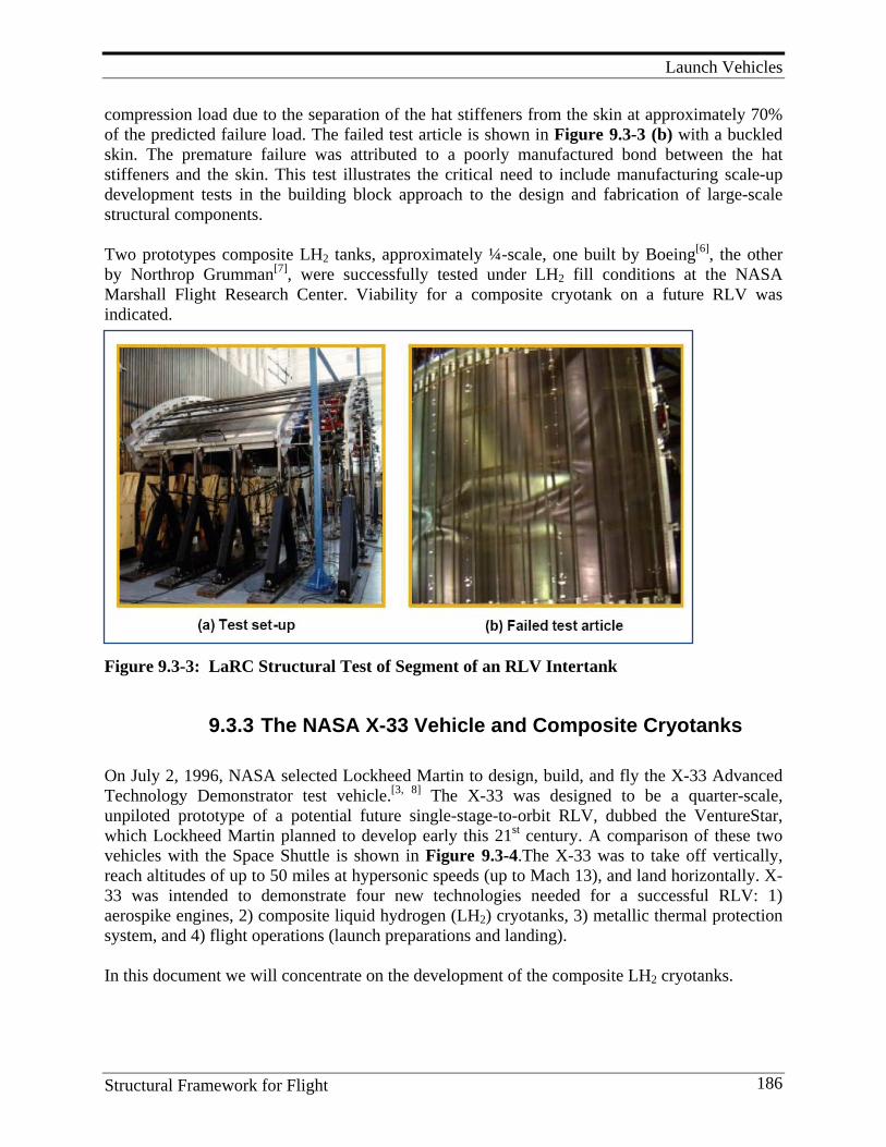
Launch Vehicles
Structural Framework for Flight 186
compression load due to the separation of the hat stiffeners from the skin at approximately 70% of the predicted failure load. The failed test article is shown in Figure 9.3-3 (b) with a buckled skin. The premature failure was attributed to a poorly manufactured bond between the hat stiffeners and the skin. This test illustrates the critical need to include manufacturing scale-up development tests in the building block approach to the design and fabrication of large-scale structural components. Two prototypes composite LH2 tanks, approximately ¼-scale, one built by Boeing[6], the other by Northrop Grumman[7], were successfully tested under LH2 fill conditions at the NASA Marshall Flight Research Center. Viability for a composite cryotank on a future RLV was indicated.
Figure 9.3-3: LaRC Structural Test of Segment of an RLV Intertank
9.3.3 The NASA X-33 Vehicle and Composite Cryotanks On July 2, 1996, NASA selected Lockheed Martin to design, build, and fly the X-33 Advanced Technology Demonstrator test vehicle.[3, 8] The X-33 was designed to be a quarter-scale, unpiloted prototype of a potential future single-stage-to-orbit RLV, dubbed the VentureStar, which Lockheed Martin planned to develop early this 21st century. A comparison of these two vehicles with the Space Shuttle is shown in Figure 9.3-4.The X-33 was to take off vertically, reach altitudes of up to 50 miles at hypersonic speeds (up to Mach 13), and land horizontally. X-33 was intended to demonstrate four new technologies needed for a successful RLV: 1) aerospike engines, 2) composite liquid hydrogen (LH2) cryotanks, 3) metallic thermal protection system, and 4) flight operations (launch preparations and landing). In this document we will concentrate on the development of the composite LH2 cryotanks.
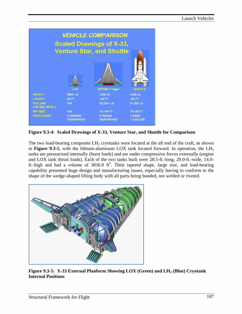
Launch Vehicles
Structural Framework for Flight 187
Figure 9.3-4: Scaled Drawings of X-33, Venture Star, and Shuttle for Comparison The two load-bearing composite LH2 cryotanks were located at the aft end of the craft, as shown in Figure 9.3-5, with the lithium-aluminum LOX tank located forward. In operation, the LH2 tanks are pressurized internally (burst loads) and are under compressive forces externally (engine and LOX tank thrust loads). Each of the two tanks built were 28.5-ft.-long, 20.0-ft.-wide, 14.0-ft.-high and had a volume of 3836.8 ft3. Their tapered shape, large size, and load-bearing capability presented huge design and manufacturing issues, especially having to conform to the shape of the wedge-shaped lifting body with all parts being bonded, not welded or riveted.
Figure 9.3-5: X-33 External Planform Showing LOX (Green) and LH2 (Blue) Cryotank Internal Positions
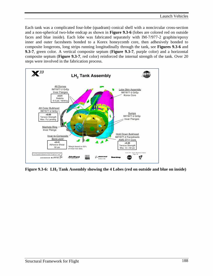
Launch Vehicles
Structural Framework for Flight 188
Each tank was a complicated four-lobe (quadrant) conical shell with a noncircular cross-section and a non-spherical two-lobe endcap as shown in Figure 9.3-6 (lobes are colored red on outside faces and blue inside). Each lobe was fabricated separately with IM-7/977-2 graphite/epoxy inner and outer facesheets bonded to a Korex honeycomb core, then adhesively bonded to composite longerons, long strips running longitudinally through the tank, see Figures 9.3-6 and 9.3-7, green color. A vertical composite septum (Figure 9.3-7, purple color) and a horizontal composite septum (Figure 9.3-7, red color) reinforced the internal strength of the tank. Over 20 steps were involved in the fabrication process.
Figure 9.3-6: LH2 Tank Assembly showing the 4 Lobes (red on outside and blue on inside)
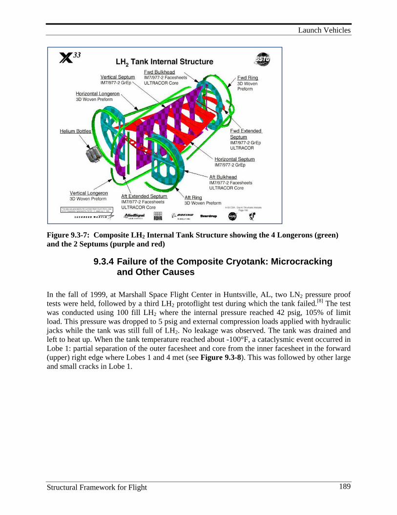
Launch Vehicles
Structural Framework for Flight 189
Figure 9.3-7: Composite LH2 Internal Tank Structure showing the 4 Longerons (green) and the 2 Septums (purple and red)
9.3.4 Failure of the Composite Cryotank: Microcracking and Other Causes
In the fall of 1999, at Marshall Space Flight Center in Huntsville, AL, two LN2 pressure proof tests were held, followed by a third LH2 protoflight test during which the tank failed.[8] The test was conducted using 100 fill LH2 where the internal pressure reached 42 psig, 105% of limit load. This pressure was dropped to 5 psig and external compression loads applied with hydraulic jacks while the tank was still full of LH2. No leakage was observed. The tank was drained and left to heat up. When the tank temperature reached about -100°F, a cataclysmic event occurred in Lobe 1: partial separation of the outer facesheet and core from the inner facesheet in the forward (upper) right edge where Lobes 1 and 4 met (see Figure 9.3-8). This was followed by other large and small cracks in Lobe 1.
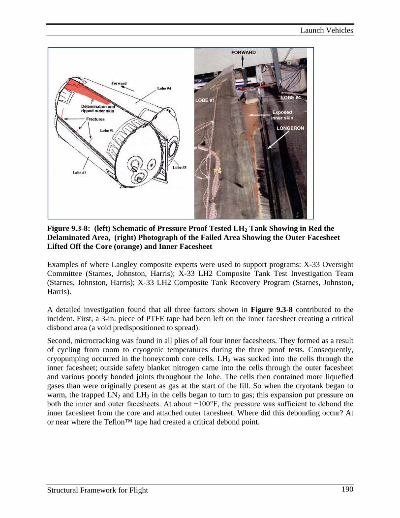
Launch Vehicles
Structural Framework for Flight 190
Figure 9.3-8: (left) Schematic of Pressure Proof Tested LH2 Tank Showing in Red the Delaminated Area, (right) Photograph of the Failed Area Showing the Outer Facesheet Lifted Off the Core (orange) and Inner Facesheet Examples of where Langley composite experts were used to support programs: X-33 Oversight Committee (Starnes, Johnston, Harris); X-33 LH2 Composite Tank Test Investigation Team (Starnes, Johnston, Harris); X-33 LH2 Composite Tank Recovery Program (Starnes, Johnston, Harris). A detailed investigation found that all three factors shown in Figure 9.3-8 contributed to the incident. First, a 3-in. piece of PTFE tape had been left on the inner facesheet creating a critical disbond area (a void predispositioned to spread). Second, microcracking was found in all plies of all four inner facesheets. They formed as a result of cycling from room to cryogenic temperatures during the three proof tests. Consequently, cryopumping occurred in the honeycomb core cells. LH2 was sucked into the cells through the inner facesheet; outside safety blanket nitrogen came into the cells through the outer facesheet and various poorly bonded joints throughout the lobe. The cells then contained more liquefied gases than were originally present as gas at the start of the fill. So when the cryotank began to warm, the trapped LN2 and LH2 in the cells began to turn to gas; this expansion put pressure on both the inner and outer facesheets. At about −100°F, the pressure was sufficient to debond the inner facesheet from the core and attached outer facesheet. Where did this debonding occur? At or near where the Teflon™ tape had created a critical debond point.
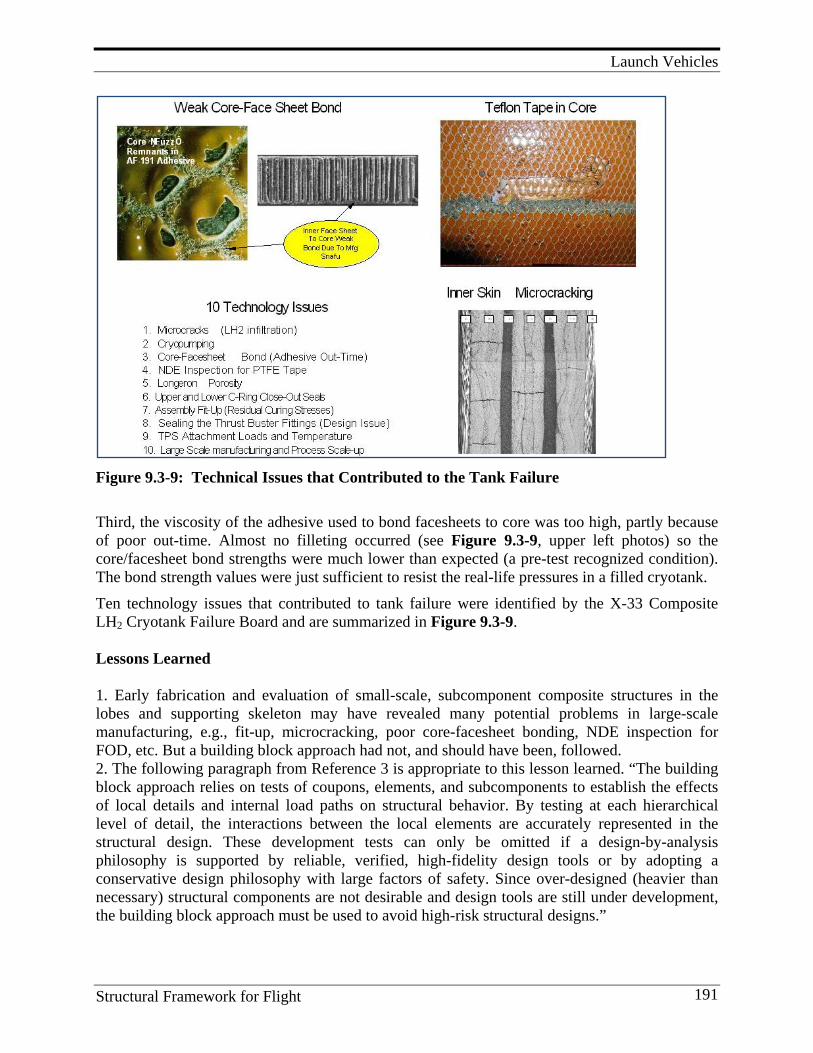
Launch Vehicles
Structural Framework for Flight 191
Figure 9.3-9: Technical Issues that Contributed to the Tank Failure Third, the viscosity of the adhesive used to bond facesheets to core was too high, partly because of poor out-time. Almost no filleting occurred (see Figure 9.3-9, upper left photos) so the core/facesheet bond strengths were much lower than expected (a pre-test recognized condition). The bond strength values were just sufficient to resist the real-life pressures in a filled cryotank. Ten technology issues that contributed to tank failure were identified by the X-33 Composite LH2 Cryotank Failure Board and are summarized in Figure 9.3-9. Lessons Learned 1. Early fabrication and evaluation of small-scale, subcomponent composite structures in the lobes and supporting skeleton may have revealed many potential problems in large-scale manufacturing, e.g., fit-up, microcracking, poor core-facesheet bonding, NDE inspection for FOD, etc. But a building block approach had not, and should have been, followed. 2. The following paragraph from Reference 3 is appropriate to this lesson learned. “The building block approach relies on tests of coupons, elements, and subcomponents to establish the effects of local details and internal load paths on structural behavior. By testing at each hierarchical level of detail, the interactions between the local elements are accurately represented in the structural design. These development tests can only be omitted if a design-by-analysis philosophy is supported by reliable, verified, high-fidelity design tools or by adopting a conservative design philosophy with large factors of safety. Since over-designed (heavier than necessary) structural components are not desirable and design tools are still under development, the building block approach must be used to avoid high-risk structural designs.”
Launch Vehicles
Structural Framework for Flight 192
3. The cryotank design was highly innovative, pushed the limits of technology, combined many unproved technology elements, and was designed and built on an accelerated schedule. Best practices in design and engineering must be used including a vigorous technology development program with adequate factors of safety.[8] 4. Well thought-out design/development planning must integrate materials, structures, and manufacturing technologies in a timely manner.[8] 5. Failure modes must be addressed in depth, e.g., FEMA.[8] 6. High levels of communication are required both internally and externally to the involved organizations. In-depth technical penetration at all levels is needed.[8] 7. A risk management plan must be used.[8] 8. An in-depth review and inspection plan must be in place to preempt errors.[8]
Future Directions 1. Develop microcrack-resistant matrix resins and their structural composites that do not
microcrack when cycled between cryo-temperatures and use temperature. They should also be microcrack-resistant to levels of impact resulting from fork-lift trucks and falling tools.
2. Increase the level of NDE inspection capability. Kissing debonds, very thin foreign objects, and microcracks and porosity of various sizes and widths must be detectable.
3. Improving our understanding of residual cure stresses that lead to warping in large composite structure is needed. Bad fit-ups require large external forces on warped composites to match bonding surfaces, especially large surfaces. This leads to severe external stresses that should not be present in large composite assemblies.
4. Non-autoclave curing will be required for structures larger than 30-ft.-diameter. For Ares 1 and 5, matrices and cure cycles that do not require autoclaves are needed for potential weight savings. Cure stresses and fabrication times will also be reduced with non-autoclave curing.
5. NASA planning teams have evaluated various technologies that are enabling for an RLV. They indicate that “extensive development of structures and materials technologies will be required to enable an RLV that will replace the Space Shuttle.” [3]
6. Development activities are needed to improve the quality, reproducibility, and quality assurance of composites to the point where safety factors imposed on composites are no more than those imposed on metals. The severe penalty currently being leveled on composites takes away all the weight savings. To increase confidence to the point where safety factors for composites are no more than for metals, the knowledge gaps need to be filled. At September 22, 2009 WSTF Composite Pressure Vessel and Structure Summit, the following questions were considered. [9] Although discussed at this conference much additional work is required to fully answer these questions for RLV cryotanks.
a) Should long-term strength testing, e.g., stress rupture testing, be considered in composite design methodology?
b) Should we establish a meaningful life factor on cyclic life or damage-tolerance life? Do we know enough about the mechanical properties of composites to do this?
Launch Vehicles
Structural Framework for Flight 193
c) Should we consider damage tolerance and fracture toughness in the design criteria to establish safe life?
d) Do we know enough about the potential failure mechanisms and coupling effects in composites for various ground and flight environments?
e) Should there be different design requirements for constructing resin-based composite tanks when different fluids are used, i.e., gas vs. liquid, in order to determine long-term stress or pressure rating?
f) Who should be responsible for modifying or developing standards that do not exist for this new technology?
Key Personnel Managers and/or researchers included: Dr. Norm Johnston, Dr. James H. Starnes Jr., Dr. Charles E. Harris, Dr. J. Wayne Sawyer, Dr. Mark J. Shuart, Herald G. Bush, Marshall Rouse, and Dr. Damodar R. Ambur References
1. Schweikle, D. 1996. DC-XA Incident Investigation Summary. Briefing to the NASA DC-XA Mishap Investigation Board,
2. Sawyer, J. W. 1996. Graphite-composite Primary Structure for Reusable Launch Vehicles. Paper presented at the AIAA Space Programs and Technologies Conference. Number AIAA-96-4268.
3. Harris, C. E., J. H. Starnes, Jr., and M. J. Shuart. 2000. An Assessment of the State-of-the-art in the Design and Manufacturing of Large Composite Structures for Aerospace Vehicles. (NASA TM-2001-210844).
4. Sawyer, J. W., H. Bush, and T. R. Sutter. 1997. Experimental Investigation of a Graphite-composite Wing-box Section for a Reusable Launch Vehicle. Proceeding of The Space Technology and Applications International Forum, El-Genk, M. S., Ed., AIP Conference Proceedings No. 387, vol. 1, No. 3, January 26-30, 1997, pp. 1245-1258.
5. Palm, T., M. Mahler, C. Shah, M. Rouse, H. Bush, C. Wu, and W. J. Small. 2000. BMI Sandwich Wing Box Analysis and Test. Paper presented at the 4th Structures, Structural Dynamics and Materials Conf. of AIAA Atlanta, GA. (Paper 1342).
6. Sawyer, J. W., and H. Bush.1998. Experimental Investigation of a Graphite-composite Intertank Section for a Reusable Launch Vehicle. Paper presented at the 3rd Conference on Next Generation Launch Systems, Proceedings of the Space Technology and Applications International Forum. Ed. M. S. El-Genk, CONF-980103:1007-1019 AIP Conference Proceedings.
7. Anon. 1997. Reusable Composite Hydrogen Tank System (RCHTS) TA-1 Final Tank Design Report. Boeing Internal Report, Huntington Beach, CA.
8. Meredith, B., T. Palm, and R. Deo. 2002. Low Cost Manufacturing of Composite Cryotanks. Aerospace Manufacturing Technology Conference and Exhibition, Hartford, CT.
9. Anon. 2000. Final Report of the X-33 Liquid Hydrogen Tank Test Investigation Team. NASA, George C. Marshall Space Flight Center, Huntsville, AL.
10. Central questions to be addressed, White Sands Test Facility 2009 Composite Pressure Vessel and Structure Summit, Las Cruces, NM. http://www.nasa.gov/centers/wstf/ news/safetysummit2009.html
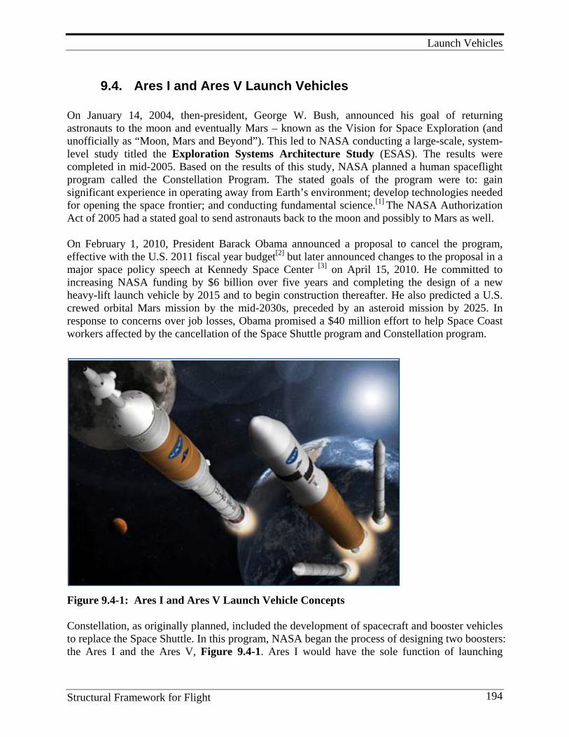
Launch Vehicles
Structural Framework for Flight 194
9.4. Ares I and Ares V Launch Vehicles On January 14, 2004, then-president, George W. Bush, announced his goal of returning astronauts to the moon and eventually Mars – known as the Vision for Space Exploration (and unofficially as “Moon, Mars and Beyond”). This led to NASA conducting a large-scale, system- level study titled the Exploration Systems Architecture Study (ESAS). The results were completed in mid-2005. Based on the results of this study, NASA planned a human spaceflight program called the Constellation Program. The stated goals of the program were to: gain significant experience in operating away from Earth’s environment; develop technologies needed for opening the space frontier; and conducting fundamental science.[1] The NASA Authorization Act of 2005 had a stated goal to send astronauts back to the moon and possibly to Mars as well. On February 1, 2010, President Barack Obama announced a proposal to cancel the program, effective with the U.S. 2011 fiscal year budget[2] but later announced changes to the proposal in a major space policy speech at Kennedy Space Center [3] on April 15, 2010. He committed to increasing NASA funding by $6 billion over five years and completing the design of a new heavy-lift launch vehicle by 2015 and to begin construction thereafter. He also predicted a U.S. crewed orbital Mars mission by the mid-2030s, preceded by an asteroid mission by 2025. In response to concerns over job losses, Obama promised a $40 million effort to help Space Coast workers affected by the cancellation of the Space Shuttle program and Constellation program.
Figure 9.4-1: Ares I and Ares V Launch Vehicle Concepts
Constellation, as originally planned, included the development of spacecraft and booster vehicles to replace the Space Shuttle. In this program, NASA began the process of designing two boosters: the Ares I and the Ares V, Figure 9.4-1. Ares I would have the sole function of launching
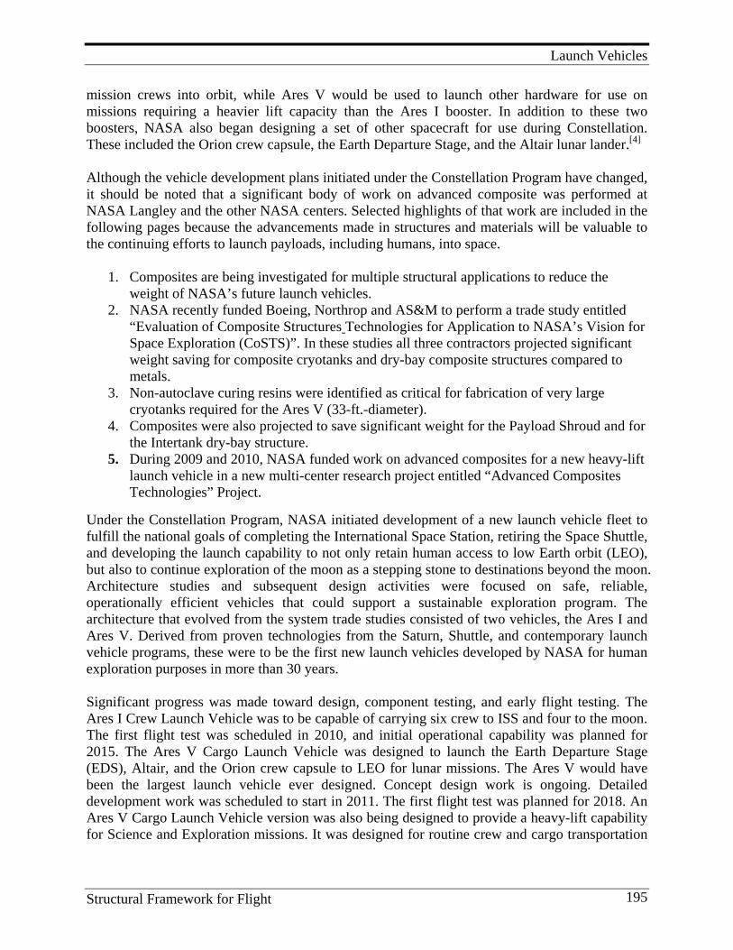
Launch Vehicles
Structural Framework for Flight 195
mission crews into orbit, while Ares V would be used to launch other hardware for use on missions requiring a heavier lift capacity than the Ares I booster. In addition to these two boosters, NASA also began designing a set of other spacecraft for use during Constellation. These included the Orion crew capsule, the Earth Departure Stage, and the Altair lunar lander.[4]
Although the vehicle development plans initiated under the Constellation Program have changed, it should be noted that a significant body of work on advanced composite was performed at NASA Langley and the other NASA centers. Selected highlights of that work are included in the following pages because the advancements made in structures and materials will be valuable to the continuing efforts to launch payloads, including humans, into space.
1. Composites are being investigated for multiple structural applications to reduce the
weight of NASA’s future launch vehicles. 2. NASA recently funded Boeing, Northrop and AS&M to perform a trade study entitled
“Evaluation of Composite Structures Technologies for Application to NASA’s Vision for Space Exploration (CoSTS)”. In these studies all three contractors projected significant weight saving for composite cryotanks and dry-bay composite structures compared to metals.
3. Non-autoclave curing resins were identified as critical for fabrication of very large cryotanks required for the Ares V (33-ft.-diameter).
4. Composites were also projected to save significant weight for the Payload Shroud and for the Intertank dry-bay structure.
5. During 2009 and 2010, NASA funded work on advanced composites for a new heavy-lift launch vehicle in a new multi-center research project entitled “Advanced Composites Technologies” Project.
Under the Constellation Program, NASA initiated development of a new launch vehicle fleet to fulfill the national goals of completing the International Space Station, retiring the Space Shuttle, and developing the launch capability to not only retain human access to low Earth orbit (LEO), but also to continue exploration of the moon as a stepping stone to destinations beyond the moon. Architecture studies and subsequent design activities were focused on safe, reliable, operationally efficient vehicles that could support a sustainable exploration program. The architecture that evolved from the system trade studies consisted of two vehicles, the Ares I and Ares V. Derived from proven technologies from the Saturn, Shuttle, and contemporary launch vehicle programs, these were to be the first new launch vehicles developed by NASA for human exploration purposes in more than 30 years. Significant progress was made toward design, component testing, and early flight testing. The Ares I Crew Launch Vehicle was to be capable of carrying six crew to ISS and four to the moon. The first flight test was scheduled in 2010, and initial operational capability was planned for 2015. The Ares V Cargo Launch Vehicle was designed to launch the Earth Departure Stage (EDS), Altair, and the Orion crew capsule to LEO for lunar missions. The Ares V would have been the largest launch vehicle ever designed. Concept design work is ongoing. Detailed development work was scheduled to start in 2011. The first flight test was planned for 2018. An Ares V Cargo Launch Vehicle version was also being designed to provide a heavy-lift capability for Science and Exploration missions. It was designed for routine crew and cargo transportation
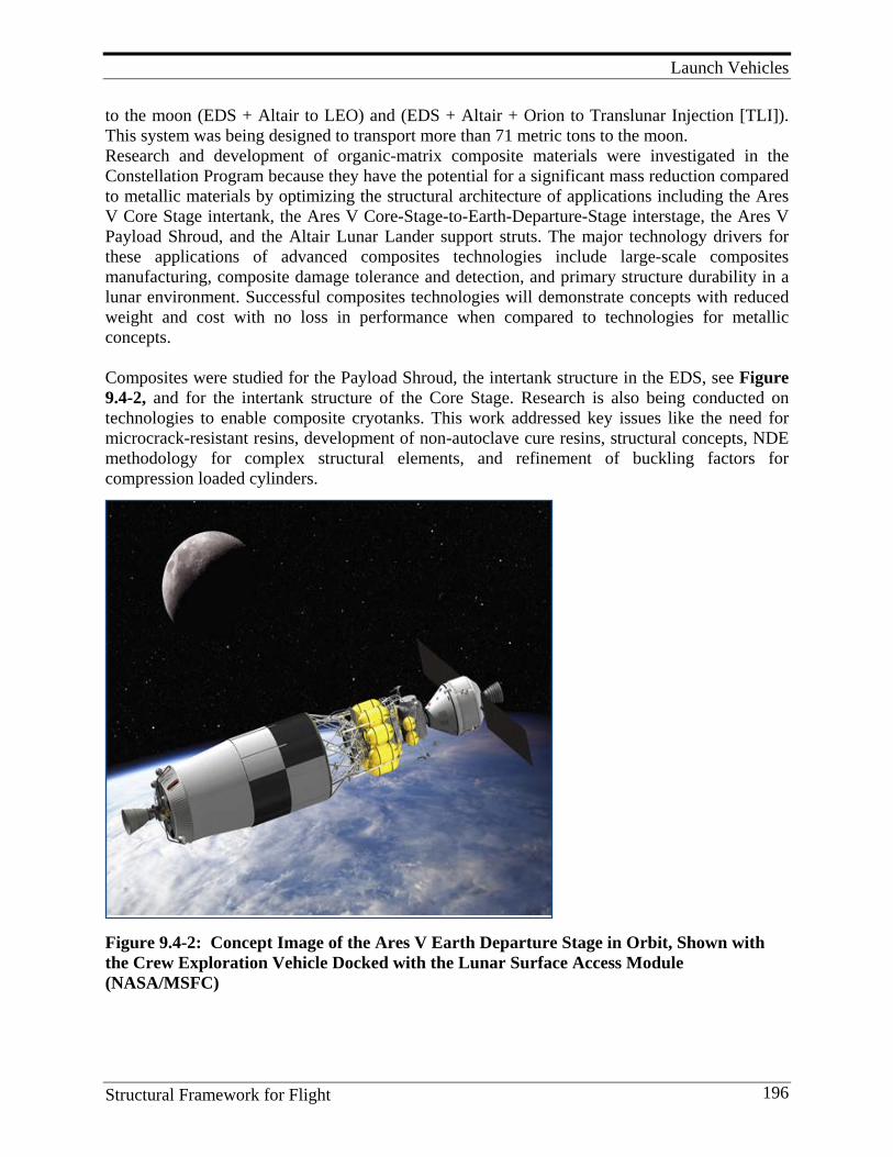
Launch Vehicles
Structural Framework for Flight 196
to the moon (EDS + Altair to LEO) and (EDS + Altair + Orion to Translunar Injection [TLI]). This system was being designed to transport more than 71 metric tons to the moon. Research and development of organic-matrix composite materials were investigated in the Constellation Program because they have the potential for a significant mass reduction compared to metallic materials by optimizing the structural architecture of applications including the Ares V Core Stage intertank, the Ares V Core-Stage-to-Earth-Departure-Stage interstage, the Ares V Payload Shroud, and the Altair Lunar Lander support struts. The major technology drivers for these applications of advanced composites technologies include large-scale composites manufacturing, composite damage tolerance and detection, and primary structure durability in a lunar environment. Successful composites technologies will demonstrate concepts with reduced weight and cost with no loss in performance when compared to technologies for metallic concepts. Composites were studied for the Payload Shroud, the intertank structure in the EDS, see Figure 9.4-2, and for the intertank structure of the Core Stage. Research is also being conducted on technologies to enable composite cryotanks. This work addressed key issues like the need for microcrack-resistant resins, development of non-autoclave cure resins, structural concepts, NDE methodology for complex structural elements, and refinement of buckling factors for compression loaded cylinders.
Figure 9.4-2: Concept Image of the Ares V Earth Departure Stage in Orbit, Shown with the Crew Exploration Vehicle Docked with the Lunar Surface Access Module (NASA/MSFC)
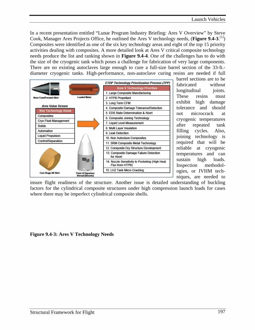
Launch Vehicles
Structural Framework for Flight 197
In a recent presentation entitled “Lunar Program Industry Briefing: Ares V Overview” by Steve Cook, Manager Ares Projects Office, he outlined the Ares V technology needs, (Figure 9.4-3.[1]) Composites were identified as one of the six key technology areas and eight of the top 15 priority activities dealing with composites. A more detailed look at Ares V critical composite technology needs produce the list and ranking shown in Figure 9.4-4. One of the challenges has to do with the size of the cryogenic tank which poses a challenge for fabrication of very large components. There are no existing autoclaves large enough to cure a full-size barrel section of the 33-ft.- diameter cryogenic tanks. High-performance, non-autoclave curing resins are needed if full
barrel sections are to be fabricated without longitudinal joints. These resins must exhibit high damage tolerance and should not microcrack at cryogenic temperatures after repeated tank filling cycles. Also, joining technology is required that will be reliable at cryogenic temperatures and can sustain high loads. Inspection methodol-ogies, or IVHM tech-niques, are needed to
insure flight readiness of the structure. Another issue is detailed understanding of buckling factors for the cylindrical composite structures under high compression launch loads for cases where there may be imperfect cylindrical composite shells. Figure 9.4-3: Ares V Technology Needs
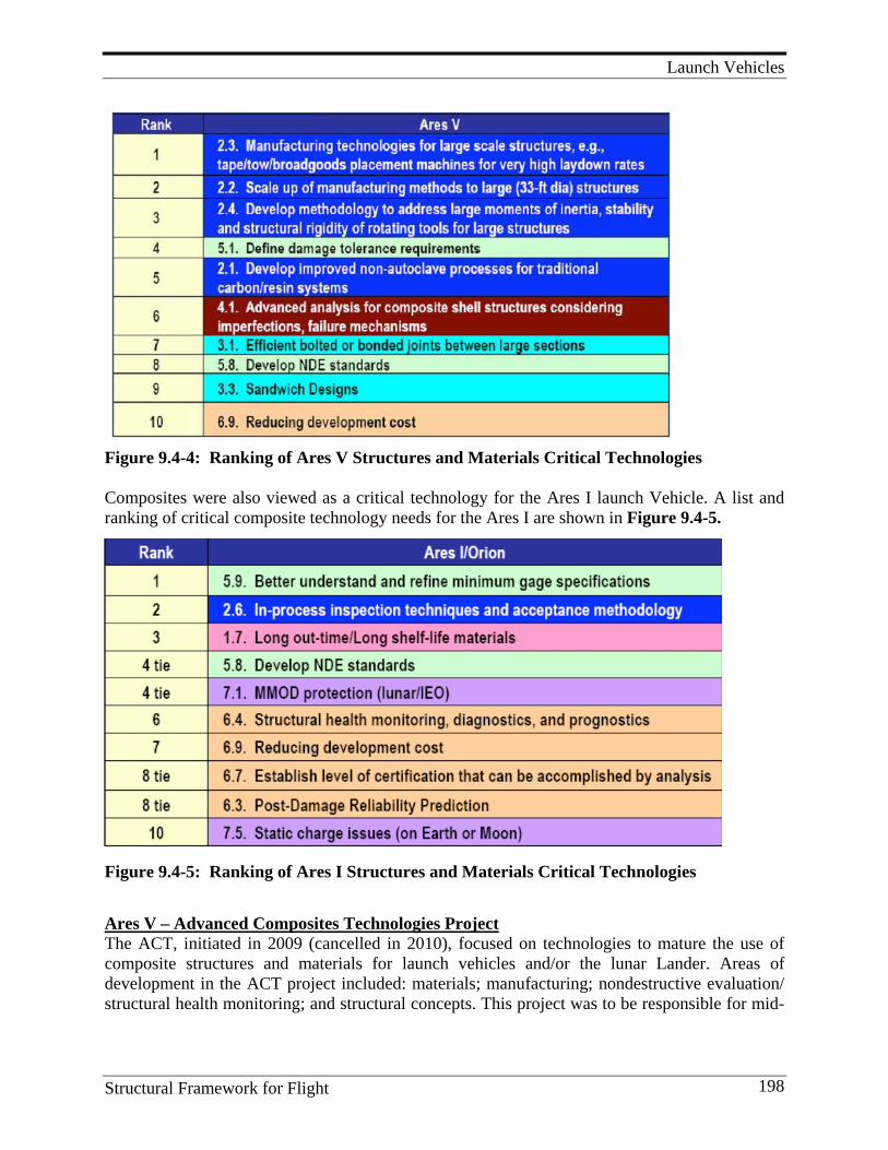
Launch Vehicles
Structural Framework for Flight 198
Figure 9.4-4: Ranking of Ares V Structures and Materials Critical Technologies Composites were also viewed as a critical technology for the Ares I launch Vehicle. A list and ranking of critical composite technology needs for the Ares I are shown in Figure 9.4-5.
Figure 9.4-5: Ranking of Ares I Structures and Materials Critical Technologies Ares V – Advanced Composites Technologies Project The ACT, initiated in 2009 (cancelled in 2010), focused on technologies to mature the use of composite structures and materials for launch vehicles and/or the lunar Lander. Areas of development in the ACT project included: materials; manufacturing; nondestructive evaluation/ structural health monitoring; and structural concepts. This project was to be responsible for mid-
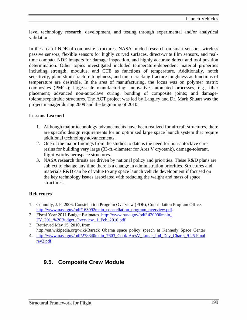
Launch Vehicles
Structural Framework for Flight 199
level technology research, development, and testing through experimental and/or analytical validation. In the area of NDE of composite structures, NASA funded research on smart sensors, wireless passive sensors, flexible sensors for highly curved surfaces, direct-write film sensors, and real-time compact NDE imagers for damage inspection, and highly accurate defect and tool position determination. Other topics investigated included temperature-dependent material properties including strength, modulus, and CTE as functions of temperature. Additionally, notch sensitivity, plain strain fracture toughness, and microcracking fracture toughness as functions of temperature are desirable. In the area of manufacturing, the focus was on polymer matrix composites (PMCs); large-scale manufacturing; innovative automated processes, e.g., fiber placement; advanced non-autoclave curing; bonding of composite joints; and damage-tolerant/repairable structures. The ACT project was led by Langley and Dr. Mark Shuart was the project manager during 2009 and the beginning of 2010. Lessons Learned
1. Although major technology advancements have been realized for aircraft structures, there are specific design requirements for an optimized large space launch system that require additional technology advancements.
2. One of the major findings from the studies to date is the need for non-autoclave cure resins for building very large (33-ft.-diameter for Ares V cryotank), damage-tolerant, flight-worthy aerospace structures.
3. NASA research thrusts are driven by national policy and priorities. These R&D plans are subject to change any time there is a change in administration priorities. Structures and materials R&D can be of value to any space launch vehicle development if focused on the key technology issues associated with reducing the weight and mass of space structures.
References 1. Connolly, J. F. 2006. Constellation Program Overview (PDF), Constellation Program Office.
http://www.nasa.gov/pdf/163092main_constellation_program_overview.pdf. 2. Fiscal Year 2011 Budget Estimates. http://www.nasa.gov/pdf/ 420990main_
FY_201_%20Budget_Overview_1_Feb_2010.pdf. 3. Retrieved May 15, 2010, from
http://en.wikipedia.org/wiki/Barack_Obama_space_policy_speech_at_Kennedy_Space_Center 4. http://www.nasa.gov/pdf/278840main_7603_Cook-AresV_Lunar_Ind_Day_Charts_9-25 Final
rev2.pdf.
9.5. Composite Crew Module
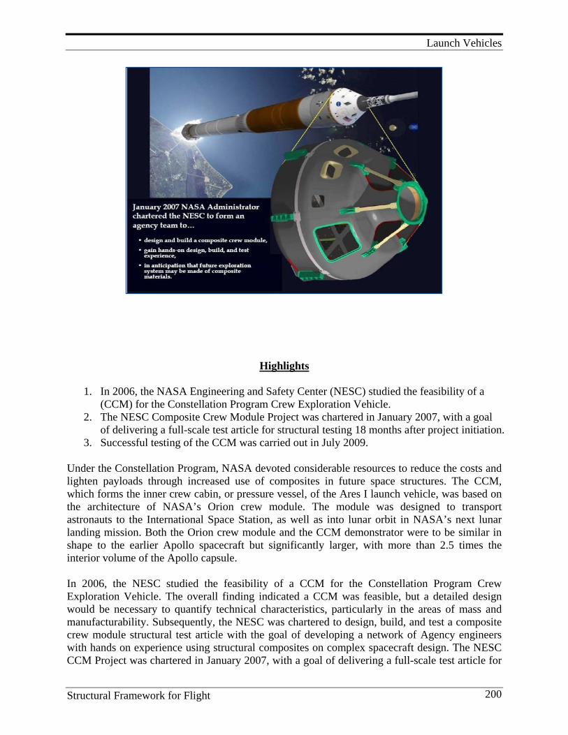
Launch Vehicles
Structural Framework for Flight 200
Highlights
1. In 2006, the NASA Engineering and Safety Center (NESC) studied the feasibility of a (CCM) for the Constellation Program Crew Exploration Vehicle.
2. The NESC Composite Crew Module Project was chartered in January 2007, with a goal of delivering a full-scale test article for structural testing 18 months after project initiation.
3. Successful testing of the CCM was carried out in July 2009. Under the Constellation Program, NASA devoted considerable resources to reduce the costs and lighten payloads through increased use of composites in future space structures. The CCM, which forms the inner crew cabin, or pressure vessel, of the Ares I launch vehicle, was based on the architecture of NASA’s Orion crew module. The module was designed to transport astronauts to the International Space Station, as well as into lunar orbit in NASA’s next lunar landing mission. Both the Orion crew module and the CCM demonstrator were to be similar in shape to the earlier Apollo spacecraft but significantly larger, with more than 2.5 times the interior volume of the Apollo capsule. In 2006, the NESC studied the feasibility of a CCM for the Constellation Program Crew Exploration Vehicle. The overall finding indicated a CCM was feasible, but a detailed design would be necessary to quantify technical characteristics, particularly in the areas of mass and manufacturability. Subsequently, the NESC was chartered to design, build, and test a composite crew module structural test article with the goal of developing a network of Agency engineers with hands on experience using structural composites on complex spacecraft design. The NESC CCM Project was chartered in January 2007, with a goal of delivering a full-scale test article for
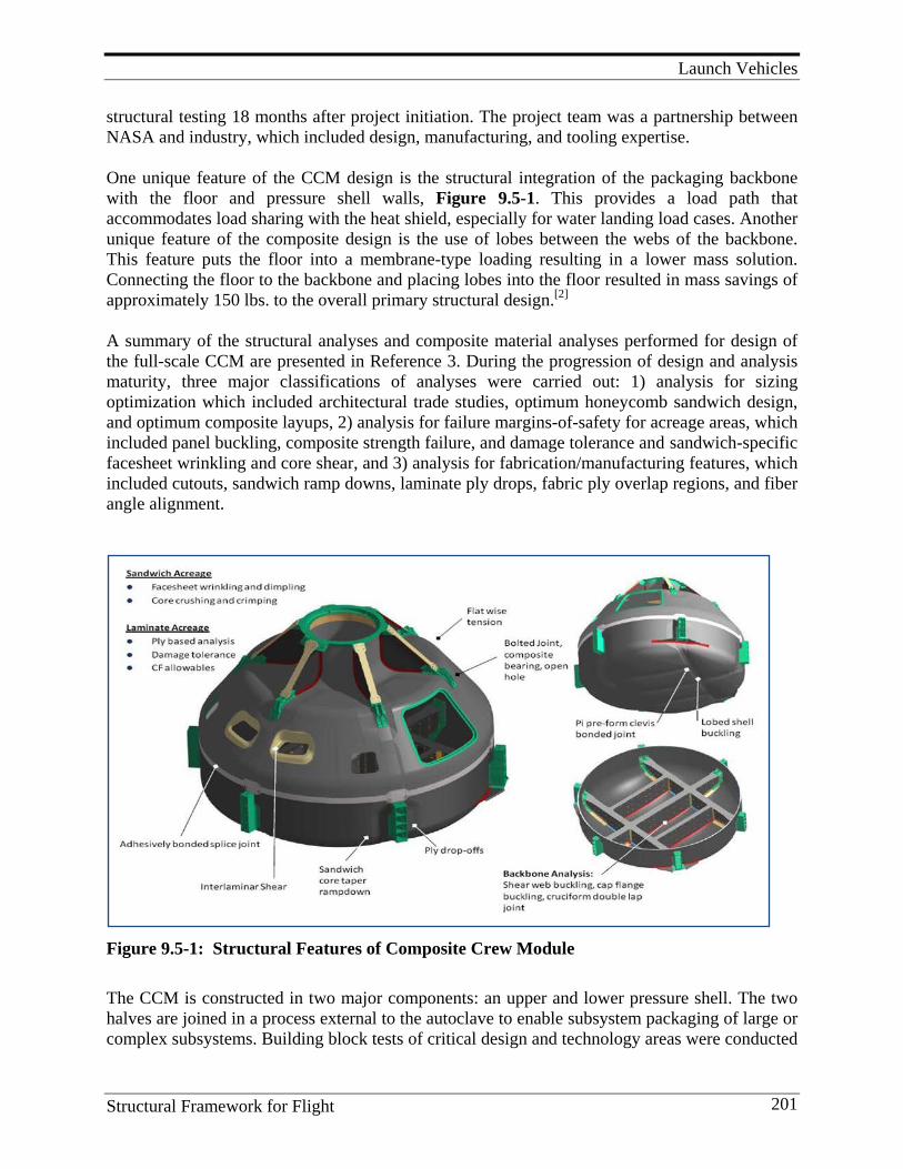
Launch Vehicles
Structural Framework for Flight 201
structural testing 18 months after project initiation. The project team was a partnership between NASA and industry, which included design, manufacturing, and tooling expertise. One unique feature of the CCM design is the structural integration of the packaging backbone with the floor and pressure shell walls, Figure 9.5-1. This provides a load path that accommodates load sharing with the heat shield, especially for water landing load cases. Another unique feature of the composite design is the use of lobes between the webs of the backbone. This feature puts the floor into a membrane-type loading resulting in a lower mass solution. Connecting the floor to the backbone and placing lobes into the floor resulted in mass savings of approximately 150 lbs. to the overall primary structural design.[2] A summary of the structural analyses and composite material analyses performed for design of the full-scale CCM are presented in Reference 3. During the progression of design and analysis maturity, three major classifications of analyses were carried out: 1) analysis for sizing optimization which included architectural trade studies, optimum honeycomb sandwich design, and optimum composite layups, 2) analysis for failure margins-of-safety for acreage areas, which included panel buckling, composite strength failure, and damage tolerance and sandwich-specific facesheet wrinkling and core shear, and 3) analysis for fabrication/manufacturing features, which included cutouts, sandwich ramp downs, laminate ply drops, fabric ply overlap regions, and fiber angle alignment.
Figure 9.5-1: Structural Features of Composite Crew Module The CCM is constructed in two major components: an upper and lower pressure shell. The two halves are joined in a process external to the autoclave to enable subsystem packaging of large or complex subsystems. Building block tests of critical design and technology areas were conducted
Launch Vehicles
Structural Framework for Flight 202
to validate critical assumptions and design allowables. Full-scale fabrication of the upper and lower pressure shells began in 2008. Successful testing of CCM was carried out in July 2009. Mike Kirsch has presented a review on the CCM project.[3]
Key Personnel Dr. Ivatury S. Raju, Sotirios Kellas, Paul W. Roberts, Michael T, Kirsch
Lessons Learned: 1. Non-autoclave splice allows concurrent fabrication, assembly, and integration of major
structural components and subsystems, and provides lower-cost cure tooling options. 2. Membrane-lobed floor integrated with backbone subsystem packaging feature offer weight
savings (~ 150lbs) through complex shapes enabled by composites. 3. State-of-the-art Pi-preforms offer robust orthogonal composite joints. 4. Inner mold line tooling offers opportunity to optimize or change design through tailoring of
layups or core density, as loads and environments change with program maturation. 5. Composite solutions offer lower part count resulting in a lower drawing count (~47) which
helps reduce overall life cycle costs. 6. Numerous (>15) analytical models using various modeling techniques, with overlaps, to
verify results. 7. Element testing confirmed failure mode and failure load predictions. 8. Thermal and dynamic differences from aluminum being investigated; preliminary estimates
do not indicate that composites create any system-level issues. 9. Mature, commercially available inspection equipment; IR thermography, ultrasound, and X-
ray were judged to be satisfactory. References 1. Collier, C., et al. 2008. Analysis Methods Used on the NASA Composite Crew Module. AIAA.
http://hypersizer.com/pdf/AIAApaperCollierCCM107727.pdf . 2. NASA Engineering & Safety Center. 2008. Technical Update http://www.nasa.gov/pdf/
346545mainNESC08TechUpweb.pdf . 3. Kirsch, M. 2009. Broad Based Teams, Case Study # 1 – Composite Crew Module. Presented in
Project Management Challenge 2009, Daytona Beach, FL. http://pmchallenge.gsfc.nasa.gov/docs/2009/presentations/Kirsch.Mike.pdf
4. Team Gains Experience as it Builds Innovative Composite Spacecraft. http://www.nasa.gov/ offices/nesc/home/Feature_6_090908.html.
5. Bednarcyk, B. A., S. M. Arnold, C. S. Collier, and P. W. Yarrington. 2007. Preliminary Structural Sizing and Alternative Material Trade Study of CEV Crew Module. (NASA TM—2007-214947) (AIAA–2007–2175).
9.6. Lessons Learned and Future Direction
1. Advanced composite technology for launch vehicles poses some unique challenges different from those of aircraft. Aircraft composites cannot be used directly for launch vehicles.
Launch Vehicles
Structural Framework for Flight 203
2. Composites structures can save weight in launch vehicles but key technical issues, such as microcracking at cryogenic temperatures, must be addressed for cryogenic tank applications.
3. Non-autoclave curing resins are required for fabrication of very large tanks (33-ft.- diameter) of the size envisioned for the Ares V Launch Vehicle.
4. For reusable launch vehicles, high-temperature composites are attractive for hot structure applications because the weight of the thermal protection system can be reduced.
5. The failure of the X-33 composite tank serves as a reminder that technology maturation efforts using a “building block approach” must be funded before committing to critical hardware programs. Pursuing a philosophy of “no flight hardware before it’s time” can prevent premature failures that can set back the application of a new technology for many years.
6. Progressive failure methodology is required to fully understand how damage initiates and propagates under space launch vehicle service conditions. Development of modeling codes must be based on careful experimentation that simulates service conditions.
Space Materials and Structures
Structural Framework for Flight 204
10. S PA C E M AT E R I A L S A N D S T R U C T U R E S
Composite materials are attractive materials for spacecraft application because of a high specific stiffness, low thermal expansion, high specific strength, and the ability to tailor properties to meet specific design requirements. Because most space structures are stiffness critical, very high modulus fibers have been preferred in resin systems that have very low out-gassing rates. For high precision applications like reflectors or antenna, dimensional stability is an important design consideration. Langley researchers have studied the dimensional stability of composites fabricated with different fibers and resins in fiber stacking sequences designed to give near-zero coefficient of expansion. This is possible because the coefficient of expansion (COE) for the graphite fibers is negative and the COE of the resin is positive. Composite truss structures are used to minimize weight in a very stiff structure than can be deployed in many applications. Langley researchers have published extensively on the use of composites in deployable and erectable space truss structures and reflectors. Work has also been conducted at Langley on manufacturing technology to produce tapered struts that maximize the packing density for launch, and to investigate the logistics of on-orbit construction of truss structures. This concept was studied for the primary truss structure of the International Space Station.
10.1. Space Materials Development Langley Research Center has a long history of solid contributions to the development of polymers and composites for space applications. This work has ranged from development of thin film technology for early applications, such as the Echo satellite in the 1960s, to the addition of single-walled carbon nanotubes (SWNTs), to endcapped amide acid polymers in solution to enable tailored thin films in 2003. This low color, flexible, space-environmentally-durable polymeric material possesses sufficient surface resistivity (106–1010 Ω/square) for electrostatic charge (ESC) mitigation. These films are of interest for potential applications on Gossamer spacecraft, as thin film membranes on antennas, large light-weight space optics, and second- surface mirrors. In addition to the development of many new polymer films, adhesives, and polymers for space-durable composites there has been a long history of excellent contributions to the fundamental understanding of space environmental effects on these and other new materials developed for space applications. Since NASA was created in 1958, over 6,400 patents have been issued to the agency—nearly one in a thousand of all patents ever issued in the United States. A large number of these inventions have focused on new materials that have made space travel and exploration of the moon, Mars, and the outer planets possible. In the last few years, the materials developed by NASA Langley Research Center embody breakthroughs in performance and properties that will enable great achievements in space. These new materials offer significant advantages for use in small satellites, i.e., those with payloads under a metric ton. These include patented products

Space Materials and Structures
Structural Framework for Flight 205
such as LaRC SI, LaRC RP 46, LaRC RP 50, PETI-5, TEEK, PETI-330, LaRC CP, TOR-LM and LaRC LCR (patent pending). They also include new advances in nanotechnology engineering, self-assembling nanostructures and multifunctional aerospace materials. Key Personnel Manager and/or researchers included: Dr. Vernon Bell, Dr. John Connell, Wayne Slemp, Dr. Paul Hergenrother, Dr. Terry St. Clair, Anne K. St. Clair, George Sykes, Robert G. Bryant, and Dr. Ruth H. Pater. References
1. Smith, J. G., J. W. Connell, D. M. Delozier, P. T. Lillehei, K. A. Watson, Y. Lin, B. Zhou, P. Sun. 2004. Space Durable Polymer/Carbon Nanotube Films for Electrostatic Charge Mitigation. Polymer 45 (February):825-36.
10.2. Space Structures During the 1970s through the early 1990s, NASA Langley conducted studies for the design and construction of large space structures in low Earth orbit. The Langley studies focused on the design and construction of erectable space structures. The construction studies evaluated assembly methods using astronauts with and without mechanized foot-restraints. Astronaut construction was shown to be very effective and efficient when the structure and the construction methods were developed in parallel. These studies included evaluation of potential applications of erectable structure assembly methods using extravehicular activity (EVA) astronauts. Integrated approaches for construction of large space structures were developed including assessment of the truss structure for the International Space Station. Dr. Martin M. Mikulas, Jr. is nationally and internationally recognized for his contributions in the development and testing of inflation deployed, rigidizable space structures and materials. Large space-based deployable structures are needed for a variety of applications. Such applications include radar antennas, solar arrays, sunshields, telescope reflectors, etc. Current concepts for large, conventionally mechanical, self-deployable space structures tend to be very expensive and mechanically complicated. Due to user requirements being very stringent (with respect to the very low-cost, high-deployment reliability, low weight, and packaged volume), new and innovative approaches to accommodate large space structures are demanded. Fortunately, a newly developed technology, called inflatable structure, can potentially revolutionize the designs and applications of large space structures. It is very likely that many of the NASA missions planned for the future will rely on space-inflatable structures to achieve their launch volume and mass goals. This is especially true for missions that require relatively large in-orbit configurations to perform properly their assigned functions. NASA, along with its industry and academia partners, have made significant progress in actually implementing inflatable structures for space applications. In May 1996, a large inflatable antenna structure was successfully inflated in space. Since this Large Antenna Experiment was the first time a large
Space Materials and Structures
Structural Framework for Flight 206
inflatable space structure was employed on-orbit, a number of new technologies were demonstrated and evaluated. Due to the successful demonstrations of these new technologies and the large inflatable antenna, the large inflatable space structures are getting more and more attention. As a result, NASA has studied several space missions using inflatable space structures. One of these missions is the inflatable sunshield of the Next Generation Space Telescope (scheduled for launch in 2014). Inflatable Synthetic Aperture Radar experiments have been conducted since the mid 1990s. Key Personnel Manager and/or researchers included: Dr. Martin M. Mikulas, Jr., Dr. Harold G. Bush, John T. Dorsey, Timothy J. Collins, Judith Watson, William R. Doggett, Mark S. Lake, P. A. Cooper, M. D. Rhodes, M. F. Card, John M. Hedgepeth, M. Stein. References:
1. Mikulas, M. M., T. J. Collins, W. Doggett, J. Dorsey, and J. Watson. 2006. Truss Performance and Packaging Metrics. Space Technology and Applications International Forum, Albuquerque, NM. (Document ID: 20060008916).
2. Freeland, R. E., R. G. Helms, P. B. Willis, M. M. Mikulas, W. Stuckey, G. Steckel, and J. Watson. 2004. Inflatable Space Structures Technology Development for Large Radar Antennas. Paper presented at the 55th International Astronautical Congress. Vancouver, Canada. (Document ID: 20040191339).
3. Mikulas, M. M., Jr., T. J. Collins, and J. M. Hedgepeth. Preliminary Design Approach for Large High Precision Segmented Reflectors. (NASA TM-102605).
4. Mikulas, M. M., Jr., A. S. Wright, Jr., H. G. Bush, J. J. Watson, E. B. Dean, L. T. Twigg, M. D. Rhodes, P. A. Cooper, J. T. Dorsey, and M. S. Lake. Deployable-erectable Trade Study for Space Station Truss Structures. (NASA TM-87573).
5. Bush, H. G., M. M. Mikulas, Jr. 1976. A Nestable Tapered Column Concept for Large Space Structures. (NASA TM-X-73927).
6. Dorsey, J. T., M. M. Mikulas, W. R. Doggett. 2008. Preliminary Structural Design Considerations and Mass Efficiencies for Lunar Surface Manipulator Concepts. (AIAA-2008-7916) (LAR-17528-1).
10.3. Space Environmental Effects Langley researchers have studied extensively the effects of the space environment on polymer films and composites. These studies have included research on the effects of: ultraviolet (UV) and extreme ultraviolet (VUV) radiation; electron and proton radiation; atomic oxygen erosion of polymers and polymer matrix composites; micrometeoroid and debris erosion on polymers and composites; hypervelocity impact; thermal cycling representative of near-earth and deep space orbits; out-gassing due to space vacuum; spacecraft charging; contamination of surfaces and changes in solar absorptance and thermal emissivity; and synergistic effects from combinations of the above parameters. Joan Funk has compiled a bibliography of much of this work performed between 1983 and 1993 (Reference 1).
Space Materials and Structures
Structural Framework for Flight 207
Lessons Learned
1. Protective coatings are required to protect polymer matrix composites from UV and VUV radiation.
2. Metals, such as aluminum and gold, are good barriers for preventing atomic oxygen erosion of polymer matrix composites. Tests of resin matrix composites covered with aluminum foil such that the metal foil was exposed to the ram or flow direction of the atomic oxygen showed no degradation when exposed to a flowing atomic oxygen environment.
3. High-energy electron and proton radiation can cause polymer chain scission and cross-linking in polymers. However, polymers that have a fully aromatic molecular structure are stable to extremely high doses, up to 1010 rads (see note below), which is approximately the maximum dose expected for 30 years of exposure in the Van Allen Radiation Belt found at geosynchronous Earth orbit. However, if the polymer has an aliphatic molecular structure, it is susceptible to radiation damage and is not recommended for long-term exposure in radiation environments.
(Note: The rad [radiation absorbed dose] is a largely-obsolete unit of absorbed radiation dose, with symbol rad. The rad was defined in CGS units in 1953 as the dose causing 100 ergs of energy to be absorbed by one gram of matter. It was restated in SI units in 1970 as the dose causing 0.01 joule of energy to be absorbed per kilogram of matter.) A sampling of the typical research studies on space environmental effects performed at Langley is illustrated by the work performed by George Sykes, Carl T. Herakovich, and Scott M. Milkovich under the NASA-Virginia Tech Composites Program and published in the Journal of Composite Materials, Vol. 20, No. 6, 579-593 (1986). The abstract of this paper states “This investigation of composite material properties utilized T300/934 graphite-epoxy that was subjected to 1.0 MeV electron radiation for a total dose of 1.0 x 10¹⁰ rads at a rate of 5.0 x 10⁷ rads/hour, simulating a worst-case exposure equivalent to 30 years in space. Mechanical testing was performed on 4-ply unidirectional laminates over the temperature range of -250°F to +250°F. In-plane elastic tensile and shear properties, as well as strength, were obtained (E1, E2, v 12, G12, XT, YT, S). The results show that electron radiation degrades the epoxy matrix and produces products that volatilize at the temperatures considered. These degradation products plasticize the epoxy at elevated temperatures and embrittle it at low temperatures, thereby altering the mechanical properties of the composite.” However, as noted above, a total dose of 1010 rads was representative of 30 years exposure in geosynchronous Earth orbit.
4. Extensive studies of micrometeoroid and debris were carried out on LDEF samples and selected results from those studies are presented below in the LDEF section.
5. Most of the work conducted at Langley by Wayne Slemp, George Sykes, and others, on out-gassing was centered on the effects of out-gassing contaminants on the optical properties (solar absorptance and thermal emissivity) of thermal-control coatings and other spacecraft surfaces that could be degraded by these contaminants. Extensive measurements were made to determine the optical property changers that occur from contamination and subsequent exposure to UV and electron and/or proton radiation. Langley had cutting-edge facilities to perform the studies that were, in some cases,

Space Materials and Structures
Structural Framework for Flight 208
unique in the world. For example, Langley had the capability to expose samples to combined vacuum, UV, and VUV radiations, and to make insitu optical property measurements as a function of exposure times and conditions. Langley also had the capability to expose samples to electrons, protons, and UV under vacuum simultaneously.
Key Personnel Manager and/or researchers included: Bill Kinard, Dr. Darrel R. Tenney, Joan G. Funk, Bland A. Stein, David E. Bowles, Sheila Ann T. Long, Ed R. Long, M.W. Hyer, S. M. Milkovich, C.T. Herakovich, Bill Kinard, Wayne Slemp, Bland A. Stein, Phil R. Young, Arlene S. Levine, W. G. Witte, John W. Connell, Anne K. St. Clair, Terry St. Clair, Ruth H. Pater, Diane M. Stoakley, B. Santos-Mason. References
1. Funk, J. G. Space Durability of Materials Bibliography, 1983-1993. NASA Langley Research
Center, Hampton, Va., Accession Number 4348, Record ID: 26340. 2. Bowles, D. E., D. Post, C. T. Herakovich, and D. R. Tenney. 1981. Moiré Interferometry for
Thermal Expansion of Composites. Experimental Mechanics. 3. Milkovich, S. M., G. F. Sykes, and C. T. Herakovich. 1986. Space Radiation Effects on the
Thermo-mechanical Behavior of Graphite-epoxy Composites. Journal of Composite Materials 20 (6): 579-593.
4. Tenney, D. R., and W. S. Slemp. 1989. Radiation Durability of Polymeric Matrix Composites. In The Effects of Radiation on High-technology Polymers, 224–251, ACS Symposium Series, Vol. 381.
5. Russell, D. A., L. B. Fogdall, and G. Bohnhoff-Hlavacek. 2000. Simulated Space Environmental Testing on Thin Films. (NASA/CR-2000-210101).
6. Russell, D. A., J. W. Connell, L. B. Fogdall, and W.W. Winkler. 2001. Effects of Electrons, Protons, and Ultraviolet Radiation on Thermophysical Properties of Polymeric Films. (AIAA Paper 2001-1414).
7. Tenney, D. R., and W. S. Slemp. 1989. Radiation Durability of Polymeric Matrix Composites. The Effects of Radiation on High-technology Polymers (A89-24891 09-23), ed. American Chemical Society, 224-251. Washington, DC.
8. Tenney, D. R., and D. E. Bowles. 1989. Space Radiation Effects on Dimensional Stability of Composites. Paper presented at the 4th European Symposium on Spacecraft Materials in Space Environment 1998, Toulouse, France Proceedings (A89-51101 22-18), Cepadues Editions,133-144.
9. Tenney, D. R., G. F. Sykes, and D. E. Bowles. 1982. Space Environmental Effects on Materials. Paper presented at NATO, AGARD, Specialists Meeting on Environmental Effects on Materials for Space Applications. Toronto, Canada.
10. Tenney, D. R., G. F. Sykes, and D. E. Bowles. Composite Materials for Space Structures. In ESA Proceedings of 3rd European Symposium on Spacecraft Materials in Space Environments, 9-21 (SEE N86-22593 13-18).
10.4. Dimensional Stability of Composites Thermal cycling studies carried out by David Bowles, Steve Tompkins, Darrel Tenney and others at NASA Langley focused on the effect of cycling on microcracking in the polymer matrix which resulted in a change in the dimensions of the composite. Dimensional stability of
Space Materials and Structures
Structural Framework for Flight 209
precision composite space structures used in science instruments or precision reflectors can result in degradation of instrument or reflector performance. Langley researchers developed precision laser interferometers for precision measurements of dimensional changes and studied many different composite laminates and resin systems. Techniques were developed for high-sensitivity moiré interferometry by reflection, using a real reference grating of 1200 lines/mm (30,000 /in.). Coefficients of thermal expansion of selected graphite-epoxy laminates were determined in the temperature range of 75°-300°F. Very good precision was achieved for a wide range of thermal-expansion coefficients, from approximately zero to 27 µ /K. Moiré interferometry was selected for measurement of the coefficients of thermal expansion of graphite-epoxy laminates. Folowing are some advantages of this method: it has sufficiently high sensitivity; it does not require a frequency-stabilized laser or a vacuum oven, as in other interferometry techniques; it is not influenced by end and edge effects developed in cross-ply laminates; it provides a large-field measurement capability; and it is relatively simple and inexpensive. Modeling was also formulated to understand and predict dimensional changes as a function of crack density and CTE properties of resin systems. The results of this research were presented at national and international conferences and extensive interactions were carried out with the spacecraft industry in an effort to disseminate widely, the important findings from this research. The list of publications in this area is extensive. Key Personnel David E. Bowles, Steve Tompkins, Darrel Tenney, Carl Herakovich, Dan Post, Mike Hyer, Joan Funk, Dan Adams. References
1. Bowles, D. E., D. Post, C. T. Herakovich, and D. R. Tenney. 1981. Moiré Interferometry for Thermal Expansion of Composites. Experimental Mechanics.
2. Moiré interferometry for thermal expansion of composites: DE Bowles, D Post, CT Herakovich, DR Tenney - Experimental Mechanics, 1981 – Springer, This research was supported by the NASA-Virginia Tech Composites Program (NASA Grant NGR 47-004-129), and NASA Cooperative Agreement NCCI-16 and by the National Science Foundation (NSF Grant ENG-7824609). The sponsorship is greatly appreciated.
3. Short, J. S., M. W. Hyer, D. Post, D. E. Bowles, and S. S. Tompkins. 1982. Development of a Priest Interferometer for Measurement of the Thermal Expansion of Graphite-epoxy in the Temperature Range 116-366K. Virginia Polytechnic Institute and State University, Blacksburg, VA. (Report VPI-E-82-18).
4. Tompkins, S. S., D. E. Bowles, and W. R. Kennedy 1984. A Laser Interferometer Dilatometer for Thermal Expansion Measurements of Composites. In Proceedings of the V International Congress on Experimental Mechanics, ed. Society for Experimental Stress Analysis, 367-376. Montreal, Canada.
5. Sykes, G. F., J. G. Funk, and W. S. Slemp. 1986. Assessment of Space Environment Induced Microdamage in Toughened Composite Materials Paper presented at the 18th International SAMPE Technical Conference of the Society for the Advancement of Materials and Process Engineering, 520-534. Seattle, WA.
6. Adams, D. S., D. E. Bowles, and C. T. Herakovich. 1986. Thermally Induced Transverse Cracking in Graphite-epoxy Cross-ply Laminates. In Journal of Reinforced Plastics and Composites, 5 (July): 152-169.
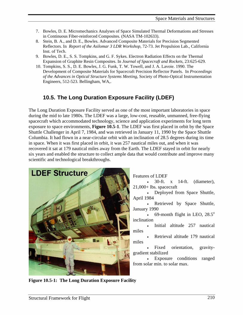
Space Materials and Structures
Structural Framework for Flight 210
7. Bowles, D. E. Micromechanics Analyses of Space Simulated Thermal Deformations and Stresses in Continuous Fiber-reinforced Composites. (NASA TM-102633).
8. Stein, B. A., and D. E., Bowles. Advanced Composite Materials for Precision Segmented Reflectors. In Report of the Asilomar 3 LDR Workshop, 72-73. Jet Propulsion Lab., California Inst. of Tech.
9. Bowles, D. E., S. S. Tompkins, and G. F. Sykes. Electron Radiation Effects on the Thermal Expansion of Graphite Resin Composites. In Journal of Spacecraft and Rockets, 23:625-629.
10. Tompkins, S. S., D. E. Bowles, J. G. Funk, T. W. Towell, and J. A. Lavoie. 1990. The Development of Composite Materials for Spacecraft Precision Reflector Panels. In Proceedings of the Advances in Optical Structure Systems Meeting, Society of Photo-Optical Instrumentation Engineers, 512-523. Bellingham, WA,.
10.5. The Long Duration Exposure Facility (LDEF) The Long Duration Exposure Facility served as one of the most important laboratories in space during the mid to late 1980s. The LDEF was a large, low-cost, reusable, unmanned, free-flying spacecraft which accommodated technology, science and application experiments for long term exposure to space environments, Figure 10.5-1. The LDEF was first placed in orbit by the Space Shuttle Challenger in April 7, 1984, and was retrieved in January 11, 1990 by the Space Shuttle Columbia. It had flown in a near-circular orbit with an inclination of 28.5 degrees during its time in space. When it was first placed in orbit, it was 257 nautical miles out, and when it was recovered it sat at 179 nautical miles away from the Earth. The LDEF stayed in orbit for nearly six years and enabled the structure to collect ample data that would contribute and improve many scientific and technological breakthroughs.
Features of LDEF
• 30-ft. x 14-ft. (diameter), 21,000+ lbs. spacecraft
• Deployed from Space Shuttle, April 1984
• Retrieved by Space Shuttle, January 1990
• 69-month flight in LEO, 28.5o inclination
• Initial altitude 257 nautical miles
• Retrieval altitude 179 nautical miles
• Fixed orientation, gravity-gradient stabilized
• Exposure conditions ranged from solar min. to solar max.
Figure 10.5-1: The Long Duration Exposure Facility
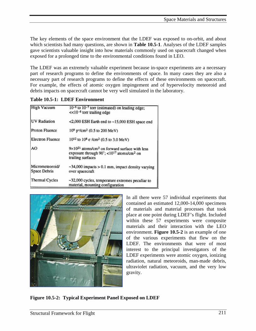
Space Materials and Structures
Structural Framework for Flight 211
The key elements of the space environment that the LDEF was exposed to on-orbit, and about which scientists had many questions, are shown in Table 10.5-1. Analyses of the LDEF samples gave scientists valuable insight into how materials commonly used on spacecraft changed when exposed for a prolonged time to the environmental conditions found in LEO. The LDEF was an extremely valuable experiment because in-space experiments are a necessary part of research programs to define the environments of space. In many cases they are also a necessary part of research programs to define the effects of these environments on spacecraft. For example, the effects of atomic oxygen impingement and of hypervelocity meteoroid and debris impacts on spacecraft cannot be very well simulated in the laboratory.
Table 10.5-1: LDEF Environment
In all there were 57 individual experiments that contained an estimated 12,000-14,000 specimens of materials and material processes that took place at one point during LDEF’s flight. Included within these 57 experiments were composite materials and their interaction with the LEO environment. Figure 10.5-2 is an example of one of the various experiments that flew on the LDEF. The environments that were of most interest to the principal investigators of the LDEF experiments were atomic oxygen, ionizing radiation, natural meteoroids, man-made debris, ultraviolet radiation, vacuum, and the very low gravity.
Figure 10.5-2: Typical Experiment Panel Exposed on LDEF
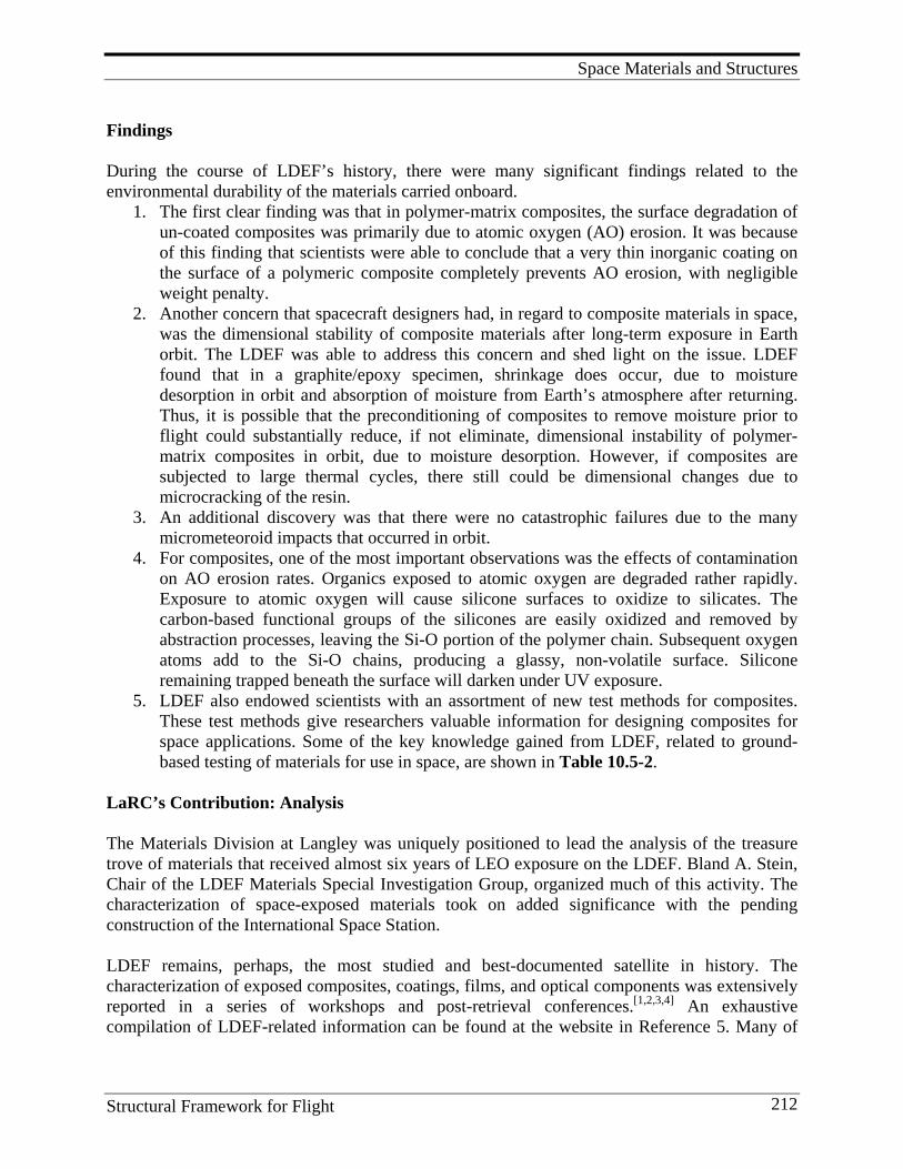
Space Materials and Structures
Structural Framework for Flight 212
Findings During the course of LDEF’s history, there were many significant findings related to the environmental durability of the materials carried onboard.
1. The first clear finding was that in polymer-matrix composites, the surface degradation of un-coated composites was primarily due to atomic oxygen (AO) erosion. It was because of this finding that scientists were able to conclude that a very thin inorganic coating on the surface of a polymeric composite completely prevents AO erosion, with negligible weight penalty.
2. Another concern that spacecraft designers had, in regard to composite materials in space, was the dimensional stability of composite materials after long-term exposure in Earth orbit. The LDEF was able to address this concern and shed light on the issue. LDEF found that in a graphite/epoxy specimen, shrinkage does occur, due to moisture desorption in orbit and absorption of moisture from Earth’s atmosphere after returning. Thus, it is possible that the preconditioning of composites to remove moisture prior to flight could substantially reduce, if not eliminate, dimensional instability of polymer-matrix composites in orbit, due to moisture desorption. However, if composites are subjected to large thermal cycles, there still could be dimensional changes due to microcracking of the resin.
3. An additional discovery was that there were no catastrophic failures due to the many micrometeoroid impacts that occurred in orbit.
4. For composites, one of the most important observations was the effects of contamination on AO erosion rates. Organics exposed to atomic oxygen are degraded rather rapidly. Exposure to atomic oxygen will cause silicone surfaces to oxidize to silicates. The carbon-based functional groups of the silicones are easily oxidized and removed by abstraction processes, leaving the Si-O portion of the polymer chain. Subsequent oxygen atoms add to the Si-O chains, producing a glassy, non-volatile surface. Silicone remaining trapped beneath the surface will darken under UV exposure.
5. LDEF also endowed scientists with an assortment of new test methods for composites. These test methods give researchers valuable information for designing composites for space applications. Some of the key knowledge gained from LDEF, related to ground-based testing of materials for use in space, are shown in Table 10.5-2.
LaRC’s Contribution: Analysis The Materials Division at Langley was uniquely positioned to lead the analysis of the treasure trove of materials that received almost six years of LEO exposure on the LDEF. Bland A. Stein, Chair of the LDEF Materials Special Investigation Group, organized much of this activity. The characterization of space-exposed materials took on added significance with the pending construction of the International Space Station. LDEF remains, perhaps, the most studied and best-documented satellite in history. The characterization of exposed composites, coatings, films, and optical components was extensively reported in a series of workshops and post-retrieval conferences.[1,2,3,4] An exhaustive compilation of LDEF-related information can be found at the website in Reference 5. Many of
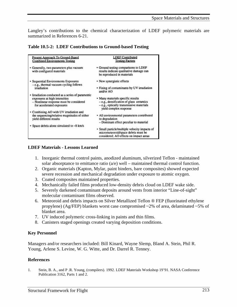
Space Materials and Structures
Structural Framework for Flight 213
Langley’s contributions to the chemical characterization of LDEF polymeric materials are summarized in References 6-21. Table 10.5-2: LDEF Contributions to Ground-based Testing
LDEF Materials - Lessons Learned
1. Inorganic thermal control paints, anodized aluminum, silverized Teflon - maintained solar absorptance to emittance ratio (a/e) well – maintained thermal control function.
2. Organic materials (Kapton, Mylar, paint binders, bare composites) showed expected severe recession and mechanical degradation under exposure to atomic oxygen.
3. Coated composites maintained properties. 4. Mechanically failed films produced low-density debris cloud on LDEF wake side. 5. Severely darkened contaminant deposits around vents from interior “Line-of-sight”
molecular contaminant films observed. 6. Meteoroid and debris impacts on Silver Metallized Teflon ® FEP (fluorinated ethylene
propylene) (Ag/FEP) blankets worst case compromised ~2% of area, delaminated ~5% of blanket area.
7. UV induced polymeric cross-linking in paints and thin films. 8. Canisters staged openings created varying deposition conditions.
Key Personnel Managers and/or researchers included: Bill Kinard, Wayne Slemp, Bland A. Stein, Phil R. Young, Arlene S. Levine, W. G. Witte, and Dr. Darrel R. Tenney. References 1. Stein, B. A., and P .R. Young, (compilers). 1992. LDEF Materials Workshop 19’91. NASA Conference
Publication 3162, Parts 1 and 2.
Space Materials and Structures
Structural Framework for Flight 214
2. First LDEF Post-Retrieval Symposium, Kissimmee, FL, June 2-8, 1991. (NASA CP 3134, Parts 1 and 2). 3. Second LDEF Post-Retrieval Symposium, San Diego, CA, June 1-5, 1992. (NASA CP 3194, Parts 1, 2, and
3). 4. Third LDEF Post-Retrieval Symposium, Williamsburg, VA, November 8-12, 1993. (NASA CP 3275, Parts 1,
2, and 3). 5. Long Duration Exposure Facility (LDEF) Archive System. NASA Langley Research Center, Hampton, VA.
http://setas-www.larc.nasa.gov/LDEF. 6. Young, P. R. and W. S. Slemp. 1990. Chemical Characterization of LDEF Polymeric Materials. Polymer
Preprints, 31(2): 353. 7. Young, P. R., W. S. Slemp, W. G. Witte, and J. Y. Shen. 1991. Characterization of Selected LDEF Polymer
Matrix Resin Composite Materials. In International SAMPE Symposium and Exhibition. Science of Advanced Materials and Process Engineering Series 36(1): 403.
8. Young, P. R., W. S. Slemp, and C. R. Gautreaux. 1992. Characterization of Selected LDEF-exposed Polymer Films. In International SAMPE Symposium and Exhibition. Science of Advanced Materials and Process Engineering Series 37:159.
9. Young, P. R.; W. S. Slemp, E. J. Siochi, and J. R. J. Davis. 1992. Analysis of a Space-exposed Thermoplastic Resin. In International SAMPE Technical Conference Series 24:T174.
10. Slemp, W. S., and P. R. Young. 1993. LDEF Thermal Control Coatings Post-flight Analysis. Second LDEF Post Retrieval Symposium, San Diego, CA. (NASA CP 3194, Part 3, 1093).
11. Young, P. R., W. S. Slemp, and A. C. Chang. 1993. LDEF Polymeric Materials: 10 Months vs. 5.8 Years of Exposure. Second LDEF Post Retrieval Symposium, San Diego, CA. (NASA CP 3194, Part 3, 827).
12. Young, P. R., A. K. St. Clair, and W. S. Slemp. 1993. Response of Selected High-performance Films to LEO Exposure. In International SAMPE Symposium and Exhibition. Science of Advanced Materials and Process Engineering Series 38(1); 664.
13. Young, P. R., and W. S. Slemp. 1993. Space Environmental Effects on Selected LDEF Polymeric Materials. In Radiation Effects on Polymeric Materials (American Chemical Society Book Series 527), ed. E. Reichmannis, C. W. Frank, J. H. O’Donnell, ACS, Washington, D.C.
14. Young, P. R., W. S. Slemp, and B. A. Stein. 1994. Performance of Selected Polymeric Materials on LDEF. LDEF Materials Results for Spacecraft Applications Conference, Huntsville, AL, October 1992, (NASA CP-3557).
15. Young, P. R., E. J. Siochi, and W.S. Slemp. 1994. Molecular Level Response of Selected Polymeric Materials to the LEO Environment. Polymer Preprints, 35(2): 916.
16. Young, P. R., W. S. Slemp, and E. J. Siochi. 1994. Polymer Performance in Low Earth Orbit. In International SAMPE Symposium and Exhibition. Science of Advanced Materials and Process Engineering Series 39:2243.
17. Young, P. R., A. K. St. Clair, and W. S. Slemp. 1995. Characterization of Space Environmental Effects on Selected Polymers. In International SAMPE Symposium and Exhibition. Science of Advanced Materials and Process Engineering Series 40:747.
18. Grammer, H. L., J. P. Wightman, P. R. Young, and W. S. Slemp. 1995. Surface Characterization of LDEF Carbon Fiber/Polymer Matrix Composites. Third LDEF Post-Retrieval Symposium, Williamsburg, VA, November 1993. (NASA CP-3275, Part 2, 601-612).
19. Grammer, H .L., J .P. Wightman, W. S. Slemp, and P. R. Young. 1995. Surface Analysis of Materials from NASA-LDEF Satellite. Third LDEF Post-Retrieval Symposium, Williamsburg, VA, November 1993. (NASA CP-3275).
20. Young, P. R., W. S. Slemp, K. S. Whitely, C. R. Kalil, E. J. Siochi, J. Y. Shen, and A. C. Chang. 1995. LDEF Polymeric Materials: A Summary of Langley Characterization. Third LDEF Post-Retrieval Symposium, Williamsburg, VA, November 1993. (NASA CP 3275, Part 2, 567-599).
21. Young, P. R., E. J., Siochi, and W. S. Slemp. 1996. Molecular Level Response of Selected Polymeric Materials to the LEO Environment. In Radiation Effects of Polymers: Chemical and Technical Effects (American Chemical Society Book Series 620), ed. R. L. Clough and W. Shalaby, ACS, Washington, D.C.
22. Bowles, D. E., R. L. Calloway, J. G. Funk, W. H. Kinard, and A. S. Levine. From LDEF to a National Space Environment and Effects. In LDEF: 69 Months in Space. Third Post-Retrieval Symposium, Part 3, 1247-1248.
Space Materials and Structures
Structural Framework for Flight 215
10.6. Lessons Learned and Future Direction
1. Composites are attractive materials for space structures because of their high specific stiffness and strength, and the flexibility to tailor the thermal expansion properties of structural elements.
2. Because most space structures are stiffness-critical, very high modulus fibers have been used to fabricate very-high-stiffness epoxy matrix composites for many spacecraft applications.
3. Protective coatings are required to prevent degradation of polymer matrices by UV and AO erosion for application where the composites are exposed to the atmosphere in LEO.
4. For materials staying up to 30 years in geosynchronous orbit, applications of resin matrix composites can be used, providing fully aromatic resins are used. Polymer that have an aliphatic molecular structure are subject to radiation degradation and should not be used for prolonged exposure time in the Van Allen radiation belts, typical of geosynchronous orbits.
5. Because the coefficient of expansion (CTE) of graphite is negative and the CTE of resins is positive, it is possible to fabricate composite laminates with near zero CTE. Therefore, composites are attractive for applications where dimensional stability is a prime design driver. However, thermal cycling can cause microcracks to form in composite laminates resulting in a permanent dimensional change. Pre-cycling has been used to develop a stable microcrack density in the composite laminates before the composites are used in critical dimensional applications.
6. Polymers and polymer matrix composites are subject to degradation when exposed for extended times in the space environment. The extent of this degradation is dependent on the levels of electron, proton, and UV radiation preset at the altitude of exposure, the presence of atomic oxygen, the temperature cycle, and the type and magnitude of loads placed on the materials.
Future research should be directed at tailoring polymers for multifunctional structural applica-tions where the mechanical, electrical, and long-term space durability can be designed into the molecular structure to meet space hardware design requirements.
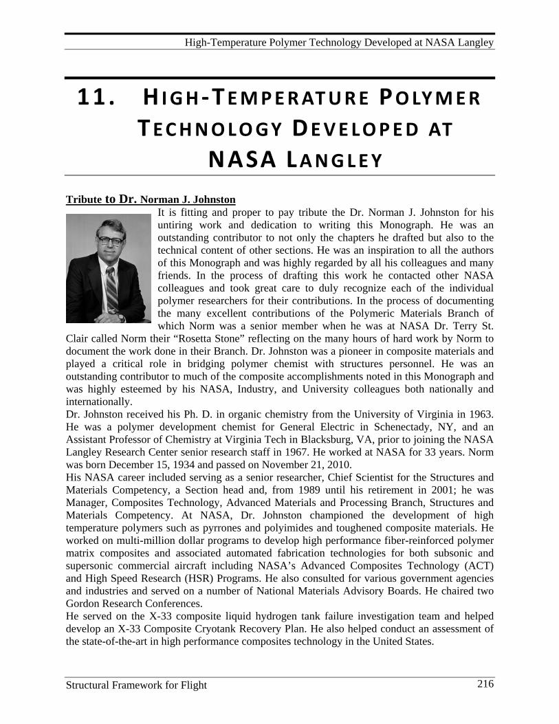
High-Temperature Polymer Technology Developed at NASA Langley
Structural Framework for Flight 216
11. H I G H -T E M P E R AT U R E P O LY M E R T E C H N O L O G Y D E V E L O P E D AT
NASA L A N G L E Y Tribute to Dr. Norman J. Johnston
It is fitting and proper to pay tribute the Dr. Norman J. Johnston for his untiring work and dedication to writing this Monograph. He was an outstanding contributor to not only the chapters he drafted but also to the technical content of other sections. He was an inspiration to all the authors of this Monograph and was highly regarded by all his colleagues and many friends. In the process of drafting this work he contacted other NASA colleagues and took great care to duly recognize each of the individual polymer researchers for their contributions. In the process of documenting the many excellent contributions of the Polymeric Materials Branch of which Norm was a senior member when he was at NASA Dr. Terry St.
Clair called Norm their “Rosetta Stone” reflecting on the many hours of hard work by Norm to document the work done in their Branch. Dr. Johnston was a pioneer in composite materials and played a critical role in bridging polymer chemist with structures personnel. He was an outstanding contributor to much of the composite accomplishments noted in this Monograph and was highly esteemed by his NASA, Industry, and University colleagues both nationally and internationally. Dr. Johnston received his Ph. D. in organic chemistry from the University of Virginia in 1963. He was a polymer development chemist for General Electric in Schenectady, NY, and an Assistant Professor of Chemistry at Virginia Tech in Blacksburg, VA, prior to joining the NASA Langley Research Center senior research staff in 1967. He worked at NASA for 33 years. Norm was born December 15, 1934 and passed on November 21, 2010. His NASA career included serving as a senior researcher, Chief Scientist for the Structures and Materials Competency, a Section head and, from 1989 until his retirement in 2001; he was Manager, Composites Technology, Advanced Materials and Processing Branch, Structures and Materials Competency. At NASA, Dr. Johnston championed the development of high temperature polymers such as pyrrones and polyimides and toughened composite materials. He worked on multi-million dollar programs to develop high performance fiber-reinforced polymer matrix composites and associated automated fabrication technologies for both subsonic and supersonic commercial aircraft including NASA’s Advanced Composites Technology (ACT) and High Speed Research (HSR) Programs. He also consulted for various government agencies and industries and served on a number of National Materials Advisory Boards. He chaired two Gordon Research Conferences. He served on the X-33 composite liquid hydrogen tank failure investigation team and helped develop an X-33 Composite Cryotank Recovery Plan. He also helped conduct an assessment of the state-of-the-art in high performance composites technology in the United States.
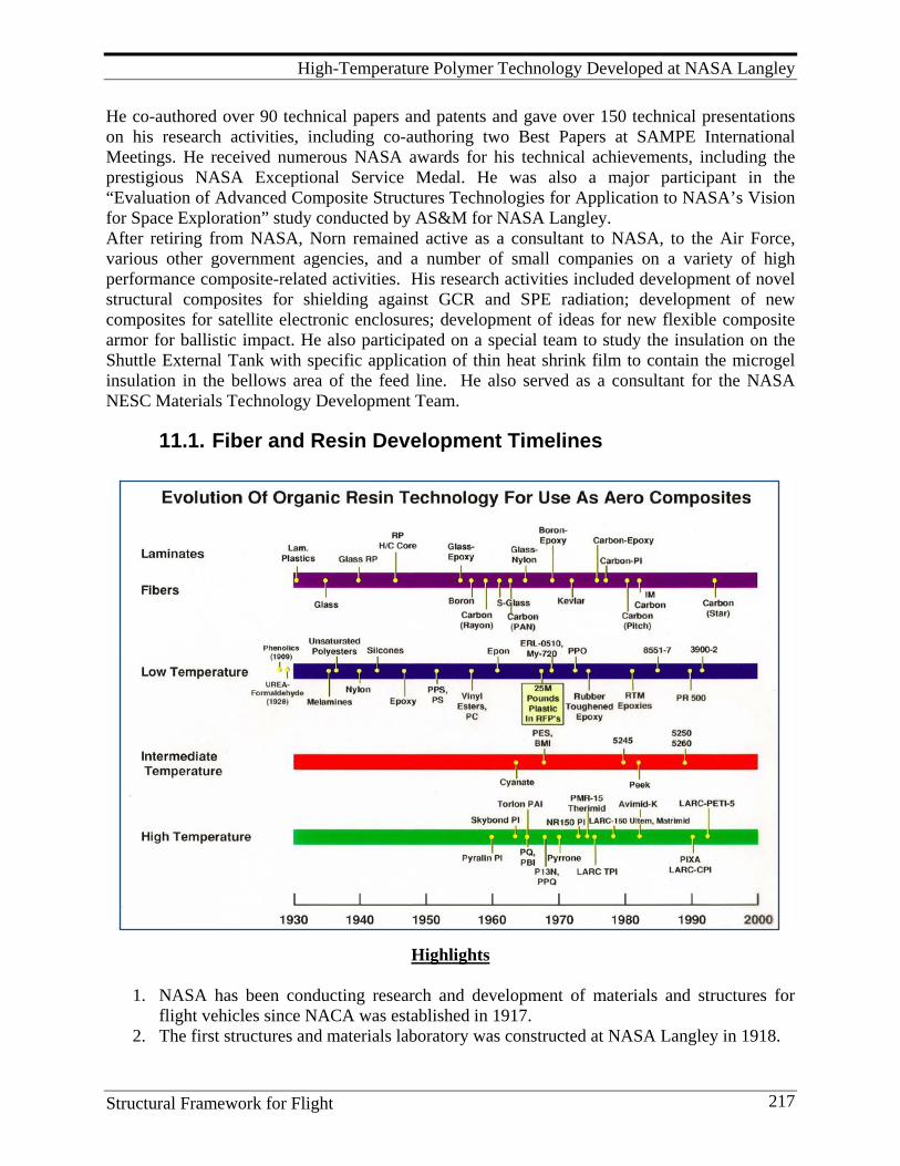
High-Temperature Polymer Technology Developed at NASA Langley
Structural Framework for Flight 217
He co-authored over 90 technical papers and patents and gave over 150 technical presentations on his research activities, including co-authoring two Best Papers at SAMPE International Meetings. He received numerous NASA awards for his technical achievements, including the prestigious NASA Exceptional Service Medal. He was also a major participant in the “Evaluation of Advanced Composite Structures Technologies for Application to NASA’s Vision for Space Exploration” study conducted by AS&M for NASA Langley. After retiring from NASA, Norn remained active as a consultant to NASA, to the Air Force, various other government agencies, and a number of small companies on a variety of high performance composite-related activities. His research activities included development of novel structural composites for shielding against GCR and SPE radiation; development of new composites for satellite electronic enclosures; development of ideas for new flexible composite armor for ballistic impact. He also participated on a special team to study the insulation on the Shuttle External Tank with specific application of thin heat shrink film to contain the microgel insulation in the bellows area of the feed line. He also served as a consultant for the NASA NESC Materials Technology Development Team.
11.1. Fiber and Resin Development Timelines
Highlights
1. NASA has been conducting research and development of materials and structures for flight vehicles since NACA was established in 1917.
2. The first structures and materials laboratory was constructed at NASA Langley in 1918.
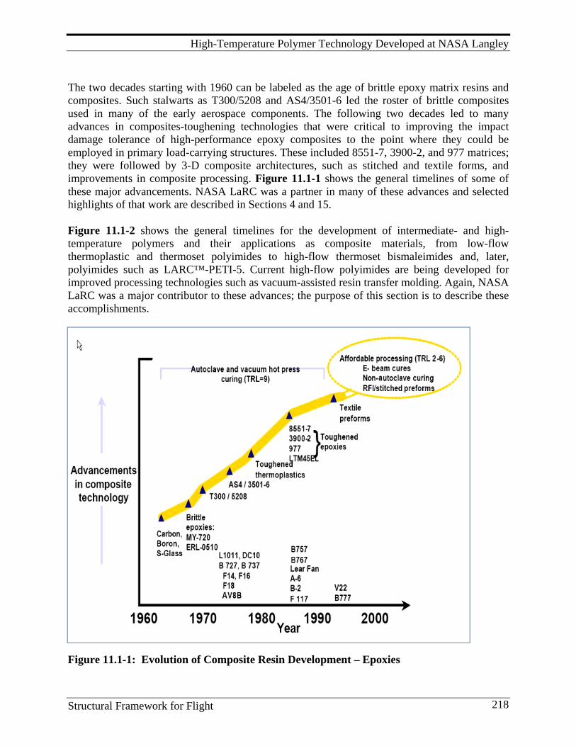
High-Temperature Polymer Technology Developed at NASA Langley
Structural Framework for Flight 218
The two decades starting with 1960 can be labeled as the age of brittle epoxy matrix resins and composites. Such stalwarts as T300/5208 and AS4/3501-6 led the roster of brittle composites used in many of the early aerospace components. The following two decades led to many advances in composites-toughening technologies that were critical to improving the impact damage tolerance of high-performance epoxy composites to the point where they could be employed in primary load-carrying structures. These included 8551-7, 3900-2, and 977 matrices; they were followed by 3-D composite architectures, such as stitched and textile forms, and improvements in composite processing. Figure 11.1-1 shows the general timelines of some of these major advancements. NASA LaRC was a partner in many of these advances and selected highlights of that work are described in Sections 4 and 15. Figure 11.1-2 shows the general timelines for the development of intermediate- and high- temperature polymers and their applications as composite materials, from low-flow thermoplastic and thermoset polyimides to high-flow thermoset bismaleimides and, later, polyimides such as LARC™-PETI-5. Current high-flow polyimides are being developed for improved processing technologies such as vacuum-assisted resin transfer molding. Again, NASA LaRC was a major contributor to these advances; the purpose of this section is to describe these accomplishments.
Figure 11.1-1: Evolution of Composite Resin Development – Epoxies
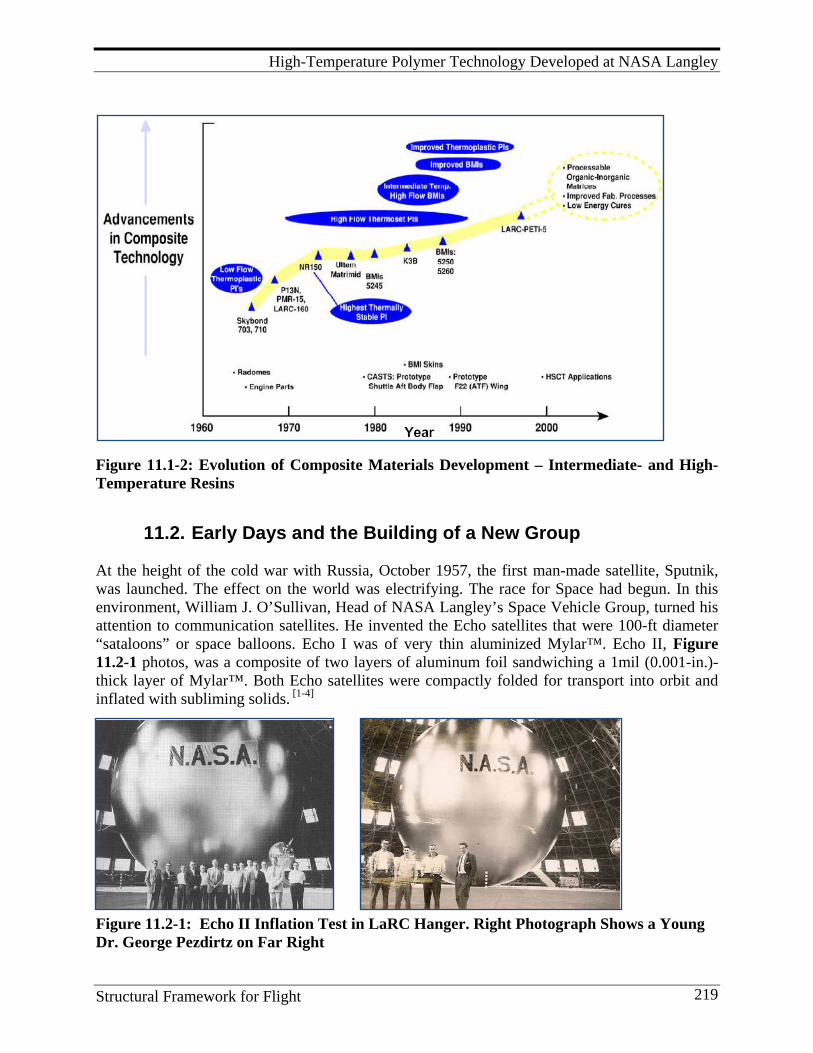
High-Temperature Polymer Technology Developed at NASA Langley
Structural Framework for Flight 219
Figure 11.1-2: Evolution of Composite Materials Development – Intermediate- and High- Temperature Resins
11.2. Early Days and the Building of a New Group At the height of the cold war with Russia, October 1957, the first man-made satellite, Sputnik, was launched. The effect on the world was electrifying. The race for Space had begun. In this environment, William J. O’Sullivan, Head of NASA Langley’s Space Vehicle Group, turned his attention to communication satellites. He invented the Echo satellites that were 100-ft diameter “sataloons” or space balloons. Echo I was of very thin aluminized Mylar™. Echo II, Figure 11.2-1 photos, was a composite of two layers of aluminum foil sandwiching a 1mil (0.001-in.)-thick layer of Mylar™. Both Echo satellites were compactly folded for transport into orbit and inflated with subliming solids. [1-4]
Figure 11.2-1: Echo II Inflation Test in LaRC Hanger. Right Photograph Shows a Young Dr. George Pezdirtz on Far Right
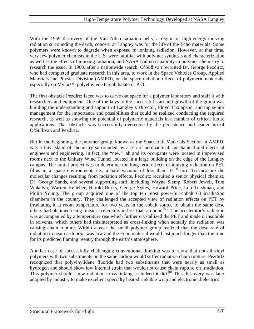
High-Temperature Polymer Technology Developed at NASA Langley
Structural Framework for Flight 220
With the 1959 discovery of the Van Allen radiation belts, a region of high-energy-ionizing radiation surrounding the earth, concern at Langley was for the life of the Echo materials. Some polymers were known to degrade when exposed to ionizing radiation. However, at that time, very few polymer chemists in the U.S. were familiar with polymer synthesis and characterization, as well as the effects of ionizing radiation, and NASA had no capability in polymer chemistry to research the issue. In 1960, after a nationwide search, O’Sullivan recruited Dr. George Pezdirtz, who had completed graduate research in this area, to work in the Space Vehicles Group, Applied Materials and Physics Division (AMPD), on the space radiation effects of polymeric materials, especially on Mylar™, polyethylene terephthalate or PET. The first obstacle Pezdirtz faced was to carve out space for a polymer laboratory and staff it with researchers and equipment. One of the keys to the successful start and growth of the group was building the understanding and support of Langley’s Director, Floyd Thompson, and top senior management for the importance and possibilities that could be realized conducting the required research, as well as showing the potential of polymeric materials in a number of critical future applications. That obstacle was successfully overcome by the persistence and leadership of O’Sullivan and Pezdirtz. But in the beginning, the polymer group, known as the Spacecraft Materials Section in AMPD, was a tiny island of chemistry surrounded by a sea of aeronautical, mechanical and electrical engineers and engineering. In fact, the “new” lab and its occupants were located in improvised rooms next to the Unitary Wind Tunnel located in a large building on the edge of the Langley campus. The initial project was to determine the long-term effects of ionizing radiation on PET films in a space environment, i.e., a hard vacuum of less than 10 -6 torr. To measure the molecular changes resulting from radiation effects, Pezdirtz recruited a senior physical chemist, Dr. George Sands, and several supporting staff, including Wayne Slemp, Robert Jewell, Tom Wakelyn, Warren Kelleher, Harold Burks, George Sykes, Howard Price, Lou Teishman, and Philip Young. The group acquired one of the top ten most powerful cobalt 60 irradiation chambers in the country. They challenged the accepted view of radiation effects on PET by irradiating it at room temperature for two years in the cobalt source to obtain the same dose others had obtained using linear accelerators in less than an hour.[5-7] The accelerator’s radiation was accompanied by a temperature rise which further crystallized the PET and made it insoluble in solvents, which others had misinterpreted as cross-linking when actually the radiation was causing chain rupture. Within a year the small polymer group realized that the dose rate of radiation in near earth orbit was low and the Echo material would last much longer than the time for its predicted flaming reentry through the earth’s atmosphere. Another case of successfully challenging conventional thinking was to show that not all vinyl polymers with two substituents on the same carbon would suffer radiation chain rupture. Pezdirtz recognized that polyvinylidene fluoride had two substituents that were nearly as small as hydrogen and should show low internal strain that would not cause chain rupture on irradiation. This polymer should show radiation cross-linking as indeed it did.[8] This discovery was later adopted by industry to make excellent specialty heat-shrinkable wrap and electronic dielectrics.
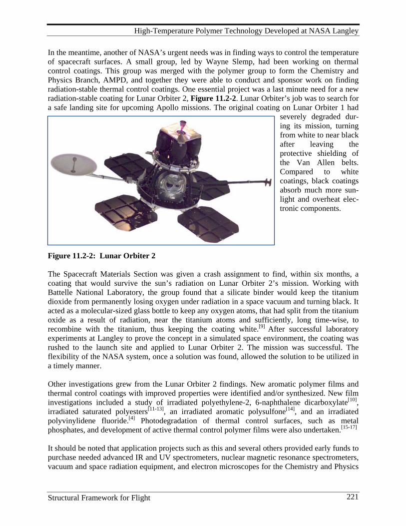
High-Temperature Polymer Technology Developed at NASA Langley
Structural Framework for Flight 221
In the meantime, another of NASA’s urgent needs was in finding ways to control the temperature of spacecraft surfaces. A small group, led by Wayne Slemp, had been working on thermal control coatings. This group was merged with the polymer group to form the Chemistry and Physics Branch, AMPD, and together they were able to conduct and sponsor work on finding radiation-stable thermal control coatings. One essential project was a last minute need for a new radiation-stable coating for Lunar Orbiter 2, Figure 11.2-2. Lunar Orbiter’s job was to search for a safe landing site for upcoming Apollo missions. The original coating on Lunar Orbiter 1 had
severely degraded dur-ing its mission, turning from white to near black after leaving the protective shielding of the Van Allen belts. Compared to white coatings, black coatings absorb much more sun-light and overheat elec-tronic components.
Figure 11.2-2: Lunar Orbiter 2 The Spacecraft Materials Section was given a crash assignment to find, within six months, a coating that would survive the sun’s radiation on Lunar Orbiter 2’s mission. Working with Battelle National Laboratory, the group found that a silicate binder would keep the titanium dioxide from permanently losing oxygen under radiation in a space vacuum and turning black. It acted as a molecular-sized glass bottle to keep any oxygen atoms, that had split from the titanium oxide as a result of radiation, near the titanium atoms and sufficiently, long time-wise, to recombine with the titanium, thus keeping the coating white.[9] After successful laboratory experiments at Langley to prove the concept in a simulated space environment, the coating was rushed to the launch site and applied to Lunar Orbiter 2. The mission was successful. The flexibility of the NASA system, once a solution was found, allowed the solution to be utilized in a timely manner. Other investigations grew from the Lunar Orbiter 2 findings. New aromatic polymer films and thermal control coatings with improved properties were identified and/or synthesized. New film investigations included a study of irradiated polyethylene-2, 6-naphthalene dicarboxylate[10], irradiated saturated polyesters[11-13], an irradiated aromatic polysulfone[14], and an irradiated polyvinylidene fluoride.[4] Photodegradation of thermal control surfaces, such as metal phosphates, and development of active thermal control polymer films were also undertaken.[15-17] It should be noted that application projects such as this and several others provided early funds to purchase needed advanced IR and UV spectrometers, nuclear magnetic resonance spectrometers, vacuum and space radiation equipment, and electron microscopes for the Chemistry and Physics

High-Temperature Polymer Technology Developed at NASA Langley
Structural Framework for Flight 222
Branch laboratories. The polymer group in this Branch was the underlying foundation for the world-class polymer synthetic effort and polymer matrix composite activities that followed during the next five decades. Lessons Learned in Forming a New Research Group
1. Start with a vision that is based on reality for an organization with changing needs. 2. Try to anticipate those needs as much as two to six years ahead. 3. Keep in touch with top management: center director and research directors, as well as
engineers and scientists in related center projects. 4. See things and needs from their perspective and explain your work in terms that are
familiar and can be seen as useful to them. 5. Translate these perspectives to scientists working in your group on their terms. 6. Accept a few applied developments and urgent tasks to keep in touch with reality and
build broader internal support for more applied research-oriented activities. 7. Recruit and hire best available people for tasks at hand, present and future. 8. Explore and use available means such as visiting fellows’ programs, grant programs and
cooperation with universities to extend on-site researchers where needed to reach beyond limits of hiring freezes.
9. Create an environment where researchers and technicians feel challenged, useful, and rewarded.
10. The senior researchers (Pezdirtz, Sands, Bell, and Johnston) were able to translate complex polymer concepts and properties into terms that were understood by senior management at Langley and in NASA Headquarters. This, along with growing recognition by the science community of the advances at Langley in developing new polymers with outstanding thermal and radiation stability, were major contributors for forming a stable base with breadth and flexibility to adapt to new demands by NASA, military, and commercial sectors.
11.3. Background in High-temperature Polymers In the 1960s, the demand for heat resistance in polymers was spurred by military and civil aeronautical and aerospace developments. Some advantages of high-temperature polymers are: excellent dimensional and thermal stability, lightweight, corrosion resistant, high mechanical strength and stiffness, low flammability, and ability to be fabricated with conventional equipment. New requirements for higher vehicle speeds, miniaturization, nuclear energy, ablation, electrical circuitry, and insulation, all served to drive the replacement of older materials with the newer polymeric materials as they became available. As a result, the beginning of the space age witnessed a worldwide activity in the development of high-temperature, thermally-stable polymers. Six books and over 70 review articles on this subject were disclosed in the open literature by 1970. Reference 18 contains this compilation as well as references to over 150 journal articles on high-temperature polymers. It provides a

High-Temperature Polymer Technology Developed at NASA Langley
Structural Framework for Flight 223
comprehensive discussion on the relationships between model compounds, polymer chemical structure and thermal stability, basically the chemical structure background for thermal stability in aromatic polymers. It contains the broadest possible combinations of reactants that could lead to previously unknown thermally stable polymers and provides a roadmap for synthetic polymer chemists worldwide. Many creative synthetic avenues were explored to develop organic polymers that could function in air for up to three years at 150° to 200° C. The main thrust was to minimize or eliminate aliphatic groups (-CH2-, also called methylene groups) in the polymer chain, and use instead aromatic groups (–C6H5-, phenyl or benzene-like) that were proven to be more thermally stable. A select list of high-temperature polymers is given below. Almost all are linear thermoplastics.
• Aramids (aromatic polyamides) • Polyimides (PIs) • Bismaleimides (BMIs) • Polyether ketones • Fluoropolymers • Polyphenylene sulfide (PPS) • Polyamideimides (PAIs) • Polysulfones • Polybenzimidazoles (PBIs) • Silicones • Polyetherimides (PEIs) • Polyphenylquinoxalines • Liquid crystal polymers (aromatic polyesters) In the early days, the thermally stable polymers were mostly aromatic thermoplastics; few aromatic thermoset polymers were synthesized. Thermoplastics are linear, long chain, high molecular weight molecules and are made by reacting two different monomers together with the evolution of by-products such as water, alcohol, phenol, or a gas (condensation polymerization) in addition to solvent. Aliphatic thermoplastics, such as polyethylene and related polyhydro-carbons, polyesters and polyamides, all containing large numbers of methylene molecular units, have high melt viscosities and are hard to process except as dissolved in organic solvents or melt-pultruded into fibers. Upon heating, they exhibit flow and can be processed into specific shapes without reacting chemically. When cooled, they regain mechanical properties. Therefore, they can be reheated and reprocessed into a different shape after initial processing. They are well known and many are commercially available. But the aliphatic thermoplastics are not thermally stable as defined in the paragraph above. Aromatic thermoplastics containing phenyl rings and none, or a minimal number, of methylene units were constructed with one or more of the following repeat units:
• Aromatic rings in single strands or chains, • Flexible links (such as O, CH2, C=O, S, SO2) between the aromatic rings, • Heteroaromatic rings (such as imide, benzimidazole, quinoxaline), • Step ladder aromatic units (combining single and double strands or chains), and • Ladder (double chain) units.
For example, over 30 heteroaromatic polymer systems alone were disclosed in the open literature by 1970. Additional polymerization of a single monomer reacting with itself with no by-products led to thermoplastic polyphenylenes and a host of heteroaromatic polymers. Non-hydrogen-containing thermoplastics, especially heavily fluorinated materials, were synthesized and studied. Teflon™, a fully-fluorinated polyethylene from DuPont, can be used almost indefinitely at temperatures up to 260°C (500°F) but has to be fabricated using powder metallurgy techniques.
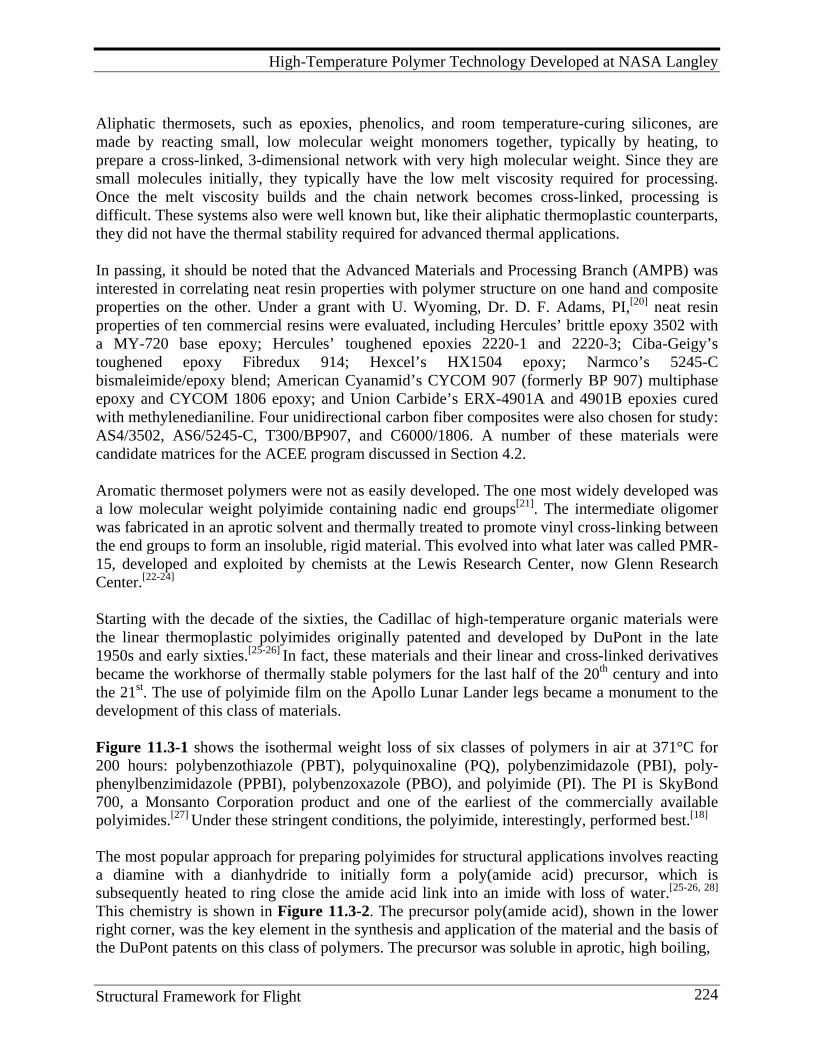
High-Temperature Polymer Technology Developed at NASA Langley
Structural Framework for Flight 224
Aliphatic thermosets, such as epoxies, phenolics, and room temperature-curing silicones, are made by reacting small, low molecular weight monomers together, typically by heating, to prepare a cross-linked, 3-dimensional network with very high molecular weight. Since they are small molecules initially, they typically have the low melt viscosity required for processing. Once the melt viscosity builds and the chain network becomes cross-linked, processing is difficult. These systems also were well known but, like their aliphatic thermoplastic counterparts, they did not have the thermal stability required for advanced thermal applications. In passing, it should be noted that the Advanced Materials and Processing Branch (AMPB) was interested in correlating neat resin properties with polymer structure on one hand and composite properties on the other. Under a grant with U. Wyoming, Dr. D. F. Adams, PI,[20] neat resin properties of ten commercial resins were evaluated, including Hercules’ brittle epoxy 3502 with a MY-720 base epoxy; Hercules’ toughened epoxies 2220-1 and 2220-3; Ciba-Geigy’s toughened epoxy Fibredux 914; Hexcel’s HX1504 epoxy; Narmco’s 5245-C bismaleimide/epoxy blend; American Cyanamid’s CYCOM 907 (formerly BP 907) multiphase epoxy and CYCOM 1806 epoxy; and Union Carbide’s ERX-4901A and 4901B epoxies cured with methylenedianiline. Four unidirectional carbon fiber composites were also chosen for study: AS4/3502, AS6/5245-C, T300/BP907, and C6000/1806. A number of these materials were candidate matrices for the ACEE program discussed in Section 4.2. Aromatic thermoset polymers were not as easily developed. The one most widely developed was a low molecular weight polyimide containing nadic end groups[21]. The intermediate oligomer was fabricated in an aprotic solvent and thermally treated to promote vinyl cross-linking between the end groups to form an insoluble, rigid material. This evolved into what later was called PMR-15, developed and exploited by chemists at the Lewis Research Center, now Glenn Research Center.[22-24] Starting with the decade of the sixties, the Cadillac of high-temperature organic materials were the linear thermoplastic polyimides originally patented and developed by DuPont in the late 1950s and early sixties.[25-26] In fact, these materials and their linear and cross-linked derivatives became the workhorse of thermally stable polymers for the last half of the 20th century and into the 21st. The use of polyimide film on the Apollo Lunar Lander legs became a monument to the development of this class of materials. Figure 11.3-1 shows the isothermal weight loss of six classes of polymers in air at 371°C for 200 hours: polybenzothiazole (PBT), polyquinoxaline (PQ), polybenzimidazole (PBI), poly-phenylbenzimidazole (PPBI), polybenzoxazole (PBO), and polyimide (PI). The PI is SkyBond 700, a Monsanto Corporation product and one of the earliest of the commercially available polyimides.[27] Under these stringent conditions, the polyimide, interestingly, performed best.[18] The most popular approach for preparing polyimides for structural applications involves reacting a diamine with a dianhydride to initially form a poly(amide acid) precursor, which is subsequently heated to ring close the amide acid link into an imide with loss of water.[25-26, 28] This chemistry is shown in Figure 11.3-2. The precursor poly(amide acid), shown in the lower right corner, was the key element in the synthesis and application of the material and the basis of the DuPont patents on this class of polymers. The precursor was soluble in aprotic, high boiling,
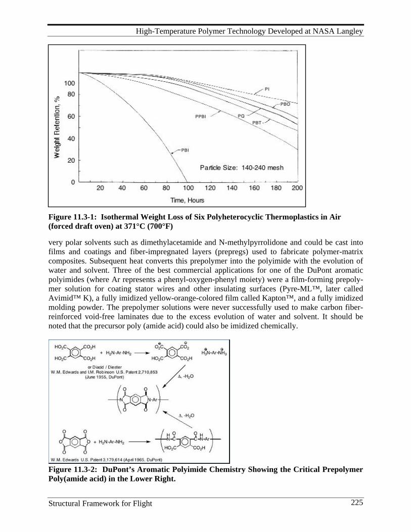
High-Temperature Polymer Technology Developed at NASA Langley
Structural Framework for Flight 225
Figure 11.3-1: Isothermal Weight Loss of Six Polyheterocyclic Thermoplastics in Air (forced draft oven) at 371°C (700°F) very polar solvents such as dimethylacetamide and N-methylpyrrolidone and could be cast into films and coatings and fiber-impregnated layers (prepregs) used to fabricate polymer-matrix composites. Subsequent heat converts this prepolymer into the polyimide with the evolution of water and solvent. Three of the best commercial applications for one of the DuPont aromatic polyimides (where Ar represents a phenyl-oxygen-phenyl moiety) were a film-forming prepoly-mer solution for coating stator wires and other insulating surfaces (Pyre-ML™, later called Avimid™ K), a fully imidized yellow-orange-colored film called Kapton™, and a fully imidized molding powder. The prepolymer solutions were never successfully used to make carbon fiber- reinforced void-free laminates due to the excess evolution of water and solvent. It should be noted that the precursor poly (amide acid) could also be imidized chemically.
Figure 11.3-2: DuPont’s Aromatic Polyimide Chemistry Showing the Critical Prepolymer Poly(amide acid) in the Lower Right.
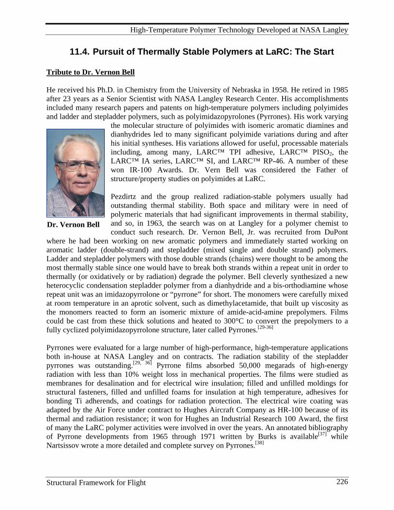
High-Temperature Polymer Technology Developed at NASA Langley
Structural Framework for Flight 226
Dr. Vernon Bell
11.4. Pursuit of Thermally Stable Polymers at LaRC: The Start Tribute to Dr. Vernon Bell He received his Ph.D. in Chemistry from the University of Nebraska in 1958. He retired in 1985 after 23 years as a Senior Scientist with NASA Langley Research Center. His accomplishments included many research papers and patents on high-temperature polymers including polyimides and ladder and stepladder polymers, such as polyimidazopyrolones (Pyrrones). His work varying
the molecular structure of polyimides with isomeric aromatic diamines and dianhydrides led to many significant polyimide variations during and after his initial syntheses. His variations allowed for useful, processable materials including, among many, LARC™ TPI adhesive, LARC™ PISO2, the LARC™ IA series, LARC™ SI, and LARC™ RP-46. A number of these won IR-100 Awards. Dr. Vern Bell was considered the Father of structure/property studies on polyimides at LaRC. Pezdirtz and the group realized radiation-stable polymers usually had outstanding thermal stability. Both space and military were in need of polymeric materials that had significant improvements in thermal stability, and so, in 1963, the search was on at Langley for a polymer chemist to conduct such research. Dr. Vernon Bell, Jr. was recruited from DuPont
where he had been working on new aromatic polymers and immediately started working on aromatic ladder (double-strand) and stepladder (mixed single and double strand) polymers. Ladder and stepladder polymers with those double strands (chains) were thought to be among the most thermally stable since one would have to break both strands within a repeat unit in order to thermally (or oxidatively or by radiation) degrade the polymer. Bell cleverly synthesized a new heterocyclic condensation stepladder polymer from a dianhydride and a bis-orthodiamine whose repeat unit was an imidazopyrrolone or “pyrrone” for short. The monomers were carefully mixed at room temperature in an aprotic solvent, such as dimethylacetamide, that built up viscosity as the monomers reacted to form an isomeric mixture of amide-acid-amine prepolymers. Films could be cast from these thick solutions and heated to 300°C to convert the prepolymers to a fully cyclized polyimidazopyrrolone structure, later called Pyrrones.[29-36] Pyrrones were evaluated for a large number of high-performance, high-temperature applications both in-house at NASA Langley and on contracts. The radiation stability of the stepladder pyrrones was outstanding.[29, 36] Pyrrone films absorbed 50,000 megarads of high-energy radiation with less than 10% weight loss in mechanical properties. The films were studied as membranes for desalination and for electrical wire insulation; filled and unfilled moldings for structural fasteners, filled and unfilled foams for insulation at high temperature, adhesives for bonding Ti adherends, and coatings for radiation protection. The electrical wire coating was adapted by the Air Force under contract to Hughes Aircraft Company as HR-100 because of its thermal and radiation resistance; it won for Hughes an Industrial Research 100 Award, the first of many the LaRC polymer activities were involved in over the years. An annotated bibliography of Pyrrone developments from 1965 through 1971 written by Burks is available[37] while Nartsissov wrote a more detailed and complete survey on Pyrrones.[38]
High-Temperature Polymer Technology Developed at NASA Langley
Structural Framework for Flight 227
Unfortunately, Pyrrones had several disadvantages. The tetraamine monomers were very expensive to make and both the tetraamine and dianhydride monomers could act as tri-and-tetra-functional moieties causing incomplete cyclodehydration to the cured imidazopyrrolone structural unit, branching, cross-linking, and low molecular weight. Notably, their oxidative stability in film and laminate applications was poorer than that observed for aromatic polyimides.[18] Since the polyimides did not have these by-product difficulties, plus the diamines were more readily available and cost less than the tetraamines, the stage was set at LaRC to pursue and exploit this intriguing class of aromatic polymers. As the Pyrrone and polyimide work grew in importance, additional experienced senior staff were added, notably Dr. Norman Johnston, to synthesize new polymers and study techniques for forming films, coating, and glass composites. At this time, 1966, a hiring freeze was in place at Langley so a visiting postdoctoral research fellowship was set up with the National Research Council (NRC) to bring Dr. Johnston on board immediately until he could be hired as a civil servant. Later, Johnston’s work was expanded to direct a broad industrial and academic team on carbon composites, especially in the area of damage tolerance and polymer matrix toughening, as noted in Section 15.1 of this work. This laid the foundation for extensive later development on other thermally stable polymers and advanced composites. The use of the NRC post-doctoral research fellowship program and similar programs at in-state universities served the polymer group at LaRC extremely well. Young post-doctoral candidates or more experienced senior researchers could be placed temporarily at LaRC while conducting NASA-related research until their qualities could be assessed and a permanent position obtained. The two decades of the 1970s and 1980s saw a number of new staff added to the Branch (at that time the Nonmetallic Materials Branch, Materials Division) in this manner, including Paul Hergenrother, Dr. Terry St. Clair, Anne St. Clair, and Dr. John Connell. Mr. Hergenrother joined the Branch in 1975. At that time, he was working in San Diego as Manager, Chemistry Department, for the Research Development Division of the Whitaker Corporation who decided without warning to close the doors. The polymer group had a proposal from the R&D division dealing with the synthesis and characterization of high temperature adhesives. As soon as Hergenrother became available, LaRC withdrew the adhesives solicitation and offered him a position as a senior research associate under a grant LaRC had with Professor James Wightman at Virginia Tech who was studying titanium surface morphology in support of our adhesives efforts. There was one problem. Dr. Wightman was on vacation at his cabin on “Skeeter Flats” near Mobjack Bay north of Yorktown. One of LaRC’s technicians lived near the area and was tasked to get to Wightman. Having no phone at the cabin but sensing the urgency, Wightman traveled out to a payphone on a busy route 17 where communications blended without caution with car and truck noise while negotiations were conducted on salary and the need for an urgent but official letter from the University to Hergenrother. Wightman came through with flying colors even though he thought the salary was too close to that of the University President and that might be a problem. It wasn’t and Paul succumbed to the offer when he decided it was better to be on the giving rather than the receiving end of federal contract dollars, plus sufficient travel money was inserted into the grant for him to attend national meetings and present his work and interact with his peers. It was California’s loss and LaRC’s gain, for Paul came with a terrific track record of research and publications on high temperature polymers and their application as adhesives and composite matrices.
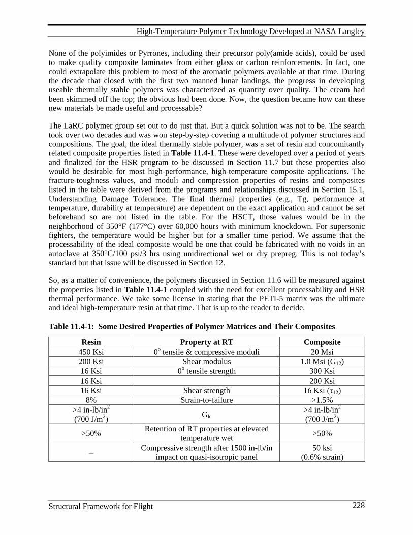
High-Temperature Polymer Technology Developed at NASA Langley
Structural Framework for Flight 228
None of the polyimides or Pyrrones, including their precursor poly(amide acids), could be used to make quality composite laminates from either glass or carbon reinforcements. In fact, one could extrapolate this problem to most of the aromatic polymers available at that time. During the decade that closed with the first two manned lunar landings, the progress in developing useable thermally stable polymers was characterized as quantity over quality. The cream had been skimmed off the top; the obvious had been done. Now, the question became how can these new materials be made useful and processable? The LaRC polymer group set out to do just that. But a quick solution was not to be. The search took over two decades and was won step-by-step covering a multitude of polymer structures and compositions. The goal, the ideal thermally stable polymer, was a set of resin and concomitantly related composite properties listed in Table 11.4-1. These were developed over a period of years and finalized for the HSR program to be discussed in Section 11.7 but these properties also would be desirable for most high-performance, high-temperature composite applications. The fracture-toughness values, and moduli and compression properties of resins and composites listed in the table were derived from the programs and relationships discussed in Section 15.1, Understanding Damage Tolerance. The final thermal properties (e.g., Tg, performance at temperature, durability at temperature) are dependent on the exact application and cannot be set beforehand so are not listed in the table. For the HSCT, those values would be in the neighborhood of 350°F (177°C) over 60,000 hours with minimum knockdown. For supersonic fighters, the temperature would be higher but for a smaller time period. We assume that the processability of the ideal composite would be one that could be fabricated with no voids in an autoclave at 350°C/100 psi/3 hrs using unidirectional wet or dry prepreg. This is not today’s standard but that issue will be discussed in Section 12. So, as a matter of convenience, the polymers discussed in Section 11.6 will be measured against the properties listed in Table 11.4-1 coupled with the need for excellent processability and HSR thermal performance. We take some license in stating that the PETI-5 matrix was the ultimate and ideal high-temperature resin at that time. That is up to the reader to decide. Table 11.4-1: Some Desired Properties of Polymer Matrices and Their Composites
Resin Property at RT Composite 450 Ksi 0o tensile & compressive moduli 20 Msi 200 Ksi Shear modulus 1.0 Msi (G12) 16 Ksi 0o tensile strength 300 Ksi 16 Ksi 200 Ksi 16 Ksi Shear strength 16 Ksi (τ12)
8% Strain-to-failure >1.5% >4 in-lb/in2 (700 J/m2) Glc
>4 in-lb/in2 (700 J/m2)
>50% Retention of RT properties at elevated temperature wet >50%
-- Compressive strength after 1500 in-lb/in impact on quasi-isotropic panel
50 ksi (0.6% strain)

High-Temperature Polymer Technology Developed at NASA Langley
Structural Framework for Flight 229
11.5. Composite Matrix Research: Successes and Failures! The Continuation
It has been pointed out that most of the early high-temperature polymers were linear thermoplastics. However, the polymer chemist has at his disposal a wider range of synthetic approaches and resulting materials such as shown in Figure 11.5-1: linear amorphous thermoplastics; lightly cross-linked thermoplastics whose cross-link density is controlled by the
amount of cross-linking agent placed on the thermo-plastic parent (these also can be semi-interpenetrating polymer solutions which utilize linear and lightly cross-linked polymers); crys-talline thermoplastics whose polymer backbones are aligned so closely they form crystalline regions (semi-crystalline aromatic poly-esters and polyarylene ethers are examples); and therm-osets such as epoxies and bismaleimides that are usu-ally heavily cross-linked.
Figure 11.5-1: Synthetic Approaches for Various Classes of Polymers The polymers, composites and adhesives developed by the polymer group at LaRC are discussed in the order given above. This is not always a chronological order but tends to favor how success was ultimately achieved. We start with the linear thermoplastics and proceed to their lightly cross-linked relatives, then finally to the heavily cross-linked thermosets.
11.5.1 Linear Thermoplastics The LaRC polymer group concentrated first on the linear amorphous thermoplastics with the goal of maintaining a high polymer glass transition temperature (Tg) while retaining sufficient melt flow and melt viscosity in the uncured state to allow processing in the neat resin stage or good solubility in solvents to allow solution processing while maintaining resistance to common aircraft solvents in the cured state. Bell developed a series of amorphous polyimides by varying the meta and para connections of the amino groups (a stereoisomeric variation) on aromatic diamine monomers. {Note: The bottom equation in Figure 11.3-2 depicts, in short hand, the formula of a diamine monomer as NH2-Ar-NH2. The diamines Bell synthesized included, among at least four others, those where Ar included -Ar'-Z-Ar'- and Z = O (4 isomers), CH2 (6 isomers), C=O (7 isomers), SO2 (4 isomers), and nil (1 isomer).}
High-Temperature Polymer Technology Developed at NASA Langley
Structural Framework for Flight 230
Using these isomeric diamines and two dianhydrides (pyromellitic dianhydride (PMDA) and benzophenone dianhydride (BTDA)), Bell developed classic relationships between Tg and polyimides having all-meta connections, all para connections and mixed meta/para connections, e.g., the effect of meta and para isomerism.[39-43] He studied solubility melt viscosity and potential processing at high temperatures. He also synthesized a variety of other polymers using the isomeric diamine monomers: bismaleimides, polyaspartimides, and aromatic polyesters as well as adhesives, moldings, and coatings. As with the Pyrrones, none of these polymer compositions were deemed useful as composite matrices but found uses as high-temperature adhesives. Most importantly, several of Bell’s diamines were used extensively in the polymer research that opened the door to practical and critical applications of high-temperature polymers over the next few decades. Bell also was involved in and contributed to a major study discussed in Section 4.3 on the potential release of carbon fiber from burning carbon fiber-reinforced composites. That study was to assess the threat and determine its criticality; if the risk was great, research and development on carbon fiber-reinforced composites would have to be severely restricted and perhaps stopped. During this time, commercial formulators were using a readily available, economical, and practical aromatic diamine, methylene dianiline, in many of their adhesive and matrix products. Benzidine (4, 4'-diaminobiphenyl) and this diamine had been shown to have serious human metabolic issues when handled improperly. Replacement monomers were being sought and it was unknown if other aromatic diamines had the same problem. Bell was in an ideal situation with his stable of isomeric diamines to deal with this important issue. Monsanto Research Corporation, Dayton Laboratory, was contracted to study the microbial mutagenicity of a series of these compounds using the Ames Salmonella assay.[44] Bell supplied the chemicals in a purified form. They found no mutagenicity for all the isomers of diaminobenzophenone. The o, o', m, m' and the m, p' isomers of methylene dianiline gave no detectable mutagenicity while the p, p' isomer displayed moderate mutagenicity, as expected. The isomers of oxydianiline and diaminodiphenlysulfone showed no mutagenicity. No mutagenicity was found in other biphenyl diamines and methylated aromatic diamines. This work exonerated the use of almost all the diamine isomers except p, p'-methylene dianiline and was a major contributor to the develop-ment of commercial adhesives and composite matrices. Terry St.Clair, who joined the polymer group in 1976, and had instant success with LARC-160, took a somewhat different creative approach incorporating a wider variety of chemical compositions in his syntheses. Over a 25-year span, he created an enormous stable of high-temperature polymers, films, adhesives, composite matrices, moldings and foams. Also during this span, he became Branch Head of what evolved from the Chemistry and Physics Branch under Pezdirtz (and later Bell and Bland Stein) to the AMPB. LARC™ TPI. This polymer was first reported by Bell in his study on the isomeric effects of aromatic diamines on polymer properties [42] and further exploited by A. K. St.Clair and T. L. St.Clair.[47, 48, 49, 51, 52] Figure 11.5-2 shows the chemistry of this polymer and that of PISO2,.

High-Temperature Polymer Technology Developed at NASA Langley
Structural Framework for Flight 231
Figure 11.5-2: Synthesis of and Chemical Formulas for LARC™TPI and PISO2 Thermoplastic Polymers LARC™ TPI is a semi-crystalline polymer and a number of studies were made on its crystalline behavior.[53-56] Extensive adhesive and carbon fiber composite studies were conducted by Langley researchers.[57-62] In its fully imidized form, it was insoluble in most organic solvents but infusible at elevated temperatures. Endcapping technology produced controlled molecular weight versions which had enhanced melt flow but poor solvent resistance. These and the fact that the diamine was costly and perhaps could cause negative physiological effects in humans encouraged further research on new, inexpensive, flexible, aromatic, thermally-stable thermo-plastics to overcome these problems. Three companies--Mitsui Toatsu Chemicals, Inc., Rogers Corporation, and High Tech Services.[45, 46] --licensed the Bell patent technology with the goal of making LARC™TPI products commercially available, including powders, moldings, films, adhesives, and prepregs. Mitsui was the most aggressive in the composites arena and furnished varnish solutions, molding powders, films, and glass fiber prepreg for sale.[45] Rogers Corporation exploited the adhesive potential of LARC™-TPI. LARC™-TPI won the Chemistry and Physics Branch’s second IR-100 Award in 1981. LARC™ ITPI. This polymer is made just like LARC™ TPI, through the poly(amide acid) as shown in the chemical equations in Figures 11.3-2 and 11.5-2.[63, 64] The chemistry of the cured material is isomeric with LARC™ TPI (e.g., it has the same number of carbon, hydrogen, oxygen, and nitrogen atoms: C30H14N2O6) but T. St.Clair removed the meta-oriented benzophenone moiety in the diamine and inserted it in the dianhydride as shown in Figure 11.5-3. This was done for several reasons. The resulting monomers are less expensive; elimination of the 3, 3’-diaminobenzophenone which, at that time, was thought to have a mutagenicity problem; and the cured product would have the same properties as the original cured LARC™ TPI. The optimized polymer precursor poly(amide acid) was scaled up and 50 pound batches produced at Imitec, Inc. in solution and powder form. A portion was used for adhesive evaluation [65] and a
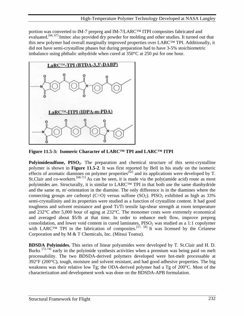
High-Temperature Polymer Technology Developed at NASA Langley
Structural Framework for Flight 232
portion was converted to IM-7 prepreg and IM-7/LARC™ ITPI composites fabricated and evaluated.[66, 67] Imitec also provided dry powder for molding and other studies. It turned out that this new polymer had overall marginally improved properties over LARC™ TPI. Additionally, it did not have semi-crystalline phases but during preparation had to have 3-5% stoichiometric imbalance using phthalic anhydride when cured at 350°C at 250 psi for one hour.
Figure 11.5-3: Isomeric Character of LARC™ TPI and LARC™ ITPI Polyimidesulfone, PISO2. The preparation and chemical structure of this semi-crystalline polymer is shown in Figure 11.5-2. It was first reported by Bell in his study on the isomeric effects of aromatic diamines on polymer properties[42] and its applications were developed by T. St.Clair and co-workers.[68-71] As can be seen, it is made via the poly(amide acid) route as most polyimides are. Structurally, it is similar to LARC™ TPI in that both use the same dianhydride and the same m, m'-orientation in the diamine. The only difference is in the diamines where the connecting groups are carbonyl (C=O) versus sulfone (SO2). PISO2 exhibited as high as 33% semi-crystallinity and its properties were studied as a function of crystalline content. It had good toughness and solvent resistance and good Ti/Ti tensile lap-shear strength at room temperature and 232°C after 5,000 hour of aging at 232°C. The monomer costs were extremely economical and averaged about $5/lb at that time. In order to enhance melt flow, improve prepreg consolidation, and lower void content in cured laminates, PISO2 was studied as a 1:1 copolymer with LARC™ TPI in the fabrication of composites.[57, 58] It was licensed by the Celanese Corporation and by M & T Chemicals, Inc. (Mitsui Toatsu). BDSDA Polyimides. This series of linear polyamides were developed by T. St.Clair and H. D. Burks [72-74] early in the polyimide synthesis activities when a premium was being paid on melt processability. The two BDSDA-derived polymers developed were hot-melt processable at 392°F (200°C), tough, moisture and solvent resistant, and had good adhesive properties. The big weakness was their relative low Tg; the ODA-derived polymer had a Tg of 200°C. Most of the characterization and development work was done on the BDSDA-APB formulation.
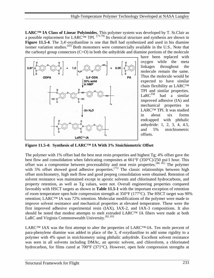
High-Temperature Polymer Technology Developed at NASA Langley
Structural Framework for Flight 233
LARC™ IA Class of Linear Polyimides. This polymer system was developed by T. St.Clair as a possible replacement for LARC™ TPI. [75-79] Its chemical structure and synthesis are shown in Figure 11.5-4. The 3,4'-oxydianiline is one that Bell had synthesized and used in his diamine isomer variation studies.[42] Both monomers were commercially available in the U.S.. Note that the carbonyl group connectors (C=O) in both the anhydride and diamine portions of the molecule
have been replaced with oxygen while the meta linkages throughout the molecule remain the same. Thus the molecule would be expected to have similar chain flexibility as LARC™ TPI and similar properties. LaRCTM had a similar improved adhesive (IA) and mechanical properties to LARC™ TPI. It was studied in about six forms endcapped with phthalic anhydride: 1, 2, 3, 4, 4.5, and 5% stoichiometric offsets.
Figure 11.5-4: Synthesis of LARC™ IA With 3% Stoichiometric Offset The polymer with 1% offset had the best neat resin properties and highest Tg; 4% offset gave the best flow and consolidation when fabricating composites at 661°F (350°C)/250 psi/1 hour. This offset was a compromise between processability and neat resin properties.[80, 81] The polymer with 5% offset showed good adhesive properties.[75] The classic relationships between high offset stoichiometry, high melt flow and good prepreg consolidation were obtained. Retention of solvent resistance was maintained except in aprotic solvents and chlorinated hydrocarbons, and property retention, as well as Tg values, were not. Overall engineering properties compared favorably with HSCT targets as shown in Table 11.5-1 with the important exception of retention of room temperature open hole compression strength at 350°F (177°C). The HSCT target was 90% retention; LARC™ IA was 72% retention. Molecular modifications of the polymer were made to improve solvent resistance and mechanical properties at elevated temperature. These were the first improved adhesive experimental resin (IAX), IAX-2, and IAX-3 compositions. It also should be noted that modest attempts to melt extruded LARC™ IA fibers were made at both LaRC and Virginia Commonwealth University.[82, 83] LARC™ IAX was the first attempt to alter the properties of LARC™-IA. Ten mole percent of para-phenylene diamine was added in place of the 3, 4'-oxydianiline to add some rigidity to a polymer with 4% upset in stoichiometry using phthalic anhydride. Excellent solvent resistance was seen in all solvents including DMAc, an aprotic solvent, and chloroform, a chlorinated hydrocarbon, for films cured at 700°F (371°C). However, open hole compression strengths at
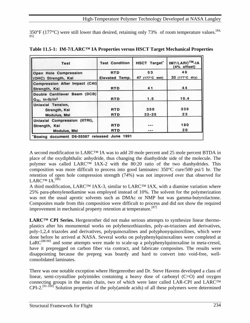
High-Temperature Polymer Technology Developed at NASA Langley
Structural Framework for Flight 234
350°F (177°C) were still lower than desired, retaining only 73% of room temperature values.[84,
85] Table 11.5-1: IM-7/LARC™ IA Properties versus HSCT Target Mechanical Properties
A second modification to LARC™ IA was to add 20 mole percent and 25 mole percent BTDA in place of the oxydiphthalic anhydride, thus changing the dianhydride side of the molecule. The polymer was called LARC™ IAX-2 with the 80:20 ratio of the two dianhydrides. This composition was more difficult to process into good laminates: 350°C cure/500 psi/1 hr. The retention of open hole compression strength (74%) was not improved over that observed for LARC™ IA.[86] A third modification, LARC™ IAX-3, similar to LARC™ IAX, with a diamine variation where 25% para-phenylenediamine was employed instead of 10%. The solvent for the polymerization was not the usual aprotic solvents such as DMAc or NMP but was gamma-butyrolactone. Composites made from this composition were difficult to process and did not show the required improvement in mechanical property retention at temperature.[87]
LARC™ CPI Series. Hergenrother did not make serious attempts to synthesize linear thermo-plastics after his monumental works on polybenzothiazoles, poly-as-triazines and derivatives, poly-1,2,4 triazoles and derivatives, polyquinoxalines and polyphonyquinoxilines, which were done before he arrived at NASA. Several works on polyphenylquinoxalines were completed at LaRC[88-90] and some attempts were made to scale-up a polyphenylquinoxaline in meta-cresol, have it prepregged on carbon fiber via contract, and fabricate composites. The results were disappointing because the prepreg was boardy and hard to convert into void-free, well-consolidated laminates. There was one notable exception where Hergenrother and Dr. Steve Havens developed a class of linear, semi-crystalline polyimides containing a heavy dose of carbonyl (C=O) and oxygen connecting groups in the main chain, two of which were later called LAR-CPI and LARC™ CPI-2.[91-100] Solution properties of the poly(amide acids) of all these polymers were determined
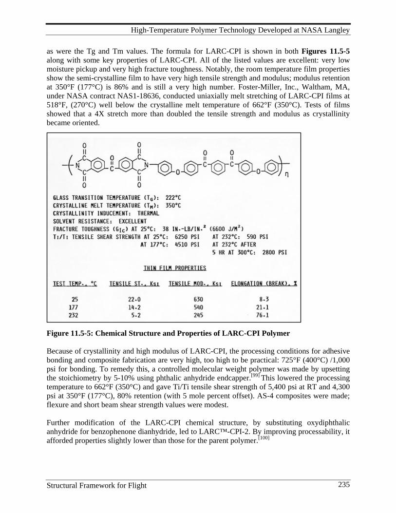
High-Temperature Polymer Technology Developed at NASA Langley
Structural Framework for Flight 235
as were the Tg and Tm values. The formula for LARC-CPI is shown in both Figures 11.5-5 along with some key properties of LARC-CPI. All of the listed values are excellent: very low moisture pickup and very high fracture toughness. Notably, the room temperature film properties show the semi-crystalline film to have very high tensile strength and modulus; modulus retention at 350°F (177°C) is 86% and is still a very high number. Foster-Miller, Inc., Waltham, MA, under NASA contract NAS1-18636, conducted uniaxially melt stretching of LARC-CPI films at 518°F, (270°C) well below the crystalline melt temperature of 662°F (350°C). Tests of films showed that a 4X stretch more than doubled the tensile strength and modulus as crystallinity became oriented.
Figure 11.5-5: Chemical Structure and Properties of LARC-CPI Polymer Because of crystallinity and high modulus of LARC-CPI, the processing conditions for adhesive bonding and composite fabrication are very high, too high to be practical: 725°F (400°C) /1,000 psi for bonding. To remedy this, a controlled molecular weight polymer was made by upsetting the stoichiometry by 5-10% using phthalic anhydride endcapper.[99] This lowered the processing temperature to 662°F (350°C) and gave Ti/Ti tensile shear strength of 5,400 psi at RT and 4,300 psi at 350°F (177°C), 80% retention (with 5 mole percent offset). AS-4 composites were made; flexure and short beam shear strength values were modest. Further modification of the LARC-CPI chemical structure, by substituting oxydiphthalic anhydride for benzophenone dianhydride, led to LARC™-CPI-2. By improving processability, it afforded properties slightly lower than those for the parent polymer.[100]
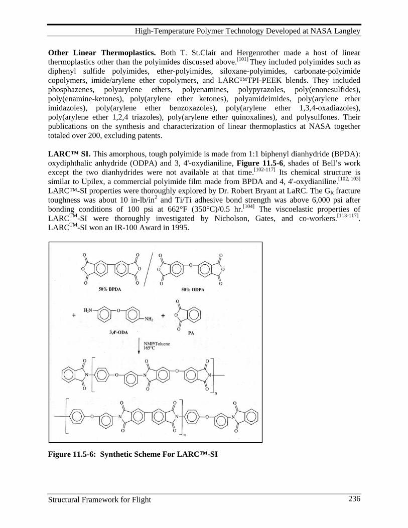
High-Temperature Polymer Technology Developed at NASA Langley
Structural Framework for Flight 236
Other Linear Thermoplastics. Both T. St.Clair and Hergenrother made a host of linear thermoplastics other than the polyimides discussed above.[101] They included polyimides such as diphenyl sulfide polyimides, ether-polyimides, siloxane-polyimides, carbonate-polyimide copolymers, imide/arylene ether copolymers, and LARC™TPI-PEEK blends. They included phosphazenes, polyarylene ethers, polyenamines, polypyrazoles, poly(enonesulfides), poly(enamine-ketones), poly(arylene ether ketones), polyamideimides, poly(arylene ether imidazoles), poly(arylene ether benzoxazoles), poly(arylene ether 1,3,4-oxadiazoles), poly(arylene ether 1,2,4 triazoles), poly(arylene ether quinoxalines), and polysulfones. Their publications on the synthesis and characterization of linear thermoplastics at NASA together totaled over 200, excluding patents. LARC™ SI. This amorphous, tough polyimide is made from 1:1 biphenyl dianhydride (BPDA): oxydiphthalic anhydride (ODPA) and 3, 4'-oxydianiline, Figure 11.5-6, shades of Bell’s work except the two dianhydrides were not available at that time.[102-117] Its chemical structure is similar to Upilex, a commercial polyimide film made from BPDA and 4, 4'-oxydianiline.[102, 103]
LARC™-SI properties were thoroughly explored by Dr. Robert Bryant at LaRC. The GIc fracture toughness was about 10 in-lb/in2 and Ti/Ti adhesive bond strength was above 6,000 psi after bonding conditions of 100 psi at 662°F (350°C)/0.5 hr.[104] The viscoelastic properties of LARCTM-SI were thoroughly investigated by Nicholson, Gates, and co-workers.[113-117]. LARCTM-SI won an IR-100 Award in 1995.
Figure 11.5-6: Synthetic Scheme For LARC™-SI
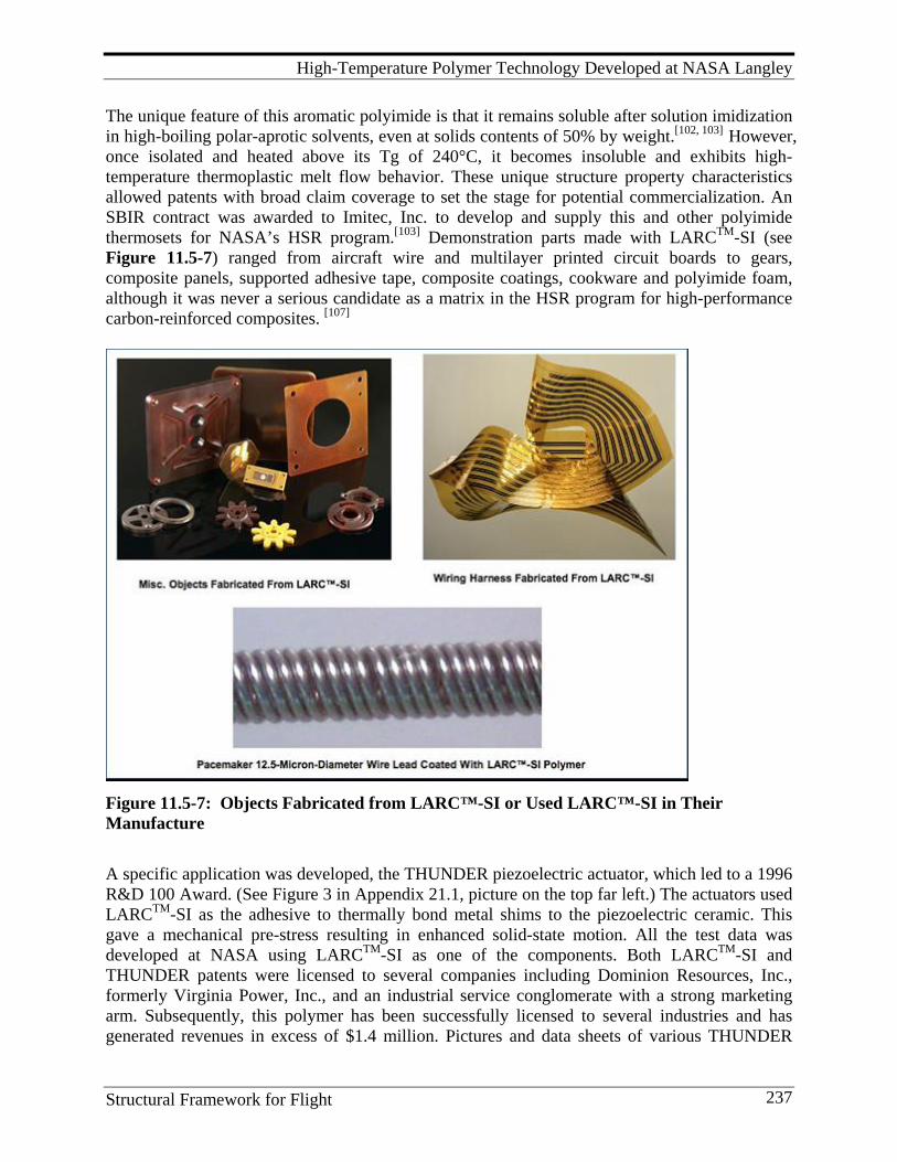
High-Temperature Polymer Technology Developed at NASA Langley
Structural Framework for Flight 237
The unique feature of this aromatic polyimide is that it remains soluble after solution imidization in high-boiling polar-aprotic solvents, even at solids contents of 50% by weight.[102, 103] However, once isolated and heated above its Tg of 240°C, it becomes insoluble and exhibits high-temperature thermoplastic melt flow behavior. These unique structure property characteristics allowed patents with broad claim coverage to set the stage for potential commercialization. An SBIR contract was awarded to Imitec, Inc. to develop and supply this and other polyimide thermosets for NASA’s HSR program.[103] Demonstration parts made with LARCTM-SI (see Figure 11.5-7) ranged from aircraft wire and multilayer printed circuit boards to gears, composite panels, supported adhesive tape, composite coatings, cookware and polyimide foam, although it was never a serious candidate as a matrix in the HSR program for high-performance carbon-reinforced composites. [107]
Figure 11.5-7: Objects Fabricated from LARC™-SI or Used LARC™-SI in Their Manufacture
A specific application was developed, the THUNDER piezoelectric actuator, which led to a 1996 R&D 100 Award. (See Figure 3 in Appendix 21.1, picture on the top far left.) The actuators used LARCTM-SI as the adhesive to thermally bond metal shims to the piezoelectric ceramic. This gave a mechanical pre-stress resulting in enhanced solid-state motion. All the test data was developed at NASA using LARCTM-SI as one of the components. Both LARCTM-SI and THUNDER patents were licensed to several companies including Dominion Resources, Inc., formerly Virginia Power, Inc., and an industrial service conglomerate with a strong marketing arm. Subsequently, this polymer has been successfully licensed to several industries and has generated revenues in excess of $1.4 million. Pictures and data sheets of various THUNDER
High-Temperature Polymer Technology Developed at NASA Langley
Structural Framework for Flight 238
actuators and sensors can be found at the website of Face International Corporation.[106] This work, as well as other actuator and piezoelectric developments, made LaRC the world leader in high-performance ceramic actuators. Sporting equipment manufacturers, printed circuit board manufacturers, military hardware suppliers, those interested in smart structures, and medical product supplies are examples of industries interested in this polymer.[105, 106, 108-112] It was the medical products industry (Medtronic) that licensed LARCTM-SI for use as a new wire insulation varnish for pacemaker 12.5-micron-diameter silicon wire leads, an application that was never envisioned. (See Figure 11.5-7, bottom photograph.) It is physically durable and biologically inert. LaRC, GRC, and JPL researchers have worked on using the LARCTM-SI polymer in electronic applications, including experiments to use the new material to replace circuit boards. Ceramic actuators are used in machine tools, wireless switching applications, transformers, and many other devices. Originally, LARCTM-SI was targeted for use as an anti-fouling coating on 20-ft-diameter marine output pipes. Unfortunately, an economical thermal powder coating method was not developed to allow for on-site application. Poly(Arylene Ether Benzimidazole)s Work on poly(arlyene ether)s containing heterocyclic ring systems was initiated by Connell, Smith and Hergenrother in the early 1990s.[118-133] This approach was undertaken as a means of imparting into poly(arylene ether)s specific properties, such as higher Tgs and higher moduli, and it avoided the need for complex or difficult-to-prepare monomers that would be required if heterocyclic ring formation was the polymer-forming reaction. In some cases, the heterocyclic ring was contained in a bisphenol monomer and, in others, it served as the electron-withdrawing moiety that activated a halide for nucleophilic displacement. The synthetic work included a wide variety of heterocyclic ring systems, with the most significant development occurring with the poly(arylene ether benzimidazole)s. Poly(arylene ether benzimidazole)s, trade named LARCTM-PAEBI, were initially investigated for microelectronic applications, whereby processing from solution, high-temperature stability during fabrication, and adhesion to both polyimide and copper surfaces were of primary importance.[134] These polymers exhibited exceptional performance in this application and were used to fabricate prototype multi-layer integrated circuit modules for use in main frame computers. Ceramic modules (~4" X 4" X 0.25") containing 60-90 layers of circuitry were fabricated using LaRCTM-PAEBI as an adhesive layer. The fabrication process required harsh conditions including many excursions to ~400°C under an inert atmosphere. LaRCTM-PAEBI performed extremely well under these fabrication conditions and offered several advantages over polyimides more commonly used in the microelectronic industry, most notably the outstanding adhesion to copper as well as to polyimides. In addition, after thermal treatment LaRCTM-PAEBI becomes insoluble and does not swell when exposed to polar aprotic solvents allowing successive layers to be deposited. LaRCTM-PAEBI was qualified for production but, for external reasons unassociated with the cost or performance of the material, was never commercialized. Another material from the poly(arylene ether benzimidazole) family which contained phosphine oxide groups was commercialized for space applications.[127, 131, 133] Due to the phosphine oxide
High-Temperature Polymer Technology Developed at NASA Langley
Structural Framework for Flight 239
group, these polymers exhibited a significant improvement in resistance to erosion from atomic oxygen.[133] This polymer technology was commercialized, marketed and sold under the trademark TORTM. It was evaluated in both ground-based simulation facilities and LEO space flight exposures for up to 18 months. It was used to fabricate prototype solar arrays at Lockheed Martin, Sunnyvale, CA and performed well as a drop-in replacement for Kapton® film. This materials technology progressed from laboratory-scale development to commercial products being used on spacecraft in less than 10 years. The polymers exhibited 1-2 orders of magnitude increase in resistance to AO over state-of-the-art materials. This translated into an increased lifetime of the spacecraft and the enabling of LEO missions that previously were only concepts. The significance of the TORTM polymer technology has resulted in several product forms (film, fiber, thread and adhesive formulations) that are building blocks for critical spacecraft components. TORTM polymers have been shown to have other unique properties, such as excellent adhesion to copper and aluminum, good insulating properties, high-temperature performance and resistance to high voltage breakdown. Due to this combination of properties, TORTM was selected to insulate and provide AO protection for 160 meters of the conductive aluminum wire on the Propulsive Small Expendable Deployer System (ProSEDS) electro-dynamic tether-based space flight demonstration. Triton Systems, Inc. manufactured, quality controlled, tested and delivered the flight tether and a back-up. This technology was selected for a R&D 100 award in 2000 and a NASA Aerospace Technology Transfer Award (Richard T. Whitcomb) in 2001. Several patents were issued and licensed exclusively to Triton Systems, Inc. [134-138] Epoxy resins were synthesized with phosphine oxide built into the diamine portion of the polymer chain for investigation as flame retardants.[139] Novel Monomers and Poly(ether imides). One other significant operation should be mentioned before proceeding to the thermosets. During the SCAR program in the early 1970s, discussed in Section 6.2, LaRC/Johnston awarded a major contract, NAS1-12079, to the General Electric Company, Corporate Research and Development (T. Takekoshi, W. R. Hillig, and G. A. Mellinger, Principal Investigators), to prepare 14 new ether dianhydride monomers from the novel nitro displacement reaction of nitrophthalimides with various bisphenols. This interesting reaction ultimately led to the development and commercialization of the ULTEM™ series of polyimide thermoplastics which used bisphenol A as one of its monomers. Fourteen dianhydride monomers were used to synthesize 42 new poly(ether imides) and several soluble ether-pyrrones. While none were of ultimate use in the HSR program, they provided a novel series of polyether-imide structures for evaluation. Of most interest, however, were the new dianhydrides that allowed the polymer group to make many novel polyimides from the multitude of new isomeric diamines that Bell had synthesized. The GE contract led to a number of very interesting publi-cations. [140-147] With this entourage of thermoplastic polyimides, one might guess that thermoplastics would win the day. As an introduction for Johnston at a Gordon Research Conference during this time, the cartoon in Figure 11.5-8 was shown and seemed to summarize the situation. But, as it turned out, Paul Revere was heading in the wrong direction. High temperature thermosets were beginning to flex their potential muscles and the dark clouds would soon disappear.
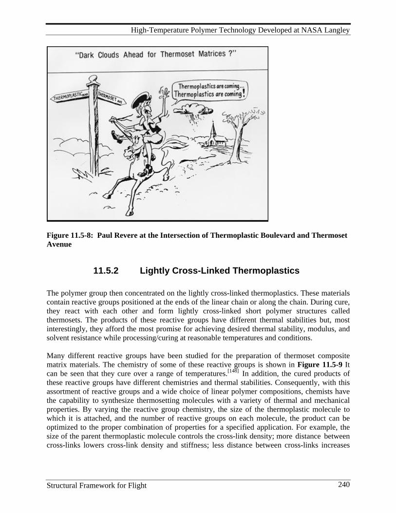
High-Temperature Polymer Technology Developed at NASA Langley
Structural Framework for Flight 240
Figure 11.5-8: Paul Revere at the Intersection of Thermoplastic Boulevard and Thermoset Avenue
11.5.2 Lightly Cross-Linked Thermoplastics The polymer group then concentrated on the lightly cross-linked thermoplastics. These materials contain reactive groups positioned at the ends of the linear chain or along the chain. During cure, they react with each other and form lightly cross-linked short polymer structures called thermosets. The products of these reactive groups have different thermal stabilities but, most interestingly, they afford the most promise for achieving desired thermal stability, modulus, and solvent resistance while processing/curing at reasonable temperatures and conditions. Many different reactive groups have been studied for the preparation of thermoset composite matrix materials. The chemistry of some of these reactive groups is shown in Figure 11.5-9 It can be seen that they cure over a range of temperatures.[148] In addition, the cured products of these reactive groups have different chemistries and thermal stabilities. Consequently, with this assortment of reactive groups and a wide choice of linear polymer compositions, chemists have the capability to synthesize thermosetting molecules with a variety of thermal and mechanical properties. By varying the reactive group chemistry, the size of the thermoplastic molecule to which it is attached, and the number of reactive groups on each molecule, the product can be optimized to the proper combination of properties for a specified application. For example, the size of the parent thermoplastic molecule controls the cross-link density; more distance between cross-links lowers cross-link density and stiffness; less distance between cross-links increases
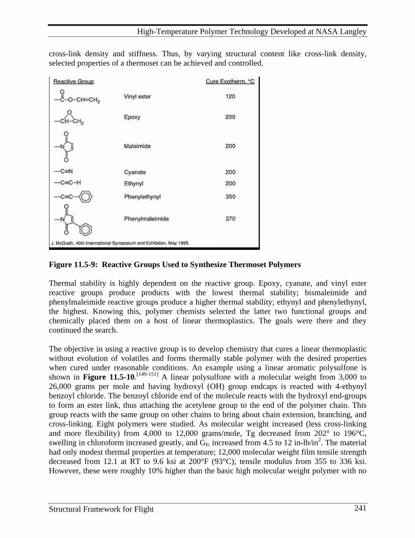
High-Temperature Polymer Technology Developed at NASA Langley
Structural Framework for Flight 241
cross-link density and stiffness. Thus, by varying structural content like cross-link density, selected properties of a thermoset can be achieved and controlled.
Figure 11.5-9: Reactive Groups Used to Synthesize Thermoset Polymers Thermal stability is highly dependent on the reactive group. Epoxy, cyanate, and vinyl ester reactive groups produce products with the lowest thermal stability; bismaleimide and phenylmaleimide reactive groups produce a higher thermal stability; ethynyl and phenylethynyl, the highest. Knowing this, polymer chemists selected the latter two functional groups and chemically placed them on a host of linear thermoplastics. The goals were there and they continued the search. The objective in using a reactive group is to develop chemistry that cures a linear thermoplastic without evolution of volatiles and forms thermally stable polymer with the desired properties when cured under reasonable conditions. An example using a linear aromatic polysulfone is shown in Figure 11.5-10.[149-151] A linear polysulfone with a molecular weight from 3,000 to 26,000 grams per mole and having hydroxyl (OH) group endcaps is reacted with 4-ethynyl benzoyl chloride. The benzoyl chloride end of the molecule reacts with the hydroxyl end-groups to form an ester link, thus attaching the acetylene group to the end of the polymer chain. This group reacts with the same group on other chains to bring about chain extension, branching, and cross-linking. Eight polymers were studied. As molecular weight increased (less cross-linking and more flexibility) from 4,000 to 12,000 grams/mole, Tg decreased from 202° to 196°C, swelling in chloroform increased greatly, and GIc increased from 4.5 to 12 in-lb/in2. The material had only modest thermal properties at temperature; 12,000 molecular weight film tensile strength decreased from 12.1 at RT to 9.6 ksi at 200°F (93°C); tensile modulus from 355 to 336 ksi. However, these were roughly 10% higher than the basic high molecular weight polymer with no
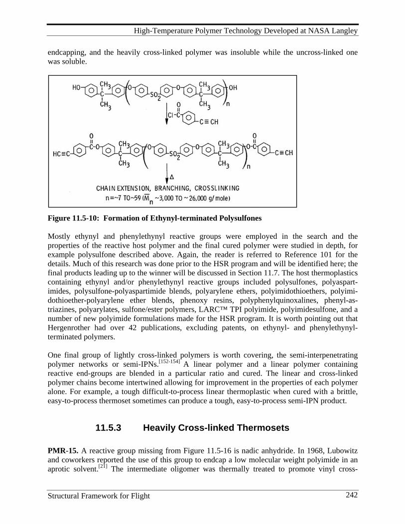
High-Temperature Polymer Technology Developed at NASA Langley
Structural Framework for Flight 242
endcapping, and the heavily cross-linked polymer was insoluble while the uncross-linked one was soluble.
Figure 11.5-10: Formation of Ethynyl-terminated Polysulfones Mostly ethynyl and phenylethynyl reactive groups were employed in the search and the properties of the reactive host polymer and the final cured polymer were studied in depth, for example polysulfone described above. Again, the reader is referred to Reference 101 for the details. Much of this research was done prior to the HSR program and will be identified here; the final products leading up to the winner will be discussed in Section 11.7. The host thermoplastics containing ethynyl and/or phenylethynyl reactive groups included polysulfones, polyaspart-imides, polysulfone-polyaspartimide blends, polyarylene ethers, polyimidothioethers, polyimi-dothioether-polyarylene ether blends, phenoxy resins, polyphenylquinoxalines, phenyl-as-triazines, polyarylates, sulfone/ester polymers, LARC™ TPI polyimide, polyimidesulfone, and a number of new polyimide formulations made for the HSR program. It is worth pointing out that Hergenrother had over 42 publications, excluding patents, on ethynyl- and phenylethynyl-terminated polymers. One final group of lightly cross-linked polymers is worth covering, the semi-interpenetrating polymer networks or semi-IPNs.[152-154] A linear polymer and a linear polymer containing reactive end-groups are blended in a particular ratio and cured. The linear and cross-linked polymer chains become intertwined allowing for improvement in the properties of each polymer alone. For example, a tough difficult-to-process linear thermoplastic when cured with a brittle, easy-to-process thermoset sometimes can produce a tough, easy-to-process semi-IPN product.
11.5.3 Heavily Cross-linked Thermosets PMR-15. A reactive group missing from Figure 11.5-16 is nadic anhydride. In 1968, Lubowitz and coworkers reported the use of this group to endcap a low molecular weight polyimide in an aprotic solvent.[21] The intermediate oligomer was thermally treated to promote vinyl cross-
High-Temperature Polymer Technology Developed at NASA Langley
Structural Framework for Flight 243
linking between the end-groups to form an insoluble, rigid material. Chemists at Lewis Research Center, now Glenn Research Center, improved on this process[22, 23, 155] by dissolving all the monomers in an alcohol solution and slowly heating the mixture to remove alcohol and allow the monomers to react with each other with evolution of water and more alcohol. A short chain polyimide is formed by heavy cross-linking through a very complex series of thermal reactions involving the nadic moiety. This procedure was dubbed Polymerization of Monomeric Reactants (PMR). The chain length created by adjusting the ratio of reactants was the number used to name the polymer: 1,500 g/mole would reduce to 15, thus PMR-15. The composition is best utilized, and most well known, as a matrix for carbon fiber-reinforced composites. The methanol solution is impregnated onto the fiber and some methanol is evaporated to make a flexible prepreg of high solids concentration. This prepreg is heated first to 392°F (200°C) to remove the remaining alcohol and some of the water of reaction. Further heating to 600°F (316°C) under pressure effects cross-linking and solidification. It maintains mechanical integrity at 600°F (316°C) for 1,000 hours in air, a most impressive performance.[24], It is not surprising it has found many applications in aircraft engines: aft bypass duct, external nozzle flap, augmentor duct, airframe interface ring, and many others. Hexcel made it available as prepreg from carbon and glass fabric and carbon tape under their trade name, F670, and issued data sheets advertising it for service up to 600°F. Hexcel did a lot of work developing modified cure cycles for the prepregs. It was also in the product line of Hysol Composites as HYCOMP M-100 PMR-15 polyimide powder, a fully imidized molding powder, and as a 70% solids solution in methanol. It is still one of the most respected and best known high-temperature, high-performance thermosets available today. It is relatively easy to process, has good mechanical properties, excellent retention of mechanical properties at elevated temperatures (288°-316°C) for an extended period (1,000-10,000 hours depending on the temperature), and a relatively low raw material cost. However, it has several shortcomings that severely limit its applications: enormous amounts of volatiles evolved during cure (for every mole of 1,500 molecular weight polyimide formed, six moles of water and six moles of methanol are produced), inadequate resin flow for fabricating thick composite structures, microcracking, and health concerns arising from the use of MDA, a suspected carcinogen.[155] For these reasons, other PMR-type polyimides were subsequently developed: LARC™-160, LARC™-RP 46, PMR-II, V-CAP, and AFR-700. The first two were developed at LaRC.
LARC™-160. LARC™-160 was developed by T. St.Clair and R. Jewell. The polymer has a unique liquid diamine mixture of isomeric methylene dianilines, called Jeffamine AP-22, where the repeat unit, n, in Figure 11.5-18 can equal 0, 1, or 2.[156,157] This mixture gave the polymer improved flow and processability over PMR-15 while compromising some thermal stability as a result of the presence of additional methylene (CH2) groups in the chain. It also greatly improved prepreg tack and drape. A 100-gallon batch was produced on contract and used to make carbon fiber prepreg by the old drum winding process. Composites were made and their properties compared favorably with PMR-15. Rockwell used it to fabricate motor rings for the Navstar satellites. A one-piece component replaced a 57-piece titanium structure that contained over 100 metal fasteners. LARC™-160 won the Branch’s first IR-100 Award in 1979. (The IR-100 Award

High-Temperature Polymer Technology Developed at NASA Langley
Structural Framework for Flight 244
for HR-100 cited in Section 6.5 was given to Hughes Aircraft Company.) However good its performance was, LARC™-160 did not have overwhelming advantages over PMR-15 and could not make inroads into markets already held by PMR-15. Also, by 1994, Jeffamine AP-22 was no longer commercially available. LARC™-RP-46. Dr. Ruth Pater transferred from NASA Lewis to NASA LaRC in the late 1980s and brought with her a thorough knowledge of PMR-15 including its advantages and disadvantages. A wealth of new monomers already developed at LaRC opened up to her and she developed a new PMR composition called LARC™-RP-46, the end result of a host of variations in the chemistry of the PMR system.[158-162] The 4, 4'-methylene dianiline used in PMR-15 and the Jeffamine methylene dianilines in LARC™-160 were replaced by an old favorite, 3,4'-oxydianiline, a diamine made by Bell, and which T. St. Clair used so effectively in the LARC™ IA and IAX series of linear thermoplastic polyimides. This diamine switch eliminated the risks involved in handling methylene dianiline, afforded a less costly monomer than those used in PMR-II, V-CAP, and AFR-700, and replaced a thermally less stable methylene group with the more oxidatively stable oxygen connection. Tg values, when cured at 700°F (371°C), varied from 747°F (397°C) to 822°F (439°C) after aging for 150 hours at 700°F in air. The Table 11.5-2 of Celion 6K composite properties shows the improvement in flexure strength and interlaminar shear strength made with LARC™-RP-46, especially at 700°F. The flexure strengths at 700°F of a series of PMR systems, cited above, are shown in the bar plot in Figure 11.5-11 and clearly show that LARC™-RP-46 is a superior material for high-temperature applications. Specifically,[163] flexure strengths at 700°F retained 83% of their unexposed value after 200 hours of exposure at 700°F and short beam shear strengths performed at 700°F retained 68% of their unexposed value after 200 hours of exposure at 700°F. Composites lost 10% weight when aged in an air-circulating oven at 700°F for 200 hours. These data suggest that LARC™RP-46 composites have a service life of approximately 100 to 200 hours at 700°F (371°C). Table 11.5-2: Flexure and Shear Properties of PMR-15 and LARC™-RP-46
Celion 6K Composite Flex Strength, MPa RT 316°C 371°C
Interlam. Shear Strength, MPa RT 316°C 371°C
PMR-15 1750 710 317 120 45 21.4 LARC™-RP-46 1724 917 793 131 51 32.4
LARC™-RP-46 won an IR-100 award in 1992; the citation quoted in R&D100 Magazine stated that it “not only retains or improves upon all the mechanical properties of PMR-15, but also features significantly improved processing characteristics, such as increased flow.”
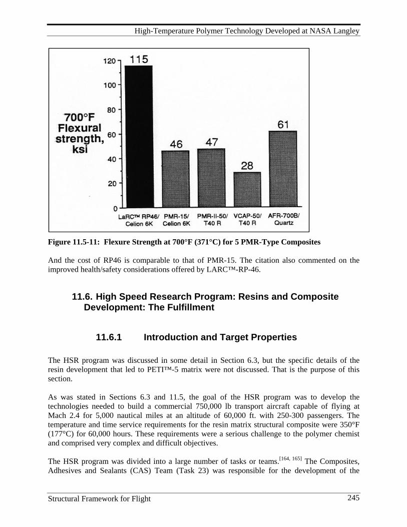
High-Temperature Polymer Technology Developed at NASA Langley
Structural Framework for Flight 245
Figure 11.5-11: Flexure Strength at 700°F (371°C) for 5 PMR-Type Composites And the cost of RP46 is comparable to that of PMR-15. The citation also commented on the improved health/safety considerations offered by LARC™-RP-46.
11.6. High Speed Research Program: Resins and Composite Development: The Fulfillment
11.6.1 Introduction and Target Properties The HSR program was discussed in some detail in Section 6.3, but the specific details of the resin development that led to PETI™-5 matrix were not discussed. That is the purpose of this section. As was stated in Sections 6.3 and 11.5, the goal of the HSR program was to develop the technologies needed to build a commercial 750,000 lb transport aircraft capable of flying at Mach 2.4 for 5,000 nautical miles at an altitude of 60,000 ft. with 250-300 passengers. The temperature and time service requirements for the resin matrix structural composite were 350°F (177°C) for 60,000 hours. These requirements were a serious challenge to the polymer chemist and comprised very complex and difficult objectives. The HSR program was divided into a large number of tasks or teams.[164, 165] The Composites, Adhesives and Sealants (CAS) Team (Task 23) was responsible for the development of the
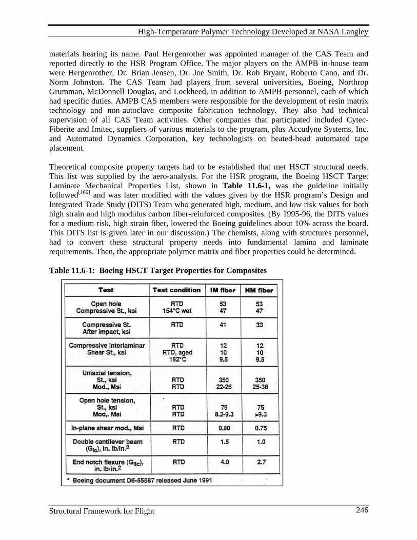
High-Temperature Polymer Technology Developed at NASA Langley
Structural Framework for Flight 246
materials bearing its name. Paul Hergenrother was appointed manager of the CAS Team and reported directly to the HSR Program Office. The major players on the AMPB in-house team were Hergenrother, Dr. Brian Jensen, Dr. Joe Smith, Dr. Rob Bryant, Roberto Cano, and Dr. Norm Johnston. The CAS Team had players from several universities, Boeing, Northrop Grumman, McDonnell Douglas, and Lockheed, in addition to AMPB personnel, each of which had specific duties. AMPB CAS members were responsible for the development of resin matrix technology and non-autoclave composite fabrication technology. They also had technical supervision of all CAS Team activities. Other companies that participated included Cytec-Fiberite and Imitec, suppliers of various materials to the program, plus Accudyne Systems, Inc. and Automated Dynamics Corporation, key technologists on heated-head automated tape placement. Theoretical composite property targets had to be established that met HSCT structural needs. This list was supplied by the aero-analysts. For the HSR program, the Boeing HSCT Target Laminate Mechanical Properties List, shown in Table 11.6-1, was the guideline initially followed[166] and was later modified with the values given by the HSR program’s Design and Integrated Trade Study (DITS) Team who generated high, medium, and low risk values for both high strain and high modulus carbon fiber-reinforced composites. (By 1995-96, the DITS values for a medium risk, high strain fiber, lowered the Boeing guidelines about 10% across the board. This DITS list is given later in our discussion.) The chemists, along with structures personnel, had to convert these structural property needs into fundamental lamina and laminate requirements. Then, the appropriate polymer matrix and fiber properties could be determined. Table 11.6-1: Boeing HSCT Target Properties for Composites
High-Temperature Polymer Technology Developed at NASA Langley
Structural Framework for Flight 247
For the chemists, three relationships were needed to do this. First, the chemists had to develop a fundamental understanding of the relationships between polymer molecular structure and polymer properties. With the manifold experiences cited in Section 11.6 on the synthesis of linear thermoplastics and cross-linked thermosets, these relationships were well-established. Second, relationships between polymer properties and experimental composite properties had to be developed. In fact, a list of desired properties for both neat resins and carbon fiber-reinforced composites had been developed earlier to guide matrix development.[167, 168, 169] This list is discussed in detail in the Damage Tolerance Section 15.1.3, and was presented in Section 11 above in Table 11.4-1. It became especially useful in screening new neat resin candidate matrices discussed in Section 11.6. A neat resin tensile modulus of 450 ksi at room temperature coupled with a fracture toughness of 4 in-lb/in2 (700 J/m2) were numbers that were difficult to obtain. Even more demanding, in the high-temperature polymer world, the achievement of a polymer with these numbers had to be combined with the achievement of a high glass transition temperature required for an HSCT (minimum 500°F/260°C). Third, fabrication of composites by whatever process must yield void-free laminates to achieve useful engineering properties. High flow matrices at whatever processing temperature would be needed for these high Tg, high modulus materials. From previous experience, Boeing dictated the autoclave temperature/pressure/time processing limits for the HSCT at 700°F (371°C)/200 psi/1hr. These were considered close to maximum for large-scale autoclave processing at that time. Fortunately, contractors found that for good adhesive bonding, the processing conditions could be lowered to 662°F (350°C).
11.6.2 Initial Candidates and Screening Protocol When the HSR Program began, a host of resin matrix candidates were available. These included the following:
1. From NASA via licensed sources: LARC™-TPI-1500 and ITPI, LARC™-RP-46, LARC™-IA, IAX and IAX-2, LARC™-CPI-2.
2. Commercial: Avimid K3B and mods (DuPont), Avimid N (DuPont), Aurum New TPI (Mitsui Toatsu), RD-92-107 (Ciba), AB Maleimidobenzocyclobutene (Dow), AFR-700 (TRW), perfluorocyclobutane XU-35033 (Dow), plus numerous bismaleimides, poly(arylene ethers), poly(amide imides), and poly(ether imides).
Many of these were evaluated either under various contracts to aerospace companies or in-house at LaRC. Almost all were found to have one or more weaknesses, such as no availability, poor thermal stability, poor solvent resistance, Tg too low, difficult to fabricate, expensive, too brittle (too low fracture toughness), too low tensile modulus, or too high Tm. Some will be discussed below. Neat resin screening was done in-house using Tg, the complex moduli at 50°, 150°, and 177°C, and the percent retention of 50°C modulus at 177°C. At one time in July 1993, the list of
High-Temperature Polymer Technology Developed at NASA Langley
Structural Framework for Flight 248
polymers examined grew to 49, 13 commercial and 36 in-house materials. And the number of experiments continued to grow. This gives an idea of the scope of the activity. The early work of Hergenrother, Jensen, Smith, and Bryant on the ethynyl-and phenylethynyl-terminated lightly cross-linked thermosets demonstrated the advantages of using the phenylethynyl group as a reactive end-group for polymers versus the ethynyl group.[170-175] The ethynyl endcaps cured without the evolution of volatiles but had several disadvantages. On relatively stiff and high Tg polymers, they reacted at too low a temperature (approximately 200°C) to allow good flow during processing. Also, at lower molecular weights, they produced high amounts of cross-linking thereby reducing toughness.[170, 171] The phenylethynyl group also cured without the evolution of volatiles but did so at temperatures higher than that of the ethynyl group (approximately 300-350°C or about 150°C delay over that of the ethynyl group), thus providing a larger processing window for the polymer backbone to flow; that is, the main chain flows before the endcapper starts to react. Thus, the material can be molded and shaped, then the end group reacts and forms a stiff solid of the desired shape. Due to the lack of ethynyl hydrogen, the cured phenylethynyl-terminated polymers also exhibited better thermal stability. But what polymer backbone was best to attach this new cross-linker? The chase was on. The phenylethynyl-terminated poly(arylene ethers) were found to have excellent processability and good thermal stability but the cured polymers were solvent sensitive and had a low modulus.[172] The phenylethynyl-terminated polyquinoxalines also possessed excellent processability and good adhesive properties but had poor solvent sensitivity to MEK.[173] A LaRC contract with Dow Chemical to develop benzocyclobutane chemistry[174] led to unique materials that did not have the thermal stability required for the HSCT. This fault was also seen with the Dow perfluorocyclobutane chemistry, the Amoco polyamide imides, the General Electric poly(ether imides), and the various commercial bismaleimides and poly(arylene ethers). It appeared the imide backbone definitely held the most promise for phenylethynyl termination.[175-177] And before the chase ended, over 200 formulations of just the phenylethynyl imides had been made. Initially, the imide oligomers were studied at the same molecular weight as the ethynyl-terminated arylene ether oligomers, 6,000 to 9,000 g/mole. If the formulated molecular weight of the phenylethynyl-terminated imide was too low, a loss of toughness would be expected as well as a higher cost since more of the expensive endcapper is required in the formulation. While higher molecular weight impedes processability, the higher processing temperature provided by the phenylethynyl moiety improved melt flow. It was also learned that the phenylethynyl thermal reaction provided lots of chain extension and little cross-linking at low molecular weights such as 6,000 to 9,000 g/mole. So, one could make phenylethynyl-terminated oligomers with molecular weights in that range and expect chain extension such that toughness would increase and not be compromised. Essentially, tradeoffs had to be considered between molecular weight, processability, properties such as toughness, and cost. Low molecular weight PETI led to lower melt viscosity and

High-Temperature Polymer Technology Developed at NASA Langley
Structural Framework for Flight 249
improved processability, but higher costs and reduced toughness. Higher molecular weight led to poorer processability, lower cost, and better toughness. Ultimately, a molecular weight of the 5,000 g/mole PETI was chosen that was slightly lower than the original 6,000 g/mole versions. The 5,000 g/mole PETI proved to provide the best combination of properties. Work also proceeded on how the phenylethynyl groups should be attached to the host oligomeric chain: pendant, terminal, both, or double terminal. Terminal endcapping afforded the overall best properties. Further events led to a number of phenylethynyl endcappers, several with amine reactive connections to the linear oligomers and several with anhydride reactive connections. Their structures will be disclosed below. To evaluate candidate matrices, HSR contract tasks were assigned to Northrop and Boeing for adhesives. A four-phase Candidate Polymer Matrix Composite Screening Protocol was developed by the HSR teams involved in composite development; it used ASTM, Northrop, and Boeing internal test methods and specifications. The four phases were later reduced to three phases by dropping Phase I. The phases were as follows: Phase I: prepreg screening (later dropped); Phase II: initial composite quality (ultrasonic inspection, OHC, interface test by transverse flexure strength, laminate physicals, Tg dry and wet, post cure optimization); Phase III: intermediate screening (OHC, compression modulus, CAI, thermal cycling for microcracks, solvent sensitivity, fatigue screening by 4-point flexure); Phase IV: final screening (5,000 hr isothermal aging at 350°F and 400°F; cure cycle envelope; prepreg shelf life; lamina properties including tension, compression and shear at RT/wet, 300°F wet, and 350°F wet; OHT, OHC, FHC, and bearing tension under the same three temperature conditions; CAI; and fabrication of subscale elements, and CAI test of a 3-spar panel). It should be noted that several of the linear polyimides developed at LaRC were evaluated under these HSR contracts using the four-phase protocol. While LARC™-IA had reasonably good mechanical properties, it had a slight solvent sensitivity. T. St. Clair’s efforts to modify the backbone to correct these deficiencies led to LARC™-IAX and LARC™-IAX-2. Their composite properties are listed below in Tables 11.6-11 and 11.6-12. Notably, DuPont’s K3B linear polyimide and its phenylethynyl-terminated successors, R1-16 and R2-19, were the major competitors for the ultimate HSR matrix resin; K3B’s properties were often compared to all other candidates, as we shall see. From 1992 to 1995, a series of PETI polyimides were made by AMPB staff that culminated in LARC™-PETI-5 which was scale-up and exploited in the last years of the program. As mentioned earlier, throughout the research, three overriding factors influenced the chase: properties, processability, and cost.
11.6.3 The Early PETI Candidates: LARC™-PETI-1 and LARC™-PETI-2
The obvious approach was to use one of the LARC-candidate polymers, control its molecular weight, and proceed with phenylethynyl termination.[177, 179, 181-184] This was done with LARC™-
High-Temperature Polymer Technology Developed at NASA Langley
Structural Framework for Flight 250
IA using two different phenylethynyl endcappers, one where an amine reactive group would react with the anhydride end-groups of the oligomer and one where an anhydride reactive group would react with the amine end-groups of the oligomer. In fact, a significant breakthrough by Hergenrother and Smith in PETI technology was the development of 4-phenylethynyl phthalic anhydride (PEPA) as an endcapper. A Northrop task was used to evaluate the IM-7 composite properties of PETI-1. Cure conditions were 662°F (350°C)/200 psi/1 hr. The data are reasonable but retention of properties at temperature is below desired levels. For PETI-1, OHC at 177°C wet was 63% of RT value; short beam shear strength at 177°C was 50% of its RT value. Its CAI (302 mPa, 43.3 ksi) was below the 50-ksi target value. Flexure strength retention at 177°C was very good for PETI-1 (88%) but very bad for PETI-2 (67%). The search needed to proceed.
11.6.4 The Candidates: LARC™-PETI-4, LARC™-8515, and LARC™-PETI-5
Hergenrother decided to split up the research by having Dr. Rob Bryant synthesize copolymers containing one diamine but multiple dianhydrides while Dr. Brian Jensen did the opposite, synthesizing copolymers with one dianhydride but multiple diamines.[178] Bryant made two polymers with 3,4'-ODA, one using ODPA, the other with BPDA.[102, 103] Then, he decided to make two more from a mixture of both dianhydrides (1:1 and 3:1) and 3,4'-ODA. All four had a 3% offset ratio using phthalic anhydride (PA) and were synthesized at 30% solids in NMP. Before he started to synthesize the four phenylethynyl-terminated prepolymers, he was sufficiently alert to note a significant difference in the solubility of the four oligomers when the prepolymers were heated in NMP to fully imidize them. The 1:1 copolymer mixture was the only one remaining soluble at 30% solids in the imidized form in either hot or cold NMP. The rest formed semi-crystalline precipitates. Jensen, in the meantime, synthesized many oligomer prepolymer powders, all endcapped with the amine phenylethynyl terminator with offset stoichiometry yielding molecular weights of 6,000 and 9,000g/mole.[179] In all compositions utilizing chain terminators going back to PMR-15, the molecular weight (e.g., chain length) had to be limited or the polymer would not flow under the heat and pressure limits used to fabricate composites. Using a variety of diamines, nine compositions were made with BTDA, four with PMDA, and seven with BPDA. Eleven of these were copolymers containing multiple diamines that were tailored to produce the desired combination of properties. The prepolymer powders were cured at 662°F (350°C) for one hour in a stainless steel mold to ascertain their processability. In only one case, whose processability was deemed excellent, a considerable amount of flash was observed around the mold. That was the composition made from BPDA and a 85/15 mixture of 3,4'-ODA and APB, an abbreviated spelling for 1,3-bis3-aminophenoxy)-benzene, an expensive diamine which had been used in earlier linear polymer compositions because of its all-aromatic ether extended-chain molecular structure. The molding flash was tough, fingernail creasable, and exhibited a cured Tg of 251°C. Therefore, this composition was chosen for scale-up and further evaluation and was designated LARC™-PETI-4. Its structure is shown in Figure 11.6-1, where the X is a portion of the amine
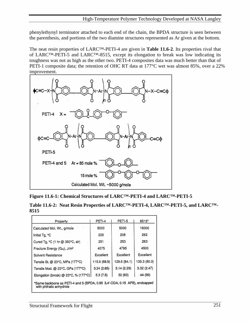
High-Temperature Polymer Technology Developed at NASA Langley
Structural Framework for Flight 251
phenylethynyl terminator attached to each end of the chain, the BPDA structure is seen between the parenthesis, and portions of the two diamine structures represented as Ar given at the bottom. The neat resin properties of LARC™-PETI-4 are given in Table 11.6-2. Its properties rival that of LARC™-PETI-5 and LARC™-8515, except its elongation to break was low indicating its toughness was not as high as the other two. PETI-4 composites data was much better than that of PETI-1 composite data; the retention of OHC RT data at 177°C wet was almost 85%, over a 22% improvement.
Figure 11.6-1: Chemical Structures of LARC™-PETI-4 and LARC™-PETI-5
Table 11.6-2: Neat Resin Properties of LARC™-PETI-4, LARC™-PETI-5, and LARC™-8515

High-Temperature Polymer Technology Developed at NASA Langley
Structural Framework for Flight 252
One might ask, what happened to PETI-3? According to Bryant,[180] it was basically the reaction of the SI prepolymer endcapped with PA and the amine phenylethynyl terminator. No data is available on its properties. Two new amine phenylethynyl terminators became available at this time and were pursued by the AMPB group. Starting from the PETI-4 backbone, but using these new endcappers, two new polyimides were synthesized.[181-182] Their cured film tensile properties were dutifully recorded and compared with the linear polymer without the endcapper, namely the PETI-4 backbone. Most interesting, this high molecular weight linear thermoplastic polyimide, overlooked in the initial PETI-4 development, had a Tg of 263°C (10°C higher than the endcapped materials) and its thin film properties were higher than those of the endcapped materials, in addition to its excellent thermal stability. It was named LARC™-8515, after the ratio of the diamine monomers used in the backbone. This chemistry is shown in Figure 11.6-2.
Figure 11.6-2: Chemistry of LARC™-8515 The neat resin properties of LARC™-8515 are shown in Table 11.6-2. It is most interesting that these properties were equal to, or better than, those of LARC™-PETI-4 and LARC™-PETI-5. The reason is that LARC™-8515 is a semicrystalline material with a melting transition temperature (Tm) of 664-671°F (351-355°C) depending on annealing and curing conditions. Consequently, to remove the crystallinity, it was shown the polymer had to be heated to 716°F (380°C). After this, the crystallinity could not be regenerated under any annealing condition. Laminate fabrication, however, had to occur at a prohibitively higher temperature than was acceptable for the HSR program in order to obtain amorphous, microcrack-resistant laminates. And the amorphous composites under stress were solvent-sensitive. Its IM-7 composite
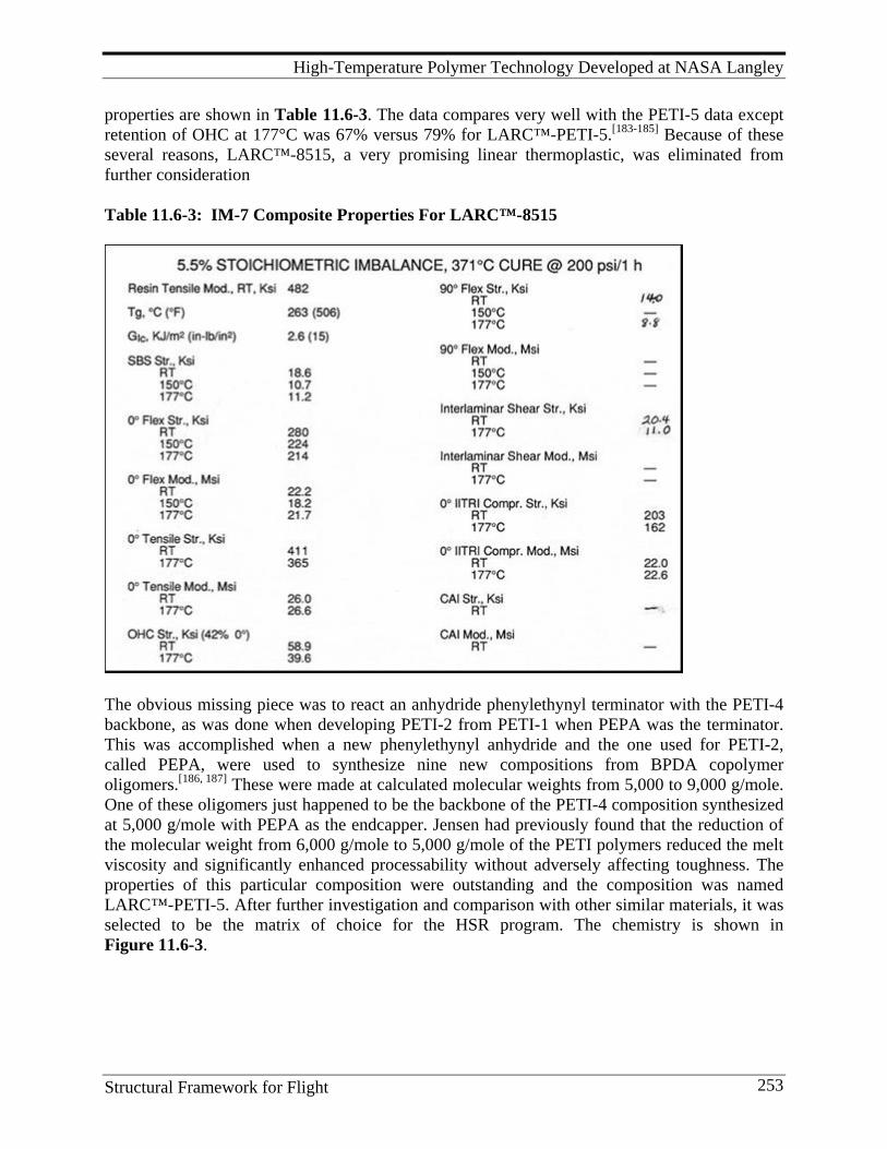
High-Temperature Polymer Technology Developed at NASA Langley
Structural Framework for Flight 253
properties are shown in Table 11.6-3. The data compares very well with the PETI-5 data except retention of OHC at 177°C was 67% versus 79% for LARC™-PETI-5.[183-185] Because of these several reasons, LARC™-8515, a very promising linear thermoplastic, was eliminated from further consideration Table 11.6-3: IM-7 Composite Properties For LARC™-8515
The obvious missing piece was to react an anhydride phenylethynyl terminator with the PETI-4 backbone, as was done when developing PETI-2 from PETI-1 when PEPA was the terminator. This was accomplished when a new phenylethynyl anhydride and the one used for PETI-2, called PEPA, were used to synthesize nine new compositions from BPDA copolymer oligomers.[186, 187] These were made at calculated molecular weights from 5,000 to 9,000 g/mole. One of these oligomers just happened to be the backbone of the PETI-4 composition synthesized at 5,000 g/mole with PEPA as the endcapper. Jensen had previously found that the reduction of the molecular weight from 6,000 g/mole to 5,000 g/mole of the PETI polymers reduced the melt viscosity and significantly enhanced processability without adversely affecting toughness. The properties of this particular composition were outstanding and the composition was named LARC™-PETI-5. After further investigation and comparison with other similar materials, it was selected to be the matrix of choice for the HSR program. The chemistry is shown in Figure 11.6-3.
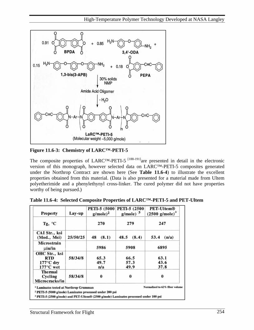
High-Temperature Polymer Technology Developed at NASA Langley
Structural Framework for Flight 254
Figure 11.6-3: Chemistry of LARC™-PETI-5 The composite properties of LARC™-PETI-5 [188-191]are presented in detail in the electronic version of this monograph, however selected data on LARC™-PETI-5 composites generated under the Northrop Contract are shown here (See Table 11.6-4) to illustrate the excellent properties obtained from this material. (Data is also presented for a material made from Ultem polyetherimide and a phenylethynyl cross-linker. The cured polymer did not have properties worthy of being pursued.) Table 11.6-4: Selected Composite Properties of LARC™-PETI-5 and PET-Ultem
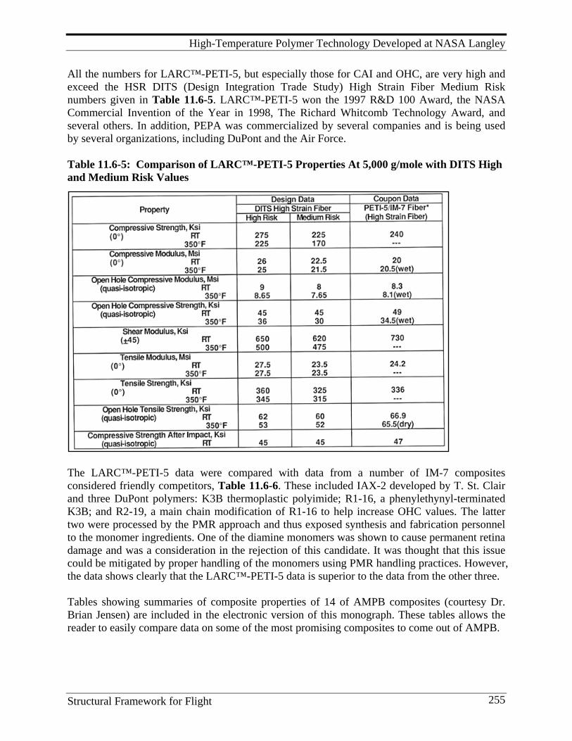
High-Temperature Polymer Technology Developed at NASA Langley
Structural Framework for Flight 255
All the numbers for LARC™-PETI-5, but especially those for CAI and OHC, are very high and exceed the HSR DITS (Design Integration Trade Study) High Strain Fiber Medium Risk numbers given in Table 11.6-5. LARC™-PETI-5 won the 1997 R&D 100 Award, the NASA Commercial Invention of the Year in 1998, The Richard Whitcomb Technology Award, and several others. In addition, PEPA was commercialized by several companies and is being used by several organizations, including DuPont and the Air Force. Table 11.6-5: Comparison of LARC™-PETI-5 Properties At 5,000 g/mole with DITS High and Medium Risk Values
The LARC™-PETI-5 data were compared with data from a number of IM-7 composites considered friendly competitors, Table 11.6-6. These included IAX-2 developed by T. St. Clair and three DuPont polymers: K3B thermoplastic polyimide; R1-16, a phenylethynyl-terminated K3B; and R2-19, a main chain modification of R1-16 to help increase OHC values. The latter two were processed by the PMR approach and thus exposed synthesis and fabrication personnel to the monomer ingredients. One of the diamine monomers was shown to cause permanent retina damage and was a consideration in the rejection of this candidate. It was thought that this issue could be mitigated by proper handling of the monomers using PMR handling practices. However, the data shows clearly that the LARC™-PETI-5 data is superior to the data from the other three. Tables showing summaries of composite properties of 14 of AMPB composites (courtesy Dr. Brian Jensen) are included in the electronic version of this monograph. These tables allows the reader to easily compare data on some of the most promising composites to come out of AMPB.
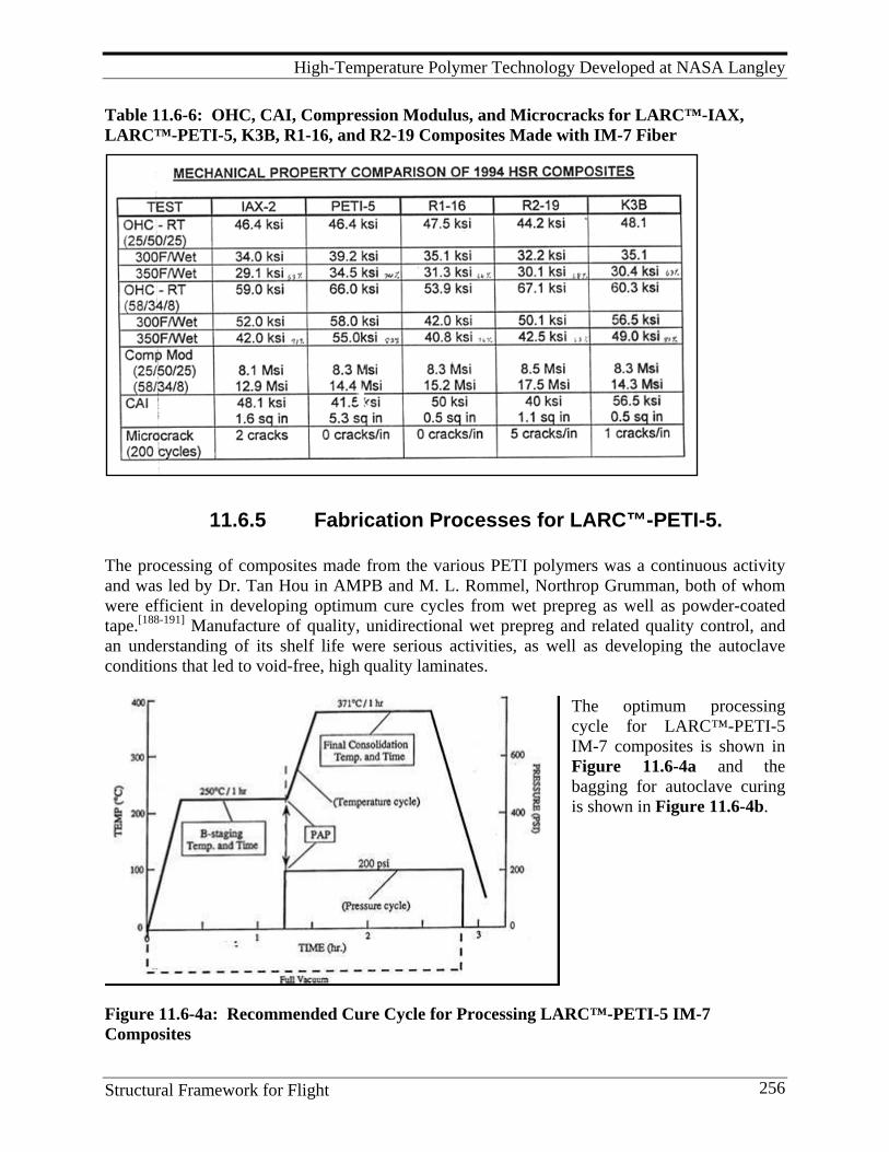
High-Temperature Polymer Technology Developed at NASA Langley
Structural Framework for Flight 256
Table 11.6-6: OHC, CAI, Compression Modulus, and Microcracks for LARC™-IAX, LARC™-PETI-5, K3B, R1-16, and R2-19 Composites Made with IM-7 Fiber
11.6.5 Fabrication Processes for LARC™-PETI-5. The processing of composites made from the various PETI polymers was a continuous activity and was led by Dr. Tan Hou in AMPB and M. L. Rommel, Northrop Grumman, both of whom were efficient in developing optimum cure cycles from wet prepreg as well as powder-coated tape.[188-191] Manufacture of quality, unidirectional wet prepreg and related quality control, and an understanding of its shelf life were serious activities, as well as developing the autoclave conditions that led to void-free, high quality laminates.
The optimum processing cycle for LARC™-PETI-5 IM-7 composites is shown in Figure 11.6-4a and the bagging for autoclave curing is shown in Figure 11.6-4b.
Figure 11.6-4a: Recommended Cure Cycle for Processing LARC™-PETI-5 IM-7 Composites
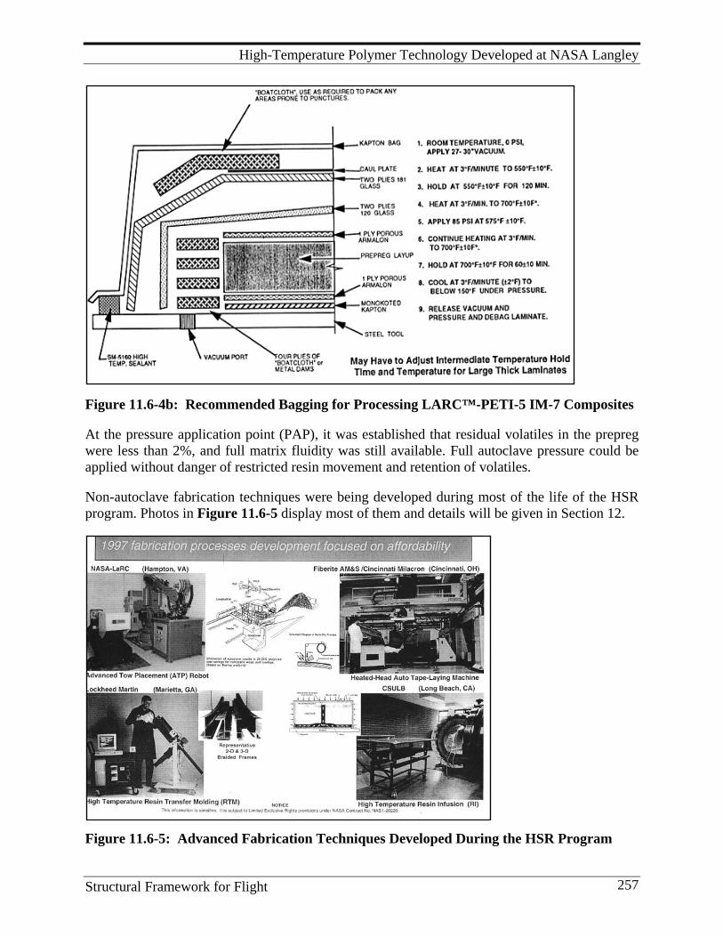
High-Temperature Polymer Technology Developed at NASA Langley
Structural Framework for Flight 257
Figure 11.6-4b: Recommended Bagging for Processing LARC™-PETI-5 IM-7 Composites At the pressure application point (PAP), it was established that residual volatiles in the prepreg were less than 2%, and full matrix fluidity was still available. Full autoclave pressure could be applied without danger of restricted resin movement and retention of volatiles. Non-autoclave fabrication techniques were being developed during most of the life of the HSR program. Photos in Figure 11.6-5 display most of them and details will be given in Section 12.
Figure 11.6-5: Advanced Fabrication Techniques Developed During the HSR Program
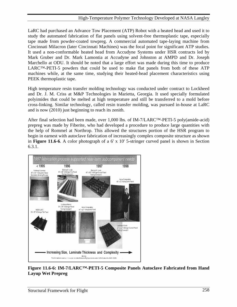
High-Temperature Polymer Technology Developed at NASA Langley
Structural Framework for Flight 258
LaRC had purchased an Advance Tow Placement (ATP) Robot with a heated head and used it to study the automated fabrication of flat panels using solvent-free thermoplastic tape, especially tape made from powder-coated towpreg. A commercial automated tape-laying machine from Cincinnati Milacron (later Cincinnati Machines) was the focal point for significant ATP studies. It used a non-conformable heated head from Accudyne Systems under HSR contracts led by Mark Gruber and Dr. Mark Lamontia at Accudyne and Johnston at AMPD and Dr. Joseph Marchello at ODU. It should be noted that a large effort was made during this time to produce LARC™-PETI-5 powders that could be used to make flat panels from both of these ATP machines while, at the same time, studying their heated-head placement characteristics using PEEK thermoplastic tape. High temperature resin transfer molding technology was conducted under contract to Lockheed and Dr. J. M. Criss at M&P Technologies in Marietta, Georgia. It used specially formulated polyimides that could be melted at high temperature and still be transferred to a mold before cross-linking. Similar technology, called resin transfer molding, was pursued in-house at LaRC and is now (2010) just beginning to reach its zenith. After final selection had been made, over 1,000 lbs. of IM-7/LARC™-PETI-5 poly(amide-acid) prepreg was made by Fiberite, who had developed a procedure to produce large quantities with the help of Rommel at Northrop. This allowed the structures portion of the HSR program to begin in earnest with autoclave fabrication of increasingly complex composite structure as shown in Figure 11.6-6. A color photograph of a 6' x 10' 5-stringer curved panel is shown in Section 6.3.1.
Figure 11.6-6: IM-7/LARC™-PETI-5 Composite Panels Autoclave Fabricated from Hand Layup Wet Prepreg
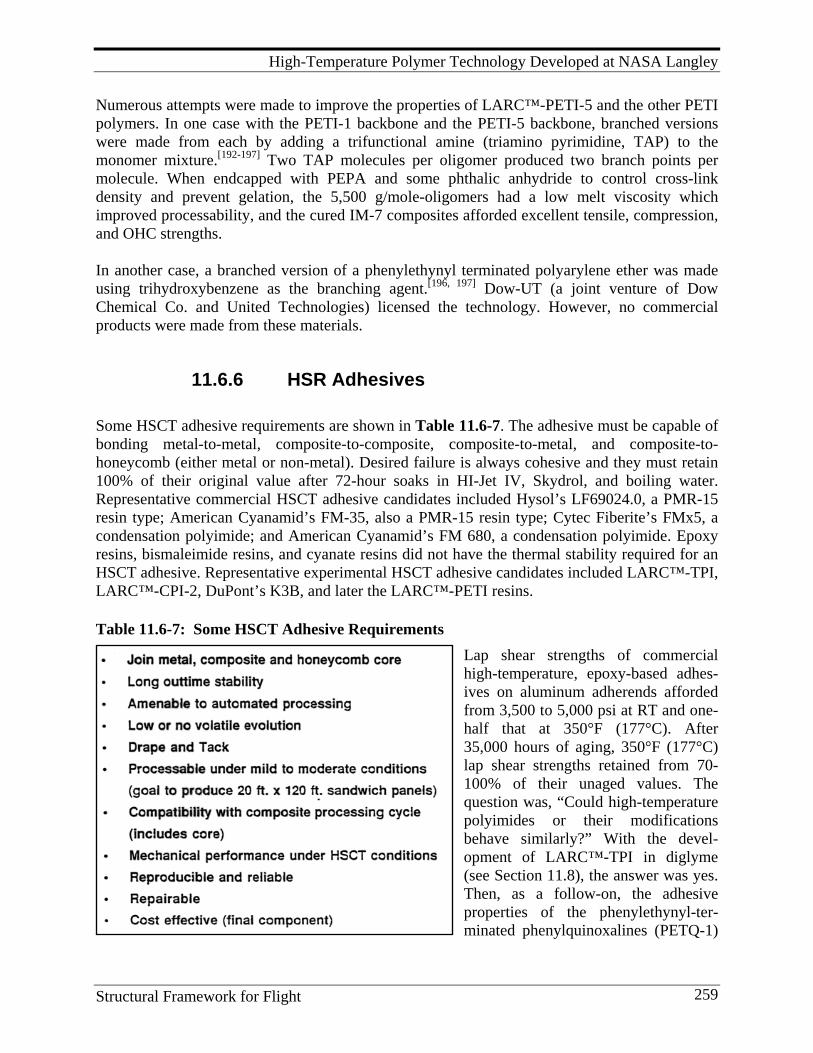
High-Temperature Polymer Technology Developed at NASA Langley
Structural Framework for Flight 259
Numerous attempts were made to improve the properties of LARC™-PETI-5 and the other PETI polymers. In one case with the PETI-1 backbone and the PETI-5 backbone, branched versions were made from each by adding a trifunctional amine (triamino pyrimidine, TAP) to the monomer mixture.[192-197] Two TAP molecules per oligomer produced two branch points per molecule. When endcapped with PEPA and some phthalic anhydride to control cross-link density and prevent gelation, the 5,500 g/mole-oligomers had a low melt viscosity which improved processability, and the cured IM-7 composites afforded excellent tensile, compression, and OHC strengths. In another case, a branched version of a phenylethynyl terminated polyarylene ether was made using trihydroxybenzene as the branching agent.[196, 197] Dow-UT (a joint venture of Dow Chemical Co. and United Technologies) licensed the technology. However, no commercial products were made from these materials.
11.6.6 HSR Adhesives Some HSCT adhesive requirements are shown in Table 11.6-7. The adhesive must be capable of bonding metal-to-metal, composite-to-composite, composite-to-metal, and composite-to-honeycomb (either metal or non-metal). Desired failure is always cohesive and they must retain 100% of their original value after 72-hour soaks in HI-Jet IV, Skydrol, and boiling water. Representative commercial HSCT adhesive candidates included Hysol’s LF69024.0, a PMR-15 resin type; American Cyanamid’s FM-35, also a PMR-15 resin type; Cytec Fiberite’s FMx5, a condensation polyimide; and American Cyanamid’s FM 680, a condensation polyimide. Epoxy resins, bismaleimide resins, and cyanate resins did not have the thermal stability required for an HSCT adhesive. Representative experimental HSCT adhesive candidates included LARC™-TPI, LARC™-CPI-2, DuPont’s K3B, and later the LARC™-PETI resins.
Table 11.6-7: Some HSCT Adhesive Requirements
Lap shear strengths of commercial high-temperature, epoxy-based adhes-ives on aluminum adherends afforded from 3,500 to 5,000 psi at RT and one-half that at 350°F (177°C). After 35,000 hours of aging, 350°F (177°C) lap shear strengths retained from 70-100% of their unaged values. The question was, “Could high-temperature polyimides or their modifications behave similarly?” With the devel-opment of LARC™-TPI in diglyme (see Section 11.8), the answer was yes. Then, as a follow-on, the adhesive properties of the phenylethynyl-ter-minated phenylquinoxalines (PETQ-1)
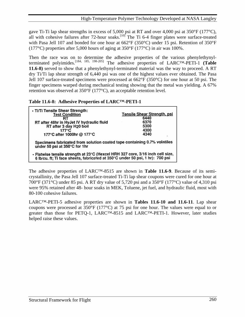
High-Temperature Polymer Technology Developed at NASA Langley
Structural Framework for Flight 260
gave Ti-Ti lap shear strengths in excess of 5,000 psi at RT and over 4,000 psi at 350°F (177°C), all with cohesive failures after 72-hour soaks.[10] The Ti 6-4 finger plates were surface-treated with Pasa Jell 107 and bonded for one hour at 662°F (350°C) under 15 psi. Retention of 350°F (177°C) properties after 5,000 hours of aging at 350°F (177°C) in air was 100%. Then the race was on to determine the adhesive properties of the various phenylethynyl-terminated polyimides.[184, 185, 198-205] The adhesive properties of LARC™-PETI-1 (Table 11.6-8) served to show that a phenylethynyl-terminated material was the way to proceed. A RT dry Ti/Ti lap shear strength of 6,440 psi was one of the highest values ever obtained. The Pasa Jell 107 surface-treated specimens were processed at 662°F (350°C) for one hour at 50 psi. The finger specimens warped during mechanical testing showing that the metal was yielding. A 67% retention was observed at 350°F (177°C), an acceptable retention level. Table 11.6-8: Adhesive Properties of LARC™-PETI-1
The adhesive properties of LARC™-8515 are shown in Table 11.6-9. Because of its semi-crystallinity, the Pasa Jell 107 surface-treated Ti-Ti lap shear coupons were cured for one hour at 700°F (371°C) under 85 psi. A RT dry value of 5,720 psi and a 350°F (177°C) value of 4,310 psi were 95% retained after 48- hour soaks in MEK, Toluene, jet fuel, and hydraulic fluid, most with 80-100 cohesive failures.
LARC™-PETI-5 adhesive properties are shown in Tables 11.6-10 and 11.6-11. Lap shear coupons were processed at 350°F (177°C) at 75 psi for one hour. The values were equal to or greater than those for PETQ-1, LARC™-8515 and LARC™-PETI-1. However, later studies helped raise these values.
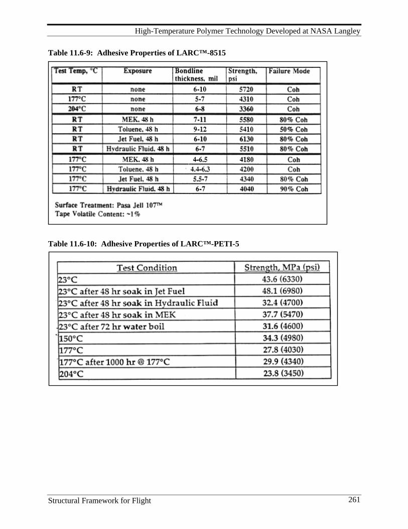
High-Temperature Polymer Technology Developed at NASA Langley
Structural Framework for Flight 261
Table 11.6-9: Adhesive Properties of LARC™-8515
Table 11.6-10: Adhesive Properties of LARC™-PETI-5
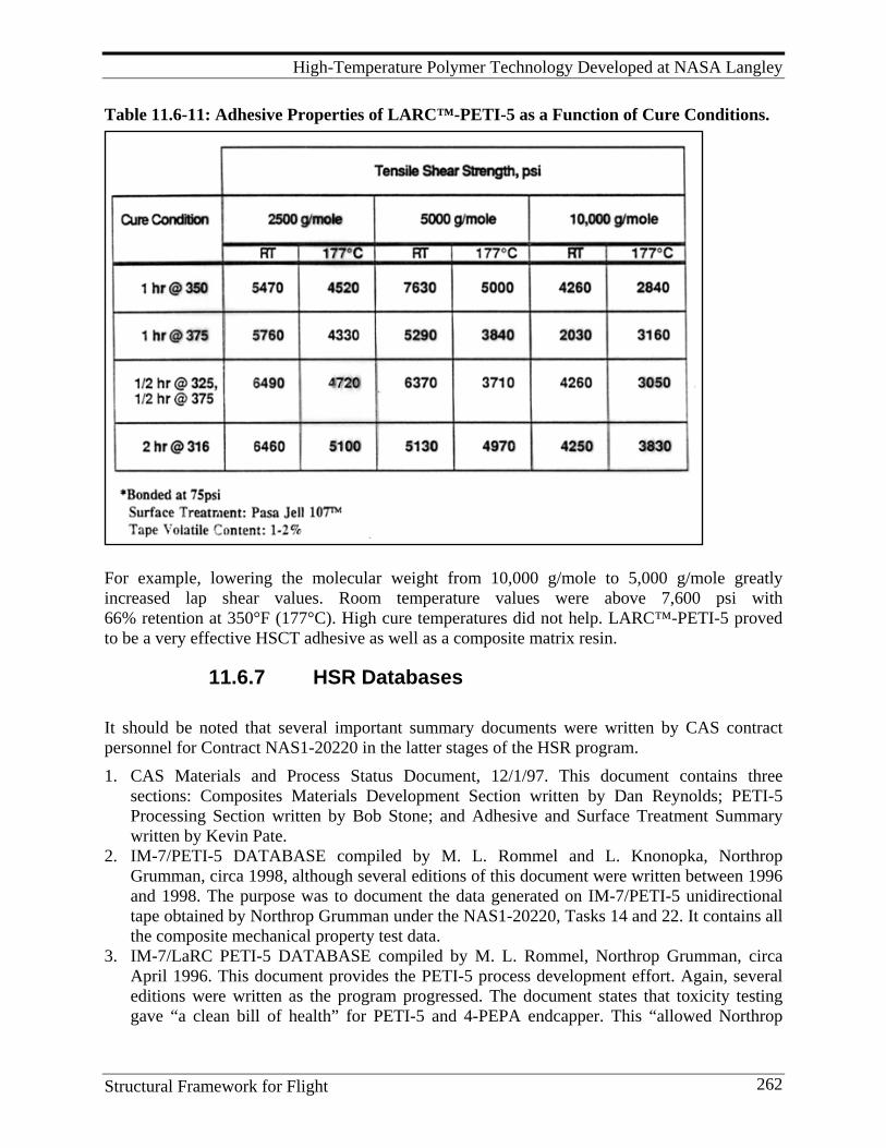
High-Temperature Polymer Technology Developed at NASA Langley
Structural Framework for Flight 262
Table 11.6-11: Adhesive Properties of LARC™-PETI-5 as a Function of Cure Conditions.
For example, lowering the molecular weight from 10,000 g/mole to 5,000 g/mole greatly increased lap shear values. Room temperature values were above 7,600 psi with 66% retention at 350°F (177°C). High cure temperatures did not help. LARC™-PETI-5 proved to be a very effective HSCT adhesive as well as a composite matrix resin.
11.6.7 HSR Databases It should be noted that several important summary documents were written by CAS contract personnel for Contract NAS1-20220 in the latter stages of the HSR program.
1. CAS Materials and Process Status Document, 12/1/97. This document contains three sections: Composites Materials Development Section written by Dan Reynolds; PETI-5 Processing Section written by Bob Stone; and Adhesive and Surface Treatment Summary written by Kevin Pate.
2. IM-7/PETI-5 DATABASE compiled by M. L. Rommel and L. Knonopka, Northrop Grumman, circa 1998, although several editions of this document were written between 1996 and 1998. The purpose was to document the data generated on IM-7/PETI-5 unidirectional tape obtained by Northrop Grumman under the NAS1-20220, Tasks 14 and 22. It contains all the composite mechanical property test data.
3. IM-7/LaRC PETI-5 DATABASE compiled by M. L. Rommel, Northrop Grumman, circa April 1996. This document provides the PETI-5 process development effort. Again, several editions were written as the program progressed. The document states that toxicity testing gave “a clean bill of health” for PETI-5 and 4-PEPA endcapper. This “allowed Northrop
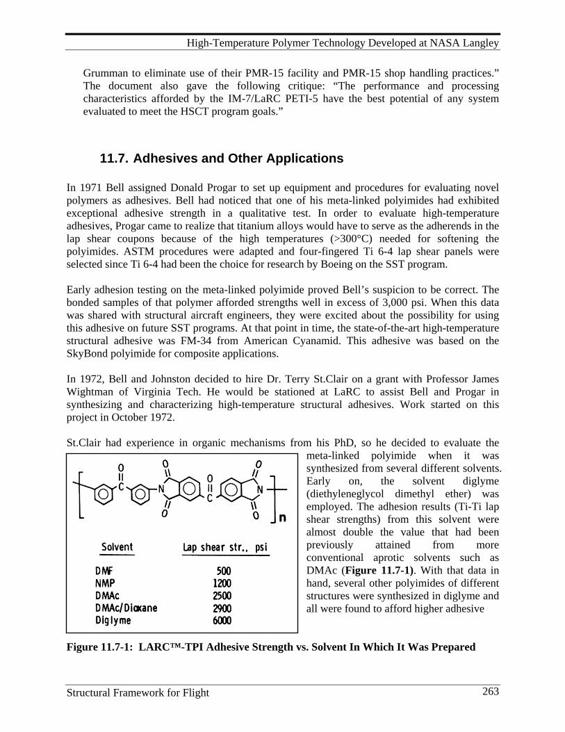
High-Temperature Polymer Technology Developed at NASA Langley
Structural Framework for Flight 263
Grumman to eliminate use of their PMR-15 facility and PMR-15 shop handling practices.” The document also gave the following critique: “The performance and processing characteristics afforded by the IM-7/LaRC PETI-5 have the best potential of any system evaluated to meet the HSCT program goals.”
11.7. Adhesives and Other Applications In 1971 Bell assigned Donald Progar to set up equipment and procedures for evaluating novel polymers as adhesives. Bell had noticed that one of his meta-linked polyimides had exhibited exceptional adhesive strength in a qualitative test. In order to evaluate high-temperature adhesives, Progar came to realize that titanium alloys would have to serve as the adherends in the lap shear coupons because of the high temperatures (>300°C) needed for softening the polyimides. ASTM procedures were adapted and four-fingered Ti 6-4 lap shear panels were selected since Ti 6-4 had been the choice for research by Boeing on the SST program. Early adhesion testing on the meta-linked polyimide proved Bell’s suspicion to be correct. The bonded samples of that polymer afforded strengths well in excess of 3,000 psi. When this data was shared with structural aircraft engineers, they were excited about the possibility for using this adhesive on future SST programs. At that point in time, the state-of-the-art high-temperature structural adhesive was FM-34 from American Cyanamid. This adhesive was based on the SkyBond polyimide for composite applications. In 1972, Bell and Johnston decided to hire Dr. Terry St.Clair on a grant with Professor James Wightman of Virginia Tech. He would be stationed at LaRC to assist Bell and Progar in synthesizing and characterizing high-temperature structural adhesives. Work started on this project in October 1972. St.Clair had experience in organic mechanisms from his PhD, so he decided to evaluate the
meta-linked polyimide when it was synthesized from several different solvents. Early on, the solvent diglyme (diethyleneglycol dimethyl ether) was employed. The adhesion results (Ti-Ti lap shear strengths) from this solvent were almost double the value that had been previously attained from more conventional aprotic solvents such as DMAc (Figure 11.7-1). With that data in hand, several other polyimides of different structures were synthesized in diglyme and all were found to afford higher adhesive
Figure 11.7-1: LARC™-TPI Adhesive Strength vs. Solvent In Which It Was Prepared
High-Temperature Polymer Technology Developed at NASA Langley
Structural Framework for Flight 264
strengths than the same polymers made in the more conventional solvents. Progar and St.Clair published early papers on this work in 1976 and 1977[47, 48, 49] and presented preliminary data in 1976 at national materials meetings where they received much attention. Simultaneously, Wight-man analyzed the failed surfaces and developed theories concerning polymer-metal interactions. Many technical papers on this subject were presented by Wightman and his group over the next 10-plus years. After the early success with the meta-linked polyimide that became known as LARC-TPI, Anne and Terry St.Clair worked on a NASA program to develop an adhesive for a large solar sail that was to be made of very thin Kapton™ film. This solar sail was to rendezvous with Halley’s Comet when its orbit came close to the Earth in the1980s. LARC-TPI made in diglyme afforded strong bonds with Kapton™ film, so that phase of the research was successful,[51, 52, 206, 207] but NASA engineers soon discovered that a solar sail of the size needed for such a mission would never fit into the Space Shuttle cargo bay. The program was abandoned. The St. Clairs published a Technical Brief on this work and Rogers Corporation showed immediate interest. They asked the NASA patent attorney, Dr. Wallace Nelson, to file a patent on this technology because they would like to license it, along with a pending patent on the meta-linked polyimide technology that Bell had filed.[50] Additionally, Rogers requested that NASA should determine if the LARC-TPI could be used to laminate copper to Kapton™. A. St.Clair carried out that experiment and proved it could be done. Rogers proceeded with the licensing and has made quite a success from this technology in their laminated electrical circuits. Circuits (Kapton™/copper/Kapton™) laminated with this adhesive withstood a 10-second immersion in molten solder at 575-600°F without blistering or delaminating. The circuits must survive 500 million flex cycles to meet the required specifications. In 2000, a facility in Hutchison, MN was making in excess of $50 million worth of such laminates per year. Interestingly, Boeing produced a circuit heater prepared by sandwiching a fine metallic heater between Kapton™ film using LARC™-TPI as the adhesive. The results from a Boeing extended-aging study of LARC™-TPI adhesive on titanium alloy adherends (10 volt chromic aid anodized surface treatment) showed no degradation in single lap shear strength after aging in air at 450°F (232°C) for 50,000 hours. Notably, while AMPB worked towards goals for structural adhesives and composites, there were many contributions to other related fields. For example, much of the pioneering polymer research made major contributions in electronics. It was thought some of the electronic applications would later come back to the aerospace industry in the form of advanced guidance equipment and smart structures. Also, the research led to development of colorless films[208-211] for, among others, advanced LCD and plasma TV applications; low dielectric polyimide films for high-temperature DoD applications[212, 213]; thermally stable piezoelectric and pyroelectric substrates and sensors[214, 215]; and fire-resistant polyimide foams for ship insulation and candidate insulation on Shuttle components[216, 217]. The fourteen IR R&D-100 awards demonstrate some of these other applications. See Appendix, Section 21.1.3. . Many commercial polyimide adhesive formulations contain metallic powder fillers, such as aluminum, to match the CTE of the metal adherends and to extend their upper-use temperature for structural bonding applications. However, for film laminating applications, this is not
High-Temperature Polymer Technology Developed at NASA Langley
Structural Framework for Flight 265
satisfactory; use of metal powder causes a large increase in bond weight and loss of adhesive joint flexibility. A. St. Clair showed that the high-temperature strength of a linear polyimide adhesive such as LARC™-TPI could be greatly improved by incorporating only 2-3% aluminum ions without embrittling the adhesive or increasing weight.[218] The aluminum ions were incorporated into the poly(amic-acid) precursor polymer solution in the form of aluminum acetylacetonate. This led to the development of a host of new polyimide coatings and films. From the early 1980s to the present (2010), AMPB has synthesized hundreds of novel high-temperature adhesives. A preview of the list of patents awarded to AMPB personnel given in the Appendix, Section 21.3, as well as the bibliographies of Hergenrother and T. St. Clair, indicate the breadth of the adhesive formulations developed at LaRC during these productive years. These materials were all bonded by Progar on the simple ASTM fixtures fabricated years before. AMPB supported both the SCAR and the HSCT/HSR programs with excellent adhesive candidates. LARC-TPI was the primary candidate for the SCAR program and an adhesive based on PETI-5 was the primary candidate for the HSCT program.
11.8. Polymer Characterization: 1962-1995 Events leading to the launch of Echo I on August 12, 1960, marked the birth of polymer research at Langley. Echo I was a 100-ft.-diameter balloon constructed of 0.5 mil Mylar™ or poly(ethylene terephthalate), PET, which had 2,200 Å of aluminum vapor deposited on its outer surface. Aluminized Mylar™ strips were adhesively bonded to produce the 31,400 ft.2 sphere, which was inflated in orbit by the sublimation of 30 lb. of benzoic acid and anthraquinone. This heralded the first large-scale use of non-metallic materials in space. Echo I served a dual purpose as a passive communication satellite and a means of measuring the density of the upper atmosphere. Since little was known of the space environment at that time, the design lifetime was predicted to be two weeks. Thus, researchers were advised to complete their experiments quickly because the vacuum of space coupled with solar UV, particulate, and electromagnetic radiation, and micrometeoroid impact was expected to completely obliterate the fragile structure in short order. To be on the safe side, President Eisenhower bounced his historic recorded message from space, also a first, from California to Bell Laboratories in New Jersey on Echo 1’s first complete orbit.[219] Approximately two years later, the satellite was still in orbit and still appeared to be spherical. The need to better understand the performance of polymeric materials in space was apparent. Plans for a directed study of the effects of the space environment on non-metallic materials were being formulated as early as April 1961.[220] The Spacecraft Materials Section in the Space Vehicle Branch, Applied Materials and Physics Division, became an official entity in April 1962. About a dozen technical and professional personal comprised its initial staff. The primary focus was on PET. However, the commercially available aromatic polyimide, Kapton™ (also called H-Film), polyvinylidene fluoride (Kynar™ or PVF), and polycarbonate (Lexan™ or PC) films were also examined. These materials were exposed to various simulated
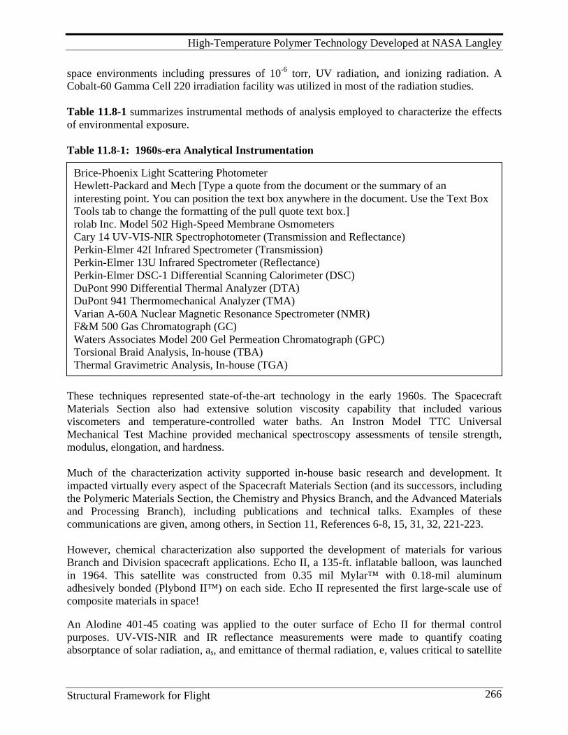
High-Temperature Polymer Technology Developed at NASA Langley
Structural Framework for Flight 266
Brice-Phoenix Light Scattering Photometer Hewlett-Packard and Mech [Type a quote from the document or the summary of an interesting point. You can position the text box anywhere in the document. Use the Text Box Tools tab to change the formatting of the pull quote text box.] rolab Inc. Model 502 High-Speed Membrane Osmometers Cary 14 UV-VIS-NIR Spectrophotometer (Transmission and Reflectance) Perkin-Elmer 42I Infrared Spectrometer (Transmission) Perkin-Elmer 13U Infrared Spectrometer (Reflectance) Perkin-Elmer DSC-1 Differential Scanning Calorimeter (DSC) DuPont 990 Differential Thermal Analyzer (DTA) DuPont 941 Thermomechanical Analyzer (TMA) Varian A-60A Nuclear Magnetic Resonance Spectrometer (NMR) F&M 500 Gas Chromatograph (GC) Waters Associates Model 200 Gel Permeation Chromatograph (GPC) Torsional Braid Analysis, In-house (TBA) Thermal Gravimetric Analysis, In-house (TGA)
space environments including pressures of 10-6 torr, UV radiation, and ionizing radiation. A Cobalt-60 Gamma Cell 220 irradiation facility was utilized in most of the radiation studies. Table 11.8-1 summarizes instrumental methods of analysis employed to characterize the effects of environmental exposure. Table 11.8-1: 1960s-era Analytical Instrumentation
These techniques represented state-of-the-art technology in the early 1960s. The Spacecraft Materials Section also had extensive solution viscosity capability that included various viscometers and temperature-controlled water baths. An Instron Model TTC Universal Mechanical Test Machine provided mechanical spectroscopy assessments of tensile strength, modulus, elongation, and hardness. Much of the characterization activity supported in-house basic research and development. It impacted virtually every aspect of the Spacecraft Materials Section (and its successors, including the Polymeric Materials Section, the Chemistry and Physics Branch, and the Advanced Materials and Processing Branch), including publications and technical talks. Examples of these communications are given, among others, in Section 11, References 6-8, 15, 31, 32, 221-223.
However, chemical characterization also supported the development of materials for various Branch and Division spacecraft applications. Echo II, a 135-ft. inflatable balloon, was launched in 1964. This satellite was constructed from 0.35 mil Mylar™ with 0.18-mil aluminum adhesively bonded (Plybond II™) on each side. Echo II represented the first large-scale use of composite materials in space! An Alodine 401-45 coating was applied to the outer surface of Echo II for thermal control purposes. UV-VIS-NIR and IR reflectance measurements were made to quantify coating absorptance of solar radiation, as, and emittance of thermal radiation, e, values critical to satellite
High-Temperature Polymer Technology Developed at NASA Langley
Structural Framework for Flight 267
temperature control. Support was also provided for several 12-ft.-diameter inflatable Explorer satellites as well as the Echo-twin Pageos satellite. The demand for characterization expanded as NASA Langley acquired a synthetic capability and began synthesizing a series of modified polyesters and high-performance polyimides and pyrrones. Many of the analytical techniques involved emerging technology, and considerable effort was devoted to gaining confidence in the data being generated. Thermoplastics, including PVF, PET, PC, and several additional polymerization materials of interest, were soluble in solvents such as ortho-chlorophenol, dimethylacetamide, and dimethylsulfoxide. This property enabled a number of solution property measurements, including light-scattering photometry and membrane osmometry, to be made. These two techniques give a measure of weight-average molecular weight (Mw) and number- average molecular weight (Mn), respectively. To meet the shift in emphasis from radiation stability to thermal stability as the Section matured, stepladder and ladder molecular structures were incorporated into the polymer backbone. These types of polymers were not soluble in conventional solvents. Thus, polymer characterization by the valuable solution property capability was eventually lost or replaced by characterization techniques applicable to insoluble polymers. Analytical instrumentation was up-graded as new technology became available. Nicolet Fourier Transform Infrared Spectometers (FTIR) replaced older prism and grating instruments. A Varian Fourier Transform Nuclear Magnetic Resonance Spectrometer (FT-NMR) provided carbon-13 as well as proton analyses. State-of-the-art DuPont and Perkin-Elmer thermal analysis instrumentation (DTA, DSC, TGA, TMA, Table 11.8-1) were also installed to support research across the entire Division. Torsional Braid and Dynamic Mechanical Analyses upgrades were implemented by the late 1960s. A Finnigan Model 3300 Quadrupole Mass Spectrometer (MS) and, later, gas chromatography-mass spectroscopy (GC-MS) were added to the arsenal of tools available for characterization. The heterocyclic, double-stranded molecular structures enabling improved radiation and thermal stability, by their very nature, resulted in intractable materials when it came to certain types of chemical characterization. Except for initial prepolymer stages, any analysis that depended on solubility was ruled out. A case in point was the series of Pyrrone polymers first reported in 1965.[29-32] Infrared spectroscopy was the primary tool employed to provide molecular-level information as the precursor was thermally cured. However, the interpretation of spectra was a complex problem. One approach taken to provide fundamental structural information was the study of model compounds. These simple organic molecules represented selected portions of the polymer repeat unit. Since these compounds were not polymeric, they were much more amenable to analysis. Various compounds resulting from the reaction of phthalic anhydride and ortho-phenylene diamine were isolated and characterized.[224] A similar, but more in-depth, study of products resulting from the reaction of PMDA and OPD was also conducted.[225] Numerous analytical techniques, in addition to infrared spectroscopy, were used to characterize these compounds, yielding unique insight into polymer chemistry. Model compound studies became an integral research tool for the characterization of experimental high-performance polymers. An example is given in Reference 226 on the cure reaction of norborene-endcapped polyimides.
High-Temperature Polymer Technology Developed at NASA Langley
Structural Framework for Flight 268
One of the lessons learned from Pyrrone research was that remarkable radiation and thermal stability could be engineered into molecular structure, but often at the expense of processability. The elimination of volatile solvent and condensation products during cure posed significant manufacturing problems. High glass transition and processing temperatures also compounded the fabrication of useful articles. Thus, some performance was sacrificed for the sake of improved processability. This led to a refocusing of interest on aromatic polyimides. Polyimides are synthesized from aromatic dianhydrides and aromatic diamines. A wide variety of monomeric dianhydrides and diamines enabled numerous structure-property relationships to be investigated. A critical factor affecting molecular weight is monomer purity. Sublimation usually provided polymerization-grade dianhydride. The amines were another problem. Many of the diamines were synthesized in-house and often only a few milligrams were available for further study. If impure, low molecular weight polymer insured a lost investment in time and effort. High performance liquid chromatography (HPLC) was an emerging technology in the early 1970s. HPLC was ideally suited for the analysis of aromatic amines and other compounds. A Waters Associated Model ALC 202/R401 HPLC became a welcome addition to the methods used for characterization. High-performance analytical and gel permeation chromatographic columns enhanced research capability. A Waters Associates Prep 500 instrument using large radially compressed columns was also available to chromatographically purify gram-sized quantities of monomers. The synthetic polymer chemist became adept at using the sharpness of both the DTA melt endotherm and the HPLC chromatogram to assess polymerization-grade monomers. Publications of the chromatographic analysis of aromatic diamines generated hundreds of requests for reprints at LaRC.[227-229] By the end of the decade, over a dozen technical and professional personnel were working almost exclusively on polymer characterization. The gradual shift in emphasis toward fiber- reinforced composite materials presented a new series of challenges, especially in the quality control of prepreg materials. Langley joined the forefront of the chemical characterization community by participating in a series of round-robins that culminated in annual meetings at the Rockwell Science Center, Thousand Oaks, CA. These meeting, first held in 1976, were organized by Clayton A. May of Lockheed and David H. Kaelble of the Rockwell Science Center. A series of identical prepreg samples were distributed to interested parties who analyzed them and then reported their results to other participants. Initial characterization techniques emphasized differential scanning calorimetry, HPLC, and infrared spectroscopy. Dielectric techniques became more prominent in later round-robins. The workshop focused on developing technology to quality-control advanced aerospace materials, primarily prepregs containing uncured epoxy and polyimide precursor matrices and carbon fiber reinforcement. The chemistry of these reactive systems can change with time
High-Temperature Polymer Technology Developed at NASA Langley
Structural Framework for Flight 269
making the reproducible manufacture of composites difficult. As many as 50 individuals from across the advanced material spectrum participated. The round-robin format matured and, in 1981, was accepted as a Gordon Research Conference entitled “Chemical Characterization of Structural Polymers.” This activity provided the Branch many professional contacts and opportunities within the industry. It also enhanced Langley’s efforts to develop industry-accepted prepreg quality-control methodology and standards.[230] The 1980s were an era in which the lessons learned from over 20 years of research were being applied to meet the ever-increasing needs for advanced materials. A significant improvement in processability accompanied the development of reactive endcapped oligomers.[161] A semi-stoichiometric mixture of monomer reactants was formulated with endcapping reagents capable of creating a cross-linked molecular structure at a later stage of processing. As with similar materials, LARC-160 resin yielded quality graphite fiber prepreg. A B-stage cure theoretically yielded imidized chemistry and the elimination of volatiles. Essentially, a low molecular weight species was being processed. A final high-temperature cure caused the reactive endcaps to cross-link the matrix resin and secure the fiber reinforcement. The new endcapped chemistry presented new characterization challenges, and studies involving both model compounds and polymers were conducted to provide basic information. The chemical characterization of carbon fiber prepreg is particularly difficult because the material is black, opaque, and intractable. Since the matrix resin is reactive, chemistry can change during the interval between when prepreg is fabricated and when it is processed into composites. Thus, aging effects become important. Information on resin chemistry as a function of temperature, heating rate, pressure, and hold time during processing was also desirable. Characterization tended to come to a halt once processing began. The characterization of composite materials moved forward with the discovery that they were good diffuse reflectors of infrared radiation.[231] A sample can either absorb, transmit, or reflect radiation. Reflection involves a specular or mirror-like reflection and a diffuse or scattered component. By exposing the sample to infrared radiation and collecting the diffuse component, a spectrum can be produced similar to that obtained in the transmission mode. It contains the characteristic fingerprint so valuable to the researcher. Fourier transform technology, where the spectrum is repeatedly scanned, data collected and averaged, and then processed, was a quantum advance in infrared spectroscopy. The arrival of the digital age revolutionized the ability to characterize materials. DR-FTIR studies were conducted on thermally-aged composite specimens. Comparison of aged and control sample spectra gave insight into changes at the molecular level as the result of exposure. This provided fundamental information on why selected mechanical properties deteriorated due to thermal aging. It also helped the synthetic polymer chemist identify weak links in the polymer backbone that could be modified to improve performance. DR-FTIR became a valued technique for the characterization of advanced materials.[232, 233] Molecular level information during cure was obtained by placing prepreg on a small programmable heater positioned at the focal point of the diffuse reflectance optics. Spectra were
High-Temperature Polymer Technology Developed at NASA Langley
Structural Framework for Flight 270
obtained during simulated cure cycles to gain insight into resin chemistry as a function of temperature.[234] The DR-FTIR work conducted at LaRC raised questions about the feasibility of placing infrared-transmitting optical fibers inside a composite to sense resin chemistry during cure. The Small Business Innovative Research Program (SBIR) was successfully employed to fund a preliminary investigation of the concept at Foster-Miller, Inc., Waltham, MA. Working with its Biorad-Digilab Division, Cambridge, MA, Foster-Miller successfully demonstrated the new tech-nology.[235] This activity led to a larger SBIR grant and eventually an R&D 100 Award in 1990 shared by Langley and Foster-Miller.[236] Much of the optical fiber sensing technology has since shifted into the near-infrared (NIR) region of the spectrum where more durable fibers are available. An impressive commercial industry involving fiber optic sensing has emerged over the past couple of decades (1990 -2010). LaRC has never been adequately recognized for their seminal work in this area. Thermoset matrix resin composites enabled remarkable structural performance. Unfortunately, they were also somewhat brittle and often exhibited less-than-desirable impact strength. Therm-oplastic polymers are inherently tougher than thermoset polymers. Thus, high-performance thermoplastics, such as LARC-TPI (thermoplastic imide), became new materials of interest.[52] Thermoplastics tend to exhibit solubility if not too crystalline. This reopened the possibility of making solution property measurements to characterize the distribution of molecular weights. Aside from molecular structure, molecular weight is the single most important property a polymer possesses. The capability to characterize molecular weights, lost in the 1960s, had to be relearned. Instrumentation available in the late 1980s and early 1990s to address this need was impressive. A number of analytical techniques were combined to achieve this goal. The ability to make light- scattering measurements at low angles using lasers eliminated the angular dependence of the Raleigh Factor. Mw values from a single measurement were possible. 1960s-era Zimm Plots were a thing of the past. However, an independent measurement of the change in refractive index of the solvent with concentration, the refractive index increment, was necessary. An LDC/ Milton Roy CMX-100 Low Angle Light Scattering (LALLS) photometer and Chromoatix Model KMX-16 Laser Differential Refractometer provided data for calculating Mw. A Knauer Digital Membrane Osmometer provided information for determining Mn. Gel permeation chromatography, in combination with various detectors, provided rapid molecular weight characterization “on-the-fly.” A Waters Associates HPLC using a 106/105/104/103 Å Ultrastyragel column bank separated samples according to size. A Waters Model 401 Refractive Index (RI) concentration detector and a Viscotek Model 100 Differential Viscometer (DV) connected in parallel in the GPC effluent stream enabled additional information. By performing a Universal GPC calibration,[237] and using software provided by Viscotek and LDC/Milton Roy in conjunction with LALLS, DV, and RI detectors, an astounding amount of information on molecular weight distribution could be generated in a short period. This dynamic data was checked by static LALLS and osmometry measurements. A Waters 150-
High-Temperature Polymer Technology Developed at NASA Langley
Structural Framework for Flight 271
C High-temperature GPC interfaced with a Viscotek Model 150R Differential Refractometer was brought online to complement the characterization of soluble polymers. A Microstyragel HT GPC column bank was employed for these analyses. By the mid-1990s, only a limited number of research laboratories could offer the types of solution property information being routinely generated in the Materials Division. This capability was used to characterize new aerospace resins being investigated in support of Division programs.[238, 239] It contributed significantly to the chemical characterization of polymeric materials that received exposure to the low-Earth environment on the LDEF. It was also used to characterize selected materials that flew on Space Shuttle flights in 1992.[240] Many talented and dedicated individuals, both technical and professional, spent much of their NASA careers working on some aspect of chemical characterization. They witnessed a remarkable transformation in the ability to gain molecular level information on macromolecules. The ability to characterize stimulated the synthetic polymer chemist to design new molecular structures to meet ever-increasing processing, performance, and durability requirements. The successes achieved were truly a team effort between management and the technical and professional staff within the Applied Materials and Physics Division and later the Materials Division and its successors.
11.9. Lessons Learned and Future Direction
11.9.1 Lessons Learned 1. By 1965, the original mission of the polymer group had been fulfilled; it quickly
converted to another and even more challenging mission, one that NASA had a huge stake in developing, that of high-temperature polymers and their processability. Any research group needs to be flexible in its goals so that it can quickly recognize and meet new challenges and continue to fruitfully exist and grow as new worthy goals are uncovered.
2. The research atmosphere needs to be such that new research areas can be explored without the need for instant gratification in terms of applications. The polymer accomplishments during the HSR program would not have been possible without the build-up of high-temperature polymer technology for 25 years prior. As so many have said before us, basic research is the father, and later custodian, of all development activities.
3. Team approach to solving complex research problems should be encouraged. The Stevenson-Wydler Act should not interfere with good team dynamics.
4. When developing new non-metallic materials, the following should be major concerns: a) fabrication must be efficient and cost-effective and robotic if at all possible; b) solvent or environmental sensitivity must be seriously considered; c) mechanical property goals (or targets) must be established; d) retention of properties under application conditions must be established; and e) aging studies, accelerated or normal, should be considered.
High-Temperature Polymer Technology Developed at NASA Langley
Structural Framework for Flight 272
11.9.2 Future Activities
1. Improved processability of composite structures should be a major pursuit. Autoclave processing is no longer competitive in most applications, either for epoxy, cyanate, bismaleimide, or polyimide resin-based, fiber-reinforced composites. It must be replaced.
2. High-temperature, vacuum-assisted, resin transfer molding (HT-VARTM) is one
possible approach to non-autoclavability. One of the toughest challenges faced in HT-VARTM is the reduction of void content to 2% or less required for aerospace applications. To date this has not been possible for polyimide resins by conventional HT-VARTM. About 3% void content has been achieved.
a. The current research must focused on in-depth studies to determine the volatile
source and when volatile evolution occurs followed by appropriate modification of the process cycle. High-temperature degradation studies under VARTM-simulated conditions of all the monomers used in the process must be done.
b. Implementation of higher fidelity temperature and pressure controls for the HT-VARTM process (essentially an upgrade of current in-house equipment) must be done.
c. Evaluation of the structural mechanical properties of the HT-VARTM polyimide composites is needed, especially at elevated temperature. We must determine if the formulation adjustments made to achieve HT-VARTM compromise their high-temperature properties.
d. Resistance to microcracking of the new HT-VARTM materials under thermal cycling from cryo (LN2, LH2) to elevated temperature should be evaluated.
e. Extend the HT-VARTM process to other classes of high-temperature polymers beside polyamides.
3. Molecular structure-property relationships through computational design must be
pursued in order to reduce the time required to develop new materials. It took about four years to develop LARC™-PETI-5 by senior polymer chemists already having a rather sophisticated background in high-temperature polymers. This is a waste of talent and time. With appropriate computational design of polymer molecules, the same development could be done in a year or less.
4. Processable inorganic/preceramic matrices should be explored for extreme temperature
applications between the organics and the ceramics. This is a fruitful field for extended research that AMPB is capable of pursuing.
5. Other non-autoclave composite processing technologies should be pursued. Robotic E-
beam curing was a bust. But robotic heated-head, automated placement using a conformable head has not seen its day. The first attempts were made during the HSR program which left lessons learned addressed later by small SBIR programs in cooperation with AMPB in-house activities. There is at least one company that under contract can be successful in this endeavor. And there are plenty of thermoplastic-type resin-based composites that can be explored with this technology. But the program needs
High-Temperature Polymer Technology Developed at NASA Langley
Structural Framework for Flight 273
funding. It could successfully attack the fabrication of large composite structures now being pursued in the ACT program.
6. Microcrack-resistant composites must be developed for applications in cryo-fuel tanks
and related linerless composite-overwrap pressure vessels (COPVs). The Constellation program or its successor could use them.
7. Room temperature curing of resin matrices has been a long-term and long-wished-for
goal. Some basic research to close the gap is required. E-beam research was the start although it ended up curing at a slightly elevated temperature. An out-of-the-box approach is needed such as the use of biochemistry.
8. High-performance matrices that are processable and possess properties similar to
continuous fiber-reinforced composites but have no continuous fibers such as carbon, boron, glass, or Kevlar should be developed. The use of nanotechnology to accomplish this should be pursued.
References
1. Price, H. L., and G. F. Pezdirtz. 1964. Mechanical Properties of Echo II Laminate. (NASA TN D-2367). 2. Price, H. L. 1966. Techniques for the Measurement of the Flexural Rigidity of Thin Films and
Laminates. (NASA TN D-3270). 3. Price, H. L. 1966. Flexural Rigidity of Spacecraft Laminates. Materials Research and Standards 6:379. 4. Price, H. L. 1968. Effect of Gamma Radiation In Vacuum on the Tensile Properties of Polymer Films.
(NASA TM-X-60858). 5. Turner, D. T., G. F. Pezdirtz, and G. D. Sands. 1966. Influence of Dose Rate on Radiation-induced
Network Formation in Polyethylene Terephthalate. J. Polym. Sci., Part A-1 4:252. 6. Burow, S. D., G. F. Pezdirtz, G. D. Sands, and D. T. Turner. 1964. Degradation of Polyethylene
Terephthalate by Gamma Radiation. (NASA TM-X-61286) . 7. Burow, S. D., G. F. Pezdirtz, G. D. Sands, and D. T. Turner. 1964. Degradation of Polyethylene
Terephthalate by Gamma Radiation. Polymer Preprints 5 (2): 396. 8. Burow, S. D., D. T. Turner, G. F. Pezdirtz, and G. D. Sands. 1966 γ-Irradiation of Poly (Ethylene
Terephthalate). I. Yields of Gas and Carboxyl Groups. J. Polym. Sci. Part A-1 4:613. 9. Sands, G. D., and G. F. Pezdirtz. 1965. Cross-linking of Polyvinylidene Fluoride by Gamma Radiation.
(NASA TM-X-57037). 10. Sands, G. D., and G. F. Pezdirtz. 1965. Cross-linking of Polyvinylidene Fluoride by Gamma Radiation.
Polymer Preprints 6 (2):987. 11. Blair, P. M., Jr., R. A. Jewell, and G. F. Pezdirtz. 1967. Ultraviolet Stability of Some White Thermal
Control Coatings Characterized in Vacuum. (AIAA Paper 67-345, NASA. Accession Number: 67A26059; Document ID: 19670047330).
12. Rogowski, R. S., and G. F. Pezdirtz. 1971. Electron Spin Resonance of Gamma-Irradiated Polyethylene 2, 6-Naphthalene Dicarboxylate. J. Polym. Sci. Part A-2 9:2111.
13. D’alelio, G. F., R. Häberli, and G. F. Pezdirtz. 1964. Effect of Ionizing Radiation on a Series of Saturated Polyesters. (NASA SP-58)
14. D’alelio, G. F., R. Häberli, and G. F. Pezdirtz. 1968. Effect of Ionizing Radiation on a Series of Saturated Polyesters. Journal of Macromolecular Science Part A.
15. Bell, V. L., and G. F. Pezdirtz. 1983. Effects of Ionizing Radiation On Linear Aromatic Polyesters. J. Polym. Sci. Part A-1 21:3083.
16. Havens, S. J., and V. L. Bell. 1986. Methylene-Bridged Aromatic Polyesters. Synthesis, Characterization, and Radiation-Induced Cross-linking. J. Polym. Sci. Part B 24:901.
High-Temperature Polymer Technology Developed at NASA Langley
Structural Framework for Flight 274
17. Gillham, J. K., G. F. Pezdirtz, and L. Epps. 1969. Thermomechanical Behavior of an Aromatic Polysulfone. Journal of Macromolecular Science Part A.
18. Pezdirtz, G. F., and N. T. Wakelyn. 1963. Ultraviolet Stability of Some Modified Metal Phosphates for Thermal-Control Surfaces. 6th National SAMPE Symposium and Exhibition, preprint.
19. Jewell, R. A., and G. F. Pezdirtz. 1965. A Study of the Photodegradation of Selected Thermal-control Surfaces. (NASA SP-55, 433-441; Air Force ML-TDR-64-159).
20. Kelliher, W. C., G. F. Pezdirtz, and P. R. Young. 1964. Phase Change in Polymeric Systems for Active Thermal Control.
21. Pezdirtz, G. F., and N. J. Johnston.1972. Thermally Stable Macromolecules. In Chemistry in Space Research, ed. R. Landel and A. Rembaum, 155-252. New York: American Elsevier Publishing Company, Inc.
22. Frazer, A. H. 1968. High-temperature Resistant Polymers. New York: Interscience. 23. NASA Grant NAG1-277, University of Wyoming, Donald F. Adams, PI. NASA Contractor Report
172303, “Investigation of the Relations Between Neat Resin and Advanced Composite Mechanical Properties, Volume I-Results and Volume II-Appendices,” November 1984; Contractor Report 177970, “Mechanical Properties Testing of Candidate Polymer Matrix Materials For Use In High-performance Composites,” December 1985; Contractor Report 181631, “Mechanical Properties of Neat Polymer Matrix Materials and Their Unidirectional Carbon Fiber-Reinforced Composites,” December 1988.
24. Burns, E. H., H. R. Lubowitz, and J. F. Jones. 1968. (NASA CR-72460) H. R. Lubowitz, U. S. Patent 3,528,950, September 1970. To TRW Systems; Am. Chem. Soc., Div. Polym. Chem., Polym. Preprints, 12 (1):329 (1971).
25. Serafini, T. T., P. Delvigs, and G. R. Lightsey. 1972. J. Appl. Polym. Sci.,16;905. 26. Serafini, T. T. 1980. Status Review of PMR Polyamides. In Resins For Aerospace, ed. C. A. May, 15-23.
ACS Symposium Series, No.132. 27. Data Sheet, Hysol Composites, “PMR-15 Polyimide Liquid Resin, HyComp M-100 Ready-to-Mold
Resin Powder,” Cleveland, OH; Data Sheet, Hexcel Corp. “Hexcel PMR-15 Polyimide Prepreg User’s Bulletin, Document F670/3, Dublin, CA, 1988.
28. Edwards, W. M. “Polyamide-Acids, Compositions Thereof, and Process For Their Preparation,” U.S. Patent 3,179,614, April 20, 1965, DuPont; W. M Edwards, “Polyamides and the Process For Preparing Them,” U.S. Patent 3,179,634, April 20, 1965, DuPont.
29. Kreuz, J. A., A. L. Endrey, F. P. Gay, and C. E., Sroog. 1966. Studies of Thermal Cyclizations of Polyamic Acids and Tertiary Amine Salts. J. Polym. Sci. Part A-1 4:2607.
30. Johnston, T. H., and C. A. Gaulin.1969. Thermal Decomposition of Polyamides in Vacuum. J. Macromol. Sci. Part A A3:1161.
31. Sroog, C. E., A. L. Endrey, S. V. Abramo, C. E. Berr, W. M. Edwards, and K. L. Olivier. 1996. Aromatic Polypyromellitimides From Aromatic Polyamic Acids. J. Polym. Sci. Part A 34:2069.
32. Bell, V. L., and G. F. Pezdirtz. 1965. Polyimidazopyrrolones: A New Route to Ladder Polymers. J. Polym. Sci. Part B 3:977-984.
33. Pezdirtz, G. F., and V. L. Bell.1965. An Exploratory Study of a New Class of Stepladder and Ladder Polymers. (NASA TN-D-3148).
34. Bell, V. L.,, and G. F. Pezdirtz. 1965. Polyimidazopyrrolones: A New Class of Radiation Resistant Polymers. (NASA TM-X-57034).
35. Bell, V. L.,, and G. F. Pezdirtz. 1965. Polyimidazopyrrolones: A New Class of Radiation Resistant Polymers. Polymer Preprints, 6 (2):747.
36. Bell, V. L., and G. F. Pezdirtz. 1965. Pyrrone-A New Class of Aromatic Stepladder and Ladder Polymers. 11th National SAMPE Symposium and Exhibition; Science of Advanced Materials and Process Engineering Series 11.
37. Bell, V. L., and R. A. Jewell. 1967. Synthesis and Properties of Polyimidazopyrrolones. J. Polym. Sci. Part A-1 5:3043.
38. Jewell, R. A. 1968. Thermal Degradation Studies of Several Pyrrone Films. J. Appl. Polym. Sci. 12:1137. 39. Price, H. L., and V. L. Bell. 1969. Radiation Stability of Unfilled Pyrrone Moldings. 15th National
SAMPE Symposium and Exhibition. Science of Advanced Materials and Process Engineering Series 15:335, preprint, Los Angeles, CA.
40. Price, H. L. 1973. Preparation and Thermomechanical Properties of Pyrrone Moldings. 28th Annual Technical Conference, Reinforced Plastics/Composites Institute, The Society of the Plastics Industry, Inc., Section 9-E 1-12, preprint.

High-Temperature Polymer Technology Developed at NASA Langley
Structural Framework for Flight 275
41. Burks, H. D. 1972. An Annotated Bibliography of Pyrrone and BBB Publications. (NASA TM X-2641). 42. Nartsissov, B. 1974. Surveys on Heat-Resistant Polymers. I. Pyrrones. J. Macromol. Sci.-Revs.
Macromol. Chem. C11 (1): 143-176. 43. Bell, V. L. 1967. Heteroaromatic Polymers Via Salt Intermediates. J. Polym. Sci. Part B 5:941. 44. Bell, V. L. 1970. Preparation and Properties of Imide-Pyrrone Copolymers. J. Appl. Polym. Sci. 14:2385. 45. Bell, V. L. 1976. Polyimide Structure-Property Relationships. I. Polymers From Fluorene-Derived
Diamines. J. Polym. Sci., Polym. Chem. Ed, 14:225. 46. Bell, V. L., B. L. Stump, and H. Gager. 1976. Polyimide Structure-Property Relationships. II. Polymers
From Isomeric Diamines. J. Polym. Sci., Polym. Chem. Ed. 14:2275. 47. Bell, V. L., L. Kilzer, E. M. Hett, and G. M. Stokes. 1981. Polyimide Structure-Property Relationships.
III. Polyimides From Multi-Ring Diamines. J. Appl. Polym. Sci. 26:3805. 48. Ross, W. D., J. E. Noble, J. A. Gridley, A. M. Fullenkamp, M. T. Wininger, and J. A. Graham. 1983.
Mutagenic Screening of Diamine Monomers. (NASA CR 166085). Contract NAS1-16246, Monsanto Research Corporation, Dayton Laboratory, Dayton, OH 45407.
49. LARC™ TPI Product Literature. 1988. New York: Mitsui Toatsu Chemicals, Inc. 50. Aurum New TPI Product Literature. 1988. New York: Mitsui Toatsu Chemicals, Inc. 51. St. Clair, T. L., and D. J. Progar. 1976. Solvent and Structure Studies of Novel Polyimide Adhesives. In
Adhesion Science and Technology Vol. 9A, 187-197. New York, NY: Plenum Press. 52. St. Clair, A. K., and T. L. St. Clair1976. Structure-Property Relationships of Addition Polyimides.
Polymer Engineering and Science, Vol. 16. 53. St. Clair, T. L., A. K. St. Clair, and E. N. Smith.1977. A Structure-Solubility Study of Polyimides.
Proceedings of Symposium on Structure-Solubility Relationships in Polymers, 199-215. New York, NY: Academic Press, Inc.
54. Progar, D. J., V. L. Bell, and T. L. St. Clair. 1979. Polyimide Adhesives. US Patent 4,065,345, December 1977.
55. St. Clair, T. L., and A. K. St. Clair. Crystalline Polyimides. US Patent 4,180,648, December 1979. 56. St. Clair, A. K., and T. L. St. Clair. 1981. LARC™-TPI. SAMPE Quarterly, 13 (1): 20-25. 57. St. Clair, A. K. and T. L. St. Clair. 1981. A Multipurpose Thermoplastic Polyimide. 26th International
SAMPE Symposium and Exhibition. Science of Advanced Materials and Process Engineering Series 26:165.
58. St. Clair, A. K. and T. L. St. Clair. 1981. A Multipurpose Thermoplastic Polyimide. SAMPE Quarterly 20 (Oct. 1981)(.
59. Burks, H. D., T. L. St. Clair, and T. H. Hou. 1986. Characterization of Crystalline LARC™-TPI Powder. SAMPE Quarterly 18 (1): 1-8.
60. Hou, T. H., J. M., Bai, and T. L. St. Clair.1987. A DSC Study on Crystalline LARC™-TPI Powder. SAMPE Quarterly 18 (4): 20-24.
61. Hou, T. H., N. T. Wakelyn, and T. L. St. Clair. 1988. Investigation of Crystalline Changes in LARC™-TPI Powders. Journal of Applied Polymer Science, 36 (1988): 1731-1739.
62. Burks, H. D., T. L. St. Clair, and C. R. Gautreaux. 1989. Effect of Thermal History on the Rheological Properties of LARC™-TPI. In Polyimides: Materials, Chemistry, and Characterization, ed. C. Feger, M. M. Khojasteh, J. E. McGrath, 613-624. Elsevier Science Publishers. .
63. Johnston, N. J., and T. L. St. Clair. 1987. Thermoplastic Matrix Composites: LARC™-TPI, Polyimidesulfone and Their Blends. SAMPE Journal 23 (1): 12-20.
64. Johnston, N. J., and T. L. St. Clair. 1987. Thermoplastic Matrix Composites: LARC™-TPI, Polyimidesulfone and Their Blends. International SAMPE Technical Conference Series 18:53-67.
65. Johnston, N. J., T. L. St. Clair, R. M. Baucom, and T. W. Towell. 1989. Polyimide Matrix Composites: Polyimidesulfone/LARC-TPI (1:1) Blend. 34th International SAMPE Symposium and Exhibition; Science of Advanced Materials and Process Engineering Series 34:976-987 (NASA TM-101568).
66. Ohta, M., S. Tamai, T. W. Towell, N. J. Johnston, and T. L. St. Clair. 1990. Improved Melt Flow and Physical Properties of Mitsui Toatsu's LARC-TPI #1500 Series Polyimide. 35th International SAMPE Symposium and Exhibition. Science of Advanced Materials and Process Engineering Series 35:1030-1044.
67. Towell, T. W., D. E. Hirt, and N. J. Johnston. 1990. LARC-TPI 1500 Composites Fabricated Using an Aqueous Slurry Process. 22nd International SAMPE Technical Conference. International SAMPE Technical Conference Series 22:1156-1169.
High-Temperature Polymer Technology Developed at NASA Langley
Structural Framework for Flight 276
68. St. Clair, T. L., and D. J. Progar. 1993. Adhesive Evaluation- LARC™-TPI. Adhesion International ed. Louis Sharpe, 621-636. Gordon and Breach.
69. Progar, D. J., and T. L. St. Clair. 1987. J. Adhesion 21:35. 70. Progar, D. J., and T. L. St. Clair. 1994. Adhesive Evaluation of New Forms of LARC™-TPI, Journal of
Adhesion 47:67-82. 71. Pratt, J. R., D. A. Blackwell, T. L. St. Clair, and N. L. Allphin. 1989. 4,4’-Isophthaloyldiphthalic
Anhydride Polyimides. Polymer Engineering and Science 29 (1): 63. 72. Pratt, J. R., and St. Clair, T. L. 1990. LARC™-I-TPI: A Status Report. SAMPE J. 26 (6):29-34. 73. Progar, D. J., T. L. St. Clair, and J. R. Pratt. 1989. Thermoplastic Adhesives Based on 4,4'-
Isophthaloyldiphthalic Anhydride (IDPA). In Polyimides: Materials, Chemistry, and Characterization, ed. C. Feger, M. M. Khojasteh, J. E. McGrath, 151-168. Elsevier Science Publishers.
74. Hou, T. H., N. J. Johnston, and T. L. St. Clair. 1993. Processing and Properties of IM-7/LARC™-ITPI Polyimide Composites. 38th International SAMPE Symposium and Exhibition. Science of Advanced Materials and Process Engineering Series 38:334-348.
75. Hou, T-H., E. J. Siochi, N. J. Johnston, and T. L. St. Clair. 1994. IM-7/LARC™-ITPI Polyimide Composites. Polymer (London) 35:4956-4969.
76. St. Clair, T. L., and D. A. Yamaki. 1983. A Thermoplastic Polyimidesulfone. In Polyimides: Synthesis, Characterization, and Applications, ed. K. L. Mittal. New York, NY: Plenum Press.
77. St. Clair, T. L., and D. A. Yamaki. 1982. A Thermoplastic Polyimidesulfone. (NASA TM 84574). US Patents 4.398,021 (1983) and 4,489,027 (1984) to NASA.
78. Johnston, N. J., and P. M. Hergenrother. 1987. High-performance Thermoplastics: A Review of Neat Resin and Composite Properties. 32nd International SAMPE Symposium and Exhibition. Science of Advanced Materials and Process Engineering Series 32:1400. Best paper award.
79. Hou, T. H., and T. L. St. Clair. 1989. Characterization of a Semi-crystalline Polyimidesulfone Powder. Transactions of Society of Automotive Engineers.
80. Hou, T. H., J. M. Bai, and T. L. St. Clair.1989. Semicrystalline Polyimidesulfone Powders. In Polyimides: Materials, Chemistry, and Characterization, ed. C. Feger, M. M. Khojasteh, and J. E. McGrath, 169-191. Elsevier Science Publishers.
81. Burks, H. D., and T. L. St. Clair. 1983. Synthesis and Characterization of a Melt Processable Polyimide. In Polyimides: Synthesis, Characterization, and Applications, ed. K. L. Mittal. New York, NY: Plenum Press.
82. Burks, H. D., and T. L. St. Clair. 1982. Synthesis and Characterization of a Melt Processable Polyimide. (NASA TM 84494).
83. Burks, H. D., and T. L. St. Clair. 1984. The Effect of Molecular Weight on the Melt Viscosity and Fracture Energy of BDSDA/APB. J. Appl. Polym. Sci., Letters Edition 29 (3): 1027-1030.
84. Burks, H. D., and T. L. St. Clair. 1984. Synthesis and Characterization of BDSDA/APB Polyimide. J. Appl. Polym. Sci. 29 (12): 4037-4053.
85. Progar, D. J., and T. L. St. Clair. 1990. Flexible Backbone Aromatic Polyimide Adhesives. Journal of Adhesion Science and Technology 4 (7): 527-549.
86. St. Clair, T. L. 1990. Structure Property Relationships in Linear Aromatic Polyimides. In Polyimides – Chemistry and Applications. Blackie & Sons.
87. Gerber, M. K., J. R. Pratt, and T. L. St. Clair. 1989. Isomeric Oxydiphthalic Anhydride Polyamides. In Polyimides: Materials, Chemistry, and Characterization, ed. C. Feger, M. M. Khojasteh and J. E. McGrath, 487-496. Elsevier Science Publishers.
88. Pratt, J. R., T. L. St. Clair, M. K. Gerber, and C. R. Gautreaux. 1989. A Study of Thermal Transitions in a New Semicrystalline, Thermoplastic Polyimide. In Polyimides: Materials, Chemistry, and Characterization, ed. C. Feger, M. M. Khojasteh, and J. E. McGrath, 193-211. Elsevier Science Publishers.
89. Progar, D. J., T. L. St. Clair, and J. R. Pratt. 1989. Thermoplastic Adhesives Based on 4,4'-Isophthaloyldiphthalic Anhydride (IDPA). In Polyimides: Materials, Chemistry, and Characterization, ed. C. Feger, M. M. Khojasteh, J. E. McGrath, 151-168. Elsevier Science Publishers.
90. Hou, T. H., N. J. Johnston, and T. L. St. Clair. 1994. Processing and Properties of IM-7/LARC™-IA Polyimide Composites. International SAMPE Symposium and Exhibition. Science of Advanced Materials and Process Engineering Series 39:573-587.
91. Hou, T. H., N. J. Johnston, and T. L. St. Clair. 1995. IM-7/LARC™-IA Polyimide Composites. High Perform. Polym. 7:105-124.
High-Temperature Polymer Technology Developed at NASA Langley
Structural Framework for Flight 277
92. Fay, C. C., J. A. Hinkley, T. L. St.Clair, and D. C. Working. 1998. Mechanical Properties of LARC-IA and ULTEM Melt-extruded Fibers and Melt-pressed Films. Advanced Performance Materials 5 (3): 193-200.
93. Dorsey, K. D., P. Desai, A. S. Abhiraman, J. A. Hinkley, and T. L. St. Clair. 1999. Structure and Properties of Melt-Extruded LaRC-IA Polyimide Fiber. J. of Appl. Polym. Sci. 73:1215-1222.
94. Hou, T. H., N. J. Johnston, E. S. Weiser, and J. M. Marchello. 1995. Processing and Properties of IM-7 Composites Made From LARC™-IAX Polyimide Powders. 27th International SAMPE Technical Conference. International SAMPE Technical Conference Series 27:135-149.
95. Hou, T-H., N. J. Johnston, E. S. Weiser, and J. M. Marchello. 1996. IM-7/LARC™-IAX Polyimide Composites. J. Adv. Materials 27 (4): 37-46.
96. Hou, T-H., A. C., Chang, N. J. Johnston, and T. L. St. Clair. 1996. Processing and Properties of IM-7/LARC™-IAX2 Polyimide Composites. J. Adv. Materials 27 (2):11-18.
97. Hou, T. H., and T. L. St. Clair. 1998. IM-7/LARC™-IAX-3 Polyimide Composites. High-performance Polymer 10:193-206.
98. Hergenrother, P. M. 1976. Polyphenylquinoxalines-High-performance Thermoplastics. Polym. Engineering and Sci. 16 (5): 303.
99. Hergenrother, P. M. 1977. Quinoxaline/Phenylquinoxaline Copolymers. J. Appl. Polym. Sci. 21:2157. 100. Hergenrother, P. M., and D. J. Progar. 1977. High-temperature Composite Bonding with PPQ.
International SAMPE Symposium and Exhibition. Science of Advanced Materials and Process Engineering Series 22;211.
101. Hergenrother, P. M., and S. J. Havens. 1987. Polyimides Containing Carbonyl and Ether Connecting Groups. J. Polym. Sci., Part A, Polymer Chemistry 25:1093.
102. Hergenrother, P. M., N. T. Wakelyn, and S. J. Havens. 1987. Polyimides Containing Carbonyl and Ether Connecting Groups. Polymer Preprints 28 (1): 92.
103. Hergenrother, P. M., and S. J. Havens. 1988. Adhesive Properties of LARC-CPI, A New Semi-Crystalline Polyimide. International SAMPE Symposium and Exhibition. Science of Advanced Materials and Process Engineering Series 33:451. Best paper award
104. Hergenrother, P. M., and S. J. Havens. 1989. Polyimides Containing Carbonyl and Ether Connecting Groups. II. J. Polym. Sci., Part A Polymer Chemistry 27:1161.
105. Hergenrother, P. M., M. W. Beltz, and S. J. Havens. 1990. Polyimides Containing Carbonyl and Ether Connecting Groups. III. J. Polym. Sci. Part A Polymer Chemistry 29 (10): 1483.
106. Hergenrother, P. M., M. W. Beltz, and S. J. Havens. 1989. LARC-CPI, A New Semi-Crystralline Polyimide. International SAMPE Symposium and Exhibition. Science of Advanced Materials and Process Engineering Series 34:963.
107. Hergenrother, P. M., M. W. Beltz, and S. J. Havens. 1989. LARC-CPI, A New Semi-Crystralline Polyimide. In Polyamides: Materials, Chemistry and Characterization, 453. B. V. Amsterdam: Elsevier Sci. Pub.
108. Havens, S. J., and P. M. Hergenrother. 1992. Polyimides Containing Carbonyl and Ether Connecting Groups. IV. J. Polym. Sci. Part A Polymer Chemistry 30:1209.
109. Hergenrother, P. M., T. T. Towell, and S. J. Havens. 1990. Composite Properties of LARC-CPI, A Semi-Crystalline Polyimide. Paper presented at the 33rd International Union of Pure and Applied Chemistry, Symposium on Macromolecules, Session 1.2.4.
110. Hergenrother, P. M., and S. J. Havens. 1991. Chemistry and Properties of Controlled Molecular Weight Endcapped LARC-CPI. International SAMPE Symposium and Exhibition. Science of Advanced Materials and Process Engineering Series 36:56.
111. Hergenrother, P. M., and S. J. Havens. 1993. Preliminary Adhesive and Composite Properties of LARC™-CPI-2, A New Semi-Crystalline Polyimide. High-performance Polymer Journal 5:177.
112. See bibliographies and abstracts in Google Scholar.com and NASA web searches such as http://ntrs.nasa.gov/search.jsp
113. Bryant, R. G. 1994. A Soluble Copolyimide. Polym. Preprints 35 (1): 517. 114. Bryant, R. G. 1996. LARC-SI: A Soluble Aromatic Polyimide. High-performance Polymers 8:607. U S
Patents 5,639,850 (1997); 5,741,883 (1998); 6,048,959 (2000). 115. Buchman, A., and R. G. Bryant. 1997. Adhesion and Fatigue Durability of LARC™-SI. In Proceedings,
20th Annual Meeting of the Adhesion Society, 335. 116. Bryant, R. G. 1996. The Electronic Applications of LARC™-SI. In Proceedings, 19th Annual Meeting of
the Adhesion Society, 36.

High-Temperature Polymer Technology Developed at NASA Langley
Structural Framework for Flight 278
117. http://www.prestostore.com/cgi-bin/pro23.pl?ref=thunderonline&pg=17188. 118. Hou, T. H., and R. G. Bryant. 1997. LARC™-SI/IM-7 Composite Properties. High-performance
Polymers 9:437. 119. Namkung, M., R. G. Bryant, R. L. Fox, and A. Buchman. 1996. Magnetic and Mechanical Properties of
Molded Iron Particle Cores. IEEE Transactions on Magnetics 32 (5): 4890. 120. Namkung, M., R. G. Bryant, R. L. Fox, and A. Buchman. 1996. Magnetic and Mechanical Properties of
Molded Iron Particle Cores. 1996. 1996 Digests of Intermag FD-11. 121. Namkung, M., R. G. Bryant, B. Wincheski, and A. Buchman. 1997. Correlation Between Magnetic and
Mechanical Properties of Molded Iron Particle Cores. Journal of Applied Physics 81 (8): 4112. 122. Namkung, M., R. G. Bryant, and A. Buchman. 1996. Correlation Between Magnetic Properties and
Molding Conditions of Magnetic Particles. In Proceedings of the 41st Annual Conference on Magnetism and Magnetic Materials BR-07:36.
123. Scott, L. A., R. Prabhakaran, R. G. Bryant and A. Buchman. 1997. Low-velocity Wear Resistance of LaRC-SI and Blends Against Titanium. Polymeric Materials Science and Engineering 77:481.
124. Scott, L. A., R. Prabhakaran, and R. G. Bryant. 1997. Wear Results of an Advanced Polymeric Material for Use in Total Knee Replacements. Virginia Journal of Science 48 (2): 65.
125. Angelovici, M., R. Bryant, B. Northam, and S. Roberts. 1998. Carbon/Ceramic Microcomposites, Preparation and Properties. Materials Letters 36 (1):254.
126. Angelovici, M., R. Bryant, B. Northam, and S. Roberts. 1998. Carbon/Ceramic Microcomposites, Preparation and Properties. 5th International Conf. on Composite Interfaces (ICCI-5), 123, preprint.
127. Buchman, A. and R. G. Bryant. 1999. Molded Carbon-Carbon Composites Based on Microcomposite Technology. Applied Composite Materials 6:309.
128. Nicholson, L. M., K. S. Whitley, T. S. Gates, and J. A. Hinkley. 1999. Influence of Molecular Weight on the Mechanical Performance of a Thermoplastric Glassy Polyimide. (NASA TM-209720)
129. Nicholson, L. M., K. S. Whitley, T. S. Gates, and J. A. Hinkley. 1999. Influence of Molecular Weight on the Mechanical Performance of a Thermoplastric Glassy Polyimide. J. Material Sci. 35 (24): 6111.
130. Nicholson, L. M., K. S. Whitley, T. S. Gates, and J. A. Hinkley. 1999. How Molecular Structure Affects Mechanical Properties of an Advanced Polymer. 44th International SAMPE Symposium and Exhibition. Science of Advanced Materials and Process Engineering Series 44., preprint.
131. Nicholson, L. M., K. S. Whitley, and T. S. Gates. 2000. Molecular Weight Effects on the Viscoelastic Response of a Polyimide. 45th International SAMPE Symposium and Exhibition. Science of Advanced Materials and Process Engineering Series 45, preprint, Section 3-A on Composites Durability.
132. Nicholson, L. M., and T. S. Gates. 2001. The Influence of Crosslink Density on the Viscoelastic Response of an Advanced Polyimide. Journal of Thermoplastic Composites Materials 14 (6): 477.
133. Nicholson, L. M., K. S. Whitley, and T. S. Gates. 2002. The Role of Molecular Weight and Temperature on the Elastic and Viscoelastic Properties of a Glassy Thermoplastic Polyimide. Internat. J. Fatigue 24:185.
134. Connell, J. W., and P. M. Hergenrother. Chemistry and Properties of Poly(Arylene Ether Imidazole)s. High-performance Polymers 2 (4): 211-221.
135. Connell, J. W., and P. M. Hergenrother. 1991. Synthesis and Characterization of Poly(Arylene Ether Imidazole)s. Journal of Polymer Science Part A Polymer Chemistry 29 (11): 1667-1674.
136. Smith, J. G., Jr., J. W. Connell, and P. M. Hergenrother. 1992. Chemistry and Properties of Poly(Arylene Ether Benzoxazole)s. Polymer 33 (8): 1742-1747.
137. Connell, J. W., P. M. Hergenrother, and P. Wolf. 1992. Chemistry and Properties of Poly(Arylene Ether 1,3,4-Oxadiazole)s and Poly(Arylene Ether 1,2,4-Triazole)s. Polymer, 33 (16): 3507-3511.
138. Connell, J. W., and P. M. Hergenrother. 1992. Synthesis of Poly(Arylene Ether)s Containing Quinoxaline Units. Polymer 33 (17): 3739-3743.
139. Hergenrother, P. M., J. G. Smith, Jr., and J. W. Connell. 1993. Synthesis and Properties of Poly(Arylene Ether Benzimidazole)s. Polymer 34 (4): 856-865.
140. Smith, J. G., Jr., J. W. Connell, and P. M. Hergenrother. 1993. Synthesis and Properties of Poly Arylene Ether (N-AryleneBenzimidazole)]s. Journal of Polymer Science Part A Polymer Chemistry 31:3099-3108 .
141. Hergenrother, P. M., J. W. Connell, and J. G. Smith, Jr. 1993. Chemistry and Properties of Poly(Arylene Ether Benzimidazole)s. Materials Research Society Symposium Proceedings 305:21-32.
142. Hergenrother, P. M., J. W. Connell, J. L. Hedrick, and J. Labadie. 1994. Poly(Arylene Ether)s Containing Heterocyclic Units. In Advances in Polymer Science ed. P.M. Hergenrother, 67-110. Springer-Verlag.
High-Temperature Polymer Technology Developed at NASA Langley
Structural Framework for Flight 279
143. Connell, J. W., J. G. Smith, Jr., and P. M. Hergenrother. 1995. Oxygen Plasma Resistant Phenylphosphine Oxide-Containing Polyimides and Poly(Arylene Ether Heterocycle)s. Polymer 36 (1): 5-12.
144. Connell, J. W., J. G. Smith, Jr., and J. L. Hedrick. 1995. Oxygen Plasma Resistant Phenylphosphine Oxide-Containing Polyimides and Poly(Arylene Ether Heterocycle)s-2. Polymer 36 (1): 13-20.
145. Smith, J. G., Jr., J. W. Connell, E. J. Siochi, and P. M. Hergenrother. 1995. Controlled Molecular Weight Poly(Arylene Ether Benzimidazole)s Endcapped with Benzimidazole and Ethynyl Groups. High-performance Polymers 7 (1): 41-53.
146. McDaniel, P. R., R. A. Orwoll, and J. W. Connell. 1995. Synthesis and Characterization of Poly(Arylene Ether)s and Poly(Arylene Ether Imidazole)s. High-performance Polymers 7 (1): 69-79.
147. Connell, J. W., J. G. Smith, Jr., and P. M. Hergenrother. 1995. Properties and Potential Applications of Poly(Arylene Ether Benzimidazole)s. In High-temperature Properties and Applications of Polymeric Materials, ACS Symposium Series 603, ed. M. R. Tant, J. W. Connell, and H. L. McManus 186-199. ACS.
148. Herbert, C. G., R. G. Bass, K.A. Watson, and J. W. Connell. 1996. Preparation of Poly(Arylene Ether Pyrimidine)s by Aromatic Nucleophilic Substitution Reactions. Macromolecules 29 (24): 7709-7716.
149. Connell, J. W. 2000. The Effect of Low Earth Orbit Atomic Oxygen Exposure on Phenylphosphine Oxide-Containing Polymers. High-performance Polymers 12 (1): 43-52.
150. Ahn, K. Y., et al. 1997. Poly (aryl ether benzimidazoles) their use capping layers in microelectronic structures. US Patent 5,660,921, issued Aug. 26, 1997, to IBM Corporation.
151. Connell, J. W., et al. 1993. Dihydroxyphenyl Benzimidazole Monomers. US Patent 5,245,044, issued, Sept. 14, 1993, to NASA.
152. Connell, J. W., et al. Poly(Benzimidazole)s Via Aromatic Nucleophilic Displacement. US Patent 5,317,078, issued May 31,1994 to NASA.
153. Connell, J. W., et al. Poly(Benzimidazole)s Via Aromatic Nucleophilic Displacement. US Patent 5,412,059, issued May 2, 1995 to NASA.
154. Connell, J. W., et al. Poly(Benzimidazole)s Via Aromatic Nucleophilic Displacement. US Patent 5,637,670, issued June 10, 1997 to NASA.
155. Thompson, C. W., P. M. Hergenrother, J. G. Smith, Jr., J. W. Connell, and R. E. Lyon. 2004. Flame Retardant Epoxy Resins. International SAMPE Symposium and Exhibition; Science of Advanced Materials and Process Engineering Series 49.
156. Takekoshi, T., W. R. Hillig, G. A. Mellinger, J. E. Kochanowski, J. S. Manello, M. J. Webber, R. W. Bulson, and J. W. Nehrich. 1975. Study of Improved Resins For Advanced Supersonic Technology Composites: Part I. Heteroaromatic Polymers Containing Ether Groups: Part II. Curing Chemistry of Aromatic Polymers and Composite Studies. (NASA CR-14500.
157. Takekoshi, T., G. A. Mellinger, R. W. Bulson, J. R. Ladd, and M. J. Webber. 1977. Study of Improved Resins For Advanced Supersonic Technology Composites: Part III. Phthalonitrile-Capped Polyetherimides As Matrix Resin For Graphite Fiber Composites. (NASA CR-145237).
158. Takekoshi, T., J. G. Wirth, J. E. Heath, W. R., J. E. Kochanowski, J. S. Manello, and M. J. Webber. 1980. J. Polym. Sci. Polym. Chem. Ed. 18:3069.
159. White, D. M., T. Takekoshi, F. J. Williams, H. M. Relles, P. E. Donahue, H. J. Klopfer, G. R. Loucks, J. S. Manello, R. O. Matthews, and R. W. Schluenz. 1981. J. Polym. Sci. Polym. Chem. Ed. 19:1635.
160. Takekoshi, T., J. E. Kochanowski, J. S. Manello, and M. J. Webber. 1985. J. Polym. Sci. Polym. Chem. Ed. 23:1759.
161. Takekoshi, T., J. E. Kochanowski, J. S. Manello, and M. J. Webber. 1986. J. Polym. Sci. Polym. Symposium 74:93.
162. Takekoshi, T. 1990. Synthesis of Polyetherimides by Transimidization Reaction. Paper presented at The Interdisciplinary Symposium on Recent Advances in Polyimides and Other High-performance Polymers, American Chemical Society, San Diego, CA,.
163. Takekoshi, T. 1990. Polyamides. In Advances in Polymer Science, New Polymer Materials 94, 1. Heidelberg: Springer Berlin.
164. McGrath, J. 1995. 40th International SAMPE Symposium and Exhibition; Science of Advanced Materials and Process Engineering Series 40.
165. Hergenrother, P. M. 1982. Ethynyl-Terminated Polysulfones: Synthesis and Characterization. J. Polym. Sci. Polym. Chem. Ed. 20:3131.
High-Temperature Polymer Technology Developed at NASA Langley
Structural Framework for Flight 280
166. Hergenrother, P. M. 1982. Polysulfones Modified Via End-Groups. Organic Coatings and Plastics Chemistry Preprints 46:165.
167. Hergenrother, P. M., and B. J. Jensen. 1983. Ethynyl-Terminated Polysulfones: Preliminary Mechanical Properties. Organic Coatings and Plastics Chemistry Preprints 48:914.
168. Hanky, A. O., and T. L. St. Clair. 1990. Semi-2-Interpenetrating Polymer Networks of High-temperature Systems. SAMPE J. 21 (4): 40.
169. Connell, J. W., and P. M. Hergenrother. 1989. Interpenetrating Polymer Networks From Acetylene Terminated Materials. Engineering Plastics 3 (2): 133.
170. Connell, J. W., and P. M. Hergenrother. 1989. Interpenetrating Polymer Networks From Acetylene Terminated Materials. 1989. International SAMPE Technical Conference Series 21:1029.
171. Moulton, R. J., and W. J. Hedges. Composites for PSR Project. (NASA Contract NAS1-18260). 172. Delaney, E., F. Riel, T. Vuong, J. Beale, K. Hirschbuehler, and A. Leone-Bay. 1992. Preliminary
Physical, Mechanical and Toxicological Properties of a Benign Version of the PMR-15 Polyimide Resin System. SAMPE J. 28 (1): 31.
173. St. Clair, A. K., and T. L. St. Clair. 1976. Structure-Property Relationships of Isomeric Addition Polyamides Containing Nadimide End Groups. Polym. Eng. and Sci. 16 (5): 314.
174. St. Clair, T. L., and R. A. Jewell. 1976. LARC-160: A New 550°F Polyimide Laminating Resin. International SAMPE Technical Conference Series 8:82.
175. St. Clair, T. L., and R. A. Jewell. 1978. International SAMPE Symposium and Exhibition. Science of Advanced Materials and Process Engineering Series 23:520.
176. Pater, R. H.. 1991. International SAMPE Symposium and Exhibition. Science of Advanced Materials and Process Engineering Series 36:78. Closed paper publication.
177. Pater, R. H. 1992. Low Toxicity High-temperature PMR Polyimide. US Patent 5,171,822. 178. Pater, R. H., C. Morgan, A. Chang, and K. Whitley. 1991. Cross-linking-property Relationships in PMR
Polyimide Composites. I. Polym. Composites 12 (2): 126. 179. Pater, R. H. 1994. Thermosetting Polyamides: A Review. SAMPE J. 30 (5): 29. 180. Hou, T. H., S. P. Wilkinson, N. J. Johnston, R. H. Pater, and T. L. Schneider. 1994. Processing and
Properties of IM-7/LARC™-RP46 Polyimide Composites. International SAMPE Symposium and Exhibition. Science of Advanced Materials and Process Engineering Series 39:560-572.
181. Hou, T. H., S. P. Wilkinson, N. J. Johnston, R. H. Pater, and T. L. Schneider. 1994. Processing and Properties of IM-7/LARC™-RP46 Polyimide Composites. High-performance Polymers 8:491.
182. Pater, R. H. 1992. LaRC™RP-46: A New 700°F Matrix Resin Having Attractive Overall Properties. In Proceedings, High Temple Workshop XII, Cocoa Beach, FL.
183. http://www.tpub.com/content/nasa2000/NASA-2000-tm210285/NASA-2000-tm2102850036.htm “High-Speed Research Program Summary.”
184. Whitehead, A. H., Jr. 1998. Status of NASA High-Speed Research Program. Paper presented at the RTO AVT course on Fluid Dynamics Research on Supersonic Aircraft. Belgium: Rhode-Saint-Gendse. (RTO EN-4).
185. Boeing Document D6-55587 released June 1991. 186. Unpublished results: Johnston, N. J., NASA Langley Research Center, 1984-1995. 187. Johnston, N. J., T. W. Towell, and P. M. Hergenrother. 1991. Physical and Mechanical Properties of
High-performance Thermoplastic Polymers and Their Composites. Thermoplastic Composite Materials, ed. L. A. Carlsson, 27-71. Elsevier Scientific Publishing Co.
188. Anon. 1987. The Place for Thermoplastic Composites In Structural Components. National Materials Advisory Board, (Report No. NMAB-434).
189. International SAMPE Symposium and Exhibition. Science of Advanced Materials and Process Engineering Series 32: 1400-1412. Best paper award.
190. Johnston, N. J., and P. M. Hergenrother. 1987. High-performance Thermoplastics: A Review of Neat Resin and Composite Properties. (NASA TM-89104).
191. Jensen, B. J., P. M. Hergenrother, and G. Nwokogu. 1993. Poly(Arylene Ethers) With Pendent Ethynyl Groups. Polym. Prepr. 34 (1): 461.
192. Jensen, B. J., P. M. Hergenrother, and G. Nwokogu.1993. Poly(Arylene Ethers) With Pendent Ethynyl Groups. J. of Macromolecular Sci.-Pure and Applied Chemistry A30 6&7:449.
193. Bryant, R. G., B. J. Jensen, and P. M. Hergenrother. 1992. Synthesis and Properties of Phenylethynyl-terminated Arylene Ethers. Polymer Preprints 33 (1): 910.
High-Temperature Polymer Technology Developed at NASA Langley
Structural Framework for Flight 281
194. Connell, J. W., J. G. Smith, and P. M. Hergenrother. 1995. Chemistry and Properties of Phenylethynyl Terminated Phenylquinoxaline Oligomers. International SAMPE Symposium and Exhibition. Science of Advanced Materials and Process Engineering Series 40:1080.
195. NASA Contract NAS1-18841 investigated the properties of 3 Dow resins: a toughened cyanate XU-71787.09L; an acetylene-chromene-terminated resin; and bisbenzocyclobutene (BCB)-based resins including a BCB-BMI, BCB-acetylene polymer blends, and BCB homopolymers such as an AB maleimide/BCB and a diketone BCB named XU 35040.00L.
196. Jensen, B. J., P. M. Hergenrother, and G. Nwokogu. 1992. Polyimides With Pendent Ethynyl Groups. Polym. Preprints 33 (1): 914.
197. Jensen, B. J., P. M. Hergenrother, and G. Nwokogu. 1993. Polyimides With Pendent Ethynyl Groups. Polymer 34:630.
198. Bryant, R. G., B. J. Jensen, and P. M. Hergenrother. 1993. Synthesis and Properties of Phenylethynyl-terminated Polyimides. Polymer Preprints 34 (1): 566.
199. Johnston, N. J. Private conversation with Drs. Jensen and Bryant. Nov. 2009. 200. Jensen, B. J., R. G. Bryant, and S. P. Wilkinson. 1994. Development of a Unique Copolyimide Backbone
for Imide Oligomers With Thermal Reactive Groups. Polymer Preprints 35 (1): 539. 201. Johnston, N. J. Private conversation with Dr. Bryant. Nov. 2009. 202. Havens, S. J., R. G. Bryant, B. J. Jensen, and P. M. Hergenrother. 1994. Phenylethynyl-Terminated Imide
Oligomers and Polymers Therefrom. Polymer Preprints 35 (1): 553. 203. Hergenrother, P. M., R. G. Bryant, B. J. Jensen, and S. J. Havens. 1994. Phenylethynyl-Terminated Imide
Oligomers and Polymers Therefrom. J. of Polymer Science: Polymer Chemistry Edition 32:3061. 204. Hou, T. H., S. P. Wilkinson, and B. J. Jensen1995. Processing and Properties of IM-7/LARC™-8515
Composites. In Polyimides: Trends in Materials and Applications, ed. C. Feger, M. M. Khojasteh, and S. E. Molis, 409. New York: Plenum Press. (Proceedings of the Fifth International Conference on Polyimides, Ellenville, NY, November, 1994).
205. Jensen, B. J., T. H. Hou, and S. P. Wilkinson. 1995. Adhesive and Composite Properties of LARC™-8515 Polyimide. International SAMPE Symposium and Exhibition. Society of Advanced Materials and Process Engineering Series 40:1072.
206. Jensen, B. J., T. H. Hou, and S. P. Wilkinson. 1995. Adhesive and Composite Properties of LARC™-8515 Polyimide. High-performance Polymers Journal 7 (1): 11.
207. Smith, J. G., and P. M. Hergenrother. 1994. Chemistry and Properties of Phenylethynyl Phthalic Anhydride Imide Oligomer. Polymer Preprints 35 (1): 353.
208. Hergenrother, P. M., and J. G. Smith, Jr.. 1994. Chemistry and Properties of Imide Oligomers Terminated with Phenylethynylphthalic Anhydrides. Polymer 35 (22): 4857.
209. Hou, T. H., B. J. Jensen, and P. M. Hergenrother. 1996. Processing and Properties of IM-7/PETI Composites. Journal of Composite Materials 30 (1): 109.
210. Hergenrother, P. M., and M. Rommel. 1996. Mechanical Properties of a Reactive Endcapped Polyimide Based Composite From Polyamide Acid. International SAMPE Symposium and Exhibition. Science of Advanced Materials and Process Engineering Series 41:1061.
211. Rommel, M. L., L. Konopka, and P. M. Hergenrother. 1996. Process Development and Mechanical Properties of IM-7/LARC PETI-5 Composites. International SAMPE Technical Conference Series 28:1.
212. Connell, J. W., J. G. Smith, and P. M. Hergenrother. 1996. Composite Properties of Cured Phenylethynyl Containing Imide Oligomers. International SAMPE Technical Conference Series 28:14.
213. Jensen, B. J. 1996. Modified Phenylethynyl Terminated Polyimides With Lower Melt Viscosity. Polym. Preprints 37 (2):222.
214. Jensen, B. J., and A. C. Chang. 1998. Synthesis and Characterization of Modified Phenylethynyl Terminated Polyimides. Proceedings of the 21st Annual Meeting of The Adhesion Society, 30.
215. Jensen, B. J., and A. C. Chang. 1998. Synthesis and Characterization of Modified Phenylethynyl Terminated Polyimides. High-performance Polymers Journal 10 (2): 175.
216. Hou, T. H., R. J. Cano, and B. J. Jensen. 1998. IM-7/LARC™ MPEI-1 Polyimide Composites. High-performance Polymers Journal 10 (2): 181.
217. Cano, R. J., B. J. Jensen, and J. E. Bennett. IM-7/LaRC™ MPEI-5 Polyimide Composites. International SAMPE Symposium and Exhibition. Society of Advanced Materials and Process Engineering Series 44 (2): 1780.
218. Jensen, B. J. 1999. Method of Preparing Polymers With Low Melt Viscosity. US Patent No. 5,965,687, 1999.
High-Temperature Polymer Technology Developed at NASA Langley
Structural Framework for Flight 282
219. Jensen, B. J.: “Method of Preparing Polymers With Low Melt Viscosity,” U.S. Patent No. 6,191,252 (2001).
220. Bryant, R. G., B. J. Jensen, and P. M. Hergenrother. 1994. Adhesive Properties of Phenylethynyl Terminated Polyimides. International SAMPE Symposium and Exhibition. Science of Advanced Materials and Process Engineering Series 39: 273. (in closed papers volume).
221. Jensen, B. J., R. G. Bryant, J. G. Smith, and P. M. Hergenrother. 1995. Adhesive Properties of Cured Phenylethynyl-terminated Imide Oligomers. Proceedings of the 18th Annual Meeting of The Adhesion Society.
222. Jensen, B. J., R. G. Bryant, J. G. Smith, and P. M. Hergenrother. 1995. Adhesive Properties of Cured Phenylethynyl-terminated Imide Oligomers. J. of Adhesion 54 (1): 57.
223. Cano, R. J., and B. J. Jensen. 1995. Synthesis and Properties of the Phenylethynyl-Terminated Polyimide LARC™-PETI-5. Proceedings of the 18th Annual Meeting of The Adhesion Society.
224. Jensen, B. J., and A. C. Chang. 1997. Adhesive Properties of Cured Phenylethynyl Containing Imides. Proceedings of the 20th Annual Meeting of The Adhesion Society, 207.
225. Cano, R. J., and B. J. Jensen. 1997. Effect of Molecular Weight on Adhesive Properties of the Phenylethynyl-terminated Polyimide LARC™-PETI-5. J. of Adhesion 60:113.
226. Connell, J. W., J. G. Smith, Jr., and P. M. Hergenrother. 1997. Adhesive and Composite Properties of Cured Imide Oligomers Containing Pendent and Terminal Phenylethynyl Groups. International SAMPE Technical Conference Series 29:317.
227. Connell, J. W. 1998. Chemistry, Adhesive and Composite Properties of Low Molecular Weight Phenylethynyl Terminated Imide Oligomers. Proceedings of the 21st Annual Meeting of the Adhesion Society 21:15-17.
228. Chang, A. C., and B. J. Jensen. 2000. Adhesive Properties of Cured Phenylethynyl Containing Imides. J. of Adhesion 72 (2): 209.
229. St. Clair, A. K., W. S. Slemp, and T. L. St. Clair. 1979. High-temperature Adhesives for Bonding Polyimide Film. Adhesives Age 22 (1): 35-39.
230. St. Clair, A. K., and T. L. St. Clair. 1985. Process for Laminating Polyimide Film. US Patent 4,543,295, Sept. 1985.
231. St. Clair, A. K., T. L. St. Clair, and K. I. Shevket. 1984. Synthesis and Characterization of Essentially Colorless Polyimide Films. Proceedings of the ACS Division of Polymeric Materials: Science and Engineering 51:62-66.
232. St. Clair, A. K., T. L. St. Clair, and W. S. Slemp. 1987. Optically Transparent/Colorless Polyamides. In Recent Advances in Polyimide Science and Technology, ed. W. Weber and M. Gupta 16-36. SPE Publications.
233. St. Clair, A. K., and T. L. St. Clair. 1986. Colorless Polyimides with Phenoxy-linked Diamines. US Patent 4,595,548, June 1986.
234. St. Clair, A. K., and T. L. St. Clair. 1986. Highly Optically Transparent Polyimide Films. US Patent 4,603,061, July 1986.
235. St. Clair, A.K., T. L. St. Clair, and W. Winfree. 1994. Structures From Low Dielectric Polyimides. US Patent 5,338,826, Aug.1994.
236. St. Clair, A. K., T. L. St. Clair, and W. Winfree. 1995. Low Dielectric Polyimide. US Patent 5,428,102, June 1995.
237. Simpson, J. O., and T. L. St.Clair. 2002. Thermally Stable Piezoelectric and Pyroelectric Substrates and Method Relating Thereto. US Patent 6,379,809, April 30, 2002.
238. St.Clair, T. L., J. S. Harrison, Ji Su, and Z. Ounaise. 2004. Polymeric Blends for Sensor and Actuation Dual Functionally. US Patent 6,689,288, Feb. 10, 2004.
239. Weiser, E.S., T. F. Johnson, T. L. St.Clair, Y. Echigo, H. Kaneshiro, and B.W. Grimsley. 2002. Polyimide Foams For Aerospace Vehicles. High Perf. Polymers 12:1-12.
240. Weiser, E. S., T. L. St.Clair, Y. Echigo, and H. Kaneshiro. 2000. Aromatic Polyimide Foam. US Patent 6,133,330, Oct. 17, 2000.
241. St. Clair, A. K., T. L. St. Clair, and L.T. Taylor. 1981. Aluminum Ion-containing Polyimide Adhesives. US Patent 4,284,461, Aug. 1981.
242. Anon. 1961. O’ Sullivan’s Wonderful Lead Balloon. Readers Digest, 45, Feb. 1961. 243. Pezdirtz, G. F. 1961. Basic Studies on the Effects of Space Environment on Polymeric Materials.
Memorandum for Associate Director, April 28, 1961.
High-Temperature Polymer Technology Developed at NASA Langley
Structural Framework for Flight 283
244. Pezdirtz, G. F. 1963. Composite Materials in Erectable Space Structures-Echo Satellites. Paper presented at the Society of the Plastic Industry, Paper No.15-E, Chicago, IL.
245. Wakelyn, N. T., and P. R. Young. 1968. The Crystallinity Index of Polyethylene Terephthalate by X-ray Diffractometry and Differential Scanning Calorimetry. J. Polym. Sci Part C 23:57.
246. Bell, V. L. 1969. Polyimidazopyrrolones. Encyclopedia of Polymer Science and Technology 11:240. 247. Young, P. R. 1972. Polyimidazopyrrolone Model Compounds. J. Heterocyclic Chem. 9: 371. 248. Young, P. R. 1973. Synthesis and Characterization of Isomeric cis-and trans-Pyrrone Model Compounds.
J. Heterocyclic Chem. 10:325. 249. Young, P. R., and A. C. Chang. 1983. Characterization of Geometric Isomers of Norbornene Endcapped
Imides. J. Heterocycylic Chem. 20:177. 250. Young, P. R., and H. M. McNair. 1975. Basicity of Aromatic Amines from Liquid Chromatographic
Behavior. Analytical Chemistry 47 (4): 756. 251. Young, P. R., and H. M. McNair. 1976. High Pressure Liquid Chromatography of Aromatic Amines.
Journal of Chromatography 119:569. 252. Young, P. R., and G. F. Sykes. 1980. Analysis of Aromatic Polyamine Mixtures for Formulation of
LARC-160 Resin. 12th SAMPE Technical Conference Series 12:602. 253. Chen, J. S., and A. B. Hunter. 1982 Development of Quality Assurance Methods for Epoxy Graphite
Prepreg. (NASA CR 3531). 254. Young, P. R., B. A. Stein, and A. C. Chang. 1983. Matrix Resin Characterization in Cured Graphite-
fiber-reinforced Composites Using Diffuse Reflectance-FTIR. 28th National SAMPE Symposium and Exhibition. Science of Advanced Materials and Process Engineering Series 28:824.
255. Young, P. R., and A. C. Chang. 1986. Polyimide Analysis Using Reflectance-FTIR. SAMPE Journal, 22 (21): 70.
256. Young, P. R., and A. C. Chang.1986. FTIR Characterization of Advanced Materials. SAMPE Quarterly 17 (4): 32.
257. Young, P. R., and A. C. Chang. 1984. Prepreg Cure Monitoring Using Diffuse Reflectance-FTIR. 16th SAMPE Technical Conference Series 16:136.
258. Young, P. R., M. A. Druy, W. A. Stevenson, and D. A. C. Compton. 1988. In Situ Composite Cure Monitoring Using Infrared Transmitting Optical Fibers. 20th SAMPE Technical Conference Series 20:336 (1988). Best paper award.
259. Young, P. R., M. A. Druy, W. A. Stevenson, and D. A. C. Compton. 1988. In Situ Composite Cure Monitoring Using Infrared Transmitting Optical Fibers. SAMPE Journal 25 (2): 11.
260. R&D 100 Award presented to the NASA-Langley Research Center for the development of “Foster-Miller In Situ Fiber Optic Sensor Reaction Monitor PRM-100”. Selected by R&D Magazine, Chicago, IL, 1990.
261. Grubisic, Z. P. Rempp, and H. Benolt. 1967. Universal GPC Calibration. Polymer Lett., 5:753. 262. Young, P. R., and R. Escott. 1990. Characterization of Polyimides. In Polyimides, ed. D. Wilson, H.D.
Stenzenberger, and P.M. Hergenrother. Glaskow, U.K.: Blackie & Son, Ltd. 263. Young, P. R., J. J. R. Davis, and A. C. Chang.1989. Molecular Weight Characterization of Advanced
Thermoplastic Resins. 34th Intl. SAMPE Symposium and Exhibition. Science of Advanced Materials and Process Engineering Series 34 (2): 1450.
264. Young, P. R., A. K. St. Clair, and W. S. Slemp. 1995. Characterization of Space Environmental Effects of Selected Polymeric Materials. 40th Intl. SAMPE Symposium and Exhibition. Science of Advanced Materials and Process Engineering Series 40:747.
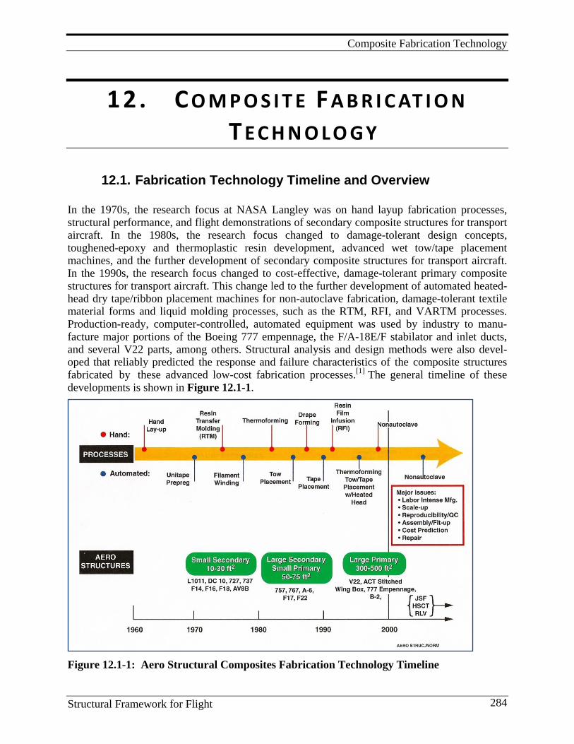
Composite Fabrication Technology
Structural Framework for Flight 284
12. C O M P O S I T E F A B R I C AT I O N T E C H N O L O G Y
12.1. Fabrication Technology Timeline and Overview
In the 1970s, the research focus at NASA Langley was on hand layup fabrication processes, structural performance, and flight demonstrations of secondary composite structures for transport aircraft. In the 1980s, the research focus changed to damage-tolerant design concepts, toughened-epoxy and thermoplastic resin development, advanced wet tow/tape placement machines, and the further development of secondary composite structures for transport aircraft. In the 1990s, the research focus changed to cost-effective, damage-tolerant primary composite structures for transport aircraft. This change led to the further development of automated heated-head dry tape/ribbon placement machines for non-autoclave fabrication, damage-tolerant textile material forms and liquid molding processes, such as the RTM, RFI, and VARTM processes. Production-ready, computer-controlled, automated equipment was used by industry to manu-facture major portions of the Boeing 777 empennage, the F/A-18E/F stabilator and inlet ducts, and several V22 parts, among others. Structural analysis and design methods were also devel-oped that reliably predicted the response and failure characteristics of the composite structures
fabricated by these advanced low-cost fabrication processes.[1] The general timeline of these developments is shown in Figure 12.1-1.
Figure 12.1-1: Aero Structural Composites Fabrication Technology Timeline
Composite Fabrication Technology
Structural Framework for Flight 285
NASA LaRC initiated fabrication studies of these cost-effective fiber-placement processes by using representative small-scale, experimental equipment that simulated the expected performance of larger manufacturing facilities. Such equipment was used to study, screen, and modify the standard composite fabrication processes as well as develop new ones as the need arose. New resins, new intermediate materials forms, new in situ curing mechanisms, and net-shape material placement procedures were explored. A prototype composite research laboratory was created at LaRC to study automated fabrication processes and to provide a means to address some of the research issues associated with these processes.[2, 3] Non-autoclave fabrication involved: 1) heated-head, automated tape placement (ATP) of thermoplastic and thermoset prepreg materials; 2) e-beam cure-on-the-fly ATP of newly formulated epoxy prepregs; and 3) inductive heating. These processes had major problems with material forms used in their operation. But, if solved, they had the potential of being scaled for in situ fabrication of large, high-quality, full-scale structures such as cryogenic fuel tanks with diameters on the order of nine meters and lengths over 18 meters. Autoclave processing of such structures would be prohibitively expensive due to the need for appropriately sized autoclaves and related fabrication tooling.
12.2. Variables in the Fabrication of High-performance Composites
Composite fabrication is a complex business. Many variables are involved so it should be realized that no one organization contributes significantly to all of them. Most of the variables and examples of each are listed below so later one can discern the contributions LaRC made. These contributions will be discussed in detail in the subsections to follow.
a. Matrix resins: epoxies, toughened epoxies, pyrrones, and polyimides b. Matrix resin forms: neat liquid, solution, powder, film (RFI), fiber, and powder slurry c. Continuous fibers: carbon high strength, carbon high modulus, carbon intermediate modulus,
carbon low modulus, Kevlar™ polyamide, standard E glass, and high strength S glass d. Fiber forms: unidirectional tow, woven fabric, braided fabric, knitted fabric, and stitched
fabric e. Prepreg forms: unidirectional wet tow, unidirectional dry powder-coated tow, unidirectional
tape, powder-coated woven, braided, knitted, and stitched fabric, and commingled structural fiber/resin fiber
f. Tooling: metal, composite, ceramic, wood, and wash-away ceramic g. Curing methods: room temperature (RT), hot thermal, e-beam, ultraviolet, and induction h. Process pressure: press, autoclave, vacuum bag, and robotic conformable compaction i. Placement: hand, robotic, RTM, VARTM, pultrusion, and filament winding A fabrication process would involve many of the variables a-i. For example, a process for fabricating a standard flat-skin panel would involve an epoxy resin (a) in neat resin liquid form (b) prepregged on an intermediate modulus carbon fiber (c) as unidirectional wet tape (d, e) placed on a flat steel tool (f) by a robot (i) and cured in an autoclave at 177°C , 350oF(g, h). One can see how many different processes can be derived from the various combinations of variables. NASA LaRC’s contributions are distributed among many of these except fibers (c).
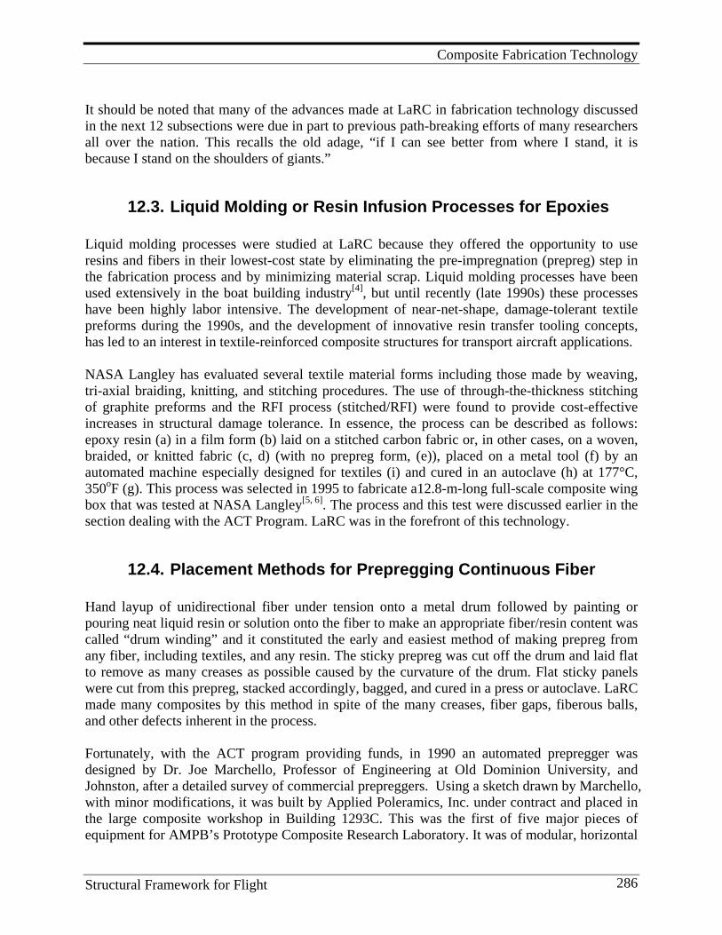
Composite Fabrication Technology
Structural Framework for Flight 286
It should be noted that many of the advances made at LaRC in fabrication technology discussed in the next 12 subsections were due in part to previous path-breaking efforts of many researchers all over the nation. This recalls the old adage, “if I can see better from where I stand, it is because I stand on the shoulders of giants.”
12.3. Liquid Molding or Resin Infusion Processes for Epoxies Liquid molding processes were studied at LaRC because they offered the opportunity to use resins and fibers in their lowest-cost state by eliminating the pre-impregnation (prepreg) step in the fabrication process and by minimizing material scrap. Liquid molding processes have been used extensively in the boat building industry[4], but until recently (late 1990s) these processes have been highly labor intensive. The development of near-net-shape, damage-tolerant textile preforms during the 1990s, and the development of innovative resin transfer tooling concepts, has led to an interest in textile-reinforced composite structures for transport aircraft applications. NASA Langley has evaluated several textile material forms including those made by weaving, tri-axial braiding, knitting, and stitching procedures. The use of through-the-thickness stitching of graphite preforms and the RFI process (stitched/RFI) were found to provide cost-effective increases in structural damage tolerance. In essence, the process can be described as follows: epoxy resin (a) in a film form (b) laid on a stitched carbon fabric or, in other cases, on a woven, braided, or knitted fabric (c, d) (with no prepreg form, (e)), placed on a metal tool (f) by an automated machine especially designed for textiles (i) and cured in an autoclave (h) at 177°C, 350oF (g). This process was selected in 1995 to fabricate a12.8-m-long full-scale composite wing box that was tested at NASA Langley[5, 6]. The process and this test were discussed earlier in the section dealing with the ACT Program. LaRC was in the forefront of this technology.
12.4. Placement Methods for Prepregging Continuous Fiber Hand layup of unidirectional fiber under tension onto a metal drum followed by painting or pouring neat liquid resin or solution onto the fiber to make an appropriate fiber/resin content was called “drum winding” and it constituted the early and easiest method of making prepreg from any fiber, including textiles, and any resin. The sticky prepreg was cut off the drum and laid flat to remove as many creases as possible caused by the curvature of the drum. Flat sticky panels were cut from this prepreg, stacked accordingly, bagged, and cured in a press or autoclave. LaRC made many composites by this method in spite of the many creases, fiber gaps, fiberous balls, and other defects inherent in the process. Fortunately, with the ACT program providing funds, in 1990 an automated prepregger was designed by Dr. Joe Marchello, Professor of Engineering at Old Dominion University, and Johnston, after a detailed survey of commercial prepreggers. Using a sketch drawn by Marchello, with minor modifications, it was built by Applied Poleramics, Inc. under contract and placed in the large composite workshop in Building 1293C. This was the first of five major pieces of equipment for AMPB’s Prototype Composite Research Laboratory. It was of modular, horizontal
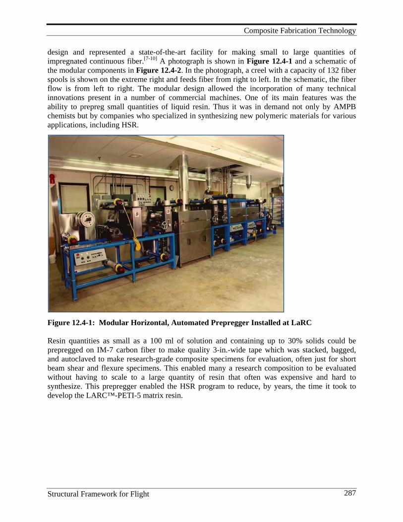
Composite Fabrication Technology
Structural Framework for Flight 287
design and represented a state-of-the-art facility for making small to large quantities of impregnated continuous fiber.[7-10] A photograph is shown in Figure 12.4-1 and a schematic of the modular components in Figure 12.4-2. In the photograph, a creel with a capacity of 132 fiber spools is shown on the extreme right and feeds fiber from right to left. In the schematic, the fiber flow is from left to right. The modular design allowed the incorporation of many technical innovations present in a number of commercial machines. One of its main features was the ability to prepreg small quantities of liquid resin. Thus it was in demand not only by AMPB chemists but by companies who specialized in synthesizing new polymeric materials for various applications, including HSR.
Figure 12.4-1: Modular Horizontal, Automated Prepregger Installed at LaRC Resin quantities as small as a 100 ml of solution and containing up to 30% solids could be prepregged on IM-7 carbon fiber to make quality 3-in.-wide tape which was stacked, bagged, and autoclaved to make research-grade composite specimens for evaluation, often just for short beam shear and flexure specimens. This enabled many a research composition to be evaluated without having to scale to a large quantity of resin that often was expensive and hard to synthesize. This prepregger enabled the HSR program to reduce, by years, the time it took to develop the LARC™-PETI-5 matrix resin.
Composite Fabrication Technology
Structural Framework for Flight 288
Figure 12.4-2: Schematic of the Modular Components Comprising the LaRC Automated Prepregger The LaRC composite lab in Building 1293C also had an18-in.-diameter autoclave with 700°F capacity, four state-of-the-art presses with heated platens, bagging tables, and an inventory of films of various types for layup and bagging. Water-cooled diamond saws were used to cut specimens that were tested on Instron and other mechanical test machines in another room. In summary, it was a self-sufficient facility for fabricating and evaluating experimental composites.
12.5. Out-of-Autoclave Placement Methods: Robotic Dry Tape/Tow Placement
Automated wet tow and wet tape placement machines started becoming popular in the 1980s and, by the 1990s, were quite sophisticated. Such automation was a far cry from hand layup procedures and allowed for more efficient placement on curved surfaces. It offered, among others, ply thickness control, in-process compaction, especially with an ultrasonic ply compactor, controlled fiber angles with non-geodesic paths, and 360° part fabrication with longitudinal joint elimination. However, the autoclave was still involved with its increased costs. Further, for thermally stable resins, the high temperatures involved required longer autoclave times and more complex procedures in terms of bagging materials and sealants. Cool-down from the high temperatures required for optimum resin flow led to high residual stresses and large CTE mismatches between the metal tool and the composite. Non-autoclave fabrication was needed both for cost mitigation and composite property improvement.
Composite Fabrication Technology
Structural Framework for Flight 289
Two companies were involved in robotic placement of thermoplastic tape or ribbon using heated-head technology that precluded autoclaves: Automated Dynamics Corporation, Schenectady, NY, and Acudyne Systems, Newark, DE. The preconsolidated dry tape or band of ribbons is placed with heat and pressure onto a metal tool layer by layer. Cut/add capability on the head allows placement on open, as well as closed, parts. The work cell elements include an automated machine platform, a placement head, tools on which to place the heated tape or ribbon, and electronic controls and software. The placement head is a stand-alone end effector that feeds, cuts, places, and laminates the tape or ribbons. The platform is usually a commercially available gantry or an articulated arm to which additional degrees of freedom may be added. Two key personnel (Dr. Mark Lamontia, DuPont/Accudyne, and Mr. Mark Gruber, Accudyne) had previous experience with thermoplastic polymer matrix composites via three DARPA programs: the Advanced Submarine Technology Program, the ARPA/ARO RAPTECH-ACM II (DuPont/Hercules) and WELDTECH-PMC (DuPont/Boeing). The former emphasized heated- head development for ATP robots; the latter emphasized inductive welding for composite fabrication and assembly. Accudyne had non-autoclave fabricated a number of IM-7/APC-2 (PEEK) underwater vehicle pressure hulls using in situ heated-head robotic winding. The RAPTECH program helped extend the advanced state of their technology by developing an in situ deposition tape-laying head that could consolidate 3-in.-wide AS-4/PEEK tape on a flat panel at speeds up to 20 fpm and temperatures up to 700°F (371°C). To show that they could fabricate large parts by this non-autoclave process, a 96-in.-diameter, 800 lb. fan containment case was made in 96 hours from IM-7/PEKK thermoplastic tape.[11, 12] During the HSR program, built-up structure was also made. A 3’ x 4’ three-stringer panel with a quasi-isotropic skin was fabricated by Accudyne by building an IML tool embedded with preconsolidated thermoplastic stringers and placing thermoplastic tape over them using the heated-head ATP machine to produce the skin and a stringer flange-skin weld. A 3’ x 4’ honeycomb panel was fabricated by heated-head placement of thermoplastic tape onto titanium honeycomb pretreated with BRX-5™ paste adhesive and FMX-5™ film adhesive. Additionally, TiGr laminates were made by heated-head alternate placement of titanium foil precoated with PEEK film and PEEK tape. TiGr honeycomb panels were fabricated by placing the foil and tape on the bottom side of the honeycomb, then on the top side.[13-19] Heated-head robotic placement offered not only out-of-the-autoclave net-shape fabrication but also use of dry fiber forms with infinite out-time, potential on-line NDE (coupled with healing of defects during initial placement), in-process compaction, variable bandwidth with tow cut/add, placement accuracy with no limit on fiber angle, reduced scrap, reduced labor with large complex parts, and application on the factory floor with no environmental housing. Figure 12.5-1 shows a photograph of a Cincinnati Milacron (later Cincinnati Machines) overhead gantry and robot tape feeder to which is attached an Accudyne Systems heated head and compactor. This equipment was used by Gruber and Lamontia under contract during the HSR program to study heated-head placement of HSR candidate materials and the development of dry prepreg tapes.
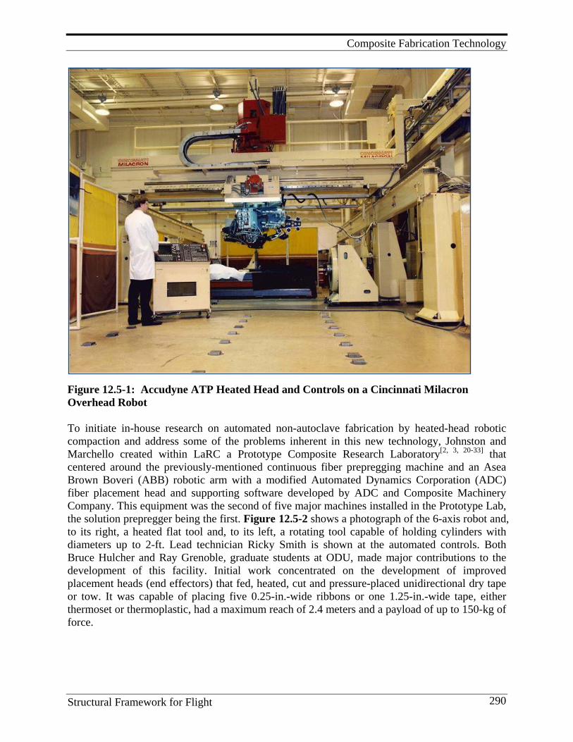
Composite Fabrication Technology
Structural Framework for Flight 290
Figure 12.5-1: Accudyne ATP Heated Head and Controls on a Cincinnati Milacron Overhead Robot To initiate in-house research on automated non-autoclave fabrication by heated-head robotic compaction and address some of the problems inherent in this new technology, Johnston and Marchello created within LaRC a Prototype Composite Research Laboratory[2, 3, 20-33] that centered around the previously-mentioned continuous fiber prepregging machine and an Asea Brown Boveri (ABB) robotic arm with a modified Automated Dynamics Corporation (ADC) fiber placement head and supporting software developed by ADC and Composite Machinery Company. This equipment was the second of five major machines installed in the Prototype Lab, the solution prepregger being the first. Figure 12.5-2 shows a photograph of the 6-axis robot and, to its right, a heated flat tool and, to its left, a rotating tool capable of holding cylinders with diameters up to 2-ft. Lead technician Ricky Smith is shown at the automated controls. Both Bruce Hulcher and Ray Grenoble, graduate students at ODU, made major contributions to the development of this facility. Initial work concentrated on the development of improved placement heads (end effectors) that fed, heated, cut and pressure-placed unidirectional dry tape or tow. It was capable of placing five 0.25-in.-wide ribbons or one 1.25-in.-wide tape, either thermoset or thermoplastic, had a maximum reach of 2.4 meters and a payload of up to 150-kg of force.
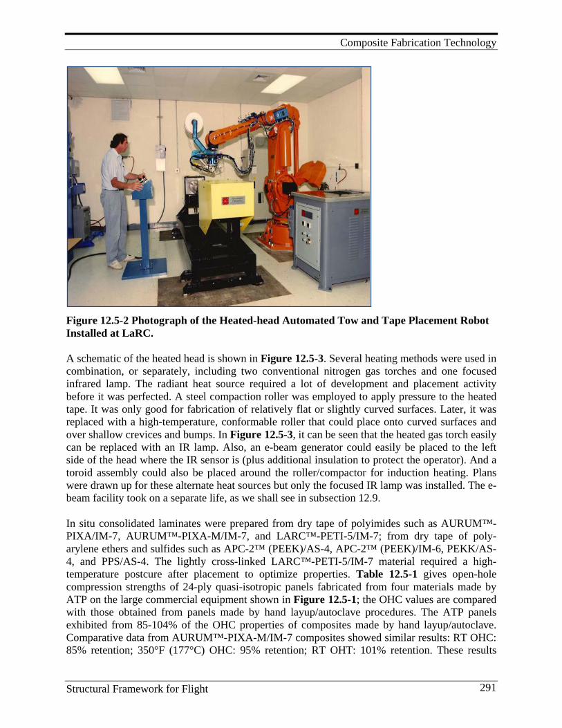
Composite Fabrication Technology
Structural Framework for Flight 291
Figure 12.5-2 Photograph of the Heated-head Automated Tow and Tape Placement Robot Installed at LaRC. A schematic of the heated head is shown in Figure 12.5-3. Several heating methods were used in combination, or separately, including two conventional nitrogen gas torches and one focused infrared lamp. The radiant heat source required a lot of development and placement activity before it was perfected. A steel compaction roller was employed to apply pressure to the heated tape. It was only good for fabrication of relatively flat or slightly curved surfaces. Later, it was replaced with a high-temperature, conformable roller that could place onto curved surfaces and over shallow crevices and bumps. In Figure 12.5-3, it can be seen that the heated gas torch easily can be replaced with an IR lamp. Also, an e-beam generator could easily be placed to the left side of the head where the IR sensor is (plus additional insulation to protect the operator). And a toroid assembly could also be placed around the roller/compactor for induction heating. Plans were drawn up for these alternate heat sources but only the focused IR lamp was installed. The e-beam facility took on a separate life, as we shall see in subsection 12.9. In situ consolidated laminates were prepared from dry tape of polyimides such as AURUM™-PIXA/IM-7, AURUM™-PIXA-M/IM-7, and LARC™-PETI-5/IM-7; from dry tape of poly-arylene ethers and sulfides such as APC-2™ (PEEK)/AS-4, APC-2™ (PEEK)/IM-6, PEKK/AS-4, and PPS/AS-4. The lightly cross-linked LARC™-PETI-5/IM-7 material required a high-temperature postcure after placement to optimize properties. Table 12.5-1 gives open-hole compression strengths of 24-ply quasi-isotropic panels fabricated from four materials made by ATP on the large commercial equipment shown in Figure 12.5-1; the OHC values are compared with those obtained from panels made by hand layup/autoclave procedures. The ATP panels exhibited from 85-104% of the OHC properties of composites made by hand layup/autoclave. Comparative data from AURUM™-PIXA-M/IM-7 composites showed similar results: RT OHC: 85% retention; 350°F (177°C) OHC: 95% retention; RT OHT: 101% retention. These results
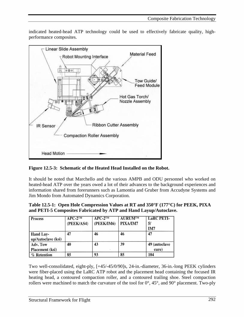
Composite Fabrication Technology
Structural Framework for Flight 292
indicated heated-head ATP technology could be used to effectively fabricate quality, high- performance composites.
Figure 12.5-3: Schematic of the Heated Head Installed on the Robot. It should be noted that Marchello and the various AMPB and ODU personnel who worked on heated-head ATP over the years owed a lot of their advances to the background experiences and information shared from forerunners such as Lamontia and Gruber from Accudyne Systems and Jim Mondo from Automated Dynamics Corporation. Table 12.5-1: Open Hole Compression Values at RT and 350°F (177°C) for PEEK, PIXA and PETI-5 Composites Fabricated by ATP and Hand Layup/Autoclave.
Two well-consolidated, eight-ply, [+45/-45/0/90]s, 24-in.-diameter, 36-in.-long PEEK cylinders were fiber-placed using the LaRC ATP robot and the placement head containing the focused IR heating head, a contoured compaction roller, and a contoured trailing shoe. Steel compaction rollers were machined to match the curvature of the tool for 0°, 45°, and 90° placement. Two-ply
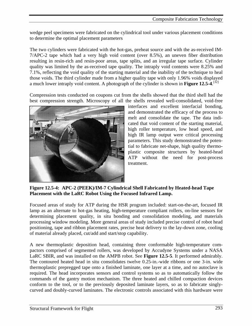
Composite Fabrication Technology
Structural Framework for Flight 293
wedge peel specimens were fabricated on the cylindrical tool under various placement conditions to determine the optimal placement parameters The two cylinders were fabricated with the hot-gas, preheat source and with the as-received IM-7/APC-2 tape which had a very high void content (over 8.5%), an uneven fiber distribution resulting in resin-rich and resin-poor areas, tape splits, and an irregular tape surface. Cylinder quality was limited by the as-received tape quality. The intraply void contents were 8.25% and 7.1%, reflecting the void quality of the starting material and the inability of the technique to heal those voids. The third cylinder made from a higher quality tape with only 1.96% voids displayed a much lower intraply void content. A photograph of the cylinder is shown in Figure 12.5-4.[32] Compression tests conducted on coupons cut from the shells showed that the third shell had the best compression strength. Microscopy of all the shells revealed well-consolidated, void-free
interfaces and excellent interfacial bonding, and demonstrated the efficacy of the process to melt and consolidate the tape. The data indi-cated that void content of the starting material, high roller temperature, low head speed, and high IR lamp output were critical processing parameters. This study demonstrated the poten-tial to fabricate net-shape, high quality thermo-plastic composite structures by heated-head ATP without the need for post-process treatment.
Figure 12.5-4: APC-2 (PEEK)/IM-7 Cylindrical Shell Fabricated by Heated-head Tape Placement with the LaRC Robot Using the Focused Infrared Lamp. Focused areas of study for ATP during the HSR program included: start-on-the-art, focused IR lamp as an alternate to hot-gas heating, high-temperature compliant rollers, on-line sensors for determining placement quality, in situ bonding and consolidation modeling, and materials processing window modeling. More general areas of study included precise control of robot head positioning, tape and ribbon placement rates, precise heat delivery to the lay-down zone, cooling of material already placed, cut/add and start/stop capability. A new thermoplastic deposition head, containing three conformable high-temperature com-pactors comprised of segmented rollers, was developed by Accudyne Systems under a NASA LaRC SBIR, and was installed on the AMPB robot. See Figure 12.5-5. It performed admirably. The contoured heated head in situ consolidates twelve 0.25-in.-wide ribbons or one 3-in. wide thermoplastic prepregged tape onto a finished laminate, one layer at a time, and no autoclave is required. The head incorporates sensors and control systems so as to automatically follow the commands of the gantry motion mechanism. The three heated and chilled compaction devices conform to the tool, or to the previously deposited laminate layers, so as to fabricate singly-curved and doubly-curved laminates. The electronic controls associated with this hardware were
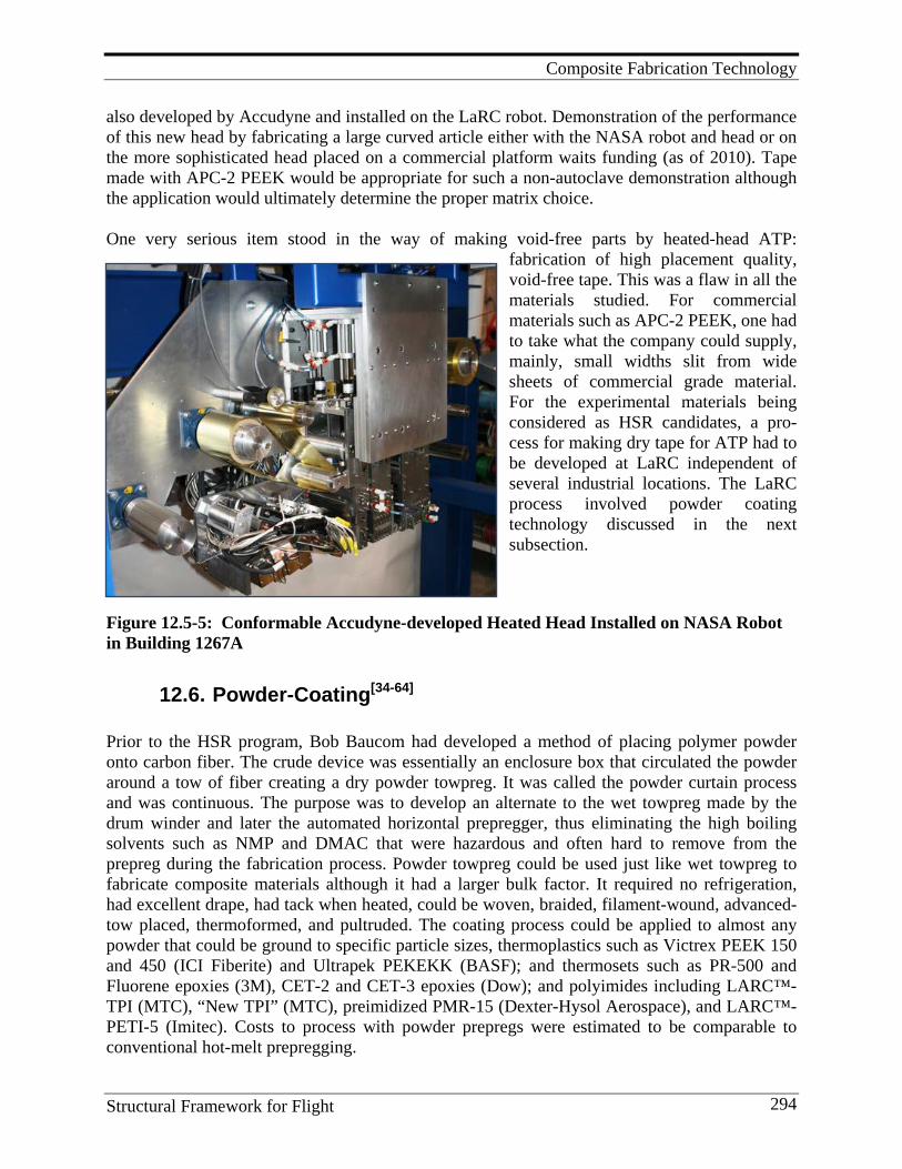
Composite Fabrication Technology
Structural Framework for Flight 294
also developed by Accudyne and installed on the LaRC robot. Demonstration of the performance of this new head by fabricating a large curved article either with the NASA robot and head or on the more sophisticated head placed on a commercial platform waits funding (as of 2010). Tape made with APC-2 PEEK would be appropriate for such a non-autoclave demonstration although the application would ultimately determine the proper matrix choice. One very serious item stood in the way of making void-free parts by heated-head ATP:
fabrication of high placement quality, void-free tape. This was a flaw in all the materials studied. For commercial materials such as APC-2 PEEK, one had to take what the company could supply, mainly, small widths slit from wide sheets of commercial grade material. For the experimental materials being considered as HSR candidates, a pro-cess for making dry tape for ATP had to be developed at LaRC independent of several industrial locations. The LaRC process involved powder coating technology discussed in the next subsection.
Figure 12.5-5: Conformable Accudyne-developed Heated Head Installed on NASA Robot in Building 1267A
12.6. Powder-Coating[34-64] Prior to the HSR program, Bob Baucom had developed a method of placing polymer powder onto carbon fiber. The crude device was essentially an enclosure box that circulated the powder around a tow of fiber creating a dry powder towpreg. It was called the powder curtain process and was continuous. The purpose was to develop an alternate to the wet towpreg made by the drum winder and later the automated horizontal prepregger, thus eliminating the high boiling solvents such as NMP and DMAC that were hazardous and often hard to remove from the prepreg during the fabrication process. Powder towpreg could be used just like wet towpreg to fabricate composite materials although it had a larger bulk factor. It required no refrigeration, had excellent drape, had tack when heated, could be woven, braided, filament-wound, advanced-tow placed, thermoformed, and pultruded. The coating process could be applied to almost any powder that could be ground to specific particle sizes, thermoplastics such as Victrex PEEK 150 and 450 (ICI Fiberite) and Ultrapek PEKEKK (BASF); and thermosets such as PR-500 and Fluorene epoxies (3M), CET-2 and CET-3 epoxies (Dow); and polyimides including LARC™-TPI (MTC), “New TPI” (MTC), preimidized PMR-15 (Dexter-Hysol Aerospace), and LARC™-PETI-5 (Imitec). Costs to process with powder prepregs were estimated to be comparable to conventional hot-melt prepregging.
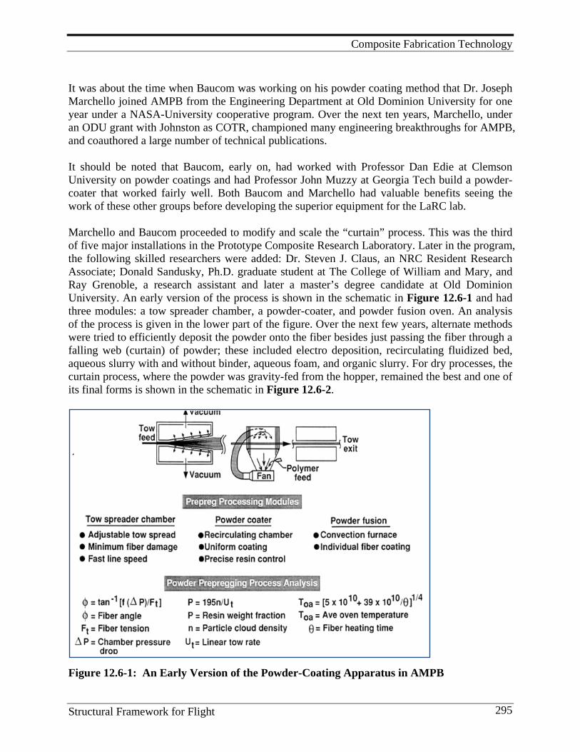
Composite Fabrication Technology
Structural Framework for Flight 295
It was about the time when Baucom was working on his powder coating method that Dr. Joseph Marchello joined AMPB from the Engineering Department at Old Dominion University for one year under a NASA-University cooperative program. Over the next ten years, Marchello, under an ODU grant with Johnston as COTR, championed many engineering breakthroughs for AMPB, and coauthored a large number of technical publications. It should be noted that Baucom, early on, had worked with Professor Dan Edie at Clemson University on powder coatings and had Professor John Muzzy at Georgia Tech build a powder- coater that worked fairly well. Both Baucom and Marchello had valuable benefits seeing the work of these other groups before developing the superior equipment for the LaRC lab. Marchello and Baucom proceeded to modify and scale the “curtain” process. This was the third of five major installations in the Prototype Composite Research Laboratory. Later in the program, the following skilled researchers were added: Dr. Steven J. Claus, an NRC Resident Research Associate; Donald Sandusky, Ph.D. graduate student at The College of William and Mary, and Ray Grenoble, a research assistant and later a master’s degree candidate at Old Dominion University. An early version of the process is shown in the schematic in Figure 12.6-1 and had three modules: a tow spreader chamber, a powder-coater, and powder fusion oven. An analysis of the process is given in the lower part of the figure. Over the next few years, alternate methods were tried to efficiently deposit the powder onto the fiber besides just passing the fiber through a falling web (curtain) of powder; these included electro deposition, recirculating fluidized bed, aqueous slurry with and without binder, aqueous foam, and organic slurry. For dry processes, the curtain process, where the powder was gravity-fed from the hopper, remained the best and one of its final forms is shown in the schematic in Figure 12.6-2.
Figure 12.6-1: An Early Version of the Powder-Coating Apparatus in AMPB
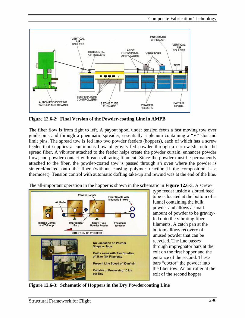
Composite Fabrication Technology
Structural Framework for Flight 296
Figure 12.6-2: Final Version of the Powder-coating Line in AMPB The fiber flow is from right to left. A payout spool under tension feeds a fast moving tow over guide pins and through a pneumatic spreader, essentially a plenum containing a “V” slot and limit pins. The spread tow is fed into two powder feeders (hoppers), each of which has a screw feeder that supplies a continuous flow of gravity-fed powder through a narrow slit onto the spread fiber. A vibrator attached to the feeder helps create the powder curtain, enhances powder flow, and powder contact with each vibrating filament. Since the powder must be permanently attached to the fiber, the powder-coated tow is passed through an oven where the powder is sintered/melted onto the fiber (without causing polymer reaction if the composition is a thermoset). Tension control with automatic doffing take-up and rewind was at the end of the line. The all-important operation in the hopper is shown in the schematic in Figure 12.6-3. A screw-
type feeder inside a slotted feed tube is located at the bottom of a funnel containing the bulk powder and allows a small amount of powder to be gravity-fed onto the vibrating fiber filaments. A catch pan at the bottom allows recovery of unused powder that can be recycled. The line passes through impregnator bars at the exit on the first hopper and the entrance of the second. These bars “doctor” the powder into the fiber tow. An air roller at the exit of the second hopper
Figure 12.6-3: Schematic of Hoppers in the Dry Powdercoating Line
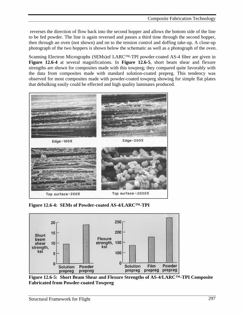
Composite Fabrication Technology
Structural Framework for Flight 297
reverses the direction of flow back into the second hopper and allows the bottom side of the line to be fed powder. The line is again reversed and passes a third time through the second hopper, then through an oven (not shown) and on to the tension control and doffing take-up. A close-up photograph of the two hoppers is shown below the schematic as well as a photograph of the oven.
Scanning Electron Micrographs (SEMs)of LARC™-TPI powder-coated AS-4 fiber are given in Figure 12.6-4 at several magnifications. In Figure 12.6-5, short beam shear and flexure strengths are shown for composites made with this towpreg; they compared quite favorably with the data from composites made with standard solution-coated prepreg. This tendency was observed for most composites made with powder-coated towpreg showing for simple flat plates that debulking easily could be effected and high quality laminates produced.
Figure 12.6-4: SEMs of Powder-coated AS-4/LARC™-TPI
Figure 12.6-5: Short Beam Shear and Flexure Strengths of AS-4/LARC™-TPI Composite Fabricated from Powder-coated Towpreg
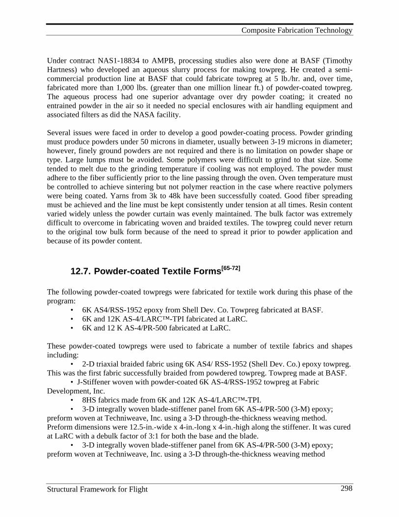
Composite Fabrication Technology
Structural Framework for Flight 298
Under contract NAS1-18834 to AMPB, processing studies also were done at BASF (Timothy Hartness) who developed an aqueous slurry process for making towpreg. He created a semi-commercial production line at BASF that could fabricate towpreg at 5 lb./hr. and, over time, fabricated more than 1,000 lbs. (greater than one million linear ft.) of powder-coated towpreg. The aqueous process had one superior advantage over dry powder coating; it created no entrained powder in the air so it needed no special enclosures with air handling equipment and associated filters as did the NASA facility. Several issues were faced in order to develop a good powder-coating process. Powder grinding must produce powders under 50 microns in diameter, usually between 3-19 microns in diameter; however, finely ground powders are not required and there is no limitation on powder shape or type. Large lumps must be avoided. Some polymers were difficult to grind to that size. Some tended to melt due to the grinding temperature if cooling was not employed. The powder must adhere to the fiber sufficiently prior to the line passing through the oven. Oven temperature must be controlled to achieve sintering but not polymer reaction in the case where reactive polymers were being coated. Yarns from 3k to 48k have been successfully coated. Good fiber spreading must be achieved and the line must be kept consistently under tension at all times. Resin content varied widely unless the powder curtain was evenly maintained. The bulk factor was extremely difficult to overcome in fabricating woven and braided textiles. The towpreg could never return to the original tow bulk form because of the need to spread it prior to powder application and because of its powder content.
12.7. Powder-coated Textile Forms[65-72] The following powder-coated towpregs were fabricated for textile work during this phase of the program: • 6K AS4/RSS-1952 epoxy from Shell Dev. Co. Towpreg fabricated at BASF. • 6K and 12K AS-4/LARC™-TPI fabricated at LaRC. • 6K and 12 K AS-4/PR-500 fabricated at LaRC. These powder-coated towpregs were used to fabricate a number of textile fabrics and shapes including:
• 2-D triaxial braided fabric using 6K AS4/ RSS-1952 (Shell Dev. Co.) epoxy towpreg. This was the first fabric successfully braided from powdered towpreg. Towpreg made at BASF.
• J-Stiffener woven with powder-coated 6K AS-4/RSS-1952 towpreg at Fabric Development, Inc.
• 8HS fabrics made from 6K and 12K AS-4/LARC™-TPI. • 3-D integrally woven blade-stiffener panel from 6K AS-4/PR-500 (3-M) epoxy;
preform woven at Techniweave, Inc. using a 3-D through-the-thickness weaving method. Preform dimensions were 12.5-in.-wide x 4-in.-long x 4-in.-high along the stiffener. It was cured at LaRC with a debulk factor of 3:1 for both the base and the blade.
• 3-D integrally woven blade-stiffener panel from 6K AS-4/PR-500 (3-M) epoxy; preform woven at Techniweave, Inc. using a 3-D through-the-thickness weaving method

Composite Fabrication Technology
Structural Framework for Flight 299
combined with a stitched quasi-isotropic layup for the base. Preform dimensions were 12-in.-wide x 20-in.-long x 4-in.-high along the stiffener. Cured at LaRC. A series of weaving studies were made with powder-coated tow that varied a number of weaving parameters including: towpreg-yarn-shape, yarn flexural rigidity, amount of twist, use of serving fiber, degree of towpreg damage during powder coating, resin content, bulk factor, and weaving speed. Twisting debulks the towpreg, encapsulates the powder in the yarn and yields a uniform surface but decreases mechanical properties 8-15%. Serving also debulks the yarn and creates a circular cross-section but is very difficult to remove so serving filaments must be used that melt and become part of the matrix without harming properties. High towpreg flexural rigidity and circular-type cross-sections are preferred. They help the towpreg to easily pass through the hettles and reed during the weaving process. Weaving damages towpreg creating broken and loose fibers on the surface of the yarn or shaped object. Towpreg shaping and compacting helped reduce this damage. Similar studies were made for the braiding process. Major issues investigated were the severe friction and abrasion at cross-over regions, yarn collapse at convergence regions, and preform consolidation with high bulk factors. To cut down on friction/abrasion, towpreg surface treatments (glazing or coating) were studied including: zinc stearate, polyethylene glycol (PEG) and polyacrylic acid gel (PAA). The latter at 1% in water decreased surface friction adequately and helped maintain yarn flexibility. It had no effect on mechanical properties. Twisting did not decrease surface friction. Powder-coated towpreg with partially cured thermoset would be too brittle for small radii braider cops, so the powder-coating process had to be carefully controlled. Braided, powder-coated preform quality varied considerably with resin content variations especially noteworthy and yarn-yarn spacing high. For example, in triaxial preforms, the ends per inch varied from 8-9.5 and resin content from 34-37 weight percent. Debulking ratios were from 7:1 to 10:1. For biaxial preforms, the resin content varied from 36-41 weight percent and debulking ratios around 8:1. These are very high debulking ratios and resulted in high void contents in curved portions of a fabricated article. High debulk ratios played havoc trying to keep pressure on curved parts with rigid tooling during consolidation. Future studies were definitely needed to decrease the bulk factor in the powder-coated towpreg. Interestingly, short block compression strength and modulus values (328 MPa/32 GPa) of triaxial braided coupons were close to the predicted values; OHT values were marginally better than laminates made by RTM. This research uncovered the major issues involved in using powdered towpreg to make high- quality textile laminates without the use of solvents. In some cases, well-consolidated composites were made with powder-coated towpreg. It is obvious from the discussions on both the weaving and braiding processes that more work would have had to be done to apply this technology to either the ACT or the HSR programs. Another application for powder-coatings was slurry prepregging using powders slurried either in water or organic liquids.[73-81] In one case, Larc™-Polyimide-Sulfone powder was slurried in polyamide-acid NMP solution of LARC™-TPI and prepregged on the large Modular Horizontal Automated Prepregger. This was in an attempt to increase the processability of the TPI polymer. Larc™-TPI 1500 was also slurried in water and also in an aqueous foam. Both slurries were fiber
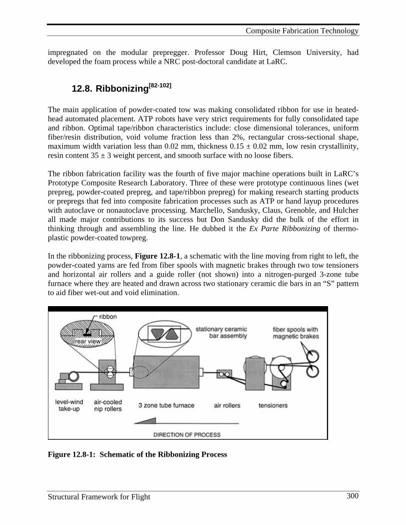
Composite Fabrication Technology
Structural Framework for Flight 300
impregnated on the modular prepregger. Professor Doug Hirt, Clemson University, had developed the foam process while a NRC post-doctoral candidate at LaRC.
12.8. Ribbonizing[82-102] The main application of powder-coated tow was making consolidated ribbon for use in heated- head automated placement. ATP robots have very strict requirements for fully consolidated tape and ribbon. Optimal tape/ribbon characteristics include: close dimensional tolerances, uniform fiber/resin distribution, void volume fraction less than 2%, rectangular cross-sectional shape, maximum width variation less than 0.02 mm, thickness 0.15 ± 0.02 mm, low resin crystallinity, resin content 35 ± 3 weight percent, and smooth surface with no loose fibers. The ribbon fabrication facility was the fourth of five major machine operations built in LaRC’s Prototype Composite Research Laboratory. Three of these were prototype continuous lines (wet prepreg, powder-coated prepreg, and tape/ribbon prepreg) for making research starting products or prepregs that fed into composite fabrication processes such as ATP or hand layup procedures with autoclave or nonautoclave processing. Marchello, Sandusky, Claus, Grenoble, and Hulcher all made major contributions to its success but Don Sandusky did the bulk of the effort in thinking through and assembling the line. He dubbed it the Ex Parte Ribbonizing of thermo-plastic powder-coated towpreg. In the ribbonizing process, Figure 12.8-1, a schematic with the line moving from right to left, the powder-coated yarns are fed from fiber spools with magnetic brakes through two tow tensioners and horizontal air rollers and a guide roller (not shown) into a nitrogen-purged 3-zone tube furnace where they are heated and drawn across two stationary ceramic die bars in an “S” pattern to aid fiber wet-out and void elimination.
Figure 12.8-1: Schematic of the Ribbonizing Process

Composite Fabrication Technology
Structural Framework for Flight 301
The consolidated composite ribbon exits the oven and into a set of air-cooled nip rollers where it is formed into the desired shape (rectangular). From there, it passes through a set of vertical pull rollers and onto a level-wind take-up spool. The line can move typically at nine meters per minute with a one or two person operation. It can ribbonize both thermoplastics and thermosets as was demonstrated for several years. Examples include IM-8/Aurum™-400, IM-7/Aurum™-500, IM-7/PIXA-M™, IM-7/Aurum™-PIXA, IM-7/LARC™-IA, IM-7/LARC™-PETI-5, AS-4/APC-2™ (PEEK), IM-7/APC-2™ (PEEK), AS-4/PEKK, and AS4/PPS. Thermosets such as LARC™-PETI-5 took more effort since the maximum temperature in the furnace must not advance the polymer; polymer flow must be retained so that the material will behave properly in the heated head ATP. Several preliminary material characterization experiments are typically performed to help determine effective ribbon fabrication parameters for any one resin. Quality assessment methods included width and thickness consistency, fiber volume fraction, DSC thermal analysis for degree of cure and Rheometrics rheology for degree of flow. Key attributes of consolidated ribbon made with this equipment: consistent local resin/fiber distribution and wet-out, low dimensional variation in thickness and width (Cv=2%), less than 2% voids, good surface finish, and uniform cross-section. SEMs of the ends of two different ribbons, AS-4/PEKK thermoplastic polyarylene ether made by DuPont and IM-7/Aurum™-400 thermoplastic polyimide made at LaRC are shown in Figure 12.8-2 at two different magnifications. The AS-4 PEKK is the top two layers in each photograph; the IM-7/Aurum™-400 is the bottom two layers in each photograph. One can see that the latter is better consolidated.
Figure 12.8-2: SEMs of the Ends of Two Different Ribbons at Two Different Magnifications. Two Layers on Top in Each Set Are AS-4/PEKK Thermoplastic; the Two Layers on Bottom Are IM-7/Aurum™-400 Thermoplastic Polyimide The ribbonizing line is shown in the photograph in Figure 12.8-3. The fiber creel is at the extreme right followed by the furnace, the air-cooled shaping assembly containing the nip rollers, then the vertical puller rolls and take-up reel in the left foreground. Figure 12.8-4 shows a sketch of the furnace, its two ceramic bars, and the equations for the heat transfer model developed by Sandusky as part of his Ph.D. effort at W&M. Figure 12.8-5 details front and side views of the nip rollers that shape the tape into a rectangle. Figure 12.8-6 shows the modular nature of the nip rollers and how they are assembled.
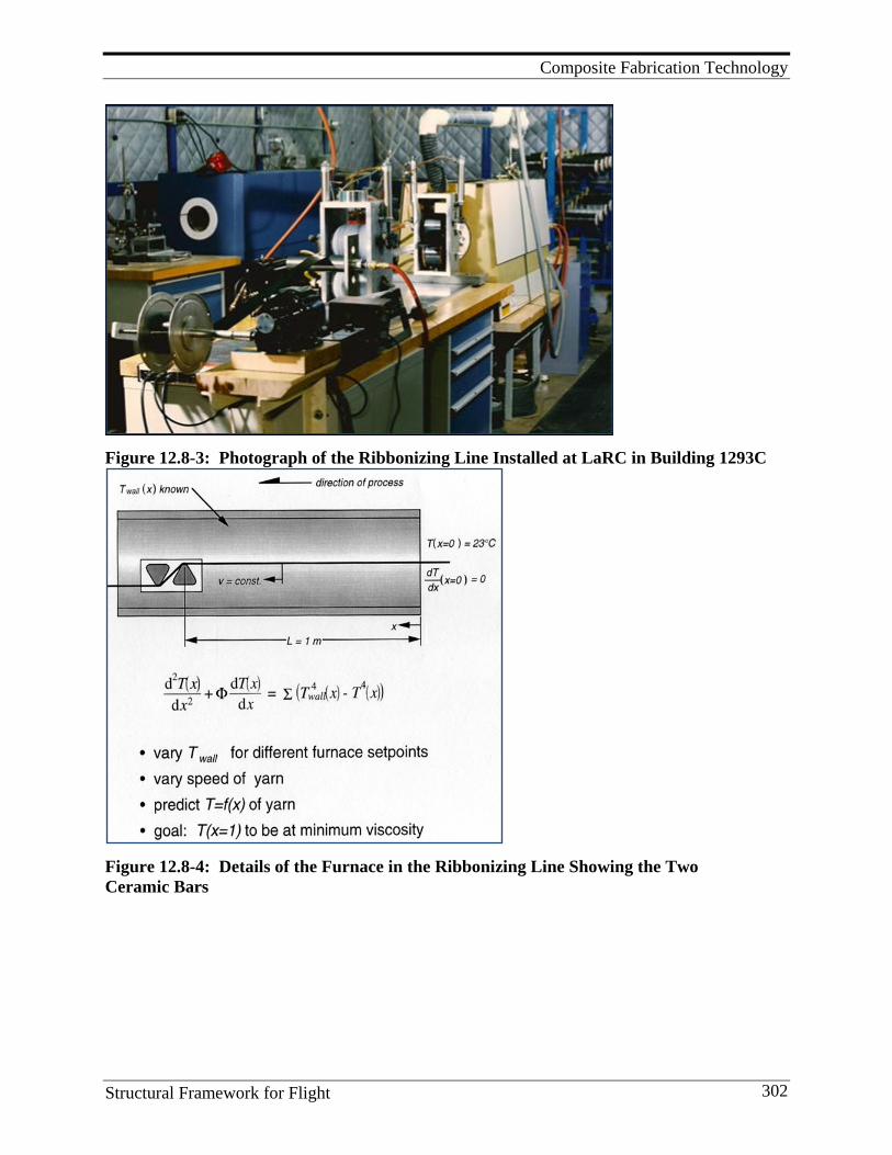
Composite Fabrication Technology
Structural Framework for Flight 302
Figure 12.8-3: Photograph of the Ribbonizing Line Installed at LaRC in Building 1293C
Figure 12.8-4: Details of the Furnace in the Ribbonizing Line Showing the Two Ceramic Bars
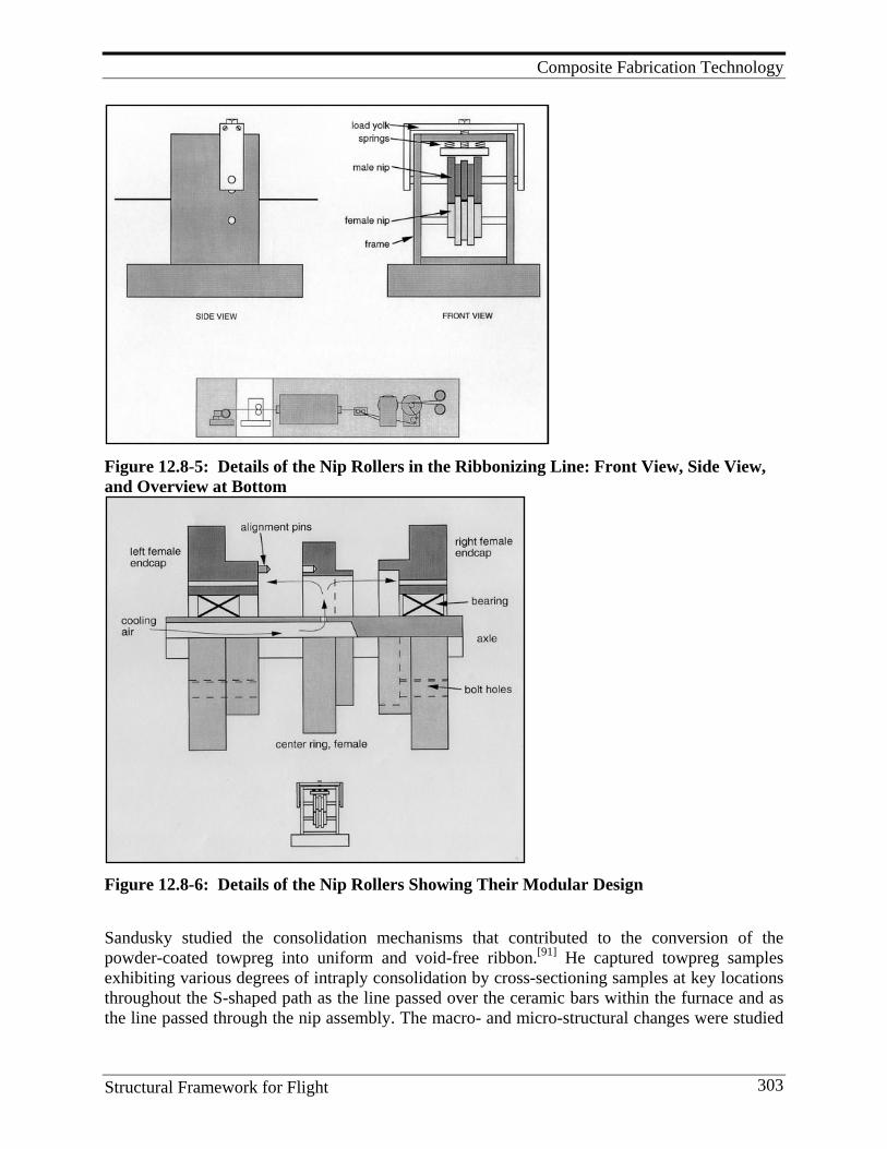
Composite Fabrication Technology
Structural Framework for Flight 303
Figure 12.8-5: Details of the Nip Rollers in the Ribbonizing Line: Front View, Side View, and Overview at Bottom
Figure 12.8-6: Details of the Nip Rollers Showing Their Modular Design Sandusky studied the consolidation mechanisms that contributed to the conversion of the powder-coated towpreg into uniform and void-free ribbon.[91] He captured towpreg samples exhibiting various degrees of intraply consolidation by cross-sectioning samples at key locations throughout the S-shaped path as the line passed over the ceramic bars within the furnace and as the line passed through the nip assembly. The macro- and micro-structural changes were studied
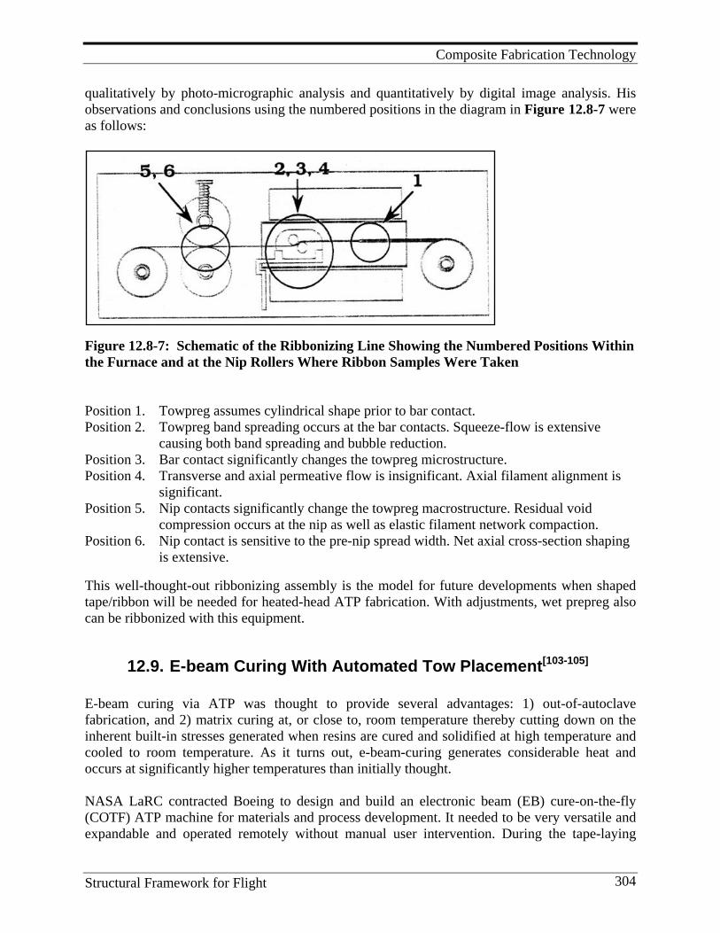
Composite Fabrication Technology
Structural Framework for Flight 304
qualitatively by photo-micrographic analysis and quantitatively by digital image analysis. His observations and conclusions using the numbered positions in the diagram in Figure 12.8-7 were as follows:
Figure 12.8-7: Schematic of the Ribbonizing Line Showing the Numbered Positions Within the Furnace and at the Nip Rollers Where Ribbon Samples Were Taken Position 1. Towpreg assumes cylindrical shape prior to bar contact. Position 2. Towpreg band spreading occurs at the bar contacts. Squeeze-flow is extensive
causing both band spreading and bubble reduction. Position 3. Bar contact significantly changes the towpreg microstructure. Position 4. Transverse and axial permeative flow is insignificant. Axial filament alignment is
significant. Position 5. Nip contacts significantly change the towpreg macrostructure. Residual void
compression occurs at the nip as well as elastic filament network compaction. Position 6. Nip contact is sensitive to the pre-nip spread width. Net axial cross-section shaping
is extensive. This well-thought-out ribbonizing assembly is the model for future developments when shaped tape/ribbon will be needed for heated-head ATP fabrication. With adjustments, wet prepreg also can be ribbonized with this equipment.
12.9. E-beam Curing With Automated Tow Placement[103-105] E-beam curing via ATP was thought to provide several advantages: 1) out-of-autoclave fabrication, and 2) matrix curing at, or close to, room temperature thereby cutting down on the inherent built-in stresses generated when resins are cured and solidified at high temperature and cooled to room temperature. As it turns out, e-beam-curing generates considerable heat and occurs at significantly higher temperatures than initially thought. NASA LaRC contracted Boeing to design and build an electronic beam (EB) cure-on-the-fly (COTF) ATP machine for materials and process development. It needed to be very versatile and expandable and operated remotely without manual user intervention. During the tape-laying
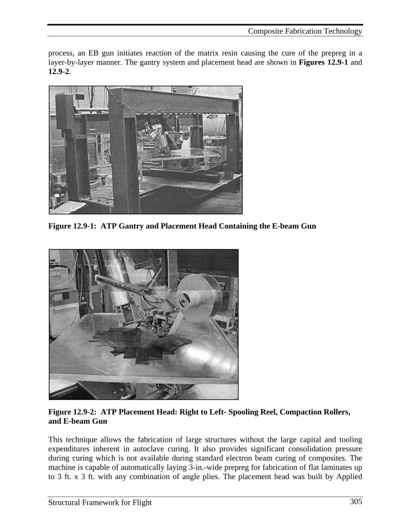
Composite Fabrication Technology
Structural Framework for Flight 305
process, an EB gun initiates reaction of the matrix resin causing the cure of the prepreg in a layer-by-layer manner. The gantry system and placement head are shown in Figures 12.9-1 and 12.9-2.
Figure 12.9-1: ATP Gantry and Placement Head Containing the E-beam Gun
Figure 12.9-2: ATP Placement Head: Right to Left- Spooling Reel, Compaction Rollers, and E-beam Gun This technique allows the fabrication of large structures without the large capital and tooling expenditures inherent in autoclave curing. It also provides significant consolidation pressure during curing which is not available during standard electron beam curing of composites. The machine is capable of automatically laying 3-in.-wide prepreg for fabrication of flat laminates up to 3 ft. x 3 ft. with any combination of angle plies. The placement head was built by Applied

Composite Fabrication Technology
Structural Framework for Flight 306
Poleramic, Inc., the EB gun by Electron Solutions, Inc., and the gantry by Boeing. The device was installed initially at the Boeing Radiation Effects Laboratory (BREL) for initial trials, then moved to LaRC’s fabrication lab in building 1267 where adequate space was available for constructing a concrete barrier between the device and the operating system. The gantry had a unique design. The rotation axis, one translation axis, and a flat tool mounted to it were located on the base of the frame and separate from the moving head. This two-axis, lower-gantry-motion design allowed the head and attached EB gun above it to travel solely in the X direction. Translation in the Y direction and rotation around the Z-axis were achieved by motion of a flat tool. This enabled fabrication of larger laminates due to the functionality of the translation/rotation on which the flat tool was mounted, as well as the expansion potential of the entire device. The tape-placement head was custom designed and engineered specifically for EB cure-on-the-fly processing. Three compliant silicone compaction rollers provided compaction of the prepreg tape via a pressure piston with a variable force control system. A hinge on which the rollers were attached allowed compaction force onto laminates that were not perfectly flat prior to in situ EB cure. An infrared heating lamp and electronic controls were integrated into the device. The 200 W, 225 keV electron gun was designed to be lightweight and fully computer programmable, and provide a uniform, delivered dose equivalent to 5 MR in 30 milliseconds with a penetration depth of 100 microns into a graphite/epoxy prepreg with a composite density of 1.7 g/cm3. At BREL, EB curing of a one-square-foot, quasi-isotropic, graphite-epoxy laminate was safely and effectively demonstrated by in situ tape-laying using a facility where the operator was 150-ft. from the EB device. The process was continuous from start to finish and no operator intervention was required. Although the panel was of poor quality, it did demonstrate that the new equipment was capable of laying and curing composite tape in a simultaneous process. Special epoxies had to be developed that were EB-curable and could be fabricated into quality prepreg tape. Two were investigated: woven 5HS AS-4/CAT B made by Applied Poleramic, Inc., and unidirectional IM-7/ORNL 1-6. After EB curing, both had mechanical properties, especially compression strengths, lower than expected compared with Cytec’s 977-3 composite autoclave-cured at 350°F. Poor fiber-resin interfaces were observed in many cases. It was obvious that the following additional technologies were needed to advance the state-of-the-art.
• Resins have to be tailored for rapid, automated fabrication • Modified resins with improved fiber-resin interfaces and mechanical properties
equivalent to IM-7/977-3 autoclave properties • Improved toughness and microcrack resistance • High-temperature capability • Improved conformable placement heads • Process that is adaptable to extended-arm ATP gantries • Better understanding of property needs for specific applications • Better understanding of cure mechanisms and kinetics for any new matrix material • Cure mechanisms must be modeled
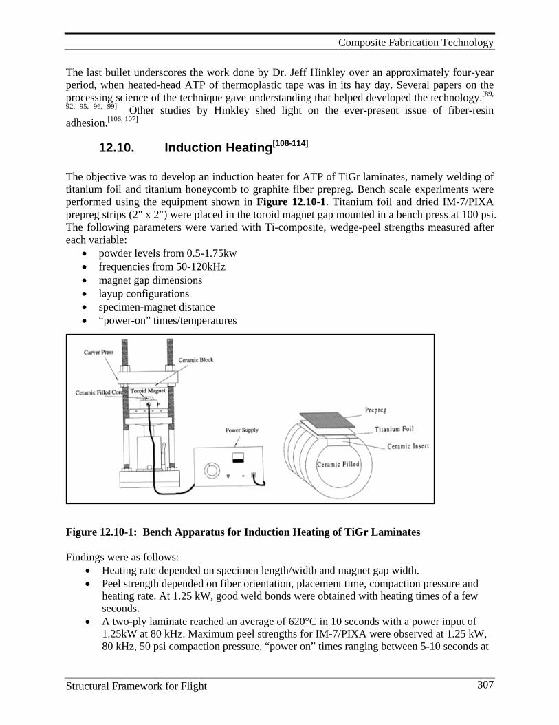
Composite Fabrication Technology
Structural Framework for Flight 307
The last bullet underscores the work done by Dr. Jeff Hinkley over an approximately four-year period, when heated-head ATP of thermoplastic tape was in its hay day. Several papers on the processing science of the technique gave understanding that helped developed the technology.[89,
92, 95, 96, 99] Other studies by Hinkley shed light on the ever-present issue of fiber-resin adhesion.[106, 107]
12.10. Induction Heating[108-114] The objective was to develop an induction heater for ATP of TiGr laminates, namely welding of titanium foil and titanium honeycomb to graphite fiber prepreg. Bench scale experiments were performed using the equipment shown in Figure 12.10-1. Titanium foil and dried IM-7/PIXA prepreg strips (2" x 2") were placed in the toroid magnet gap mounted in a bench press at 100 psi. The following parameters were varied with Ti-composite, wedge-peel strengths measured after each variable:
• powder levels from 0.5-1.75kw • frequencies from 50-120kHz • magnet gap dimensions • layup configurations • specimen-magnet distance • “power-on” times/temperatures
Figure 12.10-1: Bench Apparatus for Induction Heating of TiGr Laminates Findings were as follows:
• Heating rate depended on specimen length/width and magnet gap width. • Peel strength depended on fiber orientation, placement time, compaction pressure and
heating rate. At 1.25 kW, good weld bonds were obtained with heating times of a few seconds.
• A two-ply laminate reached an average of 620°C in 10 seconds with a power input of 1.25kW at 80 kHz. Maximum peel strengths for IM-7/PIXA were observed at 1.25 kW, 80 kHz, 50 psi compaction pressure, “power on” times ranging between 5-10 seconds at
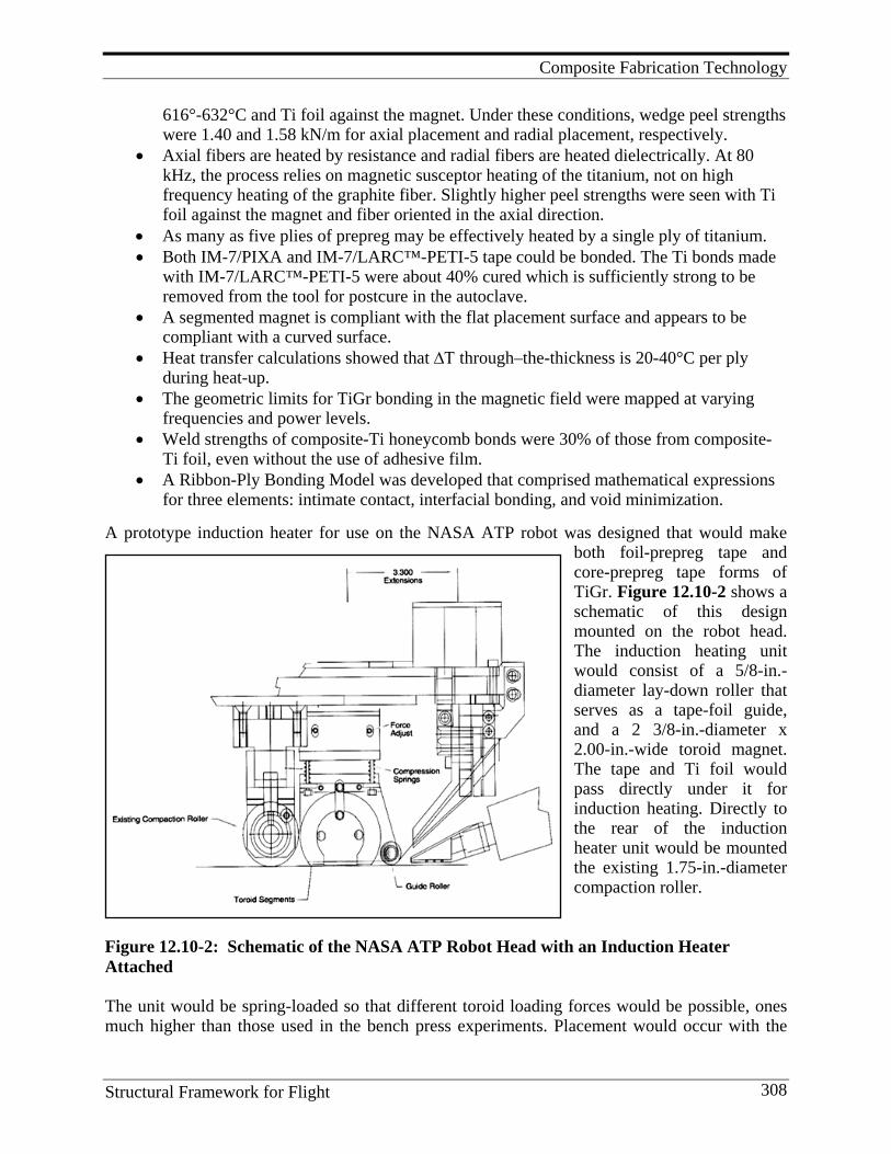
Composite Fabrication Technology
Structural Framework for Flight 308
616°-632°C and Ti foil against the magnet. Under these conditions, wedge peel strengths were 1.40 and 1.58 kN/m for axial placement and radial placement, respectively.
• Axial fibers are heated by resistance and radial fibers are heated dielectrically. At 80 kHz, the process relies on magnetic susceptor heating of the titanium, not on high frequency heating of the graphite fiber. Slightly higher peel strengths were seen with Ti foil against the magnet and fiber oriented in the axial direction.
• As many as five plies of prepreg may be effectively heated by a single ply of titanium. • Both IM-7/PIXA and IM-7/LARC™-PETI-5 tape could be bonded. The Ti bonds made
with IM-7/LARC™-PETI-5 were about 40% cured which is sufficiently strong to be removed from the tool for postcure in the autoclave.
• A segmented magnet is compliant with the flat placement surface and appears to be compliant with a curved surface.
• Heat transfer calculations showed that ∆Τ through–the-thickness is 20-40°C per ply during heat-up.
• The geometric limits for TiGr bonding in the magnetic field were mapped at varying frequencies and power levels.
• Weld strengths of composite-Ti honeycomb bonds were 30% of those from composite-Ti foil, even without the use of adhesive film.
• A Ribbon-Ply Bonding Model was developed that comprised mathematical expressions for three elements: intimate contact, interfacial bonding, and void minimization.
A prototype induction heater for use on the NASA ATP robot was designed that would make
both foil-prepreg tape and core-prepreg tape forms of TiGr. Figure 12.10-2 shows a schematic of this design mounted on the robot head. The induction heating unit would consist of a 5/8-in.-diameter lay-down roller that serves as a tape-foil guide, and a 2 3/8-in.-diameter x 2.00-in.-wide toroid magnet. The tape and Ti foil would pass directly under it for induction heating. Directly to the rear of the induction heater unit would be mounted the existing 1.75-in.-diameter compaction roller.
Figure 12.10-2: Schematic of the NASA ATP Robot Head with an Induction Heater Attached The unit would be spring-loaded so that different toroid loading forces would be possible, ones much higher than those used in the bench press experiments. Placement would occur with the
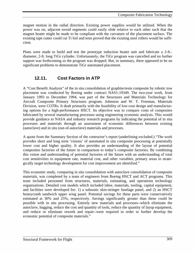
Composite Fabrication Technology
Structural Framework for Flight 309
magnet motion in the radial direction. Existing power supplies would be utilized. When the power was on, adjacent toroid segments could easily slide relative to each other such that the magnet heater might be made to be compliant with the curvature of the placement surface. The existing tape cutter could cut Ti foil and tests proved that the existing steel rollers would be suffi-cient.
Plans were made to build and test the prototype induction heater unit and fabricate a 2-ft.- diameter, 2-ft. long TiGr cylinder. Unfortunately, the TiGr program was cancelled and no further support was forthcoming so the program was dropped. But, in summary, there appeared to be no significant problems to demonstrate TiGr automated placement.
12.11. Cost Factors in ATP A “Cost Benefit Analysis” of the in situ consolidation of graphite/resin composite by robotic tow placement was conducted by Boeing under contract NAS1-19349. The two-year work, from January 1993 to December 1994, was part of the Structures and Materials Technology for Aircraft Composite Primary Structures program. Johnston and W. T. Freeman, Materials Division, were COTRs. It dealt primarily with the feasibility of low-cost design and manufactur-ing options for a high-performance HSCT. Its objective was to compare costs of composites fabricated by several manufacturing processes using engineering economic analysis. This would provide guidance to NASA and industry research programs by indicating the potential of in situ processes and materials through an assessment of economic differences between existing (autoclave) and in situ (out-of-autoclave) materials and processes. A quote from the Summary Section of the contractor’s report (underlining excluded.) “The work provides short and long term ‘visions’ of automated in situ composite processing at potentially lower cost and higher quality. It also provides an understanding of the layout of potential composites factories of the future in comparison to today’s composite factories. By combining this vision and understanding of potential factories of the future with an understanding of total cost sensitivities to equipment rate, material cost, and other variables, primary areas to strate-gically target technology development for cost improvement are identified.” This economic study, comparing in situ consolidation with autoclave consolidation of composite materials, was completed by a team of engineers from Boeing HSCT and ACT programs. This team included personnel from structures, materials, estimating, and operations technology organizations. Detailed cost models which included labor, materials, tooling, capital equipment, and facilities were developed for: 1) a subsonic skin-stringer fuselage panel, and 2) an HSCT honeycomb sandwich upper wing panel. Potential savings for these parts were conservatively estimated at 30% and 25%, respectively. Savings significantly greater than these could be possible with in situ processing. Entirely new materials and processes--which eliminate the autoclave, bagging, reduce the cost and quantity of tools, reduce the quantity of layup equipment, and reduce or eliminate rework and repair--were required in order to further develop the economic potential of composite materials.”
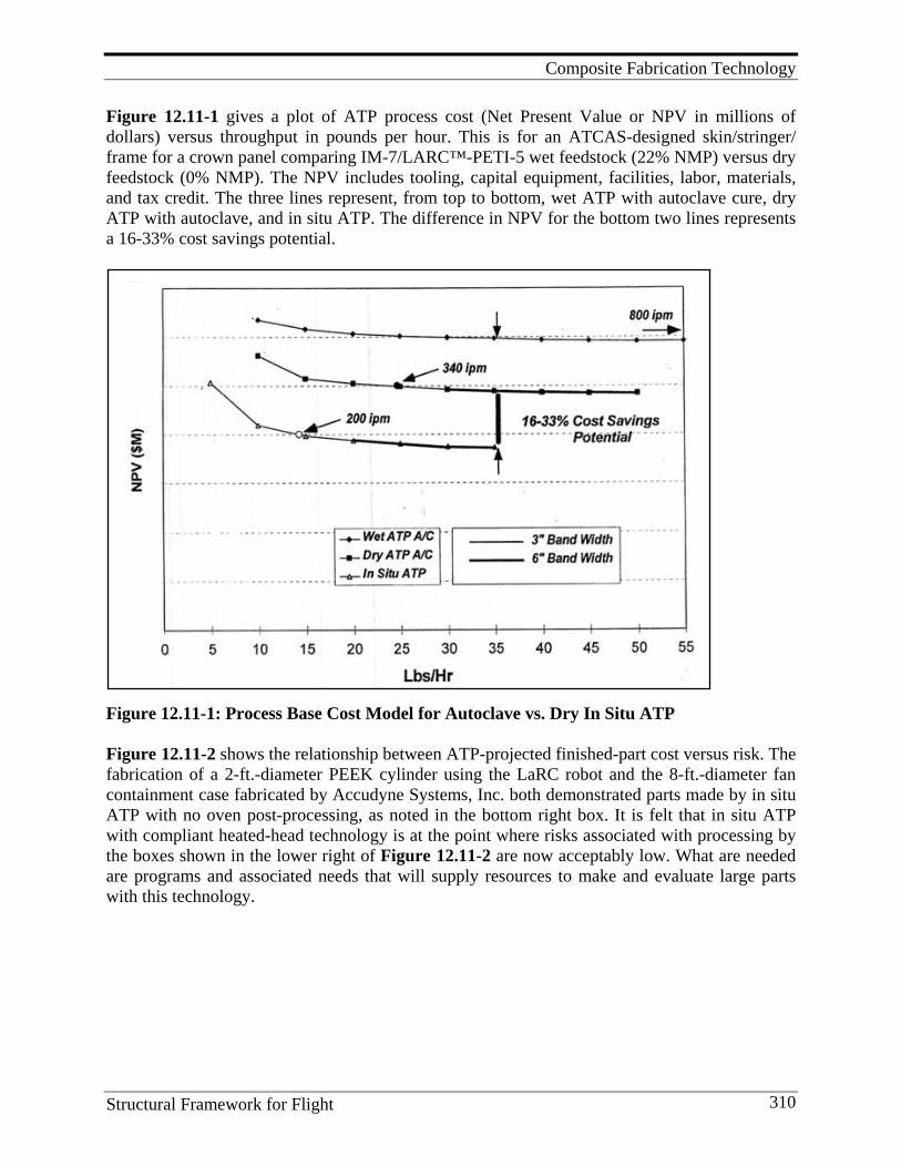
Composite Fabrication Technology
Structural Framework for Flight 310
Figure 12.11-1 gives a plot of ATP process cost (Net Present Value or NPV in millions of dollars) versus throughput in pounds per hour. This is for an ATCAS-designed skin/stringer/ frame for a crown panel comparing IM-7/LARC™-PETI-5 wet feedstock (22% NMP) versus dry feedstock (0% NMP). The NPV includes tooling, capital equipment, facilities, labor, materials, and tax credit. The three lines represent, from top to bottom, wet ATP with autoclave cure, dry ATP with autoclave, and in situ ATP. The difference in NPV for the bottom two lines represents a 16-33% cost savings potential.
Figure 12.11-1: Process Base Cost Model for Autoclave vs. Dry In Situ ATP Figure 12.11-2 shows the relationship between ATP-projected finished-part cost versus risk. The fabrication of a 2-ft.-diameter PEEK cylinder using the LaRC robot and the 8-ft.-diameter fan containment case fabricated by Accudyne Systems, Inc. both demonstrated parts made by in situ ATP with no oven post-processing, as noted in the bottom right box. It is felt that in situ ATP with compliant heated-head technology is at the point where risks associated with processing by the boxes shown in the lower right of Figure 12.11-2 are now acceptably low. What are needed are programs and associated needs that will supply resources to make and evaluate large parts with this technology.
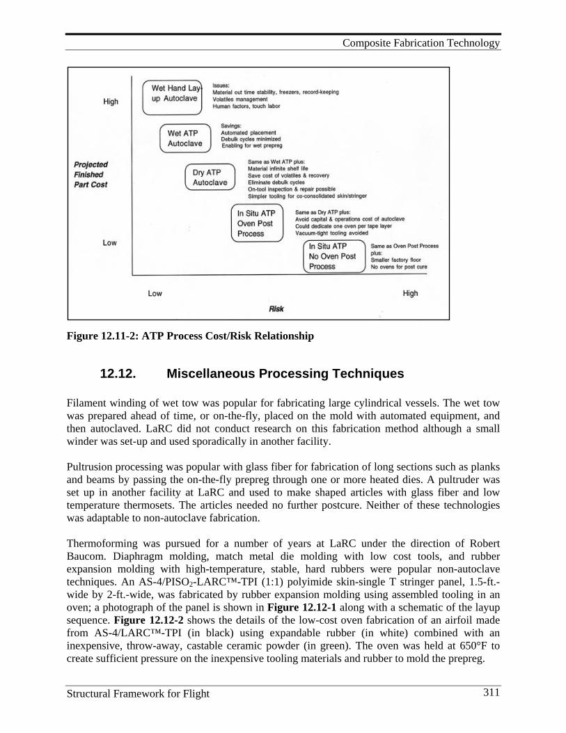
Composite Fabrication Technology
Structural Framework for Flight 311
Figure 12.11-2: ATP Process Cost/Risk Relationship
12.12. Miscellaneous Processing Techniques Filament winding of wet tow was popular for fabricating large cylindrical vessels. The wet tow was prepared ahead of time, or on-the-fly, placed on the mold with automated equipment, and then autoclaved. LaRC did not conduct research on this fabrication method although a small winder was set-up and used sporadically in another facility. Pultrusion processing was popular with glass fiber for fabrication of long sections such as planks and beams by passing the on-the-fly prepreg through one or more heated dies. A pultruder was set up in another facility at LaRC and used to make shaped articles with glass fiber and low temperature thermosets. The articles needed no further postcure. Neither of these technologies was adaptable to non-autoclave fabrication. Thermoforming was pursued for a number of years at LaRC under the direction of Robert Baucom. Diaphragm molding, match metal die molding with low cost tools, and rubber expansion molding with high-temperature, stable, hard rubbers were popular non-autoclave techniques. An AS-4/PISO2-LARC™-TPI (1:1) polyimide skin-single T stringer panel, 1.5-ft.-wide by 2-ft.-wide, was fabricated by rubber expansion molding using assembled tooling in an oven; a photograph of the panel is shown in Figure 12.12-1 along with a schematic of the layup sequence. Figure 12.12-2 shows the details of the low-cost oven fabrication of an airfoil made from AS-4/LARC™-TPI (in black) using expandable rubber (in white) combined with an inexpensive, throw-away, castable ceramic powder (in green). The oven was held at 650°F to create sufficient pressure on the inexpensive tooling materials and rubber to mold the prepreg.
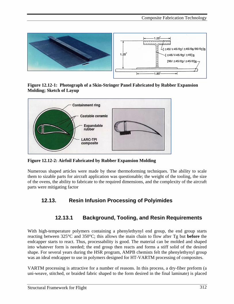
Composite Fabrication Technology
Structural Framework for Flight 312
Figure 12.12-1: Photograph of a Skin-Stringer Panel Fabricated by Rubber Expansion Molding; Sketch of Layup
Figure 12.12-2: Airfoil Fabricated by Rubber Expansion Molding Numerous shaped articles were made by these thermoforming techniques. The ability to scale them to sizable parts for aircraft application was questionable; the weight of the tooling, the size of the ovens, the ability to fabricate to the required dimensions, and the complexity of the aircraft parts were mitigating factor
12.13. Resin Infusion Processing of Polyimides
12.13.1 Background, Tooling, and Resin Requirements With high-temperature polymers containing a phenylethynyl end group, the end group starts reacting between 325°C and 350°C; this allows the main chain to flow after Tg but before the endcapper starts to react. Thus, processability is good. The material can be molded and shaped into whatever form is needed; the end group then reacts and forms a stiff solid of the desired shape. For several years during the HSR program, AMPB chemists felt the phenylethynyl group was an ideal endcapper to use in polymers designed for HT-VARTM processing of composites. VARTM processing is attractive for a number of reasons. In this process, a dry-fiber preform (a uni-weave, stitched, or braided fabric shaped to the form desired in the final laminate) is placed
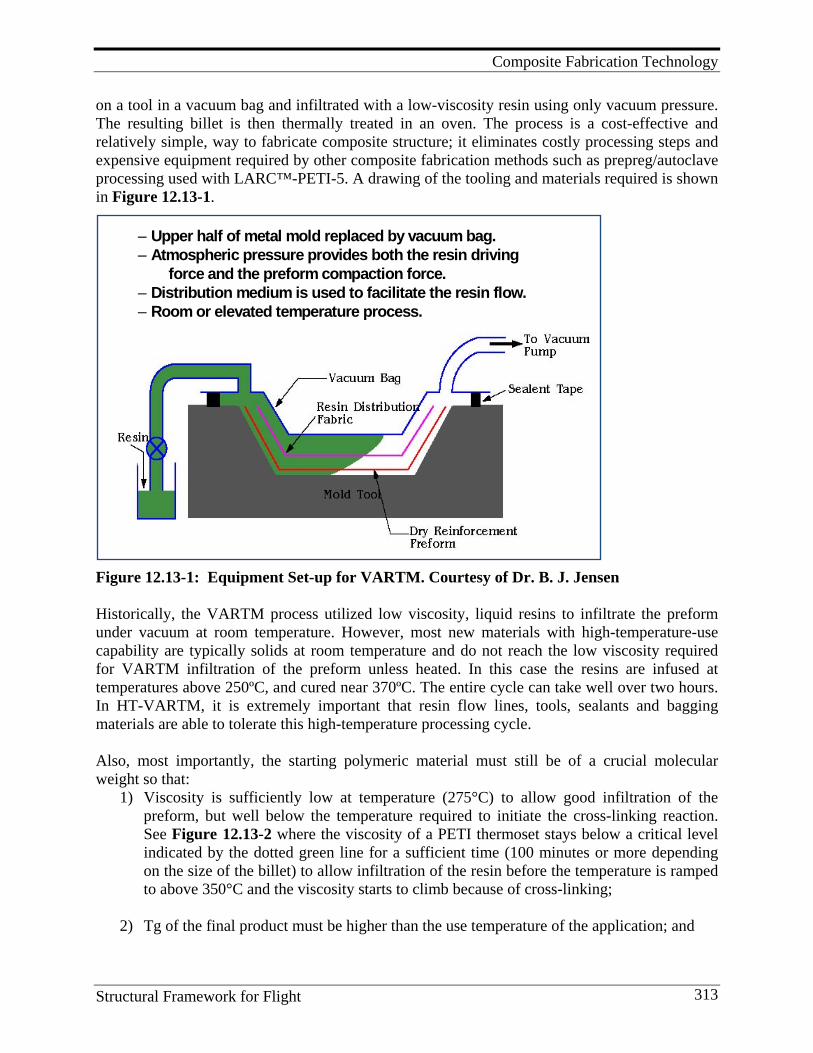
Composite Fabrication Technology
Structural Framework for Flight 313
on a tool in a vacuum bag and infiltrated with a low-viscosity resin using only vacuum pressure. The resulting billet is then thermally treated in an oven. The process is a cost-effective and relatively simple, way to fabricate composite structure; it eliminates costly processing steps and expensive equipment required by other composite fabrication methods such as prepreg/autoclave processing used with LARC™-PETI-5. A drawing of the tooling and materials required is shown in Figure 12.13-1.
Figure 12.13-1: Equipment Set-up for VARTM. Courtesy of Dr. B. J. Jensen Historically, the VARTM process utilized low viscosity, liquid resins to infiltrate the preform under vacuum at room temperature. However, most new materials with high-temperature-use capability are typically solids at room temperature and do not reach the low viscosity required for VARTM infiltration of the preform unless heated. In this case the resins are infused at temperatures above 250ºC, and cured near 370ºC. The entire cycle can take well over two hours. In HT-VARTM, it is extremely important that resin flow lines, tools, sealants and bagging materials are able to tolerate this high-temperature processing cycle. Also, most importantly, the starting polymeric material must still be of a crucial molecular weight so that:
1) Viscosity is sufficiently low at temperature (275°C) to allow good infiltration of the preform, but well below the temperature required to initiate the cross-linking reaction. See Figure 12.13-2 where the viscosity of a PETI thermoset stays below a critical level indicated by the dotted green line for a sufficient time (100 minutes or more depending on the size of the billet) to allow infiltration of the resin before the temperature is ramped to above 350°C and the viscosity starts to climb because of cross-linking;
2) Tg of the final product must be higher than the use temperature of the application; and
– Upper half of metal mold replaced by vacuum bag.– Atmospheric pressure provides both the resin driving force and the preform compaction force.– Distribution medium is used to facilitate the resin flow.– Room or elevated temperature process.
ROLE OF MATRIX BONDS AND HOLDS FILAMENTS IN PLACE PROTECTS FILAMENTS PROVIDES TRANSVERSE STRENGTH ACTS AS A LOAD TRANSFER MEDIUM PROVIDES INTERLAMINAR TOUGHNESS PROVIDES DURABILITY
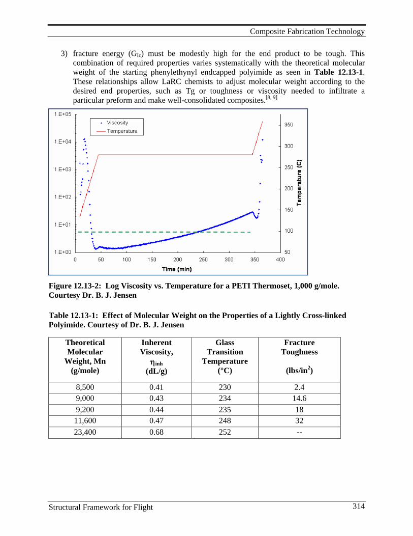
Composite Fabrication Technology
Structural Framework for Flight 314
3) fracture energy (GIc) must be modestly high for the end product to be tough. This combination of required properties varies systematically with the theoretical molecular weight of the starting phenylethynyl endcapped polyimide as seen in Table 12.13-1. These relationships allow LaRC chemists to adjust molecular weight according to the desired end properties, such as Tg or toughness or viscosity needed to infiltrate a particular preform and make well-consolidated composites.[8, 9]
Figure 12.13-2: Log Viscosity vs. Temperature for a PETI Thermoset, 1,000 g/mole. Courtesy Dr. B. J. Jensen
Table 12.13-1: Effect of Molecular Weight on the Properties of a Lightly Cross-linked Polyimide. Courtesy of Dr. B. J. Jensen
Theoretical Molecular
Weight, Mn (g/mole)
Inherent Viscosity,
ηinh (dL/g)
Glass Transition
Temperature (°C)
Fracture Toughness
(lbs/in2)
8,500 0.41 230 2.4 9,000 0.43 234 14.6 9,200 0.44 235 18 11,600 0.47 248 32 23,400 0.68 252 --
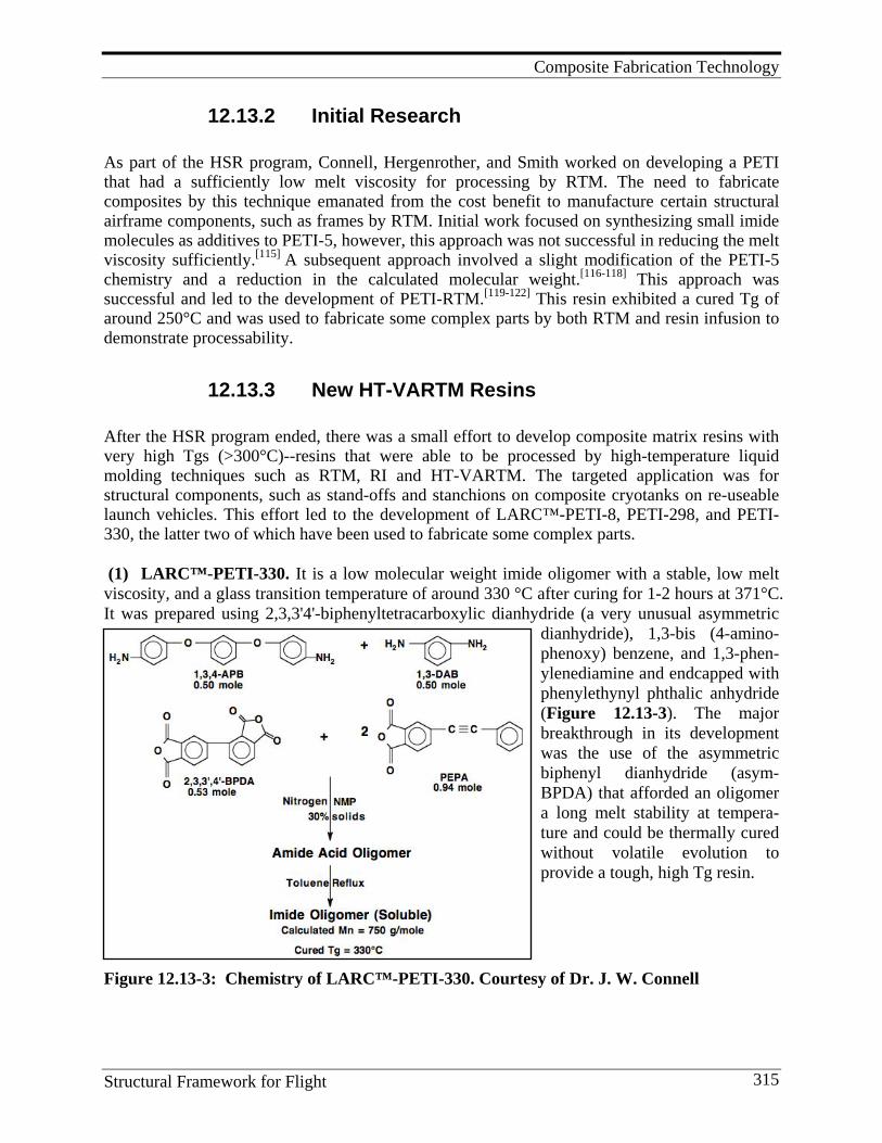
Composite Fabrication Technology
Structural Framework for Flight 315
12.13.2 Initial Research As part of the HSR program, Connell, Hergenrother, and Smith worked on developing a PETI that had a sufficiently low melt viscosity for processing by RTM. The need to fabricate composites by this technique emanated from the cost benefit to manufacture certain structural airframe components, such as frames by RTM. Initial work focused on synthesizing small imide molecules as additives to PETI-5, however, this approach was not successful in reducing the melt viscosity sufficiently.[115] A subsequent approach involved a slight modification of the PETI-5 chemistry and a reduction in the calculated molecular weight.[116-118] This approach was successful and led to the development of PETI-RTM.[119-122] This resin exhibited a cured Tg of around 250°C and was used to fabricate some complex parts by both RTM and resin infusion to demonstrate processability.
12.13.3 New HT-VARTM Resins After the HSR program ended, there was a small effort to develop composite matrix resins with very high Tgs (>300°C)--resins that were able to be processed by high-temperature liquid molding techniques such as RTM, RI and HT-VARTM. The targeted application was for structural components, such as stand-offs and stanchions on composite cryotanks on re-useable launch vehicles. This effort led to the development of LARC™-PETI-8, PETI-298, and PETI-330, the latter two of which have been used to fabricate some complex parts. (1) LARC™-PETI-330. It is a low molecular weight imide oligomer with a stable, low melt viscosity, and a glass transition temperature of around 330 °C after curing for 1-2 hours at 371°C. It was prepared using 2,3,3'4'-biphenyltetracarboxylic dianhydride (a very unusual asymmetric
dianhydride), 1,3-bis (4-amino-phenoxy) benzene, and 1,3-phen-ylenediamine and endcapped with phenylethynyl phthalic anhydride (Figure 12.13-3). The major breakthrough in its development was the use of the asymmetric biphenyl dianhydride (asym-BPDA) that afforded an oligomer a long melt stability at tempera-ture and could be thermally cured without volatile evolution to provide a tough, high Tg resin.
Figure 12.13-3: Chemistry of LARC™-PETI-330. Courtesy of Dr. J. W. Connell
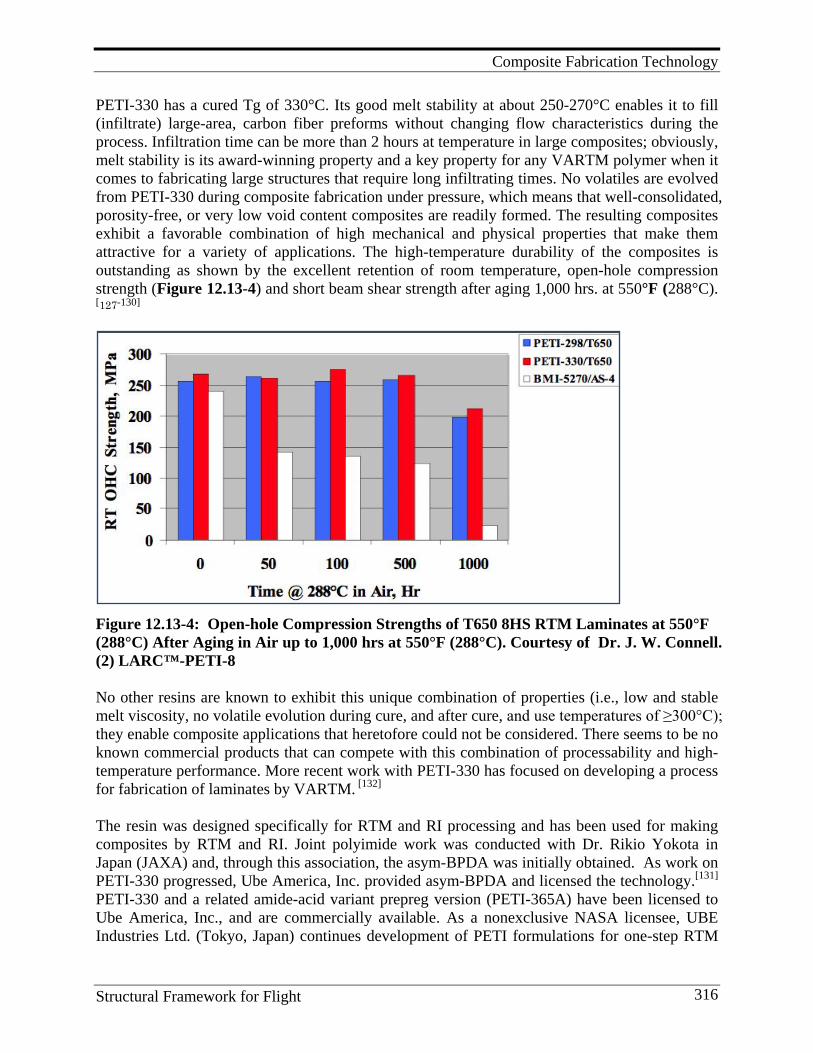
Composite Fabrication Technology
Structural Framework for Flight 316
PETI-330 has a cured Tg of 330°C. Its good melt stability at about 250-270°C enables it to fill (infiltrate) large-area, carbon fiber preforms without changing flow characteristics during the process. Infiltration time can be more than 2 hours at temperature in large composites; obviously, melt stability is its award-winning property and a key property for any VARTM polymer when it comes to fabricating large structures that require long infiltrating times. No volatiles are evolved from PETI-330 during composite fabrication under pressure, which means that well-consolidated, porosity-free, or very low void content composites are readily formed. The resulting composites exhibit a favorable combination of high mechanical and physical properties that make them attractive for a variety of applications. The high-temperature durability of the composites is outstanding as shown by the excellent retention of room temperature, open-hole compression strength (Figure 12.13-4) and short beam shear strength after aging 1,000 hrs. at 550°F (288°C). [127-130]
Figure 12.13-4: Open-hole Compression Strengths of T650 8HS RTM Laminates at 550°F (288°C) After Aging in Air up to 1,000 hrs at 550°F (288°C). Courtesy of Dr. J. W. Connell. (2) LARC™-PETI-8 No other resins are known to exhibit this unique combination of properties (i.e., low and stable melt viscosity, no volatile evolution during cure, and after cure, and use temperatures of ≥300°C); they enable composite applications that heretofore could not be considered. There seems to be no known commercial products that can compete with this combination of processability and high-temperature performance. More recent work with PETI-330 has focused on developing a process for fabrication of laminates by VARTM. [132] The resin was designed specifically for RTM and RI processing and has been used for making composites by RTM and RI. Joint polyimide work was conducted with Dr. Rikio Yokota in Japan (JAXA) and, through this association, the asym-BPDA was initially obtained. As work on PETI-330 progressed, Ube America, Inc. provided asym-BPDA and licensed the technology.[131]
PETI-330 and a related amide-acid variant prepreg version (PETI-365A) have been licensed to Ube America, Inc., and are commercially available. As a nonexclusive NASA licensee, UBE Industries Ltd. (Tokyo, Japan) continues development of PETI formulations for one-step RTM
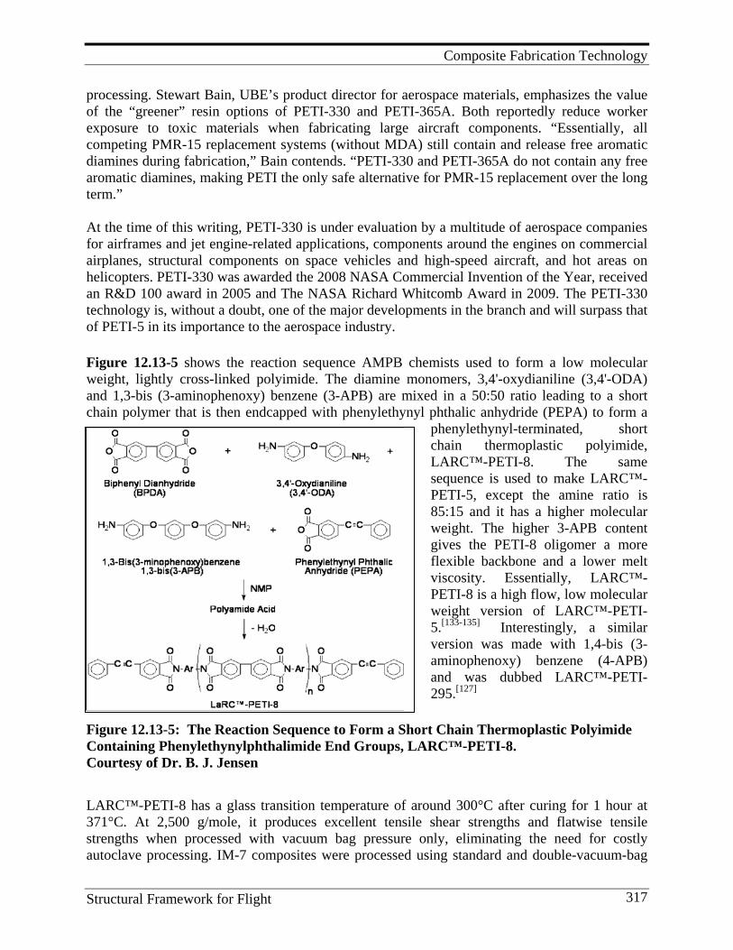
Composite Fabrication Technology
Structural Framework for Flight 317
processing. Stewart Bain, UBE’s product director for aerospace materials, emphasizes the value of the “greener” resin options of PETI-330 and PETI-365A. Both reportedly reduce worker exposure to toxic materials when fabricating large aircraft components. “Essentially, all competing PMR-15 replacement systems (without MDA) still contain and release free aromatic diamines during fabrication,” Bain contends. “PETI-330 and PETI-365A do not contain any free aromatic diamines, making PETI the only safe alternative for PMR-15 replacement over the long term.” At the time of this writing, PETI-330 is under evaluation by a multitude of aerospace companies for airframes and jet engine-related applications, components around the engines on commercial airplanes, structural components on space vehicles and high-speed aircraft, and hot areas on helicopters. PETI-330 was awarded the 2008 NASA Commercial Invention of the Year, received an R&D 100 award in 2005 and The NASA Richard Whitcomb Award in 2009. The PETI-330 technology is, without a doubt, one of the major developments in the branch and will surpass that of PETI-5 in its importance to the aerospace industry.
Figure 12.13-5 shows the reaction sequence AMPB chemists used to form a low molecular weight, lightly cross-linked polyimide. The diamine monomers, 3,4'-oxydianiline (3,4'-ODA) and 1,3-bis (3-aminophenoxy) benzene (3-APB) are mixed in a 50:50 ratio leading to a short chain polymer that is then endcapped with phenylethynyl phthalic anhydride (PEPA) to form a
phenylethynyl-terminated, short chain thermoplastic polyimide, LARC™-PETI-8. The same sequence is used to make LARC™-PETI-5, except the amine ratio is 85:15 and it has a higher molecular weight. The higher 3-APB content gives the PETI-8 oligomer a more flexible backbone and a lower melt viscosity. Essentially, LARC™- PETI-8 is a high flow, low molecular weight version of LARC™-PETI-5.[133-135] Interestingly, a similar version was made with 1,4-bis (3-aminophenoxy) benzene (4-APB) and was dubbed LARC™-PETI-295.[127]
Figure 12.13-5: The Reaction Sequence to Form a Short Chain Thermoplastic Polyimide Containing Phenylethynylphthalimide End Groups, LARC™-PETI-8. Courtesy of Dr. B. J. Jensen
LARC™-PETI-8 has a glass transition temperature of around 300°C after curing for 1 hour at 371°C. At 2,500 g/mole, it produces excellent tensile shear strengths and flatwise tensile strengths when processed with vacuum bag pressure only, eliminating the need for costly autoclave processing. IM-7 composites were processed using standard and double-vacuum-bag
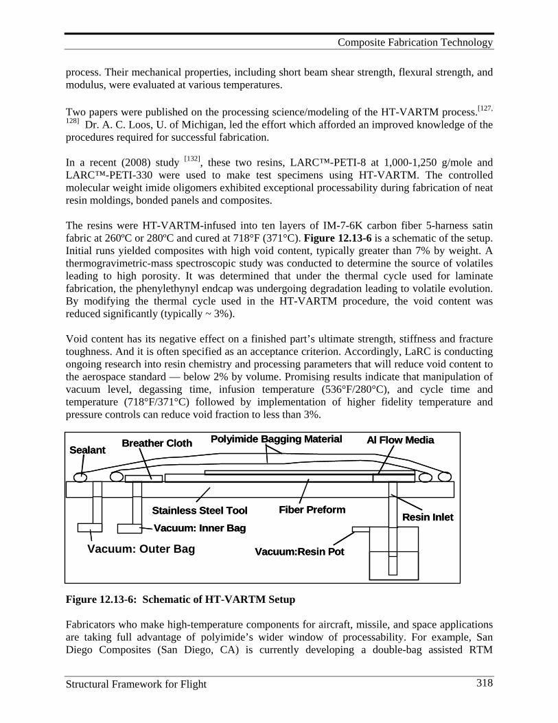
Composite Fabrication Technology
Structural Framework for Flight 318
Vacuum: Inner Bag
Vacuum: Outter Bag
Stainless Steel Tool Fiber PreformResin Inlet
Breather Cloth Al Flow MediaSealant
Polyimide Bagging Material
Vacuum:Resin Pot Vacuum: Outer Bag
Vacuum: Inner Bag
Vacuum: Outter Bag
Stainless Steel Tool Fiber PreformResin Inlet
Breather Cloth Al Flow MediaSealant
Polyimide Bagging Material
Vacuum:Resin Pot Vacuum: Outer Bag
process. Their mechanical properties, including short beam shear strength, flexural strength, and modulus, were evaluated at various temperatures.
Two papers were published on the processing science/modeling of the HT-VARTM process.[127,
128] Dr. A. C. Loos, U. of Michigan, led the effort which afforded an improved knowledge of the procedures required for successful fabrication. In a recent (2008) study [132], these two resins, LARC™-PETI-8 at 1,000-1,250 g/mole and LARC™-PETI-330 were used to make test specimens using HT-VARTM. The controlled molecular weight imide oligomers exhibited exceptional processability during fabrication of neat resin moldings, bonded panels and composites. The resins were HT-VARTM-infused into ten layers of IM-7-6K carbon fiber 5-harness satin fabric at 260ºC or 280ºC and cured at 718°F (371°C). Figure 12.13-6 is a schematic of the setup. Initial runs yielded composites with high void content, typically greater than 7% by weight. A thermogravimetric-mass spectroscopic study was conducted to determine the source of volatiles leading to high porosity. It was determined that under the thermal cycle used for laminate fabrication, the phenylethynyl endcap was undergoing degradation leading to volatile evolution. By modifying the thermal cycle used in the HT-VARTM procedure, the void content was reduced significantly (typically ~ 3%). Void content has its negative effect on a finished part’s ultimate strength, stiffness and fracture toughness. And it is often specified as an acceptance criterion. Accordingly, LaRC is conducting ongoing research into resin chemistry and processing parameters that will reduce void content to the aerospace standard — below 2% by volume. Promising results indicate that manipulation of vacuum level, degassing time, infusion temperature (536°F/280°C), and cycle time and temperature (718°F/371°C) followed by implementation of higher fidelity temperature and pressure controls can reduce void fraction to less than 3%.
Figure 12.13-6: Schematic of HT-VARTM Setup Fabricators who make high-temperature components for aircraft, missile, and space applications are taking full advantage of polyimide’s wider window of processability. For example, San Diego Composites (San Diego, CA) is currently developing a double-bag assisted RTM
Composite Fabrication Technology
Structural Framework for Flight 319
(DBARTM) cure cycle for engine nacelle components with non-flat geometry through a LaRC SBIR directed by Dr. Tan Hou. Dr. Hou developed the double-bag process for HT-VARTM.[138,
139] Company Vice President, Christine Benzie, identifies Grafil 34-700 carbon fiber and PETI-330 resin as the material system under evaluation for this part, which sees long-term exposure over 400°F (204°C). Where parts previously required autoclave processing at 100 psi/6.89 bar during prolonged cure cycles, the DBARTM cure requires vacuum pressure of only 12-14 psi (0.83-0.97 bar) during a comparatively short eight hours at 600°F (316°C).
12.14. Fiber Metal Laminates Fiber metal laminates (FMLs) are multi-component materials utilizing metals, fibers and matrix resins. Tailoring their properties is readily achievable by varying one or more of these components. Established FMLs, such as GLARE ("GLAss-REinforced" Fibre Metal Laminate (FML)), utilize aluminum foils, glass fibers, and epoxy matrices, and are manufactured using an autoclave. Two new processes for manufacturing FMLs using VARTM have been developed at NASA Langley.[140-146] One is a VARTM process that utilizes flow pathways (perforations) in the metal layers to allow for through-the-thickness resin infusion. It involves stacking alternate layers of the metal foil (aluminum, 2024-T3 with the same surface treatment as GLARE) containing resin flow pathways (perforations) and fabric. This preform is then infused with a resin via a VARTM process. The materials produced by this process are referred to as VARTMFML. A second VARTM process utilizes porous metal-coated fabrics to allow through-the-thickness infusion. These laminates are referred to as VARTMPCL. The VARTMFMLs provide good mechanical properties that can be optimized by proper selection of metal foil, fiber, resin and size, and distribution of the pathways. The VARTMPCLs allow the incorporation of a plasma-deposited metal layer that can improve functional properties like electrical and thermal conductivity. A flow visualization fixture of the VARTM FML process was constructed and used to observe the resin infiltration process.[143] Results of the flow visualization experiments showed that FMLs can be successfully manufactured by the VARTM process when flow pathways, which are primarily in the transverse direction, are machined into the metal foils. The size of the flow pathways significantly influences the shape of the flow patterns and the total infiltration time. The size and shape of the pathways must be large enough to permit resin to flow into and wet-out the glass fabrics, but small enough as not to compromise the structural performance of the FML. Results of the flow visualization experiments were favorably compared with the predictions of a VARTM process simulation model developed earlier by Professor A. C. Loos. The flow visualization work at Michigan State University was supported by the NASA NRA/Research Opportunities in Aeronautics – 2006 program, Cooperative Agreement with R. J. Cano as the Technical Officer.
Composite Fabrication Technology
Structural Framework for Flight 320
12.15. Lessons Learned and Future Directions Many professionals work hard to keep the infrastructure up-to-date but have little time left to coauthor publications although one will see their names on several publications cited in this Monograph. James Nelson played a role in building up the NASA Langley composites infrastructure including the many pieces of equipment in the Prototype Composite Research Laboratory in 1293C. Harold Burks was mainly responsible for guiding the addition of 1293C to Building 1293B where most of the composites research had been done. That expansion was a great addition and gave the needed room to enlarge the composite activities “in-house” without having to go to another building. James Dezern did (and still does) a herculean job as Safety Officer for Building 1293. With all the chemicals and machinery being used in Buildings 1293A and 1293C, this is an enormous job, especially keeping everyone posted on the safety procedures. His efforts were rewarded in 2009 with a NASA metal. George Sykes, in the limited time he was with the group, helped Phil Young equip and operate the polymer physical property character-ization lab that was a boon to all the researchers. Lessons Learned
1. Processing science needs to be an integral part of polymer chemistry and fabrication technology development and must be integrated with structures to guide fabrication studies of real engineering components.
2. Automated processes are required to reduce the cost of composite structures. 3. Scale-up studies are required to establish processing limits and quality control factors. 4. One of the toughest challenges faced in HT-VARTM is the reduction of void content to
2% or less required for aerospace applications. To date it has not been possible for polyimide resins by conventional HT-VARTM. About 3% void content has been achieved. The current research must focus on in-depth studies to determine the volatile source and when volatile evolution occurs followed by appropriate modification of the process cycle. High-temperature degradation studies under VARTM-simulated conditions of all the monomers used in the process must be done.
5. The “ultimate goal” for the composite manufacture is to reproducibly and economically fabricate high quality parts possessing proper dimensions and performance properties for a selected design and use. Automation will be part of the answer, as will non-autoclavability. Robotic labs are needed by researchers to create, study, and optimize prototype processes. These labs should be flexible and broadly adaptable to screen a variety of new approaches, as well as to develop and investigate new constituent materials, material forms, and cure mechanisms. Transfer of the best technology from such labs to industrial partners for scale-up and further tailoring should be relatively easy and efficient and will make the road to any “ultimate goal” smoother and shorter.
6. A prototype composite fabrication laboratory manned by a well-trained workforce of both professionals and technicians, and supported by world-class polymer research is critical to the future development of NASA space exploration programs. The basic issues can be sorted out and solutions proposed for scale-up by industry. LaRC does not have such a laboratory. It was dismantled years ago and only remnants exist in Building 1267. Its staff has been reduced to a very small number of competent engineers and scientists. This activity needs serious renovation if LaRC is to be a serious contender and

Composite Fabrication Technology
Structural Framework for Flight 321
contributor to future NASA missions. For example, the difficulties inherent in the composites portion of the Constitution Program illustrate what should not have happened. In fact, if sufficient resources had been dedicated to developing composites technology over the past decade, the composites portion would have been higher, had fewer problems, and made genuine serious contributions to the success of the Program.
Within the Constellation Program, development of out-of-the-autoclave composite fabrication processes for both large and small structures should have been and still should be promoted; a prototype lab was and still is essential to this goal. For example, VARTM technology with new epoxy-like resins should be developed that have microcrack-resistant properties; VARTM for high-temperature polymers should be developed for future supersonic applications; automated robotic heated head in situ fabrication should be encouraged, especially for large cryotanks and similar structures. There will be no end to the future applications that will take advantage of such developments. The serious licensing of technology emanating from AMPB findings over the years clearly makes this point as does the use of LaRC structures and analysis techniques used by industry over the past 40 years. References
1. Starnes, J. H., Jr., H. B. Dexter, N. J. Johnston, D. R. Ambur, and R. J. Cano. 2001. Composite Structures and Materials Research at NASA Langley Research Center. Paper presented at the NATO Research and Technology Agency Applied Vehicle Technical Panel Specialists’ Meeting on Low-cost Composite Structures, Loen, Norway.
2. Johnston, N. J, H. L. Belvin, R. J. Cano, J. M. Marchello, and A. B. Hulcher. 1999. A Prototype Research Laboratory For Automated Fabrication Of High-performance Composites. Twelfth International Conference On Composite Materials, preprint, 12, (Paper No. 748).
3. Cano, R. J., H. L. Belvin, N. J. Johnston, A. B. Hulcher, J. M. Marchello, and R.W. Grenoble. 2001. A Prototype Research Laboratory For Automated Fiber Placement Technology. International SAMPE Symposium and Exhibition. Science of Advanced Materials and Process Engineering Series 46.
4. Critchfield, M. O., et al. 1992. Low-cost Fabrication Of Composite Ship Structures Using Vacuum-assisted Resin Transfer Molding. Proceedings of the Composites in Marine Applications Symposium, Seattle, WA.
5. Seemann, W. H. 1990. US Patent 4,902,215. 6. Karal, M. 2001. AST Composite Wing Program - Executive Summary. (NASA/CR-2001- 210650). 7. Jegley, D. C., H. G. Bush, and A. E. Lovejoy. 2001. Structural Response and Failure of a Full-scale
Stitched Graphite-epoxy Wing. (AIAA Paper No. 2001-1334-CP). 8. Wilkinson, S. P., J. M. Marchello, and N. J. Johnston. 1993. A New NASA LaRC Multi-purpose
Prepregging Unit. International SAMPE Symposium and Exhibition. Science of Advanced Materials and Process Engineering Series 38:1-15.
9. Wilkinson, S. P., J. M. Marchello, and N. J. Johnston. 1993. Composite Material Impregnation Unit. (NASA TM 107751).
10. Cano, R. J., N. J. Johnston, and J. M. Marchello. 1995. Solution Prepreg Quality Control. 40th International SAMPE Symposium and Exhibition; Science of Advanced Materials and Process Engineering Series 40:583-595.
11. Cano, R. J., M. K. Hugh, J. M. Marchello, and R. W.:Grenoble. 1995. Properties of Polyimide Composites Made From Powder-coated Uniweave and Solution-coated Prepreg Tape. ASME International Mechanical Engineering Congress and Exposition, (ASME Materials Division 1:135-144).
12. Final Report, NASA Contract NNL 04AA10B, Task Order NNL07AD55T. 2008. Evaluation of Advanced Composite Structures Technologies For Application To NASA’s Vision For Space Exploration. Section E2:35. Hampton, VA: Analytical Services & Materials Inc
13. Lamontia, M. A., et al. 1995. Performance of a Filament Wound Graphite/Thermoplastic Composite Ring-stiffened Pressure Hull Model. Journal of Thermoplastic Composite Materials 8 (1).
Composite Fabrication Technology
Structural Framework for Flight 322
14. Lamontia, M. A. 1999. Heated Head Automated Tape and Ribbon Placement and Dry Material Forms Development--Final Report. Lamontia Technical Services to Boeing. (Purchase Contract JV9446).
15. Hulcher, A. B., J. M. Marchello, J. A. Hinkley, N. J. Johnston, and M. A. Lamontia. 1999. Dry Ribbon for Heated head Automated Fiber Placement. International SAMPE Symposium and Exhibition. Science of Advanced Materials and Process Engineering Series 44.
16. Hulcher, A. B., J. M. Marchello, J. A. Hinkley, N. J. Johnston, and M. A. Lamontia. 2000. Dry Ribbon for Heated head Automated Fiber Placement. International SAMPE Symposium and Exhibition. (NASA TR Document ID 20040086973).
17. Gruber, M. B., B. J. Waibel, and M. A. Lamontia. 2000. Low Cost Processing of Large Composite Structures. Final Report to NASA Langley Research Center, SBIR Contract (NAS1-00019, Report Number 99-1, Phase 1 25.03-5390A).
18. Gruber, M. B., M. A. Lamontia, and B. J. Waibel. 2001. Automated Fabrication Processes for Large Composite Aerospace Structures: A Trade Study. 46th International SAMPE Symposium and Exhibition. Science of Advanced Materials and Process Engineering Series 46.
19. Lamontia, M. A., M. B. Gruber, B. J. Waibel, R. D. Cope, S. B. Funck, and A. B. Hulcher. 2002. Contoured Tape Laying and Fiber Placement Heads for Automated Fiber Placement of Large Composite Aerospace Structures. Paper presented at the 34th International SAMPE Technical Conference. http://www.accudynesystems.com/ SAMPE2002.pdf
20. Lamontia, M. A., R. D. Cope, M. B. Gruber, B. J. Waibel, and J. F. Pratte. 2002. Stringer-, Honeycomb Core-, and TiGr-stiffened Skins, and Ring-stiffened Cylinders Fabricated from Automated Thermoplastic Fiber Placement and Filament Winding. Proceedings of the 23rd SAMPE EUROPE Conference. http://www.accudyne.com/ TPATP_JEC_2002.pdf.
21. Lamontia, M. A., M. B. Gruber, S. B. Funck, B. J. Waibel, R. D. Cope, N. M. Gopez, J. F. Pratte, and N. J. Johnston. 2003. The Fabrication and Performance of Flat Skin Stringer and Honeycomb Panels Manufactured by a Thermoplastic Automated Tape Placement Process. Proceedings of the 23rd SAMPE EUROPE Conference, 2003. http://www.accudyne.com/JEC_2003_Automatic_Fiber_Placement_Head.pdf .
22. Hinkley, J. A., J. M. Marchello, and B. C. Messier. 1995. A Model for Thermoplastic Tow Placement. (NASA TM 110203).
23. Towell, T. W., N. J. Johnston, R. W. Grenoble, J. M. Marchello, and W. R. Cox. 1996. Thermoplastic Fiber Placement Machine for Materials and Processing Evaluations. International SAMPE Symposium and Exhibition. Science of Advanced Materials and Process Engineering Series 4:1701-1711.
24. Hinkley, J. A., J. M. Marchello, and , B. C. Messier. 1996. Characterization of Polyimide Composite Ribbon Weld Bonding. International SAMPE Symposium and Exhibition. Science of Advanced Materials and Process Engineering Series 41:1335-1345.
25. Costen, R. C., and J. M. Marchello. 1996. High Productivity Model for In Situ Tow Placement of Thermoplastic Composites. International SAMPE Symposium and Exhibition. Science of Advanced Materials and Process Engineering Series 41:1346-1360.
26. Hinkley, J. A., B. C. Messier, and J. M. Marchello. 1997. Effect of Pressure in Thermoplastic Ribbon Thermal Welding. International SAMPE Symposium and Exhibition. Science of Advanced Materials and Process Engineering Series 42:1209-1216.
27. Costen, R. C., and J. M. Marchello. 1997. Sensitivity Studies for In Situ Automated Tape Placement of Thermoplastic Composites. International SAMPE Symposium and Exhibition. Science of Advanced Materials and Process Engineering Series 42:33-47.
28. Johnston, N. J., T. W. Towell, J. M. Marchello, and R. W. Grenoble. 1997. Automated Fabrication of High-performance Composites: An Overview of Research at the Langley Research Center. Eleventh International Conference On Composite Materials. preprint 11:85-91.
29. Grenoble, R. W., B. C. Messier, J. M. Marchello, H. L. Belvin, and N. J. Johnston. 1997. Adhesive Bonding of Composite Ribbon During Automated Tow Placement. International SAMPE Technical Conference. International SAMPE Technical Conference Series 29:98-107.
30. Grenoble, R. W., S. N. Tiwari, J. M. Marchello, and N. J. Johnston. 1998. Hybrid IR-Gas Heater for Automated Tow Placement. International SAMPE Symposium and Exhibition. Science of Advanced Materials and Process Engineering Series 43:1966-1978.
31. Shuart, M. J., N. J. Johnston, H. B. Dexter, J. M. Marchello, and R. W. Grenoble. 1998. Automated
Composite Fabrication Technology
Structural Framework for Flight 323
Fabrication Technologies for High-performance Polymer Composites. Paper presented at the NATO Workshop of the RTO Applied Vehicle Technology Panel, Brussels, Belgium (RTO-MP-9, paper 14).
32. Shuart, M. J., N. J. Johnston, H. B. Dexter, J. M. Marchello, and R. W. Grenoble. 1998. Automated Fabrication Technologies for High-performance Polymer Composites. Paper presented at the National Space and Missile Materials Symposium, Colorado Springs, CO,.
33. Hulcher, A. B., J. M. Marchello, and J. A. Hinkley. 1998. Correlation Between Double Cantilever Beam and Wedge Peel Tests for Automated Tow Placement. International SAMPE Symposium and Exhibition. Science of Advanced Materials and Process Engineering Series 43:1955-1965.
34. Hulcher, A. B., Masters Thesis, Old Dominion University, May 2000. 35. Hulcher, A. B., B. W. Grimsley, R. B.; Pipes, H. L. Belvin, and N. J. Johnston. 2001. Fiber Placement of
Thermoplastic Composite Cylindrical Shells Utilizing Infrared Heating. International SAMPE Symposium and Exhibition. Science of Advanced Materials and Process Engineering Series 46.
36. Hou, T. H., H. L. Belvin, and N. J. Johnston. 2001. Properties of Automated Tow Placed LARC-PETI-5 Composites. International SAMPE Symposium and Exhibition. Science of Advanced Materials and Process Engineering Series 46.
37. Baucom, R. M., and D. C. Working. Method of Application of Polymer Powder Material on Carbon Fiber Tows. US Patent Application LAR 13912-1.
38. Baucom, R. M., and D. C. Working. 1989. Application of Polymer Powder on Carbon Tows. (NASA Tech Brief LAR-13912).
39. Throne, J. L., R. M. Baucom, and J. M. Marchello. 1990. Recent Developments in Dry Powder Prepregging on Carbon Fiber Tows. Paper presented at Fiber-Tex '89, Clemson University, Clemson, SC. (NASA CP-3082, 235-245).
40. Baucom, R. M., and J. M. Marchello. 1990. LaRC Powder Prepreg System. International SAMPE Symposium and Exhibition. Science of Advanced Materials and Process Engineering Series 35:175-188.
41. Baucom, R. M., and J. M. Marchello.1990. LaRC Dry Powder Towpreg Systems. (NASA TM 102648). 42. Baucom, R. M., and J. M. Marchello. 1990. LaRC Powder Prepreg System. SAMPE Quart. 14 (July). 43. Hirt, D. E., J. M. Marchello, and R. M. Baucom. 1990. Study of Flexural Rigidity of Weavable Powder-
coated Towpreg. 22nd International SAMPE Technical Conference. International SAMPE Technical Conference Series 22:360-369.
44. Baucom, R. M., and J. M. Marchello. 1991. Powder Towpreg Process Development. First NASA Advanced Composites Technology Conference, Seattle, WA. (NASA CP-3104, 443-455).
45. Marchello, J. M., and R. M. Baucom. 1991. Composites From Powder-coated Thermoplastic and Thermoset Prepreg. Proceedings. Eighth Government-Industry Thermoplastic Matrix Composites Review 8:8-15.
46. Marchello, J. M., and R. M. Baucom. 1991. LaRC Powder Towpreg Process. 36th International SAMPE Symposium and Exhibition. Science of Advanced Materials and Process Engineering Series 36:68-80.
47. Baucom, R. M., J. Snoha, and J. M. Marchello. 1991. Process for Application of Powder Particles to Filamentary Materials. US Patent 5,057,338, Oct.15, 1991.
48. Working, D. C. 1991. Vacuum Powder Injector. NASA Tech Briefs 15 (10): 93. 49. Working, D. C. 1993. Vacuum Powder Injector and Method of Impregnating Fiber With Powder. US
Patent 5,213,843, May 25, 1993. 50. Baucom, R. M., J. T. Snoha, and J. M. Marchello. 1992. Process for Application of Powder Particles to
Filamentary Materials. (NASA Tech Brief LAR-14231). 51. Hugh, M. K., J. M. Marchello, R. M. Baucom, and N. J. Johnston. 1992. Composites From Powder-
coated Towpreg: Studies With Variable Tow Sizes. 37th International SAMPE Symposium and Exhibition. Science of Advanced Materials and Process Engineering Series 37:1040-1051.
52. Baucom, R. M., J. M. Marchello, and J. T. Snoha. 1992. Method for Manufacture of Fibrous Composite Towpreg by Powder Curtain Feed Method. US Patent Application LAR-14926-1-CU, filed May 1992.
53. Sandusky, D. A., J. M. Marchello, R. M. Baucom, and N. J. Johnston. 1992. Customized ATP Towpreg. 24th International SAMPE Technical Conference. International SAMPE Technical Conference Series 24:591-605.
54. Bucher, R. A., and J. A. Hinkley. 1992. Properties of Powder Impregnated Graphite/PEKK Laminates. 24th International SAMPE Technical Conference. International SAMPE Technical Conference Series 24:T110-T118.
55. Bucher, R. A., and J. A. Hinkley. 1992. Fiber/Matrix Adhesion in Graphite/PEKK Composites. J. Thermoplastic Composite Materials 5:2.
Composite Fabrication Technology
Structural Framework for Flight 324
56. Sandusky, D. A., J. M. Marchello, R. M. Baucom, and N. J. Johnston. 1993. ATP Towpreg Architecture Optimization. Proceedings. Tenth Government-Industry Thermoplastic Matrix Composites Review 10.
57. Baucom, R. M., and J. M. Marchello. 1993. Powder Curtain Prepreg Process. International SAMPE Symposium and Exhibition. Science of Advanced Materials and Process Engineering Series 38, 1902-1915 (1993).
58. Wilkinson, S. P., N. J. Johnston, and J. M. Marchello. 1993. A Dry Process For Making Uni-tape Prepreg From Powder-coated Towpreg. US Patent Application LAR 15114-1-CU, filed August 3, 1993.
59. Bayha, T. D., P. P. Osborne, T. P. Thrasher, J. T. Hartness, N. J. Johnston, R. M. Baucom, J. M. Marchello, and M. K. Hugh. 1993. Processing, Properties and Applications of Composites Using Powder-coated Epoxy Towpreg Technology. Fourth Advanced Composites Technology Conference. (NASA CP 3229) 1 (Part 2): 735-756.
60. Baucom, R. M., J. M. Marchello, and M. K. Hugh. 1994. Powder Curtain Prepreg Process for Fiber Bundle Impregnation. International SAMPE Symposium and Exhibition. Science of Advanced Materials and Process Engineering Series 39:793-801.
61. Wilkinson, S. P., N. J. Johnston, and J. M. Marchello. 1994. Polyimides from Hot-melt Prepreg Tape Using Powder-coated Towpreg. International SAMPE Symposium and Exhibition. Science of Advanced Materials and Process Engineering Series 39:905-916.
62. Baucom, R. M., and J. M. Marchello. 1994. Powder Curtain Prepreg Process. J. Adv. Mtls.25 (4):31-35. 63. Weiser, E. S., J. M. Marchello, M. K. Hugh, R. M. Baucom, and J. J. Snoha. 1994. One Step
Consolidation of Powder-coated Composite Preforms. 26th International SAMPE Technical Conference. International SAMPE Technical Conference Series 26:462-474.
64. Barre, R. E., R. L. Chu, J. G. Shukla, J. T. Hartness, M. K. Hugh, J. M. Marchello, and N. J. Johnston. 1995. Advances in Powder Coating Technology and Its Application to Fuselage Structures. 5th NASA/ DoD Advanced Composites Technology Conference. (NASA CP-3294) 1 (Part 2): 525-548.
65. Johnston, N. J., R. J. Cano, J. M. Marchello, and D. A. Sandusky. 1995. Powder-coated Towpreg: Avenues to Near-net-shape Fabrication of High-performance Composites. Tenth International Conference on Composite Materials. Proceedings. Vol. III: 407-412.
66. Hou, T. H., N. J. Johnston, E. S. Weiser, and J. M. Marchello. 1995. Processing and Properties of IM-7 Composites Made From LARC™-IAX Polyimide Powders. 27th International SAMPE Technical Conference. International SAMPE Technical Conference Series 27:135-149.
67. Cano, R. J., M. K. Hugh, J. M. Marchello, and R. W. Grenoble 1995. Properties of Polyimide Composites Made From Powder-coated Uniweave and Solution-coated Prepreg Tape. ASME International Mechanical Engineering Congress and Exposition. (ASME Materials Division) 1:135-144.
68. Hugh, M. K., J. M. Marchello, N. J. Johnston, and J. R. Maiden. 1991. Weaving Towpreg Made From Dry Powder Prepregging Process. Paper presented at Fiber-Tex '91, North Carolina State Univ., Raleigh, NC.
69. Dexter, H. B., C. E. Harris, and N. J. Johnston. 1991. Recent Progress on Langley's Textile Reinforced Composites Program. Ninth DOD/NASA/FAA Conf. on Fibrous Composites in Structural Design (DOT/FAA/CT-92/25) 2:845-873, (NASA CP 3154) 295-323.
70. Hugh, M. K., J. M. Marchello, and N. J. Johnston. 1992. Weavability of Dry Polymer Powder Towpreg. Third Advanced Composites Technology Conference. (NASA CP 3178) 1 (Part 1): 175-189.
71. Wilkinson, S. P., M. K. Hugh, and D. A. Sandusky. 1992. Towpreg With a Light Solution Cast Polymeric Sheath and Required Manufacturing Procedures. US Patent Application filed Sept. 1, 1992.
72. Hugh, M. K., J. M. Marchello, and N. J. Johnston.1992. Issues in the Use of Powder-coated Towpreg for Textile Applications. Paper presented at Fiber-Tex '92, Drexel University, Philadelphia, PA.
73. Hugh, M. K., J. M. Marchello, R. M. Baucom, and N. J. Johnston. 1993. Textile Composites From Powder-coated Towpreg: Role of Bulk Factor During Consolidation. 25th International SAMPE Technical Conference. International SAMPE Technical Conference Series 25:812-822.
74. Hugh, M. K., J. M. Marchello, J. T. Hartness, S. Goodwin, J. G. Shukla, and N. J. Johnston. 1994. Textile Composites From Powder-coated Towpreg: Yarn Treatment for Braiding. International SAMPE Symposium and Exhibition. Science of Advanced Materials and Process Engineering Series 39:551-559.
75. Grenoble, R. W., J. M. Marchello, M. K. Hugh, and N. J. Johnston. 1995. Composite Properties of Braided Powder-coated Towpreg. International SAMPE Symposium and Exhibition. Science of Advanced Materials and Process Engineering Series 40:977-984.
76. Johnston, N. J., and T. L. St. Clair. 1986. Thermoplastic Matrix Composites: LaRC-TPI, Polyimide-Sulfone and Their Blends. 18th International SAMPE Technical Conference. International SAMPE
Composite Fabrication Technology
Structural Framework for Flight 325
Technical Conference Series 18:53-67. 77. Johnston, N. J., and T. L. St. Clair. 1987. Thermoplastic Matrix Composites: LaRC-TPI, Polyimide-
Sulfone and Their Blends.SAMPE J. 23 (1):12. 78. Baucom, R. M., N. J. Johnston, T. L. St. Clair, J. R. Gleason, J. B. Nelson, and K. M. Proctor. 1987.
Preparation of Processable Aromatic Polyimide Thermoplastic Blends. (NASA Tech Brief LAR-13695). 79. Johnston, N. J., T. L. St. Clair, R. M. Baucom, and T. W. Towell. 1989. Polyimide Matrix Composites:
Polyimidesulfone/LARC-TPI (1:1) Blend. 34th International SAMPE Symposium and Exhibition. Science of Advanced Materials and Process Engineering Series 34:976-987, (NASA TM-101568).
80. Ohta, M., S. Tamai, T. W. Towell, N. J. Johnston, and T. L. St. Clair. 1990. Improved Melt Flow and Physical Properties of Mitsui Toatsu's LARC-TPI #1500 Series Polyimide. 35th International SAMPE Symposium and Exhibition. Science of Advanced Materials and Process Engineering Series 35:1030-1044.
81. Towell, T. W., D. E. Hirt, and N. J. Johnston. 1990. LARC-TPI 1500 Composites Fabricated Using an Aqueous Slurry Process. 22nd International SAMPE Technical Conference. International SAMPE Technical Conference Series 22:1156-1169.
82. Hirt, D. E. 1990. Powder Coating of Fibers Using Foam. US Patent Application LAR 14410-1, filed 1990.
83. Johnston, N. J., T. L. St. Clair, R. M. Baucom, and J. R. Gleason. 1991. Preparing Composite Materials From Matrices of Processable Aromatic Polyimide Thermoplastic Blends. US Patent 5,004,575, April 2, 1991.
84. Chary, R. R., and D. E. Hirt. 1991. Powder Coating Carbon Fibers Using Aqueous Foam. Proceedings. Eighth International Conference on Composite Materials (ICCM VIII).
85. Johnston, N. J., and T. W. Towell. 1993. Preparing Polymeric Matrix Composites Using an Aqueous Slurry Technique. US Patent 5,252,168, Oct. 12, 1993.
86. Sandusky, D. A., J. M. Marchello, and R. M. Baucom. 1992. Non-rectangular Towpreg Architectures and Required Manufacturing Procedures. US Patent Application LAR 14863-1-CU, filed Oct. 20, 1992.
87. Sandusky, D. A., and J. M. Marchello. 1992. Ceramic Die For Composite Shaping. US Patent Application LAR 14983-1-CU, Disclosed Sept. 8, 1992.
88. Sandusky, D. A., J. M. Marchello, R. M. Baucom, and N. J. Johnston. 1992. Customized ATP Towpreg. 24th International SAMPE Technical Conference. International SAMPE Technical Conference Series 24:591-605.
89. Sandusky, D.A. 1992. Apparatus for Providing a Uniform, Consolidated, Unidirectional, Continuous, Fiber-reinforced, Polymeric Material and Method Relating Thereto. US Patent Application LAR 15173-1-CU, filed Oct. 20, 1992.
90. Sandusky, D.A. 1993. Alternative Cross-section Towpregs for Robotic Layups. (NASA Tech Briefs). 91. Sandusky, D., J. M. Marchello, R. M. Baucom, and N. J. Johnston. 1993. ATP Towpreg Architecture
Optimization. Proceedings, Tenth Government-Industry Thermoplastic Matrix Composites Review. 92. Sandusky, D. A., and J. M. Marchello. 1994. Composite Prepreg Robotic Consolidation Device. US
Patent Application LAR 15259-1-CU, Disclosed March 1994. 93. Hinkley, J. A., D. C. Working, and J. M. Marchello. 1994. Graphite/Thermoplastic Consolidation
Kinetics. International SAMPE Symposium and Exhibition. Science of Advanced Materials and Process Engineering Series 39:2604-2611.
94. Sandusky, D. A., J. M. Marchello, N. J. Johnston, and R. M. Baucom. 1994. Ribbonizing Powder-impregnated Towpreg. International SAMPE Symposium and Exhibition. Science of Advanced Materials and Process Engineering Series 39:2612-2626.
95. Sandusky, D. A., J. M. Marchello, and N. J. Johnston. 1995. Consolidation Mechanism Analysis for Ex Parte Ribbonizing Thermoplastic Powder-Coated Towpreg. International SAMPE Symposium and Exhibition. Science of Advanced Materials and Process Engineering Series 40:180-193.
96. Hinkley, J. A., R. W. Grenoble, and J. M. Marchello. 1995. Rapid Welding of Thermoplastic Towpreg Ribbon. International SAMPE Symposium and Exhibition. Science of Advanced Materials and Process Engineering Series 40:1560-1571.
97. Claus, S. J., R. W. Grenoble, D. A. Sandusky, J. M. Marchello, and N. J. Johnston. 1995. Composite Ribbon Fabrication With Reactive Polymers. International SAMPE Technical Conference. International SAMPE Technical Conference Series 27:854-866.
98. Claus, S. J., and J. M. Marchello. 1995. Process For Making ATP Ribbon. Soc. Plastics Eng., Regional Meeting, RETEC, Georgia Inst. of Tech.
Composite Fabrication Technology
Structural Framework for Flight 326
99. Hinkley, J. A., J. M. Marchello, and B. C. Messier. 1995. A Model for Thermoplastic Tow Placement. (NASA /TM1-10203).
100. Hinkley, J. A., J. M. Marchello, and B. C. Messier. 1996. Characterization of Polyimide Composite Ribbon Weld Bonding. International SAMPE Symposium and Exhibition. Science of Advanced Materials and Process Engineering Series 41:1335-1345.
101. Grenoble, R. W., J. M. Marchello, H. L. Belvin, and T. W. Towell. 1996. Alternative Ribbon Cross-sections for Automated Tow Placement. International SAMPE Technical Conference. International SAMPE Technical Conference Series 28:1003-1015.
102. Belvin, H. L., R. J. Cano, R. W. Grenoble, J. M. Marchello, and S. J. Claus. 1996. Fabrication of Composite Tape from Thermoplastic Powder-impregnated Tows. International SAMPE Technical Conference. International SAMPE Technical Conference Series 28:1307-1316.
103. Hinkley, J. A., B. C. Messier, and J. M. Marchello. 1997. Effect of Pressure in Thermoplastic Ribbon Thermal Welding. International SAMPE Symposium and Exhibition. Science of Advanced Materials and Process Engineering Series 42:1209-1216.
104. Hinkley, J. A., B. C. Messier, and J. M. Marchello. 1997. Effect of Pressure in Thermoplastic Ribbon Thermal Welding. J. Adv. Mat. 29 (1): 43-47.
105. Belvin, H. L., and R. J. Cano. 1998. Fabrication of Dry Thermoplastic Polyimide Tape From Solution-coated Prepreg. Proceedings of Fifth International Conference on Composites Engineering, 1:73.
106. Hulcher, A. B., J. M. Marchello, J. A. Hinkley, N. J. Johnston, and M. A. Lamontia. 1999. Dry Ribbon for Heated Head Automated Fiber Placement. International SAMPE Symposium and Exhibition. Science of Advanced Materials and Process Engineering Series 44.
107. Hulcher, A. B., J. M. Marchello, J. A. Hinkley, N. J. Johnston, and M. A. Lamontia. 2000. Dry Ribbon for Heated Head Automated Fiber Placement. (NASA TR Document ID 20040086973).
108. Lamontia, M. A., M. B. Gruber, and B. J. Jenson. 2006. Optimal Thermoplastic Composite Material for Low Cost Fabrication of Large Composite Aerospace Structure using NASA Resins or POSS Nanoparticle Modifications. In Proceedings of the 27th International SAMPE EUROPE Conference 2006 of the Society for the Advancement of Materials and Process Engineering.
109. Clinton, R. G., Jr., N. J. Johnston, D. L. Dumbacher, W. McMahon, J. H. Vickers, J. Koenig, R. J. Cano, A. B. Hulcher, and H. L. Belvin. 2000. Out-of-autoclave Process Technology Development. NASA Conference on Processing of Fibers and Composites, Barga, Italy.
110. Burgess, J. W., M. S. Wilenski, R. J. Cano, H. L. Belvin, and N. J. Johnston. 2001. Development of a Cure-on-the-fly Automated Tape Placement Machine for Electron Beam Curable Prepregs. International SAMPE Symposium and Exhibition. Science of Advanced Materials and Process Engineering Series 46.
111. Cano, R. J., H. L. Belvin, N. J. Johnston, A. B. Hulcher, J. M. Marchello, R. W. Grenoble, M. S. Wilenski, and J. W. Burgess. 2001. A Prototype Research Laboratory For Automated Fabrication of High-performance Composites. International SAMPE Symposium and Exhibition. Science of Advanced Materials and Process Engineering Series 46.
112. Bucher, R. A., and J. A. Hinkley. 1992. Fiber/Matrix Adhesion in Graphite/PEKK Composites. J. Thermoplastic Composite Materials 5:2.
113. Cano, R. J., M. Rommel, J. A. Hinkley, and E. E. Estes. 1996. Fiber Study Involving a Polyimide Matrix. International SAMPE Symposium and Exhibition. Science of Advanced Materials and Process Engineering Series 41:1047-1060.
114. Stein, B. A., J. R. Tyeryar, and W. T. Hodges. 1984. Rapid Adhesive Bonding Concepts. (NASA TM 86256).
115. Buckley, J. D., and R. L. Fox. 1991. Rapid Induction Bonding of Composites. (NASA CP 3109)1. 116. Messier, B. C., and J. M. Marchello. 1995. Final Report, NASA Contract NAS1-19858 Task 64. Ribbon
Weld/Peel Study. 117. Marchello, J. M., and B. C. Messier. 1996. Final Report, NASA Contract NAS1-19858 Task 64.
Development of an Induction Heater for Use in the Automated Placement of TiGr. 118. Messier, B. C., and J. M. Marchello. 1997. Final Report, NASA Grant NCC-1-227. Induction Heating
Study. 119. Messier, B. C., J. M. Marchello, J. A. Hinkley, and N. J. Johnston. 1998. Induction Bonding of Prepreg
Tape and Titanium Foil. International SAMPE Symposium and Exhibition. Science of Advanced Materials and Process Engineering Series 43:1394-1408.
120. Hinkley, J. A., N. J. Johnston, A. B. Hulcher, J. M. Marchello, and B. C. Messier. 1999. Utilization of Induction Bonding for Automated Fabrication of TiGr. (NASA/TM-1999-209123).
Composite Fabrication Technology
Structural Framework for Flight 327
121. Connell, J. W., J. G. Smith, and P. M. Hergenrother. 2000. Neat Resin, Adhesive and Composite Properties of Reactive Additive/PETI-5 Blends. High-performance Polymers 12 (2): 323-333.
122. Hergenrother, P. M., J. W. Connell, and J. G. Smith, Jr. 2000. Phenylethynyl Containing Imide Oligomers. Polymer 41:5073-5081.
123. Smith, J. G., Jr., J. W. Connell, and P. M. Hergenrother. 2000. The Effect of Phenylethynyl Terminated Imide Oligomer Molecular Weight on the Properties of Composites. Journal of Composite Materials 34 (7): 614-628.
124. Connell, J. W., J. G. Smith, Jr. and P. M. Hergenrother.2000. Oligomers and Polymers Containing Phenylethynyl Groups. Journal of Macromolecular Science-Reviews in Macromolecular Chemistry and Physics C (40, 2&3): 207-230.
125. Smith, J. G., Jr.; J. W. Connell, P. M. Hergenrother, and J. M. Criss. 2000. High-temperature Transfer Molding Resins. International SAMPE Symposium and Exhibition. Science of Advanced Materials and Process Engineering Series 45:1584.
126. Criss, J. M., C. P. Arendt, J. W. Connell, J. G. Smith, and P. M. Hergenrother. 2000. Resin Transfer Molding and Resin Infusion Fabrication of High-temperature Composites. SAMPE Journal 36 (3): 32-41.
127. Criss, J. M., R. W. Koon, P. M. Hergenrother, J. W. Connell, and J. G. Smith, Jr. 2001. High-temperature VARTM of Phenylethynyl Terminated Imide Composites. Sci. Adv. Matl’s. Proc. Eng., Tech. Con. Ser. 33:1009-1021.
128. Smith, J. G., Jr., J. W. Connell, and P. M. Hergenrother. 2001. High-temperature Transfer Molding Resins II. International SAMPE Symposium and Exhibition. Science of Advanced Materials and Process Engineering Series 46:510.
129. Smith, J. G., Jr., J. W. Connell, P. M. Hergenrother, J. M. Criss, and R. Yokota. 2002. High-temperature Transfer Molding Resins Based on 2,3,3’,4’-Biphenyltetracarboxylic Dianhydride. International SAMPE Symposium and Exhibition. Science of Advanced Materials and Process Engineering Series 47:316.
130. Hergenrother, P. M., K. A. Watson, J. G. Smith, Jr., J. W. Connell, and R. Yokota. 2002. Polyimides from 2,3,3',4'-Biphenyltetracarboxylic Dianhydride and Aromatic Diamines. Polymer 43:5077-5093.
131. Smith, J. G., Jr., J. W. Connell, P. M. Hergenrother, and J. M Criss. 2002. Resin Transfer Moldable Phenylethynyl Containing Imide Oligomers. Journal of Composite Materials 36 (19): 2255-2266.
132. Smith, J. G., Jr., J. W. Connell, P. M. Hergenrother, L.A. Ford, and J. M. Criss. 2003. Transfer Molding Resins Based On 2,3,3’,4’-Biphenyltetracarboxylic Dianhydride. Macromol. Symp. 199:401-418.
133. Connell, J. W., J. G. Smith, Jr., P. M. Hergenrother, and J. M. Criss. 2003. High-temperature Transfer Molding Resins: Laminate Properties of PETI-298 and PETI-330. High-performance Polymers 15 (4): 375-394.
134. Connell, J. W., J. G. Smith, Jr., P. M. Hergenrother, and J. M. Criss. 2003. High-temperature Transfer Molding Resins: Composite Properties of PETI-330. International SAMPE Symposium and Exhibition. Science of Advanced Materials and Process Engineering Series 48:1076.
135. Criss, J. M., M. A. Meador, K. C. Chuang, J. W. Connell, J. G. Smith, Jr., P. M. Hergenrother, and E. A. Mintz. 2003. New State-of-the-art High-temperature Transfer Moldable Resins and Their Use in Composites. International SAMPE Symposium and Exhibition. Science of Advanced Materials Process Engineering Series 48:1063.
136. Connell, J. W., J. G. Smith, Jr., P. M. Hergenrother, and J. M. Criss. 2004. High-temperature Transfer Molding Resins: Preliminary Composite Properties of PETI-375. International SAMPE Symposium and Exhibition. Science of Advanced Materials and Process Engineering Series 49.
137. Connell, J. W., et al. 2002. Composition of and Method for Making High-performance Resins for Infusion and Transfer Molding Processes. US Patent 6,359,107 B1 to NASA.
138. Ghose, S., R. J. Cano, K. A. Watson, S. M. Britton, B. J. Jensen, J. W. Connell, H. M. Herring, and L. Linberry. 2008. High-temperature VARTM of Phenylethynyl Terminated Imides. International SAMPE Technical Conference. International SAMPE Technical Conference Series 40 (Paper B021).
139. Ghose, S., R. J. Cano, K. A. Watson, S. M. Britton, B. J. Jensen, J. W. Connell, H. M. Herring, and L. Linberry. 2009. High-temperature VARTM of Phenylethynyl Terminated Imides. High-performance Polymers 21 (5): 653.
140. Jensen, B. J., S. E. Lowther, and A. C. Chang. 2004. LARC PETI-8: Non-autoclave Processable Adhesive. In proceedings of the 27th Annual Meeting of the Adhesion Society.
141. Hou, T. H., R. J. Cano, B. J. Jensen, S. E. Lowther, A. C. Chang, and C. B. Kellen. 2004. Processing and Properties of IM-7/LARC PETI-8 Polyimide Composites. International SAMPE Symposium and Exhibition. Sci. Adv. Matls and Proc. Eng. Ser. 49.
Composite Fabrication Technology
Structural Framework for Flight 328
142. Cano, R. J., B. W. Grimsley, B. J. Jensen, and C. B. Kellen. 2004. High-temperature VARTM with NASA LaRC Polyimides. 36th International SAMPE Technical Conference. International SAMPE Technical Conference Series 36
143. Grimsley, B. W., X. Song, P. Hubert, R. J. Cano, A. C. Loos, and B. J. Jensen. 2003. Modeling of the Vacuum Assisted Resin Transfer Molding Process: Permeability and Compaction Characterization. In proceedings of the ASC Conference, Gainesville, FL.
144. Grimsley, B. W., R. J. Cano, P. Hubert, A. C. Loos, C. B. Kellen, and B. J. Jensen. 2004. Preform Characterization in VARTM Process Model Development. 36th International SAMPE Technical Conference. International SAMPE Technical Conference Series 36.
145. Hou, T. H., and B. J. Jensen. 2007. Double Vacuum-Bag (DVB) Process for Volatile Management in Resin Matrix Composite Manufacturing. US Patent No. 7,186,367.
146. 139. Hou, T. H., and B. J. Jensen. 2004., B. J.: “Evaluation of Double-Vacuum-Bag Process for Composite Fabrication.” International SAMPE Symposium and Exhibition., Sci. Adv. Matls and Proc. Eng. Ser., 49, (2004).
147. Cano, R. J., B. W. Grimsley, E. S. Weiser, and B. J. Jensen. 2009. Method to Prepare Hybrid Metal/Composite Laminates by Resin Infusion. US Patent No. 7,595,112.
148. Jensen, B. J., R. J. Cano, S. J. Hales, J. A. Alexa, and E. S. Weiser. 2007. Fabrication of Fiber Metal Laminates by Non-autoclave Processes. International SAMPE Technical Conference. International SAMPE Technical Conference Series 39.
149. Jensen, B. J., R. J. Cano, S. J. Hales, J. A. Alexa, and E. S. Weiser. 2007. Fabrication of Fiber Metal Laminates by Non-autoclave Processes. CD Proceedings of the NASA Fundamental Aeronautics 2007 Annual Meeting, New Orleans, LA.
150. Loos, A. C., R. J. Cano, B. J. Jensen, and E. S. Weiser. 2008. Manufacture of Layered Fiber/Metal Hybrid Composites by the VARTM Process. Paper presented at the ASC 23rd Annual Technical Conference, Memphis, TN.
151. Loos, A. C., G. Tuncol, R. J. Cano, B. J. Jensen, and E. S. Weiser. 2009. Flow Visualization and Modeling of the Resin Infusion Process During Manufacture of Fiber Metal Laminates by VARTM. In proceedings of the 17th International Conference on Composite Materials, Edinburgh, Scotland.
152. Baumert, E. K., W. S. Johnson, R. J. Cano, B. J. Jensen, and E.S. Weiser. 2009. Mechanical Evaluation of New Fiber Metal Laminates made by the VARTM Process. In proceedings of the 17th International Conference on Composite Materials, Edinburgh, Scotland.
153. Baumert, E. K. 2008. Mechanical Evaluation of New Fiber Metal Laminate Made by the VARTM Process. (thesis, Universitåt Stuttgart, Stuttgart, Germany).
154. http://www.CompositesWorld.com/articles/resins-for-the-hot-zone-part-1polyimides. aspx. Article from High-performance Composites June 19, 2009.
Nanotechnology
Structural Framework for Flight 329
13. N A N OT E C H N O L O G Y
13.1. Nanoreinforced Composites The origins of focused research into nanostructured materials can be traced back to a seminal lecture given by Richard Feynman in 1959[1]. In this lecture, he proposed an approach to “the problem of manipulating and controlling things on a small scale.” The scale he referred to was not the microscopic scale that was familiar to scientists of the day but the unexplored atomistic scale. Over the subsequent years, this idea was refined and eventually resulted in the announcement of the National Nanotechnology Initiative in 2000[2]. It is ironic that in Feynman’s lecture he conjectured that “in the year 2000, when they look back at this age, they will wonder why it was not until the year 1960 that anybody began seriously to move in this direction.” The recent history of “nano” science and engineering includes investigations into a variety of material systems and applications[3]. The discoveries of “buckyballs” (the C60 family) in 1985[4] and carbon nanotubes in 1991[5] were major events in the advancement of lightweight materials. Nanostructured materials, based on carbon nanotubes and related carbon structures, have been of interest to NASA and much of the materials community since these discoveries. Although at the time of their discoveries, other materials with well-defined nanoscopic structure were known, investigators were intrigued to find that these new forms of carbon could be viewed as either individual molecules or as potential structural materials[6]. This realization, in turn, energized a whole new culture of nanotechnology research accompanied by worldwide efforts to synthesize nanomaterials and to use them to create multifunctional composite materials. More broadly then, nanotechnology presents the vision of working at the molecular level, atom by atom, to create large structures with fundamentally new molecular organization. With regards to NASA’s objectives within the National Nanotechnology Initiative, the goals include: advances in ultra-light, ultra-strong, space-durable materials for very large space structures (telescopes, antennas, solar sails); spacecraft electronics for greater autonomy and onboard decision-making; micro systems based on biological principles; utilization of in situ resources to create complex structures in space; and biologically-inspired architectures for long duration missions. Computer simulation results and limited experimental studies show that small diameter, single-walled carbon nanotubes (SWCN) may possess elastic moduli in excess of 145 Msi (1 TPa), and strengths approaching 29 Msi (200 GPa). If small-diameter, single-walled tubes can be produced in large quantities, and incorporated into a supporting matrix to form structural materials, the resulting structures could be significantly lighter and stronger than those made from current aluminum alloys and carbon fiber-reinforced polymer (CFRP) composite materials used in conventional aerospace structures. Properties of SWCN and multi-walled carbon nanotubes (MWCN) reported in the literature exhibit quite a range in values. Theoretical properties have been determined from computer simulations using quantum mechanics, atomistic simulation (molecular dynamics), and continuum mechanics. Experimental measurements of properties have been reported using atomic force microscopy and Raman spectroscopy.
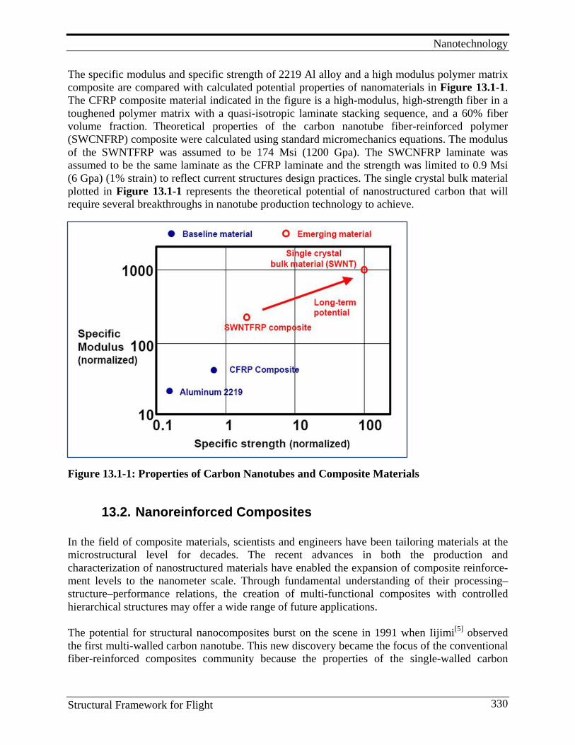
Nanotechnology
Structural Framework for Flight 330
The specific modulus and specific strength of 2219 Al alloy and a high modulus polymer matrix composite are compared with calculated potential properties of nanomaterials in Figure 13.1-1. The CFRP composite material indicated in the figure is a high-modulus, high-strength fiber in a toughened polymer matrix with a quasi-isotropic laminate stacking sequence, and a 60% fiber volume fraction. Theoretical properties of the carbon nanotube fiber-reinforced polymer (SWCNFRP) composite were calculated using standard micromechanics equations. The modulus of the SWNTFRP was assumed to be 174 Msi (1200 Gpa). The SWCNFRP laminate was assumed to be the same laminate as the CFRP laminate and the strength was limited to 0.9 Msi (6 Gpa) (1% strain) to reflect current structures design practices. The single crystal bulk material plotted in Figure 13.1-1 represents the theoretical potential of nanostructured carbon that will require several breakthroughs in nanotube production technology to achieve.
Figure 13.1-1: Properties of Carbon Nanotubes and Composite Materials
13.2. Nanoreinforced Composites In the field of composite materials, scientists and engineers have been tailoring materials at the microstructural level for decades. The recent advances in both the production and characterization of nanostructured materials have enabled the expansion of composite reinforce-ment levels to the nanometer scale. Through fundamental understanding of their processing–structure–performance relations, the creation of multi-functional composites with controlled hierarchical structures may offer a wide range of future applications. The potential for structural nanocomposites burst on the scene in 1991 when Iijimi[5] observed the first multi-walled carbon nanotube. This new discovery became the focus of the conventional fiber-reinforced composites community because the properties of the single-walled carbon
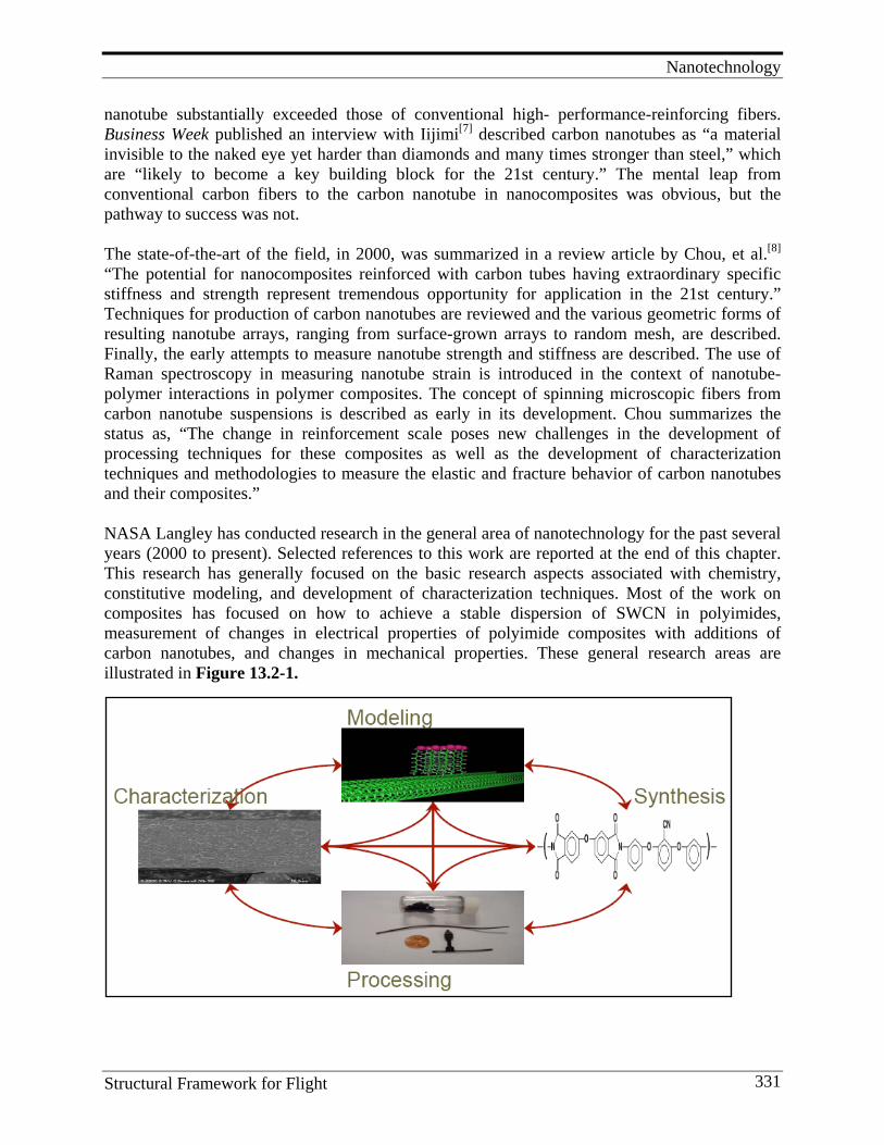
Nanotechnology
Structural Framework for Flight 331
nanotube substantially exceeded those of conventional high- performance-reinforcing fibers. Business Week published an interview with Iijimi[7] described carbon nanotubes as “a material invisible to the naked eye yet harder than diamonds and many times stronger than steel,” which are “likely to become a key building block for the 21st century.” The mental leap from conventional carbon fibers to the carbon nanotube in nanocomposites was obvious, but the pathway to success was not. The state-of-the-art of the field, in 2000, was summarized in a review article by Chou, et al.[8] “The potential for nanocomposites reinforced with carbon tubes having extraordinary specific stiffness and strength represent tremendous opportunity for application in the 21st century.” Techniques for production of carbon nanotubes are reviewed and the various geometric forms of resulting nanotube arrays, ranging from surface-grown arrays to random mesh, are described. Finally, the early attempts to measure nanotube strength and stiffness are described. The use of Raman spectroscopy in measuring nanotube strain is introduced in the context of nanotube-polymer interactions in polymer composites. The concept of spinning microscopic fibers from carbon nanotube suspensions is described as early in its development. Chou summarizes the status as, “The change in reinforcement scale poses new challenges in the development of processing techniques for these composites as well as the development of characterization techniques and methodologies to measure the elastic and fracture behavior of carbon nanotubes and their composites.” NASA Langley has conducted research in the general area of nanotechnology for the past several years (2000 to present). Selected references to this work are reported at the end of this chapter. This research has generally focused on the basic research aspects associated with chemistry, constitutive modeling, and development of characterization techniques. Most of the work on composites has focused on how to achieve a stable dispersion of SWCN in polyimides, measurement of changes in electrical properties of polyimide composites with additions of carbon nanotubes, and changes in mechanical properties. These general research areas are illustrated in Figure 13.2-1.
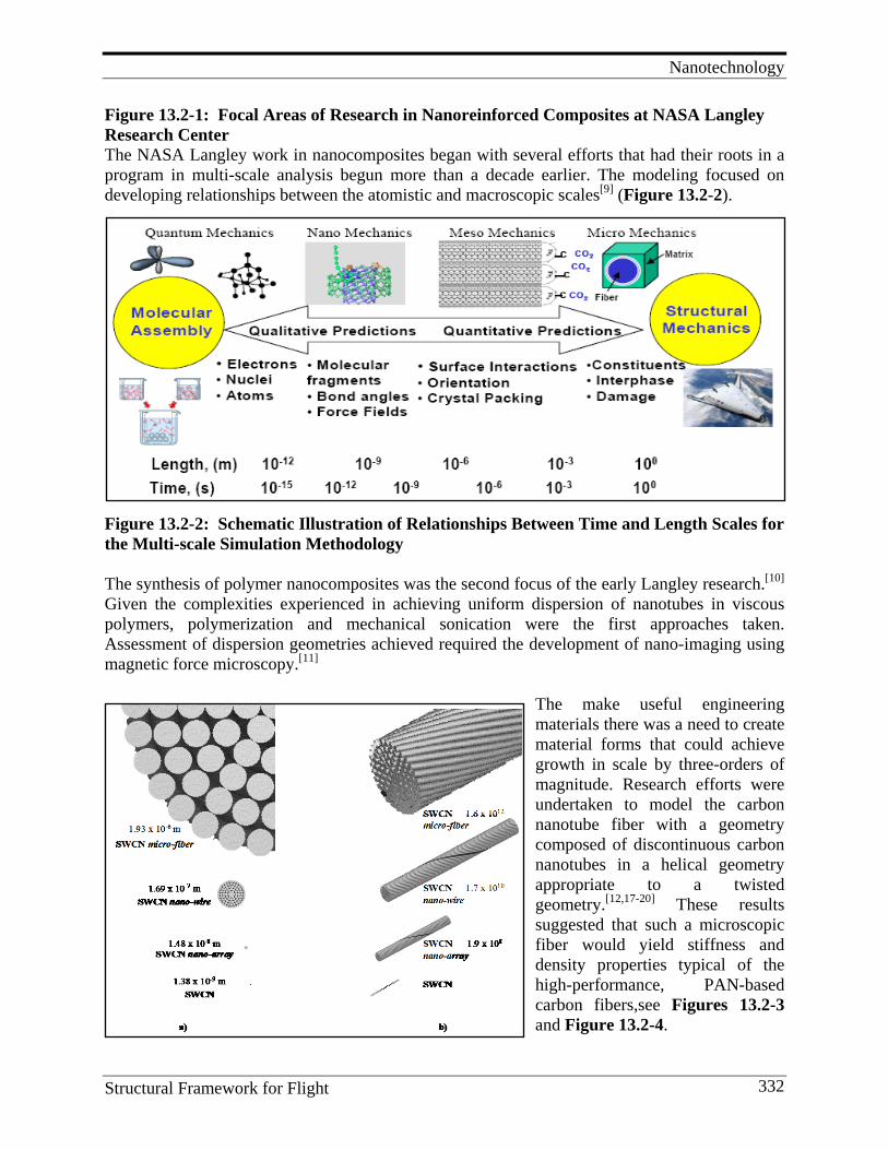
Nanotechnology
Structural Framework for Flight 332
Figure 13.2-1: Focal Areas of Research in Nanoreinforced Composites at NASA Langley Research Center The NASA Langley work in nanocomposites began with several efforts that had their roots in a program in multi-scale analysis begun more than a decade earlier. The modeling focused on developing relationships between the atomistic and macroscopic scales[9] (Figure 13.2-2).
Figure 13.2-2: Schematic Illustration of Relationships Between Time and Length Scales for the Multi-scale Simulation Methodology
The synthesis of polymer nanocomposites was the second focus of the early Langley research.[10] Given the complexities experienced in achieving uniform dispersion of nanotubes in viscous polymers, polymerization and mechanical sonication were the first approaches taken. Assessment of dispersion geometries achieved required the development of nano-imaging using magnetic force microscopy.[11]
The make useful engineering materials there was a need to create material forms that could achieve growth in scale by three-orders of magnitude. Research efforts were undertaken to model the carbon nanotube fiber with a geometry composed of discontinuous carbon nanotubes in a helical geometry appropriate to a twisted geometry.[12,17-20] These results suggested that such a microscopic fiber would yield stiffness and density properties typical of the high-performance, PAN-based carbon fibers,see Figures 13.2-3 and Figure 13.2-4.

Nanotechnology
Structural Framework for Flight 333
Figure 13.2-3: a) Self-similar Scales and b) Number of SWCN Per Meter Length[6] It is significant to note that 1012 single walled carbon nanotubes of aspect ratio of 1000 are required to produce 1 meter of micro fiber.
Figure 13.2-4: Young’s Modulus of the Carbon Nanotube Micro-fiber[6]
The multifunctional properties of carbon nanotube composites were addressed in a series of studies aimed at the utilization of the extraordinary electrical conductivity of carbon nanotubes to alter the effective electrical conductivity of the resulting polymer composite.[13] These results exhibited a marked change in the polymer from insulator to conductor with a relative low concentration of carbon nanotubes in the polymer. Percolation threshold was achieved at 0.1% carbon nanotube volume fraction. Volume DC conductivity of 10-9 to 10-8 S/cm and AC conductivity of 10-7 S/cm were achieved. Efficient dispersion of the nanotubes in a high-performance polymer matrix requires the characterization of quality of dispersion. The lack of available tools to visualize the quality of the matrix/carbon nanotube interaction suggested the use of magnetic force microscopy (MFM) as a promising technique for characterizing the dispersion of nanotubes in a high-performance polymer matrix.[11] The MFM was able to map the nanotube dispersion in polymer films and film cross-sections. Although the depth of penetration that the MFM actually maps was unclear, the value of MFM, as a rapid analysis tool for the characterization of the degree of dispersion of carbon nanotubes in a polymer matrix, was demonstrated. In 2003, Chou, et al. developed a second literature review of the field of nanocomposites. “The exceptional mechanical and physical properties observed for carbon nanotubes has stimulated the development of nanotube-based composite materials, but critical challenges exist before we can exploit these extraordinary nanoscale properties in a macroscopic composite. At the nanoscale,
SWCN
nano-array
nano-wire
micro-fibercarbon fiber
0
200
400
600
800
1000
1.E-10 1.E-09 1.E-08 1.E-07 1.E-06 1.E-05
Diameter (m)
You
ng's
Mod
ulus
(GPa
)
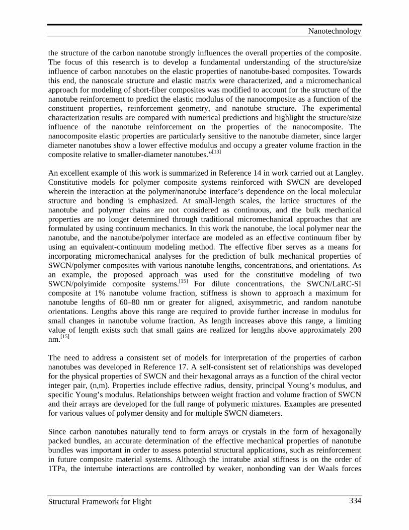
Nanotechnology
Structural Framework for Flight 334
the structure of the carbon nanotube strongly influences the overall properties of the composite. The focus of this research is to develop a fundamental understanding of the structure/size influence of carbon nanotubes on the elastic properties of nanotube-based composites. Towards this end, the nanoscale structure and elastic matrix were characterized, and a micromechanical approach for modeling of short-fiber composites was modified to account for the structure of the nanotube reinforcement to predict the elastic modulus of the nanocomposite as a function of the constituent properties, reinforcement geometry, and nanotube structure. The experimental characterization results are compared with numerical predictions and highlight the structure/size influence of the nanotube reinforcement on the properties of the nanocomposite. The nanocomposite elastic properties are particularly sensitive to the nanotube diameter, since larger diameter nanotubes show a lower effective modulus and occupy a greater volume fraction in the composite relative to smaller-diameter nanotubes.”[13] An excellent example of this work is summarized in Reference 14 in work carried out at Langley. Constitutive models for polymer composite systems reinforced with SWCN are developed wherein the interaction at the polymer/nanotube interface’s dependence on the local molecular structure and bonding is emphasized. At small-length scales, the lattice structures of the nanotube and polymer chains are not considered as continuous, and the bulk mechanical properties are no longer determined through traditional micromechanical approaches that are formulated by using continuum mechanics. In this work the nanotube, the local polymer near the nanotube, and the nanotube/polymer interface are modeled as an effective continuum fiber by using an equivalent-continuum modeling method. The effective fiber serves as a means for incorporating micromechanical analyses for the prediction of bulk mechanical properties of SWCN/polymer composites with various nanotube lengths, concentrations, and orientations. As an example, the proposed approach was used for the constitutive modeling of two SWCN/polyimide composite systems.[15] For dilute concentrations, the SWCN/LaRC-SI composite at 1% nanotube volume fraction, stiffness is shown to approach a maximum for nanotube lengths of 60–80 nm or greater for aligned, axisymmetric, and random nanotube orientations. Lengths above this range are required to provide further increase in modulus for small changes in nanotube volume fraction. As length increases above this range, a limiting value of length exists such that small gains are realized for lengths above approximately 200 nm.[15] The need to address a consistent set of models for interpretation of the properties of carbon nanotubes was developed in Reference 17. A self-consistent set of relationships was developed for the physical properties of SWCN and their hexagonal arrays as a function of the chiral vector integer pair, (n,m). Properties include effective radius, density, principal Young’s modulus, and specific Young’s modulus. Relationships between weight fraction and volume fraction of SWCN and their arrays are developed for the full range of polymeric mixtures. Examples are presented for various values of polymer density and for multiple SWCN diameters. Since carbon nanotubes naturally tend to form arrays or crystals in the form of hexagonally packed bundles, an accurate determination of the effective mechanical properties of nanotube bundles was important in order to assess potential structural applications, such as reinforcement in future composite material systems. Although the intratube axial stiffness is on the order of 1TPa, the intertube interactions are controlled by weaker, nonbonding van der Waals forces
Nanotechnology
Structural Framework for Flight 335
which are orders of magnitude less. A direct method for calculating effective transverse material constants was implemented. The Lennard-Jones potential was used to model the nonbonding cohesive forces. A complete set of transverse moduli was obtained and shown to exhibit a transversely isotropic constitutive behavior. The predicted elastic constants obtained using the direct method were compared with available published results obtained from other methods with acceptable agreement accomplished.[21] Having studied the physical properties of carbon nanotubes and their polymeric composites, the Langley researchers then turned to the subject of dilute concentration carbon nanotube micro-fibers.[22] In this work, melt processing of SWCN/Ultem nanocomposite fibers was demonstrated for fibers containing up to 1 wt % SWCNs. High-resolution electron microscopy and Raman spectroscopy were used to evaluate the quality of SWCN dispersion. SWCN alignment in the fiber direction was induced by shear forces present during the melt extrusion and fiber drawing processes. The alignment resulted in significant increase in tensile modulus and yield stress in SWCN/Ultem nanocomposite fibers relative to non-oriented nanocomposite films of the same SWCN concentration. However, the enhancements were less than what was expected from an oriented discontinuous fiber-reinforced polymer composite. This low level of improvement was likely due to inefficient and incomplete dispersion. Dispersion of carbon nanotubes in high-performance polymers is a recurring theme of the Langley work. SWCNs were dispersed in a nitrile functionalized polyimide matrix and the resulting composite showed excellent stability with respect to re-aggregation of the nanotubes. This result contrasted with the behavior of structurally similar polyimides in which the dispersion is only stable for short periods of time. Shifts in certain characteristic FTIR and Raman peaks that indicated a charge transfer interaction between the nanotubes and polymer matrix were observed. A simple model for charge transfer stabilization was developed and shown to be consistent with the experimental observations.[23] The new SWCN – polymer composite exhibited excellent dispersion and long-term stability. The polymer, (ß-CN)APB/ODPA, was believed to stabilize the dispersion of SWCNs by way of a donor acceptor interaction between the tubes and the (ß-CN)APB subunit of the polymer. This mechanism was supported by both Raman spectra of the SWCNs and FTIR spectra of the CN stretching band of the polymer, as well as by ab initio calculations on the (ß-CN)APB monomer. Combining expertise in polymer nanocomposites and space applications, low color, flexible, space-environmentally-durable polymeric materials possessing sufficient surface resistivity (106–1010V/square) for electrostatic charge (ESC) mitigation were developed for potential applications on Gossamer spacecraft as thin film membranes on antennas, large lightweight space optics, and second-surface mirrors. One method of incorporating intrinsic ESC mitigation while maintaining low color, flexibility, and optical clarity is through the utilization of SWCNs. The approach employed amide acid polymers endcapped with alkoxy silane groups that condense with oxygen containing functionalities that are present on the ends of SWCNs as a result of the oxidative purification treatment. These SWCNs were combined with the endcapped amide acid polymers in solution and subsequently cast as unoriented thin films. Two examples possessed electrical conductivity (measured as surface resistance and surface resistivity) sufficient for ESC mitigation at loading levels of #0.08 wt % SWCN as well as good retention of thermo-optical properties. The percolation threshold was determined to lie between 0.03 and
Nanotechnology
Structural Framework for Flight 336
0.04 wt % SWCN loading. Electrical conductivity of the film remained unaffected even after harsh mechanical manipulation. The best combination of properties was obtained for the nanocomposite film with a 0.05 wt % SWCN loading.[24] Low color/solar absorptivity (a) and sufficient electrical conductivity were required in these applications in order to dissipate ESC build-up brought about by the charged orbital environment. One approach taken to achieve sufficient electrical conductivity for ESC mitigation was the incorporation of SWCNs. However, when SWCNs are dispersed throughout the polymer matrix, the nanocomposite films tend to become significantly darker than the pristine material resulting in a greater value of absorptivity. The incorporation of conductive additives in combination with a decreased SWCN loading level was one approach chosen for improving “a,” while retaining conductivity. Taken individually, the low loading level of conductive additives and SWNCNs was insufficient in achieving the percolation level necessary for electrical conductivity. When added concurrently to the film, appropriate levels of conductivity were achieved. Films with surface and volume resistivities sufficient to mitigate ESC build-up (106–1010U/square) were prepared by the incorporation of a low loading level of SWCNs in conjunction with a small amount of inorganic salt. It was argued that the inorganic salt increased the ionic strength of the matrix thereby resulting in sufficient network formation.[25] To further the analytical modeling development Langley personnel compared two approaches for predicting elastic properties of SWCN/polymer composites: equivalent-continuum modeling and the self-similar approach. They were compared in terms of assumptions and ranges of validity. Both models incorporated information about molecular interactions at the nanometer length scale into a continuum-mechanics-based model. It was shown that the two approaches can predict elastic properties of SWCN/polymer composites in a combined range spanning dilute to hyper-concentrated SWCN volume fractions. In addition, the predicted Young’s moduli for a SWCN/polymer composite determined using both approaches were shown to be consistent.[26] Interpretation of both AC and DC conductivity test results for SWCN polymer composites and the scaling of these results onto a single master curve were developed by Langley researchers to examine the factors that determine the critical volume fraction and the percolation exponent for electrical conductivity predictions. The results for a series of SWCN–polyimide composites were presented and the parameters obtained from fitting these results to models. The critical volume fraction for electrical percolation of the composite was quite small, about 0.05%. Results obtained from previous work on SWCN (MWCN)–polymer composites and other percolation systems and the modeling of these results were also discussed and compared. The researchers noted inconsistency in many of the experimentally-determined properties in conventional equations governing electrical conductivity of polymer nanocomposites.[27] In 2005, yet another review of the field of nanocomposites was undertaken.[28] An overview of the recent advances in nanocomposites research was presented. The key research opportunities and challenges in the development of structural and functional nanocomposites were addressed in the context of traditional fiber composites. The state of knowledge in processing, characterization, and analysis/modeling of nanocomposites was presented with a particular emphasis on identifying fundamental structure/property relationships. Critical issues in nanocomposites research, as well as promising techniques for processing precursors for macroscopic nanocomposites were discussed. “Recent advances in producing nanostructured
Nanotechnology
Structural Framework for Flight 337
materials with novel material properties have stimulated research to create macroscopic engineering materials by designing the structure at the nanoscale. Before these novel properties can be fully realized in a macroscopic composite, considerable basic research is necessary. The change in reinforcement scale poses new challenges in the development of processing, as well as characterization techniques for these composites. The nano-meter scale of the reinforcement also presents additional challenges in mechanics research since we now must account for interactions at the atomic-scale. Like all nanostructured materials, the properties of nanostructured composites are highly structure/size dependent. To take the exceptional properties observed at the nanoscale and utilize these properties at the macroscale requires a fundamental understanding of the properties and their interactions across various length scales. Ultimately a basic understanding of the structure-property relations will enable the nanoscale design of multi-functional materials for engineering applications ranging from structural and functional materials to biomaterials and beyond. Large-scale application of nanocomposites also requires the scale-up of manufacturing processes. Finally, there is a need to address the broad societal implications of nanotechnology of which nanocomposites are an important part.” The control of the orientation state of carbon nanotubes within the nanocomposite was the subject of further work at Langley.[29] While high shear alignment has been shown to improve the mechanical properties of SWCN-polymer composites, this method does not allow for control over the electrical and dielectric properties of the composite and often results in degradation of these properties. Following is a novel method to actively align SWCNs in a polymer matrix, which permits control over the degree of alignment of the SWCNs without the side effects of shear alignment. In this process, SWCNs were aligned via AC field-induced dipolar interactions among the nanotubes in a liquid matrix. The results, presented earlier, showed that the conductivity and dielectric properties of aligned SWCN/UH composites could be tuned over a broad range by proper control of the applied field strength, frequency, and time. The structure of the aligned composites was visually investigated using high-resolution scanning electron microscopy (HRSEM), which showed clear distinctions from composites prepared by passive alignment using shear processing. The unusual cross-linked structure produced by the field alignment technique imparted unique properties to the composite relative to those created by use of high shear flows. These aligned SWCN-polymer composites enabled control over electrical and dielectric properties, in addition to mechanical reinforcement. They were expected to enable the development of multifunctional structural composites. The key feature of this approach was the novel ability to produce composites with the required properties for a specific application by simply tuning the applied field strength, frequency, and time, followed by immobilization through photopolymerization under continued application of the electric field. Alignment of SWCNs was controlled as a function of magnitude, frequency, and application time of the applied electric field. The degree of SWCN alignment was assessed using optical microscopy and polarized Raman spectroscopy, and the morphology of the aligned nanocomposites was investigated by high-resolution scanning electron microscopy. The structure of the field-induced, aligned SWCNs was intrinsically different from that of shear aligned SWCNs. In this work, SWCNs were not only aligned along the field, but also seen to migrate laterally to form thick, aligned SWCN percolative columns between the electrodes. The actively aligned SWCNs amplify the electrical and dielectric properties of the composite. All of these
Nanotechnology
Structural Framework for Flight 338
properties of the aligned nanocomposites exhibited anisotropic characteristics, which were controllable by tuning the applied field parameters. The Langley researchers continued pursuit of mixing and dispersion of carbon nanotubes in high-performance polymers through the development of dispersants.[30] Novel aromatic/aliphatic polyimides were prepared from 2,7-diamino-9, 9′-dioctylfluorene (AFDA) and aromatic dianhydrides. Upon investigating the effectiveness of these polyimides for debundling SWCNs in solution, three were discovered to aid in the dispersion of SWCNs in N, N-dimethylacetamide (DMAc). Two of these polyimides, one from 3,3′,4,4′-oxydiphthalic anhydride (ODPA) and one from symmetric 3,3′,4,4′-biphenyltetracarboxylic dianhydride (s-BPDA), were used to prepare nanocomposites. Homogeneous polyimide/SWCN suspensions from both polymers were used in the preparation of films and fibers containing up to 1 wt % SWCNs. The samples were thermally treated to remove residual solvent, and the films were characterized for SWCN dispersion by optical and HRSEM. Electrical and mechanical properties of the films were also determined. Electro-spun fibers were examined by HRSEM to characterize SWCN alignment and orientation. At the time of preparation (May 2010) of this manuscript, a literature review of the field was published.[31] This paper examined the recent advancements in the science and technology of carbon nanotube- (CNT) based fibers and composites. The assessment was made according to the hierarchical structural levels of CNTs used in composites, ranging from 1-D to 2-D to 3-D. At the 1-D level, fibers composed of pure CNTs or CNTs embedded in a polymeric matrix produced by various techniques were reviewed. At the 2-D level, the focuses were on CNT-modified advanced fibers, CNT-modified interlaminar surfaces and highly oriented CNTs in planar form. At the 3-D level, the mechanical and physical properties of CNT/ polymer composites, CNT-based damage sensing, and textile assemblies of CNTs were examined. The opportunities and challenges in basic research at these hierarchical levels have been discussed. The following general conclusions were made: “In the field of composite materials, scientists and engineers have been tailoring materials at the microstructural level for decades. The recent advances in both the production and characterization of nanostructured materials have enabled the expansion of composite reinforcement levels to the nanometer scale. Through fundamental understanding of their processing–structure–performance relations, the creation of multi-functional composites with controlled hierarchical structures may offer a wide range of future applications. The major lessons learned from this overview are given below.[31]
1. Linear CNT assemblies Opportunities: Laboratory-scale CNT fibers possess small fiber/yarn size and exhibit high modulus and strength comparable to those of commercial carbon fibers. Challenges: (1) Scale-up current processes to produce continuous fiber/yarn suitable for textile processing. (2) The efficiency of transferring the properties of CNTs to the micro- and macro-structural levels relies on CNT dispersion, interfacial bonding, CNT orientation and alignment of fibrils.
2. Planar CNT assemblies
Opportunities: (1) Interlayer with aligned CNTs enhances interlaminar fracture toughness. (2) Aligned CNT buckypapers offer high axial properties. Challenges: (1) Scale-up CNT
Nanotechnology
Structural Framework for Flight 339
forest growth and rapid, efficient transfer printing for interlayer. (2) Efficient fabrication technique for high-volume-loading of aligned CNT buckypapers.
3. 3-D CNT assemblies: mechanical properties Opportunities: (1) The addition of CNTs improves the elastic modulus, strength, and fracture toughness of the polymeric matrices, especially at low CNT loadings. (2) The addition of CNTs improves the fatigue life of glass/epoxy composites. Challenges: Processing of nanocomposites with high nanotube loadings (>5 wt % for MWCNs and >2 wt % for SWCNTs) is very challenging and inadequate resin impregnation may be partially responsible for the decrease or lack of improvement in composite mechanical properties.
4. 3-D CNT assemblies: electrical and thermal properties
Opportunities: (1) CNTs are highly effective in enhancing the electrical conductivity of polymeric matrices. (2) MWCNs seem to have the highest potential in improving the thermal conductivity of epoxy and PMMA, but CNTs overall have very limited potential in this regard. (3) Hybrid graphitic nanoplatelet and CNT fillers may offer enhanced thermal conductivity. Challenges: (1) Functionalization of CNTs, which enhances the compatibility to the epoxy matrix and reduces the aspect ratio, may be detrimental for the overall conductivity. (2) Key issues for nanocomposites’ electrical conductivity requiring further theoretical investigations: identification of filler contact status, contact resistance modeling and effect of nanotube waviness. (3) Theoretically-predicted thermal conductivities of isolated CNTs cannot be substantially transferred to polymer-based composites in practice.
5. CNT-based damage sensing
Opportunities: (1) Adding small amount of CNTs in advanced fiber composites can achieve electrically conductive network and serve as a tool for in situ sensing. (2) The ‘‘damaged resistance change” can be utilized as a quantitative damage parameter. Challenges: Damage-sensing in self-healing, dynamic-loading, joining and various polymeric matrices.
6. Textile assemblies of CNTs
Multi-functional textile structural composites may be developed by hybridizing small quantities of CNT yarns with traditional reinforcements using textile forming techniques.[31]
Additional publications documenting recent nanotechnology work done by Langley researchers are noted in references [32-49].
13.3. Boron-nitride Nanotechnology – Recent Advancements Researchers at NASA Langley, the Department of Energy’s Thomas Jefferson National Accelerator Facility, and the National Institute of Aerospace have used lasers to create the first
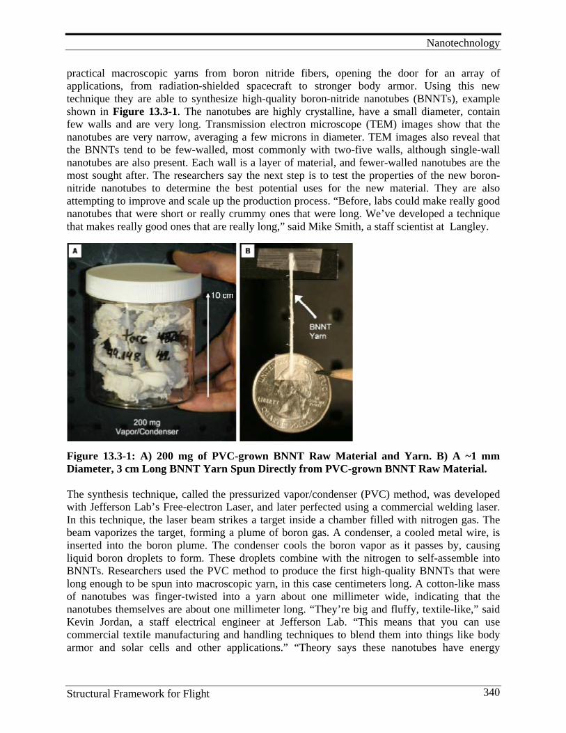
Nanotechnology
Structural Framework for Flight 340
practical macroscopic yarns from boron nitride fibers, opening the door for an array of applications, from radiation-shielded spacecraft to stronger body armor. Using this new technique they are able to synthesize high-quality boron-nitride nanotubes (BNNTs), example shown in Figure 13.3-1. The nanotubes are highly crystalline, have a small diameter, contain few walls and are very long. Transmission electron microscope (TEM) images show that the nanotubes are very narrow, averaging a few microns in diameter. TEM images also reveal that the BNNTs tend to be few-walled, most commonly with two-five walls, although single-wall nanotubes are also present. Each wall is a layer of material, and fewer-walled nanotubes are the most sought after. The researchers say the next step is to test the properties of the new boron-nitride nanotubes to determine the best potential uses for the new material. They are also attempting to improve and scale up the production process. “Before, labs could make really good nanotubes that were short or really crummy ones that were long. We’ve developed a technique that makes really good ones that are really long,” said Mike Smith, a staff scientist at Langley.
Figure 13.3-1: A) 200 mg of PVC-grown BNNT Raw Material and Yarn. B) A ~1 mm Diameter, 3 cm Long BNNT Yarn Spun Directly from PVC-grown BNNT Raw Material. The synthesis technique, called the pressurized vapor/condenser (PVC) method, was developed with Jefferson Lab’s Free-electron Laser, and later perfected using a commercial welding laser. In this technique, the laser beam strikes a target inside a chamber filled with nitrogen gas. The beam vaporizes the target, forming a plume of boron gas. A condenser, a cooled metal wire, is inserted into the boron plume. The condenser cools the boron vapor as it passes by, causing liquid boron droplets to form. These droplets combine with the nitrogen to self-assemble into BNNTs. Researchers used the PVC method to produce the first high-quality BNNTs that were long enough to be spun into macroscopic yarn, in this case centimeters long. A cotton-like mass of nanotubes was finger-twisted into a yarn about one millimeter wide, indicating that the nanotubes themselves are about one millimeter long. “They’re big and fluffy, textile-like,” said Kevin Jordan, a staff electrical engineer at Jefferson Lab. “This means that you can use commercial textile manufacturing and handling techniques to blend them into things like body armor and solar cells and other applications.” “Theory says these nanotubes have energy
Nanotechnology
Structural Framework for Flight 341
applications, medical applications and, obviously, aerospace applications,” said Jordan. Smith agreed, “Some of these things are going to be dead ends and some are going to be worth pursuing, but we won’t know until we get material in peoples’ hands.” [49] The research was published in the December 16, 2009, issue of the journal Nanotechnology. It was also presented at the 2009 Materials Research Society Fall Meeting on December 3, 2009. The research was supported by the NASA Langley Creativity and Innovation program, the NASA Subsonic Fixed Wing program, DOE’s Jefferson Lab and the Commonwealth of Virginia. The experiments were hosted at Jefferson Lab.
13.4. Lesson Learned and Future Direction
1. The development of a revolutionary new technology like nanotechnology takes decades to mature. Nanoreinforced composites for structural applications in an early stage of development representative of a new technology on a new S Curve.
2. NASA has made significant strides in beginning to understand the basic science of incorporating nanofibers in resins to fabricate nanocomposites. However, much more work is required to advance the level of technology readiness to the point where these materials will find use in real aerospace products.
3. The combination of computational materials, chemistry and NDE measurement science has proved to be successful in addressing tough development issues in nanocomposites.
4. Although the early projections of theoretically possible properties will almost assuredly never be realized, those projections served to stimulate research into this important new class of composites which will ultimately enable major advancements in light-weight structures.
5. Significant increases in electrical and thermal properties have been demonstrated for resin matrix composites. Many new applications will be found where these changes can make a significant difference in performance.
6. NASA must continue to invest in new breakthrough technologies to enable new aerospace materials to be developed to meet ever-increasing demands imposed on materials and structures for tomorrow’s aero and space structural applications.
The general field of nanotechnology offers the potential to be the next great industrial revolution. In the field of materials science, a paradigm shift may occur away from the traditional material’s role of developing metallic, polymeric, ceramic, and composite materials, to a revolutionary role of developing nanostructured, functionalized, self-assembling, and self-healing materials. Looking into the future, the theoretical potential of these revolutionary classes of new materials will create breakthroughs that will enable technology developments that are barely imaginable today. In the aerospace field, these new technologies may make space travel routine and enable human exploration of space beyond our current practical limitation of low Earth orbit. Imagine the possibilities if there was a material to replace aluminum that is an order of magnitude stiffer and two orders of magnitude stronger! References
1. Feynman, R. 1960. There’s Plenty of Room at the Bottom in American Physical Society. December, 29, 1959, E.A.S. California Institute of Technology, Pasadena. CA
Nanotechnology
Structural Framework for Flight 342
2. Anon. 2000. National Nanotechnology Initiative: The Initiative and It’s Implementation Plan. National Science and Technology Council, Committee on Technology, Subcommittee on Nanoscale Science, Engineering and Technology, Washington, D.C..
3. Edelstein, A. S., and R. C. Cammarata, eds. 1996. Nanomaterials: Synthesis, Properties and Applications. Institute of Physics: Bristol.
4. Kroto, H. W., et al. 1985. C60 Buckminsterfullerene. Nature 318:162. 5. Iijima, S. 1991. Helical microtubes of graphitic carbon. Nature 354:56. 6. Harris, P. J. F. 1999. Carbon Nanotubes and Related Structures. Cambridge: Cambridge University Press. 7. Retrieved May 2010, from http://www.ieeeghn.org/wikitest/index.php/Sumio_Iijima 8. Chou, T-W., et al. 2001. Advances in the Science and Technology of Carbon Nanotubes and their
Composites – A Review. Composites Science and Technology 1899-1912. 9. Odegard, G. M., et al. 2002. Equivalent Continuum Modeling of Nano-Structured Materials. Composites
Science and Technology 62:1869-1880. 10. Park, C., et al. 2002. Dispersion of Single-Walled Carbon Nanotubes by Insitu Polymerization and
Sonication. Chemical Physical Letters 364:303-308. 11. Lillehi, P., et al. 2002. Imaging Carbon Nanotubes in High-performance Composites via Magnetic Force
Microscopy. Nano Letters, 2(8): 827-829. 12. Pipes, R. B., and P. Hubert. 2002. Helical Carbon Nanotube Arrays: Mechanical Properties. Composites
Science and Technology 63 (3): 419-428. 13. Qunaires, Z., et al. 2003. Electrical Properties of Single Wall Carbon Nanotube-reinforced Polyimide
Composites. 63:1637-1646. 14. Thostensen, E. and T-W. Chou. 2003. On the Elastic Properties of Carbon Nanotube-based Composites:
Modeling and Characterization. J. Phys. D: Appl. Phys. 36:573-582. 15. Odegard, G. M., T. S. Gates, K. E. Wise, C. Park, and E. J. Siochi,. 2003. Constitutive modeling of
nanotube-reinforced polymer composites. Composites Science and Technology 63:1671–1687. 16. Rouse, J. H., and P. T. Lillehei. 2003. Electrostatic Assembly of Polymer/Single Walled Carbon Nanotube
Multilayer Film. Nano Letters 3 (1): 59-62. 17. R. B. Pipes, S. J. V. Frankland, P. Hubert, and E. Saether. 2003. Self-Consistent Properties of the SWCN
and Hexagonal Arrays as Composite Reinforcements. Composites Science and Technology 63 (10): 1349-1358.
18. Pipes, R. B., and P. Hubert. Scale Effects in Carbon Nanostructures: Self-Similar Analysis. Nano Letters 3 (2) : 239-243.
19. Pipes, R. B., and P. Hubert. 2002. Helical Carbon Nanotube Arrays: Mechanical Properties. Composites Science and Technology, 62 (3): 418-28.
20. Pipes, R. B., and P. Hubert. 2003. Helical Carbon Nanotube Arrays: Thermal Expansion. Composites Science and Technology 63 (11): 1571-79.
21. Saether, E., R. B. Pipes, and S. J. V. Frankland. 2003. Nanostructured Composites: Effective Mechanical Properties Determination of Nanotube Bundles, Composites Science and Technology 63 (11): 1543-50.
22. Siochi, E. J., et al. 2004. Melt Processing of SWCNT-Polyimide Nanocomposite Fibers. Composites: Part B 35:439-4446.
23. Wise, K. E., et al. 2004. Stable Dispersion of Single Wall carbon Nanotubes in Polyimide: the Role of Non-Covalent Interactions. Chemical Physics Letters 391:207-11.
24. Smith, J. G., et al. 2004. Space Durable Polymer/Carbon Nanotube Fibers for Electrostatic Charge Migration. Polymer 45:825-836.
25. Smith, J. G., et al. 2004. Carbon Nanotube Conductive Additive Space Durable Polymer Nanocomposite Films for Electrostatic Charge Dissipation. Polymer 45:6133-6142.
26. Odegard, G. M., et al. 2004. Comparison of Two Models of SWCN Polymer Composites. Composites Science and Technology 64:1011-1020.
27. McLachlan, D. S., et al. 2005. AC and DC Percolative Conductivity of Single Wall Carbon Nanotube Polymer Composites. J. Polymer Science, Part B 43: 3273-3287.
28. Thostensen, E., and T-W. Chou, 2005. Nanocomposites in Context: A Review. Composites Science and Technology 65:491-516.
29. Park, C., et al. 2006. Aligned Single Wall Carbon Nanotube Polymer Composites Using an Electric Field. J. Polymer Science, Part , 44:1751-1762.
30. Delozier, D. M., et al. 2006. Investigation of Aromatic/Aliphatic Polymers as Dispersants for Single Wall Carbon Nanotubes. Macromolecules 39:1731-1739.
Nanotechnology
Structural Framework for Flight 343
31. Chou, T-W., et al. 2010. An Assessment of the Science and Technology of Carbon Nanotube-Based Fibers and Composites. Composites Science and Technology 70:1-19.
32. Chou, T-W., L. Gao, E. T. Thostensen, Z. Zhang, and J-H. Byun. 2010. An assessment of the science and technology of carbon nanotube-based fibers and composites. Composites Science and Technology 70:1–19.
33. Odegard, G. M., and T. S. Gates. 2002. Constitutive Modeling of Nanotube/Polymer Composites with Various Nanotube Orientations, Paper presented at 2002 SEM Annual Conference and Exposition on Experimental and Applied Mechanics, Milwaukee, WI.
34. Gates, T. S., and J. A. Hinkley. 2003. Computational Materials: Modeling and Simulation of Nanostructured Materials and Systems. (NASA/TM-2003-212163).
35. Thostensen, E. T., and T-W. Chou. 2003. On the elastic properties of carbon nanotube-based composites: modeling and characterization. J. Phys. D: Appl. Phys. 36:573–582.
36. Odegarda, G. M., T. S. Gates, L. M. Nicholson, K. E. Wise. 2002. Equivalent-continuum modeling of nano-structured materials. Composites Science and Technology 62:1869–1880.
37. Thostensen, E.T., Z. Ren, and T-W. Chou. 2001. Advances in the science and technology of carbon nanotubes and their composites: a review. Composites Science and Technology 61:1899–1912.
38. Park, C., Z.Ounaies, K. A. Watson, R. E. Crooks, J. Smith, Jr., S. E. Lowther, J. W. Connell, E. J. Siochi, J. S. Harrison, and T. L. St.Clair. 2002. Dispersion of single wall carbon nanotubes by in situ polymerization under sonication. Chemical Physics Letters 364:303–308.
39. Rouse, J. H., and P. T. Lillehei. 2003. Electrostatic Assembly of Polymer/Single Walled Carbon Nanotube Multilayer Films. Nano Letters 3 (1): 59-62.
40. Lillehei, P. T., C. Park, J. H. Rouse, and E. J. Siochi. 2002. Imaging Carbon Nanotubes in High-performance Polymer Composites via Magnetic Force Microscopy. Nano Letters 2(8): 827-829.
41. Ounaies, Z., C. Park, K. E. Wise, E. J. Siochi, J. S. Harrison. 2003. Electrical properties of single wall carbon nanotube reinforced polyimide composites. Composites Science and Technology 63:1637–1646.
42. Smith, J. G., Jr., D. M. Deloziera, J. W. Connell, and K. A. Watson. 2004. Carbon nanotube-conductive additive-space durable polymer nanocomposite films for electrostatic charge dissipation. Polymer 45:6133–6142.
43. Smith, J. G., Jr., J. W. Connella, D. M. Delozier, P. T. Lillehei, K. A. Watson, Y. Lin, B. Zhou, Y.-P. Sun. 2004. Space durable polymer/carbon nanotube films for electrostatic charge mitigation. Polymer 45:825–836.
44. Thostenson, E. T., C. Li, and T-W. Chou. 2005. Review Nanocomposites in context. Composites Science and Technology 65:491–516.
45. Siochi, E. J., D. C. Working, C. Park, P. T. Lillehei, J. H. Rouse, C. C. Topping, A. R. Bhattacharyya, and S. Kumar. 2004. Melt processing of SWCNT-polyimide nanocomposite fibers. Composites: Part B 35:439–446.
46. Park, C., J. Wilkinson, S. Banda, Z. Ounaies, K. E. Wise, G. Sauti, P. T. Lillehei, and J. S. Harrison. Aligned Single-Wall Carbon Nanotube Polymer Composites Using an Electric Field. Journal of Polymer Science: Part B: Polymer Physics DOI 10.1002/polb.
47. Mclachlan, D. S., C. Chiteme, C. Park, K. E. Wise, S. E. Lowther, P. T. Lillehei, E. J. Siochi, and J. S. Harrison. 2005. AC and DC Percolative Conductivity of Single Wall Carbon Nanotube Polymer Composites. Received 21 April 2005; revised 22 July 2005; accepted 1 August 2005 DOI: 10.1002/polb.20597 Published online in Wiley InterScience (www.interscience.wiley.com).
48. Delozier, D. M., K. A. Watson, J. G. Smith, Jr., T. C. Clancy, and J.W. Connell. 2006. Investigation of Aromatic/Aliphatic Polyimides as Dispersants for Single Wall Carbon Nanotubes. Macromolecules 2006(39): 1731-1739.
49. Smith, M. W., K. C. Jordan, C. Park, J-W. Kim, P. T. Lillehei, R. Crooks, J. S. Harrison. 2009. Very Long Single and Few-Walled Boron Nitride Nanotubes via the Pressurized Vapor/Condenser Method. (NASA Report LAR-17535-1; LF99-9752), (Accepted by the journal “Nanotechnology,” Oct 26, 2009).
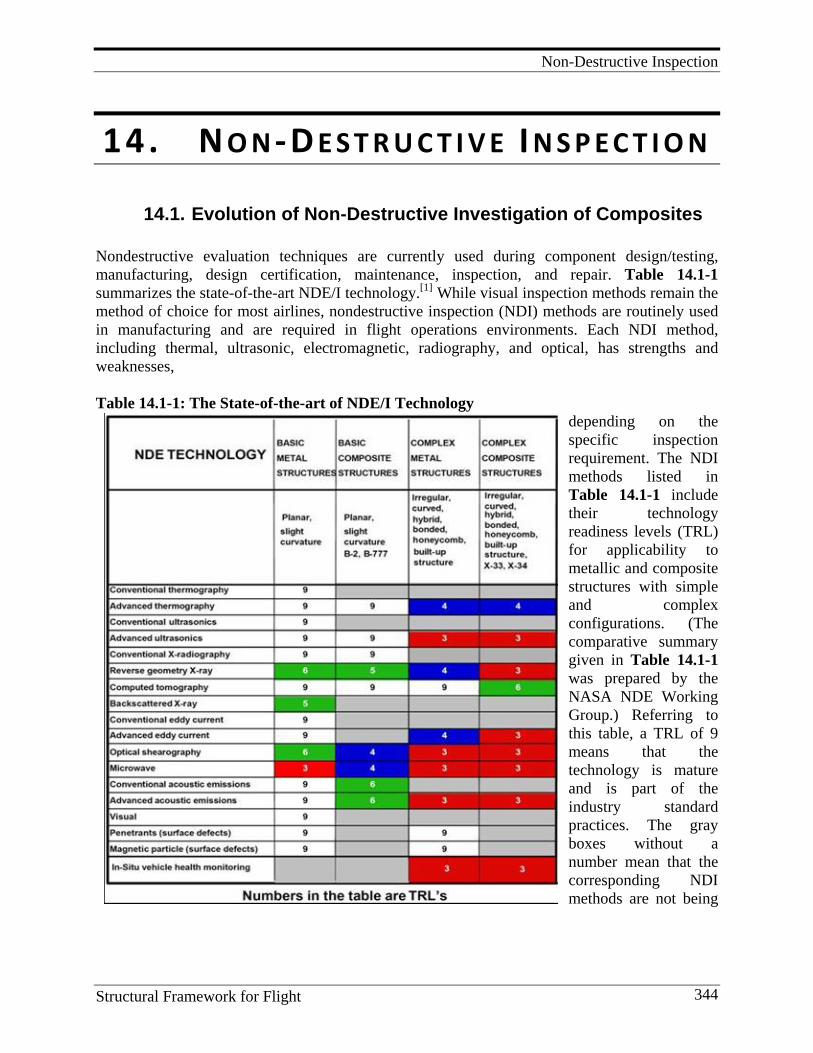
Non-Destructive Inspection
Structural Framework for Flight 344
14. N O N -D E S T R U C T I V E I N S P E C T I O N
14.1. Evolution of Non-Destructive Investigation of Composites Nondestructive evaluation techniques are currently used during component design/testing, manufacturing, design certification, maintenance, inspection, and repair. Table 14.1-1 summarizes the state-of-the-art NDE/I technology.[1] While visual inspection methods remain the method of choice for most airlines, nondestructive inspection (NDI) methods are routinely used in manufacturing and are required in flight operations environments. Each NDI method, including thermal, ultrasonic, electromagnetic, radiography, and optical, has strengths and weaknesses, Table 14.1-1: The State-of-the-art of NDE/I Technology
depending on the specific inspection requirement. The NDI methods listed in Table 14.1-1 include their technology readiness levels (TRL) for applicability to metallic and composite structures with simple and complex configurations. (The comparative summary given in Table 14.1-1 was prepared by the NASA NDE Working Group.) Referring to this table, a TRL of 9 means that the technology is mature and is part of the industry standard practices. The gray boxes without a number mean that the corresponding NDI methods are not being
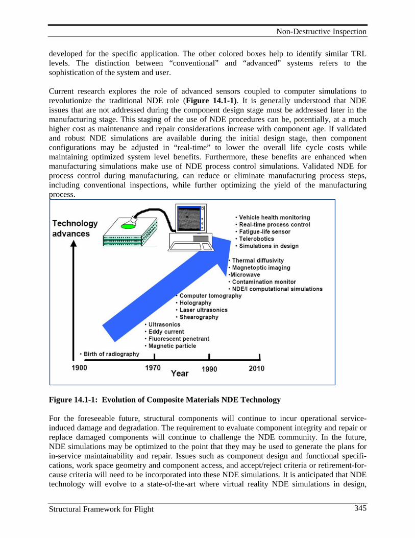
Non-Destructive Inspection
Structural Framework for Flight 345
developed for the specific application. The other colored boxes help to identify similar TRL levels. The distinction between “conventional” and “advanced” systems refers to the sophistication of the system and user. Current research explores the role of advanced sensors coupled to computer simulations to revolutionize the traditional NDE role (Figure 14.1-1). It is generally understood that NDE issues that are not addressed during the component design stage must be addressed later in the manufacturing stage. This staging of the use of NDE procedures can be, potentially, at a much higher cost as maintenance and repair considerations increase with component age. If validated and robust NDE simulations are available during the initial design stage, then component configurations may be adjusted in “real-time” to lower the overall life cycle costs while maintaining optimized system level benefits. Furthermore, these benefits are enhanced when manufacturing simulations make use of NDE process control simulations. Validated NDE for process control during manufacturing, can reduce or eliminate manufacturing process steps, including conventional inspections, while further optimizing the yield of the manufacturing process.
Figure 14.1-1: Evolution of Composite Materials NDE Technology For the foreseeable future, structural components will continue to incur operational service-induced damage and degradation. The requirement to evaluate component integrity and repair or replace damaged components will continue to challenge the NDE community. In the future, NDE simulations may be optimized to the point that they may be used to generate the plans for in-service maintainability and repair. Issues such as component design and functional specifi-cations, work space geometry and component access, and accept/reject criteria or retirement-for-cause criteria will need to be incorporated into these NDE simulations. It is anticipated that NDE technology will evolve to a state-of-the-art where virtual reality NDE simulations in design,
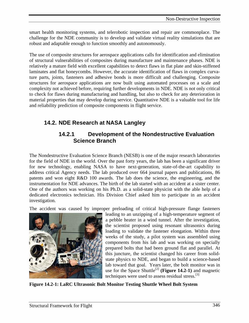
Non-Destructive Inspection
Structural Framework for Flight 346
smart health monitoring systems, and telerobotic inspection and repair are commonplace. The challenge for the NDE community is to develop and validate virtual reality simulations that are robust and adaptable enough to function smoothly and autonomously. The use of composite structures for aerospace applications calls for identification and elimination of structural vulnerabilities of composites during manufacture and maintenance phases. NDE is relatively a mature field with excellent capabilities to detect flaws in flat plate and skin-stiffened laminates and flat honeycombs. However, the accurate identification of flaws in complex curva-ture parts, joints, fasteners and adhesive bonds is more difficult and challenging. Composite structures for aerospace applications are now built using automated processes on a scale and complexity not achieved before, requiring further developments in NDE. NDE is not only critical to check for flaws during manufacturing and handling, but also to check for any deterioration in material properties that may develop during service. Quantitative NDE is a valuable tool for life and reliability prediction of composite components in flight service.
14.2. NDE Research at NASA Langley
14.2.1 Development of the Nondestructive Evaluation Science Branch
The Nondestructive Evaluation Science Branch (NESB) is one of the major research laboratories for the field of NDE in the world. Over the past forty years, the lab has been a significant driver for new technology, enabling NASA to have next-generation, state-of-the-art capability to address critical Agency needs. The lab produced over 664 journal papers and publications, 86 patents and won eight R&D 100 awards. The lab does the science, the engineering, and the instrumentation for NDE advances. The birth of the lab started with an accident at a sister center. One of the authors was working on his Ph.D. as a solid-state physicist with the able help of a dedicated electronics technician. His Division Chief asked him to participate in an accident investigation. The accident was caused by improper preloading of critical high-pressure flange fasteners
leading to an unzipping of a high-temperature segment of a pebble heater in a wind tunnel. After the investigation, the scientist proposed using resonant ultrasonics during loading to validate the fastener elongation. Within three weeks of the study, a pilot system was assembled using components from his lab and was working on specially prepared bolts that had been ground flat and parallel. At this juncture, the scientist changed his career from solid-state physics to NDE, and began to build a science-based lab toward that goal. Years later, the bolt monitor was in use for the Space Shuttle[2] (Figure 14.2-1) and magnetic techniques were used to assess residual stress.[3]
Figure 14.2-1: LaRC Ultrasonic Bolt Monitor Testing Shuttle Wheel Bolt System
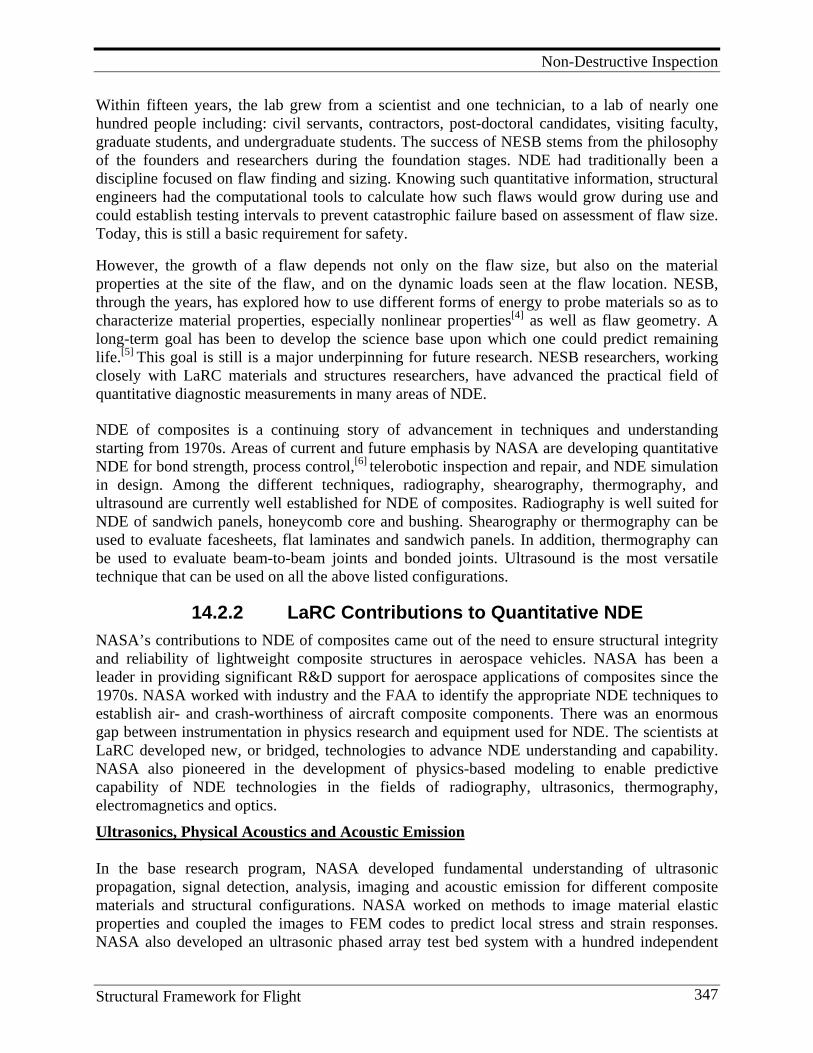
Non-Destructive Inspection
Structural Framework for Flight 347
Within fifteen years, the lab grew from a scientist and one technician, to a lab of nearly one hundred people including: civil servants, contractors, post-doctoral candidates, visiting faculty, graduate students, and undergraduate students. The success of NESB stems from the philosophy of the founders and researchers during the foundation stages. NDE had traditionally been a discipline focused on flaw finding and sizing. Knowing such quantitative information, structural engineers had the computational tools to calculate how such flaws would grow during use and could establish testing intervals to prevent catastrophic failure based on assessment of flaw size. Today, this is still a basic requirement for safety.
However, the growth of a flaw depends not only on the flaw size, but also on the material properties at the site of the flaw, and on the dynamic loads seen at the flaw location. NESB, through the years, has explored how to use different forms of energy to probe materials so as to characterize material properties, especially nonlinear properties[4] as well as flaw geometry. A long-term goal has been to develop the science base upon which one could predict remaining life.[5] This goal is still is a major underpinning for future research. NESB researchers, working closely with LaRC materials and structures researchers, have advanced the practical field of quantitative diagnostic measurements in many areas of NDE.
NDE of composites is a continuing story of advancement in techniques and understanding starting from 1970s. Areas of current and future emphasis by NASA are developing quantitative NDE for bond strength, process control,[6] telerobotic inspection and repair, and NDE simulation in design. Among the different techniques, radiography, shearography, thermography, and ultrasound are currently well established for NDE of composites. Radiography is well suited for NDE of sandwich panels, honeycomb core and bushing. Shearography or thermography can be used to evaluate facesheets, flat laminates and sandwich panels. In addition, thermography can be used to evaluate beam-to-beam joints and bonded joints. Ultrasound is the most versatile technique that can be used on all the above listed configurations.
14.2.2 LaRC Contributions to Quantitative NDE NASA’s contributions to NDE of composites came out of the need to ensure structural integrity and reliability of lightweight composite structures in aerospace vehicles. NASA has been a leader in providing significant R&D support for aerospace applications of composites since the 1970s. NASA worked with industry and the FAA to identify the appropriate NDE techniques to establish air- and crash-worthiness of aircraft composite components. There was an enormous gap between instrumentation in physics research and equipment used for NDE. The scientists at LaRC developed new, or bridged, technologies to advance NDE understanding and capability. NASA also pioneered in the development of physics-based modeling to enable predictive capability of NDE technologies in the fields of radiography, ultrasonics, thermography, electromagnetics and optics.
Ultrasonics, Physical Acoustics and Acoustic Emission In the base research program, NASA developed fundamental understanding of ultrasonic propagation, signal detection, analysis, imaging and acoustic emission for different composite materials and structural configurations. NASA worked on methods to image material elastic properties and coupled the images to FEM codes to predict local stress and strain responses. NASA also developed an ultrasonic phased array test bed system with a hundred independent
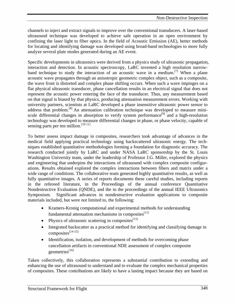
Non-Destructive Inspection
Structural Framework for Flight 348
channels to inject and extract signals to improve over the conventional transducers. A laser-based ultrasound technique was developed to achieve safe operation in an open environment by confining the laser light to fiber optics. In the field of Acoustic Emission (AE), better methods for locating and identifying damage was developed using broad-band technologies to more fully analyze several plate modes generated during an AE event.
Specific developments in ultrasonics were derived from a physics study of ultrasonic propagation, interaction and detection. In acoustic spectroscopy, LaRC invented a high resolution narrow-band technique to study the interaction of an acoustic wave in a medium.[7] When a plane acoustic wave propagates through an anisotropic geometric complex object, such as a composite, the wave front is distorted and complex phase shifting occurs. When such a wave impinges on a flat physical ultrasonic transducer, phase cancellation results in an electrical signal that does not represent the acoustic power entering the face of the transducer. Thus, any measurement based on that signal is biased by that physics, producing attenuation measurement errors. Working with university partners, scientists at LaRC developed a phase insensitive ultrasonic power sensor to address that problem.[8] An attenuation calibration technique was developed to measure mini-scule differential changes in absorption to verify system performance[9] and a high-resolution technology was developed to measure differential changes in phase, or phase velocity, capable of sensing parts per ten million.[10-11]
To better assess impact damage in composites, researchers took advantage of advances in the medical field applying practical technology using backscattered ultrasonic energy. The tech-niques established quantitative methodologies forming a foundation for diagnostic accuracy. The research conducted jointly by LaRC and under NASA LaRC sponsorship by the St. Louis Washington University team, under the leadership of Professor J.G. Miller, explored the physics and engineering that underpins the interactions of ultrasound with complex composite configur-ations. Results obtained explored the complex interactions between fibers and matrix under a wide range of conditions. The collaborative team generated highly quantitative results, as well as fully quantitative images. A series of reports documents these careful studies, including reports in the refereed literature, in the Proceedings of the annual conference Quantitative Nondestructive Evaluation (QNDE), and the in the proceedings of the annual IEEE Ultrasonics Symposium. Significant advances in nondestructive evaluation applications to composite materials included, but were not limited to, the following:
• Kramers-Kronig computational and experimental methods for understanding fundamental attenuation mechanisms in composites[11]
• Physics of ultrasonic scattering in composites[13] • Integrated backscatter as a practical method for identifying and classifying damage in
composites[14-15] • Identification, isolation, and development of methods for overcoming phase
cancellation artifacts in conventional NDE assessment of complex composite geometries[16]
Taken collectively, this collaboration represents a substantial contribution to extending and enhancing the use of ultrasound to understand and to evaluate the complex mechanical properties of composites. These contributions are likely to have a lasting impact because they are based on
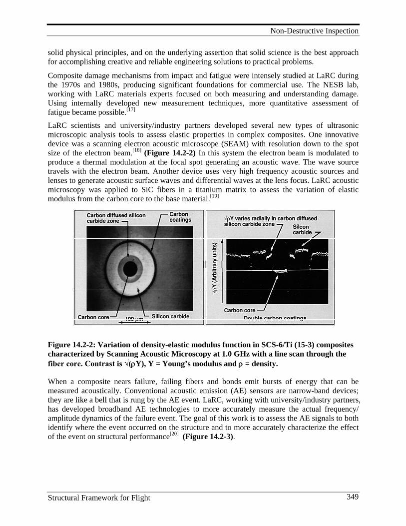
Non-Destructive Inspection
Structural Framework for Flight 349
solid physical principles, and on the underlying assertion that solid science is the best approach for accomplishing creative and reliable engineering solutions to practical problems.
Composite damage mechanisms from impact and fatigue were intensely studied at LaRC during the 1970s and 1980s, producing significant foundations for commercial use. The NESB lab, working with LaRC materials experts focused on both measuring and understanding damage. Using internally developed new measurement techniques, more quantitative assessment of fatigue became possible.[17] LaRC scientists and university/industry partners developed several new types of ultrasonic microscopic analysis tools to assess elastic properties in complex composites. One innovative device was a scanning electron acoustic microscope (SEAM) with resolution down to the spot size of the electron beam.[18] (Figure 14.2-2) In this system the electron beam is modulated to produce a thermal modulation at the focal spot generating an acoustic wave. The wave source travels with the electron beam. Another device uses very high frequency acoustic sources and lenses to generate acoustic surface waves and differential waves at the lens focus. LaRC acoustic microscopy was applied to SiC fibers in a titanium matrix to assess the variation of elastic modulus from the carbon core to the base material.[19]
Figure 14.2-2: Variation of density-elastic modulus function in SCS-6/Ti (15-3) composites characterized by Scanning Acoustic Microscopy at 1.0 GHz with a line scan through the fiber core. Contrast is √(ρY), Y = Young’s modulus and ρ = density.
When a composite nears failure, failing fibers and bonds emit bursts of energy that can be measured acoustically. Conventional acoustic emission (AE) sensors are narrow-band devices; they are like a bell that is rung by the AE event. LaRC, working with university/industry partners, has developed broadband AE technologies to more accurately measure the actual frequency/ amplitude dynamics of the failure event. The goal of this work is to assess the AE signals to both identify where the event occurred on the structure and to more accurately characterize the effect of the event on structural performance[20] (Figure 14.2-3).
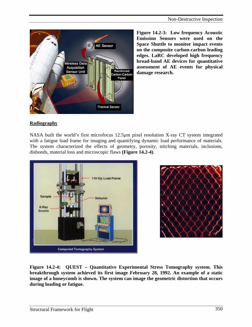
Non-Destructive Inspection
Structural Framework for Flight 350
Figure 14.2-3: Low frequency Acoustic Emission Sensors were used on the Space Shuttle to monitor impact events on the composite carbon-carbon leading edges. LaRC developed high frequency broad-band AE devices for quantitative assessment of AE events for physical damage research.
Radiography
NASA built the world’s first microfocus 12.5µm pixel resolution X-ray CT system integrated with a fatigue load frame for imaging and quantifying dynamic load performance of materials. The system characterized the effects of geometry, porosity, stitching materials, inclusions, disbonds, material loss and microscopic flaws (Figure 14.2-4).
Figure 14.2-4: QUEST – Quantitative Experimental Stress Tomography system. This breakthrough system achieved its first image February 28, 1992. An example of a static image of a honeycomb is shown. The system can image the geometric distortion that occurs during loading or fatigue.
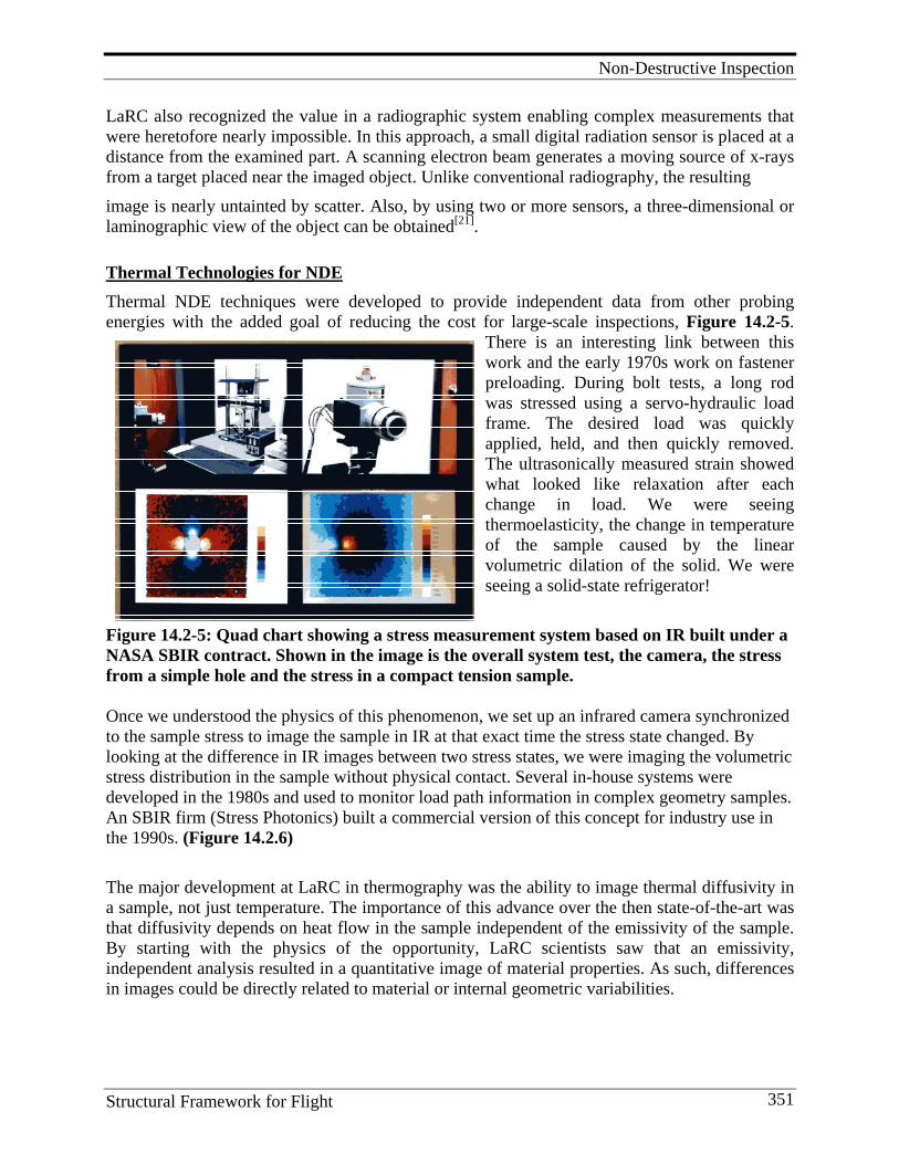
Non-Destructive Inspection
Structural Framework for Flight 351
LaRC also recognized the value in a radiographic system enabling complex measurements that were heretofore nearly impossible. In this approach, a small digital radiation sensor is placed at a distance from the examined part. A scanning electron beam generates a moving source of x-rays from a target placed near the imaged object. Unlike conventional radiography, the resulting image is nearly untainted by scatter. Also, by using two or more sensors, a three-dimensional or laminographic view of the object can be obtained[21].
Thermal Technologies for NDE Thermal NDE techniques were developed to provide independent data from other probing energies with the added goal of reducing the cost for large-scale inspections, Figure 14.2-5.
There is an interesting link between this work and the early 1970s work on fastener preloading. During bolt tests, a long rod was stressed using a servo-hydraulic load frame. The desired load was quickly applied, held, and then quickly removed. The ultrasonically measured strain showed what looked like relaxation after each change in load. We were seeing thermoelasticity, the change in temperature of the sample caused by the linear volumetric dilation of the solid. We were seeing a solid-state refrigerator!
Figure 14.2-5: Quad chart showing a stress measurement system based on IR built under a NASA SBIR contract. Shown in the image is the overall system test, the camera, the stress from a simple hole and the stress in a compact tension sample. Once we understood the physics of this phenomenon, we set up an infrared camera synchronized to the sample stress to image the sample in IR at that exact time the stress state changed. By looking at the difference in IR images between two stress states, we were imaging the volumetric stress distribution in the sample without physical contact. Several in-house systems were developed in the 1980s and used to monitor load path information in complex geometry samples. An SBIR firm (Stress Photonics) built a commercial version of this concept for industry use in the 1990s. (Figure 14.2.6) The major development at LaRC in thermography was the ability to image thermal diffusivity in a sample, not just temperature. The importance of this advance over the then state-of-the-art was that diffusivity depends on heat flow in the sample independent of the emissivity of the sample. By starting with the physics of the opportunity, LaRC scientists saw that an emissivity, independent analysis resulted in a quantitative image of material properties. As such, differences in images could be directly related to material or internal geometric variabilities.
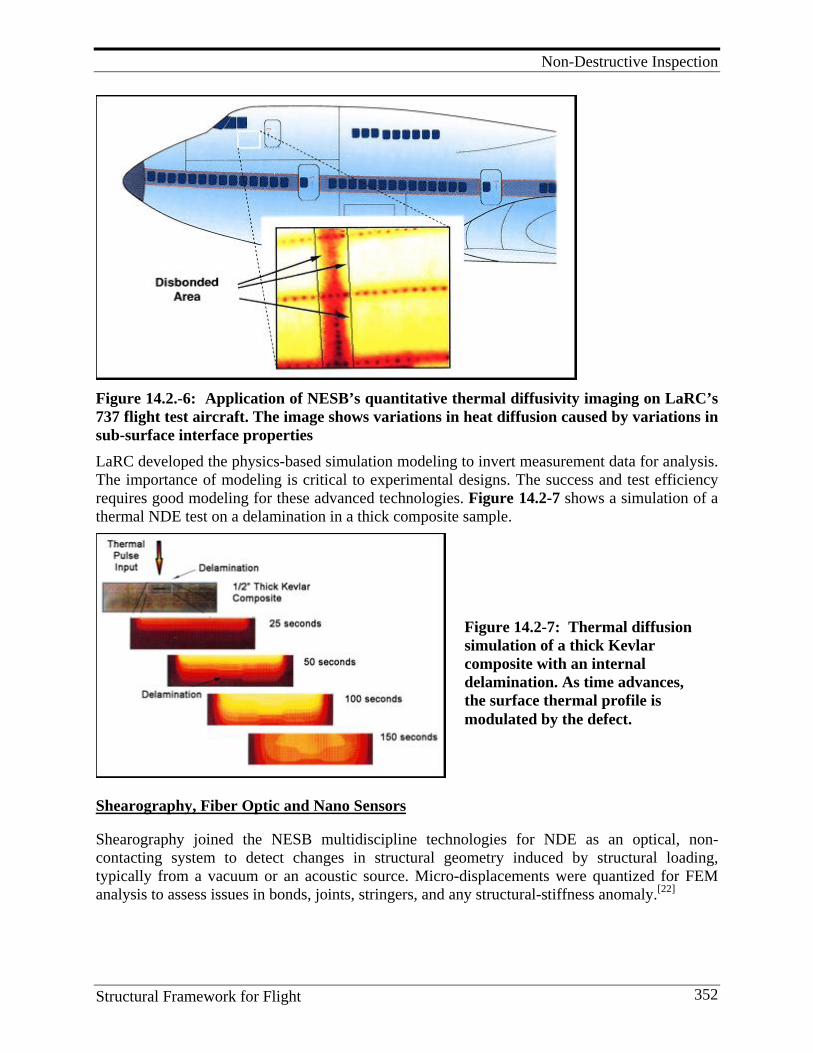
Non-Destructive Inspection
Structural Framework for Flight 352
Figure 14.2.-6: Application of NESB’s quantitative thermal diffusivity imaging on LaRC’s 737 flight test aircraft. The image shows variations in heat diffusion caused by variations in sub-surface interface properties
LaRC developed the physics-based simulation modeling to invert measurement data for analysis. The importance of modeling is critical to experimental designs. The success and test efficiency requires good modeling for these advanced technologies. Figure 14.2-7 shows a simulation of a thermal NDE test on a delamination in a thick composite sample.
Shearography, Fiber Optic and Nano Sensors Shearography joined the NESB multidiscipline technologies for NDE as an optical, non-contacting system to detect changes in structural geometry induced by structural loading, typically from a vacuum or an acoustic source. Micro-displacements were quantized for FEM analysis to assess issues in bonds, joints, stringers, and any structural-stiffness anomaly.[22]
Figure 14.2-7: Thermal diffusion simulation of a thick Kevlar composite with an internal delamination. As time advances, the surface thermal profile is modulated by the defect.
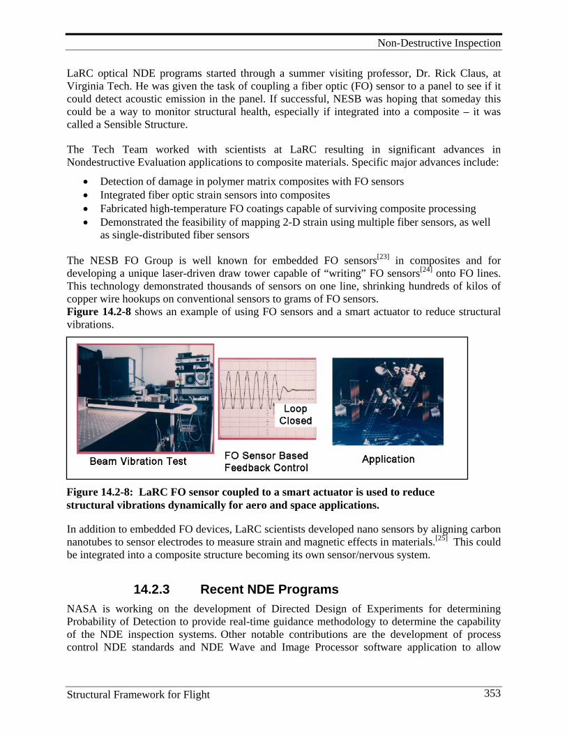
Non-Destructive Inspection
Structural Framework for Flight 353
LaRC optical NDE programs started through a summer visiting professor, Dr. Rick Claus, at Virginia Tech. He was given the task of coupling a fiber optic (FO) sensor to a panel to see if it could detect acoustic emission in the panel. If successful, NESB was hoping that someday this could be a way to monitor structural health, especially if integrated into a composite – it was called a Sensible Structure.
The Tech Team worked with scientists at LaRC resulting in significant advances in Nondestructive Evaluation applications to composite materials. Specific major advances include:
• Detection of damage in polymer matrix composites with FO sensors • Integrated fiber optic strain sensors into composites • Fabricated high-temperature FO coatings capable of surviving composite processing • Demonstrated the feasibility of mapping 2-D strain using multiple fiber sensors, as well
as single-distributed fiber sensors The NESB FO Group is well known for embedded FO sensors[23] in composites and for developing a unique laser-driven draw tower capable of “writing” FO sensors[24] onto FO lines. This technology demonstrated thousands of sensors on one line, shrinking hundreds of kilos of copper wire hookups on conventional sensors to grams of FO sensors. Figure 14.2-8 shows an example of using FO sensors and a smart actuator to reduce structural vibrations.
In addition to embedded FO devices, LaRC scientists developed nano sensors by aligning carbon nanotubes to sensor electrodes to measure strain and magnetic effects in materials.[25] This could be integrated into a composite structure becoming its own sensor/nervous system.
14.2.3 Recent NDE Programs NASA is working on the development of Directed Design of Experiments for determining Probability of Detection to provide real-time guidance methodology to determine the capability of the NDE inspection systems. Other notable contributions are the development of process control NDE standards and NDE Wave and Image Processor software application to allow
Figure 14.2-8: LaRC FO sensor coupled to a smart actuator is used to reduce structural vibrations dynamically for aero and space applications.
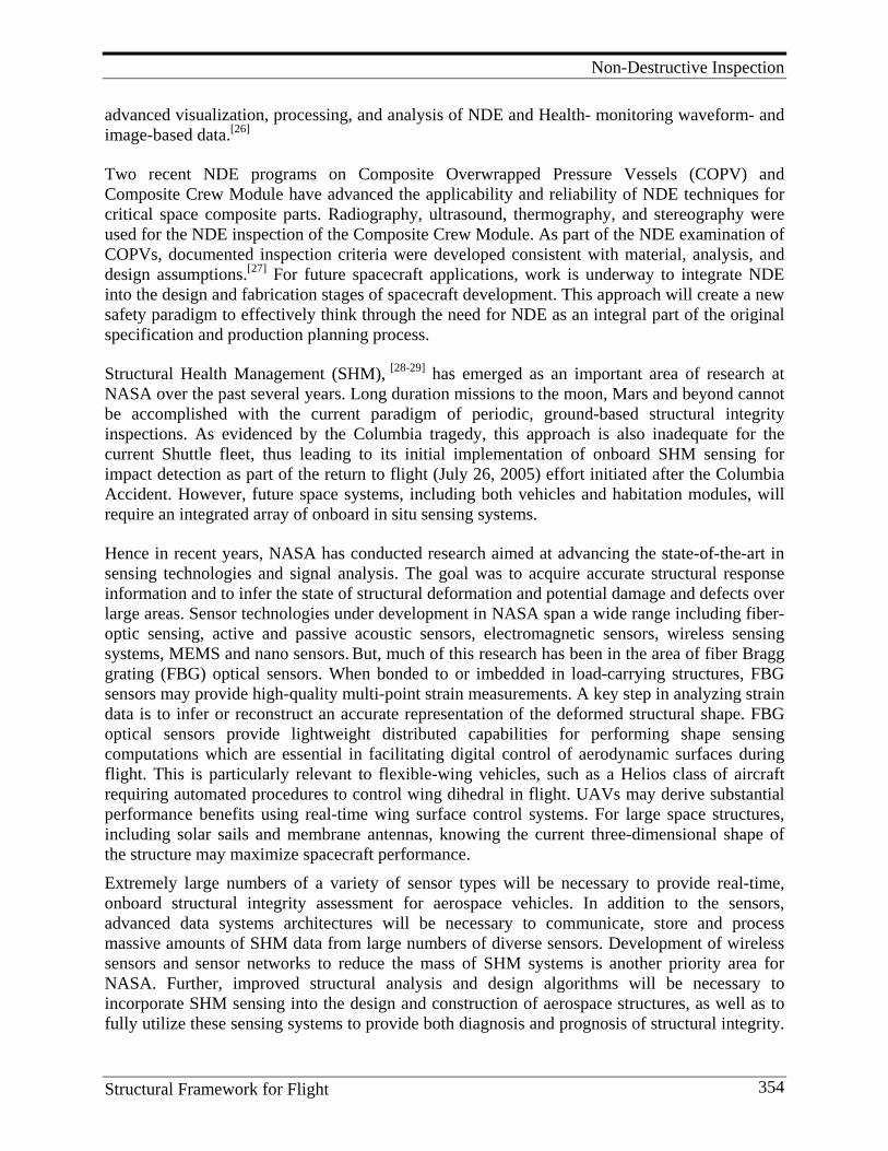
Non-Destructive Inspection
Structural Framework for Flight 354
advanced visualization, processing, and analysis of NDE and Health- monitoring waveform- and image-based data.[26]
Two recent NDE programs on Composite Overwrapped Pressure Vessels (COPV) and Composite Crew Module have advanced the applicability and reliability of NDE techniques for critical space composite parts. Radiography, ultrasound, thermography, and stereography were used for the NDE inspection of the Composite Crew Module. As part of the NDE examination of COPVs, documented inspection criteria were developed consistent with material, analysis, and design assumptions.[27] For future spacecraft applications, work is underway to integrate NDE into the design and fabrication stages of spacecraft development. This approach will create a new safety paradigm to effectively think through the need for NDE as an integral part of the original specification and production planning process.
Structural Health Management (SHM), [28-29] has emerged as an important area of research at NASA over the past several years. Long duration missions to the moon, Mars and beyond cannot be accomplished with the current paradigm of periodic, ground-based structural integrity inspections. As evidenced by the Columbia tragedy, this approach is also inadequate for the current Shuttle fleet, thus leading to its initial implementation of onboard SHM sensing for impact detection as part of the return to flight (July 26, 2005) effort initiated after the Columbia Accident. However, future space systems, including both vehicles and habitation modules, will require an integrated array of onboard in situ sensing systems.
Hence in recent years, NASA has conducted research aimed at advancing the state-of-the-art in sensing technologies and signal analysis. The goal was to acquire accurate structural response information and to infer the state of structural deformation and potential damage and defects over large areas. Sensor technologies under development in NASA span a wide range including fiber-optic sensing, active and passive acoustic sensors, electromagnetic sensors, wireless sensing systems, MEMS and nano sensors. But, much of this research has been in the area of fiber Bragg grating (FBG) optical sensors. When bonded to or imbedded in load-carrying structures, FBG sensors may provide high-quality multi-point strain measurements. A key step in analyzing strain data is to infer or reconstruct an accurate representation of the deformed structural shape. FBG optical sensors provide lightweight distributed capabilities for performing shape sensing computations which are essential in facilitating digital control of aerodynamic surfaces during flight. This is particularly relevant to flexible-wing vehicles, such as a Helios class of aircraft requiring automated procedures to control wing dihedral in flight. UAVs may derive substantial performance benefits using real-time wing surface control systems. For large space structures, including solar sails and membrane antennas, knowing the current three-dimensional shape of the structure may maximize spacecraft performance. Extremely large numbers of a variety of sensor types will be necessary to provide real-time, onboard structural integrity assessment for aerospace vehicles. In addition to the sensors, advanced data systems architectures will be necessary to communicate, store and process massive amounts of SHM data from large numbers of diverse sensors. Development of wireless sensors and sensor networks to reduce the mass of SHM systems is another priority area for NASA. Further, improved structural analysis and design algorithms will be necessary to incorporate SHM sensing into the design and construction of aerospace structures, as well as to fully utilize these sensing systems to provide both diagnosis and prognosis of structural integrity.

Non-Destructive Inspection
Structural Framework for Flight 355
Ultimately, structural integrity information will feed into an Integrated Vehicle Health Management (IVHM) system that will provide real-time knowledge of structural, propulsion, thermal protection and other critical systems for optimal vehicle management and mission control.
14.3. Lessons Learned and Future Directions Lessons Learned: 1. Different NDE techniques need to be used as they differ in detectability limits and in
probability of detection of different damages. 2. Automated processes covering large areas will help to reduce time and cost of QC. 3. As-built composite hardware can be significantly different from NDE defect standards and
test articles. 4. Determine and understand the effect of defects on part performance. This calls for integrating
disciplines of NDE with damage tolerance. For example, the major issue in NDE/SHM of COPVs is linking NDE to stress rupture and creep rupture failures.
5. Need defect standards of large specimens with well-characterized and realistic defects representative of large structures to be inspected.
6. Need certification standards based on NDE data. 7. Critical need to integrate NDE considerations into design process, which involves access for
inspection, defining inspection criteria like critical defect type, size, etc. 8. To achieve the above, requires team effort between NDE, materials, and structures
disciplines. 9. Need NDE methods to monitor in real-time the structural integrity with embedded sensors. 10. Need for in situ NDE and SHM in both short- and long-term space missions. 11. IVHM system for aerospace vehicles will require extremely large numbers of sensors to
measure a multitude of parameters like strain, load, pressure, temperature, vibration, and local chemistry.
12. Need embedded sensors with long-term reliability and signal stability for SHM. 13. Need small lightweight sensor networks that are compatible with composite material which
do not cause damage initiation under load and thermal cycles. 14. Need wireless sensors that are small enough, smart enough, and with enough
multifunctionality to be acceptable to designers. 15. Need flight testing of full-scale IVHM systems to detect multisite damage. 16. Need artificial intelligence to automatically assess structural integrity from sensor responses
and implement damage mitigation protocols.
Non-Destructive Inspection
Structural Framework for Flight 356
References 1. Harris, C.E., J. H. Starnes, Jr., and M. J. Shuart. 2001. An Assessment of the State-of-the-Art in the
Design and Manufacturing of Large Composite Structures for Aerospace Vehicles. (NASA TM-2001-210844).
2. Allison, S. G. 1992. Method of Recertifying a Loaded Bearing Member. US Patent No. 5,150,620 (Sept. 1992).
3. Namkung, Min, P. Kushnick, W. T. Yost, and J. L. Grainger. 1992. Method of Characterizing Residual Stress in Ferromagnetic Materials: A Pulse Histogram of Acoustic Emission Signals 5,164,669, Nov. 17, 1992.
4. Cantrell, J. H., and W. T. Yost. 2001. Nonlinear Ultrasonic Characterization of Fatigue Microstructures. International Journal of Fatigue 23:S487–S490.
5. Cantrell, J. H. 2009. Ultrasonic Harmonic Generation from Fatigue-induced Dislocation Substructures in Planar Slip Metals and Assessment of Remaining Fatigue Life. J, Appl. Phys. 106:093516.
6. Winfree, W. P. 1983. Ultrasonic Characterization of Changes in Viscoelastic Properties of Epoxies During Cure. 1983 IEEE Ultrasonics Symposium Proceedings, 447.
7. Cantrell, J. H., Jr., and J. S. Heyman. 1980. Ultrasonic Spectrum Analysis Using Frequency-Tracked Gated rf Pulses. J. Acoust. Soc. Am. 67:1623-1628.
8. Heyman, Joseph S. 1980. CdS Solid State Phase Insensitive Ultrasonic Transducer. US Patent 4,195,244, Mar. 25, 1980.
9. Heyman, J. S. and J. G. Miller. 1975. Ultrasonic Calibration Device. US Patent 3,924,444, Dec. 9, 1975.
10. Heyman, J. S. 1982. Pulsed Phase Locked Loop Strain Monitor.US Patent 4,363,242 Dec. 14, 1982. 11. Yost, W. T., J. H. Cantrell, and P. W. Kushnick 1991. Constant Frequency Pulsed Phase-Locked
Loop Instrument for Measuring Ultrasonic Velocity of Condensed Matter. Rev. Sci. Instrum. 62:2451-2456.
12. O’Donnell, M., E. T. Jaynes, and J. G. Miller. 1981. Kramers-Kronig Relationship Between Ultrasonic Attenuation and Phase Velocity. Journal of the Acoustical Society of America 69: 696-701.
13. O’Donnell, M., and J. G. Miller. 1981. Quantitative broadband ultrasonic backscatter: An approach to non-destructive evaluation in acoustically inhomogeneous materials. Journal of Applied Physics 52:1056-1065.
14. Shoup, T. A., J. G. Miller, J. S. Heyman, and W. Illg. 1982. Ultrasonic characterization of fatigue and impact damage in graphite epoxy composite laminates. Proceedings of IEEE Ultrasonics Symposium. 82 CH 1823-4, p. 960-964.
15. Hughes, M. S., S. M. Handley, J. G. Miller, and E. I. Madaras. 1987. A relationship between frequency dependent ultrasonic attenuation and porosity in composite laminates. Review of Progress in QNDE. Williamsburg, 7B, p. 1037-1044.
16. Johnston, P. H., and J. G. Miller. 1986. Phase-insensitive detection for measurement of backscattered ultrasound. , IEEE Transactions on Ultrasonics, Ferroelectrics, and Frequency Control 33:713-721.
17. Cantrell, J. H., Jr., W. P. Winfree, and J. S. Heyman. 1985. Profiles of Fatigue Damage in Graphite/Epoxy Composites From Ultrasonic Transmission Power Spectra. In Recent Advances in Composites in the United States and Japan, ed. J. R. Vinson and M. Taya 197-206. (ASTM STP 864) Philadelphia, PA: American Society for Testing and Materials.
18. Cantrell, J. H., and Menglu Qian. 1989. Scanning Electron Acoustic Microscopy of SiC Particles in Metal Matrix Composites. Mat. Sci. and Engng. A122:47-52.
19. Sathish, S., W. T. Yost, J. H. Cantrell, E. R. Generazio, R. A. MacKay, and K. M. B. Taminger. 1995. Scanning Acoustic Microscopy of SCS-6 SiC Fibers in Titanium Matrices. In Advanced Ceramic Composites: Design Approaches, Testing, and Life Prediction Methods Part 3 ed. E. R. Generazio 135-142. New York: Technomic Publishing.
Non-Destructive Inspection
Structural Framework for Flight 357
20. Prosser, W. H., K. E. Jackson, S. Kellas, B. T. Smith, J. McKeon, and A. Friedman. 1995. Advanced, Waveform Based Acoustic Emission Detection of Matrix Cracking in Composites. Invited Contribution Materials Evaluation 53 (9): 1052-1058.
21. Winfree, W. P., F. R. Parker, and N. A. Cmar-Mascis. Imaging Corrosion in Aircraft Structures With Reverse Geometry X-Ray. Presented at 43rd International SAMPE Symposium 43 (Book 2): 1438-1447.
22. Melvin, L. D., J. B. Deaton, and R. S. Rogowski. 1991. Full Field Laser Shearographic Inspection of Airframe Structures. Paper presented at the International Conference on Aging Aircraft and Structural Airworthiness, Washington, D.C.
23. Rogowski, R. S., J. S. Heyman, M. S. Holben, Jr., C. Egalon, D. W. Dehart, T. Doederlein, and J. Koury. 1988. Fiber Optic Strain Measurements in Filament Wound Graphite-epoxy Tubes Containing Embedded Fibers. Proc. SPIE 986.
24. Froggatt, M. E. 1988. Apparatus and Method for Measuring Strain in Bragg Gratings. US Patent 5798521, Aug. 25, 1998.
25. Sun, K. J., R. A. Wincheski, and C. Park. 2008. Magnetic Property Measurements on Single Wall Carbon Nanotube-polyimide Composites. Journal of Applied Physics 103:023908.
26. Generazio, E. 2007. Directed Design of Experiments(DOE) for Determining Probability of Detection (POD) Capability of NDE Systems. Paper presented in Review of Progress in Quantitative NDE, Colorado School of Mines, Golden, CO
27. Saulsberry R., et al. 2007. Nondestructive Methods and Special Instrumentation Supporting NASA Composite Overwrapped Pressure Vessel Assessments. 48th AIAA/ASME/AHS/ASC Structures, Structural Dynamics and Materials Conference. (AIAA-2007-2324) (NASA Document ID 20070010588).
28. Prosser, W. H.. et al. 2004. Structural Health Management for Future Aerospace Vehicles. (NASA ID 20040200975).
29. Tessler, A. 2007. Structural Analysis Methods for Structural Health Management of Future Aerospace Vehicles. (NASA/TM-2007-214871)
.
Damage Tolerance
Structural Framework for Flight 358
15. D A M A G E T O L E R A N C E 15.1. Understanding Damage Tolerance
When defining damage and defect threats to aircraft safety, there are many different factors to consider: impact damage resistance, manufacturing mistakes, growth potential (including synergistic relations with fluid ingression and environments), environmental effects, high temperature zones, fluid resistance, repair mistakes, UV and lightning protection, discrete source threats, product size/damage location, structural design detail, design criteria, damage detection and characterization methods, production quality control, production technician training, repair quality control, maintenance technician training, inspector training, and operations awareness. For composite structures, the compression and shear residual strength are affected by damage. Environmental effects, such as moisture absorption and potential exposure to UV or hydraulic fluids, manufacturing defects and impact damage must be carefully considered in the design criteria. In July 2006, the FAA sponsored a workshop on Composite Damage Tolerance and Maintenance.[1] The following graphics are from this workshop. Figure 15.1-1 shows structural design load and damage considerations. Figures 15.1-2 through 15.1-4 show examples of damage that fall within each of the following categories. Category 1 damage or defects are small enough to be non-detectable and do not pose a threat to flight safety. They are taken care of by employing a 1.5 factor of safety on design load level. Category 2 is representative of damage detected by scheduled or directed field inspection at specific intervals. The level of damage is repaired through maintenance. Category 3 damage is obvious and detected by operations personnel within a few flights. The aircraft is safe to fly but once the damage is detected, repairs take place. Category 4 damage is from a discrete source and the pilot limits flight maneuvers to execute a “get home” flight plan. Category 5 is classified as severe damage created by anomalous ground or flight events. The repair is generally beyond design validation and may require substantial reengineering and validation tests to recertify the aircraft. Table 15.1-1 lists the substantiation considerations and the elements of safety management. Federal Aviation Regulations (FAR) 25.571, Damage Tolerance and Fatigue Evaluation of Structure, states that the operator must show that catastrophic failure due to fatigue, corrosion, manufacturing defects, or accidental damage will be avoided through the operational life of the airplane. FAA aviation safety Advisory Circulars AC 20-107A Composite Airplane Structure: 7. Proof of Structure – Fatigue/Damage Tolerance (4)…states that inspection intervals should be established as part of the maintenance program. In selecting such intervals the residual strength level associated with the assumed damages should be considered.
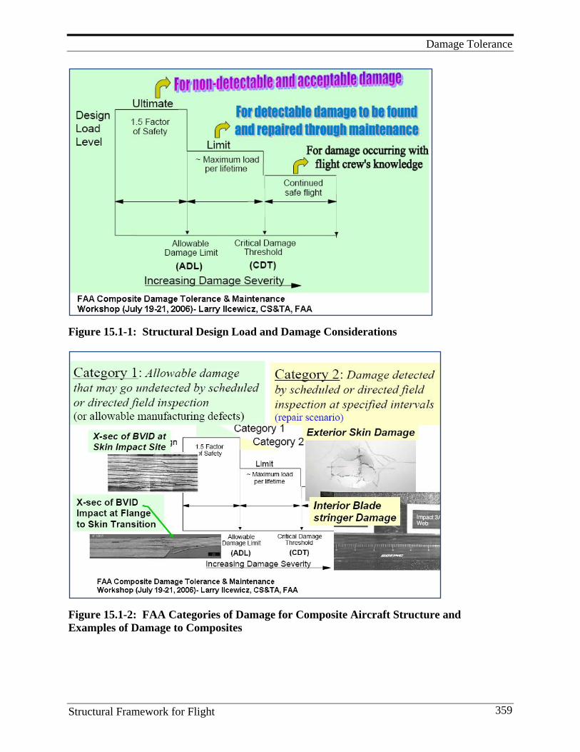
Damage Tolerance
Structural Framework for Flight 359
Figure 15.1-1: Structural Design Load and Damage Considerations
Figure 15.1-2: FAA Categories of Damage for Composite Aircraft Structure and Examples of Damage to Composites
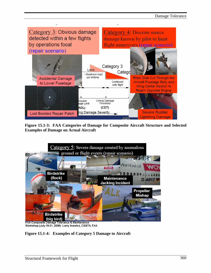
Damage Tolerance
Structural Framework for Flight 360
Figure 15.1-3: FAA Categories of Damage for Composite Aircraft Structure and Selected Examples of Damage on Actual Aircraft
Figure 15.1-4: Examples of Category 5 Damage to Aircraft
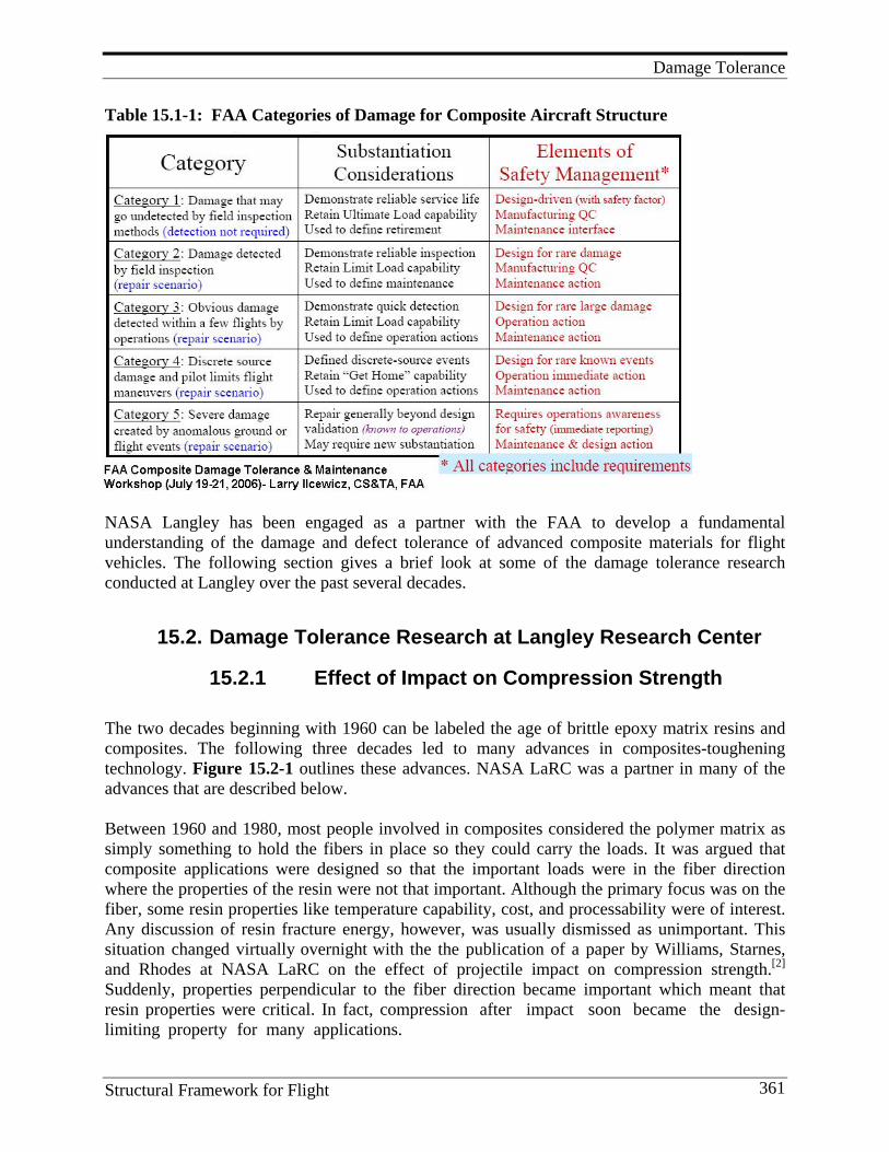
Damage Tolerance
Structural Framework for Flight 361
Table 15.1-1: FAA Categories of Damage for Composite Aircraft Structure
NASA Langley has been engaged as a partner with the FAA to develop a fundamental understanding of the damage and defect tolerance of advanced composite materials for flight vehicles. The following section gives a brief look at some of the damage tolerance research conducted at Langley over the past several decades.
15.2. Damage Tolerance Research at Langley Research Center
15.2.1 Effect of Impact on Compression Strength The two decades beginning with 1960 can be labeled the age of brittle epoxy matrix resins and composites. The following three decades led to many advances in composites-toughening technology. Figure 15.2-1 outlines these advances. NASA LaRC was a partner in many of the advances that are described below. Between 1960 and 1980, most people involved in composites considered the polymer matrix as simply something to hold the fibers in place so they could carry the loads. It was argued that composite applications were designed so that the important loads were in the fiber direction where the properties of the resin were not that important. Although the primary focus was on the fiber, some resin properties like temperature capability, cost, and processability were of interest. Any discussion of resin fracture energy, however, was usually dismissed as unimportant. This situation changed virtually overnight with the the publication of a paper by Williams, Starnes, and Rhodes at NASA LaRC on the effect of projectile impact on compression strength.[2] Suddenly, properties perpendicular to the fiber direction became important which meant that resin properties were critical. In fact, compression after impact soon became the design- limiting property for many applications.
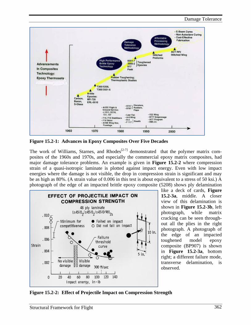
Damage Tolerance
Structural Framework for Flight 362
Figure 15.2-1: Advances in Epoxy Composites Over Five Decades The work of Williams, Starnes, and Rhodes[2-7] demonstrated that the polymer matrix com-posites of the 1960s and 1970s, and especially the commercial epoxy matrix composites, had major damage tolerance problems. An example is given in Figure 15.2-2 where compression strain of a quasi-isotropic laminate is plotted against impact energy. Even with low impact energies where the damage is not visible, the drop in compression strain is significant and may be as high as 80%. (A strain value of 0.006 in this test is about equivalent to a stress of 50 ksi.) A photograph of the edge of an impacted brittle epoxy composite (5208) shows ply delamination
like a deck of cards, Figure 15.2-3a, middle. A closer view of this delamination is shown in Figure 15.2-3b, left photograph, while matrix cracking can be seen through-out all the plies in the right photograph. A photograph of the edge of an impacted toughened model epoxy composite (BP907) is shown in Figure 15.2-3a, bottom right; a different failure mode, transverse delamination, is observed.
Figure 15.2-2: Effect of Projectile Impact on Compression Strength
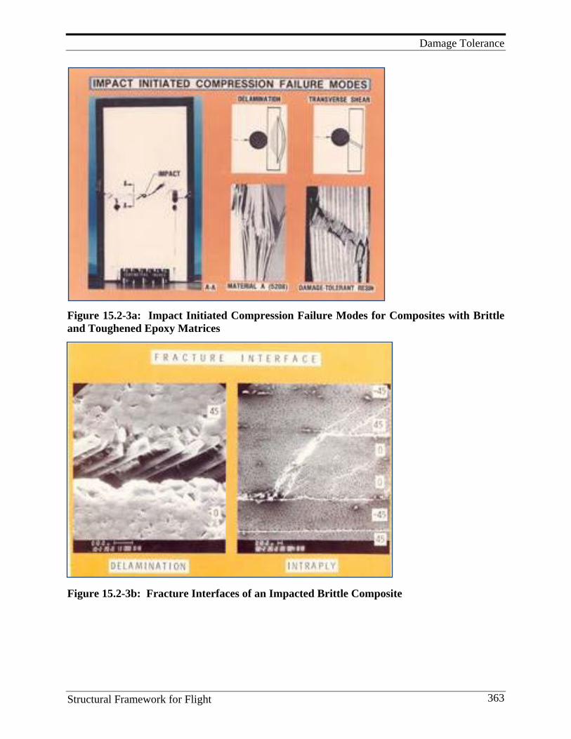
Damage Tolerance
Structural Framework for Flight 363
Figure 15.2-3a: Impact Initiated Compression Failure Modes for Composites with Brittle and Toughened Epoxy Matrices
Figure 15.2-3b: Fracture Interfaces of an Impacted Brittle Composite
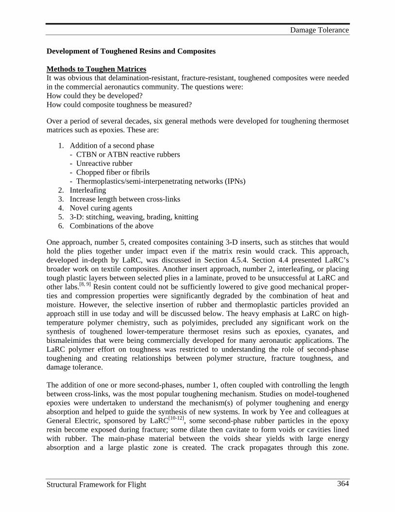
Damage Tolerance
Structural Framework for Flight 364
Development of Toughened Resins and Composites Methods to Toughen Matrices It was obvious that delamination-resistant, fracture-resistant, toughened composites were needed in the commercial aeronautics community. The questions were: How could they be developed? How could composite toughness be measured? Over a period of several decades, six general methods were developed for toughening thermoset matrices such as epoxies. These are:
1. Addition of a second phase - CTBN or ATBN reactive rubbers - Unreactive rubber - Chopped fiber or fibrils - Thermoplastics/semi-interpenetrating networks (IPNs)
2. Interleafing 3. Increase length between cross-links 4. Novel curing agents 5. 3-D: stitching, weaving, brading, knitting 6. Combinations of the above
One approach, number 5, created composites containing 3-D inserts, such as stitches that would hold the plies together under impact even if the matrix resin would crack. This approach, developed in-depth by LaRC, was discussed in Section 4.5.4. Section 4.4 presented LaRC’s broader work on textile composites. Another insert approach, number 2, interleafing, or placing tough plastic layers between selected plies in a laminate, proved to be unsuccessful at LaRC and other labs.[8, 9] Resin content could not be sufficiently lowered to give good mechanical proper-ties and compression properties were significantly degraded by the combination of heat and moisture. However, the selective insertion of rubber and thermoplastic particles provided an approach still in use today and will be discussed below. The heavy emphasis at LaRC on high- temperature polymer chemistry, such as polyimides, precluded any significant work on the synthesis of toughened lower-temperature thermoset resins such as epoxies, cyanates, and bismaleimides that were being commercially developed for many aeronautic applications. The LaRC polymer effort on toughness was restricted to understanding the role of second-phase toughening and creating relationships between polymer structure, fracture toughness, and damage tolerance. The addition of one or more second-phases, number 1, often coupled with controlling the length between cross-links, was the most popular toughening mechanism. Studies on model-toughened epoxies were undertaken to understand the mechanism(s) of polymer toughening and energy absorption and helped to guide the synthesis of new systems. In work by Yee and colleagues at General Electric, sponsored by LaRC[10-12], some second-phase rubber particles in the epoxy resin become exposed during fracture; some dilate then cavitate to form voids or cavities lined with rubber. The main-phase material between the voids shear yields with large energy absorption and a large plastic zone is created. The crack propagates through this zone.
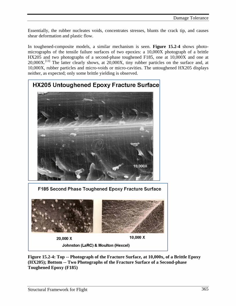
Damage Tolerance
Structural Framework for Flight 365
Essentially, the rubber nucleates voids, concentrates stresses, blunts the crack tip, and causes shear deformation and plastic flow. In toughened-composite models, a similar mechanism is seen. Figure 15.2-4 shows photo-micrographs of the tensile failure surfaces of two epoxies: a 10,000X photograph of a brittle HX205 and two photographs of a second-phase toughened F185, one at 10,000X and one at 20,000X.[13] The latter clearly shows, at 20,000X, tiny rubber particles on the surface and, at 10,000X, rubber particles and micro-voids or micro-cavities. The untoughened HX205 displays neither, as expected; only some brittle yielding is observed.
Figure 15.2-4: Top -- Photograph of the Fracture Surface, at 10,000x, of a Brittle Epoxy (HX205); Bottom -- Two Photographs of the Fracture Surface of a Second-phase Toughened Epoxy (F185)
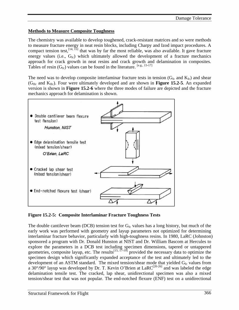
Damage Tolerance
Structural Framework for Flight 366
Methods to Measure Composite Toughness
The chemistry was available to develop toughened, crack-resistant matrices and so were methods to measure fracture energy in neat resin blocks, including Charpy and Izod impact procedures. A compact tension test,[14, 15] that was by far the most reliable, was also available. It gave fracture energy values (i.e., GIc) which ultimately allowed the development of a fracture mechanics approach for crack growth in neat resins and crack growth and delamination in composites. Tables of resin (GIc) values can be found in the literature. [e.g., 15-17]
The need was to develop composite interlaminar fracture tests in tension (GIc and KIc) and shear (GIIc and KIIc). Four were ultimately developed and are shown in Figure 15.2-5. An expanded version is shown in Figure 15.2-6 where the three modes of failure are depicted and the fracture mechanics approach for delamination is shown.
Figure 15.2-5: Composite Interlaminar Fracture Toughness Tests The double cantilever beam (DCB) tension test for GIc values has a long history, but much of the early work was performed with geometry and layup parameters not optimized for determining interlaminar fracture behavior, particularly with high-toughness resins. In 1980, LaRC (Johnston) sponsored a program with Dr. Donald Hunston at NIST and Dr. William Bascom at Hercules to explore the parameters in a DCB test including specimen dimensions, tapered or untappered geometries, composite layup, etc. The results[15, 17-19] provided the necessary data to optimize the specimen design which significantly expanded acceptance of the test and ultimately led to the development of an ASTM standard. The mixed tension/shear mode that yielded GIc values from a 30°/90° layup was developed by Dr. T. Kevin O’Brien at LaRC[20-26] and was labeled the edge delamination tensile test. The cracked, lap shear, unidirectional specimen was also a mixed tension/shear test that was not popular. The end-notched flexure (ENF) test on a unidirectional
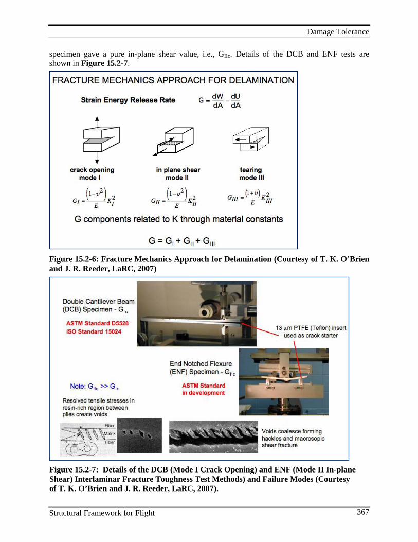
Damage Tolerance
Structural Framework for Flight 367
specimen gave a pure in-plane shear value, i.e., GIIc. Details of the DCB and ENF tests are shown in Figure 15.2-7.
Figure 15.2-6: Fracture Mechanics Approach for Delamination (Courtesy of T. K. O’Brien and J. R. Reeder, LaRC, 2007)
Development of Key Relationships Figure 15.2-7: Details of the DCB (Mode I Crack Opening) and ENF (Mode II In-plane Shear) Interlaminar Fracture Toughness Test Methods) and Failure Modes (Courtesy of T. K. O’Brien and J. R. Reeder, LaRC, 2007).
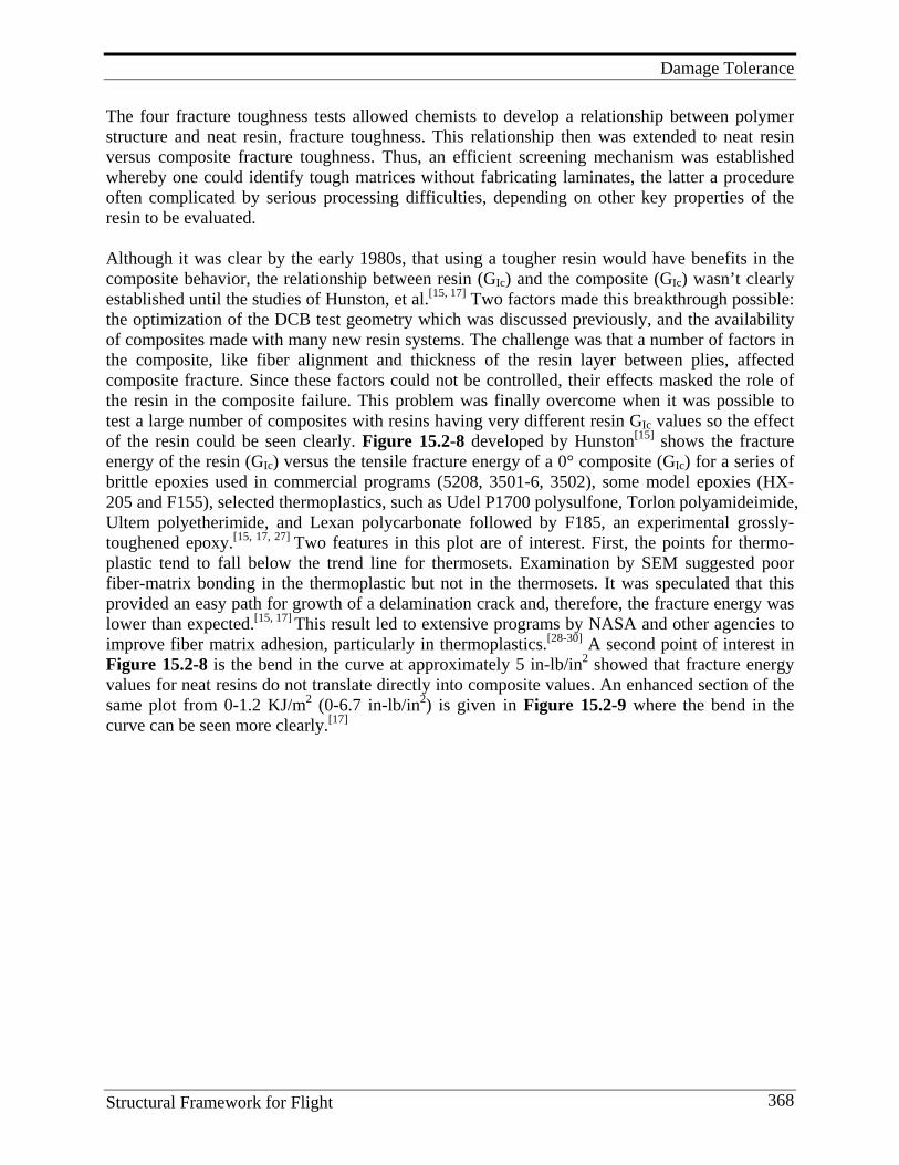
Damage Tolerance
Structural Framework for Flight 368
The four fracture toughness tests allowed chemists to develop a relationship between polymer structure and neat resin, fracture toughness. This relationship then was extended to neat resin versus composite fracture toughness. Thus, an efficient screening mechanism was established whereby one could identify tough matrices without fabricating laminates, the latter a procedure often complicated by serious processing difficulties, depending on other key properties of the resin to be evaluated. Although it was clear by the early 1980s, that using a tougher resin would have benefits in the composite behavior, the relationship between resin (GIc) and the composite (GIc) wasn’t clearly established until the studies of Hunston, et al.[15, 17] Two factors made this breakthrough possible: the optimization of the DCB test geometry which was discussed previously, and the availability of composites made with many new resin systems. The challenge was that a number of factors in the composite, like fiber alignment and thickness of the resin layer between plies, affected composite fracture. Since these factors could not be controlled, their effects masked the role of the resin in the composite failure. This problem was finally overcome when it was possible to test a large number of composites with resins having very different resin GIc values so the effect of the resin could be seen clearly. Figure 15.2-8 developed by Hunston[15] shows the fracture energy of the resin (GIc) versus the tensile fracture energy of a 0° composite (GIc) for a series of brittle epoxies used in commercial programs (5208, 3501-6, 3502), some model epoxies (HX-205 and F155), selected thermoplastics, such as Udel P1700 polysulfone, Torlon polyamideimide, Ultem polyetherimide, and Lexan polycarbonate followed by F185, an experimental grossly- toughened epoxy.[15, 17, 27] Two features in this plot are of interest. First, the points for thermo-plastic tend to fall below the trend line for thermosets. Examination by SEM suggested poor fiber-matrix bonding in the thermoplastic but not in the thermosets. It was speculated that this provided an easy path for growth of a delamination crack and, therefore, the fracture energy was lower than expected.[15, 17] This result led to extensive programs by NASA and other agencies to improve fiber matrix adhesion, particularly in thermoplastics.[28-30] A second point of interest in Figure 15.2-8 is the bend in the curve at approximately 5 in-lb/in2 showed that fracture energy values for neat resins do not translate directly into composite values. An enhanced section of the same plot from 0-1.2 KJ/m2 (0-6.7 in-lb/in2) is given in Figure 15.2-9 where the bend in the curve can be seen more clearly.[17]
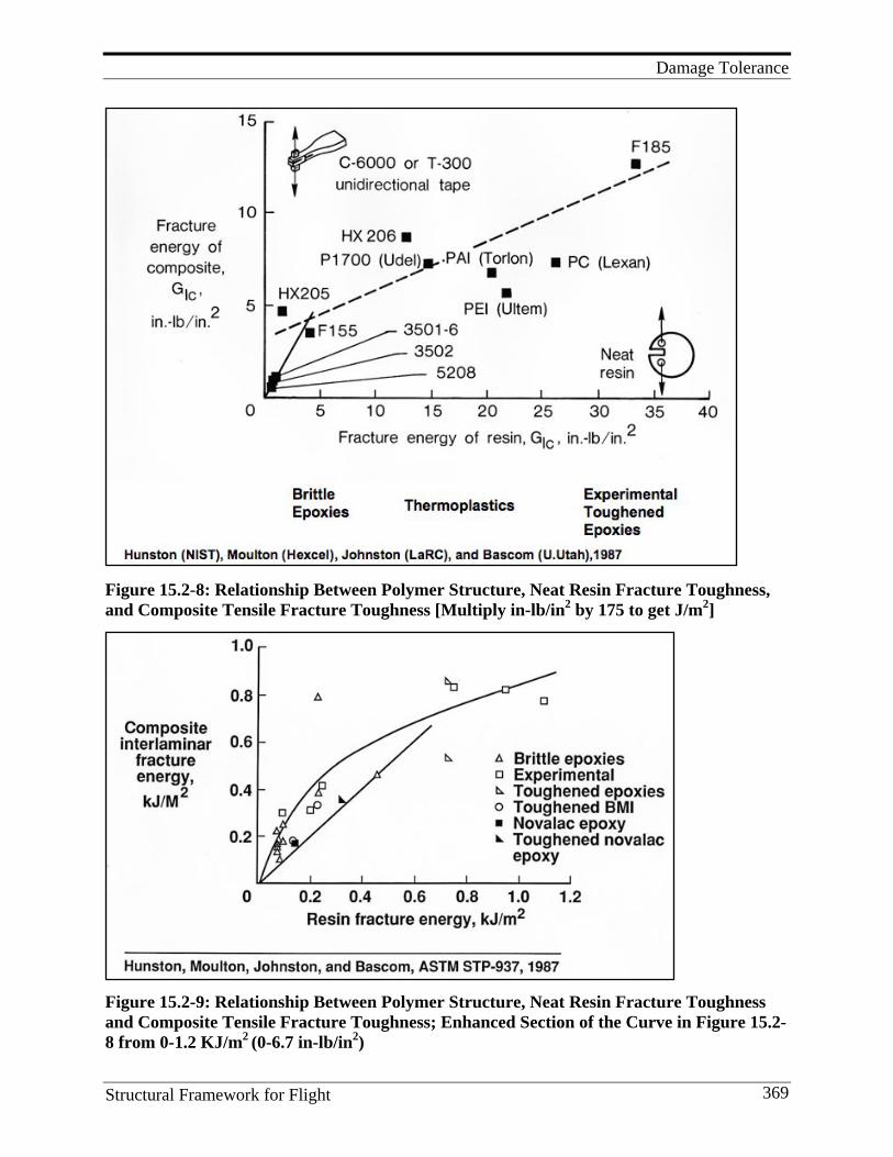
Damage Tolerance
Structural Framework for Flight 369
Figure 15.2-8: Relationship Between Polymer Structure, Neat Resin Fracture Toughness, and Composite Tensile Fracture Toughness [Multiply in-lb/in2 by 175 to get J/m2]
Figure 15.2-9: Relationship Between Polymer Structure, Neat Resin Fracture Toughness and Composite Tensile Fracture Toughness; Enhanced Section of the Curve in Figure 15.2-8 from 0-1.2 KJ/m2 (0-6.7 in-lb/in2)
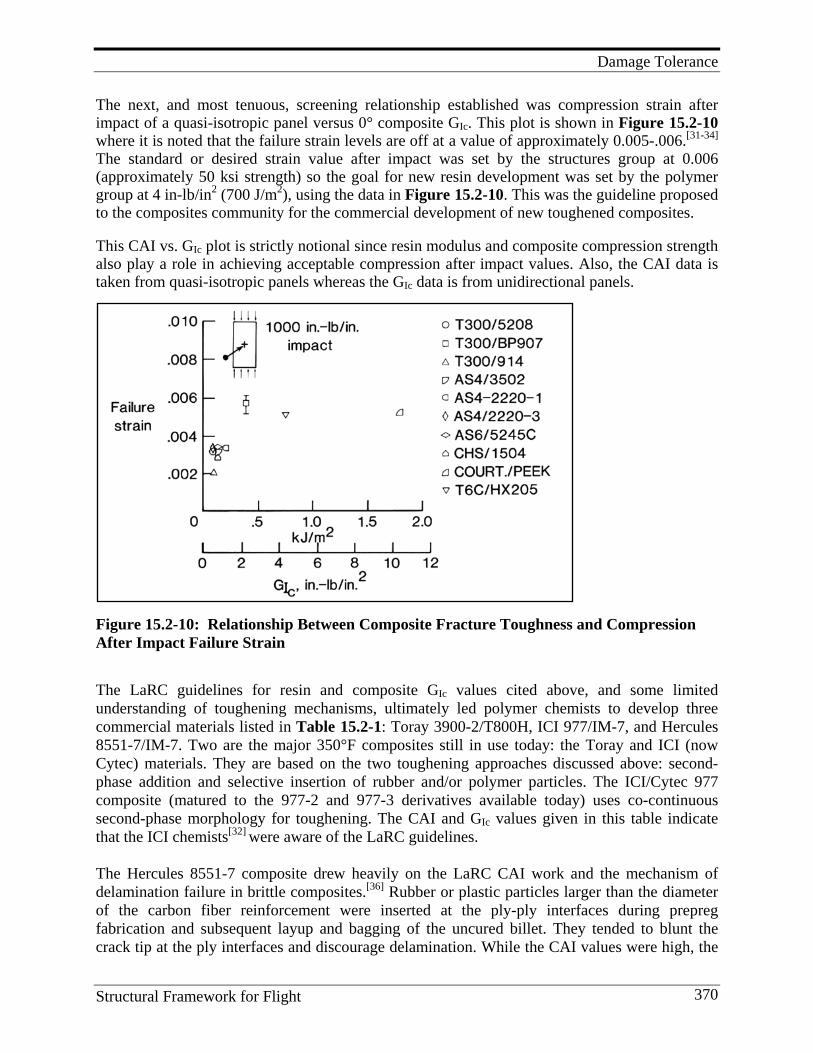
Damage Tolerance
Structural Framework for Flight 370
The next, and most tenuous, screening relationship established was compression strain after impact of a quasi-isotropic panel versus 0° composite GIc. This plot is shown in Figure 15.2-10 where it is noted that the failure strain levels are off at a value of approximately 0.005-.006.[31-34] The standard or desired strain value after impact was set by the structures group at 0.006 (approximately 50 ksi strength) so the goal for new resin development was set by the polymer group at 4 in-lb/in2 (700 J/m2), using the data in Figure 15.2-10. This was the guideline proposed to the composites community for the commercial development of new toughened composites. This CAI vs. GIc plot is strictly notional since resin modulus and composite compression strength also play a role in achieving acceptable compression after impact values. Also, the CAI data is taken from quasi-isotropic panels whereas the GIc data is from unidirectional panels.
Figure 15.2-10: Relationship Between Composite Fracture Toughness and Compression After Impact Failure Strain
The LaRC guidelines for resin and composite GIc values cited above, and some limited understanding of toughening mechanisms, ultimately led polymer chemists to develop three commercial materials listed in Table 15.2-1: Toray 3900-2/T800H, ICI 977/IM-7, and Hercules 8551-7/IM-7. Two are the major 350°F composites still in use today: the Toray and ICI (now Cytec) materials. They are based on the two toughening approaches discussed above: second- phase addition and selective insertion of rubber and/or polymer particles. The ICI/Cytec 977 composite (matured to the 977-2 and 977-3 derivatives available today) uses co-continuous second-phase morphology for toughening. The CAI and GIc values given in this table indicate that the ICI chemists[32] were aware of the LaRC guidelines. The Hercules 8551-7 composite drew heavily on the LaRC CAI work and the mechanism of delamination failure in brittle composites.[36] Rubber or plastic particles larger than the diameter of the carbon fiber reinforcement were inserted at the ply-ply interfaces during prepreg fabrication and subsequent layup and bagging of the uncured billet. They tended to blunt the crack tip at the ply interfaces and discourage delamination. While the CAI values were high, the

Damage Tolerance
Structural Framework for Flight 371
GIc values were lower simply because crack propagation in the DCB specimen would not always travel continuously at the ply interface but would wander into the resin which was only partially toughened by a small amount of a second soluble component such as a thermoplastic. Table 15.2-1: Commercial Toughened Composites and Their Toughness Properties
The more complex compression after impact, open-hole tension, and open-hole compression tests were added as part of the ACEE program at LaRC. This resulted in a widely circulated document, Standard Tests for Toughened Resin Composites, Revised Edition, which included procedures for conducting these three tests plus the DCB and edge delamination tests.[34]
15.2.2 Role of Resin Modulus; Desired Properties No discussion concerning matrix toughening can be made without considering the role of resin/matrix tensile modulus. Toughening of thermosets usually affects resin modulus negatively: as toughening increases, resin modulus decreases. In turn, composite compression strength is lowered. The relationship between composite compression strength and neat resin modulus is shown in Figure 15.2-11.[38] It is easily seen that the dependence is nearly linear; as one increases, so does the other. Table 15.2-2 nicely shows this trend for the values of four hypothetical neat resins, both at room temperature/dry and 180°F/wet. The desired RT/dry compression strength values for a IM-7-type carbon fiber-reinforced composite were usually cited to be in the 200 ksi range if the composite was of acceptable structural quality. The Boeing BMS-8-276 specification cited in Table 15.2-1 has a desired RT compressive strength of 200 ksi. From Table 15.2-2, this would require a neat resin tensile modulus of roughly 450-500 ksi. This value became a second goal for the development of new toughened commercial resins. Note that the three newly-developed, toughened commercial composites, cited in Table 15.2-1, had RT compressive strengths ranging from 216-252 ksi. As required, the toughening process in all three materials did not significantly lower composite compression strength.
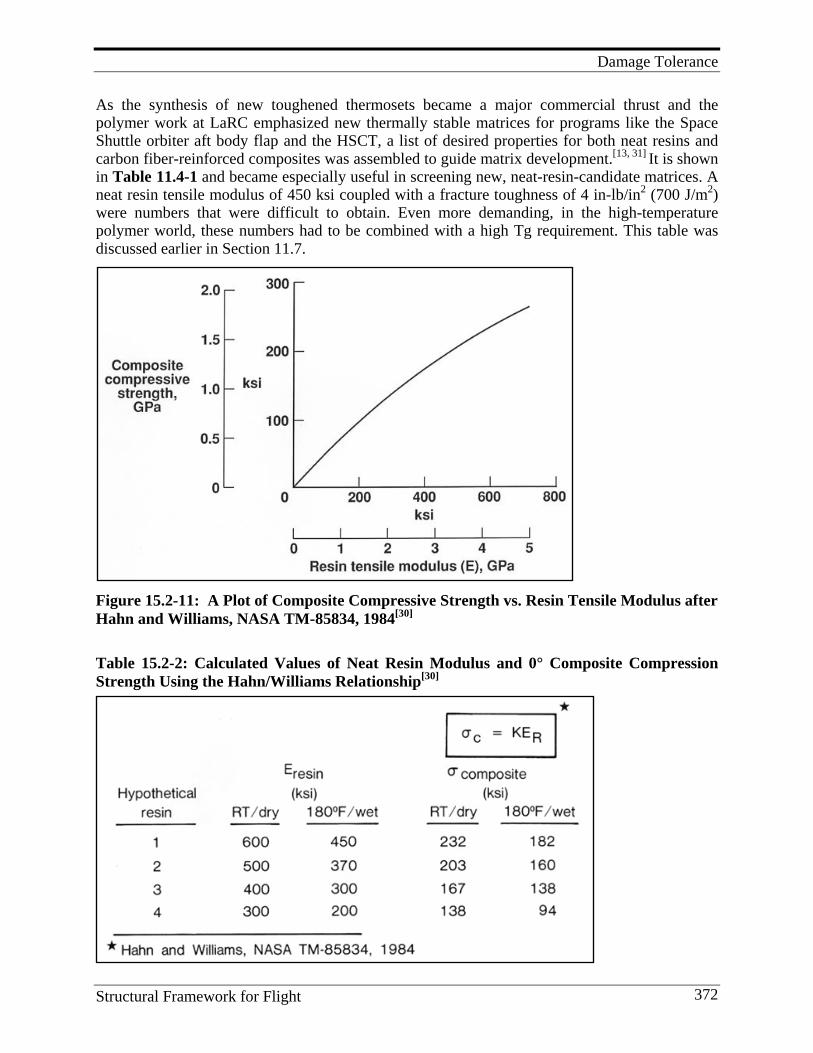
Damage Tolerance
Structural Framework for Flight 372
As the synthesis of new toughened thermosets became a major commercial thrust and the polymer work at LaRC emphasized new thermally stable matrices for programs like the Space Shuttle orbiter aft body flap and the HSCT, a list of desired properties for both neat resins and carbon fiber-reinforced composites was assembled to guide matrix development.[13, 31] It is shown in Table 11.4-1 and became especially useful in screening new, neat-resin-candidate matrices. A neat resin tensile modulus of 450 ksi coupled with a fracture toughness of 4 in-lb/in2 (700 J/m2) were numbers that were difficult to obtain. Even more demanding, in the high-temperature polymer world, these numbers had to be combined with a high Tg requirement. This table was discussed earlier in Section 11.7.
Figure 15.2-11: A Plot of Composite Compressive Strength vs. Resin Tensile Modulus after Hahn and Williams, NASA TM-85834, 1984[30]
Table 15.2-2: Calculated Values of Neat Resin Modulus and 0° Composite Compression Strength Using the Hahn/Williams Relationship[30]
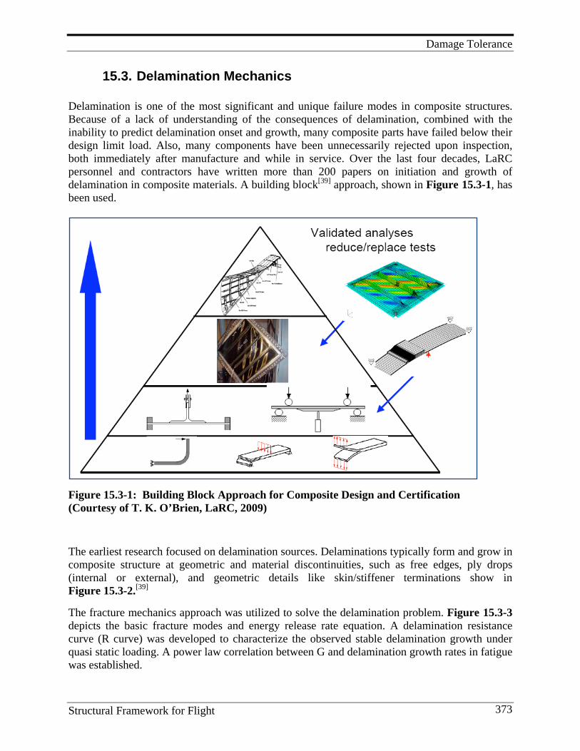
Damage Tolerance
Structural Framework for Flight 373
15.3. Delamination Mechanics Delamination is one of the most significant and unique failure modes in composite structures. Because of a lack of understanding of the consequences of delamination, combined with the inability to predict delamination onset and growth, many composite parts have failed below their design limit load. Also, many components have been unnecessarily rejected upon inspection, both immediately after manufacture and while in service. Over the last four decades, LaRC personnel and contractors have written more than 200 papers on initiation and growth of delamination in composite materials. A building block[39] approach, shown in Figure 15.3-1, has been used.
Figure 15.3-1: Building Block Approach for Composite Design and Certification (Courtesy of T. K. O’Brien, LaRC, 2009)
The earliest research focused on delamination sources. Delaminations typically form and grow in composite structure at geometric and material discontinuities, such as free edges, ply drops (internal or external), and geometric details like skin/stiffener terminations show in Figure 15.3-2.[39] The fracture mechanics approach was utilized to solve the delamination problem. Figure 15.3-3 depicts the basic fracture modes and energy release rate equation. A delamination resistance curve (R curve) was developed to characterize the observed stable delamination growth under quasi static loading. A power law correlation between G and delamination growth rates in fatigue was established.
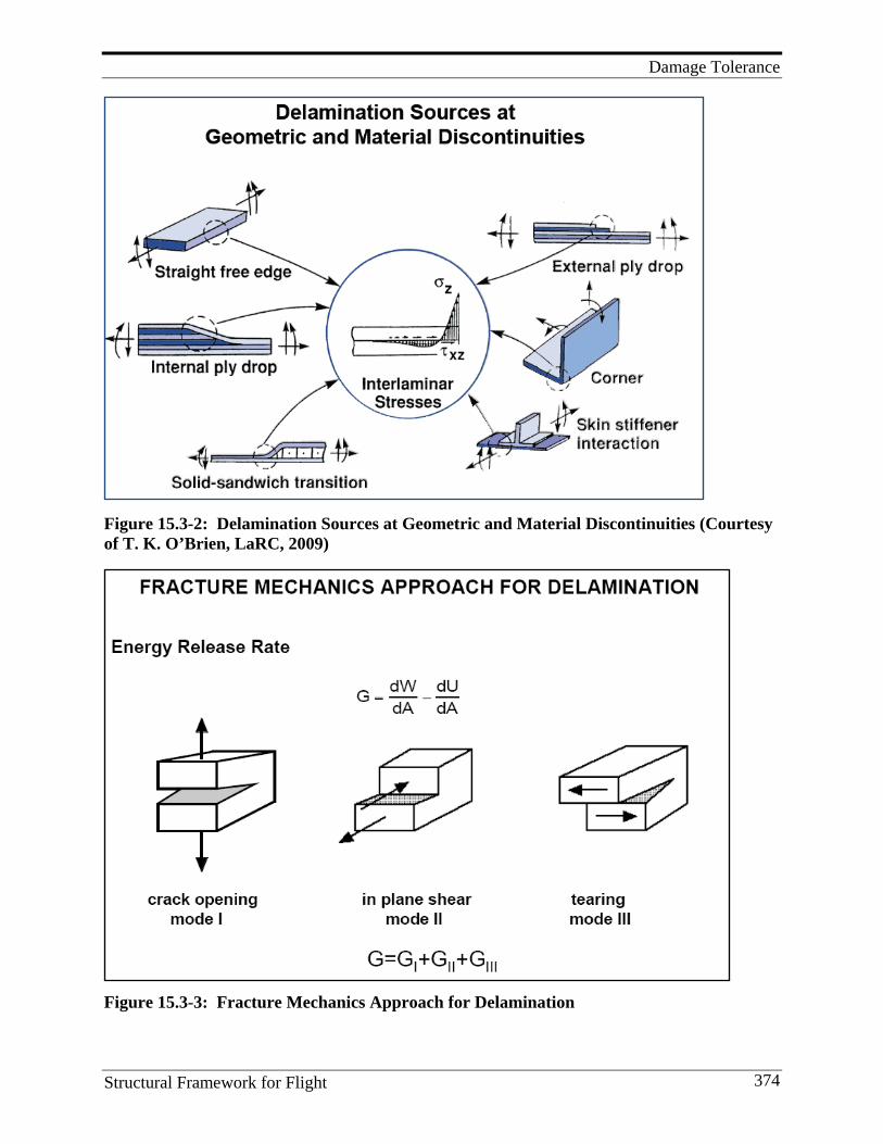
Damage Tolerance
Structural Framework for Flight 374
Figure 15.3-2: Delamination Sources at Geometric and Material Discontinuities (Courtesy of T. K. O’Brien, LaRC, 2009)
Figure 15.3-3: Fracture Mechanics Approach for Delamination
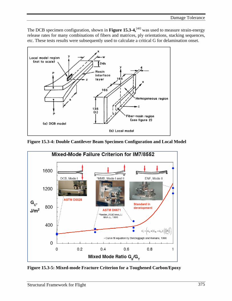
Damage Tolerance
Structural Framework for Flight 375
The DCB specimen configuration, shown in Figure 15.3-4,[40] was used to measure strain-energy release rates for many combinations of fibers and matrices, ply orientations, stacking sequences, etc. These tests results were subsequently used to calculate a critical G for delamination onset.
Figure 15.3-4: Double Cantilever Beam Specimen Configuration and Local Model
Figure 15.3-5: Mixed-mode Fracture Criterion for a Toughened Carbon/Epoxy
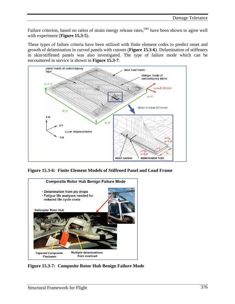
Damage Tolerance
Structural Framework for Flight 376
Failure criterion, based on ratios of strain energy release rates,[40] have been shown to agree well with experiment (Figure 15.3-5). These types of failure criteria have been utilized with finite element codes to predict onset and growth of delamination in curved panels with cutouts (Figure 15.3-6). Delamination of stiffeners in skin/stiffened panels was also investigated. The type of failure mode which can be encountered in service is shown in Figure 15.3-7.
Figure 15.3-6: Finite Element Models of Stiffened Panel and Load Frame
Figure 15.3-7: Composite Rotor Hub Benign Failure Mode
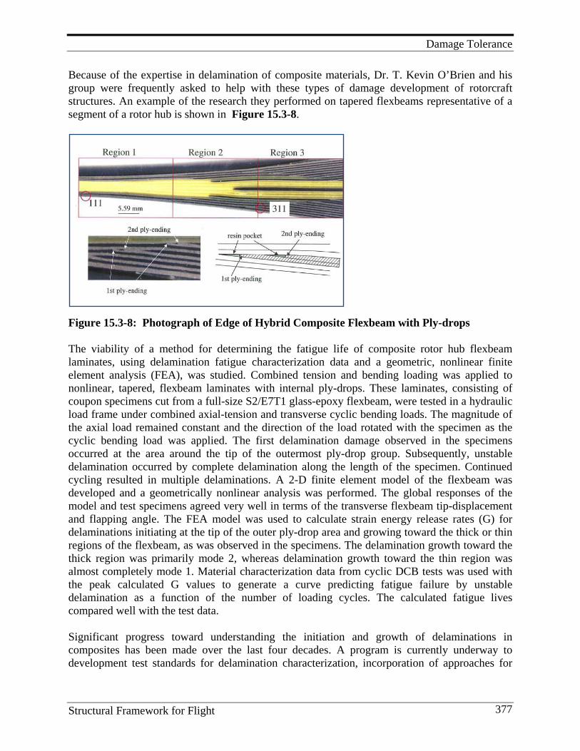
Damage Tolerance
Structural Framework for Flight 377
Because of the expertise in delamination of composite materials, Dr. T. Kevin O’Brien and his group were frequently asked to help with these types of damage development of rotorcraft structures. An example of the research they performed on tapered flexbeams representative of a segment of a rotor hub is shown in Figure 15.3-8.
Figure 15.3-8: Photograph of Edge of Hybrid Composite Flexbeam with Ply-drops The viability of a method for determining the fatigue life of composite rotor hub flexbeam laminates, using delamination fatigue characterization data and a geometric, nonlinear finite element analysis (FEA), was studied. Combined tension and bending loading was applied to nonlinear, tapered, flexbeam laminates with internal ply-drops. These laminates, consisting of coupon specimens cut from a full-size S2/E7T1 glass-epoxy flexbeam, were tested in a hydraulic load frame under combined axial-tension and transverse cyclic bending loads. The magnitude of the axial load remained constant and the direction of the load rotated with the specimen as the cyclic bending load was applied. The first delamination damage observed in the specimens occurred at the area around the tip of the outermost ply-drop group. Subsequently, unstable delamination occurred by complete delamination along the length of the specimen. Continued cycling resulted in multiple delaminations. A 2-D finite element model of the flexbeam was developed and a geometrically nonlinear analysis was performed. The global responses of the model and test specimens agreed very well in terms of the transverse flexbeam tip-displacement and flapping angle. The FEA model was used to calculate strain energy release rates (G) for delaminations initiating at the tip of the outer ply-drop area and growing toward the thick or thin regions of the flexbeam, as was observed in the specimens. The delamination growth toward the thick region was primarily mode 2, whereas delamination growth toward the thin region was almost completely mode 1. Material characterization data from cyclic DCB tests was used with the peak calculated G values to generate a curve predicting fatigue failure by unstable delamination as a function of the number of loading cycles. The calculated fatigue lives compared well with the test data. Significant progress toward understanding the initiation and growth of delaminations in composites has been made over the last four decades. A program is currently underway to development test standards for delamination characterization, incorporation of approaches for
Damage Tolerance
Structural Framework for Flight 378
modeling delamination in commercial finite element codes, and efforts to mature the technology for use in design handbooks and certification documents. Lessons Learned
1. Subcritical crack growth and inelastic materials behavior, responsible for the observed nonlinearities, are highly rate-dependent phenomena with high rates generally leading to linear elastic response.
2. All configurations of the EDT test were found to be useful for ranking the delamination resistance of composites with different matrix systems.
3. Surface properties of the graphite fiber were shown to be significant. Critical strain energy release rates for two different fibers having similar nominal tensile properties differed by 30-60%.
4. A threshold value of the maximum cyclic G-II below which no delamination occurred after one million cycles was identified for a graphite epoxy, a glass epoxy, and graphite thermoplastic.
5. The failure response of the tough thermoplastic composite could be modeled well with the bilinear criterion but could also be modeled with the more simple linear failure criterion.
6. The good correlations of the results demonstrated the effectiveness of the shell/3-D modeling technique for the investigation of skin/stiffener separation due to delamination in the adherents.
7. Delamination resistance is a complicated function of both time and temperature with the effect of temperature either increasing or decreasing the fracture toughness depending on the time scale.
8. Results from the study of Z-pins to reduce onset of delamination, indicated that increasing pin density was more detrimental to in-plane compression strength than increasing pin diameter.
9. Provided insight on a dominate failure mode for composites that is normally unimportant for metal structures.
10. Developed industry-accepted test standards to measure critical parameters required to measure fracture toughness.
11. Developed analyses to predict the delamination initiation and growth in composite laminates.
12. Developed and validated analyses to predict the delamination initiation and growth in composite components such as skin-stiffened panels.
Future Direction NASA Langley is leading a five-year, two-phase effort in the U.S. to develop a fatigue life prediction methodology for composite delamination using fracture mechanics. Research being performed to this end will be reviewed. Emphasis will be placed on the development of test standards for delamination characterization, incorporation of approaches for modeling delamination in commercial finite element codes, and efforts to mature the technology for use in design handbooks and certification documents.
Damage Tolerance
Structural Framework for Flight 379
Program Significance Interlaminar fracture mechanics has proven useful for characterizing the onset and growth of delaminations in composites. Substantial progress has been made in development of failure criterion and use of global/local modeling to predict damage growth and failure. Key Personnel Managers and researchers included: Charles Harris, Kevin O’Brien, Ivatury Raju, Gretchen Murri, Damodar Ambur, Clarence Poe, John Crews, plus numerous others.
15.4. Progressive Failure Analyses Methodology Progressive failure occurs when a structure experiences a significant amount of damage prior to final failure. The life of the structure is, therefore, not accurately represented by the point at which failure initiates, rather, failure progresses from initiation to final failure in some way. Clearly, in order to predict the life of such a structure, a methodology that tracks the failure progression is needed. Many NASA Langley researchers have contributed to this technology supporting current-day efforts to develop progressive failure analysis methodologies for predicting failure in composite structures. A search of the literature shows significant papers authored or co-authored by: Jim Starnes, Damodar Ambur, Charles E. Harris, Richard Young, Kevin O’Brien, Buddy Poe, Tim Coats, David McGowan, Dawn Jegley, Mark Hilburger, Mike Nemeth, David W. Sleight, Norm Knight, Carlos G. Davila, Vinay Goyal, Eric Johnson, and many others.
15.5. Lessons Learned and Future Directions Lessons Learned
1. Basic R&D at LaRC on the effect of impact on compression properties of composites, and on understanding the relationship between CAI and resin and composite fracture-toughness, supported the commercial development of the toughened composites in use today.
2. This high risk, basic R&D was managed and supported because it met critical application needs down the road and was exploited by the commercial aerospace community even when composites were not considered as serious replacements for primary structure. It was critical that the structures and materials research scientists were given the freedom to pursue risky solutions to problems of serious import even though the application of those solutions could have been in the far future.
3. The use of professional society meetings such as SAMPE via professional talks, printed papers (refereed or not), and informal discussions helped spread the word about the LaRC guidelines and research on toughening resins. Use of NASA personnel as consultants (paid or unpaid) was a very useful tool for implanting and promoting LaRC research into commercial labs.
Damage Tolerance
Structural Framework for Flight 380
4. Goals, guidelines (e.g., specific numbers), and measuring devices for making those guidelines are part of the research process.
5. Patents for the research developed at LaRC in this area would have been counterproductive to the development of toughened composites.
Future Directions
1. More requirements are placed on toughened composites as new applications emerge such as cryogenic fuel tanks, large aerospace structures, space-orbiting components, and lunar habitats. Composite materials are enabling if these applications are going to be utilized to the fullest. The composite requirements include:
- microcrack resistance from cryo to elevate temperature - non-autoclave processing - resistance to space radiation, both galactic and solar - operations at temperatures higher than are now in use Most likely, at the same time, toughness must be maintained!
2. Other approaches to composite toughening should be explored, including insertion of pins, rods, fibers, and other stiff materials that would prevent or discourage delamination, excluding textile approaches.
3. Develop self-healing technology to the point that it can be applied to real-world composite applications.
4. Develop Computational Chemistry technology to the point where an understanding exists between fracture energy and molecular polymer chemistry. This would be the ultimate screening tool; the polymer structure of a toughened resin could be predicted without the need to synthesize that polymer. Conversely, the fracture energy of a theoretical polymer structure could be predicted. These computational skills should also be extended to predict other more classical polymer properties.
References
1. Ilcewicz, L. 2006. Composite Damage to Tolerance and Maintenance Issues. Paper presented at FAA Damage Tolerance and maintenance workshop, Chicago, IL.
2. Rhodes, M. D., J. G. Williams, and J. H. Starnes, Jr. 1977. Effect of Low-velocity Impact Damage On the Compressive Strength of Graphite-epoxy Hat-stiffened Panels. (NASA TN D-8411).
3. Rhodes, M. D., J. G. Williams, and J. H. Starnes, Jr. 1979. Low-velocity Impact Damage in Graphite-fiber-reinforced Epoxy Laminates. 34th Annual Conference--Reinforcing the Future. SPI, New York, 20D1-20D10.
4. Rhodes, M. D., and J. G. Williams. 1984. Concepts for Improving the Damage Tolerance of Composite Compression Panels. Fifth Conference of Fibrous Composites in Structural Design (NASA TM 85748).
5. Williams, J. G., and M. D. Rhodes. 1982. Effect of Resin on Impact Damage Tolerance of Graphite/Epoxy Laminates. Composite Materials: Testing and Design (Sixth Conf.), ed. I. M. Daniel 450-480. (ASTM STP 787).
6. Starnes, J. H., Jr., and J. G. Williams. 1983. Failure Characteristics of Graphite-Epoxy Structural Components Loaded in Compression. Mechanics of Composite Materials: Recent Advances, Proceedings of the Symposium 283-306. New York and Oxford, Pergamon Press.
7. Sohi, O. M., H. T. Hahn, and J. G. Williams. 1986. The Effect of Resin Toughness and Modulus on Compressive Failure Modes of Quasi-Isotropic Graphite/Epoxy Laminates. (NASA TM-87604). Also in ASTM, Philadelphia, PA, 1987, pp. 37-60.
Damage Tolerance
Structural Framework for Flight 381
8. Johnston, N. J., K. Srinivasan, and R. H. Pater. 1992. Toughening of PMR Composites by Thermoplastic Semi-interpenetrating Networks. International SAMPE Symposium and Exhibition; Science of Advanced Materials and Process Engineering Series 37, 690-704. Unpublished research at American Cyanamid Company and other commercial laboratories.
9. Dow, M. B., and D. L. Smith. 1988. Properties of Two Composite Materials Made of Toughened Epoxy Resin and High-strain Graphite Fiber. (NASA TP 2826).
10. Yee, A. F., and R. A. Pearson. 1983. Toughening Mechanisms in Elastomer-Modified Epoxy Resins-Part 1 Mechanical Studies. (NASA CR-3718).
11. Yee, A. F., and R. A. Pearson. 1986. Toughening Mechanisms in Elastomer-Modified Epoxy Resins-Part 1 Mechanical Studies. J. Mat. Sci. 21:2462-2474.
12. Pearson, R. A., and A. F. Yee. 1986. Toughening Mechanisms in Elastomer-modified Epoxy Resins-Part 2 Microscopy Studies. J. Mat. Sci., 21:2475-2488.
13. Pearson, R. A., and A. F. Yee. 1983. The Effect of Cross-link Density on the Toughening Mechanism of Elastomer-modified Epoxies. Polymer Materials Science and Engineering 19:316;
14. Pearson, R. A., and A. F. Yee. 1986. Toughening Mechanisms in Elastomer-Modified Epoxy Resins-Part 3 The Effect of Cross-link Density. J. Mat. Sci., 21:2571-2580.
15. Unpublished results: Johnston, N. J., NASA Langley Research Center, 1984-1995. 16. Hinkley, J. A. 1986. Small Compact Tension Specimens For Polymer Toughness Screening. J. Appl.
Polym. Sci. 32:5653-5655. 17. Hunston, D. L. 1984. Composite Interlaminar Fracture: Effect of Matrix Fracture Energy. Composites
Technology Review 6 (4): 176-180. 18. Johnston, N. J., T. W. Towell, and P. M. Hergenrother. 1991. Physical and Mechanical Properties of High-
performance Thermoplastic Polymers and Their Composites. In Thermoplastic Composite Materials, ed. Carlsson, L. A., 27-71. Elsevier Scientific Publishing Co.
19. Hunston, D. L., R. J. Moulton, N. J. Johnston, and W. D. Bascom. 1987. Matrix Resin Effects in Composite Delamination: Mode I Fracture Aspects. ASTM STP 937:74-94.
20. Hunston, D. L., and W. D. Bascom. 1983. Effect of Lay-Up, Temperature, and Loading Rate in Double Cantilever Beam Tests of Interlaminar Crack Growth. Composite Technology Review 6 (4): 118-119.
21. Bascom, W. D., G. W. Bullman, D. L. Hunston, and R. M. Jensen. 1984. The Width Tappered DCB for Interlaminar Fracture Testing. 29th National SAMPE Symposium and Exhibition. Science of Advanced Materials and Process Engineering Series 29:970-978.
22. O’Brien, T. K., N. J. Johnston, D. H. Morris, and R. A. Simonds. 1982. A Simple Test for the Interlaminar Fracture Toughness of Graphite-Epoxy Laminates. 27th National SAMPE Symposium and Exhibition. Science of Advanced Materials and Process Engineering Series 27:401-415. Symposium best paper award.
23. O’Brien, T. K., N. J. Johnston, D. H. Morris, and R. A. Simonds. 1982. A Simple Test for the Interlaminar Fracture Toughness of Graphite-Epoxy Laminates. SAMPE Journal 18 (4): 8-15.
24. Johnston, N. J., T. K. O’Brien, D. H. Morris, and R. A. Simonds. 1983. Interlaminar Fracture Toughness and Fracture Toughness of Composites II. Refinement of the Edge Delamination Test and Application to Thermoplastics. 28th National SAMPE Symposium and Exhibition. Science of Advanced Materials and Process Engineering Series 28:502-517.
25. O’Brien, T. K., N. J. Johnston, D. H. Morris, and R. A. Simonds. 1983. Determination of Interlaminar Fracture Toughness and Fracture Mode Dependence of Composites Using the Edge Delamination Test. International Conference on Testing, Evaluation, and Quality Control of Composites, University of Surrey, Guildford, England. Proceedings, ed. T. Feest, 222-232. Kent, England: Butterworth Scientific Ltd. (NASA TM857-28).
26. O’Brien, T. K., N. J. Johnston, I. S. Raju, D. H. Morris, and R. A. Simonds. 1985. Comparisons of Various Configurations of the Edge Delamination Test for Interlaminar Fracture Toughness. ASTM Symposium on Toughened Composites. (NASA TM 86433) (USAAVSCOM TM 85-B-3).
27. O’Brien, T. K., N. J. Johnston, I. S. Raju, D. H. Morris, and R. A. Simonds. 1987. Comparisons of Various Configurations of the Edge Delamination Test for Interlaminar Fracture Toughness. (ASTM STP 937) 199-221.
28. Hinkley, J. A., N. J. Johnston, and T. K. O'Brien. 1987. Interlaminar Fracture Toughness of Thermoplastic Composites. Paper presented at ASTM Symposium on Advances in Thermoplastics Matrix Composite Materials. (NASA TM 100532), (AVSCOM TM 88-B-002).
29. Hinkley, J. A., N. J. Johnston, and T. K. O’Brien. 1989. Interlaminar Fracture Toughness of Thermoplastic Composites. Advances in Thermoplastic Matrix Composite Materials, (ASTM STP 1044) 251-263.
Damage Tolerance
Structural Framework for Flight 382
30. Johnston, N. J. 1984. Synthesis and Toughness Properties of Resins and Composites. Selected NASA Research in Composite Materials and Structures, ACEE Composite Structures Technology Conference (NASA CP-2321) 75-95.
31. Hinkley, J. A., N. J. Johnston and W. D. Bascom. Contract NAS1-17918 to Hercules Aerospace Division, Hercules, Inc. and grant NAG1-706 to the University of Utah. See references 28 and 29 of this work for some results.
32. Bascom, W. D. 1987. Interfacial Adhesion of Carbon Fibers. (NASA CR 178306). 33. Bascom, W. D., D. J. Boll, B. Fuller, and P. Phillips. 1987. Fractography of the Interlaminar Fracture of
Carbon-Fiber Epoxy Composites. (ASTM STP 937) 131. 34. Johnston, N. J., T. W. Towell, and P. M. Hergenrother. 1991. Physical and Mechanical Properties of High-
performance Thermoplastic Polymers and Their Composites. Thermoplastic Composite Materials, ed. L. A. Carlsson, 27-71. Elsevier Scientific Publishing Co.
35. Anon. 1987. The Place for Thermoplastic Composites In Structural Components. National Materials Advisory Board (Report No. NMAB-434).
36. St. Clair, T. L., N. J. Johnston, and R. M. Baucom. 1988. High-performance Composites Research at NASA Langley. Paper presented at the Society of Plastics Engineers and SAE 1988 International Congress & Exposition. (SAE Paper No. 880110). In SAE SP-748, Polymer Composites for Automotive Applications, 1-19 (NASA TM-100518).
37. Williams, J. G., T. K. O’Brien, and A. J. Chapman. 1984. (NASA CP-2321) 51-73. 38. Johnston, N. J., and P. M. Hergenrother. 1987. High-performance Thermoplastics: A Review of Neat Resin
and Composite Properties. International SAMPE Symposium and Exhibition. Science of Advanced Materials and Process Engineering Series 32:1400-1412. Symposium best paper award. (NASA TM-89104).
39. Unpublished discussions with P. T. McGrail, ICI Laboratories, Wilton, England, 1987. 40. MacKinnon, A. J., S. D. Jenkins, P. T. McGrail, and R. A. Pethrick. 1992. A Dielectric, Mechanical,
Rheological, and Electron Microscopy Study of Cure and Properties of a Thermoplastic-Modified Epoxy Resin. Macromolecules 25:3492-3499.
41. Unpublished discussions with Hercules’ chemists, NASA Langley Research Center, Hampton, VA, 1987. 42. Anon. 1983. Standard Tests for Toughened Resin Composites, Revised Edition. (NASA Reference
publication 1092). 43. Hahn, H. T., and J. G., Williams. 1986. Compression Failure Mechanisms in Unidirectional Composites.
Composite Materials Testing and Design (Seventh Conference), (ASTM STP 893) ed. J. M. Whitney 115-139. Philadelphia, PA: American Society for Testing and Materials.
44. O’Brien, T. K. 2009. Development of a Composite Delamination Fatigue Life Prediction Methodology. Paper presented at NATO RTO AVT-164 Workshop on Support of Composite Systems, Bonn, Germany.
45. O’Brien, T. K.. 2008. Fatigue Life Prediction Methodology for Composite Delamination Using Fracture Mechanics. Paper presented at Mechanics of Composite Materials and Structures Session, VirginiaTech. http://www.esm.vt.edu/ESM100_Presentations /ESM100_OBrien.pdf
46. Murri, G. B., J. R. Schaff, and A. Dobyns. 2001. Fatigue Life Methodology for Tapered Composite Flexbeam Laminates. Paper presented at American Helicopter Society Forum, Washington, DC.
47. Goyal, V. K., N. Jaunky, E. R. Johnson, and D. Ambur. 2002. Intralaminar and Interlaminar Progressive Failure Analysis of Composite Panels with Circular Cutouts. Paper presented at 43rd AIAA/ASME/ASCE/AHS/ASC Structures, Structural Dynamics and Materials,.
48. Krueger, R. 2006. Fracture Mechanics for Composites: State-of-the-Art and Challenges. Paper presented at NAFEMS Nordic Seminar, Copenhagen, Denmark.
49. O’Brien, T. K., and R. Krueger. 2005. Influence of Compression and Shear on the Strength of Composite Laminates with Z-Pinned Reinforcement. (NASA/TM-2005-213768).
50. Krueger, R., T. K. O’Brien, and P. J. Minguet. 2002. Application of the Shell/3-D Modeling Technique for the Analysis of Skin-Stiffener Debond Specimens. Paper presented at American Society for Composites 2002: 17th Annual Technical Conference.
Materials and Structural Mechanics
Structural Framework for Flight 383
16. M AT E R I A L S A N D S T R U C T U R A L M E C H A N I C S
16.1. Historical Perspective of Composite Failure Analyses Introduction Ultra-high fidelity predictions of failure initiation in composite materials and structures have long been the goal of designers in this emerging field. From the invention of high-strength fibers in the early 1960s, the evolution of high-performance composite materials and their adaptation in military and civilian applications has demanded design methodologies for prediction of perform-ance. The earliest failure predictions relied upon maximum strain theory wherein predictions of matrix-cracking transverse to the fiber direction was deemed appropriate for determination of failure initiation. This approach was both simple and consistent with the computational power of the day. Yet, as was pointed out by the critics of this approach, transverse cracks existed as birth defects in conventional multiaxial laminates due to thermal residual stresses. The next level of sophistication was the development of multiaxial failure theories for composite materials that reflected strength reductions and enhancements that occur in the presence of a multiaxial state of stress. Here, the heterogeneous medium consisting of collimated, high-strength fibers contained in a continuous, polymeric matrix was replaced by a homogeneous medium with equivalent elastic properties determined by micromechanical analysis or test. The multiaxial failure criteria were then exercised for a stress state within the equivalent anisotropic medium. It is noteworthy that the body of work in the area of multiaxial failure criteria for advanced composite materials carried out over the past fifty years has failed to provide a unified and broadly accepted approach. This may be due in part to the fact that the stress state described in the multiaxial failure theories exists neither in the fiber, nor in the matrix phase of these materials. That is, it is unlikely that the prediction of the failure of a heterogeneous medium will be achieved by the study of a replacement medium of equivalent anisotropic properties. Rather, it is more likely important to examine the behavior of each of the phases and their interfaces. Why then has the engineering and scientific communities ignored this obvious consideration for more than half a decade? The answer lies in the availability of the necessary computational power. In order to make this point clear, it is necessary to consider the evolution of composite mechanics beginning with micromechanics. The study of composite materials began with the goal of prediction of the effective properties of heterogeneous materials from the properties and volume fractions of the constituencies. The field of micromechanics was established with this goal in mind and its power to relate composition and property led it to early prominence because it offered the chance to design materials to meet specific requirements and thereby provide more optimum solutions. Yet early micromechanics
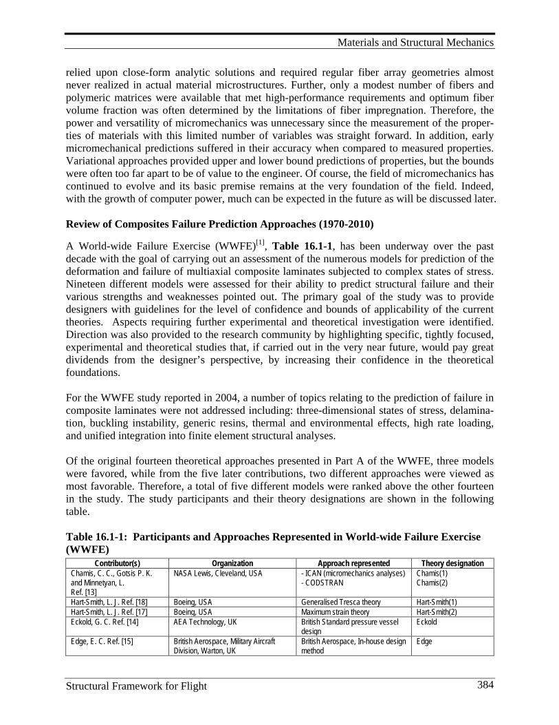
Materials and Structural Mechanics
Structural Framework for Flight 384
relied upon close-form analytic solutions and required regular fiber array geometries almost never realized in actual material microstructures. Further, only a modest number of fibers and polymeric matrices were available that met high-performance requirements and optimum fiber volume fraction was often determined by the limitations of fiber impregnation. Therefore, the power and versatility of micromechanics was unnecessary since the measurement of the proper-ties of materials with this limited number of variables was straight forward. In addition, early micromechanical predictions suffered in their accuracy when compared to measured properties. Variational approaches provided upper and lower bound predictions of properties, but the bounds were often too far apart to be of value to the engineer. Of course, the field of micromechanics has continued to evolve and its basic premise remains at the very foundation of the field. Indeed, with the growth of computer power, much can be expected in the future as will be discussed later. Review of Composites Failure Prediction Approaches (1970-2010) A World-wide Failure Exercise (WWFE)[1], Table 16.1-1, has been underway over the past decade with the goal of carrying out an assessment of the numerous models for prediction of the deformation and failure of multiaxial composite laminates subjected to complex states of stress. Nineteen different models were assessed for their ability to predict structural failure and their various strengths and weaknesses pointed out. The primary goal of the study was to provide designers with guidelines for the level of confidence and bounds of applicability of the current theories. Aspects requiring further experimental and theoretical investigation were identified. Direction was also provided to the research community by highlighting specific, tightly focused, experimental and theoretical studies that, if carried out in the very near future, would pay great dividends from the designer’s perspective, by increasing their confidence in the theoretical foundations. For the WWFE study reported in 2004, a number of topics relating to the prediction of failure in composite laminates were not addressed including: three-dimensional states of stress, delamina-tion, buckling instability, generic resins, thermal and environmental effects, high rate loading, and unified integration into finite element structural analyses. Of the original fourteen theoretical approaches presented in Part A of the WWFE, three models were favored, while from the five later contributions, two different approaches were viewed as most favorable. Therefore, a total of five different models were ranked above the other fourteen in the study. The study participants and their theory designations are shown in the following table. Table 16.1-1: Participants and Approaches Represented in World-wide Failure Exercise (WWFE)
Contributor(s) Organization Approach represented Theory designation Chamis, C. C., Gotsis P. K. and Minnetyan, L. Ref. [13]
NASA Lewis, Cleveland, USA - ICAN (micromechanics analyses) - CODSTRAN
Chamis(1) Chamis(2)
Hart-Smith, L. J. Ref. [18] Boeing, USA Generalised Tresca theory Hart-Smith(1) Hart-Smith, L. J. Ref. [17] Boeing, USA Maximum strain theory Hart-Smith(2) Eckold, G. C. Ref. [14] AEA Technology, UK British Standard pressure vessel
design Eckold
Edge, E. C. Ref. [15] British Aerospace, Military Aircraft Division, Warton, UK
British Aerospace, In-house design method
Edge
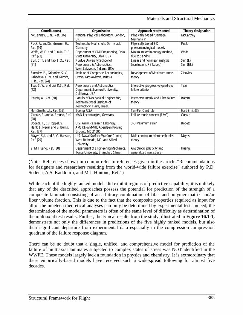
Materials and Structural Mechanics
Structural Framework for Flight 385
Contributor(s) Organization Approach represented Theory designation McCartney, L. N., Ref. [16] National Physical Laboratory, London,
UK Physically based “Damage Mechanics”
McCartney
Puck, A. and Schűrmann, H., Ref. [19]
Technische Hochchule, Darmstadt, Germany
Physically based 3-D phenomenological models
Puck
Wolfe, W. E. and Butalia, T. S. Ref. [23]
Department of Civil Engineering, Ohio State University, Ohio, USA
Maximum strain energy method, due to Sandhu
Wolfe
Sun, C. T. and Tao, J. X., Ref. [21]
Purdue University School of Aeronautics & Astronautics, West Lafayette, Indiana, USA
Linear and nonlinear analysis (nonlinear is FE based)
Sun (L) Sun (NL)
Zinoviev, P., Grigoriev, S. V., Labedeva, O. V. and Tairova, L. R., Ref. [24]
Institute of Composite Technologies, Orevo, Moskovkaya, Russia
Development of Maximum stress theory
Zinoviev
Tsai, S. W. and Liu, K.S., Ref. [22]
Aeronautics and Astronautics Department, Stanford University, California, USA
Interactive progressive quadratic failure criterion
Tsai
Rotem, A., Ref. [20] Faculty of Mechanical Engineering, Technion-Israel, Institute of Technology, Haifa, Israel.
Interactive matrix and Fibre failure theory
Rotem
Hart-Smith, L.J., Ref. [26] Boeing, USA Ten-Per-Cent rule Hart-Smith(3) Cuntze, R. and A. Freund, Ref. [28]
MAN Technologies, Germany Failure mode concept (FMC) Cuntze
Bogetti, T., C. Hoppel, V. Harik, J. Newill and B. Burns, Ref. [27]
U.S. Army Research Labortory, AMSRL-WM-MB, Aberdeen Proving Ground, MD 21005
3-D Maximum strain Bogetti
Mayes, S.J. and A. C. Hansen, Ref. [29]
U.S. Naval Surface Warfare Center, West Bethesda, MD, and Alfred University
Multi-continuum micromechanics theory
Mayes
Z. M. Huang, Ref. [30] Department of Engineering Mechanics, Tongji University, Shanghai, China
Anisotropic plasticity and generalized max stress
Huang
(Note: References shown in column refer to references given in the article “Recommendations for designers and researchers resulting from the world-wide failure exercise” authored by P.D. Sodena, A.S. Kaddourb, and M.J. Hintonc, Ref.1) While each of the highly ranked models did exhibit regions of predictive capability, it is unlikely that any of the described approaches possess the potential for prediction of the strength of a composite laminate consisting of an arbitrary combination of fiber and polymer matrix and/or fiber volume fraction. This is due to the fact that the composite properties required as input for all of the nineteen theoretical analyses can only be determined by experimental test. Indeed, the determination of the model parameters is often of the same level of difficulty as determination of the multiaxial test results. Further, the typical results from the study, illustrated in Figure 16.1-1, demonstrate not only the differences in predictions of the five highly ranked models, but also their significant departure from experimental data especially in the compression-compression quadrant of the failure response diagram. There can be no doubt that a single, unified, and comprehensive model for prediction of the failure of multiaxial laminates subjected to complex states of stress was NOT identified in the WWFE. These models largely lack a foundation in physics and chemistry. It is extraordinary that these empirically-based models have received such a wide-spread following for almost five decades.
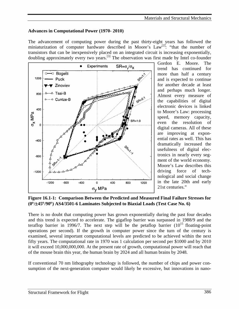
Materials and Structural Mechanics
Structural Framework for Flight 386
Advances in Computational Power (1970- 2010)
The advancement of computing power during the past thirty-eight years has followed the miniaturization of computer hardware described in Moore’s Law[2]: “that the number of transistors that can be inexpensively placed on an integrated circuit is increasing exponentially, doubling approximately every two years.[3] The observation was first made by Intel co-founder
Gordon E. Moore. The trend has continued for more than half a century and is expected to continue for another decade at least and perhaps much longer. Almost every measure of the capabilities of digital electronic devices is linked to Moore’s Law: processing speed, memory capacity, even the resolution of digital cameras. All of these are improving at expon-ential rates as well. This has dramatically increased the usefulness of digital elec-tronics in nearly every seg-ment of the world economy. Moore’s Law describes this driving force of tech-nological and social change in the late 20th and early 21st centuries.”
Figure 16.1-1: Comparison Between the Predicted and Measured Final Failure Stresses for (0°/±45°/90°) AS4/3501-6 Laminates Subjected to Biaxial Loads (Test Case No. 6)
There is no doubt that computing power has grown exponentially during the past four decades and this trend is expected to accelerate. The gigaflop barrier was surpassed in 1988/9 and the teraflop barrier in 1996/7. The next step will be the petaflop barrier (1015 floating-point operations per second). If the growth in computer power since the turn of the century is examined, several important computational levels are predicted to be achieved within the next fifty years. The computational rate in 1970 was 1 calculation per second per $1000 and by 2010 it will exceed 10,000,000,000. At the present rate of growth, computational power will reach that of the mouse brain this year, the human brain by 2024 and all human brains by 2048.
If conventional 70 nm lithography technology is followed, the number of chips and power con-sumption of the next-generation computer would likely be excessive, but innovations in nano-
Materials and Structural Mechanics
Structural Framework for Flight 387
technology and nanostructured novel materials, such as carbon nanotubes, to replace transistors and diodes, and quantum mechanics offer the potential for sustained growth in computing power.
Clearly the growth of computational power available to the engineer and scientist for modeling advanced composite materials systems during the period 1970 to the present has changed the fidelity of analytical methods. An appropriate analogy is the difference between the resolution of the optical and electron microscopes. In 1970 one of the authors observed an early finite element analysis wherein the airframe of the F-111 aircraft was modeled with a 5,000 degree-of-freedom system and the computations carried out by an IBM 360 computer with computation time of one week. Today that same simulation would be carried out on the personal computer with computational time of a few seconds. Conventional FEA models contain millions of degrees of freedom with modeling of multiple physical phenomena.
Advances in Finite Element Analysis (1970-2010)
Solutions of large scale problems are now more feasible than in 1970. Today’s computer systems can provide five trillion operations per second and store a thousand trillion bytes of data. As discussed earlier, computer power is expected to grow exponentially during the next decade and machines with an order-of-magnitude increase in computing power will be readily available to the scientist and engineer.
Empirical design methods and certification through testing are expensive undertakings that more often consume large amounts of human and facility resources. Design and certification through analysis is the goal of modern engineering driven by economics through reductions in the time necessary to develop robust solutions to meet complex requirements. FEM has evolved significantly over the past forty years to meet these needs. Today, models of 50,000 to 10,000,000 degrees of freedom, and based in Newtonian physics, are routinely exercised. Yet multi-scale phenomena require new models and interpretations to develop the necessary fidelity at each scale and to transfer relevant information between scales through “scale bridging.”[4] New methods of imaging provide the vehicle for multi-scale interrogation and visualization.
Model selection in FEM has been the source of significant debate due to the extraordinary variety developed during the past fifty years. Among the choices for the available degrees of freedom are higher-order element representations, and number and size of elements. Choice of the governing partial differential, integral, or ordinary differential equations, algorithms, geometrical, boundary and initial conditions are essential in establishing a well-posed formulation.
Several other advances are underway in the evolution of finite element methods to treat issues important to high-fidelity analyses. Methods for the treatment of uncertainties in engineering systems utilizing probabilistic models for random and stochastic processes are under development. Error estimation is a quantitative measure of errors contained in answers provided by FEM. Given the levels of approximation in formulation and the representation of continuous- field phenomena with discrete elements, it is essential that error estimates accompany all FEM solutions in order to assess their validity and fidelity. Estimates of upper and lower bounds of local approximation error providing bounding values for computed values will become
Materials and Structural Mechanics
Structural Framework for Flight 388
conventional. Embedding a different class of models into a larger class of higher-order models to achieve more detailed local representations appears to offer opportunities for enhanced fidelity.
New methods to incorporate discontinuities and meshless systems are under development as well. Early success in the prediction of fragmentation events suggests that these methods may hold significant promise for the future.
Advances in Molecular and Atomistic Modeling (1970-2009)
This may well be the dawn of the “quantum age” in engineering analysis because we now have the computational power sufficient to link atomistic and macroscopic behavior of materials and structures. Heisenberg published his first paper on quantum mechanics in 1925[5] to begin the quantum age, but its power in providing for the modeling of molecules of interest had to wait for the advent and development of modern high-speed computing. Indeed, the computational power available in 1970 still lagged significantly behind the demands of molecular modeling. Yet by 1974, Robert Langridge, et. al. published a paper on the use of computer graphics to visualize three-dimensional chemical structures.[6] The first issue of the Journal of Computational Chemistry was not published until 1980. What followed thereafter was the continuous introduction of new software and corporations for the sale and support of that software. In 1989 Cambridge Molecular Design was founded in Cambridge, UK, by Patrick Coulter with the Cerius family of software products for molecular modeling and materials design. As new corporations and software were introduced over the next decade, some did not survive, while others were merged. In 2001, Accelrys emerged as a subsidiary of Pharmacopeia by combining Molecular Simulations, Synopsys Scientific Systems, and Oxford Molecular Group. LAMMPS, Large-scale Atomic/Molecular Massively Parallel Simulator, developed by Sandia National Laboratories offers a broad range in molecular modeling capability that represents the current state-of-the-art.
Molecular dynamics simulations are limited in size and atom count and therefore, an infinite network is not feasible for modeling. Recognizing that polymer structures possess salient microstructural features that control their macroscopic behavior is the key to a successful predictive simulation.
Confluence of the Advances for Composites Failure Initiation Predictions (1970-2008) There has a significant confluence of advances in the scientific and engineering competencies that will have benefit in developing the next generation of ultra-high-fidelity failure initiation predictions for composite materials and structures. At the base is computational power where computational rate in 1970 was 1 calculation per second per $1000 and by 2010 it will exceed 10,000,000,000. This revolution has allowed for the simultaneous development of molecular modeling and finite element methods wherein millions of degrees of freedom are common place. The next vital step that has achieved a level of maturity is multi-scale modeling wherein the results at one scale can be handed off to the next without loss in fidelity. Micromechanics is the most well developed of these methods, but the advent of nano-mechanics has added yet another three orders of magnitude in scale to these methods and they continue to improve with the focus of numerous scientists and engineers. What remains to be developed in this area is a series of
Materials and Structural Mechanics
Structural Framework for Flight 389
descriptions of deformation mechanisms within the constituents or their interfaces responsible for loss in load-carrying capacity or the onset of irreversible deformation. Vision and Expectations for the Future The extraordinary opportunity to develop ultra-high-fidelity failure initiation predictions for composite structures can provide for increases in the level of optimization of composite structure not possible with today’s methods of analysis. These methods can provide the foundation for failure propagation under cyclical loading and probabilistic characteristics of materials, geometry and loadings. Since the actual physical chemistry of the polymeric phase can be related directly to structural performance, these methods can be used to develop new classes of polymers and nano-reinforced polymers to meet more advanced airframe requirements of the future. Finally, these methods can be a first step to certification of composite structure by analysis wherein the scale of experimental testing can be substantially reduced. Lessons Learned
1. Computational power has grown by a factor of 10,000,000,000 in the past forty years. It is a competency that continues to grow at an exponential rate and allows the engineer to study phenomena and options with extraordinary fidelity when compared to that available when composites technology emerged as an important aerospace structural material.
2. Multi-scale analysis based in this extraordinary computational power, initiated by NASA and others over the past 20 years, offers the potential for tracing the influence of microscopic phenomena to the macroscopic performance. The complete design of multifunctional materials systems.
3. Finite element methods have evolved significantly over the past forty years to meet engineering design needs. Today models of 50,000 to 10,000,000 degrees of freedom and based in Newtonian physics are routinely exercised. Yet multi-scale phenomena require new models and interpretations to develop the necessary fidelity at each scale and to transfer relevant information between scales through “scale bridging.”
4. Molecular modeling can now allow the study of phenomena at the nano scale by developing atomistic models that reflect molecular architecture. Yet, even with the largest computing facility available today, representative volume elements are restricted to approximately 100 nanometers in the three orthogonal dimensions.
5. It is noteworthy that the body of work in the area of multiaxial failure criteria for advanced composite materials carried out over the past fifty years has failed to provide a unified and broadly accepted approach.
16.2. Multi-scale Modeling It is recognized that within the scope of materials and structures research, the range of length and time scales addressed may extend more than 12 orders of magnitude with numerous scientific and engineering disciplines involved at each scale level. Langley has been working, over the past several years, to gain: insights into accurately controlling material structure and synthesis at the atomistic or nano scale level, and the ability to use analysis models to accurately predict the connection between multiple length scales which will be of increasing utility to the design of
Materials and Structural Mechanics
Structural Framework for Flight 390
tailored or multifunctional structures. This multi-scale approach to modeling the performance of aerospace materials has been a source of research studies in the NASA LaRC Computational Materials program. The methods developed in the LaRC Computational Materials program draw from physics and chemistry, but focus on constitutive descriptions of the materials that are useful in formulating macroscopic models. The approach relies on recent, rapid increases in computer power, computational techniques, and simulation methods, as well as improved hierarchical models and experimental designs. The emphasis of this research is on understanding how the intrinsic structures of the material, which can be controlled at synthesis, contribute to the final engineering level mechanical/thermal/electrical properties. The goal of Computational Materials research is to exploit the tremendous physical and mechanical properties of new nano-materials by gaining control of structures at atomic, molecular, and supramolecular levels. Modeling the performance of interfaces and the integration of these “nanostructures” at micron-length and macroscopic scales are some of the keys to successfully implementing the Computational Materials approach. NASA Langley’s pioneering efforts in this area were led by J.A. Hinkley and T. S. Gates. Under their leadership, and in collaboration with other Langley scientists and engineers, the two forged a program with the objective of linking molecular phenomena to macroscopic behavior of polymer composites. Molecular modeling, based in quantum physics, was the starting point of the work, but new, coarse-grained analytical methods were developed by K. E. Wise and G.M. Odegard at Langley[7-9]. Developing a suitable periodic configuration for a typical composite matrix material, an amorphous polymeric system, requires considerations that ensure configur-tions in which backbone, bond-conformer populations are representative of those which would be found with significant probability in the material being studied. Once the molecular model of the polymer is constructed, it is possible to interrogate the polymer deformation characteristics with the goal of determining their character and assessing multiple phenomena important at the nano, meso and macro scales. The Hinkley-Gates approach was illustrated in Figure 13.2-2 where molecular assembly is modeled with molecular fragments, bond angles and force fields which are used to assemble complex molecular structures. Molecular dynamics simulations are limited in size and atom count and therefore, an infinite network is not feasible for modeling. Salient microstructural features that control macroscopic behavior are the focus of predictive simulation. At the micro level, phenomena such as surface interactions, phase orientation, crystalline structure, molecular weight and free volume of the molecular structure are important in predictions behavior. Finally, the effective properties at each scale are delivered to the next greater scale to provide a continuous analytical pathway between quantum and macro levels. The results developed at the nano scale are handed off to models at the micro scale where the fiber matrix heterogeneity is considered. These homogenization steps capture the essential features of the lower scale to provide the properties of the individual phases at the greater scale. Fiber, matrix, and interphase properties are combined in micromechanical analyses to yield composite behavior. Finally, the advances in macroscopic structural analysis, based on finite element analyses, provide the macroscopic models for prediction of composite structural response.
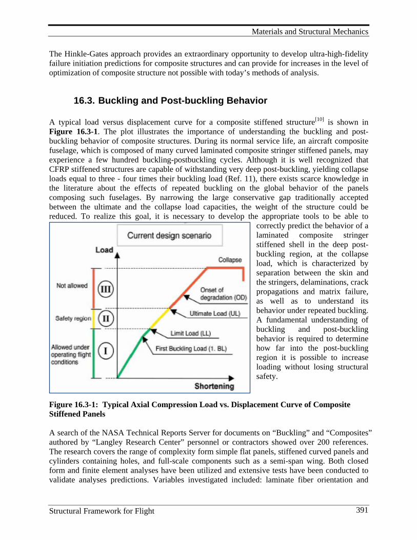
Materials and Structural Mechanics
Structural Framework for Flight 391
The Hinkle-Gates approach provides an extraordinary opportunity to develop ultra-high-fidelity failure initiation predictions for composite structures and can provide for increases in the level of optimization of composite structure not possible with today’s methods of analysis.
16.3. Buckling and Post-buckling Behavior A typical load versus displacement curve for a composite stiffened structure[10] is shown in Figure 16.3-1. The plot illustrates the importance of understanding the buckling and post- buckling behavior of composite structures. During its normal service life, an aircraft composite fuselage, which is composed of many curved laminated composite stringer stiffened panels, may experience a few hundred buckling-postbuckling cycles. Although it is well recognized that CFRP stiffened structures are capable of withstanding very deep post-buckling, yielding collapse loads equal to three - four times their buckling load (Ref. 11), there exists scarce knowledge in the literature about the effects of repeated buckling on the global behavior of the panels composing such fuselages. By narrowing the large conservative gap traditionally accepted between the ultimate and the collapse load capacities, the weight of the structure could be reduced. To realize this goal, it is necessary to develop the appropriate tools to be able to
correctly predict the behavior of a laminated composite stringer stiffened shell in the deep post-buckling region, at the collapse load, which is characterized by separation between the skin and the stringers, delaminations, crack propagations and matrix failure, as well as to understand its behavior under repeated buckling. A fundamental understanding of buckling and post-buckling behavior is required to determine how far into the post-buckling region it is possible to increase loading without losing structural safety.
Figure 16.3-1: Typical Axial Compression Load vs. Displacement Curve of Composite Stiffened Panels A search of the NASA Technical Reports Server for documents on “Buckling” and “Composites” authored by “Langley Research Center” personnel or contractors showed over 200 references. The research covers the range of complexity form simple flat panels, stiffened curved panels and cylinders containing holes, and full-scale components such as a semi-span wing. Both closed form and finite element analyses have been utilized and extensive tests have been conducted to validate analyses predictions. Variables investigated included: laminate fiber orientation and
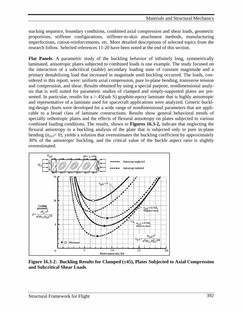
Materials and Structural Mechanics
Structural Framework for Flight 392
stacking sequence, boundary conditions, combined axial compression and shear loads, geometric proportions, stiffener configurations, stiffener-to-skin attachment methods, manufacturing imperfections, cutout-reinforcements, etc. More detailed descriptions of selected topics from the research follow. Selected references 11-20 have been noted at the end of this section. Flat Panels. A parametric study of the buckling behavior of infinitely long, symmetrically laminated, anisotropic plates subjected to combined loads is one example. The study focused on the interaction of a subcritical (stable) secondary loading state of constant magnitude and a primary destabilizing load that increased in magnitude until buckling occurred. The loads, con-sidered in this report, were: uniform axial compression, pure in-plane bending, transverse tension and compression, and shear. Results obtained by using a special purpose, nondimensional analy-sis that is well suited for parametric studies of clamped and simply-supported plates are pre-sented. In particular, results for a /- 45(sub S) graphite-epoxy laminate that is highly anisotropic and representative of a laminate used for spacecraft applications were analyzed. Generic buckl-ing-design charts were developed for a wide range of nondimensional parameters that are appli-cable to a broad class of laminate constructions. Results show general behavioral trends of specially orthotropic plates and the effects of flexural anisotropy on plates subjected to various combined loading conditions. The results, shown in Figures 16.3-2, indicate that neglecting the flexural anisotropy in a buckling analysis of the plate that is subjected only to pure in-plane bending (nxy2= 0), yields a solution that overestimates the buckling coefficient by approximately 30% of the anisotropic buckling, and the critical value of the buckle aspect ratio is slightly overestimated.
Figure 16.3-2: Buckling Results for Clamped (±45)s Plates Subjected to Axial Compression and Subcritical Shear Loads
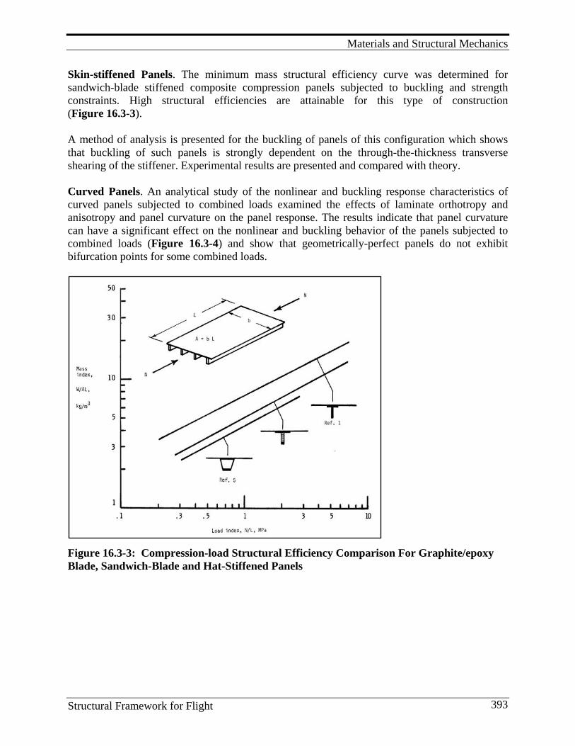
Materials and Structural Mechanics
Structural Framework for Flight 393
Skin-stiffened Panels. The minimum mass structural efficiency curve was determined for sandwich-blade stiffened composite compression panels subjected to buckling and strength constraints. High structural efficiencies are attainable for this type of construction (Figure 16.3-3). A method of analysis is presented for the buckling of panels of this configuration which shows that buckling of such panels is strongly dependent on the through-the-thickness transverse shearing of the stiffener. Experimental results are presented and compared with theory. Curved Panels. An analytical study of the nonlinear and buckling response characteristics of curved panels subjected to combined loads examined the effects of laminate orthotropy and anisotropy and panel curvature on the panel response. The results indicate that panel curvature can have a significant effect on the nonlinear and buckling behavior of the panels subjected to combined loads (Figure 16.3-4) and show that geometrically-perfect panels do not exhibit bifurcation points for some combined loads.
Figure 16.3-3: Compression-load Structural Efficiency Comparison For Graphite/epoxy Blade, Sandwich-Blade and Hat-Stiffened Panels
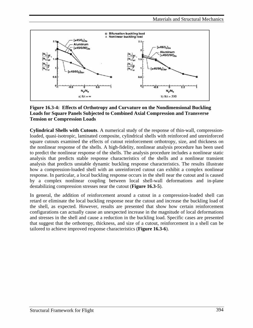
Materials and Structural Mechanics
Structural Framework for Flight 394
Figure 16.3-4: Effects of Orthotropy and Curvature on the Nondimensional Buckling Loads for Square Panels Subjected to Combined Axial Compression and Transverse Tension or Compression Loads Cylindrical Shells with Cutouts. A numerical study of the response of thin-wall, compression-loaded, quasi-isotropic, laminated composite, cylindrical shells with reinforced and unreinforced square cutouts examined the effects of cutout reinforcement orthotropy, size, and thickness on the nonlinear response of the shells. A high-fidelity, nonlinear analysis procedure has been used to predict the nonlinear response of the shells. The analysis procedure includes a nonlinear static analysis that predicts stable response characteristics of the shells and a nonlinear transient analysis that predicts unstable dynamic buckling response characteristics. The results illustrate how a compression-loaded shell with an unreinforced cutout can exhibit a complex nonlinear response. In particular, a local buckling response occurs in the shell near the cutout and is caused by a complex nonlinear coupling between local shell-wall deformations and in-plane destabilizing compression stresses near the cutout (Figure 16.3-5).
In general, the addition of reinforcement around a cutout in a compression-loaded shell can retard or eliminate the local buckling response near the cutout and increase the buckling load of the shell, as expected. However, results are presented that show how certain reinforcement configurations can actually cause an unexpected increase in the magnitude of local deformations and stresses in the shell and cause a reduction in the buckling load. Specific cases are presented that suggest that the orthotropy, thickness, and size of a cutout, reinforcement in a shell can be tailored to achieve improved response characteristics (Figure 16.3-6).
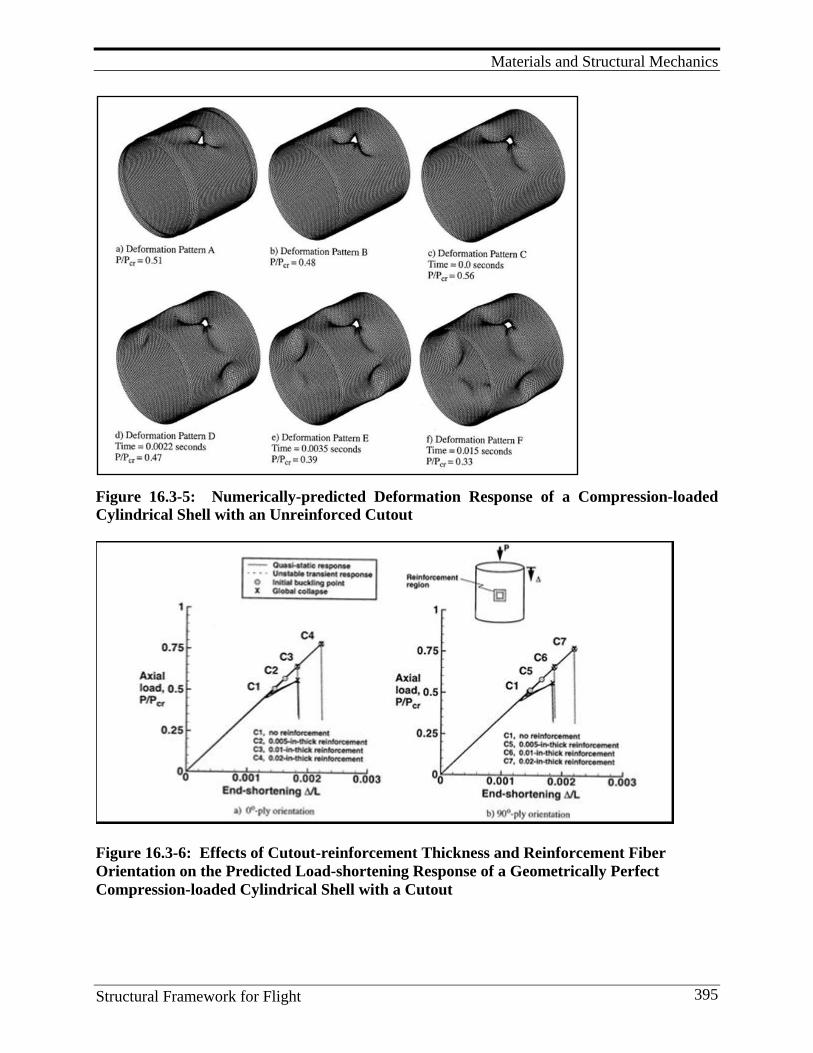
Materials and Structural Mechanics
Structural Framework for Flight 395
Figure 16.3-5: Numerically-predicted Deformation Response of a Compression-loaded Cylindrical Shell with an Unreinforced Cutout
Figure 16.3-6: Effects of Cutout-reinforcement Thickness and Reinforcement Fiber Orientation on the Predicted Load-shortening Response of a Geometrically Perfect Compression-loaded Cylindrical Shell with a Cutout
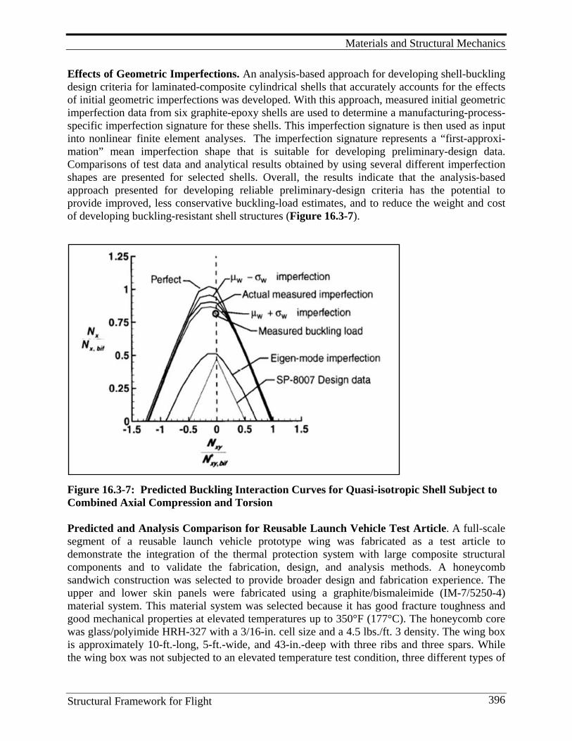
Materials and Structural Mechanics
Structural Framework for Flight 396
Effects of Geometric Imperfections. An analysis-based approach for developing shell-buckling design criteria for laminated-composite cylindrical shells that accurately accounts for the effects of initial geometric imperfections was developed. With this approach, measured initial geometric imperfection data from six graphite-epoxy shells are used to determine a manufacturing-process-specific imperfection signature for these shells. This imperfection signature is then used as input into nonlinear finite element analyses. The imperfection signature represents a “first-approxi-mation” mean imperfection shape that is suitable for developing preliminary-design data. Comparisons of test data and analytical results obtained by using several different imperfection shapes are presented for selected shells. Overall, the results indicate that the analysis-based approach presented for developing reliable preliminary-design criteria has the potential to provide improved, less conservative buckling-load estimates, and to reduce the weight and cost of developing buckling-resistant shell structures (Figure 16.3-7).
Figure 16.3-7: Predicted Buckling Interaction Curves for Quasi-isotropic Shell Subject to Combined Axial Compression and Torsion Predicted and Analysis Comparison for Reusable Launch Vehicle Test Article. A full-scale segment of a reusable launch vehicle prototype wing was fabricated as a test article to demonstrate the integration of the thermal protection system with large composite structural components and to validate the fabrication, design, and analysis methods. A honeycomb sandwich construction was selected to provide broader design and fabrication experience. The upper and lower skin panels were fabricated using a graphite/bismaleimide (IM-7/5250-4) material system. This material system was selected because it has good fracture toughness and good mechanical properties at elevated temperatures up to 350°F (177°C). The honeycomb core was glass/polyimide HRH-327 with a 3/16-in. cell size and a 4.5 lbs./ft. 3 density. The wing box is approximately 10-ft.-long, 5-ft.-wide, and 43-in.-deep with three ribs and three spars. While the wing box was not subjected to an elevated temperature test condition, three different types of
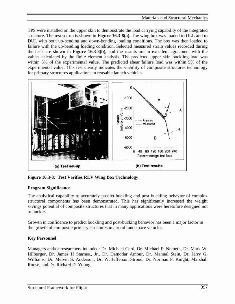
Materials and Structural Mechanics
Structural Framework for Flight 397
TPS were installed on the upper skin to demonstrate the load carrying capability of the integrated structure. The test set-up is shown in Figure 16.3-8(a). The wing box was loaded to DLL and to DUL with both up-bending and down-bending loading conditions. The box was then loaded to failure with the up-bending loading condition. Selected measured strain values recorded during the tests are shown in Figure 16.3-8(b), and the results are in excellent agreement with the values calculated by the finite element analysis. The predicted upper skin buckling load was within 3% of the experimental value. The predicted shear failure load was within 5% of the experimental value. This test clearly indicates the viability of composite structures technology for primary structures applications to reusable launch vehicles.
Figure 16.3-8: Test Verifies RLV Wing Box Technology Program Significance
The analytical capability to accurately predict buckling and post-buckling behavior of complex structural components has been demonstrated. This has significantly increased the weight savings potential of composite structures that in many applications were heretofore designed not to buckle. Growth in confidence to predict buckling and post-bucking behavior has been a major factor in the growth of composite primary structures in aircraft and space vehicles. Key Personnel Managers and/or researchers included: Dr. Michael Card, Dr. Michael P. Nemeth, Dr. Mark W. Hilburger, Dr. James H Starnes., Jr., Dr. Damodar Ambur, Dr. Manual Stein, Dr. Jerry G. Williams, Dr. Melvin S. Anderson, Dr. W. Jefferson Stroud, Dr. Norman F. Knight, Marshall Rouse, and Dr. Richard D. Young.
Materials and Structural Mechanics
Structural Framework for Flight 398
16.4. Lessons Learned and Future Direction Lessons Learned
1. Modeling the performance of interfaces and the integration of these “nanostructures” at micron-length and macroscopic scales are some of the keys to successfully implementing the Computational Materials approach.
2. The Hinkle-Gates approach provides an extraordinary opportunity to develop ultra-high- fidelity failure initiation predictions for composite structures and can provide for increases in the level of optimization of composite structure not possible with today’s methods of analysis.
3. An important finding is that the effects of flexural anisotropy on the buckling resistance of a plate can be significantly more important for plates subjected to combined loads than for plates subjected to single-component loads.
4. Certain reinforcement configurations can actually cause an unexpected increase in the magnitude of local deformations and stresses in the shell and cause a reduction in the buckling load.
5. Buckling of efficient blade stiffened panels is strongly dependent on the through-the-thickness transverse shearing of the stiffener.
6. The imperfection signature represents a “first-approximation” mean imperfection shape that is suitable for developing preliminary-design data.
7. Using the “building block approach,” state-of-the-art analyses accurately predict buckling and post-buckling behavior of full scale components.
Future Direction Growth in computational power and further advancements in multi-scale modeling are expected to provide advancements in computational materials and behavior of buckled structures. Continue:
1. Studies of the effects of combined internal pressure, mechanical and thermal loads on nonlinear stiffened panel and shell behavior, the effects of cutouts and other gradient-producing discontinuities on composite shell response, and the effects of local damage on pressure containment and residual strength.
2. Developing scaling laws that relate full-scale and subscale behavior of composite fuselage shells.
3. Identifying failure mechanisms and advanced designs. 4. Efforts to eliminate mandated conservative “knockdown factors”
References
1. Composites Science and Technology 64 (2004): 589–604. 2. Although originally calculated as a doubling every year, Moore later refined the period to two
years. It is often incorrectly quoted as a doubling of transistors every 18 months. 3. Electronics Magazine (1965), Retrieved May 2010 from
http://en.wikipedia.org/wiki/Electronics_%28magazine%29
Materials and Structural Mechanics
Structural Framework for Flight 399
4. Computing Methods Appl. Mech. Engrg. 192 (2003): 913-922. 5. Z. Phys. 33 (1925): 879. 6. Fed. Proc. Fed. Am. Soc. Exp. Biol. 33 (1974): 2332. 7. Odegard, G. M., T. S. Gates, L. M. Nicholson, and K. E. Wise. 2002. Equivalent-continuum
Modeling of Nano-structured Materials. Composites Science and Technology 62 (14): 1869-1880 (preprint).
8. Odegard, G. M., T. S. Gates, K. E. Wise, C. Park, and E. J. Siochi. 2003. Constitutive Modeling of Nanotube-reinforced Polymer Composites. Composites Science and Technology 63 (11): 1671-1687.
9. Odegard, G. M., S. J. V. Frankland, and T. S. Gates. 2005. Effect of Chemical Functionalization on Mechanical Propoerties of Nanotube/Polymer Composites. AIAA Journal 43 (8): 1828-1835.
10. Abramovich, H., and T. Weller. Repeated Buckling and Postbuckling Behavior of Laminated Stringer Stiffened Composite Panels with and without Damage.” http://www.cocomat.de/Endmeeting/Abstracts/35-TECHNION_Abramovich.pdf
11. Knight, N. F., Jr., and J. H. Starnes, Jr.. 1988. Postbuckling Elected Curved Stiffened Graphite epoxy Panels Loaded in Axial Compression. AIAA Journal 26 (3): 344-352.
12. Nemeth, M. P. 1995. Buckling Behavior Of Long Anisotropic Plates Subjected To Combined Loads. (NASA-TP-3568).
13. Hilburger, M. W., M. P. Nemeth, and J. H. Starnes, Jr. 2001. Nonlinear and Buckling Behavior of Curved Panels Subjected to Combined Loads. Paper presented at 42nd AIAA/ASME/ASCE/AHS Structures, Structural Dynamics and Materials Conference and Exhibit, Seattle, WA.
14. Hilburger, M. W., and J. H. Starnes, Jr. 2002. Buckling Behavior of Compression-loaded Composite Cylindrical Shells with Reinforced Cutouts. Paper presented at 43rd AIAA/ASME/ASCE/AHS/ASC Structures and Structural Dynamics and Materials, Denver, CO.
15. Weaver, P. M., and M. P. Nemeth. 2007. Bounds on Flexural Properties and Buckling Response for Symmetrically Laminated Plates. International Journal of Mechanical Sciences 133 (11): 1178-1191.
16. Stein, M., and J. G. Williams. 1978. Buckling and Structural Efficiency of Sandwich-Blade Stiffened Composite Compression Panels. (NASA-TP-1269).
17. Hilburger, M. W., M. P. Nemeth, and J. H. Starnes, Jr. 2004. Shell Buckling Design Criteria Based on Manufacturing Imperfection Signatures. (NASA/TM-2004-212659).
18. Young, R. D., M. W. Hyer, and J. H. Starnes, Jr. 2000. Prebuckling and Postbuckling Response of Tailored Composite Stiffened Panels with Axial-Shear Coupling. (AIAA Paper 2000-1459).
19. Nemeth, M. P., and J. H. Starnes, Jr. 1998. The NASA Monographs on Shell Stability Design Recommendations: A Review and Suggested Improvements. (NASA/TP-1998-20629.
20. Harris, C. E., J. H. Starnes, Jr., and M. J. Shuart. 2001. An Assessment of the State-of-the-Art in the Design and Manufacturing of Large Composite Structures for Aerospace Vehicles. (NASA/TM-2001-210844).
Structural Analyses
Structural Framework for Flight 400
17. S T R U C T U R A L A N A LY S E S 17.1. Finite Element Methods
From the formation of NACA through today, the Langley Research Center has made significant advancements in the capability to predict the response of aircraft and space structures subjected to both static and dynamic mechanical and thermal loads. NASA Langley has emphasized shell analysis research and development. Much of the early shell analysis research enabled space flight through the thorough understanding of shell theory and development of computerized shell design tools. This development occurred during an epoch period when several technological advancements were taking place; in particular, the development of electronic computations and associated numerical methods such as finite difference and finite element methods. By the early 1960s, the digital computer was powerful enough and easy enough to use by engineers, even though they weren’t programming professionals. Paralleling growth in capacity of computers was development of finite element analysis to predict static and dynamic response of complex structural elements utilized in aerospace structures. FEA capability has increased many orders of magnitude in number of elements, constraints and variations in element properties and geometry that can be modeled. NASTRAN NASTRAN is a powerful general purpose digital computer program[1-5] for the finite element structural analysis of small to large and complex physical devices and systems. NASTRAN has been a proven standard tool in the field of structural analysis for decades. It provides a wide range of modeling and analysis capabilities, including linear statics, displacement, strain, stress, vibration, heat transfer, and more. NASTRAN can handle any material type from plastic and metal to composites and hyperelastic materials. The 1964 annual review of NASA’s structural dynamics research program revealed that the research centers were separately developing structural analysis software that was specific to their own needs. The review recommended that a single generic software program should be used instead. In response, an ad hoc committee was formed. The committee determined that no existing software could meet their requirements. They suggested establishing a cooperative project to develop this software and created a specification that outlined the capabilities for the software. A contract was awarded to Computer Sciences Corporation (CSC) to develop the software. The name of the program is an acronym formed from NASA Structural Analysis. The NASTRAN software was released to NASA in 1968. The NASTRAN program has evolved over many versions. Each new version contains enhancements in analysis capability and numerical performance. In addition, many errors from previous versions are corrected. Today, NASTRAN is widely used throughout the world in the
Structural Analyses
Structural Framework for Flight 401
aerospace, automotive and maritime industries. It has been claimed that NASTRAN is the industry standard for analysis of aerospace structures. NASTRAN is written primarily in FORTRAN, and contains over one million lines of code. NASTRAN is compatible with a large variety of computers and operating systems, ranging from small workstations to the largest supercomputers. Commercial versions of NASTRAN are currently available from MSC Software, NEi Software (NEi Nastran) and Siemens PLM Software (NX Nastran). The following quote comes from (http://www.inter-tec.co.uk/nastran_patran.htm) “NASTRAN’s history extends back to the sixties where it was created by NASA engineers in support of the Apollo program. Within our industry it has long been recognized as the standard finite element analysis system. It has continually developed through the years and now shares its power and a common solver across all platforms. The import and export capabilities of NASTRAN and PATRAN also allow models to be saved and transferred in the format of most other industry standard FEA programs. For specific instances where customer requirements demand, this enables us to create new models or perform work on existing models in-house and to deliver them in the program-specific format required.” The following quote comes from (http://www.mscsoftware.com/Contents/Products/CAE-Tools/MSC-Nastran.aspx) “MSC Nastran is the world’s most widely used Finite Element Analysis (FEA) solver. When it comes to simulating stress, dynamics, or vibration of real-world, complex systems, MSC Nastran is still the best and most trusted software in the world – period. Today, manufacturers of everything from parts to complex assemblies are choosing the FEA solver that is reliable and accurate enough to be certified by the FAA and other regulatory agencies.” Engineers and analysts tasked with virtual prototyping are challenged to produce results fast enough to impact design decisions, and accurate enough to give their companies and management the confidence to replace physical prototypes. In today’s world, nobody has time or budget to spend evaluating the accuracy of their FEA software – you need to know its right. MSC NASTRAN is built on work done by NASA scientists and researchers, and is trusted to design mission-critical systems in every industry. Nearly every spacecraft, aircraft, and vehicle designed in the last 40 years has been analyzed using MSC NASTRAN. In recent years, some of the best and brightest scientists in Computer-Aided Engineering (CAE) have worked to extend MSC NASTRAN’s power and efficiency, resulting in its continued status as the world’s best, most trusted, and most widely used FEA software – period. New modular packaging that enables you to get only what you need makes it more affordable to own NASTRAN than ever. NASTRAN was used to perform a nonlinear analysis of the Vertical Tail Plane recovered from American Airlines Flight 587, discussed in Section 4.6 (Figure 4.6-12). Search of the NASA Technical Report Server for “NASTRAN and NASA Langley Research Center” produced 149 references authored by NASA personnel or contracts.
Structural Analyses
Structural Framework for Flight 402
IPAD Paralleling the development of finite element codes, a joint government/industry project designated Integrated Programs for Aerospace-Vehicle Design (IPAD) was carried out at NASA Langley from 1970–1984 with the goal of raising aerospace industry productivity through advanced computer technology to integrate and manage information involved in the design and manufacturing process. IPAD research was guided by an Industry Technical Advisory Board (ITAB) composed of over 100 representatives from aerospace and computer companies. The project complemented traditional NASA/DOD research to develop aerospace technology and the Air Force’s Integrated Computer-aided Manufacturing (ICAM) and advanced Computer-aided Manufacturing (CAM) technology. Major contributions from the IPAD project include: (1) development of the methodology to integrate engineering activities, (2) definition and integration of a future integrated Computer-aided Design/Computer-aided Manufacturing (CAD/CAM) system, (3) demonstration of rela-tional database management for engineering, and (4) development and demonstration of new concepts for distributed database management. A highly successful approach to joint industry/government cooperation in achieving technology transfer in an advanced engineering computer science program was demonstrated. A retrospective assessment of IPAD identified issues which should be addresses in future IPAD-like projects: (1) the natural conflict between engineering and computer science disciplines, (2) the high turnover rate in computer related technical staff, (3) the conflict between research-oriented and useful software products, (4) the benefits of a user group from program inception, (5) the need for a clear image of the software program through its lifespan, (6) the importance of small modular products completed at regular intervals throughout a program’s life, and (7) the critical need for, and cost of, technology transfer as a planned part of an engineering software research program. STAGS STAGS is an acronym for Structural Analysis of General Shells. STAGS had its beginnings as a Lockheed Missiles & Space Company research code and evolved into a powerful shell analysis code offering unique capabilities such as advanced nonlinear solution procedures, load relaxation for re-establishing equilibrium, sandwich elements, fastener elements, generalized imperfection modeling, constraint definitions, and constitutive modeling utilities. Historically, STAGS has been a shell analysis tool; however, three-dimensional, nonlinear analysis capabilities have been incorporated in recent years. STAGS continues to serve as both a structural mechanics research tool for shell analysis and nonlinear mechanics, as well as an advanced structural analysis tool for aerospace structures. NASA Marshall Space Flight Center sponsored some of the early shell analysis formulations and implementations from 1963-1968. Much of the work focused on developing equilibrium equations for cylinders, cones, and spheres, and then applying finite difference approximations to arrive at a set of algebraic equations to solve using matrix algebra. However, the system of
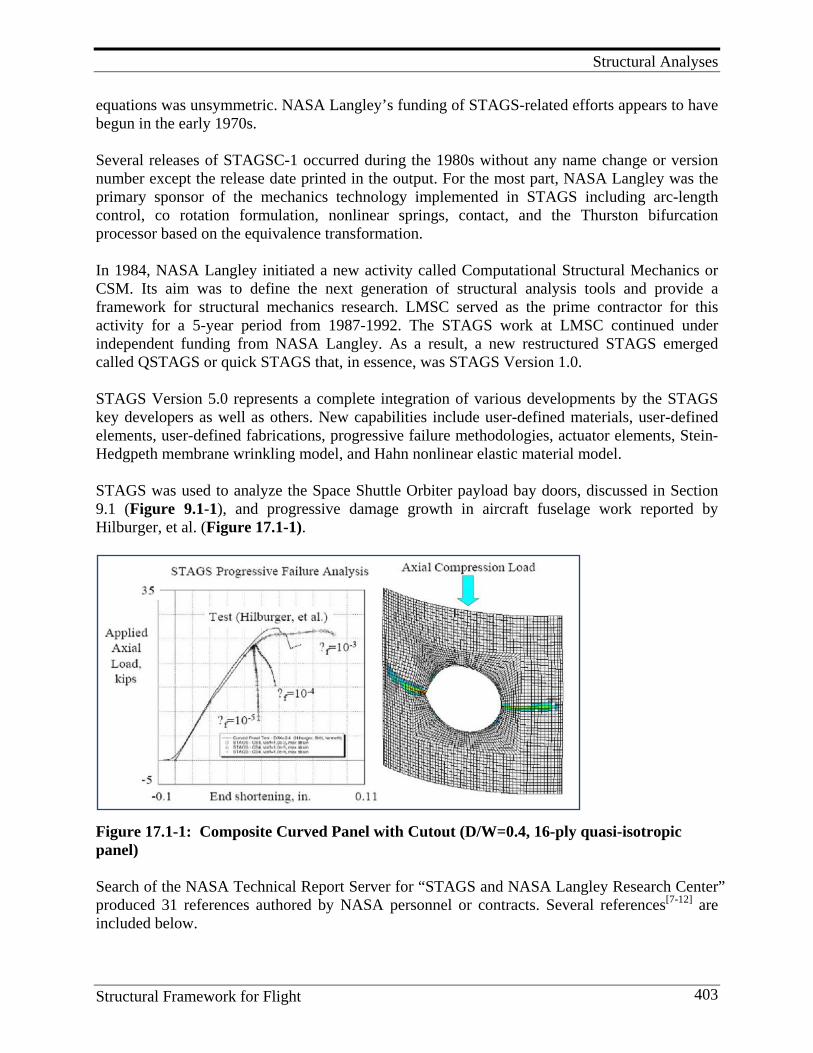
Structural Analyses
Structural Framework for Flight 403
equations was unsymmetric. NASA Langley’s funding of STAGS-related efforts appears to have begun in the early 1970s. Several releases of STAGSC-1 occurred during the 1980s without any name change or version number except the release date printed in the output. For the most part, NASA Langley was the primary sponsor of the mechanics technology implemented in STAGS including arc-length control, co rotation formulation, nonlinear springs, contact, and the Thurston bifurcation processor based on the equivalence transformation. In 1984, NASA Langley initiated a new activity called Computational Structural Mechanics or CSM. Its aim was to define the next generation of structural analysis tools and provide a framework for structural mechanics research. LMSC served as the prime contractor for this activity for a 5-year period from 1987-1992. The STAGS work at LMSC continued under independent funding from NASA Langley. As a result, a new restructured STAGS emerged called QSTAGS or quick STAGS that, in essence, was STAGS Version 1.0. STAGS Version 5.0 represents a complete integration of various developments by the STAGS key developers as well as others. New capabilities include user-defined materials, user-defined elements, user-defined fabrications, progressive failure methodologies, actuator elements, Stein-Hedgpeth membrane wrinkling model, and Hahn nonlinear elastic material model. STAGS was used to analyze the Space Shuttle Orbiter payload bay doors, discussed in Section 9.1 (Figure 9.1-1), and progressive damage growth in aircraft fuselage work reported by Hilburger, et al. (Figure 17.1-1).
Figure 17.1-1: Composite Curved Panel with Cutout (D/W=0.4, 16-ply quasi-isotropic panel) Search of the NASA Technical Report Server for “STAGS and NASA Langley Research Center” produced 31 references authored by NASA personnel or contracts. Several references[7-12] are included below.
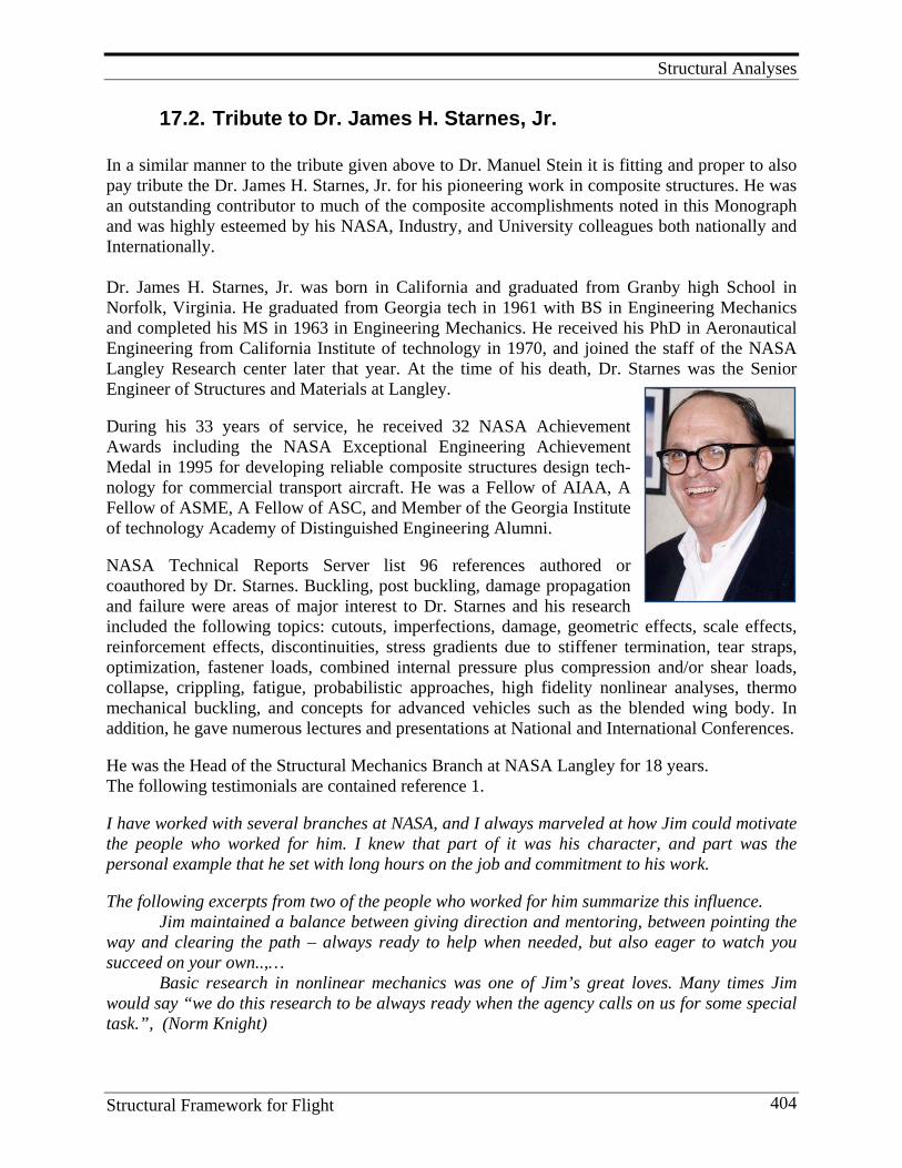
Structural Analyses
Structural Framework for Flight 404
17.2. Tribute to Dr. James H. Starnes, Jr. In a similar manner to the tribute given above to Dr. Manuel Stein it is fitting and proper to also pay tribute the Dr. James H. Starnes, Jr. for his pioneering work in composite structures. He was an outstanding contributor to much of the composite accomplishments noted in this Monograph and was highly esteemed by his NASA, Industry, and University colleagues both nationally and Internationally. Dr. James H. Starnes, Jr. was born in California and graduated from Granby high School in Norfolk, Virginia. He graduated from Georgia tech in 1961 with BS in Engineering Mechanics and completed his MS in 1963 in Engineering Mechanics. He received his PhD in Aeronautical Engineering from California Institute of technology in 1970, and joined the staff of the NASA Langley Research center later that year. At the time of his death, Dr. Starnes was the Senior Engineer of Structures and Materials at Langley. During his 33 years of service, he received 32 NASA Achievement Awards including the NASA Exceptional Engineering Achievement Medal in 1995 for developing reliable composite structures design tech-nology for commercial transport aircraft. He was a Fellow of AIAA, A Fellow of ASME, A Fellow of ASC, and Member of the Georgia Institute of technology Academy of Distinguished Engineering Alumni. NASA Technical Reports Server list 96 references authored or coauthored by Dr. Starnes. Buckling, post buckling, damage propagation and failure were areas of major interest to Dr. Starnes and his research included the following topics: cutouts, imperfections, damage, geometric effects, scale effects, reinforcement effects, discontinuities, stress gradients due to stiffener termination, tear straps, optimization, fastener loads, combined internal pressure plus compression and/or shear loads, collapse, crippling, fatigue, probabilistic approaches, high fidelity nonlinear analyses, thermo mechanical buckling, and concepts for advanced vehicles such as the blended wing body. In addition, he gave numerous lectures and presentations at National and International Conferences. He was the Head of the Structural Mechanics Branch at NASA Langley for 18 years. The following testimonials are contained reference 1. I have worked with several branches at NASA, and I always marveled at how Jim could motivate the people who worked for him. I knew that part of it was his character, and part was the personal example that he set with long hours on the job and commitment to his work. The following excerpts from two of the people who worked for him summarize this influence. Jim maintained a balance between giving direction and mentoring, between pointing the way and clearing the path – always ready to help when needed, but also eager to watch you succeed on your own..,… Basic research in nonlinear mechanics was one of Jim’s great loves. Many times Jim would say “we do this research to be always ready when the agency calls on us for some special task.”, (Norm Knight)
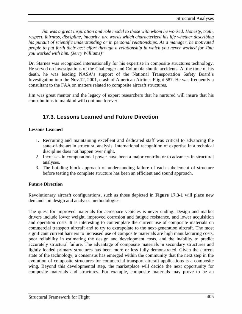
Structural Analyses
Structural Framework for Flight 405
Jim was a great inspiration and role model to those with whom he worked. Honesty, truth, respect, fairness, discipline, integrity, are words which characterized his life whether describing his pursuit of scientific understanding or in personal relationships. As a manager, he motivated people to put forth their best effort through a relationship in which you never worked for Jim; you worked with him. (Jerry Williams)” Dr. Starnes was recognized internationally for his expertise in composite structures technology. He served on investigations of the Challenger and Columbia shuttle accidents. At the time of his death, he was leading NASA’s support of the National Transportation Safety Board’s Investigation into the Nov.12, 2001, crash of American Airlines Flight 587. He was frequently a consultant to the FAA on matters related to composite aircraft structures. Jim was great mentor and the legacy of expert researchers that he nurtured will insure that his contributions to mankind will continue forever.
17.3. Lessons Learned and Future Direction Lessons Learned
1. Recruiting and maintaining excellent and dedicated staff was critical to advancing the state-of-the-art in structural analysis. International recognition of expertise in a technical discipline does not happen over night.
2. Increases in computational power have been a major contributor to advances in structural analyses.
3. The building block approach of understanding failure of each subelement of structure before testing the complete structure has been an efficient and sound approach.
Future Direction Revolutionary aircraft configurations, such as those depicted in Figure 17.3-1 will place new demands on design and analyses methodologies. The quest for improved materials for aerospace vehicles is never ending. Design and market drivers include lower weight, improved corrosion and fatigue resistance, and lower acquisition and operation costs. It is interesting to contemplate the current use of composite materials on commercial transport aircraft and to try to extrapolate to the next-generation aircraft. The most significant current barriers to increased use of composite materials are high manufacturing costs, poor reliability in estimating the design and development costs, and the inability to predict accurately structural failure. The advantage of composite materials in secondary structures and lightly loaded primary structures has been more or less fully demonstrated. Given the current state of the technology, a consensus has emerged within the community that the next step in the evolution of composite structures for commercial transport aircraft applications is a composite wing. Beyond this developmental step, the marketplace will decide the next opportunity for composite materials and structures. For example, composite materials may prove to be an

Structural Analyses
Structural Framework for Flight 406
enabling technology for a new class of aircraft that have superior performance characteristics compared to today’s commercial transport aircraft. The aerodynamic performance of these vehicles may prove to be quite superior to conventional subsonic aircraft. The potential benefits that may be derived from these revolutionary aircraft include significant increases in flight range or performance, significant reductions in fuel consumption, significant reductions in engine emissions, and significant reductions in airframe and engine noise. However, major improve-ments in the current state-of-the-art for composite structures will be required to design and build these new aircraft reliably and economically. For example, the noncircular cross-section and compound curvature features of the blended wing body configuration will be a particularly significant challenge for structural designers.
Figure 17.3-1: Examples of Revolutionary Aircraft Configurations
Current research is expected to result in dramatic improvements in structural design and analysis tools. Reliable, advanced analysis methods will significantly reduce current dependence on the empirical design approach and provide better capability to optimize structural designs. High-fidelity, physics-based structural analysis tools are under development using both deterministic and non-deterministic computational methods. Rigorous, physics-based computational methods to predict accurately damage initiation and growth, structural failure modes, and the residual strength of damaged structure remains a grand challenge that is motivating considerable research attention in the structures community. Next-generation structural design tools are under development that exploit the revolution in information technology. The use of intelligent systems to improve graphical user interfaces and three dimensional immersive simulation of structural analysis results is illustrated in Figure 17.3-2. As illustrated in Figure 17.3-2 (a), the next- generation design tools will use libraries of smart components to assemble finite element analysis models easily. Interface elements are under development that will provide seamless transitions between regions of a finite element model with different mesh refinements. These advanced methods not only automate model generation, but also facilitate the implementation of global-local modeling strategies that are essential for the prediction of progressive damage and structural failure. Finally, advanced three dimensional virtual reality capabilities, such as the
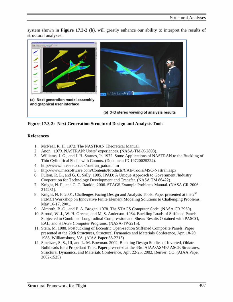
Structural Analyses
Structural Framework for Flight 407
system shown in Figure 17.3-2 (b), will greatly enhance our ability to interpret the results of structural analyses.
Figure 17.3-2: Next Generation Structural Design and Analysis Tools
References
1. McNeal, R. H. 1972. The NASTRAN Theoretical Manual. 2. Anon. 1973. NASTRAN: Users’ experiences. (NASA-TM-X-2893). 3. Williams, J. G., and J. H. Starnes, Jr. 1972. Some Applications of NASTRAN to the Buckling of
Thin Cylindrical Shells with Cutouts. (Document ID 19720025224). 4. http://www.inter-tec.co.uk/nastran_patran.htm 5. http://www.mscsoftware.com/Contents/Products/CAE-Tools/MSC-Nastran.aspx 6. Fulton, R. E., and G. C. Sally. 1985. IPAD: A Unique Approach to Government /Industry
Cooperation for Technology Development and Transfer. (NASA TM 86422). 7. Knight, N. F., and C. C. Rankin. 2006. STAGS Example Problems Manual. (NASA CR-2006-
214281). 8. Knight, N. F. 2001. Challenges Facing Design and Analysis Tools. Paper presented at the 2nd
FEMCI Workshop on Innovative Finite Element Modeling Solutions to Challenging Problems. May 16-17, 2001.
9. Almroth, B. O., and F. A. Brogan. 1978. The STAGS Computer Code. (NASA CR 2950). 10. Stroud, W. J., W. H. Greene, and M. S. Anderson. 1984. Buckling Loads of Stiffened Panels
Subjected to Combined Longitudinal Compression and Shear: Results Obtained with PASCO, EAL, and STAGS Computer Programs. (NASA-TP-2215).
11. Stein, M. 1988. Postbuckling of Eccentric Open-section Stiffened Composite Panels. Paper presented at the 29th Structures, Structural Dynamics and Materials Conference, Apr. 18-20, 1988, Williamsburg, VA. (AIAA Paper 88-2215)
12. Smeltzer, S. S., III, and L. M. Bowman. 2002. Buckling Design Studies of Inverted, Oblate Bulkheads for a Propellant Tank. Paper presented at the 43rd AIAA/ASME/ ASCE Structures, Structural Dynamics, and Materials Conference, Apr. 22-25, 2002, Denver, CO. (AIAA Paper 2002-1525)
Grand Challenges in High-Performance Composite Materials and Structures Technology
Structural Framework for Flight 408
18. G R A N D C H A L L E N G E S I N H I G H -P E R F O R M A N C E C O M P O S I T E
M AT E R I A L S A N D S T R U C T U R E S T E C H N O L O G Y
18.1. Certification by Analyses Contemporary certification of flight-critical composite structure requires extensive experimental testing. First, the material system undergoes a complete mechanical characterization wherein thousands of test samples are exposed to thermomechanical tests. Next, the process conditions appropriate for full consolidation and chemical cure kinetics are established through extensive testing. After a material system has been certified, no further changes to the system are permitted even when material performance can be enhanced with these modifications. Subelements to examine stiffness, strength, and durability are fabricated and tested to destruction. Joints and elements of complex geometry are especially subjected to extensive testing. Complete structural assemblies, such as the wing, wing carry-through structure, empennage, and fuselage, are fabricated and subjected to service loadings. Finally, the completely assembled vehicle is subjected to full lifetime spectral loading in order to certify the airframe for flight. Taken together, these steps in conventional certification of composite structure require an extraordinary investment in engineering talent, structural fabrication and test, and material certification. The first grand challenge is, therefore, the development of the knowledge necessary to substantially reduce the costs of flight certification. While advances based in iterative variations of the above approach can be expected to produce some savings, the process requires the continuous development of a number of similar airframe products. Yet the very cost of flight certification serves to limit the number of opportunities for this type of empirical learning. Therefore, the development of ultra-fidelity simulations for composite structure may well offer the most promising approach in reducing the cost-of-flight certification of composite structure. The grand challenges speak to the technology needs to accomplish this objective.
18.2. Materials by Design: Multi-scale Modeling and Measurements
This may well be the dawn of the “quantum age” in engineering analysis because we now have the computational power sufficient to link atomistic and macroscopic behavior of materials and structures. (See Section 16.2: Multi-scale Modeling) As noted in Section 16.2 NASA Langley’s pioneering efforts in this area were led by J.A. Hinkle and T. S. Gates. Under their leadership and in collaboration with other Langley scientists and engineers, the two forged a program with the objective of linking molecular phenomena to macroscopic behavior of polymer composites.
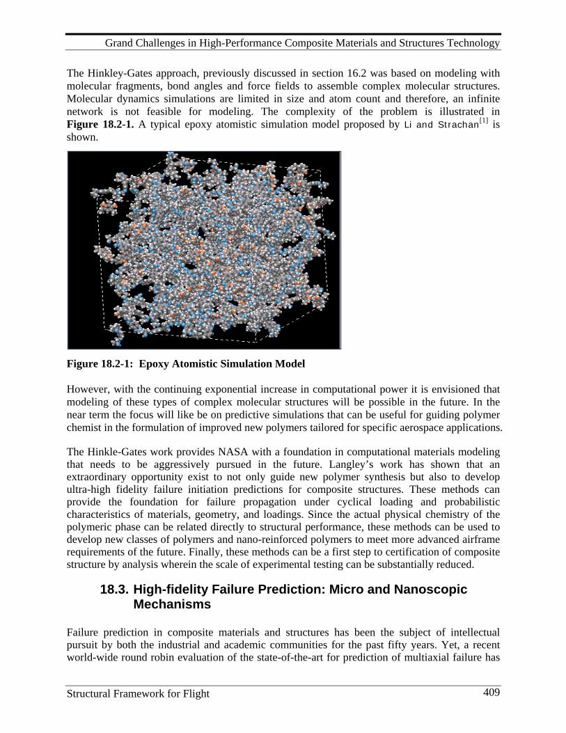
Grand Challenges in High-Performance Composite Materials and Structures Technology
Structural Framework for Flight 409
The Hinkley-Gates approach, previously discussed in section 16.2 was based on modeling with molecular fragments, bond angles and force fields to assemble complex molecular structures. Molecular dynamics simulations are limited in size and atom count and therefore, an infinite network is not feasible for modeling. The complexity of the problem is illustrated in Figure 18.2-1. A typical epoxy atomistic simulation model proposed by Li and Strachan[1] is shown.
Figure 18.2-1: Epoxy Atomistic Simulation Model However, with the continuing exponential increase in computational power it is envisioned that modeling of these types of complex molecular structures will be possible in the future. In the near term the focus will like be on predictive simulations that can be useful for guiding polymer chemist in the formulation of improved new polymers tailored for specific aerospace applications. The Hinkle-Gates work provides NASA with a foundation in computational materials modeling that needs to be aggressively pursued in the future. Langley’s work has shown that an extraordinary opportunity exist to not only guide new polymer synthesis but also to develop ultra-high fidelity failure initiation predictions for composite structures. These methods can provide the foundation for failure propagation under cyclical loading and probabilistic characteristics of materials, geometry, and loadings. Since the actual physical chemistry of the polymeric phase can be related directly to structural performance, these methods can be used to develop new classes of polymers and nano-reinforced polymers to meet more advanced airframe requirements of the future. Finally, these methods can be a first step to certification of composite structure by analysis wherein the scale of experimental testing can be substantially reduced.
18.3. High-fidelity Failure Prediction: Micro and Nanoscopic Mechanisms
Failure prediction in composite materials and structures has been the subject of intellectual pursuit by both the industrial and academic communities for the past fifty years. Yet, a recent world-wide round robin evaluation of the state-of-the-art for prediction of multiaxial failure has
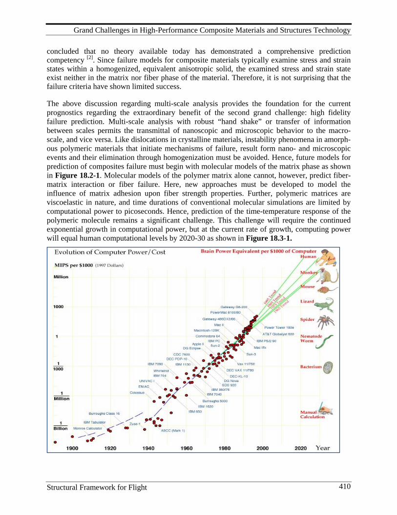
Grand Challenges in High-Performance Composite Materials and Structures Technology
Structural Framework for Flight 410
concluded that no theory available today has demonstrated a comprehensive prediction competency [2]. Since failure models for composite materials typically examine stress and strain states within a homogenized, equivalent anisotropic solid, the examined stress and strain state exist neither in the matrix nor fiber phase of the material. Therefore, it is not surprising that the failure criteria have shown limited success. The above discussion regarding multi-scale analysis provides the foundation for the current prognostics regarding the extraordinary benefit of the second grand challenge: high fidelity failure prediction. Multi-scale analysis with robust “hand shake” or transfer of information between scales permits the transmittal of nanoscopic and microscopic behavior to the macro-scale, and vice versa. Like dislocations in crystalline materials, instability phenomena in amorph-ous polymeric materials that initiate mechanisms of failure, result form nano- and microscopic events and their elimination through homogenization must be avoided. Hence, future models for prediction of composites failure must begin with molecular models of the matrix phase as shown in Figure 18.2-1. Molecular models of the polymer matrix alone cannot, however, predict fiber-matrix interaction or fiber failure. Here, new approaches must be developed to model the influence of matrix adhesion upon fiber strength properties. Further, polymeric matrices are viscoelastic in nature, and time durations of conventional molecular simulations are limited by computational power to picoseconds. Hence, prediction of the time-temperature response of the polymeric molecule remains a significant challenge. This challenge will require the continued exponential growth in computational power, but at the current rate of growth, computing power will equal human computational levels by 2020-30 as shown in Figure 18.3-1.
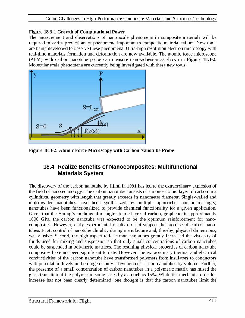
Grand Challenges in High-Performance Composite Materials and Structures Technology
Structural Framework for Flight 411
Figure 18.3-1 Growth of Computational Power The measurement and observations of nano scale phenomena in composite materials will be required to verify predictions of phenomena important to composite material failure. New tools are being developed to observe these phenomena. Ultra-high resolution electron microscopy with real-time materials formation and deformation are now available. The atomic force microscope (AFM) with carbon nanotube probe can measure nano-adhesion as shown in Figure 18.3-2. Molecular scale phenomena are currently being investigated with these new tools.
Figure 18.3-2: Atomic Force Microscopy with Carbon Nanotube Probe
18.4. Realize Benefits of Nanocomposites: Multifunctional Materials System
The discovery of the carbon nanotube by Iijimi in 1991 has led to the extraordinary explosion of the field of nanotechnology. The carbon nanotube consists of a mono-atomic layer of carbon in a cylindrical geometry with length that greatly exceeds its nanometer diameter. Single-walled and multi-walled nanotubes have been synthesized by multiple approaches and increasingly, nanotubes have been functionalized to provide chemical functionality for a given application. Given that the Young’s modulus of a single atomic layer of carbon, graphene, is approximately 1000 GPa, the carbon nanotube was expected to be the optimum reinforcement for nano-composites. However, early experimental results did not support the promise of carbon nano-tubes. First, control of nanotube chirality during manufacture and, thereby, physical dimensions, was elusive. Second, the high aspect ratio carbon nanotubes greatly increased the viscosity of fluids used for mixing and suspension so that only small concentrations of carbon nanotubes could be suspended in polymeric matrices. The resulting physical properties of carbon nanotube composites have not been significant to date. However, the extraordinary thermal and electrical conductivities of the carbon nanotube have transformed polymers from insulators to conductors with percolation levels in the range of only a few percent carbon nanotubes by volume. Further, the presence of a small concentration of carbon nanotubes in a polymeric matrix has raised the glass transition of the polymer in some cases by as much as 15%. While the mechanism for this increase has not been clearly determined, one thought is that the carbon nanotubes limit the
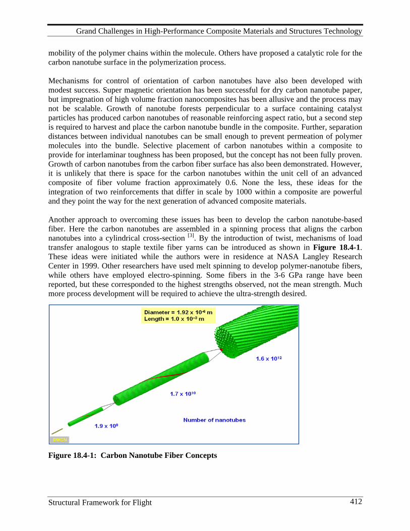
Grand Challenges in High-Performance Composite Materials and Structures Technology
Structural Framework for Flight 412
mobility of the polymer chains within the molecule. Others have proposed a catalytic role for the carbon nanotube surface in the polymerization process. Mechanisms for control of orientation of carbon nanotubes have also been developed with modest success. Super magnetic orientation has been successful for dry carbon nanotube paper, but impregnation of high volume fraction nanocomposites has been allusive and the process may not be scalable. Growth of nanotube forests perpendicular to a surface containing catalyst particles has produced carbon nanotubes of reasonable reinforcing aspect ratio, but a second step is required to harvest and place the carbon nanotube bundle in the composite. Further, separation distances between individual nanotubes can be small enough to prevent permeation of polymer molecules into the bundle. Selective placement of carbon nanotubes within a composite to provide for interlaminar toughness has been proposed, but the concept has not been fully proven. Growth of carbon nanotubes from the carbon fiber surface has also been demonstrated. However, it is unlikely that there is space for the carbon nanotubes within the unit cell of an advanced composite of fiber volume fraction approximately 0.6. None the less, these ideas for the integration of two reinforcements that differ in scale by 1000 within a composite are powerful and they point the way for the next generation of advanced composite materials. Another approach to overcoming these issues has been to develop the carbon nanotube-based fiber. Here the carbon nanotubes are assembled in a spinning process that aligns the carbon nanotubes into a cylindrical cross-section [3]. By the introduction of twist, mechanisms of load transfer analogous to staple textile fiber yarns can be introduced as shown in Figure 18.4-1. These ideas were initiated while the authors were in residence at NASA Langley Research Center in 1999. Other researchers have used melt spinning to develop polymer-nanotube fibers, while others have employed electro-spinning. Some fibers in the 3-6 GPa range have been reported, but these corresponded to the highest strengths observed, not the mean strength. Much more process development will be required to achieve the ultra-strength desired.
Figure 18.4-1: Carbon Nanotube Fiber Concepts
Grand Challenges in High-Performance Composite Materials and Structures Technology
Structural Framework for Flight 413
Strength and stiffness alone should not be the objective of the nanocomposite of the future. Rather, multifunctionality should be the goal. Self-healing is an attractive functionality of the future nanocomposite and some progress has been made in developing self-healing polymers. The concepts utilize a second phase, typically liquid, encapsulated in the polymeric phase. Cracks in the polymer release the “healing” agent and physical properties are renewed much as the human body heals itself. A second approach is to use electrical resistance-induced heat intensified at a crack tip within the material to melt the healing agent and accomplish the repair. All of these approaches require the presence of a second phase within a material architecture where little space is available. Further, repetitive loading that produces the need for multiple healing cycles seems not to have been addressed. Another approach is to utilize the functionality of nano-reinforcing phase as a vehicle to sense the presence of damage at the nano scale within the composite. As mentioned earlier, the extra-ordinary electrical conductivity of the carbon nanotube makes it ideal for development of an electrical percolation path within a polymer. It has recently, 2008, been demonstrated that by careful control of carbon nanotube volume fraction and aspect ratio, it is possible to produce a composite polymer matrix with electrical resistance that is proportional to the density of cracks within the composite. This approach provides new functionality that allows the material to be interrogated non-destructively to determine the presence of micro and nano cracks within the composite. The simple enhancement of the thermal and electrical properties of the polymeric matrix phase by the addition of carbon nanotubes seems a laudable goal. Thermal management in highly compacted electronic systems and electromagnetic shielding of electronics are benefits of thermal and electrical functionality of nanocomposites.
18.5. Intelligent Materials and Structures: Larger, More Integrated Structure
Intelligent materials and structures has been a topic of discussion for some time. Yet the develop-ment of self-sensing in materials systems opens a broad new approach to exploitation of multi-functionality in advanced composite materials. Further, near-net-shape manufacturing of advanced composite materials wherein much fewer mechanical joints are present produces large integrated structural components. The repair and disassembly of these structures can be expected to be more difficult than a conventional, mechanically-fastened structure made up of multiple subassemblies. These larger and more complex structures will likely require more careful inter-rogation to locate and isolate areas of concern. The opportunity to embed sensors in the material during fabrication or to utilize the material itself as a sensor offers an approach to overcome this challenge that may be unique to composite materials. Prognostics, or structural health monitoring, is the first step in developing intelligent structure. This technology involves the integration of sensors, data acquisition, data management, data analysis and diagnostics. By analogy this technology is comparable to the monitoring a human patient receives in an acute care facility with intervention of the physician for remediation. Here, the prognostics system is capable of sensing events important to airframe life and altering
Grand Challenges in High-Performance Composite Materials and Structures Technology
Structural Framework for Flight 414
operating conditions to ensure safe structural performance. Further, this approach reduces down time for the systems involved in the inspection of the complete structure necessary to locate and identify damage sites. The efficiency of the structural systems can be enhanced when the designer is assured that structural anomalies will be detected in their early stages of evolution and before they have grown to catastrophic size. Sensors that can be embedded in composite materials and structures include fiber optic fibers, electrical resistance gages, piezoelectric sensors, and micro-electrical-mechanical systems. The sensors may be either passive or active. In the case of passive sensors, the structural response to service loading provides the information sensed. For active sensors, the system can be interrogated on demand by exciting one sensor and observing response with the same sensor or a second one. As discussed in Grand Challenge IV, the suspension of carbon nanotubes in the polymeric matrix phase of the composite provides a “built in” sensor. Electrical resistance and Raman spectral responses can detect strain in the embedded nanotube and, thereby, the matrix phase. Discontinuities in measurements can expose regions of damage in the composite. The clear challenge is to develop structural intelligence through both active and passive systems embedded in the composite structure. Yet many issues remain concerning robustness of the system over the life of the vehicle, repair of damaged structure containing sensors, information management and archival of significant events.
18.6. Pervasive Composites Knowledge and Learning: Isotropic Plasticity Thinking
The education of engineers in the United States began in the early nineteenth century when Morrill Land-Grant Acts of 1861-2 established land-grant colleges for advancement in learning in “agriculture and the mechanic arts” in all of the states in the Union The establishment of Rensselaer Polytechnic Institute in 1824, following Stephen Van Rensselaer’s decision, “to establish a school in the application of science to the common purposes of life,” set the direction that the land-grant colleges were to develop in each of the states. Like the land-grant universities in many states, Virginia Polytechnic Institute and State University (Virginia Tech) was founded a decade after the Morrill Act had been signed into law, and today it is joined in the Common-wealth of Virginia as a land-grant institution by Virginia State University. The engineering, agriculture, and science programs in the land-grant universities that have evolved over the past 140 years are sophisticated, world-class research universities. Their contributions to the economy of the United States in this period have been enormous. As educators of technologists, the land-grant universities have been without peer. Located in Hampton, Virginia, NASA Langley Research Center has naturally attracted significant engineering and science talent from Virginia Tech. In 1974, when NASA Langley sought help from the academic community in the development of composites technology for commercial aircraft and space vehicles, it was a natural choice to establish the Virginia Tech and the National Aeronautics and Space Administration (NASA) Langley Research Center coopera-tive program in composite materials and structures. Of course, Langley engaged in relationships with numerous institutions of higher education such as M.I.T., Cal Tech, Georgia Tech,
Grand Challenges in High-Performance Composite Materials and Structures Technology
Structural Framework for Flight 415
Delaware and many others. However, the founding of the formal composites program at Virginia Tech established a long-term commitment to this field of endeavor and has been significant in focusing research and development of human talent in this emerging new field. The NASA Langley-Virginia Tech Composites program continued to produce new knowledge and graduate-level training in composites for two and a half decades. An earlier composites research center, founded in the 1960s and funded initially by the Advanced Research Projects Agency (ARPA) at Washington University St. Louis was later absorbed into the National Materials Research Laboratories Program of the National Science Foundation and dropped after less than a decade of life. Only the University of Delaware Center for Composite Materials, also founded in 1974, achieved a program life greater than that of the Virginia Tech Center, but its programs focused largely on the automotive industry for the decade of 1974-84, and it had only modest involvement in the Langley Composites programs. The academic course work and textbooks in the field of composite materials and structures were first introduced in the early 1970s and courses were then taught in only a few universities. Today there are hundreds of textbooks in the field and graduate composites courses are taught in the majority of the major research universities. While this extraordinary growth in knowledge and pedagogy is impressive, it does not meet the emerging need. If the Boeing 787 Dreamliner and Airbus 350 commercial aircraft are indicative of the commercial aircraft materials and structures technology of the future, then the scale of education in this important field must be increased by an order of magnitude. Yet much of the academic leadership in the field of composites has either retired or their interest has been diverted to the field of nanotechnology. The grand challenge to achieve pervasive composites knowledge and learning requires a reformation of engineering education at its very foundation. The design and manufacture of conventional metallic aircraft structure has occurred in a world populated by isotropic materials where material property and component geometry are independent and where material damage initiation and propagation typically involve plastic deformation. These ideas enter engineering education at the undergraduate level and propagate throughout graduate education as well. Anisotropy, heterogeneity and the composite effect are ideas that must be introduced earlier and more broadly in engineering education. Composite manufacturing methods that produce material microstructure and net shape, structural geometry simultaneously require that manufacturing and design be investigated and taught in an integrated fashion. Significant strides have been made in research and education in the field of composite materials and structures during the past four decades and the opportunities for new product adoption of composites have continued to grow. The first products were largely secondary structure applications in defense airframes and today, there is virtually no defense product untouched by composite materials. Leisure products followed quickly after the first availability of composite materials, as did industrial products and automotive applications. Today, wind energy and energy storage systems rely on composite materials for their efficiencies. If composite materials and structures are to be the technology of choice for future commercial and military aircraft and spacecraft, it is imperative that the United States engage in a bold new initiative to create pervasive knowledge and learning in this field.
Grand Challenges in High-Performance Composite Materials and Structures Technology
Structural Framework for Flight 416
18.7. Reliability-based Design Robust methods to take into account the random nature of material properties, load and usage conditions, and time-dependent processes of degradation are essential for the efficient applica-tion of composite materials and structures. Inevitable statistical variations in properties and loading results in excessive safety factors. A probabilistic approach allows the randomness to be accounted for in an intelligent and efficient way, and thereby reduce design conservatism. The following major directions are recommended for the development of probability-based design of composite materials and structures: probabilistic characterization of fatigue behavior, probabilistic estimates for damage tolerance, random nature of loading environment, condi-tioned-based maintenance with reliability assessment and reliability-based optimization. Fatigue life of composite components has been estimated using a conventional sinusoidal spec-trum of load/usage conditions. Probability-based characterization of fatigue properties of com-posites is a key to drastically increase the fidelity of lifetime predictions of aircraft components. Damage tolerance assessment can significantly reduce current conservative design approaches by seeking flaw-tolerant conditions for the composite structure. While this approach has been successfully used for metal aircraft components, their utilization for composites has not reached the practical engineering environment. Moreover, this approach for damage tolerance of composites has been primarily deterministic, i.e., the random nature of damage initiation and growth is usually ignored. Probabilistic understanding and characterization of random damage processes in composites is an important direction to increase confidence in damage-tolerance design methodologies and solutions. Aircraft composite structures are subject to complex load/usage conditions that exhibit signifi-cant variation and uncertainty. A systematic, probabilistic description of load/usage conditions must be developed to avoid conservative designs. To do so, it is necessary to capture important statistical phenomena (e.g., correlations between different load components) in order to mitigate challenges of limited test data for new aircraft designs. Structural health monitoring is a growing technological area with important benefits to mitigate uncertainty of load/usage conditions and provide much more efficient solutions regarding service, exploitation, and repair of aircraft structures. Condition-based maintenance can improve signifi-cantly the life of critical components or increase intervals between inspections, thereby reducing cost. Probability-based methodologies specifically developed for condition-based maintenance of composite components must be developed to capture issues of measurement accuracy and the random nature of damage initiation and propagation. An important advantage of composite materials and structures is an opportunity to design simultaneously the material and structure for specific loading conditions. Conventional optimization of this process utilizes deterministic methods where the randomness of internal micro-structure and the statistical variation of material properties at macro level are not taken
Grand Challenges in High-Performance Composite Materials and Structures Technology
Structural Framework for Flight 417
into account. Thus, probabilistic optimization of composite materials would be a significant step ahead to achieve significant increases in structural efficiency, improvements in the quality of manufacturing process and resulting increases in system reliability.
18.8. Non-autoclave, Low Pressure Material Systems The growing scale of integrated composite structure demands autoclave systems of extraordinary dimensions. Yet the return on investment for these large scale manufacturing systems may not be feasible for the number of fabricated units typical of the commercial aerospace industry. Therefore, there is a clear need for an advanced composite material and low pressure manufac-turing system that achieves full consolidation, complete cure of the matrix system, while deliver-ing the high-performance properties achieved with autoclave consolidation pressures. Consoli-dation pressures in the range of 6-7 atmospheres are required to consolidate and fully impregnate conventional carbon fiber systems. One approach to achieve full impregnation under lower con-solidation pressure is to reduce the viscosity of the matrix polymer. Polymer viscosity of conventional systems can be reduced by elimination of toughening and UV-blocking agents, but the resulting systems exhibit reduced toughness properties and environmental resistance. Several candidate technologies to achieve low viscosity at the processing temperature without the loss in composite properties are under development including new polymer chemistries such as cyclic polymers, but the utility of these new systems is not fully developed. Thermoplastic polymer composites offer another answer to out-of-autoclave process materials and much progress has been made in their development and application, yet the most mature thermoplastic technology is in sheet forming wherein approaches typical of manufacturing with conventional metallic materials are utilized. This approach does not provide the same large scale, integrated composite structure possible with thermoset polymers. This grand challenge focuses on the further develop-ment of the on-line consolidation manufacturing methods for thermoplastic polymer composites and the invention of new classes of thermoset polymers with the viscosity and mechanical properties appropriate to out-of-autoclave, low pressure, consolidation manufacturing methods.
18.9. Research in the “Google” Age Research in the “Google” Age will be carried out in the environment of an abundance of inform-ation derived from global sources. While the extraordinary growth in information promises to provide a much richer research environment, it also presents a serious management problem of just how the right information will be sifted and sorted from the avalanche available. Further, simulations will play an increasing role in research and the sophistication of the simulation models may prevent the user from understanding the limitations of their predictions. It is common today for engineers to use simulations, such as finite element methods, to solve problems in elasticity, heat transfer, and fluid mechanics without a full understanding of the assumptions inherent in the models thereby, developing incorrect answers without the discrim-ination necessary to detect their errors. Indeed, there is a growing tendency to accept any computer-generated answer as correct, when the more successful engineer uses experience to check these answers before proceeding.
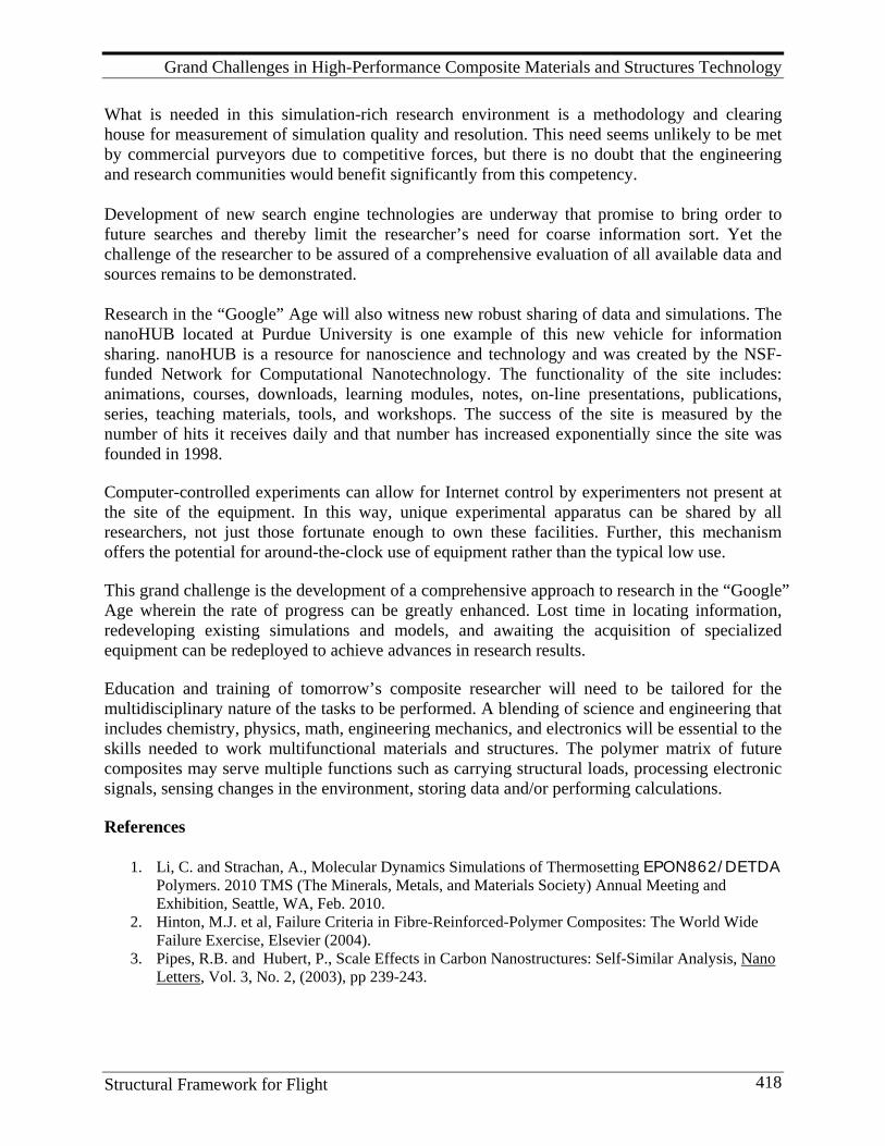
Grand Challenges in High-Performance Composite Materials and Structures Technology
Structural Framework for Flight 418
What is needed in this simulation-rich research environment is a methodology and clearing house for measurement of simulation quality and resolution. This need seems unlikely to be met by commercial purveyors due to competitive forces, but there is no doubt that the engineering and research communities would benefit significantly from this competency. Development of new search engine technologies are underway that promise to bring order to future searches and thereby limit the researcher’s need for coarse information sort. Yet the challenge of the researcher to be assured of a comprehensive evaluation of all available data and sources remains to be demonstrated. Research in the “Google” Age will also witness new robust sharing of data and simulations. The nanoHUB located at Purdue University is one example of this new vehicle for information sharing. nanoHUB is a resource for nanoscience and technology and was created by the NSF-funded Network for Computational Nanotechnology. The functionality of the site includes: animations, courses, downloads, learning modules, notes, on-line presentations, publications, series, teaching materials, tools, and workshops. The success of the site is measured by the number of hits it receives daily and that number has increased exponentially since the site was founded in 1998. Computer-controlled experiments can allow for Internet control by experimenters not present at the site of the equipment. In this way, unique experimental apparatus can be shared by all researchers, not just those fortunate enough to own these facilities. Further, this mechanism offers the potential for around-the-clock use of equipment rather than the typical low use. This grand challenge is the development of a comprehensive approach to research in the “Google” Age wherein the rate of progress can be greatly enhanced. Lost time in locating information, redeveloping existing simulations and models, and awaiting the acquisition of specialized equipment can be redeployed to achieve advances in research results. Education and training of tomorrow’s composite researcher will need to be tailored for the multidisciplinary nature of the tasks to be performed. A blending of science and engineering that includes chemistry, physics, math, engineering mechanics, and electronics will be essential to the skills needed to work multifunctional materials and structures. The polymer matrix of future composites may serve multiple functions such as carrying structural loads, processing electronic signals, sensing changes in the environment, storing data and/or performing calculations. References
1. Li, C. and Strachan, A., Molecular Dynamics Simulations of Thermosetting EPON862/DETDA Polymers. 2010 TMS (The Minerals, Metals, and Materials Society) Annual Meeting and Exhibition, Seattle, WA, Feb. 2010.
2. Hinton, M.J. et al, Failure Criteria in Fibre-Reinforced-Polymer Composites: The World Wide Failure Exercise, Elsevier (2004).
3. Pipes, R.B. and Hubert, P., Scale Effects in Carbon Nanostructures: Self-Similar Analysis, Nano Letters, Vol. 3, No. 2, (2003), pp 239-243.
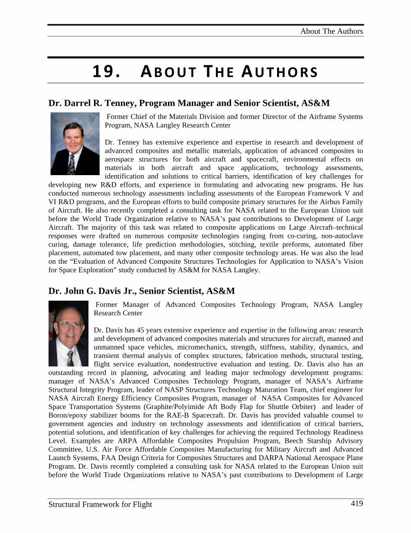
About The Authors
Structural Framework for Flight 419
19. A B O U T T H E A U T H O R S Dr. Darrel R. Tenney, Program Manager and Senior Scientist, AS&M
Former Chief of the Materials Division and former Director of the Airframe Systems Program, NASA Langley Research Center Dr. Tenney has extensive experience and expertise in research and development of advanced composites and metallic materials, application of advanced composites to aerospace structures for both aircraft and spacecraft, environmental effects on materials in both aircraft and space applications, technology assessments, identification and solutions to critical barriers, identification of key challenges for
developing new R&D efforts, and experience in formulating and advocating new programs. He has conducted numerous technology assessments including assessments of the European Framework V and VI R&D programs, and the European efforts to build composite primary structures for the Airbus Family of Aircraft. He also recently completed a consulting task for NASA related to the European Union suit before the World Trade Organization relative to NASA’s past contributions to Development of Large Aircraft. The majority of this task was related to composite applications on Large Aircraft–technical responses were drafted on numerous composite technologies ranging from co-curing, non-autoclave curing, damage tolerance, life prediction methodologies, stitching, textile preforms, automated fiber placement, automated tow placement, and many other composite technology areas. He was also the lead on the “Evaluation of Advanced Composite Structures Technologies for Application to NASA’s Vision for Space Exploration” study conducted by AS&M for NASA Langley.
Dr. John G. Davis Jr., Senior Scientist, AS&M Former Manager of Advanced Composites Technology Program, NASA Langley Research Center Dr. Davis has 45 years extensive experience and expertise in the following areas: research and development of advanced composites materials and structures for aircraft, manned and unmanned space vehicles, micromechanics, strength, stiffness, stability, dynamics, and transient thermal analysis of complex structures, fabrication methods, structural testing, flight service evaluation, nondestructive evaluation and testing. Dr. Davis also has an
outstanding record in planning, advocating and leading major technology development programs: manager of NASA’s Advanced Composites Technology Program, manager of NASA’s Airframe Structural Integrity Program, leader of NASP Structures Technology Maturation Team, chief engineer for NASA Aircraft Energy Efficiency Composites Program, manager of NASA Composites for Advanced Space Transportation Systems (Graphite/Polyimide Aft Body Flap for Shuttle Orbiter) and leader of Boron/epoxy stabilizer booms for the RAE-B Spacecraft. Dr. Davis has provided valuable counsel to government agencies and industry on technology assessments and identification of critical barriers, potential solutions, and identification of key challenges for achieving the required Technology Readiness Level. Examples are ARPA Affordable Composites Propulsion Program, Beech Starship Advisory Committee, U.S. Air Force Affordable Composites Manufacturing for Military Aircraft and Advanced Launch Systems, FAA Design Criteria for Composites Structures and DARPA National Aerospace Plane Program. Dr. Davis recently completed a consulting task for NASA related to the European Union suit before the World Trade Organizations relative to NASA’s past contributions to Development of Large
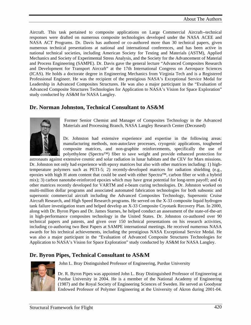
About The Authors
Structural Framework for Flight 420
Aircraft. This task pertained to composite applications on Large Commercial Aircraft--technical responses were drafted on numerous composite technologies developed under the NASA ACEE and NASA ACT Programs. Dr. Davis has authored or co-authored more than 30 technical papers, given numerous technical presentations at national and international conferences, and has been active in national technical societies, including American Society for Testing and Materials (ASTM), Applied Mechanics and Society of Experimental Stress Analysis, and the Society for the Advancement of Material and Process Engineering (SAMPE). Dr. Davis gave the general lecture “Advanced Composites Research and Development for Transport Aircraft” at the 17th International Congress on Aerospace Sciences (ICAS). He holds a doctorate degree in Engineering Mechanics from Virginia Tech and is a Registered Professional Engineer. He was the recipient of the prestigious NASA’s Exceptional Service Medal for Leadership in Advanced Composites Structures. He was also a major participant in the “Evaluation of Advanced Composite Structures Technologies for Application to NASA’s Vision for Space Exploration” study conducted by AS&M for NASA Langley.
Dr. Norman Johnston, Technical Consultant to AS&M
Former Senior Chemist and Manager of Composites Technology in the Advanced Materials and Processing Branch, NASA Langley Research Center (Deceased)
Dr. Johnston had extensive experience and expertise in the following areas: manufacturing methods, non-autoclave processes, cryogenic applications, toughened composite matrices, and non-graphite reinforcements, specifically the use of polyethylene (Spectra™) fiber to save weight and provide enhanced protection for
astronauts against extensive cosmic and solar radiation in lunar habitats and the CEV for Mars missions. Dr. Johnston not only had experience with epoxy matrices but also with other matrices including: 1) high-temperature polymers such as PETI-5; 2) recently-developed matrices for radiation shielding (e.g., epoxies with high H atom content that could be used with either Spectra™, carbon fiber or with a hybrid mix); 3) carbon nanotube-reinforced epoxies which may have great potential for long-term payoff; and 4) other matrices recently developed for VARTM and e-beam curing technologies. Dr. Johnston worked on multi-million dollar programs and associated automated fabrication technologies for both subsonic and supersonic commercial aircraft including the Advanced Composites Technology, Supersonic Cruise Aircraft Research, and High Speed Research programs. He served on the X-33 composite liquid hydrogen tank failure investigation team and helped develop an X-33 Composite Cryotank Recovery Plan. In 2000, along with Dr. Byron Pipes and Dr. James Starnes, he helped conduct an assessment of the state-of-the-art in high-performance composites technology in the United States. Dr. Johnston co-authored over 90 technical papers and patents, and given over 150 technical presentations on his research activities, including co-authoring two Best Papers at SAMPE international meetings. He received numerous NASA awards for his technical achievements, including the prestigious NASA Exceptional Service Medal. He was also a major participant in the “Evaluation of Advanced Composite Structures Technologies for Application to NASA’s Vision for Space Exploration” study conducted by AS&M for NASA Langley.
Dr. Byron Pipes, Technical Consultant to AS&M John L. Bray Distinguished Professor of Engineering, Purdue University Dr. R. Byron Pipes was appointed John L. Bray Distinguished Professor of Engineering at Purdue University in 2004. He is a member of the National Academy of Engineering (1987) and the Royal Society of Engineering Sciences of Sweden. He served as Goodyear Endowed Professor of Polymer Engineering at the University of Akron during 2001-04.
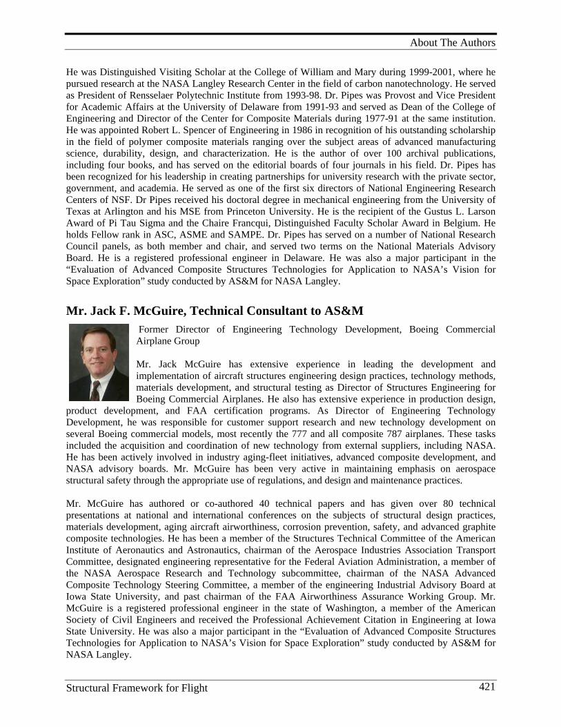
About The Authors
Structural Framework for Flight 421
He was Distinguished Visiting Scholar at the College of William and Mary during 1999-2001, where he pursued research at the NASA Langley Research Center in the field of carbon nanotechnology. He served as President of Rensselaer Polytechnic Institute from 1993-98. Dr. Pipes was Provost and Vice President for Academic Affairs at the University of Delaware from 1991-93 and served as Dean of the College of Engineering and Director of the Center for Composite Materials during 1977-91 at the same institution. He was appointed Robert L. Spencer of Engineering in 1986 in recognition of his outstanding scholarship in the field of polymer composite materials ranging over the subject areas of advanced manufacturing science, durability, design, and characterization. He is the author of over 100 archival publications, including four books, and has served on the editorial boards of four journals in his field. Dr. Pipes has been recognized for his leadership in creating partnerships for university research with the private sector, government, and academia. He served as one of the first six directors of National Engineering Research Centers of NSF. Dr Pipes received his doctoral degree in mechanical engineering from the University of Texas at Arlington and his MSE from Princeton University. He is the recipient of the Gustus L. Larson Award of Pi Tau Sigma and the Chaire Francqui, Distinguished Faculty Scholar Award in Belgium. He holds Fellow rank in ASC, ASME and SAMPE. Dr. Pipes has served on a number of National Research Council panels, as both member and chair, and served two terms on the National Materials Advisory Board. He is a registered professional engineer in Delaware. He was also a major participant in the “Evaluation of Advanced Composite Structures Technologies for Application to NASA’s Vision for Space Exploration” study conducted by AS&M for NASA Langley. Mr. Jack F. McGuire, Technical Consultant to AS&M
Former Director of Engineering Technology Development, Boeing Commercial Airplane Group Mr. Jack McGuire has extensive experience in leading the development and implementation of aircraft structures engineering design practices, technology methods, materials development, and structural testing as Director of Structures Engineering for Boeing Commercial Airplanes. He also has extensive experience in production design,
product development, and FAA certification programs. As Director of Engineering Technology Development, he was responsible for customer support research and new technology development on several Boeing commercial models, most recently the 777 and all composite 787 airplanes. These tasks included the acquisition and coordination of new technology from external suppliers, including NASA. He has been actively involved in industry aging-fleet initiatives, advanced composite development, and NASA advisory boards. Mr. McGuire has been very active in maintaining emphasis on aerospace structural safety through the appropriate use of regulations, and design and maintenance practices. Mr. McGuire has authored or co-authored 40 technical papers and has given over 80 technical presentations at national and international conferences on the subjects of structural design practices, materials development, aging aircraft airworthiness, corrosion prevention, safety, and advanced graphite composite technologies. He has been a member of the Structures Technical Committee of the American Institute of Aeronautics and Astronautics, chairman of the Aerospace Industries Association Transport Committee, designated engineering representative for the Federal Aviation Administration, a member of the NASA Aerospace Research and Technology subcommittee, chairman of the NASA Advanced Composite Technology Steering Committee, a member of the engineering Industrial Advisory Board at Iowa State University, and past chairman of the FAA Airworthiness Assurance Working Group. Mr. McGuire is a registered professional engineer in the state of Washington, a member of the American Society of Civil Engineers and received the Professional Achievement Citation in Engineering at Iowa State University. He was also a major participant in the “Evaluation of Advanced Composite Structures Technologies for Application to NASA’s Vision for Space Exploration” study conducted by AS&M for NASA Langley.
Appendix
Structural Framework for Flight 422
20. A P P E N D I X (A VA I L A B L E I N E L E C T R O N I C V E R S I O N )
Appendix 1. Selected Examples of the Productivity of One of the Premier Branches Doing Composites Research at NASA Langley, The Advanced Materials and Processing Branch (AMPB)
1. Technical References/Publications/Books 2. Patents and Invention Disclosures 3. Commercial Licensed Patents 4. Short Courses 5. Gordon Research Conferences (GRC) 6. NASA Commercial Invention of the Year 7. Other Miscellaneous Awards, Activities, and Memberships
Appendix 2. Selected Reviews/Symposia by AMPB Authors on Polymer Chemistry, Adhesives and Adhesive Properties, Composites and Composite Properties
1. Polymer Chemistry 2. Adhesives 3. Composites 4. Polymer Characterization 5. Symposia and Workshops on Polymer Chemistry, Adhesives and Adhesive Properties,
Composites and Composite Properties organized by NASA LaRC personnel; NASA and non-NASA presenters.
Appendix 3 AMPB Patents and Invention Disclosures
1. Patents (in order by number) 2. Invention Disclosures
Appendix 4 NASA-Virginia Tech Composite Program Students, Research Topics, and Advisors
STRUCTURALFRAMEWORKFOR FLIGHT I
STRUCTURAL FRAMEW
ORK FOR FLIGHT I
Research at NASA Langley Research Center onAdvanced Composite Materials
Dr. Darrel R. Tenney
Composite M
aterials
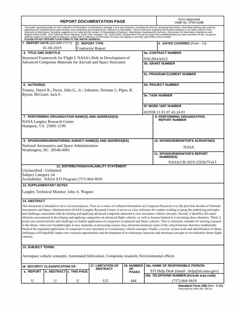
REPORT DOCUMENTATION PAGE Form ApprovedOMB No. 0704-0188
2. REPORT TYPEContractor Report
4. TITLE AND SUBTITLEStructural Framework for Flight I: NASA's Role in Development of Advanced Composite Materials for Aircraft and Space Structures
5a. CONTRACT NUMBER
NNL09AA01Z
6. AUTHOR(S)Tenney, Darrel R.; Davis, John G., Jr.; Johnston, Norman J.; Pipes, R. Byron; McGuire, Jack F.
7. PERFORMING ORGANIZATION NAME(S) AND ADDRESS(ES)NASA Langley Research CenterHampton, VA 23681-2199
9. SPONSORING/MONITORING AGENCY NAME(S) AND ADDRESS(ES)National Aeronautics and Space AdministrationWashington, DC 20546-0001
8. PERFORMING ORGANIZATIONREPORT NUMBER
10. SPONSOR/MONITOR'S ACRONYM(S)
NASA
13. SUPPLEMENTARY NOTES
Langley Technical Monitor: John A. Wagner
12. DISTRIBUTION/AVAILABILITY STATEMENTUnclassified - UnlimitedSubject Category 24Availability: NASA STI Program (757) 864-9658
19a. NAME OF RESPONSIBLE PERSONSTI Help Desk (email: [email protected])
14. ABSTRACTThis document is intended to serve several purposes. First, as a source of collated information on Composite Research over the past four decades at National Aeronautics and Space Administration (NASA) Langley Research Center, it serves as a key reference for readers wishing to grasp the underlying principles and challenges associated with developing and applying advanced composite materials to new aerospace vehicle concepts. Second, it identifies the major obstacles encountered in developing and applying composites on advanced flight vehicles, as well as lessons learned in overcoming these obstacles. Third, it points out current barriers and challenges to further application of composites to planned and future vehicles. This is extremely valuable for steering research in the future, when new breakthroughs in new materials or processing science may eliminate/minimize some of the critical barriers that have traditionally blocked the expanded application of composite to new structural or revolutionary vehicle concepts. Finally, a review of past work and identification of future challenges will hopefully inspire new research opportunities and development of revolutionary materials and structural concepts to revolutionize future flight vehicles.
15. SUBJECT TERMS
Aerospace vehicle concepts; Automated fabrication; Composite research; Environmental effects
18. NUMBEROFPAGES
44419b. TELEPHONE NUMBER (Include area code)
(757) 864-9658
a. REPORT
U
c. THIS PAGE
U
b. ABSTRACT
U
17. LIMITATION OFABSTRACT
UU
Prescribed by ANSI Std. Z39.18Standard Form 298 (Rev. 8-98)
3. DATES COVERED (From - To)
5b. GRANT NUMBER
5c. PROGRAM ELEMENT NUMBER
5d. PROJECT NUMBER
5e. TASK NUMBER
5f. WORK UNIT NUMBER
432938.11.01.07.43.24.01
11. SPONSOR/MONITOR'S REPORTNUMBER(S)
NASA/CR-2019-220267Vol I
16. SECURITY CLASSIFICATION OF:
The public reporting burden for this collection of information is estimated to average 1 hour per response, including the time for reviewing instructions, searching existing data sources, gathering and maintaining the data needed, and completing and reviewing the collection of information. Send comments regarding this burden estimate or any other aspect of this collection of information, including suggestions for reducing this burden, to Department of Defense, Washington Headquarters Services, Directorate for Information Operations and Reports (0704-0188), 1215 Jefferson Davis Highway, Suite 1204, Arlington, VA 22202-4302. Respondents should be aware that notwithstanding any other provision of law, no person shall be subject to any penalty for failing to comply with a collection of information if it does not display a currently valid OMB control number.PLEASE DO NOT RETURN YOUR FORM TO THE ABOVE ADDRESS.
1. REPORT DATE (DD-MM-YYYY)
1- 01-04-2019