narrow band and uwb wearable antennas: design and assessment of the conformal characteristics in...
TRANSCRIPT
Narrow Band and UWB Wearable Antennas: Design and Assessment of the Conformal Characteristics in terms of Impedance Matching and Radiation
Properties
Shuvashis Dey1 and Nandita Saha2
Abstract – In this paper the design of textile antennas for materials with three different substrate permittivity εr =3, 2.12, 2.22 are realized. Different textile substrates having different permittivity affect the antenna performance in various ways. Here, Microstrip Patch Antenna is designed for narrow band WBAN (Wearable Body Area Network) at the frequency level of 2.45GHz & also a design of circular disc monopole textile antenna with the operating frequency of 2.5GHz to 5GHz for UWB (Ultra Wide Band) is realized. For all design, Dacron fabric, denim jeans fabric and thick fleece fabric are used as antenna substrates & woven copper threads are used as the conductive part of the antenna patch. This paper demonstrates the effects of antenna bending at three different angles for both the antennas with denim jeans substrate. Here, resonance frequency fluctuations due to impedance matching as well as effects of radiation pattern deformation due to bending for different textile material substrates are focused. Several antennas have been tested on different substrates with acceptable performance. But this paper concentrates on textiles substrates rather than others. However here, with what extent the antenna will manage to give better performance with flexibility of textile material are mainly observed. Keywords: Microstrip Patch Antenna, narrow band, antenna bending, permittivity, WBAN, Circular disc monopole antenna, Ultra Wide Band
I. INTRODUCTION Body area networks (BAN) are a Natural progression from the personal area network (PAN). This network enables wearable computer devices to interact with each other and exchange digital information using the electrical conductivity of the human body as a data network [1]. Wearable intelligent textile system is an innovative fast growing field in application oriented field [2].The antenna is a fundamental part of wireless body area networks. Textile antenna is one of the most fascinating and cutting edge research areas of modern era. Enhancement in communication and electronic technology has enabled the development of compact and intelligent antenna devices which can be positioned on the human body or implanted inside it [3]. Such body wearable antennas should be hidden and unobtrusive [4]. Miniaturization in microelectronics along with other technologies allows these antennas to integrate into clothing paving the way to the development of wearable wireless devices. The textile antenna system can be used for a wide variety of applications including a more comfortable solution for real time physiological measurements systems, pulse rate monitoring in sports, and navigation support in the car and so on. They can also be used to keep continuous record of wearer’s health by monitoring their vital signs. Textile antennas also assist the emergency services such as fire fighters, detective and police [5]. It also helps to
establish communication between the soldiers and other units of the modern battle field including unmanned aerial vehicles [4]. In this paper, textile antenna is integrated fully into the garments to preserve flexibility and comfort. This antenna has a flat, planar structure to be comfortably worn. This antenna does not disturb the movement of the wearer since it is light weight and flexible. The radiation efficiency, cost-effectiveness, ease of system integration and immunity to performance degradation are also the factors to consider while designing this antenna. For wireless connectivity of wearable or on-body devices, ultra-wideband (UWB) technology is considered to be a favourable choice. UWB is a radio technology that can be used for short-range high-bandwidth communications by using a large portion of the radio spectrum. This wireless transmission scheme occupies a bandwidth of at least 25% of the centre frequency or more than 1.5 GHz unlike the narrower frequency band of the conventional systems. Therefore, a UWB signal centred at 2 GHz would have a minimum bandwidth of 500 MHz and the minimum bandwidth of a UWB signal centred at 4 GHz would be 1 GHz. UWB signal uses Orthogonal Frequency Division Multiplexing (OFDM) as the modulation technique to occupy the wide frequency band. This emerging wireless technology is recently approved by Federal Communications Commission (FCC) and is allocated the frequency band from 3.1 GHz to 10.6 GHz though other frequency bands with a bandwidth of more than 1.5 GHz can also be designated as UWB. In case of wearable
antennas it is quite difficult to have a flat antenna surface. Therefore, the designed antenna should be such that, even if the antenna is bent frequently, it should operate properly [6]. A circular disc monopole antenna designed for UWB wireless body area network to occupy a bandwidth of 2.5 GHz to 5 GHz & A Microstrip Patch Antenna is designed for narrow band (ISM) WBAN (Wireless Body Area Network) at the frequency level of 2.45GHz for short range communication. Here three different textile substrates with different permittivity εr = 3, 2.12, 2.22 are used to realize this types of antennas. In case of wearable textile antennas it is quite difficult to have a flat antenna surface. Therefore, the designed antenna should be such that, even if the antenna is bent frequently, it should work properly [6]. This paper mainly focuses to evaluate the designed antenna's performance under bending conditions. This phenomenon is achieved by bending designed UWB circular disc monopole textile antenna & the micro strip patch antenna having substrate textile material jeans with permittivity εr =2.12 at 3 different angles. Originality of this work is- the designed narrow band antenna resonates at ISM 2.45 GHz frequency for planar structure as well as for bended condition & for UWB antenna the bending consequences on the designed antenna at different angles are conducted and equally the resultant effects on impedance matching and radiation pattern are investigated & compared for three different textile substrate materials.
II. TEXTILE SUBSTRATE MATERIALS
SELECTION The permittivity of a material is usually given relative to that of free space which is known as relative permittivity or dielectric constant; εr. Different substrates having different dielectric constants affect the antenna performance in various ways. Here, hypalon coated Dacron fabric with εr =3, denim jeans fabric with εr =2.12, thick fleece fabric with εr =2.22 are used as antenna substrates. Selection of material for designing the antenna is unique in this paper. Properties of Dacron and fabric include high tensile strength, high resistance to stretching, durability, outstanding electrical property. Popular textile material denim jeans are a rugged cotton twill textile, in which the weft passes under two or more warp threads. The patch is made of woven copper thread. An antenna’s performance under bending conditions is one of the important factors for wearable applications. Under an on-body environment it is difficult to keep the antenna in a flat condition especially for elements made of textile materials [7]. Having established that many textiles are suitable for use as antenna substrates an electrically conductive fabric for the ground plane as well as for the antenna patches was required. For the purposes of a textile antenna design, a conductive fabric needs to satisfy the following requirements: the material must be homogeneous over the antenna area, and the variance of the resistance through the material should be small; the fabric should be flexible such that the antenna can be
deformed when worn; the fabric should be inelastic, as the electrical property of elastic fabrics might change when stretching or bending [7-8].
III. ANTENNA DESIGN AND IMPLEMENTATION Commercial electromagnetic simulation package CST Microwave Studio was used for design & simulation purposes. A good impedance matching is obtained by using the CST macros calculator for both UWB & narrow band antennas.
III. 1. Planar microstrip patch textile antenna
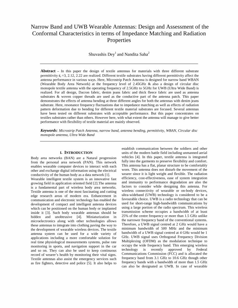
The Microstrip Patch Antenna is designed to operate at 2.45 GHz. The patch ground plane is attached on the back of the substrate with the same dimensions of it. The antenna is fed by 50 ohm impedance.
TABLE I
MICROSTRIP PATCH ANTENNA MEASUREMENTS FOR DESIGNING
Parameters For εεεεr=3
For εεεεr=2.22
For εεεεr=2.12
Rectangular patch(L)
34 40 42
Rectangular patch(W)
44 58 50
Substrate(L) 80 90 90 Substrate(W) 60 80 80 Substrate thickness
1.524 1.524 1.6
Feed(W) 3.8 4.5 5.089
Fig. 1. MICROSTRIP patch antenna for substrate permittivity 3
Fig. 2. Microstrip patch antenna for substrate permittivity 2.2

Fig. 3. Microstrip patch antenna for substrate permittivity 2.12
III. 2. Planar UWB circular disc monopole textile antenna
Circular disc monopole antenna is chosen since it has got a simple structure and it exhibits ultra wide band characteristics. It also has a nearly Omni-directional pattern. It is low profile and light in weight which enables this antenna to integrate fully into the textile materials. The disc of the antenna is fed by a 50 ohm feed line with a width of 1.4mm. A conductive ground plane with a length of 50mm is placed on the same side of the disc and the feed on the substrate. The feed gap between the metal strip and the ground plane is 0.9 mm and the gap between the disc and the ground plane is set to 1mm. The same design with exact measurement is maintained for all the three substrates Dacron, denim jeans & thick fleece fabric.
(a) Dacron Fabric
(b) Fleece Fabric (c) Denim Jeans
Fig. 4. Planar ultra wide band circular disc monopole antenna
TABLE III MEASUREMENTS OF UWB CIRCULAR DISC MONOPOLE TEXTILE
ANTENNA
Parameters Size (mm)
Circular Disc (Radius)
26.5
Circular Disc (Thickness)
0.5
Substrate (Length)
120
Substrate (Width)
130
Substrate (Thickness)
1.6
Ground (Thickness)
0.5
IV. BENDING OF MICROSTRIP PATCH ANTENNA & UWB CIRCULAR DISC MONOPOLE ANTENNA
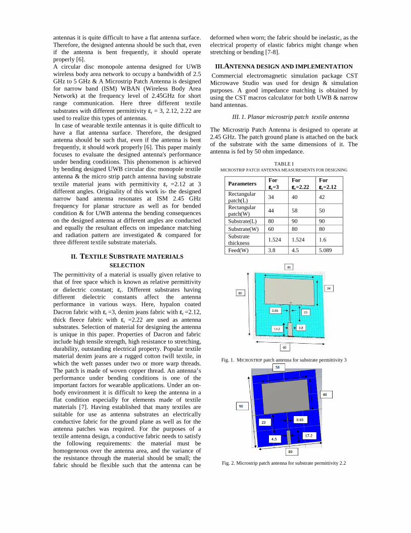
To investigate the effect of bending on the narrow band rectangular patch antenna & UWB circular disc monopole antenna, we have chosen the antenna with substrate (denim jeans) permittivity εr = 2.12. We have bended these antennas in 3 different angles 20, 40 and 70 degrees with the help of CST microwave studio.
Fig. 5. microstrip patch antenna measurements for bending purpose
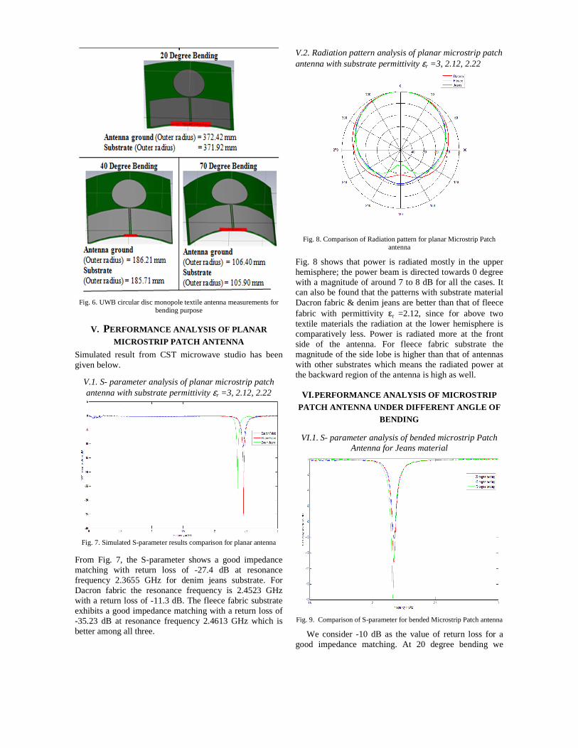
Fig. 6. UWB circular disc monopole textile antenna measurements for bending purpose
V. PERFORMANCE ANALYSIS OF PLANAR
MICROSTRIP PATCH ANTENNA Simulated result from CST microwave studio has been given below.
V.1. S- parameter analysis of planar microstrip patch antenna with substrate permittivity εr =3, 2.12, 2.22
Fig. 7. Simulated S-parameter results comparison for planar antenna
From Fig. 7, the S-parameter shows a good impedance matching with return loss of -27.4 dB at resonance frequency 2.3655 GHz for denim jeans substrate. For Dacron fabric the resonance frequency is 2.4523 GHz with a return loss of -11.3 dB. The fleece fabric substrate exhibits a good impedance matching with a return loss of -35.23 dB at resonance frequency 2.4613 GHz which is better among all three.
V.2. Radiation pattern analysis of planar microstrip patch antenna with substrate permittivity εr =3, 2.12, 2.22
Fig. 8. Comparison of Radiation pattern for planar Microstrip Patch antenna
Fig. 8 shows that power is radiated mostly in the upper hemisphere; the power beam is directed towards 0 degree with a magnitude of around 7 to 8 dB for all the cases. It can also be found that the patterns with substrate material Dacron fabric & denim jeans are better than that of fleece fabric with permittivity εr =2.12, since for above two textile materials the radiation at the lower hemisphere is comparatively less. Power is radiated more at the front side of the antenna. For fleece fabric substrate the magnitude of the side lobe is higher than that of antennas with other substrates which means the radiated power at the backward region of the antenna is high as well.
VI. PERFORMANCE ANALYSIS OF MICROSTRIP
PATCH ANTENNA UNDER DIFFERENT ANGLE OF
BENDING
VI.1. S- parameter analysis of bended microstrip Patch Antenna for Jeans material
Fig. 9. Comparison of S-parameter for bended Microstrip Patch antenna
We consider -10 dB as the value of return loss for a good impedance matching. At 20 degree bending we
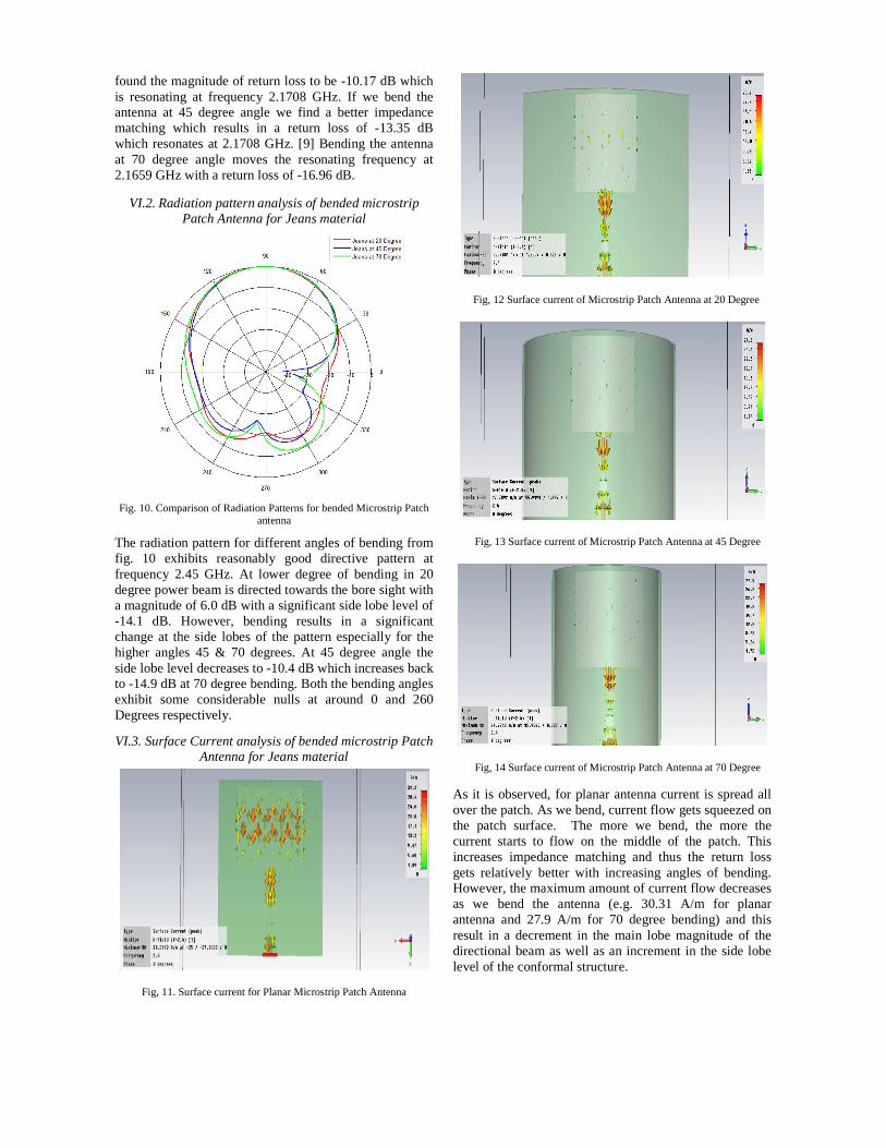
found the magnitude of return loss to be -10.17 dB which is resonating at frequency 2.1708 GHz. If we bend the antenna at 45 degree angle we find a better impedance matching which results in a return loss of -13.35 dB which resonates at 2.1708 GHz. [9] Bending the antenna at 70 degree angle moves the resonating frequency at 2.1659 GHz with a return loss of -16.96 dB.
VI.2. Radiation pattern analysis of bended microstrip Patch Antenna for Jeans material
Fig. 10. Comparison of Radiation Patterns for bended Microstrip Patch antenna
The radiation pattern for different angles of bending from fig. 10 exhibits reasonably good directive pattern at frequency 2.45 GHz. At lower degree of bending in 20 degree power beam is directed towards the bore sight with a magnitude of 6.0 dB with a significant side lobe level of -14.1 dB. However, bending results in a significant change at the side lobes of the pattern especially for the higher angles 45 & 70 degrees. At 45 degree angle the side lobe level decreases to -10.4 dB which increases back to -14.9 dB at 70 degree bending. Both the bending angles exhibit some considerable nulls at around 0 and 260 Degrees respectively.
VI.3. Surface Current analysis of bended microstrip Patch Antenna for Jeans material
Fig, 11. Surface current for Planar Microstrip Patch Antenna
Fig, 12 Surface current of Microstrip Patch Antenna at 20 Degree
Fig, 13 Surface current of Microstrip Patch Antenna at 45 Degree
Fig, 14 Surface current of Microstrip Patch Antenna at 70 Degree
As it is observed, for planar antenna current is spread all over the patch. As we bend, current flow gets squeezed on the patch surface. The more we bend, the more the current starts to flow on the middle of the patch. This increases impedance matching and thus the return loss gets relatively better with increasing angles of bending. However, the maximum amount of current flow decreases as we bend the antenna (e.g. 30.31 A/m for planar antenna and 27.9 A/m for 70 degree bending) and this result in a decrement in the main lobe magnitude of the directional beam as well as an increment in the side lobe level of the conformal structure.
VII. PERFORMANCE ANALYSIS OF PLANAR
UWB ANTENNA
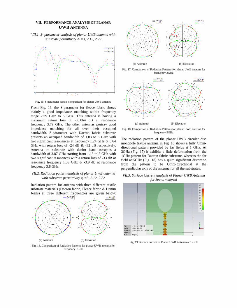
VII.1. S- parameter analysis of planar UWB antenna with substrate permittivity εr =3, 2.12, 2.22
Fig. 15. S-parameter results comparison for planar UWB antenna
From Fig. 15, the S-parameter for fleece fabric shows mainly a good impedance matching within frequency range 2.69 GHz to 5 GHz. This antenna is having a maximum return loss of -35.064 dB at resonance frequency 3.79 GHz. The other antennas portray good impedance matching for all over their occupied bandwidth. S-parameter with Dacron fabric substrate presents an occupied bandwidth of 1.03 to 5 GHz with two significant resonances at frequency 1.24 GHz & 3.64 GHz with return loss of -24 dB & -32 dB respectively. Antenna on substrate with denim jeans occupies a bandwidth of 3.87 GHz starting from 1.13 to 5 GHz with two significant resonances with a return loss of -33 dB at resonance frequency 1.39 GHz & -3.9 dB at resonance frequency 3.8 GHz.
VII.2. Radiation pattern analysis of planar UWB antenna with substrate permittivity εr =3, 2.12, 2.22
Radiation pattern for antenna with three different textile substrate materials (Dacron fabric, Fleece fabric & Denim Jeans) at three different frequencies are given below:
(a) Azimuth (b) Elevation
Fig. 16. Comparison of Radiation Patterns for planar UWB antenna for frequency 1GHz
(a) Azimuth (b) Elevation
Fig. 17. Comparison of Radiation Patterns for planar UWB antenna for frequency 3GHz
(a) Azimuth (b) Elevation
Fig. 18. Comparison of Radiation Patterns for planar UWB antenna for frequency 5GHz
The radiation pattern of the planar UWB circular disc monopole textile antenna in Fig. 16 shows a fully Omni-directional pattern provided by far fields at 1 GHz. At 3GHz (Fig. 17) it exhibits a little deformation from the 1GHz pattern for Dacron fabric substrate, whereas the far field at 5GHz (Fig. 18) has a quite significant distortion from the pattern to be Omni-directional at the perpendicular axis of the antenna for all the substrates.
VII.3. Surface Current analysis of Planar UWB Antenna for Jeans material
Fig, 19. Surface current of Planar UWB Antenna at 1 GHz
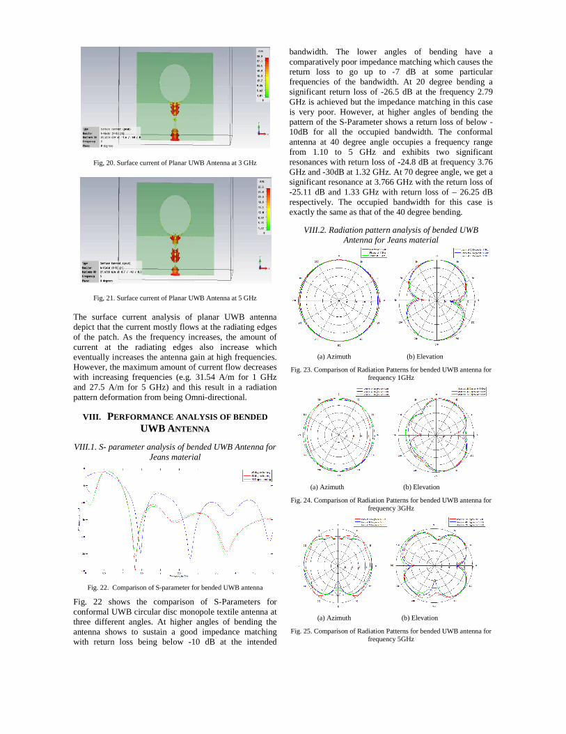
Fig, 20. Surface current of Planar UWB Antenna at 3 GHz
Fig, 21. Surface current of Planar UWB Antenna at 5 GHz The surface current analysis of planar UWB antenna depict that the current mostly flows at the radiating edges of the patch. As the frequency increases, the amount of current at the radiating edges also increase which eventually increases the antenna gain at high frequencies. However, the maximum amount of current flow decreases with increasing frequencies (e.g. 31.54 A/m for 1 GHz and 27.5 A/m for 5 GHz) and this result in a radiation pattern deformation from being Omni-directional.
VIII. PERFORMANCE ANALYSIS OF BENDED
UWB ANTENNA
VIII.1. S- parameter analysis of bended UWB Antenna for Jeans material
Fig. 22. Comparison of S-parameter for bended UWB antenna
Fig. 22 shows the comparison of S-Parameters for conformal UWB circular disc monopole textile antenna at three different angles. At higher angles of bending the antenna shows to sustain a good impedance matching with return loss being below -10 dB at the intended
bandwidth. The lower angles of bending have a comparatively poor impedance matching which causes the return loss to go up to -7 dB at some particular frequencies of the bandwidth. At 20 degree bending a significant return loss of -26.5 dB at the frequency 2.79 GHz is achieved but the impedance matching in this case is very poor. However, at higher angles of bending the pattern of the S-Parameter shows a return loss of below -10dB for all the occupied bandwidth. The conformal antenna at 40 degree angle occupies a frequency range from 1.10 to 5 GHz and exhibits two significant resonances with return loss of -24.8 dB at frequency 3.76 GHz and -30dB at 1.32 GHz. At 70 degree angle, we get a significant resonance at 3.766 GHz with the return loss of -25.11 dB and 1.33 GHz with return loss of – 26.25 dB respectively. The occupied bandwidth for this case is exactly the same as that of the 40 degree bending.
VIII.2. Radiation pattern analysis of bended UWB Antenna for Jeans material
(a) Azimuth (b) Elevation
Fig. 23. Comparison of Radiation Patterns for bended UWB antenna for frequency 1GHz
(a) Azimuth (b) Elevation
Fig. 24. Comparison of Radiation Patterns for bended UWB antenna for frequency 3GHz
(a) Azimuth (b) Elevation
Fig. 25. Comparison of Radiation Patterns for bended UWB antenna for frequency 5GHz
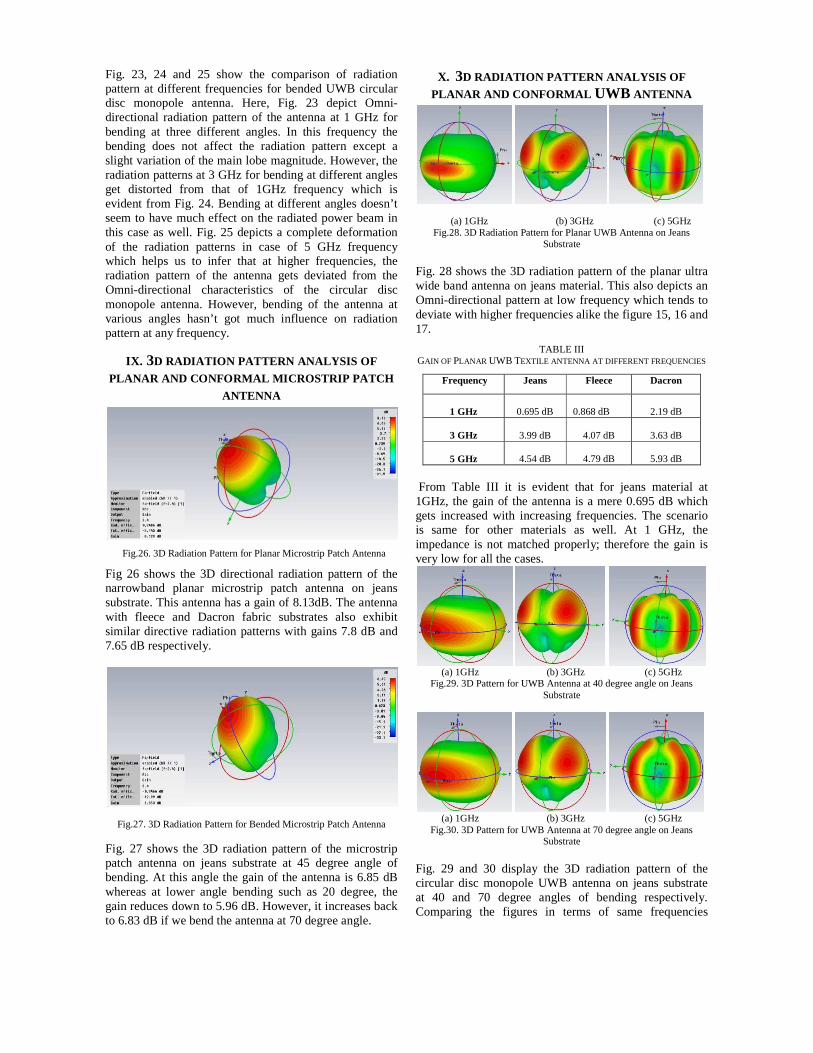
Fig. 23, 24 and 25 show the comparison of radiation pattern at different frequencies for bended UWB circular disc monopole antenna. Here, Fig. 23 depict Omni-directional radiation pattern of the antenna at 1 GHz for bending at three different angles. In this frequency the bending does not affect the radiation pattern except a slight variation of the main lobe magnitude. However, the radiation patterns at 3 GHz for bending at different angles get distorted from that of 1GHz frequency which is evident from Fig. 24. Bending at different angles doesn’t seem to have much effect on the radiated power beam in this case as well. Fig. 25 depicts a complete deformation of the radiation patterns in case of 5 GHz frequency which helps us to infer that at higher frequencies, the radiation pattern of the antenna gets deviated from the Omni-directional characteristics of the circular disc monopole antenna. However, bending of the antenna at various angles hasn’t got much influence on radiation pattern at any frequency.
IX. 3D RADIATION PATTERN ANALYSIS OF
PLANAR AND CONFORMAL MICROSTRIP PATCH
ANTENNA
Fig.26. 3D Radiation Pattern for Planar Microstrip Patch Antenna
Fig 26 shows the 3D directional radiation pattern of the narrowband planar microstrip patch antenna on jeans substrate. This antenna has a gain of 8.13dB. The antenna with fleece and Dacron fabric substrates also exhibit similar directive radiation patterns with gains 7.8 dB and 7.65 dB respectively.
Fig.27. 3D Radiation Pattern for Bended Microstrip Patch Antenna
Fig. 27 shows the 3D radiation pattern of the microstrip patch antenna on jeans substrate at 45 degree angle of bending. At this angle the gain of the antenna is 6.85 dB whereas at lower angle bending such as 20 degree, the gain reduces down to 5.96 dB. However, it increases back to 6.83 dB if we bend the antenna at 70 degree angle.
X. 3D RADIATION PATTERN ANALYSIS OF
PLANAR AND CONFORMAL UWB ANTENNA
(a) 1GHz (b) 3GHz (c) 5GHz
Fig.28. 3D Radiation Pattern for Planar UWB Antenna on Jeans Substrate
Fig. 28 shows the 3D radiation pattern of the planar ultra wide band antenna on jeans material. This also depicts an Omni-directional pattern at low frequency which tends to deviate with higher frequencies alike the figure 15, 16 and 17.
TABLE III GAIN OF PLANAR UWB TEXTILE ANTENNA AT DIFFERENT FREQUENCIES
Frequency Jeans Fleece Dacron
1 GHz
0.695 dB
0.868 dB
2.19 dB
3 GHz
3.99 dB
4.07 dB
3.63 dB
5 GHz
4.54 dB
4.79 dB
5.93 dB
From Table III it is evident that for jeans material at 1GHz, the gain of the antenna is a mere 0.695 dB which gets increased with increasing frequencies. The scenario is same for other materials as well. At 1 GHz, the impedance is not matched properly; therefore the gain is very low for all the cases.
(a) 1GHz (b) 3GHz (c) 5GHz
Fig.29. 3D Pattern for UWB Antenna at 40 degree angle on Jeans Substrate
(a) 1GHz (b) 3GHz (c) 5GHz
Fig.30. 3D Pattern for UWB Antenna at 70 degree angle on Jeans Substrate
Fig. 29 and 30 display the 3D radiation pattern of the circular disc monopole UWB antenna on jeans substrate at 40 and 70 degree angles of bending respectively. Comparing the figures in terms of same frequencies

reveal that there is literally no change of the patterns in this case, irrespective of bending. However, the patterns tend to change with increasing frequencies even for the bended antennas just like the planar structure. [10]
TABLE IV GAIN OF BENDED UWB TEXTILE ANTENNA AT DIFFERENT FREQUENCIES
Frequency 20 Degree 40 Degree 70 Degree
1 GHz
0.952 dB
2.42 dB
2.36 dB
3 GHz
4.23 dB
4.2 dB
4.08 dB
5 GHz
4.57 dB
5.47 dB
5.17 dB
Table IV shows the gain of the UWB antenna at different bending angles for different frequencies. Here, as well, the gain of the antenna increases with increasing frequencies. Interestingly, comparing table III and IV in terms of a particular frequency reveals that the impedance matching gets better as we bend the antenna and therefore, the gain increases. However, if we keep bending the antenna, the gain tends to fluctuate with higher angles of bending.
XI. CONCLUSION From the performance analysis of narrowband planar structure it has been noticed that for substrate permittivity εr =2.22 impedance matching is better than others with return loss of -35.23 dB and resonance frequency of 2.4613 GHz. Radiation patterns for NWB planar structure of the antenna depict that magnitude of main lobe is highest (8 dB) for antenna with substrate permittivity εr
=2.12 and the lowest (7.1 dB) for antenna with higher substrate permittivity εr =3. It has been observed that the antenna’s impedance matching is affected by bending. From comparison of S-parameter simulated result for different bending angles, conclusion can be drawn that more bending of the structure gives improved impedance matching during bended condition. However, the resonance frequency tends to deviate more from that of the planar structure (2.3655 GHz) as we keep bending the antenna. Bending does not affect the radiation pattern much at the bore sight; however, it causes the introduction of higher side lobe levels. The UWB antenna structures exhibit a similar performance in terms of the s-parameter. Here too, the impedance matching gets better with higher angles of bending. The radiation pattern is not subject to much change due to the conformal effects. Bending the antenna causes a very little alteration to the radiation pattern at a particular frequency though at increasing frequencies, the pattern starts to deform from its initial Omni-directional behaviour, irrespective of bending. However, the antenna exhibits a moderate gain for all the states. Since the functionality of both the antennas can be maintained even though we bend the structure, it could be deduced that the designed antennas are quite effective and fully flexible textile antenna. [9-10]
REFERENCES [1] J. G. Santas, A. Alomainy and Y. Hao (2007). “Textile Antennas
for On-Body Communications: Techniques and Properties." Antennas and Propagation, EuCAP 2007. The Second European Conference, pp. 1-4, (978-0-86341-842-6), 2007.
[2] T. E. Starner, “Wearable computing for the developing world,” IEEE Pervasive Computing, vol. 4, pp. 87–91, Jul.–Sep. 2005,
[3] A. Alomainy, Y. Hao & F. Pasveer, “Antennas for Wearable Devices in Zhi Ning Chen (Ed)”, “Antennas for Portable Devices”, West Sussex, England: Academic. (978-0-470-03073-8), pp.197 -226, 2007.
[4] C. Hertleer, A. Tronquo, H. Rogier, and L. Van Langenhove, “An aperture-coupled patch antenna for integration into wearable textile systems,” IEEE Antennas Wireless Propagation Letter vol. 6, pp. 392–395, 2007.
[5] C. Hertleer, A. Tronquo, H. Rogier, and L. Van Langenhove, “A Textile Antenna for Off-Body Communication Integrated Into Protective Clothing for Firefighters” IEEE Antennas Wireless Propagation. Letter vol. 57, pp. 919-925, 2009.
[6] P. Salonen and Y. Rahmat-Samii, "Textile Antennas: Effects of Antenna Bending on Input Impedance Matching and Bandwidth", The European Conference on Antennas and Propagation: EuCAP 2006, 6-10 November 2006, Nice, France.
[7] S. Zhu, R. Langley, “Dual Band Textile Antenna on an EBG Substrate”, IEEE Transaction on Antennas & Propagation, vol 57, no. 4, April 2009.
[8] Md. Hasanuzzaman Sagor, Qammer H. Abbasi, Akram Alomainy and Yang Hao, “Compact and conformal Ultra Wideband Antenna for Wearable Applications”, The 5th European Conference on Antenna and Propagation, 2011, April 2011, Rome, Italy
[9] Shuvashis Dey, Nandita Saha and Akram Alomainy. “Design and performance analysis of narrowband textile antenna for three different substrate permittivity materials and bending consequence." 7th Loughborough Antenna and Propagation Conference (LAPC), 2011, November 2011, Loughborough, UK
[10] Shuvashis Dey, Nandita Saha and Subrata Biswas. “Design and performance analysis of UWB circular disc monopole textile antenna and bending consequences." The 5th European Conference on Antenna and Propagation, 2011, April 2011, Rome, Italy
Shuvashis Dey was born in Chittagong, Bangladesh on January 1, 1986. Shuvashis received Bachelor of Technology (B.Tech) degree in electronics and communication engineering from National Institute of Technology-Durgapur, West Bengal, India in 2007 and he received M.Sc Degree in wireless networks (physical pathway) from Queen Mary, University of London, England,
United Kingdom in 2009.
He has worked as an Industrial Trainee during his summer internship in 2007 at Central Mechanical Engineering and Research Institute-Durgapur, India where he has participated in various projects on programmable logic controller and embedded systems. In 2010 he joined the Department of Electrical and Electronic Engineering at American International University-Bangladesh, Dhaka, Bangladesh as a lecturer. He is the author and co-author of several peer-reviewed papers and contributions at prominent journal and international conferences. His research interests include antenna for mobile communications, Wearable antennas for portable devices, Body-worn antennas for healthcare applications, Small and efficient antennas, UWB and SWB conformal antennas, CDMA-OFDM integration and Ad-hoc networks.
Mr. Dey is a member of IEEE.
Nandita Saha was born in Dhaka, Bangladesh on March 17, 1985. Nandita received B.Tech degree in Electrical Engineering from National Institute of Technology, Durgapur, India in 2008 under Indian Gov’t. Scholarship Scheme. She is currently pursuing her Master’s of Science in “Digital Communications” in the Department of Electrical Engineering and Information Technology, Technical
Faculty, University of Kiel, Germany.

She worked as a Lecturer in the department of Electrical and Electronic Engineering of American International University-Bangladesh from September 2008 to August 2012. She has done her summer interns in National Thermal Power Corporation in India and National Institute for Mass Communication of Bangladesh. She is the author and co-author of several peer-reviewed papers and contributions at international conferences. Her research interests include wearable antennas for portable devices, Body-worn antennas for healthcare applications, Small and efficient antennas, UWB and SWB conformal antennas & Medical Signal processing. Ms. Saha is a member of IEEE.