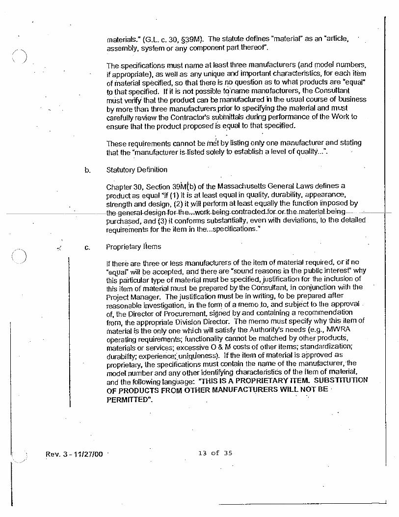
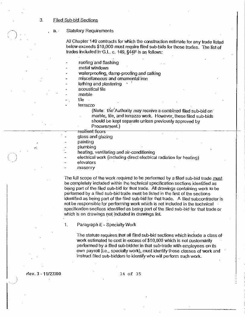
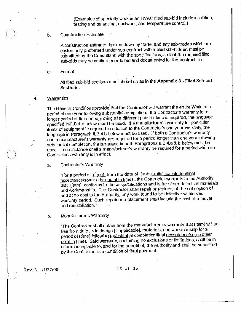
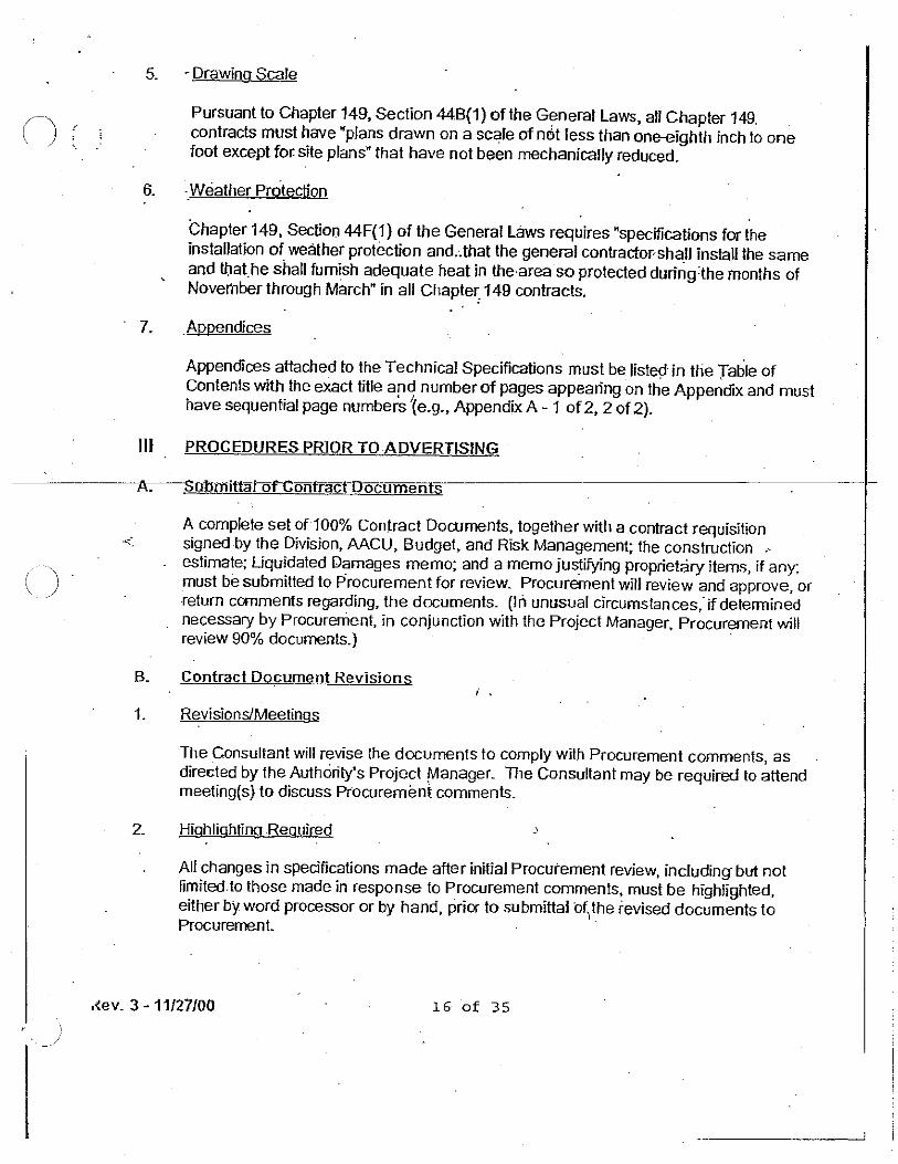
mwra contract no. 7677 - mass.gov
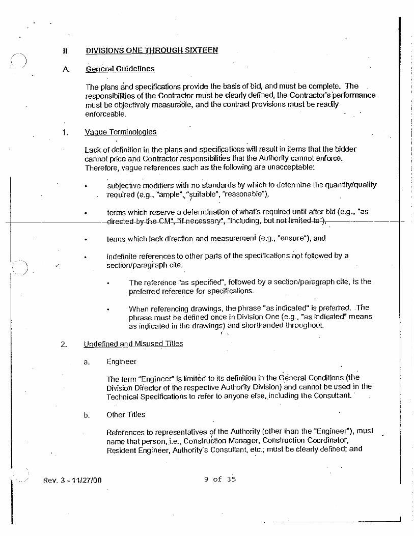
TRANSCRIPT
MWRA Contract No. 7677 DCR Quabbin Maintenance Building January 2020
GENERAL REQUIREMENTS 1. Subconsultant Communications
1.1 Any communication from subconsultants shall be through the Consultant and shall include
the Consultant’s recommended action, whether the items in question are design/ technical-related or administrative (e.g., wage rates or personnel changes).
1.2 All recommendations and all work produced by the subconsultants shall be reviewed and approved in writing by the Consultant before submittal to the Authority. If the Consultant takes issue with the product or recommendations of the subconsultant the Consultant may note the difference of opinion in its correspondence, but it shall be the Consultant’s responsibility to make the contractual recommendation that will govern the design.
1.3 All work performed by subconsultants shall be coordinated, administered, and reviewed by the Consultant. Accordingly, all deliverables and any other Project documents prepared by subconsultants shall be submitted to the Authority through the Consultant. All Project documents shall be prepared in a standard format, listing the Consultant’s name and, as applicable, that of the subcontractor preparing the deliverable.
2. Cost Analyses
2.1 At all times during the work under this contract the Consultant shall be cognizant of the
capital, operations, and maintenance (O&M) costs associated with the overall Project and with each of the technical decisions that will be made for this Project. In making these decisions, attempt to meet the Project goals and the specific objectives of this Scope of Services with the lowest cost solutions that satisfy the technical and legal requirements of the Project, as well as Authority policy.
2.2 Evaluate alternative solutions and associated costs in all technical decisions in accordance with the Authority’s Guidelines for Life Cycle Cost Estimating (LCCAP) and associated procedural requirements. LCCAP requires written documentation that, with reasonable detail, identifies the assumptions, sources of information, and technical evaluations that support the technical recommendations. Cost estimate backup and supporting documentation, shall be included with the cost estimate, and shall become a part of the Project records.
2.3 Capital and O&M cost estimates shall be detailed, and shall cover all Project elements for
each design submittal identified in the Scope of Services. All capital and O&M cost estimating performed to support the technical decisions or to produce other cost estimate deliverables required by this Scope of Services shall conform to the Authority’s, Guidelines for Life Cycle Cost Estimating.
3. Submittals
3.1 Every submittal shall include a cover letter directed to the Authority Project Manager’s attention with reference made to the contract number and subtask for which the submittal was prepared. In each cover letter, the Consultant shall state that the QA/QC procedures approved for this Project were followed.
3.2 Every deliverable in the Scope of Services shall include both draft and final submittals. The Consultant shall allow for MWRA review time for all deliverables and time to revise the deliverables in response to MWRA’s review.
3.3 Unless otherwise stated in this Scope of Services for specific submittals, the Authority will normally review submittals within three weeks of receipt.
3.4 Every revised submittal made to the Authority shall include a progress change copy, which identifies any changes made since the previous submittal. Changes shall be identified using redline/strikeout methods. Where the change is made in response to review comments made by the Authority, the change shall be annotated to show the comment which resulted in the change.
3.5 Every submittal, including draft and final memoranda, reports, specifications and
drawings shall consist of ten (10) bound paper copies and one computer file copy, unless otherwise stated in this Scope of Services. Final approved submittals shall be accompanied by one unbound, unstapled reproducible copy. The computer file copies shall be submitted on CD, or other media approved by the MWRA, and shall adhere to the document format and compatibility requirements of this Scope of Services.
3.6 The Authority may reject any draft submittal that is incomplete or otherwise unacceptable; if so, a revised draft submittal shall be prepared and submitted for review at no additional cost to the Authority.
3.7 No information shall be submitted to anyone outside of the Authority without the express permission and direction of the MWRA Project Manager. The Consultant and Subconsultants may conduct project correspondence with third parties only with prior approval of the MWRA Project Manager.
3.8 The Consultant shall meet each submittal deadline as provided in the Project Schedule. 4. Document Format and Compatibility
4.1 All Documents shall be prepared in accordance with the Authority’s Design and Information Systems Center (DISC) Documents Standards and Procedures included in the Supporting Documents. All drawings shall be prepared using AutoCAD 2013, or other acceptable software version currently in use at the Authority. Use only DWG entity types that may be converted to ARC/INFO.
4.2 Drawings generated for this Project may ultimately be input into the MWRA Planning Department’s Geographic Information System (GIS) by Authority personnel. Therefore, the following requirements shall be followed in preparing the base maps, preliminary and final contract drawings, record drawings and detail records:
4.2.1 A digital copy of all drawings shall be submitted in DWG format, which shall be readily transferable to the MWRA GIS which uses ARC/INFO Software.
4.2.2 Drawings shall utilize sheet formats, legend information and symbols provided by the Authority together with any supplemental formats, legend information and symbols which may be provided by the Consultant with the approval of the Authority.
4.2.3 In preparing base mapping and design drawings, the Consultant shall be mindful of the Authority’s requirements (technique and appearance) relative to Record Drawings and Detail Records, which shall be prepared from the Design Drawings by the Consultant following construction.
4.2.4 The DWG electronic file shall depict the same drawing content as displayed on
the hard copy.
4.2.5 Electronic files shall be submitted in TIFF format for each record drawing.
4.2.6 Provide files on a media (CD, DVD, etc.) that is compatible with hardware in use at the MWRA.
4.2.7 Each plan drawing must contain a minimum of four (4) points tied to the Massachusetts State Plane Coordinates (NAD83) and the northing and
easting of these points shall be clearly visible. Each plan drawing must reference elevations tied to the Metropolitan District Water Supply Commission Datum (MDWSC). This Datum is integral to the Quabbin Reservoir and all related infrastructure. Horizontal Datum shall be: NAD83 Massachusetts State Planes, Mainland Zone, US Foot. The provided site survey and base plan drawings are in an assumed horizontal coordinate system. Consultant shall ensure their provided plans meet the specification in the General Requirements, by establishing the above referenced horizontal datum at the site.Vertical Datum shall be: District Water Supply Commission (MDWSC) MDWSC Datum of Elevations is 6.049 feet below “Mean Sea Level” as determined by U.S. Coast and Geodetic Survey, First Order Level Net New England Preliminary Adjustment of January 1928 (with 1929 General Adjustments). MDWSC Datum is not equivalent to Boston City Base. Two (2) Permanent Benchmarks (MDWSC, vertical only) are established at the site and are indicated on the provided plans.
4.2.8 Except as noted elsewhere, Base Mapping, Design Drawings and Record Drawings shall be at 2-foot contour intervals and a scale of 40 feet equals 1 inch, with a vertical exaggeration factor of 10 for profiles. In cases where 40 scale drawings do not provide sufficient clarity, supplemental details at greater scales approved by the Project Manager shall be provided. Engineering drawings shall be 24”x36”. Each drawing shall be stamped and signed by a Massachusetts Registered Professional Engineer for that particular discipline.
4.2.9 In addition, all memoranda, reports and specifications shall be prepared in a
format compatible with Microsoft Word for Windows. 5. Project Communication Records
5.1 Maintain project communication records on behalf of the Authority with interested
communities; federal and state agencies; citizen interest groups; and individuals, including maintenance of written and oral communications records. Maintain Project files for all tasks including all plans, reports, correspondence, calculations, shop drawings and test results such that they can be reviewed by the Authority at any time during the Project. All Project files including computer files will be transferred to the Authority upon Project completion. Provide database management system to maintain all project documents that are accessible only to authorized project personnel.
5.1.1 A document distribution list and a general Project mailing list shall be computer formatted to facilitate mass printings of letters and mailing labels.
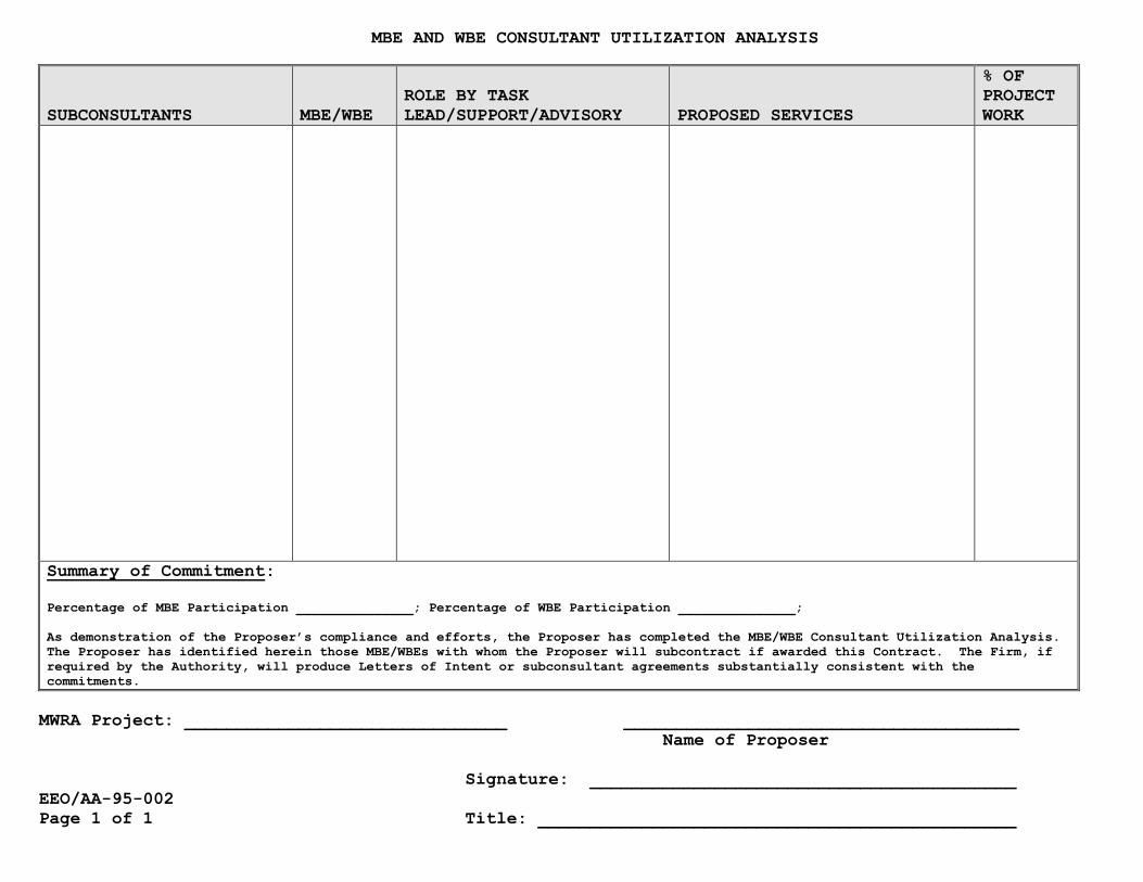
MBE AND WBE CONSULTANT UTILIZATION ANALYSIS
SUBCONSULTANTS MBE/WBE
ROLE BY TASK
LEAD/SUPPORT/ADVISORY PROPOSED SERVICES
% OF
PROJECT
WORK
Summary of Commitment:
Percentage of MBE Participation _______________; Percentage of WBE Participation _______________;
As demonstration of the Proposer’s compliance and efforts, the Proposer has completed the MBE/WBE Consultant Utilization Analysis.
The Proposer has identified herein those MBE/WBEs with whom the Proposer will subcontract if awarded this Contract. The Firm, if
required by the Authority, will produce Letters of Intent or subconsultant agreements substantially consistent with the
commitments.
MWRA Project: _______________________________ ______________________________________
Name of Proposer
Signature: _________________________________________
EEO/AA-95-002
Page 1 of 1 Title: ______________________________________________
EEO/AA-95-003 Page 1 of 1
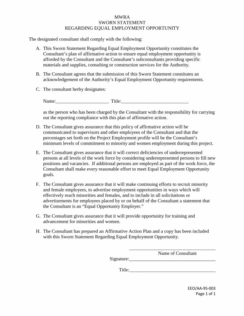
MWRA SWORN STATEMENT
REGARDING EQUAL EMPLOYMENT OPPORTUNITY
The designated consultant shall comply with the following:
A. This Sworn Statement Regarding Equal Employment Opportunity constitutes the Consultant’s plan of affirmative action to ensure equal employment opportunity is afforded by the Consultant and the Consultant’s subconsultants providing specific materials and supplies, consulting or construction services for the Authority.
B. The Consultant agrees that the submission of this Sworn Statement constitutes an
acknowledgement of the Authority’s Equal Employment Opportunity requirements.
C. The consultant herby designates: Name:______________________ Title:____________________________ as the person who has been charged by the Consultant with the responsibility for carrying out the reporting compliance with this plan of affirmative action.
D. The Consultant gives assurance that this policy of affirmative action will be communicated to supervisors and other employees of the Consultant and that the percentages set forth on the Project Employment profile will be the Consultant’s minimum levels of commitment to minority and women employment during this project.
E. The Consultant gives assurance that it will correct deficiencies of underrepresented persons at all levels of the work force by considering underrepresented persons to fill new positions and vacancies. If additional persons are employed as part of the work force, the Consultant shall make every reasonable effort to meet Equal Employment Opportunity goals.
F. The Consultant gives assurance that it will make continuing efforts to recruit minority and female employees, to advertise employment opportunities in ways which will effectively reach minorities and females, and to include in all solicitations or advertisements for employees placed by or on behalf of the Consultant a statement that the Consultant is an “Equal Opportunity Employer.”
G. The Consultant gives assurance that it will provide opportunity for training and advancement for minorities and women.
H. The Consultant has prepared an Affirmative Action Plan and a copy has been included with this Sworn Statement Regarding Equal Employment Opportunity.
____________________________________
Name of Consultant Signature:____________________________________
Title:____________________________________
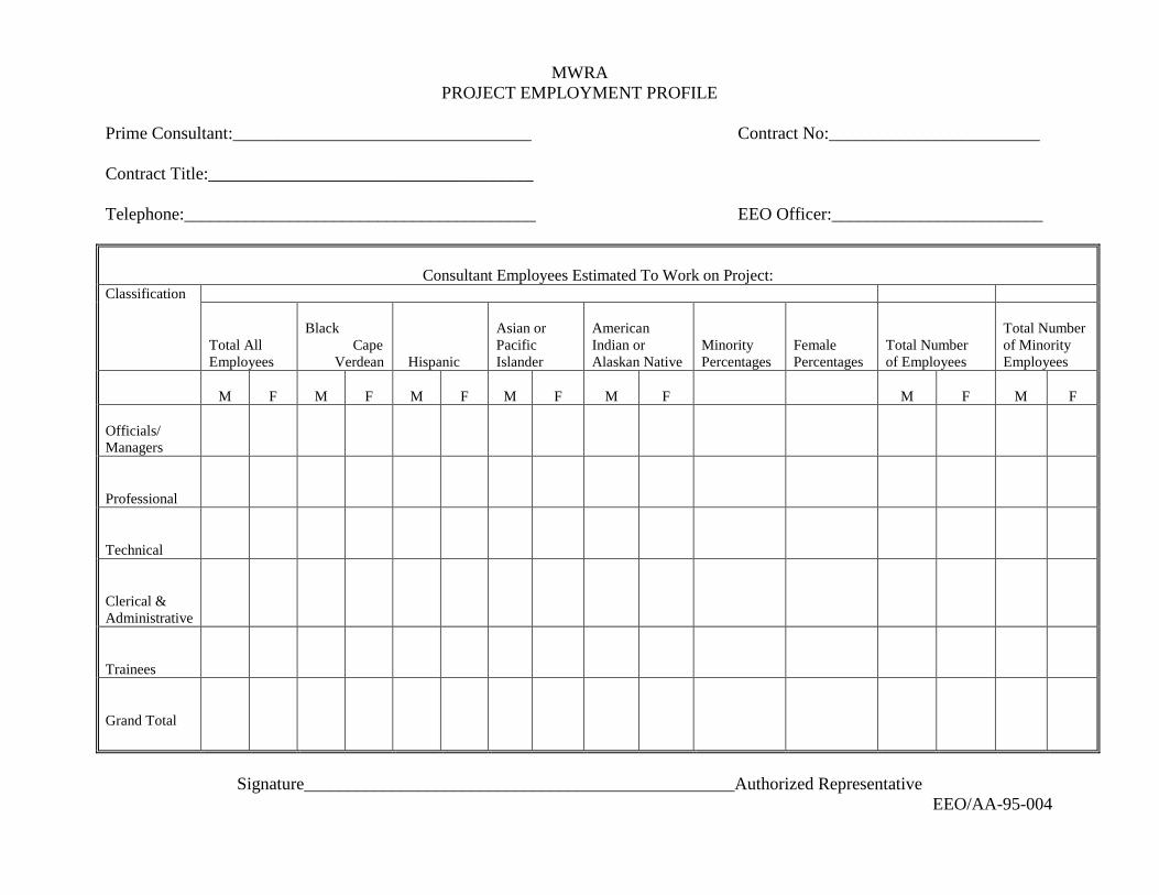
MWRA PROJECT EMPLOYMENT PROFILE
Prime Consultant:__________________________________ Contract No:________________________ Contract Title:_____________________________________ Telephone:________________________________________ EEO Officer:________________________
Consultant Employees Estimated To Work on Project:
Classification Total All Employees
Black Cape Verdean
Hispanic
Asian or Pacific Islander
American Indian or Alaskan Native
Minority Percentages
Female Percentages
Total Number of Employees
Total Number of Minority Employees
M
F
M
F
M
F
M
F
M
F
M
F
M
F
Officials/ Managers
Professional
Technical
Clerical & Administrative
Trainees
Grand Total
Signature_________________________________________________Authorized Representative
EEO/AA-95-004
Rev. 1-4/30/15
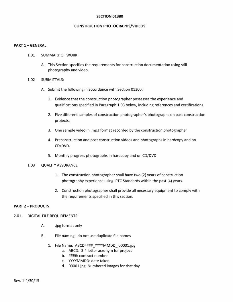
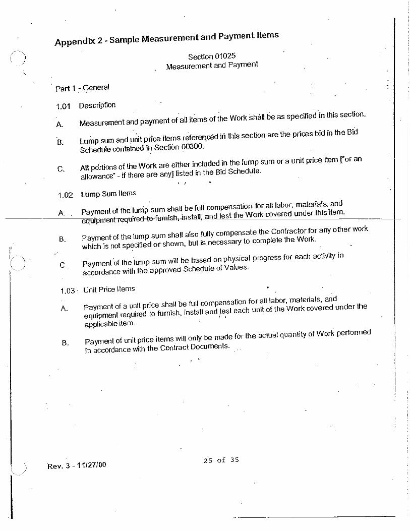
SECTION 01380
CONSTRUCTION PHOTOGRAPHS/VIDEOS
PART 1 – GENERAL
1.01 SUMMARY OF WORK:
A. This Section specifies the requirements for construction documentation using still photography and video.
1.02 SUBMITTALS:
A. Submit the following in accordance with Section 01300:
1. Evidence that the construction photographer possesses the experience and qualifications specified in Paragraph 1.03 below, including references and certifications.
2. Five different samples of construction photographer’s photographs on past construction projects.
3. One sample video in .mp3 format recorded by the construction photographer
4. Preconstruction and post construction videos and photographs in hardcopy and on CD/DVD.
5. Monthly progress photographs in hardcopy and on CD/DVD
1.03 QUALITY ASSURANCE
1. The construction photographer shall have two (2) years of construction photography experience using IPTC Standards within the past (4) years.
2. Construction photographer shall provide all necessary equipment to comply with the requirements specified in this section.
PART 2 – PRODUCTS
2.01 DIGITAL FILE REQUIREMENTS:
A. .jpg format only
B. File naming: do not use duplicate file names
1. File Name: ABCD####_YYYYMMDD_ 00001.jpg a. ABCD: 3-4 letter acronym for project b. ####: contract number c. YYYYMMDD: date taken d. 00001.jpg: Numbered images for that day
Rev. 1-4/30/15
C. Optimum, 300dpi
D. Optimum, Image size: 8 Megapixels
E. Optimum, Image Quality: Fine
F. Optimum output size shall be 8X10
G. Date & time set in camera shall be accurate.
H. Use IPTC (International Press Telecommunications Council) Photo Metadata Standards, fields; description tab; description, description writer and keywords* fields only should be filled in with; image, site, and all project specific information using Photoshop or equivalent.
*A list of suggested keywords will be supplied to the Contractor.
2.03 HARD COPY REQUIREMENTS:
A. Hardcopies shall be filed in a three ring binder with dated tabs.
B. Pre-construction, progress and post construction images shall be labeled as such and in separate binders.
C. Each binder shall be labeled on the cover with the project name, contract number, name of photographer and/or company with contact information.
D. Each print shall be inserted in a clear plastic sleeve, two prints back to back in one sleeve.
E. Each print shall be labeled within the bottom margin, not covering the image with: file name, corresponding CD, DVD or thumb drive, date taken and brief description of subject. (A more detailed description should be included with the IPTC Metadata in the file)
F. Each print shall be 8X10” on photo paper or laser print.
2.04 VIDEO REQUIREMENTS:
A. Format: MPEG-4 (.mp4) only
B. Video files shall be stored on separate media from photographs.
PART 3 – EXECUTION
3.01 REQUIREMENTS:
A. Notify the MWRA 5 days in advance of any photographic sessions.
B. Coordinate with MWRA on what views are to be taken.
Rev. 1-4/30/15
C. Some shots shall be taken consecutively from a variety of selected locations at each visit to show progress when images are shown in secession.
D. All broad views shall contain a general reference that is easily recognizable to provide scale and position on site (i.e., people, equipment, landmarks).
E. All close shots shall have similar references for scale (i.e., ruler, coin or tool).
F. Color photographs shall be taken at site locations chosen by MWRA.
a. Prior to commencement of work on site: [#] photographs in one submission
b. During construction: [#] photographs submitted monthly with application for, and as a condition of, progress payments.
c. At the completion of project: [#] photographs in one submission.
3.02 REVIEW OF SUBMITTALS:
A. All submittals will be reviewed by the MWRA Construction Documentation Team.
B. Final acceptance of photographer’s product will be determined by the MWRA Construction Documentation Team.
END OF PAGE
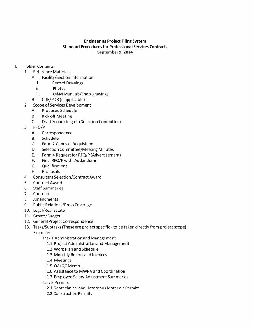
Engineering Project Filing System Standard Procedures for Professional Services Contracts
September 9, 2014
I. Folder Contents1. Reference Materials
A. Facility/Section Informationi. Record Drawingsii. Photosiii. O&M Manuals/Shop Drawings
B. CDR/PDR (if applicable)2. Scope of Services Development
A. Proposed ScheduleB. Kick off MeetingC. Draft Scope (to go to Selection Committee)
3. RFQ/PA. CorrespondenceB. ScheduleC. Form 2 Contract RequisitionD. Selection Committee/Meeting MinutesE. Form 4 Request for RFQ/P (Advertisement)F. Final RFQ/P with AddendumsG. QualificationsH. Proposals
4. Consultant Selection/Contract Award5. Contract Award6. Staff Summaries7. Contract8. Amendments9. Public Relations/Press Coverage10. Legal/Real Estate11. Grants/Budget12. General Project Correspondence13. Tasks/Subtasks (These are project specific ‐ to be taken directly from project scope)
Example:Task 1 Administration and Management
1.1 Project Administration and Management 1.2 Work Plan and Schedule 1.3 Monthly Report and Invoices 1.4 Meetings 1.5 QA/QC Memo 1.6 Assistance to MWRA and Coordination 1.7 Employee Salary Adjustment Summaries
Task 2 Permits 2.1 Geotechnical and Hazardous Materials Permits 2.2 Construction Permits

II. Naming
A. File naming conventions needed for each item below:1. Correspondence: COR 2. Telephone Log: TELE 3. Meeting Minutes MMIN 4. Memoranda: MEMO 5. Technical Information/Reports: REPORT6. Submittals: SUBM 7. Task Orders: TO# 8. Shop Drawings ShDwg 9. Amendment AMEND 10. Subtask Folder Name: subtask number‐description e.g. 3.2‐GeoTech
B. Filenames must not exceed 100 character total (including spaces): abbreviations and acronyms may berequired in order to meet the name length limit. (Some DVD and CD writers and readers have a problem withlonger names.)
C. Special characters including @ # % & \ / should not be used inside a filename. Use of underscore _ isrecommended as a substitute.
D. Folders inside a subtask may be named by subject.E. The hard copy project files to be archived will use the same folder organization as the electronic files.
III. UseA. The above filing system is only required for those electronic project files to be archived (i.e., personal files
may be saved elsewhere, in any format you like).B. Documents received as hard copy would be scanned into the file system in PDF format.C. PDF electronic file format specification for submittals is "Adobe Version PDF/A-2b" for archived PDF files.D. Design‐Build project files will be organized using the Construction Project Filing SystemE. In‐House Design Projects, Technical Support Project and Task Order Project file systems are to be determined.
IV. Electronic Filing Examples:
Folder “Task 1 – Project Administration”• Subfolder: “1.1‐Proj Admin and Mgmt”
o Files:“1.1‐COR_2014‐07‐29_PS‐MJ” (subtask#, correspondence, date, to‐from (to /from could be maneinitials or company abbrev))“1.1‐TELE_2014‐07‐29_PS‐MJ “ (subtask#, telephone log, date, to‐from)
Folder “Task 2 – Design” • Subfolder: “2.5‐Design Services”
o Sub‐subfolder “ 2.5.2‐60% Design Progress Submittal” Files:
“2.5.2‐SUBM60_2014‐06‐19_MWRA‐CONSULTX” (sub‐subtask#,submittal, date, to‐from)“2.5.2‐COR_2014‐06‐19_PS‐MJ” (sub‐subtask#, correspondence, date, to‐from)
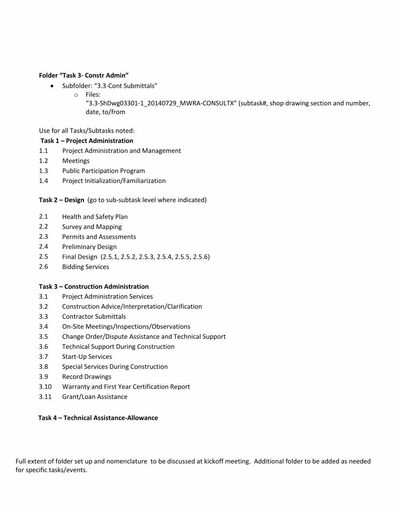
Folder “Task 3- Constr Admin” • Subfolder: “3.3‐Cont Submittals”
o Files:“3.3‐ShDwg03301‐1_20140729_MWRA‐CONSULTX” (subtask#, shop drawing section and number,date, to/from
Use for all Tasks/Subtasks noted: Task 1 – Project Administration 1.1 Project Administration and Management 1.2 Meetings 1.3 Public Participation Program 1.4 Project Initialization/Familiarization
Task 2 – Design (go to sub‐subtask level where indicated)
2.1 2.2 2.3 2.4 2.5 2.6
Health and Safety Plan Survey and MappingPermits and AssessmentsPreliminary DesignFinal Design (2.5.1, 2.5.2, 2.5.3, 2.5.4, 2.5.5, 2.5.6) Bidding Services
Task 3 – Construction Administration 3.1 3.2 3.3 3.4 3.5 3.6 3.73.83.93.103.11
Project Administration Services Construction Advice/Interpretation/Clarification Contractor Submittals On‐Site Meetings/Inspections/Observations Change Order/Dispute Assistance and Technical Support Technical Support During ConstructionStart-Up ServicesSpecial Services During ConstructionRecord DrawingsWarranty and First Year Certification ReportGrant/Loan Assistance
Task 4 – Technical Assistance-Allowance
Full extent of folder set up and nomenclature to be discussed at kickoff meeting. Additional folder to be added as needed for specific tasks/events.
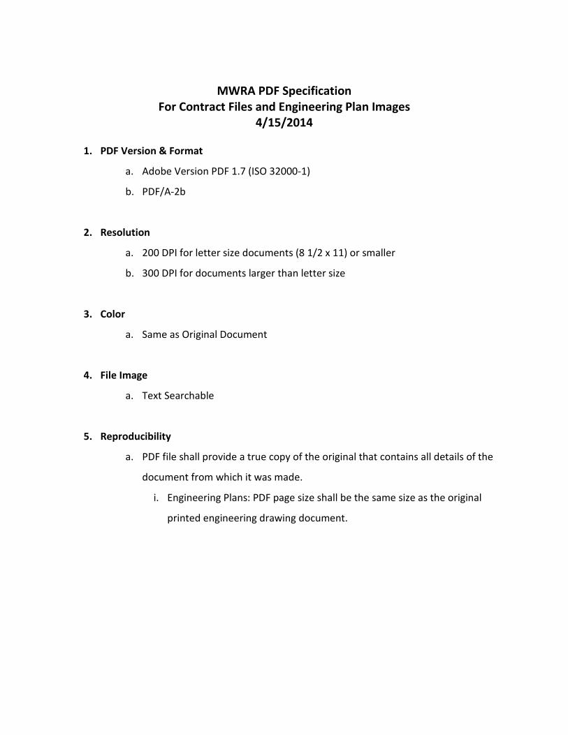
MWRA PDF Specification
For Contract Files and Engineering Plan Images 4/15/2014
1. PDF Version & Format
a. Adobe Version PDF 1.7 (ISO 32000-1)
b. PDF/A-2b
2. Resolution
a. 200 DPI for letter size documents (8 1/2 x 11) or smaller
b. 300 DPI for documents larger than letter size
3. Color
a. Same as Original Document
4. File Image
a. Text Searchable
5. Reproducibility
a. PDF file shall provide a true copy of the original that contains all details of the
document from which it was made.
i. Engineering Plans: PDF page size shall be the same size as the original
printed engineering drawing document.
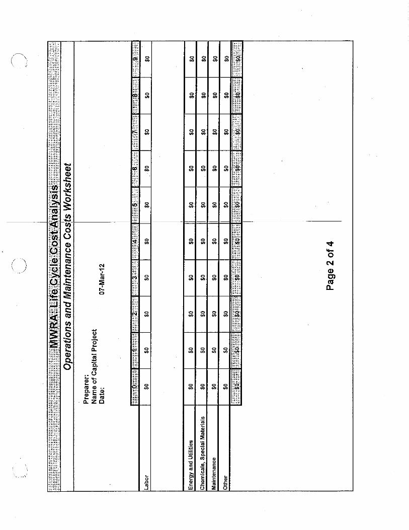
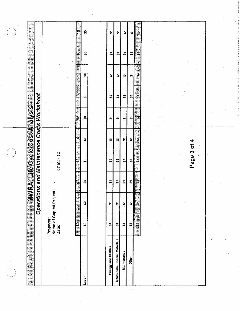
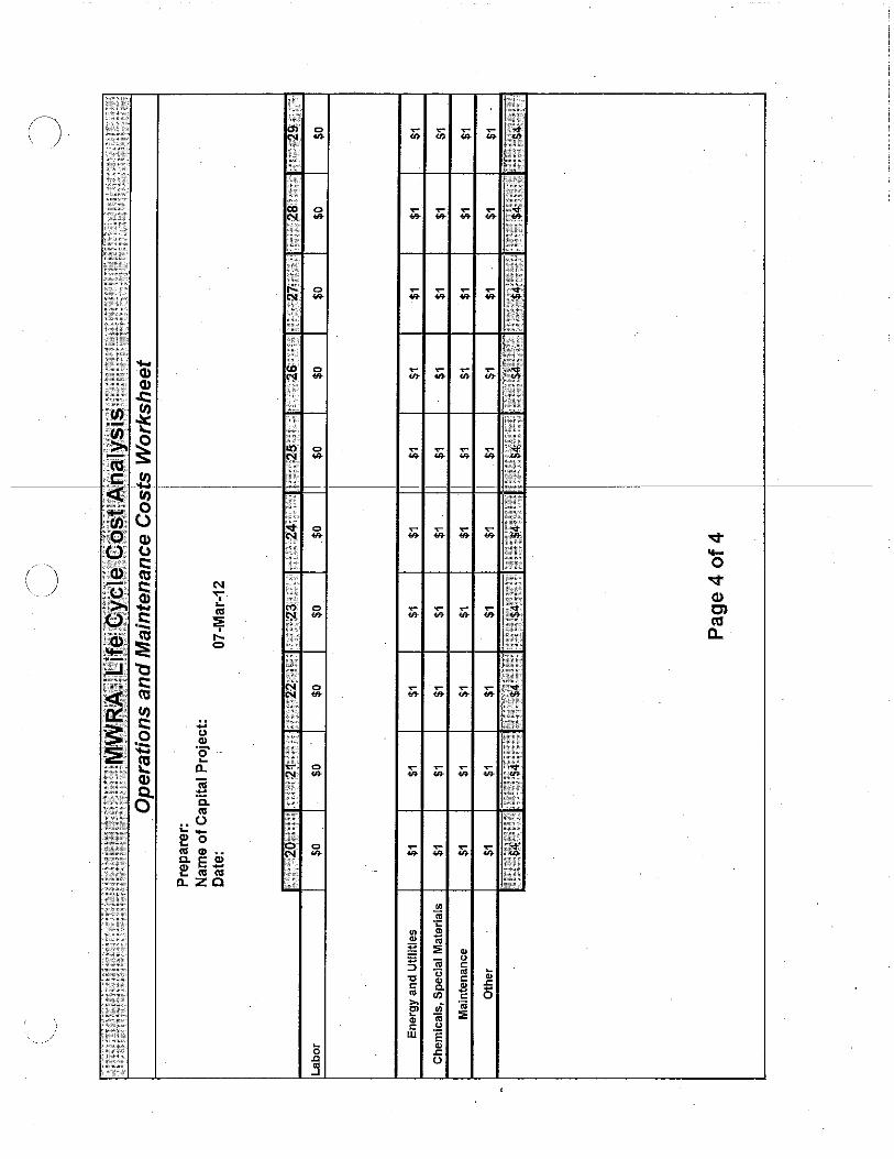
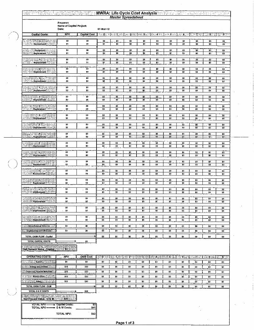
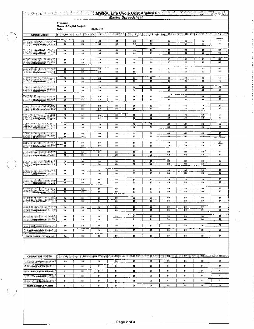
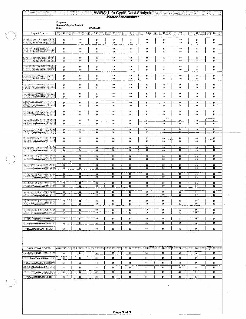
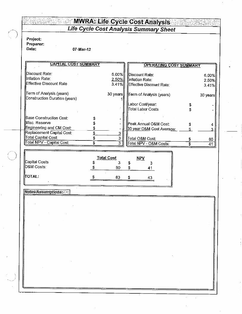
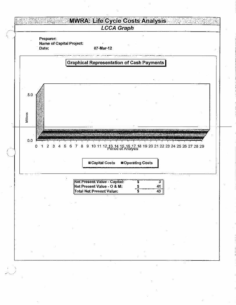
Exhibit 5
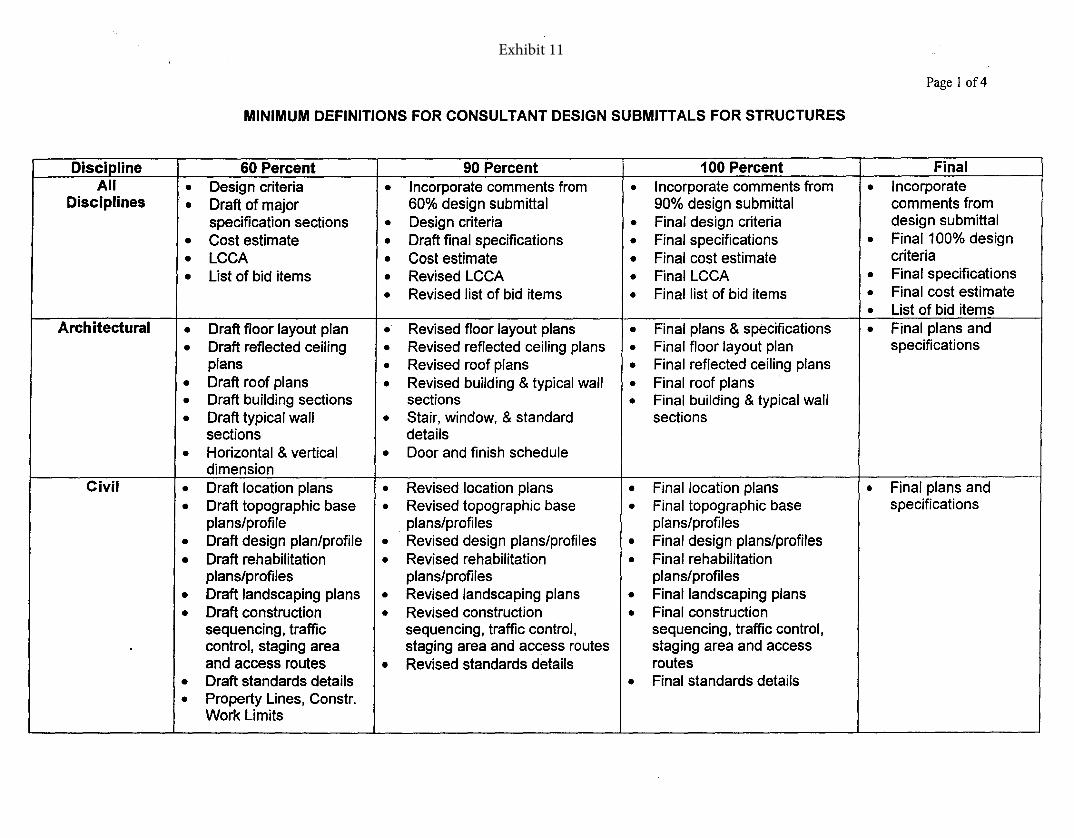
MINIMUM DEFINITIONS FOR CONSULTANT DESIGN SUBMITTALS FOR STRUCTURES
Page 1 of4
Discipline 60 Percent 90 Percent 100 Percent FinalAll • Design criteria • Incorporate comments from • Incorporate comments from • Incorporate
Disciplines • Draft of major 60% design submittal 90% design submittal comments fromspecification sections • Design criteria • Final design criteria design submittal
• Cost estimate • Draft final specifications • Final specifications • Final 100% design
• LCCA • Cost estimate • Final cost estimate criteria
• List of bid items • Revised LCCA • Final LCCA • Final specifications
• Revised list of bid items • Final list of bid items • Final cost estimate
• List of bid itemsArchitectural • Draft floor layout plan • Revised floor layout plans • Final plans & specifications • Final plans and
• Draft reflected ceiling • Revised reflected ceiling plans • Final floor layout plan specificationsplans • Revised roof plans • Final reflected ceiling plans
• Draft roof plans • Revised bUilding & typical wall • Final roof plans• Draft building sections sections • Final building & typical wall
• Draft typical wall • Stair, window, & standard sectionssections details
• Horizontal & vertical • Door and finish scheduledimension
Civil • Draft location plans • Revised location plans • Final location plans • Final plans and
• Draft topographic base • Revised topographic base • Final topographic base specificationsplans/profile . plans/profiles plans/profiles
• Draft design plan/profile • Revised design plans/profiles • Final design plans/profiles
• Draft rehabilitation • Revised rehabilitation • Final rehabilitationplans/profiles plans/profiles plans/profiles
• Draft landscaping plans • Revised landscaping plans • Final landscaping plans
• Draft construction • Revised construction • Final constructionsequencing, traffic sequencing, traffic control, sequencing, traffic control,control, staging area staging area and access routes staging area and accessand access routes • Revised standards details routes
• Draft standards details • Final standards details
• Property Lines, Constr.Work Limits
Exhibit 11
Page 2 of4
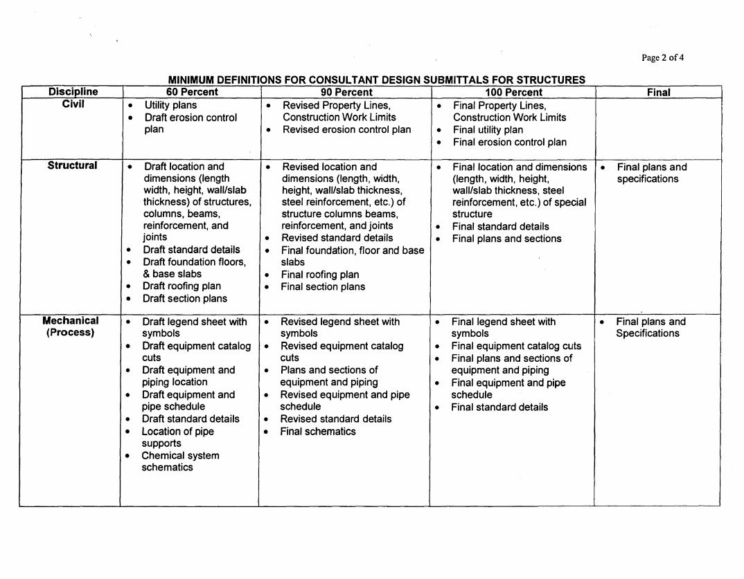
MINIMUM DEFINITIONS FOR CONSULTANT DESIGN SUBMITTALS FOR STRUCTURES Discipline 60 Percent 90 Percent 100 Percent Final
Civil • Utility plans • Revised Property Lines, • Final Property Lines,• Draft erosion control Construction Work Limits Construction Work Limits
plan • Revised erosion control plan • Final utility plan• Final erosion control plan
Structural • Draft location and • Revised location and • Final location and dimensions • Final plans anddimensions (length dimensions (length, width, (length, width, height, specificationswidth, height, wall/slab height, wall/slab thickness, wall/slab thickness, steelthickness) of structures, steel reinforcement, etc.) of reinforcement, etc.) of specialcolumns, beams, structure columns beams, structurereinforcement, and reinforcement, and joints • Final standard detailsjoints • Revised standard details • Final plans and sections
• Draft standard details • Final foundation, floor and base• Draft foundation floors, slabs
& base slabs • Final roofing plan• Draft roofing plan • Final section plans• Draft section plans
Mechanical • Draft legend sheet with • Revised legend sheet with • Final legend sheet with • Final plans and(Process) symbols symbols symbols Specifications
• Draft equipment catalog • Revised equipment catalog • Final equipment catalog cutscuts cuts • Final plans and sections of
• Draft equipment and • Plans and sections of equipment and pipingpiping location equipment and piping • Final equipment and pipe
• Draft equipment and • Revised equipment and pipe schedulepipe schedule schedule • Final standard details
• Draft standard details • Revised standard details• Location of pipe • Final schematics
supports• Chemical system
schematics
MINIMUM DEFINITIONS FOR CONSULTANT DESIGN SUBMITIALS FOR STRUCTURES
Page 3 of4
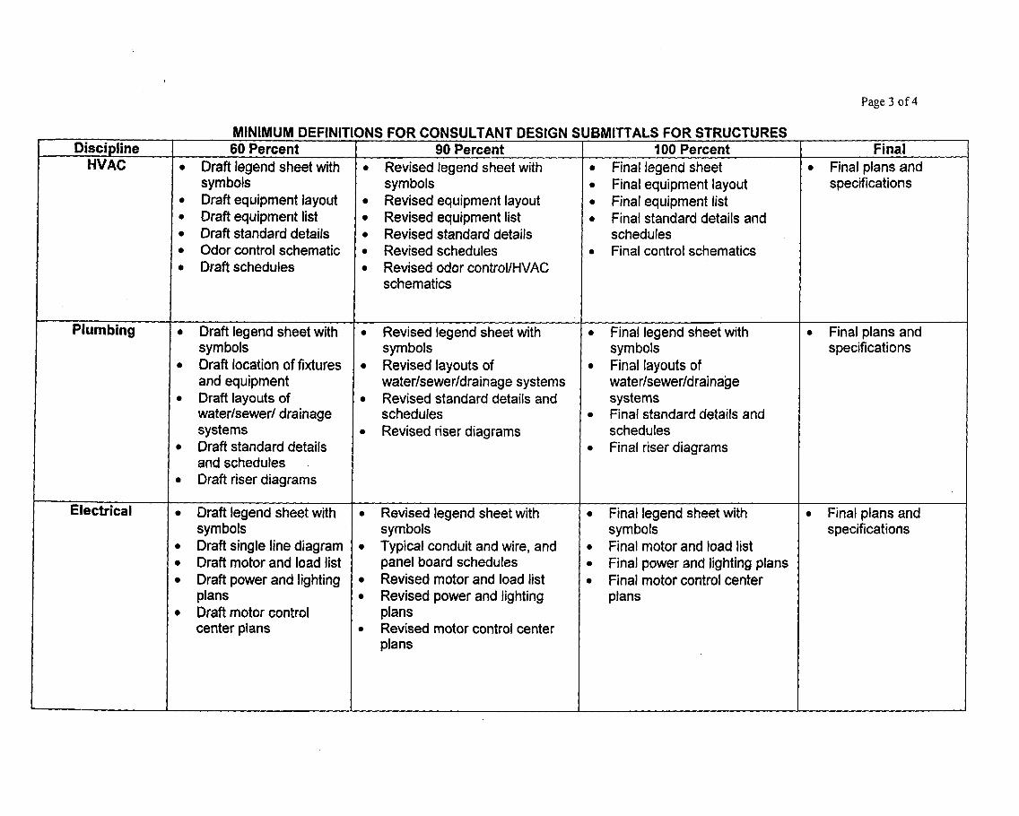
DisciDline 60 Percent 90 Percent 100 Percent FinalHVAC • Draft legend sheetwith • Revised legend sheetwith • Final legend sheet • Final plans and
symbols symbols • Final equipment layout specifications• Draft equipment layout • Revised equipment layout • Finalequipment list• Draft equipment list • Revised equipment list • Final standard details and• Draft standard details • Revised standard details schedules• Odor control schematic • Revised schedules • Final control schematics• Draft schedules • Revised odorcontrol/HVAC
schematics
Plumbing • Draft legend sheetwith • Revised legend sheetwith • Final legend sheetwith • Final plans andsymbols symbols symbols specifications
• Draft location of fixtures • Revised layouts of • Final layouts ofand equipment water/sewer/drainage systems water/sewer/drainage
• Draft layouts of • Revised standard details and systemswater/sewer/ drainage schedules • Final standard details andsystems • Revised riser diagrams schedules
• Draft standard details • Final riser diagramsand schedules
• Draft riser diagrams
Electrical • Draft legend sheetwith • Revised legend sheetwith • Final legend sheetwith • Final plans andsymbols symbols symbols specifications
• Draft single line diagram • Typical conduit and wire, and • Final motor and load list• Draft motor and load list panel board schedules • Final powerand lighting plans• Draft powerand lighting • Revised motor and load list • Final motorcontrol center
plans • Revised power and lighting plans• Draft motor control plans
centerplans • Revised motor control centerplans
MINIMUM DEFINITIONS FOR CONSULTANT DESIGN SUBMIITALS FOR STRUCTURES
Page 4 of4
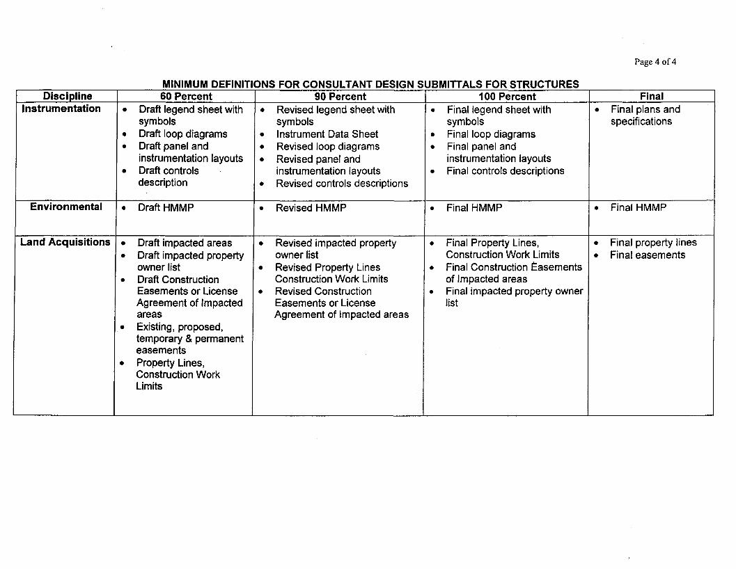
Discipline 60 Percent 90 Percent 100 Percent FinalInstrumentation • Draft legend sheet with • Revised legend sheet with • Final legend sheet with • Final plans and
symbols symbols symbols specifications
• Draft loop diagrams • Instrument Data Sheet • Final loop diagrams
• Draft panel and • Revised loop diagrams • Final panel andinstrumentation layouts • Revised panel and instrumentation layouts
• Draft controls instrumentation layouts • Final controls descriptionsdescription • Revised controls descriptions
Environmental • Draft HMMP • Revised HMMP • Final HMMP • Final HMMP
Land Acquisitions • Draft impacted areas • Revised impacted property • Final Property Lines, • Final property lines
• Draft impacted property owner list Construction Work Limits • Final easementsowner list • Revised Property Lines • Final Construction Easements
• Draft Construction Construction Work Limits of Impacted areasEasements or License • Revised Construction • Final impacted property ownerAgreement of Impacted Easements or License listareas Agreement of Impacted areas
• Existing, proposed,temporary &permanenteasements
• Property Lines,Construction WorkLimits
Massachusetts Water Resources Authority Design Information Systems Center Document Standards and Procedures
March 2013
Exhibit 10
1 February 25, 2013
MWRA Engineering and Construction
Document Standards and Procedures
Instructions The attachments referenced in this document are a compilation of the Engineering & Construction, Design Information Systems Center (DISC) Procedures Manual, Field Operations Department (FOD) Guidelines, MWRA Records Management Procedures and Standards. The following references are attached and are required in order to use this document: 1. MWRA Document Control Standards 2. MWRA Drawing Standards 3. MWRA Survey Standards 1. Drawing Setup And Preparation
1.1. All contract drawings, record drawings and detail records prepared by Consultants in Service of the Authority shall use Autodesk AutoCAD 2009 or a version compatible with the current version of AutoCAD in use by the Authority.
1.2. The consultant shall setup the electronic AutoCAD drawings as outlined in MWRA Drawing Standards (Reference 2) and MWRA Survey Standards (Reference 3). No deviation from these standards is allowed unless approved through the Authority’s Design Information Systems Center (DISC) Office.
1.3. Detail Records are required for water system projects and shall be developed using the Detail Records section of the Authority’s MWRA Drawing Standards (Reference 2).
1.4. The consultant shall use the AutoCAD template files, provided by the Authority, for all drawings developed as part of this contract (Reference 2).
2. Design Drawings
2.1. At the start of the development of Pre-Bid Design and Construction contract drawings the Consultant shall request, through the Authority’s Project Manager, drawing accession numbers for the estimated number of drawings needed for the entire project.
2.2. The Consultant shall submit the attached Accession Number Request form (Form DP1-3-7.2/1) to the Authority as outlined in the MWRA Document Control Standards (Reference 1). A percentage of extra numbers will be assigned to the project to facilitate any addition of drawings.
2.3. The consultant shall then assign the numbers to the drawings by entering the number in the Accession Number box in the title block of each drawing. This number will remain with the drawing throughout the life of the drawing.
3. Bid Drawings
3.1. Sometime after the completion of the successful bid, the consultant shall submit the following to the Authority
3.1.1. Furnish the Authority with (1) One complete set of 24”x36” (D+, Arch D) Conformed As-bid drawings, signed and stamped by a Massachusetts registered professional engineer and printed on reproducible Mylar as developed using the
2 February 25, 2013
requirements set forth in MWRA Drawing Standards (Reference 1) and MWRA Survey Standards (Reference 3).
3.1.2. Furnish the Authority with (3) three copies of the Conformed As-bid drawings 24”x36” (D+, Arch D) on paper, reproduced from the Mylar set created in 3.1.1
3.1.3. Furnish the Authority with two (2) microfilm copies of the complete set of Mylar Conformed As-bid drawings created in 3.1.1. One (1) master camera negative set and one (1) duplicate set. The master camera negative shall utilize silver halide film. The duplicate film shall be a diazo base. The microfilm shall conform to standards set forth in the MWRA Document Control Standards (Reference 1) and MWRA Drawing Standards (Reference 2).
3.1.4. CD’s and/or DVD’s containing scanned images of the Mylar Conformed As-bid drawings created in 3.1.1 in TIFF format as outlined in the MWRA Document Control Standards (Reference 1).
4. Redline Drawings
4.1. The consultant shall submit prior substantial completion, to the Authority, Redline drawings showing any revisions in the project plans. A revision is any change or deviation from the Conformed As-Bid plans as originally bid.
4.2. The redline drawings are to be submitted to Authority construction personnel for review.
4.3. All changes or revisions shall be clearly marked in red and all text and or annotations shall be clearly legible or they will not be accepted.
4.4. All revisions shall be noted in the revision box in the title block along with the date of the revision and shall be initialed by the reviser.
(Note: For water projects, add Detail Records to the Redline Drawing deliverables. Detail Records should be revised using the Detail Record section of the MWRA Drawing Standards (Reference 2).) 5. Record Drawings
5.1. The consultant shall, sometime after substantial completion of the project, but at least 3 months prior to the contract end date, submit to the Authority project manager the following:
5.1.1. (2) Full sets of 24”X36” Draft Record Drawings printed on paper for Authority review.
5.1.2. Draft Record Drawings must incorporate all revisions and or changes approved on the redline Drawings.
5.1.3. The Authority, after reviewing the Draft Record Drawings, will submit to the Consultant comments or recommendations for change or correction.
5.1.4. The Consultant will then incorporate any comments or recommendations for change or correction into the Draft Record Drawings and resubmit (2) full sets of 24”X36” of revised Draft Record Drawings printed on paper for Authority review. This process shall continue until all comments or recommendations have been satisfied.
5.2. Once the Draft Record Drawings are reviewed and approved by the Authority, the Consultant shall provide the Authority with the following:
5.2.1. Furnish the Authority with (1) One complete set of Mylar 24”x36” (D+, Arch D) Record Drawings signed and stamped by a Massachusetts registered
3 February 25, 2013
professional engineer and printed on reproducible Mylar as developed using the requirements set forth in MWRA Drawing Standards (Reference 2)and MWRA Survey Standards (Reference 3).
5.2.2. Furnish the Authority with (3) three complete sets of Paper 24”x36” (D+, Arch D) Record Drawings printed on paper, reproduced from the Mylar set created in 5.2.1.
5.2.3. Furnish the Authority with two (2) microfilm copies of the complete set of Mylar Record Drawings created in 5.2.1. One (1) master camera negative set and one (1) duplicate set. The master camera negative shall utilize silver halide film. The duplicate film shall be a diazo base. The microfilm shall conform to standards set forth in the MWRA Document Control Standards (Reference 1).
5.2.4. Furnish the Authority (1) CD and/or DVD containing the scanned images of the Record Drawings reproduced from the Mylar set created in 5.2.1. in TIFF format as outlined in MWRA Document Control Standards (Reference 1).
5.2.5. All electronic CAD files used in the development of the final Record Drawings in the format set forth in MWRA Drawing Standards (Reference 1) and MWRA Survey Standards (Reference 3).
(Note: For water projects, add Detail Records to the Redline Drawing deliverables. Detail Records should be revised using the Detail Record section of the MWRA Drawing Standards (Reference 2).) All MWRA Standards will be provided electronically on CD for distribution to Consultants through DISC upon request. Aperture cards will also be provided upon request.
MWRA Document Control Standards
1 2/27/09
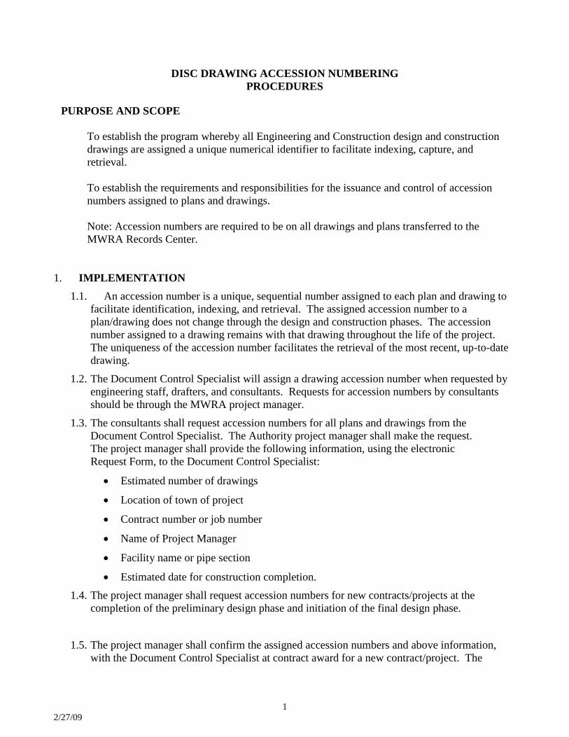
DISC DRAWING ACCESSION NUMBERING PROCEDURES
PURPOSE AND SCOPE
To establish the program whereby all Engineering and Construction design and construction
drawings are assigned a unique numerical identifier to facilitate indexing, capture, and retrieval.
To establish the requirements and responsibilities for the issuance and control of accession
numbers assigned to plans and drawings.
Note: Accession numbers are required to be on all drawings and plans transferred to the MWRA Records Center.
1. IMPLEMENTATION
1.1. An accession number is a unique, sequential number assigned to each plan and drawing to facilitate identification, indexing, and retrieval. The assigned accession number to a plan/drawing does not change through the design and construction phases. The accession number assigned to a drawing remains with that drawing throughout the life of the project. The uniqueness of the accession number facilitates the retrieval of the most recent, up-to-date drawing.
1.2. The Document Control Specialist will assign a drawing accession number when requested by engineering staff, drafters, and consultants. Requests for accession numbers by consultants should be through the MWRA project manager.
1.3. The consultants shall request accession numbers for all plans and drawings from the Document Control Specialist. The Authority project manager shall make the request. The project manager shall provide the following information, using the electronic Request Form, to the Document Control Specialist:
• Estimated number of drawings
• Location of town of project
• Contract number or job number
• Name of Project Manager
• Facility name or pipe section
• Estimated date for construction completion. 1.4. The project manager shall request accession numbers for new contracts/projects at the
completion of the preliminary design phase and initiation of the final design phase.
1.5. The project manager shall confirm the assigned accession numbers and above information, with the Document Control Specialist at contract award for a new contract/project. The
2 2/27/09
project manager will confirm the information or revisions, as necessary, by electronically providing the Document Control Specialist with an updated Accession Number Request Form.
1.6. The Document Control Specialist will assign accession numbers to a new contract/project, or to drawings, upon receipt of the competed Accession Number Request Form. The Document Control Specialist will enter the assigned accession numbers into the form, and return the form to the project manager or requestor.
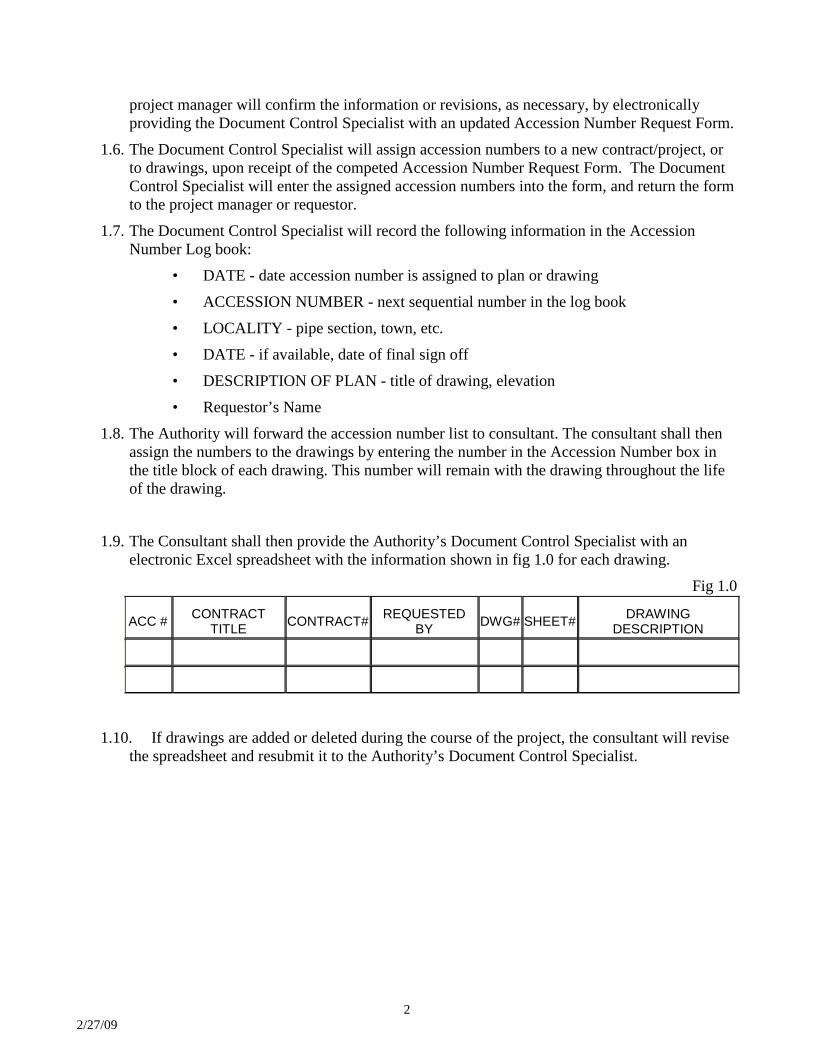
1.7. The Document Control Specialist will record the following information in the Accession Number Log book:
• DATE - date accession number is assigned to plan or drawing • ACCESSION NUMBER - next sequential number in the log book • LOCALITY - pipe section, town, etc. • DATE - if available, date of final sign off • DESCRIPTION OF PLAN - title of drawing, elevation • Requestor’s Name
1.8. The Authority will forward the accession number list to consultant. The consultant shall then assign the numbers to the drawings by entering the number in the Accession Number box in the title block of each drawing. This number will remain with the drawing throughout the life of the drawing.
1.9. The Consultant shall then provide the Authority’s Document Control Specialist with an
electronic Excel spreadsheet with the information shown in fig 1.0 for each drawing. Fig 1.0
ACC # CONTRACT TITLE CONTRACT# REQUESTED
BY DWG# SHEET# DRAWING DESCRIPTION
1.10. If drawings are added or deleted during the course of the project, the consultant will revise
the spreadsheet and resubmit it to the Authority’s Document Control Specialist.
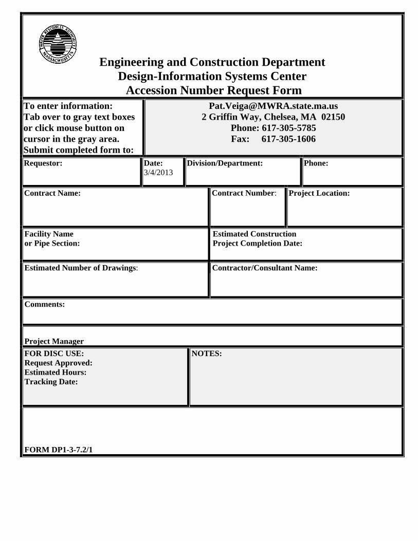
Engineering and Construction Department
Design-Information Systems Center Accession Number Request Form
To enter information: Tab over to gray text boxes or click mouse button on cursor in the gray area. Submit completed form to:
[email protected] 2 Griffin Way, Chelsea, MA 02150
Phone: 617-305-5785 Fax: 617-305-1606
Requestor:
Date: 3/4/2013
Division/Department:
Phone:
Contract Name:
Contract Number:
Project Location:
Facility Name or Pipe Section:
Estimated Construction Project Completion Date:
Estimated Number of Drawings: Contractor/Consultant Name:
Comments:
Project Manager FOR DISC USE: Request Approved: Estimated Hours: Tracking Date:
NOTES:
FORM DP1-3-7.2/1
MWRA Records Management - 03/04/13
1
MWRA Records Management Procedures, Specifications and Standards for Microfilming Records
General Purpose: Records Management procedures establish the requirements, responsibilities and methods for preparing documents for microfilming. It dictates uniform standards, certification of completeness and authenticity of the microfilming process. All records created, received and maintained during the course of business are the property of the MWRA. It is MWRA Records Management policy to microfilm records as required by the State Approved Retention Schedule. Selected records can be sent out for microfilming with Records Management review and approval.
General Scope: The standards and specifications set out in the this procedure shall be adhered to in all microfilm application for records of the MWRA and for records of consultants which relate to MWRA projects and are to eventually be transferred to the MWRA Records Center. The MWRA Project Files; Construction Files and General Files as noted on approved filing schemes define the organization and filing guidelines for MWRA submitted records to be filmed.
The MWRA general Specifications for Microfilming Records defines the standards that must be complied with for all MWRA and MWRA Contractor documents that will be maintained in microfilm/fiche format.
MWRA Records Management Procedures, Specifications and Standards for Microfilming Records (cont’d)
Created by MWRA – Records Management on 03/04/13 2
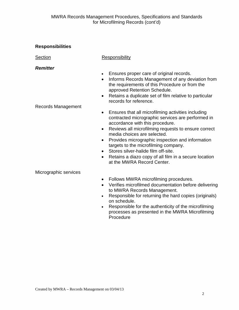
Responsibilities Section Responsibility Remitter
• Ensures proper care of original records. • Informs Records Management of any deviation from
the requirements of this Procedure or from the approved Retention Schedule.
• Retains a duplicate set of film relative to particular records for reference.
Records Management • Ensures that all microfilming activities including
contracted micrographic services are performed in accordance with this procedure.
• Reviews all microfilming requests to ensure correct media choices are selected.
• Provides micrographic inspection and information targets to the microfilming company.
• Stores silver-halide film off-site. • Retains a diazo copy of all film in a secure location
at the MWRA Record Center.
Micrographic services • Follows MWRA microfilming procedures. • Verifies microfilmed documentation before delivering
to MWRA Records Management. • Responsible for returning the hard copies (originals)
on schedule. • Responsible for the authenticity of the microfilming
processes as presented in the MWRA Microfilming Procedure
MWRA Records Management Procedures, Specifications and Standards for Microfilming Records (cont’d)
Created by MWRA – Records Management on 03/04/13 3
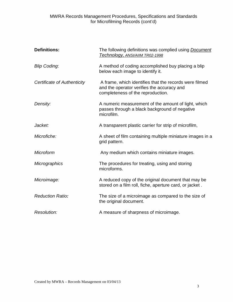
Definitions: The following definitions was complied using Document Technology, ANSI/AIIM TR02-1998
Blip Coding: A method of coding accomplished buy placing a blip below each image to identify it.
Certificate of Authenticity A frame, which identifies that the records were filmed and the operator verifies the accuracy and completeness of the reproduction.
Density: A numeric measurement of the amount of light, which passes through a black background of negative microfilm.
Jacket: A transparent plastic carrier for strip of microfilm,
Microfiche: A sheet of film containing multiple miniature images in a grid pattern.
Microform Any medium which contains miniature images.
Micrographics The procedures for treating, using and storing microforms.
Microimage: A reduced copy of the original document that may be stored on a film roll, fiche, aperture card, or jacket .
Reduction Ratio: The size of a microimage as compared to the size of the original document.
Resolution: A measure of sharpness of microimage.
MWRA Records Management Procedures, Specifications and Standards for Microfilming Records (cont’d)
Created by MWRA – Records Management on 03/04/13 4
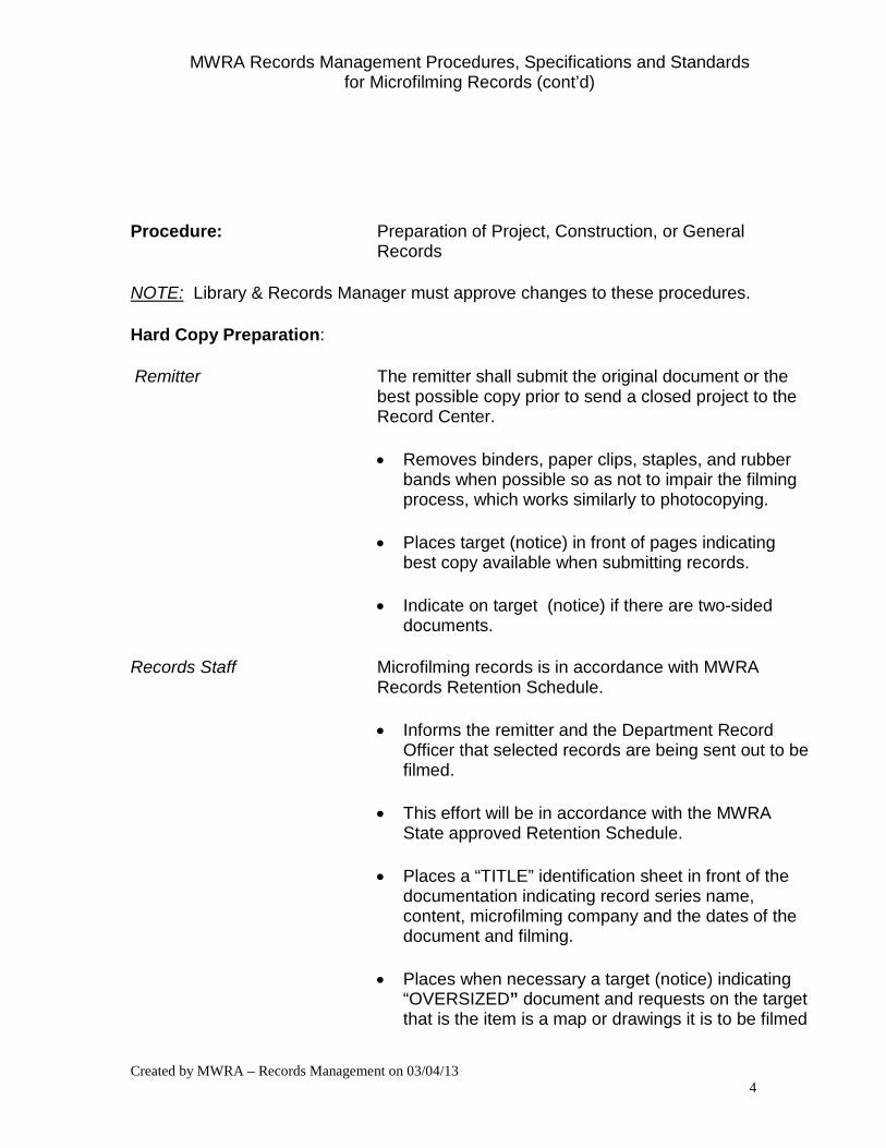
Procedure: Preparation of Project, Construction, or General Records
NOTE: Library & Records Manager must approve changes to these procedures.
Hard Copy Preparation:
Remitter The remitter shall submit the original document or the best possible copy prior to send a closed project to the Record Center.
• Removes binders, paper clips, staples, and rubber bands when possible so as not to impair the filming process, which works similarly to photocopying.
• Places target (notice) in front of pages indicating best copy available when submitting records.
• Indicate on target (notice) if there are two-sided documents.
Records Staff Microfilming records is in accordance with MWRA Records Retention Schedule.
• Informs the remitter and the Department Record Officer that selected records are being sent out to be filmed.
• This effort will be in accordance with the MWRA State approved Retention Schedule.
• Places a “TITLE” identification sheet in front of the documentation indicating record series name, content, microfilming company and the dates of the document and filming.
• Places when necessary a target (notice) indicating “OVERSIZED” document and requests on the target that is the item is a map or drawings it is to be filmed
MWRA Records Management Procedures, Specifications and Standards for Microfilming Records (cont’d)
Created by MWRA – Records Management on 03/04/13 5
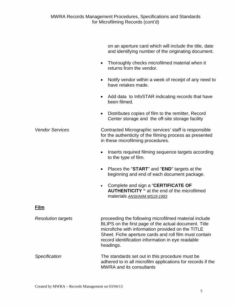
on an aperture card which will include the title, date and identifying number of the originating document.
• Thoroughly checks microfilmed material when it returns from the vendor.
• Notify vendor within a week of receipt of any need to have retakes made.
• Add data to InfoSTAR indicating records that have been filmed.
• Distributes copies of film to the remitter, Record Center storage and the off-site storage facility
Vendor Services Contracted Micrographic services’ staff is responsible for the authenticity of the filming process as presented in these microfilming procedures.
• Inserts required filming sequence targets according to the type of film.
• Places the "START" and "END" targets at the beginning and end of each document package.
• Complete and sign a “CERTIFICATE OF AUTHENTICITY “ at the end of the microfilmed materials ANSI/AIIM MS19-1993
Film
Resolution targets proceeding the following microfilmed material include BLIPS on the first page of the actual document. Title microfiche with information provided on the TITLE Sheet. Fiche aperture cards and roll film must contain record identification information in eye readable headings.
Specification The standards set out in this procedure must be adhered to in all microfilm applications for records if the MWRA and its consultants
MWRA Records Management Procedures, Specifications and Standards for Microfilming Records (cont’d)
Created by MWRA – Records Management on 03/04/13 6
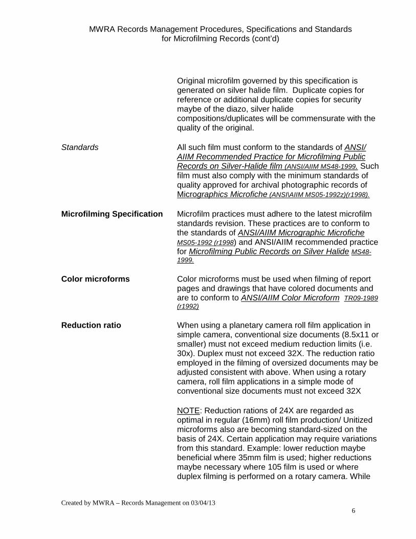
Original microfilm governed by this specification is generated on silver halide film. Duplicate copies for reference or additional duplicate copies for security maybe of the diazo, silver halide compositions/duplicates will be commensurate with the quality of the original.
Standards All such film must conform to the standards of ANSI/ AIIM Recommended Practice for Microfilming Public Records on Silver-Halide film (ANSI/AIIM MS48-1999. Such film must also comply with the minimum standards of quality approved for archival photographic records of Micrographics Microfiche (ANSI\AIIM MS05-1992z)(r1998).
Microfilming Specification Microfilm practices must adhere to the latest microfilm standards revision. These practices are to conform to the standards of ANSI/AIIM Micrographic Microfiche MS05-1992 (r1998) and ANSI/AIIM recommended practice for Microfilming Public Records on Silver Halide MS48-1999.
Color microforms Color microforms must be used when filming of report pages and drawings that have colored documents and are to conform to ANSI/AIIM Color Microform TR09-1989 (r1992)
Reduction ratio When using a planetary camera roll film application in simple camera, conventional size documents (8.5x11 or smaller) must not exceed medium reduction limits (i.e. 30x). Duplex must not exceed 32X. The reduction ratio employed in the filming of oversized documents may be adjusted consistent with above. When using a rotary camera, roll film applications in a simple mode of conventional size documents must not exceed 32X
NOTE: Reduction rations of 24X are regarded as optimal in regular (16mm) roll film production/ Unitized microforms also are becoming standard-sized on the basis of 24X. Certain application may require variations from this standard. Example: lower reduction maybe beneficial where 35mm film is used; higher reductions maybe necessary where 105 film is used or where duplex filming is performed on a rotary camera. While
MWRA Records Management Procedures, Specifications and Standards for Microfilming Records (cont’d)
Created by MWRA – Records Management on 03/04/13 7
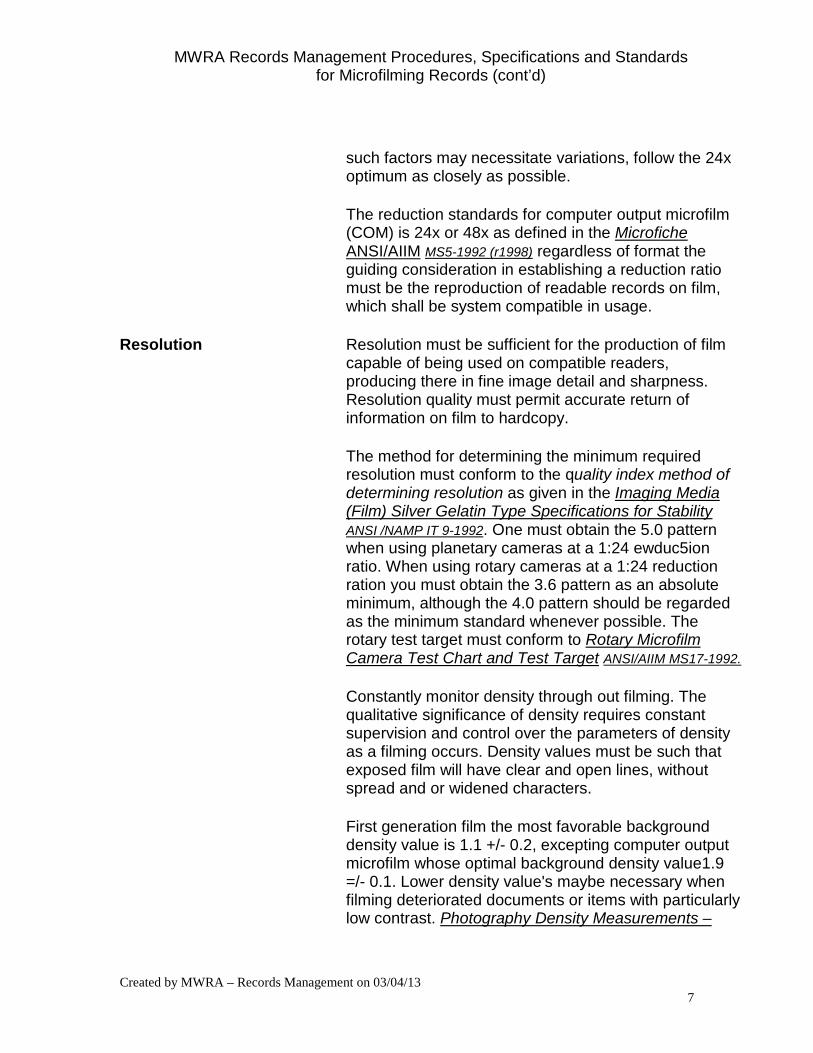
such factors may necessitate variations, follow the 24x optimum as closely as possible.
The reduction standards for computer output microfilm (COM) is 24x or 48x as defined in the Microfiche ANSI/AIIM MS5-1992 (r1998) regardless of format the guiding consideration in establishing a reduction ratio must be the reproduction of readable records on film, which shall be system compatible in usage.
Resolution Resolution must be sufficient for the production of film capable of being used on compatible readers, producing there in fine image detail and sharpness. Resolution quality must permit accurate return of information on film to hardcopy.
The method for determining the minimum required resolution must conform to the quality index method of determining resolution as given in the Imaging Media (Film) Silver Gelatin Type Specifications for Stability ANSI /NAMP IT 9-1992. One must obtain the 5.0 pattern when using planetary cameras at a 1:24 ewduc5ion ratio. When using rotary cameras at a 1:24 reduction ration you must obtain the 3.6 pattern as an absolute minimum, although the 4.0 pattern should be regarded as the minimum standard whenever possible. The rotary test target must conform to Rotary Microfilm Camera Test Chart and Test Target ANSI/AIIM MS17-1992.
Constantly monitor density through out filming. The qualitative significance of density requires constant supervision and control over the parameters of density as a filming occurs. Density values must be such that exposed film will have clear and open lines, without spread and or widened characters.
First generation film the most favorable background density value is 1.1 +/- 0.2, excepting computer output microfilm whose optimal background density value1.9 =/- 0.1. Lower density value's maybe necessary when filming deteriorated documents or items with particularly low contrast. Photography Density Measurements –
MWRA Records Management Procedures, Specifications and Standards for Microfilming Records (cont’d)
Created by MWRA – Records Management on 03/04/13 8
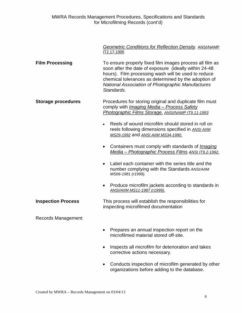
Geometric Conditions for Reflection Density. ANSI/NAMP IT2.17-1995
Film Processing To ensure properly fixed film images process all film as soon after the date of exposure (ideally within 24-48 hours). Film processing wash will be used to reduce chemical tolerances as determined by the adoption of National Association of Photographic Manufactures Standards.
Storage procedures Procedures for storing original and duplicate film must comply with Imaging Media – Process Safety Photographic Films Storage. ANSI/NAMP IT9.11-1993
• Reels of wound microfilm should stored in roll on reels following dimensions specified in ANSI AIIM MS29-1992 and ANSI AIIM MS34-1990.
• Containers must comply with standards of Imaging Media – Photographic Process Films ANSI IT9.2-1992.
• Label each container with the series title and the number complying with the Standards ANSI/AIIM MS06-1981 (r1999).
• Produce microfilm jackets according to standards in ANSI/AIIM MS11-1987 (r1999).
Inspection Process This process will establish the responsibilities for inspecting microfilmed documentation
Records Management
• Prepares an annual inspection report on the microfilmed material stored off-site.
• Inspects all microfilm for deterioration and takes corrective actions necessary.
• Conducts inspection of microfilm generated by other organizations before adding to the database.
MWRA Records Management Procedures, Specifications and Standards for Microfilming Records (cont’d)
Created by MWRA – Records Management on 03/04/13 9
Microfilming services
• Inspects film for errors and quality before delivery to MWRA.
• Performs a resolution check of film before delivery to MWRA.
• Performs retakes as necessary during the filming process and provides retake information in a report noting how many retakes on the roll.
_______________________
MWRA Records Management Procedures, Specifications and Standards for Microfilming Records (cont’d)
Created by MWRA – Records Management on 03/04/13 10
MICROFILM SERVICE CONTRACT
Scope of Services The microfilm services required consist of several microfilm applications in various MWRA departments. Microfilming will be performed on an as-needed basis. Applications listed on the attached series list must be completed by June 25, 2000 in so far as this work does not exceed $ _____________. Total estimated images: 250,000 Please provide a price for each line item in the last three columns on series list and for the hourly price of labor for document preparation for those record series for which this is required (see below). Also, provide the price for the entire job including prep. Vendor’s Capability The vendor must perform services in accordant with MWRA technical specifications attached. The vendor shall produce images on silver halide base film and shall produce two duplicate sets of diazo film. The diazo film base shall have a minimum thickness of 4.0 mil. The vendor shall blip and number each film of 16mm film. The vendor shall adjust camera exposure in order to meet resolution and density standards when filming blueprint documents or documents written in faded ink or pencil. The vendor shall perform frame by frame inspection and submit reports as completed to the MWRA Records Management and Library Manager. The vendor shall provide a list that cross-references the micromedia roll, reel or fiche number with the corresponding MWRA box number.
MWRA Records Management Procedures, Specifications and Standards for Microfilming Records (cont’d)
Created by MWRA – Records Management on 03/04/13 11
Frames improperly filmed shall be re-filmed at the vendor’s expense. The retake shall consist of at least twelve inches of images which shall them be reinserted to the master negative using an ultrasonic splice, No more than two splices may be made on one roll of film. The MWRA shall be responsible for document preparation of all applications except Journal Entries (1.1.3) that shall be prepped by the vendor. Also, continuous feed reports will be submitted to vendor in an estimated ______ mechanical binder. Vendor shall be responsible for both unfastening binders prior to filming and refastening binders after filming. Vendor shall be aware that in each continuous feed series there are several breaks, occurring with greater frequency in earlier documentation. The following specifications shall apply exclusively to journal entries: 1. All staples and paper clips shall be removed prior to filming. 2. The backup documents to each journal or invoice shall be filmed front and
back where there is information on overleaf of to capture date stamps. 3. Each journal entry shall be refastened after filming by application of
staple, or where volume required, clips or clamps. There are approximately ______ such packages, the majority requiring only a staple.
4. Hard copy shall be returned to the MWRA within five working days from date of pick-up. Vendor shall fax or return hard copy on same day (as required) if so needed by MWRA.
1
MWRA Engineering and Construction Department
Design-Information Systems Center Drawing Microfilming Technical Requirements
November 6, 2012 The intent of the microfilming of drawings on aperture cards is to provide a true copy of the original drawing. A true copy is one that contains all significant details of the document from which it was made. A true copy is an adequate substitute for that drawing for all purposes for which the original drawing was created. Vendor shall ensure the drawings are filmed on aperture cards according to the following MWRA standard: The Vendor shall furnish the Authority with two (2) microfilm sets of plans: a master camera negative set and a duplicate set. The master camera negative shall utilize silver halide film. The duplicate film shall be a diazo base. The silver halide master shall conform to standards set forth in the Authority General Specifications, where applicable, for Microfilm Records, see Attachment “Specification and Standards for Microfilming Records”. Both microfilm sets of drawings shall be 35-mm film mounted on standard microfilm aperture cards. Each frame of microfilm shall be exposed and processed so that every line and character on the document appears on the microfilm. Film shall be free of scratches, holes in the emulsion or base, tears, finger marks, or any other defect that might adversely affect quality.
Title information should be placed at the top of the card and contain from left to right, the Operations Unit (single character), the contract number, the sheet number, the project name (abbreviated), and accession number of the plan. The data printed at the top of the card shall be read into a file such as an ACCESS database and a report generated that lists the information printed on each aperture card.
Aperture Card Title Format Description: OPERATIONS UNIT: single character maximum Water Projects Shall Use: W Sewerage Projects Shall Use: S CONTRACT NUMBER: eight characters maximum For Example: 1234 For Example: C5514-01 SHEET NUMBER in the Set: 10 characters maximum For Example: 154/155 For Example: M-42 PROJECT NAME: 14 characters maximum For Example: CVA Redund ACCESSION NUMBER: six characters For Example: 123456
2
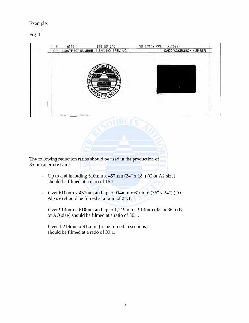
Example: Fig. 1
The following reduction ratios should be used in the production of 35mm aperture cards: - Up to and including 610mm x 457mm (24" x 18") (C or A2 size) should be filmed at a ratio of 16:1. - Over 610mm x 457mm and up to 914mm x 610mm (36" x 24") (D or Al size) should be filmed at a ratio of 24:1. - Over 914mm x 610mm and up to 1,219mm x 914mm (48" x 36") (E or AO size) should be filmed at a ratio of 30:1. - Over 1,219mm x 914mm (to be filmed in sections) should be filmed at a ratio of 30:1.
MWRA Engineering and Construction Department Drawing Scanning Technical Requirements
May 11, 2009 The intent of the electronic imaging of drawings is to provide a true copy of the original drawing. A true copy is one that contains all significant details of the document from which it was made. A true copy is an adequate substitute for that drawing for all purposes for which the original drawing was created. Vendor shall ensure the drawings are scanned as raster images according to the following MWRA standard:
• TIFF Format (Tagged Image File Format) Revision 6
• ITU-T (Formerly CCITT) Group 4 Compression
• Minimum 400 DPI (Dots Per Inch)
• Each drawing scanned is its original size (not a reduced sized)
• One TIFF file is created for each scanned drawing
• Each TIFF image file name is the MWRA accession number from the drawing
• Directory name is the MWRA contract number from the drawing
• The image file shall be Windows (Byte Order) applications compatible
The MWRA utilizes the following applications: Windows XP Microsoft Office Document Imaging AutoCAD 2009 AutoCAD Raster Design 2009 AutoVue Desktop Professional The Vendor shall format the TIFF Revision 6 file such that the images are viewable and printable utilizing existing MWRA applications.
• The image orientation is in the right-reading orientation
• The image alignment is such that the document is not skewed
• The black background images shall be inverted to provide a white background
• The Vendor shall record the images on CD-ROM according to the MWRA CD/DVD Digital Media Recording Requirements.
• The Vendor shall supply a duplicate copy of each CD-ROM produced

MWRA Drawing Standards
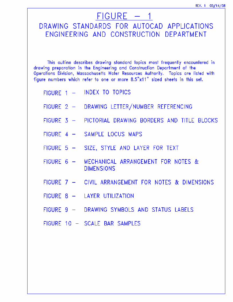
FIGURE - 1DRAWING STANDARDS FOR AUTOCAD APPLICATIONSENGINEERING AND CONSTRUCTION DEPARTMENT
This outline describes drawing standard topics most frequently encountered in drawing preparation in the Engineering and Construction Department of the Operations Division, Massachusetts Water Resources Authority. Topics are listed with figure numbers which refer to one or more 8.5"x11" sized sheets in this set.
INDEX TO TOPICS
DRAWING LETTER/NUMBER REFERENCING
PICTORIAL DRAWING BORDERS AND TITLE BLOCKS
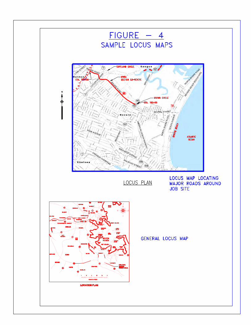
SAMPLE LOCUS MAPS
SIZE, STYLE AND LAYER FOR TEXT
MECHANICAL ARRANGEMENT FOR NOTES & DIMENSIONS
CIVIL ARRANGEMENT FOR NOTES & DIMENSIONS
LAYER UTILIZATION
DRAWING SYMBOLS AND STATUS LABELS
SCALE BAR SAMPLES
FIGURE 1 -
FIGURE 2 -
FIGURE 3 -
FIGURE 4 -
FIGURE 5 -
FIGURE 6 -
FIGURE 7 -
FIGURE 8 -
FIGURE 9 -
FIGURE 10 -
REV. 1 05/14/08
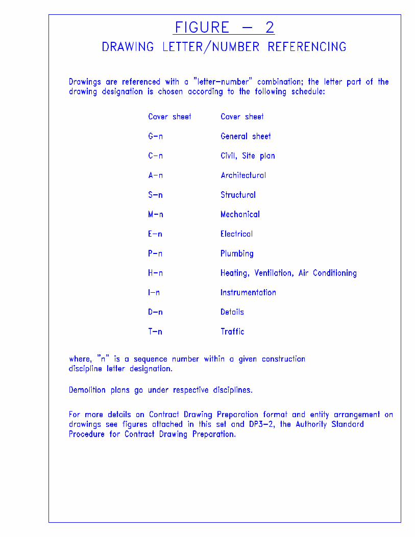
Drawings are referenced with a "letter-number" combination; the letter part of the drawing designation is chosen according to the following schedule:
Cover sheet
General sheet
Civil, Site plan
Architectural
Structural
Mechanical
Electrical
Plumbing
Heating, Ventilation, Air Conditioning
Instrumentation
Details
Traffic
Cover sheet
G-n
C-n
A-n
S-n
M-n
E-n
P-n
H-n
I-n
D-n
T-n
Demolition plans go under respective disciplines.
For more details on Contract Drawing Preparation format and entity arrangement on drawings see figures attached in this set and DP3-2, the Authority Standard Procedure for Contract Drawing Preparation.
where, "n" is a sequence number within a given construction discipline letter designation.
FIGURE - 2DRAWING LETTER/NUMBER REFERENCING
TEMPLATE
MWRA CONTRACT No.
DESIGN INFORMATION SYSTEMS CENTER
DESCRIPTION
SHEET 1 OF 5
NUMBER
DRAWING
INDEX TO DRAWINGS
DATE
MASSACHUSETTS WATER RESOURCES AUTHORITY
PREPARED BY
ENGINEERING & CONSTRUCTION DEPARTMENT
NUMBER
ACCESSION
NUMBER
SHEET
TITLE SHEET
LOCUS PLAN, LEGEND, ABBREVIATIONS, AND NOTES
SITE PLAN
PLAN OF BRIDGE
SECTIONS AND DETAILS
-
G-1
C-1
C-2
C-3
1
2
3
4
5
XXX,XXX
TITLELOCATION
ACCESSION No. XXX,XXX
LOCUS PLAN
SITE PLAN
N
WATER
RESOU
RCES AUTHO
RIT
Y
MA
SS A C H U S E T
TS
NO. DATE BY CHK'D REVISION
CONTRACT NO. :
ACCESSION NO. :
DATE:
SCALE:APPROVED BY:
CAD FILE NO. :
CHECKED BY:
DESIGNED BY:
DRAWN BY:
SECTION NO. :
MASSACHUSETTS WATER RESOURCES AUTHORITY
PREPARED BY :
DRAWING NO.
OF
A
C
M
SSA HUSETT
S
WATERR
ESOURCES A
UTHOR
ITY
ENGINEERING & CONSTRUCTION DEPARTMENT
DESIGN INFORMATION SYSTEMS CENTER
TEMPLATE
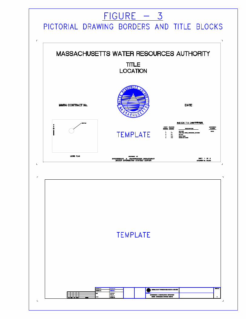
FIGURE - 3PICTORIAL DRAWING BORDERS AND TITLE BLOCKS
PROJECT LOCUS
RAILROAD
FORE RIVER
BOSTON
SCALE IN MILES
1 43210
NAVY YARD (MWRA)
EXPRESSWAY
SOUTHEAST
3A28
RIVER
CHARLES
RIVER
CHARLES
CHELSEA
MASSACHUSETTS TURNPIKE
53
WALTHAM
WESTWOOD
16
9
ROXBURY
WEST
RIVER
MYSTIC 1
1A
145
BAY
QUINCY
BAY
HINGHAM
24
NAHANT
NEWTON
BRAINTREECANTON
ROSLINDALE
PARK
HYDE
ROXBURY
95
NORWOOD
RANDOLPH
128
SEA ST.
QUINCY SHORE DR
.
90
2
99
93
3A
3
1
EVERETT
ISLAND
GEORGES
ISLAND
LOVELL
HARBOR
BOSTON
AIRPORT
LOGAN
ISLAND
SPECTACLE
ISLAND
THOMPSON
ISLAND
GRAPE
ISLAND
PEDDOCKS
ISLAND
LONG
NUT ISLAND
DEER ISLAND
WINTHROP
REVERE
BELMONT
MEDFORD
SOUND
BROAD
MILTON
BROOKLINE
DORCHESTER
QUINCY
WEYMOUTH
HULL
HINGHAMDEDHAM
WATERTOWN
CHARLESTOWN
SOMERVILLE
CAMBRIDGE
LOCATION PLAN
LOCUS PLAN
N
BROWN CIRCLE
MWRA
SECTION 53-REVERE
COPELAND CIRCLE
STA. 129+00
STA. 193+00
BR
O
O
K
PINES RIVER
PINES RIVER
ATLANTIC
OCEAN
REVERE BEACH
1A
60
GENERAL LOCUS MAP
LOCUS MAP LOCATING
MAJOR ROADS AROUND
JOB SITE
T
O
W
N
LI
N
E
FIGURE - 4
SAMPLE LOCUS MAPS
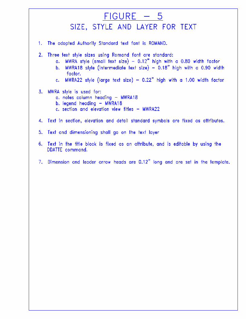
1. The adopted Authority Standard text font is ROMAND.
2. Three text style sizes using Romand font are standard: a. MWRA style (small text size) - 0.12" high with a 0.80 width factor b. MWRA18 style (intermediate text size) - 0.18" high with a 0.90 width
factor.
c. MWRA22 style (large text size) - 0.22" high with a 1.00 width factor
3. MWRA style is used for: a. notes column heading - MWRA18 b. legend heading - MWRA18 c. section and elevation view titles - MWRA22
4. Text in section, elevation and detail standard symbols are fixed as attributes.
5. Text and dimensioning shall go on the text layer
6. Text in the title block is fixed as an attribute, and is editable by using the DDATTE command.
7. Dimension and leader arrow heads are 0.12" long and are set in the template.
FIGURE - 5SIZE, STYLE AND LAYER FOR TEXT
A
P
3
E
2 3
2
3
23
O
8"
3'-6
"
B
H
D
F
Fb=1450 AND 1700 (APPLICABLE SIZES) B. BALANCE OF WOOD: NO. 1 GRADE
Fb=2000 PSI, E=1.7M PSI. A. STAIR STRINGERS: PREMIUM GRADE
WITH 0.4 CCA - ASTM D1760. PRESSURE-TREATED SOUTHERN YELLOW PINE2. ALL FRAMING WOOD AND PLANKING TO BE
COVERS BY OTHERS.
WITH PLATFORM DECK. OPENING; MANHOLE RING SHALL BE FLUSH4. PLATFORM SHALL BE CENTERED ON MANHOLE
TO MAIN PLATFORM; SEE DETAIL H, SHEET 3. FOR SECURING STAIR AND LANDING ASSEMBLY3. FAR 4"X4" POSTS EXTEND ABOVE HANDRAIL
PIPE CRADLES, RC PIPE AND RC PIPE END1. MANHOLE STRUCTURE, FRAME AND COVER,
NOTES
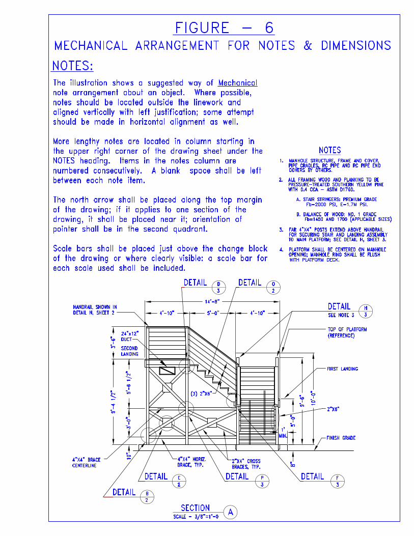
The illustration shows a suggested way of Mechanical note arrangement about an object. Where possible, notes should be located outside the linework and
aligned vertically with left justification; some attempt should be made in horizontal alignment as well. More lengthy notes are located in column starting in the upper right corner of the drawing sheet under the NOTES heading. Items in the notes column are numbered consecutively. A blank space shall be left between each note item.
The north arrow shall be placed along the top margin of the drawing; if it applies to one section of the drawing, it shall be placed near it; orientation of pointer shall be in the second quadrant.
Scale bars shall be placed just above the change block of the drawing or where clearly visible: a scale bar for each scale used shall be included.
NOTES:
FIGURE - 6MECHANICAL ARRANGEMENT FOR NOTES & DIMENSIONS
HANDRAIL SHOWN IN
DETAIL N, SHEET 2
4"X4" BRACE CENTERLINE
SECOND LANDING
4"X4" HORIZ. BRACE, TYP.
2"X4" CROSS BRACES, TYP.
TOP OF PLATFORM
(REFERENCE)
FIRST LANDING
2"X6"
FINISH GRADE
(3) 2"X6"
SCALE - 3/8"=1'-0SECTION
DETAIL DETAIL
DETAILSEE NOTE 3
DETAILDETAILDETAIL
DETAIL
9'-4
1/2
" 5'-6
1/2
"3'
-0"
10"
10'-
0"
9'-6
"
5'-0
"
1'MIN.
4'-10"5'-0"4'-10"
14'-8"
24"x12"DUCT
ROOF PLAN
ROOF DRAIN SEE DETAIL THIS DWG.
ROOF DRAIN SEE DETAIL THIS DWG.
PLUMBING VENT SEE DETAIL THIS DWG.
H.P.
FLUE-SEE DETAILTHIS DWG.
PITCH
PITCH
FURNISH AND INSTALL NEW MODIFIEDBITUMEN ROOF SYSTEM AS SPECIFIED
MM
LL
N
N
SCALE: 1/8" = 1'-0"
42'-1"
3'-9
"
3'-0"
33'-
9"
3'-9
"
3'-0"
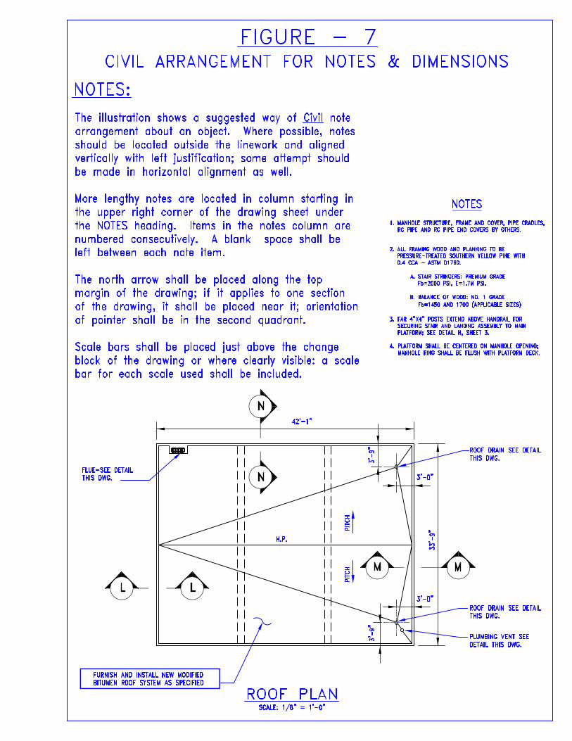
The illustration shows a suggested way of Civil note arrangement about an object. Where possible, notes should be located outside the linework and aligned vertically with left justification; some attempt should be made in horizontal alignment as well. More lengthy notes are located in column starting in the upper right corner of the drawing sheet under the NOTES heading. Items in the notes column are numbered consecutively. A blank space shall be left between each note item. The north arrow shall be placed along the top margin of the drawing; if it applies to one section of the drawing, it shall be placed near it; orientation of pointer shall be in the second quadrant.
Scale bars shall be placed just above the change block of the drawing or where clearly visible: a scale bar for each scale used shall be included.
NOTES:
FIGURE - 7CIVIL ARRANGEMENT FOR NOTES & DIMENSIONS
NOTES
MANHOLE STRUCTURE, FRAME AND COVER, PIPE CRADLES, RC PIPE AND RC PIPE END COVERS BY OTHERS.
ALL FRAMING WOOD AND PLANKING TO BE PRESSURE-TREATED SOUTHERN YELLOW PINE WITH 0.4 CCA - ASTM D1760.
STAIR STRINGERS: PREMIUM GRADE
Fb=2000 PSI, E=1.7M PSI.
BALANCE OF WOOD: NO. 1 GRADE
Fb=1450 AND 1700 (APPLICABLE SIZES)
FAR 4"X4" POSTS EXTEND ABOVE HANDRAIL FOR SECURING STAIR AND LANDING ASSEMBLY TO MAIN
PLATFORM; SEE DETAIL H, SHEET 3.
PLATFORM SHALL BE CENTERED ON MANHOLE OPENING; MANHOLE RING SHALL BE FLUSH WITH PLATFORM DECK.
1.
2.
3.
4.
A.
B.
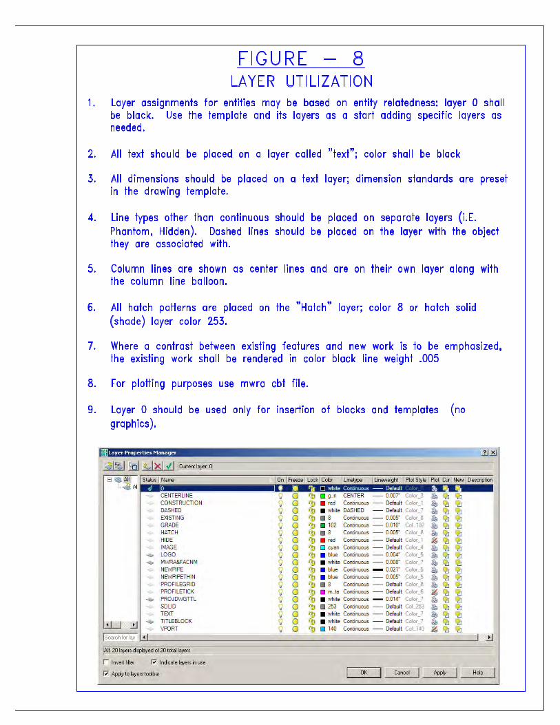
1.Layer assignments for entities may be based on entity relatedness: layer 0 shall be black. Use the template and its layers as a start adding specific layers as needed.
2.All text should be placed on a layer called "text"; color shall be black
3.All dimensions should be placed on a text layer; dimension standards are preset in the drawing template.
4.Line types other than continuous should be placed on separate layers (i.E. Phantom, Hidden). Dashed lines should be placed on the layer with the object they are associated with.
5.Column lines are shown as center lines and are on their own layer along with the column line balloon.
6.All hatch patterns are placed on the "Hatch" layer; color 8 or hatch solid (shade) layer color 253.
7.Where a contrast between existing features and new work is to be emphasized, the existing work shall be rendered in color black line weight .005
8.For plotting purposes use mwra cbt file.
9.Layer 0 should be used only for insertion of blocks and templates (no graphics).
FIGURE - 8
LAYER UTILIZATION
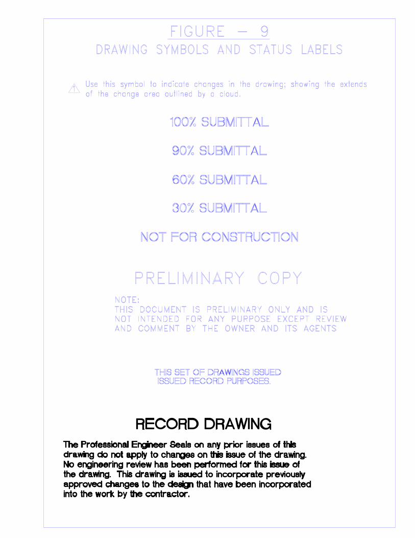
NOT FOR CONSTRUCTION
AND COMMENT BY THE OWNER AND ITS AGENTSNOT INTENDED FOR ANY PURPOSE EXCEPT REVIEWTHIS DOCUMENT IS PRELIMINARY ONLY AND ISNOTE:
PRELIMINARY COPY
100% SUBMITTAL
90% SUBMITTAL
60% SUBMITTAL
30% SUBMITTAL
1
THIS SET OF DRAWINGS ISSUED ISSUED RECORD PURPOSES.
approved changes to the design that have been incorporatedthe drawing. This drawing is issued to incorporate previouslyNo engineering review has been performed for this issue ofdrawing do not apply to changes on this issue of the drawing.The Professional Engineer Seals on any prior issues of this
into the work by the contractor.
RECORD DRAWING
FIGURE - 9DRAWING SYMBOLS AND STATUS LABELS
Use this symbol to indicate changes in the drawing; showing the extendsof the change area outlined by a cloud.
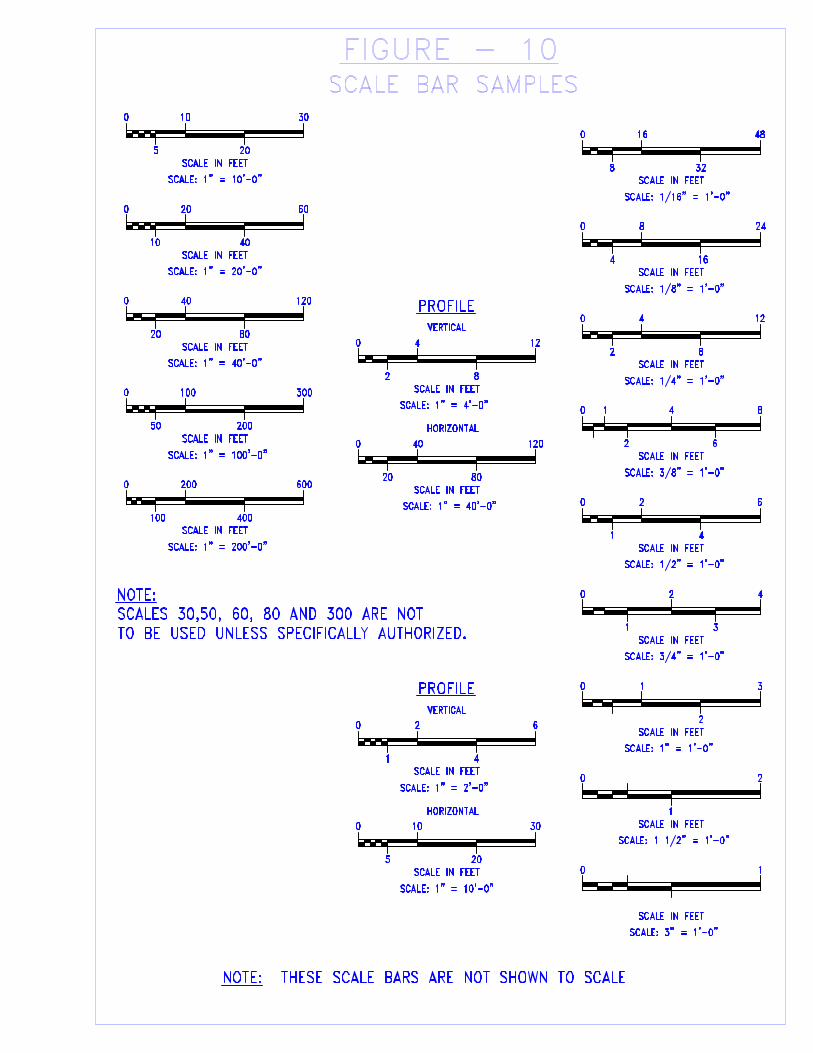
0
5
SCALE IN FEET
SCALE: 1" = 10'-0"
10 30
20
40
6020
SCALE: 1" = 20'-0"
SCALE IN FEET
10
0
80
12040
SCALE: 1" = 40'-0"
SCALE IN FEET
20
0
0
50
SCALE IN FEET
SCALE: 1" = 100'-0"
100 300
200
400
600200
SCALE: 1" = 200'-0"
SCALE IN FEET
100
0
PROFILE
0
20
SCALE IN FEET
SCALE: 1" = 40'-0"
40 120
80
HORIZONTAL
VERTICAL
8
124
SCALE: 1" = 4'-0"
SCALE IN FEET
2
0
VERTICAL
HORIZONTAL
PROFILE
0
1
SCALE IN FEET
SCALE: 1" = 2'-0"
2 6
4
20
3010
SCALE: 1" = 10'-0"
SCALE IN FEET
5
0
16
248
SCALE: 1/8" = 1'-0"SCALE IN FEET
4
0
0
2
SCALE IN FEET
SCALE: 1/4" = 1'-0"
4 12
8
8
SCALE: 3/8" = 1'-0"SCALE IN FEET
0
0
8
SCALE IN FEET
SCALE: 1/16" = 1'-0"
16 48
32
0
1
SCALE IN FEET
SCALE: 1/2" = 1'-0"
2 6
4
6
4
2
1
3
42
SCALE: 3/4" = 1'-0"SCALE IN FEET
1
0
2
31
SCALE: 1" = 1'-0"
SCALE IN FEET
0
0
SCALE IN FEET
SCALE: 1 1/2" = 1'-0"
2
1
1
SCALE: 3" = 1'-0"
SCALE IN FEET
0
NOTE: THESE SCALE BARS ARE NOT SHOWN TO SCALE
FIGURE - 10SCALE BAR SAMPLES
NOTE: SCALES 30,50, 60, 80 AND 300 ARE NOTTO BE USED UNLESS SPECIFICALLY AUTHORIZED.
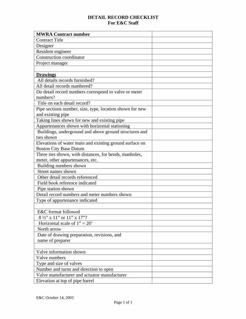
DETAIL RECORD CHECKLIST For E&C Staff
MWRA Contract number Contract Title Designer Resident engineer Construction coordinator Project manager Drawings All details records furnished? All detail records numbered? Do detail record numbers correspond to valve or meter numbers?
Title on each detail record? Pipe sections number, size, type, location shown for new and existing pipe
Taking lines shown for new and existing pipe Appurtenances shown with horizontal stationing Buildings, underground and above ground structures and ties shown
Elevations of water main and existing ground surface on Boston City Base Datum
Three ties shown, with distances, for bends, manholes, meter, other appurtenances, etc.
Building numbers shown Street names shown Other detail records referenced Field book reference indicated Pipe station shown Detail record numbers and meter numbers shown Type of appurtenance indicated E&C format followed 8 ½” x 11” or 11” x 17”? Horizontal scale of 1” = 20’ North arrow Date of drawing preparation, revisions, and name of preparer
Valve information shown Valve numbers Type and size of valves Number and turns and direction to open Valve manufacturer and actuator manufacturer Elevation at top of pipe barrel
E&C October 14, 2003 Page 1 of 1
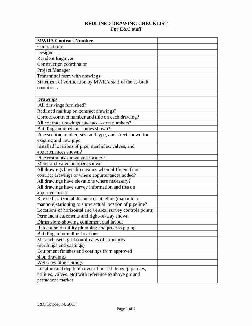
REDLINED DRAWING CHECKLIST
For E&C staff MWRA Contract Number Contract title Designer Resident Engineer Construction coordinator Project Manager Transmittal form with drawings Statement of verification by MWRA staff of the as-built conditions
Drawings All drawings furnished? Redlined markup on contract drawings? Correct contract number and title on each drawing? All contract drawings have accession numbers? Buildings numbers or names shown? Pipe section number, size and type, and street shown for existing and new pipe
Installed locations of pipe, manholes, valves, and appurtenances shown?
Pipe restraints shown and located? Meter and valve numbers shown All drawings have dimensions where different from contract drawings or where appurtenances added?
All drawings have elevations where necessary? All drawings have survey information and ties on appurtenances?
Revised horizontal distance of pipeline (manhole to manhole)stationing to show actual location of pipeline?
Locations of horizontal and vertical survey controls points Permanent easements and right-of-way shown Dimensions showing equipment pad layout Relocation of utility plumbing and process piping Building column line locations Massachusetts grid coordinates of structures (northings and eastings)
Equipment finishes and coatings from approved shop drawings
Weir elevation settings Location and depth of cover of buried items (pipelines, utilities, valves, etc) with reference to above ground permanent marker
E&C October 14, 2003 Page 1 of 2
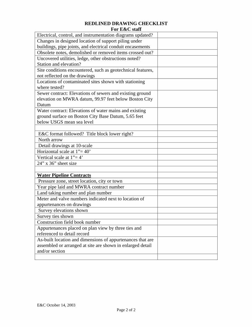
REDLINED DRAWING CHECKLIST
For E&C staff
E&C October 14, 2003 Page 2 of 2
Electrical, control, and instrumentation diagrams updated? Changes in designed location of support piling under buildings, pipe joints, and electrical conduit encasements
Obsolete notes, demolished or removed items crossed out? Uncovered utilities, ledge, other obstructions noted? Station and elevation?
Site conditions encountered, such as geotechnical features, not reflected on the drawings
Locations of contaminated sites shown with stationing where tested?
Sewer contract: Elevations of sewers and existing ground elevation on MWRA datum, 99.97 feet below Boston City Datum
Water contract: Elevations of water mains and existing ground surface on Boston City Base Datum, 5.65 feet below USGS mean sea level
E&C format followed? Title block lower right? North arrow Detail drawings at 10-scale Horizontal scale at 1”= 40’ Vertical scale at 1”= 4’ 24” x 36” sheet size Water Pipeline Contracts Pressure zone, street location, city or town Year pipe laid and MWRA contract number Land taking number and plan number Meter and valve numbers indicated next to location of appurtenances on drawings
Survey elevations shown Survey ties shown Construction field book number Appurtenances placed on plan view by three ties and referenced to detail record
As-built location and dimensions of appurtenances that are assembled or arranged at site are shown in enlarged detail and/or section

RECORD DRAWING CHECKLIST For E&C staff
MWRA Contract Number Contract title Resident Engineer Designer Construction coordinator Project manager Transmittal form with drawings Drawings All drawings furnished? Correct contract number and title on each drawing? All contract drawings have accession numbers? All redlined changes incorporated? Pipe section number, size and type, and street shown for existing and new pipe
Meter and valve numbers shown All drawings have dimensions where different from contract drawings or other appurtenances added?
All drawings have elevations where necessary? All drawings have survey information and ties on appurtenances?
Locations of horizontal and vertical survey controls points Revised horizontal pipeline stationing (manhole to manhole, and linear on ground), where necessary?
Permanent easements and right-of-way shown Dimensions showing equipment pad layout Relocation of utility plumbing and process piping Building column line locations Massachusetts grid coordinates of structures (northings and eastings)
Equipment finishes and coatings from approved shop drawings
Weir elevation settings Location and depth of cover of buried items with reference to above ground permanent marker
Electrical, control, and instrumentation diagrams updated? Changes in designed location of support piling under buildings, pipe joints and electrical conduit encasements
Obsolete notes, demolished or removed items crossed out? Uncovered utilities, ledge, and other obstructions noted? Station and elevation?
Site conditions encountered, such as geotechnical features, not reflected on the drawings
E&C October 14, 2003 Page 1 of 2
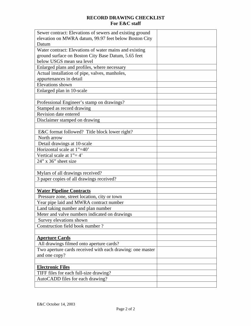
RECORD DRAWING CHECKLIST For E&C staff
E&C October 14, 2003 Page 2 of 2
Sewer contract: Elevations of sewers and existing ground elevation on MWRA datum, 99.97 feet below Boston City Datum Water contract: Elevations of water mains and existing ground surface on Boston City Base Datum, 5.65 feet below USGS mean sea level
Enlarged plans and profiles, where necessary Actual installation of pipe, valves, manholes, appurtenances in detail
Elevations shown Enlarged plan in 10-scale Professional Engineer’s stamp on drawings? Stamped as record drawing Revision date entered Disclaimer stamped on drawing E&C format followed? Title block lower right? North arrow Detail drawings at 10-scale Horizontal scale at 1”=40’ Vertical scale at 1”= 4’ 24” x 36” sheet size Mylars of all drawings received? 3 paper copies of all drawings received? Water Pipeline Contracts Pressure zone, street location, city or town Year pipe laid and MWRA contract number Land taking number and plan number Meter and valve numbers indicated on drawings Survey elevations shown Construction field book number ? Aperture Cards All drawings filmed onto aperture cards? Two aperture cards received with each drawing: one master and one copy?
Electronic Files TIFF files for each full-size drawing? AutoCADD files for each drawing?
MASSACHUSETTS WATER RESOURCES AUTHORITY
DESIGN INFORMATION SYSTEMS CENTER DRAFTING & DESIGN PROCEDURES
NO.: DP3-2 REV: 2
Page 1 of 10
TITLE:
Contract Drawing Preparation DATE: 05-14-08
APPROVED: _______________________________________________ Assistant Director of Engineering
A
C
M
SSA HUSETT
S
WATER
R
ESOURCES A
UTHORITY
1.0 PURPOSE AND SCOPE
1.1 To establish the responsibilities and describe the method by which contract drawings and revisions are prepared.
1.2 To establish the work flow for the preparation of drawings and revision among the drafters,
checkers and CADD Manager.
1.3 To establish a standard approach for the preparation of contract drawings generated by the Authority or consultants.
2.0 RESPONSIBILITIES
2.1 SENIOR PROGRAM MANAGER
Ensure the implementation of this procedure.
2.2 CADD MANAGER
Review and approve with the Project Manager the information to be incorporated into the contract drawing set.
Assign the drawings to drafters with a schedule of completion.
Oversee the drawing checking guidelines in accordance with DP3-3 Drawing Checking
Procedure.
Review drawings to ensure they are prepared in accordance with applicable MWRA standards, guidelines, and procedures.
Route the drawings to project technical review personnel for intermediate review; confer
with technical review staff on adequacy of graphical completeness for various disciplines.
NO.: DP3-2 TITLE: Contract Drawing Preparation
Page 2 of 10
On completion of drawing package, notify the project manager who shall confirm the
accession numbers for each drawing with the Accession Number Specialist in accordance with DP2-2 Drawing Accession Number Program.
Review the red-lined bid set of drawings from the Construction Unit for adequacy, clarity
and necessary information for the preparation of as-built (record) drawings.
Transfer mylars to document control for distribution in accordance with DP1-2.
2.3 DRAFTER/DESIGNER
Incorporate work methods and procedures in drawings and drawing design in accordance with this procedure.
3.0 IMPLEMENTATION
3.1 The CADD Manager, in conference with project manager, shall:
3.1.1 Determine the appropriate method of drawing preparation, (eg., AutoCAD Raster Design).
3.1.2 Determine the number of required drawings in each discipline and standard details.
3.2 The CADD Manager shall assign contract drawing tasks to the staff drafters.
3.3 Drafters shall prepare contract drawings using the following standard criteria:
1. Initial geometry drawings shall be 1:1 in model space; enlarged views of models shall
be shown in paper space
2. Plotted sheets shall be made using paper space on 36" x 24" sheet size; all plotting shall be done to minimize medium trimming wastage; see the CADD Manager for guidance in this area.
3. When possible, the graphics of only one construction discipline shall be placed on a
given sheet.
4. The adopted Authority Standard text style is ROMAND font, MWRA style.
5. The MWRA standard drawing cover sheet shall be used for the title page. The locus plan on the cover sheet shall be a site map showing the location of the work area, and the project name marked with an arrow. The index to the project drawings shall be shown on the right side of the cover sheet indicating drawing title, drawing number sheet number and accession number. The cover sheet shall be numbered sheet 1.
NO.: DP3-2 TITLE: Contract Drawing Preparation
Page 3 of 10
6. When the Drawing index is too lengthy to fit on the title page, it shall be placed on the second sheet of the project drawing series and shall be labeled G-1; for this purpose, the drawing border title block shall be the MWRA standard discipline sheet; this sheet may be used for legends and general notes.
7. The site plan drawing shall be the next drawing in sequence, defined in a standard
engineering scale showing the local street environs about the facility location; the site plan shall show but not limited to such details as:
ingress and egress to the project site with street names
security fence perimeters
construction equipment and materials lay down areas
North arrow and drawing scale bar
The site drawing number shall be prefixed with "C-".
8. The information on the cover sheet shall match information on each following sheet.
9. The drawings of the contract set shall be arranged in the discipline order listed as
follows: cover sheet G-n general sheet C-n site plan; civil A-n architectural S-n structural M-n mechanical E-n electrical P-n plumbing H-n heating, ventilation, air conditioning I-n instrumentation D-n details T-n traffic
where, "n" is a sequence number within a given construction discipline letter
designation.
10. All drawings shall bear a sequence number as "n of m" in the editable space provided in the title block.
NO.: DP3-2 TITLE: Contract Drawing Preparation
Page 4 of 10
11. The subject matter on each drawing of a given discipline series shall be as ordered as
follows:
legends and/or symbols and general notes demolition of old work plans and sections of new work details of new work when there are a large number of them equipment schedules.
12. The scale on each drawing of a given discipline series shall be defined as standard engineering scales. Scales are presented in Appendix C.
13. Notes placed on a drawing shall be placed in the upper right hand corner under the heading "NOTES" underlined and in MWRA18 text style 0.18" high uppercase letters; notes must link to items on the drawing and not take the place of the discourse that more appropriately belongs in the specifications or on a legend sheet. The notes shall be in upper case romand characters 0.12" high. See Appendix C. If the notes cannot be placed in the upper right hand corner due to length or graphics on the drawing, the notes shall be placed where appropriate on the drawing.
CAUTION
The intention of the notes feature of drawings is to supplement or clarify the graphics shown on the drawing; if there is no direct, meaningful link between the content of the note and the referent graphic entity on the drawing, the instruction should be placed in the appropriate specification section, or in the general notes.
14. When appropriate, drawings shall have a key plan placed in the lower right hand
corner of the sheet as an aid in locating within the structure where the work illustrated on the drawing is to be placed.
15. All plans, sections and details shall be identified with MWRA standard symbols and
titled with uppercase underlined MWRA22 text style 0.22" high characters; the appropriate scale notation (part of the symbol block) shall be shown below the title.
16. Notes located at the point of reference and indicated with a leader shall be left justified
and where possible lined up vertically, to the left or right side of the elevation, plan or sectional view; all characters for notes and shall be MWRA text style, 0.12" high upper case characters.
NO.: DP3-2 TITLE: Contract Drawing Preparation
Page 5 of 10
17. All dimension characters shall be 0.12" high MWRA text style characters placed in the
middle of the dimension line and paralleled to the direction of the dimension line when possible; dimension and leader arrowheads shall be 0.12" in length and filled.
NOTE: Dimension style criteria are subject to construction discipline interpretation
and this standard chooses to accommodate interpretation.
18. The minimum layer convention for a drawing is established with the insertion of the standard drawing border and the named layers are as follows:
0 centerline – for columns and center lines dashed - dashed existing – out of function grade - grade hatch – cross hatching hide – lines not to be displayed image – raster image insertions logo – title block mwra&facnm – title block newpipe – for new pipe work (heavy) newpipethin – for new pipe work (thin) profilegrid – for profile grids profiletick – for scale tick marks on profile projdwttl – title block solid - shading text – for notes, labels and dimension text and line work titleblock – title block vport - viewport

NO.: DP3-2 TITLE: Contract Drawing Preparation
Page 6 of 10
19. The template for standard layering conventions shall be used as follows:
20. Line color conventions facilitate drawing plotting with the use of .ctb files; these files can be made drawing specific; all final plots are required to be in black and white; the line-color-line width convention, as a minimum, and used at the Authority Standard is as follows:
a. color 1, red; line width 0.005"; applicable to hidden lines and lines making up
hatched entities; the layers "hidden" and "hatch" contain the entities.
b. color 12 (a shade of red); width 0.016" used for bold text styles on cover sheets and in title blocks for drawing and project titles; these are fixed in the drawing border-title block blocks.
c. color 2, yellow; line width 0.008"; applicable to "drawing info layer".
d. color 3, green; line width 0.007"; applicable to center lines and column lines
on the "centerline" layer.
NO.: DP3-2 TITLE: Contract Drawing Preparation
Page 7 of 10
e. color 4, cyan; line width 0.007"; applicable dimension and leader lines;
dimension entities are contained on the "dim" layer; leaders are on the text layer.
f. color 5, blue; unassigned.
g. color 6, magenta; unassigned.
h. color 7, black; line width 0.010" this color as well as those unassigned may be
used for visible entities (ie object lines) as seen fit and upon unreserved layers.
i. color 253; line width 0.005"; applicable to "out of function" layer.
j. color 240; line width 0.005” is reserved for the MWRA logo in the title block.
3.3 All contract drawings prepared either by Authority personnel or by Consultants in Service of the Authority shall use AutoCAD of a version compatible with the current Version in use by the Authority.
3.4 On completion of final checking of the drawing package by CADD staff and the reviewing
engineer, in preparation for bidding, the CADD manager and the project manager shall have the drawings initialed by appropriate CADD and engineering staff, respectively. The project manager shall arrive for affixing of a Professional engineer’s stamp to mylar copies of each drawing.
1. The following convention shall be used in placing personnel initials in the title block
of contract drawings:
The "designed by" box shall contain the design engineer's initials.
The "drawn by" box shall contain the drafter's initials.
The "checked by" box shall contain the initials of the engineer who reviewed and checked the work.
The "approved by" box shall contain the senior program manager(s)'s initials. The final drawing in mylar shall be manually signed (initialed) by the design
engineer, the drafter, and the engineer who reviewed and checked the work. The final drawing in mylar shall be initialed by the senior program manager when the documents are ready to bid.
NO.: DP3-2 TITLE: Contract Drawing Preparation
Page 8 of 10
The Director of Engineering shall place his engineer's stamp on the contract
drawings after all other boxes have been initialed in the title block, when the final documents are ready to bid.
3.5 All electronic contract drawings shall be secured in the designated directory structure for the contract in the appropriate server.
4.0 REFERENCES
4.1 Massachusetts General Law, Chapter 149, Section 44a - Governs all contracts for construction, reconstruction, installation, demolition, maintenance or repair of any building, including modular buildings, estimated to cost more that $25,000. Chapter 149 applies to all contracts over $25,000 which include building work, regardless of its cost.
4.2 Massachusetts General Law, Chapter 30, Section 39m - Chapter applies to contracts for
construction, reconstruction, alteration, remodeling or repair of any public work (e.g., horizontal construction - sewers, water lines, roads, etc.) or construction materials estimated to cost between $10,000 and $25,000.
4.3 Massachusetts General Law, Chapter 30 or Chapter 149 - All projects subject to Chapter 30 or
Chapter 149 of the Massachusetts General Laws require a detailed design set forth in plans and specifications.
4.4 Massachusetts General Law, Section 44b(1), Chapter 149 - All Chapter 149 contracts must
have plans drawn on a scale of not less than one-eighth inch to one foot except for site plans that have not been mechanically reduced.
4.5 The Uniform Drawing System the Construction Specifications Institute, 1997
4.6 DISC Procedure, DP1-2 Management of DISC Requests for Work for CADD Services.
4.7 DISC Procedure, DP2-2 Drawing Accession Number Program.
4.8 DISC Procedure, DP3-3 Drawing Checking Procedures.
4.9 DISC Procedure, DP3-6 Procedures for Obtaining Output (Plotting).
5.0 DEFINITIONS
5.1 Drawings - All drawings, diagrams, charts, illustrations, schedules, and other data which are specifically prepared or revised by the Project Manager to illustrate the work in support of the construction project related activities.
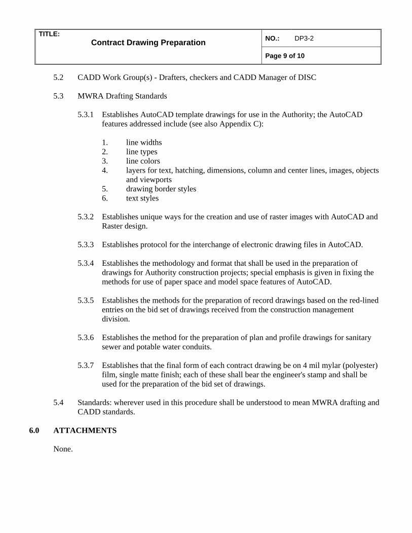
NO.: DP3-2 TITLE: Contract Drawing Preparation
Page 9 of 10
5.2 CADD Work Group(s) - Drafters, checkers and CADD Manager of DISC
5.3 MWRA Drafting Standards
5.3.1 Establishes AutoCAD template drawings for use in the Authority; the AutoCAD
features addressed include (see also Appendix C):
1. line widths 2. line types 3. line colors 4. layers for text, hatching, dimensions, column and center lines, images, objects
and viewports 5. drawing border styles 6. text styles
5.3.2 Establishes unique ways for the creation and use of raster images with AutoCAD and
Raster design.
5.3.3 Establishes protocol for the interchange of electronic drawing files in AutoCAD.
5.3.4 Establishes the methodology and format that shall be used in the preparation of drawings for Authority construction projects; special emphasis is given in fixing the methods for use of paper space and model space features of AutoCAD.
5.3.5 Establishes the methods for the preparation of record drawings based on the red-lined
entries on the bid set of drawings received from the construction management division.
5.3.6 Establishes the method for the preparation of plan and profile drawings for sanitary
sewer and potable water conduits.
5.3.7 Establishes that the final form of each contract drawing be on 4 mil mylar (polyester) film, single matte finish; each of these shall bear the engineer's stamp and shall be used for the preparation of the bid set of drawings.
5.4 Standards: wherever used in this procedure shall be understood to mean MWRA drafting and
CADD standards. 6.0 ATTACHMENTS
None.

NO.: DP3-2 TITLE: Contract Drawing Preparation
Page 10 of 10
7.0 FORMS
None.
MASSACHUSETTS WATER RESOURCES AUTHORITY
DESIGN INFORMATION SYSTEMS CENTER
DRAFTING & DESIGN PROCEDURES
TITLE:
Drawing Checking Procedures
NO.: DP3-3 REV: 2
Page 1 of 4
DATE: 05-14-08
APPROVED: _______________________________________________ Assistant Director of Engineering
A
C
M
SSA HUSETT
S
WATER
R
ESOURCES A
UTHORITY
1.0 PURPOSE AND SCOPE
1.1 To establish the responsibilities and describe the methods for the use of checking guidelines when reviewing drawings and drawing revisions.
1.2 To establish checking guidelines as a tool to be used to assist the drawing checker in
identifying the items to be checked on the drawings. 2.0 RESPONSIBILITIES
2.1 SENIOR PROGRAM MANAGER (Manager - DISC)
• Ensure the implementation of this procedure.
2.2 CADD MANAGER
• Oversees the drawing checking guidelines and assigns checking jobs to drafters and/or checkers.
2.3 DRAWING CHECKER
• Performs checking of drawings, using the items on the drawing checklist, as a
minimum. The CADD Manager will assign an individual other than the drafter making the drawing to check the drawing.
3.0 IMPLEMENTATION
3.1 SCHEDULE FOR CHECKING
3.1.1 The CADD Manager is responsible for the review of all drawings during the progress of the work to ensure MWRA drafting standards, as defined in this manual, are used.
3.1.2 CADD staff are responsible for the quality of their work and shall check their work for technical accuracy and coordination on a daily basis.
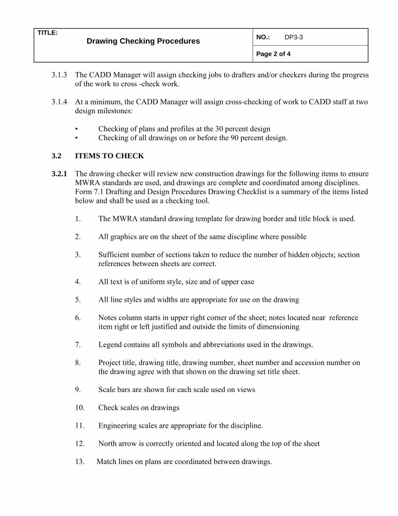
TITLE:
Drawing Checking Procedures NO.: DP3-3
Page 2 of 4
3.1.3 The CADD Manager will assign checking jobs to drafters and/or checkers during the progress
of the work to cross -check work.
3.1.4 At a minimum, the CADD Manager will assign cross-checking of work to CADD staff at two design milestones:
• Checking of plans and profiles at the 30 percent design • Checking of all drawings on or before the 90 percent design.
3.2 ITEMS TO CHECK
3.2.1 The drawing checker will review new construction drawings for the following items to ensure MWRA standards are used, and drawings are complete and coordinated among disciplines. Form 7.1 Drafting and Design Procedures Drawing Checklist is a summary of the items listed below and shall be used as a checking tool.
1. The MWRA standard drawing template for drawing border and title block is used.
2. All graphics are on the sheet of the same discipline where possible 3. Sufficient number of sections taken to reduce the number of hidden objects; section
references between sheets are correct.
4. All text is of uniform style, size and of upper case 5. All line styles and widths are appropriate for use on the drawing 6. Notes column starts in upper right corner of the sheet; notes located near reference
item right or left justified and outside the limits of dimensioning 7. Legend contains all symbols and abbreviations used in the drawings. 8. Project title, drawing title, drawing number, sheet number and accession number on
the drawing agree with that shown on the drawing set title sheet. 9. Scale bars are shown for each scale used on views 10. Check scales on drawings 11. Engineering scales are appropriate for the discipline. 12. North arrow is correctly oriented and located along the top of the sheet
13. Match lines on plans are coordinated between drawings.
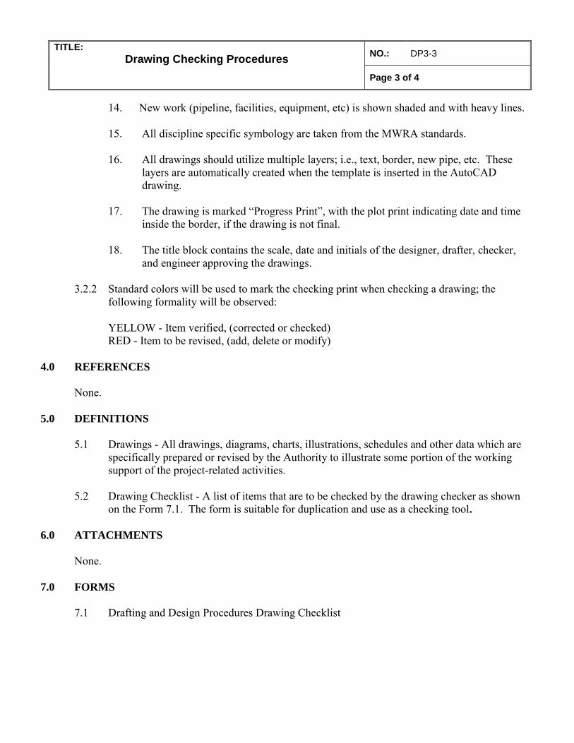
TITLE:
Drawing Checking Procedures NO.: DP3-3
Page 3 of 4
14. New work (pipeline, facilities, equipment, etc) is shown shaded and with heavy lines.
15. All discipline specific symbology are taken from the MWRA standards. 16. All drawings should utilize multiple layers; i.e., text, border, new pipe, etc. These
layers are automatically created when the template is inserted in the AutoCAD drawing.
17. The drawing is marked “Progress Print”, with the plot print indicating date and time
inside the border, if the drawing is not final.
18. The title block contains the scale, date and initials of the designer, drafter, checker, and engineer approving the drawings.
3.2.2 Standard colors will be used to mark the checking print when checking a drawing; the
following formality will be observed:
YELLOW - Item verified, (corrected or checked) RED - Item to be revised, (add, delete or modify)
4.0 REFERENCES
None. 5.0 DEFINITIONS 5.1 Drawings - All drawings, diagrams, charts, illustrations, schedules and other data which are
specifically prepared or revised by the Authority to illustrate some portion of the working support of the project-related activities.
5.2 Drawing Checklist - A list of items that are to be checked by the drawing checker as shown
on the Form 7.1. The form is suitable for duplication and use as a checking tool.
6.0 ATTACHMENTS
None. 7.0 FORMS
7.1 Drafting and Design Procedures Drawing Checklist
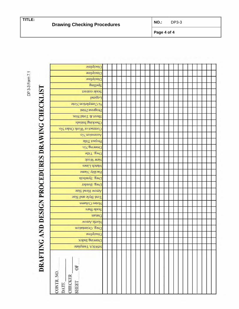
TITLE:
Drawing Checking Procedures NO.: DP3-3
Page 4 of 4
MASSACHUSETTS WATER RESOURCES AUTHORITY
DESIGN INFORMATION SYSTEMS CENTER
DRAFTING & DESIGN PROCEDURES
TITLE:
Drawing Checking Procedures
NO.: DP3-3 REV: 2
Page 5 of 4
DATE: 05-14-08
APPROVED: _______________________________________________ Assistant Director of Engineering
A
C
M
SSA HUSETT
S
WATER
R
ESOURCES A
UTHORITY
1
DRAFT
Guidelines for MWRA Waterworks
Detail Records and Record Drawings
(Revised: February 2006)
By: Rajesh Shah,
Field Operations, Waterworks Please email ‘[email protected]’ should you have any comments/suggestions on items presented in this document.
Contents 1. General Information on Record Drawings and Detail Records Pages 2 & 3 of 13 2. Detail Records Pages 4 to 9 of 13 3. Record Drawings Pages 10 to 13 of 13 4. Sample Detail Record and Record Drawing Three Sheets
2
1. General Information
1.1 Waterworks Record Drawings and Detail Records: Waterworks Record Drawings and Detail Records are essential in routine operations, operations planning, maintenance, emergency response, as well as design engineering and construction of MWRA Waterworks Distribution and Transmission Mains and Facilities.
1.1.1 Record drawings are essentially final forms of ‘As Built Drawings’ of any Design Engineering/Construction Projects. They don’t show construction related information, and correctly represent final conditions of the Pipelines/ Facilities after they are put in Operations. 1.1.2 Detail Records are developed to show enlarged views of details and appurtenances (such as, gate/BV/air/BO valves, bends, fittings meters, and connections to cities/towns or any other water mains etc.) on waterworks pipelines/facilities.
1.2 Record Drawings and Detail Records are related in a way that the references of the
‘Detail Record Numbers’ are made on to the Record Drawing sheets at locations where those individual Detail Record exists. (See Page 11, Section 3.2.2.8)
1.3 There are two main categories of Detail Records and Record Drawings : 1.3.1 Pipelines (Small/large diameters Distribution pipelines, excluding transmission tunnels) 1.3.2 Facilities (Buildings, Transmission Tunnels, or any physical structures other than Distribution Pipelines, such as, Storage Reservoirs, Treatment Plants, Pump Stations, Valve Chambers, Gate Houses etc.)
1.4 A major way of ‘Record Drawings’ and ‘Detail Records’ developed:
(1) One of the major ways Record Drawings and Detail Records are developed is through Design Engineering and Construction Contracts on Waterworks Pipelines/Facilities. Consultants for the respective Contracts coordinate with MWRA Engineering and Construction Staffs in the development process of the Record Drawings and Detail Records.
(2) MWRA Field Operations Staffs participate in interim review process on Draft Record Drawings and Detail Records submittals by the consultants.
(3) As one of the end products of the Contracts, these Drawings are submitted to the MWRA staffs. These Drawings are accepted by the MWRA after ensuring that all of the review comments are addressed.
1.5 Before working on a new Design Contracts, it is important to find if any existing
MWRA Pipelines/Facilities are situated within the geographic limits. Consultants/
3
Designer must obtain copies of the existing Record Drawings & Detail Records from the MWRA staff for review to see if there is any presence of existing pipeline/facility. Existing Pipelines/Facilities shall be duly shown on the new Pipelines/Facilities Record Drawings and Detail Records. (For further information on ‘Detail Records’, please see Page 4, Detail Records Section 2.3).
1.6 When existing pipeline/facilities are to be relocated or rehabilitated, Detail Records and Record Drawings showing them shall be updated. Any annotations, redlines or as built notes on to the existing Detail Records and Record Drawings shall be finalized
1.7 Final submission of Record Drawings and Detail Records shall be made to the MWRA staffs on a set of Mylar, 2 sets of paper copies and on latest version of CAD files.
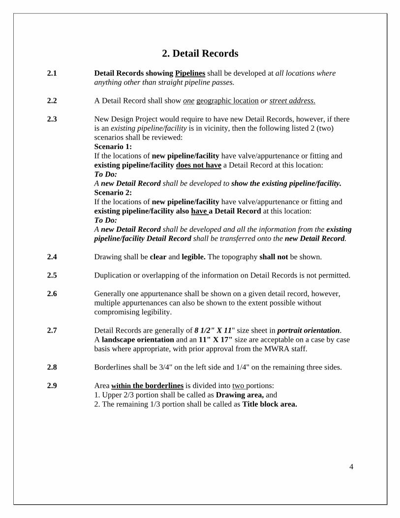
4
2. Detail Records
2.1 Detail Records showing Pipelines shall be developed at all locations where anything other than straight pipeline passes.
2.2 A Detail Record shall show one geographic location or street address. 2.3 New Design Project would require to have new Detail Records, however, if there
is an existing pipeline/facility is in vicinity, then the following listed 2 (two) scenarios shall be reviewed:
Scenario 1: If the locations of new pipeline/facility have valve/appurtenance or fitting and existing pipeline/facility does not have a Detail Record at this location: To Do:
A new Detail Record shall be developed to show the existing pipeline/facility. Scenario 2: If the locations of new pipeline/facility have valve/appurtenance or fitting and existing pipeline/facility also have a Detail Record at this location: To Do:
A new Detail Record shall be developed and all the information from the existing pipeline/facility Detail Record shall be transferred onto the new Detail Record.
2.4 Drawing shall be clear and legible. The topography shall not be shown. 2.5 Duplication or overlapping of the information on Detail Records is not permitted. 2.6 Generally one appurtenance shall be shown on a given detail record, however,
multiple appurtenances can also be shown to the extent possible without compromising legibility.
2.7 Detail Records are generally of 8 1/2" X 11" size sheet in portrait orientation.
A landscape orientation and an 11" X 17" size are acceptable on a case by case basis where appropriate, with prior approval from the MWRA staff.
2.8 Borderlines shall be 3/4" on the left side and 1/4" on the remaining three sides.
2.9 Area within the borderlines is divided into two portions: 1. Upper 2/3 portion shall be called as Drawing area, and 2. The remaining 1/3 portion shall be called as Title block area.
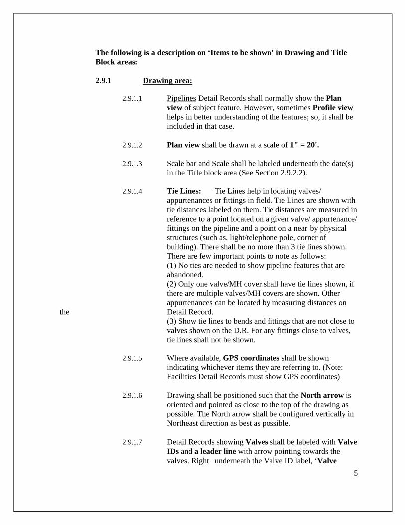
5
The following is a description on ‘Items to be shown’ in Drawing and Title Block areas:
2.9.1 Drawing area:
2.9.1.1 Pipelines Detail Records shall normally show the Plan view of subject feature. However, sometimes Profile view helps in better understanding of the features; so, it shall be included in that case.
2.9.1.2 Plan view shall be drawn at a scale of 1" = 20'.
2.9.1.3 Scale bar and Scale shall be labeled underneath the date(s)
in the Title block area (See Section 2.9.2.2).
2.9.1.4 Tie Lines: Tie Lines help in locating valves/ appurtenances or fittings in field. Tie Lines are shown with tie distances labeled on them. Tie distances are measured in reference to a point located on a given valve/ appurtenance/ fittings on the pipeline and a point on a near by physical structures (such as, light/telephone pole, corner of building). There shall be no more than 3 tie lines shown.
There are few important points to note as follows: (1) No ties are needed to show pipeline features that are abandoned. (2) Only one valve/MH cover shall have tie lines shown, if there are multiple valves/MH covers are shown. Other appurtenances can be located by measuring distances on the Detail Record. (3) Show tie lines to bends and fittings that are not close to valves shown on the D.R. For any fittings close to valves, tie lines shall not be shown.
2.9.1.5 Where available, GPS coordinates shall be shown indicating whichever items they are referring to. (Note: Facilities Detail Records must show GPS coordinates)
2.9.1.6 Drawing shall be positioned such that the North arrow is
oriented and pointed as close to the top of the drawing as possible. The North arrow shall be configured vertically in Northeast direction as best as possible.
2.9.1.7 Detail Records showing Valves shall be labeled with Valve
IDs and a leader line with arrow pointing towards the valves. Right underneath the Valve ID label, ‘Valve
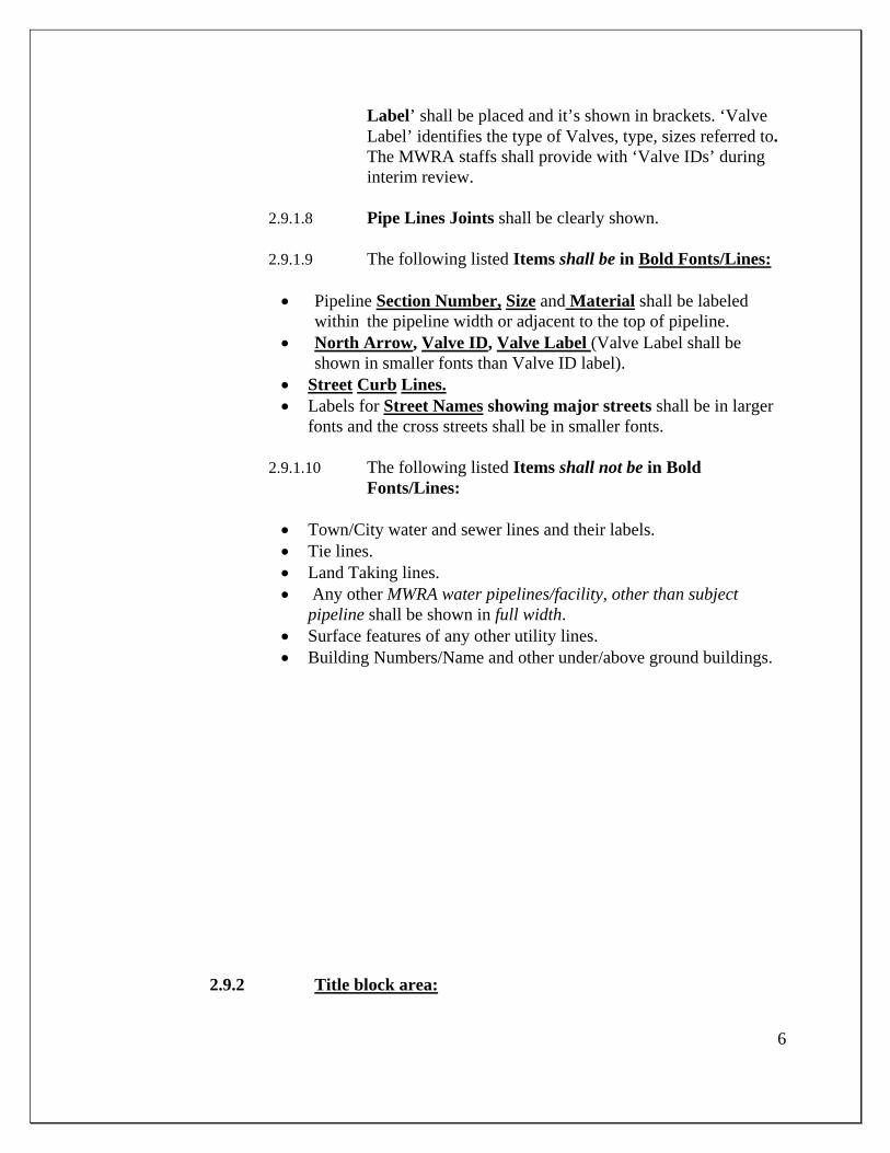
6
Label’ shall be placed and it’s shown in brackets. ‘Valve Label’ identifies the type of Valves, type, sizes referred to. The MWRA staffs shall provide with ‘Valve IDs’ during interim review.
2.9.1.8 Pipe Lines Joints shall be clearly shown.
2.9.1.9 The following listed Items shall be in Bold Fonts/Lines:
Pipeline Section Number, Size and Material shall be labeled
within the pipeline width or adjacent to the top of pipeline. North Arrow, Valve ID, Valve Label (Valve Label shall be
shown in smaller fonts than Valve ID label). Street Curb Lines. Labels for Street Names showing major streets shall be in larger
fonts and the cross streets shall be in smaller fonts.
2.9.1.10 The following listed Items shall not be in Bold Fonts/Lines:
Town/City water and sewer lines and their labels. Tie lines. Land Taking lines. Any other MWRA water pipelines/facility, other than subject
pipeline shall be shown in full width. Surface features of any other utility lines. Building Numbers/Name and other under/above ground buildings.
2.9.2 Title block area:
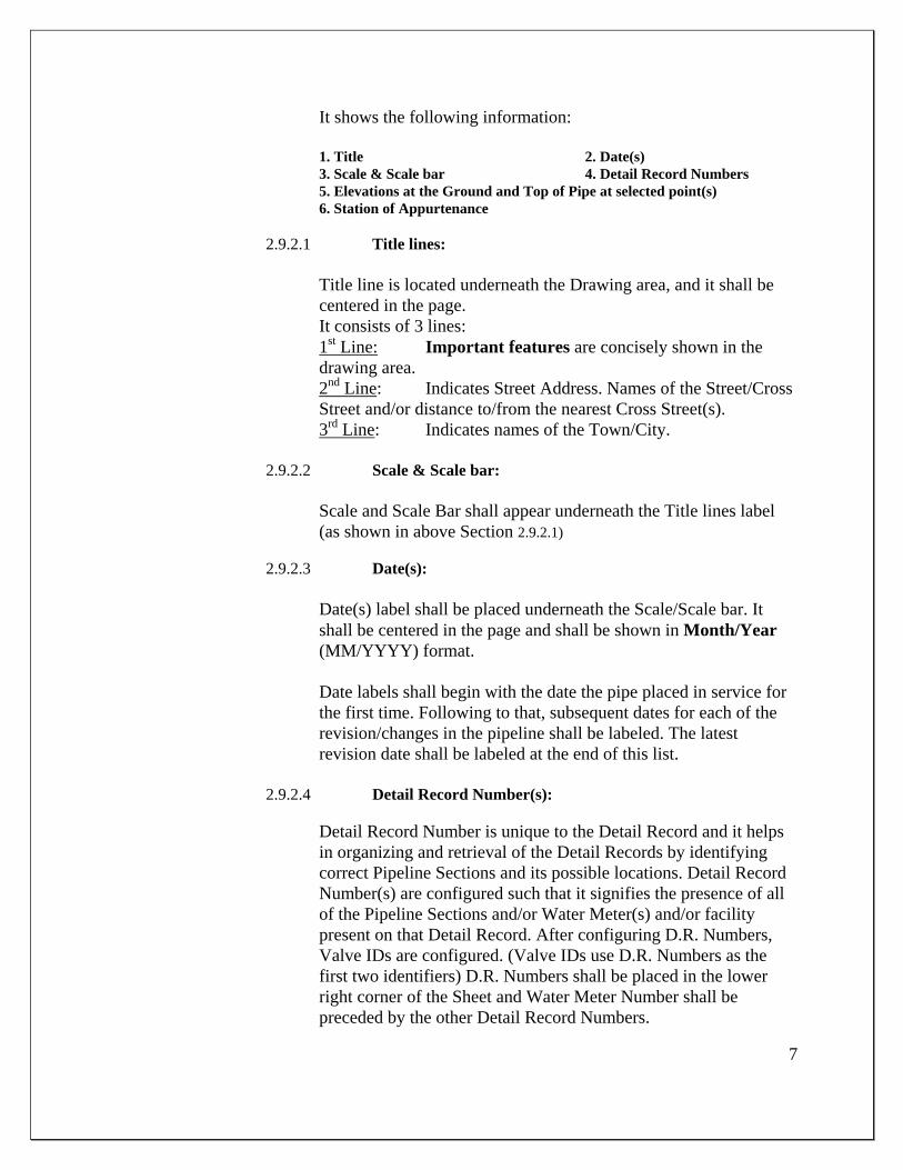
7
It shows the following information: 1. Title 2. Date(s) 3. Scale & Scale bar 4. Detail Record Numbers 5. Elevations at the Ground and Top of Pipe at selected point(s) 6. Station of Appurtenance 2.9.2.1 Title lines:
Title line is located underneath the Drawing area, and it shall be
centered in the page. It consists of 3 lines: 1st Line: Important features are concisely shown in the
drawing area. 2nd Line: Indicates Street Address. Names of the Street/Cross
Street and/or distance to/from the nearest Cross Street(s). 3rd Line: Indicates names of the Town/City.
2.9.2.2 Scale & Scale bar:
Scale and Scale Bar shall appear underneath the Title lines label (as shown in above Section 2.9.2.1) 2.9.2.3 Date(s):
Date(s) label shall be placed underneath the Scale/Scale bar. It shall be centered in the page and shall be shown in Month/Year (MM/YYYY) format. Date labels shall begin with the date the pipe placed in service for the first time. Following to that, subsequent dates for each of the revision/changes in the pipeline shall be labeled. The latest revision date shall be labeled at the end of this list.
2.9.2.4 Detail Record Number(s):
Detail Record Number is unique to the Detail Record and it helps in organizing and retrieval of the Detail Records by identifying correct Pipeline Sections and its possible locations. Detail Record Number(s) are configured such that it signifies the presence of all of the Pipeline Sections and/or Water Meter(s) and/or facility present on that Detail Record. After configuring D.R. Numbers, Valve IDs are configured. (Valve IDs use D.R. Numbers as the first two identifiers) D.R. Numbers shall be placed in the lower right corner of the Sheet and Water Meter Number shall be preceded by the other Detail Record Numbers.
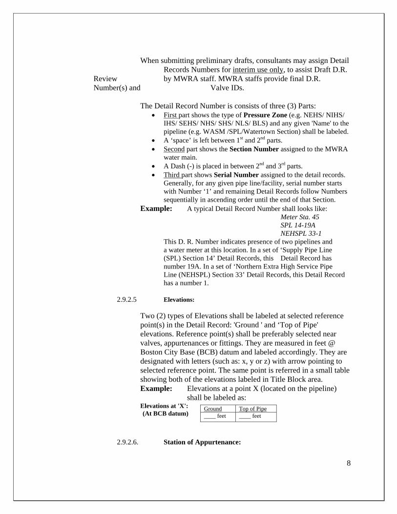
8
When submitting preliminary drafts, consultants may assign Detail Records Numbers for interim use only, to assist Draft D.R. Review by MWRA staff. MWRA staffs provide final D.R. Number(s) and Valve IDs.
The Detail Record Number is consists of three (3) Parts:
First part shows the type of Pressure Zone (e.g. NEHS/ NIHS/ IHS/ SEHS/ NHS/ SHS/ NLS/ BLS) and any given 'Name' to the pipeline (e.g. WASM /SPL/Watertown Section) shall be labeled.
A ‘space’ is left between 1st and 2nd parts. Second part shows the Section Number assigned to the MWRA
water main. A Dash (-) is placed in between 2nd and 3rd parts. Third part shows Serial Number assigned to the detail records.
Generally, for any given pipe line/facility, serial number starts with Number ‘1’ and remaining Detail Records follow Numbers sequentially in ascending order until the end of that Section.
Example: A typical Detail Record Number shall looks like: Meter Sta. 45
SPL 14-19A NEHSPL 33-1
This D. R. Number indicates presence of two pipelines and a water meter at this location. In a set of ‘Supply Pipe Line (SPL) Section 14’ Detail Records, this Detail Record has number 19A. In a set of ‘Northern Extra High Service Pipe Line (NEHSPL) Section 33’ Detail Records, this Detail Record has a number 1.
2.9.2.5 Elevations:
Two (2) types of Elevations shall be labeled at selected reference point(s) in the Detail Record: 'Ground ' and ‘Top of Pipe' elevations. Reference point(s) shall be preferably selected near valves, appurtenances or fittings. They are measured in feet @ Boston City Base (BCB) datum and labeled accordingly. They are designated with letters (such as: x, y or z) with arrow pointing to selected reference point. The same point is referred in a small table showing both of the elevations labeled in Title Block area. Example: Elevations at a point X (located on the pipeline)
shall be labeled as: Elevations at 'X':
(At BCB datum)
2.9.2.6. Station of Appurtenance:
Ground Top of Pipe____ feet ____ feet
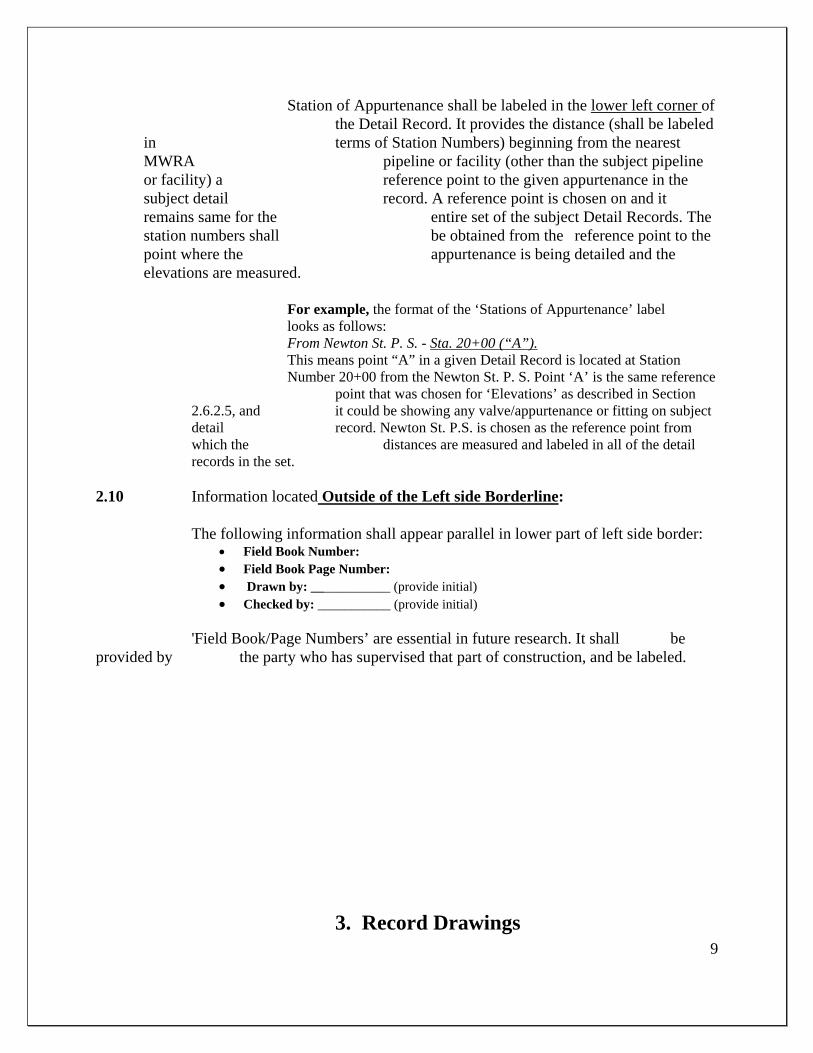
9
Station of Appurtenance shall be labeled in the lower left corner of the Detail Record. It provides the distance (shall be labeled in terms of Station Numbers) beginning from the nearest MWRA pipeline or facility (other than the subject pipeline or facility) a reference point to the given appurtenance in the subject detail record. A reference point is chosen on and it remains same for the entire set of the subject Detail Records. The station numbers shall be obtained from the reference point to the point where the appurtenance is being detailed and the elevations are measured.
For example, the format of the ‘Stations of Appurtenance’ label
looks as follows: From Newton St. P. S. - Sta. 20+00 (“A”). This means point “A” in a given Detail Record is located at Station Number 20+00 from the Newton St. P. S. Point ‘A’ is the same reference point that was chosen for ‘Elevations’ as described in Section 2.6.2.5, and it could be showing any valve/appurtenance or fitting on subject detail record. Newton St. P.S. is chosen as the reference point from which the distances are measured and labeled in all of the detail records in the set.
2.10 Information located Outside of the Left side Borderline: The following information shall appear parallel in lower part of left side border:
Field Book Number: Field Book Page Number: Drawn by: ____________ (provide initial) Checked by: ___________ (provide initial)
'Field Book/Page Numbers’ are essential in future research. It shall be provided by the party who has supervised that part of construction, and be labeled.
3. Record Drawings
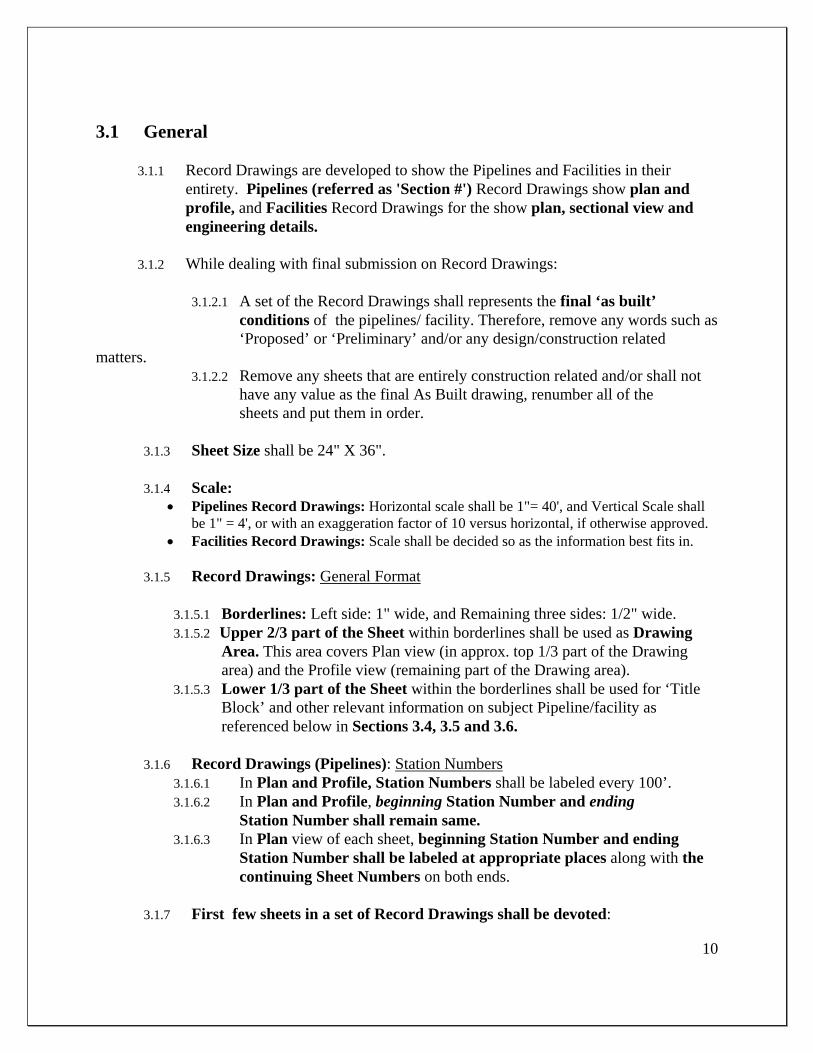
10
3.1 General
3.1.1 Record Drawings are developed to show the Pipelines and Facilities in their entirety. Pipelines (referred as 'Section #') Record Drawings show plan and profile, and Facilities Record Drawings for the show plan, sectional view and engineering details.
3.1.2 While dealing with final submission on Record Drawings:
3.1.2.1 A set of the Record Drawings shall represents the final ‘as built’ conditions of the pipelines/ facility. Therefore, remove any words such as ‘Proposed’ or ‘Preliminary’ and/or any design/construction related matters. 3.1.2.2 Remove any sheets that are entirely construction related and/or shall not have any value as the final As Built drawing, renumber all of the sheets and put them in order.
3.1.3 Sheet Size shall be 24" X 36".
3.1.4 Scale: Pipelines Record Drawings: Horizontal scale shall be 1"= 40', and Vertical Scale shall
be 1" = 4', or with an exaggeration factor of 10 versus horizontal, if otherwise approved. Facilities Record Drawings: Scale shall be decided so as the information best fits in.
3.1.5 Record Drawings: General Format
3.1.5.1 Borderlines: Left side: 1" wide, and Remaining three sides: 1/2" wide. 3.1.5.2 Upper 2/3 part of the Sheet within borderlines shall be used as Drawing
Area. This area covers Plan view (in approx. top 1/3 part of the Drawing area) and the Profile view (remaining part of the Drawing area).
3.1.5.3 Lower 1/3 part of the Sheet within the borderlines shall be used for ‘Title Block’ and other relevant information on subject Pipeline/facility as referenced below in Sections 3.4, 3.5 and 3.6.
3.1.6 Record Drawings (Pipelines): Station Numbers
3.1.6.1 In Plan and Profile, Station Numbers shall be labeled every 100’. 3.1.6.2 In Plan and Profile, beginning Station Number and ending
Station Number shall remain same. 3.1.6.3 In Plan view of each sheet, beginning Station Number and ending
Station Number shall be labeled at appropriate places along with the continuing Sheet Numbers on both ends.
3.1.7 First few sheets in a set of Record Drawings shall be devoted:
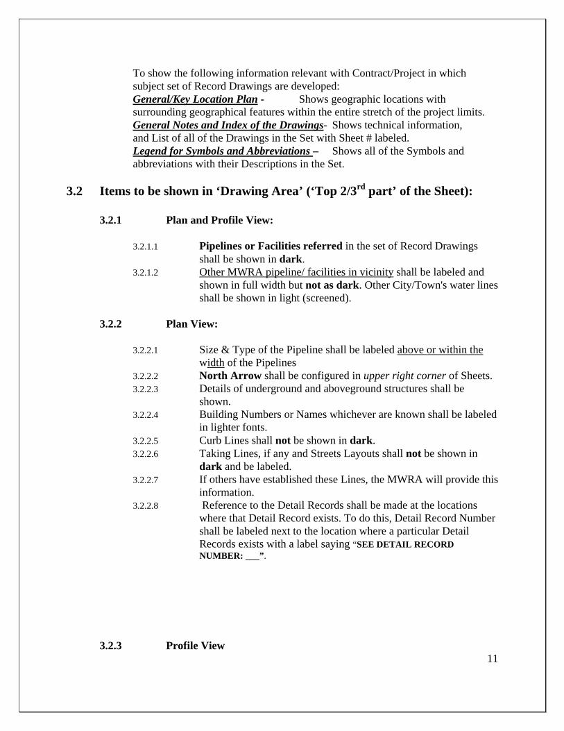
11
To show the following information relevant with Contract/Project in which subject set of Record Drawings are developed:
General/Key Location Plan - Shows geographic locations with surrounding geographical features within the entire stretch of the project limits. General Notes and Index of the Drawings- Shows technical information,
and List of all of the Drawings in the Set with Sheet # labeled. Legend for Symbols and Abbreviations – Shows all of the Symbols and
abbreviations with their Descriptions in the Set.
3.2 Items to be shown in ‘Drawing Area’ (‘Top 2/3rd part’ of the Sheet):
3.2.1 Plan and Profile View:
3.2.1.1 Pipelines or Facilities referred in the set of Record Drawings shall be shown in dark.
3.2.1.2 Other MWRA pipeline/ facilities in vicinity shall be labeled and shown in full width but not as dark. Other City/Town's water lines shall be shown in light (screened).
3.2.2 Plan View:
3.2.2.1 Size & Type of the Pipeline shall be labeled above or within the
width of the Pipelines 3.2.2.2 North Arrow shall be configured in upper right corner of Sheets. 3.2.2.3 Details of underground and aboveground structures shall be
shown. 3.2.2.4 Building Numbers or Names whichever are known shall be labeled
in lighter fonts. 3.2.2.5 Curb Lines shall not be shown in dark. 3.2.2.6 Taking Lines, if any and Streets Layouts shall not be shown in
dark and be labeled. 3.2.2.7 If others have established these Lines, the MWRA will provide this
information. 3.2.2.8 Reference to the Detail Records shall be made at the locations
where that Detail Record exists. To do this, Detail Record Number shall be labeled next to the location where a particular Detail Records exists with a label saying “SEE DETAIL RECORD NUMBER: ___”.
3.2.3 Profile View
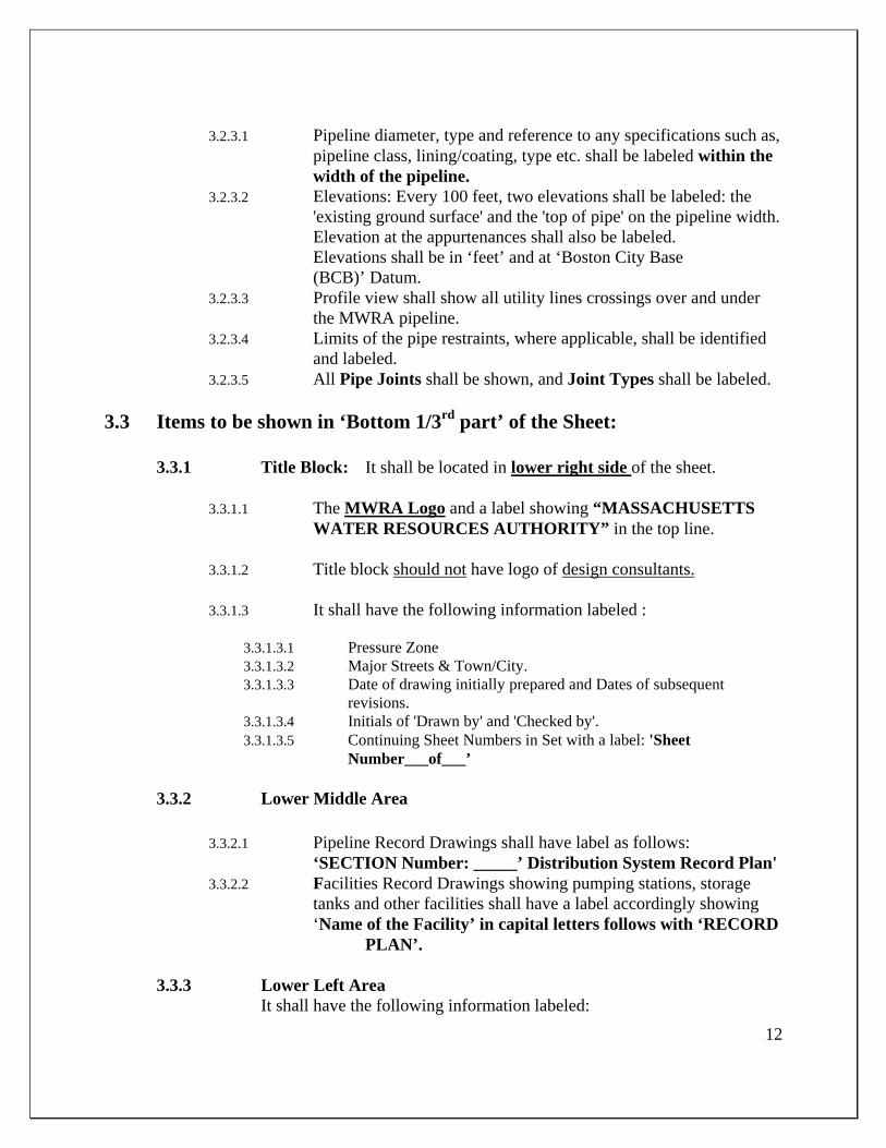
12
3.2.3.1 Pipeline diameter, type and reference to any specifications such as,
pipeline class, lining/coating, type etc. shall be labeled within the width of the pipeline.
3.2.3.2 Elevations: Every 100 feet, two elevations shall be labeled: the 'existing ground surface' and the 'top of pipe' on the pipeline width. Elevation at the appurtenances shall also be labeled.
Elevations shall be in ‘feet’ and at ‘Boston City Base (BCB)’ Datum.
3.2.3.3 Profile view shall show all utility lines crossings over and under the MWRA pipeline.
3.2.3.4 Limits of the pipe restraints, where applicable, shall be identified and labeled.
3.2.3.5 All Pipe Joints shall be shown, and Joint Types shall be labeled. 3.3 Items to be shown in ‘Bottom 1/3rd part’ of the Sheet:
3.3.1 Title Block: It shall be located in lower right side of the sheet.
3.3.1.1 The MWRA Logo and a label showing “MASSACHUSETTS WATER RESOURCES AUTHORITY” in the top line.
3.3.1.2 Title block should not have logo of design consultants. 3.3.1.3 It shall have the following information labeled :
3.3.1.3.1 Pressure Zone 3.3.1.3.2 Major Streets & Town/City. 3.3.1.3.3 Date of drawing initially prepared and Dates of subsequent
revisions. 3.3.1.3.4 Initials of 'Drawn by' and 'Checked by'. 3.3.1.3.5 Continuing Sheet Numbers in Set with a label: 'Sheet
Number___of___’
3.3.2 Lower Middle Area
3.3.2.1 Pipeline Record Drawings shall have label as follows: ‘SECTION Number: _____’ Distribution System Record Plan' 3.3.2.2 Facilities Record Drawings showing pumping stations, storage
tanks and other facilities shall have a label accordingly showing ‘Name of the Facility’ in capital letters follows with ‘RECORD PLAN’.
3.3.3 Lower Left Area It shall have the following information labeled:
13
Pipe laid in: (year) Contract Number, Name of the Contractor: Land Taking Number(s), Land Plan Number(s): List of all Detail Records Numbers applicable to that Record Drawing
Sheet: Book numbers for:
Survey & Level Book(s), Construction Field Book(s), Calculation Book(s), Force Account Book(s) Last three items in above shown list shall be provided by the MWRA.
3.4 A few specifics on the ‘Facilities’ Record Drawings
3.4.1 Show Title Sheet, General Location Plan and Key Location Plan (to
indicate Project area) 3.4.2 Show Index to the Drawings, General Notes, Abbreviation and Legend. 3.4.3 Show ‘Sheet Layout’ in case of multiple sheets is used to show one
subject matter. Highlight the sheet that is referred to on the ‘Sheet Layout’.
3.4.4 Drawings related to various project disciplines shall generally be placed in the following order: Civil, Architectural, Structural, Mechanical, HVAC, Electrical, Instrumentation, Plantings etc.
3.4.5 To provide references to the Related Drawings: Label Sheet Numbers to refer any drawing that is related with any other Drawing shown elsewhere in the Set.
3.4.6 Plan and Sectional views shall be provided. Profile view shall be shown when pipelines are shown within the Facilities.
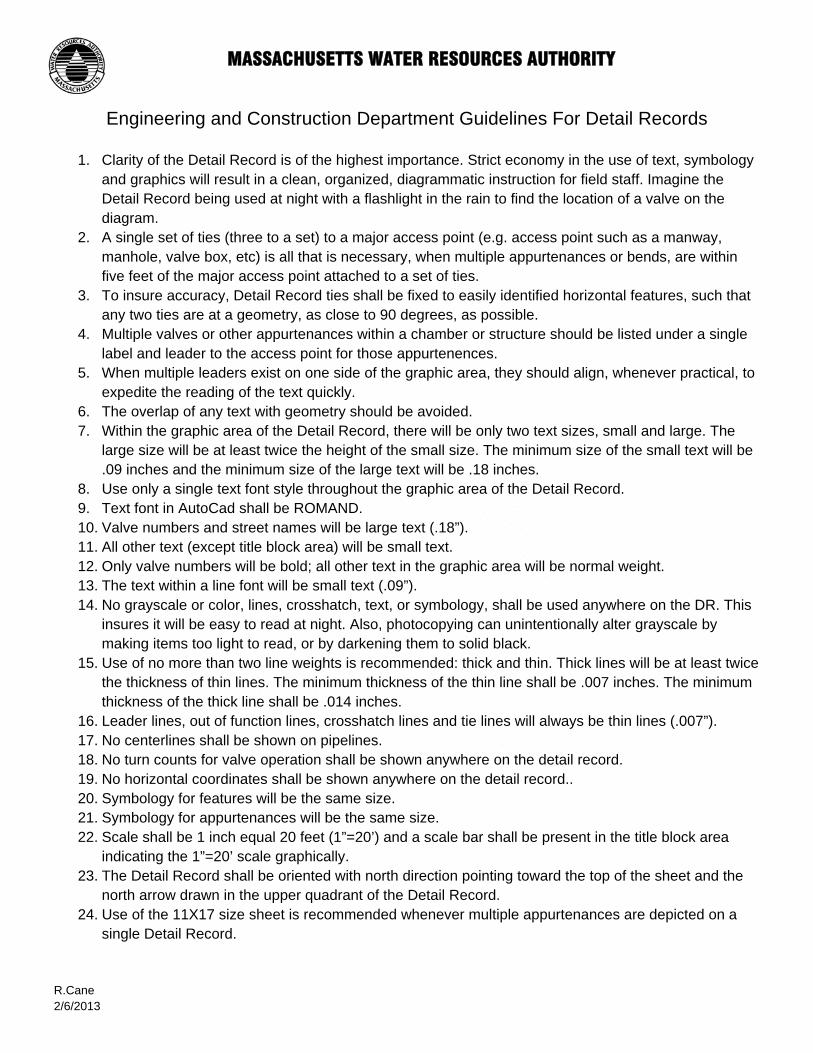
MASSACHUSETTS WATER RESOURCES AUTHORITY Engineering and Construction Department Guidelines For Detail Records
1. Clarity of the Detail Record is of the highest importance. Strict economy in the use of text, symbology
and graphics will result in a clean, organized, diagrammatic instruction for field staff. Imagine the Detail Record being used at night with a flashlight in the rain to find the location of a valve on the diagram.
2. A single set of ties (three to a set) to a major access point (e.g. access point such as a manway, manhole, valve box, etc) is all that is necessary, when multiple appurtenances or bends, are within five feet of the major access point attached to a set of ties.
3. To insure accuracy, Detail Record ties shall be fixed to easily identified horizontal features, such that any two ties are at a geometry, as close to 90 degrees, as possible.
4. Multiple valves or other appurtenances within a chamber or structure should be listed under a single label and leader to the access point for those appurtenences.
5. When multiple leaders exist on one side of the graphic area, they should align, whenever practical, to expedite the reading of the text quickly.
6. The overlap of any text with geometry should be avoided. 7. Within the graphic area of the Detail Record, there will be only two text sizes, small and large. The
large size will be at least twice the height of the small size. The minimum size of the small text will be .09 inches and the minimum size of the large text will be .18 inches.
8. Use only a single text font style throughout the graphic area of the Detail Record. 9. Text font in AutoCad shall be ROMAND. 10. Valve numbers and street names will be large text (.18”). 11. All other text (except title block area) will be small text. 12. Only valve numbers will be bold; all other text in the graphic area will be normal weight. 13. The text within a line font will be small text (.09”). 14. No grayscale or color, lines, crosshatch, text, or symbology, shall be used anywhere on the DR. This
insures it will be easy to read at night. Also, photocopying can unintentionally alter grayscale by making items too light to read, or by darkening them to solid black.
15. Use of no more than two line weights is recommended: thick and thin. Thick lines will be at least twice the thickness of thin lines. The minimum thickness of the thin line shall be .007 inches. The minimum thickness of the thick line shall be .014 inches.
16. Leader lines, out of function lines, crosshatch lines and tie lines will always be thin lines (.007”). 17. No centerlines shall be shown on pipelines. 18. No turn counts for valve operation shall be shown anywhere on the detail record. 19. No horizontal coordinates shall be shown anywhere on the detail record.. 20. Symbology for features will be the same size. 21. Symbology for appurtenances will be the same size. 22. Scale shall be 1 inch equal 20 feet (1”=20’) and a scale bar shall be present in the title block area
indicating the 1”=20’ scale graphically. 23. The Detail Record shall be oriented with north direction pointing toward the top of the sheet and the
north arrow drawn in the upper quadrant of the Detail Record. 24. Use of the 11X17 size sheet is recommended whenever multiple appurtenances are depicted on a
single Detail Record. R.Cane 2/6/2013

MWRA Survey Standards

Massachusetts Water Resources Authority September 2007 MwraLdtStandardsSept2007
1
MASSACHUSETTS WATER RESOURCES AUTHORITY
Wastewater Engineering
Design Information Systems Center
SURVEY LAND DESKTOP STANDARDS
(GUIDELINES)
September 2007
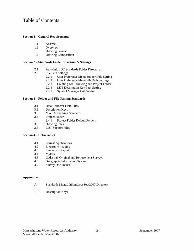
Massachusetts Water Resources Authority September 2007 MwraLdtStandardsSept2007
2
Table of Contents
Section 1 – General Requirements
1.1 Abstract 1.2 Overview 1.3 Drawing Format 1.4 Drawing Composition
Section 2 – Standards Folder Structure & Settings
2.1 Autodesk LDT Standards Folder Directory 2.2 File Path Settings
2.2.1 User Preference Menu Support File Setting 2.2.2 User Preference Menu File Path Settings 2.2.3 Creating LDT Drawing and Project Folder 2.2.4 LDT Description Key Path Setting 2.2.5 Symbol Manager Path Setting
Section 3 – Folder and File Naming Standards
3.1 Data Collector Field Files 3.2 Description Keys 3.3 MWRA Layering Standards 3.4 Project Folder 3.4.1 Project Folder Default Folders. 3.5 Drawing Files 3.6 LDT Support Files
Section 4 – Deliverables 4.1 Format Applications 4.2 Electronic Imaging 4.3 Surveyor’s Report 4.4 Mylars 4.5 Cadastral, Original and Retracement Surveys 4.6 Geographic Information System 4.7 Survey Documents Appendices: A. Standards MwraLdtStandardsSept2007 Directory B. Description Keys
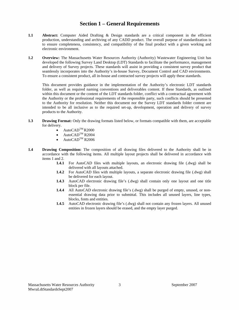
Massachusetts Water Resources Authority September 2007 MwraLdtStandardsSept2007
3
Section 1 – General Requirements
1.1 Abstract: Computer Aided Drafting & Design standards are a critical component in the efficient
production, understanding and archiving of any CADD product. The overall purpose of standardization is to ensure completeness, consistency, and compatibility of the final product with a given working and electronic environment.
1.2 Overview: The Massachusetts Water Resources Authority (Authority) Wastewater Engineering Unit has
developed the following Survey Land Desktop (LDT) Standards to facilitate the performance, management and delivery of Survey projects. These standards will assist in providing a consistent survey product that seamlessly incorporates into the Authority’s in-house Survey, Document Control and CAD environments. To ensure a consistent product, all in-house and contracted survey projects will apply these standards.
This document provides guidance in the implementation of the Authority’s electronic LDT standards folder, as well as required naming conventions and deliverables content. If these Standards, as outlined within this document or the content of the LDT standards folder, conflict with a contractual agreement with the Authority or the professional requirements of the responsible party, such conflicts should be presented to the Authority for resolution. Neither this document nor the Survey LDT standards folder content are intended to be all inclusive as to the required set-up, development, operation and delivery of survey products to the Authority.
1.3 Drawing Format: Only the drawing formats listed below, or formats compatible with them, are acceptable for delivery.
• AutoCADTM R2000 • AutoCADTM R2004 • AutoCADTM R2006
1.4 Drawing Composition: The composition of all drawing files delivered to the Authority shall be in accordance with the following items. All multiple layout projects shall be delivered in accordance with items 1 and 2.
1.4.1 For AutoCAD files with multiple layouts, an electronic drawing file (.dwg) shall be delivered with all layouts attached.
1.4.2 For AutoCAD files with multiple layouts, a separate electronic drawing file (.dwg) shall be delivered for each layout.
1.4.3 AutoCAD electronic drawing file’s (.dwg) shall contain only one layout and one title block per file.
1.4.4 All AutoCAD electronic drawing file’s (.dwg) shall be purged of empty, unused, or non-essential drawing data prior to submittal. This includes all unused layers, line types, blocks, fonts and entities.
1.4.5 AutoCAD electronic drawing file’s (.dwg) shall not contain any frozen layers. All unused entities in frozen layers should be erased, and the empty layer purged.
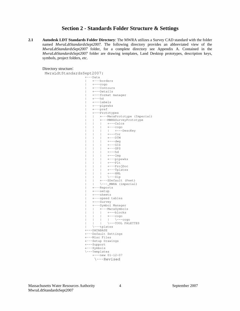
Massachusetts Water Resources Authority September 2007 MwraLdtStandardsSept2007
4
Section 2 - Standards Folder Structure & Settings
2.1 Autodesk LDT Standards Folder Directory: The MWRA utilizes a Survey CAD standard with the folder named MwraLdtStandardsSept2007. The following directory provides an abbreviated view of the MwraLdtStandardsSept2007 folder, for a complete directory see Appendix A. Contained in the MwraLdtStandardsSept2007 folder are drawing templates, Land Desktop prototypes, description keys, symbols, project folders, etc.
Directory structure: MwraLdtStandardsSept2007:
+---Data | +---borders | +---cogo | +---Contours | +---Details | +---format manager | +---hd | +---labels | +---pipewks | +---pref | +---Prototypes | | +---MwraPrototype (Imperial) | | +---MWRASurveyPrototype | | | +---Calcs | | | +---cogo | | | | +---DescKey | | | +---Cor | | | +---DTM | | | +---dwg | | | +---GIS | | | +---GPS | | | +---hd | | | +---Img | | | +---pipewks | | | +---Plt | | | +---ProjDoc | | | +---Tplates | | | +---XML | | | \---Zip | | +---ZDefault (Feet) | | \---_MWRA (imperial) | +---Reports | +---setup | +---sheets | +---speed tables | +---Survey | +---Symbol Manager | | +---MwraSymbols | | | +---blocks | | | +---cogo | | | | \---cogo | | | \---TOOL PALETTES | \---tplates +---DATABASE +---Default Settings +---Misc Files +---Setup Drawings +---Support +---Symbols \---Templates +---new 01-12-07
\---Revised
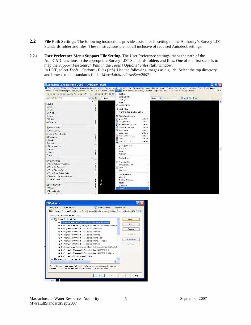
Massachusetts Water Resources Authority September 2007 MwraLdtStandardsSept2007
5
2.2 File Path Settings: The following instructions provide assistance in setting up the Authority’s Survey LDT
Standards folder and files. These instructions are not all inclusive of required Autodesk settings. 2.2.1 User Preference Menu Support File Setting. The User Preference settings, maps the path of the
AutoCAD functions to the appropriate Survey LDT Standards folders and files. One of the first steps is to map the Support File Search Path in the Tools \ Options \ Files (tab) window. In LDT, select Tools \ Options \ Files (tab). Use the following images as a guide. Select the top directory and browse to the standards folder MwraLdtStandardsSept2007.
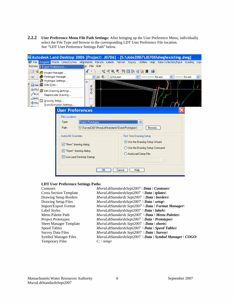
Massachusetts Water Resources Authority September 2007 MwraLdtStandardsSept2007
6
2.2.2 User Preference Menu File Path Settings: After bringing up the User Preference Menu, individually
select the File Type and browse to the corresponding LDT User Preference File location. See “LDT User Preference Settings Path” below.
LDT User Preference Settings Paths: Contours MwraLdtStandardsSept2007 \ Data \ Contours\ Cross Section Template MwraLdtStandardsSept2007 \ Data \ tplates\ Drawing Setup Borders MwraLdtStandards Sept2007 \ Data \ borders\ Drawing Setup Files MwraLdtStandardsSept2007 \ Data \ setup\ Import/Export Format MwraLdtStandards Sept2007 \ Data \ Format Manager\ Label Styles MwraLdtStandardsSept2007 \ Data \ labels\ Menu Palette Path MwraLdtStandards Sept2007 \ Data \ Menu Palettes\ Project Prototypes MwraLdtStandardsSept2007 \ Data \ Prototypes\ Sheet Manager Template MwraLdtStandards Sept2007 \ Data \ sheets\ Speed Tables MwraLdtStandardsSept2007 \ Data \ Speed Tables\ Survey Data Files MwraLdtStandards Sept2007 \ Data \ Survey\ Symbol Manager Files MwraLdtStandardsSept2007 \ Data \ Symbol Manager \ COGO\ Temporary Files C: \ temp\
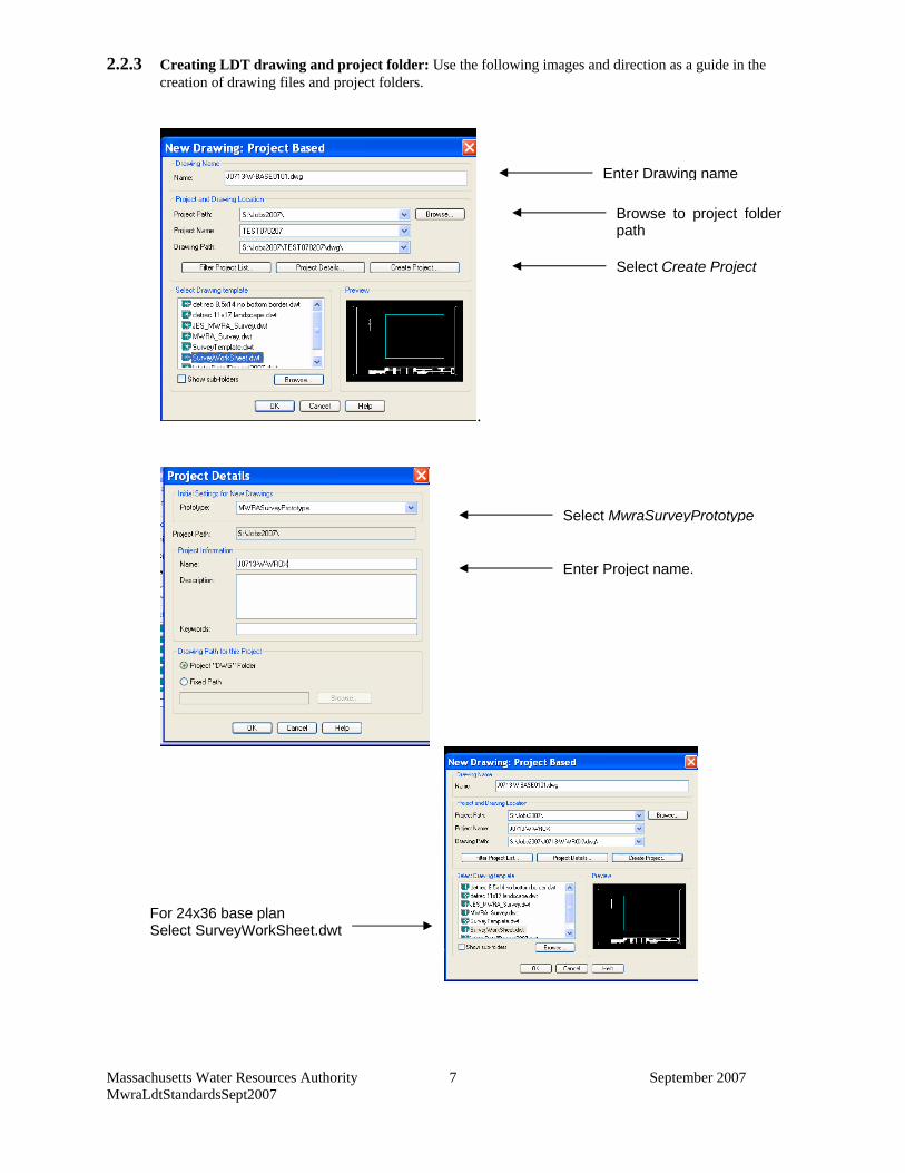
Massachusetts Water Resources Authority September 2007 MwraLdtStandardsSept2007
7
2.2.3 Creating LDT drawing and project folder: Use the following images and direction as a guide in the creation of drawing files and project folders.
.
Enter Drawing name
Browse to project folder path
Select Create Project
Select MwraSurveyPrototype
Enter Project name.
For 24x36 base plan Select SurveyWorkSheet.dwt
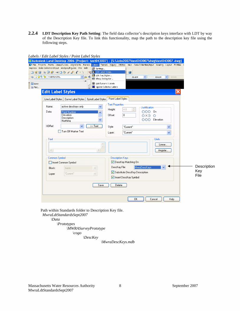
Massachusetts Water Resources Authority September 2007 MwraLdtStandardsSept2007
8
2.2.4 LDT Description Key Path Setting: The field data collector’s description keys interface with LDT by way
of the Description Key file. To link this functionality, map the path to the description key file using the following steps.
Labels / Edit Label Styles / Point Label Styles
Path within Standards folder to Description Key file. MwraLdtStandardsSept2007
\Data \Prototypes
\MWRASurveyPrototype \cogo \DescKey
\MwraDescKeys.mdb
Description Key File
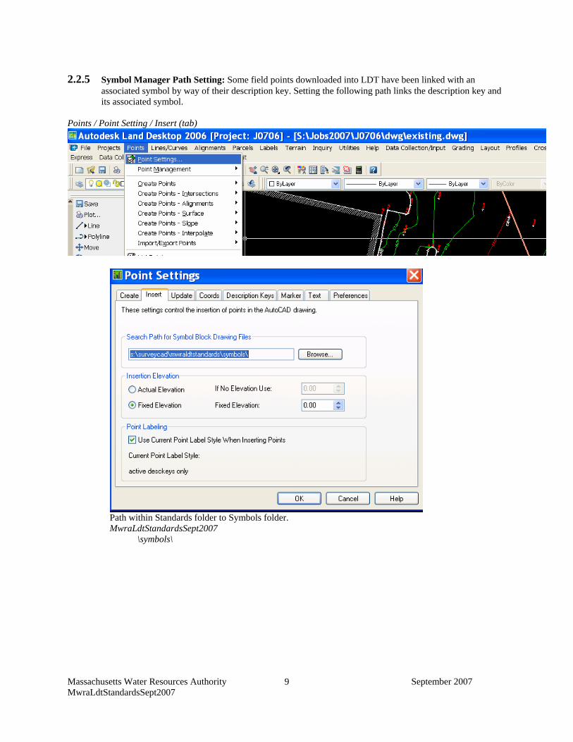
Massachusetts Water Resources Authority September 2007 MwraLdtStandardsSept2007
9
2.2.5 Symbol Manager Path Setting: Some field points downloaded into LDT have been linked with an
associated symbol by way of their description key. Setting the following path links the description key and its associated symbol.
Points / Point Setting / Insert (tab)
Path within Standards folder to Symbols folder.
MwraLdtStandardsSept2007 \symbols\
Massachusetts Water Resources Authority September 2007 MwraLdtStandardsSept2007
10
Section 3 - Folder and File Naming Standards
3.1 Data collector field files: The field raw and job file names are based on survey job number and date. Use
this naming standard for all files transferred and converted from the raw file.
Example (J0601-011006x) J = job 06 = year job received. 01 = Consecutive numbering based on order received. - = Spacer 011006 = month-day-year (Date field work performed)
X = Unique identifier (a, b, c etc.) for multiple files.
If the project does not have a survey job number, all field files associated with the job will have the same descriptive unique identifier.
Example (J06GILLISPS-011006x) J = job 06 = year job received. GILLISPS = Unique descriptive identifier. - = Spacer 011006 = month-day-year X = Unique identifier (a, b, c etc.) for multiple files. 3.2 Description Keys: The Survey CAD Standards contain a description key file (see Appendix B). The key
codes provided encompass most conditions encountered on Authority projects. In the event a custom key code is required, the Authority’s naming standards will be followed as closely as possible. The MWRA description key naming standards follows a hierarchy. The first one to three characters designates Class types that are similar in nature. The characters that follow the Class designation further define the feature located. The Description Key File contains the description key code, Format point layer, symbol, symbol block name and Symbol layer for each code.
The naming standard for MWRA facilities is as follows. Example: MWBFVMH* MW = MWRA BFV = indicates facility serviced MH = type of access to facility (For a gate valve this would be GV)
* = Notes allowed with a space after description.
Description Key Class Definitions: C = Survey Controls (All codes associated with survey control points) COM = Community features (All codes associated with community owned points. Examples:
water, sewer etc.) D = Drain features All the drainage codes) DET = Cultural details (All cultural features not covered by other classes) FC = Fences (All codes associated with fencing) GS = Topographic features (All codes associated with topographic features. Ground shots,
swales top & bottom of slopes) GT = Geotechnical features (All codes associated with below grade investigation. Test pits
borings, monitoring wells etc.) M = Property monuments All codes associated with property boundary monuments) MS = MWRA Sewer structures All codes associated with MWRA Sewer features) MW = MWRA Water structures All codes associated with MWRA Water features)
Massachusetts Water Resources Authority September 2007 MwraLdtStandardsSept2007
11
RD = Road and traveled way features (All codes associated with roads and traveled ways. Curbing, berms, edge of pavement or gravel etc.)
STR = Structures (All codes associated with structures. Buildings, sheds, tanks etc.) TR = Traffic features (All codes associated with traffic features. Lane markers, Lights,
signs etc.) UT = Utility features (All codes associated with utility companies. Gas, electric, cable etc.) VG = Vegetation (All codes associated with vegetation. Tree lines, trees, hedges etc.) WB = Water bodies (All codes associated with water bodies. Edge of water, high water
mark, water elevations etc.) WK = Walkways (All codes associated with walkways. Sidewalks, gravel walks etc.) WL = Walls (All codes associated with walls. Retaining walls, stonewalls, etc.) Due to the nature of the Authority’s work and for clarity some items such as Drain, walkways and walls, have been separated into their own class. Example: An Electrical Hand-hole (UTHHE*) label will be EHH UT = Class (Utility) HHE = Unique descriptive initial (Hand Hole Electric) * = Notes allowed with a space after description. Label displayed would be “EHH (expanded description)” For features such as fences, the format is the feature Class designation, followed by descriptive initials or acronym. Example: Chain link Fence (FCCL*) FC = Class (Fence) CL = Unique descriptive initial (Chain link) * = Notes allowed with a space after description. Label displayed would be “CLF (expanded description)” For features such as curbing the format is the feature Class designation followed by a descriptive initials or acronym. Example: Granite curb (RDGC*) RD = Class (ROAD) GC = Unique descriptive initial (Granite Curb) * = Notes allowed with a space after description.
Example of Description Key Manager Database: Example: Utility Pole with Light (UTUPL*) UT = Class (Utility) UPL = Unique descriptive initial (Utility pole with light) * = Notes allowed with a space after description.
Label displayed would be “UPL (expanded description)” KCODE KEY DESCR DFORMAT DLAYER SYMBOL SLAYER UTUPL* utility pole with light UPL* V-NODE-UTIL mwra_upl V-SYM-UTIL
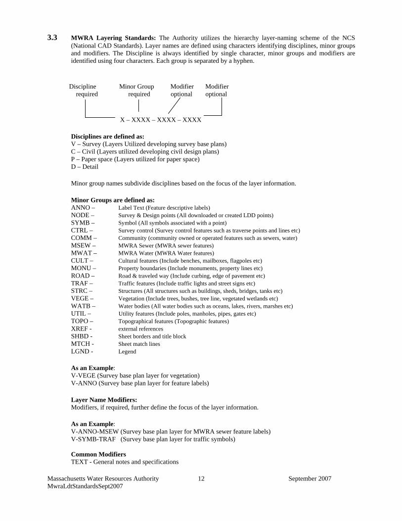
Massachusetts Water Resources Authority September 2007 MwraLdtStandardsSept2007
12
3.3 MWRA Layering Standards: The Authority utilizes the hierarchy layer-naming scheme of the NCS
(National CAD Standards). Layer names are defined using characters identifying disciplines, minor groups and modifiers. The Discipline is always identified by single character, minor groups and modifiers are identified using four characters. Each group is separated by a hyphen.
Discipline Minor Group Modifier Modifier required required optional optional X – XXXX – XXXX – XXXX
Disciplines are defined as: V – Survey (Layers Utilized developing survey base plans) C – Civil (Layers utilized developing civil design plans) P – Paper space (Layers utilized for paper space) D – Detail
Minor group names subdivide disciplines based on the focus of the layer information. Minor Groups are defined as: ANNO – Label Text (Feature descriptive labels) NODE – Survey & Design points (All downloaded or created LDD points) SYMB – Symbol (All symbols associated with a point)
CTRL – Survey control (Survey control features such as traverse points and lines etc) COMM – Community (community owned or operated features such as sewers, water)
MSEW – MWRA Sewer (MWRA sewer features) MWAT – MWRA Water (MWRA Water features)
CULT – Cultural features (Include benches, mailboxes, flagpoles etc) MONU – Property boundaries (Include monuments, property lines etc)
ROAD – Road & traveled way (Include curbing, edge of pavement etc) TRAF – Traffic features (Include traffic lights and street signs etc)
STRC – Structures (All structures such as buildings, sheds, bridges, tanks etc) VEGE – Vegetation (Include trees, bushes, tree line, vegetated wetlands etc) WATB – Water bodies (All water bodies such as oceans, lakes, rivers, marshes etc)
UTIL – Utility features (Include poles, manholes, pipes, gates etc) TOPO – Topographical features (Topographic features) XREF - external references SHBD - Sheet borders and title block MTCH - Sheet match lines LGND - Legend
As an Example: V-VEGE (Survey base plan layer for vegetation) V-ANNO (Survey base plan layer for feature labels)
Layer Name Modifiers: Modifiers, if required, further define the focus of the layer information. As an Example: V-ANNO-MSEW (Survey base plan layer for MWRA sewer feature labels) V-SYMB-TRAF (Survey base plan layer for traffic symbols) Common Modifiers TEXT - General notes and specifications
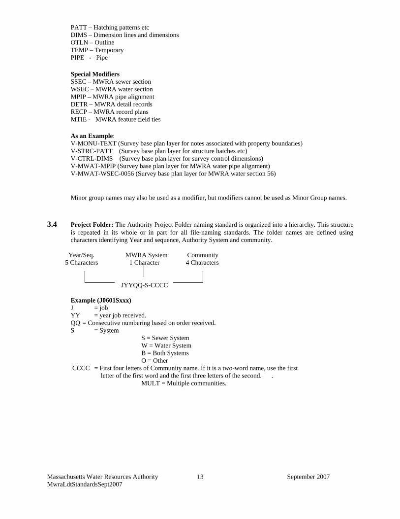
Massachusetts Water Resources Authority September 2007 MwraLdtStandardsSept2007
13
PATT – Hatching patterns etc DIMS – Dimension lines and dimensions OTLN – Outline TEMP – Temporary PIPE - Pipe Special Modifiers SSEC – MWRA sewer section WSEC – MWRA water section MPIP – MWRA pipe alignment DETR – MWRA detail records RECP – MWRA record plans MTIE - MWRA feature field ties As an Example: V-MONU-TEXT (Survey base plan layer for notes associated with property boundaries) V-STRC-PATT (Survey base plan layer for structure hatches etc) V-CTRL-DIMS (Survey base plan layer for survey control dimensions) V-MWAT-MPIP (Survey base plan layer for MWRA water pipe alignment) V-MWAT-WSEC-0056 (Survey base plan layer for MWRA water section 56) Minor group names may also be used as a modifier, but modifiers cannot be used as Minor Group names.
3.4 Project Folder: The Authority Project Folder naming standard is organized into a hierarchy. This structure
is repeated in its whole or in part for all file-naming standards. The folder names are defined using characters identifying Year and sequence, Authority System and community.
Year/Seq. MWRA System Community 5 Characters 1 Character 4 Characters JYYQQ-S-CCCC
Example (J0601Sxxx) J = job YY = year job received. QQ = Consecutive numbering based on order received. S = System S = Sewer System W = Water System B = Both Systems O = Other CCCC = First four letters of Community name. If it is a two-word name, use the first letter of the first word and the first three letters of the second. . MULT = Multiple communities.
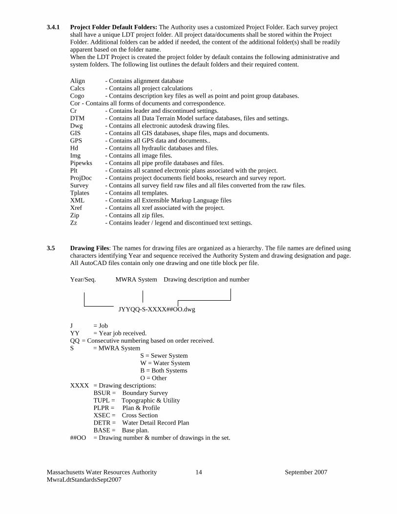
Massachusetts Water Resources Authority September 2007 MwraLdtStandardsSept2007
14
3.4.1 Project Folder Default Folders: The Authority uses a customized Project Folder. Each survey project shall have a unique LDT project folder. All project data/documents shall be stored within the Project Folder. Additional folders can be added if needed, the content of the additional folder(s) shall be readily apparent based on the folder name. When the LDT Project is created the project folder by default contains the following administrative and system folders. The following list outlines the default folders and their required content. Align - Contains alignment database Calcs - Contains all project calculations . Cogo - Contains description key files as well as point and point group databases. Cor - Contains all forms of documents and correspondence. Cr - Contains leader and discontinued settings. DTM - Contains all Data Terrain Model surface databases, files and settings. Dwg - Contains all electronic autodesk drawing files. GIS - Contains all GIS databases, shape files, maps and documents. GPS - Contains all GPS data and documents.. Hd - Contains all hydraulic databases and files. Img - Contains all image files. Pipewks - Contains all pipe profile databases and files. Plt - Contains all scanned electronic plans associated with the project. ProjDoc - Contains project documents field books, research and survey report. Survey - Contains all survey field raw files and all files converted from the raw files. Tplates - Contains all templates. XML - Contains all Extensible Markup Language files Xref - Contains all xref associated with the project. Zip - Contains all zip files. Zz - Contains leader / legend and discontinued text settings.
3.5 Drawing Files: The names for drawing files are organized as a hierarchy. The file names are defined using
characters identifying Year and sequence received the Authority System and drawing designation and page. All AutoCAD files contain only one drawing and one title block per file.
Year/Seq. MWRA System Drawing description and number
JYYQQ-S-XXXX##OO.dwg
J = Job YY = Year job received. QQ = Consecutive numbering based on order received. S = MWRA System S = Sewer System W = Water System B = Both Systems O = Other XXXX = Drawing descriptions: BSUR = Boundary Survey TUPL = Topographic & Utility PLPR = Plan & Profile XSEC = Cross Section DETR = Water Detail Record Plan BASE = Base plan. ##OO = Drawing number & number of drawings in the set.
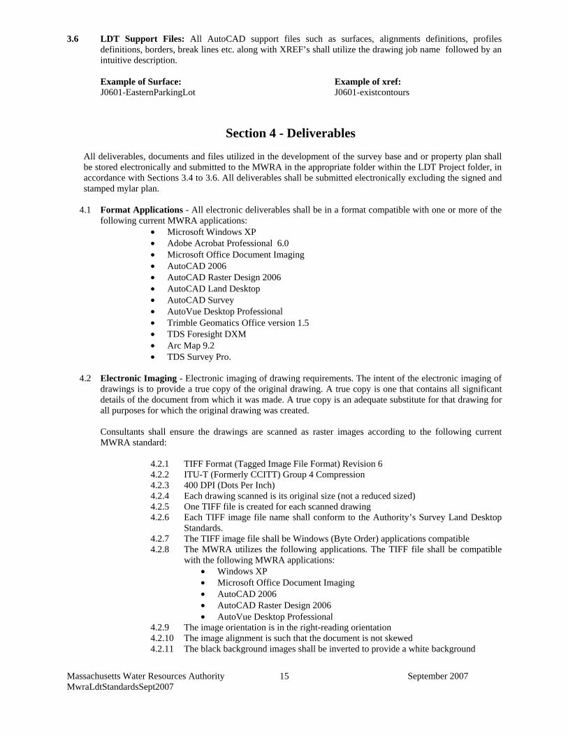
Massachusetts Water Resources Authority September 2007 MwraLdtStandardsSept2007
15
3.6 LDT Support Files: All AutoCAD support files such as surfaces, alignments definitions, profiles definitions, borders, break lines etc. along with XREF’s shall utilize the drawing job name followed by an intuitive description.
Example of Surface: Example of xref: J0601-EasternParkingLot J0601-existcontours
Section 4 - Deliverables
All deliverables, documents and files utilized in the development of the survey base and or property plan shall be stored electronically and submitted to the MWRA in the appropriate folder within the LDT Project folder, in accordance with Sections 3.4 to 3.6. All deliverables shall be submitted electronically excluding the signed and stamped mylar plan.
4.1 Format Applications - All electronic deliverables shall be in a format compatible with one or more of the
following current MWRA applications: • Microsoft Windows XP • Adobe Acrobat Professional 6.0 • Microsoft Office Document Imaging • AutoCAD 2006 • AutoCAD Raster Design 2006 • AutoCAD Land Desktop • AutoCAD Survey • AutoVue Desktop Professional • Trimble Geomatics Office version 1.5 • TDS Foresight DXM • Arc Map 9.2 • TDS Survey Pro.
4.2 Electronic Imaging - Electronic imaging of drawing requirements. The intent of the electronic imaging of
drawings is to provide a true copy of the original drawing. A true copy is one that contains all significant details of the document from which it was made. A true copy is an adequate substitute for that drawing for all purposes for which the original drawing was created. Consultants shall ensure the drawings are scanned as raster images according to the following current MWRA standard:
4.2.1 TIFF Format (Tagged Image File Format) Revision 6 4.2.2 ITU-T (Formerly CCITT) Group 4 Compression 4.2.3 400 DPI (Dots Per Inch) 4.2.4 Each drawing scanned is its original size (not a reduced sized) 4.2.5 One TIFF file is created for each scanned drawing 4.2.6 Each TIFF image file name shall conform to the Authority’s Survey Land Desktop
Standards. 4.2.7 The TIFF image file shall be Windows (Byte Order) applications compatible 4.2.8 The MWRA utilizes the following applications. The TIFF file shall be compatible
with the following MWRA applications: • Windows XP • Microsoft Office Document Imaging • AutoCAD 2006 • AutoCAD Raster Design 2006 • AutoVue Desktop Professional
4.2.9 The image orientation is in the right-reading orientation 4.2.10 The image alignment is such that the document is not skewed 4.2.11 The black background images shall be inverted to provide a white background
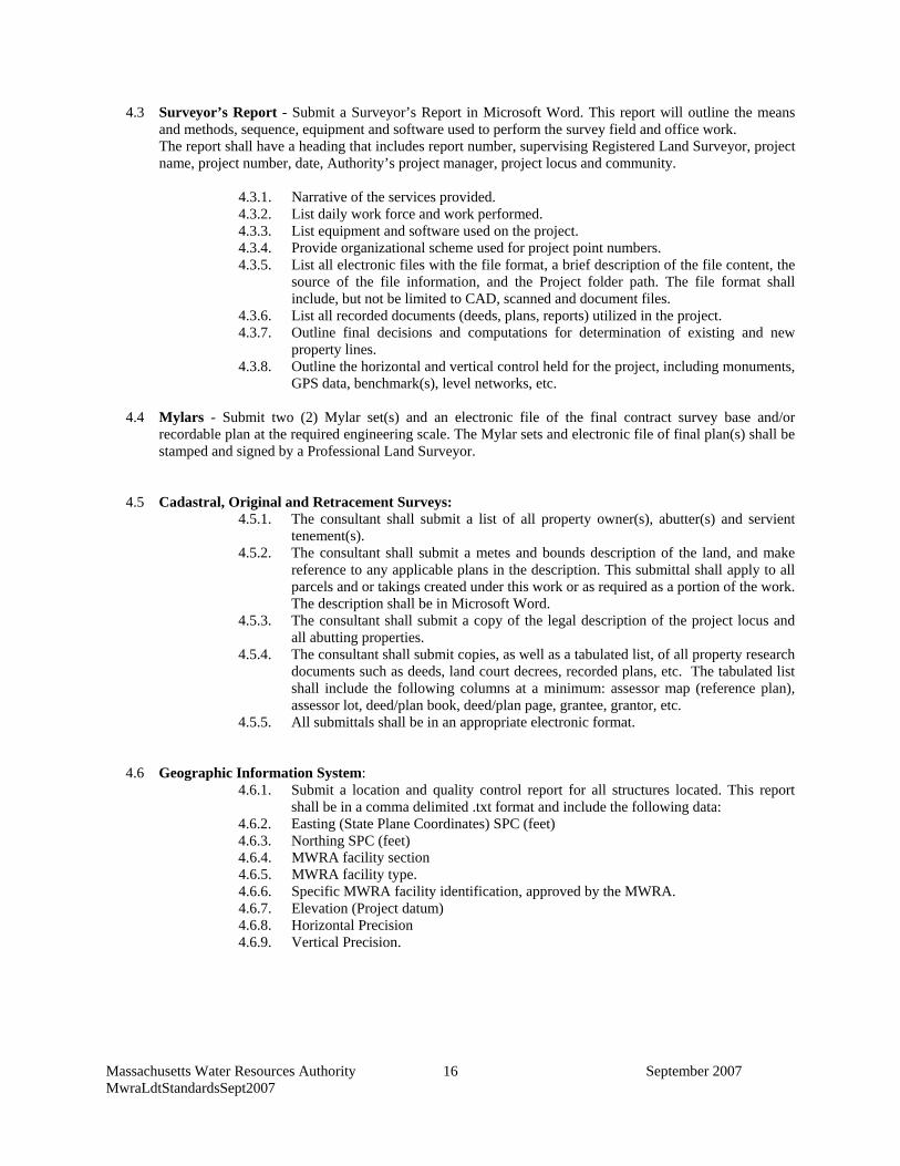
Massachusetts Water Resources Authority September 2007 MwraLdtStandardsSept2007
16
4.3 Surveyor’s Report - Submit a Surveyor’s Report in Microsoft Word. This report will outline the means and methods, sequence, equipment and software used to perform the survey field and office work. The report shall have a heading that includes report number, supervising Registered Land Surveyor, project name, project number, date, Authority’s project manager, project locus and community.
4.3.1. Narrative of the services provided. 4.3.2. List daily work force and work performed. 4.3.3. List equipment and software used on the project. 4.3.4. Provide organizational scheme used for project point numbers. 4.3.5. List all electronic files with the file format, a brief description of the file content, the
source of the file information, and the Project folder path. The file format shall include, but not be limited to CAD, scanned and document files.
4.3.6. List all recorded documents (deeds, plans, reports) utilized in the project. 4.3.7. Outline final decisions and computations for determination of existing and new
property lines. 4.3.8. Outline the horizontal and vertical control held for the project, including monuments,
GPS data, benchmark(s), level networks, etc.
4.4 Mylars - Submit two (2) Mylar set(s) and an electronic file of the final contract survey base and/or recordable plan at the required engineering scale. The Mylar sets and electronic file of final plan(s) shall be stamped and signed by a Professional Land Surveyor.
4.5 Cadastral, Original and Retracement Surveys: 4.5.1. The consultant shall submit a list of all property owner(s), abutter(s) and servient
tenement(s). 4.5.2. The consultant shall submit a metes and bounds description of the land, and make
reference to any applicable plans in the description. This submittal shall apply to all parcels and or takings created under this work or as required as a portion of the work. The description shall be in Microsoft Word.
4.5.3. The consultant shall submit a copy of the legal description of the project locus and all abutting properties.
4.5.4. The consultant shall submit copies, as well as a tabulated list, of all property research documents such as deeds, land court decrees, recorded plans, etc. The tabulated list shall include the following columns at a minimum: assessor map (reference plan), assessor lot, deed/plan book, deed/plan page, grantee, grantor, etc.
4.5.5. All submittals shall be in an appropriate electronic format.
4.6 Geographic Information System:
4.6.1. Submit a location and quality control report for all structures located. This report shall be in a comma delimited .txt format and include the following data:
4.6.2. Easting (State Plane Coordinates) SPC (feet) 4.6.3. Northing SPC (feet) 4.6.4. MWRA facility section 4.6.5. MWRA facility type. 4.6.6. Specific MWRA facility identification, approved by the MWRA. 4.6.7. Elevation (Project datum) 4.6.8. Horizontal Precision 4.6.9. Vertical Precision.
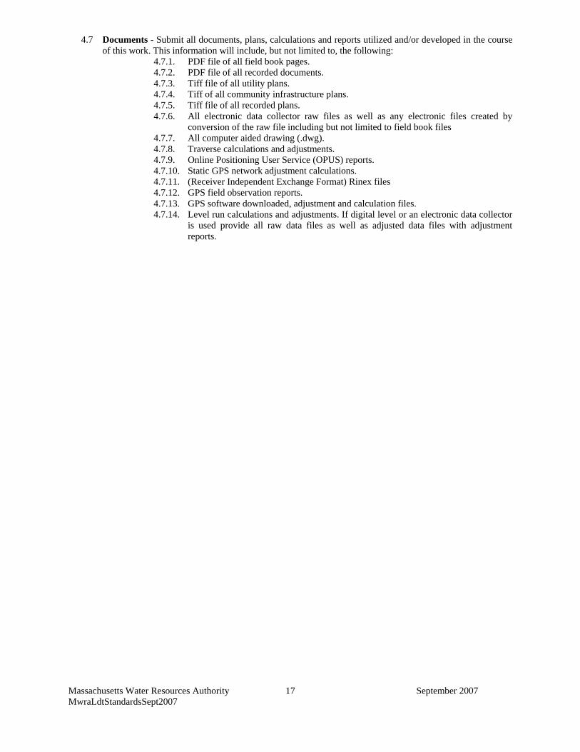
Massachusetts Water Resources Authority September 2007 MwraLdtStandardsSept2007
17
4.7 Documents - Submit all documents, plans, calculations and reports utilized and/or developed in the course of this work. This information will include, but not limited to, the following:
4.7.1. PDF file of all field book pages. 4.7.2. PDF file of all recorded documents. 4.7.3. Tiff file of all utility plans. 4.7.4. Tiff of all community infrastructure plans. 4.7.5. Tiff file of all recorded plans. 4.7.6. All electronic data collector raw files as well as any electronic files created by
conversion of the raw file including but not limited to field book files 4.7.7. All computer aided drawing (.dwg). 4.7.8. Traverse calculations and adjustments. 4.7.9. Online Positioning User Service (OPUS) reports. 4.7.10. Static GPS network adjustment calculations. 4.7.11. (Receiver Independent Exchange Format) Rinex files 4.7.12. GPS field observation reports. 4.7.13. GPS software downloaded, adjustment and calculation files. 4.7.14. Level run calculations and adjustments. If digital level or an electronic data collector
is used provide all raw data files as well as adjusted data files with adjustment reports.
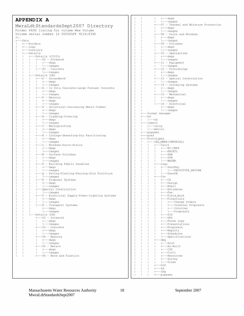
Massachusetts Water Resources Authority September 2007 MwraLdtStandardsSept2007
18
APPENDIX A MwraLdtStandardsSept2007 Directory Folder PATH listing for volume New Volume Volume serial number is 000065FF 9C16:839D J:. +---Data | +---borders | +---cogo | +---Contours | +---Details | | +---Details (CIVIL) | | | +---02 - Sitework | | | | +---dwgs | | | | \---images | | | \---03 - Concrete | | | \---images | | +---Details (UK) | | | +---D - Groundwork | | | | +---dwgs | | | | \---images | | | +---E - In Situ Concrete-Large Precast Concrete | | | | +---dwgs | | | | \---images | | | +---F - Masonry | | | | +---dwgs | | | | \---images | | | +---G - Structural-Carcassing Metal-Timber | | | | +---dwgs | | | | \---images | | | +---H - Cladding-Covering | | | | +---dwgs | | | | \---images | | | +---J - Waterproofing | | | | +---dwgs | | | | \---images | | | +---K - Linings-Sheathing-Dry Partitioning | | | | +---dwgs | | | | \---images | | | +---L - Windows-Doors-Stairs | | | | +---dwgs | | | | \---images | | | +---M - Surface Finishes | | | | +---dwgs | | | | \---images | | | +---P - Building Fabric Sundries | | | | +---dwgs | | | | \---images | | | +---Q - Paving-Planting-Fencing-Site Furniture | | | | \---images | | | +---R - Disposal Systems | | | | +---dwgs | | | | \---images | | | +---Special Construction | | | | \---images | | | +---V - Electrical Supply-Power-Lighting Systems | | | | +---dwgs | | | | \---images | | | \---X - Transport Systems | | | +---dwgs | | | \---images | | \---Details (US) | | +---02 - Sitework | | | +---dwgs | | | \---images | | +---03 - Concrete | | | +---dwgs | | | \---images | | +---04 - Masonry | | | +---dwgs | | | \---images | | +---05 - Metals | | | +---dwgs | | | \---images | | +---06 - Wood and Plastics
| | | +---dwgs | | | \---images | | +---07 - Thermal and Moisture Protection | | | +---dwgs | | | \---images | | +---08 - Doors and Windows | | | +---dwgs | | | \---images | | +---09 - Finishes | | | +---dwgs | | | \---images | | +---10 - Specialties | | | +---dwgs | | | \---images | | +---11 - Equipment | | | \---images | | +---12 - Furnishings | | | +---dwgs | | | \---images | | +---13 - Special Construction | | | \---images | | +---14 - Conveying Systems | | | +---dwgs | | | \---images | | +---15 - Mechanical | | | +---dwgs | | | \---images | | \---16 - Electrical | | +---dwgs | | \---images | +---format manager | +---hd | | \---hd | +---labels | | +---leroy | | \---metric | +---pipewks | +---pref | +---Prototypes | | +---JES_MWRA(IMPERIAL) | | | +---Calcs | | | | +---EC-CBPA | | | | +---ERCRTL | | | | +---SAN | | | | +---STM | | | | \---WATER | | | +---cogo | | | | +---DescKey | | | | | \---PROTOTYPE_REVIEW | | | | \---UserDB | | | +---Cor | | | | +---CA | | | | +---Design | | | | +---Email | | | | +---Estimates | | | | +---Fax | | | | +---Field_Book | | | | +---Financials | | | | | +---Change Orders | | | | | +---Internal Proposals | | | | | +---Invoices | | | | | \---Proposals | | | | +---GIS | | | | +---GPS | | | | +---Phone Logs | | | | +---Presentations | | | | +---Proposals | | | | +---Reports | | | | +---Schedules | | | | \---Specifications | | | +---dwg | | | | +---Arch | | | | +---As-Built | | | | +---C3D | | | | +---Civil | | | | +---Resources | | | | +---Survey | | | | \---Trash | | | +---GIS | | | +---hd | | | +---Img | | | +---pipewks
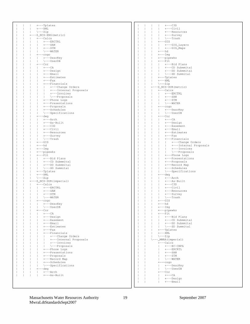
Massachusetts Water Resources Authority September 2007 MwraLdtStandardsSept2007
19
| | | +---Tplates | | | +---XML | | | \---Zip | | +---Z_NCS-ENG(metric) | | | +---Calcs | | | | +---ERCTRL | | | | +---SAN | | | | +---STM | | | | \---WATER | | | +---cogo | | | | +---DescKey | | | | \---UserDB | | | +---Cor | | | | +---CA | | | | +---Design | | | | +---Email | | | | +---Estimates | | | | +---Fax | | | | +---Financials | | | | | +---Change Orders | | | | | +---Internal Proposals | | | | | +---Invoices | | | | | \---Proposals | | | | +---Phone Logs | | | | +---Presentations | | | | +---Proposals | | | | +---Schedules | | | | \---Specifications | | | +---dwg | | | | +---Arch | | | | +---As-Built | | | | +---C3D | | | | +---Civil | | | | +---Resources | | | | +---Survey | | | | \---Trash | | | +---GIS | | | +---hd | | | +---Img | | | +---pipewks | | | +---Plt | | | | +---Bid Plans | | | | +---CD Submmital | | | | +---DD Submmital | | | | \---SD Summital | | | +---Tplates | | | +---XML | | | \---Zip | | +---Z_NCS-SUR(imperial) | | | +---Calcs | | | | +---ERCTRL | | | | +---SAN | | | | +---STM | | | | \---WATER | | | +---cogo | | | | +---DescKey | | | | \---UserDB | | | +---Cor | | | | +---CA | | | | +---Design | | | | +---Easement | | | | +---Email | | | | +---Estimates | | | | +---Fax | | | | +---Financials | | | | | +---Change Orders | | | | | +---Internal Proposals | | | | | +---Invoices | | | | | \---Proposals | | | | +---Phone Logs | | | | +---Presentations | | | | +---Proposals | | | | +---Record Map | | | | +---Schedules | | | | \---Specifications | | | +---dwg | | | | +---Arch | | | | +---As-Built
| | | | +---C3D | | | | +---Civil | | | | +---Resources | | | | +---Survey | | | | \---Trash | | | +---GIS | | | | +---GIS_Layers | | | | +---GIS_Maps | | | +---hd | | | +---Img | | | +---pipewks | | | +---Plt | | | | +---Bid Plans | | | | +---CD Submmital | | | | +---DD Submmital | | | | \---SD Summital | | | +---Tplates | | | +---XML | | | \---Zip | | +---Z_NCS-SUR(metric) | | | +---Calcs | | | | +---ERCTRL | | | | +---SAN | | | | +---STM | | | | \---WATER | | | +---cogo | | | | +---DescKey | | | | \---UserDB | | | +---Cor | | | | +---CA | | | | +---Design | | | | +---Easement | | | | +---Email | | | | +---Estimates | | | | +---Fax | | | | +---Financials | | | | | +---Change Orders | | | | | +---Internal Proposals | | | | | +---Invoices | | | | | \---Proposals | | | | +---Phone Logs | | | | +---Presentations | | | | +---Proposals | | | | +---Record Map | | | | +---Schedules | | | | \---Specifications | | | +---dwg | | | | +---Arch | | | | +---As-Built | | | | +---C3D | | | | +---Civil | | | | +---Resources | | | | +---Survey | | | | \---Trash | | | +---GIS | | | +---hd | | | +---Img | | | +---pipewks | | | +---Plt | | | | +---Bid Plans | | | | +---CD Submmital | | | | +---DD Submmital | | | | \---SD Summital | | | +---Tplates | | | +---XML | | | \---Zip | | \---_MWRA(imperial) | | +---Calcs | | | +---EC-CBPA | | | +---ERCRTL | | | +---SAN | | | +---STM | | | \---WATER | | +---cogo | | | +---DescKey | | | \---UserDB | | +---Cor | | | +---CA | | | +---Design | | | +---Email
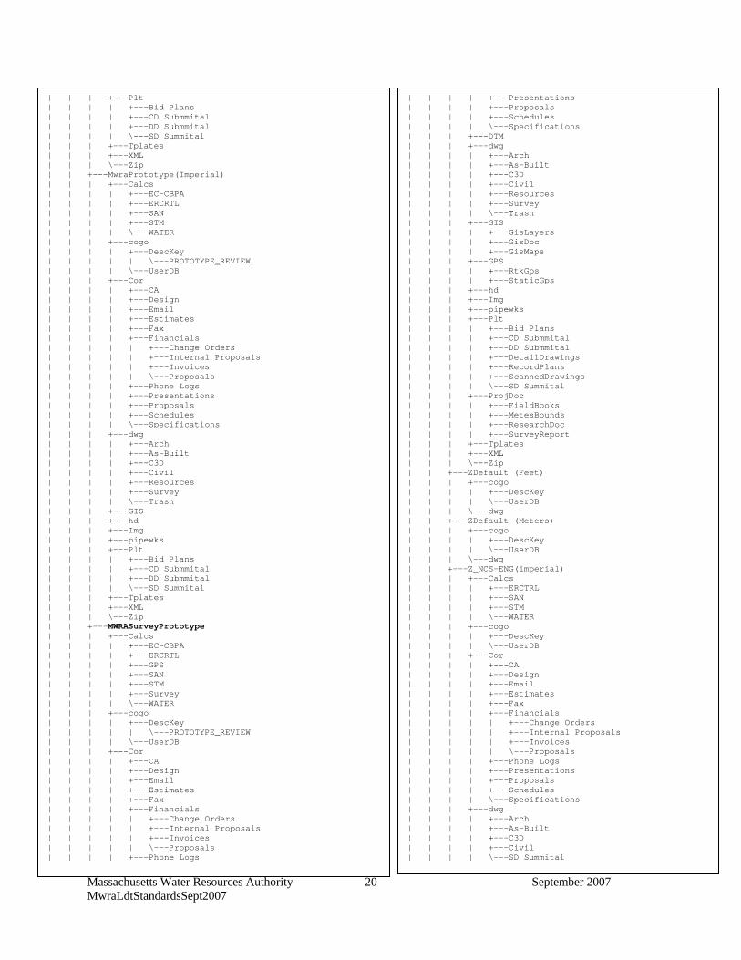
Massachusetts Water Resources Authority September 2007 MwraLdtStandardsSept2007
20
| | | +---Plt | | | | +---Bid Plans | | | | +---CD Submmital | | | | +---DD Submmital | | | | \---SD Summital | | | +---Tplates | | | +---XML | | | \---Zip | | +---MwraPrototype(Imperial) | | | +---Calcs | | | | +---EC-CBPA | | | | +---ERCRTL | | | | +---SAN | | | | +---STM | | | | \---WATER | | | +---cogo | | | | +---DescKey | | | | | \---PROTOTYPE_REVIEW | | | | \---UserDB | | | +---Cor | | | | +---CA | | | | +---Design | | | | +---Email | | | | +---Estimates | | | | +---Fax | | | | +---Financials | | | | | +---Change Orders | | | | | +---Internal Proposals | | | | | +---Invoices | | | | | \---Proposals | | | | +---Phone Logs | | | | +---Presentations | | | | +---Proposals | | | | +---Schedules | | | | \---Specifications | | | +---dwg | | | | +---Arch | | | | +---As-Built | | | | +---C3D | | | | +---Civil | | | | +---Resources | | | | +---Survey | | | | \---Trash | | | +---GIS | | | +---hd | | | +---Img | | | +---pipewks | | | +---Plt | | | | +---Bid Plans | | | | +---CD Submmital | | | | +---DD Submmital | | | | \---SD Summital | | | +---Tplates | | | +---XML | | | \---Zip | | +---MWRASurveyPrototype | | | +---Calcs | | | | +---EC-CBPA | | | | +---ERCRTL | | | | +---GPS | | | | +---SAN | | | | +---STM | | | | +---Survey | | | | \---WATER | | | +---cogo | | | | +---DescKey | | | | | \---PROTOTYPE_REVIEW | | | | \---UserDB | | | +---Cor | | | | +---CA | | | | +---Design | | | | +---Email | | | | +---Estimates | | | | +---Fax | | | | +---Financials | | | | | +---Change Orders | | | | | +---Internal Proposals | | | | | +---Invoices | | | | | \---Proposals | | | | +---Phone Logs
| | | | +---Presentations | | | | +---Proposals | | | | +---Schedules | | | | \---Specifications | | | +---DTM | | | +---dwg | | | | +---Arch | | | | +---As-Built | | | | +---C3D | | | | +---Civil | | | | +---Resources | | | | +---Survey | | | | \---Trash | | | +---GIS | | | | +---GisLayers | | | | +---GisDoc | | | | +---GisMaps | | | +---GPS | | | | +---RtkGps | | | | +---StaticGps | | | +---hd | | | +---Img | | | +---pipewks | | | +---Plt | | | | +---Bid Plans | | | | +---CD Submmital | | | | +---DD Submmital | | | | +---DetailDrawings | | | | +---RecordPlans | | | | +---ScannedDrawings | | | | \---SD Summital | | | +---ProjDoc | | | | +---FieldBooks | | | | +---MetesBounds | | | | +---ResearchDoc | | | | +---SurveyReport | | | +---Tplates | | | +---XML | | | \---Zip | | +---ZDefault (Feet) | | | +---cogo | | | | +---DescKey | | | | \---UserDB | | | \---dwg | | +---ZDefault (Meters) | | | +---cogo | | | | +---DescKey | | | | \---UserDB | | | \---dwg | | +---Z_NCS-ENG(imperial) | | | +---Calcs | | | | +---ERCTRL | | | | +---SAN | | | | +---STM | | | | \---WATER | | | +---cogo | | | | +---DescKey | | | | \---UserDB | | | +---Cor | | | | +---CA | | | | +---Design | | | | +---Email | | | | +---Estimates | | | | +---Fax | | | | +---Financials | | | | | +---Change Orders | | | | | +---Internal Proposals | | | | | +---Invoices | | | | | \---Proposals | | | | +---Phone Logs | | | | +---Presentations | | | | +---Proposals | | | | +---Schedules | | | | \---Specifications | | | +---dwg | | | | +---Arch | | | | +---As-Built | | | | +---C3D | | | | +---Civil | | | | \---SD Summital
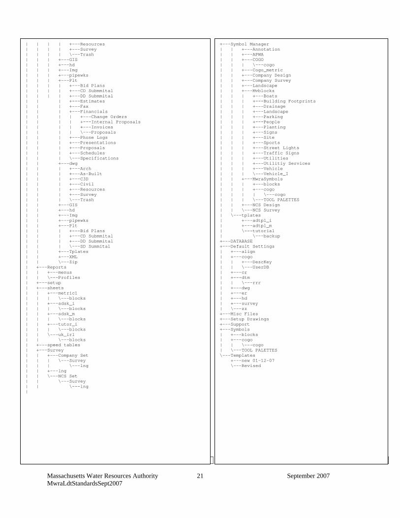
Massachusetts Water Resources Authority September 2007 MwraLdtStandardsSept2007
21
Appendix B Description Keys – File name: MwraDescKeys
CONTROL STRUCTURES
| | | | +---Resources | | | | +---Survey | | | | \---Trash | | | +---GIS | | | +---hd | | | +---Img | | | +---pipewks | | | +---Plt | | | | +---Bid Plans | | | | +---CD Submmital | | | | +---DD Submmital | | | +---Estimates | | | +---Fax | | | +---Financials | | | | +---Change Orders | | | | +---Internal Proposals | | | | +---Invoices | | | | \---Proposals | | | +---Phone Logs | | | +---Presentations | | | +---Proposals | | | +---Schedules | | | \---Specifications | | +---dwg | | | +---Arch | | | +---As-Built | | | +---C3D | | | +---Civil | | | +---Resources | | | +---Survey | | | \---Trash | | +---GIS | | +---hd | | +---Img | | +---pipewks | | +---Plt | | | +---Bid Plans | | | +---CD Submmital | | | +---DD Submmital | | | \---SD Summital | | +---Tplates | | +---XML | | \---Zip | +---Reports | | +---menus | | \---Profiles | +---setup | +---sheets | | +---metric1 | | | \---blocks | | +---sdsk_i | | | \---blocks | | +---sdsk_m | | | \---blocks | | +---tutor_i | | | \---blocks | | \---uk_irl | | \---blocks | +---speed tables | +---Survey | | +---Company Set | | | \---Survey | | | \---lng | | +---lng | | \---NCS Set | | \---Survey | | \---lng |
+---Symbol Manager | | +---Annotation | | +---APWA | | +---COGO | | | \---cogo | | +---Cogo_metric | | +---Company Design | | +---Company Survey | | +---Landscape | | +---Mvblocks | | | +---Boats | | | +---Building Footprints | | | +---Drainage | | | +---Landscape | | | +---Parking | | | +---People | | | +---Planting | | | +---Signs | | | +---Site | | | +---Sports | | | +---Street Lights | | | +---Traffic Signs | | | +---Utilities | | | +---Utilitiy Services | | | +---Vehicle | | | \---Vehicle_I | | +---MwraSymbols | | | +---blocks | | | +---cogo | | | | \---cogo | | | \---TOOL PALETTES | | +---NCS Design | | \---NCS Survey | \---tplates | +---adtpl_i | +---adtpl_m | \---tutorial | \---backup +---DATABASE +---Default Settings | +---align | +---cogo | | +---DescKey | | \---UserDB | +---cr | +---dtm | | \---rrr | +---dwg | +---er | +---hd | +---survey | \---zz +---Misc Files +---Setup Drawings +---Support +---Symbols | +---blocks | +---cogo | | \---cogo | \---TOOL PALETTES \---Templates +---new 01-12-07 \---Revised
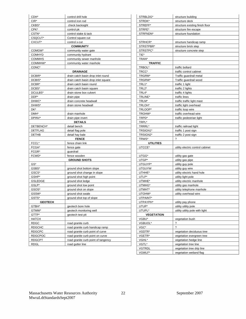
Massachusetts Water Resources Authority September 2007 MwraLdtStandardsSept2007
22
CDH* control drill hole STRBLDG* structure building
CIR* control iron rod STRDK* structure deck
CKBS* check backsight STREFF* structure existing finish floor
CPK* control pk STRFE* structure fire escape
CSTN* control stake & tack STRFNDN* structure foundation
CSQCUT* Control square cut
CXCUT* control x-cut STRHCR* structure handicap ramp
COMMUNITY STRSTPBR* structure brick step
COMGW* community water gate STRSTPC* structure concrete step
COMHYD community hydrant TIE*
COMMHS community sewer manhole TRAN*
COMMHW* community water manhole TRAFFIC
CONC* TRBOL* traffic bollard
DRAINAGE TRCC* traffic control cabinet
DCBIR* drain catch basin drop inlet round TRGRM* Traffic guardrail metal
DCBIS* drain catch basin drop inlet square TRGRW* Traffic guardrail wood
DCBR* drain catch basin round TRL1* traffic 1 light
DCBS* drain catch basin square TRL2* traffic 2 lights
DCULBS* drain stone box culvert TRL4* traffic 4 lights
DDP* drain pipe TRLINE* traffic lines
DHWC* drain concrete headwall TRLM* traffic traffic light mast
DHWS* drain stone headwall TRLOH* traffic light overhead
DK* TRLOOP* traffic loop wire
DMH* drain manhole TROHW* traffic overhead wire
DPINV* drain pipe invert TRPD* traffic pedestrian light
DETAILS TRPL*
DETBENCH* detail bench TRRRL* traffic railroad light
DETFLAG detail flag pole TRSIGN1* traffic 1 post sign
DETHB detail hay bale TRSIGN2* traffic 2 post sign
FENCE TRWS* ?
FCCL* fence chain link UTILITIES
FCGA* fence gate UTCCE* utility electric control cabinet
FCGR* guardrail
FCWD* fence wooden UTGG* utility gas gate
GROUND SHOTS UTGP* utility gas pipe
GS* UTGUYP* utility guy pole
GSBS* ground shot bottom slope UTGUYW utility guy wire
GSCS* ground shot change in slope UTHHE* utility electric hand hole
GSHP* ground shot high point UTLP* utility light pole
GSLEDGE ground shot ledge UTMHE* utility electric manhole
GSLP* ground shot low point UTMHG* utility gas manhole
GSOS* ground shot on slope UTMHT* utility telephone manhole
GSSW* ground shot swale UTOHW* utility overhead wire
GSTS* ground shot top of slope UTPAINT*
GEOTECH UTPAYPH* utility pay phone
GTBH* geotech bore hole UTUP* utility utility pole
GTMW* geotech monitoring well UTUPL* utility utility pole with light
GTTP* geotech test pit VEGETATION
HATCH VGBU* vegetation bush
RDGC road granite curb VGBUOL* ?
RDGCHC road granite curb handicap ramp VGC* ?
RDGCPC road granite curb point of curve VGDTR* vegetation deciduous tree
RDGCPOC road granite curb point on curve VGETR* vegetation evergreen tree
RDGCPT road granite curb point of tangency VGHL* vegetation hedge line
RDGL road gutter line VGTL* vegetation tree line
VGTRDL vegetation tree drip line
VGWLF* vegetation wetland flag
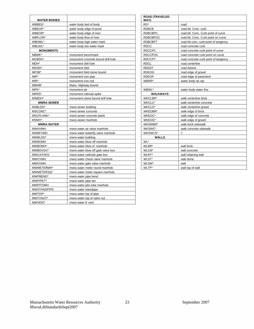
Massachusetts Water Resources Authority September 2007 MwraLdtStandardsSept2007
23
WATER BODIES ROAD (TRAVELED WAY)
WBBED* water body bed of body RD* road
WBEOP* water body edge of pond RDBCB road bit. Conc. curb
WBEOR* water body edge of river RDBCBPC road bit. Conc. Curb point of curve
WBFLOR* water body flow of river RDBCBPOC road bit. Conc. Curb point on curve
WBHWL* water body high water mark RDBCBPT road bit conc. curb point of tangency
WBLWL* water body low water mark RDCC road concrete curb
MONUMENTS RDCCPC road concrete curb point of curve
MBMK* monument benchmark RDCCPOC road concrete curb point on curve
MCBDH* monument concrete bound drill hole RDCCPT road concrete curb point of tangency
MDH* monument drill hole RDCL road centerline
MDISK* monument disk RDDST road dstone
MFSB* monument field stone bound RDEOG road edge of gravel
MIP* monument iron pipe RDEOP road edge of pavement
MIR* monument iron rod WBRR* water body rip rap
MMHB* Mass. Highway bound
MPK* monument pk WBWL* water body water line
MRRS* monument railroad spike WALKWAYS
MSBDH* monument stone bound drill hole WKCLBR* walk centerline brick
MWRA SEWER WKCLC* walk centerline concrete
MSBLDG* mwra sewer building WKCLG* walk centerline gravel
MSCONC* mwra sewer concrete WKEOBR* walk edge of brick
MSCPLANK* mwra sewer concrete plank WKEOC* walk edge of concrete
MSMH* mwra sewer manhole WKEOG* walk edge of gravel
MWRA WATER WKSWBR* walk brick sidewalk
MWAVMH mwra water air valve manhole WKSWC* walk concrete sidewalk
MWBFVMH mwra water butterfly valve manhole WKSWCS* ?
MWBLDG* mwra water building WALLS
MWBOMH mwra water blow off manhole WL*
MWBOMH* mwra water blow of manhole WLBR* wall brick
MWBOVGV* mwra water blow off gate valve box WLCN* wall concrete
MWCATHGV mwra water cathode gate box WLRT* wall retaining wall
MWCVMH mwra water check valve manhole WLST* wall stone
MWGVMH mwra water gate valve manhole WLSW* wall
MWMETERMH* mwra water meter round manhole WLTP* wall top of wall
MWMETERSQ* mwra water meter square manhole
MWPBEND* mwra water pipe bend
MWPIPET* mwra water pipe tee
MWPITOMH mwra water pito tube manhole
MWSTANDPIPE mwra water standpipe
MWTOP* mwra water top of pipe
MWTVNUT* mwra water top of valve nut
MWVENT mwra water 6' vent
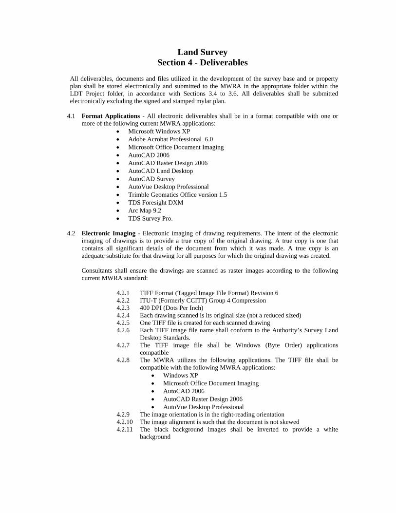
Land Survey Section 4 - Deliverables
All deliverables, documents and files utilized in the development of the survey base and or property plan shall be stored electronically and submitted to the MWRA in the appropriate folder within the LDT Project folder, in accordance with Sections 3.4 to 3.6. All deliverables shall be submitted electronically excluding the signed and stamped mylar plan.
4.1 Format Applications - All electronic deliverables shall be in a format compatible with one or
more of the following current MWRA applications: Microsoft Windows XP Adobe Acrobat Professional 6.0 Microsoft Office Document Imaging AutoCAD 2006 AutoCAD Raster Design 2006 AutoCAD Land Desktop AutoCAD Survey AutoVue Desktop Professional Trimble Geomatics Office version 1.5 TDS Foresight DXM Arc Map 9.2 TDS Survey Pro.
4.2 Electronic Imaging - Electronic imaging of drawing requirements. The intent of the electronic
imaging of drawings is to provide a true copy of the original drawing. A true copy is one that contains all significant details of the document from which it was made. A true copy is an adequate substitute for that drawing for all purposes for which the original drawing was created. Consultants shall ensure the drawings are scanned as raster images according to the following current MWRA standard:
4.2.1 TIFF Format (Tagged Image File Format) Revision 6 4.2.2 ITU-T (Formerly CCITT) Group 4 Compression 4.2.3 400 DPI (Dots Per Inch) 4.2.4 Each drawing scanned is its original size (not a reduced sized) 4.2.5 One TIFF file is created for each scanned drawing 4.2.6 Each TIFF image file name shall conform to the Authority’s Survey Land
Desktop Standards. 4.2.7 The TIFF image file shall be Windows (Byte Order) applications
compatible 4.2.8 The MWRA utilizes the following applications. The TIFF file shall be
compatible with the following MWRA applications: Windows XP Microsoft Office Document Imaging AutoCAD 2006 AutoCAD Raster Design 2006 AutoVue Desktop Professional
4.2.9 The image orientation is in the right-reading orientation 4.2.10 The image alignment is such that the document is not skewed 4.2.11 The black background images shall be inverted to provide a white
background
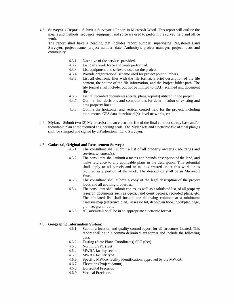
4.3 Surveyor’s Report - Submit a Surveyor’s Report in Microsoft Word. This report will outline the means and methods, sequence, equipment and software used to perform the survey field and office work. The report shall have a heading that includes report number, supervising Registered Land Surveyor, project name, project number, date, Authority’s project manager, project locus and community.
4.3.1. Narrative of the services provided. 4.3.2. List daily work force and work performed. 4.3.3. List equipment and software used on the project. 4.3.4. Provide organizational scheme used for project point numbers. 4.3.5. List all electronic files with the file format, a brief description of the file
content, the source of the file information, and the Project folder path. The file format shall include, but not be limited to CAD, scanned and document files.
4.3.6. List all recorded documents (deeds, plans, reports) utilized in the project. 4.3.7. Outline final decisions and computations for determination of existing and
new property lines. 4.3.8. Outline the horizontal and vertical control held for the project, including
monuments, GPS data, benchmark(s), level networks, etc.
4.4 Mylars - Submit two (2) Mylar set(s) and an electronic file of the final contract survey base and/or recordable plan at the required engineering scale. The Mylar sets and electronic file of final plan(s) shall be stamped and signed by a Professional Land Surveyor.
4.5 Cadastral, Original and Retracement Surveys: 4.5.1. The consultant shall submit a list of all property owner(s), abutter(s) and
servient tenement(s). 4.5.2. The consultant shall submit a metes and bounds description of the land, and
make reference to any applicable plans in the description. This submittal shall apply to all parcels and or takings created under this work or as required as a portion of the work. The description shall be in Microsoft Word.
4.5.3. The consultant shall submit a copy of the legal description of the project locus and all abutting properties.
4.5.4. The consultant shall submit copies, as well as a tabulated list, of all property research documents such as deeds, land court decrees, recorded plans, etc. The tabulated list shall include the following columns at a minimum: assessor map (reference plan), assessor lot, deed/plan book, deed/plan page, grantee, grantor, etc.
4.5.5. All submittals shall be in an appropriate electronic format.
4.6 Geographic Information System:
4.6.1. Submit a location and quality control report for all structures located. This report shall be in a comma delimited .txt format and include the following data:
4.6.2. Easting (State Plane Coordinates) SPC (feet) 4.6.3. Northing SPC (feet) 4.6.4. MWRA facility section 4.6.5. MWRA facility type. 4.6.6. Specific MWRA facility identification, approved by the MWRA. 4.6.7. Elevation (Project datum) 4.6.8. Horizontal Precision 4.6.9. Vertical Precision.
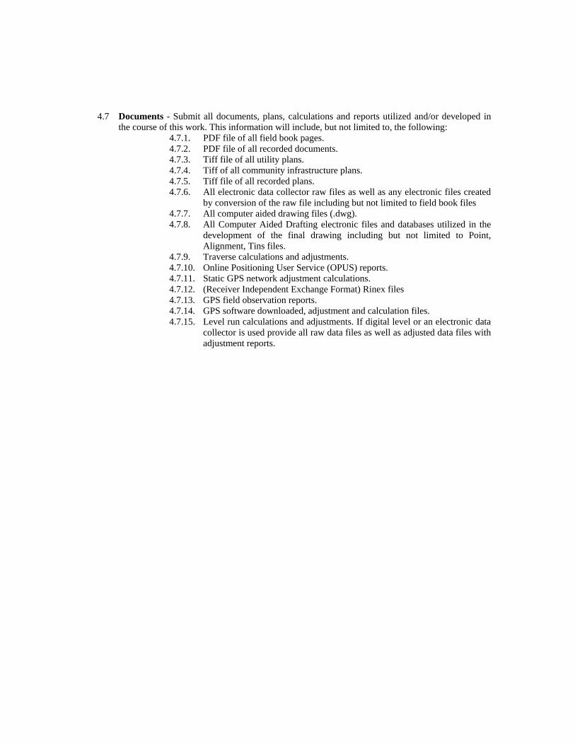
4.7 Documents - Submit all documents, plans, calculations and reports utilized and/or developed in
the course of this work. This information will include, but not limited to, the following: 4.7.1. PDF file of all field book pages. 4.7.2. PDF file of all recorded documents. 4.7.3. Tiff file of all utility plans. 4.7.4. Tiff of all community infrastructure plans. 4.7.5. Tiff file of all recorded plans. 4.7.6. All electronic data collector raw files as well as any electronic files created
by conversion of the raw file including but not limited to field book files 4.7.7. All computer aided drawing files (.dwg). 4.7.8. All Computer Aided Drafting electronic files and databases utilized in the
development of the final drawing including but not limited to Point, Alignment, Tins files.
4.7.9. Traverse calculations and adjustments. 4.7.10. Online Positioning User Service (OPUS) reports. 4.7.11. Static GPS network adjustment calculations. 4.7.12. (Receiver Independent Exchange Format) Rinex files 4.7.13. GPS field observation reports. 4.7.14. GPS software downloaded, adjustment and calculation files. 4.7.15. Level run calculations and adjustments. If digital level or an electronic data
collector is used provide all raw data files as well as adjusted data files with adjustment reports.
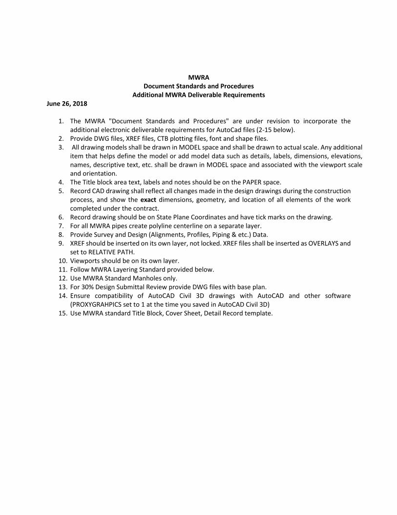
MWRA Document Standards and Procedures
Additional MWRA Deliverable Requirements June 26, 2018
1. The MWRA "Document Standards and Procedures" are under revision to incorporate the additional electronic deliverable requirements for AutoCad files (2-15 below).
2. Provide DWG files, XREF files, CTB plotting files, font and shape files. 3. All drawing models shall be drawn in MODEL space and shall be drawn to actual scale. Any additional
item that helps define the model or add model data such as details, labels, dimensions, elevations, names, descriptive text, etc. shall be drawn in MODEL space and associated with the viewport scale and orientation.
4. The Title block area text, labels and notes should be on the PAPER space. 5. Record CAD drawing shall reflect all changes made in the design drawings during the construction
process, and show the exact dimensions, geometry, and location of all elements of the work completed under the contract.
6. Record drawing should be on State Plane Coordinates and have tick marks on the drawing. 7. For all MWRA pipes create polyline centerline on a separate layer. 8. Provide Survey and Design (Alignments, Profiles, Piping & etc.) Data. 9. XREF should be inserted on its own layer, not locked. XREF files shall be inserted as OVERLAYS and
set to RELATIVE PATH. 10. Viewports should be on its own layer. 11. Follow MWRA Layering Standard provided below. 12. Use MWRA Standard Manholes only. 13. For 30% Design Submittal Review provide DWG files with base plan. 14. Ensure compatibility of AutoCAD Civil 3D drawings with AutoCAD and other software
(PROXYGRAHPICS set to 1 at the time you saved in AutoCAD Civil 3D) 15. Use MWRA standard Title Block, Cover Sheet, Detail Record template.
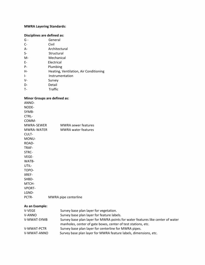
MWRA Layering Standards: Disciplines are defined as: G - General C- Civil A- Architectural S- Structural M- Mechanical E- Electrical P- Plumbing H- Heating, Ventilation, Air Conditioning I- Instrumentation V- Survey D- Detail T- Traffic Minor Groups are defined as: ANNO- NODE- SYMB- CTRL- COMM- MWRA- SEWER MWRA sewer features MWRA- WATER MWRA water features CULT- MONU- ROAD- TRAF- STRC- VEGE- WATB- UTIL- TOPO- XREF- SHBD- MTCH- VPORT- LGND- PCTR- MWRA pipe centerline As an Example: V-VEGE Survey base plan layer for vegetation. V-ANNO Survey base plan layer for feature labels. V-MWAT-SYMB Survey base plan layer for MWRA points for water features like center of water
manholes, center of gate boxes, center of test stations, etc. V-MWAT-PCTR Survey base plan layer for centerline for MWRA pipes. V-MWAT-ANNO Survey base plan layer for MWRA feature labels, dimensions, etc.
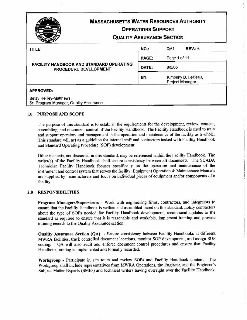
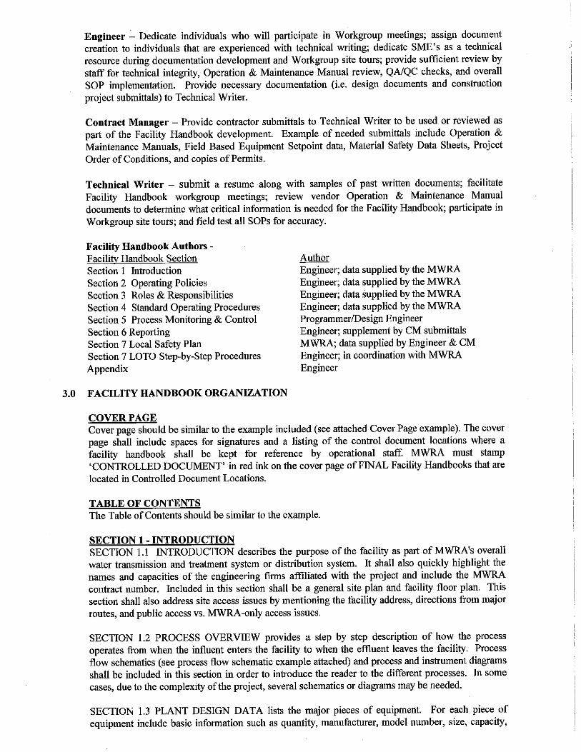
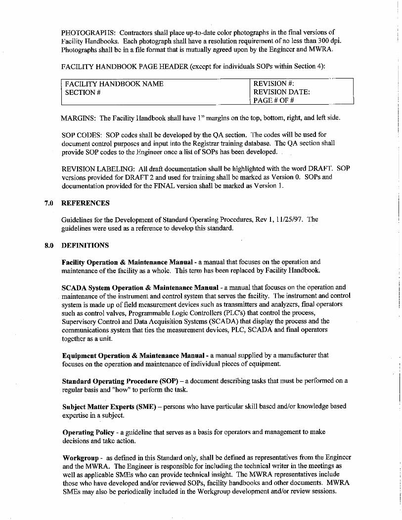
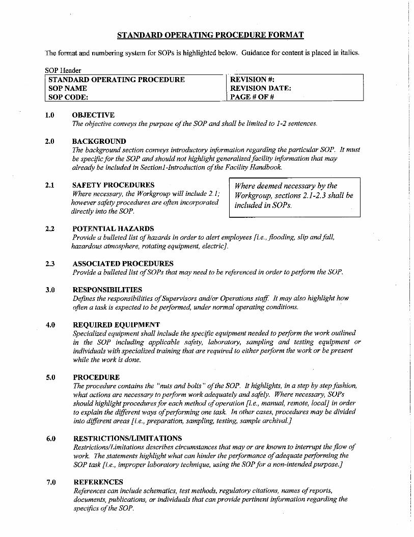
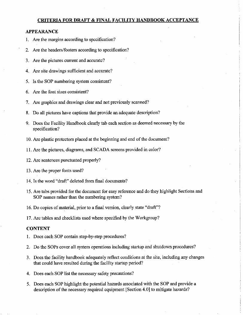
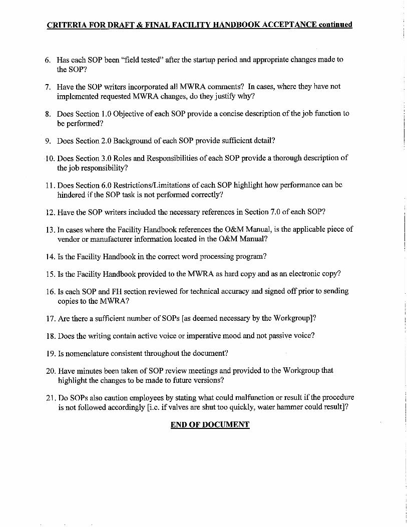

Operation and Maintenance Manual Checklist
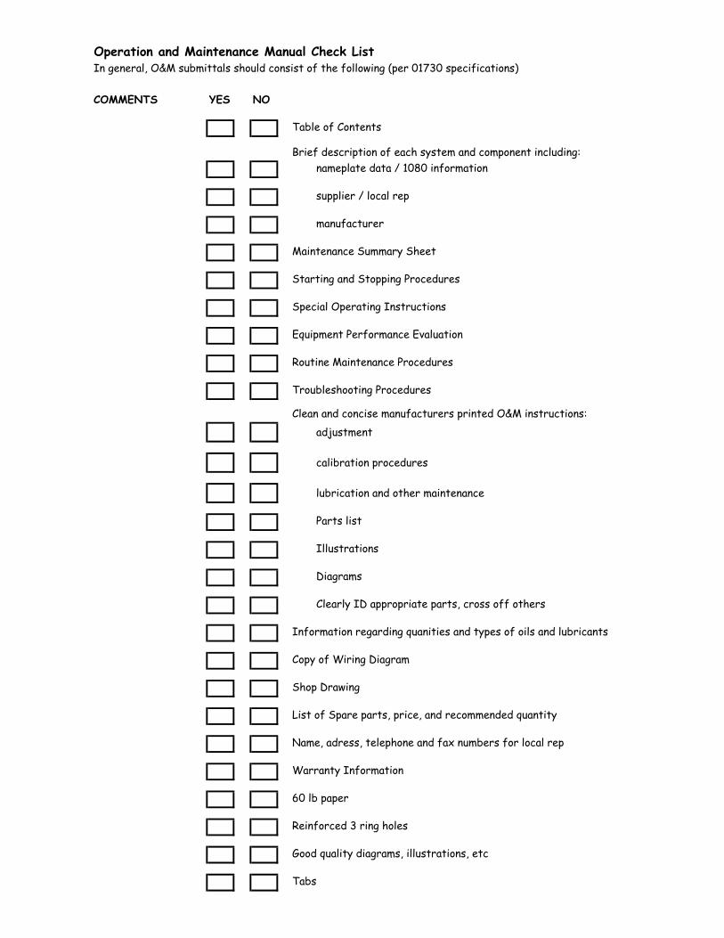
Operation and Maintenance Manual Check ListIn general, O&M submittals should consist of the following (per 01730 specifications)
COMMENTS YES NO
Table of Contents
Brief description of each system and component including:nameplate data / 1080 information
supplier / local rep
manufacturer
Maintenance Summary Sheet
Starting and Stopping Procedures
Special Operating Instructions
Equipment Performance Evaluation
Routine Maintenance Procedures
Troubleshooting Procedures
Clean and concise manufacturers printed O&M instructions:adjustment
calibration procedures
lubrication and other maintenance
Parts list
Illustrations
Diagrams
Clearly ID appropriate parts, cross off others
Information regarding quanities and types of oils and lubricants
Copy of Wiring Diagram
Shop Drawing
List of Spare parts, price, and recommended quantity
Name, adress, telephone and fax numbers for local rep
Warranty Information
60 lb paper
Reinforced 3 ring holes
Good quality diagrams, illustrations, etc
Tabs
TOC-1
MASSACHUSETTS WATER RESOURCES AUTHORITY
CONSTRUCTION DEPARTMENT
RESIDENT ENGINEER
MANUAL
(2012 UPDATE EDITION) FINAL DRAFT 12/17/12
A GUIDE FOR PROJECT CONTROL
EXHIBIT 1RESIDENT ENGINEER MANUAL
for Contract #7024

TOC-2
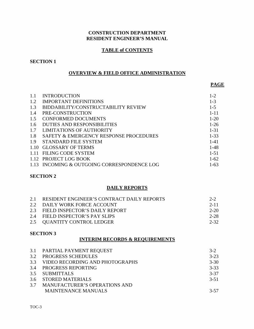
TOC-3
CONSTRUCTION DEPARTMENT RESIDENT ENGINEER’S MANUAL
TABLE of CONTENTS
SECTION 1
OVERVIEW & FIELD OFFICE ADMINISTRATION
PAGE
1.1 INTRODUCTION 1-2 1.2 IMPORTANT DEFINITIONS 1-3 1.3 BIDDABILITY/CONSTRUCTABILITY REVIEW 1-5 1.4 PRE-CONSTRUCTION 1-11 1.5 CONFORMED DOCUMENTS 1-20 1.6 DUTIES AND RESPONSIBILITIES 1-26 1.7 LIMITATIONS OF AUTHORITY 1-31 1.8 SAFETY & EMERGENCY RESPONSE PROCEDURES 1-33 1.9 STANDARD FILE SYSTEM 1-41 1.10 GLOSSARY OF TERMS 1-48 1.11 FILING CODE SYSTEM 1-51 1.12 PROJECT LOG BOOK 1-62 1.13 INCOMING & OUTGOING CORRESPONDENCE LOG 1-63 SECTION 2
DAILY REPORTS
2.1 RESIDENT ENGINEER’S CONTRACT DAILY REPORTS 2-2 2.2 DAILY WORK FORCE ACCOUNT 2-11 2.3 FIELD INSPECTOR’S DAILY REPORT 2-20 2.4 FIELD INSPECTOR’S PAY SLIPS 2-28 2.5 QUANTITY CONTROL LEDGER 2-32
SECTION 3
INTERIM RECORDS & REQUIREMENTS 3.1 PARTIAL PAYMENT REQUEST 3-2 3.2 PROGRESS SCHEDULES 3-23 3.3 VIDEO RECORDING AND PHOTOGRAPHS 3-30 3.4 PROGRESS REPORTING 3-33 3.5 SUBMITTALS 3-37 3.6 STORED MATERIALS 3-51 3.7 MANUFACTURER’S OPERATIONS AND MAINTENANCE MANUALS 3-57
TOC-4
SECTION 3 (con’t.)
PAGE 3.8 CHECKOUT, TESTING AND STARTUP
OF SYSTEMS 3-62 3.9 EQUIPMENT NOMENCLATURE AND
TECHNICAL DATA 3-81 3.10 SUBSTANTIAL COMPLETION 3-87 3.11 RELEASE OF RETAINAGE 3-91 3.12 PUNCH LIST 3-95 3.13 WARRANTY POLICY & PROCEDURES 3-99 3.14 FINAL PAYMENT 3-104 SECTION 4
CONTRACT CHANGES & MODIFICATIONS
4.1 REQUEST FOR INFORMATION (RFI) 4-2 4.2 CONTRACT CHANGES 4-7 4.3 CHANGE ORDER COST REVIEW 4-21 4.4 T&M CHANGE ORDERS 4-37 4.5 CHANGE ORDER TRACKING 4-43 4.6 CONTRACTOR CLAIMS 4-48 4.7 CONTRACT CLOSEOUT 4-69 SECTION 5
REPORTING FORMS, PROCEDURES & REVIEWS
5.1 PROJECT (ADMINISTRATIVE) REVIEWS 5-2 5.2 MATERIALS CONTROL FORM 5-9 5.3 FIELD OFFICE VISITORS LOG 5-12 5.4 JOB MEETING REPORT 5-14 5.5 ACCIDENT REPORT 5-24 5.6 DAMAGE REPORT 5-30 5.7 COMPLAINT REPORT 5-34 5.8 POLICE DETAILS 5-37 5.9 FACILITY HANDBOOK 5-38 5.10 ONE YEAR PROJECT PERFORMANCE CERTIFICATE 5-41
(UNDER REVIEW BY PROCUREMENT)
1-1
SECTION 1
OVERVIEW & FIELD OFFICE ADMINISTRATION
PAGE
1.1 INTRODUCTION 1-2
1.2 IMPORTANT DEFINITIONS 1-3
1.3 BIDDABILITY/CONSTRUCTABILITY REVIEW 1-5
1.4 PRE-CONSTRUCTION 1-11
1.5 CONFORMED DOCUMENTS 1-20
1.6 DUTIES AND RESPONSIBILITIES 1-26
1.7 LIMITATIONS OF AUTHORITY 1-31
1.8 SAFETY & EMERGENCY RESPONSE PROCEDURES 1-33
1.9 STANDARD FILE SYSTEM 1-41
1.10 GLOSSARY OF TERMS 1-48
1.11 FILING CODE SYSTEM 1-51
1.12 PROECT LOG BOOK 1-62
1.13 INCOMING & OUTGOING CORRESPONDENCE LOG 1-63
1-2
1. OVERVIEW & FIELD OFFICE ADMINISTRATION
1.1 INTRODUCTION
The Resident Engineer shall represent the Authority daily on the site of construction projects and
shall be responsible for checking, inspecting, and reporting to project management assigned on a
regular basis, both in writing and orally as to the events at the project site.
The purpose of this manual is to present a basic set of procedures for the guidance of resident
engineers and construction field staff to aid them in the performance of their duties and in the
interest of establishing uniform practices and procedures.
The manual's instructions in no way replace, supersede, or modify any of the provisions or the
requirements of the specific contract documents or statutes pertaining to the construction industry.
Records and reports in this manual are absolutely necessary and keeping them accurate,
complete and up to date is of the utmost importance. Procedures given in this manual may be
modified, where necessary, but only by the exercise of good judgment to adapt them to a
particular project or event. Field inspection is the most important function of the field staff. The
contract plans and specifications are prepared with great accuracy and detail; however, only
through intelligent inspection will the finished product meet the standards of the Authority and its
Construction Department.
1-3
1. OVERVIEW & FIELD OFFICE ADMINISTRATION
1.2 IMPORTANT DEFINITIONS
AUTHORITY: Massachusetts Water Resources Authority (MWRA)
CONFORMED PLANS AND SPECIFICATIONS: Unofficial as-bid documents that have
been modified to include all addenda items issued during the bid phase.
CONSTRUCTION CONTRACT: A specific MWRA Construction Contract which includes a
set of approved as-bid plans, specifications and addenda for proposed work.
CONSTRUCTION COORDINATOR: MWRA staff person who is assigned responsibility for
supervising, monitoring and the administration of one or more construction contracts under the
direction of the Director or Assistant Director of Construction. The Construction Coordinator
supervises field staff assigned by ensuring that MWRA policies and procedures are being adhered
to.
CONSTRUCTION PROJECT: An MWRA construction project that may include one or more
construction contracts.
CONSULTANT: An engineering firm or MWRA Department Unit responsible for the
engineering design of a construction project.
CONTRACT: An agreement, either written or oral, between at least two parties in which one
agrees to perform some task for the other in return for a specified payment.
CONTRACT PLANS AND SPECIFICATIONS: Official documents depicting the work to be
performed and work associated for a specific construction contract.
CONTRACTOR: The prime contractor of an MWRA construction contract.
1-4
ENGINEER: The MWRA Chief Engineer or his designee.
FIELD STAFF: Field personnel assigned to the construction project (i.e.: Resident Engineer,
Field Engineers, Field Inspectors, Secretary etc.).
HOME OFFICE: The MWRA Office located in Chelsea Mass.
MASSACHUSETTS WATER RESOURCES AUTHORITY
Chelsea Facility
2 Griffin Way
Chelsea, Massachusetts 02150
Telephone: 617-305-5600
Facsimile: 617-305-1606 or 1607
INSPECTOR OR FIELD ENGINEER: The person assigned to view and document
construction work in progress under the supervision of the resident engineer.
PROJECT/CONSTRUCTION/JOB SITE: The area where the construction work is performed
for a particular construction contract.
RESIDENT ENGINEER: The employee assigned to a construction contract that shall be
responsible for the record keeping, documentation and inspection of all work performed. The
Resident Engineer is also responsible for payments to the contractor and the supervision of field
staff assigned.
STANDARD CONSTRUCTION PROCEDURE: A set of standard procedures offered as a
guide to the Resident Engineer to ensure the construction contract is being administered in
accordance with MWRA policies.
1-5
1. OVERVIEW & FIELD OFFICE ADMINISTRATION
1.3 BIDDABILITY/CONSTRUCTABILTIY REVIEW
It is management’s intent to assign a Resident Engineer and Construction Coordinator to perform a
"Biddability/Constructability” (B/C) review of proposed contract documents before the design is
completed and advertised for bid. This will allow the resident engineer and construction
coordinator an opportunity to become familiar with the project and the design team; and, also
utilize the resident engineer’s and construction coordinator’s experience and training in an effort to
eliminate or reduce changes during the construction phase.
The construction coordinator will be assigned the overall responsibility of the review; however,
the review will be performed jointly with the resident engineer and possibly the construction field
inspector(s). It is management’s opinion that the vast experience and training of the construction
staff provides a valuable asset when it comes to identifying potential construction problems or
conflicts within the design documents which may cause delays and/or additional costs to an
Authority project. The resident engineer should approach a B/C review in a practicable but
professional manner. In performing a B/C review, it is not the purview of the resident engineer to
try and redesign the job or to suggest changes but to act as an adviser with the Authority's best
interest in mind.
The following procedure was developed to assist the Home Office staff in reviewing contract
documents for bidability and constructability. Because no two contracts are alike, these guidelines
1-6
are not all inclusive. The overall objective of the B/C review is threefold:
1. To ensure that the contract documents reflect the best construction practices based
on the experience of the Construction Staff;
2. To ensure that the contract documents contain appropriate requirements to permit
the Construction Staff to adequately manage the contract; and
3. To minimize the occurrence of change orders due to discrepancies in contract
documents.
REVIEW PROCEDURE:
The review shall be conducted utilizing the “General” B/C review checklist and the “Detailed”
B/C review checklist included in the Appendix of this manual. The checklists are intended as
guidance, not to limit the scope of the review. The reviewer should make maximum use of his/her
experience.
To start the review, the "General" checklist should be completed to ensure that the proper contract
documents have been assembled, submitted and are complete (It is suggested that the reviewer
read the Summary of Work, Section 01000, and perform a brief review of the plans to gain an
overall understanding of the purpose, scope and location of the project). Since part of the review
applies to several or many specification sections/plan sheets and they are not in their order of
occurrence in the contract documents, it is recommended that they all be read over before
commencing the detailed review. As the reviewer goes through the checklist, he/she shall answer
each question with the following notations; "SAT' (Satisfactory), "DEF"(Deficient), or "N/A" (Not
Applicable), as appropriate, and the sections of the specs/plans upon which negative comments are
1-7
based marked in red to indicate desired corrections.
To conduct the detailed review, relevant sections of the specifications and each sheet of the plans
shall be reviewed against the checklists respectively. Crosschecking between specifications and
plans should be accomplished throughout the review as necessary to assure consistency between
the plans and specifications and to identify any conflicts.
The review should cover all the listed, applicable elements of the contract. In reviewing each
Element, consideration should be given to the following:
• Conflicts/ambiguity with other contract information
• Accuracy
• Practicability/Do-ability Constructability
• Omission of desirable controls
• Unnecessary requirements/controls
• Clarifications to avoid change orders
The final step of the B/C review is to prepare a memo describing the results of the review.
Paragraphs should be included for each element checked "DEF", (deficiencies). The deficiencies
should be described by specification section or drawing number indicating the recommended
corrections and, when appropriate, reasons (It is recommended that these paragraphs be drafted as
the deficiencies are identified). See the attached sample memo, Exhibit 1-A.1a and 1-A.1b for a
suggested format.
1-8
The memo, along with the completed checklists and marked up contract documents should be
forwarded to the construction coordinator for review and subsequently transmitted to the memo
addressee. The reviewer should retain a copy of the memo and the completed checklists in his
personal file. The completed checklists and a copy of the comment memo shall be retained in the
Engineering and Construction Department's general files.
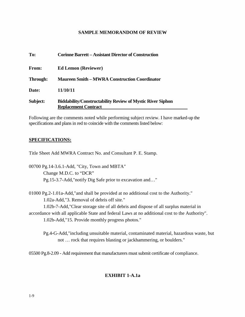
1-9
SAMPLE MEMORANDOM OF REVIEW
To: Corinne Barrett – Assistant Director of Construction
From: Ed Lemon (Reviewer)
Through: Maureen Smith – MWRA Construction Coordinator
Date: 11/10/11
Subject: Biddability/Constructability Review of Mystic River Siphon Replacement Contract
Following are the comments noted while performing subject review. I have marked-up the specifications and plans in red to coincide with the comments listed below:
SPECIFICATIONS: Title Sheet Add MWRA Contract No. and Consultant P. E. Stamp. 00700 Pg.14-3.6.1-Add, "City, Town and MBTA"
Change M.D.C. to “DCR” Pg.15-3.7-Add,"notify Dig Safe prior to excavation and…"
01000 Pg.2-1.01a-Add,"and shall be provided at no additional cost to the Authority." 1.02a-Add,"3. Removal of debris off site." 1.02b-7-Add,"Clear storage site of all debris and dispose of all surplus material in
accordance with all applicable State and federal Laws at no additional cost to the Authority". 1.02b-Add,"15. Provide monthly progress photos."
Pg.4-G-Add,"including unsuitable material, contaminated material, hazardous waste, but
not … rock that requires blasting or jackhammering, or boulders."
05500 Pg.8-2.09 - Add requirement that manufacturers must submit certificate of compliance.
EXHIBIT 1-A.1a
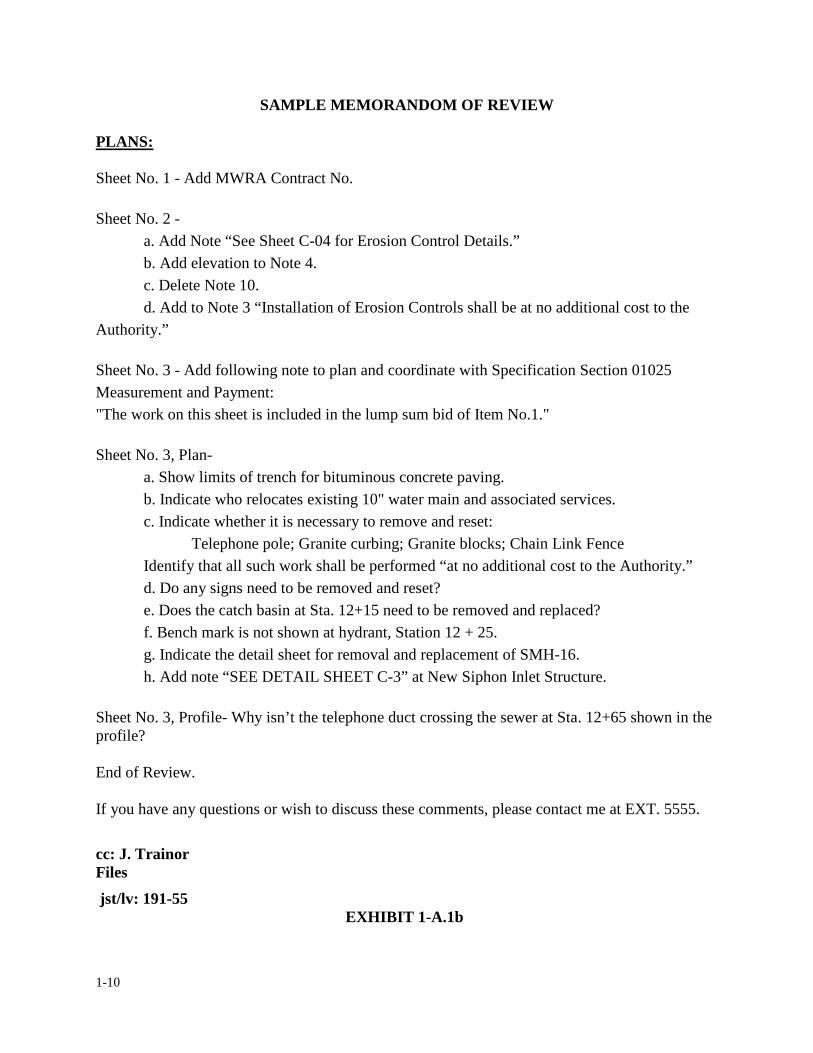
1-10
SAMPLE MEMORANDOM OF REVIEW
PLANS:
Sheet No. 1 - Add MWRA Contract No. Sheet No. 2 -
a. Add Note “See Sheet C-04 for Erosion Control Details.” b. Add elevation to Note 4. c. Delete Note 10. d. Add to Note 3 “Installation of Erosion Controls shall be at no additional cost to the
Authority.”
Sheet No. 3 - Add following note to plan and coordinate with Specification Section 01025 Measurement and Payment: "The work on this sheet is included in the lump sum bid of Item No.1." Sheet No. 3, Plan-
a. Show limits of trench for bituminous concrete paving. b. Indicate who relocates existing 10" water main and associated services. c. Indicate whether it is necessary to remove and reset:
Telephone pole; Granite curbing; Granite blocks; Chain Link Fence Identify that all such work shall be performed “at no additional cost to the Authority.” d. Do any signs need to be removed and reset? e. Does the catch basin at Sta. 12+15 need to be removed and replaced? f. Bench mark is not shown at hydrant, Station 12 + 25. g. Indicate the detail sheet for removal and replacement of SMH-16. h. Add note “SEE DETAIL SHEET C-3” at New Siphon Inlet Structure.
Sheet No. 3, Profile- Why isn’t the telephone duct crossing the sewer at Sta. 12+65 shown in the profile? End of Review. If you have any questions or wish to discuss these comments, please contact me at EXT. 5555.
cc: J. Trainor Files
jst/lv: 191-55 EXHIBIT 1-A.1b
1-11
1. OVERVIEW AND FIELD OFFICE ADMINISTRATION
1.4 PRE-CONSTRUCTION
After a project has been bid and the contract awarded by the Authority, the Authority will issue to
the Contractor a Notice to Proceed letter. The construction coordinator and/or consultant will then
establish a date for the pre-construction meeting. The purpose of this meeting is to establish lines
of communication and for all parties associated with the project and to introduce themselves. At
this meeting, if required by the Authority, the consultant shall provide conformed construction
documents, which are plans and specifications that incorporate all addenda from the bid phase of
the project. These conformed documents are considered “unofficial” and are provided by the
Authority for the convenience of the contractor and construction oversight team and do not
supersede or replace the as-bid drawings, specifications and addenda. Conformed documents are
discussed in further detail in Section 1.5. It is important for the resident engineer to acknowledge
that the contract between the Authority and the Contractor is represented by the executed contract
documents only. Exhibit 1-B.1 is an example of a Notice to Proceed letter. Exhibit 1-B.2 is an
example of consultant’s letter for the transfer of electronic drawing files to the contractor. Exhibit
1-B.3a thru Exhibit 1-B.3f is an example of a standard agenda for a pre-construction meeting.
1-12
EXAMPLE
MASSACHUSETTS WATER RESOURCES AUTHORITY CHARLESTOWN NAVY YARD
100 FIRST AVENUE, BUILDING 39 BOSTON, MA 02129
Telephone: (617) 242-6000
Frederick A. Laskey Fax: (617) 788-4899 Executive Director TTY: (617) 788-4971 June 2, 2011
NOTICE TO PROCEED Mr. Smith, President ABC Constructors, Inc. 1 Industrial Drive Canton, MA 02021 RE: Somerville Marginal CSO Facility Influent Gates and Stop Log Replacement MWRA Contract No. 7344 Dear Mr. _______________, In accordance with the terms and conditions of the aforesaid contract, you are hereby directed to commence Work as of June 2, 2011. Since the Contract Time, as stipulated in the Authority-Contractor Agreement, is One Hundred Eighty (180) calendar days from this date, the completion date for the Work is November 29, 2011. There is transmitted herewith one fully executed copy of the Contract Documents, consisting of the documents specified in the Authority-Contractor Agreement. You are advised that ________________, Chief Engineer, is the Engineer as defined in the Contract Documents and is authorized to administer your contact for and in the name of this Authority. Please contact ________________ at _________________, prior to the start of on-site work, so that the Authority can arrange to have its resident engineer on the site when your construction crew arrives. Please acknowledge acceptance of the Notice and the receipt of the Contract Documents by signing and dating the enclosed copy of this Notice, which is to be returned to this office forthwith. Very truly yours, Acceptance of the Notice to Proceed
And receipt of the Contract Documents Deputy Director of Administration and Finance are herby acknowledged this day of , 20 MG/RCJ/ba Enclosure
Name and Title
EXHIBIT 1-B.1
1-13
EXAMPLE
March 31, 2005
Mr. Joe Build Project Manager Z. Winner & Sons, Inc. 50 Sprague Street Hyde Park, MA 02136
Subject: Upper Neponset Valley Replacement Sewer MWRA Contract No. 6191 MWRA Sewer Sections 685 and 686 Electronic Drawing File Request
Dear Mr. Build, Say and Doit Engineers, LLC (SDE) is in receipt of your request for the AutoCAD files of the as-bid contract drawings for the above referenced project. Please find enclosed one (1) CD-ROM Disk containing the requested As-Bid AutoCAD Drawing Files for MWRA Contract 6191.
These electronic files are provided for informational purposes only. The electronic files are not an end product or contract document. The contract documents are the stamped hard copy prints/plans, specifications and addenda issued and used for the bidding process. The recipient recognizes that the plans transmitted as electronic files are subject to undetectable alteration, either intentional or unintentional, due to, among other causes, transmission conversion, media degradation, software error or human alteration. Accordingly, SDE makes no warranty regarding the fitness of the electronic files. The recipient agrees to waive claims against and indemnify Say and Doit Engineers, LLC and the Massachusetts Water Resources Authority (MWRA) for claims resulting from the use, misuse, unauthorized re-use or alteration of these electronic files. The information contained on these drawings is the property of Say and Doit Engineers, LLC and the Massachusetts Water Resources Authority (MWRA) and is not to be used on any project without the written authorization of SDE and the MWRA.
Please acknowledge your written consent to the release of these electronic files pursuant to the procedures described herein by returning a signed original of this letter. Should you have any question or comments on this matter, please call me at 781-221-1111.
Sincerely,
SAY AND DOIT ENGINEERS, LLC
By:
Michael A. Getitdone, P.E. Joe Build – Z. Winner & Sons, Inc.
JM-056 13.2 Cc: Maureen Smith-MWRA Construction Coordinator Margery Jackson – MWRA Design Project Manager
EXHIBIT 1-B.2
1-14
EXAMPLE
MASSACHUSETTS WATER RESOURCES AUTHORITY PRECONSTRUCTION CONFERENCE AGENDA (April 11, 2005, 10:00am –12 noon in Board Room)
A. Project: Upper Neponset Valley Replacement Sewer (MWRA Sections 685 and 686) Contract No.: MWRA-6191 B. Owner Massachusetts Water Resources Authority (MWRA) 100 First Avenue Charlestown Navy Yard Boston, Massachusetts 02129 Telephone: 617-242-6000 Deputy Chief Operating Officer: Mr. John Vetere Chief Engineer: Mr. Jae Kim Director of Construction: Mr. Anandan Navanandan Asst. Director of Construction: Ms. Corinne Barrett Construction Coordinator: Mr. Isidoro D. Perez Design Project Manager – Eng.: Ms. Margery Johnson Public Affairs: Mr. Jeffrey McLaughlin AACU Compliance Officer Mr. John Corbin C. Construction Administration and Resident Engineer: Construction Administration (Consultant Contract 6013) Consultant Name: Fay Spofford & Thorndike, Inc. Consultant Address: 5 Burlington Woods Burlington, MA 01803 Consultant Telephone No.: 781-221-1000 FAX No.: 781-229-1115
EXHIBIT 1-B.3a
1-15
EXAMPLE CA Principal: Mr. Emile J. Hamwey, P.E. CA Project Manager: Mr. James M. Taylor, P.E. CA Project Engineer: Mr. Michael A. Sorrentino, P.E. Resident Engineering (Consultant Contract 7072) Consultant Name: Fay Spofford & Thorndike, Inc. Consultant Address: 5 Burlington Woods Burlington, MA 01803 RE/I Resident Engineer: Mr. John Doherty Field Office Telephone No.: TBD FAX No.: TBD D. Contractor Contractor Name: P. Gioioso and Sons, Inc. Contractor Address: 50 Sprague Street Hyde Park, MA 02136 Contractor Telephone No.: 617-364-5800 FAX No.: 617-364-9462 Project Manager: Joe Bettencourt Superintendent: Sam Doolan E. CORRESPONDENCE:
All correspondence shall be directed to Mr. John Doherty, Resident Engineer, with copies to Mr. Isidoro D. Perez, Construction Coordinator, Mr. Michael Sorrentino, Project Engineer. No correspondence shall be directed to the Design Engineer. Official business shall not be conducted by fax transmittal. All correspondence shall include the following reference: Contract No. 6191, Specification Reference, Article/Section/Page.
F. SALES TAX:
The MWRA Sales Tax Exemption Number (E-042-850-071) shall be used by the Contractors when appropriate as indicated in Instructions to Bidders, Section 8 - Sales Tax. Under no circumstances will payments be made for any Massachusetts sales tax.
EXHIBIT 1-B.3b
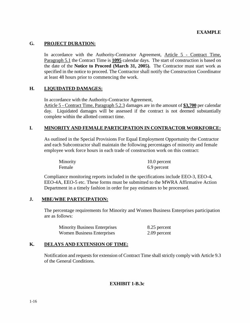
1-16
EXAMPLE G. PROJECT DURATION:
In accordance with the Authority-Contractor Agreement, Article 5 - Contract Time, Paragraph 5.1 the Contract Time is 1095 calendar days. The start of construction is based on the date of the Notice to Proceed (March 31, 2005). The Contractor must start work as specified in the notice to proceed. The Contractor shall notify the Construction Coordinator at least 48 hours prior to commencing the work.
H. LIQUIDATED DAMAGES:
In accordance with the Authority-Contractor Agreement, Article 5 - Contract Time, Paragraph 5.2.3 damages are in the amount of $3,700 per calendar day. Liquidated damages will be assessed if the contract is not deemed substantially complete within the allotted contract time.
I. MINORITY AND FEMALE PARTICIPATION IN CONTRACTOR WORKFORCE:
As outlined in the Special Provisions For Equal Employment Opportunity the Contractor and each Subcontractor shall maintain the following percentages of minority and female employee work force hours in each trade of construction work on this contract:
Minority 10.0 percent Female 6.9 percent
Compliance monitoring reports included in the specifications include EEO-3, EEO-4, EEO-4A, EEO-5 etc. These forms must be submitted to the MWRA Affirmative Action Department in a timely fashion in order for pay estimates to be processed.
J. MBE/WBE PARTICIPATION:
The percentage requirements for Minority and Women Business Enterprises participation are as follows:
Minority Business Enterprises 8.25 percent Women Business Enterprises 2.09 percent
K. DELAYS AND EXTENSION OF TIME:
Notification and requests for extension of Contract Time shall strictly comply with Article 9.3 of the General Conditions.
EXHIBIT 1-B.3c
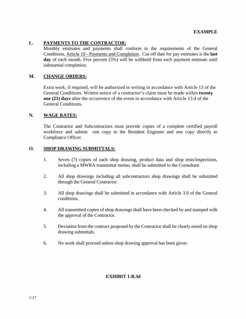
1-17
EXAMPLE
L. PAYMENTS TO THE CONTRACTOR: Monthly estimates and payments shall conform to the requirements of the General Conditions, Article 10 - Payments and Completion. Cut-off date for pay estimates is the last day of each month. Five percent (5%) will be withheld from each payment estimate until substantial completion.
M. CHANGE ORDERS:
Extra work, if required, will be authorized in writing in accordance with Article 13 of the General Conditions. Written notice of a contractor’s claim must be made within twenty one (21) days after the occurrence of the event in accordance with Article 13.4 of the General Conditions.
N. WAGE RATES:
The Contractor and Subcontractors must provide copies of a complete certified payroll workforce and submit one copy to the Resident Engineer and one copy directly to Compliance Officer.
O. SHOP DRAWING SUBMITTALS:
1. Seven (7) copies of each shop drawing, product data and shop tests/inspections, including a MWRA transmittal memo, shall be submitted to the Consultant.
2. All shop drawings including all subcontractors shop drawings shall be submitted
through the General Contractor. 3. All shop drawings shall be submitted in accordance with Article 3.9 of the General
conditions. 4. All transmitted copies of shop drawings shall have been checked by and stamped with
the approval of the Contractor.
5. Deviation from the contract proposed by the Contractor shall be clearly noted on shop drawing submittals.
6. No work shall proceed unless shop drawing approval has been given.
EXHIBIT 1-B.3d
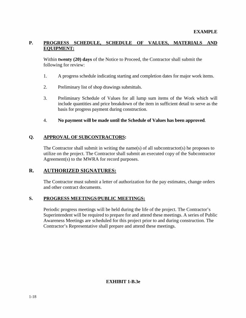
1-18
EXAMPLE P. PROGRESS SCHEDULE, SCHEDULE OF VALUES, MATERIALS AND
EQUIPMENT:
Within twenty (20) days of the Notice to Proceed, the Contractor shall submit the following for review: 1. A progress schedule indicating starting and completion dates for major work items. 2. Preliminary list of shop drawings submittals.
3. Preliminary Schedule of Values for all lump sum items of the Work which will
include quantities and price breakdown of the item in sufficient detail to serve as the basis for progress payment during construction.
4. No payment will be made until the Schedule of Values has been approved. Q. APPROVAL OF SUBCONTRACTORS:
The Contractor shall submit in writing the name(s) of all subcontractor(s) he proposes to utilize on the project. The Contractor shall submit an executed copy of the Subcontractor Agreement(s) to the MWRA for record purposes.
R. AUTHORIZED SIGNATURES: The Contractor must submit a letter of authorization for the pay estimates, change orders and other contract documents.
S. PROGRESS MEETINGS/PUBLIC MEETINGS:
Periodic progress meetings will be held during the life of the project. The Contractor’s Superintendent will be required to prepare for and attend these meetings. A series of Public Awareness Meetings are scheduled for this project prior to and during construction. The Contractor’s Representative shall prepare and attend these meetings.
EXHIBIT 1-B.3e
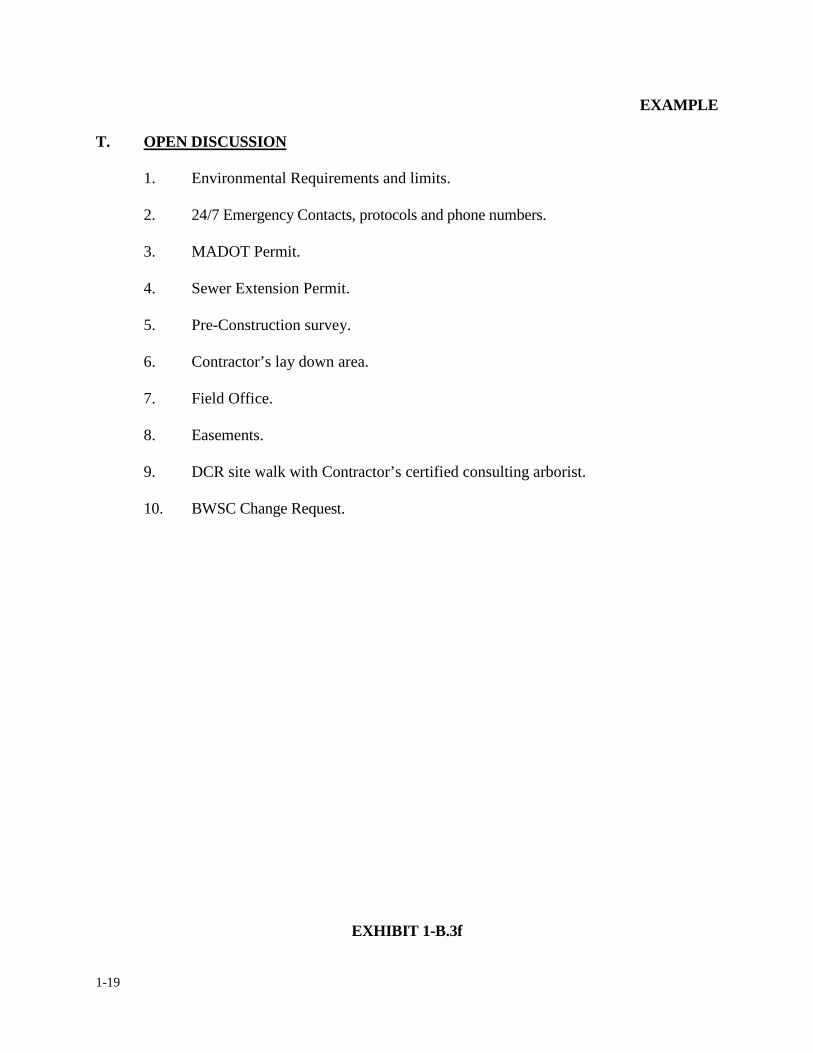
1-19
EXAMPLE T. OPEN DISCUSSION
1. Environmental Requirements and limits. 2. 24/7 Emergency Contacts, protocols and phone numbers.
3. MADOT Permit.
4. Sewer Extension Permit.
5. Pre-Construction survey.
6. Contractor’s lay down area.
7. Field Office.
8. Easements.
9. DCR site walk with Contractor’s certified consulting arborist.
10. BWSC Change Request.
EXHIBIT 1-B.3f
1-20
1. CONTRACT CHANGES & MODIFICATIONS
1.5 CONFORMED DOCUMENTS
The Resident Engineer will be provided with conformed documents prepared by the Design
Consultant consisting of the as-bid plans and specifications that have been modified to include
addenda issued during bidding. These plans and specifications are identified as “UNOFFICIAL
CONFORMED DOCUMENTS” and do not replace the official executed contract between the
Authority and the Contractor which consists of plans, specifications, and addenda.
Unofficial Conformed Documents are developed for the convenience of the Authority and the
Contractor to be used as working documents during construction. Updated specifications will be
reprinted with the phrase “UNOFFICIAL CONFORMED DOCUMENTS” in the upper right hand
corner of each page and the replaced text (“strikethrough”) and new text (underlined), identified by
Addendum No. and item number. Exhibits 1-C.1a and 1-C.1b includes a sample of conformed
specifications. On updated drawings, “UNOFFICIAL CONFORMED DOCUMENTS” will be
stamped or electronically added above the title block on each drawing, with the revision portion of
the title block indicating the revision number, date the revision was made (date addendum was
issued), initials of the person making the revision, initials of the individual who checked and
approved the revision, and the text or detail of the revision. Exhibit 1-C.1c includes a sample title
block for conformed drawings. Revised portions of the drawings will be “bubbled” or “clouded” to
identify the portion of the drawing that was changed. The revised drawings should be checked
against the bid drawings issued and updated by addendum during the bid process to ensure that
1-21
only changes made in addenda are included in the conformed drawings.
The resident engineer shall retain two full size sets of unofficial conformed drawings at the field
office, one for construction reference and one for “redline” markups of the work as it is completed.
Redline drawings shall include all relevant information within the work limits, i.e., if the project is
a sewer installation and a gas line is located within the sewer trenching system, the gas line size,
depth, material and offset from the sewer shall be documented. The resident engineer shall make
note of any changes in the work in the form of a “Sketch” or “Partial Drawing” that has been issued
with a request for information (RFI) response or an executed change order. Copies of all sketches
shall be attached to the field office drawings sets once they have been received and reviewed to
ensure incorporation into the work. If these “Sketches” and/or “Partial Drawings” include a
significant change, the Consultant shall issue a new unofficial conformed drawing with an updated
revision block. In some cases, a change order may be required to add the new drawing/work to the
contract. The Resident Engineer shall incorporate the revised drawing into the field office plan
sets and document that the revised drawing has been distributed to the Contractor.
The Construction Coordinator shall monitor the Resident Engineer’s progress on the red-line
drawings and include their progress in their monthly reporting. The Resident Engineer shall not let
redline drawings lag more than two weeks behind the completion of the work.
The Resident Engineer and field staff are responsible for maintaining redline drawings even if the
Contract Documents require the Contractor to provide as-built plans. These Contractor provided
as-built plans shall supplement the Resident Engineer’s redline drawings which together shall
1-22
become the basis of the Authority/Design Consultant record drawings of the completed work. A
guideline checklist of documented information required for Authority record drawings is included
in the Appendix of this manual.
The Resident Engineer and field staff are not responsible for preparing Auto-CAD record
drawings. The Consultant or Authority staff will be responsible for taking the “pencil” redlines
and developing the official record plans. If survey coordinates are required for record drawings,
they shall be the responsibility of the Consultant.
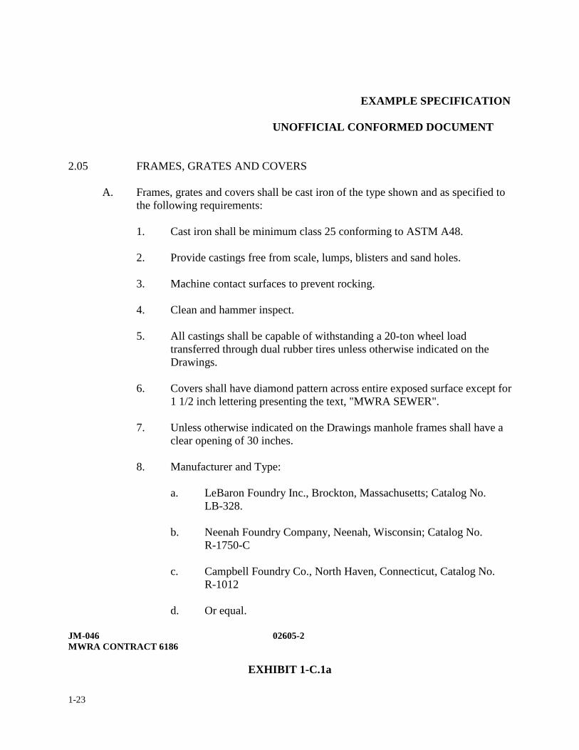
1-23
EXAMPLE SPECIFICATION
UNOFFICIAL CONFORMED DOCUMENT
2.05 FRAMES, GRATES AND COVERS
A. Frames, grates and covers shall be cast iron of the type shown and as specified to the following requirements:
1. Cast iron shall be minimum class 25 conforming to ASTM A48.
2. Provide castings free from scale, lumps, blisters and sand holes.
3. Machine contact surfaces to prevent rocking.
4. Clean and hammer inspect.
5. All castings shall be capable of withstanding a 20-ton wheel load
transferred through dual rubber tires unless otherwise indicated on the Drawings.
6. Covers shall have diamond pattern across entire exposed surface except for
1 1/2 inch lettering presenting the text, "MWRA SEWER".
7. Unless otherwise indicated on the Drawings manhole frames shall have a clear opening of 30 inches.
8. Manufacturer and Type:
a. LeBaron Foundry Inc., Brockton, Massachusetts; Catalog No. LB-328.
b. Neenah Foundry Company, Neenah, Wisconsin; Catalog No.
R-1750-C
c. Campbell Foundry Co., North Haven, Connecticut, Catalog No. R-1012
d. Or equal.
JM-046 02605-2 MWRA CONTRACT 6186
EXHIBIT 1-C.1a
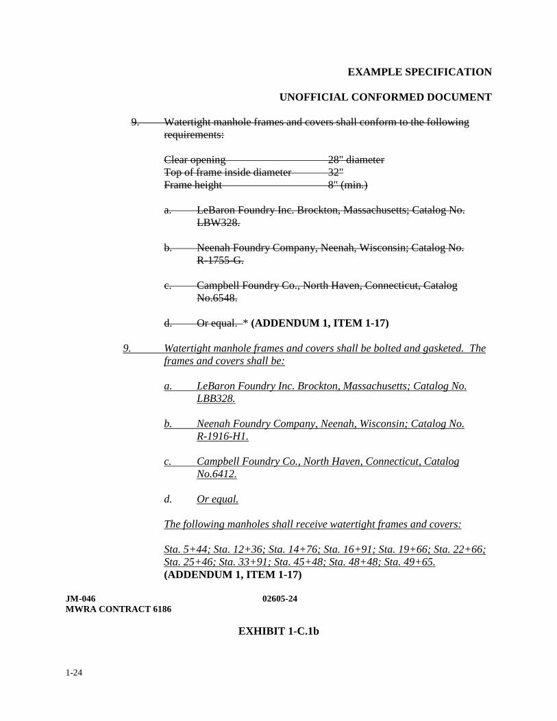
1-24
EXAMPLE SPECIFICATION
UNOFFICIAL CONFORMED DOCUMENT
9. Watertight manhole frames and covers shall conform to the following requirements:
Clear opening 28" diameter Top of frame inside diameter 32" Frame height 8" (min.)
a. LeBaron Foundry Inc. Brockton, Massachusetts; Catalog No. LBW328.
b. Neenah Foundry Company, Neenah, Wisconsin; Catalog No.
R-1755-G.
c. Campbell Foundry Co., North Haven, Connecticut, Catalog No.6548.
d. Or equal. * (ADDENDUM 1, ITEM 1-17)
9. Watertight manhole frames and covers shall be bolted and gasketed. The
frames and covers shall be:
a. LeBaron Foundry Inc. Brockton, Massachusetts; Catalog No. LBB328.
b. Neenah Foundry Company, Neenah, Wisconsin; Catalog No.
R-1916-H1.
c. Campbell Foundry Co., North Haven, Connecticut, Catalog No.6412.
d. Or equal. The following manholes shall receive watertight frames and covers: Sta. 5+44; Sta. 12+36; Sta. 14+76; Sta. 16+91; Sta. 19+66; Sta. 22+66; Sta. 25+46; Sta. 33+91; Sta. 45+48; Sta. 48+48; Sta. 49+65. (ADDENDUM 1, ITEM 1-17)
JM-046 02605-24 MWRA CONTRACT 6186
EXHIBIT 1-C.1b
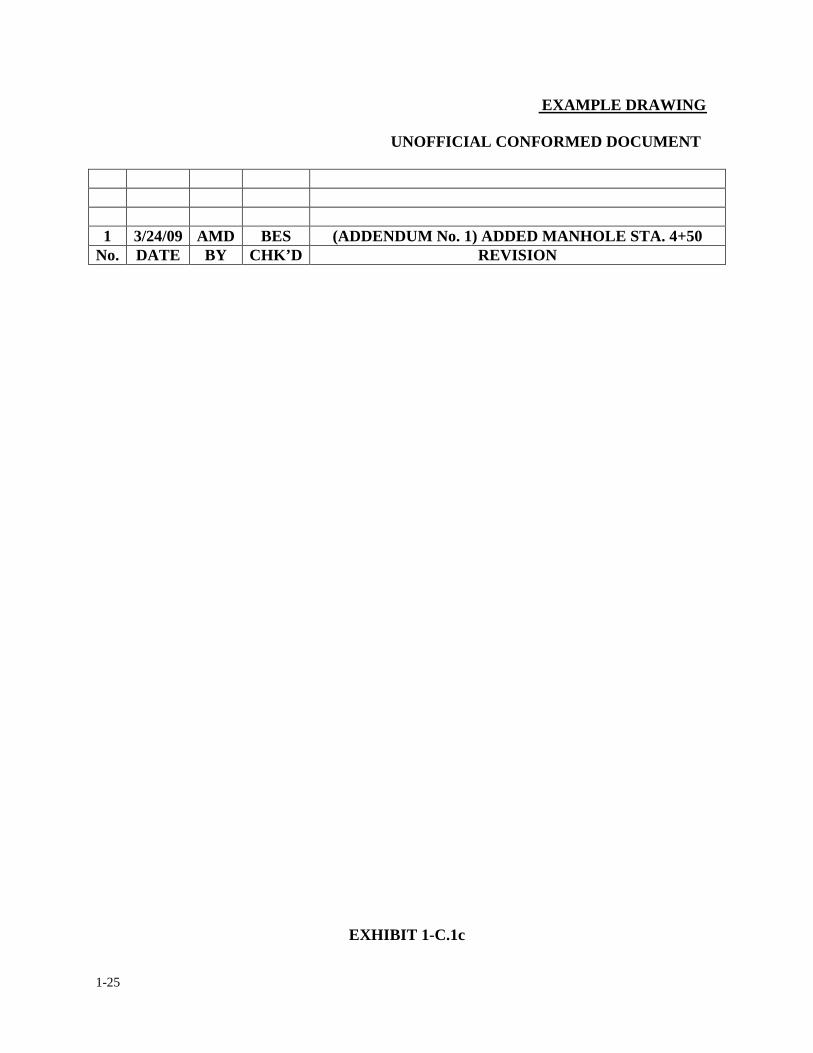
1-25
EXAMPLE DRAWING
UNOFFICIAL CONFORMED DOCUMENT
1 3/24/09 AMD BES (ADDENDUM No. 1) ADDED MANHOLE STA. 4+50
No. DATE BY CHK’D REVISION
EXHIBIT 1-C.1c
1-26
1. OVERVIEW & FIELD OFFICE ADMINISTRATION
1.6 DUTIES AND RESPONSIBILITIES
The resident engineer acts as the official representative between the Authority and the contractor
on a construction contract. The resident engineer is the person in charge of the daily routines of the
field staff on a project site. The resident engineer’s function is to oversee and document the overall
inspection of the construction project. The following is a general outline of the duties,
responsibilities and limitations of the resident engineer for an Authority construction project. It is
not meant to be all inclusive but to provide a guideline that resident engineers and field staff
assigned can use in carrying out their duties and responsibilities.
The field staff is reminded that the field office serves as an extension of the Home Office and
all Authority employment, equipment usage and conduct policies shall extend to the resident
engineer and his/her field staff.
The resident engineer is responsible for the inspection of all work on a construction project to
ensure its conformance with the requirements of the contract documents and standard engineering
practices. The resident engineer's objective is to administer the contract in a fair and equitable
manner and to provide documentation of all contractual work on a daily basis, accurately and
completely.
1-27
The resident engineer is responsible for the efficient function of the assigned field staff. All
construction projects require continuous attention and the immediate action by the resident
engineer and his staff. The field staff must be an organized team with the ability to bring each
project to a successful completion.
The resident engineer and field staff are official representatives of the Authority on the job site and
act under the supervision of the construction coordinator or his/her designee. If a field inspector
encounters a problem he/she can not solve, the problem should be directed to the resident engineer
or his/her designee. If the resident engineer can not solve the problem, it should be directed to the
construction coordinator or his/her designee. In emergencies, specific directions or orders may be
given directly to the resident engineer (or his field staff) by other authorized representatives of the
Director or Assistant Director of Construction.
The resident engineer should cooperate with the contractor in planning the course of work
operations. However, in no case shall he/she act or permit any of his/her field staff to act as a
surrogate of the contractor or to perform any duties which are the responsibility of the contractor.
His dealings with subcontractors will only be through or with the full knowledge of the prime
contractor's on-site representative. Also, his/her communications with outside local, state and
federal agencies shall be with the knowledge of the construction coordinator or his/her designee.
The resident engineer shall utilize and neatly maintain a filing system of records and
correspondence in an orderly fashion. The filing system shall reflect the filing system presented in
this manual. If a resident engineer has one of his/her field staff maintaining the job's filing system,
1-28
he/she shall periodically inspect the files for neatness and accuracy. All records and
correspondence for the project should be properly filed as soon as possible.
The resident engineer shall maintain daily field reports recording daily contractual work relating to
the project and other information such as: weather conditions start and end of each work day; list
of visitors to the job site; potential conflicts with the proposed work; and any change order work
performed. The type of daily report shall be similar to the one presented in this manual. Daily
reports shall be forwarded to the construction coordinator each day electronically. The resident
engineer shall print a copy and place it in the field report log book each day in accordance with the
instructions given herein. The resident engineer shall record his/her entries no later than noon of
the following day beginning on the first day he/she is assigned to the project. On small projects
that do not require a full time resident engineer or that do not require an MWRA field office, the
resident engineer shall complete a hand written daily report form similar to the one presented in
this manual and forward a copy to the construction coordinator by the end of the following work
day.
The resident engineer shall also maintain a quantity control ledger that will be used to substantiate
partial and/or final payment requests by the contractor. The type of ledger shall be similar to the
one offered in this manual. It should be neatly maintained and organized in the same fashion as the
examples shown in this manual. The entries in the ledger shall be updated on a daily basis, upon
completion of the work related to each pay item.
The resident engineer shall provide clear and precise instructions to staff prior to assignments to
ensure that staff is familiar with the work he/she is to perform and the type of documentation
1-29
needed. The resident engineer shall inform field staff of the proper working hours, vehicle use on
the project, safety issues, updates on current procedures, and check on staff daily to ensure that
they are performing their duties as required. The resident engineer shall assist with performance
appraisals of field staff.
In addition to the above duties, the resident engineer shall also be responsible for but not limited to
the following functions on a construction project all of which are described herein:
• Be completely familiar with contract plans and specifications.
• Maintain filing system in accordance with the RE Manual.
• Verify and enforce contractor compliance with contract documents inclusive of
specifications, Order of Conditions, State and Federal requirements etc.
• Submit updated weekly and monthly progress reports.
• Submit reporting forms as necessary or requested by the Construction Coordinator,
(reference RE Manual Appendix).
• Provide accurate information on contractor’s activities to the MWRA Home Office.
• Interface with local officials during construction.
• Schedule progress and special meetings and record minutes of meetings.
• Maintain a log with the status of all Change Orders as well as any pending claims.
• Maintain a Request for Information (RFI) Status Log.
• Maintain a Shop Drawing Submittal Log.
• Review certified payrolls for wage rate compliance.
• Review and validate contractor’s pay estimates. Perform and document calculations to
substantiate payment as necessary.

1-30
• Develop and distribute an emergency contact list for the project.
• Compile a monetary punch list for the project and monitor its completion.
• Perform DCAM evaluation at the completion of the project.
• Perform bidability and constructability reviews as requested.
1-31
1. OVERVIEW & FIELD OFFICE ADMINSTRATION
1.7 LIMITATIONS OF AUTHORITY
The resident engineer shall not authorize any deviations from the contract documents or approve
any substitute materials or equipment unless authorized by the construction coordinator and
approved by the design engineer of record.
The resident engineer shall not undertake any of the responsibilities of the contractor,
subcontractors or contractor's superintendent.
The resident engineer shall not supervise any work for the contractor or subcontractors.
The resident engineer shall not advise on or issue directions relative to any aspect of the means,
methods, techniques, sequences or procedures of the construction unless such is specifically called
for in the contract documents. The resident engineer shall not issue directions as to the contractor's
safety procedures, precautions or programs in connection with the contract work. The resident
engineer shall not participate in specialized field or laboratory tests or inspections conducted by
others except as specifically authorized by the construction coordinator or Director/Assistant
Director of Construction.
The authority and responsibilities given to the resident engineer will vary from project to project.
It will be the responsibility of the Director/Assistant Director of Construction through the
construction coordinator to define what the resident engineer's authority and responsibilities are
1-32
once the resident engineer is officially assigned to the project. However, the resident engineer
never has the authority to: (a) waive contract provisions, (b) make changes which are not within
the scope of the contract, (c) make design changes, unless authorized by the construction
coordinator and approved by the design engineer, (d) dictate or supervise the contractor's
operations, means or methods, (e) assume responsibility for contractor's job site safety, (f) stop the
work without the explicit approval of the construction coordinator.
This section is neither all inclusive nor limiting the resident engineer's role, but provides a
guideline for the resident engineers to understand and use in carrying out their duties and
responsibilities.
The Resident Engineer shall review specifications section 00700 Article 2 of the Contract
Documents to ensure that he/she does not exceed the limitations of the resident engineer’s
Authority in administrating the oversight of the construction contract.
1-33
1. OVERVIEW & FIELD OFFICE ADMINISTRATION
1.8 SAFETY EMERGENCY RESPONSE PROCEDURES
Safety is and must remain the first priority on any construction contract. No matter how many
times an organization prepares itself, or how effectively it trains its employees, accidents happen,
as they do in all industries. The construction industry is no exception. In fact, given enough time,
the chances are good that an accident or an incident involving an emergency will occur during your
assignment on a construction contract. Generally, as part of the contract documents, the contractor
is responsible for the security and safety on the job site. The contractor is required to employ a
person qualified in safety procedures to initiate, maintain and supervise all safety precautions,
methods and programs, and to ensure that the work is being performed in a safe environment. The
construction staff shall review and adhere to the written contract specific health and safety plan to
be implemented by the contractor. A copy of this plan shall be maintained at the construction field
office at all times and shall be updated by the contractor to include any substantive changes in the
work environment. The role of the resident engineer is to observe the safety measures
implemented by the contractor, and if at any time these safety measures appear unsafe or
inadequate, the resident engineer is to request that the Contractor’s Safety and Health Coordinator
re-visit the work area to increase and/or improve the level of safety. However, the resident
engineer is not required, nor has any obligation to enforce the contractor's safety measures. And,
the resident engineer shall in no way act as the contractor's surrogate Safety Officer. Should safety
problems or violations persist, the resident engineer shall inform the Director/Assistant Director of
Construction via the construction coordinator.
1-34
The resident engineer shall at all times ensure that his/her staff is following the procedures of the
Authority's Safety and Health Manual. The resident engineer shall maintain a copy of the
MWRA Safety and Health manual on site at all times to ensure that all staff is cognizant of MWRA
safety procedures. Habitual safety violations by the resident engineer and/or the field staff may
result in suspension or perhaps greater disciplinary actions. The Authority is committed to the
existence of an accident-free work place. For simplicity purposes, we will refer to accidents and
incidents as one in the same.
Basically, there are two types of incidents; an emergency situation and a non-emergency situation.
A non-emergency incident is handled at the job site level, with the proper notification to the
construction coordinator. An incident requiring emergency measures is also separated into two
classifications, (1) a local event and (2) a major event. A local event will primarily involve the
Construction Department level personnel. An event that appeared to be a local event could very
easily develop into a major event. Factors that determine a local event from a major event are
health and safety of the community or Authority personnel and/or equipment, and the involvement
of the media. In either case, the resident engineer must respond in a professional manner and
inform management of the incident as quickly as possible. The construction coordinator is the key
management official and the person the resident engineer should contact first followed by the
public affairs project administrator. In reporting the incident to the construction coordinator and
the public affairs administrator, the resident engineer should provide the following information:
1) A description of the incident.
2) The time and location of the incident.
3) The estimated degree or impact of the incident.
1-35
4) Information concerning what caused the incident.
5) Whom has been notified.
6) The location and phone number of where the resident engineer can be
contacted.
It is very important the resident engineer try not to hurry his/her message, and report only the facts
as he/she knows them. The resident engineer shall immediately try to personally contact the
construction coordinator by phone, email or both measures if necessary. If the resident engineer is
unable to contact the construction coordinator, he/she should leave a message if possible and
proceed to contact the next person on the following list until someone is personally reached.
* Assistant Director of Construction
* Director of Construction
* Chief Engineer
* Deputy COO
* Executive Director's Office
* Public Affairs
If you reach an answering machine, leave a brief message indicating that there is an emergency
situation; give the location of the emergency, and the name of the person you intend to contact
next. Note: leaving a message on an answering machine or forwarding an email does not relieve
the resident engineer of his/her obligation to personally contact a supervisor.
It is the duty of the resident engineer, once management has been informed of the incident, to
follow whatever instructions are given by management. In all likelihood, the Executive Office
1-36
shall take command of the emergency as soon as possible. Meanwhile, the resident engineer, until
such time as he/she is relieved, should follow the guidelines noted below:
• The resident engineer becomes the official "eyes" of the Authority. He/she shall observe
and monitor the events of the incident as they unfold.
• He/she shall offer whatever Authority's resources are available to help facilitate emergency
assistance (Fire, Police, Hospital, EMT etc.).
• The resident shall not relinquish his/her duties unless properly relieved (the resident
engineer should obtain the identification of the person(s) assuming command of the
incident).
• If the resident engineer is confronted with a major emergency and is approached by the
media without the benefit of management and/or Public Affairs, he/she shall respond
accordingly:
* Give your name and title of the project.
* Do not say "No Comment". Explain that you are not the spokesperson for
the Authority (Saying little is better than not saying anything). Make
known who the Authority’s spokesperson is. Decline from attempting to
predict future steps or course of actions.
* Do not give out individual names. You are not to release any records or
documents without being approved by the MWRA Law Division.
* Stay away from predicting the future.
* Do not say anything "off the record". If you don't want it used, then don't
say it.
1-37
* Speak clearly, use good posture, don't wear sunglasses and look directly at
the person speaking to you.
Remember, whatever you say or do may become part of a legal issue involving you and/or the
Authority.
In addition to the responsibilities noted above, the resident engineer shall prepare and file a report
as soon as possible, but no later than the first working day following the incident. In addition to the
resident engineer’s report, the contractor’s safety officer shall file an independent accident report.
The report shall be in the form of an Accident Report and should be detailed enough to give a clear
understanding as to what transpired. Instruction on how to prepare an accident report is covered in
Section 5.5 - Accident Report, of this manual. A sample report can be found in the same section.
Blank reports are included in the Appendix of this manual.
To aid in response to an emergency situation, the resident engineer shall compile a list of persons
who should be contacted in the event of an emergency. This listing should be made available prior
to commencement of construction or at the time of the pre-construction meeting. The primary
purpose of this listing is to inform the Police, Fire Departments and Municipal Officials in the
jurisdiction of which the construction work is to be performed, of the emergency response
telephone numbers of the Contractor's personnel and Authority key project personnel. As
personnel changes occur through the life of the project, the resident engineer shall update the
emergency response notice and distribute it accordingly. This listing is to be posted in a
conspicuous location in the job trailer. Exhibit 1-C.1a through 1-C.1c is an example of the type of
listing which the resident engineer should use as a guideline.
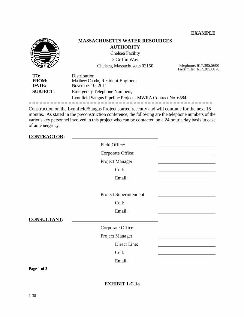
1-38
EXAMPLE MASSACHUSETTS WATER RESOURCES
AUTHORITY Chelsea Facility 2 Griffin Way
Chelsea, Massachusetts 02150 Telephone: 617.305.5600 Facsimile: 617.305.6070
TO: Distribution FROM: Matthew Cando, Resident Engineer DATE: November 10, 2011 SUBJECT: Emergency Telephone Numbers,
Lynnfield Saugus Pipeline Project - MWRA Contract No. 6584 = = = = = = = = = = = = = = = = = = = = = = = = = = = = = = = = = = = = = = = = = = = = = = = = = = = Construction on the Lynnfield/Saugus Project started recently and will continue for the next 18 months. As stated in the preconstruction conference, the following are the telephone numbers of the various key personnel involved in this project who can be contacted on a 24 hour a day basis in case of an emergency. CONTRACTOR:
Field Office:
Corporate Office:
Project Manager:
Cell:
Email:
Project Superintendent:
Cell:
Email:
CONSULTANT:
Corporate Office:
Project Manager:
Direct Line:
Cell:
Email:
Page 1 of 3
EXHIBIT 1-C.1a
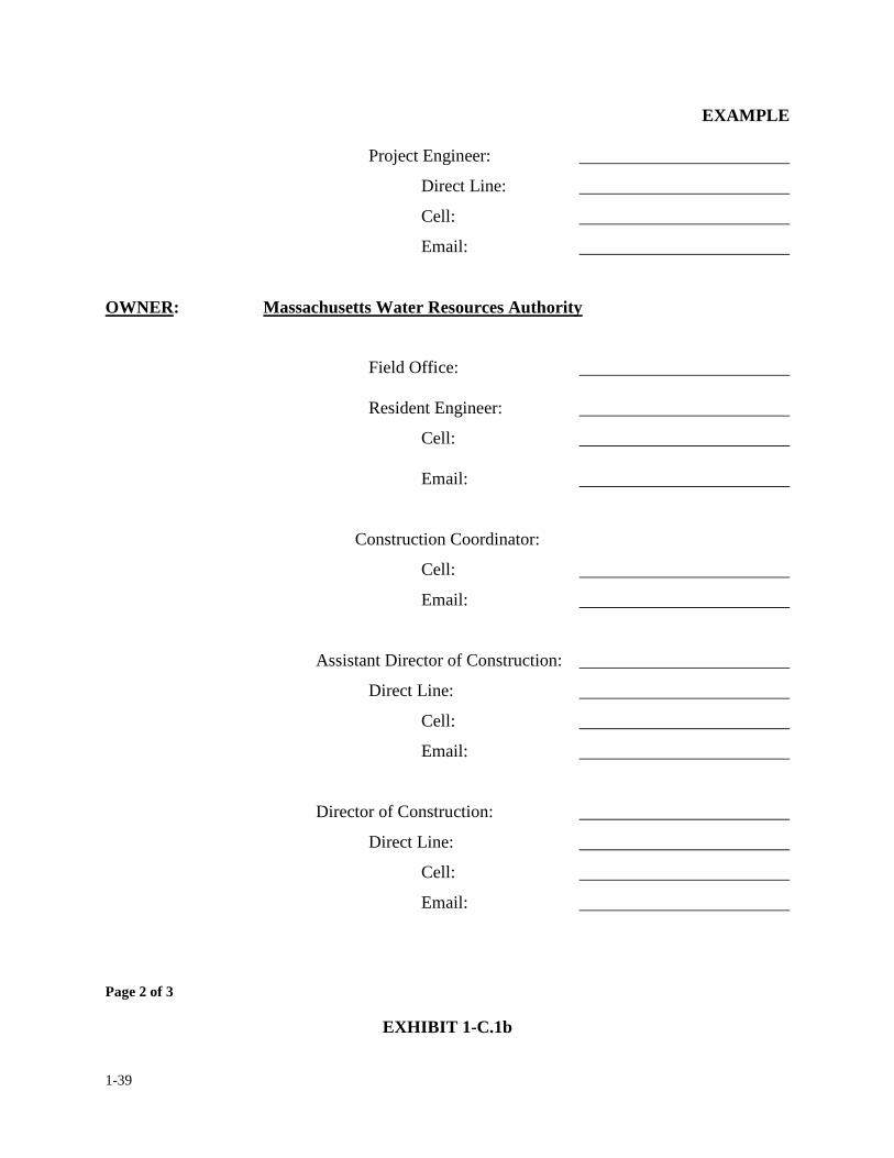
1-39
EXAMPLE
Project Engineer:
Direct Line:
Cell:
Email:
OWNER: Massachusetts Water Resources Authority
Field Office: Resident Engineer:
Cell:
Email:
Construction Coordinator:
Cell:
Email:
Assistant Director of Construction:
Direct Line:
Cell:
Email:
Director of Construction:
Direct Line:
Cell:
Email:
Page 2 of 3
EXHIBIT 1-C.1b
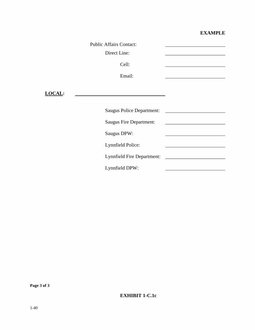
1-40
EXAMPLE Public Affairs Contact:
Direct Line:
Cell:
Email:
LOCAL:
Saugus Police Department:
Saugus Fire Department:
Saugus DPW:
Lynnfield Police:
Lynnfield Fire Department:
Lynnfield DPW:
Page 3 of 3
EXHIBIT 1-C.1c
1-41
1. OVERVIEW & FIELD OFFICE ADMINISTRATION
1.9 STANDARD FILE SYSTEM
One of the primary responsibilities of the resident engineer is to maintain at the job site a set of
orderly files which reflects the Standard File System offered in this Section. The Standard File
System is identical to the file system used at the Home Office and maintained by the construction
coordinator. There are three different variations of the file system. The resident engineer and
construction coordinator shall mutually agree on one of the three file systems depending on the
size and/or complexity of the construction project. The construction coordinator assigned to the
contract has the responsibility to ensure that the filing system selected is being properly utilized by
the resident engineer and his/her field staff.
The purpose of the Standard File System is to have the home office and the field office utilizing the
same filing system for storing important documents and correspondence on any given
construction project. If properly utilized, the Standard File System can be very helpful in the
tracking of contract documents or events which occur throughout the course of the construction.
Because of the variety of construction contracts not all contracts will require all of the file
categories offered by the Standard Filing System. On small or relatively simple construction
projects, either the Modified or Streamline version of the file system will be appropriate. However,
on most construction contracts the Standard File System will be most appropriate.
1-42
The Standard File System is made up of 33 pre-assigned file categories most common to
construction projects. Each file category has been numbered from 1 to 33. For example, File
category No. 1 is set up to store all documents relating to Contract issues, File No. 2 deals with all
correspondence for the project, File No. 4 will contain all executed copies and backup relating to
each change order processed, and File No. 11 includes all data relating to payments made to the
contractor. Neither the file numbers nor the file categories will vary from project to project or
contract to contract regardless of the size or type.
Within the file system, not all file categories are handled the same, some files are more active than
others. For example, the file set up for "Correspondence" will require a lot more filing activity
than the file set up for "Progress Schedules". On some construction contracts the amount of
correspondence could be so great that it will be necessary to divide the file into subcategories. (For
purposes of uniformity, all subcategories will be lettered, using the lower case, starting from a to
z). For example, The "CORRESPONDENCE" file may be broken-down into the following
subcategories:
2. CORRESPONDENCE:
a. Design (Consultant) Engineer
b. Home Office
c. Contractor
d. Request for Information (RFI's)
e. Resident Engineer
f. Federal Agencies
g. State Agencies
h. Other Agencies
i. Interoffice
1-43
In the above example, the correspondence file has been subdivided into nine subcategories. In
using the above format, all correspondence received from the Design (Consultant) Engineer shall
be filed under category "2a. Consultant Engineer", all correspondence received from the contractor
shall be filed under category; "2c. Contractor", and. all correspondence received from the
Massachusetts Department of Public Safety shall be filed under category: "2g. State Agencies".
Exhibit: 1-D.1 is the standard version of the Standard File System for field and home office use.
The standard version has 33 primary file categories. Each primary category has a subject assigned
to it which represents a particular job file. Additional items can be used at the discretion of the
resident engineer providing the subject is not already covered in the other categories, and they are
acceptable to the construction coordinator. Categories such as item #1, #2, #12 and #26 are
divided into subcategories. If the resident has a desire to divide other file categories into
subcategories such as items #4-Change Orders, #11-Periodic Pay Estimates, #19-Shop Drawing
Approvals or #32-Transfer of Titles he/she may do so providing the files are kept orderly and up to
date. The resident engineer may feel it necessary to divide a subcategory. In which case, the
sub-subcategory shall be numbered starting from #1. Before the resident engineer divides a
subcategory he/she shall discuss its merit with the construction coordinator.
Exhibit: 1-D.2 is the "Modified Version" of the standard file system. It has the same 33 file
categories as the standard version only it doesn't have any subcategories. This file system would
be used on less complicated construction contracts. Note that the numbering of the file categories
for the modified version is identical to the numbering for the-standard version, i.e.: the file
number for "Change Orders" for both the standard version and the modified version is #4, likewise
1-44
the file number for "Contract Close-Outs" for standard version and the modified version is file
#31.
The modified version of the standard file system is the type of file system used for less
complicated construction projects.
Exhibit 1-D.3, is the "Streamline Version" of the standard file system. The streamline version has
only 22 categories, however, the category numbers and titles that appear are identical to those
category numbers and titles for both the standard and the modified versions. The streamline
version is designed for the least complicated contracts.
The resident engineer must determine which of the three versions offered above better suit his/her
needs. Although the decision on which version of the file system to use is that of the resident
engineer, it should be discussed with the construction coordinator or the project manager assigned
for the purpose of project uniformity.
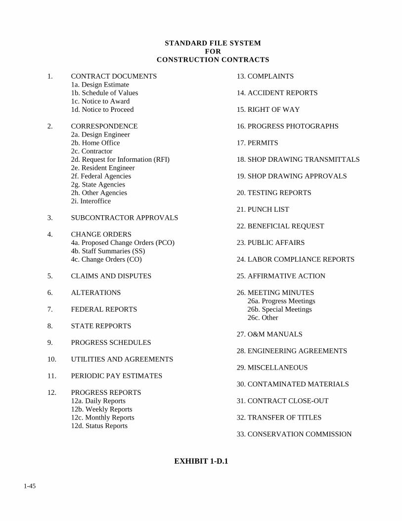
1-45
STANDARD FILE SYSTEM FOR
CONSTRUCTION CONTRACTS
1. CONTRACT DOCUMENTS 13. COMPLAINTS 1a. Design Estimate 1b. Schedule of Values 14. ACCIDENT REPORTS 1c. Notice to Award 1d. Notice to Proceed 15. RIGHT OF WAY 2. CORRESPONDENCE 16. PROGRESS PHOTOGRAPHS 2a. Design Engineer 2b. Home Office 17. PERMITS 2c. Contractor 2d. Request for Information (RFI) 18. SHOP DRAWING TRANSMITTALS 2e. Resident Engineer 2f. Federal Agencies 19. SHOP DRAWING APPROVALS 2g. State Agencies 2h. Other Agencies 20. TESTING REPORTS 2i. Interoffice 21. PUNCH LIST 3. SUBCONTRACTOR APPROVALS 22. BENEFICIAL REQUEST 4. CHANGE ORDERS 4a. Proposed Change Orders (PCO) 23. PUBLIC AFFAIRS 4b. Staff Summaries (SS) 4c. Change Orders (CO) 24. LABOR COMPLIANCE REPORTS 5. CLAIMS AND DISPUTES 25. AFFIRMATIVE ACTION 6. ALTERATIONS 26. MEETING MINUTES 26a. Progress Meetings 7. FEDERAL REPORTS 26b. Special Meetings 26c. Other 8. STATE REPPORTS 27. O&M MANUALS 9. PROGRESS SCHEDULES 28. ENGINEERING AGREEMENTS 10. UTILITIES AND AGREEMENTS 29. MISCELLANEOUS 11. PERIODIC PAY ESTIMATES 30. CONTAMINATED MATERIALS 12. PROGRESS REPORTS 12a. Daily Reports 31. CONTRACT CLOSE-OUT 12b. Weekly Reports 12c. Monthly Reports 32. TRANSFER OF TITLES 12d. Status Reports 33. CONSERVATION COMMISSION
EXHIBIT 1-D.1
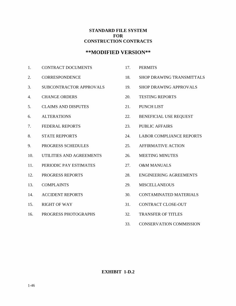
1-46
STANDARD FILE SYSTEM FOR
CONSTRUCTION CONTRACTS
**MODIFIED VERSION**
1. CONTRACT DOCUMENTS 17. PERMITS
2. CORRESPONDENCE 18. SHOP DRAWING TRANSMITTALS
3. SUBCONTRACTOR APPROVALS 19. SHOP DRAWING APPROVALS
4. CHANGE ORDERS 20. TESTING REPORTS
5. CLAIMS AND DISPUTES 21. PUNCH LIST
6. ALTERATIONS 22. BENEFICIAL USE REQUEST 7. FEDERAL REPORTS 23. PUBLIC AFFAIRS
8. STATE REPPORTS 24. LABOR COMPLIANCE REPORTS
9. PROGRESS SCHEDULES 25. AFFIRMATIVE ACTION
10. UTILITIES AND AGREEMENTS 26. MEETING MINUTES
11. PERIODIC PAY ESTIMATES 27. O&M MANUALS
12. PROGRESS REPORTS 28. ENGINEERING AGREEMENTS
13. COMPLAINTS 29. MISCELLANEOUS
14. ACCIDENT REPORTS 30. CONTAMINATED MATERIALS
15. RIGHT OF WAY 31. CONTRACT CLOSE-OUT
16. PROGRESS PHOTOGRAPHS 32. TRANSFER OF TITLES
33. CONSERVATION COMMISSION
EXHIBIT 1-D.2
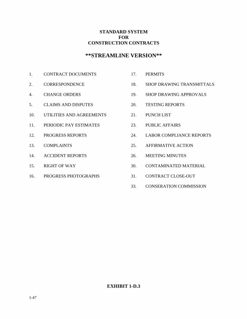
1-47
STANDARD SYSTEM FOR
CONSTRUCTION CONTRACTS
**STREAMLINE VERSION**
1. CONTRACT DOCUMENTS 17. PERMITS
2. CORRESPONDENCE 18. SHOP DRAWING TRANSMITTALS 4. CHANGE ORDERS 19. SHOP DRAWING APPROVALS
5. CLAIMS AND DISPUTES 20. TESTING REPORTS
10. UTILITIES AND AGREEMENTS 21. PUNCH LIST
11. PERIODIC PAY ESTIMATES 23. PUBLIC AFFAIRS
12. PROGRESS REPORTS 24. LABOR COMPLIANCE REPORTS
13. COMPLAINTS 25. AFFIRMATIVE ACTION
14. ACCIDENT REPORTS 26. MEETING MINUTES
15. RIGHT OF WAY 30. CONTAMINATED MATERIAL
16. PROGRESS PHOTOGRAPHS 31. CONTRACT CLOSE-OUT
33. CONSERATION COMMISSION
EXHIBIT 1-D.3
1-48
1. OVERVIEW & FIELD OFFICE ADMINSTRATION
1.10 GLOSSARY OF TERMS
The following is a listing of terms relative to the categories which make up the standard file system. The definitions given below reflect only the basic meaning of the words and how they apply to the filing systems used by the field office and home office and in no way should be considered official, technical, legal or contractual definitions. ACCIDENT REPORTS: Information regarding any and all accidents which have occurred on the project. AFFIRMATIVE ACTION: Information relating to Minority Business Enterprise (MBE), Women Business Enterprise (WBE) or Equal Employment Opportunity (EEO) matters. ALTERATIONS: Any change or substitution in the form of the work to be done within the original scope of the contract and does not affect the contract price or time. BENEFICIAL USE REQUEST: All information relating to the Authority's acceptance of any equipment, structures, or systems before the project is substantially complete. A separate file for each request is required. CHANGE ORDERS: Additional work which results in an adjustment in either the contract time or the contract price. A separate file for each change order is required, including staff summaries, if applicable, and all backup documentation to substantiate the change order. CLAIMS & DISPUTES: Conflicts or protests made by the contractor pertaining to the contract documents which are pending, or have not been resolved. COMPLAINTS: A formal expression of dissatisfaction pertaining to the contract. All complaints issued to the resident engineer shall be registered on the appropriate Authority forms. PERIODIC PAY ESTIMATE: Periodic payments to the contractor for work performed. A separate file for each payment processed, including all backup, breakdowns, or other required information is required. CONTRACT DOCUMENTS: Information relating to the executed contract between the Authority and the contractor; i.e., bonds, insurance requirements, notice to proceed/award and all addenda issued as part of the contract documents.
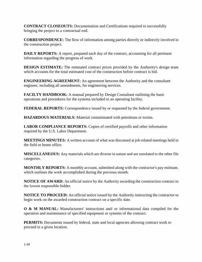
1-49
CONTRACT CLOSEOUTS: Documentation and Certifications required to successfully bringing the project to a contractual end. CORRESPONDENCE: The flow of information among parties directly or indirectly involved in the construction project. DAILY REPORTS: A report, prepared each day of the contract, accounting for all pertinent information regarding the progress of work. DESIGN ESTIMATE: The estimated contract prices provided by the Authority's design team which accounts for the total estimated cost of the construction before contract is bid. ENGINEERING AGREEMENT: An agreement between the Authority and the consultant engineer, including all amendments, for engineering services. FACILTY HANDBOOK: A manual prepared by Design Consultant outlining the basic operations and procedures for the systems included in an operating facility. FEDERAL REPORTS: Correspondence issued by or requested by the federal government. HAZARDOUS MATERIALS: Material contaminated with petroleum or toxins. LABOR COMPLIANCE REPORTS: Copies of certified payrolls and other information required by the U.S. Labor Department. MEETINGS MINUTES: A written account of what was discussed at job related meetings held in the field or home office. MISCELLANEOUS: Any materials which are diverse in nature and are unrelated to the other file categories. MONTHLY REPORTS: A monthly account, submitted along with the contractor's pay estimate, which outlines the work accomplished during the previous month. NOTICE OF AWARD: An official notice by the Authority awarding the construction contract to the lowest responsible bidder. NOTICE TO PROCEED: An official notice issued by the Authority instructing the contractor to begin work on the awarded construction contract on a specific date. O & M MANUAL: Manufacturers' instructions and/ or informational data compiled for the operation and maintenance of specified equipment or systems of the contract. PERMITS: Documents issued by federal, state and local agencies allowing contract work to proceed in a given location.
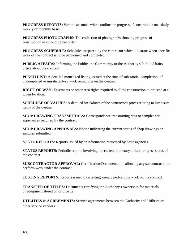
1-50
PROGRESS REPORTS: Written accounts which outline the progress of construction on a daily, weekly or monthly basis. PROGRESS PHOTOGRAPHS: The collection of photographs showing progress of construction in chronological order. PROGRESS SCHEDULE: Schedules prepared by the contractor which illustrate when specific work of the contract is to be performed and completed. PUBLIC AFFAIRS: Informing the Public, the Community or the Authority's Public Affairs office about the contract. PUNCH LIST: A detailed monetized listing, issued at the time of substantial completion, of uncompleted or unsatisfactory work remaining on the contract. RIGHT OF WAY: Easements or other area rights required to allow construction to proceed at a given location. SCHEDULE OF VALUES: A detailed breakdown of the contractor's prices relating to lump sum items of the contract. SHOP DRAWING TRANSMITTALS: Correspondence transmitting data or samples for approval as required by the contract. SHOP DRAWING APPROVALS: Notice indicating the current status of shop drawings or samples submitted. STATE REPORTS: Reports issued by or information requested by State agencies. STATUS REPORTS: Periodic reports involving the current monetary and/or progress status of the contract. SUBCONTRACTOR APPROVAL: Certification/Documentation allowing any subcontractor to perform work under the contract. TESTING REPORTS: Reports issued by a testing agency performing work on the contract. TRANSFER OF TITLES: Documents certifying the Authority's ownership for materials or equipment stored on or off-site. UTILITIES & AGREEMENTS: Service agreements between the Authority and Utilities or other service vendors.
1-51
1. OVERVIEW & FIELD OFFICE ADMINSTRATION
1.11 FILING CODE SYSTEM
In the previous Section, we developed a Standard File System. In this section we will learn how
important it is to maintain the file system in an orderly fashion. In dealing with any type of file
system, if the files are not maintained properly, it will be very difficult to track correspondence.
Often times it is the correspondence which is used as backup to substantiate, document or to justify
events which occurred during construction. A misplaced piece of correspondence or one that was
not filed correctly could lead to a lot of confusion and even prove costly to the Authority.
Therefore, it is very important that along with the standard file system, a set of procedures be
available for maintaining the file system. A construction project shall consist of two set of files,
one maintained by the resident engineer in the field and one maintained by the construction
coordinator at the Home Office.
At the completion of the contract, the resident engineer will be required to turn over a complete set
of field project files to the assigned construction coordinator. These files will be combined with the
project office file forming a complete, accurate and up-to-date project file for archiving.
The file code system is designed specifically for construction contracts because it corresponds to
the standard filing system presented in the previous section. The codes to be used identify both the
contract being worked on and the file category the correspondence or data pertains too. More than
one file code may be used, when desired, to improve retrievability or to associate certain
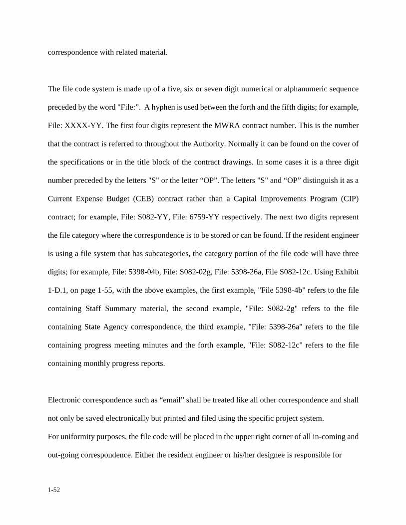
1-52
correspondence with related material.
The file code system is made up of a five, six or seven digit numerical or alphanumeric sequence
preceded by the word "File:”. A hyphen is used between the forth and the fifth digits; for example,
File: XXXX-YY. The first four digits represent the MWRA contract number. This is the number
that the contract is referred to throughout the Authority. Normally it can be found on the cover of
the specifications or in the title block of the contract drawings. In some cases it is a three digit
number preceded by the letters "S" or the letter “OP”. The letters "S" and “OP” distinguish it as a
Current Expense Budget (CEB) contract rather than a Capital Improvements Program (CIP)
contract; for example, File: S082-YY, File: 6759-YY respectively. The next two digits represent
the file category where the correspondence is to be stored or can be found. If the resident engineer
is using a file system that has subcategories, the category portion of the file code will have three
digits; for example, File: 5398-04b, File: S082-02g, File: 5398-26a, File S082-12c. Using Exhibit
1-D.1, on page 1-55, with the above examples, the first example, "File 5398-4b" refers to the file
containing Staff Summary material, the second example, "File: S082-2g" refers to the file
containing State Agency correspondence, the third example, "File: 5398-26a" refers to the file
containing progress meeting minutes and the forth example, "File: S082-12c" refers to the file
containing monthly progress reports.
Electronic correspondence such as “email” shall be treated like all other correspondence and shall
not only be saved electronically but printed and filed using the specific project system.
For uniformity purposes, the file code will be placed in the upper right corner of all in-coming and
out-going correspondence. Either the resident engineer or his/her designee is responsible for
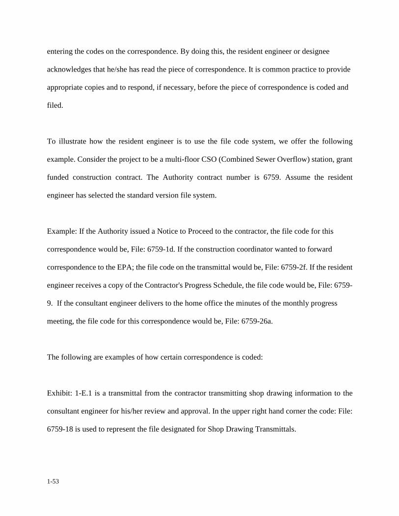
1-53
entering the codes on the correspondence. By doing this, the resident engineer or designee
acknowledges that he/she has read the piece of correspondence. It is common practice to provide
appropriate copies and to respond, if necessary, before the piece of correspondence is coded and
filed.
To illustrate how the resident engineer is to use the file code system, we offer the following
example. Consider the project to be a multi-floor CSO (Combined Sewer Overflow) station, grant
funded construction contract. The Authority contract number is 6759. Assume the resident
engineer has selected the standard version file system.
Example: If the Authority issued a Notice to Proceed to the contractor, the file code for this
correspondence would be, File: 6759-1d. If the construction coordinator wanted to forward
correspondence to the EPA; the file code on the transmittal would be, File: 6759-2f. If the resident
engineer receives a copy of the Contractor's Progress Schedule, the file code would be, File: 6759-
9. If the consultant engineer delivers to the home office the minutes of the monthly progress
meeting, the file code for this correspondence would be, File: 6759-26a.
The following are examples of how certain correspondence is coded:
Exhibit: 1-E.1 is a transmittal from the contractor transmitting shop drawing information to the
consultant engineer for his/her review and approval. In the upper right hand corner the code: File:
6759-18 is used to represent the file designated for Shop Drawing Transmittals.
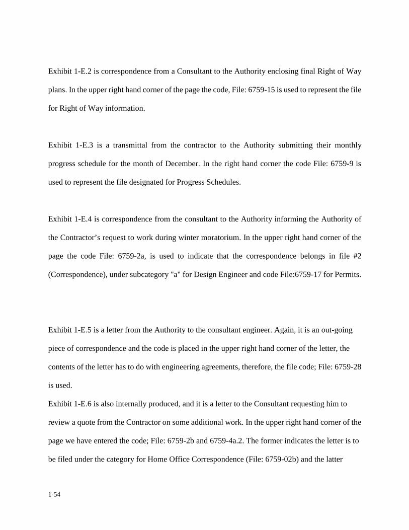
1-54
Exhibit 1-E.2 is correspondence from a Consultant to the Authority enclosing final Right of Way
plans. In the upper right hand corner of the page the code, File: 6759-15 is used to represent the file
for Right of Way information.
Exhibit 1-E.3 is a transmittal from the contractor to the Authority submitting their monthly
progress schedule for the month of December. In the right hand corner the code File: 6759-9 is
used to represent the file designated for Progress Schedules.
Exhibit 1-E.4 is correspondence from the consultant to the Authority informing the Authority of
the Contractor’s request to work during winter moratorium. In the upper right hand corner of the
page the code File: 6759-2a, is used to indicate that the correspondence belongs in file #2
(Correspondence), under subcategory "a" for Design Engineer and code File:6759-17 for Permits.
Exhibit 1-E.5 is a letter from the Authority to the consultant engineer. Again, it is an out-going
piece of correspondence and the code is placed in the upper right hand corner of the letter, the
contents of the letter has to do with engineering agreements, therefore, the file code; File: 6759-28
is used.
Exhibit 1-E.6 is also internally produced, and it is a letter to the Consultant requesting him to
review a quote from the Contractor on some additional work. In the upper right hand corner of the
page we have entered the code; File: 6759-2b and 6759-4a.2. The former indicates the letter is to
be filed under the category for Home Office Correspondence (File: 6759-02b) and the latter

1-55
indicates the letter should be filed under Change Order file (File: 6759-4a.2). Note: With this letter
we copied two people plus two files, so now we know at least five copies of the letter exist. One
copy (the Original) to the Consultant, one copy each to Contractor and Construction Coordinator
and two
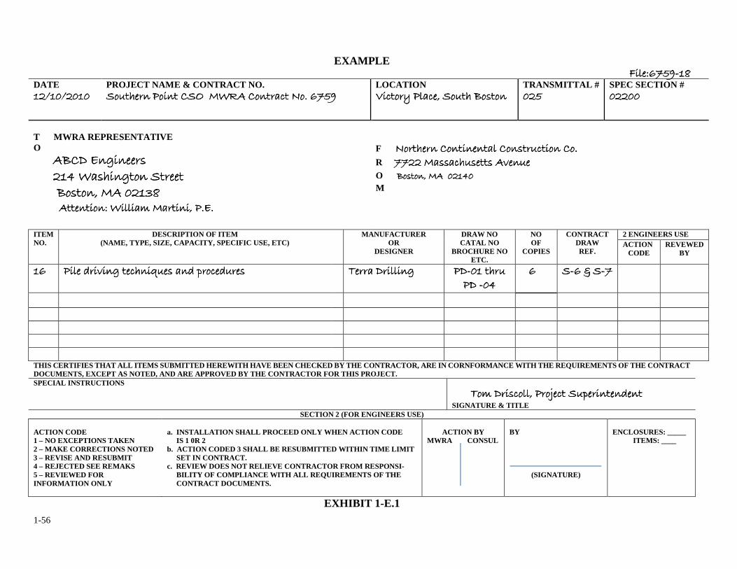
1-56
EXAMPLE ����������������������������������������
DATE ����������������������������������������
PROJECT NAME & CONTRACT NO. �������� ����� ��� ���� ������ � !�" ����������� ����� ��� ���� ������ � !�" ����������� ����� ��� ���� ������ � !�" ����������� ����� ��� ���� ������ � !�" ���
LOCATION #� ���$ ��� �% ����� &�'���#� ���$ ��� �% ����� &�'���#� ���$ ��� �% ����� &�'���#� ���$ ��� �% ����� &�'���
TRANSMITTAL # ������������
SPEC SECTION # ��������������������
T MWRA REPRESENTATIVE O �&�( )�*�����'�&�( )�*�����'�&�( )�*�����'�&�( )�*�����' ��+ ��'���*��� ��������+ ��'���*��� ��������+ ��'���*��� ��������+ ��'���*��� ������ &�'���% �� ���,�&�'���% �� ���,�&�'���% �� ���,�&�'���% �� ���,�
F !������� ����������� ���'��� ���� ��"!������� ����������� ���'��� ���� ��"!������� ����������� ���'��� ���� ��"!������� ����������� ���'��� ���� ��" R ���� ��''� ��'���' �-�������� ��''� ��'���' �-�������� ��''� ��'���' �-�������� ��''� ��'���' �-���� O &�'���% �� ���+�&�'���% �� ���+�&�'���% �� ���+�&�'���% �� ���+� M
���������� ������. �������% �")"���������� ������. �������% �")"���������� ������. �������% �")"���������� ������. �������% �")"
ITEM NO.
DESCRIPTION OF ITEM (NAME, TYPE, SIZE, CAPACITY, SPECIFIC USE, ETC) MANUFACTURER
OR DESIGNER
DRAW NO CATAL NO
BROCHURE NO ETC.
NO OF
COPIES CONTRACT
DRAW REF.
2 ENGINEERS USE ACTION
CODE REVEWED
BY
�������� ���� /��-��* �� ���0��' ��/ 1�� �/���'���� /��-��* �� ���0��' ��/ 1�� �/���'���� /��-��* �� ���0��' ��/ 1�� �/���'���� /��-��* �� ���0��' ��/ 1�� �/���' 2���� (������*2���� (������*2���� (������*2���� (������* �(�(�(�(�� ���� �� ���� �� ���� �� ���� �( �( �( �( �+�+�+�+
���� �������� 3 �3 �3 �3 �����
THIS CERTIFIES THAT ALL ITEMS SUBMITTED HEREWITH HAVE BEEN CHECKED BY THE CONTRACTOR, ARE IN CORNFORMANCE WITH THE REQUIREMENTS OF THE CONTRACT DOCUMENTS, EXCEPT AS NOTED, AND ARE APPROVED BY THE CONTRACTOR FOR THIS PROJECT. SPECIAL INSTRUCTIONS
2�. (�2�. (�2�. (�2�. (��' ���% ���4� � ��1�������/����' ���% ���4� � ��1�������/����' ���% ���4� � ��1�������/����' ���% ���4� � ��1�������/��� SIGNATURE & TITLE
SECTION 2 (FOR ENGINEERS USE) ACTION CODE 1 – NO EXCEPTIONS TAKEN 2 – MAKE CORRECTIONS NOTED 3 – REVISE AND RESUBMIT 4 – REJECTED SEE REMAKS 5 – REVIEWED FOR INFORMATION ONLY
a. INSTALLATION SHALL PROCEED ONLY WHEN ACTION CODE IS 1 0R 2 b. ACTION CODED 3 SHALL BE RESUBMITTED WITHIN TIME LIMIT SET IN CONTRACT. c. REVIEW DOES NOT RELIEVE CONTRACTOR FROM RESPONSI- BILITY OF COMPLIANCE WITH ALL REQUIREMENTS OF THE CONTRACT DOCUMENTS.
ACTION BY
MWRA CONSUL
BY
(SIGNATURE)
ENCLOSURES: _____ ITEMS: ____
EXHIBIT 1-E.1
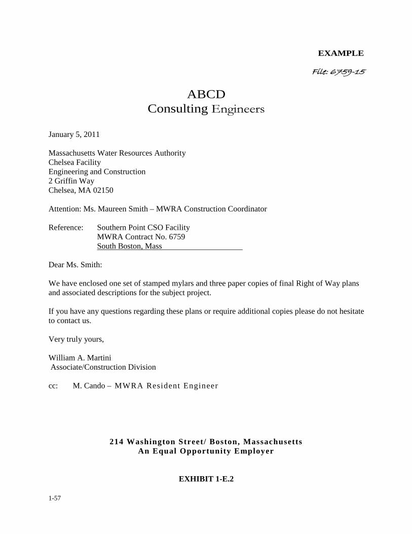
1-57
EXAMPLE
�������������������� ��������������������
ABCD Consulting�����������
January 5, 2011 Massachusetts Water Resources Authority Chelsea Facility Engineering and Construction 2 Griffin Way Chelsea, MA 02150 Attention: Ms. Maureen Smith – MWRA Construction Coordinator Reference: Southern Point CSO Facility MWRA Contract No. 6759
South Boston, Mass Dear Ms. Smith: We have enclosed one set of stamped mylars and three paper copies of final Right of Way plans and associated descriptions for the subject project. If you have any questions regarding these plans or require additional copies please do not hesitate to contact us. Very truly yours, William A. Martini Associate/Construction Division
cc: M. Cando – MWRA Resident Engineer
214 Washington Street/ Boston, Massachusetts An Equal Opportunity Employer
EXHIBIT 1-E.2
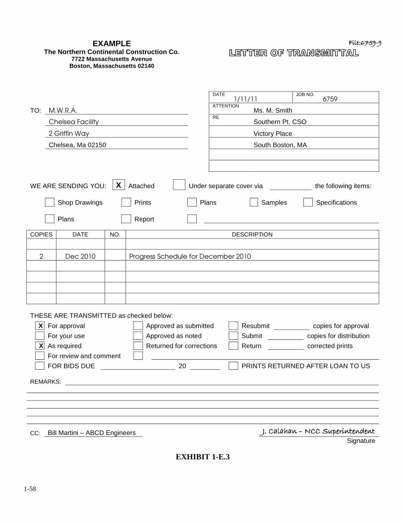
1-58
EXAMPLE The Northern Continental Construction Co.
7722 Massachusetts Avenue Boston, Massachusetts 02140
��������������������������������
��������������������������������������������������������������������������������
DATE
1/11/11 JOB NO.
6759
TO: M.W.R.A. ATTENTION
Ms. M. Smith
Chelsea Facility RE
Southern Pt. CSO
2 Griffin Way Victory Place
Chelsea, Ma 02150 South Boston, MA
WE ARE SENDING YOU: X Attached Under separate cover via the following items: Shop Drawings Prints Plans Samples Specifications Plans Report
COPIES DATE NO. DESCRIPTION
2 Dec 2010 Progress Schedule for December 2010
THESE ARE TRANSMITTED as checked below:
X For approval Approved as submitted Resubmit copies for approval For your use Approved as noted Submit copies for distribution X As required Returned for corrections Return corrected prints For review and comment FOR BIDS DUE 20 PRINTS RETURNED AFTER LOAN TO US REMARKS:
CC: Bill Martini – ABCD Engineers 5" ������� 5" ������� 5" ������� 5" ������� 6666 !�� ��1�������/���!�� ��1�������/���!�� ��1�������/���!�� ��1�������/��� Signature
EXHIBIT 1-E.3
1-59
EXAMPLE �������������������� �������������������� ��������������������
ABCD Consulting�����������
January 12, 2011 Massachusetts Water Resources Authority Chelsea Facility Engineering and Construction 2 Griffin Way Chelsea, MA 02150 Attention: Ms. Maureen Smith – MWRA Construction Coordinator Reference: Southern Point CSO Facility MWRA Contract No. 6759
South Boston, MA 02127 Dear Ms. Smith: The contractor has requested that due to the mild winter they would like to mobilize to the jacking pit at Sta. 29+40 just
past the intersection of Spring Street and East Broadway on Thursday 1/18/11. ABCD has advised the contractor that
work cannot proceed at this location without approval of the Department of Conservation and Recreation (DCR). As
you are aware work within the Parkway is subject to DCR permit which includes a winter moratorium, no work from
November 15 to April 15. It is our understanding that the Massachusetts Water Resources Authority (MWRA) is in
discussion with DCR to issue a waiver on the winter moratorium at this location so that work for the excavation and
support of the receiving pit may proceed. Until such a waiver is issued by the DCR the Contractor has been advised
that no work may proceed in this location.
Should you have any questions concerning this issue please do not hesitate to call me at 781-221-1111.
Very truly yours, William A. Martini Associate/Construction Division
cc: M. Cando – MWRA Res ident Eng ineer
214 Washington Street / Boston, Massachusetts An Equal Opportunity Employer
EXHIBIT 1-E.4
1-60
EXAMPLE ����� �������� �������� �������� �����������
MASSACHUSETTS WATER RESOURCES AUTHORITY
CHELSEA FACILITY 2 GRIFFIN WAY
CHELSEA, MA 02150 Telephone:
(617)305-5600 August 29, 2010 ABCD Consulting Engineers 214 Washington Street Boston, Massachusetts, 02134 Attention: Mr. William Martini Reference: Southern Point CSO Facility MWRA Contract 6759 Dorchester, MA 02121 Dear Mr. Martini, By this letter you are hereby authorized to proceed with the engineering services for the construction phase on the above referenced project. This action is being taken in anticipation of having executed engineering agreement between your firm and the MWRA in the very near future. If you have any questions regarding this matter, please do not hesitate to contact us. Very truly yours, Margery Smith MWRA Design Project Manager
EXHIBIT 1-E.5
1-61
EXAMPLE ����� ����� ����� ����� �������������"7�"7�"7�"7
������������+�"�+�"�+�"�+�"�
MASSACHUSETTS WATER RESOURCES AUTHORITY CHELSEA FACILITY
2 GRIFFIN WAY CHELSEA, MA 02150
Telephone: (617)305-5600 December 22, 2010 ABCD Consulting Engineers 214 Washington Street Boston, Massachusetts, 02134 Attention: Mr. William Martini Reference: Southern Point CSO Facility MWRA Contract 6759 Dorchester, MA 02121 Dear Mr. Martini, We are enclosing for your review and recommendation a cost breakdown from Northern Continental Construction Co. regarding the additional reinforcing steel for the outlet channel on the above referenced contract. Included in your findings should be a detailed description of the above mentioned change and reasons for it. If you have any questions regarding this matter, please do not hesitate to contact us. Very truly yours, Maureen Smith Construction Coordinator Cc: J. Calahann – NCC Project Manager Assistant Director of Construction
EXHIBIT 1-E.6
1-62
1. OVERVIEW & FIELD OFFICE ADMINISTRATION
1.12 PROJECT LOG BOOK
All MWRA Construction projects shall maintain a project “Log Book” which is to be set up and
maintained by the resident engineer with the assistance of the construction coordinator. The
purpose of the project log book is to summarize the daily administration at the field office for
future reference by personnel not directly related to a project. The log book shall contain copies of
the various project logs that are described in detail under their respective section of this manual.
The following is a sample of some of the logs that are recommended to be maintained in the project
log book:
1. Table of Contents of Standard File System.
2. Site Visitor Sign-In Sheet.
3. Incoming and Outgoing Correspondence Logs.
4. Contractor Payment Summary.
5. Quality Control Ledger.
6. Request for Information (RFI) Log.
7. Listing of PCO/CO/Claims.
1-63
1. OVERVIEW & FIELD OFFICE ADMINISTRATION
1.13 INCOMING & OUTGOING CORRESPONDENCE LOG
In most cases the volume of correspondence is proportional to the size and/or the complexity of the
construction contract. The smaller the contract the less flow of correspondence, while the more
complex and more technical the contract is, the larger the flow of correspondence. A project to be
constructed under Chapter 149 is likely to have more correspondence than a Chapter 30 project. A
sign of an efficiently run contract is when all correspondence relating to the job is readily
available.
As we have stated previously, it is very important to properly file the correspondence being
generated and/or received on the contract. The resident engineer has been provided guidelines
which will allow him/her to initiate a standard "filing system" and "file code system". In order to
complete the cycle of administering the daily flow of correspondence, the resident engineer is
required to, depending on the size and complexity of the project, maintain an incoming and
outgoing correspondence log book.
Generally, during Chapter 149 construction contracts, the largest volume of correspondence
occurs at the beginning of the job, it then tends to taper off until the project nears completion, and
then it seems to increase once again. Often times this increase is attributed to issues that are
outstanding and need to be resolved before the contract is closed out. In order to resolve an
outstanding issue, it is helpful to understand the complete history of the issue and have all
1-64
previous references regarding the issue in hand. One of the more efficient ways of gathering this
information is for the resident engineer to maintain an up to date correspondence log. If
maintained correctly, the resident engineer is able to track an issue either by its subject, dates or
by the person to whom the issue was addressed too. The resident engineer is also able to
determine where the correspondence relating to the issue is stored and in what file or files it can be
found.
The log book will be used to record all correspondence relating to the contract and will be
maintained by the resident engineer or his/her designee. The log will be kept current, complete
and accurate at all times. All correspondence shall be logged-in on the same day it is received or
sent. Each correspondence logged-in, on either the incoming or outgoing forms shall be uniquely
numbered. The resident engineer or his/her designee will assign the numbers, in a sequential
manner to each piece of correspondence. It is suggested the numbering system will start at 001.
The numbers assigned in the log shall appear on the first page of the correspondence. Each log
sheet will be numbered sequentially beginning with page 1. Note: There have been construction
contracts where a separate incoming and outgoing correspondence log was maintained for both
the consultant engineer and the contractor. The resident engineer, with the aid of the construction
coordinator, shall determine if a single log or separate set of incoming and outgoing logs will
better serve the correspondence flow on his/her project.
Incoming and outgoing electronic correspondence with the exception of email shall be included in
these logs. The construction staff is reminded that all emails must be electronically filed and kept
and that all information and messages that are created, sent, received, accessed or stored on the
1-65
field office system or Authority system constitute Authority records. The construction staff is
reminded that any communication that they create, send, receive, or store on Authority systems
may be read or heard by someone other than the intended recipient. Accordingly, resident engineer
and field staff should not send information not intended to be viewed. Resident engineer and field
staff are advised that there is no presumption of privacy on such correspondence.
All email correspondence shall have the specific MWRA Contract number and title in the subject
line with short description of what the email message is in reference too. The construction staff is
reminded that all electronic correspondence shall adhere to MWRA information Technology User
Responsibilities, Policy #ADM.30 dated July 21, 2000. The construction staff shall use separate
emails for separate items of discussion, he/she shall not “piggyback” different subject matters
within one email.
Exhibit 1-F.1 is the form which the resident engineer shall utilize to record all "Incoming"
correspondence on the project. The form is made up of seven columns. Each column is to be filled
out when making an entry. The first column, going from left to right is where the document
number is to be entered. As previously mentioned this number is unique to the piece of
correspondence and is assigned sequentially by the resident engineer or his/her designee. Note:
once a number has been assigned and entered in the log, that same number shall be recorded in the
upper left hand corner of the document. The second column is where the date is entered. This date
is the date the piece of correspondence is received and "Date-Stamped" at the field office, and not
the date that appears on the correspondence (document). The third column is for the person to
whom the correspondence is addressed. If the correspondence addresses a title, such as:
1-66
construction coordinator, project manager, resident engineer etc., the person's name shall be
entered in its place. If the correspondence is not addressed to anyone in particular, the acronym;
M.W.R.A. is entered in its place. The fourth column is the column where the date that appears on
the document is entered, and not the date that the field office receives the document. The fifth
column is the name of the originator (person who sent the document) and the sixth column requires
a brief description of the subject matter. The description should be brief but concise. Generally one
line is adequate for a description; however, if more space is needed, the resident engineer is
instructed to go on to the next line.
Whenever possible, the specification number relating to the subject matter should appear in the
description. Also, if the document being entered refers to another document, that document
should be referenced, example; See ABC's letter-1/12/89, Ref. NCC-1/12/89, See
MWRA-1/12/89 etc. The last column on the right is the column where the document can be
found. The entry shall refer to the number of the file category where the document is filed. If the
document is filed in more than one place, each file category is to be entered in the log. Note: If a
document is received by the field, and it appears the home office was not copied, it is the
responsibility of the field staff to forward a copy to the home office immediately.
Exhibit 1-F.2 is the form which the resident engineer shall utilize to record all "Outgoing
Correspondence" on the project. The form is basically the same form as the "Incoming
Correspondence" form and it is to be utilized in the same fashion as mentioned above.
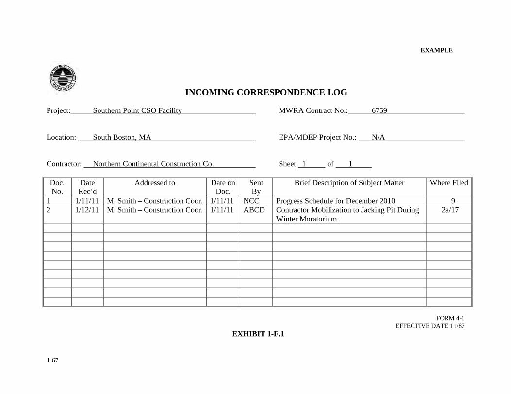
1-67
EXAMPLE
INCOMING CORRESPONDENCE LOG Project: Southern Point CSO Facility MWRA Contract No.: 6759 Location: South Boston, MA EPA/MDEP Project No.: N/A Contractor: Northern Continental Construction Co. Sheet 1 of 1 Doc. No.
Date Rec’d
Addressed to Date on Doc.
Sent By
Brief Description of Subject Matter Where Filed
1 1/11/11 M. Smith – Construction Coor. 1/11/11 NCC Progress Schedule for December 2010 9 2 1/12/11 M. Smith – Construction Coor. 1/11/11 ABCD Contractor Mobilization to Jacking Pit During
Winter Moratorium. 2a/17
FORM 4-1
EFFECTIVE DATE 11/87 EXHIBIT 1-F.1
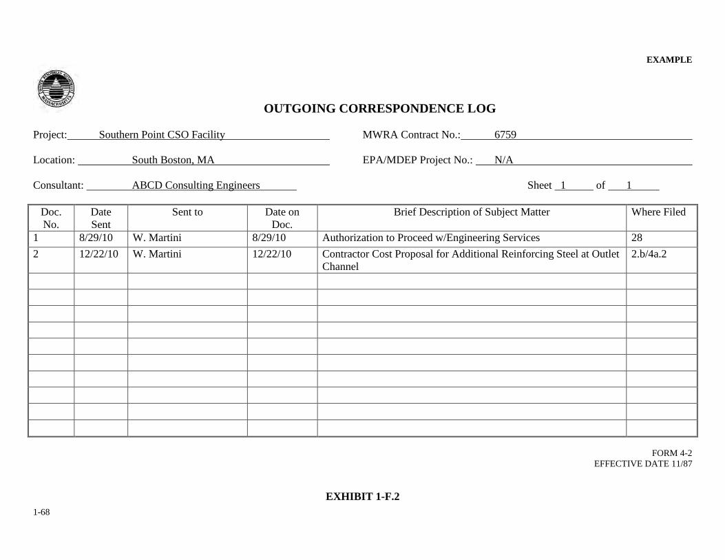
1-68
EXAMPLE
OUTGOING CORRESPONDENCE LOG Project: Southern Point CSO Facility MWRA Contract No.: 6759 Location: South Boston, MA EPA/MDEP Project No.: N/A Consultant: ABCD Consulting Engineers Sheet 1 of 1
Doc. No.
Date Sent
Sent to
Date on Doc.
Brief Description of Subject Matter Where Filed
1 8/29/10 W. Martini 8/29/10 Authorization to Proceed w/Engineering Services 28 2 12/22/10 W. Martini 12/22/10 Contractor Cost Proposal for Additional Reinforcing Steel at Outlet
Channel 2.b/4a.2
FORM 4-2
EFFECTIVE DATE 11/87
EXHIBIT 1-F.2
2-1
SECTION 2
DAILY REPORTS
PAGE
2.1 RESIDENT ENGINEER'S CONTRACT DAILY REPORTS 2-2
2.2 DAILY WORK FORCE ACCOUNT 2-11
2.3 FIELD INSPECTOR'S DAILY REPORT 2-20
2.4 FIELD INSPECTOR'S PAY SLIPS 2-28
2.5 QUANTITY CONTROL LEDGER 2-32
2-2
2. DAILY REPORTS
2.1 RESIDENT ENGINEER'S CONTRACT DAILY REPORTS (DAILY LOG)
The resident engineer shall make a thorough study of the project in order to become familiar with
each construction detail. The resident engineer is responsible for ensuring that the construction
staff has copies of pertinent submittals prior to inspection of the work. If any major discrepancies
are discovered, the resident engineer is to relay his/her findings to the construction coordinator.
The resident engineer shall conduct a minimum of two daily on-site construction reviews of the
work in progress, or as otherwise necessary to determine to the best of his/her knowledge how the
work is proceeding and that the work completed is in conformance with the contract documents.
Recording the progress on a construction site is one of the most important responsibilities of a
resident engineer. The resident engineer assigned to a construction contract shall complete daily
reports of the actions taking place on the job site. These reports shall be all inclusive and shall
represent a contract diary to record the events and progress of construction. The daily reports shall
be filed electronically with the construction coordinator on a daily basis. These reports shall be
complete, accurate and up to date at all times. A separate daily report log book shall be maintained
on site. The resident engineer shall begin maintaining daily reports on the day he/she has been
assigned to a project even if the contractor is not working on site. The resident engineer will
continue to maintain these reports until he/she has been reassigned. If the resident engineer is away
from the project for any length of time, he/she shall designate someone from the field staff to
maintain the reports in his/her absence. At the end of this section is a sample outline of a typical
daily report to be completed each day and filed by the resident engineer. This outline may be
2-3
modified by the resident engineer after conferring with the construction coordinator and a list of
items has been developed to be addressed on a daily basis.
The overall objective is to utilize these contract daily reports as the primary record source of the
daily events of the project. On contracts where the resident engineer is assigned field staff
personnel, the field staff will observe the contractor's daily progress and submit a daily report to
the resident engineer at the end of each day. The resident engineer will in turn incorporate the
information from the field inspector’s daily report into one encompassing daily project report. If
the resident engineer has several field inspectors working on the project, the resident engineer will
be responsible for collecting daily reports from each field inspector and consolidating the
information into the contract daily report no later than noon time of the following day. If the
resident engineer is the sole person on the contract, he/she is responsible for entering the
contractor's progress at the end of each work day.
The purpose of the contract daily reports is to have an accurate account, on a daily basis, of the
events which occur throughout the life of the construction contract. It is the responsibility of the
resident engineer to maintain these reports and to ensure that they reflect the contractor's daily
progress and the events of the day.
The resident engineer should attempt to document information as soon as it is known. The resident
engineer should contact the construction coordinator if he/she has any questions or requires
information unavailable to the field staff. The resident engineer shall consider that each report
refers to a specific date of the contract. Each report shall be dated and numbered consecutively.
2-4
The information entered into the daily reports must be concise and as detailed as possible. The
resident engineer is urged to use as many pages as required to avoid the possibility of not including
vital information relating to a particular day's progress or to the overall construction of the project.
The following is an outline on how to fill out a daily report for a construction contract. Each day
the resident engineer shall record the date, the hours the contractor worked on the job site and the
weather conditions during the day. The resident engineer must enter the actual hours worked by
the contractor, not the hours worked by resident engineering staff or the consultant's field staff. If
the contractor only worked a half a day, it should be noted along with a reason for it (i.e.,
Contractor stopped work at noontime due to heavy rains). If the contractor was rained-out although
his management staff worked in the field office the entire day, the hours worked by the contractor
would be none. It is the hours worked relative to the physical progress of the work that shall be
recorded. The resident engineer will then proceed to enter the following contract information, as a
minimum.
Item Entry / Subject 1. Personnel(MWRA) on job 2. Survey Parties 3. GC's Labor & Equip. Force
3a. Subcontractors Forces 4. General Contractors Progress 4a. Subcontractors Progress 5. Contact w/MWRA Officials
5a. Contact w/Consultants 5b. Contact w/Government Officials 6. Contact w/General Contractor 7. Contact w/Utility & Public Officials 8. Contact w/General Public 9. Materials Testing 10. Change Orders 11. Claims and Disputes
2-5
12. Right of Way Matters 13. Accidents/Complaints/Safety Matters 14. Job Photographs 15. Traffic Maintenance 16. Miscellaneous
The items listed above reflect the information of the contract which the resident engineer is
required to report on a dally basis. The resident engineer will end his/her entries to the daily report
with a signature, title and date. Daily reports filed electronically shall contain a form of the
resident engineer’s signature electronically.
To avoid redundancy, the resident engineer will need only to update an entry/subject when it
changes. With each subsequent day of that week, the resident engineer will compare the entries of
the previous day with those of the present day, and record only the changes that appear. For
instance, if the contractor's equipment and labor force has not changed from Monday to Tuesday,
then Tuesday's entry would include a "No Change” comment. However, if there were a change in
the contractor's equipment and labor force, then the resident engineer is expected to make the
appropriate entries in his/her daily report. Exhibits 2-A.1 through Exhibit 2-A.3 are examples of
the resident engineer’s daily report.
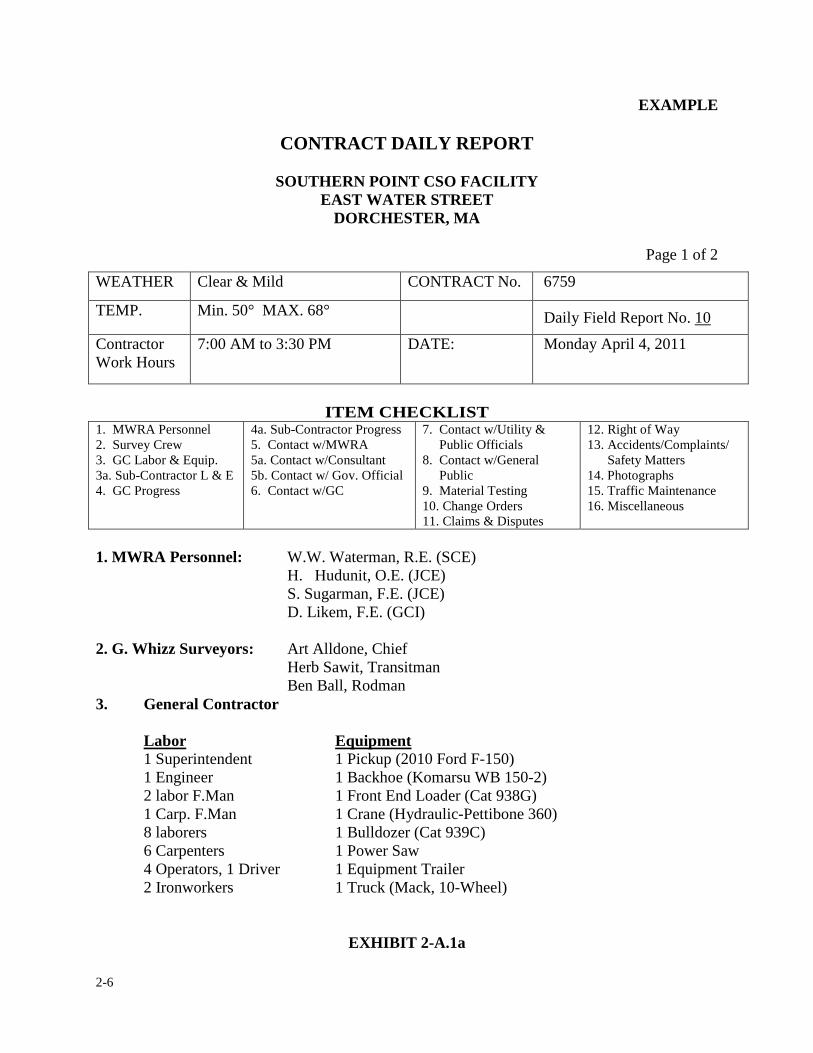
2-6
EXAMPLE
CONTRACT DAILY REPORT
SOUTHERN POINT CSO FACILITY EAST WATER STREET
DORCHESTER, MA
Page 1 of 2
WEATHER Clear & Mild CONTRACT No. 6759
TEMP. Min. 50° MAX. 68° Daily Field Report No. 10
Contractor Work Hours
7:00 AM to 3:30 PM DATE: Monday April 4, 2011
ITEM CHECKLIST
1. MWRA Personnel 2. Survey Crew 3. GC Labor & Equip. 3a. Sub-Contractor L & E 4. GC Progress
4a. Sub-Contractor Progress 5. Contact w/MWRA 5a. Contact w/Consultant 5b. Contact w/ Gov. Official 6. Contact w/GC
7. Contact w/Utility & Public Officials 8. Contact w/General Public 9. Material Testing 10. Change Orders 11. Claims & Disputes
12. Right of Way 13. Accidents/Complaints/ Safety Matters 14. Photographs 15. Traffic Maintenance 16. Miscellaneous
1. MWRA Personnel: W.W. Waterman, R.E. (SCE)
H. Hudunit, O.E. (JCE) S. Sugarman, F.E. (JCE)
D. Likem, F.E. (GCI) 2. G. Whizz Surveyors: Art Alldone, Chief Herb Sawit, Transitman Ben Ball, Rodman 3. General Contractor
Labor Equipment 1 Superintendent 1 Pickup (2010 Ford F-150) 1 Engineer 1 Backhoe (Komarsu WB 150-2) 2 labor F.Man 1 Front End Loader (Cat 938G) 1 Carp. F.Man 1 Crane (Hydraulic-Pettibone 360) 8 laborers 1 Bulldozer (Cat 939C) 6 Carpenters 1 Power Saw 4 Operators, 1 Driver 1 Equipment Trailer 2 Ironworkers 1 Truck (Mack, 10-Wheel)
EXHIBIT 2-A.1a
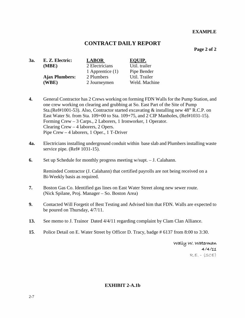
2-7
EXAMPLE
CONTRACT DAILY REPORT Page 2 of 2
3a. E. Z. Electric: LABOR EQUIP. (MBE) 2 Electricians Util. trailer 1 Apprentice (1) Pipe Bender Ajax Plumbers: 2 Plumbers Util. Trailer (WBE) 2 Journeymen Weld. Machine
4. General Contractor has 2 Crews working on forming FDN Walls for the Pump Station, and one crew working on clearing and grubbing at So. East Part of the Site of Pump Sta.(Ref#1001-53). Also, Contractor started excavating & installing new 48” R.C.P. on East Water St. from Sta. 109+00 to Sta. 109+75, and 2 CIP Manholes, (Ref#1031-15). Forming Crew – 3 Carps., 2 Laborers, 1 Ironworker, 1 Operator.
Clearing Crew – 4 laborers, 2 Opers. Pipe Crew – 4 laborers, 1 Oper., 1 T-Driver 4a. Electricians installing underground conduit within base slab and Plumbers installing waste
service pipe. (Ref# 1031-15). 6. Set up Schedule for monthly progress meeting w/supt. – J. Calahann. Reminded Contractor (J. Calahann) that certified payrolls are not being received on a
Bi-Weekly basis as required. 7. Boston Gas Co. Identified gas lines on East Water Street along new sewer route. (Nick Spilane, Proj. Manager – So. Boston Area) 9. Contacted Will Forgetit of Best Testing and Advised him that FDN. Walls are expected to
be poured on Thursday, 4/7/11. 13. See memo to J. Trainor Dated 4/4/11 regarding complaint by Clam Clan Alliance. 15. Police Detail on E. Water Street by Officer D. Tracy, badge # 6137 from 8:00 to 3:30.
����������������������������������������������������������������� � ��� � ��� � ��� � ������
�����������������
EXHIBIT 2-A.1b
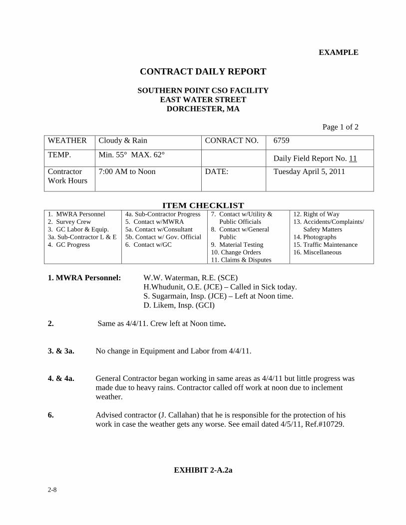
2-8
EXAMPLE
CONTRACT DAILY REPORT
SOUTHERN POINT CSO FACILITY EAST WATER STREET
DORCHESTER, MA
Page 1 of 2
WEATHER Cloudy & Rain CONRACT NO. 6759
TEMP. Min. 55° MAX. 62° Daily Field Report No. 11
Contractor Work Hours
7:00 AM to Noon DATE: Tuesday April 5, 2011
ITEM CHECKLIST
1. MWRA Personnel 2. Survey Crew 3. GC Labor & Equip. 3a. Sub-Contractor L & E 4. GC Progress
4a. Sub-Contractor Progress 5. Contact w/MWRA 5a. Contact w/Consultant 5b. Contact w/ Gov. Official 6. Contact w/GC
7. Contact w/Utility & Public Officials 8. Contact w/General Public 9. Material Testing 10. Change Orders 11. Claims & Disputes
12. Right of Way 13. Accidents/Complaints/ Safety Matters 14. Photographs 15. Traffic Maintenance 16. Miscellaneous
1. MWRA Personnel: W.W. Waterman, R.E. (SCE)
H.Whudunit, O.E. (JCE) – Called in Sick today. S. Sugarmain, Insp. (JCE) – Left at Noon time.
D. Likem, Insp. (GCI) 2. Same as 4/4/11. Crew left at Noon time.
3. & 3a. No change in Equipment and Labor from 4/4/11.
4. & 4a. General Contractor began working in same areas as 4/4/11 but little progress was
made due to heavy rains. Contractor called off work at noon due to inclement weather.
6. Advised contractor (J. Callahan) that he is responsible for the protection of his
work in case the weather gets any worse. See email dated 4/5/11, Ref.#10729.
EXHIBIT 2-A.2a
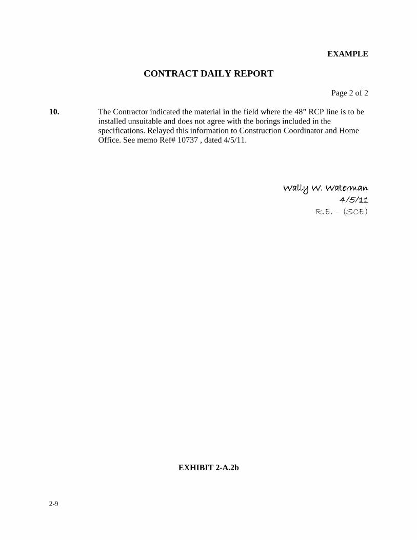
2-9
EXAMPLE
CONTRACT DAILY REPORT
Page 2 of 2 10. The Contractor indicated the material in the field where the 48” RCP line is to be
installed unsuitable and does not agree with the borings included in the specifications. Relayed this information to Construction Coordinator and Home Office. See memo Ref# 10737 , dated 4/5/11.
����������������������������������������������������������������� � ��� � ��� � ��� � ������
�������������
EXHIBIT 2-A.2b
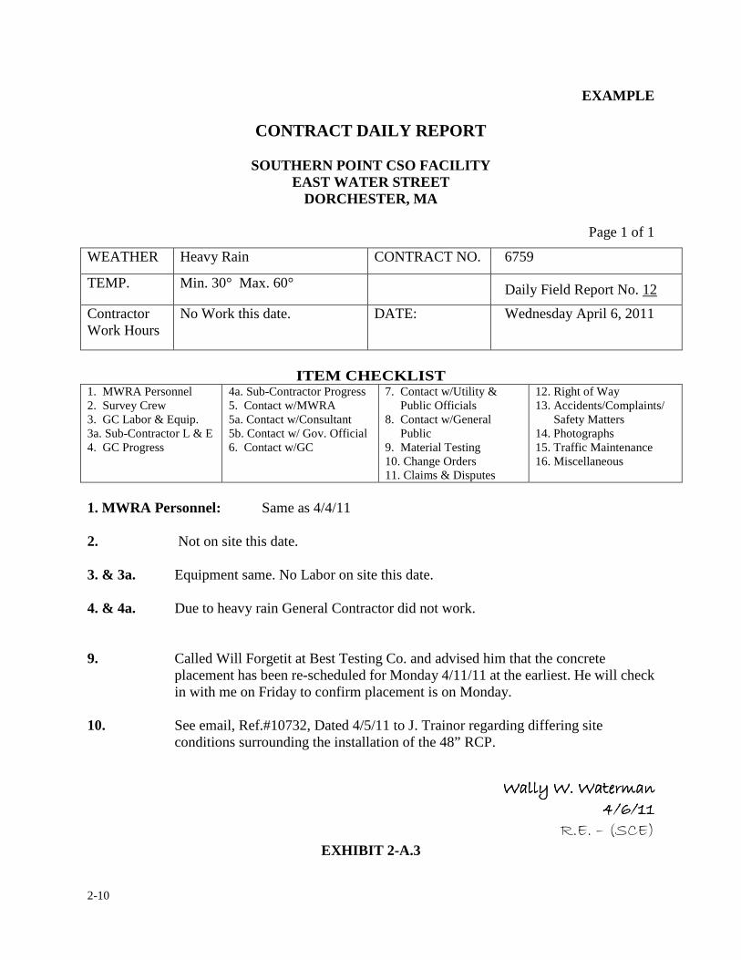
2-10
EXAMPLE
CONTRACT DAILY REPORT
SOUTHERN POINT CSO FACILITY EAST WATER STREET
DORCHESTER, MA
Page 1 of 1
WEATHER Heavy Rain CONTRACT NO. 6759
TEMP. Min. 30° Max. 60° Daily Field Report No. 12
Contractor Work Hours
No Work this date. DATE: Wednesday April 6, 2011
ITEM CHECKLIST
1. MWRA Personnel 2. Survey Crew 3. GC Labor & Equip. 3a. Sub-Contractor L & E 4. GC Progress
4a. Sub-Contractor Progress 5. Contact w/MWRA 5a. Contact w/Consultant 5b. Contact w/ Gov. Official 6. Contact w/GC
7. Contact w/Utility & Public Officials 8. Contact w/General Public 9. Material Testing 10. Change Orders 11. Claims & Disputes
12. Right of Way 13. Accidents/Complaints/ Safety Matters 14. Photographs 15. Traffic Maintenance 16. Miscellaneous
1. MWRA Personnel: Same as 4/4/11 2. Not on site this date. 3. & 3a. Equipment same. No Labor on site this date.
4. & 4a. Due to heavy rain General Contractor did not work.
9. Called Will Forgetit at Best Testing Co. and advised him that the concrete
placement has been re-scheduled for Monday 4/11/11 at the earliest. He will check in with me on Friday to confirm placement is on Monday.
10. See email, Ref.#10732, Dated 4/5/11 to J. Trainor regarding differing site
conditions surrounding the installation of the 48” RCP.
����������������������������������������������������������������� � ��� � ��� � ��� � ������
�������������EXHIBIT 2-A.3
2-11
2. DAILY REPORTS
2.2 DAILY WORK FORCE ACCOUNT
The "Contractor's Daily Workforce Account" is a special form offered as a time saving feature for
recording the contractor's labor and equipment on site, on a daily basis. This feature is optional to
the resident engineer. If the resident engineer chooses to use the form, it must be filled out on a
daily basis, for each day of the contract. The completed forms must be stored in a separate folder,
note book or three-ring binder for easy access.
The form itself is a double sided form and is included in the Appendix of this manual. The front
side outlines labor and equipment most commonly found on a construction site. The back side of
the form provides ample room for the resident engineer to record any comments regarding labor
and equipment on the job site. The Work Force (WF #) assigned to the form shall correspond to the
contract number and daily report number.
Exhibit 2-B.1 is an example of how this form is used to record the daily labor and equipment. First,
the date is entered at the top of the form. Next, the contractor’s names are placed at the top, vertical
area. This area is reserved for the contractor(s) who is on site and performing work. The actual
quantity, for either labor or equipment, is entered in its respective column and line. If there is a
particular labor description or piece of equipment which is not listed on the form, it should be
added in the area designated. The resident engineer is to identify each piece of equipment as
detailed as possible (i.e. name, model, year). At the bottom of the page the resident engineer is to
enter the daily report number, which the above work force pertains to, and signs and dates the
2-12
form. Backup information should be recorded on the backside of the form.
In Exhibit 2-B.1, the date shown is April 4, 2011. There are three contractors on site (Northern
Continental, E. Z. Electric and Ajax Plumbing). The work force for Northern Continental was; one
superintendent and engineer, 2 labor foreman, 8 laborers, 1 carpenter foreman, 6 carpenters, 4
operators, 1 truck driver and 2 ironworkers. The workforce for E. Z. Electric was; two electricians
and one apprentice (1st year). The workforce for Ajax Plumbing was; two plumbers and two
journeymen. The equipment for Northern Continental included a 2011 pickup truck, a power saw,
a 580E backhoe, a 5 cubic yd. front end loader, a Mack 10 wheel truck and a 40 foot storage trailer.
E.Z. Electric also had a storage trailer and a mechanical pipe bender. Ajax also had a utility trailer
and welding machine. The above workforce is referenced to daily report number 10. The resident
engineer, Wally Waterman signed the form on April 5, 2011. Note: Idle equipment is not listed in
this section but in the comment section of the back page. The equipment which appears on the
workforce account form should only be the equipment utilized on site and not equipment such as
small tools.
Exhibit 2-B.2 Indicates there were four comments made by the resident engineer. Comment 1
indicates that there was a labor compliance spot check made by Sally Sugarman and no
discrepancies were discovered. Comment 2 notes that the 580 backhoe broke down once again.
Comment 3 notes a laborer went home sick at approximately 10:30 AM. Comment 4 lists any idle
equipment on the job site.
On the backside of the form the resident engineer is encouraged to make whatever comments
2-13
he/she wants regarding the equipment and/or labor matters. For instance, the resident engineer
may want to enter the names of persons belonging to a particular work crew or a piece of
equipment which is not operational or perhaps he may want to note a delivery of materials and the
labor and equipment involved in the delivery, etc.
An example of how this WF Account form is used by the Resident Engineer on the Daily Report is
indicated in Exhibit 2-B.3a and 2-B3b. Note the example used is a record of the daily activities by
the resident engineer for April 4, 2011. Notice it is very similar to the entries shown in Exhibit
2-B.1 with the exception of Item's 3 and 3a. In this example the labor and equipment forces are
recorded using the "Contractor's Daily Workforce Account" form. The comment "See WF #
6759-10" refers to the form number as shown in Exhibit 2-B.3a. This type of a comment found in
the resident engineer’s daily report indicates the field staff is utilizing the Contractor's Daily
Workforce Account forms in lieu of entering the job's labor and equipment on a daily or weekly
basis.
Exhibit 2-B.4 shows another example in which Contractor's Daily Workforce Account form can be
illustrated. In this example the resident engineer shows neither the Contractor or subcontractors
came to work due to rain (Even though there was no work on this day, the resident engineer is still
required to submit and record a daily report).
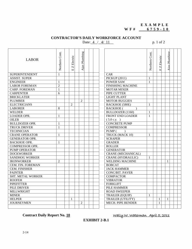
2-14
E X A M P L E W F # 6 7 5 9 - 1 0
CONTRACTOR’S DAILY WORKFORCE ACCOUNT
Date: 4 / 4/ 11 p. 1 of 2
LABOR N
orth
ern
Con
t.
E Z
Ele
ctri
c
Aja
x Pl
umbi
ng
Nor
ther
n C
ont.
E Z
Ele
ctri
c A
jax
Plum
bing
SUPERINTENDENT 1 CAR ASSIST. SUPER PICKUP (2011) 1 ENGINEER 1 POWER SAW 1 LABOR FOREMAN 2 FINISHING MACHINE CARP. FOREMAN 1 MOTAR MIXER CARPENTER 6 PIPE CUTTER BRICKLATER LIGHT PLANT PLUMBER 2 MOTOR BUGGIES ELECTRICIANS 2 BACKHOE (580E) 1 LABORER 8 BACKHOE ( ) WELDER BULLDOZER (1160) 1 LOADER OPR. 1 FRONT END LOADER
( 5.0 c.y. ) 1
OILER BULLDOZER OPR. 1 CONCRETE PUMP TRUCK DRIVER 1 COMPRESSOR TECHNICIAN PUMP ( ) CRANE OPERATOR 1 TRUCK (MACK 10) 1 GENERATOR OPR. SCRAPER BACKHOE OPR. 1 GRADER COMPRESSOR OPR. ROLLER PUMP OPERATOR GENERATOR DOCKWORKER CRANE (MECHANICAL) SANDHOG WORKER CRANE (HYDRAULIC) 1 IRONWORKER 2 WELDING MACHINE 1 CEM. FIN. FOREMAN BOBCAT CEM. FINISHER JACK HAMMER PAINTER CONC/BIT. PAVER SHT. METAL WORKER COMPACTOR ROOFER VIBRATOR PIPEFITTER FORKLIFT PILE DRIVER PILE HAMMER MILLWRIGHT ROAD SWEEPER MINER TRAILER (EQUIP) 1 HELPER 1 TRAILER (UTILITY) 1 1 JOURNEYMEN 2 MECH. PIPE BENDER 1
Contract Daily Report No. 10 ����������������������������������������������������������������������������������������������������������������������������
EXHIBIT 2-B.1
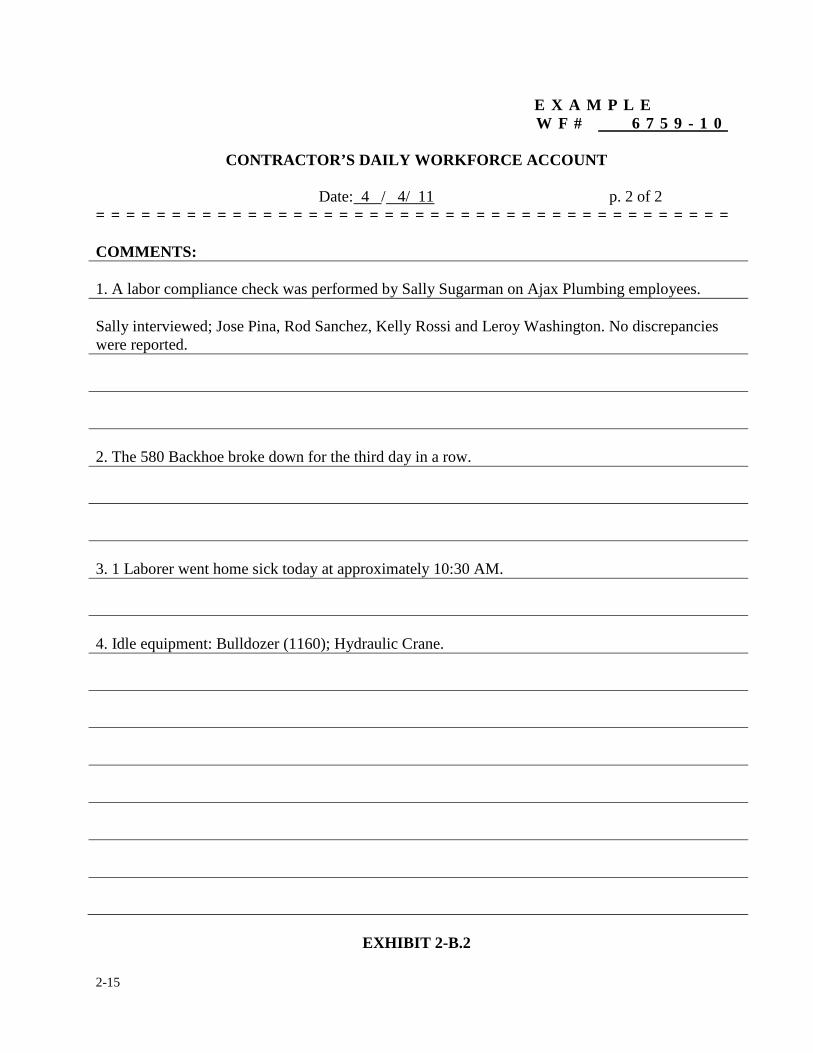
2-15
��� ����������������������������������������������������E X A M P L E W F # 6 7 5 9 - 1 0
CONTRACTOR’S DAILY WORKFORCE ACCOUNT�
Date: 4 / 4/ 11 p. 2 of 2 = = = = = = = = = = = = = = = = = = = = = = = = = = = = = = = = = = = = = = = = = =
COMMENTS:
1. A labor compliance check was performed by Sally Sugarman on Ajax Plumbing employees. Sally interviewed; Jose Pina, Rod Sanchez, Kelly Rossi and Leroy Washington. No discrepancies were reported. 2. The 580 Backhoe broke down for the third day in a row. 3. 1 Laborer went home sick today at approximately 10:30 AM. 4. Idle equipment: Bulldozer (1160); Hydraulic Crane.
EXHIBIT 2-B.2
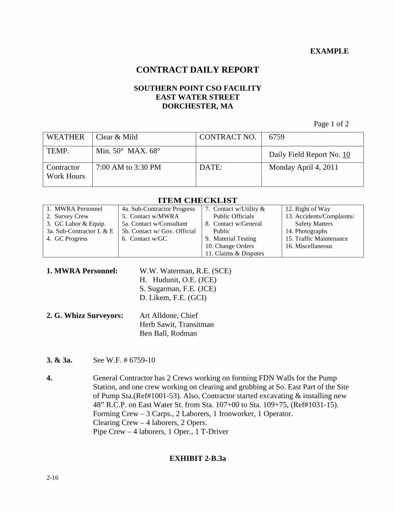
2-16
EXAMPLE
CONTRACT DAILY REPORT
SOUTHERN POINT CSO FACILITY EAST WATER STREET
DORCHESTER, MA
Page 1 of 2
WEATHER Clear & Mild CONTRACT NO. 6759
TEMP. Min. 50° MAX. 68° Daily Field Report No. 10
Contractor Work Hours
7:00 AM to 3:30 PM DATE: Monday April 4, 2011
ITEM CHECKLIST
1. MWRA Personnel 2. Survey Crew 3. GC Labor & Equip. 3a. Sub-Contractor L & E 4. GC Progress
4a. Sub-Contractor Progress 5. Contact w/MWRA 5a. Contact w/Consultant 5b. Contact w/ Gov. Official 6. Contact w/GC
7. Contact w/Utility & Public Officials 8. Contact w/General Public 9. Material Testing 10. Change Orders 11. Claims & Disputes
12. Right of Way 13. Accidents/Complaints/ Safety Matters 14. Photographs 15. Traffic Maintenance 16. Miscellaneous
1. MWRA Personnel: W.W. Waterman, R.E. (SCE)
H. Hudunit, O.E. (JCE) S. Sugarman, F.E. (JCE)
D. Likem, F.E. (GCI) 2. G. Whizz Surveyors: Art Alldone, Chief Herb Sawit, Transitman Ben Ball, Rodman
3. & 3a. See W.F. # 6759-10
4. General Contractor has 2 Crews working on forming FDN Walls for the Pump Station, and one crew working on clearing and grubbing at So. East Part of the Site of Pump Sta.(Ref#1001-53). Also, Contractor started excavating & installing new 48” R.C.P. on East Water St. from Sta. 107+00 to Sta. 109+75, (Ref#1031-15). Forming Crew – 3 Carps., 2 Laborers, 1 Ironworker, 1 Operator.
Clearing Crew – 4 laborers, 2 Opers. Pipe Crew – 4 laborers, 1 Oper., 1 T-Driver
EXHIBIT 2-B.3a
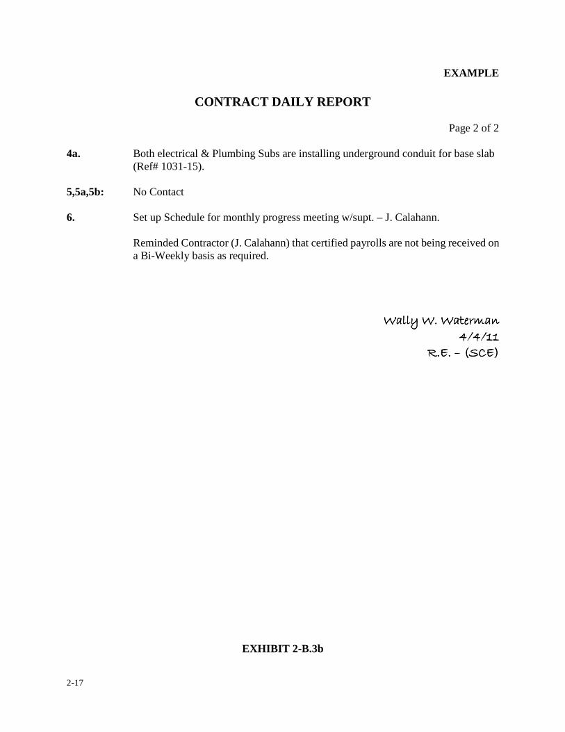
2-17
EXAMPLE
CONTRACT DAILY REPORT
Page 2 of 2 4a. Both electrical & Plumbing Subs are installing underground conduit for base slab
(Ref# 1031-15). 5,5a,5b: No Contact 6. Set up Schedule for monthly progress meeting w/supt. – J. Calahann.
Reminded Contractor (J. Calahann) that certified payrolls are not being received on a Bi-Weekly basis as required.
����������������������������������������������������������������� � ��� � ��� � ��� � ������
����������������������������������������������������
EXHIBIT 2-B.3b
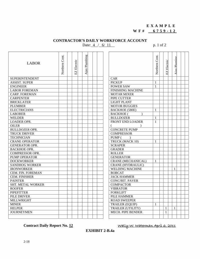
2-18
E X A M P L E W F # 6 7 5 9 - 1 2
CONTRACTOR’S DAILY WORKFORCE ACCOUNT
Date: 4 / 6/ 11 p. 1 of 2
LABOR N
orth
ern
Con
t.
EZ
Ele
ctri
c
Aja
x Pl
umbi
ng
Nor
ther
n C
ont.
EZ
Ele
ctri
c
Aja
x Pl
umin
g
SUPERINTENDENT CAR ASSIST. SUPER PICKUP 1 ENGINEER POWER SAW 1 LABOR FOREMAN FINISHING MACHINE CARP. FOREMAN MOTAR MIXER CARPENTER PIPE CUTTER BRICKLATER LIGHT PLANT PLUMBER MOTOR BUGGIES ELECTRICIANS BACKHOE (580E) 1 LABORER BACKHOE ( ) WELDER BULLDOZER 1 LOADER OPR. FRONT END LOADER
( ) 1
OILER BULLDOZER OPR. CONCRETE PUMP TRUCK DRIVER COMPRESSOR TECHNICIAN PUMP ( ) CRANE OPERATOR TRUCK (MACK 10) 1 GENERATOR OPR. SCRAPER BACKHOE OPR. GRADER COMPRESSOR OPR. ROLLER PUMP OPERATOR GENERATOR DOCKWORKER CRANE (MECHANICAL) 1 SANDHOG WORKER CRANE (HYDRAULIC) IRONWORKER WELDING MACHINE 1 CEM. FIN. FOREMAN BOBCAT CEM. FINISHER JACK HAMMER PAINTER CONC/BIT. PAVER SHT. METAL WORKER COMPACTOR ROOFER VIBRATOR PIPEFITTER FORKLIFT PILE DRIVER PILE HAMMER MILLWRIGHT ROAD SWEEPER MINER TRAILER (EQUIP) 1 HELPER TRAILER (UTILITY) 1 1 JOURNEYMEN MECH. PIPE BENDER 1
Contract Daily Report No. 12 ��������������������������������������������������������������������������������������������������������������������
EXHIBIT 2-B.4a
2-19
EXAMPLE
W F # 6 7 5 9 - 1 2
CONTRACTOR’S DAILY WORKFORCE ACCOUNT
Date: 4 / 6/ 11 p. 2 of 2
= = = = = = = = = = = = = = = = = = = = = = = = = = = = = = = = = = = = = = = =
COMMENTS:
EXHIBIT 2-B.4b
2-20
2. DAILY REPORTS
2.3 FIELD INSPECTOR'S DAILY REPORT
The purpose of the field inspector’s daily progress report is to have a record of what is being
performed by each work crew as observed by an MWRA field engineer or field representative.
It is the responsibility of the field inspector to observe the contractor's progress on a daily basis.
The means by which the field inspector will record the progress performed is through the use of a
"Daily (Manifold) Report Book". For the remaining part of this section we will refer to the Daily
Report Book as the manifold book.
The manifold book is the most effective method for a field inspector to record the daily events on a
construction job site. Basically, the manifold book is the means by which the field inspector
communicates to the resident engineer, although, the manifold book can have many other uses on a
construction site. For example; the manifold book can be used to log extra work orders, to record
delivery of materials, to keep track of pay quantities, to perform specific calculations, and to draw
sketches. However, in this Section it will be primarily used to record the daily progress of the
contractor as observed by an MWRA field inspector. The manifold book may or may not be
necessary on all construction contracts.
On jobs that require one or more persons performing the inspection, the use of the manifold book is
mandatory. On jobs where there is only one person assigned to a contract, the resident engineer
2-21
would observe the contractor's progress and maintain a daily report, therefore, the need for
maintaining a separate manifold book is not necessary. However, if the resident engineer wishes to
utilize the manifold book to record Pay Item quantities, he/she may do so.
On projects where the resident engineer has been assigned a field staff, it is the responsibility of the
resident engineer to ensure that all field inspectors utilize the manifold book as a way of reporting
daily events on the work site. The field inspectors shall promptly submit their daily report(s) to the
resident engineer at the end of the work day. The resident engineer will, in turn, review and
summarize the field inspector’s notes and record the information into the contract daily report.
The contract daily report and manifold book are similar because they serve the same purpose.
However, unlike the contract daily report, the manifold book is considerably smaller and each
manifold book is uniquely numbered. The approximate size of the manifold book is 5" x 7". It is a
hard cover, bound book with numbered pages. The pages of the manifold book are sets of
alternating white (original) and blue (copy) pages. Every two pages have the same reference
number located in the upper right hand corner of the page, starting with the white page. There are
approximately 75 pages per book, beginning with number one. The first page (white/original
sheet) of the two page set has a carbonized backing. This allows what is written on the first page to
be automatically transferred to the second page (blue/copy sheet). The first page permanently
remains a part of the manifold book. The second page is perforated at the top of the page so it can
be removed. This is the page the field inspector submits to the resident engineer each day. In some
cases the resident engineer may want to forward copies of these blue sheets to the construction
coordinator. This way the project has one set with the field inspector in his manifold book, one set
2-22
in the field office and another at the home office.
Exhibit 2-C.1 is an example of the first page (white/original sheet) of a manifold book. The book
number appears on the front cover and the spine area of the book. In this case we are using
manifold book #1001, and the page being displayed is page #53. Note: When you combine the
book number and the page number you arrive at a number unique to itself known as the "Reference
Number". This number is used as a cross-reference aid and is often referred to in the contract daily
reports and the quantity control ledger. Exhibit 2-C.1 indicates the reference number for this page
is 1001-53. Just below the reference number is a place to enter the MWRA contract number. To the
left of the contract number is a space provided for the date. The body of the page is where the field
inspector enters the contractor's daily progress. At the bottom right hand corner the field engineer
signs and enters his/her title. If the field inspector uses more than one page in preparing the daily
report, he/she shall number each page appropriately (i.e., page 1 of 3, page 2 of 3, page 3 of 3, etc.).
The field inspector needs only to sign the last page of the report.�
Attached to the inside cover of the manifold book is a list of topics which the field inspector shall
address at the end of each day (See Exhibit 2-C.2). This listing is offered as a guideline for the field
inspector. In making out his daily report, the field inspector is to review each item and respond
accordingly. The field inspector shall address each topic including topics where no activity
occurred.
The following is a brief overview of the ten items offered in the guideline: Item #1 requires the
field inspector to enter the date for which the report is being prepared, the overall weather
2-23
conditions for the work day and the temperatures at least twice a day. Item #2 is where the field
inspector enters the MWRA contract number (The MWRA contract number can be obtained
through the resident engineer or the construction coordinator and is listed on the title sheet of the
contract documents). Item #3 requires the field inspector to enter the name of the contractor he/she
is observing and whether it is a general contractor or a subcontractor. Also, the field inspector shall
identify whether the work being performed is contract work or work which is extra work beyond
the limits of the contract. Item #4 requires the field inspector to identify, as specifically as possible,
the contractor's labor force and equipment performing the work. If the contractor's labor and
equipment force does not change from day to day within a given week, the field inspector simply
indicates there was no change on his daily report. However, at the beginning of each week the field
inspector must make out a complete listing of the contractor's labor and equipment force. Each
subsequent day that there is no change, the field inspector need only refer to the reference number
of the daily report which lists the labor and equipment. Item #5 requires the field inspector to relate
the work being performed to a specific pay item of the contract, or a specific line item of the
approved schedule of values.
At the end of each work day the field inspector shall measure up and quantify the work completed.
For example, "Pay Item 4.c - Installed 75 1.f. of 48" R.C.P., from Sta.109+00 to Sta. 109+75., or
Pay Item 5.a, 2 of 2 C.I.P. manholes, one at Sta. 109+00 and one at Sta. 109+75." Item #6 indicates
the type of work and where it is being done. Item #7 requires the field inspector to document all
tests performed or any special arrangements relating to the work being performed. The field
inspector must be as specific as possible in identifying what test or other work was done. Item #8
requires the field inspector to identify visitors or incidents which occur throughout the work day.
2-24
Visitors should be identified by name, the organization they represent and the purpose of their
visit. Any complaints, accidents or reports of damage shall be followed-up by a report to the
resident engineer or the construction coordinator. It is the responsibility of the field inspector to
prepare a report on any incident no matter how insignificant it may seem. Item #9 requires the field
inspector to ensure the quality of work being performed by the contractor is as specified under the
contract. Item #10 requires the field inspector to enter his/her signature and title to conclude the
report.
Exhibit 2-C.3 is an example of how the manifold book is to be maintained by the field inspector.
This particular report relates to the resident engineer's report entered in the contract daily report for
April 4, 2011, see Exhibit 2-A.1, on page 2-6 above. Note: in the second sentence of Item #4,
which describes the progress being performed, there is a reference number that indicates the book
and page of the field inspector's manifold book. This reference number serves as a cross-reference
mechanism which exists between the contents of the resident engineer's contract daily report and
the progress reported in the field inspector’s manifold book. The field inspector should be made
aware of the fact that the manifold report book, if utilized properly, is one of the most important
written legal records documenting work performed under a given construction contract. Such
records, maintained with neatness and clarity, can be a favorable deciding factor during disputes
and protects the interests of the Authority. The resident engineer relies very heavily on the field
inspector to provide complete and accurate information of the progress being made by the
contractor and the overall project in general.
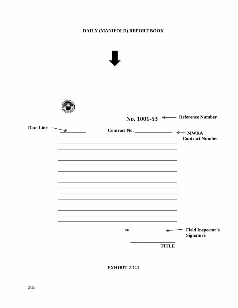
2-25
DAILY (MANIFOLD) REPORT BOOK
Date Line
No. 1001-53
___________ Contract No. ________________
Reference Number MWRA Contract Number
/s/ ___________________
___________________ TITLE
Field Inspector’s Signature
EXHIBIT 2-C.1
2-26
***MANIFOLD BOOK GUIDELINE***
1. The date, weather and temperature of the day.
2. The contract number.
3. The name of the Contractor or Subcontractor on a day to day basis. Also, if
the work being performed has anything to do with extra work, or possible
extra work, it should be identified as such.
4. The work force performing the work (being as specific as possible).
5. Relate the work being done with the Contract Pay Item number and Pay
Item Name. In the case of work being done as part of lump sum; relate it to
the Schedule of Values item name and number.
6. The location and description of the work being performed.
7. Any information pertinent to the work observed such as; concrete cylinders
made, air meter or compaction tests, samples taken, etc.
8. Any information pertinent to the construction contract such as; visitors to
the work site, accidents, complaints, reports of damage, if photographs were
taken, etc.
9. Record any irregularities regarding the work being performed.
10. At the end of the daily entries the signature and title of the field inspector is
required.
EXHIBIT 2-C.2
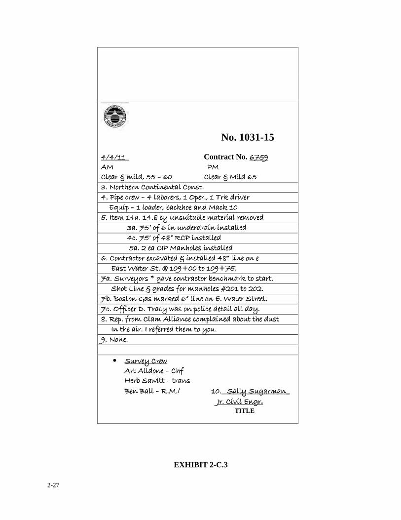
2-27
No. 1031-15
� � � � ���� ���������������� Contract No. ���������������� � �����������������������������������������������! � �����������������������������������������������! � �����������������������������������������������! � �����������������������������������������������! ���������"���#����������"���#����������"���#����������"���#������������������������������������"� ��#��������������������������"� ��#��������������������������"� ��#��������������������������"� ��#�������
$��%&�'����&�����������&�(��$��%&�'����&�����������&�(��$��%&�'����&�����������&�(��$��%&�'����&�����������&�(������ ���!����)�*����!����)�*����!����)�*����!����)�*�������������+&�(����,�������-.�#�/�����+&�(����,�������-.�#�/�����+&�(����,�������-.�#�/�����+&�(����,�������-.�#�/����� �����������������01����01����01����01��������������&�#���+�).'&����#� �).������&�#���+�).'&����#� �).������&�#���+�).'&����#� �).������&�#���+�).'&����#� �).������� ���2�����������3���2�����������3���2�����������3���2�����������3����)��1�(1���+�����������&/�#)��1�(1���+�����������&/�#)��1�(1���+�����������&/�#)��1�(1���+�����������&/�#���� ����������������������������������������������������$�����4�&5������1�#�#������(�����#$�����4�&5������1�#�#������(�����#$�����4�&5������1�#�#������(�����#$�����4�&5������1�#�#������(�����#���� �����������������������������������������������������)����4�&5��36���!���(�����#�)����4�&5��36���!���(�����#�)����4�&5��36���!���(�����#�)����4�&5��36���!���(�����#���� ������������������������������������������������������������������������2!� ��'&��(���(�����#��������2!� ��'&��(���(�����#��������2!� ��'&��(���(�����#��������2!� ��'&��(���(�����#���� �������������&���)�&��7)�/���#�"���(�����#��36������&����&���)�&��7)�/���#�"���(�����#��36������&����&���)�&��7)�/���#�"���(�����#��36������&����&���)�&��7)�/���#�"���(�����#��36������&������� ����������������������(�����������8����9����&����9�����(�����������8����9����&����9�����(�����������8����9����&����9�����(�����������8����9����&����9������� �����1/��&(�:�;�/��)&���)�&�+��)'�.��&�(���������1/��&(�:�;�/��)&���)�&�+��)'�.��&�(���������1/��&(�:�;�/��)&���)�&�+��)'�.��&�(���������1/��&(�:�;�/��)&���)�&�+��)'�.��&�(�������� ���������������������'&��<����"�;�#�(�5&���'&��(�=�����&������'&��<����"�;�#�(�5&���'&��(�=�����&������'&��<����"�;�#�(�5&���'&��(�=�����&������'&��<����"�;�#�(�5&���'&��(�=�����&��������� �+��>&(�&��?�(��.�#��6������&�����������������+��>&(�&��?�(��.�#��6������&�����������������+��>&(�&��?�(��.�#��6������&�����������������+��>&(�&��?�(��.�#��6������&�������������������� �)��,55�)��@���)��,55�)��@���)��,55�)��@���)��,55�)��@��----�)��*�(�&���&��)��#����������#����)��*�(�&���&��)��#����������#����)��*�(�&���&��)��#����������#����)��*�(�&���&��)��#����������#������� 3�������5&�����������)��)&������#��+&1���'��#1(�3�������5&�����������)��)&������#��+&1���'��#1(�3�������5&�����������)��)&������#��+&1���'��#1(�3�������5&�����������)��)&������#��+&1���'��#1(����� ��������������������2���'������2��5��#��'���&��&1�2���'������2��5��#��'���&��&1�2���'������2��5��#��'���&��&1�2���'������2��5��#��'���&��&1����� ���%&������%&������%&������%&������� ���� • �1/�����*�1/�����*�1/�����*�1/�����*����
������#&���������#&���������#&���������#&������������'5�'5�'5�'5����A�+���*����A�+���*����A�+���*����A�+���*���������������(���(���(���(����>��>��>��>������>����>����>����>�������������� ��� ��� ��� �/ ������������ �������1;����������1;����������1;����������1;���_ ������������������������������������������������������������������������������������������������������������������������������������������������������������������������B����/�����;B����/�����;B����/�����;B����/�����;.
TITLE
EXHIBIT 2-C.3
2-28
2. DAILY REPORTS
2.4 FIELD INSPECTOR’S PAY SLIPS
The resident engineer or his/her designee is responsible for documenting the quantities of work
performed by the contractor as they relate to the contract bid items or approved schedule of values.
At the end of each work day, the resident engineer will incorporate into the Quantity Control
Ledger (QCL) the daily quantities of work accomplished by the contractor for that day. If the
resident engineer has one or more field inspectors assigned to the project, each field inspector is
responsible to promptly submit his/her daily quantities to the resident engineer at the end of the
work day. All quantities will be tabulated in the QCL. These quantities submitted may either be
partial or final quantities. Partial quantities may be represented as an estimated portion of the
original bid unit or a percentage of lump sum prices of an approved schedule of values. Final pay
quantities must be field measured or calculated according to the units of the contract or the
established cost of the schedule of values. If final field quantity of a unit price bid item differs from
the original bid quantity, the field inspector shall be required to provide a reason for the item's
overrun or under-run.
Overruns must be reported to the construction coordinator as soon as they become
apparent. Refer to Section 3.1 Partial Pay Estimates for more information on notification.
In addition, under no circumstances shall a payment of a lump sum item exceed 100% of the
Schedule of Value amount.
2-29
There are several ways in which a field inspector may document the actual quantities used for
contract work. One option is to add the information to his/her daily report (Manifold Book) under
line Item No. 5 of the field inspector's guidelines. The quantities shall be clearly defined as
estimated pay quantities as opposed to progress observed and labeled "Pay Item Slip". Also, the
items shall be identified as either partial or final, or estimated or measured quantities. If
calculations are performed to verify a certain quantity, it should be noted where these calculations
can be found (i.e., in the field inspector's survey book or on a QCL Work Sheet or in a calculations
book maintained by the field inspector). From time to time the resident engineer will review the
field inspector's calculations to ensure they are accurate and are being performed correctly.
However, the preferred method to document pay quantities is to record the information on a
separate sheet in the field inspector’s manifold report book or to use a separate Manifold Report
Book just to document pay quantities. This is an ideal method for this purpose for it appears to be
less confusing when attempting to identify quantities, track quantities or to check the calculations
of pay items. The page or pages used by the field inspector to record this information should be
clearly labeled as a "Pay Item Slip". The pay slip information shall include the proper name and
number of the item, the field stations or approximate location of installation and the calculated
quantities.
Also, the pay item slip shall clearly define whether the quantity is an actual, estimated, field
measured or final quantity. The pay slip shall conclude with the field inspector's recommendation
for payment followed by his/her signature and title.
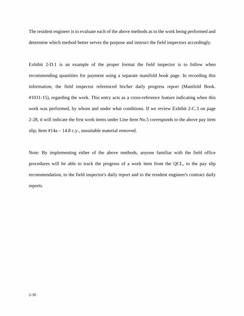
2-30
The resident engineer is to evaluate each of the above methods as to the work being performed and
determine which method better serves the purpose and instruct the field inspectors accordingly.
Exhibit 2-D.1 is an example of the proper format the field inspector is to follow when
recommending quantities for payment using a separate manifold book page. In recording this
information, the field inspector referenced his/her daily progress report (Manifold Book.
#1031-15), regarding the work. This entry acts as a cross-reference feature indicating when this
work was performed, by whom and under what conditions. If we review Exhibit 2-C.3 on page
2-28, it will indicate the first work items under Line Item No.5 corresponds to the above pay item
slip; Item #14a – 14.8 c.y., unsuitable material removed.
Note: By implementing either of the above methods, anyone familiar with the field office
procedures will be able to track the progress of a work item from the QCL, to the pay slip
recommendation, to the field inspector's daily report and to the resident engineer's contract daily
reports.
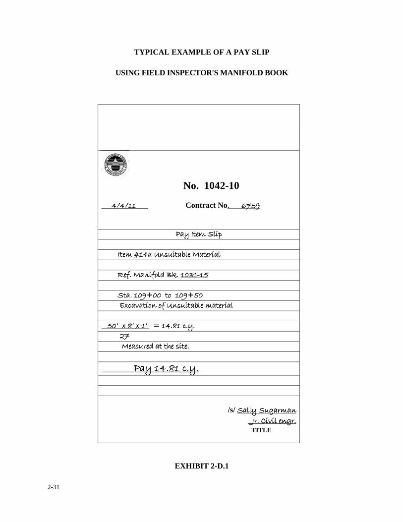
2-31
TYPICAL EXAMPLE OF A PAY SLIP
USING FIELD INSPECTOR'S MANIFOLD BOOK
No. 1042-10 ��������������������� � � � ���� �������������������������������� Contract No. ����������������
!���!���!���!���2��2��2��2�������������������������� ���� ��������������������������������2���=����C�(1���+��� ������2���=����C�(1���+��� ������2���=����C�(1���+��� ������2���=����C�(1���+��� ���������� ������������������������������������ ����������������������������������5�� ���5&�#�>.����5�� ���5&�#�>.����5�� ���5&�#�>.����5�� ���5&�#�>.����$���$���$���$�DDDD������������ ���� ����������������������������������������9�����&�����9����������9�����&�����9����������9�����&�����9����������9�����&�����9������ �������������������������������������7)�/���&��&5�C�(1���+����������7)�/���&��&5�C�(1���+����������7)�/���&��&5�C�(1���+����������7)�/���&��&5�C�(1���+������������� ���� ��������������4��7�34�7��4���4��7�34�7��4���4��7�34�7��4���4��7�34�7��4���������E����3��)���E����3��)���E����3��)���E����3��)������� ������������������������������������������������ ���������������������������������������� ��(1�#�����'��(���� ��(1�#�����'��(���� ��(1�#�����'��(���� ��(1�#�����'��(�������� ���� ������������������������������������������������!������3��)���!������3��)���!������3��)���!������3��)�������
���� ����
/s/ �������1;����������1;����������1;����������1;������� _B����/�����;�B����/�����;�B����/�����;�B����/�����;�
TITLE
EXHIBIT 2-D.1
2-32
2. DAILY REPORTS
2.5 QUANTITY CONTROL LEDGER
The purpose of having a Quantity Control Ledger (QCL) is to provide a procedure for permanently
recording quantities of work performed by the contractor on a construction contract. The QCL is
an up-to-date account of the contract quantities and/or approved schedule of values. It is designed
to aid the resident engineer in the tracking of quantities of the contract. The QCL also serves as a
cross-reference to ensure the work completed and submitted for payment by the contractor is
consistent with the contract quantities. The resident engineer is responsible for maintaining a neat
an orderly QCL throughout the contract. The information recorded in the QCL becomes a
permanent part of the job records. As soon as possible, but no later than 24 hours after the resident
engineer receives pay slips from the field inspector, he/she shall incorporate the information into
the ledger.
The QCL itself is made up of three separate forms; the Title Sheet, the Control Sheet and the Work
Sheet. The resident engineer may create electronic forms to document backup calculations but
shall maintain an updated quantity control ledger sheets in a three ring binder with separators for
easy access. Blank forms of the Title Sheet, Control Sheet and Calculation Sheet are included in
the Appendix of this manual.
Exhibit 2-E.1 is an example of the Title Sheet. The title sheet contains essential information
regarding the type, length and costs of the project. The resident engineer is to enter the required
information at the beginning of the job and update it accordingly. If a new title sheet is necessary,
2-33
the resident engineer provides a new sheet but will retain the old title sheet for historical purposes.
Contract costs may change as modifications and change orders are incurred. The lower right-hand
part of the page shows the Award Date, Notice to Proceed, Contract Time and Completion Date.
This information, once recorded, will not change, however the Revised Completion Date will
depend on whether any time extensions have been granted throughout the contraction duration. At
the end of the project the resident engineer shall complete the form by recording the Substantial
and Final Completion Dates and the Final Contract Price. In addition, the resident engineer shall
attach to the title sheet section copies of any correspondence or information which document any
changes made on the title sheet.
Exhibits 2-E.2a and 2E.2b are an example of the QCL Control Sheet. The quantity control sheet is
designed to keep track of each individual bid item of the contract. In the case of a lump sum
contract, the quantity control sheet is used to keep track of each line item of an approved schedule
of values. Depending on the type of job, the resident engineer shall maintain at least one control
sheet for each bid item or line item of the schedule of values. If the contractor submits a breakdown
of the schedule of values where the line items are broken down according to work disciplines, it is
suggested the resident engineer maintain a separate quantity control sheet for each work discipline.
Exhibits 2-E.2.a and 2E.2.b show how the resident engineer is to maintain a quantity control sheet
for a certain bid item (Item #5b, 48" reinforced concrete pipe - RCP). The quantity of 48" RCP to
be installed is 3500 l.f. and the bid price is $280.00 per lineal foot.
The body of the form is where the information is to be entered. At the left-hand column is where
2-34
the date the work was completed is entered. In this example, the installation began on April 6th and
was continuing on through May 20th. The next two columns show the book and page number of
the field engineer's pay slip or Item 5 of the daily report. Note that manifold book No.997 was used
from 4/6 to 4/20 and manifold book No.1029 starting on 4/21 to 5/20. The next column indicates
the initials of the field inspector providing the information. In this example, the information was
provided by Sally Sugarman (S.S.). The fifth column from the left indicates the location of the
work. In this example, the general location is East Water Street followed by the exact stations
where the installation was performed. The next two columns show what quantity of pipe was
installed that day and the cumulative total of pipe installed to date. The next column indicates the
pay period in which the pipe was installed. In this example, 398 lineal feet of 48” RCP was
installed and paid under Pay Estimate No. 1 and a total of 1055 l.f. of pipe was paid to date under
Pay Estimate No.2 (398 l.f. during the first pay period plus 657 1.f. during the second pay period
for a total of 1055 l.f. to date). The next column; Total Quantity is where total measured quantity or
the final quantity is recorded. This column is where the resident engineer, either by actual field
measurement or by calculations, verifies the quantities submitted by the field inspector. If the
measured quantity differs from the cumulative totals offered by the field inspector, the resident
engineer shall recommend the measured quantity for payment. The final (Total) quantity must be
balanced with the original bid quantity. If it is a bid item, any overruns and under-runs must be
explained in writing. If it is a lump sum line item, it must not exceed 100% complete. The last
column on the right is used to enter whatever comments or remarks there may be relative to the
work being performed.
Exhibit 2-E.3 is an example of the Work Sheet form. This form is used as backup or support
2-35
document to the Control Sheet. The work sheet is a form made up of a 5 1/2 inch by 10 inch
quadrille ruled face. The grids are 1/4 inch. The work sheets are often used as a supplement to the
field engineer's field survey book in determining quantities. It can also be used for records of work
performed in the field, i.e. sketches, diagrams, dimensions, elevations, tabulations, and types of
notes which will justify the quantities being requested by the contractor. All Work Sheets shall be
cross-referenced to the Control Sheet associated with the work. In this particular example, page 1,
we show actual measured quantity for the installation of the 48" RCP line for Pay Period #1 and
Pay Period #2. All information relating to the 48" RCP line appears on the sketch; including
manhole installations, boulder and unsuitable material removal. There are additional references
made to other Work Sheets regarding the boulder and unsuitable removal. Note: at the upper left
corner of the sheet, next to the word “Worksheet” the number 1 appears. This indicates that this
particular Work Sheet was the first work sheet used on the project. Each subsequent work sheet
shall be numbered in a sequential manner.
Exhibit 2-E.4 is another example of how a Work Sheet can be utilized. In this case calculations are
performed to determine the actual quantity of unsuitable material removed from Sta. 82+35 to Sta.
82+51. A comment is added to the bottom of the work sheet indicating how the dimensions were
obtained and where they can be found. In the upper left corner appears the number 2; indicating
this sketch was the second work sheet used on the project.
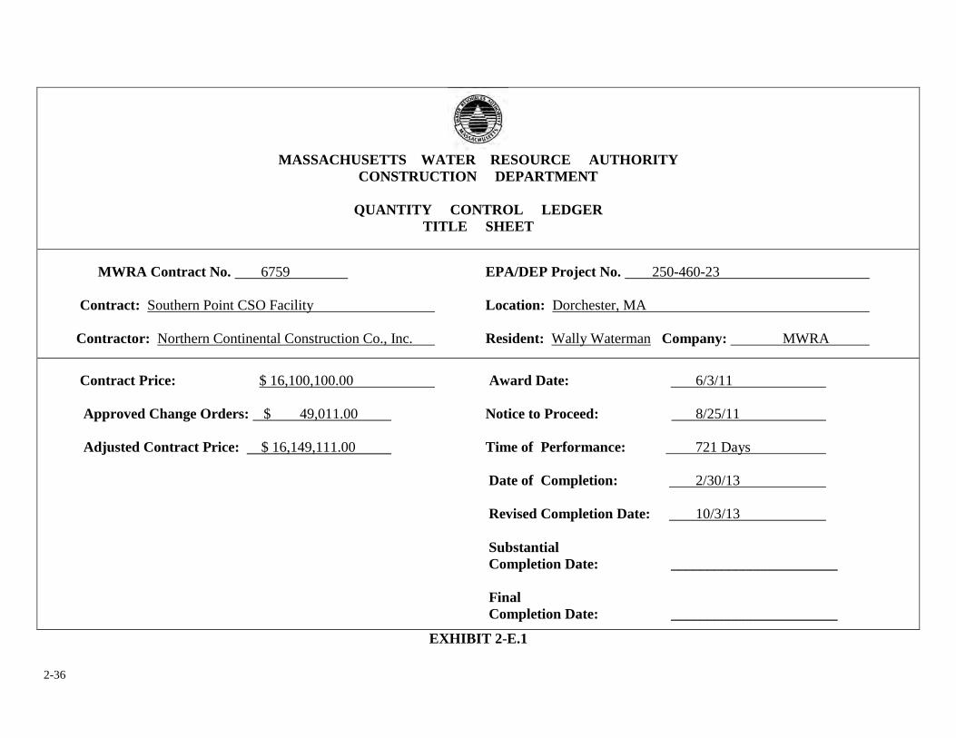
2-36
MASSACHUSETTS WATER RESOURCE AUTHORITY
CONSTRUCTION DEPARTMENT
QUANTITY CONTROL LEDGER TITLE SHEET
MWRA Contract No. 6759 EPA/DEP Project No. 250-460-23 Contract: Southern Point CSO Facility Location: Dorchester, MA Contractor: Northern Continental Construction Co., Inc. Resident: Wally Waterman Company: MWRA
Contract Price: $ 16,100,100.00 Award Date: 6/3/11 Approved Change Orders: $ 49,011.00 Notice to Proceed: 8/25/11 Adjusted Contract Price: $ 16,149,111.00 Time of Performance: 721 Days Date of Completion: 2/30/13 Revised Completion Date: 10/3/13 Substantial Completion Date: _______________________ Final Completion Date: _______________________
EXHIBIT 2-E.1
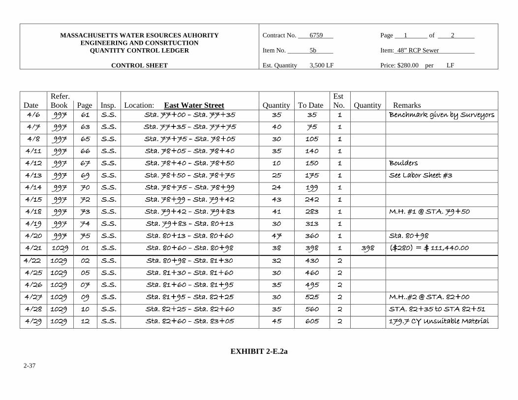
2-37
MASSACHUSETTS WATER ESOURCES AUHORITY
ENGINEERING AND CONSRTUCTION QUANTITY CONTROL LEDGER
CONTROL SHEET
Contract No. 6759 Page 1 of 2 Item No. 5b Item: 48” RCP Sewer Est. Quantity 3,500 LF Price: $280.00 per LF
EXHIBIT 2-E.2a
Refer. Est Date Book Page Insp. Location: East Water Street Quantity To Date No. Quantity Remarks ���� �������� ���������������� ������������ �������������������� �������9����������9����������9����������9������������������9$��������9$��������9$��������9$����� $�$�$�$����� $�$�$�$����� �������� >��)'�.�;�/���+���1/��&(>��)'�.�;�/���+���1/��&(>��)'�.�;�/���+���1/��&(>��)'�.�;�/���+���1/��&(����
���� �������� ���������������� �$�$�$�$���� �������������������� �������9�������9�������9�������9$�$�$�$��������������������9�������9�������9�������9������������ ������������ ������������ �������� ���� ���� 3333���� ���������������� ������������ �������������������� �������9�������9�������9�������9��������������������������������������������33339999������������ $�$�$�$����� ���������������� �������� ���� ���� ������������ ���������������� ������������ �������������������� ������������������������33339�9�9�9�����������������������������������������33339999������������ $�$�$�$����� ���������������� �������� ���� ���� ������������ ���������������� ������������ �������������������� ������������������������33339999��������������������������������������������33339999������������ ������������ ���������������� �������� ���� >&1�#�(>&1�#�(>&1�#�(>&1�#�(����
���� �$�$�$�$���� ���������������� ������������ �������������������� ������������������������33339999��������������������������������������������33339999������������ ������������ ���������������� �������� ���� ����<�+&��'����=$����<�+&��'����=$����<�+&��'����=$����<�+&��'����=$����
���� ������������ ���������������� ������������ �������������������� ������������������������33339999��������������������������������������������33339999������������ ������������ ���������������� �������� ���� ���� � � � ��������� ���������������� ������������ �������������������� ������������������������33339999������������������������������������������������9999������������ �$�$�$�$���� ���������������� �������� ���� ���� � � � �3333���� ���������������� �$�$�$�$���� �������������������� ����������������������������9999������������������������������������������������99993333$$$$���� ������������ �3$�3$�3$�3$���� �������� ���� �A��=��8��-�����9�� �A��=��8��-�����9�� �A��=��8��-�����9�� �A��=��8��-�����9������
���� � � � ��������� ���������������� ������������ �������������������� ����������������������������99993$3$3$3$��������������������������������3�3�3�3�9999�$�$�$�$���� $�$�$�$����� $�$$�$$�$$�$���� �������� ���� ���� ������������ ���������������� ������������ �������������������� ��������������������3�3�3�3�9999�$�$�$�$��������������������������������3�3�3�3�9999������������ ������������ $��$��$��$������ �������� ���� �����3�9�3������3�9�3������3�9�3������3�9�3�����
���� ������������ �������������������� ������������ �������������������� ��������������������3�3�3�3�9999����������������������������������������3�3�3�3�9999�3�3�3�3���� $3$3$3$3���� $�3$�3$�3$�3���� �������� $�3$�3$�3$�3���� �F�3���E�F������������F�3���E�F������������F�3���E�F������������F�3���E�F���������������
� ��� ��� ��� ������ ���������������� ������������ �������������������� ��������������������3�3�3�3�9999�3�3�3�3��������������������������������3�3�3�3�9$9$9$9$�������� $�$�$�$����� �$��$��$��$����� �������� ���� ���� ������������ ���������������� ������������ �������������������� ��������������������3�3�3�3�9999$$$$������������������������������������3�3�3�3�9999������������ $�$�$�$����� ���������������� �������� ���� ���� � � � ��������� ���������������� ������������ �������������������� ��������������������3�3�3�3�9999����������������������������������������3�3�3�3�9999������������ $�$�$�$����� ���������������� �������� ���� ���� � � � ��������� ���������������� ������������ �������������������� ��������������������3�3�3�3�9999����������������������������������������3�3�3�3�9999������������ $�$�$�$����� ���������������� �������� ���� �A��=��8��-���3�9�� �A��=��8��-���3�9�� �A��=��8��-���3�9�� �A��=��8��-���3�9������
���� � � � �3333���� ���������������� ������������ �������������������� ��������������������3�3�3�3�9999����������������������������������������3�3�3�3�9999������������ $�$�$�$����� ���������������� �������� ���� �-���3�9$������-��3�9���-���3�9$������-��3�9���-���3�9$������-��3�9���-���3�9$������-��3�9������
���� � � � ��������� ���������������� ������������ �������������������� ��������������������3�3�3�3�9999����������������������������������������3$3$3$3$9999������������ ������������ ���������������� �������� ���� �������G�C�(1���+��� �������������G�C�(1���+��� �������������G�C�(1���+��� �������������G�C�(1���+��� ����������
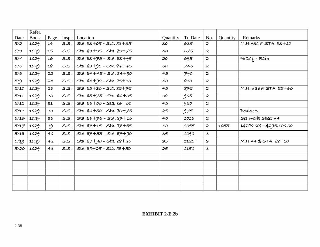
2-38
EXHIBIT 2-E.2b
Refer. Date Book Page Insp. Location Quantity To Date No. Quantity Remarks ���� � � � ����� �������������������� ������������ �������������������� �����3$9��������3$9��������3$9��������3$9����������������3$9$������3$9$������3$9$������3$9$� $�$�$�$����� �$��$��$��$����� �������� ���� �A�=$��8��-���3$9�� �A�=$��8��-���3$9�� �A�=$��8��-���3$9�� �A�=$��8��-���3$9������
���� $$$$���� ���������������� ������������ ���������������� �����3$9$�������3$9$�������3$9$�������3$9$���������������3$9�����3$9�����3$9�����3$9�������� ������������ ���������������� �������� ���� ����
���� �������� ���������������� ������������ ���������������� �����3�����3�����3�����3$$$$9999�������������������������3$9�����3$9�����3$9�����3$9�������� ������������ ���������������� �������� ���� H�@���H�@���H�@���H�@���DDDD������������������������
���� �������� ���������������� �3�3�3�3���� ���������������� �����3�����3�����3�����3$$$$9999�������������������������3�����3�����3�����3����9999�������� ������������ ���������������� �������� ���� ����
���� �������� ���������������� ������������ ���������������� �����3�����3�����3�����3����9999�������������������������3�����3�����3�����3����9999�������� ������������ ���������������� �������� ���� ����
���� �������� ���������������� ������������ ���������������� �����3�����3�����3�����3����9999�������������������������3�����3�����3�����3����9999$$$$���� ������������ 3$�3$�3$�3$����� �������� ���� ����
���� ������������ ���������������� ������������ ���������������� �����3�����3�����3�����3����9999$$$$���������������������3�����3�����3�����3����9999�������� ������������ 3��3��3��3������ �������� ���� �A��= �A��= �A��= �A��=$+�8��-���3�9��$+�8��-���3�9��$+�8��-���3�9��$+�8��-���3�9������
���� ������������ ���������������� $�$�$�$����� ���������������� �����3�����3�����3�����3����9999�������������������������3�����3�����3�����3����9��9��9��9�� $�$�$�$����� ���������������� �������� ���� ����
���� ������������ ���������������� $�$�$�$����� ���������������� �����3�����3�����3�����3����9999�������������������������3�����3�����3�����3����9999�������� ������������ ���������������� �������� ���� ����
���� � � � �$$$$���� ���������������� $$$$$$$$���� ���������������� �����3�����3�����3�����3����9999�������������������������3�����3�����3�����3����9999�������� ������������ ���������������� �������� ���� >&1�#�(>&1�#�(>&1�#�(>&1�#�(����
���� � � � ��������� ���������������� $�$�$�$����� ���������������� �����3�����3�����3�����3����9999�������������������������3�����3�����3�����3����9999�������� ������������ �������������������� �������� ���� �����&.��'����=������&.��'����=������&.��'����=������&.��'����=�����
���� � � � ��������� ���������������� $�$�$�$����� ���������������� �����3�����3�����3�����3����9999�������������������������3�����3�����3�����3����9999�������� ������������ �������������������� �������� �������������������� �F�3�����EF�����������F�3�����EF�����������F�3�����EF�����������F�3�����EF��������������
���� � � � �3333���� ���������������� ������������ ���������������� �����3�����3�����3�����3����9999�������������������������3�����3�����3�����3����9999�������� $�$�$�$����� �������������������� $$$$���� ���� ����
���� � � � ��������� ���������������� ������������ ���������������� �����3�����3�����3�����3����9999�������������������������3�����3�����3�����333339999�������� $�$�$�$����� �������������������� $$$$���� ���� �A�=��8��-���339�� �A�=��8��-���339�� �A�=��8��-���339�� �A�=��8��-���339������
���� ������������ ���������������� �$�$�$�$���� ���������������� �����3�����3�����3�����333339999�������������������������3�����3�����3�����333339999�������� ������������ �������������������� $$$$���� ���� ����� � � � � � � � � �� � � � � � � � � �� � � � � � � � � �� � � � � � � � � �� � � � � � � � � �
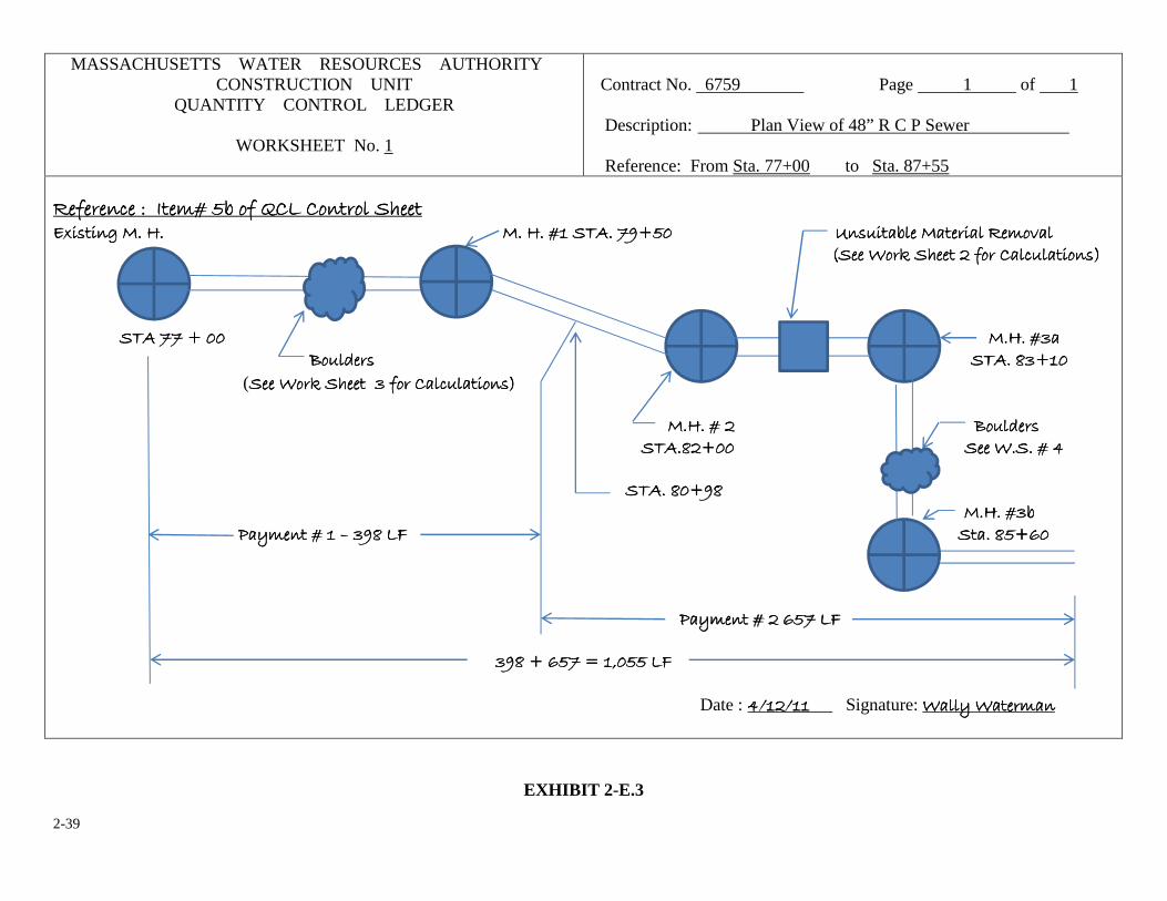
2-39
MASSACHUSETTS WATER RESOURCES AUTHORITY CONSTRUCTION UNIT
QUANTITY CONTROL LEDGER
WORKSHEET No. 1
Contract No. 6759 Page 1 of 1 Description: Plan View of 48” R C P Sewer Reference: From Sta. 77+00 to Sta. 87+55
��5���)��I��2��=��+�&5�J�<��&��&���'������5���)��I��2��=��+�&5�J�<��&��&���'������5���)��I��2��=��+�&5�J�<��&��&���'������5���)��I��2��=��+�&5�J�<��&��&���'���������7�(���;� ��A��7�(���;� ��A��7�(���;� ��A��7�(���;� ��A������������������������������������������������������������������������������������������������������������������������������������������������������������������������������������������������������������������������������������������������������������������������������������������������������������� ��A��=���-�����9�������������������������������� ��A��=���-�����9�������������������������������� ��A��=���-�����9�������������������������������� ��A��=���-�����9��������������������������������������������������������C�(1���+��� ���������&/��C�(1���+��� ���������&/��C�(1���+��� ���������&/��C�(1���+��� ���������&/������ ���������������������&.��'����&.��'����&.��'����&.��'���������5&����)1����&�(���5&����)1����&�(���5&����)1����&�(���5&����)1����&�(����� �-�����9����-�����9����-�����9����-�����9������������������������������������������������������������������������������������������������������������������������������������������������������������������������������������������������������������������������������������������������������������������������������������������������������������������������������������������������������������������������������������������������������������������������������������������������������������������������������������������������������������������������������������������������������������������������������������������������������������������������������������������������������������������������������������������������������� �A��=$�� �A��=$�� �A��=$�� �A��=$������ >&1�#�(>&1�#�(>&1�#�(>&1�#�(�������������������������������������������������������������������������������������������������������������������������������������������������������������������������������������������������������������������������������������������������������������������������������������������������������������������������������������������������������������������������������������������������������������������������������������������������������������������������������������������������������������������������������������������������-���3�-���3�-���3�-���3$$$$9999������������ (�����������������&.��'�����&.��'�����&.��'�����&.��'��������$�5&����)1����&�(�$�5&����)1����&�(�$�5&����)1����&�(�$�5&����)1����&�(��������������������������������������������������������������������������������������������������������������������������������������������������������������������������������������������������������������������������������������������������������������������������������������������������������������������������������������������������������������������������������������������������������������������� �A��=�� �A��=�� �A��=�� �A��=����������������������������������������������������������������������������������������������������������������������������������������������������������������������������������������������������������������������>&1�#�(�>&1�#�(�>&1�#�(�>&1�#�(����� �-��3�9���-��3�9���-��3�9���-��3�9�����������������������������������������������������������������������������������������������������������������������������������������������������������������������������������������������������������������������=�����������=�����������=�����������=��� ��������������������������������������������������������������������������������������������������������������������������������-���3�9�3�-���3�9�3�-���3�9�3�-���3�9�3���� �A��=$+ �A��=$+ �A��=$+ �A��=$+ ��������������������������������������������������������������������������������������������������������������������������������������������������������������������!������=��!������=��!������=��!������=��������������$�3�<K$�3�<K$�3�<K$�3�<K�������������������������������������������������������������������������������������������������������������������������������������������������������������������������������������������������������������������������������������������������������������������������������������������������������������������������������������������������������������������������������������������������������������������������������������������������������������������������������������������������������������3�����3�����3�����3����9��9��9��9��������������������������������������������������������������������������������������������������������������������������������������������������������������������������������������������������������������������������������������������������� �������������������������������������������������������������������������������������������������������������������������������������������!������=�������<K!������=�������<K!������=�������<K!������=�������<K���� $�3�9����$�3�9����$�3�9����$�3�9��������E�������<KE�������<KE�������<KE�������<K����
Date : � �� �������� �� �������� �� �������� �� ������� Signature: ������������������������������������������������
EXHIBIT 2-E.3
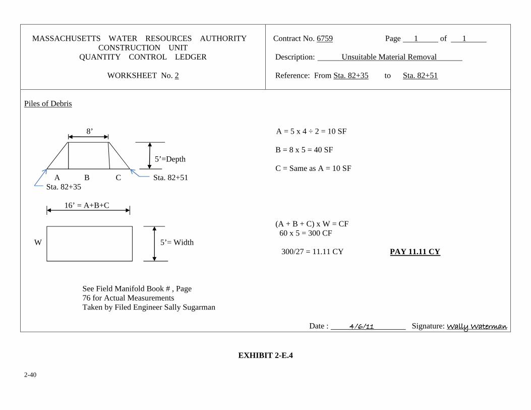
2-40
MASSACHUSETTS WATER RESOURCES AUTHORITY
CONSTRUCTION UNIT QUANTITY CONTROL LEDGER
WORKSHEET No. 2
Contract No. 6759 Page 1 of 1 Description: Unsuitable Material Removal Reference: From Sta. 82+35 to Sta. 82+51
Piles of Debris 8’ A = 5 x 4 ÷ 2 = 10 SF B = 8 x 5 = 40 SF 5’=Depth C = Same as A = 10 SF A B C Sta. 82+51 Sta. 82+35 16’ = A+B+C (A + B + C) x W = CF 60 x 5 = 300 CF W 5’= Width 300/27 = 11.11 CY PAY 11.11 CY See Field Manifold Book # , Page 76 for Actual Measurements Taken by Filed Engineer Sally Sugarman
Date : � � � � ���� �������� Signature: ������������������������������������������������
EXHIBIT 2-E.4
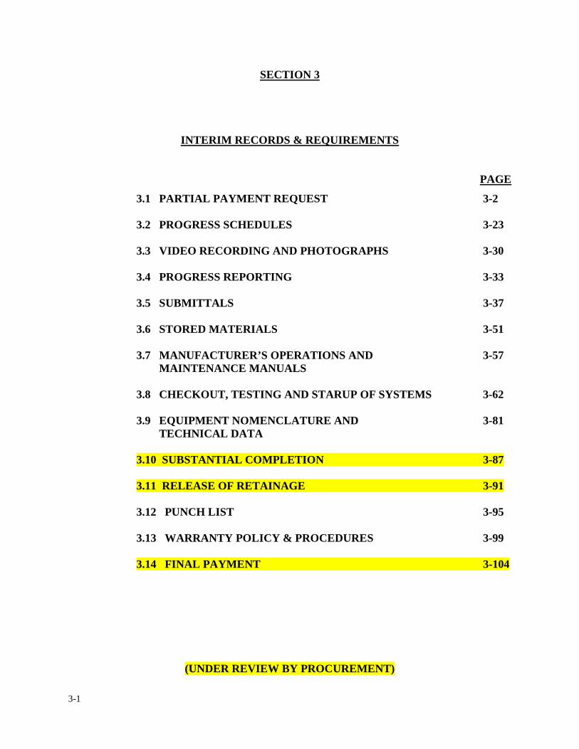
3-1
SECTION 3
INTERIM RECORDS & REQUIREMENTS
PAGE
3.1 PARTIAL PAYMENT REQUEST 3-2
� 3.2 PROGRESS SCHEDULES 3-23
3.3 VIDEO RECORDING AND PHOTOGRAPHS 3-30
3.4 PROGRESS REPORTING 3-33
3.5 SUBMITTALS 3-37
3.6 STORED MATERIALS 3-51
3.7 MANUFACTURER’S OPERATIONS AND 3-57 MAINTENANCE MANUALS
3.8 CHECKOUT, TESTING AND STARUP OF SYSTEMS 3-62
3.9 EQUIPMENT NOMENCLATURE AND 3-81 TECHNICAL DATA
3.10 SUBSTANTIAL COMPLETION 3-87
3.11 RELEASE OF RETAINAGE 3-91
3.12 PUNCH LIST 3-95
3.13 WARRANTY POLICY & PROCEDURES 3-99
3.14 FINAL PAYMENT 3-104
(UNDER REVIEW BY PROCUREMENT)
3-2
3. INTERIM RECORDS & REQUIREMENTS
3.1 PARTIAL PAYMENT REQUEST
In the next several chapters, we will introduce more procedures; however, these procedures are
governed by either conditions of the construction contract and/or local, state and federal laws. The
resident engineer should thoroughly familiarize himself/herself with general and supplemental
conditions of the contract when dealing with payments to the contractor, submittals, progress
schedules and stored materials.
IMPORTANT DEFINITIONS:
Partial Payments are also known by other terms such as; monthly pay estimates, payment
requisitions, progress estimates, progress payments, partial pay estimates etc. For simplicity and
clarity, the term "Partial Payment Request" is used throughout this section to indicate periodic
payments to the contractor.
Partial Payment Date is the date the resident engineer signs and dates the partial payment
request. The date also signifies that all quantities being requested have been checked, the required
backup material has been submitted and the payment request is ready to be forwarded to the home
office for processing.
Pay Periods also known as periodic invoicing or monthly requisitions, are intervals at which the
contractor is permitted to submit a partial payment request.
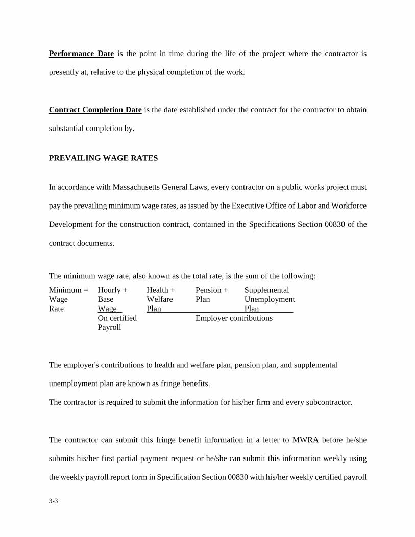
3-3
Performance Date is the point in time during the life of the project where the contractor is
presently at, relative to the physical completion of the work.
Contract Completion Date is the date established under the contract for the contractor to obtain
substantial completion by.
PREVAILING WAGE RATES
In accordance with Massachusetts General Laws, every contractor on a public works project must
pay the prevailing minimum wage rates, as issued by the Executive Office of Labor and Workforce
Development for the construction contract, contained in the Specifications Section 00830 of the
contract documents.
The minimum wage rate, also known as the total rate, is the sum of the following:
Minimum = Hourly + Health + Pension + Supplemental Wage Base Welfare Plan Unemployment Rate Wage Plan Plan On certified Employer contributions Payroll
The employer's contributions to health and welfare plan, pension plan, and supplemental
unemployment plan are known as fringe benefits.
The contractor is required to submit the information for his/her firm and every subcontractor.
The contractor can submit this fringe benefit information in a letter to MWRA before he/she
submits his/her first partial payment request or he/she can submit this information weekly using
the weekly payroll report form in Specification Section 00830 with his/her weekly certified payroll
3-4
records. Should the contractor submit a letter with this fringe benefits information, he/she must
submit separate letters for each subcontractor before he submits a partial payment request that
includes a payment request for the subcontractors. In a chapter 149 contract, the resident engineer
will have to check that the contractor submits this information for all his/her subcontractors as the
job progresses.
PARTIAL PAYMENT PROCEDURE
Prior to the contractor submitting a partial payment request for lump sum projects, the contractor
shall have submitted through the shop drawing procedure a detailed schedule of values identifying
delivered cost, installed cost, and a separate line for any item requiring performance testing or
hydrostatic testing equal to 10% of the total cost of the item, except in the case of pipelines
24-inches and larger this percentage shall be 2% of the total cost of the installed item.
Mobilization and demobilization line items shall contain detail breakdown of all items included
under these portions of the work with specific line item for bond premium and temporary
construction facilities. Mobilization and demobilization are normally set to a maximum limit of
5% of the total contract price. The resident engineer shall review the contract specifications as
described in Sections 01025 Measurement and Payment and 01370 Schedule of Values to verify
the specified set amount. The resident engineer shall be consulted for input into the breakdown by
the construction coordinator but ultimate review and approval will be the responsibility of the
construction coordinator, Home Office and consultant if applicable.
No payment request shall be made by the contractor until such a schedule of values has been
accepted by the Authority.
3-5
The contractor shall submit to the resident engineer for his/her review a partial payment requesting
payment for work completed through the established pay period. The resident engineer shall
promptly review the partial payment upon receiving it from the contractor. The partial payment
shall be accompanied by the required backup material such as; paid invoices, certified payrolls and
other pertinent documents which justify the monies being requested. The frequency for making
payments to the contractor is set forth in the contract and is usually specified to be once a month,
but the pay period dates should be mutually agreed upon by the resident engineer and the
contractor, after consulting with the construction coordinator.
The partial payments shall be based on the amount of work the contractor has completed from one
pay period to the next. Care shall be taken in estimating the value of work completed. The resident
engineer upon receiving the partial payment from the contractor shall confirm the quantities
submitted on the partial payment with the quantities entered in his/her quantity control ledger
(QCL). The resident engineer shall perform a check for value of work completed and computation
of all the figures. The resident engineer shall complete his/her review as soon as possible but no
later than two working days after it is received. Once the review is completed and the resident
engineer signs the partial payment, the partial payment along with backup material shall be
delivered to the home office for cursory review and signatures by the construction coordinator and
the department director. The construction coordinator will forward the partial payment to
Accounts Payable Unit for examination and further processing. Providing there are no errors
discovered, the contractor shall receive a check from the Authority within fifteen days from the
time it is signed by the resident engineer.
3-6
If for some reason the resident engineer does not agree with the quantities submitted on the partial
payment, the resident engineer shall immediately notify the contractor and arrange a meeting in an
attempt to resolve any matters of disagreement. If after meeting with the contractor the matter is
still unresolved, the resident engineer shall notify the construction coordinator to arbitrate the
matter.
Within 10 days after receipt of the contractor's invoice, the resident engineer must either issue a
recommendation for payment (his/her signature and date) or make known to the contractor the
reasons for rejecting the partial payment request. Aside from a quantity dispute, the only other
valid (or acceptable) reasons for withholding payment for work completed are:
1) Defective work not remedied.
2) Third party claims filed.
3) Failure of the contractor to make payments properly to the subcontractors for labor, material or equipment.
4) Reasonable evidence that the work cannot ���completed for the unpaid balance of the contract amount.
5) Damage to the Authority or another contractor.
6) Reasonable evidence that the work will not be completed within the contract time.
7) Failure to carry out the work in accordance with the contract
documents or other default by the contractor, or failure of the
contractor to comply with any provisions of the contract documents,
including failure to submit certified payrolls for two weeks previous
to the payment request.
8) Actual or anticipated claim% for damages for delay.
3-7
The resident engineer has the option to withhold monies for defective workmanship or failure to
correct deficiencies; however, the amount of funds withheld shall not exceed the equivalent value
of the items for which monies are being withheld.
The resident engineer shall not recommend payment, partial or otherwise, for change order
work for which the resident engineer does not have an executed copy of the change order in
hand.
The resident engineer shall deduct retained percentages in accordance with the provisions of the
contract. Generally, the percentage withheld for Authority contracts is five percent (5%).
If the performance date covered by the estimate extends beyond the contract completion date as
modified and substantial completion has not been achieved, liquidated damages may be deducted
in accordance with the terms of the contract. However, the construction coordinator should be
advised of the situation before this is done. When it is known that the contractor is entitled to
additional time under the contract, liquidated damages shall not be withheld from monies due the
contractor. When liquidated damages are assessed, the resident engineer shall attach a statement of
facts to the partial payment. Liquidated damages for construction contracts vary. Specification
Section 00500 typically states the contract amount per day.
At the end of each contract with Bid Items, a balancing change order is required to officially
3-8
increase or reduce the estimated bid quantities to reflect the actual quantities. More on the topic of
balancing change order is provided in Section 3.15 Contract Closeout.
PROCESSING A PARTIAL PAYMENT REQUEST
The partial payment request package will consist of the following minimum requirements:
Estimates shall be numbered consecutively and shall be submitted for each pay period in which
substantial earnings accrue throughout the life of the contract, with the last estimate marked
FINAL.
There are four parts required to process a partial payment request; 1) a Contractor's Invoice, 2) an
MWRA Summary/Certification Form, 3) a Partial Payment Breakdown and 4) Supporting
Documents package. The following is a detailed explanation of the above four requirements.
1) Contractor's Invoice: is a typical billing invoice on a contractor's letterhead addressed to the
MWRA. The invoice should contain the following data; a) the current date b) the partial payment
number c) the pay period d) the amount the contractor is currently billing e) retainage for the
current billing f) the amount to pay for this invoice g) total billings to date h) total retainage
withheld to date i) total payments made to the contractor to date. The invoice should be signed by
an authorized person employed by the contractor who the Authority can direct any questions
concerning the invoice(s). An example of the Contractor's Invoice is as shown in Exhibit 3-A.1 at
the end of this section.�
3-9
2) Summary/Certification Form: is a standard MWRA form which summarizes the partial
payment request being submitted and secures written certification of the contractor that both the
quantities and amounts shown are accurate and correct. Exhibit 3-B.1 is a sample of the MWRA
Summary/Certification form. This form can be computer generated by the contractor or the
contractor can use the MWRA standard form as shown in the exhibit. The contractor is responsible
for the neat and accurate preparation of the summary/certification sheet. Each line item shall be
filled out by the contractor, if applicable. Also, both the resident engineer and the construction
coordinator will certify that they have reviewed the payment request and recommend the payment.
The Director of Construction will approve the payment.
The date the resident engineer signs the summary/certification form begins the interval of time in
which the Authority has to remit payment to the contractor. Both Chapter 30 and Chapter 149
construction contracts have a 15 day time limit between receipt of the partial payment request and
payment by the Authority. To expedite preparation of the contractor's request for partial payment,
and to avoid changes following the contractor's formal submission, the resident engineer and the
contractor should meet just prior to the submission of the request to determine and agree on
quantities/percentages of work and monies to be requested and paid for that pay period. Being
aware of the time constraints, the resident engineer shall "date stamp" the payment request upon
receipt, and promptly review it for correctness. If there are no errors discovered, the resident
engineer shall sign and date it and promptly forward it to the construction coordinator. This
exercise should not take more than two days. If the payment request is not correct and can not be
readily resolved, the resident engineer shall promptly return it along with a memorandum
indicating why, to the contractor for revision and resubmission.
3-10
3) Partial Payment Breakdown: is a tabulation which includes the contract unit quantities and
prices or an approved schedule of values, including any and all change orders executed through the
duration of the contract. The breakdown shall be prepared on a form provided or approved by the
Authority.
The partial payment breakdown shall show the total value of work performed and materials
furnished to date by the contractor and each subcontractor, if any, the value of work completed
during the pay period and the percentage of completion to date for each line item of work.
Exhibit 3-C.1 shows the suggested format for a partial payment breakdown by a given contractor.
This particular payment breakdown is computerized and was generated by the Authority for
example purposes only. The contractor must submit for approval to the resident engineer a format
similar in nature.
On unit price items the resident engineer shall pay particular attention to the quantity completed to
date to ensure an item does not overrun prior to completion of the work. Once a unit price item
attains a completion amount equal to 85% of the total estimated quantity, the resident engineer
shall estimate the required amount to complete the work. If the resident engineer determines that a
projected overrun is apparent, a “Projected Overrun Notification” form shall be completed and
attach to the monthly pay requisition with a copy forwarded to the construction coordinator. This
notification shall serve as the initial documentation for the construction coordinator to assign and
initiate drafting a Proposed Change Order (PCO) for unit price items. Exhibit 3-C.2 is an example
of the Overrun Notification form. The resident engineer cannot pay more than 100% of the item
3-11
until a proposed change order (PCO) and a change order (CO) have been approved.
The resident engineer shall not delay or postpone adjustments to the estimated quantity
amount until the closeout of the project or the balancing change order. Unit price bid
quantities shall be monitored as the project progresses and adjustments made as necessary to bring
the project to a successful completion.
4) Supporting Documentation: is back-up material which accompanies the partial payment
request such as; certificates, paid invoices and other documentation substantiating the
contractor's-right to payment. If applicable, the following supporting documentation shall
accompany each partial payment request.
a). Minority/Women Business Enterprise Programs required by Contract.
b). Transfer of Titles - Stored Materials, See Section 3.6
c). Required Backup on Time & Materials Work, See Change Order Work, Section 4.0
d). Notice of Labor Compliance, See Exhibit, 3-D.1 shall be used for
non-federally funded projects. Projects receiving grant funding from the United
States Environmental Protection Agency (EPA) or as part of the American
Reinvestment and Recovery Act (ARRA) program or a similar federally funded
program shall use Department of Labor Form 1445, Exhibit 3-E.1. The resident
engineer shall document that the general contractor and all subcontractors are
complying with the Davis Bacon Act (Contractors Labor Compliance). By law,
every contractor and subcontractor must submit certified payrolls to the Authority
(MWRA resident engineer) every week on all persons working on the project. The
Department of Labor Form wh347, Exhibit 3-E.2a and 3-E.2b shall be used by the
contractor and subcontractor for federally funded projects. The certified payrolls
shall be complete, accurate and current within two weeks from the date of partial
3-12
payment request. The resident engineer shall review the certified payrolls
submitted and maintain them in the project files. The resident engineer shall present
a "Notice of Labor Compliance" form to the construction coordinator, at the time a
request for partial payment is made which documents that the contractor has
submitted certified payrolls.
Note: The Contractor is required to post the contract wage schedule in a conspicuous place at the
jobsite. The resident engineer shall photograph this posting to memorialize compliance with these
state and federal labor regulations.
e). Updated Progress Schedule if required by the contract.
f). Monthly Progress Photographs.
g). Paid Police/Fire Watch Invoices.
Exhibit 3-D.1 is a Notice of Labor Compliance form to be used by the resident engineer for
non-federally funded projects. On the reverse side, Exhibit 3-D.2 is an example of how this form is
to be completed. In addition to reviewing and maintaining the contractor's certified payrolls, it is
the responsibility of the resident engineer to perform, at least once a month, an on-site labor
compliance check and/or interview. This check is made to determine if the workers on the site are
being paid the prevailing Federal/State wage rate. The resident engineer is to summarize his/her
findings on a Labor Compliance Check Report form and submit it to the construction coordinator
for his/her approval. This form should accompany the above mentioned "Notice of Labor
Compliance" document. The Department of Labor, Standard Form 1445 shall be used for this
purpose. Exhibit 3-E.1 is a sample of the form to be used by the resident engineer when performing
a labor check.

3-13
Exhibit 3-E.1 once completed shall include a copy of the field inspector's notes from his/her manifold
report book. The field inspector's notes shall include when the interview was performed, with whom
and if all compliance conditions were met.
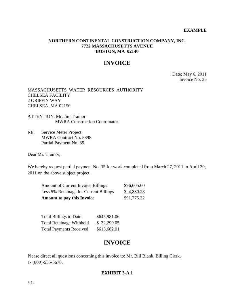
3-14
EXAMPLE
NORTHERN CONTINENTAL CONSTRUCTION COMPANY, INC. 7722 MASSACHUSETTS AVENUE
BOSTON, MA 02140
INVOICE
Date: May 6, 2011 Invoice No. 35
MASSACHUSETTS WATER RESOURCES AUTHORITY CHELSEA FACILITY 2 GRIFFIN WAY CHELSEA, MA 02150 ATTENTION: Mr. Jim Trainor MWRA Construction Coordinator RE: Service Meter Project MWRA Contract No. 5398 Partial Payment No. 35 Dear Mr. Trainor, We hereby request partial payment No. 35 for work completed from March 27, 2011 to April 30, 2011 on the above subject project. Amount of Current Invoice Billings $96,605.60 Less 5% Retainage for Current Billings $ 4,830.28 Amount to pay this Invoice $91,775.32 Total Billings to Date $645,981.06 Total Retainage Withheld $ 32,299.05 Total Payments Received $613,682.01
INVOICE Please direct all questions concerning this invoice to: Mr. Bill Blank, Billing Clerk, 1- (800)-555-5678.
EXHIBIT 3-A.1
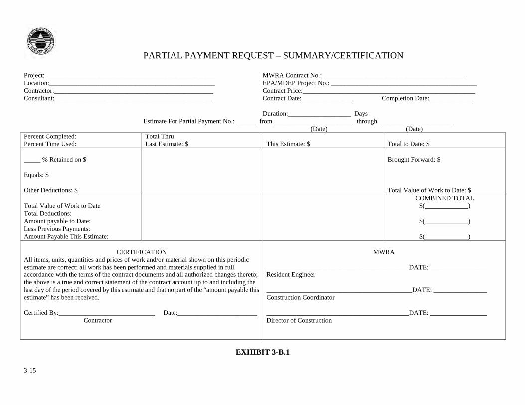
3-15
PARTIAL PAYMENT REQUEST – SUMMARY/CERTIFICATION
Project: ___________________________________________________ MWRA Contract No.: ___________________________________________ Location:__________________________________________________ EPA/MDEP Project No.: ____________________________________________ Contractor:________________________________________________ Contract Price:____________________________________________________ Consultant:________________________________________________ Contract Date: _______________ Completion Date:_____________
Duration:___________________ Days Estimate For Partial Payment No.: ______ from ________________________ through ______________________ (Date) (Date) Percent Completed: Percent Time Used:
Total Thru Last Estimate: $
This Estimate: $
Total to Date: $
_____ % Retained on $ Equals: $ Other Deductions: $
Brought Forward: $ Total Value of Work to Date: $
Total Value of Work to Date Total Deductions: Amount payable to Date: Less Previous Payments: Amount Payable This Estimate:
COMBINED TOTAL $(_____________)
$(_____________)
$(_____________)
CERTIFICATION
All items, units, quantities and prices of work and/or material shown on this periodic estimate are correct; all work has been performed and materials supplied in full accordance with the terms of the contract documents and all authorized changes thereto; the above is a true and correct statement of the contract account up to and including the last day of the period covered by this estimate and that no part of the “amount payable this estimate” has been received. Certified By:_____________________________ Date:________________________ Contractor
MWRA
___________________________________________DATE: _________________ Resident Engineer ____________________________________________DATE: ________________ Construction Coordinator ___________________________________________DATE: _________________ Director of Construction
EXHIBIT 3-B.1
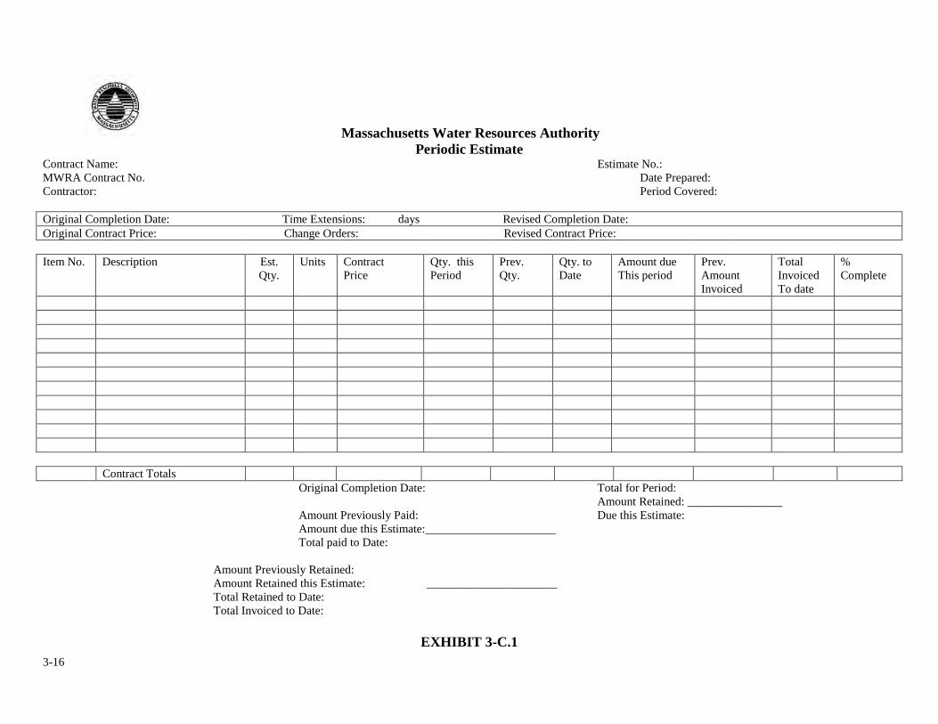
3-16
Massachusetts Water Resources Authority Periodic Estimate
Contract Name: Estimate No.: MWRA Contract No. Date Prepared: Contractor: Period Covered: Original Completion Date: Time Extensions: days Revised Completion Date: Original Contract Price: Change Orders: Revised Contract Price: Item No. Description Est.
Qty. Units Contract
Price Qty. this Period
Prev. Qty.
Qty. to Date
Amount due This period
Prev. Amount Invoiced
Total Invoiced To date
% Complete
Contract Totals
Original Completion Date: Total for Period: Amount Retained: ________________ Amount Previously Paid: Due this Estimate: Amount due this Estimate:______________________ Total paid to Date:
Amount Previously Retained:
Amount Retained this Estimate: ______________________ Total Retained to Date: Total Invoiced to Date:
EXHIBIT 3-C.1
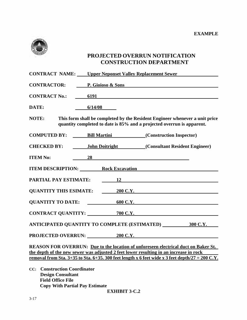
3-17
EXAMPLE
PROJECTED OVERRUN NOTIFICATION
CONSTRUCTION DEPARTMENT CONTRACT NAME: Upper Neponset Valley Replacement Sewer CONTRACTOR: P. Gioioso & Sons CONTRACT No.: 6191 DATE: 6/14/08 NOTE: This form shall be completed by the Resident Engineer whenever a unit price
quantity completed to date is 85% and a projected overrun is apparent. COMPUTED BY: Bill Martini (Construction Inspector) CHECKED BY: John Doitright (Consultant Resident Engineer) ITEM No: 28 ITEM DESCRIPTION: Rock Excavation PARTIAL PAY ESTIMATE: 12 QUANTITY THIS ESIMATE: 200 C.Y. QUANTITY TO DATE: 600 C.Y. CONTRACT QUANTITY: 700 C.Y. ANTICIPATED QUANTITY TO COMPLETE (ESTIMATED) 300 C.Y. PROJECTED OVERRUN: 200 C.Y. REASON FOR OVERRUN: Due to the location of unforeseen electrical duct on Baker St. the depth of the new sewer was adjusted 2 feet lower resulting in an increase in rock removal from Sta. 3+35 to Sta. 6+35. 300 feet length x 6 feet wide x 3 feet depth/27 = 200 C.Y. CC: Construction Coordinator Design Consultant Field Office File Copy With Partial Pay Estimate
EXHIBIT 3-C.2
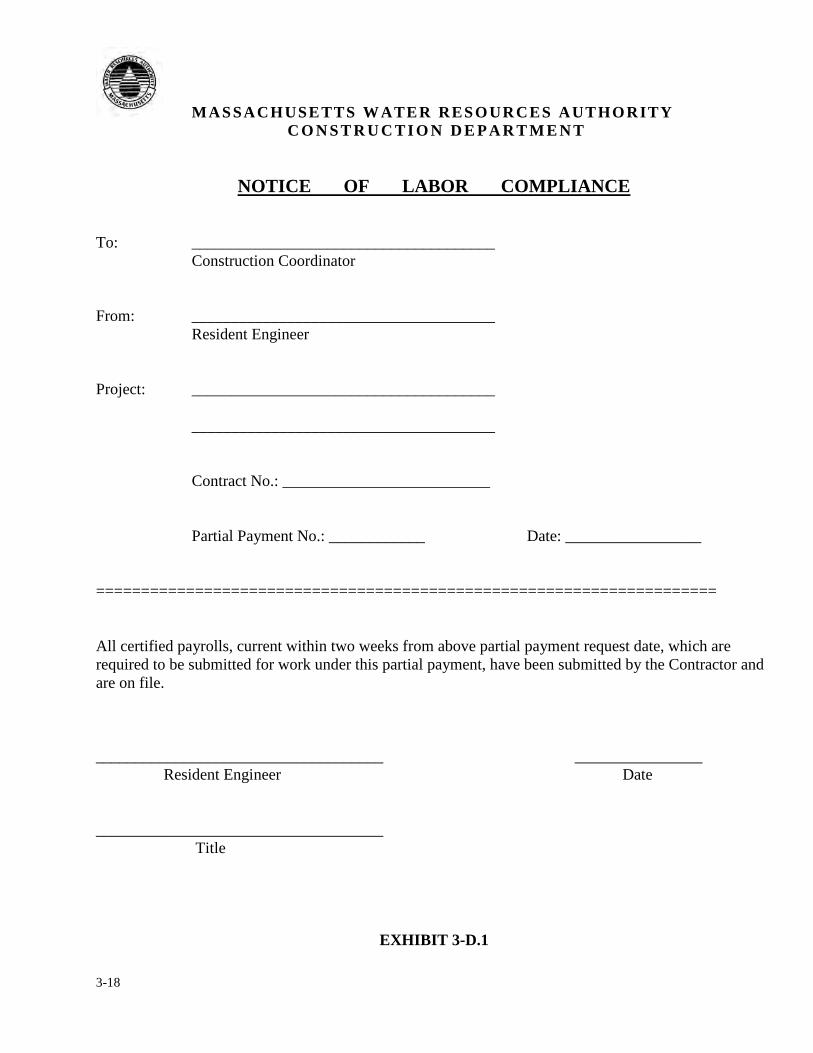
3-18
MASSACHUSETTS WATER RESOURCES AUTHORITY C O N S T R U C T I O N D E P A R T M E N T
NOTICE OF LABOR COMPLIANCE To: ______________________________________ Construction Coordinator From: ______________________________________ Resident Engineer Project: ______________________________________ ______________________________________ Contract No.: __________________________ Partial Payment No.: ____________ Date: _________________ ===================================================================== All certified payrolls, current within two weeks from above partial payment request date, which are required to be submitted for work under this partial payment, have been submitted by the Contractor and are on file. ____________________________________ ________________ Resident Engineer Date ____________________________________ Title
EXHIBIT 3-D.1
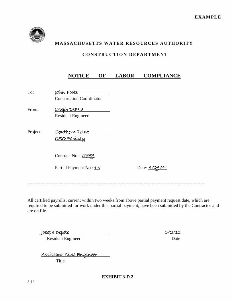
3-19
EXAMPLE
MASSACHUSETTS WATER RESOURCES AUTHORITY
C O N S T R U C T I O N D E P A R T M E N T
NOTICE OF LABOR COMPLIANCE To: ���������������������������������������� ���� ���� ���� Construction Coordinator From: ������ ������� ������� ������� ����� ���� Resident Engineer Project: �������� ������������ ������������ ������������ �������� ���� ������������������������������������������������� Contract No.: �������������������� Partial Payment No.: �������� Date: �������� � � � ������������� ===================================================================== All certified payrolls, current within two weeks from above partial payment request date, which are required to be submitted for work under this partial payment, have been submitted by the Contractor and are on file.
������������������������������������ ���� ���� �� ��� ��� ��� ������������� ���� Resident Engineer Date
!��������"���#�$���!��������"���#�$���!��������"���#�$���!��������"���#�$������� Title
EXHIBIT 3-D.2
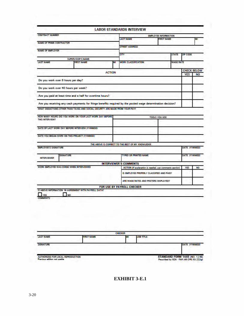
3-20
EXHIBIT 3-E.1
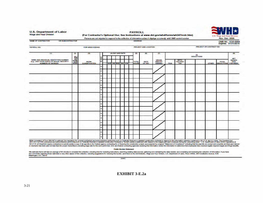
3-21
EXHIBIT 3-E.2a
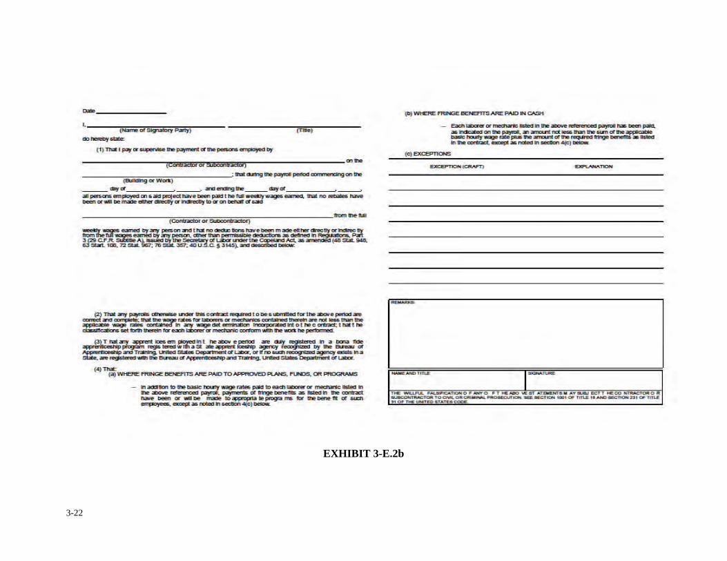
3-22
EXHIBIT 3-E.2b
3-23
3. INTERIM RECORDS & REQUIREMENTS
3.2 PROGRESS SCHEDULES
As set forth in the contract, the contractor is required to submit to the resident engineer an initial
baseline progress schedule for work to be performed. The contractor's schedule should be realistic
and prepared in detailed form to include all obvious features of work to be accomplished. It is the
responsibility of the construction coordinator and design consultant with input from the resident
engineer to promptly review the contractor's proposed schedule with care. If in the opinion of the
construction coordinator, design consultant and resident engineer, the proposed schedule appears
to be practical and adequate, he/she shall make a recommendation to the contractor accepting the
schedule as the "Baseline Schedule" of record. If the proposed schedule is not sufficiently detailed
and/or does not meet any contract constraints, the contract milestones or the overall completion
date, the construction coordinator shall promptly notify the resident engineer of the apparent
problems concerning the schedule, and have the resident engineer initiate a meeting with the
contractor in an attempt to resolve the areas of conflicts.
Once the Baseline Schedule has been accepted, it should not be modified unless the schedule
becomes unrealistic or if the duration of the project is extended through a change order. It is from
the Baseline Schedule that the contractor's progress is measured.
All other schedules generated from the Baseline Schedule will be referred to as "Progress
Schedules".
3-24
The contractor is normally required by contract to update the schedule on a monthly basis or at the
end of each pay period. These updated schedules shall be consecutively numbered similar to the
numbers of the partial payment requests. The construction coordinator, consultant and resident
engineer shall review the updated schedule to determine if the progress of work is satisfactory. If
the progress of work or scheduled milestones is not in conflict with the contract requirements, the
schedule shall be deemed in compliance and the construction coordinator shall make a
recommendation accepting the updated schedule for that particular progress period. If the updated
schedule does not meet the contract requirements, and the contractor has not offered a valid
explanation, the construction coordinator shall promptly notify the contractor of his/her decision
and return it to the contractor as being unacceptable.
The resident engineer shall post the current schedule somewhere in his/her office and plot the
contractor's actual progress of the work on the schedule, on a daily/weekly basis. If the resident
engineer discovers lack of progress, he/she shall promptly bring it to the construction
coordinator’s and Construction Department’s attention.
On a monthly basis, the resident engineer must prepare a report comparing the contractor's actual
progress with the anticipated progress of the baseline schedule. The report shall be sent to the
construction coordinator and shall summarize all work which has been completed and all work to
be performed in the near future. The report shall also show any delays or anticipated delays and, if
necessary, what actions the contractor is taking to overcome the delays. The above report will be
part of the "Monthly Progress Report" which will be discussed in Section 3.4 of this manual.

3-25
When the contractor has a valid reason for time extension, as approved in a change order he/she
should modify the current schedule to show how and when the remaining work is to be completed.
The modified schedule is to be practical, realistic, logical and show all revised work sequences
affected by the time extension. The modified schedule shall also show the new adjusted milestones
and completion date. The proposed modified schedule is to be reviewed by the construction
coordinator using the same guidelines as reviewing an initial schedule previously mentioned
above. If found acceptable, the modified schedule will then be used as a basis to measure the
contractor's future progress. Once the schedule is accepted the contractor will be required to update
it according to the same requirements as mentioned above.
The Construction Department shall not recommend acceptance of the modified schedule
unless a change order extending the milestone and project completion date(s) has been
executed by the Authority.
When the contractor does not have a valid reason as to why the project is behind schedule, the
construction coordinator shall request the contractor revise the current schedule and show what
action is being taken to complete the remaining contract work within the contract time. If the
contractor can not produce a schedule that meets the contract requirements, the construction
coordinator shall immediately refer the matter to the Assistant Director of Construction. Project
schedules can be generated either by hand or by computer. Most construction contracts require the
schedule be produced by computer, however, on small less complicated projects, a hand drawn bar
chart is acceptable. There are basically two types of schedules: the Bar Chart (Gant) schedule and
the Network Logic Diagram schedule. The most commonly used, and the easier of the two to
3-26
understand, is the Bar Chart. The Bar Chart is a graphic schedule representation using proportional
bars to show the start and completion times of each work activity in a linear calendar format. The
Network Logic Diagram is a more sophisticated type of scheduling where each work activity is
logically interrelated or dependent upon other work activities to form a sequence in which all
activities of the schedule will be performed. The latter schedule is often referred to as a Critical
Path Method (CPM).�
The Early Start and Early Finish dates are generated from the project start date (notice to proceed)
and represent the earliest times in which work on a particular activity can be performed. The Late
Start and Late Finish dates are generated from the project completion date or adjusted/revised
completion date and represent the latest times in which work on a particular activity must be
performed without delaying the contract.
Total float is the difference in time between the Early Start and the Late Start or the difference
between the Early Finish and the Late Finish. If the difference generates a positive number, it
means the work activity has developed float or slack time. Float or slack time is the length of time
that the start of an individual activity may be delayed without impacting the project completion. If
the difference generates a negative number, the work of the activity has fallen behind schedule and
is impacting the completion of the project (Initial Schedules can not have any activities that have
negative float). If the difference generates a zero (0) number, the work of the activity is considered
critical. The work must start on the date scheduled and must finish on or before the scheduled
finish dates or the work will impact subsequent work and the scheduled project completion. All
network logic diagrams generate what is called a "Critical Path". The critical path is made up of all
3-27
work activities having zero float. Generally, it is the longest time path on the schedule. It starts
with the start of construction (notice to proceed) then travels through the schedule in a sequential
manor and ends with project completion. �
The following are some important definitions the construction staff should be familiar with when
dealing with project schedules;
ACTIVITY: The performance of a specific task with resources (time, manpower, equipment,
etc.).
ACTIVITY DESCRIPTION: A short written statement of the work involved in an activity.
BAR CHART: A graphic schedule representation using proportional bars to show the duration of
each work activity in a linear calendar format.
DURATION: The amount of time estimated to accomplish an activity considering the scope of
the work involved in the activity and the resources to be used.
WORK ITEM: Another term for an activity used in some precedence diagrams.
SEQUENCE: The logical order of activities or work items may depend on interdependence or on
the availability of information, authorization, or resources.
NETWORK: Used interchangeably with "diagram". It is a drawing of arrows and boxes or circles
that represent activities and their interdependence. The direction of the arrows indicates the
sequence in which the activities will be performed.
DEPENDENCY: A determining condition factor on a work item or activity (work activity) in a
construction schedule. The work activity may be contingent upon another work activity or upon
nature. This dependence is referred to as "Natural or Physical Dependency". The work activity
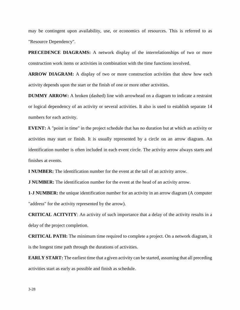
3-28
may be contingent upon availability, use, or economics of resources. This is referred to as
"Resource Dependency".
PRECEDENCE DIAGRAMS: A network display of the interrelationships of two or more
construction work items or activities in combination with the time functions involved.
ARROW DIAGRAM: A display of two or more construction activities that show how each
activity depends upon the start or the finish of one or more other activities.
DUMMY ARROW: A broken (dashed) line with arrowhead on a diagram to indicate a restraint
or logical dependency of an activity or several activities. It also is used to establish separate 14
numbers for each activity.
EVENT: A "point in time" in the project schedule that has no duration but at which an activity or
activities may start or finish. It is usually represented by a circle on an arrow diagram. An
identification number is often included in each event circle. The activity arrow always starts and
finishes at events.
I NUMBER: The identification number for the event at the tail of an activity arrow.
J NUMBER: The identification number for the event at the head of an activity arrow.
1-J NUMBER: the unique identification number for an activity in an arrow diagram (A computer
"address" for the activity represented by the arrow).
CRITICAL ACITVITY: An activity of such importance that a delay of the activity results in a
delay of the project completion.
CRITICAL PATH: The minimum time required to complete a project. On a network diagram, it
is the longest time path through the durations of activities.
EARLY START: The earliest time that a given activity can be started, assuming that all preceding
activities start as early as possible and finish as schedule.
3-29
EARLY FINISH: The earliest time that a given activity can be finished, assuming. It started at
early start and uses the given duration.
FLOAT OR SLACK: Float time is the length of time that the start of an individual activity may
be delayed without changing the project completion time. It is the total time available along any
path in a network less the sum of the durations of the activities along the path.
LATE START: The latest time that a given activity can be started and still allow the project to be
completed on schedule. All following activities on the same path will be "critical."
LATE FINISH: The latest time that a given activity can be finished and still allow the project to
be completed on schedule.
3-30
3. INTERIM RECORDS & REQUIREMENTS
3.3 VIDEO RECORDING AND PHOTOGRAPHS
A continued theme of the resident engineer’s responsibility is documentation of the work in three
phases of a construction project; pre-construction, construction progress and post construction.
Following the pre-construction meeting and prior to the contractor mobilizing to the project site it
is standard practice for an Authority construction contract to require the contractor to perform a
pre-construction video of project’s limit of work area. For pipeline project this will consist of
video recording the surface conditions along baseline route from starting point to end point and
then reversing video from end point to beginning. This video recording shall be performed in DVD
format with minimum of three DVDs provided to the Authority for review with one copy each to
be filed with home office, resident engineer and contractor. The focus of the pre-construction
video is to record the existing conditions of surface items such as street and traffic signs, traffic
signals, pavements, walks and drives, curbing, retaining walls, utility poles, lawns, guardrails,
fences, mailboxes etc. The resident engineer shall review the DVD to verify the documentation is
a proper representation of the project limit of work prior to contractor starting any physical
construction. In the case of a building or structural facility modification a video survey
documenting the existing conditions of the physical materials and equipment shall be performed.
All building material and equipment shall be cataloged for future reference.
The resident engineer shall be aware that all such video and photographic documentation may be
required to defend the Authority from property damage or liability claims and proper identification
3-31
and description is essential. If in the opinion of the resident engineer supplemental photographs are
required, he/she shall take digital images to be recorded on a compact disk, CD, with printed
copies placed in holders and stored in three ring binders. All photographs shall have a label
identifying the project name, contract number, date, location and brief description of what is being
viewed.
Progress photographs shall be taken by the contractor routinely the last week of the month. The
progress photos shall be submitted with the contractor’s monthly pay requisition for review and
acceptance by the resident engineer. The contractor shall submit monthly photographs in
accordance with the requirements of the contract for number of photographs and manner of the
submittal in accordance to shop drawing submittal requirements. The resident engineer and
his/her staff shall not rely solely on contractor requirement for photographs to document the
progress or the conditions of the work being completed. The field staff shall supplement their field
reports with photographs to record any change in the work, damage to property, or unforeseen
conditions or requirements.
After substantial completion has been documented but prior to project closeout and the
authorization of contractor’s final payment, post construction video and photographs shall be
taken to record completion of the project. Resident engineer shall confirm if final aerial
photographs depicting the completed limits of work are required in the contract. Additionally, the
resident engineer shall confirm all contractor clean up, demobilization, street and easement
restoration and landscape requirements has been completed prior to post construction video and
photography being authorized.

3-32
The transmittal of video DVDs, photography prints, and photo-CDs shall be in specific mailer for
photographs and marked “Photographs-Do Not bend”.
Resident engineer shall have in his/her files a written release from the contractor, photographer
and videographer allowing the publication and use of all photographs and videos by the Authority.
A copy of this release shall be forwarded to the construction coordinator for the home office files.
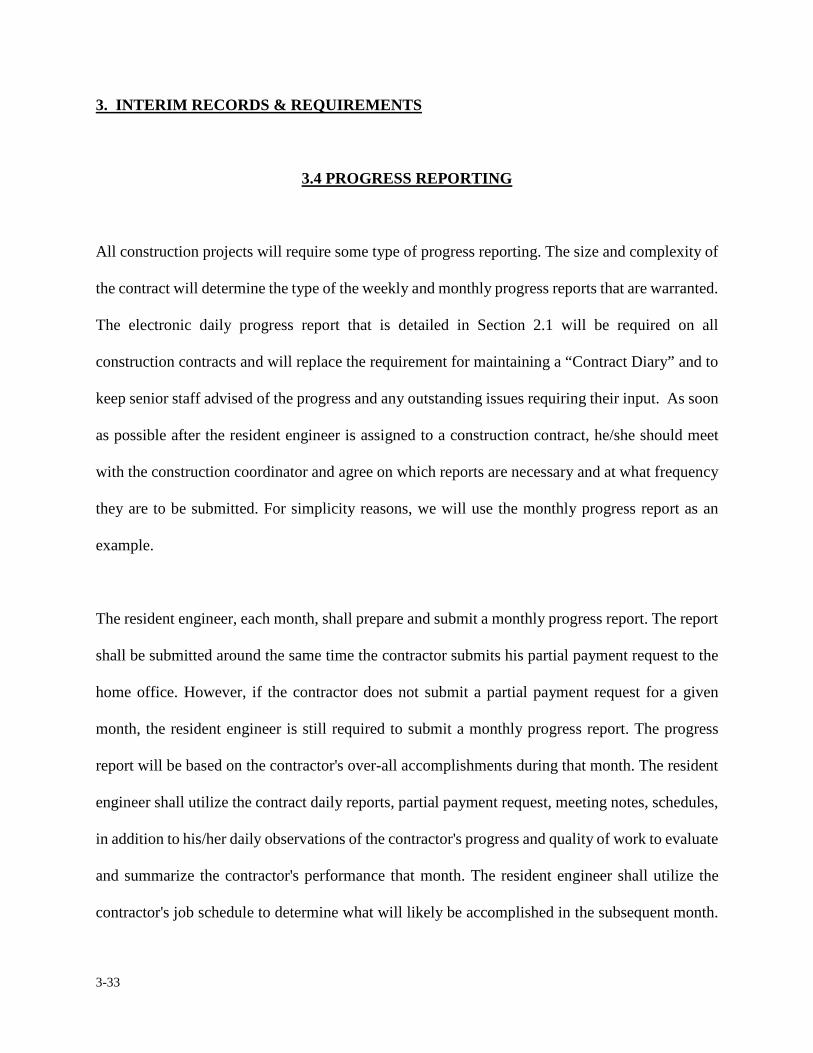
3-33
3. INTERIM RECORDS & REQUIREMENTS
3.4 PROGRESS REPORTING
All construction projects will require some type of progress reporting. The size and complexity of
the contract will determine the type of the weekly and monthly progress reports that are warranted.
The electronic daily progress report that is detailed in Section 2.1 will be required on all
construction contracts and will replace the requirement for maintaining a “Contract Diary” and to
keep senior staff advised of the progress and any outstanding issues requiring their input. As soon
as possible after the resident engineer is assigned to a construction contract, he/she should meet
with the construction coordinator and agree on which reports are necessary and at what frequency
they are to be submitted. For simplicity reasons, we will use the monthly progress report as an
example.
The resident engineer, each month, shall prepare and submit a monthly progress report. The report
shall be submitted around the same time the contractor submits his partial payment request to the
home office. However, if the contractor does not submit a partial payment request for a given
month, the resident engineer is still required to submit a monthly progress report. The progress
report will be based on the contractor's over-all accomplishments during that month. The resident
engineer shall utilize the contract daily reports, partial payment request, meeting notes, schedules,
in addition to his/her daily observations of the contractor's progress and quality of work to evaluate
and summarize the contractor's performance that month. The resident engineer shall utilize the
contractor's job schedule to determine what will likely be accomplished in the subsequent month.
3-34
If in the opinion of the resident engineer, the contractor is not making sufficient progress or is not
complying with the contract documents, the construction coordinator should be advised of this
matter immediately.
There are many types of formats in which a progress report can be generated, however, there are
five categories which the resident engineer is to address when preparing the progress report; 1) a
summary of construction activities accomplished for this reporting period, 2) a summary of
construction activities to be performed next month, 3) a summary of construction billings, 4) a
summary of all change orders or pending change orders and 5) the resident engineer's comments.
The following Exhibit 3-F.1 is an example of a typical monthly and Exhibit 3-F.2 a weekly
progress report format. The resident engineer is instructed to use a format, similar to this example
or as otherwise approved by the construction coordinator.
If a consultant engineer is preparing the job's monthly progress report, a similar format should be
suggested and monitored by the Authority's resident engineer and construction coordinator.
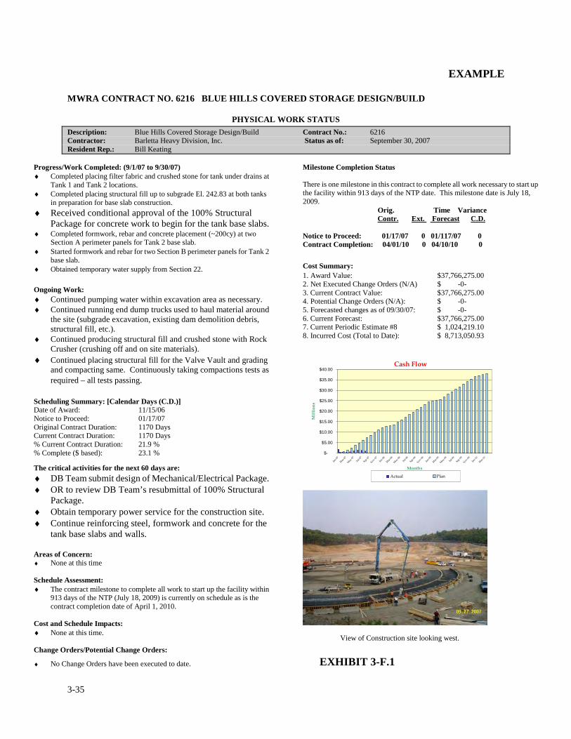
3-35
EXAMPLE
MWRA CONTRACT NO. 6216 BLUE HILLS COVERED STORAGE DESIGN/BUILD
PHYSICAL WORK STATUS
Description: Blue Hills Covered Storage Design/Build Contract No.: 6216 Contractor: Barletta Heavy Division, Inc. Status as of: September 30, 2007 Resident Rep.: Bill Keating
Progress/Work Completed: (9/1/07 to 9/30/07) ♦ Completed placing filter fabric and crushed stone for tank under drains at
Tank 1 and Tank 2 locations. ♦ Completed placing structural fill up to subgrade El. 242.83 at both tanks
in preparation for base slab construction. ♦ Received conditional approval of the 100% Structural
Package for concrete work to begin for the tank base slabs. ♦ Completed formwork, rebar and concrete placement (~200cy) at two
Section A perimeter panels for Tank 2 base slab. ♦ Started formwork and rebar for two Section B perimeter panels for Tank 2
base slab. ♦ Obtained temporary water supply from Section 22.
Ongoing Work: ♦ Continued pumping water within excavation area as necessary. ♦ Continued running end dump trucks used to haul material around
the site (subgrade excavation, existing dam demolition debris, structural fill, etc.).
♦ Continued producing structural fill and crushed stone with Rock Crusher (crushing off and on site materials).
♦ Continued placing structural fill for the Valve Vault and grading and compacting same. Continuously taking compactions tests as required – all tests passing.
Scheduling Summary: [Calendar Days (C.D.)] Date of Award: 11/15/06 Notice to Proceed: 01/17/07 Original Contract Duration: 1170 Days Current Contract Duration: 1170 Days % Current Contract Duration: 21.9 % % Complete ($ based): 23.1 %
The critical activities for the next 60 days are: ♦ DB Team submit design of Mechanical/Electrical Package. ♦ OR to review DB Team’s resubmittal of 100% Structural
Package. ♦ Obtain temporary power service for the construction site. ♦ Continue reinforcing steel, formwork and concrete for the
tank base slabs and walls. Areas of Concern: ♦ None at this time Schedule Assessment: ♦ The contract milestone to complete all work to start up the facility within
913 days of the NTP (July 18, 2009) is currently on schedule as is the contract completion date of April 1, 2010.
Cost and Schedule Impacts: ♦ None at this time. Change Orders/Potential Change Orders:
♦ No Change Orders have been executed to date.
Milestone Completion Status There is one milestone in this contract to complete all work necessary to start up the facility within 913 days of the NTP date. This milestone date is July 18, 2009. Orig. Time Variance Contr. Ext. Forecast C.D. Notice to Proceed: 01/17/07 0 01/117/07 0 Contract Completion: 04/01/10 0 04/10/10 0
Cost Summary:
1. Award Value: $37,766,275.00 2. Net Executed Change Orders (N/A) $ -0- 3. Current Contract Value: $37,766,275.00 4. Potential Change Orders (N/A): $ -0- 5. Forecasted changes as of 09/30/07: $ -0- 6. Current Forecast: $37,766,275.00 7. Current Periodic Estimate #8 $ 1,024,219.10 8. Incurred Cost (Total to Date): $ 8,713,050.93
View of Construction site looking west.
EXHIBIT 3-F.1
Cash Flow
$-
$5.00
$10.00
$15.00
$20.00
$25.00
$30.00
$35.00
$40.00
Jan-07
Mar
-07
May
-07Ju
l-07
Sep-07
Nov-07
Jan-08
Mar
-08
May
-08Ju
l-08
Sep-08
Nov
-08
Jan-09
Mar
-09
May
-09Ju
l-09
Sep-09
Nov-09
Jan-10
Mar
-10
Months
Mil
lion
s
Actual Plan
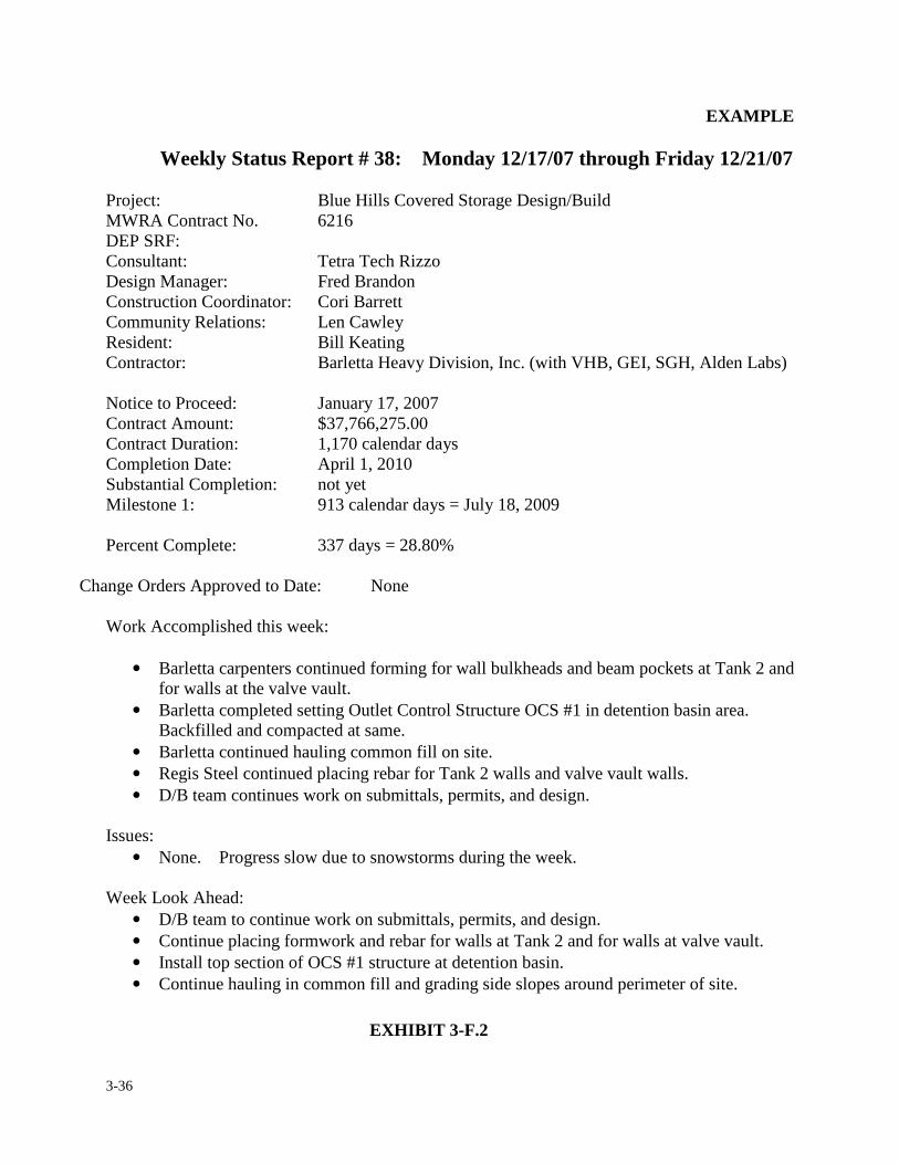
3-36
EXAMPLE
Weekly Status Report # 38: Monday 12/17/07 through Friday 12/21/07
Project: Blue Hills Covered Storage Design/Build MWRA Contract No. 6216 DEP SRF: Consultant: Tetra Tech Rizzo Design Manager: Fred Brandon Construction Coordinator: Cori Barrett Community Relations: Len Cawley Resident: Bill Keating Contractor: Barletta Heavy Division, Inc. (with VHB, GEI, SGH, Alden Labs) Notice to Proceed: January 17, 2007 Contract Amount: $37,766,275.00 Contract Duration: 1,170 calendar days Completion Date: April 1, 2010 Substantial Completion: not yet Milestone 1: 913 calendar days = July 18, 2009 Percent Complete: 337 days = 28.80%
Change Orders Approved to Date: None
Work Accomplished this week:
• Barletta carpenters continued forming for wall bulkheads and beam pockets at Tank 2 and
for walls at the valve vault. • Barletta completed setting Outlet Control Structure OCS #1 in detention basin area.
Backfilled and compacted at same. • Barletta continued hauling common fill on site. • Regis Steel continued placing rebar for Tank 2 walls and valve vault walls. • D/B team continues work on submittals, permits, and design.
Issues:
• None. Progress slow due to snowstorms during the week. Week Look Ahead:
• D/B team to continue work on submittals, permits, and design. • Continue placing formwork and rebar for walls at Tank 2 and for walls at valve vault. • Install top section of OCS #1 structure at detention basin. • Continue hauling in common fill and grading side slopes around perimeter of site.
EXHIBIT 3-F.2
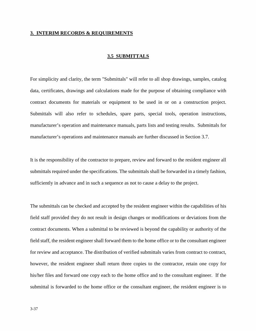
3-37
3. INTERIM RECORDS & REQUIREMENTS
3.5 SUBMITTALS
For simplicity and clarity, the term "Submittals" will refer to all shop drawings, samples, catalog
data, certificates, drawings and calculations made for the purpose of obtaining compliance with
contract documents for materials or equipment to be used in or on a construction project.
Submittals will also refer to schedules, spare parts, special tools, operation instructions,
manufacturer’s operation and maintenance manuals, parts lists and testing results. Submittals for
manufacturer’s operations and maintenance manuals are further discussed in Section 3.7.
It is the responsibility of the contractor to prepare, review and forward to the resident engineer all
submittals required under the specifications. The submittals shall be forwarded in a timely fashion,
sufficiently in advance and in such a sequence as not to cause a delay to the project.
The submittals can be checked and accepted by the resident engineer within the capabilities of his
field staff provided they do not result in design changes or modifications or deviations from the
contract documents. When a submittal to be reviewed is beyond the capability or authority of the
field staff, the resident engineer shall forward them to the home office or to the consultant engineer
for review and acceptance. The distribution of verified submittals varies from contract to contract,
however, the resident engineer shall return three copies to the contractor, retain one copy for
his/her files and forward one copy each to the home office and to the consultant engineer. If the
submittal is forwarded to the home office or the consultant engineer, the resident engineer is to
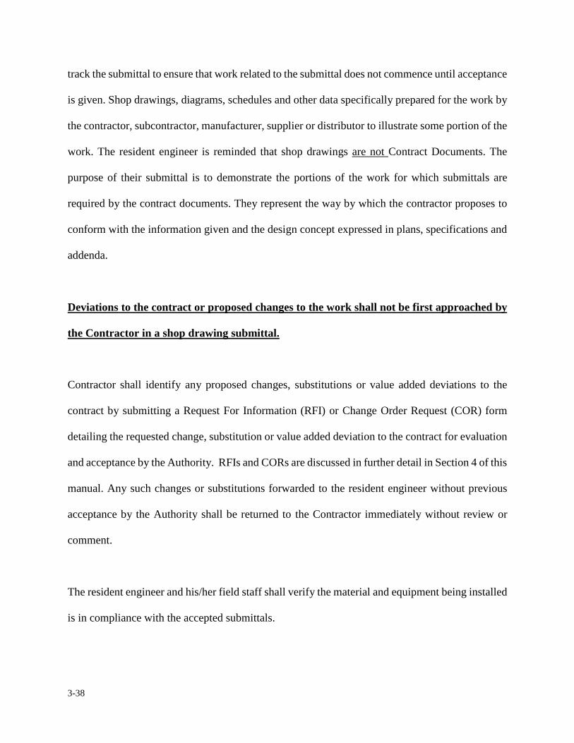
3-38
track the submittal to ensure that work related to the submittal does not commence until acceptance
is given. Shop drawings, diagrams, schedules and other data specifically prepared for the work by
the contractor, subcontractor, manufacturer, supplier or distributor to illustrate some portion of the
work. The resident engineer is reminded that shop drawings are not Contract Documents. The
purpose of their submittal is to demonstrate the portions of the work for which submittals are
required by the contract documents. They represent the way by which the contractor proposes to
conform with the information given and the design concept expressed in plans, specifications and
addenda.
Deviations to the contract or proposed changes to the work shall not be first approached by
the Contractor in a shop drawing submittal.
Contractor shall identify any proposed changes, substitutions or value added deviations to the
contract by submitting a Request For Information (RFI) or Change Order Request (COR) form
detailing the requested change, substitution or value added deviation to the contract for evaluation
and acceptance by the Authority. RFIs and CORs are discussed in further detail in Section 4 of this
manual. Any such changes or substitutions forwarded to the resident engineer without previous
acceptance by the Authority shall be returned to the Contractor immediately without review or
comment.
The resident engineer and his/her field staff shall verify the material and equipment being installed
is in compliance with the accepted submittals.
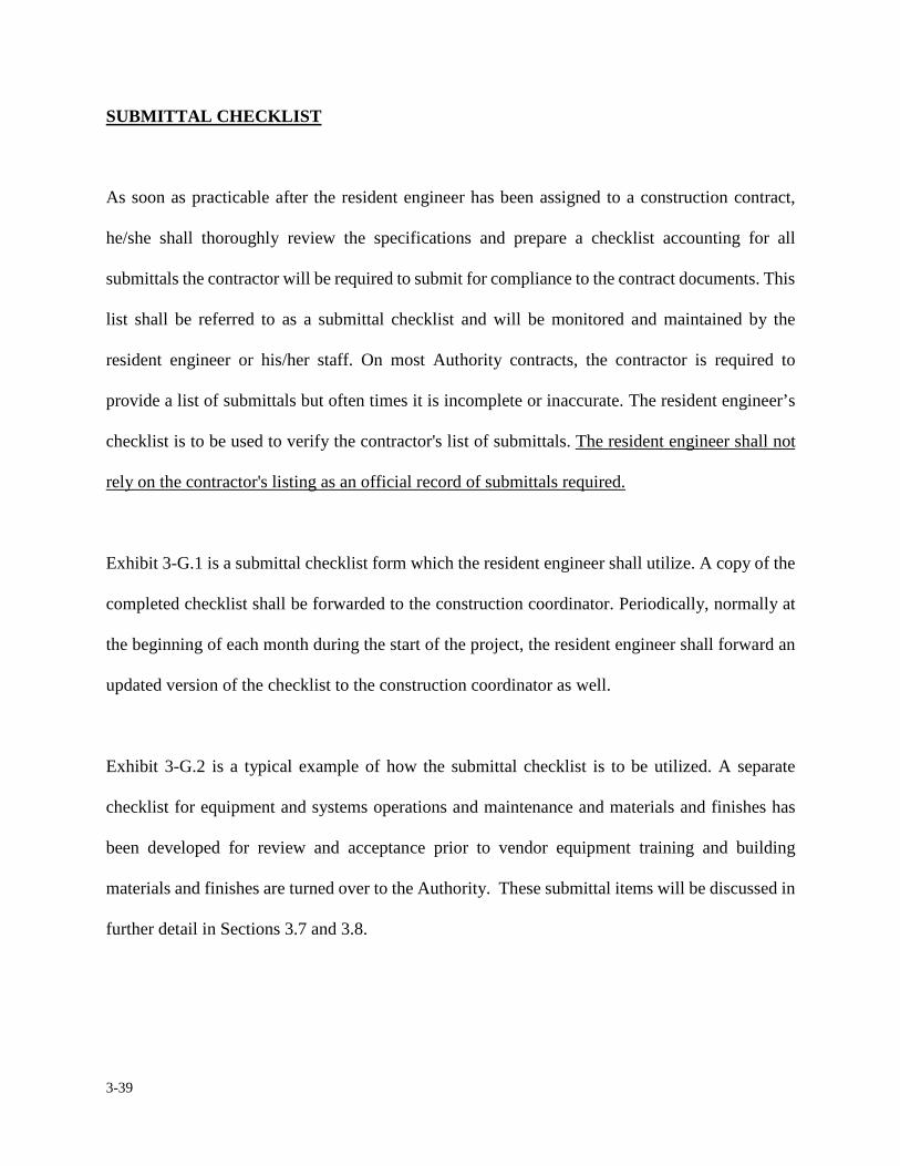
3-39
SUBMITTAL CHECKLIST
As soon as practicable after the resident engineer has been assigned to a construction contract,
he/she shall thoroughly review the specifications and prepare a checklist accounting for all
submittals the contractor will be required to submit for compliance to the contract documents. This
list shall be referred to as a submittal checklist and will be monitored and maintained by the
resident engineer or his/her staff. On most Authority contracts, the contractor is required to
provide a list of submittals but often times it is incomplete or inaccurate. The resident engineer’s
checklist is to be used to verify the contractor's list of submittals. The resident engineer shall not
rely on the contractor's listing as an official record of submittals required.
Exhibit 3-G.1 is a submittal checklist form which the resident engineer shall utilize. A copy of the
completed checklist shall be forwarded to the construction coordinator. Periodically, normally at
the beginning of each month during the start of the project, the resident engineer shall forward an
updated version of the checklist to the construction coordinator as well.
Exhibit 3-G.2 is a typical example of how the submittal checklist is to be utilized. A separate
checklist for equipment and systems operations and maintenance and materials and finishes has
been developed for review and acceptance prior to vendor equipment training and building
materials and finishes are turned over to the Authority. These submittal items will be discussed in
further detail in Sections 3.7 and 3.8.
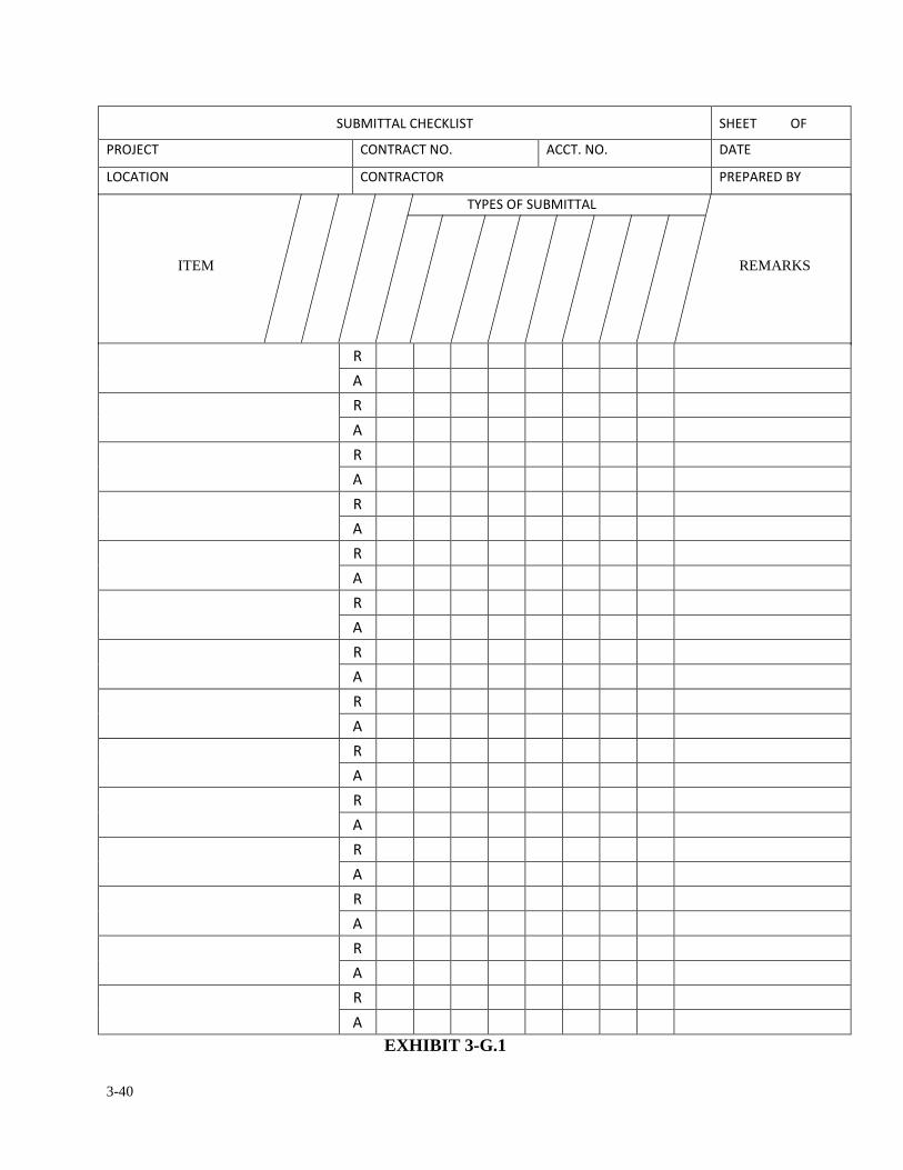
3-40
����������� ���� ������ �
��� ��� � ������ � � ���� � � ����
�� ���� � � ������ � ����������
������ ����������
�
�
� � � � � � � � � �
�
�
�
�
�
�
�
�
�
�
�
�
�
�
�
�
�
�
�
�
�
�
�
�
�
�
�
EXHIBIT 3-G.1
ITEM REMARKS
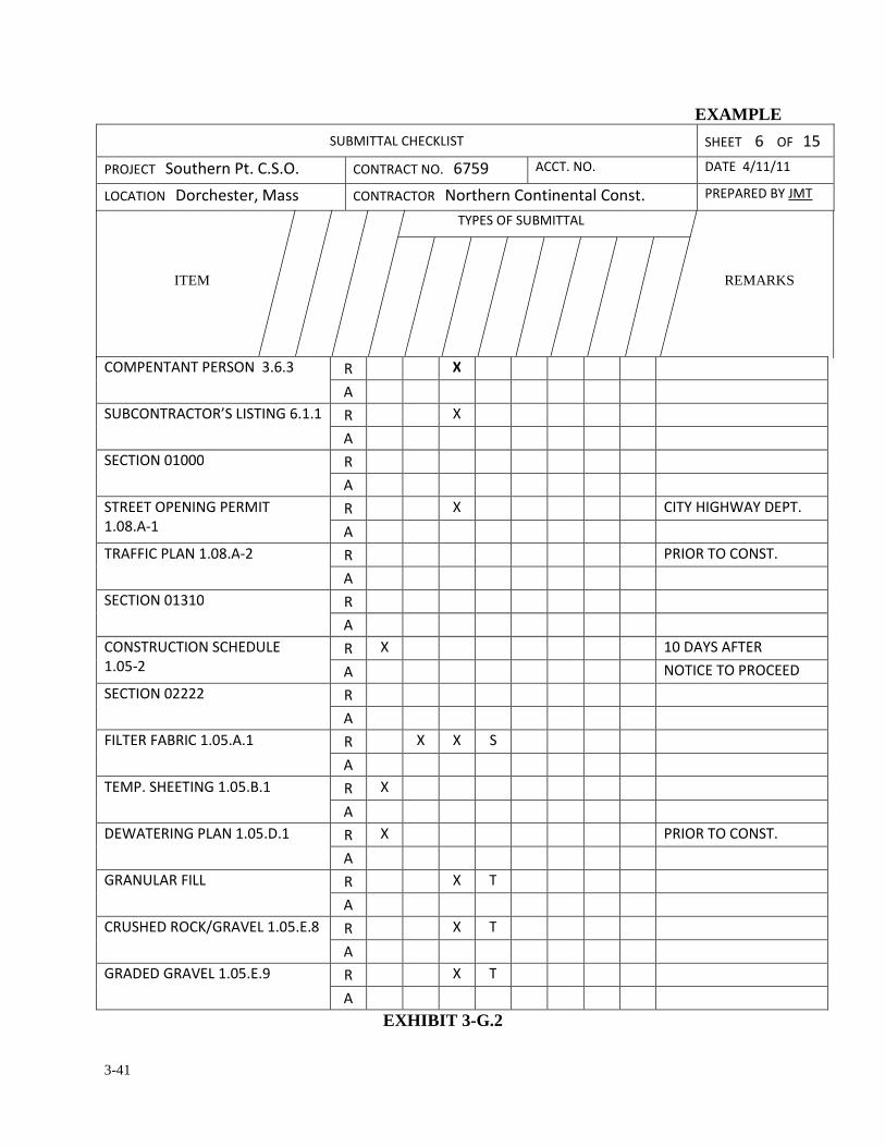
3-41
EXAMPLE ����������� ���� ������� ���
��� ���������� ������� � � ������ � ��!�" ���� � � ����#$��$��
�� ���� � ���%��&���'�(&& � � ����� �������� � �) � �(*� &�� �������������
������ ����������
�������������� � +���+ � � � �� � � � � � �
�
���� ������ �,�������- ����� � .
�
����� � /�/// �
�
������� ��� ��- ������
��/0��1�� . �����-�2 �������
�
���������� ��/0��13 � ���� ��� � ����
�
����� � /�+�/ �
�
� �������� � �������
��/�13� . �/���������
� � � ����� ��� ���
����� � /3333 �
�
�������������/����� � . . �
�
������������- ��/����� � .
�
��2 ������- ���� ��/����� � . ���� ��� � ����
�
-����������� � . �
�
������ �� $-��4����/����0 � . �
�
-����� -��4����/����" � . �
�
EXHIBIT 3-G.2
ITEM REMARKS
3-42
SHOP DRAWING LOG
Timely and complete submittals of shop drawings will contribute materially to successful
completion, of the contract. A shop drawing log shall be maintained by the resident engineer. The
purpose of maintaining a shop drawing log is to have a record of the current status of any shop
drawing submittals to date. In order to avoid unnecessary delays to the project, the shop drawing
log shall be reviewed at frequent intervals by the resident engineer or his/her staff to ensure that all
required shop drawings, samples or other data have been provided sufficiently in advance of the
project requirement. In the event the resident engineer determines the contractor is procrastinating
or negligent in furnishing shop drawings, the resident engineer shall immediately advise the
contractor, in writing, of the shop drawings in question and request prompt action to avoid delays
to the project.
It is essential that shop drawings not only be-submitted in a timely manner, but also that they be
handled expeditiously by persons reviewing the shop drawings. In order to maintain control of
submittals, the resident engineer should develop and institute his/her own systematic checks and
follow up procedure for processing shop drawings on the project.
At the start of each assigned progress meeting, the resident engineer should discuss with the
contractor the current status of shop drawing submittals, reviews and/or acceptance by maintaining
the shop drawing log as a source of information.
Exhibit 3-H.1 is a sample form of a typical page of a resident engineer's shop drawing log. The first
3-43
three columns are used to identify the shop drawing being submitted. The next two series of
columns are identical and reserved for tracking the shop drawing until it has been satisfactorily
processed. Often times a shop drawing submittal may only need to be reviewed one time; however,
there may be times in which shop drawings require several reviews. It is the obligation of the
Authority to promptly review submittals once they are received. It is an accepted practice in most
construction contracts to give the submittals an immediate cursory review to determine if they are
in conformance with the specifications, and if they are in conformance, to review and return them
to the contractor within 30 calendar days. In receiving the shop drawing submittals, the resident
engineer shall date stamp the cover transmittal. This date will be considered as the actual date the
submittal was received and not the date entered by the contractor. In tracking the submittals the
resident engineer should always indicate who is reviewing the shop drawing and what its status is
by the codes noted at the bottom of the page; "C" for consultant Engineer, "F" for Field Office
Staff, "M" for MWRA Home Office and "O" for Others. An additional type of submittal log form
developed in a Microsoft Excel format maybe substituted for EXHIBIT 3-H.1 depending on the
complexity of the project and in compliance with construction coordinator’s direction and
consultant’s role if applicable.
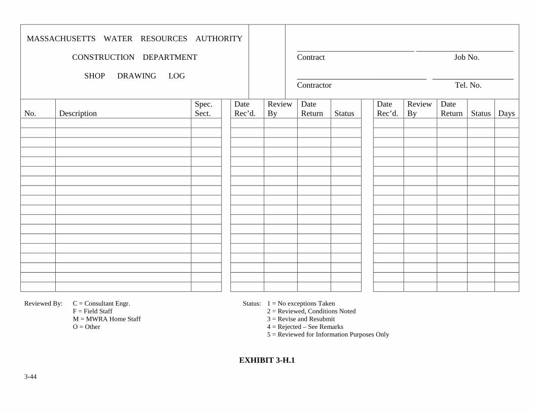
3-44
MASSACHUSETTS WATER RESOURCES AUTHORITY
CONSTRUCTION DEPARTMENT
SHOP DRAWING LOG
_____________________________ ________________________ Contract Job No. ________________________________ ____________________ Contractor Tel. No.
No.
Description
Spec. Sect.
Date Rec’d.
Review By
Date Return
Status
Date Rec’d.
Review By
Date Return
Status
Days
Reviewed By: C = Consultant Engr. Status: 1 = No exceptions Taken F = Field Staff 2 = Reviewed, Conditions Noted M = MWRA Home Staff 3 = Revise and Resubmit O = Other 4 = Rejected – See Remarks 5 = Reviewed for Information Purposes Only
EXHIBIT 3-H.1
3-45
SHOP DRAWING SUBMITALS
Submittals, particularly shop drawings, are to be submitted for complete systems. Partial submittals are not
permitted. The approval of a specific item shall not indicate acceptance of an assembly of which the item is
a component. All submittals shall be thoroughly checked by the resident engineer. or his/her field staff for
conformance with the contract requirements. Unsatisfactory submittals shall be promptly returned to the
contractor for correction and resubmission. The resident engineer shall specifically advise the contractor
that an acceptance of such drawings does not relieve the contractor of the responsibility for furnishing
material and equipment complying with the requirements of the contract documents or for any error which
may exist on the shop drawings or layout drawings.
No material, equipment or system will be allowed to be incorporated into the contract or
work performed until the shop drawing is accepted, or accepted as noted - no waiver to this
requirement is permitted or payment will be withheld by the Authority.
When reviewing requests for acceptance of methods and procedures for accomplishing such work
as blasting, control of groundwater, compaction of earthwork, grouting, pile driving, and other
types of work utilizing certain equipment and materials, care shall be given not only to request
methods and procedures, but also to require alternatives to meet all possible conditions.
Acceptances of this type should generally be made contingent upon proposed methods and
procedures obtaining the satisfactory specified results.
3-46
STANDARD TRANSMITTAL FORM
Exhibit 3-I.1 is a form for forwarding submittals to the Authority or Resident Engineer. This form
is to be made available to the contractor to transmit any item which the contract documents require
to be submitted. No action will be taken on any item unless accompanied by this form. Entries
must be printed or entered electronically. In order to expedite the processing of the submittal, the
following information is required.
See Exhibit 3-I.1:
��� Section 1 is intended only to accommodate any existing or desired in house numerical tracking systems of a contractor or consultant and is not relevant to the form's intended use.
��� The date is to be the date the form is filled out.
��� The project name and contract number are to be obtained from the contract documents.
��� The location is the city and state where the work is being done.
(5) The forms shall be numbered consecutively beginning with one. When an
item in any transmittal is to be resubmitted, the number of the original
transmittal shall be used followed by a capital letter starting at A and using
consecutive letters for each re-submittal. For example, if an item
appearing on Transmittal No. 10 is submitted for the second time, the
transmittal number will be 10A. A transmittal may consist of more than
one form, but the same transmittal number must appear on each form and
the total number of forms in the submittal noted on each (1 of 3, 2 of 3, and
so forth)
(6) Only one specification section number should be on each transmittal. Do
not mix items appearing in separate specification sections. The number
used shall be from the specification .section which covers the items being
3-47
submitted. (Several pumps for different purpose, all of which are covered
by one specification section, may be submitted on the same transmittal.
However, the pipe and valves that are used in connection with a pump
cannot be listed on the same transmittal as the pump since the pipe and
valves are covered by different specification sections.)
��� The address of the Authority or its Representative to which shop drawings
and other data are to be sent shall be determined at the preconstruction
conference.
��� In the space marked "From" shall be the name and the address of the contractor.
��� The item numbers shall be consecutive and shall start at one. THERE SHOULD BE NO MORE THAN ONE ITEM NUMBER ON EACH LINE. However, one item may cover two or more lines. Number each item.
�� The description of the item shall be in sufficient detail to clearly identify the item being submitted.
�� The manufacturer or designer shall be the originator of the drawing, catalog cut, brochure, etc.
��� The drawing number, catalog number, brochure number, etc. shall be the number used by the designer to identify the particular piece of paper. USE ONLY ONE NUMBER PER LINE.
��� The number of copies shall be the number of copies of the documents being submitted.
� � The contract drawing reference shall be the contract drawing(s) which shows the details of the particular item. If there is any question as to the item's use or application, indicate the intended service.
(15) The Contractor shall not mark in the final two columns headed "Engineer's Use”. These two columns are to be completed by the actual reviewer of the submittal.
3-48
(16) The space marked "Special Instructions" should be used to indicate other
drawings or other material with which the items being submitted must be
coordinated. In emergencies, if special handling or routing of the drawing is
requested, such instructions should be entered here.
(17) The signature and title of the contractor's representative who has reviewed
the material being submitted should be placed in the designated space. It is
the intent of this requirement that the person performing the review have the
necessary background and/or authority to perform this function. THIS IS A
CONTRACTUAL, NOT A CLERICAL CERTIFICATION.
(18) Prior to returning the submittal to the Contractor, it shall be signed, dated and the box checked indicating whether the reviewer is MWRA or the Consultant.
After reviewing and date stamping, make a copy of the transmittal submitted to the Authority or its
Representative as outlined in No. 7. Upon completion of the Consultant’s or Authority’s review,
you will receive the original white copy together with the number of copies of the submittal
required to be returned.
An electronic alternative to this process may be arranged during pre-construction meeting. The
General Contractor may choose to deliver and receive shop drawings through email or web based
system. The Authority’s acceptance of such a process will be dependent on the size and
complexity of the construction project and the availability of field office systems to support
electronic procedures. The resident engineer would be required to follow all notification and
documentation procedures for handling shop drawing submittals. The specific details of an
electronic system such as providing hard copies to field staff would be established at the
pre-construction meeting or shortly thereafter to the satisfaction of the Authority. General

3-49
Contractor and resident engineer’s contract responsibilities of implementing such a system would
not change.
The action for each item submitted will be noted in the right hand columns. Items marked with 1, 2
or 5 may be fabricated and incorporated into the work without further resubmittal of drawings,
provided that any noted corrections are made to the furnished item. Items marked 3 or 4 may not be
incorporated into the work until data concerning those items have been resubmitted and have
received an action code 1, 2 or 5.
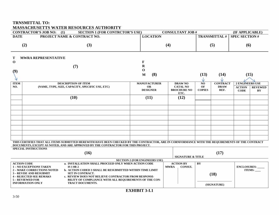
3-50
TRNSMITTAL TO: MASSACHUSETTS WATER RESOURCES AUTHORITY CONTRACTOR’S JOB NO: (1) SECTION 1 (FOR CONTRCTOR’S USE) CONSULTANT JOB # (IF APPLICABLE) DATE
(2)
PROJECT NAME & CONTRACT NO.
(3)
LOCATION
(4)
TRANSMITTAL #
(5)
SPEC SECTION #
(6)
T MWRA REPRESENTATIVE O
(7) (9)
F R O M (8) (13) (14) (15)
ITEM NO.
DESCRIPTION OF ITEM (NAME, TYPE, SIZE, CAPACITY, SPECIFIC USE, ETC) MANUFACTURER
OR DESIGNER
DRAW NO CATAL NO
BROCHURE NO ETC.
NO OF
COPIES CONTRACT
DRAW REF.
2 ENGINEERS USE ACTION
CODE REVEWED
BY
(10) (11) (12) THIS CERTIFIES THAT ALL ITEMS SUBMITTED HEREWITH HAVE BEEN CHECKED BY THE CONTRACTOR, ARE IN CORNFORMANCE WITH THE REQUIREMENTS OF THE CONTRACT DOCUMENTS, EXCEPT AS NOTED, AND ARE APPROVED BY THE CONTRACTOR FOR THIS PROJECT. SPECIAL INSTRUCTIONS (16)
(17) SIGNATURE & TITLE
SECTION 2 (FOR ENGINEERS USE) ACTION CODE 1 – NO EXCEPTIONS TAKEN 2 – MAKE CORRECTIONS NOTED 3 – REVISE AND RESUBMIT 4 – REJECTED SEE REMAKS 5 – REVIEWED FOR INFORMATION ONLY
a. INSTALLATION SHALL PROCEED ONLY WHEN ACTION CODE IS 1 0R 2 b. ACTION CODED 3 SHALL BE RESUBMITTED WITHIN TIME LIMIT SET IN CONTRACT. c. REVIEW DOES NOT RELIEVE CONTRACTOR FROM RESPONSI- BILITY OF COMPLIANCE WITH ALL REQUIREMENTS OF THE CON- TRACT DOCUMENTS.
ACTION BY MWRA CONSUL
BY (18)
(SIGNATURE)
ENCLOSURES: _____ ITEMS: ____
EXHIBIT 3-I.1
3-51
3. INTERIM RECORDS & REQUIREMENTS
3.6 STORED MATERIALS
An item may be included on the pay estimate to pay the contractor for special, job-unique materials
on hand which have not been incorporated into the work. Payment shall be made in accordance
with the provisions of the contract and shall be based on the paid invoice value, less any
deductions. Payment shall be made only on approved material to be incorporated into the project.
Materials are to be properly stored and protected at all times prior to installation. Care shall be
taken to ensure that the cost of the material does not constitute the cost for installation and testing.
Depending on the contract, certain restrictions exist regarding payment for the materials stored on
site. These restrictions are to be discussed with the contractor and clarified during the
preconstruction conference or shortly thereafter.
In order for the contractor to be paid for stored materials off site, the contractor must first obtain
written approval from the Authority through its resident engineer. Before approval is granted, the
resident engineer shall advise the general contractor that all charges associated with the storage,
including insurance, shall be borne solely by the contractor. In addition, the resident engineer shall
advise the contractor that any additional cost to the Authority resulting from the storage of
materials off-site, such as travel time and expenses for field engineer(s) may be back-charged to
the contractor.
3-52
Payment for materials stored off site shall be at the sole discretion of the Authority, via
recommendation by the resident engineer.
Before payment is recommended, the resident engineer shall receive proper "Title of Ownership"
of the materials being stored. Also, the resident engineer shall require; 1) proof of payment (paid
invoice, cancelled check etc.), 2) proof of insurance, 3) a notice identifying the contractor and/or
subcontractor leasing or owning the storage area, the exact location of the storage space within the
storage area, the date on which the material is first stored, and 4) the value of the material stored.
The contractor is required to label each sealed carton/crate to show the name of the MWRA
construction project, the MWRA contract number and resident engineer's name in clear view.
At least once a month the resident engineer or his designee shall inspect the materials being stored
at any off site location. The resident engineer will maintain an on-going inventory for all materials
held in storage for which payment has been requested and permission has been granted to the
contractor.
The resident engineer shall ensure that the title to the materials stored off site is transferred to the
Authority before he/she recommends payment for them. Exhibits 3-J.1 and 3-J.2 are forms
required for submission by the contractor to properly transfer title of ownership. Exhibit 3-J.1
transfers the ownership of equipment, materials or products from the manufacturer or supplier to
the contractor, and Exhibit 3-J.2 transfers the ownership of equipment, materials or products from
the contractor to the Authority. The resident engineer shall forward these forms to the contractor
upon his request. Once the forms are completed by the contractor and returned to the resident
3-53
engineer, he/she shall review the documents for accuracy. Also, the resident engineer should not
accept any title documents that are not properly notarized. A photocopy of the titles should
accompany the partial payment request as supporting backup, and the originals should be retained
for the resident engineer's files.
The following is a guideline for the resident engineer to use in determining if the Authority's
current procedures are being properly followed and payment of materials stored on-site or off-site
is justified.
MWRA'S GUIDELINES FOR PAYMENT OF MATERIALS STORED
1. Advanced written request and approval required for materials stored off site before
any payment is recommended.
2. Contractor must provide documents/information as follows:
a. Proof of payment by the person transferring title.
b. Materials must be paid in full.
c. Transfers of Title must properly be submitted.
d. Proof of insurance naming MWRA as beneficiary.
e. Name and address of storage area owner/lessor.
f. Specific location of MWRA materials.
g. Date materials placed in storage
h. Value of stored materials
3. Each carton/item to be marked with project data, and have a visible packing slip
attached. An inventory shall be maintained routinely.
3-54
4. Materials to be inspected by MWRA once per month or as deemed necessary by the
Consultant.
5. Personnel time and expenses for inspection to be paid by contractor.
6. Contractor must protect materials and transport them to project site.
7. Storage costs to be borne by contractor.
8. Contractor must provide manufacturer's recommended storage maintenance
requirements and provide a monthly statement certifying that proper storage
maintenance has been performed on each piece of stored material/equipment.
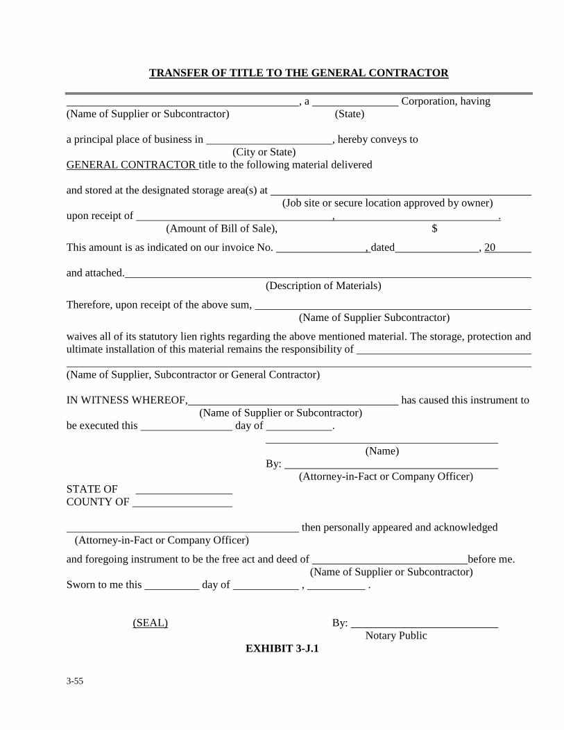
3-55
TRANSFER OF TITLE TO THE GENERAL CONTRACTOR
, a Corporation, having (Name of Supplier or Subcontractor) (State) a principal place of business in , hereby conveys to (City or State) GENERAL CONTRACTOR title to the following material delivered and stored at the designated storage area(s) at (Job site or secure location approved by owner) upon receipt of , . (Amount of Bill of Sale), $
This amount is as indicated on our invoice No. , dated , 20 and attached.
(Description of Materials)
Therefore, upon receipt of the above sum, (Name of Supplier Subcontractor)
waives all of its statutory lien rights regarding the above mentioned material. The storage, protection and ultimate installation of this material remains the responsibility of (Name of Supplier, Subcontractor or General Contractor) IN WITNESS WHEREOF, has caused this instrument to (Name of Supplier or Subcontractor) be executed this day of . (Name) By: (Attorney-in-Fact or Company Officer) STATE OF COUNTY OF then personally appeared and acknowledged (Attorney-in-Fact or Company Officer)
and foregoing instrument to be the free act and deed of before me. (Name of Supplier or Subcontractor) Sworn to me this day of , . (SEAL) By: Notary Public
EXHIBIT 3-J.1
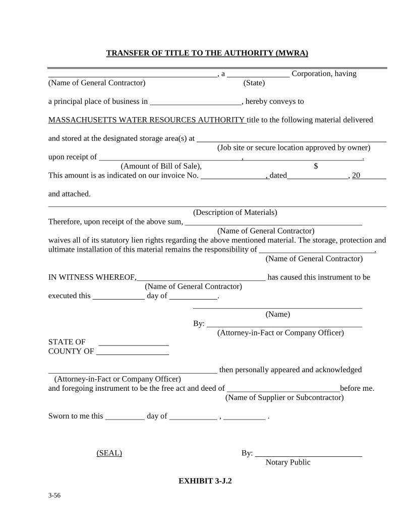
3-56
TRANSFER OF TITLE TO THE AUTHORITY (MWRA)
, a Corporation, having (Name of General Contractor) (State) a principal place of business in , hereby conveys to MASSACHUSETTS WATER RESOURCES AUTHORITY title to the following material delivered and stored at the designated storage area(s) at (Job site or secure location approved by owner) upon receipt of , . (Amount of Bill of Sale), $ This amount is as indicated on our invoice No. , dated , 20 and attached.
(Description of Materials) Therefore, upon receipt of the above sum, (Name of General Contractor) waives all of its statutory lien rights regarding the above mentioned material. The storage, protection and ultimate installation of this material remains the responsibility of . (Name of General Contractor) IN WITNESS WHEREOF, has caused this instrument to be (Name of General Contractor) executed this day of . (Name) By: (Attorney-in-Fact or Company Officer) STATE OF COUNTY OF then personally appeared and acknowledged (Attorney-in-Fact or Company Officer) and foregoing instrument to be the free act and deed of before me. (Name of Supplier or Subcontractor) Sworn to me this day of , . (SEAL) By: Notary Public
EXHIBIT 3-J.2
3-57
3. INTERIM RECORDS & REQUIREMENTS
3.7 MANUFACTURER’S OPERATIONS AND MAINTENANCE MANUALS
Operations and maintenance (O&M) manuals shall be submitted in similar manner for shop
drawings as detailed in Section 3.5. The resident engineer shall keep a separate submittal log to
document manuals have been submitted, acceptance and received.
O&M manuals shall be project specific. The contractor and/or vendor shall have reviewed and
edited the manuals to include the project specific model of the equipment supplied. Since O&M
manuals are bulky in nature, it is common practice for the contractor to submit three preliminary
copies for review and approval by the Authority. Once approved two copies shall be returned to the
contractor and one manual retained by the resident engineer to serve as his/her field copy. The
contractor shall then deliver to the resident engineer’s field office the remaining number of copies
required by the specific contract. The resident engineer shall acknowledge receipt of these
manuals by signature on submittal transmittal.
No startup, training or testing of equipment shall take place until these manuals have been
accepted. Manuals shall be delivered a minimum of thirty days prior to commencing
training, testing or startup of equipment.
EXHIBIT 3-K.1a through 3-K.1d is an example of a standard checklist for review of operations
and maintenance manuals. Resident engineer shall adapt the checklist to coincide with the specific
contract requirements. Reviewed checklist shall be signed by the reviewer and kept with the
resident engineer’s copy of the manual.
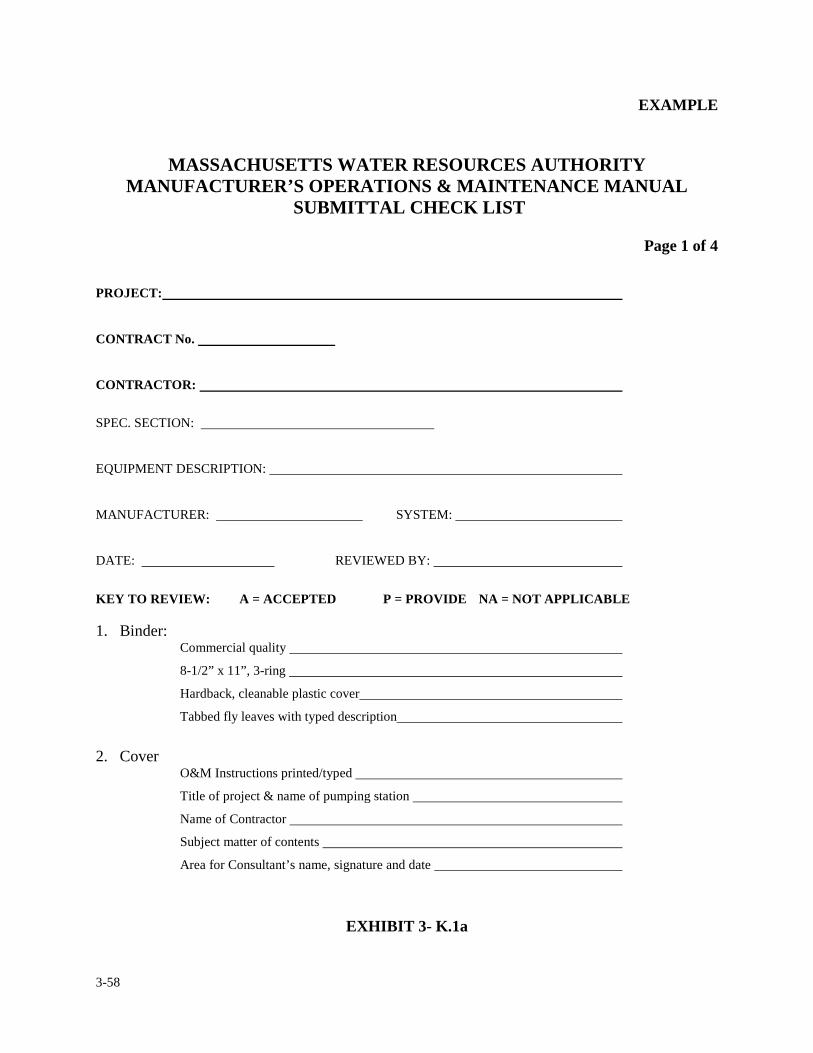
3-58
EXAMPLE
MASSACHUSETTS WATER RESOURCES AUTHORITY
MANUFACTURER’S OPERATIONS & MAINTENANCE MANUAL SUBMITTAL CHECK LIST
Page 1 of 4
PROJECT:
CONTRACT No.
CONTRACTOR:
SPEC. SECTION:
EQUIPMENT DESCRIPTION:
MANUFACTURER: SYSTEM:
DATE: REVIEWED BY:
KEY TO REVIEW: A = ACCEPTED P = PROVIDE NA = NOT APPLICABLE 1. Binder:
Commercial quality
8-1/2” x 11”, 3-ring
Hardback, cleanable plastic cover
Tabbed fly leaves with typed description
2. Cover
O&M Instructions printed/typed
Title of project & name of pumping station
Name of Contractor
Subject matter of contents
Area for Consultant’s name, signature and date
EXHIBIT 3- K.1a
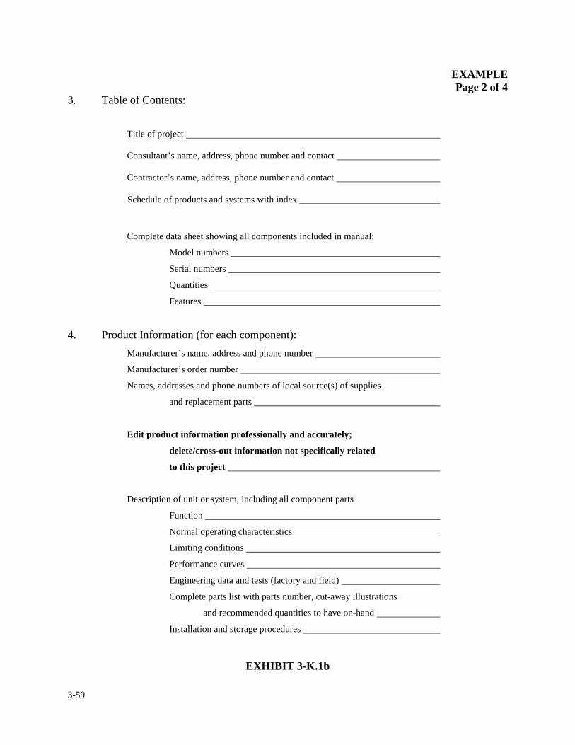
3-59
EXAMPLE Page 2 of 4
3. Table of Contents:
Title of project
Consultant’s name, address, phone number and contact
Contractor’s name, address, phone number and contact
Schedule of products and systems with index
Complete data sheet showing all components included in manual:
Model numbers
Serial numbers
Quantities
Features
4. Product Information (for each component):
Manufacturer’s name, address and phone number
Manufacturer’s order number
Names, addresses and phone numbers of local source(s) of supplies
and replacement parts
Edit product information professionally and accurately;
delete/cross-out information not specifically related
to this project
Description of unit or system, including all component parts
Function
Normal operating characteristics
Limiting conditions
Performance curves
Engineering data and tests (factory and field)
Complete parts list with parts number, cut-away illustrations
and recommended quantities to have on-hand
Installation and storage procedures
EXHIBIT 3-K.1b
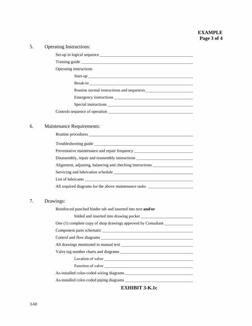
3-60
EXAMPLE Page 3 of 4
5. Operating Instructions:
Set-up in logical sequence
Training guide
Operating instructions
Start-up
Break-in
Routine normal instructions and sequences
Emergency instructions
Special instructions
Controls sequence of operation
6. Maintenance Requirements:
Routine procedures Troubleshooting guide
Preventative maintenance and repair frequency
Disassembly, repair and reassembly instructions
Alignment, adjusting, balancing and checking instructions
Servicing and lubrication schedule
List of lubricants
All required diagrams for the above maintenance tasks
7. Drawings:
Reinforced punched binder tab and inserted into text and/or
folded and inserted into drawing pocket
One (1) complete copy of shop drawings approved by Consultant
Component parts schematic
Control and flow diagrams
All drawings mentioned in manual text
Valve tag number charts and diagrams
Location of valve
Function of valve
As-installed color-coded wiring diagrams
As-installed color-coded piping diagrams EXHIBIT 3-K.1c
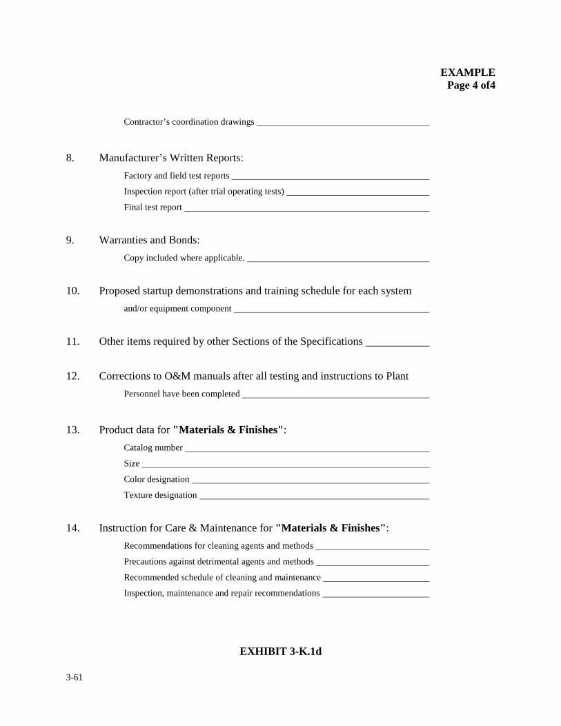
3-61
EXAMPLE Page 4 of4
Contractor’s coordination drawings
8. Manufacturer’s Written Reports:
Factory and field test reports
Inspection report (after trial operating tests)
Final test report
9. Warranties and Bonds:
Copy included where applicable.
10. Proposed startup demonstrations and training schedule for each system
and/or equipment component
11. Other items required by other Sections of the Specifications
12. Corrections to O&M manuals after all testing and instructions to Plant
Personnel have been completed
13. Product data for "Materials & Finishes":
Catalog number
Size
Color designation
Texture designation
14. Instruction for Care & Maintenance for "Materials & Finishes":
Recommendations for cleaning agents and methods
Precautions against detrimental agents and methods
Recommended schedule of cleaning and maintenance
Inspection, maintenance and repair recommendations
EXHIBIT 3-K.1d
3-62
3. INTERIM RECORDS & REQUIREMENTS
3.8 CHECKOUT, TESTING AND STARTUP OF SYSTEMS
This section shall describe resident engineer and field staff observation requirements for the
inspection of equipment checkout, testing and startup. Portions of the work or equipment may be
required to be put into operation or accepted by the Authority per contract milestones or to achieve
overall completion of the project.
When the Authority is required to take possession of portions of work before the contract is
declared substantially complete a comprehensive process for the start up of equipment systems has
been developed. The resident engineer will be required to examine the contract documents to
understand the contract requirements for the turnover of portion of the work such as equipment,
structures or operation systems. The resident engineer and the construction coordinator shall be
responsible for coordinating the work with the Authority Operations personnel. For example if a
construction contract for the upgrade of an existing pump station included an early milestone for
the Authority to occupy the newly constructed generator room to produce power, even though
overall project would not be completed for another year, this can be done once the contractor has
established the generator and associated systems have been verified to be put into operations. Once
this turnover occurs, the generator room becomes independent from the contract overall
substantial completion date. The resident engineer shall establish and document a specific punch
list and warranty period associated with this intermediate milestone. All other conditions of the
generator room relative to the technical specifications will continue to remain in effect. In
occupying the room, the Authority accepts the room as is, with the exception of unsatisfactory or
3-63
incomplete work items. Incomplete work items need to be identified to the contractor in writing
prior to the room being occupied and being accepted by the Authority. Therefore, it is absolutely
essential before the Authority accepts any area or systems that certain procedures be followed by
the resident engineer to ensure proper turn-over of portions of the work for the Authority’s use or
occupancy.
Prior to the resident engineer performing any type of building, system or equipment checkout or
testing, the contractor shall have submitted a checkout, testing and startup plan for approval by the
Authority.
The contractor’s startup plan shall contain the following items:
1. A chronological schedule of all checkout, testing and startup activities. 2. A checklist of all inspection, checkout, testing broken down by location,
discipline, system, and device or item. 3. All blank forms proposed by the Contractor for verification or recording of
the factory and field testing. 4. An index which cross references the forms to their intended application(s). 5. A list of all factory (shop) tests, and supplier’s certifications, including
those required by the applicable technical specifications. Provisions shall also be included for retesting, in the event it is required
6. Participants in the testing. 7. Special test equipment. 8. Sources of the test media (water, power, chemicals, air.) The proposed
method of delivery of the media to the equipment to be tested. 9. Temporary or interim connections for the sequencing of multiple units.
10. Ultimate disposal of the test media.
3-64
The procedure for system acceptance as recognized by the Authority shall consist of three
sequences being successfully performed, dry checkout, wet checkout and performance testing.
The steps to be taken before a portion of work can be accepted by the Authority are listed in the
order in which they should evolve.
Prior to the resident engineer performing any type of checkout, the contractor shall have
confirmed to the Authority that the authorized equipment and/or system manufacturers'
service representative(s) have performed a successful installation checkout and submitted
an installation certification form or letter.
The resident engineer or his/her designee shall document the successful completion of each step of
the following procedures. Exhibits 3-L.1 through 3-L.7 have been developed to offer a guide for
the resident engineer or his/her designee to document checkout and testing of each component of a
system prior to turnover to the Authority :
1. PIPE & TANK TESTING – HYDROSTATIC/PNEUMATIC:
Pipe and tank/vessel testing is to be conducted by the Contractor and witnessed by the
resident engineer or staff designee. Reference Exhibit 3-L.1.
2. EQUIPMENT SYSTEM PREOPERATIONAL CHECKLIST
(DRY CHECKOUT)
a. Dry Checkout of Piping, Valves and Gates. 1) Confirm hydrostatic/pneumatic tests have been conducted for pipelines and
valves. (Written test reports must be submitted by Contractor prior to scheduling Authority’s Dry Checkout.)
3-65
2) Confirm potable water pipelines have been disinfected (Written test reports
must be submitted by Contractor prior to scheduling Authority’s Dry Checkout).
3) Check that pipelines, valves and gates are supported and restrained per
manufacturer's recommendations.
4) Verify cleanliness of piping, valves and gates.
5) Verify proper valve or gate orientation and flow direction. 6) Check manual valve or gate operation (via handwheel or lever operator, as
applicable); check operation of motor-actuators for plug valves and flow control pinch valve; check operation of hydraulically-operated influent sluice gate; note any installed piping interferences with routine valve and gate operation.
7) Check for lubrication of valves and gates; check that valve or gate packing
has been installed per Contract and manufacturer’s requirements. 8) Painting, labeling and valve identification has been completed.
b. Dry Checkout of Mechanical and Process Equipment/Systems.
1) Confirm that required hydrostatic tests for adjoining piping, tanks, channels and structures have been completed and test forms submitted by the Contractor.
2) Verify equipment nameplate data (manufacturer, model, type, size, serial
number, RPM, amperage, and horsepower). 3) Check drive arrangement/orientation; check drive and belt alignment, as
applicable; check for proper belt tension as required. 4) Check for proper motor, drive and equipment rotation. 5) Check for proper coupling and shaft alignment and confirm that equipment
is within acceptable manufacturer's tolerances (review manufacturer's checkout/inspection form).
6) Check for proper equipment mounting anchors and supports; check that
grouting is installed under supports and equipment.
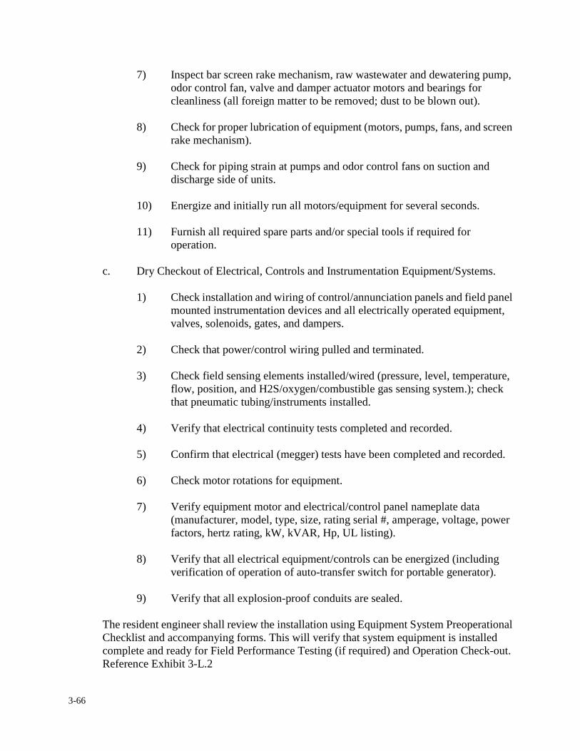
3-66
7) Inspect bar screen rake mechanism, raw wastewater and dewatering pump, odor control fan, valve and damper actuator motors and bearings for cleanliness (all foreign matter to be removed; dust to be blown out).
8) Check for proper lubrication of equipment (motors, pumps, fans, and screen
rake mechanism). 9) Check for piping strain at pumps and odor control fans on suction and
discharge side of units. 10) Energize and initially run all motors/equipment for several seconds. 11) Furnish all required spare parts and/or special tools if required for
operation.
c. Dry Checkout of Electrical, Controls and Instrumentation Equipment/Systems.
1) Check installation and wiring of control/annunciation panels and field panel mounted instrumentation devices and all electrically operated equipment, valves, solenoids, gates, and dampers.
2) Check that power/control wiring pulled and terminated. 3) Check field sensing elements installed/wired (pressure, level, temperature,
flow, position, and H2S/oxygen/combustible gas sensing system.); check that pneumatic tubing/instruments installed.
4) Verify that electrical continuity tests completed and recorded. 5) Confirm that electrical (megger) tests have been completed and recorded. 6) Check motor rotations for equipment. 7) Verify equipment motor and electrical/control panel nameplate data
(manufacturer, model, type, size, rating serial #, amperage, voltage, power factors, hertz rating, kW, kVAR, Hp, UL listing).
8) Verify that all electrical equipment/controls can be energized (including
verification of operation of auto-transfer switch for portable generator). 9) Verify that all explosion-proof conduits are sealed.
The resident engineer shall review the installation using Equipment System Preoperational Checklist and accompanying forms. This will verify that system equipment is installed complete and ready for Field Performance Testing (if required) and Operation Check-out. Reference Exhibit 3-L.2
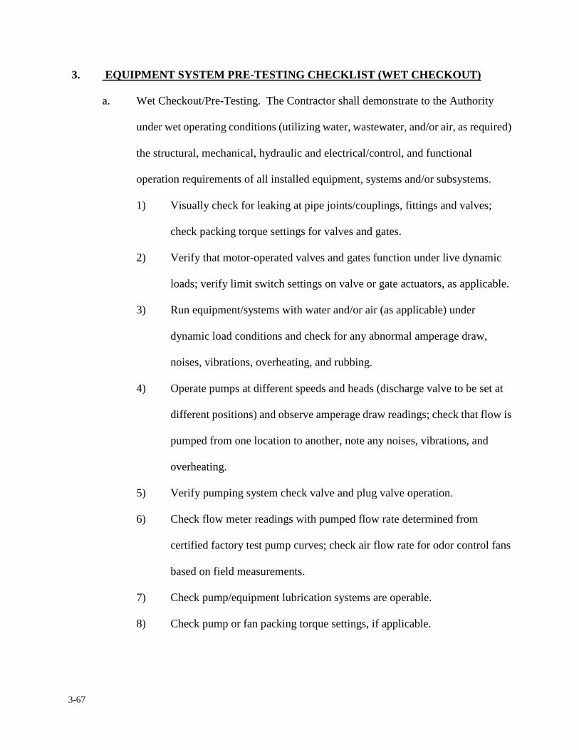
3-67
3. EQUIPMENT SYSTEM PRE-TESTING CHECKLIST (WET CHECKOUT)
a. Wet Checkout/Pre-Testing. The Contractor shall demonstrate to the Authority
under wet operating conditions (utilizing water, wastewater, and/or air, as required)
the structural, mechanical, hydraulic and electrical/control, and functional
operation requirements of all installed equipment, systems and/or subsystems.
1) Visually check for leaking at pipe joints/couplings, fittings and valves;
check packing torque settings for valves and gates.
2) Verify that motor-operated valves and gates function under live dynamic
loads; verify limit switch settings on valve or gate actuators, as applicable.
3) Run equipment/systems with water and/or air (as applicable) under
dynamic load conditions and check for any abnormal amperage draw,
noises, vibrations, overheating, and rubbing.
4) Operate pumps at different speeds and heads (discharge valve to be set at
different positions) and observe amperage draw readings; check that flow is
pumped from one location to another, note any noises, vibrations, and
overheating.
5) Verify pumping system check valve and plug valve operation.
6) Check flow meter readings with pumped flow rate determined from
certified factory test pump curves; check air flow rate for odor control fans
based on field measurements.
7) Check pump/equipment lubrication systems are operable.
8) Check pump or fan packing torque settings, if applicable.
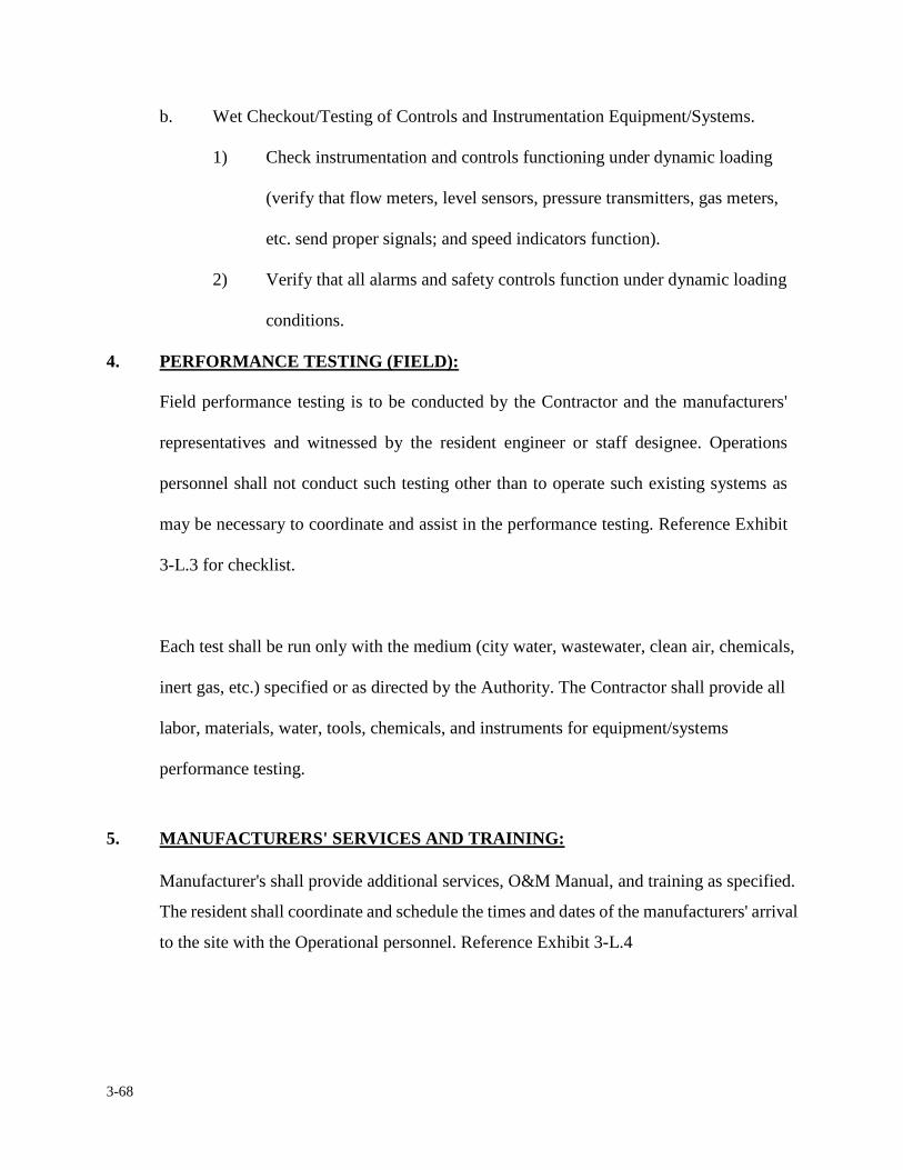
3-68
b. Wet Checkout/Testing of Controls and Instrumentation Equipment/Systems.
1) Check instrumentation and controls functioning under dynamic loading
(verify that flow meters, level sensors, pressure transmitters, gas meters,
etc. send proper signals; and speed indicators function).
2) Verify that all alarms and safety controls function under dynamic loading
conditions.
4. PERFORMANCE TESTING (FIELD):
Field performance testing is to be conducted by the Contractor and the manufacturers'
representatives and witnessed by the resident engineer or staff designee. Operations
personnel shall not conduct such testing other than to operate such existing systems as
may be necessary to coordinate and assist in the performance testing. Reference Exhibit
3-L.3 for checklist.
Each test shall be run only with the medium (city water, wastewater, clean air, chemicals,
inert gas, etc.) specified or as directed by the Authority. The Contractor shall provide all
labor, materials, water, tools, chemicals, and instruments for equipment/systems
performance testing.
5. MANUFACTURERS' SERVICES AND TRAINING:
Manufacturer's shall provide additional services, O&M Manual, and training as specified.
The resident shall coordinate and schedule the times and dates of the manufacturers' arrival
to the site with the Operational personnel. Reference Exhibit 3-L.4
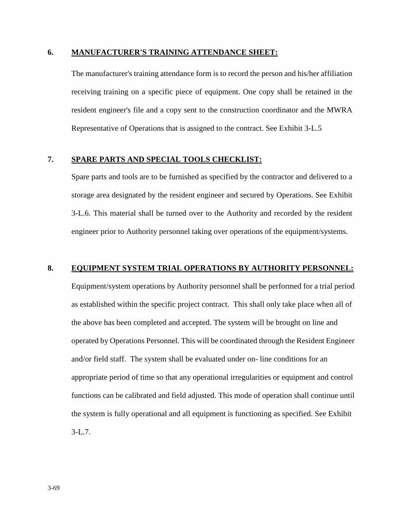
3-69
6. MANUFACTURER'S TRAINING ATTENDANCE SHEET:
The manufacturer's training attendance form is to record the person and his/her affiliation
receiving training on a specific piece of equipment. One copy shall be retained in the
resident engineer's file and a copy sent to the construction coordinator and the MWRA
Representative of Operations that is assigned to the contract. See Exhibit 3-L.5
7. SPARE PARTS AND SPECIAL TOOLS CHECKLIST:
Spare parts and tools are to be furnished as specified by the contractor and delivered to a
storage area designated by the resident engineer and secured by Operations. See Exhibit
3-L.6. This material shall be turned over to the Authority and recorded by the resident
engineer prior to Authority personnel taking over operations of the equipment/systems.
8. EQUIPMENT SYSTEM TRIAL OPERATIONS BY AUTHORITY PERSONNEL:
Equipment/system operations by Authority personnel shall be performed for a trial period
as established within the specific project contract. This shall only take place when all of
the above has been completed and accepted. The system will be brought on line and
operated by Operations Personnel. This will be coordinated through the Resident Engineer
and/or field staff. The system shall be evaluated under on- line conditions for an
appropriate period of time so that any operational irregularities or equipment and control
functions can be calibrated and field adjusted. This mode of operation shall continue until
the system is fully operational and all equipment is functioning as specified. See Exhibit
3-L.7.
3-70
9. NOTIFICATION of OPERATIONAL CHECK-OUT ISSUES:
Should any irregularities/malfunctions be identified during the trial operational period,
formal notification in the form of the Operational Check-out Notification shall be
forwarded to Contractor for immediate attention. See Exhibit 3-L.8.
10. EQUIPMENT SYSTEM TURNOVER ACKNOWLEDGEMENT:
When all of the above conditions are satisfied, the system, area or building is ready for
acceptance by the Authority for beneficial use. The resident engineer shall establish a date
in which the conditional acceptance is to go in effect along with an acknowledgement that
all prior procedures (steps) have been successfully been completed. This date will also
serve as the acknowledged date that the warranty period begins. This information is to be
recorded on an "Equipment System Turnover Acknowledgement" form (See Exhibit
3-L.9) and signed by the resident engineer, contractor, consultant engineer, if any, the
construction coordinator and the Operations personnel designee.
11. NOTIFICATION of WARRANTY ISSUES;
During the warranty period of such equipment, if a malfunction occurs and the resident
engineer is still on site, the Operations personnel are required to notify the resident
engineer. The resident engineer, in turn, shall record the necessary information on the
"Notification of Equipment Warranty Issue" form (See Exhibit 3-L.10) and forward this
notification to the contractor without delay. The resident engineer shall periodically
review the warranty issues to ensure the problems are receiving proper attention. If the
resident engineer is no longer on the site, the procedure relating to warranty issues as
outlined in Section 3.13 shall be followed.
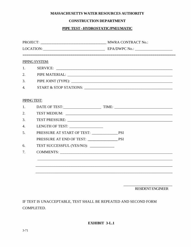
3-71
MASSACHUSETTS WATER RESOURCES AUTHORITY
CONSTRUCTION DEPARTMENT
PIPE TEST - HYDROSTATIC/PNEUMATIC
PROJECT: _______________________________________ MWRA CONTRACT No.:
LOCATION: _________________________________ EPA/DWPC No.: ____________________
================================================================================
PIPING SYSTEM:
1. SERVICE: ______________________________________________________________
2. PIPE MATERIAL: ________________________________________________________
3. PIPE JOINT (TYPE): ______________________________________________________
4. START & STOP STATIONS: _______________________________________________
PIPING TEST:
1. DATE OF TEST: TIME: _______________________________
2. TEST MEDIUM: _________________________________________________________
3. TEST PRESSURE: ________________________________________________________
4. LENGTH OF TEST: __________________
5. PRESSURE AT START OF TEST: ___________________ PSI
PRESSURE AT END OF TEST: ______________________ PSI
6. TEST SUCCESSFUL (YES/NO): _____________
7. COMMENTS: ____________________________________________________________
________________________________________________________________________
_________________________________________________________________________
_________________________________________________________________________
__________________________ RESIDENT ENGINEER
IF TEST IS UNACCEPTABLE, TEST SHALL BE REPEATED AND SECOND FORM
COMPLETED.
EXHIBIT 3-L.1
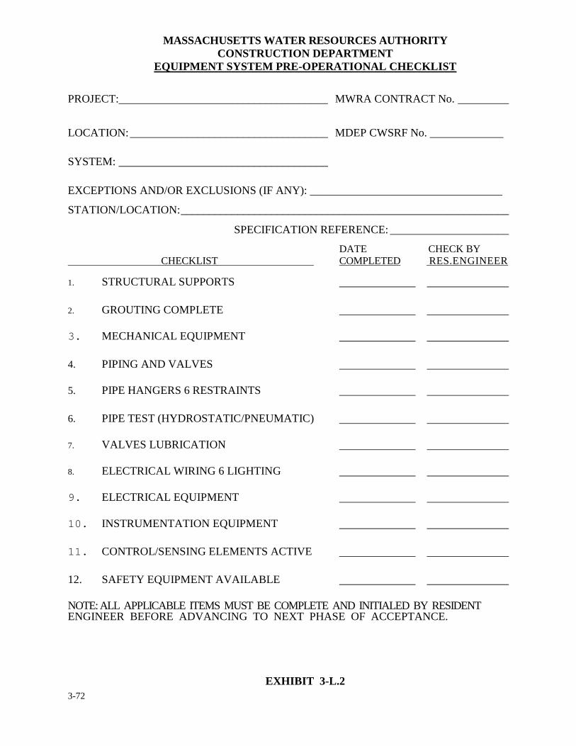
3-72
MASSACHUSETTS WATER RESOURCES AUTHORITY CONSTRUCTION DEPARTMENT
EQUIPMENT SYSTEM PRE-OPERATIONAL CHECKLIST
PROJECT:_____________________________________ MWRA CONTRACT No. _________
LOCATION: ___________________________________ MDEP CWSRF No. _____________ SYSTEM: _____________________________________ EXCEPTIONS AND/OR EXCLUSIONS (IF ANY): __________________________________
STATION/LOCATION: __________________________________________________________
SPECIFICATION REFERENCE: _____________________
DATE CHECK BY CHECKLIST COMPLETED RES.ENGINEER
1. STRUCTURAL SUPPORTS
2. GROUTING COMPLETE
3. MECHANICAL EQUIPMENT
4. PIPING AND VALVES
5. PIPE HANGERS 6 RESTRAINTS
6. PIPE TEST (HYDROSTATIC/PNEUMATIC)
7. VALVES LUBRICATION
8. ELECTRICAL WIRING 6 LIGHTING
9. ELECTRICAL EQUIPMENT
10. INSTRUMENTATION EQUIPMENT
11. CONTROL/SENSING ELEMENTS ACTIVE
12. SAFETY EQUIPMENT AVAILABLE
NOTE: ALL APPLICABLE ITEMS MUST BE COMPLETE AND INITIALED BY RESIDENT ENGINEER BEFORE ADVANCING TO NEXT PHASE OF ACCEPTANCE.
EXHIBIT 3-L.2
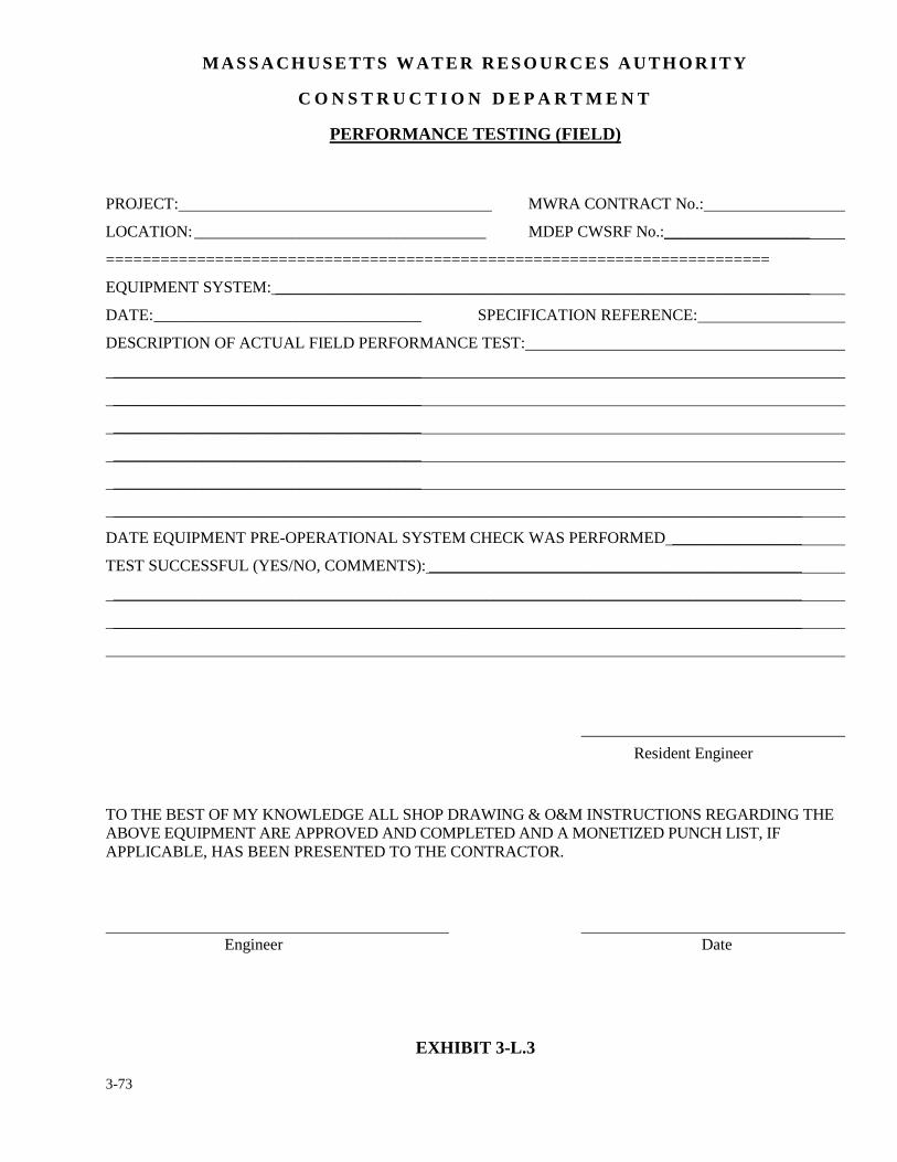
3-73
M A S S A C H U S E T T S W A T E R R E S O U R C E S A U T H O R I T Y
C O N S T R U C T I O N D E P A R T M E N T
PERFORMANCE TESTING (FIELD)
PROJECT: MWRA CONTRACT No.:
LOCATION: ____________________________________ MDEP CWSRF No.:__________________
=========================================================================
EQUIPMENT SYSTEM: __________________________________________________________________
DATE: _________________________________ SPECIFICATION REFERENCE:
DESCRIPTION OF ACTUAL FIELD PERFORMANCE TEST:
______________________________________
______________________________________
______________________________________
______________________________________
______________________________________
_____________________________________________________________________________________
DATE EQUIPMENT PRE-OPERATIONAL SYSTEM CHECK WAS PERFORMED ________________
TEST SUCCESSFUL (YES/NO, COMMENTS): ______________________________________________
_____________________________________________________________________________________
_____________________________________________________________________________________
Resident Engineer TO THE BEST OF MY KNOWLEDGE ALL SHOP DRAWING & O&M INSTRUCTIONS REGARDING THE ABOVE EQUIPMENT ARE APPROVED AND COMPLETED AND A MONETIZED PUNCH LIST, IF APPLICABLE, HAS BEEN PRESENTED TO THE CONTRACTOR.
Engineer Date
EXHIBIT 3-L.3
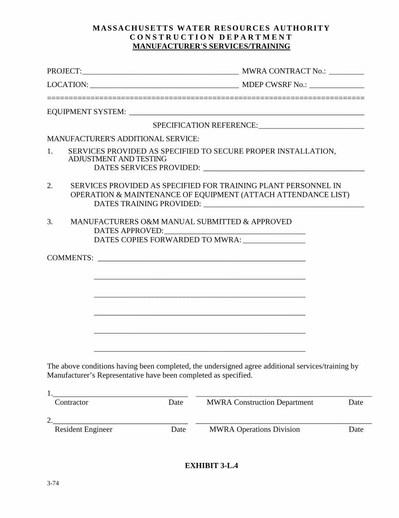
3-74
MASSACHUSETTS WATER RESOURCES AUTHORITY C O N S T R U C T I O N D E P A R T M E N T MANUFACTURER'S SERVICES/TRAINING
PROJECT: ________________________________________ MWRA CONTRACT No.: _________
LOCATION: ______________________________________ MDEP CWSRF No.: ______________
=========================================================================
EQUIPMENT SYSTEM: ____________________________________________________________
SPECIFICATION REFERENCE: ___________________________
MANUFACTURER'S ADDITIONAL SERVICE:
1. SERVICES PROVIDED AS SPECIFIED TO SECURE PROPER INSTALLATION, ADJUSTMENT AND TESTING
DATES SERVICES PROVIDED: __________________________________________ 2. SERVICES PROVIDED AS SPECIFIED FOR TRAINING PLANT PERSONNEL IN
OPERATION & MAINTENANCE OF EQUIPMENT (ATTACH ATTENDANCE LIST) DATES TRAINING PROVIDED: _________________________________________ 3. MANUFACTURERS O&M MANUAL SUBMITTED & APPROVED DATES APPROVED: ____________________________________ DATES COPIES FORWARDED TO MWRA: ________________ COMMENTS: _____________________________________________________ ______________________________________________________ ______________________________________________________ ______________________________________________________ ______________________________________________________ ______________________________________________________ The above conditions having been completed, the undersigned agree additional services/training by Manufacturer’s Representative have been completed as specified. 1. _____________________________________________ Contractor Date MWRA Construction Department Date 2. _____________________________________________ Resident Engineer Date MWRA Operations Division Date
EXHIBIT 3-L.4
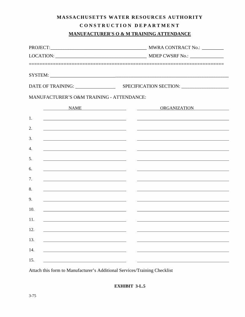
3-75
MASSACHUSETTS WATER RESOURCES AUTHORITY
C O N S T R U C T I O N D E P A R T M E N T
MANUFACTURER'S O & M TRAINING ATTENDANCE
PROJECT: ________________________________________ MWRA CONTRACT No.: _________
LOCATION: ______________________________________ MDEP CWSRF No.: ______________
========================================================================= SYSTEM: ________________________________________________ DATE OF TRAINING: SPECIFICATION SECTION: ____________________ MANUFACTURER’S O&M TRAINING - ATTENDANCE: NAME ORGANIZATION
1.
2.
3.
4.
5.
6.
7.
8.
9.
10.
11.
12.
13.
14.
15.
Attach this form to Manufacturer’s Additional Services/Training Checklist
EXHIBIT 3-L.5
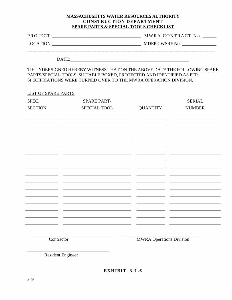
3-76
MASSACHUSETTS WATER RESOURCES AUTHORITY CONSTRUCTION DEPARTMENT
SPARE PARTS & SPECIAL TOOLS CHECKLIST
PR OJ EC T:_______________________________________ MW RA CONTRACT N o . ______
LOCATION: _______________________________________ MDEP CWSRF No. _______________
=========================================================================
DATE: ____________________________________________________ TIE UNDERSIGNED HEREBY WITNESS THAT ON THE ABOVE DATE THE FOLLOWING SPARE PARTS/SPECIAL TOOLS, SUITABLE BOXED, PROTECTED AND IDENTIFIED AS PER SPECIFICATIONS WERE TURNED OVER TO THE MWRA OPERATION DIVISION.
LIST OF SPARE PARTS
SPEC.
SECTION
SPARE PART/
SPECIAL TOOL
QUANTITY
SERIAL
NUMBER
Contractor MWRA Operations Division Resident Engineer
EXHIBIT 3-L.6
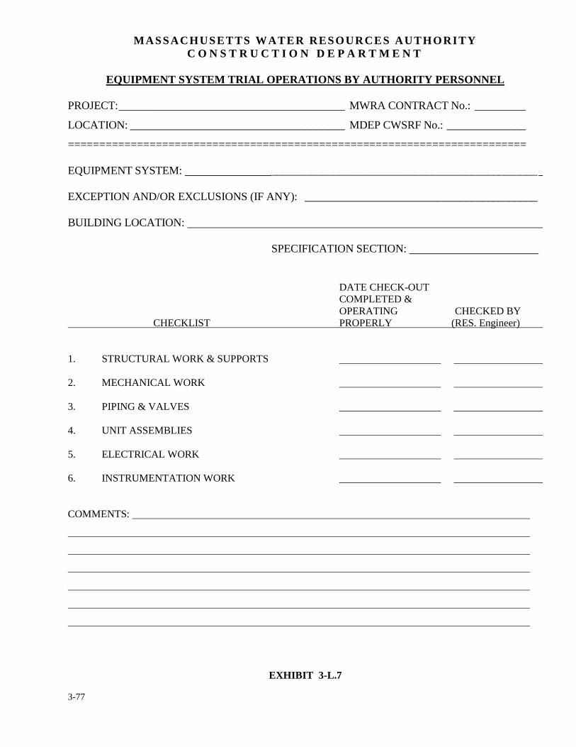
3-77
MASSACHUSETTS WATER RESOURCES AUTHORITY C O N S T R U C T I O N D E P A R T M E N T
EQUIPMENT SYSTEM TRIAL OPERATIONS BY AUTHORITY PERSONNEL
PROJECT: ________________________________________ MWRA CONTRACT No.: _________
LOCATION: ______________________________________ MDEP CWSRF No.: ______________
========================================================================= EQUIPMENT SYSTEM: ________________________________________________ EXCEPTION AND/OR EXCLUSIONS (IF ANY): __________________________________________ BUILDING LOCATION: SPECIFICATION SECTION: DATE CHECK-OUT COMPLETED & OPERATING CHECKED BY CHECKLIST PROPERLY (RES. Engineer) 1. STRUCTURAL WORK & SUPPORTS 2. MECHANICAL WORK 3. PIPING & VALVES 4. UNIT ASSEMBLIES 5. ELECTRICAL WORK 6. INSTRUMENTATION WORK COMMENTS:
EXHIBIT 3-L.7
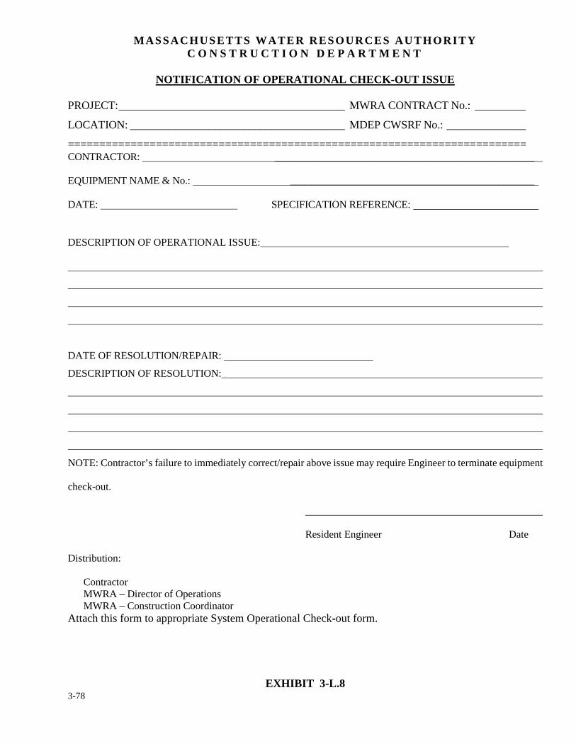
3-78
MASSACHUSETTS WATER RESOURCES AUTHORITY C O N S T R U C T I O N D E P A R T M E N T
NOTIFICATION OF OPERATIONAL CHECK-OUT ISSUE
PROJECT: ________________________________________ MWRA CONTRACT No.: _________
LOCATION: ______________________________________ MDEP CWSRF No.: ______________
========================================================================= CONTRACTOR: ___________________________________________________ EQUIPMENT NAME & No.: ________________________________________________ DATE: SPECIFICATION REFERENCE:
DESCRIPTION OF OPERATIONAL ISSUE:
DATE OF RESOLUTION/REPAIR:
DESCRIPTION OF RESOLUTION:
NOTE: Contractor’s failure to immediately correct/repair above issue may require Engineer to terminate equipment
check-out.
Resident Engineer Date
Distribution:
Contractor MWRA – Director of Operations MWRA – Construction Coordinator Attach this form to appropriate System Operational Check-out form.
EXHIBIT 3-L.8
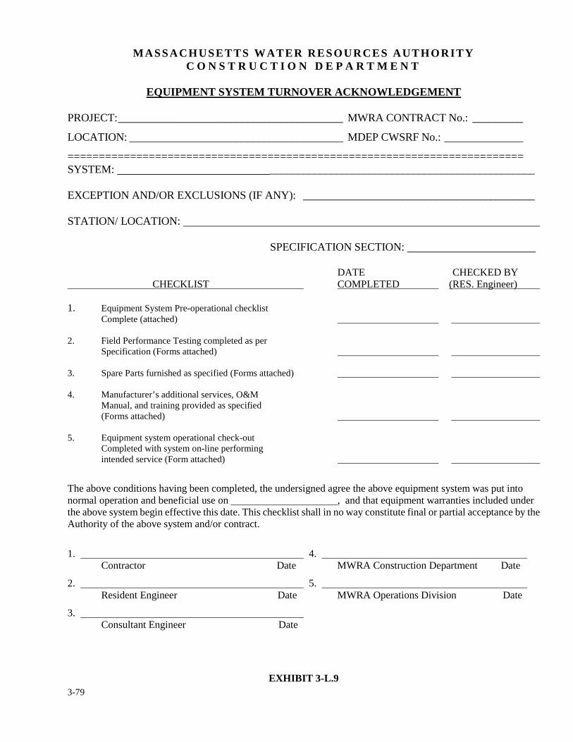
3-79
MASSACHUSETTS WATER RESOURCES AUTHORITY
C O N S T R U C T I O N D E P A R T M E N T
EQUIPMENT SYSTEM TURNOVER ACKNOWLEDGEMENT PROJECT: ________________________________________ MWRA CONTRACT No.: _________
LOCATION: ______________________________________ MDEP CWSRF No.: ______________
========================================================================= SYSTEM: ________________________________________________ EXCEPTION AND/OR EXCLUSIONS (IF ANY): __________________________________________ STATION/ LOCATION: SPECIFICATION SECTION: DATE CHECKED BY CHECKLIST COMPLETED (RES. Engineer) 1. Equipment System Pre-operational checklist Complete (attached) 2. Field Performance Testing completed as per Specification (Forms attached) 3. Spare Parts furnished as specified (Forms attached) 4. Manufacturer’s additional services, O&M Manual, and training provided as specified (Forms attached) 5. Equipment system operational check-out Completed with system on-line performing intended service (Form attached)
The above conditions having been completed, the undersigned agree the above equipment system was put into normal operation and beneficial use on , and that equipment warranties included under the above system begin effective this date. This checklist shall in no way constitute final or partial acceptance by the Authority of the above system and/or contract.
1. 4. Contractor Date MWRA Construction Department Date
2. 5. Resident Engineer Date MWRA Operations Division Date
3. Consultant Engineer Date
EXHIBIT 3-L.9
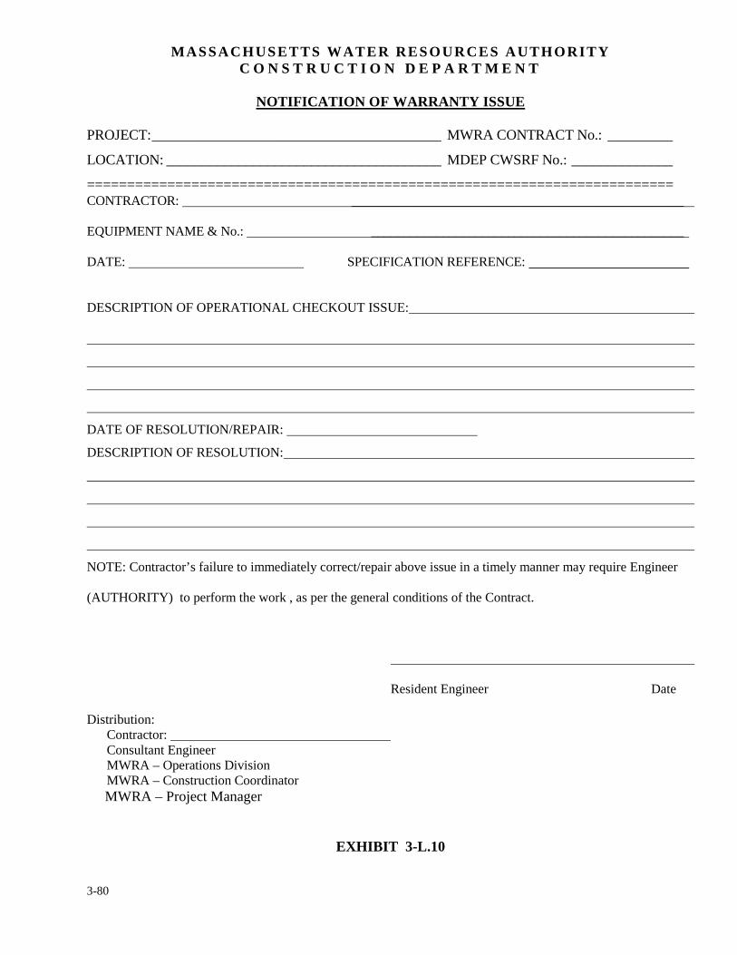
3-80
MASSACHUSETTS WATER RESOURCES AUTHORITY C O N S T R U C T I O N D E P A R T M E N T
NOTIFICATION OF WARRANTY ISSUE
PROJECT: ________________________________________ MWRA CONTRACT No.: _________
LOCATION: ______________________________________ MDEP CWSRF No.: ______________
========================================================================= CONTRACTOR: ___________________________________________________ EQUIPMENT NAME & No.: ________________________________________________ DATE: SPECIFICATION REFERENCE:
DESCRIPTION OF OPERATIONAL CHECKOUT ISSUE:
DATE OF RESOLUTION/REPAIR:
DESCRIPTION OF RESOLUTION:
NOTE: Contractor’s failure to immediately correct/repair above issue in a timely manner may require Engineer
(AUTHORITY) to perform the work , as per the general conditions of the Contract.
Resident Engineer Date
Distribution: Contractor: Consultant Engineer MWRA – Operations Division MWRA – Construction Coordinator MWRA – Project Manager
EXHIBIT 3-L.10
3-81
3. INTERIM RECORDS & REQUIREMENTS
3.9 EQUIPMENT NOMENCLATURE AND TECHNICAL DATA
The Authority requires a detailed system to uniquely identify facilities, systems, equipment,
structures and architectural units that are constructed, installed or used in the Authority’s
Facilities. The resident engineer and field staff should review the contract documents and become
familiar with the nomenclature identification systems required, however Operations will provide
the nomenclature tag number for all systems not referenced in the contract documents. All
equipment data shall be entered by the Contractor into a data base provided by the Authority. The
resident engineer should attempt to monitor completion of these forms prior to the contract
achieving substantial completion.
The Authority provides these data entry forms in Microsoft Access and Excel format for
contractor’s to use for entering the appropriate data. These forms are typically completed at the
end of the project, just prior to closeout and require some familiarity with equipment/process
systems and can be time consuming to complete. The resident engineer and construction
coordinator are reminded that the size and complexity of the project shall be considered when
evaluating the contractor’s cost to complete this work when reviewing the Schedule of Values,
release of retainage and assigning a cost for punch list items associated with this work.
A description of Authority’s nomenclature hierarchy which consists of six levels, standard and non
standard item label formats, electrical and instrumentation nomenclature system codes are
described in detail in each Authority contract specification section 01080.

3-82
Exhibits 3-M.1a and 3-M.1b and 3-M.2a and 3-M.2b are samples of MWRA Operations Technical
Data form completed for electrical lighting fixture and heating and ventilating unit heater.
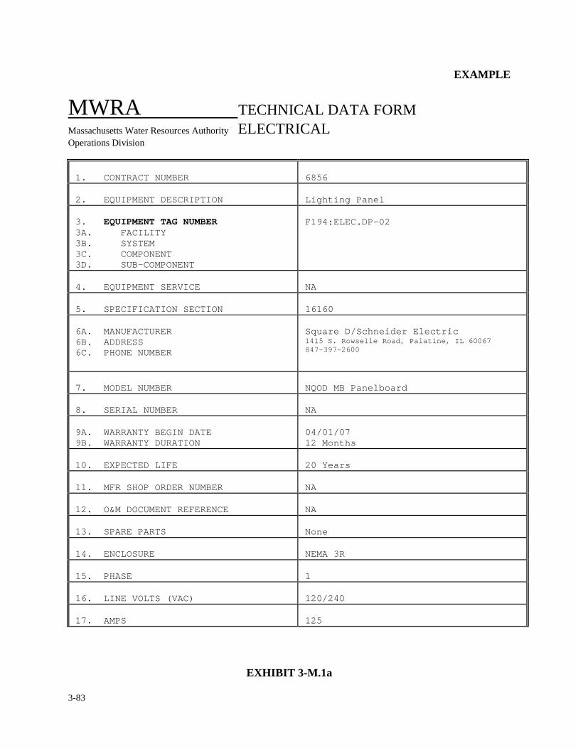
3-83
EXAMPLE
MWRA TECHNICAL DATA FORM
Massachusetts Water Resources Authority ELECTRICAL Operations Division 1. CONTRACT NUMBER
6856
2. EQUIPMENT DESCRIPTION
Lighting Panel
3. EQUIPMENT TAG NUMBER 3A. FACILITY 3B. SYSTEM 3C. COMPONENT 3D. SUB-COMPONENT
F194:ELEC.DP-02
4. EQUIPMENT SERVICE
NA
5. SPECIFICATION SECTION
16160
6A. MANUFACTURER 6B. ADDRESS 6C. PHONE NUMBER
Square D/Schneider Electric 1415 S. Rowselle Road, Palatine, IL 60067 847-397-2600
7. MODEL NUMBER
NQOD MB Panelboard
8. SERIAL NUMBER
NA
9A. WARRANTY BEGIN DATE 9B. WARRANTY DURATION
04/01/07 12 Months
10. EXPECTED LIFE
20 Years
11. MFR SHOP ORDER NUMBER
NA
12. O&M DOCUMENT REFERENCE
NA
13. SPARE PARTS
None
14. ENCLOSURE
NEMA 3R
15. PHASE
1
16. LINE VOLTS (VAC)
120/240
17. AMPS
125
EXHIBIT 3-M.1a
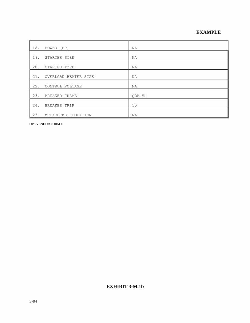
3-84
EXAMPLE
18. POWER (HP)
NA
19. STARTER SIZE
NA
20. STARTER TYPE
NA
21. OVERLOAD HEATER SIZE
NA
22. CONTROL VOLTAGE
NA
23. BREAKER FRAME
QOB-VH
24. BREAKER TRIP
50
25. MCC/BUCKET LOCATION
NA
OPS VENDOR FORM #
EXHIBIT 3-M.1b
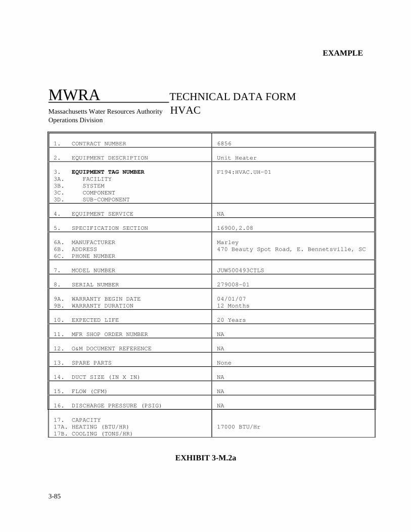
3-85
EXAMPLE
MWRA TECHNICAL DATA FORM
Massachusetts Water Resources Authority HVAC Operations Division
1. CONTRACT NUMBER
6856
2. EQUIPMENT DESCRIPTION
Unit Heater
3. EQUIPMENT TAG NUMBER 3A. FACILITY 3B. SYSTEM 3C. COMPONENT 3D. SUB-COMPONENT
F194:HVAC.UH-01
4. EQUIPMENT SERVICE
NA
5. SPECIFICATION SECTION
16900,2.08
6A. MANUFACTURER 6B. ADDRESS 6C. PHONE NUMBER
Marley 470 Beauty Spot Road, E. Bennetsville, SC
7. MODEL NUMBER
JUW500493CTLS
8. SERIAL NUMBER
279008-01
9A. WARRANTY BEGIN DATE 9B. WARRANTY DURATION
04/01/07 12 Months
10. EXPECTED LIFE
20 Years
11. MFR SHOP ORDER NUMBER
NA
12. O&M DOCUMENT REFERENCE
NA
13. SPARE PARTS
None
14. DUCT SIZE (IN X IN)
NA
15. FLOW (CFM)
NA
16. DISCHARGE PRESSURE (PSIG)
NA
17. CAPACITY 17A. HEATING (BTU/HR) 17B. COOLING (TONS/HR)
17000 BTU/Hr
EXHIBIT 3-M.2a
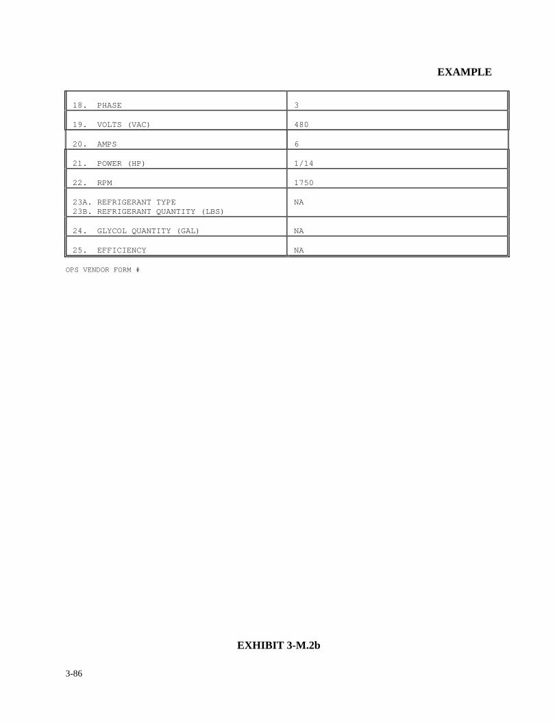
3-86
EXAMPLE
18. PHASE
3
19. VOLTS (VAC)
480
20. AMPS
6
21. POWER (HP)
1/14
22. RPM
1750
23A. REFRIGERANT TYPE 23B. REFRIGERANT QUANTITY (LBS)
NA
24. GLYCOL QUANTITY (GAL)
NA
25. EFFICIENCY
NA
OPS VENDOR FORM #
EXHIBIT 3-M.2b
3-87
3. INTERIM RECORDS & REQUIREMENTS
3.10 SUBSTANTIAL COMPLETION
Substantial completion is a milestone event which occurs at the end of construction. It signifies
that the work of the contract is basically complete except for minor incomplete or unsatisfactory
work items that do not materially impair the usefulness of the work required by the contract
documents. Because substantial completion is only a point in time in a contract, it can only be
recognized by establishing a date as to when it occurred. Basically, a contract is substantially
complete when the remaining contract work is less than one percent of the contract price or the
majority of contract work is complete and open to public use, or in the case of a building contract,
where the Authority takes possession for occupancy, whichever comes first. The resident engineer
should consult the general conditions of the contract for a more specific definition of substantial
completion, because substantial completion for Chapter 30 contracts, horizontal construction, and
Chapter 149 contracts, vertical construction, have different requirements.
Prior to the Contractor submitting a request to declare substantial completion a project
walkthrough with Field Operations Department shall take place. The purpose of this walkthrough
is to confirm all equipment/facility turnover procedures have taken place and all equipment and
systems are operational for their intended use. The resident engineer and construction coordinator
shall coordinate a “Stat-up/Turnover Package” prepared by the design consultant. The following is
a sample Table of Contents of a typical Stat-up/Turnover Package:
3-88
LIST OF SYSTEMS/ITEMS/FACILITIES
OPEN ISSUES
CONSULTANT/VENDOR SUPPORT
TESTING SUMMARY (SHOP, FUNCTIONAL, PERFORMANCE/ACCEPTANCE) –
INCLUDING COPIES OF ALL SIGNED TESTING CERTIFICATES
DOCUMENTS/O&M MANUALS/FACILITY HANDBOOKS/SOPS/RED-LINE
DRAWINGS AND SCHEDULE FOR FINAL RECORD DRAWINGS
TRAINING STATUS
PUNCH LIST
PERMITS
SPARE PARTS
WARRANTIES
OPERATING SUPPLIES
SAFETY
COMMUNICATIONS
Generally, in establishing substantial completion, the contractor, in a written notice to the
Authority, certifies that the contract is substantially complete and establishes a date in which
substantial completion occurred. Providing the contractor meets the above criterion, the resident
engineer will promptly evaluate the contractor's notification and make a recommendation to the
Authority, through the construction coordinator, which either accepts or rejects the contractor's
declaration. The Authority, in most cases, will accept the resident engineer's recommendation.
Once a date of substantial completion is mutually agreed upon, the MWRA Chief Engineer will
3-89
issue a Certificate of Substantial Completion. The date of substantial completion is also the start
date for all warranties on the project and will remain in effect for the time period designated in the
contract documents, usually one full year. Exhibit 3-N.1 is a copy of Certificate of Substantial
Completion required to be completed for the declaration of Substantial Completion. A copy is also
included in the Appendix of this manual. In addition, at the time substantial completion is
established, the contractor may request a reduction or a release of retainage. The time frame and
procedure for the release of retainage is dependent on the type of contract, Chapter 30 for
horizontal construction and Chapter 149 for vertical construction. An overview of retainage
release is in Section 3.11 Release of Retainage and with a detailed description in Section 4.7
Contract Closeout. Also, shortly after substantial completion occurs the resident engineer shall be
required to develop a monetized punch list, indicating all unsatisfactory and/or incomplete work
items. This is also discussed in greater detail in Sections 3.12 Punch List and 4.7 Contract
Closeout.
If the Construction Department does not agree that the contract work is substantially complete,
they shall promptly respond, in writing, to the contractor indicating the specific reasons for not
accepting the contractor's assessment.
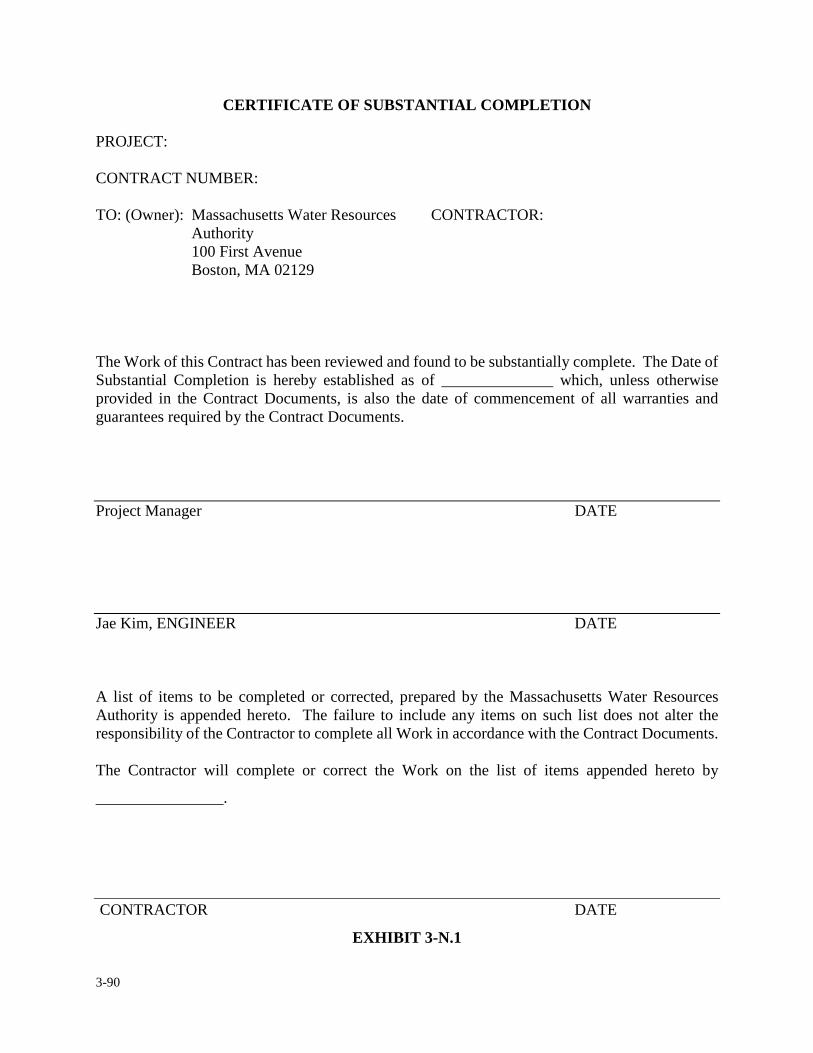
3-90
CERTIFICATE OF SUBSTANTIAL COMPLETION PROJECT: CONTRACT NUMBER: TO: (Owner): Massachusetts Water Resources CONTRACTOR:
Authority 100 First Avenue Boston, MA 02129
The Work of this Contract has been reviewed and found to be substantially complete. The Date of Substantial Completion is hereby established as of ______________ which, unless otherwise provided in the Contract Documents, is also the date of commencement of all warranties and guarantees required by the Contract Documents.
Project Manager DATE
Jae Kim, ENGINEER DATE
A list of items to be completed or corrected, prepared by the Massachusetts Water Resources Authority is appended hereto. The failure to include any items on such list does not alter the responsibility of the Contractor to complete all Work in accordance with the Contract Documents. The Contractor will complete or correct the Work on the list of items appended hereto by
________________.
CONTRACTOR DATE
EXHIBIT 3-N.1
3-91
3. INTERIM RECORDS & REQUIREMENTS
3.11 RELEASE OF RETAINAGE
By Massachusetts Law the Authority is authorized to withhold five percent (5%) of the
contractor's payment, each payment, throughout the life of the contract or until substantial
completion occurs.
Once the substantial completion date has been established, the contractor is entitled to all or most
of the retainage being withheld by the Authority. The following is an overview of the requirements
for the release of retainage. The amount of retainage to be released varies from contract to contract,
depending on the type of contract. A more detailed description is covered in Section 4.7 Contract
Closeout. If the contract is a “vertical” construction contract, Chapter 149, the contractor is entitled
to all of the retainage withheld. If the contract is a "horizontal" construction contract, Chapter 30,
the contractor is entitled to all but one percent of the value of completed work at the time of
substantial completion. The resident engineer should consult the general conditions to determine
which case pertains to his/her contract. Prior to any agreement to release retainage the resident
engineer shall establish a monetized punch list identifying all incomplete and unsatisfactory work
items. Partial release of retainage shall then be calculated by reducing the retained amount from
5% to 1% and then adding the amount for the monetized punch list to the 1%.
The Authority, by law, is obligated to release retainage withheld to the contractor within 65
calendar days after substantial completion occurs. However, in release of retainage, the contractor
3-92
must furnish certain supporting documents as required by the Authority. The following documents
should accompany a contractor's request for a partial release of retainage (reducing the amount
withheld from 5% to 1% of the contract price). Copies of the standard forms listed below can be
found in the Appendix of this manual.
SUPPORTING DOCUMENTS :
•••• Letter and invoice from contractor requesting partial release of retainage.
•••• Consent of Surety for Partial Release in Retainage and Surety's Power of Attorney.
•••• Affidavit of Release of Debts and Claims.
•••• Affidavit of Release of Liens.
•••• Certificate of Substantial Completion
•••• Monetized Punch List
The following documents are required by the contractor when requesting final release of retainage
(either reducing the amount retained from 5% to 0% as for Building contracts or from 1% to 0% as
for all other construction contracts).
• Contractor's Letter of Request for Final Release of Retainage.
• Contractor's Invoice for Final Release of Retainage accompanied by Summary/Certification.
• Consent of Surety Company for Final Payment, accompanied by Insurance Firm's Power of Attorney.
• Affidavit of Release of Liens.
• Affidavit of Payment of Debts and Claims.
• Statement by Contractor of One Year Warranty and Guarantee Starting from Date of Substantial Completion.
• Certificate of Insurance beyond Final Payment for specified time period covering Warranty/Guarantee period.
The contractor shall furnish "as-built" drawings and data, plus test data, code and building permit
3-93
compliance forms where applicable. Also, subcontractor's surety, affidavits, warranties,
guarantees and other compliance forms may be required if unresolved matters or problems exist.
At the time of final retainage release request, the resident engineer and construction coordinator
shall begin the process for issuing balancing change prior to processing substantial completion and
final release of retainage. Projects that contain State or local Conservation Commission Order of
Conditions shall begin the process of obtaining Certificate of Compliance prior to final release of
retainage is completed. This Certificate of Compliance shall be obtained by the Authority or
design consultant if applicable.
At the time of the retainage release request, a completed DCAM Contractor Standard Evaluation
Form is required. This form is to be prepared jointly by the resident engineer and the construction
coordinator or the consultant's resident engineer. It allows for the evaluation of the contractor's
performance, accountability and product quality pertaining to the construction contract.
This evaluation is to be taken very seriously. The resident engineer is urged to answer all questions
to the best of his/her ability. The form is a rating summary sheet where the resident engineer is
asked to rate the contractor's performance according to the following categories:
1) Quality of Workmanship
2) Project Management
a. Scheduling
b. Subcontractor Management
c. Safety and House Keeping Procedures
d. Change Orders
e. Working Relationships
f. Paperwork Processing
3-94
3) On-site Supervisory Personnel Rating
The total amount of points per category varies from 7 (seven) to 28 (twenty eight), however, the
total amount of points per evaluation is 100. There are five ratings; unacceptable, poor,
satisfactory, very good and excellent. The resident engineer is to address each category very
thoughtfully and choose which rating best suits his/her judgment. A rating below 80% could result
in the Authority serving notice to the contractor that his performance is considered unsatisfactory
and may cause the contractor to be disqualified from bidding future Authority construction work.
The final evaluation must be signed by the Authority's resident engineer or the consultant's
resident representative and the Director of Construction. Prior to signing by the resident engineer
and forwarding to the Director of Construction, the completed form shall be reviewed and
presented by the resident engineer to the construction coordinator for agreement on enlisted rating.
For most projects a signed copy of the evaluation shall be forwarded to the contractor with the
original mailed to DCAM. The Standard Contractor Evaluation Form can be obtained through the
Home Office or through DCAM website at:
http://www.mass.gov/anf/property-mgmt-and-construction/oversight-agencies/dcam/.
A blank copy of the “Standard Contractor Evaluation Form” is provided in the Appendix of this
manual.
3-95
3. INTERIM RECORDS & REQUIREMENTS
3.12 PUNCH LIST
Once the contract is declared substantially complete, it is the responsibility of the resident to
compile a punch list of all unsatisfactory or incomplete work items. The punch list shall be
itemized, and include a fair and reasonable dollar value to complete the work for each
unsatisfactory and/or incomplete item of work. In considering a fair and reasonable cost, the
resident engineer should arrive at the lowest estimated cost for the Authority to complete the work,
and not the cost it would take for the contractor to complete the work. In certain circumstances it
may cost the Authority more than it would cost the contractor if the Authority were to complete
certain outstanding work items. For example, in some cases the Authority would experience
mobilization and demobilization costs where the contractor would not, or the Authority may be
subject to additional consultant fees, where the contractor would not. Although it doesn't happen
very often, if the contractor were to walk off the job the resident engineer should be holding
enough of the contractor's monies to have the outstanding work completed as specified.
Exhibit 3-O.1 is a form the resident engineer may use in developing the project punch list. The
punch list should be sorted by the divisions of the specification first, followed by the description
and the specific section and article which refer to the punch list item. Each punch list item shall be
assigned a fair value as mentioned above. The resident engineer if he/she so chooses may develop
a similar listing of punch list work in Microsoft Excel format.
3-96
The unsatisfactory and incomplete work shall have a value of less than one percent of the total
contract amount which determines the declaration of substantial completion discussed in
Section 3.10.
Once the punch list is developed and reviewed by the construction coordinator, the resident
engineer shall present it to the contractor by formal transmittal. The Contractor and Resident
Engineer should then perform a walk through of the work area to be declared substantially
complete and come to an agreement on the punch list work items. This walk through by the
resident engineer shall be as thorough as practical. Although additional work items, if found to be
unsatisfactory and/or incomplete, can be added to the punch list at any time, the resident engineer
shall be cautious of creating a revolving list of work to correct/complete or using the punch list as
a tool to prolong a contract or punish a contractor. It is intended as a definitive means to achieve
satisfactory completion of a construction project. The value of the monetized punch list shall be
withheld in addition to other remaining retainage until satisfactory completion and sign-off by the
resident engineer. In the interim, each time the contractor completes an item and it is determined
satisfactory, the resident engineer shall remove the item from the list and adjust the value being
withheld accordingly. The contractor may request a partial payment for the sole reason of being
paid for punch list work completed to date. In most cases the contractor is allowed 45 days from
the date they receive the official punch list to complete the work. This time period may be
extended for delays beyond the contractor’s control. If the contractor fails to complete such work
within the time period specified, the Authority may, subsequent to seven days written notice to the
contractor by certified mail, terminate the contract and complete the incomplete or unsatisfactory
work items and charge the cost of such work to the contractor. The purpose of the punch list is to

3-97
identify all unsatisfactory and incomplete work and not such items as; warranty issues, disputes or
claims by the contractor or request for direct payments by subcontractors. The value of the punch
list shall be coordinated and substantiated in the Quantity Control Ledger.
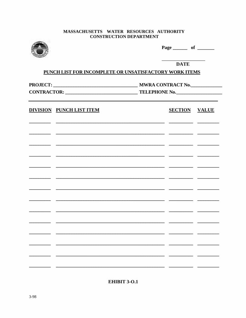
3-98
MASSACHUSETTS WATER RESOURCES AUTHORITY CONSTRUCTION DEPARTMENT
Page ______ of _______ DATE
PUNCH LIST FOR INCOMPLETE OR UNSATISFACTORY WORK ITEMS
PROJECT: ___________________________________ MWRA CONTRACT No. _____________ CONTRACTOR: ______________________________ TELEPHONE No. ___________________
DIVISION
PUNCH LIST ITEM SECTION VALUE
_________
_____________________________________________ __________ _________
_________
_____________________________________________ __________ _________
_________
_____________________________________________ __________ _________
_________
_____________________________________________ __________ _________
_________
_____________________________________________ __________ _________
_________
_____________________________________________ __________ _________
_________
_____________________________________________ __________ _________
_________
_____________________________________________ __________ _________
_________
_____________________________________________ __________ _________
_________
_____________________________________________ __________ _________
_________
_____________________________________________ __________ _________
_________
_____________________________________________ __________ _________
_________
_____________________________________________ __________ _________
_________
_____________________________________________ __________ _________
EHIBIT 3-O.1
3-99
3. INTERIM RECORDS & REQUIREMENTS
3.13 WARRANTY POLICY & PROCEDURES
The following is the Operations Division's policy and procedure for the One Year Warranty Period
for construction projects. Once a construction contract is complete (substantially complete or once
MWRA staff start operating equipment of a facility), the contractor is obligated (according to
MWRA General Conditions, Article 14 - "Correction of Work" and Article 18 - "Warranty" in the
contract) to warranty his work, material used and equipment supplied for a minimum period of one
year thereafter (Particular items or equipment may have a Warranty extending beyond the initial
one year period).
Should there be a failure of equipment, workmanship or material within the one (1) year or longer
warranty period, as described above, the supervisor in charge of the operation shall fill out the
attached Form #1 (Exhibit 3-P.1) describing the problem and submit it to the Contractor with
copies to the Director of Construction, his/her Operations Manager and the Law Division.
The Operations Manager shall coordinate the subject warranty issue with the construction
coordinator and shall review Form #1 and investigate the issue by reviewing the manufacturer’s
warranty, and if necessary draft a letter to the contractor. See attached sample letter, Form #2
(Exhibit 3-P.2), requesting appropriate action, a specified timeframe and immediate response. The
letter along with a copy of the Warranty (if longer than one year) shall be reviewed by the Law
Division prior to sending it to the contractor.
3-100
Once the letter is sent to the Contractor, the Operations Manager shall track the letter (Form #2)
and follow up by monitoring the expedition of the repair and maintaining the necessary
documentation until Form #3 (Exhibit 3-P.3), is complete.
The Form #3 Warranty Resolution Number shall match the Failure Number on Form #1. Form #3,
upon completion, shall be sent to the initiator of Form #1 with copies distributed to the manager of
the initiator, the Law Division, and the Director of Construction.
Should the contractor fail to provide the necessary repair, the Operations Manager shall notify the
Director of Construction and the Law Division and arrange to contract out or have the repair
performed by MWRA personnel. Once the repair is complete, Form #3 and invoices of the cost of
repair by the outside contractor or MWRA staff shall be submitted to the Law Division who shall
be responsible to acquire reimbursement from the primary contractor.
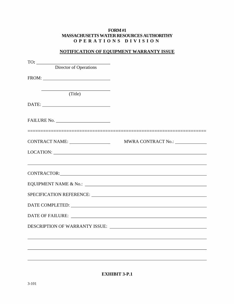
3-101
FORM #1 MASSACHUSETTS WATER RESOURCES AUTHORITHY
O P E R A T I O N S D I V I S I O N
NOTIFICATION OF EQUIPMENT WARRANTY ISSUE TO:
Director of Operations FROM:
(Title) DATE: FAILURE No. ===================================================================== CONTRACT NAME: MWRA CONTRACT No.: LOCATION: CONTRACTOR: EQUIPMENT NAME & No.: SPECIFICATION REFERENCE: DATE COMPLETED: DATE OF FAILURE: DESCRIPTION OF WARRANTY ISSUE:
EXHIBIT 3-P.1
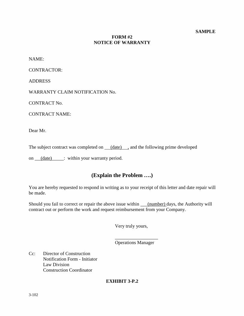
3-102
SAMPLE FORM #2
NOTICE OF WARRANTY
NAME: CONTRACTOR: ADDRESS WARRANTY CLAIM NOTIFICATION No. CONTRACT No. CONTRACT NAME: Dear Mr. The subject contract was completed on (date) , and the following prime developed on (date) : within your warranty period.
(Explain the Problem ….) You are hereby requested to respond in writing as to your receipt of this letter and date repair will be made. Should you fail to correct or repair the above issue within (number) days, the Authority will contract out or perform the work and request reimbursement from your Company.
Very truly yours, Operations Manager
Cc: Director of Construction Notification Form - Initiator Law Division Construction Coordinator
EXHIBIT 3-P.2
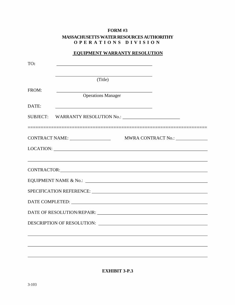
3-103
FORM #3 MASSACHUSETTS WATER RESOURCES AUTHORITHY
O P E R A T I O N S D I V I S I O N
EQUIPMENT WARRANTY RESOLUTION TO:
(Title) FROM:
Operations Manager DATE: SUBJECT: WARRANTY RESOLUTION No.: ===================================================================== CONTRACT NAME: MWRA CONTRACT No.: LOCATION: CONTRACTOR: EQUIPMENT NAME & No.: SPECIFICATION REFERENCE: DATE COMPLETED: DATE OF RESOLUTION/REPAIR: DESCRIPTION OF RESOLUTION:
EXHIBIT 3-P.3
3-104
3. INTERIM RECORDS & REQUIREMENTS
3.14 FINAL PAYMENT
Final Payment is the last act of the contract between the contractor and the Authority. It represents
the fulfillment of all contract requirements and relieves the Authority and the contractor of any
further obligations towards each other (other than warranty issues). What prompts Final Payment
is when the contractor considers the work of the contract to be complete and he/she has met all
obligations as required by the contract. At that time, the contractor shall present to the Authority,
through the Construction Department: 1) a written notice indicating the project is ready for final
inspection and acceptance, and 2) a final request for payment. The resident engineer and
representative from operations will promptly make a final inspection of the work. If and when
resident engineer, in agreement with representative of Operations, determines the work acceptable,
he/she shall issue a recommendation to the construction coordinator, Director of Construction and
Director of Operations based on his/her observations that the contract work has been completed
and to the best of his/her knowledge, the work has been performed in accordance with the contract
documents. This notice will also serve as a recommendation for final payment. The resident
engineer shall confirm that all manufacturer’s operations and maintenance manuals have been
received, operator’s training has been completed, equipment nomenclature and data
documentation has been processed and all contractor responsible as-built plans have been turned
over to the Authority. By copy of this notice, the contractor will be required to provide the
following documents in support of the final payment request.
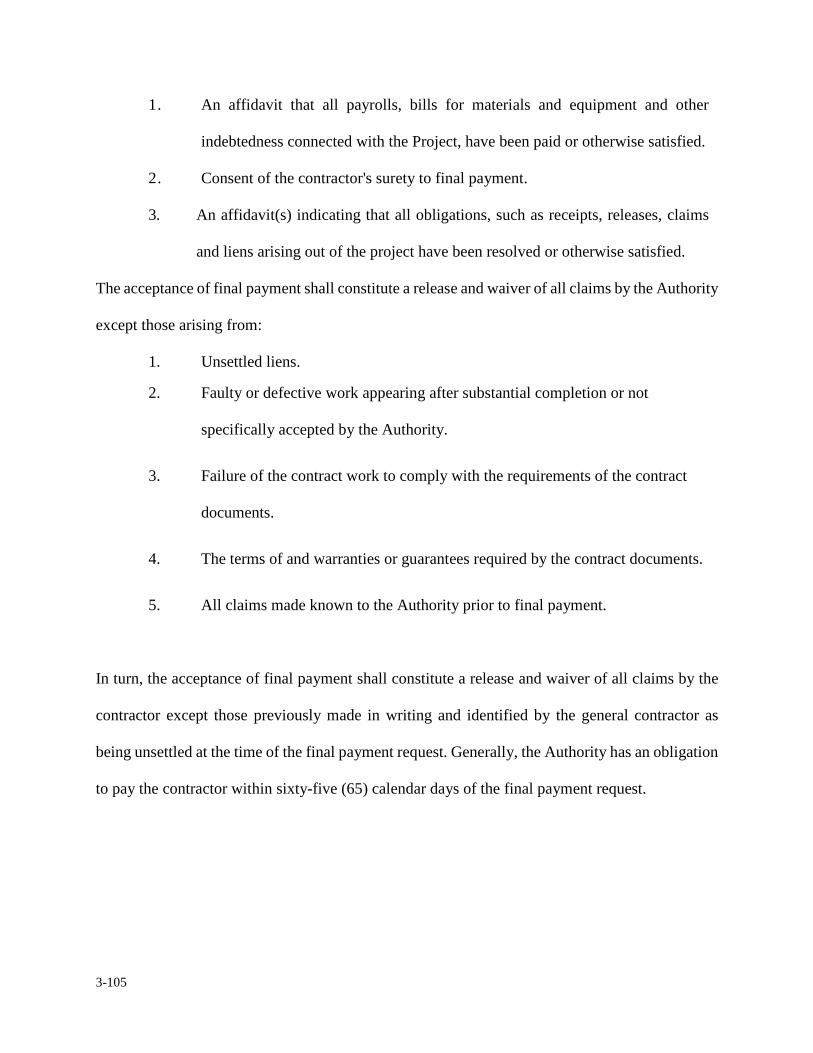
3-105
1. An affidavit that all payrolls, bills for materials and equipment and other
indebtedness connected with the Project, have been paid or otherwise satisfied.
2. Consent of the contractor's surety to final payment.
3. An affidavit(s) indicating that all obligations, such as receipts, releases, claims
and liens arising out of the project have been resolved or otherwise satisfied.
The acceptance of final payment shall constitute a release and waiver of all claims by the Authority
except those arising from:
1. Unsettled liens.
2. Faulty or defective work appearing after substantial completion or not
specifically accepted by the Authority.
3. Failure of the contract work to comply with the requirements of the contract
documents.
4. The terms of and warranties or guarantees required by the contract documents.
5. All claims made known to the Authority prior to final payment.
In turn, the acceptance of final payment shall constitute a release and waiver of all claims by the
contractor except those previously made in writing and identified by the general contractor as
being unsettled at the time of the final payment request. Generally, the Authority has an obligation
to pay the contractor within sixty-five (65) calendar days of the final payment request.
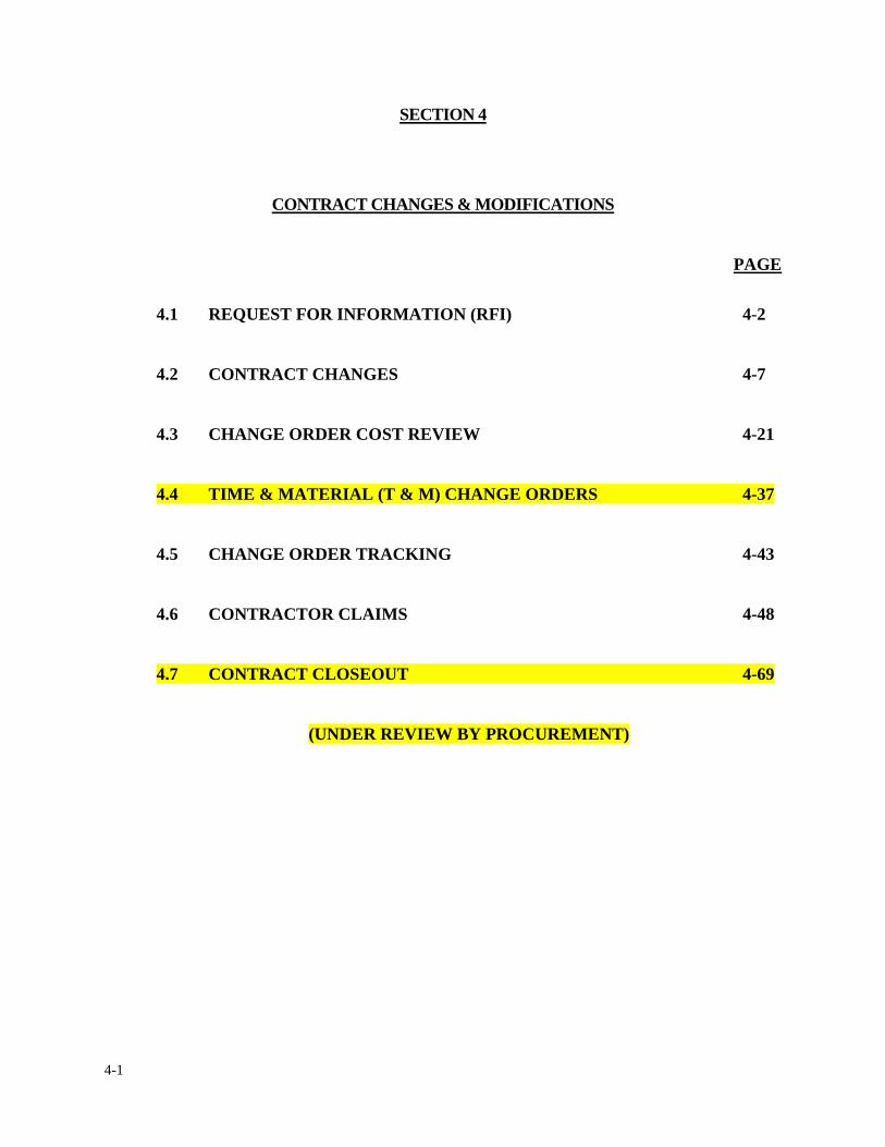
4-1
SECTION 4
CONTRACT CHANGES & MODIFICATIONS
PAGE
4.1 REQUEST FOR INFORMATION (RFI) 4-2
4.2 CONTRACT CHANGES 4-7
4.3 CHANGE ORDER COST REVIEW 4-21
4.4 TIME & MATERIAL (T & M) CHANGE ORDERS 4-37
4.5 CHANGE ORDER TRACKING 4-43
4.6 CONTRACTOR CLAIMS 4-48
4.7 CONTRACT CLOSEOUT 4-69
(UNDER REVIEW BY PROCUREMENT)
4-2
4. CONTRACT CHANGES & MODIFICATIONS
4.1 REQUEST FOR INFORMATION (RFI)
During construction, the Contractor has a right to request interpretations and/or clarifications of
conflicts, inconsistencies or discrepancies in the Contract Documents from the Authority. It is the
responsibility of the Contractor to review all Contract Documents prior to submitting a Request for
Information (RFI). The resident engineer shall log, track and file each RFI following the
procedures discussed in Section 1 of this manual. The RFI shall be reviewed and distributed
following a procedure similar to the one for Contractor submittals previously discussed in Section
3.5.
Exhibit 4-A.1a, includes a blank RFI form which will be issued to the Contractor at the
pre-construction meeting and should be used for initiating any RFI request. If it is determined that
additional work is required, the response shall be as shown in Exhibit 4-A.1b which includes an
example of an RFI response in which additional work is identified as being required and includes
the standard language to be included in all responses requiring additional work. The Contractor is
required to submit a cost proposal within (10) days after Contractor’s receipt of the response to the
RFI indicating that there is additional work (see General Conditions Article 13.1.2). If it is
determined that no additional work is required, the response shall be as shown in Exhibit 4-A.1c
which includes an example of an RFI response when the Resident Engineer determines that
additional work is not required. This standard language shall be included in all responses that in
the opinion of the Resident Engineer do not require additional work. If the Contractor wishes to
dispute the determination of no additional work, a claim must be filed by the Contractor as detailed

4-3
in Section 4.6 of this manual within twenty-one (21) days after Contractor’s receipt of the response
to the RFI (see General Conditions Article 19.2.1).
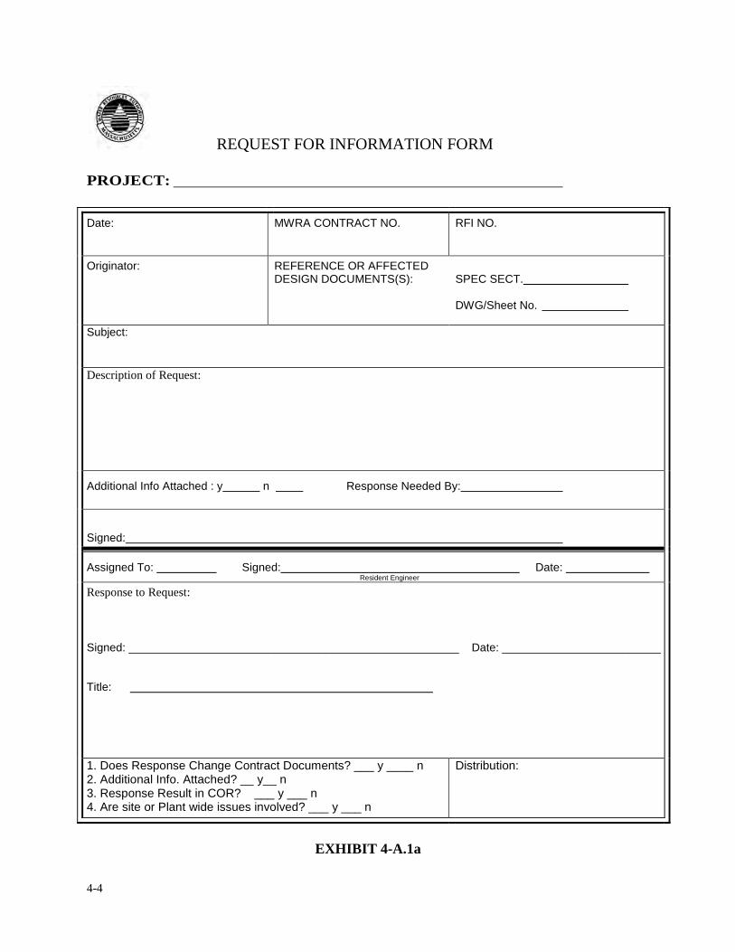
4-4
REQUEST FOR INFORMATION FORM
PROJECT:
Date:
MWRA CONTRACT NO.
RFI NO.
Originator:
REFERENCE OR AFFECTED DESIGN DOCUMENTS(S):
SPEC SECT. DWG/Sheet No.
Subject:
Description of Request:
Additional Info Attached : y n Response Needed By:
Signed:
Assigned To: Signed: Date: Resident Engineer
Response to Request:
Signed: ____________________________________________________ Date: _________________________ Title:
1. Does Response Change Contract Documents? ___ y ____ n 2. Additional Info. Attached? __ y__ n 3. Response Result in COR? ___ y ___ n 4. Are site or Plant wide issues involved? ___ y ___ n
Distribution:
EXHIBIT 4-A.1a
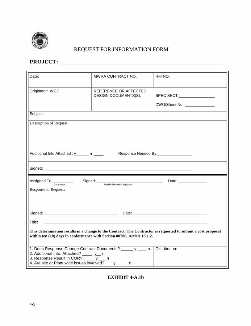
4-5
REQUEST FOR INFORMATION FORM
PROJECT:
Date:
MWRA CONTRACT NO.
RFI NO.
Originator: WCC
REFERENCE OR AFFECTED DESIGN DOCUMENTS(S):
SPEC SECT. DWG/Sheet No.
Subject:
Description of Request:
Additional Info Attached : y n Response Needed By:
Signed:
Assigned To: Signed: Date: Consultant MWRA Resident Engineer
Response to Request:
Signed: ���� ���� ���� ���� Date: ���� ���� Title: This determination results in a change to the Contract. The Contractor is requested to submit a cost proposal within ten (10) days in conformance with Section 00700, Article 13.1.2.
1. Does Response Change Contract Documents? y ____ n 2. Additional Info. Attached? y__ n 3. Response Result in COR? y ___ n 4. Are site or Plant wide issues involved? ___ y n
Distribution:
EXHIBIT 4-A.1b
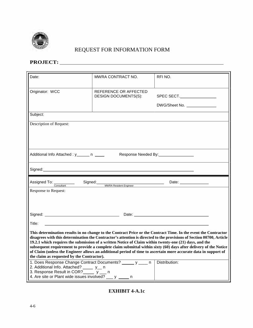
4-6
REQUEST FOR INFORMATION FORM
PROJECT:
Date:
MWRA CONTRACT NO.
RFI NO.
Originator: WCC
REFERENCE OR AFFECTED DESIGN DOCUMENTS(S):
SPEC SECT. DWG/Sheet No.
Subject:
Description of Request:
Additional Info Attached : y n Response Needed By:
Signed:
Assigned To: Signed: Date: Consultant MWRA Resident Engineer
Response to Request:
Signed: ���� ���� ���� ���� Date: ���� ���� Title: This determination results in no change to the Contract Price or the Contract Time. In the event the Contractor disagrees with this determination the Contractor’s attention is directed to the provisions of Section 00700, Article 19.2.1 which requires the submission of a written Notice of Claim within twenty-one (21) days, and the subsequent requirement to provide a complete claim submittal within sixty (60) days after delivery of the Notice of Claim (unless the Engineer allows an additional period of time to ascertain more accurate data in support of the claim as requested by the Contractor).
1. Does Response Change Contract Documents? y ____ n 2. Additional Info. Attached? y__ n 3. Response Result in COR? y ___ n 4. Are site or Plant wide issues involved? ___ y n
Distribution:
EXHIBIT 4-A.1c
4-7
4. CONTRACT CHANGES & MODIFICATIONS
4.2 CONTRACT CHANGES
A change order is a written order issued by the Authority to the Contractor authorizing an addition
to, deletion from, or revision in the work, and an adjustment in the Contract Price and/or Contract Time, if
justified. All changes to a construction contract resulting in a change in Contract Price or Contract Time require
a change order. All change orders must be processed in accordance with Article 13 of the General Conditions,
Policy #ADM.03 and applicable statutes. Either the Authority or the Contractor may initiate a change
order.
Contractor CORs:
All Contractor initiated change order requests must be in writing, must follow the Change
Order Request (COR) form, Exhibit 4-B.1, and must be submitted to the Resident Engineer for
review. When presented with a COR, the Construction Staff must answer the threshold
questions indicated in Exhibit 4-B.2a and 4-B.2b “Changes in the Work” to determine if the
Contractor is entitled to a Change Order. If it is determined that the work is additional
work to the Contract and is justifiable under ADM.03, the COR shall be responded to
using the standard COR acceptance included in Exhibit 4-B.3a. If it is determined
that the work is already specified in the contract documents or is not justifiable
under ADM.03, the COR shall be rejected using the standard COR denial response
included in Exhibit 4-B.3b. If the Contractor submits a claim, Construction Staff shall
support the Claims Management Specialist in analyzing and processing the claim and
Engineer’s Decision.
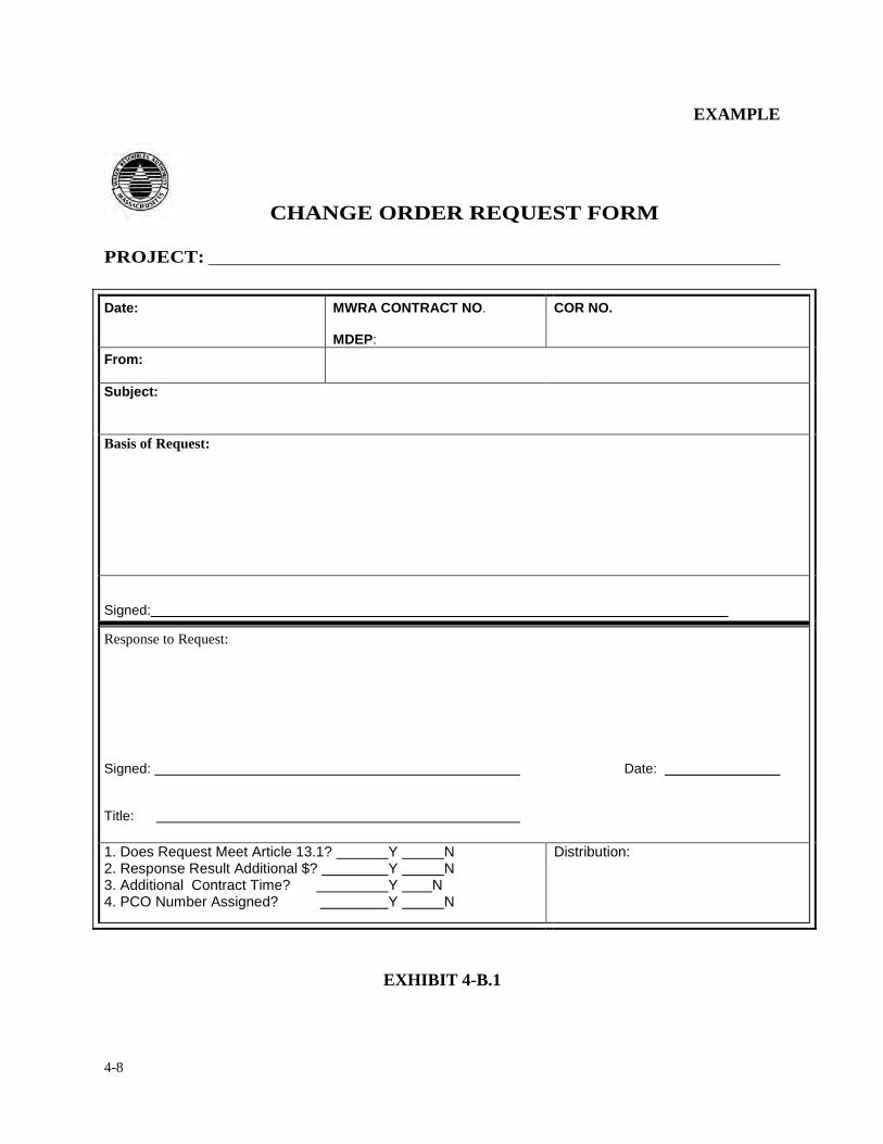
4-8
EXAMPLE
CHANGE ORDER REQUEST FORM PROJECT:
Date:
MWRA CONTRACT NO. MDEP:
COR NO.
From:
Subject:
Basis of Request:
Signed:
Response to Request:
Signed: ���� ���� ���� ���� ���� ���� Date: Title:
1. Does Request Meet Article 13.1? Y N 2. Response Result Additional $? Y N 3. Additional Contract Time? Y N 4. PCO Number Assigned? Y N
Distribution:
EXHIBIT 4-B.1
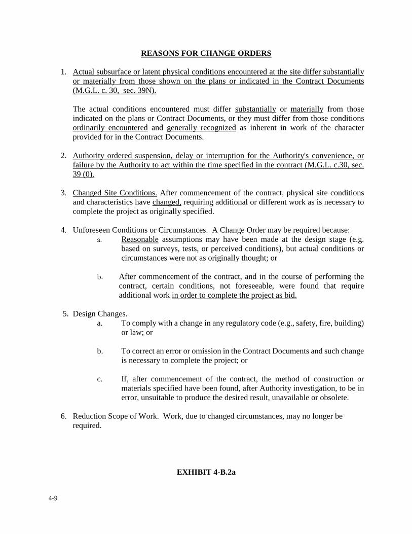
4-9
REASONS FOR CHANGE ORDERS
1. Actual subsurface or latent physical conditions encountered at the site differ substantially or materially from those shown on the plans or indicated in the Contract Documents (M.G.L. c. 30, sec. 39N). The actual conditions encountered must differ substantially or materially from those indicated on the plans or Contract Documents, or they must differ from those conditions ordinarily encountered and generally recognized as inherent in work of the character provided for in the Contract Documents.
2. Authority ordered suspension, delay or interruption for the Authority's convenience, or failure by the Authority to act within the time specified in the contract (M.G.L. c.30, sec. 39 (0).
3. Changed Site Conditions. After commencement of the contract, physical site conditions and characteristics have changed, requiring additional or different work as is necessary to complete the project as originally specified.
4. Unforeseen Conditions or Circumstances. A Change Order may be required because: �� Reasonable assumptions may have been made at the design stage (e.g.
based on surveys, tests, or perceived conditions), but actual conditions or circumstances were not as originally thought; or
�� After commencement of the contract, and in the course of performing the contract, certain conditions, not foreseeable, were found that require additional work in order to complete the project as bid.
5. Design Changes.
a. To comply with a change in any regulatory code (e.g., safety, fire, building) or law; or
b. To correct an error or omission in the Contract Documents and such change is necessary to complete the project; or
c. If, after commencement of the contract, the method of construction or materials specified have been found, after Authority investigation, to be in error, unsuitable to produce the desired result, unavailable or obsolete.
6. Reduction Scope of Work. Work, due to changed circumstances, may no longer be required.
EXHIBIT 4-B.2a
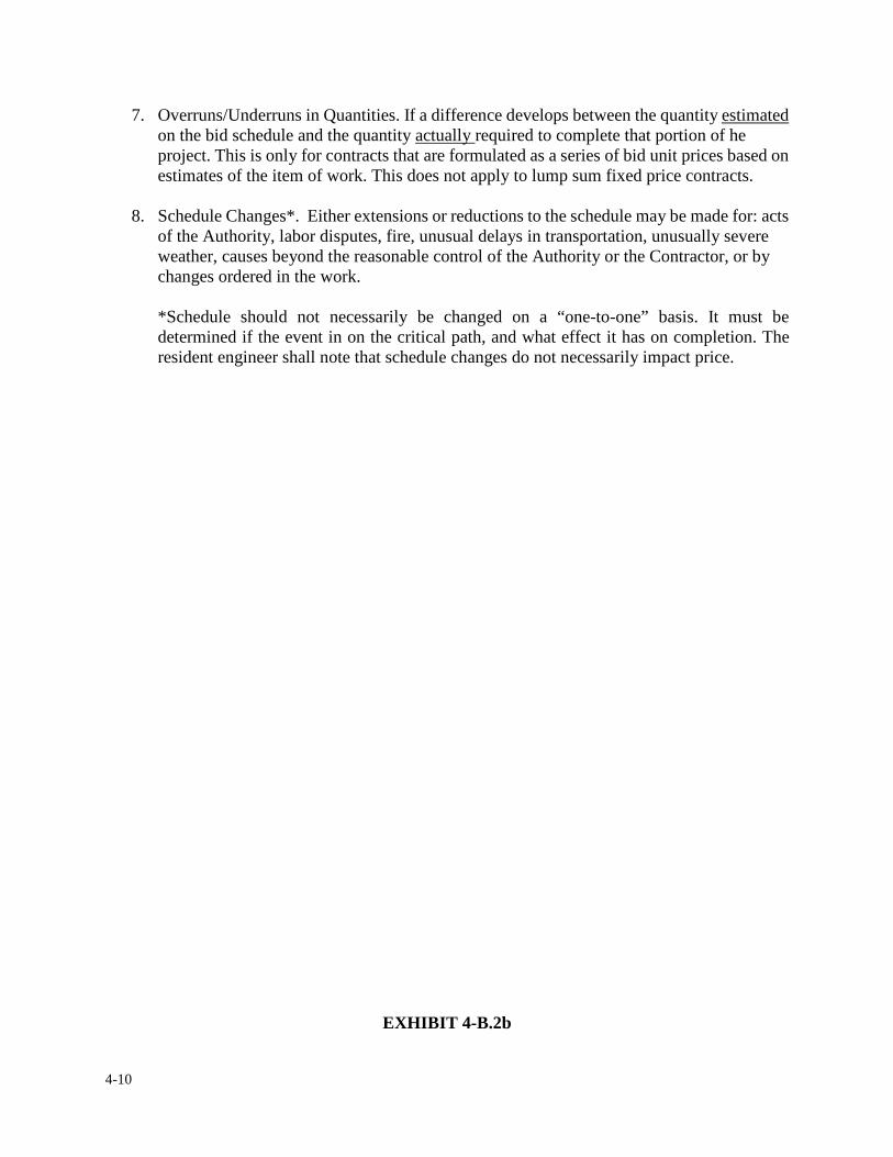
4-10
7. Overruns/Underruns in Quantities. If a difference develops between the quantity estimated on the bid schedule and the quantity actually required to complete that portion of he project. This is only for contracts that are formulated as a series of bid unit prices based on estimates of the item of work. This does not apply to lump sum fixed price contracts.
8. Schedule Changes*. Either extensions or reductions to the schedule may be made for: acts of the Authority, labor disputes, fire, unusual delays in transportation, unusually severe weather, causes beyond the reasonable control of the Authority or the Contractor, or by changes ordered in the work. *Schedule should not necessarily be changed on a “one-to-one” basis. It must be determined if the event in on the critical path, and what effect it has on completion. The resident engineer shall note that schedule changes do not necessarily impact price.
EXHIBIT 4-B.2b
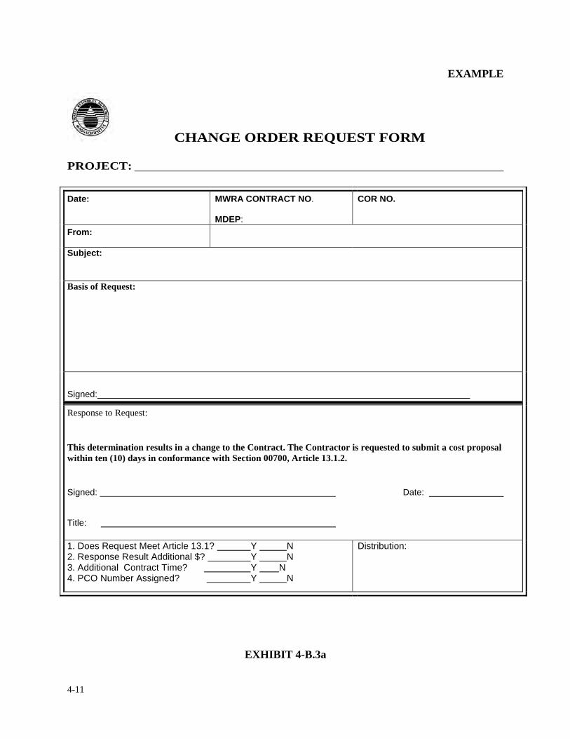
4-11
EXAMPLE
CHANGE ORDER REQUEST FORM PROJECT:
Date:
MWRA CONTRACT NO. MDEP:
COR NO.
From:
Subject:
Basis of Request:
Signed:
Response to Request: This determination results in a change to the Contract. The Contractor is requested to submit a cost proposal within ten (10) days in conformance with Section 00700, Article 13.1.2.
Signed: ���� ���� ���� ���� ���� ���� Date: Title:
1. Does Request Meet Article 13.1? Y N 2. Response Result Additional $? Y N 3. Additional Contract Time? Y N 4. PCO Number Assigned? Y N
Distribution:
EXHIBIT 4-B.3a
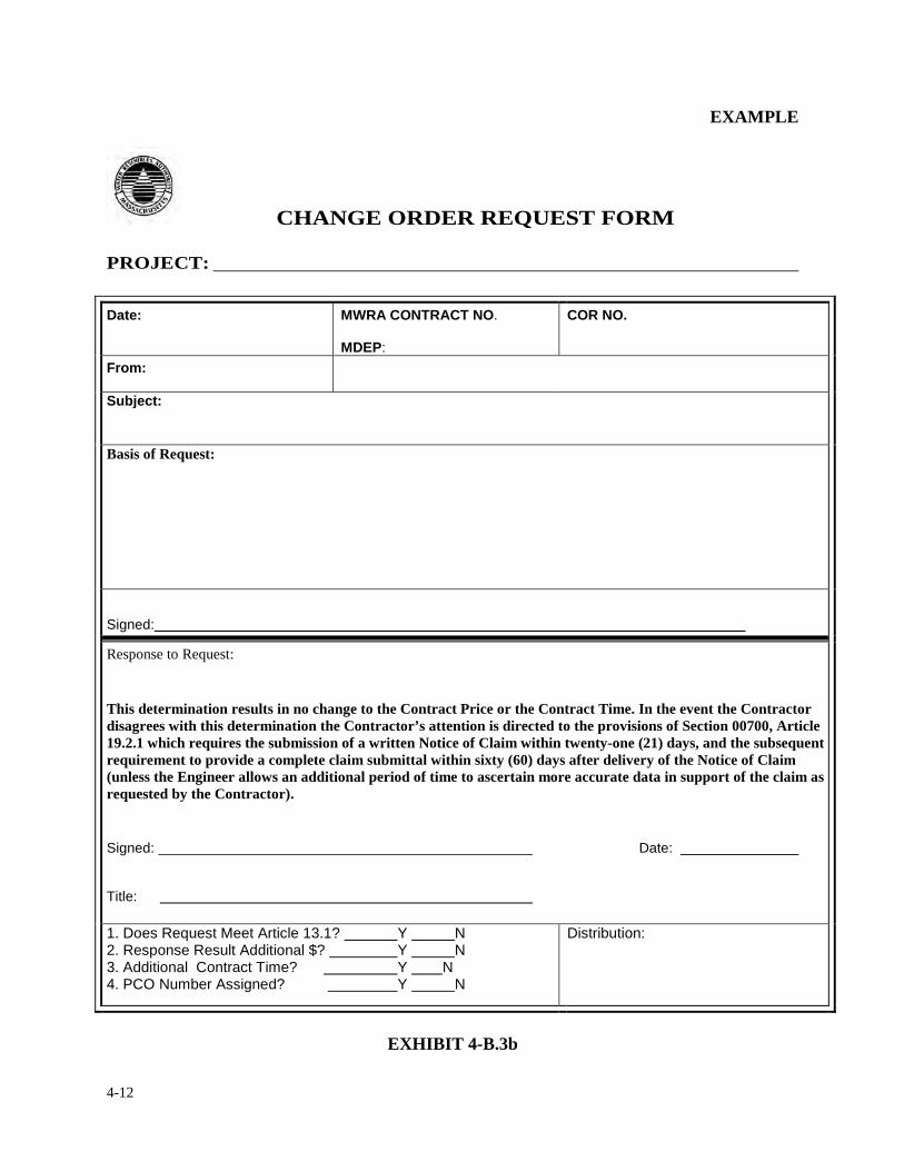
4-12
EXAMPLE
CHANGE ORDER REQUEST FORM PROJECT:
Date:
MWRA CONTRACT NO. MDEP:
COR NO.
From:
Subject:
Basis of Request:
Signed:
Response to Request: This determination results in no change to the Contract Price or the Contract Time. In the event the Contractor disagrees with this determination the Contractor’s attention is directed to the provisions of Section 00700, Article 19.2.1 which requires the submission of a written Notice of Claim within twenty-one (21) days, and the subsequent requirement to provide a complete claim submittal within sixty (60) days after delivery of the Notice of Claim (unless the Engineer allows an additional period of time to ascertain more accurate data in support of the claim as requested by the Contractor).
Signed: ���� ���� ���� ���� ���� ���� Date: Title:
1. Does Request Meet Article 13.1? Y N 2. Response Result Additional $? Y N 3. Additional Contract Time? Y N 4. PCO Number Assigned? Y N
Distribution:
EXHIBIT 4-B.3b
4-13
If the Authority initiates a Change Order or determines that a Contractor Change Order Request
has merit, Construction Staff, in conjunction with Construction Coordinator and Document
Control staff, shall process the change order in accordance with following checklist:
Reply to Contractor using standard COR acceptance response in Exhibit 4-B.3a, including a request for a cost proposal within 10 days*. *Construction Staff must prepare a scope of work for the Contractor’s use in preparing the cost proposal which clearly specifies work to be performed by the contractor and subcontractors, if any. If the scope of work is prepared by a Consulting Engineer, it must be reviewed by Construction Staff.
Resident Engineer prepares a draft Description of Work and Reason for Change for inclusion in a Proposed Change Order (PCO) as soon as the need for a change order is identified.* *Only PCO's that can be justified with one of the reasons identified in Exhibit 4-B.2a and B.2b are permitted. Exhibit 4-B.4a through 4-B.4c includes the PCO template required by ADM#03. Resident Engineer submits draft to Construction Coordinator for review Construction Coordinator reviews and transmits draft PCO language to the assigned Contract Administrator in Coordination and Control. Contract Administrator revises draft PCO language, in coordination with the Construction Coordinator, and prepares a PCO. PCOs must:
• be consecutively numbered starting with one • indicate if the change is requested by the Authority or the Contractor • indicate if urgent action (i.e. authorization/execution in 5 days or less) is
required.* *If urgent action is requested, the PCO must include an explanation of the reason for urgency (i.e. an emergency involving health and safety of persons or damage to property or a delay of project progress which will result in (1) time delays, (2) additional Authority cost for idle personnel/equipment or (3) disruption to Authority or member community operations). Contract Administrator submits PCO to Construction Coordinator and Assistant Director of Construction for signature Contract Administrator submits the PCO to Procurement Department for review and approval
4-14
If the PCO is returned by Procurement with questions, Construction Coordinator assists Contract Administrator with responses until PCO is approved* or denied** NOTE: *An approved PCO does not authorize the Contractor to proceed with or receive payment for the change order work. **If the PCO is denied, the PCO is void and the change order process ends.
If the PCO is approved, Contract Administrator determines the required level of approval based on remaining delegated authority
Assist Contract Administrator in drafting e-mail approval or Staff Summary Prepare Fair Cost Estimate Review Contractor’s Cost Proposal in accordance with Article 13 of the General Conditions
If the cost proposal is less than $100,000, Resident Engineer shall review and verify the prices in association with the contract. and determine if the costs are fair and reasonable. If the cost proposal is over $100,000, an independent fair cost estimate (FCE) shall be prepared by the Consultant or Authority and compared to the proposal.* *The Construction Coordinator may require a FCE for contractor cost proposals under $100,000.
Negotiate CO cost and time (if any) Prepare Memorandum of Negotiation (MON) Provide cost, time (if any), detailed scope of work and sketches or revised drawings (if any) to C&C for
draft Change Order Assist C&C with preparation of Draft Change Order
Exhibit 4-B.5a and 4-B.5b includes the CO template required by ADM#03
Assist C&C with obtaining Procurement approval of draft Change Order Present approved Change Order to Contractor for execution after authorization by e-mail, staff
summary or Board vote has been obtained and Procurement has approved the Draft Change Order Return Change Order to C&C for execution by the Director of Construction after obtaining
Contractor’s signature.* *If the Contractor refuses to sign the Change Order it will be issued unilaterally in accordance with the provisions of Article 13.1.11 of the General Conditions
The Contractor is authorized to proceed with the change order work as of the day the change order is executed by the Director of Construction but cannot bill for the work until the change order has been entered into the contract system.* *C&C will submit the executed change order package to Procurement for review, signature by Budget (if required by funding source), and entering into the contract system. Procurement will mail one original executed change order to the Contractor.
Integrate the change order into the “as-bid” set of drawings and specifications.
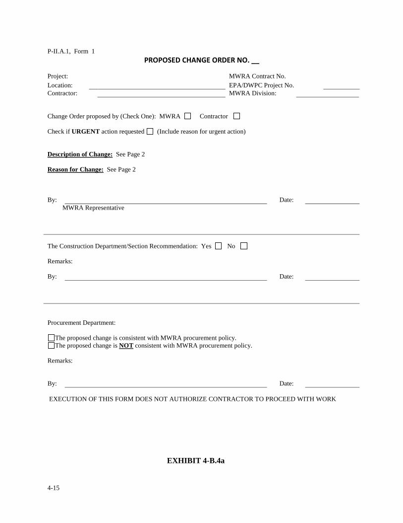
4-15
P-II.A.1, Form 1 ���������������������� ����
Project: MWRA Contract No. Location: EPA/DWPC Project No. Contractor: MWRA Division: Change Order proposed by (Check One): MWRA Contractor Check if URGENT action requested (Include reason for urgent action) Description of Change: See Page 2 Reason for Change: See Page 2 By: Date: MWRA Representative The Construction Department/Section Recommendation: Yes No Remarks: By: Date: Procurement Department:
The proposed change is consistent with MWRA procurement policy. The proposed change is NOT consistent with MWRA procurement policy.
Remarks: By: Date: EXECUTION OF THIS FORM DOES NOT AUTHORIZE CONTRACTOR TO PROCEED WITH WORK
EXHIBIT 4-B.4a

4-16
Page 2 Contract No. PCO No. 1. DESCRIPTION OF CHANGE: 2. REASON FOR CHANGE: 3) Is urgent action required? ()yes (X) no
EXHIBIT 4-B.4b

4-17
Page 3 Contract PCO No.
4. REFERENCE DOCUMENTS: .
5. ORIGINATOR/ORGANIZATION: MWRA PHONE # DATE: 6. CHANGE PROPOSED BY: MWRA ( X ); DE ( ); CONTRACTOR ( ) 7. ROUGH ORDER OF MAG. EST: $ 8. IS REWORK REQUIRED? YES ( ), NO ( X ) 9. EST. OF EFFECT ON CONTRACT COMPLETION DATE: NONE (X), or, APPROX. ________DAYS 10. IS REDESIGN REQUIRED? YES( X ), NO( ) 11. REQUESTED DELIVERY DATE FOR REDESIGN: 12. CPs AFFECTED:
13. COULD THE WORK BE PERFORMED UNDER ANOTHER CP? YES ( ), NO (X)
14. MWRA ACTION: DATE RECEIVED: / /
DECISION: APPROVED DISAPPROVED REFERRED ACTION: / / / / SENIOR CM DP MANAGER
EXHIBIT 4-B.4c
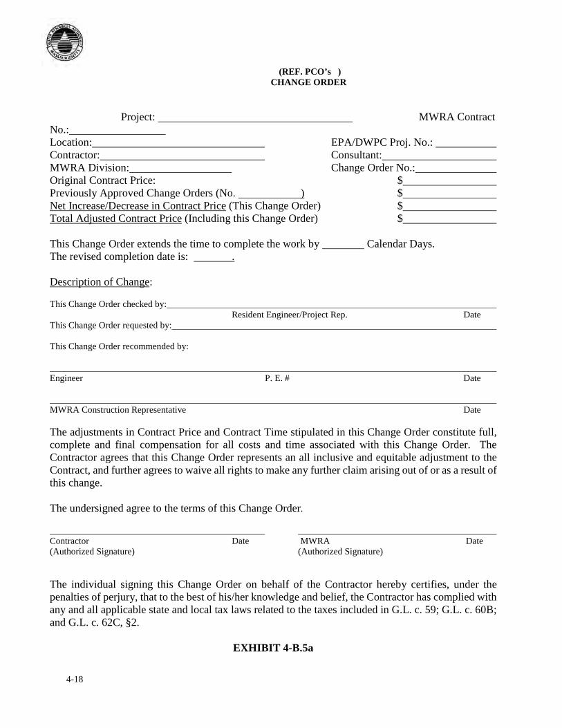
4-18
(REF. PCO’s ) CHANGE ORDER
Project: MWRA Contract
No.: Location: EPA/DWPC Proj. No.: Contractor: Consultant: MWRA Division: Change Order No.: Original Contract Price: $ Previously Approved Change Orders (No. ) $ Net Increase/Decrease in Contract Price (This Change Order) $ Total Adjusted Contract Price (Including this Change Order) $ This Change Order extends the time to complete the work by Calendar Days. The revised completion date is: . Description of Change: This Change Order checked by: Resident Engineer/Project Rep. Date This Change Order requested by: This Change Order recommended by: Engineer P. E. # Date MWRA Construction Representative Date The adjustments in Contract Price and Contract Time stipulated in this Change Order constitute full, complete and final compensation for all costs and time associated with this Change Order. The Contractor agrees that this Change Order represents an all inclusive and equitable adjustment to the Contract, and further agrees to waive all rights to make any further claim arising out of or as a result of this change. The undersigned agree to the terms of this Change Order. Contractor Date MWRA Date (Authorized Signature) (Authorized Signature) The individual signing this Change Order on behalf of the Contractor hereby certifies, under the penalties of perjury, that to the best of his/her knowledge and belief, the Contractor has complied with any and all applicable state and local tax laws related to the taxes included in G.L. c. 59; G.L. c. 60B; and G.L. c. 62C, §2.
EXHIBIT 4-B.5a
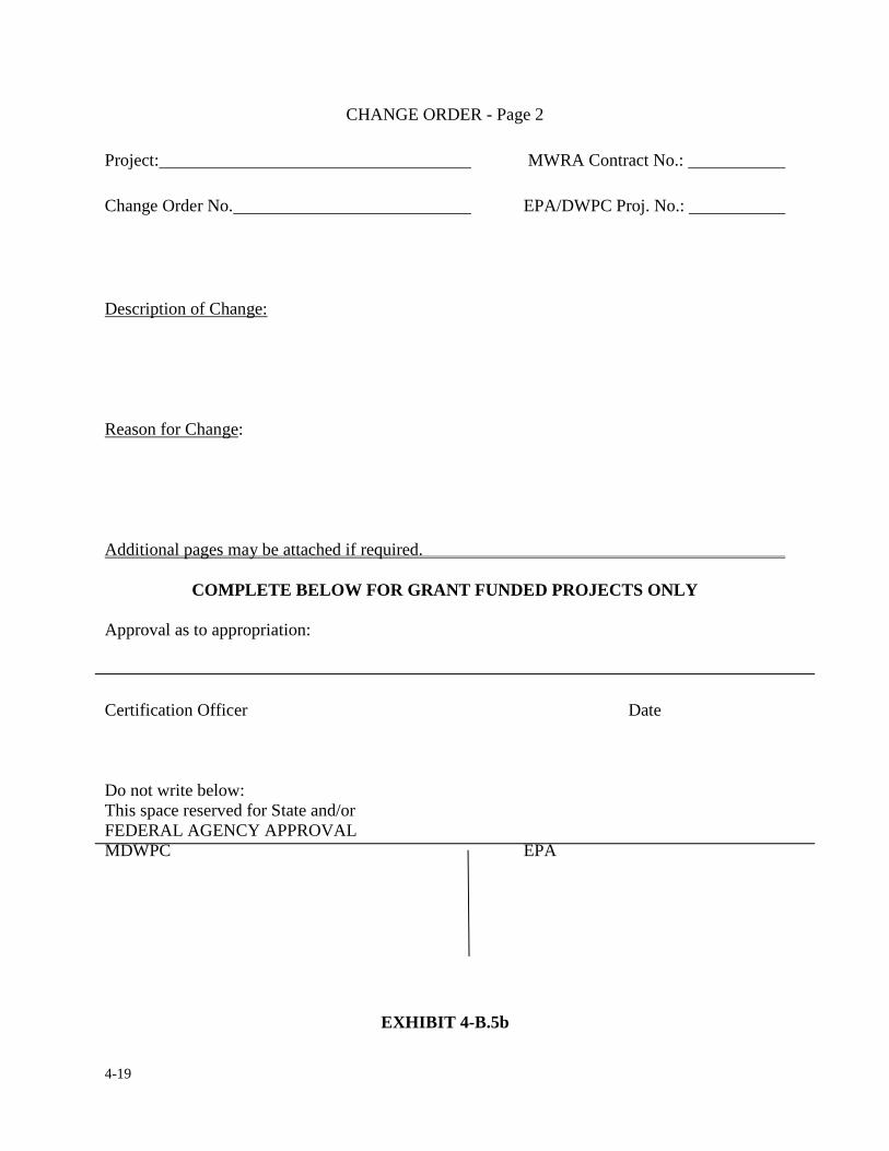
4-19
CHANGE ORDER - Page 2 Project: MWRA Contract No.: Change Order No. EPA/DWPC Proj. No.:
Description of Change:
Reason for Change:
Additional pages may be attached if required.
COMPLETE BELOW FOR GRANT FUNDED PROJECTS ONLY
Approval as to appropriation:
Certification Officer Date
Do not write below: This space reserved for State and/or FEDERAL AGENCY APPROVAL MDWPC EPA
EXHIBIT 4-B.5b
4-20
CHANGE ORDER AUTHORIZATION
There are three processes for a change order to be authorized depending on their total dollar
value as follows:
A. Change Orders less than $25,000 - Approved with email authorization from the
Executive Director.
B. Change orders greater than $25,000 but less than $250,000 - Approved by a Staff
Summary submitted to the Executive Director.
C. Change orders greater than $250,000 - Approved by a vote of the Board of
Directors based on a Staff Summary.
Staff Summaries are initiated by Construction Coordinator and Document Control with
assistance from Construction Staff and routed to the office of the Chief Operating Officer. Change
Order Staff Summaries are required to describe the change order work, the reason for the change,
the dollar amount of each change order item, and extension of Contract Time, if any, expressed in
number of days). Once a change order is authorized according to the above and the draft change
order is approved by Procurement, it is then forwarded to the Contractor by Construction Staff for
execution.
4-21
4. CONTRACT CHANGES & MODIFICATIONS
4.3 CHANGE ORDER COST REVIEW
The next step in the change order process is to make a thorough review of the contractor's cost
proposal. For simplicity reasons we shall consider that whatever change order is being discussed,
its value is less than $100,000.00. For change orders with a value greater than $100,000, an
independent Fair Cost Estimate (FCE) is required. The FCE shall be performed by an independent
Consultant Engineer, the design engineer, or the Authority to develop an independent cost for
comparison and evaluation to the contractor’s proposal. For any change order with a value greater
than $100,000 a certificate of current cost or pricing data shall be provided and executed by the
contractor. Exhibit 4-C.6 is a sample form of a certificate of current cost or pricing data.
The contractor must submit with every proposed change a detailed cost estimate which provides
sufficient information to evaluate the cost elements needed to perform the work involved. The cost
estimate must clearly distinguish between tasks or activities which will be performed by
subcontractors from those to be performed by the contractor. The resident engineer should
examine the contractor's proposed cost estimate and ask three questions: Is the cost proposal
accurate? Is the cost proposal reasonable based on current market standards? Is the cost proposal
fair?
The following are guidelines in determining if a cost proposal is accurate, reasonable and fair.
4-22
Is the cost proposal accurate?
The resident engineer must double check the contractor's submission for any quantity or math
errors and compare certain proposed costs (such as wage rates and indirect labor rates) with
certified payrolls and prevailing wage rates on file in the project records.
Whether the terms of the change are lump sum, unit price or time and materials, there are certain
cost items which are non-allowable, as defined by the contract documents. “Non-allowable costs”
simply means that although the costs may be legitimate costs borne by the contractor, they are
costs which can not be passed on to the Authority. These costs are for the most part considered to
be included in the base contract amount, or are indirect, administrative or other overhead costs.
The resident engineer shall consult Article 13 of the General Conditions in determining allowable
vs. non-allowable costs associated with determining the cost of change order work.
Is the cost proposal reasonable?
To review a cost proposal for reasonableness is to determine whether the level of effort, the
quantity of materials, and the usage are equal to the scope of work to be performed given the
existing conditions. One of the most common indications of a cost proposal being unreasonable is
showing duplication of effort in the work, (i.e. using two ten-wheel trucks instead of one, showing
the need for four laborers instead of two, listing 800 linear ft. of conduit where only 400 linear ft. is
necessary).
4-23
The resident engineer shall review the contractor’s proposal in accordance with the contract
documents for determining cost proposal reasonableness.
Is the cost proposal fair?
There is generally no cost competition in dealing with change orders. In the absence of
competition, it becomes important to determine whether the costs proposed by the contractor are
fair. The resident engineer should determine if the costs being proposed are in accordance with
Article 13 of the General Conditions.
If the work involved is extensive and requires potentially costly subcontract work, such as asbestos
removal, removal of contaminated or hazardous material or the purchase of major
equipment/systems, the resident engineer should require the contractor to obtain three written
quotes from different firms.
The preferred method to arrive at a conclusion if the contractor’s costs are accurate, fair and
reasonable is for the resident engineer or Consulting engineer to perform a “Cost Breakdown &
Verification” (CB&V) or a Fair Cost Estimate (FCE) review of the contractor's cost proposal.
Exhibit 4-C.1a and 4-C.1b is an example of a CB&V or FCE review form to be utilized to verify
the contractor's cost proposal. The CB&V is a two part form; the first part is the cost breakdown
and the second part is the summary of cost review with comments on the contractor’s cost proposal
Exhibit 4-C.2 is an example of this cost summary. (Blank forms are provided in the Appendix of
this manual).
4-24
Basically, the CB&V review is a comparison between the contractor's proposed costs and the
resident engineer's costs as per each work category. The resident engineer can design his own form
or use the CB&V form offered in this manual. Whichever the resident engineer decides, the form
should reflect the following criteria. Each work category shall be identified and each line item
shall include the description or trade, rate or quantity per unit or time, and the proposed cost. Labor
and equipment categories shall correspond to the contractor’s work force and equipment as
recorded in the resident engineer’s daily work force account log. If the contractor’s proposal
requires specific labor and equipment not currently accounted for in the project, prevailing wages
and blue book rental rates shall be used. Work categories are defined as; labor cost, indirect labor,
materials, equipment and subcontractor(s), if any. The prices derived by the resident engineer
should equal or be within reason of the contractor’s cost proposal. If not, difference between the
contractor's prices and resident engineer's prices shall be recorded and summarized as to the
reasons for the difference. If there is substantial difference between prices, further negotiation of
the contractor's proposal is warranted. At this point in time, the resident is to notify the contractor
and request a meeting to jointly review the item(s) in question. This meeting shall be documented
in a Memorandum of Negotiation (MON).
One of the more important functions of performing a CB&V is to make sure that all costs that
appear on the cost proposal can be verified and are compatible with the agreed scope of work. One
way to verify the contractor's proposal is for the resident engineer to indicate a source of reference
for each entry. Some of the most common sources of reference in dealing with construction
contracts are; Certified wage rates, Federal/State wage rate schedules, existing labor contracts,
4-25
prices from manufacturer’s catalogs, contractors stock, rental invoices and reference books (Blue
Book, Green Guide, Means Cost Data). The source of reference is a very important part of the cost
verification in that it establishes a level of accuracy to the resident engineer's review. Also, it
allows the resident engineer to show specific origins of costs, which are practically un-deniable
when it comes to substantiating prices. An example of how to document a source of reference is
included in Exhibit 4-C.1a and 4-C.1b.
If there is a conflict between the contractor's estimated costs and the prices found in the source of
reference, without an explanation provided by the contractor, the resident engineer shall use the
source of reference prices. The contractor is required to submit a statement along with his cost
breakdown indicating whether the equipment he intends to use to perform the change order work,
is, owned, leased or rented.
The CB&V review should conclude with a summary. Exhibit 4-C.2 is a suggested format for such
a summary. The summary shall indicate the total labor, material, and equipment costs along with
the Contract specified percent mark-up for the contractor as well as subcontractors. The resident
engineer is required to make a recommendation indicating the acceptable price to perform the
work and sign it as a record of his acceptance.
Once the form is completed it shall be forwarded to the construction coordinator. The construction
coordinator and the Consulting Engineer, if applicable, shall jointly review the CB&V and the
resident engineer's recommendations. The "review team" (the construction coordinator,
Consulting Engineer and the resident engineer) shall meet to review the CB&V and sign-off as to
their acceptance. If the review team does not accept the contractor's cost estimate as submitted, the
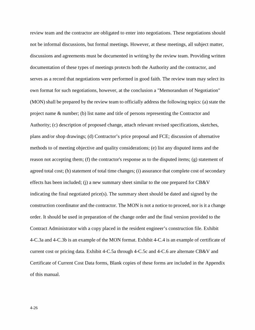
4-26
review team and the contractor are obligated to enter into negotiations. These negotiations should
not be informal discussions, but formal meetings. However, at these meetings, all subject matter,
discussions and agreements must be documented in writing by the review team. Providing written
documentation of these types of meetings protects both the Authority and the contractor, and
serves as a record that negotiations were performed in good faith. The review team may select its
own format for such negotiations, however, at the conclusion a "Memorandum of Negotiation"
(MON) shall be prepared by the review team to officially address the following topics: (a) state the
project name & number; (b) list name and title of persons representing the Contractor and
Authority; (c) description of proposed change, attach relevant revised specifications, sketches,
plans and/or shop drawings; (d) Contractor’s price proposal and FCE; discussion of alternative
methods to of meeting objective and quality considerations; (e) list any disputed items and the
reason not accepting them; (f) the contractor's response as to the disputed items; (g) statement of
agreed total cost; (h) statement of total time changes; (i) assurance that complete cost of secondary
effects has been included; (j) a new summary sheet similar to the one prepared for CB&V
indicating the final negotiated price(s). The summary sheet should be dated and signed by the
construction coordinator and the contractor. The MON is not a notice to proceed, nor is it a change
order. It should be used in preparation of the change order and the final version provided to the
Contract Administrator with a copy placed in the resident engineer’s construction file. Exhibit
4-C.3a and 4-C.3b is an example of the MON format. Exhibit 4-C.4 is an example of certificate of
current cost or pricing data. Exhibit 4-C.5a through 4-C.5c and 4-C.6 are alternate CB&V and
Certificate of Current Cost Data forms, Blank copies of these forms are included in the Appendix
of this manual.
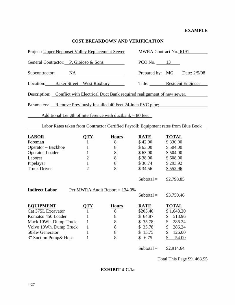
4-27
EXAMPLE
COST BREAKDOWN AND VERIFICATION Project: Upper Neponset Valley Replacement Sewer MWRA Contract No. 6191 General Contractor: P. Gioioso & Sons PCO No. 13 Subcontractor: NA Prepared by: MG Date: 2/5/08 Location: Baker Street – West Roxbury Title: Resident Engineer Description: Conflict with Electrical Duct Bank required realignment of new sewer. Parameters: Remove Previously Installed 40 Feet 24-inch PVC pipe; Additional Length of interference with ductbank = 80 feet Labor Rates taken from Contractor Certified Payroll; Equipment rates from Blue Book LABOR QTY Hours RATE TOTAL Foreman 1 8 $ 42.00 $ 336.00 Operator – Backhoe 1 8 $ 63.00 $ 504.00 Operator-Loader 1 8 $ 63.00 $ 504.00 Laborer 2 8 $ 38.00 $ 608.00 Pipelayer 1 8 $ 36.74 $ 293.92 Truck Driver 2 8 $ 34.56 $ 552.96
Subtotal = $2,798.85 Indirect Labor Per MWRA Audit Report = 134.0%
Subtotal = $3,750.46 EQUIPMENT QTY Hours RATE TOTAL Cat 375L Excavator 1 8 $205.40 $ 1,643.20 Komatsu 450 Loader 1 8 $ 64.87 $ 518.96 Mack 10Wh. Dump Truck 1 8 $ 35.78 $ 286.24 Volvo 10Wh. Dump Truck 1 8 $ 35.78 $ 286.24 50Kw Generator 1 8 $ 15.75 $ 126.00 3” Suction Pump& Hose 1 8 $ 6.75 $ 54.00
Subtotal = $2,914.64
Total This Page $9, 463.95
EXHIBIT 4-C.1a
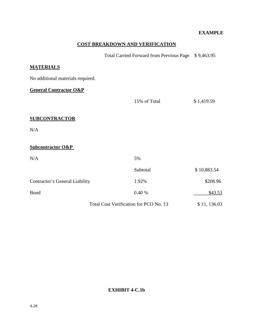
4-28
EXAMPLE
COST BREAKDOWN AND VERIFICATION Total Carried Forward from Previous Page $ 9,463.95
MATERIALS No additional materials required. General Contractor O&P 15% of Total $ 1,419.59 SUBCONTRACTOR N/A Subcontractor O&P N/A 5%
Subtotal $ 10,883.54 Contractor’s General Liability 1.92% $208.96 Bond 0.40 % $43.53
Total Cost Verification for PCO No. 13 $ 11, 136.03
EXHIBIT 4-C.1b
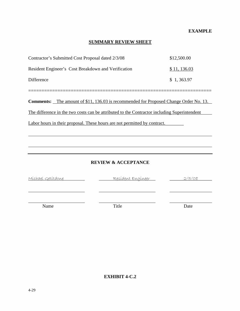
4-29
EXAMPLE
SUMMARY REVIEW SHEET
Contractor’s Submitted Cost Proposal dated 2/3/08 $12,500.00 Resident Engineer’s Cost Breakdown and Verification $ 11, 136.03 Difference $ 1, 363.97 ===================================================================== Comments: The amount of $11, 136.03 is recommended for Proposed Change Order No. 13. The difference in the two costs can be attributed to the Contractor including Superintendent Labor hours in their proposal. These hours are not permitted by contract.
REVIEW & ACCEPTANCE
������������ �� � ������ �� �� ��� ������
Name Title Date
EXHIBIT 4-C.2
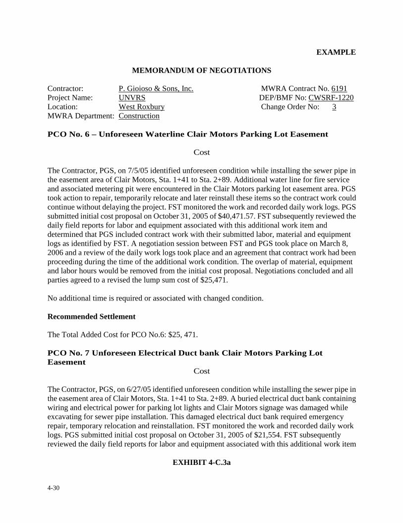
4-30
EXAMPLE
MEMORANDUM OF NEGOTIATIONS
Contractor: P. Gioioso & Sons, Inc. MWRA Contract No. 6191 Project Name: UNVRS DEP/BMF No: CWSRF-1220 Location: West Roxbury Change Order No: 3 MWRA Department: Construction PCO No. 6 – Unforeseen Waterline Clair Motors Parking Lot Easement
Cost
The Contractor, PGS, on 7/5/05 identified unforeseen condition while installing the sewer pipe in the easement area of Clair Motors, Sta. 1+41 to Sta. 2+89. Additional water line for fire service and associated metering pit were encountered in the Clair Motors parking lot easement area. PGS took action to repair, temporarily relocate and later reinstall these items so the contract work could continue without delaying the project. FST monitored the work and recorded daily work logs. PGS submitted initial cost proposal on October 31, 2005 of $40,471.57. FST subsequently reviewed the daily field reports for labor and equipment associated with this additional work item and determined that PGS included contract work with their submitted labor, material and equipment logs as identified by FST. A negotiation session between FST and PGS took place on March 8, 2006 and a review of the daily work logs took place and an agreement that contract work had been proceeding during the time of the additional work condition. The overlap of material, equipment and labor hours would be removed from the initial cost proposal. Negotiations concluded and all parties agreed to a revised the lump sum cost of $25,471. No additional time is required or associated with changed condition. Recommended Settlement The Total Added Cost for PCO No.6: $25, 471. PCO No. 7 Unforeseen Electrical Duct bank Clair Motors Parking Lot Easement
Cost
The Contractor, PGS, on 6/27/05 identified unforeseen condition while installing the sewer pipe in the easement area of Clair Motors, Sta. 1+41 to Sta. 2+89. A buried electrical duct bank containing wiring and electrical power for parking lot lights and Clair Motors signage was damaged while excavating for sewer pipe installation. This damaged electrical duct bank required emergency repair, temporary relocation and reinstallation. FST monitored the work and recorded daily work logs. PGS submitted initial cost proposal on October 31, 2005 of $21,554. FST subsequently reviewed the daily field reports for labor and equipment associated with this additional work item
EXHIBIT 4-C.3a
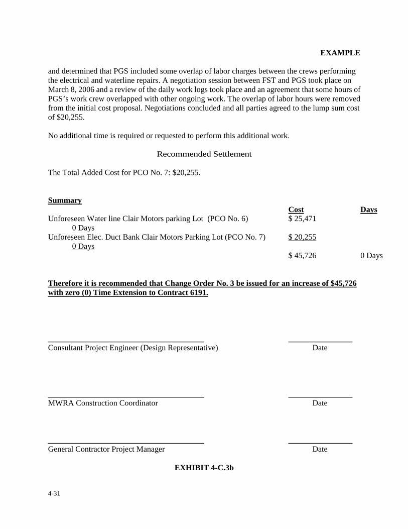
4-31
EXAMPLE
and determined that PGS included some overlap of labor charges between the crews performing the electrical and waterline repairs. A negotiation session between FST and PGS took place on March 8, 2006 and a review of the daily work logs took place and an agreement that some hours of PGS’s work crew overlapped with other ongoing work. The overlap of labor hours were removed from the initial cost proposal. Negotiations concluded and all parties agreed to the lump sum cost of $20,255.
No additional time is required or requested to perform this additional work.
Recommended Settlement
The Total Added Cost for PCO No. 7: $20,255.
Summary
Cost Days Unforeseen Water line Clair Motors parking Lot (PCO No. 6) $ 25,471 0 Days Unforeseen Elec. Duct Bank Clair Motors Parking Lot (PCO No. 7) $ 20,255 0 Days
$ 45,726 0 Days
Therefore it is recommended that Change Order No. 3 be issued for an increase of $45,726 with zero (0) Time Extension to Contract 6191.
_______________________________________ ________________ Consultant Project Engineer (Design Representative) Date _______________________________________ ________________ MWRA Construction Coordinator Date _______________________________________ ________________ General Contractor Project Manager Date
EXHIBIT 4-C.3b
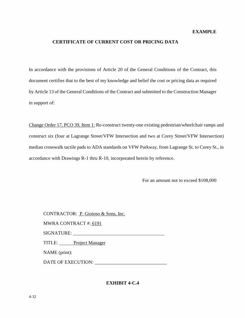
4-32
EXAMPLE CERTIFICATE OF CURRENT COST OR PRICING DATA
In accordance with the provisions of Article 20 of the General Conditions of the Contract, this
document certifies that to the best of my knowledge and belief the cost or pricing data as required
by Article 13 of the General Conditions of the Contract and submitted to the Construction Manager
in support of:
Change Order 17, PCO 39, Item 1: Re-construct twenty-one existing pedestrian/wheelchair ramps and
construct six (four at Lagrange Street/VFW Intersection and two at Corey Street/VFW Intersection)
median crosswalk tactile pads to ADA standards on VFW Parkway, from Lagrange St. to Corey St., in
accordance with Drawings R-1 thru R-10, incorporated herein by reference.
For an amount not to exceed $108,000
CONTRACTOR: P. Gioioso & Sons, Inc.
MWRA CONTRACT #: 6191
SIGNATURE: ______________________________________
TITLE: Project Manager
NAME (print):
DATE OF EXECUTION: ______________________________
EXHIBIT 4-C.4
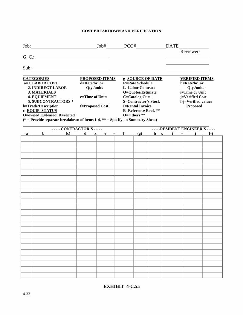
4-33
COST BREAKDOWN AND VERIFICATION
Job: Job# PCO# DATE Reviewers G. C.: Sub: CATEGORIES PROPOSED ITEMS g=SOURCE OF DATE VERIFIED ITEMS a=1. LABOR COST d=Rate/hr. or R=Rate Schedule h=Rate/hr. or 2. INDIRECT LABOR Qty./units L=Labor Contract Qty./units 3. MATERIALS Q=Quotes/Estimate i=Time or Unit 4. EQUIPMENT e=Time of Units C=Catalog Cuts j=Verified Cost 5. SUBCONTRACTORS * S=Contractor’s Stock f-j=Verified values b=Trade/Description f=Proposed Cost I=Rental Invoice Proposed c=EQUIP. STATUS B=Reference Book ** O=owned, L=leased, R=rented O=Others ** (* = Provide separate breakdown of items 1-4, ** = Specify on Summary Sheet)
- - - - CONTRACTOR’S - - - - - - - -RESIDENT ENGINEER’S - - - - a b (c) d x e = f (g) h x i = j f-j
EXHIBIT 4-C.5a
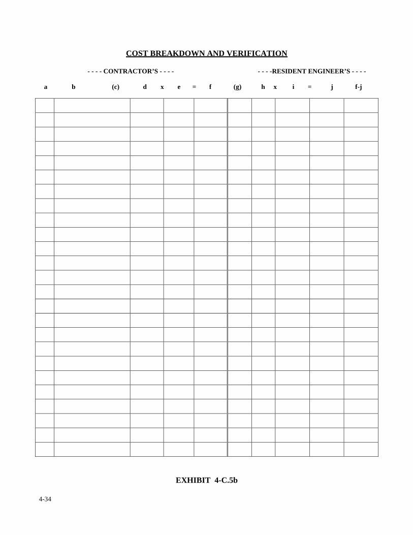
4-34
COST BREAKDOWN AND VERIFICATION
- - - - CONTRACTOR’S - - - - - - - -RESIDENT ENGINEER’S - - - -
a b (c) d x e = f (g) h x i = j f-j
EXHIBIT 4-C.5b
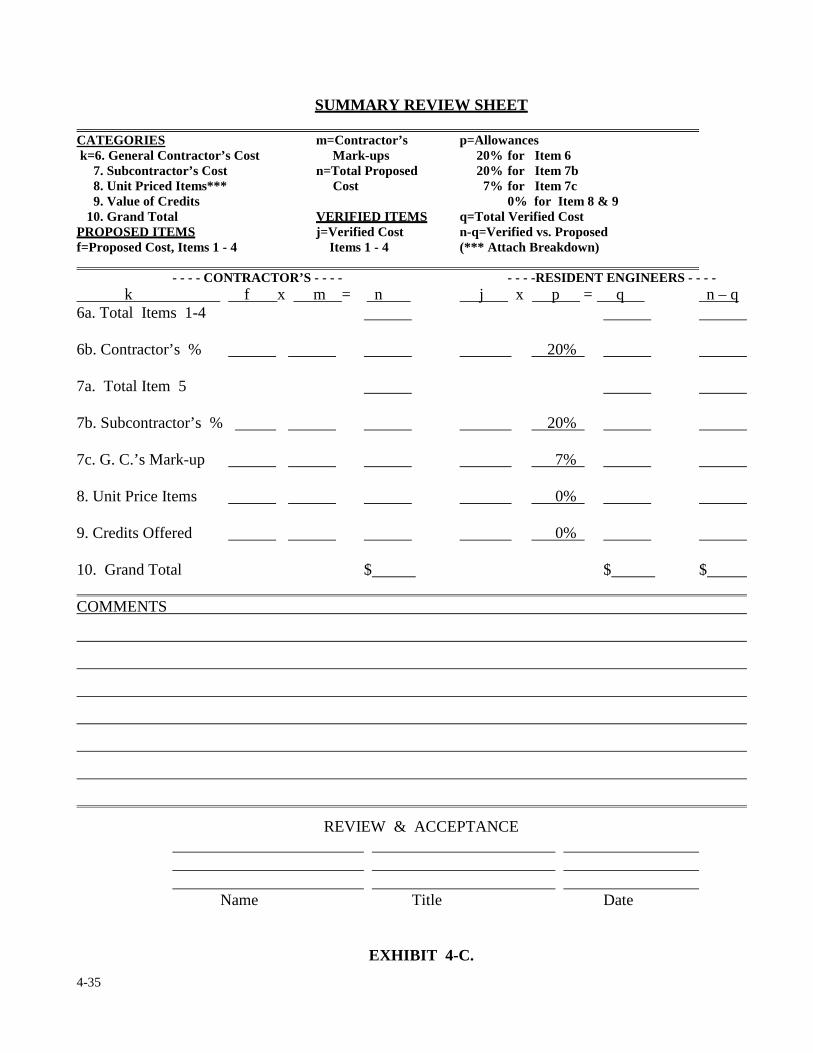
4-35
SUMMARY REVIEW SHEET CATEGORIES m=Contractor’s p=Allowances k=6. General Contractor’s Cost Mark-ups 20% for Item 6 7. Subcontractor’s Cost n=Total Proposed 20% for Item 7b 8. Unit Priced Items*** Cost 7% for Item 7c 9. Value of Credits 0% for Item 8 & 9 10. Grand Total VERIFIED ITEMS q=Total Verified Cost PROPOSED ITEMS j=Verified Cost n-q=Verified vs. Proposed f=Proposed Cost, Items 1 - 4 Items 1 - 4 (*** Attach Breakdown)
- - - - CONTRACTOR’S - - - - - - - -RESIDENT ENGINEERS - - - - k f x m = n j x p = q n – q 6a. Total Items 1-4 6b. Contractor’s % 20% 7a. Total Item 5 7b. Subcontractor’s % 20% 7c. G. C.’s Mark-up 7% 8. Unit Price Items 0% 9. Credits Offered 0% 10. Grand Total $ $ $ COMMENTS
REVIEW & ACCEPTANCE Name Title Date
EXHIBIT 4-C.
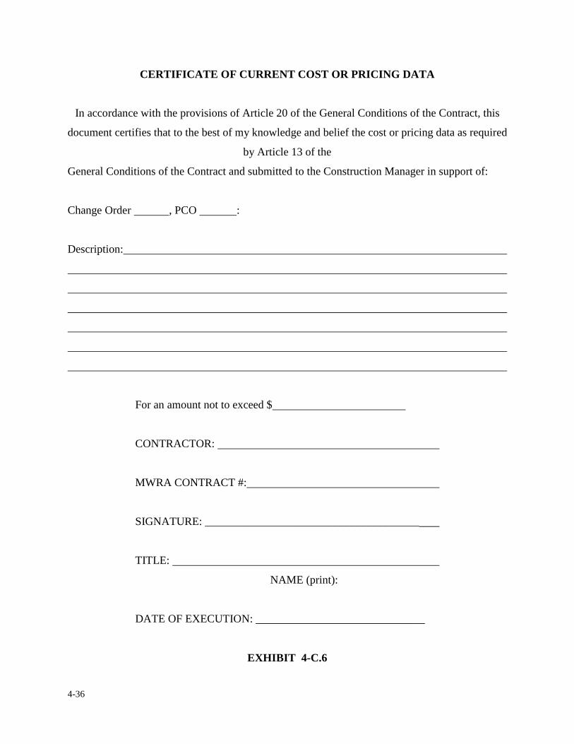
4-36
CERTIFICATE OF CURRENT COST OR PRICING DATA
In accordance with the provisions of Article 20 of the General Conditions of the Contract, this
document certifies that to the best of my knowledge and belief the cost or pricing data as required
by Article 13 of the
General Conditions of the Contract and submitted to the Construction Manager in support of:
Change Order , PCO :
Description:
For an amount not to exceed $
CONTRACTOR:
MWRA CONTRACT #:
SIGNATURE: ______________________________________
TITLE:
NAME (print):
DATE OF EXECUTION: ______________________________
EXHIBIT 4-C.6
4-37
4. CONTRACT CHANGES & MODIFICATIONS
4.4 TIME & MATERIAL (T & M) CHANGE ORDERS
Assuming that a CB&V was performed and the review team and the contractor can not agree on a
cost to complete the contract modification (change) and if extra work is urgent and must be
performed without delay due to an emergency situation, the Authority shall issue a unilateral
change order authorizing work to proceed on a time and material (T&M) basis.
Before allowing T&M work to commence, the resident engineer must receive permission
from the construction coordinator and Assistant Director of Construction.
Performing work on a T&M basis is an agreed mechanism by which the contractor performs the
work and is reimbursed by the Authority for the actual cost to complete the work, plus an agreed
upon percentage for overhead and profit. The exact percentage for overhead and profit is stipulated
in the contract documents.
T&M work is subject to specific types of documentation, principally because the contractor
must prove that the costs he/she is requesting payment for are actual costs incurred in the
performance of the work. All costs submitted by the Contractor must be actual costs and must be
verified by the resident engineer. The resident engineer and/or field staff is to observe and
document T&M work from the initial start of the extra work until the work is accepted. The
preferred way to achieve this is utilize a “Force Account - Daily Status Report”. Exhibits 4-D.1a
4-38
and 4-D.1b are an example of this form. A blank version of this form is included in the Appendix
of this manual. When the extra work is being performed, the Force Account Daily Status Report
becomes part of the contract documents representing a record of the details of a Time & Materials
change order.
The resident engineer should take care in completing this form. All entries are important. The
upper section of the front page is the header and is self explanatory. The next section, on the left
hand section of the first line, is where the field engineer enters the book and page number of his/her
daily report book where the details of the work are to be kept. On the right hand section is where
the field engineer records the weather conditions and the date. The next line the field engineer
enters time the work started and finished. The resident engineer shall advise the field engineers
that times entered on this form are to be the actual times the contractor is working and not the times
the field engineer works. If the contractor has more than one crew working at different times, in
different locations, each start and finish time shall be recorded on a separate report. If the
contractor stops and then starts work in the same location, the field engineer shall record this
information in the description section. The next item is the Area of Work. The area of work is the
location of the work in relationship to the contract drawings (Station 0+00, elevation 0.00, Room
#101, etc.). Below the area of work item is where the field engineer records if there are any
subcontractor(s) performing part or all of the work. If so, they should be listed as such. The
resident engineer shall distinguish between any as-bid contract work and T&M change order work.
The next section is where the resident engineer and/or field engineer records what materials were
delivered to the site. It is also where it is recorded if any invoices regarding materials were
4-39
submitted as backup or verification of delivery. The bottom half of the first page is where the
resident engineer/field engineer describes, in detail, the work being performed. The description
should not be the generic description of the extra work, but the description of the actual work being
done. On the backside of the form is where the resident engineer/field engineer indicates the
contractor's labor and equipment on site relative to the change order work being performed. The
labor involvement shall consist of only the labor associated with T&M change order work. If there
was a part-time laborer or tradesman present, it should be noted as such. If possible, the resident
engineer/field engineer should obtain the names of the entire workforce performing the T&M
change order work. Idle equipment unrelated to the work being performed should not be listed on
this form.
Equipment not in use but essential to the completion of the change order work should be listed and
noted as being idle. The resident engineer/field engineer observing the work is required to list any
visitors to the site. A visitor is defined as anyone other than members of the MWRA project field
staff and the contractor's work force. If a police detail is required, the resident engineer/field
engineer shall make note of this event in the “visitors” section. The resident engineer/field
engineer shall record the name of the officer; his badge number, the date, location and the actual
time worked. Also, the resident engineer/field engineer will be instructed to fill out a MWRA
Police Detail Voucher. This form is explained in greater detail in Section 5 of this manual. The last
item to be addressed on this form is for the resident engineer/field engineer to obtain the signature
and date of the contractor's representative to confirm the information on the form for that particular
day is accurate. The contractor's representative shall be the person present at the time and in charge
of work (foreman, superintendent, project engineer, project manager, etc.). This form shall be
4-40
completed by the field engineer, signed and submitted to the resident engineer at the end of each
day T&M work is performed.
The resident engineer or field staff shall get the contractor to sign this document, if a disagreement
arises, it should be resolved at the end of the day with the contractor's representative and the
resident engineer. If for some reason the contractor refuses to sign the form the resident engineer
shall: 1) consult the construction coordinator, 2) request the contractor provide his own
information in a format acceptable to the resident engineer and 3) note in the contract diary of the
contractor's reasons for not signing the form. Resident engineer shall inform the contractor that not
signing the form will jeopardize approval by the Authority for payment.
The resident engineer must be able to verify or substantiate all of the costs submitted by the
contractor for T&M work on a daily basis. If the extra work is so extensive that it spans over
several pay periods, it is the contractor's option to include the additional costs to date for T&M
work in his regularly monthly partial payment request. In order for the contractor to receive
payment, T&M cost must be approved by the resident engineer and the associated change order
must be executed.
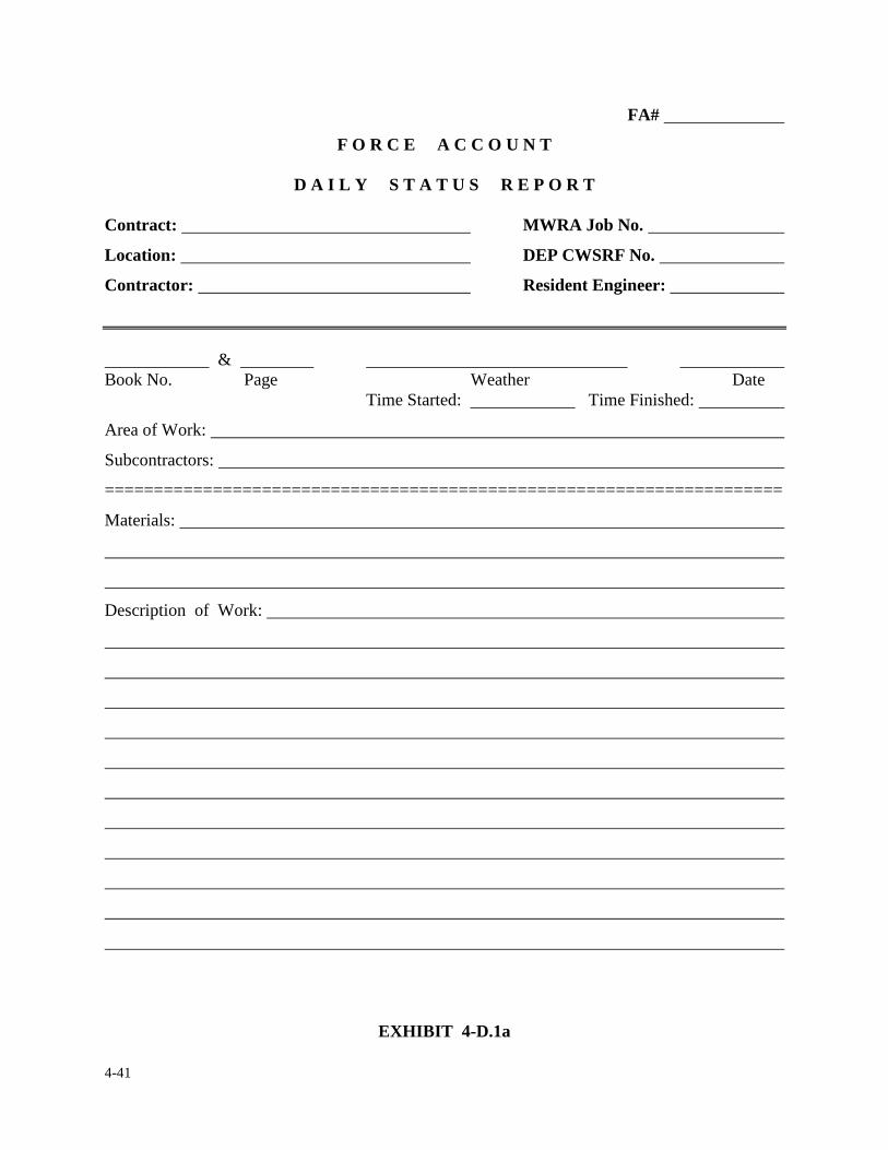
4-41
FA#
F O R C E A C C O U N T
D A I L Y S T A T U S R E P O R T Contract: MWRA Job No.
Location: DEP CWSRF No.
Contractor: Resident Engineer:
& Book No. Page Weather Date Time Started: Time Finished:
Area of Work:
Subcontractors:
=====================================================================
Materials:
Description of Work:
EXHIBIT 4-D.1a
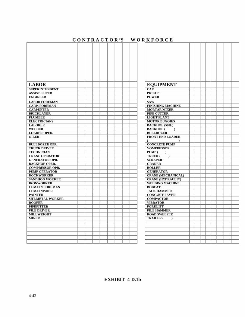
4-42
C O N T R A C T O R ’S W O R K F O R C E
LABOR EQUIPMENT SUPERINTENDENT CAR ASSIST. SUPER PICKUP ENGINEER POWER LABOR FOREMAN SAW CARP. FOREMAN FINISHING MACHINE CARPENTER MORTAR MIXER BRICKLAYER PIPE CUTTER PLUMBER LIGHT PLANT ELECTRICIANS MOTOR BUGGIES LABORER BACKHOE (580E) WELDER BACKHOE ( ) LOADER OPER. BULLDOZER OILER FRONT END LOADER
( )
BULLDOZER OPR. CONCRETE PUMP TRUCK DRIVER VOMPRESSOR TECHNICIAN PUMP ( ) CRANE OPERATOR TRUCK ( ) GENERATOR OPR. SCRAPER BACKHOE OPER. GRADER COMPRESSOR OPR. ROLLER PUMP OPERATOR GENERATOR DOCKWORKER CRANE (MECHANICAL) SANDHOG WORKER CRANE (HYDRAULIC) IRONWORKER WELDING MACHINE CEM.FIN.FOREMAN BOBCAT CEM.FINISHER JACK HAMMER PAINTER CONC./BIT PAVER SHT.METAL WORKER COMPACTOR ROOFER VIBRATOR PIPEFITTER FORKLIFT PILE DRIVER PILE HAMMER MILLWRIGHT ROAD SWEEPER MINER TRAILER ( )
EXHIBIT 4-D.1b
4-43
4. CONTRACT CHANGES & MODIFICATIONS
4.5 CHANGE ORDER TRACKING
Construction Staff shall monitor the tracking of a given change order to ensure that the appropriate
procedures and controls are being administered and the contractor is not being delayed. This
responsibility is also shared by the construction coordinator so that the tracking procedures are
maintained and the change order is processed in a timely manner.
The resident engineer shall maintain a separate tracking form for each proposed change order
(PCO). The form shall be filed along with information pertaining to a particular PCO or change
order. Exhibit 4-E.1 is a sample form for tracking a PCO.
The above policy must be strictly adhered to at all times. Variations from the policy are not
allowed. It is the responsibility of the resident engineer to monitor the tracking of a given change
order to ensure that the appropriate procedures and controls are being administered and the
contractor is not being delayed. This responsibility is also shared by the construction coordinator
so that the tracking procedures are maintained and the change order is processed in a timely
manner.
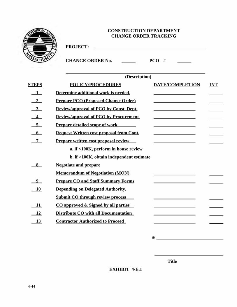
4-44
CONSTRUCTION DEPARTMENT CHANGE ORDER TRACKING
PROJECT: CHANGE ORDER No. PCO #
(Description)
STEPS POLICY/PROCEDURES DATE/COMPLETION INT
1 Determine additional work is needed.
2 Prepare PCO (Proposed Change Order)
3 Review/approval of PCO by Const. Dept.
4 Review/approval of PCO by Procurement
5 Prepare detailed scope of work
6 Request Written cost proposal from Cont.
7 Prepare written cost proposal review
a. if <100K, perform in house review
b. if >100K, obtain independent estimate
8 Negotiate and prepare
Memorandum of Negotiation (MON)
9 Prepare CO and Staff Summary Forms
10 Depending on Delegated Authority,
Submit CO through review process
11 CO approved & Signed by all parties
12 Distribute CO with all Documentation
13 Contractor Authorized to Proceed
s/
Title
EXHIBIT 4-E.1
4-45
CHANGE ORDER RECORD LOG
Another administrative function regarding the change order process is for the resident engineer to
maintain a record of all change orders. This record shall be kept in the form of a log and be kept up
to date, accurate and complete at all times. Exhibit 4-E.2 is a Change Order Record form to be
utilized by the resident engineer. The form(s) are to be kept in a three-ring binder and stored at the
field office in a place of easy access. Exhibit 4-E.3 is an example of how the Change Order Record
log is to be maintained by the resident engineer or his/her staff. All the information to be recorded
on the form can be found on the executed change order itself, with the exception of the last column
which is labeled "Remarks".
It is the responsibility of the resident engineer to ensure that these reports are kept up to date and
available. Copies should be periodically forwarded to the construction coordinator for the purpose
of comparing the field data with the data at the Home Office.
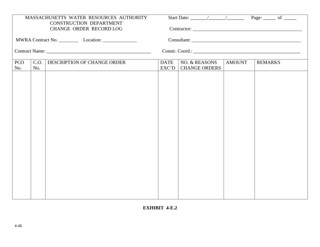
4-46
MASSACHUSETTS WATER RESOURCES AUTHORITY CONSTRUCTION DEPARTMENT CHANGE ORDER RECORD LOG
MWRA Contract No. ________ Location: ______________ Contract Name: ___________________________________________
Start Date: _______/_______/_______ Page: _____ of _____ Contractor: _____________________________________________ Consultant: _____________________________________________ Constr. Coord.: ____________________________________________
PCO No.
C.O. No.
DESCRIPTION OF CHANGE ORDER DATE EXC’D
NO. & REASONS CHANGE ORDERS
AMOUNT REMARKS
EXHIBIT 4-E.2
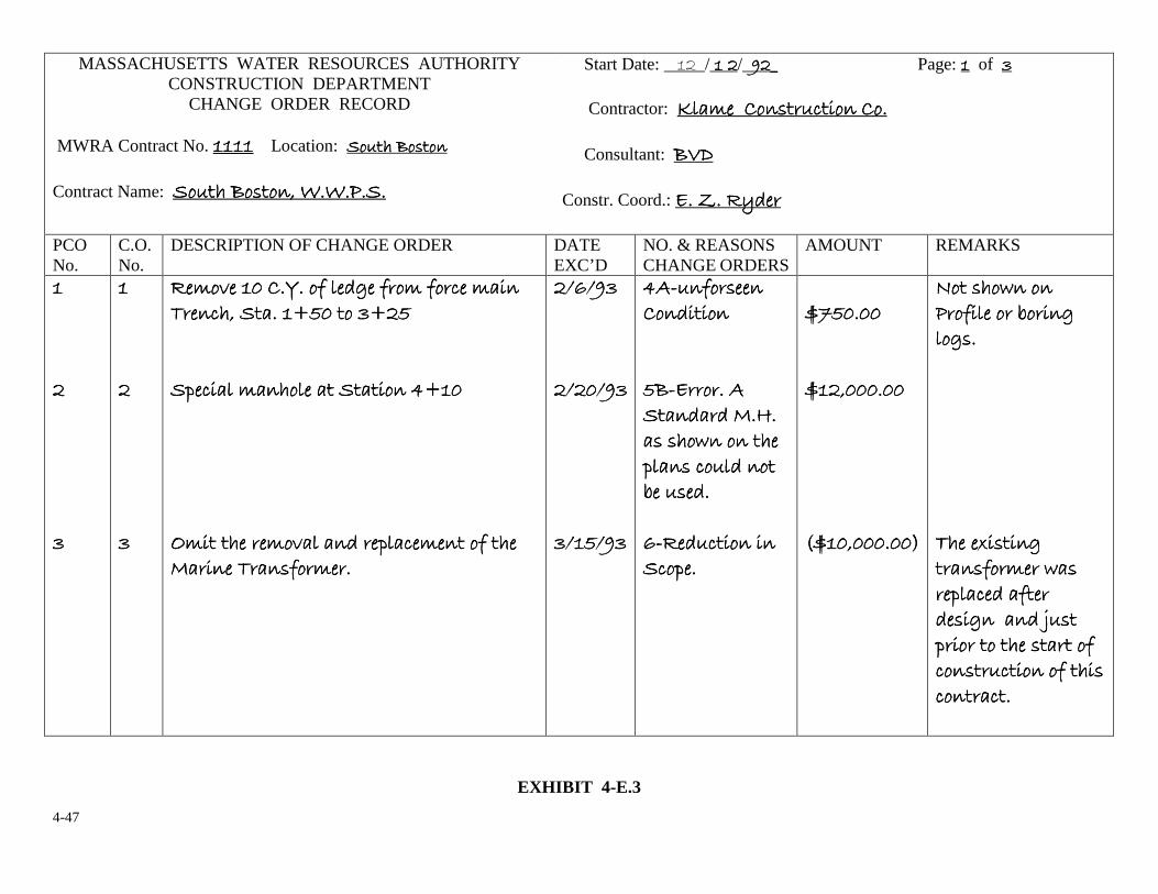
4-47
MASSACHUSETTS WATER RESOURCES AUTHORITY CONSTRUCTION DEPARTMENT
CHANGE ORDER RECORD
MWRA Contract No. ���������������� Location: ��������� ��������� ��������� ��������� Contract Name: ��������� ������������������� ������������������� ������������������� ����������
Start Date: �������/����������������/_ �! �! �! �! Page: ���� of """" Contractor: #��$���%� ������ #��$���%� ������ #��$���%� ������ #��$���%� ������ ����%��%��%��%�� Consultant: �&'������������������&'������������������&'������������������&'������������������������������������������������������������� Constr. Coord.: ���(���)������������(���)������������(���)������������(���)���������
PCO No.
C.O. No.
DESCRIPTION OF CHANGE ORDER DATE EXC’D
NO. & REASONS CHANGE ORDERS
AMOUNT REMARKS
������������������������������������������������""""��������������������������������
������������������������������������������������""""��������
��$�*�����%�+���,�������,��$�,�����$�� ��$�*�����%�+���,�������,��$�,�����$�� ��$�*�����%�+���,�������,��$�,�����$�� ��$�*�����%�+���,�������,��$�,�����$�� ����-�� ���������.�����".��-�� ���������.�����".��-�� ���������.�����".��-�� ���������.�����".���������������/������$� ����������� �0.���/������$� ����������� �0.���/������$� ����������� �0.���/������$� ����������� �0.��������������������������1$�������$�*���� ����/����$� ��,����1$�������$�*���� ����/����$� ��,����1$�������$�*���� ����/����$� ��,����1$�������$�*���� ����/����$� ��,�������� ��-�� �,��$������� ��-�� �,��$������� ��-�� �,��$������� ��-�� �,��$�������
��2� "��2� "��2� "��2� "��������������������� "����� "����� "����� "������������������������"���� ""���� ""���� ""���� "����
030303034444� ,����� � ,����� � ,����� � ,����� ����%� ���� %� ���� %� ���� %� ���� ��������������������4444�������3��������3��������3��������3������� �������5���� �������5���� �������5���� �������5��������6 �� ����������6 �� ����������6 �� ����������6 �� ����/�� �������� ��/�� �������� ��/�� �������� ��/�� �������� ��7�������7�������7�������7���������������22224444������� �� ������� �� ������� �� ������� �� �������/�����/�����/�����/������
����89�����89�����89�����89�����������������8���������8���������8���������8���������������������������������:8���������;:8���������;:8���������;:8���������;����
<�����6 �� �<�����6 �� �<�����6 �� �<�����6 �� ��������,�������7��� �����,�������7��� �����,�������7��� �����,�������7��� ������������������������������������������������������-����=��� ��-����=��� ��-����=��� ��-����=��� ���� �,��$���6����� �,��$���6����� �,��$���6����� �,��$���6�����/�������,�����/�������,�����/�������,�����/�������,�������� ��� ��>�������� ��� ��>�������� ��� ��>�������� ��� ��>���/���������������,�/���������������,�/���������������,�/���������������,��� ������ ��,������� ������ ��,������� ������ ��,������� ������ ��,������� ������ ������ ������ ������������
EXHIBIT 4-E.3
4-48
4. CONTRACT CHANGES & MODIFICATIONS
4.6 CONTRACTOR CLAIMS
Once the Authority has forwarded a decision to the contractor that a Change Order request (COR)
or Proposed Change Order (PCO) does not comply with Authority policy for a change in the
contract, the contractor may make a claim for damages by reason of any direction, interpretation,
or any act or omission of the Authority or its representative. Notice of such a claim shall be given
to the Authority within twenty-one (21) days after the occurrence of the event or notification that a
change order has been denied and given rise to such claim otherwise the claim shall be waived.
This section is designed to describe the basic aspects of a contractor claim in Authority
construction contracts. �
PURPOSE:
The purpose of this procedure is to provide step-by-step instruction to MWRA staff for the
uniform internal identification, tracking and timely disposition of Contractor Claims for
additional cost and/or time. In addition, these procedures are intended to facilitate an effective
means of communication between Construction Staff, Consultants and the Risk Management
Group so that Construction Claims are identified, Authority costs mitigated and claims
ultimately resolved expeditiously. Any questions relaying to this procedure should be directed
to Mr. Ed Brown, Claims Management Specialist, Risk Management at (617) 788-2231.

4-49
BACKGROUND:
The MWRA, through the Procurement Department, routinely advertises and solicits bids
for construction services funded by the CIP and CEB Budgets. During the course of
performing the work it is not unusual for Contractor’s to assert portions of the work
performed are not covered or specified by the Contract Documents. As a result, Authority
construction staff is often confronted with Claims for additional cost and/or time from the
Contractor. The Risk Management Department, with assistance and input from the Law
Division, the Procurement Department, Construction Coordinator, Project Manager,
Design Manager, Resident Engineer, Resident Inspector, and Design Consultant, is
ultimately responsible for the administrative resolution of these Claims, through the
issuance of an Engineer’s Decision, subject to the provisions of M.G.L. c.30 s.39J.
DOCUMENTS/FILES:
When Authority Construction Staff receive a Notice of Claim a copy must be sent by the
PM/RE to the Claims Management Specialist/Risk Management. A file is then created by
the Claims Management/Specialist identifying the Claim with a discrete number (i.e.
Contract No. ____, Claim No. 01, Claim No. 02 etc…) The Claims Management
Specialist/Risk Management will maintain that file during and after the subsequent
investigation, administration and ultimate disposition of that Claim. The investigation of
the Claim will frequently result in numerous requests for construction related documents,
including but not limited to Field Transmittal Memos (FTM - see EXHIBIT 4-F.1) RFI’s,
Submittals, Meeting Minutes, Contractor Correspondence/Letters, MWRA
Correspondence/Letters, Design Drawings, Design Calculations, Design Assumptions,
4-50
Estimates, Codes, CMR’s, Contract Specifications, Change Orders and MON’s,
chronology of events leading up to the claim, and answers to specific questions dealing
with the Claim.
The Project Manager/Construction Coordinator, and in some cases the Design Engineer,
will also be expected to provide a written recommendation on the Claim, which will be
provided to the Engineer, Jae Kim, P.E., for his consideration in deciding the Claim. The
Risk Management Department, the Law Division and the Procurement Department will
also provide a written recommendation to the Engineer for his consideration in deciding
the Claim. All of these written recommendations, as well as the applicable documents
described above are provided to the Risk Management Group, which will coordinate
dissemination of all information necessary to decide the Claim to the Engineer. The Risk
Management Department will develop an Engineer’s Review Package consisting of the
applicable documents described herein for the use of the Engineer in deciding the Claim.
Ultimately, an Engineer’s Decision will be issued deciding the Claim, which will be
drafted by the Claims Management Specialist at the direction of the Engineer. Once
received, all of the documents requested dealing with the specific claim will be maintained
in the Claim File by the Risk Management Department.
Construction Claims Procedure:
Claims processed under this procedure must be administered in a manner that is consistent
with the principles contained in the Massachusetts public construction laws, including
M.G.L. Chapters 30 and 149, the MWRA change order process, MWRA procurement
4-51
policy and procedures, and Contract requirements. These Claim procedures are designed to
work within existing administrative program guidelines and to provide an efficient
mechanism to:
• Keep the Authority and its Staff informed of all Construction Claim issues.
• Ensure timely receipt, analysis and issuance of recommendations for approval or denial of Claims by authorized parties, including Engineer’s Decisions and/or Change Orders; and
• Ensure auditable record of Claim processing, determination and disposition
In order to mitigate Claim impacts and to reduce the number of Claims processed under
these procedures, the Resident Engineer (“RE”) will initially review Claim notices and
filings and identify any issues that on the facts and/or merits may be resolved by Change
Order. Those Claims that the RE believes should be processed as a Change Order will be
referred to the MWRA’s Project Manager for further consideration and if appropriate be
processed in accordance with the Contract’s Change Order Procedures (i.e. Article 13 of
the Contract).
All issues to be resolved as Claims will be processed in accordance with the Claim
procedures described herein and Article 19 of the Contract Documents. EXHIBIT 4-F.2
“Claims Process Flow Chart” is a flow diagram that illustrates the process that will be
used for evaluating Construction Contract Claims.
4-52
DEFINITIONS:
CLAIM: A written demand or assertion by the Contractor seeking an adjustment in
Contract Price and payment of monies due; an extension in Contract Time; the adjustment
or interpretation of Contract terms or requirements; or other relief arising under or relating
to the Contract. A written demand or assertion by the Contractor seeking the payment of
money or an extension of time is not a Claim as defined herein unless clearly designated as
such by the Contractor, and until certified as required by the provisions of Article 19 of the
General Conditions of the Contract. A voucher, invoice, or other routine request for
payment that is not in dispute when submitted is not a claim as defined herein. A valid
Claim is based on a written Notice of Claim and subsequent Claim Submittal that is
complete, timely and complies in all respects with the provisions of Article 19 of the
General Conditions of the Contract.
CLAIMS MANAGEMENT SPECIALIST/RISK MANAGEMENT: The flow and
expediting of Claim documents within the MWRA will be led by the Claims Management
Specialist/Risk Management, who will ensure that Engineer’s Decisions on Contractor
Claims are promptly issued.
CLAIM SUBMITTAL: Documents submitted by the Contractor to the Resident Engineer
which provide support for a Claim made by the Contractor including supporting cost data,
CPM schedule analysis, if required, and Contractor’s Affidavit as described in Article 19
of the General Conditions, all due within 60 days of the date that the Contractor
provides its Notice of Claim. (The Authority may, if requested, extend the deadline for
4-53
the submission of the Claim Submittal if the Contractor needs additional time to ascertain
its cost in support of its claim.)
CONTRACTOR: The person, firm, corporation or joint venture with whom the Authority
has executed the Authority-Contractor Agreement (i.e. the General Contractor)
DE: Refers to the firm contracted to provide Project Design Engineering, which may also
include Resident Engineering (RE) and/or Resident Inspection (RI) Services.
ENGINEER: Jae Kim, P.E., or the person identified in the Notice to Proceed to act as the
Engineer for the given contract. The Engineer’s Decision shall be final, conclusive and
binding on the Contractor subject to the provisions of M.G.L. Chapter 30 Section 39J.
ENGINEER’S DECISION: A written determination on the Claim rendered by the
Engineer pursuant to Article 19 of the Contract Documents and the provisions of M.G.L.
c.30 s. 39J (see EXHIBIT 4-F.3).
MWRA CLAIMS REVIEW GROUP: The MWRA Claims Review Group is comprised of
the following members:
• Claims Management Specialist/Risk Management
• Associate General Counsel/Law Division
4-54
• MWRA Project Manager
• Deputy Contract Manager/Procurement
• Deputy Director of Construction (as needed)
The group’s participation in the Claims process represents the Authority’s internal review
of the Claim and includes independent recommendations to the Engineer as to the proper
disposition of the Contractor’s Claim.
NOTICE OF CLAIM: A written notification provided by the Contractor to the Authority,
usually through the RE, reporting the occurrence of an event that caused the Contractor to
seek an adjustment in Contract Price or Time, requesting an adjustment or interpretation of
contract terms or requirements or seeking other relief arising under or relating to the
Contract. The Notice of Claim must include a description of the general nature of the
Claim. A Notice of Claim must be submitted promptly, but in no event later than
twenty-one (21) days after the occurrence of the event giving rise to the Claim,
OTHERWISE THE CLAIM IS WAIVED BY THE CONTRACTOR (see Article 19
of the General Conditions of the Contract).
RESPONSIBILITIES
MWRA Risk Management Department is responsible for internal Authority Claim
processing. These responsibilities involve Claims tracking, mitigation and review
activities, including the receipt of claim related materials, development of a written Claim
Analysis and recommendation to the Engineer (Jae Kim, P.E.), drafting of Engineer’s
4-55
Decisions for the review and approval of the Engineer, distribution and coordination of
claims and claim related information to the Law Division and Procurement Department.
The Law Division, Procurement Department and MWRA Project Manager will provide
written recommendations on all claims to the Claims Management Specialist. Upon receipt
of the Law Division, Procurement Department and Project Manager’s recommendations,
the Claims Management Specialist will prepare a Claim Review Package for the Engineer.
The Engineer will ultimately decide the claim through the issuance of an Engineer’s
Decision in conformance with Article 19 of the General Conditions and M.G.L. c.30 s.39J.
The Claims Management Specialist will also provide litigation support to the Law Division
when requested.
MWRA Law Division will review all Construction Claims and provide a written
recommendation on the merit of the Claim. The recommendation will address the merit of
the claim and whether or not the Contractor has complied with the procedural requirements
for Claim Submittal specified in Article 19 of the Contract Documents. All
recommendations from the Law Division will be provided to Claims Management
Specialist/Risk Management.
MWRA Procurement Department will review all Construction Claims and provide a
written recommendation on the merits of the Claim. The recommendation will address the
merit of the Claim and whether or not the Contractor has complied with the procedural
requirements for Claim Submittal specified in Article 19 of the Contract Documents. All
4-56
recommendations from the Procurement Department will be provided to Claims
Management Specialist/Risk Management.
MWRA Internal Audit Unit will perform requested audits of Claim documentation and
Contract costs.
MWRA Project Manager (PM) is responsible for identifying and providing Notices of
Claim and Claim Submittals to the Claims Management Specialist/Risk Management. The
PM will also review the Contractor’s Claim Submittal and provide a written
recommendation on the merits of the Claim to the Claims Management Specialist/Risk
Management. The PM will provide support to the Claims Management Specialist/Risk
Management, Law Division and Procurement Department. This typically includes
answering technical questions concerning engineering and construction means and
methods, as well as gathering Claim related documents such as FTM’s, RFI’s, Submittals,
Contractor Correspondence, Specifications and Drawings. The PM is usually supported in
this function by the RE and/or DE.
Resident Engineer/Resident Inspectors have day-to-day management responsibility for
oversight of all in-the-field construction related functions and activities. The following are
some of the tasks undertaken by the Resident Engineer relative to Claims management:
• Controlling and documenting FTM’s and other correspondence between MWRA and contractor.
• Preparing background information.
4-57
• Reviewing scope of Claims. • Documenting reasons in support of or opposition to Claims. • Participating in evaluation of Contractor Claims, including field input. • Providing input for estimates and schedule if necessary • Data preparation and collection including progress photos. • Monitor Time and Material Costs on disputed work items.
Design Engineer (DE) shall provide technical support and assist in evaluations and
negotiations as required by the MWRA. Specific responsibilities include:
• Participate in evaluation of the Claim’s merit as required. • Provide relevant factual and historical information relative to any RFI’s,
submittal review, comments and approvals, substitutions, design criteria, calculations and assumptions. When requested provide opinions as to the suitability of Contractor means, methods, techniques and sequences related to the Claim. Provide further technical and engineering information or interpretation as may be required.
CLAIM IDENTIFICATION AND ASSESSMENT
CLAIM IDENTIFICATION
A Contractor may file a Claim for several reasons during the course of a Project. These
reasons may include but are not limited to:
• Denial of a Contractor’s Change Order Request (“COR”) • Differing Site Condition • Unforeseen Condition • Unusually Severe Weather • Authority/DE Contract Interpretation • Unclear Specification Requirement or Design Drawing • Code compliance • Time Extension • Design Change • MWRA/DE response to RFI
4-58
• MWRA/DE Submittal Review Comments • Construction Material Cost Increases • Unilateral Change Order • Substitution Request
SUBMISSION OF NOTICE OF CLAIM
In general a Notice of Claim is a written request by the Contractor for additional cost
and/or time. In its simplest form it is a notice from the Contractor that informs the
Authority something is going to cost more and/or take more time. Pursuant to Article 19 of
the General Conditions of the Contract (“Article 19”), a Notice of Claim must be submitted
by the Contractor to the MWRA within twenty-one (21) days of the event giving rise to the
Claim. The Notice of Claim must be identified as such and requires a brief statement of the
nature of the Claim, but does not ordinarily require detailed backup information. Pursuant
to Article 19, failure to provide a Notice of Claim within twenty-one (21) days after the
occurrence of the event giving rise to the Claim shall be conclusively deemed to be a
waiver of the Claim.
CLAIM DOCUMENTATION SUBMITTAL
Pursuant to Article 19, a complete Claim Submittal with supporting documentation and
Contractor’s Affidavit must be delivered by the Contractor to the MWRA within sixty (60)
days after delivery of the Notice of Claim. (The Authority may, if requested, extend the
deadline for the submission of the Claim Submittal if the Contractor needs additional time
to ascertain its cost in support of its claim.)
4-59
CLAIMS TRACKING AND REPORTING
Upon receipt of a Notice of Claim, the Claims Management Specialist/Risk Management
opens a Claim file, assigns a Claim Number for tracking purposes and enters the basic
claim information, including the Claim Submittal deadline (i.e. the Claim Submittal is due
60 days from the date of the Notice of Claim) in a Master list of Claims Report, maintained
by the Claims Management Specialist/Risk Management. Entering the Claim data into the
Master list of Claims allows the Claims Management Specialist to track, process, and
report Claims status to all appropriate parties. Claims Reports are considered Confidential
Documents and as such have a limited distribution.
CLAIM REVIEW PROCESS
CLAIMS MANAGEMANT SPECIALIST/RISK MANAGEMENT
Upon receipt of a Contractor Claim Submittal, the Claims Management Specialist will
provide copies to the Claims Review Group. Thereafter, the Claims Management
Specialist reviews the claim collects and researches applicable documents and prepares a
detailed analysis of the Claim, which addresses the Claims procedural compliance with the
Contract requirements, as well as a detailed analysis of the Claim on its merits. This
analysis shall include a recommendation to the Engineer to either allow or deny the Claim.
This analysis together with any additional pertinent Claim related material will be provided
to the other members of the Claim Review Group.
4-60
CLAIMS REVIEW GROUP
Each member of the Claims Review Group will also conduct an independent detailed
review of the claim considering both the Claim’s procedural compliance and its merit and
provide a written review and recommendation to the Claims Management Specialist. In the
interest of timely and expeditious processing, the other members of the Claims Review
Group shall provide their review and recommendation at any time subsequent to their
receipt of the Contractor’s Claim Submittal and do not have to wait to receive the review
and recommendation of the Claims Management Specialist/Risk Management. (In the
event there is unanimous agreement between the Claims Management Specialist, the Law
Division, the Procurement Department and the Project Manager that the Claim has merit, it
may be recommended that the PM promptly process a Proposed Change Order (PCO) in
lieu of continuing the Claim Process.)
ENGINEER’S CLAIM REVIEW PACKAGE
Subsequent to the receipt of all recommendations from the Claims Review Group members
the Claims Management Specialist will prepare an Engineer’s Review Package containing
all pertinent Claim related material and whatever additional information and documents
the Engineer may request. This package is provided to the Engineer for his use and benefit
in making his final determination on the Claim.
ENGINEER’S DECISION
Following a review by the Engineer of the Engineer’s Review Package, including the
evaluations and recommendations of the Claims Review Group, a written Engineer’s
4-61
Decision notifying the Contractor of the Engineer’s determination is issued. The
Engineer’s Decision will be drafted by the Claims Management Specialist, at the direction
of the Engineer. Engineer’s Decisions will be issued as specified in Article 19 of the
Contract Documents, subject to the provisions of M.G.L. c.30 s.39J, and will be
coordinated by the Claims Management Specialist, with the support and assistance of the
Project Manager/Resident Engineer.
CLAIMS WITHOUT MERIT
If the Engineers’ Decisions results in a denial of the Claim, the Engineer’s Decision will
reference the requirements Article 19 of the General Conditions regarding the submission
of a Notice of Objection and shall advise the Contractor that failure to provide a timely
Notice of Objection to the Engineer’s Decision will conclusively be deemed to be a waiver
of objection or further Claim of the matter. The Contractor’s written Notice of Objection to
the Engineer’s Decision must be submitted within twenty-one (21) days of receipt of the
Engineer’s Decision otherwise the claim is waived.
CLAIMS WITH MERIT
If the Engineer’s Decision results in a change to the Contract Price or Contract Time, the
Claims Management Specialist will coordinate the matter with the PM/RE for initiation of
a Change Order consistent with the determination by the Engineer, and Article 13 of the
General Conditions.
4-62
ENGINEER’S DECISION REQUIRING NEGOTIATION OF PRICE OR TIME
In the event that an Engineer’s Decision determines entitlement and directs negotiation of
price or time, and the Contractor and the PM/RE cannot reach agreement, the issue will be
returned to the Engineer for a final determination as to the amount of the change.
Differing Site Condition Claims
M.G.L. c.30 s.39N and Article 13.3 of the Contract Documents set forth the terms and
conditions concerning a Differing Site Condition (“DSC”). In the event a Contractor
encounters a DSC the procedure outlined below shall be followed:
First, upon discovery of a DSC the Contractor must provide a written notice to the
Authority within twenty-one (21) days of discovering the condition.
Second, the Authority must promptly investigate the DSC and make a determination as to
whether or not the condition(s) encountered by the Contractor: (i) differ substantially or
materially from those shown on the plans/specs (sometimes referred to as “Type I”) or (ii)
differ from those ordinarily encountered and generally recognized as inherent in the Work
being performed (sometimes referred to as “Type II”) and (iii) cause an increase or
decrease to the cost of the performance of the Work. It is important to understand that this
is a two part test. Is the condition different and does it now cost more/less to perform the
Work as a result?
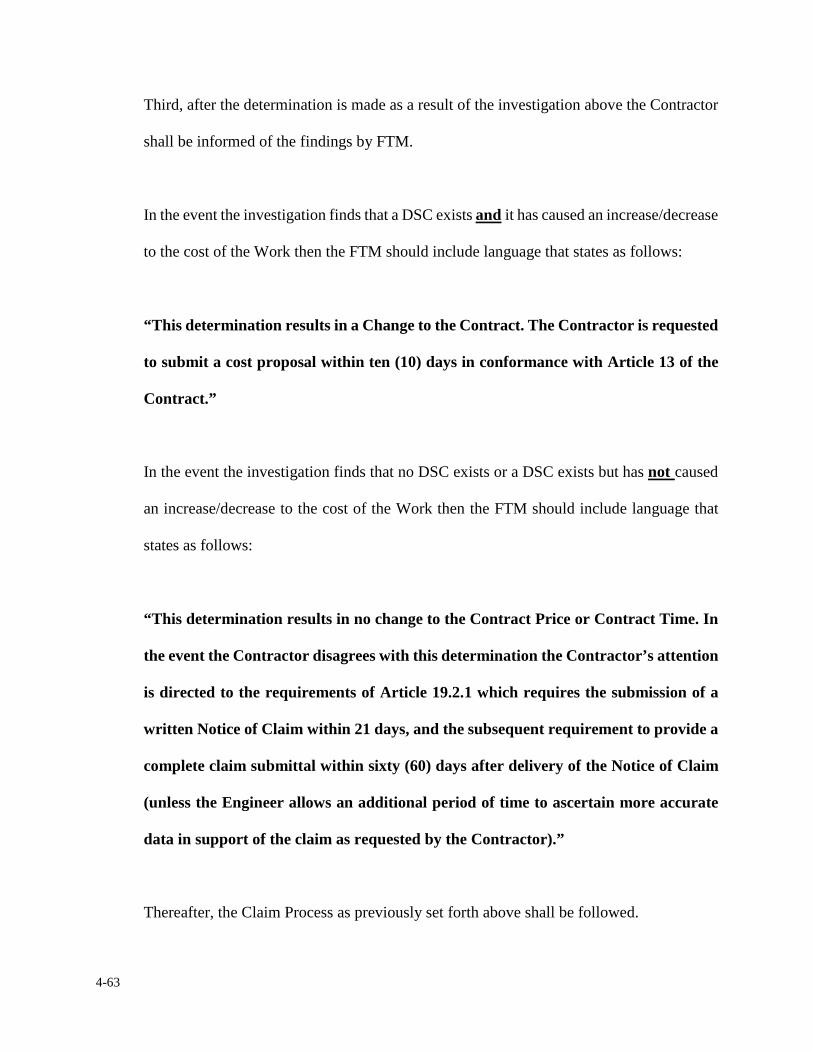
4-63
Third, after the determination is made as a result of the investigation above the Contractor
shall be informed of the findings by FTM.
In the event the investigation finds that a DSC exists and it has caused an increase/decrease
to the cost of the Work then the FTM should include language that states as follows:
“This determination results in a Change to the Contract. The Contractor is requested
to submit a cost proposal within ten (10) days in conformance with Article 13 of the
Contract.”
In the event the investigation finds that no DSC exists or a DSC exists but has not caused
an increase/decrease to the cost of the Work then the FTM should include language that
states as follows:
“This determination results in no change to the Contract Price or Contract Time. In
the event the Contractor disagrees with this determination the Contractor’s attention
is directed to the requirements of Article 19.2.1 which requires the submission of a
written Notice of Claim within 21 days, and the subsequent requirement to provide a
complete claim submittal within sixty (60) days after delivery of the Notice of Claim
(unless the Engineer allows an additional period of time to ascertain more accurate
data in support of the claim as requested by the Contractor).”
Thereafter, the Claim Process as previously set forth above shall be followed.
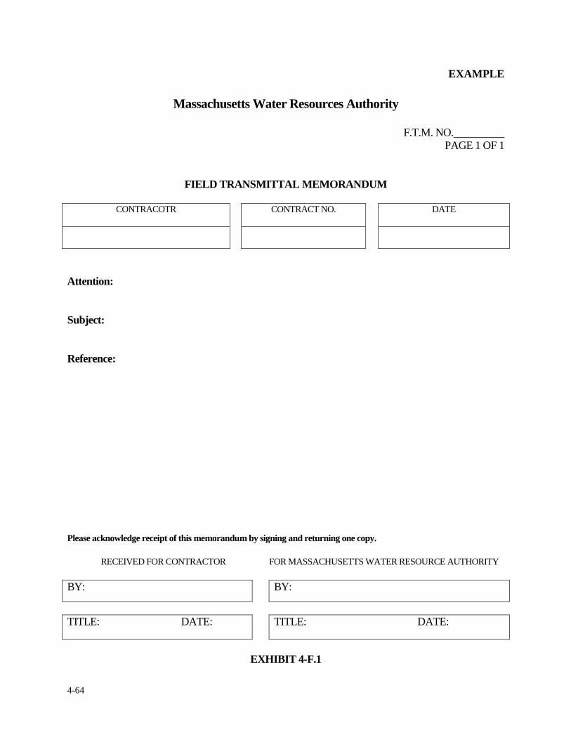
4-64
EXAMPLE
Massachusetts Water Resources Authority
F.T.M. NO. PAGE 1 OF 1
FIELD TRANSMITTAL MEMORANDUM
CONTRACOTR CONTRACT NO. DATE
Attention: Subject: Reference: Please acknowledge receipt of this memorandum by signing and returning one copy.
RECEIVED FOR CONTRACTOR FOR MASSACHUSETTS WATER RESOURCE AUTHORITY
BY: BY:
TITLE: DATE: TITLE: DATE:
EXHIBIT 4-F.1
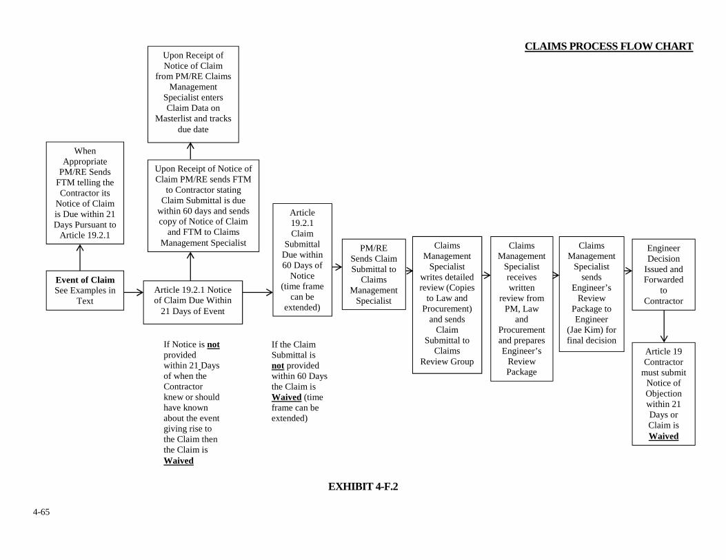
4-65
CLAIMS PROCESS FLOW CHART
EXHIBIT 4-F.2
When Appropriate
PM/RE Sends FTM telling the Contractor its
Notice of Claim is Due within 21 Days Pursuant to
Article 19.2.1
Upon Receipt of Notice of Claim
from PM/RE Claims Management
Specialist enters Claim Data on
Masterlist and tracks due date
Event of Claim See Examples in
Text
Upon Receipt of Notice of Claim PM/RE sends FTM
to Contractor stating Claim Submittal is due
within 60 days and sends copy of Notice of Claim
and FTM to Claims Management Specialist
Article 19.2.1 Notice of Claim Due Within
21 Days of Event
Article 19.2.1 Claim
Submittal Due within 60 Days of
Notice (time frame
can be extended)
PM/RE Sends Claim Submittal to
Claims Management
Specialist
Claims Management
Specialist writes detailed review (Copies
to Law and Procurement)
and sends Claim
Submittal to Claims
Review Group
Claims Management
Specialist receives written
review from PM, Law
and Procurement and prepares Engineer’s
Review Package
Claims Management
Specialist sends
Engineer’s Review
Package to Engineer
(Jae Kim) for final decision
Engineer Decision
Issued and Forwarded
to Contractor
Article 19 Contractor
must submit Notice of Objection within 21 Days or Claim is Waived
If Notice is not provided within 21 Days of when the Contractor knew or should have known about the event giving rise to the Claim then the Claim is Waived
If the Claim Submittal is not provided within 60 Days the Claim is Waived (time frame can be extended)
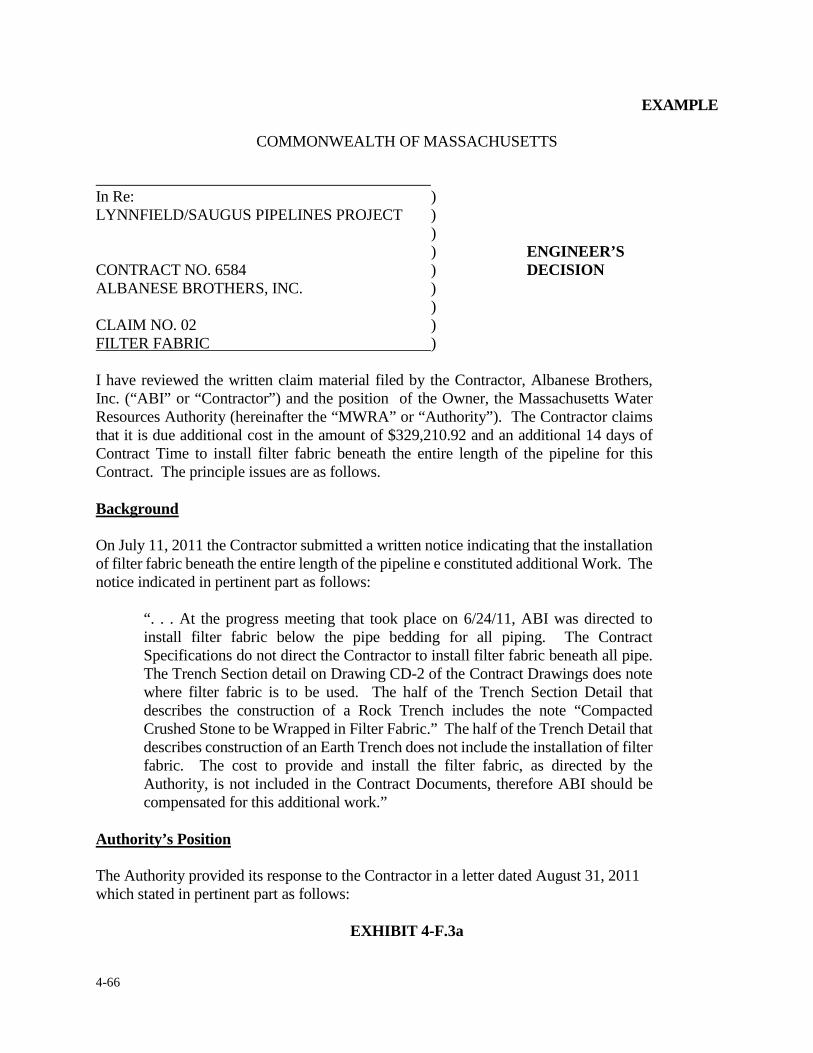
4-66
EXAMPLE
COMMONWEALTH OF MASSACHUSETTS In Re: ) LYNNFIELD/SAUGUS PIPELINES PROJECT ) ) ) ENGINEER’S CONTRACT NO. 6584 ) DECISION ALBANESE BROTHERS, INC. ) ) CLAIM NO. 02 ) FILTER FABRIC ) I have reviewed the written claim material filed by the Contractor, Albanese Brothers, Inc. (“ABI” or “Contractor”) and the position of the Owner, the Massachusetts Water Resources Authority (hereinafter the “MWRA” or “Authority”). The Contractor claims that it is due additional cost in the amount of $329,210.92 and an additional 14 days of Contract Time to install filter fabric beneath the entire length of the pipeline for this Contract. The principle issues are as follows. Background On July 11, 2011 the Contractor submitted a written notice indicating that the installation of filter fabric beneath the entire length of the pipeline e constituted additional Work. The notice indicated in pertinent part as follows:
“. . . At the progress meeting that took place on 6/24/11, ABI was directed to install filter fabric below the pipe bedding for all piping. The Contract Specifications do not direct the Contractor to install filter fabric beneath all pipe. The Trench Section detail on Drawing CD-2 of the Contract Drawings does note where filter fabric is to be used. The half of the Trench Section Detail that describes the construction of a Rock Trench includes the note “Compacted Crushed Stone to be Wrapped in Filter Fabric.” The half of the Trench Detail that describes construction of an Earth Trench does not include the installation of filter fabric. The cost to provide and install the filter fabric, as directed by the Authority, is not included in the Contract Documents, therefore ABI should be compensated for this additional work.”
Authority’s Position The Authority provided its response to the Contractor in a letter dated August 31, 2011 which stated in pertinent part as follows:
EXHIBIT 4-F.3a
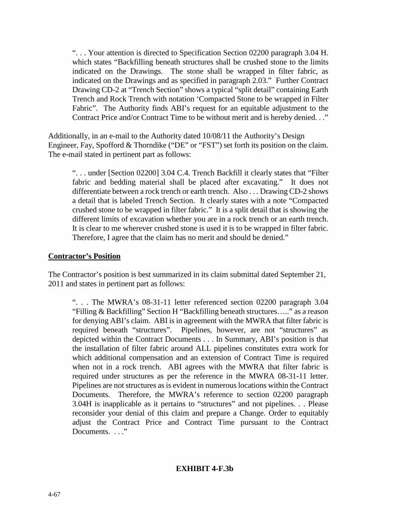
4-67
“. . . Your attention is directed to Specification Section 02200 paragraph 3.04 H. which states “Backfilling beneath structures shall be crushed stone to the limits indicated on the Drawings. The stone shall be wrapped in filter fabric, as indicated on the Drawings and as specified in paragraph 2.03.” Further Contract Drawing CD-2 at “Trench Section” shows a typical “split detail” containing Earth Trench and Rock Trench with notation ‘Compacted Stone to be wrapped in Filter Fabric”. The Authority finds ABI’s request for an equitable adjustment to the Contract Price and/or Contract Time to be without merit and is hereby denied. . .”
Additionally, in an e-mail to the Authority dated 10/08/11 the Authority’s Design Engineer, Fay, Spofford & Thorndike (“DE” or “FST”) set forth its position on the claim. The e-mail stated in pertinent part as follows:
“. . . under [Section 02200] 3.04 C.4. Trench Backfill it clearly states that “Filter fabric and bedding material shall be placed after excavating.” It does not differentiate between a rock trench or earth trench. Also . . . Drawing CD-2 shows a detail that is labeled Trench Section. It clearly states with a note “Compacted crushed stone to be wrapped in filter fabric.” It is a split detail that is showing the different limits of excavation whether you are in a rock trench or an earth trench. It is clear to me wherever crushed stone is used it is to be wrapped in filter fabric. Therefore, I agree that the claim has no merit and should be denied.”
Contractor’s Position The Contractor’s position is best summarized in its claim submittal dated September 21, 2011 and states in pertinent part as follows:
“. . . The MWRA’s 08-31-11 letter referenced section 02200 paragraph 3.04 “Filling & Backfilling” Section H “Backfilling beneath structures…..” as a reason for denying ABI’s claim. ABI is in agreement with the MWRA that filter fabric is required beneath “structures”. Pipelines, however, are not “structures” as depicted within the Contract Documents . . . In Summary, ABI’s position is that the installation of filter fabric around ALL pipelines constitutes extra work for which additional compensation and an extension of Contract Time is required when not in a rock trench. ABI agrees with the MWRA that filter fabric is required under structures as per the reference in the MWRA 08-31-11 letter. Pipelines are not structures as is evident in numerous locations within the Contract Documents. Therefore, the MWRA’s reference to section 02200 paragraph 3.04H is inapplicable as it pertains to “structures” and not pipelines. . . Please reconsider your denial of this claim and prepare a Change. Order to equitably adjust the Contract Price and Contract Time pursuant to the Contract Documents. . . .”
EXHIBIT 4-F.3b
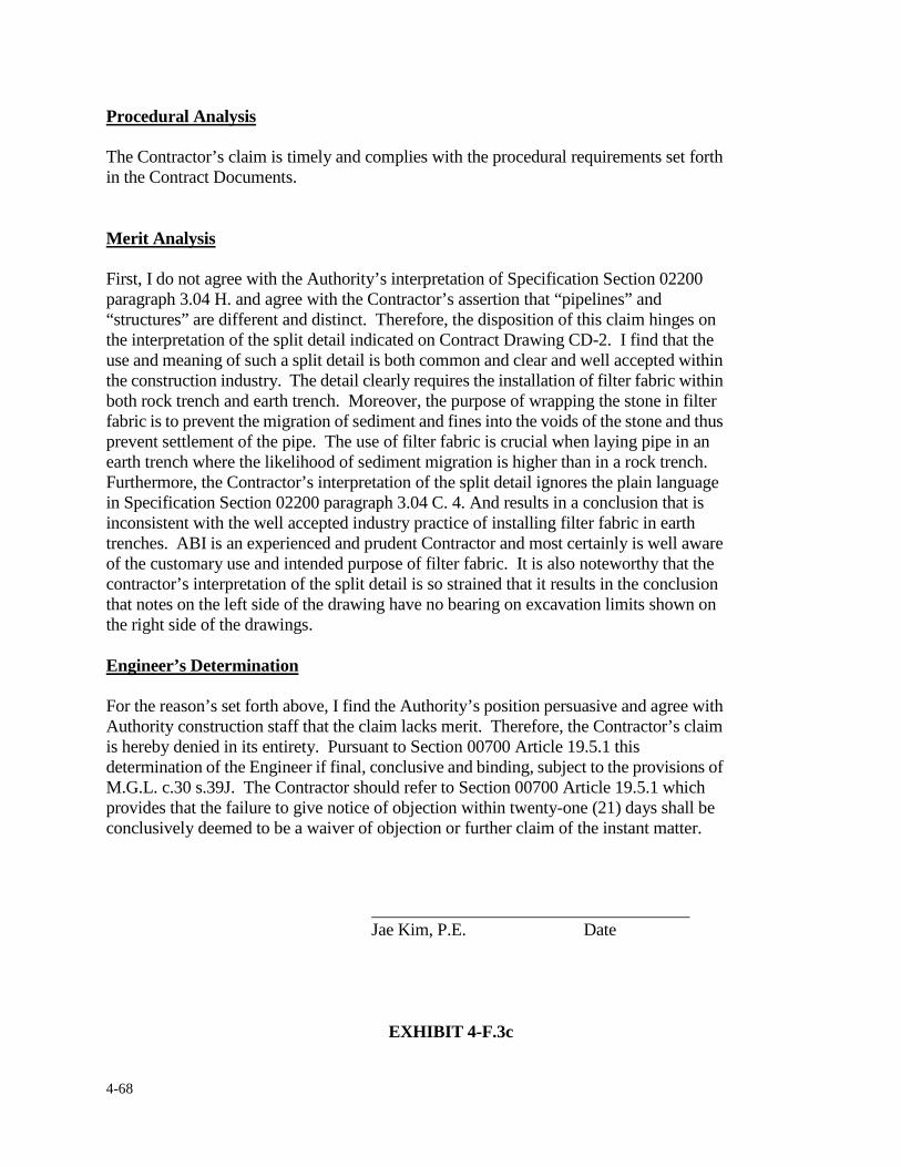
4-68
Procedural Analysis The Contractor’s claim is timely and complies with the procedural requirements set forth in the Contract Documents. Merit Analysis First, I do not agree with the Authority’s interpretation of Specification Section 02200 paragraph 3.04 H. and agree with the Contractor’s assertion that “pipelines” and “structures” are different and distinct. Therefore, the disposition of this claim hinges on the interpretation of the split detail indicated on Contract Drawing CD-2. I find that the use and meaning of such a split detail is both common and clear and well accepted within the construction industry. The detail clearly requires the installation of filter fabric within both rock trench and earth trench. Moreover, the purpose of wrapping the stone in filter fabric is to prevent the migration of sediment and fines into the voids of the stone and thus prevent settlement of the pipe. The use of filter fabric is crucial when laying pipe in an earth trench where the likelihood of sediment migration is higher than in a rock trench. Furthermore, the Contractor’s interpretation of the split detail ignores the plain language in Specification Section 02200 paragraph 3.04 C. 4. And results in a conclusion that is inconsistent with the well accepted industry practice of installing filter fabric in earth trenches. ABI is an experienced and prudent Contractor and most certainly is well aware of the customary use and intended purpose of filter fabric. It is also noteworthy that the contractor’s interpretation of the split detail is so strained that it results in the conclusion that notes on the left side of the drawing have no bearing on excavation limits shown on the right side of the drawings. Engineer’s Determination For the reason’s set forth above, I find the Authority’s position persuasive and agree with Authority construction staff that the claim lacks merit. Therefore, the Contractor’s claim is hereby denied in its entirety. Pursuant to Section 00700 Article 19.5.1 this determination of the Engineer if final, conclusive and binding, subject to the provisions of M.G.L. c.30 s.39J. The Contractor should refer to Section 00700 Article 19.5.1 which provides that the failure to give notice of objection within twenty-one (21) days shall be conclusively deemed to be a waiver of objection or further claim of the instant matter. Jae Kim, P.E. Date
EXHIBIT 4-F.3c
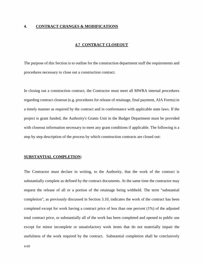
4-69
4. CONTRACT CHANGES & MODIFICATIONS
4.7 CONTRACT CLOSEOUT
The purpose of this Section is to outline for the construction department staff the requirements and
procedures necessary to close out a construction contract.
In closing out a construction contract, the Contractor must meet all MWRA internal procedures
regarding contract closeout (e.g. procedures for release of retainage, final payment, AIA Forms) in
a timely manner as required by the contract and in conformance with applicable state laws. If the
project is grant funded, the Authority's Grants Unit in the Budget Department must be provided
with closeout information necessary to meet any grant conditions if applicable. The following is a
step by step description of the process by which construction contracts are closed out:
SUBSTANTIAL COMPLETION:
The Contractor must declare in writing, to the Authority, that the work of the contract is
substantially complete as defined by the contract documents. At the same time the contractor may
request the release of all or a portion of the retainage being withheld. The term "substantial
completion", as previously discussed in Section 3.10, indicates the work of the contract has been
completed except for work having a contract price of less than one percent (1%) of the adjusted
total contract price, or substantially all of the work has been completed and opened to public use
except for minor incomplete or unsatisfactory work items that do not materially impair the
usefulness of the work required by the contract. Substantial completion shall be conclusively
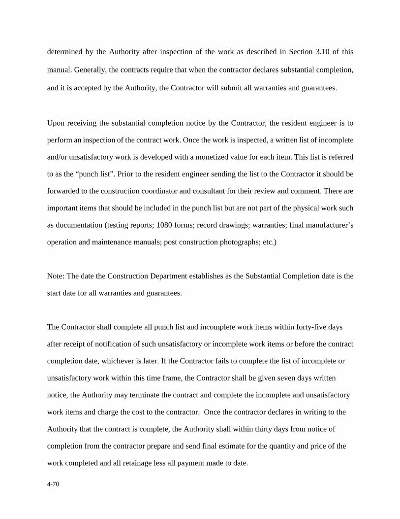
4-70
determined by the Authority after inspection of the work as described in Section 3.10 of this
manual. Generally, the contracts require that when the contractor declares substantial completion,
and it is accepted by the Authority, the Contractor will submit all warranties and guarantees.
Upon receiving the substantial completion notice by the Contractor, the resident engineer is to
perform an inspection of the contract work. Once the work is inspected, a written list of incomplete
and/or unsatisfactory work is developed with a monetized value for each item. This list is referred
to as the “punch list”. Prior to the resident engineer sending the list to the Contractor it should be
forwarded to the construction coordinator and consultant for their review and comment. There are
important items that should be included in the punch list but are not part of the physical work such
as documentation (testing reports; 1080 forms; record drawings; warranties; final manufacturer’s
operation and maintenance manuals; post construction photographs; etc.)
Note: The date the Construction Department establishes as the Substantial Completion date is the
start date for all warranties and guarantees.
The Contractor shall complete all punch list and incomplete work items within forty-five days
after receipt of notification of such unsatisfactory or incomplete work items or before the contract
completion date, whichever is later. If the Contractor fails to complete the list of incomplete or
unsatisfactory work within this time frame, the Contractor shall be given seven days written
notice, the Authority may terminate the contract and complete the incomplete and unsatisfactory
work items and charge the cost to the contractor. Once the contractor declares in writing to the
Authority that the contract is complete, the Authority shall within thirty days from notice of
completion from the contractor prepare and send final estimate for the quantity and price of the
work completed and all retainage less all payment made to date.
4-71
BALANCING CHANGE ORDER
At the time of substantial completion the resident engineer shall prepare a rough draft of the
balancing change order and present it to the construction coordinator. A balancing change order
adjusts any unit price bid item to reflect the difference between the bid estimated quantity and
actual quantity used in the work. The balancing change is processed in the same manner as all
other change orders. A proposed change order (PCO) must be approved by Procurement before the
balancing change order is finalized. The purpose of the change order is to reduce/increase
estimated quantities to reflect actual quantities used. The balancing change order must also rectify
any bid allowances (such as Police and Fire Details) and also must include any time and material
(T&M) Not to Exceed (NTE) change orders not previously rectified in other change orders.
During the progress of the work the resident engineer shall have monitored any bid items
approaching an overrun and coordinated with the construction coordinator for a change order to
adjust the bid item and not exceed the quantity during any particular pay period. The balancing
change order should mainly be comprised of under run items with the exception of minor overruns
that may have occurred during the final completion of the project. The resident engineer and
construction coordinator shall not delay until the balancing change order to combine overruns and
underruns to offset their total cost. Overruns shall be monitored and addressed throughout the
progress of the work. The balancing change order shall include the following information:
1) A tabulation of each bid item showing an overrun (minor increase in quantities) or an
underrun (reduction in quantities). The tabulation shall show the overruns separated
from the underruns with separate Subtotal cost.
4-72
2) The columns for each bid item noted above indicating the "Original Quantity/Unit
Price", the "Previous Quantity Adjustments", the "Increase/Decrease This C.O.", “Unit
Price” and "Total”. The difference between the Original Quantity and the Actual
Quantity multiplied by the Unit Price shall provide the amount of the change. Exhibit
4-Q.1a through 4-Q.1d and 4-Q.2a through 4-Q.2d are two examples of a typical
balancing change order bid item breakdown.
3) The balancing change order shall conclude with a summary which adds the net
increase/decrease to the original contract price.
4) A narrative justification must be included as to the reason for either the overrun or
underrun.
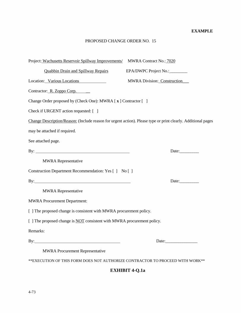
4-73
EXAMPLE
PROPOSED CHANGE ORDER NO. 15
Project: Wachusetts Reservoir Spillway Improvements/ MWRA Contract No.: 7020
Quabbin Drain and Spillway Repairs EPA/DWPC Project No.: ________
Location: Various Locations MWRA Division: Construction___
Contractor: R. Zoppo Corp. __
Change Order proposed by (Check One): MWRA [ x ] Contractor [ ]
Check if URGENT action requested: [ ]
Change Description/Reason: (Include reason for urgent action). Please type or print clearly. Additional pages
may be attached if required.
See attached page.
By: Date:_________
MWRA Representative
Construction Department Recommendation: Yes [ ] No [ ]
By: Date:_________
MWRA Representative
MWRA Procurement Department:
[ ] The proposed change is consistent with MWRA procurement policy.
[ ] The proposed change is NOT consistent with MWRA procurement policy.
Remarks:
By: Date:_______________
MWRA Procurement Representative
**EXECUTION OF THIS FORM DOES NOT AUTHORIZE CONTRACTOR TO PROCEED WITH WORK**
EXHIBIT 4-Q.1a
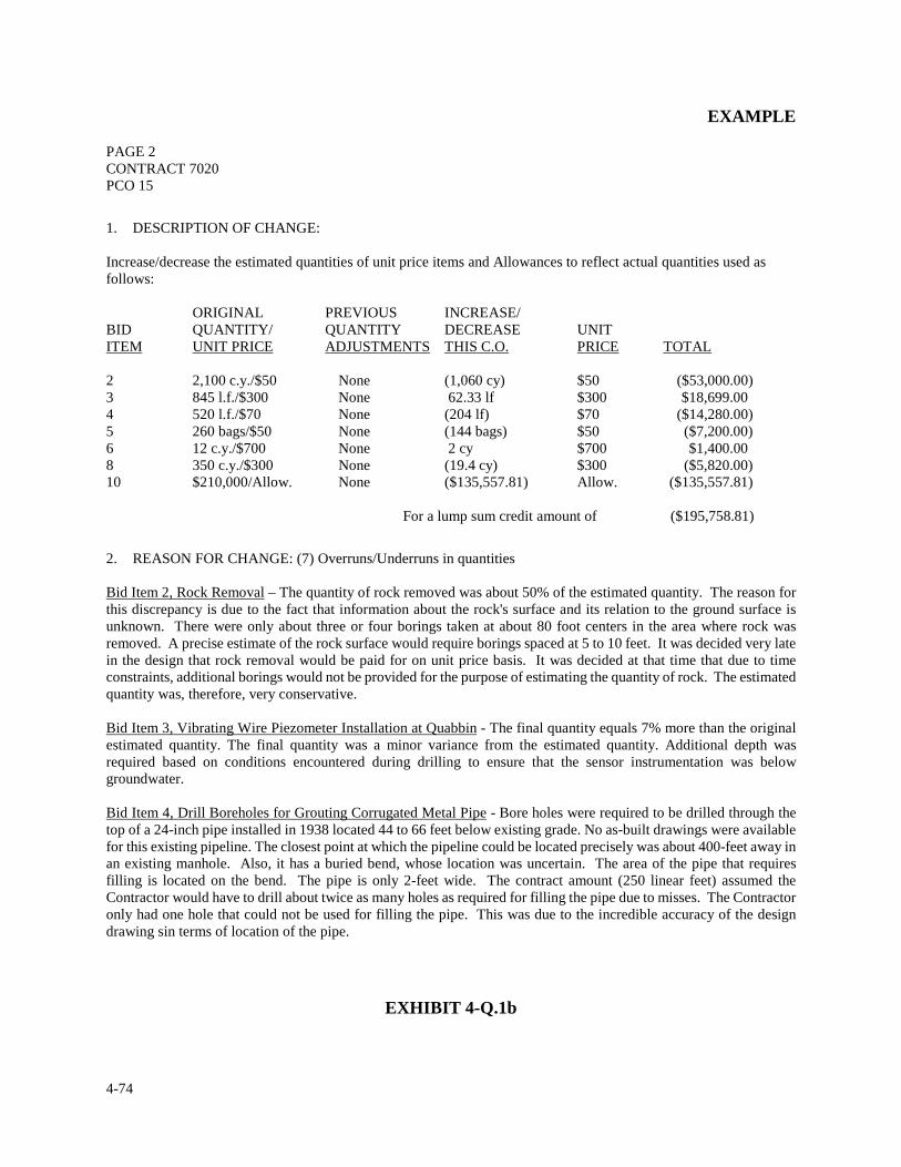
4-74
EXAMPLE PAGE 2 CONTRACT 7020 PCO 15
1. DESCRIPTION OF CHANGE: Increase/decrease the estimated quantities of unit price items and Allowances to reflect actual quantities used as follows: ORIGINAL PREVIOUS INCREASE/ BID QUANTITY/ QUANTITY DECREASE UNIT ITEM UNIT PRICE ADJUSTMENTS THIS C.O. PRICE TOTAL 2 2,100 c.y./$50 None (1,060 cy) $50 ($53,000.00) 3 845 l.f./$300 None 62.33 lf $300 $18,699.00 4 520 l.f./$70 None (204 lf) $70 ($14,280.00) 5 260 bags/$50 None (144 bags) $50 ($7,200.00) 6 12 c.y./$700 None 2 cy $700 $1,400.00 8 350 c.y./$300 None (19.4 cy) $300 ($5,820.00) 10 $210,000/Allow. None ($135,557.81) Allow. ($135,557.81)
For a lump sum credit amount of ($195,758.81)
2. REASON FOR CHANGE: (7) Overruns/Underruns in quantities Bid Item 2, Rock Removal – The quantity of rock removed was about 50% of the estimated quantity. The reason for this discrepancy is due to the fact that information about the rock's surface and its relation to the ground surface is unknown. There were only about three or four borings taken at about 80 foot centers in the area where rock was removed. A precise estimate of the rock surface would require borings spaced at 5 to 10 feet. It was decided very late in the design that rock removal would be paid for on unit price basis. It was decided at that time that due to time constraints, additional borings would not be provided for the purpose of estimating the quantity of rock. The estimated quantity was, therefore, very conservative. Bid Item 3, Vibrating Wire Piezometer Installation at Quabbin - The final quantity equals 7% more than the original estimated quantity. The final quantity was a minor variance from the estimated quantity. Additional depth was required based on conditions encountered during drilling to ensure that the sensor instrumentation was below groundwater. Bid Item 4, Drill Boreholes for Grouting Corrugated Metal Pipe - Bore holes were required to be drilled through the top of a 24-inch pipe installed in 1938 located 44 to 66 feet below existing grade. No as-built drawings were available for this existing pipeline. The closest point at which the pipeline could be located precisely was about 400-feet away in an existing manhole. Also, it has a buried bend, whose location was uncertain. The area of the pipe that requires filling is located on the bend. The pipe is only 2-feet wide. The contract amount (250 linear feet) assumed the Contractor would have to drill about twice as many holes as required for filling the pipe due to misses. The Contractor only had one hole that could not be used for filling the pipe. This was due to the incredible accuracy of the design drawing sin terms of location of the pipe.
EXHIBIT 4-Q.1b
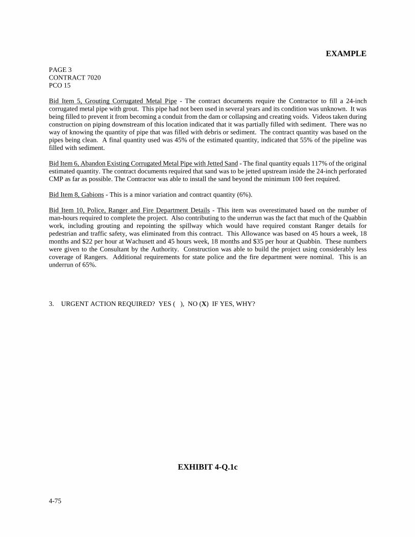
4-75
EXAMPLE PAGE 3 CONTRACT 7020 PCO 15 Bid Item 5, Grouting Corrugated Metal Pipe - The contract documents require the Contractor to fill a 24-inch corrugated metal pipe with grout. This pipe had not been used in several years and its condition was unknown. It was being filled to prevent it from becoming a conduit from the dam or collapsing and creating voids. Videos taken during construction on piping downstream of this location indicated that it was partially filled with sediment. There was no way of knowing the quantity of pipe that was filled with debris or sediment. The contract quantity was based on the pipes being clean. A final quantity used was 45% of the estimated quantity, indicated that 55% of the pipeline was filled with sediment. Bid Item 6, Abandon Existing Corrugated Metal Pipe with Jetted Sand - The final quantity equals 117% of the original estimated quantity. The contract documents required that sand was to be jetted upstream inside the 24-inch perforated CMP as far as possible. The Contractor was able to install the sand beyond the minimum 100 feet required. Bid Item 8, Gabions - This is a minor variation and contract quantity (6%). Bid Item 10, Police, Ranger and Fire Department Details - This item was overestimated based on the number of man-hours required to complete the project. Also contributing to the underrun was the fact that much of the Quabbin work, including grouting and repointing the spillway which would have required constant Ranger details for pedestrian and traffic safety, was eliminated from this contract. This Allowance was based on 45 hours a week, 18 months and $22 per hour at Wachusett and 45 hours week, 18 months and $35 per hour at Quabbin. These numbers were given to the Consultant by the Authority. Construction was able to build the project using considerably less coverage of Rangers. Additional requirements for state police and the fire department were nominal. This is an underrun of 65%.
3. URGENT ACTION REQUIRED? YES ( ), NO (X) IF YES, WHY?
EXHIBIT 4-Q.1c
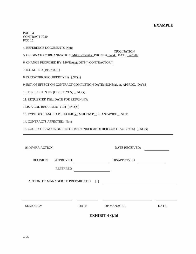
4-76
EXAMPLE PAGE 4 CONTRACT 7020 PCO 15 4. REFERENCE DOCUMENTS: None ORIGINATION 5. ORIGINATOR/ORGANIZATION: Mike Schweihs PHONE #_5434 DATE: 2/20/09
6. CHANGE PROPOSED BY: MWRA(x); DITP( );CONTRACTOR( ) 7. R.O.M. EST: (195,758.81) 8. IS REWORK REQUIRED? YES( ),NO(x) 9. EST. OF EFFECT ON CONTRACT COMPLETION DATE: NONE(x), or, APPROX._DAYS 10. IS REDESIGN REQUIRED? YES( ), NO(x) 11. REQUESTED DEL. DATE FOR REDGN:N/A 12.IS A COD REQUIRED? YES( ),NO(x ) 13. TYPE OF CHANGE: CP SPECIFIC x ; MULTI-CP ; PLANT-WIDE ; SITE 14. CONTRACTS AFFECTED: None 15. COULD THE WORK BE PERFORMED UNDER ANOTHER CONTRACT? YES( ), NO(x) 16: MWRA ACTION:
DATE RECEIVED:
DECISION: APPROVED
DISAPPROVED
REFERRED
ACTION: DP MANAGER TO PREPARE COD
[ ]
SENIOR CM
DATE
DP MANAGER
DATE
EXHIBIT 4-Q.1d
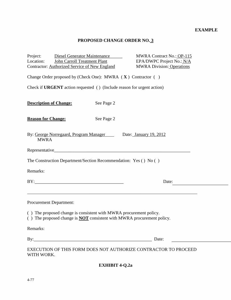
4-77
EXAMPLE
PROPOSED CHANGE ORDER NO. 3 Project: Diesel Generator Maintenance MWRA Contract No.: OP-115 Location: John Carroll Treatment Plant EPA/DWPC Project No.: N/A Contractor: Authorized Service of New England MWRA Division: Operations Change Order proposed by (Check One): MWRA ( X ) Contractor ( ) Check if URGENT action requested ( ) (Include reason for urgent action) Description of Change: See Page 2 Reason for Change: See Page 2 By: George Norregaard, Program Manager Date: January 19, 2012 MWRA Representative____________________________________________________________
The Construction Department/Section Recommendation: Yes ( ) No ( )
Remarks:
BY: Date: ___________________________________________________________________________
Procurement Department:
( ) The proposed change is consistent with MWRA procurement policy. ( ) The proposed change is NOT consistent with MWRA procurement policy.
Remarks:
By: Date:
EXECUTION OF THIS FORM DOES NOT AUTHORIZE CONTRACTOR TO PROCEED WITH WORK.
EXHIBIT 4-Q.2a
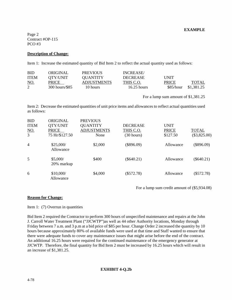
4-78
EXAMPLE Page 2 Contract #OP-115 PCO #3 Description of Change: Item 1: Increase the estimated quantity of Bid Item 2 to reflect the actual quantity used as follows: BID ORIGINAL PREVIOUS INCREASE/ ITEM QTY/UNIT QUANTITY DECREASE UNIT NO. PRICE ADJUSTMENTS THIS C.O. PRICE TOTAL 2 300 hours/$85 10 hours 16.25 hours $85/hour $1,381.25
For a lump sum amount of $1,381.25 Item 2: Decrease the estimated quantities of unit price items and allowances to reflect actual quantities used as follows: BID ORIGINAL PREVIOUS ITEM QTY/UNIT QUANTITY DECREASE UNIT NO. PRICE ADJUSTMENTS THIS C.O. PRICE TOTAL 3 75 Hr/$127.50 None (30 hours) $127.50 ($3,825.00) 4 $25,000/ $2,000 ($896.09) Allowance ($896.09) Allowance 5 $5,000/ $400 ($640.21) Allowance ($640.21) 20% markup 6 $10,000/ $4,000 ($572.78) Allowance ($572.78) Allowance For a lump sum credit amount of ($5,934.08) Reason for Change: Item 1: (7) Overrun in quantities Bid Item 2 required the Contractor to perform 300 hours of unspecified maintenance and repairs at the John J. Carroll Water Treatment Plant (“JJCWTP”)as well as 44 other Authority locations, Monday through Friday between 7 a.m. and 3 p.m at a bid price of $85 per hour. Change Order 2 increased the quantity by 10 hours because approximately 80% of available funds were used at that time and Staff wanted to ensure that there were adequate funds to cover any maintenance issues that might arise before the end of the contract. An additional 16.25 hours were required for the continued maintenance of the emergency generator at JJCWTP. Therefore, the final quantity for Bid Item 2 must be increased by 16.25 hours which will result in an increase of $1,381.25.
EXHIBIT 4-Q.2b
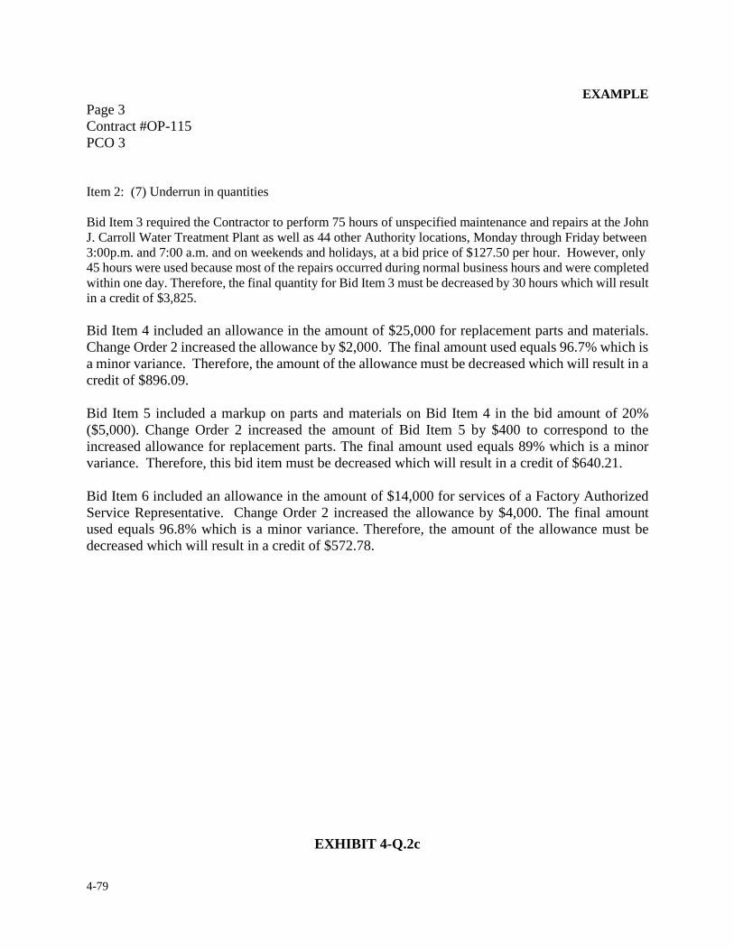
4-79
EXAMPLE Page 3 Contract #OP-115 PCO 3 Item 2: (7) Underrun in quantities Bid Item 3 required the Contractor to perform 75 hours of unspecified maintenance and repairs at the John J. Carroll Water Treatment Plant as well as 44 other Authority locations, Monday through Friday between 3:00p.m. and 7:00 a.m. and on weekends and holidays, at a bid price of $127.50 per hour. However, only 45 hours were used because most of the repairs occurred during normal business hours and were completed within one day. Therefore, the final quantity for Bid Item 3 must be decreased by 30 hours which will result in a credit of $3,825. Bid Item 4 included an allowance in the amount of $25,000 for replacement parts and materials. Change Order 2 increased the allowance by $2,000. The final amount used equals 96.7% which is a minor variance. Therefore, the amount of the allowance must be decreased which will result in a credit of $896.09. Bid Item 5 included a markup on parts and materials on Bid Item 4 in the bid amount of 20% ($5,000). Change Order 2 increased the amount of Bid Item 5 by $400 to correspond to the increased allowance for replacement parts. The final amount used equals 89% which is a minor variance. Therefore, this bid item must be decreased which will result in a credit of $640.21. Bid Item 6 included an allowance in the amount of $14,000 for services of a Factory Authorized Service Representative. Change Order 2 increased the allowance by $4,000. The final amount used equals 96.8% which is a minor variance. Therefore, the amount of the allowance must be decreased which will result in a credit of $572.78.
EXHIBIT 4-Q.2c
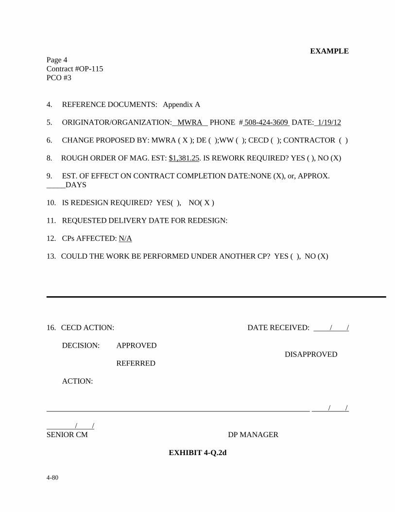
4-80
EXAMPLE Page 4 Contract #OP-115 PCO #3 4. REFERENCE DOCUMENTS: Appendix A 5. ORIGINATOR/ORGANIZATION: MWRA PHONE # 508-424-3609 DATE: 1/19/12 6. CHANGE PROPOSED BY: MWRA ( X ); DE ( );WW ( ); CECD ( ); CONTRACTOR ( ) 8. ROUGH ORDER OF MAG. EST: $1,381.25. IS REWORK REQUIRED? YES ( ), NO (X) 9. EST. OF EFFECT ON CONTRACT COMPLETION DATE:NONE (X), or, APPROX. _____DAYS 10. IS REDESIGN REQUIRED? YES( ), NO( X ) 11. REQUESTED DELIVERY DATE FOR REDESIGN: 12. CPs AFFECTED: N/A 13. COULD THE WORK BE PERFORMED UNDER ANOTHER CP? YES ( ), NO (X) 16. CECD ACTION: DATE RECEIVED: / / DECISION: APPROVED DISAPPROVED REFERRED ACTION: / / / / SENIOR CM DP MANAGER
EXHIBIT 4-Q.2d
4-81
PARTIAL RELEASE OF RETAINAGE – CHAPTER 30
At the time substantial completion is established, if the contract is a Chapter 30 Construction
Project (horizontal work contracts), the contractor is entitled to a partial release of retainage.
Under existing Laws the retainage is reduced 5% to 1% of the contract value of work done, plus
the value of the punchlist and any claims the MWRA may have against the contractor. The
Executive Director (MWRA) must approve any release of retainage under his delegated authority
in a Staff Summary which is prepared by the construction coordinator. The Staff Summary states
Substantial Completion date and it will include the total amount of retainage withheld to date, the
amount to be released and the amount still to be retained. The Staff Summary should also certify
that all the contractual requirements, relating to partial release of retainage have been met and to
further authorize staff to pay additional invoices upon completion of the punchlist up to an amount
of the total value of punchlist items. The following documents are required from the contractor in
support of a partial release of retainage.
1) Letter from contractor requesting partial release of retainage.
2) An Invoice from the contractor similar to the invoice shown in Section 3, Exhibit 3-A.1.
This pay estimate does not get assigned a numeric number but is assigned a partial release
of retainage (PRR) number.
3) Consent of the contractor's surety to Partial Release of Retainage.
4) The Surety's Power of Attorney.
After a partial release of retainage to the contractor, the outstanding monies retained by the
Authority should be 1% of the value of work done plus the value of any remaining punch list items
and any claims the MWRA may have against the contractor. The one percent of retainage
outstanding will continue to be withheld for a period of one year or until all contractual obligations
4-82
are met.
FINAL RELEASE OF RETAINAGE – CHAPTER 30
For Chapter 30 Contracts (horizontal work) in which the contractor certifies that all his contractual
obligations are complete, the contractor is entitled to final release of the 1% retainage (withheld)
and any remaining unpaid balance for completed punch list items. As mentioned above, the
Executive Director must approve any release of retainage. The Executive Director's approval is
obtained though the Staff Summary process. The Staff Summary must state that all work required
was completed in accordance with the contract documents. Also, the Staff Summary must include
a summary of the original bid amount, all change orders, including the executed balancing change
order and final contract amount as well as the amount of retainage being released. The following
documents are required from the contractor:
1) Contractor's letter stating that contract is complete and requesting final release of
retainage.
2) Contractor's invoice for final release of retainage.
3) Consent (of contractor's) Surety Company for Final Payment and Final Release of
Retainage.
4) Contractor's Affidavit of Payment of Debts and Claims.
5) Contractors Affidavit of Release of Liens.
6) Statement of One Year Warranty and Guarantee.
7) Certificate of Insurance beyond Final Payment for specified time period where the
minimum time to be equal to the warranty/guarantee period.
4-83
In addition, the staff summary must also be accompanied by a Certificate of Substantial
Completion and a DCAM Contractor Evaluation Form both of which are to be provided by the
Construction Department. It should be noted that a failing grade (less than 80 points) for a DCAM
Contractor Evaluation Form requires prior review and concurrence by MWRA Management.
Finally, all certificates of compliance and applicable permits that are to be issued by Conservation
Commission, MADEP, MADOT, Corp. of Engineers, etc., if required. These documents should be
placed in the construction files and copies attached to the staff summary.
PARTIAL RELEASE OF RETAINAGE – CHAPTER 149
At the time substantial completion is established, if the contract is a Chapter 149 Construction
Project (vertical construction work) the contractor is entitled to a partial release of retainage. As
required by statute, the 5% is reduced to 0% plus the value of incomplete and unsatisfactory work.
The retained amount shall provide a reasonable amount of money to assure that the contractor
provides the final documentation needed to declare the contract complete. The Executive Director
(MWRA) must approve any release of retainage under his delegated authority. His approval is
requested in a Staff Summary which is prepared by the construction department. The Staff
Summary states the contract is substantially complete, it will include the total amount of retainage
withheld to date, the amount to be released and the amount still to be retained. A description
should be given of any outstanding punch list items and their value. The Staff Summary can
request authorization for staff to process payments for punch list work as these items are
successfully completed prior to final completion, up to an amount no more than 10% of the total
retainage held at Substantial Completion. The following documents are required from the
contractor in support of a partial release of retainage.
4-84
1) Letter from Contractor with a declaration of Substantial Completion requesting partial
release of retainage.
2) An Invoice from the contractor similar to the invoice shown in Section 3, Exhibit 3-A.1,
with the cover sheet changing the retainage amount and the SOV pages indicating no
work this pay period. This pay estimate does not get assigned a numeric number but uses
a Partial Release Retainage (PRR) number.
3) Consent of the contractor's surety to Partial Release of Retainage.
4) The Surety's Power of Attorney.
Since 1% retainage is not held in addition to punchlist in a Chapter 149 construction contract, the
resident engineer and construction coordinator may release partial payments for the completion of
punchlist items up to an amount no more than 10% of the total retainage held at Substantial
Completion.
The amount of retainage outstanding will continue to be withheld until contractual obligations
have been met.
FINAL RELEASE OF RETAINAGE – CHAPTER 149
For Chapter 149 Contracts (vertical construction work) in which the contractor certifies that all his
contractual obligations are complete including any remaining unpaid balance of the punch list. As
mentioned above, the Executive Director must approve any release of retainage. The Executive
4-85
Director's approval is obtained though the Staff Summary process. The Staff Summary must state
that all punch list items are complete and that the contractor's contractual obligations have been
met including the receipt of all warranties, guarantees and as-built etc. Also, the Staff Summary
must include a summary of the original bid amount, all change orders, including the executed
balancing change order and final contract amount as well as the amount of retainage being
released. The following documents are required from the contractor:
1) Contractor's letter stating that all contract work is complete and requesting final release of
retainage.
2) Contractor's invoice for full release of retainage.
3) Consent (of contractor's) Surety Company for Final Payment and Final Release of
Retainage with Power of Attorney.
4) Contractor's Affidavit of Payment of Debts and Claims.
5) Contractors Affidavit of Release of Liens.
6) Statement of One Year Warranty and Guarantee.
7) Certificate of Insurance beyond Final Payment for specified time period where the
minimum time to be equal to the warranty/guarantee period.
In addition, the staff summary must also be accompanied by a Certificate of Substantial
Completion and a DCAM Contractor Evaluation Form both of which are to be provided by the
Construction Department. It should be noted that a failing grade (less than 80 points) for DCAM
Contractor Evaluation Form requires prior review and concurrence by MWRA Management.
Finally, all certificates of compliance and applicable permits that are to be issued by Conservation
Commission, MADEP, MADOT, Corp. of Engineers, etc., must be obtained at time of project
closeout. These documents should be placed in the construction files and copies attached to the
4-86
staff summary.
PROJECT CLOSE-OUT DOCUMENTATION
The resident engineer is required to assist the construction coordinator and project manager in
closing-out the contract. The Construction Department is to ensure that the following contract
requirements are received from the Contractor. The preferred method to achieve this is to notify
the Contractor, in writing, that the following documentation is needed to close-out the contract.
• The DCAM Contractor Evaluation Form is complete, accurate and non-bias. A
blank copy of this form can be found in the Appendix of this manual.
• A notice from the contractor indicating that all required insurance coverage is in
force and will continue to be enforced through out the life of the contract.
• Certification of Labor Standards and Insurance Compliance.
• Equipment Operations and Maintenance Manuals are complete, approved and are
on site.
• Construction as-built red-line drawings are complete, accurate and delivered to
the Home Office.
• All operations and maintenance manuals have been furnished by the contractor
and turned over to Operations Division.
If the contract is grant funded, the Grants Unit within Budget Department is to be provided with
copies of any required/requested documentation.
4-87
As part of the project closeout, the Construction Department shall confirm with the construction
coordinator that all requirements contained in the permits section of the contract specifications
such as Conservation Commission Order of Conditions, roadway/street opening permits, building
permit (local and/or state), MWRA 8M, MassHighway (MDOT), Department of Conservation
(DCR) and any other outside agency has been completed. Many permits have specific required
contract closeout deliverables either from the Contractor, the Consultant or the Authority. For
example, an Order of Conditions requires a Certificate of Compliance that must be applied for
from the local Conservation Commission at project completion. Stamped record drawings of work
areas covered in the Order must be prepared and the Certificate of Compliance once obtained must
be recorded at the Registry of Deeds. These tasks are all considered part of the Construction
Department contract closeout.
5-1
S E C T I O N 5
REVIEWS, REPORTING FORMS & PROCEDURES
PAGE
5.1 PROJECT (ADMINISTRATIVE) REVIEWS 5-2
5.2 MATERIALS CONTROL FORM 5-9
5.3 FIELD OFFICE VISITORS LOG 5-12
5.4 JOB MEETING REPORT 5-14
5.5 ACCIDENT REPORT 5-24
5.6 DAMAGE REPORT 5-30
5.7 COMPLAINT REPORT 5-34
5.8 POLICE DETAILS 5-37
5.9 FACILITY HANDBOOK 5-38
5.10 ONE YEAR PROJECT PERFORMANCE CERTIFICATE 5-41
5-2
5. REPORTING FORMS, PROCEDURES & REVIEWS
5.1 PROJECT (ADMINISTRATIVE) REVIEWS
From time to time, depending on the size of the construction contract, the resident engineer will be
visited by a representative of the Construction Department to review the resident engineer's
administrative procedures being maintained in the field. The purpose of this review is to assure the
appropriate records for the work in progress have been implemented and are being maintained in
accordance with current Authority policies and this manual.
The resident engineer is required to give his/her full cooperation during this review. The
representative, acting on behalf of the Assistant Director of Construction, will make a thorough
review of all field records, with the responsibility of pointing out to the resident engineer any areas
of conflict and to make positive suggestions to further improve the efficiency of record keeping in
the field. Upon completion of the review, the representative will prepare a report of his/her
findings and forward it to the Assistant Director of Construction for his/her information, and/or
action. The report shall consist of: 1) a cover letter (See Exhibit 5-A.1 for an example of a memo)
which outlines, in general, the findings of the report, 2) a summary sheet (See Exhibit 5-A.2)
which outlines project information of the contract and a brief description of the scope of work, 3) a
review checklist (See Exhibit 5-A.3) which list of a number of topics relating to the administrative
requirements of the resident engineer and 4) a list of reviewer's comments regarding the above
mentioned topics found to be in need of attention (See Exhibit 5-A.4a through Exhibit 5-A.4c).
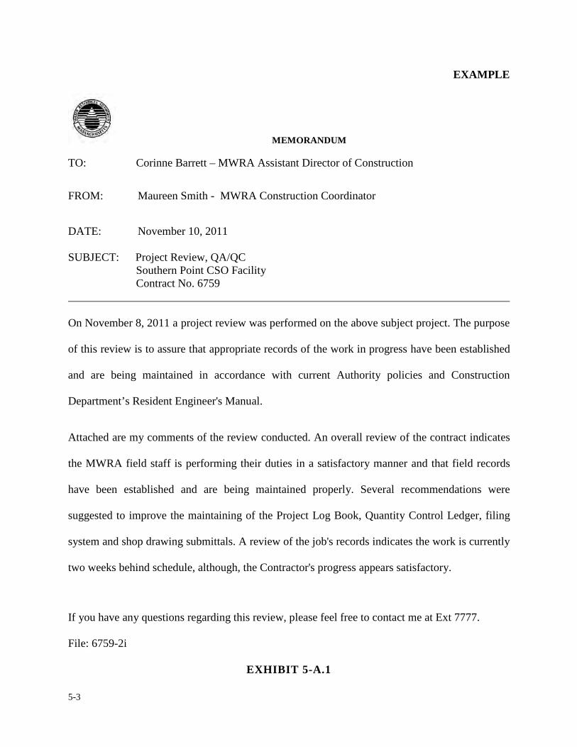
5-3
EXAMPLE
MEMORANDUM
TO: Corinne Barrett – MWRA Assistant Director of Construction
FROM: Maureen Smith - MWRA Construction Coordinator
DATE: November 10, 2011
SUBJECT: Project Review, QA/QC Southern Point CSO Facility
Contract No. 6759
On November 8, 2011 a project review was performed on the above subject project. The purpose
of this review is to assure that appropriate records of the work in progress have been established
and are being maintained in accordance with current Authority policies and Construction
Department’s Resident Engineer's Manual.
Attached are my comments of the review conducted. An overall review of the contract indicates
the MWRA field staff is performing their duties in a satisfactory manner and that field records
have been established and are being maintained properly. Several recommendations were
suggested to improve the maintaining of the Project Log Book, Quantity Control Ledger, filing
system and shop drawing submittals. A review of the job's records indicates the work is currently
two weeks behind schedule, although, the Contractor's progress appears satisfactory.
If you have any questions regarding this review, please feel free to contact me at Ext 7777.
File: 6759-2i
EXHIBIT 5-A.1
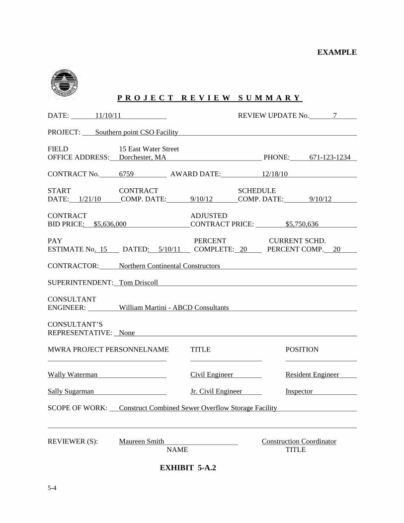
5-4
EXAMPLE
P R O J E C T R E V I E W S U M M A R Y
DATE: 11/10/11 REVIEW UPDATE No. 7 PROJECT: Southern point CSO Facility FIELD 15 East Water Street OFFICE ADDRESS: Dorchester, MA PHONE: 671-123-1234 CONTRACT No. 6759 AWARD DATE: 12/18/10 START CONTRACT SCHEDULE DATE: 1/21/10 COMP. DATE: 9/10/12 COMP. DATE: 9/10/12 CONTRACT ADJUSTED BID PRICE: $5,636,000 CONTRACT PRICE: $5,750,636 PAY PERCENT CURRENT SCHD. ESTIMATE No. 15 DATED: 5/10/11 COMPLETE: 20 PERCENT COMP. 20 CONTRACTOR: Northern Continental Constructors SUPERINTENDENT: Tom Driscoll CONSULTANT ENGINEER: William Martini - ABCD Consultants CONSULTANT’S REPRESENTATIVE: None MWRA PROJECT PERSONNELNAME TITLE POSITION Wally Waterman Civil Engineer Resident Engineer Sally Sugarman Jr. Civil Engineer Inspector
SCOPE OF WORK: Construct Combined Sewer Overflow Storage Facility
REVIEWER (S): Maureen Smith Construction Coordinator NAME TITLE
EXHIBIT 5-A.2
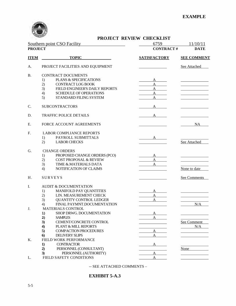
5-5
EXAMPLE
PROJECT REVIEW CHECKLIST Southern point CSO Facility 6759 11/10/11 PROJECT CONTRACT # DATE
ITEM TOPIC SATISFACTORY SEE COMMENT
A. PROJECT FACILITIES AND EQUIPMENT See Attached
B. CONTRACT DOCUMENTS
1) PLANS & SPECIFICATIONS A 2) CONTRACT LOG BOOK A 3) FIELD ENGINEER'S DAILY REPORTS A 4) SCHEDULE OF OPERATIONS A 5) STANDARD FILING SYSTEM A
C. SUBCONTRACTORS A
D. TRAFFIC POLICE DETAILS A
E. FORCE ACCOUNT AGREEMENTS NA
F. LABOR COMPLIANCE REPORTS 1) PAYROLL SUBMITTALS A 2) LABOR CHECKS See Attached
G. CHANGE ORDERS 1) PROPOSED CHANGE ORDERS (PCO) A 2) COST PROPOSAL & REVIEW A 3) TIME &.MATERIALS DATA A 4) NOTIFICATION OF CLAIMS None to date
H . SU R VE Y S See Comments
I. AUDIT & DOCUMENTATION
1) MANIFOLD PAY QUANTITIES A 2) LIN. MEASUREMENT CHECK A 3) QUANTITY CONTROL LEDGER A 4) FINAL PAYMNT.DOCUMENTATION N/A
J. MATERIALS CONTROL 1) SHOP DRWG. DOCUMENTATION A 2) SAMPLES A 3) CEMENT/CONCRETE CONTROL See Comment 4) PLANT & MILL REPORTS N/A 5) COMPACTION PROCEDURES A 6) DELIVERY SLIPS A
K. FIELD WORK PERFORMANCE 1) CONTRACTOR A 2) PERSONNEL (CONSULTANT) None 3) PERSONNEL (AUTHORITY) A
L. FIELD SAFETY CONDITIONS A -- SEE ATTACHED COMMENTS – EXHIBIT 5-A.3
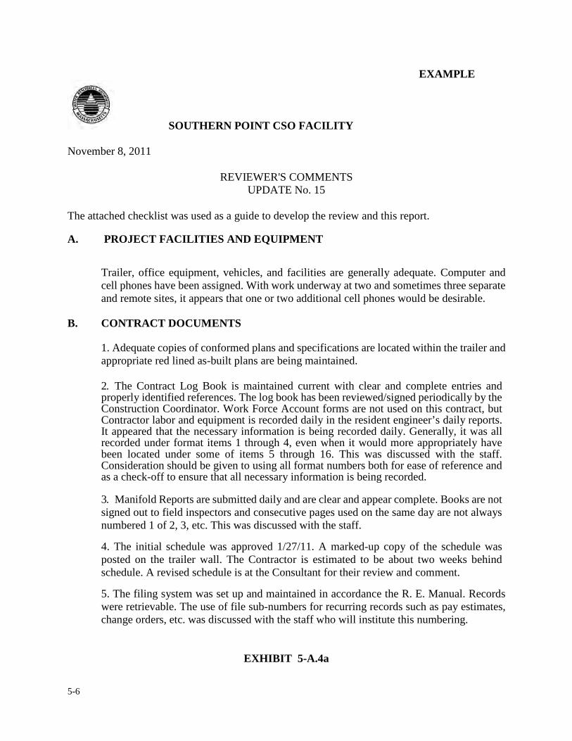
5-6
EXAMPLE
SOUTHERN POINT CSO FACILITY
November 8, 2011
REVIEWER'S COMMENTS UPDATE No. 15
The attached checklist was used as a guide to develop the review and this report.
A. PROJECT FACILITIES AND EQUIPMENT
Trailer, office equipment, vehicles, and facilities are generally adequate. Computer and cell phones have been assigned. With work underway at two and sometimes three separate and remote sites, it appears that one or two additional cell phones would be desirable.
B. CONTRACT DOCUMENTS
1. Adequate copies of conformed plans and specifications are located within the trailer and appropriate red lined as-built plans are being maintained.
2. The Contract Log Book is maintained current with clear and complete entries and properly identified references. The log book has been reviewed/signed periodically by the Construction Coordinator. Work Force Account forms are not used on this contract, but Contractor labor and equipment is recorded daily in the resident engineer’s daily reports. It appeared that the necessary information is being recorded daily. Generally, it was all recorded under format items 1 through 4, even when it would more appropriately have been located under some of items 5 through 16. This was discussed with the staff. Consideration should be given to using all format numbers both for ease of reference and as a check-off to ensure that all necessary information is being recorded.
3. Manifold Reports are submitted daily and are clear and appear complete. Books are not signed out to field inspectors and consecutive pages used on the same day are not always numbered 1 of 2, 3, etc. This was discussed with the staff.
4. The initial schedule was approved 1/27/11. A marked-up copy of the schedule was posted on the trailer wall. The Contractor is estimated to be about two weeks behind schedule. A revised schedule is at the Consultant for their review and comment.
5. The filing system was set up and maintained in accordance the R. E. Manual. Records were retrievable. The use of file sub-numbers for recurring records such as pay estimates, change orders, etc. was discussed with the staff who will institute this numbering.
EXHIBIT 5-A.4a
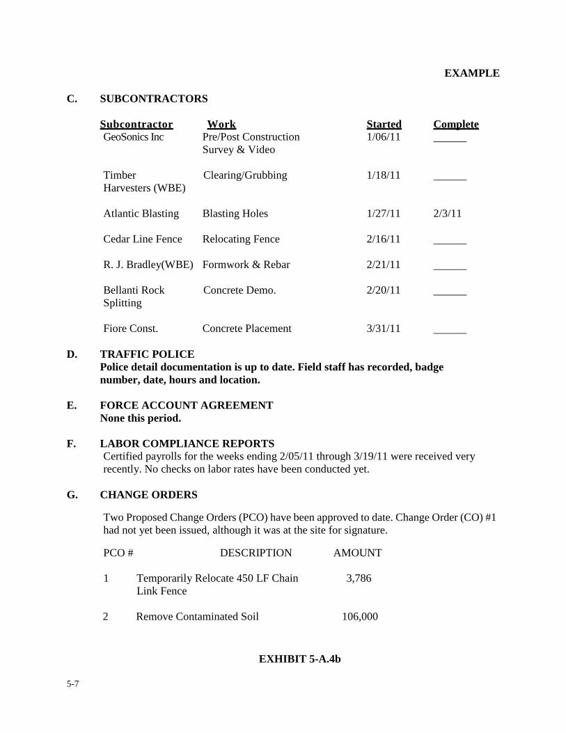
5-7
EXAMPLE
C. SUBCONTRACTORS Subcontractor Work Started Complete GeoSonics Inc Pre/Post Construction 1/06/11 Survey & Video Timber Clearing/Grubbing 1/18/11 Harvesters (WBE) Atlantic Blasting Blasting Holes 1/27/11 2/3/11 Cedar Line Fence Relocating Fence 2/16/11 R. J. Bradley(WBE) Formwork & Rebar 2/21/11 Bellanti Rock Concrete Demo. 2/20/11 Splitting Fiore Const. Concrete Placement 3/31/11
D. TRAFFIC POLICE Police detail documentation is up to date. Field staff has recorded, badge number, date, hours and location.
E. FORCE ACCOUNT AGREEMENT None this period. F. LABOR COMPLIANCE REPORTS
Certified payrolls for the weeks ending 2/05/11 through 3/19/11 were received very recently. No checks on labor rates have been conducted yet.
G. CHANGE ORDERS
Two Proposed Change Orders (PCO) have been approved to date. Change Order (CO) #1 had not yet been issued, although it was at the site for signature.
PCO # DESCRIPTION AMOUNT
1 Temporarily Relocate 450 LF Chain 3,786 Link Fence
2 Remove Contaminated Soil 106,000
EXHIBIT 5-A.4b
5-8
EXAMPLE
The site file contained a partially signed copy of PCO#1. As a result of a site meeting between Contractor, MWRA Staff, and Consultant, PCO#2 is being accomplished on a lump sum basis (for Subcontractor services) and a time and material basis for any additional labor, materials and equipment furnished by the Contractor. A copy of the PCO, Work Force Account forms documenting time and material expended, and a Contractor letter confirming the site meeting results are on file at the site. Change order authorization and file documentation requirements were discussed with the staff.
H. SURVEY
Survey Books documenting elevations taken are maintained by the field staff. It was suggested the survey books should be in the possession of the field staff while doing site inspections.
I. AUDIT AND DOCUMENTATION
Although some unnecessary entries have been made in the Q. C. L. in the past, current practices are in line with the procedures of the R. E. Manual.
J. MATERIALS CONTROL
The staff has a log of submittals and tracks them as received. It is apparent that the logging of submittals provided by the consultant had action codes which differ from the action codes * on the Authority’s shop drawing log form and shop drawing transmittal forms.
It was noted that submittals on trench support systems had not been approved (revise and resubmit) although trench work was underway. Discussion with staff indicated that this status was known and the Contractor was proceeding with the work at their risk.
Concrete test reports have not yet been received.
It is understood that the Contractor has submitted deviations to the design, these items have been forwarded to the design consultant for approval, but none have been approved to date.
K. FIELD PERFORMANCE Construction activity (form erection, concrete demolition, boulder removal, dewatering) was observed at a junction chamber off Canton Rd. and Factory Mutual Rd. The MWRA Field Inspectors were questioned as to the work in progress and were found to be knowledgeable as to the Contractor's work and the inspection procedures associated with the work being performed.
L. FIELD SAFETY CONDITIONS
Safety conditions being utilized by the Contractor for his employees were observed.
EXHIBIT 5-A.4c
5-9
5. REPORTING FORMS, PROCEDURES & REVIEW
5.2 MATERIALS CONTROL FORM
For the purpose of this section we will focus on documenting the events surrounding a typical
concrete placement at the job site.
The first step by the resident engineer is to review the contract specifications concerning concrete
inspection. If the specification refers to an ACI standard, it is the responsibility of the resident
engineer to request a copy of the standard from construction coordinator well in advance of placing
concrete. The resident engineer should verify that the source of materials and concrete mixture to
be used have been submitted and approved. The resident engineer shall ensure that the samples of
aggregate and cement are delivered to the Authority's designated testing laboratory.
During construction the resident engineer shall observe all concrete placements made by the
contractor. Prior to a concrete placement, the resident engineer shall inspect the reinforcing steel
for size, spacing and to ensure the bars are free of rust, oil, dirt etc. Also, the resident engineer shall
inspect the concrete forms for strength and soundness. Once the concrete trucks arrive on site, the
resident engineer should review the concrete slips issued at the batching plant to ascertain how
long it has been since the concrete was mixed. Concrete older than 1-1/2 hours is grounds for
rejection. The resident engineer shall time the revolutions of the transit mixer to determine if the
proper amounts of turns are achieved. As a rule of thumb not less than 70 but no more than 100
revolutions of the drum are permitted. The resident engineer shall not permit any concrete
5-10
placements to occur unless the Authority's designated materials field inspectors are present.
Exhibit 5-B.1 is a Materials Control Sheet to be used for concrete placements.
The resident engineer shall enter all pertinent information requested on this form regarding
concrete placements. The resident engineer shall retain this form in the field office files and
forward a copy to the construction coordinator.
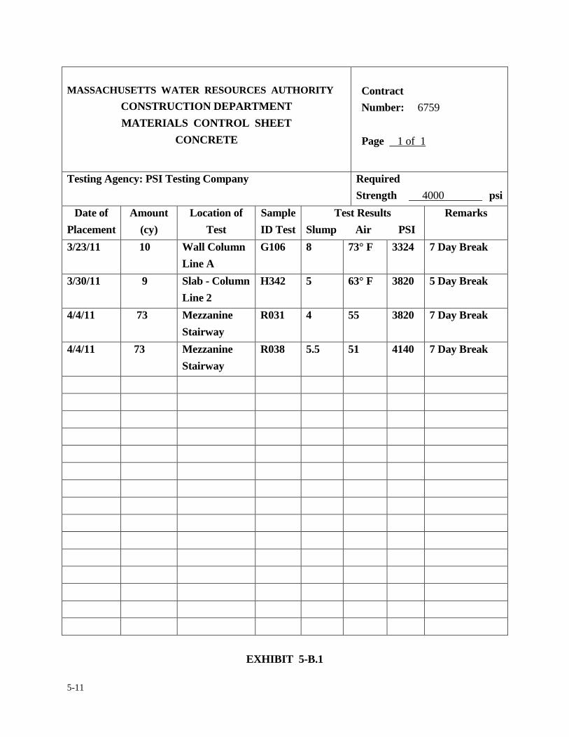
5-11
MASSACHUSETTS WATER RESOURCES AUTHORITY
CONSTRUCTION DEPARTMENT MATERIALS CONTROL SHEET
CONCRETE
Contract Number: 6759 Page 1 of 1
Testing Agency: PSI Testing Company
Required Strength 4000 psi
Date of Placement
Amount (cy)
Location of Test
Sample ID Test
Test Results Slump Air PSI
Remarks
3/23/11 10 Wall Column Line A
G106 8 73° F 3324 7 Day Break
3/30/11 9 Slab - Column Line 2
H342 5 63° F 3820 5 Day Break
4/4/11 73 Mezzanine Stairway
R031 4 55 3820 7 Day Break
4/4/11 73 Mezzanine Stairway
R038 5.5 51 4140 7 Day Break
EXHIBIT 5-B.1
5-12
5. REPORTING FORMS, PROCEDURES & REVIEWS
5.3 FIELD OFFICE VISITORS LOG A field office visitors log shall be maintained on most construction projects, depending on the size
of the job. The resident engineer will be responsible for posting the log sheet in a conspicuous
place in the field office. The purpose of the visitors log is to have a register of who visits the job
site and for what purpose, with the exception of the Authority's assigned field staff and the
contractor's on site personnel. In the effort to justify billings from consultants or vendors, these
logs are often used to verify when someone arrived and left the job site and also the reason why the
site visit was necessary, such as; shop drawing review, change order review, to attend a progress
meeting, taking concrete cylinders, testing etc.
Exhibit 5-C.1 is a Visitors Log form to be used on the job site. The resident engineer is to ensure all
persons visiting the job site are registered and the log entries are as complete as possible. If a
visitor signs in at the trailer and does not sign out, an estimated leaving time shall be entered by the
resident engineer. A copy of the log shall be periodically forwarded to the construction coordinator
for informational purposes. An up to date copy of the visitors log shall be maintained in the
resident engineer’s log book.
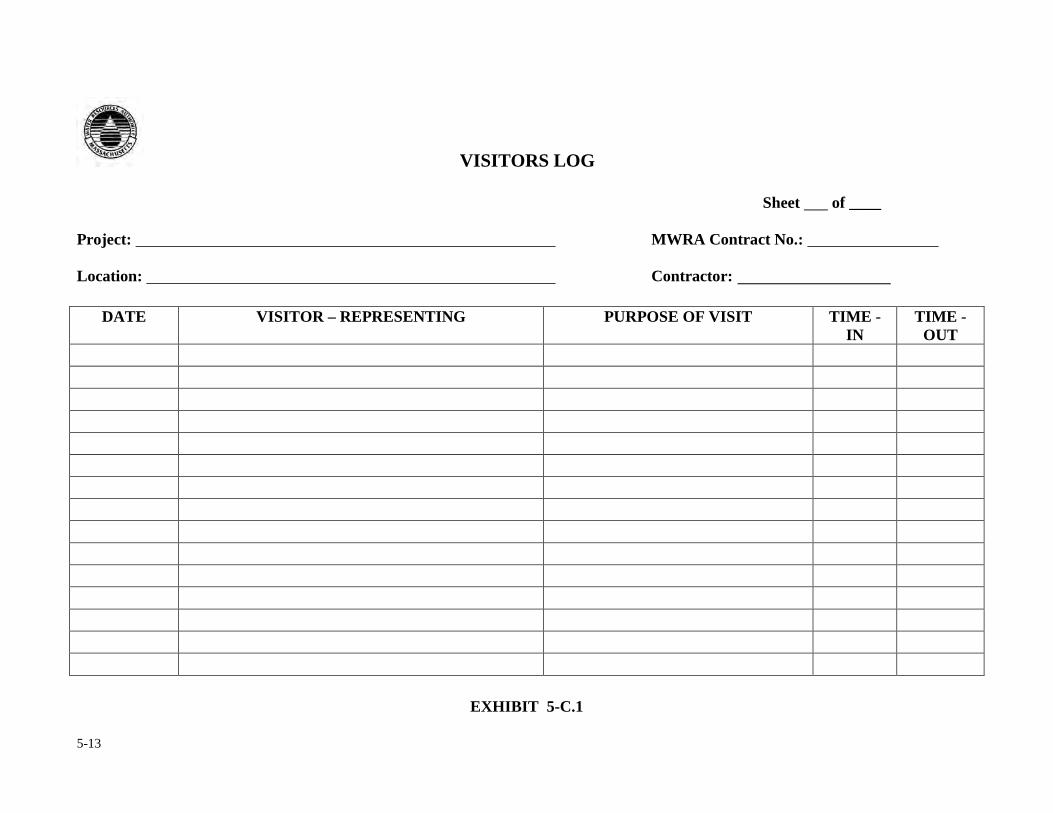
5-13
VISITORS LOG
Sheet of ____ Project: MWRA Contract No.: Location: Contractor:
DATE VISITOR – REPRESENTING PURPOSE OF VISIT TIME - IN
TIME - OUT
EXHIBIT 5-C.1
5-14
5. REPORTING FORMS, PROCEDURES & REVIEWS
5.4 JOB MEETING REPORT
Job meetings are a very important part of the construction process. Good communication between
the Authority, consultant engineer and the contractor is vital to a successful conclusion of the
project. Taking minutes of meetings is the key to good communication on a construction project.
Minutes of meeting must be taken for all meetings held in the field. The resident engineer is
responsible for recording the minutes of meeting relative to his /her assigned project, unless it is in
the scope of work for the consultant. In order to provide complete and accurate "Minutes of
Meeting", one must take good notes and be able to convert these notes into a fair representation of
what transpired at the meeting and by whom. The recorded minutes of the meeting offered by the
resident engineer may be an official record of a meeting or be combined with the construction
coordinator's thoughts to produce a joint understanding of a meeting held. The resident engineer
should always prepare a draft copy of the minutes of the meeting and review them with the project
manager or the construction coordinator. Meeting minutes shall be recorded in order of a
pre-meeting agenda. Agenda for each project meeting shall be established by the resident engineer
and coordinated with the contractor and construction coordinator. An attendance sheet shall be
circulated to document the attendees of the meeting.
Meeting minutes once completed and reviewed by the construction coordinator shall be distributed
to all parties in attendance within seven days or five work days of the date of the meeting. The
resident engineer is required to keep the minutes to the best of his/her ability to the discussion that
took place and not “ad-lib” after the fact information or insert personnel opinion about what was
5-15
said or took place and sentences should be short and direct. The resident engineer shall document
any handouts that were distributed at the meeting and make them attachments to the finalized
meeting minutes. The resident engineer shall file the meeting minutes according to the project file
system and also place a copy in a three ring binder similar to daily report book for future and
immediate reference.
The progress meeting agenda established by the resident engineer should contain a section for
project status and minimum two week look ahead to assist the resident engineer and his/her field
staff to prepare for the work ahead. The resident engineer shall be responsible for providing the
contractor with any updates on RFI’s, COR’s, PCO’s, CO’s, Shop Drawings, permits, scheduling
conflicts and outside agencies that he/his is aware of.
Basically, there are two types of meetings held on a construction contract; 1) Routine or Progress
Meetings and 2) Special Meetings. Progress meetings are held to record the daily routines of the
contractor and progress achieved and performed, while Special Meetings revolve around a certain
topic or specific issue. Progress meetings are generally held on a weekly, bi-weekly or monthly
basis depending on the type of construction contract. A Special Meeting is held as soon as possible
after a job specific issue has been raised.
Progress meetings minutes are to be sequentially numbered and dated, i.e. Progress Meeting No.
24, Dated December 5, 2005. Exhibit 5-D.1 (pg. 5-17) is a suggested form to be used by the
resident engineer or field staff to record minutes of meetings (Note: If more space than provided on
the form is necessary, additional pages are to be attached to the report). Special Meetings should
5-16
also be sequentially numbered and have a brief description of topic of concern, i.e. Special
Meeting No. 1 – Jacking Pit at Intersection of Baker Street and Cemetery Entrance. Exhibit 5-D.2
(5-22) is a suggested form to be used by the resident engineer or field staff to record minutes of
special meetings (Note: If more space than provided on the form is necessary, additional sheets are
to be attached to the report). EXHIBIT 5-D.1a through 5-D.1e is an example of progress meeting
minutes and the associated sign-in sheet and agenda and EXHIBIT 5-D.2a through 5-D.2b is an
example of special meeting minutes.
The final copy of either meeting report shall be kept in the job files with an electronic copy
forwarded to the Home Office.
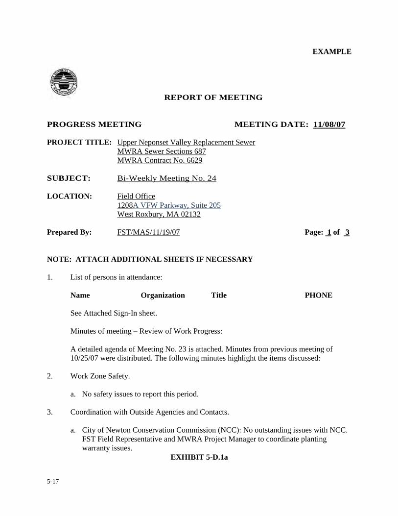
5-17
EXAMPLE
REPORT OF MEETING
PROGRESS MEETING MEETING DATE: 11/08/07
PROJECT TITLE: Upper Neponset Valley Replacement Sewer
MWRA Sewer Sections 687 MWRA Contract No. 6629
SUBJECT: Bi-Weekly Meeting No. 24 LOCATION: Field Office
1208A VFW Parkway, Suite 205 West Roxbury, MA 02132
Prepared By: FST/MAS/11/19/07 Page: 1 of 3 NOTE: ATTACH ADDITIONAL SHEETS IF NECESSARY 1. List of persons in attendance: Name Organization Title PHONE
See Attached Sign-In sheet. Minutes of meeting – Review of Work Progress:
A detailed agenda of Meeting No. 23 is attached. Minutes from previous meeting of 10/25/07 were distributed. The following minutes highlight the items discussed:
2. Work Zone Safety.
a. No safety issues to report this period. 3. Coordination with Outside Agencies and Contacts.
a. City of Newton Conservation Commission (NCC): No outstanding issues with NCC.
FST Field Representative and MWRA Project Manager to coordinate planting warranty issues.
EXHIBIT 5-D.1a
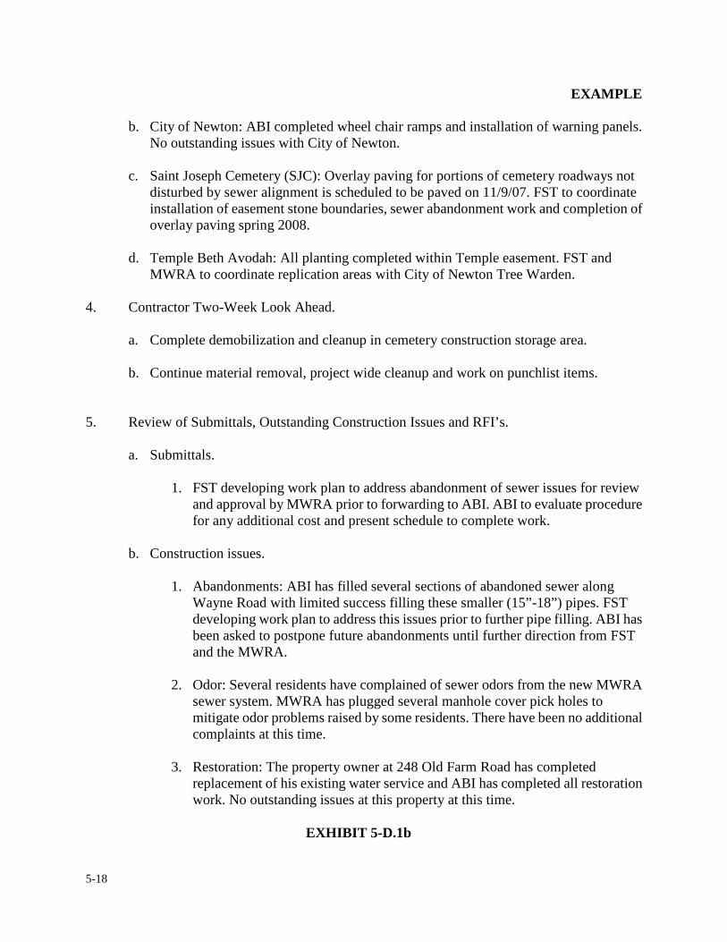
5-18
EXAMPLE
b. City of Newton: ABI completed wheel chair ramps and installation of warning panels. No outstanding issues with City of Newton.
c. Saint Joseph Cemetery (SJC): Overlay paving for portions of cemetery roadways not
disturbed by sewer alignment is scheduled to be paved on 11/9/07. FST to coordinate installation of easement stone boundaries, sewer abandonment work and completion of overlay paving spring 2008.
d. Temple Beth Avodah: All planting completed within Temple easement. FST and
MWRA to coordinate replication areas with City of Newton Tree Warden.
4. Contractor Two-Week Look Ahead.
a. Complete demobilization and cleanup in cemetery construction storage area.
b. Continue material removal, project wide cleanup and work on punchlist items.
5. Review of Submittals, Outstanding Construction Issues and RFI’s.
a. Submittals.
1. FST developing work plan to address abandonment of sewer issues for review and approval by MWRA prior to forwarding to ABI. ABI to evaluate procedure for any additional cost and present schedule to complete work.
b. Construction issues.
1. Abandonments: ABI has filled several sections of abandoned sewer along
Wayne Road with limited success filling these smaller (15”-18”) pipes. FST developing work plan to address this issues prior to further pipe filling. ABI has been asked to postpone future abandonments until further direction from FST and the MWRA.
2. Odor: Several residents have complained of sewer odors from the new MWRA
sewer system. MWRA has plugged several manhole cover pick holes to mitigate odor problems raised by some residents. There have been no additional complaints at this time.
3. Restoration: The property owner at 248 Old Farm Road has completed
replacement of his existing water service and ABI has completed all restoration work. No outstanding issues at this property at this time.
EXHIBIT 5-D.1b
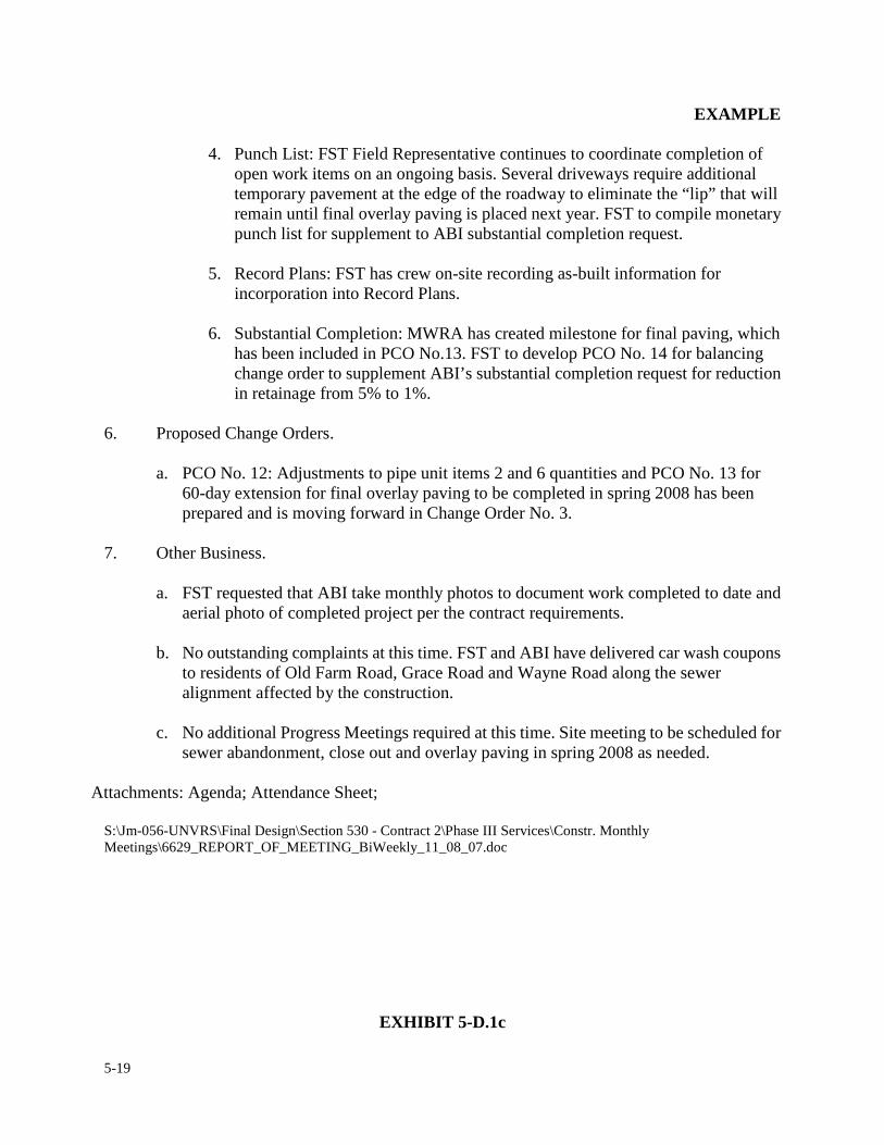
5-19
EXAMPLE
4. Punch List: FST Field Representative continues to coordinate completion of open work items on an ongoing basis. Several driveways require additional temporary pavement at the edge of the roadway to eliminate the “lip” that will remain until final overlay paving is placed next year. FST to compile monetary punch list for supplement to ABI substantial completion request.
5. Record Plans: FST has crew on-site recording as-built information for
incorporation into Record Plans.
6. Substantial Completion: MWRA has created milestone for final paving, which has been included in PCO No.13. FST to develop PCO No. 14 for balancing change order to supplement ABI’s substantial completion request for reduction in retainage from 5% to 1%.
6. Proposed Change Orders.
a. PCO No. 12: Adjustments to pipe unit items 2 and 6 quantities and PCO No. 13 for
60-day extension for final overlay paving to be completed in spring 2008 has been prepared and is moving forward in Change Order No. 3.
7. Other Business.
a. FST requested that ABI take monthly photos to document work completed to date and aerial photo of completed project per the contract requirements.
b. No outstanding complaints at this time. FST and ABI have delivered car wash coupons
to residents of Old Farm Road, Grace Road and Wayne Road along the sewer alignment affected by the construction.
c. No additional Progress Meetings required at this time. Site meeting to be scheduled for
sewer abandonment, close out and overlay paving in spring 2008 as needed.
Attachments: Agenda; Attendance Sheet;
S:\Jm-056-UNVRS\Final Design\Section 530 - Contract 2\Phase III Services\Constr. Monthly Meetings\6629_REPORT_OF_MEETING_BiWeekly_11_08_07.doc
EXHIBIT 5-D.1c
5-20
EXAMPLE
MEETING AGENDA – UPPER NEPONSET REPLACEMENT SEWER
PROGRESS MEETING NO. 24 CONTRACT No. 6629
MEETING DATE: November 8, 2007 1) APPROVAL MINUTES PREVIOUS MEETING
a. Progress Meeting No. 23
2) REVIEW OF WORK ZONE SAFETY 3) COORDINATION OUTSIDE AGENCIES AND CONTACTS 4) CONTRACTOR TWO-WEEK LOOK AHEAD 5) REVIEW OF SUBMITTALS AND OUTSTANDING CONSTRUCTION ISSUES AND RFIs
a. Construction Issues 1. Abandonments 2. Odor 3. Planting/Restoration 4. Punch List 5. Record Plans 6. Substantial Completion
6) PROPOSED CHANGE ORDERS / CHANGE ORDERS: STATUS OVERVIEW
a. PCO No. 12: Misc. Unit Quantity Adjustments b. PCO No. 13: Time extension for finish paving
7) OTHER BUSINESS
a. Open Discussion of ongoing construction. b. Complaints c. Next Meeting
S:\Jm-056-UNVRS\Final Design\Section 530 - Contract 2\Phase III Services\Constr. Monthly Meetings\6629_CONSTR_MEETING AGENDA_No24.doc
EXHIBIT 5-D.1d
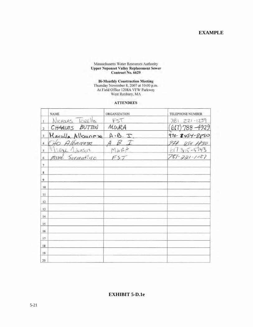
5-21
EXAMPLE
EXHIBIT 5-D.1e
5-22
EXAMPLE
REPORT OF MEETING SPECIAL MEETING No. 1
MEETING DATE: 12/21/05
PROJECT TITLE: Upper Neponset Valley Replacement Sewer MWRA Sewer Sections 685 and 686 MWRA Contract No. 6191
SUBJECT: Baker Street Jacking Pit at Entrance to Cemetery LOCATION: Baker Street Entrance to St. Joseph’s Cemetery, West Roxbury, MA Prepared By: FST/JPD 12/23/05 Page: 1 of 2 NOTE: ATTACH ADDITIONAL SHEETS IF NECESSARY 1. List of persons in attendance: Name Organization Title
Isidoro Perez MWRA Construction Coordinator Milan Horbaczewski MWRA Design Manager Margie Johnson MWRA Design Engineer Sam Doolan P. Gioioso and Sons, Inc. Superintendent Richard Leary Holyhood Cemetery Association General Manager John Doherty Fay, Spofford and Thorndike Resident Engineer
2. Minutes of meeting:
At the request of P. Gioioso & Sons (PGS) a meeting was held to discuss the impacts of construction on the Baker Street entrance to St. Joseph’s Cemetery. The meeting was held on site, at the Baker Street entrance.
A. Isidoro Perez initiated the discussion by identifying the proposed layout of the
jacking pit, which was laid out on the ground. It was made clear that the jacking pit would take up most of the entrance to the cemetery, and access through this gate would not be possible during the period of time that the pit was in place. Mr. Perez also stated that it was the intention of the contractor to complete the work before Memorial Day, 2006. Mr. Sam Doolan concurred that this was the contractor’s intention.
EXHIBIT 5-D.2a
5-23
EXAMPLE
B. Mr. Richard Leary, speaking for the cemetery, stated that there would be no
problem with closing the Baker Street gate for the duration of the construction activity at the jacking pit.
C. Mr. Doolan then identified the proposed location of the temporary utility pole, explaining that the overhead wires would need to be relocated to accommodate the jacking pit. The proposed location is just outside the layout of Baker Street, on cemetery property. Mr. Leary stated that he would have no problem granting this access.
D. P. Gioioso and Sons is now waiting for “Right of Entry” paperwork to be provided from NSTAR Electric, and will meet with Mr. Leary for his review and signature when this documentation is received.
S:\JM-056-UNVRS\Final Design\VFW - Contract 1\Phase III Services\Special Meetings\REPORT OF MEETING-St. Joseph's Cemetery-Baker Street.doc
EXHIBIT 5-D.2b
5-24
5. REPORTING FORMS, PROCEDURES & REVIEWS
5.5 ACCIDENT REPORTS
On the first working day following an incident, the resident engineer is to file an accident report.
The accident report shall be complete, accurate and contain only information pertinent to the
incident. Exhibit 5-E.1a and 5-E.1b are examples of how an accident report is properly filled out.
The resident engineer is expected to be as thorough as possible in preparing this form. The form is
in two parts. The first part (Page 1 of 2), contains the typical project information, summary of
events, a description of property damage involved, the location of the incident and any other
persons involved in the accident, either directly or indirectly. The second page (Page 2 of 2)
includes the section to describe personal injuries, if any. Note: Mention the person injured by
his/her proper name and title. When describing an injury, include both the type of injury and the
part of the body injured. Copies of this report are to be sent to the Director of Construction, the
construction coordinator, Assistant Manager of Worker’s Compensation and the MWRA
employee involved. If more than one employee sustains personal injuries as a result of an accident,
a separate accident report will be prepared for each person involved. In addition, if personal injury
is involved, both the resident engineer and the injured employee will be required to fill out a joint
“Industrial Accident Report” as soon as the injured employee returns to work. Exhibits 5-E.2a and
5-E.2b are typical accident report forms for the resident engineers use.
5-25
Emergency incidents that occur after working hours should follow the same guidelines as noted
above. Generally, the police and fire services will contact the contractor using the job’s emergency
telephone number. The contractor will, in turn, notify the MWRA resident engineer, who will
respond to the incident after notifying his/her construction coordinator.
Prior to the start of construction or at the time of the pre-construction meeting, the resident
engineer shall compile a list of persons who should be contacted in the event of an emergency. The
list shall contain the telephone numbers of the City/Town Engineer, Fire and Police Departments,
Ambulance, and the Contractor’s home office, field office and superintendent’s emergency phone
number. The list shall be posted in the field trailer close by each telephone. The list shall be
reviewed periodically and updated as necessary.
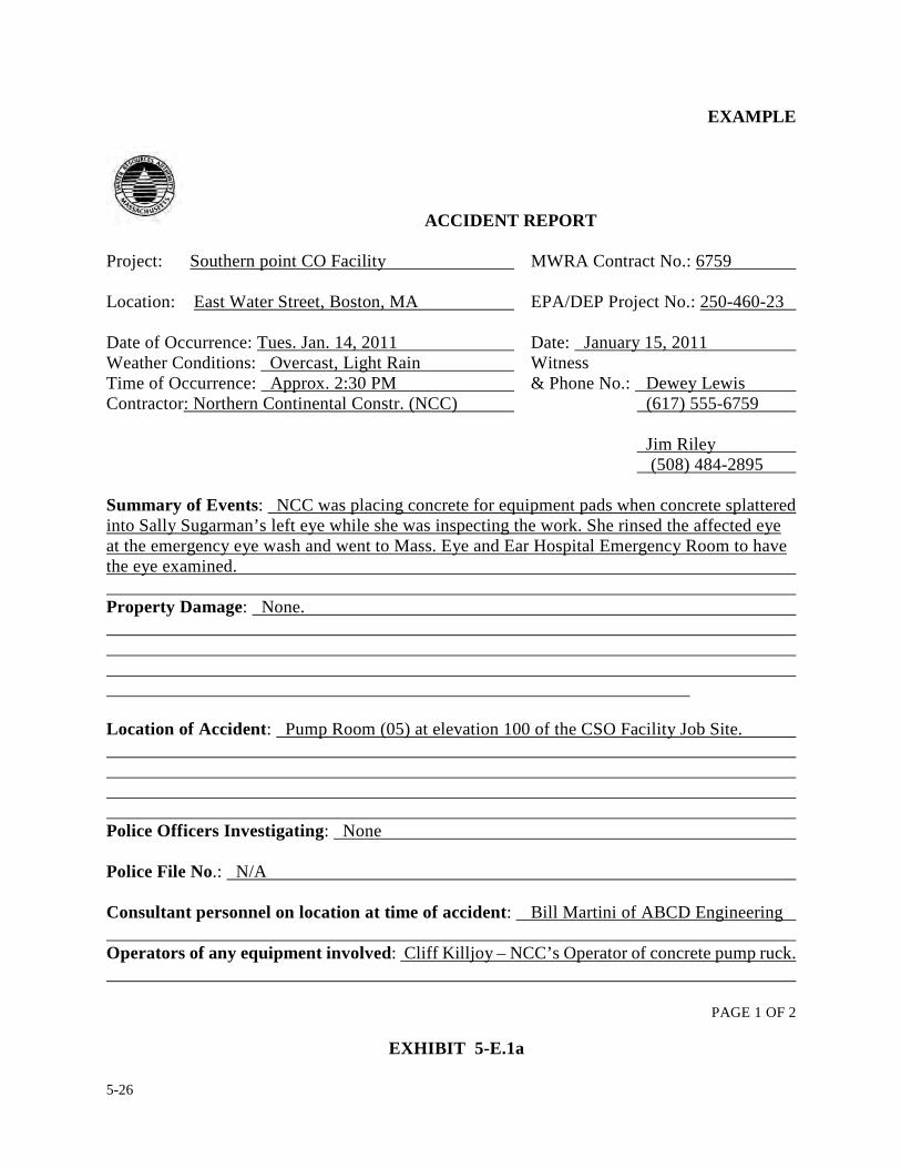
5-26
EXAMPLE
ACCIDENT REPORT
Project: Southern point CO Facility MWRA Contract No.: 6759 Location: East Water Street, Boston, MA EPA/DEP Project No.: 250-460-23 Date of Occurrence: Tues. Jan. 14, 2011 Date: January 15, 2011 Weather Conditions: Overcast, Light Rain Witness Time of Occurrence: Approx. 2:30 PM & Phone No.: Dewey Lewis Contractor: Northern Continental Constr. (NCC) (617) 555-6759 Jim Riley (508) 484-2895 Summary of Events: NCC was placing concrete for equipment pads when concrete splattered into Sally Sugarman’s left eye while she was inspecting the work. She rinsed the affected eye at the emergency eye wash and went to Mass. Eye and Ear Hospital Emergency Room to have the eye examined. Property Damage: None. Location of Accident: Pump Room (05) at elevation 100 of the CSO Facility Job Site. Police Officers Investigating: None Police File No.: N/A Consultant personnel on location at time of accident: Bill Martini of ABCD Engineering Operators of any equipment involved: Cliff Killjoy – NCC’s Operator of concrete pump ruck.
PAGE 1 OF 2
EXHIBIT 5-E.1a
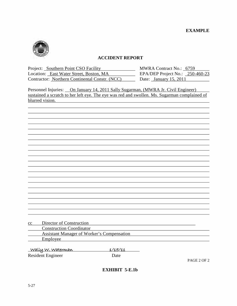
5-27
EXAMPLE
ACCIDENT REPORT
Project: Southern Point CSO Facility MWRA Contract No.: 6759 Location: East Water Street, Boston, MA EPA/DEP Project No.: 250-460-23 Contractor: Northern Continental Constr. (NCC) Date: January 15, 2011 Personnel Injuries: On January 14, 2011 Sally Sugarman, (MWRA Jr. Civil Engineer) sustained a scratch to her left eye. The eye was red and swollen. Ms. Sugarman complained of blurred vision. cc Director of Construction Construction Coordinator Assistant Manager of Worker’s Compensation Employee ������������������������������������������������������ �� ������������������������������������������������ �� ������������������������������������������������ �� ������������������������������������������������ �� ������ Resident Engineer Date
PAGE 2 OF 2
EXHIBIT 5-E.1b
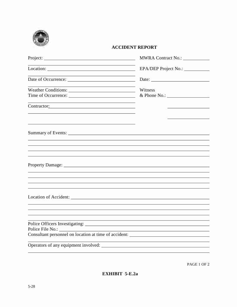
5-28
ACCIDENT REPORT
Project: MWRA Contract No.: Location: EPA/DEP Project No.: Date of Occurrence: Date: Weather Conditions: Witness Time of Occurrence: & Phone No.: Contractor: Summary of Events: Property Damage: Location of Accident: Police Officers Investigating: Police File No.: Consultant personnel on location at time of accident: Operators of any equipment involved:
PAGE 1 OF 2
EXHIBIT 5-E.2a
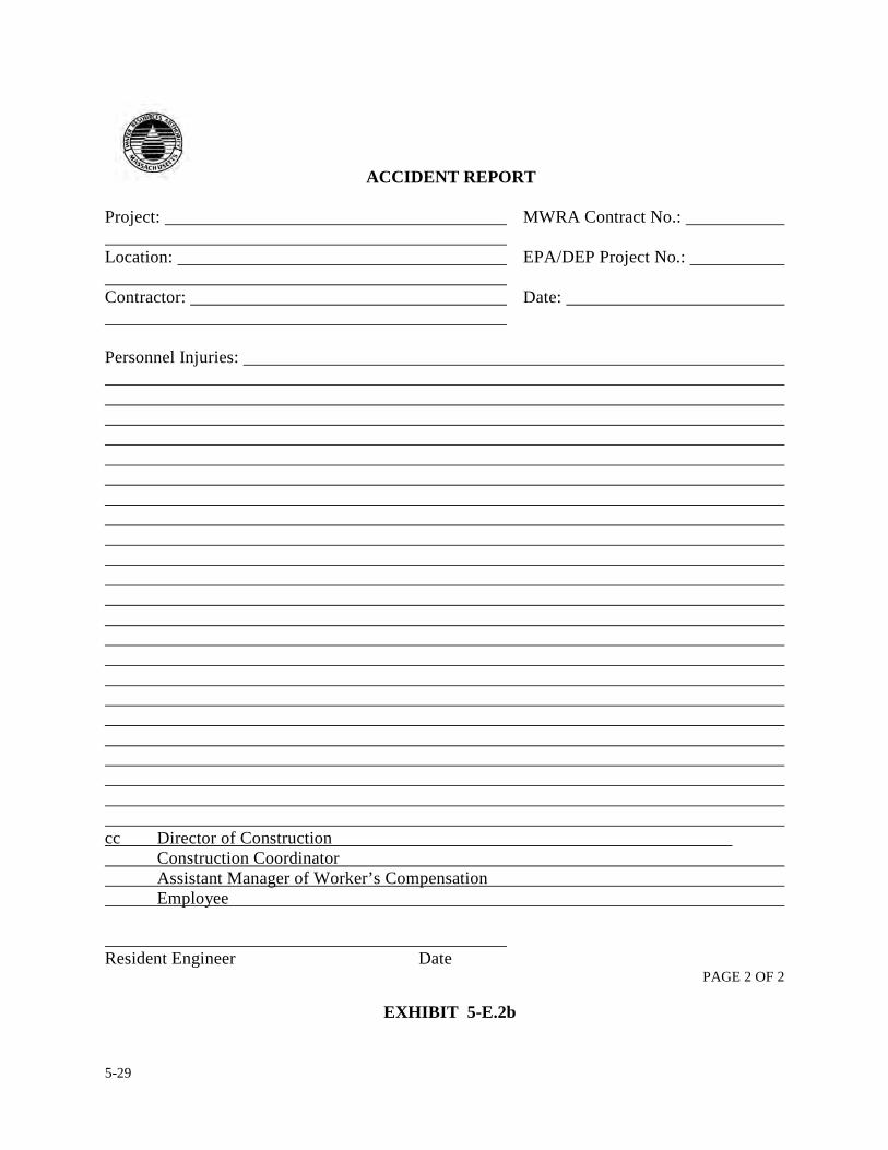
5-29
ACCIDENT REPORT
Project: MWRA Contract No.: Location: EPA/DEP Project No.: Contractor: Date: Personnel Injuries: cc Director of Construction Construction Coordinator Assistant Manager of Worker’s Compensation Employee Resident Engineer Date
PAGE 2 OF 2
EXHIBIT 5-E.2b
5-30
5. REPORTING FORMS, PROCEDURES & REVIEWS
5.6 DAMAGE REPORT
The construction industry is no stranger to accidents. No matter how hard an organization prepares
itself to prevent them from happening, accidents happen. Sometimes accidents involve personal
injuries and other times accidents involve only property and/or equipment/materials. In most
cases, accidents involving equipment/material merely result in only damages to those items. It is
the responsibility of the resident engineer to document the occurrence of any damage incurred
during construction. Exhibit 5-F.1 is a copy of a damage report form to be used by the resident
engineer and/or field staff. A damage report is a report initiated by the resident engineer whenever
he/she discovers materials or equipment damaged. The property, materials and equipment refer to
items specific to the contract, Authority owned and/or items issued to the resident engineer to
support his/her assigned duties, i.e. vehicle, cell phones, office equipment etc. The damage report
is to be filed on the first day of the discovery of incurred damage. The damage report shall be
forwarded to the construction coordinator and a copy of the report kept in the project files.
The following are construction related routines where the possibility of damage to property,
materials or equipment is likely.
MOBILIZATION/DEMOBILIZATION: Prior to the contractor mobilizing to the job site, the
resident engineer shall photograph, video and/or visually survey the job site with the contractor.
This procedure is strongly suggested because it provides the resident engineer a basis to compare
5-31
the condition of the job site before and after the contractor mobilizes or demobilizes. At the time of
mobilization/demobilization, the resident shall observe the contractor's operations and if any
damage occurs, the resident engineer shall immediately bring it to the contractor's attention. At the
same time, the resident engineer shall record the event in his daily report and prepare a damage
report.
STORED MATERIALS: The resident engineer shall periodically inspect materials on site to
ensure they are being stored properly. The resident engineer shall record such inspections in
his/her daily report and indicate the conditions in which he/she found the materials. If the resident
engineer discovers any damage, he/she shall immediately notify the contractor and prepare a
damage report.
ON-SITE DELIVERIES: The resident engineer or designated field staff shall observe all
deliveries of materials and equipment to the job site. The resident engineer shall record such
deliveries in his/her daily report and indicate the condition in which they were delivered. If
damage occurs during the off-loading, the resident engineer shall not accept items in question and
prepare a damage report.
CONSTRUCTION OPERATIONS: The safety and protection of work is the responsibility of
the contractor and that includes the protection of property, materials and equipment. During the
course of construction if the resident engineer views a particular construction operation as being
unsafe, or endangers the public, he/she has an obligation to voice their concerns to the contractor.
If the contractor continues with the operations and damage to property, materials and/or equipment
5-32
occurs, the contractor will be responsible for the damage. The resident engineer shall record the
events in their daily report and prepare a damage report.
ACTS OF GOD: There are times when an accident happens and damage occurs on a construction
site and nobody is at fault. Sometimes nature has a way of interrupting progress in a devastating
way. If these events should occur, the resident engineer shall still record it in his/her daily report
and prepare a damage report.
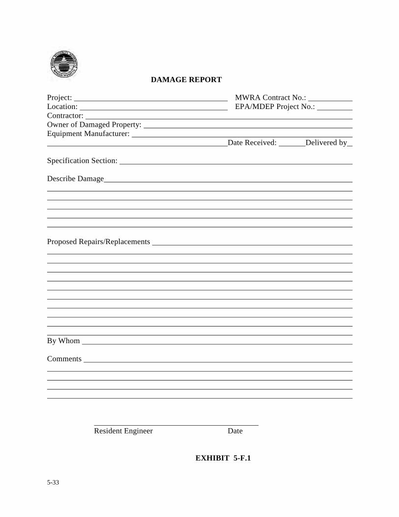
5-33
DAMAGE REPORT
Project: MWRA Contract No.: Location: EPA/MDEP Project No.: Contractor: Owner of Damaged Property: Equipment Manufacturer: Date Received: Delivered by Specification Section: Describe Damage Proposed Repairs/Replacements By Whom Comments
Resident Engineer Date
EXHIBIT 5-F.1
5-34
5. REPORTING FORMS, PROCEDURES & REVIEWS
5.7 COMPLAINT REPORT
It is hopeful, but unlikely that a resident engineer will go through a construction project without
receiving a complaint. Complaints are considered part of the process because the majority of
construction contracts interface with the Public. The Authority takes all complaints very
seriously. Often times it is the resident engineer or field staff who is the first person confronted
with a complaint. This is understandable because it is the resident engineer and/or field staff who
are most visible to the Public. It is the Authority's position to avoid or prohibit circumstances
which may cause complaints to occur. A mark of a good resident engineer is one who survey’s
situations in the field and tries to spot potential problem areas and resolve them before they evolve
into complaints. In dealing with complaints, the resident engineer is required to be courteous and
attentive to anyone making a complaint. The resident engineer is to handle complaints
expeditiously and in the most professional manner possible, no matter how small or insignificant
the complaint may appear.
Most complaints are construction related and can be resolved right on the spot with the cooperation
of the contractor. Exhibit 5-G.1 is a Complaint Report form which acts as a notice to the contractor
of a complaint and request by the Authority for an immediate response. The resident engineer is to
utilize this form whenever confronted with or has knowledge of a complaint. Moreover, the
resident engineer is to follow up on the complaint to ensure it is being handled properly by the
contractor. It is the obligation of the contractor to be responsive and cooperative when dealing with
5-35
complaints. However, if the contractor shows a lack of cooperation or responsiveness in a timely
manner, the resident engineer shall immediately bring the matter to his/her construction
coordinator’s attention.
The Authority's Public Affairs Department will deal with complaints of an environmental nature or
potential operational problems that are known to the Authority prior to awarding a contract, such
as: the use of noisy equipment necessary to complete work, work being performed during the early
morning hours and conservation or environmental restoration issues. The resident engineer may be
asked to assist the Public Affairs people with their efforts. If this is the case, the resident engineer
and/or the field staff shall willingly offer his/her support.
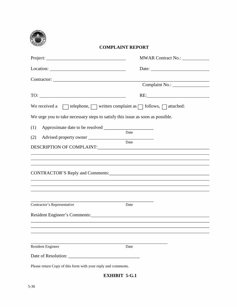
5-36
COMPLAINT REPORT
Project: MWAR Contract No.: Location: Date: Contractor:
Complaint No.:
TO: RE: We received a telephone, written complaint as follows, attached: We urge you to take necessary steps to satisfy this issue as soon as possible. (1) Approximate date to be resolved Date (2) Advised property owner Date DESCRIPTION OF COMPLAINT: CONTRACTOR’S Reply and Comments: Contractor’s Representative Date Resident Engineer’s Comments: Resident Engineer Date Date of Resolution: Please return Copy of this form with your reply and comments.
EXHIBIT 5-G.1
5-37
5. REPORTING FORMS, PROCEDURES & REVIEWS
5.8 POLICE DETAILS
Often times, the nature of the contract requires work to be performed in a public way, and for
safety reasons, a police detail is necessary. If this becomes the case, the resident engineer shall
ensure the following: Although it is the responsibility of the contractor to arrange for a police
detail, it is the responsibility of the Authority's resident engineer to ensure that no work
commences in a public way, or in the immediate area where the contractor's operations do in fact
infringe on a public way unless an authorized uniformed police detail is present. In general, a
public way is any roadway, street, highway, tunnel, bridge or any facility where access by the
public is required. When a police detail is in place, the resident engineer shall record the following
information, as a minimum, in his/her daily report; 1) First & Last Name and Badge Number, 2).
Date and Hours Actually worked and 3) Exact location of Detail. This information shall be
referenced in the resident engineer’s daily reports.
5-38
5. REVIEWS, REPORTING FORMS & PROCEDURES
5.9 FACILITY HANDBOOK
The consultant shall prepare and submit to the construction coordinator and Authority’s operations
representative within the first year of operations a project specific facility handbook. The
handbook shall contain as a minimum the following information:
• Description of the construction contract, including all major items of equipment.
• Design and operating criteria for operating procedures for the systems.
• Schematic flow and control diagrams on the operations of the systems.
• Description of standard operating procedures of the process functions, instrumentations
and controls including operating procedures, start-up, normal operation, abnormal
operation, troubleshooting and shutdown in a step by step format.
• Maintenance requirements from shop drawings and vendor operation and maintenance
manuals. Suggestions for preventative maintenance programs.
• Description and preliminary schedule of maintenance needs and requirements in a matrix
format.
• Description of safety considerations and requirements for all equipment.
• Cross reference of pertinent equipment vendor information and sales representative.
• Listing of recommended spare parts or any specialty equipment for operations.
EXHIBIT 5-J.1a and 5-J.1b are an example Table of Contents for a Facility Handbook.
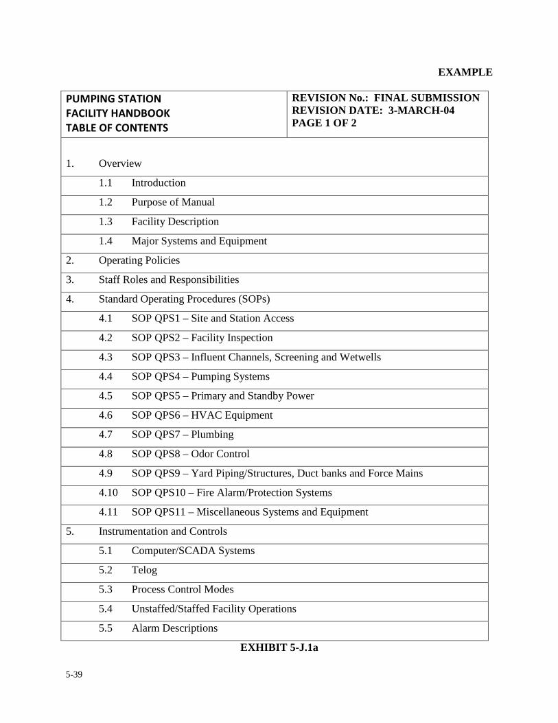
5-39
EXAMPLE �������������
� �������������
������� ������
REVISION No.: FINAL SUBMISSION REVISION DATE: 3-MARCH-04 PAGE 1 OF 2
1. Overview
1.1 Introduction
1.2 Purpose of Manual
1.3 Facility Description
1.4 Major Systems and Equipment
2. Operating Policies
3. Staff Roles and Responsibilities
4. Standard Operating Procedures (SOPs)
4.1 SOP QPS1 – Site and Station Access
4.2 SOP QPS2 – Facility Inspection
4.3 SOP QPS3 – Influent Channels, Screening and Wetwells
4.4 SOP QPS4 – Pumping Systems
4.5 SOP QPS5 – Primary and Standby Power
4.6 SOP QPS6 – HVAC Equipment
4.7 SOP QPS7 – Plumbing
4.8 SOP QPS8 – Odor Control
4.9 SOP QPS9 – Yard Piping/Structures, Duct banks and Force Mains
4.10 SOP QPS10 – Fire Alarm/Protection Systems
4.11 SOP QPS11 – Miscellaneous Systems and Equipment
5. Instrumentation and Controls
5.1 Computer/SCADA Systems
5.2 Telog
5.3 Process Control Modes
5.4 Unstaffed/Staffed Facility Operations
5.5 Alarm Descriptions
EXHIBIT 5-J.1a
5-40
EXAMPLE
�������������
� �������������
������� ������
REVISION No.: FINAL SUBMISSION REVISION DATE: 3-MARCH-04 PAGE 2 OF 2
6. Maintenance Requirements
7. Reporting Requirements
8. Local Safety Plan Appendix
A. Abbreviations, Acronyms and Definitions
B. List of Manufacturer’s O & M Manuals and Contacts
C. Phone Lists
D. Notes
EXHIBIT 5-J.1b
5-41
5. REVIEWS, REPORTING FORMS & PROCEDURES
5.10 ONE-YEAR PROJECT PERFORMANCE CERTIFICATE
One year from the date of substantial completion or final acceptance, which ever one comes first,
the resident engineer along with the consultant engineer, if any, the construction
coordinator/project manager and the Authority's Operations personnel are to perform a detailed
inspection of the facility or system and prepare a report on its performance after one year. The
report shall address the following topics:
• Is the Facility operating satisfactorily?
• Is the construction complete and in accordance with the contract documents?
• Is the O&M manual complete, accurate and up to date?
• Has all Operator training been completed?
• Review and comment on the performance of various components of the facility or
system.
• Has the Authority received a Facility Handbook from the consultant, if applicable.
During this period the consultant shall advise and assist the MWRA and its operations staff on the
operations of the project as necessary to ensure that operation is in accordance with the design
criteria, design concepts and warranty provisions. The consultant shall make recommendations to
adjust operations to optimize performance and minimize operating cost.

5-42
EXHIBIT 5-K.1a through 5-K.1m is an example of pump station one year project performance
certificate and EXHIBIT 5-L.1a through 5-L.1b is an example of sewer project one year project
performance certificate.
5-43
EXAMPLE
July 2, 2004
Mr. Robert Kovacs Senior Project Manager Massachusetts Water Resource Authority 2 Griffin Way Chelsea, MA 02150 Subject: MWRA Contract 5404 Quincy Pump Facilities Replacement Quincy Pump Station
MWRA Construction Contract 5407 One Year Project Performance Certificate Dear Mr. Kovacs: In accordance with our contract, Fay, Spofford and Thorndike, (FST), has completed the one-year warranty inspection for the subject project. The following is an outline of the project and its current status. Project Summary and Relevant Dates MWRA Construction Contract 5407 consisted of replacing the existing Quincy Pump Station and providing upgrade of Access Road and service utilities. The construction contract was awarded to P. Gioioso and Sons, Inc. (PGS) in 2000 with a Notice to Proceed of November 29, 2000 and a Substantial Completion date of December 19, 2002. A Certificate of Occupancy was issued by the Department of Public Safety on March 24, 2003. A field site walk with the Quincy Conservation Commission was performed on June 16, 2003 and Certificate of Compliance was forwarded to you on November 20, 2003. FST provided full-time, on-site, construction field inspection. FST also provided office support for review of Contractor submittals such as Shop Drawings, RFI’s, Change Orders, Schedules, etc. to ensure compliance with Contract Documents. FST’s Resident Engineer forwarded all field documents on February 13, 2004. Standard Contractor evaluation form was forwarded on February 17, 2004. Copies of the Facility Manual inclusive of electronic files were forwarded on April 27, 2004.
EXHIBIT 5-K.1a
5-44
EXAMPLE
FST provided you with all closeout files and the requisite Record Drawings on May 13, 2004.
FST is not aware of any outstanding claims, liens or complaints against the Contractor. However there is one open Contractor claim for compensation of additional electrical conduit and wiring of HVAC controls which is pending a ruling by the Authority. Facility Overview The replacement Quincy Pump Station has an operating capacity of 26.0 MGD with two of the three automatic, electric motor-driven pumps operating. It is the understanding of FST that through this operating period flow has not approached this level. Due to the nature of the new facility’s automation, the pump station is not staffed on a permanent basis with its daily operation monitored from the Authority’s Operations Control Center, OCC, in Chelsea, MA. System Operation Review A. Site and Station Access
General Overview: As part of the QPS replacement contract the pump station access road was replaced with a bituminous concrete paved roadway. Roadway width was kept to a minimum and care was taken to allow natural growth to remain. Existing walking paths to the surrounding Merrymount Park were maintained and expanded. In an agreement with the Quincy Parks Department, the Authority constructed a locked vehicle entrance gate to the access road just off Fenno Street beyond the tennis courts. This gate was installed to restrict unauthorized vehicles from the pump station site and surrounding areas. An additional Knox Box, (containing pump station access key), to allow access for emergency fire apparatus was also located at this gate. Pump station superstructure and parking area is surrounded by PVC coated chain link fence and a double access gate. After several months of operation as a non- staffed 24 hour/day facility there were several reported incidents of vandalism to the station, specifically, broken windows to east and south side of the building. The Authority through their Facility Management Division replaced the broken glass panels with Lexan, a high strength plastic panel. To the best of FST’s knowledge there has been no further indications of vandalism at the Quincy Pump Station.
The main entrance to the station is through the door on the North side of the building. This entrance is handicap-accessible via a ramp. There are four alarm indicating lights over this entrance door. To the best of FST’s knowledge there has been no complaints from residents observing these alarm indicating lights in operation.
EXHIBIT 5-K.1b
5-45
EXAMPLE
Recommendations:
FST recommends the building egress plan forwarded previously contained in a glass frame be mounted in a central location of the pump station. No Smoking signs should be installed throughout the pump station. Some type of signing, “Beware People Crossing” be added along the pump station access road. It should be Authority policy to inform/remind all workers and visitors to the pump station to be aware of pedestrian traffic along the access road.
B. Influent Channels, Screening and Wetwells
General Overview: Wastewater enters the new pump station by way of the new 48” gravity sewer and flows through the channel mounted mechanical grinder. Through manipulation of the sluice and slide gate system the wastewater can be directed to differing flow patterns into the two wetwells. There is a bypass channel and manual bar rack located adjacent to the channel mounted mechanical grinder. An aluminum rake fitted to the manual bar rack has been provided and is located in the Grinder Room at the west wall. A spare grinder was provided under this contract and is also located in the grinding room. The Authority has taken measures to protect this equipment by wrapping the mechanism in plastic. Spare motor drive and cutters are stored in the Odor Control Room. The influent sluice gate has been internally programmed to remain open when there is a computer system operation failure, malfunction of the Program Logic controller, PLC. Operation of this feature has been verified by FST and Authority personnel. Wetwell levels are monitored by level sensors. Oxygen and gas detection monitors have been provided. Supplemental system for air monitoring and circulation and odor control has been provided. FST is not aware of any operational problems with the sluice gates, slide gates, bar rack, channel grinder, gas monitoring equipment, level sensors or air monitoring and circulation systems. A two inch hose and rack with associated backflow prevention unit has been located on the south wall of the grinder room. This has been provided for equipment and channel wash down. It has been reported by the Authority’s Operations personnel that the backflow preventer has frozen during winter periods when the air exchange system was in operation. This has resulted in the Authority installing an additional shut off valve in the Pump Room after main water feed to isolate water service to the grinder room and permit the draining of the backflow system in the grinder room. FST has provided information to install heat tracing to the backflow prevention system to prevent this from happening in the future. Additionally FST has stated that the air exchange system should not operate at all times but only when there is excessive H2S gas in the grinder room, exceeding 10ppm and low oxygen, less than 14 ppm, excessive odor levels mandating the operation of the Odor Control Unit or when there is personnel present in the grinder room performing maintenance.
EXHIBIT 5-K.1c
5-46
EXAMPLE Recommendations:
FST recommends the Authority follow up on installation of heat race system to the backflow preventer unit. FST also recommends the Authority establish a routine procedure for washing down the wetwells and channels to prevent grease build up and the creation of odors from stagnant waters in the non operating channels. This can be accomplished by rotation of the flow stream into the wetwells by opening and closing the slide gates and draining down of a wetwell yearly. (Reference the flow diagrams located in Section 4.3 of the Facility manual.)
C. Pumping System
General: The pumping system includes three (3) non-clog dry pit centrifugal wastewater pumps, each with a split mechanical shaft seal. Both sides of the wetwell have been on line to support alternating and/or parallel operation of the three pump units. Any two of the three pump units operating in parallel are capable of handling the peak hourly design year (2020) flow rate of 26.0 MGD (18,000 gpm). The pumps were designed to meet their maximum flow requirements using a total dynamic head (TDH) of 66 feet. Design flows utilized in the selection of the wastewater pumps were:
Minimum 5.0 MGD Average 10.1 MGD Maximum 26.0 MGD
The pump station is currently operating at an average daily flow rate of 6 MGD. Single pump operation has been observed to exceed the design criteria of 12,000 GPM without any detrimental effects. A quick review of historical flow data did not reveal any sustainable duration of two pumps were operating. There have been no reports of three pumps being in operation at one time. The pumps are driven by extended shafting connected to 200 HP induction motors with speed controlled by variable frequency drives (VFDs). The pumps are controlled by ultrasonic type level sensors located over the wetwells in the grinder room. Pump discharges are measured continuously via a magnetic flow meter installed in the discharge piping that is common to all pumps. Associated piping and valves are arranged to permit any of the pumps to be taken out of service. Operation of the pumps can be rotated manually or automatically to rotate their operation, “lead-lag-standby” cycle. The pumps are currently set on manual rotation; the auto rotation which was programmed to rotate the lead pump operation on a 24 hour cycle has been disarmed. The pumps are currently set to be manually rotated on a weekly basis. The Authority has set up a rotation of operators to inspect and grease pumps and associated fittings according to the operation and maintenance manuals.
EXHIBIT 5-K.1d
5-47
EXAMPLE FST is not aware of any physical or operational problems with the pumps, impellers, bearings, shafting, mechanical seals, motors, piping and valving or of any reports of excessive temperatures or pump vibration. There has been a continued buildup of air within the stand-by pump volute. FST and the Authority have performed several investigations into the cause of this excessive air buildup. FST believes it is the result of air being introduced to the flow stream by the channel grinder. This air dissipates from the sewage flow and builds up in the non-operational pump volute, the standby pump, requiring “bleeding” of the air from the pump prior to putting it into operation. This is done weekly to coincide with the current manual rotation of the pumps. There is a connection by ½” clear plastic hose from the discharge gage to a one-inch PVC vent piping to relieve this air buildup when the pump is put into operation. This pipe discharges back to the wetwell. FST has recommended that this connection be hard piped and be increased to 1” to allow for higher rate of air displacement. Recommendations:
FST recommends the Authority replace the ½-inch hose connection with the one-inch hard pipe as detailed on sketch previously provided to Pump No. 1. After connection has been completed a sequence of operation be established and the amount of retained air be quantified. Once the Authority is satisfied with the startup operation of the stand-by pump the replacement of the hose connection at the remaining two pumps should be replaced. FST also recommends that verification of each pump startup from the stand-by position be performed from the different influent flow patterns to the wetwell. (Reference Facility Manual SOP 4.3 and 4.4). Verification of the stand-by pump without requiring manual bleeding of air from the pump volute will allow the Authority to enable the automatic pump rotation and set it to the duration it chooses, 24hours, one week etc. FST will work with the Authority to document these operations.
D. Primary and Standby Power General:
Electric power at the Quincy Pumping Station is supplied by Massachusetts Electric Company from a service pole located at the access road at Fenno Street. In the agreement between the City of Quincy and the Authority the service to the pumping station was installed underground within new ductbank beneath the access road to a pad-mounted transformer located adjacent to the south side of the station. The secondary service is rated for 1200 amperes, 277/480 volts, 3-phase, 4-wire.All major equipment in the pumping station is powered by 460 volt, 3-phase power. Building interior lighting, site lighting, receptacle and miscellaneous loads are powered by 120 volt, 1-phase power.
EXHIBIT 5-K.1e
5-48
EXAMPLE The motor control center contains the variable frequency drive, motor starters and circuit breakers supplying power to the station’s equipment. The lighting on the Motor Room, Office/Operation Room, Lunch Room and Locker Room side of the pump station is lighted using fluorescent lighting fixtures. The wetwell and grinder room, and odor control room, being a hazardous area, are lighted using explosion-proof incandescent lighting fixtures. The pump room is lighted using high-pressure sodium lamps. Exterior lighting fixtures utilize high pressure sodium lamps. In the event there is a loss of normal power to the station, the 500 KW standby diesel engine driven generator supplies power for the critical loads of the station. The emergency generator is exercised weekly (utilizing the test switch on the transfer switch panel) for several hours. The Authority has been advised to monitor the generator pre-test checklist prior to each startup. FST and the Authority have witnessed the operation of the emergency generator during a simulated power failure. The following items have been observed to be powered by the emergency generator as designed:
• Pump Nos. 1, 2 and 3; • Influent gate; • Grinder control panel; • Duplex sump pump control panel; • Panelboard “L” 480 to 120/208 volt transformer; • Wetwell supply fan SF-1; • Wetwell exhaust fan EF-1; • Pump Room exhaust fan EF-2; • Air handling units AHU-1 and AHU-2; and • Hot water pumps P-1 and P-2.
FST is not aware of any operational problems, operator’s dissatisfaction or resident complaints with the electrical power system and standby emergency generator as installed and operated.
Recommendations:
FST recommends that the Authority’s Operators log the condition of the lighting with each pump station service visit to insure proper lighting conditions at times of an emergency. FST also recommends that the Authority strictly enforce the requirements of the emergency generator pre-startup checklist contained in the generator operations and maintenance manual, listed on page specifically page 15 of the Kohler Power Systems Operations Manual TP-6200 12/02a. It is also recommended by FST and the generator manufacturer that a certified generator specialist check the generator yearly and operate it with a load bank.
EXHIBIT 5-K.1f
5-49
EXAMPLE E. HVAC Equipment General:
The HVAC equipment at the Quincy Pump Station is to provided low humidity and controlled temperature environment for administrative and operating personnel. A time clock has been programmed to index the temperature control unit located in the Operator’s Control Room between “Unoccupied” and “Occupied” mode. The time clock had been programmed at a station commissioning. At that time the pump station was “Occupied” 24 hours per day. The Authority has since “Unoccupied” the station operation. The system is currently “Unoccupied” mode. The Authority personnel upon arrival at the station need to place the HVAC control in “Occupied Mode” via the override timer on the front HVAC control panel located in the Operator’s control room. The operator shall ensure that the system remains in “Occupied Mode” while the station is occupied and return the system to “Unoccupied Mode” when leaving the station. Heating/cooling mode changeover is automatic. FST has advised the Authority that the EF-1/SF-1 ventilation system for the wetwell is designed for intermittent operation only, not for continuous operation . (Continuous operation has resulted in freezing temperatures in the wetwell). EF-1/SF-1 is intended to operate for a maximum of 10 minutes prior to entering the wetwell and while the wetwell is occupied. EF-1 is located in the Odor Control Room and SF-1 is located in the Wetwell/Grinder Room. EF-1/SF-1 will start automatically when H2S levels exceed 10ppm. FST has advised the Authority that if EF-1/SF-1 is out of service, shutoff at the MCC, the odor control system will not be automatically started, it needs to be initialized. (Reference Facility Manual SOP 4.6).
Hot water pumps, control panel, unit heaters, finned tube radiators, dehumidifiers, louvers, dampers, air handling units have been operating according to the intended design. The Authority has instituted maintenance program to replace filters, lubricate and maintain equipment service operation. Equipment checkout and schematic diagrams have been included in the Facility Manual SOP 4.6.
The heating system, specifically the Burnham boiler has on several occasions malfunctioned by exceeding its operating pressure. This resulted in the pressure relief valve releasing and discharging onto the floor of the motor room. Excessive steam from the heating system set off the fire alarm deploying the Quincy Fire Department to the Pump Station. (This is proper operation of the boiler safety functions). After investigation of the boiler system by the Installer, FST HVAC Engineer and boiler manufacturer’s representative it was recommended that the boiler operating pressure name plate be increased and the pressure relief valve be replaced for the higher operating pressure. This work has been completed and the boiler has operated through a winter heating season without further incident.
EXHIBIT 5-K.1g
5-50
EXAMPLE
To the best of FST’s knowledge the HVAC systems at the Quincy Pump Station are currently operating as the design intended.
Recommendations:
FST recommends that heat tracing be place on the backflow preventer system located in the grinder/wetwell room to prevent freezing during cold weather operation of the EF-1/SF-1. (The Authority is proceeding with this recommendation). FST also recommends that the boiler system be monitored for proper heating operation. If in the future the boiler has problems with its operating pressure it may be necessary to increase the size of the expansion tank.
F. Plumbing
General: Water meter and pressure reducing backflow preventers are located inside the pump station at the mezzanine level of the pump room. The gas meter is located on the east side of the pump station. A valve is located at each fixture on both cold and hot water distribution systems which individually isolates each plumbing fixture. Unions are provided where required for disconnection. The natural gas supply line to each appliance is fitted with a shut-off valve to enable isolation of the unit for repairs or maintenance without interfering with the operation of other equipment. Identification tags are provided on all plain and insulated piping at intervals of not more than 25 feet and at either side of points where pipes pass through walls and floors. All pipes are tagged and color coded. Authority personnel have monitored equipment for proper operation and maintenance. FST is not aware of any operational problems with the plumbing systems as installed and operated.
Recommendations: FST recommends that repair kits for the backflow preventers be kept on site for emergency installation repair.
G. Odor Control
General: To ensure that wetwell air is ventilated to the outside of the station contains no annoying odorous compounds, an activated carbon air scrubber has been installed.
EXHIBIT 5-K.1h
5-51
EXAMPLE This system is designed to provide a minimum removal efficiency of 90% of hydrogen sulfide at all times, even when the odor control system is in a regeneration cycle. The system can run EF-6 continuously or only when necessary. To avoid unnecessary usage of regeneration water, (non potable city water) and to conserve electrical power FST has advised the Authority to only operate the odor control unit when it is necessary to treat odorous air at the QPS, during warm weather periods of June to September. FST has also advised the Authority that when the unit is not in operation it is important to isolate the carbon cylinders from being contaminated from H2S gases emanating from the wet well or outside air by isolating the unit. (Reference Facility manual SOP 4.8). The odor control unit has automatic regeneration, washing of the cylinders approximately every 100 hours. To prevent the carbon cylinders from being water logged while the unit is not in operation the selector switch located on the control panel, located on the north wall in the Motor Room, should be in the to the OFF position. FST is not aware of any odor complaints emanating from the Quincy Pump Station. To the best of FST’s knowledge there as been no operational problems, operator’s dissatisfaction or resident complaints with the odor control system as installed and operated. Recommendations: FST recommends that operation of the odor control unit adhere to the procedures outlined in the Facility Manual, SOP 4.8.
H. Yard Piping/Structures, Ductbanks and Force Mains
General:
The electrical power and communications to the pump station is via underground wiring that is routed through duct banks installed beneath the access road. Paralleling the duct banks along the same route are the potable water supply piping and the natural gas piping that fuels the heating system for the building. The potable water supply is also looped through Merrymount Park, from a second connection to the City of Quincy’s water distribution system. Wastewater is transported to the pump station through the City of Quincy owned gravity sewers. These sewers are connected to the on-site piping system connected through influent concrete junction chambers. Effluent wastewater is pumped from the station to the Southern High Level Sewer via the 30" force main through the force main valve chamber located to the west of the pumping station. Junction chambers contain stop log slots for diversion/stoppage of flow if required. Fiberglass stop logs are stored within the odor control room.
EXHIBIT 5-K.1i
5-52
EXAMPLE FST is not aware of any operational problems with the pump station utilities as installed and operated. Recommendations: FST recommends that the following items be exercised and inspected on an annual basis: The valve stem in the force main valve chamber. In order to exercise this valve and lubricate the valve stem, the pumping station needs to be shut down for approximately one hour. The valve requires 282 turns to open or close fully, which takes approximately 30 minutes to complete. The gravity sewers and manholes should be visually inspected for grease build-up, debris deposition, infiltration, joint conditions, structural defects and overall conditions, via a camera launched into the sewers on pontoons. If excessive build-up of debris and/or grease is observed, then the gravity sewers should be cleaned. Each of the two junction chambers should be inspected for grease build-up, debris deposition, infiltration, hydrogen sulfide (H2S) gas build-up, surface corrosion and overall conditions. These chambers should be inspected twice per year during periods of high and low ground water. These underground structures, duct banks, water and gas piping systems are illustrated on Plans included in the Facility manual under SOP 4.9.
I. Fire Alarm/Protection Systems
General: This pumping station is provided with audible and visual fire alarms, manual pull stations and various detection devices located in accordance with NFPA13. The exact locations of these devices are shown on the Fire Alarm Device Location plan which has been provided with glass frame for mounting in a central location of the pump station. The Quincy Fire Department is automatically notified upon any activation of a fire alarm detection device and will respond to all alarms. In the event that an alarm device is activated and there is no station attendant present, the fire department will gain access to the station by using the station key located at the lock-box by the outer gates. If pump station operators are present when an alarm device is activated they are to report to the front gate to meet the fire department. FST and Authority personnel have witnessed the operation of this equipment. FST is not aware of any operational problems with the fire alarm/protection system as installed and operated.
EXHIBIT 5-K.1j
5-53
EXAMPLE Recommendations: FST recommends that the Fire Alarm device plan be mounted at a central location within the pump station. Fire extinguishers should be checked for certification requirements on an annual basis.
J. Miscellaneous Systems and Equipment General:
This pumping station is provided with equipment available to all facility operators to assist in day to day operations. Access hatches for equipment removal and to access each wetwell for sampling and cleaning have been provided. An entrance hatch to the attic space has been provided in the Air Lock Room to provide access to the mechanical equipment located in the attic space. The facility is serviced by 3-ton bridge crane with two trolleys for lateral movement which is located in the Pump Room. A 3-ton monorail with a spark and corrosion resistant manually operated chain hoist located in the Motor Room and a 2-ton monorail with spark and corrosion resistant manually operated chain hoist located in the Wetwell/Grinder Room. The conference/break room has been provided with a small kitchenette which includes a microwave, electric stove top burner and a refrigerator. The laundry room, located adjacent to the conference/break room, has been provided with an industrial capacity clothes washer and dryer for cleaning work clothes used at the facility. FST is not aware of any operational problems with the miscellaneous equipment identified as installed and operated.
Recommendations: FST recommends that safety check of identified miscellaneous equipment be performed before each use.
K. Instrumentation and Controls General:
The ability to operate and monitor the equipment at the pumping station is achieved through level transmitters, gas detection equipment and programmable logic controllers (PLCs). The control system includes a station control panel containing the PLCs, power supplies and the Telog data logger, a Supervisory Control and Data Acquisition (SCADA) computer, communication equipment and backup power. Two programmable logic controllers are set up in a redundant configuration. The operators' workstation consists of a Dell 330 computer, 1.5 GHZ, Pentium 4 processor with integrated network interface card, a 19-inch monitors and a Hewlett Packard inkjet printer.
EXHIBIT 5-K.1k
5-54
EXAMPLE (Similar station has been set up at the Chelsea OCC.) The computer communicates with the PLC using through an Ethernet communications network. Station processes are displayed at the operations' workstation. The central operators' workstation provides the operator with a graphical type interface to processes taking place. The personal computer (PC) collects and stores process data on a hard drive. Real time and collected data is then displayed on the monitors. The computer provides the operator the means to select and automatically or manually control station equipment. Currently all operations at coordinated at the OCC in Chelsea. FST believes that the instrumentation and controls system is operating as designed and intended. In the event of a normal power failure uninterruptible power supplies (UPSs) will maintain control and monitor functions until the station’s standby power generator comes on line. The Authority has verified the operation of this backup system. However it has been determined by the Authority that a means of determining the duration of this power backup be monitored or alarmed.
Telog dial up monitoring system has been provided to communicate certain process variable, status and alarm information to the Authority’s existing Telog monitoring system. The Telog unit has 14 channels: eight analog and six digital. Certain analog inputs have been converted to digital inputs powered from a 24-volt dc power supply. FST and the Authority’s personnel have verified the operation of this monitoring system and believe it is operating as designed and intended.
The Quincy Pumping Station has three pumps that have been operating in three control modes, automatic, manual and maintenance. FST and the Authority’s personnel have witnessed the operation of the pumps in all three mode conditions. It is FST’s belief that the pump operation is being performed as design and intended.
The water level in each of the two wet wells is measured by Milltronic Hydro Ranger ultrasonic level transmitters. In the event of a PLC failure the level sensor located at Wetwell No. 1 has been programmed to operate Pump No. 1 based on level. This is intended to give the pump station uninterrupted pump operation until the PLC is restored or an operator is present at the facility. It is FST’s understanding that this backup system to pump operation during PLC failure works as designed and intended. The pump operating levels have been set to relate to the pump station design flow rates. The Quincy Pump Station is operating as an unstaffed station. No personnel have been assigned permanently work at the station. Operating personnel have been periodically visiting the station to observe its operation and perform routine maintenance. The SCADA system has been connected to the Authority’s Operations Control Center, OCC.
EXHIBIT 5-K.1l
5-55
EXAMPLE The stations PLC/Computer system constantly monitors the station for abnormal operating conditions and displays the alarm condition on the “Alarm Summary” page on the Operator’s Work Station monitor. Refer to Facility manual for alarm conditions monitored, Section 5. It is FST’s understanding that the alarm displays have been operating as designed and intended.
Pump station flow is measured by the 20 inch electromagnetic induction type flow meter located in the discharge piping in the pump room. A digital readout of this meter has been located in the motor room for ease of calibration. The magnetic flow meter has been grounded to avoid personnel shock hazard. The flowmeter signal is controlled through the PLC for monitoring. The meter is also connected to an Authority telemetry cabinet located on the South wall of the Motor Room which forwards flow data to the OCC. The flow meter has been hydraulically calibrated at the manufacturer’s factory against master meter that has been traceable to the National Bureau of Standards. It is FST’s understanding that continual flow metering has been operational without incident.
Recommendations:
FST recommends that the flow meter be included with the Authority’s ongoing service contract for electronically calibration once per year. In the event that Pump No.1 be out of service there is no backup pump to operate if there is a PLC failure. FST recommends that a selector switch connecting Pumps 1 and 2 be installed to allow for an operational pump in the event of a PLC failure and Pump No. 1 not operational.
Conclusion In closing, Fay, Spofford & Thorndike, Inc. considers that the project improvements are performing to the standards intended in the design and are considered complete. Should you have any questions, please call me at 781-221-1172 or Mike Sorrentino at 781-221-1089. Very truly yours, FAY, SPOFFORD & THORNDIKE, LLC By, Thomas D. Jenkins, P. E. Senior Vice President cc: S:\JQ-002\5407qps\QPS\construction\Ltr_OneYearOpers_qps_7_2_04.doc
EXHIBIT 5-K.1m
5-56
EXAMPLE April 7, 2009 Ms. Margery Johnson, Project Manager Massachusetts Water Resources Authority (MWRA) Chelsea Facility 2 Griffin Way Chelsea, MA 02150
Subject: Upper Neponset Valley Replacement Sewer (UNVRS)
MWRA Contract No. 6031 MWRA Sewer Sections 685 and 687 One-Year Project Performance Certificate
Dear Ms. Johnson, In accordance with Subtask 14.5 of the subject contract, the following outline is provided as the one-year operational period report: The Upper Neponset Valley Sewer was constructed between 1896 and 1902, and extended approximately four miles through West Roxbury and Newton. Sections of the system varied in size and type from 15-inch vitrified clay to 45-inch by 48.5-inch brick and mortar pipe, and received wastewater from the communities of West Roxbury, Newton, Brookline and a small portion of Dedham. During wet weather, the capacities of these lines were often exceeded, resulting in surcharging and overflows. The purpose of this project was to replace MWRA Sewer Sections 526 through 530 with a new, larger diameter pipe to achieve the level of service provided to all MWRA member communities. Construction of the Upper Neponset Valley Replacement Sewer (UNVRS) was divided into two contracts. This project, Construction Contract 6191 (UNVRS, MWRA Sewer Sections 685 and 687) replaced MWRA Sewer Sections 526 through 528 and a portion of Section 529 of the Upper Neponset Valley Sewer. Construction Contract 6629 (UNVRS, MWRA Sewer Sections 686 and 688) replaced Section 530 and a portion of Section 529. Contract bids were opened on February 24, 2005 and with the low bidder, P. Gioioso and Sons, Inc. of Hyde Park, Massachusetts, being awarded the contract with a notice to proceed of March 30, 2005. The contract documents included construction duration of 1095 days with a completion date of March 30, 2008. The Contractor achieved substantial completion March 17, 2008 with the MWRA taking ownership responsibilities for security and maintenance of associated sewage flows from that date forward.
EXHIBIT 5-L.1a
5-57
EXAMPLE
Under Contract 6191, approximately 10,063 linear feet of 30, 36 and 42-inch diameter fiberglass reinforced sewer pipe and 4,780 linear feet of 12, 15 and 24-inch PVC sewer pipe were installed. Additionally, approximately 10,400 linear feet of sewer pipe were abandoned. The alignment of Section 685 begins in the easement off Providence Highway at the Wellesley Extension Sewer and continues onto Providence Highway, heading northwest through the intersection of Spring Street and Bridge Street (Route 109). Section 685 then continues on the VFW Parkway to Baker Street where it heads west on Baker Street, terminating at the Saint Joseph Cemetery maintenance building’s entrance at Section 686. Section 687 begins at the end of Section 686 on LaGrange Street, continuing southeast on LaGrange Street to the VFW Parkway where it heads northeast, terminating at the flow distribution chamber at the intersection with Corey Street. The contract also included construction of local 12 and 15-inch PVC, and 16-inch ductile iron sewers for the Boston Water and Sewer Commission in Baker Street, Charles Park Road, and Gardner Street. On March 24, 2009, FST performed a visual inspection of key manholes along the sewer route at the following record plan locations: Sta. 0+14 Section 685, easement off Providence Highway; Sta. 26+62.05 Section 685, Providence Highway at Spring St. (Rte. 109); Sta. 89+39 Section 685, VFW at Baker Street; Sta. 102+12.5 Section 685, Baker Street; Sta. 31+35.80 Section 687, VFW Parkway at Corey Street; and Sta. 0+22.3 Section 687, LaGrange Street. To the best of FST’s knowledge, no incidents of excessive surcharging, backups or sewer flow stoppage have been identified or recorded from the issuance of substantial completion. It is FST’s opinion that the UNVRS is operating in conformance with the design parameters as intended. Should you have any questions or comments on this submission please call me at 781-221-1089.
Very truly yours,
FAY, SPOFFORD & THORNDIKE, INC. By
Michael A. Sorrentino, P.E. Associate
JM-056 14.5 S:\Jm-056-UNVRS\Final Design\VFW - Contract 1\Phase III Services\Letter FinalOneYearOperation.doc
EXHIBIT 5-L.1b
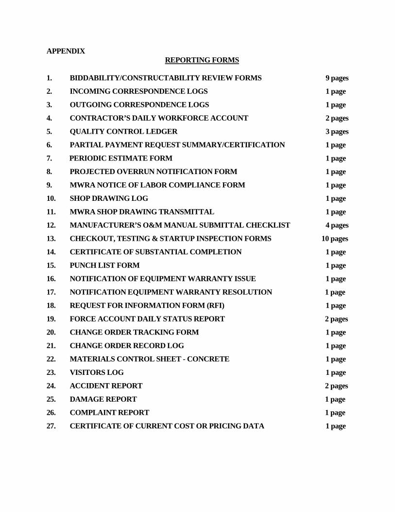
APPENDIX REPORTING FORMS
1. BIDDABILITY/CONSTRUCTABILITY REVIEW FORMS 9 pages
2. INCOMING CORRESPONDENCE LOGS 1 page
3. OUTGOING CORRESPONDENCE LOGS 1 page
4. CONTRACTOR’S DAILY WORKFORCE ACCOUNT 2 pages
5. QUALITY CONTROL LEDGER 3 pages
6. PARTIAL PAYMENT REQUEST SUMMARY/CERTIFICATION 1 page
7. PERIODIC ESTIMATE FORM 1 page
8. PROJECTED OVERRUN NOTIFICATION FORM 1 page
9. MWRA NOTICE OF LABOR COMPLIANCE FORM 1 page
10. SHOP DRAWING LOG 1 page
11. MWRA SHOP DRAWING TRANSMITTAL 1 page
12. MANUFACTURER’S O&M MANUAL SUBMITTAL CHECKLIST 4 pages
13. CHECKOUT, TESTING & STARTUP INSPECTION FORMS 10 pages
14. CERTIFICATE OF SUBSTANTIAL COMPLETION 1 page
15. PUNCH LIST FORM 1 page
16. NOTIFICATION OF EQUIPMENT WARRANTY ISSUE 1 page
17. NOTIFICATION EQUIPMENT WARRANTY RESOLUTION 1 page
18. REQUEST FOR INFORMATION FORM (RFI) 1 page
19. FORCE ACCOUNT DAILY STATUS REPORT 2 pages
20. CHANGE ORDER TRACKING FORM 1 page
21. CHANGE ORDER RECORD LOG 1 page
22. MATERIALS CONTROL SHEET - CONCRETE 1 page
23. VISITORS LOG 1 page
24. ACCIDENT REPORT 2 pages
25. DAMAGE REPORT 1 page
26. COMPLAINT REPORT 1 page
27. CERTIFICATE OF CURRENT COST OR PRICING DATA 1 page
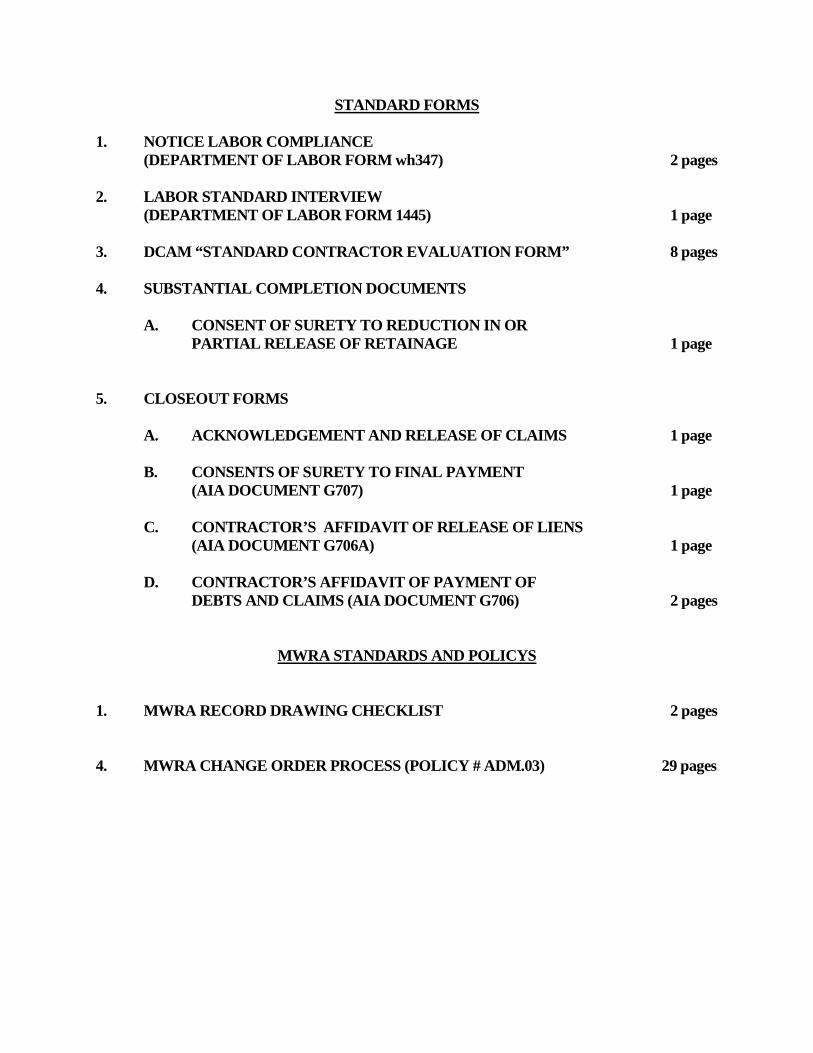
STANDARD FORMS
1. NOTICE LABOR COMPLIANCE (DEPARTMENT OF LABOR FORM wh347) 2 pages
2. LABOR STANDARD INTERVIEW
(DEPARTMENT OF LABOR FORM 1445) 1 page 3. DCAM “STANDARD CONTRACTOR EVALUATION FORM” 8 pages 4. SUBSTANTIAL COMPLETION DOCUMENTS
A. CONSENT OF SURETY TO REDUCTION IN OR PARTIAL RELEASE OF RETAINAGE 1 page
5. CLOSEOUT FORMS
A. ACKNOWLEDGEMENT AND RELEASE OF CLAIMS 1 page B. CONSENTS OF SURETY TO FINAL PAYMENT
(AIA DOCUMENT G707) 1 page C. CONTRACTOR’S AFFIDAVIT OF RELEASE OF LIENS
(AIA DOCUMENT G706A) 1 page D. CONTRACTOR’S AFFIDAVIT OF PAYMENT OF
DEBTS AND CLAIMS (AIA DOCUMENT G706) 2 pages
MWRA STANDARDS AND POLICYS
1. MWRA RECORD DRAWING CHECKLIST 2 pages 4. MWRA CHANGE ORDER PROCESS (POLICY # ADM.03) 29 pages
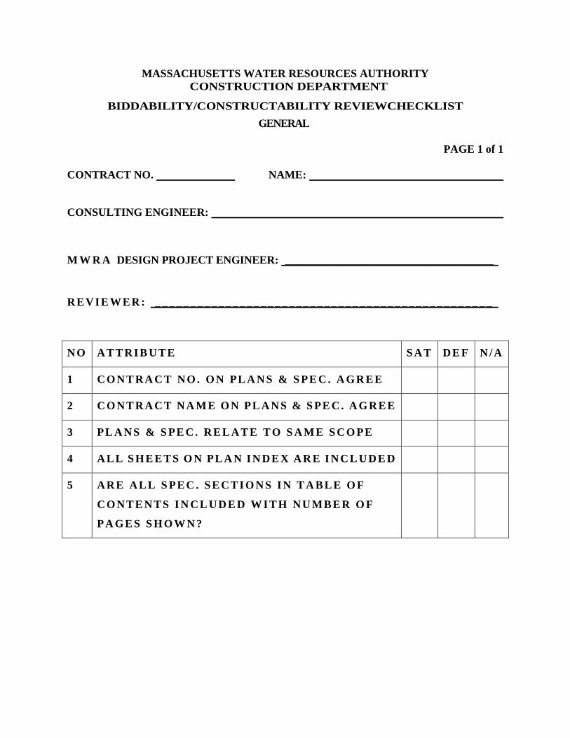
MASSACHUSETTS WATER RESOURCES AUTHORITY CONSTRUCTION DEPARTMENT
BIDDABILITY/CONSTRUCTABILITY REVIEWCHECKLIST GENERAL
PAGE 1 of 1
CONTRACT NO. NAME:
CONSULTING ENGINEER:
M W R A DESIGN PROJECT ENGINEER: ______________________________________
R E V I E W E R : _ _ _ _ _ _ _ _ _ _ _ _ _ _ _ _ _ _ _ _ _ _ _ _ _ _ _ _ _ _ _ _ _ _ _ _ _ _ _ _ _ _ _ _ _ _ _ _
N O A T T R I B U T E S A T D E F N / A
1 C O N T R A C T N O . O N PL A N S & S PE C . A GR E E
2 C O N T R A C T N A M E O N P L A N S & S PE C . A G R E E
3 PL A N S & S PE C . R E L A T E T O S A M E S C O PE
4 A L L S H E E T S O N PL A N I N D E X A R E I N C L U D E D
5 A R E A L L S P E C . S E C T I O N S I N T A B L E O F
C O N T E N T S I N C L U D E D W I T H N U M B E R O F
P A GE S S H O W N ?
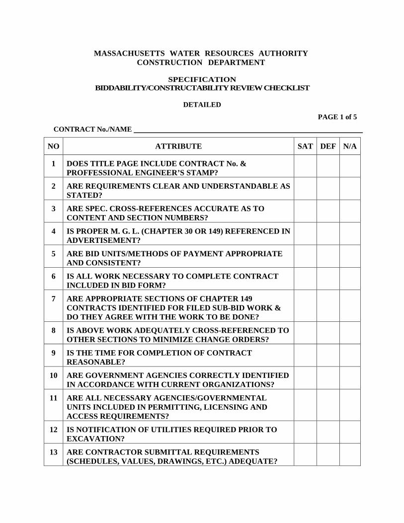
MASSACHUSETTS WATER RESOURCES AUTHORITY CONSTRUCTION DEPARTMENT
SPECIFICATION
BIDDABILITY/CONSTRUCTABILITY REVIEW CHECKLIST
DETAILED PAGE 1 of 5
CONTRACT No./NAME
NO ATTRIBUTE SAT DEF N/A
1 DOES TITLE PAGE INCLUDE CONTRACT No. & PROFFESSIONAL ENGINEER’S STAMP?
2 ARE REQUIREMENTS CLEAR AND UNDERSTANDABLE AS STATED?
3 ARE SPEC. CROSS-REFERENCES ACCURATE AS TO CONTENT AND SECTION NUMBERS?
4 IS PROPER M. G. L. (CHAPTER 30 OR 149) REFERENCED IN ADVERTISEMENT?
5 ARE BID UNITS/METHODS OF PAYMENT APPROPRIATE AND CONSISTENT?
6 IS ALL WORK NECESSARY TO COMPLETE CONTRACT INCLUDED IN BID FORM?
7 ARE APPROPRIATE SECTIONS OF CHAPTER 149 CONTRACTS IDENTIFIED FOR FILED SUB-BID WORK & DO THEY AGREE WITH THE WORK TO BE DONE?
8 IS ABOVE WORK ADEQUATELY CROSS-REFERENCED TO OTHER SECTIONS TO MINIMIZE CHANGE ORDERS?
9 IS THE TIME FOR COMPLETION OF CONTRACT REASONABLE?
10 ARE GOVERNMENT AGENCIES CORRECTLY IDENTIFIED IN ACCORDANCE WITH CURRENT ORGANIZATIONS?
11 ARE ALL NECESSARY AGENCIES/GOVERNMENTAL UNITS INCLUDED IN PERMITTING, LICENSING AND ACCESS REQUIREMENTS?
12 IS NOTIFICATION OF UTILITIES REQUIRED PRIOR TO EXCAVATION?
13 ARE CONTRACTOR SUBMITTAL REQUIREMENTS (SCHEDULES, VALUES, DRAWINGS, ETC.) ADEQUATE?
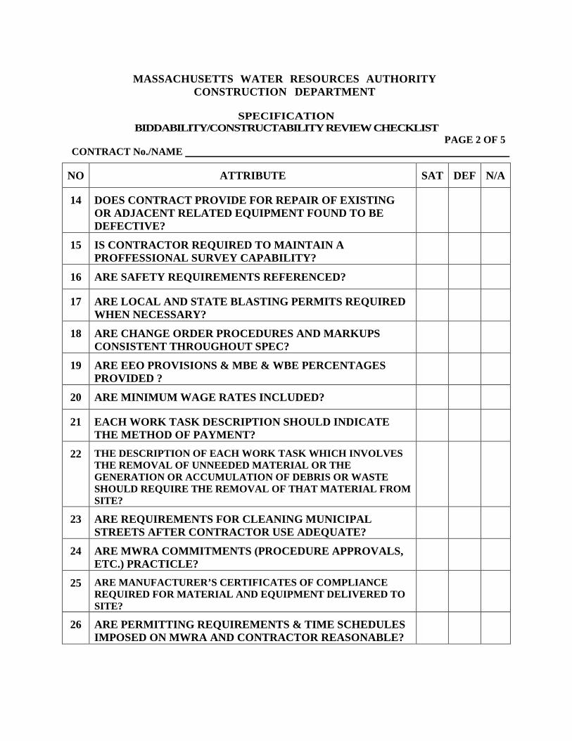
MASSACHUSETTS WATER RESOURCES AUTHORITY
CONSTRUCTION DEPARTMENT
SPECIFICATION BIDDABILITY/CONSTRUCTABILITY REVIEW CHECKLIST
PAGE 2 OF 5 CONTRACT No./NAME
NO ATTRIBUTE SAT DEF N/A
14 DOES CONTRACT PROVIDE FOR REPAIR OF EXISTING OR ADJACENT RELATED EQUIPMENT FOUND TO BE DEFECTIVE?
15 IS CONTRACTOR REQUIRED TO MAINTAIN A PROFFESSIONAL SURVEY CAPABILITY?
16 ARE SAFETY REQUIREMENTS REFERENCED?
17 ARE LOCAL AND STATE BLASTING PERMITS REQUIRED WHEN NECESSARY?
18 ARE CHANGE ORDER PROCEDURES AND MARKUPS CONSISTENT THROUGHOUT SPEC?
19 ARE EEO PROVISIONS & MBE & WBE PERCENTAGES PROVIDED ?
20 ARE MINIMUM WAGE RATES INCLUDED?
21 EACH WORK TASK DESCRIPTION SHOULD INDICATE THE METHOD OF PAYMENT?
22 THE DESCRIPTION OF EACH WORK TASK WHICH INVOLVES THE REMOVAL OF UNNEEDED MATERIAL OR THE GENERATION OR ACCUMULATION OF DEBRIS OR WASTE SHOULD REQUIRE THE REMOVAL OF THAT MATERIAL FROM SITE?
23 ARE REQUIREMENTS FOR CLEANING MUNICIPAL STREETS AFTER CONTRACTOR USE ADEQUATE?
24 ARE MWRA COMMITMENTS (PROCEDURE APPROVALS, ETC.) PRACTICLE?
25 ARE MANUFACTURER’S CERTIFICATES OF COMPLIANCE REQUIRED FOR MATERIAL AND EQUIPMENT DELIVERED TO SITE?
26 ARE PERMITTING REQUIREMENTS & TIME SCHEDULES IMPOSED ON MWRA AND CONTRACTOR REASONABLE?
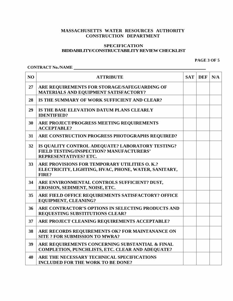
MASSACHUSETTS WATER RESOURCES AUTHORITY CONSTRUCTION DEPARTMENT
SPECIFICATION
BIDDABILITY/CONSTRUCTABILITY REVIEW CHECKLIST
PAGE 3 OF 5
CONTRACT No./NAME
NO ATTRIBUTE SAT DEF N/A
27 ARE REQUIREMENTS FOR STORAGE/SAFEGUARDING OF MATERIALS AND EQUIPMENT SATISFACTORY?
28 IS THE SUMMARY OF WORK SUFFICIENT AND CLEAR?
29 IS THE BASE ELEVATION DATUM PLANS CLEARLY IDENTIFIED?
30 ARE PROJECT/PROGRESS MEETING REQUIREMENTS ACCEPTABLE?
31 ARE CONSTRUCTION PROGRESS PHOTOGRAPHS REQUIRED?
32 IS QUALITY CONTROL ADEQUATE? LABORATORY TESTING? FIELD TESTING/INSPECTION? MANUFACTURERS’ REPRESENTATIVES? ETC.
33 ARE PROVISIONS FOR TEMPORARY UTILITIES O. K.? ELECTRICITY, LIGHTING, HVAC, PHONE, WATER, SANITARY, FIRE?
34 ARE ENVIRONMENTAL CONTROLS SUFFICIENT? DUST, EROSION, SEDIMENT, NOISE, ETC.
35 ARE FIELD OFFICE REQUIREMENTS SATISFACTORY? OFFICE EQUIPMENT, CLEANING?
36 ARE CONTRACTOR’S OPTIONS IN SELECTING PRODUCTS AND REQUESTING SUBSTITUTIONS CLEAR?
37 ARE PROJECT CLEANING REQUIREMENTS ACCEPTABLE?
38 ARE RECORDS REQUIREMENTS OK? FOR MAINTANANCE ON SITE ? FOR SUBMISSION TO MWRA?
39 ARE REQUIREMENTS CONCERNING SUBSTANTIAL & FINAL COMPLETION, PUNCHLISTS, ETC. CLEAR AND ADEQUATE?
40 ARE THE NECESSARY TECHNICAL SPECIFICATIONS INCLUDED FOR THE WORK TO BE DONE?
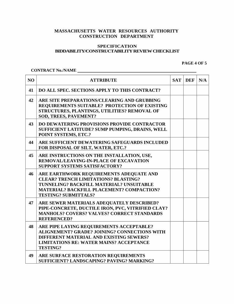
MASSACHUSETTS WATER RESOURCES AUTHORITY CONSTRUCTION DEPARTMENT
SPECIFICATION
BIDDABILITY/CONSTRUCTABILITY REVIEW CHECKLIST
PAGE 4 OF 5
CONTRACT No./NAME
NO ATTRIBUTE SAT DEF N/A
41 DO ALL SPEC. SECTIONS APPLY TO THIS CONTRACT?
42 ARE SITE PREPARATIONS/CLEARING AND GRUBBING REQUIREMENTS SUITABLE? PROTECTION OF EXISTING STRUCTURES, PLANTINGS, UTILITIES? REMOVAL OF SOD, TREES, PAVEMENT?
43 DO DEWATERING PROVISIONS PROVIDE CONTRACTOR SUFFICIENT LATITUDE? SUMP PUMPING, DRAINS, WELL POINT SYSTEMS, ETC.?
44 ARE SUFFICIENT DEWATERING SAFEGUARDS INCLUDED FOR DISPOSAL OF SILT, WATER, ETC.?
45 ARE INSTRUCTIONS ON THE INSTALLATION, USE, REMOVAL/LEAVING-IN-PLACE OF EXCAVATION SUPPORT SYSTEMS SATISFACTORY?
46 ARE EARTHWORK REQUIREMENTS ADEQUATE AND CLEAR? TRENCH LIMITATIONS? BLASTING? TUNNELING? BACKFILL MATERIAL? UNSUITABLE MATERIAL? BACKFILL PLACEMENT? COMPACTION? TESTING? SUBMITTALS?
47 ARE SEWER MATERIALS ADEQUATELY DESCRIBED? PIPE-CONCRETE, DUCTILE IRON, PVC, VITRIFIED CLAY? MANHOLS? COVERS? VALVES? CORRECT STANDARDS REFERENCED?
48 ARE PIPE LAYING REQUIREMENTS ACCEPTABLE? ALIGNEMENT? GRADE? JOINING? CONNECTIONS WITH DIFFERENT MATERIAL AND EXISTING SEWERS? LIMITATIONS RE: WATER MAINS? ACCEPTANCE TESTING?
49 ARE SURFACE RESTORATION REQUIREMENTS SUFFICIENT? LANDSCAPING? PAVING? MARKING?
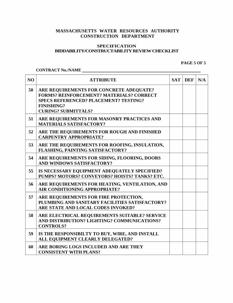
MASSACHUSETTS WATER RESOURCES AUTHORITY CONSTRUCTION DEPARTMENT
SPECIFICATION
BIDDABILITY/CONSTRUCTABILITY REVIEW CHECKLIST
PAGE 5 OF 5
CONTRACT No./NAME
NO ATTRIBUTE SAT DEF N/A
50 ARE REQUIREMENTS FOR CONCRETE ADEQUATE? FORMS? REINFORCEMENT? MATERIALS? CORRECT SPECS REFERENCED? PLACEMENT? TESTING? FINISHING? CURING? SUBMITTALS?
51 ARE REQUIREMENTS FOR MASONRY PRACTICES AND MATERIALS SATISFACTORY?
52 ARE THE REQUIREMENTS FOR ROUGH AND FINISHED CARPENTRY APPROPRIATE?
53 ARE THE REQUIREMENTS FOR ROOFING, INSULATION, FLASHING, PAINTING SATISFACTORY?
54 ARE REQUIREMENTS FOR SIDING, FLOORING, DOORS AND WINDOWS SATISFACTORY?
55 IS NECESSARY EQUIPMENT ADEQUATELY SPECIFIED? PUMPS? MOTORS? CONVEYORS? HOISTS? TANKS? ETC.
56 ARE REQUIREMENTS FOR HEATING, VENTILATION, AND AIR CONDITIONING APPROPRIATE?
57 ARE REQUIREMENTS FOR FIRE PROTECTION, PLUMBING AND SANITARY FACILITIES SATISFACTORY? ARE STATE AND LOCAL CODES INVOKED?
58 ARE ELECTRICAL REQUIREMENTS SUITABLE? SERVICE AND DISTRIBUTION? LIGHTING? COMMUNICATIONS? CONTROLS?
59 IS THE RESPONSIBILTY TO BUY, WIRE, AND INSTALL ALL EQUIPMENT CLEARLY DELEGATED?
60 ARE BORING LOGS INCLUDED AND ARE THEY CONSISTENT WITH PLANS?
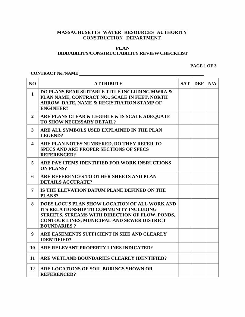
MASSACHUSETTS WATER RESOURCES AUTHORITY CONSTRUCTION DEPARTMENT
PLAN
BIDDABILITY/CONSTRUCTABILITY REVIEW CHECKLIST
PAGE 1 OF 3
CONTRACT No./NAME
NO ATTRIBUTE SAT DEF N/A
1 DO PLANS BEAR SUITABLE TITLE INCLUDING MWRA & PLAN NAME, CONTRACT NO., SCALE IN FEET, NORTH ARROW, DATE, NAME & REGISTRATION STAMP OF ENGINEER?
2 ARE PLANS CLEAR & LEGIBLE & IS SCALE ADEQUATE TO SHOW NECESSARY DETAIL?
3 ARE ALL SYMBOLS USED EXPLAINED IN THE PLAN LEGEND?
4 ARE PLAN NOTES NUMBERED, DO THEY REFER TO SPECS AND ARE PROPER SECTIONS OF SPECS REFERENCED?
5 ARE PAY ITEMS IDENTIFIED FOR WORK INSRUCTIONS ON PLANS?
6 ARE REFERENCES TO OTHER SHEETS AND PLAN DETAILS ACCURATE?
7 IS THE ELEVATION DATUM PLANE DEFINED ON THE PLANS?
8 DOES LOCUS PLAN SHOW LOCATION OF ALL WORK AND ITS RELATIONSHIP TO COMMUNITY INCLUDING STREETS, STREAMS WITH DIRECTION OF FLOW, PONDS, CONTOUR LINES, MUNICIPAL AND SEWER DISTRICT BOUNDARIES ?
9 ARE EASEMENTS SUFFICIENT IN SIZE AND CLEARLY IDENTIFIED?
10 ARE RELEVANT PROPERTY LINES INDICATED?
11 ARE WETLAND BOUNDARIES CLEARLY IDENTIFIED?
12 ARE LOCATIONS OF SOIL BORINGS SHOWN OR REFERENCED?
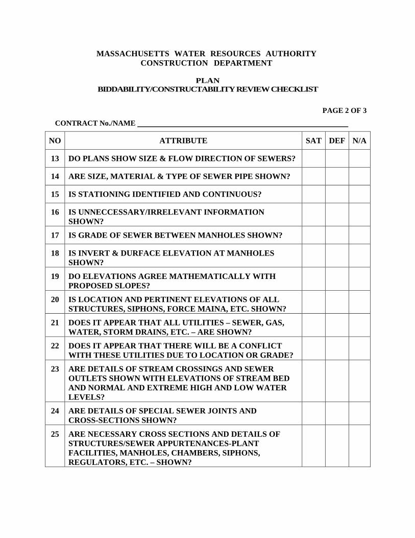
MASSACHUSETTS WATER RESOURCES AUTHORITY CONSTRUCTION DEPARTMENT
PLAN
BIDDABILITY/CONSTRUCTABILITY REVIEW CHECKLIST
PAGE 2 OF 3
CONTRACT No./NAME
NO ATTRIBUTE SAT DEF N/A
13 DO PLANS SHOW SIZE & FLOW DIRECTION OF SEWERS?
14 ARE SIZE, MATERIAL & TYPE OF SEWER PIPE SHOWN?
15 IS STATIONING IDENTIFIED AND CONTINUOUS?
16 IS UNNECCESSARY/IRRELEVANT INFORMATION SHOWN?
17 IS GRADE OF SEWER BETWEEN MANHOLES SHOWN?
18 IS INVERT & DURFACE ELEVATION AT MANHOLES SHOWN?
19 DO ELEVATIONS AGREE MATHEMATICALLY WITH PROPOSED SLOPES?
20 IS LOCATION AND PERTINENT ELEVATIONS OF ALL STRUCTURES, SIPHONS, FORCE MAINA, ETC. SHOWN?
21 DOES IT APPEAR THAT ALL UTILITIES – SEWER, GAS, WATER, STORM DRAINS, ETC. – ARE SHOWN?
22 DOES IT APPEAR THAT THERE WILL BE A CONFLICT WITH THESE UTILITIES DUE TO LOCATION OR GRADE?
23 ARE DETAILS OF STREAM CROSSINGS AND SEWER OUTLETS SHOWN WITH ELEVATIONS OF STREAM BED AND NORMAL AND EXTREME HIGH AND LOW WATER LEVELS?
24 ARE DETAILS OF SPECIAL SEWER JOINTS AND CROSS-SECTIONS SHOWN?
25 ARE NECESSARY CROSS SECTIONS AND DETAILS OF STRUCTURES/SEWER APPURTENANCES-PLANT FACILITIES, MANHOLES, CHAMBERS, SIPHONS, REGULATORS, ETC. – SHOWN?
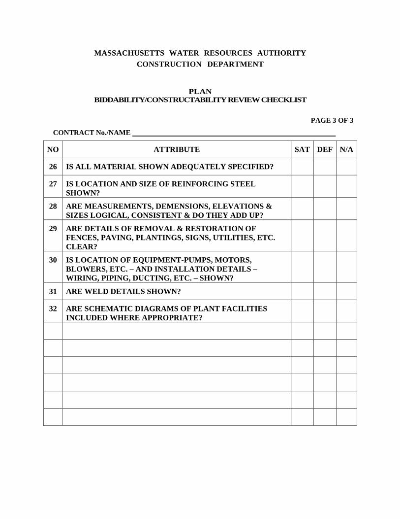
MASSACHUSETTS WATER RESOURCES AUTHORITY CONSTRUCTION DEPARTMENT
PLAN BIDDABILITY/CONSTRUCTABILITY REVIEW CHECKLIST
PAGE 3 OF 3
CONTRACT No./NAME
NO ATTRIBUTE SAT DEF N/A
26 IS ALL MATERIAL SHOWN ADEQUATELY SPECIFIED?
27 IS LOCATION AND SIZE OF REINFORCING STEEL SHOWN?
28 ARE MEASUREMENTS, DEMENSIONS, ELEVATIONS & SIZES LOGICAL, CONSISTENT & DO THEY ADD UP?
29 ARE DETAILS OF REMOVAL & RESTORATION OF FENCES, PAVING, PLANTINGS, SIGNS, UTILITIES, ETC. CLEAR?
30 IS LOCATION OF EQUIPMENT-PUMPS, MOTORS, BLOWERS, ETC. – AND INSTALLATION DETAILS – WIRING, PIPING, DUCTING, ETC. – SHOWN?
31 ARE WELD DETAILS SHOWN?
32 ARE SCHEMATIC DIAGRAMS OF PLANT FACILITIES INCLUDED WHERE APPROPRIATE?
INCOMING CORRESPONDENCE LOG Project: MWRA Contract No.: Location: EPA/MDEP Project No.: Contractor: Sheet of
FORM 4-1 EFFECTIVE DATE 11/87
OUTGOING CORRESPONDENCE LOG Project: MWRA Contract No.: Location: EPA/MDEP Project No.: Contractor: Sheet of
FORM 4-1 EFFECTIVE DATE 11/87
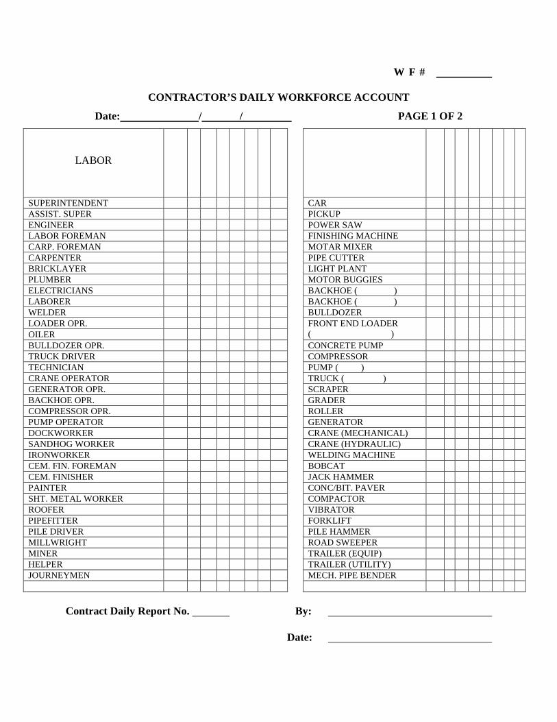
W F #
CONTRACTOR’S DAILY WORKFORCE ACCOUNT
Date: / / PAGE 1 OF 2
LABOR
SUPERINTENDENT CAR ASSIST. SUPER PICKUP ENGINEER POWER SAW LABOR FOREMAN FINISHING MACHINE CARP. FOREMAN MOTAR MIXER CARPENTER PIPE CUTTER BRICKLAYER LIGHT PLANT PLUMBER MOTOR BUGGIES ELECTRICIANS BACKHOE ( ) LABORER BACKHOE ( ) WELDER BULLDOZER LOADER OPR. FRONT END LOADER
( )
OILER BULLDOZER OPR. CONCRETE PUMP TRUCK DRIVER COMPRESSOR TECHNICIAN PUMP ( ) CRANE OPERATOR TRUCK ( ) GENERATOR OPR. SCRAPER BACKHOE OPR. GRADER COMPRESSOR OPR. ROLLER PUMP OPERATOR GENERATOR DOCKWORKER CRANE (MECHANICAL) SANDHOG WORKER CRANE (HYDRAULIC) IRONWORKER WELDING MACHINE CEM. FIN. FOREMAN BOBCAT CEM. FINISHER JACK HAMMER PAINTER CONC/BIT. PAVER SHT. METAL WORKER COMPACTOR ROOFER VIBRATOR PIPEFITTER FORKLIFT PILE DRIVER PILE HAMMER MILLWRIGHT ROAD SWEEPER MINER TRAILER (EQUIP) HELPER TRAILER (UTILITY) JOURNEYMEN MECH. PIPE BENDER
Contract Daily Report No. By: � Date:

W F #
CONTRACTOR’S DAILY WORKFORCE ACCOUNT PAGE 2 OF 2
= = = = = = = = = = = = = = = = = = = = = = = = = = = = = = = = = = = = = = = =
COMMENTS:
MASSACHUSETTS WATER RESOURCE AUTHORITY
CONSTRUCTION DEPARTMENT
QUANTITY CONTROL LEDGER TITLE SHEET
MWRA Contract No. EPA/DEP Project No. Contract: Location: Contractor: Resident: Company:
Contract Price: Award Date: Approved Change Orders: Notice to Proceed: Adjusted Contract Price: Time of Performance: Date of Completion: Revised Completion Date: Substantial Completion Date: Final Completion Date:
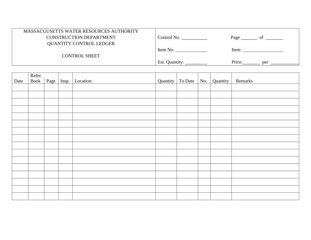
MASSACGUSETTS WATER RESOURCES AUTHORITY CONSTRUCTION DEPARTMENT QUANTITY CONTROL LEDGER
CONTROL SHEET
Control No. Page of Item No. Item: Est. Quantity: Price: per
Refer. Date Book Page Insp. Location: Quantity To Date No. Quantity Remarks ���� ���� ���� ���� ���� ���� ���� ���� ����
���� ���� ���� ���� ���� ���� ���� ���� ���� ���� ���� ���� ���� ���� ���� ���� ���� ���� ���� ���� ���� ���� ���� ���� ���� ���� ���� ���� ���� ���� ���� ���� ���� ���� ���� ���� ����
���� ���� ���� ���� ���� ���� ���� ���� ���� ����
���� ���� ���� ���� ���� ���� ���� ���� ���� ���� ���� ���� ���� ���� ���� ���� ���� ���� ���� ���� ���� ���� ���� ���� ���� ���� ���� ����
���� ���� ���� ���� ���� ���� ���� ���� ���� ���� ���� ���� ���� ���� ���� ���� ���� ���� ����
���� ���� ���� ���� ���� ���� ���� ���� ���� ����
���� ���� ���� ���� ���� ���� ���� ���� ���� ���� ���� ���� ���� ���� ���� ���� ���� ���� ���� ���� ���� ���� ���� ���� ���� ���� ���� ���� ���� ���� ���� ���� ����
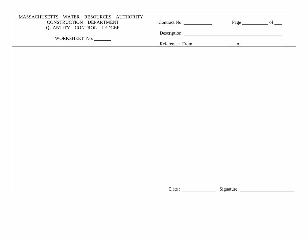
MASSACHUSETTS WATER RESOURCES AUTHORITY CONSTRUCTION DEPARTMENT QUANTITY CONTROL LEDGER
WORKSHEET No.
Contract No. Page of Description: Reference: From to
Date : �������������������� Signature:
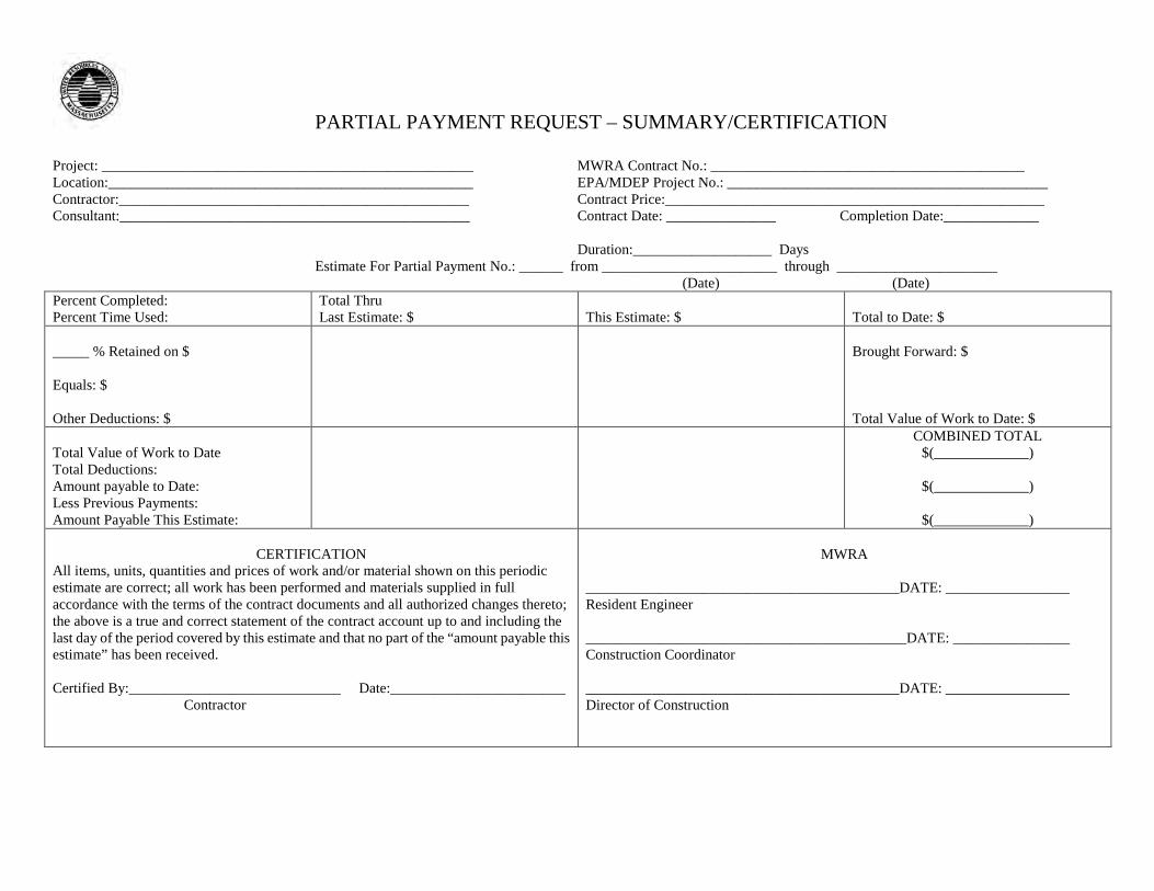
PARTIAL PAYMENT REQUEST – SUMMARY/CERTIFICATION
Project: ___________________________________________________ MWRA Contract No.: ___________________________________________ Location:__________________________________________________ EPA/MDEP Project No.: ____________________________________________ Contractor:________________________________________________ Contract Price:____________________________________________________ Consultant:________________________________________________ Contract Date: _______________ Completion Date:_____________
Duration:___________________ Days Estimate For Partial Payment No.: ______ from ________________________ through ______________________ (Date) (Date) Percent Completed: Percent Time Used:
Total Thru Last Estimate: $
This Estimate: $
Total to Date: $
_____ % Retained on $ Equals: $ Other Deductions: $
Brought Forward: $ Total Value of Work to Date: $
Total Value of Work to Date Total Deductions: Amount payable to Date: Less Previous Payments: Amount Payable This Estimate:
COMBINED TOTAL $(_____________)
$(_____________)
$(_____________)
CERTIFICATION
All items, units, quantities and prices of work and/or material shown on this periodic estimate are correct; all work has been performed and materials supplied in full accordance with the terms of the contract documents and all authorized changes thereto; the above is a true and correct statement of the contract account up to and including the last day of the period covered by this estimate and that no part of the “amount payable this estimate” has been received. Certified By:_____________________________ Date:________________________ Contractor
MWRA
___________________________________________DATE: _________________ Resident Engineer ____________________________________________DATE: ________________ Construction Coordinator ___________________________________________DATE: _________________ Director of Construction
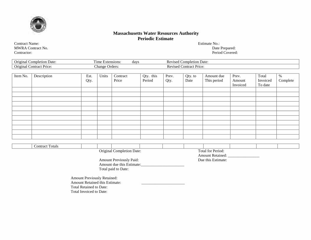
Massachusetts Water Resources Authority Periodic Estimate
Contract Name: Estimate No.: MWRA Contract No. Date Prepared: Contractor: Period Covered: Original Completion Date: Time Extensions: days Revised Completion Date: Original Contract Price: Change Orders: Revised Contract Price: Item No. Description Est.
Qty. Units Contract
Price Qty. this Period
Prev. Qty.
Qty. to Date
Amount due This period
Prev. Amount Invoiced
Total Invoiced To date
% Complete
Contract Totals
Original Completion Date: Total for Period: Amount Retained: ________________ Amount Previously Paid: Due this Estimate: Amount due this Estimate:______________________ Total paid to Date:
Amount Previously Retained:
Amount Retained this Estimate: ______________________ Total Retained to Date: Total Invoiced to Date:
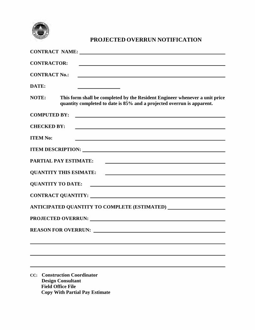
PROJECTED OVERRUN NOTIFICATION CONTRACT NAME: CONTRACTOR: CONTRACT No.: DATE: NOTE: This form shall be completed by the Resident Engineer whenever a unit price
quantity completed to date is 85% and a projected overrun is apparent. COMPUTED BY: CHECKED BY: ITEM No: ITEM DESCRIPTION: PARTIAL PAY ESTIMATE: QUANTITY THIS ESIMATE: QUANTITY TO DATE: CONTRACT QUANTITY: ANTICIPATED QUANTITY TO COMPLETE (ESTIMATED) PROJECTED OVERRUN: REASON FOR OVERRUN: CC: Construction Coordinator Design Consultant Field Office File Copy With Partial Pay Estimate
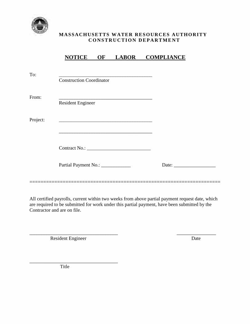
MASSACHUSETTS WATER RESOURCES AUTHORITY C O N S T R U C T I O N D E P A R T M E N T
NOTICE OF LABOR COMPLIANCE To: ______________________________________ Construction Coordinator From: ______________________________________ Resident Engineer Project: ______________________________________ ______________________________________ Contract No.: __________________________ Partial Payment No.: ____________ Date: _________________ ===================================================================== All certified payrolls, current within two weeks from above partial payment request date, which are required to be submitted for work under this partial payment, have been submitted by the Contractor and are on file. ____________________________________ ________________ Resident Engineer Date ____________________________________ Title
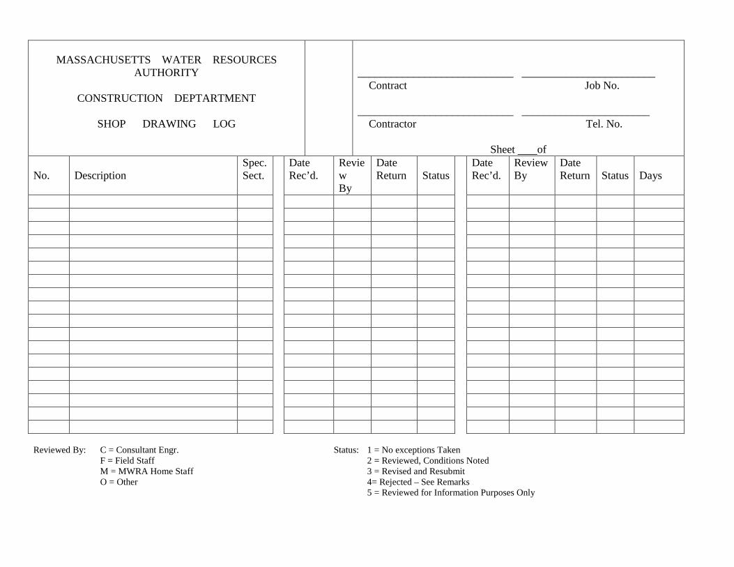
MASSACHUSETTS WATER RESOURCES
AUTHORITY
CONSTRUCTION DEPTARTMENT
SHOP DRAWING LOG
____________________________ ________________________ Contract Job No. ____________________________ _______________________ Contractor Tel. No.
Sheet of No.
Description
Spec. Sect.
Date Rec’d.
Review By
Date Return
Status
Date Rec’d.
Review By
Date Return
Status
Days
Reviewed By: C = Consultant Engr. Status: 1 = No exceptions Taken F = Field Staff 2 = Reviewed, Conditions Noted M = MWRA Home Staff 3 = Revised and Resubmit O = Other 4= Rejected – See Remarks 5 = Reviewed for Information Purposes Only
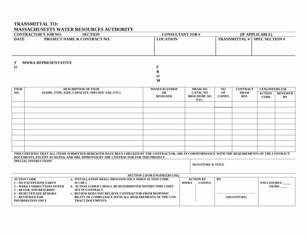
TRANSMITTAL TO: MASSACHUSETTS WATER RESOURCES AUTHORITY CONTRACTOR’S JOB NO: SECTION CONSULTANT JOB # (IF APPLICABLE) DATE
PROJECT NAME & CONTRACT NO.
LOCATION
TRANSMITTAL #
SPEC SECTION #
T MWRA REPRESENTATIVE O
F R O M
ITEM NO.
DESCRIPTION OF ITEM (NAME, TYPE, SIZE, CAPACITY, SPECIFIC USE, ETC) MANUFACTURER
OR DESIGNER
DRAW NO CATAL NO
BROCHURE NO ETC.
NO OF
COPIES CONTRACT
DRAW REF.
2 ENGINEERS USE ACTION
CODE REVEWED
BY
THIS CERTIFIES THAT ALL ITEMS SUBMITTED HEREWITH HAVE BEEN CHECKED BY THE CONTRACTOR, ARE IN CORNFORMANCE WITH THE REQUIREMENTS OF THE CONTRACT DOCUMENTS, EXCEPT AS NOTED, AND ARE APPROVED BY THE CONTRACTOR FOR THIS PROJECT. SPECIAL INSTRUCTIONS
SIGNATURE & TITLE
SECTION 2 (FOR ENGINEERS USE) ACTION CODE 1 – NO EXCEPTIONS TAKEN 2 – MAKE CORRECTIONS NOTED 3 – REVISE AND RESUBMIT 4 – REJECTED SEE REMAKS 5 – REVIEWED FOR INFORMATION ONLY
a. INSTALLATION SHALL PROCEED ONLY WHEN ACTION CODE IS 1 0R 2 b. ACTION CODED 3 SHALL BE RESUBMITTED WITHIN TIME LIMIT SET IN CONTRACT. c. REVIEW DOES NOT RELIEVE CONTRACTOR FROM RESPONSI- BILITY OF COMPLIANCE WITH ALL REQUIREMENTS OF THE CON- TRACT DOCUMENTS.
ACTION BY MWRA CONSUL
BY
(SIGNATURE)
ENCLOSURES: _____ ITEMS: ____
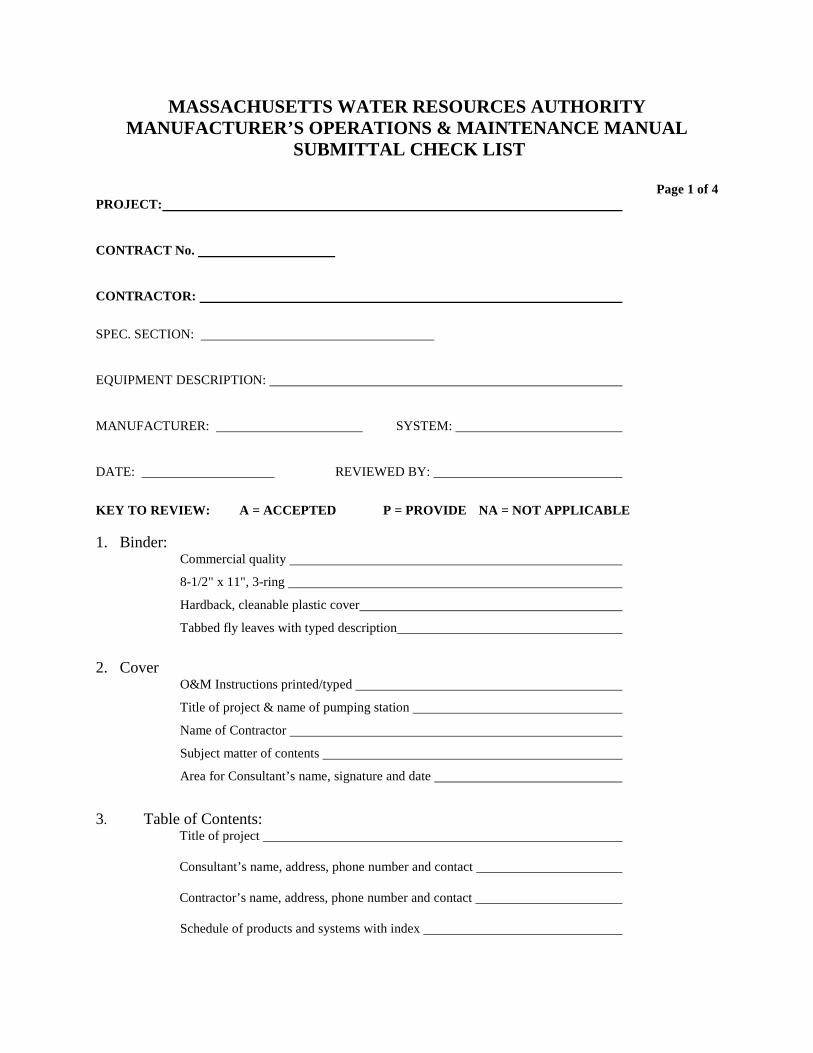
MASSACHUSETTS WATER RESOURCES AUTHORITY MANUFACTURER’S OPERATIONS & MAINTENANCE MANUAL
SUBMITTAL CHECK LIST
Page 1 of 4 PROJECT:
CONTRACT No.
CONTRACTOR:
SPEC. SECTION:
EQUIPMENT DESCRIPTION:
MANUFACTURER: SYSTEM:
DATE: REVIEWED BY:
KEY TO REVIEW: A = ACCEPTED P = PROVIDE NA = NOT APPLICABLE 1. Binder:
Commercial quality
8-1/2" x 11", 3-ring
Hardback, cleanable plastic cover
Tabbed fly leaves with typed description
2. Cover
O&M Instructions printed/typed
Title of project & name of pumping station
Name of Contractor
Subject matter of contents
Area for Consultant’s name, signature and date
3. Table of Contents:
Title of project
Consultant’s name, address, phone number and contact
Contractor’s name, address, phone number and contact
Schedule of products and systems with index
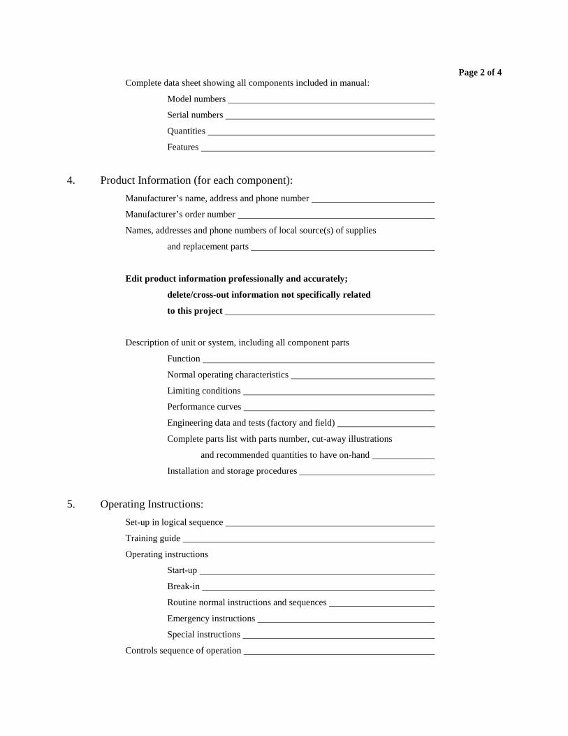
Page 2 of 4 Complete data sheet showing all components included in manual:
Model numbers
Serial numbers
Quantities
Features
4. Product Information (for each component):
Manufacturer’s name, address and phone number
Manufacturer’s order number
Names, addresses and phone numbers of local source(s) of supplies
and replacement parts
Edit product information professionally and accurately;
delete/cross-out information not specifically related
to this project
Description of unit or system, including all component parts
Function
Normal operating characteristics
Limiting conditions
Performance curves
Engineering data and tests (factory and field)
Complete parts list with parts number, cut-away illustrations
and recommended quantities to have on-hand
Installation and storage procedures
5. Operating Instructions:
Set-up in logical sequence
Training guide
Operating instructions
Start-up
Break-in
Routine normal instructions and sequences
Emergency instructions
Special instructions
Controls sequence of operation
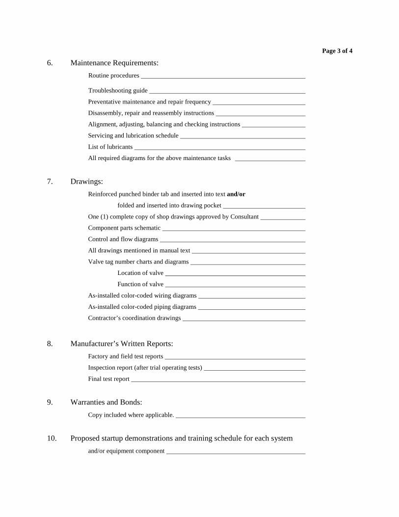
Page 3 of 4
6. Maintenance Requirements:
Routine procedures Troubleshooting guide
Preventative maintenance and repair frequency
Disassembly, repair and reassembly instructions
Alignment, adjusting, balancing and checking instructions
Servicing and lubrication schedule
List of lubricants
All required diagrams for the above maintenance tasks
7. Drawings:
Reinforced punched binder tab and inserted into text and/or
folded and inserted into drawing pocket
One (1) complete copy of shop drawings approved by Consultant
Component parts schematic
Control and flow diagrams
All drawings mentioned in manual text
Valve tag number charts and diagrams
Location of valve
Function of valve
As-installed color-coded wiring diagrams
As-installed color-coded piping diagrams
Contractor’s coordination drawings
8. Manufacturer’s Written Reports:
Factory and field test reports
Inspection report (after trial operating tests)
Final test report
9. Warranties and Bonds:
Copy included where applicable.
10. Proposed startup demonstrations and training schedule for each system
and/or equipment component
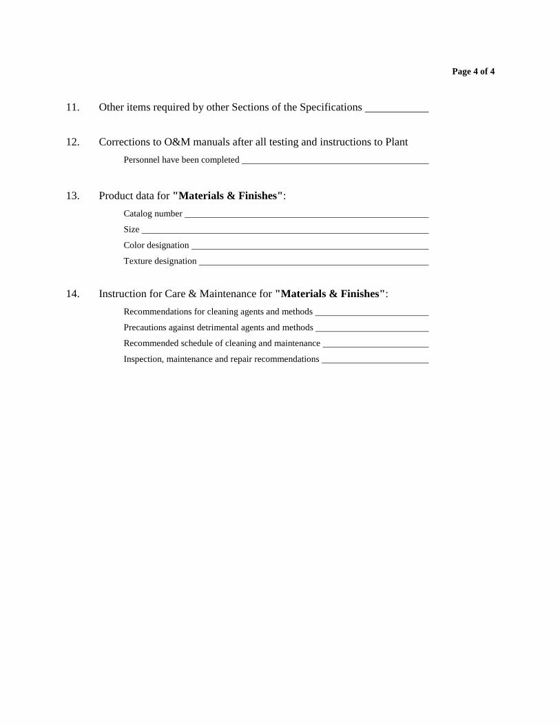
Page 4 of 4
11. Other items required by other Sections of the Specifications
12. Corrections to O&M manuals after all testing and instructions to Plant
Personnel have been completed
13. Product data for "Materials & Finishes":
Catalog number
Size
Color designation
Texture designation
14. Instruction for Care & Maintenance for "Materials & Finishes":
Recommendations for cleaning agents and methods
Precautions against detrimental agents and methods
Recommended schedule of cleaning and maintenance
Inspection, maintenance and repair recommendations
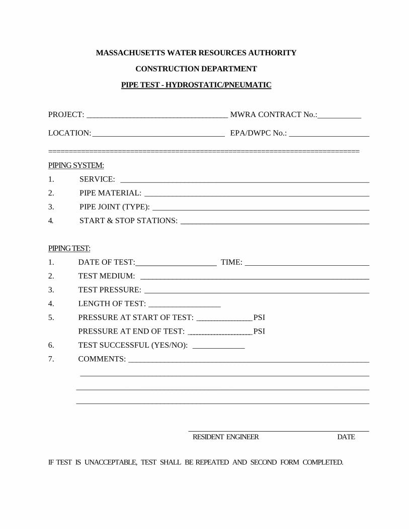
MASSACHUSETTS WATER RESOURCES AUTHORITY
CONSTRUCTION DEPARTMENT
PIPE TEST - HYDROSTATIC/PNEUMATIC
PROJECT: _______________________________________ MWRA CONTRACT No.:
LOCATION: _________________________________ EPA/DWPC No.: ____________________
============================================================================
PIPING SYSTEM:
1. SERVICE: ______________________________________________________________
2. PIPE MATERIAL: ________________________________________________________
3. PIPE JOINT (TYPE): ______________________________________________________
4. START & STOP STATIONS: _______________________________________________
PIPING TEST:
1. DATE OF TEST: TIME: _______________________________
2. TEST MEDIUM: _________________________________________________________
3. TEST PRESSURE: ________________________________________________________
4. LENGTH OF TEST: __________________
5. PRESSURE AT START OF TEST: ___________________ PSI
PRESSURE AT END OF TEST: ______________________ PSI
6. TEST SUCCESSFUL (YES/NO): _____________
7. COMMENTS: ____________________________________________________________
________________________________________________________________________
_________________________________________________________________________
_________________________________________________________________________
_____________________________________________ RESIDENT ENGINEER DATE
IF TEST IS UNACCEPTABLE, TEST SHALL BE REPEATED AND SECOND FORM COMPLETED.
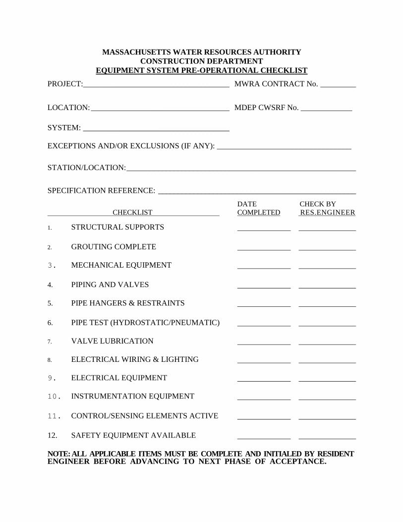
MASSACHUSETTS WATER RESOURCES AUTHORITY CONSTRUCTION DEPARTMENT
EQUIPMENT SYSTEM PRE-OPERATIONAL CHECKLIST
PROJECT:_____________________________________ MWRA CONTRACT No. _________
LOCATION: ___________________________________ MDEP CWSRF No. _____________ SYSTEM: _____________________________________
EXCEPTIONS AND/OR EXCLUSIONS (IF ANY): __________________________________
STATION/LOCATION: __________________________________________________________
SPECIFICATION REFERENCE: __________________________________________________
DATE CHECK BY CHECKLIST COMPLETED RES.ENGINEER
1. STRUCTURAL SUPPORTS
2. GROUTING COMPLETE
3. MECHANICAL EQUIPMENT
4. PIPING AND VALVES
5. PIPE HANGERS & RESTRAINTS
6. PIPE TEST (HYDROSTATIC/PNEUMATIC)
7. VALVE LUBRICATION
8. ELECTRICAL WIRING & LIGHTING
9. ELECTRICAL EQUIPMENT
10. INSTRUMENTATION EQUIPMENT
11. CONTROL/SENSING ELEMENTS ACTIVE
12. SAFETY EQUIPMENT AVAILABLE
NOTE: ALL APPLICABLE ITEMS MUST BE COMPLETE AND INITIALED BY RESIDENT ENGINEER BEFORE ADVANCING TO NEXT PHASE OF ACCEPTANCE.
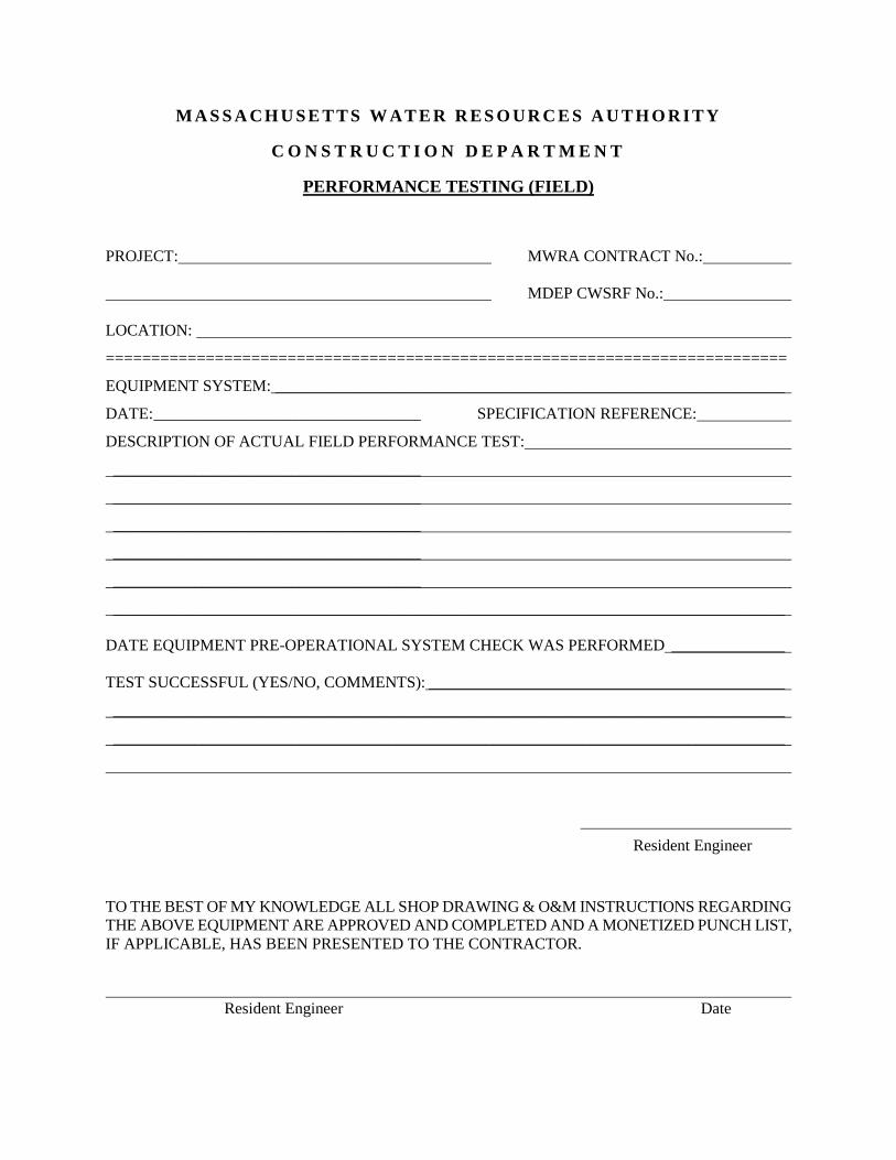
M A S S A C H U S E T T S W A T E R R E S O U R C E S A U T H O R I T Y
C O N S T R U C T I O N D E P A R T M E N T
PERFORMANCE TESTING (FIELD)
PROJECT: MWRA CONTRACT No.:
MDEP CWSRF No.:
LOCATION:
===========================================================================
EQUIPMENT SYSTEM: _______________________________________________________________
DATE: _________________________________ SPECIFICATION REFERENCE:
DESCRIPTION OF ACTUAL FIELD PERFORMANCE TEST:
______________________________________
______________________________________
______________________________________
______________________________________
______________________________________
___________________________________________________________________________________
DATE EQUIPMENT PRE-OPERATIONAL SYSTEM CHECK WAS PERFORMED ______________
TEST SUCCESSFUL (YES/NO, COMMENTS): ____________________________________________
___________________________________________________________________________________
___________________________________________________________________________________
Resident Engineer
TO THE BEST OF MY KNOWLEDGE ALL SHOP DRAWING & O&M INSTRUCTIONS REGARDING THE ABOVE EQUIPMENT ARE APPROVED AND COMPLETED AND A MONETIZED PUNCH LIST, IF APPLICABLE, HAS BEEN PRESENTED TO THE CONTRACTOR.
Resident Engineer Date
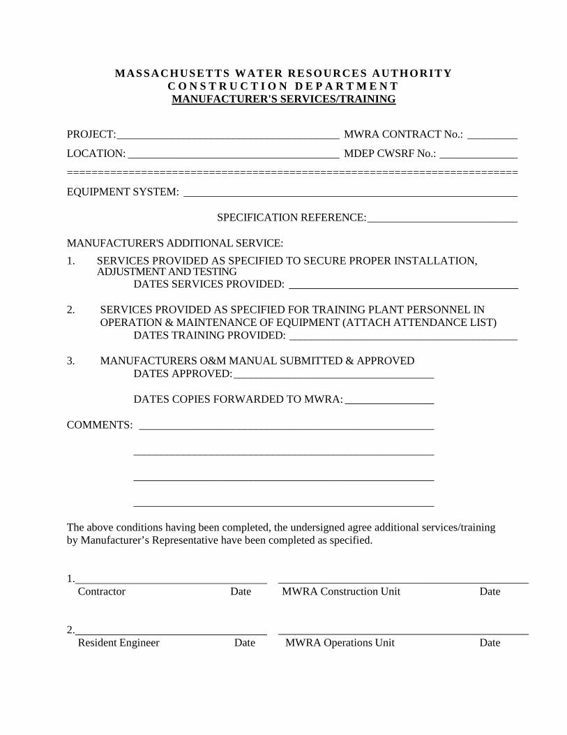
MASSACHUSETTS WATER RESOURCES AUTHORITY C O N S T R U C T I O N D E P A R T M E N T MANUFACTURER'S SERVICES/TRAINING
PROJECT: ________________________________________ MWRA CONTRACT No.: _________
LOCATION: ______________________________________ MDEP CWSRF No.: ______________
=========================================================================
EQUIPMENT SYSTEM: ____________________________________________________________
SPECIFICATION REFERENCE: ___________________________
MANUFACTURER'S ADDITIONAL SERVICE:
1. SERVICES PROVIDED AS SPECIFIED TO SECURE PROPER INSTALLATION, ADJUSTMENT AND TESTING
DATES SERVICES PROVIDED: __________________________________________ 2. SERVICES PROVIDED AS SPECIFIED FOR TRAINING PLANT PERSONNEL IN
OPERATION & MAINTENANCE OF EQUIPMENT (ATTACH ATTENDANCE LIST) DATES TRAINING PROVIDED: _________________________________________ 3. MANUFACTURERS O&M MANUAL SUBMITTED & APPROVED DATES APPROVED: ____________________________________
DATES COPIES FORWARDED TO MWRA: ________________ COMMENTS: _____________________________________________________ ______________________________________________________ ______________________________________________________ ______________________________________________________ The above conditions having been completed, the undersigned agree additional services/training by Manufacturer’s Representative have been completed as specified. 1. _____________________________________________ Contractor Date MWRA Construction Unit Date 2. _____________________________________________ Resident Engineer Date MWRA Operations Unit Date
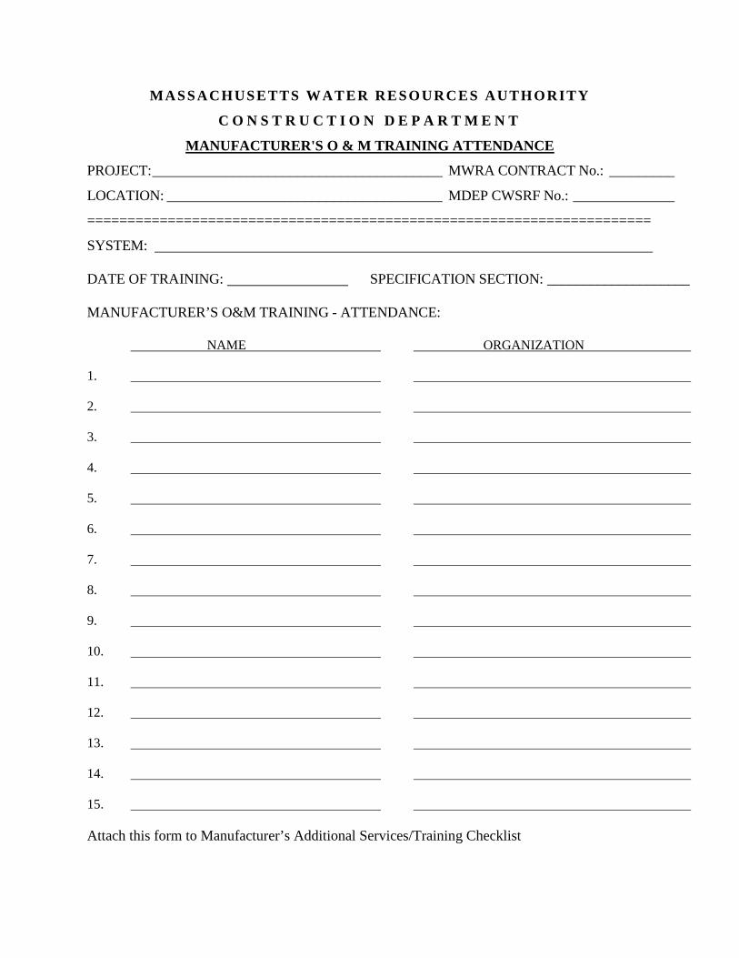
MASSACHUSETTS WATER RESOURCES AUTHORITY
C O N S T R U C T I O N D E P A R T M E N T
MANUFACTURER'S O & M TRAINING ATTENDANCE
PROJECT: ________________________________________ MWRA CONTRACT No.: _________
LOCATION: ______________________________________ MDEP CWSRF No.: ______________
======================================================================
SYSTEM: DATE OF TRAINING: SPECIFICATION SECTION: ____________________ MANUFACTURER’S O&M TRAINING - ATTENDANCE: NAME ORGANIZATION
1.
2.
3.
4.
5.
6.
7.
8.
9.
10.
11.
12.
13.
14.
15.
Attach this form to Manufacturer’s Additional Services/Training Checklist
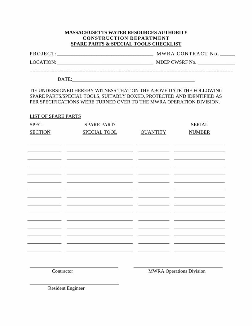
MASSACHUSETTS WATER RESOURCES AUTHORITY CONSTRUCTION DEPARTMENT
SPARE PARTS & SPECIAL TOOLS CHECKLIST
PR OJ EC T:_______________________________________ MW RA CONTRACT N o . ______
LOCATION: _______________________________________ MDEP CWSRF No. _______________
=========================================================================
DATE: TIE UNDERSIGNED HEREBY WITNESS THAT ON THE ABOVE DATE THE FOLLOWING SPARE PARTS/SPECIAL TOOLS, SUITABLY BOXED, PROTECTED AND IDENTIFIED AS PER SPECIFICATIONS WERE TURNED OVER TO THE MWRA OPERATION DIVISION.
LIST OF SPARE PARTS
SPEC.
SECTION
SPARE PART/
SPECIAL TOOL
QUANTITY
SERIAL
NUMBER
Contractor MWRA Operations Division Resident Engineer
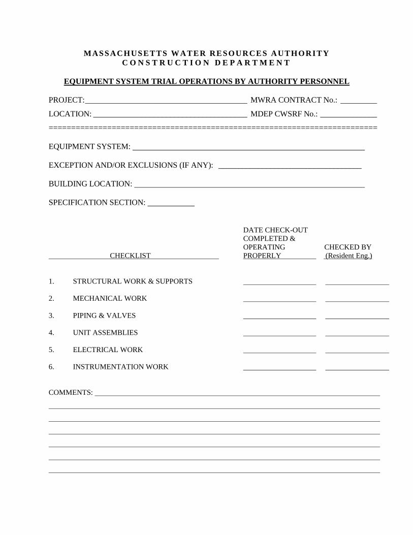
MASSACHUSETTS WATER RESOURCES AUTHORITY C O N S T R U C T I O N D E P A R T M E N T
EQUIPMENT SYSTEM TRIAL OPERATIONS BY AUTHORITY PERSONNEL
PROJECT: ________________________________________ MWRA CONTRACT No.: _________
LOCATION: ______________________________________ MDEP CWSRF No.: ______________
========================================================================= EQUIPMENT SYSTEM: EXCEPTION AND/OR EXCLUSIONS (IF ANY): ____________________________________ BUILDING LOCATION: SPECIFICATION SECTION: DATE CHECK-OUT COMPLETED & OPERATING CHECKED BY CHECKLIST PROPERLY (Resident Eng.) 1. STRUCTURAL WORK & SUPPORTS 2. MECHANICAL WORK 3. PIPING & VALVES 4. UNIT ASSEMBLIES 5. ELECTRICAL WORK 6. INSTRUMENTATION WORK COMMENTS:
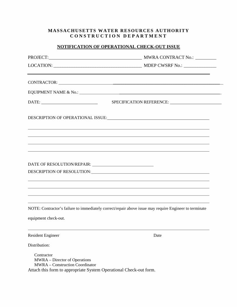
MASSACHUSETTS WATER RESOURCES AUTHORITY C O N S T R U C T I O N D E P A R T M E N T
NOTIFICATION OF OPERATIONAL CHECK-OUT ISSUE
PROJECT: ________________________________________ MWRA CONTRACT No.: _________
LOCATION: ______________________________________ MDEP CWSRF No.: ______________
CONTRACTOR: ___________________________________________________ EQUIPMENT NAME & No.: ________________________________________________ DATE: SPECIFICATION REFERENCE:
DESCRIPTION OF OPERATIONAL ISSUE:
DATE OF RESOLUTION/REPAIR:
DESCRIPTION OF RESOLUTION:
NOTE: Contractor’s failure to immediately correct/repair above issue may require Engineer to terminate
equipment check-out.
Resident Engineer Date
Distribution:
Contractor MWRA – Director of Operations MWRA – Construction Coordinator Attach this form to appropriate System Operational Check-out form.
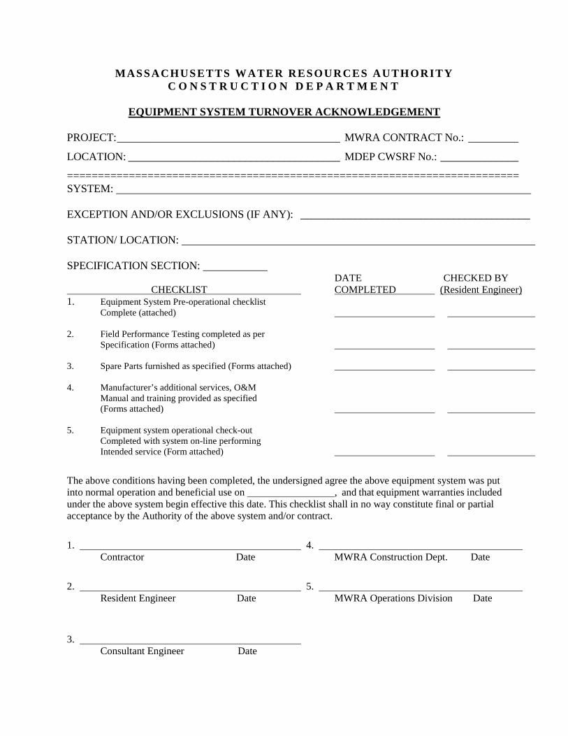
MASSACHUSETTS WATER RESOURCES AUTHORITY C O N S T R U C T I O N D E P A R T M E N T
EQUIPMENT SYSTEM TURNOVER ACKNOWLEDGEMENT
PROJECT: ________________________________________ MWRA CONTRACT No.: _________
LOCATION: ______________________________________ MDEP CWSRF No.: ______________
========================================================================= SYSTEM: EXCEPTION AND/OR EXCLUSIONS (IF ANY): __________________________________________ STATION/ LOCATION: SPECIFICATION SECTION: DATE CHECKED BY CHECKLIST COMPLETED (Resident Engineer) 1. Equipment System Pre-operational checklist Complete (attached) 2. Field Performance Testing completed as per Specification (Forms attached) 3. Spare Parts furnished as specified (Forms attached) 4. Manufacturer’s additional services, O&M Manual and training provided as specified (Forms attached) 5. Equipment system operational check-out Completed with system on-line performing Intended service (Form attached)
The above conditions having been completed, the undersigned agree the above equipment system was put into normal operation and beneficial use on , and that equipment warranties included under the above system begin effective this date. This checklist shall in no way constitute final or partial acceptance by the Authority of the above system and/or contract.
1. 4. Contractor Date MWRA Construction Dept. Date
2. 5. Resident Engineer Date MWRA Operations Division Date
3. Consultant Engineer Date
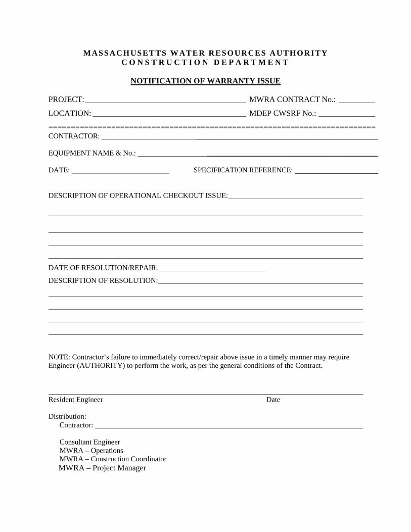
MASSACHUSETTS WATER RESOURCES AUTHORITY C O N S T R U C T I O N D E P A R T M E N T
NOTIFICATION OF WARRANTY ISSUE
PROJECT: ________________________________________ MWRA CONTRACT No.: _________
LOCATION: ______________________________________ MDEP CWSRF No.: ______________
========================================================================= CONTRACTOR: __________________________________________________ EQUIPMENT NAME & No.: _______________________________________________ DATE: SPECIFICATION REFERENCE:
DESCRIPTION OF OPERATIONAL CHECKOUT ISSUE:
DATE OF RESOLUTION/REPAIR:
DESCRIPTION OF RESOLUTION:
NOTE: Contractor’s failure to immediately correct/repair above issue in a timely manner may require Engineer (AUTHORITY) to perform the work, as per the general conditions of the Contract. Resident Engineer Date
Distribution: Contractor: Consultant Engineer MWRA – Operations MWRA – Construction Coordinator MWRA – Project Manager
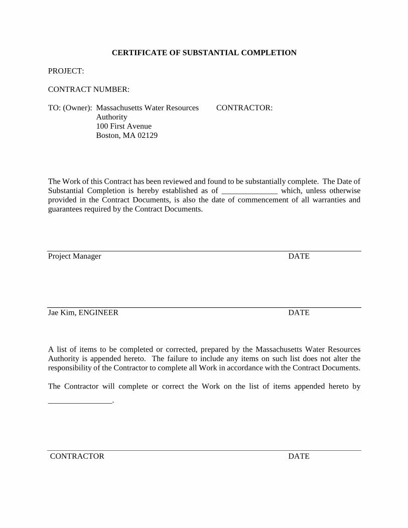
CERTIFICATE OF SUBSTANTIAL COMPLETION PROJECT: CONTRACT NUMBER: TO: (Owner): Massachusetts Water Resources CONTRACTOR:
Authority 100 First Avenue Boston, MA 02129
The Work of this Contract has been reviewed and found to be substantially complete. The Date of Substantial Completion is hereby established as of ______________ which, unless otherwise provided in the Contract Documents, is also the date of commencement of all warranties and guarantees required by the Contract Documents.
Project Manager DATE
Jae Kim, ENGINEER DATE
A list of items to be completed or corrected, prepared by the Massachusetts Water Resources Authority is appended hereto. The failure to include any items on such list does not alter the responsibility of the Contractor to complete all Work in accordance with the Contract Documents. The Contractor will complete or correct the Work on the list of items appended hereto by
________________.
CONTRACTOR DATE
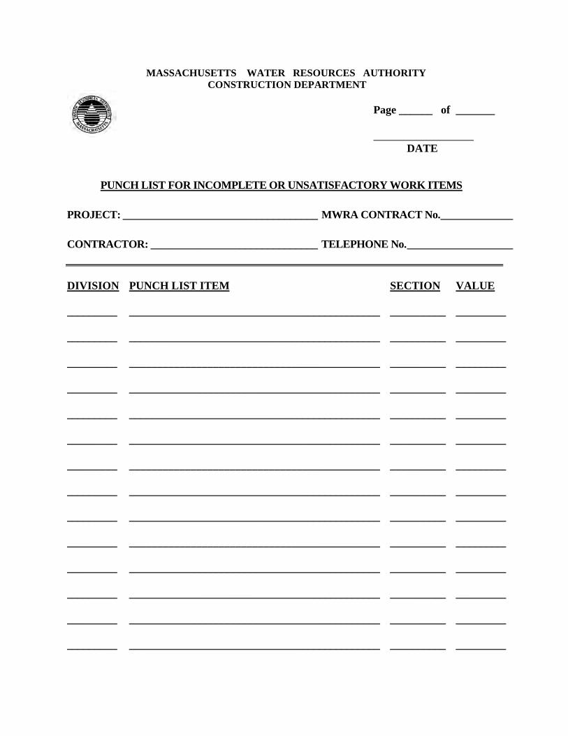
MASSACHUSETTS WATER RESOURCES AUTHORITY CONSTRUCTION DEPARTMENT
Page ______ of _______ DATE
PUNCH LIST FOR INCOMPLETE OR UNSATISFACTORY WORK ITEMS
PROJECT: ___________________________________ MWRA CONTRACT No. _____________ CONTRACTOR: ______________________________ TELEPHONE No. ___________________
DIVISION
PUNCH LIST ITEM SECTION VALUE
_________
_____________________________________________ __________ _________
_________
_____________________________________________ __________ _________
_________
_____________________________________________ __________ _________
_________
_____________________________________________ __________ _________
_________
_____________________________________________ __________ _________
_________
_____________________________________________ __________ _________
_________
_____________________________________________ __________ _________
_________
_____________________________________________ __________ _________
_________
_____________________________________________ __________ _________
_________
_____________________________________________ __________ _________
_________
_____________________________________________ __________ _________
_________
_____________________________________________ __________ _________
_________
_____________________________________________ __________ _________
_________
_____________________________________________ __________ _________
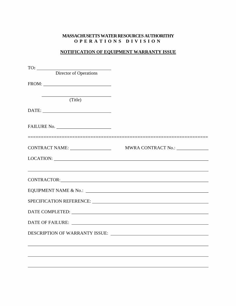
MASSACHUSETTS WATER RESOURCES AUTHORITHY
O P E R A T I O N S D I V I S I O N
NOTIFICATION OF EQUIPMENT WARRANTY ISSUE TO:
Director of Operations FROM:
(Title) DATE: FAILURE No. ===================================================================== CONTRACT NAME: MWRA CONTRACT No.: LOCATION: CONTRACTOR: EQUIPMENT NAME & No.: SPECIFICATION REFERENCE: DATE COMPLETED: DATE OF FAILURE: DESCRIPTION OF WARRANTY ISSUE:
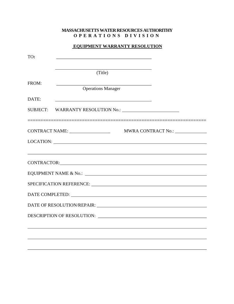
MASSACHUSETTS WATER RESOURCES AUTHORITHY O P E R A T I O N S D I V I S I O N
EQUIPMENT WARRANTY RESOLUTION
TO:
(Title) FROM:
Operations Manager DATE: SUBJECT: WARRANTY RESOLUTION No.: ===================================================================== CONTRACT NAME: MWRA CONTRACT No.: LOCATION: CONTRACTOR: EQUIPMENT NAME & No.: SPECIFICATION REFERENCE: DATE COMPLETED: DATE OF RESOLUTION/REPAIR: DESCRIPTION OF RESOLUTION:
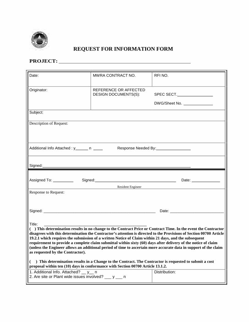
REQUEST FOR INFORMATION FORM
PROJECT:
Date:
MWRA CONTRACT NO.
RFI NO.
Originator:
REFERENCE OR AFFECTED DESIGN DOCUMENTS(S):
SPEC SECT. DWG/Sheet No.
Subject:
Description of Request:
Additional Info Attached : y n Response Needed By:
Signed:
Assigned To: Signed: Date: Resident Engineer
Response to Request:
Signed: ____________________________________________________ Date: _________________________ Title: ( ) This determination results in no change to the Contract Price or Contract Time. In the event the Contractor disagrees with this determination the Contractor’s attention is directed to the Provisions of Section 00700 Article 19.2.1 which requires the submission of a written Notice of Claim within 21 days, and the subsequent requirement to provide a complete claim submittal within sixty (60) days after delivery of the notice of claim (unless the Engineer allows an additional period of time to ascertain more accurate data in support of the claim as requested by the Contractor). ( ) This determination results in a Change to the Contract. The Contractor is requested to submit a cost proposal within ten (10) days in conformance with Section 00700 Article 13.1.2.
1. Additional Info. Attached? __ y__ n 2. Are site or Plant wide issues involved? ___ y ___ n
Distribution:
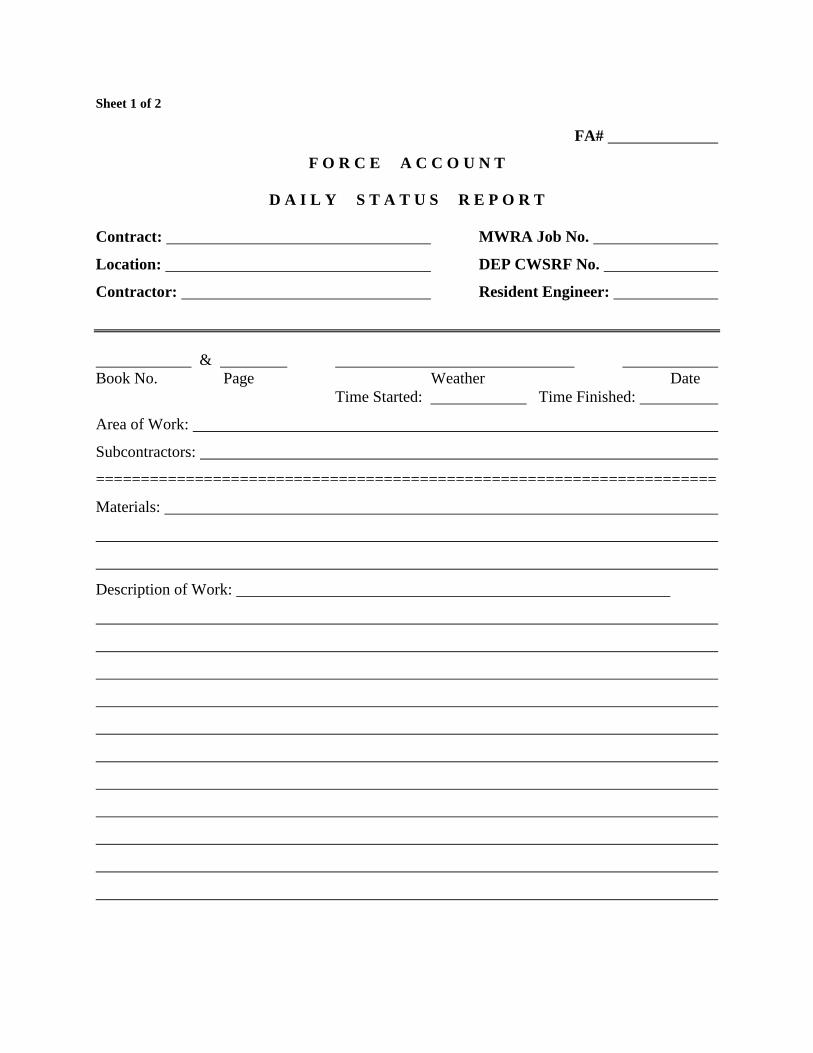
Sheet 1 of 2
FA#
F O R C E A C C O U N T
D A I L Y S T A T U S R E P O R T Contract: MWRA Job No.
Location: DEP CWSRF No.
Contractor: Resident Engineer:
& Book No. Page Weather Date Time Started: Time Finished:
Area of Work:
Subcontractors:
=====================================================================
Materials:
Description of Work:
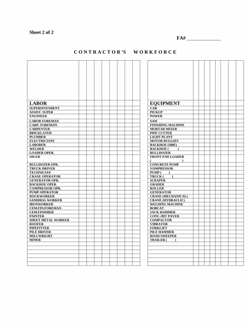
Sheet 2 of 2 FA#
C O N T R A C T O R ’S W O R K F O R C E
LABOR EQUIPMENT SUPERINTENDENT CAR ASSIST. SUPER PICKUP ENGINEER POWER LABOR FOREMAN SAW CARP. FOREMAN FINISHING MACHINE CARPENTER MORTAR MIXER BRICKLAYER PIPE CUTTER PLUMBER LIGHT PLANT ELECTRICIANS MOTOR BUGGIES LABORER BACKHOE (580E) WELDER BACKHOE ( ) LOADER OPER. BULLDOZER OILER FRONT END LOADER
( )
BULLDOZER OPR. CONCRETE PUMP TRUCK DRIVER VOMPRESSOR TECHNICIAN PUMP ( ) CRANE OPERATOR TRUCK ( ) GENERATOR OPR. SCRAPER BACKHOE OPER. GRADER COMPRESSOR OPR. ROLLER PUMP OPERATOR GENERATOR DOCKWORKER CRANE (MECHANICAL) SANDHOG WORKER CRANE (HYDRAULIC) IRONWORKER WELDING MACHINE CEM.FIN.FOREMAN BOBCAT CEM.FINISHER JACK HAMMER PAINTER CONC./BIT PAVER SHEET METAL WORKER COMPACTOR ROOFER VIBRATOR PIPEFITTER FORKLIFT PILE DRIVER PILE HAMMER MILLWRIGHT ROAD SWEEPER MINER TRAILER ( )
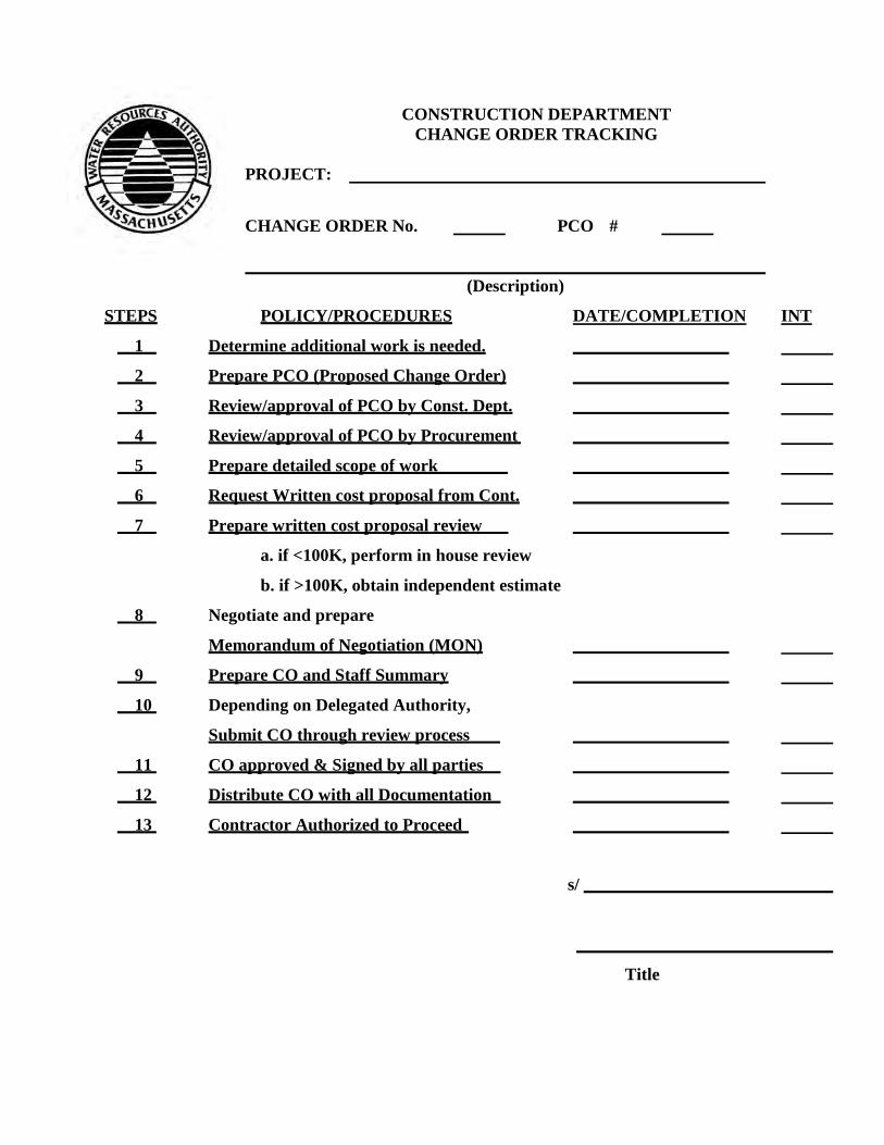
CONSTRUCTION DEPARTMENT CHANGE ORDER TRACKING
PROJECT: CHANGE ORDER No. PCO #
(Description)
STEPS POLICY/PROCEDURES DATE/COMPLETION INT
1 Determine additional work is needed.
2 Prepare PCO (Proposed Change Order)
3 Review/approval of PCO by Const. Dept.
4 Review/approval of PCO by Procurement
5 Prepare detailed scope of work
6 Request Written cost proposal from Cont.
7 Prepare written cost proposal review
a. if <100K, perform in house review
b. if >100K, obtain independent estimate
8 Negotiate and prepare
Memorandum of Negotiation (MON)
9 Prepare CO and Staff Summary
10 Depending on Delegated Authority,
Submit CO through review process
11 CO approved & Signed by all parties
12 Distribute CO with all Documentation
13 Contractor Authorized to Proceed
s/
Title
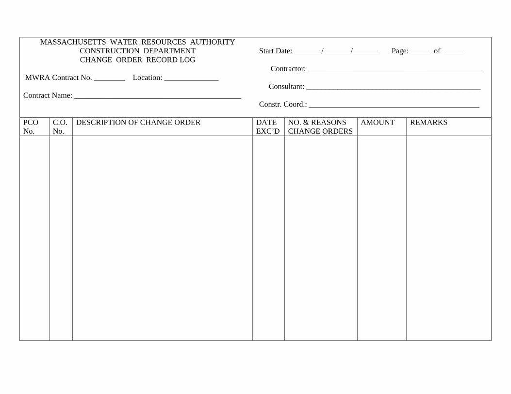
MASSACHUSETTS WATER RESOURCES AUTHORITY CONSTRUCTION DEPARTMENT CHANGE ORDER RECORD LOG
MWRA Contract No. ________ Location: ______________ Contract Name: ___________________________________________
Start Date: _______/_______/_______ Page: _____ of _____ Contractor: _____________________________________________ Consultant: _____________________________________________ Constr. Coord.: ____________________________________________
PCO No.
C.O. No.
DESCRIPTION OF CHANGE ORDER DATE EXC’D
NO. & REASONS CHANGE ORDERS
AMOUNT REMARKS
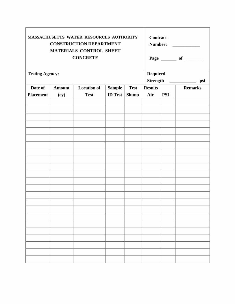
MASSACHUSETTS WATER RESOURCES AUTHORITY
CONSTRUCTION DEPARTMENT MATERIALS CONTROL SHEET
CONCRETE
Contract Number: ____________ Page of ________
Testing Agency:
Required Strength psi
Date of Placement
Amount (cy)
Location of Test
Sample ID Test
Test Slump
Results Air
PSI
Remarks
VISITORS LOG
Sheet of ____ Project: MWRA Contract No.: Location: Contractor:
DATE VISITOR – REPRESENTING PURPOSE OF VISIT TIME - IN
TIME - OUT
ACCIDENT REPORT
Project: MWRA Contract No.: Location: EPA/MDEP Project No.: Date of Occurrence: Date: Weather Conditions: Witness Time of Occurrence: & Phone No.: Contractor: Summary of Events: Property Damage: Location of Accident: Police Officers Investigating: Police File No.: Consultant personnel on location at time of accident: Operators of any equipment involved:
PAGE 1 OF 2
ACCIDENT REPORT
Project: MWRA Contract No.: Location: EPA/MDEP Project No.: Contractor: Date: Personnel Injuries: cc Director of Construction Construction Coordinator Assistant Manager of Worker’s Compensation Employee Resident Engineer Date
PAGE 2 OF 2
DAMAGE REPORT
Project: MWRA Contract No.: Location: EPA/MDEP Project No.: Contractor: Owner of Damaged Property: Equipment Manufacturer: Date Received: Delivered by Specification Section: Describe Damage Proposed Repairs/Replacements By Whom Comments
Resident Engineer Date
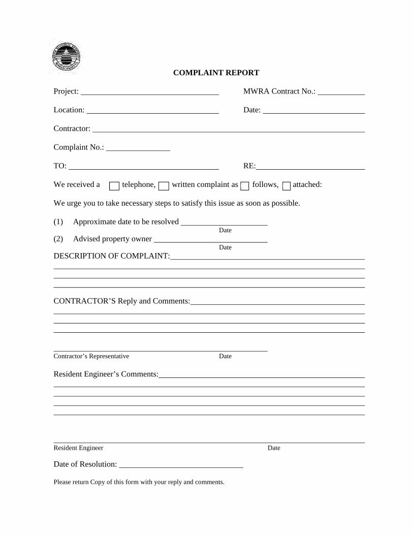
COMPLAINT REPORT
Project: MWRA Contract No.: Location: Date: Contractor: Complaint No.:
TO: RE: We received a telephone, written complaint as follows, attached: We urge you to take necessary steps to satisfy this issue as soon as possible. (1) Approximate date to be resolved Date (2) Advised property owner Date DESCRIPTION OF COMPLAINT: CONTRACTOR’S Reply and Comments: Contractor’s Representative Date Resident Engineer’s Comments: Resident Engineer Date Date of Resolution: Please return Copy of this form with your reply and comments.
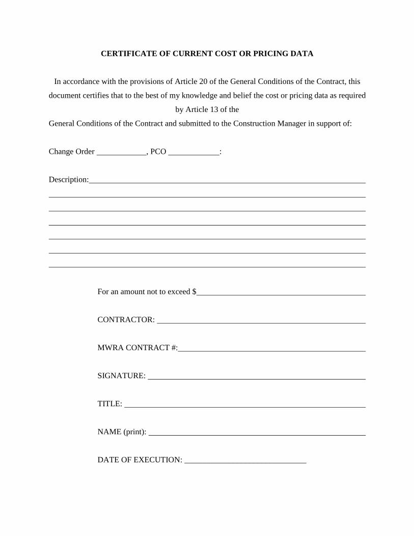
CERTIFICATE OF CURRENT COST OR PRICING DATA
In accordance with the provisions of Article 20 of the General Conditions of the Contract, this
document certifies that to the best of my knowledge and belief the cost or pricing data as required
by Article 13 of the
General Conditions of the Contract and submitted to the Construction Manager in support of:
Change Order , PCO :
Description:
For an amount not to exceed $
CONTRACTOR:
MWRA CONTRACT #:
SIGNATURE:
TITLE:
NAME (print):
DATE OF EXECUTION: ______________________________
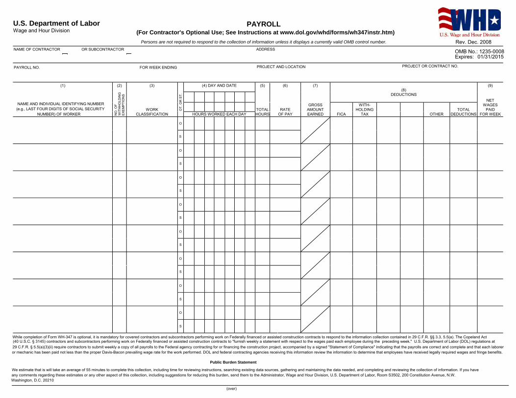
U.S. Department of Labor PAYROLL (For Contractor's Optional Use; See Instructions at www.dol.gov/whd/forms/wh347instr.htm)Wage and Hour Division
Persons are not required to respond to the collection of information unless it displays a currently valid OMB control number.
NAME OF CONTRACTOR OR SUBCONTRACTOR ADDRESS OMB No.: 1235-0008 Expires: 01/31/2015
PAYROLL NO. FOR WEEK ENDING PROJECT AND LOCATION PROJECT OR CONTRACT NO.
(1) (2) (3) (4) DAY AND DATE (5) (6) (7) (9) (8)
DEDUCTIONS
O
O
O
O
O
O
O
O
NAME AND INDIVIDUAL IDENTIFYING NUMBER (e.g., LAST FOUR DIGITS OF SOCIAL SECURITY
NUMBER) OF WORKER NO
. OF
WIT
HH
OLD
iNG
E
XEM
PTI
ON
S
WORK CLASSIFICATION
OT.
OR
ST.
HOURS WORKED EACH DAY TOTAL HOURS
RATE OF PAY
GROSS AMOUNT EARNED FICA
WITH-HOLDING
TAX OTHER TOTAL
DEDUCTIONS
NET WAGES
PAID FOR WEEK
S
S
S
S
S
S
S
S
Rev. Dec. 2008
Rev. Dec. 2008
While completion of Form WH-347 is optional, it is mandatory for covered contractors and subcontractors performing work on Federally financed or assisted construction contracts to respond to the information collection contained in 29 C.F.R. §§ 3.3, 5.5(a). The Copeland Act (40 U.S.C. § 3145) contractors and subcontractors performing work on Federally financed or assisted construction contracts to "furnish weekly a statement with respect to the wages paid each employee during the preceding week." U.S. Department of Labor (DOL) regulations at 29 C.F.R. § 5.5(a)(3)(ii) require contractors to submit weekly a copy of all payrolls to the Federal agency contracting for or financing the construction project, accompanied by a signed "Statement of Compliance" indicating that the payrolls are correct and complete and that each laborer or mechanic has been paid not less than the proper Davis-Bacon prevailing wage rate for the work performed. DOL and federal contracting agencies receiving this information review the information to determine that employees have received legally required wages and fringe benefits.
Public Burden Statement
We estimate that is will take an average of 55 minutes to complete this collection, including time for reviewing instructions, searching existing data sources, gathering and maintaining the data needed, and completing and reviewing the collection of information. If you have any comments regarding these estimates or any other aspect of this collection, including suggestions for reducing this burden, send them to the Administrator, Wage and Hour Division, U.S. Department of Labor, Room S3502, 200 Constitution Avenue, N.W. Washington, D.C. 20210
(over)
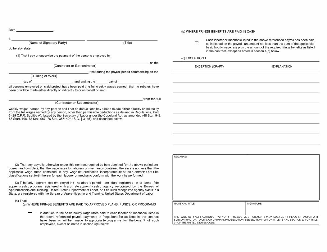
Date
I,(Name of Signatory Party) (Title)
do hereby state:
(1) That I pay or supervise the payment of the persons employed by
on the (Contractor or Subcontractor)
; that during the payroll period commencing on the (Building or Work)
day of , , and ending the day of , , all persons employed on s aid project have been paid t he full weekly wages earned, that no rebates have been or will be made either directly or indirectly to or on behalf of said
from the full (Contractor or Subcontractor)
weekly wages earned by any pers on and t hat no deduc tions hav e been m ade eit her direc tly or indirec tly from the full wages earned by any person, other than permissible deductions as defined in Regulations, Part 3 (29 C.F.R. Subtitle A), issued by the Secretary of Labor under the Copeland Act, as amended (48 Stat. 948, 63 Start. 108, 72 Stat. 967; 76 Stat. 357; 40 U.S.C. § 3145), and described below:
(2) That any payrolls otherwise under this contract required t o be s ubmitted for the abov e period are correct and complete; that the wage rates for laborers or mechanics contained therein are not less than the applicable wage rates contained in any wage det ermination incorporated int o t he c ontract; t hat t he classifications set forth therein for each laborer or mechanic conform with the work he performed.
(3) T hat any apprent ices em ployed in t he abov e period are duly registered in a bona fide apprenticeship program regis tered w ith a St ate apprent iceship agency recognized by the Bureau of Apprenticeship and Training, United States Department of Labor, or if no such recognized agency exists in a State, are registered with the Bureau of Apprenticeship and Training, United States Department of Labor.
(4) That: (a) WHERE FRINGE BENEFITS ARE PAID TO APPROVED PLANS, FUNDS, OR PROGRAMS
− in addition to the basic hourly wage rates paid to each laborer or mechanic listed in the above referenced payroll, payments of fringe bene fits as listed in the contract have been or will be made to appropria te progra ms for the bene fit of such employees, except as noted in section 4(c) below.
(b) WHERE FRINGE BENEFITS ARE PAID IN CASH
− Each laborer or mechanic listed in the above referenced payroll has been paid, as indicated on the payroll, an amount not less than the sum of the applicable basic hourly wage rate plus the amount of the required fringe benefits as listed in the contract, except as noted in section 4(c) below.
(c) EXCEPTIONS
REMARKS:
EXCEPTION (CRAFT)
EXPLANATION
NAME AND TITLE SIGNATURE
THE WILLFUL FALSIFICATION O F ANY O F T HE ABO VE ST ATEMENTS M AY SUBJ ECT T HE CO NTRACTOR O R SUBCONTRACTOR TO CIVIL OR CRIMINAL PROSECUTION. SEE SECTION 1001 OF TITLE 18 AND SECTION 231 OF TITLE 31 OF THE UNITED STATES CODE.
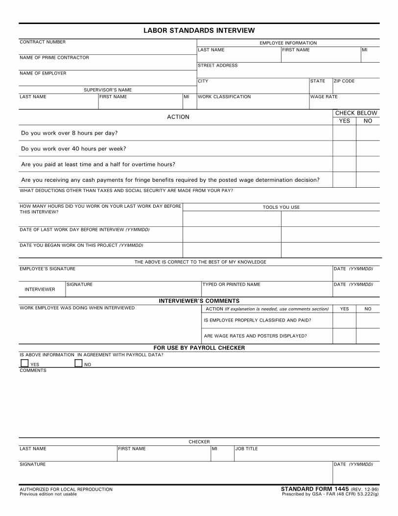
LABOR STANDARDS INTERVIEWCONTRACT NUMBER EMPLOYEE INFORMATION
LAST NAME FIRST NAME MI
STREET ADDRESS
CITY STATE ZIP CODE
WORK CLASSIFICATION WAGE RATE
NAME OF PRIME CONTRACTOR
NAME OF EMPLOYER
SUPERVISOR'S NAMELAST NAME FIRST NAME MI
ACTIONCHECK BELOWYES NO
Do you work over 8 hours per day?
Do you work over 40 hours per week?
Are you paid at least time and a half for overtime hours?
Are you receiving any cash payments for fringe benefits required by the posted wage determination decision?
WHAT DEDUCTIONS OTHER THAN TAXES AND SOCIAL SECURITY ARE MADE FROM YOUR PAY?
HOW MANY HOURS DID YOU WORK ON YOUR LAST WORK DAY BEFORETHIS INTERVIEW?
DATE OF LAST WORK DAY BEFORE INTERVIEW (YYMMDD)
DATE YOU BEGAN WORK ON THIS PROJECT (YYMMDD)
TOOLS YOU USE
THE ABOVE IS CORRECT TO THE BEST OF MY KNOWLEDGEEMPLOYEE'S SIGNATURE DATE (YYMMDD)
INTERVIEWERSIGNATURE TYPED OR PRINTED NAME DATE (YYMMDD)
INTERVIEWER'S COMMENTSACTION (If explanation is needed, use comments section) YES NOWORK EMPLOYEE WAS DOING WHEN INTERVIEWED
IS EMPLOYEE PROPERLY CLASSIFIED AND PAID?
ARE WAGE RATES AND POSTERS DISPLAYED?
FOR USE BY PAYROLL CHECKERIS ABOVE INFORMATION IN AGREEMENT WITH PAYROLL DATA?
YES NOCOMMENTS
CHECKERLAST NAME FIRST NAME MI JOB TITLE
DATE (YYMMDD)SIGNATURE
AUTHORIZED FOR LOCAL REPRODUCTIONPrevious edition not usable
STANDARD FORM 1445 (REV. 12-96)Prescribed by GSA - FAR (48 CFR) 53.222(g)
DCAM Standard Contractor Evaluation Form Instructions 1 Revised 7/09
Division of Capital Asset Management Standard Contractor Evaluation Form
(Revised July 2009)
****IMPORTANT NOTICE****
THIS FORM IS TO BE USED TO EVALUATE THE PERFORMANCE OF BOTH PRIME/GENERAL AND SUBCONTRACTORS1 ON MASSACHUSETTS PUBLIC BUILDING PROJECTS BID UNDER M.G.L. c. 149A and c. 149, § 44A AND § 44F. PLEASE DO NOT USE THIS FORM TO EVALUATE THE PERFORMANCE OF CONTRACTORS ON PRIVATE WORK. Instructions to Public Awarding Authorities 1. This evaluation form is to be used for Preliminary Evaluations and Final Evaluations on both
Prime/General Contractors and Subcontractors for all projects bid under M.G.L. c. 149A and c. 149, § 44A and § 44F. This form must be completed by every Massachusetts public agency and submitted to the Division of Capital Asset Management (“DCAM”) for inclusion in each contractors’ certification file promptly after completion (i.e. use and/or occupancy, or upon issuance of a certificate of use and/or occupancy, or termination, whichever is earlier).
2. This form must be completed and signed by one of the following:
a) For public projects estimated to be under $1.5 million dollars which do not require an Owner’s Project Manager (“OPM”), as mandated by M.G.L., c. 149, § 44A 1/2, the Awarding Authority must complete the evaluation and sign the last page of the Evaluation. At the Awarding Authority’s discretion, the Awarding Authority’s Representative (e.g. Architect/Designer) may sign the last page of the evaluation. The Awarding Authority’s Representative shall not submit a separate Evaluation to DCAM.
b) For public projects estimated to be $1.5 million dollars or greater which require an OPM, it is mandatory that the Awarding Authority and the OPM complete and sign the Evaluation.
Evaluations that do not meet these requirements will not meet the Awarding Authority’s statutory obligations regarding Contractor Evaluations and will not be accepted by DCAM. DCAM will return incorrectly completed Evaluations to the Awarding Authority for proper completion within the required time frames. The Awarding Authority’s evaluation of the contractor is critically important to DCAM and affects DCAM’s determination of whether a contractor should be, or remain certified. It is of the utmost importance that the individual from the Awarding Authority with the most knowledge of the project be the evaluator on this form.
1 For the purpose of this evaluation form, the term “Subcontractor” shall mean all filed sub-bidders as defined in M.G.L. c. 149, §44F. Subcontractors who are NOT filed sub-bidders need not be evaluated.
DCAM Standard Contractor Evaluation Form Instructions 2 Revised 7/09
3. Any public agency that fails to complete and submit the contractor evaluation forms to DCAM within 70 days (for the Prime/General Contractor) and 90 days (for Subcontractors) of the completion of a project shall be ineligible for the receipt of any public funds disbursed by the Commonwealth for the purposes of any public buildings or public works projects. Individuals completing this form on behalf of a public Awarding Authority will be indemnified and represented by that Awarding Authority in connection with any suit commenced by a contractor as a result of the completion of an evaluation form in accordance with the terms of M.G.L., c. 149, § 44D.
4. Upon completion of all Contractor Evaluation forms on your project, submit them directly to the
DCAM Contractor Certification Office at the following address: One Ashburton Place, 15th Floor Boston, MA 02108
5. As an Awarding Authority, you are also required to send a copy of any completed Contractor
Evaluation form to the contractor being evaluated. 6. We strongly encourage you to provide DCAM with copies of the Preliminary Evaluations on the Prime
Contractors and Subcontrators.
DCAM Standard Contractor Evaluation Form Instructions 3 Revised 7/09
Guidelines for Reviewers
The following definitions are being furnished as a guide for assisting evaluators in determining an appropriate rating for contractors: Finished Product Quality
The rating in this category covers general quality of workmanship.
(a) A building and/or system will be rated “very good” to “excellent” if the workmanship exceeds customary practices with no complaints.
(b) The Division will consider as “satisfactory” a building and/or system that has been installed and is operating in accordance with contract requirements with few and minor complaints.
(c) A building and/or system that has met contract requirements only after frequent adjustments or modifications and with many complaints will be rated “poor.”
(d) A building and/or system which functions with constant adjustments or modifications and serious complaints attributed to the contractor's work, and a building and/or system which fails to meet contract requirements, rates as “unacceptable,” and no points will be given to the contractor, with a written explanation attached.
Project Management
Five factors are evaluated: coordination and scheduling; ability to manage subcontractors; safety and housekeeping procedures; change orders; working relationships with others on the project; and paperwork.
(a) “Very good” to “excellent” performance is when the contractor routinely furnishes all
schedules, shop drawings, and submittals required by the contract in a timely fashion, performs according to the schedules, has the subcontractors in and out of the project as scheduled, maintains a businesslike relationship with the Awarding Authority, designer, subcontractors and the project manager, and runs an orderly and safe project with few complaints.
(b) “Satisfactory” performance is when the contractor occasionally fails to meet the above scheduling and management requirements.
(c) A “poor” rating is when the contractor fails to meet the above scheduling and management requirements on a regular and recurring basis.
(d) If the contractor's performance is so poor that the project is seriously affected, the rating should be “unacceptable,” thereby, no points should be given, and a written explanation attached.
Supervisory Personnel Rating
The contractor's on-site supervisory staff is rated on their knowledge, management skills and experience.
Standard Contractor Evaluation Form Page 1 of 5 Revised: 7/09
Division of Capital Asset Management Standard Contractor Evaluation Form
IMPORTANT – Please check (����) if this evaluation is for:
Prime/General Contractor Subcontractor Section I- General Project Information - Section I must be completed in its entirety.
Reference Name:
Reference Telephone #:
Reference Position/ Title:
Date: DCAM Interviewer (if any): Reference
Agency/ Firm: Name of Contractor Being Evaluated: Contract Cost for Contractor Being Evaluated
Including Change Orders: $ (if change order amount unknown for subcontractor then estimate as 5% of subcontract amount)
Project Title:
Contract Start/ End Dates: Actual Completion Date:
Scope of Work: Project Location (city and state):
*****************Important****************
• Please check (����) if this is a : Preliminary Evaluation (50% complete); or
Final Evaluation (once use and/or occupancy, or issuance of a certificate of use and/or occupancy, or contract termination have been achieved, whichever is earlier)
• Please check (�) if: The project was estimated to be greater than $1.5M dollars and required an Owner’s Project Manager.
• Did the contractor execute this project using their own employees? Yes No
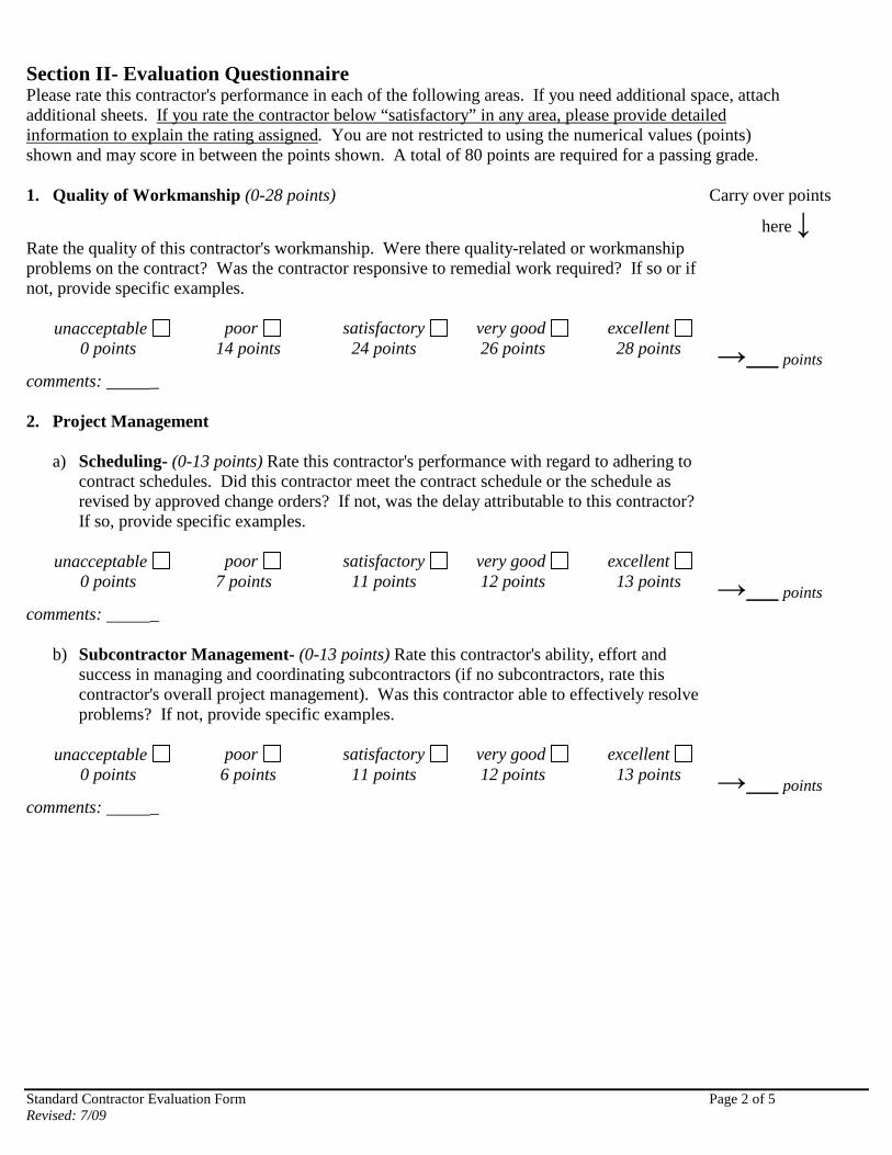
Standard Contractor Evaluation Form Page 2 of 5 Revised: 7/09
Section II- Evaluation Questionnaire Please rate this contractor's performance in each of the following areas. If you need additional space, attach additional sheets. If you rate the contractor below “satisfactory” in any area, please provide detailed information to explain the rating assigned. You are not restricted to using the numerical values (points) shown and may score in between the points shown. A total of 80 points are required for a passing grade. 1. Quality of Workmanship (0-28 points) Carry over points
here � Rate the quality of this contractor's workmanship. Were there quality-related or workmanship problems on the contract? Was the contractor responsive to remedial work required? If so or if not, provide specific examples.
unacceptable poor satisfactory very good excellent 0 points 14 points 24 points 26 points 28 points
� points comments: _ 2. Project Management
a) Scheduling- (0-13 points) Rate this contractor's performance with regard to adhering to contract schedules. Did this contractor meet the contract schedule or the schedule as revised by approved change orders? If not, was the delay attributable to this contractor? If so, provide specific examples.
unacceptable poor satisfactory very good excellent
0 points 7 points 11 points 12 points 13 points � points
comments: _
b) Subcontractor Management- (0-13 points) Rate this contractor's ability, effort and success in managing and coordinating subcontractors (if no subcontractors, rate this contractor's overall project management). Was this contractor able to effectively resolve problems? If not, provide specific examples.
unacceptable poor satisfactory very good excellent
0 points 6 points 11 points 12 points 13 points � points
comments: _
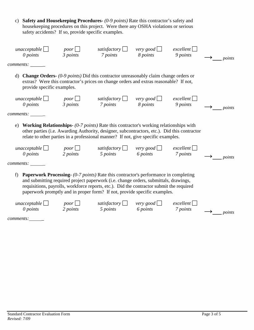
Standard Contractor Evaluation Form Page 3 of 5 Revised: 7/09
c) Safety and Housekeeping Procedures- (0-9 points) Rate this contractor’s safety and
housekeeping procedures on this project. Were there any OSHA violations or serious safety accidents? If so, provide specific examples.
unacceptable poor satisfactory very good excellent 0 points 3 points 7 points 8 points 9 points
� points comments: _
d) Change Orders- (0-9 points) Did this contractor unreasonably claim change orders or extras? Were this contractor’s prices on change orders and extras reasonable? If not, provide specific examples.
unacceptable poor satisfactory very good excellent
0 points 3 points 7 points 8 points 9 points � points
comments: _
e) Working Relationships- (0-7 points) Rate this contractor's working relationships with other parties (i.e. Awarding Authority, designer, subcontractors, etc.). Did this contractor relate to other parties in a professional manner? If not, give specific examples.
unacceptable poor satisfactory very good excellent
0 points 2 points 5 points 6 points 7 points � points
comments: _
f) Paperwork Processing- (0-7 points) Rate this contractor's performance in completing and submitting required project paperwork (i.e. change orders, submittals, drawings, requisitions, payrolls, workforce reports, etc.). Did the contractor submit the required paperwork promptly and in proper form? If not, provide specific examples.
unacceptable poor satisfactory very good excellent
0 points 2 points 5 points 6 points 7 points � points
comments: _
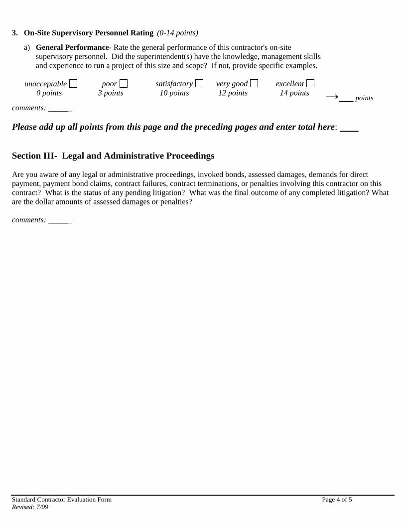
Standard Contractor Evaluation Form Page 4 of 5 Revised: 7/09
3. On-Site Supervisory Personnel Rating (0-14 points)
a) General Performance- Rate the general performance of this contractor's on-site supervisory personnel. Did the superintendent(s) have the knowledge, management skills and experience to run a project of this size and scope? If not, provide specific examples.
unacceptable poor satisfactory very good excellent
0 points 3 points 10 points 12 points 14 points � points
comments: _ Please add up all points from this page and the preceding pages and enter total here: Section III- Legal and Administrative Proceedings Are you aware of any legal or administrative proceedings, invoked bonds, assessed damages, demands for direct payment, payment bond claims, contract failures, contract terminations, or penalties involving this contractor on this contract? What is the status of any pending litigation? What was the final outcome of any completed litigation? What are the dollar amounts of assessed damages or penalties? comments: _
Standard Contractor Evaluation Form Page 5 of 5 Revised: 7/09
Section IV- Evaluator Certification I hereby certify that the information contained in this evaluation form represents, to the best of my knowledge, a true analysis of this contractor's performance record on this contract and that this Project Evaluation and Project Rating was not the subject of any negotiation, close-out, or settlement of the subject project or related thereto and that no compensation or consideration (either financial or additional work on this project or otherwise) was given to the awarding authority or me in connection with its preparation or the opinions contained herein. I also certify that I have no ties with this contractor either through a business or family relationship. I have mailed a copy of this completed evaluation form to the contractor on _________________ (Public Awarding Authorities must mail a copy of this completed evaluation form to the contractor). For Public Projects below $1,500,000, this form must be completed and signed by the Awarding Authority and may also be signed by the Owner’s Representative (i.e. Architect/Designer) in conjunction with the Awarding Authority: _______________________________________ _________________ __________ Signature of Awarding Authority Print Name and Title Date ________________________________________ _________________ __________ Signature of Awarding Authority’s Representative Print Name and Title Date (optional) For Public Projects $1,500,000 or greater, this form must be signed by the Owner’s (Awarding Authority’s) Project Manager and the Awarding Authority pursuant to M.G.L., c. 149, § 44A 1/2: ______________________________________ _________________ ___________ Signature of Owner’s (Awarding Authority’s) Print Name and Title Date Project Manager ______________________________________ _________________ ___________ Signature of Awarding Authority Print Name and Title Date Section V- Additional Comments Comments:
CONSENT OF SURETY TO REDUCTION IN OR PARTIAL RELEASE OF RETAINAGE
THIS DOCUMENT HAS IMPORTANT LEGAL CONSEQUENCES; CONSULTATION WITH AN ATTORNEY IS ENCOURAGED WITH RESPECT TO ITS COMPLETION OR MODIFICATION. TO OWNER: (Name and address) ARCHITECTS PROJECT NO.: CONTRACT FOR: PROJECT: (Name and address) CONTRACT DATED: In accordance with the provisions of the Contract between the Owner and the Contractor as indicated above, the (Insert name and address of Surety) , SURETY, on bond of (Insert name and address of Contractor) , CONTRACTOR, hereby approves the reduction in or partial release of retainage to the Contractor as follows: The Surety agrees that such reduction in or partial release of retainage to the Contractor shall not relieve the Surety of any of its obligations to (Insert name and address of Owner) , OWNER, as set forth in said Surety's bond. IN WITNESS WHEREOF, the Surety has hereunto set its hand on this date: (Insert in writing the month by the numeric date and year.) Attest: (Seal): (Surety) (Signature of authorized representative) (Printed name and title)
CONTRACT CLOSEOUT DOCUMENT
ACKNOWLEDGEMENT AND RELEASE OF CLAIMS
TO: The Massachusetts Water Resources Authority MWRA Contract #______________ Charlestown Navy Yard 100 First Avenue Contract description: ____________ Charlestown, MA 02129 ______________________________ ______________________________
In consideration of final payment by the Authority to the Contractor upon which this release is conditioned, the Contractor: 1) acknowledges that the Authority has made full, final and complete payment of all compensation payable under the provisions of the Contract referenced above, including all amendments, modifications, and change orders thereto; and, 2) fully releases and forever discharges without condition beyond receipt of final payment the Authority and its directors, officers, employees, consultants, representatives, agents, successors and assigns from any and all liability, claims, demands, causes of action, debts and suits, of every kind of nature, arising directly or indirectly out of said Contract. The person signing below on behalf of the Contractor certifies that he or she is duly authorized to act for the Contractor in this capacity and that he or she is so acting when signing this Release. IN WITNESS WHEREOF, the Contractor has hereunto set its hand and seal this _______________day of____________________________20______.
______________________________ CONTRACTOR ______________________________ Authorized Company Signature ______________________________ (Print Name and Title)
COMMONWEALTH OF MASSACHUSETTS
____________________,SS _________________, 20 On this _____ day of ___________, 20___, before me, the undersigned notary public, personally appeared_____________________, proved to me through satisfactory evidence of identification, which was _______________________________, to be the person whose name is signed above, and acknowledged to me that he/she signed it voluntarily for its stated purpose as __________________of______________________, pursuant to due and proper authority. (Title) (Contractor) __________________________________________ Notary Public My Commission Expires:
�
�
������ ��� ��� ������� ��������������������� ������ ��� ��������������� �������������� ����������� �������������������� ���� ���������
� �������������� � !�" ��� �#�����!" !��" ������� ��!�!�$����% $�$!� �" ����&� %�� '()*+',+-�./010*0.2)'3�4)0(51+,��!�!�*0.26)3/1�(57 ,�5'-�),�
,89:+*1�10�(+35(�.60,+*81)0'!���/),�-0*8; +'1�7 5,�+(+*160')*5((2�.60-8*+-�7 )1/�.+6; ),,)0'�0<�1/+�����5'-�*5'�9+�6+.60-8*+-�7 )1/081�4)0(51)0'�8'1)(�1/+�-51+�0<�
+=.)651)0'�5,�'01+-�9+(07 !�
�0',+'1�0<��86+12�
10��)'5(��52; +'1��
�����0*8; +'1�� � �%�
� OWNER [ ] ARCHITECT [ ] CONTRACTOR [ ] SURETY [ ] OTHER [ ]
THIS DOCUMENT HAS IMPORTANT LEGAL CONSEQUENCES; CONSULTATION WITH AN ATTORNEY IS ENCOURAGED WITH RESPECT TO ITS COMPLETION OR MODIFICATION. AUTHENTICATION OF THIS ELECTRONICALLY DRAFTED AIA DOCUMENT MAY BE MADE BY USING AIA DOCUMENT D401.
TO OWNER: (Name and address) ARCHITECT’S PROJECT NO.: CONTRACT FOR: PROJECT: (Name and address) CONTRACT DATED:
In accordance with the provisions of the Contract between the Owner and the Contractor as indicated above, the
(Insert name and address of Surety)
,SURETY on bond of (Insert name and address of Contractor)
,CONTRACTOR hereby approves of the final payment to the contractor, and agrees that final payment to the Contractor shall not relieve the Surety and of its obligations to (Insert name and address of Owner)
,OWNER as set forth in said Surety’s bond. IN WITNESS WHEREOF, the Surety has hereunto set its hand on this date: (Insert in writing the month followed by the numeric date and year) __________________________________________________________ (Surety) Attest: (Seal): ______________________________________________ (Signature of authorized representative) (Printed name and title)
�
�
���� �� ��� �� � ��� ���� �������������������� � �� ���� �� � �� �������� ����� �� �� ���������� ������� �� ��������������� ������� ���� �
��������� �������������� � !�" ��� �#�����!" !��" ������� ��!�!�$����% $�$!��" ����&�%�� '()*+',+-�./010*0.2)'3�4)0(51+,��!�!�*0.26)3/1�
(57 ,�5'-�),�,89:+*1�10�(+35(�.60,+*81)0'!���/),�-0*8; +'1�7 5,�+(+*160')*5((2�.60-8*+-�7 )1/�.+6; ),,)0'�0<�1/+�����5'-�*5'�9+�6+.60-8*+-�7 )1/081�4)0(51)0'�
8'1)(�1/+�-51+�0<�+=.)651)0'�5,�'01+-�9+(07 !�
�0'165*106�,��<<)-54)1�0<�
�+(+5,+�0<��)+',��
�����0*8; +'1�� ����%�
�
OWNER [ ] ARCHITECT [ ] CONTRACTOR [ ] SURETY [ ] OTHER [ ]
THIS DOCUMENT HAS IMPORTANT LEGAL CONSEQUENCES; CONSULTATION WITH AN ATTORNEY IS ENCOURAGED WITH RESPECT TO ITS COMPLETION OR MODIFICATION. AUTHENTICATION OF THIS ELECTRONICALLY DRAFTED AIA DOCUMENT MAY BE MADE BY USING AIA DOCUMENT D401.
TO OWNER: (Name and address) ARCHITECT’S PROJECT NO.: CONTRACT FOR: PROJECT: (Name and address) CONTRACT DATED:
STATE OF: COUNTY OF: The undersigned hereby certifies that, to the best of the undersigned’s knowledge, information and belief, except as listed below, the Releases or Waivers of Lien attached hereto include the Contractor, all Subcontractors, all suppliers of materials and equipment, and all performers of Work, labor or services who have or may have liens or encumbrances or the right to assert liens or encumbrances against any property of the Owner arising in any manner out of the performance of the Contract referenced above: EXCEPTIONS: SUPPORTING DOCUMENTS ATTACHED HERETO:
1. Contractor’s Release or Waiver of Liens, conditional upon receipt of final payment.
2. Separate Releases or Waivers of Liens from
Subcontractors and material and equipment suppliers, to the extent required by the Owner, accompanied by a list thereof.
CONTRACTOR:
(Name and address)
BY:_____________________________________________ (Signature of authorized representative) (Printed name and title) Subscribed and sworn to before me on this date: ______________ Notary Public:__________________________________________ My Commission Expires:_________________________________
�
�
���� �� ��� �� � ��� ���� ������ ���� ���������� � �� ���� �� � �� �������� ����� �� �� ���������� ��� ���� �� ��������������� ����� �� ���� �
��������� �������������� � !�" ��� �#�����!" !��" ������� ��!�!�$����% $�$!��" ����&�%�� '()*+',+-�./010*0.2)'3�4)0(51+,��!�!�*0.26)3/1�
(57 ,�5'-�),�,89:+*1�10�(+35(�.60,+*81)0'!���/),�-0*8; +'1�7 5,�+(+*160')*5((2�.60-8*+-�7 )1/�.+6; ),,)0'�0<�1/+�����5'-�*5'�9+�6+.60-8*+-�7 )1/081�4)0(51)0'�
8'1)(�1/+�-51+�0<�+=.)651)0'�5,�'01+-�9+(07 !�
�0'165*106�,��<<)-54)1�0<�
�52; +'1�0<��+91,�
5'-��(5); ,��
�����0*8; +'1�� ���%�
� OWNER [ ] ARCHITECT [ ] CONTRACTOR [ ] SURETY [ ] OTHER [ ]
THIS DOCUMENT HAS IMPORTANT LEGAL CONSEQUENCES; CONSULTATION WITH AN ATTORNEY IS ENCOURAGED WITH RESPECT TO ITS COMPLETION OR MODIFICATION. AUTHENTICATION OF THIS ELECTRONICALLY DRAFTED AIA DOCUMENT MAY BE MADE BY USING AIA DOCUMENT D401.
TO OWNER: (Name and address) ARCHITECT’S PROJECT NO.: CONTRACT FOR: PROJECT: (Name and address) CONTRACT DATED:
STATE OF: COUNTY OF: The undersigned hereby certifies that, except as listed below, payment has been made in full and all obligations have otherwise been satisfied for all materials and equipment furnished, for all work, labor, and services performed, and for all known indebtedness and claims against the Contractor for damages arising in any manner in connection with the performance of the Contract referenced above for which the Owner or Owner’s property might in any way be held responsible or encumbered, against any property of the Owner arising in any manner out of the performance of the Contract referenced above: EXCEPTIONS: SUPPORTING DOCUMENTS ATTACHED HERETO:
1. Consent of Surety to Final Payment. Whenever Surety is involved, Consent of Surety is required. AIA Document G707, Consent of Surety, may be used for this purpose.
Indicate attachment: [ ] yes [ ] no The following supporting documents should be attached hereto if required by the Owner: 1. Contractor’s Release or Waiver of Liens, conditional upon
receipt of final payment.
2. Separate Releases or Waivers of Liens from Subcontractors and material and equipment suppliers, to the extent required by the Owner, accompanied by a list thereof.
3. Contractor’s Affidavit of Release of Liens (AIA Document G706A).
CONTRACTOR: (Name and address) BY:__________________________________________ (Signature of authorized representative) (Printed name and title) Subscribed and sworn to before me on this date: ___________

�
�
���� �� ��� �� � ��� ���� ������ ���� ���������� � �� ���� �� � �� �������� ����� �� �� ���������� ��� ���� �� ��������������� ����� �� ���� �
��������� �������������� � !�" ��� �#�����!" !��" ������� ��!�!�$����% $�$!��" ����&�%�� '()*+',+-�./010*0.2)'3�4)0(51+,��!�!�*0.26)3/1�
(57 ,�5'-�),�,89:+*1�10�(+35(�.60,+*81)0'!���/),�-0*8; +'1�7 5,�+(+*160')*5((2�.60-8*+-�7 )1/�.+6; ),,)0'�0<�1/+�����5'-�*5'�9+�6+.60-8*+-�7 )1/081�4)0(51)0'�
8'1)(�1/+�-51+�0<�+=.)651)0'�5,�'01+-�9+(07 !�
Notary Public:______________________________________ My Commission Expires:___________________________
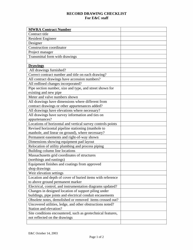
RECORD DRAWING CHECKLIST For E&C staff
MWRA Contract Number Contract title Resident Engineer Designer Construction coordinator Project manager Transmittal form with drawings Drawings All drawings furnished? Correct contract number and title on each drawing? All contract drawings have accession numbers? All redlined changes incorporated? Pipe section number, size and type, and street shown for existing and new pipe
Meter and valve numbers shown All drawings have dimensions where different from contract drawings or other appurtenances added?
All drawings have elevations where necessary? All drawings have survey information and ties on appurtenances?
Locations of horizontal and vertical survey controls points Revised horizontal pipeline stationing (manhole to manhole, and linear on ground), where necessary?
Permanent easements and right-of-way shown Dimensions showing equipment pad layout Relocation of utility plumbing and process piping Building column line locations Massachusetts grid coordinates of structures (northings and eastings)
Equipment finishes and coatings from approved shop drawings
Weir elevation settings Location and depth of cover of buried items with reference to above ground permanent marker
Electrical, control, and instrumentation diagrams updated? Changes in designed location of support piling under buildings, pipe joints and electrical conduit encasements
Obsolete notes, demolished or removed items crossed out? Uncovered utilities, ledge, and other obstructions noted? Station and elevation?
Site conditions encountered, such as geotechnical features, not reflected on the drawings
E&C October 14, 2003 Page 1 of 2

RECORD DRAWING CHECKLIST For E&C staff
E&C October 14, 2003 Page 2 of 2
Sewer contract: Elevations of sewers and existing ground elevation on MWRA datum, 99.97 feet below Boston City Datum Water contract: Elevations of water mains and existing ground surface on Boston City Base Datum, 5.65 feet below USGS mean sea level
Enlarged plans and profiles, where necessary Actual installation of pipe, valves, manholes, appurtenances in detail
Elevations shown Enlarged plan in 10-scale Professional Engineer’s stamp on drawings? Stamped as record drawing Revision date entered Disclaimer stamped on drawing E&C format followed? Title block lower right? North arrow Detail drawings at 10-scale Horizontal scale at 1”=40’ Vertical scale at 1”= 4’ 24” x 36” sheet size Mylars of all drawings received? 3 paper copies of all drawings received? Water Pipeline Contracts Pressure zone, street location, city or town Year pipe laid and MWRA contract number Land taking number and plan number Meter and valve numbers indicated on drawings Survey elevations shown Construction field book number ? Aperture Cards All drawings filmed onto aperture cards? Two aperture cards received with each drawing: one master and one copy?
Electronic Files TIFF files for each full-size drawing? AutoCADD files for each drawing?
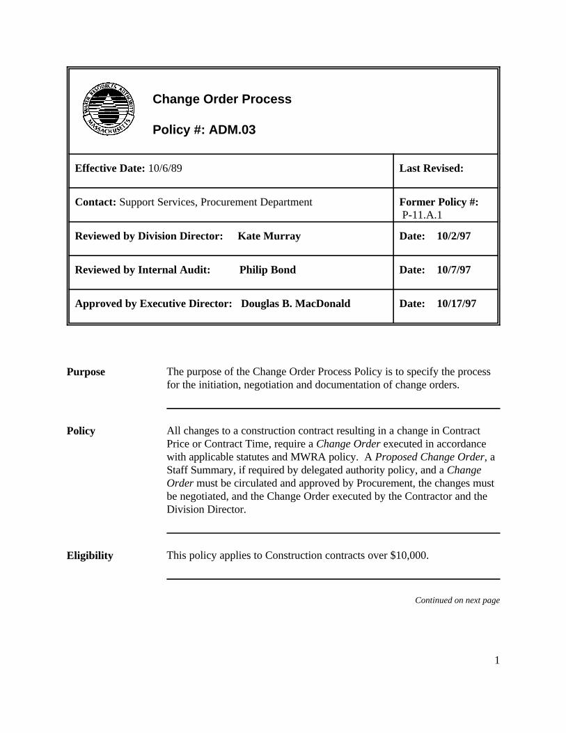
1
Change Order Process
Policy #: ADM.03
Effective Date: 10/6/89 Last Revised:
Contact: Support Services, Procurement Department Former Policy #: P-11.A.1
Reviewed by Division Director: Kate Murray Date: 10/2/97
Reviewed by Internal Audit: Philip Bond Date: 10/7/97
Approved by Executive Director: Douglas B. MacDonald Date: 10/17/97
Purpose The purpose of the Change Order Process Policy is to specify the processfor the initiation, negotiation and documentation of change orders.
Policy All changes to a construction contract resulting in a change in ContractPrice or Contract Time, require a Change Order executed in accordancewith applicable statutes and MWRA policy. A Proposed Change Order, aStaff Summary, if required by delegated authority policy, and a ChangeOrder must be circulated and approved by Procurement, the changes mustbe negotiated, and the Change Order executed by the Contractor and theDivision Director.
Eligibility This policy applies to Construction contracts over $10,000.
Continued on next page
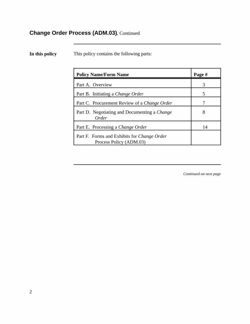
2
Change Order Process (ADM.03), Continued
In this policy This policy contains the following parts:
Policy Name/Form Name Page #
Part A. Overview 3
Part B. Initiating a Change Order 5
Part C. Procurement Review of a Change Order 7
Part D. Negotiating and Documenting a Change 8 Order
Part E. Processing a Change Order 14
Part F. Forms and Exhibits for Change Order Process Policy (ADM.03)
Continued on next page
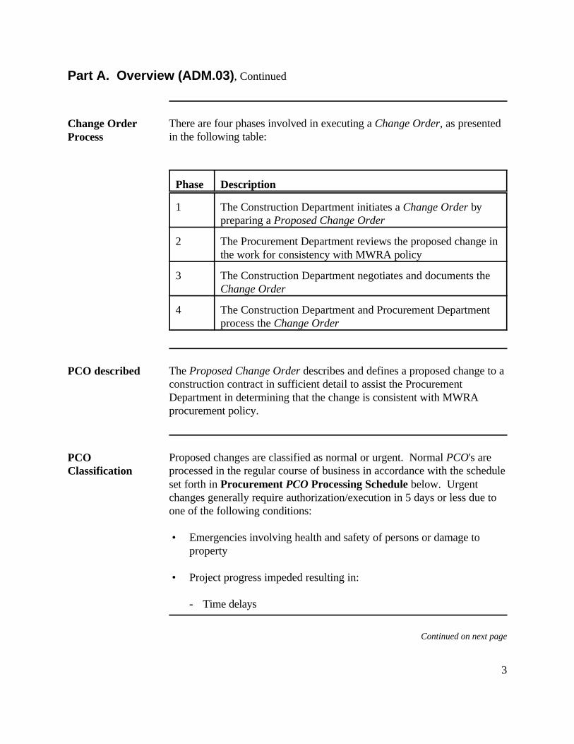
3
Part A. Overview (ADM.03), Continued
Change OrderProcess
There are four phases involved in executing a Change Order, as presentedin the following table:
Phase Description
1 The Construction Department initiates a Change Order bypreparing a Proposed Change Order
2 The Procurement Department reviews the proposed change inthe work for consistency with MWRA policy
3 The Construction Department negotiates and documents theChange Order
4 The Construction Department and Procurement Departmentprocess the Change Order
PCO described The Proposed Change Order describes and defines a proposed change to aconstruction contract in sufficient detail to assist the ProcurementDepartment in determining that the change is consistent with MWRAprocurement policy.
PCOClassification
Proposed changes are classified as normal or urgent. Normal PCO's areprocessed in the regular course of business in accordance with the scheduleset forth in Procurement PCO Processing Schedule below. Urgentchanges generally require authorization/execution in 5 days or less due toone of the following conditions:
• Emergencies involving health and safety of persons or damage toproperty
• Project progress impeded resulting in:
- Time delays
Continued on next page
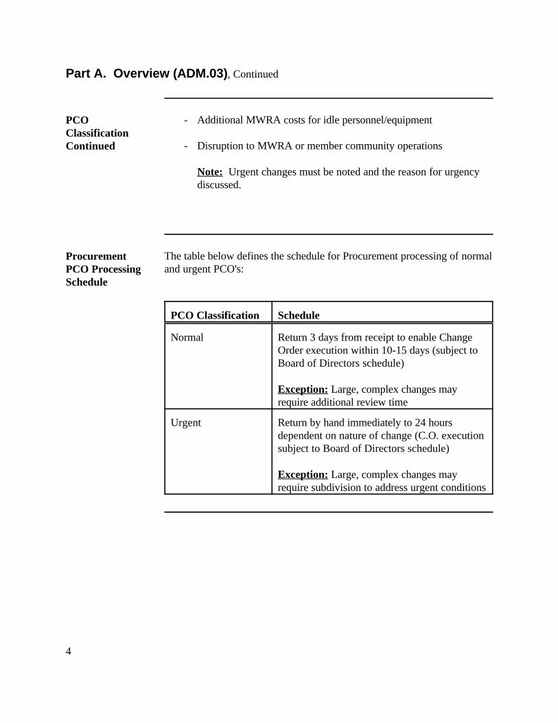
4
Part A. Overview (ADM.03), Continued
PCOClassificationContinued
- Additional MWRA costs for idle personnel/equipment
- Disruption to MWRA or member community operations
Note: Urgent changes must be noted and the reason for urgencydiscussed.
ProcurementPCO ProcessingSchedule
The table below defines the schedule for Procurement processing of normaland urgent PCO's:
PCO Classification Schedule
Normal Return 3 days from receipt to enable ChangeOrder execution within 10-15 days (subject toBoard of Directors schedule)
Exception: Large, complex changes mayrequire additional review time
Urgent Return by hand immediately to 24 hoursdependent on nature of change (C.O. executionsubject to Board of Directors schedule)
Exception: Large, complex changes mayrequire subdivision to address urgent conditions
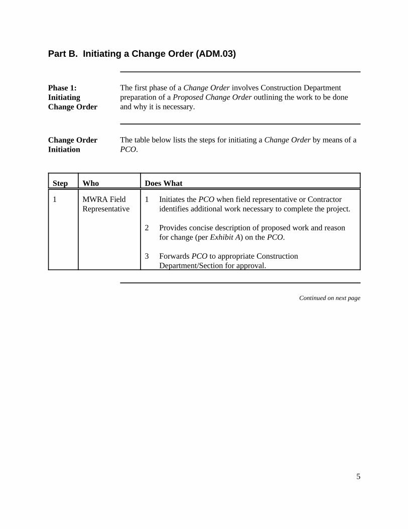
5
Part B. Initiating a Change Order (ADM.03)
Phase 1:InitiatingChange Order
The first phase of a Change Order involves Construction Departmentpreparation of a Proposed Change Order outlining the work to be doneand why it is necessary.
Change OrderInitiation
The table below lists the steps for initiating a Change Order by means of aPCO.
Step Who Does What
1 MWRA Field 1 Initiates the PCO when field representative or ContractorRepresentative identifies additional work necessary to complete the project.
2 Provides concise description of proposed work and reasonfor change (per Exhibit A) on the PCO.
3 Forwards PCO to appropriate ConstructionDepartment/Section for approval.
Continued on next page
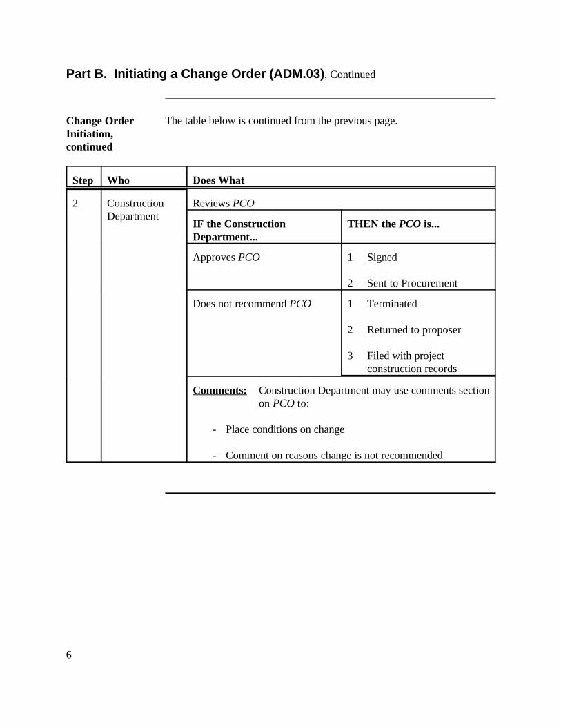
6
Part B. Initiating a Change Order (ADM.03), Continued
Change OrderInitiation,continued
The table below is continued from the previous page.
Step Who Does What
2 Construction Reviews PCODepartment
IF the Construction THEN the PCO is...Department...
Approves PCO 1 Signed
2 Sent to Procurement
Does not recommend PCO 1 Terminated
2 Returned to proposer
3 Filed with projectconstruction records
Comments: Construction Department may use comments sectionon PCO to:
- Place conditions on change
- Comment on reasons change is not recommended
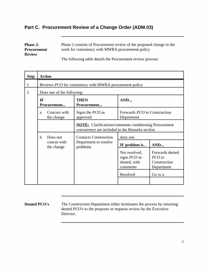
7
Part C. Procurement Review of a Change Order (ADM.03)
Phase 2:ProcurementReview
Phase 2 consists of Procurement review of the proposed change in thework for consistency with MWRA procurement policy
The following table details the Procurement review process:
Step Action
1 Reviews PCO for consistency with MWRA procurement policy
2 Does one of the following:
IF THEN AND...Procurement... Procurement...
a Concurs with Signs the PCO as Forwards PCO to Constructionthe change approved Department
NOTE: Clarifications/comments conditioning Procurementconcurrence are included in the Remarks section
b Does not Contacts Construction does oneconcur with Department to resolvethe change problems IF problem is... AND...
Not resolved, Forwards deniedsigns PCO as PCO todenied, with Constructioncomments Department
Resolved Go to a
Denied PCO's The Construction Department either terminates the process by returningdenied PCO's to the proposer or requests review by the ExecutiveDirector.
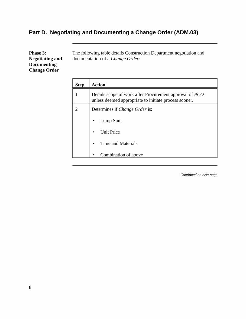
8
Part D. Negotiating and Documenting a Change Order (ADM.03)
Phase 3:Negotiating andDocumentingChange Order
The following table details Construction Department negotiation anddocumentation of a Change Order:
Step Action
1 Details scope of work after Procurement approval of PCOunless deemed appropriate to initiate process sooner.
2 Determines if Change Order is:
• Lump Sum
• Unit Price
• Time and Materials
• Combination of above
Continued on next page
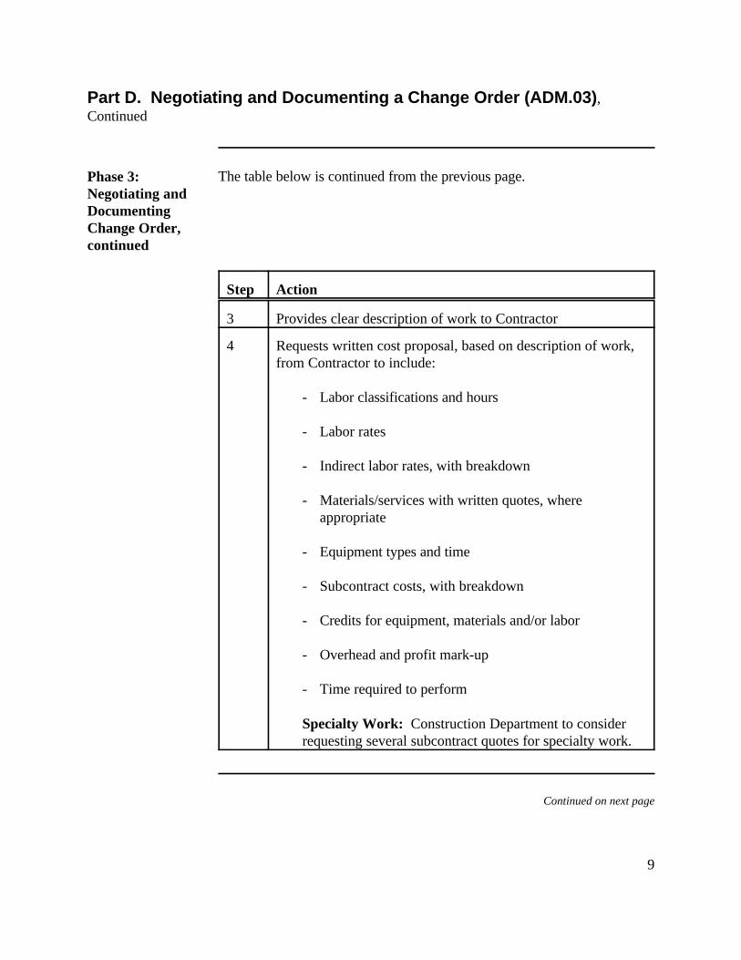
9
Part D. Negotiating and Documenting a Change Order (ADM.03),Continued
Phase 3:Negotiating andDocumentingChange Order,continued
The table below is continued from the previous page.
Step Action
3 Provides clear description of work to Contractor
4 Requests written cost proposal, based on description of work,from Contractor to include:
- Labor classifications and hours
- Labor rates
- Indirect labor rates, with breakdown
- Materials/services with written quotes, whereappropriate
- Equipment types and time
- Subcontract costs, with breakdown
- Credits for equipment, materials and/or labor
- Overhead and profit mark-up
- Time required to perform
Specialty Work: Construction Department to considerrequesting several subcontract quotes for specialty work.
Continued on next page
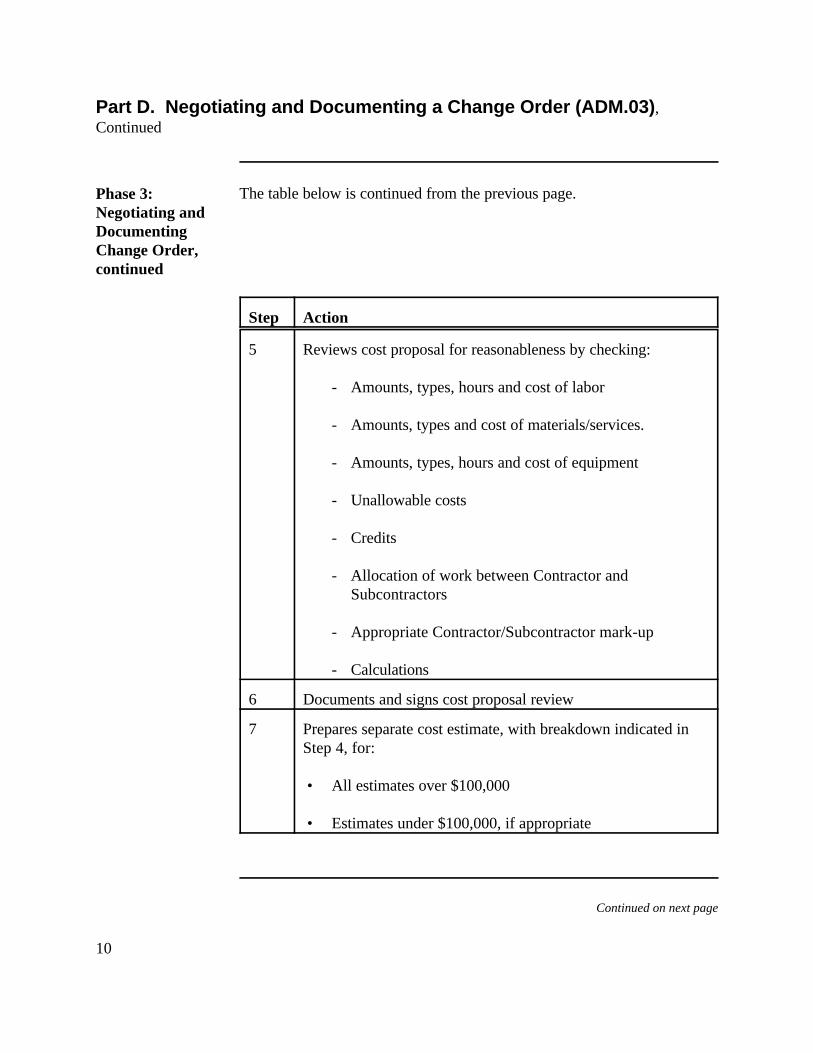
10
Part D. Negotiating and Documenting a Change Order (ADM.03),Continued
Phase 3:Negotiating andDocumentingChange Order,continued
The table below is continued from the previous page.
Step Action
5 Reviews cost proposal for reasonableness by checking:
- Amounts, types, hours and cost of labor
- Amounts, types and cost of materials/services.
- Amounts, types, hours and cost of equipment
- Unallowable costs
- Credits
- Allocation of work between Contractor andSubcontractors
- Appropriate Contractor/Subcontractor mark-up
- Calculations
6 Documents and signs cost proposal review
7 Prepares separate cost estimate, with breakdown indicated inStep 4, for:
• All estimates over $100,000
• Estimates under $100,000, if appropriate
Continued on next page
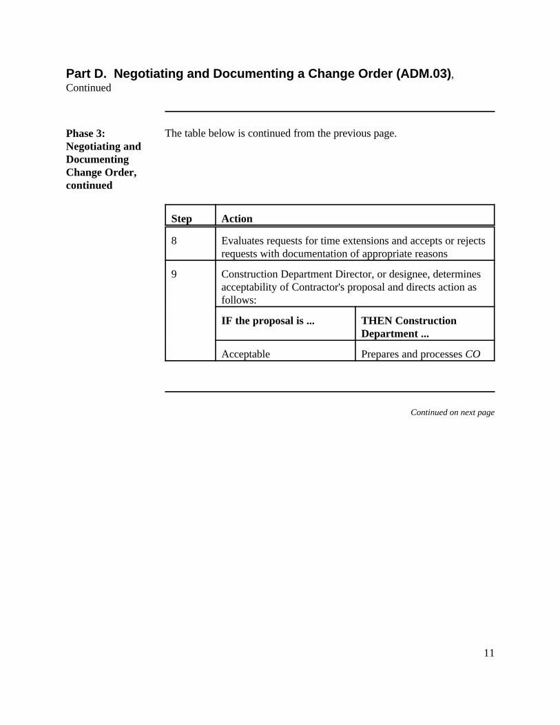
11
Part D. Negotiating and Documenting a Change Order (ADM.03),Continued
Phase 3:Negotiating andDocumentingChange Order,continued
The table below is continued from the previous page.
Step Action
8 Evaluates requests for time extensions and accepts or rejectsrequests with documentation of appropriate reasons
9 Construction Department Director, or designee, determinesacceptability of Contractor's proposal and directs action asfollows:
IF the proposal is ... THEN ConstructionDepartment ...
Acceptable Prepares and processes CO
Continued on next page
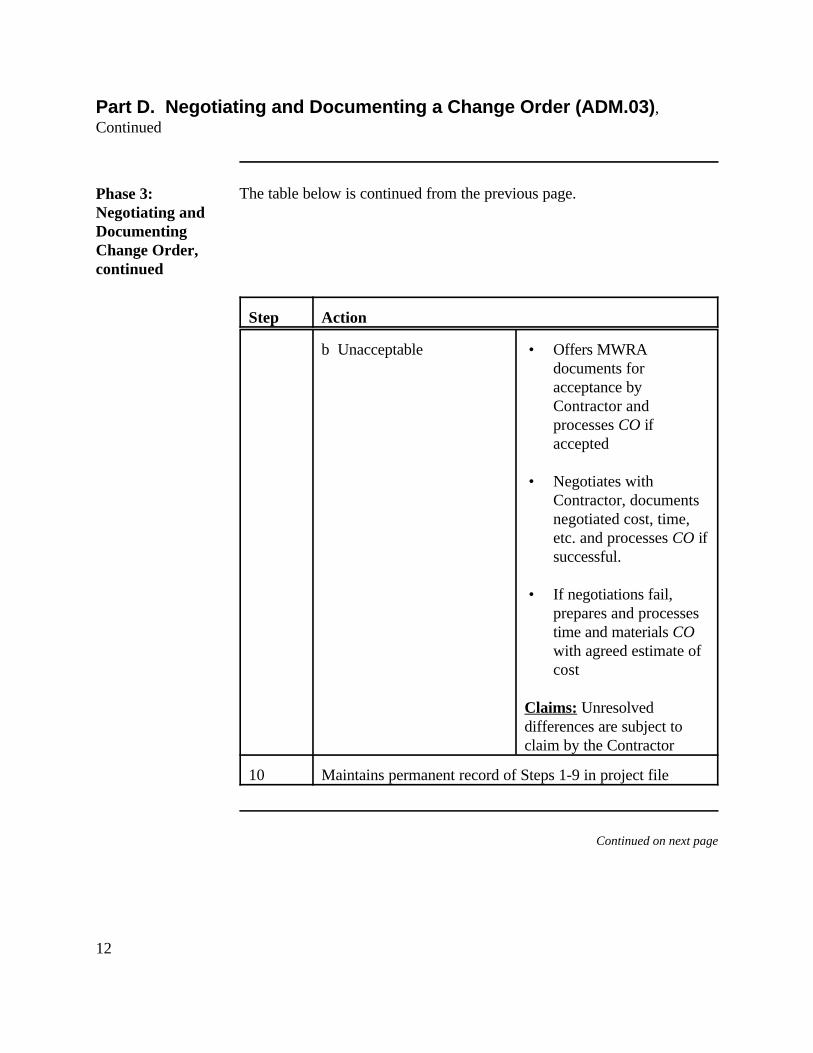
12
Part D. Negotiating and Documenting a Change Order (ADM.03),Continued
Phase 3:Negotiating andDocumentingChange Order,continued
The table below is continued from the previous page.
Step Action
b Unacceptable • Offers MWRAdocuments foracceptance byContractor andprocesses CO ifaccepted
• Negotiates withContractor, documentsnegotiated cost, time,etc. and processes CO ifsuccessful.
• If negotiations fail,prepares and processestime and materials COwith agreed estimate ofcost
Claims: Unresolveddifferences are subject toclaim by the Contractor
10 Maintains permanent record of Steps 1-9 in project file
Continued on next page
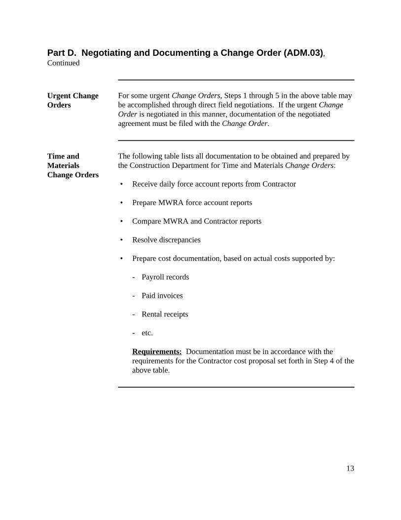
13
Part D. Negotiating and Documenting a Change Order (ADM.03),Continued
Urgent ChangeOrders
For some urgent Change Orders, Steps 1 through 5 in the above table maybe accomplished through direct field negotiations. If the urgent ChangeOrder is negotiated in this manner, documentation of the negotiatedagreement must be filed with the Change Order.
Time andMaterialsChange Orders
The following table lists all documentation to be obtained and prepared bythe Construction Department for Time and Materials Change Orders:
• Receive daily force account reports from Contractor
• Prepare MWRA force account reports
• Compare MWRA and Contractor reports
• Resolve discrepancies
• Prepare cost documentation, based on actual costs supported by:
- Payroll records
- Paid invoices
- Rental receipts
- etc.
Requirements: Documentation must be in accordance with therequirements for the Contractor cost proposal set forth in Step 4 of theabove table.
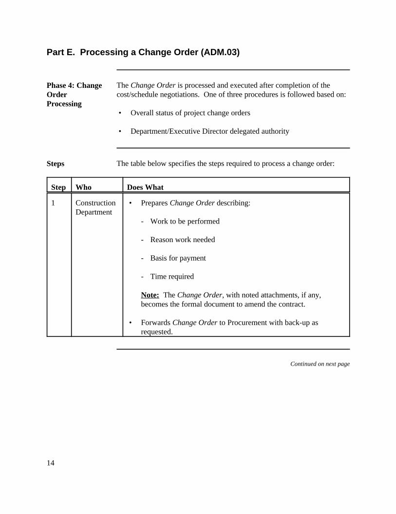
14
Part E. Processing a Change Order (ADM.03)
Phase 4: ChangeOrderProcessing
The Change Order is processed and executed after completion of thecost/schedule negotiations. One of three procedures is followed based on:
• Overall status of project change orders
• Department/Executive Director delegated authority
Steps The table below specifies the steps required to process a change order:
Step Who Does What
1 Construction • Prepares Change Order describing:Department
- Work to be performed
- Reason work needed
- Basis for payment
- Time required
Note: The Change Order, with noted attachments, if any,becomes the formal document to amend the contract.
• Forwards Change Order to Procurement with back-up asrequested.
Continued on next page
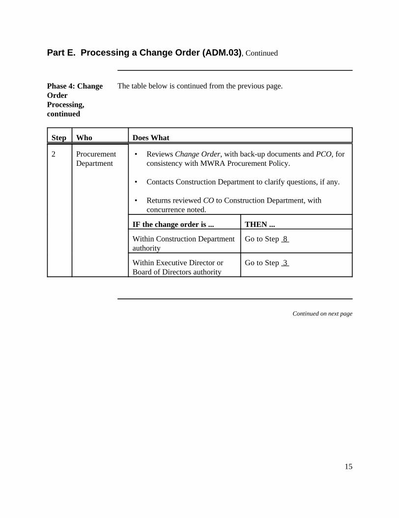
15
Part E. Processing a Change Order (ADM.03), Continued
Phase 4: ChangeOrderProcessing,continued
The table below is continued from the previous page.
Step Who Does What
2 Procurement • Reviews Change Order, with back-up documents and PCO, forDepartment consistency with MWRA Procurement Policy.
• Contacts Construction Department to clarify questions, if any.
• Returns reviewed CO to Construction Department, withconcurrence noted.
IF the change order is ... THEN ...
Within Construction Department Go to Step 8 authority
Within Executive Director or Go to Step 3 Board of Directors authority
Continued on next page
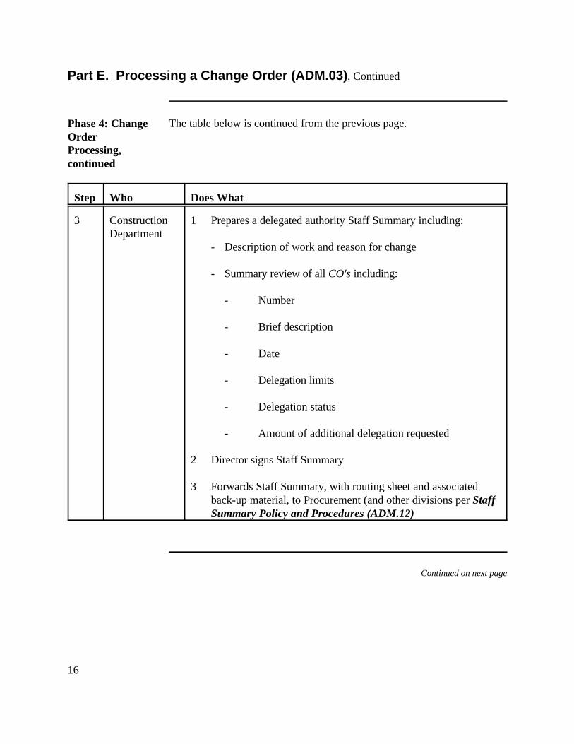
16
Part E. Processing a Change Order (ADM.03), Continued
Phase 4: ChangeOrderProcessing,continued
The table below is continued from the previous page.
Step Who Does What
3 Construction 1 Prepares a delegated authority Staff Summary including:Department
- Description of work and reason for change
- Summary review of all CO's including:
- Number
- Brief description
- Date
- Delegation limits
- Delegation status
- Amount of additional delegation requested
2 Director signs Staff Summary
3 Forwards Staff Summary, with routing sheet and associatedback-up material, to Procurement (and other divisions per StaffSummary Policy and Procedures (ADM.12)
Continued on next page
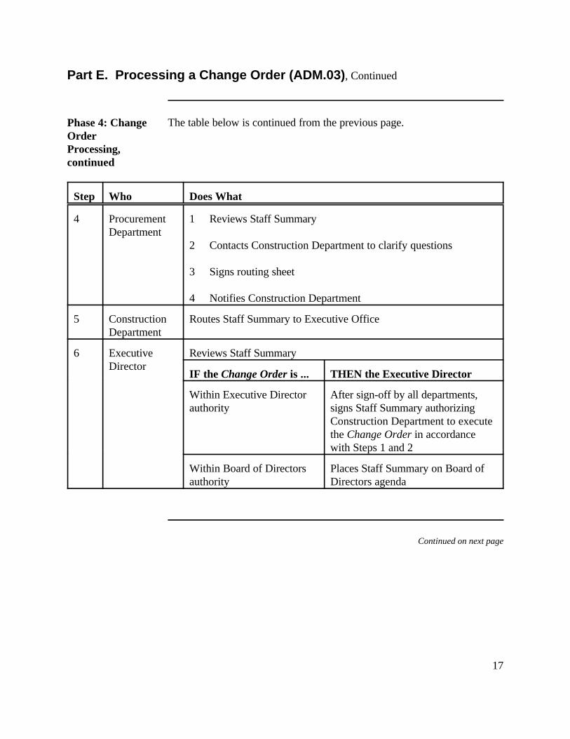
17
Part E. Processing a Change Order (ADM.03), Continued
Phase 4: ChangeOrderProcessing,continued
The table below is continued from the previous page.
Step Who Does What
4 Procurement 1 Reviews Staff SummaryDepartment
2 Contacts Construction Department to clarify questions
3 Signs routing sheet
4 Notifies Construction Department
5 Construction Routes Staff Summary to Executive OfficeDepartment
6 Executive Reviews Staff SummaryDirector
IF the Change Order is ... THEN the Executive Director
Within Executive Director After sign-off by all departments,authority signs Staff Summary authorizing
Construction Department to executethe Change Order in accordancewith Steps 1 and 2
Within Board of Directors Places Staff Summary on Board ofauthority Directors agenda
Continued on next page
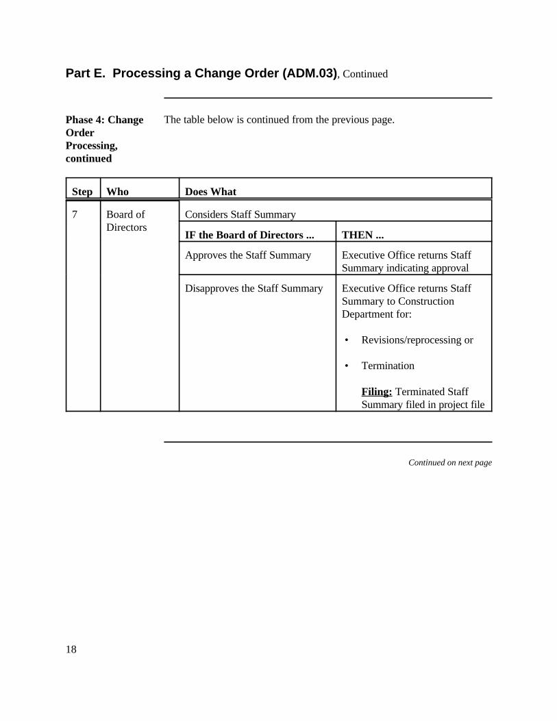
18
Part E. Processing a Change Order (ADM.03), Continued
Phase 4: ChangeOrderProcessing,continued
The table below is continued from the previous page.
Step Who Does What
7 Board of Considers Staff SummaryDirectors
IF the Board of Directors ... THEN ...
Approves the Staff Summary Executive Office returns StaffSummary indicating approval
Disapproves the Staff Summary Executive Office returns StaffSummary to ConstructionDepartment for:
• Revisions/reprocessing or
• Termination
Filing: Terminated StaffSummary filed in project file
Continued on next page
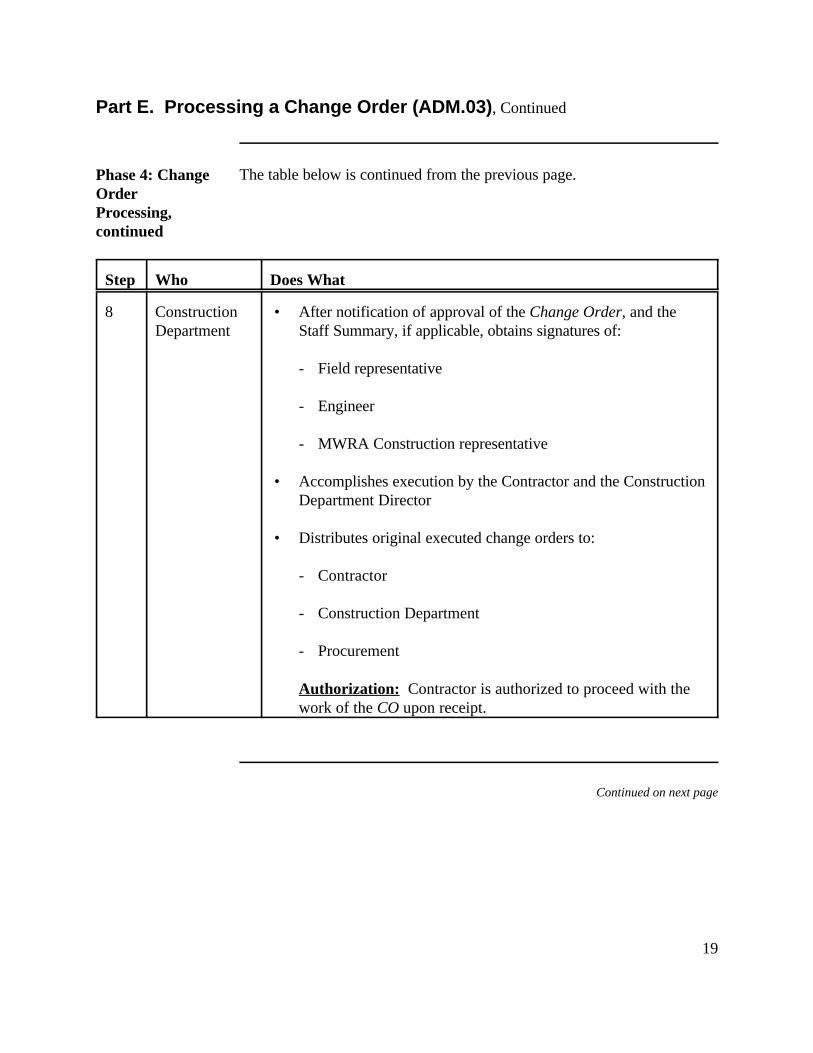
19
Part E. Processing a Change Order (ADM.03), Continued
Phase 4: ChangeOrderProcessing,continued
The table below is continued from the previous page.
Step Who Does What
8 Construction • After notification of approval of the Change Order, and theDepartment Staff Summary, if applicable, obtains signatures of:
- Field representative
- Engineer
- MWRA Construction representative
• Accomplishes execution by the Contractor and the ConstructionDepartment Director
• Distributes original executed change orders to:
- Contractor
- Construction Department
- Procurement
Authorization: Contractor is authorized to proceed with thework of the CO upon receipt.
Continued on next page
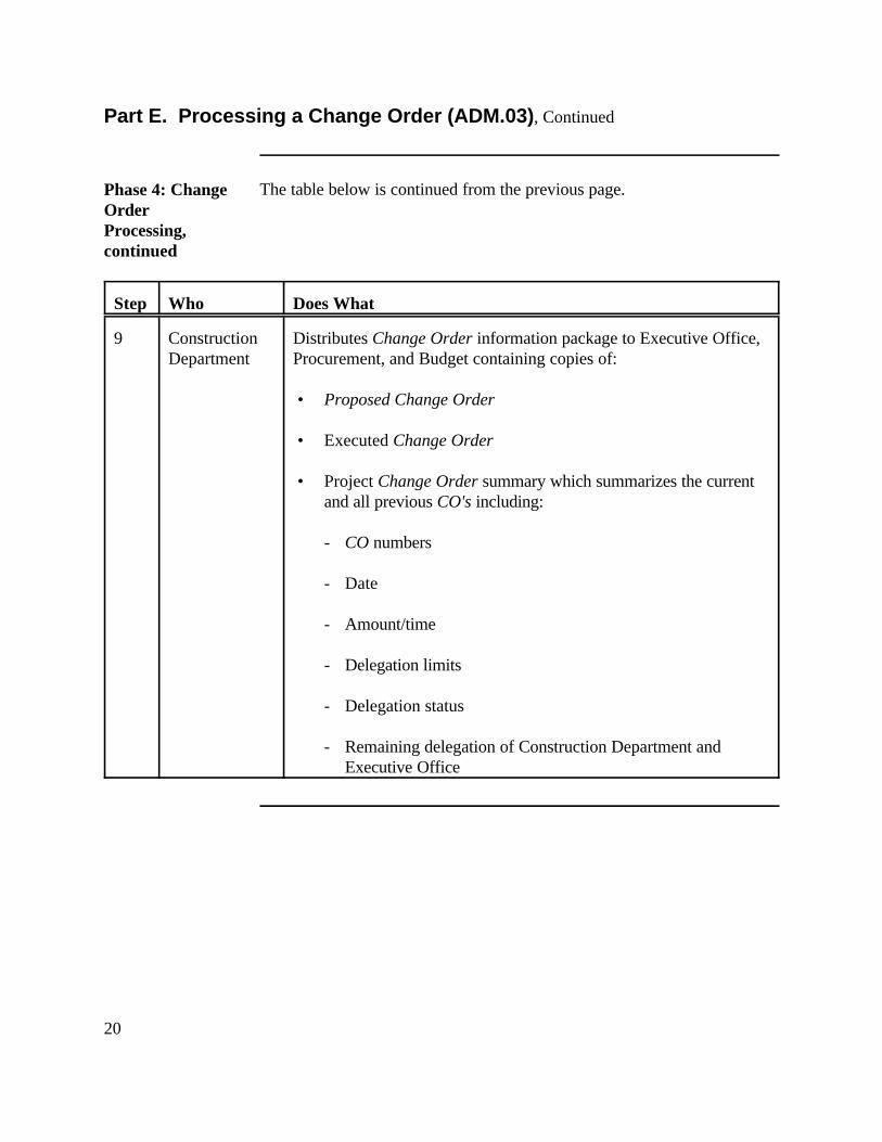
20
Part E. Processing a Change Order (ADM.03), Continued
Phase 4: ChangeOrderProcessing,continued
The table below is continued from the previous page.
Step Who Does What
9 Construction Distributes Change Order information package to Executive Office,Department Procurement, and Budget containing copies of:
• Proposed Change Order
• Executed Change Order
• Project Change Order summary which summarizes the currentand all previous CO's including:
- CO numbers
- Date
- Amount/time
- Delegation limits
- Delegation status
- Remaining delegation of Construction Department andExecutive Office
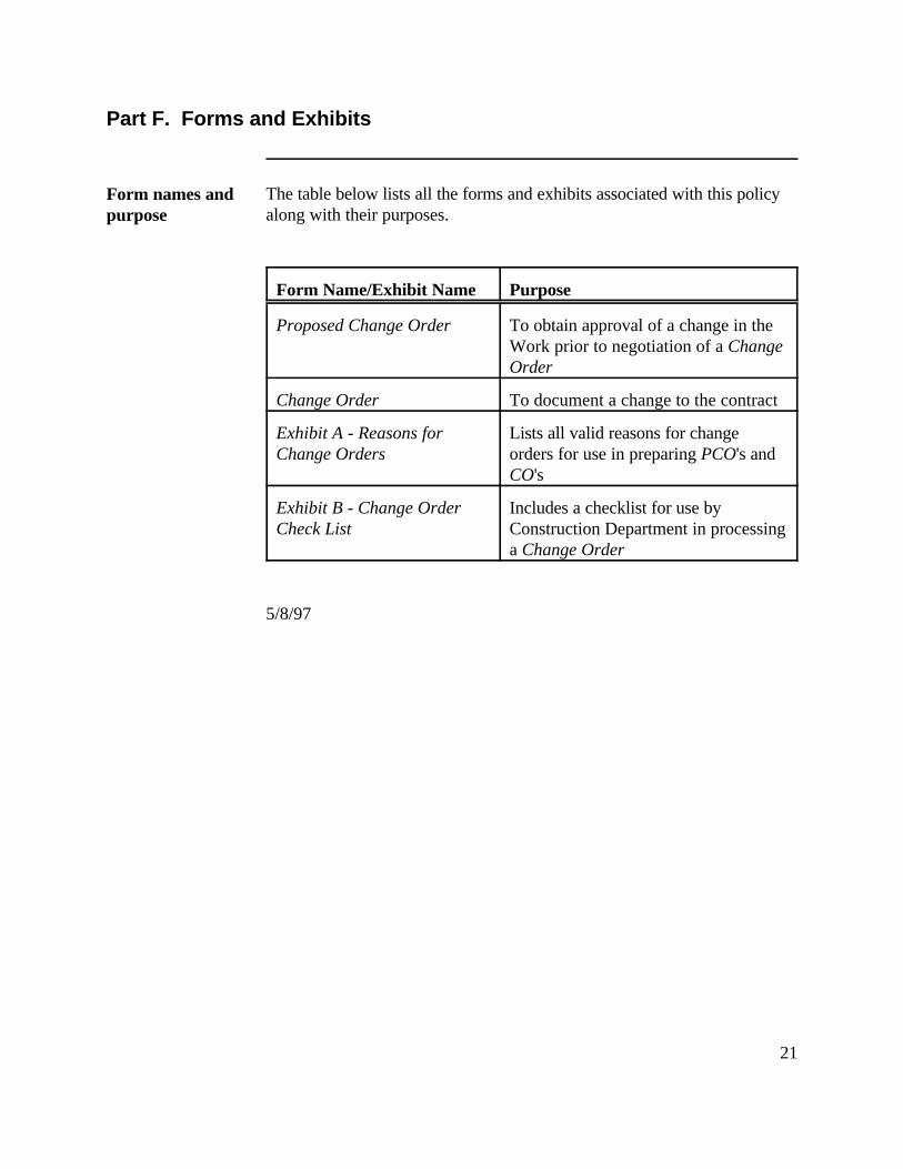
21
Part F. Forms and Exhibits
Form names andpurpose
The table below lists all the forms and exhibits associated with this policyalong with their purposes.
Form Name/Exhibit Name Purpose
Proposed Change Order To obtain approval of a change in theWork prior to negotiation of a ChangeOrder
Change Order To document a change to the contract
Exhibit A - Reasons for Lists all valid reasons for changeChange Orders orders for use in preparing PCO's and
CO's
Exhibit B - Change Order Includes a checklist for use byCheck List Construction Department in processing
a Change Order
5/8/97
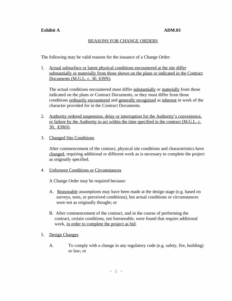
- i -
Exhibit A ADM.03
REASONS FOR CHANGE ORDERS
The following may be valid reasons for the issuance of a Change Order:
1. Actual subsurface or latent physical conditions encountered at the site differsubstantially or materially from those shown on the plans or indicated in the ContractDocuments (M.G.L. c. 30, §39N).
The actual conditions encountered must differ substantially or materially from thoseindicated on the plans or Contract Documents, or they must differ from thoseconditions ordinarily encountered and generally recognized as inherent in work of thecharacter provided for in the Contract Documents.
2. Authority ordered suspension, delay or interruption for the Authority’s convenience,or failure by the Authority to act within the time specified in the contract (M.G.L. c.30, §39(0).
3. Changed Site Conditions
After commencement of the contract, physical site conditions and characteristics havechanged, requiring additional or different work as is necessary to complete the projectas originally specified.
4. Unforseen Conditions or Circumstances
A Change Order may be required because:
A. Reasonable assumptions may have been made at the design stage (e.g. based on surveys, tests, or perceived conditions), but actual conditions or circumstances were not as originally thought; or
B. After commencement of the contract, and in the course of performing the contract, certain conditions, not foreseeable, were found that require additional work, in order to complete the project as bid.
5. Design Changes
A. To comply with a change in any regulatory code (e.g. safety, fire, building)or law; or
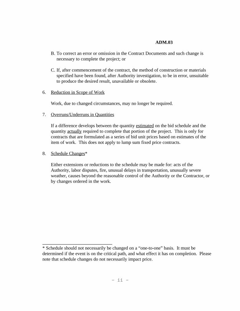
- ii -
ADM.03
B. To correct an error or omission in the Contract Documents and such change isnecessary to complete the project; or
C. If, after commencement of the contract, the method of construction or materialsspecified have been found, after Authority investigation, to be in error, unsuitableto produce the desired result, unavailable or obsolete.
6. Reduction in Scope of Work
Work, due to changed circumstances, may no longer be required.
7. Overruns/Underruns in Quantities
If a difference develops between the quantity estimated on the bid schedule and thequantity actually required to complete that portion of the project. This is only forcontracts that are formulated as a series of bid unit prices based on estimates of theitem of work. This does not apply to lump sum fixed price contracts.
8. Schedule Changes*
Either extensions or reductions to the schedule may be made for: acts of theAuthority, labor disputes, fire, unusual delays in transportation, unusually severeweather, causes beyond the reasonable control of the Authority or the Contractor, orby changes ordered in the work.
* Schedule should not necessarily be changed on a “one-to-one” basis. It must bedetermined if the event is on the critical path, and what effect it has on completion. Pleasenote that schedule changes do not necessarily impact price.
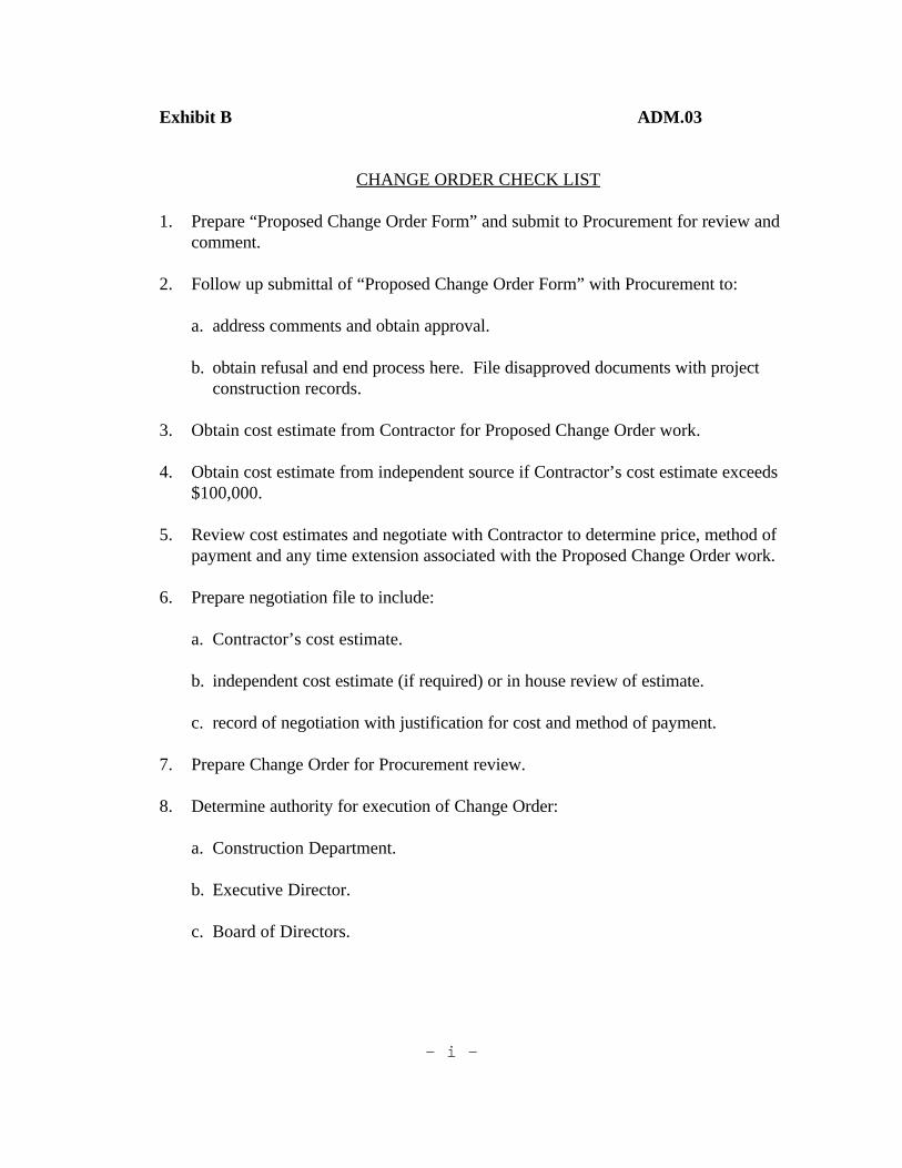
- i -
Exhibit B ADM.03
CHANGE ORDER CHECK LIST
1. Prepare “Proposed Change Order Form” and submit to Procurement for review andcomment.
2. Follow up submittal of “Proposed Change Order Form” with Procurement to:
a. address comments and obtain approval.
b. obtain refusal and end process here. File disapproved documents with projectconstruction records.
3. Obtain cost estimate from Contractor for Proposed Change Order work.
4. Obtain cost estimate from independent source if Contractor’s cost estimate exceeds$100,000.
5. Review cost estimates and negotiate with Contractor to determine price, method ofpayment and any time extension associated with the Proposed Change Order work.
6. Prepare negotiation file to include:
a. Contractor’s cost estimate.
b. independent cost estimate (if required) or in house review of estimate.
c. record of negotiation with justification for cost and method of payment.
7. Prepare Change Order for Procurement review.
8. Determine authority for execution of Change Order:
a. Construction Department.
b. Executive Director.
c. Board of Directors.
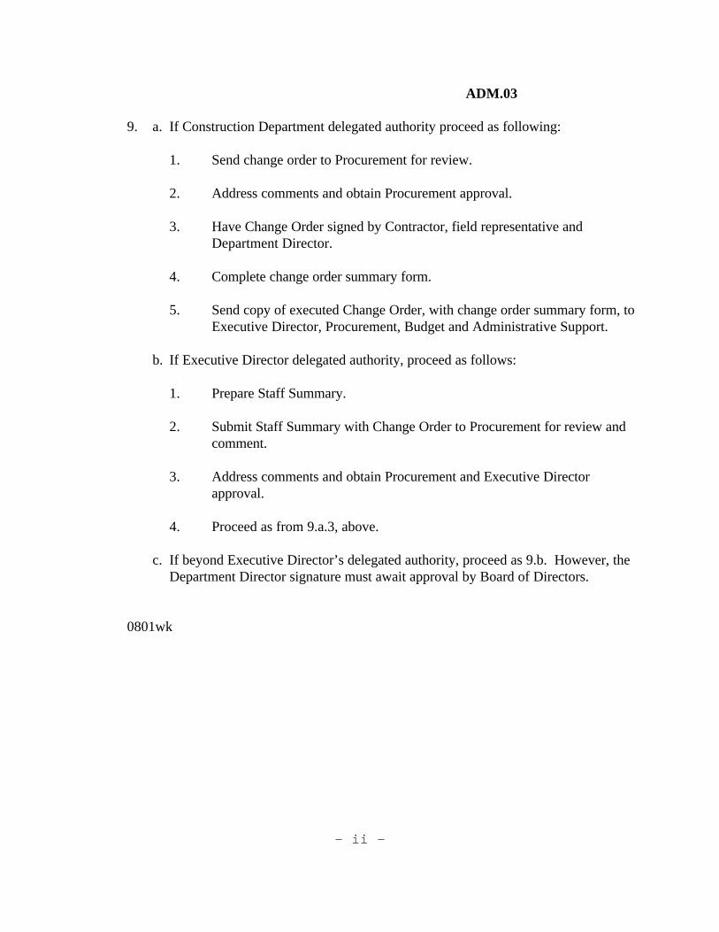
- ii -
ADM.03
9. a. If Construction Department delegated authority proceed as following:
1. Send change order to Procurement for review.
2. Address comments and obtain Procurement approval.
3. Have Change Order signed by Contractor, field representative andDepartment Director.
4. Complete change order summary form.
5. Send copy of executed Change Order, with change order summary form, toExecutive Director, Procurement, Budget and Administrative Support.
b. If Executive Director delegated authority, proceed as follows:
1. Prepare Staff Summary.
2. Submit Staff Summary with Change Order to Procurement for review andcomment.
3. Address comments and obtain Procurement and Executive Directorapproval.
4. Proceed as from 9.a.3, above.
c. If beyond Executive Director’s delegated authority, proceed as 9.b. However, theDepartment Director signature must await approval by Board of Directors.
0801wk
ADM.03
PROPOSED CHANGE ORDER NO.
Project: MWRA Contract No.: Location: EPA/DWPC Project No.: Contractor: MWRA Division:
Change Order proposed by (Check One): MWRA [ ] Contractor [ ]
Check if URGENT action requested: [ ]
Change Description/Reason: (Include reason for urgent action). Please type or print clearly. Additional pages may be attached if required.
By: Date: MWRA Representative
The Construction Department/Section Recommendation: Yes [ ] No [ ]
By: Date:
Procurement Department:
[ ] The proposed change is consistent with MWRA procurement policy.
[ ] The proposed change is NOT consistent with MWRA procurement policy.
Remarks:
By: Date: MWRA Procurement Representative
**EXECUTION OF THIS FORM DOES NOT AUTHORIZE CONTRACTOR TO PROCEED WITH WORK**
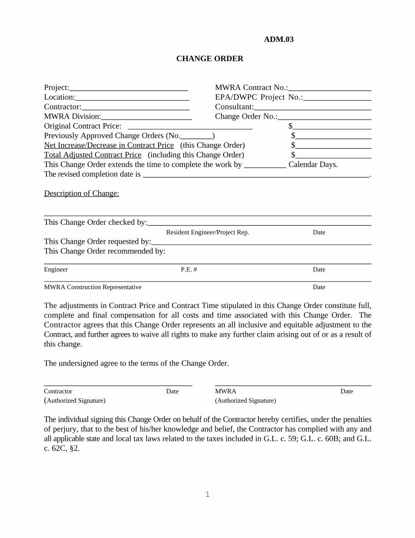
1
ADM.03
CHANGE ORDER
Project: MWRA Contract No.: Location: EPA/DWPC Project No.: Contractor: Consultant: MWRA Division: Change Order No.: Original Contract Price: $ Previously Approved Change Orders (No. ) $ Net Increase/Decrease in Contract Price (this Change Order) $ Total Adjusted Contract Price (including this Change Order) $ This Change Order extends the time to complete the work by Calendar Days.The revised completion date is .
Description of Change:
This Change Order checked by: Resident Engineer/Project Rep. Date This Change Order requested by: This Change Order recommended by: Engineer P.E. # Date MWRA Construction Representative Date
The adjustments in Contract Price and Contract Time stipulated in this Change Order constitute full,complete and final compensation for all costs and time associated with this Change Order. TheContractor agrees that this Change Order represents an all inclusive and equitable adjustment to theContract, and further agrees to waive all rights to make any further claim arising out of or as a result ofthis change.
The undersigned agree to the terms of the Change Order.
Contractor Date MWRA Date(Authorized Signature) (Authorized Signature)
The individual signing this Change Order on behalf of the Contractor hereby certifies, under the penaltiesof perjury, that to the best of his/her knowledge and belief, the Contractor has complied with any andall applicable state and local tax laws related to the taxes included in G.L. c. 59; G.L. c. 60B; and G.L.c. 62C, §2.
CHANGE ORDER
Project: MWRA Contract No.: Change Order No.: EPA/DWPC Project No.:
2
Reason for Change:
Additional pages may be attached if required.
COMPLETE BELOW FOR GRANT FUNDED PROJECTS ONLY
Approval as to appropriation:
Certification Officer Date
Do not write below:This space reserved for STATE and/orFEDERAL AGENCY APPROVAL
MDWPC EPA
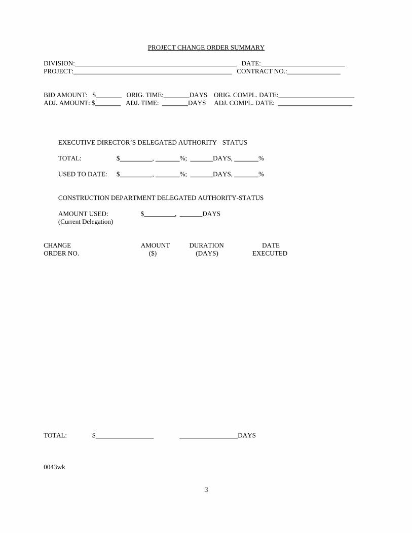
3
PROJECT CHANGE ORDER SUMMARY
DIVISION: DATE: PROJECT: CONTRACT NO.:
BID AMOUNT: $ ORIG. TIME: DAYS ORIG. COMPL. DATE: ADJ. AMOUNT: $ ADJ. TIME: DAYS ADJ. COMPL. DATE:
EXECUTIVE DIRECTOR’S DELEGATED AUTHORITY - STATUS
TOTAL: $ , %; DAYS, %
USED TO DATE: $ , %; DAYS, %
CONSTRUCTION DEPARTMENT DELEGATED AUTHORITY-STATUS
AMOUNT USED: $ , DAYS(Current Delegation)
CHANGE AMOUNT DURATION DATEORDER NO. ($) (DAYS) EXECUTED
TOTAL: $ DAYS
0043wk