multiport fuel injection (mfi) - mmc manuals
TRANSCRIPT
13A-1
GROUP 13A
MULTIPORT FUEL INJECTION (MFI)
CONTENTS
GENERAL DESCRIPTION. . . . . . . 13A-2
MULTIPORT FUEL INJECTION (MFI) DIAGNOSIS . . . . . . . . . . . . . . . . . . 13A-4
TROUBLESHOOTING STRATEGY . . . . . . 13A-4DIAGNOSTIC FUNCTION . . . . . . . . . . . . . 13A-4FAIL-SAFE FUNCTION REFERENCE TABLE. . . . . . . . . . . . . . . . . . . . . . . . . . . . . 13A-24DIAGNOSTIC TROUBLE CODE CHART. . 13A-26SYMPTOM CHART. . . . . . . . . . . . . . . . . . . 13A-30DIAGNOSTIC TROUBLE CODE PROCEDURES. . . . . . . . . . . . . . . . . . . . . . 13A-33SYMPTOM PROCEDURES . . . . . . . . . . . . 13A-831DATA LIST REFERENCE TABLE . . . . . . . 13A-950ACTUATOR TEST REFERENCE TABLE. . 13A-966CHECK AT THE POWERTRAIN CONTROL MODULE (PCM) . . . . . . . . . . . . . . . . . . . . . 13A-968INSPECTION PROCEDURE USING AN OSCILLOSCOPE . . . . . . . . . . . . . . . . . . . . 13A-975
SPECIAL TOOLS. . . . . . . . . . . . . . 13A-985
ON-VEHICLE SERVICE. . . . . . . . . 13A-987COMPONENT LOCATION . . . . . . . . . . . . . 13A-987THROTTLE BODY (THROTTLE VALVE AREA) CLEANING . . . . . . . . . . . . . . . . . . . . . . . . . 13A-993ACCELERATOR PEDAL POSITION SENSOR ADJUSTMENT . . . . . . . . . . . . . . . . . . . . . . 13A-994FUEL PRESSURE TEST . . . . . . . . . . . . . . 13A-995FUEL PUMP CONNECTOR DISCONNECTION (HOW TO REDUCE PRESSURIZED FUEL LINES) . . . . . . . . . . . . . . . . . . . . . . . 13A-998FUEL PUMP OPERATION CHECK . . . . . . 13A-998MULTIPORT FUEL INJECTION (MFI) RELAY, THROTTLE ACTUATOR CONTROL MOTOR RELAY AND FUEL PUMP RELAY CONTINUITY
CHECK . . . . . . . . . . . . . . . . . . . . . . . . . . . . 13A-999INTAKE AIR TEMPERATURE SENSOR CHECK . . . . . . . . . . . . . . . . . . . . . . . . . . . . 13A-1000ENGINE COOLANT TEMPERATURE SENSOR CHECK . . . . . . . . . . . . . . . . . . . . . . . . . . . . 13A-1000THROTTLE POSITION SENSOR CHECK . 13A-1001ACCELERATOR PEDAL POSITION SENSOR CHECK . . . . . . . . . . . . . . . . . . . . . . . . . . . . 13A-1001ACCELERATOR PEDAL POSITION SWITCH CHECK . . . . . . . . . . . . . . . . . . . . . . . . . . . . 13A-1002HEATED OXYGEN SENSOR CHECK . . . . 13A-1002INJECTOR CHECK . . . . . . . . . . . . . . . . . . . 13A-1007THROTTLE ACTUATOR CONTROL MOTOR CHECK . . . . . . . . . . . . . . . . . . . . . . . . . . . . 13A-1008EVAPORATIVE EMISSION PURGE SOLENOID CHECK . . . . . . . . . . . . . . . . . . . . . . . . . . . . 13A-1008EGR VALVE CHECK. . . . . . . . . . . . . . . . . . 13A-1009INTAKE MANIFOLD TUNING SOLENOID CHECK . . . . . . . . . . . . . . . . . . . . . . . . . . . . 13A-1009
INJECTOR . . . . . . . . . . . . . . . . . . . 13A-1010REMOVAL AND INSTALLATION . . . . . . . . 13A-1010
THROTTLE BODY ASSEMBLY . . . 13A-1012REMOVAL AND INSTALLATION . . . . . . . . 13A-1012
POWERTRAIN CONTROL MODULE (PCM) . . . . . . . . . . . . . . . . . . . . . . . 13A-1014
REMOVAL AND INSTALLATION . . . . . . . . 13A-1014
SPECIFICATIONS . . . . . . . . . . . . . 13A-1015FASTENER TIGHTENING SPECIFICATIONS. . . . . . . . . . . . . . . . . . . . 13A-1015GENERAL SPECIFICATIONS . . . . . . . . . . 13A-1015SERVICE SPECIFICATIONS . . . . . . . . . . . 13A-1016SEALANT AND ADHESIVE . . . . . . . . . . . . 13A-1016
GENERAL DESCRIPTIONMULTIPORT FUEL INJECTION (MFI)13A-2
GENERAL DESCRIPTIONM1131000101005
.
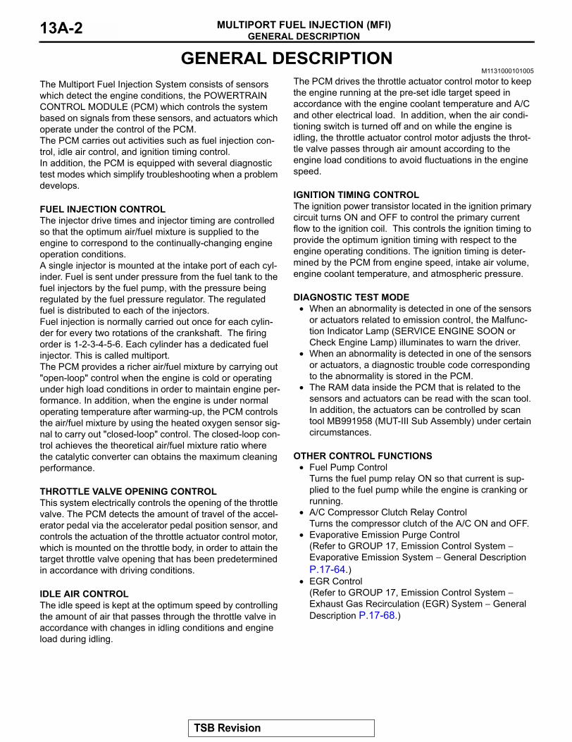
The Multiport Fuel Injection System consists of sensors which detect the engine conditions, the POWERTRAIN CONTROL MODULE (PCM) which controls the system based on signals from these sensors, and actuators which operate under the control of the PCM.The PCM carries out activities such as fuel injection con-trol, idle air control, and ignition timing control.In addition, the PCM is equipped with several diagnostic test modes which simplify troubleshooting when a problem develops.
.
FUEL INJECTION CONTROLThe injector drive times and injector timing are controlled so that the optimum air/fuel mixture is supplied to the engine to correspond to the continually-changing engine operation conditions.A single injector is mounted at the intake port of each cyl-inder. Fuel is sent under pressure from the fuel tank to the fuel injectors by the fuel pump, with the pressure being regulated by the fuel pressure regulator. The regulated fuel is distributed to each of the injectors.Fuel injection is normally carried out once for each cylin-der for every two rotations of the crankshaft. The firing order is 1-2-3-4-5-6. Each cylinder has a dedicated fuel injector. This is called multiport.The PCM provides a richer air/fuel mixture by carrying out "open-loop" control when the engine is cold or operating under high load conditions in order to maintain engine per-formance. In addition, when the engine is under normal operating temperature after warming-up, the PCM controls the air/fuel mixture by using the heated oxygen sensor sig-nal to carry out "closed-loop" control. The closed-loop con-trol achieves the theoretical air/fuel mixture ratio where the catalytic converter can obtains the maximum cleaning performance.
.
THROTTLE VALVE OPENING CONTROLThis system electrically controls the opening of the throttle valve. The PCM detects the amount of travel of the accel-erator pedal via the accelerator pedal position sensor, and controls the actuation of the throttle actuator control motor, which is mounted on the throttle body, in order to attain the target throttle valve opening that has been predetermined in accordance with driving conditions.
.
IDLE AIR CONTROLThe idle speed is kept at the optimum speed by controlling the amount of air that passes through the throttle valve in accordance with changes in idling conditions and engine load during idling.
The PCM drives the throttle actuator control motor to keep the engine running at the pre-set idle target speed in accordance with the engine coolant temperature and A/C and other electrical load. In addition, when the air condi-tioning switch is turned off and on while the engine is idling, the throttle actuator control motor adjusts the throt-tle valve passes through air amount according to the engine load conditions to avoid fluctuations in the engine speed.
.
IGNITION TIMING CONTROLThe ignition power transistor located in the ignition primary circuit turns ON and OFF to control the primary current flow to the ignition coil. This controls the ignition timing to provide the optimum ignition timing with respect to the engine operating conditions. The ignition timing is deter-mined by the PCM from engine speed, intake air volume, engine coolant temperature, and atmospheric pressure.
.
DIAGNOSTIC TEST MODE• When an abnormality is detected in one of the sensors
or actuators related to emission control, the Malfunc-tion Indicator Lamp (SERVICE ENGINE SOON or Check Engine Lamp) illuminates to warn the driver.
• When an abnormality is detected in one of the sensors or actuators, a diagnostic trouble code corresponding to the abnormality is stored in the PCM.
• The RAM data inside the PCM that is related to the sensors and actuators can be read with the scan tool. In addition, the actuators can be controlled by scan tool MB991958 (MUT-III Sub Assembly) under certain circumstances.
.
OTHER CONTROL FUNCTIONS• Fuel Pump Control
Turns the fuel pump relay ON so that current is sup-plied to the fuel pump while the engine is cranking or running.
• A/C Compressor Clutch Relay ControlTurns the compressor clutch of the A/C ON and OFF.
• Evaporative Emission Purge Control(Refer to GROUP 17, Emission Control System − Evaporative Emission System − General Description P.17-64.)
• EGR Control(Refer to GROUP 17, Emission Control System − Exhaust Gas Recirculation (EGR) System − General Description P.17-68.)
TSB Revision
GENERAL DESCRIPTIONMULTIPORT FUEL INJECTION (MFI) 13A-3
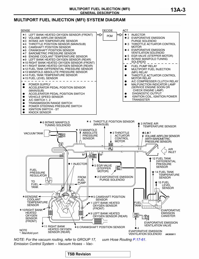
MULTIPORT FUEL INJECTION (MFI) SYSTEM DIAGRAM
NOTE: For the vacuum routing, refer to GROUP 17, Emission Control System − Vacuum Hoses − Vac-
uum Hose Routing P.17-61.AK303011
1 LEFT BANK HEATED OXYGEN SENSOR (FRONT)2 VOLUME AIRFLOW SENSOR3 INTAKE AIR TEMPERATURE SENSOR4 THROTTLE POSITION SENSOR (MAIN/SUB)5 CAMSHAFT POSITION SENSOR6 CRANKSHAFT POSITION SENSOR7 BAROMETRIC PRESSURE SENSOR8 ENGINE COOLANT TEMPERATURE SENSOR9 LEFT BANK HEATED OXYGEN SENSOR (REAR)10 RIGHT BANK HEATED OXYGEN SENSOR (FRONT)11 RIGHT BANK HEATED OXYGEN SENSOR (REAR)12 FUEL TANK DIFFERENTIAL PRESSURE SENSOR13 MANIFOLD ABSOLUTE PRESSURE SENSOR14 FUEL TANK TEMPERATURE SENSOR15 FUEL LEVEL SENSOR
POWER SUPPLY ACCELERATOR PEDAL POSITION SENSOR (MAIN/SUB) ACCELERATOR PEDAL POSITION SWITCH VEHICLE SPEED SENSOR A/C SWITCH 1, 2 TRANSMISSION RANGE SWITCH POWER STEERING PRESSURE SWITCH IGNITION SWITCH - ST KNOCK SENSOR
1 INJECTOR2 EVAPORATIVE EMISSION PURGE SOLENOID3 THROTTLE ACTUATOR CONTROL MOTOR4 EVAPORATIVE EMISSION VENTILATION SOLENOID5 EGR VALVE (STEPPER MOTOR)6 INTAKE MANIFOLD TUNING SOLENOID
FUEL PUMP RELAY MULTIPORT FUEL INJECTION (MFI) RELAY THROTTLE ACTUATOR CONTROL MOTOR RELAY A/C COMPRESSER CLUTCH RELAY MALFUNCTION INDICATOR LAMP (SERVICE ENGINE SOON OR CHECK ENGINE LAMP) DIAGNOSTIC OUTPUT IGNITION COIL, IGNITION POWER TRANSISTER
PCM
SENSE DECIDE ACT
1 LEFT BANK HEATED OXYGEN SENSOR (FRONT)
6 CRANKSHAFT POSITION SENSOR11 RIGHT BANK HEATED OXYGEN SENSOR (REAR)
9 LEFT BANK HEATED OXYGEN SENSOR (REAR)
5 CAMSHAFT POSITION SENSOR
1 INJECTOR
M* M*
6 INTAKE MANIFOLD TUNING SOLENOID
VACUUM TANK 3 THROTTLE ACTUATOR CONTROL MOTOR
2 EVAPORATIVE EMISSION PURGE SOLENOID
5 EGR VALVE (STEPPER MOTOR)
4
EVAPORATIVE EMISSIONCANISTER
FUEL TANK
FROMFUELPUMP
8
2, 7VOLUME AIRFLOW SENSOR(WITH BAROMETRICPRESSURE SENSOR)
3 INTAKE AIR TEMPERATURE SENSOR
AIR INLET
12 FUEL TANK DIFFERENTIAL PRESSURE SENSOR
14 FUEL TANK TEMPERATURE SENSOR
15 FUEL LEVEL SENSOR
4 THROTTLE POSITION SENSOR (MAIN/SUB)
TOFUELTANK
FUELPRESSUREREGULATOR
13 MANIFOLD ABSOLUTE PRESSURE SENSOR
ENGINE COOLANT TEMPERATURESENSOR
10RIGHT BANK HEATED OXYGEN SENSOR(FRONT)
NOTE*: Manifold port
EVAPORATIVE EMISSIONVENTILATION SOLENOID
EVAPORATIVE EMISSIONVENTILATION VALVE
TSB Revision
MULTIPORT FUEL INJECTION (MFI) DIAGNOSISMULTIPORT FUEL INJECTION (MFI)13A-4
MULTIPORT FUEL INJECTION (MFI) DIAGNOSISTROUBLESHOOTING STRATEGY
M1131150000557
NOTE: If a DTC is erased, its "freeze frame" data will be also erased and the system readiness test status will be reset. Store the "freeze frame" data before erasing the DTC.Use these steps to plan your diagnostic strategy. If you follow them carefully, you will be sure to have exhausted most of the possible ways to find an MFI fault.1. Gather as much information as possible about the
complaint from the customer.2. Verify that the condition described by the
customer exists.3. Check the vehicle for any MFI Diagnostic Trouble
Code (DTC).4. If you cannot verify the condition and there are no
DTCs, the malfunction is intermittent. For information on how to cope with intermittent malfunctions, refer to GROUP 00, How to Use Troubleshooting/Inspection Service Points − How to cope with Intermittent Malfunction P.00-6.
5. If you can verify the condition but there are no DTCs, or the system cannot communicate with the scan tool, refer to the trouble symptom classification table.
6. If there is a DTC, record the number of the code, then erase the code from the memory using the scan tool.
7. Reconfirm the malfunction symptom and carry out a test drive with the drive cycle pattern.
8. If DTC is set again, carry out an inspection with appropriate diagnostic trouble code procedures.
9. If DTC is not set again, the malfunction is intermittent. For information on how to cope with intermittent malfunctions, refer to GROUP 00, How to Use Troubleshooting/Inspection Service Points − How to cope with Intermittent Malfunction P.00-6.
10.After repairs are completed, conduct a road test duplicating the complaint set conditions to confirm the malfunction has been connected.
NOTE: If the powertrain control module (PCM) is replaced, Immobilizer Encrypted Code Registration should be carried out, Refer to GROUP 54A, Ignition Switch − On-vehicle Service − Immobilizer Encrypted Code Registration P.54A-29.
DIAGNOSTIC FUNCTIONM1131155500201
.
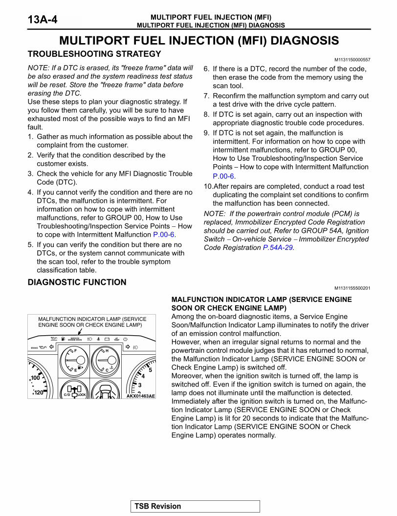
MALFUNCTION INDICATOR LAMP (SERVICE ENGINE SOON OR CHECK ENGINE LAMP)Among the on-board diagnostic items, a Service Engine Soon/Malfunction Indicator Lamp illuminates to notify the driver of an emission control malfunction. However, when an irregular signal returns to normal and the powertrain control module judges that it has returned to normal, the Malfunction Indicator Lamp (SERVICE ENGINE SOON or Check Engine Lamp) is switched off. Moreover, when the ignition switch is turned off, the lamp is switched off. Even if the ignition switch is turned on again, the lamp does not illuminate until the malfunction is detected. Immediately after the ignition switch is turned on, the Malfunc-tion Indicator Lamp (SERVICE ENGINE SOON or Check Engine Lamp) is lit for 20 seconds to indicate that the Malfunc-tion Indicator Lamp (SERVICE ENGINE SOON or Check Engine Lamp) operates normally.
.
BRAKE
SERVICEENGINE SOON
F H
CE
ATTEMP
C/D LOCK
100
120 23
45
AKX01463AE
MALFUNCTION INDICATOR LAMP (SERVICE ENGINE SOON OR CHECK ENGINE LAMP)
TSB Revision
MULTIPORT FUEL INJECTION (MFI) DIAGNOSISMULTIPORT FUEL INJECTION (MFI) 13A-5
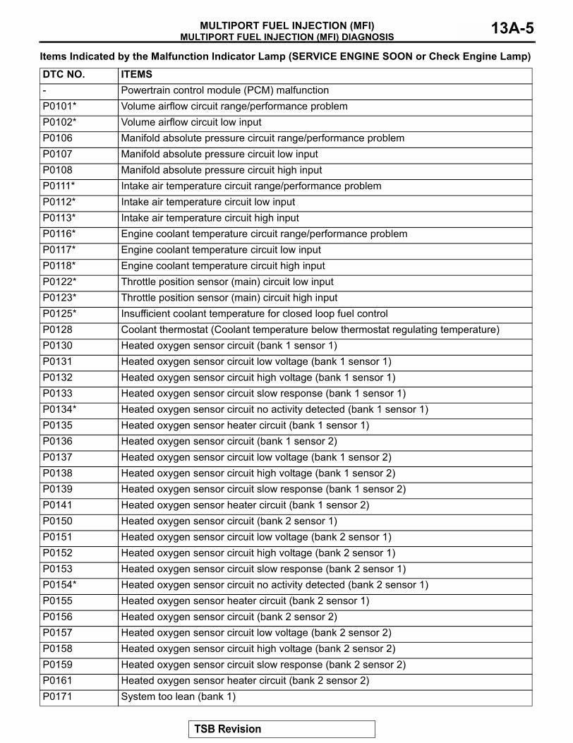
Items Indicated by the Malfunction Indicator Lamp (SERVICE ENGINE SOON or Check Engine Lamp)
DTC NO. ITEMS- Powertrain control module (PCM) malfunctionP0101* Volume airflow circuit range/performance problemP0102* Volume airflow circuit low inputP0106 Manifold absolute pressure circuit range/performance problemP0107 Manifold absolute pressure circuit low inputP0108 Manifold absolute pressure circuit high inputP0111* Intake air temperature circuit range/performance problemP0112* Intake air temperature circuit low inputP0113* Intake air temperature circuit high inputP0116* Engine coolant temperature circuit range/performance problemP0117* Engine coolant temperature circuit low inputP0118* Engine coolant temperature circuit high inputP0122* Throttle position sensor (main) circuit low inputP0123* Throttle position sensor (main) circuit high inputP0125* Insufficient coolant temperature for closed loop fuel controlP0128 Coolant thermostat (Coolant temperature below thermostat regulating temperature)P0130 Heated oxygen sensor circuit (bank 1 sensor 1)P0131 Heated oxygen sensor circuit low voltage (bank 1 sensor 1)P0132 Heated oxygen sensor circuit high voltage (bank 1 sensor 1) P0133 Heated oxygen sensor circuit slow response (bank 1 sensor 1)P0134* Heated oxygen sensor circuit no activity detected (bank 1 sensor 1)P0135 Heated oxygen sensor heater circuit (bank 1 sensor 1)P0136 Heated oxygen sensor circuit (bank 1 sensor 2)P0137 Heated oxygen sensor circuit low voltage (bank 1 sensor 2)P0138 Heated oxygen sensor circuit high voltage (bank 1 sensor 2)P0139 Heated oxygen sensor circuit slow response (bank 1 sensor 2)P0141 Heated oxygen sensor heater circuit (bank 1 sensor 2) P0150 Heated oxygen sensor circuit (bank 2 sensor 1)P0151 Heated oxygen sensor circuit low voltage (bank 2 sensor 1)P0152 Heated oxygen sensor circuit high voltage (bank 2 sensor 1)P0153 Heated oxygen sensor circuit slow response (bank 2 sensor 1)P0154* Heated oxygen sensor circuit no activity detected (bank 2 sensor 1)P0155 Heated oxygen sensor heater circuit (bank 2 sensor 1) P0156 Heated oxygen sensor circuit (bank 2 sensor 2)P0157 Heated oxygen sensor circuit low voltage (bank 2 sensor 2) P0158 Heated oxygen sensor circuit high voltage (bank 2 sensor 2) P0159 Heated oxygen sensor circuit slow response (bank 2 sensor 2)P0161 Heated oxygen sensor heater circuit (bank 2 sensor 2)P0171 System too lean (bank 1)
TSB Revision
MULTIPORT FUEL INJECTION (MFI) DIAGNOSISMULTIPORT FUEL INJECTION (MFI)13A-6
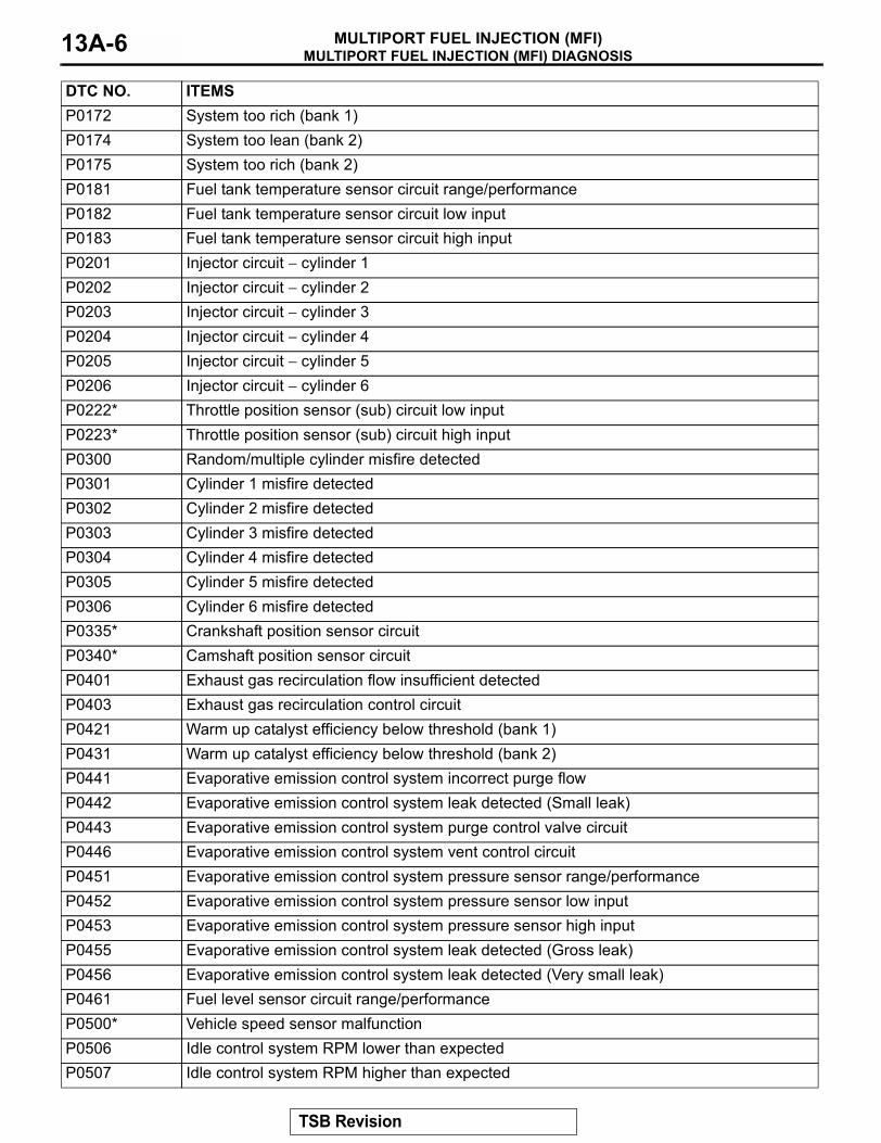
P0172 System too rich (bank 1)P0174 System too lean (bank 2)P0175 System too rich (bank 2)P0181 Fuel tank temperature sensor circuit range/performanceP0182 Fuel tank temperature sensor circuit low inputP0183 Fuel tank temperature sensor circuit high inputP0201 Injector circuit − cylinder 1P0202 Injector circuit − cylinder 2P0203 Injector circuit − cylinder 3P0204 Injector circuit − cylinder 4P0205 Injector circuit − cylinder 5P0206 Injector circuit − cylinder 6P0222* Throttle position sensor (sub) circuit low inputP0223* Throttle position sensor (sub) circuit high inputP0300 Random/multiple cylinder misfire detectedP0301 Cylinder 1 misfire detectedP0302 Cylinder 2 misfire detectedP0303 Cylinder 3 misfire detectedP0304 Cylinder 4 misfire detectedP0305 Cylinder 5 misfire detectedP0306 Cylinder 6 misfire detectedP0335* Crankshaft position sensor circuitP0340* Camshaft position sensor circuitP0401 Exhaust gas recirculation flow insufficient detectedP0403 Exhaust gas recirculation control circuitP0421 Warm up catalyst efficiency below threshold (bank 1)P0431 Warm up catalyst efficiency below threshold (bank 2)P0441 Evaporative emission control system incorrect purge flowP0442 Evaporative emission control system leak detected (Small leak)P0443 Evaporative emission control system purge control valve circuitP0446 Evaporative emission control system vent control circuitP0451 Evaporative emission control system pressure sensor range/performanceP0452 Evaporative emission control system pressure sensor low inputP0453 Evaporative emission control system pressure sensor high inputP0455 Evaporative emission control system leak detected (Gross leak)P0456 Evaporative emission control system leak detected (Very small leak)P0461 Fuel level sensor circuit range/performanceP0500* Vehicle speed sensor malfunctionP0506 Idle control system RPM lower than expectedP0507 Idle control system RPM higher than expected
DTC NO. ITEMS
TSB Revision
MULTIPORT FUEL INJECTION (MFI) DIAGNOSISMULTIPORT FUEL INJECTION (MFI) 13A-7
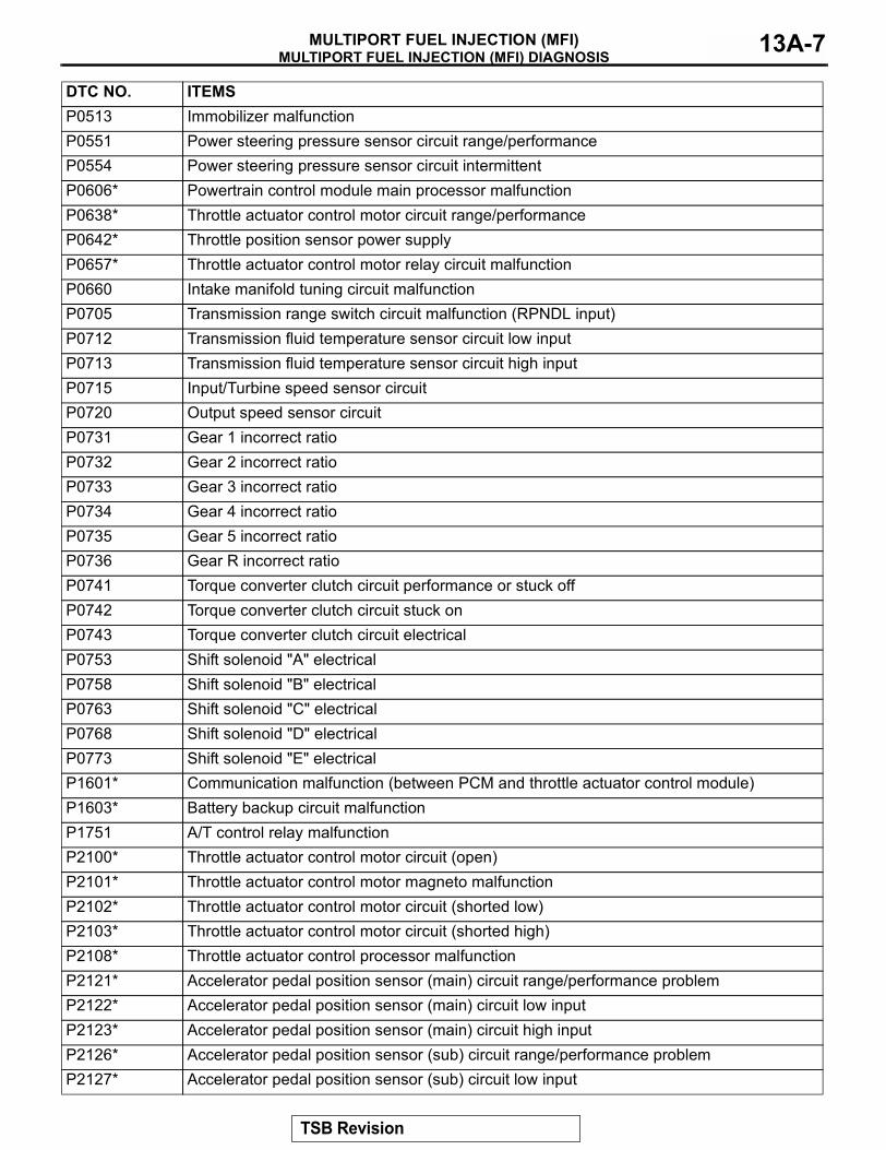
P0513 Immobilizer malfunctionP0551 Power steering pressure sensor circuit range/performanceP0554 Power steering pressure sensor circuit intermittentP0606* Powertrain control module main processor malfunctionP0638* Throttle actuator control motor circuit range/performanceP0642* Throttle position sensor power supplyP0657* Throttle actuator control motor relay circuit malfunctionP0660 Intake manifold tuning circuit malfunctionP0705 Transmission range switch circuit malfunction (RPNDL input)P0712 Transmission fluid temperature sensor circuit low inputP0713 Transmission fluid temperature sensor circuit high inputP0715 Input/Turbine speed sensor circuitP0720 Output speed sensor circuitP0731 Gear 1 incorrect ratioP0732 Gear 2 incorrect ratioP0733 Gear 3 incorrect ratioP0734 Gear 4 incorrect ratioP0735 Gear 5 incorrect ratioP0736 Gear R incorrect ratioP0741 Torque converter clutch circuit performance or stuck offP0742 Torque converter clutch circuit stuck onP0743 Torque converter clutch circuit electricalP0753 Shift solenoid "A" electricalP0758 Shift solenoid "B" electricalP0763 Shift solenoid "C" electricalP0768 Shift solenoid "D" electricalP0773 Shift solenoid "E" electricalP1601* Communication malfunction (between PCM and throttle actuator control module)P1603* Battery backup circuit malfunctionP1751 A/T control relay malfunctionP2100* Throttle actuator control motor circuit (open)P2101* Throttle actuator control motor magneto malfunctionP2102* Throttle actuator control motor circuit (shorted low)P2103* Throttle actuator control motor circuit (shorted high)P2108* Throttle actuator control processor malfunctionP2121* Accelerator pedal position sensor (main) circuit range/performance problemP2122* Accelerator pedal position sensor (main) circuit low inputP2123* Accelerator pedal position sensor (main) circuit high inputP2126* Accelerator pedal position sensor (sub) circuit range/performance problemP2127* Accelerator pedal position sensor (sub) circuit low input
DTC NO. ITEMS
TSB Revision
MULTIPORT FUEL INJECTION (MFI) DIAGNOSISMULTIPORT FUEL INJECTION (MFI)13A-8
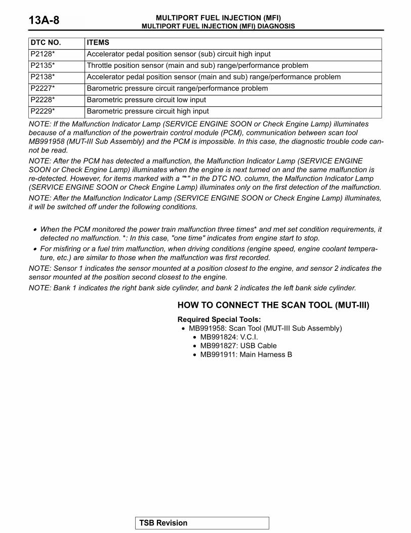
NOTE: If the Malfunction Indicator Lamp (SERVICE ENGINE SOON or Check Engine Lamp) illuminates because of a malfunction of the powertrain control module (PCM), communication between scan tool MB991958 (MUT-III Sub Assembly) and the PCM is impossible. In this case, the diagnostic trouble code can-not be read.NOTE: After the PCM has detected a malfunction, the Malfunction Indicator Lamp (SERVICE ENGINE SOON or Check Engine Lamp) illuminates when the engine is next turned on and the same malfunction is re-detected. However, for items marked with a "*" in the DTC NO. column, the Malfunction Indicator Lamp (SERVICE ENGINE SOON or Check Engine Lamp) illuminates only on the first detection of the malfunction.NOTE: After the Malfunction Indicator Lamp (SERVICE ENGINE SOON or Check Engine Lamp) illuminates, it will be switched off under the following conditions..
• When the PCM monitored the power train malfunction three times* and met set condition requirements, it detected no malfunction. *: In this case, "one time" indicates from engine start to stop.
• For misfiring or a fuel trim malfunction, when driving conditions (engine speed, engine coolant tempera-ture, etc.) are similar to those when the malfunction was first recorded.
NOTE: Sensor 1 indicates the sensor mounted at a position closest to the engine, and sensor 2 indicates the sensor mounted at the position second closest to the engine.NOTE: Bank 1 indicates the right bank side cylinder, and bank 2 indicates the left bank side cylinder.
HOW TO CONNECT THE SCAN TOOL (MUT-III)Required Special Tools:
• MB991958: Scan Tool (MUT-III Sub Assembly)• MB991824: V.C.I.• MB991827: USB Cable• MB991911: Main Harness B
P2128* Accelerator pedal position sensor (sub) circuit high inputP2135* Throttle position sensor (main and sub) range/performance problemP2138* Accelerator pedal position sensor (main and sub) range/performance problemP2227* Barometric pressure circuit range/performance problemP2228* Barometric pressure circuit low inputP2229* Barometric pressure circuit high input
DTC NO. ITEMS
TSB Revision
MULTIPORT FUEL INJECTION (MFI) DIAGNOSISMULTIPORT FUEL INJECTION (MFI) 13A-9
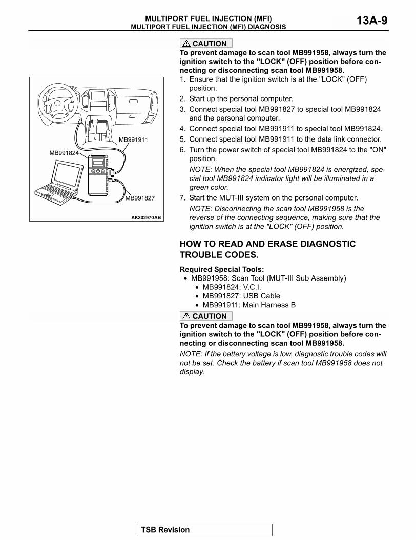
CAUTIONTo prevent damage to scan tool MB991958, always turn the ignition switch to the "LOCK" (OFF) position before con-necting or disconnecting scan tool MB991958.1. Ensure that the ignition switch is at the "LOCK" (OFF)
position.2. Start up the personal computer.3. Connect special tool MB991827 to special tool MB991824
and the personal computer.4. Connect special tool MB991911 to special tool MB991824.5. Connect special tool MB991911 to the data link connector.6. Turn the power switch of special tool MB991824 to the "ON"
position.NOTE: When the special tool MB991824 is energized, spe-cial tool MB991824 indicator light will be illuminated in a green color.
7. Start the MUT-III system on the personal computer.NOTE: Disconnecting the scan tool MB991958 is the reverse of the connecting sequence, making sure that the ignition switch is at the "LOCK" (OFF) position.
HOW TO READ AND ERASE DIAGNOSTIC TROUBLE CODES.Required Special Tools:
• MB991958: Scan Tool (MUT-III Sub Assembly)• MB991824: V.C.I.• MB991827: USB Cable• MB991911: Main Harness B
CAUTIONTo prevent damage to scan tool MB991958, always turn the ignition switch to the "LOCK" (OFF) position before con-necting or disconnecting scan tool MB991958.NOTE: If the battery voltage is low, diagnostic trouble codes will not be set. Check the battery if scan tool MB991958 does not display.
AK302970AB
MB991911
MB991824
MB991827
TSB Revision
MULTIPORT FUEL INJECTION (MFI) DIAGNOSISMULTIPORT FUEL INJECTION (MFI)13A-10
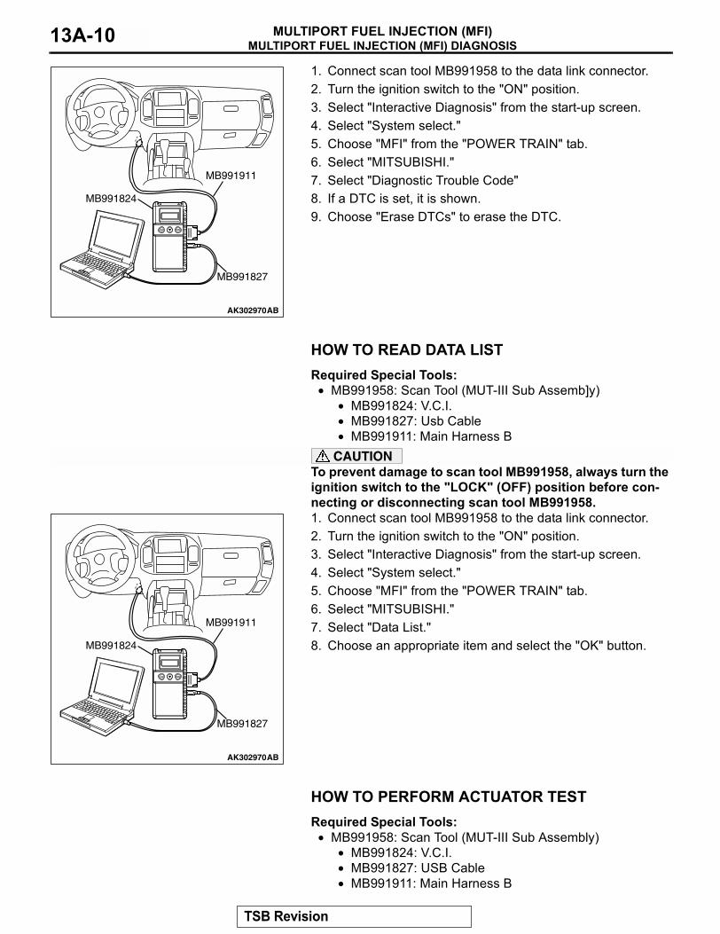
1. Connect scan tool MB991958 to the data link connector.2. Turn the ignition switch to the "ON" position.3. Select "Interactive Diagnosis" from the start-up screen.4. Select "System select."5. Choose "MFI" from the "POWER TRAIN" tab.6. Select "MITSUBISHI."7. Select "Diagnostic Trouble Code"8. If a DTC is set, it is shown.9. Choose "Erase DTCs" to erase the DTC.
HOW TO READ DATA LISTRequired Special Tools:
• MB991958: Scan Tool (MUT-III Sub Assemb]y)• MB991824: V.C.I.• MB991827: Usb Cable• MB991911: Main Harness B
CAUTIONTo prevent damage to scan tool MB991958, always turn the ignition switch to the "LOCK" (OFF) position before con-necting or disconnecting scan tool MB991958.1. Connect scan tool MB991958 to the data link connector.2. Turn the ignition switch to the "ON" position.3. Select "Interactive Diagnosis" from the start-up screen.4. Select "System select."5. Choose "MFI" from the "POWER TRAIN" tab.6. Select "MITSUBISHI."7. Select "Data List."8. Choose an appropriate item and select the "OK" button.
HOW TO PERFORM ACTUATOR TESTRequired Special Tools:
• MB991958: Scan Tool (MUT-III Sub Assembly)• MB991824: V.C.I.• MB991827: USB Cable• MB991911: Main Harness B
AK302970AB
MB991911
MB991824
MB991827
AK302970AB
MB991911
MB991824
MB991827
TSB Revision
MULTIPORT FUEL INJECTION (MFI) DIAGNOSISMULTIPORT FUEL INJECTION (MFI) 13A-11
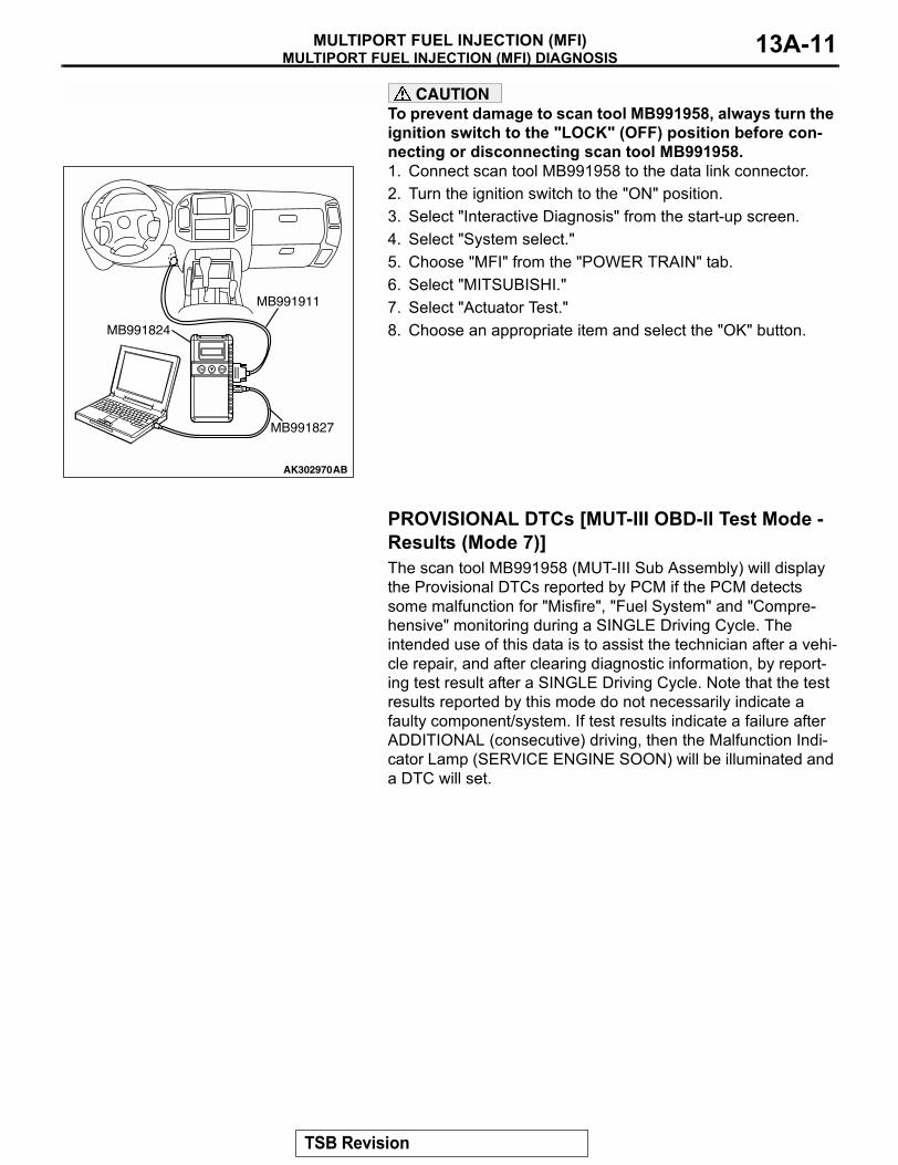
CAUTIONTo prevent damage to scan tool MB991958, always turn the ignition switch to the "LOCK" (OFF) position before con-necting or disconnecting scan tool MB991958.1. Connect scan tool MB991958 to the data link connector.2. Turn the ignition switch to the "ON" position.3. Select "Interactive Diagnosis" from the start-up screen.4. Select "System select."5. Choose "MFI" from the "POWER TRAIN" tab.6. Select "MITSUBISHI."7. Select "Actuator Test."8. Choose an appropriate item and select the "OK" button.
PROVISIONAL DTCs [MUT-III OBD-II Test Mode - Results (Mode 7)]The scan tool MB991958 (MUT-III Sub Assembly) will display the Provisional DTCs reported by PCM if the PCM detects some malfunction for "Misfire", "Fuel System" and "Compre-hensive" monitoring during a SINGLE Driving Cycle. The intended use of this data is to assist the technician after a vehi-cle repair, and after clearing diagnostic information, by report-ing test result after a SINGLE Driving Cycle. Note that the test results reported by this mode do not necessarily indicate a faulty component/system. If test results indicate a failure after ADDITIONAL (consecutive) driving, then the Malfunction Indi-cator Lamp (SERVICE ENGINE SOON) will be illuminated and a DTC will set.
AK302970AB
MB991911
MB991824
MB991827
TSB Revision
MULTIPORT FUEL INJECTION (MFI) DIAGNOSISMULTIPORT FUEL INJECTION (MFI)13A-12
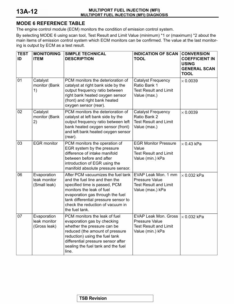
MODE 6 REFERENCE TABLEThe engine control module (ECM) monitors the condition of emission control system.By selecting MODE 6 using scan tool, Test Result and Limit Value (minimum) *1 or (maximum) *2 about the main items of emission control system which ECM monitors can be confirmed. The value at the last monitor-ing is output by ECM as a test result.
TEST ID
MONITORING ITEM
SIMPLE TECHNICAL DESCRIPTION
INDICATION OF SCAN TOOL
CONVERSION COEFFICIENT IN USING GENERAL SCAN TOOL
01 Catalyst monitor (Bank 1)
PCM monitors the deterioration of catalyst at right bank side by the output frequency ratio between right bank heated oxygen sensor (front) and right bank heated oxygen sensor (rear).
Catalyst Frequency Ratio Bank 1Test Result and Limit Value (max.)
× 0.0039
02 Catalyst monitor (Bank 2)
PCM monitors the deterioration of catalyst at left bank side by the output frequency ratio between left bank heated oxygen sensor (front) and left bank heated oxygen sensor (rear).
Catalyst Frequency Ratio Bank 2Test Result and Limit Value (max.)
× 0.0039
03 EGR monitor PCM monitors the operation of EGR system by the pressure difference of intake manifold between before and after introduction of EGR using the manifold absolute pressure sensor.
EGR Monitor Pressure ValueTest Result and Limit Value (min.) kPa
× 0.43 kPa
06 Evaporation leak monitor (Small leak)
After PCM vacuumizes the fuel tank and the fuel line and then the specified time is passed, PCM monitors the leak of fuel evaporation gas through the fuel tank differential pressure sensor to check the reduction of vacuum in the fuel tank.
EVAP Leak Mon. 1 mm Pressure ValueTest Result and Limit Value (max.) kPa
× 0.032 kPa
07 Evaporation leak monitor (Gross leak)
PCM monitors the leak of fuel evaporation gas by checking whether the pressure can be reduced (the amount of pressure reduction) using the fuel tank differential pressure sensor after sealing the fuel tank and the fuel line.
EVAP Leak Mon. Gross Pressure ValueTest Result and Limit Value (min.) kPa
× 0.032 kPa
TSB Revision
MULTIPORT FUEL INJECTION (MFI) DIAGNOSISMULTIPORT FUEL INJECTION (MFI) 13A-13
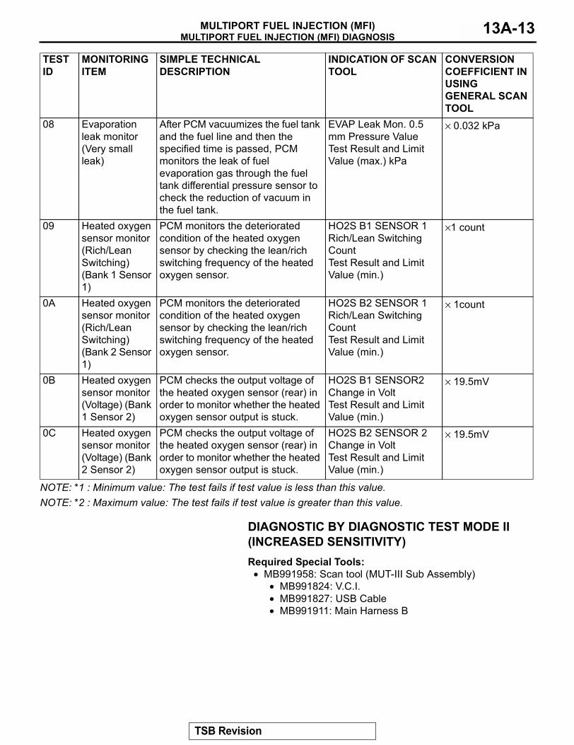
NOTE: *1 : Minimum value: The test fails if test value is less than this value.NOTE: *2 : Maximum value: The test fails if test value is greater than this value.
DIAGNOSTIC BY DIAGNOSTIC TEST MODE II (INCREASED SENSITIVITY)Required Special Tools:
• MB991958: Scan tool (MUT-III Sub Assembly)• MB991824: V.C.I.• MB991827: USB Cable• MB991911: Main Harness B
08 Evaporation leak monitor (Very small leak)
After PCM vacuumizes the fuel tank and the fuel line and then the specified time is passed, PCM monitors the leak of fuel evaporation gas through the fuel tank differential pressure sensor to check the reduction of vacuum in the fuel tank.
EVAP Leak Mon. 0.5 mm Pressure ValueTest Result and Limit Value (max.) kPa
× 0.032 kPa
09 Heated oxygen sensor monitor (Rich/Lean Switching) (Bank 1 Sensor 1)
PCM monitors the deteriorated condition of the heated oxygen sensor by checking the lean/rich switching frequency of the heated oxygen sensor.
HO2S B1 SENSOR 1 Rich/Lean Switching CountTest Result and Limit Value (min.)
×1 count
0A Heated oxygen sensor monitor (Rich/Lean Switching) (Bank 2 Sensor 1)
PCM monitors the deteriorated condition of the heated oxygen sensor by checking the lean/rich switching frequency of the heated oxygen sensor.
HO2S B2 SENSOR 1 Rich/Lean Switching CountTest Result and Limit Value (min.)
× 1count
0B Heated oxygen sensor monitor (Voltage) (Bank 1 Sensor 2)
PCM checks the output voltage of the heated oxygen sensor (rear) in order to monitor whether the heated oxygen sensor output is stuck.
HO2S B1 SENSOR2 Change in VoltTest Result and Limit Value (min.)
× 19.5mV
0C Heated oxygen sensor monitor (Voltage) (Bank 2 Sensor 2)
PCM checks the output voltage of the heated oxygen sensor (rear) in order to monitor whether the heated oxygen sensor output is stuck.
HO2S B2 SENSOR 2 Change in VoltTest Result and Limit Value (min.)
× 19.5mV
TEST ID
MONITORING ITEM
SIMPLE TECHNICAL DESCRIPTION
INDICATION OF SCAN TOOL
CONVERSION COEFFICIENT IN USING GENERAL SCAN TOOL
TSB Revision
MULTIPORT FUEL INJECTION (MFI) DIAGNOSISMULTIPORT FUEL INJECTION (MFI)13A-14
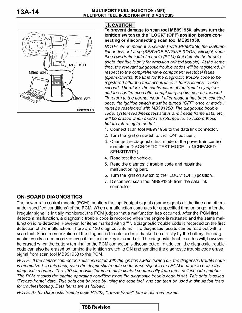
CAUTIONTo prevent damage to scan tool MB991958, always turn the ignition switch to the "LOCK" (OFF) position before con-necting or disconnecting scan tool MB991958.NOTE: When mode II is selected with MB991958, the Malfunc-tion Indicator Lamp (SERVICE ENGINE SOON) will light when the powertrain control module (PCM) first detects the trouble (Note that this is only for emission-related trouble). At the same time, the relevant diagnostic trouble codes will be registered. In respect to the comprehensive component electrical faults (opens/shorts), the time for the diagnostic trouble code to be registered after the fault occurrence is four seconds → one second. Therefore, the confirmation of the trouble symptom and the confirmation after completing repairs can be reduced. To return to the normal mode I after mode II has been selected once, the ignition switch must be turned "OFF" once or mode I must be reselected with MB991958. The diagnostic trouble code, system readiness test status and freeze frame data, etc., will be erased when mode I is returned to, so record these before returning to mode I.1. Connect scan tool MB991958 to the data link connector.2. Turn the ignition switch to the "ON" position.3. Change the diagnostic test mode of the powertrain control
module to DIAGNOSTIC TEST MODE II (INCREASED SENSITIVITY).
4. Road test the vehicle.5. Read the diagnostic trouble code and repair the
malfunctioning part.6. Turn the ignition switch to the "LOCK" (OFF) position.7. Disconnect scan tool MB991958 from the data link
connector.
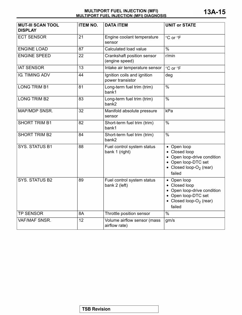
ON-BOARD DIAGNOSTICSThe powertrain control module (PCM) monitors the input/output signals (some signals all the time and others under specified conditions) of the PCM. When a malfunction continues for a specified time or longer after the irregular signal is initially monitored, the PCM judges that a malfunction has occurred. After the PCM first detects a malfunction, a diagnostic trouble code is recorded when the engine is restarted and the same mal-function is re-detected. However, for items marked with a "*", a diagnostic trouble code is recorded on the first detection of the malfunction. There are 130 diagnostic items. The diagnostic results can be read out with a scan tool. Since memorization of the diagnostic trouble codes is backed up directly by the battery, the diag-nostic results are memorized even if the ignition key is turned off. The diagnostic trouble codes will, however, be erased when the battery terminal or the PCM connector is disconnected. In addition, the diagnostic trouble code can also be erased by turning the ignition switch to ON and sending the diagnostic trouble code erase signal from scan tool MB991958 to the PCM. NOTE: If the sensor connector is disconnected with the ignition switch turned on, the diagnostic trouble code is memorized. In this case, send the diagnostic trouble code erase signal to the PCM in order to erase the diagnostic memory. The 130 diagnostic items are all indicated sequentially from the smallest code number. The PCM records the engine operating condition when the diagnostic trouble code is set. This data is called "Freeze-frame" data. This data can be read by using the scan tool, and can then be used in simulation tests for troubleshooting. Data items are as follows:NOTE: As for Diagnostic trouble code P1603, "freeze frame" data is not memorized.
AK302970AB
MB991911
MB991824
MB991827
TSB Revision
MULTIPORT FUEL INJECTION (MFI) DIAGNOSISMULTIPORT FUEL INJECTION (MFI) 13A-15
MUT-III SCAN TOOL DISPLAY
ITEM NO. DATA ITEM UNIT or STATE
ECT SENSOR 21 Engine coolant temperature sensor
°C or °F
ENGINE LOAD 87 Calculated load value %ENGINE SPEED 22 Crankshaft position sensor
(engine speed)r/min
IAT SENSOR 13 Intake air temperature sensor °C or °FIG. TIMING ADV 44 Ignition coils and ignition
power transistordeg
LONG TRIM B1 81 Long-term fuel trim (trim) bank1
%
LONG TRIM B2 83 Long-term fuel trim (trim) bank2
%
MAP/MDP SNSR. 32 Manifold absolute pressure sensor
kPa
SHORT TRIM B1 82 Short-term fuel trim (trim) bank1
%
SHORT TRIM B2 84 Short-term fuel trim (trim) bank2
%
SYS. STATUS B1 88 Fuel control system status bank 1 (right)
• Open loop• Closed loop • Open loop-drive condition • Open loop-DTC set • Closed loop-O2 (rear)
failedSYS. STATUS B2 89 Fuel control system status
bank 2 (left)• Open loop• Closed loop • Open loop-drive condition • Open loop-DTC set • Closed loop-O2 (rear)
failedTP SENSOR 8A Throttle position sensor %VAF/MAF SNSR. 12 Volume airflow sensor (mass
airflow rate)gm/s
TSB Revision
MULTIPORT FUEL INJECTION (MFI) DIAGNOSISMULTIPORT FUEL INJECTION (MFI)13A-16
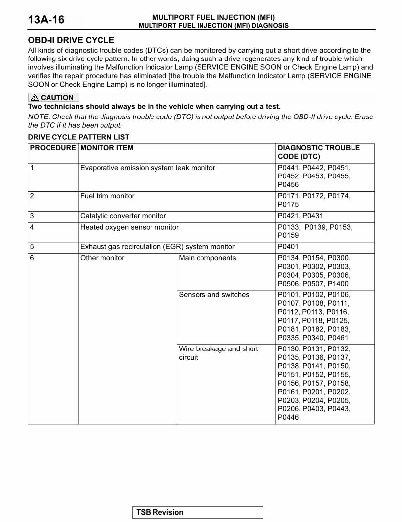
OBD-II DRIVE CYCLEAll kinds of diagnostic trouble codes (DTCs) can be monitored by carrying out a short drive according to the following six drive cycle pattern. In other words, doing such a drive regenerates any kind of trouble which involves illuminating the Malfunction Indicator Lamp (SERVICE ENGINE SOON or Check Engine Lamp) and verifies the repair procedure has eliminated [the trouble the Malfunction Indicator Lamp (SERVICE ENGINE SOON or Check Engine Lamp) is no longer illuminated].
CAUTIONTwo technicians should always be in the vehicle when carrying out a test.NOTE: Check that the diagnosis trouble code (DTC) is not output before driving the OBD-II drive cycle. Erase the DTC if it has been output.DRIVE CYCLE PATTERN LISTPROCEDURE MONITOR ITEM DIAGNOSTIC TROUBLE
CODE (DTC)1 Evaporative emission system leak monitor P0441, P0442, P0451,
P0452, P0453, P0455, P0456
2 Fuel trim monitor P0171, P0172, P0174, P0175
3 Catalytic converter monitor P0421, P04314 Heated oxygen sensor monitor P0133, P0139, P0153,
P01595 Exhaust gas recirculation (EGR) system monitor P04016 Other monitor Main components P0134, P0154, P0300,
P0301, P0302, P0303, P0304, P0305, P0306, P0506, P0507, P1400
Sensors and switches P0101, P0102, P0106, P0107, P0108, P0111, P0112, P0113, P0116, P0117, P0118, P0125, P0181, P0182, P0183, P0335, P0340, P0461
Wire breakage and short circuit
P0130, P0131, P0132, P0135, P0136, P0137, P0138, P0141, P0150, P0151, P0152, P0155, P0156, P0157, P0158, P0161, P0201, P0202, P0203, P0204, P0205, P0206, P0403, P0443, P0446
TSB Revision
MULTIPORT FUEL INJECTION (MFI) DIAGNOSISMULTIPORT FUEL INJECTION (MFI) 13A-17
.
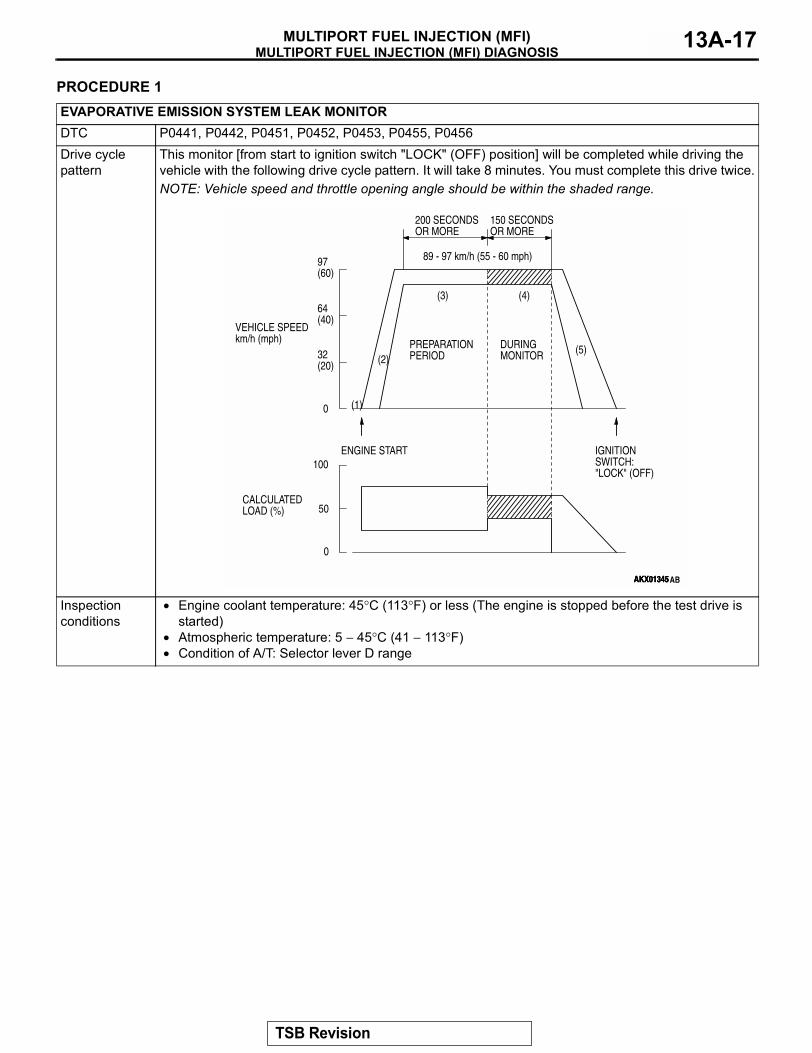
PROCEDURE 1EVAPORATIVE EMISSION SYSTEM LEAK MONITORDTC P0441, P0442, P0451, P0452, P0453, P0455, P0456Drive cycle pattern
This monitor [from start to ignition switch "LOCK" (OFF) position] will be completed while driving the vehicle with the following drive cycle pattern. It will take 8 minutes. You must complete this drive twice.NOTE: Vehicle speed and throttle opening angle should be within the shaded range.
Inspection conditions
• Engine coolant temperature: 45°C (113°F) or less (The engine is stopped before the test drive is started)
• Atmospheric temperature: 5 − 45°C (41 − 113°F)• Condition of A/T: Selector lever D range
AKX01345AKX01345
(3)
(2)
(1)
(4)
(5)
200 SECONDSOR MORE
PREPARATIONPERIOD
ENGINE START IGNITION SWITCH: "LOCK" (OFF)
DURINGMONITOR
150 SECONDSOR MORE
89 - 97 km/h (55 - 60 mph)97(60)
64(40)
32(20)
0
100
50
0
VEHICLE SPEEDkm/h (mph)
AKX01345AB
CALCULATEDLOAD (%)
TSB Revision
MULTIPORT FUEL INJECTION (MFI) DIAGNOSISMULTIPORT FUEL INJECTION (MFI)13A-18
.
Test procedure 1. Engine: start2. Accelerate until the vehicle speed is 89 − 97 km/h (55 − 60 mph).3. Travel for 200 seconds or more while keeping the vehicle speed at 89 − 97 km/h (55 − 60 mph).4. While keeping the accelerator pedal opening degree constant, keep the vehicle speed at 89 − 97
km/h (55 − 60 mph) and travel for 150 seconds or more. (During monitor)5. Return the vehicle to the shop, then turn the ignition switch to "LOCK" (OFF) position.6. Confirm that the diagnostic trouble code (DTC) is not output.7. If DTC P0441 is output, refer to DTC P0441 − Evaporative Emission Control System Incorrect
Purge Flow P.13A-521.If DTC P0442 is output, refer to DTC P0442 − Evaporative Emission Control System Leak Detected (Small Leak) P.13A-525.If DTC P0451 is output, refer to DTC P0451 − Evaporative Emission Control System Pressure Sensor Range/performance P.13A-558.If DTC P0452 is output, refer to DTC P0452 − Evaporative Emission Control System Pressure Sensor Low Input P.13A-575.If DTC P0453 is output, refer to DTC P0453 − Evaporative Emission Control System Pressure Sensor High Input P.13A-592.If DTC P0455 is output, refer to DTC P0455 − Evaporative Emission Control System Leak Detected (Gross Leak) P.13A-609.If DTC P0456 is output, refer to DTC P0456 − Evaporative Emission Control System Leak Detected (Very Small Leak) P.13A-630.
EVAPORATIVE EMISSION SYSTEM LEAK MONITOR
TSB Revision
MULTIPORT FUEL INJECTION (MFI) DIAGNOSISMULTIPORT FUEL INJECTION (MFI) 13A-19
PROCEDURE 2
.
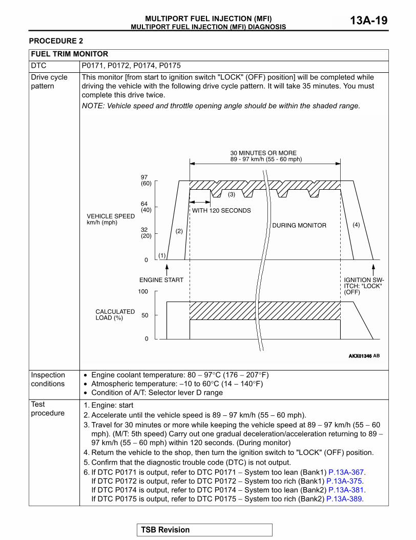
FUEL TRIM MONITORDTC P0171, P0172, P0174, P0175Drive cycle pattern
This monitor [from start to ignition switch "LOCK" (OFF) position] will be completed while driving the vehicle with the following drive cycle pattern. It will take 35 minutes. You must complete this drive twice.NOTE: Vehicle speed and throttle opening angle should be within the shaded range.
Inspection conditions
• Engine coolant temperature: 80 − 97°C (176 − 207°F)• Atmospheric temperature: −10 to 60°C (14 − 140°F)• Condition of A/T: Selector lever D range
Test procedure
1. Engine: start2. Accelerate until the vehicle speed is 89 − 97 km/h (55 − 60 mph).3. Travel for 30 minutes or more while keeping the vehicle speed at 89 − 97 km/h (55 − 60
mph). (M/T: 5th speed) Carry out one gradual deceleration/acceleration returning to 89 − 97 km/h (55 − 60 mph) within 120 seconds. (During monitor)
4. Return the vehicle to the shop, then turn the ignition switch to "LOCK" (OFF) position.5. Confirm that the diagnostic trouble code (DTC) is not output.6. If DTC P0171 is output, refer to DTC P0171 − System too lean (Bank1) P.13A-367.
If DTC P0172 is output, refer to DTC P0172 − System too rich (Bank1) P.13A-375.If DTC P0174 is output, refer to DTC P0174 − System too lean (Bank2) P.13A-381.If DTC P0175 is output, refer to DTC P0175 − System too rich (Bank2) P.13A-389.
AKX01346AKX01346
(3)
(2)
(1)
(4)
30 MINUTES OR MORE89 - 97 km/h (55 - 60 mph)
WITH 120 SECONDS
ENGINE START IGNITION SW-ITCH: "LOCK" (OFF)
DURING MONITOR
97(60)
64(40)
32(20)
0
100
50
0
VEHICLE SPEEDkm/h (mph)
AKX01346 AB
CALCULATEDLOAD (%)
TSB Revision
MULTIPORT FUEL INJECTION (MFI) DIAGNOSISMULTIPORT FUEL INJECTION (MFI)13A-20
PROCEDURE 3
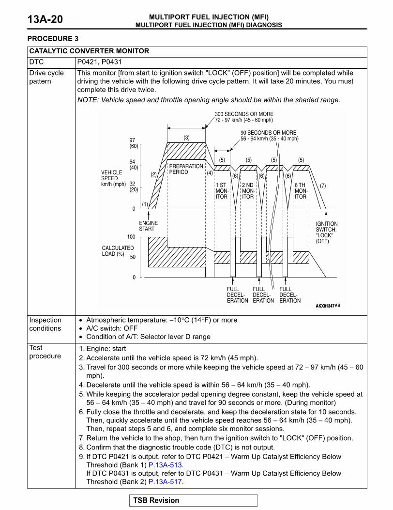
CATALYTIC CONVERTER MONITORDTC P0421, P0431Drive cycle pattern
This monitor [from start to ignition switch "LOCK" (OFF) position] will be completed while driving the vehicle with the following drive cycle pattern. It will take 20 minutes. You must complete this drive twice.NOTE: Vehicle speed and throttle opening angle should be within the shaded range.
Inspection conditions
• Atmospheric temperature: −10°C (14°F) or more• A/C switch: OFF• Condition of A/T: Selector lever D range
Test procedure
1. Engine: start2. Accelerate until the vehicle speed is 72 km/h (45 mph).3. Travel for 300 seconds or more while keeping the vehicle speed at 72 − 97 km/h (45 − 60
mph).4. Decelerate until the vehicle speed is within 56 − 64 km/h (35 − 40 mph).5. While keeping the accelerator pedal opening degree constant, keep the vehicle speed at
56 − 64 km/h (35 − 40 mph) and travel for 90 seconds or more. (During monitor)6. Fully close the throttle and decelerate, and keep the deceleration state for 10 seconds.
Then, quickly accelerate until the vehicle speed reaches 56 − 64 km/h (35 − 40 mph). Then, repeat steps 5 and 6, and complete six monitor sessions.
7. Return the vehicle to the shop, then turn the ignition switch to "LOCK" (OFF) position.8. Confirm that the diagnostic trouble code (DTC) is not output.9. If DTC P0421 is output, refer to DTC P0421 − Warm Up Catalyst Efficiency Below
Threshold (Bank 1) P.13A-513.If DTC P0431 is output, refer to DTC P0431 − Warm Up Catalyst Efficiency Below Threshold (Bank 2) P.13A-517.
AKX01347
(3)
(2)
(1)
(4)
(5) (5)
(6) (6) (6)
(5) (5)
(7)
300 SECONDS OR MORE72 - 97 km/h (45 - 60 mph)
PREPARATIONPERIOD
ENGINE START
IGNITION SWITCH: "LOCK"(OFF)
1 STMON-ITOR
FULLDECEL-ERATION
FULLDECEL-ERATION
FULLDECEL-ERATION
2 NDMON-ITOR
6 THMON-ITOR
90 SECONDS OR MORE56 - 64 km/h (35 - 40 mph)97
(60)
64(40)
32(20)
0
100
50
0
VEHICLE SPEEDkm/h (mph)
AKX01347AB
CALCULATEDLOAD (%)
TSB Revision
MULTIPORT FUEL INJECTION (MFI) DIAGNOSISMULTIPORT FUEL INJECTION (MFI) 13A-21
. PROCEDURE 4
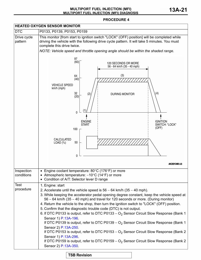
HEATED OXYGEN SENSOR MONITORDTC P0133, P0139, P0153, P0159Drive cycle pattern
This monitor [from start to ignition switch "LOCK" (OFF) position] will be completed while driving the vehicle with the following drive cycle pattern. It will take 5 minutes. You must complete this drive twice.NOTE: Vehicle speed and throttle opening angle should be within the shaded range.
Inspection conditions
• Engine coolant temperature: 80°C (176°F) or more• Atmospheric temperature: −10°C (14°F) or more• Condition of A/T: Selector lever D range
Test procedure
1. Engine: start2. Accelerate until the vehicle speed is 56 − 64 km/h (35 − 40 mph).3. While keeping the accelerator pedal opening degree constant, keep the vehicle speed at
56 − 64 km/h (35 − 40 mph) and travel for 120 seconds or more. (During monitor)4. Return the vehicle to the shop, then turn the ignition switch to "LOCK" (OFF) position.5. Confirm that the diagnostic trouble code (DTC) is not output.6. If DTC P0133 is output, refer to DTC P0133 − O2 Sensor Circuit Slow Response (Bank 1
Sensor 1) P.13A-196. If DTC P0139 is output, refer to DTC P0139 − O2 Sensor Circuit Slow Response (Bank 1 Sensor 2) P.13A-250.If DTC P0153 is output, refer to DTC P0153 − O2 Sensor Circuit Slow Response (Bank 2 Sensor 1) P.13A-296. If DTC P0159 is output, refer to DTC P0159 − O2 Sensor Circuit Slow Response (Bank 2 Sensor 2) P.13A-350.
AKX01348AKX01348
(3)
(2)
(1)
(4)
120 SECONDS OR MORE 56 - 64 km/h (35 - 40 mph)
ENGINE START
IGNITION SWITCH: "LOCK"(OFF)
DURING MONITOR
97(60)
64(40)
32(20)
0
100
50
0
VEHICLE SPEEDkm/h (mph)
AKX01348 AB
CALCULATEDLOAD (%)
TSB Revision
MULTIPORT FUEL INJECTION (MFI) DIAGNOSISMULTIPORT FUEL INJECTION (MFI)13A-22
.
PROCEDURE 5
.
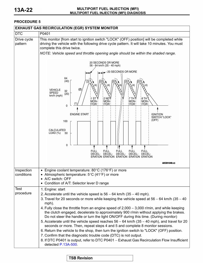
EXHAUST GAS RECIRCULATION (EGR) SYSTEM MONITORDTC P0401Drive cycle pattern
This monitor [from start to ignition switch "LOCK" (OFF) position] will be completed while driving the vehicle with the following drive cycle pattern. It will take 10 minutes. You must complete this drive twice.NOTE: Vehicle speed and throttle opening angle should be within the shaded range.
Inspection conditions
• Engine coolant temperature: 80°C (176°F) or more• Atmospheric temperature: 5°C (41°F) or more• A/C switch: OFF• Condition of A/T: Selector lever D range
Test procedure
1. Engine: start2. Accelerate until the vehicle speed is 56 − 64 km/h (35 − 40 mph).3. Travel for 20 seconds or more while keeping the vehicle speed at 56 − 64 km/h (35 − 40
mph).4. Fully close the throttle from an engine speed of 2,000 − 3,000 r/min, and while keeping
the clutch engaged, decelerate to approximately 900 r/min without applying the brakes. Do not steer the handle or turn the light ON/OFF during this time. (During monitor)
5. Accelerate until the vehicle speed reaches 56 − 64 km/h (35 − 40 mph), and travel for 20 seconds or more. Then, repeat steps 4 and 5 and complete 8 monitor sessions.
6. Return the vehicle to the shop, then turn the ignition switch to "LOCK" (OFF) position.7. Confirm that the diagnostic trouble code (DTC) is not output.8. If DTC P0401 is output, refer to DTC P0401 − Exhaust Gas Recirculation Flow Insufficient
detected P.13A-500.
AKX01349
(2)
AKX01349
(3) (5) (5) (5) (5)
(2)
(1)
(4) (4) (4) (4) (4)
20 SECONDS OR MORE56 - 64 km/h (35 - 40 mph)
20 SECONDS OR MORE
1 STMON-ITOR
7 THMON-ITOR
8 THMON-ITOR
2 NDMON-ITOR
ENGINE START IGNITION SWITCH:"LOCK" (OFF)
FULLDECEL-ERATION
FULLDECEL-ERATION
FULLDECEL-ERATION
FULLDECEL-ERATION
FULLDECEL-ERATION
64(40)
32(20)
0
100
50
0
VEHICLE SPEEDkm/h (mph)
AKX01349AB
CALCULATEDLOAD (%)
TSB Revision
MULTIPORT FUEL INJECTION (MFI) DIAGNOSISMULTIPORT FUEL INJECTION (MFI) 13A-23
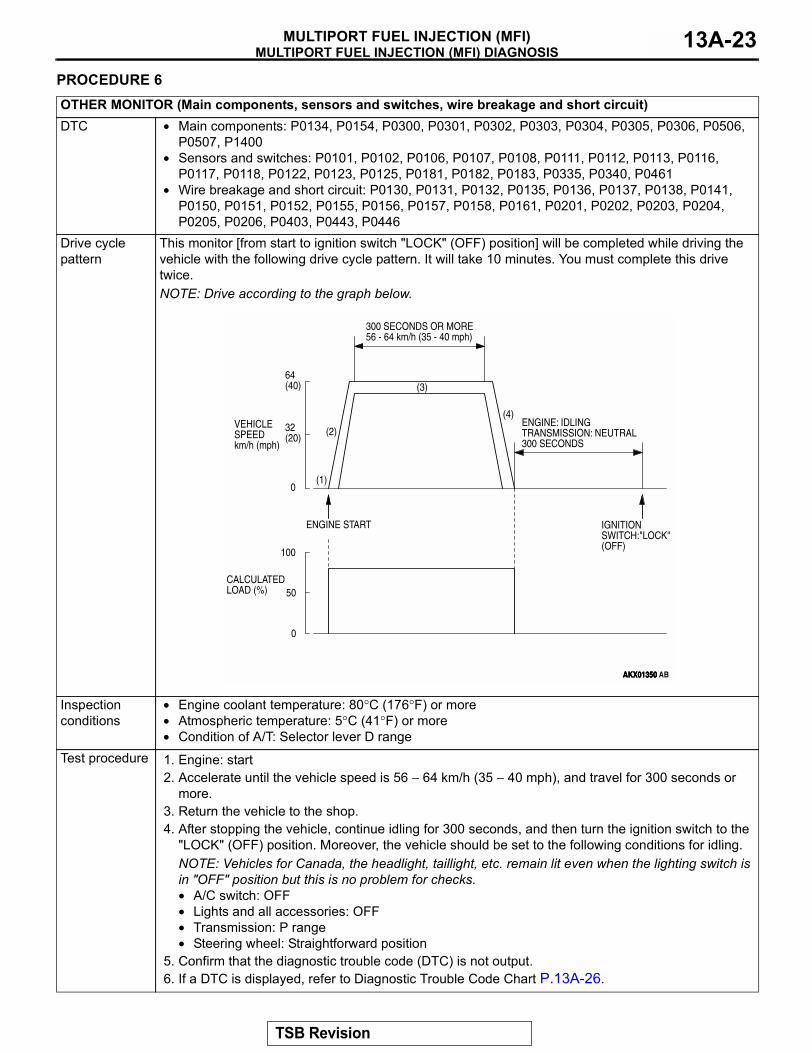
PROCEDURE 6OTHER MONITOR (Main components, sensors and switches, wire breakage and short circuit)DTC • Main components: P0134, P0154, P0300, P0301, P0302, P0303, P0304, P0305, P0306, P0506,
P0507, P1400• Sensors and switches: P0101, P0102, P0106, P0107, P0108, P0111, P0112, P0113, P0116,
P0117, P0118, P0122, P0123, P0125, P0181, P0182, P0183, P0335, P0340, P0461• Wire breakage and short circuit: P0130, P0131, P0132, P0135, P0136, P0137, P0138, P0141,
P0150, P0151, P0152, P0155, P0156, P0157, P0158, P0161, P0201, P0202, P0203, P0204, P0205, P0206, P0403, P0443, P0446
Drive cycle pattern
This monitor [from start to ignition switch "LOCK" (OFF) position] will be completed while driving the vehicle with the following drive cycle pattern. It will take 10 minutes. You must complete this drive twice.NOTE: Drive according to the graph below.
Inspection conditions
• Engine coolant temperature: 80°C (176°F) or more• Atmospheric temperature: 5°C (41°F) or more• Condition of A/T: Selector lever D range
Test procedure 1. Engine: start2. Accelerate until the vehicle speed is 56 − 64 km/h (35 − 40 mph), and travel for 300 seconds or
more. 3. Return the vehicle to the shop. 4. After stopping the vehicle, continue idling for 300 seconds, and then turn the ignition switch to the
"LOCK" (OFF) position. Moreover, the vehicle should be set to the following conditions for idling.NOTE: Vehicles for Canada, the headlight, taillight, etc. remain lit even when the lighting switch is in "OFF" position but this is no problem for checks.• A/C switch: OFF• Lights and all accessories: OFF• Transmission: P range• Steering wheel: Straightforward position
5. Confirm that the diagnostic trouble code (DTC) is not output.6. If a DTC is displayed, refer to Diagnostic Trouble Code Chart P.13A-26.
AKX01350AKX01350
(3)
(2)
(1)
(4)
300 SECONDS OR MORE56 - 64 km/h (35 - 40 mph)
ENGINE: IDLINGTRANSMISSION: NEUTRAL300 SECONDS
ENGINE START IGNITION SWITCH:"LOCK" (OFF)
64(40)
32(20)
0
100
50
0
VEHICLE SPEEDkm/h (mph)
AKX01350 AB
CALCULATEDLOAD (%)
TSB Revision
MULTIPORT FUEL INJECTION (MFI) DIAGNOSISMULTIPORT FUEL INJECTION (MFI)13A-24
SYSTEM READINESS TEST STATUS.
PURPOSEThe Readiness function (also referred as I/M Readi-ness or I/M Flags) indicates if a full diagnostic check has been "Completed" (is "Ready") for each non-continuous monitor. Enhanced I/M State Emis-sion Programs will use the Readiness status (Codes) to see if the vehicle is ready for OBD-II testing. "Incomplete" (Not Ready) codes will be one of the triggers for I/M failure..
OVERVIEWThe PCM monitors the following main diagnosis items and records whether the evaluation was com-pleted or is incomplete. The Readiness codes were established for the I/M programs, thereby confirming that the vehicle was not tampered with by erasing the diagnostic trouble code(s) (DTC's) before I/M testing. The Readiness and DTC codes can be reset by dis-connecting the battery or by erasing the codes with a scan tool. For this reason all Readiness codes must read "Complete" before I/M testing.When the monitors run and complete, the scan tool MB991958 (MUT-III Sub Assembly) will record the Readiness Code as " Complete " (General Scan Tools record as " Ready "). When the vehicle is oper-ating normally and the OBD-II Drive Cycle is carried
out, Readiness Code will set as " Complete " on the first drive cycle. If during the first drive cycle a fault is detected then, a second drive is required before the Readiness Code will " Complete. " If the fault is still there, then a DTC will set.
• Catalyst: P0421, P0431• Evaporative system: P0441, P0442, P0455,
P0456• Heated oxygen sensor: P0130, P0131, P0132,
P0133, P0134, P0136, P0137, P0138, P0139, P0150, P0151, P0152, P0153, P0154, P0156, P0157, P0158, P0159
• Heated oxygen sensor heater: P0135, P0141, P0155, P0161
• EGR system: P0401After the Readiness is "Complete," the technician is assured that any DTC's associated with that monitor will be displayed if the system has a problem. That is why some State's I/M programs require the Readi-ness Code as "Complete" before they check for DTC's. NOTE: After a repair is mode for a DTC the techni-cian should drive the OBD-II drive cycle checking that the scan tool MB991958 (MUT-III Sub Assem-bly) records all Readiness as "Complete".
FAIL-SAFE FUNCTION REFERENCE TABLEM1131153000318
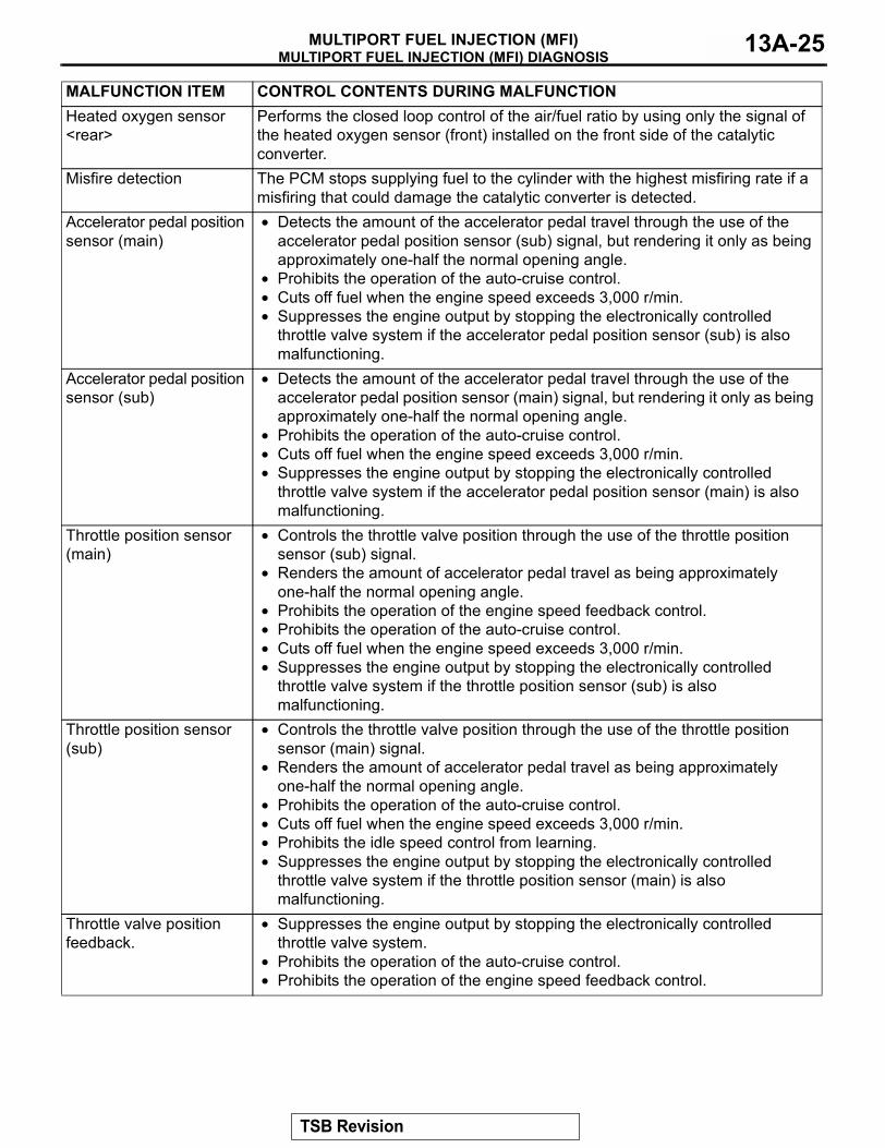
When the main sensor malfunctions are detected by the diagnostic test mode, the vehicle is controlled by means of the following defaults.MALFUNCTION ITEM CONTROL CONTENTS DURING MALFUNCTIONVolume airflow sensor • Uses the throttle position sensor signal and engine speed signal (crankshaft
position sensor signal) for basic injector drive time and basic ignition timing from the pre-set mapping.
• Fixes the IAC motor in the appointed position so idle air control is not performed.
Intake air temperature sensor
Controls as if the intake air temperature is 25°C (77°F).
Engine coolant temperature sensor
Controls as if the engine coolant temperature is 80°C (176°F). (This control will be continued until the ignition switch is turned to " LOCK " (OFF) position even though the sensor signal returns to normal.)
Camshaft position sensor Injects fuel simultaneously into all cylinders. (After the ignition switch is turned to " ON " position, the No.1 cylinder top dead center is not detected at all.)
Barometric pressure sensor
Controls as if the barometric pressure is 101 kPa (30 in.Hg).
Knock sensor Switches the ignition timing from ignition timing for high octane to ignition timing for standard octane fuel.
Heated oxygen sensor <front>
Air/fuel ratio closed loop control is not performed.
TSB Revision
MULTIPORT FUEL INJECTION (MFI) DIAGNOSISMULTIPORT FUEL INJECTION (MFI) 13A-25
Heated oxygen sensor <rear>
Performs the closed loop control of the air/fuel ratio by using only the signal of the heated oxygen sensor (front) installed on the front side of the catalytic converter.
Misfire detection The PCM stops supplying fuel to the cylinder with the highest misfiring rate if a misfiring that could damage the catalytic converter is detected.
Accelerator pedal position sensor (main)
• Detects the amount of the accelerator pedal travel through the use of the accelerator pedal position sensor (sub) signal, but rendering it only as being approximately one-half the normal opening angle.
• Prohibits the operation of the auto-cruise control. • Cuts off fuel when the engine speed exceeds 3,000 r/min.• Suppresses the engine output by stopping the electronically controlled
throttle valve system if the accelerator pedal position sensor (sub) is also malfunctioning.
Accelerator pedal position sensor (sub)
• Detects the amount of the accelerator pedal travel through the use of the accelerator pedal position sensor (main) signal, but rendering it only as being approximately one-half the normal opening angle.
• Prohibits the operation of the auto-cruise control.• Cuts off fuel when the engine speed exceeds 3,000 r/min.• Suppresses the engine output by stopping the electronically controlled
throttle valve system if the accelerator pedal position sensor (main) is also malfunctioning.
Throttle position sensor (main)
• Controls the throttle valve position through the use of the throttle position sensor (sub) signal.
• Renders the amount of accelerator pedal travel as being approximately one-half the normal opening angle.
• Prohibits the operation of the engine speed feedback control.• Prohibits the operation of the auto-cruise control.• Cuts off fuel when the engine speed exceeds 3,000 r/min.• Suppresses the engine output by stopping the electronically controlled
throttle valve system if the throttle position sensor (sub) is also malfunctioning.
Throttle position sensor (sub)
• Controls the throttle valve position through the use of the throttle position sensor (main) signal.
• Renders the amount of accelerator pedal travel as being approximately one-half the normal opening angle.
• Prohibits the operation of the auto-cruise control.• Cuts off fuel when the engine speed exceeds 3,000 r/min.• Prohibits the idle speed control from learning.• Suppresses the engine output by stopping the electronically controlled
throttle valve system if the throttle position sensor (main) is also malfunctioning.
Throttle valve position feedback.
• Suppresses the engine output by stopping the electronically controlled throttle valve system.
• Prohibits the operation of the auto-cruise control.• Prohibits the operation of the engine speed feedback control.
MALFUNCTION ITEM CONTROL CONTENTS DURING MALFUNCTION
TSB Revision
MULTIPORT FUEL INJECTION (MFI) DIAGNOSISMULTIPORT FUEL INJECTION (MFI)13A-26
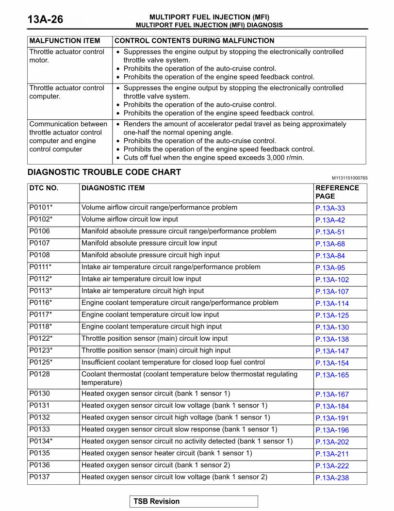
DIAGNOSTIC TROUBLE CODE CHARTM1131151000765
Throttle actuator control motor.
• Suppresses the engine output by stopping the electronically controlled throttle valve system.
• Prohibits the operation of the auto-cruise control.• Prohibits the operation of the engine speed feedback control.
Throttle actuator control computer.
• Suppresses the engine output by stopping the electronically controlled throttle valve system.
• Prohibits the operation of the auto-cruise control.• Prohibits the operation of the engine speed feedback control.
Communication between throttle actuator control computer and engine control computer
• Renders the amount of accelerator pedal travel as being approximately one-half the normal opening angle.
• Prohibits the operation of the auto-cruise control.• Prohibits the operation of the engine speed feedback control.• Cuts off fuel when the engine speed exceeds 3,000 r/min.
MALFUNCTION ITEM CONTROL CONTENTS DURING MALFUNCTION
DTC NO. DIAGNOSTIC ITEM REFERENCE PAGE
P0101* Volume airflow circuit range/performance problem P.13A-33P0102* Volume airflow circuit low input P.13A-42P0106 Manifold absolute pressure circuit range/performance problem P.13A-51P0107 Manifold absolute pressure circuit low input P.13A-68P0108 Manifold absolute pressure circuit high input P.13A-84P0111* Intake air temperature circuit range/performance problem P.13A-95P0112* Intake air temperature circuit low input P.13A-102P0113* Intake air temperature circuit high input P.13A-107P0116* Engine coolant temperature circuit range/performance problem P.13A-114P0117* Engine coolant temperature circuit low input P.13A-125P0118* Engine coolant temperature circuit high input P.13A-130P0122* Throttle position sensor (main) circuit low input P.13A-138P0123* Throttle position sensor (main) circuit high input P.13A-147P0125* Insufficient coolant temperature for closed loop fuel control P.13A-154P0128 Coolant thermostat (coolant temperature below thermostat regulating
temperature)P.13A-165
P0130 Heated oxygen sensor circuit (bank 1 sensor 1) P.13A-167P0131 Heated oxygen sensor circuit low voltage (bank 1 sensor 1) P.13A-184P0132 Heated oxygen sensor circuit high voltage (bank 1 sensor 1) P.13A-191P0133 Heated oxygen sensor circuit slow response (bank 1 sensor 1) P.13A-196P0134* Heated oxygen sensor circuit no activity detected (bank 1 sensor 1) P.13A-202P0135 Heated oxygen sensor heater circuit (bank 1 sensor 1) P.13A-211P0136 Heated oxygen sensor circuit (bank 1 sensor 2) P.13A-222P0137 Heated oxygen sensor circuit low voltage (bank 1 sensor 2) P.13A-238
TSB Revision
MULTIPORT FUEL INJECTION (MFI) DIAGNOSISMULTIPORT FUEL INJECTION (MFI) 13A-27
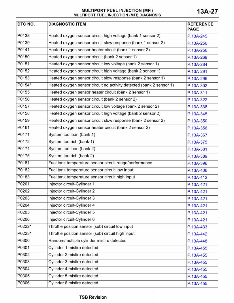
P0138 Heated oxygen sensor circuit high voltage (bank 1 sensor 2) P.13A-245P0139 Heated oxygen sensor circuit slow response (bank 1 sensor 2) P.13A-250P0141 Heated oxygen sensor heater circuit (bank 1 sensor 2) P.13A-256P0150 Heated oxygen sensor circuit (bank 2 sensor 1) P.13A-268P0151 Heated oxygen sensor circuit low voltage (bank 2 sensor 1) P.13A-284P0152 Heated oxygen sensor circuit high voltage (bank 2 sensor 1) P.13A-291P0153 Heated oxygen sensor circuit slow response (bank 2 sensor 1) P.13A-296P0154* Heated oxygen sensor circuit no activity detected (bank 2 sensor 1) P.13A-302P0155 Heated oxygen sensor heater circuit (bank 2 sensor 1) P.13A-311P0156 Heated oxygen sensor circuit (bank 2 sensor 2) P.13A-322P0157 Heated oxygen sensor circuit low voltage (bank 2 sensor 2) P.13A-338P0158 Heated oxygen sensor circuit high voltage (bank 2 sensor 2) P.13A-345P0159 Heated oxygen sensor circuit slow response (bank 2 sensor 2) P.13A-350P0161 Heated oxygen sensor heater circuit (bank 2 sensor 2) P.13A-356P0171 System too lean (bank 1) P.13A-367P0172 System too rich (bank 1) P.13A-375P0174 System too lean (bank 2) P.13A-381P0175 System too rich (bank 2) P.13A-389P0181 Fuel tank temperature sensor circuit range/performance P.13A-396P0182 Fuel tank temperature sensor circuit low input P.13A-406P0183 Fuel tank temperature sensor circuit high input P.13A-412P0201 Injector circuit-Cylinder 1 P.13A-421P0202 Injector circuit-Cylinder 2 P.13A-421P0203 Injector circuit-Cylinder 3 P.13A-421P0204 Injector circuit-Cylinder 4 P.13A-421P0205 Injector circuit-Cylinder 5 P.13A-421P0206 Injector circuit-Cylinder 6 P.13A-421P0222* Throttle position sensor (sub) circuit low input P.13A-433P0223* Throttle position sensor (sub) circuit high input P.13A-442P0300 Random/multiple cylinder misfire detected P.13A-448P0301 Cylinder 1 misfire detected P.13A-455P0302 Cylinder 2 misfire detected P.13A-455P0303 Cylinder 3 misfire detected P.13A-455P0304 Cylinder 4 misfire detected P.13A-455P0305 Cylinder 5 misfire detected P.13A-455P0306 Cylinder 6 misfire detected P.13A-455
DTC NO. DIAGNOSTIC ITEM REFERENCE PAGE
TSB Revision
MULTIPORT FUEL INJECTION (MFI) DIAGNOSISMULTIPORT FUEL INJECTION (MFI)13A-28
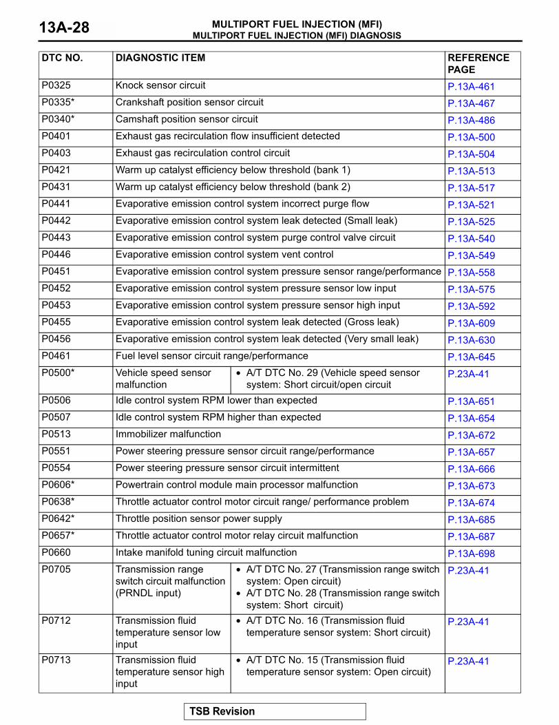
P0325 Knock sensor circuit P.13A-461P0335* Crankshaft position sensor circuit P.13A-467P0340* Camshaft position sensor circuit P.13A-486P0401 Exhaust gas recirculation flow insufficient detected P.13A-500P0403 Exhaust gas recirculation control circuit P.13A-504P0421 Warm up catalyst efficiency below threshold (bank 1) P.13A-513P0431 Warm up catalyst efficiency below threshold (bank 2) P.13A-517P0441 Evaporative emission control system incorrect purge flow P.13A-521P0442 Evaporative emission control system leak detected (Small leak) P.13A-525P0443 Evaporative emission control system purge control valve circuit P.13A-540P0446 Evaporative emission control system vent control P.13A-549P0451 Evaporative emission control system pressure sensor range/performance P.13A-558P0452 Evaporative emission control system pressure sensor low input P.13A-575P0453 Evaporative emission control system pressure sensor high input P.13A-592P0455 Evaporative emission control system leak detected (Gross leak) P.13A-609P0456 Evaporative emission control system leak detected (Very small leak) P.13A-630P0461 Fuel level sensor circuit range/performance P.13A-645P0500* Vehicle speed sensor
malfunction• A/T DTC No. 29 (Vehicle speed sensor
system: Short circuit/open circuitP.23A-41
P0506 Idle control system RPM lower than expected P.13A-651P0507 Idle control system RPM higher than expected P.13A-654P0513 Immobilizer malfunction P.13A-672P0551 Power steering pressure sensor circuit range/performance P.13A-657P0554 Power steering pressure sensor circuit intermittent P.13A-666P0606* Powertrain control module main processor malfunction P.13A-673P0638* Throttle actuator control motor circuit range/ performance problem P.13A-674P0642* Throttle position sensor power supply P.13A-685P0657* Throttle actuator control motor relay circuit malfunction P.13A-687P0660 Intake manifold tuning circuit malfunction P.13A-698P0705 Transmission range
switch circuit malfunction (PRNDL input)
• A/T DTC No. 27 (Transmission range switch system: Open circuit)
• A/T DTC No. 28 (Transmission range switch system: Short circuit)
P.23A-41
P0712 Transmission fluid temperature sensor low input
• A/T DTC No. 16 (Transmission fluid temperature sensor system: Short circuit)
P.23A-41
P0713 Transmission fluid temperature sensor high input
• A/T DTC No. 15 (Transmission fluid temperature sensor system: Open circuit)
P.23A-41
DTC NO. DIAGNOSTIC ITEM REFERENCE PAGE
TSB Revision
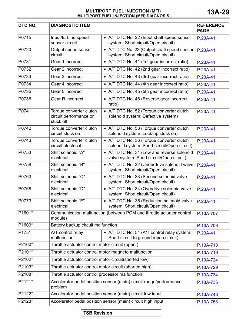
MULTIPORT FUEL INJECTION (MFI) DIAGNOSISMULTIPORT FUEL INJECTION (MFI) 13A-29
P0715 Input/turbine speed sensor circuit
• A/T DTC No. 22 (Input shaft speed sensor system: Short circuit/Open circuit)
P.23A-41
P0720 Output speed sensor circuit
• A/T DTC No. 23 (Output shaft speed sensor system: Short circuit/Open circuit)
P.23A-41
P0731 Gear 1 incorrect • A/T DTC No. 41 (1st gear incorrect ratio) P.23A-41P0732 Gear 2 incorrect • A/T DTC No. 42 (2nd gear incorrect ratio) P.23A-41P0733 Gear 3 incorrect • A/T DTC No. 43 (3rd gear incorrect ratio) P.23A-41P0734 Gear 4 incorrect • A/T DTC No. 44 (4th gear incorrect ratio) P.23A-41P0735 Gear 5 incorrect • A/T DTC No. 45 (5th gear incorrect ratio) P.23A-41P0736 Gear R incorrect • A/T DTC No. 46 (Reverse gear incorrect
ratio)P.23A-41
P0741 Torque converter clutch circuit performance or stuck off
• A/T DTC No. 52 (Torque converter clutch solenoid system: Defective system)
P.23A-41
P0742 Torque converter clutch circuit stuck on
• A/T DTC No. 53 (Torque converter clutch solenoid system: Lock-up stuck on)
P.23A-41
P0743 Torque converter clutch circuit electrical
• A/T DTC No. 36 (Torque converter clutch solenoid system: Short circuit/Open circuit)
P.23A-41
P0753 Shift solenoid "A" electrical
• A/T DTC No. 31 (Low and reverse solenoid valve system: Short circuit/Open circuit)
P.23A-41
P0758 Shift solenoid "B" electrical
• A/T DTC No. 32 (Underdrive solenoid valve system: Short circuit/Open circuit)
P.23A-41
P0763 Shift solenoid "C" electrical
• A/T DTC No. 33 (Second solenoid valve system: Short circuit/Open circuit)
P.23A-41
P0768 Shift solenoid "D" electrical
• A/T DTC No. 34 (Overdrive solenoid valve system: Short circuit/Open circuit)
P.23A-41
P0773 Shift solenoid "E" electrical
• A/T DTC No. 35 (Reduction solenoid valve system: Short circuit/Open circuit)
P.23A-41
P1601* Communication malfunction (between PCM and throttle actuator control module)
P.13A-707
P1603* Battery backup circuit malfunction P.13A-708P1751 A/T control relay
malfunction• A/T DTC No. 54 (A/T control relay system:
Short circuit to ground /open circuit)P.23A-41
P2100* Throttle actuator control motor circuit (open ) P.13A-713P2101* Throttle actuator control motor magneto malfunction P.13A-719P2102* Throttle actuator control motor circuit(shorted low) P.13A-724P2103* Throttle actuator control motor circuit (shorted high) P.13A-729P2108* Throttle actuator control processor malfunction P.13A-734P2121* Accelerator pedal position sensor (main) circuit range/performance
problemP.13A-735
P2122* Accelerator pedal position sensor (main) circuit low input P.13A-743P2123* Accelerator pedal position sensor (main) circuit high input P.13A-753
DTC NO. DIAGNOSTIC ITEM REFERENCE PAGE
TSB Revision
MULTIPORT FUEL INJECTION (MFI) DIAGNOSISMULTIPORT FUEL INJECTION (MFI)13A-30
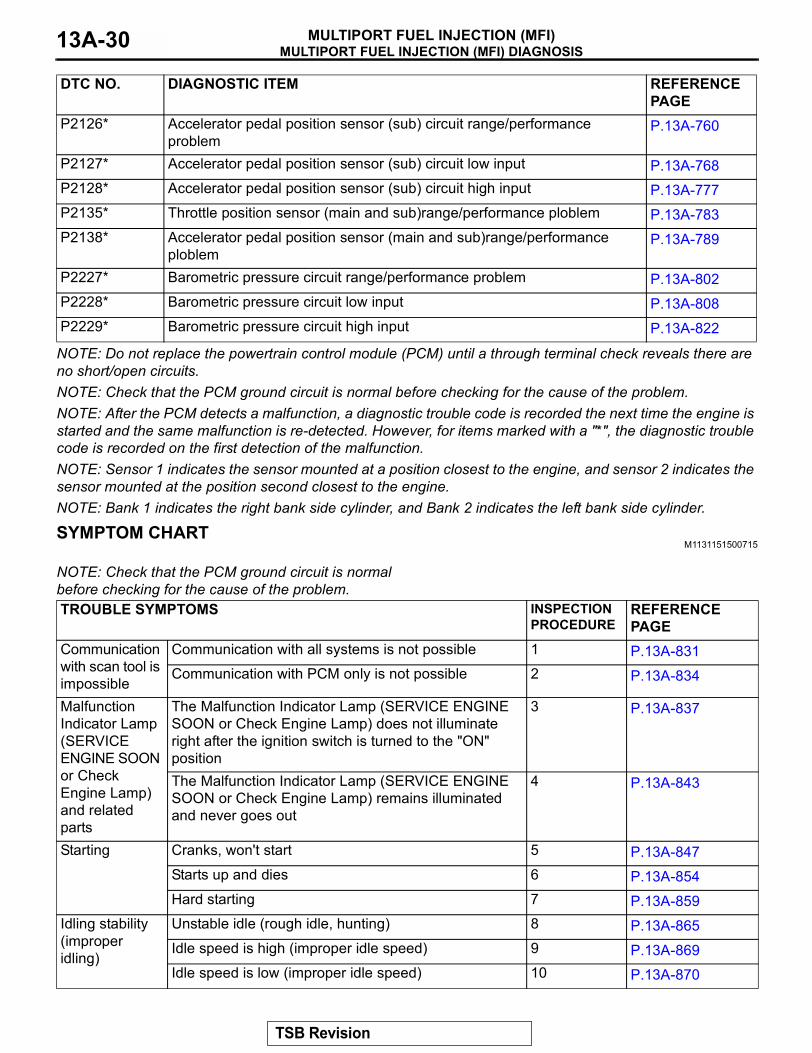
NOTE: Do not replace the powertrain control module (PCM) until a through terminal check reveals there are no short/open circuits.NOTE: Check that the PCM ground circuit is normal before checking for the cause of the problem.NOTE: After the PCM detects a malfunction, a diagnostic trouble code is recorded the next time the engine is started and the same malfunction is re-detected. However, for items marked with a "*", the diagnostic trouble code is recorded on the first detection of the malfunction.NOTE: Sensor 1 indicates the sensor mounted at a position closest to the engine, and sensor 2 indicates the sensor mounted at the position second closest to the engine.NOTE: Bank 1 indicates the right bank side cylinder, and Bank 2 indicates the left bank side cylinder.
SYMPTOM CHARTM1131151500715
.
NOTE: Check that the PCM ground circuit is normal before checking for the cause of the problem.
P2126* Accelerator pedal position sensor (sub) circuit range/performance problem
P.13A-760
P2127* Accelerator pedal position sensor (sub) circuit low input P.13A-768P2128* Accelerator pedal position sensor (sub) circuit high input P.13A-777P2135* Throttle position sensor (main and sub)range/performance ploblem P.13A-783P2138* Accelerator pedal position sensor (main and sub)range/performance
ploblemP.13A-789
P2227* Barometric pressure circuit range/performance problem P.13A-802P2228* Barometric pressure circuit low input P.13A-808P2229* Barometric pressure circuit high input P.13A-822
DTC NO. DIAGNOSTIC ITEM REFERENCE PAGE
TROUBLE SYMPTOMS INSPECTION PROCEDURE
REFERENCE PAGE
Communication with scan tool is impossible
Communication with all systems is not possible 1 P.13A-831Communication with PCM only is not possible 2 P.13A-834
Malfunction Indicator Lamp (SERVICE ENGINE SOON or Check Engine Lamp) and related parts
The Malfunction Indicator Lamp (SERVICE ENGINE SOON or Check Engine Lamp) does not illuminate right after the ignition switch is turned to the "ON" position
3 P.13A-837
The Malfunction Indicator Lamp (SERVICE ENGINE SOON or Check Engine Lamp) remains illuminated and never goes out
4 P.13A-843
Starting Cranks, won't start 5 P.13A-847Starts up and dies 6 P.13A-854Hard starting 7 P.13A-859
Idling stability (improper idling)
Unstable idle (rough idle, hunting) 8 P.13A-865Idle speed is high (improper idle speed) 9 P.13A-869Idle speed is low (improper idle speed) 10 P.13A-870
TSB Revision
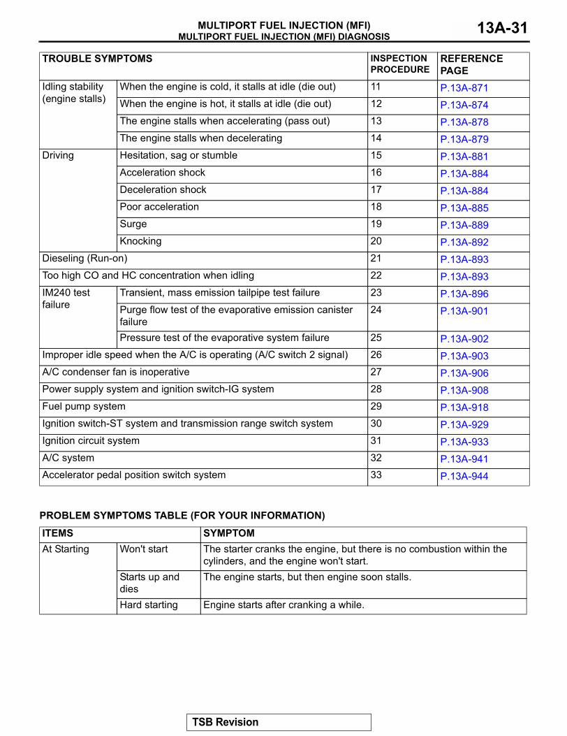
MULTIPORT FUEL INJECTION (MFI) DIAGNOSISMULTIPORT FUEL INJECTION (MFI) 13A-31
.
PROBLEM SYMPTOMS TABLE (FOR YOUR INFORMATION)
Idling stability (engine stalls)
When the engine is cold, it stalls at idle (die out) 11 P.13A-871When the engine is hot, it stalls at idle (die out) 12 P.13A-874The engine stalls when accelerating (pass out) 13 P.13A-878The engine stalls when decelerating 14 P.13A-879
Driving Hesitation, sag or stumble 15 P.13A-881Acceleration shock 16 P.13A-884Deceleration shock 17 P.13A-884Poor acceleration 18 P.13A-885Surge 19 P.13A-889Knocking 20 P.13A-892
Dieseling (Run-on) 21 P.13A-893Too high CO and HC concentration when idling 22 P.13A-893IM240 test failure
Transient, mass emission tailpipe test failure 23 P.13A-896Purge flow test of the evaporative emission canister failure
24 P.13A-901
Pressure test of the evaporative system failure 25 P.13A-902Improper idle speed when the A/C is operating (A/C switch 2 signal) 26 P.13A-903A/C condenser fan is inoperative 27 P.13A-906Power supply system and ignition switch-IG system 28 P.13A-908Fuel pump system 29 P.13A-918Ignition switch-ST system and transmission range switch system 30 P.13A-929Ignition circuit system 31 P.13A-933A/C system 32 P.13A-941Accelerator pedal position switch system 33 P.13A-944
TROUBLE SYMPTOMS INSPECTION PROCEDURE
REFERENCE PAGE
ITEMS SYMPTOMAt Starting Won't start The starter cranks the engine, but there is no combustion within the
cylinders, and the engine won't start.Starts up and dies
The engine starts, but then engine soon stalls.
Hard starting Engine starts after cranking a while.
TSB Revision
MULTIPORT FUEL INJECTION (MFI) DIAGNOSISMULTIPORT FUEL INJECTION (MFI)13A-32
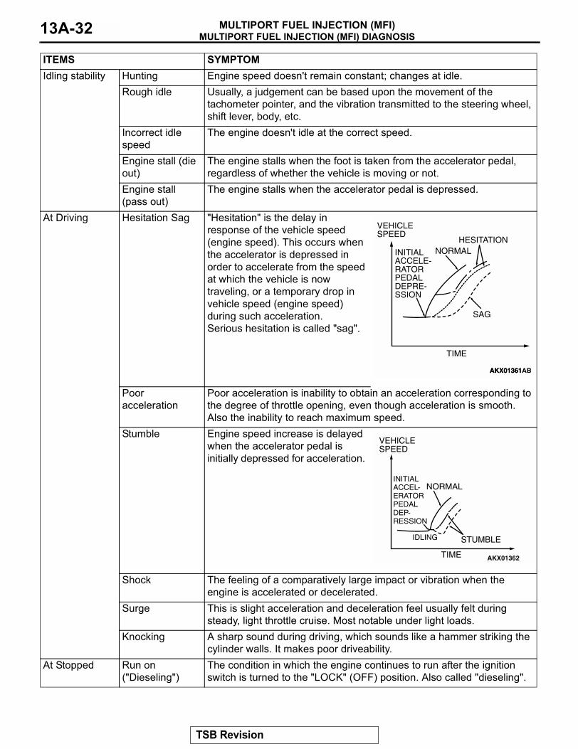
Idling stability Hunting Engine speed doesn't remain constant; changes at idle.Rough idle Usually, a judgement can be based upon the movement of the
tachometer pointer, and the vibration transmitted to the steering wheel, shift lever, body, etc.
Incorrect idle speed
The engine doesn't idle at the correct speed.
Engine stall (die out)
The engine stalls when the foot is taken from the accelerator pedal, regardless of whether the vehicle is moving or not.
Engine stall (pass out)
The engine stalls when the accelerator pedal is depressed.
At Driving Hesitation Sag "Hesitation" is the delay in response of the vehicle speed (engine speed). This occurs when the accelerator is depressed in order to accelerate from the speed at which the vehicle is now traveling, or a temporary drop in vehicle speed (engine speed) during such acceleration. Serious hesitation is called "sag".
Poor acceleration
Poor acceleration is inability to obtain an acceleration corresponding to the degree of throttle opening, even though acceleration is smooth. Also the inability to reach maximum speed.
Stumble Engine speed increase is delayed when the accelerator pedal is initially depressed for acceleration.
Shock The feeling of a comparatively large impact or vibration when the engine is accelerated or decelerated.
Surge This is slight acceleration and deceleration feel usually felt during steady, light throttle cruise. Most notable under light loads.
Knocking A sharp sound during driving, which sounds like a hammer striking the cylinder walls. It makes poor driveability.
At Stopped Run on ("Dieseling")
The condition in which the engine continues to run after the ignition switch is turned to the "LOCK" (OFF) position. Also called "dieseling".
ITEMS SYMPTOM
AKX01361
VEHICLESPEED
TIME
NORMALHESITATION
SAG
INITIALACCELE-RATORPEDALDEPRE-SSION
AKX01361AB
AKX01362
VEHICLESPEED
TIME
NORMAL
STUMBLE
INITIALACCEL-ERATORPEDAL DEP-RESSION
IDLING
TSB Revision
MULTIPORT FUEL INJECTION (MFI) DIAGNOSISMULTIPORT FUEL INJECTION (MFI) 13A-33
DIAGNOSTIC TROUBLE CODE PROCEDURES
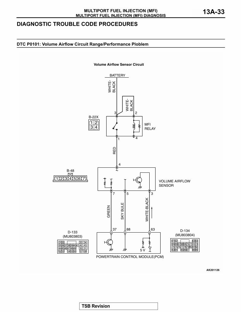
DTC P0101: Volume Airflow Circuit Range/Performance Ploblem
1 2 3 4 5 6 7
3 41 2
RE
D
GR
EE
N
WH
ITE
-BLA
CK
SK
Y B
ULE
WH
ITE
-B
LAC
K
WH
ITE
-B
LAC
K
AK201126
B-48
B-22X
MFI RELAY
BATTERY
VOLUME AIRFLOW SENSOR
POWERTRAIN CONTROL MODULE(PCM)
5 V
37
7
88 63
4
3 2
5 3
1 4
Volume Airflow Sensor Circuit
3135363738394041 42 43444546474849 50 515253 545556 57 58
32 33 34
D-133(MU803803)
616566676869707172737475767778798081828384 858687 8889
62 6364
D-134(MU803804)
TSB Revision
MULTIPORT FUEL INJECTION (MFI) DIAGNOSISMULTIPORT FUEL INJECTION (MFI)13A-34
.
CIRCUIT OPERATION• The volume airflow sensor power is supplied from
the MFI relay (terminal No. 1), and the ground is provided on the PCM (terminal No. 88).
• 5-volt power is applied to the volume airflow sen-sor output terminal (terminal No. 3) from the PCM (terminal No. 63). The volume airflow sensor gen-erates a pulse signal when the output terminal and ground are opened/closed (opened/short).
.
TECHNICAL DESCRIPTION• While the engine is running, the volume airflow
sensor outputs a pulse signal which corresponds to the volume of air flow.
• The PCM checks whether the frequency of this signal output by the volume airflow sensor while the engine is running is at or above the set value.
• When the throttle position sensor output voltage is low, the PCM causes the power transistor to be "ON" to send an volume airflow sensor reset sig-nal to the volume airflow sensor. In response to the reset signal, the volume airflow sensor resets the filter circuit and improves the ability of the vol-ume airflow sensor to measure the amount of air in a small air intake region.
.
DESCRIPTIONS OF MONITOR METHODS• An abnormal condition is detected in the volume
airflow sensor output through a comparison between the driving load and the output fre-quency of the volume airflow sensor.
.
MONITOR EXECUTION• Continuous
.
MONITOR EXECUTION CONDITIONS (Other monitor and Sensor)
Other Monitor (There is no temporary DTC stored in memory for the item monitored below)
• Not applicable
Sensor (The sensor below is determined to be normal)
• Throttle position sensor.
AK201039
MFI RELAY
B-22X
AB
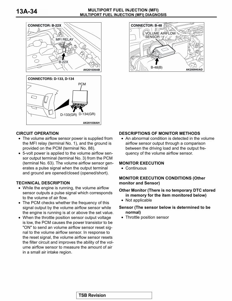
CONNECTOR: B-22X
AK201038AH
CONNECTORS: D-133, D-134
PCM
D-134(GR)D-133(GR)
AK200940ADB-48(B)
CONNECTOR: B-48
VOLUME AIRFLOW SENSOR
TSB Revision
MULTIPORT FUEL INJECTION (MFI) DIAGNOSISMULTIPORT FUEL INJECTION (MFI) 13A-35
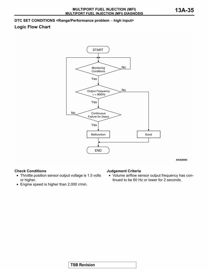
DTC SET CONDITIONS <Range/Performance problem − high input>
Logic Flow Chart
Check Conditions• Throttle position sensor output voltage is 1.5 volts
or higher.• Engine speed is higher than 2,000 r/min.
Judgement Criteria• Volume airflow sensor output frequency has con-
tinued to be 60 Hz or lower for 2 seconds..
START
MonitoringConditions
END
No
Yes
No
Yes
No
Yes
Malfunction Good
Output Frequency> = 800Hz
ContinuousFailure for 2secs
AK302693
TSB Revision
MULTIPORT FUEL INJECTION (MFI) DIAGNOSISMULTIPORT FUEL INJECTION (MFI)13A-36
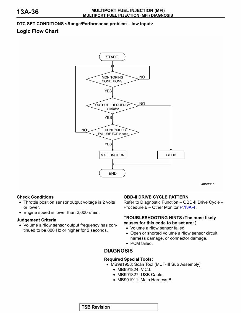
DTC SET CONDITIONS <Range/Performance problem − low input>
Logic Flow Chart
Check Conditions• Throttle position sensor output voltage is 2 volts
or lower.• Engine speed is lower than 2,000 r/min.
Judgement Criteria• Volume airflow sensor output frequency has con-
tinued to be 800 Hz or higher for 2 seconds..
OBD-II DRIVE CYCLE PATTERNRefer to Diagnostic Function − OBD-II Drive Cycle − Procedure 6 − Other Monitor P.13A-4..
TROUBLESHOOTING HINTS (The most likely causes for this code to be set are: )
• Volume airflow sensor failed.• Open or shorted volume airflow sensor circuit,
harness damage, or connector damage.• PCM failed.
DIAGNOSISRequired Special Tools:
• MB991958: Scan Tool (MUT-III Sub Assembly)• MB991824: V.C.I.• MB991827: USB Cable• MB991911: Main Harness B
START
MONITORINGCONDITIONS
END
NO
YES
NO
YES
NO
YES
MALFUNCTION GOOD
OUTPUT FREQUENCY< =60Hz
CONTINUOUSFAILURE FOR 2 secs
AK302918
TSB Revision
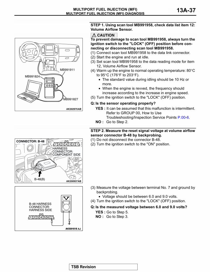
MULTIPORT FUEL INJECTION (MFI) DIAGNOSISMULTIPORT FUEL INJECTION (MFI) 13A-37
STEP 1. Using scan tool MB991958, check data list item 12: Volume Airflow Sensor.
CAUTIONTo prevent damage to scan tool MB991958, always turn the ignition switch to the "LOCK" (OFF) position before con-necting or disconnecting scan tool MB991958.(1) Connect scan tool MB991958 to the data link connector.(2) Start the engine and run at idle.(3) Set scan tool MB991958 to the data reading mode for item
12, Volume Airflow Sensor.(4) Warm up the engine to normal operating temperature: 80°C
to 95°C (176°F to 203°F).• The standard value during idling should be 10 Hz or
more.• When the engine is revved, the frequency should
increase according to the increase in engine speed.(5) Turn the ignition switch to the "LOCK" (OFF) position.Q: Is the sensor operating properly?
YES : It can be assumed that this malfunction is intermittent. Refer to GROUP 00, How to Use Troubleshooting/Inspection Service Points P.00-6.
NO : Go to Step 2.
STEP 2. Measure the reset signal voltage at volume airflow sensor connector B-48 by backprobing.(1) Do not disconnect the connector B-48.(2) Turn the ignition switch to the "ON" position.
(3) Measure the voltage between terminal No. 7 and ground by backprobing.
• Voltage should be between 6.0 and 9.0 volts.(4) Turn the ignition switch to the "LOCK" (OFF) position.Q: Is the measured voltage between 6.0 and 9.0 volts?
YES : Go to Step 5.NO : Go to Step 3.
AK302970AB
MB991911
MB991824
MB991827
AK200937
345 1267
AB
HARNESS CONNECTOR: COMPONENT SIDE
CONNECTOR: B-48
B-48(B)
AKX01515
6 71 2 3 4 5
AKX01515 AJ
B-48 HARNESS CONNECTOR: HARNESS SIDE
TSB Revision
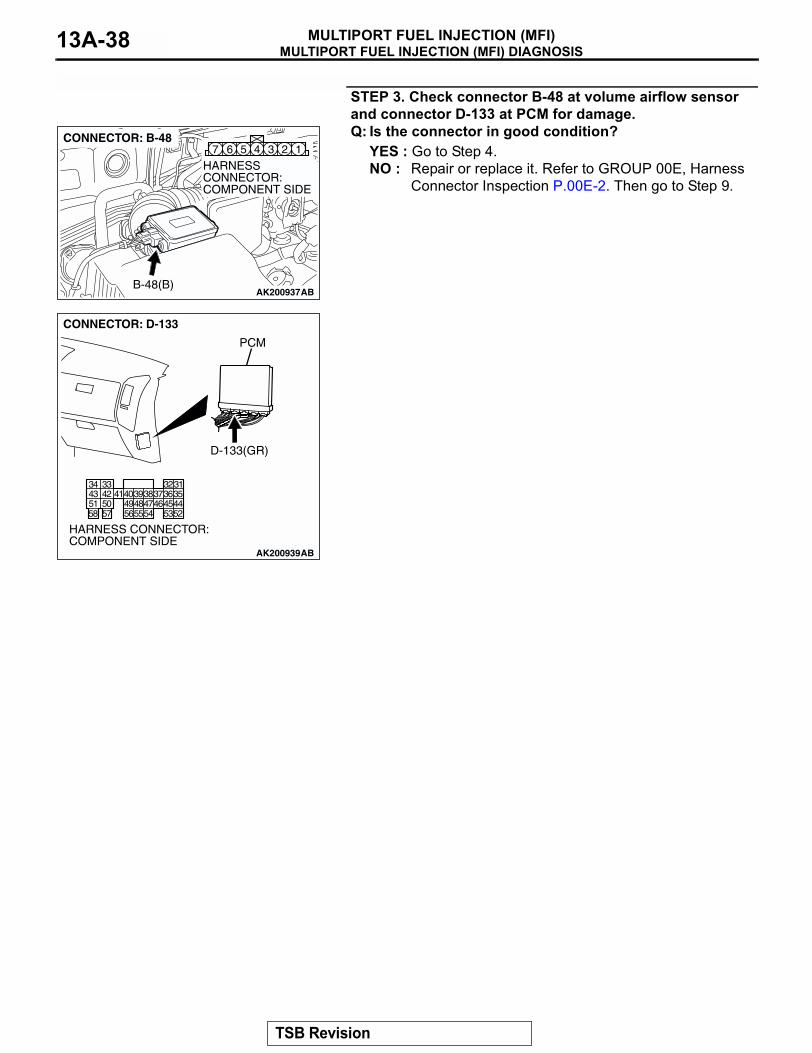
MULTIPORT FUEL INJECTION (MFI) DIAGNOSISMULTIPORT FUEL INJECTION (MFI)13A-38
STEP 3. Check connector B-48 at volume airflow sensor and connector D-133 at PCM for damage.Q: Is the connector in good condition?
YES : Go to Step 4.NO : Repair or replace it. Refer to GROUP 00E, Harness
Connector Inspection P.00E-2. Then go to Step 9.
AK200937
345 1267
AB
HARNESS CONNECTOR: COMPONENT SIDE
CONNECTOR: B-48
B-48(B)
AK200939
3132333435363738394041424344454647484952535455565758
5051
AB
CONNECTOR: D-133
HARNESS CONNECTOR: COMPONENT SIDE
PCM
D-133(GR)
TSB Revision
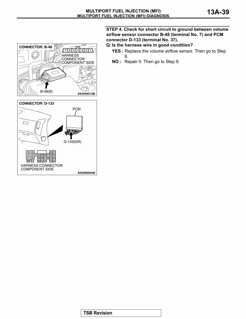
MULTIPORT FUEL INJECTION (MFI) DIAGNOSISMULTIPORT FUEL INJECTION (MFI) 13A-39
STEP 4. Check for short circuit to ground between volume airflow sensor connector B-48 (terminal No. 7) and PCM connector D-133 (terminal No. 37).Q: Is the harness wire in good condition?
YES : Replace the volume airflow sensor. Then go to Step 9.
NO : Repair it. Then go to Step 9.
AK200937
345 1267
AB
HARNESS CONNECTOR: COMPONENT SIDE
CONNECTOR: B-48
B-48(B)
AK200939
3132333435363738394041424344454647484952535455565758
5051
AB
CONNECTOR: D-133
HARNESS CONNECTOR: COMPONENT SIDE
PCM
D-133(GR)
TSB Revision
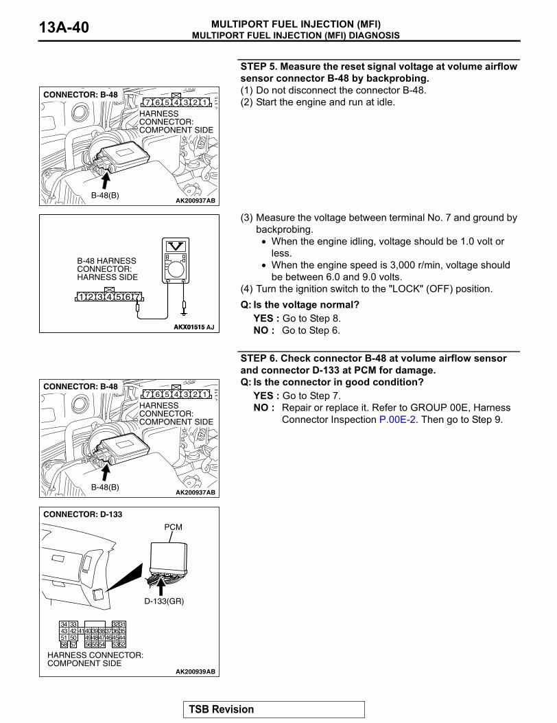
MULTIPORT FUEL INJECTION (MFI) DIAGNOSISMULTIPORT FUEL INJECTION (MFI)13A-40
STEP 5. Measure the reset signal voltage at volume airflow sensor connector B-48 by backprobing.(1) Do not disconnect the connector B-48.(2) Start the engine and run at idle.
(3) Measure the voltage between terminal No. 7 and ground by backprobing.
• When the engine idling, voltage should be 1.0 volt or less.
• When the engine speed is 3,000 r/min, voltage should be between 6.0 and 9.0 volts.
(4) Turn the ignition switch to the "LOCK" (OFF) position.Q: Is the voltage normal?
YES : Go to Step 8.NO : Go to Step 6.
STEP 6. Check connector B-48 at volume airflow sensor and connector D-133 at PCM for damage.Q: Is the connector in good condition?
YES : Go to Step 7.NO : Repair or replace it. Refer to GROUP 00E, Harness
Connector Inspection P.00E-2. Then go to Step 9.
AK200937
345 1267
AB
HARNESS CONNECTOR: COMPONENT SIDE
CONNECTOR: B-48
B-48(B)
AKX01515
6 71 2 3 4 5
AKX01515 AJ
B-48 HARNESS CONNECTOR: HARNESS SIDE
AK200937
345 1267
AB
HARNESS CONNECTOR: COMPONENT SIDE
CONNECTOR: B-48
B-48(B)
AK200939
3132333435363738394041424344454647484952535455565758
5051
AB
CONNECTOR: D-133
HARNESS CONNECTOR: COMPONENT SIDE
PCM
D-133(GR)
TSB Revision
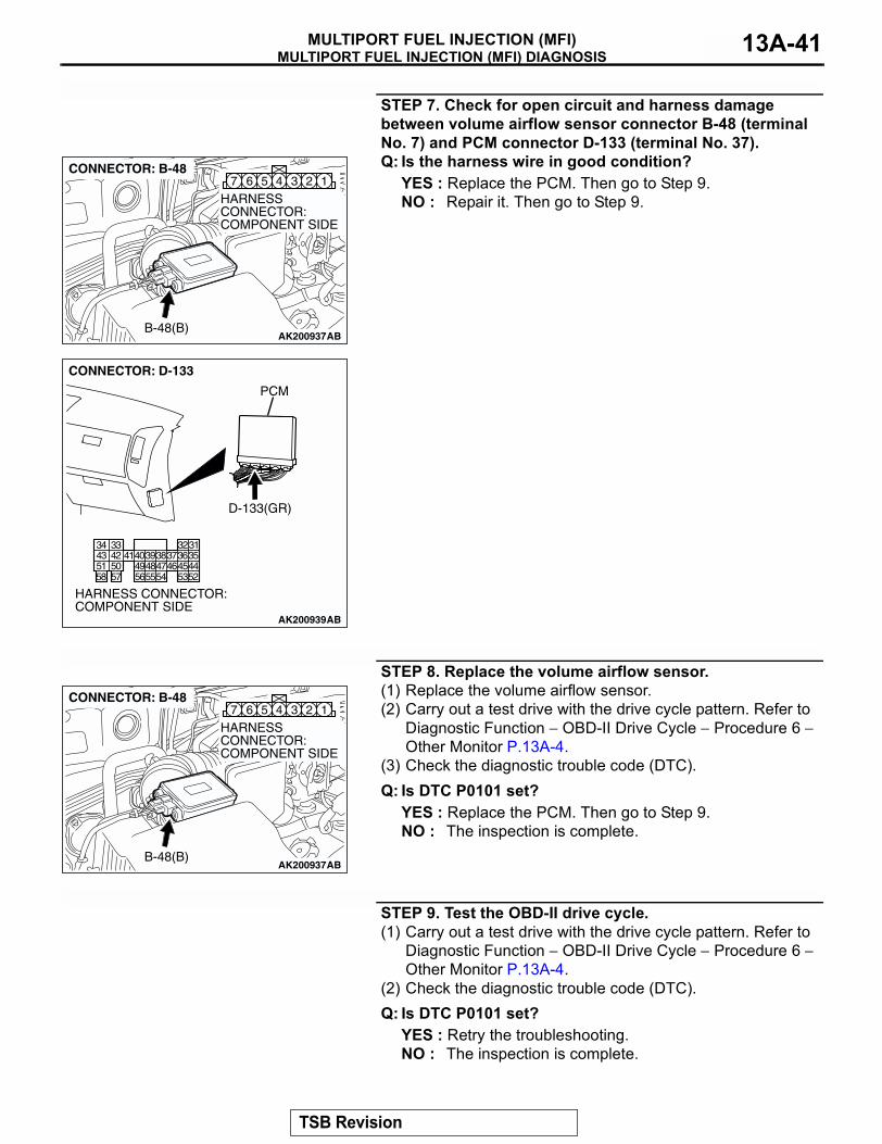
MULTIPORT FUEL INJECTION (MFI) DIAGNOSISMULTIPORT FUEL INJECTION (MFI) 13A-41
STEP 7. Check for open circuit and harness damage between volume airflow sensor connector B-48 (terminal No. 7) and PCM connector D-133 (terminal No. 37).Q: Is the harness wire in good condition?
YES : Replace the PCM. Then go to Step 9.NO : Repair it. Then go to Step 9.
STEP 8. Replace the volume airflow sensor.(1) Replace the volume airflow sensor.(2) Carry out a test drive with the drive cycle pattern. Refer to
Diagnostic Function − OBD-II Drive Cycle − Procedure 6 − Other Monitor P.13A-4.
(3) Check the diagnostic trouble code (DTC).Q: Is DTC P0101 set?
YES : Replace the PCM. Then go to Step 9.NO : The inspection is complete.
STEP 9. Test the OBD-II drive cycle.(1) Carry out a test drive with the drive cycle pattern. Refer to
Diagnostic Function − OBD-II Drive Cycle − Procedure 6 − Other Monitor P.13A-4.
(2) Check the diagnostic trouble code (DTC).Q: Is DTC P0101 set?
YES : Retry the troubleshooting.NO : The inspection is complete.
AK200937
345 1267
AB
HARNESS CONNECTOR: COMPONENT SIDE
CONNECTOR: B-48
B-48(B)
AK200939
3132333435363738394041424344454647484952535455565758
5051
AB
CONNECTOR: D-133
HARNESS CONNECTOR: COMPONENT SIDE
PCM
D-133(GR)
AK200937
345 1267
AB
HARNESS CONNECTOR: COMPONENT SIDE
CONNECTOR: B-48
B-48(B)
TSB Revision
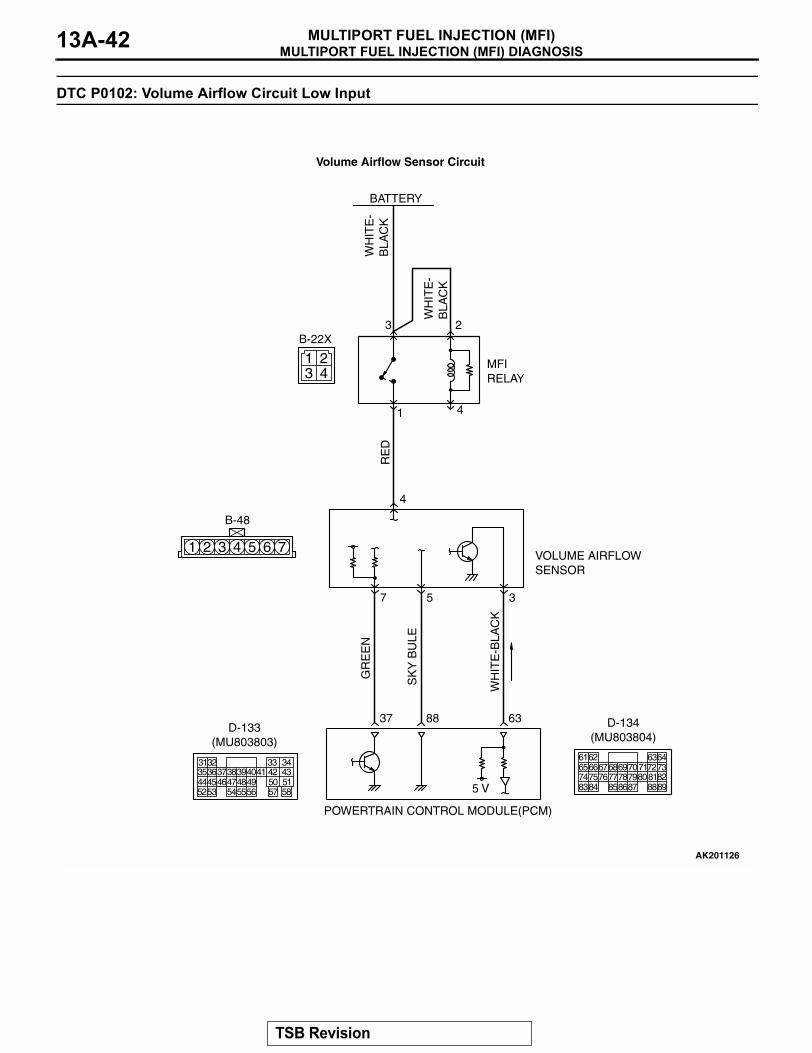
MULTIPORT FUEL INJECTION (MFI) DIAGNOSISMULTIPORT FUEL INJECTION (MFI)13A-42
DTC P0102: Volume Airflow Circuit Low Input
1 2 3 4 5 6 7
3 41 2
RE
D
GR
EE
N
WH
ITE
-BLA
CK
SK
Y B
ULE
WH
ITE
-B
LAC
K
WH
ITE
-B
LAC
K
AK201126
B-48
B-22X
MFI RELAY
BATTERY
VOLUME AIRFLOW SENSOR
POWERTRAIN CONTROL MODULE(PCM)
5 V
37
7
88 63
4
3 2
5 3
1 4
Volume Airflow Sensor Circuit
3135363738394041 42 43444546474849 50 515253 545556 57 58
32 33 34
D-133(MU803803)
616566676869707172737475767778798081828384 858687 8889
62 6364
D-134(MU803804)
TSB Revision
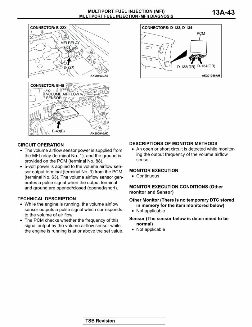
MULTIPORT FUEL INJECTION (MFI) DIAGNOSISMULTIPORT FUEL INJECTION (MFI) 13A-43
.
CIRCUIT OPERATION• The volume airflow sensor power is supplied from
the MFI relay (terminal No. 1), and the ground is provided on the PCM (terminal No. 88).
• 5-volt power is applied to the volume airflow sen-sor output terminal (terminal No. 3) from the PCM (terminal No. 63). The volume airflow sensor gen-erates a pulse signal when the output terminal and ground are opened/closed (opened/short).
.
TECHNICAL DESCRIPTION• While the engine is running, the volume airflow
sensor outputs a pulse signal which corresponds to the volume of air flow.
• The PCM checks whether the frequency of this signal output by the volume airflow sensor while the engine is running is at or above the set value.
.
DESCRIPTIONS OF MONITOR METHODS• An open or short circuit is detected while monitor-
ing the output frequency of the volume airflow sensor.
.
MONITOR EXECUTION• Continuous
.
MONITOR EXECUTION CONDITIONS (Other monitor and Sensor)
Other Monitor (There is no temporary DTC stored in memory for the item monitored below)
• Not applicable
Sensor (The sensor below is determined to be normal)
• Not applicable.
AK201039
MFI RELAY
B-22X
AB
CONNECTOR: B-22X
AK200940ADB-48(B)
CONNECTOR: B-48
VOLUME AIRFLOW SENSOR
AK201038AH
CONNECTORS: D-133, D-134
PCM
D-134(GR)D-133(GR)
TSB Revision
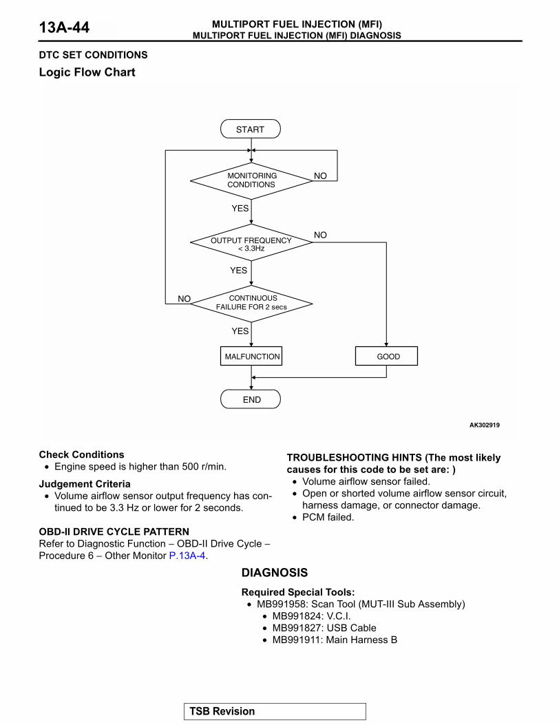
MULTIPORT FUEL INJECTION (MFI) DIAGNOSISMULTIPORT FUEL INJECTION (MFI)13A-44
DTC SET CONDITIONS
Logic Flow Chart
Check Conditions• Engine speed is higher than 500 r/min.
Judgement Criteria• Volume airflow sensor output frequency has con-
tinued to be 3.3 Hz or lower for 2 seconds..
OBD-II DRIVE CYCLE PATTERNRefer to Diagnostic Function − OBD-II Drive Cycle − Procedure 6 − Other Monitor P.13A-4.
.
TROUBLESHOOTING HINTS (The most likely causes for this code to be set are: )
• Volume airflow sensor failed.• Open or shorted volume airflow sensor circuit,
harness damage, or connector damage.• PCM failed.
DIAGNOSISRequired Special Tools:
• MB991958: Scan Tool (MUT-III Sub Assembly)• MB991824: V.C.I.• MB991827: USB Cable• MB991911: Main Harness B
START
MONITORINGCONDITIONS
END
NO
NO
NO
YES
YES
YES
MALFUNCTION GOOD
OUTPUT FREQUENCY< 3.3Hz
CONTINUOUSFAILURE FOR 2 secs
AK302919
TSB Revision
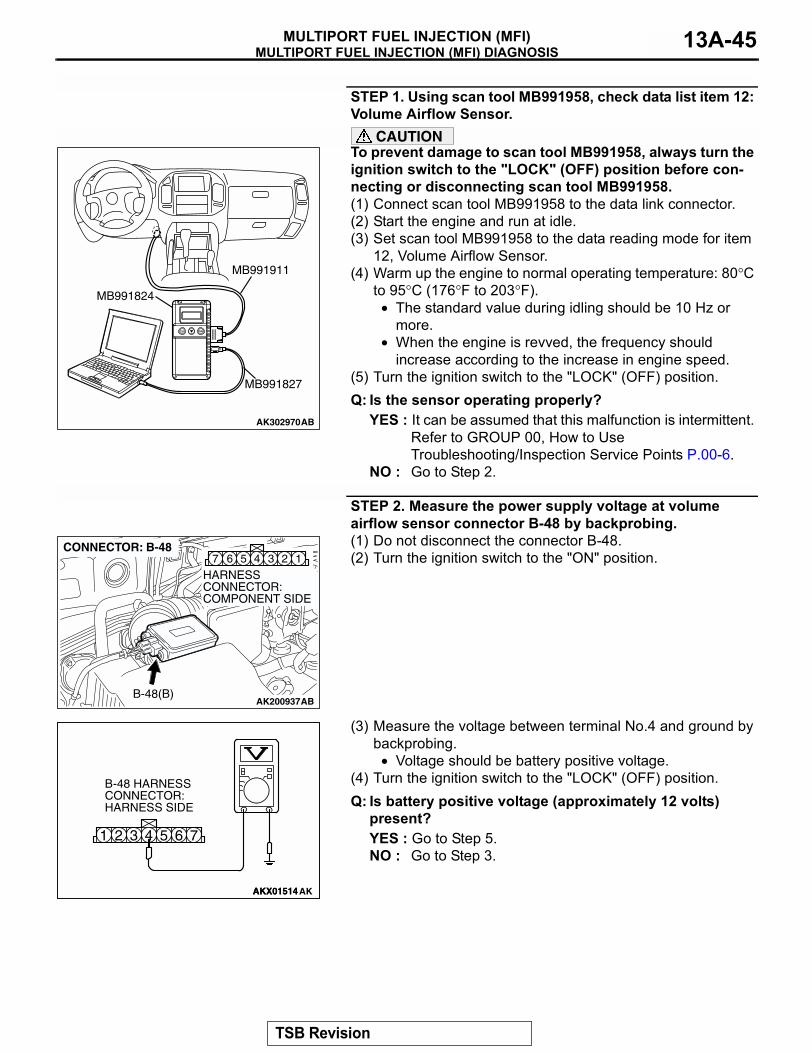
MULTIPORT FUEL INJECTION (MFI) DIAGNOSISMULTIPORT FUEL INJECTION (MFI) 13A-45
STEP 1. Using scan tool MB991958, check data list item 12: Volume Airflow Sensor.
CAUTIONTo prevent damage to scan tool MB991958, always turn the ignition switch to the "LOCK" (OFF) position before con-necting or disconnecting scan tool MB991958.(1) Connect scan tool MB991958 to the data link connector.(2) Start the engine and run at idle.(3) Set scan tool MB991958 to the data reading mode for item
12, Volume Airflow Sensor.(4) Warm up the engine to normal operating temperature: 80°C
to 95°C (176°F to 203°F).• The standard value during idling should be 10 Hz or
more.• When the engine is revved, the frequency should
increase according to the increase in engine speed.(5) Turn the ignition switch to the "LOCK" (OFF) position.Q: Is the sensor operating properly?
YES : It can be assumed that this malfunction is intermittent. Refer to GROUP 00, How to Use Troubleshooting/Inspection Service Points P.00-6.
NO : Go to Step 2.
STEP 2. Measure the power supply voltage at volume airflow sensor connector B-48 by backprobing.(1) Do not disconnect the connector B-48.(2) Turn the ignition switch to the "ON" position.
(3) Measure the voltage between terminal No.4 and ground by backprobing.
• Voltage should be battery positive voltage.(4) Turn the ignition switch to the "LOCK" (OFF) position.Q: Is battery positive voltage (approximately 12 volts)
present?YES : Go to Step 5.NO : Go to Step 3.
AK302970AB
MB991911
MB991824
MB991827
AK200937
345 1267
AB
HARNESS CONNECTOR: COMPONENT SIDE
CONNECTOR: B-48
B-48(B)
AKX01514
6 71 2 3 4 5
AKX01514AK
B-48 HARNESS CONNECTOR: HARNESS SIDE
TSB Revision
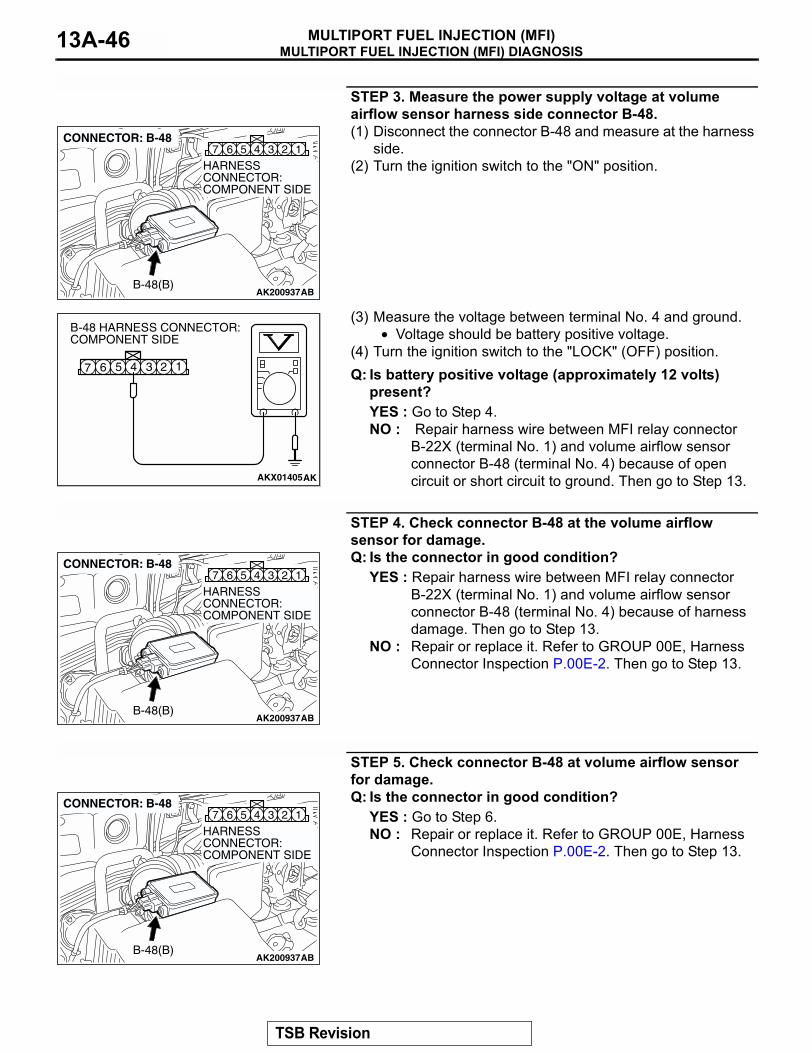
MULTIPORT FUEL INJECTION (MFI) DIAGNOSISMULTIPORT FUEL INJECTION (MFI)13A-46
STEP 3. Measure the power supply voltage at volume airflow sensor harness side connector B-48.(1) Disconnect the connector B-48 and measure at the harness
side.(2) Turn the ignition switch to the "ON" position.
(3) Measure the voltage between terminal No. 4 and ground.• Voltage should be battery positive voltage.
(4) Turn the ignition switch to the "LOCK" (OFF) position.Q: Is battery positive voltage (approximately 12 volts)
present?YES : Go to Step 4. NO : Repair harness wire between MFI relay connector
B-22X (terminal No. 1) and volume airflow sensor connector B-48 (terminal No. 4) because of open circuit or short circuit to ground. Then go to Step 13.
STEP 4. Check connector B-48 at the volume airflow sensor for damage.Q: Is the connector in good condition?
YES : Repair harness wire between MFI relay connector B-22X (terminal No. 1) and volume airflow sensor connector B-48 (terminal No. 4) because of harness damage. Then go to Step 13.
NO : Repair or replace it. Refer to GROUP 00E, Harness Connector Inspection P.00E-2. Then go to Step 13.
STEP 5. Check connector B-48 at volume airflow sensor for damage.Q: Is the connector in good condition?
YES : Go to Step 6.NO : Repair or replace it. Refer to GROUP 00E, Harness
Connector Inspection P.00E-2. Then go to Step 13.
AK200937
345 1267
AB
HARNESS CONNECTOR: COMPONENT SIDE
CONNECTOR: B-48
B-48(B)
AKX01405
B-48 HARNESS CONNECTOR: COMPONENT SIDE
AK
1234567
AK200937
345 1267
AB
HARNESS CONNECTOR: COMPONENT SIDE
CONNECTOR: B-48
B-48(B)
AK200937
345 1267
AB
HARNESS CONNECTOR: COMPONENT SIDE
CONNECTOR: B-48
B-48(B)
TSB Revision
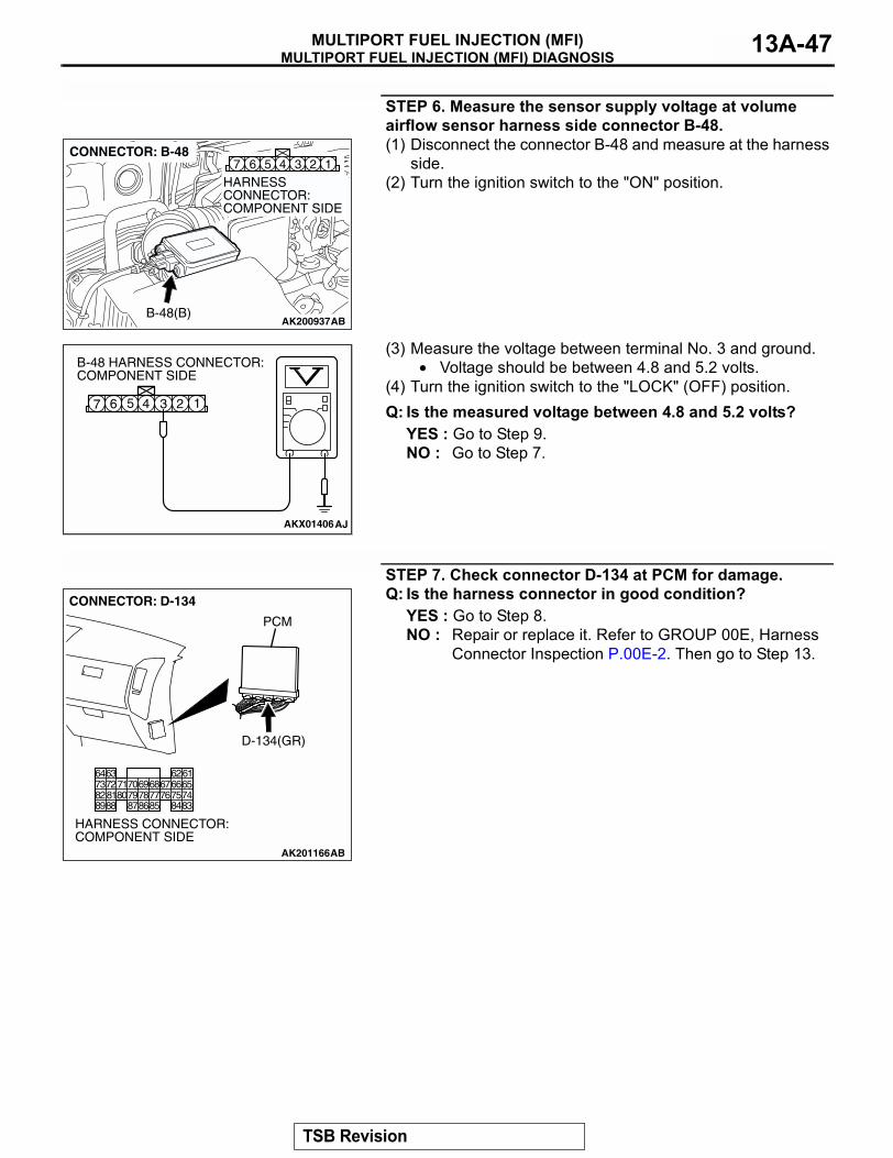
MULTIPORT FUEL INJECTION (MFI) DIAGNOSISMULTIPORT FUEL INJECTION (MFI) 13A-47
STEP 6. Measure the sensor supply voltage at volume airflow sensor harness side connector B-48.(1) Disconnect the connector B-48 and measure at the harness
side.(2) Turn the ignition switch to the "ON" position.
(3) Measure the voltage between terminal No. 3 and ground.• Voltage should be between 4.8 and 5.2 volts.
(4) Turn the ignition switch to the "LOCK" (OFF) position.Q: Is the measured voltage between 4.8 and 5.2 volts?
YES : Go to Step 9.NO : Go to Step 7.
STEP 7. Check connector D-134 at PCM for damage.Q: Is the harness connector in good condition?
YES : Go to Step 8.NO : Repair or replace it. Refer to GROUP 00E, Harness
Connector Inspection P.00E-2. Then go to Step 13.
AK200937
345 1267
AB
HARNESS CONNECTOR: COMPONENT SIDE
CONNECTOR: B-48
B-48(B)
AKX01406AJ
B-48 HARNESS CONNECTOR: COMPONENT SIDE
1234567
AK201166
6162636465666768697071
76777879858687
807273
7475818283848889
CONNECTOR: D-134
AB
PCM
D-134(GR)
HARNESS CONNECTOR: COMPONENT SIDE
TSB Revision
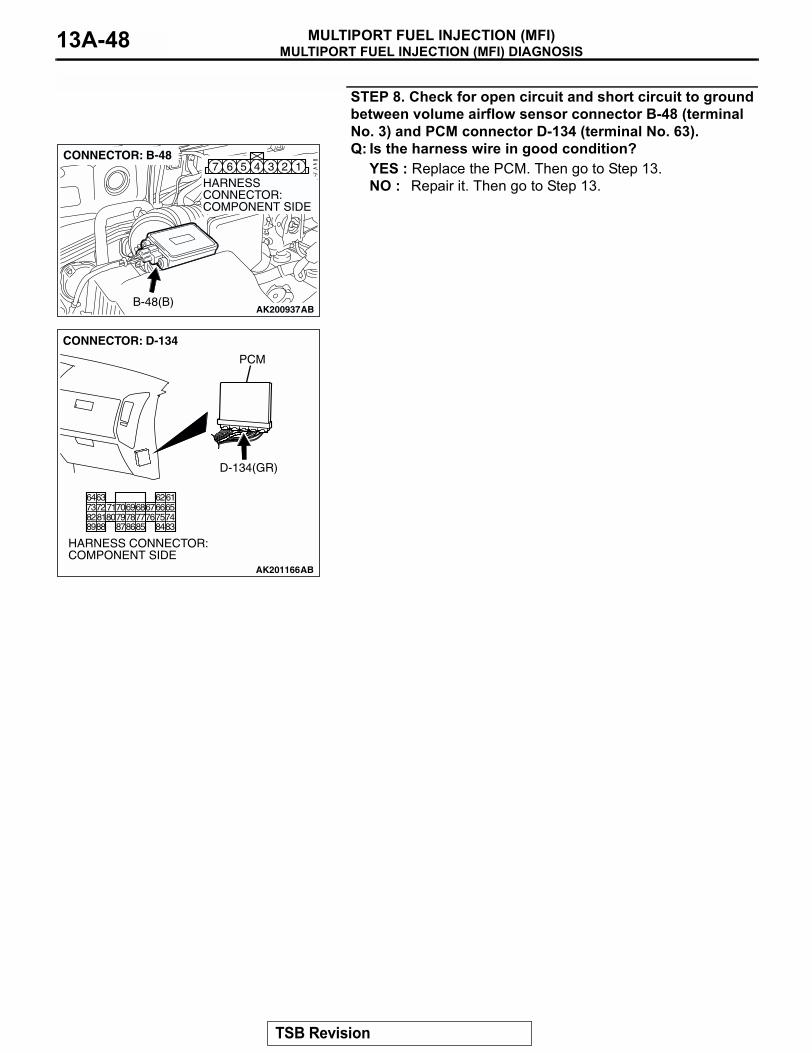
MULTIPORT FUEL INJECTION (MFI) DIAGNOSISMULTIPORT FUEL INJECTION (MFI)13A-48
STEP 8. Check for open circuit and short circuit to ground between volume airflow sensor connector B-48 (terminal No. 3) and PCM connector D-134 (terminal No. 63).Q: Is the harness wire in good condition?
YES : Replace the PCM. Then go to Step 13.NO : Repair it. Then go to Step 13.
AK200937
345 1267
AB
HARNESS CONNECTOR: COMPONENT SIDE
CONNECTOR: B-48
B-48(B)
AK201166
6162636465666768697071
76777879858687
807273
7475818283848889
CONNECTOR: D-134
AB
PCM
D-134(GR)
HARNESS CONNECTOR: COMPONENT SIDE
TSB Revision
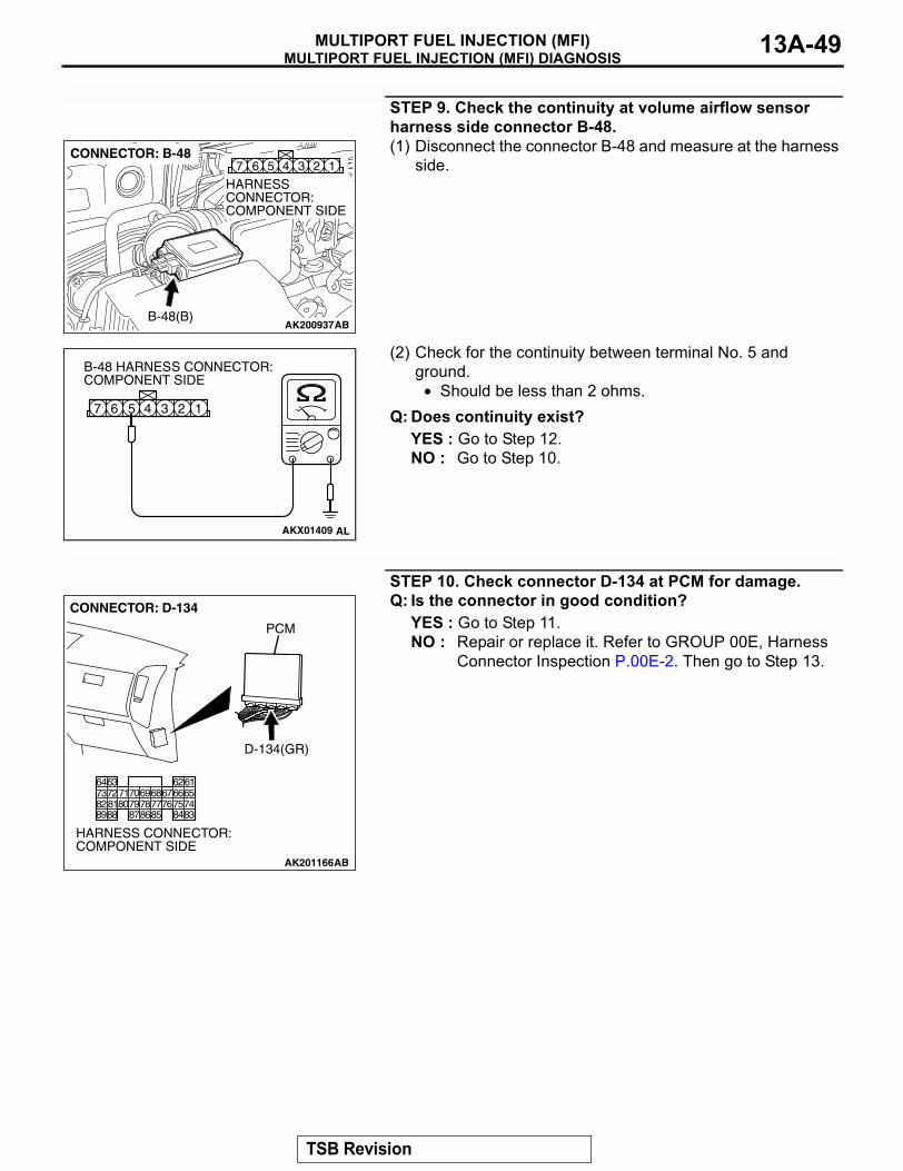
MULTIPORT FUEL INJECTION (MFI) DIAGNOSISMULTIPORT FUEL INJECTION (MFI) 13A-49
STEP 9. Check the continuity at volume airflow sensor harness side connector B-48.(1) Disconnect the connector B-48 and measure at the harness
side.
(2) Check for the continuity between terminal No. 5 and ground.
• Should be less than 2 ohms.Q: Does continuity exist?
YES : Go to Step 12.NO : Go to Step 10.
STEP 10. Check connector D-134 at PCM for damage.Q: Is the connector in good condition?
YES : Go to Step 11.NO : Repair or replace it. Refer to GROUP 00E, Harness
Connector Inspection P.00E-2. Then go to Step 13.
AK200937
345 1267
AB
HARNESS CONNECTOR: COMPONENT SIDE
CONNECTOR: B-48
B-48(B)
AKX01409
1234567
B-48 HARNESS CONNECTOR: COMPONENT SIDE
AL
AK201166
6162636465666768697071
76777879858687
807273
7475818283848889
CONNECTOR: D-134
AB
PCM
D-134(GR)
HARNESS CONNECTOR: COMPONENT SIDE
TSB Revision
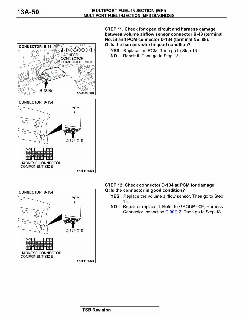
MULTIPORT FUEL INJECTION (MFI) DIAGNOSISMULTIPORT FUEL INJECTION (MFI)13A-50
STEP 11. Check for open circuit and harness damage between volume airflow sensor connector B-48 (terminal No. 5) and PCM connector D-134 (terminal No. 88).Q: Is the harness wire in good condition?
YES : Replace the PCM. Then go to Step 13.NO : Repair it. Then go to Step 13.
STEP 12. Check connector D-134 at PCM for damage.Q: Is the connector in good condition?
YES : Replace the volume airflow sensor. Then go to Step 13.
NO : Repair or replace it. Refer to GROUP 00E, Harness Connector Inspection P.00E-2. Then go to Step 13.
AK200937
345 1267
AB
HARNESS CONNECTOR: COMPONENT SIDE
CONNECTOR: B-48
B-48(B)
AK201166
6162636465666768697071
76777879858687
807273
7475818283848889
CONNECTOR: D-134
AB
PCM
D-134(GR)
HARNESS CONNECTOR: COMPONENT SIDE
AK201166
6162636465666768697071
76777879858687
807273
7475818283848889
CONNECTOR: D-134
AB
PCM
D-134(GR)
HARNESS CONNECTOR: COMPONENT SIDE
TSB Revision
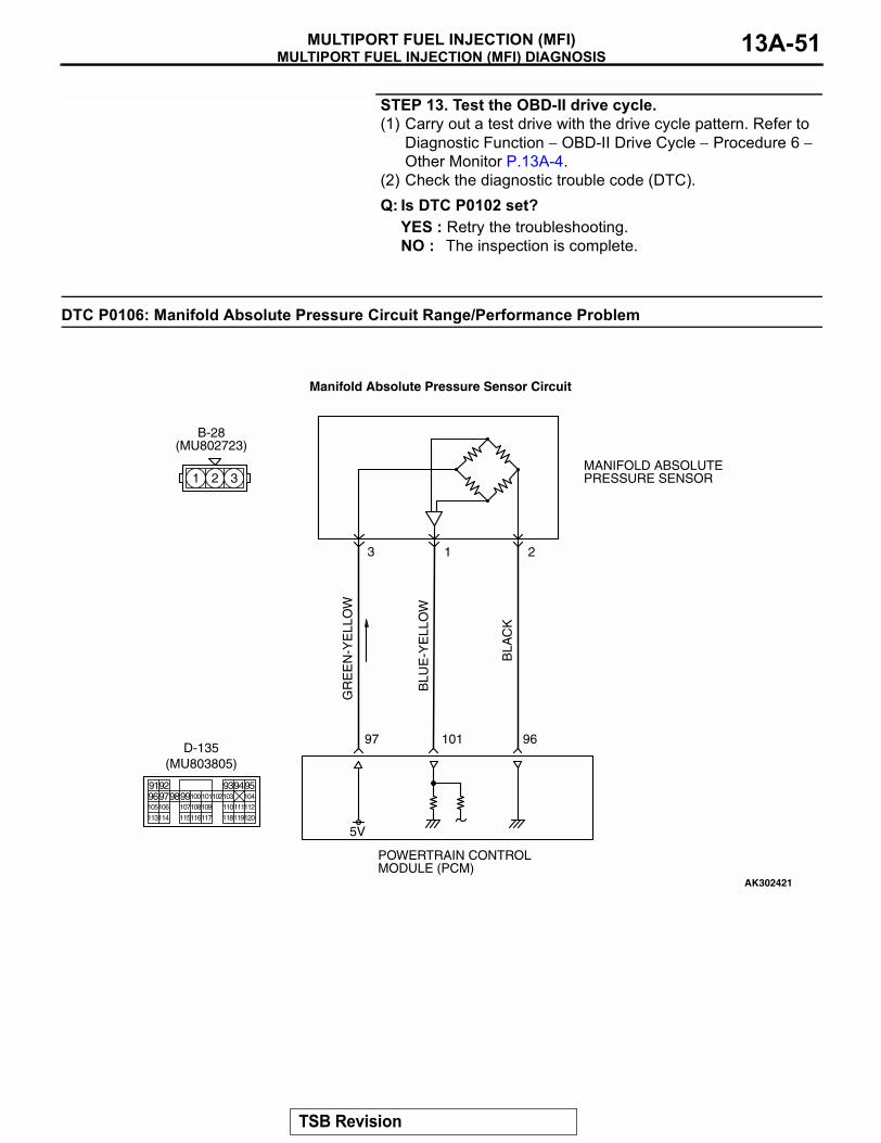
MULTIPORT FUEL INJECTION (MFI) DIAGNOSISMULTIPORT FUEL INJECTION (MFI) 13A-51
STEP 13. Test the OBD-II drive cycle.(1) Carry out a test drive with the drive cycle pattern. Refer to
Diagnostic Function − OBD-II Drive Cycle − Procedure 6 − Other Monitor P.13A-4.
(2) Check the diagnostic trouble code (DTC).Q: Is DTC P0102 set?
YES : Retry the troubleshooting.NO : The inspection is complete.
DTC P0106: Manifold Absolute Pressure Circuit Range/Performance Problem
AK302421
GR
EE
N-Y
ELL
OW
BLU
E-Y
ELL
OW
BLA
CK
POWERTRAIN CONTROL MODULE (PCM)
5V
B-28(MU802723)
MANIFOLD ABSOLUTE PRESSURE SENSOR
3 1 2
Manifold Absolute Pressure Sensor Circuit
97 96101
1 2 3
9192 93949596979899100
105
113114 115116117 118119120
106 107108109 110111112
101102103 104
D-135(MU803805)
TSB Revision
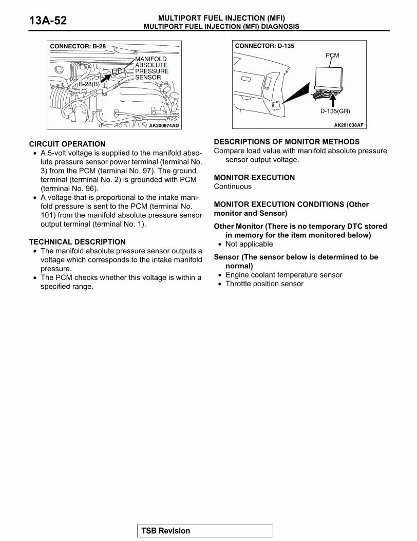
MULTIPORT FUEL INJECTION (MFI) DIAGNOSISMULTIPORT FUEL INJECTION (MFI)13A-52
.
CIRCUIT OPERATION• A 5-volt voltage is supplied to the manifold abso-
lute pressure sensor power terminal (terminal No. 3) from the PCM (terminal No. 97). The ground terminal (terminal No. 2) is grounded with PCM (terminal No. 96).
• A voltage that is proportional to the intake mani-fold pressure is sent to the PCM (terminal No. 101) from the manifold absolute pressure sensor output terminal (terminal No. 1).
.
TECHNICAL DESCRIPTION• The manifold absolute pressure sensor outputs a
voltage which corresponds to the intake manifold pressure.
• The PCM checks whether this voltage is within a specified range.
.
DESCRIPTIONS OF MONITOR METHODSCompare load value with manifold absolute pressure
sensor output voltage..
MONITOR EXECUTIONContinuous.
MONITOR EXECUTION CONDITIONS (Other monitor and Sensor)
Other Monitor (There is no temporary DTC stored in memory for the item monitored below)
• Not applicable
Sensor (The sensor below is determined to be normal)
• Engine coolant temperature sensor• Throttle position sensor
.
AK200974
MANIFOLD ABSOLUTEPRESSURE SENSOR
AD
B-28(B)
CONNECTOR: B-28
AK201038AF
CONNECTOR: D-135
PCM
D-135(GR)
TSB Revision
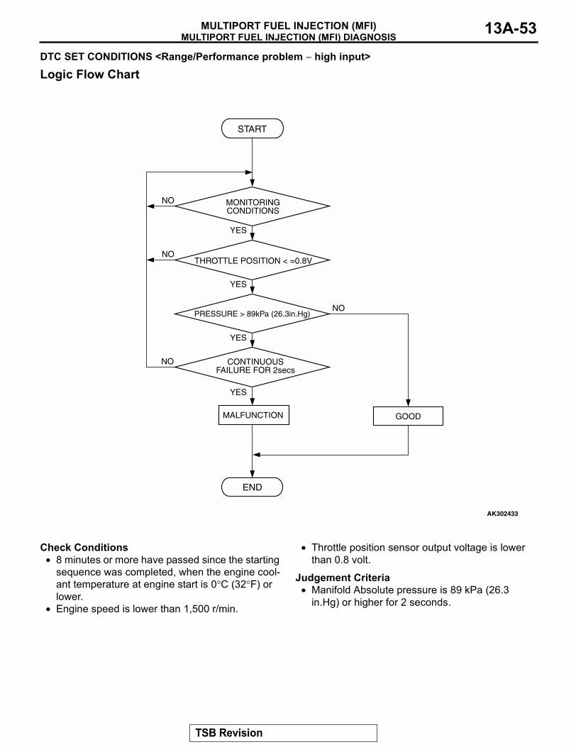
MULTIPORT FUEL INJECTION (MFI) DIAGNOSISMULTIPORT FUEL INJECTION (MFI) 13A-53
DTC SET CONDITIONS <Range/Performance problem − high input>
Logic Flow Chart
Check Conditions• 8 minutes or more have passed since the starting
sequence was completed, when the engine cool-ant temperature at engine start is 0°C (32°F) or lower.
• Engine speed is lower than 1,500 r/min.
• Throttle position sensor output voltage is lower than 0.8 volt.
Judgement Criteria• Manifold Absolute pressure is 89 kPa (26.3
in.Hg) or higher for 2 seconds..
START
YES
YES
YES
YES
NO
NO
NO
NO
MONITORINGCONDITIONS
PRESSURE > 89kPa (26.3in.Hg)
CONTINUOUSFAILURE FOR 2secs
MALFUNCTION
END
GOOD
THROTTLE POSITION < =0.8V
AK302433
TSB Revision
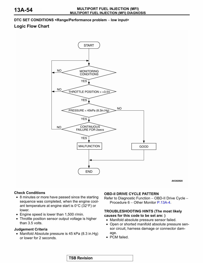
MULTIPORT FUEL INJECTION (MFI) DIAGNOSISMULTIPORT FUEL INJECTION (MFI)13A-54
DTC SET CONDITIONS <Range/Performance problem − low input>
Logic Flow Chart
Check Conditions• 8 minutes or more have passed since the starting
sequence was completed, when the engine cool-ant temperature at engine start is 0°C (32°F) or lower.
• Engine speed is lower than 1,500 r/min.• Throttle position sensor output voltage is higher
than 3.5 volts.
Judgement Criteria• Manifold Absolute pressure is 45 kPa (8.3 in.Hg)
or lower for 2 seconds.
.
OBD-II DRIVE CYCLE PATTERNRefer to Diagnostic Function − OBD-II Drive Cycle −
Procedure 6 − Other Monitor P.13A-4..
TROUBLESHOOTING HINTS (The most likely causes for this code to be set are: )
• Manifold absolute pressure sensor failed.• Open or shorted manifold absolute pressure sen-
sor circuit, harness damage or connector dam-age.
• PCM failed.
START
YES
YES
YES
YES
NO
NO
NO
NO
MONITORINGCONDITIONS
PRESSURE < 45kPa (8.3in.Hg)
CONTINUOUSFAILURE FOR 2secs
MALFUNCTION
END
GOOD
THROTTLE POSITION > =3.5V
AK302920
TSB Revision

MULTIPORT FUEL INJECTION (MFI) DIAGNOSISMULTIPORT FUEL INJECTION (MFI) 13A-55
DIAGNOSISRequired Special Tools:
• MB991958: Scan Tool (MUT-III Sub Assembly)• MB991824: V.C.I.• MB991827: USB Cable• MB991911: Main Harness B
STEP 1. Using scan tool MB991958, check data list item 95: Manifold Absolute Pressure Sensor.
CAUTIONTo prevent damage to scan tool MB991958, always turn the ignition switch to the "LOCK" (OFF) position before con-necting or disconnecting scan tool MB991958.(1) Connect scan tool MB991958 to the data link connector.(2) Turn the ignition switch to the "ON" position.(3) Set scan tool MB991958 to the data reading mode for item
95, Manifold Absolute Pressure Sensor.• When altitude is 0 m (0 foot), 101 kPa (29.8 in.Hg).• When altitude is 600 m (1,969 feet), 95 kPa (28.1 in.Hg).• When altitude is 1,200 m (3,937 feet), 88 kPa (26.0
in.Hg).• When altitude is 1,800 m (5,906 feet), 81 kPa (23.9
in.Hg).(4) Start the engine.
• When the engine is idling, 16 − 36 kPa (4.7 − 10.6 in.Hg).
• When the engine is suddenly revved, manifold absolute pressure increases.
(5) Turn the ignition switch to the "LOCK" (OFF) position.Q: Is the sensor operating properly?
YES : It can be assumed that this malfunction is intermittent. Refer to GROUP 00, How to Use Troubleshooting/Inspection Service Points P.00-6.
NO : Go to Step 2.
AK302970AB
MB991911
MB991824
MB991827
TSB Revision

MULTIPORT FUEL INJECTION (MFI) DIAGNOSISMULTIPORT FUEL INJECTION (MFI)13A-56
STEP 2. Measure the sensor output voltage at Manifold Absolute pressure sensor connector B-28 by backprobing.(1) Do not disconnect the connector B-28.(2) Turn the ignition switch to the "ON" position.
(3) Measure the voltage between terminal No. 1 and ground by backprobing.
• When altitude is 0 m (0 foot), voltage should be 3.7 and 4.3 volts.
• When altitude is 600 m (1,969 feet), voltage should be 3.4 and 4.0 volts.
• When altitude is 1,200 m (3,937 feet), voltage should be 3.2 and 3.8 volts.
• When altitude is 1,800 m (5,906 feet), voltage should be 2.9 and 3.5 volts.
(4) Turn the ignition switch to the "LOCK" (OFF) position.Q: Is the voltage normal?
YES : Go to Step 3.NO : Go to Step 7.
AK200975
123
AB
HARNESS CONNECTOR: COMPONENT SIDE
CONNECTOR: B-28
B-28(B)
321
AK203034
B-28 HARNESS CONNECTOR: HARNESS SIDE
AI
TSB Revision

MULTIPORT FUEL INJECTION (MFI) DIAGNOSISMULTIPORT FUEL INJECTION (MFI) 13A-57
STEP 3. Measure the sensor output voltage at PCM connector D-135 by backprobing.(1) Do not disconnect the connector D-135.(2) Turn the ignition switch to the "ON" position.
(3) Measure the voltage between terminal No. 101 and ground.• When altitude is 0 m (0 foot), voltage should be 3.7 and
4.3 volts.• When altitude is 600 m (1,969 feet), voltage should be
3.4 and 4.0 volts.• When altitude is 1,200 m (3,937 feet), voltage should be
3.2 and 3.8 volts.• When altitude is 1,800 m (5,906 feet), voltage should be
2.9 and 3.5 volts.(4) Turn the ignition switch to the "LOCK" (OFF) position.Q: Is the voltage normal?
YES : Go to Step 4.NO : Go to Step 6.
AK200947
919293949596979899100101102103104
105106107108109110111112
113114115116117118119120
CONNECTOR: D-135
HARNESS CONNECTOR: COMPONENT SIDE
AB
PCM
D-135(GR)
AK302424
9192 93949596979899100
105
113 115116 118119120
107108 110111112
101102103 104
106
114
D-135 HARNESS CONNECTOR: HARNESS SIDE
AB
106
114
TSB Revision

MULTIPORT FUEL INJECTION (MFI) DIAGNOSISMULTIPORT FUEL INJECTION (MFI)13A-58
STEP 4. Check connector B-28 at the manifold absolute pressure sensor and connector D-135 at PCM for damage.Q: Is the connector in good condition?
YES : Go to Step 5.NO : Repair or replace it. Refer to GROUP 00E, Harness
Connector Inspection P.00E-2. Then go to Step 18.
AK200975
123
AB
HARNESS CONNECTOR: COMPONENT SIDE
CONNECTOR: B-28
B-28(B)
AK200947
919293949596979899100101102103104
105106107108109110111112
113114115116117118119120
CONNECTOR: D-135
HARNESS CONNECTOR: COMPONENT SIDE
AB
PCM
D-135(GR)
TSB Revision
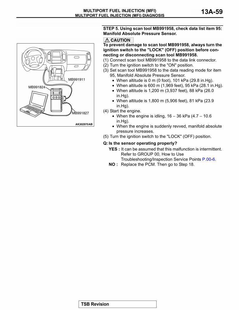
MULTIPORT FUEL INJECTION (MFI) DIAGNOSISMULTIPORT FUEL INJECTION (MFI) 13A-59
STEP 5. Using scan tool MB991958, check data list item 95: Manifold Absolute Pressure Sensor.
CAUTIONTo prevent damage to scan tool MB991958, always turn the ignition switch to the "LOCK" (OFF) position before con-necting or disconnecting scan tool MB991958.(1) Connect scan tool MB991958 to the data link connector.(2) Turn the ignition switch to the "ON" position.(3) Set scan tool MB991958 to the data reading mode for item
95, Manifold Absolute Pressure Sensor.• When altitude is 0 m (0 foot), 101 kPa (29.8 in.Hg).• When altitude is 600 m (1,969 feet), 95 kPa (28.1 in.Hg).• When altitude is 1,200 m (3,937 feet), 88 kPa (26.0
in.Hg).• When altitude is 1,800 m (5,906 feet), 81 kPa (23.9
in.Hg).(4) Start the engine.
• When the engine is idling, 16 − 36 kPa (4.7 − 10.6 in.Hg).
• When the engine is suddenly revved, manifold absolute pressure increases.
(5) Turn the ignition switch to the "LOCK" (OFF) position.Q: Is the sensor operating properly?
YES : It can be assumed that this malfunction is intermittent. Refer to GROUP 00, How to Use Troubleshooting/Inspection Service Points P.00-6.
NO : Replace the PCM. Then go to Step 18.
AK302970AB
MB991911
MB991824
MB991827
TSB Revision
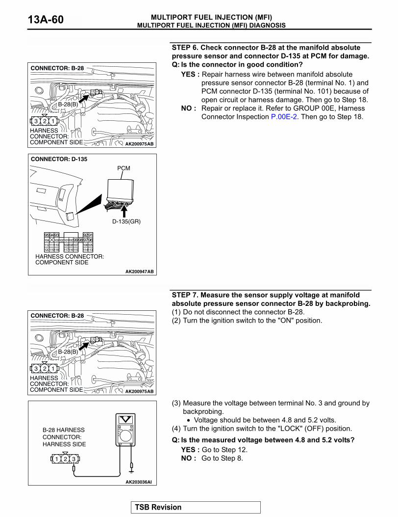
MULTIPORT FUEL INJECTION (MFI) DIAGNOSISMULTIPORT FUEL INJECTION (MFI)13A-60
STEP 6. Check connector B-28 at the manifold absolute pressure sensor and connector D-135 at PCM for damage.Q: Is the connector in good condition?
YES : Repair harness wire between manifold absolute pressure sensor connector B-28 (terminal No. 1) and PCM connector D-135 (terminal No. 101) because of open circuit or harness damage. Then go to Step 18.
NO : Repair or replace it. Refer to GROUP 00E, Harness Connector Inspection P.00E-2. Then go to Step 18.
STEP 7. Measure the sensor supply voltage at manifold absolute pressure sensor connector B-28 by backprobing.(1) Do not disconnect the connector B-28.(2) Turn the ignition switch to the "ON" position.
(3) Measure the voltage between terminal No. 3 and ground by backprobing.
• Voltage should be between 4.8 and 5.2 volts.(4) Turn the ignition switch to the "LOCK" (OFF) position.Q: Is the measured voltage between 4.8 and 5.2 volts?
YES : Go to Step 12.NO : Go to Step 8.
AK200975
123
AB
HARNESS CONNECTOR: COMPONENT SIDE
CONNECTOR: B-28
B-28(B)
AK200947
919293949596979899100101102103104
105106107108109110111112
113114115116117118119120
CONNECTOR: D-135
HARNESS CONNECTOR: COMPONENT SIDE
AB
PCM
D-135(GR)
AK200975
123
AB
HARNESS CONNECTOR: COMPONENT SIDE
CONNECTOR: B-28
B-28(B)
321
AK203036
B-28 HARNESSCONNECTOR:HARNESS SIDE
AI
TSB Revision
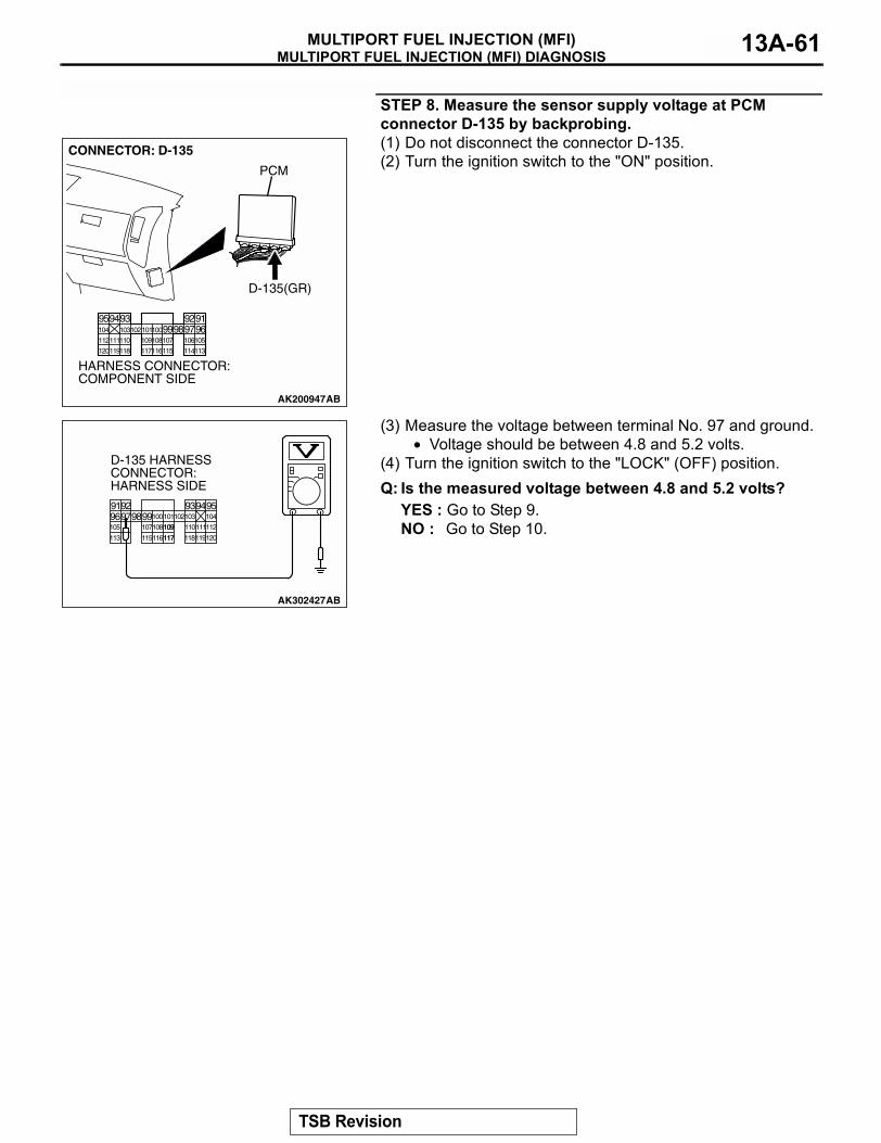
MULTIPORT FUEL INJECTION (MFI) DIAGNOSISMULTIPORT FUEL INJECTION (MFI) 13A-61
STEP 8. Measure the sensor supply voltage at PCM connector D-135 by backprobing.(1) Do not disconnect the connector D-135.(2) Turn the ignition switch to the "ON" position.
(3) Measure the voltage between terminal No. 97 and ground.• Voltage should be between 4.8 and 5.2 volts.
(4) Turn the ignition switch to the "LOCK" (OFF) position.Q: Is the measured voltage between 4.8 and 5.2 volts?
YES : Go to Step 9.NO : Go to Step 10.
AK200947
919293949596979899100101102103104
105106107108109110111112
113114115116117118119120
CONNECTOR: D-135
HARNESS CONNECTOR: COMPONENT SIDE
AB
PCM
D-135(GR)
AK302427
9192 93949596979899100
105
113 115116 118119120
107108 110111112
101102103 104
109
117
D-135 HARNESS CONNECTOR: HARNESS SIDE
AB
109
117
TSB Revision
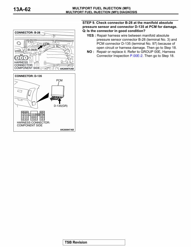
MULTIPORT FUEL INJECTION (MFI) DIAGNOSISMULTIPORT FUEL INJECTION (MFI)13A-62
STEP 9. Check connector B-28 at the manifold absolute pressure sensor and connector D-135 at PCM for damage.Q: Is the connector in good condition?
YES : Repair harness wire between manifold absolute pressure sensor connector B-28 (terminal No. 3) and PCM connector D-135 (terminal No. 97) because of open circuit or harness damage. Then go to Step 18.
NO : Repair or replace it. Refer to GROUP 00E, Harness Connector Inspection P.00E-2. Then go to Step 18.
AK200975
123
AB
HARNESS CONNECTOR: COMPONENT SIDE
CONNECTOR: B-28
B-28(B)
AK200947
919293949596979899100101102103104
105106107108109110111112
113114115116117118119120
CONNECTOR: D-135
HARNESS CONNECTOR: COMPONENT SIDE
AB
PCM
D-135(GR)
TSB Revision

MULTIPORT FUEL INJECTION (MFI) DIAGNOSISMULTIPORT FUEL INJECTION (MFI) 13A-63
STEP 10. Check connector B-28 at the manifold absolute pressure sensor and connector D-135 at PCM for damage.Q: Is the connector in good condition?
YES : Go to Step 11.NO : Repair or replace it. Refer to GROUP 00E, Harness
Connector Inspection P.00E-2. Then go to Step 18.
AK200975
123
AB
HARNESS CONNECTOR: COMPONENT SIDE
CONNECTOR: B-28
B-28(B)
AK200947
919293949596979899100101102103104
105106107108109110111112
113114115116117118119120
CONNECTOR: D-135
HARNESS CONNECTOR: COMPONENT SIDE
AB
PCM
D-135(GR)
TSB Revision
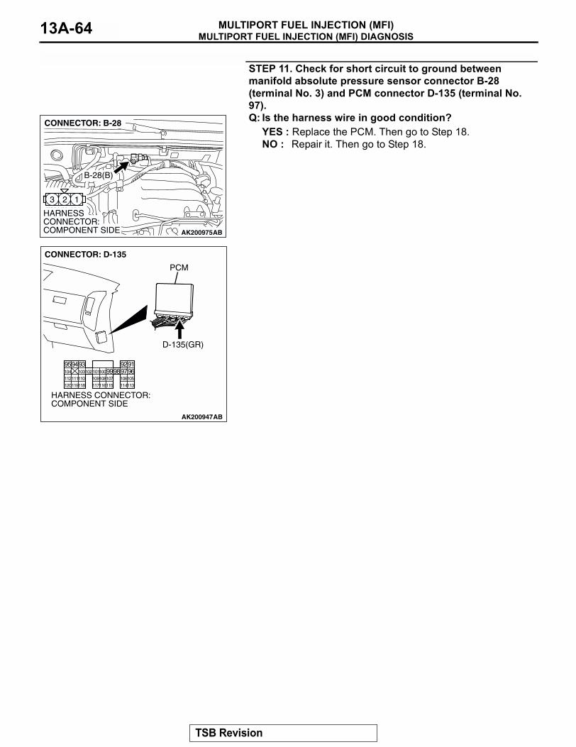
MULTIPORT FUEL INJECTION (MFI) DIAGNOSISMULTIPORT FUEL INJECTION (MFI)13A-64
STEP 11. Check for short circuit to ground between manifold absolute pressure sensor connector B-28 (terminal No. 3) and PCM connector D-135 (terminal No. 97).Q: Is the harness wire in good condition?
YES : Replace the PCM. Then go to Step 18.NO : Repair it. Then go to Step 18.
AK200975
123
AB
HARNESS CONNECTOR: COMPONENT SIDE
CONNECTOR: B-28
B-28(B)
AK200947
919293949596979899100101102103104
105106107108109110111112
113114115116117118119120
CONNECTOR: D-135
HARNESS CONNECTOR: COMPONENT SIDE
AB
PCM
D-135(GR)
TSB Revision

MULTIPORT FUEL INJECTION (MFI) DIAGNOSISMULTIPORT FUEL INJECTION (MFI) 13A-65
STEP 12. Measure the ground voltage at manifold absolute pressure sensor connector B-28 by backprobing.(1) Do not disconnect the connector B-28.(2) Turn the ignition switch to the "ON" position.
(3) Measure the voltage between terminal No. 2 and ground by backprobing.
• Voltage should be 0.5 volt or less.(4) Turn the ignition switch to the "LOCK" (OFF) position.Q: Is the measured voltage 0.5 volt or less?
YES : Go to Step 15.NO : Go to Step 13.
STEP 13. Check connector B-28 at the manifold absolute pressure sensor and connector D-135 at PCM for damage.Q: Is the connector in good condition?
YES : Go to Step 14.NO : Repair or replace it. Refer to GROUP 00E, Harness
Connector Inspection P.00E-2. Then go to Step 18.
AK200975
123
AB
HARNESS CONNECTOR: COMPONENT SIDE
CONNECTOR: B-28
B-28(B)
321
AK203038
B-28 HARNESS CONNECTOR: HARNESS SIDE
AI
AK200975
123
AB
HARNESS CONNECTOR: COMPONENT SIDE
CONNECTOR: B-28
B-28(B)
AK200947
919293949596979899100101102103104
105106107108109110111112
113114115116117118119120
CONNECTOR: D-135
HARNESS CONNECTOR: COMPONENT SIDE
AB
PCM
D-135(GR)
TSB Revision

MULTIPORT FUEL INJECTION (MFI) DIAGNOSISMULTIPORT FUEL INJECTION (MFI)13A-66
STEP 14. Check for harness damage between manifold absolute pressure sensor connector B-28 (terminal No. 2) and PCM connector D-135 (terminal No. 96).Q: Is the harness wire in good condition?
YES : Replace the PCM. Then go to Step 18.NO : Repair it. Then go to Step 18.
STEP 15. Check connector B-28 at manifold absolute pressure sensor for damage.Q: Is the connector in good condition?
YES : Go to Step 16.NO : Repair or replace it. Refer to GROUP 00E, Harness
Connector Inspection P.00E-2. Then go to Step 18.
AK200975
123
AB
HARNESS CONNECTOR: COMPONENT SIDE
CONNECTOR: B-28
B-28(B)
AK200947
919293949596979899100101102103104
105106107108109110111112
113114115116117118119120
CONNECTOR: D-135
HARNESS CONNECTOR: COMPONENT SIDE
AB
PCM
D-135(GR)
AK200975
123
AB
HARNESS CONNECTOR: COMPONENT SIDE
CONNECTOR: B-28
B-28(B)
TSB Revision

MULTIPORT FUEL INJECTION (MFI) DIAGNOSISMULTIPORT FUEL INJECTION (MFI) 13A-67
STEP 16. Check connector D-135 at PCM for damage.Q: Is the connector in good condition?
YES : Go to Step 17.NO : Repair or replace it. Refer to GROUP 00E, Harness
Connector Inspection P.00E-2. Then go to Step 18.
STEP 17. Check for short circuit to ground and harness damage between manifold absolute pressure sensor connector B-28 (terminal No. 1) and PCM connector D-135 (terminal No. 101).Q: Is the harness wire in good condition?
YES : Replace the manifold absolute pressure sensor. Then go to Step 18.
NO : Repair it. Then go to Step 18.
AK200947
919293949596979899100101102103104
105106107108109110111112
113114115116117118119120
CONNECTOR: D-135
HARNESS CONNECTOR: COMPONENT SIDE
AB
PCM
D-135(GR)
AK200975
123
AB
HARNESS CONNECTOR: COMPONENT SIDE
CONNECTOR: B-28
B-28(B)
AK200947
919293949596979899100101102103104
105106107108109110111112
113114115116117118119120
CONNECTOR: D-135
HARNESS CONNECTOR: COMPONENT SIDE
AB
PCM
D-135(GR)
TSB Revision
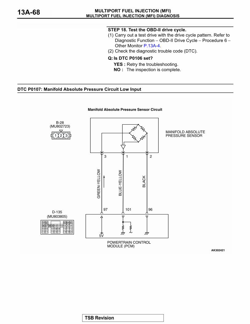
MULTIPORT FUEL INJECTION (MFI) DIAGNOSISMULTIPORT FUEL INJECTION (MFI)13A-68
STEP 18. Test the OBD-II drive cycle.(1) Carry out a test drive with the drive cycle pattern. Refer to
Diagnostic Function − OBD-II Drive Cycle − Procedure 6 − Other Monitor P.13A-4.
(2) Check the diagnostic trouble code (DTC).Q: Is DTC P0106 set?
YES : Retry the troubleshooting.NO : The inspection is complete.
DTC P0107: Manifold Absolute Pressure Circuit Low Input
AK302421
GR
EE
N-Y
ELL
OW
BLU
E-Y
ELL
OW
BLA
CK
POWERTRAIN CONTROL MODULE (PCM)
5V
B-28(MU802723)
MANIFOLD ABSOLUTE PRESSURE SENSOR
3 1 2
Manifold Absolute Pressure Sensor Circuit
97 96101
1 2 3
9192 93949596979899100
105
113114 115116117 118119120
106 107108109 110111112
101102103 104
D-135(MU803805)
TSB Revision
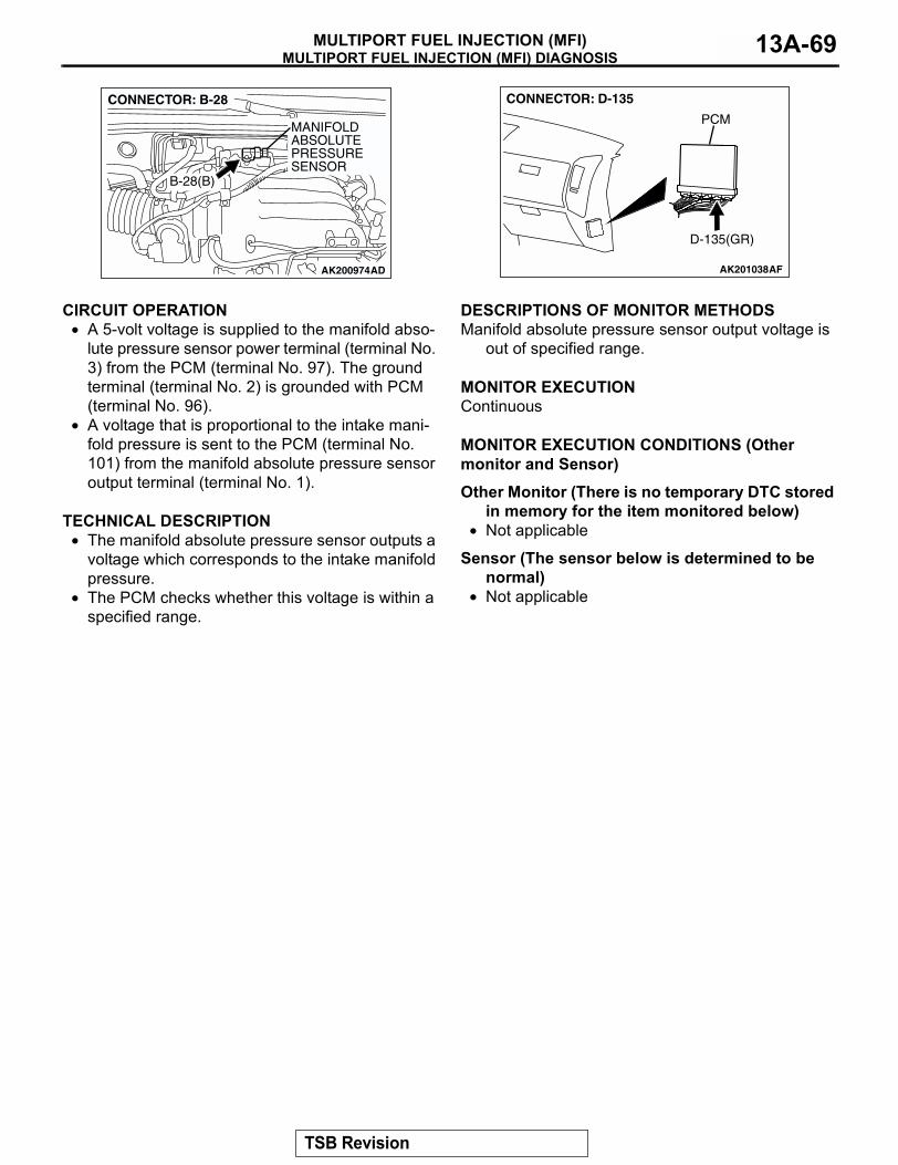
MULTIPORT FUEL INJECTION (MFI) DIAGNOSISMULTIPORT FUEL INJECTION (MFI) 13A-69
.
CIRCUIT OPERATION• A 5-volt voltage is supplied to the manifold abso-
lute pressure sensor power terminal (terminal No. 3) from the PCM (terminal No. 97). The ground terminal (terminal No. 2) is grounded with PCM (terminal No. 96).
• A voltage that is proportional to the intake mani-fold pressure is sent to the PCM (terminal No. 101) from the manifold absolute pressure sensor output terminal (terminal No. 1).
.
TECHNICAL DESCRIPTION• The manifold absolute pressure sensor outputs a
voltage which corresponds to the intake manifold pressure.
• The PCM checks whether this voltage is within a specified range.
.
DESCRIPTIONS OF MONITOR METHODSManifold absolute pressure sensor output voltage is
out of specified range..
MONITOR EXECUTIONContinuous.
MONITOR EXECUTION CONDITIONS (Other monitor and Sensor)
Other Monitor (There is no temporary DTC stored in memory for the item monitored below)
• Not applicable
Sensor (The sensor below is determined to be normal)
• Not applicable.
AK200974
MANIFOLD ABSOLUTEPRESSURE SENSOR
AD
B-28(B)
CONNECTOR: B-28
AK201038AF
CONNECTOR: D-135
PCM
D-135(GR)
TSB Revision
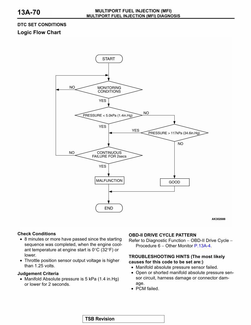
MULTIPORT FUEL INJECTION (MFI) DIAGNOSISMULTIPORT FUEL INJECTION (MFI)13A-70
DTC SET CONDITIONS
Logic Flow Chart
Check Conditions• 8 minutes or more have passed since the starting
sequence was completed, when the engine cool-ant temperature at engine start is 0°C (32°F) or lower.
• Throttle position sensor output voltage is higher than 1.25 volts.
Judgement Criteria• Manifold Absolute pressure is 5 kPa (1.4 in.Hg)
or lower for 2 seconds.
.
OBD-II DRIVE CYCLE PATTERNRefer to Diagnostic Function − OBD-II Drive Cycle −
Procedure 6 − Other Monitor P.13A-4..
TROUBLESHOOTING HINTS (The most likely causes for this code to be set are:)
• Manifold absolute pressure sensor failed.• Open or shorted manifold absolute pressure sen-
sor circuit, harness damage or connector dam-age.
• PCM failed.
YES
YES
YES
YES
NO
NO
NO
NO
MONITORINGCONDITIONS
PRESSURE < 5.0kPa (1.4in.Hg)
PRESSURE > 117kPa (34.6in.Hg)
CONTINUOUSFAILURE FOR 2secs
MALFUNCTION
END
GOOD
START
AK302688
TSB Revision
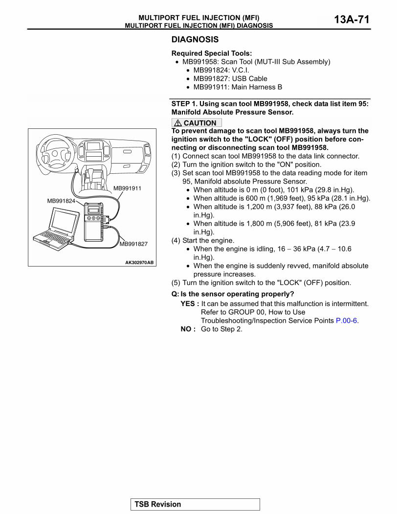
MULTIPORT FUEL INJECTION (MFI) DIAGNOSISMULTIPORT FUEL INJECTION (MFI) 13A-71
DIAGNOSISRequired Special Tools:
• MB991958: Scan Tool (MUT-III Sub Assembly)• MB991824: V.C.I.• MB991827: USB Cable• MB991911: Main Harness B
STEP 1. Using scan tool MB991958, check data list item 95: Manifold Absolute Pressure Sensor.
CAUTIONTo prevent damage to scan tool MB991958, always turn the ignition switch to the "LOCK" (OFF) position before con-necting or disconnecting scan tool MB991958.(1) Connect scan tool MB991958 to the data link connector.(2) Turn the ignition switch to the "ON" position.(3) Set scan tool MB991958 to the data reading mode for item
95, Manifold absolute Pressure Sensor.• When altitude is 0 m (0 foot), 101 kPa (29.8 in.Hg).• When altitude is 600 m (1,969 feet), 95 kPa (28.1 in.Hg).• When altitude is 1,200 m (3,937 feet), 88 kPa (26.0
in.Hg).• When altitude is 1,800 m (5,906 feet), 81 kPa (23.9
in.Hg).(4) Start the engine.
• When the engine is idling, 16 − 36 kPa (4.7 − 10.6 in.Hg).
• When the engine is suddenly revved, manifold absolute pressure increases.
(5) Turn the ignition switch to the "LOCK" (OFF) position.Q: Is the sensor operating properly?
YES : It can be assumed that this malfunction is intermittent. Refer to GROUP 00, How to Use Troubleshooting/Inspection Service Points P.00-6.
NO : Go to Step 2.
AK302970AB
MB991911
MB991824
MB991827
TSB Revision
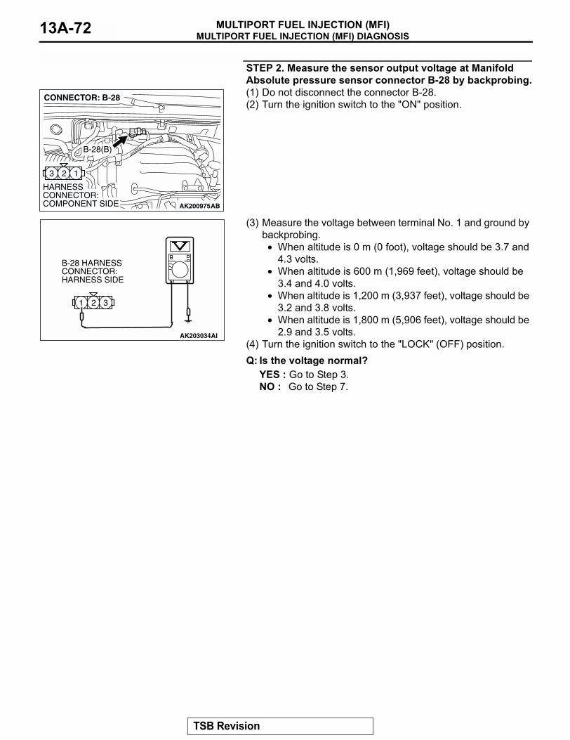
MULTIPORT FUEL INJECTION (MFI) DIAGNOSISMULTIPORT FUEL INJECTION (MFI)13A-72
STEP 2. Measure the sensor output voltage at Manifold Absolute pressure sensor connector B-28 by backprobing.(1) Do not disconnect the connector B-28.(2) Turn the ignition switch to the "ON" position.
(3) Measure the voltage between terminal No. 1 and ground by backprobing.
• When altitude is 0 m (0 foot), voltage should be 3.7 and 4.3 volts.
• When altitude is 600 m (1,969 feet), voltage should be 3.4 and 4.0 volts.
• When altitude is 1,200 m (3,937 feet), voltage should be 3.2 and 3.8 volts.
• When altitude is 1,800 m (5,906 feet), voltage should be 2.9 and 3.5 volts.
(4) Turn the ignition switch to the "LOCK" (OFF) position.Q: Is the voltage normal?
YES : Go to Step 3.NO : Go to Step 7.
AK200975
123
AB
HARNESS CONNECTOR: COMPONENT SIDE
CONNECTOR: B-28
B-28(B)
321
AK203034
B-28 HARNESS CONNECTOR: HARNESS SIDE
AI
TSB Revision
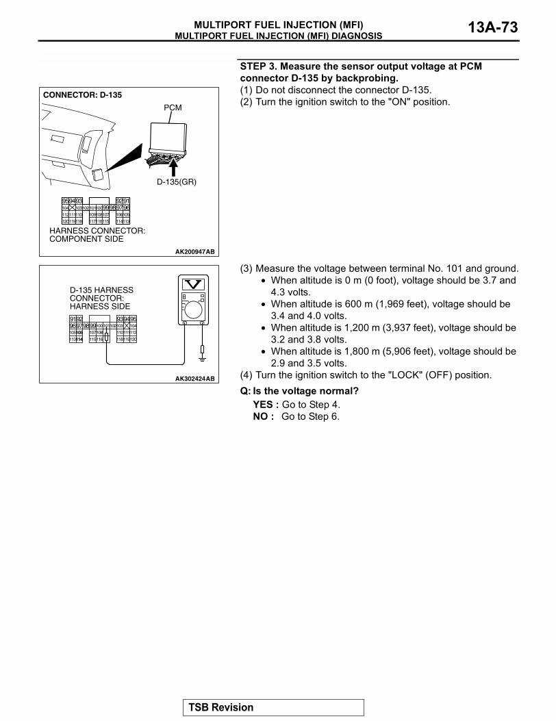
MULTIPORT FUEL INJECTION (MFI) DIAGNOSISMULTIPORT FUEL INJECTION (MFI) 13A-73
STEP 3. Measure the sensor output voltage at PCM connector D-135 by backprobing.(1) Do not disconnect the connector D-135.(2) Turn the ignition switch to the "ON" position.
(3) Measure the voltage between terminal No. 101 and ground.• When altitude is 0 m (0 foot), voltage should be 3.7 and
4.3 volts.• When altitude is 600 m (1,969 feet), voltage should be
3.4 and 4.0 volts.• When altitude is 1,200 m (3,937 feet), voltage should be
3.2 and 3.8 volts.• When altitude is 1,800 m (5,906 feet), voltage should be
2.9 and 3.5 volts.(4) Turn the ignition switch to the "LOCK" (OFF) position.Q: Is the voltage normal?
YES : Go to Step 4.NO : Go to Step 6.
AK200947
919293949596979899100101102103104
105106107108109110111112
113114115116117118119120
CONNECTOR: D-135
HARNESS CONNECTOR: COMPONENT SIDE
AB
PCM
D-135(GR)
AK302424
9192 93949596979899100
105
113 115116 118119120
107108 110111112
101102103 104
106
114
D-135 HARNESS CONNECTOR: HARNESS SIDE
AB
106
114
TSB Revision
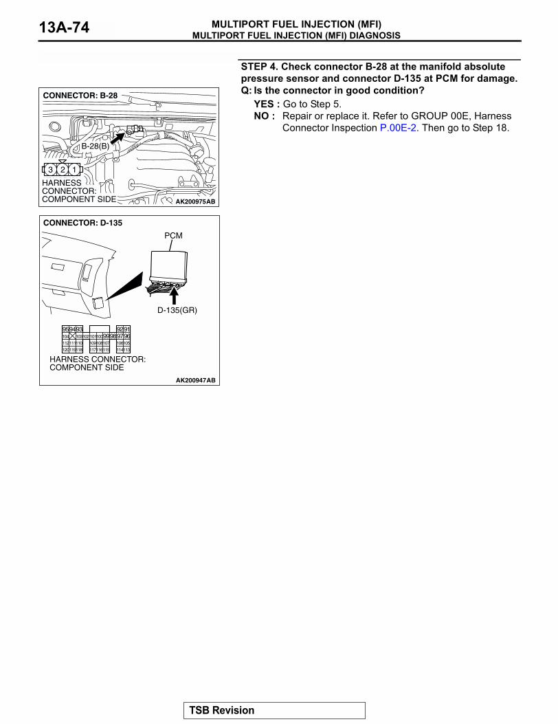
MULTIPORT FUEL INJECTION (MFI) DIAGNOSISMULTIPORT FUEL INJECTION (MFI)13A-74
STEP 4. Check connector B-28 at the manifold absolute pressure sensor and connector D-135 at PCM for damage.Q: Is the connector in good condition?
YES : Go to Step 5.NO : Repair or replace it. Refer to GROUP 00E, Harness
Connector Inspection P.00E-2. Then go to Step 18.
AK200975
123
AB
HARNESS CONNECTOR: COMPONENT SIDE
CONNECTOR: B-28
B-28(B)
AK200947
919293949596979899100101102103104
105106107108109110111112
113114115116117118119120
CONNECTOR: D-135
HARNESS CONNECTOR: COMPONENT SIDE
AB
PCM
D-135(GR)
TSB Revision

MULTIPORT FUEL INJECTION (MFI) DIAGNOSISMULTIPORT FUEL INJECTION (MFI) 13A-75
STEP 5. Using scan tool MB991958, check data list item 95: Manifold Absolute Pressure Sensor.
CAUTIONTo prevent damage to scan tool MB991958, always turn the ignition switch to the "LOCK" (OFF) position before con-necting or disconnecting scan tool MB991958.(1) Connect scan tool MB991958 to the data link connector.(2) Turn the ignition switch to the "ON" position.(3) Set scan tool MB991958 to the data reading mode for item
95, Manifold Absolute Pressure Sensor.• When altitude is 0 m (0 foot), 101 kPa (29.8 in.Hg).• When altitude is 600 m (1,969 feet), 95 kPa (28.1 in.Hg).• When altitude is 1,200 m (3,937 feet), 88 kPa (26.0
in.Hg).• When altitude is 1,800 m (5,906 feet), 81 kPa (23.9
in.Hg).(4) Start the engine.
• When the engine is idling, 16 − 36 kPa (4.7 − 10.6 in.Hg).
• When the engine is suddenly revved, manifold absolute pressure increases.
(5) Turn the ignition switch to the "LOCK" (OFF) position.Q: Is the sensor operating properly?
YES : It can be assumed that this malfunction is intermittent. Refer to GROUP 00, How to Use Troubleshooting/Inspection Service Points P.00-6.
NO : Replace the PCM. Then go to Step 18.
AK302970AB
MB991911
MB991824
MB991827
TSB Revision

MULTIPORT FUEL INJECTION (MFI) DIAGNOSISMULTIPORT FUEL INJECTION (MFI)13A-76
STEP 6. Check connector B-28 at the manifold absolute pressure sensor and connector D-135 at PCM for damage.Q: Is the connector in good condition?
YES : Repair harness wire between manifold absolute pressure sensor connector B-28 (terminal No. 1) and PCM connector D-135 (terminal No. 101) because of open circuit or harness damage. Then go to Step 18.
NO : Repair or replace it. Refer to GROUP 00E, Harness Connector Inspection P.00E-2. Then go to Step 18.
STEP 7. Measure the sensor supply voltage at manifold absolute pressure sensor connector B-28 by backprobing.(1) Do not disconnect the connector B-28.(2) Turn the ignition switch to the "ON" position.
(3) Measure the voltage between terminal No. 3 and ground by backprobing.
• Voltage should be between 4.8 and 5.2 volts.(4) Turn the ignition switch to the "LOCK" (OFF) position.Q: Is the measured voltage between 4.8 and 5.2 volts?
YES : Go to Step 12.NO : Go to Step 8.
AK200975
123
AB
HARNESS CONNECTOR: COMPONENT SIDE
CONNECTOR: B-28
B-28(B)
AK200947
919293949596979899100101102103104
105106107108109110111112
113114115116117118119120
CONNECTOR: D-135
HARNESS CONNECTOR: COMPONENT SIDE
AB
PCM
D-135(GR)
AK200975
123
AB
HARNESS CONNECTOR: COMPONENT SIDE
CONNECTOR: B-28
B-28(B)
321
AK203036
B-28 HARNESSCONNECTOR:HARNESS SIDE
AI
TSB Revision

MULTIPORT FUEL INJECTION (MFI) DIAGNOSISMULTIPORT FUEL INJECTION (MFI) 13A-77
STEP 8. Measure the sensor supply voltage at PCM connector D-135 by backprobing.(1) Do not disconnect the connector D-135.(2) Turn the ignition switch to the "ON" position.
(3) Measure the voltage between terminal No. 97 and ground.• Voltage should be between 4.8 and 5.2 volts.
(4) Turn the ignition switch to the "LOCK" (OFF) position.Q: Is the measured voltage between 4.8 and 5.2 volts?
YES : Go to Step 9.NO : Go to Step 10.
AK200947
919293949596979899100101102103104
105106107108109110111112
113114115116117118119120
CONNECTOR: D-135
HARNESS CONNECTOR: COMPONENT SIDE
AB
PCM
D-135(GR)
AK302427
9192 93949596979899100
105
113 115116 118119120
107108 110111112
101102103 104
109
117
D-135 HARNESS CONNECTOR: HARNESS SIDE
AB
109
117
TSB Revision

MULTIPORT FUEL INJECTION (MFI) DIAGNOSISMULTIPORT FUEL INJECTION (MFI)13A-78
STEP 9. Check connector B-28 at the manifold absolute pressure sensor and connector D-135 at PCM for damage.Q: Is the connector in good condition?
YES : Repair harness wire between manifold absolute pressure sensor connector B-28 (terminal No. 3) and PCM connector D-135 (terminal No. 97) because of open circuit or harness damage. Then go to Step 18.
NO : Repair or replace it. Refer to GROUP 00E, Harness Connector Inspection P.00E-2. Then go to Step 18.
AK200975
123
AB
HARNESS CONNECTOR: COMPONENT SIDE
CONNECTOR: B-28
B-28(B)
AK200947
919293949596979899100101102103104
105106107108109110111112
113114115116117118119120
CONNECTOR: D-135
HARNESS CONNECTOR: COMPONENT SIDE
AB
PCM
D-135(GR)
TSB Revision
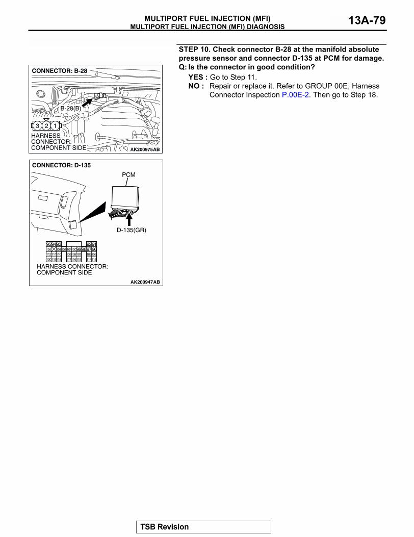
MULTIPORT FUEL INJECTION (MFI) DIAGNOSISMULTIPORT FUEL INJECTION (MFI) 13A-79
STEP 10. Check connector B-28 at the manifold absolute pressure sensor and connector D-135 at PCM for damage.Q: Is the connector in good condition?
YES : Go to Step 11.NO : Repair or replace it. Refer to GROUP 00E, Harness
Connector Inspection P.00E-2. Then go to Step 18.
AK200975
123
AB
HARNESS CONNECTOR: COMPONENT SIDE
CONNECTOR: B-28
B-28(B)
AK200947
919293949596979899100101102103104
105106107108109110111112
113114115116117118119120
CONNECTOR: D-135
HARNESS CONNECTOR: COMPONENT SIDE
AB
PCM
D-135(GR)
TSB Revision

MULTIPORT FUEL INJECTION (MFI) DIAGNOSISMULTIPORT FUEL INJECTION (MFI)13A-80
STEP 11. Check for short circuit to ground between manifold absolute pressure sensor connector B-28 (terminal No. 3) and PCM connector D-135 (terminal No. 97).Q: Is the harness wire in good condition?
YES : Replace the PCM. Then go to Step 18.NO : Repair it. Then go to Step 18.
AK200975
123
AB
HARNESS CONNECTOR: COMPONENT SIDE
CONNECTOR: B-28
B-28(B)
AK200947
919293949596979899100101102103104
105106107108109110111112
113114115116117118119120
CONNECTOR: D-135
HARNESS CONNECTOR: COMPONENT SIDE
AB
PCM
D-135(GR)
TSB Revision
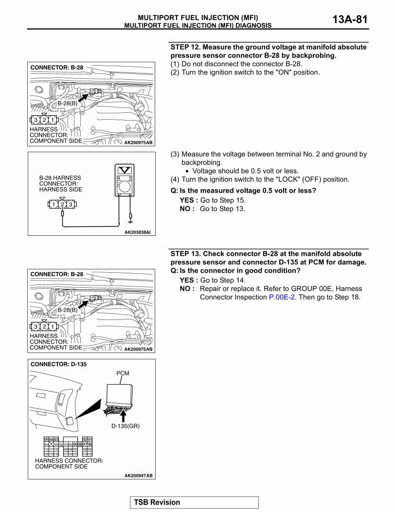
MULTIPORT FUEL INJECTION (MFI) DIAGNOSISMULTIPORT FUEL INJECTION (MFI) 13A-81
STEP 12. Measure the ground voltage at manifold absolute pressure sensor connector B-28 by backprobing.(1) Do not disconnect the connector B-28.(2) Turn the ignition switch to the "ON" position.
(3) Measure the voltage between terminal No. 2 and ground by backprobing.
• Voltage should be 0.5 volt or less.(4) Turn the ignition switch to the "LOCK" (OFF) position.Q: Is the measured voltage 0.5 volt or less?
YES : Go to Step 15.NO : Go to Step 13.
STEP 13. Check connector B-28 at the manifold absolute pressure sensor and connector D-135 at PCM for damage.Q: Is the connector in good condition?
YES : Go to Step 14.NO : Repair or replace it. Refer to GROUP 00E, Harness
Connector Inspection P.00E-2. Then go to Step 18.
AK200975
123
AB
HARNESS CONNECTOR: COMPONENT SIDE
CONNECTOR: B-28
B-28(B)
321
AK203038
B-28 HARNESS CONNECTOR: HARNESS SIDE
AI
AK200975
123
AB
HARNESS CONNECTOR: COMPONENT SIDE
CONNECTOR: B-28
B-28(B)
AK200947
919293949596979899100101102103104
105106107108109110111112
113114115116117118119120
CONNECTOR: D-135
HARNESS CONNECTOR: COMPONENT SIDE
AB
PCM
D-135(GR)
TSB Revision
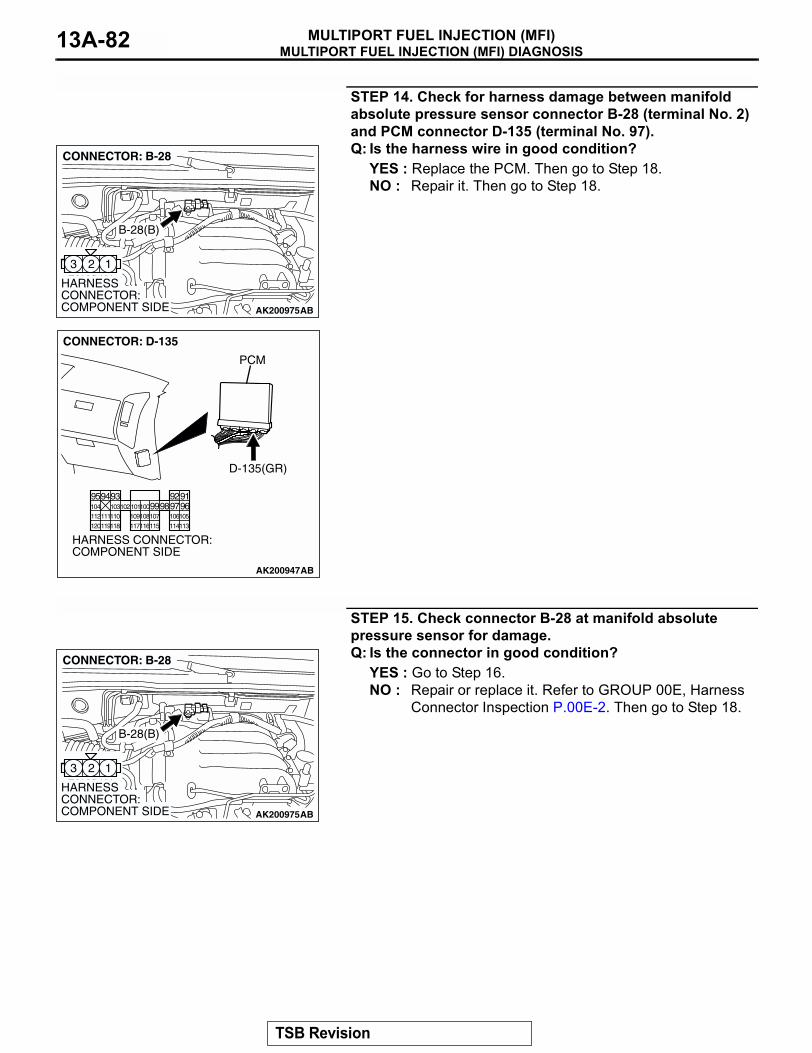
MULTIPORT FUEL INJECTION (MFI) DIAGNOSISMULTIPORT FUEL INJECTION (MFI)13A-82
STEP 14. Check for harness damage between manifold absolute pressure sensor connector B-28 (terminal No. 2) and PCM connector D-135 (terminal No. 97).Q: Is the harness wire in good condition?
YES : Replace the PCM. Then go to Step 18.NO : Repair it. Then go to Step 18.
STEP 15. Check connector B-28 at manifold absolute pressure sensor for damage.Q: Is the connector in good condition?
YES : Go to Step 16.NO : Repair or replace it. Refer to GROUP 00E, Harness
Connector Inspection P.00E-2. Then go to Step 18.
AK200975
123
AB
HARNESS CONNECTOR: COMPONENT SIDE
CONNECTOR: B-28
B-28(B)
AK200947
919293949596979899100101102103104
105106107108109110111112
113114115116117118119120
CONNECTOR: D-135
HARNESS CONNECTOR: COMPONENT SIDE
AB
PCM
D-135(GR)
AK200975
123
AB
HARNESS CONNECTOR: COMPONENT SIDE
CONNECTOR: B-28
B-28(B)
TSB Revision
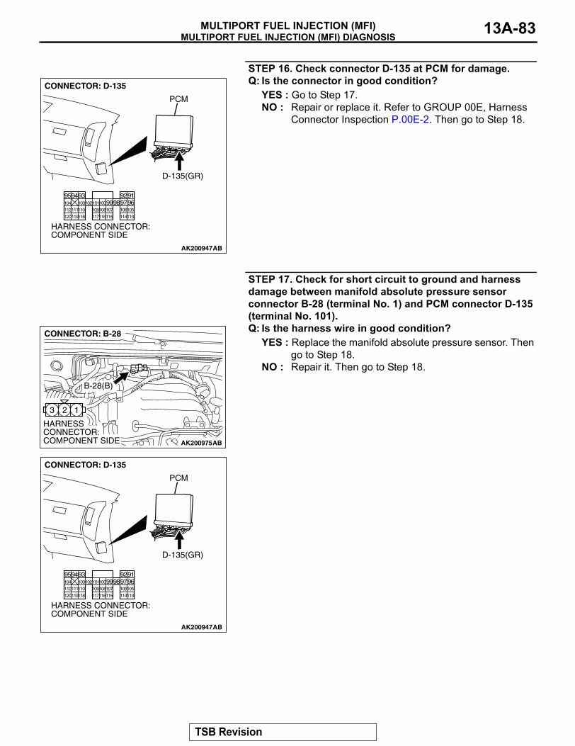
MULTIPORT FUEL INJECTION (MFI) DIAGNOSISMULTIPORT FUEL INJECTION (MFI) 13A-83
STEP 16. Check connector D-135 at PCM for damage.Q: Is the connector in good condition?
YES : Go to Step 17.NO : Repair or replace it. Refer to GROUP 00E, Harness
Connector Inspection P.00E-2. Then go to Step 18.
STEP 17. Check for short circuit to ground and harness damage between manifold absolute pressure sensor connector B-28 (terminal No. 1) and PCM connector D-135 (terminal No. 101).Q: Is the harness wire in good condition?
YES : Replace the manifold absolute pressure sensor. Then go to Step 18.
NO : Repair it. Then go to Step 18.
AK200947
919293949596979899100101102103104
105106107108109110111112
113114115116117118119120
CONNECTOR: D-135
HARNESS CONNECTOR: COMPONENT SIDE
AB
PCM
D-135(GR)
AK200975
123
AB
HARNESS CONNECTOR: COMPONENT SIDE
CONNECTOR: B-28
B-28(B)
AK200947
919293949596979899100101102103104
105106107108109110111112
113114115116117118119120
CONNECTOR: D-135
HARNESS CONNECTOR: COMPONENT SIDE
AB
PCM
D-135(GR)
TSB Revision

MULTIPORT FUEL INJECTION (MFI) DIAGNOSISMULTIPORT FUEL INJECTION (MFI)13A-84
STEP 18. Test the OBD-II drive cycle.(1) Carry out a test drive with the drive cycle pattern. Refer to
Diagnostic Function − OBD-II Drive Cycle − Procedure 6 − Other Monitor P.13A-4.
(2) Check the diagnostic trouble code (DTC).Q: Is DTC P0107 set?
YES : Retry the troubleshooting.NO : The inspection is complete.
DTC P0108: Manifold Absolute Pressure Circuit High Input
AK302421
GR
EE
N-Y
ELL
OW
BLU
E-Y
ELL
OW
BLA
CK
POWERTRAIN CONTROL MODULE (PCM)
5V
B-28(MU802723)
MANIFOLD ABSOLUTE PRESSURE SENSOR
3 1 2
Manifold Absolute Pressure Sensor Circuit
97 96101
1 2 3
9192 93949596979899100
105
113114 115116117 118119120
106 107108109 110111112
101102103 104
D-135(MU803805)
TSB Revision
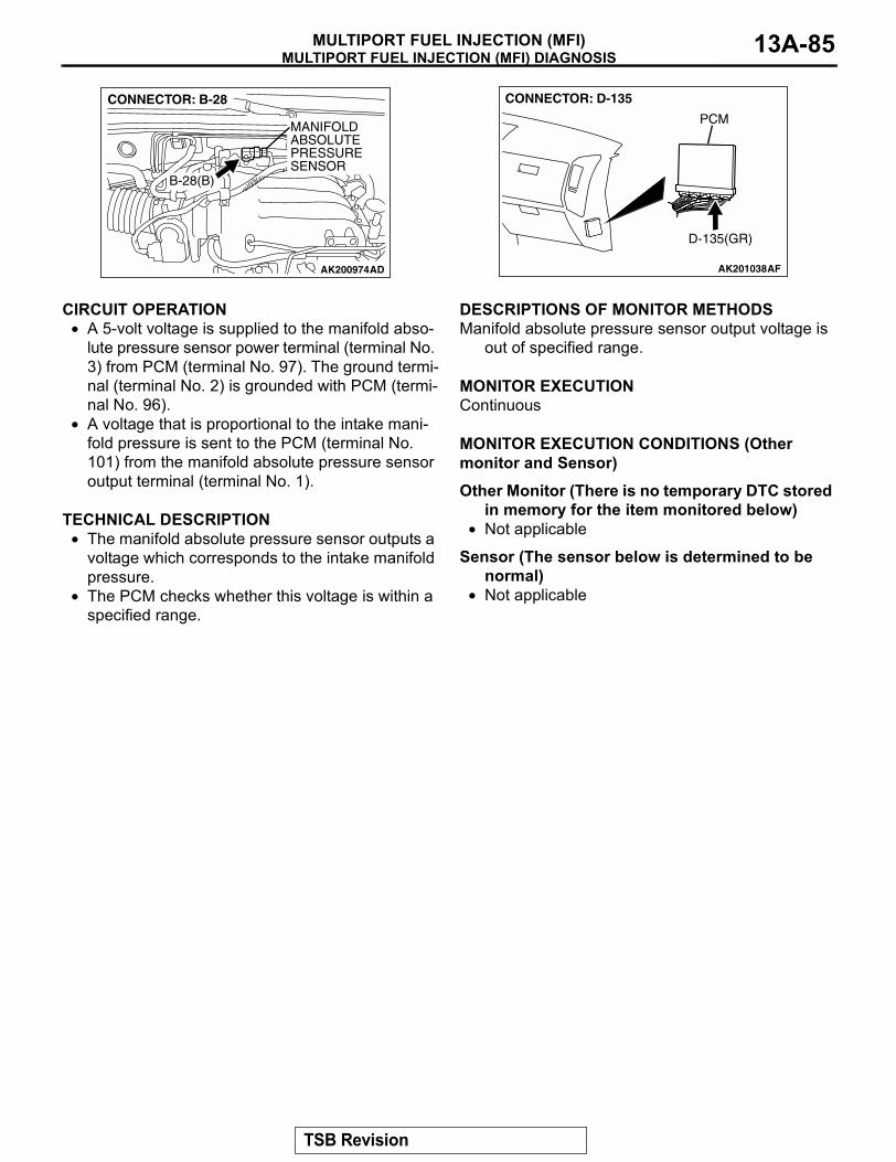
MULTIPORT FUEL INJECTION (MFI) DIAGNOSISMULTIPORT FUEL INJECTION (MFI) 13A-85
.
CIRCUIT OPERATION• A 5-volt voltage is supplied to the manifold abso-
lute pressure sensor power terminal (terminal No. 3) from PCM (terminal No. 97). The ground termi-nal (terminal No. 2) is grounded with PCM (termi-nal No. 96).
• A voltage that is proportional to the intake mani-fold pressure is sent to the PCM (terminal No. 101) from the manifold absolute pressure sensor output terminal (terminal No. 1).
.
TECHNICAL DESCRIPTION• The manifold absolute pressure sensor outputs a
voltage which corresponds to the intake manifold pressure.
• The PCM checks whether this voltage is within a specified range.
.
DESCRIPTIONS OF MONITOR METHODSManifold absolute pressure sensor output voltage is
out of specified range..
MONITOR EXECUTIONContinuous.
MONITOR EXECUTION CONDITIONS (Other monitor and Sensor)
Other Monitor (There is no temporary DTC stored in memory for the item monitored below)
• Not applicable
Sensor (The sensor below is determined to be normal)
• Not applicable.
AK200974
MANIFOLD ABSOLUTEPRESSURE SENSOR
AD
B-28(B)
CONNECTOR: B-28
AK201038AF
CONNECTOR: D-135
PCM
D-135(GR)
TSB Revision
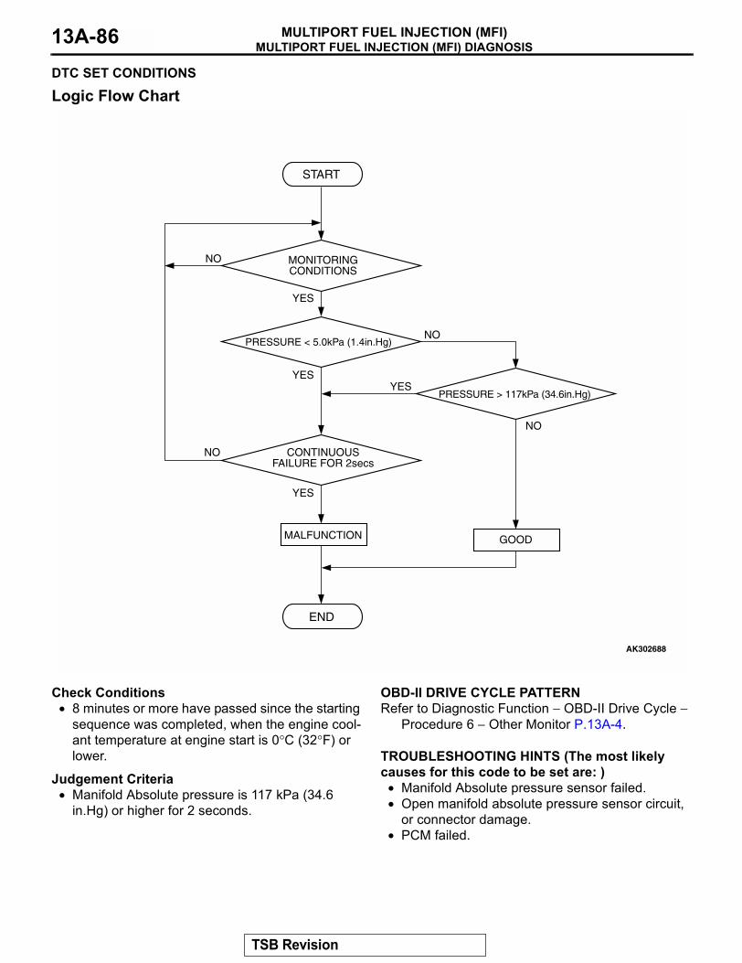
MULTIPORT FUEL INJECTION (MFI) DIAGNOSISMULTIPORT FUEL INJECTION (MFI)13A-86
DTC SET CONDITIONS
Logic Flow Chart
Check Conditions• 8 minutes or more have passed since the starting
sequence was completed, when the engine cool-ant temperature at engine start is 0°C (32°F) or lower.
Judgement Criteria• Manifold Absolute pressure is 117 kPa (34.6
in.Hg) or higher for 2 seconds..
OBD-II DRIVE CYCLE PATTERNRefer to Diagnostic Function − OBD-II Drive Cycle −
Procedure 6 − Other Monitor P.13A-4..
TROUBLESHOOTING HINTS (The most likely causes for this code to be set are: )
• Manifold Absolute pressure sensor failed.• Open manifold absolute pressure sensor circuit,
or connector damage.• PCM failed.
YES
YES
YES
YES
NO
NO
NO
NO
MONITORINGCONDITIONS
PRESSURE < 5.0kPa (1.4in.Hg)
PRESSURE > 117kPa (34.6in.Hg)
CONTINUOUSFAILURE FOR 2secs
MALFUNCTION
END
GOOD
START
AK302688
TSB Revision

MULTIPORT FUEL INJECTION (MFI) DIAGNOSISMULTIPORT FUEL INJECTION (MFI) 13A-87
DIAGNOSISRequired Special Tools:
• MB991958: Scan Tool (MUT-III Sub Assembly)• MB991824: V.C.I.• MB991827: USB Cable• MB991911: Main Harness B
STEP 1. Using scan tool MB991958, check data list item 95: Manifold Absolute Pressure Sensor.
CAUTIONTo prevent damage to scan tool MB991958, always turn the ignition switch to the "LOCK" (OFF) position before con-necting or disconnecting scan tool MB991958.(1) Connect scan tool MB991958 to the data link connector.(2) Turn the ignition switch to the "ON" position.(3) Set scan tool MB991958 to the data reading mode for item
95, Manifold Absolute Pressure Sensor.• When altitude is 0 m (0 foot), 101 kPa (29.8 in.Hg).• When altitude is 600 m (1,969 feet), 95 kPa (28.1 in.Hg).• When altitude is 1,200 m (3,937 feet), 88 kPa (26.0
in.Hg).• When altitude is 1,800 m (5,906 feet), 81 kPa (23.9
in.Hg).(4) Start the engine.
• When the engine is idling, 16 − 36 kPa (4.7 − 10.6 in.Hg).
• When the engine is suddenly revved, manifold absolute pressure increases.
(5) Turn the ignition switch to the "LOCK" (OFF) position.Q: Is the sensor operating properly?
YES : It can be assumed that this malfunction is intermittent. Refer to GROUP 00, How to Use Troubleshooting/Inspection Service Points P.00-6.
NO : Go to Step 2.
AK302970AB
MB991911
MB991824
MB991827
TSB Revision

MULTIPORT FUEL INJECTION (MFI) DIAGNOSISMULTIPORT FUEL INJECTION (MFI)13A-88
STEP 2. Measure the sensor output voltage at manifold absolute pressure sensor connector B-28 by backprobing.(1) Do not disconnect the connector B-28.(2) Turn the ignition switch to the "ON" position.
(3) Measure the voltage between terminal No. 1 and ground by backprobing.
• When altitude is 0 m (0 foot), voltage should be 3.7 and 4.3 volts.
• When altitude is 600 m (1,969 feet), voltage should be 3.4 and 4.0 volts.
• When altitude is 1,200 m (3,937 feet), voltage should be 3.2 and 3.8 volts.
• When altitude is 1,800 m (5,906 feet), voltage should be 2.9 and 3.5 volts.
(4) Turn the ignition switch to the "LOCK" (OFF) position.Q: Is the voltage normal?
YES : Go to Step 3.NO : Go to Step 5.
AK200975
123
AB
HARNESS CONNECTOR: COMPONENT SIDE
CONNECTOR: B-28
B-28(B)
321
AK203034
B-28 HARNESS CONNECTOR: HARNESS SIDE
AI
TSB Revision

MULTIPORT FUEL INJECTION (MFI) DIAGNOSISMULTIPORT FUEL INJECTION (MFI) 13A-89
STEP 3. Check connector B-28 at the manifold absolute pressure sensor and connector D-135 at PCM for damage.Q: Is the connector in good condition?
YES : Go to Step 4.NO : Repair or replace it. Refer to GROUP 00E, Harness
Connector Inspection P.00E-2. Then go to Step 12.
AK200975
123
AB
HARNESS CONNECTOR: COMPONENT SIDE
CONNECTOR: B-28
B-28(B)
AK200947
919293949596979899100101102103104
105106107108109110111112
113114115116117118119120
CONNECTOR: D-135
HARNESS CONNECTOR: COMPONENT SIDE
AB
PCM
D-135(GR)
TSB Revision
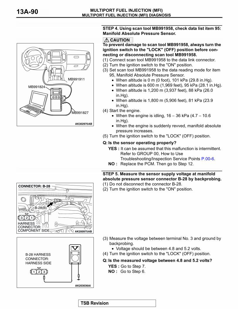
MULTIPORT FUEL INJECTION (MFI) DIAGNOSISMULTIPORT FUEL INJECTION (MFI)13A-90
STEP 4. Using scan tool MB991958, check data list item 95: Manifold Absolute Pressure Sensor.
CAUTIONTo prevent damage to scan tool MB991958, always turn the ignition switch to the "LOCK" (OFF) position before con-necting or disconnecting scan tool MB991958.(1) Connect scan tool MB991958 to the data link connector.(2) Turn the ignition switch to the "ON" position.(3) Set scan tool MB991958 to the data reading mode for item
95, Manifold Absolute Pressure Sensor.• When altitude is 0 m (0 foot), 101 kPa (29.8 in.Hg).• When altitude is 600 m (1,969 feet), 95 kPa (28.1 in.Hg).• When altitude is 1,200 m (3,937 feet), 88 kPa (26.0
in.Hg).• When altitude is 1,800 m (5,906 feet), 81 kPa (23.9
in.Hg).(4) Start the engine.
• When the engine is idling, 16 − 36 kPa (4.7 − 10.6 in.Hg).
• When the engine is suddenly revved, manifold absolute pressure increases.
(5) Turn the ignition switch to the "LOCK" (OFF) position.Q: Is the sensor operating properly?
YES : It can be assumed that this malfunction is intermittent. Refer to GROUP 00, How to Use Troubleshooting/Inspection Service Points P.00-6.
NO : Replace the PCM. Then go to Step 12.
STEP 5. Measure the sensor supply voltage at manifold absolute pressure sensor connector B-28 by backprobing.(1) Do not disconnect the connector B-28.(2) Turn the ignition switch to the "ON" position.
(3) Measure the voltage between terminal No. 3 and ground by backprobing.
• Voltage should be between 4.8 and 5.2 volts.(4) Turn the ignition switch to the "LOCK" (OFF) position.Q: Is the measured voltage between 4.8 and 5.2 volts?
YES : Go to Step 7.NO : Go to Step 6.
AK302970AB
MB991911
MB991824
MB991827
AK200975
123
AB
HARNESS CONNECTOR: COMPONENT SIDE
CONNECTOR: B-28
B-28(B)
321
AK203036
B-28 HARNESSCONNECTOR:HARNESS SIDE
AI
TSB Revision
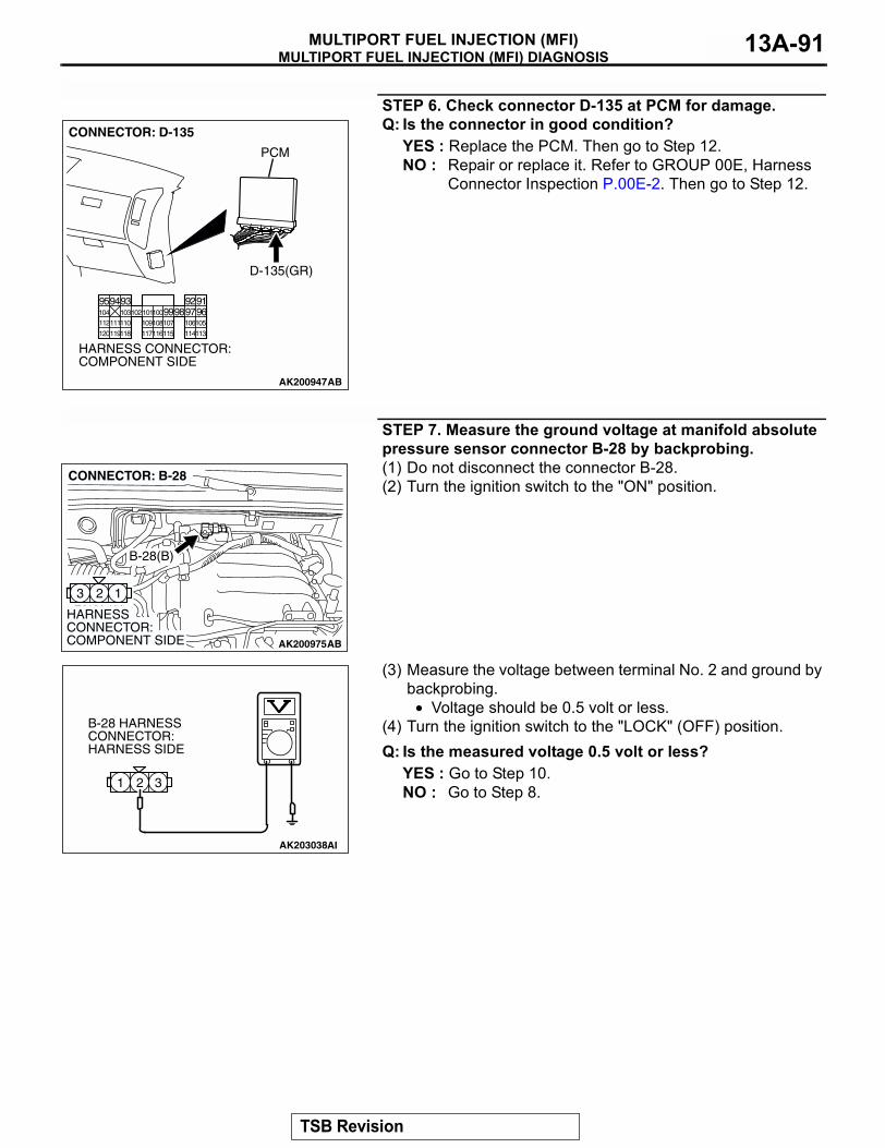
MULTIPORT FUEL INJECTION (MFI) DIAGNOSISMULTIPORT FUEL INJECTION (MFI) 13A-91
STEP 6. Check connector D-135 at PCM for damage.Q: Is the connector in good condition?
YES : Replace the PCM. Then go to Step 12.NO : Repair or replace it. Refer to GROUP 00E, Harness
Connector Inspection P.00E-2. Then go to Step 12.
STEP 7. Measure the ground voltage at manifold absolute pressure sensor connector B-28 by backprobing.(1) Do not disconnect the connector B-28.(2) Turn the ignition switch to the "ON" position.
(3) Measure the voltage between terminal No. 2 and ground by backprobing.
• Voltage should be 0.5 volt or less.(4) Turn the ignition switch to the "LOCK" (OFF) position.Q: Is the measured voltage 0.5 volt or less?
YES : Go to Step 10.NO : Go to Step 8.
AK200947
919293949596979899100101102103104
105106107108109110111112
113114115116117118119120
CONNECTOR: D-135
HARNESS CONNECTOR: COMPONENT SIDE
AB
PCM
D-135(GR)
AK200975
123
AB
HARNESS CONNECTOR: COMPONENT SIDE
CONNECTOR: B-28
B-28(B)
321
AK203038
B-28 HARNESS CONNECTOR: HARNESS SIDE
AI
TSB Revision

MULTIPORT FUEL INJECTION (MFI) DIAGNOSISMULTIPORT FUEL INJECTION (MFI)13A-92
STEP 8. Check connector B-28 at the manifold absolute pressure sensor and connector D-135 at PCM for damage.Q: Is the connector in good condition?
YES : Go to Step 9.NO : Repair or replace it. Refer to GROUP 00E, Harness
Connector Inspection P.00E-2. Then go to Step 12.
AK200975
123
AB
HARNESS CONNECTOR: COMPONENT SIDE
CONNECTOR: B-28
B-28(B)
AK200947
919293949596979899100101102103104
105106107108109110111112
113114115116117118119120
CONNECTOR: D-135
HARNESS CONNECTOR: COMPONENT SIDE
AB
PCM
D-135(GR)
TSB Revision
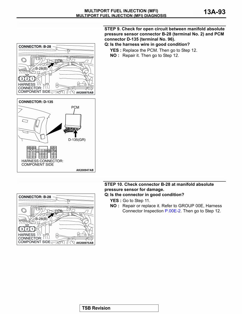
MULTIPORT FUEL INJECTION (MFI) DIAGNOSISMULTIPORT FUEL INJECTION (MFI) 13A-93
STEP 9. Check for open circuit between manifold absolute pressure sensor connector B-28 (terminal No. 2) and PCM connector D-135 (terminal No. 96).Q: Is the harness wire in good condition?
YES : Replace the PCM. Then go to Step 12.NO : Repair it. Then go to Step 12.
STEP 10. Check connector B-28 at manifold absolute pressure sensor for damage.Q: Is the connector in good condition?
YES : Go to Step 11.NO : Repair or replace it. Refer to GROUP 00E, Harness
Connector Inspection P.00E-2. Then go to Step 12.
AK200975
123
AB
HARNESS CONNECTOR: COMPONENT SIDE
CONNECTOR: B-28
B-28(B)
AK200947
919293949596979899100101102103104
105106107108109110111112
113114115116117118119120
CONNECTOR: D-135
HARNESS CONNECTOR: COMPONENT SIDE
AB
PCM
D-135(GR)
AK200975
123
AB
HARNESS CONNECTOR: COMPONENT SIDE
CONNECTOR: B-28
B-28(B)
TSB Revision
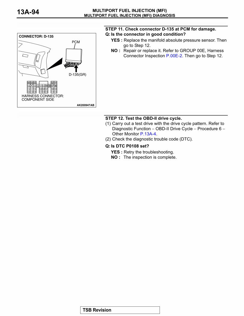
MULTIPORT FUEL INJECTION (MFI) DIAGNOSISMULTIPORT FUEL INJECTION (MFI)13A-94
STEP 11. Check connector D-135 at PCM for damage.Q: Is the connector in good condition?
YES : Replace the manifold absolute pressure sensor. Then go to Step 12.
NO : Repair or replace it. Refer to GROUP 00E, Harness Connector Inspection P.00E-2. Then go to Step 12.
STEP 12. Test the OBD-II drive cycle.(1) Carry out a test drive with the drive cycle pattern. Refer to
Diagnostic Function − OBD-II Drive Cycle − Procedure 6 − Other Monitor P.13A-4.
(2) Check the diagnostic trouble code (DTC).Q: Is DTC P0108 set?
YES : Retry the troubleshooting.NO : The inspection is complete.
AK200947
919293949596979899100101102103104
105106107108109110111112
113114115116117118119120
CONNECTOR: D-135
HARNESS CONNECTOR: COMPONENT SIDE
AB
PCM
D-135(GR)
TSB Revision
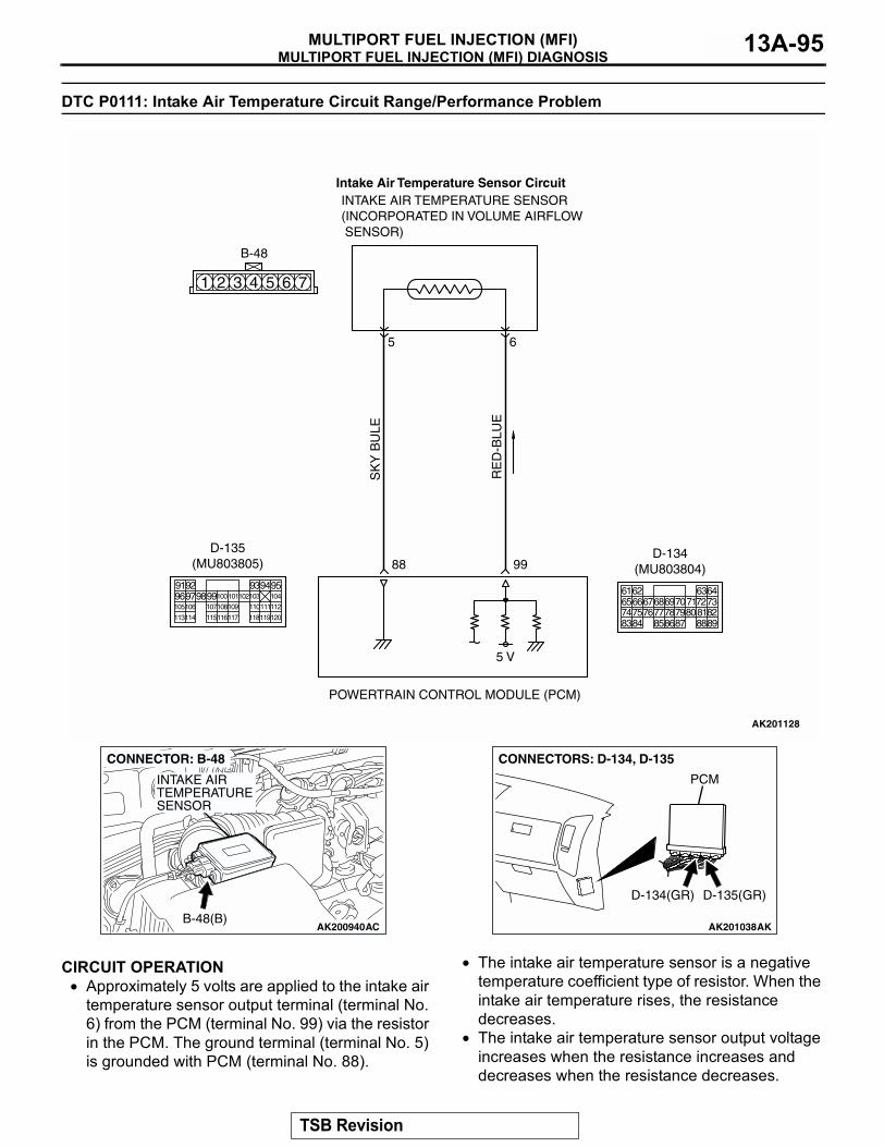
MULTIPORT FUEL INJECTION (MFI) DIAGNOSISMULTIPORT FUEL INJECTION (MFI) 13A-95
DTC P0111: Intake Air Temperature Circuit Range/Performance Problem
.
CIRCUIT OPERATION• Approximately 5 volts are applied to the intake air
temperature sensor output terminal (terminal No. 6) from the PCM (terminal No. 99) via the resistor in the PCM. The ground terminal (terminal No. 5) is grounded with PCM (terminal No. 88).
• The intake air temperature sensor is a negative temperature coefficient type of resistor. When the intake air temperature rises, the resistance decreases.
• The intake air temperature sensor output voltage increases when the resistance increases and decreases when the resistance decreases.
.
SK
Y B
ULE
AK201128
RE
D-B
LUE
INTAKE AIR TEMPERATURE SENSOR(INCORPORATED IN VOLUME AIRFLOW SENSOR)
POWERTRAIN CONTROL MODULE (PCM)
5 V
99
5
88
6
1 2 3 4 5 6 7
B-48
Intake Air Temperature Sensor Circuit
9192 93949596979899100
105
113114 115116117 118119120
106 107108109 110111112
101102103 104
D-135(MU803805)
616566676869707172737475767778798081828384 858687 8889
62 6364
D-134(MU803804)
AK200940AC
CONNECTOR: B-48
INTAKE AIRTEMPERATURESENSOR
B-48(B)AK201038AK
CONNECTORS: D-134, D-135
PCM
D-134(GR) D-135(GR)
TSB Revision
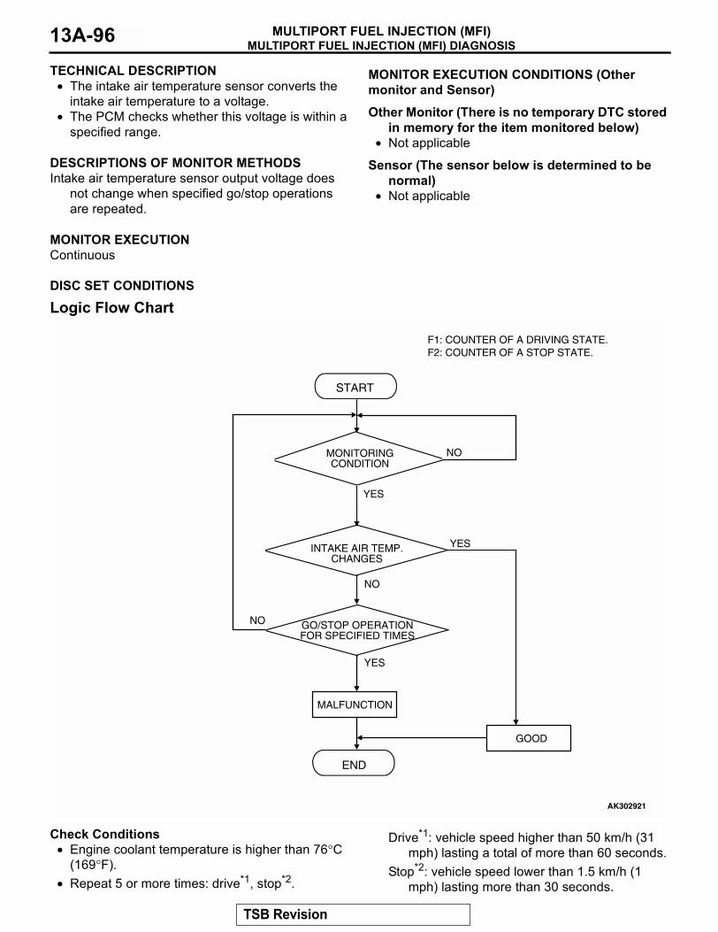
MULTIPORT FUEL INJECTION (MFI) DIAGNOSISMULTIPORT FUEL INJECTION (MFI)13A-96
TECHNICAL DESCRIPTION• The intake air temperature sensor converts the
intake air temperature to a voltage.• The PCM checks whether this voltage is within a
specified range..
DESCRIPTIONS OF MONITOR METHODSIntake air temperature sensor output voltage does
not change when specified go/stop operations are repeated.
.
MONITOR EXECUTIONContinuous
.
MONITOR EXECUTION CONDITIONS (Other monitor and Sensor)
Other Monitor (There is no temporary DTC stored in memory for the item monitored below)
• Not applicable
Sensor (The sensor below is determined to be normal)
• Not applicable.
DISC SET CONDITIONS
Logic Flow Chart
Check Conditions• Engine coolant temperature is higher than 76°C
(169°F).• Repeat 5 or more times: drive*1, stop*2.
Drive*1: vehicle speed higher than 50 km/h (31 mph) lasting a total of more than 60 seconds.
Stop*2: vehicle speed lower than 1.5 km/h (1 mph) lasting more than 30 seconds.
END
YES
NO
NO
NO
START
MONITORINGCONDITION
YES
MALFUNCTION
GOOD
F1: COUNTER OF A DRIVING STATE.F2: COUNTER OF A STOP STATE.
INTAKE AIR TEMP.CHANGES
GO/STOP OPERATIONFOR SPECIFIED TIMES
YES
AK302921
TSB Revision
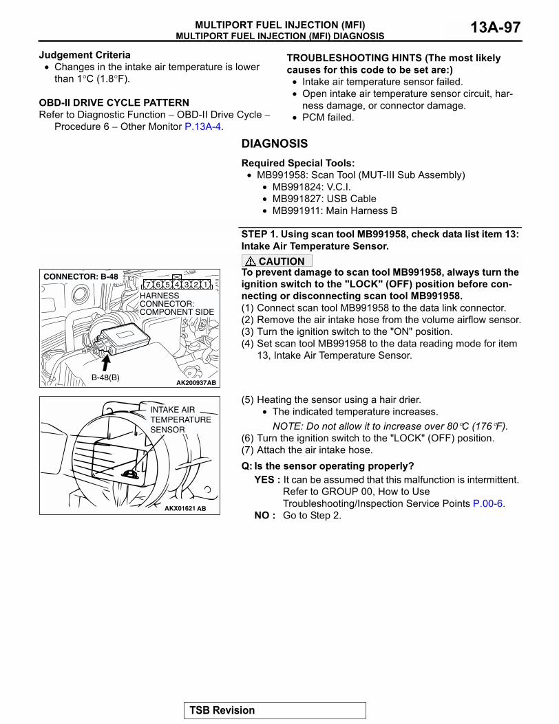
MULTIPORT FUEL INJECTION (MFI) DIAGNOSISMULTIPORT FUEL INJECTION (MFI) 13A-97
Judgement Criteria• Changes in the intake air temperature is lower
than 1°C (1.8°F)..
OBD-II DRIVE CYCLE PATTERNRefer to Diagnostic Function − OBD-II Drive Cycle −
Procedure 6 − Other Monitor P.13A-4.
.
TROUBLESHOOTING HINTS (The most likely causes for this code to be set are:)
• Intake air temperature sensor failed.• Open intake air temperature sensor circuit, har-
ness damage, or connector damage.• PCM failed.
DIAGNOSISRequired Special Tools:
• MB991958: Scan Tool (MUT-III Sub Assembly)• MB991824: V.C.I.• MB991827: USB Cable• MB991911: Main Harness B
STEP 1. Using scan tool MB991958, check data list item 13: Intake Air Temperature Sensor.
CAUTIONTo prevent damage to scan tool MB991958, always turn the ignition switch to the "LOCK" (OFF) position before con-necting or disconnecting scan tool MB991958.(1) Connect scan tool MB991958 to the data link connector.(2) Remove the air intake hose from the volume airflow sensor.(3) Turn the ignition switch to the "ON" position.(4) Set scan tool MB991958 to the data reading mode for item
13, Intake Air Temperature Sensor.
(5) Heating the sensor using a hair drier.• The indicated temperature increases.
NOTE: Do not allow it to increase over 80°C (176°F).(6) Turn the ignition switch to the "LOCK" (OFF) position.(7) Attach the air intake hose.Q: Is the sensor operating properly?
YES : It can be assumed that this malfunction is intermittent. Refer to GROUP 00, How to Use Troubleshooting/Inspection Service Points P.00-6.
NO : Go to Step 2.
AK200937
345 1267
AB
HARNESS CONNECTOR: COMPONENT SIDE
CONNECTOR: B-48
B-48(B)
AKX01621 AB
INTAKE AIRTEMPERATURESENSOR
TSB Revision
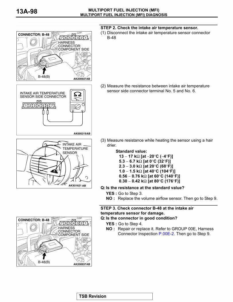
MULTIPORT FUEL INJECTION (MFI) DIAGNOSISMULTIPORT FUEL INJECTION (MFI)13A-98
STEP 2. Check the intake air temperature sensor.(1) Disconnect the intake air temperature sensor connector
B-48
(2) Measure the resistance between intake air temperature sensor side connector terminal No. 5 and No. 6.
(3) Measure resistance while heating the sensor using a hair drier.
Standard value:13 − 17 kΩ [at −20°C (−4°F)]5.3 − 6.7 kΩ [at 0°C (32°F)]2.3 − 3.0 kΩ [at 20°C (68°F)]1.0 − 1.5 kΩ [at 40°C (104°F)]0.56 − 0.76 kΩ [at 60°C (140°F)]0.30 − 0.42 kΩ [at 80°C (176°F)]
Q: Is the resistance at the standard value?YES : Go to Step 3.NO : Replace the volume airflow sensor. Then go to Step 9.
STEP 3. Check connector B-48 at the intake air temperature sensor for damage.Q: Is the connector in good condition?
YES : Go to Step 4.NO : Repair or replace it. Refer to GROUP 00E, Harness
Connector Inspection P.00E-2. Then go to Step 9.
AK200937
345 1267
AB
HARNESS CONNECTOR: COMPONENT SIDE
CONNECTOR: B-48
B-48(B)
AK000319AB
1 2 3 4 5 6 7
INTAKE AIR TEMPERATURESENSOR SIDE CONNECTOR
AKX01621 AB
INTAKE AIRTEMPERATURESENSOR
AK200937
345 1267
AB
HARNESS CONNECTOR: COMPONENT SIDE
CONNECTOR: B-48
B-48(B)
TSB Revision
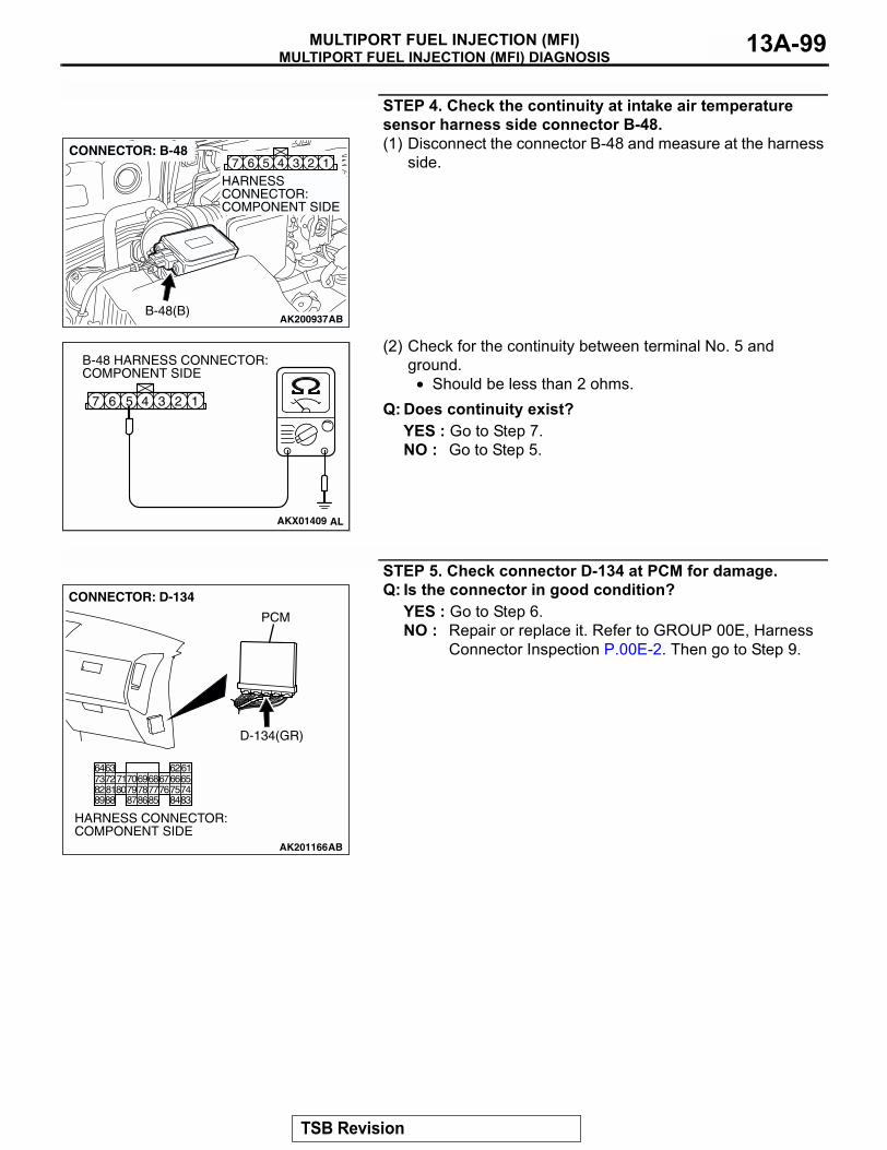
MULTIPORT FUEL INJECTION (MFI) DIAGNOSISMULTIPORT FUEL INJECTION (MFI) 13A-99
STEP 4. Check the continuity at intake air temperature sensor harness side connector B-48.(1) Disconnect the connector B-48 and measure at the harness
side.
(2) Check for the continuity between terminal No. 5 and ground.
• Should be less than 2 ohms.Q: Does continuity exist?
YES : Go to Step 7.NO : Go to Step 5.
STEP 5. Check connector D-134 at PCM for damage.Q: Is the connector in good condition?
YES : Go to Step 6.NO : Repair or replace it. Refer to GROUP 00E, Harness
Connector Inspection P.00E-2. Then go to Step 9.
AK200937
345 1267
AB
HARNESS CONNECTOR: COMPONENT SIDE
CONNECTOR: B-48
B-48(B)
AKX01409
1234567
B-48 HARNESS CONNECTOR: COMPONENT SIDE
AL
AK201166
6162636465666768697071
76777879858687
807273
7475818283848889
CONNECTOR: D-134
AB
PCM
D-134(GR)
HARNESS CONNECTOR: COMPONENT SIDE
TSB Revision
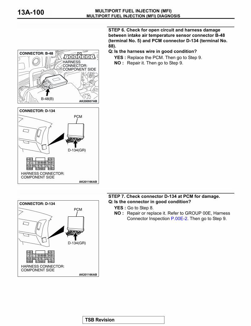
MULTIPORT FUEL INJECTION (MFI) DIAGNOSISMULTIPORT FUEL INJECTION (MFI)13A-100
STEP 6. Check for open circuit and harness damage between intake air temperature sensor connector B-48 (terminal No. 5) and PCM connector D-134 (terminal No. 88).Q: Is the harness wire in good condition?
YES : Replace the PCM. Then go to Step 9.NO : Repair it. Then go to Step 9.
STEP 7. Check connector D-134 at PCM for damage.Q: Is the connector in good condition?
YES : Go to Step 8.NO : Repair or replace it. Refer to GROUP 00E, Harness
Connector Inspection P.00E-2. Then go to Step 9.
AK200937
345 1267
AB
HARNESS CONNECTOR: COMPONENT SIDE
CONNECTOR: B-48
B-48(B)
AK201166
6162636465666768697071
76777879858687
807273
7475818283848889
CONNECTOR: D-134
AB
PCM
D-134(GR)
HARNESS CONNECTOR: COMPONENT SIDE
AK201166
6162636465666768697071
76777879858687
807273
7475818283848889
CONNECTOR: D-134
AB
PCM
D-134(GR)
HARNESS CONNECTOR: COMPONENT SIDE
TSB Revision
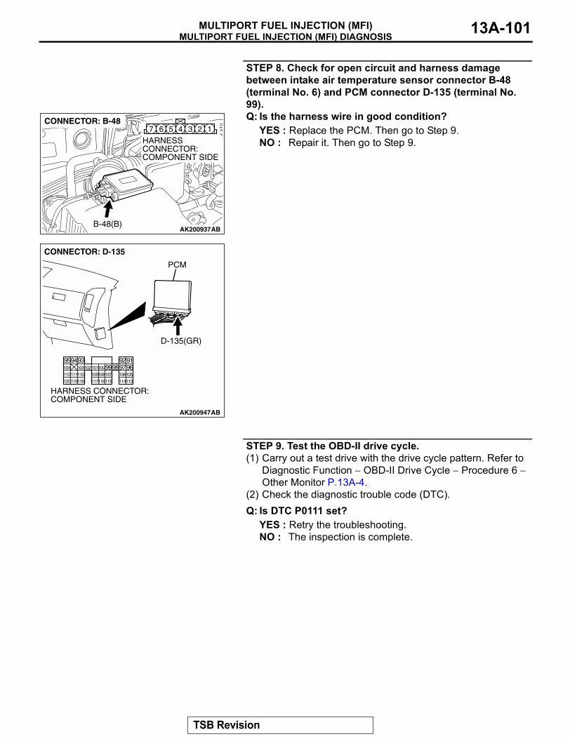
MULTIPORT FUEL INJECTION (MFI) DIAGNOSISMULTIPORT FUEL INJECTION (MFI) 13A-101
STEP 8. Check for open circuit and harness damage between intake air temperature sensor connector B-48 (terminal No. 6) and PCM connector D-135 (terminal No. 99).Q: Is the harness wire in good condition?
YES : Replace the PCM. Then go to Step 9.NO : Repair it. Then go to Step 9.
STEP 9. Test the OBD-II drive cycle.(1) Carry out a test drive with the drive cycle pattern. Refer to
Diagnostic Function − OBD-II Drive Cycle − Procedure 6 − Other Monitor P.13A-4.
(2) Check the diagnostic trouble code (DTC).Q: Is DTC P0111 set?
YES : Retry the troubleshooting.NO : The inspection is complete.
AK200937
345 1267
AB
HARNESS CONNECTOR: COMPONENT SIDE
CONNECTOR: B-48
B-48(B)
AK200947
919293949596979899100101102103104
105106107108109110111112
113114115116117118119120
CONNECTOR: D-135
HARNESS CONNECTOR: COMPONENT SIDE
AB
PCM
D-135(GR)
TSB Revision
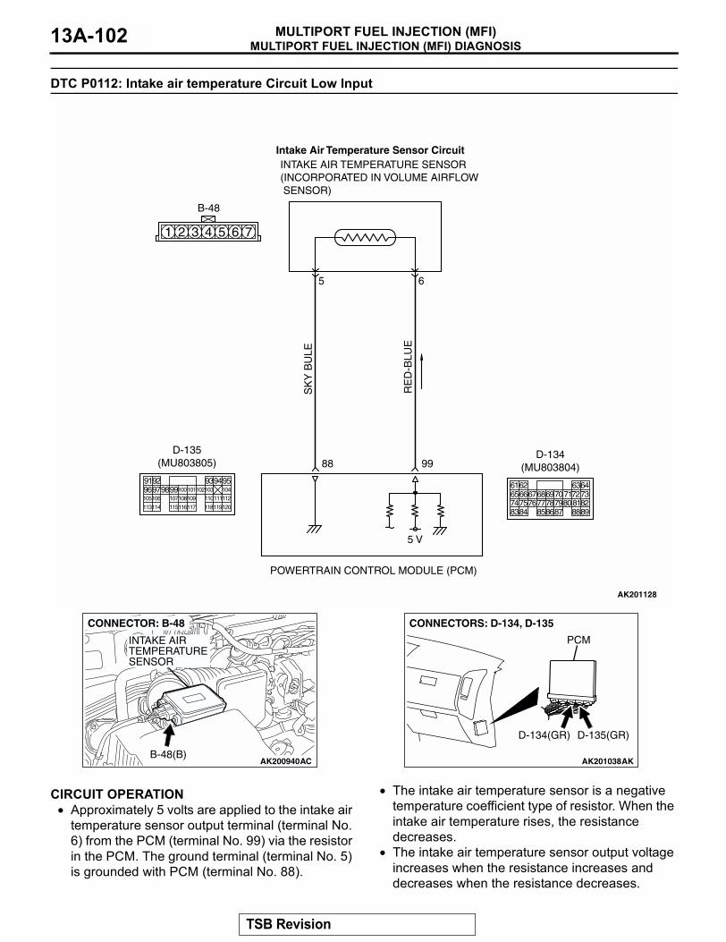
MULTIPORT FUEL INJECTION (MFI) DIAGNOSISMULTIPORT FUEL INJECTION (MFI)13A-102
DTC P0112: Intake air temperature Circuit Low Input
.
CIRCUIT OPERATION• Approximately 5 volts are applied to the intake air
temperature sensor output terminal (terminal No. 6) from the PCM (terminal No. 99) via the resistor in the PCM. The ground terminal (terminal No. 5) is grounded with PCM (terminal No. 88).
• The intake air temperature sensor is a negative temperature coefficient type of resistor. When the intake air temperature rises, the resistance decreases.
• The intake air temperature sensor output voltage increases when the resistance increases and decreases when the resistance decreases.
.
SK
Y B
ULE
AK201128
RE
D-B
LUE
INTAKE AIR TEMPERATURE SENSOR(INCORPORATED IN VOLUME AIRFLOW SENSOR)
POWERTRAIN CONTROL MODULE (PCM)
5 V
99
5
88
6
1 2 3 4 5 6 7
B-48
Intake Air Temperature Sensor Circuit
9192 93949596979899100
105
113114 115116117 118119120
106 107108109 110111112
101102103 104
D-135(MU803805)
616566676869707172737475767778798081828384 858687 8889
62 6364
D-134(MU803804)
AK200940AC
CONNECTOR: B-48
INTAKE AIRTEMPERATURESENSOR
B-48(B)AK201038AK
CONNECTORS: D-134, D-135
PCM
D-134(GR) D-135(GR)
TSB Revision
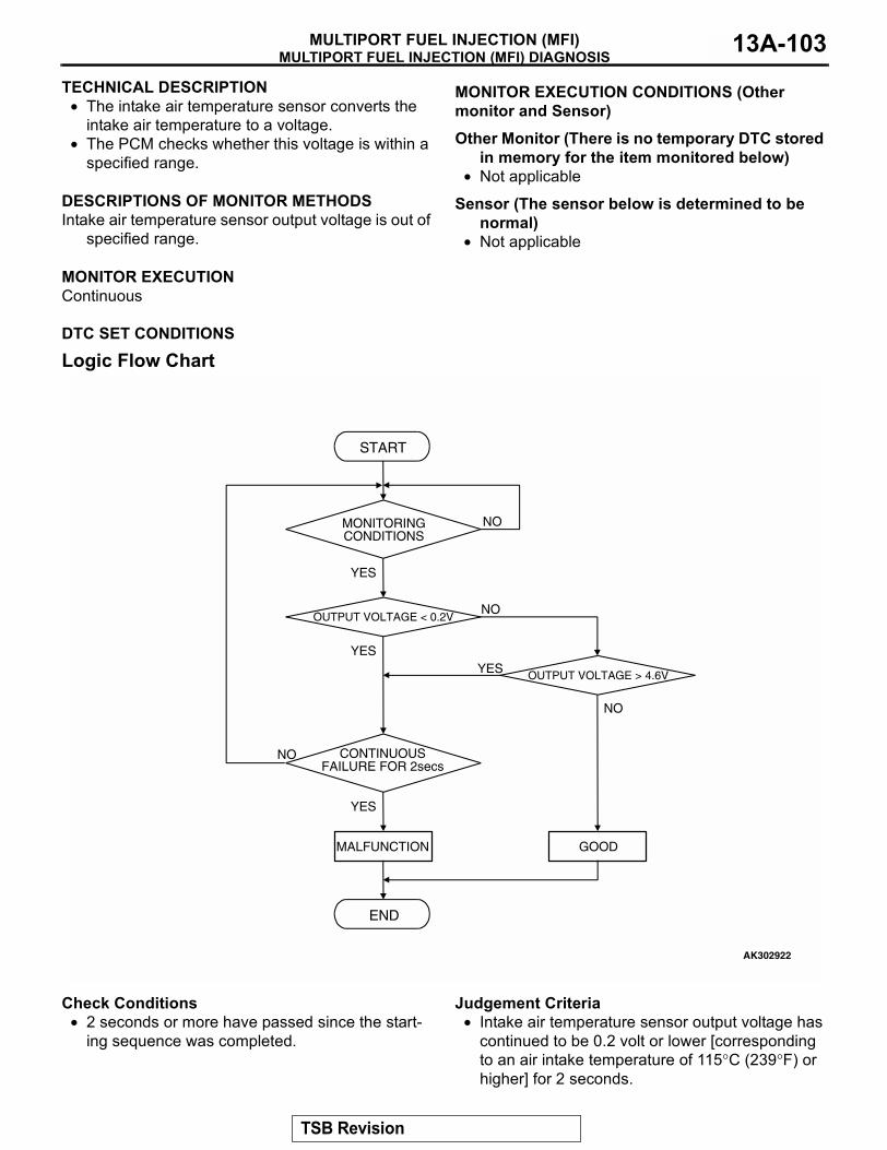
MULTIPORT FUEL INJECTION (MFI) DIAGNOSISMULTIPORT FUEL INJECTION (MFI) 13A-103
TECHNICAL DESCRIPTION• The intake air temperature sensor converts the
intake air temperature to a voltage.• The PCM checks whether this voltage is within a
specified range..
DESCRIPTIONS OF MONITOR METHODSIntake air temperature sensor output voltage is out of
specified range..
MONITOR EXECUTIONContinuous
.
MONITOR EXECUTION CONDITIONS (Other monitor and Sensor)
Other Monitor (There is no temporary DTC stored in memory for the item monitored below)
• Not applicable
Sensor (The sensor below is determined to be normal)
• Not applicable.
DTC SET CONDITIONS
Logic Flow Chart
Check Conditions• 2 seconds or more have passed since the start-
ing sequence was completed.
Judgement Criteria• Intake air temperature sensor output voltage has
continued to be 0.2 volt or lower [corresponding to an air intake temperature of 115°C (239°F) or higher] for 2 seconds.
.
START
OUTPUT VOLTAGE < 0.2V
END
NO
NO
NO
YESYES
YES
MALFUNCTION GOOD
CONTINUOUSFAILURE FOR 2secs
OUTPUT VOLTAGE > 4.6V
MONITORINGCONDITIONS
NO
YES
AK302922
TSB Revision
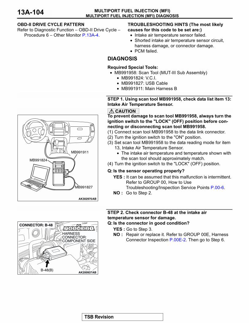
MULTIPORT FUEL INJECTION (MFI) DIAGNOSISMULTIPORT FUEL INJECTION (MFI)13A-104
OBD-II DRIVE CYCLE PATTERNRefer to Diagnostic Function − OBD-II Drive Cycle −
Procedure 6 − Other Monitor P.13A-4..
TROUBLESHOOTING HINTS (The most likely causes for this code to be set are:)
• Intake air temperature sensor failed.• Shorted intake air temperature sensor circuit,
harness damage, or connector damage.• PCM failed.
DIAGNOSISRequired Special Tools:
• MB991958: Scan Tool (MUT-III Sub Assembly)• MB991824: V.C.I.• MB991827: USB Cable• MB991911: Main Harness B
STEP 1. Using scan tool MB991958, check data list item 13: Intake Air Temperature Sensor.
CAUTIONTo prevent damage to scan tool MB991958, always turn the ignition switch to the "LOCK" (OFF) position before con-necting or disconnecting scan tool MB991958.(1) Connect scan tool MB991958 to the data link connector.(2) Turn the ignition switch to the "ON" position.(3) Set scan tool MB991958 to the data reading mode for item
13, Intake Air Temperature Sensor.• The intake air temperature and temperature shown with
the scan tool should approximately match.(4) Turn the ignition switch to the "LOCK" (OFF) position.Q: Is the sensor operating properly?
YES : It can be assumed that this malfunction is intermittent. Refer to GROUP 00, How to Use Troubleshooting/Inspection Service Points P.00-6.
NO : Go to Step 2.
STEP 2. Check connector B-48 at the intake air temperature sensor for damage.Q: Is the connector in good condition?
YES : Go to Step 3.NO : Repair or replace it. Refer to GROUP 00E, Harness
Connector Inspection P.00E-2. Then go to Step 6.
AK302970AB
MB991911
MB991824
MB991827
AK200937
345 1267
AB
HARNESS CONNECTOR: COMPONENT SIDE
CONNECTOR: B-48
B-48(B)
TSB Revision
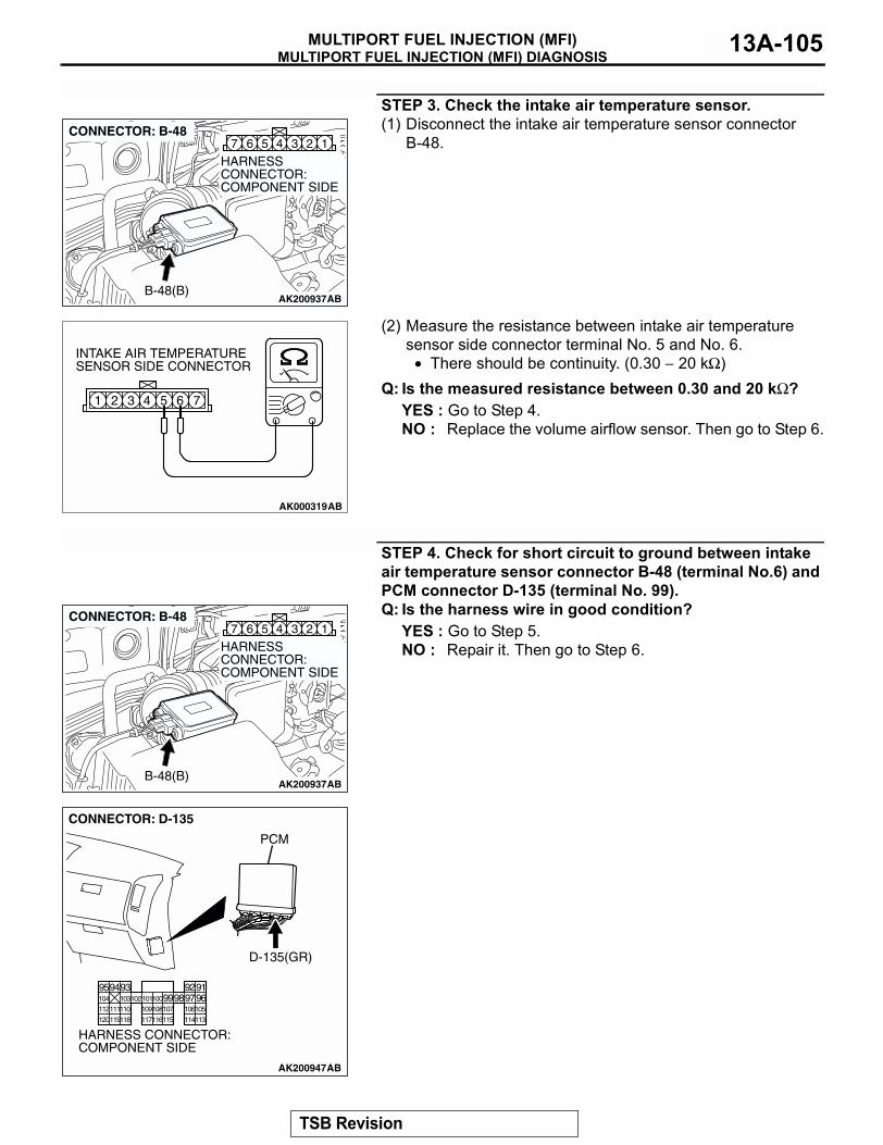
MULTIPORT FUEL INJECTION (MFI) DIAGNOSISMULTIPORT FUEL INJECTION (MFI) 13A-105
STEP 3. Check the intake air temperature sensor.(1) Disconnect the intake air temperature sensor connector
B-48.
(2) Measure the resistance between intake air temperature sensor side connector terminal No. 5 and No. 6.
• There should be continuity. (0.30 − 20 kΩ)Q: Is the measured resistance between 0.30 and 20 kΩ?
YES : Go to Step 4.NO : Replace the volume airflow sensor. Then go to Step 6.
STEP 4. Check for short circuit to ground between intake air temperature sensor connector B-48 (terminal No.6) and PCM connector D-135 (terminal No. 99).Q: Is the harness wire in good condition?
YES : Go to Step 5.NO : Repair it. Then go to Step 6.
AK200937
345 1267
AB
HARNESS CONNECTOR: COMPONENT SIDE
CONNECTOR: B-48
B-48(B)
AK000319AB
1 2 3 4 5 6 7
INTAKE AIR TEMPERATURESENSOR SIDE CONNECTOR
AK200937
345 1267
AB
HARNESS CONNECTOR: COMPONENT SIDE
CONNECTOR: B-48
B-48(B)
AK200947
919293949596979899100101102103104
105106107108109110111112
113114115116117118119120
CONNECTOR: D-135
HARNESS CONNECTOR: COMPONENT SIDE
AB
PCM
D-135(GR)
TSB Revision
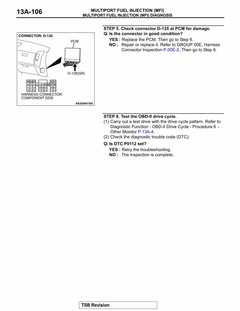
MULTIPORT FUEL INJECTION (MFI) DIAGNOSISMULTIPORT FUEL INJECTION (MFI)13A-106
STEP 5. Check connector D-135 at PCM for damage.Q: Is the connector in good condition?
YES : Replace the PCM. Then go to Step 6.NO : Repair or replace it. Refer to GROUP 00E, Harness
Connector Inspection P.00E-2. Then go to Step 6.
STEP 6. Test the OBD-II drive cycle.(1) Carry out a test drive with the drive cycle pattern. Refer to
Diagnostic Function - OBD-II Drive Cycle - Procedure 6 − Other Monitor P.13A-4.
(2) Check the diagnostic trouble code (DTC).Q: Is DTC P0112 set?
YES : Retry the troubleshooting.NO : The inspection is complete.
AK200947
919293949596979899100101102103104
105106107108109110111112
113114115116117118119120
CONNECTOR: D-135
HARNESS CONNECTOR: COMPONENT SIDE
AB
PCM
D-135(GR)
TSB Revision
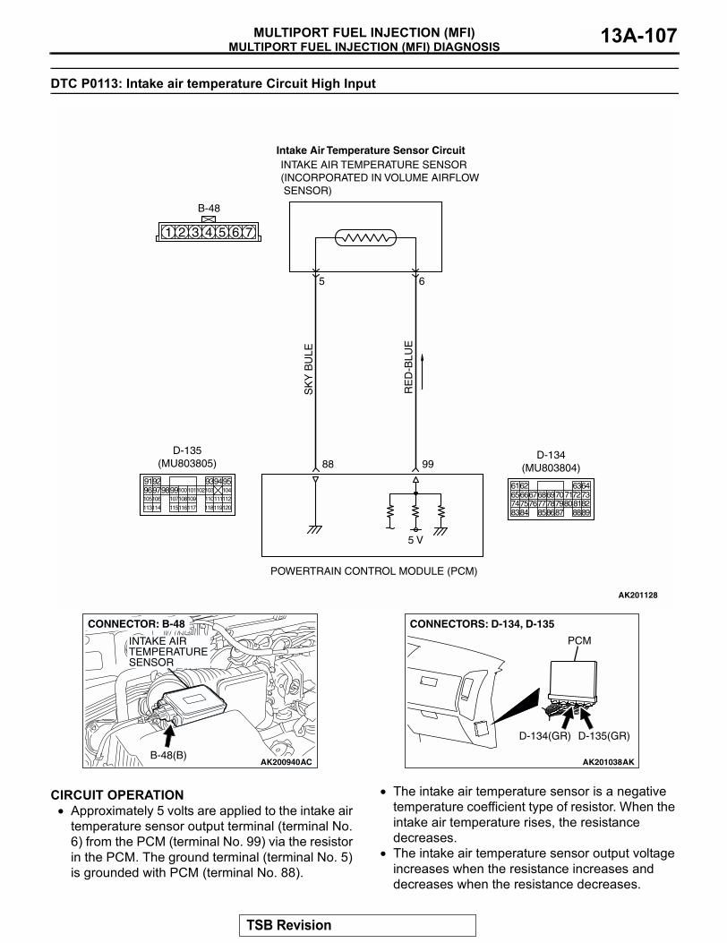
MULTIPORT FUEL INJECTION (MFI) DIAGNOSISMULTIPORT FUEL INJECTION (MFI) 13A-107
DTC P0113: Intake air temperature Circuit High Input
.
CIRCUIT OPERATION• Approximately 5 volts are applied to the intake air
temperature sensor output terminal (terminal No. 6) from the PCM (terminal No. 99) via the resistor in the PCM. The ground terminal (terminal No. 5) is grounded with PCM (terminal No. 88).
• The intake air temperature sensor is a negative temperature coefficient type of resistor. When the intake air temperature rises, the resistance decreases.
• The intake air temperature sensor output voltage increases when the resistance increases and decreases when the resistance decreases.
.
SK
Y B
ULE
AK201128
RE
D-B
LUE
INTAKE AIR TEMPERATURE SENSOR(INCORPORATED IN VOLUME AIRFLOW SENSOR)
POWERTRAIN CONTROL MODULE (PCM)
5 V
99
5
88
6
1 2 3 4 5 6 7
B-48
Intake Air Temperature Sensor Circuit
9192 93949596979899100
105
113114 115116117 118119120
106 107108109 110111112
101102103 104
D-135(MU803805)
616566676869707172737475767778798081828384 858687 8889
62 6364
D-134(MU803804)
AK200940AC
CONNECTOR: B-48
INTAKE AIRTEMPERATURESENSOR
B-48(B)AK201038AK
CONNECTORS: D-134, D-135
PCM
D-134(GR) D-135(GR)
TSB Revision
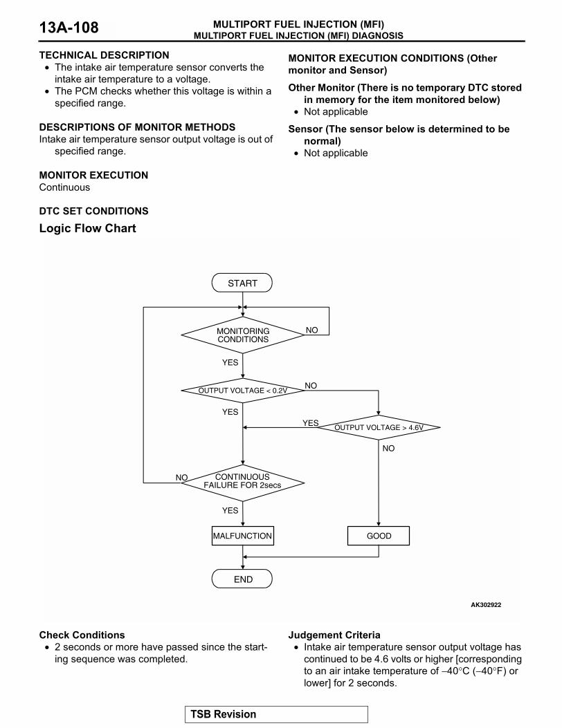
MULTIPORT FUEL INJECTION (MFI) DIAGNOSISMULTIPORT FUEL INJECTION (MFI)13A-108
TECHNICAL DESCRIPTION• The intake air temperature sensor converts the
intake air temperature to a voltage.• The PCM checks whether this voltage is within a
specified range..
DESCRIPTIONS OF MONITOR METHODSIntake air temperature sensor output voltage is out of
specified range..
MONITOR EXECUTIONContinuous
.
MONITOR EXECUTION CONDITIONS (Other monitor and Sensor)
Other Monitor (There is no temporary DTC stored in memory for the item monitored below)
• Not applicable
Sensor (The sensor below is determined to be normal)
• Not applicable.
DTC SET CONDITIONS
Logic Flow Chart
Check Conditions• 2 seconds or more have passed since the start-
ing sequence was completed.
Judgement Criteria• Intake air temperature sensor output voltage has
continued to be 4.6 volts or higher [corresponding to an air intake temperature of −40°C (−40°F) or lower] for 2 seconds.
.
START
OUTPUT VOLTAGE < 0.2V
END
NO
NO
NO
YESYES
YES
MALFUNCTION GOOD
CONTINUOUSFAILURE FOR 2secs
OUTPUT VOLTAGE > 4.6V
MONITORINGCONDITIONS
NO
YES
AK302922
TSB Revision
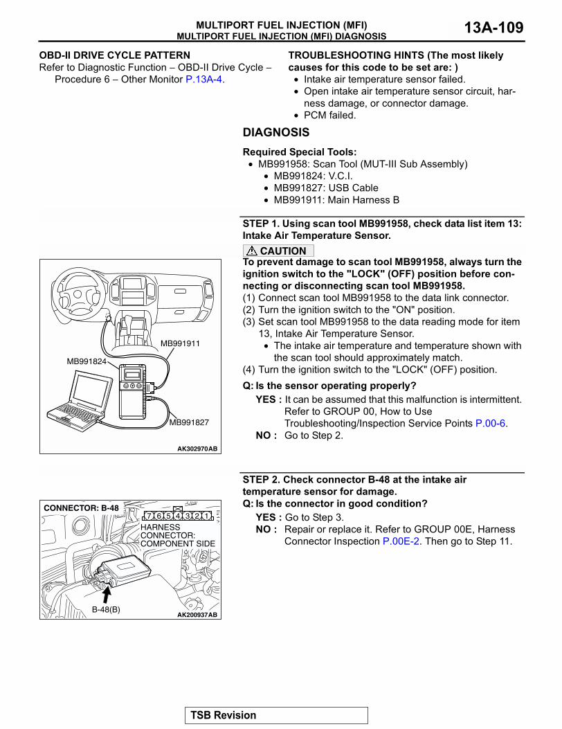
MULTIPORT FUEL INJECTION (MFI) DIAGNOSISMULTIPORT FUEL INJECTION (MFI) 13A-109
OBD-II DRIVE CYCLE PATTERNRefer to Diagnostic Function − OBD-II Drive Cycle −
Procedure 6 − Other Monitor P.13A-4..
TROUBLESHOOTING HINTS (The most likely causes for this code to be set are: )
• Intake air temperature sensor failed.• Open intake air temperature sensor circuit, har-
ness damage, or connector damage.• PCM failed.
DIAGNOSISRequired Special Tools:
• MB991958: Scan Tool (MUT-III Sub Assembly)• MB991824: V.C.I.• MB991827: USB Cable• MB991911: Main Harness B
STEP 1. Using scan tool MB991958, check data list item 13: Intake Air Temperature Sensor.
CAUTIONTo prevent damage to scan tool MB991958, always turn the ignition switch to the "LOCK" (OFF) position before con-necting or disconnecting scan tool MB991958.(1) Connect scan tool MB991958 to the data link connector.(2) Turn the ignition switch to the "ON" position.(3) Set scan tool MB991958 to the data reading mode for item
13, Intake Air Temperature Sensor.• The intake air temperature and temperature shown with
the scan tool should approximately match.(4) Turn the ignition switch to the "LOCK" (OFF) position.Q: Is the sensor operating properly?
YES : It can be assumed that this malfunction is intermittent. Refer to GROUP 00, How to Use Troubleshooting/Inspection Service Points P.00-6.
NO : Go to Step 2.
STEP 2. Check connector B-48 at the intake air temperature sensor for damage.Q: Is the connector in good condition?
YES : Go to Step 3.NO : Repair or replace it. Refer to GROUP 00E, Harness
Connector Inspection P.00E-2. Then go to Step 11.
AK302970AB
MB991911
MB991824
MB991827
AK200937
345 1267
AB
HARNESS CONNECTOR: COMPONENT SIDE
CONNECTOR: B-48
B-48(B)
TSB Revision
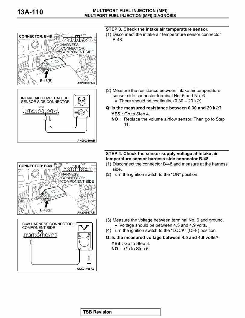
MULTIPORT FUEL INJECTION (MFI) DIAGNOSISMULTIPORT FUEL INJECTION (MFI)13A-110
STEP 3. Check the intake air temperature sensor.(1) Disconnect the intake air temperature sensor connector
B-48.
(2) Measure the resistance between intake air temperature sensor side connector terminal No. 5 and No. 6.
• There should be continuity. (0.30 − 20 kΩ)Q: Is the measured resistance between 0.30 and 20 kΩ?
YES : Go to Step 4.NO : Replace the volume airflow sensor. Then go to Step
11.
STEP 4. Check the sensor supply voltage at intake air temperature sensor harness side connector B-48.(1) Disconnect the connector B-48 and measure at the harness
side.(2) Turn the ignition switch to the "ON" position.
(3) Measure the voltage between terminal No. 6 and ground.• Voltage should be between 4.5 and 4.9 volts.
(4) Turn the ignition switch to the "LOCK" (OFF) position.Q: Is the measured voltage between 4.5 and 4.9 volts?
YES : Go to Step 8.NO : Go to Step 5.
AK200937
345 1267
AB
HARNESS CONNECTOR: COMPONENT SIDE
CONNECTOR: B-48
B-48(B)
AK000319AB
1 2 3 4 5 6 7
INTAKE AIR TEMPERATURESENSOR SIDE CONNECTOR
AK200937
345 1267
AB
HARNESS CONNECTOR: COMPONENT SIDE
CONNECTOR: B-48
B-48(B)
AKX01408AJ
B-48 HARNESS CONNECTOR: COMPONENT SIDE
1234567
TSB Revision
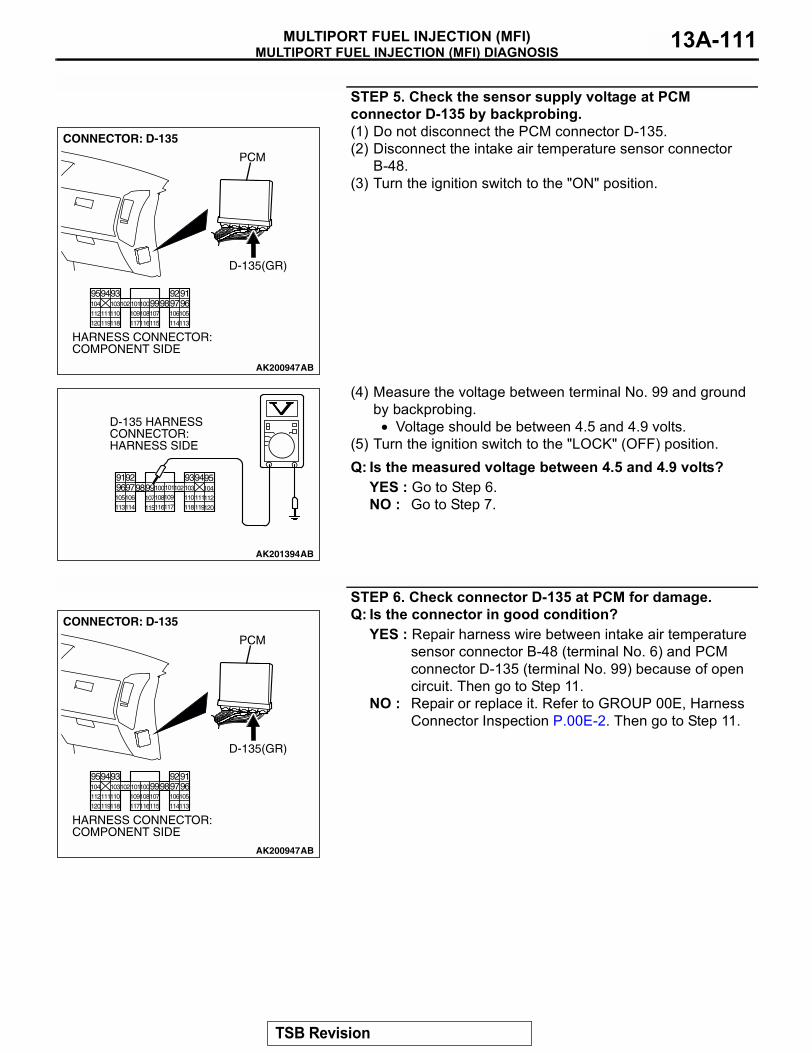
MULTIPORT FUEL INJECTION (MFI) DIAGNOSISMULTIPORT FUEL INJECTION (MFI) 13A-111
STEP 5. Check the sensor supply voltage at PCM connector D-135 by backprobing.(1) Do not disconnect the PCM connector D-135.(2) Disconnect the intake air temperature sensor connector
B-48.(3) Turn the ignition switch to the "ON" position.
(4) Measure the voltage between terminal No. 99 and ground by backprobing.
• Voltage should be between 4.5 and 4.9 volts.(5) Turn the ignition switch to the "LOCK" (OFF) position.Q: Is the measured voltage between 4.5 and 4.9 volts?
YES : Go to Step 6.NO : Go to Step 7.
STEP 6. Check connector D-135 at PCM for damage.Q: Is the connector in good condition?
YES : Repair harness wire between intake air temperature sensor connector B-48 (terminal No. 6) and PCM connector D-135 (terminal No. 99) because of open circuit. Then go to Step 11.
NO : Repair or replace it. Refer to GROUP 00E, Harness Connector Inspection P.00E-2. Then go to Step 11.
AK200947
919293949596979899100101102103104
105106107108109110111112
113114115116117118119120
CONNECTOR: D-135
HARNESS CONNECTOR: COMPONENT SIDE
AB
PCM
D-135(GR)
AK201394
9192 93949596979899100101102103 104105106 107108109 110111112113114 115116117 118119120
D-135 HARNESS CONNECTOR: HARNESS SIDE
AB
AK200947
919293949596979899100101102103104
105106107108109110111112
113114115116117118119120
CONNECTOR: D-135
HARNESS CONNECTOR: COMPONENT SIDE
AB
PCM
D-135(GR)
TSB Revision
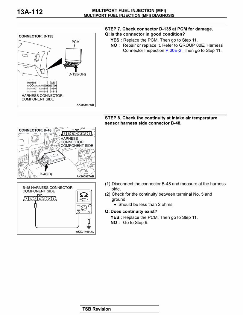
MULTIPORT FUEL INJECTION (MFI) DIAGNOSISMULTIPORT FUEL INJECTION (MFI)13A-112
STEP 7. Check connector D-135 at PCM for damage.Q: Is the connector in good condition?
YES : Replace the PCM. Then go to Step 11.NO : Repair or replace it. Refer to GROUP 00E, Harness
Connector Inspection P.00E-2. Then go to Step 11.
STEP 8. Check the continuity at intake air temperature sensor harness side connector B-48.
(1) Disconnect the connector B-48 and measure at the harness side.
(2) Check for the continuity between terminal No. 5 and ground.
• Should be less than 2 ohms.Q: Does continuity exist?
YES : Replace the PCM. Then go to Step 11.NO : Go to Step 9.
AK200947
919293949596979899100101102103104
105106107108109110111112
113114115116117118119120
CONNECTOR: D-135
HARNESS CONNECTOR: COMPONENT SIDE
AB
PCM
D-135(GR)
AK200937
345 1267
AB
HARNESS CONNECTOR: COMPONENT SIDE
CONNECTOR: B-48
B-48(B)
AKX01409
1234567
B-48 HARNESS CONNECTOR: COMPONENT SIDE
AL
TSB Revision
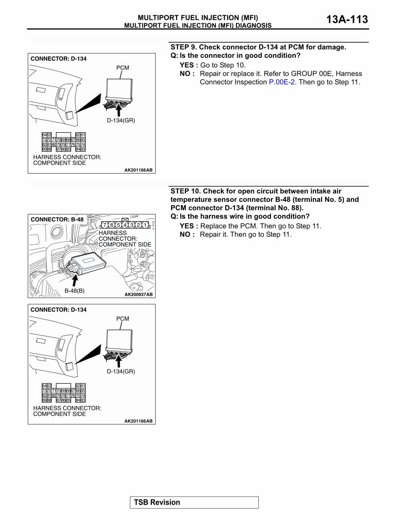
MULTIPORT FUEL INJECTION (MFI) DIAGNOSISMULTIPORT FUEL INJECTION (MFI) 13A-113
STEP 9. Check connector D-134 at PCM for damage.Q: Is the connector in good condition?
YES : Go to Step 10.NO : Repair or replace it. Refer to GROUP 00E, Harness
Connector Inspection P.00E-2. Then go to Step 11.
STEP 10. Check for open circuit between intake air temperature sensor connector B-48 (terminal No. 5) and PCM connector D-134 (terminal No. 88).Q: Is the harness wire in good condition?
YES : Replace the PCM. Then go to Step 11.NO : Repair it. Then go to Step 11.
AK201166
6162636465666768697071
76777879858687
807273
7475818283848889
CONNECTOR: D-134
AB
PCM
D-134(GR)
HARNESS CONNECTOR: COMPONENT SIDE
AK200937
345 1267
AB
HARNESS CONNECTOR: COMPONENT SIDE
CONNECTOR: B-48
B-48(B)
AK201166
6162636465666768697071
76777879858687
807273
7475818283848889
CONNECTOR: D-134
AB
PCM
D-134(GR)
HARNESS CONNECTOR: COMPONENT SIDE
TSB Revision
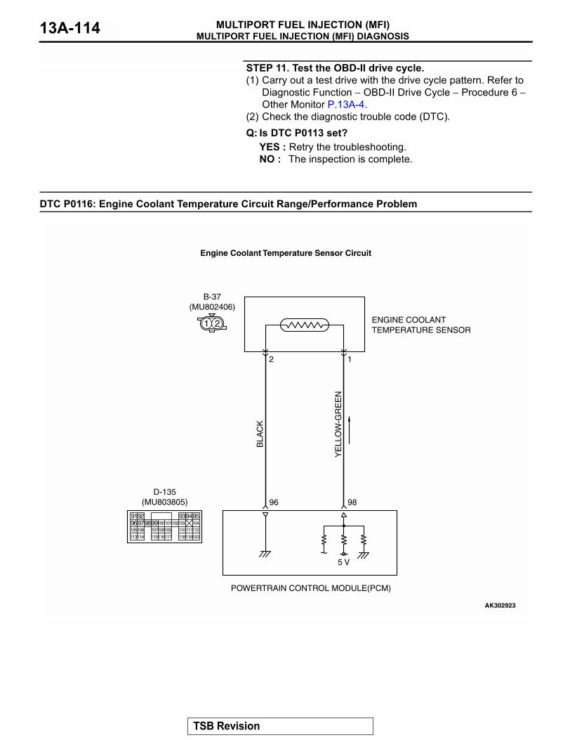
MULTIPORT FUEL INJECTION (MFI) DIAGNOSISMULTIPORT FUEL INJECTION (MFI)13A-114
STEP 11. Test the OBD-II drive cycle.(1) Carry out a test drive with the drive cycle pattern. Refer to
Diagnostic Function − OBD-II Drive Cycle − Procedure 6 − Other Monitor P.13A-4.
(2) Check the diagnostic trouble code (DTC).Q: Is DTC P0113 set?
YES : Retry the troubleshooting.NO : The inspection is complete.
DTC P0116: Engine Coolant Temperature Circuit Range/Performance Problem
YE
LLO
W-G
RE
EN
BLA
CK
AK302923
ENGINE COOLANTTEMPERATURE SENSOR
POWERTRAIN CONTROL MODULE(PCM)
5 V
98
2
B-37(MU802406)
96
1
Engine Coolant Temperature Sensor Circuit
1 2
9192 93949596979899100
105
113114 115116117 118119120
106 107108109 110111112
101102103 104
D-135(MU803805)
TSB Revision
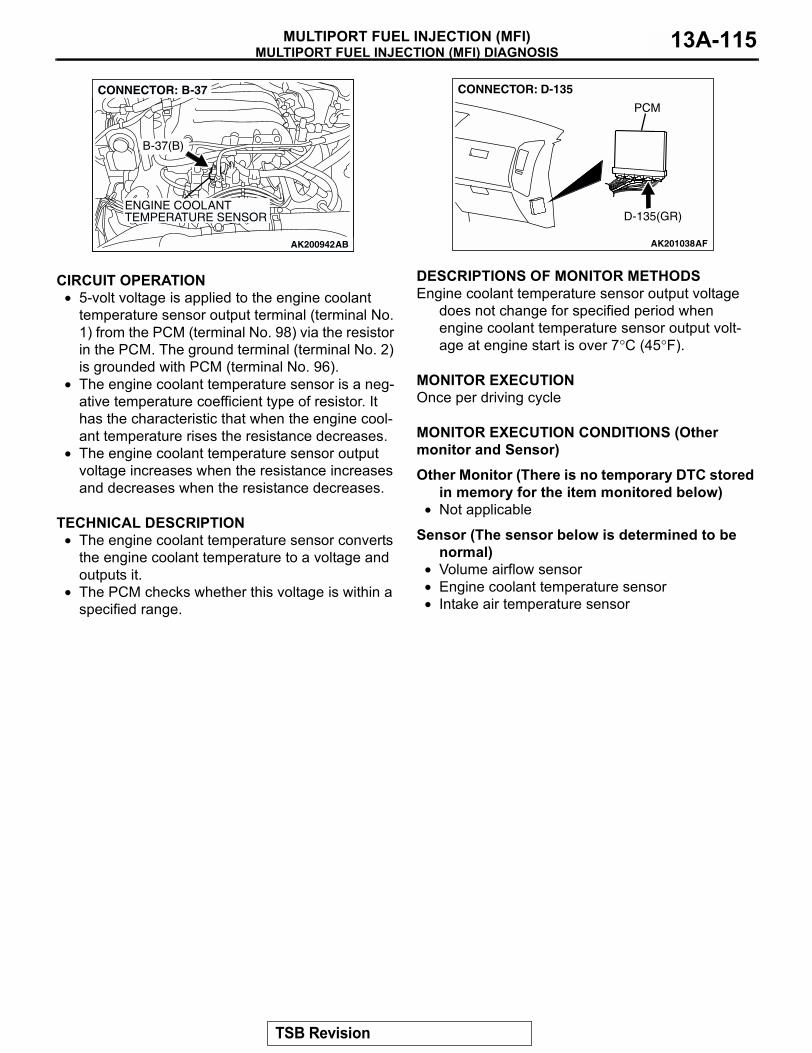
MULTIPORT FUEL INJECTION (MFI) DIAGNOSISMULTIPORT FUEL INJECTION (MFI) 13A-115
.
CIRCUIT OPERATION• 5-volt voltage is applied to the engine coolant
temperature sensor output terminal (terminal No. 1) from the PCM (terminal No. 98) via the resistor in the PCM. The ground terminal (terminal No. 2) is grounded with PCM (terminal No. 96).
• The engine coolant temperature sensor is a neg-ative temperature coefficient type of resistor. It has the characteristic that when the engine cool-ant temperature rises the resistance decreases.
• The engine coolant temperature sensor output voltage increases when the resistance increases and decreases when the resistance decreases.
.
TECHNICAL DESCRIPTION• The engine coolant temperature sensor converts
the engine coolant temperature to a voltage and outputs it.
• The PCM checks whether this voltage is within a specified range.
.
DESCRIPTIONS OF MONITOR METHODSEngine coolant temperature sensor output voltage
does not change for specified period when engine coolant temperature sensor output volt-age at engine start is over 7°C (45°F).
.
MONITOR EXECUTIONOnce per driving cycle.
MONITOR EXECUTION CONDITIONS (Other monitor and Sensor)
Other Monitor (There is no temporary DTC stored in memory for the item monitored below)
• Not applicable
Sensor (The sensor below is determined to be normal)
• Volume airflow sensor• Engine coolant temperature sensor• Intake air temperature sensor
.
AK200942
ENGINE COOLANTTEMPERATURE SENSOR
AK200942AB
B-37(B)
CONNECTOR: B-37
AK201038AF
CONNECTOR: D-135
PCM
D-135(GR)
TSB Revision
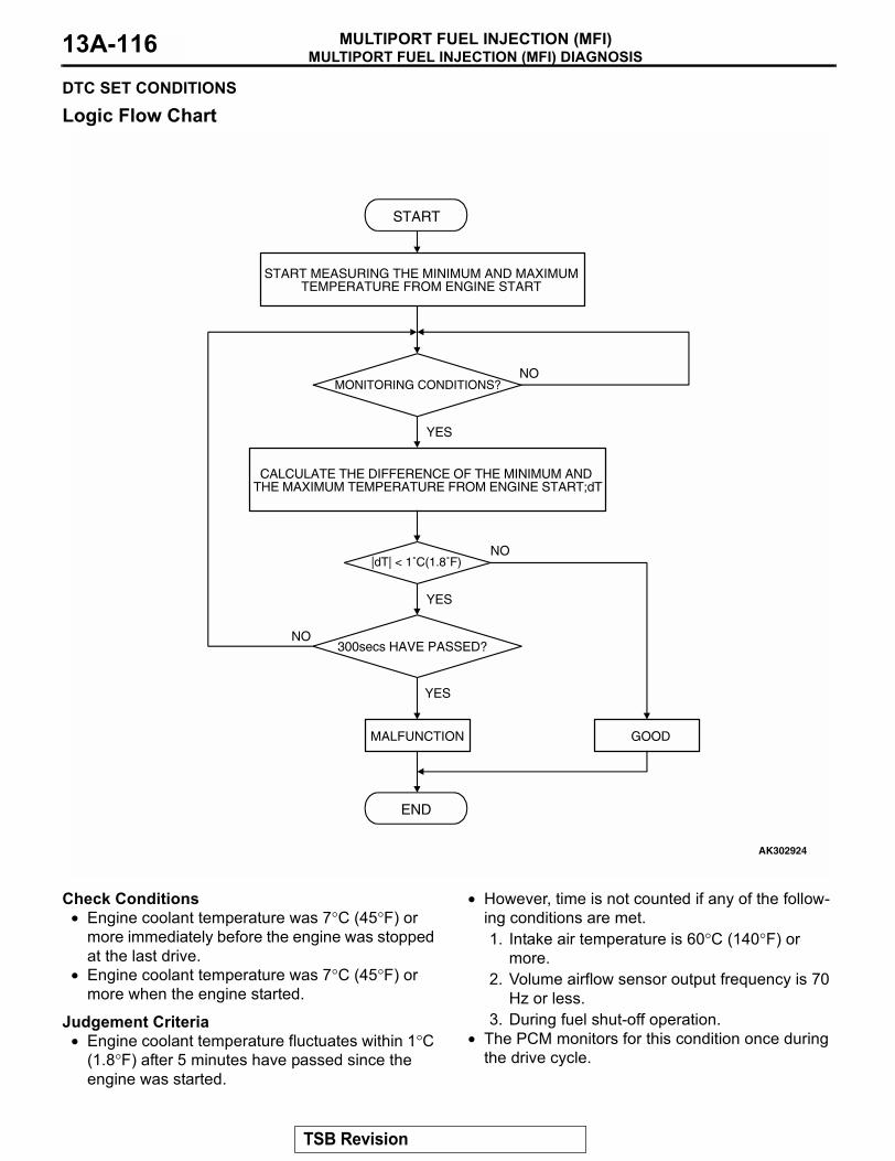
MULTIPORT FUEL INJECTION (MFI) DIAGNOSISMULTIPORT FUEL INJECTION (MFI)13A-116
DTC SET CONDITIONS
Logic Flow Chart
Check Conditions• Engine coolant temperature was 7°C (45°F) or
more immediately before the engine was stopped at the last drive.
• Engine coolant temperature was 7°C (45°F) or more when the engine started.
Judgement Criteria• Engine coolant temperature fluctuates within 1°C
(1.8°F) after 5 minutes have passed since the engine was started.
• However, time is not counted if any of the follow-ing conditions are met.1. Intake air temperature is 60°C (140°F) or
more.2. Volume airflow sensor output frequency is 70
Hz or less.3. During fuel shut-off operation.
• The PCM monitors for this condition once during the drive cycle.
.
START
END
YES
NO
NO
YES
MALFUNCTION GOOD
300secs HAVE PASSED?
|dT| < 1˚C(1.8˚F)
MONITORING CONDITIONS?
START MEASURING THE MINIMUM AND MAXIMUMTEMPERATURE FROM ENGINE START
CALCULATE THE DIFFERENCE OF THE MINIMUM AND THE MAXIMUM TEMPERATURE FROM ENGINE START;dT
YES
NO
AK302924
TSB Revision
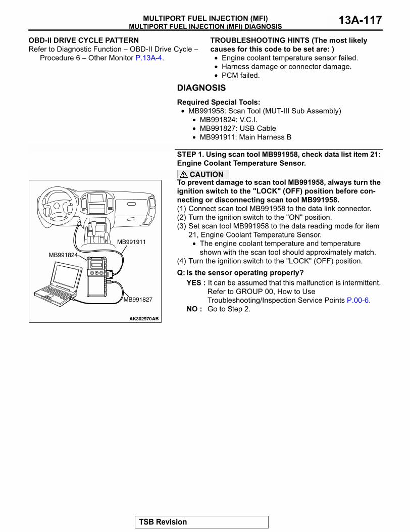
MULTIPORT FUEL INJECTION (MFI) DIAGNOSISMULTIPORT FUEL INJECTION (MFI) 13A-117
OBD-II DRIVE CYCLE PATTERNRefer to Diagnostic Function − OBD-II Drive Cycle −
Procedure 6 − Other Monitor P.13A-4..
TROUBLESHOOTING HINTS (The most likely causes for this code to be set are: )
• Engine coolant temperature sensor failed.• Harness damage or connector damage.• PCM failed.
DIAGNOSISRequired Special Tools:
• MB991958: Scan Tool (MUT-III Sub Assembly)• MB991824: V.C.I.• MB991827: USB Cable• MB991911: Main Harness B
STEP 1. Using scan tool MB991958, check data list item 21: Engine Coolant Temperature Sensor.
CAUTIONTo prevent damage to scan tool MB991958, always turn the ignition switch to the "LOCK" (OFF) position before con-necting or disconnecting scan tool MB991958.(1) Connect scan tool MB991958 to the data link connector.(2) Turn the ignition switch to the "ON" position.(3) Set scan tool MB991958 to the data reading mode for item
21, Engine Coolant Temperature Sensor.• The engine coolant temperature and temperature
shown with the scan tool should approximately match.(4) Turn the ignition switch to the "LOCK" (OFF) position.Q: Is the sensor operating properly?
YES : It can be assumed that this malfunction is intermittent. Refer to GROUP 00, How to Use Troubleshooting/Inspection Service Points P.00-6.
NO : Go to Step 2.AK302970AB
MB991911
MB991824
MB991827
TSB Revision
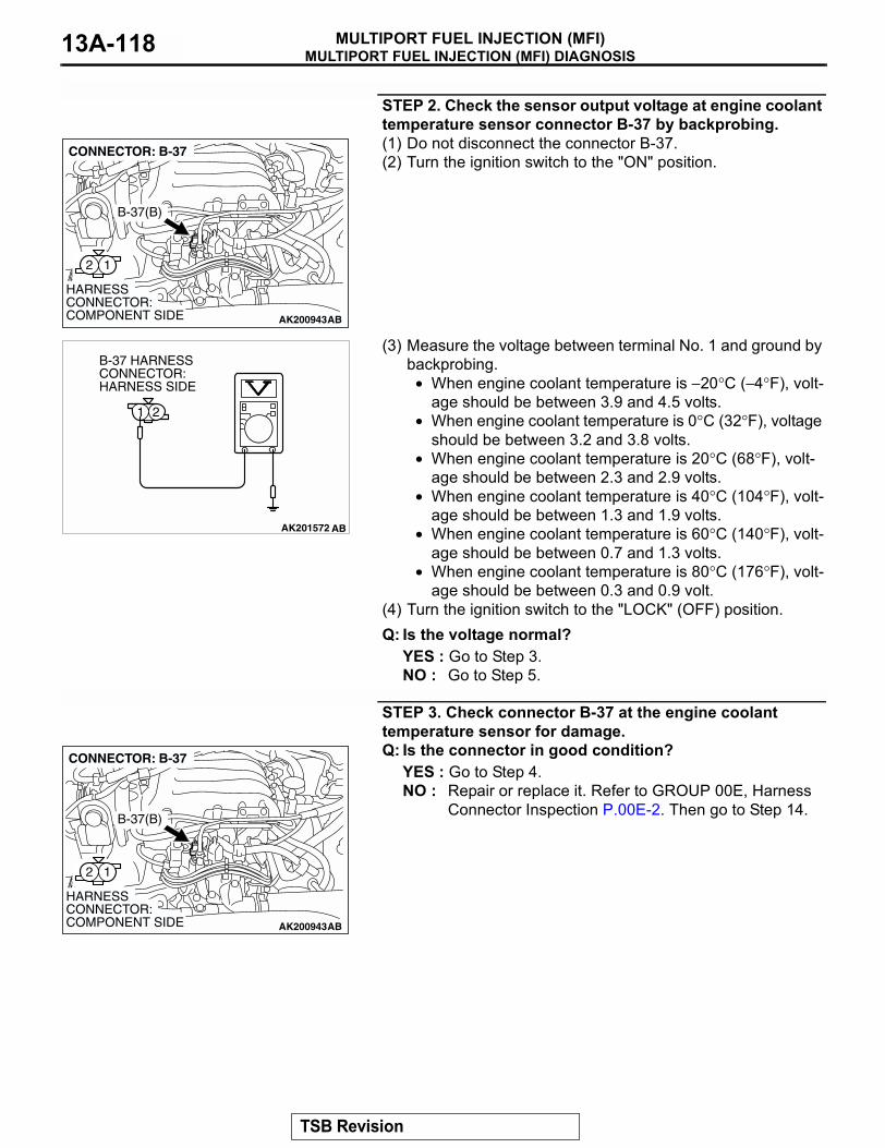
MULTIPORT FUEL INJECTION (MFI) DIAGNOSISMULTIPORT FUEL INJECTION (MFI)13A-118
STEP 2. Check the sensor output voltage at engine coolant temperature sensor connector B-37 by backprobing.(1) Do not disconnect the connector B-37.(2) Turn the ignition switch to the "ON" position.
(3) Measure the voltage between terminal No. 1 and ground by backprobing.
• When engine coolant temperature is −20°C (−4°F), volt-age should be between 3.9 and 4.5 volts.
• When engine coolant temperature is 0°C (32°F), voltage should be between 3.2 and 3.8 volts.
• When engine coolant temperature is 20°C (68°F), volt-age should be between 2.3 and 2.9 volts.
• When engine coolant temperature is 40°C (104°F), volt-age should be between 1.3 and 1.9 volts.
• When engine coolant temperature is 60°C (140°F), volt-age should be between 0.7 and 1.3 volts.
• When engine coolant temperature is 80°C (176°F), volt-age should be between 0.3 and 0.9 volt.
(4) Turn the ignition switch to the "LOCK" (OFF) position.Q: Is the voltage normal?
YES : Go to Step 3.NO : Go to Step 5.
STEP 3. Check connector B-37 at the engine coolant temperature sensor for damage.Q: Is the connector in good condition?
YES : Go to Step 4.NO : Repair or replace it. Refer to GROUP 00E, Harness
Connector Inspection P.00E-2. Then go to Step 14.
AK200943
12
AB
HARNESS CONNECTOR: COMPONENT SIDE
CONNECTOR: B-37
B-37(B)
AK201572
21
AB
B-37 HARNESS CONNECTOR: HARNESS SIDE
AK200943
12
AB
HARNESS CONNECTOR: COMPONENT SIDE
CONNECTOR: B-37
B-37(B)
TSB Revision
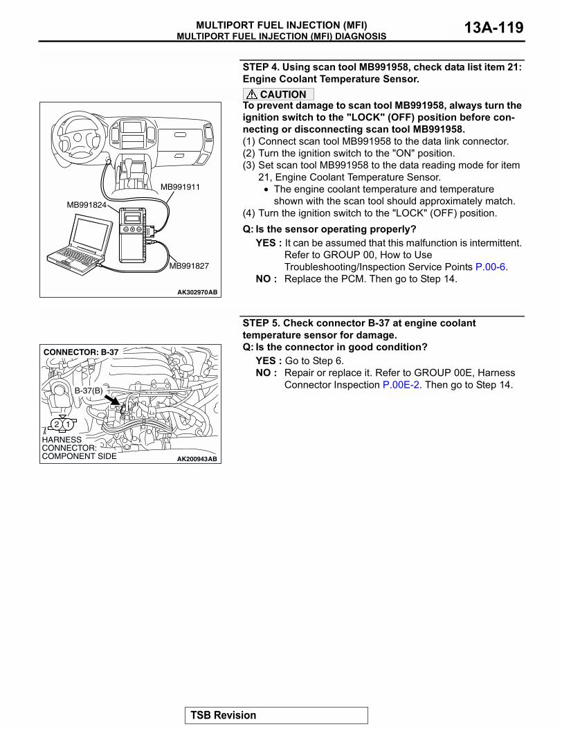
MULTIPORT FUEL INJECTION (MFI) DIAGNOSISMULTIPORT FUEL INJECTION (MFI) 13A-119
STEP 4. Using scan tool MB991958, check data list item 21: Engine Coolant Temperature Sensor.
CAUTIONTo prevent damage to scan tool MB991958, always turn the ignition switch to the "LOCK" (OFF) position before con-necting or disconnecting scan tool MB991958.(1) Connect scan tool MB991958 to the data link connector.(2) Turn the ignition switch to the "ON" position.(3) Set scan tool MB991958 to the data reading mode for item
21, Engine Coolant Temperature Sensor.• The engine coolant temperature and temperature
shown with the scan tool should approximately match.(4) Turn the ignition switch to the "LOCK" (OFF) position.Q: Is the sensor operating properly?
YES : It can be assumed that this malfunction is intermittent. Refer to GROUP 00, How to Use Troubleshooting/Inspection Service Points P.00-6.
NO : Replace the PCM. Then go to Step 14.
STEP 5. Check connector B-37 at engine coolant temperature sensor for damage.Q: Is the connector in good condition?
YES : Go to Step 6.NO : Repair or replace it. Refer to GROUP 00E, Harness
Connector Inspection P.00E-2. Then go to Step 14.
AK302970AB
MB991911
MB991824
MB991827
AK200943
12
AB
HARNESS CONNECTOR: COMPONENT SIDE
CONNECTOR: B-37
B-37(B)
TSB Revision
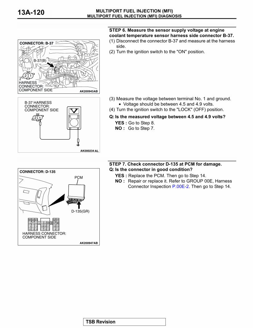
MULTIPORT FUEL INJECTION (MFI) DIAGNOSISMULTIPORT FUEL INJECTION (MFI)13A-120
STEP 6. Measure the sensor supply voltage at engine coolant temperature sensor harness side connector B-37.(1) Disconnect the connector B-37 and measure at the harness
side.(2) Turn the ignition switch to the "ON" position.
(3) Measure the voltage between terminal No. 1 and ground.• Voltage should be between 4.5 and 4.9 volts.
(4) Turn the ignition switch to the "LOCK" (OFF) position.Q: Is the measured voltage between 4.5 and 4.9 volts?
YES : Go to Step 8.NO : Go to Step 7.
STEP 7. Check connector D-135 at PCM for damage.Q: Is the connector in good condition?
YES : Replace the PCM. Then go to Step 14.NO : Repair or replace it. Refer to GROUP 00E, Harness
Connector Inspection P.00E-2. Then go to Step 14.
AK200943
12
AB
HARNESS CONNECTOR: COMPONENT SIDE
CONNECTOR: B-37
B-37(B)
AK000234 AL
2 1
B-37 HARNESS CONNECTOR: COMPONENT SIDE
AK200947
919293949596979899100101102103104
105106107108109110111112
113114115116117118119120
CONNECTOR: D-135
HARNESS CONNECTOR: COMPONENT SIDE
AB
PCM
D-135(GR)
TSB Revision
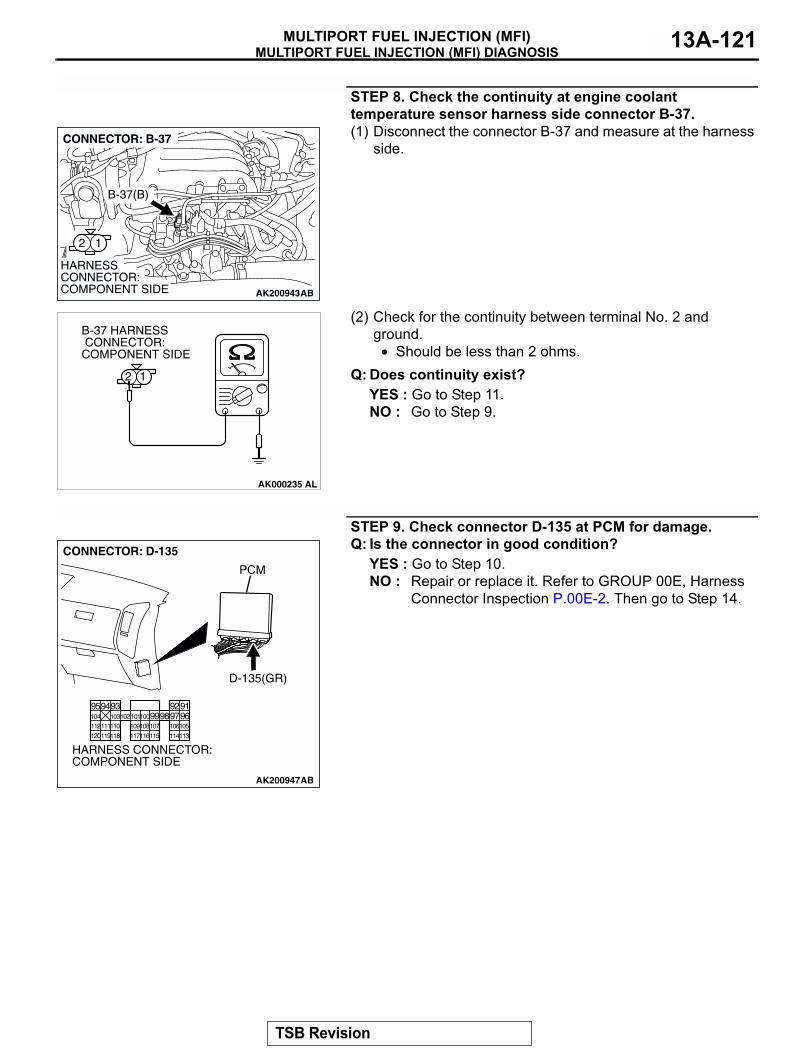
MULTIPORT FUEL INJECTION (MFI) DIAGNOSISMULTIPORT FUEL INJECTION (MFI) 13A-121
STEP 8. Check the continuity at engine coolant temperature sensor harness side connector B-37.(1) Disconnect the connector B-37 and measure at the harness
side.
(2) Check for the continuity between terminal No. 2 and ground.
• Should be less than 2 ohms.Q: Does continuity exist?
YES : Go to Step 11.NO : Go to Step 9.
STEP 9. Check connector D-135 at PCM for damage.Q: Is the connector in good condition?
YES : Go to Step 10.NO : Repair or replace it. Refer to GROUP 00E, Harness
Connector Inspection P.00E-2. Then go to Step 14.
AK200943
12
AB
HARNESS CONNECTOR: COMPONENT SIDE
CONNECTOR: B-37
B-37(B)
AK000235
B-37 HARNESS CONNECTOR: COMPONENT SIDE
12
AL
AK200947
919293949596979899100101102103104
105106107108109110111112
113114115116117118119120
CONNECTOR: D-135
HARNESS CONNECTOR: COMPONENT SIDE
AB
PCM
D-135(GR)
TSB Revision
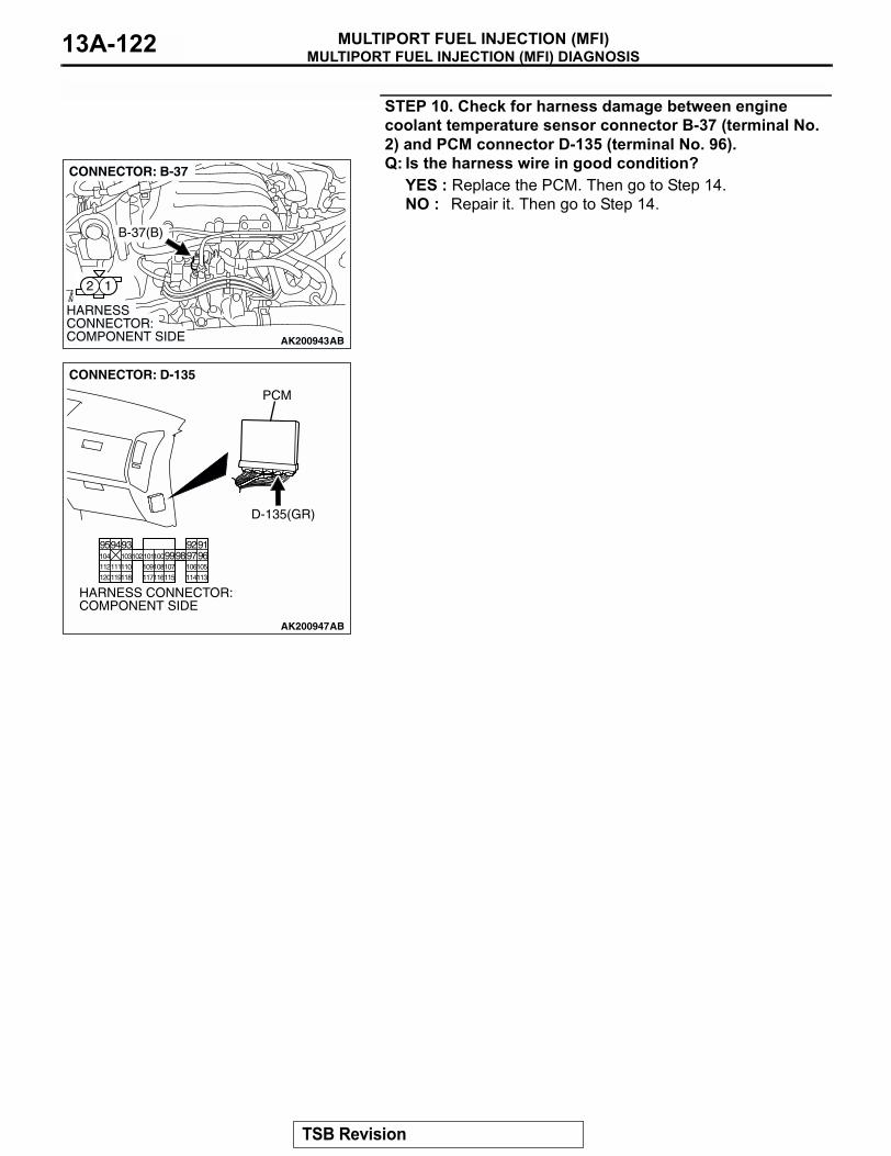
MULTIPORT FUEL INJECTION (MFI) DIAGNOSISMULTIPORT FUEL INJECTION (MFI)13A-122
STEP 10. Check for harness damage between engine coolant temperature sensor connector B-37 (terminal No. 2) and PCM connector D-135 (terminal No. 96).Q: Is the harness wire in good condition?
YES : Replace the PCM. Then go to Step 14.NO : Repair it. Then go to Step 14.
AK200943
12
AB
HARNESS CONNECTOR: COMPONENT SIDE
CONNECTOR: B-37
B-37(B)
AK200947
919293949596979899100101102103104
105106107108109110111112
113114115116117118119120
CONNECTOR: D-135
HARNESS CONNECTOR: COMPONENT SIDE
AB
PCM
D-135(GR)
TSB Revision
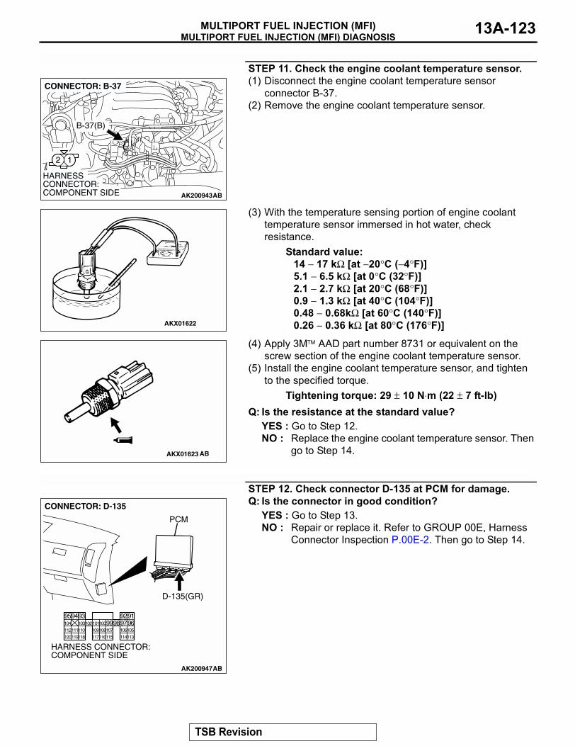
MULTIPORT FUEL INJECTION (MFI) DIAGNOSISMULTIPORT FUEL INJECTION (MFI) 13A-123
STEP 11. Check the engine coolant temperature sensor.(1) Disconnect the engine coolant temperature sensor
connector B-37.(2) Remove the engine coolant temperature sensor.
(3) With the temperature sensing portion of engine coolant temperature sensor immersed in hot water, check resistance.
Standard value:14 − 17 kΩ [at −20°C (−4°F)]5.1 − 6.5 kΩ [at 0°C (32°F)]2.1 − 2.7 kΩ [at 20°C (68°F)]0.9 − 1.3 kΩ [at 40°C (104°F)]0.48 − 0.68kΩ [at 60°C (140°F)]0.26 − 0.36 kΩ [at 80°C (176°F)]
(4) Apply 3M AAD part number 8731 or equivalent on the screw section of the engine coolant temperature sensor.
(5) Install the engine coolant temperature sensor, and tighten to the specified torque.
Tightening torque: 29 ± 10 N⋅m (22 ± 7 ft-lb)Q: Is the resistance at the standard value?
YES : Go to Step 12.NO : Replace the engine coolant temperature sensor. Then
go to Step 14.
STEP 12. Check connector D-135 at PCM for damage.Q: Is the connector in good condition?
YES : Go to Step 13.NO : Repair or replace it. Refer to GROUP 00E, Harness
Connector Inspection P.00E-2. Then go to Step 14.
AK200943
12
AB
HARNESS CONNECTOR: COMPONENT SIDE
CONNECTOR: B-37
B-37(B)
AKX01622
AKX01623 AB
AK200947
919293949596979899100101102103104
105106107108109110111112
113114115116117118119120
CONNECTOR: D-135
HARNESS CONNECTOR: COMPONENT SIDE
AB
PCM
D-135(GR)
TSB Revision
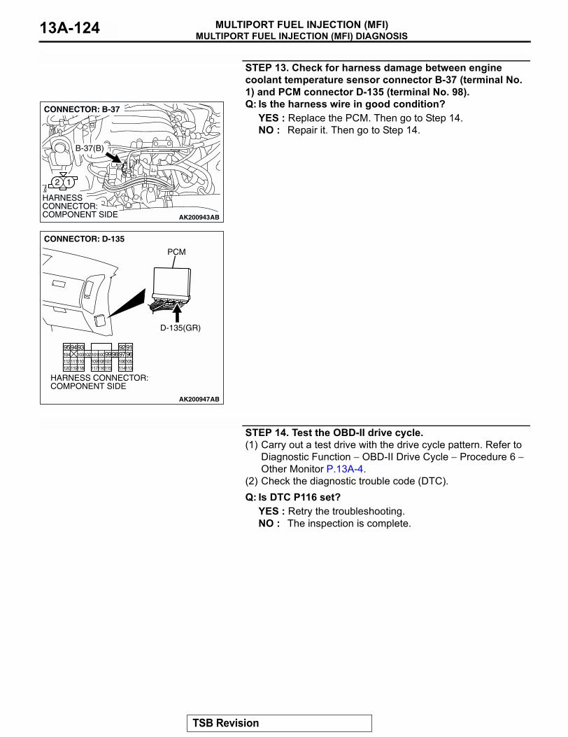
MULTIPORT FUEL INJECTION (MFI) DIAGNOSISMULTIPORT FUEL INJECTION (MFI)13A-124
STEP 13. Check for harness damage between engine coolant temperature sensor connector B-37 (terminal No. 1) and PCM connector D-135 (terminal No. 98).Q: Is the harness wire in good condition?
YES : Replace the PCM. Then go to Step 14.NO : Repair it. Then go to Step 14.
STEP 14. Test the OBD-II drive cycle.(1) Carry out a test drive with the drive cycle pattern. Refer to
Diagnostic Function − OBD-II Drive Cycle − Procedure 6 − Other Monitor P.13A-4.
(2) Check the diagnostic trouble code (DTC).Q: Is DTC P116 set?
YES : Retry the troubleshooting.NO : The inspection is complete.
AK200943
12
AB
HARNESS CONNECTOR: COMPONENT SIDE
CONNECTOR: B-37
B-37(B)
AK200947
919293949596979899100101102103104
105106107108109110111112
113114115116117118119120
CONNECTOR: D-135
HARNESS CONNECTOR: COMPONENT SIDE
AB
PCM
D-135(GR)
TSB Revision
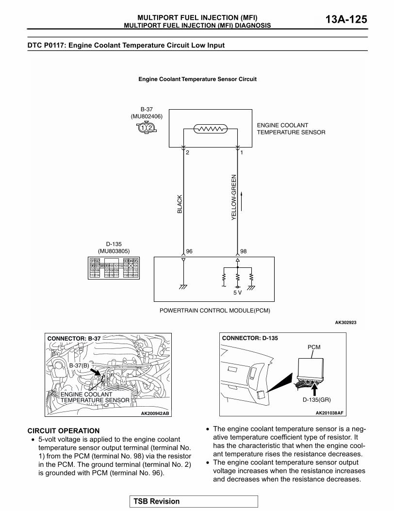
MULTIPORT FUEL INJECTION (MFI) DIAGNOSISMULTIPORT FUEL INJECTION (MFI) 13A-125
DTC P0117: Engine Coolant Temperature Circuit Low Input
.
CIRCUIT OPERATION• 5-volt voltage is applied to the engine coolant
temperature sensor output terminal (terminal No. 1) from the PCM (terminal No. 98) via the resistor in the PCM. The ground terminal (terminal No. 2) is grounded with PCM (terminal No. 96).
• The engine coolant temperature sensor is a neg-ative temperature coefficient type of resistor. It has the characteristic that when the engine cool-ant temperature rises the resistance decreases.
• The engine coolant temperature sensor output voltage increases when the resistance increases and decreases when the resistance decreases.
.
YE
LLO
W-G
RE
EN
BLA
CK
AK302923
ENGINE COOLANTTEMPERATURE SENSOR
POWERTRAIN CONTROL MODULE(PCM)
5 V
98
2
B-37(MU802406)
96
1
Engine Coolant Temperature Sensor Circuit
1 2
9192 93949596979899100
105
113114 115116117 118119120
106 107108109 110111112
101102103 104
D-135(MU803805)
AK200942
ENGINE COOLANTTEMPERATURE SENSOR
AK200942AB
B-37(B)
CONNECTOR: B-37
AK201038AF
CONNECTOR: D-135
PCM
D-135(GR)
TSB Revision
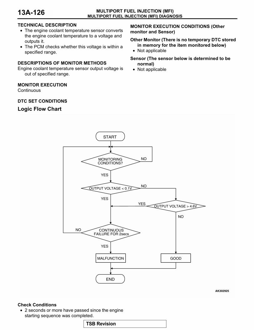
MULTIPORT FUEL INJECTION (MFI) DIAGNOSISMULTIPORT FUEL INJECTION (MFI)13A-126
TECHNICAL DESCRIPTION• The engine coolant temperature sensor converts
the engine coolant temperature to a voltage and outputs it.
• The PCM checks whether this voltage is within a specified range.
.
DESCRIPTIONS OF MONITOR METHODSEngine coolant temperature sensor output voltage is
out of specified range..
MONITOR EXECUTIONContinuous
.
MONITOR EXECUTION CONDITIONS (Other monitor and Sensor)
Other Monitor (There is no temporary DTC stored in memory for the item monitored below)
• Not applicable
Sensor (The sensor below is determined to be normal)
• Not applicable.
DTC SET CONDITIONS
Logic Flow Chart
Check Conditions• 2 seconds or more have passed since the engine
starting sequence was completed.
START
OUTPUT VOLTAGE > 4.6V
OUTPUT VOLTAGE < 0.1V
END
NO
NO
NO
YESYES
YES
MALFUNCTION GOOD
CONTINUOUSFAILURE FOR 2secs
MONITORINGCONDITIONS?
NO
YES
AK302925
TSB Revision
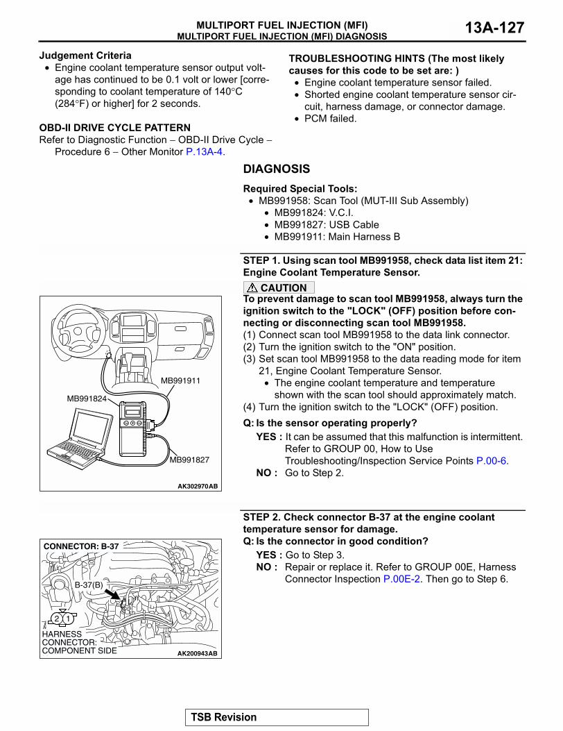
MULTIPORT FUEL INJECTION (MFI) DIAGNOSISMULTIPORT FUEL INJECTION (MFI) 13A-127
Judgement Criteria• Engine coolant temperature sensor output volt-
age has continued to be 0.1 volt or lower [corre-sponding to coolant temperature of 140°C (284°F) or higher] for 2 seconds.
.
OBD-II DRIVE CYCLE PATTERNRefer to Diagnostic Function − OBD-II Drive Cycle −
Procedure 6 − Other Monitor P.13A-4.
.
TROUBLESHOOTING HINTS (The most likely causes for this code to be set are: )
• Engine coolant temperature sensor failed.• Shorted engine coolant temperature sensor cir-
cuit, harness damage, or connector damage.• PCM failed.
DIAGNOSISRequired Special Tools:
• MB991958: Scan Tool (MUT-III Sub Assembly)• MB991824: V.C.I.• MB991827: USB Cable• MB991911: Main Harness B
STEP 1. Using scan tool MB991958, check data list item 21: Engine Coolant Temperature Sensor.
CAUTIONTo prevent damage to scan tool MB991958, always turn the ignition switch to the "LOCK" (OFF) position before con-necting or disconnecting scan tool MB991958.(1) Connect scan tool MB991958 to the data link connector.(2) Turn the ignition switch to the "ON" position.(3) Set scan tool MB991958 to the data reading mode for item
21, Engine Coolant Temperature Sensor.• The engine coolant temperature and temperature
shown with the scan tool should approximately match.(4) Turn the ignition switch to the "LOCK" (OFF) position.Q: Is the sensor operating properly?
YES : It can be assumed that this malfunction is intermittent. Refer to GROUP 00, How to Use Troubleshooting/Inspection Service Points P.00-6.
NO : Go to Step 2.
STEP 2. Check connector B-37 at the engine coolant temperature sensor for damage.Q: Is the connector in good condition?
YES : Go to Step 3.NO : Repair or replace it. Refer to GROUP 00E, Harness
Connector Inspection P.00E-2. Then go to Step 6.
AK302970AB
MB991911
MB991824
MB991827
AK200943
12
AB
HARNESS CONNECTOR: COMPONENT SIDE
CONNECTOR: B-37
B-37(B)
TSB Revision
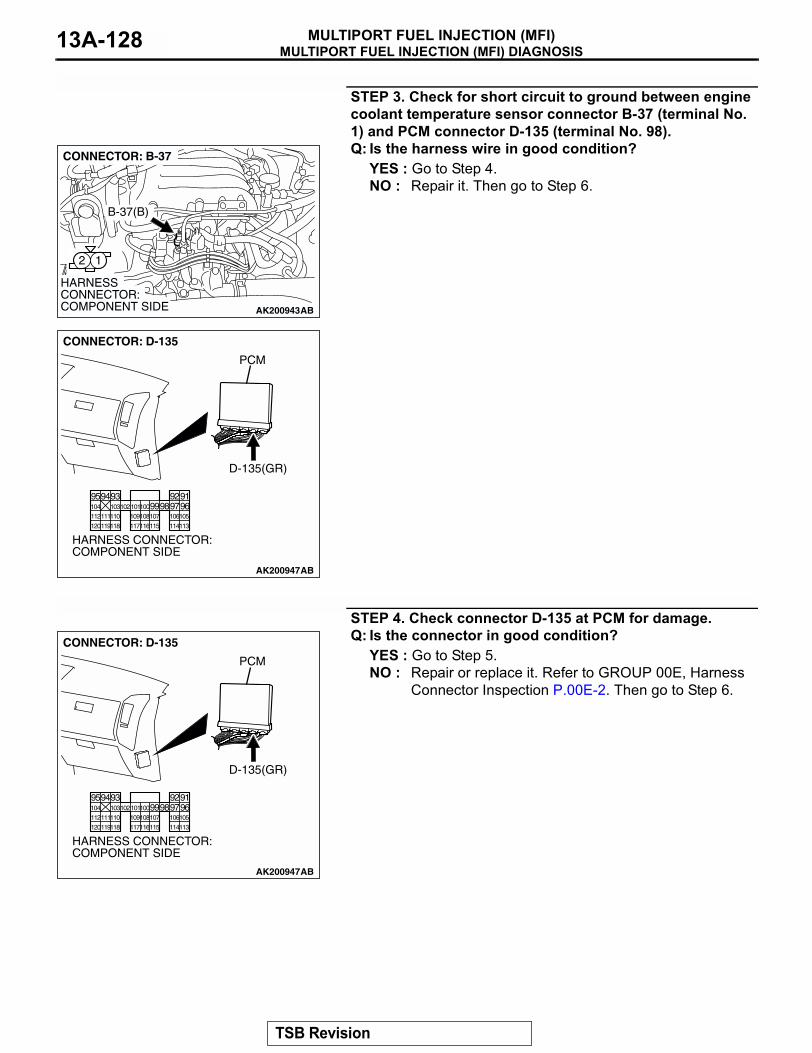
MULTIPORT FUEL INJECTION (MFI) DIAGNOSISMULTIPORT FUEL INJECTION (MFI)13A-128
STEP 3. Check for short circuit to ground between engine coolant temperature sensor connector B-37 (terminal No. 1) and PCM connector D-135 (terminal No. 98).Q: Is the harness wire in good condition?
YES : Go to Step 4.NO : Repair it. Then go to Step 6.
STEP 4. Check connector D-135 at PCM for damage.Q: Is the connector in good condition?
YES : Go to Step 5.NO : Repair or replace it. Refer to GROUP 00E, Harness
Connector Inspection P.00E-2. Then go to Step 6.
AK200943
12
AB
HARNESS CONNECTOR: COMPONENT SIDE
CONNECTOR: B-37
B-37(B)
AK200947
919293949596979899100101102103104
105106107108109110111112
113114115116117118119120
CONNECTOR: D-135
HARNESS CONNECTOR: COMPONENT SIDE
AB
PCM
D-135(GR)
AK200947
919293949596979899100101102103104
105106107108109110111112
113114115116117118119120
CONNECTOR: D-135
HARNESS CONNECTOR: COMPONENT SIDE
AB
PCM
D-135(GR)
TSB Revision
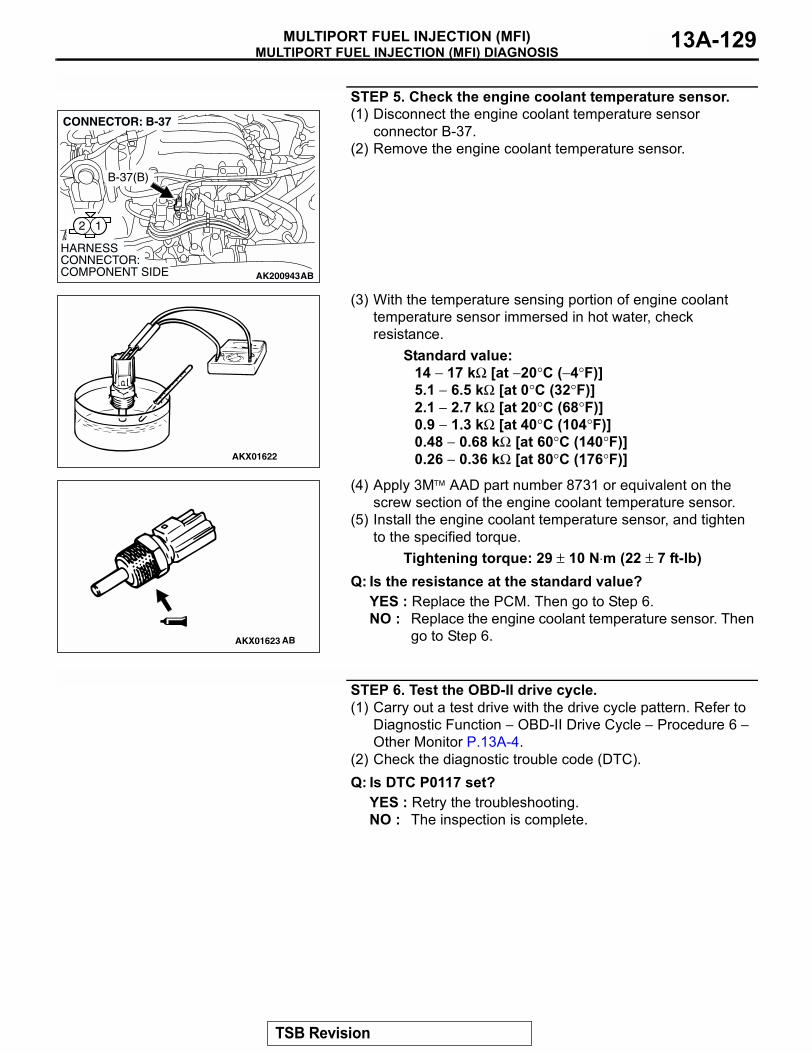
MULTIPORT FUEL INJECTION (MFI) DIAGNOSISMULTIPORT FUEL INJECTION (MFI) 13A-129
STEP 5. Check the engine coolant temperature sensor.(1) Disconnect the engine coolant temperature sensor
connector B-37.(2) Remove the engine coolant temperature sensor.
(3) With the temperature sensing portion of engine coolant temperature sensor immersed in hot water, check resistance.
Standard value:14 − 17 kΩ [at −20°C (−4°F)]5.1 − 6.5 kΩ [at 0°C (32°F)]2.1 − 2.7 kΩ [at 20°C (68°F)]0.9 − 1.3 kΩ [at 40°C (104°F)]0.48 − 0.68 kΩ [at 60°C (140°F)]0.26 − 0.36 kΩ [at 80°C (176°F)]
(4) Apply 3M AAD part number 8731 or equivalent on the screw section of the engine coolant temperature sensor.
(5) Install the engine coolant temperature sensor, and tighten to the specified torque.
Tightening torque: 29 ± 10 N⋅m (22 ± 7 ft-lb)Q: Is the resistance at the standard value?
YES : Replace the PCM. Then go to Step 6.NO : Replace the engine coolant temperature sensor. Then
go to Step 6.
STEP 6. Test the OBD-II drive cycle.(1) Carry out a test drive with the drive cycle pattern. Refer to
Diagnostic Function − OBD-II Drive Cycle − Procedure 6 − Other Monitor P.13A-4.
(2) Check the diagnostic trouble code (DTC).Q: Is DTC P0117 set?
YES : Retry the troubleshooting.NO : The inspection is complete.
AK200943
12
AB
HARNESS CONNECTOR: COMPONENT SIDE
CONNECTOR: B-37
B-37(B)
AKX01622
AKX01623 AB
TSB Revision
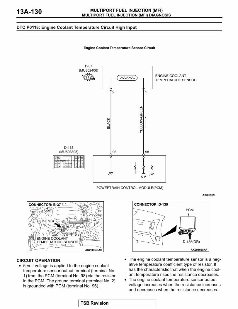
MULTIPORT FUEL INJECTION (MFI) DIAGNOSISMULTIPORT FUEL INJECTION (MFI)13A-130
DTC P0118: Engine Coolant Temperature Circuit High Input
.
CIRCUIT OPERATION• 5-volt voltage is applied to the engine coolant
temperature sensor output terminal (terminal No. 1) from the PCM (terminal No. 98) via the resistor in the PCM. The ground terminal (terminal No. 2) is grounded with PCM (terminal No. 96).
• The engine coolant temperature sensor is a neg-ative temperature coefficient type of resistor. It has the characteristic that when the engine cool-ant temperature rises the resistance decreases.
• The engine coolant temperature sensor output voltage increases when the resistance increases and decreases when the resistance decreases.
.
YE
LLO
W-G
RE
EN
BLA
CK
AK302923
ENGINE COOLANTTEMPERATURE SENSOR
POWERTRAIN CONTROL MODULE(PCM)
5 V
98
2
B-37(MU802406)
96
1
Engine Coolant Temperature Sensor Circuit
1 2
9192 93949596979899100
105
113114 115116117 118119120
106 107108109 110111112
101102103 104
D-135(MU803805)
AK200942
ENGINE COOLANTTEMPERATURE SENSOR
AK200942AB
B-37(B)
CONNECTOR: B-37
AK201038AF
CONNECTOR: D-135
PCM
D-135(GR)
TSB Revision
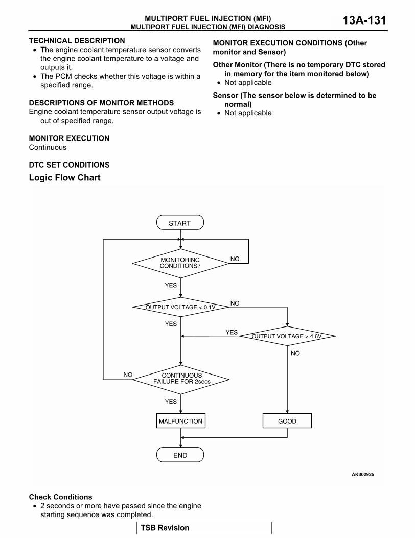
MULTIPORT FUEL INJECTION (MFI) DIAGNOSISMULTIPORT FUEL INJECTION (MFI) 13A-131
TECHNICAL DESCRIPTION• The engine coolant temperature sensor converts
the engine coolant temperature to a voltage and outputs it.
• The PCM checks whether this voltage is within a specified range.
.
DESCRIPTIONS OF MONITOR METHODSEngine coolant temperature sensor output voltage is
out of specified range..
MONITOR EXECUTIONContinuous
.
MONITOR EXECUTION CONDITIONS (Other monitor and Sensor)
Other Monitor (There is no temporary DTC stored in memory for the item monitored below)
• Not applicable
Sensor (The sensor below is determined to be normal)
• Not applicable.
DTC SET CONDITIONS
Logic Flow Chart
Check Conditions• 2 seconds or more have passed since the engine
starting sequence was completed.
START
OUTPUT VOLTAGE > 4.6V
OUTPUT VOLTAGE < 0.1V
END
NO
NO
NO
YESYES
YES
MALFUNCTION GOOD
CONTINUOUSFAILURE FOR 2secs
MONITORINGCONDITIONS?
NO
YES
AK302925
TSB Revision
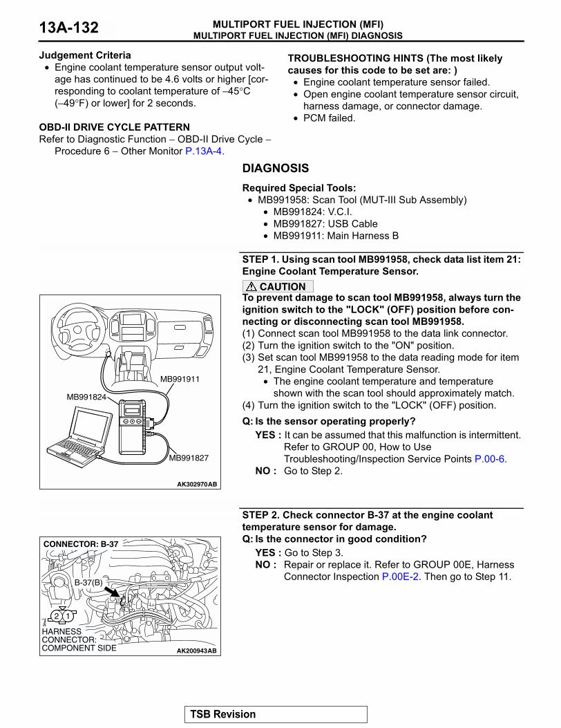
MULTIPORT FUEL INJECTION (MFI) DIAGNOSISMULTIPORT FUEL INJECTION (MFI)13A-132
Judgement Criteria• Engine coolant temperature sensor output volt-
age has continued to be 4.6 volts or higher [cor-responding to coolant temperature of −45°C (−49°F) or lower] for 2 seconds.
.
OBD-II DRIVE CYCLE PATTERNRefer to Diagnostic Function − OBD-II Drive Cycle −
Procedure 6 − Other Monitor P.13A-4.
.
TROUBLESHOOTING HINTS (The most likely causes for this code to be set are: )
• Engine coolant temperature sensor failed.• Open engine coolant temperature sensor circuit,
harness damage, or connector damage.• PCM failed.
DIAGNOSISRequired Special Tools:
• MB991958: Scan Tool (MUT-III Sub Assembly)• MB991824: V.C.I.• MB991827: USB Cable• MB991911: Main Harness B
STEP 1. Using scan tool MB991958, check data list item 21: Engine Coolant Temperature Sensor.
CAUTIONTo prevent damage to scan tool MB991958, always turn the ignition switch to the "LOCK" (OFF) position before con-necting or disconnecting scan tool MB991958.(1) Connect scan tool MB991958 to the data link connector.(2) Turn the ignition switch to the "ON" position.(3) Set scan tool MB991958 to the data reading mode for item
21, Engine Coolant Temperature Sensor.• The engine coolant temperature and temperature
shown with the scan tool should approximately match.(4) Turn the ignition switch to the "LOCK" (OFF) position.Q: Is the sensor operating properly?
YES : It can be assumed that this malfunction is intermittent. Refer to GROUP 00, How to Use Troubleshooting/Inspection Service Points P.00-6.
NO : Go to Step 2.
STEP 2. Check connector B-37 at the engine coolant temperature sensor for damage.Q: Is the connector in good condition?
YES : Go to Step 3.NO : Repair or replace it. Refer to GROUP 00E, Harness
Connector Inspection P.00E-2. Then go to Step 11.
AK302970AB
MB991911
MB991824
MB991827
AK200943
12
AB
HARNESS CONNECTOR: COMPONENT SIDE
CONNECTOR: B-37
B-37(B)
TSB Revision
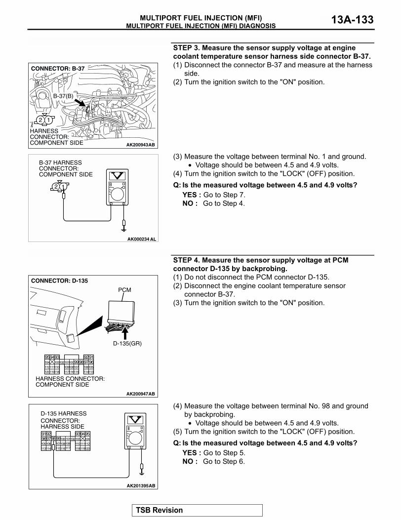
MULTIPORT FUEL INJECTION (MFI) DIAGNOSISMULTIPORT FUEL INJECTION (MFI) 13A-133
STEP 3. Measure the sensor supply voltage at engine coolant temperature sensor harness side connector B-37.(1) Disconnect the connector B-37 and measure at the harness
side.(2) Turn the ignition switch to the "ON" position.
(3) Measure the voltage between terminal No. 1 and ground.• Voltage should be between 4.5 and 4.9 volts.
(4) Turn the ignition switch to the "LOCK" (OFF) position.Q: Is the measured voltage between 4.5 and 4.9 volts?
YES : Go to Step 7.NO : Go to Step 4.
STEP 4. Measure the sensor supply voltage at PCM connector D-135 by backprobing.(1) Do not disconnect the PCM connector D-135.(2) Disconnect the engine coolant temperature sensor
connector B-37.(3) Turn the ignition switch to the "ON" position.
(4) Measure the voltage between terminal No. 98 and ground by backprobing.
• Voltage should be between 4.5 and 4.9 volts.(5) Turn the ignition switch to the "LOCK" (OFF) position.Q: Is the measured voltage between 4.5 and 4.9 volts?
YES : Go to Step 5.NO : Go to Step 6.
AK200943
12
AB
HARNESS CONNECTOR: COMPONENT SIDE
CONNECTOR: B-37
B-37(B)
AK000234 AL
2 1
B-37 HARNESS CONNECTOR: COMPONENT SIDE
AK200947
919293949596979899100101102103104
105106107108109110111112
113114115116117118119120
CONNECTOR: D-135
HARNESS CONNECTOR: COMPONENT SIDE
AB
PCM
D-135(GR)
AK201395
9192 93949596979899100101102103 104
105106 107108109 110111112
113114 115116117 118119120
AB
D-135 HARNESS CONNECTOR: HARNESS SIDE
TSB Revision
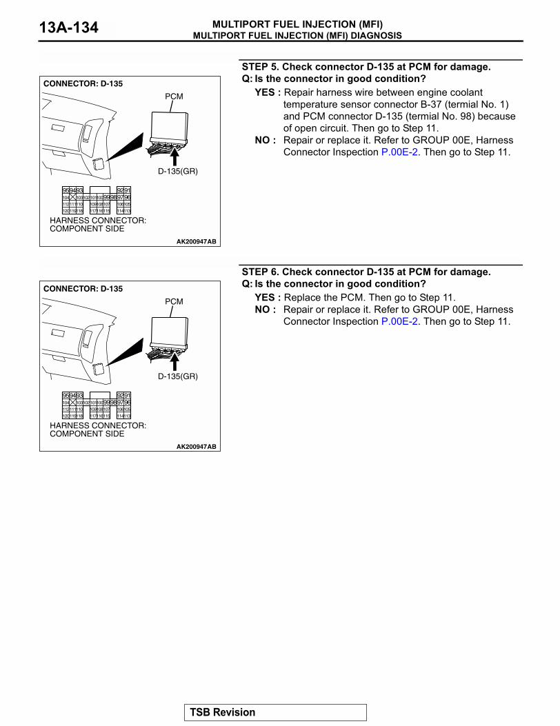
MULTIPORT FUEL INJECTION (MFI) DIAGNOSISMULTIPORT FUEL INJECTION (MFI)13A-134
STEP 5. Check connector D-135 at PCM for damage.Q: Is the connector in good condition?
YES : Repair harness wire between engine coolant temperature sensor connector B-37 (termial No. 1) and PCM connector D-135 (termial No. 98) because of open circuit. Then go to Step 11.
NO : Repair or replace it. Refer to GROUP 00E, Harness Connector Inspection P.00E-2. Then go to Step 11.
STEP 6. Check connector D-135 at PCM for damage.Q: Is the connector in good condition?
YES : Replace the PCM. Then go to Step 11.NO : Repair or replace it. Refer to GROUP 00E, Harness
Connector Inspection P.00E-2. Then go to Step 11.
AK200947
919293949596979899100101102103104
105106107108109110111112
113114115116117118119120
CONNECTOR: D-135
HARNESS CONNECTOR: COMPONENT SIDE
AB
PCM
D-135(GR)
AK200947
919293949596979899100101102103104
105106107108109110111112
113114115116117118119120
CONNECTOR: D-135
HARNESS CONNECTOR: COMPONENT SIDE
AB
PCM
D-135(GR)
TSB Revision
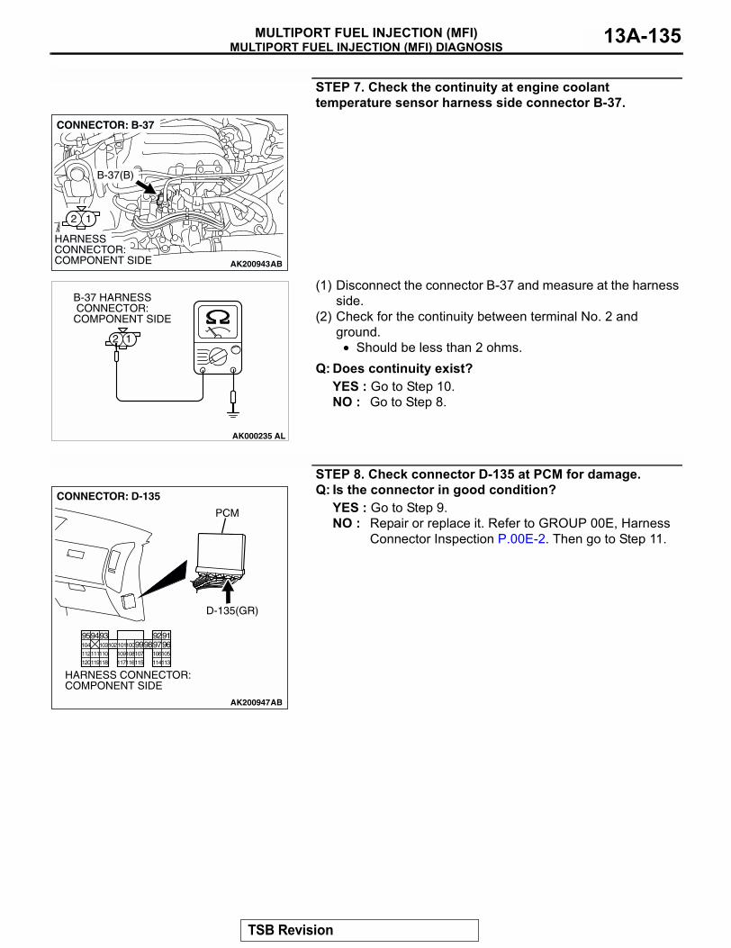
MULTIPORT FUEL INJECTION (MFI) DIAGNOSISMULTIPORT FUEL INJECTION (MFI) 13A-135
STEP 7. Check the continuity at engine coolant temperature sensor harness side connector B-37.
(1) Disconnect the connector B-37 and measure at the harness side.
(2) Check for the continuity between terminal No. 2 and ground.
• Should be less than 2 ohms.Q: Does continuity exist?
YES : Go to Step 10.NO : Go to Step 8.
STEP 8. Check connector D-135 at PCM for damage.Q: Is the connector in good condition?
YES : Go to Step 9.NO : Repair or replace it. Refer to GROUP 00E, Harness
Connector Inspection P.00E-2. Then go to Step 11.
AK200943
12
AB
HARNESS CONNECTOR: COMPONENT SIDE
CONNECTOR: B-37
B-37(B)
AK000235
B-37 HARNESS CONNECTOR: COMPONENT SIDE
12
AL
AK200947
919293949596979899100101102103104
105106107108109110111112
113114115116117118119120
CONNECTOR: D-135
HARNESS CONNECTOR: COMPONENT SIDE
AB
PCM
D-135(GR)
TSB Revision
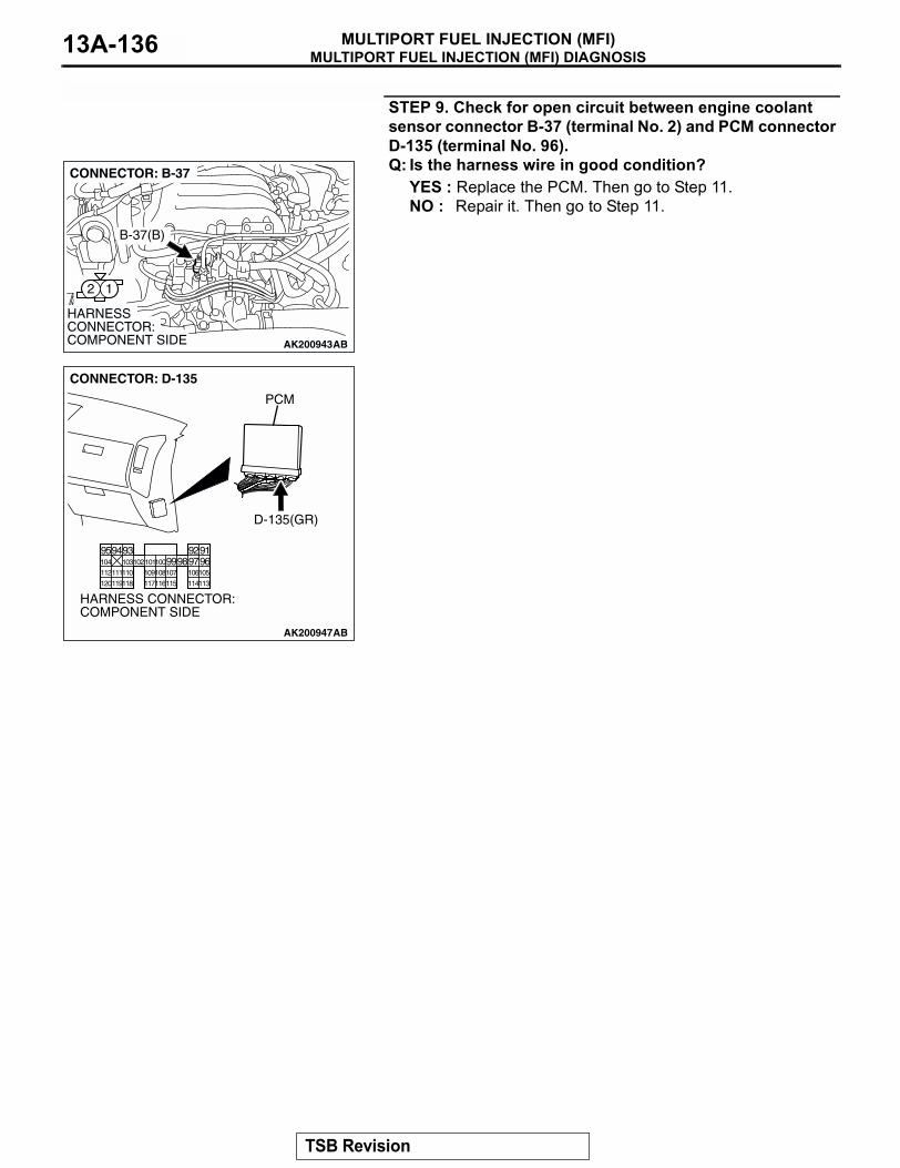
MULTIPORT FUEL INJECTION (MFI) DIAGNOSISMULTIPORT FUEL INJECTION (MFI)13A-136
STEP 9. Check for open circuit between engine coolant sensor connector B-37 (terminal No. 2) and PCM connector D-135 (terminal No. 96).Q: Is the harness wire in good condition?
YES : Replace the PCM. Then go to Step 11.NO : Repair it. Then go to Step 11.
AK200943
12
AB
HARNESS CONNECTOR: COMPONENT SIDE
CONNECTOR: B-37
B-37(B)
AK200947
919293949596979899100101102103104
105106107108109110111112
113114115116117118119120
CONNECTOR: D-135
HARNESS CONNECTOR: COMPONENT SIDE
AB
PCM
D-135(GR)
TSB Revision

MULTIPORT FUEL INJECTION (MFI) DIAGNOSISMULTIPORT FUEL INJECTION (MFI) 13A-137
STEP 10. Check the engine coolant temperature sensor.(1) Disconnect the engine coolant temperature sensor
connector B-37.(2) Remove the engine coolant temperature sensor.
(3) With the temperature sensing portion of engine coolant temperature sensor immersed in hot water, check resistance.
Standard value:14 − 17 kΩ [at −20°C (−4°F)]5.1 − 6.5 kΩ [at 0°C (32°F)]2.1 − 2.7 kΩ [at 20°C (68°F)]0.9 − 1.3 kΩ [at 40°C (104°F)]0.48 − 0.68 kΩ [at 60°C (140°F)]0.26 − 0.36 kΩ [at 80°C (176°F)]
(4) Apply 3M AAD part number 8731 or equivalent on the screw section of the engine coolant temperature sensor.
(5) Install the engine coolant temperature sensor, and tighten to the specified torque.
Tightening torque: 29 ± 10 N⋅m (22 ± 7 ft-lb)Q: Is the resistance at the standard value?
YES : Replace the PCM. Then go to Step 11.NO : Replace the engine coolant temperature sensor. Then
go to Step 11.
STEP 11. Test the OBD-II drive cycle.(1) Carry out a test drive with the drive cycle pattern. Refer to
Diagnostic Function − OBD-II Drive Cycle − Procedure 6 − Other Monitor P.13A-4.
(2) Check the diagnostic trouble code (DTC).Q: Is DTC P0118 set?
YES : Retry the troubleshooting.NO : The inspection is complete.
AK200943
12
AB
HARNESS CONNECTOR: COMPONENT SIDE
CONNECTOR: B-37
B-37(B)
AKX01622
AKX01623 AB
TSB Revision
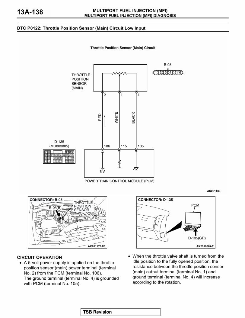
MULTIPORT FUEL INJECTION (MFI) DIAGNOSISMULTIPORT FUEL INJECTION (MFI)13A-138
DTC P0122: Throttle Position Sensor (Main) Circuit Low Input
.
CIRCUIT OPERATION• A 5-volt power supply is applied on the throttle
position sensor (main) power terminal (terminal No. 2) from the PCM (terminal No. 106).The ground terminal (terminal No. 4) is grounded with PCM (terminal No. 105).
• When the throttle valve shaft is turned from the idle position to the fully opened position, the resistance between the throttle position sensor (main) output terminal (terminal No. 1) and ground terminal (terminal No. 4) will increase according to the rotation.
.
AK201130
RE
D
WH
ITE
BLA
CK
B-05
5 V
106
2
THROTTLEPOSITIONSENSOR(MAIN)
POWERTRAIN CONTROL MODULE (PCM)
115 105
1 4
Throttle Position Sensor (Main) Circuit
9192 93949596979899100
105
113114 115116117 118119120
106 107108109 110111112
101102103 104
D-135(MU803805)
61 2 3 4 5
AK201173
THROTTLE POSITION SENSOR
AB
B-05(B)
CONNECTOR: B-05
AK201038AF
CONNECTOR: D-135
PCM
D-135(GR)
TSB Revision
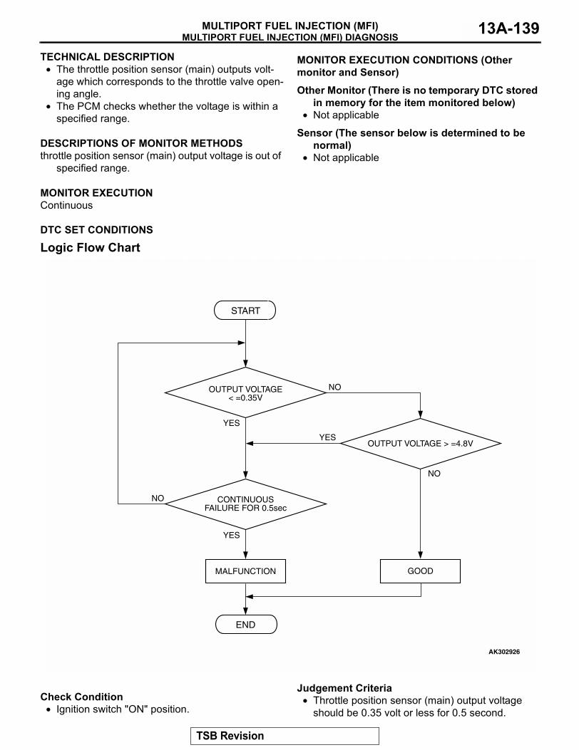
MULTIPORT FUEL INJECTION (MFI) DIAGNOSISMULTIPORT FUEL INJECTION (MFI) 13A-139
TECHNICAL DESCRIPTION• The throttle position sensor (main) outputs volt-
age which corresponds to the throttle valve open-ing angle.
• The PCM checks whether the voltage is within a specified range.
.
DESCRIPTIONS OF MONITOR METHODSthrottle position sensor (main) output voltage is out of
specified range..
MONITOR EXECUTIONContinuous
.
MONITOR EXECUTION CONDITIONS (Other monitor and Sensor)
Other Monitor (There is no temporary DTC stored in memory for the item monitored below)
• Not applicable
Sensor (The sensor below is determined to be normal)
• Not applicable.
DTC SET CONDITIONS
Logic Flow Chart
.
Check Condition• Ignition switch "ON" position.
Judgement Criteria• Throttle position sensor (main) output voltage
should be 0.35 volt or less for 0.5 second.
START
YES
YES
YES
NO
NO
NO
CONTINUOUSFAILURE FOR 0.5sec
MALFUNCTION
END
GOOD
OUTPUT VOLTAGE< =0.35V
OUTPUT VOLTAGE > =4.8V
AK302926
TSB Revision
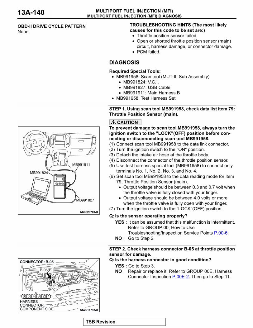
MULTIPORT FUEL INJECTION (MFI) DIAGNOSISMULTIPORT FUEL INJECTION (MFI)13A-140
.
OBD-II DRIVE CYCLE PATTERNNone..
TROUBLESHOOTING HINTS (The most likely causes for this code to be set are:)
• Throttle position sensor failed.• Open or shorted throttle position sensor (main)
circuit, harness damage, or connector damage.• PCM failed.
DIAGNOSISRequired Special Tools:
• MB991958: Scan tool (MUT-III Sub Assembly)• MB991824: V.C.I.• MB991827: USB Cable• MB991911: Main Harness B
• MB991658: Test Harness Set
STEP 1. Using scan tool MB991958, check data list item 79: Throttle Position Sensor (main).
CAUTIONTo prevent damage to scan tool MB991958, always turn the ignition switch to the "LOCK"(OFF) position before con-necting or disconnecting scan tool MB991958.(1) Connect scan tool MB991958 to the data link connector.(2) Turn the ignition switch to the "ON" position.(3) Detach the intake air hose at the throttle body.(4) Disconnect the connector of the throttle position sensor.(5) Use test harness special tool (MB991658) to connect only
terminals No. 1, No. 2, No. 3, and No. 4.(6) Set scan tool MB991958 to the data reading mode for item
79, Throttle Position Sensor (main).• Output voltage should be between 0.3 and 0.7 volt when
the throttle valve is fully closed with your finger.• Output voltage should be between 4.0 volts or more
when the throttle valve is fully open with your finger.(7) Turn the ignition switch to the "LOCK"(OFF) position.Q: Is the sensor operating properly?
YES : It can be assumed that this malfunction is intermittent. Refer to GROUP 00, How to Use Troubleshooting/Inspection Service Points P.00-6.
NO : Go to Step 2.
STEP 2. Check harness connector B-05 at throttle position sensor for damage.Q: Is the harness connector in good condition?
YES : Go to Step 3.NO : Repair or replace it. Refer to GROUP 00E, Harness
Connector Inspection P.00E-2. Then go to Step 11.
AK302970AB
MB991911
MB991824
MB991827
AK201174
16 5 4 3 2
B-05(B)
CONNECTOR: B-05
HARNESS CONNECTOR: COMPONENT SIDE AB
TSB Revision
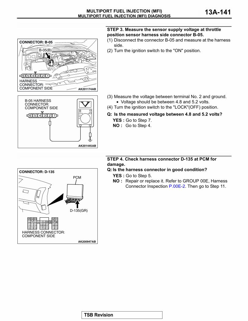
MULTIPORT FUEL INJECTION (MFI) DIAGNOSISMULTIPORT FUEL INJECTION (MFI) 13A-141
STEP 3. Measure the sensor supply voltage at throttle position sensor harness side connector B-05.(1) Disconnect the connector B-05 and measure at the harness
side.(2) Turn the ignition switch to the "ON" position.
(3) Measure the voltage between terminal No. 2 and ground.• Voltage should be between 4.8 and 5.2 volts.
(4) Turn the ignition switch to the "LOCK"(OFF) position.Q: Is the measured voltage between 4.8 and 5.2 volts?
YES : Go to Step 7.NO : Go to Step 4.
STEP 4. Check harness connector D-135 at PCM for damage.Q: Is the harness connector in good condition?
YES : Go to Step 5.NO : Repair or replace it. Refer to GROUP 00E, Harness
Connector Inspection P.00E-2. Then go to Step 11.
AK201174
16 5 4 3 2
B-05(B)
CONNECTOR: B-05
HARNESS CONNECTOR: COMPONENT SIDE AB
AK201445
16 5 4 3 2
B-05 HARNESS CONNECTOR: COMPONENT SIDE
AB
AK200947
919293949596979899100101102103104
105106107108109110111112
113114115116117118119120
CONNECTOR: D-135
HARNESS CONNECTOR: COMPONENT SIDE
AB
PCM
D-135(GR)
TSB Revision
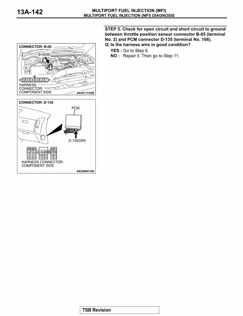
MULTIPORT FUEL INJECTION (MFI) DIAGNOSISMULTIPORT FUEL INJECTION (MFI)13A-142
STEP 5. Check for open circuit and short circuit to ground between throttle position sensor connector B-05 (terminal No. 2) and PCM connector D-135 (terminal No. 106).Q: Is the harness wire in good condition?
YES : Go to Step 6.NO : Repair it. Then go to Step 11.
AK201174
16 5 4 3 2
B-05(B)
CONNECTOR: B-05
HARNESS CONNECTOR: COMPONENT SIDE AB
AK200947
919293949596979899100101102103104
105106107108109110111112
113114115116117118119120
CONNECTOR: D-135
HARNESS CONNECTOR: COMPONENT SIDE
AB
PCM
D-135(GR)
TSB Revision
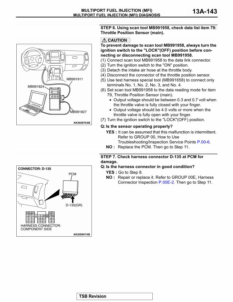
MULTIPORT FUEL INJECTION (MFI) DIAGNOSISMULTIPORT FUEL INJECTION (MFI) 13A-143
STEP 6. Using scan tool MB991958, check data list item 79: Throttle Position Sensor (main).
CAUTIONTo prevent damage to scan tool MB991958, always turn the ignition switch to the "LOCK"(OFF) position before con-necting or disconnecting scan tool MB991958.(1) Connect scan tool MB991958 to the data link connector.(2) Turn the ignition switch to the "ON" position.(3) Detach the intake air hose at the throttle body.(4) Disconnect the connector of the throttle position sensor.(5) Use test harness special tool (MB991658) to connect only
terminals No. 1, No. 2, No. 3, and No. 4.(6) Set scan tool MB991958 to the data reading mode for item
79, Throttle Position Sensor (main).• Output voltage should be between 0.3 and 0.7 volt when
the throttle valve is fully closed with your finger.• Output voltage should be 4.0 volts or more when the
throttle valve is fully open with your finger.(7) Turn the ignition switch to the "LOCK"(OFF) position.Q: Is the sensor operating properly?
YES : It can be assumed that this malfunction is intermittent. Refer to GROUP 00, How to Use Troubleshooting/Inspection Service Points P.00-6.
NO : Replace the PCM. Then go to Step 11.
STEP 7. Check harness connector D-135 at PCM for damage.Q: Is the harness connector in good condition?
YES : Go to Step 8.NO : Repair or replace it. Refer to GROUP 00E, Harness
Connector Inspection P.00E-2. Then go to Step 11.
AK302970AB
MB991911
MB991824
MB991827
AK200947
919293949596979899100101102103104
105106107108109110111112
113114115116117118119120
CONNECTOR: D-135
HARNESS CONNECTOR: COMPONENT SIDE
AB
PCM
D-135(GR)
TSB Revision
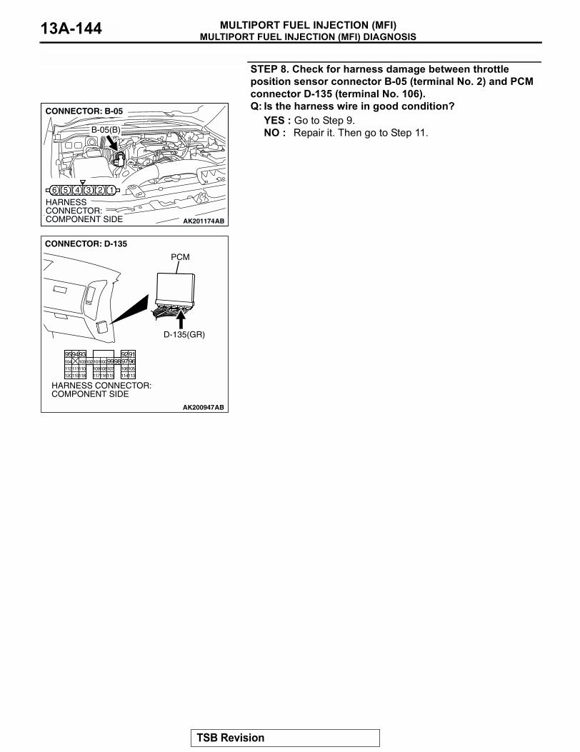
MULTIPORT FUEL INJECTION (MFI) DIAGNOSISMULTIPORT FUEL INJECTION (MFI)13A-144
STEP 8. Check for harness damage between throttle position sensor connector B-05 (terminal No. 2) and PCM connector D-135 (terminal No. 106).Q: Is the harness wire in good condition?
YES : Go to Step 9.NO : Repair it. Then go to Step 11.
AK201174
16 5 4 3 2
B-05(B)
CONNECTOR: B-05
HARNESS CONNECTOR: COMPONENT SIDE AB
AK200947
919293949596979899100101102103104
105106107108109110111112
113114115116117118119120
CONNECTOR: D-135
HARNESS CONNECTOR: COMPONENT SIDE
AB
PCM
D-135(GR)
TSB Revision
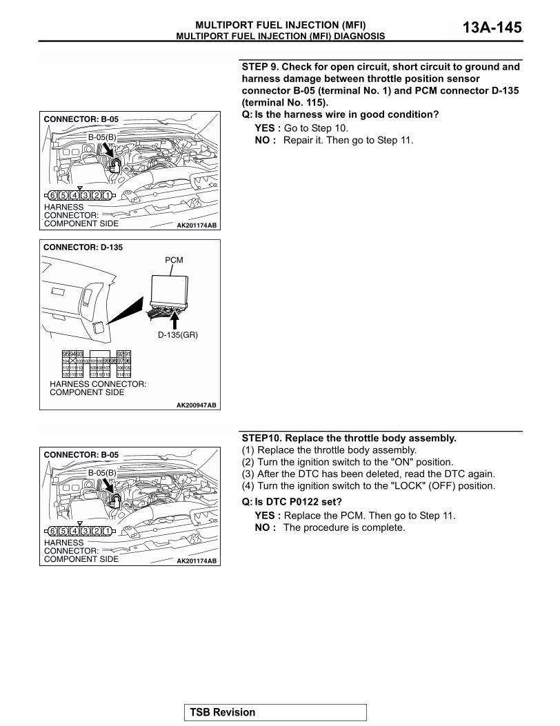
MULTIPORT FUEL INJECTION (MFI) DIAGNOSISMULTIPORT FUEL INJECTION (MFI) 13A-145
STEP 9. Check for open circuit, short circuit to ground and harness damage between throttle position sensor connector B-05 (terminal No. 1) and PCM connector D-135 (terminal No. 115).Q: Is the harness wire in good condition?
YES : Go to Step 10.NO : Repair it. Then go to Step 11.
STEP10. Replace the throttle body assembly.(1) Replace the throttle body assembly.(2) Turn the ignition switch to the "ON" position.(3) After the DTC has been deleted, read the DTC again.(4) Turn the ignition switch to the "LOCK" (OFF) position.Q: Is DTC P0122 set?
YES : Replace the PCM. Then go to Step 11.NO : The procedure is complete.
AK201174
16 5 4 3 2
B-05(B)
CONNECTOR: B-05
HARNESS CONNECTOR: COMPONENT SIDE AB
AK200947
919293949596979899100101102103104
105106107108109110111112
113114115116117118119120
CONNECTOR: D-135
HARNESS CONNECTOR: COMPONENT SIDE
AB
PCM
D-135(GR)
AK201174
16 5 4 3 2
B-05(B)
CONNECTOR: B-05
HARNESS CONNECTOR: COMPONENT SIDE AB
TSB Revision
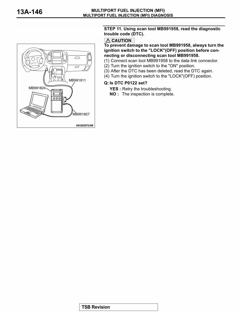
MULTIPORT FUEL INJECTION (MFI) DIAGNOSISMULTIPORT FUEL INJECTION (MFI)13A-146
STEP 11. Using scan tool MB991958, read the diagnostic trouble code (DTC).
CAUTIONTo prevent damage to scan tool MB991958, always turn the ignition switch to the "LOCK"(OFF) position before con-necting or disconnecting scan tool MB991958.(1) Connect scan tool MB991958 to the data link connector.(2) Turn the ignition switch to the "ON" position.(3) After the DTC has been deleted, read the DTC again.(4) Turn the ignition switch to the "LOCK"(OFF) position.Q: Is DTC P0122 set?
YES : Retry the troubleshooting.NO : The inspection is complete.
AK302970AB
MB991911
MB991824
MB991827
TSB Revision
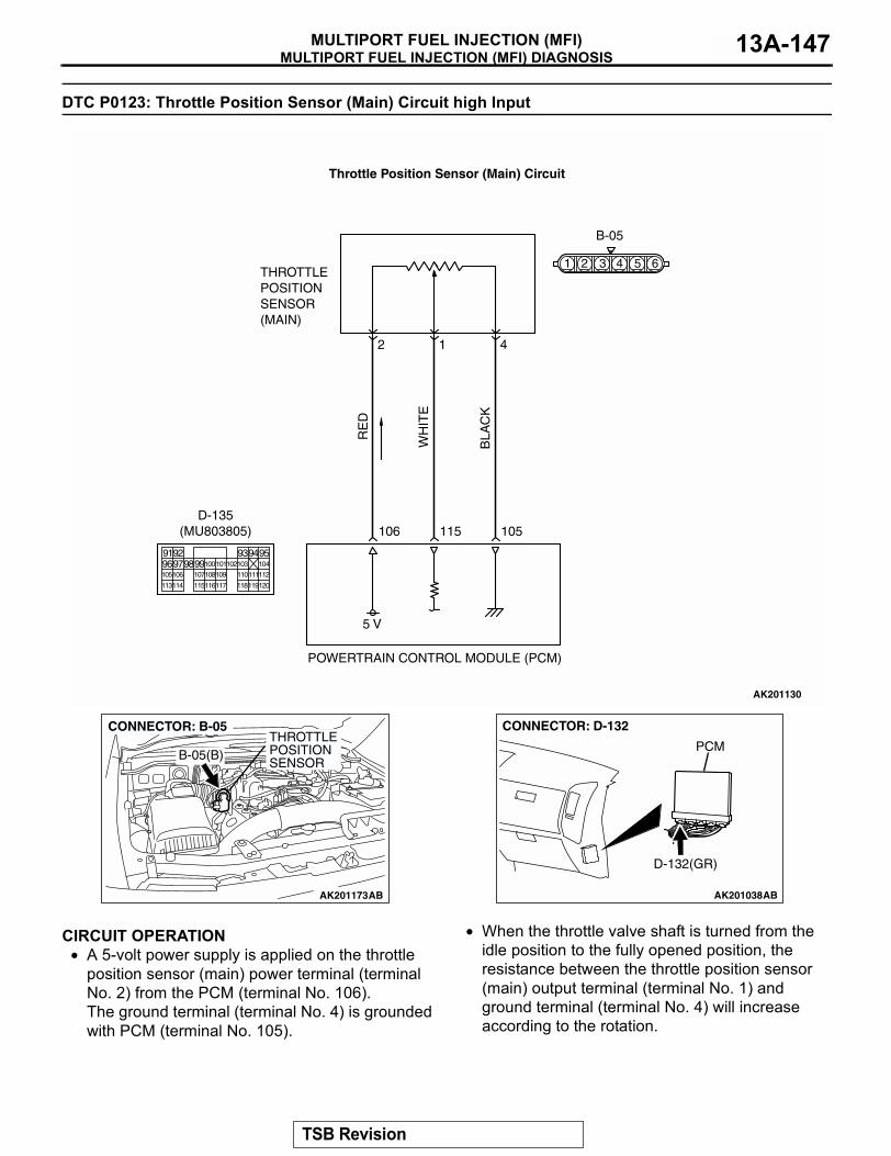
MULTIPORT FUEL INJECTION (MFI) DIAGNOSISMULTIPORT FUEL INJECTION (MFI) 13A-147
DTC P0123: Throttle Position Sensor (Main) Circuit high Input
.
CIRCUIT OPERATION• A 5-volt power supply is applied on the throttle
position sensor (main) power terminal (terminal No. 2) from the PCM (terminal No. 106).The ground terminal (terminal No. 4) is grounded with PCM (terminal No. 105).
• When the throttle valve shaft is turned from the idle position to the fully opened position, the resistance between the throttle position sensor (main) output terminal (terminal No. 1) and ground terminal (terminal No. 4) will increase according to the rotation.
.
AK201130
RE
D
WH
ITE
BLA
CK
B-05
5 V
106
2
THROTTLEPOSITIONSENSOR(MAIN)
POWERTRAIN CONTROL MODULE (PCM)
115 105
1 4
Throttle Position Sensor (Main) Circuit
9192 93949596979899100
105
113114 115116117 118119120
106 107108109 110111112
101102103 104
D-135(MU803805)
61 2 3 4 5
AK201173
THROTTLE POSITION SENSOR
AB
B-05(B)
CONNECTOR: B-05
AK201038
CONNECTOR: D-132
AB
PCM
D-132(GR)
TSB Revision
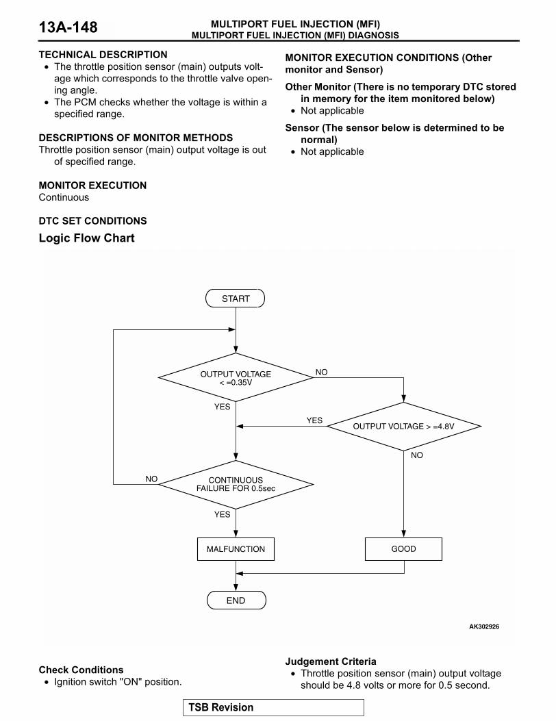
MULTIPORT FUEL INJECTION (MFI) DIAGNOSISMULTIPORT FUEL INJECTION (MFI)13A-148
TECHNICAL DESCRIPTION• The throttle position sensor (main) outputs volt-
age which corresponds to the throttle valve open-ing angle.
• The PCM checks whether the voltage is within a specified range.
.
DESCRIPTIONS OF MONITOR METHODSThrottle position sensor (main) output voltage is out
of specified range..
MONITOR EXECUTIONContinuous
.
MONITOR EXECUTION CONDITIONS (Other monitor and Sensor)
Other Monitor (There is no temporary DTC stored in memory for the item monitored below)
• Not applicable
Sensor (The sensor below is determined to be normal)
• Not applicable.
DTC SET CONDITIONS
Logic Flow Chart
.
Check Conditions• Ignition switch "ON" position.
Judgement Criteria• Throttle position sensor (main) output voltage
should be 4.8 volts or more for 0.5 second.
START
YES
YES
YES
NO
NO
NO
CONTINUOUSFAILURE FOR 0.5sec
MALFUNCTION
END
GOOD
OUTPUT VOLTAGE< =0.35V
OUTPUT VOLTAGE > =4.8V
AK302926
TSB Revision
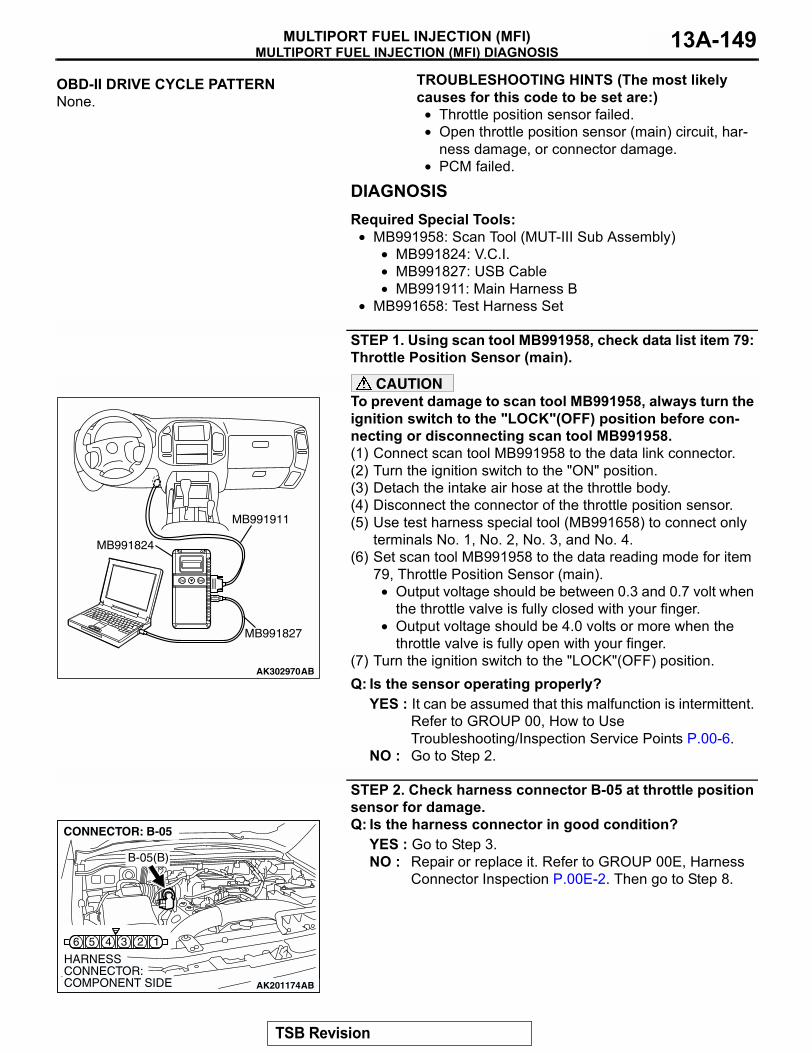
MULTIPORT FUEL INJECTION (MFI) DIAGNOSISMULTIPORT FUEL INJECTION (MFI) 13A-149
.
OBD-II DRIVE CYCLE PATTERNNone..
TROUBLESHOOTING HINTS (The most likely causes for this code to be set are:)
• Throttle position sensor failed.• Open throttle position sensor (main) circuit, har-
ness damage, or connector damage.• PCM failed.
DIAGNOSISRequired Special Tools:
• MB991958: Scan Tool (MUT-III Sub Assembly)• MB991824: V.C.I.• MB991827: USB Cable• MB991911: Main Harness B
• MB991658: Test Harness Set
STEP 1. Using scan tool MB991958, check data list item 79: Throttle Position Sensor (main).
CAUTIONTo prevent damage to scan tool MB991958, always turn the ignition switch to the "LOCK"(OFF) position before con-necting or disconnecting scan tool MB991958.(1) Connect scan tool MB991958 to the data link connector.(2) Turn the ignition switch to the "ON" position.(3) Detach the intake air hose at the throttle body.(4) Disconnect the connector of the throttle position sensor.(5) Use test harness special tool (MB991658) to connect only
terminals No. 1, No. 2, No. 3, and No. 4.(6) Set scan tool MB991958 to the data reading mode for item
79, Throttle Position Sensor (main).• Output voltage should be between 0.3 and 0.7 volt when
the throttle valve is fully closed with your finger.• Output voltage should be 4.0 volts or more when the
throttle valve is fully open with your finger.(7) Turn the ignition switch to the "LOCK"(OFF) position.Q: Is the sensor operating properly?
YES : It can be assumed that this malfunction is intermittent. Refer to GROUP 00, How to Use Troubleshooting/Inspection Service Points P.00-6.
NO : Go to Step 2.
STEP 2. Check harness connector B-05 at throttle position sensor for damage.Q: Is the harness connector in good condition?
YES : Go to Step 3.NO : Repair or replace it. Refer to GROUP 00E, Harness
Connector Inspection P.00E-2. Then go to Step 8.
AK302970AB
MB991911
MB991824
MB991827
AK201174
16 5 4 3 2
B-05(B)
CONNECTOR: B-05
HARNESS CONNECTOR: COMPONENT SIDE AB
TSB Revision
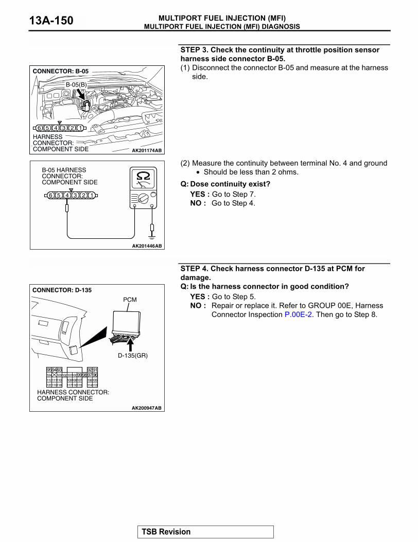
MULTIPORT FUEL INJECTION (MFI) DIAGNOSISMULTIPORT FUEL INJECTION (MFI)13A-150
STEP 3. Check the continuity at throttle position sensor harness side connector B-05.(1) Disconnect the connector B-05 and measure at the harness
side.
(2) Measure the continuity between terminal No. 4 and ground• Should be less than 2 ohms.
Q: Dose continuity exist?YES : Go to Step 7.NO : Go to Step 4.
STEP 4. Check harness connector D-135 at PCM for damage.Q: Is the harness connector in good condition?
YES : Go to Step 5.NO : Repair or replace it. Refer to GROUP 00E, Harness
Connector Inspection P.00E-2. Then go to Step 8.
AK201174
16 5 4 3 2
B-05(B)
CONNECTOR: B-05
HARNESS CONNECTOR: COMPONENT SIDE AB
AK201446
16 5 4 3 2
AB
B-05 HARNESS CONNECTOR: COMPONENT SIDE
AK200947
919293949596979899100101102103104
105106107108109110111112
113114115116117118119120
CONNECTOR: D-135
HARNESS CONNECTOR: COMPONENT SIDE
AB
PCM
D-135(GR)
TSB Revision
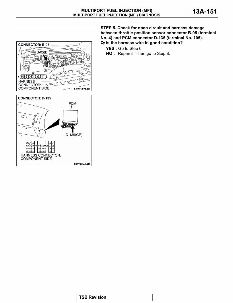
MULTIPORT FUEL INJECTION (MFI) DIAGNOSISMULTIPORT FUEL INJECTION (MFI) 13A-151
STEP 5. Check for open circuit and harness damage between throttle position sensor connector B-05 (terminal No. 4) and PCM connector D-135 (terminal No. 105).Q: Is the harness wire in good condition?
YES : Go to Step 6.NO : Repair it. Then go to Step 8.
AK201174
16 5 4 3 2
B-05(B)
CONNECTOR: B-05
HARNESS CONNECTOR: COMPONENT SIDE AB
AK200947
919293949596979899100101102103104
105106107108109110111112
113114115116117118119120
CONNECTOR: D-135
HARNESS CONNECTOR: COMPONENT SIDE
AB
PCM
D-135(GR)
TSB Revision
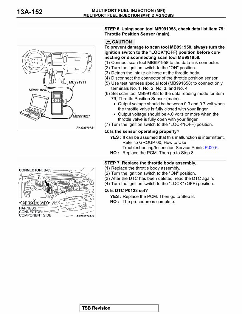
MULTIPORT FUEL INJECTION (MFI) DIAGNOSISMULTIPORT FUEL INJECTION (MFI)13A-152
STEP 6. Using scan tool MB991958, check data list item 79: Throttle Position Sensor (main).
CAUTIONTo prevent damage to scan tool MB991958, always turn the ignition switch to the "LOCK"(OFF) position before con-necting or disconnecting scan tool MB991958.(1) Connect scan tool MB991958 to the data link connector.(2) Turn the ignition switch to the "ON" position.(3) Detach the intake air hose at the throttle body.(4) Disconnect the connector of the throttle position sensor.(5) Use test harness special tool (MB991658) to connect only
terminals No. 1, No. 2, No. 3, and No. 4.(6) Set scan tool MB991958 to the data reading mode for item
79, Throttle Position Sensor (main).• Output voltage should be between 0.3 and 0.7 volt when
the throttle valve is fully closed with your finger.• Output voltage should be 4.0 volts or more when the
throttle valve is fully open with your finger.(7) Turn the ignition switch to the "LOCK"(OFF) position.Q: Is the sensor operating properly?
YES : It can be assumed that this malfunction is intermittent. Refer to GROUP 00, How to Use Troubleshooting/Inspection Service Points P.00-6.
NO : Replace the PCM. Then go to Step 8.
STEP 7. Replace the throttle body assembly.(1) Replace the throttle body assembly.(2) Turn the ignition switch to the "ON" position.(3) After the DTC has been deleted, read the DTC again.(4) Turn the ignition switch to the "LOCK" (OFF) position.Q: Is DTC P0123 set?
YES : Replace the PCM. Then go to Step 8.NO : The procedure is complete.
AK302970AB
MB991911
MB991824
MB991827
AK201174
16 5 4 3 2
B-05(B)
CONNECTOR: B-05
HARNESS CONNECTOR: COMPONENT SIDE AB
TSB Revision
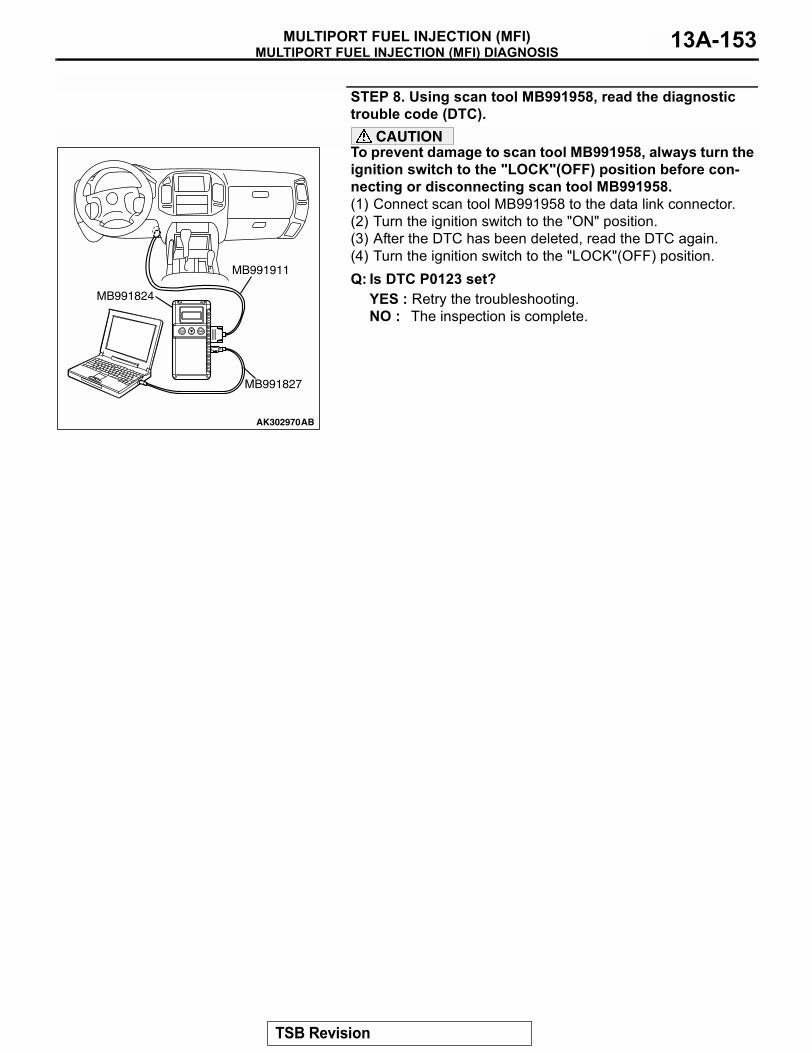
MULTIPORT FUEL INJECTION (MFI) DIAGNOSISMULTIPORT FUEL INJECTION (MFI) 13A-153
STEP 8. Using scan tool MB991958, read the diagnostic trouble code (DTC).
CAUTIONTo prevent damage to scan tool MB991958, always turn the ignition switch to the "LOCK"(OFF) position before con-necting or disconnecting scan tool MB991958.(1) Connect scan tool MB991958 to the data link connector.(2) Turn the ignition switch to the "ON" position.(3) After the DTC has been deleted, read the DTC again.(4) Turn the ignition switch to the "LOCK"(OFF) position.Q: Is DTC P0123 set?
YES : Retry the troubleshooting.NO : The inspection is complete.
AK302970AB
MB991911
MB991824
MB991827
TSB Revision
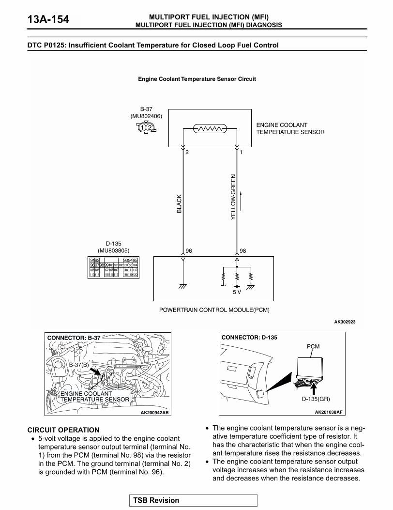
MULTIPORT FUEL INJECTION (MFI) DIAGNOSISMULTIPORT FUEL INJECTION (MFI)13A-154
DTC P0125: Insufficient Coolant Temperature for Closed Loop Fuel Control
.
CIRCUIT OPERATION• 5-volt voltage is applied to the engine coolant
temperature sensor output terminal (terminal No. 1) from the PCM (terminal No. 98) via the resistor in the PCM. The ground terminal (terminal No. 2) is grounded with PCM (terminal No. 96).
• The engine coolant temperature sensor is a neg-ative temperature coefficient type of resistor. It has the characteristic that when the engine cool-ant temperature rises the resistance decreases.
• The engine coolant temperature sensor output voltage increases when the resistance increases and decreases when the resistance decreases.
.
YE
LLO
W-G
RE
EN
BLA
CK
AK302923
ENGINE COOLANTTEMPERATURE SENSOR
POWERTRAIN CONTROL MODULE(PCM)
5 V
98
2
B-37(MU802406)
96
1
Engine Coolant Temperature Sensor Circuit
1 2
9192 93949596979899100
105
113114 115116117 118119120
106 107108109 110111112
101102103 104
D-135(MU803805)
AK200942
ENGINE COOLANTTEMPERATURE SENSOR
AK200942AB
B-37(B)
CONNECTOR: B-37
AK201038AF
CONNECTOR: D-135
PCM
D-135(GR)
TSB Revision
MULTIPORT FUEL INJECTION (MFI) DIAGNOSISMULTIPORT FUEL INJECTION (MFI) 13A-155
TECHNICAL DESCRIPTION• The engine coolant temperature sensor converts
the engine coolant temperature to a voltage and outputs it.
• The PCM checks whether this voltage is within a specified range.
.
DESCRIPTIONS OF MONITOR METHODS• Engine coolant temperature sensor output volt-
age drops from over 40°C (104°F) to under 40°C (104°F) and keeps under 40°C (104°F) for 5 min-utes.
• Engine coolant temperature sensor output volt-age does not reach close loop enable tempera-ture within specified period when engine coolant temperature sensor output voltage at engine start is under 7°C (45°F).
.
MONITOR EXECUTIONContinuous.
MONITOR EXECUTION CONDITIONS (Other monitor and Sensor)
Other Monitor (There is no temporary DTC stored in memory for the item monitored below)
• Not applicable
Sensor (The sensor below is determined to be normal)
• Volume airflow sensor• Engine coolant temperature sensor• Intake air temperature sensor
.
TSB Revision
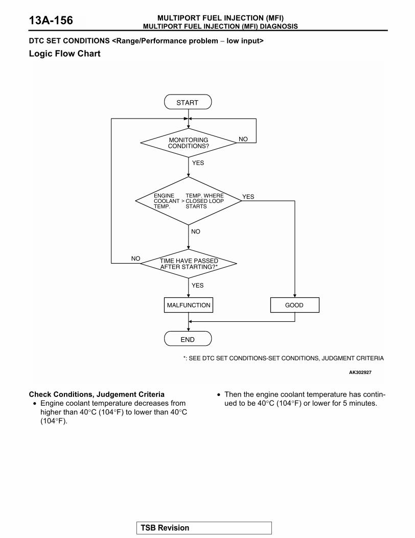
MULTIPORT FUEL INJECTION (MFI) DIAGNOSISMULTIPORT FUEL INJECTION (MFI)13A-156
DTC SET CONDITIONS <Range/Performance problem − low input>
Logic Flow Chart
Check Conditions, Judgement Criteria• Engine coolant temperature decreases from
higher than 40°C (104°F) to lower than 40°C (104°F).
• Then the engine coolant temperature has contin-ued to be 40°C (104°F) or lower for 5 minutes.
.
START
END
YES
NO
NO
YES
MALFUNCTION GOOD
TIME HAVE PASSEDAFTER STARTING?*
ENGINECOOLANTTEMP.
TEMP. WHERECLOSED LOOPSTARTS
>
MONITORINGCONDITIONS?
NO
YES
*: SEE DTC SET CONDITIONS-SET CONDITIONS, JUDGMENT CRITERIA
AK302927
TSB Revision
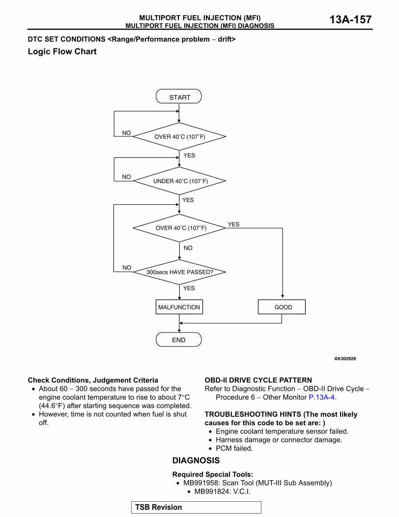
MULTIPORT FUEL INJECTION (MFI) DIAGNOSISMULTIPORT FUEL INJECTION (MFI) 13A-157
DTC SET CONDITIONS <Range/Performance problem − drift>
Logic Flow Chart
Check Conditions, Judgement Criteria• About 60 − 300 seconds have passed for the
engine coolant temperature to rise to about 7°C (44.6°F) after starting sequence was completed.
• However, time is not counted when fuel is shut off.
.
OBD-II DRIVE CYCLE PATTERNRefer to Diagnostic Function − OBD-II Drive Cycle −
Procedure 6 − Other Monitor P.13A-4..
TROUBLESHOOTING HINTS (The most likely causes for this code to be set are: )
• Engine coolant temperature sensor failed.• Harness damage or connector damage.• PCM failed.
DIAGNOSISRequired Special Tools:
• MB991958: Scan Tool (MUT-III Sub Assembly)• MB991824: V.C.I.
START
END
NO
NO
YES
YES
MALFUNCTION GOOD
UNDER 40˚C (107˚F)
300secs HAVE PASSED?
NO
YES
OVER 40˚C (107˚F)
YESOVER 40˚C (107˚F)
NO
AK302928
TSB Revision
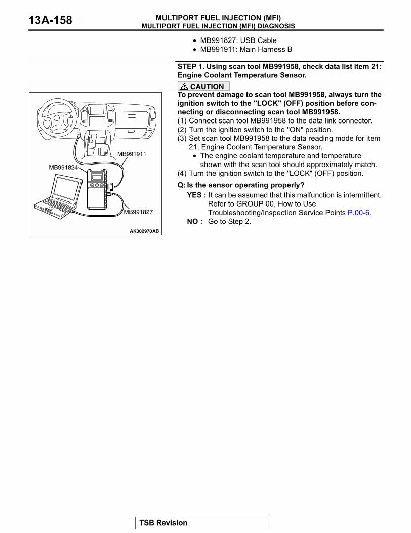
MULTIPORT FUEL INJECTION (MFI) DIAGNOSISMULTIPORT FUEL INJECTION (MFI)13A-158
• MB991827: USB Cable• MB991911: Main Harness B
STEP 1. Using scan tool MB991958, check data list item 21: Engine Coolant Temperature Sensor.
CAUTIONTo prevent damage to scan tool MB991958, always turn the ignition switch to the "LOCK" (OFF) position before con-necting or disconnecting scan tool MB991958.(1) Connect scan tool MB991958 to the data link connector.(2) Turn the ignition switch to the "ON" position.(3) Set scan tool MB991958 to the data reading mode for item
21, Engine Coolant Temperature Sensor.• The engine coolant temperature and temperature
shown with the scan tool should approximately match.(4) Turn the ignition switch to the "LOCK" (OFF) position.Q: Is the sensor operating properly?
YES : It can be assumed that this malfunction is intermittent. Refer to GROUP 00, How to Use Troubleshooting/Inspection Service Points P.00-6.
NO : Go to Step 2.AK302970AB
MB991911
MB991824
MB991827
TSB Revision
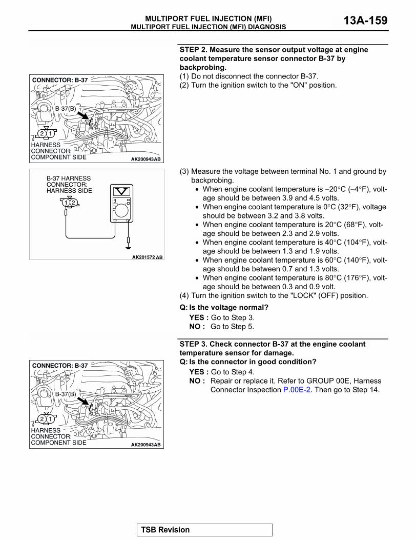
MULTIPORT FUEL INJECTION (MFI) DIAGNOSISMULTIPORT FUEL INJECTION (MFI) 13A-159
STEP 2. Measure the sensor output voltage at engine coolant temperature sensor connector B-37 by backprobing.(1) Do not disconnect the connector B-37.(2) Turn the ignition switch to the "ON" position.
(3) Measure the voltage between terminal No. 1 and ground by backprobing.
• When engine coolant temperature is −20°C (−4°F), volt-age should be between 3.9 and 4.5 volts.
• When engine coolant temperature is 0°C (32°F), voltage should be between 3.2 and 3.8 volts.
• When engine coolant temperature is 20°C (68°F), volt-age should be between 2.3 and 2.9 volts.
• When engine coolant temperature is 40°C (104°F), volt-age should be between 1.3 and 1.9 volts.
• When engine coolant temperature is 60°C (140°F), volt-age should be between 0.7 and 1.3 volts.
• When engine coolant temperature is 80°C (176°F), volt-age should be between 0.3 and 0.9 volt.
(4) Turn the ignition switch to the "LOCK" (OFF) position.Q: Is the voltage normal?
YES : Go to Step 3.NO : Go to Step 5.
STEP 3. Check connector B-37 at the engine coolant temperature sensor for damage.Q: Is the connector in good condition?
YES : Go to Step 4.NO : Repair or replace it. Refer to GROUP 00E, Harness
Connector Inspection P.00E-2. Then go to Step 14.
AK200943
12
AB
HARNESS CONNECTOR: COMPONENT SIDE
CONNECTOR: B-37
B-37(B)
AK201572
21
AB
B-37 HARNESS CONNECTOR: HARNESS SIDE
AK200943
12
AB
HARNESS CONNECTOR: COMPONENT SIDE
CONNECTOR: B-37
B-37(B)
TSB Revision
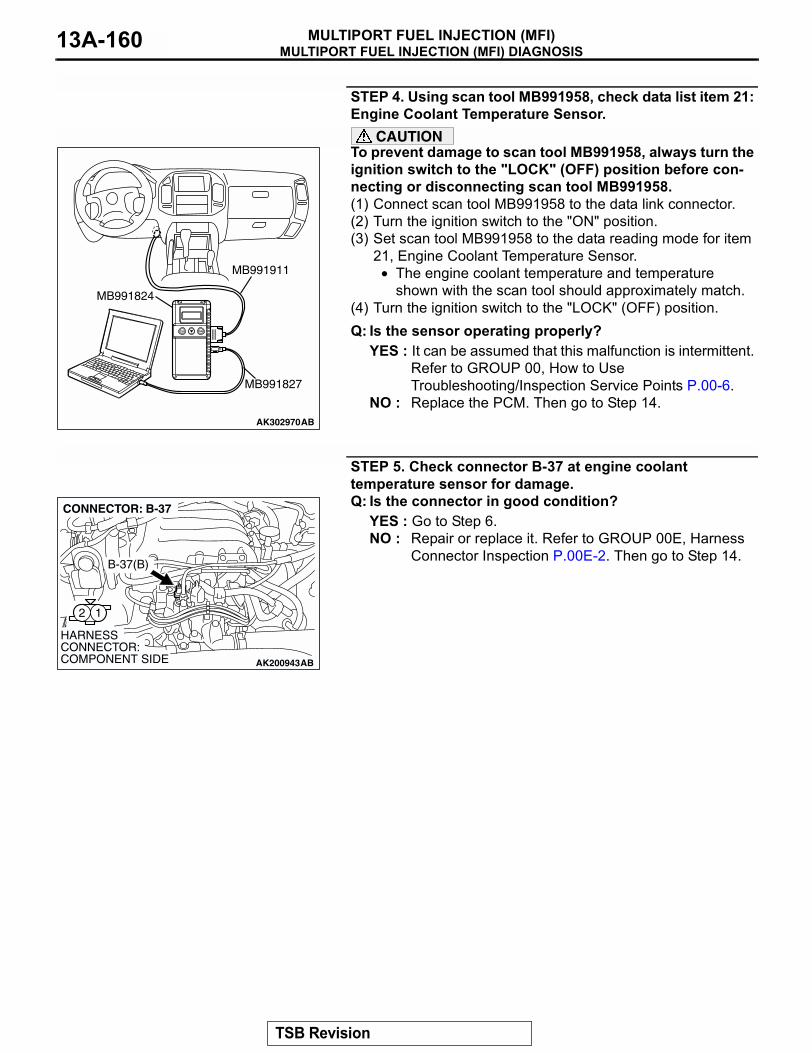
MULTIPORT FUEL INJECTION (MFI) DIAGNOSISMULTIPORT FUEL INJECTION (MFI)13A-160
STEP 4. Using scan tool MB991958, check data list item 21: Engine Coolant Temperature Sensor.
CAUTIONTo prevent damage to scan tool MB991958, always turn the ignition switch to the "LOCK" (OFF) position before con-necting or disconnecting scan tool MB991958.(1) Connect scan tool MB991958 to the data link connector.(2) Turn the ignition switch to the "ON" position.(3) Set scan tool MB991958 to the data reading mode for item
21, Engine Coolant Temperature Sensor.• The engine coolant temperature and temperature
shown with the scan tool should approximately match.(4) Turn the ignition switch to the "LOCK" (OFF) position.Q: Is the sensor operating properly?
YES : It can be assumed that this malfunction is intermittent. Refer to GROUP 00, How to Use Troubleshooting/Inspection Service Points P.00-6.
NO : Replace the PCM. Then go to Step 14.
STEP 5. Check connector B-37 at engine coolant temperature sensor for damage.Q: Is the connector in good condition?
YES : Go to Step 6.NO : Repair or replace it. Refer to GROUP 00E, Harness
Connector Inspection P.00E-2. Then go to Step 14.
AK302970AB
MB991911
MB991824
MB991827
AK200943
12
AB
HARNESS CONNECTOR: COMPONENT SIDE
CONNECTOR: B-37
B-37(B)
TSB Revision
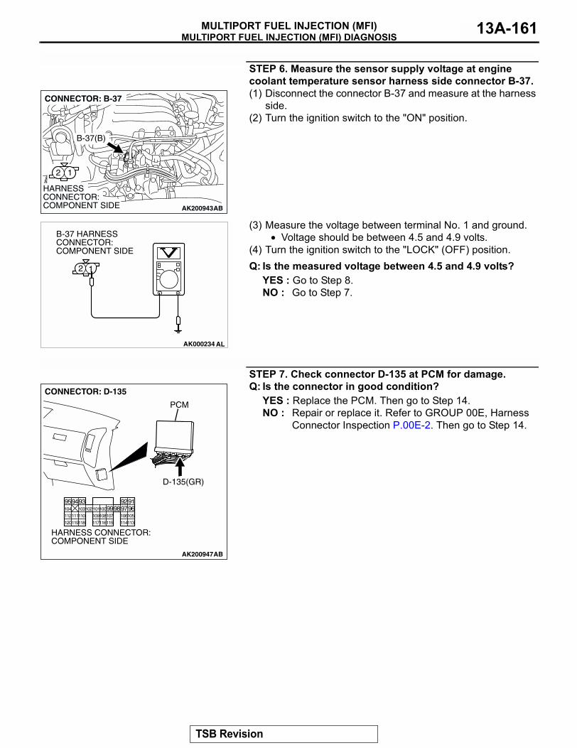
MULTIPORT FUEL INJECTION (MFI) DIAGNOSISMULTIPORT FUEL INJECTION (MFI) 13A-161
STEP 6. Measure the sensor supply voltage at engine coolant temperature sensor harness side connector B-37.(1) Disconnect the connector B-37 and measure at the harness
side.(2) Turn the ignition switch to the "ON" position.
(3) Measure the voltage between terminal No. 1 and ground.• Voltage should be between 4.5 and 4.9 volts.
(4) Turn the ignition switch to the "LOCK" (OFF) position.Q: Is the measured voltage between 4.5 and 4.9 volts?
YES : Go to Step 8.NO : Go to Step 7.
STEP 7. Check connector D-135 at PCM for damage.Q: Is the connector in good condition?
YES : Replace the PCM. Then go to Step 14.NO : Repair or replace it. Refer to GROUP 00E, Harness
Connector Inspection P.00E-2. Then go to Step 14.
AK200943
12
AB
HARNESS CONNECTOR: COMPONENT SIDE
CONNECTOR: B-37
B-37(B)
AK000234 AL
2 1
B-37 HARNESS CONNECTOR: COMPONENT SIDE
AK200947
919293949596979899100101102103104
105106107108109110111112
113114115116117118119120
CONNECTOR: D-135
HARNESS CONNECTOR: COMPONENT SIDE
AB
PCM
D-135(GR)
TSB Revision
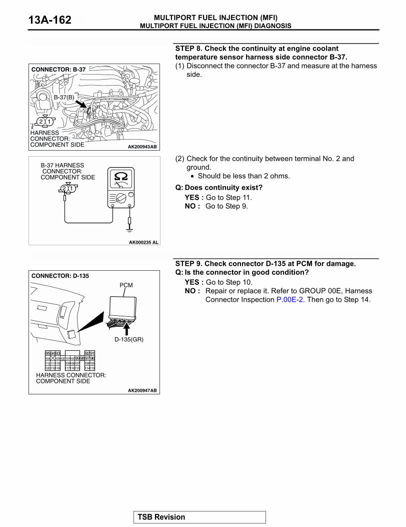
MULTIPORT FUEL INJECTION (MFI) DIAGNOSISMULTIPORT FUEL INJECTION (MFI)13A-162
STEP 8. Check the continuity at engine coolant temperature sensor harness side connector B-37.(1) Disconnect the connector B-37 and measure at the harness
side.
(2) Check for the continuity between terminal No. 2 and ground.
• Should be less than 2 ohms.Q: Does continuity exist?
YES : Go to Step 11.NO : Go to Step 9.
STEP 9. Check connector D-135 at PCM for damage.Q: Is the connector in good condition?
YES : Go to Step 10.NO : Repair or replace it. Refer to GROUP 00E, Harness
Connector Inspection P.00E-2. Then go to Step 14.
AK200943
12
AB
HARNESS CONNECTOR: COMPONENT SIDE
CONNECTOR: B-37
B-37(B)
AK000235
B-37 HARNESS CONNECTOR: COMPONENT SIDE
12
AL
AK200947
919293949596979899100101102103104
105106107108109110111112
113114115116117118119120
CONNECTOR: D-135
HARNESS CONNECTOR: COMPONENT SIDE
AB
PCM
D-135(GR)
TSB Revision
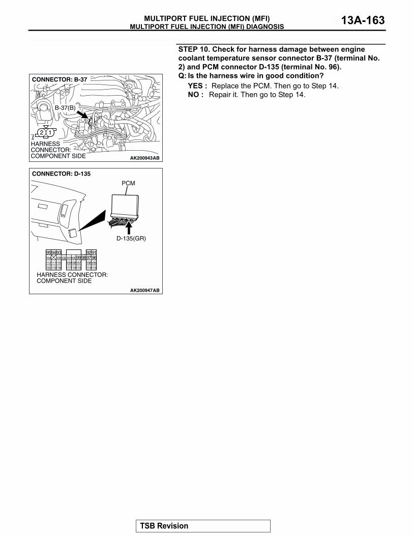
MULTIPORT FUEL INJECTION (MFI) DIAGNOSISMULTIPORT FUEL INJECTION (MFI) 13A-163
STEP 10. Check for harness damage between engine coolant temperature sensor connector B-37 (terminal No. 2) and PCM connector D-135 (terminal No. 96).Q: Is the harness wire in good condition?
YES : Replace the PCM. Then go to Step 14.NO : Repair it. Then go to Step 14.
AK200943
12
AB
HARNESS CONNECTOR: COMPONENT SIDE
CONNECTOR: B-37
B-37(B)
AK200947
919293949596979899100101102103104
105106107108109110111112
113114115116117118119120
CONNECTOR: D-135
HARNESS CONNECTOR: COMPONENT SIDE
AB
PCM
D-135(GR)
TSB Revision
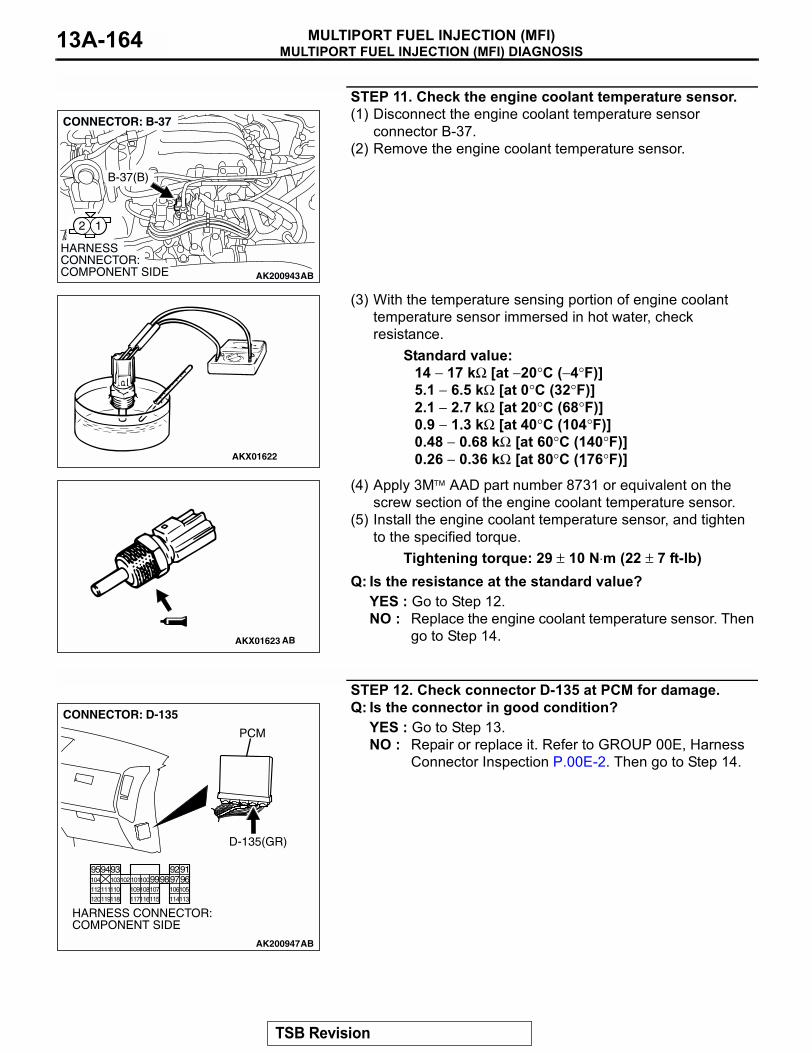
MULTIPORT FUEL INJECTION (MFI) DIAGNOSISMULTIPORT FUEL INJECTION (MFI)13A-164
STEP 11. Check the engine coolant temperature sensor.(1) Disconnect the engine coolant temperature sensor
connector B-37.(2) Remove the engine coolant temperature sensor.
(3) With the temperature sensing portion of engine coolant temperature sensor immersed in hot water, check resistance.
Standard value:14 − 17 kΩ [at −20°C (−4°F)]5.1 − 6.5 kΩ [at 0°C (32°F)]2.1 − 2.7 kΩ [at 20°C (68°F)]0.9 − 1.3 kΩ [at 40°C (104°F)]0.48 − 0.68 kΩ [at 60°C (140°F)]0.26 − 0.36 kΩ [at 80°C (176°F)]
(4) Apply 3M AAD part number 8731 or equivalent on the screw section of the engine coolant temperature sensor.
(5) Install the engine coolant temperature sensor, and tighten to the specified torque.
Tightening torque: 29 ± 10 N⋅m (22 ± 7 ft-lb)Q: Is the resistance at the standard value?
YES : Go to Step 12.NO : Replace the engine coolant temperature sensor. Then
go to Step 14.
STEP 12. Check connector D-135 at PCM for damage.Q: Is the connector in good condition?
YES : Go to Step 13.NO : Repair or replace it. Refer to GROUP 00E, Harness
Connector Inspection P.00E-2. Then go to Step 14.
AK200943
12
AB
HARNESS CONNECTOR: COMPONENT SIDE
CONNECTOR: B-37
B-37(B)
AKX01622
AKX01623 AB
AK200947
919293949596979899100101102103104
105106107108109110111112
113114115116117118119120
CONNECTOR: D-135
HARNESS CONNECTOR: COMPONENT SIDE
AB
PCM
D-135(GR)
TSB Revision
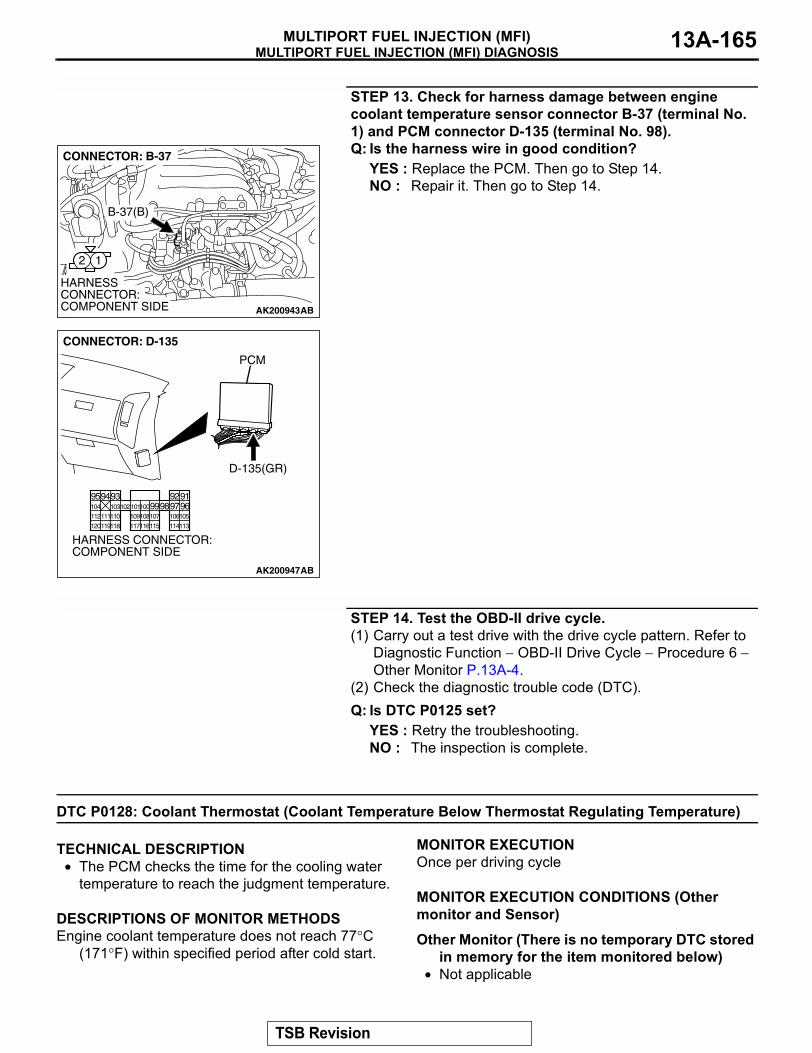
MULTIPORT FUEL INJECTION (MFI) DIAGNOSISMULTIPORT FUEL INJECTION (MFI) 13A-165
STEP 13. Check for harness damage between engine coolant temperature sensor connector B-37 (terminal No. 1) and PCM connector D-135 (terminal No. 98).Q: Is the harness wire in good condition?
YES : Replace the PCM. Then go to Step 14.NO : Repair it. Then go to Step 14.
STEP 14. Test the OBD-II drive cycle.(1) Carry out a test drive with the drive cycle pattern. Refer to
Diagnostic Function − OBD-II Drive Cycle − Procedure 6 − Other Monitor P.13A-4.
(2) Check the diagnostic trouble code (DTC).Q: Is DTC P0125 set?
YES : Retry the troubleshooting.NO : The inspection is complete.
DTC P0128: Coolant Thermostat (Coolant Temperature Below Thermostat Regulating Temperature)
.
TECHNICAL DESCRIPTION• The PCM checks the time for the cooling water
temperature to reach the judgment temperature..
DESCRIPTIONS OF MONITOR METHODSEngine coolant temperature does not reach 77°C
(171°F) within specified period after cold start..
MONITOR EXECUTIONOnce per driving cycle.
MONITOR EXECUTION CONDITIONS (Other monitor and Sensor)
Other Monitor (There is no temporary DTC stored in memory for the item monitored below)
• Not applicable
AK200943
12
AB
HARNESS CONNECTOR: COMPONENT SIDE
CONNECTOR: B-37
B-37(B)
AK200947
919293949596979899100101102103104
105106107108109110111112
113114115116117118119120
CONNECTOR: D-135
HARNESS CONNECTOR: COMPONENT SIDE
AB
PCM
D-135(GR)
TSB Revision
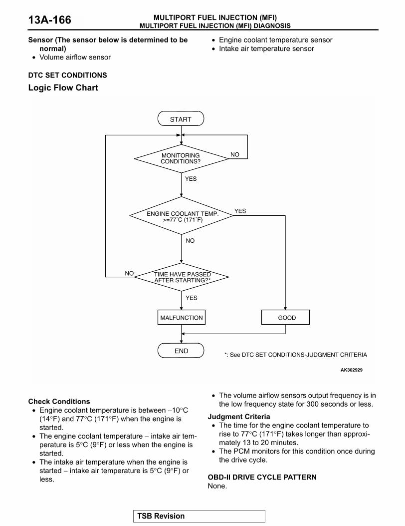
MULTIPORT FUEL INJECTION (MFI) DIAGNOSISMULTIPORT FUEL INJECTION (MFI)13A-166
Sensor (The sensor below is determined to be normal)
• Volume airflow sensor
• Engine coolant temperature sensor• Intake air temperature sensor
.
DTC SET CONDITIONS
Logic Flow Chart
.
Check Conditions• Engine coolant temperature is between −10°C
(14°F) and 77°C (171°F) when the engine is started.
• The engine coolant temperature − intake air tem-perature is 5°C (9°F) or less when the engine is started.
• The intake air temperature when the engine is started − intake air temperature is 5°C (9°F) or less.
• The volume airflow sensors output frequency is in the low frequency state for 300 seconds or less.
Judgment Criteria• The time for the engine coolant temperature to
rise to 77°C (171°F) takes longer than approxi-mately 13 to 20 minutes.
• The PCM monitors for this condition once during the drive cycle.
.
OBD-II DRIVE CYCLE PATTERNNone..
START
END
YES
NO
NO
YES
MALFUNCTION GOOD
TIME HAVE PASSEDAFTER STARTING?*
ENGINE COOLANT TEMP.>=77˚C (171˚F)
*: See DTC SET CONDITIONS-JUDGMENT CRITERIA
MONITORINGCONDITIONS?
NO
YES
AK302929
TSB Revision
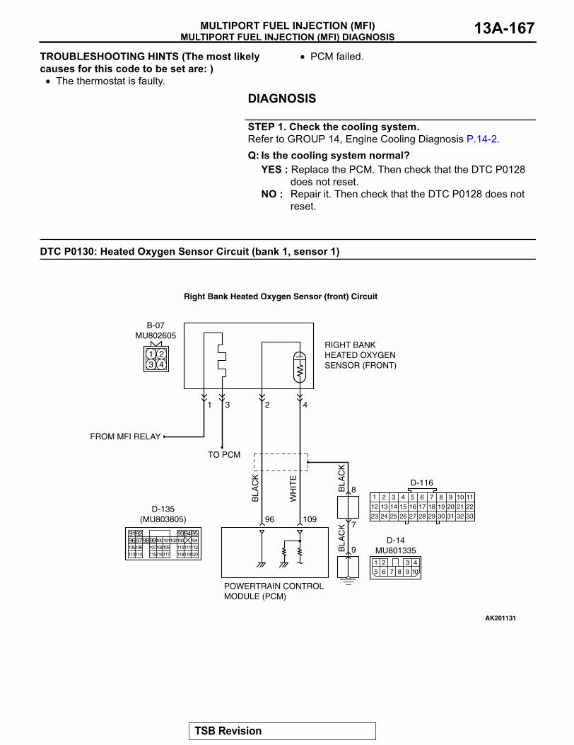
MULTIPORT FUEL INJECTION (MFI) DIAGNOSISMULTIPORT FUEL INJECTION (MFI) 13A-167
TROUBLESHOOTING HINTS (The most likely causes for this code to be set are: )
• The thermostat is faulty.
• PCM failed.
DIAGNOSIS
STEP 1. Check the cooling system.Refer to GROUP 14, Engine Cooling Diagnosis P.14-2.Q: Is the cooling system normal?
YES : Replace the PCM. Then check that the DTC P0128 does not reset.
NO : Repair it. Then check that the DTC P0128 does not reset.
DTC P0130: Heated Oxygen Sensor Circuit (bank 1, sensor 1) B
LA
CK
BL
AC
KB
LA
CK
TO PCM
FROM MFI RELAY
WH
ITE
AK201131
96 109
431
RIGHT BANKHEATED OXYGENSENSOR (FRONT)
POWERTRAIN CONTROLMODULE (PCM)
8
9
7
1 243
B-07MU802605
2
1
12
23 24 25 26
2
13
3
14
4
15
5
16
6
17
7
18
8
19
9
20 21 22
27 28 29 30 31 32 33
10 11
D-116
15 7 8
3 49 10
26
D-14MU801335
Right Bank Heated Oxygen Sensor (front) Circuit
9192 93949596979899100
105
113114 115116117 118119120
106 107108109 110111112
101102103 104
D-135(MU803805)
TSB Revision
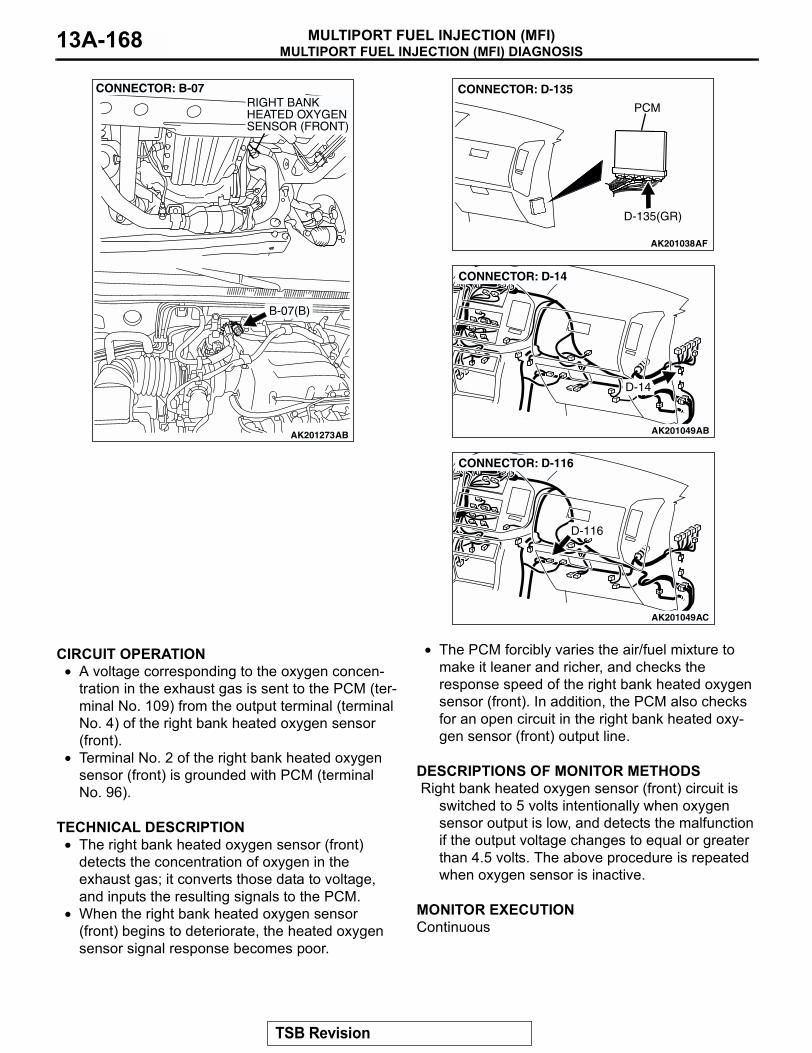
MULTIPORT FUEL INJECTION (MFI) DIAGNOSISMULTIPORT FUEL INJECTION (MFI)13A-168
.
CIRCUIT OPERATION• A voltage corresponding to the oxygen concen-
tration in the exhaust gas is sent to the PCM (ter-minal No. 109) from the output terminal (terminal No. 4) of the right bank heated oxygen sensor (front).
• Terminal No. 2 of the right bank heated oxygen sensor (front) is grounded with PCM (terminal No. 96).
.
TECHNICAL DESCRIPTION• The right bank heated oxygen sensor (front)
detects the concentration of oxygen in the exhaust gas; it converts those data to voltage, and inputs the resulting signals to the PCM.
• When the right bank heated oxygen sensor (front) begins to deteriorate, the heated oxygen sensor signal response becomes poor.
• The PCM forcibly varies the air/fuel mixture to make it leaner and richer, and checks the response speed of the right bank heated oxygen sensor (front). In addition, the PCM also checks for an open circuit in the right bank heated oxy-gen sensor (front) output line.
.
DESCRIPTIONS OF MONITOR METHODS Right bank heated oxygen sensor (front) circuit is
switched to 5 volts intentionally when oxygen sensor output is low, and detects the malfunction if the output voltage changes to equal or greater than 4.5 volts. The above procedure is repeated when oxygen sensor is inactive.
.
MONITOR EXECUTIONContinuous.
AK201273
CONNECTOR: B-07
B-07(B)
AB
RIGHT BANKHEATED OXYGENSENSOR (FRONT)
AK201038AF
CONNECTOR: D-135
PCM
D-135(GR)
AK201049
D-14
AB
CONNECTOR: D-14
AK201049
CONNECTOR: D-116
D-116
AC
TSB Revision
MULTIPORT FUEL INJECTION (MFI) DIAGNOSISMULTIPORT FUEL INJECTION (MFI) 13A-169
MONITOR EXECUTION CONDITIONS (Other monitor and Sensor)
Other Monitor (There is no temporary DTC stored in memory for the item monitored below)
• Heated oxygen sensor heater (front) monitor• Misfire monitor• Fuel system monitor
Sensor (The sensor below is determined to be normal)
• Volume airflow sensor• Engine coolant temperature sensor• Intake air temperature sensor• Barometric pressure sensor• Accelerator pedal position sensor
.
TSB Revision
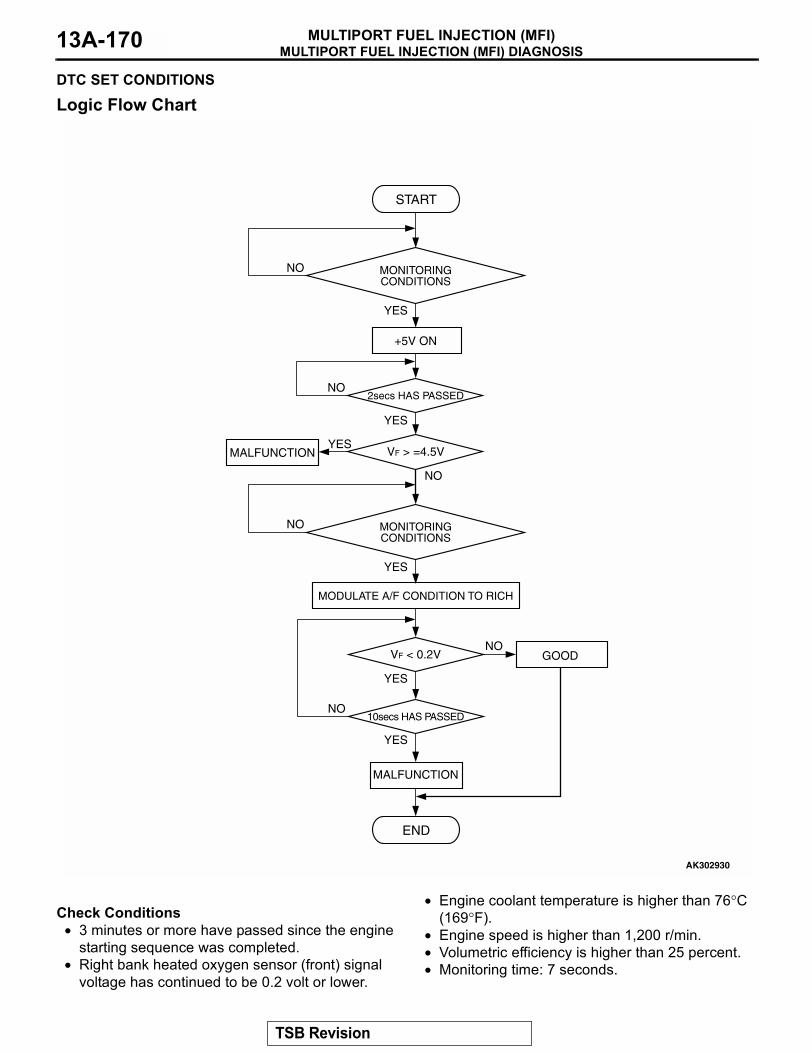
MULTIPORT FUEL INJECTION (MFI) DIAGNOSISMULTIPORT FUEL INJECTION (MFI)13A-170
DTC SET CONDITIONS
Logic Flow Chart
.
Check Conditions• 3 minutes or more have passed since the engine
starting sequence was completed.• Right bank heated oxygen sensor (front) signal
voltage has continued to be 0.2 volt or lower.
• Engine coolant temperature is higher than 76°C (169°F).
• Engine speed is higher than 1,200 r/min.• Volumetric efficiency is higher than 25 percent.• Monitoring time: 7 seconds.
START
VF > =4.5V
2secs HAS PASSED
YES
YES
YES
NO
NO
NO
MALFUNCTION
MONITORINGCONDITIONS
YES
NO MONITORINGCONDITIONS
+5V ON
AK302930
VF < 0.2V
10secs HAS PASSED
YES
YES
NO
NO
END
MALFUNCTION
GOOD
MODULATE A/F CONDITION TO RICH
TSB Revision
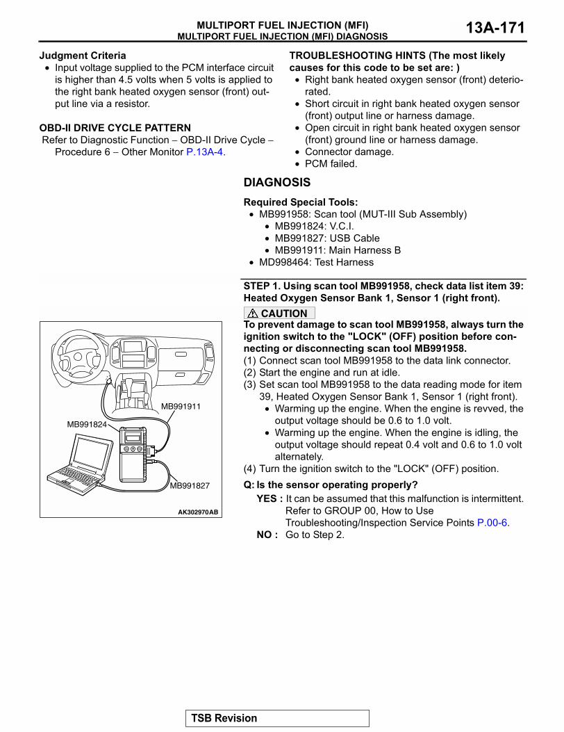
MULTIPORT FUEL INJECTION (MFI) DIAGNOSISMULTIPORT FUEL INJECTION (MFI) 13A-171
Judgment Criteria• Input voltage supplied to the PCM interface circuit
is higher than 4.5 volts when 5 volts is applied to the right bank heated oxygen sensor (front) out-put line via a resistor.
.
OBD-II DRIVE CYCLE PATTERN Refer to Diagnostic Function − OBD-II Drive Cycle −
Procedure 6 − Other Monitor P.13A-4..
TROUBLESHOOTING HINTS (The most likely causes for this code to be set are: )
• Right bank heated oxygen sensor (front) deterio-rated.
• Short circuit in right bank heated oxygen sensor (front) output line or harness damage.
• Open circuit in right bank heated oxygen sensor (front) ground line or harness damage.
• Connector damage.• PCM failed.
DIAGNOSISRequired Special Tools:
• MB991958: Scan tool (MUT-III Sub Assembly)• MB991824: V.C.I.• MB991827: USB Cable• MB991911: Main Harness B
• MD998464: Test Harness
STEP 1. Using scan tool MB991958, check data list item 39: Heated Oxygen Sensor Bank 1, Sensor 1 (right front).
CAUTIONTo prevent damage to scan tool MB991958, always turn the ignition switch to the "LOCK" (OFF) position before con-necting or disconnecting scan tool MB991958.(1) Connect scan tool MB991958 to the data link connector.(2) Start the engine and run at idle.(3) Set scan tool MB991958 to the data reading mode for item
39, Heated Oxygen Sensor Bank 1, Sensor 1 (right front).• Warming up the engine. When the engine is revved, the
output voltage should be 0.6 to 1.0 volt.• Warming up the engine. When the engine is idling, the
output voltage should repeat 0.4 volt and 0.6 to 1.0 volt alternately.
(4) Turn the ignition switch to the "LOCK" (OFF) position.Q: Is the sensor operating properly?
YES : It can be assumed that this malfunction is intermittent. Refer to GROUP 00, How to Use Troubleshooting/Inspection Service Points P.00-6.
NO : Go to Step 2.
AK302970AB
MB991911
MB991824
MB991827
TSB Revision
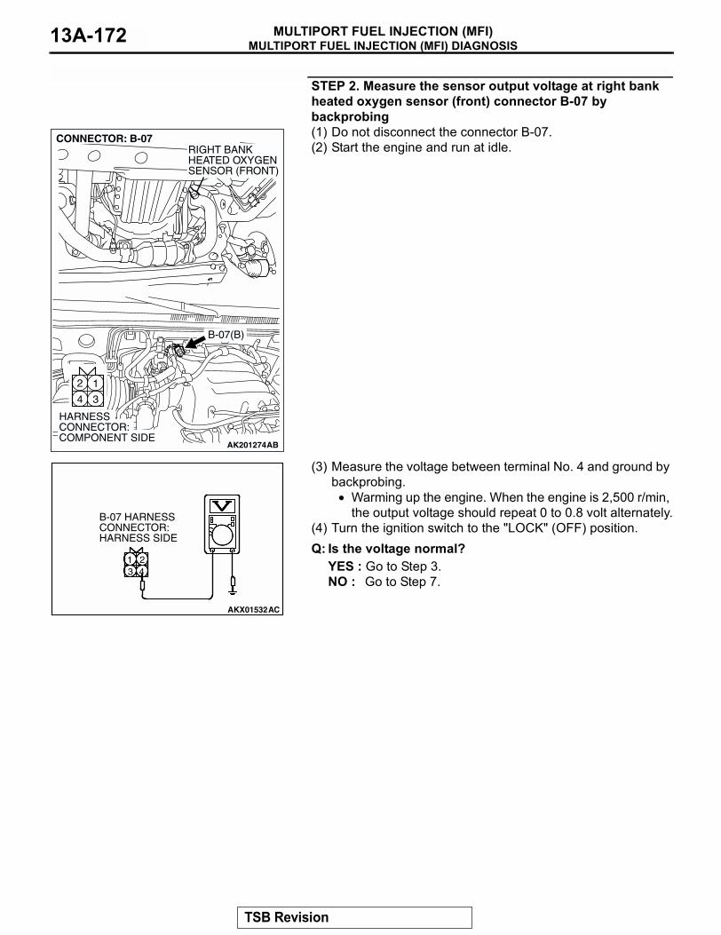
MULTIPORT FUEL INJECTION (MFI) DIAGNOSISMULTIPORT FUEL INJECTION (MFI)13A-172
STEP 2. Measure the sensor output voltage at right bank heated oxygen sensor (front) connector B-07 by backprobing(1) Do not disconnect the connector B-07.(2) Start the engine and run at idle.
(3) Measure the voltage between terminal No. 4 and ground by backprobing.
• Warming up the engine. When the engine is 2,500 r/min, the output voltage should repeat 0 to 0.8 volt alternately.
(4) Turn the ignition switch to the "LOCK" (OFF) position.Q: Is the voltage normal?
YES : Go to Step 3.NO : Go to Step 7.
AK201274
12
34
CONNECTOR: B-07
B-07(B)
AB
HARNESS CONNECTOR: COMPONENT SIDE
RIGHT BANKHEATED OXYGENSENSOR (FRONT)
AKX01532AC
31 2
4
B-07 HARNESS CONNECTOR: HARNESS SIDE
TSB Revision
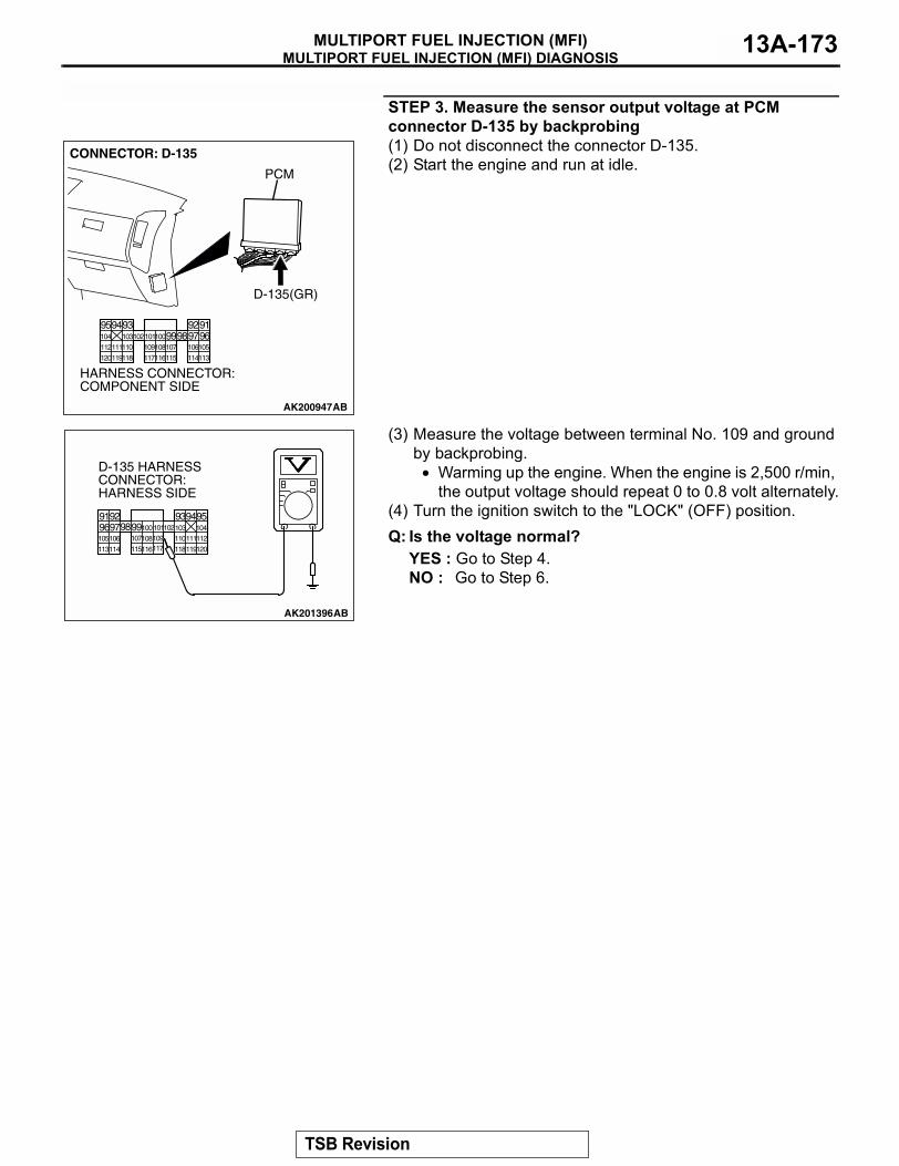
MULTIPORT FUEL INJECTION (MFI) DIAGNOSISMULTIPORT FUEL INJECTION (MFI) 13A-173
STEP 3. Measure the sensor output voltage at PCM connector D-135 by backprobing(1) Do not disconnect the connector D-135.(2) Start the engine and run at idle.
(3) Measure the voltage between terminal No. 109 and ground by backprobing.
• Warming up the engine. When the engine is 2,500 r/min, the output voltage should repeat 0 to 0.8 volt alternately.
(4) Turn the ignition switch to the "LOCK" (OFF) position.Q: Is the voltage normal?
YES : Go to Step 4.NO : Go to Step 6.
AK200947
919293949596979899100101102103104
105106107108109110111112
113114115116117118119120
CONNECTOR: D-135
HARNESS CONNECTOR: COMPONENT SIDE
AB
PCM
D-135(GR)
AK201396
9192 93949596979899100101102103 104
105106 107108109 110111112
113114 115116117 118119120
AB
D-135 HARNESS CONNECTOR:HARNESS SIDE
TSB Revision
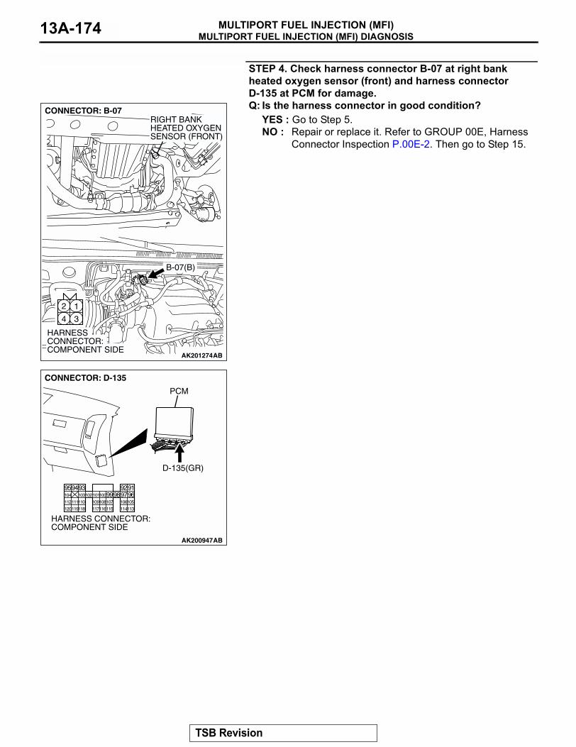
MULTIPORT FUEL INJECTION (MFI) DIAGNOSISMULTIPORT FUEL INJECTION (MFI)13A-174
STEP 4. Check harness connector B-07 at right bank heated oxygen sensor (front) and harness connector D-135 at PCM for damage.Q: Is the harness connector in good condition?
YES : Go to Step 5.NO : Repair or replace it. Refer to GROUP 00E, Harness
Connector Inspection P.00E-2. Then go to Step 15.
AK201274
12
34
CONNECTOR: B-07
B-07(B)
AB
HARNESS CONNECTOR: COMPONENT SIDE
RIGHT BANKHEATED OXYGENSENSOR (FRONT)
AK200947
919293949596979899100101102103104
105106107108109110111112
113114115116117118119120
CONNECTOR: D-135
HARNESS CONNECTOR: COMPONENT SIDE
AB
PCM
D-135(GR)
TSB Revision
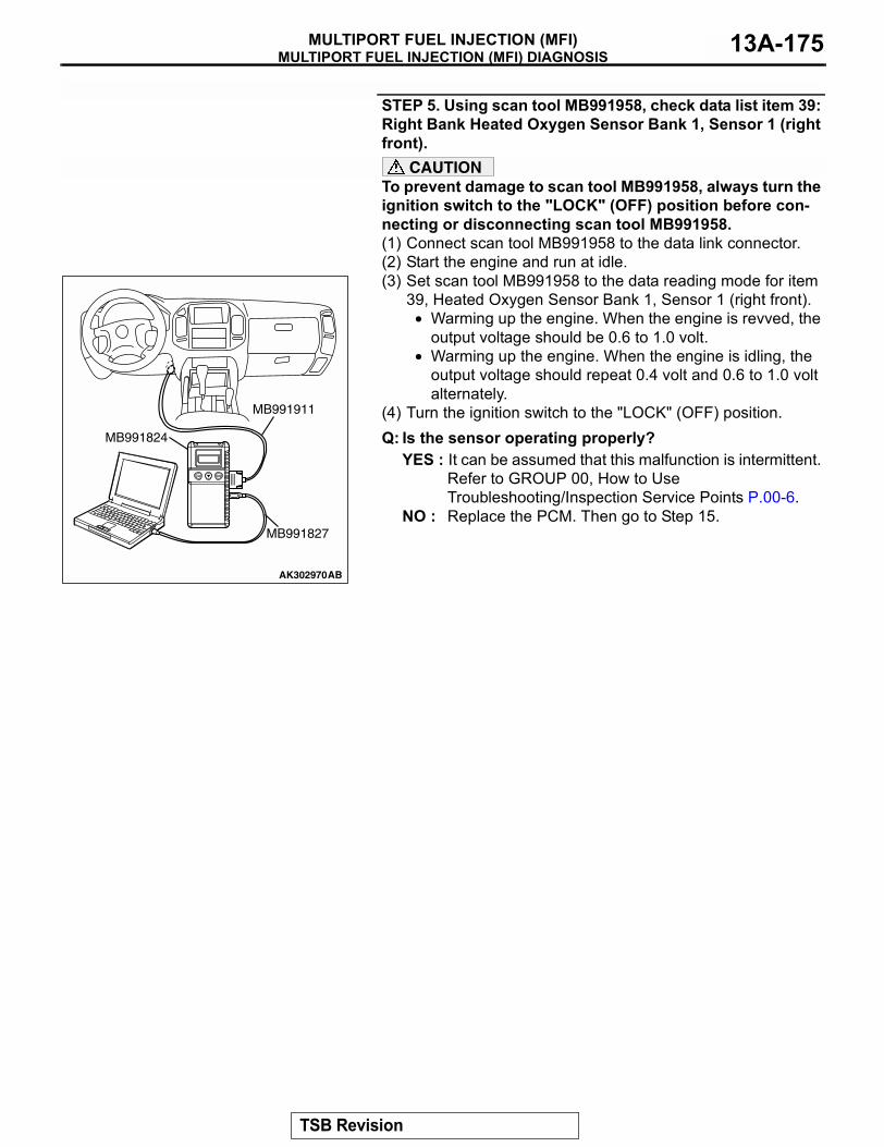
MULTIPORT FUEL INJECTION (MFI) DIAGNOSISMULTIPORT FUEL INJECTION (MFI) 13A-175
STEP 5. Using scan tool MB991958, check data list item 39: Right Bank Heated Oxygen Sensor Bank 1, Sensor 1 (right front).
CAUTIONTo prevent damage to scan tool MB991958, always turn the ignition switch to the "LOCK" (OFF) position before con-necting or disconnecting scan tool MB991958.(1) Connect scan tool MB991958 to the data link connector.(2) Start the engine and run at idle.(3) Set scan tool MB991958 to the data reading mode for item
39, Heated Oxygen Sensor Bank 1, Sensor 1 (right front).• Warming up the engine. When the engine is revved, the
output voltage should be 0.6 to 1.0 volt.• Warming up the engine. When the engine is idling, the
output voltage should repeat 0.4 volt and 0.6 to 1.0 volt alternately.
(4) Turn the ignition switch to the "LOCK" (OFF) position.Q: Is the sensor operating properly?
YES : It can be assumed that this malfunction is intermittent. Refer to GROUP 00, How to Use Troubleshooting/Inspection Service Points P.00-6.
NO : Replace the PCM. Then go to Step 15.
AK302970AB
MB991911
MB991824
MB991827
TSB Revision
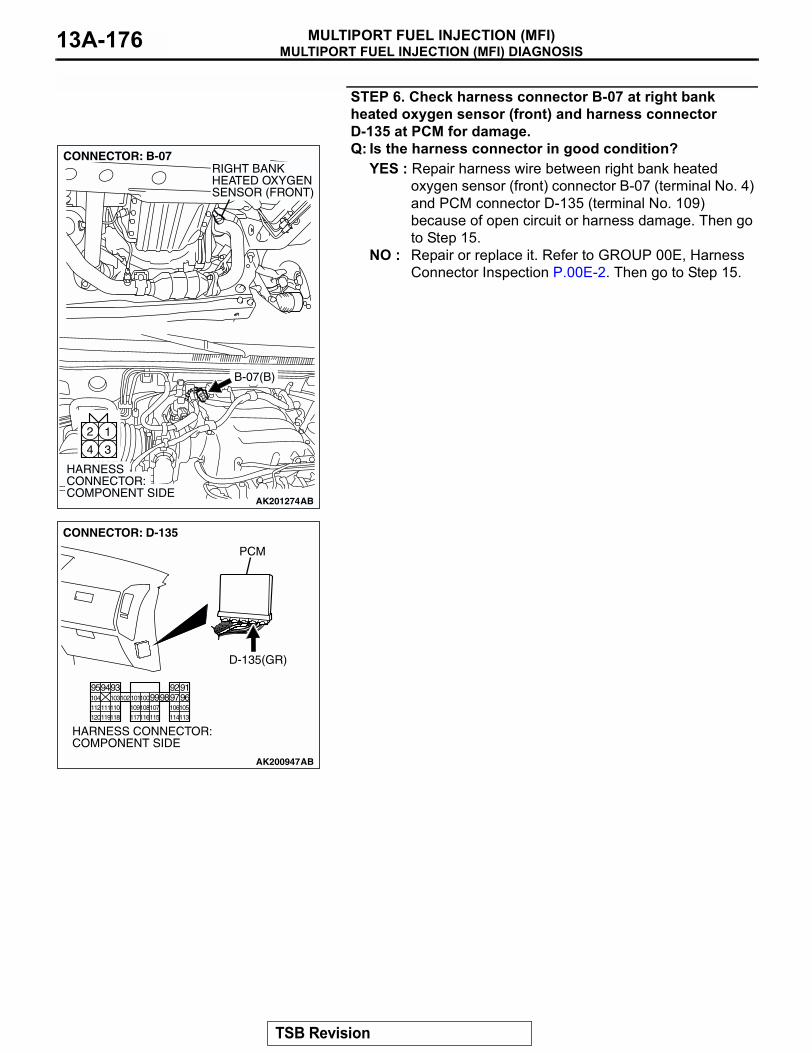
MULTIPORT FUEL INJECTION (MFI) DIAGNOSISMULTIPORT FUEL INJECTION (MFI)13A-176
STEP 6. Check harness connector B-07 at right bank heated oxygen sensor (front) and harness connector D-135 at PCM for damage.Q: Is the harness connector in good condition?
YES : Repair harness wire between right bank heated oxygen sensor (front) connector B-07 (terminal No. 4) and PCM connector D-135 (terminal No. 109) because of open circuit or harness damage. Then go to Step 15.
NO : Repair or replace it. Refer to GROUP 00E, Harness Connector Inspection P.00E-2. Then go to Step 15.
AK201274
12
34
CONNECTOR: B-07
B-07(B)
AB
HARNESS CONNECTOR: COMPONENT SIDE
RIGHT BANKHEATED OXYGENSENSOR (FRONT)
AK200947
919293949596979899100101102103104
105106107108109110111112
113114115116117118119120
CONNECTOR: D-135
HARNESS CONNECTOR: COMPONENT SIDE
AB
PCM
D-135(GR)
TSB Revision
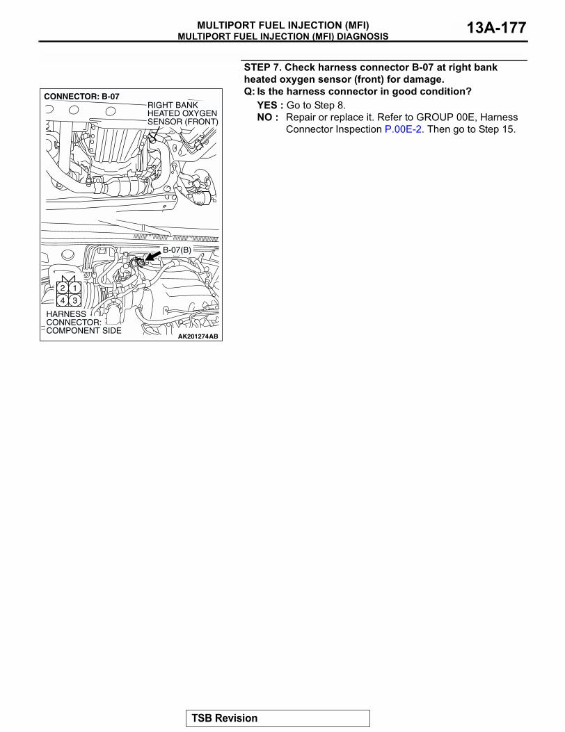
MULTIPORT FUEL INJECTION (MFI) DIAGNOSISMULTIPORT FUEL INJECTION (MFI) 13A-177
STEP 7. Check harness connector B-07 at right bank heated oxygen sensor (front) for damage.Q: Is the harness connector in good condition?
YES : Go to Step 8.NO : Repair or replace it. Refer to GROUP 00E, Harness
Connector Inspection P.00E-2. Then go to Step 15.
AK201274
12
34
CONNECTOR: B-07
B-07(B)
AB
HARNESS CONNECTOR: COMPONENT SIDE
RIGHT BANKHEATED OXYGENSENSOR (FRONT)
TSB Revision
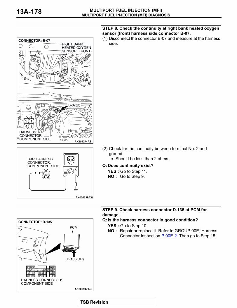
MULTIPORT FUEL INJECTION (MFI) DIAGNOSISMULTIPORT FUEL INJECTION (MFI)13A-178
STEP 8. Check the continuity at right bank heated oxygen sensor (front) harness side connector B-07.(1) Disconnect the connector B-07 and measure at the harness
side.
(2) Check for the continuity between terminal No. 2 and ground.
• Should be less than 2 ohms.Q: Does continuity exist?
YES : Go to Step 11.NO : Go to Step 9.
STEP 9. Check harness connector D-135 at PCM for damage.Q: Is the harness connector in good condition?
YES : Go to Step 10.NO : Repair or replace it. Refer to GROUP 00E, Harness
Connector Inspection P.00E-2. Then go to Step 15.
AK201274
12
34
CONNECTOR: B-07
B-07(B)
AB
HARNESS CONNECTOR: COMPONENT SIDE
RIGHT BANKHEATED OXYGENSENSOR (FRONT)
AK000239AW
124 3
B-07 HARNESS CONNECTOR: COMPONENT SIDE
AK200947
919293949596979899100101102103104
105106107108109110111112
113114115116117118119120
CONNECTOR: D-135
HARNESS CONNECTOR: COMPONENT SIDE
AB
PCM
D-135(GR)
TSB Revision
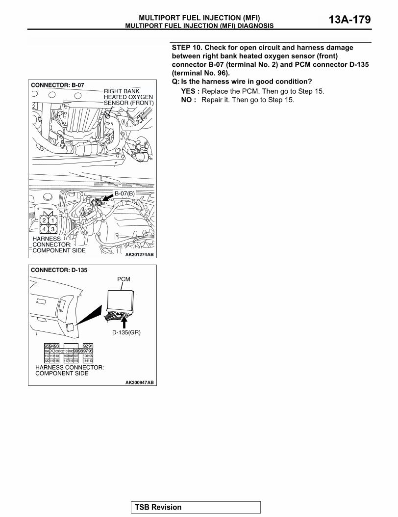
MULTIPORT FUEL INJECTION (MFI) DIAGNOSISMULTIPORT FUEL INJECTION (MFI) 13A-179
STEP 10. Check for open circuit and harness damage between right bank heated oxygen sensor (front) connector B-07 (terminal No. 2) and PCM connector D-135 (terminal No. 96).Q: Is the harness wire in good condition?
YES : Replace the PCM. Then go to Step 15.NO : Repair it. Then go to Step 15.
AK201274
12
34
CONNECTOR: B-07
B-07(B)
AB
HARNESS CONNECTOR: COMPONENT SIDE
RIGHT BANKHEATED OXYGENSENSOR (FRONT)
AK200947
919293949596979899100101102103104
105106107108109110111112
113114115116117118119120
CONNECTOR: D-135
HARNESS CONNECTOR: COMPONENT SIDE
AB
PCM
D-135(GR)
TSB Revision
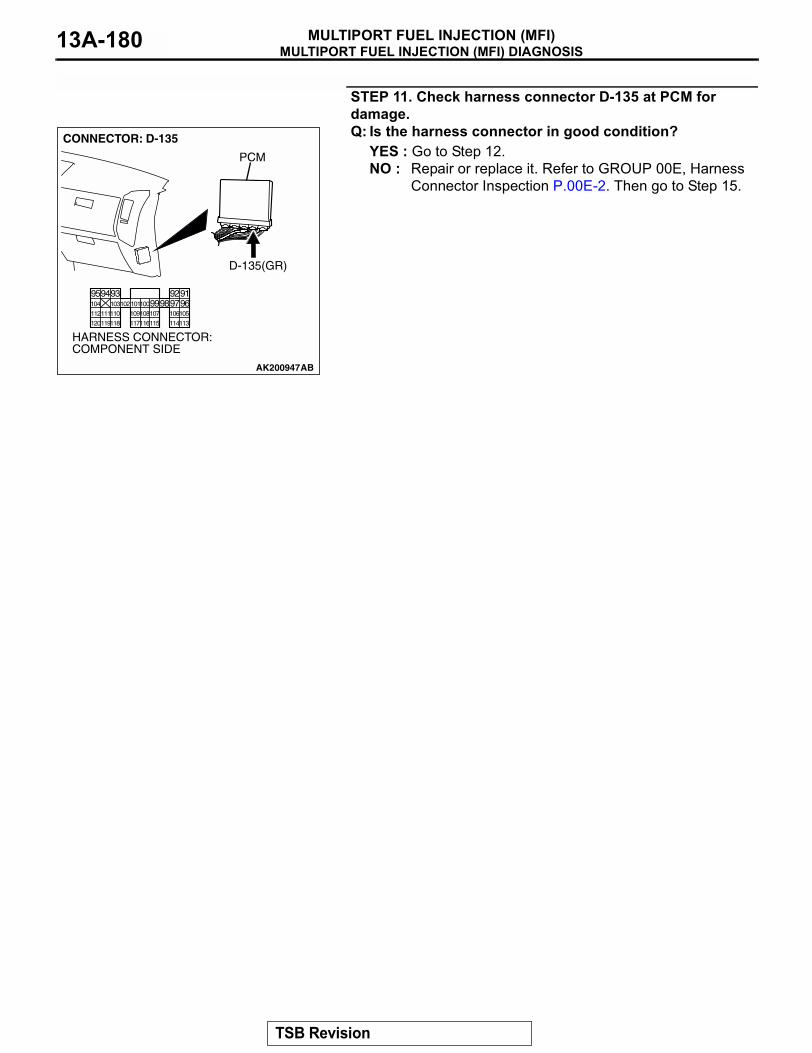
MULTIPORT FUEL INJECTION (MFI) DIAGNOSISMULTIPORT FUEL INJECTION (MFI)13A-180
STEP 11. Check harness connector D-135 at PCM for damage.Q: Is the harness connector in good condition?
YES : Go to Step 12.NO : Repair or replace it. Refer to GROUP 00E, Harness
Connector Inspection P.00E-2. Then go to Step 15.
AK200947
919293949596979899100101102103104
105106107108109110111112
113114115116117118119120
CONNECTOR: D-135
HARNESS CONNECTOR: COMPONENT SIDE
AB
PCM
D-135(GR)
TSB Revision
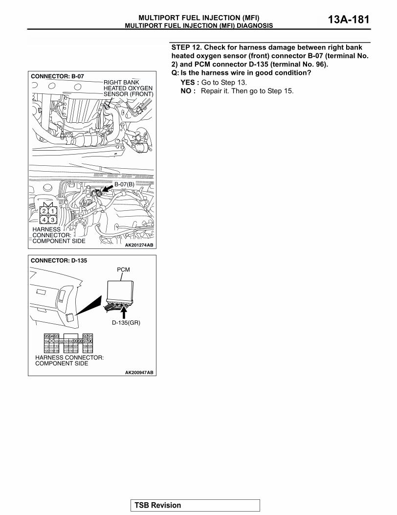
MULTIPORT FUEL INJECTION (MFI) DIAGNOSISMULTIPORT FUEL INJECTION (MFI) 13A-181
STEP 12. Check for harness damage between right bank heated oxygen sensor (front) connector B-07 (terminal No. 2) and PCM connector D-135 (terminal No. 96).Q: Is the harness wire in good condition?
YES : Go to Step 13.NO : Repair it. Then go to Step 15.
AK201274
12
34
CONNECTOR: B-07
B-07(B)
AB
HARNESS CONNECTOR: COMPONENT SIDE
RIGHT BANKHEATED OXYGENSENSOR (FRONT)
AK200947
919293949596979899100101102103104
105106107108109110111112
113114115116117118119120
CONNECTOR: D-135
HARNESS CONNECTOR: COMPONENT SIDE
AB
PCM
D-135(GR)
TSB Revision
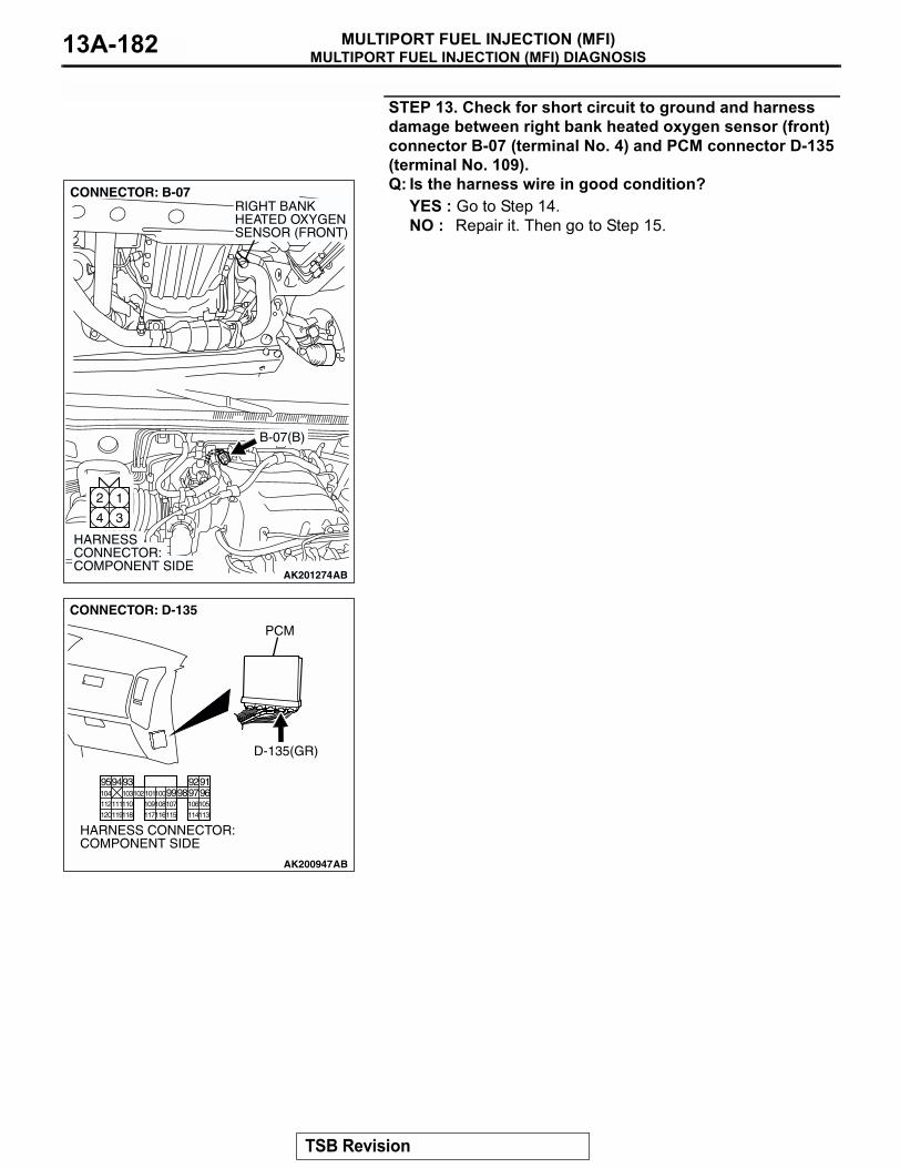
MULTIPORT FUEL INJECTION (MFI) DIAGNOSISMULTIPORT FUEL INJECTION (MFI)13A-182
STEP 13. Check for short circuit to ground and harness damage between right bank heated oxygen sensor (front) connector B-07 (terminal No. 4) and PCM connector D-135 (terminal No. 109).Q: Is the harness wire in good condition?
YES : Go to Step 14.NO : Repair it. Then go to Step 15.
AK201274
12
34
CONNECTOR: B-07
B-07(B)
AB
HARNESS CONNECTOR: COMPONENT SIDE
RIGHT BANKHEATED OXYGENSENSOR (FRONT)
AK200947
919293949596979899100101102103104
105106107108109110111112
113114115116117118119120
CONNECTOR: D-135
HARNESS CONNECTOR: COMPONENT SIDE
AB
PCM
D-135(GR)
TSB Revision
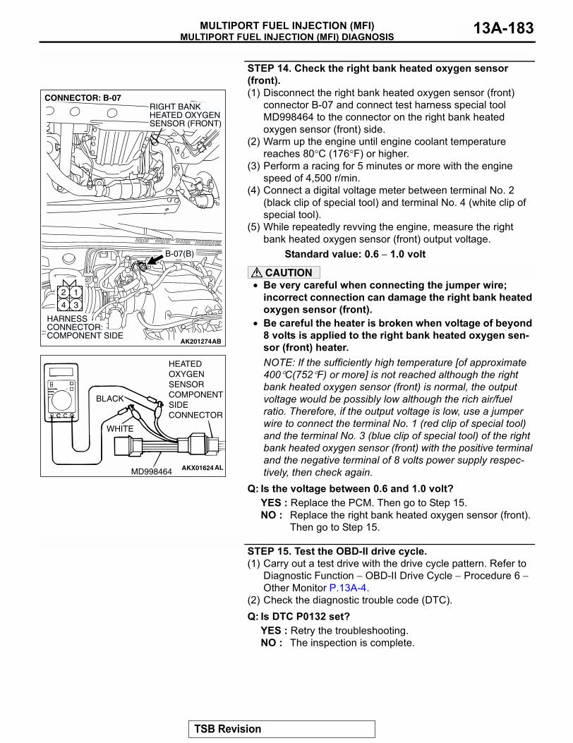
MULTIPORT FUEL INJECTION (MFI) DIAGNOSISMULTIPORT FUEL INJECTION (MFI) 13A-183
STEP 14. Check the right bank heated oxygen sensor (front).(1) Disconnect the right bank heated oxygen sensor (front)
connector B-07 and connect test harness special tool MD998464 to the connector on the right bank heated oxygen sensor (front) side.
(2) Warm up the engine until engine coolant temperature reaches 80°C (176°F) or higher.
(3) Perform a racing for 5 minutes or more with the engine speed of 4,500 r/min.
(4) Connect a digital voltage meter between terminal No. 2 (black clip of special tool) and terminal No. 4 (white clip of special tool).
(5) While repeatedly revving the engine, measure the right bank heated oxygen sensor (front) output voltage.
Standard value: 0.6 − 1.0 volt
CAUTION• Be very careful when connecting the jumper wire;
incorrect connection can damage the right bank heated oxygen sensor (front).
• Be careful the heater is broken when voltage of beyond 8 volts is applied to the right bank heated oxygen sen-sor (front) heater.NOTE: If the sufficiently high temperature [of approximate 400°C(752°F) or more] is not reached although the right bank heated oxygen sensor (front) is normal, the output voltage would be possibly low although the rich air/fuel ratio. Therefore, if the output voltage is low, use a jumper wire to connect the terminal No. 1 (red clip of special tool) and the terminal No. 3 (blue clip of special tool) of the right bank heated oxygen sensor (front) with the positive terminal and the negative terminal of 8 volts power supply respec-tively, then check again.
Q: Is the voltage between 0.6 and 1.0 volt?YES : Replace the PCM. Then go to Step 15.NO : Replace the right bank heated oxygen sensor (front).
Then go to Step 15.
STEP 15. Test the OBD-II drive cycle.(1) Carry out a test drive with the drive cycle pattern. Refer to
Diagnostic Function − OBD-II Drive Cycle − Procedure 6 − Other Monitor P.13A-4.
(2) Check the diagnostic trouble code (DTC).Q: Is DTC P0132 set?
YES : Retry the troubleshooting.NO : The inspection is complete.
AK201274
12
34
CONNECTOR: B-07
B-07(B)
AB
HARNESS CONNECTOR: COMPONENT SIDE
RIGHT BANKHEATED OXYGENSENSOR (FRONT)
AKX01624
HEATEDOXYGENSENSORCOMPONENTSIDECONNECTOR
MD998464
WHITE
BLACK
AL
TSB Revision
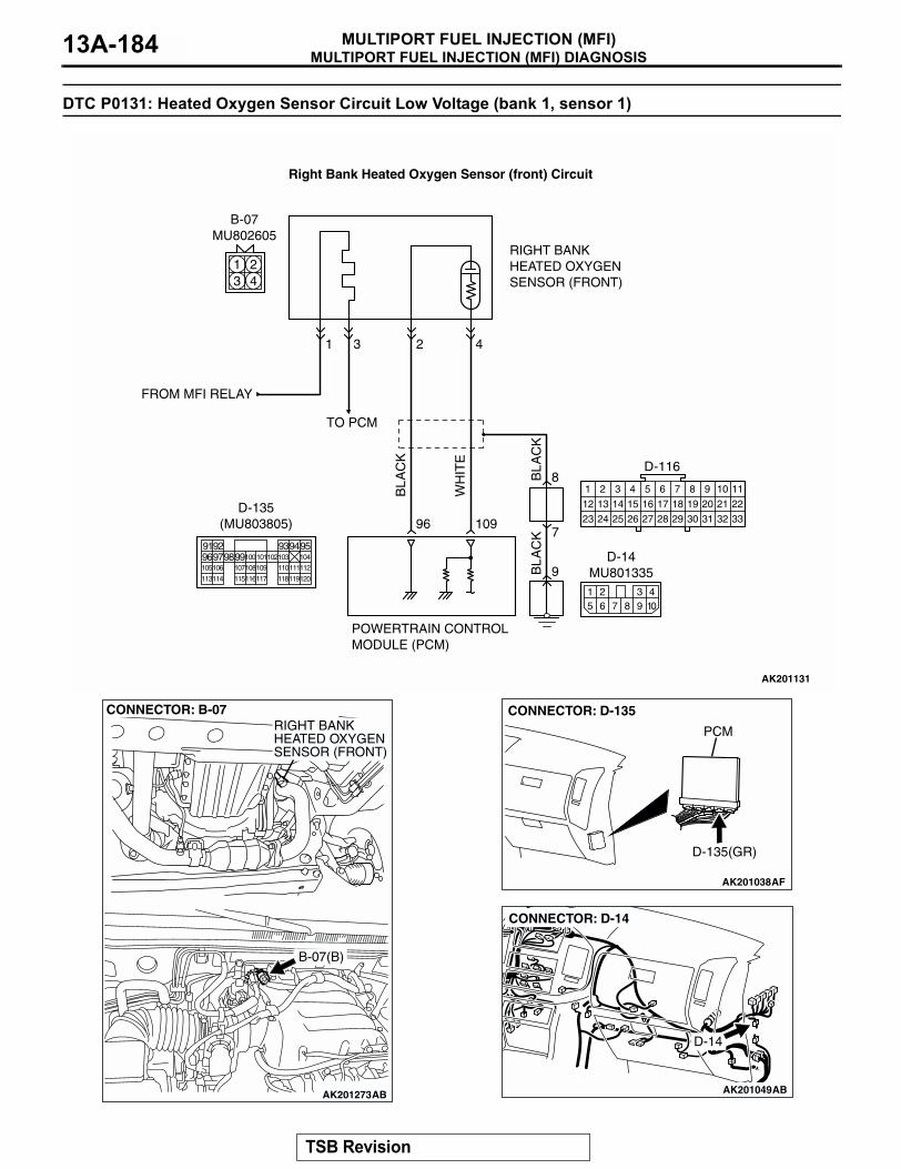
MULTIPORT FUEL INJECTION (MFI) DIAGNOSISMULTIPORT FUEL INJECTION (MFI)13A-184
DTC P0131: Heated Oxygen Sensor Circuit Low Voltage (bank 1, sensor 1)
BL
AC
K
BL
AC
KB
LA
CK
TO PCM
FROM MFI RELAY
WH
ITE
AK201131
96 109
431
RIGHT BANKHEATED OXYGENSENSOR (FRONT)
POWERTRAIN CONTROLMODULE (PCM)
8
9
7
1 243
B-07MU802605
2
1
12
23 24 25 26
2
13
3
14
4
15
5
16
6
17
7
18
8
19
9
20 21 22
27 28 29 30 31 32 33
10 11
D-116
15 7 8
3 49 10
26
D-14MU801335
Right Bank Heated Oxygen Sensor (front) Circuit
9192 93949596979899100
105
113114 115116117 118119120
106 107108109 110111112
101102103 104
D-135(MU803805)
AK201273
CONNECTOR: B-07
B-07(B)
AB
RIGHT BANKHEATED OXYGENSENSOR (FRONT)
AK201038AF
CONNECTOR: D-135
PCM
D-135(GR)
AK201049
D-14
AB
CONNECTOR: D-14
TSB Revision
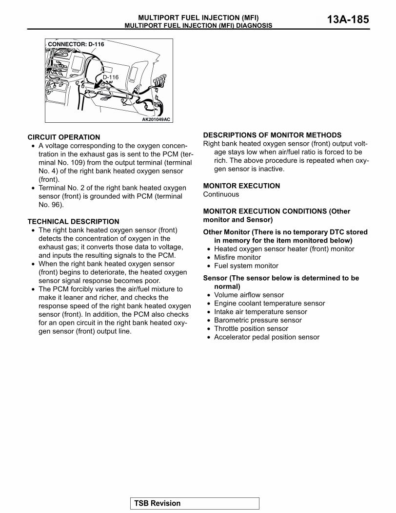
MULTIPORT FUEL INJECTION (MFI) DIAGNOSISMULTIPORT FUEL INJECTION (MFI) 13A-185
.
CIRCUIT OPERATION• A voltage corresponding to the oxygen concen-
tration in the exhaust gas is sent to the PCM (ter-minal No. 109) from the output terminal (terminal No. 4) of the right bank heated oxygen sensor (front).
• Terminal No. 2 of the right bank heated oxygen sensor (front) is grounded with PCM (terminal No. 96).
.
TECHNICAL DESCRIPTION• The right bank heated oxygen sensor (front)
detects the concentration of oxygen in the exhaust gas; it converts those data to voltage, and inputs the resulting signals to the PCM.
• When the right bank heated oxygen sensor (front) begins to deteriorate, the heated oxygen sensor signal response becomes poor.
• The PCM forcibly varies the air/fuel mixture to make it leaner and richer, and checks the response speed of the right bank heated oxygen sensor (front). In addition, the PCM also checks for an open circuit in the right bank heated oxy-gen sensor (front) output line.
.
DESCRIPTIONS OF MONITOR METHODSRight bank heated oxygen sensor (front) output volt-
age stays low when air/fuel ratio is forced to be rich. The above procedure is repeated when oxy-gen sensor is inactive.
.
MONITOR EXECUTIONContinuous.
MONITOR EXECUTION CONDITIONS (Other monitor and Sensor)
Other Monitor (There is no temporary DTC stored in memory for the item monitored below)
• Heated oxygen sensor heater (front) monitor• Misfire monitor• Fuel system monitor
Sensor (The sensor below is determined to be normal)
• Volume airflow sensor• Engine coolant temperature sensor• Intake air temperature sensor• Barometric pressure sensor• Throttle position sensor• Accelerator pedal position sensor
.
AK201049
CONNECTOR: D-116
D-116
AC
TSB Revision
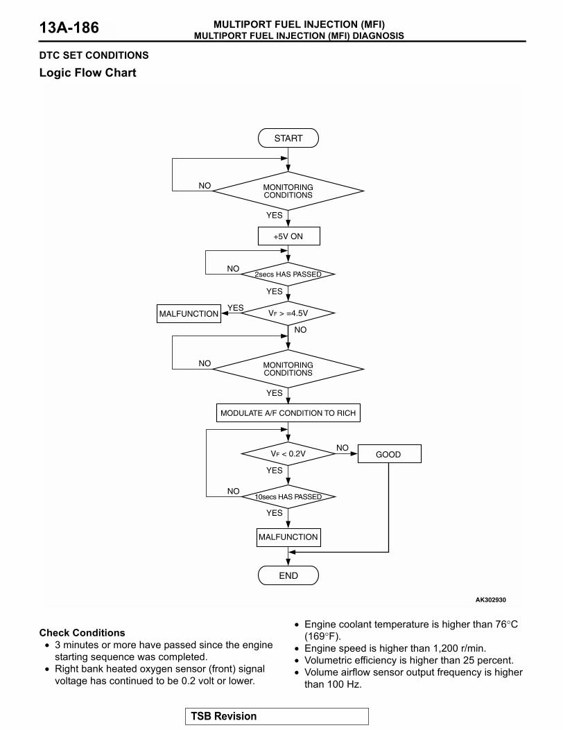
MULTIPORT FUEL INJECTION (MFI) DIAGNOSISMULTIPORT FUEL INJECTION (MFI)13A-186
DTC SET CONDITIONS
Logic Flow Chart
.
Check Conditions• 3 minutes or more have passed since the engine
starting sequence was completed.• Right bank heated oxygen sensor (front) signal
voltage has continued to be 0.2 volt or lower.
• Engine coolant temperature is higher than 76°C (169°F).
• Engine speed is higher than 1,200 r/min.• Volumetric efficiency is higher than 25 percent.• Volume airflow sensor output frequency is higher
than 100 Hz.
START
VF > =4.5V
2secs HAS PASSED
YES
YES
YES
NO
NO
NO
MALFUNCTION
MONITORINGCONDITIONS
YES
NO MONITORINGCONDITIONS
+5V ON
AK302930
VF < 0.2V
10secs HAS PASSED
YES
YES
NO
NO
END
MALFUNCTION
GOOD
MODULATE A/F CONDITION TO RICH
TSB Revision
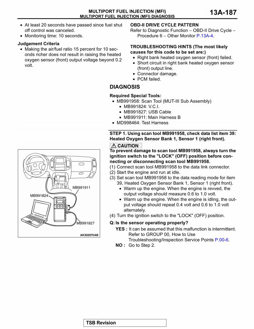
MULTIPORT FUEL INJECTION (MFI) DIAGNOSISMULTIPORT FUEL INJECTION (MFI) 13A-187
• At least 20 seconds have passed since fuel shut off control was canceled.
• Monitoring time: 10 seconds.
Judgement Criteria• Making the air/fuel ratio 15 percent for 10 sec-
onds richer does not result in raising the heated oxygen sensor (front) output voltage beyond 0.2 volt.
.
OBD-II DRIVE CYCLE PATTERNRefer to Diagnostic Function − OBD-II Drive Cycle −
Procedure 6 − Other Monitor P.13A-4..
TROUBLESHOOTING HINTS (The most likely causes for this code to be set are:)
• Right bank heated oxygen sensor (front) failed.• Short circuit in right bank heated oxygen sensor
(front) output line.• Connector damage.• PCM failed.
DIAGNOSISRequired Special Tools:
• MB991958: Scan Tool (MUT-III Sub Assembly)• MB991824: V.C.I.• MB991827: USB Cable• MB991911: Main Harness B
• MD998464: Test Harness
STEP 1. Using scan tool MB991958, check data list item 39: Heated Oxygen Sensor Bank 1, Sensor 1 (right front).
CAUTIONTo prevent damage to scan tool MB991958, always turn the ignition switch to the "LOCK" (OFF) position before con-necting or disconnecting scan tool MB991958.(1) Connect scan tool MB991958 to the data link connector.(2) Start the engine and run at idle.(3) Set scan tool MB991958 to the data reading mode for item
39, Heated Oxygen Sensor Bank 1, Sensor 1 (right front).• Warm up the engine. When the engine is revved, the
output voltage should measure 0.6 to 1.0 volt.• Warm up the engine. When the engine is idling, the out-
put voltage should repeat 0.4 volt and 0.6 to 1.0 volt alternately.
(4) Turn the ignition switch to the "LOCK" (OFF) position.Q: Is the sensor operating properly?
YES : It can be assumed that this malfunction is intermittent. Refer to GROUP 00, How to Use Troubleshooting/Inspection Service Points P.00-6.
NO : Go to Step 2.
AK302970AB
MB991911
MB991824
MB991827
TSB Revision
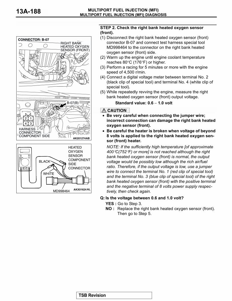
MULTIPORT FUEL INJECTION (MFI) DIAGNOSISMULTIPORT FUEL INJECTION (MFI)13A-188
STEP 2. Check the right bank heated oxygen sensor (front).(1) Disconnect the right bank heated oxygen sensor (front)
connector B-07 and connect test harness special tool MD998464 to the connector on the right bank heated oxygen sensor (front) side.
(2) Warm up the engine until engine coolant temperature reaches 80°C (176°F) or higher.
(3) Perform a racing for 5 minutes or more with the engine speed of 4,500 r/min.
(4) Connect a digital voltage meter between terminal No. 2 (black clip of special tool) and terminal No. 4 (white clip of special tool).
(5) While repeatedly revving the engine, measure the right bank heated oxygen sensor (front) output voltage.
Standard value: 0.6 − 1.0 volt
CAUTION• Be very careful when connecting the jumper wire;
incorrect connection can damage the right bank heated oxygen sensor (front).
• Be careful the heater is broken when voltage of beyond 8 volts is applied to the right bank heated oxygen sen-sor (front) heater.NOTE: If the sufficiently high temperature [of approximate 400°C(752°F) or more] is not reached although the right bank heated oxygen sensor (front) is normal, the output voltage would be possibly low although the rich air/fuel ratio. Therefore, if the output voltage is low, use a jumper wire to connect the terminal No. 1 (red clip of special tool) and the terminal No. 3 (blue clip of special tool) of the right bank heated oxygen sensor (front) with the positive terminal and the negative terminal of 8 volts power supply respec-tively, then check again.
Q: Is the voltage between 0.6 and 1.0 volt?YES : Go to Step 3.NO : Replace the right bank heated oxygen sensor (front).
Then go to Step 5.
AK201274
12
34
CONNECTOR: B-07
B-07(B)
AB
HARNESS CONNECTOR: COMPONENT SIDE
RIGHT BANKHEATED OXYGENSENSOR (FRONT)
AKX01624
HEATEDOXYGENSENSORCOMPONENTSIDECONNECTOR
MD998464
WHITE
BLACK
AL
TSB Revision
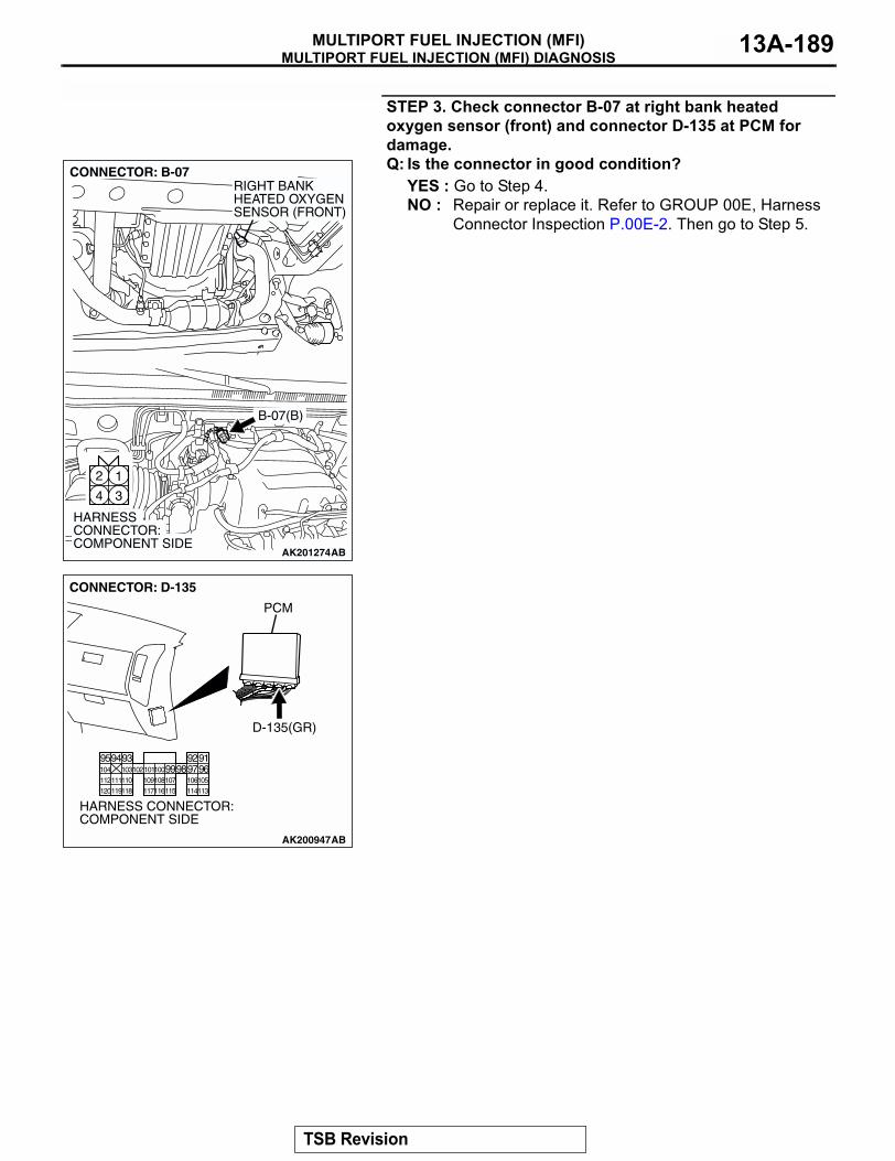
MULTIPORT FUEL INJECTION (MFI) DIAGNOSISMULTIPORT FUEL INJECTION (MFI) 13A-189
STEP 3. Check connector B-07 at right bank heated oxygen sensor (front) and connector D-135 at PCM for damage.Q: Is the connector in good condition?
YES : Go to Step 4.NO : Repair or replace it. Refer to GROUP 00E, Harness
Connector Inspection P.00E-2. Then go to Step 5.
AK201274
12
34
CONNECTOR: B-07
B-07(B)
AB
HARNESS CONNECTOR: COMPONENT SIDE
RIGHT BANKHEATED OXYGENSENSOR (FRONT)
AK200947
919293949596979899100101102103104
105106107108109110111112
113114115116117118119120
CONNECTOR: D-135
HARNESS CONNECTOR: COMPONENT SIDE
AB
PCM
D-135(GR)
TSB Revision
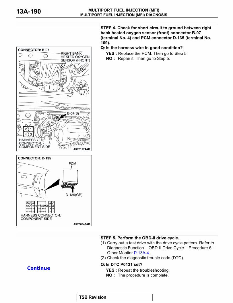
MULTIPORT FUEL INJECTION (MFI) DIAGNOSISMULTIPORT FUEL INJECTION (MFI)13A-190
STEP 4. Check for short circuit to ground between right bank heated oxygen sensor (front) connector B-07 (terminal No. 4) and PCM connector D-135 (terminal No. 109).Q: Is the harness wire in good condition?
YES : Replace the PCM. Then go to Step 5.NO : Repair it. Then go to Step 5.
STEP 5. Perform the OBD-II drive cycle.(1) Carry out a test drive with the drive cycle pattern. Refer to
Diagnostic Function − OBD-II Drive Cycle − Procedure 6 − Other Monitor P.13A-4.
(2) Check the diagnostic trouble code (DTC).Q: Is DTC P0131 set?
YES : Repeat the troubleshooting.NO : The procedure is complete.
AK201274
12
34
CONNECTOR: B-07
B-07(B)
AB
HARNESS CONNECTOR: COMPONENT SIDE
RIGHT BANKHEATED OXYGENSENSOR (FRONT)
AK200947
919293949596979899100101102103104
105106107108109110111112
113114115116117118119120
CONNECTOR: D-135
HARNESS CONNECTOR: COMPONENT SIDE
AB
PCM
D-135(GR)
TSB Revision