multi-fingered haptic palpation using pneumatic feedback actuators
TRANSCRIPT
DOI: 10.1016/j.sna.2014.08.003 Sensors and Actuators 1
Multi-Fingered Haptic Palpation using Pneumatic Feedback Actuators Min Li1*, Shan Luo1, Thrishantha Nanayakkara1, Lakmal. D. Seneviratne1, 3, Prokar Dasgupta2, and Kaspar Althoefer1 1. Department of Informatics, Kings College London, London, WC2R 2LS, UK. (e-mail: {min.m.li; shan.luo; thrish.antha; lakmal.seneviratne; k.althoefer}@kcl.ac.uk). 2. Medical Research Council (MRC) Centre for Transplantation, King's College London, King’s Health Partners, Guy’s Hospital, London SE1 9RT, UK. ([email protected]). 3. College of Engineering, Khalifa University of Science, Technology and Research, Abu Dhabi, U.A.E. (e-mail: [email protected]).
Abstract —This paper proposes a multi-fingered palpation method which employs pneumatic haptic feedback actuators allowing users to experience haptic sensations at multiple fingers while carrying out remote soft tissue palpation. Pneumatic actuators are used to vary the stress on the user’s fingertips in accordance with the tissue stiffness, experienced during manual palpation. The proposed method reduces actuator elements compared to tactile actuators and provides more information than single-point force feedback. The results of our finite element analysis have proven that our pneumatic haptic feedback device can recreate the contact stress between fingertip and soft tissue during palpation. The accuracy (96.8% vs. 93.3%) and time-efficiency (4.6 s vs. 8.3 s) advantages of using three-fingered over single-fingered palpation have been confirmed in our user study results of stiffness levels discrimination. Relatively good tumor detection sensitivities have been demonstrated by the palpation user study which has showed a direct correlation between tumor size and detection sensitivity and has further proven the efficiency of the proposed actuator and multi-fingered palpation method for tumor detection in palpation simulation.
Keywords —Haptic feedback, Multi-fingered feedback, Palpation simulation, Pneumatic haptic actuator, Tumor identification.
1 Introduction Tactile actuators, which provide the user with tactile feedback as experienced during palpation, have been introduced for
tumor identification in Minimally Invasive Surgery (MIS) as for instance described in [1]. Currently, tactile feedback display can be divided into two main simulation types: movable components and materials with variable stiffness. Providing distributed pressure (tactile information) to one finger during palpation has been conducted in [2–5]. Pneumatic activated tactile displays use air pressure to displace the skin, either by discharging air directly through nozzles against the skin or inflating conformable tactors. Kim et al. [5] have tested a pneumatic approach during which compressed air is discharged directly against the skin using an array of open nozzles. Culjat et al. [3] developed a pneumatic balloon tactile display, which can be easily attached to existing commercial robot-assisted surgery systems such as the da Vinci. Pneumatic activated tactile display has the potential to provide distributed pressure (tactile information) to one finger during palpation. However, its current application is limited due to its complexity, the lack of commercially available choices, and the high cost of the required tactile actuators.
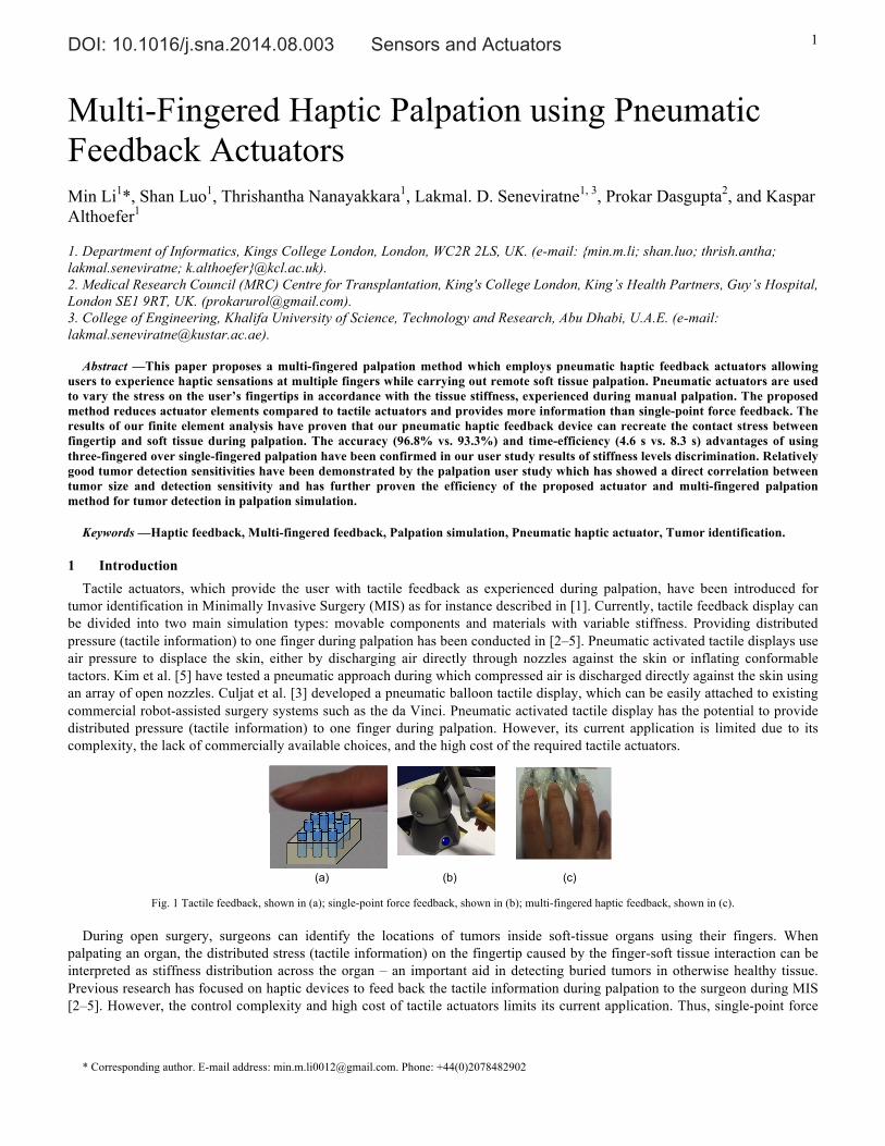
Fig. 1 Tactile feedback, shown in (a); single-point force feedback, shown in (b); multi-fingered haptic feedback, shown in (c).
During open surgery, surgeons can identify the locations of tumors inside soft-tissue organs using their fingers. When
palpating an organ, the distributed stress (tactile information) on the fingertip caused by the finger-soft tissue interaction can be interpreted as stiffness distribution across the organ – an important aid in detecting buried tumors in otherwise healthy tissue. Previous research has focused on haptic devices to feed back the tactile information during palpation to the surgeon during MIS [2–5]. However, the control complexity and high cost of tactile actuators limits its current application. Thus, single-point force
* Corresponding author. E-mail address: [email protected]. Phone: +44(0)2078482902
(a)
(b)
(c)
DOI: 10.1016/j.sna.2014.08.003 Sensors and Actuators 2
feedback is more common currently, although the haptic information it provides is significantly reduced compared to the information conveyed by tactile actuators. Many commercially available haptic devices provide single-point force feedback ranging from the low-cost Falcon (Novint Technologies, Inc.) to the more advanced Sigma.7 (Force Dimension Inc.) [6–10]. However, multi-fingered palpation is more common and is considered more useful than single-fingered palpation when attempting to detect differences in stiffness in the examined tissue in real practice [11]. Compared to tactile haptic methods, for example, as described in [2, 3], the actuator elements in multi-fingered palpation haptic devices are much reduced. Among the reports about multi-fingered palpation simulation, Rutgers Master II force feedback glove [12] can feed back force up to 16 N to each finger using pneumatic actuators. However, the glove limits the range of motion of the fingers because cylinders are placed between the palm and fingers. The haptic Interface Robot (HIRO) device developed by Kawasaki et al. [13] has been used for breast palpation simulation [14]. It consists of a force actuated 6-DOF arm and three fingers with 3-DOF force output. And it has been updated to a five-fingered HIRO III device [15]. Nevertheless, the price is relatively high. Finger-worn haptic feedback devices can increase the flexibility of the multi-fingered feedback system. Initial studies of finger-worn force and torque feedback devices using dual motors have been reported in [16, 17]. The combination of them and conventional kinesthetic feedback devices have also been investigated [16, 17]. However, they have not been applied in palpation simulation.
This paper presents the creation and validation of a multi-fingered palpation method using pneumatic feedback actuators. Section 2 describes the methodology of the system design and the evaluation tests. Section 3 provides the results and discussions and section 4 draws the conclusion.
2 Methodology
2.1 Design During palpation, a stiff area and a healthy soft tissue area convey different levels of stress on the practitioner’s fingertips at
the same indentation depth. In this paper, a pneumatic actuator containing a deformable surface, a non-deformable substrate with a cylindrical hole, air tubing and a pressure-controllable air supply is proposed as a means to express soft tissue stiffness information. The user employs a finger to contact the surface of the actuator and the air pressure inside the actuator causes stress on the fingertip and gives an impression of the indentation when palpating a soft organ. Lower pressure represents softer regions while higher air pressure represents stiffer tissue regions.
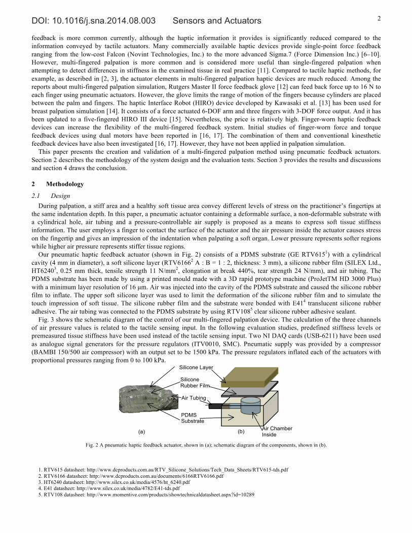
Our pneumatic haptic feedback actuator (shown in Fig. 2) consists of a PDMS substrate (GE RTV6151) with a cylindrical cavity (4 mm in diameter), a soft silicone layer (RTV61662 A : B = 1 : 2, thickness: 3 mm), a silicone rubber film (SILEX Ltd., HT62403, 0.25 mm thick, tensile strength 11 N/mm2, elongation at break 440%, tear strength 24 N/mm), and air tubing. The PDMS substrate has been made by using a printed mould made with a 3D rapid prototype machine (ProJetTM HD 3000 Plus) with a minimum layer resolution of 16 µm. Air was injected into the cavity of the PDMS substrate and caused the silicone rubber film to inflate. The upper soft silicone layer was used to limit the deformation of the silicone rubber film and to simulate the touch impression of soft tissue. The silicone rubber film and the substrate were bonded with E414 translucent silicone rubber adhesive. The air tubing was connected to the PDMS substrate by using RTV1085 clear silicone rubber adhesive sealant.
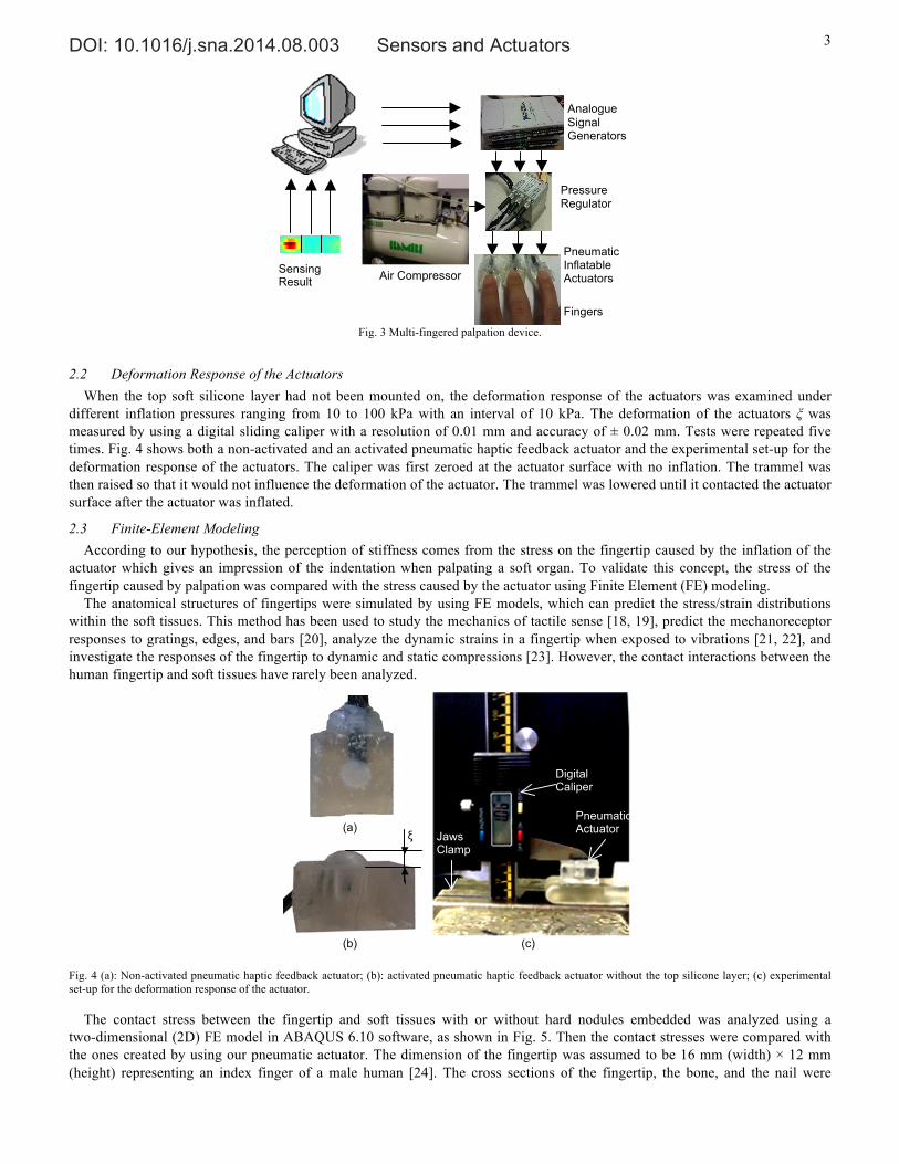
Fig. 3 shows the schematic diagram of the control of our multi-fingered palpation device. The calculation of the three channels of air pressure values is related to the tactile sensing input. In the following evaluation studies, predefined stiffness levels or premeasured tissue stiffness have been used instead of the tactile sensing input. Two NI DAQ cards (USB-6211) have been used as analogue signal generators for the pressure regulators (ITV0010, SMC). Pneumatic supply was provided by a compressor (BAMBI 150/500 air compressor) with an output set to be 1500 kPa. The pressure regulators inflated each of the actuators with proportional pressures ranging from 0 to 100 kPa.
Fig. 2 A pneumatic haptic feedback actuator, shown in (a); schematic diagram of the components, shown in (b).
1. RTV615 datasheet: http://www.dcproducts.com.au/RTV_Silicone_Solutions/Tech_Data_Sheets/RTV615-tds.pdf 2. RTV6166 datasheet: http://www.dcproducts.com.au/documents/6166RTV6166.pdf 3. HT6240 datasheet: http://www.silex.co.uk/media/4576/ht_6240.pdf 4. E41 datasheet: http://www.silex.co.uk/media/4782/E41-tds.pdf 5. RTV108 datasheet: http://www.momentive.com/products/showtechnicaldatasheet.aspx?id=10289
Air Chamber Inside
(a)
(b)
PDMS Substrate
Air Tubing
Silicone Layer
Silicone Rubber Film
DOI: 10.1016/j.sna.2014.08.003 Sensors and Actuators 3
Fig. 3 Multi-fingered palpation device.
2.2 Deformation Response of the Actuators When the top soft silicone layer had not been mounted on, the deformation response of the actuators was examined under
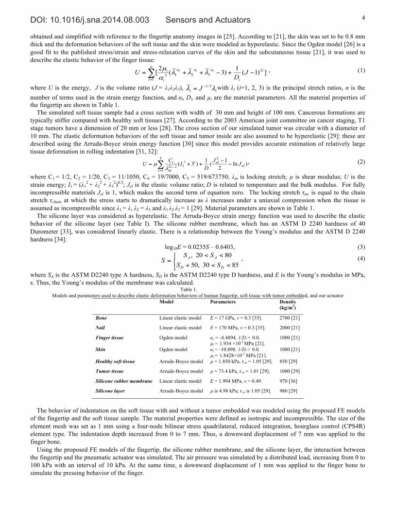
different inflation pressures ranging from 10 to 100 kPa with an interval of 10 kPa. The deformation of the actuators ξ was measured by using a digital sliding caliper with a resolution of 0.01 mm and accuracy of ± 0.02 mm. Tests were repeated five times. Fig. 4 shows both a non-activated and an activated pneumatic haptic feedback actuator and the experimental set-up for the deformation response of the actuators. The caliper was first zeroed at the actuator surface with no inflation. The trammel was then raised so that it would not influence the deformation of the actuator. The trammel was lowered until it contacted the actuator surface after the actuator was inflated.
2.3 Finite-Element Modeling According to our hypothesis, the perception of stiffness comes from the stress on the fingertip caused by the inflation of the
actuator which gives an impression of the indentation when palpating a soft organ. To validate this concept, the stress of the fingertip caused by palpation was compared with the stress caused by the actuator using Finite Element (FE) modeling.
The anatomical structures of fingertips were simulated by using FE models, which can predict the stress/strain distributions within the soft tissues. This method has been used to study the mechanics of tactile sense [18, 19], predict the mechanoreceptor responses to gratings, edges, and bars [20], analyze the dynamic strains in a fingertip when exposed to vibrations [21, 22], and investigate the responses of the fingertip to dynamic and static compressions [23]. However, the contact interactions between the human fingertip and soft tissues have rarely been analyzed.
Fig. 4 (a): Non-activated pneumatic haptic feedback actuator; (b): activated pneumatic haptic feedback actuator without the top silicone layer; (c) experimental set-up for the deformation response of the actuator.
The contact stress between the fingertip and soft tissues with or without hard nodules embedded was analyzed using a two-dimensional (2D) FE model in ABAQUS 6.10 software, as shown in Fig. 5. Then the contact stresses were compared with the ones created by using our pneumatic actuator. The dimension of the fingertip was assumed to be 16 mm (width) × 12 mm (height) representing an index finger of a male human [24]. The cross sections of the fingertip, the bone, and the nail were
Analogue Signal Generators
Pneumatic Inflatable Actuators Air Compressor
Pressure Regulators
Sensing Result
Fingers 20 40 60 80 100 120
5
10
15
20
25
30
Digital Caliper
Pneumatic Actuator
Jaws Clamp
(a) ξ
(b)
(c)
DOI: 10.1016/j.sna.2014.08.003 Sensors and Actuators 4
obtained and simplified with reference to the fingertip anatomy images in [25]. According to [21], the skin was set to be 0.8 mm thick and the deformation behaviors of the soft tissue and the skin were modeled as hyperelastic. Since the Ogden model [26] is a good fit to the published stress/strain and stress-relaxation curves of the skin and the subcutaneous tissue [21], it was used to describe the elastic behavior of the finger tissue:
])1(1)3(2[ 2321
12
i
i
n
i i
i JD
U iii −+−++=∑=
ααα λλλαµ , (1)
where U is the energy, J is the volume ratio (J = λ1λ2λ3), ii J λλ 3/1−= with λi (i=1, 2, 3) is the principal stretch ratios, n is the number of terms used in the strain energy function, and αi, Di, and µi are the material parameters. All the material properties of the fingertip are shown in Table 1.
The simulated soft tissue sample had a cross section with width of 30 mm and height of 100 mm. Cancerous formations are typically stiffer compared with healthy soft tissues [27]. According to the 2003 American joint committee on cancer staging, T1 stage tumors have a dimension of 20 mm or less [28]. The cross section of our simulated tumor was circular with a diameter of 10 mm. The elastic deformation behaviors of the soft tissue and tumor inside are also assumed to be hyperelastic [29]: these are described using the Arruda-Boyce strain energy function [30] since this model provides accurate estimation of relatively large tissue deformation in rolling indentation [31, 32]:
)ln21(1)3(
2
1
5
122 el
elii
iim
i JJD
ICU −−
++= ∑=
−λµ , (2)
where C1 = 1/2, C2 = 1/20, C3 = 11/1050, C4 = 19/7000, C5 = 519/673750; λm is locking stretch; µ is shear modulus; U is the strain energy; I1 = (λ1
2 + λ22 + λ3
2)0.5; Jel is the elastic volume ratio; D is related to temperature and the bulk modulus. For fully incompressible materials Jel is 1, which makes the second term of equation zero. The locking stretch τm, is equal to the chain stretch τchain at which the stress starts to dramatically increase as λ increases under a uniaxial compression when the tissue is assumed as incompressible since λ1 = λ, λ2 = λ3 and λ1 λ2 λ3 = 1 [29]. Material parameters are shown in Table 1.
The silicone layer was considered as hyperelastic. The Arruda-Boyce strain energy function was used to describe the elastic behavior of the silicone layer (see Table I). The silicone rubber membrane, which has an ASTM D 2240 hardness of 40 Durometer [33], was considered linearly elastic. There is a relationship between the Young’s modulus and the ASTM D 2240 hardness [34]:
log10E = 0.0235S – 0.6403, (3)
⎩⎨⎧
<<+
<<=
8530,508020,
DD
AA
SSSS
S , (4)
where SA is the ASTM D2240 type A hardness, SD is the ASTM D2240 type D hardness, and E is the Young’s modulus in MPa, s. Thus, the Young’s modulus of the membrane was calculated.
Table 1. Models and parameters used to describe elastic deformation behaviors of human fingertip, soft tissue with tumor embedded, and our actuator
Model Parameters Density (kg/m3)
Bone Linear elastic model E = 17 GPa, ν = 0.3 [35]. 2700 [21]
Nail Linear elastic model E = 170 MPa, ν = 0.3 [35]. 2000 [21]
Finger tissue Ogden model αi = -4.4894, 1/Di = 0.0, µi = 1.934 ×10⁻² MPa [21].
1000 [21]
Skin Ogden model αi = -10.898, 1/Di = 0.0, µi = 1.8428×10⁻³ MPa [21].
1000 [21]
Healthy soft tissue Arrude-Boyce model µ = 1.850 kPa, τ m = 1.05 [29]. 850 [29]
Tumor tissue Arrude-Boyce model µ = 73.4 kPa, τ m = 1.01 [29]. 1000 [29]
Silicone rubber membrane Linear elastic model E = 1.994 MPa, ν = 0.49. 970 [36]
Silicone layer Arrude-Boyce model µ is 4.98 kPa; τ m is 1.05 [29]. 980 [29]
The behavior of indentation on the soft tissue with and without a tumor embedded was modeled using the proposed FE models
of the fingertip and the soft tissue sample. The material properties were defined as isotropic and incompressible. The size of the element mesh was set as 1 mm using a four-node bilinear stress quadrilateral, reduced integration, hourglass control (CPS4R) element type. The indentation depth increased from 0 to 7 mm. Thus, a downward displacement of 7 mm was applied to the finger bone.
Using the proposed FE models of the fingertip, the silicone rubber membrane, and the silicone layer, the interaction between the fingertip and the pneumatic actuator was simulated. The air pressure was simulated by a distributed load, increasing from 0 to 100 kPa with an interval of 10 kPa. At the same time, a downward displacement of 1 mm was applied to the finger bone to simulate the pressing behavior of the finger.
DOI: 10.1016/j.sna.2014.08.003 Sensors and Actuators 5
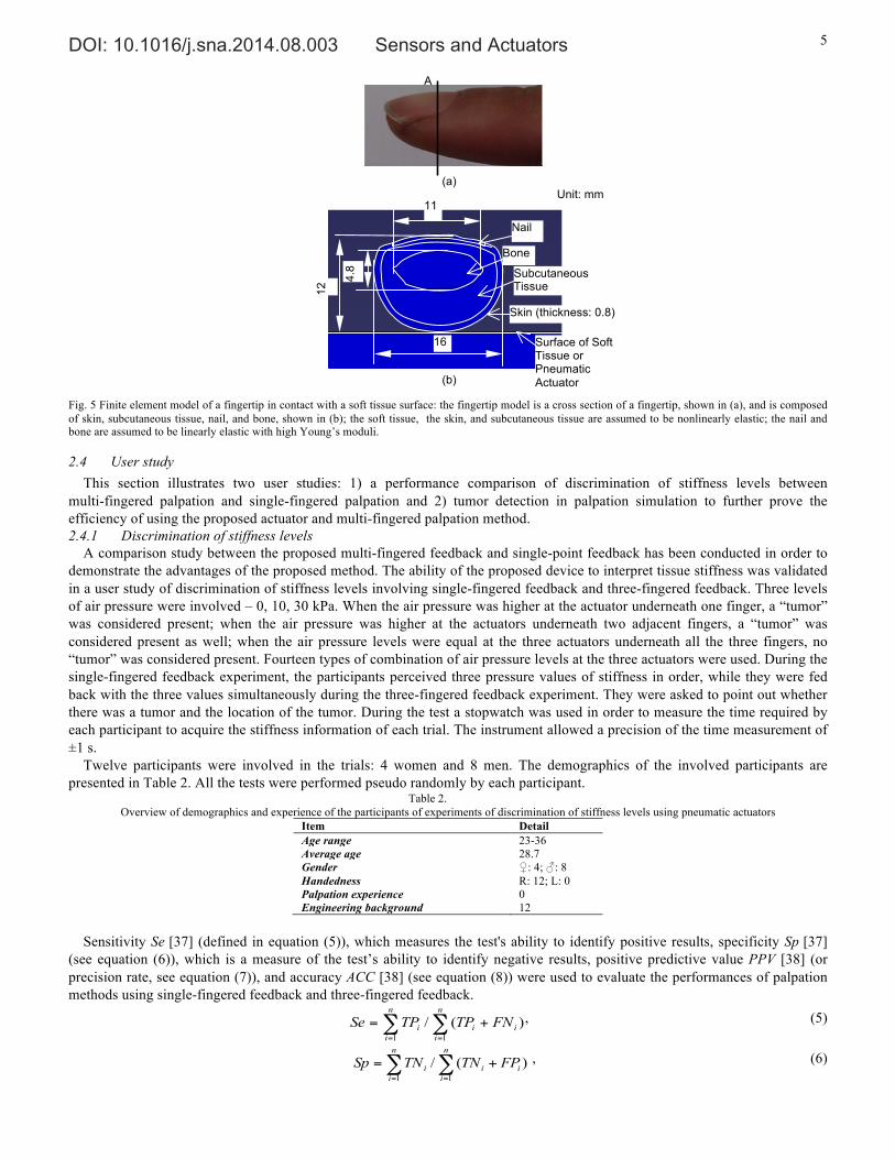
Fig. 5 Finite element model of a fingertip in contact with a soft tissue surface: the fingertip model is a cross section of a fingertip, shown in (a), and is composed of skin, subcutaneous tissue, nail, and bone, shown in (b); the soft tissue, the skin, and subcutaneous tissue are assumed to be nonlinearly elastic; the nail and bone are assumed to be linearly elastic with high Young’s moduli.
2.4 User study This section illustrates two user studies: 1) a performance comparison of discrimination of stiffness levels between
multi-fingered palpation and single-fingered palpation and 2) tumor detection in palpation simulation to further prove the efficiency of using the proposed actuator and multi-fingered palpation method. 2.4.1 Discrimination of stiffness levels
A comparison study between the proposed multi-fingered feedback and single-point feedback has been conducted in order to demonstrate the advantages of the proposed method. The ability of the proposed device to interpret tissue stiffness was validated in a user study of discrimination of stiffness levels involving single-fingered feedback and three-fingered feedback. Three levels of air pressure were involved – 0, 10, 30 kPa. When the air pressure was higher at the actuator underneath one finger, a “tumor” was considered present; when the air pressure was higher at the actuators underneath two adjacent fingers, a “tumor” was considered present as well; when the air pressure levels were equal at the three actuators underneath all the three fingers, no “tumor” was considered present. Fourteen types of combination of air pressure levels at the three actuators were used. During the single-fingered feedback experiment, the participants perceived three pressure values of stiffness in order, while they were fed back with the three values simultaneously during the three-fingered feedback experiment. They were asked to point out whether there was a tumor and the location of the tumor. During the test a stopwatch was used in order to measure the time required by each participant to acquire the stiffness information of each trial. The instrument allowed a precision of the time measurement of ±1 s.
Twelve participants were involved in the trials: 4 women and 8 men. The demographics of the involved participants are presented in Table 2. All the tests were performed pseudo randomly by each participant.
Table 2. Overview of demographics and experience of the participants of experiments of discrimination of stiffness levels using pneumatic actuators
Item Detail Age range 23-36 Average age 28.7 Gender ♀: 4; ♂: 8 Handedness R: 12; L: 0 Palpation experience 0 Engineering background 12
Sensitivity Se [37] (defined in equation (5)), which measures the test's ability to identify positive results, specificity Sp [37]
(see equation (6)), which is a measure of the test’s ability to identify negative results, positive predictive value PPV [38] (or precision rate, see equation (7)), and accuracy ACC [38] (see equation (8)) were used to evaluate the performances of palpation methods using single-fingered feedback and three-fingered feedback.
∑ ∑= =
+=n
i
n
iiii FNTPTPSe
1 1
)(/ , (5)
∑ ∑= =
+=n
i
n
iiii FPTNTNSp
1 1
)(/ , (6)
Nail
Subcutaneous Tissue
Skin (thickness: 0.8)
Bone
Surface of Soft Tissue or Pneumatic Actuator
16
12
11
4.8
A
(a)
(b)
Unit: mm
DOI: 10.1016/j.sna.2014.08.003 Sensors and Actuators 6
∑∑==
+=n
iii
n
ii FPTPTPPPV
11
)(/ , (7)
)(/)(1 1
iii
n
i
n
iiii FNFPTNTNTNTPACC ++++=∑ ∑
= =
, (8)
where n is the number of trials; TP is true positives – participants correctly claim there is a hard nodule; FN represents false negatives – participants wrongly claim there is no hard nodule; TN is true negatives – participants correctly claim there is no hard nodule; FP represents false positives – participants wrongly claim there is a hard nodule.
Wilson score intervals [39] were calculated for those statistical measures at a 95% confidence level:
⎥⎥⎦
⎤
⎢⎢⎣
⎡+
−±+
+2
22
2 4)ˆ1(ˆ
2ˆ
1
1nz
nppz
nzp
nz
, (9)
where n is the sample size; p̂ is the proportion of successes estimated from the statistical sample; z is the 1–α/2 percentile of a standard normal distribution where α is the error percentile.
The significance of the differences of the statistical measures between the single-fingered feedback and three-fingered feedback were examined by comparing the observed probabilities (p1 and p2) with a combined interval (CI), which was calculated in the following formula [40]:
222
211 )()( pPpPCI −+−= . (10)
If p1 > p2, P1 is the lower bound of p1 while P2 is the higher bound of p2, vice versa. If |p1 - p2| > CI, there is a significant difference between the two tests. 2.4.2 Palpation
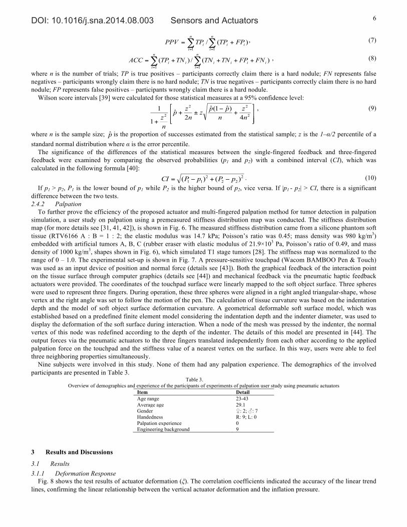
To further prove the efficiency of the proposed actuator and multi-fingered palpation method for tumor detection in palpation simulation, a user study on palpation using a premeasured stiffness distribution map was conducted. The stiffness distribution map (for more details see [31, 41, 42]), is shown in Fig. 6. The measured stiffness distribution came from a silicone phantom soft tissue (RTV6166 A : B = 1 : 2; the elastic modulus was 14.7 kPa; Poisson’s ratio was 0.45; mass density was 980 kg/m3) embedded with artificial tumors A, B, C (rubber eraser with elastic modulus of 21.9×10³ Pa, Poisson’s ratio of 0.49, and mass density of 1000 kg/m3, shapes shown in Fig. 6), which simulated T1 stage tumors [28]. The stiffness map was normalized to the range of 0 – 1.0. The experimental set-up is shown in Fig. 7. A pressure-sensitive touchpad (Wacom BAMBOO Pen & Touch) was used as an input device of position and normal force (details see [43]). Both the graphical feedback of the interaction point on the tissue surface through computer graphics (details see [44]) and mechanical feedback via the pneumatic haptic feedback actuators were provided. The coordinates of the touchpad surface were linearly mapped to the soft object surface. Three spheres were used to represent three fingers. During operation, these three spheres were aligned in a right angled triangular-shape, whose vertex at the right angle was set to follow the motion of the pen. The calculation of tissue curvature was based on the indentation depth and the model of soft object surface deformation curvature. A geometrical deformable soft surface model, which was established based on a predefined finite element model considering the indentation depth and the indenter diameter, was used to display the deformation of the soft surface during interaction. When a node of the mesh was pressed by the indenter, the normal vertex of this node was redefined according to the depth of the indenter. The details of this model are presented in [44]. The output forces via the pneumatic actuators to the three fingers translated independently from each other according to the applied palpation force on the touchpad and the stiffness value of a nearest vertex on the surface. In this way, users were able to feel three neighboring properties simultaneously.
Nine subjects were involved in this study. None of them had any palpation experience. The demographics of the involved participants are presented in Table 3.
Table 3. Overview of demographics and experience of the participants of experiments of palpation user study using pneumatic actuators
Item Detail Age range 23-43 Average age 29.1 Gender ♀: 2; ♂: 7 Handedness R: 9; L: 0 Palpation experience 0 Engineering background 9
3 Results and Discussions
3.1 Results 3.1.1 Deformation Response
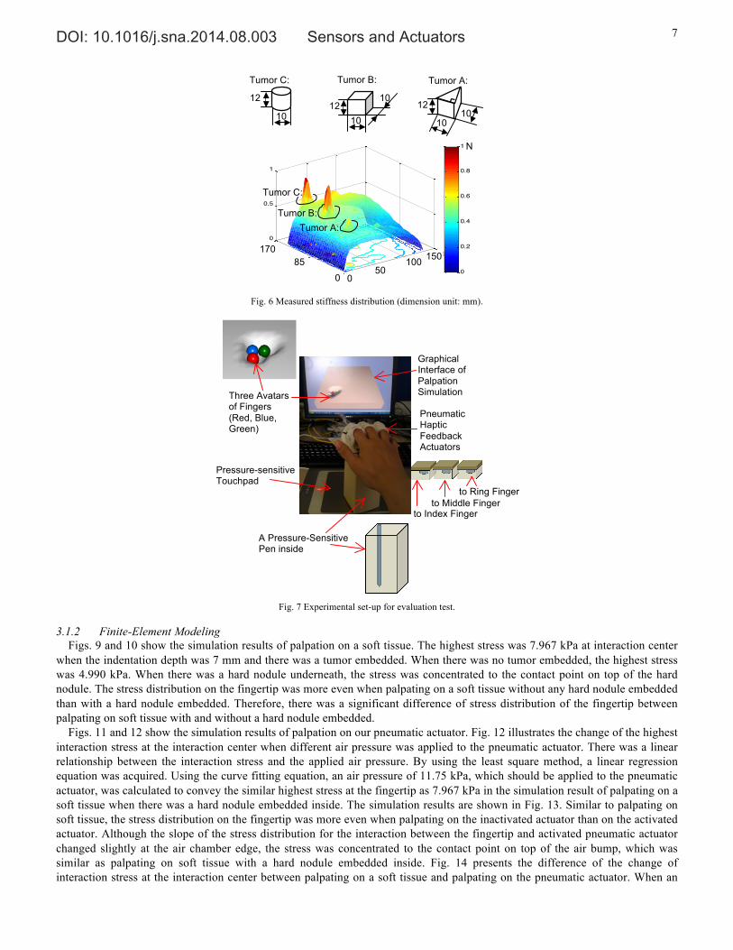
Fig. 8 shows the test results of actuator deformation (ξ). The correlation coefficients indicated the accuracy of the linear trend lines, confirming the linear relationship between the vertical actuator deformation and the inflation pressure.
DOI: 10.1016/j.sna.2014.08.003 Sensors and Actuators 7
Fig. 6 Measured stiffness distribution (dimension unit: mm).
Fig. 7 Experimental set-up for evaluation test.
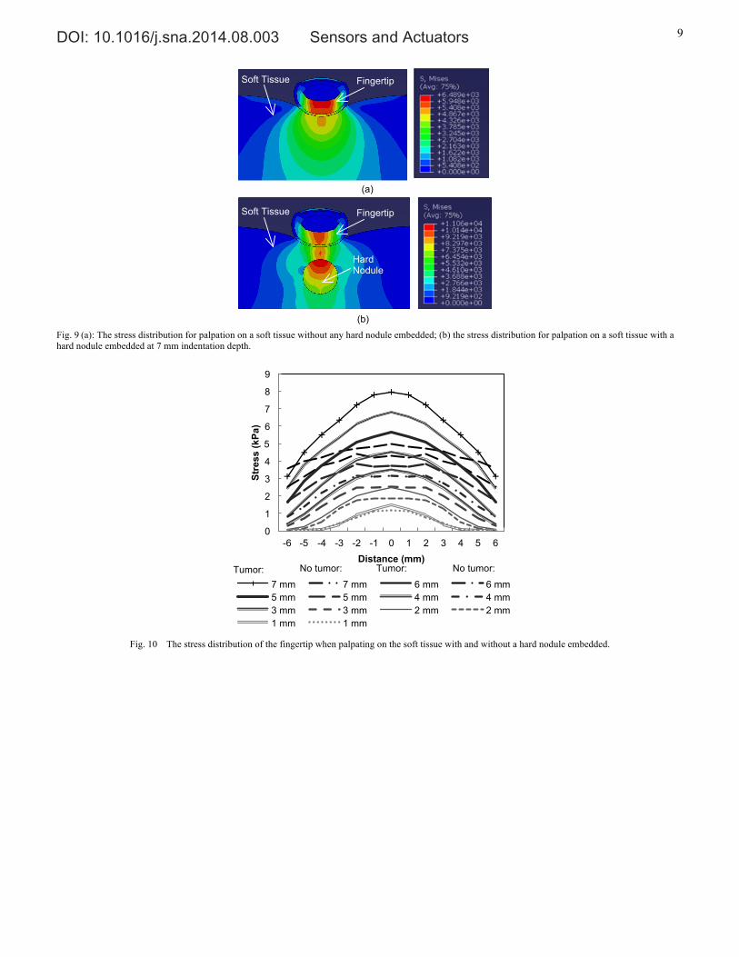
3.1.2 Finite-Element Modeling Figs. 9 and 10 show the simulation results of palpation on a soft tissue. The highest stress was 7.967 kPa at interaction center
when the indentation depth was 7 mm and there was a tumor embedded. When there was no tumor embedded, the highest stress was 4.990 kPa. When there was a hard nodule underneath, the stress was concentrated to the contact point on top of the hard nodule. The stress distribution on the fingertip was more even when palpating on a soft tissue without any hard nodule embedded than with a hard nodule embedded. Therefore, there was a significant difference of stress distribution of the fingertip between palpating on soft tissue with and without a hard nodule embedded.
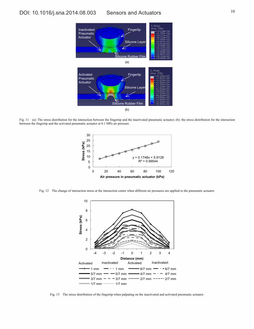
Figs. 11 and 12 show the simulation results of palpation on our pneumatic actuator. Fig. 12 illustrates the change of the highest interaction stress at the interaction center when different air pressure was applied to the pneumatic actuator. There was a linear relationship between the interaction stress and the applied air pressure. By using the least square method, a linear regression equation was acquired. Using the curve fitting equation, an air pressure of 11.75 kPa, which should be applied to the pneumatic actuator, was calculated to convey the similar highest stress at the fingertip as 7.967 kPa in the simulation result of palpating on a soft tissue when there was a hard nodule embedded inside. The simulation results are shown in Fig. 13. Similar to palpating on soft tissue, the stress distribution on the fingertip was more even when palpating on the inactivated actuator than on the activated actuator. Although the slope of the stress distribution for the interaction between the fingertip and activated pneumatic actuator changed slightly at the air chamber edge, the stress was concentrated to the contact point on top of the air bump, which was similar as palpating on soft tissue with a hard nodule embedded inside. Fig. 14 presents the difference of the change of interaction stress at the interaction center between palpating on a soft tissue and palpating on the pneumatic actuator. When an
050
100150
0
20
400
0.5
1
0
0.2
0.4
0.6
0.8
1
Tumor C:
Tumor B: Tumor A:
12 12
12
10 10
10
10
10
Tumor C: Tumor B: Tumor A:
N
100 50
0 0
170 85 150
Pressure-sensitive Touchpad
Pneumatic Haptic Feedback Actuators
Three Avatars of Fingers (Red, Blue, Green)
Graphical Interface of Palpation Simulation
A Pressure-Sensitive Pen inside
to Index Finger
to Middle Finger
to Ring Finger
DOI: 10.1016/j.sna.2014.08.003 Sensors and Actuators 8
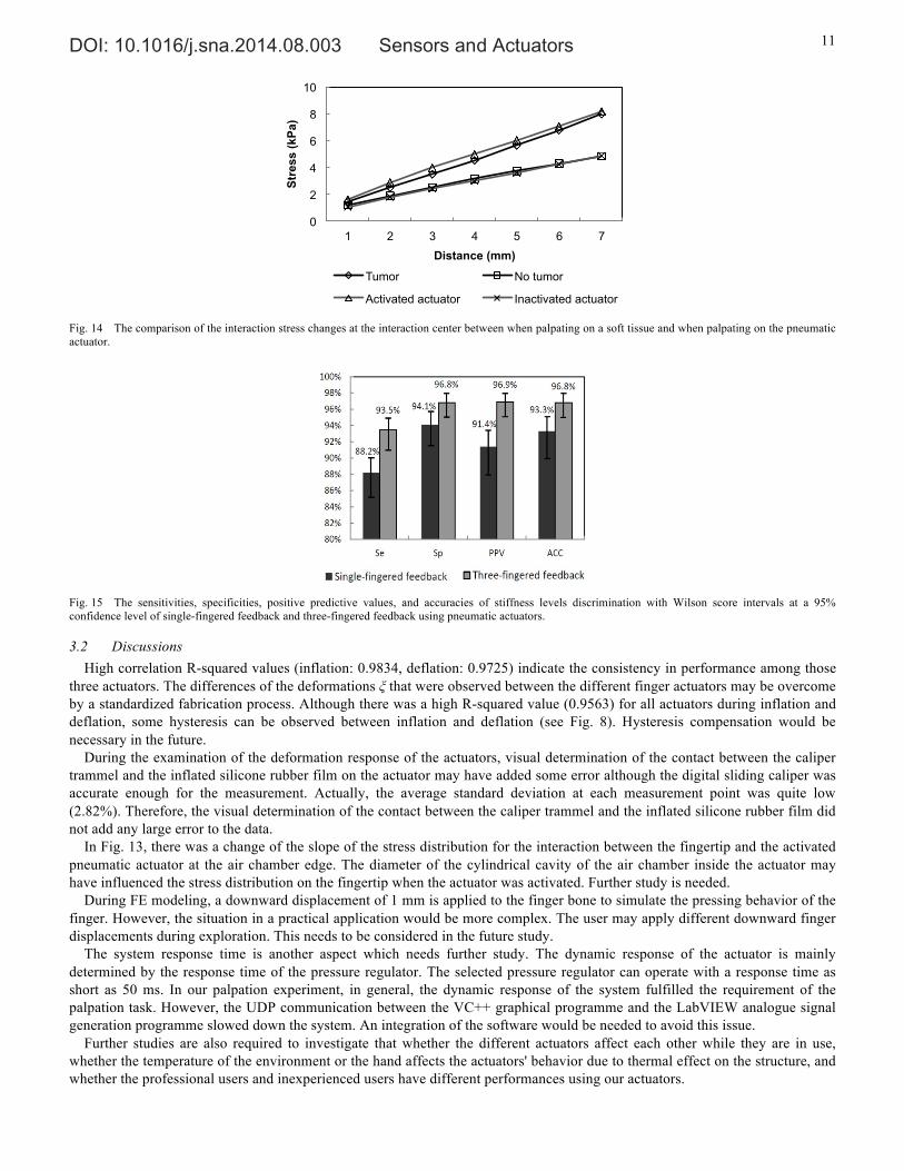
activated actuator was used to simulate the situation where a tumor was embedded, the correlation R-squared value was 0.9969. When using an inactivated actuator to simulate the situation of no tumor embedded, the value was 0.9998.
(a) (b)
(c) (d)
Fig. 8 Pneumatic haptic feedback actuators deformation (ξ) testing results: linear regression models are used to describe the relationship between the deformation and the pressure of (a) actuator 1, (b) actuator 2, (c) actuator 3, and (d) all actuators.
3.1.3 User Study Fig. 15 presents the sensitivities Se, specificities Sp, positive predictive values PPV, and accuracies ACC with Wilson score
intervals at a 95% confidence level of the stiffness levels discrimination tests by using single-fingered feedback and three-fingered feedback through the proposed pneumatic actuators. Here, since the confidence level was 95%, the error α in Eq. (9) was 5%. The sample size was 504 (3 values × 14 trails × 12 participants). From Fig. 15, one can see that three-fingered feedback had higher values in Se, Sp, PPV and ACC. There was no overlap of Se and PPV intervals between the single-fingered feedback and three-fingered feedback. Therefore, the differences were significant. The combined interval (CI) of Sp is 0.026 while the probability difference (Δp) was 0.027, Δp > CI; the combined interval (CI) of ACC was 0.027 while the probability difference (Δp) was 0.035, Δp > CI. Thus, both the Sp and ACC were also significantly different between the single-fingered feedback and three-fingered feedback.
The average consumed time during the tests of stiffness levels discrimination using the three-fingered feedback (4.6 ± 2.3 s) was less than using the single-fingered feedback (8.3 ± 2.9 s). Since the population was 168 (14 trails × 12 participants), it was considered as normally distributed and a student t-test was performed to compare the consumed time during the tests. The three-fingered feedback test consumed significantly less time than the single-fingered feedback test since p-value was 7.42 × 10⁻³².
During the palpation simulation test, all participants could feel the simulated stiffness differences. The detection sensitivities Se of the simulated tumors A, B, and C were 66.7%, 100%, and 88.9%, respectively. There was a positive correlation between the nodule detection sensitivities and nodule sizes.
0 20 40 60 80 1000
1
2
3
4
5
Pressure (kPa)
Defo
rmat
ion
(m
m)
InflationDeflationLinear regression
0 20 40 60 80 1000
1
2
3
4
5
Pressure (kPa)
Defo
rmat
ion
(m
m)
InflationDeflationLinear regression
0 20 40 60 80 1000
1
2
3
4
5
Pressure (kPa)
Defo
rmat
ion
(m
m)
InflationDeflationLinear regression
0 20 40 60 80 1000
1
2
3
4
5
Pressure (kPa)
Def
lect
ion
(m
m)
Actuator 1 Inflation
Actuator 1 Deflation
Actuator 2 InflationActuator 2 Deflation
Actuator 3 Inflation
Actuator 3 Deflation
y = 0.0457x-‐0.2098 R2 = 0.9563
y = 0.0475x-‐0.1875 R2 = 0.9677
y = 0.045x-‐0.2088 R2 = 0.9529
y = 0.0448x-‐0.2331 R2 = 0.9612
ξ
ξ
ξ
ξ
DOI: 10.1016/j.sna.2014.08.003 Sensors and Actuators 9
Fig. 9 (a): The stress distribution for palpation on a soft tissue without any hard nodule embedded; (b) the stress distribution for palpation on a soft tissue with a hard nodule embedded at 7 mm indentation depth.
Fig. 10 The stress distribution of the fingertip when palpating on the soft tissue with and without a hard nodule embedded.
0
1
2
3
4
5
6
7
8
9
-6 -5 -4 -3 -2 -1 0 1 2 3 4 5 6
Stre
ss (k
Pa)
Distance (mm)
7 mm 7 mm 6 mm 6 mm 5 mm 5 mm 4 mm 4 mm 3 mm 3 mm 2 mm 2 mm 1 mm 1 mm
Soft Tissue
Fingertip
(a)
Soft Tissue
Fingertip
Hard Nodule
(b)
Tumor: Tumor: No tumor: No tumor:
DOI: 10.1016/j.sna.2014.08.003 Sensors and Actuators 10
Fig. 11 (a): The stress distribution for the interaction between the fingertip and the inactivated pneumatic actuator; (b): the stress distribution for the interaction between the fingertip and the activated pneumatic actuator at 0.1 MPa air pressure.
Fig. 12 The change of interaction stress at the interaction center when different air pressures are applied to the pneumatic actuator.
Fig. 13 The stress distribution of the fingertip when palpating on the inactivated and activated pneumatic actuator.
y = 0.1748x + 5.9128 R² = 0.99544
0 5
10 15 20 25 30
0 20 40 60 80 100 120
Stre
ss (k
Pa)
Air pressure in pneumatic actuator (kPa)
0
2
4
6
8
10
-4 -3 -2 -1 0 1 2 3 4
Stre
ss (k
Pa)
Distance (mm)
1 mm 1 mm 6/7 mm 6/7 mm 5/7 mm 5/7 mm 4/7 mm 4/7 mm 3/7 mm 3/7 mm 2/7 mm 2/7 mm 1/7 mm 1/7 mm
Fingertip
Activated Pneumatic Actuator Silicone Layer
Silicone Rubber Film
Fingertip
Inactivated Pneumatic Actuator Silicone Layer
Silicone Rubber Film
(a)
(b)
Activated: Inactivated: Inactivated: Activated:
DOI: 10.1016/j.sna.2014.08.003 Sensors and Actuators 11
Fig. 14 The comparison of the interaction stress changes at the interaction center between when palpating on a soft tissue and when palpating on the pneumatic actuator.
Fig. 15 The sensitivities, specificities, positive predictive values, and accuracies of stiffness levels discrimination with Wilson score intervals at a 95% confidence level of single-fingered feedback and three-fingered feedback using pneumatic actuators.
3.2 Discussions High correlation R-squared values (inflation: 0.9834, deflation: 0.9725) indicate the consistency in performance among those
three actuators. The differences of the deformations ξ that were observed between the different finger actuators may be overcome by a standardized fabrication process. Although there was a high R-squared value (0.9563) for all actuators during inflation and deflation, some hysteresis can be observed between inflation and deflation (see Fig. 8). Hysteresis compensation would be necessary in the future.
During the examination of the deformation response of the actuators, visual determination of the contact between the caliper trammel and the inflated silicone rubber film on the actuator may have added some error although the digital sliding caliper was accurate enough for the measurement. Actually, the average standard deviation at each measurement point was quite low (2.82%). Therefore, the visual determination of the contact between the caliper trammel and the inflated silicone rubber film did not add any large error to the data.
In Fig. 13, there was a change of the slope of the stress distribution for the interaction between the fingertip and the activated pneumatic actuator at the air chamber edge. The diameter of the cylindrical cavity of the air chamber inside the actuator may have influenced the stress distribution on the fingertip when the actuator was activated. Further study is needed.
During FE modeling, a downward displacement of 1 mm is applied to the finger bone to simulate the pressing behavior of the finger. However, the situation in a practical application would be more complex. The user may apply different downward finger displacements during exploration. This needs to be considered in the future study.
The system response time is another aspect which needs further study. The dynamic response of the actuator is mainly determined by the response time of the pressure regulator. The selected pressure regulator can operate with a response time as short as 50 ms. In our palpation experiment, in general, the dynamic response of the system fulfilled the requirement of the palpation task. However, the UDP communication between the VC++ graphical programme and the LabVIEW analogue signal generation programme slowed down the system. An integration of the software would be needed to avoid this issue.
Further studies are also required to investigate that whether the different actuators affect each other while they are in use, whether the temperature of the environment or the hand affects the actuators' behavior due to thermal effect on the structure, and whether the professional users and inexperienced users have different performances using our actuators.
0
2
4
6
8
10
1 2 3 4 5 6 7
Stre
ss (k
Pa)
Distance (mm)
Tumor No tumor
Activated actuator Inactivated actuator
DOI: 10.1016/j.sna.2014.08.003 Sensors and Actuators 12
4 Conclusion In this paper, a multi-fingered pneumatic device that allows a user to carry out palpation of soft tissue experiencing haptic
sensations at multiple fingers is proposed. The tissue stiffness information is conveyed by using pneumatic actuators to vary the stress on the user’s fingertips as experienced during palpation. This principle is proven by examining the deformation response of the actuators, analyzing the contact stress using finite element analysis, and evaluating the performance of discrimination of stiffness levels and tumor localization in user studies. The experimental results proved that the changes of stress on the fingertips during palpation can be recreated by using the proposed pneumatic multi-fingered haptic feedback method. The user study results of discrimination of stiffness levels have shown that the multi-fingered feedback is more accurate and efficient in conveying tissue stiffness information to the user. The results of palpation user study have demonstrated relatively good tumor detection sensitivities showing direct correlation between tumor size and detection sensitivity.
The proposed pneumatic actuators provide a solution for multi-fingered haptic palpation. The accuracy and time-efficiency advantages of using multi-fingered palpation over single-fingered have been proven. The proposed method provides a better balance between the control complexity and the efficiency of tactile information rendering compared to both single-point force feedback and tactile feedback devices. With real-time tactile sensing data, the application of these actuators can be extended to intra-operative palpation. For example, our actuators can be added to the grippers at the master side of the surgical robot Da Vinci or the handle of a MIS probe equipped with tactile sensors.
Acknowledgement The work described in this paper was partially funded by the GSTT Charity, National Institute for Health Research (NIHR)
Biomedical Research Centre based at Guy's and St Thomas' NHS Foundation Trust and King's College London, the European Commission’s Seventh Framework Programme under grant agreement 287728 in the framework of EU project STIFF-FLOP, the China Scholarship Council, and the Vattikuti Foundation. The views expressed are those of the authors and not necessarily those of the NHS, the NIHR or the Department of Health.
References [1] C. King, M. O. Culjat, M. L. Franco, J. W. Bisley, G. P. Carman, E. P. Dutson, and W. S. Grundfest, “A multielement tactile feedback system for
robot-assisted minimally invasive surgery,” Haptics, IEEE Trans., vol. 2, no. 1, pp. 52–56, 2009. [2] S.-Y. Kim, K.-U. Kyung, J. Park, and D.-S. Kwon, “Real-time area-based haptic rendering and the augmented tactile display device for a palpation
simulator,” Adv. Robot., vol. 21, no. 9, pp. 961–981, Sep. 2007. [3] M. Culjat, C.-H. King, M. Franco, J. Bisley, W. Grundfest, and E. Dutson, “Pneumatic balloon actuators for tactile feedback in robotic surgery,” Ind. Robot
An Int. J., vol. 35, no. 5, pp. 449–455, 2008. [4] C. Roke, C. Melhuish, T. Pipe, D. Drury, and C. Chorley, “Lump localisation through a deformation-based tactile feedback system using a biologically
inspired finger sensor,” Rob. Auton. Syst., vol. 60, no. 11, pp. 1442–1448, Nov. 2012. [5] Y. Kim, I. Oakley, and J. Ryu, “Design and psychophysical evaluation of pneumatic tactile display,” in SICE-ICASE, 2006. International Joint Conference,
2006, pp. 1933–1938. [6] Y. Kuroda, M. Nakao, T. Kuroda, H. Oyama, M. Komori, and T. Matsuda, “FEM-based interaction model between elastic objects for indirect palpation
simulator.,” Stud. Health Technol. Inform., vol. 98, pp. 183–189, 2004. [7] A. Crossan, S. Brewster, S. Reid, and D. Mellor, “A horse ovary palpation simulator for veterinary training,” Haptic human-computer Interact., pp. 157–164,
2001. [8] R. Parkes, N. Forrest, and S. Baillie, “A mixed reality simulator for feline abdominal palpation training in veterinary medicine.,” Stud. Health Technol.
Inform., vol. 142, pp. 244–246, Jan. 2009. [9] M. Nakao, T. Kuroda, M. Komori, and H. Oyama, “Evaluation and user study of haptic simulator for learning palpation in cardiovascular surgery,” Int. Conf.
Artif. Real. Telexistence, pp. 203–208, 2003. [10] S. Ullrich and T. Kuhlen, “Haptic palpation for medical simulation in virtual environments.,” IEEE Trans. Vis. Comput. Graph., vol. 18, no. 4, pp. 617–625,
2012. [11] M. Dinsmore, N. Langrana, G. Burdea, and J. Ladeji, “Virtual reality training simulation for palpation of subsurface tumors,” in IEEE Virtual Reality Annual
International Symposium, 1997, pp. 54–60. [12] N. A. Langrana, G. Burdea, K. Lange, D. Gomez, and S. Deshpande, “Dynamic force feedback in a virtual knee palpation.,” Artif. Intell. Med., vol. 6, no. 4,
pp. 321–333, 1994. [13] H. Kawasaki, J. Takai, Y. Tanaka, C. Mrad, and T. Mouri, “Control of multi-fingered haptic interface opposite to human hand,” in Proceedings 2003
IEEERSJ International Conference on Intelligent Robots and Systems IROS 2003, 2003, vol. 3, no. October, pp. 2707–2712. [14] V. Daniulaitis and M. O. Alhalabi, “Medical palpation of deformable tissue using physics-based model for gaptic interface robot ( HIRO ),” in Information
Systems, 2004, pp. 3907–3911. [15] T. Endo, H. Kawasaki, T. Mouri, Y. Doi, T. Yoshida, Y. Ishigure, H. Shimomura, M. Matsumura, and K. Koketsu, “Five-fingered haptic interface robot:
HIRO III,” World Haptics 2009 Third Jt. EuroHaptics Conf. Symp. Haptic Interfaces Virtual Environ. Teleoperator Syst., vol. 4, no. 1, pp. 458–463, 2009. [16] N. Nakamura and Y. Fukui, “Development of fingertip type non-grounding force feedback display,” in Proceedings - Second Joint EuroHaptics Conference
and Symposium on Haptic Interfaces for Virtual Environment and Teleoperator Systems, World Haptics 2007, 2007, pp. 582–583. [17] K. Minamizawa, D. Prattichizzo, and S. Tachi, “Simplified design of haptic display by extending one-point kinesthetic feedback to multipoint tactile
feedback,” in 2010 IEEE Haptics Symposium, 2010, pp. 257–260. [18] M. A. Srinivasan and K. Dandekar, “An investigation of the mechanics of tactile sense using two-dimensional models of the primate fingertip.,” J. Biomech.
Eng., vol. 118, no. 1, pp. 48–55, Mar. 1996. [19]K. Dandekar, B. I. Raju, and M. a. Srinivasan, “3-D Finite-Element Models of Human and Monkey Fingertips to Investigate the Mechanics of Tactile Sense,”
J. Biomech. Eng., vol. 125, no. 5, p. 682, 2003. [20] J. R. Phillips and K. O. Johnson, “Tactile spatial resolution . III . A continuum mechanics model of skin predicting mechanoreceptor responses to bars ,
edges , and gratings Tactile Spatial Resolution . III . A Continuum Mechanics Model of Skin Predicting Mechanoreceptor Responses to Bars,” 1981.
DOI: 10.1016/j.sna.2014.08.003 Sensors and Actuators 13
[21] J. Z. Wu, K. Krajnak, D. E. Welcome, and R. G. Dong, “Analysis of the dynamic strains in a fingertip exposed to vibrations: Correlation to the mechanical stimuli on mechanoreceptors,” J. Biomech., vol. 39, no. 13, pp. 2445–2456, 2006.
[22] J. Z. Wu, D. E. Welcome, and R. G. Dong, “Three-dimensional finite element simulations of the mechanical response of the fingertip to static and dynamic compressions.,” Comput. Methods Biomech. Biomed. Engin., vol. 9, no. 1, pp. 55–63, Mar. 2006.
[23] J. Z. Wu, K. Krajnak, D. E. Welcome, and R. G. Dong, “Three-dimensional finite element simulations of the dynamic response of a fingertip to vibration,” J. Biomech. Eng., vol. 130, no. 5, p. 054501, 2008.
[24] C. D. Clemente, Anatomy: a Regional Atlas of the Human Body (Second Edition). Urban and Achwarzengerg, Baltimore, Munich, 1981. [25] D. Klemm, “Fingertip anatomy.” [Online]. Available: http://www8.georgetown.edu/dml/facs/graphics/POP-UPS/pop-up-fingernail.html. [26] R. W. Ogden, “Large deformation isotropic elasticity: on the correlation of theory and experiment for compressible rubberlike solids,” Proceedings of the
Royal Society A: Mathematical, Physical and Engineering Sciences, vol. 328, no. 1575. pp. 567–583, 1972. [27] P. Wellman and R. Howe, “Breast tissue stiffness in compression is correlated to histological diagnosis,” 1999. [28] W. a Woodward, E. a Strom, S. L. Tucker, M. D. McNeese, G. H. Perkins, N. R. Schechter, S. E. Singletary, R. L. Theriault, G. N. Hortobagyi, K. K. Hunt,
and T. a Buchholz, “Changes in the 2003 American Joint Committee on Cancer staging for breast cancer dramatically affect stage-specific survival.,” J. Clin. Oncol. Off. J. Am. Soc. Clin. Oncol., vol. 21, no. 17, pp. 3244–8, Sep. 2003.
[29] K. Sangpradit, H. Liu, P. Dasgupta, K. Althoefer, and L. D. Seneviratne, “Finite-element modeling of soft tissue rolling indentation.,” IEEE Trans. Biomed. Eng., vol. 58, no. 12, pp. 3319–3327, Dec. 2011.
[30]E. M. Arruda and M. C. Boyce, “A three-dimensional constitutive model for the large stretch behavior of rubber elastic materials,” J. Mech. Phys. Solids, vol. 41, no. 2, pp. 389–412, 1993.
[31] K. Sangpradit, H. Liu, L. D. Seneviratne, and K. A. Althoefer, “Tissue identification using inverse finite element analysis of rolling indentationof Rolling Indentation,” in IEEE International conference on Robotics and Automation ICRA, 2009, pp. 1250–1255.
[32] H. Liu, K. Sangpradit, M. Li, P. Dasgupta, K. Althoefer, and L. D. Seneviratne, “Inverse finite-element modeling for tissue parameter identification using a rolling indentation probe,” Med. Biol. Eng. Comput., Sep. 2013.
[33] S. S. Ltd., “HT 6240 data sheet,” 2014. [Online]. Available: http://www.silex.co.uk/media/4576/ht_6240.pdf. [34]H. J. Qi, K. Joyce, and M. C. Boyce, “Durometer hardness and the stress-strain behavior of elastomeric materials,” Rubber Chem. Technol., vol. 76, no. 2, pp.
419–435, 2003. [35] H. Yamada, Strength of Biological Materials. Baltimore, MD: Willians and Wilkins Co., 1970. [36] O. K. Bates, “Termal conductivity of liquid silicones,” Ind. Eng. Chem., vol. 41, no. 9, pp. 1966–1968, 1966. [37] D. Altman and J. Bland, “Diagnostic test 1: Sensitivity and specificity,” BMJ, vol. 308, p. 1552, 1994. [38] T. Fawcett, “An introduction to ROC analysis,” Pattern Recognit. Lett., vol. 27, no. 8, pp. 861–874, Jun. 2006. [39] E. B. Wilson, “Probable inference, the law of succession, and statistical inference,” J. Am. Stat. Assoc., vol. 22, pp. 209–212, 1927. [40] S. Wallis, “Binomial confidence intervals and contingency tests: mathematical fundamentals and the evaluation of alternative methods,” J. Quant. Linguist.,
vol. 20, no. 3, pp. 178–208, Aug. 2013. [41] M. Li, H. Liu, L. D. Seneviratne, and K. Althoefer, “Tissue stiffness simulation and abnormality localization using pseudo-haptic feedback,” in IEEE
International Conference on Robotics and Automation, 2012, pp. 5359–5364. [42] H. Liu, J. Li, X. Song, L. D. Seneviratne, and K. Althoefer, “Rolling indentation probe for tissue abnormality identification during minimally invasive
surgery,” IEEE Trans. Robot., vol. 27, no. 3, pp. 450–460, 2011. [43] M. Li, M. B. Ridzuan, S. Sareh, L. D. Seneviratne, P. Dasgupta, and K. Althoefer, “Pseudo-Haptics for Rigid Tool/Soft Surface Interaction Feedback in
Virtual Environments,” Mechatronics, in press. [44] M. Li, “Haptic Feedback of Rigid Tool / Soft Object Interaction in Medical Training and Robot-Assisted Minimally Invasive Surgery,” King’s College
London, PhD thesis, 2014.