muitary, rosita and del monte lift stations - seaside, ca
TRANSCRIPT
ISSUED FOR BID
PROJECT WAL FOR THE CONSTRUCTION OF
LnFT STATION UPGRADES FOR
Muitary, Rosita and Del Monte Lift Stations
VOLUMEHI
TECHNICAL SPECIF1C4T10NS
Prepared forSEASmE COUNTY SfflATION DISTRICT
Depmrtmaat ofPubMeWorks
LS Deeember 2017

ISSUED FOR BID
PROJECT MANUAL FOR THE CONSTRUCTION OF LIFT STATION UPGRADES FOR
Military, Rosita and Del Monte Lift Stations
VOLUME IB TECHNICAL SPECIFICATIONS
Prepared for
SEASIDE COUNTY SANITATION DISTRICT Department of Public Works
15 December 2017
Prepared by E2 CONSULTING ENGINEERS, INC.
1900 POWELL STREET, SUITE 250, EMERYVILLE, CA 94608 • 510-428-4721


TABLE OF CONTENTS


R0-10-27-17 TOC - i Q:\Seaside County Sanitation District (SCSD)\Lift Station Upgrades\PS-Specifications\IFB specs_new date_w. review comments\Table of Contents vmb 12-15-17.doc
LIFT STATION UPGRADES FOR MILITARY, ROSITA AND DEL MONTE LIFT STATIONS
TABLE OF CONTENTS
VOLUME IA PROCUREMENT AND CONTRACTING
REQUIREMENTS
DIVISION 00
INTRODUCTORY INFORMATION
Documents
00 01 10 Table of Contents
PROCUREMENT REQUIREMENTS
Documents
00 11 16 Invitation to Bid
00 21 13 Instructions to Bidders
00 41 00 Bid Form
00 43 13 Bid Security Form
00 45 19 Non-Collusion Affidavit
00 45 26 Worker’s Compensation Insurance Certificate
CONTRACTING REQUIREMENTS
Documents
00 51 00 Notice of Award
00 52 00 Agreement Form
00 55 00 Notice to Proceed
R0-10-27-17 TOC - ii Q:\Seaside County Sanitation District (SCSD)\Lift Station Upgrades\PS-Specifications\IFB specs_new date_w. review comments\Table of Contents vmb 12-15-17.doc
00 61 13.13 Performance Bond
00 61 13.16 Payment Bond
00 72 00 General Conditions
00 73 00 Supplementary Conditions
Attachment 00800-A Prevailing Wages
VOLUME IB – TECHNICAL SPECIFICATIONS
DIVISION 01 - GENERAL REQUIREMENTS
01 11 00 Summary of Work
01 14 00 Work Restriction
01 20 00 Price and Payment Procedures
01 30 00 Administrative Requirements
01 31 19 Project Meetings
01 32 16 Construction Progress Schedule
01 33 00 Submittal Procedures
01 41 00 Regulatory Requirements
01 42 13 Abbreviations & Acronyms
01 45 00 Quality Control
01 50 00 Construction and Temporary Facilities
01 55 26 Traffic Control
01 57 23 Temporary Erosion Control
R0-10-27-17 TOC - iii Q:\Seaside County Sanitation District (SCSD)\Lift Station Upgrades\PS-Specifications\IFB specs_new date_w. review comments\Table of Contents vmb 12-15-17.doc
01 57 30 Temporary Flow Bypass
01 70 00 Execution and Closeout Requirements
DIVISION 02 – EXISTING CONDITIONS
02 41 00 Demolition
DIVISION 03 – CONCRETE
03 11 00 Concrete Forming
03 20 00 Concrete Reinforcing
03 30 00 Cast-in-Place Concrete
DIVISION 04 - MASONRY (NOT USED)
DIVISION 05 – METALS
05 50 00 Metal Fabrications
DIVISION 06 – WOOD, PLASTICS, AND COMPOSITES (NOT USED)
DIVISION 07 – THERMAL AND MOISTURE PROTECTION
07 11 16 Crystalline Waterproofing
07 92 00 Joint Sealants
DIVISION 08 – OPENINGS (NOT USED)
DIVISION 09 – FINISHES
09 90 00 Painting and Coating
09 98 00 Corrosion Resistant Lining System
DIVISION 10 – SPECIALTIES (NOT USED)
R0-10-27-17 TOC - iv Q:\Seaside County Sanitation District (SCSD)\Lift Station Upgrades\PS-Specifications\IFB specs_new date_w. review comments\Table of Contents vmb 12-15-17.doc
DIVISION 11 - EQUIPMENT
11 05 00 General Equipment Provisions
DIVISION 12 – FURNISHINGS (NOT USED)
DIVISION 13 – SPECIAL CONSTRUCTION (NOT USED)
DIVISION 14 – CONVEYING EQUIPMENT (NOT USED)
DIVISIONS 15 - 19 – RESERVED FOR FUTURE EXPANSION
DIVISION 21 – FIRE SUPPRESION (NOT USED)
DIVISION 22 – PLUMBING (NOT USED)
DIVISION 23 – HEATING, VENTILATING and AIR CONDITIONING (HVAC) (NOT USED)
DIVISION 25 – INTEGRATED AUTOMATION (NOT USED)
DIVISION 26 - ELECTRICAL
26 00 10 Electrical General
26 01 10 Conduit, Boxes and Grounding
26 01 20 Wires, Fuses and Terminal Blocks
26 32 13 Engine Generator
26 36 23 Automatic Transfer Switch
26 44 82 Solid State Soft Starter
26 66 00 Factory and Field Testing
26 79 05 Control Panel
26 79 10 PLC & OI Hardware
26 89 60 Bubbler System
R0-10-27-17 TOC - v Q:\Seaside County Sanitation District (SCSD)\Lift Station Upgrades\PS-Specifications\IFB specs_new date_w. review comments\Table of Contents vmb 12-15-17.doc
DIVISION 27 – COMMUNICATIONS (NOT USED)
DIVISION 28 – ELECTRONIC SAFETY and SECURITY (NOT USED)
DIVISION 31 – EARTHWORK
31 10 00 Site Clearing
31 23 00 Excavation and Fill
31 23 19 Dewatering
31 23 33 Trenching, Backfilling and Compaction
31 40 00 Sheeting, Waling and Shoring
DIVISION 32 – EXTERIOR IMPROVEMENTS
32 12 00 Asphalt Concrete Paving
32 80 00 Irrigation
32 90 00 Planting
DIVISION 33 - UTILITIES –
33 05 16 Utility Structures
33 05 20 General Piping Requirements
33 05 20.10 PVC Pressure Pipe and Fittings
33 05 20.11 PVC Gravity Sewer Pipe and Fittings
33 05 20.13 Ductile Iron Pipe and Fittings
33 08 30 Commissioning of Wastewater Utilities
33 32 20 Submersible Non-Clog Pumps
R0-10-27-17 TOC - vi Q:\Seaside County Sanitation District (SCSD)\Lift Station Upgrades\PS-Specifications\IFB specs_new date_w. review comments\Table of Contents vmb 12-15-17.doc
DIVISION 34 - TRANSPORTATION (NOT USED)
DIVISION 35 – WATERWAY AND MARINE CONSTRUCTION (NOT USED)
DIVISION 40 – PROCESS INTEGRATION
40 05 23 Valves and Miscellaneous Piping Appurtenances
DIVISION 41 – MATERIAL PROCESSING and HANDLING EQUIPMENT (NOT USED)
DIVISION 42 – PROCESS HEATING, COOLING, and DRYING (NOT USED)
DIVISION 43 – PROCESS GAS and LIQUID HANDLING, PURIFICATION and STORAGE EQUIPMENT (NOT USED)
DIVISION 44 – POLLUTION and WASTE CONTROL EQUIPMENT (NOT USED)
DIVISION 45 – INDUSTRY SPECIFIC MANUFACTURING EQUIPMENT (NOT USED)
DIVISION 46 – WATER and WASTEWATER EQUIPMENT (NOT USED)
DIVISION 48 – ELECTRICAL POWER GENERATION (NOT USED)
SPECIFICATIONS


DIVISION 01
GENERAL REQUIREMENTS

R0: IFB-10-27-17 Summary of Work
01 11 00 - 1
C:\Seaside CSD\IFB Specs_12-29-2017\IFB Vol 1B\Div 01 - General Requirements\01 11 00 - Summary Of Work.Docx
SECTION 01 11 00
SUMMARY OF WORK
PART 1 - GENERAL
1.01 WORK UNDER THIS CONTRACT AGREEMENT
A. The Work of this Contract includes work at the existing Military, Rosita and Del Monte Lift Stations of the Seaside County Sanitation District (SCSD) consisting of: 1. Military Lift Station:
a. Construction of new Pump Bypass Valve Vault, including piping, fittings and valves to complete connection to the existing force main;
b. Construction of new precast concrete Overflow Structure including protective lining and coating of interior surfaces;
c. Rehabilitation and restoration of the existing lift station including providing two (2) new submersible pumps and motors, piping, fittings and valves to complete the connection to the new pump discharge valve vault and application of a new protective coating system on the interior of the existing wet well;
d. Construction of new electrical controls, including control panel and a manual transfer switch to incorporate a portable standby generator into the facility operation.
e. Construction of a new pump discharge valve vault, including piping, fittings and valves to complete the connection to the existing force main;
f. Construction of a concrete retaining wall along one side of the property and civil site work as shown on the Drawings
g. Demolition as required, including that of an existing abandoned wet well distinct from the wet well currently in use;
h. Providing flow bypassing system including backup pump and standby power during the performance of the work at this facility.
2. Rosita Lift Station: a. Construction of new precast concrete Overflow Structure and connection
piping to the existing wet well (permanent) and connection (temporary) to an existing manhole upstream of the existing wet well, including protective lining and coating of interior surfaces;
R0: IFB-10-27-17 Summary of Work
01 11 00 - 2
C:\Seaside CSD\IFB Specs_12-29-2017\IFB Vol 1B\Div 01 - General Requirements\01 11 00 - Summary Of Work.Docx
b. Demolition of the existing lift station (including discharge valve vault) and construction of a new wet well including providing two (2) new submersible pumps and motors, discharge piping, fittings, valves and valve vault required to complete the connection to the existing force main and pump discharge valve vault, and including protective lining and coating of interior surfaces of the wet well structure and equipment installed in the wet well;
c. Construction of new electrical controls, including control panel and an automatic transfer switch to incorporate the existing remote engine generator for standby power into the operation as needed.;
d. Demolition as required, including equipment and piping in the existing wet well;
e. Civil and site work restoration of the site as shown on the Drawings; f. Providing flow bypassing system including backup pump and standby
power during the performance of the work at this facility. 3. Del Monte Lift Station:
a. Construction of new Pump Bypass Valve Vault, including piping, fittings and valves to complete connection to the existing force main and protective lining and coating of the interior of the structure;
b. Application of a new protective coating system on the interior of the existing wet well;
c. Providing flow bypassing system including backup pump and standby power during the performance of the work at this facility.
d. Construction of a new permanent engine generator for standby power, and modifications to the existing electrical controls including providing automatic transfer switch for the new engine generator;
e. Providing of landscape planting and modifications and additions to the site irrigation system and other site restoration work as shown on the Drawings;
f. Provide traffic control as required and shown on the Drawings to operate the flow bypassing system and ensure public safety.
B. The Work shall be in accordance with the intent of the Contract Documents as stated in Division 1 of the Standard Specifications and the General and Supplementary Conditions of the Contract.
R0: IFB-10-27-17 Summary of Work
01 11 00 - 3
C:\Seaside CSD\IFB Specs_12-29-2017\IFB Vol 1B\Div 01 - General Requirements\01 11 00 - Summary Of Work.Docx
1.02 TIME ALLOWED FOR COMPLETION.
A. Substantial Completion for the Project: Time shall be as stated in the Invitation to Bid, Document Section 00 11 16, said time to begin with the date of the Notification to Proceed (NTP) from the District.
B. Final Completion of the Project: The Contract Time for Final Completion shall be as stated in the Invitation to Bid, Document Section 00 11 16, said time to be following and beginning with the date of certification of Substantial Completion of the Work for the last of the three (3) lift stations.
1.03 CONSTRUCTION MANAGEMENT
A. E2 Consulting Engineers, Inc., is the design engineer (“Engineer”) for the subject facilities. The District will perform construction management for and furnish inspection of the Work.
1.04 DRAWINGS
The Drawings forming a part of the Contract Documents are listed on Drawing G-2.
PART 2 – PRODUCTS (Not Used)
PART 3 - EXECUTION (Not Used)
END OF SECTION 01 11 00

R0: IFB-10-27-17 Summary of Work
01 11 00 - 4
C:\Seaside CSD\IFB Specs_12-29-2017\IFB Vol 1B\Div 01 - General Requirements\01 11 00 - Summary Of Work.Docx
This page intentionally blank.
R0: IFB-12-15-17 Work Restrictions 01 14 00 - 1 C:\Seaside CSD\IFB Specs_12-29-2017\IFB Vol 1B\Div 01 - General Requirements\01 14 00 - Work Restrictions.Docx
SECTION 01 14 00
WORK RESTRICTIONS
PART 1 - GENERAL
1.01 SUMMARY
A. This Section covers restrictions that affect construction operations and is supplementary to those of Division 1 of the Standard Specifications and the General and Supplementary Conditions of the Contract. The requirements include but are not limited to coordination with entities having jurisdiction over work in the project area or are responsible for maintaining existing improvements in the project area.
B. Section Includes: 1. Project Coordination. 2. Construction Sequence.
C. Related Sections: 1. Special Provisions Section 7-1.04 – Public Safety 2. Section 01 41 00 – Regulatory Requirements 3. Section 01 50 0 - Construction and Temporary Facilities 4. Section 01 70 00 – Execution and Closeout Requirements 5. Section 02 41 00 – Demolition 6. Section 31 23 33 – Trenching, Backfilling and Compaction 7. Section 32 12 00 – Asphalt Concrete Paving
1.02 PROJECT COORDINATION
A. Seaside County Sanitation District (SCSD) (District): Where the activities for this work cross existing utilities, exercise caution in construction activities to protect the integrity of the existing utilities. Promptly notify the SCSD of any potential interference with existing utilities. Where damage to any existing utilities occurs as a result of construction activities for this Work, promptly perform the repair or replacement in accordance with the requirements of and as directed by the SCSD at no additional costs to the District.
B. California-American Water Company (Cal-Am): California-American Water Company (Cal-Am): See Technical Specification Section 01 30 00, “Administrative Requirements”, regarding requirements for maintenance of constant operation of the existing water distribution system facilities in the vicinity of the lift station
R0: IFB-12-15-17 Work Restrictions 01 14 00 - 2 C:\Seaside CSD\IFB Specs_12-29-2017\IFB Vol 1B\Div 01 - General Requirements\01 14 00 - Work Restrictions.Docx
sites. Notify Cal-Am at least five (5) working days in advance of the work at a respective site and notify them of potential impacts on their facilities.
C. City of Seaside: 1. The City of Seaside is responsible for the maintenance of roads within the City
of Seaside boundaries, which includes the Military Lift Station project and the Del Monte Lift Station project. Refer to the requirements described in Specification Section 01 55 26 and the requirements shown on the Drawings specific for the Del Monte Lift Station. Coordinate with the City of Seaside Public Works Department and with California Department of Transportation (Del Monte Lift Station only) in advance of the Work to ensure compliance with the notification requirements for road closures, signage for detours and in general to minimize the impacts on traffic disruption and safety.
2. In addition to any special events identified in Paragraph 1.02G below, conduct construction activities, including temporary on-site storage of materials and equipment, for this Contract in a manner that will not impede or interrupt normal flow of traffic through any of the entry gates. Strict enforcement of this requirement will be applied to any work performed at the Del Monte Lift Station during the period from the beginning of the Memorial Day weekend continuing through Labor Day weekend.
3. Prevent excavated soils and backfill materials resulting from or used on this Work that are stored on the Project site from being carried into storm drains by rainfall run-off or by drainage water from the construction operation. See Article 3.07 of Specification section 01 30 00 and Article 8 of the General Conditions for general requirements.
D. City of Del Rey Oaks: 1. The City of Del Rey Oaks is responsible for the maintenance of roads within
the Del Rey Oaks boundaries, which includes the Rosita Lift Station project. Refer to the requirements described in Specification Section 01 55 26 regarding traffic control. Coordinate with the City of Del Rey Oaks Maintenance Department in advance of the Work at this site to ensure compliance with the notification requirements for road closures, signage for detours and in general to minimize the impacts on traffic disruption and safety.
2. Prevent excavated soils and backfill materials resulting from or used on this Work that are stored on the Project site from being carried into storm drains or the nearby stream by rainfall run-off or by drainage water from the construction operation. See Article 3.07 of Specification section 01 30 00 and Article 8 of the General Conditions for general requirements.
R0: IFB-12-15-17 Work Restrictions 01 14 00 - 3 C:\Seaside CSD\IFB Specs_12-29-2017\IFB Vol 1B\Div 01 - General Requirements\01 14 00 - Work Restrictions.Docx
E. California Department of Transportation (Caltrans): 1. Canyon Del Rey Boulevard is also State Route 218 (SR218). Any work
performed in the right-of-way of SR 218 is therefor in the jurisdiction of Caltrans. Flow bypassing required at the Del Monte Lift Station will need to have equipment placed for a specified, limited duration of field construction period in the traffic lanes of SR218. This work will require a permit from Caltrans, including requirements for traffic control for the duration of the work.
F. Pacific Gas and Electric Company (PG&E): Exercise care in the construction activities to protect the integrity of the existing gas mains and transmission lines within project area. Coordinate all activities with PG&E as required. Contractor is advised that there is a 10-inch diameter PG&E gas line in Del Monte Blvd, crossing Canyon Del Rey Blvd near the Del Monte Lift Station project.
G. Special Events Listing: During the contract period special events will occur on the Monterey Peninsula that will result in a marked increase in traffic volumes SR218 (Canyon Del Rey Blvd.) and Del Monte Blvd. in the vicinity of the Del Monte Lift Station. During these events, construction activities that will impact the traffic carrying capacity of SR 218 and Del Monte Blvd. near the intersection with SR 218 may not be permitted at District’s discretion or may be subject to additional restrictions. Prepare the project schedule accordingly. Contractor shall be cautioned that restrictions on construction may also be imposed during the week preceding the identified events. No extension of contract time will be given for the interruption of work because of these events. 1. AT&T Pebble Beach Pro-Am Golf Tournament – 2/05-2/11/2018 2. Sea Otter Classic at Laguna Seca Recreation Area – 4/19-4/22/2018 3. Big Sur Marathon between Carmel and Big Sur – 4/29/2018 4. California Roots Music Festival at Monterey County Fair & Events Center –
5/25-5/27/2018 5. Monterey Beer Festival at Monterey County Fair & Events Center –
7/07/2018 6. FIM Superbike World Superbike Championship at Mazda Raceway Laguna
Seca – 6/22-6/24/2018 7. U.S. Amateur Golf Championship (Pebble Beach) – 8/1/-8/19/2018 8. Car Week (including Concourse d’Elegance) – 8/20/-8/26/2018 9. Sand City West End Celebration at Sand City – 8/24-8/2624/2018 10. First City Festival at Monterey County Fair & Events Center – 11. Rolex Motorsports Reunion – Laguna Seca – 8/23-8/26/2018 12. Monterey County Fair at Monterey County Fair & Events Center –
R0: IFB-12-15-17 Work Restrictions 01 14 00 - 4 C:\Seaside CSD\IFB Specs_12-29-2017\IFB Vol 1B\Div 01 - General Requirements\01 14 00 - Work Restrictions.Docx
13. Continental Tire Monterey Grand Prix at Mazda Raceway Laguna Seca – 9/06-9/09/2018
14. Monterey Jazz Festival at Monterey County Fair & Events Center – 9/21-23/2018
15. Pirelli World Challenge at Mazda Raceway Laguna Seca – 10/18-10/21/2018
The schedule and dates of any additional relevant events will be announced by the District during the next regularly scheduled construction progress meeting following confirmation.
1.03 CONTRACTOR’S USE OF SITE AND PREMISES
A. In performing this Work, observe the same holidays as the District, which are: New Year’s Day, Martin Luther King Day, President’s Day, Cesar Chavez Day, Memorial Day, 4th of July, Labor Day, Admissions Day, Columbus Day, Veteran’s Day, Thanksgiving Day and all days during that week, Christmas Day and all days during that week.
B. Do not perform any work for the District not shown on or described in the Contract Documents unless authorized by the District’s representative.
PART 2 – PRODUCTS NOT USED.
PART 3 - EXECUTION
3.01 CONSTRUCTION SCHEDULE AND SEQUENCE
A. General: General description of work elements of this project is provided in Section 01 11 00, “Summary of Work,” of these Specifications. The sequence of the work must be scheduled to meet completion schedule given in paragraph III of Document Section 00 11 16, “Invitation to Bid”, of these Specifications and as further detailed below. The Special Events Listing in Paragraph 1.02G above may affect the scheduling and sequencing of the Work.
B. Sequence: The initial Notice to Proceed (NTP) issued by the District is intended to enable the Contractor to collect and submit shop drawing and material data, obtain approval of submittals, procure equipment and materials for each respective lift station and arrange for delivery to meet the as-planned sequencing and scheduling of the work at each respective lift station. The field work to be performed at each lift station may proceed in the sequence given in the Project Schedule submitted by the Contractor and accepted by the District. Field work is permitted and may occur at multiple lift stations concurrently. Once field work commences at a respective lift station, the work shall proceed continuously without interruption until certification of substantial completion for the respective lift station is issued by the
R0: IFB-12-15-17 Work Restrictions 01 14 00 - 5 C:\Seaside CSD\IFB Specs_12-29-2017\IFB Vol 1B\Div 01 - General Requirements\01 14 00 - Work Restrictions.Docx
District. The District shall issue NTP for field work on each respective Lift Station upon receiving written application from the Contractor that all equipment and material for the work at that lift station are available or will be available in the time required to enable completion of the work for that station. The Contractor shall continue with punch list and other administrative work items for the lift station certified as substantially complete while performing field work on the other lift stations. Final Completion for each lift station shall be achieved within the 30-day period specified for Final Completion, or, subject to District approval, the 30-day period for Final Completion may commence upon certification of Substantial Completion of the last of the three (3) lift stations.
C. Schedule: Once NTP is issued by the District for field work for a respective lift station, the Contractor shall achieve certification of Substantial Completion for the respective lift station according to the following schedule: a. Rosita Lift Station: 60 calendar days. b. Military Lift Station: 75 calendar days. c. Del Monte Lift Station: 90 calendar days. The Contractor shall schedule his
work to minimize the time work activity is occurring in Canyon Del Rey Blvd and traffic control in that street is required. Contractor shall indicate in his submitted as-planned schedule the time in which traffic control will be conducted and whether the time is continuous or occurs in incremental segments.
Contractor shall prepare and submit for acceptance an as-planned construction schedule that clearly describes how the constraints described in this Article are met and completion of Work within the Contract Time is achieved.
END OF SECTION 01 14 00

R0: IFB-12-15-17 Work Restrictions 01 14 00 - 6 C:\Seaside CSD\IFB Specs_12-29-2017\IFB Vol 1B\Div 01 - General Requirements\01 14 00 - Work Restrictions.Docx
This page intentionally blank.
R0: IFB-12-15-17 Price and Payment Procedures 01 20 00 - 1 C:\Seaside CSD\IFB Specs_12-29-2017\IFB Vol 1B\Div 01 - General Requirements\01 20 00 - Price And Payment Procedures.Docx
SECTION 01 20 00
PRICE AND PAYMENT PROCEDURES
PART 1 - GENERAL
1.01 DESCRIPTION
A. This Section defines the prices and the manner in which they will be used to determine measurement and payment for all items in the Bid Schedule for the Contract.
1.02 PRICES REQUIRED
A. In the appropriate places in the Bid Form, each Bidder shall quote prices for the appropriate items of Work stated in the Bid Form. Failure to quote on each price item may cause rejection of the Bidders’ entire Bid at the discretion of the District.
B. Unbalanced Prices: Proposed prices which are so unbalanced as to be detrimental to the District’s interests may be rejected or cause rejection of the Bidders’ entire Bid, at the discretion of the District.
C. Costs Included: Each proposed price, whether additive or deductive, shall cover all costs and charges including without limitation the costs of material, fabrication, delivery, installation or application, supervision, bond and insurance charges, overhead, profit, and taxes. Quoted prices shall be the exact amount for all work required to complete the respective item as described and shown in the Contract Documents. No adjustment in prices will be made where any quantities provided in the Item Description vary from actual quantities, unless the work described and shown in the Contract Documents has been modified by the District.
D. Duration of Prices: Quoted prices accepted by the District shall be held good and in effect until the Work is completed and accepted by the District, unless modified by Change Order.
1.03 MEASUREMENT AND PAYMENT
A. General: This section defines the manner and method of measurement and payment for all items included in the Contract.
B. Compensation for all plant, equipment, tools, materials, labor, service, and all other items required to complete the Work in conformity with the Contract Documents
R0: IFB-12-15-17 Price and Payment Procedures 01 20 00 - 2 C:\Seaside CSD\IFB Specs_12-29-2017\IFB Vol 1B\Div 01 - General Requirements\01 20 00 - Price And Payment Procedures.Docx
will be included in the payment provided in this Section unless specifically excluded. No other compensation will be made except for the items listed in the Bid Proposal. Work for which no separate payment has been provided will be considered as a subsidiary obligation of the Contractor, and the cost therefore shall be included in the applicable contract price for the item to which the work applies. All measurements of work done will be made by the District.
C. Bid (Pay) Item 1: 1. Mobilization includes preparatory work and operations, including, but not
limited to, those necessary for the movement of personnel, equipment, supplies and incidentals to the project site for; a) the establishment of all offices, supplies, and incidentals to the project site; b) the establishment of all buildings and facilities necessary for work on the project; c) the marshaling of equipment; and d) all other work and operations which must be performed or costs incurred prior to beginning work on the various contract items on the project site, including obtaining the bonds, insurance policies and permits except as covered by other items, required by the Contract Documents for this Project. a. Payment for Mobilization will be at seventy (70) percent of the fixed
lump sum price amount as shown in the Bid Schedule. b. Payment for Mobilization will be made in the indicated amount in
Paragraph 1a above, contingent upon the Contractor furnishing and District’s acceptance of: 1) the Construction Progress Schedule, 2)the Schedule of Values, and 3) proof of acquisition of all required bonds, insurance and permits, and 4) the establishment of the Contractor’s field office on site, where used, including all utilities and ready for occupancy.
c. Payment for mobilization shall be proportionally divided in the Schedule of Values according to the respective work sites – Military, Rosita and Del Monte Lift Stations. This breakdown shall be used in determining progress payments as the work proceeds.
d. Payment for Mobilization will be subject to retention in accordance with the procedures described in Article 20.4 of the General Conditions. Any cost mobilization not covered in the respective fixed price given in the Bid Schedule shall be considered included in the lump sum and unit fixed prices given in the Bid Schedule for the remaining Bid Items. No additional compensation will be made therefore.
2. Demobilization of the Contractor’s forces, materials and equipment from the project area(s) includes the cleanup and removal of all debris and unused materials and equipment resulting from this Work and such work as is
R0: IFB-12-15-17 Price and Payment Procedures 01 20 00 - 3 C:\Seaside CSD\IFB Specs_12-29-2017\IFB Vol 1B\Div 01 - General Requirements\01 20 00 - Price And Payment Procedures.Docx
necessary to leave the sites affected by the work of this Contract in a clean, acceptable condition. a. Work includes, but is not limited to, disposal of debris and unused
materials and equipment in a manner in accordance with applicable local, state and federal codes and regulations and clean up.
b. Payment for Demobilization will be made at thirty (30) percent of the fixed lump sum price amount given in the Bid Schedule, in accordance with the accepted Schedule of Values and subject to retention in accordance with applicable Contract requirements.
c. Payment for demobilization shall be proportionally divided in the Schedule of Values according to the respective work sites – Military, Rosita and Del Monte Lift Stations. This breakdown shall be used in determining progress payments as the work proceeds.
d. Any cost for demobilization not covered in the respective fixed price given in the Bid Schedule shall be considered included in the lump sum and unit fixed prices given in the Bid Schedule for the remaining Base Bid Items. No additional compensation will be made therefore.
D. Bid (Pay) Items 2, 7 and 13 – Sheeting and Shoring: The work to be done for these Pay Items includes all material, labor, equipment and appurtenances required to provide sheeting and shoring at the respective sites as required for the Contractor to construct the intake structure and pump station. This work includes protection of the stability of the ditch embankments while excavation and other construction activities for the Work are performed. In addition, this work (for each respective lift station) includes the removal of the installed sheeting and shoring upon completion of the permanent works at the respective facilities site and the restoration of the site to the elevations and grades shown on the Drawings. 1. Work for Pay Items 2, 7 and 13 is exclusive of that work covered in Pay Items
3, 8, and 14 - dewatering of the respective lift station work site; Pay Items 4, 9 and 15 - temporary flow bypass required to perform the work for each respective lift station; and in Pay Item 20, excavation safety measures.
2. Payment of Pay Items 2, 7 and 13 will be made at the respective lump sum price given in the Schedule of Bid Items, in accordance with the accepted Schedule of Values and based in terms of percentage of the total work completed in the judgment of the District. Payment shall be subject to retention in accordance with applicable Contract requirements.
E. Bid (Pay) Items 3, 8 and 14 - Dewatering: The work to be done for these Pay Items includes all material, labor, equipment, pumps, piping, controls and
R0: IFB-12-15-17 Price and Payment Procedures 01 20 00 - 4 C:\Seaside CSD\IFB Specs_12-29-2017\IFB Vol 1B\Div 01 - General Requirements\01 20 00 - Price And Payment Procedures.Docx
appurtenances required to provide dewatering systems during the construction of permanent work for the Military Lift Station (Pay Item 3), for the Rosita Lift Station (Pay Item 8) and for the Del Monte Lift Station (Pay Item 14). Work includes drilling for the well points, pumps, standby pumps in the event the primary pump(s) fail, collector piping, electrical power supply and emergency stand-by electrical power to ensure continuous operation of the respective dewatering system during the work without causing an unintentional rise in water table and consequent damage to permanent or temporary works, including structures. 1. Work also includes removal of the dewatering system, all piping and
equipment, upon completion and acceptance of the permanent work at the respective location, and restoration to original conditions (or such other improved site works as indicated on the Drawings).
2. Work for Pay Items 3, 8 and14 is exclusive of that work covered in Pay Items 4, 9 and 15 - temporary flow bypass required to perform the work for each respective lift station; and in Pay Item 20, excavation safety measures.
3. Payment of Pay Items 3, 8 and 14 will be made at the respective lump sum price given in the Bid Schedule, in accordance with the accepted Schedule of Values and based in terms of percentage of the total work completed in the judgment of the District. Payment shall be subject to retention in accordance with applicable Contract requirements.
F. Bid (Pay) Items 4, 9 and 15 – Temporary Flow Bypassing: The work to be done for these Bid Items include all material, labor, equipment, piping, controls and appurtenances required to provide temporary flow bypass pumping during the construction of permanent work for the respective Lift Station (Bid Item 4 for Military Lift Station, Bid Item 9 for Rosita Lift Station and Bid Item 15 for Del Monte Lift Station), including providing the bypass pumps with electrical power supply and emergency standby electrical power to ensure continuous operation of the pumps during the Work without causing backup and overflows into buildings connected to the collection sewer or to the surface, and traffic control as required. Work for each of these respective Bid Items includes a standby (reserve) bypass pump in the event the first unit fails and maintenance of the bypass pumping system to ensure uninterrupted flow operation. Work also includes removal of the bypass flow equipment upon completion and acceptance of the permanent work at this location, and restoration to original conditions or better of the site improvements and landscaping, collection system sewers and manholes, and lift station facilities used and incorporated into the temporary flow bypassing system for its operation. 1. Payment of Bid Items 4, 9 and 15 will be made at the respective lump sum
price given in the Bid Schedule, in accordance with the accepted Schedule of
R0: IFB-12-15-17 Price and Payment Procedures 01 20 00 - 5 C:\Seaside CSD\IFB Specs_12-29-2017\IFB Vol 1B\Div 01 - General Requirements\01 20 00 - Price And Payment Procedures.Docx
Values and subject to retention in accordance with applicable Contract requirements.
G. Bid Item 5 – Military Lift Station: This is a furnish and install bid item. The work to be done for this Bid Item includes all material, labor, equipment, paint and appurtenances necessary for the construction of civil, site improvements, and mechanical work required for the Military Lift Station which includes construction of a new Bypass Pumping Valve Vault and a new Overflow Vault / Standby Wet Well; demolition of existing lift station pumps and motors and replacement with new units, including new guide rail systems, and new Pump Discharge Vault; cleaning, surface preparation and restoration as required of the interior surfaces in the existing wet well, followed by the application of the specified corrosion resistant protective coating to all interior surfaces, concrete and metal, in the existing wet well; PVC lining, surface preparation and application of protective coating to the interior surfaces of the Overflow Structure; making a new tie-in of the rehabilitated lift station to the existing force main; demolition of the existing abandoned lift station wet well; miscellaneous piping, valves, site catch basin and site grading as shown on the Drawings and in accordance with the Specifications. 1. Work shall include, but not be limited to, clearing, hauling, grubbing,
demolition of pavement, site preparation, earthwork, excavation and trenching; appurtenant piping, valves, fittings, piping appurtenances, temporary plugs and caps, carpentry, metals, furnishing and placement of precast concrete vaults and Overflow Structure (including precast concrete top slab or cover and access hatches), pipeline encasement, thrust blocks and other concrete work shown on the Drawings; excavation for below grade structures and pipeline trench in the material encountered; maintenance of excavations and trenches stable and dewatered; fine grading and shaping the structure excavation and trench bottom; removal and disposal or, where required, relocation and replacement of obstructions; furnishing, placing and joining pipe, fittings, valves, thrust restraints, and special bedding; concrete for structure bases or bottoms; protection and maintenance of all subsurface utilities; protection and support of all surface improvements, drainage structures, trees and vegetation not specifically designated for removal, etc.; backfilling and compaction of the trenches and structure excavation to the finish subgrade; restoration of aggregate base material and asphalt paved areas damaged as a result of the construction activities for this Work; cleaning, restoration (patching) and coating of all concrete and metal surfaces in the interior of the existing wet well; furnishing and installing two (2) new submersible pumping systems and associated guide rail systems in the rehabilitated existing wet well; painting; furnishing and placement of
R0: IFB-12-15-17 Price and Payment Procedures 01 20 00 - 6 C:\Seaside CSD\IFB Specs_12-29-2017\IFB Vol 1B\Div 01 - General Requirements\01 20 00 - Price And Payment Procedures.Docx
mechanical equipment as indicated on the Drawings and in accordance with the Specifications.
2. Payment for electrical and instrumentation work required for the Military Lift Station will be covered in Bid Item 6.
3. Payment of Bid Item 5 will be made at the lump sum price given in the Bid Schedule, in accordance with the accepted Schedule of Values and subject to retention in accordance with applicable contract requirements.
H. Bid (Pay) Item 10 – Rosita Lift Station: This is a furnish and install item. The work to be done for Bid Item 10 includes all material, labor, equipment, paint and appurtenances necessary for the construction of civil, site improvements, and mechanical work required for the Rosita Lift Station which includes construction of a new Overflow Vault / Standby Wet Well; demolition of existing lift station wet well, the existing pumps and motors and the existing pump discharge valve vault and valves, and the construction of a new wet well and replacement of the pumps with new units, including new guide rail systems, construction of a new Pump Discharge Vault including new vault, piping and valves and the reconnection of the pump discharge piping to the existing force main; cleaning, application of PVC liner and surface preparation and restoration as required for application of liquid coating of the interior surfaces in the new Overflow Structure and new Lift Station Wet Well; miscellaneous piping, valves, and site grading as shown on the Drawings and in accordance with the Specifications. 1. Work shall include, but not be limited to, clearing, hauling, grubbing,
demolition of pavement, site preparation, earthwork, excavation and trenching; appurtenant piping, valves, fittings, piping appurtenances, temporary plugs and caps, carpentry, metals, furnishing and placement of precast concrete Overflow Structure and precast concrete wet well structure (including precast top slabs or covers and access hatches for both, pipeline encasement, thrust blocks and other cast-in-place concrete work for both structures and as shown on the Drawings; excavation for below grade structures and pipeline trench in the material encountered; maintenance of excavations and trenches stable and dewatered; fine grading and shaping the structure excavation and trench bottom; removal and disposal or, where required, relocation and replacement of obstructions; furnishing, placing and joining pipe, fittings, valves, thrust restraints, and special bedding; concrete for structure bases or bottoms; protection and maintenance of all subsurface utilities; protection and support of all surface improvements, drainage structures, trees and vegetation not specifically designated for removal, etc.; backfilling and compaction of the trenches and structure excavation to the finish subgrade; restoration of aggregate base material and asphalt paved
R0: IFB-12-15-17 Price and Payment Procedures 01 20 00 - 7 C:\Seaside CSD\IFB Specs_12-29-2017\IFB Vol 1B\Div 01 - General Requirements\01 20 00 - Price And Payment Procedures.Docx
areas damaged as a result of the construction activities for this Work; furnishing and installing two (2) new submersible pumping systems and associated guide rail systems in the new wet well;; painting; furnishing and placement of mechanical equipment as indicated on the Drawings and in accordance with the Specifications.
2. Payment for electrical and instrumentation work required for the Rosita Lift Station will be covered in Bid Item 11.
3. Payment of Bid Item 10 will be made at the lump sum price given in the Bid Schedule, in accordance with the accepted Schedule of Values and subject to retention in accordance with applicable contract requirements.
I. Bid Item 12: The work to be done for this Bid Item includes the furnishing of all materials, labor and equipment, and appurtenances necessary for the excavation of rock, as defined in Specification Sections 31 23 00, “Excavation and Fill” and 31 23 33, Trenching, Backfilling and Compaction”, required to complete the excavation of structures or trenching for piping and electrical conduit at the Rosita Lift Station site as shown on the Drawings and in accordance with the requirements described in the Specifications, and removal and disposal of such replaced and/or abandoned material in accordance with the Contract requirements. 1. Payment for Bid Item 12 will be made at the unit price given in the Bid
Schedule and shall be based on actual quantities of rock excavated as measured in-place by the District. Payment is subject to retention in accordance with applicable Contract requirements.
J. Bid Item 16 – Del Monte Lift Station: This is a furnish and install item. The work to be done for this Bid Item includes all material, labor, equipment, paint and appurtenances necessary for the construction of civil, site improvements and work required for the Del Monte Lift Station which includes construction of a new Bypass Pumping Valve Vault and connection of the bypass piping to the existing force main and construction of a new Overflow Structure. 1. Work shall include, but not be limited to, clearing, hauling, grubbing,
demolition of pavement, site preparation, earthwork, excavation and trenching; appurtenant piping, valves, fittings, piping appurtenances, temporary plugs and caps, carpentry, metals, furnishing and placement of precast concrete Overflow Structure (including precast concrete top slab or cover, pipeline encasement, thrust blocks and other concrete work shown on the Drawings; excavation for below grade structures and pipeline trench in the material encountered; maintenance of excavations and trenches stable and dewatered; fine grading and shaping the structure excavation and trench bottom; removal and disposal or, where required, relocation and replacement of obstructions; furnishing, placing and joining pipe, fittings, valves, thrust
R0: IFB-12-15-17 Price and Payment Procedures 01 20 00 - 8 C:\Seaside CSD\IFB Specs_12-29-2017\IFB Vol 1B\Div 01 - General Requirements\01 20 00 - Price And Payment Procedures.Docx
restraints, and special bedding; concrete for base or bottom for Overflow Structure and other structures where applicable; protection and maintenance of all subsurface utilities; protection and support of all surface improvements, drainage structures, trees and vegetation not specifically designated for removal, etc.; backfilling and compaction of the trenches and structure excavation to the finish subgrade; restoration of sidewalk and asphalt paved areas damaged as a result of the construction activities for this Work; as indicated on the Drawings and in accordance with the Specifications.
2. Payment for electrical and instrumentation work required for the Del Monte Lift Station will be covered in Bid Item 18.
3. Payment of Bid Item 16 will be made at the lump sum price given in the Bid Schedule, in accordance with the accepted Schedule of Values and subject to retention in accordance with applicable contract requirements.
K. Bid Item 17: This is a furnish and install bid item. The work to be done for this Bid Item includes all material, labor, equipment, paint and appurtenances necessary for cleaning, surface preparation and restoration as required of the interior surfaces in the existing wet well of the Del Monte Lift Station, followed by the application of the specified corrosion resistant protective coating to all interior surfaces, concrete and metal, in the existing wet well as shown on the Drawings and in accordance with the Specifications. 1. Work shall include, but not be limited to removal and disposal of the liquid
and solids contents in the existing wet well and other foreign materials resulting from the cleaning, surface preparation and restoration of the wet well interior concrete surfaces; cleaning, restoration (patching) and coating of all concrete and metal surfaces in the interior of the existing wet well; restoration of floats and other level sensing instruments originally in the wet well, all work as indicated on the Drawings and in accordance with the Specifications.
2. Payment of Bid Item 17 will be made at the lump sum price given in the Bid Schedule, in accordance with the accepted Schedule of Values and subject to retention in accordance with applicable contract requirements.
L. Bid Items 6, 11 and 18 – Electrical and Instrumentation Work: These are furnish and install items. The work to be done for Pay Item 6 (Military Lift Station), Pay Item 11 (Rosita Lift Station) and Pay Item 18 (Del Monte Lift Station) includes all material, labor, equipment, paint and appurtenances necessary for the construction of electrical, and instrumentation work required for the Work at the respective facilities; application of the specified protective coating to all exposed metal surfaces not provided with factory finish coating; furnishing and installing
R0: IFB-12-15-17 Price and Payment Procedures 01 20 00 - 9 C:\Seaside CSD\IFB Specs_12-29-2017\IFB Vol 1B\Div 01 - General Requirements\01 20 00 - Price And Payment Procedures.Docx
instruments for flow measurement at the indicated locations or structures; all as shown on the Drawings and in accordance with the Specifications.
1. Work shall include, but not be limited to, clearing, hauling, grubbing, site preparation, earthwork, excavation and trenching; conduit, wiring, Instrument Control Panels, Panelboards, Pump Control Panels (all lift stations), engine generator (Del Monte Lift Station only – Pay Item 18); concrete work for equipment pads as shown on the Drawings; backfilling and compaction of conduit trenches; restoration of aggregate base material damaged as a result of the construction activities for this Work; furnishing and placement of new electrical and instrumentation work; and system startup, calibration, testing and documentation.
2. Payment of Pay Items 6, 11 and 18 will be made at the respective lump sum price given in the Schedule of Pay Items, in accordance with the accepted Schedule of Values and based in terms of percentage of the total work completed in the judgment of the Owner. Payment shall be subject to retention in accordance with applicable contract requirements.
M. Bid (Pay) Item 19 – Del Monte Lift Station Landscape and Irrigation: This is a furnish and install item. The work for Pay Item 19 includes all material, labor, equipment and appurtenances necessary for the performance of site grading, landscaping and modification and expansion of the existing landscape irrigation system at the Del Monte Lift Station site; furnishing and placement of plants, shrubs and trees as shown on the Landscape Drawings; furnishing and installing irrigation piping, sprinkler heads and controllers; furnishing, placement and compaction of top soil and fine grading for finish surfaces. Work for this Pay Item is exclusive of that work and items covered in Pay Items 13 through 18. 1. Work includes, but is not limited to, clearing and grubbing; demolition, site
preparation, and excavation; removal and disposal of existing plantings and irrigation piping; relocation and, where required, replacement of obstructions; protection and maintenance of all subsurface utilities; protection and support of all surface improvements, drainage and sewerage structures, vegetation not specifically designated for removal, etc.; furnishing and installing new planting and new irrigation system piping and appurtenances; temporary erosion control and restoration measures; and cleanup.
2. Monthly progress payment estimates will be made at the lump sum price given in the Bid Schedule for Items 19, in accordance with the accepted Schedule of Values and based in terms of percentage of work satisfactorily completed for the Bid Item as mutually agreed upon by District and Contractor. Payment for Bid Items 19 shall be subject to retention in accordance with the applicable Contract requirements.
R0: IFB-12-15-17 Price and Payment Procedures 01 20 00 - 10 C:\Seaside CSD\IFB Specs_12-29-2017\IFB Vol 1B\Div 01 - General Requirements\01 20 00 - Price And Payment Procedures.Docx
N. Bid Item 20: The requirements of Sections 6705 and 6707 of the California Labor Code apply to this project. Accordingly, each Bidder shall state in the Bid for each respective portion of the Work for this Project the lump sum bid price for providing excavation safety measures for all excavations 5 feet or more in depth, exclusive of that covered in Bid Items 2, 7, and 13. Before any work is commenced, the Contractor shall secure and pay for the required excavation permits. 1. Payment of this Bid Item will be made at the applicable lump sum fixed price
given in the Bid Schedule, in accordance with the accepted Schedule of Values and subject to retention in accordance with the contract requirements.
O. Bid Item 21 – Contractor’s Record Drawings: The work to be done for Bid Item 21 includes the furnishing of all material, labor, equipment, supplies, and incidentals, and performance of the work necessary for the maintenance and submission of the Contractor’s Record Drawings for the entire Work (all 3 lift stations), as shown on the Drawings and as described in the Specifications. 1. Payment for Bid Item 21 will be made at the lump sum fixed price given in
the Bid Schedule, in accordance with the accepted Schedule of Values and subject to retention in accordance with applicable Contract requirements. Any costs for Bid Item 21 not covered by the fixed price given in the Bid Schedule shall be considered as included in the lump sum fixed prices given in the Bid Schedule for Bid Items 2 through 19, and no additional compensation will be made therefore.
END OF SECTION 01 20 00
R0: IFB-12-15-17 Administrative Requirements 01 30 00 - 1
C:\Seaside CSD\IFB Specs_12-29-2017\IFB Vol 1B\Div 01 - General Requirements\01 30 00 - Administrative Requirements.Docx
SECTION 01 30 00
ADMINISTRATIVE REQUIREMENTS
PART 1 - GENERAL
1.01 DESCRIPTION
A. This Section covers general provisions and requirements for the Work and is supplementary to the General Conditions and the Supplementary Conditions.
1.02 GUARANTEE
A. Guarantee that the equipment, materials, and workmanship furnished under this Contract will be as specified and will be free from defects for a one-year guarantee period, starting from the date of Substantial Completion of the Work, unless a longer period of time is prescribed by law or required by special provisions elsewhere in the Contract Documents and except as otherwise noted herein. If a specific item (or items) of equipment or material cannot be utilized by the District at Substantial Completion because the Work is incomplete or defective, the guarantee for that item (or items) shall begin when the District is provided beneficial use. Provide beneficial use for any such items prior to Final Completion. In addition, guarantee the equipment furnished is free from defects in design.
B. Within the guarantee period and upon notification by the District, promptly make all needed adjustments, repairs or replacements arising out of defects, failure or abnormalities, which, in the judgment of the District, become necessary during such period. Bear responsibility for the cost of all materials, parts, labor, transportation, supervision, special tools and supplies required for correction of defects, failure, or abnormalities. In the event warranty work involves repair or replacement of parts, machine work, or any other work which affects the equipment or materials installed under this Contract, extend the guarantee on such items and work for a period of one year from the date of installation of said items, or the performance of said work.
C. If, within fifteen (15) days, unless specified otherwise by the District, after the District gives the Contractor notice of a defect, failure, or abnormality of the Work, the Contractor neglects to make the necessary repair or adjustments, the District may make the repair or adjustments or order the Work to be done by a third party, with the cost of the Work to be paid by the Contractor. In the event of an emergency where, in the judgment of the District, delay would cause serious loss or
R0: IFB-12-15-17 Administrative Requirements 01 30 00 - 2
C:\Seaside CSD\IFB Specs_12-29-2017\IFB Vol 1B\Div 01 - General Requirements\01 30 00 - Administrative Requirements.Docx
damage, repairs or adjustments may be made by the District, without giving notice to the Contractor, and the cost of the work shall be paid by the Contractor.
1.03 PERMITS AND LICENSES
A. At the time of the bid for this Contract, possession of a valid California Class A General Engineering Contractor’s License is required. For those permits and licenses generally required to work or do business, procure the permit or license and pay all charges and fees. Unless otherwise specified in the Contract Documents, pay all costs for complying with special requirements of permits and give notice necessary and incident to the prosecution of the Work.
1.04 PATENTS
A. Include in the Contract amount royalties and fees from patents covering materials, articles, apparatus, devices, or equipment (as distinguished from processes) used in the Work. Satisfy all demands that may be made at any time for such royalties or fees and be liable for any damage or claims for patent infringements.
B. At no additional cost and expense to the District, defend all suits or proceedings that may be instituted against the District for infringement or alleged infringement of any patents involved in the Work and, in case of an award of damages, pay such award.
C. Final payment to the Contractor by the District will not be made while any suit or claim remains unsettled. The Contractor, however, will not be held liable for the defense of any suit or other proceeding, nor for the payment of any damages or other costs for the infringement of any patented process required by the Contract Documents. The exception being if the Contractor has information that the process so required is an infringement of a patent, in which case he shall bear full liability for any damages or claims in connection therewith unless the District is promptly notified of such infringement.
PART 2 - PRODUCTS (NOT APPLICABLE IN THIS SECTION)
PART 3 - EXECUTION
3.01 SUPERVISION
A. Contractor’s Supervision: Supervise and direct the Work efficiently and with best skill and attention. Bear sole responsibility for means, methods, techniques,
R0: IFB-12-15-17 Administrative Requirements 01 30 00 - 3
C:\Seaside CSD\IFB Specs_12-29-2017\IFB Vol 1B\Div 01 - General Requirements\01 30 00 - Administrative Requirements.Docx
procedures, and sequences of construction. Coordinate all parts of the Work and bear responsibility to see that the finished Work complies accurately with the Contract Documents.
B. Superintendent: Keep on the Work at all times during its progress a competent resident Superintendent satisfactory to the District, who shall not be replaced without at least ten (10) days written notice to the District except under extraordinary circumstances. The Superintended shall be the Contractor’s representative at the site, having the authority to act on behalf of the Contractor. Communications, instructions, and directions given to the Superintendent shall be as binding as if given to the Contractor. Whenever the Contractor or Superintendent is not present on part of the Work where the District wishes to give orders or directions, the orders or directions shall be received and obeyed by the foreman in charge of that part of the work the same as if the order or direction had been given to the Contractor or Superintendent. Any order or direction given by the District not otherwise required to be in writing will be given or confirmed in writing upon request of the Contractor. 1. The Superintendent and foremen on the job site during working hours shall be
capable of reading, writing, and conversing fluently in the English language. In addition, if a Quality Control (QC) representative is required or provided on the Work, then that individual shall also have fluent English communication skills.
3.02 CONTRACTOR’S DAILY REPORT
A. Complete a Contractor’s daily report and submit a copy to the District on a daily basis by the end of the succeeding work day. Include, but do not necessarily limit the information contained in the daily report, to the following: • Project name and number • Contractor’s name • Date • Report #___ (also “page ___ of ___”) • Weather conditions • Staff employed on the project and duties performed (distinguish between field
and office staff) • Trades on job site, respective number of tradespersons used, and work
description • Subcontractors on job site, number of respective subcontractor’s staff present,
and work description
R0: IFB-12-15-17 Administrative Requirements 01 30 00 - 4
C:\Seaside CSD\IFB Specs_12-29-2017\IFB Vol 1B\Div 01 - General Requirements\01 30 00 - Administrative Requirements.Docx
• Equipment on job site, type and number and whether or not used • Summary of work performed • Materials delivered to site • Delays to project • Visitors to project • Other comments • Contractor’s signature • Safety/accident activities
B. The Contractor’s standard daily report form may be used provided it furnishes, as a minimum, all the information cited above.
3.03 PUBLIC COMPLAINTS
A. Respond to public complaints when requested by the District.
3.04 GUARANTEES AND WARRANTIES
A. Except as required by the Specifications, provide all guarantees and warranties conforming to applicable requirements of Article 19 of the General Conditions, “Guarantees and Warranties”.
3.05 PRECEDENCE OF CONTRACT DOCUMENTS
A. Should conflicts occur between Contract Documents, or errors exist in the Contract Documents, report the situation to the District, who will issue a clarification.
B. Specifications take precedence over the Drawings.
C. Detail Drawings take precedence over small-scale Drawings and full-scale (1:1) Drawings shall be followed in preference to both. Full-size Drawings take precedence over reduced-size Drawings.
D. Change orders and approved revisions to Drawings and Specifications will take precedence over original Contract Documents.
3.06 GENERAL EASEMENTS
A. In the company of the District, make a joint field inspection and report of the apparent existence, character, and condition of all buildings, structures, landscaping, and facilities located within the easement, and areas adjacent thereto, on each parcel of private property upon which construction operations will be executed prior to the
R0: IFB-12-15-17 Administrative Requirements 01 30 00 - 5
C:\Seaside CSD\IFB Specs_12-29-2017\IFB Vol 1B\Div 01 - General Requirements\01 30 00 - Administrative Requirements.Docx
actual commencement of operation on such property. This inspection and report shall serve as the principal guide for determining whether or not, upon completion of construction on such property, the disturbed property has been restored in a satisfactory manner.
B. Upon completion of the Work through such property, restore the surface and all fences or other structures disturbed by the operations of this Contract as nearly as possible to the condition in which the site was found prior to start of Work. Conduct a second joint field inspection with the District upon completion of the Work. This inspection shall serve to determine if the property has been properly restored.
C. Do not use or remove material from private property without the written consent of the District or responsible party in charge of such property. Save the District (of this Work) harmless from any claim or damage arising out of or in connection with the performance of Work across and through private property.
D. As a condition precedent to the making of final payment for the Work performed under this Contract, secure and submit to the District, upon the forms to be furnished by the District, a release on each easement stating that the property has been restored in a satisfactory manner.
3.07 CARE AND PROTECTION OF PROPERTY
A. If any direct or indirect damage is done to public or private property by or on account of any act, omission, neglect or misconduct in the execution of the Work on the part of the Contractor, restore such property at no additional expense to the District to a condition, as determined by the District, which is similar or equal to that existing before the damage was done, or make good the damage in another manner acceptable to the District. Be responsible for the conditions described herein at no additional expense to the District.
B. Conduct operations for this Work in a manner, which will cause the least amount of damage, inconvenience and interference with the normal use of any public or private property. Confine such operations to the least possible space and accomplish same in a neat and workmanlike manner, taking care not to unnecessarily disturb or damage adjoining property, disturbing only those trees, shrubbery, floral pieces or other landscaping planting, fences, buildings, structures or other facilities of any kind or description in the manner and as directed by the District. Remove all transplantable trees, shrubs and bushes that may be damaged or destroyed by construction and reset them after construction. Perform revegetation of disturbed property in such manner as required to return the property to its prior condition or better.
R0: IFB-12-15-17 Administrative Requirements 01 30 00 - 6
C:\Seaside CSD\IFB Specs_12-29-2017\IFB Vol 1B\Div 01 - General Requirements\01 30 00 - Administrative Requirements.Docx
C. Store apparatus, materials, supplies, and equipment used or available on site in such orderly fashion at the site of the Work as does not unduly interfere with the progress of the Work or the work of any other contractor.
D. Provide suitable storage facilities for all materials, which are liable to injury by exposure to weather, theft, breakage, or otherwise. If the District determines that suitable storage for certain materials is not being provided, he may direct the Contractor to remove it from the job site, or to store it properly at the job site.
E. Place upon the Work or any part thereof only such loads as are consistent with the safety of that portion of the Work.
F. Clean up not less than at the end of each work day, all refuse, rubbish, scrap materials, and debris caused by the operations for this Work, to the end that at all times the site of the Work presents a neat, orderly, safe and workmanlike appearance. Perform more frequent cleanup as required to maintain access to all other District facilities, or facilities owned by others, still in operation.
G. Remove and dispose of off-site in accordance with all Federal, State and local regulations, all surplus material, false-work, temporary structures, including foundations thereof, plants of any description and debris of every nature resulting from the operations of this Work, and put the site in a neat, orderly condition before final payment.
H. Effect all cutting, fitting or patching of this Work required to make the same to conform to the Drawings and Specifications and, except with the consent of the District, not to cut or otherwise alter the work of any other contractor.
I. Close work access during times when active construction work is not ongoing.
3.08 FIELD CHECK OF EXISTING IMPROVEMENTS
A. Check all dimensions, elevations, and location of existing structures, utilities, pipelines, grades, or other existing items affected by or affecting the Work under this Contract, prior to the start of construction and ordering of materials and equipment affected thereby. Be solely responsible for determining the extent and cost of all removal and salvage operations. Notify the District if existing conditions are not as shown on the Drawings.
3.09 PROTECTION OF EXISTING IMPROVEMENTS
A. In the performance of the Work contemplated under this Contract, take all precautions necessary, including but not limited to those described herein, to ensure
R0: IFB-12-15-17 Administrative Requirements 01 30 00 - 7
C:\Seaside CSD\IFB Specs_12-29-2017\IFB Vol 1B\Div 01 - General Requirements\01 30 00 - Administrative Requirements.Docx
that all existing improvements not specifically indicated for removal are not damaged or interfered with in any way. 1. Should activities of this Contract disturb or damage such improvements
without authorization, bear all expense for replacement or repair of the existing improvements so disturbed or damaged.
2. The District has diligently attempted to correctly locate and show the existing utilities, pipelines and substructures in the vicinity of the Work, but the District does not guarantee that there are not improvements other than those shown, nor that the locations shown are entirely correct.
3. Failure of the District to show all the existing utilities, pipelines and substructures and their locations shall not be a basis for claim for extra work. Be responsible for all damage to existing utilities, pipelines and substructures whether shown or not.
B. Notify Underground Service Alert (U.S.A.), telephone 8-1-1, at least 48 hours prior to performing any excavation for this Work. In coordination with the appropriate authorities, probe, pothole, or otherwise ascertain the exact location of all existing underground improvements in advance of excavation such that no damage to these improvements will occur. 1. In the event interferences in construction are encountered with the various
existing improvements, the District reserves the right to appropriately change the alignment and grade of the facilities. Additional materials required to accommodate such change shall be paid in accordance with Article 16 of the General Conditions of the Contract.
C. Provide for the flow of water mains, sewers, and drains interrupted during the progress of the Work, in a manner acceptable to the District and immediately cart away and remove all offensive matter at no additional cost to the District.
D. Where interruption of existing utilities occurs as the result of the activity for this Work, whether intentional or accidental, perform repairs to the interrupted utility in a manner acceptable to the District unless instructed otherwise in these Contract Documents. Perform the repairs, including materials used, in accordance with the requirements of the respective utility as well as the requirements of the Contract Documents for this Work. Where a conflict exists between the requirements of the respective utility and those of the Contract Documents for this Work, the more stringent of the two shall apply unless instructed otherwise by the District.
R0: IFB-12-15-17 Administrative Requirements 01 30 00 - 8
C:\Seaside CSD\IFB Specs_12-29-2017\IFB Vol 1B\Div 01 - General Requirements\01 30 00 - Administrative Requirements.Docx
3.10 MAINTENANCE OF CONSTANT OPERATION OF EXISTING UTILITY FACILITIES
A. At all times during all phases of the Contract, conduct Work or perform all necessary operations to maintain the existing wastewater conveyance system facilities owned and operated by the District and components of any other existing utility encountered in conducting work for this Contract to ensure that they remain in continuous satisfactory operation.
B. Discuss in full detail with and receive the prior approval of the District and the operator of the respective utility for any construction involving any existing facility, which could impair the operation of the utility facilities.
C. Submit in writing to the District at least five (5) working days prior to the scheduled commencement of the proposed work, a description of the proposed construction work, the extent of its impact on any existing facilities, and the procedures to be used to minimize the impact.
D. Successfully test and place into operation any proposed substitute system used to temporarily replace an existing facility system that is required to be taken out of operation to perform the Work for this Contract.
E. Obtain written approval of the proposed plan from the District, and the respective utility District if not the same, prior to taking the existing system out of service. Obtain the District’s approval of the construction steps and procedures before performing the work. If the proposed procedures, whether approved or unapproved, cause a shutdown of an existing utility system, immediately proceed to perform all work as necessary to promptly reestablish satisfactory operation of the facility in question. Cooperate fully with and permit personnel of the affected utility to maintain the existing utility system in continuous satisfactory operation.
3.11 COOPERATION WITH OTHERS
A. Be advised that work on other contracts within or adjacent to limits of the work for this Contract may already be in progress. Contracts for construction may also be subsequently awarded to others and because of relocation and construction of various utilities, work for this Contract may not have exclusive occupancy of the territory within or adjacent to the limits of the Contract.
B. In case of interferences between the operations of different construction contractors, the District will determine the work priority of each contractor and the sequence of work necessary to expedite the completion of the entire project. In all such cases,
R0: IFB-12-15-17 Administrative Requirements 01 30 00 - 9
C:\Seaside CSD\IFB Specs_12-29-2017\IFB Vol 1B\Div 01 - General Requirements\01 30 00 - Administrative Requirements.Docx
the decision of the District shall be accepted as final. The temporary delay of the Contractor’s work due to such circumstances shall not be considered as justification for claims for additional compensation.
C. Coordinate the activities for this Work with the District as they relate to utility shutdowns. Unless otherwise permitted, existing operating utilities must operate 24 hours per day, and only the staff of the respective utility District may be permitted to operate valves or other utilities.
3.12 UNFAVORABLE OR HAZARDOUS CONSTRUCTION CONDITIONS
A. During unfavorable weather, wet ground or other unsuitable construction conditions, confine the operations for this Contract to work which will not be affected adversely thereby. Do not construct any portion of the Work under conditions which would affect adversely the quality or efficiency thereof, unless special means or precautions are taken by the Contractor to perform the Work in a proper and satisfactory manner as determined by the District.
B. Implement erosion control and mitigation measures as required for the Work.
3.13 SUPPLY OF LUBRICANTS
A. Provide one year’s supply of lubricants based on the respective equipment manufacturer’s recommendation, at the time of Substantial Completion of the Work.
3.14 TESTING AND SUBSTANTIAL AND FINAL COMPLETION
A. Refer to Section 01 70 00, “Execution and Closeout Requirements”, of the Technical Specifications.
END OF SECTION 01 30 00

R0: IFB-12-15-17 Administrative Requirements 01 30 00 - 10
C:\Seaside CSD\IFB Specs_12-29-2017\IFB Vol 1B\Div 01 - General Requirements\01 30 00 - Administrative Requirements.Docx
This page intentionally blank.
R0: IFB-12-15-17 Project Meetings 01 31 19-1 C:\Seaside CSD\IFB Specs_12-29-2017\IFB Vol 1B\Div 01 - General Requirements\01 31 19 - Project Meetings.docx
SECTION 01 31 19
PROJECT MEETINGS
PART 1 - GENERAL
1.01 DESCRIPTION
A. General: This Section covers restrictions that affect construction operations and is supplementary to those the General Conditions and Supplementary Conditions of the Contract.
B. Attendees: Unless otherwise specified or required by the District, the meetings shall be attended by the District, the Engineer, the Inspector, and the Contractor and his Superintendent. Subcontractors may attend when involved in the matters to be discussed or resolved, but only when requested by the District, Engineer, or Contractor.
C. Meeting Records: The District or the Engineer will record minutes of each meeting and will furnish copies to the Contractor within five (5) working days thereafter. If the Contractor does not submit written objection to the contents of such minutes within seven (7) days after presentation to him, it shall be understood and agreed that the Contractor accepts the minutes as a true and complete record of the meeting.
D. Meeting Schedule: The dates, times and locations for the various meetings shall be agreed upon and recorded at the preconstruction conference. Then after, changes to the schedule shall be by agreement between the District and Contractor, with appropriate written notice to all parties involved.
PART 2 - PRODUCTS (NOT USED)
PART 3 - EXECUTION
3.01 PRECONSTRUCTION CONFERENCE
A. Prior to issuance of the Notice to Proceed (NTP), a preconstruction conference shall be held at the location, date, and time designated by the District. In addition to the attendees named herein, the meeting shall be attended by the representatives of

R0: IFB-12-15-17 Project Meetings 01 31 19-2 C:\Seaside CSD\IFB Specs_12-29-2017\IFB Vol 1B\Div 01 - General Requirements\01 31 19 - Project Meetings.docx
regulatory agencies having jurisdiction of the Project, if required, and such other persons the District may designate.
B. Execution and Submittal of Documents: At the preconstruction conference, unless otherwise specified or agreed by the District and Contractor, the Contract Agreement shall be executed by the parties thereto and the Contractor shall present to the District the Bonds, certificates of insurance, progress schedule, schedule of values, written safety program, and all other preconstruction documents required of him by the Contract Documents.
C. Agenda: In general, the matters to be discussed or resolved and the instructions and information to be furnished to or given by the Contractor at the preconstruction conference include: 1. Project meeting schedule. 2. Progress schedule and schedule of values submitted by Contractor. 3. Communication procedures between the parties. 4. The names and titles of all persons authorized by the Contractor to represent
and execute documents for him, with samples of all authorized signatures. 5. The names, addresses, and telephone numbers of all those authorized by the
Contractor to act for him in emergencies. 6. Constructions permit requirements, procedures, and posting. 7. Public notice of starting Work. 8. Procedures concerning the installation of Work on public or private property
not owned by the District. 9. Access and rights-of-way furnished by the District. 10. Forms and procedures for Contractor's submittals. 11. Change Order forms and procedures. 12. Payment application forms and procedures and the revised progress schedule
reports to accompany the applications. 13. Contractor's safety and training program and designation of the Contractor's
Safety Officer and his qualifications. 14. First-aid and medical facilities to be furnished by Contractor. 15. Contractor's provisions for barricades, traffic control, utilities, sanitary
facilities, and other temporary facilities and controls. 16. Project sign for District, if required. 17. Inspector and his duties. 18. Construction surveyor and initiation of surveying services.

R0: IFB-12-15-17 Project Meetings 01 31 19-3 C:\Seaside CSD\IFB Specs_12-29-2017\IFB Vol 1B\Div 01 - General Requirements\01 31 19 - Project Meetings.docx
19. Testing laboratory or District, and testing procedures. 20. Construction equipment and methods proposed by the Contractor. 21. Procedures for payroll and labor cost reporting by the Contractor. 22. Procedures to ensure nondiscrimination in employment on and for the Work. 23. Issuance of the Notice to Proceed. 24. Other administrative and general matters as needed.
3.02 PROGRESS MEETINGS
A. The meetings shall be held on a bi-weekly basis in accordance with the agreed schedule. All matters bearing on the progress and performance of the Work since the preceding progress meeting shall be discussed and resolved, including without limitation any previously unresolved matters, deficiencies in the Work or the methods being employed for the Work, and problems, difficulties, or delays which may be encountered.
3.03 SPECIAL MEETINGS
A. General: Upon appropriate notice to the other parties, special meetings may be called by the District, Engineer, or Contractor.
3.04 REGULATORY AGENCIES
A. When requested, the Contractor shall attend meetings held or required by the governmental regulatory agencies having jurisdiction of the Project.
3.05 POSTCONSTRUCTION CONFERENCE
A. A post-construction conference shall be held prior to final inspection of the Work to discuss and resolve all unsettled matters. The bonds and insurance to remain in force, and the other documents required to be submitted by the Contractor will be reviewed and any deficiencies determined. Schedules and procedures for the final inspection process, and for the correction of defects and deficiencies, shall be discussed and agreed upon.
END OF SECTION 01 31 19

R0: IFB-12-15-17 Project Meetings 01 31 19-4 C:\Seaside CSD\IFB Specs_12-29-2017\IFB Vol 1B\Div 01 - General Requirements\01 31 19 - Project Meetings.docx
This page intentionally blank.

R0: IFB-12-15-17 Project Meetings 01 31 19-1 C:\Seaside CSD\IFB Specs_12-29-2017\IFB Vol 1B\Div 01 - General Requirements\01 31 19 - Project Meetings.docx
SECTION 01 31 19
PROJECT MEETINGS
PART 1 - GENERAL
1.01 DESCRIPTION
A. General: This Section covers restrictions that affect construction operations and is supplementary to those the General Conditions and Supplementary Conditions of the Contract.
B. Attendees: Unless otherwise specified or required by the District, the meetings shall be attended by the District, the Engineer, the Inspector, and the Contractor and his Superintendent. Subcontractors may attend when involved in the matters to be discussed or resolved, but only when requested by the District, Engineer, or Contractor.
C. Meeting Records: The District or the Engineer will record minutes of each meeting and will furnish copies to the Contractor within five (5) working days thereafter. If the Contractor does not submit written objection to the contents of such minutes within seven (7) days after presentation to him, it shall be understood and agreed that the Contractor accepts the minutes as a true and complete record of the meeting.
D. Meeting Schedule: The dates, times and locations for the various meetings shall be agreed upon and recorded at the preconstruction conference. Then after, changes to the schedule shall be by agreement between the District and Contractor, with appropriate written notice to all parties involved.
PART 2 - PRODUCTS (NOT USED)
PART 3 - EXECUTION
3.01 PRECONSTRUCTION CONFERENCE
A. Prior to issuance of the Notice to Proceed (NTP), a preconstruction conference shall be held at the location, date, and time designated by the District. In addition to the attendees named herein, the meeting shall be attended by the representatives of
R0: IFB-12-15-17 Project Meetings 01 31 19-2 C:\Seaside CSD\IFB Specs_12-29-2017\IFB Vol 1B\Div 01 - General Requirements\01 31 19 - Project Meetings.docx
regulatory agencies having jurisdiction of the Project, if required, and such other persons the District may designate.
B. Execution and Submittal of Documents: At the preconstruction conference, unless otherwise specified or agreed by the District and Contractor, the Contract Agreement shall be executed by the parties thereto and the Contractor shall present to the District the Bonds, certificates of insurance, progress schedule, schedule of values, written safety program, and all other preconstruction documents required of him by the Contract Documents.
C. Agenda: In general, the matters to be discussed or resolved and the instructions and information to be furnished to or given by the Contractor at the preconstruction conference include: 1. Project meeting schedule. 2. Progress schedule and schedule of values submitted by Contractor. 3. Communication procedures between the parties. 4. The names and titles of all persons authorized by the Contractor to represent
and execute documents for him, with samples of all authorized signatures. 5. The names, addresses, and telephone numbers of all those authorized by the
Contractor to act for him in emergencies. 6. Constructions permit requirements, procedures, and posting. 7. Public notice of starting Work. 8. Procedures concerning the installation of Work on public or private property
not owned by the District. 9. Access and rights-of-way furnished by the District. 10. Forms and procedures for Contractor's submittals. 11. Change Order forms and procedures. 12. Payment application forms and procedures and the revised progress schedule
reports to accompany the applications. 13. Contractor's safety and training program and designation of the Contractor's
Safety Officer and his qualifications. 14. First-aid and medical facilities to be furnished by Contractor. 15. Contractor's provisions for barricades, traffic control, utilities, sanitary
facilities, and other temporary facilities and controls. 16. Project sign for District, if required. 17. Inspector and his duties. 18. Construction surveyor and initiation of surveying services.
R0: IFB-12-15-17 Project Meetings 01 31 19-3 C:\Seaside CSD\IFB Specs_12-29-2017\IFB Vol 1B\Div 01 - General Requirements\01 31 19 - Project Meetings.docx
19. Testing laboratory or District, and testing procedures. 20. Construction equipment and methods proposed by the Contractor. 21. Procedures for payroll and labor cost reporting by the Contractor. 22. Procedures to ensure nondiscrimination in employment on and for the Work. 23. Issuance of the Notice to Proceed. 24. Other administrative and general matters as needed.
3.02 PROGRESS MEETINGS
A. The meetings shall be held on a bi-weekly basis in accordance with the agreed schedule. All matters bearing on the progress and performance of the Work since the preceding progress meeting shall be discussed and resolved, including without limitation any previously unresolved matters, deficiencies in the Work or the methods being employed for the Work, and problems, difficulties, or delays which may be encountered.
3.03 SPECIAL MEETINGS
A. General: Upon appropriate notice to the other parties, special meetings may be called by the District, Engineer, or Contractor.
3.04 REGULATORY AGENCIES
A. When requested, the Contractor shall attend meetings held or required by the governmental regulatory agencies having jurisdiction of the Project.
3.05 POSTCONSTRUCTION CONFERENCE
A. A post-construction conference shall be held prior to final inspection of the Work to discuss and resolve all unsettled matters. The bonds and insurance to remain in force, and the other documents required to be submitted by the Contractor will be reviewed and any deficiencies determined. Schedules and procedures for the final inspection process, and for the correction of defects and deficiencies, shall be discussed and agreed upon.
END OF SECTION 01 31 19

R0: IFB-12-15-17 Project Meetings 01 31 19-4 C:\Seaside CSD\IFB Specs_12-29-2017\IFB Vol 1B\Div 01 - General Requirements\01 31 19 - Project Meetings.docx
This page intentionally blank.
R0: IFB-12-15-17 Construction Progress Schedule 01 32 16 - 1 C:\Seaside CSD\IFB Specs_12-29-2017\IFB Vol 1B\Div 01 - General Requirements\01 32 16 - Construction Progress Schedule.docx
SECTION 01 32 16
CONSTRUCTION PROGRESS SCHEDULE
PART 1 - GENERAL
1.01 DESCRIPTION
A. This Section covers the specific requirements for the Schedule required by Article 2.6 of the General Conditions and the Supplementary Conditions.
B. Section Includes: 1. Progress Schedule Printouts and Plot 2. Progress Schedule Narrative
C. Related Sections: 1. Progress Payment Requests: See Article 20 of the General Conditions and
Section 01 33 00, “Submittal Procedures”.
1.02 SUBMITTALS
A. General: Comply with the general requirements and procedures described in Article 12 of Document Section 00 72 00, “General Conditions”, and Section 01 33 00, “Submittal Procedures”, of the Technical Specifications pertaining to submittals, including preparation, transmittals, and guarantees.
B. Provide three (3) copies of each Progress Schedule, updated schedule and revised narrative for the District’s review and record purposes.
PART 2 - PRODUCTS
2.01 GENERAL
A. Submit a bar-chart schedule or comparable flow diagram for construction progress control. Clearly indicate all construction activities and sub-activities on a time-oriented basis. Where possible or applicable, identify the critical path for all activities.
B. Include the following minimum information for each activity and schedule item: 1. Date of initial submittal, as applicable. 2. Ordering dates for long lead-time items. 3. Dates for arrival of materials on site. 4. Start of work on the item. 5. Completion of work on the item.
R0: IFB-12-15-17 Construction Progress Schedule 01 32 16 - 2 C:\Seaside CSD\IFB Specs_12-29-2017\IFB Vol 1B\Div 01 - General Requirements\01 32 16 - Construction Progress Schedule.docx
6. Dates for bypassing or shut down of specific facilities. 7. Resumption of normal operation to bypassed facilities. 8. Testing (hydrostatic and leakage). 9. Substantial completion, including District occupancy of individual facilities. 10. Final cleanup. 11. Final completion.
C. Provide a Progress Schedule demonstrating the plan for fulfilling all Contract requirements; including review time for submittals as prescribed in Section 01 33 00, “Submittal Procedures”, of the Technical Specifications.
2.02 FORMAT
A. Size: Prepare on 11- by 17-inch graph paper or on computer printout paper when computer plotted.
B. Technique: The diagram technique used shall be a bar chart or other graphic depiction of comparable simplicity.
C. Activity Descriptions: Select activity descriptions that clearly indicate the work task. 1. Duration Work Days Required: Indicate each trade activity utilizing a
standardized workday calendar. Said calendar will be based on a 5-day week. Select activities such that their durations are not less than five (5) days or more than thirty (30) days. Use additional bars or activity symbols as required.
D. Activity Listing: Provide the following activity listings: 1. Consecutive listing with activity description starting from the earliest activity
to be performed to the latest starting and completed activity. 2. Listing of activities by early start consecutive from first early-start item to last
early-start item. 3. Listing of all activities on the schedule with starting and finishing dates.
E. Cost Allocation: Assign the cost of work, a sum including allocation for materials, labor, equipment, overhead, and profit, to each activity. Do not exceed cost per activity bar of $10,000, except in the case of where a single family of performance or material items exceeds this value. Use additional activity bars as required.
F. Narratives: 1. When requested by the District, prepare detailed narrative statements of
assumptions and conditions that provide supportive information for conclusions represented in each activity schedule submitted. Submit such narratives in accompaniment with the Progress Schedule submittals.
2. Indicate proposed areas for work and for storage of specific materials, assumptions, and methods that determine durations and sequences represented
R0: IFB-12-15-17 Construction Progress Schedule 01 32 16 - 3 C:\Seaside CSD\IFB Specs_12-29-2017\IFB Vol 1B\Div 01 - General Requirements\01 32 16 - Construction Progress Schedule.docx
in specific areas of the schedule. Additionally, submit specific narrative statements relating to control and expediting of submittals, fabrication or procurement, and delivery of specific materials and to supplement progress reports and successive revisions of the Project Schedule.
G. Progress Payment Printout: Include with the Progress Schedule a computerized monthly Job Progress Report Form. Include in the form all items listed in the cost breakdown provided to the District, including the following: 1. Total units required for the Work. 2. Units completed to-date. 3. Units completed this month. 4. Unit cost. 5. Total cost this month. 6. Total cost to-date. Appropriately sum the columns indicating total project cost, total work completed to-date and total work this month. Obtain District’s approval of the format for the printout.
PART 3 - EXECUTION
3.01 INITIAL SUBMITTAL
A. Within fifteen (15) workdays after receipt of Notice of Award, submit for review and acceptance the complete Progress Schedule for this Contract work, and be prepared to assign costs to each activity item indicated for such work.
3.02 REVIEW AND ACCEPTANCE
A. Within five (5) working days after receipt of the initial Progress Schedule, the District will meet with the Contractor for joint review, correction or adjustment of the Contractor’s proposed approach. Within five (5) days after the joint review, submit a revised program reflecting agreements reached during the joint review. The District will review this resubmission, and if it is determined that it is as previously agreed, it will be accepted by the District in writing. The accepted program will constitute the Contractor’s as-planned Project Schedule until it is subsequently revised by the Contractor and accepted by the District
B. Any omission of project work from the progress schedule or activity listing, otherwise required for Contract compliance, will not excuse the Contractor from completing such work within any applicable completion date.
3.03 UPDATE
A. Every month, on a date mutually agreed upon, a job site meeting will be held to review the Progress Schedule, activity listing, and actual job progress.
R0: IFB-12-15-17 Construction Progress Schedule 01 32 16 - 4 C:\Seaside CSD\IFB Specs_12-29-2017\IFB Vol 1B\Div 01 - General Requirements\01 32 16 - Construction Progress Schedule.docx
B. The conditions under which a revision of the schedule will be required are as follows: 1. When delay in completion of any work item or sequence of work items results
in an estimated extension of project completion by either twenty (20) working days or by five percent (5%) of the remaining duration of time to complete the Contract, whichever is less.
2. When delays in submittals or deliveries or work stoppages are encountered which make re-planning or rescheduling of the work necessary.
3. When the schedule does not represent actual prosecution and progress of the work.
4. When Contract modification necessitates schedule revision, submit a sub-network analysis of all change work with the associated proposal. If accepted, this sub-network will become a part of the accepted schedule.
C. As part of this review, prepare a brief narrative (letter) report relating to the status of construction, of submittals, of approvals, and of procurement. Indicate in this report, areas where problems exist and are anticipated as well as prescribe action(s), which needed to be taken by the District or by the Contractor.
3.04 CONTRACTOR’S REPRESENTATIVE
A. Designate an authorized representative having responsibility for production and review of the Progress Schedule and having responsibility for reviewing progress of the work with the District. Provide a representative having direct control and complete authority to act on behalf of the Contractor; and do not interrupt such authority throughout the duration of the Contract without approval of the District.
3.05 PROGRESS PAYMENT
A. The Job Progress Report will constitute the basis for monthly payment. Payment will not be made until the Job Progress Report is approved. Updating obsolete progress schedule and acceptance of the updated Progress Schedule by the District are conditions precedent for payment.
3.06 PAYMENT FOR PROGRESS SCHEDULE
A. Include as part of the Lump Sum Bid Amount stated in the Bid Schedule for the Basic Project payment for the work in preparing and updating the Progress Schedule. This cost shall be proportionally distributed throughout the applicable bid items listed in the Bid Schedule.
END OF SECTION 01 32 16
R0: IFB-12-15-17 Submittal Procedures 01 33 00-1 C:\Seaside CSD\IFB Specs_12-29-2017\IFB Vol 1B\Div 01 - General Requirements\01 33 00 - Submittal Procedures.docx
SECTION 01 33 00
SUBMITTAL PROCEDURES
PART 1 - GENERAL
1.01 DESCRIPTION
A. General: This Section covers requirements for submittals in addition to those stated in the General Conditions and forms a part of all other Specification Sections in which submittals are specified or required. Refer to the specific Sections and Divisions of the Specifications for additional submittal requirements.
B. Submittal Requirements Included in This Section: 1. Number of submittal copies required. 2. CPM progress schedule. 3. Shop drawings. 4. Samples. 5. Materials lists and equipment data. 6. Instruction (Operation and Maintenance) manuals. 7. Installation instructions. 8. Seismic calculations, as applicable. 9. Record drawings and specifications. 10. Certificates. 11. Schedule of values.
C. Submittal Requirements in Special Provisions and Other Sections: 1. Applications for payments. 2. Schedule of testing laboratory services. 3. Written guarantees and warranties. 4. Factory test reports. 5. Manufacturers' certified reports. 6. System validation test procedures and results.
R0: IFB-12-15-17 Submittal Procedures 01 33 00-2 C:\Seaside CSD\IFB Specs_12-29-2017\IFB Vol 1B\Div 01 - General Requirements\01 33 00 - Submittal Procedures.docx
1.02 DEFINITIONS
A. Manufacturer’s Instructions: Instructions, stipulations, directions, and recommendations issued in printed form by the manufacturer of a product addressing handling, installation, erection, and application of the product; Manufacturer’s Instructions are not prepared especially for the Work.
B. Shop Drawings: Drawings, diagrams, schedules, and other data specially prepared for the Work to illustrate some portion of the Work.
C. Product Data: Illustrations, standard schedules, performance charts, brochures, diagrams and other information to illustrate materials or equipment for some portion of the Work.
D. Mix Design: Proportioning of materials to be used for the Work.
E. Samples: Physical examples which illustrate materials, equipment, or workmanship and establish standards by which the Work will be judged.
F. Special Samples: Physical examples which illustrate materials, equipment, or workmanship and establish standards by which the Work will be judged, and will be incorporated in the Work.
PART 2 - PRODUCTS (NOT USED)
PART 3 - EXECUTION
3.01 SUBMITTAL-GENERAL REQUIREMENTS
A. General: Refer to Article 12 of Document Section 00 72 00, “General Conditions”. Bear full expense for furnishing all items required to be submitted for review. Do not proceed with any work affected by them without such review and approval or acceptance by the District. Except for record documents, test plans, and instructional manuals for operation and maintenance, obtain submittal approval before the material or equipment covered by the submittal is delivered to the site.
B. Submittal Review Time: Allow no less than fifteen (15) calendar days for the review of the submittals, not including the time necessary for delivery or mailing, and this time shall cause no delay in the Work. No extension of the Contract Time shall be granted because of the failure to make timely and correctly prepared and presented submittals within ninety (90) days after Notice to Proceed by the District,
R0: IFB-12-15-17 Submittal Procedures 01 33 00-3 C:\Seaside CSD\IFB Specs_12-29-2017\IFB Vol 1B\Div 01 - General Requirements\01 33 00 - Submittal Procedures.docx
unless an alternative schedule of submission of submittals is proposed by the Contractor and is accepted by the District. This time provision does not obligate the District to approve submittals that may otherwise be deemed not acceptable.
C. Deviations: At the time of submission, give notice in writing in the submittal, of any deviation from the requirements of the Project Specifications and Plans. Clearly indicate or describe the deviations and reasons therefore, including all other changes required to correlate the Work. State in writing all variations in costs occasioned by the identified deviations and any assumption of the cost of all related changes if the deviation is approved. Requirements stated in Paragraph F below shall also apply.
1. When deviations from the Contract Documents are accepted, record completely the details of the deviations, including consequent changes, in the Record Drawings and Specifications maintained in accordance with Paragraph 3.11 of this Section.
D. Number of Submittals: 1. General: Except for manufacturer's instruction manuals and samples, the
District shall require and retain three (3) hard copies of all submittals, specified or required in this and all other Sections of these Specifications, for his and his representatives' use, unless otherwise specifically noted in a specific Specification section. Submit such additional number of copies, not to exceed 3, to be reviewed and returned for the Contractor’s use. a. For submitted drawings 11- by 17-inch and larger, submittal of an
electronic format is preferred and encouraged. Furthermore, furnishing all submittals in an electronic format is preferred and encouraged. In the case of submitting electronic, reproducible copy of a submittal, the number of copies specified above does not apply.
b. An electronic set or copy of the submittal will be returned to the Contractor marked to show the required corrections or approval.
2. Samples: Provide the number of samples for each material or equipment item submitted in accordance with Paragraph 3.04 herein as listed below, unless otherwise required in the respective section of these Specifications. a. General: Submit two (2) samples labeled with reference to the
applicable Specification section. Sample label will be returned with the reviewer’s selection, with appropriate comments and status stamp. Samples will not be returned unless return is requested in writing and an additional sample(s) is submitted.

R0: IFB-12-15-17 Submittal Procedures 01 33 00-4 C:\Seaside CSD\IFB Specs_12-29-2017\IFB Vol 1B\Div 01 - General Requirements\01 33 00 - Submittal Procedures.docx
b. Special Samples: Submit one (1) sample labeled with reference to the applicable Specification Section or Drawing. Sample and 1 label will be returned for installation in the Work.
3. Manufacturer's Instruction Manuals: Provide one (1) electronic set of the preliminary submittals. Upon approval of the preliminary submittals, deliver three (3) hard copies and one (1) electronic copy of each manual to the District, unless otherwise specified or directed.
E. Method of Submittal: 1. Deliver submittals by means of separate, dated, signed, and sequentially-
numbered transmittals, identifying as to initial or re-submittal status, and fully describing the submittal contents.
2. Where submittal documents are common to more than one piece of equipment (or material), identify the documents with all the appropriate equipment numbers. Assemble submittals for various items with a single form when the items taken together constitute a manufacturer’s package, or are so functionally related that expediency indicates checking or review of the group or package as a whole.
3. Except as noted, do not combine in a single submittal, equipment that is specified in one section of the Specifications, with equipment specified in other sections of the Specifications.
4. Submittals are not acceptable directly from Subcontractors, suppliers, or manufacturers.
5. In each transmittal, state the District’s Project Number and Name, Name and Address of Contractor, Name and Address of Subcontractor, Manufacturer, Supplier, or Distributor as applicable. Reference Plan and/or Specification Section, Articles, and paragraphs to which the submittal pertains; identify accompanying data sheets, catalogs, and brochures in the same manner. Where several types or models are contained in the literature, delete non-applicable portions or specifically indicate which portions are intended and applicable for the Work.
6. Fully index all items submitted in the transmittal letter. 7. Incomplete Submittals, including those not correctly transmitted, not correctly
titled and identified, or not bearing the Contractor’s review and approval stamp, shall be returned to the Contractor without review.
8. Interrelated Submittals: Except where the preparation of a submittal is dependent upon the approval of a prior submittal, simultaneously submit all submittals pertaining to the same class or portion of the Work.
R0: IFB-12-15-17 Submittal Procedures 01 33 00-5 C:\Seaside CSD\IFB Specs_12-29-2017\IFB Vol 1B\Div 01 - General Requirements\01 33 00 - Submittal Procedures.docx
9. During the preparation of submittals, informal communication and clarifications may be required between the Contractor and the District for exchange of technical information to assist and expedite preparation of complete submittals. Because of this informal information exchange, certain minor refinements and revisions in the systems, equipment or materials specified may be authorized informally by the District; do not consider such refinements or revisions as altering the scope of work or cause for an increase or decrease in the Contract Price unless a claim is specifically made at the time. During this informal exchange, do not construe any oral statement by the District as giving formal approval of any component or method, nor construe any statement to grant formal exception to, or variation from, these Specifications.
F. Contractor’s Review and Approval: 1. Furnish all submittals as the instruments of the Contractor, and bear full
responsibility for their accuracy, completeness, and coordination. Do not delegate such responsibility in whole or part to subcontractors or suppliers. These submittals may be prepared by the Contractor, subcontractors, design professionals, or suppliers, but the Contractor shall bear responsibility for ascertaining that submittals meet all the requirements of the Contract Documents. Ensure that there is no conflict with other submittals and notify the District in each case where its submittal may affect the work of another contractor or the District. Ensure the coordination of submittals among the related crafts and subcontractors.
2. On every submittal of shop drawings, samples, materials lists, equipment data, instruction manuals, and other submittals upon which the proper execution of the Work is dependent, mark with the Contractor’s review and approval stamp certifying: (1) the submittal has been reviewed, checked, and approved and the contents have been coordinated with the requirements of the Work and the Technical Specifications and Project Plans, including related work, (2) all quantities, field measurements, field construction criteria, materials, equipment, catalog numbers, and similar data have been determined and verified, or that it shall be done, and (3) the work covered by the submittal is recommended by the Contractor and the Contractor’s guarantee shall fully apply thereto. The Contractor’s stamp shall be dated and signed by the Contractor in every case.
G. Review and Approval: 1. Submittals will be reviewed only for conformance with the design concept of
the Project and with the information given in the Technical Specifications and Project Plans.
R0: IFB-12-15-17 Submittal Procedures 01 33 00-6 C:\Seaside CSD\IFB Specs_12-29-2017\IFB Vol 1B\Div 01 - General Requirements\01 33 00 - Submittal Procedures.docx
2. The approval of a separate item as such shall not indicate approval of the assembly in which the item functions, nor shall approval be construed as revising, in any way, the requirements for a fully integrated and operable system as specified.
3. The approval of submittals shall not relieve the Contractor of responsibility for any deviation from the requirements of the Technical Specifications and Project Plans or for any revision at the time of submission or resubmission and written approval has been given to the specific deviation or revision.
4. The approval of submittals shall not relieve the Contractor of responsibility for errors or omissions in the submittals, or for the accuracy of dimensions and quantities, the adequacy of connections, and the proper and acceptable fitting, execution, and completion of the Work.
H. Form of Approval: 1. Review of submittals has as its primary objective the completion for the
District of a project in full conformance with the Contract Drawings, including design drawings prepared by the Contractor, and Specifications, unmarred by field corrections, provided. In addition to this primary objective, submittal review as a secondary objective will assist the Contractor in its procurement of equipment that will meet all requirements of the project Drawings and Specifications, will fit the structures detailed on the Drawings, including design drawings prepared by the Contractor, will be complete with respect to piping connections, will have the proper functional characteristics, and will become an integral part of a complete operating system.
2. Copies of submittals which are returned to the Contractor and which are subject to approval will be marked with notation “A”, “B”, “B-R”, “C”, “D”, or “E”, in which case the action so indicated shall be taken by the Contractor. These notations are defined as follows:
“A” No Exceptions Noted (Resubmittal Not Required): Accepted subject to its compatibility with future submissions and additional partial submissions for portions of the Work not covered in this submission. This notation does not constitute approval or deletion of specified or required items not shown in the partial submission.
“B” Make Corrections Noted (Resubmittal Not Required): Same as “A”, except make minor corrections as noted.
“B-R” Make Corrections Noted (Resubmit for Record Purposes): Same as “B”, except that resubmittal is required.
R0: IFB-12-15-17 Submittal Procedures 01 33 00-7 C:\Seaside CSD\IFB Specs_12-29-2017\IFB Vol 1B\Div 01 - General Requirements\01 33 00 - Submittal Procedures.docx
“C” Amend and Resubmit: Rejected because of major inconsistencies or error. Resolve or correct prior to subsequent review by the Design Consultant.
“D” Reject – Resubmit: Submitted material does not conform to Drawings and Specifications in major respect, i.e., wrong size, model, capacity, or material.
“E” Received for Record Purposes Only: Applies to submittals which are required but not reviewed, such as shoring submittals.
3. Returned copies of submittals marked with either notation “A”, “B”, or “B-R” indicate authorization to proceed with the fabrication or procurement, installation or construction, or any combination thereof, covered by such returned drawings, catalog cuts, or other data, provided that such fabrication, procurement, installation or construction shall be subject to the comments, if any, shown on such returned copies and to the Contract requirements whether or not specifically referenced. Although fabrication or procurement may proceed on a notation “B-R”, incorporate the comments, resubmit, and obtain notation “A” before release for shipment can be granted. Failure to satisfactorily address the review comments shall result in designation of the resulting work as being defective.
4. Correct returned copies of submittals marked with notation “C” or “D” as necessary and provide revised submittals in the same manner as before.
I. Corrections and Resubmittals: Make all required corrections and resubmit the required number of corrected submittals until approved by the District. Direct specific attention in writing to revisions other than the corrections called for by the District on previous submittals, and state in writing all variations in costs and your assumption of the cost of related changes. Identify each resubmittal with number of the original submittal followed by consecutive letters starting with “A” for first resubmittals, “B” for second resubmittal, etc. 1. The District reserves the right to deduct moneys from the amounts due the
Contractor to cover the cost of its review time for any and all resubmittals beyond the second submission.
J. Check of Returned Submittals: Check returned submittals for correction and ascertain if the corrections result in extra cost above that included under the Technical Specifications and Project Plans, and give written notice to the District within five (5) days if, in your opinion, such extra cost results from corrections. By failing to so notify the District or by starting any Work covered by a submittal, all claims for extra costs resulting from required corrections are waived.
R0: IFB-12-15-17 Submittal Procedures 01 33 00-8 C:\Seaside CSD\IFB Specs_12-29-2017\IFB Vol 1B\Div 01 - General Requirements\01 33 00 - Submittal Procedures.docx
K. Conformance: 1. Do not purchase, fabricate, deliver, construct, or commence any Work
represented by required submittals until the applicable submittal has been approved. Conform Work to the approved submittals and all other requirements of the Technical Specifications and Project Plans unless subsequently revised by contract change order, in which case prepare and submit revised submittals as may be required.
2. Do not proceed with any related Work which may be affected by the Work covered under submittals until the applicable submittals have been approved, particularly where piping, machinery, equipment, concrete work and the required arrangements, embedment, and clearances are involved.
L. Piecemeal Submittals: Except for reinforcing steel submittals, piecemeal submittals will be returned unreviewed. However, for mechanical equipment and the like, separate submittals for embedded items, embedded metal work and anchors will be accepted for review.
3.02 CPM PROGRESS SCHEDULE
A. Refer to Section 01 32 16, “Construction Progress Schedule”, as it concerns Construction Schedule.
3.03 SHOP DRAWINGS
A. General: Furnish submittals that are complete with respect to dimensions, design criteria, materials, connections, bases, foundations, anchors, and the like, and accompany with technical and performance data as necessary to fully illustrate conformance with the Technical Specifications and Project Plans. Provide the number of submittal sets as indicated in Paragraph 3.01D of this Section.
B. Title Block and Identification: On each shop drawing, provide a space for the Engineer's approval or correction stamp and a title block showing the following: 1. Name and address of Contractor. 2. Name and address of Subcontractor, manufacturer, supplier, or distributor, as
applicable. 3. Name and address of District. 4. Date, scale of drawings, and identification number. 5. Revision date, number, and brief description. 6. Contractor's review and approval stamp. 7. District's Project Number (if applicable).
R0: IFB-12-15-17 Submittal Procedures 01 33 00-9 C:\Seaside CSD\IFB Specs_12-29-2017\IFB Vol 1B\Div 01 - General Requirements\01 33 00 - Submittal Procedures.docx
8. Drawing Reference and Specification Section reference. 9. Project Name.
C. Preparation and Size: Clearly draw, dimension, note, and cross-reference details and information. Unless otherwise approved, prepare shop drawings of the same size as the Contract Drawings or on 8-½ by 11-inch sheets as applicable. Refer to Paragraph 3.01A above regarding use of a reproducible drawing copy.
D. Data: Unless the following data is included in instruction manuals or equipment data submitted prior to or with the shop drawings, submit with the shop drawings complete catalog and technical data for all manufactured products, materials, machinery, and equipment covered by the shop drawing submittal. Include data showing for each item, as applicable, the following information: 1. Manufacturer's specifications and details. 2. Applicable technical data and performance curves. 3. Preparation, assembly, and installation instruction with allowable tolerances. 4. Connection requirements. 5. Pre-start-up servicing and operating methods. 6. Other data and information necessary to demonstrate that the proposed items
conform to the Contract Documents.
E. Information Required: Submit shop drawings containing details and information fully developing the pertinent Contract Document requirements and such other information as may be specified or required for approval, including but not limited to: 1. Related work with cross-references to applicable portions of the Contract
Documents. 2. Dimensions, including variations between indicated dimensions and actual
conditions. 3. Physical configurations with critical dimensions for clearance, access, and
servicing. 4. List of materials, including fasteners and connectors. 5. Structural construction and assemblies, welds shown by AWS symbols, and
each fastener and connector shown by type and class. 6. Grouting work, including grouting space and material. 7. Concrete foundations and bases for machinery and equipment including
joints, joint filler and sealer, and reinforcing.
R0: IFB-12-15-17 Submittal Procedures 01 33 00-10 C:\Seaside CSD\IFB Specs_12-29-2017\IFB Vol 1B\Div 01 - General Requirements\01 33 00 - Submittal Procedures.docx
8. Anchor bolt details showing type and class, sizes, embedment, projections, and locations measured with respect to permanent structural features. Show an anchor bolt template on the Shop Drawings and furnish same unless waived in writing by the District.
9. Protective coatings and factory finishes fully described as to materials, number of coats, plated and metallic coating finishes, treatments, and similar information, all based on specified requirements. The term “as specified” is not acceptable for this purpose.
10. Machinery and equipment details. Standard catalog items need not be illustrated in detail, but indicate and detail sizes, supports, and connections.
11. Location of auxiliary items that are parts of machinery and equipment including sight glasses, petcocks, gauges, lubrication fittings and access, and maintenance monitoring devices.
12. Piping systems and piping including layout, fittings, valves, appurtenances, hangers and supports, and sleeves.
13. Electrical equipment showing plans, elevations, sections, arrangements, materials, anchor bolts, supports, weights, wiring and circuit diagrams, internal connections, busses, grounding, conduit spaces, layout of instruments, gauges, meters, and other components.
14. Underground duct banks showing typical details of conduits, joints, spacers, and means of securing conduits in place during concrete placement.
15. Dielectric connections, and materials and methods to be used to isolate dissimilar materials.
16. Full-size lettering layouts for data plate and nameplate inscriptions.
F. Details and Connections: Satisfactorily detail all connections required to complete the Work, including details necessary to make indicated or specified additions to existing work or to provide connections for future work. Design connections and parts of strength to withstand, without adverse deflection or stress, all loads or pressures to which they may be subjected and to develop the strength of the members or parts connected. In no case shall the connections, parts, or details be inferior to those required by the Contract Documents.
G. Related Work: The term “by others” is not acceptable for the description of related work shown in the shop drawings. Clearly note by name or description the contractor, subcontractor, or trade to provide such related Work; where such name or description is missing, it shall be understood and agreed that the Contractor is to furnish and install such related Work.

R0: IFB-12-15-17 Submittal Procedures 01 33 00-11 C:\Seaside CSD\IFB Specs_12-29-2017\IFB Vol 1B\Div 01 - General Requirements\01 33 00 - Submittal Procedures.docx
H. Clearances: Do not proceed with any related Work that may be affected by piping, machinery, equipment, or other work therein until shop drawings and data showing all components with acceptable clearances have been approved.
I. Composite Shop Drawings with Installation Layouts: Prepare and submit drawings, wherever specified or required, to resolve tight or conflicting field conditions. 1. Show dimensional plans and elevations of the materials or equipment of all
trades in the involved area or space, and include complete information as to arrangements, locations, clearances, avoidance of interferences, access, sizes, supports, connections, services, assembly, disassembly, and installation.
2. Coordinate composite shop drawings and layouts in the field with Subcontractors for proper relationship to the work of all trades, based on field conditions, and check and approve before submittal. Have competent technical personnel readily available for such coordinating and checking.
3.04 SAMPLES
A. Identification: Label or tag each sample or set of samples identifying the manufacturer's name and address, brand name, catalog number, intended use and other data specified in Article 3.01D.2 herein.
B. Colors, Patterns, and Textures: For items required to be of selected and approved colors, patterns, textures, or other finish, submit sufficient samples to show the range of shades, tones, values, patterns, textures, or other features corresponding to the instructions and requirements specified.
C. Field-Applied Paint and Coatings: Submit samples of finishes at least 60 days prior to start of such finishing operations in conformance with requirements specified in Technical Specification Section 09 90 00, “Painting and Coating”.
D. Factory Finish Colors: Colors of material specified to be furnished with a factory finish are subject to approval. Submit duplicate samples of factory finishes showing the full range of available colors for selection and approval when requested by the District.
3.05 MATERIALS LISTS AND EQUIPMENT DATA
A. General: Submit materials lists and equipment data for all items proposed to be incorporated into the Work. In determining acceptability, consideration will be given to the availability of maintenance and replacement parts and materials, the availability of manufacturer's technical representatives, other factors that relate to the maintenance and repair of installed items without excessive inconvenience to
R0: IFB-12-15-17 Submittal Procedures 01 33 00-12 C:\Seaside CSD\IFB Specs_12-29-2017\IFB Vol 1B\Div 01 - General Requirements\01 33 00 - Submittal Procedures.docx
the District, guarantees and warranties, as well as determination of conformance with the Contract Documents.
B. Material Lists: Submit copies of Material Lists, number of copies submitted shall be as stated in Paragraph 3.01.D herein.
C. Equipment Data: Submit equipment data except that the number of submittals shall be as stated in Paragraph 3.01D herein. Submittals for equipment incorporating logic circuits shall include a draft of a detailed theory of operation. Data shall be submitted in sets covering complete systems or functioning units.
3.06 INSTRUCTION (OPERATIONS AND MAINTENANCE) MANUALS:
A. General: Comply with the requirements of General Conditions article 12.7 and as further described below.
B. Applicable/Non-Applicable Contents: Obtain data from the various manufacturers and submit instruction manuals covering all mechanical equipment and machinery installed in the Work. Submit only those manufacturer’s instructions, or O&M manuals required by these Specifications that are specific to this project and to the equipment being furnished. The requirements of General conditions article 12.7 regarding inapplicable data shall be strictly enforced. 1. Identify Operation and Maintenance Manuals (on submittal transmittal) by
consecutive numbers starting with “1”. Provide prefix “OM” on the transmittal cover for O&M Manuals (e.g., “OM - #”).
C. Contents: Provide in each manual an index listing the contents. Include information in the manuals not less than (a) general, introduction and overall equipment description, purpose, functions, and simplified theory of operation, (b) specifications, (c) installation instructions, procedures, sequences, and precautions, including tolerances for level, horizontal, and vertical alignment, (d) grouting requirements including grout spaces and materials, (e) list showing lubricants for each item of mechanical equipment, approximate quantities needed per year, and recommended lubrication intervals; where possible, consolidate types of lubricants with equipment manufacturers’ approval to minimize the number of different lubricants required for plant maintenance, (f) startup and beginning operation procedures, (g) operational procedures, (h) shut down procedures, (i) short and long term inactivation procedures, (j) maintenance, calibration, and repair instruction, (k) parts lists and spare parts recommendations, (1) lists of all special tools, instruments, accessories, and special lifting and handling devices required for periodic maintenance, repair, adjustment, and calibration, (m) wiring diagrams and
R0: IFB-12-15-17 Submittal Procedures 01 33 00-13 C:\Seaside CSD\IFB Specs_12-29-2017\IFB Vol 1B\Div 01 - General Requirements\01 33 00 - Submittal Procedures.docx
detailed circuit operations, (n) performance curve and data, and (o) other information as may be specified or required for approval. 1. It is the intent that the instruction manuals be a complete document on the
respective equipment item(s), independent of any separate shop drawing submittals, for the information and use by operation and maintenance personnel. As such, in addition to the contents listed above, provide manuals containing the following: all approved shop drawing data necessary to describe the respective equipment and conform to the requirements specified in this Section; wiring diagrams and detailed circuit operation description; and performance curves and data.
D. Format and Organization: 1. Use drawings and pictorials to illustrate the printed text as necessary to fully
present the information. 2. Where information covers a family of similar items of equipment, identify the
applicable portions by heavy weighted arrows, boxes or circles, or strike out the inapplicable information. The exclusion or striking out of inapplicable data will be strictly enforced. Non-conforming data are not acceptable and will be returned for rework and re-submittal.
3. Incorporate into books all Manufacturers’ Equipment Manuals including those specified in pertinent Sections of the Specifications. Organize books by Equipment Class in the same manner and sequence as the Specifications, i.e. Mechanical, Electrical, Instrumentation, etc. Make book size and quantity sufficient for inclusion of all data, and be of type and quality hereinafter specified in 3.06E below.
4. Within each book of manuals, provide a Table of Contents for that book. If more than one book is necessary for a Class of Equipment, place a complete Table of Contents for that Class of Equipment within each book of that Class.
5. In addition, prepare an overall Index of Contents in the required number of sets and submit separately to the District for his or her insertion into his or her copy of the Operation and Maintenance Manuals. a. Furnish an index for each manual that addresses all of the content
categories listed in 3.06C above to facilitate their being located by the reader. Identify categories which are considered to be not applicable or not required as such in the index.
b. For each class of equipment or machinery identify the name, address and telephone number of the manufacturer, supplier and closest authorized service organization or company. Include this information at the beginning of each respective equipment manual.
R0: IFB-12-15-17 Submittal Procedures 01 33 00-14 C:\Seaside CSD\IFB Specs_12-29-2017\IFB Vol 1B\Div 01 - General Requirements\01 33 00 - Submittal Procedures.docx
6. When a manufacturer’s manual exceeds one inch in thickness and is bound as specified in 3.06E below. It need not be rebound within another book, but refer in the Overall Index to it by title and indicate that it is bound separately.
E. Manual Binding: 1. Bind all books in sturdy hard covers fastened to provide full view of contents
on each page, and ease of making content additions or replacements. Do not use a book more than four inches thick. Bind manuals less than one inch thick in substantial three ring loose leaf binders; in others secure covers by operable locking bars to permit full view opening with contents bound by hinged interfacing pairs of three-ring binding posts, Model S70468 l2 by McBee, Springfield, MO., or Model 745483 by Inter City, St. Louis, Mo., or equal.
2. Permanently label face of cover and bound edge of each book “MANUFACTURERS’ INSTRUCTION MANUAL,” and indicate Class of Equipment, i.e., Mechanical, Electrical, Instrumentation, etc., or name specific equipment if a single unit is contained. Where more than one (1) book is needed for a Class of Equipment or a single specific equipment unit, number books consecutively BOOK I, BOOK II, etc.
3. If more than one (1) Class of Equipment is contained in a book, separate each class with a tabbed stiff divider insert page.
4. Prior to purchase or delivery, submit samples of each intended type of binder and obtain approval from the District.
F. Manual Submittals: 1. Include in the respective submittals three (3) copies of each manual, one of
which will be returned to the Contractor marked to show the required corrections or approval. When approved, deliver five (5) copies to the District unless otherwise specified.
3.07 INSTALLATION INSTRUCTIONS
A. In addition to the instructions submitted under Article 3.06 above, submit two (2) copies of manufacturers' installation instructions for material and equipment incorporated in the Work to the extent specified in other Sections and Divisions of the Specifications or requested by the District for its review. Installation instructions will be reviewed for general adequacy only. After review, distribute copies to all those involved with the installation.
B. Submit this information sufficiently in advance of the Work to ensure proper coordination of the respective equipment installation into the Work. In no case furnish this information later than delivery of the respective material or equipment.
R0: IFB-12-15-17 Submittal Procedures 01 33 00-15 C:\Seaside CSD\IFB Specs_12-29-2017\IFB Vol 1B\Div 01 - General Requirements\01 33 00 - Submittal Procedures.docx
Payment for materials and equipment delivered will not be approved without submittal of the respective manufacturer's installation instructions.
3.08 EARTHQUAKE DESIGN AND RESTRAINT
A. General: Provide all manufactured equipment supplied under this Contract that is designed, constructed and attached to resist stresses produced by seismic forces specified in this Section. Rigidly attach equipment that does not vibrate during normal operation. Attach equipment that vibrates during normal operation by means of isolators with mechanical stops that limit movement in all directions, unless it can be demonstrated by calculations that such stops are not required. Restrain equipment or portions of equipment that move during normal operation with mechanical devices that prevent displacement, unless it can be demonstrated by calculations that such restraints are not required.
B. Work Included: The work included in this Paragraph includes, but is not limited to, the following: All machinery, mechanical and electrical equipment, cabinets and casework plus contents, instrumentation panels, electrical panels, lighting fixtures, and all other manufactured equipment.
C. Minimum Earthquake Forces: Except as provided herein, the minimum earthquake forces shall be those prescribed for Essential Facilities by the Current Edition of the California Building Code CBC), Minimum Design Loads for Buildings and Other Structures ASCE 7-16, and IBC 2015.
D. Include seismic calculations, as applicable, with submittals of shop drawings, details and data specified in technical Sections of these Specifications. See Section 11 05 00, “General Equipment Provisions” Paragraphs 1.02C and 3.14.
E. Submit seismic calculations, as applicable, sealed and signed by an Engineer (Civil and/or Structural) registered in the State of California.
3.09 OTHER SUBMITTALS
A. Provide copies of other submittals such as calculations, manufacturer's certified reports, operational demonstration and system validation reports specified in other Sections and Divisions of the Specifications.
3.10 STORAGE INSTRUCTIONS
A. For each equipment and material item furnished, provide for the District's records two (2) copies of the manufacturer's recommended instructions for storage of the respective equipment or material. Address in the instructions conditions both before
R0: IFB-12-15-17 Submittal Procedures 01 33 00-16 C:\Seaside CSD\IFB Specs_12-29-2017\IFB Vol 1B\Div 01 - General Requirements\01 33 00 - Submittal Procedures.docx
installation and (for mechanical, electrical and instrumentation equipment) after installation but before placing into continuous operation.
B. Submit manufacturer's storage instructions either prior to delivery of the material/equipment or with the request for payment of materials delivered. Payment for materials delivered will not be approved without submittal of the manufacturer's storage instructions.
3.11 RECORD DRAWINGS AND SPECIFICATIONS
A. General: Maintain one (1) record copy of all Drawings, Specifications, Addenda, Modifications, approved submittals, correspondence, and transmittals at the site in good order and readily available to the District. Clearly and correctly mark the Record Drawings and annotate the Record Specifications to show all changes made during the construction process at the time the changed Work is installed. Do not make such changes in the Work unless previously authorized by a Modification or by specific approval of deviations or revisions in submittals.
B. Buried and Concealed Work: Record the precise location of all piping, conduits, ducts, cables, and like Work that is buried, embedded in concrete or masonry, or concealed in wood or metal framed walls and structures at the time such Work is installed and prior to concealment. Accurately locate each feature of the concealed Work, such as the beginning and end of straight runs, radius center point of curved runs, angles, connections, plugged tees or other fittings for future connections, and like items by not less than 2 dimensions to permanent structures. Note the depth below finish grade, slab, or paving for buried pipe, conduit, or ducts at the beginning and end of straight grade runs and at all grade change points, excepting sewer or drain lines run between manholes. Should such buried or concealed Work fail to be recorded, uncover the unrecorded Work to the extent required by the District and satisfactorily restore and reconstruct the removed Work with no change in the Contract Price or the Contract Time.
C. Delivery: Upon completion and prior to final inspection of the Work and as a condition of final payment, submit the Record Drawings and Specifications to the District for review, and make such revisions or corrections as may be necessary for them to be a true, complete, and accurate record of the Work in the opinion of the District. When approved, deliver the Record Drawings and Specifications to the District.

R0: IFB-12-15-17 Submittal Procedures 01 33 00-17 C:\Seaside CSD\IFB Specs_12-29-2017\IFB Vol 1B\Div 01 - General Requirements\01 33 00 - Submittal Procedures.docx
3.12 CERTIFICATES
A. Sign each certificate required under the Contract or in any of the following Sections by the individual, officer, or agent lawfully authorized to execute the certificate, and cite such authority in the certificate by title, description, or other acceptable evidence. All certificates shall be sworn as to the correctness and validity of the contents. Where specifically required in the respective Section of the Specifications notarize certificates and also notarize duplicate copies of required certificates to be true copies.
B. Furnish a Certificate of Compliance prior to the use of any materials for which these specifications or the special provisions require that such a certificate be furnished. In addition, when so authorized in these Specifications or in the special provisions, the Engineer may permit the use of certain materials or assemblies prior to sampling and testing if accompanied by a Certificate of Compliance. The certificate shall be signed by the manufacturer of the material or the manufacturer of assembled materials and shall state that the materials involved comply in all respects with the requirements of the Specifications. Furnish a Certificate of Compliance with each lot of material delivered to the work, and the lot so certified shall be clearly identified in the Certificate.
C. All materials used on the basis of a Certificate of Compliance may be sampled and tested at any time. The fact that material is used on the basis of a Certificate of Compliance shall not relieve the Contractor of responsibility for incorporating material in the work which conforms to the requirements of the Plans and Specifications and any such material not conforming to such requirements will be subject to rejection whether in place or not.
D. The District or Engineer reserves the right to refuse to permit the use of material on the basis of a Certificate of Compliance.
E. The form of the Certificate of Compliance and its disposition shall be as directed by the District.
3.13 SCHEDULE OF VALUES
A. Submit to the District for acceptance, in the form directed by or acceptable to the District, a complete schedule of the values of the various portions of the Work, including quantities and unit prices if required by the District, aggregating the Contract Price (except in cases and to the extent that accepted unit prices form the basis for payment).
R0: IFB-12-15-17 Submittal Procedures 01 33 00-18 C:\Seaside CSD\IFB Specs_12-29-2017\IFB Vol 1B\Div 01 - General Requirements\01 33 00 - Submittal Procedures.docx
B. Submit schedules that subdivide the Work into component parts in sufficient detail to serve as the basis for progress payments during construction and to coordinate with the progress schedule required for this Work, and support by such data to substantiate its correctness as the District may require. Include in each item in the schedule of values its proper share of overhead and profit. An unbalanced breakdown providing for overpayment to the Contractor on items of Work which would be performed first will not be approved.
C. Use the schedule of values, when accepted by the District, only as a basis for the applications for payment and not for additions to or deductions from the Contract Price. Provide the initial submittal for the schedule of values at the preconstruction conference as per Section 01 20 00, “Price and Payment Procedures”, or within 10 days of the Notice to Proceed, whichever comes sooner.
END OF SECTION 01 33 00
R0: IFB-12-15-17 Regulatory Requirements 01 41 00-1 C:\Seaside CSD\IFB Specs_12-29-2017\IFB Vol 1B\Div 01 - General Requirements\01 41 00 - Regulatory Requirements.docx
SECTION 01 41 00
REGULATORY REQUIREMENTS
PART 1 - GENERAL
1.01 DESCRIPTION
A. This Section summarizes without limitation the laws and codes by which the Work has been designed and to which the Contractor shall conform in the prosecution of the Work. Make available for use at the site such copies of laws, regulations, or codes applicable to the Work as the District or Engineer may request.
B. Laws and Regulations: As specified in Special Provisions.
C. Codes: 1. California Building Code (CBC), current edition. 2. California Code of Regulations:
a. Title 8, Industrial Relations, Chapter 4 - Division of Industrial Safety; b. Title 19, Public Safety, Subchapter 3; c. Title 22, Division 4 – Environmental Health; d. Title 24, Part 2 – California Building Code (CBC), current edition
3. Health and Safety Code, Chapters 6.5 and 6.95, for hazardous waste management.
4. Codes and Standards listed in Division 16 of these Specifications. 5. Local Mechanical Code. 6. Local Plumbing Code. 7. National Fire Protection Association. 8. State and Local Public Health Codes.
D. Specifications: Standard Specifications, State of California Business and Transportation Agency, Department of Transportation, current edition, referred to in the Contract Documents as “Caltrans Standard Specifications” or “Standard Specifications”.
R0: IFB-12-15-17 Regulatory Requirements 01 41 00-2 C:\Seaside CSD\IFB Specs_12-29-2017\IFB Vol 1B\Div 01 - General Requirements\01 41 00 - Regulatory Requirements.docx
PART 2 - PRODUCTS (NOT USED)
PART 3 - EXECUTION (NOT USED)
END OF SECTION 01 41 00
R0: IFB-12-15-17 Abbreviations and Acronyms 01 42 13-1 C:\Seaside CSD\IFB Specs_12-29-2017\IFB Vol 1B\Div 01 - General Requirements\01 42 13 - Abbreviations & Acronyms.docx
SECTION 01 42 13
ABBREVIATIONS AND ACRONYMS
PART 1 - GENERAL
1.01 DESCRIPTION
A. This Section summarizes without limitation the abbreviations and acronyms used in the Contract Documents.
1.02 ABBREVIATIONS / ACRONYMS
A. Abbreviations and acronyms used in the Contract Documents shall be interpreted according to their recognized and well-known technical or trade meanings; such abbreviations include but are not limited to the following: AASHTO American Association of State Highway and Transportation
Officials. ACI American Concrete Institute. AGA American Gas Association. AGMA American Gear Manufacturers Association. AIMA Acoustical and Insulating Materials Association. AISC American Institute of Steel Construction, Inc. AISI American Iron and Steel Institute. AMCA Air Moving and Conditioning Association, Inc. ANSI American National Standards Institute. APA American Plywood Association. API American Petroleum Institute. ASCE American Society of Civil Engineers. ASHRAE American Society of Heating, Refrigeration and Air-Conditioning
Engineers. ASME American Society of Mechanical Engineers. ASTM American Society for Testing and Materials. AWI Architectural Woodwork Institute. AWPB American Wood Preservers Bureau. AWPI American Wood Preservers Institute. AWS American Welding Society.
R0: IFB-12-15-17 Abbreviations and Acronyms 01 42 13-2 C:\Seaside CSD\IFB Specs_12-29-2017\IFB Vol 1B\Div 01 - General Requirements\01 42 13 - Abbreviations & Acronyms.docx
AWWA American Water Works Association. CBC California Building Code. CLFMI Chain Link Fencing Manufacturers Institute. CRSI Concrete Reinforcing Steel Institute. CS Commercial Standard, US Department of Commerce. DSOD Division of Safety of Dams, Department of Water Resources (State
of California) ETL Electrical Testing Laboratories. Fed Spec Federal Specification. HI Hydraulics Institute. IBC International Building Code. ICBO International Conference of Building Officials IEEE Institute of Electrical and Electronic Engineers IPCEA Insulated Power Cable Engineers Association. MIL Military Specification (leading symbol). MSS Manufacturers Standardization Society of the Valve and Fittings
Industry. NAPF National Association of Plastic Fabricators. NEC National Electric Code. NEMA National Electrical Manufacturers Association. NFPA National Fire Protection Association. NSF National Sanitation Foundation. NWMA National Woodwork Manufacturers Association. OSHA Occupational Safety and Health Administration, U.S. Department
of Labor, as defined in the General Conditions. PCA Portland Cement Association. PDI Plumbing and Drainage Institute. PS Product Standard, U.S. Department of Commerce. SDI Steel Deck Institute. SJI Steel Joist Institute. SMACNA Sheet Metal and Air-Conditioning Contractors National
Association. SPR Simplified Practice Recommendations, U.S. Department of
Commerce. UBC Uniform Building Code.
R0: IFB-12-15-17 Abbreviations and Acronyms 01 42 13-3 C:\Seaside CSD\IFB Specs_12-29-2017\IFB Vol 1B\Div 01 - General Requirements\01 42 13 - Abbreviations & Acronyms.docx
UL Underwriters' Laboratories, Inc. WCLIB West Coast Lumber Inspection Bureau. WIC Woodwork Institute of California. WWPA Western Wood Products Association.
PART 2 – PRODUCTS (NOT USED).
PART 3 – EXECUTION (NOT USED)
END OF SECTION 01 42 13

R0: IFB-12-15-17 Abbreviations and Acronyms 01 42 13-4 C:\Seaside CSD\IFB Specs_12-29-2017\IFB Vol 1B\Div 01 - General Requirements\01 42 13 - Abbreviations & Acronyms.docx
This page intentionally blank.
R0: IFB-12-15-17 Quality Control 01 45 00-1 C:\Seaside CSD\IFB Specs_12-29-2017\IFB Vol 1B\Div 01 - General Requirements\01 45 00 - Quality Control.docx
SECTION 01 45 00
QUALITY CONTROL
PART 1 - GENERAL
1.01 DESCRIPTION
A. This Section covers quality control requirements supplementary to those of the Division 1 of the Standard Specifications, the General Conditions and other Sections of the Technical Specifications.
1.02 QUALITY ASSURANCE
A. Testing Laboratory Qualifications: Whether employed by the District or Contractor, the testing laboratory used to monitor the quality of the Work shall be licensed to conduct and perform testing services in the State and jurisdiction where the Work is located. All testing shall be performed under the direct supervision and control of a qualified registered professional engineer employed by the laboratory.
B. Foundation or Soils Engineer: The District will employ and pay for the services of a Civil Engineer registered in the State of California specializing in Foundation or Soils Engineering to observe the specified portions of the Work and to supervise or perform testing pertaining to the observed Work.
C. Requirements of Regulatory Agencies: 1. If the laws, ordinances, rules, regulations, or orders of any public body or
authority having jurisdiction require any Work to be specifically inspected, tested, or approved by someone other than the Contractor, the District, or the Inspector, the Contractor shall give all required notices and make all required arrangements therefore and shall deliver to the District certificates of inspection, testing, or approval issued by the applicable public bodies or authorities having jurisdiction. The cost of all such inspections, tests, and approvals shall be borne by the Contractor unless otherwise provided in the Contract Documents.
2. The Testing Laboratory, where retained by the District, will perform tests required by the regulatory agencies at no cost to the Contractor, except where retesting is required due to failure to pass the initial test.
3. Furnish all other inspections and approvals required by the agencies at no additional expense to the District.
R0: IFB-12-15-17 Quality Control 01 45 00-2 C:\Seaside CSD\IFB Specs_12-29-2017\IFB Vol 1B\Div 01 - General Requirements\01 45 00 - Quality Control.docx
D. Source Quality Control: To the extent specified herein or in other Sections, the Testing Laboratory shall obtain samples of various materials at the source of supply and test the materials for compliance with the Contract Documents. The Testing Laboratory shall tag, seal, label, or otherwise suitably identify the bulk materials so sampled, and no such materials shall be used in the Work until the test reports are submitted to and approved by the District. The applicable tests shall be repeated at the specified intervals, whenever the source of supply is changed, or whenever the characteristics of the materials change or vary in the opinion of the District.
E. Factory Test Witnessing: To the extent specified or ordered by the District, the District will witness testing performed at the factory or supplier's test facility. The District will pay the cost of factory test witnessing.
F. Inspection: 1. Refer to Article 17.2 of the General Conditions (Document Section 00 72 00).
The District will furnish inspection of the Work at no cost to the Contractor except for Unauthorized Delays; Claims by Separate Contractors; Uncovering of Work; Inspections, Tests, Approvals Required by Others; Correction of Defective Work; Suspension of Contract Agreement; and except for inspections required to be furnished and paid for by the Contractor elsewhere in the Contract Documents. All Work shall be performed and constructed under the inspection of the Inspector unless waived in writing by the District in each case or exempted wholly or in part from inspection elsewhere in the Contract Documents. a. Any Work requiring such inspection that is performed or constructed in
the absence of the Inspector shall be considered defective and is subject to rejection. Inspection of any material or equipment at the factory or shop will not constitute an acceptance.
b. The Inspector is authorized to suspend any part or all of the Work, by notice to the Contractor confirmed in writing, when a question arises as to whether the materials or equipment being installed or the methods or workmanship being used comply with the Contract Documents until such question is decided by the District. The Inspector is not authorized to accept or reject any Work, to modify or change any requirement of the Contract Documents, to advise or instruct the Contractor or his employees as to the prosecution of the Work, to perform any duty or service for the Contractor, or relieve the Contractor of the obligation to fulfill any conditions and requirements of the Contract Documents.
c. Give written notice to the District at least ten (1) working days in advance of the performance of any part of the Work requiring special
R0: IFB-12-15-17 Quality Control 01 45 00-3 C:\Seaside CSD\IFB Specs_12-29-2017\IFB Vol 1B\Div 01 - General Requirements\01 45 00 - Quality Control.docx
inspection by someone other than the Inspector and state the probable duration of the required special inspection. The Special Inspector is authorized to reject work that does not meet the Contract Documents. Such rejection shall be confirmed by the District in writing.
2. Provide the Engineer not less than ten (10) working days written notice whenever construction operations require the services of more than one Inspector.
3. To the extent specified, the Testing Laboratory shall furnish specially qualified inspectors for various field inspections.
1.03 SUBMITTALS
A. General: Comply with the requirements and procedures described in Article 12 of Document Section 00 72 00, “General Conditions”, and Section 01 33 00, “Submittal Procedures”, of the Technical Specifications pertaining to submittals, including preparation, transmittals, and guarantees.
B. Laboratory Test or Inspection Reports: Each report is to be signed and certified by the supervising engineer of the Testing Laboratory. Unless otherwise specified, the Testing Laboratory will submit five (5) copies of each report to the District. Copies of reports will be furnished to the Contractor upon request.
C. Foundation or Soils Engineer's Reports: These reports shall be certified and submitted to the District. A copy of each report will be furnished to the Contractor by the District.
D. Schedule of Testing Laboratory Services: Submit a schedule giving the dates and duration that the Testing Laboratory will be required or needed to perform testing services or furnish special inspections. After this, give the Engineer and Testing Laboratory not less than ten (10) working days written notice of any change in the schedule.
PART 2 - PRODUCTS (NOT USED)
PART 3 – EXECUTION
3.01 SAMPLING
A. Field samples will be selected and obtained by the Testing Laboratory or Inspector unless otherwise specified.
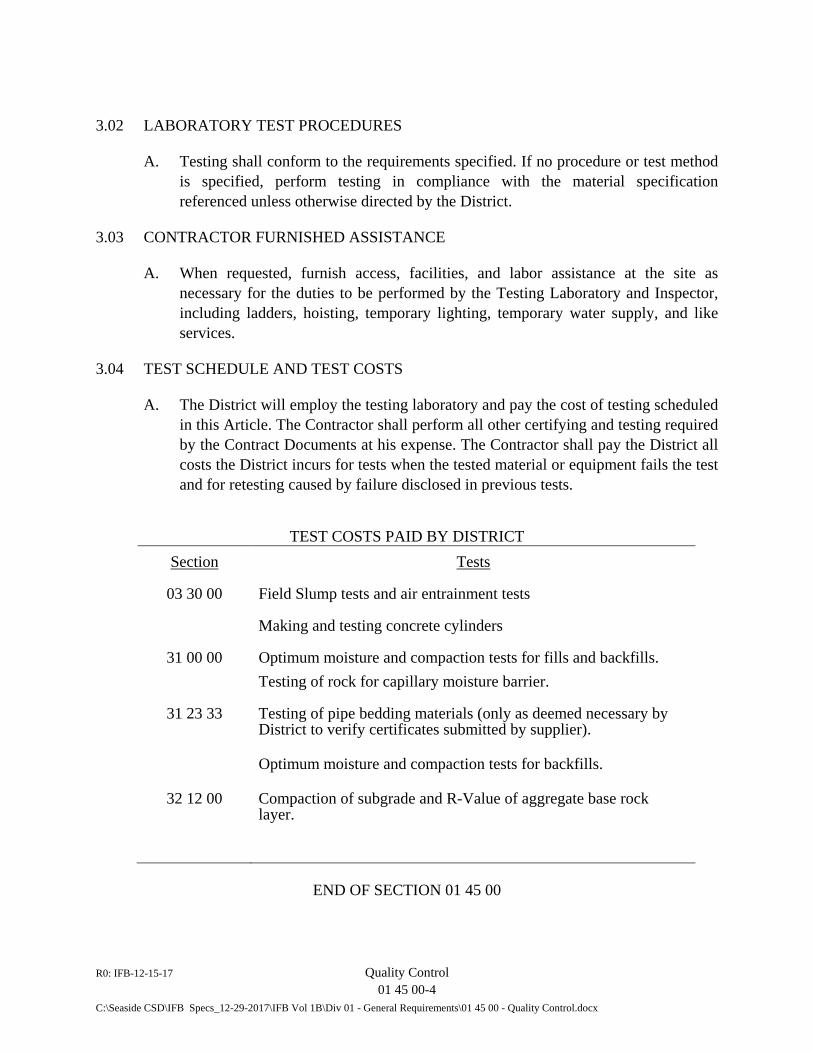
R0: IFB-12-15-17 Quality Control 01 45 00-4 C:\Seaside CSD\IFB Specs_12-29-2017\IFB Vol 1B\Div 01 - General Requirements\01 45 00 - Quality Control.docx
3.02 LABORATORY TEST PROCEDURES
A. Testing shall conform to the requirements specified. If no procedure or test method is specified, perform testing in compliance with the material specification referenced unless otherwise directed by the District.
3.03 CONTRACTOR FURNISHED ASSISTANCE
A. When requested, furnish access, facilities, and labor assistance at the site as necessary for the duties to be performed by the Testing Laboratory and Inspector, including ladders, hoisting, temporary lighting, temporary water supply, and like services.
3.04 TEST SCHEDULE AND TEST COSTS
A. The District will employ the testing laboratory and pay the cost of testing scheduled in this Article. The Contractor shall perform all other certifying and testing required by the Contract Documents at his expense. The Contractor shall pay the District all costs the District incurs for tests when the tested material or equipment fails the test and for retesting caused by failure disclosed in previous tests.
TEST COSTS PAID BY DISTRICT Section Tests
03 30 00
31 00 00
Field Slump tests and air entrainment tests
Making and testing concrete cylinders
Optimum moisture and compaction tests for fills and backfills. Testing of rock for capillary moisture barrier.
31 23 33 Testing of pipe bedding materials (only as deemed necessary by District to verify certificates submitted by supplier).
Optimum moisture and compaction tests for backfills.
32 12 00
Compaction of subgrade and R-Value of aggregate base rock layer.
END OF SECTION 01 45 00

R0: IFB–12-15-17 Construction and Temporary Facilities 01 50 00-1 C:\Seaside CSD\IFB Specs_12-29-2017\IFB Vol 1B\Div 01 - General Requirements\01 50 00 - Construction and Temporary Facilities.docx
SECTION 01 50 00
CONSTRUCTION AND TEMPORARY FACILITIES
PART 1 - GENERAL
1.01 DESCRIPTION
A. General: This Section covers the temporary facilities and controls for the Work and is supplementary to the General and Supplementary Conditions of the Contract.
B. Work Included in This Section: 1. Construction utilities. 2. Construction aids. 3. Barriers. 4. Security provisions. 5. Roads and access. 6. Special controls. 7. Traffic control. 8. Sanitary facilities.
C. Related Work Specified in Other Sections: 1. Permanent construction and facilities. 2. Permanent utility services.
1.02 REQUIREMENTS OF REGULATORY AGENCIES
A. Make all necessary arrangements, secure required permits, and pay all fees and charges required by public authorities where temporary facilities or controls are located on public property.
1.03 WORKING AREAS
A. Drawings indicate the site and related areas furnished or owned by District for prosecution of the Work. Keep all areas clean, orderly, and free of hazards, and leave in a clean condition acceptable to District, Engineer, and governing public authorities.
R0: IFB–12-15-17 Construction and Temporary Facilities 01 50 00-2 C:\Seaside CSD\IFB Specs_12-29-2017\IFB Vol 1B\Div 01 - General Requirements\01 50 00 - Construction and Temporary Facilities.docx
1.04 SUBMITTALS
A. General: Comply with the general requirements and procedures described in Article 12 of Document Section 00 72 00, “General Conditions” and Section 01 33 00, “Submittal Procedures”, of the Technical Specifications pertaining to submittals, including preparation, transmittals, and guarantees. Submit the documents identified below in advance of commencing the respective work in conformance with applicable requirements.
B. Drawings and Data: Follow procedures for submittal of shop drawings and materials lists. Submit the following: 1. Site barriers and fences showing details and layout. Mark on reproducible
prints of site plans provided by District. 2. Layout and sizing of temporary utilities (water, gas, sewer, etc.) installed by
Contractor for execution of Work. 3. Layout of temporary access and haul roads, and layout and arrangement of
Contractor's storage facilities. Mark on reproducible prints of site plans.
PART 2 - PRODUCTS (NOT USED)
PART 3 - EXECUTION
3.01 CONSTRUCTION UTILITIES
A. Furnish the temporary piping, power, lighting, communications, and other services necessary to distribute utilities to the places where Work is performed. Provide construction power (temporary power) and install power circuits separately from lighting and communication circuits. Install construction lighting when Work is performed at night or under deficient daylight conditions to ensure correct performance and to provide for inspection and safe working conditions.
3.02 CONSTRUCTION AIDS
A. Comply with OSHA requirements and applicable laws, ordinances, rules, regulations, and orders pertaining to construction machinery and equipment, hoists, cranes, scaffolding, staging, materials handling facilities, tools, appliances, and other construction aids. OSHA requirements shall govern where mandatory; otherwise, comply with most stringent requirements. Construct specially designed scaffolding and staging in accordance with drawings prepared by an engineer as specified for submittals.
R0: IFB–12-15-17 Construction and Temporary Facilities 01 50 00-3 C:\Seaside CSD\IFB Specs_12-29-2017\IFB Vol 1B\Div 01 - General Requirements\01 50 00 - Construction and Temporary Facilities.docx
3.03 BARRIERS
A. Erect and maintain barriers as required by Code and as required to safeguard the site and Work. Equip gates with holdopens and padlocks; furnish padlock keys to Inspector. Obtain and pay for required permit when barriers are located on public property.
B. Solid Barricades: Construct of wood or metal framing faced with plywood panels, framing located on side away from adjoining property lines. Use clean, sound materials. Design and erect to withstand not less than 25 psf wind load. Where shown on the Drawings as required, apply 2 coats of paint on barricades. Color to be approved by District. Construct barricades not less than 6 feet in height.
C. Fencing Barricades: Construct of galvanized or aluminum chain link fencing with green fabric acceptable to the District; either new materials or used materials that are clean and free of hazards. Install and braced to withstand at least a 150-pound transverse load applied to the top. Secure fencing to posts at maximum 12-inch intervals. Provide doubled posts at gates. Construct barricades not less than 8 feet in height.
3.04 SECURITY
A. Fire Protection: Provide necessary fire extinguishers and water as necessary to protect District's property and immediately adjacent property from damaging consequences of the construction activities for this Work.
3.05 ROADS AND ACCESS
A. Transportation Facilities: Investigate the availability of transportation facilities and make necessary arrangements for delivery of materials to the site. Determine the condition and availability of public roads, access, rights-of-way, and of restrictions, bridge load limits, and other limitations affecting transportation and ingress and egress at the Work site.
B. Clean Roads: Clean streets, including streets adjacent to the respective lift station sites and access roads, and places where construction operations create dirt accumulation at frequent intervals as directed by the District or his/her representative. Be responsible for all damage resulting from dirt accumulation and cleaning during construction operations.
R0: IFB–12-15-17 Construction and Temporary Facilities 01 50 00-4 C:\Seaside CSD\IFB Specs_12-29-2017\IFB Vol 1B\Div 01 - General Requirements\01 50 00 - Construction and Temporary Facilities.docx
3.06 SPECIAL CONTROLS
A. Noise Control: Comply with OSHA requirements as to allowable noise levels during construction. Equip all internal combustion engines in vehicles and construction equipment with effective mufflers. Prevent noise disturbance to adjoining property owners and the public.
B. Dust Control: Sprinkle streets, unpaved access roads and other places where construction operations create a dust nuisance at frequent intervals and not less than twice daily and be responsible for all damage resulting from dust produced by construction operations for this Work.
C. Water Control: Perform grading and other operations to maintain site drainage. Do not allow surface water to accumulate in excavations, under structures, or in ponds on the site. Control surface water by means of ditches, dams, temporary pumps and piping, and other necessary methods. Legally dispose of surface and subsurface water and do not allow mud, silt, or debris to flow on to adjoining or public property or into nearby water courses or bodies.
D. Air Pollution Control: Comply with all laws, ordinances, rules, regulations, and other restrictions pertaining to air pollution. Do not use any fuel nor perform any operation that emits smoke which is defined as equal to Ringleman No. 2 or darker.
E. Temporary Heating: Furnish and pay for heat, fuel, and services to protect the Work against injury from dampness and cold until final acceptance. Use only temporary heating equipment that produces no combustion gases or that discharges such gases directly to the exterior atmosphere by ducts, tubes, or similar conduits.
F. Erosion Control: Comply with Monterey County Ordinance No. 2806. A copy is attached at the end of Section 01 57 23, “Temp0rary Erosion Control”.
G. Floodplain Control: Comply with Monterey County Ordinance No. 3272.
H. End Dumping: Equipment end dumping in areas where existing tree canopy creates low overhead clearance is prohibited.
3.07 TRAFFIC CONTROL – SEE SECTION 01 55 26
3.08 SANITARY FACILITIES
A. Toilet and Washing Facilities: Provide temporary chemical toilets and fresh water washing facilities for the use of all workers at the site. Supply paper, soap, and
R0: IFB–12-15-17 Construction and Temporary Facilities 01 50 00-5 C:\Seaside CSD\IFB Specs_12-29-2017\IFB Vol 1B\Div 01 - General Requirements\01 50 00 - Construction and Temporary Facilities.docx
towels, and maintain the facilities in a clean and sanitary condition. Pit type privies are not permitted.
B. Drinking Water: Maintain a supply of cool, pure drinking water at the site, readily available to workers, with individual disposal drinking cups.
3.09 REMOVAL OF TEMPORARY FACILITIES
A. Upon completion of the Work of this Contract, remove construction and temporary facilities used or provided during the performance of the Work from the work areas. Remove rubbish, debris and other material resulting from the construction operations and leave the site(s) in a neat, clean and acceptable condition.
3.10 TEMPORARY BYPASS FACILITY
A. Bear responsibility for the design and construction of facilities for flow bypassing of the wastewater collection systems as required to perform the Work. This includes required connections and pumping, where required, of flows affected by the Work to enable work to be performed as described in the Contract Documents. Bear complete responsibility to provide any and all components required to complete the bypass connections and provide adequate bypass pumping capabilities, including back-up power. Make all bypass connections as required to satisfactorily perform the work. Refer to Specification Section 01 57 23, Temporary Flow Bypass”, for requirements specific to the respective lift station facilities.
B. Submit plans for providing flow bypassing capabilities to the District for review and approval prior to making any connections in the field. Also submit an emergency plan in case the proposed flow bypass provisions fail to perform as constructed. Operate each flow bypass facility after it has been assembled and tested until it is no longer required at the respective conveyance pipeline. Disassemble the flow bypass facility when it is no longer required and clean up the site.
END OF SECTION 01 50 00

R0: IFB–12-15-17 Construction and Temporary Facilities 01 50 00-6 C:\Seaside CSD\IFB Specs_12-29-2017\IFB Vol 1B\Div 01 - General Requirements\01 50 00 - Construction and Temporary Facilities.docx
This page intentionally blank.
R0: IFB-12-15-17 Traffic Control 01 55 26 - 1 C:\Seaside CSD\IFB Specs_12-29-2017\IFB Vol 1B\Div 01 - General Requirements\01 55 26 - Traffic Control.Docx
SECTION 01 55 26
TRAFFIC CONTROL
PART 1 - GENERAL
1.01 DESCRIPTION
A. This section covers requirements pertaining to traffic control and related work and is supplementary to the General and Supplementary Conditions of the Contract and other sections of Division 01.
B. Schedule and perform contract work operations in a manner approved by the District to cause as little inconvenience as possible to the District, the operations of the City of Seaside and the California Department of Transportation and other governmental jurisdictions in which portions of the Work are conducted and to other adjacent landholders or users.
C. Prior to any construction, provide a detailed schedule and traffic maintenance plan for review and acceptance by the District. Continually update the plan as required. Before each working day, notify the Inspector of the proposed work location(s) for that day.
D. Unless otherwise directed, at all times maintain open a minimum of one lane of traffic in each direction on roads affected by the Work, where physically feasible. Do not cause complete closure of all lanes or access for a period exceeding twenty (20) minutes during working hours. Provide temporary traffic closures and signage in accordance with applicable details in the latest editions of the Standard Plans as issued by the State of California, Department of Transportation.
E. Notify the City of Seaside fire, ambulance, police, and local transit services at least two (2) working days in advance of street closures and traffic flow disruption. Provide for adequate emergency access at all times.
F. In order to expedite pipe and conduit installation and other construction activities or replacement work, work may be scheduled to proceed at more than one location at the same time. Exact work locations and time of proposed work will be subject to review and approval. In accordance with Caltrans permit, only equipment and materials suitable to produce the quality and timeliness of the work operations will be permitted to be used on work at the Del Monte Lift Station facility. Maintain equipment in a satisfactory operational condition at all times.
R0: IFB-12-15-17 Traffic Control 01 55 26 - 2 C:\Seaside CSD\IFB Specs_12-29-2017\IFB Vol 1B\Div 01 - General Requirements\01 55 26 - Traffic Control.Docx
G. As specified under Article 7.2 of the General Conditions (Document Section 00 72 00), designate in writing, before starting work, an authorized representative who shall have the authority to represent and act for the Contractor. Provide an off-hours phone number for said representative for immediate contact 24 hours a day during the Contract work period.
H. In accordance with Section 5-1.08 of the Standard Specifications, provide access to the work site at all times for the District and the jurisdictional entities referenced in Paragraph B above.
1.02 PUBLIC SAFETY AND CONVENIENCE
A. Special attention is directed to the requirement to conform to all applicable technical provisions of Sections 7-1.08, 7-1.09, and 7-1.11 of the Standard Specifications. Bear all costs in the Bid Price.
B. Conduct the operations in a manner as to cause the least possible obstruction and inconvenience to public traffic. Where work is being done on existing public roads or streets, and no detours are available, permit traffic to pass through the work with as little inconvenience and delay as possible. See Paragraph 1.01D above.
C. Furnish, erect, and maintain such fences, barriers, lights, signs, and flaggers in accordance with the Caltrans permit (where applicable) as are necessary to give adequate warning to the public at all times that the work is under construction and of any dangerous conditions to be encountered as a result thereof. At any and all points along the work where the nature of construction operations are in progress and the equipment and machinery in use is of such character as to endanger passing traffic, provide such lights and signs and station such guards as may appear necessary to prevent accidents and avoid damage or injury to passing traffic.
D. Examine all existing bridges, culverts and other structures affected by Contract work operations. Protect such structures, where necessary, prior to performing work affecting such facilities.
E. Remove or clear immediately at the end of each day’s operation all spillage or mud-tracking resulting from work operation on public and private streets or roads, or private parking areas.
F. Provide positive traffic control on all public and private streets or roads affected by the work operations. In conformance with Sections 7-1.08 and 7-1.09 of the Standard Specifications, provide warning signing both on streets directly affected by work and streets adjacent to Contract work areas. Provide “walky-talkies” for communication between flaggers and other Contractor personnel.
R0: IFB-12-15-17 Traffic Control 01 55 26 - 3 C:\Seaside CSD\IFB Specs_12-29-2017\IFB Vol 1B\Div 01 - General Requirements\01 55 26 - Traffic Control.Docx
G. Do not exceed a noise level from the construction operations of 86 dBA at a distance of 50 feet from the source of construction noise.
1.03 HAULING
A. Develop a haul route plan using approved truck routes as approved by the City of Seaside with copies furnished to the District. Be responsible for determining and coordinating with the City of Seaside to obtain the approval routes. Select haul routes that have minimal effects on traffic flows within the Cities of Seaside, Del Rey Oaks, Sand City and Monterey.
B. Use only vehicles equipped with pneumatic shock absorbers to haul materials over existing roads, streets or highway. Use truck loadings not exceeding legal weight limits and observe limits regarding vertical clearance. On trucks hauling earthen materials, either cover or sprinkle such material so that dust is not blown off while in transit. Avoid “mud tracking” of paved streets or roads. As required, wash down truck frames and tires prior to entering State, or County roads.
1.04 OTHER REQUIREMENTS
A. As a minimum, provide vehicular access for adjacent landholders until 8:30 a.m. and after 4:30 p.m. of each weekday and at all times on Saturday and Sunday. Perform work operations, including truck hauling and delivery operations that do impact traffic or access, within the hours of 8:00 a.m. and 5:00 p.m. on weekdays and weekends.
B. Unless otherwise directed, storage of construction materials during non-working hours is prohibited on public streets and public rights-of-way. Immediately remove all excavated material from the work site. Restrict stockpiling of trench backfill and bedding material in public right-of-way in quantity to not more than two (2) days’ demand. Exact size and location of temporary storage area space on any public street will be subject to the determination of District or respective entities. Unless otherwise directed, maintain walkways open to pedestrian traffic at all times. Wherever feasible, to minimize storage in public areas, directly install pipe or conduit in trench from delivery trucks. As required and at no additional cost to the District, use an off-site private supplementary storage area.
C. Post any signing restricting or detouring public traffic movements or parking on a public street a minimum of 48 hours before such restriction occurs. Similarly, for any temporary restriction of access to driveway access to a private landholder, provide prior notification, a minimum of 48 hours prior to such restriction, to the landholder and/or resident. Do not block driveways overnight.
R0: IFB-12-15-17 Traffic Control 01 55 26 - 4 C:\Seaside CSD\IFB Specs_12-29-2017\IFB Vol 1B\Div 01 - General Requirements\01 55 26 - Traffic Control.Docx
D. Maintain width of pipe or conduit trench section to the minimum width necessary for pipe or conduit, pipeline accessories, or structure installation, as indicated on details shown on the Drawings. During construction, do not open trenching farther than permitted in Section 31 23 33, “Trenching, Backfilling, and Compaction”, unless otherwise permitted by the District. In any case, do not affect more than one intersection by Contract work at any one time, unless otherwise approved.
E. At all times during construction hours, maintain at the site of construction an adequate supply of steel plating and utilize same to provide emergency access, if required. Remove steel plating and provide temporary pavement patch prior to the weekends.
F. By no later than 4:30 p.m. of each workday, either completely backfill in accordance with these Specifications all trenching and cap with compacted asphalt cutback suitable for temporary traffic usage until permanent repaving is effected, or cover with steel plating of adequate thickness and size. If necessary and subject to determination and approval of the District, certain lengths of trench may be designated to be left open overnight. Enclose such trench lengths by suitable temporary fencing.
G. By 4:30 p.m. of each workday, clean all affected street and driveway areas not designated to be temporarily left open and fenced and return for overnight public and private traffic usage. If overnight trench closure and cleanup operations are not properly performed by 5:00 p.m. of any day, the District may elect to perform such operations. Costs for all such District-performed operations will be at the Contractor’s expense and with all costs therefore deducted from Contractor’s progress payments.
PART 2 - PRODUCTS - (Not Used)
PART 3 - EXECUTION
3.01 Applicable sections of Part 3 of Section 01 30 00, “Administrative Requirements”, and Section 01 14 00, “Work Restrictions”, apply as if repeated herein. No direct payment will be made to the Contractor for any work or materials specified under this Section.
3.02 Work at the Del Monte Lift Station: Conduct work at this site in accordance with the traffic control drawing included in the Contract Documents and the requirements of the permit issued by the California Department of Transportation (Caltrans) for work activities occurring on Del Rey Oaks Blvd (State Highway 218).
END OF SECTION 01 55 26
R0: IFB-12-15-17 Temporary Erosion Control 01 57 23-1 C:\Seaside CSD\IFB Specs_12-29-2017\IFB Vol 1B\Div 01 - General Requirements\01 57 23 Temporary Erosion Control.docx
SECTION 01 57 23
TEMPORARY EROSION CONTROL
PART 1 – GENERAL
1.01 DESCRIPTION
A. This Section includes the furnishing, installation, and maintenance of temporary erosion and sedimentation controls for all earthwork, trenching, clearing and grubbing operations.
B. For projects with soil disturbances of one (1) acre or more, comply with the National Pollution Discharge Elimination System (NPDES) General Permit for Storm Water Discharges Associated with Construction Activity and requirements included herein.
C. For projects with soil disturbances under one (1) acre, erosion and sedimentation control measures shall comply with requirements provided herein, local jurisdictional agency requirements, and applicable requirements in local storm water management programs developed to comply with NPDES permits issued by the Regional Water Quality Control Board.
1.02 RELATED WORK
A. Section 31 10 00 Site Clearing
B. Section 31 23 00 Excavation and Fill
C. Section 31 23 19 Dewatering
D. Section 31 23 33 Trenching, Backfilling and Compaction
1.03 SUBMITTALS
A. General: Comply with the general requirements and procedures described in Article 12 of Document Section 00 72 00, “General Conditions”, and Section 01 33 00, “Submittal Procedures”, of the Technical Specifications pertaining to submittals, including preparation, transmittals, and guarantees.
B. Submit work plans, including drawings and other details required for compliance with the Monterey County Ordinance No. 2806 – Erosion Control. A copy of the Monterey County Ordinance No. 2806 – Erosion
R0: IFB-12-15-17 Temporary Erosion Control 01 57 23-2 C:\Seaside CSD\IFB Specs_12-29-2017\IFB Vol 1B\Div 01 - General Requirements\01 57 23 Temporary Erosion Control.docx
Control is included at the end of this section.
C. Manufacturer’s catalog data and samples on materials used for erosion control, including the physical characteristics, application and installation instructions.
PART 2 - MATERIALS
2.01 MATERIALS
A. Provide sand bags, silt fences, straw bales and other materials to control erosion and sedimentation as shown in the approved Contractor’s SWPPP and Shop Drawings.
PART 3 – EXECUTION
3.01 GENERAL
A. Restore areas, having existing landscaping or not, disturbed as a result of temporary erosion control measures or due to any other construction activities to their original conditions as directed by the District and in accordance with the landscape plans and details included in the Drawings.
3.02 CONSTRUCTION
A. Construct and implement erosion control measures in accordance with the Monterey County Ordinance No. 2806 – “Erosion Control”, to District’s satisfaction that BMPs are being followed.
B. Grade disturbed surfaces to provide positive drainage and prevent ponding of water. Control surface water shall to prevent water damage or deposition of sediment to all adjoining and downstream properties.
C. Install silt fences, sedimentation ponds, sandbag dikes, stabilized construction entrances and any other erosion control measure to minimize sediment escape from the construction sites and to maintain runoff quality in compliance with the Monterey County Ordinance No. 2806 – Erosion Control. Prevent construction sediment from entering any streams, ponds, drainage facilities, wastewater manholes or other water and stormwater bearing structures.
D. At a minimum, provide erosion and sedimentation control measures immediately following clearing and grubbing operations in the following locations:
R0: IFB-12-15-17 Temporary Erosion Control 01 57 23-3 C:\Seaside CSD\IFB Specs_12-29-2017\IFB Vol 1B\Div 01 - General Requirements\01 57 23 Temporary Erosion Control.docx
1. In pipeline rights of way immediately upstream of all natural channels. 2. At the lowest end of areas disturbed by construction before runoff
from storms can reach natural streams or adjacent property. 3. At additional locations as required for controlling sedimentation as
required by the Monterey County Ordinance No. 2806 – Erosion Control.
E. Retain erosion and sedimentation control measures in place until such time that the site work is prepared for permanent drainage and erosion control measures. Remove temporary erosion and sediment control measures so as not to interfere with permanent drainage, erosion control and revegetation.
3.03 MAINTENANCE
A. Conduct site inspections of the erosion and sedimentation control measures prior to forecasted storm events and after the actual storm to evaluate the adequacy and effectiveness of such measures. Make and implement modifications as necessary to comply with the Monterey County Ordinance No. 2806 – Erosion Control. Submit inspection reports to the District after each storm event. Include in the inspection reports at a minimum, the date of the inspection, the individual(s) who performed the inspection, the observations, and any modifications implemented.
B. Maintain sedimentation and erosion control measures, ensuring proper operation before, during, and after storm events.
C. Repair all damaged erosion and sedimentation controls. Reinstate to finished condition any erosion damage with in the construction area for the duration of the Contract.
D. Certify that the construction activity is in compliance with the requirements of the Monterey County Ordinance No. 2806 – Erosion Control. The certification shall be based upon the site inspections required above. The written notification shall be submitted by the District to the Contractor in writing if it is determined that the construction activity is not or has not been in compliance with any of the Monterey County Ordinance No. 2806 – Erosion Control requirements. The notification will identify the type of noncompliance and include a time schedule for compliance.
E. Additional site inspections and/or sampling and analysis may be required at the request of the California Regional Water Quality Control Board, Central Coast, or the District.
R0: IFB-12-15-17 Temporary Erosion Control 01 57 23-4 C:\Seaside CSD\IFB Specs_12-29-2017\IFB Vol 1B\Div 01 - General Requirements\01 57 23 Temporary Erosion Control.docx
3.04 REMOVAL
A. Remove and dispose of materials used for temporary sedimentation and erosion control measures offsite when permanent erosion control facilities are completed and accepted by the District.
END OF SECTION 01 57 23
MONTEREY COUNTY CODES
CHAPTER 16.12 EROSION CONTROL


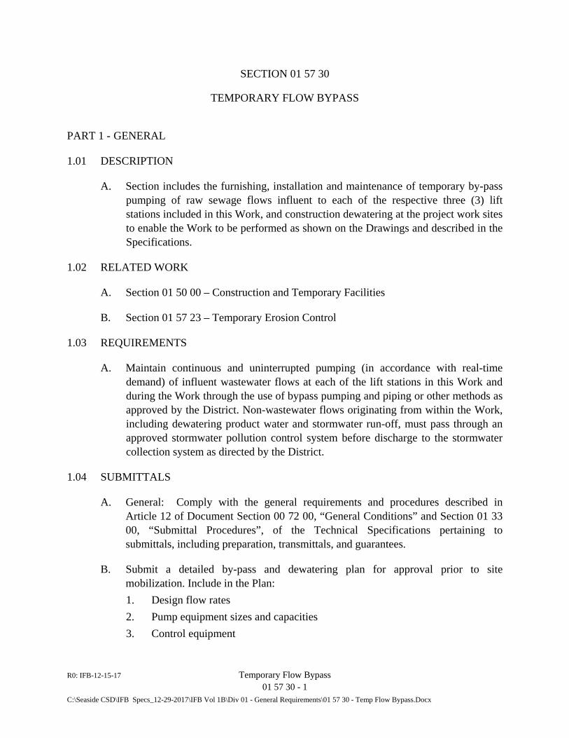
R0: IFB-12-15-17 Temporary Flow Bypass 01 57 30 - 1 C:\Seaside CSD\IFB Specs_12-29-2017\IFB Vol 1B\Div 01 - General Requirements\01 57 30 - Temp Flow Bypass.Docx
SECTION 01 57 30
TEMPORARY FLOW BYPASS
PART 1 - GENERAL
1.01 DESCRIPTION
A. Section includes the furnishing, installation and maintenance of temporary by-pass pumping of raw sewage flows influent to each of the respective three (3) lift stations included in this Work, and construction dewatering at the project work sites to enable the Work to be performed as shown on the Drawings and described in the Specifications.
1.02 RELATED WORK
A. Section 01 50 00 – Construction and Temporary Facilities
B. Section 01 57 23 – Temporary Erosion Control
1.03 REQUIREMENTS
A. Maintain continuous and uninterrupted pumping (in accordance with real-time demand) of influent wastewater flows at each of the lift stations in this Work and during the Work through the use of bypass pumping and piping or other methods as approved by the District. Non-wastewater flows originating from within the Work, including dewatering product water and stormwater run-off, must pass through an approved stormwater pollution control system before discharge to the stormwater collection system as directed by the District.
1.04 SUBMITTALS
A. General: Comply with the general requirements and procedures described in Article 12 of Document Section 00 72 00, “General Conditions” and Section 01 33 00, “Submittal Procedures”, of the Technical Specifications pertaining to submittals, including preparation, transmittals, and guarantees.
B. Submit a detailed by-pass and dewatering plan for approval prior to site mobilization. Include in the Plan: 1. Design flow rates 2. Pump equipment sizes and capacities 3. Control equipment
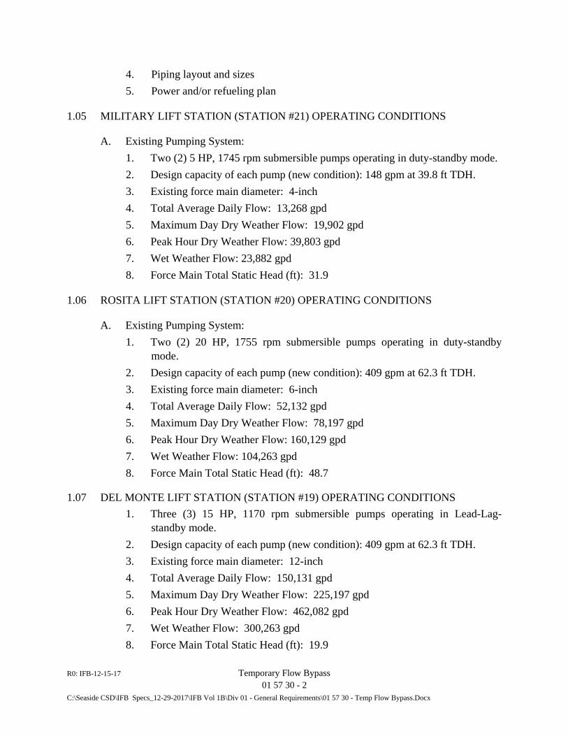
R0: IFB-12-15-17 Temporary Flow Bypass 01 57 30 - 2 C:\Seaside CSD\IFB Specs_12-29-2017\IFB Vol 1B\Div 01 - General Requirements\01 57 30 - Temp Flow Bypass.Docx
4. Piping layout and sizes 5. Power and/or refueling plan
1.05 MILITARY LIFT STATION (STATION #21) OPERATING CONDITIONS
A. Existing Pumping System: 1. Two (2) 5 HP, 1745 rpm submersible pumps operating in duty-standby mode. 2. Design capacity of each pump (new condition): 148 gpm at 39.8 ft TDH. 3. Existing force main diameter: 4-inch 4. Total Average Daily Flow: 13,268 gpd 5. Maximum Day Dry Weather Flow: 19,902 gpd 6. Peak Hour Dry Weather Flow: 39,803 gpd 7. Wet Weather Flow: 23,882 gpd 8. Force Main Total Static Head (ft): 31.9
1.06 ROSITA LIFT STATION (STATION #20) OPERATING CONDITIONS
A. Existing Pumping System: 1. Two (2) 20 HP, 1755 rpm submersible pumps operating in duty-standby
mode. 2. Design capacity of each pump (new condition): 409 gpm at 62.3 ft TDH. 3. Existing force main diameter: 6-inch 4. Total Average Daily Flow: 52,132 gpd 5. Maximum Day Dry Weather Flow: 78,197 gpd 6. Peak Hour Dry Weather Flow: 160,129 gpd 7. Wet Weather Flow: 104,263 gpd 8. Force Main Total Static Head (ft): 48.7
1.07 DEL MONTE LIFT STATION (STATION #19) OPERATING CONDITIONS 1. Three (3) 15 HP, 1170 rpm submersible pumps operating in Lead-Lag-
standby mode. 2. Design capacity of each pump (new condition): 409 gpm at 62.3 ft TDH. 3. Existing force main diameter: 12-inch 4. Total Average Daily Flow: 150,131 gpd 5. Maximum Day Dry Weather Flow: 225,197 gpd 6. Peak Hour Dry Weather Flow: 462,082 gpd 7. Wet Weather Flow: 300,263 gpd 8. Force Main Total Static Head (ft): 19.9
R0: IFB-12-15-17 Temporary Flow Bypass 01 57 30 - 3 C:\Seaside CSD\IFB Specs_12-29-2017\IFB Vol 1B\Div 01 - General Requirements\01 57 30 - Temp Flow Bypass.Docx
PART 2 - PRODUCTS
2.01 EQUIPMENT
A. Provide temporary pumps, valves and electrical power as required to provide continuous maintenance of flow at each respective lift station to prevent overflows and or surface spills. Provide and maintain piping in condition that does not permit leakage of wastewater onto surfaces that may come in contact with humans or that may flow into nearby water bodies or stormwater systems.
PART 3 - EXECUTION
3.01 SCHEDULE AND SEQUENCE OF WORK
A. Military Lift Station: Work at this facility includes construction a new Overflow Structure and a new pump bypass connection including vault, valves and piping connected to the existing lift station force main. The sequence of work at the Military Lift Station requires these components to be completed and functional prior to demolition of the existing pumps, rehabilitation (recoating) of the existing lift station wet well and installation of new pumps in the re-furbished wet well and installation of a new pump controls system. 1. The completed new Overflow Structure shall serve as a temporary wet well in
which temporary bypass pumps are installed. These temporary bypass pumps shall be connected to the new pump bypass connection. Raw sewage influent to the Military Lift Station shall be re-directed from the existing wet well to the Overflow Structure, either by additional pumps installed in an upstream manhole or by temporary gravity regime piping. The temporary pumps installed in the Overflow Structure shall serve as a lift station replacement while the existing lift station wet well is rehabilitated and a new pumping system installed in the existing wet well.
2. Once rehabilitation of the existing wet well and the installation of new permanent pumping system and new electrical control system has been completed, satisfactorily tested and accepted by the District, the wastewater collection system for this facility shall be reconnected to the existing wet well.
3. Once raw wastewater flows are re-directed to the existing wet well, the temporary bypass pumps in the Overflow Structure, and any other flow bypass facilities required for the work, and associated piping shall be disassembled and removed from the site.
B. Rosita Lift Station: Work at this facility includes construction a new Overflow Structure. This lift station has an existing pump bypass connection which shall be incorporated into and utilized for the temporary flow bypass while the existing lift
R0: IFB-12-15-17 Temporary Flow Bypass 01 57 30 - 4 C:\Seaside CSD\IFB Specs_12-29-2017\IFB Vol 1B\Div 01 - General Requirements\01 57 30 - Temp Flow Bypass.Docx
station is demolished and a new lift station wet well and pumping system constructed. The sequence of work at the Rosita Lift Station requires construction of the New Overflow Structure to be completed, bypass pumps installed in the Overflow Structure, temporary piping in place connecting the bypass pumps to the existing pump bypass connection and the temporary flow diversion from the upstream manhole to the new Overflow Structure in place and operational prior to commencing demolition of the existing lift station wet well and pumps. Work may then proceed with construction of a new wet well and installation of new pumps in the new wet well and a new pump controls system. 1. The completed new Overflow Structure shall serve as a temporary wet well in
which temporary bypass pumps are installed. These temporary bypass pumps shall be connected to the existing pump bypass connection. Raw sewage influent to the Rosita Lift Station shall be re-directed from an existing upstream manhole to the Overflow Structure as shown on the Drawings. The temporary pumps installed in the Overflow Structure shall serve as a lift station replacement while the existing lift station wet well and pumping system are demolished and replaced with new facilities as shown on the Drawings and described in the Specifications.
2. Once construction of the new wet well and the installation of new permanent pumping system and new electrical control system has been completed, satisfactorily tested and accepted by the District, the wastewater collection system for this facility shall be reconnected to the permanent lift station wet well.
3. Once raw wastewater flows are re-directed to the permanent lift station wet well, the temporary bypass pumps in the Overflow Structure, and any other flow bypass facilities required for the work, and associated piping shall be disassembled and removed from the site.
C. Del Monte Lift Station: Work at this facility includes construction of a new Overflow Structure and a new pump bypass connection including vault, valves and piping connected to the existing lift station force main. The sequence of work at the Del Monte Lift Station requires these components to be completed and functional prior to rehabilitation and coating of the existing wet well. 1. While coating of the existing wet well is being performed, the completed
Overflow Structure shall serve as a temporary wet well in which temporary bypass pumps are installed. These temporary bypass pumps shall be connected to the new pump bypass connection.
2. Once rehabilitation of the existing wet well is completed and accepted by the District, the raw wastewater flows shall be re-directed to the existing wet well, and the temporary bypass pumps and associated piping disassembled and removed from the site.
R0: IFB-12-15-17 Temporary Flow Bypass 01 57 30 - 5 C:\Seaside CSD\IFB Specs_12-29-2017\IFB Vol 1B\Div 01 - General Requirements\01 57 30 - Temp Flow Bypass.Docx
D. Provide uninterruptible electrical service to the temporary flow bypass pumps either by means of engine generators or temporary wiring connection to the existing electrical service to the respective site.
E. Schedule the work to minimize the duration of the bypass pumping.
3.02 BYPASS PUMPING
A. Provide temporary bypass pumps and piping sufficient to carry the anticipated maximum daily flow at each respective lift station. Multiple pumps may be required. Provide at least one stand-by pump.
B. Provide the pumping system with automatic controls that start and stop pumps as needed to respond to changing flow rates.
C. Rout / lay discharge piping in a manner that does not interfere with the execution of the Work.
3.03 DEWATERING WITHIN THE WORK
A. Comply with the requirements specified in Section 31 23 19, Dewatering”.
B. Provide pumps or dewatering wells in quantity in capacity as needed to provide a dry and stable working surface at the bottom of excavations.
3.04 ALARMS
A. Provide monitoring of the bypass pumping system during non-working hours, or include an automated alarm which will inform the Contractor if the system is not operating or if stream flows exceed the by-pass pumping capacity.
3.05 PROTECTION OF THE WORK
A. Monitor the 3-day weather forecast and advise the District of anticipated increases in influent flow to a lift station.
B. To the extent practical, close up open excavations at the end of each workday to minimize the risk of flood damage.
3.06 CLEAN-UP OF LIFT STATION SITES A. Keep the work area and the adjacent areas affected at each respective site, free and
clear from all debris caused by the work of this Section. During and upon completion of work herein specified, promptly remove from each respective site all debris, unused materials and equipment caused by the work of this Section, and leave the Work in a clean, acceptable condition.
R0: IFB-12-15-17 Temporary Flow Bypass 01 57 30 - 6 C:\Seaside CSD\IFB Specs_12-29-2017\IFB Vol 1B\Div 01 - General Requirements\01 57 30 - Temp Flow Bypass.Docx
END OF SECTION 01 57 30

R0: IFB-12-15-17 Execution and Closeout Requirements 01 70 00-1 C:\Seaside CSD\IFB Specs_12-29-2017\IFB Vol 1B\Div 01 - General Requirements\01 70 00 Execution and Closeout Requirements.docx
SECTION 01 70 00
EXECUTION AND CLOSEOUT REQUIREMENTS
PART 1 - GENERAL
1.01 SUMMARY
A. This Section covers the general requirements and procedures for testing and start-up of the various facilities and systems included in this Contract, and also the requirements for attaining the District’s acceptance of the Work as complete. Specific requirements and procedures are described in individual technical sections of this Project Manual.
B. Exceptions noted in an individual technical section modify only the individual Article and related topic described in this Section; other topics and Articles in this Section remain in force unless specifically deleted by the technical Section.
C. Work Included in This Section: 1. System description 2. Submittals 3. Maintenance of new work 4. Testing and start-up 5. Validation testing 6. Final facility testing 7. Substantial completion 8. Final completion
D. Related Work specified in Other Sections: 1. Section 01 33 00 – Submittal Procedures 2. Section 01 32 16 – Construction Progress Schedule 3. Section 11 05 00 – General Equipment Provisions 4. Section 33 08 30 – Commissioning of Wastewater Utilities 5. Division 26 – Electrical
R0: IFB-12-15-17 Execution and Closeout Requirements 01 70 00-2 C:\Seaside CSD\IFB Specs_12-29-2017\IFB Vol 1B\Div 01 - General Requirements\01 70 00 Execution and Closeout Requirements.docx
1.02 SYSTEM DESCRIPTION
A. Design Requirements of Testing System: 1. Design temporary connections and utility lines to meet the specified design
requirements of the component, system, and subsystem to which they are connected. This includes providing water and, where required, air for pressure and leakage tests, closed loop systems for performance or demonstration tests, and the disposal of water used in testing.
2. Include required additional restraints. Pipe restraints shown on the Drawings are based on a completed piping system. Testing of partially completed piping systems may result in insufficient restraint against resulting thrust forces, which therefore requires additional temporary restraint to ensure system being tested is adequately secured.
3. Do not place structural loads on permanent facility elements beyond their design load capacity.
4. Provide dielectric unions on temporary connections wherever dissimilar metals connect.
5. Provide safety valves and similar safety devices on temporary connections wherever they would be required if the connections were permanent.
6. Isolate instrumentation and other attached equipment which may be damaged while pressure testing of pumping and associated piping system.
1.03 SUBMITTALS
A. General: Comply with the general requirements and procedures described in Article 12 of Document Section 00 72 00, “General Conditions”, and Section 01 33 00, “Submittal Procedures”, of the Technical Specifications pertaining to submittals, including preparation, transmittals, and guarantees. Submit the documents identified below in advance of commencing the respective work in conformance with applicable requirements.
B. Procedures: Submit to the District for review and approval a detailed description of testing and initial start-up procedures that are intended to be used for all mechanical, electrical, and instrumentation equipment, along with respective test report forms specific for each type of equipment or system being tested and procedures for leakage and pressure testing of all piping systems. Submit these procedures and test reports forms a minimum of thirty (30) days prior to the date of these activities as shown on the Contractor’s construction schedule and obtain approval prior to initiating testing and start-up. Incorporate into the testing and
R0: IFB-12-15-17 Execution and Closeout Requirements 01 70 00-3 C:\Seaside CSD\IFB Specs_12-29-2017\IFB Vol 1B\Div 01 - General Requirements\01 70 00 Execution and Closeout Requirements.docx
start-up procedures any specific requirements hereinafter specified for a particular piece of equipment. 1. The testing and start-up procedure is the responsibility of the Contractor who
is solely responsible for its means, methods, techniques, sequences, procedures, coordination, completeness, accuracy, and validity.
2. Individual sections of the start-up procedure may be accepted by the District, with District’s prior approval, but must be incorporated into the final accepted start-up procedure.
3. Rejection of individual sections of the start-up procedure by the District is not a cause for a claim of delay.
4. Identify each person or organization that will have a functional part in the start up, and identify their duties and responsibilities.
5. Provide for corrective actions and other contingencies on validation failure. 6. Provide complete information on temporary connections in the form of shop
drawings or a complete written description or a combination of both.
C. Test Data: Submit completed test report forms, as described herein, containing data collected during initial and subsequent re-testing, if performed, to the District for review and record purposes.
D. Certification: Submit to the District a certification form from each equipment manufacturer stating that his equipment has been properly installed and tested. District will provide Certification form to Contractor.
1.04 MAINTENANCE OF NEW WORK
A. Provide proper maintenance of work furnished and installed as part of this Contract until accepted by the District. Include in the maintenance: lubrication, operating adjustments, fueling, replacement of worn, defective or improperly functioning components, and other effort as necessary to ensure the equipment is in satisfactory new condition when acceptance by the District is certified.
B. Perform maintenance in compliance with respective equipment manufacturer’s written instructions. Written maintenance instructions shall correspond to the information provided in the equipment instruction manuals submitted to the District. Resolve discrepancies and correct submitted equipment instruction manuals to the District’s satisfaction.
R0: IFB-12-15-17 Execution and Closeout Requirements 01 70 00-4 C:\Seaside CSD\IFB Specs_12-29-2017\IFB Vol 1B\Div 01 - General Requirements\01 70 00 Execution and Closeout Requirements.docx
PART 2 - PRODUCTS
2.01 CHEMICALS, LUBRICANTS, AND EQUIPMENT PARTS
A. Provide chemicals, lubricants, and maintenance and replacement parts required during system validation and final system testing. Also provide power, air, water and fuels if required for testing procedures.
PART 3 - EXECUTION
3.01 TESTING AND START-UP
A. Test all mechanical, electrical and instrumentation equipment to the satisfaction of the District before placing such equipment into operation. Equipment includes pumps and valves that are part of piping and mechanical piping systems at the Military and Rosita Lift Stations and valves and engine generator at the Del Monte Lift Station. The equipment to be tested also includes level measuring sensors in the wet wells, pump control systems and SCADA and communication systems at all three (3) facilities. The Del Monte Lift Station does not have changes to the existing pumps and communication system, but testing is required to ensure that these systems have not been affected by the construction activities. 1. Conduct tests to determine that the equipment has been properly assembled,
aligned, adjusted and connected. Make all necessary adjustments, replacements or changes to correct all deficiencies so that the equipment will operate as specified.
2. Satisfactorily complete leakage and pressure testing of pressure piping, and the leakage testing of gravity pipelines, before placing all equipment and facilities into operation.
3. Record all data collected during the testing on the approved test report forms. Refer to Paragraph 1.03 above regarding submittal of collected data.
B. Start-Up and System Validation Testing: 1. Following completion of operational demonstrations specified in Divisions 11
and 26, and testing specified in Section 33 08 30, “Commissioning of Wastewater Utilities”, Section 33 32 20, “Submersible Non-Clog Pumps”, and Section 26 32 13, Engine Generator”, start-up and operate all individual equipment based systems so that it may be determined if the equipment meets the specification requirements, a procedure herein referred to as the System Validation Testing.
R0: IFB-12-15-17 Execution and Closeout Requirements 01 70 00-5 C:\Seaside CSD\IFB Specs_12-29-2017\IFB Vol 1B\Div 01 - General Requirements\01 70 00 Execution and Closeout Requirements.docx
a. As applicable, system validation tests are required for all work, equipment, and systems specified in Divisions 11, 26 and 33 of these Specifications including all associated and related electrical systems and control devices specified in Division 26 and instrumentation and control systems specified in Division 26. Perform validation tests in the presence of the District’s representative.
b. Successfully complete the required equipment manufacturer’s validation for all equipment components of each system and submit the specified Manufacturer’s Certified Reports before each respective system is validation tested.
c. Perform validation testing in accordance with the approved procedure plan. As applicable, refer to Divisions 11, 26 and 33 regarding requirements for the equipment system validation testing and Section 33 05 20, for the piping validation testing.
2. Equipment Demonstrations: Demonstrate that the performance of installed equipment complies with all requirements indicated and specified. Operate systems continuously under constant inspection of trained operators. Cycle system operation of electrical and rotating mechanical equipment from full load to light load and back to full load through all operational modes. Induce simulated alarm and distressed operating conditions, and test controls and protective devices for correct operation in adjusting system functions or causing system shutdown.
3. Test Period: Test each system, including standby systems, by continuous operation in “in-service” condition for not less than twenty-four (24) consecutive hours, with no interruptions. After satisfactory completion of the testing of all individual systems, the Contractor may proceed to the final facility testing.
4. Simulation of Conditions: Subject to Contractor’s request and District’s approval in each case, simulation of certain operating conditions relating to flow rates, water levels, and malfunctions may be permitted. Permission for simulations will be granted only where it is unwise or impossible to obtain the conditions covered by the capability of ranges or equipment. Use simulation methods that reasonably approximate anticipated operating conditions.
5. Recording of Data: Maintain neat and comprehensive records of each systems validation test. Describe each portion of the demonstration or validation procedure, with all components itemized. Prepare records on forms in a step-by-step fashion paralleling the approved procedure plans. On the forms list for each condition: a. Operating and weather conditions;
R0: IFB-12-15-17 Execution and Closeout Requirements 01 70 00-6 C:\Seaside CSD\IFB Specs_12-29-2017\IFB Vol 1B\Div 01 - General Requirements\01 70 00 Execution and Closeout Requirements.docx
b. Step taken; c. Result anticipated; d. Result obtained; e. If incorrect result or interruption of operation occurs, corrective action
taken; and f. Retest result; g. Repeat steps (d) and (e) and record retest data until all systems operate
as required. (1) Recording Devices: Employ instruments, gauges, and other sensors
and display devices forming a part of the various systems for data acquisition to the extent applicable. Furnish all other instruments, gauges, recorders, and test devices and required types conforming to the approved procedure plans.
(2) Information and Intervals: Record at the start and finish of each system validation test, and at approved intervals in between, not exceeding 1 hour, all applicable data such as but not limited to water and other liquid levels, flows, pressures, and related information, as applicable, and in accordance with the approved procedure plans.
(3) Repetitions: When a repeat of the same demonstration or validation test is required to verify the results, indicate the repeat procedure on the recorded data as a retest by numerical indication and the date and time.
6. Correction of Defects: Immediately correct all defect and malfunctions disclosed by validation tests using approved methods and new materials for repairs as required. Add interruption time necessary for corrective work to the specified total validation test period. In the case of leakage test, restart the test period to time zero.
3.02 PERSONNEL TRAINING
A. Make available experienced factory certified personnel representing the manufacturer of the equipment furnished on this Contract to check his or her equipment for proper installation and to instruct the District’s personnel in the operation and care of the equipment. Include in the instruction detailed operating and troubleshooting procedures of such quality that the District’s personnel can continue the operation of the facility in an orderly manner after Substantial Completion of the Work.
R0: IFB-12-15-17 Execution and Closeout Requirements 01 70 00-7 C:\Seaside CSD\IFB Specs_12-29-2017\IFB Vol 1B\Div 01 - General Requirements\01 70 00 Execution and Closeout Requirements.docx
B. Obtain District’s approval of equipment instruction manuals and furnish the required number of copies of respective instruction manuals, in conformance with Technical Specifications Section 01 33 00, “Submittal Procedures”, at least fourteen (14) days prior to the scheduled date for each instruction program for District’s personnel. (Early submittal of manuals is strongly encouraged.)
C. Perform training and instruction as specified in Technical Specifications Section 11 05 00, “General Equipment Provisions”, Paragraph 3.09, Instruction of District’s Personnel.
3.03 RETESTING COSTS
A. The District reserves the right to deduct monies due to Contractor to cover the District’s additional costs should the Contractor be required to retest his equipment.
3.04 SPECIAL REQUIREMENTS AND SEQUENCES FOR FINAL FACILITY TESTING AND ACCEPTANCE
A. General: Each of the three (3) lift station facilities are to be treated as distinct facilities independent of each other for the purposes of the Final Facility Testing. After all equipment and piping systems at each respective facility have been successfully completed and tested, and all test reports have been filled out and submitted to the District, conduct final system testing at each respective facility in accordance with the following special requirements and sequences:
B. Final Facility Validation Test: Upon successful completion of the individual system validation tests, operate all systems at each of the respective facilities comprising the Work simultaneously for 48 continuous hours under actual operating conditions with all systems in operation to validate interrelated system operation and control. The exception to this requirement is at Del Monte Lift Station, where operation of the engine generator is required for only 8 hours. Test all systems equipment and/or materials under all modes of operation including automatic, manual, power loss, and emergency conditions. Perform final facility validation testing in accordance with the approved procedure plan and in the presence of the District’s representative. 1. Conduct the Final Facility Validation Test at the Military and Rosita Lift
Stations by operating the respective pumping systems to convey flows from the respective wet wells to the designated discharge point.
2. At the Del Monte Lift Station, operation of the emergency engine generator to power the pump station for a period of eight (8) hours shall be considered completion of the Final Facility Validation Testing. Should breakdown or
R0: IFB-12-15-17 Execution and Closeout Requirements 01 70 00-8 C:\Seaside CSD\IFB Specs_12-29-2017\IFB Vol 1B\Div 01 - General Requirements\01 70 00 Execution and Closeout Requirements.docx
interruption of the operations occur during this period, testing shall resume for another 8 continuous hours.
3.05 SUBSTANTIAL COMPLETION
A. Substantial Completion shall be defined as the date upon which written acceptance by the District has occurred stating that the construction of each facility in the Work is sufficiently completed in accordance with the Contract Documents, such that each facility can be utilized for the purpose for which it is intended and the District thereupon takes beneficial occupancy of each facility.
B. The Del Monte, Rosita and Military Lift Stations are considered distinct and independent facilities and therefore are permitted to achieve Substantial Completion separately.
C. The following items as they pertain to the Work are included in the requirements which shall be completed prior to Substantial Completion being certified unless described otherwise herein: 1. All requirements of this Section and the General Provisions. 2. Submission of all required shop drawings, instruction manuals, samples, spare
parts, guarantees, and warranties. 3. Correction of all Work deficiencies and/or non-compliances which affect the
utilization of the facilities. Determination of whether or not any given deficiency or non-compliance affects the utilization of the Contract Work shall be the decision of the District and shall be final and binding.
4. Written certification by the Contractor stating that all the above items have been accomplished and a request that the District accept the (respective) Facility as Substantially Complete.
3.06 FINAL COMPLETION
A. Final Completion shall be defined as the date upon which written acceptance by the District has occurred stating that the Construction of all remaining Work as required by the Contract Documents, is completed in accordance with the Contract Documents. Certification of Final Completion shall be made only for the entire Contract Work; Final Completion of only one of the facilities without the other will not be permitted.
R0: IFB-12-15-17 Execution and Closeout Requirements 01 70 00-9 C:\Seaside CSD\IFB Specs_12-29-2017\IFB Vol 1B\Div 01 - General Requirements\01 70 00 Execution and Closeout Requirements.docx
B. The following items as they pertain to all remaining Work of the Project are included in the requirements, which shall be completed prior to Final Completion being certified: 1. Correction of all work deficiencies and/or non-compliance items. The punch
list for the entire Contract shall be resolved to the District’s satisfaction prior to Final Completion.
2. Removal of all salvageable material to the District’s designated site, disposal of all non-salvageable materials, and cleanup of the project area.
3. Completion of all landscaping, where required, landscape and surface restoration and new surface pavement or restoration as specified or shown.
4. Written certification by the Contractor stating that all the above items have been accomplished and a request that the District accept the project as having attained “Final Completion.”
END OF SECTION 01 70 00

R0: IFB-12-15-17 Execution and Closeout Requirements 01 70 00-10 C:\Seaside CSD\IFB Specs_12-29-2017\IFB Vol 1B\Div 01 - General Requirements\01 70 00 Execution and Closeout Requirements.docx
This page intentionally blank.
DIVISION 02
EXISTING CONDITIONS


R0: IFB-12-15-17 Demolition 02 41 00 - 1 C:\Seaside CSD\IFB Specs_12-29-2017\IFB Vol 1B\Div 02 - Existing Conditions\02 41 00 Demolition.docx
SECTION 02 41 00
DEMOLITION
PART 1 - GENERAL
1.01 SUMMARY
A. Requirements specified in Conditions of the Contract and Division 1 of the Technical Specifications form a part of this Section. Perform demolition, complete as indicated, specified and required.
B. Work Included in This Section: 1. Demolition of designated areas, including concrete structure (wet wells) and
concrete slabs and foundations, as shown in the Drawings. 2. Cutting and removal of existing paving to permit excavation and to
accommodate Work of this General contract 3. Cutting and removal of existing site piping, valves and appurtenances, to
accommodate Work of this General Contract. 4. Cutting, demolition and removal of existing pumps, mechanical piping and civil
and mechanical appurtenances and electrical control panels. 5. Removal from site and disposition in a legal manner of debris and all
salvageable and demolished materials without on-site accumulation thereof. 6. Obtain necessary permits, licenses and inspections as incidental to work of this
Section. 7. Protection of existing and new Work from damage.
C. Related Work specified in Other Sections: 1. Section 31 10 00 – Site Clearing and other work specified in pertinent Sections
of the Specifications. 2. Section 31 23 00 – Excavation and Fill 3. Section 31 23 33 - Trenching, Backfilling, and Compaction 4. Section 32 12 00 – Asphalt Concrete Paving.
1.02 VERIFICATION OF CONDITIONS
A. Prior to performance of demolition work, inspect the site, and perform the following: 1. Thoroughly investigate on and off-site conditions as they affect work of this
Section. Determine type of structures, materials to designate for salvage,
R0: IFB-12-15-17 Demolition 02 41 00 - 2 C:\Seaside CSD\IFB Specs_12-29-2017\IFB Vol 1B\Div 02 - Existing Conditions\02 41 00 Demolition.docx
improvements, new construction schedule and priorities and applicable requirements of governing authorities.
2. Obtain and pay for all incidental licenses, permits, and inspections required by governing authorities.
3. Perform work in a fully coordinated manner with Work of other contractors and/or other trades to assure completion without interference or delay to progress of the Work.
1.03 SUBMITTALS.
A. Comply with the general requirements and procedures described in Article 12 of the General Conditions and Section 01 33 00, “Submittal Procedures”, of the Technical Specifications pertaining to submittals, including preparation, transmittals, and guarantees.
B. Prepare and submit a detailed demolition plan, including work procedures and safety precautions to be used in the identification, demolition, handling, removal, transportation, and salvaging or disposal of the materials removed. Attend a meeting with District’s representative to discuss the demolition plan prior to starting demolition work.
1.04 REQUIREMENTS
A. Methods and Timing: Prior to commencing any demolition work, submit in writing to the District a detailed proposal including time sequence and the methods, which are proposed to be used for a particular demolition operation. Delay demolition work in location until the District has approved, in writing, the methods to be employed and has given notice to proceed for the respective location. Approvals by the District of methods to be used in no way limits the responsibility of the Contractor under any clause in any of the Specifications. 1. Where demolition work will result in the removal of existing lift station
facilities from service, either temporarily or for an extended time, ensure that all required temporary flow bypass pumping and piping systems are in place and functional. Describe the provide temporary flow bypass systems in the demolition plan and describe the sequence of work that must occur before the respective demolition work is permitted to proceed.
B. Facilities to Remain in Place: 1. Wastewater Collection System: As specified, wastewater flows and wastewater
pumping systems must continue uninterrupted during the conduct of the Work, except as the use of flow bypass facilities are specifically indicated and/or
R0: IFB-12-15-17 Demolition 02 41 00 - 3 C:\Seaside CSD\IFB Specs_12-29-2017\IFB Vol 1B\Div 02 - Existing Conditions\02 41 00 Demolition.docx
approved by the District. Precautions must therefore be taken to ensure that no damage is done to any facilities except those indicated on the Drawings and in these Specifications to be demolished or modified. Bear full responsibility for any costs whatsoever involved in any damage which caused to any works outside the Contract limits. This responsibility extends not only for the cost of any repairs to any structure existing or new (including that under construction at the time), but also for any other costs which are attributable to damages resulting from construction activities for this Work.
2. Domestic Water Systems – Cal Am Water Company and private: Protect and maintain in service during the performance of this Work.
C. Pipes, Utilities, and Conduits: 1. The locations where pipes and conduits are to be encountered are generally
shown on the Drawings. Where the location for cutting is not specifically shown, cut the pipe or conduit at the limit of demolition or at some other location approved in advance by the District.
2. Inform the District in writing at least 72 hours prior to the cutting of any pipes or conduits leading to or from a structure to be demolished. Bring to the attention of the District any pipes or conduits which are located and which are not shown on the Drawings.
3. Where pipes, conduits, utilities, etc., are necessarily to be cut to perform the Work, either carefully or permanently cap the existing improvements as specified by the Contract Documents, or reroute as indicated on the Drawings. Cap, extend, protect, or rework as necessary for completion of the work as directed by the Owner those utility lines not specifically noted for disposition, but which are encountered in the Work.
D. Debris Removal: Remove all rubble, debris, and waste materials generated during the demolition procedures for the Work from the site as it accumulates. Keep the whole of the site occupied because of the activities for the Work in a clean and orderly state. At no additional expense to the District, find suitable dumping grounds for the waste materials and pay any costs whatsoever involved in securing the dumping grounds. Use only the dumping ground sites approved by all relevant authorities. Seek and obtain such approval and file with the District copies of all approvals or agreements so obtained.
1.05 PROTECTION
A. Take care to prevent spread of dust and flying particles. Sprinkle rubbish and debris with water to keep dust to a minimum.
R0: IFB-12-15-17 Demolition 02 41 00 - 4 C:\Seaside CSD\IFB Specs_12-29-2017\IFB Vol 1B\Div 02 - Existing Conditions\02 41 00 Demolition.docx
B. Maintain adequate fire protection, including extinguishers and operative water-hose lines, during demolition of flammable portions of Work.
C. Provide temporary barricades, fences and safeguards to eliminate hazards to persons and property without interference to use of adjacent property, public rights-of-way, utilities and structures.
1.06 SAFETY RULES AND REGULATIONS
A. Perform demolition in conformance with applicable requirements of Article 31, Demolition, of the Construction Safety Orders of the California Division of Occupational Health and Safety.
B. Treat and handle asbestos thermal or sound insulation encountered in performance of the Work in conformance with requirements of Section 5208 of General Industrial Safety Orders of California Division of Occupational Health and Safety.
PART 2 - PRODUCTS (NOT USED)
PART 3 - EXECUTION
3.01 PERFORMANCE, GENERAL
A. Upon commencement of the Work, bear responsibility for equipment items taken from service preparatory to demolition and areas which are occupied for the purpose of conducting the demolition work of the Contract, until such work is completed. This responsibility shall extend to the prevention of damage to equipment, buildings and structures which are not designated for demolition but which occur as a result of the activities for the Work.
B. Perform Work by personnel experienced in this type of work and in such manner as to eliminate hazards to persons and property without interference with new work and with the use of adjacent areas, public rights-of-way, utilities and structures.
C. Coordinate fully with work of other trades, and perform all work in conformance with applicable requirements Safety Orders hereinbefore specified in Article 1.06, Safety Rules and Regulations.
D. Utilities:
R0: IFB-12-15-17 Demolition 02 41 00 - 5 C:\Seaside CSD\IFB Specs_12-29-2017\IFB Vol 1B\Div 02 - Existing Conditions\02 41 00 Demolition.docx
1. Notify utility firms having company-owned equipment on site. In the case of the electrical utility, notify the utility of an interruption of service and any re-direction of power to temporary flow bypass pumping systems.
2. Seal in an approved manner all utility services encountered during work of this Section.
3. Remove and dispose off-site the abandoned and or demolished pumps, piping, valves, conduits and other utilities that are inside the work area and are not designated as “to be salvaged.”
E. During the progress of Work and upon completion, conform in every detail to the Drawings and Specifications. Should any detail or details be omitted from the Drawings, then furnish and execute such detail so that on completion of the proposed construction the site conditions are acceptable to the District and fully operative as required.
3.02 EXISTING IN-USE PIPING
A. When cutting into existing in-use piping, take special care to prevent disturbance of the existing pipe bedding and jointing. Carefully drill and saw-cut openings without the use of impact tools. Employ methods resulting in the prevention of debris spillage into existing piping. Exercise care in the removal of cut out sections to avoid spillage into existing piping.
3.03 CLEANING
A. Keep the work area and the adjacent areas affected, free and clear from all debris caused by the work of this Section. During and upon completion of work herein specified, promptly remove from buildings and site all debris, unused materials and equipment caused by the work of this Section, and leave the Work in a clean, acceptable condition.
END OF SECTION 02 41 00

R0: IFB-12-15-17 Demolition 02 41 00 - 6 C:\Seaside CSD\IFB Specs_12-29-2017\IFB Vol 1B\Div 02 - Existing Conditions\02 41 00 Demolition.docx
This page intentionally blank.

DIVISION 03
CONCRETE

R0: IFB-12-15-17 Formwork 03 11 00 - 1
C:\Seaside CSD\IFB Specs_12-29-2017\IFB Vol 1B\Div 03 - Concrete\03 11 00 Concrete Forming.docx
SECTION 03 11 00
CONCRETE FORMING
PART 1 - GENERAL
1.01 SUMMARY
A. Requirements specified in the Conditions of the Contract and Division 1 of these Specifications form a part of this Section. Provide formwork for cast-in-place concrete as indicated, specified, and required.
B. Section Includes: 1. Furnishing, erection, and removal of forms. 2. Shoring and bracing of formwork. 3. Setting of embedded items, and in non-waterbearing locations, setting of pipe
sleeves for mechanical and electrical work under direction of respective trade requiring holes for passage of pipe or conduit.
4. Submittals.
C. Related Sections: 1. Section 03 20 00 - Reinforcing. 2. Section 03 30 00 - Cast-in-Place Concrete: Concrete mixing, placing and
finishing, and waterstops. 3. Section 05 50 00 – Metal Fabrications: Miscellaneous Metals. 4. Section 33 05 20 – General Piping Requirement
1.02 QUALITY ASSURANCE
A. Requirements of Regulatory Agencies: The requirements of California Division of Occupational Health and Safety Construction Safety Orders Section 1717 and OSHA Part 1926, Section 1926.701 apply to the Work of this Section. The Contractor shall prepare and maintain at least one (1) copy of the required drawings at the site. Design of the structures shown on the Drawings does not include any allowance or consideration for imposed construction loads. Provide forms, shoring and falsework adequate for imposed live and dead loads, including equipment, height of concrete drop, concrete and foundation pressures, stresses, lateral stability, and other safety factors during construction.
B. Standards and Tolerances: Employ formwork complying with ACI 347R-14 Guide to Formwork for Concrete, except as exceeded by the requirements of regulatory
R0: IFB-12-15-17 Formwork 03 11 00 - 2
C:\Seaside CSD\IFB Specs_12-29-2017\IFB Vol 1B\Div 03 - Concrete\03 11 00 Concrete Forming.docx
agencies or as otherwise indicated or specified. Design and construct formwork to produce finished concrete conforming to tolerances given in ACI 117R-10.
1.03 SUBMITTALS
A. Comply with the general requirements and procedures described in Article 12 of the General Conditions and Section 01 33 00, “Submittal Procedures”, of the Technical Specifications pertaining to submittals, including preparation, transmittals, and guarantees.
B. Provide concrete construction joints and expansion joints of the types and locations indicated. Submit for approval shop drawings showing proposed location and type of required construction for any joints not shown on the Drawings, and sequence of forming and concrete placing operations. Submit shop drawings at least 15 working days in advance of form fabrication.
PART 2 - PRODUCTS
2.01 FORM COATING
A. Furnish non-grain raising and non-staining resin or polymer type that will not leave residual matter on surface of concrete or adversely affect bonding to concrete of paint, plaster, mortar, protective coatings, waterproofing or other applied materials. Coatings containing mineral oils, paraffin, waxes, or other non-drying ingredients are not permitted. For concrete surfaces contacting potable stored water, use only coatings and form release agents that are completely non-toxic.
2.02 LUMBER
A. WWPA No. 1 Structural Light Framing or No. 1 Structural Joists and Planks, or equal. Board forms, if used, shall be No. 2 Common or better, T&G or shiplap, S1S2E or better.
2.03 PLYWOOD
A. Conform to U.S. Product Standard PS-1 and bearing APA or DFPA grade mark.
B. General Use: Exterior type, Grade B-B Plyform, Class I, minimum 5/8-inch thickness.
C. Smooth Surface: Use one or more of the following materials, or equal: 1. HDO coating two sides on Plyform, Class I, Exterior. 2. Exterior Type Grade B-B Plyform, Class I, having 1/8-inch thick fully adhesive
bonded facing on one side of tempered structural hardboards.
R0: IFB-12-15-17 Formwork 03 11 00 - 3
C:\Seaside CSD\IFB Specs_12-29-2017\IFB Vol 1B\Div 03 - Concrete\03 11 00 Concrete Forming.docx
3. Birch hardwood plywood, all plies of Arctic white birch, with panel faces on both sides of phenolic plastic impregnated or faced with phenolic plastic applied by the hot press process, panel edges factory sealed, bearing manufacturer’s logo in lieu of grade mark.
2.04 METAL FORM TIES
A. Furnish prefabricated rod, snap-off, or threaded internal disconnecting type of tensile strength to resist all imposed loads. Use only ties that leave no metal within 1-1/2-inch of concrete surfaces after removal. Employ snap-off type ties having integral washer spreaders of diameter to fully close tie holes in forms. Equip ties with an integral waterstop, which shall remain in place in waterbearing structures.
2.05 METAL FORMS
A. Provide forms that are true to detail, in good condition, clean, free from dents, bends, rust and oil. Panel forms such as Symons or Advance are acceptable, provided oiled plywood liners are not used, and provided new, or used in approved good condition, serviceable plastic-coated plywood liners are supplied for this project.
2.06 FORM JOINT SEALERS
A. For joints between form panels, use resilient foam rubber strips, nonhardening plastic type calking compound free of oil, or waterproof pressure-sensitive plastic tape of minimum 8 mil thickness and 2 inches’ width. For form tie holes, use rubber plugs, plastic caulking compound, or equal.
2.07 MOLDS
A. For grooves, drips, rebates, profiles, chamfers, and similar items, provide smooth milled pine or Douglas fir coated with specified form coating, or standard product extruded polymer plastic units of the indicated or required shapes.
PART 3 - EXECUTION
3.01 FORM TYPES
A. Smooth Surface Concrete: Use specified plywood or metal forms, as approved, for interior and exterior exposed above-grade concrete and all formed concrete in contact with liquids, waterproofing and protective coatings.
B. General Concrete: Use either plywood or board forms for concealed surfaces, or form as specified for smooth surface concrete. Earth forming may be used only with the prior approval of the District.
R0: IFB-12-15-17 Formwork 03 11 00 - 4
C:\Seaside CSD\IFB Specs_12-29-2017\IFB Vol 1B\Div 03 - Concrete\03 11 00 Concrete Forming.docx
3.02 SHORING AND FALSE WORK
A. Distribute loads properly over base area on which shoring is erected, either concrete slabs or ground; if on ground, protect against undermining or settlement, particularly against wetting of soils.
B. Alignment: Construct forms to produce in finished structure all lines, grades, and camber as required.
C. Camber: Provide jacks, wedges, or similar means to induce camber and to take any settlement in formwork, which may occur either before or during placing of concrete. Provide camber for beams and slabs as and where indicated on Drawings. Perform screeding in such manner as to maintain beam depths and slab thicknesses.
3.03 FORM CONSTRUCTION
A. Build forms to exact shapes, sizes, lines, and dimensions as required to obtain accurate alignment, location and grades, and level and plumb work in finished structures. Provide for openings, offsets, keyways, recesses, moldings, reglets, chamfers, blocking, joint screeds, bulkheads, anchorages, and other required features. Make forms easily removable without hammering or prying against concrete. Use approved metal spreaders to provide accurate spreading of forms. Construct forms so that no sagging, leakage, or displacement occurs during and after pouring of concrete. Coat forms with specified coating material only prior to placement of reinforcing steel; do not allow coating to contact reinforcing bars.
B. Chamfers: Provide 3/4-inch by 3/4-inch chamfer strips for all exposed concrete corners and edges unless otherwise indicated.
C. Recesses, Drips and Profiles: Provide types shown and required.
D. Form Joints and Tie Holes: Seal joints between form panels with specified foam plastic strips, calking compound, or tape. Unless form tie spreaders fully seal tie holes in forms, seal around ties with specified materials and prevent leakage of concrete mortar.
E. Form Windows: Provide windows in forms wherever necessary for access for concrete placement and vibration. Construct windows of size adequate for tremies and vibrators, spaced at maximum 8 foot centers, as approved by the District.
F. Cleanouts and Cleaning: Provide temporary openings in wall forms for cleaning and inspection. Prior to pouring, clean all forms and surfaces to receive concrete.
G. Reglets and Rebates: Properly form all required reglets and rebates to receive flashing, frames, and other equipment. Ascertain and coordinate dimensions, details,
R0: IFB-12-15-17 Formwork 03 11 00 - 5
C:\Seaside CSD\IFB Specs_12-29-2017\IFB Vol 1B\Div 03 - Concrete\03 11 00 Concrete Forming.docx
and precise positions of all such reglets and rebates with the trades whose work is related to or contingent upon same, and form the concrete work accordingly.
H. Equipment Pads: Provide equipment pad sizing and location, as well as anchor bolt size, type and location, as per manufacturer’s approved submittals.
I. Re-use: Clean and recondition form material before each reuse. Unsatisfactory material (in the opinion of the District) shall be rejected and removed from the site.
3.04 EMBEDDED PIPING AND ROUGH HARDWARE
A. Consult with all trades, which require openings for the passage of pipes, conduits, and other inserts and properly and accurately install the necessary pipe sleeves, anchors, or other required inserts and properly size the equipment pads. Reinforce openings as indicated and required.
B. Locate conduits or pipes so as not to reduce the strength of the construction, and in no case place pipes other than conduits in a slab 4-1/2-inch or less in thickness. Do not embed conduit having an outside diameter greater than 1/3 of the thickness of the slab in a concrete slab nor place conduit below bottom reinforcing steel or over top reinforcing steel. Conduits may be embedded in walls provided they are not larger in outside diameter than 1/3 the thickness of the wall, are not spaced closer than three diameters on center, and do not impair the strength of the structure.
C. Support embedded pipes and conduits independently from reinforcing steel in a manner to prevent metallic contact and thereby prevent electrolytic deterioration. Place embedded pipes and conduits as nearly as possible to the center line of the concrete section.
D. Submit all conduit, piping and other wall penetrations, reinforcements and anchor bolt sizing and locations for District’s review and approval.
3.05 FIELD QUALITY
A. Inspection of Forms: Refer to Section 03 30 00, “Cast-In-Place Concrete”, of these Specifications.
B. Control During Concrete Placement: Assign workers to check forms during concrete placement and to promptly seal all mortar leaks and to correct all form movement or misalignment.
C. Embedded Items: Prior to the placement of concrete within the forms, obtain certification from each trade having embedded items, including waterstops, within the forms and affected by the pour that all items are properly located and braced. Provide this certification to the District at least 24 hours in advance of pouring.
R0: IFB-12-15-17 Formwork 03 11 00 - 6
C:\Seaside CSD\IFB Specs_12-29-2017\IFB Vol 1B\Div 03 - Concrete\03 11 00 Concrete Forming.docx
3.06 REMOVAL OF FORMS AND SHORING
A. Do not remove forms or shoring until concrete has attained sufficient strength to support its own weight and all imposed construction and permanent loads. Correct, at no added expense to the District, any damage to the Work resulting from early removal of forms or shoring or early imposed loading.
B. Form Removal: Comply with the following minimum times for removal after concrete placement: 1. Beam sides but not shoring 3 days 2. Column forms and wall forms 2 days 3. Forms for supported slabs but not shoring 14 days
C. Shoring and Falsework Removal: Do not remove shoring and falsework until twenty-one (21) days after concrete placement, or concrete has attained at least 90 percent of the 28-day design compressive strength as demonstrated by control test cylinders, but not sooner than fourteen (14) days.
D. Restriction: Do not impose construction, equipment, or permanent loads on columns, supported slabs, or supported beams until concrete has attained the 28-day design compressive strength.
E. Concrete Curing During Removals: Thoroughly wet concrete as soon as forms are first loosened and keep wet during the removal operations and until curing media is applied. Keep potable water supply with hoses ready at each removal location before removal operations are commenced. Bear all costs and delays caused by any damage resulting from early removal of forms or shoring.
END OF SECTION 03 11 00
R0: IFB 12-15-17 Reinforcing 03 20 00 - 1 C:\Seaside CSD\IFB Specs_12-29-2017\IFB Vol 1B\Div 03 - Concrete\03 20 00 Concrete Reinforcing.docx
SECTION 03 20 00
CONCRETE REINFORCING
PART 1 - GENERAL
1.01 DESCRIPTION A. Requirements specified in Conditions of the Contract and Division 1 of these
Technical Specifications form a part of this Section. Provide reinforcing work, complete as indicated, specified and required.
B. Section Includes: 1. Furnishing and placing bar and mesh reinforcing for cast-in-place concrete. 2. Submittals.
C. Related Sections: 1. Section 03 10 00 – Concrete Formwork. 2. Section 03 30 00 - Cast-in-Place Concrete.
1.02 QUALITY ASSURANCE
A. Code Requirements: Unless otherwise specified, perform work specified herein and as shown on the drawings in conformance with the applicable requirements of Chapter 19 of the Uniform Building Code, 2015 Edition.
B. Testing: Test materials as hereinafter specified and unless specified otherwise perform all sampling and testing by a Testing Laboratory responsible to the District and with cost borne by the District. 1. Test Samples: Bars, ties, and stirrups will be selected by Testing Laboratory
representative from material at the site or from place of distribution. Selection will include at least 2 pieces, each 18 inches long, of each sampling.
2. Required Tests: a. Identified Bars: Testing will not be required if reinforcement is taken from
bundles as delivered from the mill, identified as to heat number and accompanied by certified mill analyses and mill test reports, and is properly tagged with Identification Certificate to be readily identified, unless otherwise directed by the District.
b. Unidentified Bars: When positive identification cannot be made or when random samples are taken, conduct tests on samples taken from each 5 tons or fraction thereof for each size. Perform one tensile and one bend test made from specimens of each size of reinforcement. Bear costs and delays caused by testing unidentified bars.
C. Standard: Provide reinforcing steel installations conforming to the current specification requirements of the Concrete Reinforcing Steel Institute “Manual of
R0: IFB 12-15-17 Reinforcing 03 20 00 - 2 C:\Seaside CSD\IFB Specs_12-29-2017\IFB Vol 1B\Div 03 - Concrete\03 20 00 Concrete Reinforcing.docx
Standard Practice” (herein referred to as the CRSI Manual), except as otherwise indicated or specified.
D. Field Quality Control: All continuous inspections shall be performed by “Special Inspectors” qualified and approved by Governing Building Code Authority or inspector as otherwise qualified and approved by the District. Reports as required by Code shall be prepared and submitted to District, Building Department, and Contractor. 1. Inspection of Reinforcing: Provide 48-hour advance notice to permit inspection
of in-place reinforcement prior to closing forms, and refer to applicable requirements of Section 03 30 00 -Cast-In-Place Concrete.
2. Concreting Operations: During concrete placing, assign construction personnel to inspect reinforcement and maintain bars in correct positions at each pour location.
3. Welding Inspection: Welding of reinforcing steel shall not be allowed.
1.03 SUBMITTALS
A. Comply with the general requirements and procedures described in Article 12 of the General Conditions and Section 01 33 00, “Submittal Procedures”, of the Technical Specifications pertaining to submittals, including preparation, transmittals, and guarantees.
B. Submit the following in advance of fabrication in conformance with applicable requirements. 1. Shop Drawings: Submit shop drawings for reinforcing steel prepared in
accordance with ACI Detailing Manual, Publication SP-066 (04). Show layouts, bending diagrams, assembly diagrams, dimensioned types and locations of all bar laps and splices, and shapes, dimensions, and details of bar reinforcing and accessories. Include layout plans for bar supports and chairs, with typical details. Dimensions and quantities shown on the shop drawings are the responsibility of the Contractor and District’s approval of shop drawings shall not constitute approval of dimensions and quantities thereon.
2. Samples: Submit two 12-inch long samples of each bar support and two samples of each individual type chair coupler splice devices, with catalog data detailing all dimensions, materials, weights and manufacturer’s specifications.
PART 2 - PRODUCTS
2.01 REINFORCING
A. Deformed bars conforming to ASTM A615, Grade 60.
2.02 WELDED WIRE MESH
A. Conform to ASTM A185-01.
R0: IFB 12-15-17 Reinforcing 03 20 00 - 3 C:\Seaside CSD\IFB Specs_12-29-2017\IFB Vol 1B\Div 03 - Concrete\03 20 00 Concrete Reinforcing.docx
2.03 TIE WIRE
A. Annealed steel, 16 gage minimum.
2.04 HORIZONTAL JOINT REINFORCING
A. For concrete masonry unit ladder Type #9 gage galvanized steel manufactured by Dur-O-Wall or equal.
2.05 COUPLER SPLICE DEVICES
A. Reinforcing bar coupler/splice devices which bear current I.C.B.O. Research Recommendation Approval, and which develop at least 125 percent of bar yield strength in tension may be used with District’s approval in lieu of lapped bar type splices. Submit for District’s approval in each instance.
2.06 SUPPORTS AND ACCESSORIES
A. Use no aluminum, galvanized steel, plastic or stainless steel supports or accessories.
B. Supports as herein specified shall conform to CRSI Manual of Standard Practice, Chapter 3, for Types SB, BB, BC, JC, HC, CHC, and others of standard types as required.
C. Use precast concrete block supports with embedded wire ties or dowels for placement on grade or on membranes.
D. Use Class “1” plastic coated chairs and spacers at waterbearing surfaces, roofs of waterbearing structures, and at all interior or exterior surfaces exposed to view or weather in the completed structure.
2.07 DOWELS
A. Where and as designated on Structural Drawings, provide reinforcing bar dowels in new work and for anchorage to existing concrete. For anchorage where shown or required to existing construction, use non-shrink epoxy type grout or deferred bolting devices as approved in each instance and conforming to “Product” Article requirements of Section 03 30 00, “Cast-In-Place Concrete”.
2.08 FABRICATION AND DELIVERY
A. Conform to CRSI Manual Chapters 6 and 7 except as otherwise indicated or specified. Bundle reinforcement and tag with suitable identification to facilitate sorting and placing, and transport and store at site so as not to damage material. Keep a sufficient supply of tested, approved, and proper reinforcement at site to avoid delays.
R0: IFB 12-15-17 Reinforcing 03 20 00 - 4 C:\Seaside CSD\IFB Specs_12-29-2017\IFB Vol 1B\Div 03 - Concrete\03 20 00 Concrete Reinforcing.docx
B. Bending and Forming: Fabricate bars of indicated size and accurately form to shapes and lengths indicated and required by methods not injurious to materials. Do not heat reinforcement for bending. Bars with kinks or bends not scheduled will be rejected.
C. Reinforcing Bars for Masonry: Detail and fabricate bars at shop, ready for installation by mason.
PART 3 - EXECUTION
3.01 PLACING
A. Unless otherwise indicated or specified, conform to CRSI Manual Chapter 8 including placement tolerances, except no reduction of concrete cover is allowable for bars at concrete surfaces exposed in liquid or water-containing structures.
B. Cleaning: Before placing reinforcing, and again before concrete is placed, clean reinforcement of loose mill scale, oil, or other coating that might destroy or reduce bond. Do not allow form coatings, release agents, bond breaker, or curing compound to contact reinforcement.
C. Concrete coverage over reinforcing bars shall be as indicated. Measure the coverage to the outer edge of ties, stirrups, bar spacers, hangers, and like items, and detail and fabricate the reinforcing accordingly. Refer to Structural General Note requirements.
D. Securing in Place: Accurately place reinforcement and securely wire tie in precise position at all points where bars cross. Tie stirrups to bars at both top and bottom. Bend ends of binding wires inward, allowing no encroachment on the concrete cover; exercise special care at surfaces to remain exposed and unpainted. Support bars in accordance with CRSI Manual Chapter 3, Specifications for Placing Bar Supports, using approved chairs and supports.
E. Splices: Provide wired contact lap splices unless otherwise indicated or approved. Provide lap lengths shall be as indicated on the Drawings. 1. Vertical Bars: Except as specifically detailed or otherwise indicated, splicing of
vertical bars in concrete is not permitted except at the indicated or approved horizontal construction joints or as otherwise specifically detailed.
2. Horizontal Bars: Except as specifically detailed or otherwise indicated, splicing of horizontal bars in concrete is not permitted except at the indicated or approved vertical construction joints or as otherwise specifically detailed.
F. Welding: Welding of reinforcing bars is not permitted.
G. Additional Reinforcing: Provide additional reinforcing bars at sleeves and openings as indicated on Drawings.
H. Welded Wire Mesh: Install necessary supports and chairs to hold in place during concrete pours. Straighten mesh to lay in flat plane and bend mesh as shown or
R0: IFB 12-15-17 Reinforcing 03 20 00 - 5 C:\Seaside CSD\IFB Specs_12-29-2017\IFB Vol 1B\Div 03 - Concrete\03 20 00 Concrete Reinforcing.docx
required to fit work. Provide laps of no less than one complete mesh unless otherwise detailed. Tie every other wire at laps. Roll mesh is not acceptable.
END OF SECTION 03 20 00

R0: IFB 12-15-17 Reinforcing 03 20 00 - 6 C:\Seaside CSD\IFB Specs_12-29-2017\IFB Vol 1B\Div 03 - Concrete\03 20 00 Concrete Reinforcing.docx
This page intentionally blank.
R0: IFB-12-15-17 Cast-in-Place Concrete 03 30 00 - 1
C:\Seaside CSD\IFB Specs_12-29-2017\IFB Vol 1B\Div 03 - Concrete\03 30 00 Cast-in-Place Concrete.docx
SECTION 03 30 00
CAST-IN-PLACE CONCRETE
PART 1 - GENERAL
1.01 SUMMARY
A. Requirements specified in the General Conditions and Division 1 form a part of this section.
B. Section Includes: 1. All cast-in-place concrete including bases for mechanical and electrical
equipment and encasement for underground conduits. 2. Concrete finishing, patching, grouting, and crack repair. 3. Imbedded waterstops for cast-in-place concrete. 4. Concrete curing. 5. Sealing of joints in structures and elsewhere shown. 6. On grade slab vapor barrier membranes. 7. Submittals. 8. Water tightness testing. 9. Precast concrete items.
C. Related Sections: 1. Section 03 11 00 – Concrete Forming. 2. Section 03 20 00 – Concrete Reinforcing. 3. Section 07 11 16 – Crystalline Waterproofing 4. Section 07 92 00 – Joint Sealants 5. Section 09 90 00 - Painting and Protective Coatings. 6. Section 31 23 00 – Excavation and Fill. 7. Section 33 05 20 – General Piping Requirements
D. Definitions: 1. Water Bearing Structure shall be construed to mean any structure any part of
which contains water or process liquids, or which protects spaces from groundwater.
R0: IFB-12-15-17 Cast-in-Place Concrete 03 30 00 - 2
C:\Seaside CSD\IFB Specs_12-29-2017\IFB Vol 1B\Div 03 - Concrete\03 30 00 Cast-in-Place Concrete.docx
1.02 REFERENCE STANDARDS
A. Except as herein modified, perform concrete work in conformance with the requirements of ACI 301-16, Specifications for Structural Concrete for Buildings, and to requirements of ACI 350-06, Code Requirements for Environmental Engineering Concrete Structures and commentary, as well as with requirements of ACI Standards and ACI Recommended Practices as contained therein.
B. Use ASTM Standard in Building Codes, 2015 edition.
1.03 SUBMITTALS
A. General: Comply with the general requirements and procedures described in Article 12 of the General Conditions and Section 01 33 00, “Submittal Procedures”, of the Technical Specifications pertaining to submittals, including preparation, transmittals, and guarantees.
B. Provide concrete construction joints and expansion joints of the types and locations indicated. Submit for approval shop drawings showing proposed location and type of required construction for any joints not shown on the Drawings, and sequence of forming and concrete placing operations. Submit shop drawings at least 15 working days in advance of form fabrication.
C. Manufacturer’s notarized mill certificates for Portland cement and fly ash attesting to full compliance with the specified requirements or, as applicable, results of the laboratory testing permitted in Paragraph 1.04B of this Section.
D. Results of all laboratory testing on the stone aggregate for concrete performed in accordance with Paragraph 1.04B of this Section and demonstrating satisfactory compliance with the requirements of the respective standards listed therein.
E. Detailed description of each mix design identifying the composition and proportions or quantities of all mix ingredients, including entrained air and admixtures used. Include, with the basic mix data, preliminary strength test reports and drying shrinkage test report for each mix design, or as permitted the alternative of certified test results of previously used concrete mix designs. In addition, submit a letter of certification that the concrete materials, mixes properties, and work for each mix design conforms to the requirements indicated and specified herein.
F. Catalog cuts and other manufacturer’s technical data demonstrating compliance with the requirements indicated and specified herein for the following materials: 1. All admixtures used in the concrete mix design. 2. Expansion joint material. 3. Waterstops, both flexible PVC and preformed plastic adhesive types.
R0: IFB-12-15-17 Cast-in-Place Concrete 03 30 00 - 3
C:\Seaside CSD\IFB Specs_12-29-2017\IFB Vol 1B\Div 03 - Concrete\03 30 00 Cast-in-Place Concrete.docx
4. Concrete joint sealants. 5. Non-shrink grout. 6. Epoxies. 7. Liquid curing compounds. Include manufacturer’s written recommendation for
application rate. 8. Gasket seals for manholes and members of other precast concrete structures.
1.04 SOURCE QUALITY CONTROL
A. Code Requirements: Unless more stringent requirements are specified herein and/or shown on the Drawings perform all work in accordance with the applicable requirements of the California Building Code (CBC), 2016 Edition.
B. Testing: Test materials as hereinafter specified and unless specified otherwise perform all sampling and testing by District approved Testing Laboratory with cost borne by the District, except in instances of retesting and/or re-inspection because of faulty materials or methods, in which instances costs of replacement, retesting and re-inspection shall be borne by the Contractor. 1. Cementitious Material:
a. Portland Cement: Submit notarized Mill Certificates, provided by the cement manufacturer, attesting full compliance with requirements specified. In the absence of certificates, Testing Laboratory shall perform sampling of cement in conformance with ASTM Designation C 183 and testing of cement in accordance with ASTM Designation C 150, all at Contractor’s expense. Tag cement for identification at location of sampling.
b. Fly Ash: Submit notarized certificates, provided by the supplier, attesting to full compliance with the requirements specified. In absence of certificates, perform sampling and testing in accordance with ASTM C618, all at Contractor’s expense.
2. Stone Aggregate for Concrete: Test aggregate before concrete mix is established and whenever character or source of material is changed. Include a sieve analysis to determine conformity with limits of gradation. In accordance with ASTM D75, take samples of aggregates at source of supply or at the ready-mix concrete plant. a. Sieve Analysis: ASTM C136. b. Organic Impurities: ASTM C40. Fine aggregate shall develop a color not
darker than reference standard color. c. Soundness: ASTM C88. Loss resulting there from, after 5 cycles, shall not
exceed: 8 percent of coarse aggregate, 10 percent for fine aggregate when
R0: IFB-12-15-17 Cast-in-Place Concrete 03 30 00 - 4
C:\Seaside CSD\IFB Specs_12-29-2017\IFB Vol 1B\Div 03 - Concrete\03 30 00 Cast-in-Place Concrete.docx
using sodium sulfate solution; or 11 percent and 14 percent, respectively, when using magnesium sulfate solution.
d. Abrasion of Concrete Aggregate: ASTM C131; loss shall not exceed 10-1/2 percent after 100 revolutions, 42 percent after 500 revolutions.
e. Deleterious Materials: ASTM C33-02a. f. Material Finer Than 200 Sieve: ASTM C117; not to exceed 1 percent for
gravel, 1.5 percent for crushed aggregate per ASTM C33. g. Reactivity Potential: Aggregates shall be considered innocuous in
accordance with Figure 2 of ASTM C289. h. Potential Alkali Reactivity: ASTM C227. i. Cleanliness and Sand Equivalent: For all aggregate, provide materials
having quality not less than 75 for average of 3 samples and no individual sample less than 65, when tested according to California Test Method No. 217E (Materials Manual, Testing and Control Procedures - Materials and Research Department, State of California).
1.05 CONCRETE MIX DESIGNS AND PRELIMINARY TESTS
A. At Contractor’s expense, Testing Laboratory shall prepare mix designs for all cast-in-place concrete and perform preliminary testing in accordance with the following requirements. Submit test results to the District. In lieu thereof, the concrete supplier may submit previously designed, used and tested concrete mixes, utilizing materials similar to those intended for this project, together with a minimum of three (3) certified test reports of the 28-day strength of the proposed concrete mix.
B. Mix Designs: 1. Basis for Mix Designs:
a. Design concrete mixes for workability of mix and durability of concrete. Rigidly control concrete mixes in accordance with laboratory trial batch method or combinations of materials previously evaluated as required by Sections 5.4 and 5.3, respectively, Building Code Requirements for Reinforced Concrete (ACI 318-14), of the American Concrete Institute and to satisfy herein specified concrete strength requirements. Provide minimum quantity of Portland cement in Class 1 concrete of not less than 564 pounds per cubic yard of concrete. When in the opinion of District, it becomes necessary to increase the cement content to gain the required strength, make such adjustment at no additional expense to the District.
b. Use fly ash in Class 1 concrete mix design. Do not use maximum quantity of fly ash in Class 1 concrete exceeding 85 pounds per cubic yard of concrete.
R0: IFB-12-15-17 Cast-in-Place Concrete 03 30 00 - 5
C:\Seaside CSD\IFB Specs_12-29-2017\IFB Vol 1B\Div 03 - Concrete\03 30 00 Cast-in-Place Concrete.docx
2. Compressive Strength Requirements: Unless otherwise shown on the Structural Drawings or otherwise specified herein, use normal weight aggregate concrete mixes providing the following minimum compressive strength for use in various locations: a. Class 1, 4,000 psi Concrete: Provide throughout except as hereinafter
specified. b. Class 2, 3,000 psi Concrete: Provide for concrete used in: encasement of
pipe or conduit; fills for over excavation; on-grade walks, paving, curbs, gutters; thrust blocks; catch basins and other locations requiring similar concrete.
3. Water/Cement Ratios: Provide mixes for normal weight aggregate concrete designed within the following maximum water/cement ratios: a. For Class 1, 4,000 psi concrete: Limit water/cement ratios to 0.40
maximum by weight. b. For Class 2, 3,000 psi concrete: Limit water/cement ratio to 0.45 maximum
by weight. 4. Admixtures: Add to concrete mixes, upon approval prior to use, and modify
mix design proportions accordingly.
C. Preliminary Strength Tests: In laboratory, prepare 6 compression test cylinders for each concrete mix design (unless more tests are required for an earlier age). Fabricate and cure cylinders in accordance with ASTM C31/C31M. Use concrete, aggregates and admixtures proposed for the concrete work. In accordance with ASTM C39/C39M, test three (3) sets of two (2) cylinders at 28-day age. For each mix, no individual strength test result shall fall below the required minimum F’c.
D. Drying Shrinkage Tests: For each mix design used for preliminary strength tests, using same concrete materials including admixtures, prepare three (3) test specimens for drying shrinkage testing. Make drying shrinkage specimens in 4-inch by 4-inch by 11-inch prisms with an effective gage length of 10 inches fabricated, cured, dried and measured in accordance with ASTM C157/C157M. Remove specimens from molds at an age of 23 ± 1 hours after trial batching, place immediately in water at 73°F ± 3°F for at least 30 minutes, and measure within 30 minutes thereafter to determine original length and then submerge in saturated lime water at 73°F ± 3oF. Perform the measurement to determine expansion expressed as a percentage of original length at age 7 days. Use this length at age 7 days as the base length for drying shrinkage calculations. Then store specimens immediately in a humidity control room maintained at 73°F ± 3°F and 50 percent ±4 percent relative humidity for the remainder of the test. Perform the measurements to determine shrinkage expressed as percentage of base length and report separately for 7, 14, and 21 days of drying after 7 days of moist curing. The average drying shrinkage of each set of test specimens
R0: IFB-12-15-17 Cast-in-Place Concrete 03 30 00 - 6
C:\Seaside CSD\IFB Specs_12-29-2017\IFB Vol 1B\Div 03 - Concrete\03 30 00 Cast-in-Place Concrete.docx
after 21 days of drying shall not exceed 0.048 percent for Class 1 concrete. Single specimens shall be within a tolerance of 25 percent of said maximum percentage.
E. Reports: See paragraph 1.03 above.
1.06 PRODUCT DELIVERY, STORAGE, AND HANDLING
A Deliver materials in a timely manner to ensure uninterrupted progress of the Work.
B. Store materials in a manner that will preclude damage and permit ready access for inspection and identification.
PART 2 - PRODUCTS
2.01 CEMENTITIOUS MATERIALS
A. Portland Cement: Standard brand of domestic Portland cement, ASTM C150, Type V, low alkali. Do not change brand of cement during progress of Work without written approval of District.
B. Fly Ash: Conform to the requirements of ASTM C618, Class F, except loss on ignition shall not exceed 4 percent. Use maximum quantity of fly ash in Class 1 and 2 concrete not exceeding 85 pounds per cubic yard of concrete. Do not change the source for the duration of this contract.
2.02 NORMAL WEIGHT (STONE) AGGREGATES
A. Furnish natural aggregates from approved pits, free from opaline, chert, feldspar, mica (fool’s gold), siliceous magnesium limestone or other deleterious or reactive substances. Conform to ASTM C33 except as modified herein. Fine aggregates shall pass a No. 4 sieve. Do not use pozzolan or other additives to compensate for aggregate alkali reactivity.
B. Coarse Aggregates: Clean, hard, fine-grained sound crushed rock or washed gravel which does not contain more than 5 percent in weight of flat, chip-like, thin, elongated, friable or laminated pieces, or more than 2 percent by weight of total amount of cherty material and soft particles, or more than 1 percent of chert as soft material as defined on Table 3 of ASTM C33. Consider any piece having a major dimension more than 5 times its average dimension to be flat or elongated. 1. Maximum Sizes: Size No. 57 or 67 gradation. 2. Quality. All aggregates shall meet the test requirements of Article “Source
Quality Control” herein before in this Section.
R0: IFB-12-15-17 Cast-in-Place Concrete 03 30 00 - 7
C:\Seaside CSD\IFB Specs_12-29-2017\IFB Vol 1B\Div 03 - Concrete\03 30 00 Cast-in-Place Concrete.docx
C. Fine Aggregates: Natural sand or a combination of natural and manufactured sand that is hard and durable. 1. Gradation of Fine Aggregate: Conform to ASTM C33, with 15 to 30 percent
passing the number 50 screen and 5 to 10 percent passing the number 100 screen. Do not use material having a fineness modulus of sand over 3.00.
2. Materials Passing 200 Sieve: 4 percent maximum. 3. Limit deleterious substances as shown in Table 1 of ASTM C33 with material
finer than 200 sieve limited to 3 percent and coal and lignite limited to 0.5 percent.
2.03 ADMIXTURES
A. Use one manufacturer’s products throughout. Upon District’s approval of use and of a specific brand or type, assure that use is reflected in mix designs.
B. General: Use no admixture containing chlorides or triethanolamine. Use only admixtures in combination that are physically and chemically compatible and are so certified by each admix manufacturer and by Testing Laboratory that prepared respective mix designs.
C. Water Reducing and Retarding Admixture: In all concrete amounts recommended by manufacturer, as approved by District, use water-reducing, retarding chemical admixture conforming to ASTM C 494, Type D. Use an admixture providing the following, and provide proof thereof at time of request for approval: 1. Decrease drying shrinkage. 2. Increase compressive strength at all ages up to and including five (5) years. 3. Increase flexural strength, modulus of elasticity, and abrasive resistance. 4. Maintain the water-cement ratio and required strengths as scheduled (cement
factor for a cubic yard of concrete, reduced proportionately). 5. There shall be no loss of workability resulting from reduction in slump. If the
admixture is of liquid type, it must be considered in proportioning water.
D. Water Reducing High Range Admixture: Conform to ASTM C494, Type F. Use of water reduction high range chemical admixture (super plasticizing) in concrete is at Contractor’s option, in amounts as recommended by manufacturer and approved of by District.
E. Air Entrainment: Use air entrainment additive conforming to ASTM C260 as approved by the District. 1. Air Entrainment for all classes of concrete as determined in accordance with
ASTM C231 or C173, shall provide air contents as follows for mixes with the
R0: IFB-12-15-17 Cast-in-Place Concrete 03 30 00 - 8
C:\Seaside CSD\IFB Specs_12-29-2017\IFB Vol 1B\Div 03 - Concrete\03 30 00 Cast-in-Place Concrete.docx
following coarse aggregate sizes: 4 percent plus or minus 1 percent for Sizes 57 or 67 (1 in. or 3/4-inch nominal sizes).
F. Cementitious Crystalline Waterproofing:
1. Where specifically shown on the Drawings or required in these Specifications, add waterproofing admixture to the concrete mix at the time of batching. Use of the waterproofing admixture where not specifically specified, but as an alternative, may be allowed on a case-by-case basis subject to District’s approval.
2. Use a waterproofing admixture product meeting the requirements of Specification Section 07 11 16, “Crystalline Waterproofing”. Use the manufacturer’s crystalline waterproofing compound specifically recommended for use as an admixture to be added to the concrete.
3. Strictly follow the manufacturer’s printed instructions for mixing and for recommended dosage rates.
2.04 WATER
A. Use only that from a domestic potable source.
2.05 EXPANSION JOINT MATERIAL
A. Type I, preformed sponge neoprene expansion joint filler conforming to AASHTO Designation M-153.
2.06 WATERSTOPS
A. General: 1. Provide waterstop joints conforming to Drawing Requirements. 2. Before waterstop material is installed in any structure, submit current test reports
and written certificates to the District indicating that all waterstops meet the requirements outlined as specified herein.
3. Obtain District’s approval of all in-place waterstop installations, including locations and joints, prior to placement of concrete.
B. Flexible PVC Waterstop: 1. Provide waterstop extruded from an elastomeric polyvinyl chloride compound,
which contains the necessary plasticizers, resins, stabilizers, and other materials necessary to meet the performance requirements of this specification. Do not use reclaimed or scrap PVC. Unless shown otherwise on Drawings, use waterstop at construction joints that are 3/8-inch-thick by 6-inch-wide with serrated ends-center bulb not required. All waterstop intersections (ells, tees, crosses, etc.)
R0: IFB-12-15-17 Cast-in-Place Concrete 03 30 00 - 9
C:\Seaside CSD\IFB Specs_12-29-2017\IFB Vol 1B\Div 03 - Concrete\03 30 00 Cast-in-Place Concrete.docx
shall be fabricated by the manufacturer and these shall have two-foot-long legs to facilitate field butt splicing.
2. Provide waterstop meeting the physical property requirements outlined in the current U.S. Army Corps of Engineers Specifications CRD-C-572.
C. Preformed Plastic Adhesive Waterstop: 1. Provide waterstop meeting the requirements of Federal Specifications SS-S-
210A, “Sealing Compound for Expansion Joints.” 2. Manufacturer: SF302 Synko-Flex by Henry Company, or equal.
2.07 CONCRETE JOINT SEALANTS
A. For sealing joints in non-waterbearing concrete surfaces, use materials conforming with requirements specified in Section 07 92 0, “Joint Sealants”. For sealing concrete joints, which will be immersed or intermittently immersed in water or sewage-bearing surfaces, use: Karlee Company’s “Lastex M” 100 percent solids polyurethane sealant; Mameco International’s Vulkem 227, Vulkem 45, or Vulkem 245 contingent upon need for self-leveling, non-sag and atmospheric humidity at time of usage; Hunt’s Seal Flex 227-U Special Reservoir Grade polyurethane sealant; or equal.
B. Primer: Use primer produced and/or recommended by sealant manufacturer.
C. Back-up Preformed Joint Filler: Use closed cell polyethylene foam or equally impervious, compatible, compressible foam material recommended for retaining sealant depth in expansion joints while curing. Use no bitumen or oil saturated material.
D. Bond Breakers, where required: Polyethylene tape or equal as recommended by sealant manufacturer to prevent adherence of sealant to back-up material.
2.08 NON-SHRINK GROUT
A. Use Masterflow 713 cement based non-shrink grout manufactured by Master Builders Technologies, Ltd., or equal nonmetallic, non-shrinking, non-staining, premixed, water and oil resistant, high-strength grout meeting U.S. Corps of Engineers Specification CRD-C621-80 (formerly CRD-C588-79) with manufacturer’s non-disclaimer type warrantee provided.
2.09 ANCHOR BOLTS AND DEFERRED BOLTING DEVICES (D.B.D.)
A. Refer to requirements contained in Section 05 50 00, “Metal Fabrications” of these Technical Specifications.
R0: IFB-12-15-17 Cast-in-Place Concrete 03 30 00 - 10
C:\Seaside CSD\IFB Specs_12-29-2017\IFB Vol 1B\Div 03 - Concrete\03 30 00 Cast-in-Place Concrete.docx
2.10 EPOXY
A. For grouting, crack repair, patching, bonding or other uses, use products as follows: As manufactured by Master Builders, Sika Chemical Company, or equal by another manufacturer. Use products of single manufacturer throughout Project.
B. Perform all epoxy mixing, surface preparation and application in conformance with manufacturer’s printed specifications, and as approved by the District.
C. For bonding new concrete to old concrete and for grouting metal anchors, use products as recommended by the manufacturer and approved by the District to satisfy entailed project temperature and surface moisture variations at time of application.
D. For patching concrete surfaces, making high strength epoxy concrete or grout, and grouting metal anchors, use products recommended by the manufacturer and approved by the District.
E. For pressure injection or gravity-feed grouting, use products recommended by manufacturer and approved by District.
2.11 FLOOR HARDENER. Not Used.
2.12 LIQUID CURING COMPOUND
A. Use white pigmented “TLF” or “Clear All Resin Base” by Hunt Process Company, Burke “Rez-X,” or equal white pigmented compound conforming to ASTM C309 and providing no detrimental effects with deferred finishes.
2.13 SHEET CURING MATERIALS
A. ASTM C171, waterproof paper, polyethylene film or white burlap-polyethylene sheet, non-staining.
2.14 VAPOR BARRIER MEMBRANE – NOT USED
2.15 BEARING PADS – NOT USED
2.16 WALL SLEEVES
A. Refer to requirements contained in Section 33 05 20, “General Piping Requirements” of these Technical Specifications.
2.17 GASKET SEAL FOR PRECAST CONCRETE MEMBERS
A. Provide gasket seals at mating joint of precast concrete sections. Size gaskets to suit joint dimension, surface conditions and to assure watertight completed installation.
R0: IFB-12-15-17 Cast-in-Place Concrete 03 30 00 - 11
C:\Seaside CSD\IFB Specs_12-29-2017\IFB Vol 1B\Div 03 - Concrete\03 30 00 Cast-in-Place Concrete.docx
B. Furnish seal consisting of either compressible closed-cell neoprene rods with compatible bonding agent recommended by material manufacturer; G.S. No. 5 extruded non-hardening rubber based Precast Concrete Sealant produced by General Sealants, Inc., City of Industry, California; or equal non-bituminous joint sealing compressible gaskets.
2.18 CONCRETE MIXES
A. 28-Day Compressive Strength: Bear sole responsibility to mix, place, and cure concrete of 150 pounds per cubic feet nominal density and attain the compressive strengths at 28 days as stated in paragraph 1.05 of this Section of the specification.
B. Maximum Aggregate Size: Conform to paragraph 2.02.
C. Mix Designs: Conform to requirements of Article “Concrete Mix Designs and Preliminary Tests”, of this Section. At least thirty (30) days before any Class of concrete is to be placed, submit for approval, mix designs for each proposed mix made by a Testing Laboratory approved by the District.
2.19 CONCRETE MIXING
A. Use ready-mixed concrete, supplied from an off-site commercial ready-mix plant approved by District, each load accompanied by a bonded weight master’s certificate listing the quantity of each concrete ingredient, admixture quantity, water content and slump, and time of loading and departure from ready-mix plant. Also, include notations to indicate equipment was checked and found to be free of contaminants prior to batching.
B. Ready-Mixed Concrete: Unless approved otherwise in advance of batching, provide all concrete of a single design mix for any one day’s pour from a single batch plant of a single supplier. Conform to ASTM C94, except materials, testing and mix design shall be as specified herein. Use transit mixers equipped with automatic devices for recording number of revolutions of drum.
C. Mixing Water Limitations: If water is added at the batching plant, do not hold ready-mixed concrete in the mixer for more than 1 hour from the time the water is added. Do not deliver ready-mixed concrete to job with the total specified amount of water incorporated therein. Withhold 2-½ U.S. gal. of water per cubic yard, then incorporate in mix before concrete is discharged from mixer truck. If no water is added at the batching plant, add measured quantities of water at the site and rotate mixer at 70 to 100 revolutions in accordance with requirements of ASTM C94 to achieve uniformity of mix without segregation and without exceeding water/cementitious ratio or slump. Perform adding of water only under observation of Inspector. Ensure each mixer truck
R0: IFB-12-15-17 Cast-in-Place Concrete 03 30 00 - 12
C:\Seaside CSD\IFB Specs_12-29-2017\IFB Vol 1B\Div 03 - Concrete\03 30 00 Cast-in-Place Concrete.docx
arrives at the job site with its water container full. In event container is not full or concrete tests to a greater slump than specified, the load is subject to rejection.
D. Consistency: Adjust quantity of water so concrete does not exceed maximum slumps specified when placed or specified water cement ratio; use minimum necessary for workability required by the part of the structure being cast. Measure consistency of concrete in accordance with ASTM Cl43. Concrete exceeding the following maximum slump shall be rejected.
Part of Structure Maximum Slump
Footings, floors, slabs and beams 3 inches Walls and Columns 4 inches Equipment bases 3 inches
PART 3 - EXECUTION
3.01 PREPARATION BEFORE PLACING
A. Remove excess water from forms before concrete is deposited. Divert any flow of water without washing over freshly deposited concrete. Remove hardened concrete, debris, and foreign materials from interior of forms and from inner surfaces of mixing and conveying equipment.
B. Reinforcement: Ensure that it has been secured under work of Sections 03 11 00, “Concrete Forming”, and 03 20 00, “Concrete Reinforcing”, and inspected and approved. Clean embedded metal free of old mortar, oils, mill scale, and other encrustations or coatings that might reduce bond. Do not operate wheeled concrete-handling equipment over reinforcing nor support runways on reinforcing.
C. Wetting: Wet wood forms sufficiently to tighten up cracks. Wet other materials sufficiently to reduce suction and maintain concrete workability.
D. Earth Subgrade: Fine grade subgrades smooth and level. Lightly dampen 24 hours in advance of concrete placing, but do not muddy. Remove all loose materials. Place screeds accurately at intervals not exceeding 8 feet. Support screeds on adjustable removable metal screed supports.
E. Aggregate Fill Base: Prepare same as earth subgrade. Center 30-mil plastic sheeting or roofing cap sheet on base course under indicated waterstop joints to retain mix fines within mix and prevent their percolation into base course.
R0: IFB-12-15-17 Cast-in-Place Concrete 03 30 00 - 13
C:\Seaside CSD\IFB Specs_12-29-2017\IFB Vol 1B\Div 03 - Concrete\03 30 00 Cast-in-Place Concrete.docx
F. Vapor Barrier Membrane: Not Used.
G. Existing Concrete Surfaces: For those surfaces to which new work is to be bonded, conform with requirements herein specified in Paragraph entitled, “Joints in Concrete.” For abutting surfaces, which are not to be bonded to new work, prior to forming, clean surfaces to remove dirt and other deleterious substances, which may contaminate or interfere with new work.
H. Corrosion Resistant Lining System: Used only for precast concrete manholes or wet well structures where shown on the Drawings. Refer to Specification Section 09 98 00, “Corrosion Resistant Lining System”.
3.02 WATERSTOPS
A. Flexible PVC Waterstop: Heat-fuse polyvinyl chloride joints and connections in strict compliance with manufacturer’s instructions including heating tools and devices. Construct waterstops continuous in joints, following offsets and angles in joints until spliced to waterstops at intersecting joints, completely sealing the structure. Align and center waterstops in joints. Secure flanges of waterstops to reinforcing bars with 18 gage wire ties spaced maximum 18 inch centers. 1. Visually inspect all waterstops, splices, joints, intersections, and welds for
integrity and holidays before concrete is placed. 2. Locate waterstops where shown on Drawings, and in waterbearing walls and
slabs where common to: earth-bearing or earth-support; occupied areas; or above grade exposed surfaces.
B. Preformed Plastic Adhesive Waterstop. Install waterstop in strict compliance with manufacturer’s instructions. Construct waterstop continuous in joints completely sealing the structure. Visually inspect all waterstops, splices, joints, intersections before concrete is placed. Locate waterstops where shown on Drawings, and in waterbearing walls and slabs where common to: earth-bearing or earth-support; occupied areas; or above grade exposed surfaces.
3.03 JOINTS IN CONCRETE
A. Locate joints in concrete where indicated on Drawings unless otherwise approved. Obtain approval of points of stoppage of any pour.
B. Construction Joints: Unless otherwise shown on Drawings, provide all construction joints with suitable keyways or other keying methods. Clean and roughen contact surfaces of construction joints by removing entire surface and exposing clean aggregate solidly embedded in mortar matrix. Use mechanical chipping, sandblasting, or application of surface mortar retarder followed by washing and scrubbing with stiff
R0: IFB-12-15-17 Cast-in-Place Concrete 03 30 00 - 14
C:\Seaside CSD\IFB Specs_12-29-2017\IFB Vol 1B\Div 03 - Concrete\03 30 00 Cast-in-Place Concrete.docx
broom. Cover and protect waterstops and other inserts from damage. Water and keep wet the hardened concrete for at least 24 hours before placing new concrete.
C. Expansion Joints: Use principally to relieve slab pressures where exterior slabs abut structure and where slabs abut equipment pads. Unless otherwise detailed, provide 1/2-inch width where indicated on Drawings. Except where synthetic rubber (sealant) sealed joints are shown or specified, provide expansion joint filler and joint sealer, hold filler down 1/2 inch to 3/4 inch and finish sealer flush with surface. At synthetic rubber, sealed joints, hold filler down 1/2 inch unless otherwise shown, ready to receive sealant.
D. Concrete Pouring Sequence: Make concrete pours for slabs on grade and structural slabs in an alternating checkerboard pattern sequence. Make concrete pours for walls in an alternating pattern sequence between indicated construction joints. Cure in place concrete a minimum of seven (7) days before contiguous pours are made.
E. Future Connection Preparation: Refer to Drawings and provide, complete with designated embedment of dowel bar splices and waterstops.
F. Gasket Seals: At joints between sections of precast concrete manhole and/or junction structures or precast concrete wet wells, clean mating surfaces of both members. Then within groove, place and lay continuous rod of specified compressible gasket to provide watertight installation after placement of matching tongued concrete member and compression of the gasket.
3.04 CONVEYING AND PLACING CONCRETE
A. Do not pour concrete until forms and reinforcing steel have been inspected and approved as specified in Sections 03 10 00 and 03 20 00, respectively. Notify District at least 3 working days in advance of readiness for inspection of forms and reinforcing.
B. Weather: Do not place concrete during rain or freezing weather unless approved measures are taken to prevent damage to concrete. When placing concrete during periods of dry winds, low humidity, high temperatures, and other conditions causing rapid drying, initially cure with a fine fog spray of water applied immediately after finishing and maintain until final curing operations are started. Also, under hot weather conditions take steps to reduce concrete temperature and water evaporation by proper attention to ingredients, production methods, handling, placing, protection, and curing. Subject to District’s approval of proposed measures, take applicable preventative measures for placing concrete during hot and cold weather in conformance with ACI 305R-10 and 306R-16, respectively entitled, “Hot Weather Concreting,” and “Cold Weather Concreting.”
R0: IFB-12-15-17 Cast-in-Place Concrete 03 30 00 - 15
C:\Seaside CSD\IFB Specs_12-29-2017\IFB Vol 1B\Div 03 - Concrete\03 30 00 Cast-in-Place Concrete.docx
C. Conveying: Do not drop concrete from its point of release at mixer, hoppers, tremies, or conveyances more than 3 feet, nor through reinforcing bars in a manner that causes segregation. Provide form windows, tremies, elephant trunks, and equivalent devices as required. The use of chutes for conveying or depositing concrete is not allowed except for small isolated portions of the work and only with prior approval of District. Deposit concrete directly into conveyances and from conveyances to final points of repose. Deposit concrete so that the surface is kept level throughout, a minimum being permitted to flow from one portion to another.
D. Placing Concrete: Place and compact concrete within 60 minutes after water is first added to the mix, and do not place concrete after there is evidence of initial set. Re-tempering of concrete is not allowed. 1. Lifts: Pour concrete into forms immediately after mixing in a manner that will
prevent separation of ingredients. Except as interrupted by joints, place all formed concrete in continuous, approximately horizontal layers, generally not exceeding 18 inches in depth. Where directed by the District, place in lesser depths to ensure each new layer being placed while the previous layer is still soft and so the two layers can be made monolithic by penetration of the vibrators. Make all construction joints which will be exposed to view straight and level or plumb. a. Walls: Pour walls as one continuous operation from footing to top of wall
between indicated construction joints at the specified pour rate. Allow each section of wall to be in place at least 5 days before the adjoining wall section is cast. Other walls may have horizontal construction joints at approved locations.
b. Slabs: Pour slabs as one continuous operation between indicated or approved construction joints. Cure in place slabs not less than 5 days prior to pouring alternate slabs. Then continue to cure until required curing time is attained.
c. Pour all beams and slabs continuous and monolithic with the floor system where shown on the Drawings. Allow at least two (2) hours to elapse after depositing concrete in walls or columns before pouring beams, etc. supported thereon.
2. Pumping Concrete: No increase in the specified slumps will be allowed; maintain required water/cement ratios for concrete pumping. Aluminum tubes or any aluminum equipment are not acceptable for conveying concrete. Employ equipment capable of maintaining the specified pour rates. Conform to requirements of ACI 304R-00, except as more stringent requirements are specified herein. Use a minimum conduit (tube) diameter of 4 inches.
R0: IFB-12-15-17 Cast-in-Place Concrete 03 30 00 - 16
C:\Seaside CSD\IFB Specs_12-29-2017\IFB Vol 1B\Div 03 - Concrete\03 30 00 Cast-in-Place Concrete.docx
3. Pour Rates: a. Vertical Elements: Place concrete in lifts as specified at a rate that does
not overstress forms nor allows the top of a lift to begin to harden before the next lift is placed.
b. Slabs: Place concrete at a rate that ensures all deposits are joined to concrete that is still plastic.
c. Do not place concrete adjoining a construction joint until the adjoining concrete has cured for at least 7 days, unless approved otherwise by the District.
4. Horizontal Construction Joints: Keep horizontal surface of previously placed and hardened concrete wet. Then cover with a 6-inch thick layer of concrete of the design mix with 50 percent of coarse aggregate omitted just before balance of concrete is placed.
E. Compaction: Obtain effective compaction by vibration, agitation, spading, and rodding until the concrete is free from voids, air bubbles, or rock pockets. Do not use vibrators to transport concrete within the forms. Keep no less than one spare vibrator for each two (2) vibrators in use on a pour, each in good working condition on the job during pours. Assign one experienced worker to the operation of each vibrator as his/her only duty. Immediately correct operations not deemed to be satisfactory by the District. 1. Vibration: Compact all concrete, except for concrete slabs 4 inches or less in
depth, with high frequency, internal mechanical vibrating equipment supplemented by hand spading and tamping. Consolidate concrete slabs 4 inches or less in depth by wood or metal grid tampers, spading and settling with a heavy leveling straight edge. Carefully vibrate concrete around waterstops and ensure the waterstops are not bent or damaged. a. Vibrators: Use those designed to operate with vibratory element
submerged in the concrete and having a frequency of not less than 7,000 impulses per minute when submerged. Provide vibrating equipment adequate at all times in number of units and power of each unit to consolidate the concrete to the maximum practicable density so that it is free from air pockets, honeycomb, entrapped air and so it closes snugly against all surfaces of forms and embedded items.
b. Operation of Vibrators: Do not allow vibrators to contact forms, the corrosion resistant lining system where required, or reinforcing. In vibrating a freshly placed layer of concrete, insert the vibrator vertically through the preceding layers that are still completely plastic and slowly withdraw, producing the maximum obtainable density in the concrete without creating voids. Under no circumstances allow the vibrator to enter or disturb concrete that has stiffened or partially set. Maintain interval of vibrator placing not exceeding 2/3 the effective visible vibration diameter
R0: IFB-12-15-17 Cast-in-Place Concrete 03 30 00 - 17
C:\Seaside CSD\IFB Specs_12-29-2017\IFB Vol 1B\Div 03 - Concrete\03 30 00 Cast-in-Place Concrete.docx
of the submerged vibrator. Avoid excessive vibration that causes concrete segregation or causes an inordinate amount of entrained air to move to the face of the forms.
c. Re-Vibration of Retarded Concrete: Place concrete containing retarding admixture for structural walls and columns on a schedule that allows each layer of concrete to be in place and compacted for at least 30 minutes before the next layer of concrete is placed. Remove bleed water on the surface of the concrete before additional concrete is placed and re-vibrated the concrete in place before the next lift is placed. At tops of walls and columns, remove concrete containing excess water or fine aggregate caused by vibration while plastic, and fill the space with compacted concrete of the correct proportions, vibrated in place.
F. Slabs: Set screeds at maximum centers as approved, and verify correct elevations and consideration for any camber in the form. Compact and tamp concrete to bring 3/8-inch mortar to surface, and wood float to straightedges and screeds. Make finished surfaces level or sloped as detailed, with maximum deviation of 1/4 inch from 10-foot straightedge for exposed finishes. Do not cause or allow low spots that impound water. Do not use steel or plastic floats of any kind for initial floating operations. Unless otherwise specified, do not apply hereinafter specified finishes until surface water disappears and surface is sufficiently hardened. Remove all bleed water and laitance as it appears.
3.05 CURING FORMED CONCRETE
A. Maintain forms containing concrete in a thoroughly wet condition until forms are removed. Maintain all concrete in a continuously moist condition for not less than 7 consecutive days after pouring. Apply curing material after 7 consecutive days. Keep concrete moist with fine fog spray until protected by curing materials. Use water curing method or specified liquid membrane-forming compound. Apply liquid curing material in strict accordance with material manufacturer’s published application rates; apply 2 spray coats, with second coat sprayed at right angle direction from first coat. Carefully mask and protect adjoining surfaces where compound is used.
3.06 FINISHING FORMED CONCRETE
A. Immediately remove projections and offsets. Saturate form tie holes with approved epoxy concrete adhesive and fill holes with non-shrink grout, cure, and dry. Pre-formed concrete tie-hole plugs may be used provided finish is flush with adjoining surfaces. Cut out all surface holes 1/4 inch in depth and larger, all rock pockets and damaged surfaces to sound concrete, square edges to surface and back bevel. Apply approved epoxy concrete adhesive and fill patched area with mortar as specified for the holes. Finish patches flush with adjoining surfaces and cure the same as the
R0: IFB-12-15-17 Cast-in-Place Concrete 03 30 00 - 18
C:\Seaside CSD\IFB Specs_12-29-2017\IFB Vol 1B\Div 03 - Concrete\03 30 00 Cast-in-Place Concrete.docx
concrete. No other finishing operations are required for permanently concealed concrete.
B. On concrete surfaces not covered by soil and exposed to view, perform grout cleaned finish in conformance with applicable requirements of ACI Standard 301-16. Grind all forming and casting marks from surface prior to applying finish.
3.07 FINISHING SLABS AND FLATWORK
A. As specified above, initially compact, bring 3/8-inch mortar to surface and float surfaces. Work finished surfaces “puddle-free” and level or sloped as indicated, not exceeding maximum deviation limits specified above. Remove surfaces, which are not within these limits and replace at no additional cost to District. Patching is not acceptable. Keep surface moist with fine fog spray of water to prevent drying during finishing operations and until curing media is applied. Dusting with cement or sand during finishing operations is not permitted.
B. Precautions: Slabs have not been designed for heavy construction loads. Repair or replace as directed by the District damaged slabs resulting from use of heavy equipment or loadings.
C. Rough Slabs: Broom surfaces of slab after initial set of concrete leaving coarse aggregate slightly exposed. Apply on following areas and surfaces: 1. Concrete to receive filled concrete, grout or mortar. 2. Tops of footings for masonry.
D. Monolithic Trowel Finish: For all floor, slab, and flatwork surfaces not otherwise indicated or specified. After surface water disappears and floated surface is sufficiently hardened, steel trowel and re-trowel to smooth surface. After concrete has set enough to ring trowel, re-trowel to a smooth uniform finish free of trowel marks or other blemishes. Avoid excessive troweling that produces burnished areas.
E. Hair Broom Finish: Provide medium broom finish produced by steel troweling followed by texturing with a stiff hair broom non-slip finish matching sample selected by District from Contractor prepared 2 foot square panels. Run texture transverse to the direction of traffic or slope. Apply at exterior walks, aprons, ramps pads and similar site features.
F. Floor Hardener Application. (Not used)
3.08 CURING SLABS AND FLATWORK
A. Apply curing media as soon as feasible after finishing operations without marring surfaces, and in any case on same day. Keep surfaces moist until curing is applied.
R0: IFB-12-15-17 Cast-in-Place Concrete 03 30 00 - 19
C:\Seaside CSD\IFB Specs_12-29-2017\IFB Vol 1B\Div 03 - Concrete\03 30 00 Cast-in-Place Concrete.docx
Apply liquid compounds in strict accordance with material manufacturer’s published application rates; apply 2 spray coats, with second coat sprayed at right angle direction from first coat. Carefully mask and protect adjoining surfaces where compound is used.
B. Curing Period and Protection: Maintain curing materials in proper sealed condition for minimum of 14 days after application. Keep traffic on curing surfaces to minimum possible, and completely off liquid compound cured surfaces. Immediately restore any damaged or defective curing media.
C. Restriction: Do not use liquid membrane-forming curing compound within water bearing structures, or on surfaces to receive deferred concrete or masonry, or on surfaces to receive fluid-applied protective coatings or waterproofing.
D. Liquid Membrane-Forming Curing Compound: Except as restricted above, use liquid curing compound for all walls, slabs, floors, and flatwork. On slabs having floor hardener treatment, cure such slabs in strict conformance with printed recommendations of floor hardener manufacturer.
E. Sheet Curing: Use concrete curing sheet material, all joints sealed with pressure-sensitive tape; immediately repair any tears during curing period. Verify that surfaces remain damp for full curing period; if necessary or directed, lift sheeting and wet surfaces with clean water, and replace sheeting. Use on surfaces where liquid curing is not permitted.
F. Water Curing: Alternate to either liquid curing compound or sheet curing method. Keep concrete continuously wet by ponding, sprinklers, or equivalent for entire curing period.
3.09 CHAMFERS
A. Unless otherwise shown on the Drawings or directed by the District, provide exposed edges of formed concrete structure with a 3/4-inch by 3/4-inch chamfer. Where fillets are shown on the Drawings form these with a 3/4-inch by 3/4-inch form chamfer.
3.10 JOINTS WITH SEALANT
A. Prepare surfaces and joints, mix and apply sealant in strict accordance with the manufacturer’s printed specifications by a firm specializing in this type of work for not less than five (5) years, or by the Contractor under direct supervision of the manufacturer’s representative.
B. Manufacturer’s Supervision: Provide for a technical representative of the sealant manufacturer to be present at the time sealant operations are started to supervise and approve preparation, sealant mixing, and sealant applications procedures and
R0: IFB-12-15-17 Cast-in-Place Concrete 03 30 00 - 20
C:\Seaside CSD\IFB Specs_12-29-2017\IFB Vol 1B\Div 03 - Concrete\03 30 00 Cast-in-Place Concrete.docx
applicators. The representative shall make frequent visits to the site to ensure the sealant installations conform to the manufacturer’s instructions, and shall issue a written report to District covering each visit.
C. Sandblast joints to clean sound concrete, using oil-free air to provide surfaces free of oil, foreign materials, and moisture. Install foam backing in joints so sealant depth is between 1/2 and 2/3 of joint width. Isolate backing from sealant using a bond breaker such as polyethylene tape, aluminum foil, or wax paper.
D. Crack Sealing: Seal all cracks over 0.005-inch wide in concrete surfaces as per District’s recommendations at no additional cost to the District.
3.11 INSTALLATION OF PIPELINES THROUGH CONCRETE STRUCTURES
A. Whenever a pipeline or any material terminates or extends at or through a structural wall or sump, install in advance of pouring the concrete the fitting or special casting required for the particular installation. Otherwise, prepare and submit shop/erection drawings of other installation methods and obtain approvals in advance of commencement of work.
B. Whenever any run of pipe is to be installed per approved shop/erection drawings after placing of concrete, accurately position the opening in the concrete for such pipelines.
3.12 FIELD QUALITY CONTROL
A. Continuous Inspection: At District’s expense for supervision, place all concrete under the continuous inspection of District’s selected “Special Inspector” qualified by governing Building Code Authority or Inspector as otherwise qualified and approved by the District. Code required reports will be prepared by the Inspector and submitted to Building Official, District and Contractor.
B. Concrete Tests: At District’s expense, District’s selected Testing Laboratory will perform the following concrete tests: 1. Compression Tests: Make one set of at least four standard test cylinders from
each day’s placing and each 150 cubic yards or fraction thereof, of each class of concrete. Date cylinder, number and tag, indicating location in structure from which sample was taken. Indicate slump test result of sample. Make no more than one set of test cylinders from any one location or batch of concrete.
2. Test Cylinders: Provide for testing by District or Testing Laboratory to take test cylinders at the job in accordance with ASTM C31. Test specimens in accordance with ASTM C39 at the age of 7 and 28 days. Furnish labor and assistance for casting test cylinders, and furnish moist curing cabinets, as required, conforming to ASTM C31, at the site.
R0: IFB-12-15-17 Cast-in-Place Concrete 03 30 00 - 21
C:\Seaside CSD\IFB Specs_12-29-2017\IFB Vol 1B\Div 03 - Concrete\03 30 00 Cast-in-Place Concrete.docx
3. Core Tests: Should strength of concrete, as indicated by tests, fall below required minimum, then additional tests of concrete which the unsatisfactory samples represent may be required by the District. Testing Laboratory will make such test in accordance with ASTM C42. Fill the holes made by cutting cores with dry pack concrete. Tests for below-strength concrete shall be paid for by the Contractor even though such tests indicate the concrete has obtained the required minimum compressive strength.
4. Air Content: At time the compression test cylinders are cast, test a sample of the concrete for air content in accordance with ASTM C23l.
3.13 ALTERATIONS AND REWORK
A. Heavily sandblast existing concrete surfaces to receive new concrete to expose coarse aggregate and produce clean coarse textured surface. Coat such prepared surfaces with epoxy bonding compound immediately prior to placing concrete.
B. Use compound as herein before specified in Paragraph 2.10, Epoxy. Use products of single manufacturer throughout project. Mix and apply in strict accordance with manufacturer’s printed recommendations and directions for various conditions, as approved.
3.14 PRECAST CONCRETE
A. General: Provide shop/erection drawings prepared by a State of California Registered Civil Engineer showing exact profile and size of each unit, steel reinforcement, lifting inserts and other pertinent details related to fabrication, handling and installation. On setting plans, show connections and anchorage to supports, conditions to receive work of other trades and method of installation.
B. Fabrication: Accurately produce respective precast units true to size and configuration shown. Perform work by manufacturer and crews experienced in production and handling of precast concrete. 1. Reinforce each unit as detailed, and additionally as designed by a State of
California Registered Civil Engineer to withstand entailed loads in handling, movement and installation.
2. Equip units with approved lifting devices for safe handling and ease of installation.
3. Finish exposed surfaces with dense smooth troweled finish free of flaws and irregularities, and true to required configurations. Top surfaces and exposed edges of units shall have uniform color and texture per requirements of Section Article “Finishing Slabs and Flatwork.”
4. Cure precast units to 5,000 psi minimum compressive strength, as verified by compressive cylinder tests, before installation.
R0: IFB-12-15-17 Cast-in-Place Concrete 03 30 00 - 22
C:\Seaside CSD\IFB Specs_12-29-2017\IFB Vol 1B\Div 03 - Concrete\03 30 00 Cast-in-Place Concrete.docx
5. Repair or replace as directed by District precast units damaged during handling or storage.
C. Installation and Erection: In fully coordinated manner with work of other trades, deliver and accurately and securely install work of this Section in a timely manner to prevent delay to job progress. 1. Align and secure precast units in accordance with Drawings and approved
shop/erection drawings. 2. Neatly finish work, and remove from the site all surplus materials and rubbish
attributed to this work.
3.15 WATER TIGHTNESS OF CONCRETE STRUCTURES
A. The requirements specified below apply also to precast concrete manholes and other precast water-bearing concrete structures (e.g., wet wells or Overflow Structures).
B. Test all concrete structures designed to contain or convey fluid for water-tightness prior to earth backfilling by filling with water to levels approximating what will be attained during operation and measuring the drop-in level due to leakage, if any. Perform these tests under the direction of the District, and if necessary repeat the tests until water tightness is ensured. Perform tests prior to backfilling below grade structures and prior to installation of any coating.
C. Limit rate of filling to minimize shock-effect to new concrete construction. Hold water under each condition long enough to satisfy the District that the structures are watertight. Demonstrate that structures are free of internal or external water leakage.
D. Do not exceed a total loss of water-level of 1/2-inch depth in any basin or channel over 24 hours. Locate and stop leakage and test the structure again until this requirement is met. If the structure does not meet the test, repair or replace at no expense to the District and as approved by the District, such part of the work as may be necessary to secure the desired results.
E. Regardless of the rate of leakage, no visible leakage from any concrete structure is permitted.
3.16 QUALITY OF WORK
A. Concrete work, which is found to be in any way defective or out of tolerance may be ordered by the District to be removed and replaced. Should this occur, all costs shall be paid by the Contractor.
R0: IFB-12-15-17 Cast-in-Place Concrete 03 30 00 - 23
C:\Seaside CSD\IFB Specs_12-29-2017\IFB Vol 1B\Div 03 - Concrete\03 30 00 Cast-in-Place Concrete.docx
B. Repair or replace to the satisfaction of the District, and at no additional cost to the District, concrete containing the following principal defects. 1. Not meeting minimum strength. 2. Not formed properly as indicated. 3. Not true, plumb or level. 4. Cracks detrimental to performance or appearance. 5. Shavings, debris, honeycomb or voids.
C. Replacement of defective concrete includes all expenses of additional testing and inspections required because of such defective concrete. Repair of holes from core cutting is also included in this provision.
END OF SECTION 03 30 00

R0: IFB-12-15-17 Cast-in-Place Concrete 03 30 00 - 24
C:\Seaside CSD\IFB Specs_12-29-2017\IFB Vol 1B\Div 03 - Concrete\03 30 00 Cast-in-Place Concrete.docx
This page intentionally blank.

DIVISION 04
MASONRY (NOT USED)

DIVISION 05
METALS

R0: IFB-12-15-17 Metal Fabrications 05 50 00 - 1
C:\Seaside CSD\IFB Specs_12-29-2017\IFB Vol 1B\Div 05 - Metals\05 50 00 - Metal Fabrications.docx
SECTION 05 50 00
METAL FABRICATIONS
PART 1 - GENERAL
1.01 SUMMARY
A. Requirements specified in Conditions of the Contract and Division 1 of the Technical Specifications form a part of this Section.
B. Section Includes: 1. Shop/erection drawings. 2. Steel channel and/or angle frames with anchors. 3. Pipe supports with saddles, hangers, bracing and attachments as detailed and
required, except as provided by other trades. 4. Miscellaneous iron and steel items indicated, specified, or required for
completion of the Contract, unless included under other Sections of the Specification.
5. Miscellaneous connections, anchors, bolts, clips, spacers, nuts, washers, shapes and inserts, as required for completion of the Work, unless included under other Sections of this specification.
6. Aluminum compensating hinged sidewalk type hatch assemblies, complete with frames, drains, anchors, attachments, hardware, and lifting provisions.
C. Related Sections: 1. Section 03 20 00 – Concrete Reinforcing 2. Section 09 90 00 - Painting and Coating: field-applied paint and protective
coatings, except touchups of damaged shop coats 3. Section 09 98 00 – Corrosion Resistant Lining System 4. Section 33 05 20 - General Piping Requirements: steel supports, hangers,
brackets, and other miscellaneous items accessory to the mechanical installations
1.02 SUBMITTALS
A. Furnish submittals, samples and material data in accordance with the requirements and procedures described in Article 12 of the General Conditions, and Section 01 30 00, “Submittal Procedures”, of the Technical Specifications pertaining to submittals, including preparation, transmittals, and guarantees. Prior to fabrication or delivery,
R0: IFB-12-15-17 Metal Fabrications 05 50 00 - 2
C:\Seaside CSD\IFB Specs_12-29-2017\IFB Vol 1B\Div 05 - Metals\05 50 00 - Metal Fabrications.docx
furnish submittals, samples, material data and other information described herein, and obtain District’s approvals.
B. Shop Drawings and Erection Drawings: Show materials and specification list, construction and fabrication details, layout and erection diagrams and method of anchorage to adjacent construction. Give location, type, size and extent of welding and bolted connections and clearly distinguish between shop and field connections. Prior to submittal, coordinate shop drawings with related trades to ensure proper mating of assemblies. Perform work conforming to approved shop drawings. 1. Catalog work sheets showing illustrated cuts of item to be furnished, scale
details and dimensions may be submitted for standard manufactured items. 2. Where items must fit and coordinate with finished surfaces and/or constructed
spaces, take measurements at site and not from Drawings. Where concrete, masonry or other materials must be set to exact locations to receive work, furnish assistance and direction necessary to permit other trades to properly locate their work. Where welded connectors, concrete, or masonry inserts are required to receive work, show on shop drawings exact locations required, and furnish all such drawings to the trades responsible for installing the connectors or inserts.
C. Test Reports: Furnish certified physical and chemical mill test reports for material used for major structural members. Perform all tests in accordance with applicable ASTM standards.
D. Shop Painting Data: Submit product list with product data sheets of intended shop coats. Perform shop coating in accordance with requirements for Painting and Coating specified in Section 09 90 00. Unless otherwise approved by the District, ensure compatibility between shop coating and field-applied system by using the same products and manufacturer as those of deferred field-applied systems intended to be used in work of Section 09 90 00. Always use prime coat systems compatible with the approved finish coat system, whether shop- or field-applied.
1.03 QUALITY ASSURANCE
A. Unless otherwise specified all work specified herein and shown on the Drawings shall conform to the applicable requirements of the specifications and codes described herein.
B. Fabricate and erect miscellaneous metal work in accordance with the latest edition of the AISC “Specification for the Design, Fabrication and Erection of Steel for Buildings,” and “Code of Standard Practice for Steel Buildings and Bridges,” except
R0: IFB-12-15-17 Metal Fabrications 05 50 00 - 3
C:\Seaside CSD\IFB Specs_12-29-2017\IFB Vol 1B\Div 05 - Metals\05 50 00 - Metal Fabrications.docx
whenever there is a discrepancy between the design drawings and this specification, the Drawings shall govern.
C. Continuous Inspections: Not used.
PART 2 - PRODUCTS
2.01 MATERIALS - GENERAL
A. Provide materials that are new, sound and conforming to the requirements described herein.
B. Structural Steel: Rolled shapes, plates, and bars conforming to the latest edition of the AISC “Manual of Steel Construction”. 1. Wide Flange Shapes – ASTM A992 (fy = 50 ksi) 2. Channels, Plates and Angles – ASTM A36 (fy =36 ksi) 3. Structural Pipes – ASTM A53, Grade B 4. Structural Tubes – ASTM A500, Grade B (fy=46 ksi)
C Stainless Steel: Unless otherwise designated or approved, use stainless steel alloy types as follows which conform to ASTM A167 and ASTM A276: 1. Stainless steel plates, pipe, equipment rails and shafts, and structural shapes:
Type 316. 2. Stainless steel anchor bolts: Type 316. 3. Stainless steel bolts, nuts and washer: Type 316 where connecting or bearing
on aluminum.
D. Ductile Iron: Conform to ASTM A536 using grade 60-40-18 or better, except as specifically designated otherwise.
E. Aluminum: Provide aluminum structural shapes that are new and conforming to applicable Federal Specification for 6061-T6 alloy. 1. Aluminum Pipe: Provide Schedule 40 or greater weight.
F. Checkered Plate: Not Used
G. Anchor Bolts: Use bolts, nuts, and washers conforming to ASTM A36, galvanize where used with galvanized work.
R0: IFB-12-15-17 Metal Fabrications 05 50 00 - 4
C:\Seaside CSD\IFB Specs_12-29-2017\IFB Vol 1B\Div 05 - Metals\05 50 00 - Metal Fabrications.docx
H. Common Bolts: Except as otherwise designated or specified, use standard commercial quality steel units conforming to ASTM A307, galvanize where used with galvanized work.
I. Deferred Bolting Devices (noted D.B.D. on Drawings): Use in lieu of anchor bolts only where specifically noted or detailed. Install in accordance with current I.C.B.O. Research Report Approval, and include the following: 1. Anchorages for All Locations: Unless otherwise indicated on Drawings,
Stainless steel, Type 316, Hilti HVA adhesive anchors, or equal. 2. Chemical bond or adhesive type D.B.D.s, if approved by the manufacturer and
the District, are acceptable for anchorage of any vibrating machinery or equipment. This includes pump bases and supports.
J. Expansion Anchors: Provide the following types, as called out on Drawings, Hilti Kwik-Bolt or equal: 1. Stainless Steel Type 316 bolts, nuts and washers.
K. Galvanizing: Not Used
L. Welding Electrodes: 1. Steel Electrodes: Use welding electrodes conforming to AWS D1.1, except
E7024 rods or electrodes are not to be used. 2. Aluminum Electrodes: Contingent upon alloys being welded, use only inert gas
shielded arc or resistant welding process with filler alloys conforming to California Building Code, Chapter 20. Use no process requiring a welding fluxes.
3. Stainless Steel Electrodes: Perform welding of stainless steel with electrodes and techniques as contained in pertinent AWS A5 Series Specification, and as recommended in Welded Austenitic Chromium-Nickel Stainless Steel Techniques and Properties as published by the International Nickel Company, Inc., New York, New York.
M. Sidewalk Type Access Hatch Assemblies: 1. For Vehicular Traffic Loading: For purposes of defining type and quality,
Drawings and Specifications are based on Special Type “J” single-leaf or Special Type “JD” for double leaf exterior door assemblies manufactured by the Bilco Company, or equal as produced by Milcor Division of Inryco, or other experienced manufacturer providing the following or superior characteristics. Provide supporting technical data showing certified conformance with HS-20 Truck Loading per current AASHTO Standard Specifications, and ease of operation by one person.
R0: IFB-12-15-17 Metal Fabrications 05 50 00 - 5
C:\Seaside CSD\IFB Specs_12-29-2017\IFB Vol 1B\Div 05 - Metals\05 50 00 - Metal Fabrications.docx
a. Construct of 6061-T6 alloy aluminum to withstand HS-20 Loading. Use diamond patterned face sheets.
b. Equip doors with heavy forged bronze hinges, stainless steel pins and spring operators for ease of single man operation. Equip each door leaf with an automatic hold-open arm having a release handle.
c. Attach safety chains at ends of hatch leafs to automatically stretch across openings as hatches are opened, and which drop freely into shaft as leafs are closed without interference with other equipment or freedom of hatch operation.
d. Equip each hatch assembly with drain couplings and nipple extensions to drain collected moisture from perimeter and edge channel.
e. Fall Protection Grating System: Furnish and install on vault, wet well or Overflow Structure access doors the manufacturer’s fall protection grating system. Install the grating when the door is fabricated to ensure a proper fit. If required to remove the grating for shipping of the access door, (re) install in the field in accordance with the access door manufacturer’s printed instructions. (1) Performance Characteristics: (a) High visibility safety yellow in color. (b) Design to automatically lock in the full open position. (c) Furnish twenty-five (25) year warranty. (d) Furnish locking provisions to prevent unauthorized opening. (2) Grating: Furnish panels fabricated of aluminum with the
manufacturer’s standard powder coat finish and designed to meet OSHA 29 CFR.
(3) Hold Open Feature: Provide a Type 316 stainless steel hold open device that enables the cover to be locked in the fully open, 90-degree position.
(4) Hardware: Type 316 stainless steel only permitted. f. Lock each hatch cover assembly using approved heavy-duty corrosion-
resistant cylinder lock keyed and master keyed as directed by District. Lock shall operate concealed strike-bar, and be suitably recessed and vandal-proofed with removable threaded plug, which also protects locking assembly from damage due to traffic, dirt or dust, and moisture.
g. Shop prime ferrous, aluminum, and galvanized metal surfaces using surface preparation procedures and prime coat material conforming to the requirements specified in Section “Protective Coatings.” Perform such
R0: IFB-12-15-17 Metal Fabrications 05 50 00 - 6
C:\Seaside CSD\IFB Specs_12-29-2017\IFB Vol 1B\Div 05 - Metals\05 50 00 - Metal Fabrications.docx
priming only after near-white blasting of metal surfaces, and after application of specified etching/wash primer on aluminum surfaces.
N. Shop Prime Paint: To assure compatibility with deferred field-applied paint or coating systems, for ferrous metals other than stainless steel, galvanized steel and cast iron, provide surface preparations and use shop prime paint product and manufacturer as painting or protective coating system intended for field application specified in Section 09 90 00, “Painting and Coating”. Do not shop prime portions of work immediately adjacent to intended field welds, or portions intended for embedment.
PART 3 - EXECUTION
3.01 GENERAL FABRICATION AND INSTALLATION REQUIREMENTS
A. Standards: Thoroughly clean ferrous metals of all loose scale and rust before being fabricated. Provide finished members free of twists, bends or open joints, and that present a neat workmanlike appearance when completed. Perform steel work conforming to the best practices set forth in the “Specifications for the Design, Fabrication and Erection of Structural Steel for Buildings” of the American Institute of Steel Construction, latest edition. Perform aluminum work conforming to the applicable requirements of “Specifications for Aluminum Structures, Aluminum Construction Manual” of the Aluminum Association, latest edition.
B. Welding: Perform all welding in accordance with the “Structural Welding Code-Steel,” AWS D1.1 and current revisions, except where Gas Metal Arc Welding (GMAW) process is used, and employ the short-circuited mode only for light gage material (12 gage and lighter). Use only welders qualified by tests in accordance with AWS B3.0. 1. Weld aluminum in accordance with the applicable requirements of California
Building Code, Chapter 20 and to the detail requirements of “Welding Aluminum” by the American Welding Society and the Aluminum Association.
C. General Fabrication and Installation: Using specified new stock of standard sizes specified or detailed, fabricate in shop producing high-grade metal work. Form and fabricate to meet required conditions. Include clips, straps, bolts, screws, and other fastenings necessary to secure the work. Perform applicable work conforming to latest edition of Referenced Standards. Accurately make and tightly fit joining and intersections in true planes with adequate secure fastenings. Erect all metal work plumb, true on line and in its designated location. Grind and finish smooth field welds on exposed surface. Bolt or weld connections as indicated on Drawings. After
R0: IFB-12-15-17 Metal Fabrications 05 50 00 - 7
C:\Seaside CSD\IFB Specs_12-29-2017\IFB Vol 1B\Div 05 - Metals\05 50 00 - Metal Fabrications.docx
installation, leave all work in a neat and clean condition, ready for field painting or coating. 1. Coordinate work of this Section with related trades. Particular attention is
required for items to be embedded in concrete work. Provide all punching and drilling indicated or required for attachment of other work to that of this Section.
2. Compliance with Safety Requirements: Dimensions required for the fabrication and installation of handrails, ladders, grating, plate, pipe hangers, etc., which are not shown on the Drawings, are to conform to the Division of Occupational Health and Safety, General Industrial Safety Orders, State of California.
D. Protection: Provide and be responsible for protection and repair of adjacent surfaces and areas, which may become damaged as a result of work of this Section. Protect work performed hereunder until completion and final acceptance of Work by District. Repair or replace all damaged or defective work to original specified condition, at no additional cost to the District. 1. Protect finished floor surfaces and adjacent work from damage. Do not overload
concrete floors. Use mobile equipment having pneumatic tires in placing steel. Do not place steel members directly on floors; use pads of timber or other material for cushioning.
2. Where welding is done in proximity to glass or finished surfaces protect such surfaces from damage due to weld sparks, spatter, or tramp metal.
E. Painting: 1. Provide one or more shop coats of paint on all ferrous metals, except cast-iron,
ductile iron, stainless steel and galvanized metals. Before priming, thoroughly clean surfaces. Allow shop coats to dry before materials are loaded for delivery to the job site. After erection, paint all areas where the shop coats have been rubbed off or omitted, and all field bolting and welding as specified for shop priming. See Section 09 90 00 of these specifications for surface preparation, prime coatings, finish painting and coatings.
2. Isolate aluminum members from contact with dissimilar metals, concrete and masonry to provide protection from electrolytic deterioration. Use non-absorptive tape or gaskets, heavy brush coat of approved zinc chromate primer made with a synthetic resin vehicle; or apply a heavy coat of approved alkali-resistant bituminous paint.
3.02 SPECIFIC ITEMS
A. List of items hereinafter is not necessarily complete. Check Drawings, other Sections of Specifications and with other trades and provide miscellaneous iron and steel items
R0: IFB-12-15-17 Metal Fabrications 05 50 00 - 8
C:\Seaside CSD\IFB Specs_12-29-2017\IFB Vol 1B\Div 05 - Metals\05 50 00 - Metal Fabrications.docx
as required to complete entire work. Provide fasteners and connectors of approved types, whether or not indicated.
B. Access Hatch Assemblies: Install and adjust hatches in conformance with approved shop drawings and detailed requirements of Drawings and Specifications to provide freedom and ease of operation and weather-tight completed installation.
C. Checkered Plate: Not Used
D. Pipe and Conduit Supports and Bracing: Fabricate and install units detailed on the Drawings and in accordance with the requirements described in Section 33 05 20, “General Piping Requirements”, in a fully coordinated manner with work of other trades. Where shown or indicated, hot-dip galvanize after fabrication, and touch-up abraded or burned galvanizing using hereinbefore specified materials. Otherwise, shop prime members with rust-inhibitive primer conforming to requirements of Section 09 90 00. Field coat installed units in accordance with Section 09 90 00.
E. Embedded Steel Channel and Angle Frames: Not Used
F. Ladders: Not Used
G. Aluminum Pipe Rails and Railings: Not Used
H. Warning Signs: Furnish and install warning signs in the locations specified below. Provide units that are not less than designated sizes. Fabricate signs of porcelain enamel safety blanks with red lettering on a white background. Fabricate of 18-gauge vitreous enameling steel (ASTM A424 - Type II). Equip each with 6 eyeleted holes for No. 10 fastener. Provide fused porcelain enamel, both sides, suitable for exterior or industrial end use by experienced fabricators in strict conformance with pertinent requirements as published by Porcelain Enamel Institute, Inc. 1. At the Del Monte Lift Station provide and post on the exterior of the access
door for the engine generator weather enclosure, or on the engine generator itself in a visible location, a 10-inch by 14-inch sign reading:
“AUTOMATIC MACHINERY MAY START AT ANY TIME”
END OF SECTION 05 50 00

DIVISION 06
WOOD, PLASTICS, AND COMPOSITES (NOT USED)

DIVISION 07
THERMAL AND MOISTURE PROTECTION

R0: IFB-12-15-17 Crystalline Waterproofing 07 11 16 - 1 C:\Seaside CSD\IFB Specs_12-29-2017\IFB Vol 1B\Div 07 - Thermal & Moisture Protection\07 11 16 Crystalline Waterproofing.docx
SECTION 07 11 16
CRYSTALLINE WATERPROOFING
PART 1 - GENERAL
1.01 DESCRIPTION
A. Requirements specified in Conditions of the Contract and Division 1 of the Technical Specifications form a part of this Section. Provide labor, equipment, tools, materials, and services needed to accomplish application of waterproofing materials to concrete surfaces and incidental work as described herein and shown on the Drawings.
B. Section Includes: 1. Submittals 2. Guarantees 3. Storage of materials 4. Cementitious crystalline waterproofing materials 5. Surface preparation 6. Application of waterproofing materials 7. Clean-up
C. Related Sections: 1. Section 03 30 00 - Cast-In-Place Concrete 2. Section 33 05 16 – Utility Structures
1.02 SUBMITTALS
A. Furnish submittals, samples and material data in accordance with the requirements and procedures described in Article 12 of the General Conditions, and Section 01 30 00, “Submittal Procedures”, of the Technical Specifications pertaining to submittals, including preparation, transmittals, and guarantees. Prior to fabrication or delivery, furnish submittals, samples, material data and other information described herein, and obtain Owner’s approvals. Provide submittals in sufficient time to allow for approval, and if necessary, disapproval and re-submittal without causing delay of the Project.
B. Submit complete supporting technical data, descriptions and details for materials and of each preparation and application procedures intended to be used. Submit, including but not limit to, the following information: 1. Waterproofing manufacturer’s recommended details and procedures for
applying waterproofing materials to effectively seal against moisture penetration. Indicate application rates to be used and cure finish before backfilling against structure.
R0: IFB-12-15-17 Crystalline Waterproofing 07 11 16 - 2 C:\Seaside CSD\IFB Specs_12-29-2017\IFB Vol 1B\Div 07 - Thermal & Moisture Protection\07 11 16 Crystalline Waterproofing.docx
2. Manufacturer’s recommended installation procedures for applying waterproofing materials to snap tie holes and at transition between vertical and horizontal surfaces.
1.03 QUALITY ASSURANCE
A. General: Obtain primary materials from a single manufacturer. Provide secondary materials only as recommended by the manufacturer of the primary materials.
B. Performance Requirements: Provide crystalline waterproofing product having performance characteristics meeting or exceeding the following test results: 1. Permeability: Resist up to 125 psi water pressure using 6,000 psi test concrete. 2. Adhesive Resistance Under Water: 10,000 psi 3. Bonding Capacity: Greater than concrete tested based on 4,000 psi test sample. 4. Compatibility: Produces no harmful effect on steel reinforcing or conduit.
1.04 DELIVERY AND STORAGE OF MATERIALS
A. Deliver materials to job site in manufacturer’s original, unopened and undamaged containers with manufacturer’s seals and labels intact.
B. Store materials off the ground in a dry enclosed area. Protect materials against damage and moisture while stored at site and prior to use. Do not use materials that have been damaged in any manner.
1.05 GUARANTEES
A. Prior to acceptance of Work, submit to District a written certification signed by the Contractor, product manufacturer, and installer, stating that all materials and workmanship in connection with the specified work have been furnished and installed in complete conformance with the Specifications and approved manufacturer’s requirements for this Work.
B. Furnish a written guarantee countersigned by the applicator and manufacturer that all waterproofing is unconditionally guaranteed to be watertight for a period of five (5) years.
PART 2 - PRODUCTS
2.01 MATERIALS
A. General: Waterproofing materials shall be of a concentrated cementitious crystalline type that chemically controls and permanently fixes non-soluble crystals of dendritic fibers in the voids and capillary passages of the concrete, thereby rendering the concrete to be waterproofed. Migration of the chemical into the concrete from the surface shall be accomplished using moisture present in the concrete as the migrating
R0: IFB-12-15-17 Crystalline Waterproofing 07 11 16 - 3 C:\Seaside CSD\IFB Specs_12-29-2017\IFB Vol 1B\Div 07 - Thermal & Moisture Protection\07 11 16 Crystalline Waterproofing.docx
medium. Provide derivative products as required to complete the Work, including but not limited to: general use concentrate; super-fast setting material for plugging high flow or high pressure water leaks through concrete; and single component, fast-setting hydraulic cement compound for concrete repairs and that is capable of stopping flowing water.
B. Concrete Admix: Where cementitious waterproofing compound is specified, or accepted by the District, to be integrally mixed with cement, use the manufacturer’s product specifically recommended for the application and meeting the properties specified in Paragraph A above. The integral mixing may be performed either as part of the dry batch operation or as a slurry to the prepared concrete mix at the time of batching. Provide waterproofing compound in the proportions as recommended by the manufacturer of the waterproofing compound for the selected mixing procedure.
C. Manufacturers: Xypex Chemicals Corporation, Vandex Sales and Services, Inc., or approved equal.
PART 3 - EXECUTION
3.01 EXAMINATION
A. Examine all surfaces to receive waterproofing for form tie holes and defects such as honeycombing, rock pockets, and cracks. Repair these areas in accordance with Section 03 30 00, as specified herein, and the coating manufacturer’s printed instructions
3.02 SURFACE PREPARATION
A. Ensure concrete surfaces have an open capillary system to provide tooth and suction and are clean, free of scale, excess form oil, laitance, curing compounds, and other foreign matter. In the case of existing structures, clean oils, greases, and other wastewater products from the surface in a manner that does not drive the foreign materials into the pore structure of the concrete. Prevent removed residue from entering downstream flow channels and other facilities of the District’s collection and pumping system.
B. Where smooth surfaces caused by steel or similar smooth forms, or surfaces with excess form oil or other contaminants are encountered, prepare surface by washing, lightly sandblasting, water blasting or etching with 15 percent solution of muriatic acid as required to provide a clean absorbent surface.
C. Do not trowel horizontal concrete surfaces to be waterproofed. Provide rough float or broom finish. Vertical surfaces may have a sacked finish where required by the Specifications.
R0: IFB-12-15-17 Crystalline Waterproofing 07 11 16 - 4 C:\Seaside CSD\IFB Specs_12-29-2017\IFB Vol 1B\Div 07 - Thermal & Moisture Protection\07 11 16 Crystalline Waterproofing.docx
3.03 APPLICATION OF WATERPROOFING MATERIALS
A. Apply waterproofing to green or moist surfaces as soon as possible after forms have been stripped. Thoroughly moisten surfaces to be treated prior to application as required to ensure proper migration of the crystalline formation into the capillary voids in the concrete. Remove excess surface water prior to application.
B. Mix material with potable water. Strictly comply with manufacturer’s recommendations regarding mix proportions, mixing time and pot life for either brush or spray application, whichever is used. Do not use additional water beyond that required for mixing, once mixing has been completed.
C. Apply two coats of waterproofing treatment to the concrete surface, a concentrated (first coat) application and a modified (second coat) application. Apply each coat at the rate of 1.5 lb of material per square yard, minimum. 1. Apply a second coat of a cementitious waterproofing modified by the
manufacturer to provide a harder finish. Apply the second coat while the first is still green, but has not reached an initial set. If necessary, lightly pre-water the first coat surface when rapid drying conditions occur before applying the second coat.
D. The waterproofing treatment may be applied by either brushing on the material with a semi-stiff short bristle brush or broom, or by spray equipment approved by the District and manufacturer. In either case apply the treatment in a manner to ensure the slurry is forced into the surface of the concrete, filling hairline cracks and surface pores.
E. Apply cementitious waterproofing in slurry form to cavities at the minimum rate of 1.5 lb per square yard. Immediately after the slurry has reached an initial set, fill the cavity with dry pack, packing the material tightly with a pneumatic packer or hammer and block.
3.04 CURING
A. Begin curing as soon as the applied waterproofing material has set up sufficiently so as not to be damaged by a fine spray. Fog-spray the treated surfaces for a three (3) day period, maintaining the surfaces continuously moist.
B. Protect the treated surfaces from damage due to wind, sun, rain and temperature below 35 degrees F for a period of 48 hours after application. Keep horizontal surfaces free of foot and wheeled traffic during this period. Do not backfill against treated surfaces until specified curing period is completed.
3.05 CLEAN UP
A. Collect surplus materials and remove from the site and leave areas broom clean. Where temporary protection measures are used, remove such items carefully to avoid damaging the treated surfaces.

R0: IFB-12-15-17 Crystalline Waterproofing 07 11 16 - 5 C:\Seaside CSD\IFB Specs_12-29-2017\IFB Vol 1B\Div 07 - Thermal & Moisture Protection\07 11 16 Crystalline Waterproofing.docx
END OF SECTION 07 11 16

R0: IFB-12-15-17 Crystalline Waterproofing 07 11 16 - 6 C:\Seaside CSD\IFB Specs_12-29-2017\IFB Vol 1B\Div 07 - Thermal & Moisture Protection\07 11 16 Crystalline Waterproofing.docx
This page intentionally blank.
R0: IFB-12-15-17 Joint Sealants 07 92 00 - 1 C:\Seaside CSD\IFB Specs_12-29-2017\IFB Vol 1B\Div 07 - Thermal & Moisture Protection\07 92 00 Joint Sealants.docx
SECTION 07 92 00
JOINT SEALANTS
PART 1 GENERAL
1.01 SUMMARY
A. Requirements specified in Conditions of the Contract and Division 1 of the Technical Specifications form a part of this Section. This Specification is intended to be general in scope as to locations of caulking and sealants.
B. Section Includes: 1. Submittals. 2. Warranty. 3. Materials. 4. Surface preparation. 5. Application/installation.
C. Related Sections: Coordinate with the work of this Section additional information pertaining to sealing and/or caulking found in the various specific trade sections of these Specifications. 1. Section 03 30 00 - Cast-in-Place Concrete 2. Section 09 90 00 - Painting and Coating 3. Section 09 98 00 – Corrosion Resistant Lining System 4. Section 33 05 20 - General Piping Requirements
1.02 SUBMITTALS
A. Comply with the general requirements and procedures described in Article 12 of the General Conditions and Section 01 33 00, “Submittal Procedures”, of the Technical Specifications pertaining to submittals, including preparation, transmittals, and guarantees. Prior to purchase or delivery of materials, submit the following, and obtain District’s approval.
B. Samples and Technical Data: 1. Submit technical data by all manufacturers of proposed materials. 2. Submit material manufacturers’ printed preparation and application instructions
to District and furnish copies to all trades concerned.
C. Shop Drawings and Mock-Ups: When requested, submit the following in accordance with these Specifications:
R0: IFB-12-15-17 Joint Sealants 07 92 00 - 2 C:\Seaside CSD\IFB Specs_12-29-2017\IFB Vol 1B\Div 07 - Thermal & Moisture Protection\07 92 00 Joint Sealants.docx
1. Full-size details indicating all the necessary components for each type of joint to be sealed.
2. Observed field conditions and measurements. Schedule mockup units or test sections after receiving written approval of shop drawings by the District.
1.03 QUALITY ASSURANCE
A. Examine all Drawings and Details thoroughly and be familiar with the extent of the caulking and sealing involved. Only a complete and absolutely watertight and weather-tight job will be accepted.
1.04 WARRANTY
A. Fully guarantee all materials and workmanship under this Section for a period of 3 years from the date of final acceptance of the work against all defects in both workmanship and materials. Promptly correct and/or replace such faulty work if so notified, at no additional cost to the District.
PART 2 - PRODUCTS
2.01 MATERIALS
A. Delivery: Deliver sealant and caulking compounds in unopened factory labeled containers; with labels bearing statement of conformance to standards specified for each material; and bearing manufacturer’s name and product designation.
B. Colors: As selected to match adjoining surfaces. Special colors may be required.
C. Sealant Compounds: Furnish materials conforming to Fed. Spec. TTS00227E(3) for multi-component sealant, or to Fed. Spec. TTS00230C(2) for single component sealant. Furnish 1-part sealant materials having properties and adhesion equal to 2-part materials. Furnish Type I or Type II sealants, as applicable. Limit sealants to acceptable compound compositions which are polysulfide, polyurethane, and silicone. Use Class “B” sealants each conforming with above referenced Federal Specifications or with ASTM C920 like characteristics. For above grade sealants, use products that are resistant to ultra-violet deterioration. 1. For joints in waterbearing surfaces, use only polyurethane or polysulfide
sealants certified and approved by manufacturer for continuous or intermittent submergence in water or sewage.
2. Use silicone type sealant only on above grade joints that are not subject to immersion or to vehicular or pedestrian traffic.
R0: IFB-12-15-17 Joint Sealants 07 92 00 - 3 C:\Seaside CSD\IFB Specs_12-29-2017\IFB Vol 1B\Div 07 - Thermal & Moisture Protection\07 92 00 Joint Sealants.docx
3. For Traffic (Vehicular or Pedestrian) Horizontal Sealant Joints: Furnish MAMECO International’s No. 45, or equal. Provide with Shore “A” Hardness Range of 25-35.
D. Primer: Where required, use as recommended in writing by the sealant manufacturer. Furnish primer that has been tested for non-staining characteristics and durability on samples of actual surfaces to be sealed.
E. Backup Materials and Preformed Joint Fillers: Use non-staining material, compatible with sealant and primer, and of a resilient nature, such as closed cell polyethylene rod, or elastomeric tubing or rod (neoprene, butyl, or EDPM). Do not use materials impregnated with oil bitumen, or similar. Furnish size and shape compatible with that as indicated by joint details in Drawings and as recommended by sealant manufacturer in writing. Do not use sealant that adheres to backup material.
F. Bond Breakers: Where required, furnish polyethylene tape, aluminum foil or other material as recommended by sealant manufacturer in writing.
PART 3 - EXECUTION
3.01 GENERAL
A. Perform work of this Section by material manufacturer’s approved applicator in strict conformance with manufacturer’s printed instructions, or perform such operations under direct supervision of qualified representative of material manufacturer.
B. With the assistance of the applicator, examine all surfaces and report to the District all conditions not acceptable. Correct all unacceptable conditions and provide a certification of acceptability before proceeding with installation of the sealants and caulking.
3.02 PREPARATION
A. Thoroughly clean all joints, removing all foreign matter such as dust, oil, grease, water, surface dirt, frost and old caulking materials. Apply sealant to the base surface. Entirely remove existing or previously applied paint or primer.
B. Clean porous materials such as concrete masonry or stone where necessary by grinding, blast cleaning, mechanical abrading, acid washing or combination of these methods to provide a clean, sound base surface for sealant adhesion. 1. Remove laitance by acid washing, grinding, or mechanical abrading. 2. Remove form oils by blast cleaning.
R0: IFB-12-15-17 Joint Sealants 07 92 00 - 4 C:\Seaside CSD\IFB Specs_12-29-2017\IFB Vol 1B\Div 07 - Thermal & Moisture Protection\07 92 00 Joint Sealants.docx
3. Remove loose particles present or resulting from grinding, abrading or blast cleaning by blowing out joints with oil-free compressed air (or vacuuming) prior to application of primer or sealant.
C. Clean nonporous surfaces, such as metal and glass, by either mechanical or chemical means. Remove protective coatings such as methacrylite lacquer on metallic surfaces by a solvent that leaves no residue. Use solvent with clean cloths or lintless paper towels. Do not allow solvent to air dry without wiping. Wipe dry with clean, dry cloth, or lintless paper towels.
D. Clean joint areas to be protected with masking tape or strippable films before application of tape or film.
E. Ensure all joints to receive sealant are as indicated on shop or Contract Drawings. Do not seal joints until they are in compliance with Drawings or meet with the approval of the District. 1. Construct joints to receive sealant a minimum of ¼ inch wide by ¼ inch deep,
unless otherwise approved. 2. For, joints in concrete, masonry, or stone: provide a depth of the sealant equal
to the width of joints up to ½ inch wide. For joints ½inch to 1 inch wide: provide a depth equal to ½ inch. For expansion and other joints, 1 to 2 inches wide: do not make depth greater than ½ the applied sealant width. For joints exceeding 2 inch in width: provide depth as directed by sealant manufacturer.
3. For joints in metal, glass, and other nonporous surfaces: provide sealant depth a minimum of ½ the applied sealant width, and in no case exceed the applied sealant width.
F. Clean out joints to receive sealant, backup material or preformed joint filler and rake to full width and depth as required by Applicator.
G. Construct joints of sufficient width and depth to accommodate specified backup material or preformed joint filler and sealant.
3.03 APPLICATION
A. Install backup material or joint filler, of type and size specified, at proper depth to provide sealant dimensions as detailed. Provide backup material of suitable size and shape; and compressed 25 to 50 percent to fit joints as required. Do not apply sealant without backup material and/or bond breaker strip. When using backup tube, avoid lengthwise stretching. Do not twist or braid tube or rod.
B. Apply masking tape, where required, in continuous strips in alignment with joint edge.
R0: IFB-12-15-17 Joint Sealants 07 92 00 - 5 C:\Seaside CSD\IFB Specs_12-29-2017\IFB Vol 1B\Div 07 - Thermal & Moisture Protection\07 92 00 Joint Sealants.docx
C. Prime surfaces, where required, with primer as recommended by sealant manufacturer.
D. Follow sealant manufacturer’s instruction regarding mixing (if required), surface preparation, priming, and application procedure.
E. Apply sealant under pressure with hand or power actuated gun or other appropriate means. Gun shall have nozzle of proper size and provide sufficient pressure to completely fill joints as designed. Tool all joint surfaces to provide the contour as indicated on Drawings. When tooling joints, use tooling solution recommended by manufacturer. Remove masking tape immediately after joints have been tooled. 1. For sealant application when air temperature is below 40 degrees Fahrenheit (4
degrees Celsius), consult sealant manufacturer for recommendations.
3.04 CLEANUP AND PROTECTION
A. Clean adjacent surfaces of sealant as work progresses. Use solvent or cleaning agent as recommended by sealant manufacturer. Leave finished work in a neat, clean condition.
3.05 QUALITY CONTROL
A. Provide sealant joints that uniformly smooth, free of wrinkles, flush with adjacent surfaces and absolutely water tight. Wipe clean and leave neat adjacent surfaces that have been soiled by the application of the sealing compound. The work will be adjudged defective due to the sealant’s hardening, cracking, crumbling, melting, wrinkling, shrinking, splitting, leaking, or running.
END OF SECTION 07 92 00

R0: IFB-12-15-17 Joint Sealants 07 92 00 - 6 C:\Seaside CSD\IFB Specs_12-29-2017\IFB Vol 1B\Div 07 - Thermal & Moisture Protection\07 92 00 Joint Sealants.docx
This page intentionally blank.

DIVISION 08
OPENINGS (NOT USED)


DIVISION 09
FINISHES

R0: IFB-12-15-17 Painting and Protective Coatings 09 90 00-1 C:\Seaside CSD\IFB Specs_12-29-2017\IFB Vol 1B\Div 09 - Finishes\09 90 00 Painting and Coating.docx
SECTION 09 90 00
PAINTING AND COATING
PART 1 - GENERAL
1.01 SUMMARY
A. Requirements of the Conditions of the Contract and Division 1 of the Technical Specifications apply to this Section.
B. This Section Includes: 1. Surface preparation, painting, and application of protective coatings on:
a. All exposed piping, conduits, ducts, piping supports and other metal surfaces, except as hereinafter specifically excluded.
b. All submerged and intermittently submerged metal surfaces, except stainless steel.
c. All structural and miscellaneous steel and other metal work except as hereinafter specifically excluded.
d. Equipment or material furnished with and without factory finished surfaces, except as hereinafter specified otherwise.
e. Equipment on which factory applied finishes have been marred, abraded, scratched, nicked, or otherwise damaged.
f. The undersides of aluminum and nonferrous metal access hatches and frames except as otherwise specified hereinafter.
g. Interior surfaces of water bearing concrete structures, including manholes.
2. Furnish to the District, at no charge for use during this project, the necessary dry film thickness gages and electrical flaw detection equipment.
3. Providing all labor, materials, apparatus, scaffolding, and all appurtenant work in connection with painting and protective coatings, complete as indicated, specified and required.
4. Guarantee.
C. Related Work: The following surfaces, in general, are not to be painted or are covered in other sections: 1. Concrete surfaces, except as herein specified. 2. Nonferrous metals and stainless steel unless otherwise noted or indicated.
Galvanized metal shall not be considered a nonferrous metal. 3. Mechanical equipment with approved factory finish as specified herein. 4. Plastic surfaces, except for color-coding and as otherwise noted or indicated.
R0: IFB-12-15-17 Painting and Protective Coatings 09 90 00-2 C:\Seaside CSD\IFB Specs_12-29-2017\IFB Vol 1B\Div 09 - Finishes\09 90 00 Painting and Coating.docx
5. Pavement striping and marking. 6. Existing painted surfaces that are not within areas of alterations performed
under this General Contract unless such surfaces are damaged in performance of work of this Contract.
D. In no case leave any concrete, wood, metal, or any other surface requiring protection unpainted or uncoated even though not specifically defined herein.
1.02 GUARANTEE
A. Provide a three (3) year guarantee against failure of all coatings, which commences on the date of District’s acceptance (substantial completion), against failure of all coatings. Repair coating failure(s) during the guarantee period. Absorb all costs related to the repair of the coating.
1.03 REFERENCE SPECIFICATIONS AND STANDARDS
A. Without limiting the generality of other requirements of these Specifications, in performing cleaning, surface preparation, and coating conform to the applicable requirements of the referenced portions of the standards specified herein to the extent that the requirements therein specified are not in conflict with the provisions of this Section.
B. Unless otherwise specified, perform all work and provide materials for the preparation and coating of all metal surfaces conforming to the applicable requirements specified in the Steel Structures Painting Manual, Volume 2, Systems and Specifications, most recent edition, published by the Steel Structures Painting Council.
C. The following referenced surface preparation specifications of the Steel Structures Painting Council form a part of this Section: 1. White Metal Blast Cleaning (SSPC-SP5): Required for very corrosive
environment. Removal of all visible rust, mill scale, paint, and foreign matter by blast cleaning by wheel or nozzle (dry) using sand, grit, or shot.
2. Near-White Blast Cleaning (SSPC-SP10): Required for high humidity, chemical atmosphere, marine or other corrosive environment. Blast cleaning nearly to White Metal Cleanliness, until at least 95 percent of each element of surface area is free of all visible residues.
3. Commercial Blast (SSPC-SP6): Blast cleaning until at least 67 percent of each element of surface area is free of all visible residues.
4. Brush-Off Blast Cleaning (SSPC-SP7): Blast cleaning of all except tightly adhering residues of mill scale, rust and coatings, exposing numerous evenly distributed flecks of underlying metal.
R0: IFB-12-15-17 Painting and Protective Coatings 09 90 00-3 C:\Seaside CSD\IFB Specs_12-29-2017\IFB Vol 1B\Div 09 - Finishes\09 90 00 Painting and Coating.docx
5. Solvent Cleaning (SSPC-SP1): Removal of oil, grease, dirt, soil, salts, and contaminants by cleaning with solvent, vapor, alkali, emulsion or steam.
D. Quality Assurance: Evaluation of surface preparation for ferrous metals will be based upon SSPC-Vis 1 ASTM Designation D2200 and “Standard Methods of Evaluating Degree of Rusting on Painted Steel Surfaces,” SSPC-Vis 2 ASTM Designation D610.
1.04 SUBMITTALS
A. Comply with the general requirements and procedures described in Article 12 of the General Conditions and Section 01 30 00, “Submittal Procedures”, of the Technical Specifications pertaining to submittals, including preparation, transmittals, and guarantees, as well as the additional requirements specified below. Prior to manufacture or delivery, furnish submittals, samples, material data and other information described herein, and obtain District’s approvals.
B. Samples: Not required
C. Coating Materials List: 1. Provide paint and coating materials list which indicates the manufacturer and
paint number, keyed to the coating schedule herein. 2. Include with the submittal, a protective coating schedule for shop and field
coatings of items to receive protection. Conform schedule to the specified requirements for surface preparation, priming, and coating for items covered, and follow the same requirements for similar work where such work has not been specifically called-out. Omit no bare ferrous nonworking surfaces from the schedule. Take particular care to cover in sufficient detail the coating of mechanical joints and other mechanical devices. Follow the recommended practice of the manufacturer of the joint or other mechanical devices.
3. Furnish submittal sufficiently early to permit District’s reviews, and Contractor’s coordination with affected material and equipment suppliers to assure their use of approved shop coats of same manufacture as field coats and compatible with field applied coats for respective coating systems.
4. Submit certifications by all plastic and fiberglass manufacturers whose products are to be coated, stating that coatings to be used on respective plastic and fiberglass materials are acceptable. Submit certification copies to the District. Submit written certification by the painting and coating material manufacturers that the Contractor is a qualified applicator of their products.
D. Product Data Sheets: Submit paint and coatings material manufacturers’ printed technical data sheets for products intended for use in each of various paint and coating systems. Fully describe material in the data sheets as to its intended use,
R0: IFB-12-15-17 Painting and Protective Coatings 09 90 00-4 C:\Seaside CSD\IFB Specs_12-29-2017\IFB Vol 1B\Div 09 - Finishes\09 90 00 Painting and Coating.docx
make-up, recommended surface preparation and application conditions, primers, material mixing and application (including recommended dry mil thickness), precautions, safety and maintenance cleaning directions, and storage of opened and unopened containers.
1.05 PROTECTION OF WORK
A. Correct any and all damage resulting from the performance of activities for the work of this Contract or the work of others during the time the work for this Contract is progress.
1.06 EXTRA STOCK – NOT REQUIRED
1.07 RIGHT OF REJECTION
A. The District shall have the right to reject all material or work that is unsatisfactory, and require the replacement of either or both at the expense of the Contractor.
1.08 JOB CONFERENCE
A. Prior to commencing work, a pre-job conference will be held for the purpose of reviewing and clarifying the painting and coating requirements of the project. The District, Contractor, Applicator, Coatings and Paint Manufacturers, and the Inspector are required to be present. A schedule of work to be accomplished will be established.
PART 2 - PRODUCTS
2.01 GENERAL
A. Coat surfaces to receive paint and protective coatings as herein specified in this Section, in conformance with the applicable coating systems specified herein. Deliver all materials specified by name and/or manufacturer or selected for use under these Specifications, unopened at the job site in their original containers and do not open until inspected by the District. Whenever a manufacturer’s brand name is specified, it is intended to define the general type and quality of paint or coating desired. Other coatings or paints of equal quality may be used. Use coating materials that are a product of Carboline, Tnemec, Ameron, Sherwin-Williams, or equal. Provide and apply all paint and coatings as herein called for or, if not specifically called for, apply in accordance with the manufacturer’s printed recommendations as approved by District. So far as possible, provide all paint and coating materials by a single source supplier. All products used for this project must meet the requirements of CA Air Resources Board Regulations. Listed products
R0: IFB-12-15-17 Painting and Protective Coatings 09 90 00-5 C:\Seaside CSD\IFB Specs_12-29-2017\IFB Vol 1B\Div 09 - Finishes\09 90 00 Painting and Coating.docx
may or may not comply with the CA Air Resources Board Regulations; however equivalent products must be submitted for review and acceptance.
2.02 PAINT AND COATING MATERIALS
A. Definitions: The term “coating materials,” as used herein, includes enamels, paints, sealers, epoxy resins, stains, and all other paints and protective coatings, excepting galvanizing, whether used as a pretreatment, primer, intermediate coat, or finish coat.
B. General:
1. Seal paint and protective coating materials in containers that plainly show the designated name, formula or specification number, batch number, color, date of manufacture, manufacturer’s directions, and name of manufacturer, all of which are plainly legible at the time of use. Furnish pigmented paints in containers not larger than five (5) gallons. Furnish materials conforming to the specifications shown herein and the requirements hereinafter specified.
2. Furnish products that are standard for a recognized manufacturer engaged in production of such materials for essentially identical or similar applications in the water and wastewater treatment industry and industrial plants.
C. Compatibility: Use only compatible materials in the work. Direct particular attention to compatibility of primers and finish coats. It is Contractor’s responsibility to coordinate that all shop primers are compatible with the approved field coating system. If necessary, subject to approval of the District, apply a compatible barrier coat between all existing prime coat and subsequent field coats to ensure compatibility.
D. Colors: Furnish all colors and shades of colors of all coats of paints and protective coating material as selected by the District. Furnish each coat in a slightly different shade, as directed by the District to facilitate inspection of surface coverage of each coat.
2.03 SERVICE CONDITION A
A. Condition Description: Prepare and coat ferrous metals, other than stainless steel, submerged or intermittently submerged in water, sludge, sewage, chemical mixtures or similar corrosive liquid in accordance with the following requirements.
B. Surface Preparation: Field sandblast all metal surfaces in accordance with Steel Structures Painting Council Specification SSPC-SP10 (Near White Blast Cleaning). Grind weld surface, edges, and sharp corners to a curve and remove all weld splatter and neutralize all welds with thinner.
R0: IFB-12-15-17 Painting and Protective Coatings 09 90 00-6 C:\Seaside CSD\IFB Specs_12-29-2017\IFB Vol 1B\Div 09 - Finishes\09 90 00 Painting and Coating.docx
C. Application: Perform application in strict conformance with the manufacturer’s printed recommendations. Prior to application of each coat, apply by brush a coat of the specified coating to all sharp edges, nuts, bolts, or other items difficult to coat.
E. Coating System A: Except as otherwise noted, furnish the prime coat of 4 mils minimum thickness and two (2) finish coats of 16 mils minimum total dry film thickness. If finish coat is not applied within manufacturer’s recommended time period, apply an intermediate special surface conditioner in advance of finish coats. Provide total system having a minimum dry thickness of 20 mils.
Carboline System: Two (2) Coats - Bitumastic 300 M, 8-10 mils DFT per
coat Ameron System: Two (2) Coats - Amercoat 78HB, 10 mils DFT per coat Sherwin-Williams System:
Two (2) Coats – Targuard Coal- Tar Epoxy B69 Series, 10 mils DFT min. per coat
Tnemec System: One (1) or two (2) Coats – Hi-Build Tneme-Tar® 46H-413, 16-20 mils DFT total. or Two (2) Coats – Epoxoline HS 166, 15 mils min. DFT total
2.04 SERVICE CONDITION B
A. Condition Description: Prepare and coat galvanized and ferrous metals, other than stainless steel, not subject to chemical attack; normal indoor or outdoor exposure, in accordance with the following requirements.
B. Surface Preparation: Clean all surfaces free of dirt, dust, grease, or other foreign matter before coating. Clean ferrous surfaces in accordance with the Steel Structures Painting Council Specification SSPC-SP6 (Commercial Blast Cleaning). Grind weld surfaces and rough edges as required making the piece neat and for proper application of coating, and removing weld splatter. Clean galvanized surfaces in accordance with SSPC-SP1 (Solvent Cleaning).
C. Application: Perform application of approved coating system in strict conformance with the manufacturer’s printed recommendations. Prior to application of each coat, provide a brush-applied coat of the specified coating to all sharp edges, nuts, bolts, or other difficult-to-coat items.
D. Coating System B: Except as specified below, furnish the prime coat of 3.0 mils minimum thickness and two or more finish coats of 4.0 mils minimum total dry film thickness.
Carboline System:
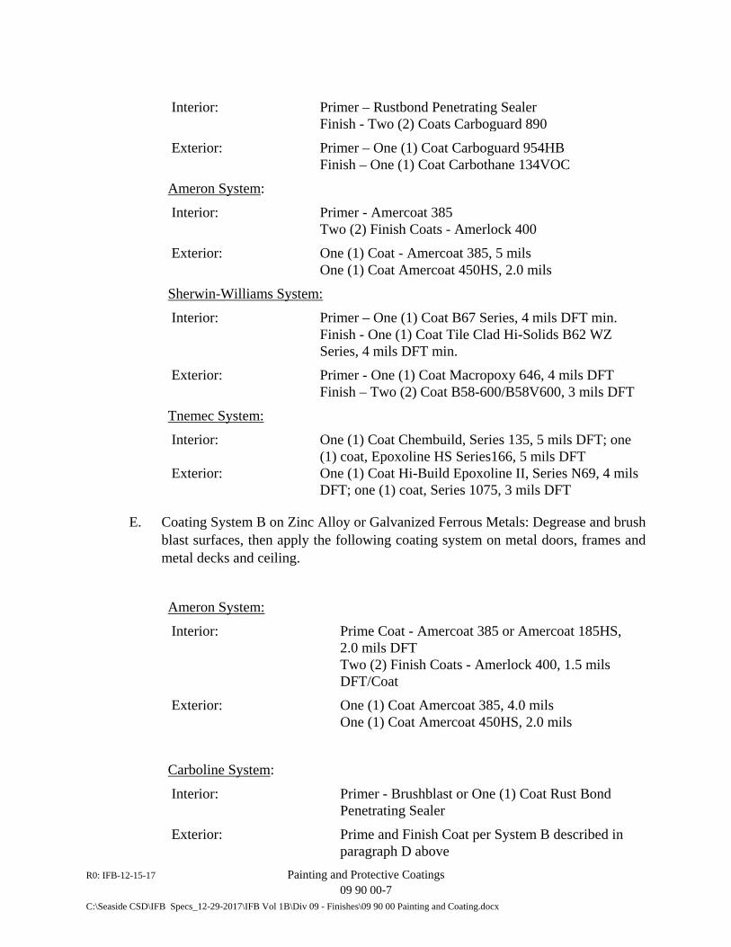
R0: IFB-12-15-17 Painting and Protective Coatings 09 90 00-7 C:\Seaside CSD\IFB Specs_12-29-2017\IFB Vol 1B\Div 09 - Finishes\09 90 00 Painting and Coating.docx
Interior: Primer – Rustbond Penetrating Sealer Finish - Two (2) Coats Carboguard 890
Exterior: Primer – One (1) Coat Carboguard 954HB Finish – One (1) Coat Carbothane 134VOC
Ameron System:
Interior: Primer - Amercoat 385 Two (2) Finish Coats - Amerlock 400
Exterior: One (1) Coat - Amercoat 385, 5 mils One (1) Coat Amercoat 450HS, 2.0 mils
Sherwin-Williams System:
Interior: Primer – One (1) Coat B67 Series, 4 mils DFT min. Finish - One (1) Coat Tile Clad Hi-Solids B62 WZ
Series, 4 mils DFT min.
Exterior: Primer - One (1) Coat Macropoxy 646, 4 mils DFT Finish – Two (2) Coat B58-600/B58V600, 3 mils DFT
Tnemec System:
Interior: One (1) Coat Chembuild, Series 135, 5 mils DFT; one (1) coat, Epoxoline HS Series166, 5 mils DFT
Exterior: One (1) Coat Hi-Build Epoxoline II, Series N69, 4 mils DFT; one (1) coat, Series 1075, 3 mils DFT
E. Coating System B on Zinc Alloy or Galvanized Ferrous Metals: Degrease and brush blast surfaces, then apply the following coating system on metal doors, frames and metal decks and ceiling.
Ameron System:
Interior: Prime Coat - Amercoat 385 or Amercoat 185HS, 2.0 mils DFT
Two (2) Finish Coats - Amerlock 400, 1.5 mils DFT/Coat
Exterior: One (1) Coat Amercoat 385, 4.0 mils One (1) Coat Amercoat 450HS, 2.0 mils
Carboline System:
Interior: Primer - Brushblast or One (1) Coat Rust Bond Penetrating Sealer
Exterior: Prime and Finish Coat per System B described in paragraph D above
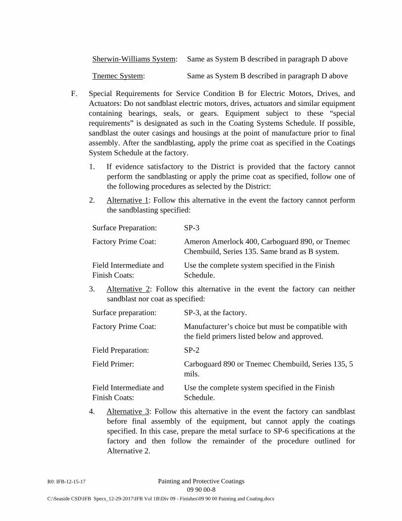
R0: IFB-12-15-17 Painting and Protective Coatings 09 90 00-8 C:\Seaside CSD\IFB Specs_12-29-2017\IFB Vol 1B\Div 09 - Finishes\09 90 00 Painting and Coating.docx
Sherwin-Williams System: Same as System B described in paragraph D above
Tnemec System: Same as System B described in paragraph D above
F. Special Requirements for Service Condition B for Electric Motors, Drives, and Actuators: Do not sandblast electric motors, drives, actuators and similar equipment containing bearings, seals, or gears. Equipment subject to these “special requirements” is designated as such in the Coating Systems Schedule. If possible, sandblast the outer casings and housings at the point of manufacture prior to final assembly. After the sandblasting, apply the prime coat as specified in the Coatings System Schedule at the factory.
1. If evidence satisfactory to the District is provided that the factory cannot perform the sandblasting or apply the prime coat as specified, follow one of the following procedures as selected by the District:
2. Alternative 1: Follow this alternative in the event the factory cannot perform the sandblasting specified:
Surface Preparation: SP-3
Factory Prime Coat: Ameron Amerlock 400, Carboguard 890, or Tnemec Chembuild, Series 135. Same brand as B system.
Field Intermediate and Finish Coats:
Use the complete system specified in the Finish Schedule.
3. Alternative 2: Follow this alternative in the event the factory can neither sandblast nor coat as specified:
Surface preparation: SP-3, at the factory.
Factory Prime Coat: Manufacturer’s choice but must be compatible with the field primers listed below and approved.
Field Preparation: SP-2
Field Primer: Carboguard 890 or Tnemec Chembuild, Series 135, 5 mils.
Field Intermediate and Finish Coats:
Use the complete system specified in the Finish Schedule.
4. Alternative 3: Follow this alternative in the event the factory can sandblast before final assembly of the equipment, but cannot apply the coatings specified. In this case, prepare the metal surface to SP-6 specifications at the factory and then follow the remainder of the procedure outlined for Alternative 2.
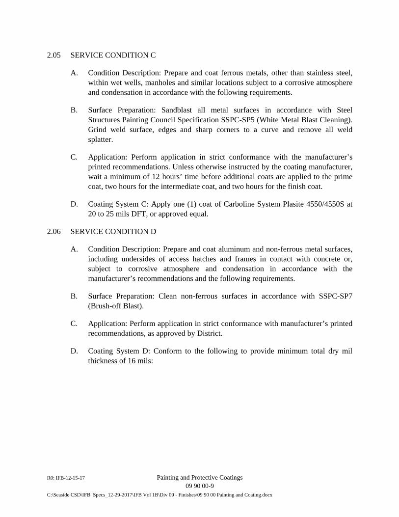
R0: IFB-12-15-17 Painting and Protective Coatings 09 90 00-9 C:\Seaside CSD\IFB Specs_12-29-2017\IFB Vol 1B\Div 09 - Finishes\09 90 00 Painting and Coating.docx
2.05 SERVICE CONDITION C
A. Condition Description: Prepare and coat ferrous metals, other than stainless steel, within wet wells, manholes and similar locations subject to a corrosive atmosphere and condensation in accordance with the following requirements.
B. Surface Preparation: Sandblast all metal surfaces in accordance with Steel Structures Painting Council Specification SSPC-SP5 (White Metal Blast Cleaning). Grind weld surface, edges and sharp corners to a curve and remove all weld splatter.
C. Application: Perform application in strict conformance with the manufacturer’s printed recommendations. Unless otherwise instructed by the coating manufacturer, wait a minimum of 12 hours’ time before additional coats are applied to the prime coat, two hours for the intermediate coat, and two hours for the finish coat.
D. Coating System C: Apply one (1) coat of Carboline System Plasite 4550/4550S at 20 to 25 mils DFT, or approved equal.
2.06 SERVICE CONDITION D
A. Condition Description: Prepare and coat aluminum and non-ferrous metal surfaces, including undersides of access hatches and frames in contact with concrete or, subject to corrosive atmosphere and condensation in accordance with the manufacturer’s recommendations and the following requirements.
B. Surface Preparation: Clean non-ferrous surfaces in accordance with SSPC-SP7 (Brush-off Blast).
C. Application: Perform application in strict conformance with manufacturer’s printed recommendations, as approved by District.
D. Coating System D: Conform to the following to provide minimum total dry mil thickness of 16 mils:
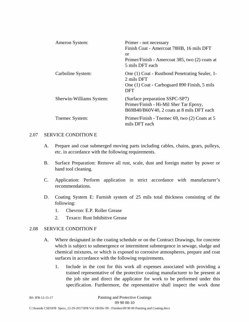
R0: IFB-12-15-17 Painting and Protective Coatings 09 90 00-10 C:\Seaside CSD\IFB Specs_12-29-2017\IFB Vol 1B\Div 09 - Finishes\09 90 00 Painting and Coating.docx
Ameron System: Primer - not necessary Finish Coat - Amercoat 78HB, 16 mils DFT or Primer/Finish - Amercoat 385, two (2) coats at 5 mils DFT each
Carboline System: One (1) Coat - Rustbond Penetrating Sealer, 1-2 mils DFT One (1) Coat - Carboguard 890 Finish, 5 mils DFT
Sherwin-Williams System: (Surface preparation SSPC-SP7) Primer/Finish - Hi-Mil Sher Tar Epoxy, B69B40/B60V40, 2 coats at 8 mils DFT each
Tnemec System: Primer/Finish - Tnemec 69, two (2) Coats at 5 mils DFT each
2.07 SERVICE CONDITION E
A. Prepare and coat submerged moving parts including cables, chains, gears, pulleys, etc. in accordance with the following requirements.
B. Surface Preparation: Remove all rust, scale, dust and foreign matter by power or hand tool cleaning.
C. Application: Perform application in strict accordance with manufacturer’s recommendations.
D. Coating System E: Furnish system of 25 mils total thickness consisting of the following: 1. Chevron: E.P. Roller Grease 2. Texaco: Rust Inhibitive Grease
2.08 SERVICE CONDITION F
A. Where designated in the coating schedule or on the Contract Drawings, for concrete which is subject to submergence or intermittent submergence in sewage, sludge and chemical mixtures, or which is exposed to corrosive atmospheres, prepare and coat surfaces in accordance with the following requirements.
1. Include in the cost for this work all expenses associated with providing a trained representative of the protective coating manufacturer to be present at the job site and direct the applicator for work to be performed under this specification. Furthermore, the representative shall inspect the work done
R0: IFB-12-15-17 Painting and Protective Coatings 09 90 00-11 C:\Seaside CSD\IFB Specs_12-29-2017\IFB Vol 1B\Div 09 - Finishes\09 90 00 Painting and Coating.docx
under this specification upon completion and shall certify in writing that the work has been performed in accordance with the manufacturer’s recommendations and instructions and that the quality of work is satisfactory for the purpose of providing the specified guarantee.
B. Surface Preparation: Prepare the surfaces of concrete structures described herein or identified in the Schedule included at the end of this Section as receiving the selected coating system in accordance with the selected coating system manufacturer’s written instructions and as specified herein to provide the proper substrate for maximum product service. 1. Allow concrete and concrete patching products to be fully cured before
application of the selected and approved product. Allow minimum cure time of the patching product as recommended in writing by the manufacturer of the selected coating system.
2. Remove from the substrate release agents and curing compounds used. If requested by District, submit data verifying compatibility of curing compounds used with the selected Coating System F.
3. Stop water seeping or flowing into or through the concrete substrate before applying the system. Employ “Patch ’N Plug” by Xypex Chemical Corporation, Waterplug by Thoro System Product, or similar equal products of other manufacturers for this purpose.
4. Expansion Joints: Round off edges, remove debris/dust and inspect joint to assure that the joint compound used is reasonably flush with the top edge of the expansion joint. Apply a prime coat of material recommended by coating manufacturer to the adjacent areas. Seal joint with bond breaker tape (polyethylene-backed adhesive tape is acceptable) centered over the joint and of sufficient width to extend a minimum of 1-inch onto the concrete surface on both sides of the joint. Use a tape of thickness no more than 50 percent of the specified coating.
5. Cleaning of Concrete Surfaces: a. Cleanliness: Check concrete surface for dryness and contamination by
oils or dust. If wetness or contamination is found, correct to coating manufacturer’s requirements.
b. Chemical Cleaning: Clean surfaces of oily substances using solutions of caustic soda or trisodium phosphate. Apply solution with vigorous scrubbing, followed by flushing with water to remove all traces of contaminants and solution.
c. Blast Cleaning: Remove oil and grease contamination using chemical cleaning prior to use of blast cleaning. Employ “brush blast” technique to achieve a textured finish surface. Continue brush blasting until a strong, sound substrate is reached. Use compressor air that is clean and
R0: IFB-12-15-17 Painting and Protective Coatings 09 90 00-12 C:\Seaside CSD\IFB Specs_12-29-2017\IFB Vol 1B\Div 09 - Finishes\09 90 00 Painting and Coating.docx
free of oil particles. Demonstrate oil free air is provided in accordance with NACE procedure for “Blotter Testing” of compressed air.
d. Dusty Conditions: Blow down substrate areas with clean dry air. Demonstrate cleanliness by wiping surface with a dark, clean cloth and showing absence of white powder on cloth. Repeat procedures until satisfactory results are achieved. Vacuum debris to ensure dust and particles are effectively removed from the areas.
e. pH Condition: Using either pH paper or a pH meter to demonstrate the pH at the concrete surface complies with the coating manufacturer’s written recommendations for acceptable conditions.
C. Application of Coating: Mix and apply the protective coating in strict conformance with the directions of the selected coating manufacturer. 1. Submit coating manufacturer’s printed instructions for application at least 20
days in advance of commencing coating operations. In the application instructions address recoat times and acceptable relative humidity and temperature at time of coating application.
2. For system F-P, submit written procedures and identify acceptable results for the following material quality tests that are to be performed at the start of application or after long breaks in application of the coating or malfunction of equipment. a. Ratio check of A and B components to verify required volumetric
proportioning. b. Mixed material check to verify proper mixing of components. c. Curing cycle test to verify reaction is proceeding properly. d. Weight check to verify proper expansion rate. e. Flow rate check of component C materials to assure proper metering.
3. For system F, only applicator’s certified by the coating manufacturer for the specific system proposed shall be allowed to apply the coating.
D. Coating System F: Except where PVC liner per Specification Section 09 98 00 is shown on the Drawings or in the Coating System Schedule at the end of this Section as required, provide the system described herein in accordance with the Coating System Schedule at the end of this Section. 1. Coating System F-P: A two-component 100 percent solids, aromatic, MDI
elastomeric polyurethane coating containing no sand or silica fillers. Endura-Flex EF-1988 as manufactured by Global EcoTechnologies, Inc. EF-1988 shall have the following physical properties:
Physical Properties Test Method Result
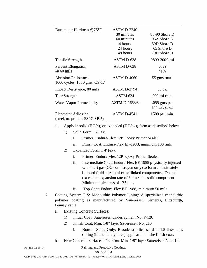
R0: IFB-12-15-17 Painting and Protective Coatings 09 90 00-13 C:\Seaside CSD\IFB Specs_12-29-2017\IFB Vol 1B\Div 09 - Finishes\09 90 00 Painting and Coating.docx
Durometer Hardness @75°F ASTM D-2240 30 minutes 60 minutes
4 hours 24 hours 48 hours
85-90 Shore D 95A Shore A 50D Shore D 65 Shore D
70D Shore D Tensile Strength ASTM D-638 2800-3000 psi Percent Elongation @ 60 mils
ASTM D-638 65% 41%
Abrasion Resistance 1000 cycles, 1000 gms, CS-17
ASTM D-4060 55 gms max.
Impact Resistance, 80 mils ASTM D-2794 35 psi Tear Strength ASTM 624 200 psi min. Water Vapor Permeability ASTM D-1653A .055 gms per
144 in2, max. Elcometer Adhesion (steel, no primer, SSPC SP-5)
ASTM D-4541 1500 psi, min.
a. Apply in solid (F-P(s)) or expanded (F-P(ex)) form as described below. 1) Solid Form, F-P(s):
i. Primer: Endura-Flex 12P Epoxy Primer Sealer ii. Finish Coat: Endura-Flex EF-1988, minimum 100 mils
2) Expanded Form, F-P (ex): i. Primer: Endura-Flex 12P Epoxy Primer Sealer ii. Intermediate Coat: Endura-Flex EF-1988 physically injected
with inert gas (CO2 or nitrogen only) to form an intimately blended fluid stream of cross-linked components. Do not exceed an expansion rate of 3 times the solid component. Minimum thickness of 125 mils.
iii. Top Coat: Endura-Flex EF-1988, minimum 50 mils 2. Coating System F-S: Monolithic Polymer Lining: A specialized monolithic
polymer coating as manufactured by Sauereisen Cements, Pittsburgh, Pennsylvania. a. Existing Concrete Surfaces:
1) Initial Coat: Sauereisen Underlayment No. F-120 2) Finish Coat: Min. 1/8” layer Sauereisen No. 210
i. Bottom Slabs Only: Broadcast silica sand at 1.5 lbs/sq. ft. during (immediately after) application of the finish coat.
b. New Concrete Surfaces: One Coat Min. 1/8” layer Sauereisen No. 210.
R0: IFB-12-15-17 Painting and Protective Coatings 09 90 00-14 C:\Seaside CSD\IFB Specs_12-29-2017\IFB Vol 1B\Div 09 - Finishes\09 90 00 Painting and Coating.docx
3. Coating System F2: SewperCoat (100% Calcium Aluminate): a. General:
1) The specifications outlined below take precedence over any other requirements in this Section when using the SewperCoat material.
2) Submittals: i. Furnish detailed and complete data pertaining to the surfaces
of the structure to be rehabilitated, the rehabilitation product, surface preparation and installation to the Owner for approval. Submit this data in a timely manner to prevent project delay. Where requested by Owner test application environment and substrate for adverse chemical conditions that may hinder overall product performance. Provide a clean, rough sub-surface sufficiently prepared in accordance with the International Concrete Repair Institute (ICRI) Guideline No. 03732 – Selecting and Specifying Concrete Surface Preparation for Sealers, Coatings, and Polymer Overlays.
ii. Prior to initiating the work, submit specific technical data with complete physical properties of the structure to be rehabilitated and the proposed product for the rehabilitation of the structure, as well as a specific plan for sub-surface preparation.
ii. Submit a work plan and a safety plan. Acceptance by the Owner of the safety plan shall not relieve the Contractor’s to comply with OSHA standards and all regulations pertaining to the work, including confined space entry
b. Materials: 1) Furnish lining material that is a prepackaged mortar mix, including
all cement, aggregates, and any required additives. It is the intent of this specification that the Contractor only be required to add the proper amount of potable water to produce concrete suitable for spray application. Do not add Portland cement, other aggregates, or any admixtures whatsoever to lining material. Furnish typical package weights of not less than 50 lbs and that are identical for all material furnished on this project.
2) The chemical composition of the cement portion as well as the aggregates of the mortar mix shall be as follows:
Al2O3 CaO FeO + Fe2O3 SiO2
39-44% 35-39% 9-14% 5-7%
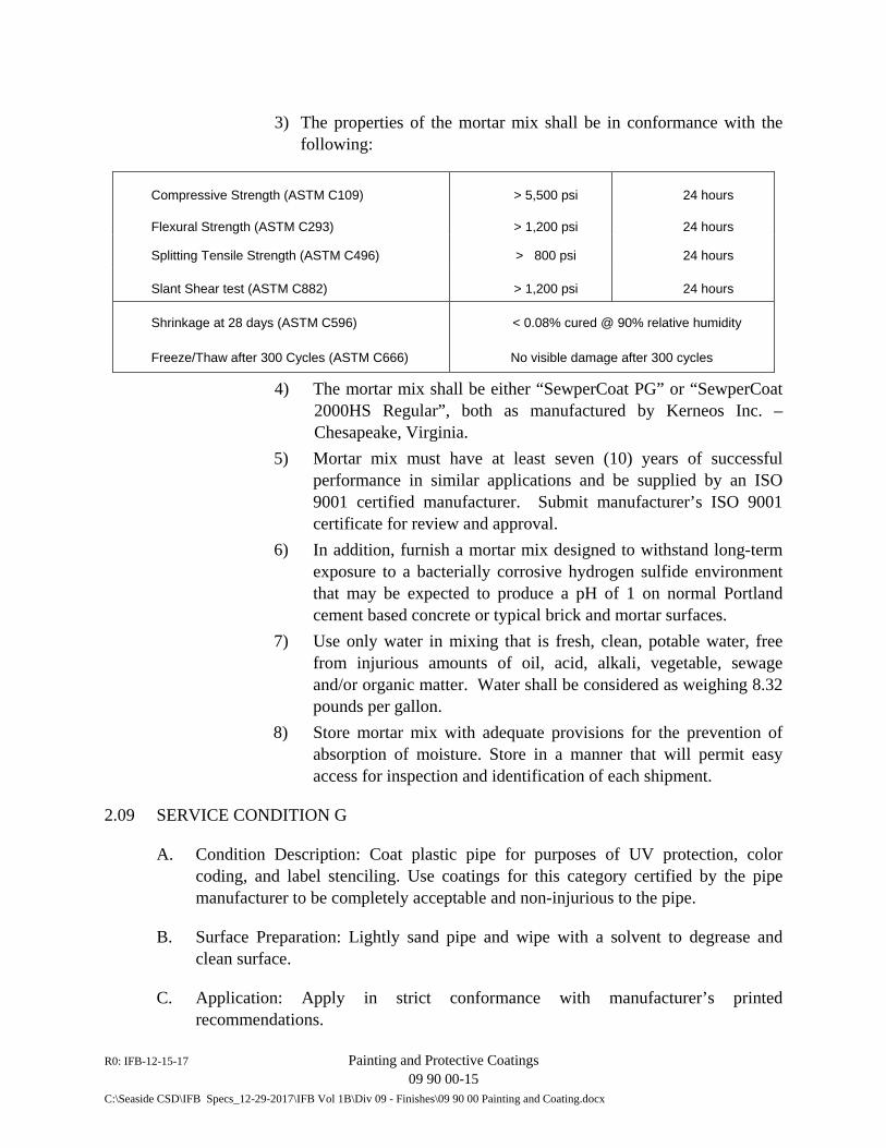
R0: IFB-12-15-17 Painting and Protective Coatings 09 90 00-15 C:\Seaside CSD\IFB Specs_12-29-2017\IFB Vol 1B\Div 09 - Finishes\09 90 00 Painting and Coating.docx
3) The properties of the mortar mix shall be in conformance with the following:
Compressive Strength (ASTM C109) > 5,500 psi 24 hours
Flexural Strength (ASTM C293) > 1,200 psi 24 hours
Splitting Tensile Strength (ASTM C496) > 800 psi 24 hours
Slant Shear test (ASTM C882) > 1,200 psi 24 hours
Shrinkage at 28 days (ASTM C596) < 0.08% cured @ 90% relative humidity
Freeze/Thaw after 300 Cycles (ASTM C666) No visible damage after 300 cycles
4) The mortar mix shall be either “SewperCoat PG” or “SewperCoat 2000HS Regular”, both as manufactured by Kerneos Inc. – Chesapeake, Virginia.
5) Mortar mix must have at least seven (10) years of successful performance in similar applications and be supplied by an ISO 9001 certified manufacturer. Submit manufacturer’s ISO 9001 certificate for review and approval.
6) In addition, furnish a mortar mix designed to withstand long-term exposure to a bacterially corrosive hydrogen sulfide environment that may be expected to produce a pH of 1 on normal Portland cement based concrete or typical brick and mortar surfaces.
7) Use only water in mixing that is fresh, clean, potable water, free from injurious amounts of oil, acid, alkali, vegetable, sewage and/or organic matter. Water shall be considered as weighing 8.32 pounds per gallon.
8) Store mortar mix with adequate provisions for the prevention of absorption of moisture. Store in a manner that will permit easy access for inspection and identification of each shipment.
2.09 SERVICE CONDITION G
A. Condition Description: Coat plastic pipe for purposes of UV protection, color coding, and label stenciling. Use coatings for this category certified by the pipe manufacturer to be completely acceptable and non-injurious to the pipe.
B. Surface Preparation: Lightly sand pipe and wipe with a solvent to degrease and clean surface.
C. Application: Apply in strict conformance with manufacturer’s printed recommendations.
R0: IFB-12-15-17 Painting and Protective Coatings 09 90 00-16 C:\Seaside CSD\IFB Specs_12-29-2017\IFB Vol 1B\Div 09 - Finishes\09 90 00 Painting and Coating.docx
D. Coating System G: Two (2) coats having a total dry film thickness of 6.0 mils.
Ameron System: Amercoat 450HS
Carboline System: Carbothane 134VOC Polyurethane (2 coats)
Tnemec System: Tnemec 1075
Sherwin-Williams System: Primer - B67 Finish - B65W300 Series
2.10 SERVICE CONDITION H - Not Used.
2.11 SERVICE CONDITION I - NOT Used.
2.12 SERVICE CONDITION J - NOT Used.
2.13 ARCHITECTURAL PAINT FINISHES - NOT Used
2.14 MISCELLANEOUS COATINGS
A. Paint indicator posts, traffic posts, guardrails, ladders, and stair nosings safety yellow, matching OSHA Safety Yellow color, using specified coating System “B”.
B. Paint handwheels and operating handles of all valves, gates, and equipment safety red, matching OSHA Safety Red Color, using Coating System “B” in non-corrosive atmosphere and Coating System “C” in corrosive atmosphere and high humidity exposures.
2.15 PATCH COAT FOR GALVANIZED SURFACES
A. Patch all galvanized surfaces which are scratched, marred, or otherwise damaged with Carboline’s Galvanox, “Drygalv” by American Solder and Flux Co., Rust-Oleum 2185 Cold Galvanizing Compound, Glidden’s Glid Zinc organic 5526/5527/5528, Mobil 13F1180, Sherwin-Williams’ Zinc Clad I (Low VOC) B69AW9, Tnemec 90-97, or equal.
2.16 PRIMER OVER BITUMINOUS COATING
A. Use two (2) coats of Rust-Oleum 5781 Rust-O-Crylic, Carboline’s Carbomastic 15, Sherwin-Williams’ DTM Acrylic Primer/Finish B66W1, Tnemec 69, or equal.
R0: IFB-12-15-17 Painting and Protective Coatings 09 90 00-17 C:\Seaside CSD\IFB Specs_12-29-2017\IFB Vol 1B\Div 09 - Finishes\09 90 00 Painting and Coating.docx
2.17 HEAT RESISTANT COATINGS - NOT Used.
2.18 STEEL WATER STORAGE TANK COATING MATERIALS - NOT Used.
2.19 MISCELLANEOUS BURIED FERROUS METAL SURFACES
A. All buried valves, small pipes and other miscellaneous buried ferrous metal surfaces: Perform surface preparation in conformance with SSPC-SP2 or SSPC-SP7, clean as previously specified, and apply not less than two coats of coal-tar mastic coating, Caroline’s Bitumastic 300M, Tnemec 46-450, or equal. Do not apply prime coat under coal-tar mastic or Sherwin Williams Coopers Creek No. 750.
B. Apply coating thickness from 30 to 36 mils total dry-film thickness for the two (2) coat system unless otherwise noted. Allow coated surfaces to dry before backfilling.
PART 3 - EXECUTION
3.01 MANUFACTURER’S RECOMMENDATIONS
A. Unless otherwise specified herein, strictly follow the paint and coating manufacturer’s printed recommendations and instructions for thinning, mixing, handling, applying, and protection of his coating materials; for preparation of surfaces for coating; and for all other procedures relative to coating. No substitutions or other deviations will be permitted without written permission of the District.
3.02 DELIVERY AND STORAGE
A. Deliver materials in manufacturer’s original, sealed containers, with labels and tags intact.
B. Store coating materials and equipment in designated areas.
C. Open coating containers only when required for use.
D. Mix coatings only in designated rooms or spaces in the presence of the District’s representative. Thoroughly stir or agitate coating to uniformly smooth consistency and prepare and handle in a manner to prevent deterioration and inclusion of foreign matter.
E. Unless otherwise specified or approved, do not reduce, change, or use materials except in accordance with the manufacturer’s label or tag on container.
R0: IFB-12-15-17 Painting and Protective Coatings 09 90 00-18 C:\Seaside CSD\IFB Specs_12-29-2017\IFB Vol 1B\Div 09 - Finishes\09 90 00 Painting and Coating.docx
3.03 SAFETY REQUIREMENTS
A. Provide and require the use of personal protective lifesaving equipment for all persons working in or about the project site in accordance with the requirements of the latest revision of the Construction Safety orders of the California Division of Occupational Health and applicable OSHA Regulations for Construction.
B. Require respirators to be worn by all persons engaged in, and assisting in, spray painting. In addition, require workers engaged in or near the work during sandblasting to wear eye and face protection devices meeting the requirements of ANSI Z87.1 latest revision, and approved OSHA Regulations for sandblasting operations and approved air-purifying, half-mask or mouthpiece respirator with appropriate filter.
C. Ventilation: Where ventilation is used to control potential exposure to workers as set forth in Section 1910.94 of the OSHA Regulations for Construction, provide adequate ventilation to reduce the concentration of the air contaminant to a level at which no hazard to the workers exists. Employ methods of ventilation meeting the requirements set forth in ANSI-Z9.2, latest revision.
D. Sound Levels: In accordance with Sections 1926.52 and 1926.101 of OSHA Regulations For Construction, whenever the occupational noise exposure exceeds maximum sound levels as set forth in Table D-2 therein, ensure ear protective devices are fitted and determined individually and used, and administer a continuing, effective hearing conservation program.
E. Store and mix coating materials only in those areas designated by the District.
F. Place cloths and cotton waste that might constitute a fire hazard in closed metal containers or destroy same at the end of each work day.
3.04 STORAGE, MIXING, AND THINNING
A. Protect paint and coating materials from exposure to cold weather, and thoroughly stir, strain, and keep at a uniform consistency during application. Do not mix materials of different manufacturers together. Unless otherwise specified herein, packaged materials may be thinned immediately prior to application in accordance with the manufacturer’s directions.
3.05 WORKMANSHIP
A. Use only skilled craftsmen and experienced supervision on all work. Where required in Part 2 of this Section for particular coating systems, use only certified applicators for the respective system or product.
R0: IFB-12-15-17 Painting and Protective Coatings 09 90 00-19 C:\Seaside CSD\IFB Specs_12-29-2017\IFB Vol 1B\Div 09 - Finishes\09 90 00 Painting and Coating.docx
B. Provide the finished surfaces free from runs, drops, ridges, waves, laps, brush marks, and variations in color, texture, and finish. Complete the hiding in a manner such that the addition of another coat of paint will not cause the hiding to increase.
C. Apply all paint and coatings in a workmanlike manner that produces a uniform film of the specified thickness. Give special attention to ensure that edges, corners, crevices, welds, joints and similar areas have been properly cleaned and prepared and receive an adequate film thickness equivalent to adjacent areas. Protect installations by the use of drop cloths or other approved precautionary measures.
3.06 PREPARATION FOR PAINTING AND PROTECTIVE COATING
A. Clean all surfaces to receive paint and protective coatings as specified herein prior to application of coating materials. Examine all surfaces to be coated, and correct all surface defects before application of any coating material. Beginning the work of this Section without reporting unsuitable conditions to the District constitutes acceptance of conditions by the Contractor.
B. Perform any required removal, repair, or replacement of this work caused by unsuitable conditions at no additional cost to the District. Perform touch-up restoration to all marred or abraded spots on shop-primed and factory-finished surfaces prior to any other coating application.
3.07 ITEMS NOT TO BE COATED
A. For hardware, hardware accessories, nameplate data tags, machined surfaces and similar items in contact with coated surfaces not required to be coated, remove or mask prior to surface preparation and painting operations. Following completion of coating of each piece, reinstall removed items or remove masking material. Perform required removal and installation by workmen skilled in the trades involved.
3.08 SANDBLASTING
A. Perform all sandblasting in strict accordance with the referenced specifications of the Steel Structures Painting Council.
B. When items are to be shop primed or shop primed and finish coated in the shop, perform surface preparation as specified in this Section. The District reserves the right to witness, inspect, and reject any sandblasting done in the shop.
C. When sandblasting is done in the field, take care to prevent damage to structures and equipment. Shield, cover, or otherwise protect pumps, motors, and other equipment to prevent the entrance of sand. Do not sandblast before the District inspects and approves the protective measures.
R0: IFB-12-15-17 Painting and Protective Coatings 09 90 00-20 C:\Seaside CSD\IFB Specs_12-29-2017\IFB Vol 1B\Div 09 - Finishes\09 90 00 Painting and Coating.docx
D. After sandblasting, remove dust and spent sand from the surfaces by brushing or vacuum cleaning.
3.09 APPLICATION OF ARCHITECTURAL PAINT FINISHES (NOT USED)
3.10 APPLICATION OF PROTECTIVE COATINGS
A. Shop Coating: Fabricated metalwork and equipment which requires coating may be shop primed with specified primer. In the event work is delivered to the job site with any other shop coat, remove this coating and apply the specified coating in the field. Exempt from this requirement of stripping are manufactured equipment with approved corrosion resistant factory finishes.
1. For application of Coating System F to precast concrete manhole or other structure sections, comply with coating manufacturer’s recommendations and to the requirements specified in Paragraph B below, except when using System F2 (SewperCoat), comply with Paragraph C below.
B. Application of Field Coatings: 1. Except where in conflict with the manufacturer’s printed instructions, or
where otherwise specified herein, use brush, roller, air spray, or so-called airless spray application; however, first obtain the District’s approval if using spray painting. Use rollers having a short nap for applying enamel. Coat areas inaccessible to spray coating or rolling by brushing or other suitable means.
2. Give special attention to the work to ensure that edges, corners, crevices, welds, bolts, and other areas, as determined by the District, receive a film thickness at least equivalent to that of adjacent coated surfaces.
3. Apply all protective coating materials in strict accordance with the manufacturer's printed instructions.
4. Apply prime coat to all clean surfaces within a four (4) hour period of the cleaning, and prior to deterioration or oxidation of the surface, and in accordance with the manufacturer's recommendations. Do not allow drift from sand-blasting procedures to settle on freshly painted surfaces.
5. Apply all coatings in dry and dust-free environment. Do not apply coating or paint when the surrounding air temperature, measured in the shade, is below 40 degrees Fahrenheit. Do not apply coating or paint to wet or damp surfaces and do not apply in rain, fog or mist, or when the relative humidity exceeds 85 percent. a. Do not apply coating or paint when it is expected that the relative
humidity will exceed 85 percent or that the air temperature will drop below 40 degrees Fahrenheit within 18 hours after the application of the coating or paint. Dew or moisture condensation should be anticipated
R0: IFB-12-15-17 Painting and Protective Coatings 09 90 00-21 C:\Seaside CSD\IFB Specs_12-29-2017\IFB Vol 1B\Div 09 - Finishes\09 90 00 Painting and Coating.docx
and if such conditions are prevalent, delay coating or painting until mid-morning to be certain that the surfaces are dry.
b. Further, complete the coating or painting each day well in advance of the probable time of day when condensation will occur, in order to permit the film a sufficient drying time prior to the formation of moisture.
6. Apply each coat evenly, at the proper consistency, and free of brush marks, sags, runs, and other evidence of poor workmanship. Exercise care to avoid lapping paint on glass or hardware. Sharply cut coatings to lines. Provide finished coated surfaces free from defects or blemishes. a. Use protective coverings to protect floors, fixtures, and equipment.
Exercise care to prevent paint from being spattered onto surfaces from which such paint cannot be removed satisfactorily. For surfaces from which paint cannot be removed satisfactorily, paint or repaint as required to produce a finish satisfactory to the District.
b. Whenever two (2) coats of a dark colored paint are specified, provide first coat containing sufficient powdered aluminum to act as an indicator of proper coverage, or provide two (2) coatings of a contrasting color.
7. Coat all contact surfaces inaccessible after assembly, before erection; however, do not paint structural friction connections or high tensile bolts and nuts before erection. Hand or power-tool clean areas damaged during erection and recoated with prime coat.
8. Perform touchup of all surfaces after installation. 9. Clean and dry all surfaces to be coated at the time of coating application. 10. Coating System F: Apply a non-skid top coat to exposed surfaces (other than
the flow channel) of manhole bases (precast and cast-in-place) while the coating base coat is still tacky but firm enough so as to “cradle” the non-skid grit at the surface of the base coat. Use clean #2 sand, dry and free of oil. a. Apply sand by air-assisted dispensing systems or hand-operated seeders
in a density sufficient to provide an even non-skid surface. Remove loose grit by air or brush when the seeded coat is tack free. Topcoat the surface with sufficient coating material to encapsulate the exposed remaining embedded grit.
C. Application of Coating System F2 (SewperCoat): 1. Quality Assurance: Coating system F2 (SewperCoat) shall be applied only by
an applicator certified by the material manufacturer 2. Surface Preparation:
a. Ensure all sub-surfaces are clean and free of laitance, loose material, residue and all existing coating and lining materials. See Section 4.4 for Inflow and Infiltration Prevention. For detailed explanation of the
R0: IFB-12-15-17 Painting and Protective Coatings 09 90 00-22 C:\Seaside CSD\IFB Specs_12-29-2017\IFB Vol 1B\Div 09 - Finishes\09 90 00 Painting and Coating.docx
required surface preparation see ACI RAP-3 “Spall Repair by Low Pressure Spraying” page 2. ACI 546R “Concrete Repair Guide”, chapter 2 also provides a good reference for important considerations for repairing concrete surfaces using mortar.
b. Thoroughly saturate sub-surfaces with water prior to the application of the lining materials. In no instance apply shotcrete in an area where running water exists. Ensure the existing surface is saturated and free of any running water just prior to installation. This condition is known as SSD, “saturated surface dry condition.” To achieve this condition, it may be necessary to presoak the sub-surface for at least 24 hours prior to application of the material mix.
3. Operations a. Provide all equipment necessary to individually gauge, control, and
monitor the actual amounts of all component materials necessary to complete the lining installation. Submit coating manufacturer’s certification that the type of equipment and methods used to gauge, control, and monitor component materials are in accordance with his recommendations
b. Thoroughly mix lining materials by mechanical means to ensure all agglomerated particles are reduced to original size or removed prior to placement into the application equipment (i.e. the hopper). Entirely discharge each batch of material before recharging with fresh material. Clean mixing equipment at regular intervals to remove all adherent materials.
c. Add water to the mix in strict accordance with the Manufacturer’s recommendations.
d. Re-mixing or tempering shall not be permitted. Do not reuse rebound materials.
4. Protection of Adjacent Surfaces: During progress of the work, adequately protect adjacent areas or grounds which may be permanently discolored, stained or otherwise damaged by dust and rebound material, and, if contacted, promptly clean by scraping, brushing or washing as the surroundings permit.
5. Inflow and Infiltration Prevention: a. If inflow or infiltration is observed within the structure after surface
preparation is complete, use a rapid setting crystalline enhanced hydraulic cement product specifically formulated for infiltration control to stop minor infiltration flows in accordance with the manufacturer's recommendations. The hydraulic cement material shall meet the following strength requirements:
Compressive Strength (ASTM C597B) 600 psi (24 hours)
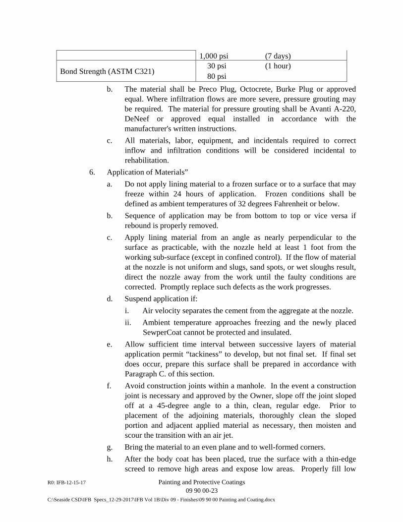
R0: IFB-12-15-17 Painting and Protective Coatings 09 90 00-23 C:\Seaside CSD\IFB Specs_12-29-2017\IFB Vol 1B\Div 09 - Finishes\09 90 00 Painting and Coating.docx
1,000 psi (7 days)
Bond Strength (ASTM C321) 30 psi (1 hour) 80 psi
b. The material shall be Preco Plug, Octocrete, Burke Plug or approved equal. Where infiltration flows are more severe, pressure grouting may be required. The material for pressure grouting shall be Avanti A-220, DeNeef or approved equal installed in accordance with the manufacturer's written instructions.
c. All materials, labor, equipment, and incidentals required to correct inflow and infiltration conditions will be considered incidental to rehabilitation.
6. Application of Materials” a. Do not apply lining material to a frozen surface or to a surface that may
freeze within 24 hours of application. Frozen conditions shall be defined as ambient temperatures of 32 degrees Fahrenheit or below.
b. Sequence of application may be from bottom to top or vice versa if rebound is properly removed.
c. Apply lining material from an angle as nearly perpendicular to the surface as practicable, with the nozzle held at least 1 foot from the working sub-surface (except in confined control). If the flow of material at the nozzle is not uniform and slugs, sand spots, or wet sloughs result, direct the nozzle away from the work until the faulty conditions are corrected. Promptly replace such defects as the work progresses.
d. Suspend application if: i. Air velocity separates the cement from the aggregate at the nozzle. ii. Ambient temperature approaches freezing and the newly placed
SewperCoat cannot be protected and insulated. e. Allow sufficient time interval between successive layers of material
application permit “tackiness” to develop, but not final set. If final set does occur, prepare this surface shall be prepared in accordance with Paragraph C. of this section.
f. Avoid construction joints within a manhole. In the event a construction joint is necessary and approved by the Owner, slope off the joint sloped off at a 45-degree angle to a thin, clean, regular edge. Prior to placement of the adjoining materials, thoroughly clean the sloped portion and adjacent applied material as necessary, then moisten and scour the transition with an air jet.
g. Bring the material to an even plane and to well-formed corners. h. After the body coat has been placed, true the surface with a thin-edge
screed to remove high areas and expose low areas. Properly fill low
R0: IFB-12-15-17 Painting and Protective Coatings 09 90 00-24 C:\Seaside CSD\IFB Specs_12-29-2017\IFB Vol 1B\Div 09 - Finishes\09 90 00 Painting and Coating.docx
areas with additional material to ensure a true, flat surface in accordance with Paragraph 6.e above.
i. For manhole applications, provide a minimum thickness of the F2 coating of ½-inch cover over all surfaces. For other larger structures (lift stations, wet wells, treatment plant structures, etc.), provide a minimum thickness of 1-inch cover over all surfaces.
7. Curing: a. If the material has been applied and furnished in accordance to the
specifications, and it has been determined that the environment is not moist enough for natural curing, apply a curing compound to all coated surfaces. Employ a curing compound meeting the requirements of ASTM C309 and that has the approval of the lining material Manufacturer and the Owner prior to use.
b. Moist curing may also be used in lieu of curing compound. If moist curing is selected, it should be implemented just after the notice of uniform heat generation of the installed lining. Moist curing can consist of the use of soaker hoses, water sprinklers, or vapor/misting machines. Regardless of delivery method, moist curing should continue for a minimum of 18 hours.
D. Time of Coating: 1. Strictly comply with manufacturer's recoat time. Allow sufficient time to
elapse between successive coats to permit satisfactory recoating, but once commenced, complete the entire coating operation without delay. Do not undertake additional coating of any structure, equipment, or other item designated to be painted without specific permission of the District and until the previous coating has been completed for the entire structure, piece of equipment, or other item.
2. Do not apply finish coat to piping until piping has been pressure tested and approved.
E. Thickness of Coating: Achieve and verify the dry film mil-thickness specified for each coat.
3.11 TESTING AND INSPECTION
A. Inspection Devices: Furnish, until final acceptance of coating and painting, inspection devices in good working condition for detection of holidays and measurement of dry-film thickness of coatings and paints. Furnish U.S. Department of Commerce, National Bureau of Standards certified thickness calibration plates to test accuracy of dry-film thickness gauge and certified instrumentation to test
R0: IFB-12-15-17 Painting and Protective Coatings 09 90 00-25 C:\Seaside CSD\IFB Specs_12-29-2017\IFB Vol 1B\Div 09 - Finishes\09 90 00 Painting and Coating.docx
accuracy. Make dry-film thickness gauges available for the Inspector's use at all times until final acceptance of application. 1. Operate holiday detection devices in the presence of the Inspector. Operate
inspection devices in accordance with the manufacturer's instructions at the direction of the District's Representative.
B. Conduct film thickness measurements and electrical inspection of the coated surfaces with self-furnished equipment and recoat and repair as necessary for compliance with the Specifications.
C. After repaired and recoated ferrous metals areas have cured, final inspection tests will be conducted by the District or District's representative. 1. Coating thicknesses specified in mils on ferrous substrates will be measured
with a nondestructive magnetic type dry-film thickness gage such as the Elcometer, manufactured by Gardner Laboratories, Inc.
2. Discontinuities, voids and pinholes in the coatings will be determined with a nondestructive type electrical holiday detector.
3. Epoxy coatings and other thin film coatings will be checked for discontinuities and voids with a low voltage detector of the wet-sponge type, such as Model M1 as manufactured by Tinker and Rasor. Use a non-sudsing type wetting agent, such as Kodak Photo-Flo, added to the water prior to wetting the sponge.
4. A high voltage, low current, spark type detector such as Model EP, manufactured by Tinker and Rasor, will be used for electrical inspection of only coal tar enamel.
5. Tape type coatings will be inspected for holidays using a device designed for use in detecting such flaws.
6. All pinholes shall be marked, repaired in accordance with the manufacturer's printed recommendations and retested. No pinholes or other irregularities will be permitted. Wide film thickness discrepancies shall be measured and verified with a micrometer or other approved measuring instrument.
7. Coatings not in compliance with the Specifications will not be acceptable; replace the coatings and re-inspect at no additional expense to the District until the Specifications are met.
D. On non-ferrous surfaces, conduct dry film thickness readings taken at random locations with a Tooke Gauge at the rate of approximately five readings per 100 square feet of surface. Repair groove cut into coating by application of all coats of paint or coating film being tested.
R0: IFB-12-15-17 Painting and Protective Coatings 09 90 00-26 C:\Seaside CSD\IFB Specs_12-29-2017\IFB Vol 1B\Div 09 - Finishes\09 90 00 Painting and Coating.docx
1. The average of all readings for a given area or surface shall be within required dry film thickness range and no individual reading shall be more than 20 percent below the recommended dry film thickness.
2. Mark areas that are found to be below standard and recoat to obtain proper film thickness.
E. Coating System F: The entire surface of the coating shall be visually checked for imperfections by the District, the Contractor, the Coating Subcontractor, and the Coating Manufacturer’s representative. Check entire surface of the coating for pinholes or holidays with a nondestructive holiday detector of less than 100 volts such as Tinker & Rasor Model M-1, K-D Bird Dog, or approved equal. Use of a spark tester is not acceptable. Thoroughly wet just prior to testing as directed by the District. Repair detected holidays and voids in accordance with the coating manufacturer’s instructions.
F. Warranty Inspection: Conduct warranty inspection during the eleventh month following completion of all coating and painting work. All personnel present at the Pre-Job Conference shall attend this inspection. Repair all defective work in accordance with this specification and to the satisfaction of the District or his appointed representative.
3.12 CLEANUP
A. Upon completion of the work, remove staging, scaffolding, and containers from the site or destroyed in an approved manner. Remove paint spots, oil, or stains found upon adjacent surfaces.
3.13 PAINT AND COATING SCHEDULE
A. General: Use appropriate coating system according to the following schedule. The list is not be construed as a complete list of all surfaces to be coated but rather as a guide as to the application of the various coating systems. Paint all surfaces except those specifically deleted herein. Provide only colors selected by the District. Where reference is made to ferrous metal in this schedule, it shall not include stainless steel or galvanized metals.
B. Piping Systems: Conform identification of piping systems to the requirements of ANSI A13.1, "Scheme for the Identification of Piping System," unless otherwise specified herein.
C. Process Valve Identification: After the painting of process piping is complete, stencil the tag numbers of all valves numbered on the "I" Drawings, on the pipe adjacent to the valve for pipe 2 inches and over. Provide characters one inch high minimum and oriented to be visible from the valve operating position.
R0: IFB-12-15-17 Painting and Protective Coatings 09 90 00-27 C:\Seaside CSD\IFB Specs_12-29-2017\IFB Vol 1B\Div 09 - Finishes\09 90 00 Painting and Coating.docx
1. When the valve has extended operator shaft or chain operator, place the number both at the operating position and at the valve if practicable. The latter requirement does not apply if the valve is buried or in a pit.
2. On valves in pipes less than 2 inches provide characters as large as the pipe will permit or at the District's option on an adjacent surface.
3. Furnish characters in white, preferably. However, if this would not provide sufficient contrast to the pipe, the District may select another color. Use paint of the same type and quality as used for painting the pipe.
D. General Coating System: The following list indicates the coating system for all new, and/or altered existing work. For this coating system "Piping" is defined as all pipes, valves, fittings, supports, operating stems and guides. Mechanical equipment includes all drives, motor control panels, electrical equipment and accessory equipment requiring a protective coating. Furnish colors of mechanical equipment as selected by the District.
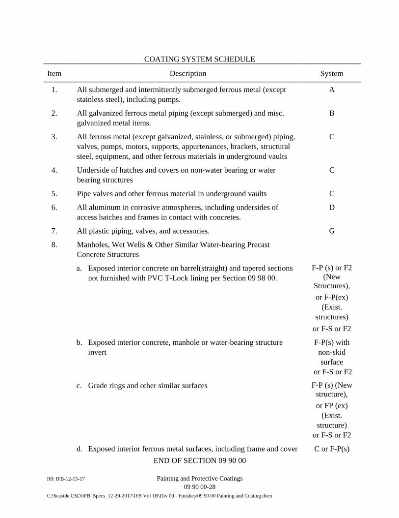
R0: IFB-12-15-17 Painting and Protective Coatings 09 90 00-28 C:\Seaside CSD\IFB Specs_12-29-2017\IFB Vol 1B\Div 09 - Finishes\09 90 00 Painting and Coating.docx
COATING SYSTEM SCHEDULE
Item Description System
1. All submerged and intermittently submerged ferrous metal (except stainless steel), including pumps.
A
2. All galvanized ferrous metal piping (except submerged) and misc. galvanized metal items.
B
3. All ferrous metal (except galvanized, stainless, or submerged) piping, valves, pumps, motors, supports, appurtenances, brackets, structural steel, equipment, and other ferrous materials in underground vaults
C
4. Underside of hatches and covers on non-water bearing or water bearing structures
C
5. Pipe valves and other ferrous material in underground vaults C
6. All aluminum in corrosive atmospheres, including undersides of access hatches and frames in contact with concretes.
D
7. All plastic piping, valves, and accessories. G
8. Manholes, Wet Wells & Other Similar Water-bearing Precast Concrete Structures
a. Exposed interior concrete on barrel(straight) and tapered sections not furnished with PVC T-Lock lining per Section 09 98 00.
F-P (s) or F2 (New
Structures), or F-P(ex)
(Exist. structures)
or F-S or F2
b. Exposed interior concrete, manhole or water-bearing structure invert
F-P(s) with non-skid surface
or F-S or F2
c. Grade rings and other similar surfaces F-P (s) (New structure), or FP (ex)
(Exist. structure)
or F-S or F2
d. Exposed interior ferrous metal surfaces, including frame and cover C or F-P(s) END OF SECTION 09 90 00
R0: IFB-12-15-17 Corrosion Resistant Lining System 09 98 00 - 1 C:\Seaside CSD\IFB Specs_12-29-2017\IFB Vol 1B\Div 09 - Finishes\09 98 00 Corrosion Resistant Lining System.docx
SECTION 09 98 00
CORROSION RESISTANT LINING SYSTEM
PART 1 - GENERAL
1.01 SUMMARY
A. Requirements specified in Conditions of the Contract and Division 1 of the Technical Specifications form a part of this Section.
B. Section Includes: 1. Corrosion resistant polyvinyl chloride (PVC) liner installed on concrete and
cement grouted interior surfaces. 2. Application of PVC liner to precast utility structures. 3. Factory testing of PVC sheets for chemical resistance and holidays. 4. Field testing of installed PVC liner for holidays and other defects. 5. Repair of existing manholes having PVC liner that is damaged as a result of
this Work.
C. Related Sections: 1. Section 03 11 00 - Formwork 2. Section 03 30 00 – Cast-in-Place Concrete 3. Section 07 92 00 – Joint Sealants 4. Section 09 90 00 – Painting and Protective Coating Systems 5. Section 33 05 16 - Utility Structures
1.02 REFERENCES
A. ASTM D412 - Test Methods for Rubber Properties in Tension.
B. ASTM D2240 - Test Method for Rubber Property, Durometer Hardness.
C. Standard Specifications for Public Works Construction, most recent edition.
1.03 SUBMITTALS
A. Comply with the general requirements and procedures described in Article 12 of the General Conditions and Section 01 30 00, “Submittal Procedures”, of the Technical Specifications pertaining to submittals, including preparation, transmittals, and guarantees. Submit the following:
R0: IFB-12-15-17 Corrosion Resistant Lining System 09 98 00 - 2 C:\Seaside CSD\IFB Specs_12-29-2017\IFB Vol 1B\Div 09 - Finishes\09 98 00 Corrosion Resistant Lining System.docx
1. Catalog cuts describing in detail the composition, physical property and chemical resistance of PVC liner material.
2. Liner manufacturer’s written instructions regarding installation or application, welding, repairing and testing and detailed drawings of typical application details (e.g. corners, pipe penetrations, terminations, joints, etc.)
3. Liner manufacturer’s recommended shipping and storage procedures. 4. PVC Shop Test: Certified results of physical property, chemical resistance and
quality control testing on PVC liner. 5. Liner manufacturer’s certification of applicator. 6. Markings: Stencil the following on all PVC liner blankets and sheets:
a. Name of manufacturer. b. Manufacturer’s production date.
7. Testing Firm: Experience and references of the firm employed to perform the holiday testing of the completed installation.
1.05 QUALITY ASSURANCE
A. Strength Test: 1. Subject liner plate with locking extensions embedded in concrete to a test pull
of at least one hundred (100) pounds per linear inch, applied perpendicularly to the concrete surface for a period of one minute, without rupture of the locking extensions or withdrawal from embedment. Conduct test at a temperature between 70 degrees F to 80 degrees F inclusive. Prove liner capable of withstanding 40 psi external hydrostatic pressure without losing anchorage or rupturing the sheet.
2. Inspect representative specimens taken from shop welded joints to verify no cracks or separation appear. Test welded joint specimens in tension after flexing. Demonstrate specimens satisfactorily withstand a minimum load of 132 pounds per linear inch of weld.
B. Shop Defect Test: Visually inspect and test 100 percent of PVC liner sheet area for holidays and defects using a wet sponge holiday detector as described in Part 3 of the Section. Repair sheets having holidays or flaws at the liner manufacturer’s plant prior to shipping or destroy defective sheets.
C. Product Factory Test: Not used.
D. PVC Liner Welders (Applicators): Perform welding of PVC liner using only welders passing a qualification welding test as described in Subsection 311-1.5 of the Standard Specifications for Public Works Construction (Green Book 2012).
R0: IFB-12-15-17 Corrosion Resistant Lining System 09 98 00 - 3 C:\Seaside CSD\IFB Specs_12-29-2017\IFB Vol 1B\Div 09 - Finishes\09 98 00 Corrosion Resistant Lining System.docx
1.07 DELIVERY, STORAGE AND HANDLING
A. Ship and store PVC liner sheets in a protective wrapper and use measures that prevent damage to the sheets until placed into the final installation.
PART 2 - PRODUCTS
2.01 MANUFACTURERS
A. Provide PVC lining conforming to the specifications described herein as fabricated by Ameron Protective Linings Division or approved equal.
2.02 MATERIALS
A. General: Design PVC lining to be mechanically and permanently imbedded in the concrete, impermeable to sewage gasses and liquids and that does not promote bacterial or fungus growth. Manufacture lining material consisting of PVC resins with additive pigments and plasticizers, compounded, blended and extruded to make permanently flexible sheets. PVC shall constitute not less than ninety-nine (99) percent by weight of the resin used in the formulation. Furnish liner sheets, joints, corners and welding strips having the following physical properties when tested at 77 degrees F ±5 degrees F.
Property ASTM Test Method Initial After Chemical(a) Exposure Test
Tensile Strength D-412-Die B 2200 psi min. 2100 psi min. Elongation at break D-412-Die B 200% min. 200% min.
Shore durometer - Type D Instantaneous 50-60 ±5% (with respect to initial test result)
Shore durometer - Type D 10 seconds(b) 35-50 ±5% Weight change ±1.5%
(a) Chemical Exposure Test requirements listed below. (b) Specimens shall be 1-inch x 3-inch sample sheet thickness, taken from sheet and strip at
any time prior to final acceptance of the work. 1. Conduct chemical resistance test as follows:
a. After conditioning to constant weight at 110 degrees F, expose tensile specimens and weight change specimens to the following solutions for a period of 112 days at 77 degrees F ±5 degrees F.
b. At thirty- (30) day intervals remove tensile specimens and weight change specimens from each of the chemical solutions and test in accordance with test methods indicated in table above. If any specimens
R0: IFB-12-15-17 Corrosion Resistant Lining System 09 98 00 - 4 C:\Seaside CSD\IFB Specs_12-29-2017\IFB Vol 1B\Div 09 - Finishes\09 98 00 Corrosion Resistant Lining System.docx
fail to meet the 112-day requirements before completion of the 112-day exposure, the material will be subject to rejection.
Chemical Solution Concentration Sulfuric Acid 20 percent(a)
Sodium Hydroxide 5 percent Ammonium Hydroxide 5 percent(a)
Nitric Acid 1 percent(a) Ferric Chloride 1 percent
Soap 0.1 percent Detergent (Linear alkyl benzyl sulfonate or LAS) 0.1 percent
Bacteriological BOD not less than 700 ppm
(a) Volumetric percentages of concentrated C.P. grade reagents. 2. Provide joint and welding strips having the same corrosion resistance as the
sheet lining material. 3. Provide plastic liner plate sheets, including locking extensions, all joint,
corner, and welding strips, free of cracks, cleavages, or other defects adversely affecting the protective characteristics of the material. The District may authorize the repair of such defects by approved methods.
4. Design PVC lining to be repairable at any time during the life of the structure. 5. Manufacture material to have the following minimum thickness:
Material Thickness (in.) Sheet, integral locking extensions 0.065
Sheet, plain 0.094 Joint strip 0.075 Weld strip 0.094
6. Fabricate liner in 4 foot by 8 foot sheets or in other special sizes to suite product installation condition or as required provide the coverage shown on the Drawings. Fabricate joint strips in 4 inches (±0.25 inch) widths with each edge beveled prior to application. Fabricate welding strips in 1 inch (±0.125 inch) widths. Bevel edges of welding and outside corner strips at time of manufacture.
B. PVC Liner with Locking Extensions: Unless specific exception is approved or otherwise allowed in these Specifications, provide PVC liner with integral locking extensions. Fabricate locking extensions of the same material as the liner. Integrally mold or extrude the extensions with the sheets. Provide locking extensions of approved cross section with a minimum height of 0.375 inches and minimum web thickness of 0.085 inch. Fabricate the base of the extensions thick enough to
R0: IFB-12-15-17 Corrosion Resistant Lining System 09 98 00 - 5 C:\Seaside CSD\IFB Specs_12-29-2017\IFB Vol 1B\Div 09 - Finishes\09 98 00 Corrosion Resistant Lining System.docx
withstand the normal force of clamping bands without distorting the base sheet when the sheets are banded with normal force to the inside pipe or structural shape form. Space extensions approximately 2.5 inches apart. Design locking extensions to be parallel and continuous except where interrupted for joint flaps, weep channels, strap channels and for other purposes shown on the Drawings or permitted by the District. On the liner sheet edge that will be the lower terminal edge in the structure, do not extend the edge of the sheet beyond the base of the final locking extension more than 3/8 inch.
C. Plain Sheet: Use plain sheet PVC liner conforming to these material specifications on irregular shape grouted or cast-in-place concrete surfaces where specifically indicated on the Drawings or permitted by the District. PVC liner with locking extension may be used in these applications in lieu of plain sheet where proposed construction methods lend themselves to satisfactory application of the PVC liner with locking extensions and the alternate is approved by the District.
D. Strap Channels: Unless alternate methods are approved by the District, where the liner is required to be secured to an inner form using straps, provide strap channels in the liner at not more than 20 inches on center, aligned perpendicular to the locking extensions. 1. Form maximum 1-inch wide channels by removing the locking extensions at
strap locations. Leave not more than 3/16 inch maximum of the base in the strap channel. Do not locate strap channels in the final two locking extensions adjacent to the terminal edge of the liner coverage.
E. Flaps: Where specified or required to complete the installation, provide flaps fabricated by removing the locking extensions. Allow not more than 0.032 inch maximum of the base (height) of the locking extensions to remain on the sheet at the flap.
2.03 ADHESIVE PRODUCTS
A. Use adhesive products and application procedures for installation of plastic liner as recommended by the liner manufacturer and approved by the District prior to use. Employ non-flammable adhesive products. Unless otherwise directed, use Ameron Primer 19Y or equal.
2.04 CLEANERS
A. Use only cleaners recommended by the liner manufacturer that are non-flammable, water soluble or water dispersible, and non-detrimental to the plastic liner.
R0: IFB-12-15-17 Corrosion Resistant Lining System 09 98 00 - 6 C:\Seaside CSD\IFB Specs_12-29-2017\IFB Vol 1B\Div 09 - Finishes\09 98 00 Corrosion Resistant Lining System.docx
PART 3 - EXECUTION
3.01 GENERAL
A. Perform installation of blankets on pipe forms, structure forms, etc. and the placement of concrete in strict conformance with the lining manufacturer’s instructions and recommendations and Section 311 of the Standard Specifications for Public Works Construction, except as otherwise noted herein.
B. Liner Position: Unless otherwise noted on the Drawings or permitted by the District, position liner installed in precast structures with the locking extensions vertically, unless weep channels are furnished and approved in which case locking extensions may be positioned horizontally.
C. Repair PVC liner on existing structures damaged as a result of the Work in accordance with the same methods and process described below for new construction and in strict accordance with the written instructions of the manufacturer of the PVC liner.
3.02 FIELD WELDING AND TESTING
A. Field weld and test lining installed in structures, cast-in-place and precast, and repair any defects found in strict conformance with the lining manufacturer’s instructions and recommendations and as specified herein. Following completion of the installation of the PVC liner, test for the presence of holidays, incomplete seam welds and other defects. Perform testing using a spark type detector set to operate at a minimum of 20,000 volts. Repair holes and defects found in the lining and retest to verify satisfactory repair. Testing and repairs shall be performed by the applicator or other firm experienced in the installation and testing of the specified material and approved by the District. Perform all testing and repairs in the presence of the District or Inspector. Notify District at least 24 hours in advance of test schedule. Bear full responsibility for all costs to satisfactorily complete installation, repairs and testing. Where protective wrapping of PVC liner displays evidence of damage during transportation, or the wrapping has been replaced during transportation or after arriving at the job site, retest the respective material at the District’s request.
B. Provide adequate ventilation, ladders and scaffolding required for access and barricades or other traffic control devices, and open and close entrances and exits as required to properly conduct both the testing and allow inspection of the testing by the District.
3.03 EXPOSED EDGES
A. Caulk exposed edges of liner (e.g., in precast concrete manholes, where the vertical section meets the base and at the top of the cone section) using approved products
R0: IFB-12-15-17 Corrosion Resistant Lining System 09 98 00 - 7 C:\Seaside CSD\IFB Specs_12-29-2017\IFB Vol 1B\Div 09 - Finishes\09 98 00 Corrosion Resistant Lining System.docx
specified in Section 07 92 00, “Joint Sealants. Apply sufficient caulking to prevent entry of liquids and gasses behind the liner. Where a joint occurs between adjacent liner sheets, this joint shall be welded in accordance with the liner manufacturer’s instructions; caulking is not a permitted substitute for heat welding.
3.04 CLEANUP
A. Remove concrete splatter, dirt and other foreign matter from the surface of PVC liner prior to testing. Remove all formwork from the structure prior to testing, except as necessary to conduct testing. Remove ladder, scaffolding and other devices used to enable testing and inspection following satisfactory completion of the testing.
END OF SECTION 09 98 00

R0: IFB-12-15-17 Corrosion Resistant Lining System 09 98 00 - 8 C:\Seaside CSD\IFB Specs_12-29-2017\IFB Vol 1B\Div 09 - Finishes\09 98 00 Corrosion Resistant Lining System.docx
This page intentionally blank.

DIVISION 10
SPECIALTIES (NOT USED)


DIVISION 11
EQUIPMENT

R0: IFB-12-15-17 General Equipment Provisions 11 05 00 - 1
C:\Seaside CSD\IFB Specs_12-29-2017\IFB Vol 1B\Div 11 - Equipment\11 05 00 General Equipment Provisions.docx
SECTION 11 05 00
GENERAL EQUIPMENT PROVISIONS
PART 1 - GENERAL
1.01 DESCRIPTION
A. Requirements specified in the Conditions of the Contract and Division 1 of the Technical Specifications form a part of this Section.
B. These General Equipment Provisions, which apply to all systems and equipment, are hereby made a part of each and all of the separate applicable Sections of this Specification. Direct the attention of all Subcontractors and suppliers of equipment and related appurtenances for the Work to the provisions of this Section.
1.02 SUBMITTALS
A. Comply with the general requirements and procedures described in Article 12 of the General Conditions, Section 01 33 00, “Submittal Procedures”, pertaining to submittals, including preparation, transmittals, and guarantees, and as described herein, and to specific Divisions and Sections for additional submittal requirements.
B. Shop Drawings: Submit shop drawings to the District in complete sets, indexed by Specification paragraph and Drawing number, describing the various equipment items or systems. Show anchor bolt templates on the shop drawings; furnish said templates unless waived in writing by the District. Unless otherwise specified or directed, submit shop drawings for all mechanical equipment specified herein.
C. Earthquake Design Data: Submit with the shop drawings complete calculations or test results, details of construction, and method of attachment for all manufactured products showing compliance with Paragraph 3.l4 herein, “Earthquake Design and Restraint.” The calculations and details shall be signed by a Professional Engineer (PE) who is registered in the State of California as a Civil and/or Structural Engineer.
D. Instruction Manuals: Prepare and submit instruction manuals covering all mechanical equipment and machinery specified herein.
E. Manufacturers’ Certified Reports: Submit a notarized written report from each equipment manufacturer, or his authorized representative, certifying with respect to his equipment that (1) the equipment has been properly installed and lubricated
R0: IFB-12-15-17 General Equipment Provisions 11 05 00 - 2
C:\Seaside CSD\IFB Specs_12-29-2017\IFB Vol 1B\Div 11 - Equipment\11 05 00 General Equipment Provisions.docx
under his supervision, (2) the equipment is in accurate alignment, (3) he was present when the equipment was placed in operation, (4) he has checked, inspected, and adjusted the equipment as necessary, (5) the equipment is free from any undue stress imposed by connecting piping or anchor bolts, (6) the equipment has been operated under full load conditions and operated satisfactorily, (7) he has inspected his equipment during the operational demonstrations and system validation tests to the extent specified, and (8) the equipment is fully covered under the terms of the guarantee.
F. Submittals for Operational Demonstration and System Validation Tests: 1. Operational Demonstration: At least 35 days before the first operational
demonstration is to be performed, submit a detailed and comprehensive procedure plan for performance of each operational demonstration required. Identical equipment items may be covered under one plan. Include an estimated date and duration for each procedure and the personnel required.
2. System Validation Tests: At least 35 days before the first system validation test is to be performed, submit a detailed and comprehensive procedure plan for performance of each separate validation test and for each validation test that covers two or more systems. In each procedure plan, describe and itemize the involved system, including associated electrical equipment and instrumentation and control systems. Include evidence of an organized step-by-step procedure properly coordinating the efforts of the various trades and manufacturers’ representatives involved and impacts on operation of the facilities. Include in each plan an estimated duration and date for each procedure and the personnel required.
3. Procedure Plan Information: In addition to the information specified above, include in each procedure plan the following information, as applicable: a. Description of temporary procedure facilities, including drawings and
sketches as required to fully illustrating the facilities. b. List of test materials and estimated quantities. c. List of instruments, measuring and recording devices, and other test
equipment, whether a part of the plant or furnished separately for temporary use.
d. Names of supervising and inspecting manufacturers. e. Complete listing of all functional parameters to be observed and
recorded. f. Recording intervals.
4. Records Materials: Submit samples of the forms, charts, and other materials to be used in recording demonstration and validation test results.
R0: IFB-12-15-17 General Equipment Provisions 11 05 00 - 3
C:\Seaside CSD\IFB Specs_12-29-2017\IFB Vol 1B\Div 11 - Equipment\11 05 00 General Equipment Provisions.docx
5. Results: Within 10 days after completion of each procedure plan, submit 3 copies of all recordings and results of all operational demonstrations and system validation tests.
G. Electrical Motors: Conform to the applicable requirements specified herein, in Division 26 and Section 33 32 30, “Submersible Non-Clog Pumps”, as applicable
H. Equipment Data and Spare Parts Summary: Complete and submit to the District for his records the Equipment Data and Spare Parts summary form included at the end of this Section for all mechanical equipment, including valves and motors, furnished for the Work. Obtain input from the respective equipment manufacturer or supplier as required.
1.03 QUALITY ASSURANCE
A. Incorporated Documents: Published specifications, standards, test, or recommended methods of trade, industry, or governmental organizations apply to work of these Specifications where cited by abbreviations noted in the Section 01 42 13. In every situation, the latest specifications, standards, tests, etc., shall apply unless otherwise noted.
B. Variances: In instances where two requirements are at variance, the more restrictive requirements apply.
C. Contractor’s Expense: Obtain and pay for the required bonds, insurance, licenses, permits, and manufacturer and Contractor inspections, and pay all taxes, fees and utility charges required for performance of the mechanical construction work.
D. Extra Work: Do not perform work that is not included in the Contract Documents, except when approved in writing by the District.
E. Manufacturer’s Experience: Unless specifically named in the detailed specifications, a manufacturer shall have furnished equipment of the type and size specified which has demonstrated successful operation and is in regular use.
F. Factory Inspection: The District or its representative may inspect fabricated equipment at the factory without cost to Contractor. Notify the District in sufficient time so that factory inspection can be arranged. Factory inspection will be made after manufacturer has performed satisfactory checks, adjustments, tests and operations. Approval of equipment at the factory only allows the manufacturer to ship the equipment to the site, and does not constitute final acceptance by the District. District will provide his own expenses for travel, lodging, and meals associated with factory inspection or factory testing of equipment.
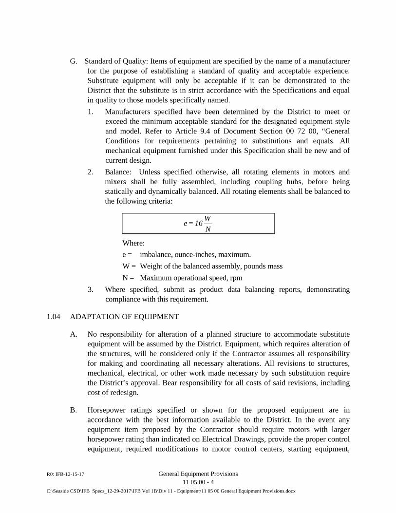
R0: IFB-12-15-17 General Equipment Provisions 11 05 00 - 4
C:\Seaside CSD\IFB Specs_12-29-2017\IFB Vol 1B\Div 11 - Equipment\11 05 00 General Equipment Provisions.docx
G. Standard of Quality: Items of equipment are specified by the name of a manufacturer for the purpose of establishing a standard of quality and acceptable experience. Substitute equipment will only be acceptable if it can be demonstrated to the District that the substitute is in strict accordance with the Specifications and equal in quality to those models specifically named. 1. Manufacturers specified have been determined by the District to meet or
exceed the minimum acceptable standard for the designated equipment style and model. Refer to Article 9.4 of Document Section 00 72 00, “General Conditions for requirements pertaining to substitutions and equals. All mechanical equipment furnished under this Specification shall be new and of current design.
2. Balance: Unless specified otherwise, all rotating elements in motors and mixers shall be fully assembled, including coupling hubs, before being statically and dynamically balanced. All rotating elements shall be balanced to the following criteria:
Where:
e = imbalance, ounce-inches, maximum. W = Weight of the balanced assembly, pounds mass N = Maximum operational speed, rpm
3. Where specified, submit as product data balancing reports, demonstrating compliance with this requirement.
1.04 ADAPTATION OF EQUIPMENT
A. No responsibility for alteration of a planned structure to accommodate substitute equipment will be assumed by the District. Equipment, which requires alteration of the structures, will be considered only if the Contractor assumes all responsibility for making and coordinating all necessary alterations. All revisions to structures, mechanical, electrical, or other work made necessary by such substitution require the District’s approval. Bear responsibility for all costs of said revisions, including cost of redesign.
B. Horsepower ratings specified or shown for the proposed equipment are in accordance with the best information available to the District. In the event any equipment item proposed by the Contractor should require motors with larger horsepower rating than indicated on Electrical Drawings, provide the proper control equipment, required modifications to motor control centers, starting equipment,
NW16=e
R0: IFB-12-15-17 General Equipment Provisions 11 05 00 - 5
C:\Seaside CSD\IFB Specs_12-29-2017\IFB Vol 1B\Div 11 - Equipment\11 05 00 General Equipment Provisions.docx
feeder and branch circuits, and accessories as required to make the installation comply with the electrical code, and to prevent excessive voltage drop, without added cost to the District.
C. Equipment: Where equipment to be furnished is installed in an existing enclosure or adjacent to existing equipment, field check the dimensions of existing equipment, location of conduits, etc., and ascertain all existing conditions and difficulties likely to be encountered in performing such work.
1.05 GUARANTEE AND WARRANTY
A. Guarantee all equipment in accordance with the Article 19 of Document Section 00 72 00, “General Conditions”. In addition to the general guarantee requirements, provide equipment guarantee covering (1) faulty or inadequate design; (2) improper assembly or erection; (3) defective workmanship or materials; and (4) leakage, breakage, or other failure. For equipment bearing a manufacturer’s warranty of more than one (1) year in length, furnish a copy of the warranty to District with District named as beneficiary. Furnish guarantees having a period commencing on the date of Substantial Completion of the Work in accordance with Section 01 30 00, “Administrative Requirements”, of these Specifications.
B. Manufacturer’s Warranties: As a precedent to final inspection, deliver to the District all the manufacturers’ warranties required by the Contract Documents, with the District named as beneficiary. In addition, for all equipment and machinery bearing a manufacturer’s warranty that extends for a longer period than the Contractor’s guarantee, secure and deliver the warranties to the District in the same manner.
1.06 CONTRACT DRAWINGS
A. The Structural, Mechanical and Electrical Drawings are diagrammatic and show the general layout of the complete construction work.
B. Determine locations of equipment, inserts, anchors, motors, panels, conduits, stub-ups, fittings, fixtures, air, water, power and process inlets, unless specifically dimensioned on the Drawings, to suit field conditions encountered. Ensure adequate and proper clearance between pipes, equipment, and similar appurtenances, without extra cost to the District.
C. Review the Drawings and Specifications of other trades and include the mechanical and electrical work shown thereon that will be required for the installations.
R0: IFB-12-15-17 General Equipment Provisions 11 05 00 - 6
C:\Seaside CSD\IFB Specs_12-29-2017\IFB Vol 1B\Div 11 - Equipment\11 05 00 General Equipment Provisions.docx
D. Should there be a need to deviate from the Mechanical and Electrical Drawings and specifications, submit written details and reasons for all changes to the Engineer for approval before making such changes. All extra costs to make the changes must be borne by the Contractor.
E. In the event of varying interpretations of the Contract Documents, the District’s interpretation shall govern.
1.07 PRODUCT DELIVERY, STORAGE AND HANDLING
A. Box, crate, or otherwise enclose and protect equipment during shipment, handling, storage, and following installation, until final acceptance of the project. Refer to Section 01 33 00 regarding requirements for submittal of manufacturer’s recommended instructions for storage. Comply with all procedures described therein. 1. Keep equipment dry and covered from exposure to weather. Store equipment
having antifriction or sleeve bearings in weather tight storage facilities. 2. Lift large equipment items only at the points designated by manufacturer. 3. Rotate shafts at minimum 7-day intervals. 4. Clean and restore to the District’s satisfaction materials and equipment
showing evidence of rust, dirt contamination or other surface or subsurface deterioration, or replace prior to installation.
B. Do not, without the District’s written consent, assign, sell, mortgage, hypothecate, or remove equipment or materials which have been installed or delivered and which may be necessary for completion of the Work.
C. Factory Painted Surfaces: Protect against impact, abrasion, discoloration, and other damage. Repair damage as directed and approved.
D. Electrical Equipment: Keep electrical equipment, controls, and insulation dry at all times. Keep heaters in equipment connected and operating until equipment is placed in operation.
E. Maintain equipment storage facilities in accordance with the provisions of Division of the Technical Specifications. Provide District access to the storage facilities at any time to inspect the equipment stored therein.
F. Store equipment in the designated storage facilities from delivery until installation.
R0: IFB-12-15-17 General Equipment Provisions 11 05 00 - 7
C:\Seaside CSD\IFB Specs_12-29-2017\IFB Vol 1B\Div 11 - Equipment\11 05 00 General Equipment Provisions.docx
1.08 JOB CONDITIONS
A. Drawings are diagrammatic and show the intended arrangement of principal apparatus, piping, and appurtenances. Conform to Drawings as closely as possible and exercise care to secure approved headroom and space conditions, neat arrangement of piping, valves, hangers, and like items, and to overcome structural interferences.
B. Verify dimensions and conditions at the place of installation, and install materials and equipment in the available space.
C. Submit written details and reasons for proposed deviations from Drawings and Specifications, and do not deviate therefrom unless authorized by Field Order or Change Order. If approved changes require alteration of structures or related work, make such alterations as approved in advance by District at no additional cost to District and/or Engineer.
PART 2 - PRODUCTS
2.01 MATERIALS AND WORKMANSHIP
A. Furnish equipment that is new and guaranteed free from defects in materials, design, and workmanship. Ascertain the conditions and service under which the equipment will operate and warrant that operation under those conditions shall be successful. Proportion all parts of the equipment amply for all stresses that may occur during fabrication, erection, and intermittent or continuous operation.
B. Design, fabricate, and assemble all equipment in accordance with the best modern engineering and shop practice. Manufacture individual parts in standard sizes and gages so that repair parts, furnished at any time, can be installed in the field. Provide like parts of duplicate units, which are interchangeable. Do not furnish equipment that has been in service at any time prior to delivery, except as required by tests.
C. Provide equipment and materials suitable for the service conditions and meeting standard specifications such as ANSI, ASME, AWWA, ASTM, NEMA, UBC, and UL.
D. Furnish iron castings, which are tough, close-grained gray iron free from blowholes, flaws, or excessive shrinkage conforming to ASTM A48, or of ductile iron conforming to ASTM A536.
R0: IFB-12-15-17 General Equipment Provisions 11 05 00 - 8
C:\Seaside CSD\IFB Specs_12-29-2017\IFB Vol 1B\Div 11 - Equipment\11 05 00 General Equipment Provisions.docx
E. Except where otherwise specified, furnish structural and miscellaneous fabricated steel used in items of equipment conforming to the Standards of the American Institute of Steel Construction. Consider all structural members subject to shock or vibratory loads. Unless otherwise specified, furnish all steel which will be submerged, all or in part, during normal operation of the equipment in a minimum nominal thickness of 1/4 inch.
F. Furnish the location of the fabricator and his shop schedule to the District prior to the beginning of fabrication so that the District can schedule shop inspection.
2.02 LUBRICATION
A. Lubricants: Provide lubricants of types recommended by equipment manufacturers, quantities sufficient for consumption prior to completion, testing, and final acceptance.
B. Lubrication Systems: Furnish lubrication systems, which ensure constant presence of lubricant on all wearing surfaces. Provide lubricant fill and drain openings, which are readily accessible. Provide easy means for checking the lubricant level. 1. Prior to testing and/or operation, lubricate the equipment with the prescribed
amount and type of lubricant as required by the equipment manufacturer. 2. Furnish equipment lubrication systems which require attention no more often
than weekly during continuous operation, do not require attention during startup or shut down, and do not waste lubricants.
2.03 STRUCTURAL STEEL FABRICATIONS – NOT USED
2.04 EQUIPMENT BASES AND BEDPLATES
A. Mount equipment assemblies on a single welded steel bedplate unless otherwise shown or specified. Provide bases and bedplates with machined support pads, tapered dowels for alignment or mating of adjacent items, adequate openings to facilitate grouting, and openings for electrical conduits. Continuously weld seams and contact edges between steel plates and shapes, and grind welds smooth.
B. Do not support machinery or piping on bedplates other than that which is factory installed.
C. Provide jacking screws in equipment bases and bedplates to aid in leveling prior to grouting.
D. Provide plates of minimum 1/4-inch thickness.
R0: IFB-12-15-17 General Equipment Provisions 11 05 00 - 9
C:\Seaside CSD\IFB Specs_12-29-2017\IFB Vol 1B\Div 11 - Equipment\11 05 00 General Equipment Provisions.docx
2.05 ANCHORS AND SLEEVES
A. Arrange for each equipment manufacturer to furnish all required anchor bolts, nuts, washers, and sleeves of adequate design for securing equipment bases to concrete bases or concrete surface. Provide anchor bolts of sufficient length to allow for 1-1/2 inches of grout under baseplates and adequate anchorage into structural concrete. Other specifically detailed lengths either shown or specified supersede this requirement.
B. Conform to designs for attachments to resist seismic forces. Provide sleeves with a diameter of at least 1-1/2 times anchor bolt diameter and of the same material as the anchor bolts. Furnish all anchor bolts, nuts, washers, and sleeves constructed of Type 316 or Type 316L stainless steel. Furnish deferred bolting devices conforming to requirements specified in Section 05 50 00, “Metal Fabrication”.
2.06 SAFETY GUARDS
A. Cover belt or chain drives, fan blades, couplings, exposed shafts and other moving or rotating parts on all sides with safety guards conforming to all Federal, state, and local codes and regulations pertaining; conform to the most restrictive requirements. Furnish safety guards free of all sharp edges and corners.
B. Use corrosion-resistant materials at least equivalent to hot-dip galvanized steel. Fabricate safety guards from 16 USS gage, or heavier, galvanized or aluminum-clad steel or 1/2-inch mesh galvanized expanded metal.
C. Design guards for easy installation and removal. Provide necessary supports, accessories, and fasteners, of hot-dip galvanized steel or stainless steel. Design guards in outdoor locations to prevent entrance of rain and dripping water.
2.07 DRIVE UNITS
A. General: Provide drive units designed with a AGMA rating and service factor suitable for 24-hour continuous duty service under operating load, constructed to preclude oil leakage around shafts. Construct drive unit housings of high-grade cast iron, welded steel, or other suitable material. Provide units having thermal rating exceeding the design load or proper cooling devices. Design all drives especially for the service for which they are to operate.
B. Motor Ratings: Provide drive motors having nameplate horsepower rating at least equal to the theoretical brake horsepower required to drive equipment under full load for conditions specified, including all losses in speed reducers and power transmission.
R0: IFB-12-15-17 General Equipment Provisions 11 05 00 - 10
C:\Seaside CSD\IFB Specs_12-29-2017\IFB Vol 1B\Div 11 - Equipment\11 05 00 General Equipment Provisions.docx
C. V-Belt Drives: (NOT USED)
2.08 GEARS
A. Provide oil-lubricated totally-enclosed gear reducers and increasers.
B. Service Ratings: Provide gears which each have a nameplate service horsepower rating equal to the nameplate rating of the driving motor. Furnish gears which each have mechanical and thermal capacity equal to or greater than an equivalent horsepower determined by multiplying the service horsepower rating by the specified service factor recommended by AGMA for heavy duty service, except each set of worm gears shall have a minimum service factor of 1.20 and all other gears shall have a minimum service factor of 1.50.
C. Thermal Rating: Obtain thermal rating for the equivalent horsepower without auxiliary cooling equipment such as heat exchangers. Design units to operate continuously for the conditions specified in a location where ambient temperatures vary from 20° to 130°F (-6.7°C to 54.4°C). If a cooling coil is required, provide minimum 1-inch diameter tubing and a 1-inch solenoid supply water valve with the gear.
D. Bearings: Provide antifriction bearings throughout, designed for 100,000 hours B10 bearing life per current AFBMA test procedures, of proportions, mountings, and adjustment consistent with acceptable modern practices for applied radial and thrust loads at speeds involved. Provide thrust bearing rates at 1-1/2 times the maximum thrust loadings involved.
E. Gear Nameplates: Equip each gear with an AGMA nameplate which shows service horsepower, actual service factor for actual mechanical or thermal rating as applicable, and AGMA gear Class I rating.
2.09 ELECTRIC MOTORS FOR MECHANICAL EQUIPMENT
A. Conform to applicable requirements specified herein and in Section 33 32 30, “Submersible Non-Clog Pumps”, as applicable.
2.10 ELECTRICAL WORK AND INSTRUMENTS
A. Perform Electrical and Instrumentation work in accordance with the applicable requirements of Division 26.
R0: IFB-12-15-17 General Equipment Provisions 11 05 00 - 11
C:\Seaside CSD\IFB Specs_12-29-2017\IFB Vol 1B\Div 11 - Equipment\11 05 00 General Equipment Provisions.docx
2.11 TAGGINGS
A. Data Plates: Provide Type 316 stainless steel data plates with a minimum thickness of 1/16-inch with embossed or preprinted lettering, fastened to the equipment in a prominent place with corrosion-resisting pins. On data plates, display manufacturer, serial number, date of manufacture, model number and essential operating characteristics. Provide letters and numbers that are not smaller than 3/16-inch height.
B. Nameplates: Provide nameplates and attach to each piece of equipment and device item to identify it. THIS REQUIREMENT WILL BE STRICTLY ENFORCED. Construct name tags to have a rectangular configuration with square corners. Size nameplates approximately 1-1/2 inches by 3 inches or larger as required for the indicated engraving. Fabricate nameplates from black lamicoid. Engrave or etch letters and numerals in the name tags not smaller than 1/4-inch high in size. 1. Provide the equipment functional name and tag number for each item of
equipment or device, as designated on the Drawings, in particular the P&IDs (E drawings), on the nameplate for the item. Provide a 3/16-inch diameter hole in the upper left-hand corner of each nameplate which shall be used to attach the nameplates to the equipment and device items with 1/8-inch thickness stainless steel chain.
2.12 PAINTING
A. Conform to applicable requirements of Section 09 90 00, “Painting and Coating”, and following requirements unless modified or superseded under other Sections of Divisions 11, 26 and 33.
B. Factory Painting: On mechanical equipment, drives, starters, control panels and other similar self-contained or enclosed components, apply a factory primer and high-quality oil-resistant baked industrial enamel finish. Paint or otherwise protect surfaces that are inaccessible after assembly by a method which provides protection for the life of the equipment.
C. Shop Priming: Apply one or more shop coats of metal primer on surfaces to be finish painted at the site, with sufficient coating thickness to protect surfaces until finish coats are applied. Use primers specified for the required paint systems in Section 09 90 00, Painting and Coating. Submit for approval the coating systems intended for use. Use shop primers for items of equipment which will receive finish coats at site which are compatible with the intended finish coating systems. Coordination of shop priming with approved coating systems is the responsibility of
R0: IFB-12-15-17 General Equipment Provisions 11 05 00 - 12
C:\Seaside CSD\IFB Specs_12-29-2017\IFB Vol 1B\Div 11 - Equipment\11 05 00 General Equipment Provisions.docx
the Contractor. Submit shop drawing which clearly indicates compliance with this requirement.
D. Rust Preventive Coating: Coat machined, polished, other ferrous surfaces, and non-ferrous surfaces which are not to be painted with rust preventive compound, Dearborn Chemical No-Ox-Id 2W, Houghton Rust Veto 344, Rust-Oleum 4-9, or equal.
2.13 UNIT CONTROL PANELS
A. Where required (e.g., submersible pumps, level sensors and engine generator), conform to the requirements of Division 26.
2.14 FLANGES AND PIPE THREADS
A. Provide flanges on equipment and appurtenances provided under this section conforming in dimensions and drilling to ANSI B16.1, Class 125. Provide pipe threads conforming in dimension and limits of size to ANSI B1.1, coarse thread series, Class 2 fit.
B. Threaded Flanges: Standard taper pipe thread conforming to ANSI B1.20.1. Unless otherwise specified, provide flat faced flanges.
C. Flange Assembly Bolts: Heavy pattern, hexagonal head, carbon steel machine bolts with heavy pattern, hot pressed, hexagonal nuts conforming to ANSI B18.2.1 and B18.2.2. 1. Threads: Unified Screw Threads, Standard Coarse Thread Series, Class 2A
and 2B, ANSI B1.1. 2.15 BEARINGS
A. Unless otherwise specified, furnish equipment bearings that are oil or grease lubricated, ball or roller type, designed to withstand the stresses of the service specified. Furnish bearings rated in accordance with the latest revisions of ABMA Methods of Evaluating Load Ratings of Ball and Roller Bearings. Unless otherwise specified, furnish equipment bearings having a minimum B-10 rating life of 100,000 hours. The rating life shall be determined using the maximum equipment operating speed.
B. Furnish grease lubricated bearings, except those specified to be factory sealed and lubricated, fitted with easily accessible grease supply, flush, drain and relief fittings. Use extension tubes when necessary. Furnish grease supply fittings of standard hydraulic alemite type.
R0: IFB-12-15-17 General Equipment Provisions 11 05 00 - 13
C:\Seaside CSD\IFB Specs_12-29-2017\IFB Vol 1B\Div 11 - Equipment\11 05 00 General Equipment Provisions.docx
C. Furnish oil lubricated bearings equipped with either a pressure lubricating system or a separate oil reservoir type system. Provide each oil lubrication system of sufficient size to safely absorb the heat energy normally generated in the bearing under a maximum ambient temperature of 600C and equip with a filler pipe and an external level indicator gage.
D. For all bearings accessible to touch and located within 7 feet measured vertically from floor or working level or within 15 inches measured horizontally from stairways, ramps, fixed ladders or other access structures, either incorporate bearing housings with sufficient cooling to maintain surface temperature at 650C or less for continuous operation at bearing rated load and a 500C ambient temperature or provide appropriate shielding that will prevent inadvertent human contact.
2.16 COUPLINGS
A. Unless otherwise specified in the respective equipment sections, on equipment with a driver greater than 1/2 HP, and where the input shaft of a driven unit is directly connected to the output shaft of the driver, employ a design having its two shafts connected by a flexible coupling which can accommodate angular misalignment, parallel misalignment and end float, and which cushions shock loads and dampens torsional vibrations. Furnish the flexible member consisting of a tire with synthetic tension members bonded together in rubber. Attach the flexible member to flanges by means of clamping rings and cap screws, and attach the flanges to the stub shaft by means of taperlock bushings which shall give the equivalent of a shrunk-on fit. There shall be no metal-to-metal contact between the driver and the driven unit. Size each coupling and provide as recommended by the coupling manufacturer for the specific application, considering horsepower, speed of rotation, and type of service.
B. Where torque or horsepower capacities of couplings of the foregoing type is exceeded, Thomas-Rex, Falk Steel Flex, or equal, couplings will be acceptable provided they are sized in accordance with the equipment manufacturer's recommendations and sizing data are submitted. Install in conformance to the coupling manufacturer's instructions.
PART 3 - EXECUTION
3.01 COORDINATION
A. The Drawings show in a diagrammatic form the arrangements desired for the principal apparatus, piping, and similar appurtenances. Follow them as closely as
R0: IFB-12-15-17 General Equipment Provisions 11 05 00 - 14
C:\Seaside CSD\IFB Specs_12-29-2017\IFB Vol 1B\Div 11 - Equipment\11 05 00 General Equipment Provisions.docx
possible. Exercise proper judgment when carrying out the work to secure the best possible headroom and space conditions throughout, to secure neat arrangement of piping, valves, fixtures, hangers, and similar appurtenances, and to overcome local difficulties and interferences of structural conditions wherever encountered.
B. Take all measurements for the work at the installation sites, verify all subcontractor drawings and ensure proper installation within the available space of the apparatus specified and shown on the Drawings. Secure the approval of the District for variations before making changes.
C. Unit Responsibility: Refer to pertinent Sections for items of component equipment to be assembled under the unit responsibility of one manufacturer. Monitor and verify the work of the responsible manufacturer and submit the following information to the District in writing monthly: 1. Shipment dates of the various components to the responsible manufacturer. 2. Scheduled dates of factory tests by responsible manufacturer. 3. Scheduled shipment dates of assembled items to site by responsible
manufacturer. 4. Scheduled arrival, installation, and start-up dates of assembled items.
3.02 EXAMINATION
A. Examine each item of equipment for damage, defects, completeness, and correct operation before installing. Examine previously installed related work and verify that it is ready for installation of equipment.
B. Notify the District in the event any equipment or material is damaged subsequent to receipt at the jobsite, and prior to acceptance by the District.
C. Do not make repairs to damaged products in lieu of replacement without prior written approval by the District.
3.03 PREPARATION
A. Prior to installing equipment, ensure that installation areas are clean and that concrete operations are completed. Maintain the areas in a broom-clean condition during installation operations. Clean, condition, and service equipment in accordance with the approved Instruction Manuals and requirements in other Sections of these Specifications before installing.
R0: IFB-12-15-17 General Equipment Provisions 11 05 00 - 15
C:\Seaside CSD\IFB Specs_12-29-2017\IFB Vol 1B\Div 11 - Equipment\11 05 00 General Equipment Provisions.docx
3.04 MANUFACTURERS’ SUPERVISION AND INSTALLATION CHECK
A. Arrange for each equipment manufacturer to furnish the services of an authorized representative especially trained and experienced in the installation of his equipment to (1) see that the equipment is installed in accordance with the approved Instruction Manual, (2) be present when the equipment is first put into operation, (3) inspect, check, adjust as necessary, and approve the installation, (4) repeat the inspection, checking, and adjusting until all trouble or defects are corrected and the equipment installation and operation are acceptable, (5) witness operational demonstrations and system validation tests to the extent specified, and (6) prepare and submit the specified Manufacturers’ Certified Report. Include all costs for representative services in the Contract Price.
3.05 INSTALLATION
A. Structural Fabrications: Conform to the AISC Code and Specification references in Division 5.
B. Equipment: Conform to approved Instruction Manuals. Employ skilled craftsmen experienced in installation of the types of equipment specified. Use specialized tools and equipment, such as precision machinist levels, dial indicators, gages, and micrometers, as applicable. Produce acceptable installations free of vibration or other defects.
C. Anchor Bolts: Deliver bolts with templates or setting drawings and verify that bolts are properly sized and correctly located before structural concrete is placed.
3.06 PLACING IN OPERATION
A. Remove internal coatings applied at the factory if required. Apply lubricant in the proper places and levels conforming to the manufacturer’s recommendations. Perform full-load operational testing, as described in Paragraph 3.08, in the presence of the District, and record results of such tests. Correct unsatisfactory performance and repeat test until the equipment performance meets the Specifications. Submit results of tests and re-tests to the District for record purposes.
B. Furnish all power, materials, services, test equipment and labor required to successfully complete all full-load equipment testing specified.
C. Certify in writing to the District, in triplicate, that all tests were conducted in accordance with these Specifications and that all components within each system successfully function as required.
R0: IFB-12-15-17 General Equipment Provisions 11 05 00 - 16
C:\Seaside CSD\IFB Specs_12-29-2017\IFB Vol 1B\Div 11 - Equipment\11 05 00 General Equipment Provisions.docx
D. Notify the District in advance of the time when the equipment will be placed into operation. Refer to Section 01 70 00, Execution and Closeout Requirements, for requirements regarding notification. During the course of initial operation, but after verifying satisfactory performance of the equipment, instruct District’s personnel in the proper operation and maintenance of the equipment.
3.07 SPECIAL TOOLS, SPARE PARTS, AND ACCESSORIES
A. Deliver to the District special tools, spare parts, equipment, and accessories required for the installation, maintenance, and operation of equipment, as well as the required number of copies each of instruction manuals necessary for the proper use of such tools, equipment, or accessories provided by the equipment manufacturer.
3.08 FIELD TESTING
A. General: Include all costs of performing operational demonstrations and system validation tests in the Contract Price. No extra payment will be made on account of overtime, weekend, or holiday labor costs required to perform and complete the demonstrations and validation tests. Requirements specified in this Paragraph 3.08 are in addition to the demonstration and test requirements specified under other Sections of these Specifications. 1. Operational Demonstration and Systems Validation Testing: Perform in
accordance with the approved procedure plans to demonstrate to the District’s satisfaction that: a. All specified components and the complete systems have been installed
satisfactorily and are operable. b. All specified component units and complete systems operate with the
efficiency, repeatability, and accuracy indicated and specified; and c. All component units and complete systems conform to the requirements
specified in the Contract Documents and the approved shop drawings, samples, construction manuals, materials lists, and other approved submittals.
2. Scope of Demonstrations and Validation Testing: Operational demonstrations and system validation tests are required for all work, equipment, and systems specified in Divisions 11, 26 and 33 of these Specifications. a. Perform operational demonstrations on all individual equipment items
such as pumps, valves, engine generators, and like equipment items. Perform demonstrations simultaneously on groups of identical
R0: IFB-12-15-17 General Equipment Provisions 11 05 00 - 17
C:\Seaside CSD\IFB Specs_12-29-2017\IFB Vol 1B\Div 11 - Equipment\11 05 00 General Equipment Provisions.docx
equipment items and groups of items supplied by one manufacturer, to the extent feasible.
b. Perform validation tests on all complete systems that perform a discrete process function of the facility such as the pumping system at each respective lift station and similar systems. Each system includes associated structures, tanks, piping, utilities, instrumentation and controls, and like related items. Validation test two (2) or more separate systems simultaneously when necessary to validate an entire discrete facility function.
3. Prerequisite Conditions: Do not commence operational demonstrations and validation testing for any equipment item or system until all related structures, piping, electrical, instrumentation, control, and like work has been installed, tested, and connected in compliance with the pertaining requirements specified elsewhere in the Specifications.
4. Demonstration and Testing Materials: Furnish materials and electrical power for operational demonstrations and validation tests. Use fresh water to fill tanks, piping, and systems that contain water, wastewater or reclaimed wastewater in normal operation. Furnish temporary facilities as required such as bypass or recirculation piping, diversions, storage, and similar facilities. Use procedures that conserve testing materials and avoid wastage, especially with respect to large quantities of fresh water and electrical power.
5. Inspection and Supervision by Manufacturers: Perform operational demonstrations and system validation testing under continuous inspection by the District. Arrange for technical representatives of the various equipment manufacturers to be present at the start of the operational demonstrations, to examine their equipment at least twice near the beginning and end of the validation tests, to supervise the start-up and adjustment procedures, and to perform all other services necessary for the manufacturer’s certified reports required herein.
6. Correction of Defects: Immediately correct all defects and malfunctions disclosed by demonstrations and validation tests using approved methods and new materials for repairs as required. Add interruption time necessary for corrective work to the specified total demonstration and validation test periods.
7. Acceptance: Satisfactory completion and approval of required operational demonstrations and system validation testing is one of the conditions precedent to the District’s acceptance of the work and does not constitute final acceptance. Refer to the Specification Section 01 70 00, of these Specifications.
R0: IFB-12-15-17 General Equipment Provisions 11 05 00 - 18
C:\Seaside CSD\IFB Specs_12-29-2017\IFB Vol 1B\Div 11 - Equipment\11 05 00 General Equipment Provisions.docx
B. Operational Demonstrations: Demonstrate that the performance of installed equipment complies with all requirements indicated and specified. Operate each equipment item through entire no-load to full-load range in accordance with the approved procedure plan for not less than 24 consecutive hours, unless a longer period is specified under other Sections.
C. System Validation Tests: Ensure equipment components of each system have successfully completed the required operational demonstration before commencing the system validation tests. Perform validation testing in accordance with the approved procedure plan. 1. Test Period: Unless specified otherwise in other Sections, test each system,
including standby systems, by continuous operation in “in-service” condition for not less than 48 consecutive hours, with no interruptions except for normal maintenance or corrective work.
2. Testing Methods: Operate systems continuously, 24 hours a day, under constant inspection of trained operators. Cycle system operation from full load to light load and back to full load each 24 hours. Induce simulated alarm and distressed operating conditions, and test controls and protective devices for correct operation in adjusting system functions or causing system shutdown.
3. Simulation of Conditions: Under special circumstances, the District may approve the simulation of certain operating conditions relating to flow rates, water levels, and malfunctions. Permission for simulations will be granted only where it is unwise or impossible to obtain the conditions covered by the capability of ranges or equipment under test conditions. Employ simulations that reasonably reflect the design operating conditions to the District’s satisfaction.
4. Ranges for Testing: a. Liquid Level Indicating Systems: Test at not less than 4 levels
corresponding approximately to low, normal, maximum and high alarm levels, respectively. Also test low-low and high-high level alarms and system reaction, where equipment or instruments, where equipment or instruments are required to react to such conditions. This includes transmission of alarm signals to a central monitoring facility
5. Automatic Response of Equipment: Demonstrate response of equipment to appropriate manual or automatic controls, or combinations of both automatic and manual controls, to be correct and accurate. Where applicable, test all components for both manual and automatic operation. Where a component performs more than one function, validate every function.
R0: IFB-12-15-17 General Equipment Provisions 11 05 00 - 19
C:\Seaside CSD\IFB Specs_12-29-2017\IFB Vol 1B\Div 11 - Equipment\11 05 00 General Equipment Provisions.docx
a. Pumping Equipment: Demonstrate equipment responds accurately and reliably to liquid level signals from the respective wet well. Also validate automatic alternation and backup pump functions.
b. Auxiliary Equipment Items, such as automatic samplers, annunciators, alarms, and like items: Demonstrate accurate and reliable response to every condition to which they are programmed, in the manner specified.
D. Data Recording: 1. Maintain neat and comprehensive records of each operational demonstration
and system validation test. Describe each portion of the demonstration or validation procedure, with all components itemized. Prepare records on forms in a step-by-step fashion paralleling the approved procedure plans. For each condition, list on the forms:
a. Step taken; b. Result anticipated; c. Result obtained; d. If result is incorrect, corrective action taken; e. Retest result; and f. Steps (d) and (e) shall be repeated until all systems operate as required.
2. Recording Devices: Employ instruments, gages, and other sensors and display devices forming a part of the various systems for data acquisition to the extent applicable. Furnish all other instruments, gages, recorders, and test devices as required, types conforming to the approved procedure plans.
3. Information and Intervals: Record all applicable data such as, but not limited to, water and other liquid levels, flows, pressures, head differentials, duration of runs, instrument readings, voltage settings, drive speeds, motor running currents, torque, voltages, gpm, pressures, and related information, as applicable, and in accordance with the approved procedure plans, at the start and finish of each operational demonstration and at maximum 8-hour intervals during system validation tests, unless shorter intervals are specified elsewhere.
4. Repetitions: When a demonstration or validation test is repeated to verify the results, indicate the repeat procedure on the recorded data by numerical indication, date, and time.
3.09 INSTRUCTION OF DISTRICT’S PERSONNEL
A. General: Conduct an instruction program for District’s operation and maintenance personnel. Provide training for the purpose of familiarizing the District’s personnel with the proper operation and maintenance of all equipment, including complete
R0: IFB-12-15-17 General Equipment Provisions 11 05 00 - 20
C:\Seaside CSD\IFB Specs_12-29-2017\IFB Vol 1B\Div 11 - Equipment\11 05 00 General Equipment Provisions.docx
overhaul. Include in the training both classroom instruction and “hands-on” instruction held at the equipment.
B. Instructors: Conduct training employing manufacturers’ factory-certified personnel from the various equipment manufacturers. Employ instructors trained and familiar with giving both classroom and “hands-on” instruction.
C. Scheduling: Conduct training after the equipment has been installed, tested and adjusted, and prior to District acceptance for beneficial occupancy or substantial completion of the respective equipment item. Training shall be a prerequisite for such acceptance. 1. Schedule instruction periods acceptable to the District, and provide formal
written notice of the proposed instruction period at least fourteen (14) days prior to commencement of the instruction period. The District will review and comment on the proposed training schedule to accommodate scheduling personnel and ongoing or forecasted workload. The duration of the training sessions may vary from one hour up through multiple days, and should be based upon the complexity of the equipment involved and the training required.
D. Instruction Program: Include in the instruction programs basic system operation theory, troubleshooting, routine maintenance and repair, “hands-on” operation of equipment, and rebuilt/overhaul procedures. Provide copies of all training material (graphs, diagrams, cutaways, charts, descriptions, instructions, etc.) used in the training sessions for the use of District’s personnel in attendance and for insertion into the instruction manuals. 1. Submit to the District a typed agenda prepared by the Instructors for each
training session with the proposed training schedule fourteen (14) days prior to the proposed commencement of the training period. District will review and comment on the adequacy of the proposed training and training schedule. Obtain District’s approval of each training session agenda prior to the start of its respective session.
2. Organize training sessions, and their respective agendas, into operational, routine maintenance, and major maintenance/overhaul topics, with the topics identified on the agenda and taught by topic grouping to allow District to coordinate personnel attendance with the topics being taught. For example, operators do not need to attend overhaul training. Include in the agenda a statement of the intended audience, list of major training topics, goals and objectives for each major training topic, and motivational statements (i.e., why is this important).
R0: IFB-12-15-17 General Equipment Provisions 11 05 00 - 21
C:\Seaside CSD\IFB Specs_12-29-2017\IFB Vol 1B\Div 11 - Equipment\11 05 00 General Equipment Provisions.docx
3. Conduct training sessions to thoroughly cover the information required in the Operation and Maintenance manuals submitted in accordance with Section 01 33 00 of the Technical Specifications and the following topics, as applicable: a. Operation, including theory of operation, start-up procedures, shutdown
procedures, instrumentation and controls. b. Lubrication, including changing of major fluids. c Operation safety. d. Emergency situation response. e. Troubleshooting. f. Preventive maintenance procedures. g. Optimizing life of equipment components. h. Maintenance, including adjustment and/or removal and replacement of
wear components. i. Overhaul and repair, including takedown procedures, disassembly and
assembly. j. Programming. k. Recordkeeping.
4. Conduct the training for overhaul and repair on mechanical equipment, and for troubleshooting, repair, and programming on instrumentation and control equipment, to provide sufficient detail, duration, and quality to result in factory certification for District’s staff receiving such training, where factory certification is available.
E. Location: Conduct training at the location of the completed work, except that training for factory certification in overhaul and major repair of mechanical equipment or for factory certification in troubleshooting, repair, and programming of instrumentation and control equipment may occur at the manufacturer’s facility at the manufacturer’s option, subject to District’s acceptance. Should the manufacturer choose to conduct this factory certification training at its facilities, arrange for and pay all costs for travel, lodging, meals, and other associated expenses for District’s staff to travel to and from, and receive training at, the manufacturer’s facility, at no additional cost to the District.
F. Recording of Training Sessions: Videotape record every session of the instruction program for each respective equipment item or system in color using DVD or CD format. Have the recording performed by a person experienced in the operation of digital video recording equipment. Take care to ensure good audio quality throughout each session. For video recording of “hands-on” training at the equipment, consider ambient noise too loud to obtain satisfactory sound quality. For
R0: IFB-12-15-17 General Equipment Provisions 11 05 00 - 22
C:\Seaside CSD\IFB Specs_12-29-2017\IFB Vol 1B\Div 11 - Equipment\11 05 00 General Equipment Provisions.docx
“hands-on” training sessions at the equipment, conduct the recording without sound and have the instructor dub a detailed narrative onto the recording by a means that will provide sound quality satisfactory to the District. Submit a proposed dubbing methodology to the District for approval prior to the first “hands-on” training session. Video recording of factory certification training that occurs at the manufacturer’s facilities is not required, but record any such training that occurs at the Contract facilities. 1. Label each DVD/CD identifying the session and respective equipment item or
system. Multiple sessions of the same instruction program may be contained on the same DVD/CD, but only record one equipment item or system on the same DVD/CD. Submit the original and one copy of each DVD/CD to the District within seven days following completion of each respective instruction program and any post-session dubbing. Coordinate and provide all equipment, including video camera or recorder and microphones, necessary to satisfactorily record each session, including all associated costs, at no additional cost to the District.
2. Factory-produced videos specific to the equipment being provided on this project may be used to fulfill this requirement, only if they cover all subjects to be presented in the training sessions.
3.10 CONSOLIDATION OF DEMONSTRATION, TESTING, AND INSTRUCTION REQUIREMENTS
A. Simultaneous performance of operational demonstrations, system validation testing, and instruction of the District’s personnel may be permitted subject to prior approval of the extent of consolidation in each case.
3.11 SOUND LEVEL TESTING AND WORKER PROTECTION
A. Measure the sound level developed by the motors on the submersible pumps at the Military and Rosita Lift Stations and the engine generator at the Del Monte Lift Station. Perform testing in spaces containing such equipment (e.g., over the wet well opening for the submersible pumps) during the final operation test program, with all equipment operating. Use an OSHA approved instrument and record the highest sound level developed when measured according to OSHA standards in each respective space. Deliver a copy of the test result records to the District.
3.12 IN-SERVICE CHECKS
A. During the guarantee period, perform an in-service check of each system required to be validation tested twice by qualified technical representatives of the various system manufacturers, including manufacturers of equipment components within
R0: IFB-12-15-17 General Equipment Provisions 11 05 00 - 23
C:\Seaside CSD\IFB Specs_12-29-2017\IFB Vol 1B\Div 11 - Equipment\11 05 00 General Equipment Provisions.docx
systems. Conduct detailed and complete checks, requiring not less than 2 hours at each site, and perform under the observation and to the satisfaction of the District or his designated representative. Include all costs for in-service checks in the Contract Price.
B. Notification: Notify the District in writing at least ten (10) days before the performance of each in-service check and obtain his approval of the proposed dates.
C. Consultation: At the time of each in-service check, consult with the District, review the O&M Manual and the pertinent operational and maintenance problems encountered, and furnish technical advice and recommendations to the District’s maintenance superintendent.
D. Schedule: Perform initial in-service checks approximately 6 months after final acceptance of the facility. Perform the second in-service check within 30 days of the end of the contractual guarantee period.
E. Reports: Deliver a written report of each in-service check, signed by the appropriate manufacturer or his representative, to the District within 10 days following the check. Describe the checking procedure in detail, and state all advice and recommendations given to the District.
3.13 PUMPS
A. This Article covers general stipulations applicable to the submersible pumps specified in Section 33 32 20. All relevant parts of this Section also apply.
B. Shop Testing: 1. General: Subject each major component of the pumping equipment to a
complete shop test as specified herein. Submit certified test reports, in triplicate, to the District. Do not ship equipment until receipt of the District’s written approval. Include all costs for the shop tests in the Bid Price.
2. Pumps: Shop test each assembled pump and drive to determine the following characteristics at the maximum speed at which the pumps are to be operated: a. Head-Capacity Curve. b. Brake Horsepower Curve. c. Efficiency Curve. d. Balance. e. Vibration. f. Bearing temperature and alignment.
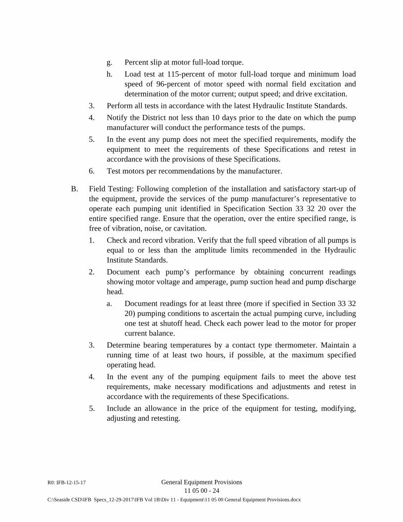
R0: IFB-12-15-17 General Equipment Provisions 11 05 00 - 24
C:\Seaside CSD\IFB Specs_12-29-2017\IFB Vol 1B\Div 11 - Equipment\11 05 00 General Equipment Provisions.docx
g. Percent slip at motor full-load torque. h. Load test at 115-percent of motor full-load torque and minimum load
speed of 96-percent of motor speed with normal field excitation and determination of the motor current; output speed; and drive excitation.
3. Perform all tests in accordance with the latest Hydraulic Institute Standards. 4. Notify the District not less than 10 days prior to the date on which the pump
manufacturer will conduct the performance tests of the pumps. 5. In the event any pump does not meet the specified requirements, modify the
equipment to meet the requirements of these Specifications and retest in accordance with the provisions of these Specifications.
6. Test motors per recommendations by the manufacturer.
B. Field Testing: Following completion of the installation and satisfactory start-up of the equipment, provide the services of the pump manufacturer’s representative to operate each pumping unit identified in Specification Section 33 32 20 over the entire specified range. Ensure that the operation, over the entire specified range, is free of vibration, noise, or cavitation. 1. Check and record vibration. Verify that the full speed vibration of all pumps is
equal to or less than the amplitude limits recommended in the Hydraulic Institute Standards.
2. Document each pump’s performance by obtaining concurrent readings showing motor voltage and amperage, pump suction head and pump discharge head. a. Document readings for at least three (more if specified in Section 33 32
20) pumping conditions to ascertain the actual pumping curve, including one test at shutoff head. Check each power lead to the motor for proper current balance.
3. Determine bearing temperatures by a contact type thermometer. Maintain a running time of at least two hours, if possible, at the maximum specified operating head.
4. In the event any of the pumping equipment fails to meet the above test requirements, make necessary modifications and adjustments and retest in accordance with the requirements of these Specifications.
5. Include an allowance in the price of the equipment for testing, modifying, adjusting and retesting.
R0: IFB-12-15-17 General Equipment Provisions 11 05 00 - 25
C:\Seaside CSD\IFB Specs_12-29-2017\IFB Vol 1B\Div 11 - Equipment\11 05 00 General Equipment Provisions.docx
3.14 EARTHQUAKE DESIGN AND RESTRAINT
A. Design, construct and attach manufactured equipment supplied under this Contract to resist stresses produced by seismic forces specified in this Section. Rigidly attach equipment that does not vibrate during normal operation. Attach equipment that vibrates during normal operation by means of isolators with mechanical stops that limit movement in all directions, unless it can be demonstrated by calculations that such stops are not required. Restrain equipment or portions of equipment that move during normal operation with mechanical devices that prevent displacement, unless it can be demonstrated by calculations that such restraints are not required.
B. Work Included: The requirements specified in this Article apply to all machinery, mechanical and electrical equipment, instrumentation panels, and electrical panels, including but not limited to: 1. Submersible Pumps (Military and Rosita Lift Stations) 2. Engine Generator (Del Monte Lift Station only)
C. Minimum Earthquake Forces: The minimum design earthquake forces shall be those prescribed by the 2013 edition of the California Building Code.
D. Submit shop drawings, details and data required by Paragraph 1.02C of this Section.
END OF SECTION 11 05 00

R0: IFB-12-15-17 General Equipment Provisions 11 05 00 - 26
C:\Seaside CSD\IFB Specs_12-29-2017\IFB Vol 1B\Div 11 - Equipment\11 05 00 General Equipment Provisions.docx
This page intentionally blank.
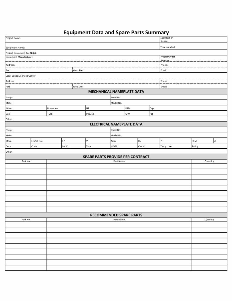
Project Name: Specfication
Section:
Equipment Name: Year Installed:
Project Equipment Tag No(s).:
Equipment Manufacturer: Project/Order
Number
Address: Phone:
Fax: Web Site: Email:
Address: Phone:
Fax: Web Site: Email:
Equip.: Serial No.
Make: Model No.
ID No. Frame No. HP RPM Cap.
Size: TDH: Imp. Sz. CFM PSI
Other:
Equip.: Serial No.
Make: Model No.
ID No. Frame No.: HP V. Amp. HZ PH RPM SF
Duty Code: Ins. Cl. Type NEMA C Amb. Temp. rise Rating
Other:
MECHANICAL NAMEPLATE DATA
ELECTRICAL NAMEPLATE DATA
Local Vendor/Service Center:
Equipment Data and Spare Parts Summary
SPARE PARTS PROVIDE PER CONTRACTPart No. Part Name Quantity
RECOMMENDED SPARE PARTSPart No. Part Name Quantity
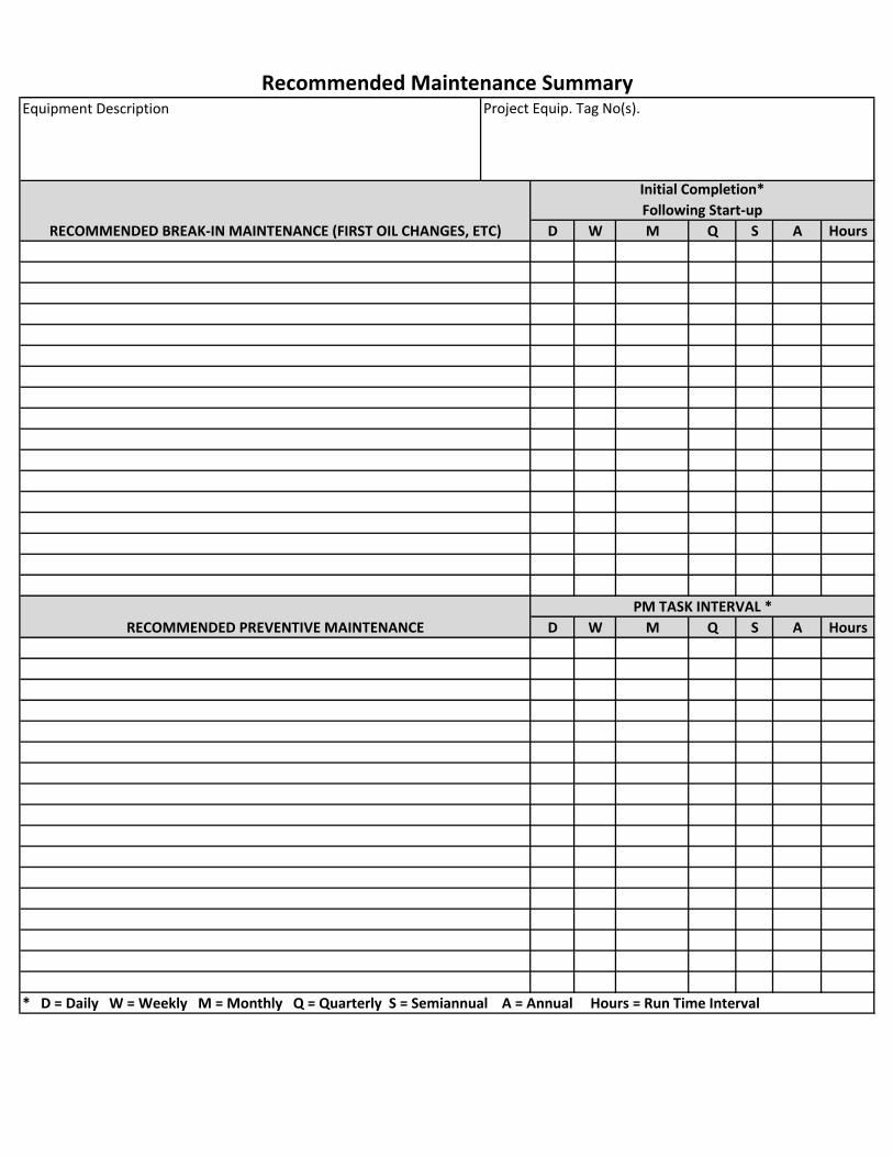
Project Equip. Tag No(s).
D W M Q S A
D W M Q S A
* D = Daily W = Weekly M = Monthly Q = Quarterly S = Semiannual A = Annual Hours = Run Time Interval
Hours
Hours
Recommended Maintenance SummaryEquipment Description
Initial Completion*
Following Start-up
RECOMMENDED BREAK-IN MAINTENANCE (FIRST OIL CHANGES, ETC)
RECOMMENDED PREVENTIVE MAINTENANCE
PM TASK INTERVAL *
DIVISION 12
FURNISHINGS (NOT USED)


DIVISION 13
SPECIAL CONSTRUCTION (NOT USED)

DIVISION 14
CONVEYING EQUIPMENT (NOT USED)

DIVISION 21
FIRE SUPPRESSION (NOT USED)


DIVISION 22
PLUMBING (NOT USED)

DIVISION 23
HEATING, VENTILATING AND AIR CONDITIONING (HVAC)
(NOT USED)


DIVISION 25
INTEGRATED AUTOMATION (NOT USED)

DIVISION 26
ELECTRICAL


Seaside Del Monte, Rosita and Military LS Electrical Specifications 1412d-260010 electrical general.doc 26 00 10-1 Electrical
SECTION 26 00 10 – ELECTRICAL GENERAL
PART 1: GENERAL
1.01 SCOPE OF WORK
A. The following list of components and areas of work is a summary of the work required in the drawings and specifications. The list is not comprehensive of the total work required nor is it in any specific order. It is merely being provided as an aid to the bidder. Work not listed herein, but described in the plans or specifications, is also part of the overall scope of work.
1. Motor Control Pedestals (3 units)
a. Utility metering and power distribution b. Motor controls. c. Transfer switch. d. Generator Receptacle e. Control Panel.
2. Bubbler Panel
3. Generator with sound attenuating enclosure and fuel tank. (2 units)
4. Control panel(s).
a. Contractor shall remove PLCs from Control Panels and provide to Application Programmer upon completion of factory testing. Purpose is for Application Programmer to complete program testing.
5. PLC and SCADA.
a. Hardware, Software, Configuration and Programming of the SCADA System is by Application Programmer – a person or entity further defined in this section.
b. Setup, configuration, programming, and integration of the Pump Station Programmable Logic Controller used in this project will be by Application Programmer.
c. Contractor shall furnish and remove PLCs from Control Panels and provide to Application Programmer upon completion of factory testing. Purpose is for Application Programmer to complete program testing.
d. PLCs will be returned to Contractor for re-installation into control
Seaside Del Monte, Rosita and Military LS Electrical Specifications 1412d-260010 electrical general.doc 26 00 10-2 Electrical
panels at the beginning of pre-operational testing
6. Communications system. Contractor to coordinate, configure, test, and place communications system(s) into operation.
7. Instrumentation
a. Mounting supports or other accessories as detailed and as recommended by the instrument manufacturer for the application.
b. Contractor shall calibrate, configure and test all instrumentation and document results.
8. Coordination and timely installation of critical path equipment and services such that construction may be facilitated. The Electrical Contractor and System Integrator should not assume that submittals, manufacturing, installation, start-up will be based on their own schedule. The Electrical Contractor and System Integrator scope of work is part of a much larger project and will need to be coordinated. Expect that additional cost in time and labor will be required beyond normal optimistic projections.
9. Conduit – support systems, wire, and grounding system, for equipment interconnection, and operation.
10. All necessary process piping, shut off, sample and calibration valves, drains, pressure reducers and calibration equipment for connection of instrumentation.
11. Trenching, backfilling, compaction and resurfacing for all new underground conduit routes, concrete pads, and pull boxes.
12. Coordination and equipment for connection of power utility and telephone services per utility drawings and standards.
13. Site electrical devices, lights and receptacles.
14. Seismic Anchorage Design Calculations and conforming installation.
15. System startup, calibration, testing and documentation.
a. The Application Programmer (defined in Electrical Specifications [Electrical General].) and/or Construction Manager will be actively engaged in Operational Testing and Commissioning. These efforts shall be combined efforts of the Application-Programmer/Construction-Manager/Engineer and Contractor.
b. The Contractor shall facilitate test as outlined herein such that
Seaside Del Monte, Rosita and Military LS Electrical Specifications 1412d-260010 electrical general.doc 26 00 10-3 Electrical
hardware, software and application programming are tested completely and all applicable test documentation is completed.
c. The Contractor shall assume that a minimum of 64 hours, project wide, will be required to assist in this task.
d. Sufficient time shall be allocated in the construction schedule for troubleshooting, testing, startup, and verification of application programming in front of associated construction milestones. For instance, if a pump station is required to be operational prior to a date certain, then the schedule shall allocate time for these activities. The time necessary depends on the system to be started and shall be coordinated with the Owner Representative or Application Programmer during construction scheduling early in the project.
B. Electro-mechanical equipment to be installed in this project may be specified in other divisions but will interface to equipment provided under Electrical Specifications. Obtain submittals for those devices, review, coordinate and provide all interfacing equipment, software, communications, I/O, and testing to integrate the equipment to the extent possible and as intended.
C. Install electrical and control portion of electro-mechanical equipment specified in other sections. Reference those specifications, pertinent details, and follow all manufacturer instructions to erect, install and commission equipment. Furnish all electrical equipment, interconnecting wire, and make connections to place equipment in operation.
D. All electrical equipment and materials, and methods - including installation, calibration, and testing - shall conform to the applicable codes and standards listed in this and other Sections. All electrical materials and work shall conform to published standards of the National Electric Code (NEC) current issue, Institute of Electrical and Electronic Engineers (IEEE), and Underwriters Laboratories Inc (UL).
1.02 RELATED SPECIFICATIONS
A. The following specification sections are part of Division 26 [Electrical Specifications].
1. Section 26 01 10 – Conduit, Boxes and Grounding 2. Section 26 01 20 – Wire, Fuses and Terminal Blocks 3. Section 26 32 13 – Engine Generator 4. Section 26 36 23 – Automatic Transfer Switch 5. Section 26 44 82 – Solid State Soft Starter 6. Section 26 66 00 – Factory and Field Testing 7. Section 26 79 05 – Control Panel 8. Section 26 79 10 – PLC & OI Hardware
Seaside Del Monte, Rosita and Military LS Electrical Specifications 1412d-260010 electrical general.doc 26 00 10-4 Electrical
9. Section 26 89 60 – Bubbler System
B. Owner, Engineer, Construction Manager, Application Programmer, and City are used within Electrical Specifications and are interchangeable. They are all representatives of the Owner, in this case, the City of Seaside.
1.03 QUALIFICATIONS AND REQURIED WORK SCOPE
A. Electrical Contractor
1. Management and installation of the entire electrical and control system (including stand-by generator) required for this project shall be by an Electrical Contractor meeting qualifications as defined herein.
a. Contractor shall be capable of looking at electrical equipment submittals, prior to installation, comparing hookup requirements to the drawings, and noting any deficiencies.
2. Electrical Contractor shall select, furnish, and install all commodity electrical materials (conduit, wire, supports, fittings, ductbanks, etc) that are generally not “custom” or uniquely manufactured for this project. Custom electrical panels, controls, and instrumentation shall be furnished by Systems Integrator.
3. Shall be competent in and familiar with management and subcontracting of specialty electrical and instrumentation supply and engineering work as requires of a Systems Integrator as described herein.
4. Electrical Contractor must be competent in performance, supervision and coordination of work required and performed by equipment suppliers and Systems Integrator (Subcontractors).
5. The Electrical Contractor (EC) shall meet the following minimum qualifications:
a. Has a current C10 Electrical Contractor’s License issued by the State of California Department of Consumer Affairs.
b. EC shall be regularly engaged in similar industrial power and controls electrical contracting for the Water and Wastewater Industry.
c. EC shall have successfully performed work of similar or greater complexity (as measured in contract value on industrial power and controls projects) on at least three (3) previous projects.
d. EC shall carry all insurances as defined and required by the special provisions and as required by law.
e. EC shall be competent in methods and materials execution and selection associated in the type of electrical and instrumentation work specified in this Division.
Seaside Del Monte, Rosita and Military LS Electrical Specifications 1412d-260010 electrical general.doc 26 00 10-5 Electrical
1) EC shall be familiar with and understand codes and requirements from NFPA70, NFPA110, and all other governing national or local codes as required for work scope as described in the drawings and specifications.
2) EC shall know and understand common terms and abbreviations used in this Industry. Not all terms and abbreviations will be defined in the drawings and specifications.
f. EC shall comply with State law which requires that all personnel installing electrical components are certified by the State of California as “Electrician” or “Electrician Trainee.” Apprentices may install electrical components only under direct supervision of a certified Electrician.
g. EC shall have sufficient qualified personnel to staff the project and meet the construction schedule as defined by the Contract requirements or as approved during the submittal process.
B. System Integrator
1. Systems Integrator shall be a supplier to the Electrical Contractor and must be competent in performance, supervision and coordination of work required in this contract.
2. This includes, but is not limited to, all work necessary to select, furnish, construct, supervise installation, configure, calibrate, test, and place into operation all transmitters, instruments, programmable controllers, control panels, motor controls, alarm equipment, communications, monitoring equipment, and accessories.
3. The System Integrator shall have on staff a Project Engineer with three years prior experience on similar sized projects. This Project Engineer shall coordinate the technical aspects of this project and prepare the submittals and drawings. The Project Engineer shall attend all coordination meetings when specifically requested by the Engineer.
4. The System Integrator (SI) shall meet the following minimum qualifications:
a. SI shall be regularly engaged providing electrical and control systems for the Municipal Water and Wastewater Industry.
b. SI shall have an Electrical Engineer on staff registered in the State of California as a Professional Engineer.
c. SI shall be capable of labeling all electrical panels as manufactured or customized by the System Integrator with appropriate UL label prior to factory testing or shipment to project site.
d. SI shall have successfully completed work of similar or greater complexity and on similar facilities on at least ten previous

Seaside Del Monte, Rosita and Military LS Electrical Specifications 1412d-260010 electrical general.doc 26 00 10-6 Electrical
projects under the present company name. e. SI shall be actively engaged in the following disciplines for the last
5 consecutive years. 1) Design and manufacturing of custom Control Panels, Motor
Controls Centers, and associated devices and equipment as specified in this division.
2) Programming and commissioning of SCADA, PLC and Operator Interface hardware.
3) Instrumentation - selection, purchase, calibration, start-up and commissioning.
4) Testing, calibration, start-up, and commissioning of control systems as applied to the Water and Wastewater industry.
f. SI shall employ personnel on this project who have successfully completed ISA or equal training courses on general purpose instrumentation.
g. SI shall have a permanent, fully staffed and equipped service facility within 200 miles of the project site for a minimum of 1 year prior to bid date with personnel and equipment required to maintain, repair and calibrate the instrumentation system.
5. The companies listed below have been determined to meet the minimum qualifications specified in this Section and are pre-qualified for performing work as System Integrators on the project. Other System Integrators may submit a statement of qualifications, proving requirements above, and listing relevant project experience on similar completed projects. Include project references with phone numbers including the Owner, Engineer and Electrical Contractor. See submittals section of this specification section.
a. Tesco Controls, Inc. (916) 395-8800 b. Wunderlich Malec (925) 460-9910 c. Cal Con Systems (925) 277-0665
C. Application Programmer
1. The Applications Programmer will be a part of the construction management team and their work is not in contract.
2. The Application Programmer work is limited to programming and configuration, and associated startup and testing services of the PLC, Operator Interface, and SCADA. All other work is by Contractor.
3. The application programmer will further define the specific portion of the station control description.
4. The Application Programmer will assist to coordinate the project program installation and testing work and further define the control descriptions.
Seaside Del Monte, Rosita and Military LS Electrical Specifications 1412d-260010 electrical general.doc 26 00 10-7 Electrical
5. The Application Programmer will attend coordination meetings when specifically requested by the Construction Manager.
1.04 CONTRACT DOCUMENTS
A. The resolution of conflicting information within the contract electrical documents shall put precedence on electrical drawings over that of electrical specifications.
B. The Drawings and specifications are intended to be descriptive of the type of electrical system to be provided with sufficient detail to construct. Minor omission of detail shall not relieve a qualified contractor from the obligation to provide a complete operational system if it can be determined that the particular detail is usual and customary for similar systems.
C. The following specifications may incorporate specific equipment or materials that do not have equal equipment listed. These items are standards because of their familiarity, serviceability, and/or spare parts inventory. However, equal alternate equipment or materials (noted in the submittal cover letter) will be considered for use on this project if submitted. The Engineer may reject said equipment for the purpose of adherence to standards.
D. Contract drawings are diagrammatic and indicate general arrangement of systems and equipment, except when specifically dimensioned or detailed. Exact locations and layouts of electrical products shall be defined during submittal, assembly, or field fit during construction. Field measurements take precedence over dimensioned drawings. Drawing intent is to show initial size, capacity, approximate location, orientation, and general relationship of equipment in area shown but not exact detail or arrangement. The requirements or descriptions in the drawings shall take precedence in the event of conflict.
E. The Contractor is encouraged to visit site and shall thoroughly examine existing conditions before submitting his bid proposal to perform any work. He shall compare site conditions with data given on the plans or in these Specifications. No allowance shall be made for any additional costs incurred by the Contractor due to his failure to examine each site or report any discrepancies to the Engineer.
F. The Contractor shall examine the architectural, mechanical, structural, and electrical and instrumentation submittals and equipment furnished under other specifications divisions in order to determine conduit routing, stub-up locations, and final terminations for all conduits and cables. Conduits shall be stubbed up as near as possible to equipment electrical terminals. The exact locations and routing of cables and conduits shall be governed by structural conditions, physical interferences, and the physical location of wire terminations on equipment. If the Contractor installs equipment conflicting with the architectural, mechanical, structural, instrumentation or electrical equipment provided under this and other specifications sections, the Contractor shall replace without additional cost.
G. All equipment shall be installed and located so that it can be readily accessed for

Seaside Del Monte, Rosita and Military LS Electrical Specifications 1412d-260010 electrical general.doc 26 00 10-8 Electrical
operation and maintenance. If accessibility appears to be compromised, the location of equipment or stub ups shall be modified to the extent possible.
H. Where conduits are shown on the Drawings, or stated to be furnished but not explicitly shown, as part of the scope of work; the Contractor shall provide all fittings, boxes, wiring, etc. as required for completion of the raceway system in compliance with the NEC and the applicable specifications in this Section.
I. No changes from the Drawings or specifications shall be made without written approval of the Engineer. Should there be a need to deviate from the Contract documents, submit written details and reasons for all changes to the Engineer for review.
J. The Contractor shall maintain a neatly and accurately marked full size set of Contract Drawings recording the as built locations and layout of all electrical and instrumentation equipment, routing of raceways, junction and pull boxes, and other diagram or drawing changes. Drawings shall be kept current weekly, with all "change orders", submittal modifications, and construction changes shown. Drawings shall be subject to the inspection by the Engineer at all times, progress payments or portions thereof may be withheld if drawings are not accurate or current.
K. When documents are changed, they shall be marked with erasable colored pencils using the following coloring scheme:
Additions - red Deletions - green Comments - blue Dimensions - black
L. Prior to acceptance of the work, the Contractor shall deliver to the Engineer one set of record full size drawings neatly marked accurately showing the information required above.
1.05 UTILITY COORDINATION AND FEES
A. All fees and charges of the Power Utility, Pacific Gas & Electric (PG&E), for design and final connection will be paid by others.
B. Coordinate all work with the Utility for the work shown on Contract Drawings.
1. Unless already completed, apply for electric service within 10 working days from Notice to Proceed.
2. Coordinate and meet with the Utility’s Representative at the project site(s) within 30 days after award of contract.
3. Discuss specific installation and comply with Utility requirements.
Seaside Del Monte, Rosita and Military LS Electrical Specifications 1412d-260010 electrical general.doc 26 00 10-9 Electrical
Contact Engineer in the event that Utility requirements far exceed allowances in the plans and specifications. Provide an itemized list of deviations and potential costs or credits.
4. Coordinate and obtain required inspections prior to backfill. Make corrections to installation as required.
5. Coordinate connection and date of service with Utility. Utility back-charges due to mis-coordination or installation problems will be Contractor responsibility to pay and correct.
C. Furnish and install electric service in accordance with the serving Utility's requirements.
1. The contract plans show the preliminary design for the Utility installation. Slight changes required by the Utility do not constitute extra work unless cost impacts in material and labor exceed $5000. In that event, the agreed excess amount will be allowed as a contract change.
2. The Contractor shall provide and install service entrance equipment, all material, conduits, wiring, pull ropes, pole risers, transformer pads, bollards, etc. as shown on Utility design drawings and standards for new power service. Utility standards are available upon request from the Utility or for download from the Utility’s website.
D. Following award of Contract, schedule all service installations and connections with utilities. Construction or start-up delays as a consequence to lack of documented effort by the Contractor which delay the project completion due to lack of Utility services will not be considered valid and Contract liquidated damages may be assessed.
1.06 PROJECT COORDINATION
A. Prior to submittal, the Electrical Contractor shall coordinate with equipment suppliers to verify sizes, mounting, connections, storage, and delivery of equipment. If there are any issues whereby the solution will be in conflict with plans and specifications, or that are undefined and need direction, they shall be brought to the attention of the Engineer or Construction Manager via the RFI process.
B. Where connections must be made to existing or new operational facilities, the Contractor shall schedule all the required work with Engineer, including the power shutdown period. Carry out each shutdown so as to cause the least disruption to the operation of the installation.
1. The Contractor shall limit all unscheduled shutdown periods to less than 15 minutes and only with prior approval of the Station operator.
Seaside Del Monte, Rosita and Military LS Electrical Specifications 1412d-260010 electrical general.doc 26 00 10-10 Electrical
2. Carry out shut downs of durations greater than 15 minutes only after the time and date schedule and sequence of work proposed to be accomplished during shutdown has been favorably reviewed by the Engineer. Submit shutdown plans at least 2 days in advance of when the scheduled shutdown is to occur.
3. Provide temporary power to all existing facilities utilizing a portable generator. The generator shall be utilized for all shutdowns that exceed 15 minutes and run continuously for the duration of the primary power shutdown. All cost for operating the generator including equipment, fuel and labor shall be provided.
4. The Engineer reserves the right to delay, change, or modify any scheduled shutdown at any time, at no additional cost to the Engineer, when the risk of such a shutdown would jeopardize the operation of the water distribution system and/or water plant operation.
1.07 SUPERVISION
A. The Contractor shall schedule all activities, manage all technical aspects of the project, coordinate submittals and drawings, and attend all project meetings associated with this Section. The Contractor shall coordinate and confirm that the project schedule is being adhered to and all work is being completed within the scheduled time frames.
B. The Contractor shall supervise all work in this Section, including the electrical system general construction work, from the beginning to completion and final acceptance.
C. The Contractor shall coordinate, obtain, prepare, and/or complete the documentation required within this division. All documentation shall be complete and delivered prior to final acceptance.
1.08 INSPECTIONS
A. General
1. Contract work or materials shall be subject to inspection at any time by the Engineer. If equipment, material, or installation method does not conform to the Contract documents, or does not have a favorably reviewed submittal status and has been determined to be unsatisfactory by the Engineer, then the Contractor shall remove said material from the premises; and if said material has been installed, the entire expense of removing and replacing same, including any cutting and patching that may be necessary, shall be borne by the Contractor.
2. The Engineer may inspect and test the fabricated equipment at the factory before shipment to job site. See Electrical Specifications [Factory and
Seaside Del Monte, Rosita and Military LS Electrical Specifications 1412d-260010 electrical general.doc 26 00 10-11 Electrical
Field Testing] for requirements.
3. Work shall not be closed in or covered over before inspection and approval by the Engineer. All costs associated with uncovering and making repairs where non-inspected work has been performed shall be borne by the Contractor.
4. The Contractor shall cooperate with the Engineer and provide assistance at all times for the inspection of the electrical system under this Contract. The Contractor shall remove covers, provide access, operate equipment, and perform other reasonable work which, in the opinion of the Engineer, will be necessary to determine the quality of the work.
B. Milestones requiring inspection and signoff.
1. Underground conduit complete. Do not cover any portion of conduit prior to inspection. Conduits must be labeled with temporary tags per Electrical Specifications [Conduit, Boxes and Grounding].
2. Factory testing. Coordinate test date with Engineer 2 weeks prior to test scheduled date.
3. Installation of electrical equipment. Equipment is anchored in place, conduit connections are complete, no wire is yet pulled into conduit. Permanent conduit tags must be in place per Electrical Specifications [Conduit, Boxes and Grounding].
4. Wire termination complete. Do not energize equipment. All wire tags must be installed and wires terminated per Electrical Specifications [Wire, Fuses and Terminal Blocks]. Pre-energization testing to commence after inspection.
5. Testing per Electrical Specifications [Factory and Field Testing]. All testing per Electrical Specifications [Factory and Field Testing] shall be witnessed unless specifically declined by the Engineer. Schedule tests with Engineer 2 weeks prior to test date.
6. Start-up per Electrical Specifications [Factory and Field Testing]. Schedule tests with Engineer 2 weeks prior to test date.
7. Punch list – final inspection. Schedule final walkthrough with Engineer one week prior to intended project completion date. All items on punchlist must be complete prior to scheduling walk-through.
1.09 JOB CONDITIONS
A. Construction Power and Telephone Service
Seaside Del Monte, Rosita and Military LS Electrical Specifications 1412d-260010 electrical general.doc 26 00 10-12 Electrical
1. The Contractor shall coordinate, furnish and install, temporary utility services required during construction of the project, such as temporary electrical power and telephone service. Temporary services shall be installed in accordance with the applicable codes and regulations of the serving utilities.
2. Upon completion of the project, remove temporary services. All equipment and material shall be the property of the Contractor.
B. Equipment Storage
1. The Contractor shall provide adequate protection for all equipment and materials during shipment, storage and construction.
2. Equipment and materials shall be completely and sufficiently sealed and covered and set on a pallet above grade so that they are protected from weather, wind, dust, water, or construction operations.
3. Equipment shall not be stored outdoors. Where equipment is stored or installed in an area with susceptibility to moisture, such as unheated buildings, untested piping, etc., provide an acceptable means to prevent moisture damage, such as plastic cover and a uniformly distributed heat source to prevent condensation.
C. The project site is located where outside temperatures vary between 10 deg F. to 110 deg F. Humidity in this area will range from 10% to 100%.
1.10 AREA CLASSIFICATIONS
A. Area classifications are shown on the site electrical plans. The area enclosed by walls or the entire drawing area shall be classified as shown unless otherwise described in notes.
B. All electrical equipment, enclosures, conduit, and supports shall be formally rated for or, at minimum, meet the intent of the rating as interpreted by Engineer.
C. If no area classification rating is shown on the drawings, classification shall default to a NEMA 12 rating for indoors, and NEMA 4 rating for outdoors (non corrosive) and NEMA 4X for corrosive areas both indoors and outdoors.
1.11 SUBMITTAL REQUIREMENTS
A. General
1. Requirements described herein are specific to electrical submittals and are secondary to those described in other general specifications sections. Any additional requirements described here that are beyond those described in those sections shall be provided as described. Conflicts shall be resolved
Seaside Del Monte, Rosita and Military LS Electrical Specifications 1412d-260010 electrical general.doc 26 00 10-13 Electrical
by giving priority to general specifications.
2. The Contractor shall ensure that the System Integrator and/or equipment suppliers provide the submittal documentation required in this section. Submittals shall be neat, orderly, complete (without un-needed parsing), and indexed.
a. Like equipment shall be submitted complete in a single submittal. For instance, all general electrical materials shall be in a single submittal. All instrumentation, all control panels, or all MCCs and so on shall be submitted complete where possible.
b. Submittals that are broken down without sufficient cause will be rejected for future inclusion into a combined submittal.
c. Do not separate submittals by area.
d. Do not separate submittals by specification division unless agreed to in advance.
e. Submittals for work scope covered in this contract are expected to be as follows. This list is intended to be a guideline and not to be specific of all submittals required. Project circumstances or leadtimes or availability will each impact the order and division of submittals.
1) General electrical materials – conduit, wire, labels, etc. 2) Power Distribution and Motor Controls 3) PLC and Control Panels 4) Engine Generator 5) Seismic Calculations 6) Instrumentation 7) Factory and Field Testing forms and procedures 8) Installation details or procedures 9) O&M Manuals
3. The Contractor shall coordinate submittals with the work so that project will not be delayed. This coordination shall include scheduling the different categories of submittals, so that one will not be delayed for lack of coordination with another. Time extensions will not be allowed due to failure to properly schedule submittals.
4. No material or equipment shall be delivered to the job site until the submittal for such items has been reviewed by the Engineer and marked "no exceptions noted" or "make corrections noted".
5. The equipment specifications have been prepared on the basis of the equipment first named in the Specifications. The Contractor shall note that the second named equipment, if given, is considered acceptable and equal equipment, but in some cases additional design, options, or modifications
Seaside Del Monte, Rosita and Military LS Electrical Specifications 1412d-260010 electrical general.doc 26 00 10-14 Electrical
may be required to meet Specifications or functional installation.
6. Exceptions to the Specifications or Drawings or equipment or procedures submitted as “equal” to specified equipment shall be clearly identified in a letter at the front of the submittal. Submittal data for “equal” equipment or procedures shall contain sufficient details so a proper evaluation may be made by the Engineer. The Contractor is responsible for verifying proper application/operation of substituted equipment.
7. The opinion of the Engineer will be the final determination whether a substitution request meets the design intent.
8. Deviations from the Contract documents shall not be incorporated into the work without prior written approval of the Engineer. A "Change Order" directive from the Engineer is required prior to incorporating any deviation from the Contract documents that has costs associated. The cost differential associated with this change order must be negotiated with the Engineer to amend the Contract to reflect the costs or savings.
B. Submittal Procedures
1. Identify all submittals by submittal number on letter of transmittal. Submittals shall be numbered consecutively and resubmittals shall have a letter suffix. For example:
a. 1st submittal: 1 b. 1st resubmittal: 1A c. 2nd resubmittal: 1B, etc.
2. Shop documents and drawings shall be submitted for all devices and components in the electrical system. The Contractor is notified that this is a “Fast Track” project and all electrical & instrumentation drawings shall be submitted in a timely manner as not to delay completion of the project.
3. Within 30 calendar days after contract award, the Contractor shall furnish to the Engineer all submittals (electronic) required for this Division. Interconnection drawings, training documents test procedures, and O&M Manuals as applicable shall be submitted timely as to not delay the project.
a. Submittals shall be delivered entirely electronically via email (no hard copy required). However, General Contractor supervision must not be circumvented by sending submittals direct to Engineer.
b. Electronic Submittals shall be viewable using a PDF reader.
c. Electronic (PDF) submittals must follow all applicable requirements for indexing, bookmarks, highlighting, selection
Seaside Del Monte, Rosita and Military LS Electrical Specifications 1412d-260010 electrical general.doc 26 00 10-15 Electrical
indicators (box, highlight) etc. Use of native PDF files (not scans) are required if one exists on the World Wide Web (WWW).
4. Submittal Preparation
a. Electronic submittals shall be assembled in accordance with the specifications with table of contents, bookmarks, tabs, subtabs, etc. utilizing the electronic bookmarks feature available in the PDF assembler. Only one PDF file is allowed for each submittal. Multiple (.PDF) files will not be acceptable.
b. Use of native PDF files (not scans) are required if one exists on the www. Ignoring this requirement is cause for submittal rejection.
c. Submittal shall be appropriately labeled with the project name, contract number, equipment supplier's name, specification section(s), and major material contained therein.
d. An index shall be provided. This index shall itemize the contents of each tab and subtab section.
e. Field equipment shop documents, panel equipment shop documents, drawings, and bill of materials shall be grouped under separate tabs. Shop documents shall be ordered in the same sequence as their corresponding Contract specification subsection.
f. All spare parts shall be listed separately at the end of the Bill of Materials list.
g. Data summary sheets shall be provided for each individual piece of instrumentation. The data summary sheets shall have the following information preceding their corresponding catalog data:
1) Instrumentation type and tag name. 2) Location/description. 3) The manufacturer's model and part number with all options. 4) Range, span, units, input and output signals. 5) Description of component. 6) Contract specification subsection number reference.
5. The reviewed submittals will be annotated "Make Corrections Noted", "No Exceptions Noted", "Revise and Resubmit Noted Items", or "Rejected without Review." The following actions shall then be taken by the Contractor:
a. "No Exceptions Noted" - The Contractor may proceed with the work covered in this submittal. No resubmission is necessary.
Seaside Del Monte, Rosita and Military LS Electrical Specifications 1412d-260010 electrical general.doc 26 00 10-16 Electrical
b. “Make Corrections Noted” - The Contractor may proceed with the work covered in this submittal incorporating the changes noted. However, the Contractor shall revise the submittal in accord with the changes noted and resubmit six (6) copies of drawings, bill of materials, and catalog data denoting changes within 14 calendar days when requested by the Engineer for record keeping purposes.
c. "Revise and Resubmit Noted Items" - The Contractor shall not proceed with the work covered in this submittal. The Contractor shall revise and correct the submittal in accordance with the comments and resubmit six (6) copies within 14 calendar days for approval.
d. "Rejected without Review" submittal - The Contractor shall not proceed with the work covered in this submittal. The submittal did not address the work scope as defined by the submittal’s title or the previous submittal comments have not been addressed in full. The Contractor shall revise and correct the submittal in accordance with the specifications, and resubmit six (6) copies within calendar 14 days for approval.
6. Resubmittals shall address all comments by the Engineer. A submittal response letter shall be submitted that addresses each comment by the Engineer with a standardized response of “revised” or with a written explanation. Partial re-submittals (that do not address all comments) may be returned without review at the discretion of the Engineer.
7. The Contractor shall be responsible for the Engineer's review cost for each resubmittal in excess of the second resubmittal. These costs will be back-charged to the Contractor and will be deducted from his progress payments.
C. Electrical Equipment -- Submittal data shall be grouped by equipment type. Each submittal shall be as complete as possible covering the entire project and scope of supply. Drawings or equipment submitted individually that are not on the critical path will not be accepted for individual review. The electrical submittals shall include (as a minimum):
1. Table of Contents
2. Comment Letter: The Project Engineer of the System Integrator shall note all deviations from Contract Documents and the reason(s) for the deviation. They may use this forum to inform the Engineer or installing Contractor of important information related to the project. RFIs must be submitted separately. Re-submittals shall include written responses to every comment provided by the engineer during the previous review.
3. Bill of Materials: The Contractor and System Integrator each shall
Seaside Del Monte, Rosita and Military LS Electrical Specifications 1412d-260010 electrical general.doc 26 00 10-17 Electrical
provide Bill of Material for electrical components formatted as shown below. Generic names or part numbers as defined by a distributor or Integrator are not acceptable. Only the originating manufacturer’s name and part number shall be listed. Provide separate bill of materials for each panel, MCC, instrument list, etc.
Bill of Material
Item # Qty Tag# Description Manufacturer Part #
4. Shop Drawings:
a. Equipment elevations with enclosure details drawn to scale or dimensioned with relative scale.
b. Electrical One-line, Elementary, and wiring diagrams c. PLC I/O wiring diagrams
5. Catalog Data shall include the following: (features and options shall be highlighted, circled, or “arrowed.”)
a. Instrumentation data summary sheets (by Contractor) b. Manufacturer’s technical information brochure c. Physical size and mounting details and illustrations d. Calibration Range e. Input/output signals f. Electric power, air, and/or water supply requirements. g. Options selected and available (Cross out items not included) h. Materials of construction of components
D. Shop Drawings - Shop drawings shall be furnished for each electrical panel even if one was not shown explicitly on the Drawings. Shop drawings shall be numbered in sequence. Blank drawings or drawings that contain no specific project data will not be accepted for review.
All drawings shall be generated with a computer utilizing AutoCAD or similar drafting program. Drawings shall be no smaller than 11" x 17". The lettering shall be legible and no smaller than 0.75 inch in height.
Drawings shall be custom prepared for this project and shall have borders and a title block identifying the project, manufacturer, system or location, drawing number, drawing title, AutoCAD file name, project engineer, date, revisions, and type of drawing. Diagrams shall carry a uniform and coordinated set of wire colors, wire numbers, and terminal block numbers. The shop drawings shall include the following as a minimum:
1. Electrical one-line diagrams detailing all devices associated with the
Seaside Del Monte, Rosita and Military LS Electrical Specifications 1412d-260010 electrical general.doc 26 00 10-18 Electrical
power distribution system. The following applicable information or data shall be shown on the one- or three- line diagram: location, size and amperage rating of bus; size and amperage rating of wire or cable; breaker ratings, number of poles, and frame sizes; power fail and other protective devices; fuse size and type.
2. Detailed analog and digital I/O diagrams showing the wiring requirements for each instrument or device connection. Reference the Drawings for an example of each I/O card drawing requirements. If one is not included in the Drawings, then one may be obtained from the Engineer upon request.
3. Elementary (wiring) diagrams shall be provided for all relay logic, programmable logic controls, motor controls, power supplies, and other wiring. All elementary (wiring) diagrams shall be drawn in JIC EMP/EGP format and standards showing ladder rung numbers and coil and contact cross referencing numbers.
4. Equipment exterior and interior scaled drawings of front, side, elevation, deadfront, front panel devices, and backpan components. Show fabrication methods and details; including material of construction, paint color, door latch and lock, and ventilation system. Show shipping split locations and offloading information. Submit base plan showing allowed conduit entrance areas and bolt hole locations.
5. Drawings shall show UL required information as needed to UL label the equipment in accordance with UL procedures for label applied.
6. Submit full size drawing of all nameplates and tags, as specified herein, to be used on project. Submittal to include the following:
a. Dimensions of nameplate. b. Exact lettering and font for each nameplate. c. Color of nameplate. d. Color of lettering. e. Materials of construction. f. Method and materials for attachment. g. Drawing showing location of nameplates on each, panel and
enclosure.
E. Seismic Anchor Design Calculations
1. All switchgear, motor controls centers, transformers, cabinets, raceways, supports, and electrical materials shall be so installed as to remain in a secure and captive position when subjected to a horizontal force in accordance with the current, applicable, and more stringent of California Building Code (CBC) or International Building Code (IBC) requirements. Method of securing shall constrain equipment against both vertical and horizontal forces and overturning forces.
Seaside Del Monte, Rosita and Military LS Electrical Specifications 1412d-260010 electrical general.doc 26 00 10-19 Electrical
2. Calculations as prepared by a structural engineer registered in the State of California shall be submitted in accordance with code requirements for earthquakes forces on all specified equipment. Calculations shall include wind loading forces for equipment installed outdoors.
1.12 OPERATING AND MAINTENANCE INFORMATION
A. Operational Training
1. At time of completion, the Contractor shall provide a period of not less than 6 hours training for instruction of operation and maintenance personnel in the use of systems. Instruct all personnel at one time in one session. Make necessary arrangements with manufacturer's representative. Provide product literature and application guides for user's reference during instruction.
B. Operations and Maintenance Manuals
1. Provide Operation and Maintenance manuals per specifications as described in “Submittal Requirements” in this section with the following additional requirements:
a. A comprehensive index.
b. A complete "Record" set of favorably reviewed electrical submittals as provided under subsection “Submittal Requirements” illustrating all components, piping, and electrical connections.
c. A complete list of the equipment supplied, including serial numbers, ranges, catalog cuts, and pertinent data.
d. Full specifications on each item.
e. Detailed service, maintenance and operation instructions for each item supplied. Schematic diagrams of all electronic devices shall be included. A complete parts list with stock numbers shall be provided for the components that make up the assembly. All of these shall be originals, no copies.
f. Special maintenance requirements particular to this system shall be clearly defined, along with special calibration and test procedures.
2. Submit electronic readable PDF file format (CD disk copies (2) or email attachments) of the proposed O&M manuals for review by the Engineer. Submittals shall be delivered timely to the Engineer to allow for review period, corrections, and re-submissions as necessary.
a. General Contractor supervision must not be circumvented by sending submittals direct to Engineer.
Seaside Del Monte, Rosita and Military LS Electrical Specifications 1412d-260010 electrical general.doc 26 00 10-20 Electrical
b. O&M Submittals shall be published 1st electronically and 2nd on hard copy paper stock.
c. Electronic Submittals shall be transmitted with the hard copy submittals and be viewable using a PDF reader.
d. Electronic submittals shall be assembled in accordance with the specifications for hard copy submittals with table of contents, bookmarks, tabs, subtabs, etc. utilizing the electronic bookmarks feature available in the PDF assembler.
e. Electronic (PDF) submittals must follow all applicable requirements for hard copy submittals including indexing, item selection indication, bookmarks, etc.
3. Provide four (4) hard copy O&M manuals per specifications as described in SUBMITTALS REQUIREMENTS in this section.
a. Deliver approved hard-copy O&M manuals to the project site and Owner prior to pre-operational testing or equipment start-up.
C. At the end of the project hard copy and soft copy electronic PDF files, shall be updated to "as-built" conditions.
D. Provide two (2) sets of compact disk (CD) containing all shop drawings, application programs, configurations, calculations, documents or other computer electronic files prepared for this project in native file format and updated to reflect as-built conditions.
PART 2: PRODUCTS
2.01 QUALITY
A. All equipment and materials shall be new, in current production, and the products of reputable suppliers having adequate experience in the manufacture of these particular items. For uniformity, only one manufacturer will be accepted for each type of product.
B. Products specified that have become obsolete (out of current manufacturing, or have been superseded by another product) shall be cross-referenced to a replacement product(s) and provided in lieu of the specified product(s) for no additional cost. Under no conditions, shall products be submitted or furnished that are known (on manufacturer’s list of obsolescence) and expected to be removed from current production within 12 months after project submittal. Products found to have been furnished this way will be removed and replaced at Contractor’s expense.
C. All equipment shall be designed for the service intended and shall be of rugged
Seaside Del Monte, Rosita and Military LS Electrical Specifications 1412d-260010 electrical general.doc 26 00 10-21 Electrical
construction, of ample strength for all stresses which may occur during fabrication, transportation, erection, and continuous or intermittent operation. All equipment shall be adequately braced and anchored and shall be installed in a neat and workmanlike manner. Appearance and safety, as well as utility, shall be given consideration in the design of details. All components and devices installed shall be standard items of industrial grade, unless otherwise noted, and shall be of sturdy and durable construction suitable for long, trouble free service. Light duty, fragile and competitive grade devices of questionable durability shall not be used.
D. The Contractor should expect that there will be occasional freezing conditions at the project site in outdoor locations. Instrument valves, tubing, instrumentation, and other components, etc. which are outdoors and susceptible to damage if frozen, must be provided with internal or external protection. Freeze protection can consist of internal or external active heaters with thermostats and/or passive insulation systems. Active systems can be powered from a nearby receptacle or via the conduit intended for the device.
E. Products that are specified and include a manufacturer, trade name or catalog number are intended to establish a standard of quality, performance, warranty and service. Products that are specified “or equal,” do not prohibit the use of equal products of other manufacturers provided they are submitted, identified and promoted as equal, and favorably reviewed by the Engineer prior to procurement and installation.
F. Products submitted as “equal” to the named products will be reviewed for conformance with the specifications and in comparison with the first named product. If the equal product meets specifications, but does not have a feature or performance characteristic that is available with the first named product, and that feature or performance is required for this project, then the submitted equal product may be rejected on those grounds.
G. In the event that some claims of the manufacturer of submitted “equal” product are called into question by the Engineer, the Contractor, may be required to prove those claims either prior to installation or during startup of product. If the product does not meet the claims made or specifications, the product may be rejected by the Engineer and a replacement product must be submitted by the Contractor in its place. All cost for the rejected product, installation, testing, and removal will be the responsibility of the Contractor.
H. Underwriters Laboratories (UL) listing is required for all substituted equipment when such a listing is available for the first named equipment. Extra parts, labor, panel space, power supplies, GFIC devices shall be provided as necessary for incorporation of specified non-UL components.
I. When required herein or requested by the Engineer, the Contractor shall submit equipment or material samples for test or evaluation. The samples shall be furnished with information as to their source and prepared in such quantities and
Seaside Del Monte, Rosita and Military LS Electrical Specifications 1412d-260010 electrical general.doc 26 00 10-22 Electrical
sizes as may be required for proper examination and tests, with all freight and charges prepaid. All samples shall be submitted before shipment of the equipment or material to the job site and in ample time to permit the making of proper tests, analyses, examinations, rejections, and resubmissions before incorporated into the work.
2.02 NAMEPLATES & TAGS
A. Equipment exterior nameplates - Nameplate material shall be rigid laminated black plastic with beveled edges and white lettering; except for caution, warning, and danger nameplates the color shall be red with white lettering. The size of the nameplate shall be as shown on the drawings. No letters are allowed smaller than 3/16". All nameplates located outdoors shall be UV resistant. Securely fasten nameplates in place using two stainless steel screws type, 316L, if the nameplate is not an integral part of the device. Epoxy cement or glued on nameplates will not be acceptable. Engrave the nameplates with the inscriptions as approved by the Engineer in the submittal.
1. For each major piece of electrical equipment provide a manufacturer's nameplate showing the Contract specified name and number designation, and pertinent ratings such as voltage, # of phases, ratings, etc.
2. For each device with a specific identity (pushbutton, indicator, instrument, etc.) mounted on the exterior or deadfront of a piece of equipment provide a nameplate with the inscription as shown on the Drawings and described herein.
3. Where no inscription is indicated on the Drawings or described herein, furnish nameplates with an appropriate inscription providing the name and number of device.
4. Install Safety Signs in accordance with the latest OSHA requirements.
a. Entrances to electrical rooms and stations: Danger Sign requirements, ELECTRICAL ROOM, HIGH VOLTAGE (define voltage, example 480 VAC) KEEP OUT, AUTHORIZED PERSONNEL ONLY.
b. Equipment enclosures, cable tray and wireway where 120 VAC or higher and 50 V DC and higher exist: Danger Sign requirements, HIGH VOLTAGE (define voltage, example 480 VAC) AUTHORIZED PERSONNEL ONLY.
c. Equipment such as motor control centers, control panels, etc., where more than one source may be present in an enclosure or cubicle: Danger Sign requirements, VOLTAGE (define voltage, example 120 VAC control voltage or 480 VAC power) FROM MULTIPLE SOURCES IN THIS ENCLOSURE.
Seaside Del Monte, Rosita and Military LS Electrical Specifications 1412d-260010 electrical general.doc 26 00 10-23 Electrical
d. Equipment such as switchboards, switchgear, panelboards and motor control centers: Warning Sign requirements, WARNING, SERVICE ENTRANCE DISCONNECT FOR 1 OF ___ (define quantity) SERVICES TO THIS BUILDING. OTHER SERVICE ENTRANCE DISCONNECTS ARE LOCATED AT (define locations).
5. Caution, warning and danger nameplates shall be red with white lettering
B. Equipment Interior Nameplates - Nameplate material shall be clear plastic with black machine printed lettering as produced by a KROY or similar machine; except caution, warning, and danger nameplates shall have red lettering. The size of the nameplate tape shall be no smaller than 1/2” in height with 3/8" lettering unless otherwise approved by the Engineer. Securely fasten nameplates in place on a clean surface using the adhesion of the tape. For each device with a specific identity (relay, module, power supply, fuse, terminal block, etc.) mounted in the interior of a piece of equipment provide a nameplate with the inscription as shown on the Drawings and described herein. Where no inscription is indicated on the Drawings or described herein, furnish nameplates with an appropriate inscription providing the name and number of device used on the submittal drawings. Stamp the nameplates with the inscriptions as approved by the Engineer in the submittal.
C. Equipment Tags - When there is no space or it is impractical to attach an engraved plastic nameplate with screws, as is the case with most field devices and instruments, the Contractor shall attach a tag to the equipment with the same inscriptions as specified above in paragraph A. The tag shall be made from stainless steel material and the size of the nameplate shall be no smaller than 3/8"h x 2"w with 3/16" machine printed or engraved lettering unless otherwise approved by the Engineer. The tag shall be attached to the equipment with stainless steel wire of the type normally used for this purpose.
2.03 FASTENERS
A. Fasteners for securing equipment to walls, floors, or ceilings, shall be stainless steel. The minimum size fastener shall be 3/8 inch diameter.
2.04 COMPONENTS
A. Switches and Pushbuttons
1. Switches (HS) and pushbuttons (HC) for general purpose applications shall be water and oil tight as defined by NEMA 4X, corrosion resistant as defined by NEMA ICS 6-110.58, U.L. listed, standard 30 mm diameter, with plastic holding nut.
2. Switches and pushbuttons shall have contacts rated NEMA A600 or 10 amperes continuous and 600 VAC. Provide NO and NC contacts as required.
Seaside Del Monte, Rosita and Military LS Electrical Specifications 1412d-260010 electrical general.doc 26 00 10-24 Electrical
3. Engraved black legend plates shall be provided to define each switch and pushbutton function.
4. Selector switch handles and pushbutton caps shall be black unless otherwise noted on drawing. Lock-out stop caps shall be red.
5. Selector switches for hand-off-auto (HOA) applications shall have the hand position to the left, off in center, and auto in the right position.
6. Pushbuttons and selector switches in hazardous locations shall have hermetically sealed contacts or explosion proof enclosures.
7. Lockout stop pushbuttons shall include padlocking attachment. Pushbutton type shall be coordinated with padlock attachment type.
8. Switches and pushbuttons shall be Allen-Bradley 800H, or equal.
B. Indicating Lights
1. Indicating Lights for general purpose applications shall be NEMA 4X, corrosion resistant as defined by NEMA ICS 6-110.58, U.L. listed, 30 mm diameter, with plastic lens, plastic holding nut, and miniature bayonet lamp base.
2. Lamp shall be full voltage 120 VAC with 28 chip (min) High Intensity LED.
3. Indicating lights shall have contacts rated NEMA A600 or 10 amperes continuous and 600 VAC. Provide NO and NC contacts as required.
4. Engraved black legend plates shall be provided to define each lights function.
5. Indicating light type and color of lens shall as follows or as otherwise shown on the Drawings:
a. Open/On Green b. Closed/Off Red c. Alarm Amber or Blue d. Power On White
6. Indicating lights designated "PTT" on wiring diagram or shown with push-to-test wiring shall be provided with a push-to-test switch and wiring.
7. Indication lights shall be Allen-Bradley 800H, or equal.
C. Relays and Timers
1. General: Relays and timers shall be provided with N.O. or N.C. contacts
Seaside Del Monte, Rosita and Military LS Electrical Specifications 1412d-260010 electrical general.doc 26 00 10-25 Electrical
as shown on the Drawings. All spare contacts shown shall be provided. Contacts shall be rated 10 amps minimum at 120 VAC, 60 Hz unless otherwise shown on the Drawings. Coil voltage shall be 120 VAC unless otherwise described or shown on the Drawings. Relays and timers shall be designed for continuous duty. All relays shall be U.L. listed. All relays and sockets shall be the product of a single manufacturer. The following is a summary of abbreviations associated with relays and timers:
CR – Control relay TR – Timing relay TDOE – Time delay on energization TDOD – Time delay on de-energization PR – Power Relay PFR – Phase Fail Relay
2. Sockets for plug-in relays and timers shall be standard industrial type din rail mount with barrier type pressure plate screw terminals. Sockets shall be rated 300 VAC, 10 amps minimum.
a. Blade 8 or 11 pin for coil voltage above 90 volts AC or DC.
b. Octal 8 or 11 pin for coil voltage below 90 volts AC or DC.
3. Control relays (CR) shall be plug-in type with neon indicating lights and clear see-through sealed housing to exclude dust. Provide IDEC Type RR, or equal. Two form-C contacts (minimum) shall be provided on each relay.
4. Time delay relays on energization (TR-TDOE) shall be solid state plug-in relays with adjustable timer ranges from 1 second to 10 hours selectable unless other ranges are shown. Provide LED timer energized indicator lamp. Time delay relays shall be IDEC RTE, or equal.
5. Time Delay Relays (TR-TDOD)
a. Time delay relays on de-energization (TR-TDOD) (continuous power control input) shall be solid state plug-in relays with a timer adjustable range from 1 second to 10 hours selectable unless other ranges are shown. Provide LED timer energized indicator lamp. Time delay relays shall be IDEC RTE, or equal.
b. Time delay relays on de-energization (TR-TDOD) (true off) shall be solid state plug-in relays with a timer adjustable range from 1 second to 10 minutes unless other ranges are shown. True off time delay relays shall be IDEC GT3F-2, or equal.
6. Power relays (PR) shall be plug-in type and clear see-through sealed
Seaside Del Monte, Rosita and Military LS Electrical Specifications 1412d-260010 electrical general.doc 26 00 10-26 Electrical
housing to exclude dust. Provide Magnecraft Type 389FXCXC-120A, or equal. 3PDT contacts rated 20A or 1 HP at 240 VAC (minimum) shall be provided on each relay. Furnish compatible blade type relay socket model 70-788EL11-1 or equal.
7. Phase fail relay (PFR) shall continuously monitor the three phases for power loss, low voltage, phase loss, and phase reversal. The PFR shall interface to the control circuit with DPDT contacts rated for 4 Amps at 120 VAC. The phase fail relay shall have a drop-out voltage adjustment, time delay adjustment, and status indicating LEDs. Phase fail relay shall be Time Mark 2652, or equal.
D. Amperage Transducer:
1. Amperage transducer shall produce 4-20mADC output directly proportional to measured current (utilizing integral CT) of the power feed. Transducer range shall be selected for the load to be measured with expected load current between 50% and 75% of available measurement range. Transducer shall measure true RMS current and have an accuracy of 5% and repeatability of 1/2% of full scale (minimum). Operating temperature range shall be -20 deg C to 50 deg C. Transducer shall have separate zero and span adjustments. Insulation between output and case shall be rated at 1000VAC. Amperage transducer shall be as manufactured by Neilsen-Kuljian (NK technologies) ATR series or equal.
2.05 MOLDED CASE CIRCUIT BREAKERS
A. GENERAL
1. Circuit breakers and motor circuit protectors shall be manufactured by Eaton Cutler-Hammer, Square D, G.E., Siemens, or equal.
2. Circuit breakers shall be the bolt-on type.
3. Multiple-pole circuit breakers shall be designed so that an overload on one pole automatically causes all poles to open. The use of tandem or dual circuit breakers in a normal single-pole space to provide the number of poles or spaces specified are not acceptable.
4. Molded case circuit breakers shall be operated by a single toggle-type handle and shall have a quick-make, quick-break switching mechanism. An automatic trip of the breaker shall be clearly indicated by the handle position. Contacts shall be non-welding silver alloy and have flash reduction arc chutes. A push-to-trip button on the front of the circuit breaker shall provide a local manual means to exercise the trip mechanism.
5. Minimum interrupting capacity:
a. 480 volt circuit breaker shall have a minimum interrupting capacity of 42,000 amperes.
Seaside Del Monte, Rosita and Military LS Electrical Specifications 1412d-260010 electrical general.doc 26 00 10-27 Electrical
b. 120 or 208 or 240 volt breaker shall have a minimum interrupting capacity of 22,000 amperes
6. Circuit Breakers protecting full voltage or solid state reduced voltage motor starters shall be motor circuit protector (MCP) breakers with adjustable magnetic trip unless otherwise noted on the drawings.
7. Circuit breakers shall be UL listed for series application.
8. Where indicated circuit breakers shall be current limiting.
9. Where indicated on drawings, provide UL listed circuit breakers for continuous duty at 100% of their ampere rating in the intended enclosure.
10. Furnish add-on features such as auxilliary position status contacts, trip indication contacts, shunt trip coils, etc, as shown in the drawings.
B. TRIP UNIT – Molded Case Circuit Breakers
1. Circuit Breakers less than 400 volt shall have thermal-magnetic (TM) trip units and inverse time-current characteristics. All other circuit breakers shall have trip units as defined herein.
2. The trip unit shall be Eaton type Digitrip 310+ or equal.
3. Each molded case circuit breaker microprocessor-based tripping system shall consist of three (3) current sensors, a trip unit and a flux-transfer shunt trip. The trip unit shall use microprocessor-based technology to provide the adjustable time-current protection functions. True RMS sensing circuit protection shall be achieved by analyzing the secondary current signals received from the circuit breaker current sensors, and initiating trip signals to the circuit breaker trip actuators when predetermined trip levels and time-delay settings are reached.
4. Interchangeable rating plugs shall establish the continuous trip ratings of each circuit breaker. Rating plugs shall non-adjustable. Rating plugs shall be interlocked so they are not interchangeable between frames, and interlocked such that a breaker cannot be closed and latched with the rating plug removed.
5. Furnish 24VDC power supply with terminal blocks and 0.5A miniature circuit breakers to distribute power to each circuit breaker trip unit that requires it. Circuit breaker trip units shall be operable and adjustable with zero current flowing through the circuit breaker. The power supply shall be connected after the main breaker and above any feeder circuit breakers.
6. System coordination shall be provided by the following microprocessor-based time-current curve shaping adjustments:
a. Adjustable long-time setting (set by adjusting the trip setting dial to an amount not to exceed rating plug)
b. Adjustable short-time setting and delay with selective flat or I2t curve shaping,
Seaside Del Monte, Rosita and Military LS Electrical Specifications 1412d-260010 electrical general.doc 26 00 10-28 Electrical
c. Adjustable instantaneous setting
d. Adjustable ground fault setting and delay with selective flat or I2t curve shaping.
7. The microprocessor-based trip unit shall have both powered and unpowered thermal memory to provide protection against cumulative overheating should a number of overload conditions occur in quick succession.
8. Furnish internal ground fault protection with adjustable settings. Provide neutral ground fault sensor for four-wire loads.
9. Breakers shall have built-in test points for testing the long-time delay, instantaneous, and ground fault functions of the breaker by means of a test set.
2.06 MOTOR CONTROL ACCESSORIES
A. Control Power Transformer:
1. Control power transformer shall be epoxy encapsulated for dust and moisture protection. The internal wiring shall be copper and have 105 deg. C insulation rating. The unit shall feature barriered screw terminals for connection to electrical circuits. Provide with time-delay, slow-blow secondary fuse rated to protect the transformer and interrupt 10,000 amperes at 120VAC. Two primary fuses rated for 480 VAC and AIC as shown in the drawings shall be provided. Transformer minimum size and voltage ratings shall be as shown on Contract drawings. Control power transformer shall be Micron Impervitran, Cutler Hammer MTE or equal.
B. Motor Starter:
1. Motor starters shall be NEMA rated of size shown on the Drawings. Coil voltage shall be 120 volts AC or as shown otherwise in elementary drawings. Provide auxiliary contacts as required per the elementary diagrams and/or as shown in the P&IDs. Motor starters shall include contactor and overload relay as a package unit or as separate pieces to accommodate for special switching requirements. Motor starters shall be Cutler Hammer Freedom, Square D, GE or equal.
C. Motor Overload:
1. External motor overload protection shall be required per drawings. External overload shall use bimetallic heating strips and provide +/-15% adjustment for full load amperage. Provide Cutler Hammer Freedom or equal.
Seaside Del Monte, Rosita and Military LS Electrical Specifications 1412d-260010 electrical general.doc 26 00 10-29 Electrical
D. Voltage monitor Relay (VMR)
1. The voltage monitor relay (VMR) shall continuously monitor the three phases for power loss, low voltage, phase loss, and phase reversal. The VMR shall interface to the control circuit with DPDT contacts rated for 4 Amps at 120 VAC. The VMR shall have a drop-out voltage adjustment, time delay adjustment, and status indicating LEDs. Voltage monitor relay shall be Time Mark 2652, or equal.
2.07 DEVICES
A. Switches
1. General purpose commercial grade switches shall be manufactured in accordance with UL 20. Switches shall be one pole, brown, 20 amps at 277 VAC, 1HP at 120 VAC, 2 HP at 240 VAC. Switches shall have copper alloy contact arm with silver cadmium oxide contacts. Switches shall have slotted terminal screws and a separate green grounding screw. Provide Leviton 1221, or equal.
B. Receptacles
1. General purpose receptacles shall be commercial grade, duplex and rated 20 amps, 120 VAC, 2 pole, 3 wire grounding, NEMA 5-20R configuration, specification grade, and side wired to screw terminals. Face color shall be brown when paired with stainless steel covers. General purpose receptacles shall be specification grade Leviton 5362-B or equal.
2. Ground fault circuit interrupter receptacles (denoted by GFI next to receptacle symbol on plan) shall be used where noted as GFI and in all boxes shown as weatherproof (WP). GFI receptacles shall be commercial grade, duplex, brown, 20A, 120V, back and side wired, with "test" and "reset" buttons. “Daisy Chain” connecting multiple receptacles from one GFI unit is not acceptable. GFI receptacles shall be Leviton 8898, Leviton MGNF2-B, Leviton 7899, or equal.
2.08 GENERATOR CONNECTION
A. Generator receptacles shall be rated 200 Amp, 480v, 3 wire, 4 pole service. The receptacle shall be reverse service and include the back box and angle adapter. The generator receptacle shall be Russel Stoll DS2504MRB00, no equal.
B. One mating plug shall be provided for customer use and connection to a generator multi-conductor cable. Provide mating plug mounted on cord and coordinated with receptacle or equal.
C. Generator Hook-up
Seaside Del Monte, Rosita and Military LS Electrical Specifications 1412d-260010 electrical general.doc 26 00 10-30 Electrical
1. Provide 3 or 4 conductor plus ground power supply cable to connect generator to building or electrical system to be powered. See electrical one-line drawings for cable amperage and conductor requirements. Cable jacket shall be UV and oil resistant PVC. Individual conductors shall have have type K stranding for flexibility and color coded, 90 deg C, 2000 Volt, EPDM insulation. Cable shall be Carol cable, Super VU-Tron II type G or equal.
a. Cable length shall be 25 feet.
2.09 UTILITY METERING PANEL
A. Metering Pedestal
1. Provide totally metal enclosed front accessible, self contained meter/main power utility metering panel. Voltage, phase, AIC and continuous amperage rating shall be as shown on Contract Drawings. Panel will include meter socket, factory installed main breaker(s) and test by-pass facility.
2. Design entrance features per NEC, local codes, and serving Utility requirements.
3. Metering enclosure shall be NEMA 3R construction for underground utility service. Enclosure shall be manufactured as shown on Contract Drawings. Enclosure shall be manufactured from 316 stainless steel. Provide pad mount, surface mount or flush mount cabinet per installation detail.
4. Reduced arc flash rating through the use of specialized circuit breakers and barriering to obtain PPE category 1 or less.
5. Utility metering enclosure shall be Tesco Type 24-200 Arc Flash, pedestal mount or equal.
B. Surge Protective Device (SPD):
1. The surge protective device shall be rated for use on a 480 VAC, 3 phase WYE system or 240 VAC, 3 phase Delta system. The nominal line voltage of the device shall be 277V L-N with a maximum continuous line voltage of 320V L-N. The unit shall dissipate a minimum of 80,000 amps single pulse surge current over a 8x20 usec period. The device shall dissipate a minimum of 2560 joules transient energy per phase. Provide external fusing as required by the manufacturer for proper operation. Furnish Leviton 32277-DY3, or equal.
2.10 RADIO SYSTEM
Seaside Del Monte, Rosita and Military LS Electrical Specifications 1412d-260010 electrical general.doc 26 00 10-31 Electrical
A. ANTENNA POLE
1. 30ft round tapered steel main section, hot dip galvanized, 11 ga steel thickness, min.
2. Welded top plate with welded 6” x 2” threaded pipe tenon with Y adapter and threaded extension pipe and lighting arrestor per details.
3. Handhole near base, 5” x 7” minimum.
4. Anchor Bolts: Galvanized with 2 hex nuts and 2 washers bolt for leveling.
5. Design information
a. IBC 2012 (MOD W/AASHTO), Exposure category C, Risk Category II.
b. Wind Velocity 130 MPH, with effective panel area (EPA) and weight as required based on radios.
c. 1 degree of movement maximum at top of pole under extreme wind conditions.
d. Designed and manufactured by Valmont Industries or equal.
B. RADIO MODEM
1. Unlicensed 5.8 Ghz radio for continuous communications to multiple addresses or point to point applications. The radio shall be system addressable to minimize interference from adjacent systems with different system addresses. The radio shall be mounted within the antenna and utilize a power over Ethernet RJ45 port for Ethernet communications and power input The radio shall operate on from included POE power supply. The radio shall provide full performance over a temperature range of -30 deg C to +60 deg C. The radio shall be the following at each site, no equal. Multiple radios may be required at each site.
a. Each station - Ubiquiti Litebeam LBE-5AC-23 dbi, no equal
2. Each radio system shall be furnished and installed complete and functional for the intended use. A radio system shall include but not be limited to, radio, antenna, mounting hardware, Ethernet cables with connectors, and an ESD protector mounted within 2 feet of radio.
2.11 LEVEL INSTRUMENTS
A. Submersible Level Transmitter (LT at Military and Rosita and Del Monte)
1. The submersible level transmitter shall be 4-20 mA loop powered with
Seaside Del Monte, Rosita and Military LS Electrical Specifications 1412d-260010 electrical general.doc 26 00 10-32 Electrical
integral manufacturer’s cable containing electrical conductors and breather tube. The transmitter electronics shall be electrically isolated from the fluid and include lightning protection and a sealed breathing system on the end of the breather tube.
2. The suspension cable shall be Oil resistant PVC insulated with #20 ga shielded wire cable with integral non-pinch breather tube. The transmitter shall be suspended from the electrical cable.
3. The calibration of the level transmitter shall be 0-34.6 ft.
4. Provide cable length to reach control panel where the termination kit shall be installed.
5. The body of the transmitter shall be corrosion resistant, all stainless steel construction. The transmitter shall have ¾” in diameter (or larger) sensing diaphragm protected by a removable stainless steel cage. The submersible level transmitter shall be Blue-Ribbon Bird Cage model BC001, APG PT-500, or equal.
B. Float Switch (LSH and LSL, all sites)
1. Float switch level detection system shall use fiber optic cable to transmit a beam of light from a transmitter in a control panel to the float. The light beam will be either returned or not returned to the transmitter/sensor depending on the tilt of the float. The transmitter/sensor shall detect the presence or absence of light and operate a relay in the receiver. The float shall have no electrical components or metallic wires that could cause arcs and sparks in an explosive atmosphere. Consequently, the device is inherently intrinsically safe. The float switch shall be polypropylene with a flexible cable consisting of dual plastic fibers. The transceiver shall include a DC power supply and operate at 12 to 24 VDC. The float switch system shall be Tesco Controls Opti-float Level Detector or equal.
PART 3: EXECUTION
3.01 CONSTRUCTION METHODS
A. Equipment shall be assembled and wired by the manufacturer prior to shipment. Field modifications or changes are not allowed without a written "change order" to the Contract. Field changes, however large or small, shall be executed using the components, materials, wiring, labeling, and assembly methods identical to that of the original supplied equipment.
B. Electrical plugs, receptacles, cords, and connectors required to power or interface the equipment and panels shall be furnished and installed by the Contractor.
C. Factory as-built drawings for each custom manufactured control panel or MCC
Seaside Del Monte, Rosita and Military LS Electrical Specifications 1412d-260010 electrical general.doc 26 00 10-33 Electrical
shall be shipped with the equipment and placed inside in waterproof envelopes.
3.02 EQUIPMENT FABRICATION
A. All electrical equipment, including custom manufactured equipment, shall meet the requirements of Underwriters Laboratories (UL) and bear the appropriate label. Panels shall be affixed with UL label prior to shipment and be built in accordance with the UL guidelines and procedure that corresponds to the UL label. Custom control equipment shall bear a UL-508 label, minimum, with additional UL labels as required per intended service.
B. Panel cutouts for devices (i.e. indicating lights, switches) shall be cut, punched, or drilled and smoothly finished with rounded edges. Exposed metal from cutouts that are made after the final paint finish has been applied shall be touched up with a matching paint prior to installing device.
C. Equipment doors shall swing freely and close and latch with proper alignment.
D. Component within the electrical equipment shall be securely mounted on an interior subpanel or backpan and arranged for easy servicing. Mounting bolts and screws shall be front mounted for device removal without special tools or removal of entire mounting panel.
E. A ground bus shall be provided in each enclosure or cabinet. It shall have provisions for connecting a minimum of ten grounding conductors. Screw type lugs shall be provided for connection of grounding conductors. All grounding conductors shall be sized as shown on plans or in accordance with NEC Table 250-95, whichever is larger.
F. Bolts and screws for mounting devices on doors shall have a flush head which blends into the device or door surface. No fastening devices shall project through the outer surfaces of equipment.
3.03 WORKMANSHIP
A. All work in this division shall conform to the codes and standards outlined herein.
B. Installation shall be performed by qualified personnel providing first class workmanship per Electrical Specifications [Electrical General, Qualifications].
C. Maintain equipment installed (or to be installed) in new condition. Protect equipment from damage while in Contractor care from dust, water, or mishaps that are typical to construction sites
D. Confirm that equipment and materials are correct for their intended duty and will be installed per manufacturer guidelines. Equipment and components found to be installed inconsistent with manufacturer guidelines and/or these specifications will not be acceptable and subject to removal and replacement.
Seaside Del Monte, Rosita and Military LS Electrical Specifications 1412d-260010 electrical general.doc 26 00 10-34 Electrical
E. Upon completion of daily work, remove excess materials, scraps, and debris from the work area and from the inside of equipment.
F. Upon notification, stop work on any portion of the installation that is determined to be non-compliant with contract or being installed by unqualified personnel.
G. Perform all work to correct improper installations at no additional cost to the owner.
H. Equipment furnished under this contract or provided to Contractor for installation shall be installed in accordance with manufacturer's instructions, installation calculations, and contract documents.
3.04 EQUIPMENT SHIPMENT AND STORAGE
A. Shipment -- Any equipment whose destination (jobsite) is more than 25 miles from the factory shall be carefully protected for shipping. All openings shall be protected by plywood securely fastened to the framework of the equipment. Equipment shall be adequately covered during local delivery.
B. Storage -- From the time of receipt until the equipment is installed and energized, the equipment shall be considered in storage. While in storage, a 120V, 1 phase source of power shall be made available and connected to space heaters in all items of equipment so equipped. Equipment not provided with space heaters shall be provided with a light bulb or electric heater while in storage to prevent moisture condensation. Unless stored indoors, it shall be a least 1 foot above grade covered with at least 2 layers of heavy polyethylene plastic sheets and anchored to prevent damage by high winds. All equipment shall be protected from dust and moisture prior to and during construction.
3.05 DAMAGED PRODUCTS
A. Damaged products that cannot be repaired to new condition shall be replaced with new products. All equipment and materials shall be in like-new condition at start-up and commissioning.
B. Minor cosmetic damage shall be repaired by spray painting, after properly preparing the surface, all scratches or defects in the finish of the equipment. Only identical paint furnished by the equipment manufacturer shall be used for such purposes.
3.06 INSTALLATION
A. General
1. Install all products per manufacturer's recommendations and the Drawings.

Seaside Del Monte, Rosita and Military LS Electrical Specifications 1412d-260010 electrical general.doc 26 00 10-35 Electrical
2. Provide all necessary hardware, conduit, wiring, fittings, and devices to connect the electrical equipment provided under other Sections.
3. Protect wiring insulation from wear by installing rubber cushions, bushings, or strip insulation, or by fastening the wiring to a rigid surface with zip ties and anchors.
4. Provide additional devices, wiring, conduits, relays, signal converters, isolators to complete interfaces of the electrical and instrumentation system.
5. Changing normally open contacts to normally closed contacts or vice versa
6. Adding additional relays to provide more contacts as necessary.
7. All programmable devices (not specifically excluded herein) shall be programmed, set-up and tested by the Contractor prior to startup. Programming and set-up parameters shall be adjusted or changed as directed by the Engineer during start-up and throughout the warranty period.
8. Coordinate with the Engineer and setup all alarm, process, and operation setpoints.
9. Keep a copy of the manufacturer’s installation instructions on the jobsite available for review at all times prior to and during the installation of the associated equipment.
B. Panels and enclosures:
1. Install panels and enclosures at the location shown on the Plans or approved by the Engineer.
2. Install level and plumb.
3. Seal all enclosure openings to prevent entrance of insects and rodents.
4. Clearance about electrical equipment shall meet the minimum requirements of NEC 110.26
C. Conduits and Ducts:
1. Install all conduits and ducts per Electrical Specifications [Conduit, Boxes & Grounding].
2. Minimum wire bending space at terminals and minimum width of wiring gutters shall comply with NEC tables 312-6 (a) & (b).
Seaside Del Monte, Rosita and Military LS Electrical Specifications 1412d-260010 electrical general.doc 26 00 10-36 Electrical
D. Wiring, Grounding, and Shielding:
1. Observe proper grounding and shielding practices as this application environment is generally noisy. The shield of shielded cables shall be terminated to ground at one end only, the origination end. The shield at the other end shall be encased in an insulated material to isolate it from ground.
E. Cutting and Patching:
1. The Contractor shall do all cutting and patching required for installing his work. Any cutting which may impair the structure shall require prior approval by the Engineer. Cutting and patching shall be done only by skilled labor of the respective trades. All surfaces shall be restored to their original condition after cutting and patching.
F. Cleaning and Touch up:
1. At the completion of the work, all parts of the installation, including all equipment, exposed conduit, and fittings, shall be thoroughly cleaned of grease and metal cuttings. Any discoloration or other damage to parts of the building, the finish, or the furnishings, due to the Contractor's failure to properly clean the system, shall be repaired by the Contractor.
2. The Contractor shall thoroughly clean any of his exposed work requiring same.
3. Vacuum and clean the inside of all electrical and instrumentation enclosures prior to applying power.
4. The Contractor shall paint scratched or blemished surfaces with the necessary coats of quick drying paint to match existing color, texture and thickness. This shall include all prime painted electrical equipment including but not limited to enclosures, poles, boxes, devices etc.
3.07 APPLICATION OF POWER
A. The Engineer will direct the energization and de-energization of all existing and new equipment. The Contractor is not authorized to energize or de-energize any equipment unless they have been given written permission to do so or while in the presence of the Engineer.
1. Any equipment that is under repair, demolition or installation shall be locked off and tagged out of service with Contractor supplied padlocks and tags.
2. The Contractor is required to comply with NFPA 70E and specifically in regards to safety when working on live equipment. Obtain work permits
Seaside Del Monte, Rosita and Military LS Electrical Specifications 1412d-260010 electrical general.doc 26 00 10-37 Electrical
when needed to do live work.
B. The Contractor is responsible for grounding of high and medium voltage cabling and/or bus during installation and removal of equipment. The contractor is responsible for complying with all California Electrical Safety Orders (ESO) and Occupational Safety and Health Act (OSHA) safety requirements and procedures while working in or near medium voltage equipment.
3.08 WARRANTY
A. The Contractor shall warrant all electrical and instrumentation equipment & software for a period of 1 year from date of final acceptance. Standard published warranties of equipment which exceed the preceding specified length of time shall be honored by the manufacturer or supplier.
B. The Contractor shall have a staff of experienced personnel available to provide on-site warranty service on 2 working days notice during the warranty period. Such personnel shall be capable of fully testing and diagnosing hardware & software and implementing corrective measures.
3.09 FINAL ACCEPTANCE
A. Final acceptance will be given by the Engineer after the equipment has passed the "final acceptance trial period", each deficiency has been corrected, final documentation has been provided, and all the requirements of Contract documents have been fulfilled.
B. At the end of the project, following the completion of the field tests, and prior to final acceptance, the Contractor shall provide the following:
1. Each "operation and maintenance" manual shall be modified or supplemented to reflect all field changes and as-built conditions.
2. Two (2) disk copies of all final documentation to reflect as-built conditions.
C. Keys: Submit two sets of all keys for locks supplied on this project. Wire all keys for each lock securely together. Tag and plainly mark with lock number or equipment identification, and indicate physical location, such as panel or switch number.
END OF SECTION
Seaside Del Monte, Rosita and Military LS Electrical Specifications 1412d-260010 electrical general.doc 26 00 10-38 Electrical
THIS PAGE INTENTIONALLY BLANK
Seaside Del Monte, Rosita and Military LS Electrical Specifications 1412d-260110 conduit boxes and grounding.doc 26 01 10-1 Conduit, Boxes and Grounding
SECTION 26 01 10 - CONDUIT, BOXES AND GROUNDING
PART 1: GENERAL
1.01 SCOPE OF WORK
A. Labor, materials, equipment, tools, safety gear, test equipment, incidentals, services, and transportation for a complete electro-mechanical installation as shown on the Drawings, included in these Specifications, or as can be reasonably implied from project descriptions.
B. The scope of work includes:
1. Furnish and install conduits, junction boxes, pull boxes, and associated hardware. Provide hardware, conduit, fittings, and other parts for a complete raceway installation.
2. Furnish and install grounding system required by drawings, or if not shown or defined, as required by Article 250 of the NEC.
3. Installations shall be designed and installed with components meeting the NEMA area designation.
C. Work includes that specified in Electrical Specifications [Electrical General].
1.02 REFERENCES
A. Electrical Specifications [Electrical General] B. Electrical Specifications [Wire, Fuses, and Terminal Blocks] C. Project Drawings
1.03 QUALIFICATIONS
A. Material furnished under this specification shall be installed by qualified installers meeting requirements specified in Electrical Specifications [Electrical General, Qualifications].
1.04 SUBMITTAL REQUIREMENTS
A. Provide submittals and drawings as specified in Electrical Specifications [Electrical General, Submittal Requirements].
Seaside Del Monte, Rosita and Military LS Electrical Specifications 1412d-260110 conduit boxes and grounding.doc 26 01 10-2 Conduit, Boxes and Grounding
PART 2: PRODUCTS
2.01 CONDUIT, RACEWAYS AND WIREWAYS
A. GENERAL - Conduit, raceways, and wireways, wiring methods, materials, installation shall meet all requirements of the NEC, be UL labeled for the application, and meet the minimum following specifications.
1. All wiring shall be installed in conduits, raceways, or wireways when interconnecting equipment and devices.
a. The minimum size conduit shall be 3/4-inch unless indicated otherwise on the Drawings or for special connections to equipment.
b. Provide cords and cord seals for devices or instrumentation requiring waterproof seal to maintain NEMA 4 or 4X ratings. Example devices include lighting and pipe mounted instruments that are located below grade.
2. Conduits may connect into junction boxes or wireways as shown in the drawings or as requested by Contractor and approved by Engineer. Junction boxes (circle with J in drawings) can be as simple as a condulet or JIC box, or larger box as determined by contractor and needed for the installation. Drawing may depict junction box requirements. Wireways or junction boxes shall be rated for area (as noted in the drawings), or furnish minimum NEMA 4 if not noted.
3. The Contractor shall use conduit material types (SPEC per conduit schedule) as defined below or as otherwise shown in the contract drawings or as specifically called out in the conduit schedule.
a. Non-exposed underground portions of conduit run shall be PVC-40 for all signals and voltages unless otherwise shown in the conduit schedule.
b. Exposed conduit material (not underground and beyond transition) shall be per the following table unless specifically noted otherwise in the plan drawings. The conduit schedule denotes the conduit type for non-exposed (under-ground, in-concrete, etc.) and does not apply or coordinate with this table. Exposed condulets, elbows, fittings, device boxes, and hardware shall be of the same material and finish as the adjacent conduit.
Location Material
NEMA 1 or 12 Galvanized rigid steel (GRS)
Seaside Del Monte, Rosita and Military LS Electrical Specifications 1412d-260110 conduit boxes and grounding.doc 26 01 10-3 Conduit, Boxes and Grounding
NEMA 3R Galvanized rigid steel (GRS)
NEMA 4 PVC-Coated Steel (GRS-PVC)
NEMA4X PVC-Coated Steel (GRS-PVC)
Class 1 Div 1 or 2 hazardous PVC-Coated Steel (GRS-PVC)
4. Conduit stubs and transitions:
a. Conduit transitions shall be GRS-PVC for 6” on either side of the transition point (minimum) or as shown in drawing details. Conduit transition is defined as conduit sections emerging from or through concrete or earth or from below to above grade or through walls or vaults, non-exposed to exposed.
b. Beneath pad mounted electrical equipment, where not exposed, shall be installed or trimmed to 2” or less above slab and have bushing or end bell installed. Overall height of conduit entering into the base of equipment shall be enough for bushings/bells to be installed but be high enough for conduit tags to be installed.
c. Uniform in height for each panel or section. Conduits end bushings/bells shall not vary in height above slab more than ½” from lowest to highest.
d. Conduits shall be spaced apart such that bushings and end bells may be installed without interfering with the adjacent conduits.
e. Transitions to PVC shall include PVC coated locknuts to shield exposed steel pipe threads.
f. Through walls – shall protrude approximately 2” and include end bell or bushing. Pack space around conduit with non-shrink grout if the thru-hole was core drilled.
g. Conduits for future use shall be capped with coupling and plug. Identify each end with conduit labels.
h. Existing conduits that are no longer able to be used due to removal of a section or shown demolished and that protrude above graded shall be cut flush and filled with grout.
5. Conduit Tags
a. All conduits listed in the “Conduit and Wire Routing Schedule” shall have conduit tags at both ends of each conduit run with tag number from schedule identified. This shall include ends within underground pull boxes.
Seaside Del Monte, Rosita and Military LS Electrical Specifications 1412d-260110 conduit boxes and grounding.doc 26 01 10-4 Conduit, Boxes and Grounding
b. All conduits shall have temporary tags during construction. Temporary tags may be made from duct tape with hand written ink marking or suitable equivalent. Temporary tags shall be removed by Contractor at time of installation of permanent tags.
c. Tag material shall be rigid laminated red plastic with white lettering. The size of the tag shall be ¼” thick by ¾” round or ¾” x 1” rectangle minimum.
d. Letter height shall be ¼” minimum. Engrave the tags with the conduit number or acronym. Labeling shall be neatly installed for visibility and shall be clearly legible. Securely fasten tags in place using 20ga stainless steel tie wire through a pilot hole on the tag.
e. Conduit tags shall be Custom manufactured per specification.
6. Supports
a. Cross section of a single channel shall be 1-5/8" x 1-5/8" and cross-section of a double channel shall be 1-5/8" x 3-1/4". The channel wall thickness shall be 12 gauge as applicable.
b. One-Hole clamps shall be intended for pipe mounting on support channels and equipped with clamp-backs. The clamps shall be Efcor, Thomas and Betts, Appleton or equal
c. Spacers, provided to support underground conduits in concrete encasements, shall be plastic. The spacers shall be Carlon, Johns-Manville, Underground Products or equal
d. Anchors shall be expansion type for securing equipment to concrete foundations, floors and walls. Anchors shall have length identification mark on the exposed end of the bolt. Provide Hilti Kwik Bolt 3, or equal.
e. Stanchions shall be provided as needed to mount equipment and electrical components. Stanchions shall be shop fabricated from welded 4” c-channel, 12” x 12” x ¼” steel base plate, coated with a rust inhibiting primer and top coat of gray polyurethane gloss paint. Attach equipment to the stanchion direct or on a ¼” aluminum sheet sized for the equipment supported.
f. Conduit Hangers shall be trapeze construction, with double channel, 3/8-inch rods and nuts. Suspend from suitable structural support.
g. Support material and finish shall be per the following table unless otherwise noted in the drawings. Brackets, fittings and hardware
Seaside Del Monte, Rosita and Military LS Electrical Specifications 1412d-260110 conduit boxes and grounding.doc 26 01 10-5 Conduit, Boxes and Grounding
shall be of the same material and finish.
Location Material Indoors NEMA 12 Galvanized steel Outdoors NEMA 3R Galvanized steel Outdoors NEMA 4 Stainless Steel type 316 Corrosive areas NEMA4X
PVC bonded, 40 mil, factory applied
h. Equipment mounting racks shall be designed by installer for rigid equipment and conduit mounting. Racks shall be bolted or welded construction and sized for equipment or as shown on the drawings.
i. Strut channels shall be used for mounting equipment to walls and for supporting conduit runs. Double strut channel type shall be used for fabricating equipment mounting racks as required and/or as detailed on the drawings. Add additional supports to rigid mounting locations as needed to prevent wobbling and to meet seismic requirements. All field cut surfaces of the strut channels shall be deburred and coated to prevent rust.
B. GALVANIZED RIGID STEEL CONDUIT - (GRS)
1. Manufactured from high-strength steel and hot dipped zinc galvanized inside and out. Conduit and fittings shall meet UL 514B, UL 6, and conform to NEMA RN 2. Conduit shall be capable of being used as an equipment grounding conductor per NEC 250.
2. Provide galvanized rigid steel factory sweeps and elbows for 90 degree transitions.
3. Cast fittings and device boxes shall be malleable iron or aluminum. Appleton type FS/FD or equal.
4. In hazardous locations, fittings shall meet and be listed UL 886.
5. All fittings, hubs, couplings, pulling elbows and connectors shall be threaded-type. Set-screw type and compression-type are not acceptable. All thread conduit is not allowed over 1/2” exposed length. Cover plates shall be cast iron with sealing gasket in NEMA 3R locations.
6. Conduits entering enclosures shall be fitted with insulated grounding bushing; O-Z "HBLG", Appleton "GIB", or approved equal. All grounding bushings shall be tied to the grounding system with properly sized bonding conductors per the NEC code.
7. Combination expansion-deflection fittings installed exposed shall be Type XD as manufactured by Crouse-Hinds Co.; Type DX as manufactured by
Seaside Del Monte, Rosita and Military LS Electrical Specifications 1412d-260110 conduit boxes and grounding.doc 26 01 10-6 Conduit, Boxes and Grounding
O.Z. Gedney Co.; Type DF as manufactured by Appleton Electric Co., or equal
C. GALVANIZED RIGID STEEL CONDUIT - PVC COATED (GRS-PVC)
1. Galvanized Rigid Steel conduit with a 40-mil thick polyvinylchloride exterior coating and a 2-mil urethane interior coating meeting NEMA RN-1, UL-6 and ETL PVC-001. The bond of the PVC to the zinc coated pipe must be stronger than the tensile strength of the PVC.
2. Provide PVC coated galvanized rigid steel factory sweeps and elbows for 90 degree transitions.
3. Cast fittings and device boxes shall be malleable iron or aluminum with a 40-mil thick PVC coating meeting the same
4. In hazardous locations, fittings shall meet and be listed UL 886.
5. Provide PVC coated threaded-type fittings, hubs, pulling elbows, couplings, and connectors; set-screw type and compression-type are not acceptable. Form 8 conduit fittings, ½” through 4”, must have a tongue-in-groove gasket to effectively seal out the corrosive elements. Covers shall be supplied with plastic encapsulated stainless steel cover screws. Form 8 fittings shall be UL and type 4X and IP69 listed.
6. A “PVC Coated Sealing Locknut” shall be used on all exposed male threads transitioning into female NPT threads which do not have sealing sleeves, including transitions from PVC couplings/female adapters to PVC Coated GRC elbows in direct burial applications. “PVC Coated Sealing Locknuts” are not to be used in place of a myers hub
7. A PVC sleeve extending one pipe diameter or two inches, whichever is less, shall be formed at every female fitting opening except unions. The inside sleeve diameter shall be matched to the outside diameter of the conduit.
8. All junction and metal pull boxes shall be galvanized with exterior surfaces PVC coated to 40 mils thickness.
9. Unistrut, strut clamps, pipe straps, and clamp back spacers, shall have 40 mil thick PVC coating. All mounting anchors shall be stainless steel.
10. Conduits entering enclosures shall be fitted with insulated grounding bushing. All grounding bushings shall be tied to the grounding system with properly sized bonding conductors per the NEC code.
11. Installers of PVC Coated Conduit must be certified by the manufacturer and be able to present a valid, unexpired certified installer card.
Seaside Del Monte, Rosita and Military LS Electrical Specifications 1412d-260110 conduit boxes and grounding.doc 26 01 10-7 Conduit, Boxes and Grounding
12. GRS-PVC conduit to be Robroy Plasti-bond, Perma-Cote, KorKap, T&B OCAL or equal.
D. PVC CONDUIT, SCHEDULE 40 or 80 (PVC-40, PVC-80)
1. Shall be high impact schedule 40 or 80 polyvinylchloride suitable for use underground, direct burial and for use with 90 C wires, and shall conform to UL 651. Shall be UL listed and labeled for "direct" burial.
2. A copper bonding conductor shall be pulled in each raceway and bonded to equipment at each end with approved lugs.
3. Each underground run shall be placed in a trench with a five (5) inch sand bed evenly compacted on all sides, top and bottom unless otherwise noted.
4. Elbows, and risers shall be per exposed conduit transition detail. PVC conduit is not allowed above ground.
5. PVC fittings shall have solvent-weld-type conduit connections. Fittings and device boxes shall be PVC with factory fabricated conduit connections. Provide Carlon or equal.
6. Conduits entering enclosures shall be fitted with a glued male adapter, lock ring and bushing to prevent wire chafing. Conduits entering panels through concrete to an open bottom or entering a pull box shall have a glued end bell fitting.
7. PVC conduit shall be stored on a flat surface and shielded from the sun.
E. LIQUID TIGHT FLEXIBLE NON-METALLIC CONDUIT (up to 2”) - (FLEX)
1. Liquid tight flexible Nonmetallic Conduit shall be constructed of flexible PVC and have a smooth inner surface with integral crush resistant reinforcement within the conduit and be designated as a Type LFNC-B (for FNMC-B).
2. Liquid tight Flexible Nonmetallic Conduit shall be sunlight, oil, and flame resistant and approved for the installation of electrical conductors in indoor and outdoor applications.
3. Liquid tight Flexible Nonmetallic Conduit shall be listed to UL standard UL1660.
4. Liquid tight flexible non-metallic conduit shall be installed in accordance with Article 351, Part B of the National Electrical Code (NEC) and other applicable sections of the NEC and/or local electrical codes.
5. Liquid tight Fittings shall be listed for the use with Liquid tight Flexible
Seaside Del Monte, Rosita and Military LS Electrical Specifications 1412d-260110 conduit boxes and grounding.doc 26 01 10-8 Conduit, Boxes and Grounding
Nonmetallic Conduit and shall be marked LFNC-B (FNMC-B).
6. Flexible Non-Metallic Conduit shall be Carlon Carflex or equal.
F. LIQUID TIGHT FLEXIBLE METAL CONDUIT (above 2-1/2”) - (FLEX)
1. Liquid Tight Flexible Metal conduit shall be moisture and oil-proof with PVC jacket extruded over a galvanized flexible steel conduit.
2. Liquid tight Flexible Metallic Conduit shall be sunlight, oil, and flame resistant and approved for the installation of electrical conductors in indoor and outdoor applications.
3. Liquid tight Flexible Nonmetallic Conduit shall be listed to UL standard UL 360.
4. Liquid tight flexible metallic conduit shall be installed in accordance with Article 351, Part B of the National Electrical Code (NEC) and other applicable sections of the NEC and/or local electrical codes.
5. Liquid tight Fittings shall be listed for the use with Liquid tight Flexible Metallic Conduit and conform to UL514B.
a. Outdoors when extension of GRS-PVC: PVC coated galvanized steel with insulated bushings.
b. Outdoors when extension of GRS: Galvanized steel with insulated bushings.
c. Indoors or outdoors when extension of stainless steel: 316 stainless steel with sealing ring and insulated bushing.
d. Indoors: Galvanized steel with insulated bushings.
6. Flexible Metallic Conduit shall be Amer-Tite type GP or equal.
2.02 DEVICE BOXES
A. BOXES
1. Device boxes shall be of zinc-galvanized malleable iron or cast aluminum with shape and size best suited for the particular application, rated for the location installed, and shall be supported directly to structure by means of screws, anchors, or bolts.
2. Box dimensions shall be in accordance with size, quantity of conductors, and conduit clearances per NEC articles 314 requirements.
3. Boxes exposed to the weather or in moist locations shall be weatherproof
Seaside Del Monte, Rosita and Military LS Electrical Specifications 1412d-260110 conduit boxes and grounding.doc 26 01 10-9 Conduit, Boxes and Grounding
(WP) by means of gasketing under a weatherproof cover.
4. Boxes connected to GRS-PVC conduit runs shall be PVC coated with 40 mil coating.
2.03 PULL BOXES
A. JUNCTION BOXES
1. Where required for best installation or where specifically called out in the drawings, junction boxes shall have JIC type construction with hinged door, NEMA 4X rating, manufactured of type 304 stainless steel or as otherwise shown. Door shall be fastened with clamps and stainless steel screws. No devices, screws, rivets, or bolts shall protrude through the exterior surface unless specifically shown on the drawings. Boxes shall be Hoffman, Circle AW, or equal.
B. UNDERGROUND BOXES
1. Underground pull boxes shall be prefabricated concrete with “Christy Box” size and type or equivalent or dimensioned on the Drawings. Provide larger boxes as determined in field to allow for adequate pull area at Contractor discretion. Extension sections shall be provided as necessary to reach the depth of underground conduits with maximum depth of 48”. All boxes shall have galvanized steel hold down bolts and hardware. Boxes located in paved areas or other areas which vehicles may travel shall be H/20 loading rated and have traffic covers. Steel covers or lids shall be galvanized and grounded with bonding jumper to the local grounding circuit per NEC. Pull box covers shall be labeled electrical, signal, utility, and telephone, whichever applies. Pull boxes shall be Christy Concrete Products, Brooks or equal.
C. PULL BOX AND VAULT IDENTIFICATION
1. Engrave or bead weld box covers with minimum thickness of ¼” x 1” lettering with pullbox name (i.e. PBX-XXX) and purpose (electrical, signal, fiber, telephone, etc.). Provide an additional identifier “high voltage” for boxes with 600 volts or higher.
2. Utility pull boxes shall be labeled per Utility Company standards.
2.04 GROUNDING SYSTEM
A. The ground rod shall consist of not less than 10 continuous feet of 3/4 inch copper coated electroplated high grade carbon steel. The ground rod shall be a Nehring type NCC, Weater 348 or approved equal. The ground rod shall extend up for visible connection of a UL approved “ground clamp” to the ground conductors.
Seaside Del Monte, Rosita and Military LS Electrical Specifications 1412d-260110 conduit boxes and grounding.doc 26 01 10-10 Conduit, Boxes and Grounding
B. Provide ground well enclosures for all outdoor ground rods. Furnish Christy type F8 or equal unless otherwise shown on the drawings.
C. The main ground bonding wire from the ground rod shall extend up into the utility service panel with readily visible UL approved "ground clamp" attached to the ground bus.
D. Install bare copper ground bond wires from the UFER ground to the various locations shown on the drawings.
E. Ground rod clamps shall be bolt-on type as manufactured by O-Z Gedney type GRC, or equal.
F. Grounding conductors shall be sized as shown on the drawings or in accordance with NEC table 250, whichever is larger.
G. Grounding and bonding wires shall be installed in all PVC conduits and nonmetallic raceways and connected to the ground bus and all equipment.
H. Each electrical enclosure shall have a copper ground bus. Screw type fasteners shall be provided on all ground busses for connection of grounding conductors. Ground bus shall be a Challenger GB series, ILSCO CAN series or equal.
I. The system neutral conductor and all equipment and devices required to be grounded by the National Electrical Code shall be grounded in a manner that satisfies the requirements of the National Code.
J. The system neutral (grounded conductor) shall be connected to the system's grounding conductor at only a single point in the system. This connection shall be made by a removable bonding jumper sized in accordance with the applicable provisions of the National Electrical Code if the size is not shown on the Drawings. The grounding of the system neutral shall be in the enclosure that houses the service entrance main overcurrent protection.
K. The secondary on all transformers shall be grounded.
L. All raceway systems, supports, enclosures, panels, motor frames, and equipment housings shall be permanently and effectively grounded.
M. All receptacles shall have their grounding contact connected to a grounding conductor.
N. Branch circuit grounding conductors for receptacles or other electrical loads shall be arranged such that the removal of a lighting fixture, receptacle, or other load does not interrupt the ground continuity to any other part of the circuit.
O. Attachment of the grounding conductor to equipment or enclosures shall be by connectors specifically provided for grounding. Mounting, support, or bracing
Seaside Del Monte, Rosita and Military LS Electrical Specifications 1412d-260110 conduit boxes and grounding.doc 26 01 10-11 Conduit, Boxes and Grounding
bolts shall not be used as an attachment point for ground conductors.
PART 3: EXECUTION
3.01 WORKMANSHIP
A. All work in this Section shall conform to the codes and standards specified in specified in Electrical Specifications [Electrical General, Workmanship].
3.02 INSTALLATION
A. System:
1. Install all products per Electrical Specifications [Electrical General, Installation].
B. Rigid Conduits and Ducts:
1. Exposed conduits shall be neatly arranged with runs perpendicular or level and parallel to walls. Bends shall be concentric.
2. Except as expressly indicated or approved, all conduits shall be surface mount on block walls, concealed behind gypsum walls, and buried to required depth below floor slabs.
3. Pipe threads shall be treated with conductive thread compound.
4. Installation of the GRS-PVC conduits must be in accordance with the manufacturer’s installation procedures using recommended tools.
a. Apply touch up compound at each fitting sealing sleeve edge to improve watertight seal.
b. To ensure compliance, the installer(s) must be “manufacturer certified” before installation can proceed.
c. Certification available by contacting manufacturer’s representative and attending a brief instructional course. Valid and unexpired certification card shall be available for review per installer.
5. Repair GRS-PVC coating utilizing a touch-up compound as provided by the manufacturer of the conduit of the same material as the coating. Overlap beyond the damaged area to cover the PVC coating. Contact from touchup compound to PVC is required to maintain integrity. The entire conduit shall be replaced if the repair exceeds 1” combined length.
6. A maximum of three equivalent 90 degree elbows are allowed in any continuous run. Install pull boxes where required to limit bends in conduit runs to not more than 270 degrees or where pulling tension would exceed
Seaside Del Monte, Rosita and Military LS Electrical Specifications 1412d-260110 conduit boxes and grounding.doc 26 01 10-12 Conduit, Boxes and Grounding
the maximum allowable for the cable.
7. Route all above grade conduits parallel or perpendicular to structure lines and/or piping. Conduits installed above grade shall be braced in place with stanchions. Expansion joints shall be installed every 100 feet. Bends shall be concentric.
a. Combination expansion-deflection fittings installed exposed shall be Type XD as manufactured by Crouse-Hinds Co.; Type DX as manufactured by O.Z. Gedney Co.; Type DF as manufactured by Appleton Electric Co., or equal
8. Care shall be exercised to avoid interference with the work of other trades. This work shall be planned and coordinated with the other trades to prevent such interference. Process Pipe, mechanical and HVAC shall have precedence over conduits for routing and space requirements.
9. Seal each bottom entrance conduit into the MCC and other electrical enclosures with plugging compound sealant to prevent the entrance of gasses, insects and rodents. Plugging compound sealant shall be Gardner Bender Duct Seal or equal.
10. Exposed conduit stubs for future use shall be capped with coupling and plugged. Drill hole in plug for pull rope as necessary.
11. Explosion proof seal-off fittings shall be provided on all conduits that enter or leave hazardous areas per requirements of the National Electrical Code, Chapter 5 and UL 886. The seal-off fitting shall prevent hazardous gases and/or flames from passing from one type area to another through the conduit system. Ceramic or other non-asbestos fiber material and sealing compound shall be placed in the fitting to complete the seal.
12. Hazardous location conduit outlet boxes shall be used in hazardous locations for change in direction, access to conductors and as pull and splice boxes.
13. All spare conduits shall have 1/8" nylon pull ropes installed.
C. Flexible Conduit and Cords
1. Final connections to vibrating equipment such as motors, heaters and fans shall be made with liquid tight flexible conduit.
2. Flexible conduit lengths shall not be greater than 36 inches for sizes up to 2 ½” and 48 inches for 3” and larger conduit.
3. Flexible conduit shall include a ground conductor for equipment bonding in circuits over 30 VDC or as shown in the conduit schedule.
Seaside Del Monte, Rosita and Military LS Electrical Specifications 1412d-260110 conduit boxes and grounding.doc 26 01 10-13 Conduit, Boxes and Grounding
4. Flexible conduit shall only be installed in exposed or accessible locations.
5. Where equipment is cord connected, submersible rated, and conduit connections are not possible without modification, devices and equipment may be free-air cord connected in lieu of flexible conduit. Connection to adjacent rigid conduit shall be through liquid-tight cord connector fitting specifically designed for the purpose and sized appropriately for the cord. Cord connectors shall be rated similar to the adjacent conduit they are connected to: Stainless steel, galvanized or plastic.
D. Excavation and Back Filling:
1. Trenches for conduit below floor slabs and other underground electrical conduit shall be excavated to the required depths per utility requirements or specific detail. Conduits under floor slabs shall have minimum trench depth to contain bends without any portion of the radius visible at finished grade.
2. Underground conduits outside of structures, excluding utility conduits, shall have a minimum cover of 24 inches except under roadways where minimum cover shall be 30 inches or as otherwise shown in the Contract Drawings. Back filling shall be done only after conduits have been inspected. Excavation and back fill of conduits shall conform to the requirements of other applicable Specifications sections unless modified on plans, and to other entities (Utilities, etc.) as required.
3. Install spacers to support underground conduits. Horizontal and vertical separation shall be maintained by plastic spacers set every four feet. Spacers shall be Carlon Snap-Loc or equal.
4. At all times during the installation of the electrical system, the Contractor shall provide barricades, fences, guard rails, etc., to safeguard all personnel, including small children, from excavated trenches.
E. Underground pullboxes:
1. Pullboxes shall be located in areas that will experience the least traffic loading and in the general vicinity as shown in the contract drawings. Boxes in pavement shall be set at final grade and boxes in planter areas shall be set 1” above final grade. Boxes shall not be buried by landscape material.
2. Steel pull box lids shall be grounded per NEC 250.4(A)(5) and 314.4.
3. Boxes shall be set on compacted base and base rock to minimize settling of the box over time. If the box is located in a paved traffic area, a 6” x 6” concrete ring shall be poured around the box below the pavement.
Seaside Del Monte, Rosita and Military LS Electrical Specifications 1412d-260110 conduit boxes and grounding.doc 26 01 10-14 Conduit, Boxes and Grounding
F. Device Mounting Heights:
1. Mounting heights of fixtures and devices shall be as follows unless otherwise indicated or when height has to be adjusted to be over or under counter tops.
Wall switches => 48 inches Convenience outlets => 18 inches Telephone outlets => 18 inches Bracket fixtures => 7 feet 6 inches
G. Cutting, Coring, Patching and Repairing:
1. The Contractor shall do all cutting and patching required to install his work. Any cutting which may impair the structure will require prior approval. Cutting and patching shall be done only by skilled labor of the respective trades. Where it is becomes necessary to cut into existing work for the purpose of making electrical installations, locate existing post tension cables, rebar and electrical services prior to core drilling using ground penetrating radar or similar technologies. All surfaces shall be restored to their original condition after cutting and patching.
3.03 FIELD ASSISTANCE
A. General: Provide all equipment and supplies necessary to perform all testing. The Owner Representative shall have the option to witness and participate in the on-site tests performed by the installer.
B. Per Electrical Specifications [Factory and Field Testing].
3.04 WARRANTY
A. Provide warranty as specified in Electrical Specifications [Electrical General, Warranty].
END OF SECTION
Seaside Del Monte, Rosita and Military LS Electrical Specifications 1412d-260120 wire fuses and terminal blocks.doc 26 01 20-1 Wire, Fuses and Terminal Blocks
SECTION 26 01 20 - WIRE, FUSES AND TERMINAL BLOCKS
PART 1: GENERAL
1.01 SCOPE OF WORK
A. Labor, materials, equipment, tools, safety gear, test equipment, incidentals, services, and transportation for a complete electro-mechanical installation as shown on the Drawings, included in these Specifications, or as can be reasonably implied from project descriptions.
B. The scope of work includes:
1. Furnish and install wire, terminals, splices, lugs, fuses, circuit breakers, or other miscellaneous devices as defined in this specification.
2. Testing of conductors and completed wired systems.
3. Installations shall be designed and installed with components meeting the NEMA area designation.
C. Work includes that specified in Electrical Specifications [Electrical General].
1.02 REFERENCES
A. Electrical Specifications [Electrical General] B. Electrical Specifications [Conduit, Boxes, and Grounding] C. Project Drawings
1.03 QUALIFICATIONS
A. Material furnished under this specification shall be installed by qualified installers meeting requirements specified in Electrical Specifications [Electrical General, Qualifications].
1.04 SUBMITTALS AND DRAWINGS
A. Provide submittals and drawings as specified in Electrical Specifications [Electrical General, Submittal Requirements].
Seaside Del Monte, Rosita and Military LS Electrical Specifications 1412d-260120 wire fuses and terminal blocks.doc 26 01 20-2 Wire, Fuses and Terminal Blocks
PART 2: PRODUCTS
2.01 WIRING AND ELECTRICAL DEVICES
A. GENERAL
1. General
a. Provide wiring and electrical devices specified herein and install field and internal panel wiring as shown on the Contract Drawings. This section applies to all wires or conductors used internal (non-field) to electrical equipment or external for field wiring. Wire quantity and size shall be per “Conduit and Wire Routing Schedule”.
2. Power Distribution
a. All electrical and instrumentation panels shall be equipped with a 120 VAC main power disconnect circuit breaker and power distribution circuit breakers. The circuit breakers shall be mounted on a standard DIN rail, and finger safe.
b. For each power distribution circuit breaker, a neutral return terminal block shall be installed at the bottom of the breaker rail. The neutral return terminal block shall be standard DIN rail mounted.
c. A spare GFI duplex outlet wired to a non-control circuit shall be provided in each control and instrumentation panel. This outlet shall remain available for future use, shall be labeled "Convenience Receptacle" and shall not be used to power any equipment installed by the Control and Instrumentation panel vendor.
3. Analog Signals
a. Analog signal transmission between electric or electronic instruments shall be 4-20 milliamperes and shall operate at 24 volts DC unless otherwise specified. Milliampere signals shall be current regulated and shall not be affected by changes in load resistance within the unit's rating. Provide powered current isolators wherever the loops’ load resistance exceeds the originating current signal transmitter's rating. Associated shunt resistors shall be located on rail-mounted terminal blocks. Exposed resistor leads shall be insulated with heat-shrink tubing.
B. LOW VOLTAGE WIRE AND CABLE (through 600V except instrument signals)
Seaside Del Monte, Rosita and Military LS Electrical Specifications 1412d-260120 wire fuses and terminal blocks.doc 26 01 20-3 Wire, Fuses and Terminal Blocks
1. General: Low voltage conductors shall be used for power, control, lighting and miscellaneous circuits. This Section applies to all wires or conductors used internal for all electrical equipment or external for field wiring. Wire shall be new, plainly marked with UL label, gauge, voltage, type of insulation, and manufacturer's name.
a. Conductors shall be copper with a minimum of 98% conductivity.
b. Class C stranding. Solid conductors may be used for lighting and receptacle circuits.
c. Wire shall be rated 600 volt (min).
d. Size all conductors per NEC minimum or as shown on the drawings.
1) Minimum #12 AWG for wires used in power transmission circuits or as defined on the drawings.
2) Minimum #14 AWG for wires used in signal transmission circuits or as defined on the drawings.
2. Wire colors and sizes shall not change within the circuit.
3. Wire shall be properly fused or breaker protected at or below the maximum amperage rating allowed by the NEC.
4. Control and Power Wiring:
a. Field wire in conduit:
1) Type XHHW-2, XLPE insulation, rated 90 °C in wet or dry locations, oil resistant.
i Use for power circuits carrying voltages higher than 200 volts phase to ground.
2) Type THHN / THWN, PVC with nylon jacket insulation, rated 90 °C in dry locations and 75 °C in wet locations, oil resistant, UL83.
i Use for power circuits with voltages below 200 volts phase to ground, or control circuits.
3) Minimum #12 AWG for wires used in power transmission circuits or as defined on the drawings.
4) Minimum #14 AWG for wires used in signal transmission circuits or as defined on the drawings.
Seaside Del Monte, Rosita and Military LS Electrical Specifications 1412d-260120 wire fuses and terminal blocks.doc 26 01 20-4 Wire, Fuses and Terminal Blocks
b. Field wire in tray (Tray Cable type TC):
1) Individual cables - Insulation type THHN/THWN, rated 90 °C in dry locations and 75 °C in wet locations, oil resistant, UL83.
2) Multi-conductor cables - Insulation type THHN/THWN (PVC/Nylon) conductors with an overall polyvinyl chloride (PVC) jacket, conforming to Article 318 “Cable Trays” and Article 340 “Power and Control Cable Type TC” of the National Electrical Code, and Standard 1277 of Underwriters Laboratories, Inc. Rated 600 volts, 90°C dry and 75°C wet, oil resistant, UL83.
3) 3 or more conductor plus ground wire in a single cable.
4) UL Listed as sunlight resistant, direct burial, and open wiring.
5) Conductor sizing per ICEA Publication P-54-440 for cable tray and ICEA P-46-426 for conduit
6) Minimum #12 AWG for wires used in power transmission circuits or as defined on the drawings.
7) Minimum #14 AWG for wires used in signal or control transmission circuits or as defined on the drawings.
c. Power cord
1) Flexible wire cord shall be type SOW, SOOW, or G and be provided in 2, 3, or 4 conductor plus ground as required for connected load.
2) EPR insulation, 90 deg C rating, oil and abrasion resistant, overall jacket plus individual conductor jackets. 600V rated
3) Conductors shall be stranded copper.
4) Cord shall be installed with cord grips on each end where it enters termination enclosures.
d. Nonfield control panel or factory installed equipment internal wiring:
1) Insulation - Type MTW, NFPA standard 79, UL 1063 with tinned copper.
Seaside Del Monte, Rosita and Military LS Electrical Specifications 1412d-260120 wire fuses and terminal blocks.doc 26 01 20-5 Wire, Fuses and Terminal Blocks
2) Minimum #16 AWG for wires used for individual conductor circuits 100 volts and above.
3) Minimum #18 AWG for wires used for individual conductor circuits below 100 volts.
5. Instrument wiring:
a. Field: Instrument cables shall have 600V tray cable rated insulation and 100% individual shielded twisted pair #16 conductors with drain wire. Single twisted shielded pair (TSPR) cables shall be Belden 9342, or approved equal. Three wire twisted shielded cables (#18 TS3W) shall be Belden 1119A or equal.
b. Non-Field: Instrument cables shall have 300V rated insulation and 100% individual shielded twisted pair #18 conductors with drain wire. Single twisted shielded pair (TSPR.) cables shall be Belden 8760, or approved equal. Three wire shielded cable shall be Belden 8770 or equal.
c. Field multi-pair instrument cable as required per conduit schedule shall have 300V rated insulation and 100% individual shielded twisted pair #18 conductors with drain wire. Multiple twisted shielded pair (T.S.PR.) cables shall be Belden 9773 thru 9777, or equal.
d. Multi-pair cable is not allowed (unless specifically called out in conduit schedule or on plans) for use in field or non-field applications. One T.S.PR cable is required for each signal.
6. Manufacturer Supplied Cables
a. Cables and wiring for special systems provided by the manufacturer with the equipment shall be installed per the manufacturer's recommendations.
7. Data Cable
a. Data network category 6 cable (indoor) shall consist of 4 pair unshielded twisted pair #24 awg solid copper conductors. The cable shall be rated by IEEE for service intended – plenum and dry.
1) Cable: IEEE Category 6, various manufacturers.
2) Connectors: Standard RJ-45 with boot.
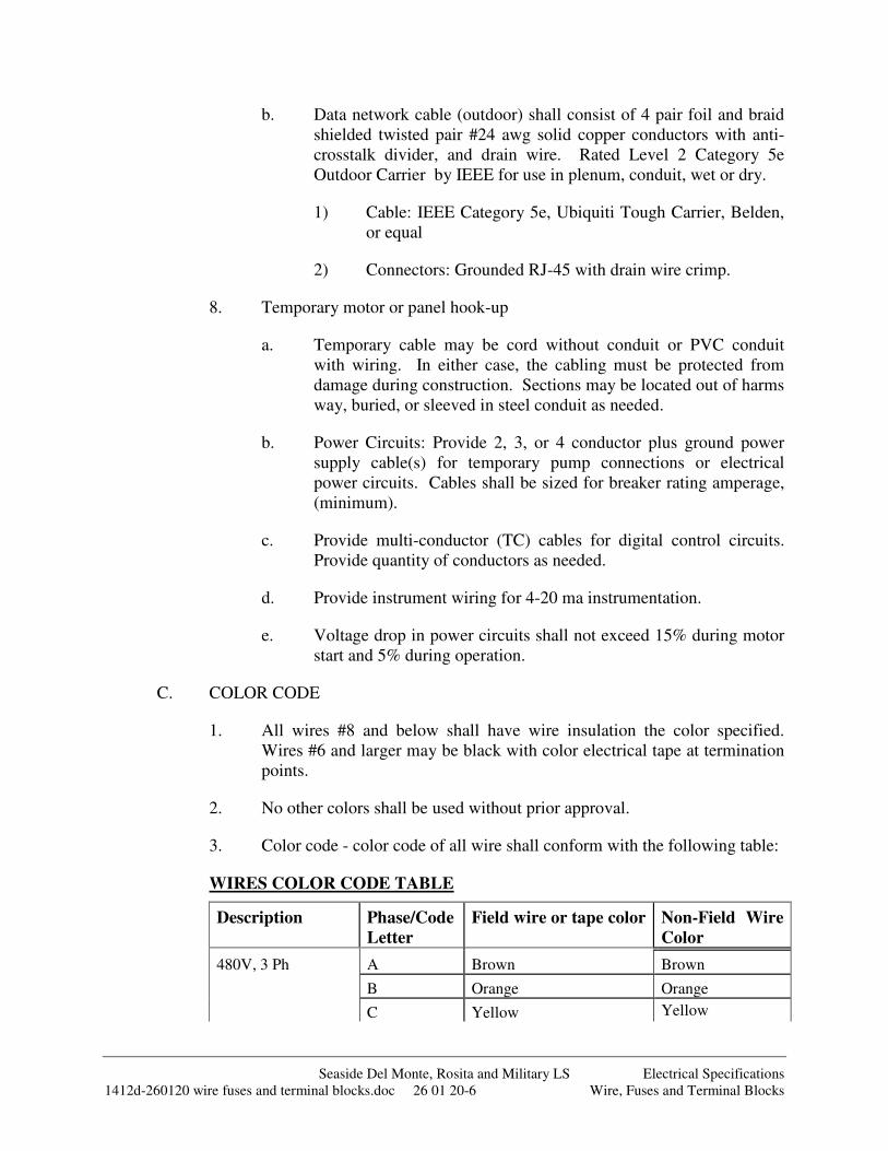
Seaside Del Monte, Rosita and Military LS Electrical Specifications 1412d-260120 wire fuses and terminal blocks.doc 26 01 20-6 Wire, Fuses and Terminal Blocks
b. Data network cable (outdoor) shall consist of 4 pair foil and braid shielded twisted pair #24 awg solid copper conductors with anti-crosstalk divider, and drain wire. Rated Level 2 Category 5e Outdoor Carrier by IEEE for use in plenum, conduit, wet or dry.
1) Cable: IEEE Category 5e, Ubiquiti Tough Carrier, Belden, or equal
2) Connectors: Grounded RJ-45 with drain wire crimp.
8. Temporary motor or panel hook-up
a. Temporary cable may be cord without conduit or PVC conduit with wiring. In either case, the cabling must be protected from damage during construction. Sections may be located out of harms way, buried, or sleeved in steel conduit as needed.
b. Power Circuits: Provide 2, 3, or 4 conductor plus ground power supply cable(s) for temporary pump connections or electrical power circuits. Cables shall be sized for breaker rating amperage, (minimum).
c. Provide multi-conductor (TC) cables for digital control circuits. Provide quantity of conductors as needed.
d. Provide instrument wiring for 4-20 ma instrumentation.
e. Voltage drop in power circuits shall not exceed 15% during motor start and 5% during operation.
C. COLOR CODE
1. All wires #8 and below shall have wire insulation the color specified. Wires #6 and larger may be black with color electrical tape at termination points.
2. No other colors shall be used without prior approval.
3. Color code - color code of all wire shall conform with the following table:
WIRES COLOR CODE TABLE
Description Phase/Code
Letter
Field wire or tape color Non-Field Wire
Color
480V, 3 Ph A Brown Brown
B Orange Orange
C Yellow Yellow
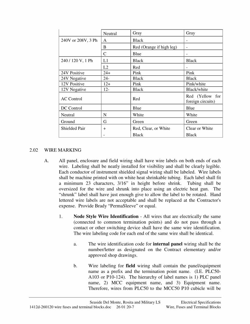
Seaside Del Monte, Rosita and Military LS Electrical Specifications 1412d-260120 wire fuses and terminal blocks.doc 26 01 20-7 Wire, Fuses and Terminal Blocks
Neutral Gray Gray
240V or 208V, 3 Ph A Black -
B Red (Orange if high leg) -
C Blue -
240 / 120 V, 1 Ph L1 Black Black
L2 Red -
24V Positive 24+ Pink Pink
24V Negative 24- Black Black
12V Positive 12+ Pink Pink/white
12V Negative 12- Black Black/white
AC Control Red Red (Yellow for foreign circuits)
DC Control Blue Blue
Neutral N White White
Ground G Green Green
Shielded Pair + Red, Clear, or White Clear or White
- Black Black
2.02 WIRE MARKING
A. All panel, enclosure and field wiring shall have wire labels on both ends of each wire. Labeling shall be neatly installed for visibility and shall be clearly legible. Each conductor of instrument shielded signal wiring shall be labeled. Wire labels shall be machine printed with on white heat shrinkable tubing. Each label shall fit a minimum 23 characters, 3/16” in height before shrink. Tubing shall be oversized for the wire and shrunk into place using an electric heat gun. The “shrunk” label shall have just enough give to allow the label to be rotated. Hand lettered wire labels are not acceptable and shall be replaced at the Contractor's expense. Provide Brady “PermaSleeve” or equal.
1. Node Style Wire Identification - All wires that are electrically the same (connected to common termination points) and do not pass through a contact or other switching device shall have the same wire identification. The wire labeling code for each end of the same wire shall be identical.
a. The wire identification code for internal panel wiring shall be the number/letter as designated on the Contract elementary and/or approved shop drawings.
b. Wire labeling for field wiring shall contain the panel/equipment name as a prefix and the termination point name. (I.E. PLC50-A103 or P10-124). The hierarchy of label names is 1) PLC panel name, 2) MCC equipment name, and 3) Equipment name. Therefore, wires from PLC50 to the MCC50 P10 cubicle will be
Seaside Del Monte, Rosita and Military LS Electrical Specifications 1412d-260120 wire fuses and terminal blocks.doc 26 01 20-8 Wire, Fuses and Terminal Blocks
labeled PLC50-XXX. Wires from MCC50 P10 to field pressure switch PSH10 will be labeled P10-XXX.
c. Wire labels shall be exactly per interconnection submittal and/or control panel drawings -- abbreviations determined in the field are not allowed. Abbreviations may be used in the wire label as submitted and approved in the interconnection drawings submittal.
d. Wire labels for lighting and receptacle circuits shall consist of the panel board and circuit number and a unique node number. (I.E. LP#3-A, LP#3-B, LP#3-N)
e. Wire labels may be omitted on “neutral jumpers” less than 8” in length.
2.03 CONTROL PANEL CIRCUIT BREAKERS
A. Furnish circuit breakers and accessories as required per Drawings and application.
1. Copper busbar systems, up to 480VAC, 115A, 1, 2 or 3 phase as needed for application
2. Trip rating per Drawings or as needed for protected device. Trip curves as selected by System Integrator.
a. B curve magnetic trip point: 3 to 5 times the rated current, typically used for computers and electronic equipment with very low inrush loads (PLC wiring).
b. C curve magnetic trip point: 5 to 10 times the rated current, typically used for small transformers, pilot devices, etc.
c. D curve magnetic trip point: 10 to 20 times the rated current, typically used for transformers or loads with very high inductive loads.
3. Quantity of pins and feed in lugs as required.
4. Auxiliary contact, shunt trip as required in Drawings.
5. Din rail mounted, 18mm width per pole, finger safe pressure plate terminals.
B. Motor applications:
1. UL489 for branch circuit protection up to 40A, 1 to 3 pole.
2. 5 kAIC interrupting capacity @ 480 VAC

Seaside Del Monte, Rosita and Military LS Electrical Specifications 1412d-260120 wire fuses and terminal blocks.doc 26 01 20-9 Wire, Fuses and Terminal Blocks
3. Alltech, Eaton FAZ, or equal.
C. Control circuit transformers and other Non-motor applications:
1. UL1077 supplementary protection up to 63 amps, 1 to 2 pole, AC or DC.
2. Used where a UL489 protective device is upstream powering the circuit (from a panelboard or other source).
3. Used within control circuits for power supplies, control power transformers, relays and PLC I/O points.
4. Used in place of fuses that are applied as supplementary protection.
5. Eaton FAZ, or equal.
2.04 FUSES AND FUSE HOLDER
A. Fuses shall not be used in branch or control circuits unless specifically shown in the drawings. Circuit breakers shall be furnished and utilized where possible.
B. Fuses used in circuits 200 VAC and above shall be time- delay, 13/32" x 1-1/2", and have an interrupting rating of 10,000 AIC at 500 VAC. Fuses shall be Bussman type FNQ or approved equal. Fuse holders shall feature open fuse indication lights and shall be rated 30A at 600 VAC. Fuse holders shall be Bussman Optima Series OPM or equal.
C. Fuses used in 120 VAC shall be time-delay, 1/4" x 1-1/4", and have a rating of 250 VAC. Fuses shall be Bussman type MDA or approved equal. Fuse-holders shall be of the same manufacturer, series and color as the adjacent terminal blocks and have blown fuse neon indicators. Fuse holders shall be Entrelec ML 10/13.SFL, Allen Bradley 1492-H4 or equal.
D. Fuses used in signal and 24 VDC circuits shall be fast acting, 5mm x 20mm and have a rating of 250 VAC. Fuses shall be Bussman type GMA or approved equal Fuse-holders shall be of the same manufacturer, series and color as the adjacent terminal blocks and have blown fuse LED indicators. Fuse holders shall be Entrelec M 4/8.SFDT, Allen Bradley- 1492-H5 or equal
E. Fuses shall be sized in conformance with the NEC.
2.05 TERMINAL BLOCKS AND ACCESSORIES
A. General
1. Terminal blocks to be clamp type, 5 spacing, 300 volt, minimum rating of 20 amps, and mounted on DIN rail. DIN rail shall be same type as used for the relays. Install extra DIN rail on each type of terminal strip with
Seaside Del Monte, Rosita and Military LS Electrical Specifications 1412d-260120 wire fuses and terminal blocks.doc 26 01 20-10 Wire, Fuses and Terminal Blocks
10% spare terminals for future additions.
a. Provide larger terminal as necessary based on gauge of connected wiring. Those terminals with 10 gauge larger gauge wiring or more than one 12 gauge wire should be evaluated and changed.
2. Provide terminal blocks with "follower" plates that compress the wires and have wire guide tangs for ease of maintenance. Terminal blocks that compress the wires with direct screw compression are unacceptable. All power, control and instrument wires entering and leaving a compartment shall terminate on terminal blocks with wire numbers on terminals and on both ends of the wires.
3. Provide end clamps, separators, din rails, and jumpers to complete terminal block system. See example PLC I/O drawing for additional information. Engineer can provide on request if not available in plans.
4. Terminal Tags and Markers: Each terminal strip shall have a unique identifying alphanumeric code at one end ( i.e.: TB1, TB2, etc. ) or as shown in drawings.
5. Plastic marking tabs shall be provided to label each terminal block. These marking tabs shall have a unique number/letter for each terminal which is identical to the "elementary" and "loop" diagram wire designation. Numbers on these marking strip shall be machine printed and 1/8” high letters minimum.
6. Terminal blocks shall be physically separated into groups by the level of signal and voltage served an by PLC I/O card. Power and control wiring above 100 volts shall have a separate group of terminal blocks from terminal blocks for wiring below 100 volts, intermixing of these two types of wiring on the same group of terminal blocks is not allowed.
7. Terminal blocks shall be gray in color unless otherwise shown on the drawings.
8. Provide a ground terminal or connection point for each grounding conductor.
9. Provide a separate signal, common, and/or neutral terminal for every wire and PLC or remote device connection at minimum.
B. CP – Control Panel Terminal Blocks
Description Model number, Allen Bradley or
equal
General Purpose Terminal Block 1492-W3 Disconnecting Terminal Block 1492-JKD3
Seaside Del Monte, Rosita and Military LS Electrical Specifications 1412d-260120 wire fuses and terminal blocks.doc 26 01 20-11 Wire, Fuses and Terminal Blocks
Grounding Terminal Block 1492-JG4 PLC AI Sensor Block 1492-WTS3 PLC Digital Output Relays 700-HLT1U1
Note: General purpose relays are defined in ELECTRICAL – GENERAL
C. MCC – Motor Starter Cubicle Terminal Blocks
1. MCC cubicle terminal blocks shall be pull apart as supplied standard by MCC manufacturer.
D. Power – Power terminal Blocks
1. Backpan mounted termination blocks shall be rated for 600V (min). The power termination blocks shall be rated to accept Copper or Aluminum cable and rated as shown on Contract one-line diagrams. Termination blocks shall be insulated with molded plastic covering and finger safe cover. Each termination block shall be provided with quantity and size of primary and secondary cable connections as required per installation. The power termination blocks shall be Erico UD, UDJ, BD, TD, or SB series or equal.
2. Unmounted termination blocks shall be constructed of aluminum and suitable for use with Aluminum and copper wire. Size and quantity of cable connections shall be as required for installation. Termination blocks shall be insulated with molded high-dielectric strength plastic covering and eliminate the need for tape insulation of electric connection. The termination block shall have removable access plugs over the wire entry and hex screw ports. Provide NSI Polaris IPL or IPLD Series terminal blocks or equal.
E. PANEL GROUND
1. Each electrical, control and instrumentation panel shall be provided with a 1 inch x 0.25 inch x 8 inch (minimum size) solid copper grounding bus bar, mounted on the inside of the enclosure. The grounding bar shall be mounted on insulated standoffs so that no electrical connection is made between the ground bar and the cabinet through the mounting. The ground bar shall be drilled and tapped for a 0.25-20 screws at 0.5 inch interval along its entire length.
2. An un-insulated solid copper #8 AWG ground wire shall be attached between the ground bar and the panel enclosure, and between the ground bar and the mounting panels. The ground connection to the enclosure and panel shall be made by sanding the paint finish off a small area, drilling a hole for a 0.25 inch bolt and mounting a 0.25-20 bolt to the panel to serve as grounding stud. The grounding stud shall be attached with a nut and flat washers on both sides of the enclosure/panel, and with an inside tooth
Seaside Del Monte, Rosita and Military LS Electrical Specifications 1412d-260120 wire fuses and terminal blocks.doc 26 01 20-12 Wire, Fuses and Terminal Blocks
star lock washer next to the panel surface. The star lock washer shall be on the inside surface of the enclosure, and the front surface of the mounting panel. The grounding wire shall be secured to the stud with a nut and inside tooth star lock washer. These grounding points shall be located within 12 inches of the bottom to the grounding bar. Each terminal strip rail shall be individually grounded by means of a #12 AWG wire to the ground bus. The PLC rack, power supply, lightning arrestor shall be similarly grounded according to the manufacturer's recommendations.
2.06 ELECTRICAL TAPE / SHRINKABLE INSULATORS
A. Vinyl tape shall be 7 mil, 600 volt rated, flame retardant, hot and cold weather resistant conforming to UL510. Provide 3M Scotch Super 33+ vinyl tape or equal
1. Vinyl tape for color coding shall be 7 mil, ¾” width, vinyl tape conforming to UL 510. Provide 3M Scotch 35 vinyl tape or equal.
B. Rubber Tape: EPR rubber, 90 deg C continuous rated. Provide 3M 130C rubber tape or equal.
C. Varnished Cambric Tape: Adhesive backed, 7 mil, bias cut cotton tape, coated with yellow insulating varnish. Provide 3M Scotch 2510 or equal.
D. Shrinkable insulators shall be heat shrinkable, polyolefin thick wall sleeves, end caps and cable repair sleeves are designed for use in splicing, sealing and re-jacketing of direct bury secondary cables. The insulators shall comply with UL 486D and be rated up to 1000 Volts. They shall provide long-term reliable performance overhead, underground or submerged with mechanical and environmental protection. Shrinkable insulators shall be 3M ITCSN or 3M IMCSN per manufacturer instructions for the application or equal.
PART 3: EXECUTION
3.01 WORKMANSHIP
A. All work in this Section shall conform to the codes and standards specified in Electrical Specifications [Electrical General, Workmanship].
B. Perform work to remedy non-compliant installations after inspection.
C. Upon notification, stop work on any portion of the installation that is determined to be substandard or being installed by unqualified personnel.
3.02 FABRICATION AND INSTALLATION
A. System:
1. Install all products specified in Electrical Specifications [Electrical
Seaside Del Monte, Rosita and Military LS Electrical Specifications 1412d-260120 wire fuses and terminal blocks.doc 26 01 20-13 Wire, Fuses and Terminal Blocks
General, Installation].
2. Panels shall be completely factory wired and tested before shipment.
3. All spare PLC input / output points shall be wired to terminal blocks.
4. A minimum of 20% spare unwired terminals shall be provided in each panel.
B. Wiring Methods:
1. Wiring Separation: Wires carrying 100 volts and above shall be physically separated from lower voltage wiring by using separate bundles or wire ways with sufficient distance to minimize the introduction of noise, crossing only at 90 degree angles.
2. Harness: All wiring shall be neatly bundled and laced with plastic tie-wraps, anchored in place by screw attached retainer. Where space is available, wiring shall be run in slotted plastic wireways with dust covers. Wireways shall be sized such that the wire fill does not exceed 60%. Tie-wraps shall be T&B TY-RAP or equal.
3. Retainers: Wireways, retainers, and other devices shall be screw mounted with round-head 316 stainless steel screws or mechanically mounted by push-in or snap-in attachments. Glue or sticky back attachment of any type or style shall not be used. Retainers shall be T&B TC series or equal.
4. Hinge Loops: Where wiring crosses hinged surfaces, provide a "U" shaped hinge loop protected by clear nylon spiral wrap. The hinge loop shall be of sufficient length to permit opening and closing the door without stressing any of the terminations or connections. Spiral wrap shall be Graybar T25N or equal.
5. Routing: Wires and cable shall be routed such as to maintain separation between 100 Volt or higher from 100 volt or lower wiring being run in the same duct or bundle. Wires and cables shall have sufficient length to allow slack and to avoid any strain or tension in the wire or cable.
a. Wires shall be routed in slotted plastic wireways with snap covers. Wires carrying 120 VAC shall be separated as much as possible from other wires and signal cables, and shall be routed only in ducts for 120 VAC. If the power wiring has to cross the signal wiring, the crossing shall be as close to a right angle as possible. Wireways for 24 VDC wiring shall be used for all other wires and cables. Routing of 120 VAC in combined wireways shall be minimized. Wires and cables shall be placed in the wireways in a straight, neat and organized fashion and shall not be kinked, tangled or twisted together. Additional wire ducting shall be provided for use by the electrical subcontractor for routing field
Seaside Del Monte, Rosita and Military LS Electrical Specifications 1412d-260120 wire fuses and terminal blocks.doc 26 01 20-14 Wire, Fuses and Terminal Blocks
wires to their landing points in the each electrical and instrumentation panel.
b. Provide 2” minimum separation between wireway and terminal blocks.
c. Wiring not routed in wireways shall be neatly bundled, treed, and laced with plastic ties.
C. Wire Terminations
1. Single wire and cable conductors shall be terminated according to the requirements of the terminal device as follows:
a. Crimp-on terminals: shall be UL listed, self-insulating sleeve type, with ring or rectangular type tongue, suitable for the size and material of the wire to be terminated, and for use with either solid or stranded conductors.
b. Terminal Blocks: Remove the last +/- 0.25 inches insulation from of the conductor and insert it under the pressure plate to full length of the bare portion of the conductor. Tighten the screw to close the pressure plate onto the conductor. No more than two conductors shall be installed in a single terminal. All strands of the conductor shall be captured under the pressure plate.
c. Screw-less terminals: wire shall be stripped back and inserted per the terminal manufacturer's instructions.
d. Motors with pigtail leads: Install terminal connectors on the motor pigtails and the cable to be connected. Terminals shall be non-insulated crimp-on type applied with a rachet-type crimping tool. The terminals shall be bolted together with a nut, bolt and lock washer combination. The connection shall be booted with 3/16” thick rubber boot. Boot kit shall include rubber boot for each motor connection, plastic locking pins, silicone grease, and mastic sealing strips, Boot kits shall be 3M Motor Lead Pigtail Splice #5302, #5303,or #5404 as applicable for wire size applied.
2. When stripping insulation from conductors, do not score or damage conductor.
3. The drain wire and stripped end of outer jacket of shielded cables shall be covered with heat shrink insulating tubing. The drain wire shall be covered along its full bare length between the cable jacket cover and the terminal lug and placed on end outer jacket to cover foil.
4. Condulets with wire nut connections shall be supplied for wire termination
Seaside Del Monte, Rosita and Military LS Electrical Specifications 1412d-260120 wire fuses and terminal blocks.doc 26 01 20-15 Wire, Fuses and Terminal Blocks
to devices with leads instead of terminals (i.e. solenoid valves, level probe, etc.).
D. Wire Splicing
1. No wires shall be spliced without prior approval.
2. Where splices are allowed or approved they shall conform to the following:
a. Wire splicing devices shall be sized according to manufacturer's recommendations.
b. Splices of #10 and smaller, including fixture taps, shall be made with nylon self-insulated twist on wire nuts; T & B "Piggys", Ideal "Wing-Nut" or equal.
c. Splices of #8 and larger shall be hex key screw, two way connectors, insulated with molded high-dielectric strength plastic; NSI Polaris IPL or IPLD Series terminal blocks or equal.
d. Non-Motor Splices #6 and smaller in underground pullboxes shall have wire-nut connections which are sealed with non-hardening silicone based sealant that protects the connection from moisture and corrosion. The wire nuts shall be factory filled with sealant and UL listed for waterproof connections. Provide Ideal Model 60 or equal.
e. Motor lead Splices in underground pullboxes shall have terminal connectors on the motor leads and the cable to be connected. Terminals shall be non-insulated crimp-on type applied with a ratchet-type crimping tool. The terminals shall be bolted together with a nut, bolt and lock washer combination. The connection shall be wrapped with four (4) layers varnished cambric tape, six (6) layers of rubber tape and six (6) layers of vinyl electrical tape, each half lapped. Seal the connection with epoxy resin coating.
E. Wire Installation
1. Exercise care in pulling wires and cables into conduit or wireways so as to avoid kinking, stressing the cables, or damaging the insulation. Use a UL listed pulling compound for lubrication within conduits as necessary. The raceway construction shall be complete and protected from weather before cable is pulled in. Swab conduits before installing cables and exercise care in pulling, to avoid damage to the insulation or conductors.
2. All wire and cables (with the exception of coaxial antenna cable) shall be installed within UL listed raceways or enclosures. Install all wires and
Seaside Del Monte, Rosita and Military LS Electrical Specifications 1412d-260120 wire fuses and terminal blocks.doc 26 01 20-16 Wire, Fuses and Terminal Blocks
cables in one continuous length unless splices are per contract drawings, required to connect equipment or submitted and favorably reviewed.
3. Bundle incoming wire and cables in panels. Zip-tie at intervals of 2” and neatly spread into trees and connect to their respective terminals. Allow sufficient slack in cables for alterations in terminal connections. Do not bundle, tape or tie wires within conduits.
3.03 WARRANTY
A. Provide warranty as specified in Electrical Specifications [Electrical General, Warranty].
END OF SECTION
Seaside Del Monte, Rosita and Military LS Electrical Specifications 1412d-263213 engine generator.doc 26 32 13-1 Engine Generator
SECTION 26 32 13 – ENGINE GENERATOR
PART 1: GENERAL
1.01 SCOPE OF WORK
A. Because of potentially long permit applications processes and manufacturing lead times for the generator equipment, the Contractor is required to submit the complete generator submittal within 14 days of notice-to-proceed and/or contract award.
B. These specifications describe the minimum requirements for a STANDBY duty three phase engine driven generator. The “Generator Data Sheet” at the end of this specification lists the minimum sizing for the generator and accessories. A larger generator shall be supplied when necessary to meet the requirements of this section. The Contractor shall complete this form with proposed generator values and include it with the generator submittal.
C. The generator shall be provided as described in the following specification and as shown on the Contract drawings, herein designated as the design documents. The generator shall comply with all applicable sections of NFPA 30, 37, 70, 72 and 110, California Fire Code Articles 79 and 80 as well as State Statues.
D. The equipment furnished under these specifications shall meet the requirements of NEC Article 702, “Optional Standby Systems” and any other applicable articles of the NEC.
E. The system shall meet the requirements of NFPA 704 Hazard Identification System Diamond indicating the hazards associated with the fuel being stored.
F. The generator shall be delivered as a skid mounted unit, completely assembled to the extent possible and factory tested.
G. Only new models in current production by a U.S. firm that meet the requirements of these specifications and which are cataloged by the manufacturer and for which manufacturer's published literature and printed specifications are currently available, will be considered. Special options may be included only when recommended by the manufacturer of the unit approved.
H. All equipment/options are to be factory installed. If the equipment/options are not available factory installed, dealer installed equipment/accessories may be acceptable. The bidder is to specify those items which will be dealer installed in the submitted bid document.
I. The manufacturer's local representative shall be an authorized distributor who maintains a stock of spare parts for the supplied generator and has a service facility with factory-trained service personnel. The manufacturer's local
Seaside Del Monte, Rosita and Military LS Electrical Specifications 1412d-263213 engine generator.doc 26 32 13-2 Engine Generator
representative shall be located within a radius of 200 miles of the project.
J. The Contractor shall perform complete startup, training and testing services for the generator per Electrical Specifications [Factory and Field Testing] and as detailed herein.
K. Generator system shall be EPA Certified and meet all current Local, State and Federal air emissions requirements at time and location of installation.
L. Generator system shall be coordinated and compliant with all current Local and State building and Fire Protection codes and requirements at time and location of installation. Furnish alarms, signage, shutdowns, and other devices and systems as required.
M. The Contractor shall supply the generator, labor, testing and associated documentation as specified herein. This document describes the materials and intended operation, but does not necessarily describe all devices necessary for a functional system. All components and devices shall be furnished and installed as required to provide a complete, operable and reliable system for accomplishing the functions and meeting the performance set forth hereinafter.
N. The generator scope of work includes:
1. Engine driven electric generator 2. Sub-base fuel tank with fuel pump and associated piping. 3. Battery charger (120 VAC operated) mounted to generator frame. 4. Sound attenuating housing. 5. All auxiliary apparatus and accessories shall be provided, at no additional
cost to the Owner, as required for a fully functional generator. 6. Install a steel reinforced concrete pad, adequately sized to support the
specified generator and fuel tank. 7. All piping associated with exhaust system. 8. Trenching, back filling, compaction and paving of each underground
conduit route and fuel line piping. 9. Field installation, startup, testing and training for the generator and
associated equipment as part of this scope of work. 10. Fuel for use during testing and full tank top off upon testing acceptance.
1.02 REFERENCES
A. Electrical Specifications [Electrical General]
B. Project Drawings
C. The following manufacturing and installation standards apply to this section:
1. ASTM International (ASTM): A335/A335M, Specification for Seamless Ferritic Alloy-Steel Pipe for High-Temperature Service.
Seaside Del Monte, Rosita and Military LS Electrical Specifications 1412d-263213 engine generator.doc 26 32 13-3 Engine Generator
2. Best Available Control Technology Standards (BACT)
3. Code of Federal Regulations (CRF): Title 40 Volume 18, Control of Emissions from New and In-Use Non-road Compression-Ignition Engines.
4. National Fire Protection Association (NFPA):
a. 37, Installation and Use of Stationary Combustion Engines and Gas Turbines.
b. 70, National Electric Code.
c. 110, Emergency and Standby Power Systems.
5. SAE International (SAE): J1074, Engine Sound Level Measurement.
6. Underwriters Laboratories, Inc. (UL):
a. 142, Steel Aboveground Tanks for Flammable and Combustible Liquids.
b. 2085, Protected Aboveground Tanks for Flammable and Combustible Liquids.
c. 508, Industrial Control Equipment.
d. 1236, Battery Chargers for Charging Engine-Starter Batteries.
e. 2200, Stationary Engine Generator.
D. The bidder shall carefully examine the plans and specifications, and be familiar with the conditions of the location of installation.
1.03 QUALIFICATIONS
A. Equipment manufacturers shall be represented by a company capable of servicing and testing the generator unit from a mobile service vehicle dispatched from within a 200 mile radius.
1.04 SUBMITTAL REQUIREMENTS
A. Submit shop documents and drawings for approval in accordance with this subsection and as specified in Electrical Specifications [Electrical General, Submittal Requirements]. All non-relevant items not provided on this project shall be crossed-off or deleted from all submitted documents and drawings.
B. Submit a specification compliance statement, describing differences between specified and proposed equipment. Note equipment provided specifically to meet local District or authority having jurisdiction requirements.
C. Complete “Generator Data Sheet” at the end of this section and submit this form with the generator submittal.
Seaside Del Monte, Rosita and Military LS Electrical Specifications 1412d-263213 engine generator.doc 26 32 13-4 Engine Generator
D. Submit data sheets and catalog information detailing:
1. Engine:
a. Make and model. b. Fuel type. c. Number of cylinders and cylinder arrangement. d. Bore and stroke. e. Compression ratio. f. Piston speed, Feet per Minute, at rated RPM. g. Cylinder head, piston, valve, and block material. h. Crankshaft material. i. Main bearings, quantity and type. j. Rated RPM and HP at rated RPM. k. Governor type.
2. Generator:
a. Make and model. b. Generator full load electrical rating, KVA, KW, Voltage,
Amperage, Frequency (Hz), # of Phases, # of Wires, Power Factor. c. Generator and Exciter type. d. Insulation material, class, and temperature rise. e. Bearings, quantity and type. f. Peak motor starting, KVA. g. Voltage regulator type and regulation % from no load to full load. h. Frequency regulator type and regulation %, from no-load to full
load. i. One step load acceptance. j. Unbalanced load capability. k. Number of leads. l. Generator transient (x'd) and subtransient (x"d) reactance in per
unit. m. Ambient temperature range.
3. Electrical
a. Control and instrument panel. b. Generator main breaker. c. Batteries and battery charger.
4. Cooling System
a. Maximum ambient temperature. b. Capacity (gallons). c. Coolant flow (gpm). d. Fan diameter (in). e. Fan HP requirement at rated RPM.
Seaside Del Monte, Rosita and Military LS Electrical Specifications 1412d-263213 engine generator.doc 26 32 13-5 Engine Generator
5. Accessories:
a. Exhaust silencer, stack, and piping system. b. Fuel tank and piping system. c. Vibration isolation system. d. Block Heater system. e. Weatherproof/Soundproof Housing as specified herein. f. Paint Finish.
E. Submit electrical schematics and wiring diagrams for:
1. Generator control panel. 2. Battery charging system. 3. Main generator. 4. Voltage regulator. 5. Governing system. 6. Generator main breaker.
F. Submit dimension drawings for:
1. Engine generator side, front, and top. 2. Pad construction (minimum) size, anchor details. 3. Enclosure (if required). 4. Fuel tank and containment basin. 5. Exhaust muffler and air intake baffle. 6. Conduit stub-up areas under generator frame and/or sub-base fuel tank.
G. Submit reports, calculations, and curves for:
1. Generator sizing calculation (computer generated report acceptable) showing that the unit is sized adequately to start all loads as shown on Contract Drawings “Load Calculation” without exceeding the maximum voltage dip specified.
2. Generator air emissions data, prototype or actual, suitable for submission to governing air quality management agency where generator is to be installed. Emissions data shall be for fuel type as required by local air quality agency.
3. Sound level data showing that the complete generator package meets the sound level requirements stated herein.
4. Engine generator fuel consumption data at 25%, 50%, 75% and 100% electrical loading.
5. Proposed concrete pad dimensions, reinforcement method and isolation material (as necessary) for submitted generator.
Seaside Del Monte, Rosita and Military LS Electrical Specifications 1412d-263213 engine generator.doc 26 32 13-6 Engine Generator
6. Seismic calculations for bolt down anchorage for seismic site class D. Calculation shall be signed by a California Registered Professional Structural Engineer. Generator installation shall meet applicable CBC or IBC requirements for stand-by power systems.
a. Calculations shall include calculations for wind loading on equipment to be mounted outdoors.
b. The Contractor shall submit a copy of the current ICBO anchor evaluation report for each type of anchor submitted.
c. The Contractor shall submit a copy of the concrete mix design to include the concrete design strength.
d. The Contractor shall submit Near Fault Vicinity and Location maps.
H. Air Quality Management Applications and Permits
1. The Contractor shall obtain the correct ATC application from the AQMD and preliminarily complete the application by inserting the project specific generator technical information. Submit preliminary partially completed application to the Engineer for use by the Owner in preparation of the final completed ATC application.
2. The Contractor shall submit all generator specific information required to complete the ATC permit application. The Owner will not submit the application until all the information is received and the submittal receives a status of “make corrections noted” or “approved.” Submit information in sufficient time for application processing and submittal review as to not delay project completion. The generator will not be considered approved until the ATC permit is obtained.
3. The Owner shall complete and apply for the "Authority to Construct" (ATC) permit from the Air Quality Management District or Board with jurisdiction for this generator system. Fees for permit and application will be paid by the Owner. The Owner will submit the permit application within 14 days of submittal approval. Allocate 12 weeks for Owner to obtain ATC permit once application has been submitted.
4. The Contractor shall confirm that the submitted generator meets all AQMD guidelines prior to submittal of the generator unit or preliminary application. Failure to do so will delay the ATC permitting and submittal approval.
I. Descriptive literature shall be provided that describes the generator and all accessories. This literature shall provide sufficient detail to determine that the generator has all the accessories, options, features, and characteristics specified
Seaside Del Monte, Rosita and Military LS Electrical Specifications 1412d-263213 engine generator.doc 26 32 13-7 Engine Generator
herein. Items that are not provided shall be neatly lined out.
J. Deviations from the Contract documents shall not be incorporated into the work without prior written approval. A "Change Order" directive is required prior to incorporating any deviation from the Contract documents that has costs associated. The cost differential associated with this change order must be negotiated to amend the Contract to reflect the costs or savings.
K. Exceptions to the Specifications or Drawings or equipment or procedures submitted as “equal” to specified equipment shall be clearly identified by the equipment supplier in a letter at the front of the submittal. Submittal data for “equal” equipment or procedures shall contain sufficient details so a proper evaluation may be made. The Contractor is responsible for verifying proper application/operation of substituted equipment.
L. The Owner will not accept any ownership for material or equipment until the corresponding submittals have been reviewed by the Owner and approved.
M. Submit complete and specific information with regard to equipment representatives and service facilities.
1.05 OPERATION AND MAINTENANCE INFORMATION
A. Provide six (6) sets of operating, maintenance & parts instructions in original manuals (no copies allowed).
PART 2: PRODUCTS
2.01 QUALITY
A. The generator shall be as manufactured by Caterpillar, Cummins, Generac, Kohler or equal with accessories as defined herein.
B. The equipment supplied and installed shall meet the requirements of the National Fire Protection Association (NFPA 70 and NFPA 110) and all applicable local codes and regulations.
C. The generator system shall be designed as a “black start” unit capable of starting and operating without any external power.
D. Provide all of the features, options, and accessories specified herein and shown on the design drawings. Finished equipment shall be complete and site tested as an installed unit with all accessories functioning.
E. All rotating parts shall have guards to protect against accidental contact in accordance with Federal OSHA and Cal-OSHA requirements.
2.02 RATING
Seaside Del Monte, Rosita and Military LS Electrical Specifications 1412d-263213 engine generator.doc 26 32 13-8 Engine Generator
A. The engine generator shall have a minimum continuous standby rating as listed in “Generator Data Sheet” at the end of this section. Standby rated shall mean that generator starts within 60 seconds upon being called and operates continuously for the total duration of the generator call or fuel supply. Rating of the generator shall be based on operation when equipped with all necessary operating accessories such as radiator, fan, air cleaners, lubricating oil pump, governor, exhaust silencer, etc.
B. No derating from the ratings specified shall occur for ambient temperatures below 122°F or installation elevation below 1,000 feet.
C. The generator will be installed at approximately 100 feet above sea level. The generator shall operate as specified at ambient temperatures between 0 degrees Fahrenheit and 104 degrees Fahrenheit.
D. The engine/generator shall accept 100% of its nameplate rating at 0.8 PF in one step, in compliance with NFPA 110, Paragraph 5-13.2.6.
E. The generator shall be capable of successfully providing three phase, four wire, 60 hertz power to start and continuously operate at the specified KW rating and below for loads shown in the drawing and/or with power factors between 0.5 lag to 0.9 lead. It shall be capable of operating in noisy electrical environments that are typical of variable frequency drive motor loads. The nominal voltage and maximum step voltage dip shall be per the “Generator Data Sheet,” as measured line to line at the generator terminals, during start of any of the station loads.
F. Generator set mean time between failures shall be a minimum of 5,000 hours.
2.03 ENGINE
A. The engine shall be a turbocharged ignition engine type, water cooled, four cycle, with vertical inline or V-type cylinders and an overhead valve configuration.
B. The engine shall utilize only NO. 2 diesel fuel. Generator shall operate per manufacturer’s specifications using fuel approved by local air quality authorities.
C. The engine shall be of direct injection design, i.e. pre-combustion chambers shall not be incorporated in the cylinder heads.
D. The engine shall have sufficient power to produce the specified ratings when operating with all accessories including exhaust, fuel, cooling, and battery charging systems, etc.
E. The engine shall be equipped with:
1. Engine driven or electric fuel transfer pump, fuel filters, and electric fuel shutoff valve. The fuel transfer pump shall be capable of lifting the fuel from the sub-base fuel tank. Primary and secondary fuel filters shall be
Seaside Del Monte, Rosita and Military LS Electrical Specifications 1412d-263213 engine generator.doc 26 32 13-9 Engine Generator
provided. The fuel filters shall be replaceable and conveniently located for servicing.
2. Electrical governor; consisting of a magnetic pickup speed sensor, adjustable electronic control, and an electrical actuator mounted integrally with the fuel pump. The governor shall provide automatic engine generator set frequency regulation adjustable from isochronous to 5% droop. Governors using external throttle linkages are not acceptable.
3. An electric starting system complete with batteries, battery charger, battery rack, connector cables, and any other equipment required to start the standby generator. The starting system shall not require an auxiliary AC power supply to start, fully load, and operate the standby generator. The batteries shall be sized to provide five starts with 30 seconds cranking for each start attempt. The battery charger shall be sized to fully recharge the batteries within 12 hours. If required to maintain the above criteria, an electrical heat pad for the batteries shall be provided to keep the batteries in a ready state at the specified minimum ambient temperature. The charger shall be furnished with charger trouble alarm and an automatic equalize timer for fast recharge. The charger shall alarm on loss of power and cause a generator common alarm output.
4. Battery charging alternator with a minimum ampere output as listed in “Generator Data Sheet.”
5. Positive displacement, full pressure lubrication oil pump, cartridge oil filters, dipstick, and oil drain. The oil pump shall be capable of supplying adequate lubricating oil under pressure to the main bearings, crankshaft bearings, pistons, piston pins, timing gears, camshaft bearings, and valve rocker mechanism. The cartridge oil filters shall be full flow type, conveniently located for servicing. Filters shall be equipped with a spring loaded bypass valve to ensure oil circulation if filters are clogged.
6. An electric DC motor-driven pre-lube oil pump shall be provided if required by the engine manufacturer’s design for “black start” of the standby generator.
7. Dry type replaceable air cleaner elements. The dry-type air cleaner shall be equipped with a self-cleaning dust and water evacuator and a vacuum restriction gauge to indicate maximum allowable restriction of the air cleaner system according to the engine manufacturer's recommendations. The air cleaner elements shall be conveniently located for servicing.
8. Unit mounted radiator, blower fan, water pump, and thermostat. The radiator with blower type fan shall be sized to maintain safe operation at 104° F ambient temperature. The engine cooling system shall be filled with a solution of 50/50 ethylene glycol/water antifreeze or equivalent as
Seaside Del Monte, Rosita and Military LS Electrical Specifications 1412d-263213 engine generator.doc 26 32 13-10 Engine Generator
recommended by the manufacturer.
9. Replaceable type cylinder liners.
10. Replaceable insert main bearings.
2.04 GENERATOR
A. The generator shall be a synchronous wye-connected generator designed for direct connection to the engine. It shall be salient-pole, brushless, 12-lead reconnectable, self-ventilated, drip-proof construction, with amortisseur rotor or damper windings and skewed stator for smooth voltage waveform. The unit shall conform to the applicable standards for synchronous generators, salient pole type.
B. The generator shall have the following features:
1. Temperature rise of the rotor and stator shall be limited to 125° C for the specified KW and KVA ratings.
2. Steady state voltage regulation from no load to full load within +/- 0.25% for electronic governors, +/- 0.8% for mechanical governors.
3. Steady state regulation from no load to full load within +/- 0.25%.
4. The insulation material shall meet the NEMA standard (MG1-22.40 and 16.40) for class H and be vacuum impregnated with epoxy varnish to be fungus resistant per MIL I-24092.
5. The excitation system shall be of brushless construction controlled by a solid state voltage regulator with adjustable volts-per-hertz operation capable of maintaining voltage within +/- 2% at any constant load from 0 to 100% of rating. The regulator isolated from the load to prevent tracking when connected to SCR loads. The regulator shall be protected from the environment by conformal coating and provide individual adjustments for voltage range, stability and volts-per-hertz operations. Provide permanent magnet (PM) excitation for generators above 150KW or AREP excitation for generators smaller than 150KW.
6. The generator shall have a single maintenance-free bearing and be connected to the flywheel housing with a semi-flexible coupling between the rotor and the flywheel.
7. Radio interference suppression to meet the BS.800 and VDE Class G and N standards.
8. Telephone interference factor of less than 50 per NEMA MG1-22.43.
9. AC voltage waveform total harmonic distortion of less than 5% total from
Seaside Del Monte, Rosita and Military LS Electrical Specifications 1412d-263213 engine generator.doc 26 32 13-11 Engine Generator
no load to full load. Any individual harmonic shall have less than 3% THD.
C. The generator shall be inherently capable of sustaining at least 300% of rated current for at least 10 seconds under a 3-phase symmetrical short circuit without the addition of separate current support devices.
D. On starting each listed load, the instantaneous voltage dip shall not exceed that listed in “Generator Data Sheet” and shall recover to +/- 1% of rated voltage within one second.
2.05 CONTROLLER & INSTRUMENT PANEL
A. Provide a generator-set mounted controller & instrument panel. The controller top shall be mounted no higher than 6 feet above finished grade. Controller mounting shall be vibration isolated from the rest of the engine / generator set.
B. Emergency stop maintained pushbutton located at maximum 6 feet above grade .
C. Remote mounted emergency stop glass covered pull switch located as shown in the drawings at maximum 54 inches above grade.
D. Controller Features
1. All solid state construction, except for interface relays. The controller shall utilize a microcomputer based logic with a ROM based control algorithm. Circuit boards shall be coated to protect from environmental damage.
2. Graphical display with preconfigured screens for parameter and alarm viewing and setpoint changes.
3. Voltage, current and power metering, engine and generator parameter viewing.
4. Real time clock for time stamping of diagnostic events and maintenance reminders.
5. Non-volitile memory for setpoint storage through power failures.
6. Security through password access.
7. Control of generator output circuit breaker for generator protection and synchronizing functions.
a. Paralleling functions to including automatic and manual synchronizing, dead bus arbitration, load sharing, and load sense/load demand.
Seaside Del Monte, Rosita and Military LS Electrical Specifications 1412d-263213 engine generator.doc 26 32 13-12 Engine Generator
b. Protective relaying functions – phase sequence, over/under voltage, over/under frequency, reverse power, overcurrent, current balance.
E. Control circuitry shall be of plug-in design for quick replacement. The controller shall be equipped to accept a plug-in device capable of allowing maintenance personnel to test controller performance without operating the engine. The controller shall be capable of operation from –40°C to 85°C.
F. Input circuitry from fuel tank devices such as fuel level switches and level transmitters, shall be designed to be suitable for the application and consist of current limiting circuitry and/or non-sparking devices.
G. Control must meet NFPA-110 Level 1 requirements (2005 version) and meet NFPA-70.
H. The panel display shall include as a minimum:
1. AC voltmeter. 2. AC ammeter. 3. Frequency meter. 4. Water temperature gauge. 5. Oil pressure gauge. 6. Battery voltmeter gauge. 7. Engine running time meter (non-resettable) 8. Voltage adjustment. 9. Pre-alarms:
a. Auxiliary fault. b. Battery Charger Fault. c. Fuel low level/pressure. d. Low oil pressure. e. Low engine temperature f. High engine temperature. g. High battery voltage h. Low battery voltage i. Fuel leak alarm
10. Engine shutdowns:
a. Auxiliary Shutdown. b. Emergency Stop. c. Low coolant level d. Overcrank. e. Overspeed. f. Low oil pressure. g. Low fuel level. h. High engine temperature.
Seaside Del Monte, Rosita and Military LS Electrical Specifications 1412d-263213 engine generator.doc 26 32 13-13 Engine Generator
11. Audible Alarm:
a. Generator switch not-in-auto.
12. Functions:
a. Three position (RUN-OFF-AUTO) function: In the RUN position the engine shall start and run regardless of the position of the remote starting contact. In the AUTO position, the engine shall start when contacts in the remote control circuit close and stop five minutes after those contacts open following the engine cooldown sequence. In the OFF position the engine shall not start even though the remote start contact closes. This position shall also shutdown engine immediately.
I. Wiring – The manufacturer shall furnish, install at the factory, and test all wiring required between devices mounted within or on the standby generator unit base. All wiring shall be neatly and carefully installed in wiring gutters, wire looms, or raceway. All power supply circuits shall be provided with suitable isolation/electrical protection means consisting of either fuses or circuit breakers. All internal wiring shall be marked at both ends of the conductor.
J. Operation:
1. Two-wire generator start/stop control from an automatic transfer switch (normal start and stop with cooldown).
2. Engine starter control for:
a. Cranking cycler with 15 second ON and OFF cranking periods or as recommended by the manufacturer. Cranking shall cease upon engine starting and running.
b. Two methods of cranking termination shall be provided:
1) After three 15 second cranking cycles. 2) After 75 seconds if the engine fails to start or as
recommended by the manufacturer 3) Each condition shall lockout the engine, and visually
indicate an overcrank alarm.
c. Starting system shall be designed for restarting in event of a false engine start. It shall permit the engine to completely stop rotating before reengaging the starter.
3. Provide wiring circuitry and sensing devices as required for emergency shutdown of the engine on any occurrence of the following conditions.
Seaside Del Monte, Rosita and Military LS Electrical Specifications 1412d-263213 engine generator.doc 26 32 13-14 Engine Generator
a. Low coolant level. b. Over speed. c. Over-crank. d. High engine temperature. e. Low oil pressure. f. Low fuel g. Emergency stop h. Auxiliary shutdown
4. Engine cool down timer factory set at five (5) minutes to permit unloaded running of the generator set after the call to operate is dropped.
5. Programmable I/O contacts to be provided and brought out to terminals for connection to remote monitoring equipment:
a. A common alarm dry contact, normally open which closes on any alarm condition.
b. A generator running dry contact, normally open which closes when the engine is running.
c. A generator in cool-down dry contact, normally open which closes when the engine is running but opens when the engine enters cool-down.
d. Low fuel level dry contact, normally open which closes on low fuel alarm condition.
e. Auto switch position dry contact that closes when the three position (RUN-OFF-AUTO) selector switch is in the "AUTO" switch position.
f. Remote emergency shutdown from normally closed switch.
2.06 ACCESSORIES
A. Engine block heater. Thermostatically controlled and sized to maintain manufacturers recommended engine coolant temperature to meet the start-up requirements of NFPA-99 and NFPA-110, Level 1. Wattage and voltage shall be per “Generator Data Sheet.”
B. Exhaust System:
1. The complete exhaust system (silencer, stack, and exhaust piping) shall be sized to ensure that exhaust back pressure falls within the manufacturer's minimum and maximum limitations under all operating conditions.
2. Exhaust Silencer: Provide exhaust silencer including flexible piping & fittings properly sized and installed according to the manufacturer's requirements. The silencer shall be critical type (30dB attenuation minimum) and coated to be temperature and rust resistant. The flexible connector section(s) shall be seamless, stainless steel and the ends shall be pipe thread (2” maximum) or SAE flanged. Support for exhaust silencer
Seaside Del Monte, Rosita and Military LS Electrical Specifications 1412d-263213 engine generator.doc 26 32 13-15 Engine Generator
shall be from overhead or side supports or as shown and shall not be carried by the exhaust manifold.
3. Exhaust Stack and Piping: Provide thin-gauge steel pipes with flange connections, high temperature gaskets, elbows and straight runs to complete the exhaust system. The exhaust system shall extend vertically above roof to direct exhaust and heat away from building or enclosure or as shown on the drawings. Provide wall thimble and roof penetrations designed for high heat applications and a gravity actuated steel rain cap at end of exhaust pipe. Exhaust system shall be supported from side or above utilizing galvanized steel channel trapeze hangars, gusseted wall brackets or custom welded brackets per manufacturer’s recommendations to meet the specified seismic design conditions. Design system to accommodate engine vibration and not loosen or break exhaust system mounts.
C. Vibration Isolation
1. Engine Generator: Vibration isolation dampeners between the engine and steel mounting skid.
2. Exhaust Silencer: Mount with vibration isolators and/or flexible exhaust piping.
3. Enclosures shall be mounted with vibration isolators and/or steel structural stiffeners to minimize added noise due to vibration.
4. The generator shall have provisions for shipping/transit such that expected shocks will not damage the vibration isolators or generator.
D. Sub-Base Fuel Tank:
1. Fuel tanks shall be sized to provide fuel for a minimum full load run time in hours at full load listed in “Generator Data Sheet.”
2. The sub-base fuel system shall be listed under UL 142, sub section entitled Special Purpose Tanks EFVT category, and will bear their mark of UL Approval according to their particular classification
3. Comply with local code requirements depending on location of installation. For example, furnish or provide the following:
a. Tank pressure test b. Tank venting c. Spill containment. d. Hazardous labeling e. Fuel filling level alarm f. Others as required per code.
Seaside Del Monte, Rosita and Military LS Electrical Specifications 1412d-263213 engine generator.doc 26 32 13-16 Engine Generator
4. Perform a 2 hour site fuel tank pressure test. Local codes will govern the requirements and need for pressure testing. Comply with local codes.
5. The fuel tank shall have the following features:
a. Constructed of sheet steel with steel framing suitable for mounting the generator on top.
b. 1-1/4" mechanical fuel level gauge. Readout shall be fraction of full tank with indicators at 25%, 50%, 75%, 95% and 100% full. Provide Krueger Sentry Gauge or equal.
c. Flexible fuel line(s) rated 300°F and 100 PSI ending with pipe thread connections. Provide normally closed solenoid shutoff valve at fuel tank outlet that will energize/de-energize with generator run command.
d. 3/8" suction and return connections (minimum). e. 3/8" diameter drain (minimum). f. Primer and enamel exterior. g. Venting per NFPA 30 and American Petroleum Institute Standard
No. 2000. h. Code required spill containment around 2” fill port with normally
closed valve to release spilled fuel into the primary steel tank. Provide cover for spill containment area.
i. Secondary containment tank sized to contain 110% of the capacity of the fuel tank. A 3/8" minimum drain plug and 1” leak detection threaded hole and plug shall be provided.
j. Fuel level switches that are rated for use in fuel or fuel vapor atmosphere that are non-sparking. Switches shall actuate on a float mechanism which operates a sealed switch for connection to the generator control panel. Provide the following independent or combination switches: 1) High High (90% full) level audible alarm. 2) High (85% full) level audible alarm. 3) Low (25% full) level for low fuel alarm indication. 4) Low Low (5% full) for low fuel engine shutdown and
indication. 5) Secondary Containment Leak for fuel tank leak alarm.
6. Fuel pump as required for the installation per generator manufacturer. The fuel pump shall be powered from the generator’s DC electrical system. Provide foot valve on suction tube in tank to keep the line primed and expansion relief on feed line to bleed excess fuel into tank.
7. Additional 2” FNPT installation of level transmitter as specified in 16940.
E. xBatteries: Support tray with plastic battery enclosure, tie downs, battery cables, and 12-volt batteries all mounted to the engine/generator skid. The batteries shall be capable of delivering the cold-cranking amps required at zero degrees
Seaside Del Monte, Rosita and Military LS Electrical Specifications 1412d-263213 engine generator.doc 26 32 13-17 Engine Generator
Fahrenheit per SAE Standard J-537.
F. Signage:
1. Signage shall be posted on the sides of the generator enclosure facing the main approaches to the system.
2. Provide an engraved placard with fuel filling procedure, tank capacity, fuel type, and maximum fill guidelines.
3. Provide signage 0.08” thick white painted/silk-screened aluminum with 1-1/2” red lettering to read “No Smoking”. Signs shall be posted on all sides of generator enclosure.
4. Provide signage 4” x 6” x 0.08” white painted aluminum with red lettering to read “Generator Emergency Stop” for installation at a remote emergency stop switch as shown on the drawings.
G. Automatic Battery Charger suitable for continuous operation to maintain the battery charge voltage with no manual intervention. Battery charger features shall be as follows:
1. Solid state circuitry with charging modes as described to automatically recharge the starting batteries. When battery voltage drops below the specified value the battery charger shall operate at the high rate constant current mode until the battery voltage rises to the preset equalize level. The equalize mode will continue until the current required to maintain this voltage drops to 50% of the high rate level.
2. A current limiting circuitry to prevent charger overload under low battery voltage conditions. Provide minimum DC voltage and amp ratings (minimum) as listed in “Generator Data Sheet.”
3. The battery charger shall provide temperature compensation of -2 mv/°C per cell over the ambient temperature of –40°C up to 60°C. This shall automatically adjust the "float" and "equalize" voltage settings to prevent the batteries from overcharging at high temperature and under charging at low ambient temperatures.
4. The complete charger unit shall be U.L. listed.
5. The charger shall be mounted to the engine/ generator skid. The charger shall be operational through an ambient temperature range of –40°F to 140°F. It shall include the following features:
a. Fused AC input and DC output overload & short circuit protection.
b. DC ammeter and voltmeter, 5% full scale accuracy, to indicate battery charging amps and volts.
Seaside Del Monte, Rosita and Military LS Electrical Specifications 1412d-263213 engine generator.doc 26 32 13-18 Engine Generator
c. "Power on" lamp to indicate when the charger is operating.
d. DC voltage regulation +/- 1% from no load to full load and over AC input line variations of +/- 10%.
e. Reverse polarity protection to prevent the charger from energizing outputs if improperly connected.
f. Current limiting. Current limiting circuitry shall be provided to prevent damage to the charger from being overloaded at low battery voltage such as occurs during short circuit conditions or during engine starter cranking.
g. The battery charger shall be powered from 120 VAC.
H. Sound Attenuating Weatherproof Housing for the generator shall be as follows:
1. Manufactured from heavy-gauge aluminum or galvanized sheet steel and painted with the manufacturer’s standard finish. Paint color shall be submitted to Owner for approval. Color choices shall include but not be limited to autumn white and beige. All surfaces shall be painted inside and out.
2. The interior of housing shall have a heat resistant thermo-acoustic insulation system designed to meet sound attenuation requirements for the life of the generator. The placement, type, thickness and weight of the attenuator panels shall provide sound dampening to the specified level of allowable noise outside the generator. The air intake and exhaust shall have similar dampening and allow ample air flow for proper engine cooling, without having to remove side panels. The insulation shall be mechanically held against walls, ceiling and doors behind full sheets of perforated galvanized sheet steel. All insulation shall be covered with the exception of the exhaust piping.
3. The enclosure shall house the engine, generator, control & instrument panel, battery charger, generator breaker, and all accessories.
4. All exterior panels shall have lockable latches to prevent unauthorized entry.
5. The specified exhaust silencer shall be mounted in or on the roof of the enclosure with vibration isolators.
6. Pressure drops through the enclosure openings shall not exceed limits set by the manufacturer of the generator.
7. The enclosure shall be free standing and anchored to the concrete pad (or trailer) supporting the engine generator. The enclosure may be mounted to the generator skid only if a skid mounted enclosure can meet the sound attenuation requirements specified.
Seaside Del Monte, Rosita and Military LS Electrical Specifications 1412d-263213 engine generator.doc 26 32 13-19 Engine Generator
8. The enclosure shall be designed so that sound levels measured at a 25 feet radius from any side of the enclosure (free field) and 5 feet above ground level, noise levels shall not exceed (Generator Data Sheet) dB with the engine generator running at full load and full speed inclusive of exhaust noise.
I. CIRCUIT BREAKER DISCONNECT
1. GENERAL
a. Circuit breakers and motor circuit protectors shall be manufactured by Eaton Cutler-Hammer, Square D, G.E., Siemens, or equal.
b. Sized by Generator manufacturer to meet UL standards, cabling requirements per plans, and “Generator Data Sheet.”
c. Multiple-pole circuit breakers shall be designed so that an overload on one pole automatically causes all poles to open. The use of tandem or dual circuit breakers in a normal single-pole space to provide the number of poles or spaces specified are not acceptable.
d. Molded case circuit breakers shall be operated by a single toggle-type handle and shall have a quick-make, quick-break switching mechanism. An automatic trip of the breaker shall be clearly indicated by the handle position. Contacts shall be non-welding silver alloy and have flash reduction arc chutes. A push-to-trip button on the front of the circuit breaker shall provide a local manual means to exercise the trip mechanism.
e. Minimum interrupting capacity:
1) 480 volt circuit breaker shall have a minimum interrupting capacity of 42,000 amperes.
2) 120 or 208 or 240 volt breaker shall have a minimum interrupting capacity of 22,000 amperes
f. Circuit Breakers less than 400 volt and below 100-ampere trip or less shall have thermal-magnetic (TM) trip units and inverse time-current characteristics unless protecting full voltage or solid state reduced voltage motor starters, 15kva or larger transformer secondary, or as specifically shown on drawings.
g. Circuit Breakers protecting full voltage or solid state reduced voltage motor starters shall be motor circuit protector (MCP) breakers with adjustable magnetic trip unless otherwise noted on the drawings.
h. Circuit breakers shall be UL listed for series application.
i. Where indicated circuit breakers shall be current limiting.
j. Where indicated on drawings, provide UL listed circuit breakers for continuous duty at 100% of their ampere rating in the intended enclosure.
Seaside Del Monte, Rosita and Military LS Electrical Specifications 1412d-263213 engine generator.doc 26 32 13-20 Engine Generator
2. TRIP UNIT – Molded Case Circuit Breakers below 400 A
a. The trip unit shall be Eaton type Digitrip 310+ or approved equal.
b. Each molded case circuit breaker microprocessor-based tripping system shall consist of three (3) current sensors, a trip unit and a flux-transfer shunt trip. The trip unit shall use microprocessor-based technology to provide the adjustable time-current protection functions. True RMS sensing circuit protection shall be achieved by analyzing the secondary current signals received from the circuit breaker current sensors, and initiating trip signals to the circuit breaker trip actuators when predetermined trip levels and time-delay settings are reached.
c. Interchangeable rating plugs shall establish the continuous trip ratings of each circuit breaker. Rating plugs shall be fixed-type. Rating plugs shall be interlocked so they are not interchangeable between frames, and interlocked such that a breaker cannot be closed and latched with the rating plug removed.
d. System coordination shall be provided by the following microprocessor-based time-current curve shaping adjustments:
1) Adjustable long-time setting (set by adjusting the trip setting dial to an amount not to exceed rating plug)
2) Adjustable short-time setting and delay with selective flat or I2t curve shaping,
3) Adjustable instantaneous setting
4) Adjustable ground fault setting and delay with selective flat or I2t curve shaping.
e. The microprocessor-based trip unit shall have both powered and unpowered thermal memory to provide protection against cumulative overheating should a number of overload conditions occur in quick succession.
f. Furnish internal ground fault protection with adjustable settings. Provide neutral ground fault sensor for four-wire loads.
g. Breakers shall have built-in test points for testing the long-time delay, instantaneous, and ground fault functions of the breaker by means of a test set.
PART 3: EXECUTION
3.01 WORKMANSHIP
A. The construction methods specified herein shall be followed by the manufacturer
Seaside Del Monte, Rosita and Military LS Electrical Specifications 1412d-263213 engine generator.doc 26 32 13-21 Engine Generator
of the generator. If the manufacturer fails to comply, the Contractor shall pay all costs required to make the changes to the equipment to conform to these construction methods.
B. Screw type solderless terminals or lugs shall be provided for all field connected power cables, control and instrument wiring. All connections shall be accessible from a designated connection panel without removal of internal components.
C. A terminal strip shall be provided for control and instrument wiring. Number all terminals with machine printed lettering.
D. All internal and external control and instrument wiring shall have permanent identification at each point of connection. Wire identification shall be by machine printed numbered “shrink-tube” wiring sleeves. Internal wire numbers shall be per generator manufacturer’s wiring diagram. External wire numbers shall be determined by the connected control panel(s).
E. Control and instrument wiring shall be neatly bundled and secured in place with screw down anchors and plastic cable ties. Wiring shall be protected with plastic spiral wrap where it is subject to mechanical damage or crosses over to a hinged door.
F. The generator and any accessories shall be a product of excellent workmanship and shall be free from any defects or imperfections that will affect their appearance or serviceability.
G. The generator’s neutral shall be grounded per generator manufacturer’s installation instructions for 3 wire distribution systems.
3.02 INSTALLATION
A. The generator shall not be delivered to the job site until the manufacturer’s certified factory test report has been submitted, reviewed and accepted. A non-existent or non-reviewed certified factory test report shall be sufficient cause for the unit to be rejected.
B. The Contractor shall remove rejected equipment immediately from the jobsite at his expense until the generator submittal and/or factory test report is approved.
C. Fuel tank shall be installed per manufacturer’s instructions, NFPA 30, and local codes. Provide and install all necessary options, traffic bollards, vent piping, restraint, etc. to satisfy governing agencies and performance requirements of generator.
1. List exact installed tank location with manufacturer and provide confirming documentation and related warranty information.
2. All electrical devices within 20 feet of the tank must conform to NFPA 70
Seaside Del Monte, Rosita and Military LS Electrical Specifications 1412d-263213 engine generator.doc 26 32 13-22 Engine Generator
Hazardous Locations. All electric conduits and wiring connected to the tank shall be explosion proof and in strict accordance with NEC Class-1, Division 1 or local standards whichever is more stringent.
3. Grounding per NFPA 780.
4. Provide necessary installation information to aid in the permitting process. Compile installation specific information as necessary for the Owner to obtain the proper permits.
3.03 FACTORY INSPECTION AND TESTS
A. Factory or Factory Authorized Dealer shall be considered one in the same for the purposes of inspection, testing, service facility and herein after may be referred to as “factory” or “manufacturer.”
B. Factory Tests: Each generator to be supplied shall be tested by the manufacturer prior to shipment. All tests shall be made with all accessories installed. The factory tests shall be made under varying loads (30% to 100%) for a minimum of one hour total.
The factory testing shall include the following tests:
1. Single step load pickup. 2. Transient and steady state governing. 3. Safety shutdown device testing. 4. Voltage regulation. 5. Rated power. 6. Maximum power. 7. Test all generator control panel alarms, status lights & indicators. 8. Test all remote connection status and alarm points (dry contacts). 9. Simulate remote ATS start/stop of generator utilizing a wire jumper.
C. A typewritten factory test report shall be provided which lists the factory tests performed. The results of the each test, name & phone number of person who performed the tests, date(s) when tests were performed, serial & part number of equipment tested, setting values, failures encountered, and repairs made during testing.
3.04 FIELD ASSISTANCE
A. The Contractor shall take all precautions necessary to ensure the safety of all personnel during the tests. Absolutely no tests shall be run that could potentially cause injury or jeopardize personnel safety.
B. The initial setup of each generator shall be performed by a factory-trained service person of the manufacturer's local representative. Fill the engine fuel, lubricants, and cooling system and make all preliminary tests and checks required before
Seaside Del Monte, Rosita and Military LS Electrical Specifications 1412d-263213 engine generator.doc 26 32 13-23 Engine Generator
engine start-up the day prior to witness field testing.
C. The Contractor shall be responsible for and pay the costs for the necessary fuel to fill each generator tank prior to the start of the field tests. The fuel shall include a fuel conditioner as recommended by the manufacturer.
D. The Contractor shall pay for a factory-trained service representative to perform one (1) 8-hour day of field tests for each generator, beginning at 8:00 a.m. any weekday, except Friday.
1. Each failure mode, alarm, and control function shall be demonstrated to Owner by the Contractor's factory-trained service representative prior to performing any other field tests.
2. The generator manufacturer representative shall furnish a temporary 1.0 PF load bank and connection cabling rated for a load equal to no less than 100 percent of the generator nameplate KW. The load bank shall be connected to the generator output terminals for a four (4) hour, full-load test. The Owner Representative shall be allowed to change loads during the tests to simulate normal operating conditions. The factory-trained service person shall be responsible for running the generator during the load tests. Any defects or failures discovered during these tests shall be corrected or adjusted by the factory-trained service person. The engine generator load test shall be restarted after each repair or adjustment that requires shutdown of the generator. The test shall be restarted as many times as necessary until the generator runs for four (4) continuous hours without shutdown or failure.
3. The temporary load bank shall be set-up the day before testing. Under no circumstances shall the testing be allowed to extend beyond 5:30 p.m.
4. All field tests shall be witnessed by Owner. Written notice shall be provided to the Owner Representative seven (7) days prior to the date for the field test.
E. The Generator Field Checklist (GCL per Electrical Specifications [Factory and Field Testing] shall be completed by the generator manufacturer representative prior to beginning of operational testing. The checklist shall be signed by the representative submitted prior to the start of operational load bank testing.
F. The Generator Performance Test Report (GPT per Electrical Specifications [Factory and Field Testing].) shall be completed by the generator manufacturer representative during operational testing. The forms shall be signed by the representative and given to the Owner Representative prior to completion of operational load bank testing.
G. The Generator Sound Level Data Form (GSLD Electrical Specifications [Factory and Field Testing] shall be completed by the generator manufacturer
Seaside Del Monte, Rosita and Military LS Electrical Specifications 1412d-263213 engine generator.doc 26 32 13-24 Engine Generator
representative during operational testing. The forms shall be signed by the representative and given to the Owner Representative prior to completion of operational load bank testing.
H. Training
1. The local representative's factory-trained service person shall instruct in the proper operating and maintenance procedures for all components of the generator. This instruction shall be given for a minimum length of two (2) hours. The training shall cover "operation" and "maintenance". Training shall not begin until Operation and Maintenance manuals are approved and field tests have been completed.
3.05 WARRANTY
A. The Generator System Supplier shall have a staff of experienced personnel available to provide service on two (2) working days notice during the warranty period. Such personnel shall be capable of fully testing and diagnosing the equipment delivered; and of implementing corrective measures.
B. If the Generator System Supplier fails to respond in two (2) working days, the Owner at its option will proceed to have the warranty work completed by other resources; the total cost for these other resources shall be reimbursed in full by the Contractor. The use of other resources, as stated above, shall not change or relieve the Contractor from fulfilling the remainder of the warranty requirements.
C. Prior to final acceptance, the Contractor shall furnish a listing of warranty information for all manufacturers of materials and equipment supplied under the scope of work covered in these design documents. The listing shall include the following:
1. Manufacturer's name, service contact person, phone number, and address. 2. Material and equipment description, equipment number, part number,
serial number, and model number. 3. Warranty expiration date.
D. Hardware support:
1. The Contractor shall provide warranty of all equipment for a period of one (1) year from date of final acceptance. Standard published warranties of equipment which exceed the preceding specified length of time shall be honored by the manufacturer.
2. The Contractor shall provide all labor and material to replace or repair any hardware that fails during the warranty period, at no additional cost to the Owner.
3.06 FINAL ACCEPTANCE
Seaside Del Monte, Rosita and Military LS Electrical Specifications 1412d-263213 engine generator.doc 26 32 13-25 Engine Generator
A. Final acceptance will be given by the Owner after the equipment has been field tested satisfactorily, each deficiency has been corrected, documentation has been provided, and all the requirements of design documents have been fulfilled.
B. At the end of the project, following the completion of the field tests, and prior to final acceptance, the Contractor shall provide the following to the Owner:
1. Fuel tank top off. The Contractor shall supply up to one entire tank of fuel at the end of the project.
2. Each "operation, maintenance and parts" manual shall be modified or supplemented by the Contractor to reflect all field changes and as-built conditions.
3. Two sets of keys for all locks.
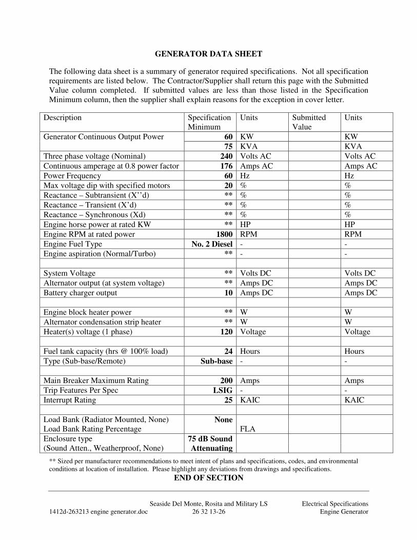
Seaside Del Monte, Rosita and Military LS Electrical Specifications 1412d-263213 engine generator.doc 26 32 13-26 Engine Generator
GENERATOR DATA SHEET
The following data sheet is a summary of generator required specifications. Not all specification requirements are listed below. The Contractor/Supplier shall return this page with the Submitted Value column completed. If submitted values are less than those listed in the Specification Minimum column, then the supplier shall explain reasons for the exception in cover letter.
Description Specification Minimum
Units Submitted Value
Units
Generator Continuous Output Power 60 KW KW
75 KVA KVA
Three phase voltage (Nominal) 240 Volts AC Volts AC
Continuous amperage at 0.8 power factor 176 Amps AC Amps AC
Power Frequency 60 Hz Hz
Max voltage dip with specified motors 20 % %
Reactance – Subtransient (X’’d) ** % %
Reactance – Transient (X’d) ** % %
Reactance – Synchronous (Xd) ** % %
Engine horse power at rated KW ** HP HP
Engine RPM at rated power 1800 RPM RPM
Engine Fuel Type No. 2 Diesel - -
Engine aspiration (Normal/Turbo) ** - -
System Voltage ** Volts DC Volts DC
Alternator output (at system voltage) ** Amps DC Amps DC
Battery charger output 10 Amps DC Amps DC
Engine block heater power ** W W
Alternator condensation strip heater ** W W
Heater(s) voltage (1 phase) 120 Voltage Voltage
Fuel tank capacity (hrs @ 100% load) 24 Hours Hours
Type (Sub-base/Remote) Sub-base - -
Main Breaker Maximum Rating 200 Amps Amps
Trip Features Per Spec LSIG - -
Interrupt Rating 25 KAIC KAIC
Load Bank (Radiator Mounted, None) None Load Bank Rating Percentage FLA
Enclosure type 75 dB Sound (Sound Atten., Weatherproof, None) Attenuating
** Sized per manufacturer recommendations to meet intent of plans and specifications, codes, and environmental conditions at location of installation. Please highlight any deviations from drawings and specifications.
END OF SECTION
Seaside Del Monte, Rosita and Military LS Electrical Specifications 1412d-263623 automatic transfer switch.doc 26 36 23-1 Automatic Transfer Switch
SECTION 26 36 23 - AUTOMATIC TRANSFER SWITCH
PART 1: GENERAL
1.01 SCOPE OF WORK
A. The Contractor shall supply the automatic transfer switch (ATS) as specified herein.
B. The ATS scope of work includes:
1. Providing and installing one automatic transfer switch of rating shown on Contract Drawings.
2. Submittal data and drawings. 3. Startup assistance. 4. Factory and field testing. 5. Operation and maintenance manuals. 6. Warranty of all components.
C. Startup and configuration of ATS with installed voltages and loads.
D. As required under Electrical Specifications [Factory and Field Testing], furnish all required labor, materials, safety equipment, transportation, test equipment, incidentals and services to perform factory and/or field testing.
1.02 REFERENCES
A. Electrical Specifications [Electrical General] B. Electrical Specifications [Factory and Field Testing] C. Project Drawings
1.03 SUBMITTALS REQUIREMENTS
A. Provide Submittals as specified in Electrical Specifications [Electrical General, Submittal Requirements].
B. Include a record of each parameter available to be changed by the user. The list shall include factory defaults and space for entered values.
1.04 OPERATION AND MAINTENANCE INFORMATION
A. Provide operation and maintenance information as specified in Electrical Specifications [Electrical General, Operating and Maintenance Information].
B. Include a record of each ATS parameter setup during startup and testing and place a copy of setting in each O & M manual.
Seaside Del Monte, Rosita and Military LS Electrical Specifications 1412d-263623 automatic transfer switch.doc 26 36 23-2 Automatic Transfer Switch
PART 2: PRODUCTS
2.01 AUTOMATIC TRANSFER SWITCH
A. General:
1. The ATS shall be UL listed in accordance with UL 1008 and be labeled in accordance with that standard's 1½ and 3 cycle, long-time ratings. ATSs which are not tested and labeled with 1½ and 3 cycle (any breaker) ratings and have series, or specific breaker ratings only, are not acceptable.
2. The ATS shall be rated to close on and withstand 42,000 RMS symmetrical short circuit amperes at the ATS terminals or otherwise shown. Provide over-current protection as shown on the Contract drawings.
3. The ATS manufacturer shall be certified to ISO 9001 International Quality Standard and the manufacturer shall have third party certification verifying quality assurance in design/development, production, installation and servicing in accordance with ISO 9001.
4. ATS types utilizing components of molded-case circuit breakers, contactors, or parts thereof, are not acceptable.
5. The switch assembly shall be installed in a NEMA enclosure located as shown on Contract drawings.
6. The automatic transfer switch shall be an ASCO Model 7000, with options to meet specified requirements, no equal.
B. Switch Unit:
1. The transfer switch unit shall be electrically operated and mechanically held. The electrical operator shall be solenoid operated and only momentarily energized to minimize power consumption and heat generation.
2. The transfer switch shall be a conventional 2 position transfer configuration. The switch may only remain in transition for a fraction of a second.
3. The switch shall be 3 pole double-throw with inherently interlocked construction. A solid neutral shall be provided for all systems.
4. Wide contact gaps shall be provided to insure positive isolation of the normal and emergency power sources.
5. The switch shall be fully rated for amperage shown on Contract Drawings,
Seaside Del Monte, Rosita and Military LS Electrical Specifications 1412d-263623 automatic transfer switch.doc 26 36 23-3 Automatic Transfer Switch
for switching all types of loads including induction motors. The ratings shall apply to the voltage and mounting arrangement as shown in the drawings.
6. The main power contacts shall have silver alloy contact construction featuring a wiping action each time the switch is operated. Arc chutes shall be utilized to contain the inherent spark created when switching under load.
7. The main contact design shall allow repeated making and breaking of rated full load current, with a combination of motor and other loads and without damage or undue wear to the contacts.
8. All main power contacts and auxiliary contacts shall be mechanically driven from a common actuator shaft.
9. The bus shall be constructed of silver plated copper.
10. Inspection of all contacts, linkages and moving parts shall be possible from the front of the switch without disassembly of operating linkages and without disconnection of power conductors.
11. All switch and relay contacts, coils, mechanical linkages, and control elements shall be serviceable or removable from the front of the mounted switch or accessory assembly without removal of the switch or assembly from the compartment and without disconnection of the power cables or control wiring.
12. The switch shall have a manual operating handle for maintenance purposes.
13. Compression screw type solder-less terminals or lugs shall be provided for connecting all external line & load power cables and control wiring. All connections shall be accessible from the front without removal of internal components.
14. A terminal strip shall be provided for terminating all control wiring. All terminals shall be numbered with machine printed lettering matching the wire number of the terminated wire.
15. All control wiring shall have permanent identification at each point of connection. Wire identification shall be by machine printed numbered wiring sleeves. Electrically common wires shall have the same wire number. Electrically different wiring shall have unique wire numbers.
16. Control wiring shall be neatly bundled and secured in place by plastic cable ties. Wiring shall be protected with plastic spiral wrap where it crosses over a hinge to the door.
Seaside Del Monte, Rosita and Military LS Electrical Specifications 1412d-263623 automatic transfer switch.doc 26 36 23-4 Automatic Transfer Switch
C. ATS CONTROL PANEL
1. A control panel shall be provided to direct the operation of the transfer switch. The modules sensing and logic shall be a controlled by a built-in microprocessor. Control panels that do not utilize microprocessor electronics to control the operation of the switch are not acceptable.
2. A four line, 20 character LCD display and keypad shall be an integral part of the controller for viewing all available data and setting desired operational parameters. Operational parameters shall also be available for viewing and limited control through the serial communications input port.
3. The controller shall be connected to the transfer switch by an interconnecting wiring harness. The harness shall include a keyed disconnect plug to enable the controller to be disconnected from the transfer switch for routine maintenance.
a. Sensing and control logic shall be provided on multi-layer printed circuit boards.
b. The panel shall be enclosed with a protective cover and be outer door or deadfront mounted such that it may be operated with the door closed for safety and ease of maintenance.
4. A single controller shall provide twelve selectable nominal voltages for maximum application flexibility and minimal spare part requirements.
Voltage sensing shall be true RMS type and shall be accurate to ± 1% of
nominal voltage. Frequency sensing shall be accurate to ± 0.2%.
a. The under-voltage of each phase of the normal source shall be monitored, with pickup adjustable from 85% to 100% of nominal and the dropout adjustable from 75% to 98% of pickup setting, both in increments of 1%. These adjustments shall be factory set at 85% dropout, and 90% pickup.
b. The voltage of each phase of the emergency source shall be monitored, with pickup adjustable from 85% to 100% of nominal. This adjustment shall be factory set at 95% pickup.
c. Frequency sensing of the emergency source shall be provided, with pickup adjustable from 90% to 100% of nominal. This adjustment shall be factory set at 97% pickup.
d. The control panel shall meet or exceed the voltage surge withstand capability in accordance with IEEE Standard 472-1974 (ANSI C37.90a 1974) and the withstand voltage test in accordance with the proposed NEMA Standard ICS1-109.21.
5. The transfer switch control panel shall be capable of operating over a temperature range of -20 to +60 degrees C.
Seaside Del Monte, Rosita and Military LS Electrical Specifications 1412d-263623 automatic transfer switch.doc 26 36 23-5 Automatic Transfer Switch
6. The transfer switch shall be provided with advanced in-phase algorithm which measures the frequency difference between the two sources and initiates transfer at appropriate phase angels to minimize disturbances from transferring motor loads.
7. The control panel shall include the following field adjustable time delays:
a. Time delay to override momentary normal source outages, adjustable from 0 to 5 minutes. This adjustment shall be field set to place emergency generator on-line in 1 minute.
b. Transfer to emergency time delay for controlled timing of load transfer to emergency, adjustable from 0 to 5 minutes. This adjustment shall be field set switch position in 5 seconds after power has stabilized.
c. Emergency source failure time delay to ignore momentary transients during initial generator set loading, adjustable from 0 to 6 seconds. Set at 2 seconds.
d. Retransfer to normal time delay, adjustable 0 to 60 minutes. This adjustment shall be factory set at 5 minutes. The time delay is automatically bypassed if the emergency source fails and normal source is acceptable.
e. Unloaded running time delay for emergency engine generator cool down, adjustable from 0 to 60 minutes. This adjustment shall be factory set at 5 minutes.
f. Generator Exercise Timer: Timer provided for operator adjustment of day of week, time of day and run duration for exercising the generator under operating loads by activating the automatic transfer switch. . Timer shall be mounted on the ATS outer deadfront door.
g. The controller shall provide an integral engine exerciser. The timer shall be field set by the Contractor with date and time during training. The engine exerciser shall allow the user to program up to seven different exercise routines. For each routine, the user shall be able to:
1) Enable or disable the routine. 2) Enable or disable transfer of the load during routine. 3) Set the start time of day, day of week, week of month,
alternate or every time start, duration of run. 4) At the end of the specified duration the switch shall transfer
the load back to normal and run the generator for the specified cool down period. A 10-year life battery that supplies power to the real time clock in the event of a power loss will maintain all time and date information.
8. The controller shall commit-to-start engine which requires the engine to reach proper output and run at least the duration of the cool down setting,
Seaside Del Monte, Rosita and Military LS Electrical Specifications 1412d-263623 automatic transfer switch.doc 26 36 23-6 Automatic Transfer Switch
regardless of whether the load is transferred.
9. Provide interface relays or main switch follower contacts to comply with I/O interface requirements as defined in the P&ID diagram. Interfacing relays shall be industrial grade plug-in type with dust covers. Interface connections shall be wired to backpan terminal blocks. At minimum, the switch shall have the following unused I/O contacts available:
a. Switch in Normal – SPDT rated 10 amps, 120 VAC b. Switch in Emergency – SPDT rated 10 amps, 120 VAC c. Engine starting contact -- DPDT gold-flashed contacts rated 10
amps, 32 VDC d. Emergency Power available – SPDT rated 10 amps, 120 VAC e. Normal Power available – SPDT rated 10 amps, 120 VAC
10. Terminals shall be provided for a remote contact which opens to signal the ATS to transfer to emergency and for remote contacts which open to inhibit transfer to emergency and/or retransfer to normal.
11. Provide separate LED signal lights with nameplates indicating the following:
a. Utility power is available (green) b. Generator power is available (red) c. ATS is connected to Utility source (green) d. ATS is connected to the Generator source (red) e. ATS in neutral position (wht)
12. A three position momentary-type test switch shall be provided for the test / automatic / reset modes:
a. Test: simulate normal source failure b. Automatic: normal operation c. Reset: bypass the time delays on either transfer to emergency or
retransfer to normal.
13. All adjustments shall be field adjustable without the use of tools, meters, power supplies, or special test equipment and can be made safely without personal exposure to live parts
14. Each adjustment resolution shall be settable within minimum increments of 1%.
15. Repetitive accuracy of timer, voltage and frequency settings over a temperature range of –20° C to 70° C shall be within +/-2%.
16. The control panel programming shall be lockable via password protection.
Seaside Del Monte, Rosita and Military LS Electrical Specifications 1412d-263623 automatic transfer switch.doc 26 36 23-7 Automatic Transfer Switch
17. The wire harness for connection of the control panel to the transfer switch shall have sufficient length to reach between the mounting locations shown on the Contract drawings.
18. Provide the following displays on the controller:
a. Event log to display 99 logged events with the time and date of the event, event type and event reason.
b. Total number of ATS transfers. c. Number of ATS transfers caused by power source failures. d. Total number of days ATS has been in operation. e. Total number of hours that the normal and emergency sources have
been available.
PART 3: EXECUTION
3.01 WORKMANSHIP
A. All work in this Section shall conform to the codes and standards specified in Electrical Specifications [Electrical General, Workmanship].
3.02 FIELD ASSISTANCE
A. Testing, checkout and start-up of the ATS equipment shall be performed under the technical direction of a factory trained authorized manufacturer representative.
1. The setup and programming of the ATS shall be provided by a factory-trained representative who is authorized by the ATS manufacturer to perform the startup. This setup and programming shall be done prior to and during the first application of power.
2. Provide testing as specified in Electrical Specifications [Factory and Field Testing].
B. Provide 1 hour of “ATS Setup” Training on operating and maintenance procedures.
3.03 WARRANTY
A. Provide warranty as specified in Electrical Specifications [Electrical General, Warranty].
END OF SECTION
Seaside Del Monte, Rosita and Military LS Electrical Specifications 1412d-263623 automatic transfer switch.doc 26 36 23-8 Automatic Transfer Switch
THIS PAGE INTENTIONALLY BLANK
Seaside Del Monte, Rosita and Military LS Electrical Specifications 1412d-264482 solid state soft starter.doc 26 44 82-1 Solid State Starter
SECTION 26 44 82 - SOLID STATE SOFT STARTER
PART 1: GENERAL
1.01 SCOPE OF WORK
A. Provide each Solid State Starter (SSS) drive as shown on elementary and one-line drawings. All SSSs shall be of the same manufacturer.
B. Provide enclosure (and wire chase as required) for top or bottom feed conduit connection as shown in the drawings. Enclosure size shall not exceed the space allocated in the drawings for such use.
C. Provide cooling/ventilation system, mounting hardware, associated components, devices, and field control stations. Some components may be specified in other Electrical Specifications such as terminal blocks, wire, buttons, etc.
D. The SSS scope of work includes:
1. Providing and installing SSS(s) of rating shown on Contract Drawings. 2. Submittal data and drawings. 3. Startup assistance. 4. Factory and field testing. 5. Operation and maintenance manuals. 6. Warranty of all components.
E. Startup and configuration of SSS with actual motor load.
F. Electrical Specifications [Factory and Field Testing]. Furnish all required labor, materials, safety equipment, transportation, test equipment, incidentals and services to perform factory and/or field testing.
1.02 REFERENCES
A. Electrical Specifications [Electrical General] B. Electrical Specifications [Wire, Fuses and Terminal Blocks] C. Electrical Specifications [Factory and Field Testing]
1.03 SUBMITTALS REQUIREMENTS
A. Provide Submittals as specified in Electrical Specifications [Electrical General, Submittal Requirements].
B. Include a record of each SSS parameter available to be changed by the user. The list shall include factory defaults and space for entered values.
1.04 OPERATION AND MAINTENANCE INFORMATION
Seaside Del Monte, Rosita and Military LS Electrical Specifications 1412d-264482 solid state soft starter.doc 26 44 82-2 Solid State Starter
A. Provide operation and maintenance instructions as specified in Electrical Specifications [Electrical General].
B. Include a record of each SSS parameter setup during startup and testing and place a copy of setting in each O & M manual.
PART 2: PRODUCTS
2.01 QUALITY
A. It is the intent of the Contract Specifications and Drawings to secure the highest quality in all materials and equipment in order to facilitate operation and maintenance of the facility. All equipment and materials shall be new and the products of reputable suppliers having adequate experience in the manufacture of these particular items. For uniformity, only one manufacturer will be accepted for each type of product.
B. All equipment shall be designed for the service intended and shall be of rugged construction, of ample strength for all stresses which may occur during fabrication, transportation, erection, and continuous or intermittent operation. All equipment shall be adequately stayed and braced and anchored and shall be installed in a neat and workmanlike manner. Appearance and safety, as well as utility, shall be given consideration in the design of details. All components and devices installed shall be standard items of industrial grade, unless otherwise noted, and shall be of sturdy and durable construction suitable for long, trouble-free service. Light duty, fragile, and competitive grade devices of questionable durability shall not be used.
C. Products that are specified by manufacturer, trade name, or catalog number establish a standard of quality and do not prohibit the use of equal products of other manufacturers provided they are favorably reviewed prior to installation.
D. Underwriter’s Laboratories (UL) listing is required for all substituted equipment when such a listing is available for the first named equipment.
2.02 SOLID STATE SOFT STARTER
A. General:
1. Each solid state soft starter (SSS) shall be provided as a standalone system as an integral unit. The SSS shall be of the latest technology used exclusively for starting motors of the voltage and horsepower shown in the drawings by limiting the voltage and/or current provided to the motor. The SSS shall be available from a single manufacturer in the horsepower range of 1 to 500. The SSS shall be microprocessor controlled and use high efficiency gated power Silicon Controlled Rectifiers (SCRs).
2. The SSS shall be Allen-Bradley SMC Dialog Plus with pump control
Seaside Del Monte, Rosita and Military LS Electrical Specifications 1412d-264482 solid state soft starter.doc 26 44 82-3 Solid State Starter
option, Schneider Altstart, Cutler hammer S811 or equal.
3. The SSS shall feature the following selectable motor starting/stopping modes:
a. Internal bypass contactor - The SSS shall have an internal running load rated full voltage contactor. The contactor shall automatically engage when the SSS has completed the ramp start of the motor. The bypass contactor shall automatically disengage at the beginning of the ramp stop of the motor. The voltage across the bypass contactor while engaged shall be less than 0.1 volts.
b. Soft Start – The motor shall be raised to an initial torque value that is programmable from 0-90% of locked rotor torque. The motor voltage is gradually increased during the acceleration ramp time, which is adjustable from 0-30 seconds.
c. Soft Start with Selectable Kickstart – The kickstart, or voltage boost, is in addition to the normal soft start as described above. The soft starter shall provide a 0-2 second (selectable) current pulse equal to 550% of the motors full load current.
d. Current Limit Start – This starting mode will limit the maximum starting current supplied to the motor during starting. The user shall be able to adjust the current limit from 50% to 600% of full load current.
e. Full voltage Start- This mode will provide full voltage and current to the motor with a 1/4 second ramp.
f. Soft Stop – This feature will linearly ramp down the voltage over a time interval of 0-60 seconds (selectable)
g. Pump Control – This optional mode (required as specified herein) provides non-linear voltage ramp starting and stopping to smoothly accelerate and decelerate the motor. The starting time shall be programmable from 0-30 seconds and the stopping time programmable from 0-120 seconds.
B. Load - The SSS shall be designed to continuously operate the following motor/pump load:
1. Motor, squirrel-cage induction. 2. Pump, per Mechanical Division Specification. 3. Horsepower, at Full speed R.P.M. of supplied motor. 4. Voltage, 460 VAC, three phase, 60 cycle. 5. Service factor, 1.15 S.F.
Seaside Del Monte, Rosita and Military LS Electrical Specifications 1412d-264482 solid state soft starter.doc 26 44 82-4 Solid State Starter
C. Input Power - The SSS shall be rated to continuously operate under the following input power conditions:
1. Voltage, VAC as shown in Contract one-line diagram, +10%, -10%. 2. Frequency, 60 Hz. 3. Three phase.
D. Output Power - The SSS shall be rated to continuously operate while providing the following output power conditions:
1. Voltage, 0 to 460 VAC. 2. Frequency, 60 Hz. 3. SSS amp size (minimum) as shown on Contract one-line drawing. 4. Continuous motor horsepower. 5. Continuous current, 125% of rated motor nameplate Amps.
E. Environmental - The SSS shall be rated to continuously operate under the following environmental conditions:
1. Ambient temperature, 32°F to 122°F (0°C to 50°C). 2. Altitude, no derating below 3,300 ft. 3. Relative humidity, 95% non-condensing.
F. Digital programmer/controller –The SSS shall be provided with a door mounted alpha-numeric human interface module (HIM) digital display with keypad to view and adjust the following diagnostic and status registers:
1. Volts AC per phase. 2. Current per phase. 3. Watts. 4. KWH. 5. Power Factor.
G. Adjustments - The following setting ranges shall be provided and made independently accessible for operator adjustment:
1. Overvoltage level/delay. 2. Undervoltage level/delay. 3. Current unbalance level/delay. 4. Underload level/delay 5. Phase reversal 6. Jam level/delay. 7. Starts per hour. 8. Backspin delay. 9. Ramp times (start and stop). 10. Motor code letter 11. Overload class 12. Motor FLA
Seaside Del Monte, Rosita and Military LS Electrical Specifications 1412d-264482 solid state soft starter.doc 26 44 82-5 Solid State Starter
13. Motor Service Factor.
H. Input and Output Terminations - The SSS assembly shall have terminals for input and output cabling as defined in the Conduit and Wire Schedule as shown on the Contract Electrical Drawings.
I. Features - The SSS assembly shall have the following features:
1. Bypass Contactor Control - The SSS shall be capable of controlling a bypass motor contactor to allow motor current to flow around the soft starter, through the contactor, and to the motor. Once the motor is up to speed, the contactor shall be closed and held until a fault or stop command. In this mode, no current will flow through the soft starter power terminals but shall remain in the “on” state. An external current sensing module shall monitor the motor current to maintain the diagnostic, fault and control functions. Upon shutdown, the bypass contactor shall open and allow the soft starter to ramp down the motor. Provide sensing module as required per one-line or elementary diagram.
2. Phase rebalance – If enabled, the soft starter shall monitor the incoming three-phase line voltage and automatically adjust the output voltage to balance the three phase currents drawn by the motor.
3. Connection of the three incoming line leads and three-motor leads shall be the only connections necessary for manual operation of the SSS unit. All other wiring shall be prewired at the factory and self-contained within the SSS unit. A 120 VAC control power transformer and other auxiliary power supplies shall be provided with the SSS assembly for power to pilot lights, meters, relays, and miscellaneous devices specified to be supplied with the SSS. Lugs shall be provided for connection of all power leads; terminal blocks shall be provided for all other wiring.
4. The SSS shall be protected by a circuit breaker disconnect. The disconnect shall be externally operated and shall have an operator mechanism that is an integral part of the enclosure. An operator mechanism shall be provided to allow padlocking the disconnect in the "off" position with up to two padlocks.
5. AC input fuses shall be provided on the line and/or load side of the SSS (if required by the manufacturer) to isolate the SSS power circuitry upon a fault condition.
6. Transient and surge voltage power line input protection shall be provided for the SSS through use of metal oxide varistors (MOVs), surge protective module, or other approved equal methods. Transient protection integral to the SSS shall be provided to a minimum of 1,600 volts, 220 joules without failure. The transient protection shall meet or exceed ANSI C7, 90-1971 and IEEE 472-1974 Standards without failure. Failure is defined as loss of
Seaside Del Monte, Rosita and Military LS Electrical Specifications 1412d-264482 solid state soft starter.doc 26 44 82-6 Solid State Starter
components in the SSS including power SCRs and fuses. The SSS shall be protected from the following, as a minimum, power line transients and recover to automatically restart and resume normal operation without posting a fault:
a. Switching the primary of a power transformer. b. Switching power factor correction capacitors “ON” and “OFF”
line. c. De-energization or energization of contactors, relays, and other
power equipment from the power line. d. Starting and stopping of other motors when powered from Utility.
7. Opening of the SSS’s input switches, or breakers while the SSS is operating under load shall not result in damage to the SSS power or control circuit components.
8. The SSS shall be capable of starting and operating without a motor load connected.
9. Phase loss, reversal, undervoltage, overvoltage, and unbalance motor protection shall be provided built in to the SSS.
10. Any configuration of adjustments or controls not set by a switch or potentiometer shall be stored in nonvolatile memory. No configuration information shall be lost due to power failures of any duration.
11. The SSS shall be capable of starting into a rotating motor without tripping out on a fault.
12. Digital Programmer/Controller (HIM) shall be provided and remote door mounted. Remote serial interface shall be suitable for communication via Allen-Bradley standard protocol. Cable for remote digital programmer/controller shall be supplied. The remote controller shall be mounted and housed to maintain the NEMA 12 door rating.
13. Laptop programming connectivity shall be provided to access the drives internal parameters. Provide a USB or RS232 serial converter device and cable for connection to the laptop. Provide programming software as necessary to allow upload/download of data parameters and view current drive status.
J. Enclosure - All components shall be accessible from the front of the enclosure. Rear or side access shall not be required in order to remove or service any component. The enclosure shall include the following in its construction:
1. The SSS shall incorporate fans for cooling. The air flow through the SSS compartment shall provide proper cooling of the operating SSS at an ambient temperature of 104° F.
Seaside Del Monte, Rosita and Military LS Electrical Specifications 1412d-264482 solid state soft starter.doc 26 44 82-7 Solid State Starter
2. The complete SSS unit, including the enclosure assembly, shall be UL listed for a minimum of 42,000 RMS symmetrical ampere fault withstand capability or as otherwise shown on the drawings. SSS assemblies consisting of the SSS, enclosure and all accessories that are not UL listed will not be approved.
PART 3: EXECUTION
3.01 WORKMANSHIP
A. All work in this Section shall conform to the codes and standards specified in Electrical Specifications [Electrical General, Workmanship].
B. Requirements of Related Electrical Sections apply to design, documentation construction and assembly of Solid State Soft Starters.
C. Perform work to remedy non-compliant installations after inspection.
3.02 FIELD ASSISTANCE
A. Testing, checkout and start-up of the solid state starter equipment shall be performed under the technical direction of a factory trained authorized representative.
1. The setup and programming of the SSS shall be provided by a factory-trained representative who is authorized by the SSS manufacturer to perform the startup. This setup and programming shall be done prior to and during the first application of power to the motor. The SSS electronic motor overload protection shall be set to meet the motor nameplate and NEC Code requirements.
2. Provide testing as specified in Electrical Specifications [Factory and Field Testing].
B. Provide 1 hour of “SSS Setup” Training on operating and maintenance procedures.
3.03 WARRANTY
A. Provide warranty as specified in Electrical Specifications [Electrical General, Warranty].
END OF SECTION
Seaside Del Monte, Rosita and Military LS Electrical Specifications 1412d-264482 solid state soft starter.doc 26 44 82-8 Solid State Starter
THIS PAGE INTENTIONALLY BLANK
Seaside Del Monte, Rosita and Military LS Electrical Specifications 1412d-266600 factory and field testing.doc 26 66 00-1 Factory and Field Testing
SECTION 26 66 00 - FACTORY AND FIELD TESTING
PART 1: GENERAL
1.01 SCOPE OF WORK
A. This division defines factory and field testing requirements of electrical and instrumentation equipment and as specified in this section and in Electrical Specifications. All equipment provided under Electrical Specifications and electrical equipment provided under other sections shall be tested as specified herein.
B. The System Integrator, Testing Company and/or Electrical Contractor shall provide all labor, tools, material, power, and technical supervision to perform the specified tests and inspections.
C. The Electrical Contractor shall be present during field testing and assist the System Integrator and/or Testing Company in testing all equipment. The Electrical Contractor shall be ready to correct any wiring problems found during testing.
D. The Application Programmer (defined in Electrical Specifications [Electrical General].) and/or Construction Manager will be actively engaged in Operational Testing and Commissioning. These efforts shall be combined efforts of the Application-Programmer/Construction-Manager/Engineer and Contractor. The Contractor shall facilitate test as outlined herein such that hardware, software and application programming are tested completely and all applicable test documentation is completed.
E. It is the intent of these tests to ensure that all equipment is operational within industry and manufacturer's tolerances and is assembled in accordance with design plans and Specifications.
F. All tests shall be documented in writing by the person performing the test on the test forms submitted (and similar to those shown at the end of this section) and signed by the Engineer as satisfactorily completed. The Testing Company, Electrical Contractor or System Integrator performing tests shall keep a detailed log of all tests that failed or did not meet Specifications, including date of occurrence and correction.
G. The radio and communications equipment shall be completely configured by the Contractor for permanent operation. Radio diagnostics, addresses, and configuration shall be recorded and provided with testing submittals. Provide data in tabular format on Excel spreadsheet. Contractor is required to test every path, link, repeater until optimum results are obtained. Test form example is not provided for this purpose and must be generated by the Contractor.
Seaside Del Monte, Rosita and Military LS Electrical Specifications 1412d-266600 factory and field testing.doc 26 66 00-2 Factory and Field Testing
1.02 REFERENCES
A. Electrical Specifications [Electrical General] B. Project Drawings C. Additional testing may be specified in other Electrical Specifications.
1.03 FACTORY AND FIELD GENERAL REQUIREMENTS
A. Testing General
1. Prior to any field testing Operation & Maintenance Manuals shall have been submitted and approved.
2. The test forms shall be completed by the contractor during testing and calibration of all equipment. All tests shall be witnessed by the Owner’s Representative. Completed test forms shall be given to the Owner’s Representative the day of the test. Complete two sets of test forms if Contractor wants to keep a copy.
3. The Contractor shall give the Engineer 10 working days notice of the dates and time for inspections and testing using the “Scheduled Test Date Request Form.”
4. Include test results in the Maintenance and Operational Manual.
5. As a minimum, all the tests indicated/specified on the test forms shall be performed and test forms filled out by the Contractor.
6. Prepare and submit formal test procedures and forms at least two weeks prior to the start of testing. Testing shall not commence until the test procedures have been reviewed and approved. Submit a combined test procedure submittal with separate sections for factory and field tests.
7. If the results of any of tests are unacceptable, the Contractor shall make corrections and perform the tests again until they are acceptable; these tests shall be done at no additional cost.
B. Failure to Meet Test
1. Any system, material or workmanship which is found defective on the basis of these tests shall be reported immediately following the test. The Contractor shall replace the defective material or equipment and have tests repeated.
C. Safety
1. Testing shall conform to the respective manufacturer's recommendations. All manufacturers’ safety precautions shall be followed.
Seaside Del Monte, Rosita and Military LS Electrical Specifications 1412d-266600 factory and field testing.doc 26 66 00-3 Factory and Field Testing
2. Safety, as shown herein and in other divisions, shall be a combination of all methods and practices described. Safety practices may not be determined based on the least restrictive requirement, but instead, on the most restrictive requirement. Obtain clarification if there is any question prior to performing tests.
3. The procedures stated herein are guidelines for the intended tests, the Contractor shall be responsible to modify these tests to fit the particular application and ensure personnel safety. Absolutely no tests shall be performed in such a fashion that personnel safety is jeopardized.
4. The Contractor shall have two or more personnel present at all tests.
5. Two non-licensed portable radios shall be provided by the Contractor for use during testing.
6. Contractor shall comply with California Electrical Safety Orders (ESO) and Occupational Safety and Health Act (OSHA): All test and procedures shall comply with ESO and OSHA as to safety, protective clothing, clearances, padlocks and barriers around electrical equipment energized during testing.
7. The first set of tests to be performed (pre-energization) shall determine the suitability for energization and shall be completed with all power turned off.
1.04 QUALIFICATIONS
A. Testing Company
1. Testing company shall have been actively engaged in the type of electrical testing specified in this Division for the past three years (minimum). The Testing Company representative shall have two years experience in field testing of equipment working for the Testing Company or equivalent. The following Electrical Testing Companies are pre-approved.
a. EETS (916) 339-9691 b. Industrial Test (888)-809-8550 c. Emerson Electrical Reliability Services d. Apparatus Testing and Engineering (916) 853-6280 e. Apparatus Testing and Engineering (925) 454-1363 f. Power Systems Testing (925) 583-2361
2. Testing Companies not listed are required to submit company and individual representative resumes for review and approval.
B. System Integrator Representative
Seaside Del Monte, Rosita and Military LS Electrical Specifications 1412d-266600 factory and field testing.doc 26 66 00-4 Factory and Field Testing
1. The system integrator representative shall have 1 year experience in field testing of equipment working for the System Integrator or equivalent. If the representative does not demonstrate necessary experience or competence during testing or start-up, the System Integrator shall provide a representative meeting the required competence and experience.
C. Electrical Contractor Representative
1. The Electrician shall have 5 years minimum experience working with industrial control systems and have a Journeyman level experience rating.
1.05 SUBMITTAL REQUIREMENTS
A. The Contractor shall ensure that the Testing Company, System Integrator, and all equipment suppliers provide the submittal documentation required in this section. Submittals shall be complete, neat, orderly, and indexed. The Contractor shall check all submittals required under this Division for the correct number of copies, adequate identification, correctness, and compliance with the Contract Specifications and Drawings, and initial all copies certifying compliance.
B. The System Integrator shall assemble and submit for approval complete testing procedures and forms at least two weeks prior to the start of testing. Contractor is responsible for compiling testing procedures and forms from multiple sub-contractors as required.
C. Test submittal shall include: (as applicable)
1. Proposed procedure for operational testing whether it is performed in the factory or field. Procedure shall include method, simulated I/O requirements, bypass piping, telemetry, and necessary materials and equipment to conduct test.
2. Test forms (for all tests, factory and field, and regardless of who performs tests). Test forms shall be electronically completed prior to submittal with entry spaces filled to the extent possible. The only remaining data that shall require completion during the test is the test data itself. Test forms shall be provided as illustrated at the end of this section or equal.
3. Approved shop one-line, elementary diagrams and PLC I/O drawings.
4. Control strategies photocopied at 75% reduction with room at the side of page for comments on each paragraph or control strategy.
PART 2: PRODUCTS
2.01 TEST EQUIPMENT
A. Test equipment required to perform testing and document results shall be
Seaside Del Monte, Rosita and Military LS Electrical Specifications 1412d-266600 factory and field testing.doc 26 66 00-5 Factory and Field Testing
provided by Contractor, Testing Company or System Integrator.
B. Test instruments shall be calibrated to references traceable to the National Institute of Standards and Technology. Instrument calibration shall be current to one year from date of start-up. Test equipment accuracy shall be at least twice the accuracy of instrument being calibrated. Test instrument certificates of calibration shall be on-hand and provided prior to testing.
C. All test equipment to be used as part of the testing shall be listed in the submitted testing sheets. Contractor supplying the component or system to be tested shall provide all necessary test equipment.
D. The overall accuracy of each input and output loop shall be checked to ensure that it is within manufacturer's Specification tolerances. In no case shall the error exceed 0.25% or 0.04 mA.
PART 3: EXECUTION
3.01 FACTORY TESTING
A. General Requirements
1. The System Integrator shall conduct a thorough and complete factory test witnessed by Engineer per the criteria specified herein. Factory test shall be held within 150 miles of project location.
2. Temporary wiring and equipment shall be provided and connected during these tests to simulate the complete assembled system.
3. The testing shall not be started until the manufacturer has completed fabrication, wiring, setup, programming; quality control testing; and can demonstrate the system is complete and operational.
4. The equipment required for factory testing shall consist of, but is not limited to, control panels, MCCs, and/or miscellaneous electrical panels as provided under this contract.
5. Two digital multimeters/signal generators (minimum +/- 0.1% accuracy) with clip-on leads shall be supplied and utilized during testing for measurement of digital and analog outputs.
6. All factory tests shall be conducted at the System Integrator’s facility. All factory tests shall be completed prior to shipment to the jobsite. The equipment shall be fully assembled, and connected (and programmed) similar to as it will be installed.
7. The length of the factory testing shall be a minimum of one (1) working day(s) (8 hours per day).
Seaside Del Monte, Rosita and Military LS Electrical Specifications 1412d-266600 factory and field testing.doc 26 66 00-6 Factory and Field Testing
8. If the equipment is not ready for factory testing, the test will be cancelled and rescheduled for a later date. The Contractor shall be responsible for paying liquidated damages for expenses incurred by the Owner Representative to come to a cancelled test. One thousand dollars ($1000.00) in liquidated damages shall be deducted from his contract each occurrence.
9. Faulty and/or incorrect hardware or software operation of major portions of the system may, at the discretion of the Engineer, be cause for suspension, cancellation, or restarting of the factory test, at no additional cost to the Owner or extension in Contract time.
10. The Systems Integrator shall develop, furnish, and install a test program to be loaded into PLCs to verify all Logic Controller I/O Point to Point Tests prior to start of applications program testing. Systems Integrator shall use a computer running PLC programming software to confirm I/O calibration and status, force outputs and communications configuration.
11. The factory test will be considered complete only when the integrated system has successfully passed all tests. No electrical equipment shall be shipped to jobsite without completed test documentation.
12. During the testing period, under the supervision of the System Integrator, the Owner’s Representative shall have unlimited and unrestricted access to the usage and testing of system hardware, configuration, software, meters and tools.
13. The System Integrator shall pay all expenses incurred by his personnel including labor, material, transportation, lodging, daily subsistence, and other associated incidental costs during the factory testing.
14. Acceptance and witnessing of the factory tests does not relieve or exclude the Contractor from conforming to the requirements of the Contract Documents.
15. Upon conclusion of factory testing, and at the request of the Owner’s Representative, the System integrator shall remove the PLC, OI, and communication equipment for Owner Representative’s use and programming. The System Integrator shall provide equipment to Owner representative immediately or ship unit within 2 working days to Owner Representative. The System Integrator shall not be responsible for equipment while in Owners Representative’s care.
16. All modifications to documentation as a result of the factory tests shall be corrected and completed before the submittal and delivery of "Operation and Maintenance" Manuals.
17. Copies of the completed and witnessed factory testing forms shall be
Seaside Del Monte, Rosita and Military LS Electrical Specifications 1412d-266600 factory and field testing.doc 26 66 00-7 Factory and Field Testing
included in the Operation and Maintenance Manual.
B. Factory Tests
1. Structured Factory Tests: The associated factory tests are to be performed by the System Integrator and witnessed by the Owner’s Representative. The associated test forms shall be completed during each stage of the test.
a. Visual and Mechanical Inspection Tests
b. Wiring Tests
1) Contractor shall confirm correct panel wiring per System Integrator panel shop drawings. Panel shop drawings shall be compared with Contract P&IDs and other drawings to verify all hardwire logic are accounted for. Panel drawings used in factory tests shall be redlined and inserted into Factory Testing Results submittal.
c. MCC and Control Panel Pre-Operational Tests
d. Logic Controller I/O Point to Point Tests
e. Simulated Alarm Tests
1) Simulate the digital and/or analog signals at the terminals to verify that each PLC I/O point is functional and properly programmed. Verify that all parameters (i.e., setpoints, enable/disable toggle bits, timers, etc.) for the alarms operate according to the Specifications. Multiple alarm states (i.e., LO, LO-LO, HI, HI-HI, etc.) shall be checked.
f. Simulated Operational Control Tests
1) Simulate the digital and/or analog signals at the field terminals to verify that each control system is functional and properly configured and programmed.
2) Each line of control logic in the Control Strategies section shall be checked. When the complete control strategy has been checked, it shall be signed and dated by testing person and person witnessing test.
3) Verify that all parameters (i.e., setpoints, runtimers, totalization, etc.) operate according to the Specifications.
2. Unstructured Factory Tests: The various unstructured tests shall include, but are not limited to, the following.
Seaside Del Monte, Rosita and Military LS Electrical Specifications 1412d-266600 factory and field testing.doc 26 66 00-8 Factory and Field Testing
a. Simulate the equipment failure and power fail/restart of PLC. Check the effects of each failure on maintaining operations with the remaining equipment.
b. The factory tests, as a minimum, shall simulate all normal and abnormal operating conditions including steady state, change of state, variable changes, fluctuations, transients, upsets, start-up, shutdown, power failure, and equipment failure conditions.
c. Measure and test all power supplies for correct voltage. Operate rechargeable devices under battery power to test run duration, alarms and automatic recovery.
3.02 FIELD TESTING
A. General Requirements
1. Field testing is broken down into 4 components
a. Pre-Energization testing b. Pre-Operational Testing c. Operational Testing d. Commissioning
2. Project wide, all Pre-Energization testing must be completed prior to Pre-Operational testing, all Pre-Operational testing must be completed prior to Operational Testing, and all Operational Testing must be completed prior to Commissioning.
a. Any deviation of this order, whether on a component level or larger scale, must be approved.
b. Out of order testing, if allowed, will be evaluated on a case-by-case basis when brought to the attention of the Owner’s Representative. The Owner’s Representative may require that the entire system, or portions thereof, be retested once the missing component(s) are installed and functional.
3. All equipment supplied by the Contractor or others shall be tested by Contractor per these specifications.
4. Two digital multimeters/signal generators (minimum +/- 0.1% accuracy) , AC current meters, torque wrench, and other specialized test equipment shall be provided by the Contractor for use during testing.
5. If the equipment is determined not to be ready for testing, the test will be cancelled and rescheduled for a later date.
Seaside Del Monte, Rosita and Military LS Electrical Specifications 1412d-266600 factory and field testing.doc 26 66 00-9 Factory and Field Testing
6. Faulty and/or incorrect hardware or software operation of major portions of the system may be cause for suspension, cancellation, or restarting of the area of testing, at no additional cost or extension in Contract time.
7. During the Operational testing period, under the supervision of the System Integrator, the Owner’s Representative shall have unlimited and unrestricted access to the usage and testing of all hardware and software in the system.
8. The System Integrator shall pay all expenses incurred by his personnel including labor, material, transportation, lodging, daily subsistence, and other associated incidental costs during field testing.
9. Acceptance and witnessing of the tests does not relieve or exclude the Contractor from conforming to the requirements of the Contract Documents.
10. All modifications to documentation as a result of the tests shall be corrected and completed before the delivery of "as-built” documentation.
11. Copies of the completed and witnessed field testing forms shall be included in the Operation and Maintenance Manual.
12. The various contractors on this project (General Contractor, Electrical Contractor, Testing Company, and System Integrator) shall assume the lead role in testing activities as listed below. The Contractor shall obtain assistance of suppliers and/or manufacturers representatives for any major equipment testing.
a. Electrical Contractor:
1) Pre Energization Tests a) Visual Mechanical Tests b) Wire Insulation and Continuity Tests. c) Panelboard Tests d) Breaker Tests
2) Operational Tests. a) Generator Tests
3) Commissioning.
b. System Integrator:
1) Pre-Operational Tests a) Visual Mechanical Tests b) Control panel pre-operational test c) MCC pre-operational test
Seaside Del Monte, Rosita and Military LS Electrical Specifications 1412d-266600 factory and field testing.doc 26 66 00-10 Factory and Field Testing
d) Motor Tests. e) PLC I/O point to point tests. f) Instrumentation switch tests g) Instrumentation transmitter tests.
2) Operational Tests. 3) Commissioning
c. Testing Company
1) Grounding System Tests 2) Breaker Device Tests
d. General Contractor
1) Test Scheduling 2) Operational Tests. 3) Commissioning.
e. Owner Representative (software systems)
1) Operational Tests. 2) Commissioning.
B. Electrical Field Tests – The following test shall be performed within each test category. Complete test forms for each electrical panel, instrument, and/or device. Provide separate form for each component to be tested.
1. Pre-Energization Inspections and Tests:
a. Visual and Mechanical Inspection Tests b. Wire Insulation and Continuity Tests c. Grounding System Tests d. Panelboard Tests e. Breaker Tests
2. Pre-Operational Tests:
a. MCC Pre-operational Tests: b. Control Panel Pre-operational Tests: c. Motor Testing: d. Generator Testing (if generator is furnished) e. Instrumentation Switch Calibration Tests f. Instrument Transmitter Calibration Tests g. PLC I/O point tests. h. Communication Tests
1) The Contractor shall verify that all communications via radio, telephone, wireline, fiber optic, or other are
Seaside Del Monte, Rosita and Military LS Electrical Specifications 1412d-266600 factory and field testing.doc 26 66 00-11 Factory and Field Testing
functional and ready for operational testing. Revise all configurable parameters without additional cost to the Owner as required for an optimally functional system.
2) Verify that all components of the communication system operate together under all operating and power restart conditions. If faults occur, investigate source of problem and correct. Revise all configurable parameters without additional cost to the Owner.
3) Change setpoints from SCADA and confirm that corresponding field setpoint changes correctly. Check every I/O point on every screen, trend, and database.
3. Operational Tests:
a. After all the previous tests in this subsection are complete, the test forms are completed and signed-off, the Contractor shall conduct operational testing.
b. Representatives from the General Contractor, Electrical Contractor, System Integrator, and Owner’s Representative shall be present during testing. Operational testing shall be performed by Contractor in the presence of the Owner’s Representative.
c. During operational testing the Contractor shall follow the instructions of the Owner. The Owner may place restrictions on operation that must be followed by the Contractor during testing. Any accidents or fines caused by actions of the Contractor where warnings or restrictions were placed, shall be remedied or paid by the Contractor.
d. Alarm Tests
1) Generate the digital and/or analog signals at the primary device to verify that each PLC I/O point is functional and properly programmed. Verify that all parameters (i.e., setpoints, enable/disable toggle bits, timers, etc.) for the alarms operate according to the Specifications. Multiple alarm states (i.e., LO, LO-LO, HI, HI-HI, etc.) shall be checked.
e. Operational Control Tests
1) Generate the digital and/or analog signals at the primary device by raising or lowering the actual measured process. Inject signal into the terminals or utilize a “force” function within the device only as necessary. Verify that each
Seaside Del Monte, Rosita and Military LS Electrical Specifications 1412d-266600 factory and field testing.doc 26 66 00-12 Factory and Field Testing
control system is functional and properly configured and programmed.
2) Each line of control logic in the Control Strategies section shall be checked. When the complete control strategy has been checked, it shall be signed and dated by testing person and person witnessing test.
3) Verify that all parameters (i.e., setpoints, runtimers, totalization, etc.) operate according to the Specifications.
f. Other Tests
1) Force a power failure and power fail/restart of PLC and all other systems. Check the effects of each failure on each piece of equipment and automatic recovery.
2) Force a PLC communication error. Demonstrate error detection, alarming, and recovery.
3) Perform additional operational testing that has not already been witnessed.
4) Perform any additional operational testing as necessary to confirm robust and error free operation under all operational conditions.
4. Trial Period
a. Station/Equipment shall be activated to automatically run for 5 days, 24 hours per day Monday through Friday.
b. During the trial period the Owner’s Representative will test all modes of operation and will look for errors and malfunctions. A punchlist will be generated to be completed by Contractor and re-tested prior to Commissioning.
c. If equipment failure occurs during the trial period, the Contractor shall repair or replace the defective equipment and shall begin another trial period, Monday through Friday.
d. This test shall be repeated until all new equipment functions acceptably and without failure for consecutive days.
C. Commissioning:
1. Commissioning shall not commence until Operational testing and System Training are complete with documentation submitted and with prior

Seaside Del Monte, Rosita and Military LS Electrical Specifications 1412d-266600 factory and field testing.doc 26 66 00-13 Factory and Field Testing
approval.
2. The Owner may delay Commissioning for a period up to 30 days, during which time all testing documentation will be reviewed and preparation for operation will be made. Costs for project delays during this review may not be forwarded on to the Owner.
3. Commissioning period
a. The new equipment shall be activated by the Contractor to operate in full automatic for 10 consecutive days, 24 hours per day. Commissioning shall only start on Mondays or Tuesdays.
b. During Commissioning, the Owner will monitor and run the station in normal automatic mode. If equipment failure occurs during Commissioning, the Contractor shall repair or replace the defective equipment and shall begin another commissioning period after repairs are complete.
c. Parallel, existing and/or back-up systems shall remain in place and functional during commissioning period. Demolition of parallel, existing or back-up systems shall not begin until commissioning is completed.
d. This test shall be repeated until the new equipment functions acceptably for a consecutive commissioning period.
e. Warranty will begin at the start of a successful commissioning period. However, if major hardware failure occurs during commissioning, the warranty and commissioning will restart once the problem has been identified and repaired.
3.03 WARRANTY:
A. Provide warranty per Electrical Specifications [Electrical General, Warranty].
1. The completion of the above tests does not relieve the Contractor from any warranties specified in the Electrical Specifications or other sections.
2. Warranty shall begin on the start date of a successful Commissioning period.
3.04 FINAL ACCEPTANCE:
A. Final Acceptance per Electrical Specifications [Electrical General].
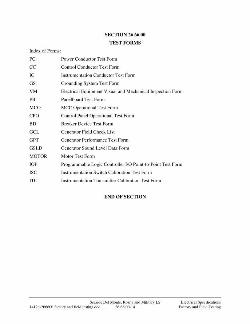
Seaside Del Monte, Rosita and Military LS Electrical Specifications 1412d-266600 factory and field testing.doc 26 66 00-14 Factory and Field Testing
SECTION 26 66 00
TEST FORMS
Index of Forms:
PC Power Conductor Test Form
CC Control Conductor Test Form
IC Instrumentation Conductor Test Form
GS Grounding System Test Form
VM Electrical Equipment Visual and Mechanical Inspection Form
PB Panelboard Test Form
MCO MCC Operational Test Form
CPO Control Panel Operational Test Form
BD Breaker Device Test Form
GCL Generator Field Check List
GPT Generator Performance Test Form
GSLD Generator Sound Level Data Form
MOTOR Motor Test Form
IOP Programmable Logic Controller I/O Point-to-Point Test Form
ISC Instrumentation Switch Calibration Test Form
ITC Instrumentation Transmitter Calibration Test Form
END OF SECTION
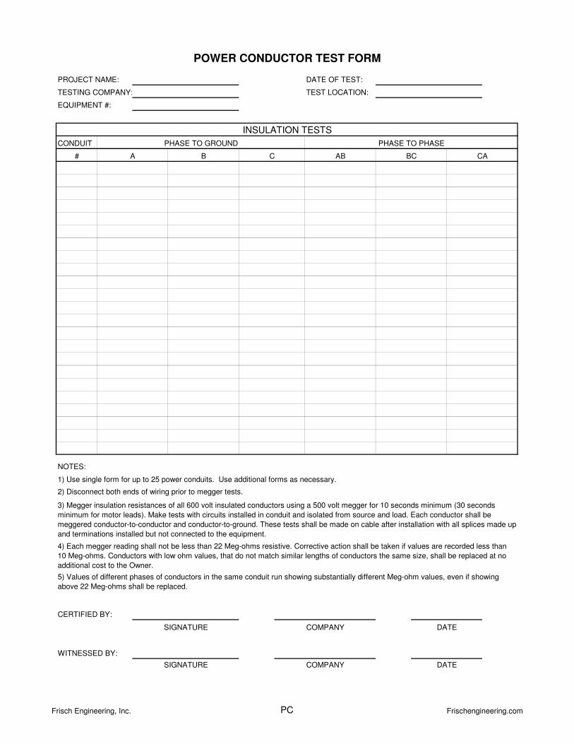
CONDUIT
#
NOTES:
WITNESSED BY:
SIGNATURE COMPANY
SIGNATURE COMPANY
CERTIFIED BY:
INSULATION TESTS
POWER CONDUCTOR TEST FORM
CB
PROJECT NAME:
TESTING COMPANY:
EQUIPMENT #:
TEST LOCATION:
DATE OF TEST:
PHASE TO GROUND PHASE TO PHASE
AB BC CAA
3) Megger insulation resistances of all 600 volt insulated conductors using a 500 volt megger for 10 seconds minimum (30 seconds
minimum for motor leads). Make tests with circuits installed in conduit and isolated from source and load. Each conductor shall be
meggered conductor-to-conductor and conductor-to-ground. These tests shall be made on cable after installation with all splices made up
and terminations installed but not connected to the equipment.
2) Disconnect both ends of wiring prior to megger tests.
1) Use single form for up to 25 power conduits. Use additional forms as necessary.
DATE
DATE
5) Values of different phases of conductors in the same conduit run showing substantially different Meg-ohm values, even if showing
above 22 Meg-ohms shall be replaced.
4) Each megger reading shall not be less than 22 Meg-ohms resistive. Corrective action shall be taken if values are recorded less than
10 Meg-ohms. Conductors with low ohm values, that do not match similar lengths of conductors the same size, shall be replaced at no
additional cost to the Owner.
Frisch Engineering, Inc. PC Frischengineering.com
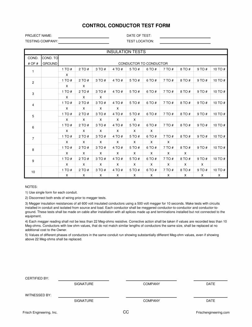
COND. COND. TO
# OF # GROUND
1 TO # 2 TO # 3 TO # 4 TO # 5 TO # 6 TO # 7 TO # 8 TO # 9 TO # 10 TO #
x
1 TO # 2 TO # 3 TO # 4 TO # 5 TO # 6 TO # 7 TO # 8 TO # 9 TO # 10 TO #
x x
1 TO # 2 TO # 3 TO # 4 TO # 5 TO # 6 TO # 7 TO # 8 TO # 9 TO # 10 TO #
x x x
1 TO # 2 TO # 3 TO # 4 TO # 5 TO # 6 TO # 7 TO # 8 TO # 9 TO # 10 TO #
x x x x
1 TO # 2 TO # 3 TO # 4 TO # 5 TO # 6 TO # 7 TO # 8 TO # 9 TO # 10 TO #
x x x x x
1 TO # 2 TO # 3 TO # 4 TO # 5 TO # 6 TO # 7 TO # 8 TO # 9 TO # 10 TO #
x x x x x x
1 TO # 2 TO # 3 TO # 4 TO # 5 TO # 6 TO # 7 TO # 8 TO # 9 TO # 10 TO #
x x x x x x x
1 TO # 2 TO # 3 TO # 4 TO # 5 TO # 6 TO # 7 TO # 8 TO # 9 TO # 10 TO #
x x x x x x x x
1 TO # 2 TO # 3 TO # 4 TO # 5 TO # 6 TO # 7 TO # 8 TO # 9 TO # 10 TO #
x x x x x x x x x
1 TO # 2 TO # 3 TO # 4 TO # 5 TO # 6 TO # 7 TO # 8 TO # 9 TO # 10 TO #
x x x x x x x x x x
NOTES:
5) Values of different phases of conductors in the same conduit run showing substantially different Meg-ohm values, even if showing
above 22 Meg-ohms shall be replaced.
1) Use single form for each conduit.
2) Disconnect both ends of wiring prior to megger tests.
3) Megger insulation resistances of all 600 volt insulated conductors using a 500 volt megger for 10 seconds. Make tests with circuits
installed in conduit and isolated from source and load. Each conductor shall be meggered conductor-to-conductor and conductor-to-
ground. These tests shall be made on cable after installation with all splices made up and terminations installed but not connected to the
equipment.
4) Each megger reading shall not be less than 22 Meg-ohms resistive. Corrective action shall be taken if values are recorded less than 10
Meg-ohms. Conductors with low ohm values, that do not match similar lengths of conductors the same size, shall be replaced at no
additional cost to the Owner.
SIGNATURE COMPANY DATE
WITNESSED BY:
CERTIFIED BY:
SIGNATURE COMPANY
CONDUCTOR TO CONDUCTOR
DATE
CONTROL CONDUCTOR TEST FORM
8
9
10
INSULATION TESTS
4
5
PROJECT NAME:
TESTING COMPANY:
DATE OF TEST:
TEST LOCATION:
1
2
3
7
6
Frisch Engineering, Inc. CC Frischengineering.com
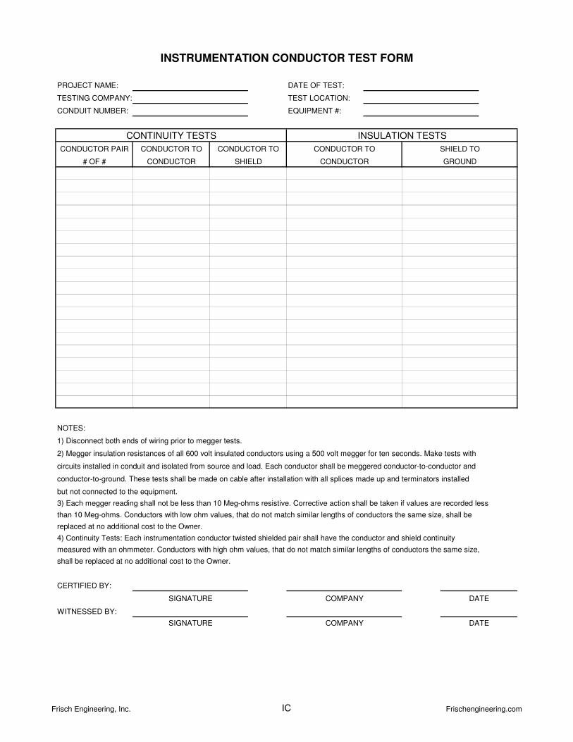
NOTES:
4) Continuity Tests: Each instrumentation conductor twisted shielded pair shall have the conductor and shield continuity
measured with an ohmmeter. Conductors with high ohm values, that do not match similar lengths of conductors the same size,
shall be replaced at no additional cost to the Owner.
2) Megger insulation resistances of all 600 volt insulated conductors using a 500 volt megger for ten seconds. Make tests with
circuits installed in conduit and isolated from source and load. Each conductor shall be meggered conductor-to-conductor and
conductor-to-ground. These tests shall be made on cable after installation with all splices made up and terminators installed
but not connected to the equipment.
replaced at no additional cost to the Owner.
3) Each megger reading shall not be less than 10 Meg-ohms resistive. Corrective action shall be taken if values are recorded less
than 10 Meg-ohms. Conductors with low ohm values, that do not match similar lengths of conductors the same size, shall be
1) Disconnect both ends of wiring prior to megger tests.
WITNESSED BY:
SIGNATURE COMPANY DATE
INSTRUMENTATION CONDUCTOR TEST FORM
CERTIFIED BY:
SIGNATURE COMPANY DATE
INSULATION TESTSCONTINUITY TESTS
PROJECT NAME:
TESTING COMPANY:
CONDUIT NUMBER:
CONDUCTOR TO SHIELD TO
GROUND
DATE OF TEST:
TEST LOCATION:
EQUIPMENT #:
CONDUCTOR PAIR
# OF #
CONDUCTOR TO
SHIELD
CONDUCTOR TO
CONDUCTOR CONDUCTOR
Frisch Engineering, Inc. IC Frischengineering.com
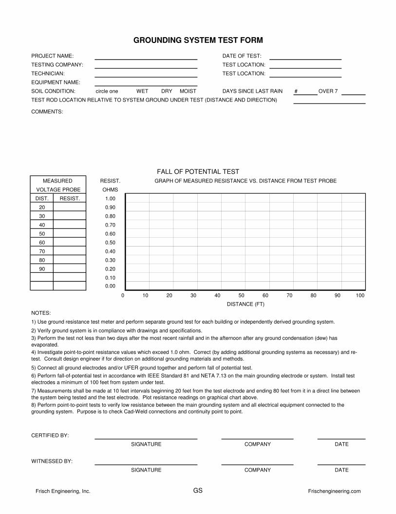
circle one WET DRY MOIST DAYS SINCE LAST RAIN # OVER 7
TEST ROD LOCATION RELATIVE TO SYSTEM GROUND UNDER TEST (DISTANCE AND DIRECTION)
RESIST.
OHMS
DIST. RESIST. 1.00
20 0.90
30 0.80
40 0.70
50 0.60
60 0.50
70 0.40
80 0.30
90 0.20
0.10
0.00
0 10 20 30 40 50 60 70 80 90 100
NOTES:
3) Perform the test not less than two days after the most recent rainfall and in the afternoon after any ground condensation (dew) has
evaporated.
2) Verify ground system is in compliance with drawings and specifications.
VOLTAGE PROBE
GROUNDING SYSTEM TEST FORM
PROJECT NAME: DATE OF TEST:
GRAPH OF MEASURED RESISTANCE VS. DISTANCE FROM TEST PROBE
FALL OF POTENTIAL TEST
MEASURED
TECHNICIAN: TEST LOCATION:
WITNESSED BY:
CERTIFIED BY:
COMMENTS:
DISTANCE (FT)
DATESIGNATURE
COMPANY
COMPANY
8) Perform point-to-point tests to verify low resistance between the main grounding system and all electrical equipment connected to the
grounding system. Purpose is to check Cad-Weld connections and continuity point to point.
SIGNATURE
4) Investigate point-to-point resistance values which exceed 1.0 ohm. Correct (by adding additional grounding systems as necessary) and re-
test. Consult design engineer if for direction on additional grounding materials and methods.
7) Measurements shall be made at 10 feet intervals beginning 20 feet from the test electrode and ending 80 feet from it in a direct line between
the system being tested and the test electrode. Plot resistance readings on graphical chart above.
DATE
TEST LOCATION:TESTING COMPANY:
EQUIPMENT NAME:
SOIL CONDITION:
1) Use ground resistance test meter and perform separate ground test for each building or independently derived grounding system.
6) Perform fall-of-potential test in accordance with IEEE Standard 81 and NETA 7.13 on the main grounding electrode or system. Install test
electrodes a minimum of 100 feet from system under test.
5) Connect all ground electrodes and/or UFER ground together and perform fall of potential test.
Frisch Engineering, Inc. GS Frischengineering.com
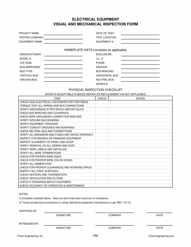
MODEL #: U.L. #:
PHASE:
SERVICE:
SERIES #:
CHECK
NOTES:
CHECK IF DRAWINGS MATCH EQUIPMENT
CHECK BUS BRACING AND CLEARANCE
1) Complete checklist above. Note any items that were found out of compliance.
VERIFY EQUIPMENT GROUNDS
CHECK HEATERS AND THERMOSTATS
CHECK VENTILATION AND FILTERS
VERIFY ALL BREAKERS AND FUSES ARE RATED PROPERLY
VERIFY ALL NAMEPLATES
INSPECT FOR BROKEN OR DAMAGED EQUIPMENT
INSPECT ALIGNMENT OF PANEL AND DOOR
VERIFY ANCHORAGE IS PER SPECS AND/OR CALCS
VERIFY REMOVAL OF ALL DEBRIS AND DUST
VERIFY CONDUIT GROUNDS AND BUSHINGS
CHECK NEUTRAL BUS AND CONNECTIONS
ENTER A-ACCEPTABLE R-NEEDS REPAIR OR REPLACEMENT NA-NOT APPLICABLE
NOTES
VERTICAL BUS:
GROUND BUS:
BUS TYPE:
NEUTRAL BUS:
BUS BRACING:
ENCLOSURE:
PROJECT NAME:
TESTING COMPANY:
EQUIPMENT NAME:
NAMEPLATE DATA (complete as applicable)
DATE OF TEST:
TEST LOCATION:
EQUIPMENT #:
VOLTAGE:
BUS AMPERAGE:
MANUFACTURER:
ELECTRICAL EQUIPMENT
VISUAL AND MECHANICAL INSPECTION FORM
HORIZONTAL BUS:
CERTIFIED BY:
SIGNATURE COMPANY
CHECK ACCURACY OF OPERATION & MAINTENANCE
DATE
2) Torque all electrical connections to values defined by equipment manufacturer or per NEC 110-14.
WITNESSED BY:
SIGNATURE COMPANY DATE
CHECK FOR PROPER CLEARANCES AND WORKING SPACE
PHYSICAL INSPECTION CHECKLIST
ITEM
INSPECT ALL PAINT SURFACES
CHECK FOR PROPER WIRE COLOR CODES
VERIFY WIRE LABELS ARE INSTALLED
VERIFY ALL WIRE TERMINATIONS
CHECK FOR PROPER WIRE SIZES
CHECK NON-ELECTRICAL FASTENERS FOR TIGHTNESS
TORQUE TEST ALL WIRING AND BUS CONNECTIONS
CHECK MAIN GROUNDING CONNECTION AND SIZE
VERIFY GROUND BUS BONDING
Frisch Engineering, Inc. VM Frischengineering.com
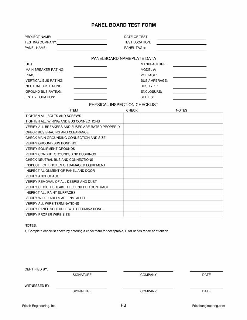
UL #:
MAIN BREAKER RATING: MODEL #:
PHASE:
VERTICAL BUS RATING:
NEUTRAL BUS RATING:
GROUND BUS RATING:
ENTRY LOCATION: SERIES:
CHECK
NOTES:
VERIFY ALL WIRE TERMINATIONS
VERIFY PANEL SCHEDULE WITH TERMINATIONS
VERIFY PROPER WIRE SIZE
CHECK NEUTRAL BUS AND CONNECTIONS
INSPECT FOR BROKEN OR DAMAGED EQUIPMENT
INSPECT ALIGNMENT OF PANEL AND DOOR
VERIFY ANCHORAGE
VERIFY CIRCUIT BREAKER LEGEND PER CONTRACT
INSPECT ALL PAINT SURFACES
VERIFY WIRE LABELS ARE INSTALLED
CHECK MAIN GROUNDING CONNECTION AND SIZE
VERIFY GROUND BUS BONDING
VERIFY EQUIPMENT GROUNDS
VERIFY CONDUIT GROUNDS AND BUSHINGS
DATE
WITNESSED BY:
SIGNATURE COMPANY DATE
SIGNATURE COMPANY
CERTIFIED BY:
PANEL BOARD TEST FORM
PROJECT NAME:
TESTING COMPANY:
PANEL NAME:
PANELBOARD NAMEPLATE DATA
DATE OF TEST:
TEST LOCATION:
PANEL TAG #:
BUS AMPERAGE:
BUS TYPE:
ENCLOSURE:
VOLTAGE:
MANUFACTURE:
PHYSICAL INSPECTION CHECKLIST
NOTESITEM
TIGHTEN ALL BOLTS AND SCREWS
VERIFY ALL BREAKERS AND FUSES ARE RATED PROPERLY
TIGHTEN ALL WIRING AND BUS CONNECTIONS
CHECK BUS BRACING AND CLEARANCE
1) Complete checklist above by entering a checkmark for acceptable, R for needs repair or attention
VERIFY REMOVAL OF ALL DEBRIS AND DUST
Frisch Engineering, Inc. PB Frischengineering.com
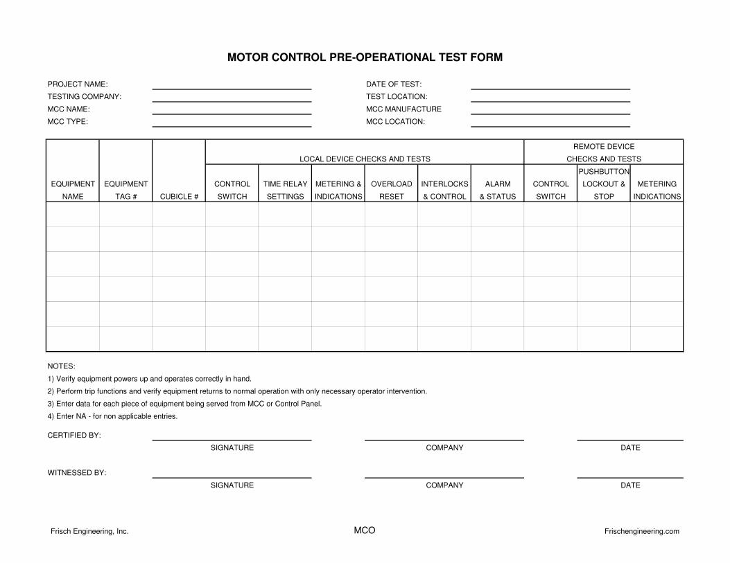
MCC NAME:
MCC TYPE:
PUSHBUTTON
EQUIPMENT EQUIPMENT CONTROL TIME RELAY METERING & OVERLOAD INTERLOCKS ALARM CONTROL LOCKOUT & METERING
NAME TAG # CUBICLE # SWITCH SETTINGS INDICATIONS RESET & CONTROL & STATUS SWITCH STOP INDICATIONS
WITNESSED BY:
SIGNATURE COMPANY DATE
CERTIFIED BY:
SIGNATURE COMPANY DATE
REMOTE DEVICE
CHECKS AND TESTSLOCAL DEVICE CHECKS AND TESTS
1) Verify equipment powers up and operates correctly in hand.
2) Perform trip functions and verify equipment returns to normal operation with only necessary operator intervention.
3) Enter data for each piece of equipment being served from MCC or Control Panel.
4) Enter NA - for non applicable entries.
MOTOR CONTROL PRE-OPERATIONAL TEST FORM
NOTES:
MCC LOCATION:
PROJECT NAME:
TESTING COMPANY:
DATE OF TEST:
TEST LOCATION:
MCC MANUFACTURE
Frisch Engineering, Inc. MCO Frischengineering.com
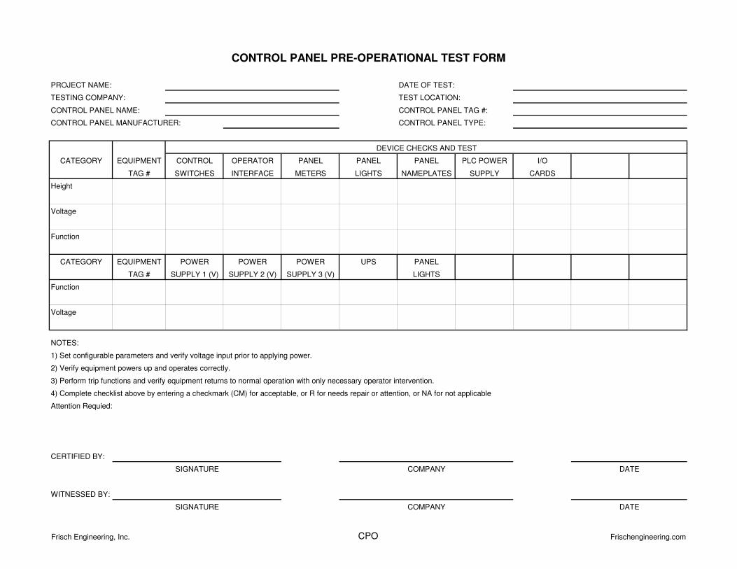
CATEGORY EQUIPMENT CONTROL OPERATOR PANEL PANEL PANEL PLC POWER I/O
TAG # SWITCHES INTERFACE METERS LIGHTS NAMEPLATES SUPPLY CARDS
Height
Voltage
Function
CATEGORY EQUIPMENT POWER POWER POWER UPS PANEL
TAG # SUPPLY 1 (V) SUPPLY 2 (V) SUPPLY 3 (V) LIGHTS
Function
Voltage
NOTES:
Attention Requied:
CERTIFIED BY:
WITNESSED BY:
CONTROL PANEL PRE-OPERATIONAL TEST FORM
TESTING COMPANY:
DATE OF TEST:
TEST LOCATION:
PROJECT NAME:
COMPANYSIGNATURE
COMPANY DATE
DATE
SIGNATURE
2) Verify equipment powers up and operates correctly.
CONTROL PANEL MANUFACTURER:
3) Perform trip functions and verify equipment returns to normal operation with only necessary operator intervention.
4) Complete checklist above by entering a checkmark (CM) for acceptable, or R for needs repair or attention, or NA for not applicable
1) Set configurable parameters and verify voltage input prior to applying power.
DEVICE CHECKS AND TEST
CONTROL PANEL NAME: CONTROL PANEL TAG #:
CONTROL PANEL TYPE:
Frisch Engineering, Inc. CPO Frischengineering.com
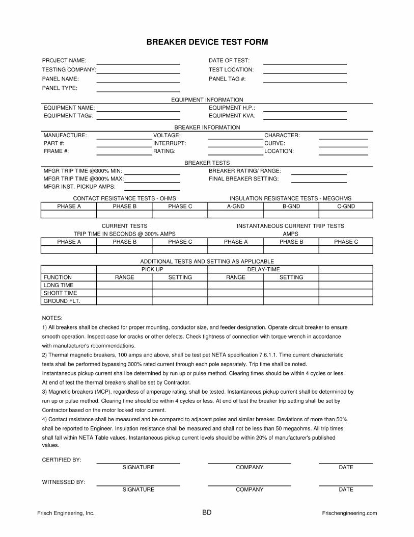
PART #: CURVE:
RATING:
values.
CERTIFIED BY:
WITNESSED BY:
DATE
DATE
SIGNATURE
SIGNATURE COMPANY
COMPANY
smooth operation. Inspect case for cracks or other defects. Check tightness of connection with torque wrench in accordance
NOTES:
GROUND FLT.
ADDITIONAL TESTS AND SETTING AS APPLICABLE
PICK UP DELAY-TIME
FUNCTION RANGE SETTINGRANGE SETTING
TRIP TIME IN SECONDS @ 300% AMPS AMPS
PHASE A PHASE B PHASE C PHASE A PHASE B PHASE C
CURRENT TESTS INSTANTANEOUS CURRENT TRIP TESTS
EQUIPMENT INFORMATION
BREAKER DEVICE TEST FORM
CHARACTER:
LOCATION:
DATE OF TEST:
TEST LOCATION:
PANEL TAG #:
EQUIPMENT NAME:
PROJECT NAME:
TESTING COMPANY:
PANEL NAME:
PANEL TYPE:
EQUIPMENT H.P.:
EQUIPMENT KVA:
BREAKER INFORMATION
PHASE A PHASE B PHASE C A-GND B-GND C-GND
BREAKER RATING/ RANGE:
BREAKER TESTS
EQUIPMENT TAG#:
MANUFACTURE: VOLTAGE:
INTERRUPT:
CONTACT RESISTANCE TESTS - OHMS INSULATION RESISTANCE TESTS - MEGOHMS
MFGR INST. PICKUP AMPS:
FINAL BREAKER SETTING:
MFGR TRIP TIME @300% MIN:
MFGR TRIP TIME @300% MAX:
1) All breakers shall be checked for proper mounting, conductor size, and feeder designation. Operate circuit breaker to ensure
LONG TIME
SHORT TIME
with manufacturer's recommendations.
tests shall be performed bypassing 300% rated current through each pole separately. Trip time shall be noted.
Instantaneous pickup current shall be determined by run up or pulse method. Clearing times should be within 4 cycles or less.
At end of test the thermal breakers shall be set by Contractor.
2) Thermal magnetic breakers, 100 amps and above, shall be test pet NETA specification 7.6.1.1. Time current characteristic
shall be reported to Engineer. Insulation resistance shall be measured and shall not be less than 50 megaohms. All trip times
shall fall within NETA Table values. Instantaneous pickup current levels should be within 20% of manufacturer's published
3) Magnetic breakers (MCP), regardless of amperage rating, shall be tested. Instantaneous pickup current shall be determined by
run up or pulse method. Clearing time should be within 4 cycles or less. At end of test the breaker trip setting shall be set by
Contractor based on the motor locked rotor current.
4) Contact resistance shall be measured and be compared to adjacent poles and similar breaker. Deviations of more than 50%
FRAME #:
Frisch Engineering, Inc. BD Frischengineering.com
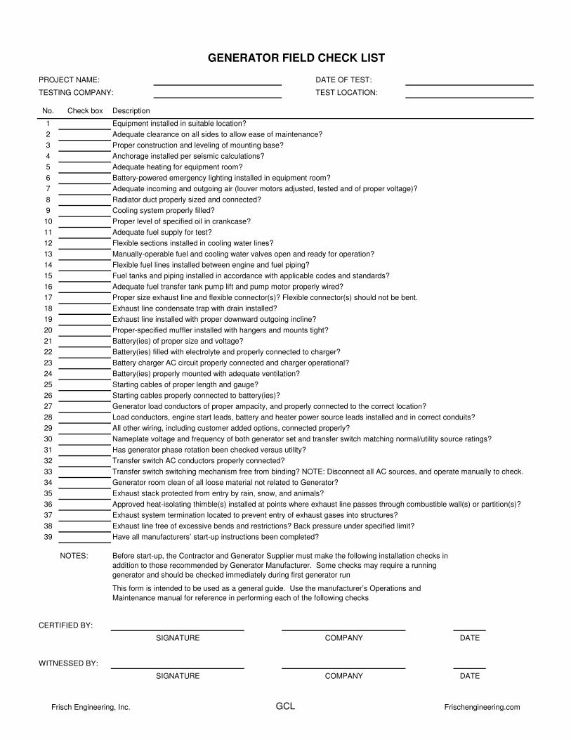
PROJECT NAME:
TESTING COMPANY:
No. Check box
1
2
3
4
5
6
7
8
9
10
11
12
13
14
15
16
17
18
19
20
21
22
23
24
25
26
27
28
29
30
31
32
33
34
35
36
37
38
39
NOTES:
CERTIFIED BY:
DATE
WITNESSED BY:
DATE
Description
Equipment installed in suitable location?
Adequate clearance on all sides to allow ease of maintenance?
GENERATOR FIELD CHECK LIST
DATE OF TEST:
TEST LOCATION:
Anchorage installed per seismic calculations?
Proper construction and leveling of mounting base?
Battery-powered emergency lighting installed in equipment room?
Adequate incoming and outgoing air (louver motors adjusted, tested and of proper voltage)?
Adequate heating for equipment room?
Radiator duct properly sized and connected?
Cooling system properly filled?
Proper level of specified oil in crankcase?
Adequate fuel supply for test?
Flexible sections installed in cooling water lines?
Manually-operable fuel and cooling water valves open and ready for operation?
Flexible fuel lines installed between engine and fuel piping?
Fuel tanks and piping installed in accordance with applicable codes and standards?
Adequate fuel transfer tank pump lift and pump motor properly wired?
Proper size exhaust line and flexible connector(s)? Flexible connector(s) should not be bent.
Exhaust line condensate trap with drain installed?
Exhaust line installed with proper downward outgoing incline?
Proper-specified muffler installed with hangers and mounts tight?
Battery(ies) of proper size and voltage?
Battery(ies) filled with electrolyte and properly connected to charger?
Battery charger AC circuit properly connected and charger operational?
Battery(ies) properly mounted with adequate ventilation?
Starting cables of proper length and gauge?
Starting cables properly connected to battery(ies)?
Generator load conductors of proper ampacity, and properly connected to the correct location?
Load conductors, engine start leads, battery and heater power source leads installed and in correct conduits?
All other wiring, including customer added options, connected properly?
Nameplate voltage and frequency of both generator set and transfer switch matching normal/utility source ratings?
Has generator phase rotation been checked versus utility?
Transfer switch AC conductors properly connected?
Transfer switch switching mechanism free from binding? NOTE: Disconnect all AC sources, and operate manually to check.
Generator room clean of all loose material not related to Generator?
Exhaust stack protected from entry by rain, snow, and animals?
Approved heat-isolating thimble(s) installed at points where exhaust line passes through combustible wall(s) or partition(s)?
Exhaust system termination located to prevent entry of exhaust gases into structures?
Exhaust line free of excessive bends and restrictions? Back pressure under specified limit?
Have all manufacturers’ start-up instructions been completed?
SIGNATURE COMPANY
Before start-up, the Contractor and Generator Supplier must make the following installation checks in
addition to those recommended by Generator Manufacturer. Some checks may require a running
generator and should be checked immediately during first generator run
This form is intended to be used as a general guide. Use the manufacturer’s Operations and
Maintenance manual for reference in performing each of the following checks
SIGNATURE COMPANY
Frisch Engineering, Inc. GCL Frischengineering.com
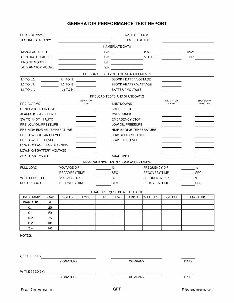
MANUFACTURER: S/N: KW: KVA:
GENERATOR MODEL S/N: VOLTS: PH:
ENGINE MODEL: S/N:
ALTERNATOR MODEL: S/N:
L1 TO L2: L1 TO N: BLOCK HEATER VOLTAGE
L2 TO L3: L2 TO N: BLOCK HEATER WATTAGE
L3 TO L1: L3 TO N: BATTERY VOLTAGE
PRE-ALARMSINDICATOR
LIGHT SHUTDOWNSINDICATOR
LIGHT
SHUTDOWN
FUNCTION
GENERATOR RUN LIGHT OVERSPEED
ALARM HORN & SILENCE OVERCRANK
SWITCH NOT IN AUTO EMERGENCY STOP
PRE LOW OIL PRESSURE LOW OIL PRESSURE
PRE HIGH ENGINE TEMPERATURE HIGH ENGINE TEMPERATURE
PRE LOW COOLANT LEVEL LOW COOLANT LEVEL
PRE LOW FUEL LEVEL LOW FUEL LEVEL
LOW COOLANT TEMP WARNING
LOW/HIGH BATTERY VOLTAGE
AUXILLIARY FAULT AUXILLIARY
FULL LOAD VOLTAGE DIP % FREQUENCY DIP %
RECOVERY TIME SEC RECOVERY TIME SEC
WITH SPECIFIED VOLTAGE DIP % FREQUENCY DIP %
MOTOR LOAD RECOVERY TIME SEC RECOVERY TIME SEC
TIME STAMP LOAD VOLTS AMPS HZ KW AMB ºF WATER ºF OIL PSI
WARM UP 0
0.1 25
0.1 50
0.2 75
0.2 100
3.4 100
NOTES:
CERTIFIED BY:
DATE
WITNESSED BY:
DATE
NAMEPLATE DATA
SIGNATURE
SIGNATURE
COMPANY
COMPANY
LOAD TEST @ 1.0 POWER FACTOR
PRELOAD TESTS VOLTAGE MEASUREMENTS
ENGR HRS
PERFORMANCE TESTS / LOAD ACCEPTANCE
GENERATOR PERFORMANCE TEST REPORT
DATE OF TEST:
TEST LOCATION:
PROJECT NAME:
TESTING COMPANY:
PRELOAD TESTS AND SHUTDOWNS
Frisch Engineering, Inc. GPT Frischengineering.com
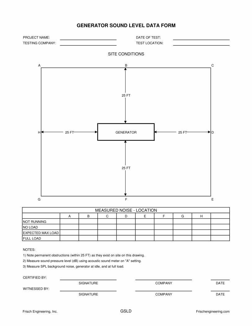
A B C
H 25 FT 25 FT D
G F E
A B C D E F G H
NOTES:
DATE
DATE
1) Note permanent obstructions (within 25 FT) as they exist on site on this drawing.
2) Measure sound pressure level (dB) using acoustic sound meter on "A" setting.
3) Measure SPL background noise, generator at idle, and at full load.
EXPECTED MAX LOAD
NO LOAD
NOT RUNNING
FULL LOAD
SITE CONDITIONS
MEASURED NOISE - LOCATION
25 FT
25 FT
GENERATOR
CERTIFIED BY:
SIGNATURE COMPANY
WITNESSED BY:
SIGNATURE COMPANY
GENERATOR SOUND LEVEL DATA FORM
PROJECT NAME:
TESTING COMPANY:
DATE OF TEST:
TEST LOCATION:
Frisch Engineering, Inc. GSLD Frischengineering.com
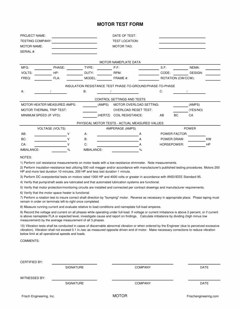
MFG: PHASE: TYPE: P.F: S.F: NEMA:
VOLTS: HP: DUTY: RPM: CODE: DESIGN:
FREQ: FLA: MODEL: FRAME #:
A: / B: / C: /
(AMPS) (AMPS)
(YES/NO)
(HERTZ) AB BC CA
AB: V A: A
BC: V B: A KW
CA: V C: A HP
% %IMBALANCE:IMBALANCE:
4) Verify that pump/shaft seals are lubricated and that automated lubrication systems are functional.
3) Perform DC overpotential tests on motors rated 1000 HP and 4000 volts or greater in accordance with ANSI/IEEE Standard 95.
NOTES:
8) Measure running current and evaluate relative to load conditions and nameplate full-load amperes.
10) Vibration tests shall be conducted in cases of discernable abnormal vibration or when ordered by the Engineer (due to perceived excessive
vibration). Vibration shall not exceed 0.1 in./sec as measured opposite driven end of motor. Make necessary corrections to reduce vibration
below limit at all operational speeds and loads.
1) Perform coil resistance measurements on motor leads with a low-resistance ohmmeter. Note measurements.
COIL RESISTANCE:
HORSEPOWER:
POWER FACTOR:
SERIAL #:
PROJECT NAME:
TESTING COMPANY:
MOTOR NAME:
MINIMUM SPEED (IF VFD):
MOTOR TAG:
DATE OF TEST:
TEST LOCATION:
MOTOR NAMEPLATE DATA
ROTATION (CW/CCW):
POWER DRAW:
INSULATION RESISTANCE TEST PHASE-TO-GROUND/PHASE-TO-PHASE
CONTROL SETTINGS AND TESTS
MOTOR HEATER MEASURED AMPS:
MOTOR THERMAL TRIP TEST:
5) Verify that motor protection/monitoring circuits are installed and connected per contract drawings and manufacturer requirements.
2) Perform insulation-resistance test utilizing 500 volt megger and/or accordance with manufacturer's published testing procedures. Motors 200
HP and more test duration 10 minutes, 200 HP and less test duration 1 minute.
6) Verify that the motor space heater is functional.
MOTOR TEST FORM
VOLTAGE (VOLTS) AMPERAGE (AMPS) POWER
MOTOR OVERLOAD SETTING:
OVERLOAD RESET TEST:
PHYSICAL MOTOR TESTS - ACTUAL MEASURED VALUES
SIGNATURE COMPANY
7) Perform a rotation test to insure correct shaft direction by "bumping" motor. Reverse as necessary in appropriate place. Phase taping must
remain in order on terminals left-to-right once completed.
DATE
9) Record the voltage and current on all phases while operating under full-load. If voltage or current imbalance is above 2 percent, or if current
is above nameplate FLA or expected level, investigate cause and report on findings. Calculate imbalance by dividing (high minus low
measurement) by the average measurement of all 3 phases.
COMMENTS:
CERTIFIED BY:
WITNESSED BY:
SIGNATURE COMPANY DATE
Frisch Engineering, Inc. MOTOR Frischengineering.com
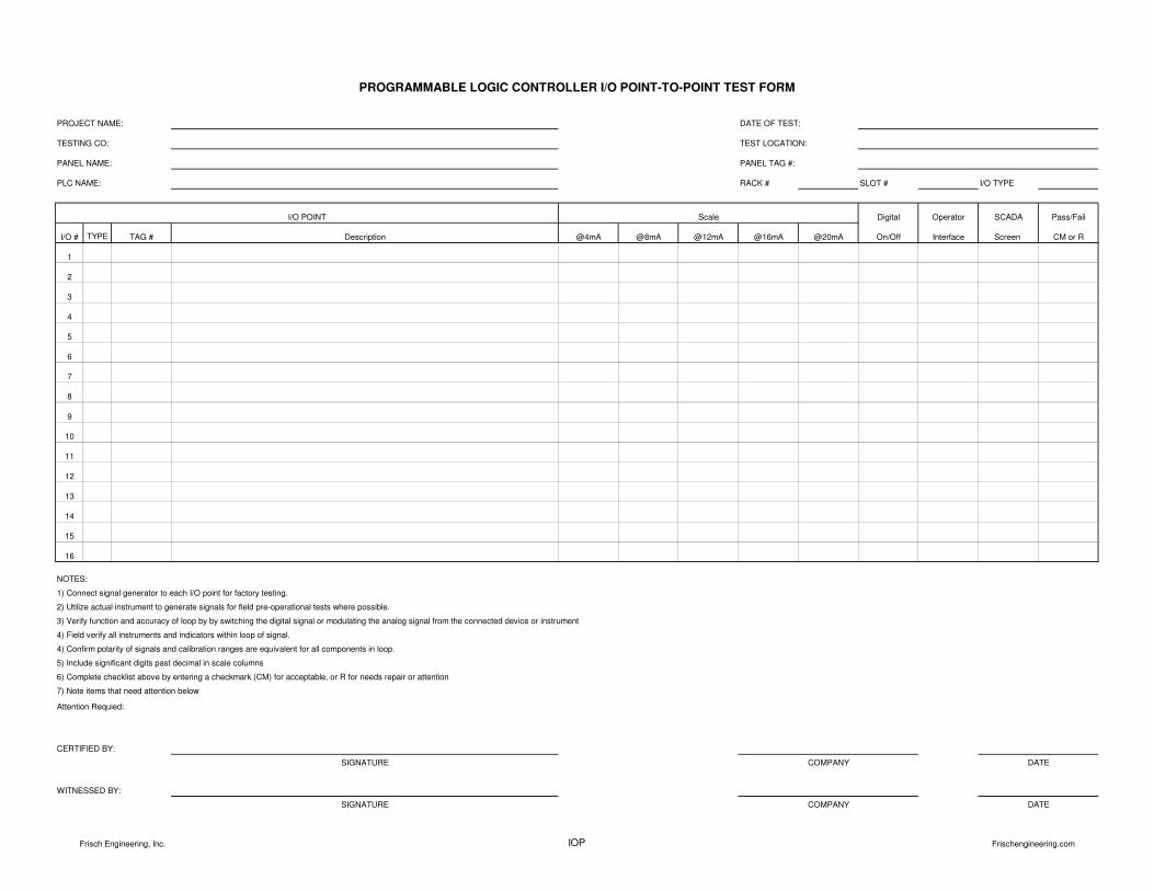
RACK # SLOT # I/O TYPE
Digital Operator SCADA Pass/Fail
I/O # TYPE TAG # @4mA @8mA @12mA @16mA @20mA On/Off Interface Screen CM or R
1
2
3
4
5
6
7
8
9
10
11
12
13
14
15
16
Attention Requied:
PROGRAMMABLE LOGIC CONTROLLER I/O POINT-TO-POINT TEST FORM
PROJECT NAME: DATE OF TEST:
TEST LOCATION:
Description
PANEL NAME: PANEL TAG #:
TESTING CO:
PLC NAME:
I/O POINT Scale
NOTES:
4) Field verify all instruments and indicators within loop of signal.
1) Connect signal generator to each I/O point for factory testing.
2) Utilize actual instrument to generate signals for field pre-operational tests where possible.
3) Verify function and accuracy of loop by by switching the digital signal or modulating the analog signal from the connected device or instrument
4) Confirm polarity of signals and calibration ranges are equivalent for all components in loop.
5) Include significant digits past decimal in scale columns
6) Complete checklist above by entering a checkmark (CM) for acceptable, or R for needs repair or attention
7) Note items that need attention below
CERTIFIED BY:
WITNESSED BY:
SIGNATURE COMPANY DATE
DATESIGNATURE COMPANY
Frisch Engineering, Inc. IOP Frischengineering.com
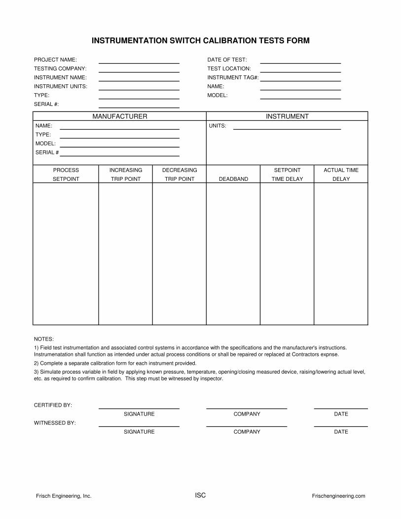
INSTRUMENT UNITS: NAME:
TYPE: MODEL:
SERIAL #:
NAME: UNITS:
TYPE:
MODEL:
SERIAL #:
NOTES:
1) Field test instrumentation and associated control systems in accordance with the specifications and the manufacturer's instructions.
Instrumenatation shall function as intended under actual process conditions or shall be repaired or replaced at Contractors expnse.
2) Complete a separate calibration form for each instrument provided.
3) Simulate process variable in field by applying known pressure, temperature, opening/closing measured device, raising/lowering actual level,
etc. as required to confirm calibration. This step must be witnessed by inspector.
WITNESSED BY:
CERTIFIED BY:
SIGNATURE COMPANY DATE
DELAY
COMPANY DATESIGNATURE
PROCESS
INSTRUMENTATION SWITCH CALIBRATION TESTS FORM
DEADBAND TIME DELAY
SETPOINT ACTUAL TIMEINCREASING
TRIP POINT
DECREASING
TRIP POINT
PROJECT NAME:
TESTING COMPANY:
INSTRUMENT NAME:
DATE OF TEST:
TEST LOCATION:
INSTRUMENT TAG#:
SETPOINT
INSTRUMENTMANUFACTURER
Frisch Engineering, Inc. ISC Frischengineering.com
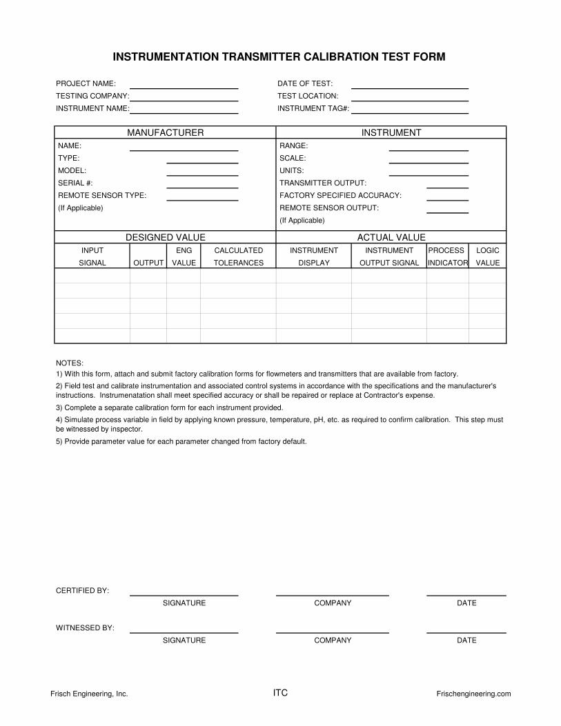
NAME: RANGE:
TYPE: SCALE:
MODEL: UNITS:
SERIAL #:
(If Applicable)
ENG PROCESS LOGIC
OUTPUT VALUE INDICATOR VALUE
NOTES:
5) Provide parameter value for each parameter changed from factory default.
INSTRUMENTINSTRUMENT
WITNESSED BY:
CERTIFIED BY:
4) Simulate process variable in field by applying known pressure, temperature, pH, etc. as required to confirm calibration. This step must
be witnessed by inspector.
2) Field test and calibrate instrumentation and associated control systems in accordance with the specifications and the manufacturer's
instructions. Instrumenatation shall meet specified accuracy or shall be repaired or replace at Contractor's expense.
3) Complete a separate calibration form for each instrument provided.
DATESIGNATURE
DATESIGNATURE COMPANY
COMPANY
DESIGNED VALUE
INPUT
REMOTE SENSOR TYPE:
CALCULATED
DISPLAY
REMOTE SENSOR OUTPUT:
1) With this form, attach and submit factory calibration forms for flowmeters and transmitters that are available from factory.
(If Applicable)
TRANSMITTER OUTPUT:
FACTORY SPECIFIED ACCURACY:
INSTRUMENTATION TRANSMITTER CALIBRATION TEST FORM
PROJECT NAME:
TESTING COMPANY:
INSTRUMENT NAME:
DATE OF TEST:
INSTRUMENT TAG#:
TEST LOCATION:
MANUFACTURER INSTRUMENT
ACTUAL VALUE
OUTPUT SIGNALTOLERANCESSIGNAL
Frisch Engineering, Inc. ITC Frischengineering.com
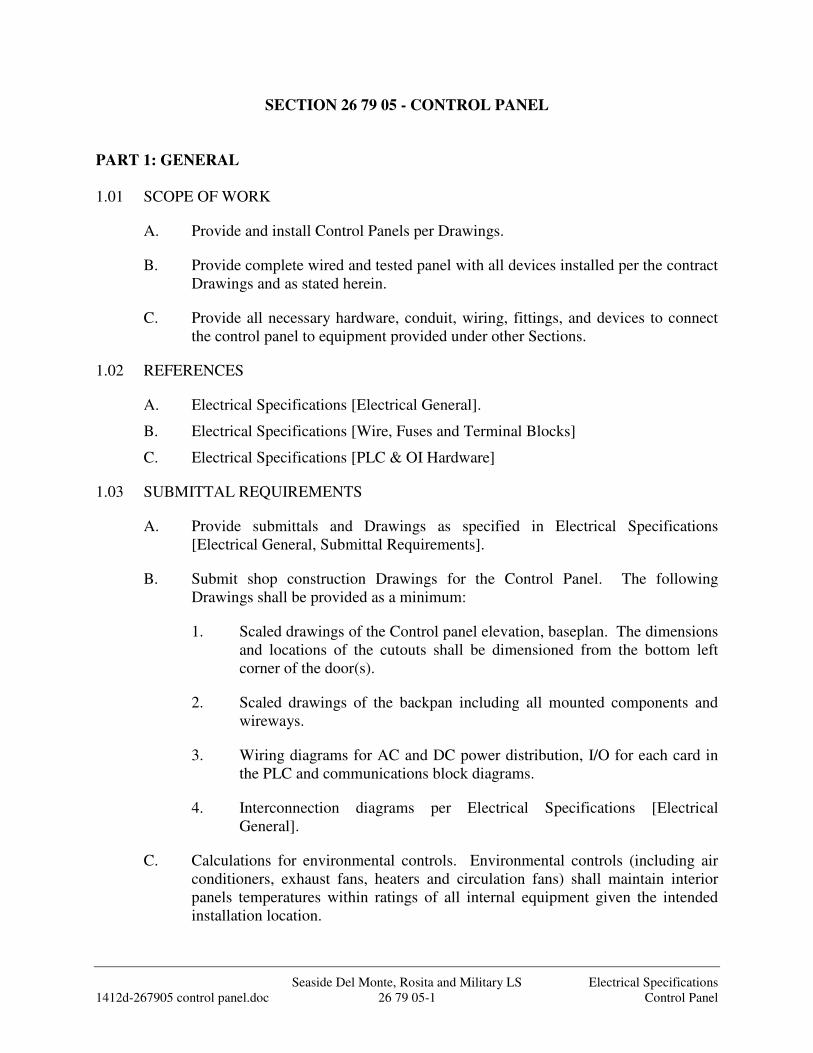
Seaside Del Monte, Rosita and Military LS Electrical Specifications 1412d-267905 control panel.doc 26 79 05-1 Control Panel
SECTION 26 79 05 - CONTROL PANEL
PART 1: GENERAL
1.01 SCOPE OF WORK
A. Provide and install Control Panels per Drawings.
B. Provide complete wired and tested panel with all devices installed per the contract Drawings and as stated herein.
C. Provide all necessary hardware, conduit, wiring, fittings, and devices to connect the control panel to equipment provided under other Sections.
1.02 REFERENCES
A. Electrical Specifications [Electrical General].
B. Electrical Specifications [Wire, Fuses and Terminal Blocks]
C. Electrical Specifications [PLC & OI Hardware]
1.03 SUBMITTAL REQUIREMENTS
A. Provide submittals and Drawings as specified in Electrical Specifications [Electrical General, Submittal Requirements].
B. Submit shop construction Drawings for the Control Panel. The following Drawings shall be provided as a minimum:
1. Scaled drawings of the Control panel elevation, baseplan. The dimensions and locations of the cutouts shall be dimensioned from the bottom left corner of the door(s).
2. Scaled drawings of the backpan including all mounted components and wireways.
3. Wiring diagrams for AC and DC power distribution, I/O for each card in the PLC and communications block diagrams.
4. Interconnection diagrams per Electrical Specifications [Electrical General].
C. Calculations for environmental controls. Environmental controls (including air conditioners, exhaust fans, heaters and circulation fans) shall maintain interior panels temperatures within ratings of all internal equipment given the intended installation location.
Seaside Del Monte, Rosita and Military LS Electrical Specifications 1412d-267905 control panel.doc 26 79 05-2 Control Panel
1. Design and install environmental control systems to meet requirements herein and prevent premature failure of panel internal components.
2. Environmental controls may be shown in the Drawings and shall be considered the minimum level required. Additional components or systems shall be provided to meet internal temperature requirements.
3. Environmental control systems shall prevent and control intrusion of dust and bugs through the use of filtration systems.
4. Environmental control systems shall maintain humidity below that of the external ambient air and without condensation within panel.
1.04 OPERATING AND MAINTENANCE INSTRUCTIONS
A. Provide operating instructions as specified in Electrical Specifications [Electrical General].
PART 2: PRODUCTS
2.01 ENCLOSURE
A. Freestanding
1. Arrangement: Where so indicated, the instruments mounted in the panels shall have the nominal size and general arrangement shown. Panel layouts and nameplates shall conform to the approved submittal.
2. Assembly: Mount all equipment on 12 ga. painted white backpan(s) that is bolted to rear (and sides) of the enclosure. Use drill and tap method for machine thread screws for all internal components on mounting panels. Provide extra mounting bolts through the rear of the structure if equipment weight exceeds backpanel mounting stud capacity.
3. Hardware: Provide door latch and accessories as detailed in the Contract Drawings. 3 point latching mechanisms shall consist of rotating handle with latch, extension bars with plastic wheels at ends and guide slots at top and bottom of door. Hinges, pins, bolts and screws shall be of 316 stainless steel only.
4. When physical size requirements for individual components are different than that detailed on the Control Panel backpan drawing, the wiring diagrams and specifications herein shall supersede the elevation drawing and the Contractor shall furnish additional panel width as needed to fit the electrical equipment. Deviations with sufficient evidence for the change shall be submitted for approval. The Contractor is required to provide for all equipment including spares and spaces as shown in the wiring diagrams.
Seaside Del Monte, Rosita and Military LS Electrical Specifications 1412d-267905 control panel.doc 26 79 05-3 Control Panel
5. The control pedestal enclosure shall be as required per Drawings and custom manufactured by Tesco, Gaylord, Hoffman, or equal
2.02 POWER SUPPLIES
A. Uninterruptible Power Supply (UPS)
1. The UPS shall be installed within the control panel and power all process related 120 VAC devices and DC power supplies.
2. The UPS capacity/size shall be as shown in the contract Drawings. The battery capacity shall be such that it may provide nameplate power for 10 minutes (min) from a fully charged battery(s).
3. The UPS shall provide surge protection and filtering: 0.3% IEEE surge let-through, zero clamping response time to meet UL 1449. The inverter shall provide true sine wave output.
4. When the Utility power voltage is outside of a preset range (approx. <100 < V < 130 VAC) then the UPS shall power the load from storage batteries and a solid state inverter.
5. The power supply shall be wired into the control panel power circuit per the contract Drawings.
6. The UPS operating ambient temperature range shall be 32 deg F to 122 deg F minimum.
7. The inverter shall be self resetting and continuously on-line regardless of the Utility power existence. Configure the UPS to restart automatically upon restart of utility power without operator intervention. The rectifier/charger shall recharge and maintain float charge on the batteries automatically.
2.03 CONTROL PANEL CIRCUIT BREAKERS
A. Furnish circuit breakers and accessories as required per Drawings and application.
1. Copper busbar systems, up to 480VAC, 115A, 1, 2 or 3 phase as needed for application
2. Trip rating per Drawings or as needed for protected device. Trip curves as selected by System Integrator.
a. B curve magnetic trip point: 3 to 5 times the rated current, typically used for computers and electronic equipment with very low inrush loads (PLC wiring).
Seaside Del Monte, Rosita and Military LS Electrical Specifications 1412d-267905 control panel.doc 26 79 05-4 Control Panel
b. C curve magnetic trip point: 5 to 10 times the rated current, typically used for small transformers, pilot devices, etc.
c. D curve magnetic trip point: 10 to 20 times the rated current, typically used for transformers or loads with very high inductive loads.
3. Quantity of pins and feed in lugs as required.
4. Auxiliary contact, shunt trip as required in Drawings.
5. Din rail mounted, 18mm width per pole, finger safe pressure plate terminals.
B. Motor applications:
1. UL489 for branch circuit protection up to 40A, 1 to 3 pole.
2. 5 kAIC interrupting capacity @ 480 VAC
3. Alltech, Eaton FAZ, or equal.
C. Control circuit transformers and other Non-motor applications:
1. UL1077 supplementary protection up to 63 amps, 1 to 2 pole, AC or DC.
2. Used where a UL489 protective device is upstream powering the circuit (from a panelboard or other source).
3. Used within control circuits for power supplies, control power transformers, relays and PLC I/O points.
4. Used in place of fuses that are applied as supplementary protection.
5. Eaton FAZ, or equal.
2.04 INTRINSICALLY SAFE BARRIER AND RELAY
A. Intrinsically Safe Barrier
1. Intrinsic safe barrier terminal blocks shall utilize a zener barrier that is negative-earth-ground for intrinsic safety. Apply IS barrier to 4-20 mA loop circuits that extend into the hazardous area. Terminal block shall be rated for Class 1, Division 1 for potentially hazardous atmospheres. Intrinsic safe barrier terminal blocks shall be Gems Series A65800 or equal.
B. Intrinsically Safe Relay
Seaside Del Monte, Rosita and Military LS Electrical Specifications 1412d-267905 control panel.doc 26 79 05-5 Control Panel
1. Intrinsically safe relay shall be UL listed for use where the probes and/or wiring is located in Class I or II, Division 1, Groups A-G hazardous atmospheres. The sensor circuit shall be incapable of igniting flammable gasses or dust. The relay shall be 120 VAC powered and have one 8 amp SPDT relay output. The relay shall be capable of single level or differential level service. The relay shall be wired to use two probe devices (latch device and unlatch device) for differential level service. The relay shall be wired to use a single probe device for single level service. Provide UL listed Warrick Series 27 or equal.
2.05 MISCELLANEOUS COMPONENTS
A. Intrusion Switch: The intrusion switch shall have a pin plunger that is depressed when the door is closed. The form C contacts shall be rated 2A at 120 VAC. Provide Hoffman A-LFSWD, Microswitch 1AC2 or equal.
B. LED Strip Light: The LED light shall be an “under cabinet” style with multiple LED lamps and acrylic diffuser. Lamp shall be switched on/off from integral switch or PIR motion sensor. Light housing shall be capable of magnet mount to top or side of enclosure or will include mounting tabs for mounting to brackets. Lamp shall be powered from 120VAC or from 24~48 VDC as shown in the contract drawings. LED Strip Light shall be Genesis Automation G02541 series, or equal.
C. Exhaust Fan: The control panel temperature shall be maintained 10 deg. F below lowest internal device’s temperature rating. The fan system shall provide 275 CFM air flow through aluminum washable filters. Exhaust Fan System shall be Hoffman Blower Package A-DB275 with EXGR-275 exhaust grill, no equal.
D. Circulation Fans: The control panel temperature shall be maintained 10 deg. F below lowest internal device’s temperature rating. The fans shall be 6” (min), 240 CFM, unless otherwise noted on Contract Drawings. The Contractor shall calculate the heat generation of all internal components and determine if the fans submitted will meet the cooling requirements of the internal components. Circulation fans shall be Dayton (Grainger #4C720) with wire guard (or louver with filter or bug screen as required), Genesis Automation KRYOS GVK1500, or equal.
E. Convection Heater: The control panel temperature shall be kept above 50 deg. F through the use of an aluminum heat-sinked convection heater when the panel is located outdoors. The heater shall contain heat sink, heating elements, and high temperature silicone wire within a single self contained unit. The wattage of the heater shall be 80 watts at 120 vac. The heater shall be Genesis Automation Nimbus D series or equal.
F. Thermostats: The air circulation fans shall be controlled by adjustable thermostat. The thermostat shall be mounted near the top of the panel and easily accessible by
Seaside Del Monte, Rosita and Military LS Electrical Specifications 1412d-267905 control panel.doc 26 79 05-6 Control Panel
a technician. The thermostat shall be capable of control of a heater or cooling fan(s) by selecting the proper contact logic. The thermostat range shall be adjustable from 30 to 140 deg F. Thermostat shall be Hoffman A-TEMxx, Genesis FGTxxx or dual heat/cool version Genesis Automation ZR011 as required for application or equal.
G. Wireway: Manufactured from light gray rigid PVC suitable for continuous use at temperatures up to 50 deg C. Wireway shall be 2” height, width as required with 0.5” slot spacing with removable covers. Provide Panduit type “F” or equal.
PART 3: EXECUTION
3.01 WORKMANSHIP
A. All work in this Section shall conform to the codes and standards specified in Electrical Specifications [Electrical General, Workmanship].
3.02 FABRICATION
A. Equipment Mounting:
1. Mount all equipment using manufacturers mounting tabs/holes or brackets where possible. Where not possible, construct custom brackets to panel mount or backpan mount components as shown in the Contract Drawings.
2. Equipment or laptop shelves shall be provided where shown on the Contract Drawings. Equipment shown on shelves shall not be placed on the bottom of the panel after field installation.
3. All nuts, bolts, screws, washers and hinges used in the panel shall be stainless steel. All components shall be mounted using bolts or screw fasteners only which are drilled and tapped into the backpan. Pop rivets shall not be allowed within panel except for enclosure support arms.
B. Environmental:
1. Control panel environmental accessories including fans, louvers, filters, bugscreens, air conditioners, etc. shall be provided as noted in the Drawings and as necessary for a complete environmental solution.
2. Panels environmental controls shall be designed during shop drawing submittal and fabricated to maintain temperatures 10 degrees F below lowest internal equipment maximum temperature rating.
3. Contractor shall provide [additional] fans, louvers, screens, sunshades, air conditioners, etc. as necessary to prevent equipment malfunction or premature failure. Provide associated wiring and thermostats as needed.
Seaside Del Monte, Rosita and Military LS Electrical Specifications 1412d-267905 control panel.doc 26 79 05-7 Control Panel
4. Environments:
a. NEMA 4X rated panels shall be cooled/heated with closed loop type conditioning systems to include air conditioners, internal panel circulation fans and resistive heaters.
b. NEMA 3R rated outdoor panels shall be cooled/heated with open loop type conditioning systems to include air conditioners, exhaust fans and louvers, internal panel circulation fans and resistive heaters. All exhaust fans and louvers shall include filters and bugscreens.
c. NEMA 12 or 1 rated indoor panels shall be cooled/heated with open loop type conditioning systems to include air conditioners, exhaust fans and louvers, internal panel circulation fans and resistive heaters. All exhaust fans and louvers shall include filters and bugscreens.
C. Wiring:
1. Panel Wiring: All wiring shall be installed in wireways between terminal blocks, PLC, and devices. Reference Contract Drawings for control panel power distribution diagram and control panel elementary diagrams.
3.03 INSTALLATION
A. Wiring:
1. Install all equipment per Electrical Specifications [Electrical General].
2. All field wires and panel wires shall be per Electrical Specifications [Wire, Fuses and Terminal Blocks].
3. Panel Wiring: All wiring shall be installed in wireways between terminal blocks, PLC and devices. Reference Contract Drawings for Control panel power distribution diagram and control panel elementary diagrams.
4. Field Wiring: Wireways shall be provided for field wiring. Reference Contract Drawings for control panel power distribution diagram and control panel elementary diagrams.
B. Cleaning:
1. The Contractor shall clean the inside of the control panel of any dust or debris remaining at the completion of installation and testing.
2. The Contractor shall exercise care when using a vacuum cleaner or compressed air such as not to damage any component within the panel.
Seaside Del Monte, Rosita and Military LS Electrical Specifications 1412d-267905 control panel.doc 26 79 05-8 Control Panel
3. Many electrical and computer components are open for ventilation. Falling debris can penetrate the openings and cause equipment failure. Equipment with debris inside shall be removed, cleaned and/or replaced.
3.04 FIELD ASSISTANCE
A. Provide testing as specified in Electrical Specifications [Factory and Field Testing].
3.05 WARRANTY
A. Provide warranty as specified in Electrical Specifications [Electrical General, Warranty].
3.06 FINAL ACCEPTANCE
A. Final Acceptance per Electrical Specifications [Electrical General].
END OF SECTION
Seaside Del Monte, Rosita and Military LS Electrical Specifications 1412d-267910 PLC and OI Hardware.doc 26 79 10-1 PLC and OI Hardware
SECTION 26 79 10 - PLC & OI HARDWARE
PART 1: GENERAL
1.01 SCOPE OF WORK
A. Providing and installing Programmable Logic Controller (PLC) and Operator Interface Hardware and all supporting hardware, wiring and devices as specified in Electrical Specifications.
1.02 REFERENCES
A. Electrical Specifications [Electrical General] B. Electrical Specifications [Wire, Fuses and Terminal Blocks]
1.03 SUBMITTAL REQUIREMENTS
A. Provide submittals per Electrical Specifications [Electrical General, Submittal Requirements].
B. Submit documentation showing the number and type of I/O modules required to meet the I/O requirements specified herein. Include complete manufacturer's part and model numbers.
1. PLC I/O points are determined by the P&ID drawings. The Contractor shall count and total the PLC I/O points per PLC controller and per type of I/O required based on the P&ID diagrams. Provide 25% spare I/O points per I/O type per PLC.
C. Submit calculations showing that the power supply meets the specified requirements and the requirements of the devices powered.
D. Submit shop drawings showing physical backpan layout of equipment in Control Panel.
E. Submit PLC communications block diagram showing I/O module order and slot location.
F. Submit hardware Operations and Maintenance Manual per Electrical Specifications [Electrical General].
Seaside Del Monte, Rosita and Military LS Electrical Specifications 1412d-267910 PLC and OI Hardware.doc 26 79 10-2 PLC and OI Hardware
PART 2: PRODUCTS
2.01 PLC COMPONENTS
A. The following components (Allen Bradley, no equal) shall be provided to complete the PLC(s). Only major components are listed. Multiples of some components are required- see drawings.
B. Compact Logix
1. Processor 1769-L24ER-QB1B, 24VDC, 16DC DI, 16DC DO, 4 expansion cards, Ethernet, 8 IP connections, 120 TCP connections.
2. Digital Input Module (DC) 1769-IQ16 3. Analog Input Module Spectrum Controls 1769sc-IF4IH 4. Analog Output Module 1769-OF4CI 5. End Cap 1769-ECR, 1769-ECL
2.02 ISOLATION/INTERFACE RELAYS
A. Provide output isolation relays on all digital outputs that operate devices external to the control panel and on spare outputs or as otherwise shown in the drawings. The relay coil connection shall be on one side of the relay base and form-C output contacts on the other.
B. Relays shall be 6A SPDT, 24 VDC coil, indicating, plug in style as manufactured by Allen Bradley 700-HLT1U1 or equal. Provide jumper bars for common buss connections, Allen Bradley 700-TBJ20G, or equal.
2.03 ETHERNET SWITCH
A. Control Panels
1. The Ethernet switch shall have 8 ports with automatic uplink detection and OPC monitoring capability. Ports shall be auto-sensing 10/100/1000 Base-Tx with RJ-45, 8 pin female connectors, meeting IEEE 802.3 standards. Case shall be ventilated steel with provisions for wall or DIN rail mounting. Switch shall be suitable for power from 10 - 30 VDC. Switch shall be N-Tron 1008TX-N, Moxa EDS-G308, or equal.
Seaside Del Monte, Rosita and Military LS Electrical Specifications 1412d-267910 PLC and OI Hardware.doc 26 79 10-3 PLC and OI Hardware
B. Radio Panel
1. The Managed Ethernet switch shall have 16 ports with automatic uplink detection and OPC monitoring capability. Ports shall be auto-sensing 10/100/1000 Base-Tx with RJ-45, 8 pin female connectors, meeting IEEE 802.3 standards. Case shall be ventilated steel with provisions for wall or DIN rail mounting. Switch shall be suitable for power from 10 - 30 VDC. Switch shall be N-Tron NT24k-16TX, Moxa EDS-G519-4GSFP, or equal.
2.04 OPERATOR INTERFACE (OI)
A. Allen Bradley Panelview Plus 6, Version 8.1, 64 bit, no equal.
B. Touch Screen
1. 10 inch screen size with 1024 x 768 resolution, 18 bit colors.
2. TFT color touchscreen with LED backlight.
3. Alarm history screen with present status and acknowledge functions.
C. Communications
1. Ethernet communications. Provide cables for connection to PLC.
D. Data storage
1. 512MB backed up RAM for program,
2. Furnish one 32GB SDHC card for data storage.
3. Trending for up to 16 pens (colors).
E. Environmental conditions:
1. Operating Temperature: 32 to 122 degrees F
2. Storage Temperature: -4 to 140 degrees F
3. Humidity Rating: 10 to 90%, non-condensing at 32° F to 86° F
4. Rating: NEMA 12, 13, 4X (indoor only)
5. Power: 1.9A at 24 VDC.
PART 3: EXECUTION
3.01 WORKMANSHIP
A. All work in this Section shall conform to the codes and standards specified in Electrical Specifications [Electrical General, Workmanship].
3.02 INSTALLATION
A. Fabrication
1. Mount, wire and Ground PLC and OI per manufacturer’s
Seaside Del Monte, Rosita and Military LS Electrical Specifications 1412d-267910 PLC and OI Hardware.doc 26 79 10-4 PLC and OI Hardware
recommendations. 2. Organize equipment on control panel backpan per Backpan Layout detail
in Contract drawings. 3. Locate and install PLC(s) and OI(s) per Contract drawings.
B. Wiring
1. Terminate status, control and analog wiring on terminal blocks.
2. Label and wire PLC to terminal blocks per Electrical Specifications [Wire, Fuses & Terminal Block] and Example I/O Wiring Diagram in the drawings.
3. All spare I/O points shall be wired to terminal blocks. 4. Install communication cables to connect the PLC to external devices. 5. Bundle and tie down wires in a neat and orderly manner. 6. Terminate drain wire of shielded cables at backpan terminal block only.
3.03 FIELD ASSISTANCE
A. Provide testing as specified in Electrical Specifications [Factory and Field Testing].
3.04 WARRANTY
A. Provide warranty per Electrical Specifications [Electrical General, Warranty].
B. Perform the following services during the warranty period:
1. Repair or replace damaged modules returned for service within 24 hours. 2. Determine and report the cause of failure of modules returned for service. 3. Resolve design or implementation problems discovered.
3.05 FINAL ACCEPTANCE
A. Final Acceptance per Electrical Specifications [Electrical General].
END OF SECTION
Seaside Del Monte, Rosita and Military LS Electrical Specifications 1412d-268960 bubbler system.doc 26 89 60-1 Bubbler System
SECTION 26 89 60 - BUBBLER SYSTEM
PART 1: GENERAL
1.01 SCOPE OF WORK
A. This specification covers work required for bubbler level control system and the backup pump control floats.
B. Bubbler System shall be fully assembled and functional with interconnecting tubing, instrumentation, compressor, tank, fittings and valves.
1.02 REFERENCES
A. Electrical Specifications [Electrical General]
B. Electrical Specifications [Control Panels]
1.03 SUBMITTAL REQUIREMENTS
A. Provide submittals and drawings as specified in Electrical Specifications [Electrical General, Submittal Requirements]. Submit additional detailed information as listed below:
1. System configuration with pipe riser areas defined.
2. Detailed descriptions of equipment including weights, dimensions, installation requirements, and heat dissipations.
3. Internal panel layouts indicating spacing and dimensions.
1.04 MANUFACTURER’S SERVICES
A. Provide equipment manufacturers services at the job site for the minimum man days listed below, travel time excluded:
B. One man-day to check the installation, calibrate the equipment, supervise start-up and supervise testing of the system.
1.05 OPERATION AND MAINTENANCE INFORMATION
A. Provide operating instructions as specified in Electrical Specifications [Electrical General, Operating and Maintenance Instructions].
B. Provide operation and maintenance manuals in accordance with Electrical Specifications [Electrical General].
Seaside Del Monte, Rosita and Military LS Electrical Specifications 1412d-268960 bubbler system.doc 26 89 60-2 Bubbler System
C. PART 2: PRODUCTS
2.01 GENERAL
A. Bubbler system products shall be provided as required to meet the intent of the specifications. Some minor components are not listed or specified but shall be provided for an operational system. Those components shall be of similar quality, compatibility, and manufacturer catalog series where possible.
2.02 NAMEPLATES
A. Nameplates shall be per Electrical Specifications [Electrical General].
2.03 AIR COMPRESSOR SYSTEM
A. Provide 1/3 HP motor driven, 120 VAC, oil-less, single stage piston type compressor, two gallon air receiver tank, adjustable pressure switch shut off, in line check valve, air intake filter, receiver air pressure gage and cord with plug attached. Provide spare parts for servicing compressor as described in section. Furnish Speedaire 25F538, or equal.
B. Provide quantity of compressors as shown in the drawings.
2.04 BUBBLER TUBING AND FITTINGS
A. Tubing: ¼” inch inside diameter flexible polyethylene tubing with minimum .062 inch wall thickness. Provide Parker Parflex, Flexicraft E or equivalent.
B. Wetwell (LE):
1. As shown in details.
2. Anchor Weighted tube – Strap flexible tubing to coated stainless steel cable. Cable shall be weighted with coated anchor. Provide Anchor Scientific float anchor or equal.
C. Fittings, tees, connectors:
1. Brass compression type tube fittings complete with body nut and plastic ferrule. Provide Parker CPI tube fittings or equivalent.
2.05 VALVES
A. Provide the following valves
1. Switching valve, 2 way ¼” Brass Swagelock Model # B42S4 or equal.
2. Solenoid Valve, 3 way, brass body, ¼” threaded connections, normally
Seaside Del Monte, Rosita and Military LS Electrical Specifications 1412d-268960 bubbler system.doc 26 89 60-3 Bubbler System
closed, ASCO Red-Hat Series 8320, or equal.
2.06 AIR REGULATION DEVICES
A. Pressure Filter/Regulator: Anodized aluminum with ¼” FNPT ports and anodized aluminum bowl. Filter element shall be 1 micron coalescing filter. Regulator shall be adjustable from 10 to 30 psi and be able to withstand pressures of 250psi. Pressure gauge shall be rear mount 1/8” NPT, 1” diameter with 0-30 psi gauge. Provide Balston #AFR-940A-30 with mounting bracket 11536 or equal.
B. Air Flow Regulator: Polycarbonate plastic 4% accuracy, 2-inch scale, 0.1 to 1 standard cubic feet per hour (SCFH) range, with stainless metering valve. Provide Dwyer RM Rate-Master flow meters, catalog number RMA-2-SSV or equal.
2.07 GAUGES
A. Compressed Air Tank Gauge: Provide 0-160 psig air pressure gauge for air tank pressure. Provide ASHCROFT 100 series, or equal.
B. Regulated Air Supply Gauge: Provide 0 to 30 psig air pressure gauge for monitoring regulated supply air pressure. Provide ASHCROFT 100 series, or equal or equal.
2.08 LEVEL INSTRUMENTATION
A. Pressure/Level Transmitter
1. The pressure indicating transmitter shall be a loop powered, two wire, 4-20 mA signal transmitting device with signal derived from the applied sensor pressure. Transmitter shall be capable of driving 0 to 500 ohm loads with 24 VDC supply.
2. The transmitter shall have the following features:
a. Programmable 4-digit Liquid Crystal Display (LCD) process indicator.
b. HART programming with programming selections for square root extraction, output calibration, and adjustable dampening 0.0 to 36.0 seconds, minimum.
c. Integral microprocessor based circuitry with RFI filtering and shielding.
d. The transmitter shall have accuracy of +/- 0.1% of span over a range of 10 to 1 turndown. Elevated zero setting capable of 0-50% upper calibration limit.
Seaside Del Monte, Rosita and Military LS Electrical Specifications 1412d-268960 bubbler system.doc 26 89 60-4 Bubbler System
e. Operating temperature range shall be -40 to 185°F (minimum). Process wetted materials shall be hastalloy diaphragm and 316 stainless steel body. Process flanges shall be 316 stainless steel, 1/2" NPT.
f. The level transmitter shall be 0-100PSI range and scaled 0-35ft for wetwell depth.
g. The pressure transmitter shall be 0-300PSI range and scaled 0-200 psi for air pressure.
3. Provide backpan mounting bracket.
4. The pressure transmitter shall be Rosemount Smart 3051TG series or equal.
B. Calibration Valve
1. Calibration valve for use with gauge transmitters shall have the following features:
a. Stainless steel body with integral blocking valve and calibration valve and port.
b. Calibration port shall be 1/4” FNPT with 1/4” MNPT x 1/2” FNPT adapter.
c. Valve shall have a non-rotating stem tip and a fully backseated bonnet.
d. Process and transmitter connections shall be 1/2” MNPT. Include 1/2” stainless steel close nipple as required.
2. Calibration valve shall be Hex HB59, Anderson Greenwood, or equal.
PART 3: EXECUTION
3.01 WORKMANSHIP
A. All work in this Section shall conform to the codes and standards specified in Electrical Specifications [Electrical General, Workmanship].
B. Requirements of Electrical Specifications Sections apply to design, documentation construction, configuration and testing and assembly of the bubbler system.
3.02 INSTALLATION
A. Equipment Mounting:
Seaside Del Monte, Rosita and Military LS Electrical Specifications 1412d-268960 bubbler system.doc 26 89 60-5 Bubbler System
1. Mount all equipment using manufacturers mounting tabs/holes where possible. Where not possible, construct custom brackets to panel mount or backpan mount components as shown in the Contract drawings.
2. Equipment or laptop shelves shall be provided where shown on the Contract drawings. Equipment shown on shelves shall not be placed on the bottom of the panel after field installation.
3. All nuts, bolts, screws, washers and hinges used in the panel shall be stainless steel. All components shall be mounted using bolts or screw fasteners only which are drilled and tapped into the backpan. Pop rivets shall not be allowed within panel except for enclosure support arms.
B. Wiring:
1. Install all products per Electrical Specifications [Electrical General, Installation].
2. All field wires and panel wires shall be per Electrical Specifications [Wire, Fuses & Terminal Blocks].
3. Panel Wiring: All wiring shall be installed in wireways between terminal blocks, PLC and devices. Reference Contract drawings for Control panel power distribution diagram and control panel elementary diagrams.
C. Cleaning:
1. The Contractor shall clean the inside of the control panel of any dust or debris remaining at the completion of installation and testing. The Contractor shall exercise care when using a vacuum cleaner or compressed air such as not to permanently damage any component within the panel.
3.03 FIELD ASSISTANCE
A. Provide testing as specified in Electrical Specifications [Factory and Field Testing].
3.04 WARRANTY
A. Provide warranty as specified in Electrical Specifications [Electrical General, Warranty].
END OF SECTION
Seaside Del Monte, Rosita and Military LS Electrical Specifications 1412d-268960 bubbler system.doc 26 89 60-6 Bubbler System
THIS PAGE INTENTIONALLY BLANK

DIVISION 27
COMMUNICATIONS (NOT USED)

DIVISION 28
ELECTRONIC SAFETY AND SECURITY (NOT USED)

DIVISION 31
EARTHWORK

R0: IFB-12-15-17 Site Clearing 31 10 00 - 1 C:\Seaside CSD\IFB Specs_12-29-2017\IFB Vol 1B\Div 31 - Earthwork\31 10 00 - Site Clearing.docx
SECTION 31 10 00
SITE CLEARING
PART 1 - GENERAL
1.01 SUMMARY
A. Requirements specified in the Conditions of the Contract and Division 1 of the Technical Specifications form a part of this Section.
B. Work Included in This Section: 1. Submittals. 2. Disposal off site of all debris, stumps, roots, pavement and other objectionable
materials. 3. Removal and storage of topsoil.
C. Related Work specified in Other Sections: 1. Section 02 41 00 - Demolition 2. Section 31 23 00 – Excavation and Fill 3. Section 31 23 33 - Trenching, Backfilling and Compaction 4. Section 32 90 00 - Planting
1.02 CODE REQUIREMENTS AND ENVIRONMENTAL SAFEGUARDS
A. Accomplish disposal of material removed from site in accordance with applicable State and local regulations. At all times, comply with regulations in force to prevent pollution of air and water.
1.03 SITE INVESTIGATIONS
A. Carefully examine the site to determine the full extent of the Work required to conform to the Drawings and Specifications. Verify the nature and location of the Work, conditions, the formation and condition of the existing ground surface and the character, equipment and facilities needed prior to and during prosecution of the Work. Verify the existence of the obstacles to be encountered, if any. Bring to the District’s attention any inaccuracies or discrepancies between the Drawings and Specifications discovered, in order to clarify the exact nature of the Work to be performed. Refer to the paragraph 1.02 in Section 31 23 00 of these Specifications.
R0: IFB-12-15-17 Site Clearing 31 10 00 - 2 C:\Seaside CSD\IFB Specs_12-29-2017\IFB Vol 1B\Div 31 - Earthwork\31 10 00 - Site Clearing.docx
1.04 SAFETY
A. Comply with OSHA requirements and with the regulations of the “General Construction Safety Orders” of the State of California, Department of Industrial Relations, Division of Occupational Safety and Health (DOSH).
1.05 SUBMITTALS
A. Comply with the general requirements and procedures described in Article 12 of the General Conditions and Section 01 33 00, “Submittal Procedures”, of the Technical Specifications pertaining to submittals, including preparation, transmittals, and guarantees.
B. Furnish for District’s review a written description of the proposed work plan for removing and storing topsoil, including location of storage sites and method of protecting topsoil from contamination and erosion (wind and rain). Submit description not less than fourteen (14) days before beginning the work.
1.06 JOB CONDITIONS
A. Limits of clearing work are identified as follows: 1. Not to exceed the width of the construction easement where shown on the
Drawings. 2. Width of pipe trench for pipeline construction in existing street or road right-
of-way areas or other paved areas.
B. Do not clear areas outside the boundaries of the easements, construction areas or property lines shown on the Drawings and specified above.
C. Protect trees and other landscaping specifically shown on the Drawings or identified in the field as requiring protection from damage resulting from work for this Contract. Restore any protected trees or vegetation damaged as a result of this Work.
R0: IFB-12-15-17 Site Clearing 31 10 00 - 3 C:\Seaside CSD\IFB Specs_12-29-2017\IFB Vol 1B\Div 31 - Earthwork\31 10 00 - Site Clearing.docx
PART 2 - PRODUCTS (NOT USED)
PART 3 - EXECUTION
3.01 CLEARING AND SITE PREPARATION
A. Include in the clearing and site preparation the removal from the site of all vegetation, including, but not limited to: weed growth, brush, shrubs, stumps, logs, roots and boulders within the Project area, as well as the foundations, walls, slabs, pavements, walkways, buried drain lines, utilities, and pipes indicated on the Drawings to be removed. 1. In off-road and other vegetated areas, strip and remove an additional
minimum of 6 inches depth of the existing soil after clearing and removing all vegetation growth, such material to be designated topsoil for storage and restoration to the originating site area.
2. Clean holes resulting from the removal of underground structures and roots that extend below the finished grade and backfill with suitable materials compacted in conformance with requirements of Section 31 23 00, “Excavation and Fill”.
B. Procure or provide all permits, lighting, temporary barricades, fencing, etc., required for Work within the construction limits. Bear, and relieve the District of, any and all legal responsibility for this phase of the Work.
C. Remove trees, shrubs, and vegetation only with prior District approval. Violation of this provision shall require the Contractor to bear all damages and consequences. Do not damage as a result of the operations under this Section or any other Section the roots of trees to remain. Do not use herbicides for the control of woody plants. Trunks, stumps, limbs, branches and roots within the designated work area may be removed without District approval, unless otherwise designated.
D. Selectively remove, as determined by the District, undesirable shrubs and saplings, and surface vegetation within the construction limits. Preserve existing growth on adjacent land and rights-of-way.
E. Topsoil: Rake the cleared area with a tooth harrow to remove remaining roots and vines. Remove the topsoil to a depth of 15 inches unless otherwise approved by the District, to a designated storage site and protect the stored material against contamination and removal by erosion. Stockpile topsoil separately from other fill/backfill material, and restore to within its originating sub-area.
R0: IFB-12-15-17 Site Clearing 31 10 00 - 4 C:\Seaside CSD\IFB Specs_12-29-2017\IFB Vol 1B\Div 31 - Earthwork\31 10 00 - Site Clearing.docx
1. Following completion of structure construction or pipe installation, testing and backfill, spread the topsoil to the original depth over the stripped construction area in accordance with the requirements specified in Section 32 90 00, “Planting”.
F. Protect from damage existing items not designated to be demolished or removed. Restore or replace immediately any such item damaged as a result of the activities of this Work at no additional expense to the District.
G. Remove from the site and legally dispose of debris and waste material resulting from clearing and grubbing.
END OF SECTION 31 10 00
R0: IFB-12-15-17 Excavation and Fill 31 23 00-1 C:\Seaside CSD\IFB Specs_12-29-2017\IFB Vol 1B\Div 31 - Earthwork\31 23 00 - Excavation and Fill.docx
SECTION 31 23 00
EXCAVATION AND FILL
PART 1 - GENERAL
1.01 SUMMARY
A. Requirements specified in the Conditions of the Contract and Division 1of the Technical Specifications form a part of this Section.
B. Section Includes: 1. Preparation of fill areas. 2. Excavation and controlled fill construction. 3. Structural excavation, fill and backfill. 4. Compaction of controlled fills and backfills. 5. Disposal of surplus and unsuitable materials. 6. Dust control and drainage control. 7. Cleanup.
C. Related Sections: 1. Section 31 10 00 – Site Clearing 2. Section 31 23 19 - Dewatering 3. Section 31 23 33 - Trenching, Backfilling and Compaction 4. Section 31 40 00 - Sheeting, Waling and Shoring 5. Section 32 12 00 - Asphalt Concrete Paving 6. Section 32 90 00 - Planting
D. Definitions: 1. Site: The property owned by the District within the boundaries shown on the
Drawings, easements and rights-of-way (ROW) for roads, drainage facilities, and pipelines, and the Contractor’s working and storage areas adjacent to the facilities.
2. Excavation: All excavation, whether in rock or other material, shall be considered unclassified, except as provided for in Section 01 20 00 - Price and Payment Procedures, and in Article 3.05B below in this Section.
R0: IFB-12-15-17 Excavation and Fill 31 23 00-2 C:\Seaside CSD\IFB Specs_12-29-2017\IFB Vol 1B\Div 31 - Earthwork\31 23 00 - Excavation and Fill.docx
3. Controlled Fill: Compacted suitable fill material in all areas of the site requiring filling to grade as shown on the Drawings.
4. Structural Fill: Compacted select fill material, which will support a structure or some part of a structure.
5. Structural Backfill: Compacted suitable fill material placed between the wall of a structure and construction excavation slope up to finished grade and where called for placement in other excavations as indicated on the Drawings.
6. Suitable Material: As specified herein, of any material imported or excavated from the cut areas which, in the opinion of the Soils Engineer, are suitable for use in constructing fills.
7. Waste Excavation: Material from project excavations which is not suitable for use in backfill or compacted fills or is in excess of that required to be used for backfilling or to construct fills.
8. Utility Systems: Piping, conduit cables and cableways, electrical conductors, communications facilities, fuel lines, storm drains, potable water distribution piping, signal circuits and the like for transmission of commodities of information in sub-surface systems.
1.02 SITE INVESTIGATION
A. Soil Investigation: No soil investigation was performed in preparation for this Work. The District makes no statement or warranty regarding the type of soil conditions to be encountered in the performance of this Work.
B. Contractor’s Responsibility: Carefully examine the site and make all inspections necessary in order to determine the full extent of the work required to make the completed Work conform to the Drawings and Specifications. Be thoroughly satisfied as to the nature and location of the Work, conditions, the conformation and condition of the existing ground surface, and the character of equipment and facilities needed prior to and during prosecution of the Work. Also, be thoroughly satisfied as to the character, quality, and quantity of surface and subsurface materials or obstacles to be encountered. 1. Any inaccuracies or discrepancies between the actual field conditions and the
Drawings, or between the Drawings and Specifications must be brought to the District’s attention in order to clarify the exact nature of the Work to be performed.
1.03 SUBMITTALS
A. General: Comply with the general requirements and procedures described in Article 12 of the General Conditions and Section 01 33 00, “Submittal Procedures” of the
R0: IFB-12-15-17 Excavation and Fill 31 23 00-3 C:\Seaside CSD\IFB Specs_12-29-2017\IFB Vol 1B\Div 31 - Earthwork\31 23 00 - Excavation and Fill.docx
Technical Specifications pertaining to submittals, including preparation, transmittals, and guarantees. 1. Test materials as herein specified and, unless specified otherwise, have all
sampling and testing performed by an independent testing laboratory subject to District approval. Include costs for material testing as herein specified in the bid price for this Work.
B. Native Sand: Provide a certified test report on the sand equivalent for a minimum of three samples from each materials source. The District retains the right to request, at no additional cost to the District, additional sand equivalent tests when in his opinion the source has been substantially changed.
C. ½-Inch x 1-Inch Drain Rock, ¾” Foundation Rock and 1-1/2-inch Drain (Foundation/Structural Fill) Rock: Provide a certified test report on the sieve analysis and grading characteristics for a minimum of three samples each of the respective rock sizes to be used for this Work. Test for the grading characteristics as herein below noted.
D. Imported Granular Material: Submit sand equivalent, sieve analysis, and quality test reports as noted above in items B and C for District review and approval for each source.
1.04 QUALITY ASSURANCE
A. By Contractor: Exercise due care to assure procurement, storage and placement of materials from site or off-site sources which will comply with the requirements, Specifications and standards set out herein. The performance, by qualified personnel or independent testing services, of such tests and inspections as may be desired for guidance and control of the Work is left to the discretion of the Contractor and is to be performed at no additional cost to the District.
B. By Engineer: The Engineer, through his project representative(s) will be the on-site arbiter and judge of the acceptability of the work done, based on such observations and tests he may require or perform.
C. By District (Owner): The District may, on the recommendation of the Engineer, provide inspection and testing by his own representatives or by independent testing services, engaged and paid for by the District. In this regard, a Soils Engineer will be engaged by the District, who shall act as the direct representative of the District in soils work, to perform inspection of the removal and replacement of unsuitable materials, all excavations, and the placement and compaction of all fills and backfills within the limits of earthwork on this Contract. Costs for all such
R0: IFB-12-15-17 Excavation and Fill 31 23 00-4 C:\Seaside CSD\IFB Specs_12-29-2017\IFB Vol 1B\Div 31 - Earthwork\31 23 00 - Excavation and Fill.docx
inspections and tests will be paid for by the District, except that the cost of retest and reinspection of reworked faulty work are borne by the Contractor.
D. Applicable Criteria, Tests and Standards: 1. For Site Earthwork: Grade rough graded surfaces ready to receive top soil,
sod, or seed, crushed rock, or aggregate base to plus or minus 0.2 feet of the Plan elevation, except where meeting curbs, walks, or building entrances grade to plus or minus 0.1 feet of Plan. However, do not construe the acceptance of such irregularities to reduce the thickness of topsoil, sod or pavement. Construct permanent surface water courses to average plan grades and to drain completely throughout their length. Grade finish surfaces to plus or minus 0.1 feet of the Plan elevation and finish all areas so as to drain readily.
2. For Earthwork for Structures: The District will provide the services of a qualified Soils Engineer to make tests of prepared subgrade and compacted fill. Testing will be at the discretion of the Soils Engineer. Provide the Soils Engineer 24 hours notice of the scheduled commencement of sub-grade preparation.
3. For Waste: Dispose of in an area that is acceptable to local authorities material deemed unsuitable by the Soils Engineer from tests or visual inspection, and all material delivered for fill or embankment which cannot be satisfactorily compacted.
4. For Cleanup: Remove all rubbish, debris, junk, temporary materials, and any waste excavated materials from the Contract Site and dispose of it in accordance with all applicable laws, regulations, permits and approvals from District and owners of property upon which the material will be disposed. Perform restoration of staging and storage areas and temporary roads to the satisfaction of the District and respective property owner(s), as a condition for acceptance and final payment.
5. Standards for Soil Classification, Properties and Tests (current edition): a. Earthwork and Embankment (Excluding Roads):
(1) Classification - ASTM D2487. (2) Physical Properties - ASTM D854, D2216. (3) Soil Density - ASTM D1556, D2922. (4) Gradation - ASTM C136. (5) Cleanness Value - California Test 227. (6) L.A. Rattler Test - California Test 211. (7) Compaction - ASTM D1557.
R0: IFB-12-15-17 Excavation and Fill 31 23 00-5 C:\Seaside CSD\IFB Specs_12-29-2017\IFB Vol 1B\Div 31 - Earthwork\31 23 00 - Excavation and Fill.docx
b. Backfill for Trench: (1) Classification - ASTM D2487. (2) Sand Equivalent - ASTM D2419. (3) Soil Density - ASTM D1556, D2922. (4) Gradation - ASTM C136. (5) Cleanness Value - California Test 227. (6) L.A. Rattler Test - California Test 211. (7) Compaction - ASTM D1557.
c. Structural Fill and Backfill: (1) Classification - ASTM D2487. (2) Liquid Limits (LL), Plastic Limit (PL), and Plasticity Index (PI) of
Soils – ASTM D4318. (3) Compaction - ASTM D1557. (4) Physical Properties - ASTM D854, D2216. (5) Sand Equivalent - ASTM D2419. (6) Particle Size Analysis - ASTM D422. (7) Soil Density - ASTM D1556, D2922. (8) Gradation - ASTM C136. (9) Cleanness Value - California Test 227. (10) L.A. Rattler Test - California Test 211.
d. Controlled Fills: (1) Classification - ASTM D2487. (2) Physical Properties - ASTM D854, D2216. (3) Compaction - ASTM D1557. (4) CBR - ASTM D1883 (R-Value - ASTM 2844). (5) Soil Density - ASTM D1556, D2922.
e. Borrow: (2) Classification - ASTM D2487. (3) Other Properties - as determined by requirements at point of use.
1.05 SAFETY
A. Be familiar with, and at all times conform to, the regulations of the “General Construction Safety Orders” and “Trench Construction Safety Orders” of the State of California, Department of Industrial Relations, Division of Occupational Health and Safety.
R0: IFB-12-15-17 Excavation and Fill 31 23 00-6 C:\Seaside CSD\IFB Specs_12-29-2017\IFB Vol 1B\Div 31 - Earthwork\31 23 00 - Excavation and Fill.docx
1.06 ENVIRONMENTAL SAFEGUARDS AND REGULATIONS
A. At all times comply with regulations in force to prevent pollution of air and water.
1.07 COMPACTION
A. The maximum dry density and optimum moisture content of each soil type used in the controlled compacted fill in accordance with ASTM D1557. Determine field density tests in accordance with ASTM D1556 or ASTM D2922.
1.08 INSPECTION
A. Observation and compaction tests will be made by the Soils Engineer during the filling and compacting operations so that he can state his opinion that the fill was constructed in accordance with the Specifications.
B. The Soils Engineer will make field density tests in the compacted materials below the surface where the surface is disturbed. When these tests indicate that the density of any layer of fill or portion thereof is below the specified density, rework the particular layer or portion until the specified density has been obtained. Costs for re-work and re-inspection will be borne by the Contractor.
1.09 JOB CONDITIONS
A. Protection: 1. Take all measures necessary during grading to protect the work area, both cut
and fill, and adjacent properties from storm damage, flood hazard, caving of trenches and embankments and sloughing of material until final acceptance by the District. Maintain completed areas until the entire Contract work areas are in satisfactory compliance with the Specifications.
2. Protect excavation and excavated slopes from flooding and erosion due to rainfall and runoff.
B. Access: Maintain access for construction operations within the roadway easement or public rights-of-way, construction easement and Contract work site boundaries shown on the Drawings. Coordinate entrance to the easements and site with the District and all local agencies prior to commencing Work. Preserve property within and adjacent to the easements in accordance with the General Conditions and Section 31 10 00, “Site Clearing. Where existing access roads, including fire roads, are used for the movement and transportation of equipment and materials, exercise care in the use of these roads, and repair at no additional cost to the District any damage caused by the activities and operations performed in completing the Work

R0: IFB-12-15-17 Excavation and Fill 31 23 00-7 C:\Seaside CSD\IFB Specs_12-29-2017\IFB Vol 1B\Div 31 - Earthwork\31 23 00 - Excavation and Fill.docx
for this Contract. Accomplish such repair in a satisfactory manner acceptable to the District. Conduct operations for this Work in such manner that the normal use of these roads by the land owner or lessee, or the general public in the cases where such access roads are for the purpose of public conveyance, are not impeded or subject to an unsafe condition resulting from the operations for this Contract.
C. Utilities: Existing utilities consist of electricity, water, telephone or instrument signal service, sewers, gas lines, and storm drains. Protect existing utilities from any damage as a result of operations for this Contract. Check utility lines and structures indicated on the Drawings, which are to remain in service. Where utility lines or structures not shown on the Drawings are encountered, report them to the District before proceeding with the Work. Bear the cost of repair or replacement of any utility lines or structures which are broken or damaged by the operations for this Contract.
D. Water: Furnish water required for compaction, dust control and testing.
E. Dust Control: Perform all work required for the alleviation or prevention of any dust nuisance on the site or access roads caused by the operations either during the performance of the earthwork or resulting from the condition in which the site is left by this Work. Assume all liability, including court costs of co-defendants, for all claims related to dust or wind-blown materials attributable to the Work for this Contract.
F. Protection of Trees: Comply with the requirements described herein to protect existing trees in the work area not specifically designated by the District for removal from harm or damage as a result of the activities for this Work. 1. Construct excavations and new pipeline trench required for the Work a
minimum distance from existing trees not designated or permitted for removal, equal to the sum of 4 trunk diameters.
2. Provide protective fencing around any tree located within a distance of 10 feet from the edge of new excavation or trench. Prevent bark injury to any tree from equipment or materials used in the activities for the Work. In the event bark injury does occur, report immediately to the District and provide repairs as directed by the District. Where the injury results in irreparable damage to the tree, replace the tree with one of same species and similar size, unless otherwise directed by the District and at no additional cost to the District.
3. Cutting or removal by backhoe operation of tree roots greater than 2 inches in diameter is not permitted, unless the tree is designated for removal.
4. Roots with diameters between 2 inches and 6 inches may be hand cut and removed.
R0: IFB-12-15-17 Excavation and Fill 31 23 00-8 C:\Seaside CSD\IFB Specs_12-29-2017\IFB Vol 1B\Div 31 - Earthwork\31 23 00 - Excavation and Fill.docx
5. Do not disturb roots greater than 6 inches in diameter, allow such roots to remain. Conduct excavation or trenching operations for new structures and pipeline below or around larger tree roots.
1.10 GUARANTEE
A. Work done under this section, in all respects, comes under the items of the guarantee stated in the General Conditions.
PART 2 - PRODUCTS
2.01 MATERIALS
A. General: 1. Use material for controlled fill consisting of any material imported or
excavated from the cut areas that, in the opinion of the Soils Engineer, is suitable for use in constructing fills. Use material that is inorganic, well graded, containing no rocks or hard lumps greater than 4 inches in greatest dimension, having a plasticity index (PI) between 4 and 12, and a liquid limit of 35 percent or less, and containing no more than 25 percent passing the 200 sieve. Nesting of rocks in the backfill is not permitted. Material of a perishable, spongy, or otherwise of an improper nature is not permitted to be used in backfill.
2. Place within 24 inches of rough grade select material containing no rocks or hard lumps greater than 2 inches in size and that swells less than 3 percent when compacted as hereinafter specified for compacted fill and when subjected to an axial pressure of 160 psf.
3. Representative samples of material to be used for fill will be tested in the laboratory by the Soils Engineer in order to determine the maximum dry density, optimum moisture content and classification of the soil. In addition, the Soils Engineer will determine the approximate bearing value of a re-compacted saturated sample by direct shear tests or other tests applicable to the particular soil.
4. During grading operations, soil types other than those analyzed in the report of the soil investigation may be encountered, in which case consult the Soils Engineer to determine the suitability of these soils for reuse as fill.
B. Structural Fill and/or Backfill Materials: Consist of select granular material, either imported or manufactured from excavated on-site rocky materials.
R0: IFB-12-15-17 Excavation and Fill 31 23 00-9 C:\Seaside CSD\IFB Specs_12-29-2017\IFB Vol 1B\Div 31 - Earthwork\31 23 00 - Excavation and Fill.docx
1. The select granular material can be import coarse sand, import “DG” (decomposed granite) or a processed material derived from the on-site excavation. Use selected granular soil having a gradation within the following limits:
Sieve Size Percent Finer ¾ inch 100 No. 4 80 - 100 No. 30 46 - 70 No. 100 6 - 40 No. 200 0 - 20
2. Provide material of a quality as specified in Subsection 200-1.1 of Section 200, “Rock Materials,” in the Standard Specification for Public Works Construction, (Green Book) 2012 edition.
C. 1/2-Inch Drain Rock: Conform to the following grading when determined by California Test Method No. 202:
Sieve Size Percentage Passing ¾ inch 100 ½ inch 95 - 100
3/8 inch 70 - 100 No. 4 0 - 55 No. 8 0 - 10
No. 200 0 - 3
Also conform to the following quality requirement
s. Cleanness Value 75 plus Durability Index 50 plus Specific Gravity 2.7 (minimum) L.A. Rattler % loss (500 REV) 40 minus Unit Weight, pcf, rodded 98 pounds (minimum)
D. ¾-Inch Foundation Rock: Conform to the following grading when determined by ASTM C131 Test Grading B:
Sieve Size Percentage Passing 1-inch 100
R0: IFB-12-15-17 Excavation and Fill 31 23 00-10 C:\Seaside CSD\IFB Specs_12-29-2017\IFB Vol 1B\Div 31 - Earthwork\31 23 00 - Excavation and Fill.docx
Sieve Size Percentage Passing ¾-inch 90 - 100 ½ inch 30 - 60
3/8 inch 0 - 20 No. 4 0 - 5
1. Also conform to the following quality requirements: a. Percentage Wear per ASTM C131
100 Revolutions 15 Maximum 500 Revolutions 52 Maximum
E. Gravel: 1/2 inch drain rock as specified above.
F. Geotextile Fabric: Conform to the following requirements:
Property Test Value Test Method
Weight 5.4 oz./yd. (min.) ASTM D4632
Grab Tensile Strength 150 lb. (min.) ASTM D4833
Elongation at Break 50% (max.) ASTM D3786
Puncture Strength 80 lb. (min.) ASTM D4751
Burst Strength 300 psi (min.) ASTM D3786
Apparent Opening Size #70 (max.) ASTM D4751
Permittivity 1.0 sec-1 (min.) ASTM D4491
UV Resistance 70% (min.) ASTM D4355
G. 1-1/2 Inch Drain (Foundation) Rock: Material consisting of rock having the following gradation which meets requirements for Size No. 467 as per ASTM D448 (latest edition). Crushed rock, 1-1/2-inch maximum size, of comparable gradation and quality approved by the District, may be allowed as an alternative, subject to District’s approval. Percent Passing (by weight)
Sieve Size Minimum Maximum 2 inch 100
1-1/2 inch 95 100 1 inch - -
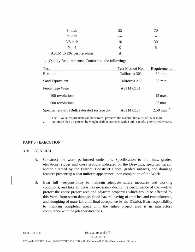
R0: IFB-12-15-17 Excavation and Fill 31 23 00-11 C:\Seaside CSD\IFB Specs_12-29-2017\IFB Vol 1B\Div 31 - Earthwork\31 23 00 - Excavation and Fill.docx
¾ inch 35 70 ½ inch --- --
3/8 inch 10 30 No. 4 0 5
ASTM C-136 Test Grading A
1. Quality Requirements: Conform to the following:
Test Test Method No. Requirements R-value1 California 301 80 min.
Sand Equivalent California 217 50 min.
Percentage Wear ASTM C131
100 revolutions 15 max.
500 revolutions 52 max.
Specific Gravity (Bulk saturated surface dry ASTM C127 2.58 min. 2
1. The R-value requirement will be waived, provided the material has a SE of 55 or more. 2. Not more than 15 percent by weight shall be particles with a bulk specific gravity below 2.50.
PART 3 - EXECUTION
3.01 GENERAL
A. Construct the work performed under this Specification to the lines, grades, elevations, slopes and cross sections indicated on the Drawings, specified herein, and/or directed by the District. Construct slopes, graded surfaces, and drainage features presenting a neat uniform appearance upon completion of the Work.
B. Bear full responsibility to maintain adequate safety measures and working conditions, and take all measures necessary during the performance of the work to protect the entire project area and adjacent properties which would be affected by this Work from storm damage, flood hazard, caving of trenches and embankments, and sloughing of material, until final acceptance by the District. Bear responsibility to maintain completed areas until the entire project area is in satisfactory compliance with the job specifications.

R0: IFB-12-15-17 Excavation and Fill 31 23 00-12 C:\Seaside CSD\IFB Specs_12-29-2017\IFB Vol 1B\Div 31 - Earthwork\31 23 00 - Excavation and Fill.docx
C. Protect from any damage as a result of the operations for this Contract utility lines and structures indicated on the Drawings, which are to remain in service. Where utility lines or structures not shown on the Drawings are encountered, report them to the District before proceeding with the work. Bear the cost of repair or replacement of any utility lines or structures, which are broken or damaged by the operations for this Contract.
3.02 REMOVALS, CLEARING AND GRUBBING
A. Comply with Section 31 10 00, “Site Clearing”, of these Specifications.
3.03 DUST CONTROL
A. Take all steps possible to prevent and reduce dust arising from the construction activity. Have adequate water trucks on the site at all times and water, as necessary, the areas where dust may arise. Cooperate fully with the District and water immediately when told to do so.
3.04 CARE OF DRAINAGE WATER
A. Take care of drainage water from the construction operations, and of storm water, wastewater and other non-potable sources reaching the construction area from any source, so that no damage will be done to the excavation, pipe trench, pipe or structures. Bear responsibility for any damages to persons or property on or off the construction site due to such drainage water or to the interruption or diversion of such storm water, wastewater, or other non-potable water source on account of the operations for this Contract.
B. Perform such grading as may be necessary to prevent surface water from flowing into excavations, and remove by pumping or by other approved methods any water accumulating therein.
3.05 EXCAVATION
A. General: Perform all excavation necessary or required as shown on the Drawings. Excavation includes the removal and disposal of all earth materials of whatever nature encountered, including both rock excavation and common excavation when both are present, and including the furnishing, placing, and maintaining of shoring and bracing necessary to safely support the sides of the excavations. The work also includes all pumping, ditching and other required measures for the removal or exclusion of water.
R0: IFB-12-15-17 Excavation and Fill 31 23 00-13 C:\Seaside CSD\IFB Specs_12-29-2017\IFB Vol 1B\Div 31 - Earthwork\31 23 00 - Excavation and Fill.docx
B. Rock Excavation: The word “rock” shall mean any material that cannot be dug with a Case 780, John Deere 710 backhoe or equal. The Contract includes a unit price for rock excavation, defined as including the removal, hauling, stockpiling, and/or proper disposal of all material required to be excavated which involves barring and wedging of material for removal, boulders or loose rock of one cubic yard or more in volume, or material which cannot be loosened or broken down by ripping with the above-mentioned equipment which is designed to remove rock. No payment will be made for rock removal unless the Contractor gives prompt notice to the District upon encountering such material and prior to its removal. The District’s determination as to whether the material meets the definition of rock and the District’s measurement of the volume of rock removal for which the Contractor is entitled to payment will be final and conclusive.
3.06 STRUCTURAL FILL and BACKFILL
A. Limits of Structural Fill and Backfill. Unless otherwise shown on the Drawings or directed by the District, place structural fill and backfill to the following limits of excavations: 1. to foundation grade where over-excavation for structure foundation was
required in accordance with 3.05B above. 2. A minimum horizontal dimension of 3 feet from the exterior face of the
structure or face of the wall. 3. Where sheeting, shoring or other measures used in accordance with Section
31 40 00, “Sheeting, Waling and Shoring”, results in an excavated zone remaining after construction of the structure that is less than 3 feet deep horizontally to the face of either the native material or sheeting and shoring permitted to be left in place, backfill the entire excavated zone.
B. Placement of Structural Fill/Backfill: 1. Before beginning backfilling, remove from the space to be backfilled all
foreign material, including water, and obtain inspection and approval by the District of the area to be backfilled. Step sloping sides of the excavated space to prevent wedging action of the backfill against the structure. Do not place backfill around or upon any structure until it is proven that the concrete has attained satisfactory strength in accordance with Section 03 30 00, “Cast-in-Place Concrete”, and that the structure as a whole is adequate to receive backfill.
2. Place backfill in uniform layers not exceeding 18-inches in depth on opposite sides of structures and walls before compaction. Inform the District of the
R0: IFB-12-15-17 Excavation and Fill 31 23 00-14 C:\Seaside CSD\IFB Specs_12-29-2017\IFB Vol 1B\Div 31 - Earthwork\31 23 00 - Excavation and Fill.docx
sequence of backfilling to be followed around each structure and obtain the District’s approval of this sequence before placing any backfill.
C. Compaction of Structural Fill/Backfill: 1. Place structural backfill in horizontal layers of such depths compatible to the
type of compaction equipment being used, but in no case place lifts exceeding 8 inches in un-compacted thickness. Evenly spread each layer, bring the moisture content to near optimum conditions and then compact to a density that is not less than 95 percent of maximum dry density at optimum moisture.
2. Mechanically compact backfill by equipment of a size and type required to achieve the compaction results specified in this Section. Permission to use specified compaction equipment shall not be construed as guaranteeing or implying that the use of such equipment will not result in damage to adjacent ground, existing improvements, or improvements installed under the Contract.
3. Flooding, jetting or ponding will not be permitted for the compaction of any structural backfill.
3.07 CONTROLLED FILL
A. General: Unless otherwise specified, compact fill material while at a moisture content near the optimum moisture content and to a density that is not less than 90 percent of the maximum dry density at optimum moisture.
B. Preparing Areas to be Filled: 1. Remove all vegetable matter and objectionable material from the surface upon
which the fill is to be placed and remove any loose and porous soils or compact same to a depth specified by the Soil Engineer. Then plow or scarify the surface to a minimum depth of 6 inches until the surface is free from uneven features that would tend to prevent uniform compaction by the equipment to be used.
2. Where fills are constructed on hillsides or slopes, step or key the slope of the original ground on which the fill is to be placed as shown on the Drawings. Extend the steps completely through the soil mantle and into the underlying formation materials.
3. After the foundation for the fill has been cleared, plowed or scarified, disc or blade the foundation material until it is uniform and free from large clods, brought to the proper moisture content and compacted as specified.
C. Placing, Spreading, and Compacting Fill Material:
R0: IFB-12-15-17 Excavation and Fill 31 23 00-15 C:\Seaside CSD\IFB Specs_12-29-2017\IFB Vol 1B\Div 31 - Earthwork\31 23 00 - Excavation and Fill.docx
1. Place the fill material in layers not exceeding 8 inches un-compacted thickness. Spread each layer evenly and thoroughly mix during the spreading to obtain uniformity of material in each layer.
2. When the moisture content of the fill material is below that specified by the District, add water until the moisture content is as specified.
3. When the moisture content of the fill material is above that specified by the District, aerate the fill material by blading, mixing, or other satisfactory methods until the moisture content is as specified.
4. After each layer has been placed, mixed and spread evenly, thoroughly compact the fill material to the specified density. Accomplish compaction by sheepsfoot rollers, vibratory rollers, multiple-wheel pneumatic-tired rollers or other types of acceptable compacting equipment. Employ equipment of such design that it will be able to compact the fill to the specified density. Perform compaction continuously over the entire area and make sufficient passes with the equipment over the material to ensure that the desired density has been obtained.
5. Compact surface of fill slopes so that the slopes are stable and which results in no excessive loose soil on the slopes.
6. Provide and maintain adequate erosion control facilities during the construction of the fill areas. Maintain the erosion control facilities in optimum condition until the permanent drainage system and vegetation are complete. Inspect the facilities following significant rainfall, perform repairs and remove excess sediment. Prevent the discharge of sediment off-site or to adjacent water courses.
3.08 PAVEMENT SUBGRADE
A. See Sections 31 23 33, “Trenching and Backfilling”, and Section 32 12 00, “Asphalt Concrete Paving, for requirements regarding pavement subgrade adjacent to structures (including vaults and boxes) and other areas shown on the Drawings or required to complete the Work as shown.
3.09 CLEANUP
A. Upon completion of work in this Section, remove all rubbish and debris from the job site. Remove all construction equipment and implements of service and leave the entire area involved in a neat, clean and acceptable condition.
R0: IFB-12-15-17 Excavation and Fill 31 23 00-16 C:\Seaside CSD\IFB Specs_12-29-2017\IFB Vol 1B\Div 31 - Earthwork\31 23 00 - Excavation and Fill.docx
3.10 DISPOSAL OF SURPLUS AND/OR UNSUITABLE MATERIALS
A. Dispose of away from the site, at no additional cost to the District and in accordance with all applicable local codes and regulations, excavated materials which are determined by the District to be unsuitable for use in backfill or compacted fills or excavated material that is in excess of that required to be used for backfill or to construct fills.
END OF SECTION 31 23 00

R0: IFB-12-15-17 Dewatering
31 23 19 - 1
C:\Seaside CSD\IFB Specs_12-29-2017\IFB Vol 1B\Div 31 - Earthwork\31 23 19 Dewatering.docx
SECTION 31 23 19
DEWATERING
PART 1 - GENERAL
1.01 SUMMARY
A. Requirements specified in the General and Supplementary Conditions of the Contract and Division 1 of the Technical Specifications form a part of this Section.
B. Work Included in this Section: 1. Design, construction, operation and maintenance of effective dewatering and
recharging systems. 2. Submittals for dewatering and recharging operations. 3. Disposal of extracted ground water. 4. Removal and relocation of equipment and clean-up of work areas.
C. Related Work specified in Other Sections: 1. Section 31 10 00 – Site Clearing and Site Preparation 2. Section 31 23 00 – Excavation and Fill 3. Section 31 23 33 - Trenching, Backfilling and Compaction 4. Section 31 40 00 - Sheeting, Waling and Shoring 5. Section 33 05 20 - General Piping Requirements 6. Section 40 05 23 - Valves and Miscellaneous Piping Appurtenances
1.02 SUBMITTAL
A. General: Comply with the general requirements and procedures described in Article 12 of the General Conditions and Section 01 33 00 of the Technical Specifications, “Submittal Procedures”, pertaining to submittals, including preparation, transmittals, and guarantees.
B. Submit for record purposes only and not for review or approval, shop drawings and data showing the intended plan for dewatering operations. Include locations and capacities of dewatering wells, well points, pumps, sumps, collection and discharge lines, standby units, water recharge system, water disposal methods, monitoring and settlement measuring equipment, and data collection and dissemination. Indicate parts of dewatering and recharge systems, which are intended to be abandoned in-
R0: IFB-12-15-17 Dewatering
31 23 19 - 2
C:\Seaside CSD\IFB Specs_12-29-2017\IFB Vol 1B\Div 31 - Earthwork\31 23 19 Dewatering.docx
place upon completion of the work. Abandonment of materials and equipment shall be subject to District approval. Submit the referenced intended plan not less than 15 days prior to start of dewatering operations.
1.03 QUALITY ASSURANCE
A. Qualifications: Furnish the services of an experienced, qualified, and equipped Dewatering Subcontractor to design and operate the dewatering required for the Work. In lieu of the above, the General Contractor may do the dewatering in accordance with a system approved by District and designed by a Civil Engineer who is registered in the State of California and who has proven experience in this type of work.
B. Data Available for Examination: No soil investigation was performed in preparation for this Work. The District makes no statement or warranty regarding the type of soil conditions to be encountered in the performance of this Work. Refer to Section 31 23 00, “Excavation and Fill”, for Contractor’s responsibilities.
C. Monitoring: When and where directed by District, construct observation wells using minimum 4-inch diameter pipe, with well screens and gravel packing. Furnish and install settlement gauges at times and locations selected by the District to monitor settlement of new and existing facilities.
1.04 JOB CONDITIONS
A. The descriptions of job conditions under Section 31 23 00 of the Technical Specifications, “Excavation and Fill”, shall form a part of this sub-section.
1.05 ALTERNATIVES
A. Groundwater may be high and seasonally variable at excavations. Employ dewatering systems that effectively intercept and remove water from the surrounding strata and thus prevent its entry into the excavation. Employ all such available alternatives as required to achieve this objective, including construction of pervious vertical channels. Do not rely solely on sheeting to protect work areas. The alternative use of a system of interlocking sheet piling with braces or anchorage supplemented by dewatering measures, or freezing methods, or other means which may be suitable, will be permitted, subject to review and acceptance by the District.
R0: IFB-12-15-17 Dewatering
31 23 19 - 3
C:\Seaside CSD\IFB Specs_12-29-2017\IFB Vol 1B\Div 31 - Earthwork\31 23 19 Dewatering.docx
PART 2 - PRODUCTS
2.01 COMPONENTS OF THE DEWATERING SYSTEM
A. Provide units of standard manufacture and in good working order. Remove from the job site unserviceable parts and equipment. Major equipment for which repair parts are unavailable from local suppliers shall be considered obsolete and therefore not acceptable.
PART 3 - EXECUTION
3.01 PREPARATION
A. Coordination: Layout and install dewatering installations beyond the limits of the permanent works. Avoid interference with access or other necessary activities.
B. Barricades, Shelters, and Safety: Provide protections for vital parts from accidental damage or freezing, and erect signs and barricades to isolate hazardous areas.
3.02 PERFORMANCE
A. Dewatering: Perform dewatering operations as required so all underground and below-grade work is performed or installed in dry excavations, excepting only that work specified for installation in wet excavations. Maintain dewatering systems in continuous operation until the involved work is completed, including the placing and compaction of backfill materials in the dry.
B. Protection of Existing Facilities: Provide standby equipment of sufficient size and capacity to ensure continuous operation of the dewatering systems. Where any sloped excavation infringes on or potentially endangers any existing facilities or structures, provide shoring, sheeting, and bracing according to shop drawings and calculations signed and stamped by a Structural or Civil Engineer registered in the State of California. File a copy of such plans and calculations with the District for record purposes. 1. At Contractor’s expense and to the District’s satisfaction, repair and make
good all damage or settlement to the foundation or other portion of any new or any existing facilities or structures caused by permanent or temporary failure or operation of the dewatering (or recharging systems) or by failure to maintain the existing groundwater level outside the dewatered areas.
R0: IFB-12-15-17 Dewatering
31 23 19 - 4
C:\Seaside CSD\IFB Specs_12-29-2017\IFB Vol 1B\Div 31 - Earthwork\31 23 19 Dewatering.docx
C. Drainage: During the life of this Contract, provide and maintain adequate means to promptly and effectively remove water from all areas of work, to prevent the entry of harmful quantities of water into the excavations and to dispose of the water removed. Avoid environmental damage and nuisance.
D. Disposal of Extracted Ground Water: Obtain all required permits from the entity having regulatory jurisdiction over the receiving body to which the extracted ground water is to be discharged. Bear responsibility for all costs in obtaining required permits and complying with imposed conditions.
E. Removal: Remove equipment when no longer required for dewatering or water controlling operations. Maintain operation of monitoring and settlement measurement systems until their removal is approved. To the extent approved, well points and like items may be abandoned in place. Otherwise, remove all temporary works, dewatering and/or recharging facilities in a manner satisfactory to the District.
3.03 CLEANUP
A. Upon completion of the work in this Section, remove rubbish and debris and leave the entire area affected by the Work in a neat, clean and acceptable condition. Refer to Section 32 90 00 of the Technical Specifications for landscape restoration required the Del Monte Lift Station site.
END OF SECTION 31 23 19
R0: IFB-12-15-17 Trenching, Backfilling and Compaction 31 23 33 - 1 C:\Seaside CSD\IFB Specs_12-29-2017\IFB Vol 1B\Div 31 - Earthwork\31 23 33 Trenching, Backfilling & Compaction.docx
SECTION 31 23 33
TRENCHING, BACKFILLING AND COMPACTION
PART 1 - GENERAL
1.01 SUMMARY
A. Requirements specified in the General and Supplementary Conditions of the Contract and Division 1 of the Technical Specifications form a part of this Section.
B. Section Includes: 1. Submittals. 2. Backfill materials. 3. Trench excavation. 4. Placement and compaction of trench backfill, including pipe bedding.
C. Related Sections: 1. Section 31 23 00 – Excavation and Fill 2. Section 31 23 19 - Dewatering 3. Section 31 40 00 – Sheeting, Waling and Shoring 4. Piping and conduit work specified in Division 33.
1.02 GENERAL REQUIREMENTS
A. Requirements in Part 1 of Section 31 23 00 of the Technical Specifications apply to this Section.
1.03 SUBMITTALS
A. Comply with the general requirements and procedures described in Article 12 of the General Conditions and Section 01 33 00, “Submittal Procedures”, of the Technical Specifications, “Submittal Procedures”, of the Technical Specifications pertaining to submittals, including preparation, transmittals and guarantees.
B. Prior to shipment of respective materials to the Work site, submit copies of certified test reports demonstrating properties of proposed material are in compliance with the requirements stated herein below. Have the test reports prepared by a testing laboratory approved by the District and signed by a responsible party in charge of the testing laboratory.
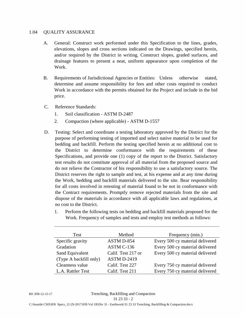
R0: IFB-12-15-17 Trenching, Backfilling and Compaction 31 23 33 - 2 C:\Seaside CSD\IFB Specs_12-29-2017\IFB Vol 1B\Div 31 - Earthwork\31 23 33 Trenching, Backfilling & Compaction.docx
1.04 QUALITY ASSURANCE
A. General: Construct work performed under this Specification to the lines, grades, elevations, slopes and cross sections indicated on the Drawings, specified herein, and/or required by the District in writing. Construct slopes, graded surfaces, and drainage features to present a neat, uniform appearance upon completion of the Work.
B. Requirements of Jurisdictional Agencies or Entities: Unless otherwise stated, determine and assume responsibility for fees and other costs required to conduct Work in accordance with the permits obtained for the Project and include in the bid price.
C. Reference Standards: 1. Soil classification - ASTM D-2487 2. Compaction (where applicable) - ASTM D-1557
D. Testing: Select and coordinate a testing laboratory approved by the District for the purpose of performing testing of imported and select native material to be used for bedding and backfill. Perform the testing specified herein at no additional cost to the District to determine conformance with the requirements of these Specifications, and provide one (1) copy of the report to the District. Satisfactory test results do not constitute approval of all material from the proposed source and do not relieve the Contractor of his responsibility to use a satisfactory source. The District reserves the right to sample and test, at his expense and at any time during the Work, bedding and backfill materials delivered to the site. Bear responsibility for all costs involved in retesting of material found to be not in conformance with the Contract requirements. Promptly remove rejected materials from the site and dispose of the materials in accordance with all applicable laws and regulations, at no cost to the District. 1. Perform the following tests on bedding and backfill materials proposed for the
Work. Frequency of samples and tests and employ test methods as follows:
Test Method Frequency (min.) Specific gravity ASTM D-854 Every 500 cy material delivered Gradation ASTM C-136 Every 500 cy material delivered Sand Equivalent (Type A backfill only)
Calif. Test 217 or ASTM D-2419
Every 500 cy material delivered
Cleanness value Calif. Test 227 Every 750 cy material delivered L.A. Rattler Test Calif. Test 211 Every 750 cy material delivered
R0: IFB-12-15-17 Trenching, Backfilling and Compaction 31 23 33 - 3 C:\Seaside CSD\IFB Specs_12-29-2017\IFB Vol 1B\Div 31 - Earthwork\31 23 33 Trenching, Backfilling & Compaction.docx
1.05 JOB CONDITIONS
A. General: 1. Perform all excavation by open cut unless otherwise specified or shown on the
Drawings. Stockpile all excavated and imported material suitable for use as backfill in an orderly manner a sufficient distance from excavated banks to avoid overloading and prevent slides or cave-ins of banks. Remove from the working area in an expeditious manner excavated materials deemed unsuitable for backfill, as specified herein or determined by the District from tests or visual inspection, and surplus material, and dispose of these materials at a site approved for such use by relevant authorities. Perform grading as may be necessary to prevent surface water from flowing into trenches. Remove by pumping or other approved means any water accumulating in trenches.
2. Conduct measures necessary during the performance of the Work to protect the entire Contract work area and adjacent properties which would be affected by and as a result of this Work, from storm damage, flood hazard, caving of trenches and embankments, and sloughing of material. Maintain completed areas until the entire Contract work area is in satisfactory compliance with the Specifications.
B. Safety: Be familiar with, and at all times conform to, all applicable regulations of the “General Industry Safety Orders” and “Construction Safety Orders” of the State of California, Department of Industrial Relations, and Division of Industrial Safety. Before excavating any trench 5 feet in depth or greater and into which a person will be required to descend, submit to the District a detailed plan showing the design of shoring, bracing, sloping or other provisions to be made for the workers’ protection from the hazard of caving ground during the excavation of such trench. 1. The requirements of Section 31 40 00 of the Technical Specifications,
“Sheeting, Waling and Shoring”, apply to this portion of the Work. Obtain a permit from the State Division of Industrial Safety before commencing excavation. Submit a copy of the permit to the District.
2. Completely cover (with metal plate) or backfill at the end of each working day trenches in paved areas. During normal working periods, conduct all reasonable measures to protect public safety around open excavations.
C. Utility Protection: Protect from any damage as a result of operations from this Contract utility lines and structures indicated on the Drawings which are to remain in service. Where utility lines or structures not shown on the Drawings are encountered, report them to the District before proceeding with the work. Bear the cost of repair or replacement of any utility lines or structures which are broken or damaged by operations performed as part of the Work for this Contract.
R0: IFB-12-15-17 Trenching, Backfilling and Compaction 31 23 33 - 4 C:\Seaside CSD\IFB Specs_12-29-2017\IFB Vol 1B\Div 31 - Earthwork\31 23 33 Trenching, Backfilling & Compaction.docx
D. Protection of Trees: Comply with the requirements described herein to protect existing trees in the work area from harm or damage as result of the activities for this Work, unle3ss approved by the District for removal. 1. Construct excavations and new pipeline trench required for the Work a
minimum distance from existing trees equal to the sum of four (4) trunk diameters.
2. Provide protective fencing around any tree located within a distance of 10 feet from the edge of new excavation of trench. Prevent bark injury to any tree from equipment or materials used in the activities for the Work. In the event bark injury does occur, report immediately to the District and provide repairs as directed by the District. Where the injury results in irreparable damage to the tree, replace the tree with one of the same species and similar size, unless otherwise directed by the District and at no additional cost to the District.
3. Cutting or removal by backhoe operation of tree root greater than 2 inches in diameter is not permitted.
4. Roots with diameter between 2 inches and 6 inches may be hand cut and removed.
5. Do not disturb roots greater than 6 inches in diameter, allow such roots to remain. Conduct excavation or trenching operations for new pipeline below or around larger tree roots.
E. Existing Conditions: Unless otherwise specifically notified to the District prior to the Bid Date, the conditions of the construction sites in existence at the time of bidding are understood to be accepted.
1.06 INSPECTION AND CONTROL
A. A Soils Engineer will be engaged by the District, who will act as the direct representative of the District in soils work, to perform inspection of the removal and replacement of unsuitable materials, and the placement and compaction of all fills and backfills within the limits of earthwork on this project. Perform all work in accordance with these Specifications and as directed and approved by the District. Costs for all such inspections and tests will be paid by the District. If retesting is required because the Work did not meet the Specifications, all costs for retesting and reinspections will be deducted from the funds due the Contractor.
PART 2 – PRODUCTS
2.01 MATERIALS
A. Fill Soils: Consists of excavated on-site soils except when unsuitable soils are encountered, as determined by the District or his representative, in which case use
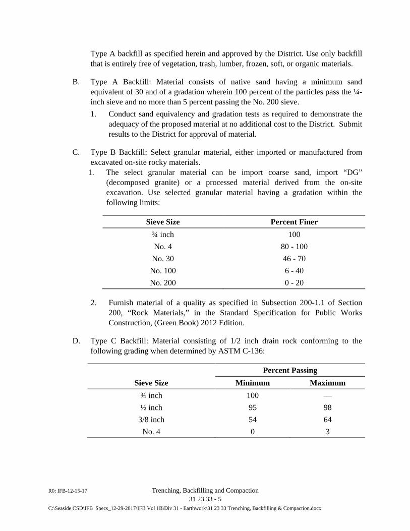
R0: IFB-12-15-17 Trenching, Backfilling and Compaction 31 23 33 - 5 C:\Seaside CSD\IFB Specs_12-29-2017\IFB Vol 1B\Div 31 - Earthwork\31 23 33 Trenching, Backfilling & Compaction.docx
Type A backfill as specified herein and approved by the District. Use only backfill that is entirely free of vegetation, trash, lumber, frozen, soft, or organic materials.
B. Type A Backfill: Material consists of native sand having a minimum sand equivalent of 30 and of a gradation wherein 100 percent of the particles pass the ¼-inch sieve and no more than 5 percent passing the No. 200 sieve. 1. Conduct sand equivalency and gradation tests as required to demonstrate the
adequacy of the proposed material at no additional cost to the District. Submit results to the District for approval of material.
C. Type B Backfill: Select granular material, either imported or manufactured from excavated on-site rocky materials.
1. The select granular material can be import coarse sand, import “DG” (decomposed granite) or a processed material derived from the on-site excavation. Use selected granular material having a gradation within the following limits:
Sieve Size Percent Finer ¾ inch 100 No. 4 80 - 100
No. 30 46 - 70 No. 100 6 - 40 No. 200 0 - 20
2. Furnish material of a quality as specified in Subsection 200-1.1 of Section 200, “Rock Materials,” in the Standard Specification for Public Works Construction, (Green Book) 2012 Edition.
D. Type C Backfill: Material consisting of 1/2 inch drain rock conforming to the following grading when determined by ASTM C-136:
Percent Passing Sieve Size Minimum Maximum
¾ inch 100 — ½ inch 95 98
3/8 inch 54 64 No. 4 0 3
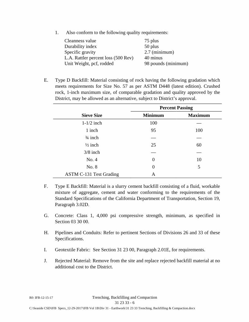
R0: IFB-12-15-17 Trenching, Backfilling and Compaction 31 23 33 - 6 C:\Seaside CSD\IFB Specs_12-29-2017\IFB Vol 1B\Div 31 - Earthwork\31 23 33 Trenching, Backfilling & Compaction.docx
1. Also conform to the following quality requirements:
Cleanness value 75 plus Durability index 50 plus Specific gravity 2.7 (minimum) L.A. Rattler percent loss (500 Rev) 40 minus Unit Weight, pcf, rodded 98 pounds (minimum)
E. Type D Backfill: Material consisting of rock having the following gradation which meets requirements for Size No. 57 as per ASTM D448 (latest edition). Crushed rock, 1-inch maximum size, of comparable gradation and quality approved by the District, may be allowed as an alternative, subject to District’s approval.
Percent Passing Sieve Size Minimum Maximum 1-1/2 inch 100 —
1 inch 95 100 ¾ inch — — ½ inch 25 60
3/8 inch — — No. 4 0 10 No. 8 0 5
ASTM C-131 Test Grading A
F. Type E Backfill: Material is a slurry cement backfill consisting of a fluid, workable mixture of aggregate, cement and water conforming to the requirements of the Standard Specifications of the California Department of Transportation, Section 19, Paragraph 3.02D.
G. Concrete: Class 1, 4,000 psi compressive strength, minimum, as specified in Section 03 30 00.
H. Pipelines and Conduits: Refer to pertinent Sections of Divisions 26 and 33 of these Specifications.
I. Geotextile Fabric: See Section 31 23 00, Paragraph 2.01E, for requirements.
J. Rejected Material: Remove from the site and replace rejected backfill material at no additional cost to the District.
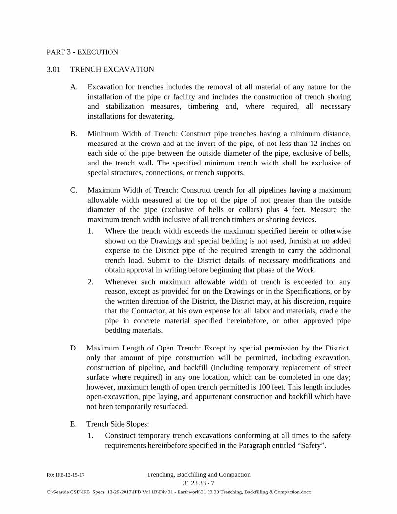
R0: IFB-12-15-17 Trenching, Backfilling and Compaction 31 23 33 - 7 C:\Seaside CSD\IFB Specs_12-29-2017\IFB Vol 1B\Div 31 - Earthwork\31 23 33 Trenching, Backfilling & Compaction.docx
PART 3 - EXECUTION
3.01 TRENCH EXCAVATION
A. Excavation for trenches includes the removal of all material of any nature for the installation of the pipe or facility and includes the construction of trench shoring and stabilization measures, timbering and, where required, all necessary installations for dewatering.
B. Minimum Width of Trench: Construct pipe trenches having a minimum distance, measured at the crown and at the invert of the pipe, of not less than 12 inches on each side of the pipe between the outside diameter of the pipe, exclusive of bells, and the trench wall. The specified minimum trench width shall be exclusive of special structures, connections, or trench supports.
C. Maximum Width of Trench: Construct trench for all pipelines having a maximum allowable width measured at the top of the pipe of not greater than the outside diameter of the pipe (exclusive of bells or collars) plus 4 feet. Measure the maximum trench width inclusive of all trench timbers or shoring devices. 1. Where the trench width exceeds the maximum specified herein or otherwise
shown on the Drawings and special bedding is not used, furnish at no added expense to the District pipe of the required strength to carry the additional trench load. Submit to the District details of necessary modifications and obtain approval in writing before beginning that phase of the Work.
2. Whenever such maximum allowable width of trench is exceeded for any reason, except as provided for on the Drawings or in the Specifications, or by the written direction of the District, the District may, at his discretion, require that the Contractor, at his own expense for all labor and materials, cradle the pipe in concrete material specified hereinbefore, or other approved pipe bedding materials.
D. Maximum Length of Open Trench: Except by special permission by the District, only that amount of pipe construction will be permitted, including excavation, construction of pipeline, and backfill (including temporary replacement of street surface where required) in any one location, which can be completed in one day; however, maximum length of open trench permitted is 100 feet. This length includes open-excavation, pipe laying, and appurtenant construction and backfill which have not been temporarily resurfaced.
E. Trench Side Slopes: 1. Construct temporary trench excavations conforming at all times to the safety
requirements hereinbefore specified in the Paragraph entitled “Safety”.
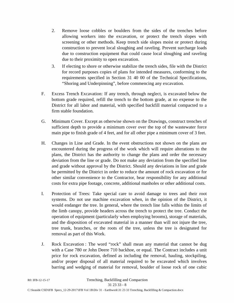
R0: IFB-12-15-17 Trenching, Backfilling and Compaction 31 23 33 - 8 C:\Seaside CSD\IFB Specs_12-29-2017\IFB Vol 1B\Div 31 - Earthwork\31 23 33 Trenching, Backfilling & Compaction.docx
2. Remove loose cobbles or boulders from the sides of the trenches before allowing workers into the excavation, or protect the trench slopes with screening or other methods. Keep trench side slopes moist or protect during construction to prevent local sloughing and raveling. Prevent surcharge loads due to construction equipment that could cause local sloughing and raveling due to their proximity to open excavation.
3. If electing to shore or otherwise stabilize the trench sides, file with the District for record purposes copies of plans for intended measures, conforming to the requirements specified in Section 31 40 00 of the Technical Specifications, “Shoring and Underpinning”, before commencing any excavation.
F. Excess Trench Excavation: If any trench, through neglect, is excavated below the bottom grade required, refill the trench to the bottom grade, at no expense to the District for all labor and material, with specified backfill material compacted to a firm stable foundation.
G. Minimum Cover. Except as otherwise shown on the Drawings, construct trenches of sufficient depth to provide a minimum cover over the top of the wastewater force main pipe to finish grade of 4 feet, and for all other pipe a minimum cover of 3 feet.
H. Changes in Line and Grade. In the event obstructions not shown on the plans are encountered during the progress of the work which will require alterations to the plans, the District has the authority to change the plans and order the necessary deviation from the line or grade. Do not make any deviation from the specified line and grade without approval by the District. Should any deviations in line and grade be permitted by the District in order to reduce the amount of rock excavation or for other similar convenience to the Contractor, bear responsibility for any additional costs for extra pipe footage, concrete, additional manholes or other additional costs.
I. Protection of Trees: Take special care to avoid damage to trees and their root systems. Do not use machine excavation when, in the opinion of the District, it would endanger the tree. In general, where the trench line falls within the limits of the limb canopy, provide headers across the trench to protect the tree. Conduct the operation of equipment (particularly when employing brooms), storage of materials, and the disposition of excavated material in a manner than will not injure the tree, tree trunk, branches, or the roots of the tree, unless the tree is designated for removal as part of this Work.
J. Rock Excavation : The word “rock” shall mean any material that cannot be dug with a Case 780 or John Deere 710 backhoe, or equal. The Contract includes a unit price for rock excavation, defined as including the removal, hauling, stockpiling, and/or proper disposal of all material required to be excavated which involves barring and wedging of material for removal, boulder of loose rock of one cubic
R0: IFB-12-15-17 Trenching, Backfilling and Compaction 31 23 33 - 9 C:\Seaside CSD\IFB Specs_12-29-2017\IFB Vol 1B\Div 31 - Earthwork\31 23 33 Trenching, Backfilling & Compaction.docx
yard or more in volume, or material which cannot be loosened or broken down by ripping with the above-mentioned equipment which is designated to remove rock. 1. No payment will be made for rock removal unless the Contractor gives
prompt notice to the District upon encountering such material and prior to its removal.
2. The District’s determination as to whether the material meets the definition of rock and the District’s measurement of the volume of rock removal for which the Contractor is entitled to payment will be final and conclusive.
3.02 BRACING TRENCHES
A. Support the sides of the trenches with plank sheeting and bracing in accordance with Section 31 430 00, “Sheeting, Waling and Shoring”, of these Specifications, and in a manner as to prevent caving of the sides of the trench. Completely fill the space left by withdrawal of sheeting or shoring with dry granular material blown or rammed in place. Shore trenches 5 feet and greater in depth unless the sides of the trench are cut to the angle of repose of the excavated soils.
3.03 PIPE BEDDING
A. Excavate the trench to 6 inches below the pipe grade as shown on the Drawings for the full width of the trench and place 6 inches of Type A or C backfill as specified above upon which the pipe is to be laid.
B. Where groundwater is encountered, and the native material does not afford a solid foundation for pipe subgrade, suitably dewater the trench and construct a firm, stable base for pipe by excavating any unstable material to 12-inch minimum depth below subgrade base, or as District decides is necessary, and construct a stable base placing specified Type C or D backfill or combination of the two as required upon which the subgrade can be prepared. 1. Wrap the subgrade base backfill in the specified and approved geotextile
fabric to the required subgrade level and upon which the pipe bedding can be prepared. Where the Drawings show the geotextile fabric is required or where the encountered soil conditions require a fabric wrap to achieve the specified backfill compaction, continue the geotextile fabric up the sides of the trench walls and wrap the trench backfill in the fabric.
C. Where rock is encountered in the trench, excavate to a minimum 12-inch depth below subgrade or as the District decides is necessary, and construct a suitable base by placing Type A or C backfill material upon which a subgrade can be prepared.
D. Before any pipe is lowered in place, prepare the trench bottom or bedding so that each pipe will have a firm and uniform bearing over the entire length of the barrel
R0: IFB-12-15-17 Trenching, Backfilling and Compaction 31 23 33 - 10 C:\Seaside CSD\IFB Specs_12-29-2017\IFB Vol 1B\Div 31 - Earthwork\31 23 33 Trenching, Backfilling & Compaction.docx
and a width equal to one half (1/2) of the outside diameter of the pipe. Make adjustments in line and grade by scraping away or filling and tamping in under the barrel of the pipe. Wedging or blocking the pipe is not permitted.
3.04 BACKFILLING PIPE TRENCHES
A. Backfilling Pipe Zone: Use selected backfill material for the pipe zone consisting of Type A backfill as specified above and approved by the District in advance of placement. Place material in the trench simultaneously on each side of the pipe for the full width of the trench and the depth of the pipe zone in layers not to exceed 6 inches in un-compacted depth. Thoroughly compact each layer by tamping. Water settling is not permitted. In all cases, perform backfilling of the pipe zone by hand tools, except that backfilling the pipe zone above the pipe spring-line may be by suitable equipment used in a manner that does not disturb or damage the pipe. 1. Pay particular attention to the underside of the pipe and fittings to provide a
firm support along the full length of the pipe. The pipe zone is considered to be that volume of the trench extending from the bottom up to 12 inches above the top of the pipe. Compact backfill material for the pipe zone in the trench in accordance with the Specifications described herein below. Native material is not permitted as backfill in the pipe zone unless it can be shown to comply with Type A backfill material.
2. For PVC pipe installation, ensure that no stones or rocks 1-inch and larger in any dimension are in the pipe zone backfill or area on the trench walls within 4 inches of the pipe wall.
3. In those cases where separation between a new sanitary sewer (force or gravity mains) and an existing water main or recycled water pipeline is found to be less than the minimum acceptable, use Type E backfill or Class 2 concrete for backfilling the pipe zone unless otherwise approved by the District. Fully encircle the pipe with at least 6-inch thickness of the special backfill in these cases. Promptly notify the District when these sub-minimum separation conditions are encountered.
4. Type E backfill as specified above may be used in the pipe zone in lieu of Type A backfill, at the Contractor’s option. When placing Type E backfill, vibrate the material along both sides of the pipe in accordance with the requirements for vibration compaction specified in Part 3 of Section 03 30 00, “Cast-in-Place Concrete” of these Specifications to prevent voids.
5. Do not begin backfilling of the trench until after the pipe installation has been inspected by the District. Backfilling of the trench prior to inspection may require re-excavation of the trench, if directed by the District, for the purpose of inspecting the pipe. Backfill trenches in a manner that does not disturb the pipe, fittings, or appurtenances, or damage the coating on these materials.
R0: IFB-12-15-17 Trenching, Backfilling and Compaction 31 23 33 - 11 C:\Seaside CSD\IFB Specs_12-29-2017\IFB Vol 1B\Div 31 - Earthwork\31 23 33 Trenching, Backfilling & Compaction.docx
6. Where geotextile fabric wrap of the trench backfill (including pipe zone) is shown on the Drawings as required or where the encountered soil conditions require fabric wrap to achieve the specified backfill compaction and prevent migration of backfill material into the native material on the trench sides, continue the geotextile fabric up the sides of the trench walls and wrap the trench backfill in the fabric.
B. Backfilling Remainder of the Pipe Trench: Refer to the preceding paragraph “Requirements of Jurisdictional Agencies or Entities” in this Section regarding all Work and materials used on the project sites. Unless otherwise required in the encroachment permits of the respective agencies or entity, the following requirements prevail. 1. After the pipe has been laid in the trench and has been inspected and
approved, and backfilling in the pipe zone is complete and compacted, the remainder of the trench may be backfilled. Exercise care to ensure that no voids remain under, around, or near the pipes. Provide backfill material complying with the following: a. Trench backfill in existing or proposed future paved areas: Provide Type
A, Type B, or Type E backfill in the trench volume between the top of the pipe zone to the subgrade elevation requiring backfill with aggregate base rock. Where Type E backfill material is used, vibrate into place as specified in Paragraph 3.04A above. Do not move concrete slurry after evidence of initial set. Close street to traffic or plate trench until the slurry cement backfill has sufficiently stiffened to support vehicular traffic and compacted cold mix asphalt have been brought to grade to provide an even surface for vehicular traffic.
b. In easement or other areas not within existing or proposed paved areas: place select native material having a plasticity index (PI) of 15 or less and liquid limit of 35 percent or less, free from all clods, lumps, or stones over 3-inches in greatest dimension, and other deleterious material. Do not use material containing more than 4 percent by volume of organics. Where native materials do not meet these specifications, use Type A, B, or E trench backfill. In road shoulders, place Class 2 aggregate base to finish grade in the last 8-inches, minimum, to finish grade.
2. Include the expenses of imported material required for backfill and disposal of excess trench excavation in the respective construction payment item for this Work.
C. Compaction: Determine the maximum dry density and optimum moisture content of each soil type used in the controlled compacted fill by the specified compaction
R0: IFB-12-15-17 Trenching, Backfilling and Compaction 31 23 33 - 12 C:\Seaside CSD\IFB Specs_12-29-2017\IFB Vol 1B\Div 31 - Earthwork\31 23 33 Trenching, Backfilling & Compaction.docx
method. Provide minimum relative compaction densities at optimum moisture content in accordance with the following: 1. Pipe Zone (as defined above). 95 percent 2. Pipe Trench. a. Under paving, structures, and slabs 95 percent b. All other areas 90 percent
D. Placement and Compaction of Trench Backfill: In placing and compacting trench backfill conform to one of the following methods, subject to the qualifications specified therein: 1. Mechanically Compacted Backfill: Mechanically compact backfill by means
of tamping rollers, sheepsfoot rollers, pneumatic tire rollers, vibrating rollers, or other mechanical tampers. Use equipment of size and type necessary to achieve the compaction results specified herein but which, when used, will not result in damage to the pipe or other buried appurtenances. a. Impact-type pavement breakers (stompers) will not be permitted over
any pipe. NOTE: Vibratory and/or impact type compaction equipment are not permitted in the pipe zone or within 4 feet over installed pipe of any kind.
b. Do not construe District’s inspection of the use of any specific compaction equipment as guaranteeing or implying that the use of such equipment will not result in damage to adjacent ground, existing improvements, or improvements installed under the Contract. Make determinations in this regard as necessary to ensure compliance.
c. Place mechanically compacted backfill in horizontal layers not exceeding the maximum lift thickness specified below. Evenly spread each layer, bring the moisture content to near optimum condition and then tamp or roll the backfill material until the specified compaction has been attained.
Compaction Equipment Maximum Uncompacted Lift Thickness (ft)
Vibratory 1.33
Rolling 0.67
Hand-directed mechanical tampers 0.5
2. Water Densified Backfill: Water densified backfill (flooding, jetting, etc.) is not permitted.
R0: IFB-12-15-17 Trenching, Backfilling and Compaction 31 23 33 - 13 C:\Seaside CSD\IFB Specs_12-29-2017\IFB Vol 1B\Div 31 - Earthwork\31 23 33 Trenching, Backfilling & Compaction.docx
3.05 PIPELINE INSTALLATION
A. See Section 33 05 20, “General Piping Requirements”, of these Specifications and other pertinent sections for applicable pipe material.
3.06 PAVEMENT REPLACEMENT
A. Prior to replacing pavement, perform a second saw-cutting of existing pavement as shown on the Drawings and specified in Section 02 41 00, “Demolition,” to provide a neat joint line and to provide a stable shelf on which to place and extend the HMA material. See Section 32 12 00, “Asphalt Concrete Paving”, for complete pavement replacement/restoration requirements.
B. Place and compact cut-back or cold mix asphalt concrete over backfilled trench flush to adjacent paved surface until paving operations are commenced. Use of trench plates to cover unfinished trenches is subject to District approval. If trench plates are allowed, place and compact cold mix around all edges to provide smooth transition for vehicular traffic. In wet weather conditions, remove trench plates when directed by District, promptly backfill trench as specified, and top with cold-mix asphalt concrete.
3.07 CLEAN-UP
A. When working within areas frequented by the public, remove all excess excavated material at the end of each workday and maintain the site in a clean and neat condition. Immediately upon completion of the work of this Section, remove all rubbish and debris from the job site. Remove all construction equipment and implements of service and leave the entire area involved in a neat, clean, and acceptable condition.
END OF SECTION 31 23 33

R0: IFB-12-15-17 Trenching, Backfilling and Compaction 31 23 33 - 14 C:\Seaside CSD\IFB Specs_12-29-2017\IFB Vol 1B\Div 31 - Earthwork\31 23 33 Trenching, Backfilling & Compaction.docx
This page intentionally blank.
R0: IFB-12-15-17 Sheeting, Waling and Shoring 31 40 00-1 C:\Seaside CSD\IFB Specs_12-29-2017\IFB Vol 1B\Div 31 - Earthwork\31 40 00 - Sheeting, Waling and Shoring.docx
SECTION 31 40 00
SHEETING, WALING AND SHORING
PART 1 - GENERAL
1.01 SUMMARY
A. Requirements specified in the General and Supplementary Conditions of the Contract and in Division 1 of the Technical Specifications form a part of this Section.
B. Work Included in This Section: 1. Temporary sheeting and bracing for trenches. 2. Submittals
C. Related Work specified in Other Sections: 1. Section 31 10 00 – Site Clearing 2. Section 31 23 00 – Excavation and Fill 3. Section 31 23 33 - Trenching, Backfilling, and Compaction
1.02 SUBMITTALS
A. Comply with the general requirements and procedures described in Article 12 of the General Conditions and Section 01 33 00, “Submittal Procedures”, of the Technical specifications pertaining to submittals, including preparation, transmittals, and guarantees. All designs submitted under this Section must be signed by a Civil Engineer duly registered in the State of California.
B. Prior to the start of any Work involving sheeting and bracing, submit the design drawings and complete calculations of the sheeting system, including but not limited to, sheeting size, wales, rakers, anchor systems, struts, earth anchors, anchor piles, tie rods or any other components pertinent to the design, to the California Division of Occupational Health and Safety for review. 1. Provide such additions and modifications as are required for Division
acceptance. When Division acceptance is obtained, file three (3) copies of the final design drawings and data with the District for record purposes only and not for review or approval.
R0: IFB-12-15-17 Sheeting, Waling and Shoring 31 40 00-2 C:\Seaside CSD\IFB Specs_12-29-2017\IFB Vol 1B\Div 31 - Earthwork\31 40 00 - Sheeting, Waling and Shoring.docx
1.03 QUALITY ASSURANCE
A. Material Standards: Furnish lumber for shores, wales, and sheeting of grading required by the American Lumber Standards for the particular application.
B. Design Criteria: Design and construct temporary sheeting and shoring which are to be used as an aid in construction. Prepare design in conformance with applicable requirements of Article 6, "Excavations, Trenches, Earthwork" of Construction Safety Orders of California State Division of Occupational Health and Safety. In addition, base sheet piling design on the material requirements specified herein. 1. Do not employ sloping of trenches below the groundwater elevation. 2. Open cut excavation will not be permitted in paved areas unless otherwise
permitted by the District. 3. Employ designs prepared and signed by a Civil Engineer registered in the
State of California, and based on the stresses for various materials of construction contained in California Building Code (CBC), 2013 Edition.
1.04 JOB CONDITIONS
A. The description of job conditions under Section 31 10 00, “Clearing and Site Preparation”, forms a part of this subsection.
1.05 SITE INVESTIGATION
A. The description for site investigation under Section 31 23 00, “Excavation and Fill”, forms a part of this subsection.
1.06 ALTERNATIVES
A. The use or application of alternative methods and materials, and the employment of proprietary systems under lease or franchise in lieu of that specified herein, may be allowed. Demonstration of suitability and compliance with these Specifications and approval of the District shall be required.
PART 2 - PRODUCTS
2.01 MATERIALS
A. Lumber: 1. Temporary Shores, Wales, and Sheeting: Furnish structural grade planks,
beams, and posts as defined and specified for stress-grade lumber in the
R0: IFB-12-15-17 Sheeting, Waling and Shoring 31 40 00-3 C:\Seaside CSD\IFB Specs_12-29-2017\IFB Vol 1B\Div 31 - Earthwork\31 40 00 - Sheeting, Waling and Shoring.docx
American Lumber standards. Lumber may be rough, untreated, in random lengths, and shall be of standard dimensions.
B. Sheet Piling: 1. Material: Provide sheet pile manufactured from steel conforming to ASTM A-
328, or from steel conforming to ASTM A-572, Grade 42. 2. Dimensions and Section Properties: Furnish standard rolled sections PZ, PDA,
PSA, or PS for steel sheet piling used for cofferdams or trench sheeting. Use weights, dimensions and section properties that are appropriate for the intended use, as demonstrated by the design (refer to Par. 1.02 and 1.03 of this Section).
PART 3 - EXECUTION
3.01 INSTALLATION
A. General: Install sheeting and bracing for trench and structure excavation progressively as the removal of excavated material requires. Butt planks to exclude groundwater and fines, preventing the erosion of voids outside sheeting. In soft, wet ground, drive sheeting to a lower level as excavation progresses so that sheeting is embedded in undisturbed earth. Install wales and struts at close intervals so as to prevent displacement of the surrounding earth and to maintain safe conditions in the work area. 1. Take full responsibility to correct any damage proven to result from improper
installations. 2. Temporary sheeting for trench and structure excavation may be removed and
re-used. Withdraw individual planks alternately as the backfill is raised, maintaining sufficient sheeting and bracing to protect the Work and workers. Remove bracing completely.
3. Where unstable conditions occur in the underlying strata from any cause, and withdrawal of sheeting will endanger the Work, a portion of the sheeting, including bracing, may be left in place with approval of the District. Remove all wood within a zone extending 4 feet below finished grade. Leaving such material in place shall not be cause for an increase in Contract Price.
B. Sheet Piling: Using steel sheet piling for temporary protective installations is an acceptable option. Provide continuous piling installations. 1. Installation of Sheet Piling: Provide sufficient depth of piling to prevent heave
when the trench or excavation is dewatered. Drive piles with a hammer with an adequate capacity to complete pile driving without changing hammers.
R0: IFB-12-15-17 Sheeting, Waling and Shoring 31 40 00-4 C:\Seaside CSD\IFB Specs_12-29-2017\IFB Vol 1B\Div 31 - Earthwork\31 40 00 - Sheeting, Waling and Shoring.docx
a. The use of air or water jets to assist in driving the sheet piling will be permitted, providing that the last 5 feet of advance is by driving.
b. Drive piles accurately to the lines and grades shown or required, with each section interlocked with the sheet piles driven previously. To ensure proper alignment of the sheet piles, use a driving template or jig.
c. If any pile is damaged during driving, remove and replace the damaged pile. If piles are driven out of interlock or are not properly plumbed or aligned, pull and redrive the non-conforming piles.
2. Removal and Reuse of Sheet Piling: Upon completion of the Work, remove the temporary sheet piling unless approved by the District to be left in place. Salvaged piling may be reused providing the sheet pile is not seriously damaged. The District will inspect all salvaged piling and indicate which is suitable for reuse. All salvaged piling shall remain the property of the Contractor. Piling left in place becomes the property of the District, at no extra cost.
3. Prevention of Damage: In installing, cutting off, or removing sheet piles, take every precaution to ensure that damage to structures does not occur. If damage does occur, repair the damage at no additional expense to the District.
3.02 PROTECTION OF EXISTING FACILITIES
A. Protect existing facilities from the consequences of the work for this Section. Where any sloped excavation infringes on or potentially endangers any existing facilities or structures, provide shoring, sheeting, and bracing according to shop drawings and calculations signed and stamped by a Civil Engineer registered in the State of California. For record purposes only, file a copy of such plans and calculations with the District.
3.03 CLEANUP
A. Upon completion of the work in this Section, remove rubbish and debris from the job site. Remove construction equipment and implements of service. Leave the entire area affected by the work in this Section in a neat, clean and acceptable condition.
END OF SECTION 31 40 00
DIVISION 32
EXTERIOR IMPROVEMENTS

R0: IFB-12-15-17 Asphalt Concrete Paving 32 12 00 - 1 C:\Seaside CSD\IFB Specs_12-29-2017\IFB Vol 1B\Div 32 - Exterior Improvements\32 12 00 - Asphalt Concrete Paving.docx
SECTION 32 12 00
ASPHALT CONCRETE PAVING
PART 1 - GENERAL
1.01 SUMMARY
A. Requirements specified in the General and Supplementary Conditions of the Contract and Division 1 of the Technical Specifications form a part of this Section. Furnish all tools, equipment, materials, and supplies and perform all labor necessary for the furnishing, placing and compacting of asphalt concrete / hot mix asphalt (HMA) pavement and base to the lines, grades and dimensions shown on the Drawings and as specified herein.
B. Section Includes: 1. Submittals 2. Extended warranty 3. Aggregate base 4. Temporary patch 5. Construction of asphalt concrete pavement and asphalt concrete curbs, both
new and replacement of existing pavement and curbs damaged as a result of Work of this Contract
6. Slurry seal 7. Drainage ditches 8. Pavement markings and striping 9. Restoration and cleanup
C. Related Sections: 1. Section 02 41 00 - Demolition 2. Section 31 10 00 – Site Clearing 3. Section 31 23 00 - Excavation and Fill 4. Section 31 23 33 - Trenching, Backfilling and Compaction
1.02 SUBMITTALS
A. Comply with general requirements and procedures specified in Article 12 of the General Conditions and Section 01 33 00, “Submittal Procedures”, of the Technical Specifications pertaining to submittals, including preparation, transmittals, and guarantees.
R0: IFB-12-15-17 Asphalt Concrete Paving 32 12 00 - 2 C:\Seaside CSD\IFB Specs_12-29-2017\IFB Vol 1B\Div 32 - Exterior Improvements\32 12 00 - Asphalt Concrete Paving.docx
B. Provide plant certificates for aggregate and asphalt concrete materials attesting to compliance with the requirements specified herein.
C. Provide catalog cuts, detailed description (including manufacturer’s specifications) and 6-inch by 6-inch sample of the pavement reinforcing fabric to be used.
D. Provide catalog cuts and material data sheets for proposed striping materials.
1.03 QUALITY ASSURANCE
A. Standard Specification: Except as supplemented or otherwise specifically modified herein, perform the entire work under this Section in compliance with the provisions in Sections of the Standard Specifications, State of California, Business & Transportation District, Department of Transportation, most recent edition, referred to in this Section of these Specifications as the “Caltrans Standard Specifications.” In case of conflict between requirements set forth in this Section and any provisions of said Standard Specifications, the requirements set forth herein control.
104. WARRANTY
A. Repair failure to trench integrity occurring within two (2) years from the date of acceptance by the District. Include in repairs removal of the failed section for its full length, re-compaction of the subgrade, replacement of the failed subgrade with cement slurry backfill where directed by the District and replacement of the pavement section in accordance with the requirements specified in this Section.
B. Failure to commence repairs of the indicated areas within ten (10) working days of notification by the District, or failure to complete repairs within 10 working days after commencing work on the repair, shall be cause for the District to have the repairs performed and completed by others and the consequent incurred cost shall be reimbursed by the Contractor.
PART 2 - PRODUCTS
2.01 AGGREGATE BASE
A. Conform to Section 26 of the Caltrans Standard Specifications for Class 2, 3/4-inch maximum aggregate size, unless otherwise stated herein.
2.02 ASPHALT CONCRETE (AC) / HOT MIX ASPHALT (HMA)
A. Conform to the applicable provisions of Section 39, “Hot Mix Asphalt” of Caltrans Standard Specifications except as modified herein.
R0: IFB-12-15-17 Asphalt Concrete Paving 32 12 00 - 3 C:\Seaside CSD\IFB Specs_12-29-2017\IFB Vol 1B\Div 32 - Exterior Improvements\32 12 00 - Asphalt Concrete Paving.docx
B. For roadways and other paved access ways and parking areas, including resurface overlay where shown on the Drawings as required: HMA Type B, ½-inch maximum, medium grading, with minimum of 5 percent asphalt content.
C. Berms: HMA Type B, 3/8-inch maximum.
D. Temporary Resurfacing: Material passing a 3/8-inch size U.S. Standard Sieve.
2.03 ASPHALT BINDER
A. Asphalt binder to be mixed with aggregate for the following applications: 1. For Roadway, Berms and Ditches: Steam refined paving asphalt Grade PG 64-
10 conforming to the applicable provisions of Section 92 of Caltrans Standard Specifications.
2. Temporary Resurfacing: Liquid asphalt, Grade SC-800, conforming to the applicable provisions of Section 93 of Caltrans Standard Specifications.
2.04 PRIME COAT
A. Use liquid asphalt conforming to the provisions in Section 93 of Caltrans Standard Specifications, “Liquid Asphalts”, for Grade SC-70 or per Section 94 of Caltrans Standard Specifications, “Asphaltic Emulsions”, for Grade SS1h, unless otherwise directed or approved by the District.
2.05 PAINT BINDER
A. Emulsified asphalt conforming to the provisions in Section 94, Caltrans Standard Specifications, “Asphaltic Emulsion”, for Grade SS-1h or PG 64-10 paving asphalt, or as directed and approved by the District.
2.06 SEAL COATS
A. General: Provide bituminous seal coats conforming to the provisions of Section 37 of the Caltrans Standard Specifications except as modified herein.
B. Fog Seal: Use SS-1h or CSS-1h grade asphaltic emulsion conforming to the provisions in Section 94 of the Caltrans Standard Specifications as the bituminous binder for fog seal coat. Add water to the asphaltic emulsion as provided in Section 37-1.02 of Caltrans Standard Specifications.
C. Slurry Seal: Use polymer modified asphaltic emulsion for slurry seal coat, grade PMCQS or LMCQS conforming to the provisions of Section 94 of Caltrans Standard Specifications. Use aggregate conforming to the Type II grading and other quality requirements as described in Section 37-2.02 of the Caltrans Standard
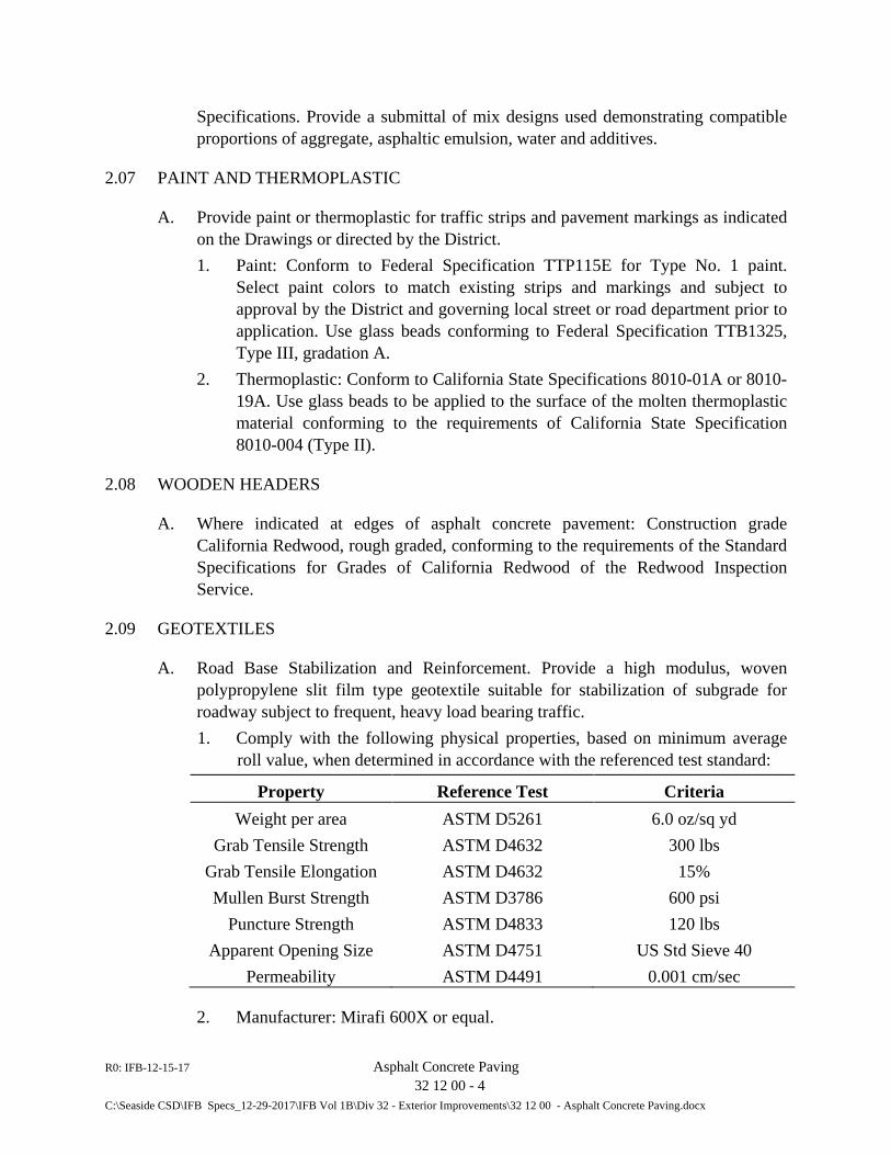
R0: IFB-12-15-17 Asphalt Concrete Paving 32 12 00 - 4 C:\Seaside CSD\IFB Specs_12-29-2017\IFB Vol 1B\Div 32 - Exterior Improvements\32 12 00 - Asphalt Concrete Paving.docx
Specifications. Provide a submittal of mix designs used demonstrating compatible proportions of aggregate, asphaltic emulsion, water and additives.
2.07 PAINT AND THERMOPLASTIC
A. Provide paint or thermoplastic for traffic strips and pavement markings as indicated on the Drawings or directed by the District. 1. Paint: Conform to Federal Specification TTP115E for Type No. 1 paint.
Select paint colors to match existing strips and markings and subject to approval by the District and governing local street or road department prior to application. Use glass beads conforming to Federal Specification TTB1325, Type III, gradation A.
2. Thermoplastic: Conform to California State Specifications 8010-01A or 8010-19A. Use glass beads to be applied to the surface of the molten thermoplastic material conforming to the requirements of California State Specification 8010-004 (Type II).
2.08 WOODEN HEADERS
A. Where indicated at edges of asphalt concrete pavement: Construction grade California Redwood, rough graded, conforming to the requirements of the Standard Specifications for Grades of California Redwood of the Redwood Inspection Service.
2.09 GEOTEXTILES
A. Road Base Stabilization and Reinforcement. Provide a high modulus, woven polypropylene slit film type geotextile suitable for stabilization of subgrade for roadway subject to frequent, heavy load bearing traffic. 1. Comply with the following physical properties, based on minimum average
roll value, when determined in accordance with the referenced test standard:
Property Reference Test Criteria Weight per area ASTM D5261 6.0 oz/sq yd
Grab Tensile Strength ASTM D4632 300 lbs Grab Tensile Elongation ASTM D4632 15% Mullen Burst Strength ASTM D3786 600 psi
Puncture Strength ASTM D4833 120 lbs Apparent Opening Size ASTM D4751 US Std Sieve 40
Permeability ASTM D4491 0.001 cm/sec
2. Manufacturer: Mirafi 600X or equal.
R0: IFB-12-15-17 Asphalt Concrete Paving 32 12 00 - 5 C:\Seaside CSD\IFB Specs_12-29-2017\IFB Vol 1B\Div 32 - Exterior Improvements\32 12 00 - Asphalt Concrete Paving.docx
B. Filter Fabric: Provide permeable nonwoven polypropylene material conforming to the provisions of Section 88-1.03 of the Caltrans Standard Specifications for underdrains. Treat fabric with an ultraviolet ray (UV) protection. 1. Manufacturer: Mirafi 140 NC or equal.
C. Pavement Reinforcing Fabric: Non-woven polypropylene material conforming to the provisions in Section 88-1.02 of the Caltrans Standard Specifications. Protect fabric from exposure to ultraviolet rays and keep dry until placed. 1. Manufacturer: Phillips Fibers Corp., (Petromat); Amoco Fabric Co.
(Amopave); Crown Zellerbach, (Fibreten); or equal.
PART 3 - EXECUTION
3.01 GENERAL
A. Construct new paved area where indicated on the Drawings and repair, replace, and resurface existing pavements and related items damaged as a result of construction activities for this Work, the pavement section as shown on the Drawings. Conform to the requirements of Sections 37 and 39 of the Caltrans Standard Specifications, and as stated herein.
3.02 SUBGRADE PREPARATION
A. Complete all backfilling, compaction and grading including where applicable placement and leveling of the slurry cement trench backfill, prior to scarifying, compacting, and installation of road base or paving.
B. Scarify the full width of the roadway or driveway to a minimum depth of six (6) inches and re-compact to a minimum density of not less than 95 percent of the maximum dry density in accordance with ASTM D1557 at plus or minus 2 percent of optimum soil moisture content.
C. Where unsuitable subgrade material is encountered, replace with compacted native material or crushed aggregate base placed in 6-inch to 8-inch lifts and compacted to not less than 95 percent of maximum dry density in accordance with ASTM D1577 at plus or minus 2 percent optimum soil moisture content.
D. Do not vary subgrade more than 0.05-feet in 10-feet from a uniform grade along the centerline of the road and perpendicular to the centerline, or as applicable, across paved parking or paved maintenance access area.
E. Where shown on the Drawings, or where “soft” soil conditions are encountered, place an approved road stabilization geotextile on the prepared subgrade immediately before placing the aggregate base.
R0: IFB-12-15-17 Asphalt Concrete Paving 32 12 00 - 6 C:\Seaside CSD\IFB Specs_12-29-2017\IFB Vol 1B\Div 32 - Exterior Improvements\32 12 00 - Asphalt Concrete Paving.docx
3.03 SOIL STERILIZATION
A. Apply soil sterilant to the subgrade at a uniform rate of 8 ounces per square yard, subject to manufacturer’s recommendation, to the entire width of the roadway, driveway or other paved access. When using sterilant applied in dry form, lightly spray with water to prevent loss. 1. Soil sterilant manufacturer: U.S. Borax, Tompson-Hayward Chemical
Company, or equal.
3.04 AGGREGATE BASE
A. On graded and compacted subgrade, place, mix, spread, and compact specified aggregate bases in conformance with applicable requirements of Section 26 of the Caltrans Standard Specifications. For pavement repair over trench sections not requiring cement slurry backfill, construct the compacted aggregate base course to the same thickness as the base course removed in the excavation of the trench, except that provide a total compacted thickness of aggregate base of not less than 6 inches. For new paved areas, construct a minimum thickness of compacted aggregate base course of 8-inches unless noted otherwise.
3.05 TEMPORARY PATCH
A. Place a temporary cold mix patch of minimum 2-inch compacted thickness over all trenches in paved areas on the same day of completing the backfilling and compaction, unless trench plates are otherwise permitted. Spread temporary asphalt surfacing on top of the aggregate base the full width and length of the cut pavement section on all paved roads or roadways. Spread the temporary resurfacing material hot or cold, directly from the plant mixer or from stockpiles. Roll the temporary patch with a minimum 8-ton tandem roller or other equipment producing satisfactory equivalent results, until it has been compacted to a hard and smooth surface which will permit traffic to pass over at the legal rate of speed. 1. Do not place more than 3-inches in compacted thickness of temporary
surfacing material. Grade the finished surface of the temporary surfacing flush with the adjoining pavement grade.
B. Maintain and repair the condition of the temporary patch to ensure safe traffic traveled way until placement of the final surface course and underlying base. Remove the temporary patch at the time of final surface restoration, including, but not limited to, placement and compaction of hot mix asphalt and underlying base as described herein.
3.06 ASPHALT CONCRETE (AC) / HOT MIX ASPHALT (HMA)
A. General: Spread hot mix asphalt in layers in accordance with the requirements of Section 39 of the Standard Specifications, and as specified herein.
R0: IFB-12-15-17 Asphalt Concrete Paving 32 12 00 - 7 C:\Seaside CSD\IFB Specs_12-29-2017\IFB Vol 1B\Div 32 - Exterior Improvements\32 12 00 - Asphalt Concrete Paving.docx
1. Placement of hot mix asphalt in repaired paved areas is to be performed in a two-phase operation. Perform the preliminary surface course closely behind and as the pipe installation and backfill progresses. Perform the final surface course immediately prior to Substantial Completion unless otherwise directed by the Engineer to have the work performed earlier.
2. Placement of hot mix asphalt in areas indicated on the Drawings as required to receive pavement surfacing is to be performed in a single operation. In this case, preliminary surface course and final surface course are to be combined in a single operation in accordance with Paragraph 3.06B below.
B. Preliminary Surface Course:
1. Site and Trench Paving: Resurface the pipeline trench with hot mix asphalt at all locations where the trench is within a traveled way pavement or paved parking area. Prior to the placement of the aggregate base and preliminary surface course of hot mix asphalt, perform a second saw cut of the existing pavement to a depth of 1-1/2 inches, minimum, at a minimum distance of 12 inches from the top edge of each side of the pipe trench as indicated on the Drawings. Perform the first saw cut operation prior to excavation of the pipeline trench, or in the case of area excavation, prior to removal of existing paving that is in the way of the work. Re-cut to straight, neat lines all edges of the trench, or paved site area, made ragged by the work of this Contract and remove the damaged edge before proceeding with the specified base preparation and paving work.
a. Remove the pavement, base and subgrade between the saw cut and the edge of trench section, or paved site area, to the depth as required to permit placement of the aggregate base and surface course of hot mix asphalt to the respective thickness specified herein, yet still match the finish grade of the adjoining paved surfaces. If the distance from the top edge of the trench, or demolished paved area, to the closest edge of pavement is less than eighteen (18) inches, remove the existing pavement on that side of the trench or paved area, and replace with new hot mix asphalt as specified herein. Place a thickness of hot mix asphalt of not less than 3 inches total in the public roads and streets or match existing thickness, whichever is greater, and 3 inches minimum for private driveways and access roads. Compact the subgrade and aggregate base as specified above.
b. Apply a prime coat to the exposed prepared surfaces in accordance with Section 39 of the Caltrans Standard Specifications. Place the pavement reinforcing fabric specified above on the sprayed area in accordance with the fabric manufacturer’s instructions and as described herein. Overlap the fabric a minimum of 6 inches at all joints and do not lap any
R0: IFB-12-15-17 Asphalt Concrete Paving 32 12 00 - 8 C:\Seaside CSD\IFB Specs_12-29-2017\IFB Vol 1B\Div 32 - Exterior Improvements\32 12 00 - Asphalt Concrete Paving.docx
joint with more than 2 layers of fabric. Shingle transverse joints to prevent pickup by the paver. Apply asphaltic emulsion binder or paving asphalt to all fabric joints.
c. Carefully place the fabric to avoid wrinkles. Broom or squeegee the laid fabric to remove any bubbles or wrinkles. Should wrinkles occur which are large enough to cause laps, cut and lay the fabric out flat, place a fabric patch 12-inches in width over the cut and seal with RS-1 or paving asphalt. Provide a minimum of 6 inches overlap on all edges. Overlapped cut pieces are suggested as the preferred method for lay-down on curves.
d. At each utility cover that would be covered with fabric, neatly cut the fabric around the cover to allow for raising of the cover to finish grade. After the pavement reinforcing fabric has been satisfactorily laid, aligned and wrinkles removed, spread a small quantity of hot mix asphalt over the fabric to prevent the fabric from being picked up by paving or other construction equipment. Immediately proceed with placement of the hot mix asphalt in accordance with the provisions of Section 39 of Caltrans Standard Specifications and as specified herein.
e. Turning of the paving machine or other vehicles should be gradual and kept to a minimum to avoid damage to the fabric. Should equipment tires tend to stick to the fabric during paving operations, broadcast small quantities of hot mix asphalt ahead to prevent sticking.
f. Caution is advised that rain or water on exposed fabric can cause hydro-planing of vehicles. Take appropriate action to prevent exposed fabric being left open to vehicular traffic during periods of precipitation or flooding.
g. Place and roll hot mix asphalt in maximum 2-inch layers. Match the existing pavement elevation and grade at the saw cuts and provide a finished surface free from undulations or abrupt changes in elevation or grade.
2. Repaving of Damaged Traveled Ways: Replace all pavement damage, which, as determined by the District, resulted from the Contractor’s operations. Saw cut the distressed pavements to a depth of 1-1/2 inches, minimum, and remove the full pavement depth. Recompact the underlying base in accordance with Section 26 of the Caltrans Standard Specifications. Accomplish restoration of the pavement by an application of prime coat and then placement and compaction of hot mix asphalt as described in 3.06B.1, above. a. Refer to Paragraph 3.06C.1 below, where in the judgment of the
Engineer, the area of the damage surface is extensive or the criteria for replacement described therein is met.
R0: IFB-12-15-17 Asphalt Concrete Paving 32 12 00 - 9 C:\Seaside CSD\IFB Specs_12-29-2017\IFB Vol 1B\Div 32 - Exterior Improvements\32 12 00 - Asphalt Concrete Paving.docx
3. New Paved Areas: Conform to the following procedures for both new paved areas and areas where pavement replacement is required for the full street, road, or driveway width in accordance with Paragraph 3.01 or where specifically shown on the Drawings.
a Preparation: Prepare subgrade in accordance with Section 31 10 00 and Paragraphs 3.02 and 3.03 above. Excavate subgrade to the elevation required to provide a finish elevation as shown on the Drawings or to match the adjoining existing pavement elevation and grade. Where preparation for new pavement requires the replacement of existing pavement, remove and dispose of the existing pavement in accordance with the requirements of Section 02 41 00, “Demolition”.
b Compaction: Compact all pavement layers in accordance with Section 39 of the Caltrans Standard Specifications. Compaction by vehicular traffic is not permitted.
c Pavement Thickness: Provide a preliminary course thickness of 3 inches minimum, or matching the thickness of the replaced or adjoining pavement, whichever is greater. This is the full and final course thickness for this Work.
d Joining Pavement: Construct joints between existing and new pavements, or between work placed on successive days, in a manner that ensures a proper and continuous bond between existing (old) and new sections of the course. Saw cut edges of existing pavement, including private driveways and intersecting roads, where joining to new pavement to provide a straight, clean and vertical surface to which to join. Paint joints with a uniformly applied coat of specified paint binder prior to placing the fresh HMA mixture.
e Protection of Pavement: After final rolling, prevent vehicular traffic from traveling on the pavement until cooling and hardening are completed, but in no case for less than six (6) hours.
C. Final Surface Course:
1. Trench / Site Paving. Where pavement replacement is required following trenching, where damage to paved roads occurs as a result of the construction operations, or where new paving of site area is shown on the Drawings as otherwise required, apply a slurry seal coat per Paragraph 3.09C below over the entire width of the road or designated site area and for an additional 10 feet in length beyond each end of the paved trench section as the final surface course. Where a constructed trench section is transverse to the road, apply the slurry seal coat over the entire width of the road at this location and for a distance extending at least 10 feet beyond each side of the replaced pavement
R0: IFB-12-15-17 Asphalt Concrete Paving 32 12 00 - 10 C:\Seaside CSD\IFB Specs_12-29-2017\IFB Vol 1B\Div 32 - Exterior Improvements\32 12 00 - Asphalt Concrete Paving.docx
section. Cover both the new preliminary surface course and the undamaged existing pavement with the slurry seal coat.
3.07 PRIME COAT
A. Perform prime coat application in conformance with applicable requirements of Section 39-4 and 93 of the Caltrans Standard Specifications. Uniformly distribute prime coat over the completed aggregate base at an application rate of 0.25-gallons per square yard, unless the District specifies a different application rate at the time work is performed.
3.08 PAINT BINDER
A. Uniformly apply paint binder to the surface of the lower course of hot mix asphalt pavement at the rate of 0.10 gallons per square yard or as specified by the District. Apply paint binder in conformance with the applicable requirements specified in Section 94, “Asphaltic Emulsions,” of Caltrans Standard Specifications. Apply paint binder to all vertical surfaces of walls, headers, concrete slabs, pavement joints, and similar faces against which asphalt concrete pavement is to be placed.
3.09 SEAL COATS
A. General: Apply seal coats in accordance with Section 37 of the Caltrans Standard Specifications and as stated herein.
B. Fog Seal: Apply undiluted asphaltic emulsion as a fog seal to finished pavement, dikes, paved ditches, and other areas where the surface existing prior to disturbance by this Work has a fog seal, or where designated by the District or governing local street or road department. Use an application rate of approximately 0.20 gallon per square yard, the exact rate to be as directed by the District or governing local street or road department.
C. Slurry Seal: Apply slurry seal as the final surface course work for streets, roads and other paved areas not fog sealed. Fog seal is not required where slurry seal is applied. Apply the slurry seal coat at the rates specified in Section 37-2 of Caltrans Standard Specifications for Type II seal coat.
D. Prior to applying any seal coat, install a protective cover of visqueen, roofing paper, duct tape or other material acceptable to the District over manhole, valve box, vault and monument covers and other metal work located in the paved areas specified to receive a seal cost to prevent these improvements from being stained by the seal coat material. Upon completion and curing of the seal coat application, remove the temporary protective coverings from the metal work and other existing improvements.
R0: IFB-12-15-17 Asphalt Concrete Paving 32 12 00 - 11 C:\Seaside CSD\IFB Specs_12-29-2017\IFB Vol 1B\Div 32 - Exterior Improvements\32 12 00 - Asphalt Concrete Paving.docx
3.10 DRAINAGE DITCHES
A. Where replacing an existing ditch damaged as a result of construction activities for the Work for this Contract, grade to the existing slope line.
3.11 HOT MIX ASPHALT DIKES/CURBS
A. Completely replace existing asphalt dike and curb sections damaged by construction activities during the course of Work for this Contract. Physically match the existing contiguous dikes and curbs. Use materials and construct dikes and curbs in conformance with the applicable provisions of Section 39 of the Caltrans Standard Specifications.
3.12 HEADERS
A. Provide headers of 2-inch by 4-inch redwood with 2-inch by 2-inch redwood side stakes set at a maximum of 4 feet on centers at all locations where existing headers were damaged by construction activities during the course of Work for this Contract and along the edge of new paved areas for the work as shown on the Drawings. Maintain headers in place upon completion of Work until Final Completion. At all other locations where headers are not required, round off the pavement section at the edge of the street, road or other paved areas.
3.13 PAVEMENT MARKINGS AND STRIPING
A. For all existing pavement markings damaged or obliterated by the construction activities for this Work, replace in kind and size as existing, subject to approval of the governmental entity having jurisdiction over the physical location. Allow at least two (2) weeks after paving is completed or, where applicable, pavement overcoat has been applied before applying pavement markings and striping. 1. For use of paint: Apply pavement markings only on dry surfaces and only
during periods of favorable weather as defined in Section 84-3.05 of the Caltrans Standard Specifications. Apply pavement markings at a wet film thickness of 0.015 inch;
2. For use of thermoplastic: Apply pavement markings on surfaces that have been mechanically wire brushed or abrasive blast cleaned. Apply thermoplastic material for pavement markings at a thickness of 0.100-inch to 0.150-inch and in accordance with Section 84-2.04 of the Caltrans Standard Specifications.
B. For all traffic striping damaged or obliterated by the construction activities for this Work, provide traffic striping the same as that damaged or obliterated. 1. For use of paint: Apply traffic stripes only on dry surfaces and only during
periods of favorable weather as defined in Section 84-3.05 of the Caltrans
R0: IFB-12-15-17 Asphalt Concrete Paving 32 12 00 - 12 C:\Seaside CSD\IFB Specs_12-29-2017\IFB Vol 1B\Div 32 - Exterior Improvements\32 12 00 - Asphalt Concrete Paving.docx
Standard Specifications. Apply stripping at a wet film thickness of 0.015 inch. Add glass bead reflective media to the wet paint by the drop-on method before the paint dries or sets up. Use an application rate for the glass beads of 6 pounds per gallon of paint, uniformly distributed to the wet paint.
2. For use of thermoplastic: Apply striping to surfaces that have been mechanically wire brushed or abrasive blast cleaned. Apply thermoplastic material for traffic stripes at a thickness of 0.06 inch and in accordance with Section 84-2.04 of the Caltrans Standard Specifications.”
3.14 INSTALLATION OF GEOTEXTILES
A. Prior to installation, keep geotextiles covered or wrapped to prevent UV degradation. Install geotextiles in strict accordance with the manufacturer’s written guidelines and recommendations.
B. Where road stabilization geotextile is required, place on prepared subgrade immediately prior to placing and spreading the aggregate base.
C. Where joints in fabric are required, overlap fabric a minimum of 2-feet each side of the seam. Place and spread aggregate base in a manner that does not cause the fabric to tear, bunch or move out of position.
3.15 RESTORATION
A. In conjunction with the final paving operations, raise to finished grade all survey monuments existing in areas paved as part of this Contract.
B. Restore survey monuments damaged as a consequence of construction operations.
C. Raise to finished grade all metal work (manhole frame and covers, valve boxes, etc.), existing and new, located in areas paved as part of this Contract.
D. Dress the edges of new paved areas with crushed decomposed granite or Class 2 aggregate base to provide a smooth transition from the newly finished paved surface elevation to the existing adjacent unpaved areas.
E. Comply with requirements of the Division 1 of the Standard Specifications and Section 01 30 00, “Administrative Requirements”, regarding protection of existing improvements.
3.16 PAVEMENT OVERCOAT
R0: IFB-12-15-17 Asphalt Concrete Paving 32 12 00 - 13 C:\Seaside CSD\IFB Specs_12-29-2017\IFB Vol 1B\Div 32 - Exterior Improvements\32 12 00 - Asphalt Concrete Paving.docx
A. General: Where directed by the District or indicated on the Drawings as required, comply with the following: 1. Allow new pavement to thoroughly cure (min. 30 days) before applying
overcoat. 2. Apply overcoat only if air temperature is at least 55 deg. F and rising. Do not
apply if rain is forecast within 48 hours after application. 3. Curing Time: As soon as application of overcoat is dry to touch and will not
scuff under normal walking, proceed with second application of overcoat. 4. Submit scale tags for products and application rates.
B. Surface Preparation: 1. Remove weeds or other vegetation growing through asphalt paving
and spray with approved chemical sterilant 2. Prior to applying overcoat, clean surface free of foreign material (e.g., sand,
clay, dust and grease) which may adversely affect bonding of the overcoat. Use high pressure air blowers, vacuums or sweepers to remove objectionable materials. Clean deposits of grease or oil by scraping, burning, using a detergent or combination of any of these methods. Scrub oil or grease area clean with TSP and stiff brush. Thoroughly rinse detergents, where used, from surface with water. After cleaning and removing grease or oil spots, seal areas with an approved oil-spot sealant.
3. Examine the prepared pavement areas thoroughly before proceeding. Notify District if conditions exist which would affect the success of the work or the warranty, or if a bond coat is considered necessary.
C. Equipment: 1. Employ mixing or agitating equipment that is a tank-type power mixer with a
round bottom and is equipped with a power driven mixer of sufficient capacity to maintain the mineral content in complete suspension.
2. Apply the mixture by a combination or individual use of rubber faced squeegees, mechanized material spreading equipment, or other suitable methods approved by the District.
D. Application: 1. Thoroughly mix the overcoat to a uniform, free-flowing consistency. Add
water, not to exceed 15% by volume, as required to obtain a semi-fluid consistency.
2. When applying the overcoat in exceptionally hot weather, prior to first application dampen the surface with water. Remove any excess water to leave surface slightly damp before proceeding.
R0: IFB-12-15-17 Asphalt Concrete Paving 32 12 00 - 14 C:\Seaside CSD\IFB Specs_12-29-2017\IFB Vol 1B\Div 32 - Exterior Improvements\32 12 00 - Asphalt Concrete Paving.docx
3. Apply the overcoat to the area shown on the Drawings in continuous parallel lines and spread immediately by use of rubber faced squeegees and/or mechanized material spreading equipment.
4. Apply two (2) or more coats using a minimum of 30 gallons total of undiluted overcoat per 1,000 square feet of area. Increase the number of coats or the quantity of overcoat solution as required to provide a finished surface that is smooth and uniform, showing no evidence of course or uneven texture, except that directly attributed to the underlying pavement surface.
END OF SECTION 32 12 00
R0-IFB-12-15-17 Irrigation 32 80 00 - 1 C:\Seaside CSD\IFB Specs_12-29-2017\IFB Vol 1B\Div 32 - Exterior Improvements\32 80 00 IRRIGATION.docx
SECTION 32 80 00
IRRIGATION
PART I – GENERAL 1.01 RELATED DOCUMENTS
A. Drawings and General Provisions of Contract, including General and Supplementary Conditions and Division-1 Specification Sections, apply to the work of this Section.
B. Marina Coast Water District Procedures, Guidelines, and Design Requirements, latest
revision. 1.02 DESCRIPTION OF WORK
A. Extent: Work in this Section is as shown on the Plans and includes, but is not limited to, furnishing all material, equipment, labor, and incidentals for the installation of a complete automatic irrigation system including trenching, piping, equipment, electrical, maintenance of the system during landscape maintenance, and shall include: 1. Connection to existing mains and controller(s).
B. Related Work
1. Landscape Planting 2. Landscape Maintenance
1.03 STANDARDS
A. Unless otherwise shown or specified, all materials and methods shall conform to the applicable current sections of: 1. The State of California, Department of Transportation (CALTRANS) Standard
Specifications (DTSS), except for measurement and payment requirements. 2. Applicable ASTM Specifications as they apply to the work in this Section. 3. Uniform Plumbing Code (UPC) 4. NEC (National Electrical Code) 5. American Society of Irrigation Consultants (ASIC) Guideline 100 for Earth Grounding
Electronic Equipment in Irrigation Systems
1.04 REVIEWS
A. Contractor shall specifically request at least (2) two days in advance the following reviews prior to progressing with the work: 1. Preliminary Review – Main-line layout, trenching, pressure-test.
R0-IFB-12-15-17 Irrigation 32 80 00 - 2 C:\Seaside CSD\IFB Specs_12-29-2017\IFB Vol 1B\Div 32 - Exterior Improvements\32 80 00 IRRIGATION.docx
2. Intermediate Review - Irrigation coverage, controller location. Requirements for irrigation coverage inspection are specified herein.
3. Substantial Completion Review - valve box inspection, and overall operation of the irrigation system.
4. Final Review (at the completion of Maintenance Period) - overall operation of the irrigation system, including all punch-list items identified at Substantial Completion Review.
5. See 32 00 00 Planting for other items to be inspected during these reviews. 6. Each review shall be conducted only after all items pertaining to that review as noted
above and in related Sections have been completed by the Contractor.
1.05 QUALITY ASSURANCE
A. All materials shall be new and of the best quality available unless otherwise specified. Manufacturer shall be clearly marked on all material, containers, or certificates of contents for inspection.
B. Submit product data on all irrigation equipment, including Controller manufacturer’s
recommended grounding details. See Irrigation Legend for additional irrigation equipment.
C. Any desired substitutions for irrigation equipment require submittals for specific written
approval. 1.06 UTILITIES
A. Contractor shall verify location of all on site utilities prior to trenching. Notify Owner’s Representative by telephone and in writing of any conflicts prior to installation. Restoration of damaged utilities shall be made at the Contractor's expense to the satisfaction of the Owner’s Representative.
1.07 CODES
A. Irrigation system and electrical power to controller shall be installed and tested in accordance with local codes and manufacturer's specifications.
1.08 TESTING
A. The backflow preventer shall be tested and approved by a licensed testing agency prior to substantial completion. Submit test results certificate to Owner as part of Substantial Completion review for Landscape Maintenance Period authorization.
PART II - PRODUCTS 2.01 PLASTIC PIPE AND FITTINGS
R0-IFB-12-15-17 Irrigation 32 80 00 - 3 C:\Seaside CSD\IFB Specs_12-29-2017\IFB Vol 1B\Div 32 - Exterior Improvements\32 80 00 IRRIGATION.docx
A. Unless otherwise noted:
1. PVC material shall conform to ASTM D-1784 2. Lateral pipe shall be ASTM D-1785 SCH-40 PVC 3. Mainline for pipes up to 2” diameter shall be ASTM D-1785 SCH-40 PVC. 4. All PVC solvent weld fittings for lateral piping shall be Schedule 40 PVC. 5. Main line fittings shall be Schedule 40 PVC. 6. All threaded fittings for lateral pipe shall be Schedule 40 PVC heavy wall. 7. All main line threaded fittings shall match the pipe type. 8. All risers and nipples shall be Schedule 80 PVC. 9. Plastic threaded fittings shall have Permatex #2 thread sealant with Teflon or equal. 10. PVC cement shall be IPS (Industrial Poly Chemicals) for solvent weld, with associated
primer to fit pipe type and size. 2.03 GALVANIZED PIPE AND FITTINGS
A. Galvanized steel pipe ASTM A120. Fittings shall be standard threaded galvanized malleable iron. All galvanized main below grade shall be wrapped with 2" wide plastic adhesive tape (#50 "Scotch Wrap" or equal).
2.04 SLEEVING
A. All main and lateral lines located beneath paving shall be sleeved with Schedule 40 PVC
pipe unless otherwise noted. 2.05 CONTROL WIRE
A. Type UF, 600v. insulation, copper, common ground white, U.L. approved for irrigation control use. 1. Minimum wire gauge #14, use gauge appropriate to distance to account for voltage
loss. 2. Splices shall be sealed with approved wire nuts enclosed in resin–filled envelopes.
2.06 VALVE BOXES
A. Valve boxes: Pre-cast lockable plastic by Carson Industries LLC, or approved equal, free of all cracks, chips or structural defects. Size as required by equipment plus adequate clearance to operate valves unless otherwise noted. Green color unless otherwise noted. 1. Boxes subject to vehicular traffic shall be concrete and have traffic lid covers. 2. Plastic valve box lids shall be branded with the valve station # as connected to the
controller as indicated on the Plans. Concrete / iron valve box lids shall be labeled with the valve station # using a weather resistant method.
3. Lids shall be a green color.
B. Valve identification tags: as manufactured by Christy Enterprises, Anaheim CA, (800)258-4583, or approved equal. See Irrigation Details.
R0-IFB-12-15-17 Irrigation 32 80 00 - 4 C:\Seaside CSD\IFB Specs_12-29-2017\IFB Vol 1B\Div 32 - Exterior Improvements\32 80 00 IRRIGATION.docx
2.07 IRRIGATION EQUIPMENT
A. Refer to Plans.
2.08 CONDUIT A. All conduits shall be U.L. listed and bear the label of the national board of fire underwriters,
and shall be of a rigid nonmetallic type, Schedule 40 PVC plastic for underground installations, rated 90 degrees C, with glue-on PVC couplings and factory made elbows and sweeps; Carlon "plus 80".
B. Couplings and connectors shall be made watertight in all runs. Utilize solvent cement of
type approved by conduit manufacturer. Conduits shall be joined by approved conduit couplings and shall have ends butted in all cases where couplings are used. Provide adapters and locknuts where conduit is attached to metal boxes and panels.
C. Bends shall be made with standard conduit elbows or conduit bent to not less than same
radius. All bends shall be free from dents or flattening. PART III - EXECUTION 3.01 GENERAL
A. Acceptance of Work: Site grading shall be completed and/or accommodated to specified tolerances, before trenching. The contractor shall be responsible for verifying the existing conditions on site and the removal and or reinstallation required making the grades.
B. Schematic: System features are shown schematically for graphic clarity. Install all piping
and valves in common trenches where feasible and inside planting areas. C. Grading: Contractor shall be responsible for installing all irrigation features to their
finished elevation and at depths indicated. D. Finish Grade: Unless otherwise noted, all heads shall be set at, and perpendicular to, finish
grade. E. Record Plans of As-Built Conditions: Contractor shall regularly update a print of the
system and any changes made to the system throughout the project. Features below ground shall be indicated with at least two measurements from surface features such as pavements, fences and buildings. Indicate actual control and ball valve locations in a similar manner. 1. All final changes shall be recorded on a reproducible plan before trenches are
backfilled. The as-built plan shall be completed and submitted to the Owner’s Representative before final payment shall be made for work installed.
R0-IFB-12-15-17 Irrigation 32 80 00 - 5 C:\Seaside CSD\IFB Specs_12-29-2017\IFB Vol 1B\Div 32 - Exterior Improvements\32 80 00 IRRIGATION.docx
F. Guarantee: Contractor shall guarantee irrigation system for one year from date of acceptance.
3.02 INSTALLATION
A. Point of Connection: shall be below grade. Connect to water meter and plumb backflow device and remaining system.
B. Trenching: Trenching for mainline, sleeves, and laterals shall be to the required depths as
shown on the Plans. Maintain excavations free of water while installing pipe and until backfilled.
C. Pipelines: pipelines shown parallel on the Plan may be installed in a common trench. Where
required, snake pipe from side to side when trench exceeds 30 feet in length. 1. Where pipelines are shown parallel to or adjacent to shrub or ground cover areas, they
shall be installed in these areas. 2. Where shown parallel to or adjacent to lawn areas versus pavement, they shall be
installed in the lawn area. All changes in depth of pipe shall be accomplished using 45 degree fittings.
D. Sleeving: Contractor shall adequately size sleeving for all wiring and irrigation lines to be
placed (with ends clearly marked above grade) under driveways and walks prior to their construction. 1. Sleeving shall continue a minimum of 1 foot into planting areas.
E. Fabrication: All manifolds shall be neat, orderly, and constructed for ease in maintenance
operations. Install manifolds to allow valve boxes to be parallel to each other and to adjacent walls, walks, and curbs. Cuts and joints shall be free of burrs, smooth and minimum in quantity.
F. Control Wire:
1. Install control wire in pipe trenches wherever practical. All wire shall be installed below or level with the bottom of adjacent pipes.
2. Tape to pipe every 10 feet. Conduits or sleeve required shall be sized based on control wires as specified herein.
3. All wiring above finish grade shall be enclosed in steel conduit. 4. All splices shall be sealed with 3M connectors or equal. All intermittent wire splices
between valves or between controller valves shall be installed in a valve box, locations as approved by the Owner’s Representative.
5. Color of control wire shall be different than pilot wire. 6. Provide 24" excess wiring in each valve box or pull box. Neatly coil in valve box or
pull box. 7. All wiring shall be tested for continuity, open circuits and unintentional grounding prior
to connecting.
G. Irrigation Equipment:
R0-IFB-12-15-17 Irrigation 32 80 00 - 6 C:\Seaside CSD\IFB Specs_12-29-2017\IFB Vol 1B\Div 32 - Exterior Improvements\32 80 00 IRRIGATION.docx
1. Install irrigation equipment as shown on the Plans.
H. Backfilling:
1. Cover no joints until system has been pressure tested and approved by the Owner’s Representative. Level bottom trenches for a smooth flat grade, and excavate bell holes where necessary to ensure that pipe rests for entire length on solid ground. Should rock or other unsuitable material be encountered, excavate to 6" below bottom of pipe and replace with well tamped and compacted approved backfill material or sand before laying pipe. When piping has been installed, tested, inspected, and approved, backfill excavations with clean earth from excavation, or with imported sandy soil in layers not exceeding 8". The top 6" of the trenches shall contain on-site near surface soils. Backfill with potentially damaging rocks and debris shall not be permitted. Moisten and machine tamp, and restore the ground or paving to original condition. Jet trenches in planting areas.
2. Backfill shall be compacted per specification, see Section 02200 Earthwork and Grading.
3. After backfilling, remove from the premises all surplus earth resulting from this work and dispose of same, to the satisfaction of the Owner’s Representative.
I. Flushing of System: After installation of pipe lines, but before installation of the subsurface
drip, thoroughly flush the system under full water main pressure to remove any foreign material in the pipes. Backfill and settle soil. Rake smooth to match surrounding grade. 1. Flushing shall include flushing out the existing mainline prior to operating any portion
of the system again.
J. Subsurface Dripline Layout Options: For information on system layout, see Netafim Wastewater Dispersal Design Guide and contact Bob Best, Netafim Design Representative, 559-287-7929
K. Valve Boxes: Install valve boxes so that the top of box is ½” above finish grade in turf
areas and 2 finish grade, so the lid is flush with mulch areas. Install valve box assembly in ground cover / shrub and not in hard paved areas. Install in lawn area only if groundcover does not exist adjacent to lawn. 1. Each valve shall have a valve-identification tag, the corresponding valve box cover
shall be branded with the valve identification number.
L. Clean-up: Keep project area clean on a daily basis, removing debris from the site.
3.03 CONTROLLER
A. General: The Contractor is advised that based on existing soil types, soil imports, and final ground conditions, additional grounding equipment may require to be installed at no extra cost to the Owner. 1. Submit manufacturers grounding equipment details recommended for the Project.
R0-IFB-12-15-17 Irrigation 32 80 00 - 7 C:\Seaside CSD\IFB Specs_12-29-2017\IFB Vol 1B\Div 32 - Exterior Improvements\32 80 00 IRRIGATION.docx
B. Installation: Install power to controller following all applicable electrical codes. Mount controller onto concrete base or on to wall per the Plans. Install 9-volt battery. 1. For multiple controllers – each controller shall have a separate, dedicated common.
C. Grounding: Contractor shall bear responsibility for determining, from the Controller
manufacturer, the grounding equipment recommended for the specific project soil and weather conditions. The guidelines below are provided for information only. 1. Each controller shall be grounded individually, unless otherwise noted by the
Controller manufacturer. 2. Grounding rods, where required, shall be of copper-clad steel type and grounding
plates, or where required, shall be of solid-copper type. 3. A typical installation requires the installation of a grounding rod in the soil, per
Controller manufacturer’s instructions. 4. For sandy, dry, and/or loose soils, a grounding plate set in appropriate earth contact
material may be required per Controller manufacturer’s instructions. 5. For rocky soils, one or two grounding plates may be required per Controller
manufacturer’s recommendations. 6. For areas known to be prone to lightning, transient protection board(s) is required inside
the controller(s) per Controller manufacturer’s instructions. 7. Contractor shall demonstrate, at Final Completion that the Controller has been
adequately grounded for the specific project soil and weather conditions and provide a written statement to this effect from the Controller Manufacturers representative or other qualified testing professional.
3.04 VALVE STATIONING
A. Contractor shall clearly label and sequence stations for ease in maintenance operations. Final valve stationing shall be marked clearly on the as-built plans. 1. Provide copies, 11x17 and 8.5x11 sizes, of the marked-up as built plans with color-
coded valve zones (MCWD Irrigation System Map and Valve Site Map), for reference purposes inside the controller.
2. For modifications/additions to existing irrigation systems, obtain clear copies of the valve stationing plans and mark-up as required to reflect changes. Submit modified plan to the Owner’s Representative for approval prior to laminating and replacing inside the controller.
3. Include a copy of the valve-stationing plans in the Maintenance Binder, see Section 02970 Landscape Maintenance.
4. Verify and document station sequence and run-times (Controller Schedule) with maintenance personnel at an in-service meeting, see Section 02970 Landscape Maintenance.
3.05 PRESSURE TEST
A. Pressure Test:
1. Notify the Owner a minimum of two working days prior to pressure test.

R0-IFB-12-15-17 Irrigation 32 80 00 - 8 C:\Seaside CSD\IFB Specs_12-29-2017\IFB Vol 1B\Div 32 - Exterior Improvements\32 80 00 IRRIGATION.docx
2. Exercise caution in filling the system to prevent excessive surge pressure and water hammer.
3. Pipe subject to continuous water pressure (pressure lines) shall be tested at 125 lbs. of hydro-static pressure for two hours with a maximum 5 PSI drop. Repair any leaks, if necessary, and re-test.
4. The Contractor must furnish all equipment and temporary connections required for tests.
B. Closing in Un-inspected Work: The Contractor shall pay all costs necessitated by requiring
opening, restoration and correction of all work closed in or concealed before inspection, testing as required and approval by Owner’s Representative. Notify Owner’s Representative 48 hours in advance of required testing.
3.06 IRRIGATION COVERAGE
A. Inspection of irrigation coverage/subsurface dripline layout shall take place during the
Intermediate Review, as specified herein. 1. The Contractor shall, in the presence of the Owner’s Representative, perform a
coverage and operation test to determine if the system is fully operational. 2. The Contractor shall be responsible for making changes and obtaining complete and
adequate coverage in all irrigated areas at no additional cost to the Owner.
END OF SECTION 32 80 00
R0-IFB-12-15-17 Planting 32 90 00 - 1 C:\Seaside CSD\IFB Specs_12-29-2017\IFB Vol 1B\Div 32 - Exterior Improvements\32 90 00 PLANTING.docx
SECTION 32 90 00
PLANTING
PART I - GENERAL 1.01 RELATED DOCUMENTS
A. Drawings and General Provisions of Contract, including General and Supplementary Conditions and Division-1 Specification Sections, apply to the work of this Section.
1.02 DESCRIPTION OF WORK
A. Extent: Work in this Section is as shown on the Plans and includes, but is not limited to, furnishing all material, equipment, labor, and incidentals to plant areas indicated.
B. Related Work:
1. Soil Preparation 2. Landscape Irrigation 3. Landscape Maintenance
1.03 QUALITY ASSURANCE
A. Quality: Minimum quality of all plant material shall conform to prevailing published specifications of the California Association of Nurserymen and the American Association of Nurserymen unless otherwise indicated. Additional specifications shall be indicated on the Plans.
1.04 SUBMITTALS
A. Plants: Within ten days after Notice to Proceed, Contractor shall submit notice to the Owner’s Representative certifying quantity and species of plant material ordered, the nursery supplier(s), any plant material not available at that time, or proposed substitutions to be reviewed.
B. Products: Submit product data on all associated planting products specified herein and
products specified in the drawings: Planting Legend. 1. Submit 4-ounce sample of mulch.
C. Soils analysis: Contractor shall submit a soils analysis of the existing soil by an agricultural soils testing laboratory approved by the Engineer, referred to herein as the Testing Lab.
1. Soil testing laboratory - SOIL AND PLANT LABORATORY, 352 Mathew Street, Santa Clara, California 95052 (408) 727-0330, or prior approved equal.
2. Analysis shall not be more than three months old at the time of planting.
R0-IFB-12-15-17 Planting 32 90 00 - 2 C:\Seaside CSD\IFB Specs_12-29-2017\IFB Vol 1B\Div 32 - Exterior Improvements\32 90 00 PLANTING.docx
4. Soil texture analysis shall note percent of gravel, sand, silt, and clay, and indicate USDA soil classification. Soil agricultural suitability analysis shall indicate pH, salinity (ECe), and sodium absorption ration (SAR).
5. The Engineer reserves the right to take a separate sample of the soil on-site and send to the Testing Lab for analysis
6. Proposed soil amendments shall be approved by landscape architect prior to application.
1.05 REVIEWS
A. Contractor shall specifically request at least (2) two days in advance the following review prior to progressing with the work: 1. Intermediate Review – plant material approval and layout/locations. See Section 02810
Landscape Irrigation for other items to be inspected during this review.
B. Contractor shall specifically request at least (5) five days in advance the following reviews prior to progressing with the work: 1. Substantial Completion Review (to initiate Maintenance Period) – all planting areas
including sod and hydroseed areas if applicable. See Section 02970 Landscape Maintenance.
2. Final Review (at the completion of Maintenance Period) - all planting areas including sod and hydroseed areas if applicable, including all punch-list items identified at Substantial Completion Review. See Section 02970 Landscape Maintenance.
C. Each review shall be conducted only after all items pertaining to that review as noted above
and in related Sections have been completed by the Contractor. 2.01 GENERAL
A. Nomenclature and Labels: Plant botanical names conform to “Standardized Plant Names,” second edition, and secondly, “A Checklist of Woody Ornamental Plants of California, “ Manual 32, University of California. All plants of each clone, species, and cultivar shall be delivered to the site labeled with their full botanical name. Every plant species shall be labeled with no less than one label for every ten plants of a species.
B. Quantities: The quantities shown on the plant list and in labels are for the Owner’s
Representative's use and are not to be construed as the complete and accurate limits of the Contract. Contractor shall furnish and install all plants shown schematically on the Plans.
C. Root Systems: All container-grown stock shall be grown in its container for at least six
months prior to its planting. Contractor shall allow one percent of the quantity of plants for removal and inspection. Any plant material, within two years following the final acceptance of the project, determined by the Owner’s Representative to be defective, restricted, declining or otherwise deficient due to abnormal root growth, shall be replaced
R0-IFB-12-15-17 Planting 32 90 00 - 3 C:\Seaside CSD\IFB Specs_12-29-2017\IFB Vol 1B\Div 32 - Exterior Improvements\32 90 00 PLANTING.docx
by the Contractor, to the equal condition of the adjacent plants, at the time of replacement.
D. Health: Foliage, roots and stems of all plants shall be of vigorous health and normal habit
of growth for its species. All plants shall be free of all disease, insect stages, burns or disfiguring characteristics.
E. Untrue Species: All plant material, within two years following the final acceptance of the
Project, determined by the Owner to be untrue to the species, clone, and/or variety specified, shall be replaced by the Contractor, to the equal condition of adjacent plants at the time of replacement.
2.02 TREES A. All trees shall conform to the requirement of the planting legend. Trunks shall be free of
damaged bark, with all minor abrasions and cuts showing healing tissue. Sucker basal growth and lateral growth shall be removed and treated to eliminate re-sprouting. Normal lower side branching shall remain. Trees unable to stand upright without support shall be rejected.
2.05 FERTILIZER
A. Per the soil test recommendations. 2.06 TREE STAKES AND GUYING
A. Per Planting Details
2.07 MULCH
A. 3” Wood chip mulch
PART III - EXECUTION 3.01 GENERAL
A. Plant Material Approvals: Before planting operations commence, all plant material shall
be reviewed by the Owner’s Representative. Defective plants shall be removed from the site and acceptable material substituted in its place. The review does not accept defective plants which may be installed.
B. Layout: Only those plants to be planted in any single day should be laid out. Locations of
all plants shall be reviewed prior to planting. Plants installed without this review may be transplanted/relocated as directed by the Owner’s Representative.
R0-IFB-12-15-17 Planting 32 90 00 - 4 C:\Seaside CSD\IFB Specs_12-29-2017\IFB Vol 1B\Div 32 - Exterior Improvements\32 90 00 PLANTING.docx
C. Protection of Plants: Contractor shall maintain all plant material in a healthy growing
condition prior to and during planting operation. Contractor shall be responsible for vandalism, theft, and damage to plant material until commencement of the maintenance period.
D. Pruning: Contractor shall do no pruning without specific authorization of the Owner’s
Representative. Plants pruned without authorization shall be replaced by the Contractor if necessary.
3.02 PLANT PITS
A. Rootball shall rest only on undisturbed soil, or in the case of fill areas, on compacted, un-
amended sub-grade. See 02920 Soil Preparation for backfill mix requirements. Plant rootball and pits shall have their sides and bottoms loosened and otherwise broken to prevent glazing or compaction. 1. Plant pits shall be at least the following minimum sizes: 1 gallon container 6" backfill all around 5 gallon container 8" backfill all around 15 gallon container 10" backfill all around 2. Fertilize per Soil Preparation Specification.
3.03 TREE AND SHRUB INSTALLATION A. Watering: Thoroughly water in all planting material after installation. B. Basins: Construct basins as necessary to water plants. Basin bottoms shall drain to berm
away from plant stems. 1. Remove basins from all plants under a permanent irrigation system prior to
operation of the irrigation system and finish grade the planting area. B. Staking: All trees shall be staked unless otherwise noted on the Plans. Install stakes per
the Details. 1. Stakes shall be driven securely into existing soil on the windward side of the tree.
C. Tree Wind Screen: Only trees noted on plans shall be staked for windscreens Install stakes and wind screen per the Details. 1. Stakes shall be driven securely into existing soil on the windward side of the tree.
3.04 SOD INSTALLATION
A. The installation specifications below shall prevail over the sod grower’s installation
specifications, unless otherwise noted.
R0-IFB-12-15-17 Planting 32 90 00 - 5 C:\Seaside CSD\IFB Specs_12-29-2017\IFB Vol 1B\Div 32 - Exterior Improvements\32 90 00 PLANTING.docx
B. Grading / Soil Preparation: Finish grade to smooth, even surface, allowing for sod thickness at pavement and other structures to leave the sod flush to the finish grade of adjacent surfaces. The soil surface shall be sufficiently firm to resist impressions over 1/4 inch deep, and shall be lightly rolled until meeting this firmness. The top six to eight inches of soil shall be watered until this zone has an optimum moisture content for root growth.
C. Fertilization: Follow Soil Preparation Specification for amendments and fertilization. D. Installation: Sod shall be laid in rows with staggered ends neatly and tightly butted on all
edges. Harvesting netting shall be removed upon installation. Sod shall be protected from wind and sun exposure during storage, with a maximum storage period of twenty-four hours. No overlap, gaps, ripples, or other uneven placement will be accepted. Contractor shall lightly roll sod after installation to insure optimum contact with the soil. Trimming and cutting around structures shall be completed with sharp tools and carefully fitted so the final appearance is a solid, continuous turf.
E. Establishment Watering / Mowing: Follow sod grower’s specifications.
3.05 MULCH
A. Install 3-inch mulch layer in all planting areas, including existing planting areas within
the project area.
3.08 MAINTENANCE
A. Contractor is responsible for maintaining new plantings and irrigation for 1 year. B. It is the contractors responsibility to replace any and all plants that die at any time during
the maintenance period. Plants must be replaced as soon as plants are within decline.
3.09 CLEAN UP A. After completion of all operations, Contractor shall remove all trash, excess soil and
other debris. All walks, walls, and pavement shall be swept and washed clean. Leave the entire area in a neat, orderly condition.
END OF SECTION

R0-IFB-12-15-17 Planting 32 90 00 - 6 C:\Seaside CSD\IFB Specs_12-29-2017\IFB Vol 1B\Div 32 - Exterior Improvements\32 90 00 PLANTING.docx
This page intentionally blank.

DIVISION 33
UTILITIES

R0: IFB-12-15-17 Utility Structures 33 05 16-1 C:\Seaside CSD\IFB Specs_12-29-2017\IFB Vol 1B\Div 33 - Utilities\33 05 16 Utility Structures.docx
SECTION 33 05 16
UTILITY STRUCTURES
PART 1 - GENERAL
1.01 SUMMARY
A. Requirements specified in the General and Supplementary Conditions of the Contract and Division 1 of the Technical Specifications form a part of this Section.
B. Section Includes: 1. Precast reinforced concrete manhole or wet well vertical sections, cones,
grade rings and caps. 2. Manhole and Catch basin frames and covers. 3. Installation.
C. Related Sections: 1. Section 03 30 00 - Cast-in-Place Concrete 2. Section 09 90 00 – Painting and Coating 3. Section 09 98 00 – Corrosion Resistant Lining System 4. Section 31 23 00 – Excavation and Fill 5. Section 31 23 33 - Trenching, Backfilling and Compaction 6. Section 32 12 00 – Asphalt Concrete Paving 7. Section 33 05 20 - General Piping Requirements and other pertinent Sections
of Division 33.
1.02 REFERENCES
A. Standard Specifications of the State of California Department of Transportation, most recent Edition.
B. ASTM C478, Specification for Precast Reinforced Concrete Manhole Sections.
C. ASTM A159, Specification for Automotive Gray Iron Castings.
D. ASTM A48, Specification for Gray Iron Castings.
E. ASTM A536, Specification for Ductile Iron Castings.
R0: IFB-12-15-17 Utility Structures 33 05 16-2 C:\Seaside CSD\IFB Specs_12-29-2017\IFB Vol 1B\Div 33 - Utilities\33 05 16 Utility Structures.docx
1.03 SUBMITTALS
A. Provide shop drawings or catalog cuts for work included in this Section in accordance with the applicable requirements of Article 12 of the General Conditions and Section 01 33 00 of the Technical Specifications, “Submittal Procedures”.
B. Submit manufacturer's technical and test data attesting to compliance with these specifications for gasket seals and watertight caulking. Submit printed installation recommendations.
PART 2 - PRODUCTS
2.01 MANHOLES, WET WELL AND OVERFLOW STRUCTURES
A. General: Conform to the requirements of ASTM C478 and the details shown on the Drawings and the following requirements. Design precast concrete vertical sections, rings, cones, grade rings and caps for AASHTO HS-20 highway loading. Use Class A, 4,000 psi Portland cement concrete conforming to Section 90 of Caltrans Standard Specifications throughout the work except as otherwise indicated. Design reinforcing steel of single circular cage with a minimum cross-sectional area of 0.20 square inch of steel per foot. Elliptical single line reinforcing is not permitted. Unless otherwise indicated on the Drawings provide corrosion resistant lining system on vertical and cone sections, as specified in Section 09 98 00.
B. Vertical Sections: Centrifugally spin or compactly vibrate in forms. Furnish sections in lengths and diameters as required to coordinate with the work shown on the Drawings, but not less than 1 foot in length not more than 4 foot in length.
C. Cones (Manholes Only): Provide taper section in maximum 3-foot height unless otherwise indicated on Drawings, concentrically or eccentrically tapered from diameter of vertical section to 24 inches inside diameter at the opposite end unless otherwise indicated on Drawings.
D. Manhole Caps: Construct caps to match manhole diameter indicated on Drawings. Construct bottom face of cap with tongue and groove joint to snugly fit into adjoining vertical section and thereby prevent lateral movement. Provide 24-inch diameter clear opening, unless indicated on drawings, concentrically or eccentrically in cap for entry. Construct cap in minimum 12-inch thickness and provide sufficient reinforcing to ensure HS-20 loading carrying capability with 30 percent impact loading. Provide additional reinforcing around opening to prevent cracking. Provide lifting hooks in cap for handling. Unless otherwise indicated on
R0: IFB-12-15-17 Utility Structures 33 05 16-3 C:\Seaside CSD\IFB Specs_12-29-2017\IFB Vol 1B\Div 33 - Utilities\33 05 16 Utility Structures.docx
the Drawings provide corrosion resistant lining system on bottom surface, as specified in Section 09 98 00.
E. Wet Well/Overflow Structure Cap: Provide flat top cap on wet well and overflow structures constructed with cast-in-place concrete or using precast concrete construction as indicated on Drawings. Provide corrosion resistant lining system on the interior face of the cap as shown on the Drawings and specified in Section 09 98 00. 1. Provide access hatches or manhole frame and covers as shown on the
Drawings.
F. Grade Rings: Provide in sections not greater than 6 inches in height, unless otherwise approved by the District, with an inside diameter of 24 inches. Reinforce grade rings to the same standards as for the vertical and taper sections.
2.02 MANHOLE FRAMES AND COVERS
A. Fabricate manhole frames and covers of superior quality grey iron conforming to the requirements of ASTM A48 or ductile iron conforming to the requirements of ASTM A536 and designed for H20 loading. Provide sets weighing 320 pounds each, minimum. Design and fabricate covers to fit neatly and bear firmly in the frame without rocking and to be easily removable. Provide castings bearing the lettering “S” or “SANITARY SEWER.” Provide castings having 24 inch inside diameter clear opening, Alhambra Foundry Company A-1176 or approved equal unless otherwise indicated on Drawings. For castings having 36 inch inside diameter clear opening, Alhambra Foundry Company A-1251B-4 or approved equal.
2.03 PRECAST CONCRETE MANHOLE BASES
A. Where permitted on the Drawings or by the District, provide precast concrete bases on manholes, and overflow structures, by the same manufacturer as for the precast manhole or overflow structure furnished per Paragraph 2.01 above.
B. Concrete Mix Design: Class 1, 4,000 psi concrete for manhole base, Class 1, 4,000 psi concrete for precast overflow and wet well structures, both per Section 03 30 00.
C. Reinforcing: Provide reinforcing steel in each base the same as required for a cast-in-place base as indicated on the Drawing.
D. Other Requirements:
R0: IFB-12-15-17 Utility Structures 33 05 16-4 C:\Seaside CSD\IFB Specs_12-29-2017\IFB Vol 1B\Div 33 - Utilities\33 05 16 Utility Structures.docx
1. Base diameter to be 12 inches larger than the outside diameter of the joining vertical section (6 inches minimum from outside face of vertical section to outside face of base).
2. Provide base with pipe to manhole connectors of PVC SDR 35, or where indicated SDR 26, style detail.
3. Coat interior exposed surface of precast base as indicated on the Drawings.
2.04 CATCH BASINS
A. Provide as shown on the Drawings.
2.05 CATCH BASIN FRAMES AND COVERS
A. Provide the catch basin manufacturer’s standard for the type shown on the Drawings.
2.06 GASKET SEALS
A. Preformed plastic sealing gaskets conforming to Federal Specifications SS-S-00210; Ram-Nek or equal.
B. Where specifically indicated on the Drawings, provide preformed plastic waterstop per Specification Section 03 33 00, “Cast-in-Place Concrete”.
2.06 JOINT SEALING COMPOUND
A. Compound shall be Quik-Seal by Associated Concrete Products; Ram-Nek by K. T. Snyder Company; or approved equal.
PART 3 - EXECUTION
3.01 EXCAVATION AND BACKFILL
A. Perform Work in accordance with applicable requirements of pertinent Sections of Division 31 of these Technical Specifications.
3.02 CONCRETE AND GROUT
A. Use materials in construction of manhole and manhole bases conforming to Section 03 33 00 of these Technical Specifications.
R0: IFB-12-15-17 Utility Structures 33 05 16-5 C:\Seaside CSD\IFB Specs_12-29-2017\IFB Vol 1B\Div 33 - Utilities\33 05 16 Utility Structures.docx
3.03 INSTALLATION
A. Concrete Manhole Bases: Construct manhole bases using Class 1, 4,000 psi, concrete mix to the form and dimensions indicated. Form and pour-in-place base on 8-inch minimum thickness of Type C backfill specified in Section 31 23 33 of these Technical Specifications. Where possible lay pipe through manhole base, using pipe to form smooth channel. Cut out top of pipe and shape and mortar smooth the flow channel. 1. Alternate method permitted is to provide a smooth channel section using a
form reviewed and approved by District for accuracy of dimensions and relative smoothness prior to pouring the base. If required, vary channels uniformly in size and shape from inlet to outlet.
2. Construct manhole base in single monolithic pour. Use approved metal forming ring to form a level groove in the fresh concrete of the manhole base for the purpose of providing a solid joint to later set the first precast section of the manhole. Remove the forming ring once the concrete has set sufficiently to not slump in the joint groove.
3. Where PVC pipe is laid to or through the manhole base, install a manhole adapter ring around the pipe in the base as shown on the Drawings. Construct cast-in-place base for overflow structure in similar manner.
4. Protective Coating System: See Section 09 90 00. Allow cast-in-place concrete to cure sufficiently in accordance with the coating manufacturer’s recommendation before applying the specified coating. Place constructed manhole into operation after acceptance by District. After recommended concrete cure period has elapsed, clean and prepare concrete surfaces to be coated by power washing to remove foreign material, followed by sand blasting to provide proper surface profile. Allow cleaned surfaces to dry before applying the coating system. Allow applied coating system to cure for a period as recommended by coating manufacturer to validate warranty, but not less than 4 hours, before exposing coated surfaces to wastewater flows.
B. Catch Basin Bases: Provide precast bases for catch basins.
C. Catch Basin Walls: Provide precast basins for this Work and install in accordance with the manufacturer’s instructions and in good industry practices.
D. Precast Sections: Handle and install precast sections in a careful, timely manner to prevent damaging materials, especially the factory installed corrosion-resistant lining system, and to coordinate with associated work for this Project to prevent delays to job progress. Apply specified gasket seal at mating surfaces of the precast
R0: IFB-12-15-17 Utility Structures 33 05 16-6 C:\Seaside CSD\IFB Specs_12-29-2017\IFB Vol 1B\Div 33 - Utilities\33 05 16 Utility Structures.docx
section in accordance with the material manufacturer's written recommendations to provide a watertight completed installation. 1. Grade Rings: After construction of the manhole is complete and prior to
placing into operation, apply the protective coating system specified in Section 09 90 00 to the interior face of grade rings and all other concrete surface not furnished with the corrosion-resistant (PVC) lining system specified in Section 09 98 00. Allow applied coating system to cure for a period as recommended by coating manufacturer to validate warranty, but not less than 4 hours, before exposing coated surfaces to wastewater flows.
E. Frame and Covers: Conform to the requirements indicated on the Drawings for finished elevation at which manhole frames and covers and catch basin frames and covers and drain pipes are to be set. Set to finish grade manhole frames and covers located within an area paved or graded as part of this Work whether the manhole was constructed as part of this Work or only affected by the activities of the Work. Comply with the following requirements. 1. For assemblies in hot mix asphaltic paving or unpaved traffic way, set to
finish grade as hereinafter specified and shown on the Drawings. 2. Prevent debris from falling into manholes and associated piping. Immediately
remove any debris that does fall into a manhole, catch basin or associated pipe.
3. When frames and covers are removed from structures to facilitate paving or road construction, temporarily cover resulting opening with a steel plate. When this procedure is impractical, complete all remodeling or reconstruction to the required finished permanent surface prior to the paving operations or road construction.
4. After the pavement or road construction has been completed, neatly remove the necessary portions of the subgrade, base and pavement or road section. Build up the structure and set frame to the grade of the adjacent pavement or finished grade. Backfill the removal area to within 1 ½ inches of the surface with Class 3 Portland cement concrete. Backfill the remaining 1 ½ inches with a hot mix asphalt wearing surface mixture or material matching the specified road surface to match the finished surface. Place and compact this material in a manner that produces a surface quality and durability at least equal to that of the surrounding pavement or road surface and to conform to the appearance of the surrounding pavement or road surface.
R0: IFB-12-15-17 Utility Structures 33 05 16-7 C:\Seaside CSD\IFB Specs_12-29-2017\IFB Vol 1B\Div 33 - Utilities\33 05 16 Utility Structures.docx
3.04 PENETRATIONS
A. For pipes penetrating precast structures where no opening has been provided in the casting, core drill a hole not more than 3 inches in diameter greater than the outside diameter of the penetrating pipe. Encircle the pipe to be inserted with the specified gasket or wall seal, or in the case of PVC pipe with the specified adapter ring, insert the pipe into the wall so that the gasket seal or adapter ring is centered in the wall and then pack the remaining annular space from both the interior and exterior of the structure with non-shrink grout.
1. For pipes penetrating cast-in-place structures or where openings have been provided in pre-cast structures, conform to the requirements specified in Section 03 30 00 of these Specifications.
3.05 CONNECTIONS TO EXISTING MANHOLES AND OVERFLOW STRUCTURES
A. Follow details indicated on Drawings. For new connections to existing manholes wherein stubs have not been provided, core drill or chip through the walls and base or use other acceptable method, in the presence of and as directed by the District. Complete new connection as described above for penetrations to pre-cast structures with no opening provided. An approved wall seal is required on all penetrations.
B. Where the existing manhole or structure has a protective inner liner, accurately determine the size of the proposed penetration and carefully cut the liner from the inside to a maximum diameter 3 inches larger than the penetration. Repair the liner at completion of pipe penetration. Perform repairs to the PVC liner using only qualified personnel and in accordance with the requirements specified in Section 09 98 00, “Corrosion Resistant Lining System”.
END OF SECTION 33 05 16

R0: IFB-12-15-17 Utility Structures 33 05 16-8 C:\Seaside CSD\IFB Specs_12-29-2017\IFB Vol 1B\Div 33 - Utilities\33 05 16 Utility Structures.docx
This page intentionally blank.
R0: IFB-12-15-17 General Piping Requirements 33 05 20 - 1 C:\Seaside CSD\IFB Specs_12-29-2017\IFB Vol 1B\Div 33 - Utilities\33 05 20 General Piping Requirements.docx
SECTION 33 05 20
GENERAL PIPING REQUIREMENTS
PART 1 GENERAL
1.01 SUMMARY
A. Requirements specified in the General and Supplementary Conditions of the Contract and Division 1 form a part of this Section. Specific requirements in any other pipe, valve, or piping appurtenance Section take precedence over these general requirements.
B. Section Includes: 1. Submittals. 2. Gaskets. 3. Bolts and nuts. 4. Warning tape. 5. Locating wire. 6. Restrained joints. 7. Mechanical couplings. 8. Wall sleeves. 9. Pipe hangers and supports. 10. Modular wall seals. 11. Installation of pipe. 12. Flushing and testing piping systems. 13. Clean-up.
C. Related Sections: 1. Section 03 30 00 - Cast-in-Place Concrete 2. Section 31 23 33 - Trenching, Backfilling and Compaction 3. Section 31 40 00 - Sheeting, Waling and Shoring 4. Section 33 05 16 - Utility Structures 5. Section 33 05 20.10- PVC Pressure Pipe and Fittings 6. Section 33 05 20.11 – PVC Gravity Sewer Pipe and Fittings 7. Section 33 05 20.13 – Ductile Iron Pipe and Fittings 8. Section 40 05 23 - Valves and Miscellaneous Piping Appurtenances
R0: IFB-12-15-17 General Piping Requirements 33 05 20 - 2 C:\Seaside CSD\IFB Specs_12-29-2017\IFB Vol 1B\Div 33 - Utilities\33 05 20 General Piping Requirements.docx
1.02 SUBMITTALS
A. General: Furnish submittals, samples and material data in accordance with the requirements and procedures described in Article 12 of the General Conditions, and Section 01 30 00, “Submittal Procedures”, of the Technical Specifications pertaining to submittals, including preparation, transmittals, and guarantees.
B. Inspection and Certification by Contractor: 1. In coordination with the respective pipe manufacturer, establish the necessary
quality control and inspection practices to assure compliance with the standards cited herein.
2. Submit a notarized statement that the inspection and all of the specified tests have been made by the manufacturer and that the results thereof comply with requirements of the applicable standards.
3. Submit copies of the statement to the District for record purposes. Refer to Section 01 33 00 of these Technical Specifications for the number of copies to be submitted.
C. Shop Drawings: Submit pipeline and pipe design layouts, specials, and fitting details where required and as specified in the respective pipe Sections for review and approval by the District prior to manufacturing.
D. Submit a copy of all the manufacturer’s installation instructions and recommendations to the District for his review prior to incorporation of the respective pipe, piping or appurtenance into the Work.
1.03 QUALITY ASSURANCE
A. Experience Clause: Incorporate in the Work materials and products manufactured by establishments regularly engaged in the production of goods meeting the specifications cited herein and in applicable piping or piping appurtenance Section.
B. Factory Inspection: NOT USED
C. General Design Criteria: Furnish piping and accessories of suitable design for the service intended. Furnish products of ample strength for all stresses which may occur during fabrication, transportation, erection, testing, and continuous or intermittent operation, and corrosion resistant to the fluid being conveyed. Piping sizes shown are nominal inside diameter of the finished pipe unless otherwise shown. No additional payment will be made for piping and piping appurtenances, which are not shown on the Drawings but are required to complete the Contract.
R0: IFB-12-15-17 General Piping Requirements 33 05 20 - 3 C:\Seaside CSD\IFB Specs_12-29-2017\IFB Vol 1B\Div 33 - Utilities\33 05 20 General Piping Requirements.docx
D. Testing: 1. Material Strength Test: Furnish certificates of strength tests, supplied by the
manufacturer, to the District for all materials, which are incorporated into the finished pipe.
2. Factory Hydrostatic Test: Unless otherwise noted, subject all pipe to a factory hydrostatic test in accordance with the requirements specified for each respective type of pipe. Furnish certified statements of compliance with the hydrostatic tests for each pipe, supplied by the manufacturer, to the District.
1.04 DELIVERY, STORAGE, AND HANDLING OF MATERIALS
A. Shipment, Receiving, and Inventory: Provide a shipping list, bill of lading, or invoice describing the items comprising the lot with all materials shipments; tag or mark pieces as listed.
B. Storage and Handling: 1. Store pipe sections on suitable supports to prevent damage of any kind or
rolling. Store fittings on a clean surface such as pavement or gravel. Protect gaskets and machined surfaces from weather and dirt by membrane covers.
2. Bedding materials may be stockpiled on a designated Contractor storage site or on the job site except as noted herein, or may be arranged for delivery as the need occurs. Only that material which can be used that same day may be stockpiled in public rights-of-way, subject to conditions specified for traffic control and in applicable permits. Leave no material overnight in public rights-of-way. Maintain sufficient materials on the job site to prevent impediment to the Project schedule.
3. Damaged and unprotected or improperly stored materials will not be accepted for payment as materials on hand.
1.05 JOB CONDITIONS
A. General: The description of job or permit conditions given in Section 01 14 00, “Work Restrictions,” Section 31 23 00, “Excavation and Fill,” and Section 31 23 33, “Trenching, Backfilling and Compaction,” forms a part of this subsection.
B. Tools, Supplies, and Services: Provide needed tools, supplies, and services to handle materials and accomplish the Work.
C. Scheduling: Coordinate the extent of Work and available labor force so that the Work undertaken can be secured in such manner by the end of the work day and before the arrival of adverse weather that it will not pose an endangerment to the safety of other property or to the public.
R0: IFB-12-15-17 General Piping Requirements 33 05 20 - 4 C:\Seaside CSD\IFB Specs_12-29-2017\IFB Vol 1B\Div 33 - Utilities\33 05 20 General Piping Requirements.docx
D. Safety: Provide and maintain at all times, signs, flag-persons, barricades, warning lights, ladders, railings, and other safety items needed to protect the public, work personnel and Work.
PART 2 - PRODUCTS
2.01 GASKETS
A. Pipe Joints: Furnish elastomeric gaskets that provide a water-tight seal and are made from materials that are compatible with the pipe and/or appurtenance in which they are used. 1. For ductile iron pipe furnish SBR or EPDM gaskets meeting the requirements of
AWWA C111. 2. For PVC pipe furnish gaskets meeting the requirements of ASTM F 477.
B. Flange Gaskets: Provide full face gaskets complying with the requirements of AWWA C207, Section 4.1.5.
C. Insulating Joints: Where indicated on the Drawings or required by the Owner, furnish Type E Maloney insulation kit with neoprene gasket facing and one-sixteenth (1/16) inch special sleeves or approved equal.
2.02 BOLTS AND NUTS
A. Unless otherwise indicated, use bolts of steel with ANSI regular unfinished square or hexagon heads, and nuts of steel with ANSI regular hexagonal dimensions, as specified in ANSI B18.2 for wrench head bolts and nuts and wrench openings. Use only Type 316 stainless steel bolts and nuts for buried service and service locations inside structures subject to condensation and corrosive gasses.
B. Furnish threaded bolts and nuts conforming to ANSI B1.1 for screw threads, coarse-thread series, Class 2A and 2B fit.
2.03 UTILITY WARNING TAPE
A. Detectable Type: When required, provide tape conforming to the requirements herein for placement above existing utilities encountered and uncovered during construction. Furnish tape of minimum 5 mil total thickness, minimum 3 inches wide, and containing a solid aluminum foil core of no less than 50-gauge (0.0005”) thickness. Design tape specifically for direct burial, with foil visible from both sides of the tape and a protective plastic jacket bonded to both sides of the foil. Apply the bonding adhesive directly to the film and foil layers with no inks or printing extending to the edges of the tape. Encase printing to prevent the ink from rubbing
R0: IFB-12-15-17 General Piping Requirements 33 05 20 - 5 C:\Seaside CSD\IFB Specs_12-29-2017\IFB Vol 1B\Div 33 - Utilities\33 05 20 General Piping Requirements.docx
off while handling. Furnish tape in colors conforming to the APWA code for the respective intended service. Imprint tape with a message appropriate for the uncovered service. Provide warning tape for all existing utilities encountered and uncovered during construction. For the new and replaced wastewater force main and new and replaced gravity sewer main imprint on the tape the following message:
CAUTION: SEWER LINE BURIED BELOW 1. When required, furnish tape conforming to the above requirements for
placement above existing utilities encountered and uncovered during construction. Imprint tape with a message similar to above appropriate for respective service.
2. Repeat the message at 30-inch intervals, minimum. Furnish product of T. Christy Enterprises, Inc., Terra Tape by Griffolyn Company, Inc. or equal.
2.04 LOCATING WIRE
A. #10 gage insulated wire.
2.05 POLYVINYL CHLORIDE (PVC) SCHEDULE PIPE AND FITTINGS
A. Polyvinyl Chloride Pipe: Furnish polyvinyl (PVC) pipe of unplasticized compounds as shown on the Drawings, and as specified herein, bearing the seal of approval to this effect from an accredited testing laboratory. Furnish pipe bearing the seal of approval from the NSF or Factory Mutual (FM). Conform to the requirements of ASTM D1785, Type 1, Grade 1, with a fiber stress for deriving the short-time burst pressure requirement in accordance with Table 6 therein, of not less than 6,000 psi at 73.40F. Furnish either Schedule 80 or Schedule 40 pipe and fittings, designation 1120, as shown on the Drawings or permitted by the Owner.
B. Polyvinyl Chloride Pipe Fittings: Conform to the requirements of ASTM D2467, Class 12454-B for Schedule 80 socket type PVC pipe fittings. Conform to the requirements of ASTM D2466 for Schedule 40 socket type PVC fittings.
C. Rigid Unplasticized Compounds: Conform to the requirements of ASTM D1784, Class 12454-B.
D. Joints in PVC Pipe and Fittings: Provide joints of the solvent –welded socket or flanged type, unless threaded type are specifically indicated on the Drawings as permitted or required (Schedule 80 pipe and fittings only) to connect to equipment or a pipe appurtenance.
R0: IFB-12-15-17 General Piping Requirements 33 05 20 - 6 C:\Seaside CSD\IFB Specs_12-29-2017\IFB Vol 1B\Div 33 - Utilities\33 05 20 General Piping Requirements.docx
1. Furnish flanges where shown or required, of the Van Stone style, of the same material as the pipe and conforming to the dimensional requirements for 150 pound class in accordance with ANSI standards.
2. Threaded joints on PVC pipe larger than 3-inch diameter is prohibited.
E. Bolting Materials: ANSI Type 316 stainless steel conforming to the requirements of ASTM A320.
F. Gaskets: Teflon envelope with EPDM core, full face type.
G. Solvent Cements: Having low volatile organic compound (VOC) content, meeting ASTM D2564, NSF, and UPC standards.
2.06 STAINLESS STEEL PIPE AND FITTINGS
A. Pipe: Seamless stainless steel conforming to the requirements of ASTM A312-TP-316L and dimensional specifications according to ANSI B-36.19. Furnish Schedule 40 pipe, with ends as shown on Drawings or specified herein. Furnish beveled ends where welding is required.
B. Fittings: Schedule 40, unless otherwise stated, seamless stainless steel with beveled ends for welding. Conform to material specification ASTM A403-WP316L and dimensional requirements of MSS Standard Practice SP43P.
C Flanges: ASNSI slip-on or welding neck type, with 150 pound rating. Conform to material specification ASTM A182-F316L and dimensional specification ANSI-B16.5. When a stainless steel flange is to be connected to a plastic flanged fitting or valve, remove the raised face of the stainless steel flange.
D. Grooved End: Where grooved joint is shown on the Drawings as required, furnish pipe and fittings with rigid groove in accordance with AWWA C606. Where grooved joint pipe is furnished, provide pipe having the required pressure rating after grooving.
2.07 COPPER TUBING AND FITTINGS
A. Copper Tubing 1. Hard Drawn: ASTM Designation B-88, Type L 2. Soft Annealed: ASTM Designation B-88, Type K.
B. Fittings: 1. Flared: ANSI/ASME B16.26. 2. Solder Joint: ANSI B16.18 or ANSI/ASME B16.22.
R0: IFB-12-15-17 General Piping Requirements 33 05 20 - 7 C:\Seaside CSD\IFB Specs_12-29-2017\IFB Vol 1B\Div 33 - Utilities\33 05 20 General Piping Requirements.docx
3. Compression Type: Brass, Crawford’s “Swagelok” or Parker Hannefin “CPI”.
4. Insulating: a. Threaded: Dielectric steel pipe nipple, ASTM A53, Schedule 40,
polypropylene lined, zinc plated; Perfection Corporation’s “Clearflow Fittings” or equal.
C. Soldering flux: Solid wire, ASTM B32, alloy Grade Sb5, (95-5), lead-free.
D. Paste Type, Fed Spec. O-F-506, Type 1, Form A.
E. Brazing Filler Material: AWSA5.8, BCuP-5; Englehard “Silvaloy 15”, Goldsmith “GB-15”, or Hardy & Harman (Lucas & Milhaupt) “Sil-Fos”.
F. Brazing Flux: Paste type, Fed. Spec. O-F-499, Type B.
2.08 BRASS PIPE AND FITTINGS
A. Pipe: ASTM B43, red brass, standard weight.
B. Fittings: ANSI/ASME B16.15, Class 125.
C. Unions: Fed. Spec. WW-U-516, Class 125.
2.09 RESTRAINED JOINTS
A. As shown on the Drawings, provide the joint restraint devices described in this paragraph where such devices are specified to be used on C-900 pipe or ductile iron pipe. Joint restraint devices shall be FM or UL approved.
B. Design:
1. Comply with requirements of AWWA C111.
2. Restrained mechanical joints shall use an integral retainer weldment, or lugged type joint with type 304 stainless steel tie rods and nuts.
3. Design restrained push-on joints to permit easy disassembly of the restraining system not requiring cutting or burning of the gasket.
C. Field Welding: When field welding of the retainer weldment is required, submit welder’s qualifications attesting that the welder is certified by the factory to do field welding of the retainer.
D. Mechanical Joint Restraint: Incorporate mechanical joint restraint in the design of the follower gland to include a restraining mechanism that causes multiple wedging
R0: IFB-12-15-17 General Piping Requirements 33 05 20 - 8 C:\Seaside CSD\IFB Specs_12-29-2017\IFB Vol 1B\Div 33 - Utilities\33 05 20 General Piping Requirements.docx
action against the pipe when actuated by increasing system pressure. Design device to maintain joint flexibility after installation and burial. Manufacture glands and body of ductile iron conforming to ASTM A-536. Heat-treat body to a minimum hardness of 370 BHN. Design gland dimensions compatible with standard mechanical joint bell and tee-head bolts conforming to ANSI/AWWA A21.11 and ANSI/AWWA C153/A21.53. Furnish twist-off nuts, same size as tee head bolts. Design restraint device to be suitable for minimum working pressure of 250 psi, with a minimum safety factor of 2:1. Shop coat primer and finish on restraint device, exclusive of bolts and nuts, per Part 3 of this Section. Furnish MEGALUG by EBAA Iron, Inc.
E. Retainers for Bell and Coupled Pipe Joints. Manufacture gland, bolts and nuts of 60-45-12 ductile iron. Design retainers with sufficient number and size of ductile tie bolts to properly restrain against a minimum pressure of 250 psi for sizes 8 inches and smaller and against a minimum pressure of 150 psi for sizes larger than 8 inches, both based on a minimum safety factor of 2:1. Furnish EBAA Iron, Inc. Series 1500 or 1600 for PVC pipe; Series 800 for ductile iron pipe. Shop coat (primer and finish) gland per Part 3 of this Section.
F. Push-On Joints: 1. The restraining system shall be comprised of ductile iron locking segments
inserted through slots in the bell face, providing positive axial lock between the bell interior surface and a retainer weldment on the spigot end of the pipe.
2. An acceptable alternate system shall have positive restraint against joint separation by a retainer weldment through a boltless system. a. Alternative system for restrained push-on joints: As manufactured by
United States Pipe and Foundry Company, TR Flex pipe and fittings, TR Flex gripper ring, TR Flex pipe field weldment and Field Lok gaskets; American Ductile Iron Pipe Company Lok-Ring joint, Flex-Ring joint, Fast-Grip joint; or equal.
2.10 MECHANICAL COUPLINGS
A. See Section 40 05 23, Valves and Miscellaneous Piping Appurtenances” for requirements.
2.11 WALL SLEEVES
A. Fabricate wall sleeves from Schedule 40 steel pipe, with a steel annular ring welded to the middle of the pipe. The ring shall be 1/4 inch thick by 1 inch wide for 3-inch pipe or smaller and 3/8 inch thick by 2 inches wide for 4-inch pipe or larger. Secure the ring to the barrel by continuous welds on both sides of the ring. Hot-dip
R0: IFB-12-15-17 General Piping Requirements 33 05 20 - 9 C:\Seaside CSD\IFB Specs_12-29-2017\IFB Vol 1B\Div 33 - Utilities\33 05 20 General Piping Requirements.docx
galvanize the sleeve and ring after fabrication. Coordinate sleeve size with carrier pipe size.
2.12 PIPE HANGERS AND SUPPORTS
A. General. Provide adjustable type pipe hangers, brackets, saddles, clamps, and other supports conforming to the requirements of ANSI B31.1, Section 6 and conforming to the additional requirements specified in Section 05 50 00, “Metal Fabrications”; with ample strength and rigidity to resist the hydraulic thrusts at changes in direction and at dead ends as well as the dead weight loads and the load carried; and hot-dip galvanized, except for all 316 SS bolts, nuts, and threaded parts. Where not specifically identified or called out on the Drawings, submit computations showing adequacy of Contractor-selected hangers and supports to meet these requirements with the Shop Drawings. Hangers and supports identified on the Drawings do not relieve the Contractor from meeting all requirements specified herein. Wherever possible, use brackets in lieu of hangers.
B. Hangers and supports shall include all hanging and supporting devices of metallic construction shown, specified, or required for pipelines, apparatus, and equipment other than electrical equipment. Show on the working drawings required herein, the quantity, type, design, and location of all hangers and supports required under the various Contract items. Coat all hangers and supports the same as required for the supported piping.
1. Where specified or shown, furnish bolts, stud bolts, rods, yokes, and nuts of hangers and supports of steel construction. Furnish bolts of not less than 1/2-inch diameter, unless otherwise called for on the Drawings.
2. Except where otherwise shown, specified, or required, furnish hangers, supports, anchors and concrete inserts which are the standard types manufactured by Elcen Co., Grinnell Co., Fee and Mason Manufacturing Co., or equal meeting the requirements specified herein. Unless otherwise approved by the District, provide hangers, supports, and concrete inserts, which are listed with the Underwriters’ Laboratory.
C. Design: Design hangers and supports to be adequate to maintain the pipelines, apparatus, and equipment in proper position and alignment under all operating conditions. Furnish hangers and supports of standard design, where possible, which are best suited for the service required, as approved by the District. Where required, they may be screw adjustable after installation. Design supporting devices in accordance with the best practice; they shall not be unnecessarily heavy. Install sufficient hangers and supports to provide a working safety factor of not less than 4 for each hanger, assuming that the hanger is supporting 12 feet of pipe filled with water. On pipes 3 inches in diameter and larger which are covered with heating
R0: IFB-12-15-17 General Piping Requirements 33 05 20 - 10 C:\Seaside CSD\IFB Specs_12-29-2017\IFB Vol 1B\Div 33 - Utilities\33 05 20 General Piping Requirements.docx
insulation, include proper pipe protection saddles. Design hangers and supports to resist all induced thrusts and lateral loads as required for seismic design according to the International Building Code (IBC), latest edition.
1. Design and select hangers and supports in accordance with MSS Standard Practices: SP-58, Pipe Hangers and Supports - Materials and Design; and SP-69, Pipe Hangers and Supports - Selection and Application.
D. Saddle Stands: Furnish saddle stands of the adjustable type. Design each stand to consist of a length of wrought pipe fitted at the base with a standard screw threaded cast iron flange and at the top with an adjustable saddle or roll. Bolt the base flange to the foundation. Furnish stanchions of similar construction to the saddle stand, except fitted at the top with cast iron pipe saddle supports or with pipe stanchion saddles with yokes and nuts. Where adjustable supporting devices are not required, pipe lines 3 inches in diameter and smaller may be supported on approved cast iron, malleable iron, or wrought steel hooks, hook plates, ring or ring plates.
E. Anchors: Furnish and install anchors where specified, shown, or required for holding the pipelines and equipment in position or alignment. Design for rigid fastening to the structures, either directly or through brackets. The design of all anchors shall be subject to approval by the District.
1. Furnish cast iron chair type pipe anchors with wrought steel strap, except where anchors form an integral part of pipe fittings or where an anchor of special design is required.
F. Inserts: Furnish galvanized inserts and install in concrete structures where required for fastening supporting devices. Design to permit the rods to be adjusted horizontally in one plane and to lock the rod nut or head automatically. Provide nail slots in the exposed flanges of the insert. Design inserts to safely carry the maximum load that can be imposed by the rod, which they engage.
G. Materials: Do not use wire, straps, or chains for supporting piping or use cast expansion shields for anchoring bolts. Furnish hangers and supports of metallic construction, which conform to the requirements specified herein and to the following standards:
1. Structural steel ASTM A36 and A283
2. Steel bars (grade 1022) ASTM A107
3. Steel castings (grade N-1) ASTM A27
4. Iron castings (grade 35) ASTM A42
5. Cast iron pipe fittings (class 125) ANSI B16.1
R0: IFB-12-15-17 General Piping Requirements 33 05 20 - 11 C:\Seaside CSD\IFB Specs_12-29-2017\IFB Vol 1B\Div 33 - Utilities\33 05 20 General Piping Requirements.docx
6. Malleable iron castings ASTM A47
7. Bolting materials, steel
a. Bolts, yokes and stud bolts ASTM A307
b. Nuts ASTM A563
c. Physical requirements
(1) Tensile strength 60,000-72,000 psi
(2) Yield strength 38,000-50,000 psi
(3) Elongation 27 percent maximum
(4) Reduction of area 35-55 percent 8. Bolting materials, silicon bronze
a. Bolts, stud bolts, yokes and nuts (alloy A) ASTM B98
b. Physical requirements:
(1) Tensile strength 70,000 psi minimum
(2) Yield strength 38,000 psi minimum
(3) Elongation 17 percent maximum
9. Bolting materials, stainless steel
a. Bolts, stud bolts and nuts (type 3l6) ASTM A276
b. Physical requirements:
(1) Tensile strength 75,000 psi minimum
(2) Yield strength 30,000 psi minimum
(3) Elongation 35 percent maximum
(4) Reduction of area 45 percent maximum
10. Where specified or shown, furnish bolts, stud bolts, rods, yokes and nuts of hangers and supports of silicon bronze or stainless steel, as specified above, with dimensions, threads and sizes equivalent to those specified in steel. Where submerged in process fluids or where located in covered manholes, furnish bolts, stud bolts, rods, yokes and nuts of hangers and supports of silicon bronze, unless otherwise noted.
H. Supports for Piping: Furnish brackets for support of piping from walls and columns of welded wrought steel, designed for three maximum loads classified as follows:
1. Light 750 pounds
2. Medium 1,500 pounds
R0: IFB-12-15-17 General Piping Requirements 33 05 20 - 12 C:\Seaside CSD\IFB Specs_12-29-2017\IFB Vol 1B\Div 33 - Utilities\33 05 20 General Piping Requirements.docx
3. Heavy 3,000 pounds
When medium or heavy brackets are bolted to walls, furnish and install back plates of adequate size and thickness to distribute the load against the wall. When used on concrete walls, cast the back plates in the concrete. Where the use of back plates is not practicable, fasten the brackets to the wall in such a manner that the safe bearing strength of the wall will not be exceeded. Provide pipe rolls or chairs of the cast iron type. Provide pipe rolls with threaded rods.
I. Supports for PVC Piping: Rigid plastic piping normally shall be supported by the same type of hangers used with steel pipe, except that in no instance will C-clamp, or other point-bearing supports be allowed. Riser clamps, if required, shall be full-circumferential type only.
J. Support Spacing: Pipe support spacing requirements are indicated on the Drawings or elsewhere in these Specifications, but in no case may the spacing exceed the following, or the manufacturer’s recommendations, whichever span is shorter:
MAXIMUM UNSUPPORTED PIPE SPAN (FEET) Nominal Pipe Size
Inches
Ductile Iron PVC Schedule
40
PVC Schedule
80 ½ -- 3.0 3.5 ¾ -- 3.0 3.5 1 -- 3.3 3.8
1-1/4 -- 3.3 4.0 1-1/2 -- 3.5 4.0
2 -- 3.5 4.33 2-1/2 -- 4.0 4.75
3 -- 4.25 5.0 3-1/2 -- 4.25 5.0
4 8 4.5 5.25 5 10 -- -- 6 10 4.8 6.0 8 10 -- --
* Base spacing for guides, legs, supports on the manufacturer’s recommendation for a temperature difference of 75°F.
K. Where concentrations of valves, fittings, and equipment occur, closer spacing of supports is required. In no case may any total hanger load (weight of piping, insulation, and contents) exceed the following load carrying capacities for hot rolled steel rod ASTM A36):
R0: IFB-12-15-17 General Piping Requirements 33 05 20 - 13 C:\Seaside CSD\IFB Specs_12-29-2017\IFB Vol 1B\Div 33 - Utilities\33 05 20 General Piping Requirements.docx
Nominal Rod Diameter - Inches
Maximum Safe Load - Pounds Max. Temp. 650°F
½ 1,130 5/8 1,810 ¾ 2,710
7/8 3,770 1 4,960
1-1/8 6,230 1-1/4 8,000 1-3/8 9,470 1-1/2 11,630
L. Support of Vertical Pipes: Where vertical pipe runs exceed 15 feet, and a support system is not indicated on the Drawings, provide carbon steel riser clamps for support and steadying of the pipe. Where possible, fit and bolt riser clamps below a coupling, flange, or hub. Space clamps at 15 feet maximum.
2.13 PIPE SLEEVE SEALING MATERIALS
A. Pipe Sleeve Sealant: Furnish one of the following approved materials which will bond securely to concrete and steel, be watertight under continuous submergence, and will not contaminate water in any way. Furnish material that will not harden materially when exposed to weather, and is suitable for application by caulking, knife, or gun. Submit certified test reports by the manufacturer on the actual batch of compound material furnished, showing compliance with the specifications before sealant is delivered. Conform to the following:
1. Polyurethane Compound: Provide a polyurethane polymer that cures at ambient air temperature to a firm, flexible, tear-resistant rubber designed for bonding to continuously submerged surfaces. It shall have cured physical properties meeting the requirements of ANSI A115.1 and Federal Specification TT-S-00227E; shall develop a Shore “A” hardness of between 22 and 40 after 7 days submergence in water; shall have 150-psi minimum tensile strength and 500 percent minimum elongation when tested in accordance with ASTM D412 at 75 degrees F.; and shall be provided in gray color for non-submerged use and black for submerged use.
B. Joint Filler: Glass fiber roping, formed neoprene, butyl, or polyurethane type as recommended by the sealant manufacturer.
C. Bond Breaker Material: Polyethylene tape, masking tape or other product recommended by the sealant manufacturer.
R0: IFB-12-15-17 General Piping Requirements 33 05 20 - 14 C:\Seaside CSD\IFB Specs_12-29-2017\IFB Vol 1B\Div 33 - Utilities\33 05 20 General Piping Requirements.docx
D. Modular Wall Seal:
1. Seals: Furnish modular mechanical type consisting of interlocking solid synthetic rubber links, shaped to continuously fill the annular space between the pipe and wall opening. Loosely assemble links with bolts to form a continuous rubber belt around the pipe, with a pressure plate under each bolt head and nut. After the seal assembly is positioned in the sleeve, tightening of the bolts shall cause the rubber sealing elements to expand and provide an absolutely water-tight seal between the pipe and the wall opening, capable of, and guaranteed to be water-tight with up to forty (40) feet of hydrostatic pressure differential. Construct the seal to provide dielectric insulation between the pipe and the wall opening.
2. Wall Opening: Provide the wall opening sized as recommended by the seal manufacturer to assure a water-tight joint. The wall opening casing shall be a steel wall sleeve with embedded wall flange, as specified in the Wall Sleeves paragraph.
3. Materials:
a. Rubber Links: EPDM synthetic rubber, ASTM D1418.
b. Pressure Plate: Delrin Plastic.
c. Bolts and Nuts: Type 316 stainless steel,
4. Submittal: Submit marked manufacturer’s catalog cuts and materials information for each modular wall seal in accordance with these Specifications.
2.14 LUBRICANT FOR STAINLESS STEEL BOLTS AND NUTS
A. Furnish TRX-Synlube by Ramco, Anti-Seize by Ramco, Husk-It Husky Lube O’Seal, or equal.
PART 3 - EXECUTION
3.01 PREPARATION
A. Prior Work: Accomplish dewatering, if necessary, in such a manner as to enable pipe installation to be satisfactorily completed in accordance with the requirements specified herein.
B. Layout of Controls: Establish temporary points (hubs) at the requisite locations for geometric control of pipeline. Install grade boards (or laser control set up) to permit verification by District of pipe alignment and grade by direct measurement as the Work progresses. Independently verify the controls at the start of each shift or
R0: IFB-12-15-17 General Piping Requirements 33 05 20 - 15 C:\Seaside CSD\IFB Specs_12-29-2017\IFB Vol 1B\Div 33 - Utilities\33 05 20 General Piping Requirements.docx
separate section. Protect controls from displacement. Establish location and size of all points of service.
3.02 EXCAVATION AND TRENCHING
A. Perform all excavations for pipelines and appurtenances, of whatever substances encountered, to the depths indicated on the Drawings or otherwise required as specified in Section 31 23 33, “Trenching, Backfilling and Compaction”, of the Technical Specifications.
3.03 INSTALLATION
A. General: 1. Install piping and accessories in accordance with the detailed requirements
contained herein, and the respective pipe material section and the instructions and recommendations of the manufacturer. Lay pipe in accordance with the approved layout drawings. Reference layout and trenching to the stationing given on the Drawings.
2. Except as otherwise shown on the Drawings, install buried piping with minimum cover over the pipe to finish grade as specified in Section 31 23 33 of the Technical Specifications.
3. Locating Wire: Attach locating wire to top of pipe with duct tape as shown on the Drawings. Provide looped connections at all valve boxes at ground or pavement surface as shown on the Drawings.
4. Warning Tape: Bury in trench directly, but not less than 12-inches, above force main pipe and all gravity sewer main pipes. Refer to respective pipe material specifications for specific instructions regarding depth of burial. a. Provide detectable warning tape as specified in this Section above the
following existing utility lines uncovered during performance of this Work before backfilling: (1) Potable water pipelines (2) Gas pipelines (3) Telephone or television cable (4) Wastewater (Sewer) pipelines (5) Stormwater pipelines
b. Where existing utility pipelines uncovered during performance of this Work have been installed with warning tape, before backfilling replace that section of damaged existing tape exposed in the pipe trench.
B. Defective Material: If, at any time before the completion of the Contract or guarantee period, in the judgment of the District any pipe is irreparably damaged, or
R0: IFB-12-15-17 General Piping Requirements 33 05 20 - 16 C:\Seaside CSD\IFB Specs_12-29-2017\IFB Vol 1B\Div 33 - Utilities\33 05 20 General Piping Requirements.docx
any defects are found in the pipelines or in any of their appurtenances, in accordance with Article 8.9 of the General Conditions and Article 3.09 of Specification Section 01 30 00, “Administrative Requirements” remove and replace same by proper material and workmanship without extra compensation. Carefully examine all materials for defects just before placing and do not place in the line any found defective, but replace with satisfactory material at no additional cost to the District.
C. Pipe Laying: 1. Equipment for Handling Material: Use proper and suitable tools and
appliances for the safe and convenient handling and laying of pipe. 2. Handling and Alignment of Pipe: Carefully handle and lower pipe into the
trench. Install pipe in accordance with the Drawings. The end of the joint bell shall define the station of the joint. In laying pipe, take special care to ensure that each length abuts against the next in such a manner that the manufacturer’s recommended joint spacing and the amount of deflection for the type of joint or pipe material being used is not exceeded.
3. Positioning of Pipe: In general, lay pipe up-station, from point to point or structure to point of connection to the existing system. Lay pipe spools other than straight pipe with the field identification marks on top. For bell and spigot pipe, unless otherwise directed or permitted by the District, normally face the position or direction of bells in the direction the pipe is being laid.
4. Bedding of Pipe: Before joints are made, bed each pipe well on a solid foundation. Do not bring the next pipe section into position until the preceding length has been checked for proper line and grade. Correct defects due to settlement at no additional expense to the District. Dig bell holes sufficiently large to ensure the making of proper joints. Compact and grade fill material or trench subgrade to provide a uniform and continuous support beneath the pipe at all points between the pipe joints.
5. Cleaning Pipes: Thoroughly clean pipe sections and fittings before laying and keep clean at all times. Provide a watertight plug or cap on the open ends of all pipelines, carefully fitted so as to keep water, dirt and other substances from entering. Keep the plug or cap in place on the open end of the pipeline at all times when laying is not in actual progress and when working in the vicinity of other utility piping which, if damaged, could spill their contents into the pipe trench. Conduct Work to prevent pipe flotation should the trench fill with water.
6. Cutting Pipe: Whenever a pipe requires cutting to fit into the line or to bring it to the required location, perform the work in a satisfactory manner so as to leave a smooth, square end. Include the cost of cutting pipe in the Contract
R0: IFB-12-15-17 General Piping Requirements 33 05 20 - 17 C:\Seaside CSD\IFB Specs_12-29-2017\IFB Vol 1B\Div 33 - Utilities\33 05 20 General Piping Requirements.docx
Price for pipeline construction; this work will not be paid as a separate or extra payment item.
7. Piping through Walls: a. On all piping which will pass through walls of cast-in-place concrete
structures, provide a wall sleeve in the structure and install a modular wall seal around the portion of the pipe in the wall as shown on the detail on the Drawings.
b. On all piping which will pass through walls of precast concrete vaults or boxes, seal the annular space to provide a watertight penetration. Provide a modular wall seal around the penetrating pipe where called for on the Drawings.
c. Provide sleeve sealant as specified in Section 40 05 23, “Valves and Miscellaneous Piping Appurtenances”, of these Technical Specifications or as otherwise specified in the section for the respective pipe material. No pipe joint will be allowed to occur in the wall. Provide wall castings where shown on Drawings. Where pipes pass through walls, make pipe joints adjacent to the wall penetration watertight. Clean pipe sleeves and wall castings of all dirt and grease to secure a tight bond with the concrete.
8. Trench Water: Maintain the excavation in which pipe is being laid free from water and do not assemble pipe joints under water. Do not allow water to rise in the excavation until the joint material has received its set. Perform the work in a manner to secure water-tightness and to prevent damage to, or disturbance of, the joints during the refilling process, or at any other time.
D. Joint Construction: 1. Joint Workmanship Demonstration: Before any joints are actually made in the
trench, demonstrate to the District, by making a sample joint, that the methods which will be employed to conform to the Specifications and will secure a watertight joint, and that the workers used in this work are familiar with the requirements.
2. Bell and Spigot and Mechanical Joint Pipe: Bring the spigot end of the pipe true to line and grade and insert to the required depth of the socket according to the pipe manufacturer’s instructions and recommendations before the joints are made. Ensure the inner surface of adjoining pipe conforms at the joints, except where deflected joints are used. Where applicable, verify the annular space for the gasket element is of uniform width and depth before deflecting the joint, where joint deflection is permitted and used. If any pipe does not allow sufficient space for the gasket element, replace with one of proper dimensions.
R0: IFB-12-15-17 General Piping Requirements 33 05 20 - 18 C:\Seaside CSD\IFB Specs_12-29-2017\IFB Vol 1B\Div 33 - Utilities\33 05 20 General Piping Requirements.docx
3. Flanged Joints: Where flanges are shown on the Drawings, provide flanges complying with AWWA Standard C207, Class D. a. Where insulating flanges are shown on the Drawings or required, install
insulating sleeves and washers on bolts and nuts for insulating flanges in accordance with details shown on the Drawings.
b. Bolt flanged joints up evenly and tightly. For buried flanged joints, after installation, coat bolts and nuts with coal tar mastic compatible with the corrosion resistant coating used by the pipe manufacturer on joint rings.
4. Transition Joints: Transition joints may be required at Contract interfaces, where Drawings and Specifications permit the option of alternative pipe materials, or where connection of new pipe to existing pipe involves different materials. Apply a coal tar epoxy coating to the bolts and nuts as specified above for buried flange joints. a. Joints between two different non-ferrous pipe materials or between a
non-ferrous material and a ferrous pipe material may be made using a flexible transition coupling as specified in Section 40 05 23, “Valves and Miscellaneous Piping Appurtenances,” as shown on the Drawings or other means as approved by the District.
E. Piping Appurtenances: Provide all accessories and appurtenances required for the proper installation and operation of the piping and accessories including, but not limited to: guides, inserts, anchor and assembly bolts, washers, nuts, gaskets, and, where permitted or specifically required, thrust blocks. 1. For installations in damp or submerged locations, embedded in concrete, or in
buried locations, use Type 316 stainless steel bolts and nuts; for damp enclosures, either Type 316 stainless or cadmium-plated steel bolts and nuts; in dry locations, use bolts and nuts of black steel or other materials listed herein.
F. Pipe Thrust Restraints: 1. General: Adequately brace all piping and piping accessories against thrust.
Only typical pipe support details are shown on the project Drawings. Construct thrust blocks, where permitted and restrained joints for buried and exposed piping and pipe supports in accordance with the details shown on the Project Drawings and as specified herein below. On this Project use restrained joints as the primary means of thrust restraint. No additional payment will be made for thrust restraints, which are required to complete operable piping systems but are not shown on the Drawings.
2. Thrust Blocks: Provided concrete thrust blocks at fittings, dead ends, and bends greater than 7 degrees, only where specifically called for on the Drawings, or where cutting into existing piping and an existing fitting is
R0: IFB-12-15-17 General Piping Requirements 33 05 20 - 19 C:\Seaside CSD\IFB Specs_12-29-2017\IFB Vol 1B\Div 33 - Utilities\33 05 20 General Piping Requirements.docx
exposed. Use concrete conforming to the requirements for Class 2 concrete as specified in Section 03 33 00, “Cast-in-Place Concrete”, of the Technical Specifications and place against properly dampened, undisturbed soil, centered on the thrust resultant line. Construct concrete thrust blocks free of pipe joints, and remove any mortar contaminating the joints.
G. Protecting and Backfilling Pipes: 1. Protecting Laid Pipe: After pipes have been laid and the joints have been
made, carefully remove sheeting and shoring or any other work around the pipe to avoid hitting or dropping heavy, hard objects which may damage the pipe, or that may displace or move the joined pipe.
2. Backfilling around Pipes: After the joints have been made and checked for gasket position or completion of restraints, backfill the trench in accordance with Section 31 23 33 of these Technical Specifications.
H. Pipe Sleeves: Provide all piping which will pass through walls, slabs, footings, or beams with specified pipe sleeves with annular space sealed or with wall castings. Provide the wall sleeves and castings for insertion in the concrete work covered in Section 03 30 00, “Cast in Place Concrete”, and verify their correct setting prior to concrete placement. Furnish Synko-Flex® sleeve sealant. No pipe joint may be allowed to occur in the sleeve. Install such that the seal (face of caulking) on both ends of the sleeve is flush with the concrete surfaces on completion of work and drying of sealant. Caulk and seal wall sleeves in conformance with the following requirements:
1. Preparation for Sealing: Ensure that the annular space between the pipe and sleeve is cleaned of all loose particles and contamination, and dry, prior to sealing. Apply tape or other recommended protection on the structure surfaces to preclude contamination by the sealant, and remove any contamination, which occurs immediately, followed by a thorough washing of the surfaces with solvent. Discard prepared compound not used during the application time limits designated by the manufacturer of such compound.
2. Application of Compound Sealant: Perform the sealing after any required primer has been applied and backup material placed. Perform the work in accordance with the submitted erection drawing detail and procedure, and solidly fill all grooves. Make the application in clean, straight lines free of wrinkles, tool as required and finish with a convex surface just sufficient to provide the required flush surface upon drying. Do not perform work when the air temperature is below 50 degrees F.
3. Modular Wall Seals: Install modular wall seals in accordance with the manufacturer’s written instructions. Exercise care in sequentially tightening
R0: IFB-12-15-17 General Piping Requirements 33 05 20 - 20 C:\Seaside CSD\IFB Specs_12-29-2017\IFB Vol 1B\Div 33 - Utilities\33 05 20 General Piping Requirements.docx
each bolt to prevent applying excessive torque to the bolts; use multiple passes to tighten the bolts.
3.04 WELDING (NOT USED)
3.05 PROTECTIVE COATINGS
A. General: Conform to the applicable requirements of technical Specifications Section 09 90 00, “Painting and Coating”, and the schedule submitted with the shop and erection-drawings. Fully coordinate the protective coating requirements with the foregoing color code identification requirements to ensure compatibility of materials used. All aboveground (non-buried, including that in vaults) piping shall be coated.
B. Buried Service: Shop coat ferrous metal piping appurtenances intended for buried installation in accordance with the following or equal systems.
1. Kop Coat: 893RCP epoxy primer (SP-6 surface preparation), 6 mils min. DFT; Bitumastic No. 300-M finish, 16 mils min. DFT
2. Tnemec: Series 69 primer (SP-6 surface preparation), 6 mils min. DFT; Series 46H413 finish, 16 mils min. DFT
3. Field touch up wrench, handling or other damage to shop coated appurtenances and coat all buried nuts, bolts, tie rods and flanges with Kop-Coat 50, Tnemec Series 46-449 (or Tnemecol 46-450) or equal compatible system, 16 mils minimum DFT. For touch up of damaged shop coating, roughen shop-coated surface to receive overcoating with 80 grit sandpaper before application.
3.06 FLUSHING
A. General: Flush all piping clean of all dirt and foreign material prior to performing the hydrostatic and leakage test.
B. Equipment and Supplies: Provide all equipment, and supplies for performing the work, and waste the water at locations or by procedures approved by the District. Furnish fittings and all special pipe taps required for injecting any required sterilizing solution.
3.07 TESTING
A. See Section 33 08 30, “Commissioning of Wastewater Utilities,” Section 33 05 20.10, “PVC Pressure Pipe and Fittings,” and Section 33 05 20.11, “PVC Gravity Sewer Pipe and Fittings”, and Section 33 05 20.13, Ductile Iron Pipe and Fittings”, of these Specifications.
R0: IFB-12-15-17 General Piping Requirements 33 05 20 - 21 C:\Seaside CSD\IFB Specs_12-29-2017\IFB Vol 1B\Div 33 - Utilities\33 05 20 General Piping Requirements.docx
3.08 CLEAN-UP
A. Remove tools, equipment, rocks larger than 2 inches in diameter (1 inch and larger for plastic pipe, pipe with a PVC tape coat, and pipe with a polyethylene encasement), and other foreign matter from the pipe trench before beginning backfilling operations. Refer to Section 31 23 33 for general requirements regarding clean-up of the work area.
END OF SECTION 33 05 20

R0: IFB-12-15-17 General Piping Requirements 33 05 20 - 22 C:\Seaside CSD\IFB Specs_12-29-2017\IFB Vol 1B\Div 33 - Utilities\33 05 20 General Piping Requirements.docx
This page intentionally blank.

R0: IFB-12-15-17 PVC Pressure Pipe and Fittings 33 05 20.10 - 1
C:\Seaside CSD\IFB Specs_12-29-2017\IFB Vol 1B\Div 33 - Utilities\33 05 20.10 PVC Pressure Pipe Fittings.docx
SECTION 33 05 20.10
PVC PRESSURE PIPE AND FITTINGS
PART 1 - GENERAL
1.01 SUMMARY
A. Requirements specified in the General and Supplementary Conditions of the Contract and Division 1 of the Technical Specifications and applicable portions of Section 33 05 20 form a part of this Section.
B. Section Includes: 1. Submittals. 2. Pipe, including miscellaneous sections of thick-walled polyvinyl chloride
pressure pipe (PVCPP) to be used for wastewater force mains and other applications as shown on the Drawings.
3. Fittings for polyvinyl chloride pressure pipe, all sizes. 4. Warning tape. 5. Polyethylene encasement of fittings 6. Pipe installation. 7. Field leakage test.
C. Related Sections: 1. Section 31 23 19 – Dewatering 2. Section 31 23 33 - Trenching, Backfilling and Compaction 3. Section 31 40 00 – Sheeting, Waling, and Shoring 4. Section 33 05 20 – General Piping Requirements 5. Section 33 08 30 - Commissioning of Wastewater Utilities 6. Section 40 05 23 - Valves and Miscellaneous Piping Appurtenances
1.02 REFERENCED CODES AND STANDARDS
A. American Water Works Association (AWWA),latest edition: 1. C104 – ANSI Standard for Cement Mortar Lining for Ductile-Iron Pipe and
Fittings for Ductile Iron Pipe and Fittings for Water 2. C105 – ANSI Standard for Polyethylene Encasement for Ductile-Iron Pipe
Systems 3. C110 – ANSI Standard for Ductile-Iron and Gray-Iron Fittings, 3 In. Through
48 In. (76 mm Through 1,219 mm), for Water
R0: IFB-12-15-17 PVC Pressure Pipe and Fittings 33 05 20.10 - 2
C:\Seaside CSD\IFB Specs_12-29-2017\IFB Vol 1B\Div 33 - Utilities\33 05 20.10 PVC Pressure Pipe Fittings.docx
4. C605 – Underground Installation of Polyvinyl Chloride (PVC) Pressure Pipe and Fittings for Water
5. C900 - Polyvinyl Chloride (PVC) Pressure Pipe, and Fabricated Fittings, 4 In. through 60 In. (100 mm Through 1,500 mm)
6. C907 – Polyvinyl Chloride (PVC) Pressure Fittings for Water – 4 In. Through 12 In. (100 mm Through 300 mm) for Water Distribution
7. AWWA M23 – PVC Pipe-Design and Installation
B. American Society for Testing and Materials (ASTM), latest edition: 1. D1598 – Standard Test Method for Time-to-Failure of Plastic Pipe Under
Constant Internal Pressure 2. D1599 – Test Method for Short-Time Hydraulic Failure Pressure of Plastic
Pipe, Tubing, and Fittings 3. D1784 – Specification for Rigid Poly(Vinyl Chloride) (PVC) Compounds and
Chlorinated Poly(Vinyl Chloride) (CPVC) Compounds 4. D2122 – Standard Method of Determining Dimensions of Thermoplastic Pipe
and Fittings 5. D2241 – Standard Specification for Poly(Vinyl Chloride) (PVC) Pressure-
Related Pipe (SDR series) 6. D2412 – Standard Test Method for Determination of External Loading
Characteristics of Plastic Pipe by Parallel-Plate Loading 7. ASTM D2774 – Recommended Practice for Underground Installation of
Thermoplastic Pressure Pipe 8. D3139 – Specification for Joints for Plastic Pressure Pipes Using Flexible
Elastomeric Seals 9. F477 – Specification for Elastomeric Seals (Gaskets) for Joining Plastic Pipe
C. National Science Foundation: 1. Standard 14 – Plastic Piping System Components and Related Materials
1.03 SUBMITTALS
A. General: Comply with the general requirements and procedures described in Article 12 of the General Conditions and Section 01 33 00, “Submittal Procedures”, of the Technical Specifications pertaining to submittals, including preparation, transmittals, and guarantees.
B. Shop Drawings: Furnish to the District sworn statements, supplied by the pipe manufacturer, of pipe material compliance with ASTM-D1784 and AWWA C-900 for PVC pressure pipe and of compliance with the testing specified and performed
R0: IFB-12-15-17 PVC Pressure Pipe and Fittings 33 05 20.10 - 3
C:\Seaside CSD\IFB Specs_12-29-2017\IFB Vol 1B\Div 33 - Utilities\33 05 20.10 PVC Pressure Pipe Fittings.docx
in accordance with AWWA C-900. Submit information including, but not limited to, the following: 1. Virgin compound class and property values. 2. Pipe inside and outside diameters. 3. Wall thickness. 4. Gasket materials. 5. Results of all tests for:
a. Burst pressure. b. Pipe flattening. c. Sustained pressure. d. Hydrostatic pressure. e. Extrusion quality. f. Drop-impact.
6. Dimension ratio. 7. Pressure class and color of pipe 8. Fitting material. 9. Length of pipe sections. 10. Location of factory (pipe). 11. Installation instructions.
B. Markings: Mark all pipe sections and couplings in accordance with AWWA C-900.
C. Furnish catalog cuts, data sheets, and other information supplied by the manufacturer showing materials, dimensions, weight, and other pertinent features demonstrating compliance with the respective specifications for the following products: 1. Fittings. 2. Warning tape. 3. Polyethylene encasement.
1.03 QUALITY ASSURANCE
A. Materials: Test PVC compounds and certify in accordance with AWWA C-900.
B. Factory Inspection: District or his representative may inspect pipe production at the manufacturer’s plant. See Technical Specifications Section 33 05 20 for general conditions. The District shall have the right to call for and witness the quality control tests required and described in AWWA C-900, including quick burst tests, hydrostatic tests on the pipe and couplings and check of dimension variations. Also subject pipe to a drop impact test, described as follows:
R0: IFB-12-15-17 PVC Pressure Pipe and Fittings 33 05 20.10 - 4
C:\Seaside CSD\IFB Specs_12-29-2017\IFB Vol 1B\Div 33 - Utilities\33 05 20.10 PVC Pressure Pipe Fittings.docx
1. Pipe shall withstand, without failure, at 73 degrees Fahrenheit an impact of a falling 20-lbs weight with a 2-inch radius nose, in accordance with ASTM-D2444.
2. There shall be no visible evidence of shattering or splitting when the energy is imposed.
3. Denting will not be considered a failure. 4. Perform test procedures, number of tests required, requirements for test
compliance, and retest procedures in the event of specimen failure as specified in AWWA C-900.
PART 2 - PRODUCTS
2.01 PIPE
A. Fabricate polyvinyl chloride pressure pipe and couplings in conformance with AWWA Standard C-900. Furnish all pipe appurtenances by the same pipe manufacturer. Random pipe lengths are acceptable for closures and where required to achieve the shown or required alignment. Furnish pipe and couplings conforming to the outside diameter dimensions of cast iron or ductile iron pipe.
B. Unless otherwise indicated on the Drawings, provide pipe and couplings conforming to Class 350, meeting the requirements of dimension ratio (DR) 14, for C-900 pipe. Pipe color shall be green or white. Blue pipe color shall not be approved for this Work.
2.02 PIPE AND COUPLINGS JOINTS
A. Furnish pipe with elastomeric-gasket bell ends or elastomeric gasketed couplings conforming to the AWWA C-900.
B. Solvent weld joints are not allowed, except as approved by the District on a case-by-case basis or specifically shown on the Drawings. Furnish elastomeric gaskets conforming to the requirements of AWWA C-900. Furnish a push-on joint with the flexible elastomeric ring that provides a tight seal that will protect the line from vibration, earth movement, shock, and that compensates for the expansion and contraction of the pipe.
C. Pipe Joint Restraints: See Section 33 05 20 for requirements pertaining to acceptable types of pipe joint restraint systems, mechanical and retainers for bell and coupled pipe joints.
R0: IFB-12-15-17 PVC Pressure Pipe and Fittings 33 05 20.10 - 5
C:\Seaside CSD\IFB Specs_12-29-2017\IFB Vol 1B\Div 33 - Utilities\33 05 20.10 PVC Pressure Pipe Fittings.docx
2.03 FITTINGS
A. General: Furnish ductile iron fittings only. Molded PVC fittings are not permitted, except where specifically shown on the Drawings as required and unless approved by the District on a case-by-case basis.
B. Ductile Iron: Furnish ductile iron fittings conforming to AWWA C-110. AWWA C-153 fittings are permitted only for mechanical piping systems in the pump station. Furnish ductile iron fittings of minimum pressure rating Class 250. Furnish fittings of push-on, mechanical joint, or flanged type as shown on the Drawings for use with AWWA C-900. Furnish push-on fittings that are equal to “Tyton” as manufactured by the U.S. Pipe and Foundry Company or “Fastite” as manufactured by American Cast Iron Pipe Company.
2.04 WARNING TAPE
A. Refer to Section 33 05 20 for general requirements. Furnish detectable warning tapes labeled “Caution: Sanitary Sewage Force Main Pipeline Below”, as applicable, or other wording as appropriate for the usage of the piping in question.
2.5 JOINT RESTRAINT DEVICES : See Section 33 05 20.
2.6 POLYETHYLENE ENCASEMENT
A. Furnish polyethylene encasement conforming to AWWA Standard C-105, tube or sheet form. Furnish 2-inch wide tape conforming to Polyken No. 900 (polyethylene), Scotchrap No. 50 (polyvinyl), or equal for use with the polyethylene encasement. Furnish tape having an adhesive surface that bonds securely to both pipe (PVC, DIP, or other), valve or fitting surfaces, and the polyethylene film.
PART 3 - EXECUTION
3.01 HANDLING AND STORAGE
A. Deliver polyvinyl chloride pipe and fittings to the job site from the factory and store at the job site in palletized units or bundles to prevent unnecessary deflection prior to installation. Size each palletized unit to limit the stacking of pipe to not more than 40 inches high or as approved by the District.
B. Transport pipe with care to ensure that the binding and tie-down methods do not damage or deflect the pipe in any manner. Pipe or fittings bent, deflected, or otherwise damaged during handling or transporting shall be rejected. Exercise caution to ensure that pipe and fitting storage at the job site conforms to
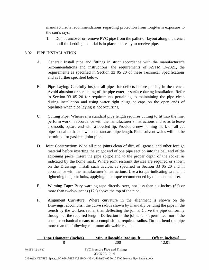
R0: IFB-12-15-17 PVC Pressure Pipe and Fittings 33 05 20.10 - 6
C:\Seaside CSD\IFB Specs_12-29-2017\IFB Vol 1B\Div 33 - Utilities\33 05 20.10 PVC Pressure Pipe Fittings.docx
manufacturer’s recommendations regarding protection from long-term exposure to the sun’s rays. 1. Do not uncover or remove PVC pipe from the pallet or layout along the trench
until the bedding material is in place and ready to receive pipe.
3.02 PIPE INSTALLATION
A. General: Install pipe and fittings in strict accordance with the manufacturer’s recommendations and instructions, the requirements of ASTM D-2321, the requirements as specified in Section 33 05 20 of these Technical Specifications and as further specified below.
B. Pipe Laying: Carefully inspect all pipes for defects before placing in the trench. Avoid abrasion or scratching of the pipe exterior surface during installation. Refer to Section 33 05 20 for requirements pertaining to maintaining the pipe clean during installation and using water tight plugs or caps on the open ends of pipelines when pipe laying is not occurring.
C. Cutting Pipe: Whenever a standard pipe length requires cutting to fit into the line, perform work in accordance with the manufacturer’s instructions and so as to leave a smooth, square end with a beveled lip. Provide a new homing mark on all cut pipes equal to that shown on a standard pipe length. Field solvent welds will not be permitted for gasketed joint pipe.
D. Joint Construction: Wipe all pipe joints clean of dirt, oil, grease, and other foreign material before inserting the spigot end of one pipe section into the bell end of the adjoining piece. Insert the pipe spigot end to the proper depth of the socket as indicated by the home mark. Where joint restraint devices are required or shown on the Drawings, install such devices as specified in Section 33 05 20 and in accordance with the manufacturer’s instructions. Use a torque-indicating wrench in tightening the joint bolts, applying the torque recommended by the manufacturer.
E. Warning Tape: Bury warning tape directly over, not less than six-inches (6”) or more than twelve-inches (12”) above the top of the pipe.
F. Alignment Curvature: Where curvature in the alignment is shown on the Drawings, accomplish the curve radius shown by manually bending the pipe in the trench by the workers rather than deflecting the joints. Curve the pipe uniformly throughout the required length. Deflection in the joints is not permitted, nor is the use of mechanical means to accomplish the required radius. Do not bend the pipe more than the following minimum allowable radius.
Pipe Diameter (inches)
Min. Allowable Radius, ft
Offset, inches(b)
8 200 12.01
R0: IFB-12-15-17 PVC Pressure Pipe and Fittings 33 05 20.10 - 7
C:\Seaside CSD\IFB Specs_12-29-2017\IFB Vol 1B\Div 33 - Utilities\33 05 20.10 PVC Pressure Pipe Fittings.docx
10 250 9.61 12 300 8.00
14 - 16 1.5 degrees (a) 6.25 (a) Given pipe thickness, bending may not be possible. Joint deflection may be
used, maximum indicated. (b) Based on 20-feet length of pipe piece.
F. Locating Wire: Install locating wire on the PVC pipelines and associated fittings as described in Section 33 05 20 of these Specifications and as shown on the Drawings. Terminate loose ends of the locating wire in a G5 box provided at ± 500 foot intervals, or at each end of pipe runs between structures, whichever distance is less.
G. Installation of polyethylene encasement: Polyethylene encased all ductile iron fittings, joint restraint devices external to the pipe and connected valves used with the PVC pipeline. Install polyethylene encasement per AWWA C-105, Method A or C at the Contractor’s option, and as described herein. Wrap tubes, seams and overlaps on the polyethylene film and hold in place by means of the specified plastic-backed adhesive tape or plastic binding straps. Apply tape to seal seams, overlaps, and ends of the polyethylene encasement to prevent entry of groundwater and soil into the film envelope.
3.03 DAMAGED PIPE
A. Reject and remove from the job site pipe or fittings having cracks, splits, pipe curvature exceeding the offset specified hereinabove or scratches which, in the judgment of the District, affect the pipe strength of the pipe or fitting. Repair of damaged PVC pipe or fitting will not be permitted.
3.04 FIELD LEAKAGE TEST
A. Test all polyvinyl chloride pressure pipelines in accordance with the provision for pipeline testing contained in AWWA Standard C600, except as further noted or where more stringent requirements are described in Section 33 08 30, “Commissioning of Wastewater Utilities.” PVC pressure pipe exposed inside vaults or boxes shall exhibit no visible leakage at the joints in the exposed pipe.
END OF SECTION 33 05 20.11

R0: IFB-12-15-17 PVC Pressure Pipe and Fittings 33 05 20.10 - 8
C:\Seaside CSD\IFB Specs_12-29-2017\IFB Vol 1B\Div 33 - Utilities\33 05 20.10 PVC Pressure Pipe Fittings.docx
This page intentionally blank.
R0: IFB-12-15-17 PVC Gravity Sewer Pipe and Fittings 33 05 20.11 - 1 C:\Seaside CSD\IFB Specs_12-29-2017\IFB Vol 1B\Div 33 - Utilities\33 05 20.11 PVC Gravity Sewer Pipe Fittings.docx
SECTION 33 05 20.11
PVC GRAVITY SEWER PIPE AND FITTINGS
PART 1 - GENERAL
1.01 SUMMARY
A. Requirements specified in the General and Supplementary Conditions of the Contract and Division 1 of the Technical Specifications and applicable portions of Section 33 05 20 form a part of this Section.
B. Section Includes: 1. Submittals. 2. Polyvinyl chloride gravity sewer pipe (PVCP) and fittings for uses where
shown on the Drawings. 3. Warning tape. 4. Pipe installation.
C. Related Sections: 1. Section 31 23 19 - Dewatering 2. Section 31 23 33 - Trenching, Backfilling and Compaction 3. Section 31 40 00 - Sheeting, Waling and Shoring 4. Section 33 05 16 - Utility Structures 5. Section 33 05 20 - General Piping Requirements 6. Section 33 08 30 – Commissioning of Wastewater Utilities
1.02 REFERENCED CODES AND STANDARDS
A. American Society of Testing and Materials (ASTM): 1. C564 – Specification for Rubber Gaskets for Cast Iron Soil Pipe and Fittings 2. C1173 – Specification for Flexible Transition Couplings for Underground
Piping Systems 3. D1784 – Specification for Rigid Poly(Vinyl Chloride) (PVC) Compounds and
Chlorinated Poly(Vinyl Chloride) (CPVC) Compounds 4. D2321 – Standard Practice for Underground Installation of Thermoplastic
Pipe for Sewers and Other Gravity-Flow Applications. 5. D2444 – Test Method for Determination of the Impact Resistance of
Thermoplastic Pipe and Fittings by Means of a Tup (Falling Weight)
R0: IFB-12-15-17 PVC Gravity Sewer Pipe and Fittings 33 05 20.11 - 2 C:\Seaside CSD\IFB Specs_12-29-2017\IFB Vol 1B\Div 33 - Utilities\33 05 20.11 PVC Gravity Sewer Pipe Fittings.docx
6. D3034 – Standard Specification for Type PSM Polyvinyl Chloride (PVC) Sewer Pipe and Fittings.
7. F477 – Specification for Elastomeric Seals (Gaskets) for Joining Plastic Pipe 8. F679 – Specification for Poly(Vinyl Chloride) (PVC) Large-Diameter Plastic
Gravity Sewer Pipe and Fittings
B. NSF: 1. Standard No. 61 – Drinking Water System Components, Health Effects
1.O3 SUBMITTALS
A. Comply with the general requirements and procedures specified in Article 12 of the General Conditions and Section 01 33 00, “Submittal Procedures”, of the Technical Specifications pertaining to submittals, including preparation, transmittals, and guarantees.
B. Inspection and Certification by Contractor: 1. In coordination with the respective pipe manufacturer, establish the necessary
quality control and inspection practices to assure compliance with standards cited herein.
1.04 QUALITY ASSURANCE
A. Factory Inspection: No factory inspection will be required except where, in the judgment of the District, a substantial portion of the pipe delivered to the job site does not meet the standards specified herein. In this event, factory inspection shall be at the Contractor’s expense.
B. Factory Testing: Provide pipe, fittings and couplings meeting the requirements of the section titled “Requirements” of ASTM D-3034. During production of the pipe, the manufacturer shall perform the specified test for each pipe marking. Deliver, with the pipe, a certificate by the manufacturer indicating compliance with specification requirements. Include the test result data with the certificate. Manufacture pipe of PVC compound conforming to the chemical resistance requirements of Subsection 207-17.5, Standard Specifications for Public Works Construction (Southern California Chapter American Public Works Association). 1. Pipe shall be subject to a drop impact test using a free falling tup as follows:
a. Pipe shall withstand, without failure, at 73 degrees Fahrenheit an impact of a falling 20 pound weight with a 1/2 inch radius nose (Tup A), in accordance with ASTM D-2444. Use the specified pound of weight per pipe size as follows:
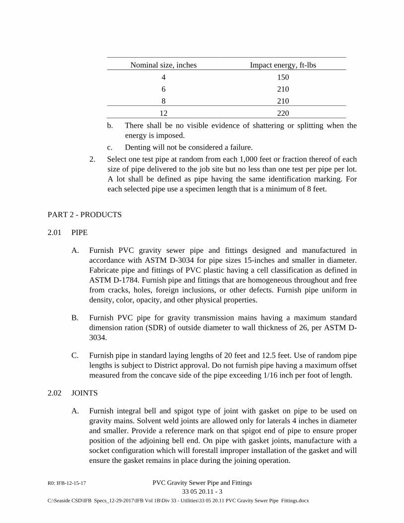
R0: IFB-12-15-17 PVC Gravity Sewer Pipe and Fittings 33 05 20.11 - 3 C:\Seaside CSD\IFB Specs_12-29-2017\IFB Vol 1B\Div 33 - Utilities\33 05 20.11 PVC Gravity Sewer Pipe Fittings.docx
Nominal size, inches Impact energy, ft-lbs
4 150 6 210 8 210 12 220
b. There shall be no visible evidence of shattering or splitting when the energy is imposed.
c. Denting will not be considered a failure. 2. Select one test pipe at random from each 1,000 feet or fraction thereof of each
size of pipe delivered to the job site but no less than one test per pipe per lot. A lot shall be defined as pipe having the same identification marking. For each selected pipe use a specimen length that is a minimum of 8 feet.
PART 2 - PRODUCTS
2.01 PIPE
A. Furnish PVC gravity sewer pipe and fittings designed and manufactured in accordance with ASTM D-3034 for pipe sizes 15-inches and smaller in diameter. Fabricate pipe and fittings of PVC plastic having a cell classification as defined in ASTM D-1784. Furnish pipe and fittings that are homogeneous throughout and free from cracks, holes, foreign inclusions, or other defects. Furnish pipe uniform in density, color, opacity, and other physical properties.
B. Furnish PVC pipe for gravity transmission mains having a maximum standard dimension ration (SDR) of outside diameter to wall thickness of 26, per ASTM D-3034.
C. Furnish pipe in standard laying lengths of 20 feet and 12.5 feet. Use of random pipe lengths is subject to District approval. Do not furnish pipe having a maximum offset measured from the concave side of the pipe exceeding 1/16 inch per foot of length.
2.02 JOINTS
A. Furnish integral bell and spigot type of joint with gasket on pipe to be used on gravity mains. Solvent weld joints are allowed only for laterals 4 inches in diameter and smaller. Provide a reference mark on that spigot end of pipe to ensure proper position of the adjoining bell end. On pipe with gasket joints, manufacture with a socket configuration which will forestall improper installation of the gasket and will ensure the gasket remains in place during the joining operation.
R0: IFB-12-15-17 PVC Gravity Sewer Pipe and Fittings 33 05 20.11 - 4 C:\Seaside CSD\IFB Specs_12-29-2017\IFB Vol 1B\Div 33 - Utilities\33 05 20.11 PVC Gravity Sewer Pipe Fittings.docx
2.03 FITTINGS AND ACCESSORIES
A. Furnish fittings and accessories manufactured and supplied by the same manufacturer as the pipe and having compatible connections with the pipe.
2.04 SOLVENT CEMENT
A. Allowed only for use on 4-inch and smaller laterals, which are not part of this Work.
2.05 GASKETS
A. Conform to the requirements of ASTM F-477.
2.06 COUPLINGS
A. Repair Couplings: Molded of same material as pipe specified above. Furnish with gaskets at both ends and without a stop.
B. Flexible Shielded Couplings: Conform to ASTM C564 and ASTM C1173. 1. Fabricate body of synthetic SBR rubber conforming to ASTM C564. 2. Design to use a mechanical compression joint requiring no sealant to make the
pipe connection. 3. Shear Ring: 0.012-inch thick, made of Type 316 stainless steel; width of
shield to match coupling length. 4. Furnish with at least two (2) Type 316 stainless bands and clamps at each
coupling. Spot weld clamps in place on the shield. 5. Manufacturer: Fernco Strong Back Flexible Repair Coupling or equal.
PART 3 - EXECUTION
3.01 HANDLING AND STORAGE OF PIPE
A. Deliver polyvinyl chloride pipe to the job site from the factory and store at the job site in palletized units or bundles to prevent unnecessary deflection prior to installation. Size each palletized unit to limit the stacking of pipe to not more than 30 inches high or as approved by the District. 1. Transport pipe with care to ensure that the binding and tie-down methods do
not damage or deflect the pipe in any manner. Pipe bent, deflected, or otherwise damaged during shipping shall be rejected. Ensure that pipe storage at the job site conforms to manufacturer’s recommendations regarding protection from long term exposure to the sun’s rays.
R0: IFB-12-15-17 PVC Gravity Sewer Pipe and Fittings 33 05 20.11 - 5 C:\Seaside CSD\IFB Specs_12-29-2017\IFB Vol 1B\Div 33 - Utilities\33 05 20.11 PVC Gravity Sewer Pipe Fittings.docx
2. Do not uncover or remove PVC pipe from the pallet or lay out along the ditch until the bedding material is in place and ready to receive pipe.
3.02 PIPE INSTALLATION
A. General: Install pipe and fittings in strict accordance with the manufacturer’s recommendations and instructions, the requirements of ASTM D-2321, the requirements as specified in Section 33 05 20 of these Technical Specifications and as further specified below.
B. Pipe Laying: Carefully inspect all pipes for defects before placing in the trench. Avoid abrasion or scratching of the pipe exterior surface during installation. Unless otherwise required, lay all pipes straight between changes in grade. Make changes in a grade only at manholes, unless otherwise indicated on the Drawings.
C. Cutting Pipe: Whenever a standard pipe length requires cutting to fit into the line, provide for a lateral connection or to bring it to the required location, perform work in accordance with the manufacturer’s instructions so as to leave a smooth, square end with a beveled lip. Provide a new homing mark on all cut pipes equal to that shown on a standard pipe length. 1. Field welds will not be permitted for gasket joint pipe. 2. Where a plain end to plain end joint occurs as a result of cutting into the pipe,
install a solid wall repair couplings as specified above. Flexible couplings are not permitted for this installation, but only when necessary to join pipe of different materials having different outside diameters.
D. Manhole Connections: Pipe may be laid through a manhole when possible to form a channel. In this case, after construction of the manhole cut out the top of the pipe. On all pipe entering a manhole install a gasket joint within 1 foot maximum of the manhole or structure base and install a standard manhole gasket (water stop) as supplied by the manufacturer firmly clamped around the pipe’s exterior and near the structure wall center. 1. Pipe connecting to a cast-in-place concrete structure: Provide a wall sleeve
and modular wall seal, both per Specification Section 33 05 20. “General Piping Requirements”, in the wall penetration.
E. Joint Construction: Wipe all pipe joints clean of dirt, oil, grease, and other foreign material before inserting the spigot end of one pipe section into the bell end of the adjoining piece. Perform solvent welded jointing of lateral pipe in strict accordance with the manufacturer’s instructions. Insert the pipe spigot end to the proper depth of the socket as indicated by the home mark.
F. Service Laterals: None required on Work.
R0: IFB-12-15-17 PVC Gravity Sewer Pipe and Fittings 33 05 20.11 - 6 C:\Seaside CSD\IFB Specs_12-29-2017\IFB Vol 1B\Div 33 - Utilities\33 05 20.11 PVC Gravity Sewer Pipe Fittings.docx
G. Locating Wire: Install locating wire as specified in Section 33 05 20 on new PVC gravity sewer main. Attach wire to pipe and terminate wires in a precast concrete box as shown on Drawings.
3.03 DAMAGED PIPE
A. Reject and remove from the job site pipes having cracks, splits, pipe curvature exceeding the offset specified hereinabove or scratches which, in the judgment of the District, affect the pipe strength. Repair of damaged PVC pipe will not be permitted.
3.04 TESTING
A. General: See Section 33 08 30 of the technical Specifications.
B. Field Leakage Test: See Section 33 08 30.
C. Mandrel Test: Following the leakage test and not sooner than thirty (30) days following the placement of compaction of backfill and prior final surface restoration, clean all main line pipe and then perform a deflection test using a mandrel to measure for obstructions (deflections, joint offsets, and lateral pipe intrusions). Pull a rigid mandrel through the pipe by hand or by mechanical means approved by the District. Use a mandrel having a cross-section equivalent to a circle having a minimum diameter as follows:
Pipe Size, inch Mandrel Diameter (minimum), inch
SDR 26 8 7.11 10 8.87 12 10.55
1. Employ a mandrel composed of two (2) steel circular plates set parallel and joined by 0.50-inch steel flats set on edge around the plates to form points of contact with the pipe being tested and having an odd numbered contact points, but not less than 9 in number. Mandrel testing of service laterals is not required.
2. At the beginning of Work, have pipe manufacturer inspect the proposed mandrel and submit written certification that the mandrel’s precision conforms to the permitted deflection specified herein. If during the course of the Work, there is a change in the mandrel, have each new mandrel inspected and certified by the pipe manufacturer and submit certification to the District.
R0: IFB-12-15-17 PVC Gravity Sewer Pipe and Fittings 33 05 20.11 - 7 C:\Seaside CSD\IFB Specs_12-29-2017\IFB Vol 1B\Div 33 - Utilities\33 05 20.11 PVC Gravity Sewer Pipe Fittings.docx
3. Remove pipe exceeding the permitted deflection and replace in conformance with the Specifications at no expense to the District. Use of a re-rounder to reduce deflection is not permitted.
D. Video Inspection: Not required.
3.05 CORRECTIVE WORK AND CLEAN-UP
A. Correct, at the direction of the District, lateral pipe intrusions, deflected or offset joints, sags or crowns in grade, damaged pipe and all other conditions not conforming to the requirements of these Specifications found as a result of this inspection. Similarly, remove obstructions and foreign material found in pipe. Perform corrections and removals as required at no additional expense to the District.
B. Where, in the opinion of the District, major corrective work or replacement is required, re-perform leakage test on the corrected or replaced section of pipe main.
END OF SECTION 33 05 20.11

R0: IFB-12-15-17 PVC Gravity Sewer Pipe and Fittings 33 05 20.11 - 8 C:\Seaside CSD\IFB Specs_12-29-2017\IFB Vol 1B\Div 33 - Utilities\33 05 20.11 PVC Gravity Sewer Pipe Fittings.docx
This page intentionally blank.
R0: IFB-12-15-17 Ductile Iron Pipe and Fittings 33 05 20.13 - 1
C:\Seaside CSD\IFB Specs_12-29-2017\IFB Vol 1B\Div 33 - Utilities\33 05 20.13 Ductile Iron Pipe and Fittings.docx
SECTION 33 05 20.13
DUCTILE IRON PIPE AND FITTINGS
PART 1 GENERAL
1.01 SUMMARY
A. Requirements specified in the General and Supplementary Conditions of the Contract and Division 1 of the Technical Specifications, and applicable portions of Section 33 05 20 form a part of this Section.
B. Section Includes: 1. Submittals. 2. Ductile iron pipe (DIP) and fittings. 3. Pipe installation. 4. Polyethylene encasement.
C. Related Sections: 1. Section 31 23 19 - Dewatering 2. Section 31 23 33 - Trenching, Backfilling and Compaction 3. Section 31 40 00 - Sheeting, Waling and Shoring 4. Section 33 05 20 - General Piping Requirements 5. Section 33 08 30 - Commissioning of Wastewater Utilities 6. Section 40 05 23 - Valves and Miscellaneous Piping Appurtenances
1.02 REFERENCED CODES AND STANDARDS
A. American Water Works Association (AWWA),latest edition: 1. C104 – Cement Mortar Lining for Ductile-Iron Pipe and Fittings 2. C105 – Polyethylene Encasement for Ductile –Iron Pipe Systems 3. C110 – Ductile-Iron and Gray-Iron Fittings 4. C111 – Rubber-Gasket Joints for Ductile-Iron Pressure Pipe and Fittings 5. C115 – Flanged Ductile-Iron Pipe With Ductile-Iron or Gray-Iron Threaded
Flanges 6. C150 – Thickness Design of Ductile Iron Pipe 7. C151 – Ductile-Iron Pipe, Centrifugally Cast 8. C600 – Installation of Ductile-Iron Water Mains and Their Appurtenances 9. C606 – Grooved and Shouldered Joints
B. NSF International
R0: IFB-12-15-17 Ductile Iron Pipe and Fittings 33 05 20.13 - 2
C:\Seaside CSD\IFB Specs_12-29-2017\IFB Vol 1B\Div 33 - Utilities\33 05 20.13 Ductile Iron Pipe and Fittings.docx
1. 60 – Drinking Water Treatment Chemicals – Health Effects 2. 61 – Drinking Water System Components – Health Effects
1.03 SUBMITTALS
A. Provide shop drawings or catalog cuts for work included in this Section in accordance with the applicable requirements of Article 12 of the General Conditions and Section 01 33 00 of the Technical Specifications, “Submittal Procedures”, pertaining to submittals, including preparation, transmittals, and guarantees.
B. Shop Drawings: Submit drawings of joint details and thickness design calculation, furnished by the manufacturer, for review and approval before manufacturing and shipping commences. Submit information including, but not limited to, the following: 1. Pipe inside diameter. 2. Wall thickness. 3. Allowable working pressure, pipe and fittings. 4. Fitting material. 5. Thickness of mortar lining. 6. Thickness of polyethylene lining, where required. 7. Gasket material. 8. Location of factory.
C. Certificates: Clearly cast or stamp the following on each pipe section: 1. Class. 2. Casting period. 3. Internal diameter in inches. 4. Name of manufacturer. 5. Date of manufacture. 6. The letters “DI” or “DUCTILE.”
1.04 QUALITY ASSURANCE
A. Factory Inspection: District or his representative may inspect pipe production at the manufacturer’s plant. See Section 33 05 20 for general conditions regarding factory inspection. The District shall have the right to call for and witness tensile and impact tests on the pipe material, hydrostatic tests on the finished pipe, analysis and physical tests of cement and sand used for the cement-mortar lining, and check of permissible weight and dimension variations. Conduct test procedures, number of tests required, requirements for test compliance, and retest procedures in the event of specimen failure as specified in AWWA C151 for the pipe and AWWA C104 for the cement-mortar lining.
R0: IFB-12-15-17 Ductile Iron Pipe and Fittings 33 05 20.13 - 3
C:\Seaside CSD\IFB Specs_12-29-2017\IFB Vol 1B\Div 33 - Utilities\33 05 20.13 Ductile Iron Pipe and Fittings.docx
B. Field Leakage Test: Field leak test ductile iron pipelines in accordance with the provisions for pipeline testing contained in AWWA Standard C600, except as further noted in Section 33 08 30, Commissioning of Wastewater Utilities.
PART 2 PRODUCTS
2.01 PIPE
A. As indicated on Drawings, furnish ductile iron pipe (DIP) conforming to AWWA Standard C151 (ANSI A21.51). Furnish pipe appurtenances produced by the pipe manufacturer. Random pipe lengths are acceptable. Furnish ductile iron pipe of pressure Class 200 unless otherwise on the Drawings, except in no case shall it be less than Class 150.
2.02 PIPE JOINTS
A. Furnish joints of mechanical type, except where flanged, push-on, or grooved joints are shown on the Drawings.
B. Push-on and Mechanical Joints: Furnish push-on and mechanical joints conforming to AWWA Standard C111 (ANSI A21.11). Furnish gasket material of neoprene, conforming to AWWA Standard C111.
C. Flanges: Furnish flanges of the screw-on type, conforming to AWWA Standard C111 (ANSI A21.15), of the thickness class compatible with the flanges of the equipment, valves, and fittings to which they must be joined. Furnish bolts for buried flanged joints of Type 316 stainless steel machine bolts with square heads and cold pressed hexagon nuts.
D. Restrained Joints: Furnish restrained mechanical joints where required that comply with the requirements specified in Section 33 05 30, “General Piping Requirements”. 1. Alternative joint restraint devices that are specially modified bell joints with
joint restraint provided by ductile iron retainer rings joined together by corrosion resistant, low alloy high strength steel tee head bolts and nuts may be used in lieu of the wedging action restraining devices specified above where joint restraint is specified or shown on the Drawings to be required. Such alternative use is subject to Owner review and approval. a. The restrain feature shall be American Ductile Iron Pipe’s MJ Coupled
Joint, U.S. Pipe’s Mechanical Joint with restraining gland or equal. Furnish restrained mechanical bell joints for pipes and fittings designed to withstand satisfactorily the test pressure indicated in the hydrostatic test schedule. Furnish joints with joint restraint that are capable of deflection during assembly.
R0: IFB-12-15-17 Ductile Iron Pipe and Fittings 33 05 20.13 - 4
C:\Seaside CSD\IFB Specs_12-29-2017\IFB Vol 1B\Div 33 - Utilities\33 05 20.13 Ductile Iron Pipe and Fittings.docx
E. Grooved Joints: Where shown on the Drawings as required, furnish pipe and fittings with rigid grooves in accordance with AWWA C606. Where grooved joint pipe is furnished, provide pipe having the required pressure rating after grooving.
2.03 FITTINGS
A. Furnish fittings of ductile iron, in conformance with AWWA Standard C153. Furnish ductile iron fittings having a minimum pressure rating of Class 250. Provide fittings having a pressure rating sufficient for the pipeline leakage test pressure specified in Section 33 08 30 of the Technical Specifications. Furnish fittings for buried pipe of mechanical joint or push-on type unless otherwise shown on the Drawings. Push-on fittings shall be equal to “Tyton” as manufactured by the United States Pipe and Foundry Company. Fittings above grade, including exposed inside vaults, shall be flanged.
2.04 EXTERIOR COATING
A. For pipe and fittings to be buried, furnish with a factory-applied bituminous coating, generally used for ductile iron pipe. Coating that does not bond firmly or shows voids or holidays shall be rejected.
2.05 LININGS
A. Cement-Mortar Lining: Except where otherwise indicated on the Drawings and herein, provide ductile iron pipe and fittings for potable water pipelines that are lined with cement-mortar in accordance with AWWA Standard C104 (ANSI A21.4), except as further noted in these Specifications. Use Type II cement conforming to ASTM C150. Provide a lining thickness of not less than 1/16-inch for pipe 12 inches in diameter and smaller, and 3/32-inch for pipe over 12 inches in diameter. Apply over the cement lining a factory-applied coat of bituminous coating as specified above for the pipe exterior coating.
2.06 POLYETHYLENE ENCASEMENT
A. Furnish polyethylene encasement conforming to AWWA Standard C-105, tube or sheet form. Furnish 2-inch wide tape conforming to Polyken No. 900 (polyethylene), Scotchrap No. 50 (polyvinyl), or equal for use with the polyethylene encasement. Furnish tape having an adhesive surface that bonds securely to both pipe (PVC, DIP, or other), valve or fitting surfaces, and the polyethylene film.
PART 3 EXECUTION
3.01 PIPE INSTALLATION
A. General: Install pipe joints and fittings in accordance with the manufacturer’s recommendations, the requirements as specified in Section 33 05 20 of these Specifications, and the additional requirements specified herein.
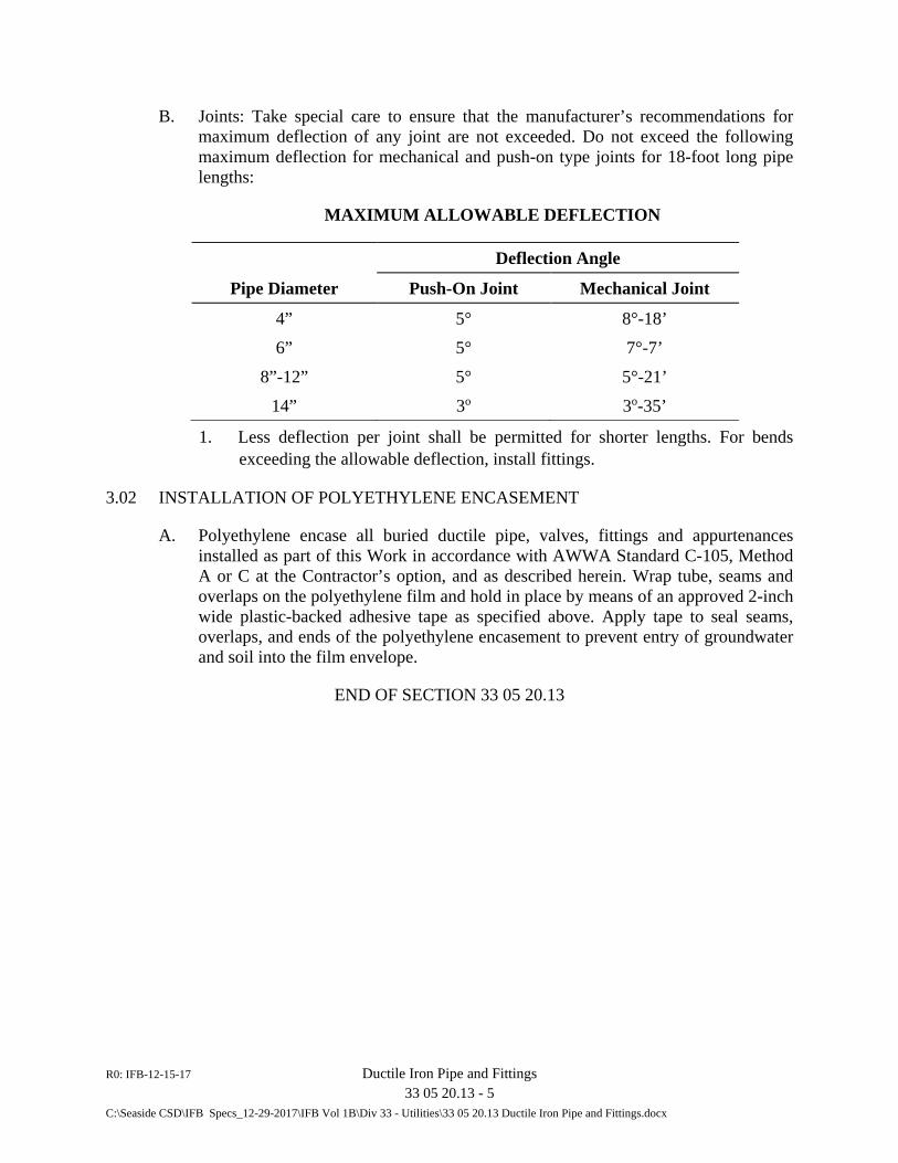
R0: IFB-12-15-17 Ductile Iron Pipe and Fittings 33 05 20.13 - 5
C:\Seaside CSD\IFB Specs_12-29-2017\IFB Vol 1B\Div 33 - Utilities\33 05 20.13 Ductile Iron Pipe and Fittings.docx
B. Joints: Take special care to ensure that the manufacturer’s recommendations for maximum deflection of any joint are not exceeded. Do not exceed the following maximum deflection for mechanical and push-on type joints for 18-foot long pipe lengths:
MAXIMUM ALLOWABLE DEFLECTION
Deflection Angle
Pipe Diameter Push-On Joint Mechanical Joint
4” 5° 8°-18’ 6” 5° 7°-7’
8”-12” 5° 5°-21’ 14” 3o 3o-35’
1. Less deflection per joint shall be permitted for shorter lengths. For bends exceeding the allowable deflection, install fittings.
3.02 INSTALLATION OF POLYETHYLENE ENCASEMENT
A. Polyethylene encase all buried ductile pipe, valves, fittings and appurtenances installed as part of this Work in accordance with AWWA Standard C-105, Method A or C at the Contractor’s option, and as described herein. Wrap tube, seams and overlaps on the polyethylene film and hold in place by means of an approved 2-inch wide plastic-backed adhesive tape as specified above. Apply tape to seal seams, overlaps, and ends of the polyethylene encasement to prevent entry of groundwater and soil into the film envelope.
END OF SECTION 33 05 20.13

R0: IFB-12-15-17 Ductile Iron Pipe and Fittings 33 05 20.13 - 6
C:\Seaside CSD\IFB Specs_12-29-2017\IFB Vol 1B\Div 33 - Utilities\33 05 20.13 Ductile Iron Pipe and Fittings.docx
This page intentionally blank.
R0: IFB-12-15-17 Commissioning of Wastewater Utilities 33 08 30 - 1 C:\Seaside CSD\IFB Specs_12-29-2017\IFB Vol 1B\Div 33 - Utilities\33 08 30 Commissioning of Wastewater Utilities.docx
SECTION 33 08 30
COMMISSIONING OF WASTEWATER UTILITIES
PART 1 - GENERAL
1.01 SUMMARY
A. Requirements specified in General and Supplementary Conditions of the Contract and Division 1 of the Technical Specifications, in particular Section 01 70 00; and applicable portions of Section 33 05 20 form a part of this Section.
B. Section Includes: 1. Submittals. 2. Piping testing, 3. Leakage tests of pressure (force) and gravity flow mains.
C. Related Sections: 1. Section 31 23 00 – Excavation and Fill 2. Section 31 23 19 - Dewatering 3. Section 31 23 33 - Trenching, Backfilling, and Compaction 4. Section 26 66 00 – Factory and Field Testing (of electrical Equipment and
Control Panels) 5. Section 33 05 16 - Utility Structures 6. Section 33 05 20.10 – PVC Pressure Pipe and Fittings 7. Section 33 05 20.11 – PVC Gravity Sewer Pipe and Fittings 8. Section 33 05 20.13 – Ductile Iron Pipe and Fittings 9. Section 33 32 20 – Submersible Non-Clog Pumps 10. Section 40 05 23 – Valves and Miscellaneous Piping Appurtenances
1.02 SUBMITTALS
A. Comply with the general requirements and procedures described in Article 12 of the General Conditions and Sections 01 33 00, “Submittal Procedures”, pertaining to submittals, including preparation, transmittals, and guarantees.
B. Work Plan: Prior to or in conjunction with submittal of the pipe fabrication drawings, submit for District’s review and approval a detailed work plan outlining the proposed procedures and schedule for pressure and leakage testing. Include, but do not limit the details provided in the work plan to the following:
R0: IFB-12-15-17 Commissioning of Wastewater Utilities 33 08 30 - 2 C:\Seaside CSD\IFB Specs_12-29-2017\IFB Vol 1B\Div 33 - Utilities\33 08 30 Commissioning of Wastewater Utilities.docx
1. Stationing or location of the pipeline segments to be tested and the sequence of testing various segments of the same pipeline.
2. Details of equipment and connections used in conducting the testing. 3. Details of the jumper connection used to fill the pipeline being tested with
water. 4. Source (include location) of water, air, or other gas to be used for testing. 5. Whether or not pressure and leakage testing are to be performed concurrently. 6. Method and location for disposing of water used for testing.
1.03 QUALITY ASSURANCE
A. Test all piping and associated appurtenances installed as part of this Contract, for holding pressure and leakage, except where noted otherwise herein. Test pipe installed or replaced as a result of the Work for this Contract as specified herein.
B. Pressure and leakage test pipelines, piping systems, and appurtenances in accordance with the applicable AWWA Standards except as may be modified herein. Pressure and leakage test other pipelines damaged and subsequently repaired as a result of the activity for this Contract, if required, in accordance with the applicable requirements of the respective utility entity.
C. Leakage test gravity flow pipelines, including manholes and appurtenances, installed as part of this Work in accordance with the requirements specified herein. Also comply with such additional testing requirements as are specified in the respective pipe materials Sections.
D. Perform testing of pipelines, piping systems, appurtenances, and if required, other pipe systems installed or replaced as part of the Work for this Contract, in the presence of the Inspector. Notify the District not less than two (2) working days in advance of the actual time of testing so that the District or Inspector may observe the procedure.
1.04 JOB CONDITIONS
A. General: 1. Connecting to Existing Potable Water Lines: No permanent connection
between any sewer force main pipeline, pressure piping or gravity sewer main to any existing potable water main is permitted.
2. Water required for initial filling, pressure testing, and leakage testing of Force Main, gravity sewer main, overflow structures or manholes may be obtained from a Cal-Am Water Company or the use of reclaimed water, obtained from the Monterey One Water, may be permitted. Include in the Contract Price the cost of the connection, all water used, and the means of delivering the water.
R0: IFB-12-15-17 Commissioning of Wastewater Utilities 33 08 30 - 3 C:\Seaside CSD\IFB Specs_12-29-2017\IFB Vol 1B\Div 33 - Utilities\33 08 30 Commissioning of Wastewater Utilities.docx
B. Testing: Conduct all tests for which acceptance are sought in the presence of the Contractor and the District, or his representatives.
PART 2 - PRODUCTS (NOT USED)
PART 3 - EXECUTION
3.01 PRIOR WORK
A. Accomplish and complete backfill and compaction in accordance with the requirements of Sections 31 23 00 and 31 23 33 of these Technical Specifications.
3.02 LEAKAGE TESTS
A. Pressure Piping Systems and Force Mains: 1. General. Pressure testing of force mains or pressure piping constructed as part
of this Work is required as described herein. Perform pressure and leakage testing as directed by the Engineer on any pressure piping not scheduled to be replaced or modified, but which is damaged as a result of the activities for this Work, and is therefore required to be repaired or replaced. a. hydrostatically tests the pressure pipeline systems listed in Paragraph
A.3 below. Do not perform the leakage test until the following conditions have been met:
b. Unimproved Areas: In unimproved areas, that is, in areas where no pavement surface of any nature is to be constructed, perform the pressure test only after the backfill has been placed and satisfactorily compacted and the general areas have been rough graded to approximately finished grade; all pipeline appurtenances have been adjusted and set to final grade and location in accordance with the Contract Drawings and until not less than 72 hours have elapsed since the last concrete thrust block, reverse anchor, or valve pad has been cast. Refer to Paragraph 1.04A above for exceptions to this required status of completion.
b. Improved Areas: In improved areas, that is, in areas where a pavement surfacing exists, perform the pressure test only after all other new and existing utilities, such as storm drains, potable water mains, electrical and instrumentation cable, etc., installed, damaged, or relocated as a consequence of work for this Contract have been restored to original or existing condition; all pipeline appurtenances have been adjusted and set to final grade and location in accordance with the Contract Drawings and until not less than 72 hours have elapsed since the last concrete thrust block, reverse anchor, or valve pad has been cast. Refer to
R0: IFB-12-15-17 Commissioning of Wastewater Utilities 33 08 30 - 4 C:\Seaside CSD\IFB Specs_12-29-2017\IFB Vol 1B\Div 33 - Utilities\33 08 30 Commissioning of Wastewater Utilities.docx
Paragraph 1.04A above for exceptions to this required status of completion.
2. Test Procedure: a. Upon acceptable completion of the installation and joining of pipe,
including installation of joint restraint devices, backfill trench to the extent necessary to maintain the completed piping system in place during the testing yet still allowing the joints to be visible for detection of leakage, and then proceed to hydrostatically test the subject piping system.
b. Maintain the leakage/pressure test of the pipeline or piping system for a minimum duration of 6 hours, except as otherwise noted herein. Maintain the duration for mechanical piping systems within the pump station that are required to be tested, for not less than 2 hours. This duration also applies to all valves and pipeline appurtenances that are part of the respective pipeline being tested. A preliminary pressure and leakage test may be conducted for convenience at any time prior to District’s leakage test. The results of the preliminary test will not be considered by the District as satisfying the requirements specified herein.
c. Establish the length of completed respective pressure pipeline to be tested at one time in accordance with Paragraph 1.04A, Job Conditions, herein above. For all other pressure pipelines or piping systems installed, repaired, or replaced as part of this Work, the amount of footage to be tested at one time shall be determined by the District. Include appurtenant valves and other shown accessories.
d. During testing, carefully examine all exposed pipes, fittings, valves, and joints. If found to be cracked or defective, remove the cracked or defective material and replace with sound material in accordance with the Contract requirements. Repeat the test until satisfactory results are demonstrated to the Engineer.
e. Test the pressure pipeline or piping system by slowly filling with water from the nearest potable water source (or reclaimed wastewater system, where and if approved) by means of a jumper pipe system or other method directed by the District. For piping with cement mortar lining, load the pipeline section or piping system being tested with water for at least 48 hours prior to initiating the leakage test to obtain a maximum absorption of water. For all other pipe, load the system at least 8 hours in advance. Vent all air from all high spots in the pipe section being tested before making any leakage tests.
f. Furnish pump, pipe connections, corporation stops, valves, calibrated pressure gage, measuring devices, and all other equipment, materials,
R0: IFB-12-15-17 Commissioning of Wastewater Utilities 33 08 30 - 5 C:\Seaside CSD\IFB Specs_12-29-2017\IFB Vol 1B\Div 33 - Utilities\33 08 30 Commissioning of Wastewater Utilities.docx
and labor required for performing the leakage test satisfactory to the District. Use only laboratory calibrated test gages and meters, which shall be recalibrated by a certified laboratory at the Contractor’s expense immediately prior to performing the leakage test for this Work.
3. Test Pressure: During the leakage test maintain the pressure noted in the Pipe Testing Schedule below. All pressures are referenced to pipe centerline at point of measurement.
a. Military Lift Station Force Main: 100 psi at connection to the existing force main at the lift station.
b. Lift Station Mechanical Piping- All lift stations: Apply a test pressure of 100 psi equivalent pressure measured at the lowest elevation of the piping under test.
4. Allowable Leakage: Do not exceed the following measured leakage during the specified test period: a. Exposed Piping, Valves, and Accessories: Permit no leakage in any type
of exposed piping, valves, or accessories. b. All Pipes including Military Lift Station Force main. No leakage
permitted. c. Rubber Gasket Piping System (Includes Military Lift Station Force
Main): 2 gallons per inch diameter per mile of pipeline being tested for the specified test period.
B. Sanitary Gravity Systems: 1. General: Perform leakage test in the field on all portions of the sanitary
gravity sewers constructed under this Contract; using the air or hydrostatic test as described herein, the method being at the Contractor’s option. See Section 33 05 20.11, “PVC Gravity Sewer Pipe and Fittings”, for mandrel test required in addition to the leakage test specified herein for acceptance of completed work. The leakage test is waived for those sewers where live service connections are made as part of the Work. For those lines in which the leakage test is not required, the mandrel test is still required as specified before closure/connection of the new piping. Conduct hydrostatic tests on gravity sewers in accordance with the requirements specified for each type of pipe. Provide all materials and labor required for the leakage test, including compressed air supply (or water, for hydrostatic testing), gages, corporation stops and temporary plugs. Use laboratory calibrated test gages and have the gages recalibrate by a certified laboratory at no additional expense to the District prior to the leakage test if required by the District. Perform the tests in the presence of an District representative. Perform tests only after the line has been properly installed, including any necessary test fittings, and backfilled. Allow a minimum of 24 hours to elapse between completion of backfilling
R0: IFB-12-15-17 Commissioning of Wastewater Utilities 33 08 30 - 6 C:\Seaside CSD\IFB Specs_12-29-2017\IFB Vol 1B\Div 33 - Utilities\33 08 30 Commissioning of Wastewater Utilities.docx
and applying the test pressure. Carefully place test plugs at each end of line to be tested.
2. Air Test: When all necessary test equipment is in place, attach a compressed air supply to the air fitting on the test equipment and increase the air pressure within the line to 4 pounds per square inch (psig). After the air supply is securely turned off or disconnected, permit a 2-minute waiting period to allow stabilization of air within the sewer line before beginning the actual test period. Air may be added only to maintain a pressure of 4.0 psig. a. When the internal pressure decreases to 3.5 psig, start the test period and
count the seconds until the pressure decreased to 2.5 psig. Minimum permissible pressure holding times for PVC pipe gravity sewer mains are listed in Uni-Bell PVC Pipe Association Practice UNI-B-6, “Practice for Low-Pressure Air Testing of Installed Sewer Pipe”. For vitrified clay pipe gravity sewer mains, the minimum permissible holding times are listed in Table 1 of ASTM C-828, “Standard Practice for Low Pressure Air Test of Vitrified Clay Pipelines.”
b. The maximum length of a line that may be tested at one time shall be 350 feet or the length between two (2) adjacent manholes, except where shown otherwise. After completion of a test, release the air pressure slowly through the valve, which is incorporated in the test equipment. Do not remove air test plugs until the air pressure is no longer measurable.
3. Hydrostatic Test: At the Contractor’s option, gravity lines may be tested by the hydrostatic ex-filtration method. The allowable rate of leakage shall not exceed 100 gallons per inch of diameter per mile of pipe per day. Measure ex-filtration as the leakage out of the pipeline when the lower end is plugged at a manhole and the upper end is filled at a manhole so as to create a minimum hydrostatic head of 4 feet above the invert of the pipe at the center of the upper manhole; or, if groundwater is present, 4 feet above the average groundwater level adjacent to the upper manhole. Calculate the leakage rate as the amount of water necessary to maintain the level in the upper manhole during the 3-hour testing period.
C. Leakage Test Failure: Should the test of any section of pipe or piping system result in the inability to maintain the test pressure as specified, or leakage greater than the specified limit, perform excavation necessary to locate and repair leaks or other defects which may develop under test, including removal of backfill already placed, replace such excavated material, and perform all repairs necessary until this section is retested at a leakage within the specified allowance. If, in the judgment of the District, the backfill over any section of the pipeline has been substantially disturbed in repairing a leak, recompact the backfill and subject the material to a compaction test at no additional cost to the District.
R0: IFB-12-15-17 Commissioning of Wastewater Utilities 33 08 30 - 7 C:\Seaside CSD\IFB Specs_12-29-2017\IFB Vol 1B\Div 33 - Utilities\33 08 30 Commissioning of Wastewater Utilities.docx
D. Storm Drains, Culverts: No leakage test is required on any storm drain or culvert installed new or as a replacement of existing as a consequence of activities for this Work.
3.03 DISINFECTION – NOT USED
3.04 BACTERIOLOGICAL TEST – NOT USED
3.05 LIFT STATIONS – MILITARY AND ROSITA LIFT STATIONS
A. See Section 33 32 20, “Submersible Non-Clog Pumps”, for operating and testing requirements. Operate each of the two (2) pumps at each of the lift stations through its complete cycle (Pump On – Pump Off) as a single unit. 1. Verify Lead – Standby/Lag and automatic alternation functions satisfactorily
perform at both facilities. In this test demonstrate Lead and Standby/Lag pumps start at the levels or operating points specified on the Drawings or as directed by the Owner
2. Measure and record flow and discharge pressure during all operating modes (including 1 and 2 pumps simultaneously) at minimum 10 minute intervals during the entire specified duration of the test.
3. In addition, test and verify operating pumps off at the specified level and the last operating pump (or pumps) stops on Low-Low water level in the wet well.
4. Submit the completed test reports to the Owner to demonstrate satisfactory compliance with the Contract requirements and for his records.
CONTRACTOR’S RESPONSIBILITY FOR TESTING
A. Notwithstanding anything contained herein, bear sole and full responsibility to construct piping systems capable of passing the leakage tests as required herein. The fact that the District provides inspection during the construction and testing of the water facilities shall not be cause for the Contractor to abrogate his responsibility in this regard.
B. Prevent the consumption of water for any and all uses from unsterile piping systems whether by their workers, subcontractors, or any other person who may come in contact with the water from an unsterile piping system.
C. Indemnify and save the District harmless from any suits, claims, or actions brought by any person or persons for or on account of any sickness or death sustained or arising out of the consumption of water from an unsterile piping system.
D. Dispose of water following completion of any test, successful or otherwise, in a manner in accordance with all local and state laws, in particular with all requirements of the California Regional Water Quality Control Board. In disposing

R0: IFB-12-15-17 Commissioning of Wastewater Utilities 33 08 30 - 8 C:\Seaside CSD\IFB Specs_12-29-2017\IFB Vol 1B\Div 33 - Utilities\33 08 30 Commissioning of Wastewater Utilities.docx
of water, do not cause erosion of the receiving flow channel or damage to property, private or public.
END OF SECTION 33 08 30

R0: IFB-12-15-17 Submersible Non-Clog Pumps 33 32 20 - 1 C:\Seaside CSD\IFB Specs_12-29-2017\IFB Vol 1B\Div 33 - Utilities\33 32 20 Submersible Non-Clog Pumps.docx
SECTION 33 32 20
SUBMERSIBLE NON-CLOG PUMPS
PART 1 - GENERAL
1.01 SUMMARY
A. Requirements specified in the General and Supplementary Conditions of the Contract and Division 1 of the Technical Specifications form a part of this Section.
B. Work Included in this Section: 1. Submittals 2. Pump, motor, guide rails, controls and necessary appurtenances 3. Spare parts 4. Installation and startup
C. Related Work specified in Other Sections: 1. Section 05 50 00 – Metal Fabrications 2. Section 11 05 00 - General Equipment Provisions 3. Division 26 – Electrical 43. Section 33 08 30 – Commissioning of Wastewater Utilities
1.02 SUBMITTALS
A. General: Comply with the general requirements and procedures described in Article 122of the General Conditions and Section 01 33 00 and Section 11 05 00 of the Technical Specifications pertaining to submittals, including preparation, transmittals and guarantees and the supplementary requirements specified herein. Provide data and specifications for the equipment including but not limited to that described herein.
B. Pump Data: Prior to preparation of shop drawings, submit the following information for each pump specified under this Section: 1. Pump curves indicating total dynamic head, flow rate, brake horsepower,
shutoff head and submergence requirements. 2. Motor data, including the manufacturer; locked rotor current in amps; full load
current in amps; and motor speed in rpm. 3. Complete the Equipment Data and Spare Parts Summary form included in
Section 11 05 00 for each furnished pump unit and submit to the District.

R0: IFB-12-15-17 Submersible Non-Clog Pumps 33 32 20 - 2 C:\Seaside CSD\IFB Specs_12-29-2017\IFB Vol 1B\Div 33 - Utilities\33 32 20 Submersible Non-Clog Pumps.docx
C. Shop Drawings: Provide shop drawings showing fabrication, assembly, and installation drawings, together with detailed specifications and data covering performance and materials of construction, power drive assembly, parts, devices, floats, controls and other accessories forming a part of the equipment furnished.
D. Assembly and Installation Drawings: After the above equipment submittals have been approved, submit complete fabrication, assembly, foundation and installation drawings, together with detailed specification and data covering materials of construction, parts, devices, wiring diagrams and other accessories forming a part of the equipment furnished. Submit drawings, specifications and other required data including but not limited to the following. 1. Materials of pump construction including shafts, bearings, impellers, castings
and pump body. 2. Electric motor data including size, make, operating voltage, and number of
phases. 3. Spare Parts List 4. Warranty
E. Operations and Maintenance Manuals: Prior to or concurrent with delivery of approved equipment, submit operation and maintenance (O&M) manuals specific to the equipment furnished.
1.03 QUALITY
A. Provide pumping equipment furnished under this Section of a design and manufacture that is rated for operation in hazardous locations in accordance with NEC Class 1, Division 1, Group C and D requirements and suitable for continuous operation under submerged and partially submerged conditions.
1.04 OPERATING CONDITIONS
A. Provide pumps capable of conveying raw wastewater and that are FM rated for explosive environments. Level control at the Military and Rosita Lift Stations will be provided by a submersible level transmitter complying with Specification Section 26 89 40 and provided as part of the instrumentation package. Pumps at these stations will operate in a lead-lag/standby mode via a new Control Panel provided as part of this Work. Pump controls for both facilities shall be capable of automatically alternating the Lead pump and setting the assignment of Lag pump, and allow manual selection of the Lead pump without automatic alternation until manually changed. It is also the intent of this project for each of the facilities to be
R0: IFB-12-15-17 Submersible Non-Clog Pumps 33 32 20 - 3 C:\Seaside CSD\IFB Specs_12-29-2017\IFB Vol 1B\Div 33 - Utilities\33 32 20 Submersible Non-Clog Pumps.docx
able to manually operate the Lag/Standby pump simultaneously with the Lead pump.
1.05 FACTORY TESTING
A. In addition to the factory tests indicated in Section 11 05 00, test each pump for performance at the factory to determine head versus capacity, efficiencies, and kilowatt draw required for the operating points indicated. Conduct tests in accordance with the American Hydraulic Institute (HI) Standards for HI-A level. Include the following in the testing: 1. Check impeller, motor rating, and electrical connections for compliance with
the Contract Documents. 2. Conduct a motor and cable insulation test for moisture content and insulation
defects. 3. Prior to submergence, operate the pumps dry to establish correct rotation and
mechanical integrity. 4. Operate each pump for 30 minutes submerged, a minimum of 6 feet under
water at ¼, ½, ¾, and full flow to demonstrate there is no cavitation or overheating.
5. After operational test described in Item 4 above, perform again the insulation test described in Item 2 above.
B. Prior to shipment of the pumps, submit for each pump a certified written report stating the factory tests have successfully been completed and include the results of the factory testing described above, and obtain District’s approval. Delivery of pumps to the project site without prior District approval of the factory test results will render the pumps to be considered defective work and this status will remain until corrected to the District’s satisfaction.
1.06 GUARANTEES AND WARRANTIES
A. Furnish a manufacturer’s written warranty against defects in materials and workmanship for a period of at least 5 years or 10,000 operating hours, whichever is longer.
1.07 SERVICES OF MANUFACTURER
A. Inspection, Startup and Field Adjustment: Furnish the services of an authorized representative of the pump manufacturer for a site visit of not less than 4 hours at each lift station.
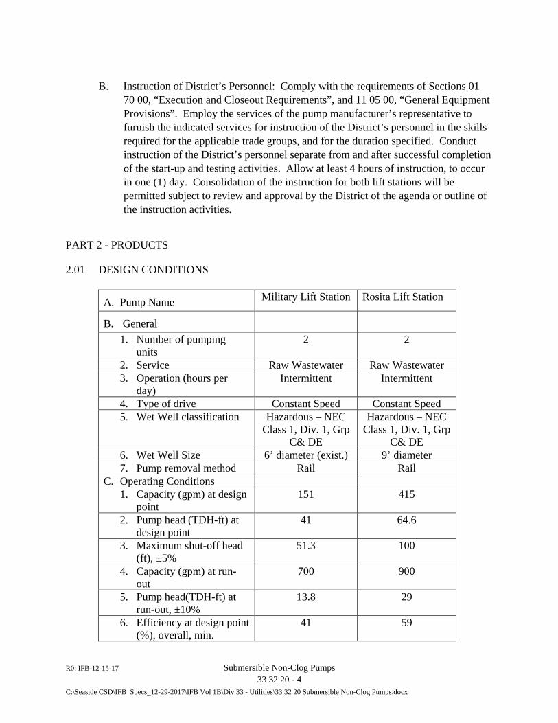
R0: IFB-12-15-17 Submersible Non-Clog Pumps 33 32 20 - 4 C:\Seaside CSD\IFB Specs_12-29-2017\IFB Vol 1B\Div 33 - Utilities\33 32 20 Submersible Non-Clog Pumps.docx
B. Instruction of District’s Personnel: Comply with the requirements of Sections 01 70 00, “Execution and Closeout Requirements”, and 11 05 00, “General Equipment Provisions”. Employ the services of the pump manufacturer’s representative to furnish the indicated services for instruction of the District’s personnel in the skills required for the applicable trade groups, and for the duration specified. Conduct instruction of the District’s personnel separate from and after successful completion of the start-up and testing activities. Allow at least 4 hours of instruction, to occur in one (1) day. Consolidation of the instruction for both lift stations will be permitted subject to review and approval by the District of the agenda or outline of the instruction activities.
PART 2 - PRODUCTS
2.01 DESIGN CONDITIONS
A. Pump Name Military Lift Station Rosita Lift Station
B. General
1. Number of pumping units
2 2
2. Service Raw Wastewater Raw Wastewater 3. Operation (hours per
day) Intermittent Intermittent
4. Type of drive Constant Speed Constant Speed 5. Wet Well classification Hazardous – NEC
Class 1, Div. 1, Grp C& DE
Hazardous – NEC Class 1, Div. 1, Grp
C& DE 6. Wet Well Size 6’ diameter (exist.) 9’ diameter 7. Pump removal method Rail Rail
C. Operating Conditions 1. Capacity (gpm) at design
point 151 415
2. Pump head (TDH-ft) at design point
41 64.6
3. Maximum shut-off head (ft), ±5%
51.3 100
4. Capacity (gpm) at run-out
700 900
5. Pump head(TDH-ft) at run-out, ±10%
13.8 29
6. Efficiency at design point (%), overall, min.
41 59
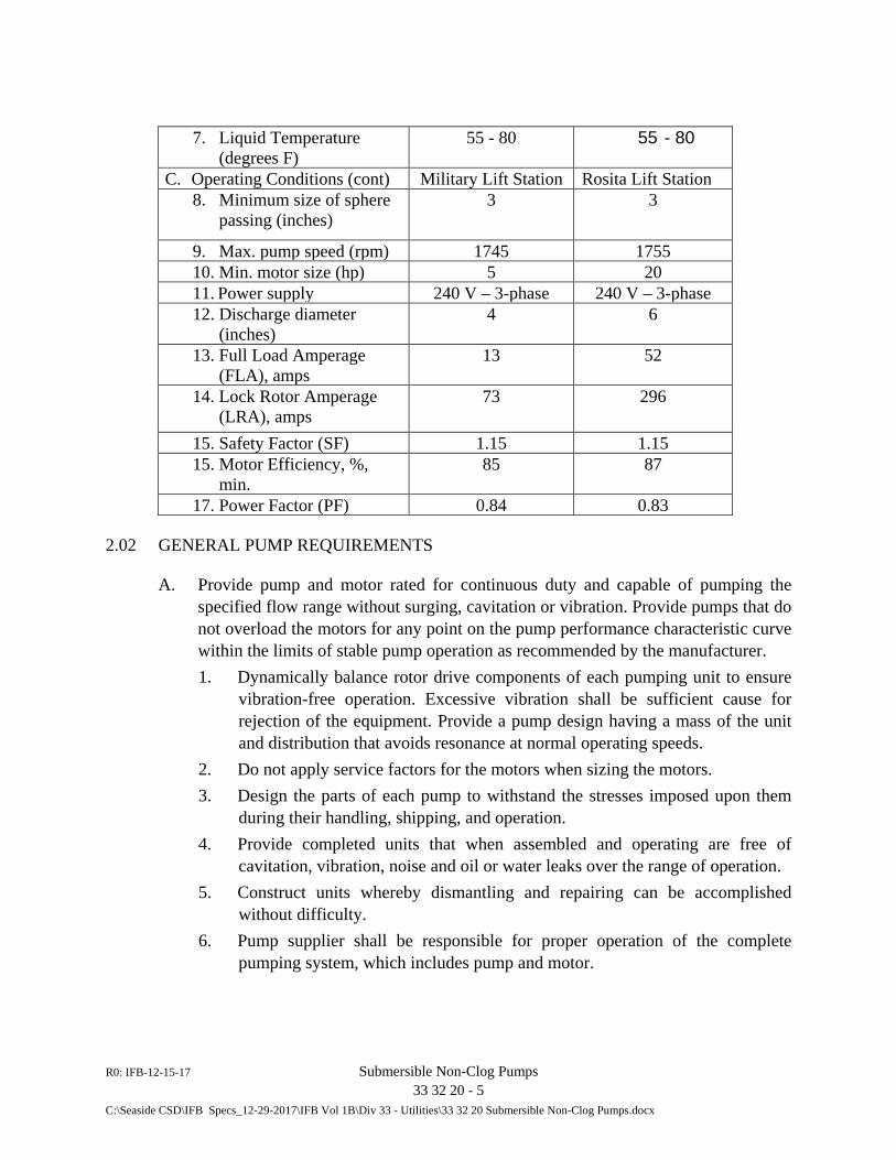
R0: IFB-12-15-17 Submersible Non-Clog Pumps 33 32 20 - 5 C:\Seaside CSD\IFB Specs_12-29-2017\IFB Vol 1B\Div 33 - Utilities\33 32 20 Submersible Non-Clog Pumps.docx
7. Liquid Temperature (degrees F)
55 - 80 55 - 80
C. Operating Conditions (cont) Military Lift Station Rosita Lift Station 8. Minimum size of sphere
passing (inches) 3 3
9. Max. pump speed (rpm) 1745 1755 10. Min. motor size (hp) 5 20 11. Power supply 240 V – 3-phase 240 V – 3-phase 12. Discharge diameter
(inches) 4 6
13. Full Load Amperage (FLA), amps
13 52
14. Lock Rotor Amperage (LRA), amps
73 296
15. Safety Factor (SF) 1.15 1.15 15. Motor Efficiency, %,
min. 85 87
17. Power Factor (PF) 0.84 0.83
2.02 GENERAL PUMP REQUIREMENTS
A. Provide pump and motor rated for continuous duty and capable of pumping the specified flow range without surging, cavitation or vibration. Provide pumps that do not overload the motors for any point on the pump performance characteristic curve within the limits of stable pump operation as recommended by the manufacturer. 1. Dynamically balance rotor drive components of each pumping unit to ensure
vibration-free operation. Excessive vibration shall be sufficient cause for rejection of the equipment. Provide a pump design having a mass of the unit and distribution that avoids resonance at normal operating speeds.
2. Do not apply service factors for the motors when sizing the motors. 3. Design the parts of each pump to withstand the stresses imposed upon them
during their handling, shipping, and operation. 4. Provide completed units that when assembled and operating are free of
cavitation, vibration, noise and oil or water leaks over the range of operation. 5. Construct units whereby dismantling and repairing can be accomplished
without difficulty. 6. Pump supplier shall be responsible for proper operation of the complete
pumping system, which includes pump and motor.
R0: IFB-12-15-17 Submersible Non-Clog Pumps 33 32 20 - 6 C:\Seaside CSD\IFB Specs_12-29-2017\IFB Vol 1B\Div 33 - Utilities\33 32 20 Submersible Non-Clog Pumps.docx
B. Furnish pumps, including cables and appurtenances, designed to withstand continuous submergence to a minimum depth of 65 feet, when running or off, without leakage.
C. Furnish pumps able to operate for short periods at zero static suction head without causing damage to any part of the unit.
2.03 PUMP CONSTRUCTION
A. Connections: Machined metal-to-metal quick disconnect type, for withdrawal of unit from above, without disconnecting the pipe. Furnish pump that when lowered i4nto place automatically connects and locks into the discharge pipe without touching the floor. 1. Provide pumps employing two (2) stainless steel, Type 316, guide bars (2-in.
diameter) to guide the pump ensuring match up to the discharge elbow. 2. Sealing of the discharge interface with a diaphragm, O-ring, or profile gasket
will not be acceptable.
B. Pump Design: Single stage, centrifugal type, close-coupled to sealed electric motor, for operation in dry or wet pit without external cooling.
C. Impeller: Two-port non-clog type dynamically balanced, with replaceable wear rings in casing, to handle solids and fibrous materials.
D. Pump Shaft: Same diameter along its length, without machined shoulders. Minimum surface finish: 12 micro-inches. Provide pump shaft of stainless steel per ASTM A479 S43100-T. Use of stainless steel sleeves shall not be considered equal and are not permitted.
E. Bearings: Permanently lubricated, heavy-duty axial and radial ball or roller bearings, top and bottom, double shielded with a minimum L-10 life of 50,000 hours, at continuous, maximum load and speed, supported by detailed calculations, submitted with the shop drawings if requested by District.
F. Seals: Provide each pump with a positively driven dual, tandem mechanical shaft seal system consisting of two seal sets, each having an independent spring. The lower primary seal, located between the pump and seal chamber, shall contain one stationary and one positively driven rotating corrosion and abrasion resistant tungsten-carbide ring. The upper secondary seal, located between the seal chamber and the seal inspection chamber shall be a leakage-free seal. The upper seal shall contain one stationary and one positively driven rotating corrosion and abrasion resistant tungsten-carbide seal ring. The rotating seal ring shall have small back-
R0: IFB-12-15-17 Submersible Non-Clog Pumps 33 32 20 - 7 C:\Seaside CSD\IFB Specs_12-29-2017\IFB Vol 1B\Div 33 - Utilities\33 32 20 Submersible Non-Clog Pumps.docx
swept grooves laser inscribed upon its face to act as a pump as it rotates, returning any fluid that should enter the dry motor chamber back into the lubricant chamber.
1. All seal rings shall be individual, solid sintered rings. Hold each seal interface in place by its own spring system. Do not have seals depend upon direction of rotation for sealing. Mounting of the lower seal on the impeller hub is not acceptable. Shaft seals without positively driven rotating members or conventional double mechanical seals containing either a common single or double spring acting between the upper and lower seal faces are not acceptable. Isolate the seal springs from the pumped media to prevent materials from packing around them, thereby limiting their performance.
2. Provide each pump with a lubricant chamber for the shaft sealing system. Furnish a lubricant chamber designed to prevent overfilling and providing capacity for lubricant expansion. Provide the seal lubricant chamber with one drain and one inspection plug that are accessible from the exterior of the motor unit. Do not employ a seal system that relies upon the pumped media for lubrication.
3. Cast in the area about the exterior of the lower mechanical seal in the cast iron housing an integral concentric spiral groove. Design this groove such that it protects the seals by causing abrasive particulate entering the seal cavity to be forced out away from the seal due to centrifugal action.
4. Provide a separate seal leakage chamber so that any leakage that may occur past the upper, secondary mechanical seal will be captured prior to entry into the motor stator housing. Such seal leakage shall not contaminate the motor lower bearing. Equip the leakage chamber with a float type switch that will signal if the chamber should reach 50% capacity.
G. Oil Chamber: Provide to supply oil for lubrication and cooling of the shaft seals. Use only FDA approved lubricant.
H. Support: Cast duckfoot bend or discharge elbow with machined face, anchored to wet well floor. Provide a support design that automatically and firmly connects the pumps to the discharge connection. Design(s) needing personnel to the wet well to accomplish the connection shall not be permitted. Accomplish sealing of the pumping unit to the discharge connection by a machined metal to metal watertight contact. Sealing of the discharge interface with a diaphragm, O-ring or profile gasket shall not be acceptable.
I. Cables: Furnish each pump with the necessary cables for power connection, moisture detection, and overload protection, sheathed, coded, and suitable for submersible pumps, and of 100-foot minimum length, unless otherwise approved by
R0: IFB-12-15-17 Submersible Non-Clog Pumps 33 32 20 - 8 C:\Seaside CSD\IFB Specs_12-29-2017\IFB Vol 1B\Div 33 - Utilities\33 32 20 Submersible Non-Clog Pumps.docx
the District, for direct connection to the existing terminal boxes. Connect cables to the pumps and test at the factory.
J. Lifting Devices: Furnish each pump with a pair of Type 316 stainless steel guide pipe type rails with brackets (quantity as recommended by pump manufacturer, but not less than 2) and stainless steel Flygt Grip-Eye system of sufficient operating length, or with a stainless steel guide cable system with hooks and tension device. Provide only Type 316 stainless steel for all miscellaneous metals used in the lifting devices.
K. Nameplates: Furnish pump unit with a Type 316 stainless steel plate permanently attached to the pump frame onto which the following information shall be impressed, engraved or embossed: manufacturer's name, pump size and model number, serial number, impeller diameter, capacity, head rating, speed, horsepower, required electrical service and service rating. Also provide a nameplate containing information unique to each item of equipment and device to identify its function as described in these specifications.
2.04 MATERIALS
A. Pump, volute, oil casing, sliding bracket, motor frame: cast iron, per ASTM A-48.
B. Impeller: Hard-IronTM (ASTM A-532 (Alloy III A), 25% chrome cast iron), dynamically balanced, semi-open, multi-vane, back swept, screw-shaped, non-clog design. 1. Brush or spray-on coating such as Belzona “Metal-glide” or flame spray
coating by means of HVOF shall not be an acceptable substitute for Hard-IronTM.
2. Provide impeller leading edges that are mechanically self-cleaned automatically upon each rotation as they pass across a spiral groove located on the volute suction.
3. Harden the leading edges of the impeller to Rc 60 and that are capable of handling solids, fibrous materials, heavy sludge and other matter normally found in wastewater.
4. Furnish an impeller inlet having a screw shape that provides an inducing effect for the handling of up to 5% sludge and rag-laden wastewater.
5. Make the impeller to volute clearance readily adjustable by the means of a single trim screw. Lock the impeller to the shaft, held by an impeller bolt and coated with alkyd resin primer.
R0: IFB-12-15-17 Submersible Non-Clog Pumps 33 32 20 - 9 C:\Seaside CSD\IFB Specs_12-29-2017\IFB Vol 1B\Div 33 - Utilities\33 32 20 Submersible Non-Clog Pumps.docx
C. Volute / Suction Cover: Provide a pump volute that is a single piece gray cast iron, ASTM A-48, Class 35B, non-concentric design with smooth passages of sufficient size to pass any solids that may enter the impeller. Furnish minimum inlet and discharge size as specified. 1. Provide the volute with a replaceable suction cover insert ring in which are
cast spiral-shaped, sharp-edged groove(s). 2. Furnish spiral groove(s) designed to provide trash release pathways and sharp
edge(s) across which each impeller vane leading edge shall cross during rotation so to remain unobstructed.
3. Provide the insert ring cast of Hard-IronTM (ASTM A-532 (Alloy III A) 25% chrome cast iron) and provide effective sealing between the multi-vane semi-open impeller and the volute housing. a. Brush or spray-on coating such as Belzona “Metal-glide” or flame spray
coating by means of HVOF shall not be an acceptable substitute for Hard-IronTM
D. Pump Shaft: Type 316, 420 or 431 stainless steel.
E. Exposed Bolts, Nuts and washers: Type 316 stainless steel.
F. Mechanical Seals: Independently operating double tungsten –carbide and carbon rings with stainless steel springs.
2.05 MOTORS
A. General: NEMA B design, induction type with a squirrel cage rotor, shell type design, housed in an air filled, watertight chamber. Insulate the stator windings with moisture resistant Class H insulation rated for 180°C (356°F). Insulate the stator by the trickle impregnation method using Class H monomer-free polyester resin resulting in a winding fill factor of at least 95%. Furnish the motor that is inverter duty rated in accordance with NEMA MG1, Part 31. Heat-shrink fit the stator into the cast iron stator housing. The use of multiple step dip and bake-type stator insulation process is not acceptable. The use of pins, bolts, screws or other fastening devices used to locate or hold the stator and that penetrate the stator housing are not acceptable. Design the motor for continuous duty while handling pumped media of up to 104°F. The motor shall be capable of no less than 30 evenly spaced starts per hour. Fabricate the rotor bars and short circuit rings of aluminum. Embed three (3) thermal switches in the stator end coils, one per phase winding, to monitor the stator temperature. These thermal switches shall be used in conjunction with and supplemental to external motor overload protection and shall be connected to the motor control panel.
R0: IFB-12-15-17 Submersible Non-Clog Pumps 33 32 20 - 10 C:\Seaside CSD\IFB Specs_12-29-2017\IFB Vol 1B\Div 33 - Utilities\33 32 20 Submersible Non-Clog Pumps.docx
1. Furnish the junction chamber sealed off from the stator housing and containing a terminal board for connection of power and pilot sensor cables using threaded compression type terminals. The use of wire nuts or crimp-type connectors is not acceptable. Provide the motor and the pump produced by the same manufacturer. Furnish motor that is inverter duty rated
2. Furnish motor with service factor (combined effect of voltage, frequency and specific gravity) equal to 1.15. Furnish motors having a voltage tolerance of +/- 10%. Furnish a motor designed for continuous operation in up to a 40°C ambient and having a NEMA Class B maximum operating temperature rise of 80°C. Upon request provide a motor performance chart exhibiting curves for motor torque, current, power factor, input/output kW and efficiency. Include in the chart data on motor starting and no-load characteristics.
3. Provide motor horsepower sufficient so that the pump is non-overloading throughout its entire performance curve, from shut-off to run-out. Provide motor and cable capable of continuous submergence underwater without loss of watertight integrity to a depth of 65 feet or greater.
B. Stator: Provide a motor stator mounted in an air-filled, watertight casing, and not fixed in place by externally–mounted screws which may cause leakage in the motor.
C. Rating: Motor non-overloading all throughout the pump curve, and having a combined service factor of 1.15 or greater and explosion-proof rated (Class 1, division 1, Group C&D).
E. Cooling System: Provide each pump with an adequately designed cooling system using a wastewater jacket or thermal radiator integrally cast with the stator casing. Employ cooling medium channels and ports that are non-clogging by virtue of their dimensions. 1. If a cooling jacket is required, provide each unit with an integral motor
cooling system. Provide a stainless steel motor cooling jacket that encircles the stator housing, providing for dissipation of motor heat regardless of the type of pump installation. Employ an impeller, integral to the cooling system and driven by the pump shaft, providing the necessary circulation of the cooling liquid through the jacket. Furnish a design having cooling liquid passing about the stator housing in the closed loop system in turbulent flow and thereby providing for superior heat transfer. Provide a cooling system having one fill port and one drain port integral to the cooling jacket. Furnish a cooling system providing for continuous pump operation in liquid or ambient temperatures of up to 104°F (40°C). Operational restrictions at temperatures below 104°F are not acceptable. Fans, blowers or auxiliary cooling systems that are mounted external to the pump motor are not acceptable.
R0: IFB-12-15-17 Submersible Non-Clog Pumps 33 32 20 - 11 C:\Seaside CSD\IFB Specs_12-29-2017\IFB Vol 1B\Div 33 - Utilities\33 32 20 Submersible Non-Clog Pumps.docx
2.06 MONITORING SYSTEM
A. Incorporate in each pump motor stator three (3) thermal switches, one per stator phase winding and that shall be connected in series, to monitor the temperature of the motor. Should the thermal switches open, the motor shall stop and activate an alarm. Furnish a float switch installed in the seal leakage chamber that will activate if leakage into the chamber reaches 50% chamber capacity, signaling the need to schedule an inspection. 1. Connect the thermal switches and float switch to a Mini CAS or equal control
and status monitoring unit. Furnish the Mini CAS, or equal, unit that is designed to be mounted in the pump control panel specified in this Section.
2.07 CONTROL EQUIPMENT
A. Provide a control panel for the pumps at the Military Lift Station and at the Rosita Lift Station as part of the instrumentation work for the respective facility (by other than the pump suppler) and in conformance with Specification Section 26 79 05, “Control Panels” and as shown on the Drawings.
2.08 SPARE PARTS
A. Provide the following for each of the two (2) lift stations: 1. One (1) set of wear rings. 2. One (1) set of O-rings. 3. One (1) set of complete inner and outer Mechanical Seals. 4. One (1) Bearing Set 5. Any special tools required for repair.
B. Deliver all spare parts packed in a water-resistant package(s).
2.09 PROTECTIVE COATINGS
A. Furnish all ferrous surfaces and passages of pumps, motors, and supports in contact with the process with the manufacturer’s standard epoxy coating. Field coat exterior of pump and motor unit per Technical Specifications Section 09 90 00, “Painting and Coating”.
2.10 MANUFACTURER
A. Products shall be Flygt N-pump series: 1. Military Lift Station: Model NP 3102 MT 3~463
R0: IFB-12-15-17 Submersible Non-Clog Pumps 33 32 20 - 12 C:\Seaside CSD\IFB Specs_12-29-2017\IFB Vol 1B\Div 33 - Utilities\33 32 20 Submersible Non-Clog Pumps.docx
2. Rosita Lift Station: Model NP 3153 HT 3~ 465
B. All or equal manufacturers proposed must meet the specifications described in this Section to be approved and considered equal to the specified manufacturer.
PART 3 - EXECUTION
3.01 INSTALLATION AND STARTUP
A. Examine the equipment delivered to the site to verify that it is in good condition and in conformance with the approved shop drawings.
B. Install equipment in conformance with the requirements of Section 11 05 00 and as shown on the Drawings. Complete all electrical and process piping connections to provide a pumping system that satisfactorily functions in conformance with the control description herein and shown in the Contractor Information Drawings for the respective lift stations. 1. Completion of the electrical and instrument connections in the field, including
installation of the respective Control and Status Monitoring Units (Mini CAS systems) specified above and furnished by the pump manufacturer/supplier into the unit control panel furnished as part of the instrumentation package, shall be included in the work for this Section. Coordination and completion of this work shall be the responsibility of the Contractor
C. Furnish the required oil and grease for initial operation in accordance with the manufacturer’s recommendations. Re-check at end of testing and refresh to manufacturer’s specified levels as required.
D. Set anchor bolts only after the discharge piping has been properly installed, to ensure exact fit with embedded piping components.
E. Wrap pump discharge pipes and guide rails with Trenton #2 wax tape or approved equal at area of contact with support brackets to isolate different metals and prevent galvanic corrosion.
3.02 FIELD TESTING AND TRAINING
A. Conduct field testing and furnish operating training as indicated in Part 1 of this Section.
R0: IFB-12-15-17 Submersible Non-Clog Pumps 33 32 20 - 13 C:\Seaside CSD\IFB Specs_12-29-2017\IFB Vol 1B\Div 33 - Utilities\33 32 20 Submersible Non-Clog Pumps.docx
B. Coordinate schedule and work for this Section with the electrical subcontractor to confirm satisfactory completion of the electrical and instrumentation work for the project before commencing the field testing.
C. At least 2 weeks prior to proposed start of field testing, submit for District’s approval a testing plan indicating, but not limited to, names of personnel attending the testing and their respective responsibility, source of water and discharge location, operating points and conditions to be monitored and recorded, and including record forms to be used for test data.
D. Submit to District the completed test forms signed by Contractor’s representative in charge of testing and District’s representative attending the field test.
END OF SECTION 33 32 20

R0: IFB-12-15-17 Submersible Non-Clog Pumps 33 32 20 - 14 C:\Seaside CSD\IFB Specs_12-29-2017\IFB Vol 1B\Div 33 - Utilities\33 32 20 Submersible Non-Clog Pumps.docx
This page intentionally blank.

DIVISION 34
TRANSPORTATION (NOT USED)


DIVISION 35
WATERWAY AND MARINE CONSTRUCTION (NOT USED)

DIVISION 40 PROCESS INTEGRATION

R0: IFB-12-15-17 Valves and Miscellaneous Piping Appurtenances 40 05 23 - 1 C:\Seaside CSD\IFB Specs_12-29-2017\IFB Vol 1B\Div 40 - Process Integration\40 05 23_Valves and Misc Piping Appurtenances.docx
SECTION 40 05 23
VALVES AND MISCELLANEOUS PIPING APPURTENANCES
PART 1 - GENERAL
1.01 SUMMARY
A. Requirements specified in the General and Supplementary Conditions of the Contract and Division 1 of the Technical Specifications form a part of this Section. Furnish all tools, equipment, materials, and supplies and perform all labor required to furnish, install and test all valves and piping (and pipeline) appurtenances as indicated on the Drawings, and specified herein.
B. Section Includes: 1. Submittals 2. Manual Operators 3. Plug Valves 4. Check Valves 5. Mechanical Couplings 6. Flexible Couplings 7. Valve Boxes 8. Protective Coatings 9. Field tests
C. Related Sections: 1. Section 05 50 00 – Metal Fabrications 2. Section 09 90 00 - Painting and Coating 3. Section 31 23 33 - Trenching, Backfilling, and Compaction 4. Section 33 05 20 – General Piping Requirements 5. Section 33 08 30 – Commissioning of Wastewater Utilities
1.02 REFERENCED CODES AND SPECIFICATIONS
A. American Water Works Association (AWWA)-Current Editions
1. C210 - Liquid Epoxy Coating Systems for the Interior and Exterior of Steel Water Pipelines
2. C508 – Swing-Check Valves for Waterworks Service, 2-In. Through 24-In. (50-mm through 600-mm) NPS
R0: IFB-12-15-17 Valves and Miscellaneous Piping Appurtenances 40 05 23 - 2 C:\Seaside CSD\IFB Specs_12-29-2017\IFB Vol 1B\Div 40 - Process Integration\40 05 23_Valves and Misc Piping Appurtenances.docx
3. C509 - Resilient Seated Gate Valves for Water Supply Service 4. C517 – Resilient Seated Cast Iron Eccentric Plug Valves 5. C550 - Protective Epoxy Interior Coatings for Valves and Hydrants 6. C800 - Underground Service Line Valves and Fittings
B. National Sanitation Foundation (NSF): 1. Standard No. 61 - Drinking Water System Components, Health Effects-
Current Edition
1.03 SUBMITTALS
A. Comply with the general requirements and procedures specified in Article 12 of the General Conditions and Sections 01 30 00 and 11 05 00 of the Technical Specifications in submitting the information described in this article.
B. Shop Drawings: Submit shop drawings for valves and miscellaneous piping appurtenances specified herein and required for the Work for review and approval prior to shipment to the project. Provide complete shop drawings with bill-of-materials showing kind and class of materials, and catalog and engineering data in sufficient detail to demonstrate compliance with the specified requirements. Include at least the following information: 1. Outline and principal dimensions of the assembled valve, including attached
operator where applicable, and other equipment specified in this Section. 2. Material specifications for all components used in the valve or other specified
equipment to be furnished. Where applicable, note ANSI, ASTM, or other standard specification numbers.
3. Coating material to be used. 4. Weight of valve, regulator or other furnished equipment.
C. Valves: 1. General: For each type and model of valve provide:
a. Operator arrangement and position. b. Assembly instructions and spare parts list. c. Preventative/corrective maintenance instructions. d. Certificate of seat compatibility with entailed fluid exposure.
2. Tests: Perform shop and laboratory tests on plug valves as follows: a. Material Tests: Manufacturer shall perform physical and chemical
properties tests on all components to be used in manufacturing plug
R0: IFB-12-15-17 Valves and Miscellaneous Piping Appurtenances 40 05 23 - 3 C:\Seaside CSD\IFB Specs_12-29-2017\IFB Vol 1B\Div 40 - Process Integration\40 05 23_Valves and Misc Piping Appurtenances.docx
valves similar to that described in Section 5 of AWWA Standard C504. Submit records of such tests to the District upon request.
b. Gear Operator Tests: Manufacturer shall test each model or gear operator and establish torque-rating curves. Submit test data to the District for review and approval.
c. Valve Performance Tests: To demonstrate the adequacy of the valve, perform a proof of design test as described in AWWA Standard C504-80, Section 5, Paragraph 5.5, on the prototype valve for each size of valve to be furnished. Upon successful completion of this test, test the same prototype in accordance with Paragraphs 5.3 and 5.4 of the aforementioned standard. Conduct tests by an independent laboratory. Furnish certified copies of reports pertaining to these tests.
3. Plug Valves: Submit for review and approval before manufacturing commences, details and material specifications for all parts used in the construction of the plug valves to be furnished. Provide drawings in sufficient detail to enable to District to check compliance with these specifications, and include at least the following information: a. Outline the principal dimensions of the assembled valve with its
operator attached. b. Materials of all valve and operator components. Where applicable,
ANSI, ASTM, or other standard specification numbers shall be noted. c. Details of the following:
1) Plug. 2) Body seats, including provisions for clamping and adjusting if
provided. 3) Attachment of plug to shaft. 4) Plug details at section on shaft centerline and attachment of plug to
shaft. 5) Main shaft bearing length and diameter.
d. Cv values for each size valve from zero to 90 degrees open in 10 degree increments.
e. Coating material to be used. f. Operator arrangement and position.
4. Physical Inspection: Submit an affidavit of compliance, furnished by both the manufacturer and product representative, stating that the respective valves furnished for installation in this Work comply with these specifications. The District, at its option, may select at random from valves furnished, a valve or valves to be disassembled for inspection.
R0: IFB-12-15-17 Valves and Miscellaneous Piping Appurtenances 40 05 23 - 4 C:\Seaside CSD\IFB Specs_12-29-2017\IFB Vol 1B\Div 40 - Process Integration\40 05 23_Valves and Misc Piping Appurtenances.docx
D. Markings: Comply with the requirements of Section 6.1 of AWWA C504. In addition stamp the country of origin of all castings and an identifying serial number on a corrosion resistant plate and attach the plate to the valve body.
1. Temporary Number Plates: Factory tag or mark each valve to identify the valve by number or service indicated in the Drawings.
E. Erection Drawings: Submit erection drawings, including the procedures to be used in setting, supporting, and/or anchoring the valves, the fitting of line pipe to the valves for proper coupling, and for adjusting and testing all valve assemblies.
F. Instruction Manuals: Prepare and submit operation and maintenance manuals in accordance with Sections 01 33 00 and 11 05 00 for all furnished valves, regulators and miscellaneous mechanical components.
1.04 QUALITY ASSURANCE
A. Shop and Laboratory Tests: Perform shop and laboratory tests on valves and appurtenances as follows: 1. Material Tests: Manufacturer shall perform physical and chemical properties
tests on all components to be used in manufacturing plug valves corresponding to that described in Section 4 of AWWA Standard C517. For gate valves, comply with AWWA Standard C509. Submit records of such tests to the District upon request.
2. Gear Operator Tests: Manufacturer shall test each model of gear operator and establish torque-rating curves. Submit test data to the District for review and acceptance.
3. Valve Performance Test: a. To demonstrate the adequacy of the plug valves, the Manufacturer shall
perform a proof of design test comparable to that described in AWWA Standard C517, Section 5, Paragraph 5.2.2, on a prototype valve for each size of valve to be furnished. Upon successful completion of this test, subject the same prototype to a shell test and a hydrostatic seat test in accordance with Section 5.2 of the aforementioned AWWA standard.
b. For gate valves, the proof of design test shall be performed on prototypes on each size and class of the manufacturer’s design proposed for this work in accordance with AWWA Standard C509, Section 5.1.
c. Conduct tests using an independent laboratory. Furnish certified copies of reports including results pertaining to these tests.
R0: IFB-12-15-17 Valves and Miscellaneous Piping Appurtenances 40 05 23 - 5 C:\Seaside CSD\IFB Specs_12-29-2017\IFB Vol 1B\Div 40 - Process Integration\40 05 23_Valves and Misc Piping Appurtenances.docx
1.05 WARRANTY
A. Submit a warranty from the valve manufacturer stating the valve to be free of defects in material and workmanship for a period of three years from the data of acceptance of the valve installation.
PART 2 – PRODUCTS
2.01 PRESSURE RATING
A. Furnish process valves rated for a working pressure equal to or greater than the pressure rating of the connecting piping, unless specifically shown otherwise on the Drawings or specified in other Sections of these Specifications. Where valves may be affected by a minimum working pressure, the pressure level will be indicated on the Drawings or in the requirements for the respective valve described in this Section.
2.02 PROTECTIVE COATINGS
A. General: Provide protective coatings on all interior nonworking ferrous surfaces other than stainless steel and all exterior ferrous surfaces other than stainless steel on valves and pipeline appurtenances.
B. Interior Surfaces Coating: Factory applied epoxy coating, 4 to 8 mil thickness, complying with AWWA C505.
C. Exterior Surfaces Coating: Apply shop prime coating conforming to requirements and products specified in Section 09 90 00, except as otherwise noted herein. To ensure compatibility for the applicable service conditions, use same products and manufacturer as those selected and approved for deferred field applied systems. Provide evidence in material or equipment submittals that this coordination has occurred between Contractor and valve or appurtenance manufacturer. Refer to Part 3 of this Section for requirements pertaining to field applied coating systems.
1. For valves and ferrous metal components intended for buried service, shop coat materials in accordance with the following or equal systems: a. Kop-Coat: 893RCP epoxy primer (SP-6 surface preparations), 6 mils
DFT; Bitumastic No. 300-M finish, 16 mils min. DFT b. Tnemec: Series 69 primer (SP-6 surface preparation), 6 mils min.
DFT; Series 46H413 finish, 16 mils min. DFT."
R0: IFB-12-15-17 Valves and Miscellaneous Piping Appurtenances 40 05 23 - 6 C:\Seaside CSD\IFB Specs_12-29-2017\IFB Vol 1B\Div 40 - Process Integration\40 05 23_Valves and Misc Piping Appurtenances.docx
2.03 MANUAL OPERATORS
A. General: Provide operators sized in accordance with the maximum expected torque per valve manufacturer’s recommendations. Responsibility for selection of the proper operator and consequent valve operation resides with the valve supplier. Furnish, install and adjust valve actuator under the supervision of the valve manufacturer or in accordance with his written instructions. Furnish actuator-mounting arrangements that facilitate operation and maintenance as determined by the valve manufacturer in accordance with the layout shown on the Drawings or directed by the District.
B. Furnish manual operators, except where otherwise shown or specified, of the worm-gear type, by Limitorque HBC, E-I-M Type MG, DeZurik, or equal. Direct mounted units, except those furnished with extensions or floor stands, shall be assembled and tested by the manufacturer per the respective AWWA valve standard referenced herein. The axis of the worm shaft shall remain fixed during operation. Provide handwheel, except where an extension stem and floor stand, valve box, or tee wrench and street box are required. Furnish extension stems and accessories sized per valve manufacturer’s recommendations.
1. Plug Valves: Plug valves 6-inch and smaller in size shall be lever operated and plug valves 8-inch and larger in size shall be provided with totally enclosed oil, water and dust tight handwheel operated gear actuator, unless otherwise shown or specified. Gear actuator shall be mounted on an extension neck to allow for adjustment of valve packing with removal of actuator.
C. Wrench Nut Operation: Provide wrench nut complying with Section 3.16 of AWWA C500 or shaft key, as applicable, in lieu of handwheel where required for connection to extension stem or as indicated on the Drawings. Provide nut constructed of cast iron. No submerged or buried operator shall require maintenance following installation. Furnish suitable gaskets, O-rings, and other features to ensure permanent watertightness.
D. Extension Stems: 1. Provide extension stems for buried valves where the valve actuator is 4 feet or
deeper below finished grade. The extension stem shall extend to within 6 inches of the ground surface, and shall be centered in the valve box using spacers.
2. Provide extension stems of schedule 80 black iron pipes, of diameter no smaller than the stem of the valve actuator shaft.
R0: IFB-12-15-17 Valves and Miscellaneous Piping Appurtenances 40 05 23 - 7 C:\Seaside CSD\IFB Specs_12-29-2017\IFB Vol 1B\Div 40 - Process Integration\40 05 23_Valves and Misc Piping Appurtenances.docx
2.04 VALVE BOXES
A. General: Provide either cast-iron or precast concrete valve boxes; except, that where indicated for cast-iron construction, no option is permitted.
B. Design: Provide valve boxes designed to be installed over each direct buried valve. Provide boxes of extension type with slide-type adjustment and with flared base. 1. Covers: Cast-iron and having cast-iron ring. 2. Covers on valve boxes: Drilled to accept expansion rivets and having a brass
nameplate affixed thereto identifying the process piping controlled by said valve and the valve number shown on the P and ID Drawings or directed by District. Affix each cover by stainless steel chain to the respective box.
3. The box shall be of such length as will be adapted, without full extension, to the depth of the cover required over the pipe at the valve location. Boxes of improper length will be rejected.
4. Boxes: Suitable for the valve size and depth of trench as recommended by the manufacturer.
C. Cast Iron Valve Boxes: Provide units having minimum wall thickness of 3/16-inch and as manufactured by Alhambra Foundry, Clow, Mueller Co., Kennedy, or equal.
D. Precast Concrete Valve Boxes: Brooks Products, Inc., Traffic Box, Quick Set, or equal. Provide with features equivalent to that specified for cast-iron valve boxes. Provide boxes and covers adequate for carrying HS-20 traffic loading.
2.05 BRONZE VALVES
A. Furnish valves Class 125 psi SWP and 150 psi SWP, which comply with ASTM B62. All stems shall be silicon bronze 80,000 psi tensile strength.
2.06 IRON BODY VALVES
A. Except as otherwise specified, provide iron body valves which comply with ASTM A126 Class B.
2.07 BALL VALVES
A. General. Furnish ball valves that are the product of an experienced manufacturer regularly engaged in the production of the type of valve specified herein for use in similar installations and applications. Furnish and install valves compatible with the materials and layout provided and conforming to the Drawings unless otherwise
R0: IFB-12-15-17 Valves and Miscellaneous Piping Appurtenances 40 05 23 - 8 C:\Seaside CSD\IFB Specs_12-29-2017\IFB Vol 1B\Div 40 - Process Integration\40 05 23_Valves and Misc Piping Appurtenances.docx
approved by the Owner. Equip valves with a handle operator and provide screwed end connections unless otherwise specified or shown on the Drawings.
B. Metal Ball Valves: 1. General Service: Furnish valves having Teflon body seal and TFE seat,
designed to seal in both directions. Furnish bronze two-piece bodies on valves 2 inches and smaller. For this project, general service includes all water services, including air valves. Provide metal ball valves manufactured by Jamesbury, Worcestor, Walworth, or approved equal.
2.08 ECCENTRIC PLUG VALVES
A. Furnish full (100%) port AWWA C517 valves of the non-lubricated eccentric type with resilient faced plugs. Drill flanged valves to ANSI/ASME B16.1, Class 125. Furnish NPT standard screwed ends. Construct eccentric plug valve bodies of A126, Class B cast iron.
B. Furnish bodies of valves 3-inch and larger with an overlay seat of not less than 90 percent pure nickel. The overlay seat shall be weld-in nickel; sprayed, plated, nickel welded rings or seats screwed into the body are not acceptable. Furnish plugs of cast iron or carbon steel per valve body material, of one piece construction. Construct resilient plug facing of neoprene or ethylene propylene ter-polymer elastomer. Furnish valves with replaceable, sleeve-type metal bearings conforming to AWWA C504, Section 3.6 and AWWA C507, Section 8.
C. Furnish bearings sintered, oil-impregnated and permanently lubricated, of ASTM A743 Type 316 SS Grade CFI-8M or AISI Type 317L SS.
D. Provide valve shaft seals of ASTM A743 Type 316 SS Grade CFI-8M or AISI Type 317L SS. Furnish valve shaft seals of multiple V-ring, externally adjustable, and repackable without removal of bonnet. O-ring and U-ring type seals are not acceptable.
E. All exposed nuts, bolts, springs, washers, etc., shall be 316 stainless steel for both buried and exposed valves.
F. Manufacturer: DeZurik Figure PEF, or approved equal. Contractor has the option, for buried valves, of using restrained mechanical joint ends for added flexibility of the pipeline.
R0: IFB-12-15-17 Valves and Miscellaneous Piping Appurtenances 40 05 23 - 9 C:\Seaside CSD\IFB Specs_12-29-2017\IFB Vol 1B\Div 40 - Process Integration\40 05 23_Valves and Misc Piping Appurtenances.docx
2.09 GATE VALVES
A. Gate Valves 2-½ Inches and Smaller: Provide non-rising stem, solid wedge, threaded, bronze gate valves, Class 125, as manufactured by Kennedy, Crane, or equal.
B. Gate Valves 3 inches through 12 inches: Unless otherwise shown on the Drawings, provide flanged end, iron body, non-rising bronze stem, resilient seated type valves conforming to the requirements of AWWA C509, as manufactured by Clow, American-Darling (Waterous), or Kennedy, suitable for the pressure service indicated below and complying with the exceptions as modified below: 1. Valves to open left. 2. On valves with mechanical joint ends, furnish all necessary glands, followers
and bolts and nuts required for a complete installation. 3. Provide bronze valve stems interchangeable with stems of double disc valves
of the same size, direction of opening and manufacture. 4. Secure the seat to the disc with self-locking stainless steel screws. Design seat
in a way that it cannot be improperly installed. Resilient wedge seats are acceptable.
5. Design valve with a full-faced composition gasket or O-ring between the machined body and mating bonnet flanges.
6. Pressure service (operating) shall be 150 psi for all lines. 7. Valves to be furnished for tapping service shall be provided with the
appropriate clearance for the diameter of the tapping machine cutter as recommended by the valve manufacturer and shall be provided with flange ends conforming to Section 4.5.4 of AWWA C509.
2.10 SWING CHECK VALVES
A. Furnish AWWA C508 swing check valves with ANSI Class 125 flanges.
1. Body: Cast iron. 2. Shaft: Single and continuous, of stainless steel extending both sides of
the body with a lever and weight, using a side mounted air cushion cylinder.
3. Manufacturer: APCO Series 6000, Milliken/Pratt/Mueller Model 8501, or equal.
2.11 MECHANICAL COUPLINGS
A. General: Furnish flexible (sleeve) couplings of the full sleeve type, split sleeve type, or flanged adaptor type, as shown on the Drawings, specified herein, or as
R0: IFB-12-15-17 Valves and Miscellaneous Piping Appurtenances 40 05 23 - 10 C:\Seaside CSD\IFB Specs_12-29-2017\IFB Vol 1B\Div 40 - Process Integration\40 05 23_Valves and Misc Piping Appurtenances.docx
otherwise permitted by the District. Design couplings to provide the requisite pipe flexibility without jeopardizing pipe joint integrity due to hydraulic thrust. Furnish couplings having the same pressure-rating as the pipe. Furnish couplings with all metal bearing surfaces and fusion bonded coatings. Provide 316 stainless steel (SS) bolts and nuts. Restrain flexible couplings unless the District has given his approval to omit this feature for specific cases.
B. Full Sleeve Type Couplings: Furnish properly gasket and of a diameter to fit the pipe. For underground installation, furnish an epoxy lined and coated sleeve with corrosion resistant bolts as specified in Part 2.02 of Specification Section 33 05 20, “General Piping Requirements”. 1. For couplings for joining steel and iron pipe sizes, provide a steel middle ring,
2 steel followers, 2 gaskets and the necessary steel bolts and nuts to compress the gaskets. Provide Dresser Style 38, Smith-Blair Type 411, or equal. Furnish an epoxy lined and coated sleeve for couplings to be installed underground.
C. Restrained Flanged Coupling Adaptor (FCAs): Furnish the sleeve type. The couplings shall contain anchor studs of strength adequate to hold the pipe together under a pull equal to the longitudinal strength of the pipe at a tensile stress of 20,000 psi. Furnish couplings to be installed underground which corrosion resistant bolts as specified in Part 2.02 of Specification Section 33 05 20, “General Piping Requirements”.
1. Provide adaptor for joining steel and cast iron pipe consisting of a steel middle ring, steel followers, gaskets, and steel bolts and nuts to compress the gaskets. Furnish Smith-Blair No. 913, Dresser Style 128, or equal. Furnish couplings to be installed underground with an epoxy lined and coated sleeve.
2. Provide adaptors for joining pipe to flanged valves and fittings of the sleeve type, consisting of cast iron body and follower and steel bolts and nuts to compress the gaskets. Furnish Smith-Blair No. 912, Dresser Style 127, or equal.
3. For ductile iron and PVC pressure pipe, provide flanged adapter fabricated of ductile iron conforming to ASTM A536 and having a flange bolt circle compatible with ANSI/AWWA C115/A21.15. Provide restraint for the flange adapter consisting of multiple, individually actuated gripping wedges to maximize restraint capability. Use torque-limiting actuating screws to ensure proper set of the gripping wedges. Provide flange adapters capable of minimum 3 degrees of joint deflection during assembly. Provide flange adapters having a pressure rating of 350 psi when used on ductile iron pipe and pressure rating equal to the pipe when used on C-900 / C-905 or IPS PVC pipe.
R0: IFB-12-15-17 Valves and Miscellaneous Piping Appurtenances 40 05 23 - 11 C:\Seaside CSD\IFB Specs_12-29-2017\IFB Vol 1B\Div 40 - Process Integration\40 05 23_Valves and Misc Piping Appurtenances.docx
a. Manufacturer: EBAA Iron, Inc. Series 2100 Megaflange or equal.
D. Molded Expansion Joint: Where shown on the Drawings, provide molded wide arch spherical type as shown by Figure 2J in the Rubber Expansion Joint Division’s Technical Handbook - 5th Edition, with integral flanges in accordance with the manufacturer’s recommendations. Design expansion joints to be suitable for 150 psi maximum operating pressure. Tap flanges to ANSI standards for indicated pressure rating. Fabricate the carcass or body of synthetic elastomer chlorobutyl, for the tube and cover, and synthetic fabric reinforcement suitable for the intended service, unless otherwise noted herein. Furnish retaining rings and control unit assemblies with all non-metallic expansion joints, the size and number of control rods conforming with Appendix B of the Rubber Expansion Joint Division’s Technical Handbook - 5th Edition for the operating pressure noted herein. Design molded expansion joints to provide the following minimum movements:
Elongation 0.5 inch
Compression 0.75 inch
Lateral 0.5 inch
Angular 4 degrees
E. Molded Expansion Joint/Reducer: Comply with the requirements specified above for molded expansion joints except furnish with a taper to transition from one pipe size to another. Provide concentric or eccentric taper as shown on the Drawings.
F. Grooved End Pipe Couplings: Where shown on the Drawings or permitted by the District, furnish grooved end pipe couplings as manufactured by the Victaulic Co., Gustin-Bacon, or equal. Design couplings to engage and lock the grooved or shouldered pipe ends in a manner allowing some degree of contraction, expansion, and angular deflection. Manufacture coupling housing of ductile iron or malleable iron, consisting of two or more segments held securely together by at least two steel bolts. Design sealing gasket in a manner that internal pressure in the pipe increases the tightness of the seal and use materials suitable for the intended service. Provide coupling conforming to AWWA C-606, having a rated working pressure not less than the pressure rating of the pipe.
G. Transition Type Couplings: Provide the full sleeve type, consisting of a steel middle ring, 2 ductile iron followers, 2 gaskets and the necessary 316 SS bolts and nuts to compress the gaskets. Furnish Smith-Blair Type 413, Dresser Type 162, or equal. Furnish couplings to be installed underground with corrosion resistant bolts conforming to ANSI/AWWA C219.
R0: IFB-12-15-17 Valves and Miscellaneous Piping Appurtenances 40 05 23 - 12 C:\Seaside CSD\IFB Specs_12-29-2017\IFB Vol 1B\Div 40 - Process Integration\40 05 23_Valves and Misc Piping Appurtenances.docx
2.12 SERVICE SADDLES
A. Nylon coated ductile iron as manufactured by Romac or approved equal. 1. For 1-inch diameter and smaller taps, provide 316 stainless steel strap saddles
for mains 4-inch through 12-inch in diameter and double strap for mains larger than 12-inches in diameter.
2. Provide double strap saddles for all taps larger than 1-inch diameter.
2.13 VALVE TAGS
A. Provide all exposed valves (includes those in vaults) with a valve tag heavily stamped or engraves to duplicate the valve symbol shown on the P&ID Drawings, including hexagons and/or circles with notations as applicable.
B. Fabricate tags of minimum 3/32-inch thick brass or minimum 18-gauge Type 304 or better stainless steel and a minimum of 1-¼-inch wide, with length as required for engraving.
C. Secure valve tags to valves with minimum 18-gauge Type 304 stainless steel wire or stainless steel chain through a hole in the tag.
2.14 LUBRICANT FOR STAINLESS STEEL BOLTS AND NUTS
A. Provide lubricant by TRX-Synlube by Ramco, Anti-Sieze by Ramco, Husk-It Husky Lube O’Seal, or equal.
PART 3 - EXECUTION
3.01 GENERAL
A. Install valves, and pipeline appurtenances in accordance with the manufacturers recommendations, the requirements specified in Section 33 05 20, “General Piping Requirements”, and herein, and as shown on the Drawings.
B. Earthwork. Conform to excavation trenching and backfilling requirements specified in Division 31.
C. Concrete Work. Conform to the requirements of Division 3, as applicable.
D. Caulking and Sealing of Pipe Penetrations. Conform to the requirements of Section 07 92 00, as applicable.
R0: IFB-12-15-17 Valves and Miscellaneous Piping Appurtenances 40 05 23 - 13 C:\Seaside CSD\IFB Specs_12-29-2017\IFB Vol 1B\Div 40 - Process Integration\40 05 23_Valves and Misc Piping Appurtenances.docx
E. Couplings and Expansion Joints. Coordinate with and conform to the requirements of Section 33 05 20 and respective Sections for pipe materials used.
F. Stainless Steel Nuts and Bolts. Prior to assembly, coat threaded portions of stainless steel nuts and bolts with the specified
3.02 VALVES
A. General Requirements: Set valves and valve boxes in true alignment and grade in accordance with the procedures submitted with the shop and erection drawings, and the valves mounted as shown. Perform adjustments and operating settings of valves and appurtenances in accordance with procedures and detailed instructions furnished with the erection drawings.
B. Buried Valves: Firmly support in place by the foundations to preclude strain on the pipe connections. Check valve boxes for centering plumb over the wrench nut to ensure that the box cover is flush with the finish grade. Carefully tamp specified backfill around each valve box to a distance of 4 feet on all sides of the box, or to undisturbed trench face if less than 4 feet. Clean valve interiors of all foreign matter before installation. Inspect valves in opened and closed positions before installation to ensure that all parts are in working condition.
C. Aboveground Valves: Rigidly hold in place using supports and hangers as shown on the Drawings and as specified. Obtain Owner’s approval of the stem orientation of valves in elevated piping for accessibility, but in no case install the valve with the stem in the downward direction. Provide saddle type valve supports for all valves in vaults. Design supports of rugged construction providing at least 120 degrees under-support for the valve body, constructed of steel as specified in Division 5, and anchored to the foundations using stainless steel anchor bolts as shown on the Drawings.
3.03 INSTALLATION OF PIPING APPURTENANCES
A. General: Conduct installation of valves and piping appurtenances in conformance with Sections 33 05 20 and 11 05 00 and the following requirements.
B. Pipe Sleeves: Provide all piping which will pass through walls, slabs, footings, or beams with specified pipe sleeves with annular space sealed or with wall castings. Provide the wall sleeves and castings for insertion in the concrete work covered in Specification Section 03 30 00, “Cast-in-Place Concrete”, and verify their correct setting prior to concrete placement. Furnish Synko-flex sleeve sealant. No pipe joint may be allowed to occur in the sleeve. Install such that the seal on both ends of the
R0: IFB-12-15-17 Valves and Miscellaneous Piping Appurtenances 40 05 23 - 14 C:\Seaside CSD\IFB Specs_12-29-2017\IFB Vol 1B\Div 40 - Process Integration\40 05 23_Valves and Misc Piping Appurtenances.docx
sleeve is flush with the concrete surfaces on completion of work and drying of sealant. Caulk and seal wall sleeves in conformance with the following requirements: 1. Preparation for Sealing: Ensure that the annular space between the pipe and
sleeve is cleaned of all loose particles and contamination, and dry, prior to sealing. Apply tape or other recommended protection on the structure surfaces to preclude contamination by the sealant, and remove any contamination which occurs immediately, followed by a thorough washing of the surfaces with solvent. Discard prepared compound not used during the application time limits designated by the manufacturer of such compound.
2. Application of Compound Sealant: Perform the sealing after any required primer has been applied and backup material placed. Perform the work in accordance with the submitted erection drawing detail and procedure, and solidly fill all grooves. Make the application in clean, straight lines free of wrinkles, tool as required and finish with a convex surface just sufficient to provide the required flush surface upon drying. Do not perform work when the air temperature is below 50 degrees F.
F. Mechanical Coupling Type Joints: Make joints of the sleeve, grooved mechanical, split sleeve, and flanged coupling adapter types in accordance with the printed instructions of the manufacturer. Finish the pipe ends to receive the couplings to the outside diameter and surface finish required by the coupling manufacturer. Prior to assembly, apply protective coating to all surfaces which will be inaccessible after installation.
G. Joint Restraint: Provide joint restraint on all pressure pipelines 4 inch and larger with bell and spigot or mechanical joints, at all fittings and dead-ends, at bends greater than 10 degrees, and upstream and downstream distance as shown on the Drawings.
3.04 TESTS
A. Shop and Laboratory Tests: Perform shop and laboratory tests on valves and appurtenances as specified in Part 1 of this Section.
B. Warrantee: Guarantee plug valves for a period of 3 years from date of project acceptance by the Owner by extending the valve manufacturer’s warranty period.
C. Field Tests: Test all valves and appurtenances for proper operating adjustments and settings and for freedom from vibration, binding, scraping, and other defects. Verify the adequacy of all pipe hangers and supports and valve supports to meet specified
R0: IFB-12-15-17 Valves and Miscellaneous Piping Appurtenances 40 05 23 - 15 C:\Seaside CSD\IFB Specs_12-29-2017\IFB Vol 1B\Div 40 - Process Integration\40 05 23_Valves and Misc Piping Appurtenances.docx
requirements by visual inspection that all valves and appurtenances maintain proper position and alignment. Correct defects found until approved.
D. Testing of Appurtenances: 1. Pressure test valves and other appurtenances concurrently with the piping
system to which they are attached. Refer to Section 33 08 30. Coordinate with Owner for scheduling of validation testing.
3.04 CLEANING
A. Flush appurtenances clean of all foreign matter together with the piping as specified in other sections.
END OF SECTION 40 05 23

R0: IFB-12-15-17 Valves and Miscellaneous Piping Appurtenances 40 05 23 - 16 C:\Seaside CSD\IFB Specs_12-29-2017\IFB Vol 1B\Div 40 - Process Integration\40 05 23_Valves and Misc Piping Appurtenances.docx
This page intentionally blank.

DIVISION 41
MATERIAL PROCESSING AND HANDLING (NOT USED)


DIVISION 42
PROCESS HEATING, COOLING AND DRYING (NOT USED)

DIVISION 43
PROCESS GAS AND LIQUID HANDLING, PURIFICATION AND STORAGE EQUIPMENT
(NOT USED)

DIVISION 44
POLLUTION AND WASTE CONTROL EQUIPMENT (NOT USED)

DIVISION 45
INDUSTRY SPECIFIC MANUFACTURING EQUIPMENT (NOT USED)


DIVISION 46
WATER AND WASTEWATER EQUIPMENT (NOT USED)


DIVISION 48
ELECTRICAL POWER GENERATION
