moving object localization using sound-based positioning system with doppler shift compensation
TRANSCRIPT

Robotics 2013, 2, 36-53; doi:10.3390/robotics2020036
robotics ISSN 2218-6581
www.mdpi.com/journal/robotics
Article
Moving Object Localization Using Sound-Based Positioning
System with Doppler Shift Compensation
Slamet Widodo 1,*, Tomoo Shiigi
1, Naoki Hayashi
1, Hideo Kikuchi
2, Keigo Yanagida
2,
Yoshiaki Nakatsuchi 3, Yuichi Ogawa
1 and Naoshi Kondo
1
1 Graduate School of Agriculture, Kyoto University, Kitashirakawa, Oiwake-cho, Sakyo-ku,
Kyoto 606-8502, Japan; E-Mails: [email protected] (T.S.);
[email protected] (N.H.); [email protected] (Y.O.);
[email protected] (N.K.) 2 System Watt Co., Ltd. 4-1-38, Isobedori, Chuo-ku, Kobe 651-0084, Japan;
E-Mail: [email protected] (H.K.); [email protected] (K.Y.) 3 The New Industry Research Organization (NIRO), 1-5-2, Minatojima-minamimachi, Chuo-ku,
Kobe 650-0047, Japan; E-Mail: [email protected]
* Author to whom correspondence should be addressed; E-Mail: [email protected].
Received: 24 February 2013; in revised form: 26 March 2013 / Accepted: 27 March 2013 /
Published: 10 April 2013
Abstract: Sound-based positioning systems are a potential alternative low-cost navigation
system. Recently, we developed such an audible sound-based positioning system, based on
a spread spectrum approach. It was shown to accurately localize a stationary object. Here,
we extend this localization to a moving object by compensating for the Doppler shift
associated with the object movement. Numerical simulations and experiments indicate that
by compensating for the Doppler shift, the system can accurately determine the position of
an object moving along a non-linear path. When the object moved in a circular path with
an angular velocity of 0 to 1.3 rad/s, it could be localized to within 25 mm of the actual
position. Experiments also showed the proposed system has a high noise tolerance of up to
−25 dB signal-to-noise ratio (SNR) without compromising accuracy.
Keywords: Doppler shift; moving object localization; spread spectrum; agricultural robot
OPEN ACCESS

Robotics 2013, 2 37
1. Introduction
Automated robotic systems in agriculture have been studied extensively in the last few decades [1,2].
It has been applied to various agricultural operations, such as weeding [3,4], plant monitoring [5],
application of fertilizer and chemicals [6] and harvesting [7–9]. However, to date, there have been
limited commercial applications of these agricultural robots; mainly due to their high cost. Among the
components that make up an automated agricultural robot, the navigation system is a major contributor
to the total development cost. A reduction in the price of the navigation system, combined with
optimum operating time, will enable autonomous agricultural vehicles to become economically
feasible [10]. Thus, the development of a low cost navigation system is critical to realizing the wide
spread use of commercial agricultural robots.
In existing agricultural vehicle navigation systems (see [11] for a brief review), a Real Time
Kinematics Global Positioning System (RTK-GPS) is the most widely used for determining vehicle
position. It can provide very high positioning accuracy. However, due to the high price of RTK-GPS,
it is also considered to be the main component contributing to the increased cost of these robotic
systems [12]. Therefore, finding an alternative low cost positioning system is highly sought after.
The use of a sound-based local positioning system has the potential to achieve this. Compared to other
alternative positioning systems, it offers a number of merits. It can provide high positioning accuracy
at a relatively low cost. There have been many reports of the development of sound-based positioning
systems in an indoor environment, such as Active Bat [13], Cricket [14,15], Dolphin [16–18] and
3D-Locus [18,19]. However, only a limited number have documented the use of such a system in an
outdoor environment.
In the current research, we develop an alternative outdoor navigation system for agricultural
autonomous vehicles using a sound-based positioning system. Although ultrasound has been widely
used in previous research, we use a spread spectrum sound. There are a number of characteristics that
recommend such an approach for this application. It has high noise tolerance, as well as high signal
identification properties [20]. Also, as mentioned in [21], high measurement accuracy can be achieved
using this kind of system, due to the large bandwidth and continuous nature of the spread
spectrum approach.
To date, this approach has been applied to non-agricultural settings [18,19,22–25]. In the current
research, we optimize the system to an agricultural setting, where conditions are substantially different
from previous applications. For instance, in order to obtain high positioning accuracy, there are many
factors that need to be taken into account, such as temperature gradient, wind, background noise and
the presence of obstacles. We used spread spectrum sound in which part of its spectrum is in the range
of audible sound. Hence, it gives an advantage of the low frequency sound waves for handling the
obstacles issue [22,26]. Although it will generate additional noise, it is considered to be more
applicable to an agricultural setting, where many obstacles are present.
In previous work [27], we found that high positioning accuracy can be achieved using this
positioning system for a stationary object. Within a 30 m × 30 m outdoor area, on average, the position
of a stationary object was estimated with accuracy around 20 mm. This accuracy level is sufficient for
many applications, including navigation of autonomous agricultural vehicles. The next step is to
Robotics 2013, 2 38
develop a system for localization of a dynamic/moving object. Such a sequential development process
has been used effectively to develop other systems [21,28].
To accurately locate an object, it is first necessary to accurately measure distances to that object.
In the proposed sound-based positioning system, distance is calculated by measuring the time of flight
(TOF) of the sound wave to or from the object and then multiplying by the sound velocity. When an
object is in motion, there is a frequency shift of the transmitted sound wave, due to the Doppler Effect.
Thus, the correlation calculation between received signal and replica signal will be affected, resulting
in an inaccurate estimation of the TOF and, therefore, distance estimation. This will in turn mean a
decreased accuracy in localization. Even more, for faster moving objects, a system without Doppler
compensation cannot be expected to accurately localize the object.
There are alternative solutions for moving object localization by using sound wave proposed in
previous works. Among them, filtering methods, such as the Kalman filter [21] and particle filter [28,29],
are the most popular. In [25], a tracking method with a limited range of correlation calculation was
proposed for moving object localization using a spread spectrum ultrasonic wave. In their work,
they used a limited correlation range instead of full range to prevent decreasing of the correlation
value. As stated, using this approach, a moving object with a speed of 0.2 m/s could be realized within
an average error of 50 mm. Another approach was proposed in [30]. They develop a Doppler-tolerant
receiver for an ultrasonic positioning system by using the Kasami sequence. Simulation results showed
the capability of the system to detect the signal emitted by moving a device with a velocity up to 3 m/s.
The real experiment results unfortunately did not show the actual best performance that can be
achieved, due to manufacturing defect and problems for performance evaluation when the robot is turning.
In this paper, we propose an alternative approach for accurate localization of moving objects by
compensating for the Doppler shift associated with the movement. This approach is similar to that used
in [31,32]. Beside the methodology for compensating for the Doppler shift associated with moving
objects, we also present performance evaluation results using this proposed localization system.
Furthermore, we also investigated the potential of noise to interfere with the performance of the
proposed system.
2. Spread Spectrum Sound-Based Positioning System
2.1. System Configuration
Figure 1(a) shows the configuration of the spread spectrum sound-based positioning system used.
The proposed system applies an inverse-GPS configuration, where four microphones are installed at
known positions as fixed nodes and one omni-directional speaker is installed on a mobile platform
(mobile station). Photos of the microphones and omni-directional speaker used in this work are shown
in Figure 1(b,c).
This equipment consisted of silicon microphones (MP0404UD, Knowles Electronics, Tokyo,
Japan), a speaker (FT28D, Fostex Company, Tokyo, Japan), a sound interface (Octa-Capture, Roland
Corporation, Hamamatsu, Japan), an amplifier (Kama Bay Amp Rev. B, Scythe Inc., Ichikawa, Japan)
and a personal computer (Windows XP, Core 2 duo processor 2.66 GHz and 3 GB RAM). For
simplicity, a wired system was used here. In a real life application, this would be replaced by a

Robotics 2013, 2 39
wireless system. Each microphone and mobile station is equipped with a digital thermometer to
monitor surrounding temperature, so that sound velocity could be adjusted for variation with
temperature.
Figure 1. (a) Configuration of spread spectrum sound-based local positioning system.
(b) Microphone. (c) Omni-directional speaker.
The spread spectrum sound was created from a maximum length sequence (M-sequence), pseudo
random code with Binary Phase Shift Keying (BPSK) modulation [33]. The main parameters of the
emitted signal were the carrier frequency, the length of the sequence and the number of carrier cycles
per code chip (chip rate). For signal detection, the sampling frequency and sampling bit, as well as
other parameters were set as shown in Table 1. To synchronize signal reception for all microphones,
especially for the arrival time calculation, a trigger signal is also sent at the time of the spread spectrum
sound emitted from the speaker, as depicted in Figure 2.
Table 1. Property of spread spectrum sound. M-sequence, maximum length sequence;
BPSK, Binary Phase Shift Keying.
Property Value/Remark
Number of sound wave 1
Sampling frequency 96 kHz
Sampling bit 16 bits
M-sequence length 1,023
Modulation BPSK
Carrier wave frequency 24 kHz

Robotics 2013, 2 40
Figure 2. Spread spectrum sound emission and trigger signal for synchronization.
2.2. Position Estimation Method
To estimate the position of an object in three-dimensional space, it is necessary to have at least three
distances from that object to known fixed nodes. Because our system used an inverse GPS
configuration, position estimation was as follows: when the speaker on the mobile station is located at
an unknown position (xm, ym, zm) and the four nodes are located at known positions, Ri = (xi, yi, zi),
with i denoting each of the four nodes. Using the estimated distance from the speaker to each node (dmi):
222 )()()( imimimmi zzyyxxd (1)
mismi tvd
(2)
where vs is sound velocity and tmi is the TOF of the sound wave, the position of the speaker can be
obtained by solving these equations. Here, a least squares method was used to solve the equation.
In this current system, it takes 150 ms to estimate the position. However, to accommodate longer
distance measurement, the period of updating position is set as 250 ms.
To calculate TOF, the trigger and arrival time of the signal were first estimated using
cross-correlation. Then, TOF was calculated as the difference between these two times. Thus,
determining detection time, obtained by detecting the peak correlation value, was critical, as this
determines the accuracy of the distance measurement, as well as positioning accuracy. This will be
elaborated on below.
3. Doppler Shift Compensation
Signal arrival time was obtained by calculating a cross-correlation value, Ci, from the received
signal, ri(n), and a replica of the transmitted signal, s(n), using Fourier transform:
1
0
N
n
ii tnrnsC (3)
where n = 0, 1, 2, …, N − 1 with N is the number of samples used in the Fourier transform calculation.
For efficient calculation, a Fast Fourier Transform (FFT) was used to calculate the correlation value
as follows:

Robotics 2013, 2 41
nRnSconjIFFTC ii . (4)
where conj.(S(n)) and R(n) are the complex conjugate of the FFT of s(n) and the complex spectrum of
FFT for ri(n), respectively. IFFT denotes the Inverse Fast Fourier Transform.
After calculating cross-correlation, a threshold operation was applied to get peak values. The signal
arrival time is then estimated from the first detected peak. The threshold value Cth is set as:
2
3max corraveth
CCC
(5)
where Cmax, Cave and σcorr are the maximum value, average and standard deviation of cross-correlation.
Based on the three-sigma rule, for normally distributed data, 99.7% data can be represented by
Cave + 3 σcorr. However, there is no information about the data distribution of the correlation signal.
Therefore, Cmax value was added. We used half of this value as the threshold, and it works well for
our system.
To compensate for the Doppler shift, another sound wave is added to the spread spectrum sound.
Thus, the transmitted sound wave s(n) is changed from Equation (6) into Equation (7):
mMfs
nfns c
2sin)( (6)
s
dsc
f
nfmM
fs
nfns
2sin
2sin)( (7)
with:
n
f
froundm
s
c
2
(8)
where fc = frequency of carrier wave, fs = sampling frequency and fds = frequency of sound wave used
for detecting Doppler shift. Here, fds is set to 36 kHz.
The Doppler shift is then estimated by detecting the maximum value of the power spectrum (fds_max)
in the range 35.84–36.16 kHz. This range can be used to detect a frequency shift caused by an object
moving at a speed of up to 1.5 m/s. This speed is thought to be commensurate with general agricultural
operations. FFT was calculated from 16,384 samples for the FFT calculation, giving a 5.86 Hz
frequency resolution for Doppler shift estimation. The Doppler shift can be calculated as follows:
dsdsds fff max_ (9)
Using this information, a new replica of the transmitted signal is re-generated using Equation (7),
replacing fc with the new value (fc_new), as follows:
ds
ds
ccnewc f
f
fff
_ (10)
A cross-correlation is then calculated using this new replica signal and the detected signal using
Equation (4). A summary of the proposed Doppler shift compensation is depicted in Figure 3.

Robotics 2013, 2 42
Figure 3. Schematic of the proposed Doppler-shift compensation method.
4. Experimental Setup
To evaluate the performance of the proposed method, we conducted several experiments to localize
a moving object in one dimension (1D) and two dimensions (2D).
4.1. The Influence of Moving Speed
In the first experiment (Figure 4), the influence of moving speed on the performance of the
proposed method was examined. An omni-directional speaker was placed on a conveyor as the object
to be localized. The conveyor could move at variable speeds in both directions: toward and away from
the microphone. In this experiment, the distance to the moving speaker (with respect to the
microphone) was measured periodically using the spread spectrum sound system, with and without
Doppler shift compensation.
We compared the localization performance in terms of position error, as well as signal identification,
as indicated by the signal-to-noise ratio of cross-correlation (correlation SNR or SNRCorr). First,
the incoming signal ( ) was detected for the case of Doppler shift compensation, and correlation
SNR was calculated as:
1
*1
0
*
*
N
CC
Noise
sig
N
i
i
; for Ci >0 (11)
*
*
*
Noise
CSNR
sig
Corr
(12)
The asterisk symbol (*) denotes a system with Doppler shift compensation. Using the same sample
number as (the i-th sample, where
= ), then the same procedure was used to calculate the
correlation SNR of the non-compensated system. The experiments were conducted indoors to prevent
other undesirable influences, such as wind and noise, from interfering. We also compared the result
with theoretical values obtained from numerical simulations.

Robotics 2013, 2 43
Figure 4. Experimental setup for the moving object localization in one dimension (1D).
4.2. Moving Object Localization Test
To evaluate the performance of the proposed method to localize an object moving along a
non-linear path, we developed a testbed as illustrated in Figure 5. An omni-directional speaker was
mounted on a mobile platform that could move in a circular path with an angular velocity () between
0–1.3 rad/s. A stepping motor (Plexmotion SSA-PR-42D4, Shinano Kenshi Co., Ltd., Nagano, Japan)
was used to generate the motion, and the desired angular velocity was achieved by controlling the
input signal sent to the motor. As the floor was relatively flat, only positioning in 2D space was
considered in this evaluation. Trials at different angular velocities were performed to evaluate the
influence of object speed on localization performance.
Figure 5. A testbed for moving object localization using spread spectrum sound.
4.3. The Influence of Noise
Background noise is common in an agricultural setting, especially in open fields. Therefore, we also
investigated the influence of background noise. Using the same setup as in Figure 4, white noise sound

Robotics 2013, 2 44
with a different sound signal-to-noise ratio (sound SNR) was introduced to simulate background noise.
Sound SNR is calculated as:
noise
soundSNRsound 10log20
(13)
Seven noise levels were trialed: 0, −5, −10, −15, −20, −25 and −30 (all values in dB). The
performance was then evaluated by using correlation SNR, as described in Equations (11) and (12).
5. Results and Discussion
In this section, both simulation and experimental results are presented. The simulation results were
conducted to give an extended perspective on the experiment results obtained.
5.1. The Influence of Moving Speed
Figure 6 shows a profile of the distance to the moving speaker with respect to the microphone in a
1D case. From a start position, the speaker moves at a set speed for a few seconds and then stops.
While stationary, the distance to the object was accurately determined. However, when the object is
moving, the localization estimates obtained without compensating for the Doppler shift were quite
inaccurate. When the Doppler shift was compensated for, there was accurate localization of the object.
Due to limitations with the conveyor’s speed controller, only two speeds were used in this experiment:
0.2 m/s and 0.8 m/s.
To further analyze the influence of object speed, numerical simulations in Matlab were conducted.
As shown in Figure 7, the correlation value of the detected signal obtained from the numerical
simulation was in good agreement with the experimental results. This indicates simulations can be
used to extend the analysis of the influence of object speed on the proposed localization method.
Figure 6. Profile of distance travelled by the moving speaker: (a) speaker moves toward
the microphone; (b) speaker moves away from the microphone.
(a) (b)
0 3 6 9 12 150
500
1000
1500
2000
2500
3000
3500
Time (s)
Dis
tan
ce (
m)
Non-compensated
Compensated
0 3 6 9 12 150
500
1000
1500
2000
2500
3000
3500
Time (s)
Dis
tan
ce (
m)
Non-compensated
Compensated

Robotics 2013, 2 45
Figure 7. Correlation value of received signal for moving speed 0.2 m/s. (a) without
Doppler shift compensation; (b) without Doppler-shift compensation; (c) with Doppler shift
compensation; and (d) with Doppler shift compensation. Real experiment: (a,c);
simulation (b,d).
(a) (b)
(c) (d)
The correlation SNR, as described in Equations (11) and (12), is used to compare localization
performance with and without Doppler shift compensation. This value indicates the ease with which
peak correlation could be detected, which is critical for distance measurements using sound waves.
The higher the correlation SNR value, the easier the incoming signal could be detected. As shown in
Figure 8, when attempting to localize without compensation, the correlation SNR values decreased
with increasing object speed. For localization with Doppler shift compensation, there was no
significant influence of object speed. This result concurs with the experimental results shown in
Figure 6. When the object (speaker) was moving at 0.8 m/s, the correlation SNR was almost zero. Thus,
it was difficult to detect the incoming signal correctly, and as a result, it failed to provide a correct
position for the object when there was no Doppler shift compensation.
Figure 8. Comparison of correlation signal-to-noise ratio (SNR) for different moving
speed with and without Doppler shift compensation.
0 2000 4000 6000 8000 10000
-5
0
5
x 1010
Sample Number
Corr
ela
tio
n
0 2000 4000 6000 8000 10000
-2
0
2
x 107
Sample Number
Corr
ela
tio
n
Non-Compensated
Compensated
0 2000 4000 6000 8000 10000-5
0
5x 10
11
Sample Number
Corr
ela
tio
n
0 2000 4000 6000 8000 10000
-5
0
5
x 1012
Sample NumberC
orr
ela
tio
n
Non-Compensated
Compensated
0 2000 4000 6000 8000 10000
-5
0
5
x 1010
Sample Number
Corr
ela
tio
n
0 2000 4000 6000 8000 10000
-2
0
2
x 107
Sample Number
Corr
ela
tio
n
Non-Compensated
Compensated
0 2000 4000 6000 8000 10000-5
0
5x 10
11
Sample Number
Co
rre
latio
n
0 2000 4000 6000 8000 10000
-5
0
5
x 1012
Sample Number
Co
rre
latio
n
Non-Compensated
Compensated
0.0 0.1 0.2 0.3 0.4 0.5 1.0-20
30
80
130
180
Moving Speed (m/s)
Corr
ela
tion S
NR
Non-Compensated
Compensated

Robotics 2013, 2 46
5.2. Moving Object Localization Test
The localization results for an object moving in a circular path at various angular velocities are
shown in Figure 9. Generally, the position was accurately estimated. No performance degradation was
observed, even when the object was moving at a relatively high speed (1.3 rad/s).
However, there was an issue with regards to outliers. An occasional incorrect measurement was
obtained, presumably due to a disturbance, such as reflection, interference and so on (see Figure 9).
Further analysis showed that this problem was generated by erroneous distance measurements.
Figure 10 shows a profile of the measured distances to the node 3, where erroneous distance
measurements were observed.
Figure 9. Examples of outlier (marked with red circle) as the result of inaccurate distance
measurement: (a) = 0.3 rad/s and (b) = 1.3 rad/s.
(a) (b)
Figure 10. Examples of wrong distance measurements (marked with red circle) at different
angular velocity: (a) = 0.3 rad/s and (b) = 1.3 rad/s.
(a) (b)
4000 5000 6000 7000 80000
1000
2000
3000
4000
X-Axis (mm)
Y-A
xis
(m
m)
Desired
Estimated
4000 5000 6000 7000 80000
1000
2000
3000
4000
X-Axis (mm)
Y-A
xis
(m
m)
Desired
Estimated
4000 5000 6000 7000 80000
1000
2000
3000
4000
X-Axis (mm)
Y-A
xis
(m
m)
Desired
Estimated
4000 5000 6000 7000 80000
1000
2000
3000
4000
X-Axis (mm)
Y-A
xis
(m
m)
Desired
Estimated

Robotics 2013, 2 47
This problem was also seen in other development systems [21,25]. To overcome this problem,
outlier rejection is necessary, regardless of the cause. We implemented an outlier rejection procedure
as follows:
(1) Get the current distance from the speaker to each fixed microphones (nodes): dm/k = [dm1/k, dm2/k,
dm3/k, dm4/k] and Doppler-shift fk = [f1/k, f2/k, f3/k, f4/k].
(2) Estimate the velocity the object is moving towards or away from each microphone vm/k = [vm1/k,
vm2/k, vm3/k, vm3/k] using the following equation:
0
/
/ 1 fvv
vf
kmis
ski
(14)
where f0 = 36 kHz and c is the velocity of sound, which depends on temperature (T) as follows:
Tvs 61.05.331 (15)
(3) From the previous valid distance, dm/k−1 and vs/k, the predicted distance at the next time step,
= [
, ,
, ] can be estimated using a kinematics model:
= dm/k−1 + vsi/k ∆ts (16)
where Δts is sampling time.
(4) In order to validate a new data point, a standard deviation of measurement error associated with
each fixed microphone (i) is set, and the measured distance (dm/k) is compared with the predicted
distance ( ). If
5i dmi/k 5i then dmi/k is a valid value, otherwise it is considered
an outlier and rejected.
Note: The value of i is obtained from measurement results in previous research. Here, the tolerance
value is set to ±5i to moderate outlier rejection (statistically, for normally distributed data, 99.7% of
data will be in the range of ± 3i).
(5) To estimate the position of an object in 3D space, three or more valid distances are required.
Therefore, after validating the measured distances, if the number of valid distances is 3, then the
position of the speaker is updated. Otherwise, the update is postponed until the required number of
valid distances can be obtained.
Figure 11 shows localization performance after implementing the outlier rejection procedure.
In these figures, only the data of estimated position for one revolution are shown. Despite this,
the performance was evaluated from several revolutions data. For real life navigation of autonomous
vehicles, this system can be combined with an odometer to provide additional information to validate
and determine the position in between data updates. Thus, data gaps, due to outlier rejection, can be
accommodated. This approach is also widely used for GPS-based navigation system, e.g., the system
used in [34].
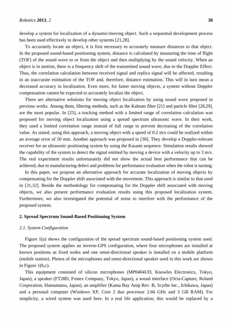
Position errors relative to object moving speed are shown in Figure 12. Where was between
0.3–1.3 rad/s, the position error was around 20 mm. This performance is better than that reported in
another experiment [28]. Even for faster moving objects, the measured errors were smaller than that
previously reported. Beside the advantage of using a spread spectrum approach, the main reason for
this difference in performance was related to the system configuration. In that previous report, they
used a GPS configuration (passive mobile system), while in our system, we used an inverse-GPS

Robotics 2013, 2 48
configuration (active mobile system). The main limitation of passive systems for localization of a
moving object is that simultaneous measurement of distance cannot be guaranteed [21]. Usually, the
distances are measured one at a time; in between measurements, the object has moved on from one
measuring point to another. As a result, there is a high dependency between positioning accuracy and
object moving speed. The faster the object moves, the more positioning accuracy deteriorates.
Figure 11. Localization of an object moving in a circular path with variable velocity.
(a) = 0.3 rad/s; (b) = 0.7 rad/s; (c) = 1.0 rad/s; (d) = 1.3 rad/s.
(a) (b)
(c) (d)
In [28], two different frequencies were used for the ultrasonic positioning system. This system has
both the advantage of a faster measurement time and minimized problems with simultaneous
measurement. However, because four beacons were used, it means that two successive measurements
were still needed to get all four distances, thus the problem of simultaneous measurements is retained.
This could contribute to increased position inaccuracy in such a system, as the angular velocity of the
object increases.
4500 5000 5500 6000 6500 7000 7500500
1000
1500
2000
2500
3000
3500
X-axis (mm)
Y-a
xis
(m
m)
Reference
Estimated
4500 5000 5500 6000 6500 7000 7500500
1000
1500
2000
2500
3000
3500
X-axis (mm)
Y-a
xis
(m
m)
Reference
Estimated
4500 5000 5500 6000 6500 7000 7500500
1000
1500
2000
2500
3000
3500
X-axis (mm)
Y-a
xis
(m
m)
Reference
Estimated
4500 5000 5500 6000 6500 7000 7500500
1000
1500
2000
2500
3000
3500
X-axis (mm)
Y-a
xis
(m
m)
Reference
Estimated
Robotics 2013, 2 49
Figure 12. Relation of angular velocity of moving object and the localization error.
An active system does, however, have its limitations. There is a problem related to network
infrastructure as the number of mobile station increases and also a privacy issue [21]. This, however, is
not an issue here, because the system is used for navigation or other possible applications with limited
numbers of mobile stations. In any event, privacy may not be a critical issue for those applications.
Another important issue is related with the possibility of performance degradation for application at
a wider area and at a higher moving speed. Even though performance evaluation of the proposed
method was conducted in a relatively small area, the obtained results show that the accuracy of the
moving object localization is close to the accuracy of the distance measurement. Based on this result
and also the results from our previous work [27], the proposed method is expected to work well at a
wider area without significantly decreasing the performance. With respect to moving speed, there is no
clear trend from the plot shown in Figure 12. However, considering high accuracy at the current
highest speed (~1.3 m/s), it is plausible that the proposed method also has a possibility to be applied at
a higher speed. Indeed, the speeds used in this experiment are sufficient for general agricultural
application and, therefore, may not be a critical issue here.
5.3. The Influence of Noise
For real life applications in agriculture, background noise is likely to be present. Intense noises may
come from a variety of sources, especially agricultural machinery [35]. Thus, it is necessary to
evaluate the performance of the proposed method in the presence of noise. We tested localization
performance at various noise levels (i.e., at variable sound SNR values) ranging from 0 to −30 dB.
We also compared the performance for both stationary and moving objects.
When the object was stationary (Figures 13(a) and 14(a)), the object could be accurately localized,
with or without compensation, up to a −25 dB noise level. Clear identification of the signal was
achieved as the high correlation SNR indicates. However, for a moving object (Figures 13(b) and 14(b)),
for the non-compensated system, there was a very low correlation SNR. On the other hand, although
there was some decrease in the correlation SNR for the compensated system compared to when the
object was not moving, it still accurately localized the moving object. This indicates that the presence
of background noise did not significantly interfere with the performance of the system with the
Doppler shift compensation. The background noise limit that the system could tolerate was −25 dB.

Robotics 2013, 2 50
Beyond this value, interference to the system was too large, regardless of whether the object was
stationary or moving.
Figure 13. Correlation SNR for compensated and non-compensated system: (a) stationary;
(b) moving object (0.2 m/s).
(a) (b)
Figure 14. Correlation SNR for compensated and non-compensated system: (a) stationary;
(b) moving condition (0.8 m/s).
(a) (b)
6. Conclusions
This paper evaluates an alternative solution for localizing a moving object by using a spread
spectrum sound-based positioning system with Doppler shift compensation. By taking advantage of a
spread-spectrum approach, which is capable of precise distance measurements; and an active mobile
architecture, experimental results demonstrate that the proposed system can achieve high positioning
accuracy. Investigations also indicate that the proposed system can tolerate background noise up to
−25 dB without compromising accuracy. To further improve the current system, estimation of the
position using filtering methods, such as a Kalman filter or a particle filter, could be investigated. For
-25 -20 -15 -10 -5 00
10
20
30
40
50
60
70
80
90
100
Sound SNR (dB)
Corr
elat
ion S
NR
Non-Compensated
Compensated
-25 -20 -15 -10 -5 00
10
20
30
40
50
60
70
Sound SNR (dB)
Co
rrel
atio
n S
NR
Non-Compensated
Compensated
-25 -20 -15 -10 -5 00
10
20
30
40
50
60
70
80
90
100
Sound SNR (dB)
Co
rrela
tio
n S
NR
Non-Compensated
Compensated
-25 -20 -15 -10 -5 0-10
0
10
20
30
40
50
60
Sound SNR (dB)
Co
rrel
atio
n S
NR
Non-Compensated
Compensated

Robotics 2013, 2 51
practical applications, the limitation of the proposed system in terms of the position updating rate
could be overcome by integration with an odometer and/or inertial measurement unit. Another
important issue is about the scalability of the system for wider area (i.e., using more devices). In this
case, the development of an auto-calibrated system is highly required and will be a point of interest for
further improvement.
Acknowledgments
The authors would like to express their gratitude to Tateshi Fujiura and Josse De Baerdemaeker
for their valuable discussion and suggestion. We are also grateful to Garry Piller for checking
this manuscript. This work is supported by MAFF (the Ministry of Agriculture, Forestry and Fisheries
of Japan).
References
1. Kondo, N.; Ting, K.C. Robotics for Bioproduction Systems; American Society of Agricultural
Engineers: Ann Arbor, MI, USA, 1998.
2. Edan, Y.; Han, S.; Kondo, N. Automation in agriculture. In Springer Handbook of Automation;
Springer: Berlin, Germany, 2009; pp. 1095–1128.
3. Bakker, T.; van Asselt, K.; Bontsema, J.; Müller, J.; van Straten, G. An autonomous weeding
robot for organic farming. In Field and Service Robotics; Corke, D.P., Sukkariah, D.S., Eds.;
Springer: Berlin, Germany, 2006; pp. 579–590.
4. Slaughter, D.C.; Giles, D.K.; Downey, D. Autonomous robotic weed control systems: A review.
Comput. Electron. Agr. 2008, 61, 63–78.
5. Acaccia, G.M.; Michelini, R.C.; Molfino, R.M.; Razzoli, R.P. Mobile Robots in Greenhouse
Cultivation: Inspection and Treatment of Plants. In Proceesings of the the 1st International
Workshop on Advances in Service Robotics, Bardolino, Italy, 13–15 March 2003.
6. Søgaard, H.T.; Lund, I. Application accuracy of a machine vision-controlled robotic micro-dosing
system. Biosyst. Eng. 2007, 96, 315–322.
7. Van Henten, E.J.; van Tuijl, B.A.J.; Hemming, J.; Kornet, J.G.; Bontsema, J.; van Os, E.A. Field
test of an autonomous cucumber picking robot. Biosyst. Eng. 2003, 86, 305–313.
8. Tanigaki, K.; Fujiura, T.; Akase, A.; Imagawa, J. Cherry-harvesting robot. Comput. Electron. Agr.
2008, 63, 65–72.
9. Hayashi, S.; Shigematsu, K.; Yamamoto, S.; Kobayashi, K.; Kohno, Y.; Kamata, J.; Kurita, M.
Evaluation of a strawberry-harvesting robot in a field test. Biosyst. Eng. 2010, 105, 160–171.
10. Goense, D. The Economics of Autonomous Vehicles. In Proceedings of the VDI-MEG
Conference on Agricultural Engineering, VDI-Tagung Landtechnic, Hannover, Germany,
7–8 November 2003.
11. Li, M.; Imou, K.; Wakabayashi, K.; Yokoyama, S. Review of research on agricultural vehicle
autonomous guidance. Int. J. Agric. Biol. Eng. 2009, 2, 1–16.
12. Pedersen, S.M.; Fountas, S.; Have, H.; Blackmore, B.S. Agricultural robots—System analysis and
economic feasibility. Precis. Agr. 2006, 7, 295–308.

Robotics 2013, 2 52
13. Harter, A.; Hopper, A.; Steggles, P.; Ward, A.; Webster, P. The anatomy of a context-aware
application. Wireless Netw. 2002, 8, 187–197.
14. Priyantha, N.B.; Chakraborty, A.; Balakrishnan, H. The Cricket Location-Support System.
In Proceeding of the 6th Annual International Conference on Mobile Computing and Networking,
Boston, MA, USA, 6–11 August 2000; pp. 32–43.
15. Balakrishnan, H.; Priyantha, N.B. The Cricket Indoor Location System: Experience and Status.
In Proceedings of the 2003 Workshop on Location-Aware Computing, Seattle, WA, USA,
12 October 2003; pp. 7–9.
16. Hazas, M.; Ward, A. A High Performance Privacy-Oriented Location System. In Proceeding of
the 1st IEEE International Conference on Pervasive Computing and Communications, Fort Worth,
TX, USA, 23–26 March 2003; pp. 216–233.
17. Hazas, M.; Hopper, A. Broadband ultrasonic location systems for improved indoor positioning.
IEEE Trans. Mobile Comput. 2006, 5, 536–547.
18. Prieto, J.C.; Jiménez, A.R.; Guevara, J.I.; Ealo, J.L.; Seco, F.A.; Roa, J.O.; Ramos, J.X.
Subcentimeter-Accuracy Localization through Broadband Acoustic Transducers. In Proceeding of
IEEE International Symposium on Intelligent Signal Processing 2007, Alcala de Henares, Spain,
3–5 October 2007; pp. 1–6.
19. Prieto, J.C.; Jiménez, A.R.; Guevara, J.I.; Ealo, J.L.; Seco, F.A.; Roa, J.O.; Ramos, F.
Performance evaluation of 3D-LOCUS advanced acoustic LPS. IEEE Trans. Instrum. Meas.
2009, 58, 2385–2395.
20. Girod, L.; Estrin, D. Robust Range Estimation Using Acoustic and Multimodal Sensing.
In Proceeding of the 2001 IEEE/RSJ International Conference on Intelligent Robots and Systems,
Maui, HI, USA, 29 October–3 November 2011; pp. 1312–1320.
21. Smith, A.; Balakrishnan, H.; Goraczko, M.; Priyantha, N. Tracking Moving Devices with the
Cricket Location System. In Proceeding of MobiSYS’04, Boston, MA, USA, 6–9 June 2004.
22. Vallidis, N.M. WHISPER: A Spread Spectrum Approach to Occlusion in Acoustic Tracking.
Ph.D. Thesis, The University of North Carolina, Chapel Hill, NC, USA, 2002.
23. Suzuki, A.; Iyota, T.; Choi, Y.; Kubota, Y.; Watanabe, K.; Yamane, A. Measurement Accuracy
on Indoor Positioning System Using Spread Spectrum Ultrasonic Waves. In Proceeding of the 4th
International Conference on Autonomous Robots and Agents, Wellington, New Zealand,
10–12 February 2009; pp. 294–297.
24. Ito, N.; Suzuki, A.; Iyota, T. Verification of CDMA and Accuracy on Echo Ranging System
Using Spread Spectrum Ultrasonic Signals. In Proceeding of the 5th International Conference on
Automation, Robotics and Applications, Wellington, New Zealand, 6–8 December 2011;
pp. 476–479.
25. Itagaki, Y.; Suzuki, A.; Iyota, T. Indoor Positioning for Moving Objects Using a Hardware
Device with Spread Spectrum Ultrasonic Waves. In Proceeding of the 2012 International
Conference on Indoor Positioning and Indoor Navigation, Sydney, Australia, 13–15 November
2012; pp. 1–6.
26. Mak, L.C.; Furukawa, T. A time-of-arrival-based positioning technique with non-line-of-sight
mitigation using low-frequency sound. Adv. Robot. 2008, 22, 507–526.

Robotics 2013, 2 53
27. Widodo, S.; Shiigi, T.; Than, N.M.; Kikuchi, H.; Yanagida, K.; Nakatsuchi, Y.; Ogawa, Y.;
Kondo, N. Wind compensation using base station for spread spectrum sound-based positioning
system in open field. EAEF 2013, in press.
28. Ko, S.I.; Choi, J.S.; Kim, B.H. Indoor mobile localization system and stabilization of localization
performance using pre-filtering. Int. J. Contr. Autom. Syst. 2008, 6, 204–213.
29. Muller, H.L.; McCarthy, M.; Randell, C. Particle Filters for Position Sensing with Asynchronous
Ultrasonic Beacons. In Proceeding of the Second International Workshop, Dublin, Ireland,
10–11 May 2006; pp. 1–13.
30. Álvarez, F.J.; Hernández, Á.; Moreno, J.A.; Pérez, M.C.; Ureña, J.; de Marziani, C.
Doppler-tolerant receiver for an ultrasonic LPS based on Kasami sequences. Sens. Actuator. A
Phys. 2013, 189, 238–253.
31. Kusy, B.; Ledeczi, A.; Koutsoukos, X. Tracking Mobile Nodes Using RF Doppler Shifts.
In Proceeding of the 5th ACM Conference on Embedded Networked Sensor Systems, Sydney,
Australia, 6–9 November 2007.
32. Amundson, I.; Koutsoukos, X.; Sallai, J. Mobile Sensor Localization and Navigation Using RF
Doppler Shifts. In Proceedings of the 1st ACM international Workshop on Mobile Entity
Localization and Tracking in GPS-Less Environments, San Francisco, CA, USA, 14–19 September
2008.
33. Shiigi, T.; Kondo, N.; Tsuzuki, S.; Okada, S.; Maekawa, A.; Nobara, T.; Sakakibara, M.;
Watanabe, K.; Naniwada, Y.; Okada, K. Position Detecting Method Using Spread Spectrum
Sound: Correction Method of Measurement Error by Compensating Wind and Temperature.
In Proceedings of the 3rd IFAC International Conference Agricontro, Kyoto, Japan,
6–8 December 2010.
34. Ohno, K.; Tsubouchi, T.; Shigematsu, B.; Yuta, S. Differential GPS and odometry-based outdoor
navigation of a mobile robot. Adv. Robot. 2004, 18, 611–635.
35. McBride, D.I.; Firth, H.M.; Herbison, G.P. Noise exposure and hearing loss in agriculture:
A survey of farmers and farm workers in the southland region of New Zealand. J. Occup.
Environ. Med. 2003, 45, 1281–1288.
© 2013 by the authors; licensee MDPI, Basel, Switzerland. This article is an open access article
distributed under the terms and conditions of the Creative Commons Attribution license
(http://creativecommons.org/licenses/by/3.0/).