motorcycle service manual
TRANSCRIPT

Ninja ZX-12R
MotorcycleService Manual

This quick reference guide will assistyou in locating a desired topic or pro-cedure.•Bend the pages back to match theblack tab of the desired chapter num-ber with the black tab on the edge ateach table of contents page.•Refer to the sectional table of contentsfor the exact pages to locate the spe-cific topic required.
Quick Reference Guide
General Information 1 j
Periodic Maintenance 2 j
Fuel System (DFI) 3 j
Cooling System 4 j
Engine Top End 5 j
Clutch 6 j
Engine Lubrication System 7 j
Engine Removal/Installation 8 j
Crankshaft/Transmission 9 j
Wheels/Tires 10 j
Final Drive 11 j
Brakes 12 j
Suspension 13 j
Steering 14 j
Frame 15 j
Electrical System 16 j
Troubleshooting 17 j


Ninja ZX-12R
MotorcycleService Manual
All rights reserved. No parts of this publication may be reproduced, stored in a retrieval system, ortransmitted in any form or by any means, electronic mechanical photocopying, recording or otherwise,without the prior written permission of Quality Assurance Department/Consumer Products & MachineryCompany/Kawasaki Heavy Industries, Ltd., Japan.No liability can be accepted for any inaccuracies or omissions in this publication, although every possible
care has been taken to make it as complete and accurate as possible.The right is reserved to make changes at any time without prior notice and without incurring an obligation
to make such changes to products manufactured previously. See your Motorcycle dealer for the latestinformation on product improvements incorporated after this publication.All information contained in this publication is based on the latest product information available at the time
of publication. Illustrations and photographs in this publication are intended for reference use only and maynot depict actual model component parts.
© 2002 Kawasaki Heavy Industries, Ltd. Fourth Edition (1) : Mar. 5, 2004 (K)

LIST OF ABBREVIATIONSA ampere(s) lb pound(s)
ABDC after bottom dead center m meter(s)
AC alternating current min minute(s)
ATDC after top dead center N newton(s)
BBDC before bottom dead center Pa pascal(s)
BDC bottom dead center PS horsepower
BTDC before top dead center psi pound(s) per square inch
°C degree(s) Celsius r revolution
DC direct current rpm revolution(s) per minute
F farad(s) TDC top dead center
°F degree(s) Fahrenheit TIR total indicator reading
ft foot, feet V volt(s)
g gram(s) W watt(s)
h hour(s) Ω ohm(s)
L liter(s)
Read OWNER’S MANUAL before operating.
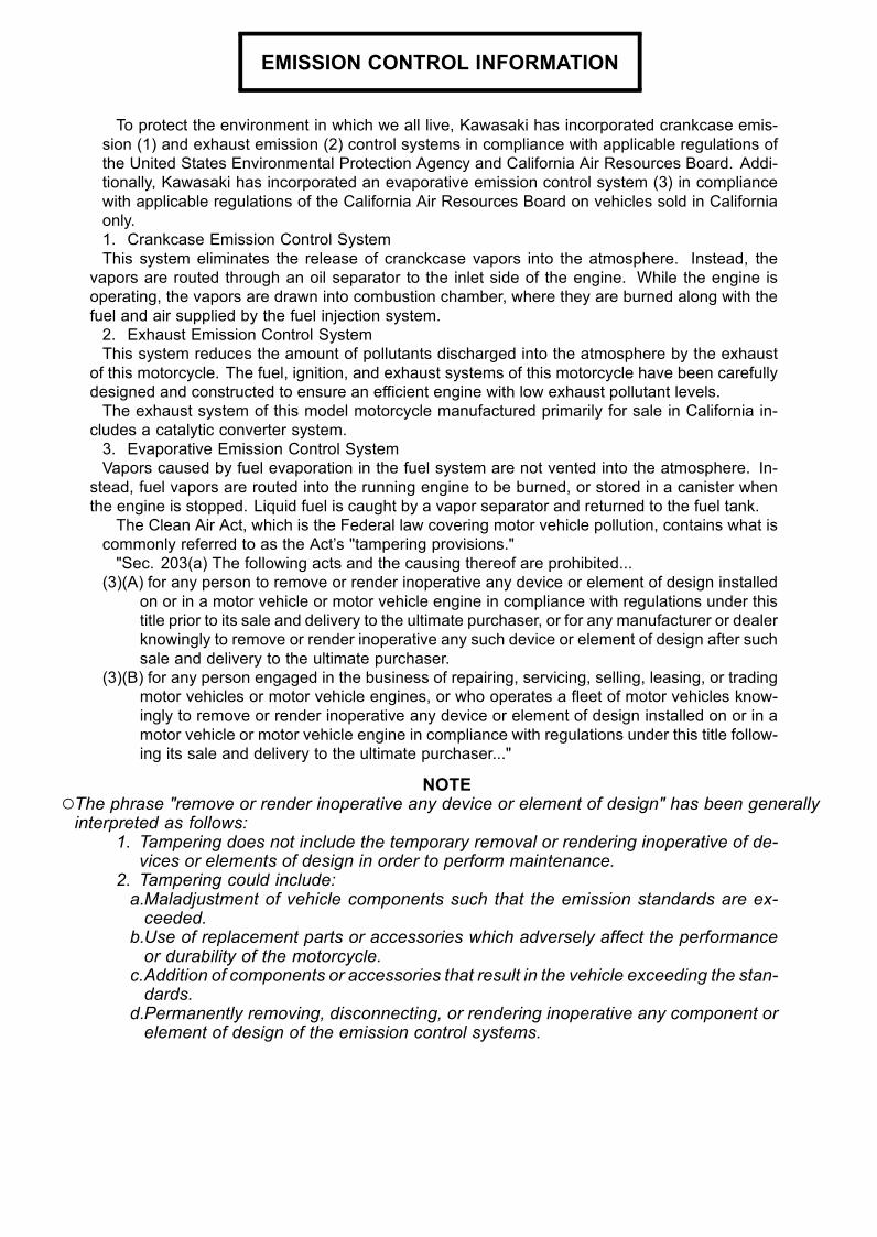
EMISSION CONTROL INFORMATION
To protect the environment in which we all live, Kawasaki has incorporated crankcase emis-sion (1) and exhaust emission (2) control systems in compliance with applicable regulations ofthe United States Environmental Protection Agency and California Air Resources Board. Addi-tionally, Kawasaki has incorporated an evaporative emission control system (3) in compliancewith applicable regulations of the California Air Resources Board on vehicles sold in Californiaonly.1. Crankcase Emission Control SystemThis system eliminates the release of cranckcase vapors into the atmosphere. Instead, the
vapors are routed through an oil separator to the inlet side of the engine. While the engine isoperating, the vapors are drawn into combustion chamber, where they are burned along with thefuel and air supplied by the fuel injection system.2. Exhaust Emission Control SystemThis system reduces the amount of pollutants discharged into the atmosphere by the exhaust
of this motorcycle. The fuel, ignition, and exhaust systems of this motorcycle have been carefullydesigned and constructed to ensure an efficient engine with low exhaust pollutant levels.The exhaust system of this model motorcycle manufactured primarily for sale in California in-
cludes a catalytic converter system.3. Evaporative Emission Control SystemVapors caused by fuel evaporation in the fuel system are not vented into the atmosphere. In-
stead, fuel vapors are routed into the running engine to be burned, or stored in a canister whenthe engine is stopped. Liquid fuel is caught by a vapor separator and returned to the fuel tank.
The Clean Air Act, which is the Federal law covering motor vehicle pollution, contains what iscommonly referred to as the Act’s "tampering provisions.""Sec. 203(a) The following acts and the causing thereof are prohibited...
(3)(A) for any person to remove or render inoperative any device or element of design installedon or in a motor vehicle or motor vehicle engine in compliance with regulations under thistitle prior to its sale and delivery to the ultimate purchaser, or for any manufacturer or dealerknowingly to remove or render inoperative any such device or element of design after suchsale and delivery to the ultimate purchaser.
(3)(B) for any person engaged in the business of repairing, servicing, selling, leasing, or tradingmotor vehicles or motor vehicle engines, or who operates a fleet of motor vehicles know-ingly to remove or render inoperative any device or element of design installed on or in amotor vehicle or motor vehicle engine in compliance with regulations under this title follow-ing its sale and delivery to the ultimate purchaser..."
NOTEThe phrase "remove or render inoperative any device or element of design" has been generallyinterpreted as follows:
1. Tampering does not include the temporary removal or rendering inoperative of de-vices or elements of design in order to perform maintenance.
2. Tampering could include:a.Maladjustment of vehicle components such that the emission standards are ex-ceeded.
b.Use of replacement parts or accessories which adversely affect the performanceor durability of the motorcycle.
c.Addition of components or accessories that result in the vehicle exceeding the stan-dards.
d.Permanently removing, disconnecting, or rendering inoperative any component orelement of design of the emission control systems.

WE RECOMMEND THAT ALL DEALERS OBSERVE THESE PROVISIONS OF FEDERAL LAW,THE VIOLATION OF WHICH IS PUNISHABLE BY CIVIL PENALTIES NOT EXCEEDING$10,000 PER VIOLATION.
TAMPERING WITH NOISE CONTROL SYSTEM PROHIBITED
Federal law prohibits the following acts or the causing thereof: (1) The removal or renderinginoperative by any person other than for purposes of maintenance, repair, or replacement, of anydevice or element of design incorporated into any new vehicle for the purpose of noise controlprior to its sale or delivery to the ultimate purchaser or while it is in use, or (2) the use of thevehicle after such device or element of design has been removed or rendered inoperative byany person.Among those acts presumed to constitute tampering are the acts listed below:
•Replacement of the original exhaust system or muffler with a component not in compliancewith Federal regulations.
•Removal of the muffler(s) or any internal portion of the muffler(s).• Removal of the air box or air box cover.•Modifications to the muffler(s) or air inlet system by cutting, drilling, or other means if suchmodifications result in increased noise levels.
Foreword
This manual is designed primarily for use bytrained mechanics in a properly equipped shop.However, it contains enough detail and basic in-formation to make it useful to the owner who de-sires to perform his own basic maintenance andrepair work. A basic knowledge of mechanics,the proper use of tools, and workshop proce-dures must be understood in order to carry outmaintenance and repair satisfactorily. When-ever the owner has insufficient experience ordoubts his ability to do the work, all adjust-ments, maintenance, and repair should be car-ried out only by qualified mechanics.In order to perform the work efficiently and
to avoid costly mistakes, read the text, thor-oughly familiarize yourself with the proceduresbefore starting work, and then do the work care-fully in a clean area. Whenever special tools orequipment are specified, do not use makeshifttools or equipment. Precision measurementscan only be made if the proper instruments areused, and the use of substitute tools may ad-versely affect safe operation.For the duration of the warranty period,
we recommend that all repairs and scheduledmaintenance be performed in accordance withthis service manual. Any owner maintenance orrepair procedure not performed in accordancewith this manual may void the warranty.To get the longest life out of your vehicle:
• Follow the Periodic Maintenance Chart in theService Manual.
• Be alert for problems and non-scheduledmaintenance.
•Use proper tools and genuine Kawasaki Mo-torcycle parts. Special tools, gauges, andtesters that are necessary when servicingKawasaki motorcycles are introduced by theSpecial Tool Catalog or Manual. Genuineparts provided as spare parts are listed in theParts Catalog.
• Follow the procedures in this manual care-fully. Don’t take shortcuts.
•Remember to keep complete records of main-tenance and repair with dates and any newparts installed.
How to Use This ManualIn this manual, the product is divited into its
major systems and these systems make upthe manual’s chapters. The Quick Reference
Guide shows you all of the product’s systemand assists in locating their chapters. Eachchapter in turn has its own comprehensiveTable of Contents.For example, if you want ignition coil informa-
tion, use the Quick Reference Guide to locatethe Electrical System chapter. Then, use theTable of Contents on the first page of the chap-ter to find the Ignition Coil section.Whenever you see these WARNING and
CAUTION symbols, heed their instructions!Always follow safe operating and maintenancepractices.
WARNINGThis warning symbol identifies specialinstructions or procedures which, if notcorrectly followed, could result in per-sonal injury, or loss of life.
CAUTION
This caution symbol identifies specialinstructions or procedures which, if notstrictly observed, could result in dam-age to or destruction of equipment.
This manual contains four more symbols (inaddition toWARNING andCAUTION) which willhelp you distinguish different types of informa-tion.
NOTEThis note symbol indicates points of par-ticular interest for more efficient and con-venient operation.
• Indicates a procedural step or work to bedone.Indicates a procedural sub-step or how to dothe work of the procedural step it follows. Italso precedes the text of a NOTE.Indicates a conditional step or what action totake based on the results of the test or inspec-tion in the procedural step or sub-step it fol-lows.
In most chapters an exploded view illustrationof the system components follows the Table ofContents. In these illustrations you will find theinstructions indicating which parts require spec-ified tightening torque, oil, grease or a lockingagent during assembly.

GENERAL INFORMATION 1-1
1General Information
Table of Contents
Before Servicing ..................................................................................................................... 1-2Model Identification................................................................................................................. 1-5General Specifications............................................................................................................ 1-6Technical Information – KAWASAKI LOW EXHAUST EMISSION SYSTEM ......................... 1-9Technical Information – Monocoque Frame ........................................................................... 1-12Technical Information – Spark Plug ........................................................................................ 1-13Technical Information – Immobilizer System (ZX1200-B3)..................................................... 1-14Torque and Locking Agent...................................................................................................... 1-17Special Tools and Sealant ...................................................................................................... 1-22Cable, Wire, and Hose Routing (ZX1200-B1/B2) ................................................................... 1-29Cable, Wire, and Hose Routing (ZX1200-B3) ........................................................................ 1-46Unit Conversion Table ............................................................................................................ 1-60

1-2 GENERAL INFORMATION
Before Servicing
Before starting to service a motorcycle, careful reading of the applicable section is recommended toeliminate unnecessary work. Photographs, diagrams, notes, cautions, warnings, and detailed descrip-tions have been included wherever necessary. Nevertheless, even a detailed account has limitations,a certain amount of basic knowledge is also required for successful work.
Especially note the following:(1) Dirt
Before removal and disassembly, clean the motorcycle. Any dirt entering the engine or otherparts will work as an abrasive and shorten the life of the motorcycle. For the same reason, beforeinstalling a new part, clean off any dust or metal filings.
(2) Battery CablesDisconnect the ground (–) cable from the battery before performing any disassembly operations
on the motorcycle. This prevents the engine from accidentally turning over while work is beingcarried out, sparks from being generated while disconnecting the leads from electrical parts, aswell as damage to the electrical parts themselves. For reinstallation, first connect the positivecable to the positive (+) terminal of the battery.
(3) Installation, AssemblyGenerally, installation or assembly is the reverse of removal or disassembly. But if this Service
Manual has installation or assembly procedures, follow them. Note parts locations and cable,lead, and hose routing during removal or disassembly so they can be installed or assembled inthe same way. It is preferable to mark and record the locations and routing as much as possible.
(4) Tightening SequenceGenerally, when installing a part with several bolts, nuts, or screws, start them all in their holes
and tighten them to a snug fit. Then tighten them evenly in a cross pattern. This is to avoiddistortion of the part and/or causing gas or oil leakage. Conversely when loosening the bolts,nuts, or screws, first loosen all of them by about a quarter turn and then remove them. Wherethere is a tightening sequence indication in this Service Manual, the bolts, nuts, or screws mustbe tightened in the order and method indicated.
(5) TorqueWhen torque values are given in this Service Manual, use them. Either too little or too much
torque may lead to serious damage. Use a good quality, reliable torque wrench.(6) Force
Common sense should dictate how much force is necessary in assembly and disassembly. Ifa part seems especially difficult to remove or install, stop and examine what may be causing theproblem. Whenever tapping is necessary, tap lightly using a wooden or plastic-faced mallet. Usean impact driver for screws (particularly for the removal of screws held by a locking agent) in orderto avoid damaging the screw heads.
(7) EdgesWatch for sharp edges, especially during major engine disassembly and assembly. Protect your
hands with gloves or a piece of thick cloth when lifting the engine or turning it over.(8) High-Flash Point Solvent
A high-flash point solvent is recommended to reduce fire danger. A commercial solvent com-monly available in North America is Stoddard solvent (generic name). Always follow manufacturerand container directions regarding the use of any solvent.
(9) Gasket, O-ringDo not reuse a gasket or O-ring once it has been in service. The mating surfaces around the
gasket should be free of foreign matter and perfectly smooth to avoid oil or compression leakage.(10)Liquid Gasket, Non-Permanent Locking Agent
Follow manufacturer’s directions for cleaning and preparing surfaces where these compoundswill be used. Apply sparingly. Excessive amounts may block engine oil passages and cause seri-ous damage. An example of non-permanent locking agent commonly available in North Americais Loctite Lock’n Seal (Blue).
(11)PressA part installed using a press or driver, such as a wheel bearing, should first be coated with oil
on its outer or inner circumference so that it will go into place smoothly.

GENERAL INFORMATION 1-3
Before Servicing
(12)Ball Bearing and Needle BearingDo not remove a ball bearing or a needle bearing unless it is absolutely necessary. Replace
any ball or needle bearings that were removed with new ones, as removal generally damagesbearings. Install bearings with the marked side facing out applying pressure evenly with a suitabledriver. Only press on the race that forms the press fit with the base component to avoid damagingthe bearings. This prevents severe stress on the balls or needles and races, and prevent racesand balls or needles from being dented. Press a ball bearing until it stops at the stopper in thehole or on the shaft.
(13)Oil Seal and Grease SealReplace any oil or grease seals that were removed with new ones, as removal generally dam-
ages seals. When pressing in a seal which has manufacturer’s marks, press it in with the marksfacing out. Seals should be pressed into place using a suitable driver, which contacts evenly withthe side of seal, until the face of the seal is even with the end of the hole. Before a shaft passesthrough a seal, apply little high temperature grease on the lips to reduce rubber to metal friction.
(14)Circlip, Retaining Ring, and Cotter PinReplace any circlips and retaining rings, and cotter pins that were removed with new ones, as
removal weakens and deforms them. When installing circlips and retaining rings, take care tocompress or expand them only enough to install them and no more.
(15)LubricationEngine wear is generally at its maximum while the engine is warming up and before all the
rubbing surfaces have an adequate lubricative film. During assembly, oil or grease (whicheveris more suitable) should be applied to any rubbing surface which has lost its lubricative film. Oldgrease and dirty oil should be cleaned off. Deteriorated grease has lost its lubricative quality andmay contain abrasive foreign particles.Don’t use just any oil or grease. Some oils and greases in particular should be used only in
certain applications and may be harmful if used in an application for which they are not intended.This manual makes reference to molybdenum disulfide grease (MoS2) and molybdenum disulfideoil in the assembly of certain engine and chassis parts. The molybdenum disulfide oil is a mixtureof engine oil and molybdenum disulfide grease with a weight ratio (10 : 1), which can be made inyour work shop. Always check manufacturer recommendations before using such special lubri-cants.
(16)Electrical LeadsAll the electrical leads are either single-color or two-color and, with only a few exceptions, must
be connected to leads of the same color. On any of the two-color leads there is a greater amountof one color and a lesser amount of a second color, so a two-color lead is identified by first theprimary color and then the secondary color. For example, a yellow lead with thin red stripes isreferred to as a "yellow/red" lead; it would be a "red/yellow" lead if the colors were reversed tomake red the main color.
(17)Replacement PartsWhen there is a replacement instruction, replace these parts with new ones every time they are
removed. These replacement parts will be damaged or lose their original function once removed.
1-4 GENERAL INFORMATION
Before Servicing
(18)InspectionWhen parts have been disassembled, visually inspect these parts for the following conditions
or other damage. If there is any doubt as to the condition of them, replace them with new ones.
Abrasion Crack Hardening Warp
Bent Dent Scratch Wear
Color change Deterioration Seizure
(19)SpecificationsSpecification terms are defined as follows:"Standards" show dimensions or performances which brand-new parts or systems have."Service Limits" indicate the usable limits. If the measurement shows excessive wear or dete-
riorated performance, replace the damaged parts.(20)Instrument
Use a meter that has enough accuracy for an accurate measurement.Read the manufacturer’s instructions thoroughly before using the meter.Incorrect values may lead to improper adjustments.
GENERAL INFORMATION 1-5
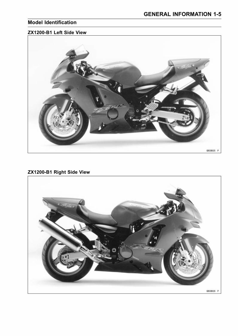
Model Identification
ZX1200-B1 Left Side View
ZX1200-B1 Right Side View

1-6 GENERAL INFORMATION
General Specifications
Items ZX1200-B1 ∼ B3Dimensions
Overall Length 2 085 mm (82.09 in.)
Overall Width 740 mm (29.13 in.)
Overall Height 1 200 mm (47.24 in.)
Wheelbase 1 450 mm (57.09 in.)
Road Clearance 120 mm (4.72 in.)
Seat Height 820 mm (32.28 in.)
Dry Mass 210 kg (463 lb)
Curb Mass:
Front 125 kg (276 lb)
Rear 121 kg (267 lb)
Fuel Tank Capacity 19.0 L (5.0 US gal)
Performance
Minimum Turning Radius 3.0 m (9.8 ft)
Engine
Type 4-stroke, DOHC, 4-cylinder
Cooling System Liquid-cooled
Bore and Stroke 83.0 × 55.4 mm (3.27 × 2.18 in.)
Displacement 1 199 mL (73.16 cu in.)
Compression Ratio 12.2
Maximum Horsepower (H) 131 kW (178 PS) @9 500 r/min (rpm),
(AU) ZX1200-B1/B2: 130 kW (177 PS) @10 500 r/min (rpm),
(AU) ZX1200-B3: 131 kW (178 PS) @10 500 r/min (rpm),
(HR) 78.2 kW (106.4 PS) @8 500 r/min (rpm),
(MY) ZX1200-B1/B2: 131 kW (178 PS) @ 9 500 r/min (rpm),
(MY) ZX1200-B3: 128 kW (174 PS) @9 500 r/min (rpm)
(US), (CA) – – –
Maximum Torque (H, AU) 134 N·m (13.7 kgf·m, 99 ft·lb) @7 500 r/min (rpm),
(MY) ZX1200-B1/B2: 134 N·m (13.7 kgf·m, 99 ft·lb) @7 500r/min (rpm),
(MY) ZX1200-B3: 130 N·m (13.3 kgf·m, 96 ft·lb) @7 500 r/min(rpm),
(HR) 111 N·m (11.3 kgf·m, 82 ft·lb) @5 000 r/min (rpm),
(US), (CA) – – –
Carburetion System FI (Fuel Injection), ZX1200-B1/B2: MIKUNI 46 EIS × 4
ZX1200-B3: KEIHIN ( 46 × 4)
Starting System Electric starter
Ignition System Battery and coil (transistorized)
Timing Advance Electronically advanced (digital igniter in ECU)
Ignition Timing 10° BTDC @1 000 r/min (rpm)
Spark Plugs NGK CR9EKPA
Cylinder Numbering Method Left to right, 1-2-3-4
Firing Order 1-2-4-3

GENERAL INFORMATION 1-7
General Specifications
Items ZX1200-B1 ∼ B3Valve Timing:
Inlet:
Open 46° BTDC
Close 74° ABDC
Duration 300°
Exhaust:
Open 69° BBDC
Close 45° ATDC
Duration 294°
Lubrication System Forced lubrication (wet sump with cooler)
Engine Oil:
Grade API SE, SF or SG
API SH or SJ with JASO MA
Viscosity SAE 10W-40
Capacity 3.6 L (3.8 US qt)
Drive Train
Primary Reduction System:
Type Gear
Reduction Ratio 1.596 (83/52)
Clutch Type Wet, multi disc
Transmission:
Type 6-speed, constant mesh, return shift
Gear Ratios:
1st 2.429 (34/14)
2nd 1.824 (31/17)
3rd 1.440 (36/25)
4th 1.250 (30/24)
5th 1.130 (26/23)
6th 1.033 (31/30)
Final Drive System:
Type Chain drive
Reduction Ratio 2.556 (46/18)
Overall Drive Ratio 4.215 @Top gear
Frame
Type Press backbone
Caster (Rake Angle) 23.5°
Trail 98 mm (3.86 in.)
Front Tire:
Type Tubeless
Size 120/70 ZR17 M/C (58W)
Rear Tire:
Type Tubeless
Size 200/50 ZR17 M/C (75W)
1-8 GENERAL INFORMATION
General Specifications
Items ZX1200-B1 ∼ B3Front Suspension:
Type Telescopic fork (upside-down)
Wheel Travel 120 mm (4.72 in.)
Rear Suspension:
Type Swingarm (uni-trak)
Wheel Travel 140 mm (5.51 in.)
Brake Type:
Front Dual discs
Rear Single disc
Electrical Equipment
Battery 12 V 12 Ah
Headlight:
Type Semi-sealed beam
Bulb 12 V 60/55 W (quartz-halogen) × 2
Tail/Brake Light 12 V 5/21 W × 2
Alternator:
Type Three-phase AC
Rated Output 31 A/14 V @5 000 r/min (rpm)
Specifications are subject to change without notice, and may not apply to every country.AU: Australian ModelUS: U.S.A. ModelCA: Canadian ModelMY: Malaysian ModelHR: WVTA Approval Model, Honeycomb Catalytic Converter (Restricted Power)H: WVTA Approval Model, Honeycomb Catalytic Converter
GENERAL INFORMATION 1-9
Technical Information – KAWASAKI LOW EXHAUST EMISSION SYSTEM
Since the emission regulations become more severe, Kawasaki has adopted a type of simplifiedKAWASAKI LOW EXHAUST EMISSION SYSTEM (KLEEN), which have no catalyst protection sys-tem, according to each regulation of different countries.The muffler with built-in catalyst has the same durability as the conventional muffler, however, do
not use leaded gasoline and do not coast with the ignition system OFF. Running the engine withoutignition damages catalyst.Refer to the ZX900E Service Manual (Part No. 99924-1255) for more information about the KLEEN
(theory, maintenance, and handling precautions), including the secondary air injection system.
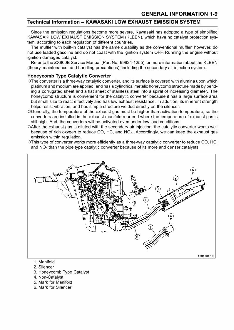
Honeycomb Type Catalytic ConverterThe converter is a three-way catalytic converter, and its surface is covered with alumina upon whichplatinum and rhodium are applied, and has a cylindrical metalic honeycomb structure made by bend-ing a corrugated sheet and a flat sheet of stainless steel into a spiral of increasing diameter. Thehoneycomb structure is convenient for the catalytic converter because it has a large surface areabut small size to react effectively and has low exhaust resistance. In addition, its inherent strengthhelps resist vibration, and has simple structure welded directly on the silencer.Generally, the temperature of the exhaust gas must be higher than activation temperature, so theconverters are installed in the exhaust manifold rear end where the temperature of exhaust gas isstill high. And, the converters will be activated even under low load conditions.After the exhaust gas is diluted with the secondary air injection, the catalytic converter works wellbecause of rich oxygen to reduce CO, HC, and NOx. Accordingly, we can keep the exhaust gasemission within regulation.This type of converter works more efficiently as a three-way catalytic converter to reduce CO, HC,and NOx than the pipe type catalytic converter because of its more and denser catalysts.
1. Manifold2. Silencer3. Honeycomb Type Catalyst4. Non-Catalyst5. Mark for Manifold6. Mark for Silencer
1-10 GENERAL INFORMATION
Technical Information – KAWASAKI LOW EXHAUST EMISSION SYSTEM
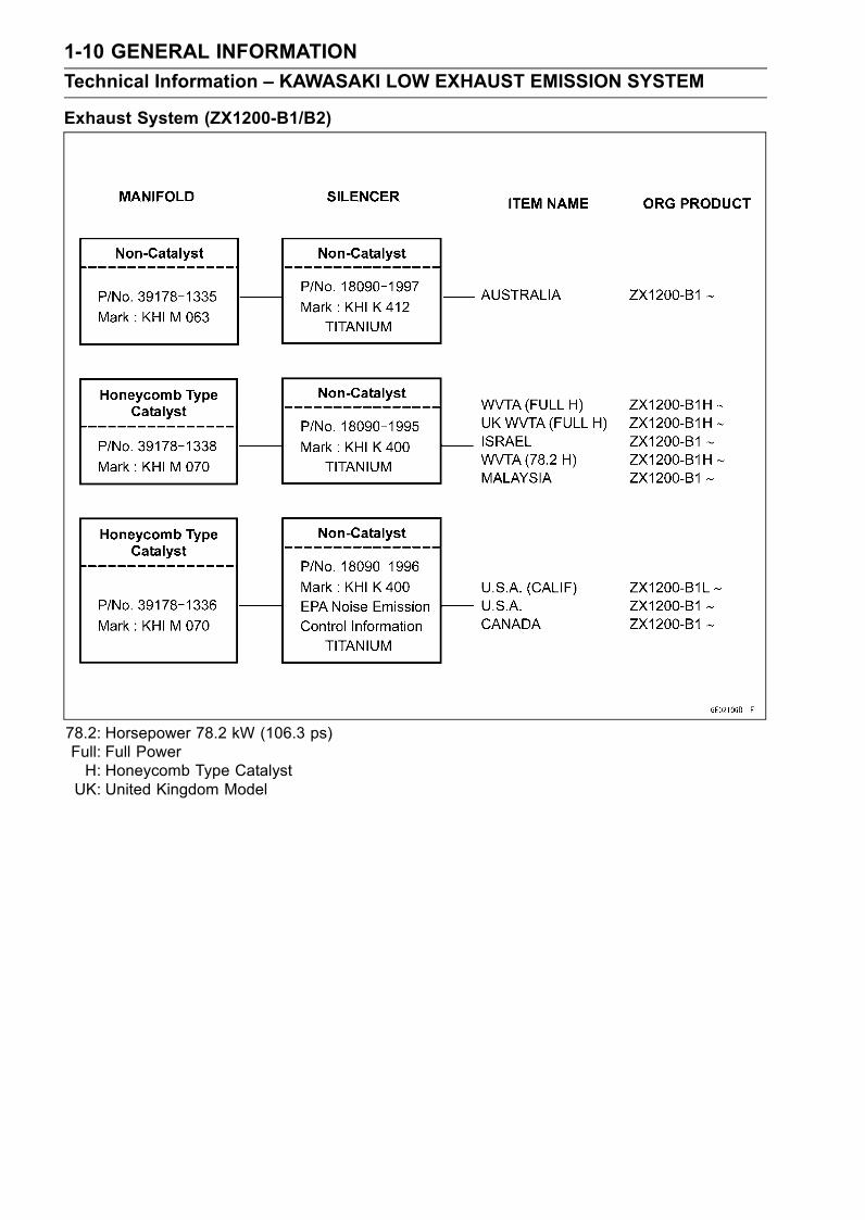
Exhaust System (ZX1200-B1/B2)
78.2: Horsepower 78.2 kW (106.3 ps)Full: Full PowerH: Honeycomb Type CatalystUK: United Kingdom Model
GENERAL INFORMATION 1-11
Technical Information – KAWASAKI LOW EXHAUST EMISSION SYSTEM
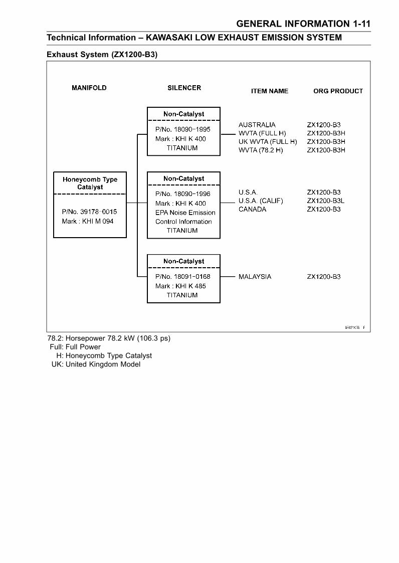
Exhaust System (ZX1200-B3)
78.2: Horsepower 78.2 kW (106.3 ps)Full: Full PowerH: Honeycomb Type CatalystUK: United Kingdom Model
1-12 GENERAL INFORMATION
Technical Information – Monocoque Frame
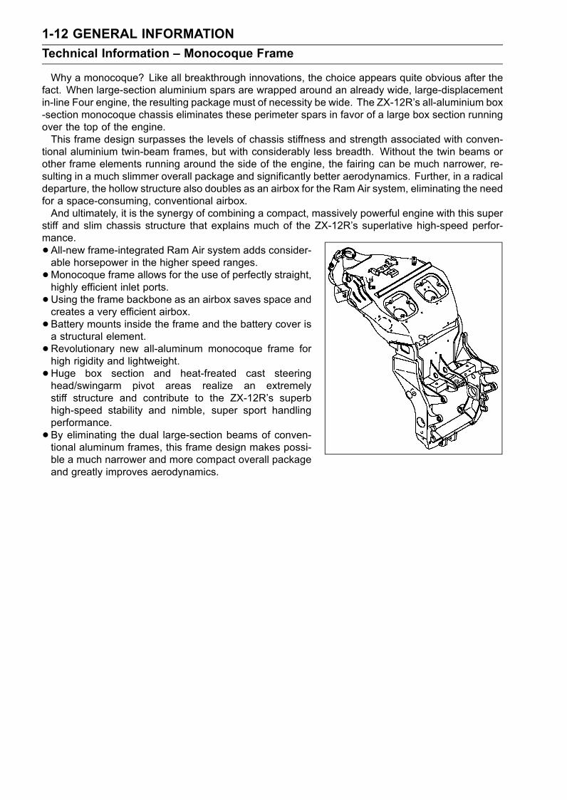
Why a monocoque? Like all breakthrough innovations, the choice appears quite obvious after thefact. When large-section aluminium spars are wrapped around an already wide, large-displacementin-line Four engine, the resulting package must of necessity be wide. The ZX-12R’s all-aluminium box-section monocoque chassis eliminates these perimeter spars in favor of a large box section runningover the top of the engine.This frame design surpasses the levels of chassis stiffness and strength associated with conven-
tional aluminium twin-beam frames, but with considerably less breadth. Without the twin beams orother frame elements running around the side of the engine, the fairing can be much narrower, re-sulting in a much slimmer overall package and significantly better aerodynamics. Further, in a radicaldeparture, the hollow structure also doubles as an airbox for the Ram Air system, eliminating the needfor a space-consuming, conventional airbox.And ultimately, it is the synergy of combining a compact, massively powerful engine with this super
stiff and slim chassis structure that explains much of the ZX-12R’s superlative high-speed perfor-mance.
• All-new frame-integrated Ram Air system adds consider-able horsepower in the higher speed ranges.
•Monocoque frame allows for the use of perfectly straight,highly efficient inlet ports.
•Using the frame backbone as an airbox saves space andcreates a very efficient airbox.
• Battery mounts inside the frame and the battery cover isa structural element.
•Revolutionary new all-aluminum monocoque frame forhigh rigidity and lightweight.
• Huge box section and heat-freated cast steeringhead/swingarm pivot areas realize an extremelystiff structure and contribute to the ZX-12R’s superbhigh-speed stability and nimble, super sport handlingperformance.
• By eliminating the dual large-section beams of conven-tional aluminum frames, this frame design makes possi-ble a much narrower and more compact overall packageand greatly improves aerodynamics.
GENERAL INFORMATION 1-13
Technical Information – Spark Plug
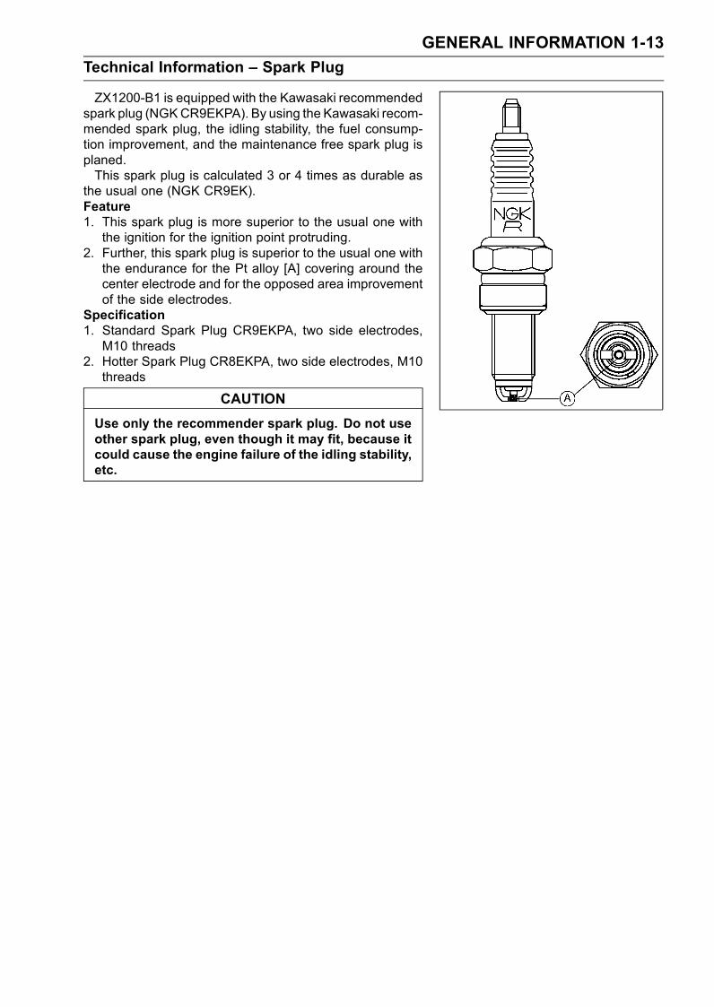
ZX1200-B1 is equipped with the Kawasaki recommendedspark plug (NGKCR9EKPA). By using the Kawasaki recom-mended spark plug, the idling stability, the fuel consump-tion improvement, and the maintenance free spark plug isplaned.This spark plug is calculated 3 or 4 times as durable as
the usual one (NGK CR9EK).Feature1. This spark plug is more superior to the usual one withthe ignition for the ignition point protruding.
2. Further, this spark plug is superior to the usual one withthe endurance for the Pt alloy [A] covering around thecenter electrode and for the opposed area improvementof the side electrodes.
Specification1. Standard Spark Plug CR9EKPA, two side electrodes,M10 threads
2. Hotter Spark Plug CR8EKPA, two side electrodes, M10threads
CAUTION
Use only the recommender spark plug. Do not useother spark plug, even though it may fit, because itcould cause the engine failure of the idling stability,etc.

1-14 GENERAL INFORMATION
Technical Information – Immobilizer System (ZX1200-B3)
OverviewThis system provides a theft proof device by means of matching a code between the inbuilt key
transponder and the ECU (Electronic Control Unit). If this code does not match, the fuel pump, injec-tors, ignition system and sub-throttle valve actuator will not operate and the engine will not start.
Related Parts and Function
1. Transponder (Inside Keys)2. Master Key3. User Keys4. FI Indicator Light5. Immobilizer Antenna6. Ignition Switch7. Immobilizer Amplifier
8. Starter Relay9. Battery10. Electronic Control Unit (ECU)11. Junction Box12. Fuse Box13. Immobilizer/Kawasaki Diagnostic System
Connector
Master Key (1 piece)The master key (colored red) has an inbuilt transponder, containing a master key code. These
codes are unique to each key. This code and an additional two user key codes must be registeredin the ECU for the system to operate. The master key is necessary when registering user keys andshould not be used as the main key to start the motorcycle except in emergencies (loss or damage ofuser keys). It should be kept in a safe place.
GENERAL INFORMATION 1-15
Technical Information – Immobilizer System (ZX1200-B3)
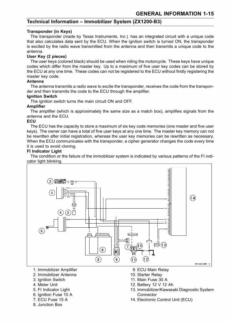
Transponder (in Keys)The transponder (made by Texas Instruments, Inc.) has an integrated circuit with a unique code
that also calculates data sent by the ECU. When the ignition switch is turned ON, the transponderis excited by the radio wave transmitted from the antenna and then transmits a unique code to theantenna.User Key (2 pieces)The user keys (colored black) should be used when riding the motorcycle. These keys have unique
codes which differ from the master key. Up to a maximum of five user key codes can be stored bythe ECU at any one time. These codes can not be registered to the ECU without firstly registering themaster key code.AntennaThe antenna transmits a radio wave to excite the transponder, receives the code from the transpon-
der and then transmits the code to the ECU through the amplifier.Ignition SwitchThe ignition switch turns the main circuit ON and OFF.
AmplifierThe amplifier (which is approximately the same size as a match box), amplifies signals from the
antenna and the ECU.ECUThe ECU has the capacity to store a maximum of six key code memories (one master and five user
keys). The owner can have a total of five user keys at any one time. The master key memory can notbe rewritten after initial registration, whereas the user key memories can be rewritten as necessary.When the ECU communicates with the transponder, a cipher generator changes the code every timeit is used to avoid cloning.FI Indicator LightThe condition or the failure of the immobilizer system is indicated by various patterns of the FI indi-
cator light blinking.
1. Immobilizer Amplifier2. Immobilizer Antenna3. Ignition Switch4. Meter Unit5. FI Indicator Light6. Ignition Fuse 10 A7. ECU Fuse 15 A8. Junction Box
9. ECU Main Relay10. Starter Relay11. Main Fuse 30 A12. Battery 12 V 12 Ah13. Immobilizer/Kawasaki Diagnostic System
Connector14. Electronic Control Unit (ECU)
1-16 GENERAL INFORMATION
Technical Information – Immobilizer System (ZX1200-B3)
Sequence of Operation1. Turn ON the ignition switch, the ECU, amplifier and antenna start working, and the meter assemblyFI indicator lights up.
2. The transponder excited by radio waves transmitted from the antenna receives the ciphered codefrom the ECU.
3. The transponder transmits the calculated result from the key’s unique code to the ECU.4. The ECU compares this with its memorized code, and if they match the engine can start. At thistime, the FI indicator in the meter assembly is switched off.
GENERAL INFORMATION 1-17
Torque and Locking Agent
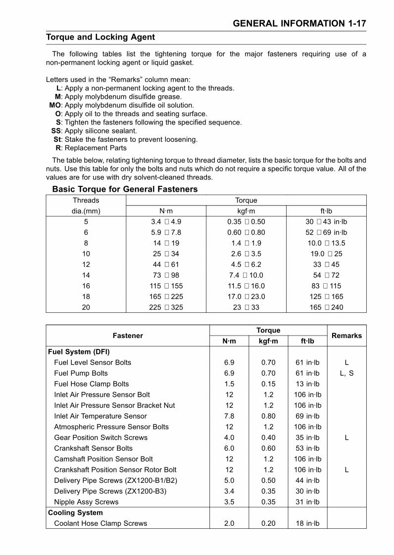
The following tables list the tightening torque for the major fasteners requiring use of anon-permanent locking agent or liquid gasket.
Letters used in the “Remarks” column mean:L: Apply a non-permanent locking agent to the threads.M: Apply molybdenum disulfide grease.
MO: Apply molybdenum disulfide oil solution.O: Apply oil to the threads and seating surface.S: Tighten the fasteners following the specified sequence.SS: Apply silicone sealant.St: Stake the fasteners to prevent loosening.R: Replacement Parts
The table below, relating tightening torque to thread diameter, lists the basic torque for the bolts andnuts. Use this table for only the bolts and nuts which do not require a specific torque value. All of thevalues are for use with dry solvent-cleaned threads.
Basic Torque for General FastenersThreads Torque
dia.(mm) N·m kgf·m ft·lb
5 3.4 ∼ 4.9 0.35 ∼ 0.50 30 ∼ 43 in·lb6 5.9 ∼ 7.8 0.60 ∼ 0.80 52 ∼ 69 in·lb8 14 ∼ 19 1.4 ∼ 1.9 10.0 ∼ 13.510 25 ∼ 34 2.6 ∼ 3.5 19.0 ∼ 2512 44 ∼ 61 4.5 ∼ 6.2 33 ∼ 4514 73 ∼ 98 7.4 ∼ 10.0 54 ∼ 7216 115 ∼ 155 11.5 ∼ 16.0 83 ∼ 11518 165 ∼ 225 17.0 ∼ 23.0 125 ∼ 16520 225 ∼ 325 23 ∼ 33 165 ∼ 240
TorqueFastener
N·m kgf·m ft·lbRemarks
Fuel System (DFI)
Fuel Level Sensor Bolts 6.9 0.70 61 in·lb L
Fuel Pump Bolts 6.9 0.70 61 in·lb L, S
Fuel Hose Clamp Bolts 1.5 0.15 13 in·lb
Inlet Air Pressure Sensor Bolt 12 1.2 106 in·lb
Inlet Air Pressure Sensor Bracket Nut 12 1.2 106 in·lb
Inlet Air Temperature Sensor 7.8 0.80 69 in·lb
Atmospheric Pressure Sensor Bolts 12 1.2 106 in·lb
Gear Position Switch Screws 4.0 0.40 35 in·lb L
Crankshaft Sensor Bolts 6.0 0.60 53 in·lb
Camshaft Position Sensor Bolt 12 1.2 106 in·lb
Crankshaft Position Sensor Rotor Bolt 12 1.2 106 in·lb L
Delivery Pipe Screws (ZX1200-B1/B2) 5.0 0.50 44 in·lb
Delivery Pipe Screws (ZX1200-B3) 3.4 0.35 30 in·lb
Nipple Assy Screws 3.5 0.35 31 in·lb
Cooling System
Coolant Hose Clamp Screws 2.0 0.20 18 in·lb

1-18 GENERAL INFORMATION
Torque and Locking Agent
TorqueFastener
N·m kgf·m ft·lbRemarks
Coolant Fitting Nozzle (ZX1200-B1/B2) 12 1.2 106 in·lb L
Coolant Drain Plug (Water Pump) 12 1.2 106 in·lb
Coolant Drain Plug (Cylinder) 10 1.0 89 in·lb
Radiator Fan Switch 18 1.8 13
Water Temperature Sensor 25 2.5 18 SS
Water Pump Impeller Bolt 10 1.0 89 in·lb
Water Pump Cover Bolts 12 1.2 106 in·lb
Coolant Pipe Bolt 12 1.2 106 in·lb
Thermostat Housing Cover Bolts 8.0 0.80 71 in·lb L
Fitting Bolts 12 1.2 106 in·lb
Engine Top End
Spark Plugs 13 1.3 115 in·lb
Air Suction Valve Cover Bolts 12 1.2 106 in·lb
Baffle Plate Bolts 10 1.0 89 in·lb
Cylinder Head Cover Bolts 10 1.0 89 in·lb
Crankshaft Sensor Cover Bolts 15 1.5 11 L
Camshaft Chain Tensioner Mounting Bolts 10 1.0 89 in·lb L
Camshaft Cap Bolts 12 1.2 106 in·lb
Upper Camshaft Chain Guide Bolts 12 1.2 106 in·lb
Front Camshaft Chain Guide Bolt (Upper) 25 2.5 18
Front Camshaft Chain Guide Bolt (Lower) 12 1.2 106 in·lb
Rear Camshaft Chain Guide Bolt 25 2.5 18
Camshaft Position Sensor Bolt 12 1.2 106 in·lb
Camshaft Position Sensor Rotor Bolt 12 1.2 106 in·lb L
Cylinder Head Bolts: M11 First Tighten 23 2.3 17 MO, S(Washer)
Cylinder Head Bolts: M11 Final Tighten 59 6.0 44 MO, S(Washer)
Cylinder Head Bolts: M7 20 2.0 15 S
Cylinder Head Jacket Plugs 22 2.2 16 L
Throttle Body Holder Bolts 12 1.2 106 in·lb
Muffler Body Connection Nuts 34 3.5 25
Guard Mounting Bolts 12 1.2 106 in·lb
Exhaust Pipe Holder Studs – – – (Stopped)
Clutch
Clutch Lever Clamp Bolts 7.8 0.80 69 in·lb S
Clutch Cover Bolts 15 1.5 11 L (2)
Clutch Cover Damper Plate Bolts 7.0 0.70 62 in·lb L
Clutch Spring Bolts 8.8 0.90 78 in·lb
Clutch Hub Nut 135 14 100 R
Engine Lubrication System
Oil Level Gauge Bolts 12 1.2 106 in·lb
GENERAL INFORMATION 1-19
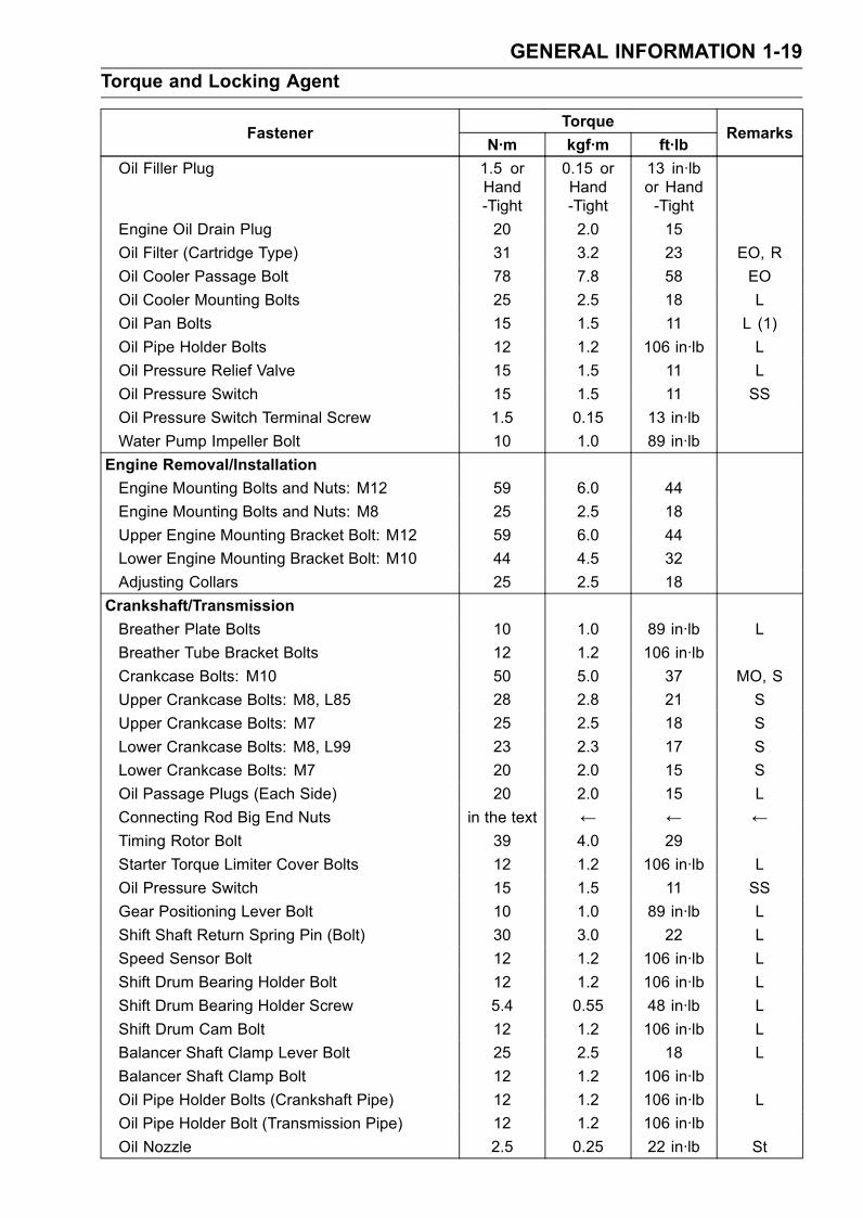
Torque and Locking Agent
TorqueFastener
N·m kgf·m ft·lbRemarks
Oil Filler Plug 1.5 orHand-Tight
0.15 orHand-Tight
13 in·lbor Hand-Tight
Engine Oil Drain Plug 20 2.0 15
Oil Filter (Cartridge Type) 31 3.2 23 EO, R
Oil Cooler Passage Bolt 78 7.8 58 EO
Oil Cooler Mounting Bolts 25 2.5 18 L
Oil Pan Bolts 15 1.5 11 L (1)
Oil Pipe Holder Bolts 12 1.2 106 in·lb L
Oil Pressure Relief Valve 15 1.5 11 L
Oil Pressure Switch 15 1.5 11 SS
Oil Pressure Switch Terminal Screw 1.5 0.15 13 in·lb
Water Pump Impeller Bolt 10 1.0 89 in·lb
Engine Removal/Installation
Engine Mounting Bolts and Nuts: M12 59 6.0 44
Engine Mounting Bolts and Nuts: M8 25 2.5 18
Upper Engine Mounting Bracket Bolt: M12 59 6.0 44
Lower Engine Mounting Bracket Bolt: M10 44 4.5 32
Adjusting Collars 25 2.5 18
Crankshaft/Transmission
Breather Plate Bolts 10 1.0 89 in·lb L
Breather Tube Bracket Bolts 12 1.2 106 in·lb
Crankcase Bolts: M10 50 5.0 37 MO, S
Upper Crankcase Bolts: M8, L85 28 2.8 21 S
Upper Crankcase Bolts: M7 25 2.5 18 S
Lower Crankcase Bolts: M8, L99 23 2.3 17 S
Lower Crankcase Bolts: M7 20 2.0 15 S
Oil Passage Plugs (Each Side) 20 2.0 15 L
Connecting Rod Big End Nuts in the text ← ← ←Timing Rotor Bolt 39 4.0 29
Starter Torque Limiter Cover Bolts 12 1.2 106 in·lb L
Oil Pressure Switch 15 1.5 11 SS
Gear Positioning Lever Bolt 10 1.0 89 in·lb L
Shift Shaft Return Spring Pin (Bolt) 30 3.0 22 L
Speed Sensor Bolt 12 1.2 106 in·lb L
Shift Drum Bearing Holder Bolt 12 1.2 106 in·lb L
Shift Drum Bearing Holder Screw 5.4 0.55 48 in·lb L
Shift Drum Cam Bolt 12 1.2 106 in·lb L
Balancer Shaft Clamp Lever Bolt 25 2.5 18 L
Balancer Shaft Clamp Bolt 12 1.2 106 in·lb
Oil Pipe Holder Bolts (Crankshaft Pipe) 12 1.2 106 in·lb L
Oil Pipe Holder Bolt (Transmission Pipe) 12 1.2 106 in·lb
Oil Nozzle 2.5 0.25 22 in·lb St
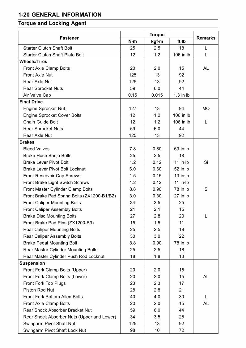
1-20 GENERAL INFORMATION
Torque and Locking Agent
TorqueFastener
N·m kgf·m ft·lbRemarks
Starter Clutch Shaft Bolt 25 2.5 18 L
Starter Clutch Shaft Plate Bolt 12 1.2 106 in·lb L
Wheels/Tires
Front Axle Clamp Bolts 20 2.0 15 AL
Front Axle Nut 125 13 92
Rear Axle Nut 125 13 92
Rear Sprocket Nuts 59 6.0 44
Air Valve Cap 0.15 0.015 1.3 in·lb
Final Drive
Engine Sprocket Nut 127 13 94 MO
Engine Sprocket Cover Bolts 12 1.2 106 in·lb
Chain Guide Bolt 12 1.2 106 in·lb L
Rear Sprocket Nuts 59 6.0 44
Rear Axle Nut 125 13 92
Brakes
Bleed Valves 7.8 0.80 69 in·lb
Brake Hose Banjo Bolts 25 2.5 18
Brake Lever Pivot Bolt 1.2 0.12 11 in·lb Si
Brake Lever Pivot Bolt Locknut 6.0 0.60 52 in·lb
Front Reservoir Cap Screws 1.5 0.15 13 in·lb
Front Brake Light Switch Screws 1.2 0.12 11 in·lb
Front Master Cylinder Clamp Bolts 8.8 0.90 78 in·lb S
Front Brake Pad Spring Bolts (ZX1200-B1/B2) 3.0 0.30 27 in·lb
Front Caliper Mounting Bolts 34 3.5 25
Front Caliper Assembly Bolts 21 2.1 15
Brake Disc Mounting Bolts 27 2.8 20 L
Front Brake Pad Pins (ZX1200-B3) 15 1.5 11
Rear Caliper Mounting Bolts 25 2.5 18
Rear Caliper Assembly Bolts 30 3.0 22
Brake Pedal Mounting Bolt 8.8 0.90 78 in·lb
Rear Master Cylinder Mounting Bolts 25 2.5 18
Rear Master Cylinder Push Rod Locknut 18 1.8 13
Suspension
Front Fork Clamp Bolts (Upper) 20 2.0 15
Front Fork Clamp Bolts (Lower) 20 2.0 15 AL
Front Fork Top Plugs 23 2.3 17
Piston Rod Nut 28 2.8 21
Front Fork Bottom Allen Bolts 40 4.0 30 L
Front Axle Clamp Bolts 20 2.0 15 AL
Rear Shock Absorber Bracket Nut 59 6.0 44
Rear Shock Absorber Nuts (Upper and Lower) 34 3.5 25
Swingarm Pivot Shaft Nut 125 13 92
Swingarm Pivot Shaft Lock Nut 98 10 72
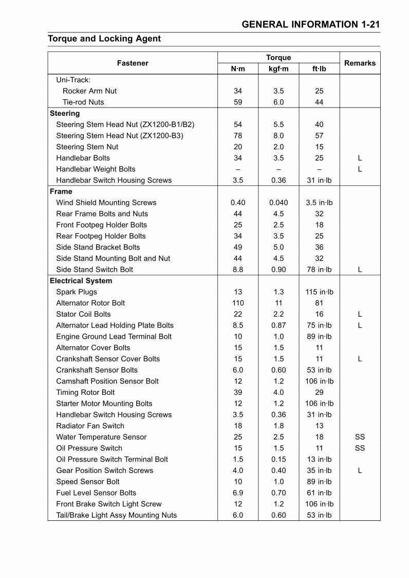
GENERAL INFORMATION 1-21
Torque and Locking Agent
TorqueFastener
N·m kgf·m ft·lbRemarks
Uni-Track:
Rocker Arm Nut 34 3.5 25
Tie-rod Nuts 59 6.0 44
Steering
Steering Stem Head Nut (ZX1200-B1/B2) 54 5.5 40
Steering Stem Head Nut (ZX1200-B3) 78 8.0 57
Steering Stem Nut 20 2.0 15
Handlebar Bolts 34 3.5 25 L
Handlebar Weight Bolts – – – L
Handlebar Switch Housing Screws 3.5 0.36 31 in·lb
Frame
Wind Shield Mounting Screws 0.40 0.040 3.5 in·lb
Rear Frame Bolts and Nuts 44 4.5 32
Front Footpeg Holder Bolts 25 2.5 18
Rear Footpeg Holder Bolts 34 3.5 25
Side Stand Bracket Bolts 49 5.0 36
Side Stand Mounting Bolt and Nut 44 4.5 32
Side Stand Switch Bolt 8.8 0.90 78 in·lb L
Electrical System
Spark Plugs 13 1.3 115 in·lb
Alternator Rotor Bolt 110 11 81
Stator Coil Bolts 22 2.2 16 L
Alternator Lead Holding Plate Bolts 8.5 0.87 75 in·lb L
Engine Ground Lead Terminal Bolt 10 1.0 89 in·lb
Alternator Cover Bolts 15 1.5 11
Crankshaft Sensor Cover Bolts 15 1.5 11 L
Crankshaft Sensor Bolts 6.0 0.60 53 in·lb
Camshaft Position Sensor Bolt 12 1.2 106 in·lb
Timing Rotor Bolt 39 4.0 29
Starter Motor Mounting Bolts 12 1.2 106 in·lb
Handlebar Switch Housing Screws 3.5 0.36 31 in·lb
Radiator Fan Switch 18 1.8 13
Water Temperature Sensor 25 2.5 18 SS
Oil Pressure Switch 15 1.5 11 SS
Oil Pressure Switch Terminal Bolt 1.5 0.15 13 in·lb
Gear Position Switch Screws 4.0 0.40 35 in·lb L
Speed Sensor Bolt 10 1.0 89 in·lb
Fuel Level Sensor Bolts 6.9 0.70 61 in·lb
Front Brake Switch Light Screw 12 1.2 106 in·lb
Tail/Brake Light Assy Mounting Nuts 6.0 0.60 53 in·lb
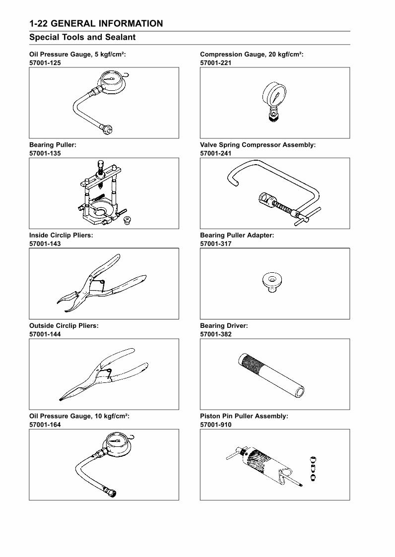
1-22 GENERAL INFORMATION
Special Tools and Sealant
Oil Pressure Gauge, 5 kgf/cm²:57001-125
Bearing Puller:57001-135
Inside Circlip Pliers:57001-143
Outside Circlip Pliers:57001-144
Oil Pressure Gauge, 10 kgf/cm²:57001-164
Compression Gauge, 20 kgf/cm²:57001-221
Valve Spring Compressor Assembly:57001-241
Bearing Puller Adapter:57001-317
Bearing Driver:57001-382
Piston Pin Puller Assembly:57001-910
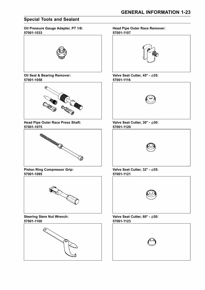
GENERAL INFORMATION 1-23
Special Tools and Sealant
Oil Pressure Gauge Adapter, PT 1/8:57001-1033
Oil Seal & Bearing Remover:57001-1058
Head Pipe Outer Race Press Shaft:57001-1075
Piston Ring Compressor Grip:57001-1095
Steering Stem Nut Wrench:57001-1100
Head Pipe Outer Race Remover:57001-1107
Valve Seat Cutter, 45° - 35:57001-1116
Valve Seat Cutter, 30° - 30:57001-1120
Valve Seat Cutter, 32° - 35:57001-1121
Valve Seat Cutter, 60° - 30:57001-1123

1-24 GENERAL INFORMATION
Special Tools and Sealant
Valve Seat Cutter Holder Bar:57001-1128
Bearing Driver Set:57001-1129
Valve Seat Cutter, 45° - 30:57001-1187
Valve Spring Compressor Adapter, 22:57001-1202
Valve Guide Arbor, 5:57001-1203
Valve Guide Reamer, 5:57001-1204
Valve Seat Cutter Holder, 5:57001-1208
Rotor Puller, M16/M18/M20/M22 × 1.5:57001-1216
Jack:57001-1238
Clutch Holder:57001-1243
GENERAL INFORMATION 1-25
Special Tools and Sealant
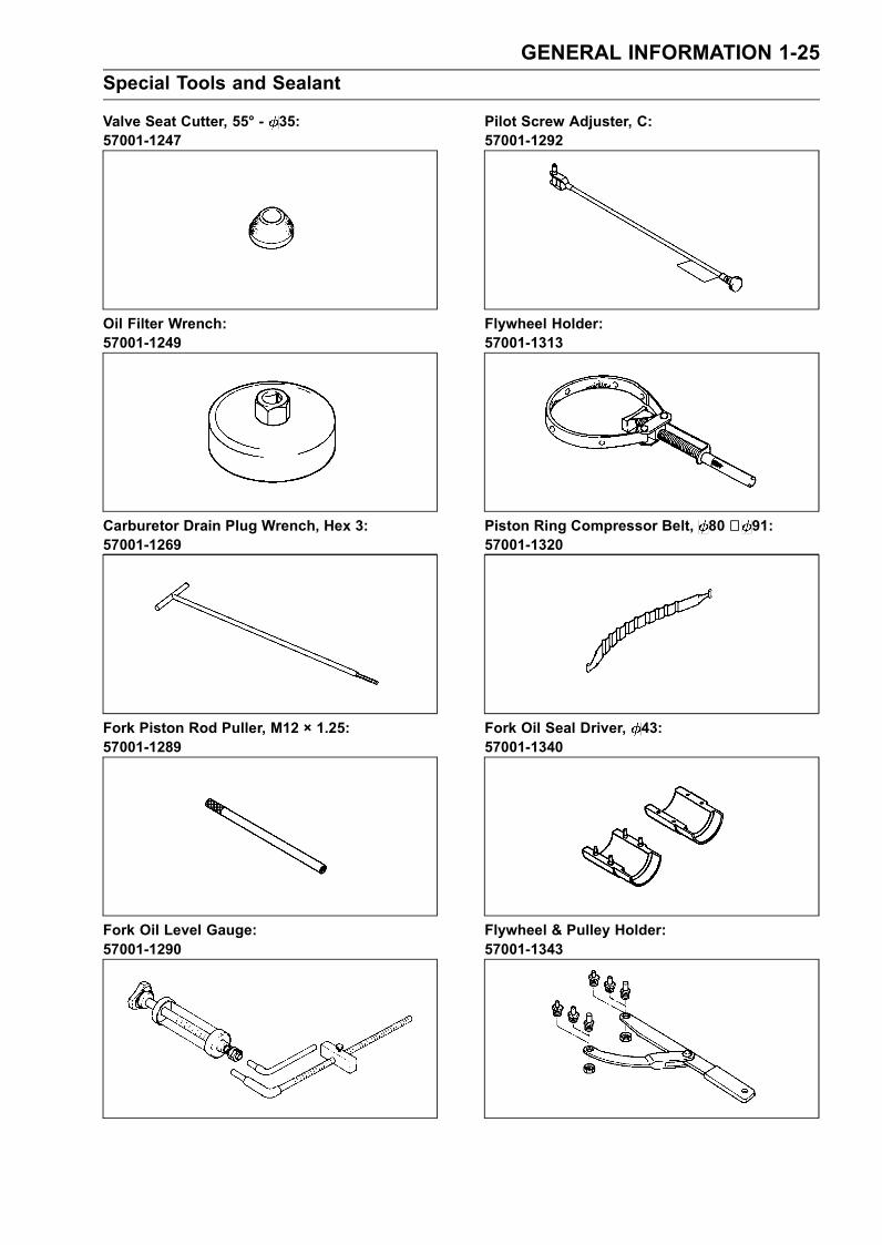
Valve Seat Cutter, 55° - 35:57001-1247
Oil Filter Wrench:57001-1249
Carburetor Drain Plug Wrench, Hex 3:57001-1269
Fork Piston Rod Puller, M12 × 1.25:57001-1289
Fork Oil Level Gauge:57001-1290
Pilot Screw Adjuster, C:57001-1292
Flywheel Holder:57001-1313
Piston Ring Compressor Belt, 80 ∼ 91:57001-1320
Fork Oil Seal Driver, 43:57001-1340
Flywheel & Pulley Holder:57001-1343
1-26 GENERAL INFORMATION
Special Tools and Sealant
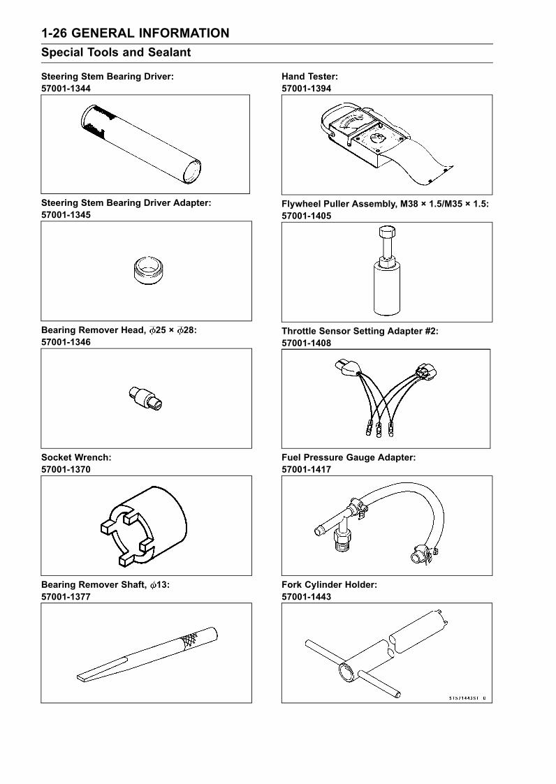
Steering Stem Bearing Driver:57001-1344
Steering Stem Bearing Driver Adapter:57001-1345
Bearing Remover Head, 25 × 28:57001-1346
Socket Wrench:57001-1370
Bearing Remover Shaft, 13:57001-1377
Hand Tester:57001-1394
Flywheel Puller Assembly, M38 × 1.5/M35 × 1.5:57001-1405
Throttle Sensor Setting Adapter #2:57001-1408
Fuel Pressure Gauge Adapter:57001-1417
Fork Cylinder Holder:57001-1443
GENERAL INFORMATION 1-27
Special Tools and Sealant
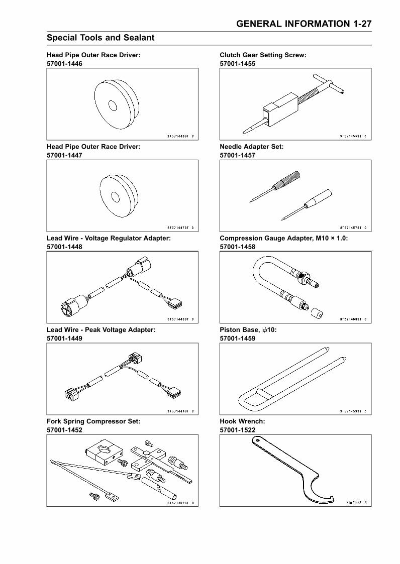
Head Pipe Outer Race Driver:57001-1446
Head Pipe Outer Race Driver:57001-1447
Lead Wire - Voltage Regulator Adapter:57001-1448
Lead Wire - Peak Voltage Adapter:57001-1449
Fork Spring Compressor Set:57001-1452
Clutch Gear Setting Screw:57001-1455
Needle Adapter Set:57001-1457
Compression Gauge Adapter, M10 × 1.0:57001-1458
Piston Base, 10:57001-1459
Hook Wrench:57001-1522
1-28 GENERAL INFORMATION
Special Tools and Sealant
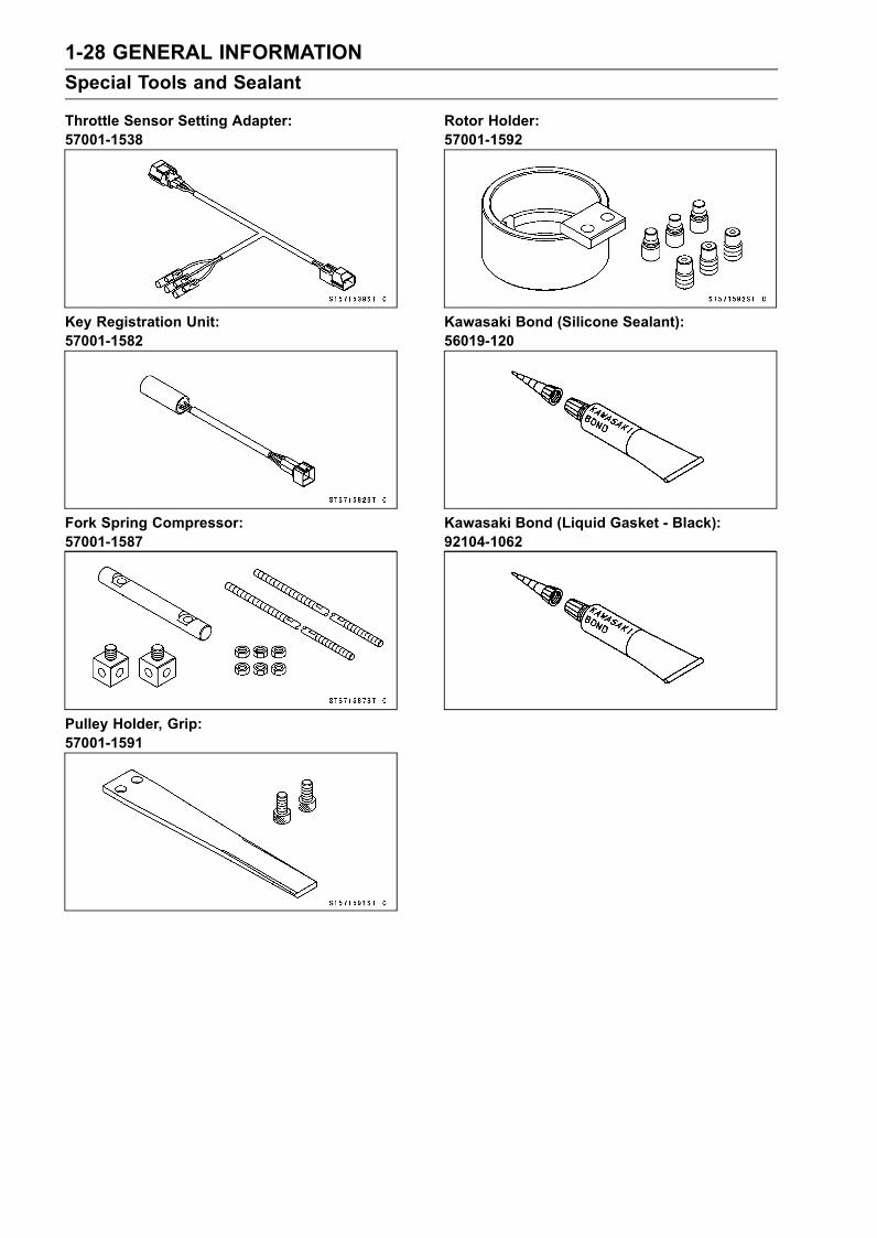
Throttle Sensor Setting Adapter:57001-1538
Key Registration Unit:57001-1582
Fork Spring Compressor:57001-1587
Pulley Holder, Grip:57001-1591
Rotor Holder:57001-1592
Kawasaki Bond (Silicone Sealant):56019-120
Kawasaki Bond (Liquid Gasket - Black):92104-1062
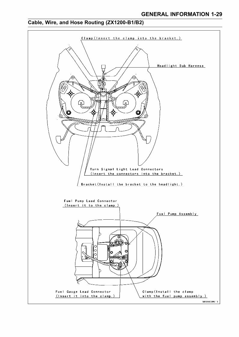
GENERAL INFORMATION 1-29
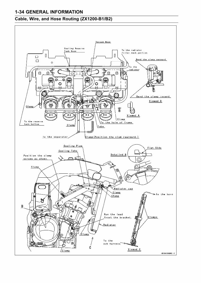
Cable, Wire, and Hose Routing (ZX1200-B1/B2)
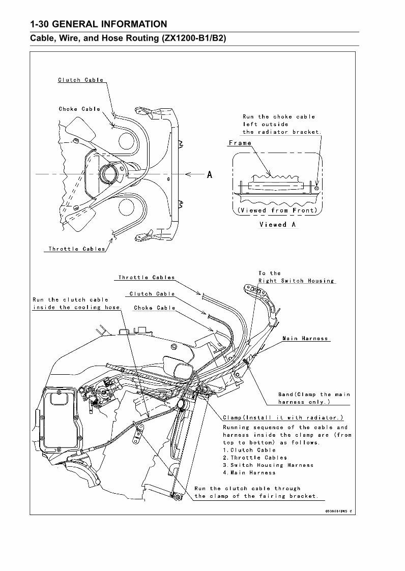
1-30 GENERAL INFORMATION
Cable, Wire, and Hose Routing (ZX1200-B1/B2)
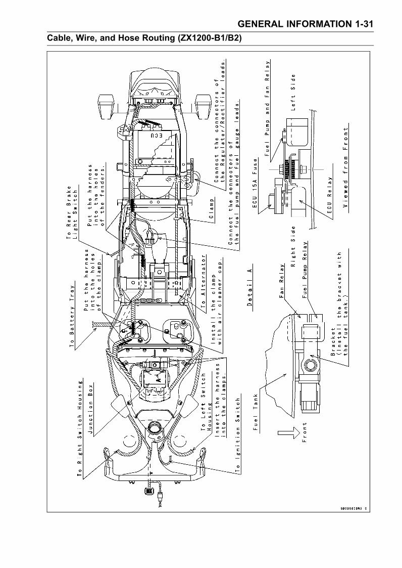
GENERAL INFORMATION 1-31
Cable, Wire, and Hose Routing (ZX1200-B1/B2)
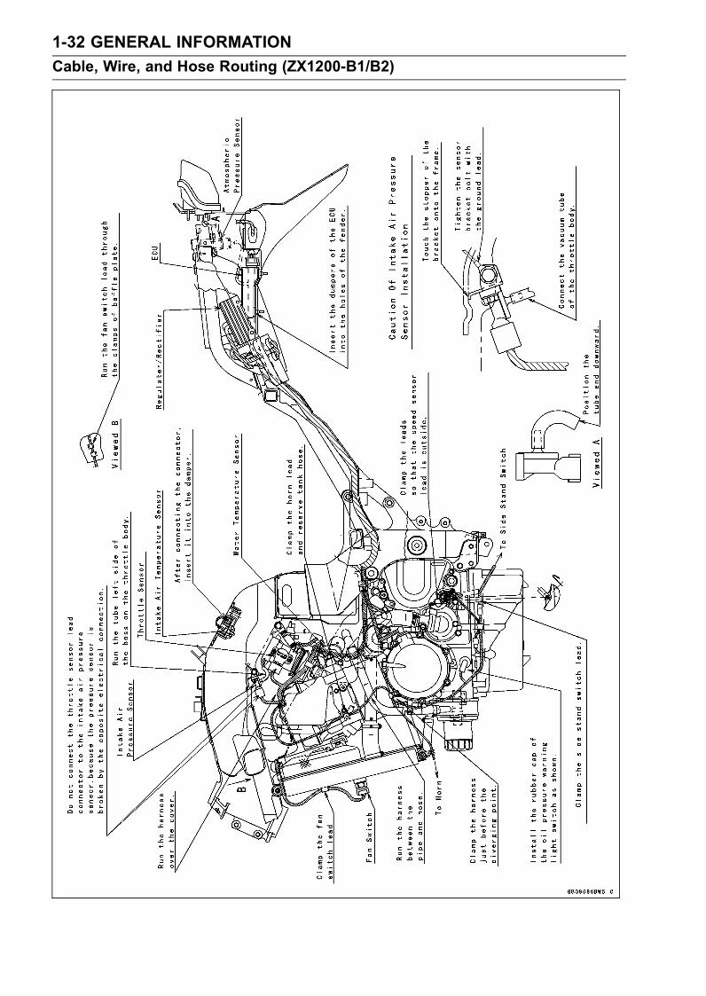
1-32 GENERAL INFORMATION
Cable, Wire, and Hose Routing (ZX1200-B1/B2)

GENERAL INFORMATION 1-33
Cable, Wire, and Hose Routing (ZX1200-B1/B2)
1-34 GENERAL INFORMATION
Cable, Wire, and Hose Routing (ZX1200-B1/B2)

GENERAL INFORMATION 1-35
Cable, Wire, and Hose Routing (ZX1200-B1/B2)
1-36 GENERAL INFORMATION
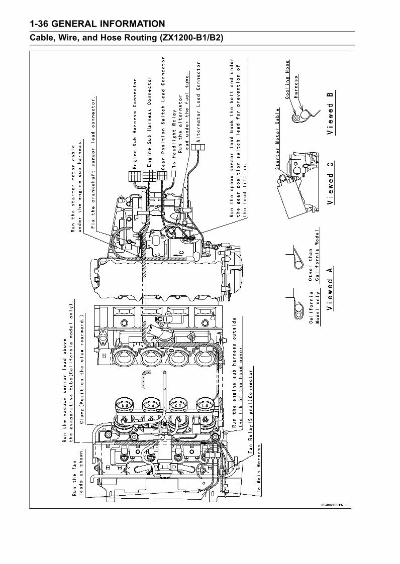
Cable, Wire, and Hose Routing (ZX1200-B1/B2)
GENERAL INFORMATION 1-37
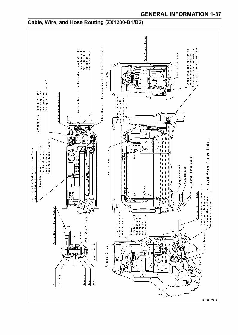
Cable, Wire, and Hose Routing (ZX1200-B1/B2)
1-38 GENERAL INFORMATION
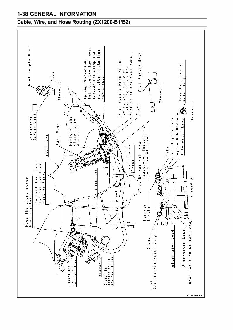
Cable, Wire, and Hose Routing (ZX1200-B1/B2)
GENERAL INFORMATION 1-39
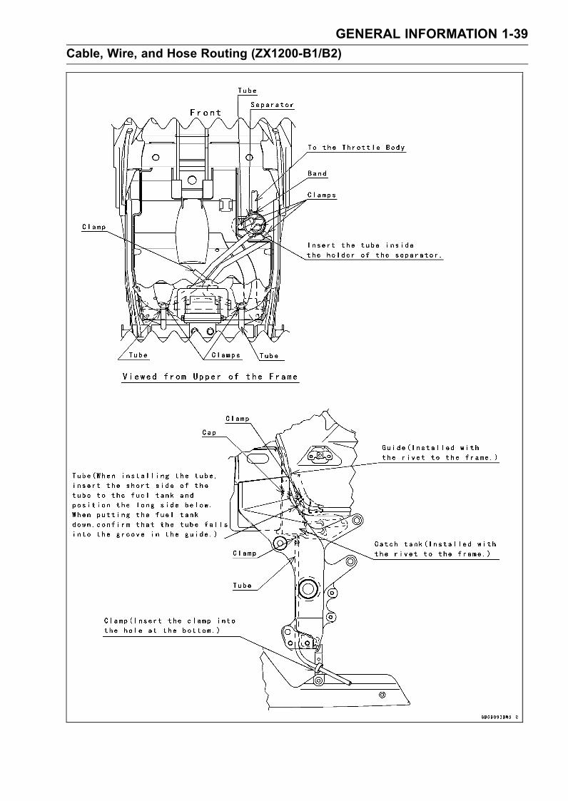
Cable, Wire, and Hose Routing (ZX1200-B1/B2)
1-40 GENERAL INFORMATION
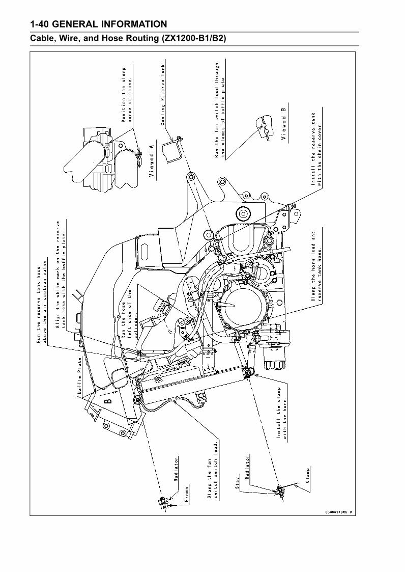
Cable, Wire, and Hose Routing (ZX1200-B1/B2)
GENERAL INFORMATION 1-41
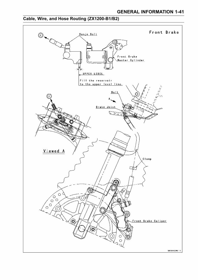
Cable, Wire, and Hose Routing (ZX1200-B1/B2)
1-42 GENERAL INFORMATION
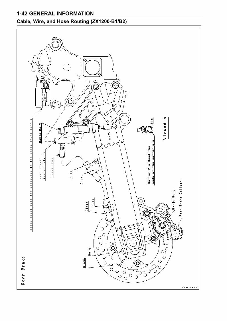
Cable, Wire, and Hose Routing (ZX1200-B1/B2)
GENERAL INFORMATION 1-43
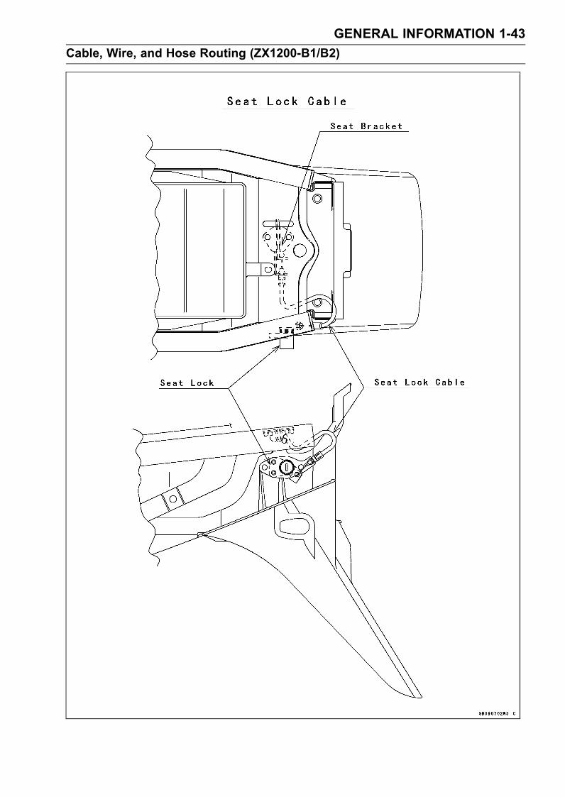
Cable, Wire, and Hose Routing (ZX1200-B1/B2)
1-44 GENERAL INFORMATION
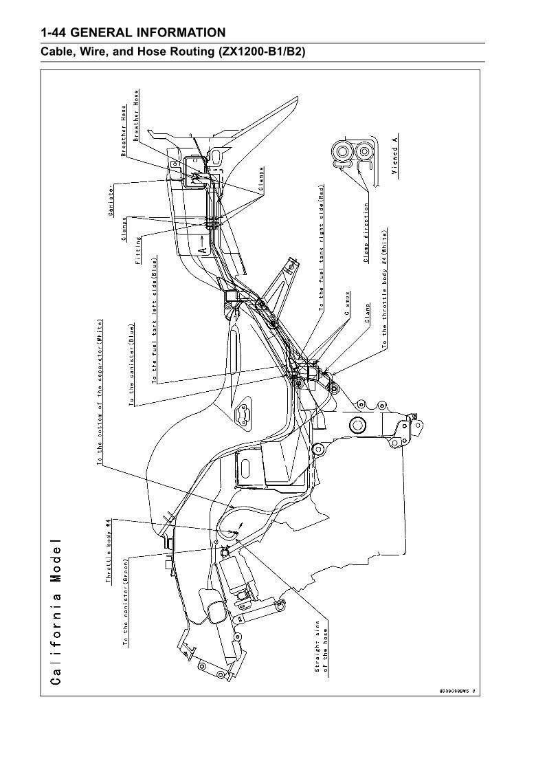
Cable, Wire, and Hose Routing (ZX1200-B1/B2)
GENERAL INFORMATION 1-45
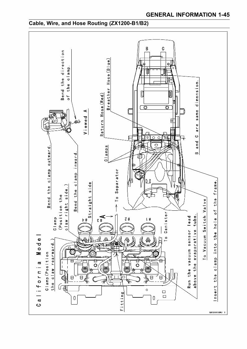
Cable, Wire, and Hose Routing (ZX1200-B1/B2)
1-46 GENERAL INFORMATION
Cable, Wire, and Hose Routing (ZX1200-B3)
GENERAL INFORMATION 1-47
Cable, Wire, and Hose Routing (ZX1200-B3)
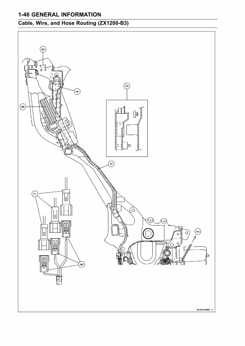
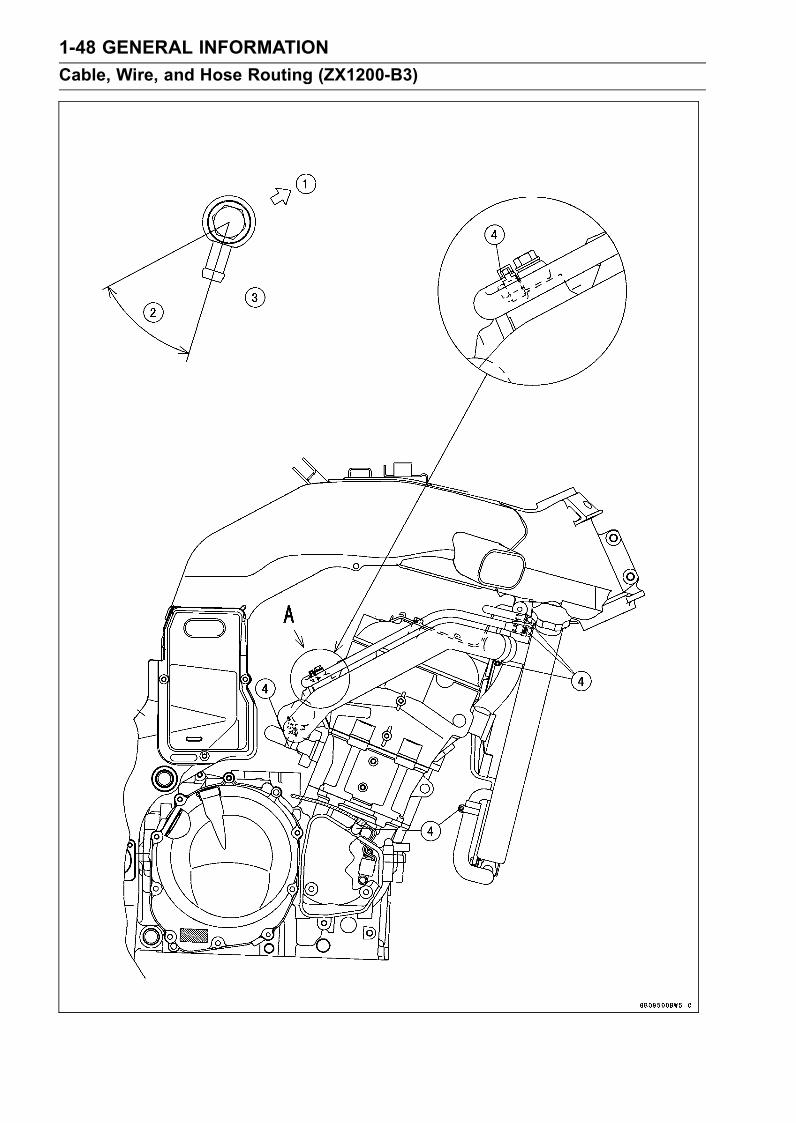
1. Clamp2. To Side Stand Switch3. Insert the dampers of the ECU into the holes of the fender.4. ECU5. Atmospheric Pressure Sensor6. Regulator/rectifier7. From Regulator/rectifier8. From Alternator
1-48 GENERAL INFORMATION
Cable, Wire, and Hose Routing (ZX1200-B3)
GENERAL INFORMATION 1-49
Cable, Wire, and Hose Routing (ZX1200-B3)
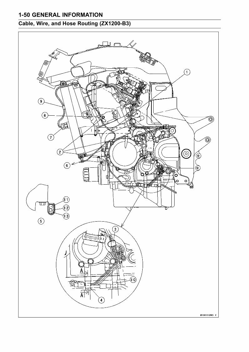
1. Front2. About 45°3. Viewed A4. Clamp
1-50 GENERAL INFORMATION
Cable, Wire, and Hose Routing (ZX1200-B3)

GENERAL INFORMATION 1-51
Cable, Wire, and Hose Routing (ZX1200-B3)
1. Run the horn lead between the water hose and water pipe.2. Clamp3. Clamp the leads so that the speed sensor lead is outside.4. Clamp the speed sensor lead, gear position switch lead and sub harness.5. Section A-A6. To Horn7. Radiator Fan Switch8. Clamp the horn lead and reserve tank hose.9. Clamp the fan switch lead.10. Clamp the side stand switch lead.11. Gear Position Switch Lead12. Speed Sensor Lead13. Sub Harness

1-52 GENERAL INFORMATION
Cable, Wire, and Hose Routing (ZX1200-B3)
GENERAL INFORMATION 1-53
Cable, Wire, and Hose Routing (ZX1200-B3)
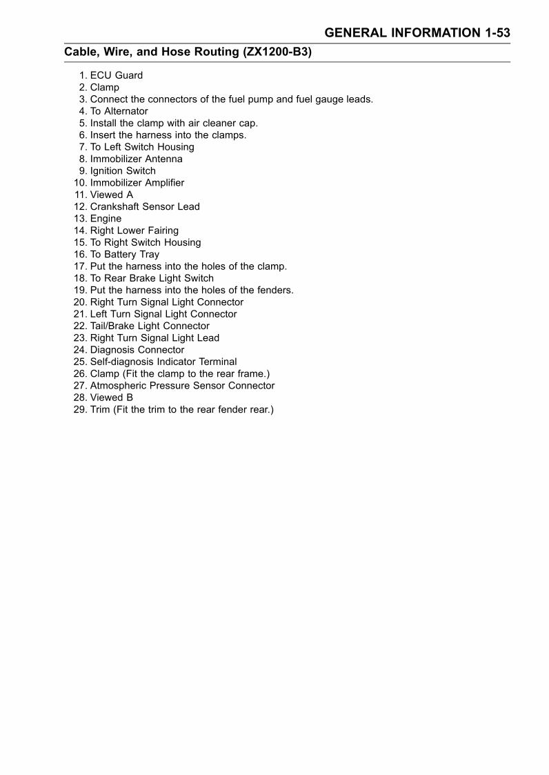
1. ECU Guard2. Clamp3. Connect the connectors of the fuel pump and fuel gauge leads.4. To Alternator5. Install the clamp with air cleaner cap.6. Insert the harness into the clamps.7. To Left Switch Housing8. Immobilizer Antenna9. Ignition Switch10. Immobilizer Amplifier11. Viewed A12. Crankshaft Sensor Lead13. Engine14. Right Lower Fairing15. To Right Switch Housing16. To Battery Tray17. Put the harness into the holes of the clamp.18. To Rear Brake Light Switch19. Put the harness into the holes of the fenders.20. Right Turn Signal Light Connector21. Left Turn Signal Light Connector22. Tail/Brake Light Connector23. Right Turn Signal Light Lead24. Diagnosis Connector25. Self-diagnosis Indicator Terminal26. Clamp (Fit the clamp to the rear frame.)27. Atmospheric Pressure Sensor Connector28. Viewed B29. Trim (Fit the trim to the rear fender rear.)
1-54 GENERAL INFORMATION
Cable, Wire, and Hose Routing (ZX1200-B3)
GENERAL INFORMATION 1-55
Cable, Wire, and Hose Routing (ZX1200-B3)
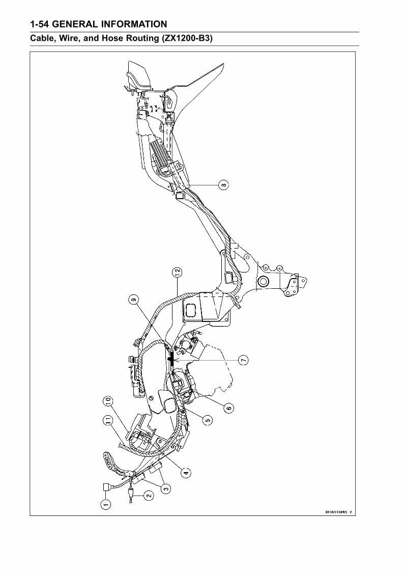
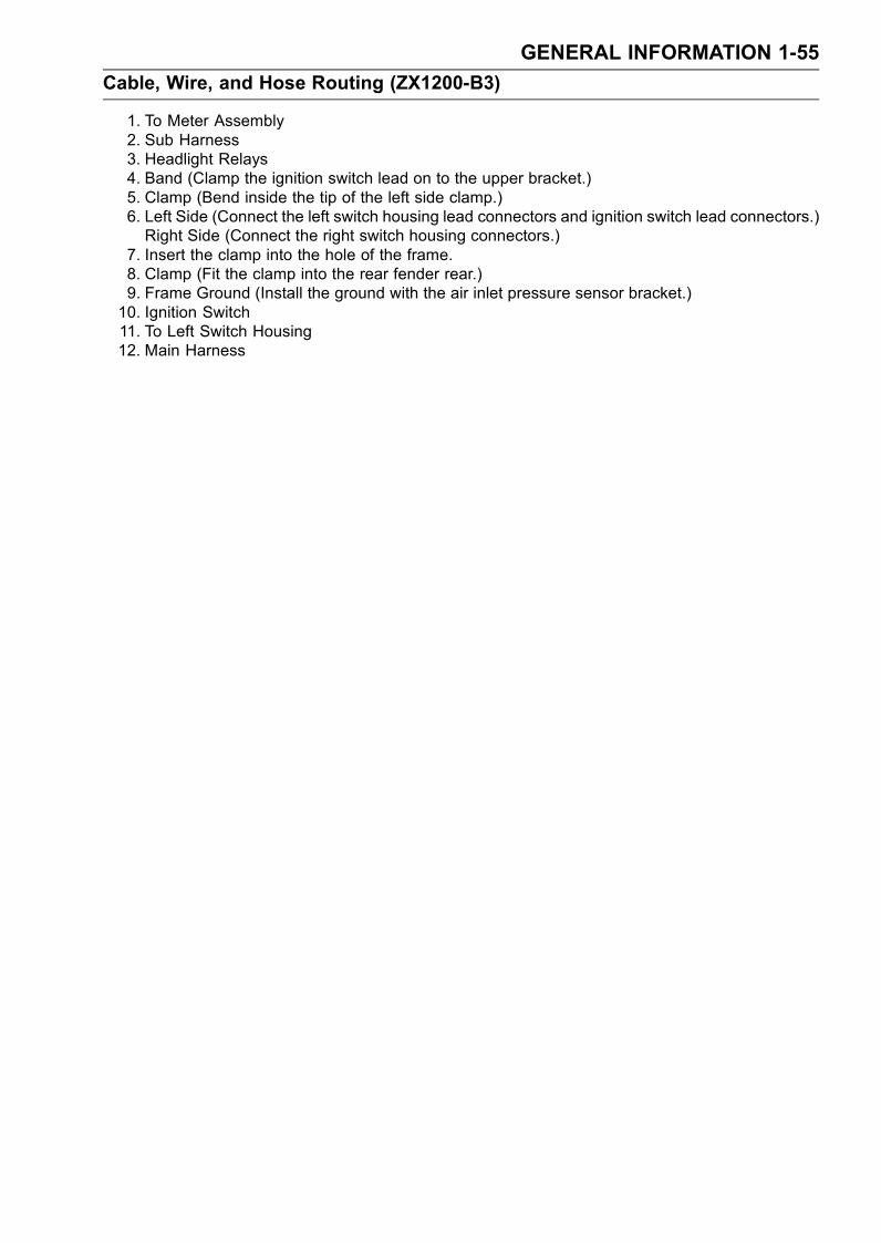
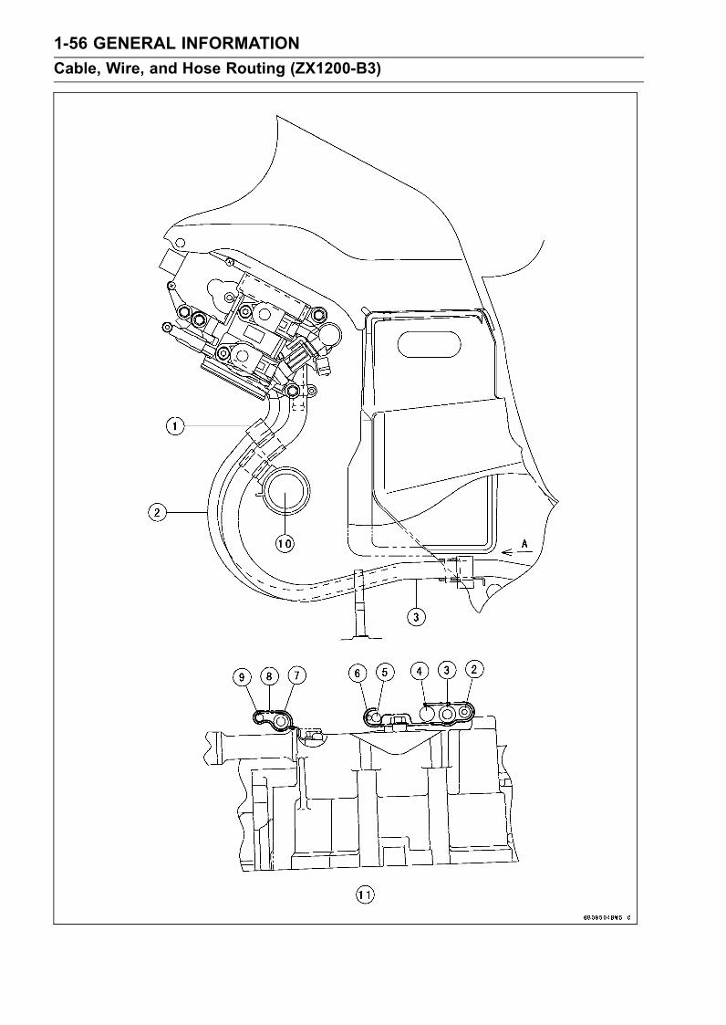
1. To Meter Assembly2. Sub Harness3. Headlight Relays4. Band (Clamp the ignition switch lead on to the upper bracket.)5. Clamp (Bend inside the tip of the left side clamp.)6. Left Side (Connect the left switch housing lead connectors and ignition switch lead connectors.)Right Side (Connect the right switch housing connectors.)
7. Insert the clamp into the hole of the frame.8. Clamp (Fit the clamp into the rear fender rear.)9. Frame Ground (Install the ground with the air inlet pressure sensor bracket.)10. Ignition Switch11. To Left Switch Housing12. Main Harness
1-56 GENERAL INFORMATION
Cable, Wire, and Hose Routing (ZX1200-B3)
GENERAL INFORMATION 1-57
Cable, Wire, and Hose Routing (ZX1200-B3)
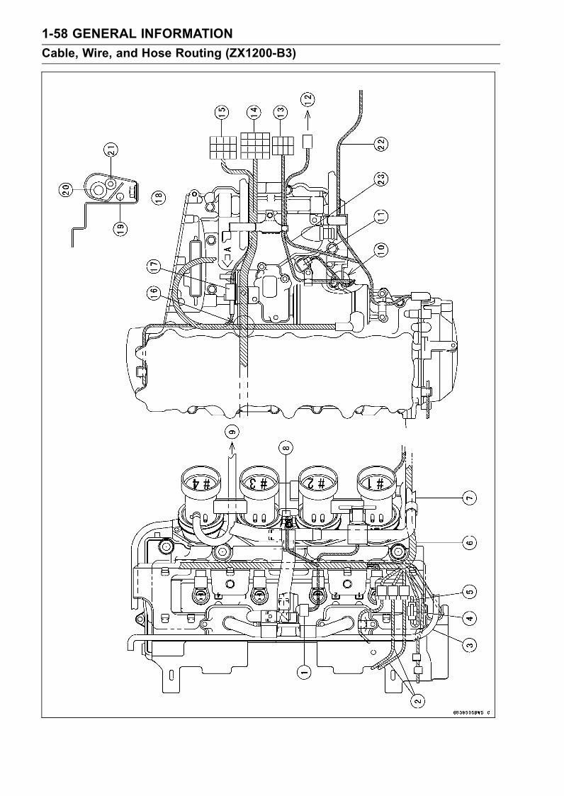
1. Clamp the vacuum hose and fuel hose.2. Vacuum Hose3. Fuel Hose4. Engine Sub Harness5. Gear Position Switch Lead6. Alternator Lead7. Tube (Air Switching Valve – Canister):California Model Only8. Clamp9. Alternator Lead10. Water Hose11. Viewed A
1-58 GENERAL INFORMATION
Cable, Wire, and Hose Routing (ZX1200-B3)
GENERAL INFORMATION 1-59
Cable, Wire, and Hose Routing (ZX1200-B3)
1. Air Switching Valve2. Fan Leads3. Run the water hose on the fan leads and fan switch lead.4. Fan Relay (Signal) Connector5. To Main Harness6. Run the engine sub harness outside the lib of the head cover.7. To Canister8. Actuator9. To Separator10. Run the speed sensor lead back the bolt and under the gear position switch lead for prevention
of the lead lift up.11. Speed Sensor12. To Headlight Relay13. Gear Position Switch Lead Connector14. Engine Sub Harness Connector15. Engine Sub Harness Connector16. Run the starter motor cable under the engine sub harness.17. Fix the crankshaft sensor lead connector.18. Viewed A19. Crankshaft Sensor Lead20. Fuel Hose21. Tube (Throttle Body – Separator): California Model Only22. Alternator Lead23. Run the alternator lead under the fuel tube.

1-60 GENERAL INFORMATION
Unit Conversion Table
Prefixes for Units:
Prefix Symbol Power
mega M × 1 000 000
kilo k × 1 000
centi c × 0.01
milli m × 0.001
micro µ × 0.000001
Units of Mass:kg × 2.205 = lb
g × 0.03527 = oz
Units of Volume:L × 0.2642 = gal (US)
L × 0.2200 = gal (imp)
L × 1.057 = qt (US)
L × 0.8799 = qt (imp)
L × 2.113 = pint (US)
L × 1.816 = pint (imp)
mL × 0.03381 = oz (US)
mL × 0.02816 = oz (imp)
mL × 0.06102 = cu in
Units of Force:N × 0.1020 = kg
N × 0.2248 = lb
kg × 9.807 = N
kg × 2.205 = lb
Units of Length:km × 0.6214 = mile
m × 3.281 = ft
mm × 0.03937 = in
Units of Torque:N·m × 0.1020 = kgf·m
N·m × 0.7376 = ft·lb
N·m × 8.851 = in·lb
kgf·m × 9.807 = N·m
kgf·m × 7.233 = ft·lb
kgf·m × 86.80 = in·lb
Units of Pressure:kPa × 0.01020 = kgf/cm²
kPa × 0.1450 = psi
kPa × 0.7501 = cm Hg
kgf/cm² × 98.07 = kPa
kgf/cm² × 14.22 = psi
cm Hg × 1.333 = kPa
Units of Speed:km/h × 0.6214 = mph
Units of Power:kW × 1.360 = PS
kW × 1.341 = HP
PS × 0.7355 = kW
PS × 0.9863 = HP
Units of Temperature:
PERIODIC MAINTENANCE 2-1
2
Periodic Maintenance
Table of Contents
Periodic Maintenance Chart .............. 2-2Specifications .................................... 2-4Periodic Maintenance Procedures..... 2-6Fuel System (DFI)........................... 2-6Fuel Hose and ConnectionInspection.................................. 2-6
Throttle Control SystemInspection.................................. 2-7
Idle Speed Inspection .................. 2-8Engine Vacuum SynchronizationInspection.................................. 2-9
Air Cleaner Element Cleaning(ZX1200-B1/B2)/ElementReplacement (ZX1200-B3) ....... 2-13
Evaporative Emission ControlSystem Inspection(CAL) ........... 2-14
Cooling System............................... 2-15Cooling Hose and ConnectionInspection.................................. 2-15
Coolant Change........................... 2-15Engine Top End .............................. 2-17Air Suction Valve Inspection ........ 2-17Valve Clearance Inspection ......... 2-18
Clutch.............................................. 2-22Clutch Adjust Inspection .............. 2-22
Engine Lubrication System............. 2-23Engine Oil Change....................... 2-23Oil Filter Replace ......................... 2-23
Wheels/Tires................................... 2-24Tire Wear Inspection .................... 2-24
Final Drive....................................... 2-25Drive Chain Slack Inspection ....... 2-25Drive Chain Wear Inspection ....... 2-26
Drive Chain Lubrication................ 2-28Brakes............................................. 2-28Brake Hose, ConnectionInspection.................................. 2-28
Brake Fluid Level Inspection........ 2-29Brake Fluid Change ..................... 2-29Front Brake Pad Wear Inspection 2-30Rear Brake Pad Wear Inspection 2-31Brake/Master Cylinder Cup andDust Seal Replace .................... 2-31
Caliper Piston/Dust Seal Replace 2-31Front Brake Light SwitchInspection.................................. 2-31
Rear Brake Light SwitchInspection/Adjustment............... 2-31
Suspension..................................... 2-32Front Fork Oil Change ................. 2-32Front Fork Oil Leak Inspection..... 2-42Rear Shock Absorber Oil LeakInspection.................................. 2-42
Swingarm Pivot Lubrication ......... 2-42Unit-trak Linkage Lubrication ....... 2-43
Steering .......................................... 2-43Steering Inspection ...................... 2-43Steering Stem BearingLubrication................................. 2-45
Electrical System ............................ 2-45Spark Plug Cleaning andInspection.................................. 2-45
General Lubrication ........................ 2-45Lubrication Perform...................... 2-45
Nut, Bolt, and Fastener Tightness .. 2-47Tightness Inspection .................... 2-47

2-2 PERIODIC MAINTENANCE
Periodic Maintenance Chart
The scheduled maintenance must be done in accordance with this chart to keep the motorcycle ingood running condition. The initial maintenance is vitally important and must not be neglected.
FREQUENCY Whichevercomesfirst
*Odometer Reading× 1000 km
(× 1000 mile)
1 6 12 18 24 30 36
OPERATION Every (0.6) (4) (7.5) (12) (15) (20) (24)
Refer-ence
Steering - inspect † • • • • • • • 2-43
Steering stem bearing - lubricate 2 years • 2-45
Brake hoses, connections - inspect † • • • • • • 2-28
Brake fluid level - inspect † month • • • • • • • 2-29
Brake fluid - change 2 years • 2-29
Brake pad wear - inspect † # • • • • • • 2-30
Brake master cylinder cup and dust seal- replace
4 years 2-31
Caliper piston seal and dust seal - replace 4 years 2-31
Brake light switches - inspect † • • • • • • • 2-31
Tire wear - inspect † • • • • • • 2-24
Front fork oil - change 2 years • 2-32
Front fork oil leak - inspect † • • • 2-42
Rear shock absorber oil leak - inspect † • • • 2-42
Swingarm pivot, Unit-track linkage -lubricate • • • 2-42
Clutch adjust - inspect † • • • • • • • 2-22
Drive chain slack - inspect † # 1 000 km 2-25
Drive chain wear - inspect † # • • • • • • 2-26
Drive chain roller wear - inspect † # • • • • • • 2-27
Drive chain - lubricate # 600 km 2-28
Spark plug (e) - clean and gap † • • • • • • 2-45
Fuel hoses, connections - inspect † • • • • • • 2-6
Throttle control system (e) - inspect † • • • • • • • 2-7
Idle speed (e) - inspect † • • • • 2-8
Engine vacuum sychronization (e) -inspect † • • • 2-9
Air cleaner element (e) - clean † #(ZX1200-B1/B2) • • • 2-13
Air cleaner element (e) - replace † #(ZX1200-B3) • 2-13
Evaporative emission control system (e)(CAL) - inspect † • • • • • • • 2-14
Air suction valve (e) - inspect † • • • • • • 2-17
Valve clearance (e) - inspect † • • • 2-18
Cooling hoses, connections - inspect † • 2-15
Coolant - change 2 years • 2-15
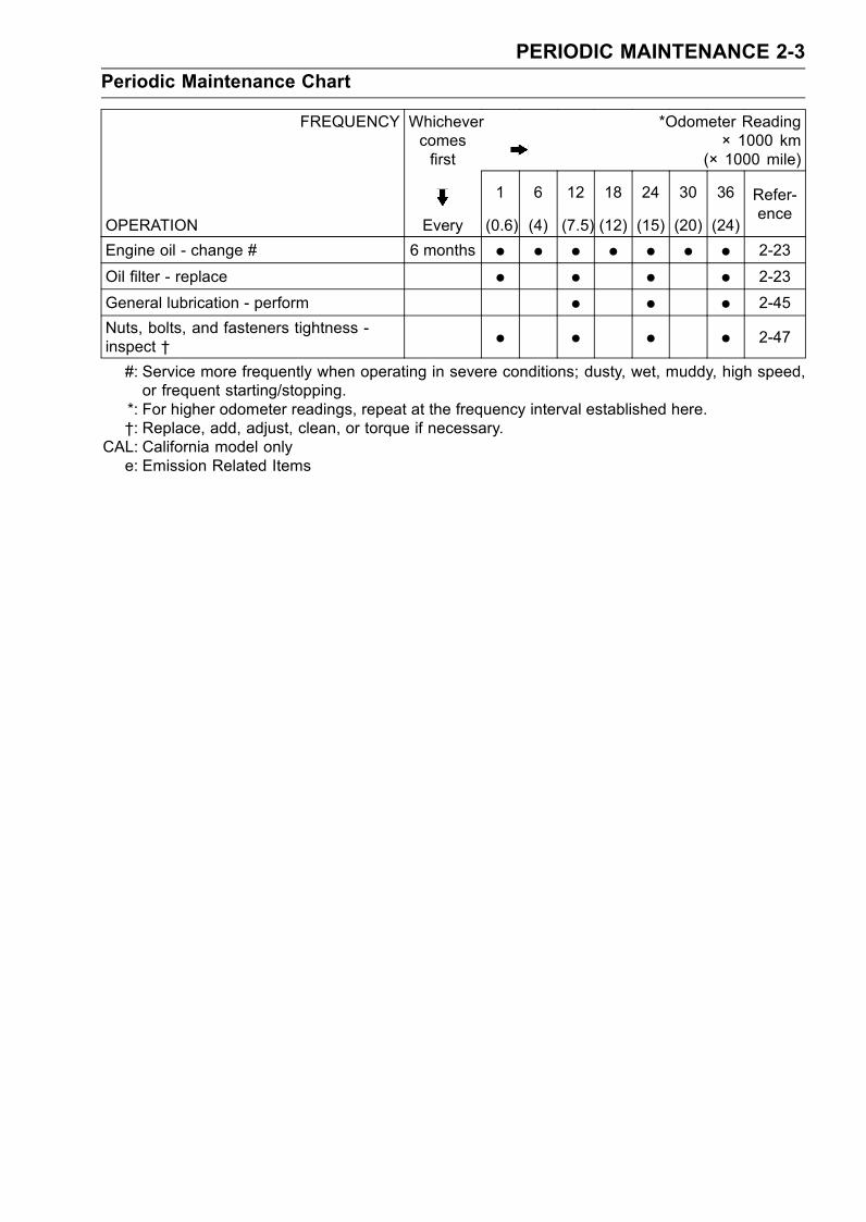
PERIODIC MAINTENANCE 2-3
Periodic Maintenance Chart
FREQUENCY Whichevercomesfirst
*Odometer Reading× 1000 km
(× 1000 mile)
1 6 12 18 24 30 36
OPERATION Every (0.6) (4) (7.5) (12) (15) (20) (24)
Refer-ence
Engine oil - change # 6 months • • • • • • • 2-23
Oil filter - replace • • • • 2-23
General lubrication - perform • • • 2-45
Nuts, bolts, and fasteners tightness -inspect † • • • • 2-47
#: Service more frequently when operating in severe conditions; dusty, wet, muddy, high speed,or frequent starting/stopping.
*: For higher odometer readings, repeat at the frequency interval established here.†: Replace, add, adjust, clean, or torque if necessary.
CAL: California model onlye: Emission Related Items

2-4 PERIODIC MAINTENANCE
Specifications
Item Standard Service Limit
Fuel System (DFI)
Throttle Grip Free Play 2 ∼ 3 mm (0.08 ∼ 0.12 in.) – – –
Idle Speed 1 000 ±50 r/min (rpm) – – –
Throttle Body Vacuum 26 ±1.333 kPa (195 ±10 mmHg) – – –
Air Cleaner Element:
ZX1200-B1/B2 Polyurethane foam – – –
ZX1200-B3 Filter paper – – –
Air Cleaner Element Oil SE, SF or SG SAE 30, or High-quality airfilter oil
– – –
Cooling System
Coolant:
Type (Recommended) Permanent type antifreeze – – –
Color Green – – –
Mixed Ratio Soft water 50%, Coolant 50% – – –
Freezing Point – 35°C (– 31°F) – – –
Total Amount 3.6 L (3.8 US qt) – – –
Engine Top End
Valve Clearance:
Exhaust 0.22 ∼ 0.31 mm (0.0087 ∼ 0.0122 in.) – – –
Inlet 0.15 ∼ 0.24 mm (0.0059 ∼ 0.0094 in.) – – –
Clutch
Clutch Lever Free Play 2 ∼ 3 mm (0.08 ∼ 0.12 in.) – – –
Engine Lubrication System
Engine Oil:
Type API SE, SF or SG – – –
API SH or SJ with JASO MA
Viscosity SAE 10W-40 – – –
Capacity 2.5 L (2.6 US qt, when filter is not removed) – – –
2.8 L (3.0 US qt, when filter is removed) – – –
3.6 L (3.8 US qt, when engine is completelydisassembled and dry)
– – –
Level Between upper and lower level lines (afteridling or running)
– – –
Tires
Tread Depth:
Front: DUNLOP D208FJ 4.0 mm (0.16 in.) 1 mm (0.04 in.)
(AT, CH, DE):
1.6 mm (0.063 in.)
Up to 130 km/h
(80 mph)
Rear: DUNLOP D208J 5.4 mm (0.21 in.) 2 mm (0.08 in.)
Over 130 km/h
(80 mph)
3 mm (0.12 in.)
PERIODIC MAINTENANCE 2-5
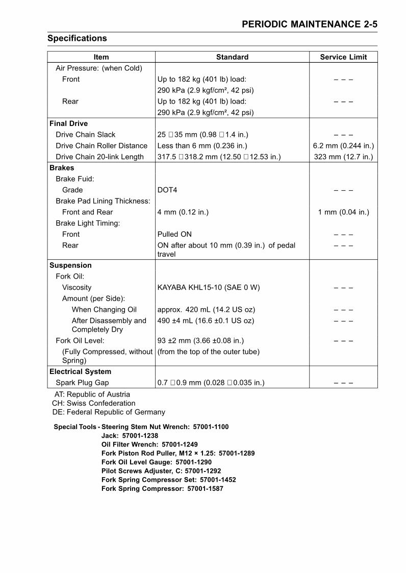
Specifications
Item Standard Service Limit
Air Pressure: (when Cold)
Front Up to 182 kg (401 lb) load: – – –
290 kPa (2.9 kgf/cm², 42 psi)
Rear Up to 182 kg (401 lb) load: – – –
290 kPa (2.9 kgf/cm², 42 psi)
Final Drive
Drive Chain Slack 25 ∼ 35 mm (0.98 ∼ 1.4 in.) – – –
Drive Chain Roller Distance Less than 6 mm (0.236 in.) 6.2 mm (0.244 in.)
Drive Chain 20-link Length 317.5 ∼ 318.2 mm (12.50 ∼ 12.53 in.) 323 mm (12.7 in.)
Brakes
Brake Fuid:
Grade DOT4 – – –
Brake Pad Lining Thickness:
Front and Rear 4 mm (0.12 in.) 1 mm (0.04 in.)
Brake Light Timing:
Front Pulled ON – – –
Rear ON after about 10 mm (0.39 in.) of pedaltravel
– – –
Suspension
Fork Oil:
Viscosity KAYABA KHL15-10 (SAE 0 W) – – –
Amount (per Side):
When Changing Oil approx. 420 mL (14.2 US oz) – – –
After Disassembly andCompletely Dry
490 ±4 mL (16.6 ±0.1 US oz) – – –
Fork Oil Level: 93 ±2 mm (3.66 ±0.08 in.) – – –
(Fully Compressed, withoutSpring)
(from the top of the outer tube)
Electrical System
Spark Plug Gap 0.7 ∼ 0.9 mm (0.028 ∼ 0.035 in.) – – –
AT: Republic of AustriaCH: Swiss ConfederationDE: Federal Republic of Germany
Special Tools - Steering Stem Nut Wrench: 57001-1100Jack: 57001-1238Oil Filter Wrench: 57001-1249Fork Piston Rod Puller, M12 × 1.25: 57001-1289Fork Oil Level Gauge: 57001-1290Pilot Screws Adjuster, C: 57001-1292Fork Spring Compressor Set: 57001-1452Fork Spring Compressor: 57001-1587
2-6 PERIODIC MAINTENANCE
Periodic Maintenance Procedures
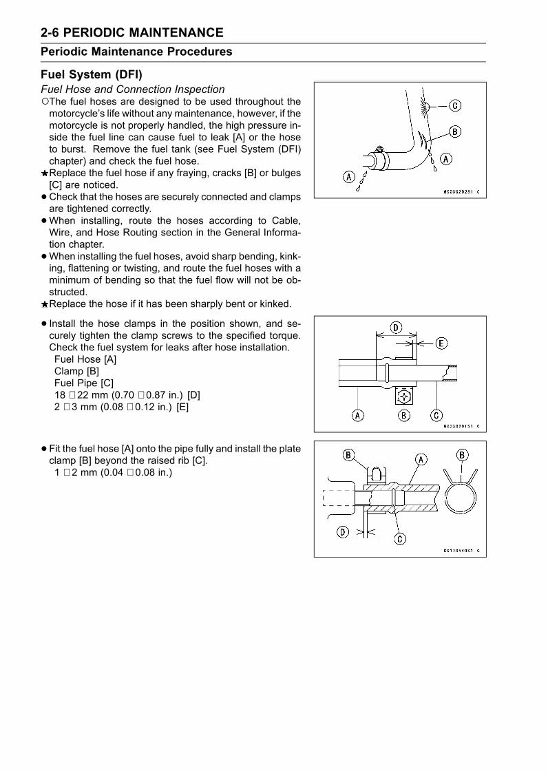
Fuel System (DFI)Fuel Hose and Connection InspectionThe fuel hoses are designed to be used throughout themotorcycle’s life without any maintenance, however, if themotorcycle is not properly handled, the high pressure in-side the fuel line can cause fuel to leak [A] or the hoseto burst. Remove the fuel tank (see Fuel System (DFI)chapter) and check the fuel hose.Replace the fuel hose if any fraying, cracks [B] or bulges[C] are noticed.
•Check that the hoses are securely connected and clampsare tightened correctly.
•When installing, route the hoses according to Cable,Wire, and Hose Routing section in the General Informa-tion chapter.
•When installing the fuel hoses, avoid sharp bending, kink-ing, flattening or twisting, and route the fuel hoses with aminimum of bending so that the fuel flow will not be ob-structed.Replace the hose if it has been sharply bent or kinked.
• Install the hose clamps in the position shown, and se-curely tighten the clamp screws to the specified torque.Check the fuel system for leaks after hose installation.Fuel Hose [A]Clamp [B]Fuel Pipe [C]18 ∼ 22 mm (0.70 ∼ 0.87 in.) [D]2 ∼ 3 mm (0.08 ∼ 0.12 in.) [E]
• Fit the fuel hose [A] onto the pipe fully and install the plateclamp [B] beyond the raised rib [C].1 ∼ 2 mm (0.04 ∼ 0.08 in.)
PERIODIC MAINTENANCE 2-7
Periodic Maintenance Procedures
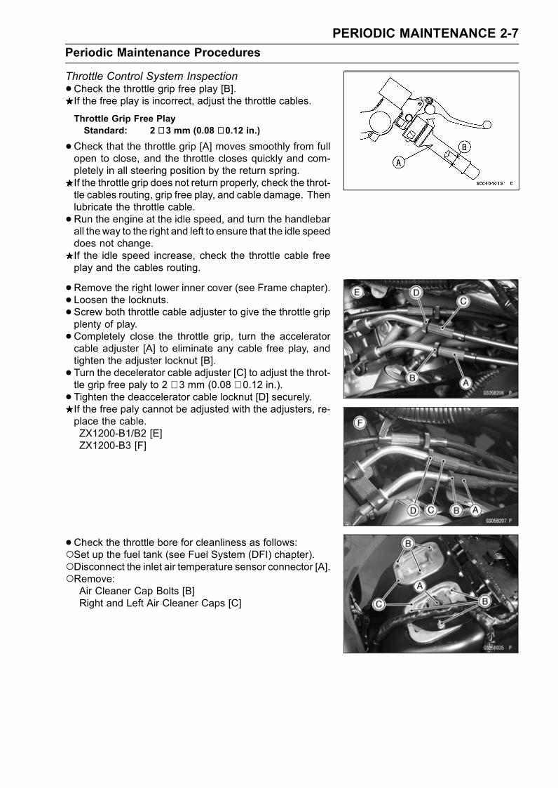
Throttle Control System Inspection
•Check the throttle grip free play [B].If the free play is incorrect, adjust the throttle cables.
Throttle Grip Free PlayStandard: 2 ∼ 3 mm (0.08 ∼ 0.12 in.)
•Check that the throttle grip [A] moves smoothly from fullopen to close, and the throttle closes quickly and com-pletely in all steering position by the return spring.If the throttle grip does not return properly, check the throt-tle cables routing, grip free play, and cable damage. Thenlubricate the throttle cable.
•Run the engine at the idle speed, and turn the handlebarall the way to the right and left to ensure that the idle speeddoes not change.If the idle speed increase, check the throttle cable freeplay and the cables routing.
•Remove the right lower inner cover (see Frame chapter).• Loosen the locknuts.• Screw both throttle cable adjuster to give the throttle gripplenty of play.
•Completely close the throttle grip, turn the acceleratorcable adjuster [A] to eliminate any cable free play, andtighten the adjuster locknut [B].
• Turn the decelerator cable adjuster [C] to adjust the throt-tle grip free paly to 2 ∼ 3 mm (0.08 ∼ 0.12 in.).• Tighten the deaccelerator cable locknut [D] securely.If the free paly cannot be adjusted with the adjusters, re-place the cable.ZX1200-B1/B2 [E]ZX1200-B3 [F]
•Check the throttle bore for cleanliness as follows:Set up the fuel tank (see Fuel System (DFI) chapter).Disconnect the inlet air temperature sensor connector [A].Remove:Air Cleaner Cap Bolts [B]Right and Left Air Cleaner Caps [C]
2-8 PERIODIC MAINTENANCE
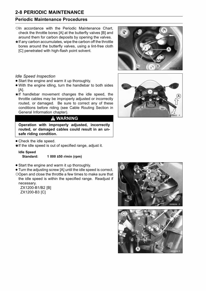
Periodic Maintenance Procedures
In accordance with the Periodic Maintenance Chart,check the throttle bores [A] at the butterfly valves [B] andaround them for carbon deposits by opening the valves.If any carbon accumulates, wipe the carbon off the throttlebores around the butterfly valves, using a lint-free cloth[C] penetrated with high-flash point solvent.
Idle Speed Inspection
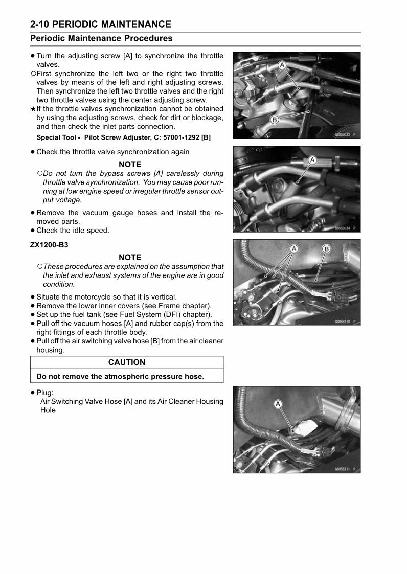
•Start the engine and warm it up thoroughly.
•With the engine idling, turn the handlebar to both sides[A].If handlebar movement changes the idle speed, thethrottle cables may be improperly adjusted or incorrectlyrouted, or damaged. Be sure to correct any of theseconditions before riding (see Cable Routing Section inGeneral Information chapter).
WARNINGOperation with improperly adjusted, incorrectlyrouted, or damaged cables could result in an un-safe riding condition.
•Check the idle speed.If the idle speed is out of specified range, adjust it.
Idle SpeedStandard: 1 000 ±50 r/min (rpm)
•Start the engine and warm it up thoroughly.
• Turn the adjusting screw [A] until the idle speed is correct.Open and close the throttle a few times to make sure thatthe idle speed is within the specified range. Readjust ifnecessary.ZX1200-B1/B2 [B]ZX1200-B3 [C]

PERIODIC MAINTENANCE 2-9
Periodic Maintenance Procedures
Engine Vacuum Synchronization InspectionZX1200-B1/B2
NOTEThese procedures are explained on the assumption thatthe inlet and exhaust system of the engine are in goodcondition.
•Remove the lower inner covers (see Frame chapter).• Set up the fuel tank (see Fuel System (DFI) chapter).
• Pull out the vacuum switch valve hose [B] from the aircleaner.
• Pull off the three vacuum hoses [A] and rubber cap fromthe right fittings on the throttle bodies.
CAUTION
Do not remove the atmospheric pressure hose.
•Completely close the removed hoses [A] and [B] of theclean air system with the proper plugs.
•Completely close the clean air system hole of the aircleaner with the proper plug.
• Start the engine and warm it up thoroughly.
•Check the engine speed, using the engine revolutiontester [A] for high accuracy.If the engine speed is out of 1 000 rpm, set the enginespeed to1 000 rpm.
CAUTION
Do not adjust the engine speed by the tachometerin the meter unit.
•Connect the vacuum gauge hoses [A] to the right fittingson the throttle bodies.
•Connect the vacuum gauge hoses to the vacuum gauge[B].
• Start the engine and left it idle to measure the inlet vac-uum.If the vacuum is incorrect, adjust the synchronization.
Engine VacuumStandard: 26 ±1.333 kPa (195 ±10 mmHg) at Idle
Speed 1 000 ±50 r/min (rpm)
2-10 PERIODIC MAINTENANCE
Periodic Maintenance Procedures
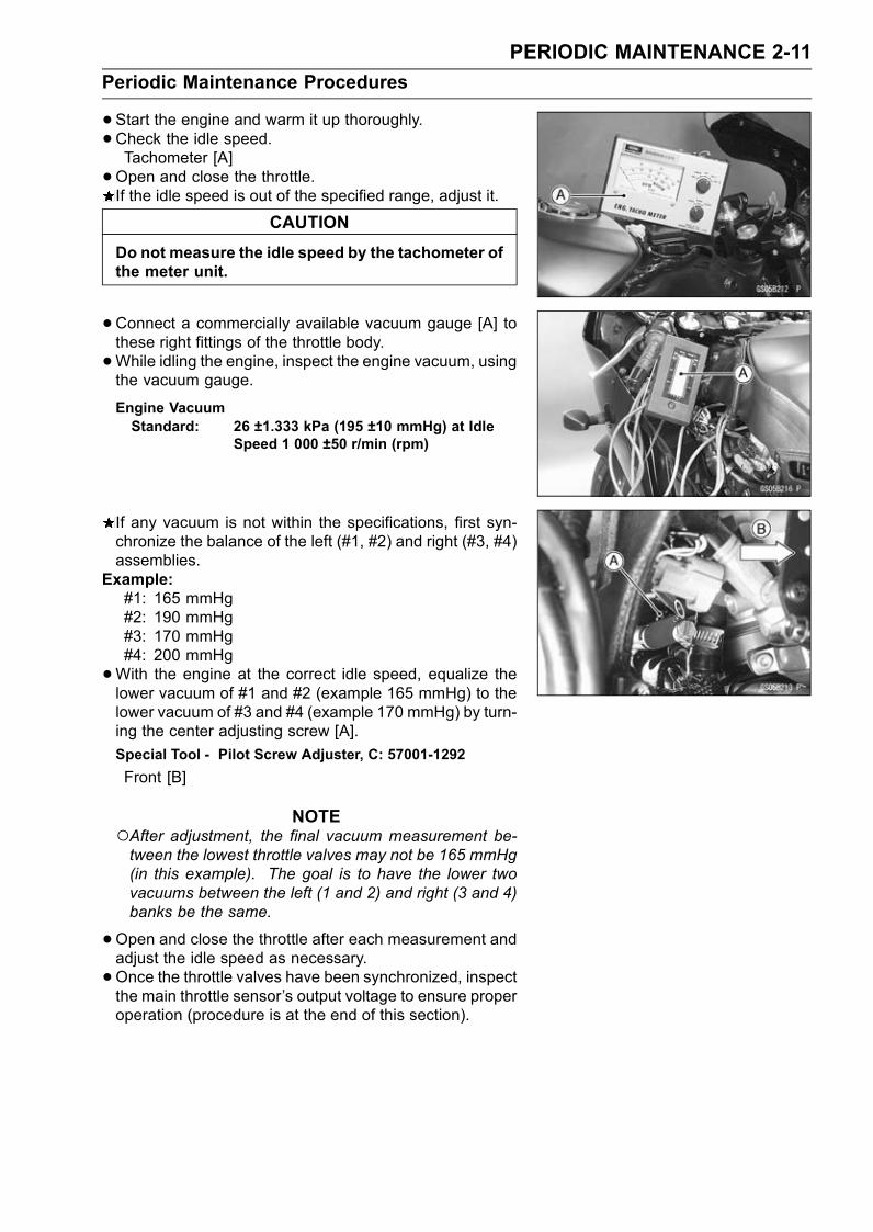
•Turn the adjusting screw [A] to synchronize the throttlevalves.First synchronize the left two or the right two throttlevalves by means of the left and right adjusting screws.Then synchronize the left two throttle valves and the righttwo throttle valves using the center adjusting screw.If the throttle valves synchronization cannot be obtainedby using the adjusting screws, check for dirt or blockage,and then check the inlet parts connection.
Special Tool - Pilot Screw Adjuster, C: 57001-1292 [B]
•Check the throttle valve synchronization againNOTE
Do not turn the bypass screws [A] carelessly duringthrottle valve synchronization. Youmay cause poor run-ning at low engine speed or irregular throttle sensor out-put voltage.
•Remove the vacuum gauge hoses and install the re-moved parts.
•Check the idle speed.ZX1200-B3
NOTEThese procedures are explained on the assumption thatthe inlet and exhaust systems of the engine are in goodcondition.
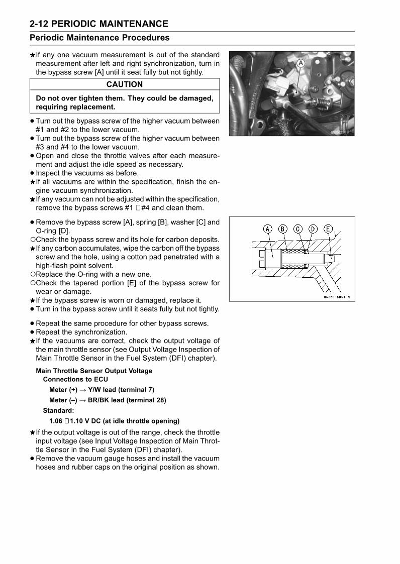
•Situate the motorcycle so that it is vertical.• Remove the lower inner covers (see Frame chapter).• Set up the fuel tank (see Fuel System (DFI) chapter).• Pull off the vacuum hoses [A] and rubber cap(s) from theright fittings of each throttle body.
• Pull off the air switching valve hose [B] from the air cleanerhousing.
CAUTION
Do not remove the atmospheric pressure hose.
•Plug:Air Switching Valve Hose [A] and its Air Cleaner HousingHole
PERIODIC MAINTENANCE 2-11
Periodic Maintenance Procedures
•Start the engine and warm it up thoroughly.
•Check the idle speed.Tachometer [A]
•Open and close the throttle.If the idle speed is out of the specified range, adjust it.
CAUTION
Do not measure the idle speed by the tachometer ofthe meter unit.
•Connect a commercially available vacuum gauge [A] tothese right fittings of the throttle body.
•While idling the engine, inspect the engine vacuum, usingthe vacuum gauge.
Engine VacuumStandard: 26 ±1.333 kPa (195 ±10 mmHg) at Idle
Speed 1 000 ±50 r/min (rpm)
If any vacuum is not within the specifications, first syn-chronize the balance of the left (#1, #2) and right (#3, #4)assemblies.
Example:#1: 165 mmHg#2: 190 mmHg#3: 170 mmHg#4: 200 mmHg
•With the engine at the correct idle speed, equalize thelower vacuum of #1 and #2 (example 165 mmHg) to thelower vacuum of #3 and #4 (example 170 mmHg) by turn-ing the center adjusting screw [A].
Special Tool - Pilot Screw Adjuster, C: 57001-1292
Front [B]
NOTEAfter adjustment, the final vacuum measurement be-tween the lowest throttle valves may not be 165 mmHg(in this example). The goal is to have the lower twovacuums between the left (1 and 2) and right (3 and 4)banks be the same.
•Open and close the throttle after each measurement andadjust the idle speed as necessary.
•Once the throttle valves have been synchronized, inspectthe main throttle sensor’s output voltage to ensure properoperation (procedure is at the end of this section).
2-12 PERIODIC MAINTENANCE
Periodic Maintenance Procedures
If any one vacuum measurement is out of the standardmeasurement after left and right synchronization, turn inthe bypass screw [A] until it seat fully but not tightly.
CAUTION
Do not over tighten them. They could be damaged,requiring replacement.
•Turn out the bypass screw of the higher vacuum between#1 and #2 to the lower vacuum.
• Turn out the bypass screw of the higher vacuum between#3 and #4 to the lower vacuum.
•Open and close the throttle valves after each measure-ment and adjust the idle speed as necessary.
• Inspect the vacuums as before.If all vacuums are within the specification, finish the en-gine vacuum synchronization.If any vacuum can not be adjusted within the specification,remove the bypass screws #1 ∼ #4 and clean them.
•Remove the bypass screw [A], spring [B], washer [C] andO-ring [D].Check the bypass screw and its hole for carbon deposits.If any carbon accumulates, wipe the carbon off the bypassscrew and the hole, using a cotton pad penetrated with ahigh-flash point solvent.Replace the O-ring with a new one.Check the tapered portion [E] of the bypass screw forwear or damage.If the bypass screw is worn or damaged, replace it.
• Turn in the bypass screw until it seats fully but not tightly.•Repeat the same procedure for other bypass screws.•Repeat the synchronization.If the vacuums are correct, check the output voltage ofthe main throttle sensor (see Output Voltage Inspection ofMain Throttle Sensor in the Fuel System (DFI) chapter).
Main Throttle Sensor Output VoltageConnections to ECU
Meter (+) → Y/W lead (terminal 7)
Meter (–) → BR/BK lead (terminal 28)
Standard:
1.06 ∼ 1.10 V DC (at idle throttle opening)
If the output voltage is out of the range, check the throttleinput voltage (see Input Voltage Inspection of Main Throt-tle Sensor in the Fuel System (DFI) chapter).
• Remove the vacuum gauge hoses and install the vacuumhoses and rubber caps on the original position as shown.

PERIODIC MAINTENANCE 2-13
Periodic Maintenance Procedures
Air Cleaner Element Cleaning (ZX1200-B1/B2)/Element Replacement (ZX1200-B3)
NOTEIn dusty areas, the element should be cleaned morefrequently than the recommended interval.After riding through rain or on muddily roads, the ele-ment should be cleaned immediately.
WARNINGIf dirt or dust is allowed to pass through into thethrottle assy, the throttle may become stuck, possi-bly causing accident.
CAUTION
If dirt gets through into the engine, excessive en-gine wear and possibly engine damage will occur.
WARNINGClean the element in a well-ventilated area, and takecare that there are no sparks or flame anywherenear the working area; this includes any appliancewith a pilot light.Because of the danger of highly flammable liquids,do not use gasoline or a low flash-point solvent toclean the element.
•Remove:Seats (see Frame chapter)Fuel Tank Cover (see Fuel Tank Removal section in FuelSystem (DFI) chapter)
• Set up the fuel tank [A] with the supporting rod [B].CAUTION
Do not insert the supporting rod into the bolt hole,or the thread of the bolt hole could be damaged.
•Unscrew the nuts [A] and remove the bolts.• Pull out the elements [B].
2-14 PERIODIC MAINTENANCE
Periodic Maintenance Procedures
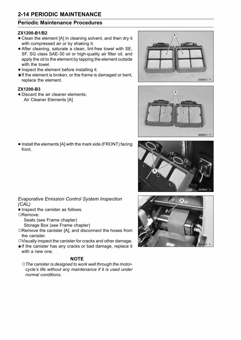
ZX1200-B1/B2
•Clean the element [A] in cleaning solvent, and then dry itwith compressed air or by shaking it.
• After cleaning, saturate a clean, lint-free towel with SE,SF, SG class SAE-30 oil or high-quality air filter oil, andapply the oil to the element by tapping the element outsidewith the towel.
• Inspect the element before installing it.If the element is broken, or the frame is damaged or bent,replace the element.
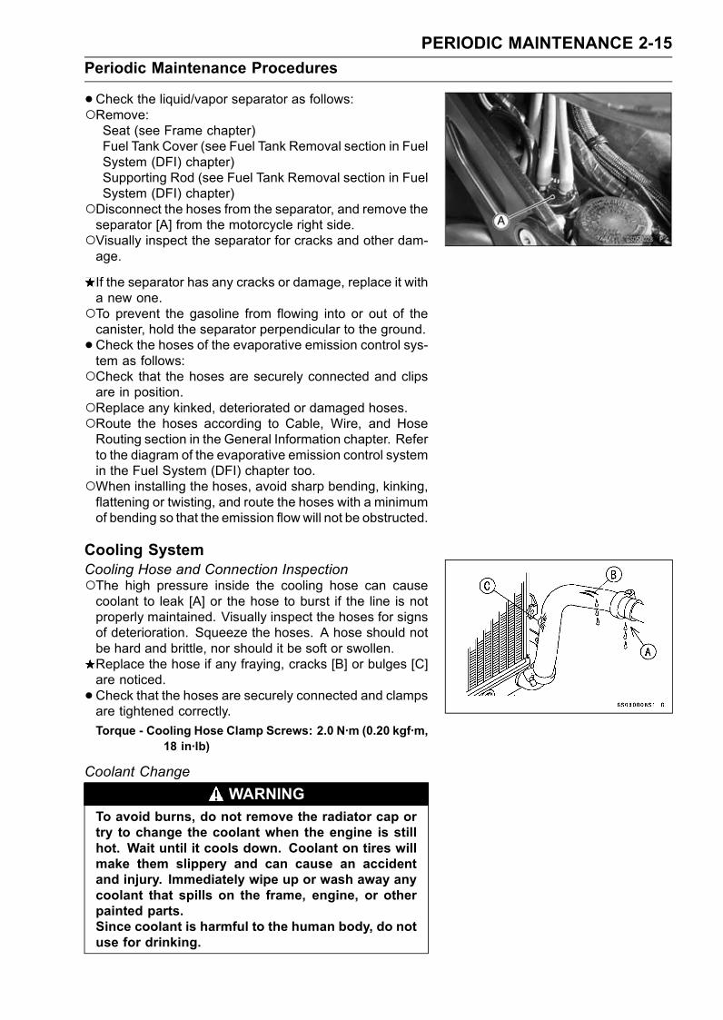
ZX1200-B3
•Discard the air cleaner elements.Air Cleaner Elements [A]
• Install the elements [A] with the mark side (FRONT) facingfront.
Evaporative Emission Control System Inspection(CAL)
• Inspect the canister as follows.Remove:Seats (see Frame chapter)Storage Box (see Frame chapter)
Remove the canister [A], and disconnect the hoses fromthe canister.Visually inspect the canister for cracks and other damage.If the canister has any cracks or bad damage, replace itwith a new one.
NOTEThe canister is designed to work well through themotor-cycle’s life without any maintenance if it is used undernormal conditions.
PERIODIC MAINTENANCE 2-15
Periodic Maintenance Procedures
•Check the liquid/vapor separator as follows:Remove:Seat (see Frame chapter)Fuel Tank Cover (see Fuel Tank Removal section in FuelSystem (DFI) chapter)Supporting Rod (see Fuel Tank Removal section in FuelSystem (DFI) chapter)
Disconnect the hoses from the separator, and remove theseparator [A] from the motorcycle right side.Visually inspect the separator for cracks and other dam-age.
If the separator has any cracks or damage, replace it witha new one.To prevent the gasoline from flowing into or out of thecanister, hold the separator perpendicular to the ground.
•Check the hoses of the evaporative emission control sys-tem as follows:Check that the hoses are securely connected and clipsare in position.Replace any kinked, deteriorated or damaged hoses.Route the hoses according to Cable, Wire, and HoseRouting section in the General Information chapter. Referto the diagram of the evaporative emission control systemin the Fuel System (DFI) chapter too.When installing the hoses, avoid sharp bending, kinking,flattening or twisting, and route the hoses with a minimumof bending so that the emission flow will not be obstructed.
Cooling SystemCooling Hose and Connection InspectionThe high pressure inside the cooling hose can causecoolant to leak [A] or the hose to burst if the line is notproperly maintained. Visually inspect the hoses for signsof deterioration. Squeeze the hoses. A hose should notbe hard and brittle, nor should it be soft or swollen.Replace the hose if any fraying, cracks [B] or bulges [C]are noticed.
•Check that the hoses are securely connected and clampsare tightened correctly.
Torque - Cooling Hose Clamp Screws: 2.0 N·m (0.20 kgf·m,18 in·lb)
Coolant Change
WARNINGTo avoid burns, do not remove the radiator cap ortry to change the coolant when the engine is stillhot. Wait until it cools down. Coolant on tires willmake them slippery and can cause an accidentand injury. Immediately wipe up or wash away anycoolant that spills on the frame, engine, or otherpainted parts.Since coolant is harmful to the human body, do notuse for drinking.
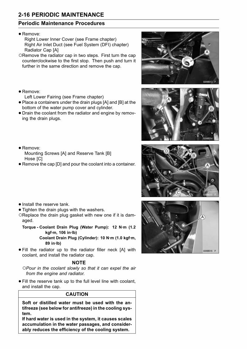
2-16 PERIODIC MAINTENANCE
Periodic Maintenance Procedures
•Remove:Right Lower Inner Cover (see Frame chapter)Right Air Inlet Duct (see Fuel System (DFI) chapter)Radiator Cap [A]
Remove the radiator cap in two steps. First turn the capcounterclockwise to the first stop. Then push and turn itfurther in the same direction and remove the cap.
•Remove:Left Lower Fairing (see Frame chapter)
• Place a containers under the drain plugs [A] and [B] at thebottom of the water pump cover and cylinder.
•Drain the coolant from the radiator and engine by remov-ing the drain plugs.
•Remove:Mounting Screws [A] and Reserve Tank [B]Hose [C]
•Remove the cap [D] and pour the coolant into a container.
• Install the reserve tank.• Tighten the drain plugs with the washers.Replace the drain plug gasket with new one if it is dam-aged.
Torque - Coolant Drain Plug (Water Pump): 12 N·m (1.2kgf·m, 106 in·lb)
Coolant Drain Plug (Cylinder): 10 N·m (1.0 kgf·m,89 in·lb)
•Fill the radiator up to the radiator filler neck [A] withcoolant, and install the radiator cap.
NOTEPour in the coolant slowly so that it can expel the airfrom the engine and radiator.
•Fill the reserve tank up to the full level line with coolant,and install the cap.
CAUTION
Soft or distilled water must be used with the an-tifreeze (see below for antifreeze) in the cooling sys-tem.If hard water is used in the system, it causes scalesaccumulation in the water passages, and consider-ably reduces the efficiency of the cooling system.

PERIODIC MAINTENANCE 2-17
Periodic Maintenance Procedures
Water and Coolant Mixture Ratio (Recommended)Soft Water: 50%
Coolant: 50%
Freezing Point: – 35°C (– 31°F)
Total Amount: 3.6 L (3.8 US qt)
NOTEChoose a suitable mixture ratio by referring to thecoolant manufacturer’s directions.
•Bleed the air from the cooling system as follows.Start the engine with the radiator cap removed and run ituntil no more air bubbles [A] can be seen in the coolant.Tap the radiator hoses to force any air bubbles caughtinside.Stop the engine and add coolant up to the radiator fillerneck.
• Install the radiator cap.• Start the engine, warm it up thoroughly until the radiatorfan turns on and then stop the engine.
•Check the coolant level in the reserve tank after the en-gine cools down.If the coolant level is lower than the low level line, addcoolant to the full level line.
CAUTION
Do not add more coolant above the full level line.
Engine Top EndAir Suction Valve Inspection
•Remove the air suction valve (see Air Suction Valve Re-moval section in Engine Top End chapter).ZX1200-B1/B2 [A]ZX1200-B3 [B]
• Visually inspect the reeds [C] for cracks, folds, warps,heat damage, or other damage.If there is any doubt as to the condition of the reed, replacethe air suction valve as an assembly.
•Check the reed contact areas [D] of the valve holderfor grooves, scratches, any signs of separation from theholder, or heat damage.If there is any doubt as to the condition of the reed contactareas, replace the air suction valve as an assembly.If any carbon or other foreign particles have accumulatedbetween the reed and the reed contact area, wash thevalve assembly with a high flash-point solvent.
CAUTION
Do not scrape off the deposits with a scraper as thiscould damage the rubber, requiring replacement ofthe suction valve assembly.
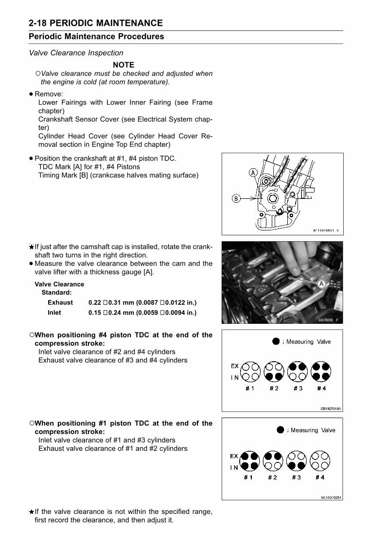
2-18 PERIODIC MAINTENANCE
Periodic Maintenance Procedures
Valve Clearance Inspection
NOTEValve clearance must be checked and adjusted whenthe engine is cold (at room temperature).
•Remove:Lower Fairings with Lower Inner Fairing (see Framechapter)Crankshaft Sensor Cover (see Electrical System chap-ter)Cylinder Head Cover (see Cylinder Head Cover Re-moval section in Engine Top End chapter)
• Position the crankshaft at #1, #4 piston TDC.TDC Mark [A] for #1, #4 PistonsTiming Mark [B] (crankcase halves mating surface)
If just after the camshaft cap is installed, rotate the crank-shaft two turns in the right direction.
•Measure the valve clearance between the cam and thevalve lifter with a thickness gauge [A].
Valve ClearanceStandard:
Exhaust 0.22 ∼ 0.31 mm (0.0087 ∼ 0.0122 in.)Inlet 0.15 ∼ 0.24 mm (0.0059 ∼ 0.0094 in.)
When positioning #4 piston TDC at the end of thecompression stroke:Inlet valve clearance of #2 and #4 cylindersExhaust valve clearance of #3 and #4 cylinders
When positioning #1 piston TDC at the end of thecompression stroke:Inlet valve clearance of #1 and #3 cylindersExhaust valve clearance of #1 and #2 cylinders
If the valve clearance is not within the specified range,first record the clearance, and then adjust it.
PERIODIC MAINTENANCE 2-19
Periodic Maintenance Procedures
•To change the valve clearance, remove the camshaftchain tensioner, camshafts and valve lifters. Replace theshim with one of a different thickness.
NOTEMark and record the valve lifter and shim locations sothey can be reinstalled in their original positions.If there is no clearance, select a shim which is severalsizes smaller and then measure the clearance.
•To select a new shim which brings the valve clearancewithin the specified range, refer to the Valve ClearanceAdjustment Charts.
• Apply molybdenum disulfide oil to the valve lifters and ap-ply engine oil to the shims.
• Install the camshafts. Be sure to time the camshafts prop-erly (see Camshaft Installation).Remeasure any valve clearance that was adjusted.Readjust if necessary.
CAUTION
Do not put shim stock under the shim. This maycause the shim to pop out at high rpm, causing ex-tensive engine damage.Do not grind the shim. Thismay cause it to fracture,causing extensive engine damage.
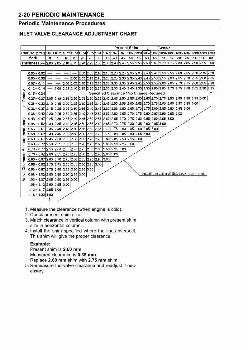
2-20 PERIODIC MAINTENANCE
Periodic Maintenance Procedures
INLET VALVE CLEARANCE ADJUSTMENT CHART
1. Measure the clearance (when engine is cold).2. Check present shim size.3. Match clearance in vertical column with present shimsize in horizontal column.
4. Install the shim specified where the lines intersect.This shim will give the proper clearance.
Example:Present shim is 2.60 mm.Measured clearance is 0.35 mm.Replace 2.60 mm shim with 2.75 mm shim.
5. Remeasure the valve clearance and readjust if nec-essary.
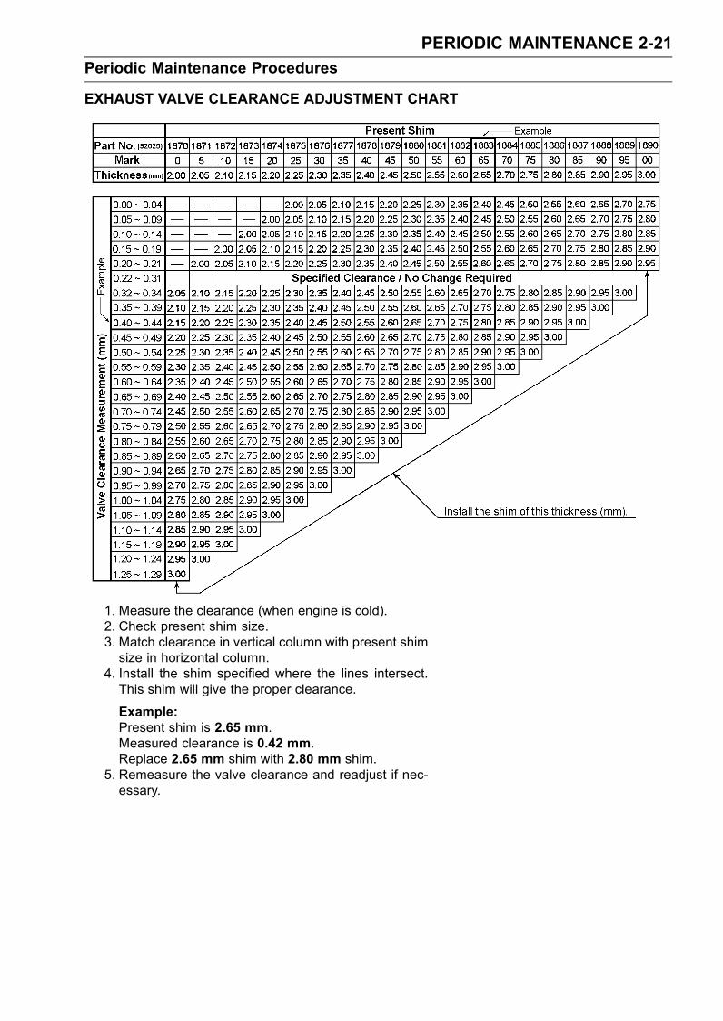
PERIODIC MAINTENANCE 2-21
Periodic Maintenance Procedures
EXHAUST VALVE CLEARANCE ADJUSTMENT CHART
1. Measure the clearance (when engine is cold).2. Check present shim size.3. Match clearance in vertical column with present shimsize in horizontal column.
4. Install the shim specified where the lines intersect.This shim will give the proper clearance.
Example:Present shim is 2.65 mm.Measured clearance is 0.42 mm.Replace 2.65 mm shim with 2.80 mm shim.
5. Remeasure the valve clearance and readjust if nec-essary.
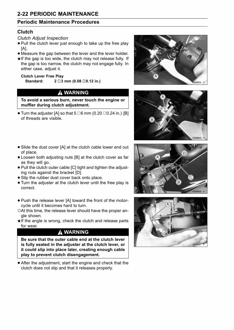
2-22 PERIODIC MAINTENANCE
Periodic Maintenance Procedures
ClutchClutch Adjust Inspection
•Pull the clutch lever just enough to take up the free play[A].
•Measure the gap between the lever and the lever holder.If the gap is too wide, the clutch may not release fully. Ifthe gap is too narrow, the clutch may not engage fully. Ineither case, adjust it.
Clutch Lever Free PlayStandard: 2 ∼ 3 mm (0.08 ∼ 0.12 in.)
WARNINGTo avoid a serious burn, never touch the engine ormuffler during clutch adjustment.
•Turn the adjuster [A] so that 5 ∼ 6 mm (0.20 ∼ 0.24 in.) [B]of threads are visible.
• Slide the dust cover [A] at the clutch cable lower end outof place.
• Loosen both adjusting nuts [B] at the clutch cover as faras they will go.
• Pull the clutch outer cable [C] tight and tighten the adjust-ing nuts against the bracket [D].
• Slip the rubber dust cover back onto place.• Turn the adjuster at the clutch lever until the free play iscorrect.
• Push the release lever [A] toward the front of the motor-cycle until it becomes hard to turn.At this time, the release lever should have the proper an-gle shown.If the angle is wrong, check the clutch and release partsfor wear.
WARNINGBe sure that the outer cable end at the clutch leveris fully seated in the adjuster at the clutch lever, orit could slip into place later, creating enough cableplay to prevent clutch disengagement.
•After the adjustment, start the engine and check that theclutch does not slip and that it releases properly.
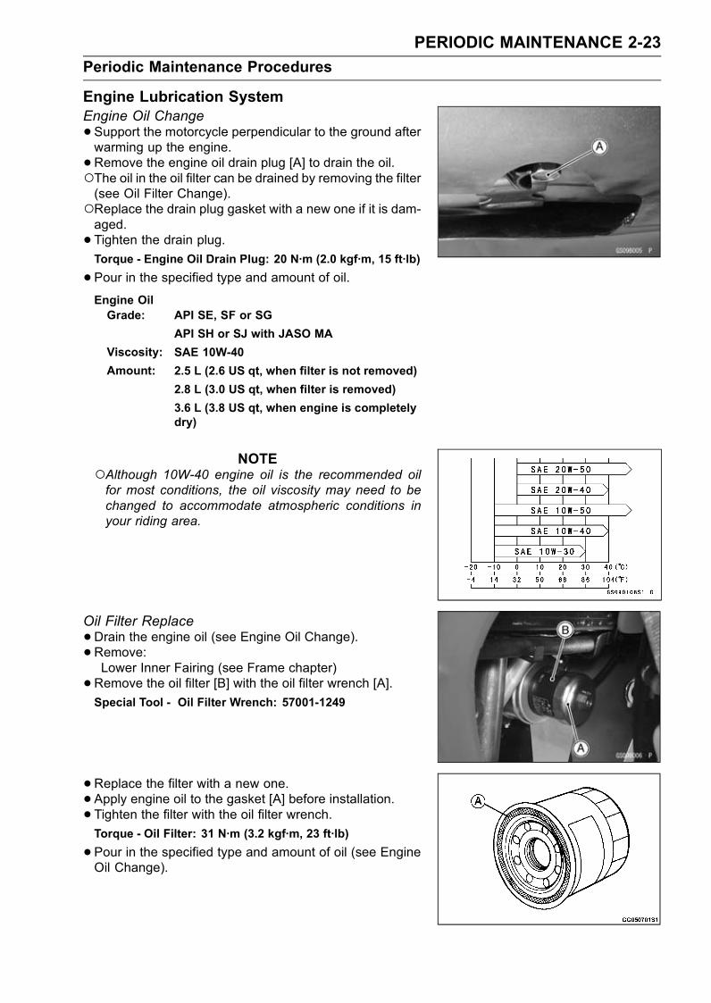
PERIODIC MAINTENANCE 2-23
Periodic Maintenance Procedures
Engine Lubrication SystemEngine Oil Change
•Support the motorcycle perpendicular to the ground afterwarming up the engine.
•Remove the engine oil drain plug [A] to drain the oil.The oil in the oil filter can be drained by removing the filter(see Oil Filter Change).Replace the drain plug gasket with a new one if it is dam-aged.
• Tighten the drain plug.Torque - Engine Oil Drain Plug: 20 N·m (2.0 kgf·m, 15 ft·lb)
•Pour in the specified type and amount of oil.Engine OilGrade: API SE, SF or SG
API SH or SJ with JASO MA
Viscosity: SAE 10W-40
Amount: 2.5 L (2.6 US qt, when filter is not removed)
2.8 L (3.0 US qt, when filter is removed)
3.6 L (3.8 US qt, when engine is completelydry)
NOTEAlthough 10W-40 engine oil is the recommended oilfor most conditions, the oil viscosity may need to bechanged to accommodate atmospheric conditions inyour riding area.
Oil Filter Replace
•Drain the engine oil (see Engine Oil Change).•Remove:Lower Inner Fairing (see Frame chapter)
•Remove the oil filter [B] with the oil filter wrench [A].Special Tool - Oil Filter Wrench: 57001-1249
•Replace the filter with a new one.• Apply engine oil to the gasket [A] before installation.• Tighten the filter with the oil filter wrench.Torque - Oil Filter: 31 N·m (3.2 kgf·m, 23 ft·lb)
•Pour in the specified type and amount of oil (see EngineOil Change).
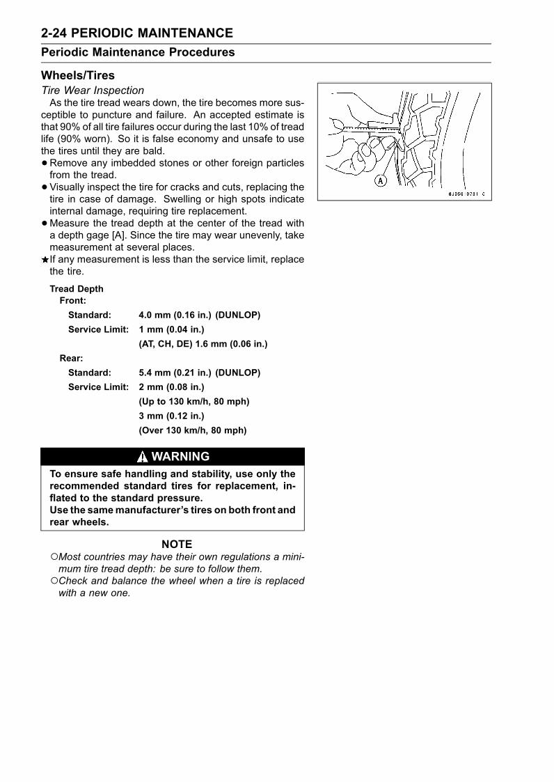
2-24 PERIODIC MAINTENANCE
Periodic Maintenance Procedures
Wheels/TiresTire Wear InspectionAs the tire tread wears down, the tire becomes more sus-
ceptible to puncture and failure. An accepted estimate isthat 90% of all tire failures occur during the last 10% of treadlife (90% worn). So it is false economy and unsafe to usethe tires until they are bald.
•Remove any imbedded stones or other foreign particlesfrom the tread.
• Visually inspect the tire for cracks and cuts, replacing thetire in case of damage. Swelling or high spots indicateinternal damage, requiring tire replacement.
•Measure the tread depth at the center of the tread witha depth gage [A]. Since the tire may wear unevenly, takemeasurement at several places.If any measurement is less than the service limit, replacethe tire.
Tread DepthFront:
Standard: 4.0 mm (0.16 in.) (DUNLOP)
Service Limit: 1 mm (0.04 in.)
(AT, CH, DE) 1.6 mm (0.06 in.)
Rear:
Standard: 5.4 mm (0.21 in.) (DUNLOP)
Service Limit: 2 mm (0.08 in.)
(Up to 130 km/h, 80 mph)
3 mm (0.12 in.)
(Over 130 km/h, 80 mph)
WARNINGTo ensure safe handling and stability, use only therecommended standard tires for replacement, in-flated to the standard pressure.Use the samemanufacturer’s tires on both front andrear wheels.
NOTEMost countries may have their own regulations a mini-mum tire tread depth: be sure to follow them.Check and balance the wheel when a tire is replacedwith a new one.

PERIODIC MAINTENANCE 2-25
Periodic Maintenance Procedures
Final DriveDrive Chain Slack Inspection
NOTECheck the slack with the motorcycle setting on its sidestand.Clean the chain if it is dirty, and lubricate it if it appearsdry.
•Check the wheel alignment.•Rotate the rear wheel to find the position where the chainis tightest.
•Measure the vertical movement (chain slack) [A] midwaybetween the sprockets.If the chain slack exceeds the standard, adjust it.
Chain SlackStandard: 25 ∼ 35 mm (0.98 ∼ 1.4 in.)
•Remove the cotter pin [A], and loosen the axle nut [B].• Loosen the both chain adjuster locknuts [C].• Turn the chain adjusters [D] forward or rearward until thedrive chain has the correct amount of chain slack.
• The right and left notches [E] on the alignment indicators[F] should point to the same marks or positions [G] on theswingarm.
WARNINGMisalignment of the wheel will result in abnormalwear and may result in an unsafe riding condition.
•Tighten both chain adjuster locknuts securely.• Tighten the axle nut.Torque - Rear Axle Nut: 125 N·m (13 kgf·m, 92 ft·lb)
•Turn the wheel, measure the chain slack again at the tight-est position, and readjust if necessary.
• Insert a new cotter pin [A].NOTE
When inserting the cotter pin, if the slots in the nut donot align with the cotter pin hole in the axle, tighten thenut clockwise [B] up to next alignment.It should be within 30 degree.Loosen once and tighten again when the slot goes pastthe nearest hole.
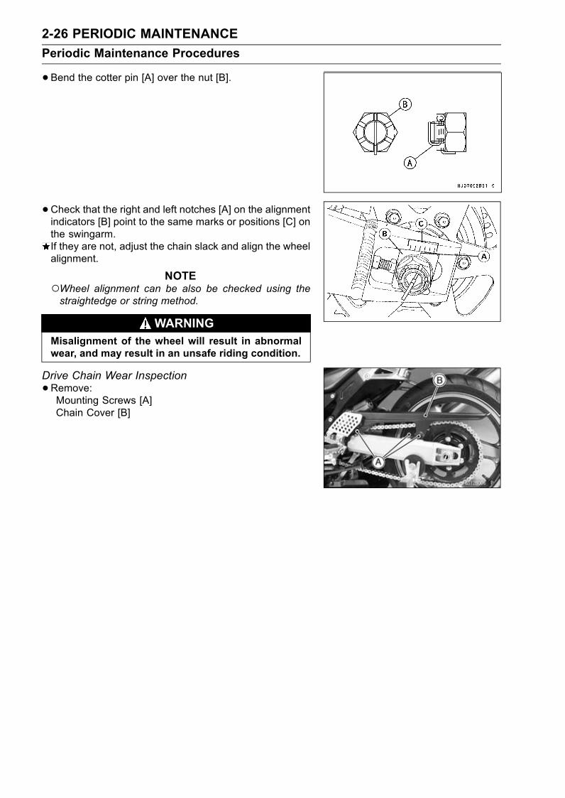
2-26 PERIODIC MAINTENANCE
Periodic Maintenance Procedures
•Bend the cotter pin [A] over the nut [B].
• Check that the right and left notches [A] on the alignmentindicators [B] point to the same marks or positions [C] onthe swingarm.If they are not, adjust the chain slack and align the wheelalignment.
NOTEWheel alignment can be also be checked using thestraightedge or string method.
WARNINGMisalignment of the wheel will result in abnormalwear, and may result in an unsafe riding condition.
Drive Chain Wear Inspection
•Remove:Mounting Screws [A]Chain Cover [B]
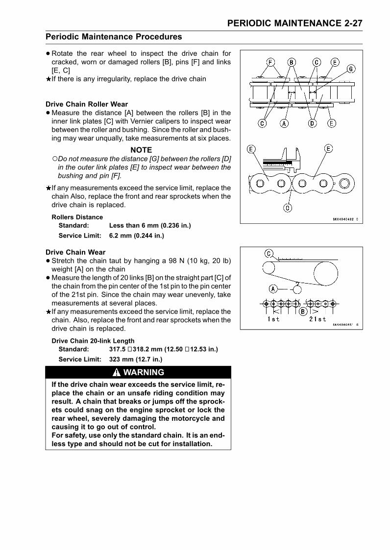
PERIODIC MAINTENANCE 2-27
Periodic Maintenance Procedures
•Rotate the rear wheel to inspect the drive chain forcracked, worn or damaged rollers [B], pins [F] and links[E, C]If there is any irregularity, replace the drive chain
Drive Chain Roller Wear
•Measure the distance [A] between the rollers [B] in theinner link plates [C] with Vernier calipers to inspect wearbetween the roller and bushing. Since the roller and bush-ing may wear unqually, take measurements at six places.
NOTEDo not measure the distance [G] between the rollers [D]in the outer link plates [E] to inspect wear between thebushing and pin [F].
If any measurements exceed the service limit, replace thechain Also, replace the front and rear sprockets when thedrive chain is replaced.
Rollers DistanceStandard: Less than 6 mm (0.236 in.)
Service Limit: 6.2 mm (0.244 in.)
Drive Chain Wear
•Stretch the chain taut by hanging a 98 N (10 kg, 20 lb)weight [A] on the chain
•Measure the length of 20 links [B] on the straight part [C] ofthe chain from the pin center of the 1st pin to the pin centerof the 21st pin. Since the chain may wear unevenly, takemeasurements at several places.If any measurements exceed the service limit, replace thechain. Also, replace the front and rear sprockets when thedrive chain is replaced.
Drive Chain 20-link LengthStandard: 317.5 ∼ 318.2 mm (12.50 ∼ 12.53 in.)Service Limit: 323 mm (12.7 in.)
WARNINGIf the drive chain wear exceeds the service limit, re-place the chain or an unsafe riding condition mayresult. A chain that breaks or jumps off the sprock-ets could snag on the engine sprocket or lock therear wheel, severely damaging the motorcycle andcausing it to go out of control.For safety, use only the standard chain. It is an end-less type and should not be cut for installation.

2-28 PERIODIC MAINTENANCE
Periodic Maintenance Procedures
Drive Chain Lubrication
• If a special lubricant is not available, a heavy oil such asSAE 90 is preferred to lighter oil because if will stay onthe chain longer and provide better lubrication.
• If the chain appears especially dirty, clean it before lubri-cation.Oil Applied Grease [A]O-rings [B]
CAUTION
The O-rings between the side plates seal the lubri-cant between the pin and the bushing. To avoiddamaging the O-rings and resultant loss of lubri-cant, observe the following rules.Use only kerosene or diesel oil for cleaning an O-ring drive chain.Any other cleaning solution such as gasolineor trichloroethylene will cause deterioration andswelling of the O-ring.Immediately blow the chain drywith compressed airafter cleaning.Complete cleaning and drying the chain within 10minutes.
•Apply oil to the sides of the rollers so that oil will penetrateto the rollers and bushings. Apply oil to the O-rings so thatthe O-rings will be coated with oil.
•Wipe off any excess oil.BrakesBrake Hose, Connection Inspection
• Inspect the brake hose and fitting for deterioration, cracksand signs of leakage.The high pressure inside the brake line can cause fluid toleak [A] or the hose to burst if the line is not properly main-tained. Bend and twist the rubber hose while examiningit.Replace it if any cracks [B], bulges [C] or fluid lead arenoticed.Tighten any loose fittings.

PERIODIC MAINTENANCE 2-29
Periodic Maintenance Procedures
Brake Fluid Level Inspection
•Check that the brake fluid level in the front brake reservoir[A] is above the lower level line [B].
NOTEHold the reservoir horizontal by turning the handlebarwhen checking brake fluid level.
If the fluid level is lower than the lower level line, fill thereservoir to the upper level line [A] in the reservoir [B].
• Check that the brake fluid level in the rear brake reservoir[A] is between the upper [B] and the lower [C] level lines.If the fluid level is lower than the lower level line, removethe seats and fill the reservoir to the upper level line.
WARNINGChange the brake fluid in the brake line completelyif the brake fluid must be refilled but the type andbrand of the brake fluid that is already in the reser-voir are unidentified. After changing the fluid, useonly the same type and brand of fluid thereafter.
Recommended Disc Brake FluidGrade: DOT4
Brake Fluid Change
NOTEThe procedure to change the front brake fluid is as fol-lows. Changing the rear brake fluid is the same as forthe front brake.
•Level the brake fluid reservoir.• Remove the reservoir cap and diaphragm.•Remove the rubber cap from the bleed valve [A] on thecaliper.
• Attach a clear plastic hose [B] to the bleed valve, and runthe other end of the hose into a container.
• Fill the reservoir with fresh specified brake fluid.
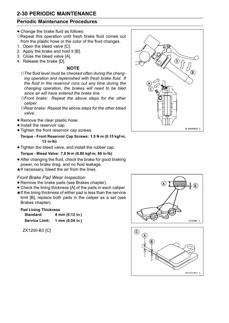
2-30 PERIODIC MAINTENANCE
Periodic Maintenance Procedures
•Change the brake fluid as follows:Repeat this operation until fresh brake fluid comes outfrom the plastic hose or the color of the fluid changes.
1. Open the bleed valve [C].2. Apply the brake and hold it [B].3. Close the bleed valve [A].4. Release the brake [D].
NOTEThe fluid level must be checked often during the chang-ing operation and replenished with fresh brake fluid. Ifthe fluid in the reservoir runs out any time during thechanging operation, the brakes will need to be bledsince air will have entered the brake line.Front brake: Repeat the above steps for the othercaliper.Rear brake: Repeat the above steps for the other bleedvalve.
•Remove the clear plastic hose.• Install the reservoir cap.• Tighten the front reservoir cap screws.Torque - Front Reservoir Cap Screws: 1.5 N·m (0.15 kgf·m,
13 in·lb)
•Tighten the bleed valve, and install the rubber cap.Torque - Bleed Valve: 7.8 N·m (0.80 kgf·m, 69 in·lb)
•After changing the fluid, check the brake for good brakingpower, no brake drag, and no fluid leakage.If necessary, bleed the air from the lines.
Front Brake Pad Wear Inspection
•Remove the brake pads (see Brakes chapter).• Check the lining thickness [A] of the pads in each caliper.If the lining thickness of either pad is less than the servicelimit [B], replace both pads in the caliper as a set (seeBrakes chapter).
Pad Lining ThicknessStandard: 4 mm (0.12 in.)
Service Limit: 1 mm (0.04 in.)
ZX1200-B3 [C]

PERIODIC MAINTENANCE 2-31
Periodic Maintenance Procedures
Rear Brake Pad Wear Inspection
•Remove the brake pads (see Brakes chapter).• Check the lining thickness [A] of the pads in each caliper.If the lining thickness of either pad is less than the servicelimit [B], replace both pads in the caliper as a set (seeBrakes chapter).
Pad Lining ThicknessStandard: 4 mm (0.12 in.)
Service Limit: 1 mm (0.04 in.)
Brake/Master Cylinder Cup and Dust Seal Replace
•Refer to the Master Cylinder section in the Brakes chapterfor Brake/Master Cylinder Cup and Dust Seal Replace-ment.
Caliper Piston/Dust Seal Replace
•Refer to the Calipers section in the Brakes chapter forCaliper Piston/Dust Seals Replacement.
Front Brake Light Switch Inspection
•Turn on the ignition switch.• The brake light should go on when the front brake leveris applied.If it does not, replace the switch.
Rear Brake Light Switch Inspection/Adjustment
•Turn on the ignition switch.•Check the operation of the rear brake light switch by de-pressing the brake pedal.If it does not as specified, adjust the brake light timing.
Brake Light TimingStandard: On after about 10 mm (0.39 in.) of pedal
travel [A]
•While holding the switch body, turn the adjusting nut [A]to adjust the switch.
CAUTION
To avoid damaging the electrical connections in-side the switch, be sure that the switch body doesnot turn during adjustment.
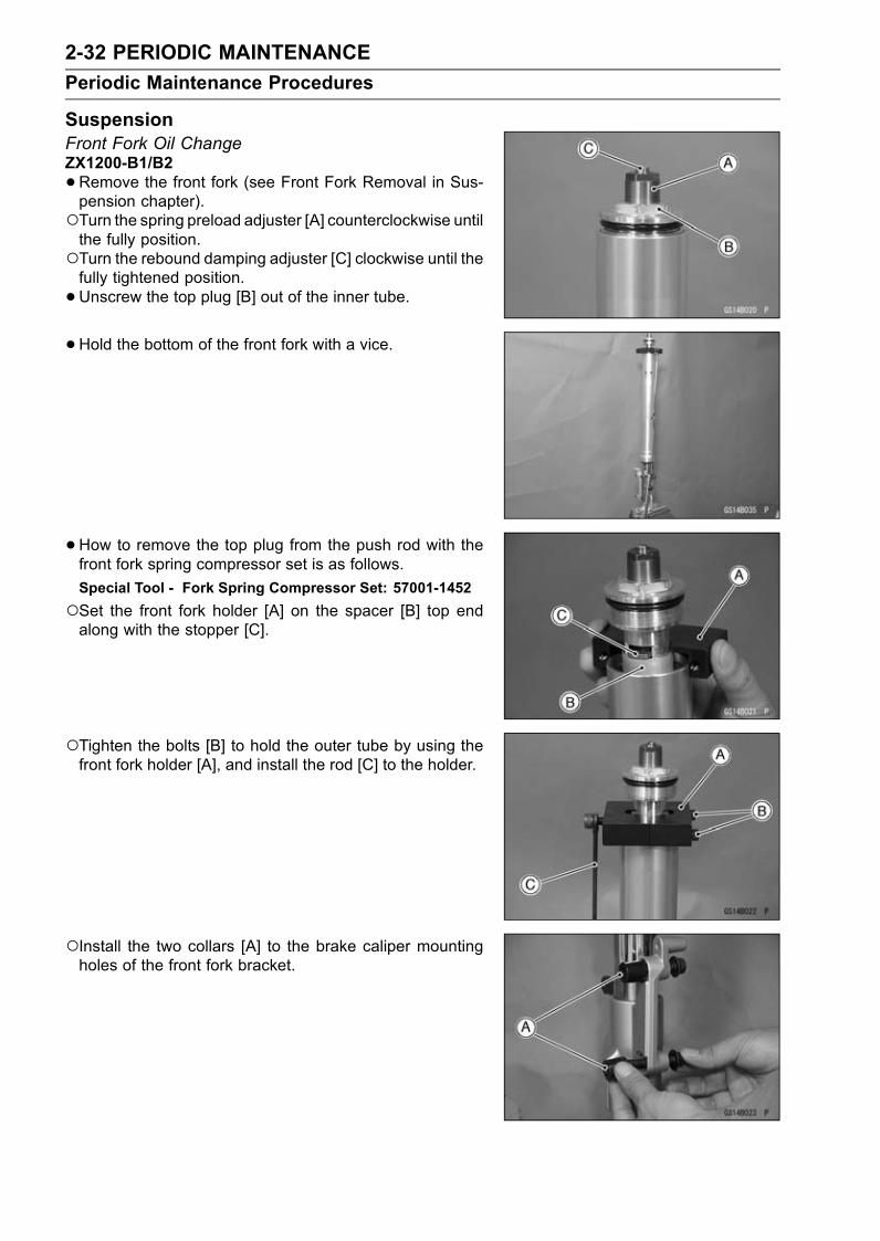
2-32 PERIODIC MAINTENANCE
Periodic Maintenance Procedures
SuspensionFront Fork Oil ChangeZX1200-B1/B2
•Remove the front fork (see Front Fork Removal in Sus-pension chapter).Turn the spring preload adjuster [A] counterclockwise untilthe fully position.Turn the rebound damping adjuster [C] clockwise until thefully tightened position.
•Unscrew the top plug [B] out of the inner tube.
•Hold the bottom of the front fork with a vice.
•How to remove the top plug from the push rod with thefront fork spring compressor set is as follows.
Special Tool - Fork Spring Compressor Set: 57001-1452
Set the front fork holder [A] on the spacer [B] top endalong with the stopper [C].
Tighten the bolts [B] to hold the outer tube by using thefront fork holder [A], and install the rod [C] to the holder.
Install the two collars [A] to the brake caliper mountingholes of the front fork bracket.
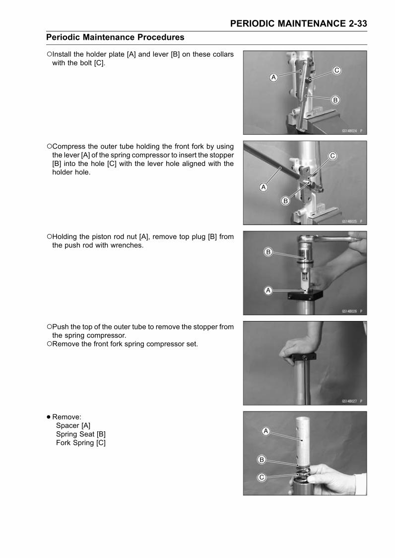
PERIODIC MAINTENANCE 2-33
Periodic Maintenance Procedures
Install the holder plate [A] and lever [B] on these collarswith the bolt [C].
Compress the outer tube holding the front fork by usingthe lever [A] of the spring compressor to insert the stopper[B] into the hole [C] with the lever hole aligned with theholder hole.
Holding the piston rod nut [A], remove top plug [B] fromthe push rod with wrenches.
Push the top of the outer tube to remove the stopper fromthe spring compressor.Remove the front fork spring compressor set.
• Remove:Spacer [A]Spring Seat [B]Fork Spring [C]

2-34 PERIODIC MAINTENANCE
Periodic Maintenance Procedures
•Remove:Rebound Damping Adjuster Rod [D]
•Drain the fork oil into a suitable container.Pump the piston rod [A] up and down at least ten times toexpel the oil from the fork.
•Hold the fork tube upright, press the outer tube [A] andthe piston rod all the way down.
• Pour in the type and amount of fork oil specified.Fork OilViscosity
KAYABA KHL15-10 (SAE 0 W)
Amount (per side):
When changing oil:
approx. 420 mL (14.2 US oz)
After disassembly and completely dry:
490 ±4 mL (16.6 ±0.1 US oz)
If necessary, measure the oil level as follows.Hold the inner tube vertically in a vise.Using the piston rod puller [A], move the piston rod [B] upand down more than ten times in order to expel all the airfrom the fork oil.
Special Tool - Fork Piston Rod Puller, M12 × 1.25: 57001-1289
Pump the inner tube several times to expel air bubbles.Remove the piston rod puller.Wait until the oil level settles.With the fork fully compressed and the piston rod fullypushed in, insert a tape measure or rod into the innertube, and measure the distance from the top of the outertube to the oil.
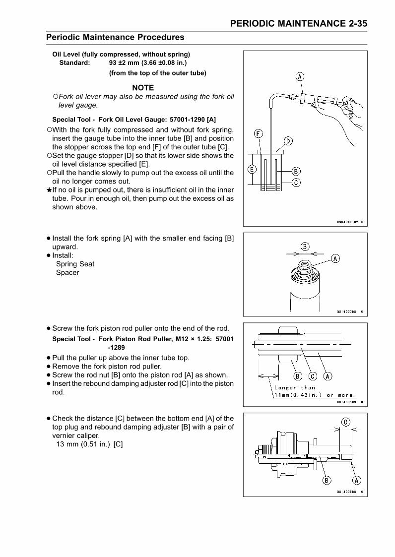
PERIODIC MAINTENANCE 2-35
Periodic Maintenance Procedures
Oil Level (fully compressed, without spring)Standard: 93 ±2 mm (3.66 ±0.08 in.)
(from the top of the outer tube)
NOTEFork oil lever may also be measured using the fork oillevel gauge.
Special Tool - Fork Oil Level Gauge: 57001-1290 [A]
With the fork fully compressed and without fork spring,insert the gauge tube into the inner tube [B] and positionthe stopper across the top end [F] of the outer tube [C].Set the gauge stopper [D] so that its lower side shows theoil level distance specified [E].Pull the handle slowly to pump out the excess oil until theoil no longer comes out.If no oil is pumped out, there is insufficient oil in the innertube. Pour in enough oil, then pump out the excess oil asshown above.
• Install the fork spring [A] with the smaller end facing [B]upward.
• Install:Spring SeatSpacer
• Screw the fork piston rod puller onto the end of the rod.Special Tool - Fork Piston Rod Puller, M12 × 1.25: 57001
-1289
•Pull the puller up above the inner tube top.•Remove the fork piston rod puller.• Screw the rod nut [B] onto the piston rod [A] as shown.• Insert the rebound damping adjuster rod [C] into the pistonrod.
•Check the distance [C] between the bottom end [A] of thetop plug and rebound damping adjuster [B] with a pair ofvernier caliper.13 mm (0.51 in.) [C]

2-36 PERIODIC MAINTENANCE
Periodic Maintenance Procedures
•Hold the spacer and outer tube with the fork spring com-pressor set [A] to compress it.
Special Tool - Fork Spring Compressor Set: 57001-1452
•Check the O-ring [B] on the top plug and replace it with anew one if damaged.
• Screw in the top plug [C] stopped onto the piston rod.
•Holding the top plug [A] with a wrench, tighten the pistonrod nut [B] against the top plug.
Torque - Piston Rod Nut: 28 N·m (2.8 kgf·m, 21 ft·lb)
•Remove the fork spring compressor set.
• Raise the outer tube and screw the top plug into it andinstall it to the steering stem.
•Screw in the spring preload adjuster [A] of the top plugso that the distance between the adjuster top and the topplug surface [C] is 17 mm (0.67 in.) [D].
• Turn in the rebound damping adjuster [B] until the fullytightened position and turn backward the 1 1/2 turns.
• Install the front fork (see Front Fork Installation).
ZX1200-B3
•Remove the front fork (see Front Fork Removal in Sus-pension chapter).
• Hold the inner tube lower end in a vise.Turn the spring preload adjuster [A] counterclockwise untilthe fully position.Turn the rebound damping adjuster [C] clockwise until thefully tightened position.
•Unscrew the top plug [B] out of the inner tube.
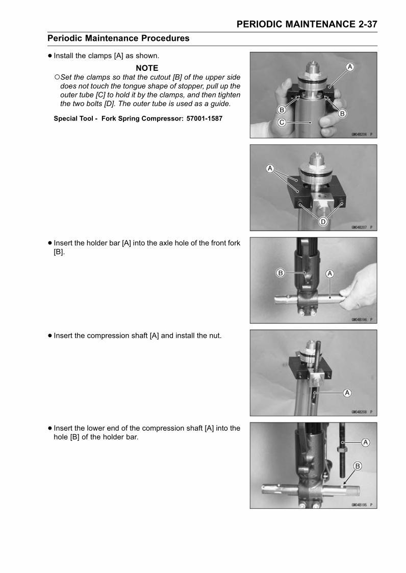
PERIODIC MAINTENANCE 2-37
Periodic Maintenance Procedures
• Install the clamps [A] as shown.NOTE
Set the clamps so that the cutout [B] of the upper sidedoes not touch the tongue shape of stopper, pull up theouter tube [C] to hold it by the clamps, and then tightenthe two bolts [D]. The outer tube is used as a guide.
Special Tool - Fork Spring Compressor: 57001-1587
• Insert the holder bar [A] into the axle hole of the front fork[B].
• Insert the compression shaft [A] and install the nut.
• Insert the lower end of the compression shaft [A] into thehole [B] of the holder bar.

2-38 PERIODIC MAINTENANCE
Periodic Maintenance Procedures
•Screw the adjust nut [A] onto the compression shaft asshown.
• Screw the locknut [B].• Set the other side compression shaft same process.
• Screw in one side nut [A] come out the piston rod nut.
•Holding the piston rod nut with a wrench [A], remove thetop plug [B] from the piston rod.
•Remove:Spacer [A]Spring Seat [B]Fork Spring [C]
•Remove:Rebound Damping Adjuster Rod [D]

PERIODIC MAINTENANCE 2-39
Periodic Maintenance Procedures
•Drain the fork oil into a suitable container.Pump the piston rod [A] up and down at least ten times toexpel the oil from the fork.
•Hold the fork tube upright, press the outer tube [A] andthe piston rod all the way down.
• Pour in the type and amount of fork oil specified.Fork OilViscosity
KAYABA KHL15-10 (SAE 0 W)
Amount (per side):
When changing oil:
approx. 420 mL (14.2 US oz)
After disassembly and completely dry:
490 ±4 mL (16.6 ±0.1 US oz)
If necessary, measure the oil level as follows.Hold the inner tube vertically in a vise.Using the piston rod puller [A], move the piston rod [B] upand down more than ten times in order to expel all the airfrom the fork oil.
Special Tool - Fork Piston Rod Puller, M12 × 1.25: 57001-1289
Pump the inner tube several times to expel air bubbles.Remove the piston rod puller.Wait until the oil level settles.With the fork fully compressed and the piston rod fullypushed in, insert a tape measure or rod into the innertube, and measure the distance from the top of the outertube to the oil.

2-40 PERIODIC MAINTENANCE
Periodic Maintenance Procedures
Oil Level (fully compressed, without spring)Standard: 93 ±2 mm (3.66 ±0.08 in.)
(from the top of the outer tube)
NOTEFork oil lever may also be measured using the fork oillevel gauge.
Special Tool - Fork Oil Level Gauge: 57001-1290 [A]
With the fork fully compressed and without fork spring,insert the gauge tube into the inner tube [B] and positionthe stopper across the top end [F] of the outer tube [C].Set the gauge stopper [D] so that its lower side shows theoil level distance specified [E].Pull the handle slowly to pump out the excess oil until theoil no longer comes out.If no oil is pumped out, there is insufficient oil in the innertube. Pour in enough oil, then pump out the excess oil asshown above.
• Install the fork spring [A] with the smaller end facing [B]upward.
• Install:Spring SeatSpacer
• Screw the fork piston rod puller onto the end of the rod.Special Tool - Fork Piston Rod Puller, M12 × 1.25: 57001
-1289
•Pull the puller up above the inner tube top.•Remove the fork piston rod puller.• Screw the rod nut [B] onto the piston rod [A] as shown.• Insert the rebound damping adjuster rod [C] into the pistonrod.
•Check the distance [C] between the bottom end [A] of thetop plug and rebound damping adjuster [B] with a pair ofvernier caliper.13 mm (0.51 in.) [C]
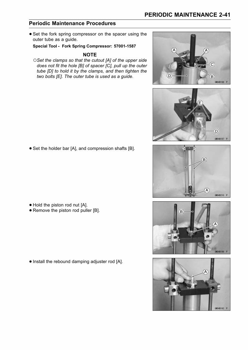
PERIODIC MAINTENANCE 2-41
Periodic Maintenance Procedures
•Set the fork spring compressor on the spacer using theouter tube as a guide.
Special Tool - Fork Spring Compressor: 57001-1587
NOTESet the clamps so that the cutout [A] of the upper sidedoes not fit the hole [B] of spacer [C], pull up the outertube [D] to hold it by the clamps, and then tighten thetwo bolts [E]. The outer tube is used as a guide.
•Set the holder bar [A], and compression shafts [B].
• Hold the piston rod nut [A].• Remove the piston rod puller [B].
• Install the rebound damping adjuster rod [A].
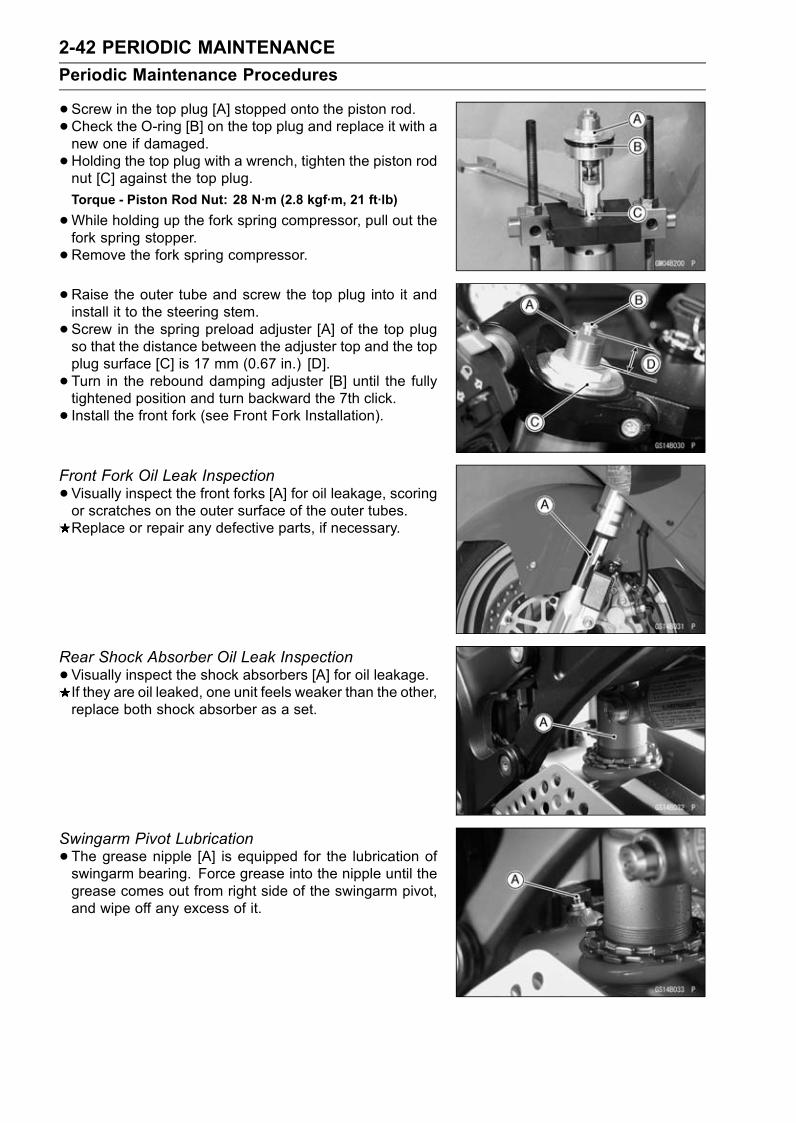
2-42 PERIODIC MAINTENANCE
Periodic Maintenance Procedures
•Screw in the top plug [A] stopped onto the piston rod.•Check the O-ring [B] on the top plug and replace it with anew one if damaged.
•Holding the top plug with a wrench, tighten the piston rodnut [C] against the top plug.
Torque - Piston Rod Nut: 28 N·m (2.8 kgf·m, 21 ft·lb)
•While holding up the fork spring compressor, pull out thefork spring stopper.
•Remove the fork spring compressor.
•Raise the outer tube and screw the top plug into it andinstall it to the steering stem.
•Screw in the spring preload adjuster [A] of the top plugso that the distance between the adjuster top and the topplug surface [C] is 17 mm (0.67 in.) [D].
• Turn in the rebound damping adjuster [B] until the fullytightened position and turn backward the 7th click.
• Install the front fork (see Front Fork Installation).
Front Fork Oil Leak Inspection
•Visually inspect the front forks [A] for oil leakage, scoringor scratches on the outer surface of the outer tubes.Replace or repair any defective parts, if necessary.
Rear Shock Absorber Oil Leak Inspection
•Visually inspect the shock absorbers [A] for oil leakage.If they are oil leaked, one unit feels weaker than the other,replace both shock absorber as a set.
Swingarm Pivot Lubrication
•The grease nipple [A] is equipped for the lubrication ofswingarm bearing. Force grease into the nipple until thegrease comes out from right side of the swingarm pivot,and wipe off any excess of it.
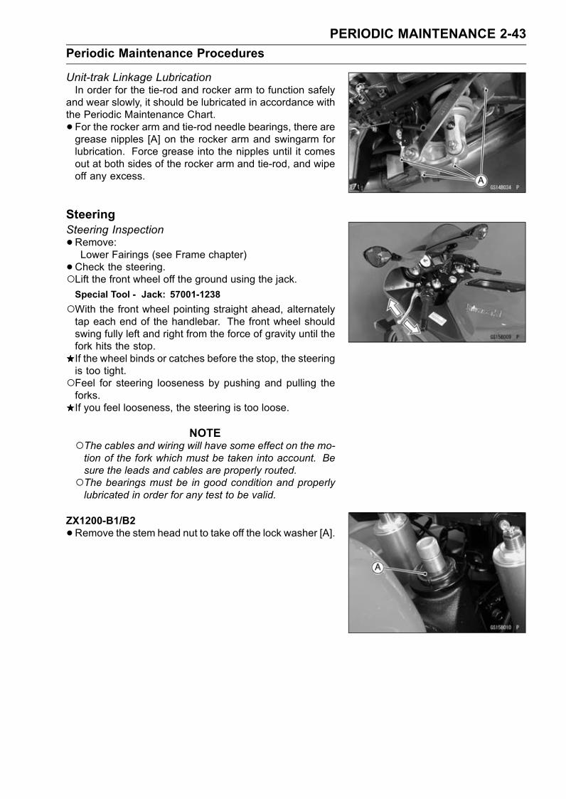
PERIODIC MAINTENANCE 2-43
Periodic Maintenance Procedures
Unit-trak Linkage LubricationIn order for the tie-rod and rocker arm to function safely
and wear slowly, it should be lubricated in accordance withthe Periodic Maintenance Chart.
• For the rocker arm and tie-rod needle bearings, there aregrease nipples [A] on the rocker arm and swingarm forlubrication. Force grease into the nipples until it comesout at both sides of the rocker arm and tie-rod, and wipeoff any excess.
SteeringSteering Inspection
•Remove:Lower Fairings (see Frame chapter)
•Check the steering.Lift the front wheel off the ground using the jack.Special Tool - Jack: 57001-1238
With the front wheel pointing straight ahead, alternatelytap each end of the handlebar. The front wheel shouldswing fully left and right from the force of gravity until thefork hits the stop.If the wheel binds or catches before the stop, the steeringis too tight.Feel for steering looseness by pushing and pulling theforks.If you feel looseness, the steering is too loose.
NOTEThe cables and wiring will have some effect on the mo-tion of the fork which must be taken into account. Besure the leads and cables are properly routed.The bearings must be in good condition and properlylubricated in order for any test to be valid.
ZX1200-B1/B2
•Remove the stem head nut to take off the lock washer [A].
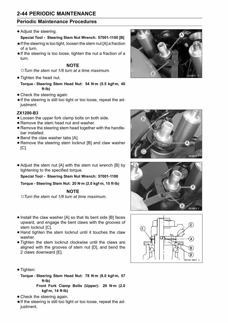
2-44 PERIODIC MAINTENANCE
Periodic Maintenance Procedures
•Adjust the steering.Special Tool - Steering Stem Nut Wrench: 57001-1100 [B]
If the steering is too tight, loosen the stem nut [A] a fractionof a turn.If the steering is too loose, tighten the nut a fraction of aturn.
NOTETurn the stem nut 1/8 turn at a time maximum.
•Tighten the head nut.Torque - Steering Stem Head Nut: 54 N·m (5.5 kgf·m, 40
ft·lb)
•Check the steering againIf the steering is still too tight or too loose, repeat the ad-justment.
ZX1200-B3
•Loosen the upper fork clamp bolts on both side.•Remove the stem head nut and washer.
•Remove the steering stem head together with the handle-bar installed.
• Bend the claw washer tabs [A].•Remove the steering stem locknut [B] and claw washer[C].
• Adjust the stem nut [A] with the stem nut wrench [B] bytightening to the specified torque.
Special Tool - Steering Stem Nut Wrench: 57001-1100
Torque - Steering Stem Nut: 20 N·m (2.0 kgf·m, 15 ft·lb)
NOTETurn the stem nut 1/8 turn at time maximum.
• Install the claw washer [A] so that its bent side [B] facesupward, and engage the bent claws with the grooves ofstem locknut [C].
•Hand tighten the stem locknut until it touches the clawwasher.
• Tighten the stem locknut clockwise until the claws arealigned with the grooves of stem nut [D], and bend the2 claws downward [E].
• Tighten:Torque - Steering Stem Head Nut: 78 N·m (8.0 kgf·m, 57
ft·lb)Front Fork Clamp Bolts (Upper): 20 N·m (2.0kgf·m, 14 ft·lb)
•Check the steering again.If the steering is still too tight or too loose, repeat the ad-justment.
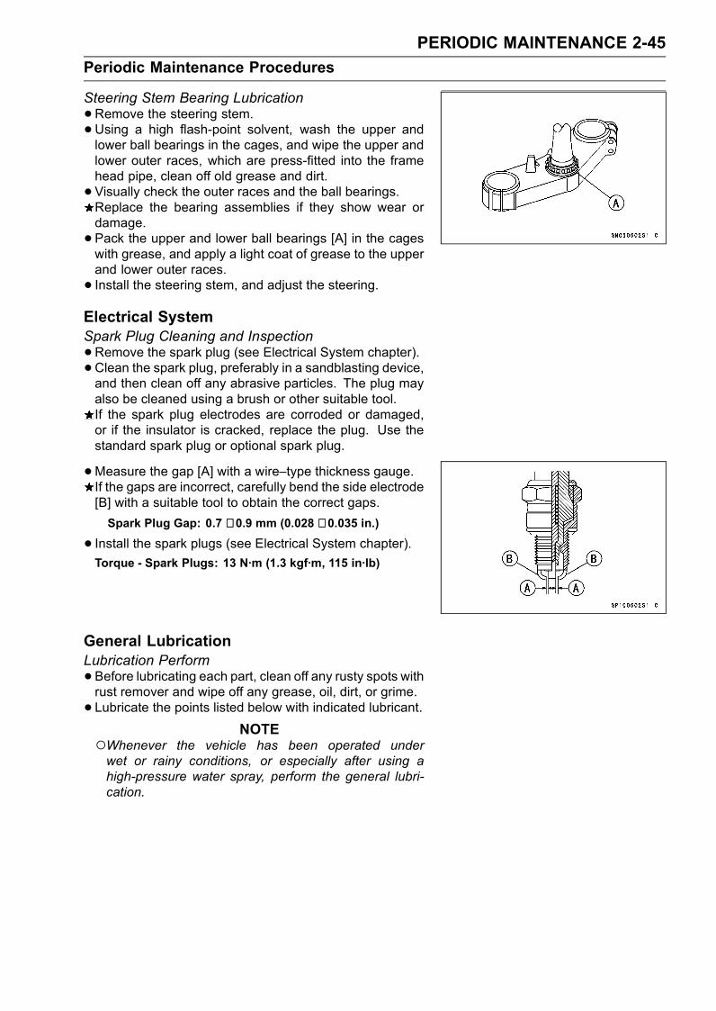
PERIODIC MAINTENANCE 2-45
Periodic Maintenance Procedures
Steering Stem Bearing Lubrication
•Remove the steering stem.•Using a high flash-point solvent, wash the upper andlower ball bearings in the cages, and wipe the upper andlower outer races, which are press-fitted into the framehead pipe, clean off old grease and dirt.
• Visually check the outer races and the ball bearings.Replace the bearing assemblies if they show wear ordamage.
• Pack the upper and lower ball bearings [A] in the cageswith grease, and apply a light coat of grease to the upperand lower outer races.
• Install the steering stem, and adjust the steering.Electrical SystemSpark Plug Cleaning and Inspection
•Remove the spark plug (see Electrical System chapter).• Clean the spark plug, preferably in a sandblasting device,and then clean off any abrasive particles. The plug mayalso be cleaned using a brush or other suitable tool.If the spark plug electrodes are corroded or damaged,or if the insulator is cracked, replace the plug. Use thestandard spark plug or optional spark plug.
•Measure the gap [A] with a wire–type thickness gauge.If the gaps are incorrect, carefully bend the side electrode[B] with a suitable tool to obtain the correct gaps.
Spark Plug Gap: 0.7 ∼ 0.9 mm (0.028 ∼ 0.035 in.)
• Install the spark plugs (see Electrical System chapter).Torque - Spark Plugs: 13 N·m (1.3 kgf·m, 115 in·lb)
General LubricationLubrication Perform
•Before lubricating each part, clean off any rusty spots withrust remover and wipe off any grease, oil, dirt, or grime.
• Lubricate the points listed below with indicated lubricant.NOTE
Whenever the vehicle has been operated underwet or rainy conditions, or especially after using ahigh-pressure water spray, perform the general lubri-cation.
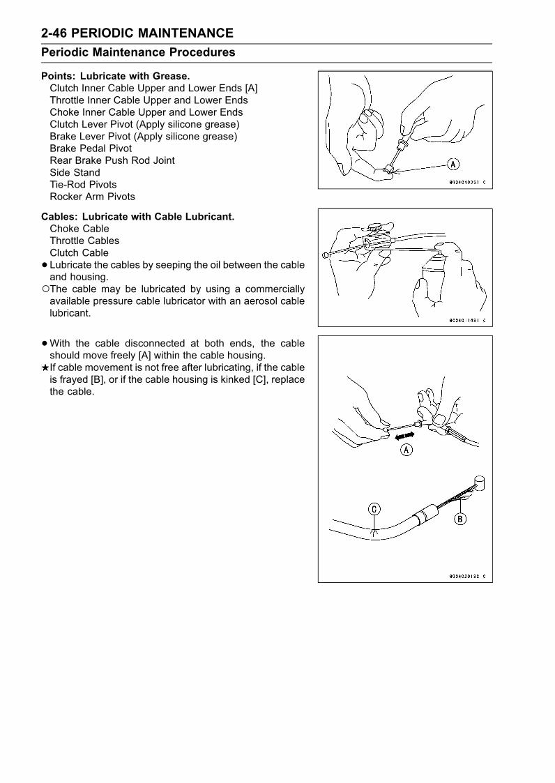
2-46 PERIODIC MAINTENANCE
Periodic Maintenance Procedures
Points: Lubricate with Grease.Clutch Inner Cable Upper and Lower Ends [A]Throttle Inner Cable Upper and Lower EndsChoke Inner Cable Upper and Lower EndsClutch Lever Pivot (Apply silicone grease)Brake Lever Pivot (Apply silicone grease)Brake Pedal PivotRear Brake Push Rod JointSide StandTie-Rod PivotsRocker Arm Pivots
Cables: Lubricate with Cable Lubricant.Choke CableThrottle CablesClutch Cable
• Lubricate the cables by seeping the oil between the cableand housing.The cable may be lubricated by using a commerciallyavailable pressure cable lubricator with an aerosol cablelubricant.
•With the cable disconnected at both ends, the cableshould move freely [A] within the cable housing.If cable movement is not free after lubricating, if the cableis frayed [B], or if the cable housing is kinked [C], replacethe cable.
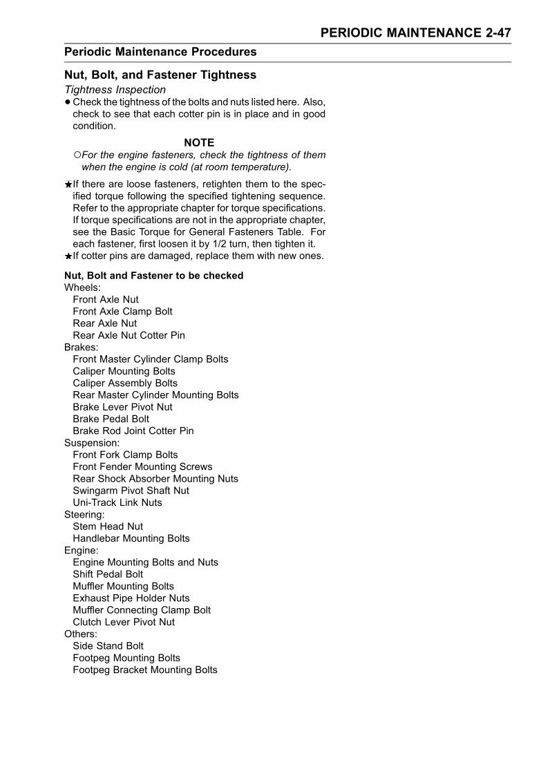
PERIODIC MAINTENANCE 2-47
Periodic Maintenance Procedures
Nut, Bolt, and Fastener TightnessTightness Inspection
•Check the tightness of the bolts and nuts listed here. Also,check to see that each cotter pin is in place and in goodcondition.
NOTEFor the engine fasteners, check the tightness of themwhen the engine is cold (at room temperature).
If there are loose fasteners, retighten them to the spec-ified torque following the specified tightening sequence.Refer to the appropriate chapter for torque specifications.If torque specifications are not in the appropriate chapter,see the Basic Torque for General Fasteners Table. Foreach fastener, first loosen it by 1/2 turn, then tighten it.If cotter pins are damaged, replace them with new ones.
Nut, Bolt and Fastener to be checkedWheels:Front Axle NutFront Axle Clamp BoltRear Axle NutRear Axle Nut Cotter Pin
Brakes:Front Master Cylinder Clamp BoltsCaliper Mounting BoltsCaliper Assembly BoltsRear Master Cylinder Mounting BoltsBrake Lever Pivot NutBrake Pedal BoltBrake Rod Joint Cotter Pin
Suspension:Front Fork Clamp BoltsFront Fender Mounting ScrewsRear Shock Absorber Mounting NutsSwingarm Pivot Shaft NutUni-Track Link Nuts
Steering:Stem Head NutHandlebar Mounting Bolts
Engine:Engine Mounting Bolts and NutsShift Pedal BoltMuffler Mounting BoltsExhaust Pipe Holder NutsMuffler Connecting Clamp BoltClutch Lever Pivot Nut
Others:Side Stand BoltFootpeg Mounting BoltsFootpeg Bracket Mounting Bolts

FUEL SYSTEM (DFI) 3-1
3
Fuel System (DFI)
Table of Contents
Exploded View................................... 3-3Specifications .................................... 3-12Throttle Grip and Cables ................... 3-15
Free Play Inspection .................... 3-15Free Play Adjustment................... 3-15Cable Installation ......................... 3-15Cable Lubrication......................... 3-15
Choke Cable...................................... 3-16Free Play Inspection .................... 3-16Free Play Adjustment................... 3-16Choke Cable Installation .............. 3-16Cable Lubrication......................... 3-16
Throttle Body Assy ............................ 3-17Idle Speed Inspection .................. 3-17Throttle Bore Cleaning ................. 3-17Synchronization Inspection .......... 3-17Synchronization Adjustment ........ 3-17Throttle Body Assy Removal........ 3-17Throttle Body Assy Installation..... 3-20Throttle Body Assy Disassembly . 3-22Throttle Body Assy Assembly ...... 3-24
Air Line .............................................. 3-26Element Removal......................... 3-26Element Installation...................... 3-26Air Cleaner Element Cleaning andInspection.................................. 3-26
Oil Draining .................................. 3-26Air Inlet Duct Removal ................. 3-27Air Inlet Duct Installation .............. 3-27Front Duct Removal/Installation... 3-27
Fuel Tank........................................... 3-28Fuel Tank Removal ...................... 3-28Fuel Tank Installation ................... 3-30Fuel Tank Inspection .................... 3-30Fuel Tank Cleaning ...................... 3-31
DFI System........................................ 3-32DFI Servicing Precautions................. 3-40Troubleshooting the DFI System ....... 3-42Outline ............................................ 3-42Inquiries to Rider............................. 3-46
DFI System Troubleshooting Guide .. 3-49DFI System TroubleshootingGuide......................................... 3-49
Self-Diagnosis ................................... 3-58Self-diagnosis Outline..................... 3-58Self-diagnosis Function .................. 3-58
Self-diagnosis Procedures.............. 3-59How to Read Service Codes........... 3-61How to Erase Service Codes.......... 3-62Backups .......................................... 3-64
Throttle Sensor (Service Code 11)(ZX1200-B1/B2).............................. 3-67Throttle SensorRemoval/Adjustment ................. 3-67
Input Voltage Inspection............... 3-67Output Voltage Inspection............ 3-68Resistance Inspection.................. 3-70
Main Throttle Sensor (Service Code11) (ZX1200-B3) ............................. 3-72Main Throttle SensorRemoval/Adjustment ................. 3-72
Input Voltage Inspection............... 3-72Output Voltage Inspection............ 3-73Resistance Inspection.................. 3-74
Inlet Air Pressure Sensor (ServiceCode 12) ......................................... 3-75Removal....................................... 3-75Installation.................................... 3-76Input Voltage Inspection............... 3-76Output Voltage Inspection............ 3-77
Inlet Air Temperature Sensor (ServiceCode 13) ......................................... 3-81Removal/Installation..................... 3-81Output Voltage Inspection............ 3-81Sensor Resistance Inspection ..... 3-82
Water Temperature Sensor (ServiceCode 14) ......................................... 3-84Removal/Installation..................... 3-84Output Voltage Inspection............ 3-84Sensor Resistance Inspection ..... 3-86
Atmospheric Pressure Sensor(Service Code 15)........................... 3-87Removal....................................... 3-87Installation.................................... 3-87Input Voltage Inspection............... 3-87Output Voltage Inspection............ 3-88
Crankshaft Sensor (Service Code21)................................................... 3-92Crankshaft SensorRemoval/Installation.................. 3-92
Crankshaft Sensor Inspection...... 3-92
3-2 FUEL SYSTEM (DFI)
Camshaft Position Sensor (ServiceCode 23) ......................................... 3-94Camshaft Position SensorRemoval/Installation.................. 3-94
Camshaft Position SensorInspection.................................. 3-94
Speed Sensor (Service Code 24)...... 3-96Speed SensorRemoval/Installation.................. 3-96
Speed Sensor Inspection............. 3-96Gear Position Switch (Service Code25)................................................... 3-98Gear Position Switch Removal .... 3-98Gear Position Switch Installation . 3-98Gear Position Switch InputVoltage Inspection..................... 3-99
Gear Position Switch Inspection .. 3-100Vehicle-down Sensor (Service Code31)................................................... 3-103Removal....................................... 3-103Installation.................................... 3-104Inspection..................................... 3-104
Subthrottle Sensor (Service Code 32)(ZX1200-B3) ................................... 3-108Subthrottle SensorRemoval/Adjustment ................. 3-108
Input Voltage Inspection............... 3-108Output Voltage Inspection............ 3-109Resistance Inspection.................. 3-110
Immobilizer Amplifier (Service Code35) (ZX1200-B3) ............................. 3-111Antenna Resistance Inspection ... 3-111Amplifier Input Voltage Inspection 3-111
Blank Key Detection (Service Code36) (ZX1200-B3) ............................. 3-112User Key Inspection..................... 3-112
Fuel Injectors (#1, #2, #3, #4: ServiceCode 41, 42, 43, 44) ....................... 3-113Power Source Voltage Inspection 3-113Output Voltage Inspection............ 3-115Audible Inspection........................ 3-116Injector Signal Test....................... 3-117Injector Resistance Inspection ..... 3-118Injector Unit Test .......................... 3-118Injector Fuel Line Inspection ........ 3-119
Fuel Pump Relay (Service Code 45,46)................................................... 3-122
Fuel Pump Relay Removal .......... 3-122Operating Voltage Inspection....... 3-122Power Source Voltage Inspection 3-124Relay Inspection .......................... 3-125
Stick Coils (#1, #2, #3, #4: ServiceCode 51, 52, 53, 54) ....................... 3-127Removal/Installation..................... 3-127Input Voltage Inspection............... 3-127
Subthrottle Valve Actuator (ServiceCode 62) (ZX1200-B3) ................... 3-131Subthrottle Valve ActuatorRemoval .................................... 3-131
Audible Inspection........................ 3-131Visual Inspection.......................... 3-131Resistance Inspection.................. 3-131Input Voltage Inspection............... 3-132
ECU................................................... 3-133ECU Removal .............................. 3-133ECU Installation ........................... 3-133ECU Power Supply Inspection..... 3-133
DFI Power Source ............................. 3-137ECU Fuse Removal ..................... 3-137ECU Fuse Installation .................. 3-137ECU Fuse Inspection ................... 3-137ECU Main Relay Removal ........... 3-137ECU Main Relay Inspection ......... 3-137
FI Indicator LED Light........................ 3-138LED Light Inspection.................... 3-139
Fuel Line............................................ 3-141Fuel Pressure Inspection ............. 3-141Fuel Flow Rate Inspection ........... 3-142
In-tank Fuel Pump ............................. 3-144Fuel Pump Removal .................... 3-144Pump Screen Cleaning ................ 3-145Fuel Pump Installation ................. 3-145Operation Inspection.................... 3-146Operating Voltage Inspection....... 3-146
Evaporative Emission ControlSystem............................................ 3-149Parts Removal/Installation ........... 3-149Hose Inspection ........................... 3-149Separator Inspection.................... 3-149Separator Operation Test............. 3-150Canister Inspection (CaliforniaModel Only)............................... 3-150

FUEL SYSTEM (DFI) 3-3
Exploded View
1. Air Cleaner Elements2. Ducts3. Vacuum Switch Valve
AO: Apply high-quality-form-air-filter oil.
CAL: California Model
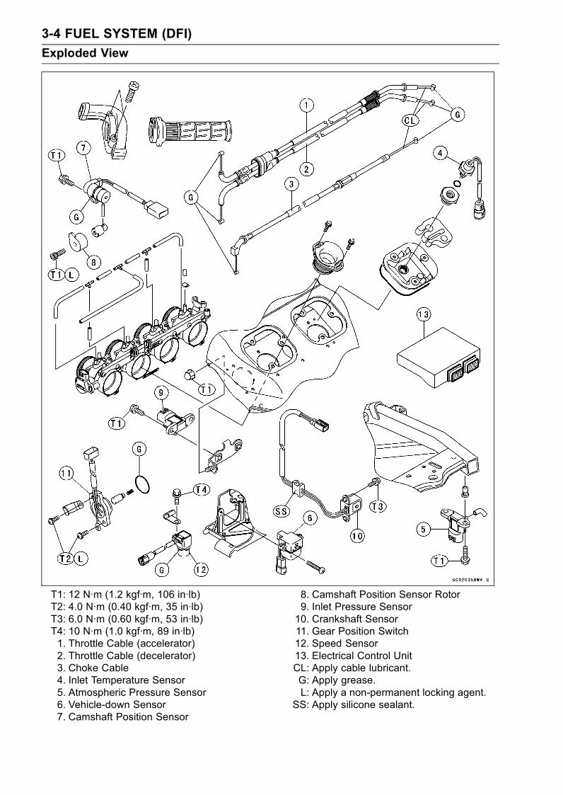
3-4 FUEL SYSTEM (DFI)
Exploded View
T1: 12 N·m (1.2 kgf·m, 106 in·lb)T2: 4.0 N·m (0.40 kgf·m, 35 in·lb)T3: 6.0 N·m (0.60 kgf·m, 53 in·lb)T4: 10 N·m (1.0 kgf·m, 89 in·lb)1. Throttle Cable (accelerator)2. Throttle Cable (decelerator)3. Choke Cable4. Inlet Temperature Sensor5. Atmospheric Pressure Sensor6. Vehicle-down Sensor7. Camshaft Position Sensor
8. Camshaft Position Sensor Rotor9. Inlet Pressure Sensor10. Crankshaft Sensor11. Gear Position Switch12. Speed Sensor13. Electrical Control UnitCL: Apply cable lubricant.G: Apply grease.L: Apply a non-permanent locking agent.
SS: Apply silicone sealant.
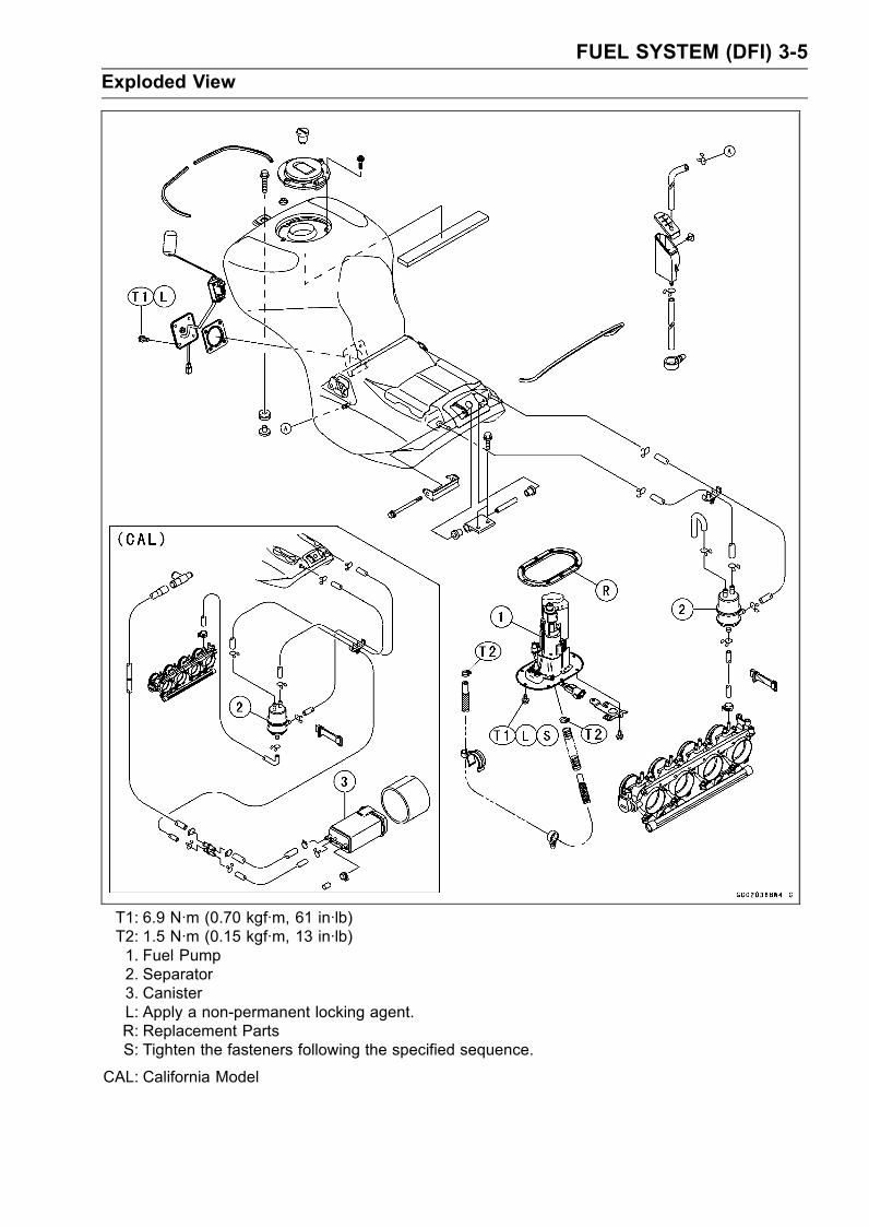
FUEL SYSTEM (DFI) 3-5
Exploded View
T1: 6.9 N·m (0.70 kgf·m, 61 in·lb)T2: 1.5 N·m (0.15 kgf·m, 13 in·lb)1. Fuel Pump2. Separator3. CanisterL: Apply a non-permanent locking agent.R: Replacement PartsS: Tighten the fasteners following the specified sequence.
CAL: California Model
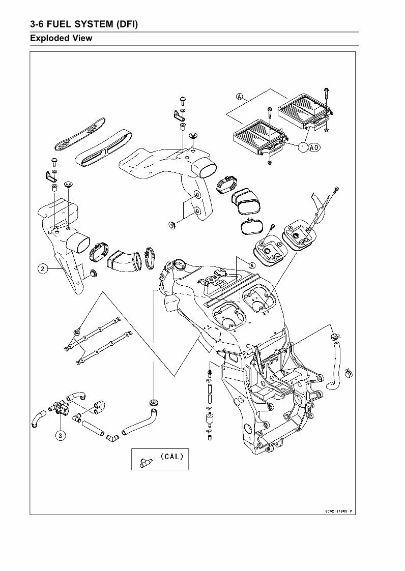
3-6 FUEL SYSTEM (DFI)
Exploded View
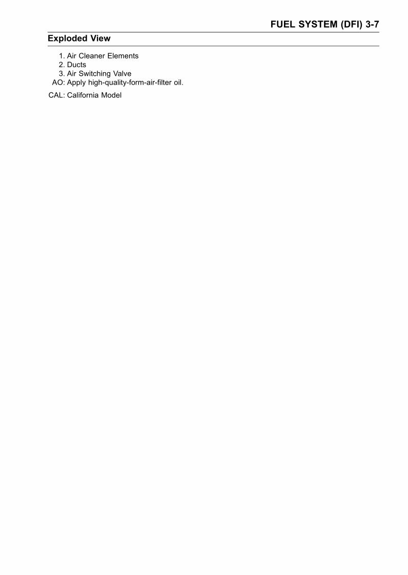
FUEL SYSTEM (DFI) 3-7
Exploded View
1. Air Cleaner Elements2. Ducts3. Air Switching Valve
AO: Apply high-quality-form-air-filter oil.
CAL: California Model
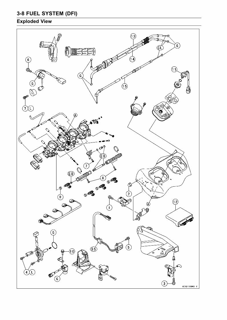
3-8 FUEL SYSTEM (DFI)
Exploded View
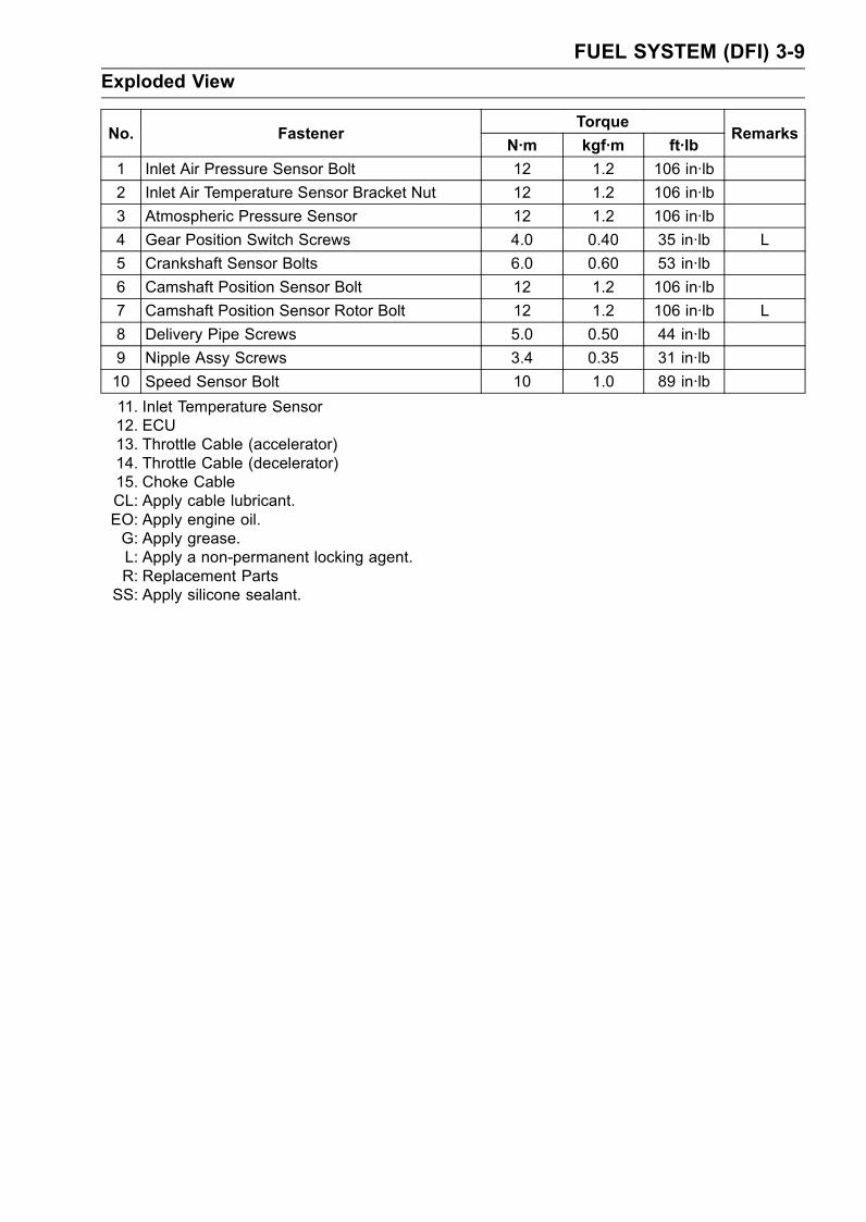
FUEL SYSTEM (DFI) 3-9
Exploded View
TorqueNo. Fastener
N·m kgf·m ft·lbRemarks
1 Inlet Air Pressure Sensor Bolt 12 1.2 106 in·lb
2 Inlet Air Temperature Sensor Bracket Nut 12 1.2 106 in·lb
3 Atmospheric Pressure Sensor 12 1.2 106 in·lb
4 Gear Position Switch Screws 4.0 0.40 35 in·lb L
5 Crankshaft Sensor Bolts 6.0 0.60 53 in·lb
6 Camshaft Position Sensor Bolt 12 1.2 106 in·lb
7 Camshaft Position Sensor Rotor Bolt 12 1.2 106 in·lb L
8 Delivery Pipe Screws 5.0 0.50 44 in·lb
9 Nipple Assy Screws 3.4 0.35 31 in·lb
10 Speed Sensor Bolt 10 1.0 89 in·lb
11. Inlet Temperature Sensor12. ECU13. Throttle Cable (accelerator)14. Throttle Cable (decelerator)15. Choke CableCL: Apply cable lubricant.EO: Apply engine oil.G: Apply grease.L: Apply a non-permanent locking agent.R: Replacement PartsSS: Apply silicone sealant.

3-10 FUEL SYSTEM (DFI)
Exploded View
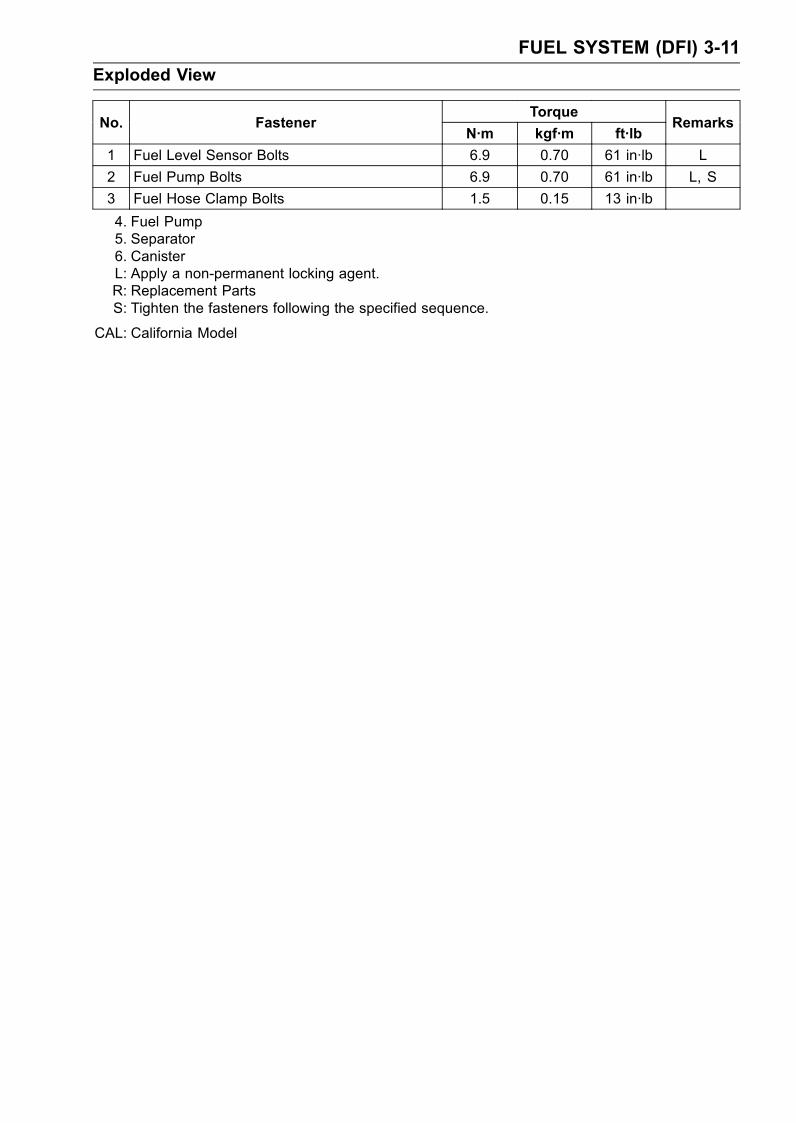
FUEL SYSTEM (DFI) 3-11
Exploded View
TorqueNo. Fastener
N·m kgf·m ft·lbRemarks
1 Fuel Level Sensor Bolts 6.9 0.70 61 in·lb L
2 Fuel Pump Bolts 6.9 0.70 61 in·lb L, S
3 Fuel Hose Clamp Bolts 1.5 0.15 13 in·lb
4. Fuel Pump5. Separator6. CanisterL: Apply a non-permanent locking agent.R: Replacement PartsS: Tighten the fasteners following the specified sequence.
CAL: California Model

3-12 FUEL SYSTEM (DFI)
Specifications
Item Standard
Throttle Grip and Cables
Throttle Grip Free Play 2 ∼ 3 mm (0.08 ∼ 0.12 in.)Choke Cable
Choke Cable Free Play 2 ∼ 3 mm (0.08 ∼ 0.12 in.)Digital Fuel Injection System
Idle Speed 1 000 ±50 r/min (rpm)
Throttle Assy:
Type Four barrel type
Bore 46 mm (1.8 in.)
Throttle Body Vacuum 26 ±1.333 kPa (195 ±10 mmHg)
Bypass Screws:
ZX1200-B1/B2 – – –
ZX1200-B3 0 ∼ 2 1/2 (for reference)ECU (Electronic Control Unit):
Make Denso
Type Digital memory type, with built in IC igniter, sealed with resin
Usable Engine Speed:
ZX1200-B1/B2 100 ∼ 11 870 r/min (rpm)ZX1200-B3 100 ∼ 11 840 r/min (rpm)
Fuel Pump:
Type In-tank pump (in fuel tank), or Wesco pump (friction pump)
Discharge 83 mL (2.8 US oz) or more/3 seconds
Fuel Pressure (High Pressure Line):
Right after Ignition Switch ON, withFuel Pump Running for 3 seconds
285 ∼ 315 kPa (2.91 ∼ 3.21 kgf/cm², 41 ∼ 46 psi)
Throttle Sensor (ZX1200-B1/B2): Non-adjustable, and non-removable
Input Voltage 4.75 ∼ 5.25 V DC between BL/W and BR/BK leads
Output Voltage 1.07 ∼ 4.61 V DC between Y/W and BR/BK leads (idlethrottle opening to full throttle opening)
Resistance 4 ∼ 6 kΩMain Throttle Sensor (ZX1200-B3): Non-adjustable, and non-removable
Input Voltage 4.75 ∼ 5.25 V DC between BL/W and BR/BK leads
Output Voltage at Idle ThrottleOpening
1.06 ∼ 1.10 V DC between Y/W and BR/BK leads
Output Voltage at Full ThrottleOpening
4.26 ∼ 4.86 V DC between Y/W and BR/BK leads
Resistance 4 ∼ 6 kΩSub Throttle Sensor (ZX1200-B3): Non-adjustable, and non-removable
Input Voltage 4.75 ∼ 5.25 V DC between BL/W and BR/BK leads
Output Voltage at Idle ThrottleOpening
0.48 ∼ 0.52 V DC between BR and BR/BK leads
Output Voltage at Full ThrottleOpening
3.6 ∼ 4.0 V DC between BR and BR/BK leads
Resistance 4 ∼ 6 kΩ

FUEL SYSTEM (DFI) 3-13
Specifications
Item Standard
Sub Throttle Valve Actuator(ZX1200-B3):
Resistance about 2 ∼ 4 kΩInput Voltage about 10 ∼ 14 V DC
Atmospheric Pressure Sensor/InletAir Pressure Sensor:
Input Voltage 4.75 ∼ 5.25 V DC between BL/W and BR/BK lead
Output Voltage 3.46 ∼ 3.82 V DC at standard atmospheric pressure (seethis text for details)
Inlet Air Temperature Sensor:
Resistance 657 ∼ 1 003 kΩ at 0°C (32°F)68 ∼ 89 kΩ at 50°C (122°F)11.95 ∼ 14.37 kΩ at 100°C (212°F)
Output Voltage at ECU about 2.26 ∼ 2.50 V @20°C (68°F)Water Temperature Sensor:
Resistance 2.32 ∼ 2.59 kΩ at 20°C (68°F)0.31 ∼ 0.326 kΩ at 80°C (176°F)0.1399 ∼ 0.1435 kΩ at 110°C (230°F)
Output Voltage at ECU about 1.95 ∼ 2.29 V @20°C (68°F)Vehicle-down Sensor:
Detection Method Magnetic flux detection method
Detection Angle more than 65° ±5° for each bank
Detection Time within 0.5 ∼ 1.0 secondsOutput Voltage with the sensor tilted 60 ∼ 70° or more: 3.7 ∼ 4.4 V
with sensor arrow mark pointed up: 0.4 ∼ 1.4 VFuel Injectors:
Type:
ZX1200-B1/B2 46EIS × 4
ZX1200-B3 INP-284
Nozzle Type:
ZX1200-B1/B2 One spray type with 4 holes
ZX1200-B3 One spray type with 12 holes
Resistance:
ZX1200-B1/B2 about 12.5 Ω at 20°C (68°F)ZX1200-B3 about 11.7 ∼ 12.3 Ω at 20°C (68°F)
Immobilizer Amplifier:
Antenna Resistance about 0.6 ∼ 0.9 Ω

3-14 FUEL SYSTEM (DFI)
Specifications
Special Tools - Oil Pressure Gauge: 57001-125Carburetor Drain Plug Wrench, Hex 3: 57001-1269Fork Oil Level Gauge: 57001-1290Pilot Screw Adjuster, C: 57001-1292Hand Tester: 57001-1394Throttle Sensor Harness Adapter #2: 57001-1408Fuel Pressure Gauge Adapter: 57001-1417Needle Adapter Set: 57001-1457Throttle Sensor Setting Adapter: 57001-1538
Sealant - Kawasaki Bond (Silicone Sealant): 56019-120
FUEL SYSTEM (DFI) 3-15
Throttle Grip and Cables
Free Play Inspection
•Refer to the Throttle Control System Inspection in the Pe-riodic Maintenance chapter.
Free Play Adjustment
•Refer to the Throttle Control System Inspection in the Pe-riodic Maintenance chapter.
Cable Installation
• Install the throttle cables in accordance with the CableRouting section in the General Information chapter.
• Install the lower ends of the throttle cables in the cablebracket on the throttle assy after installing the upper endsof the throttle cables in the grip.
• After installation, adjust each cable properly.WARNING
Operation with incorrectly routed or improperly ad-justed cables could result in an unsafe riding con-dition.
Cable Lubrication
•Refer to the General Lubrication Perform in the PeriodicMaintenance chapter.
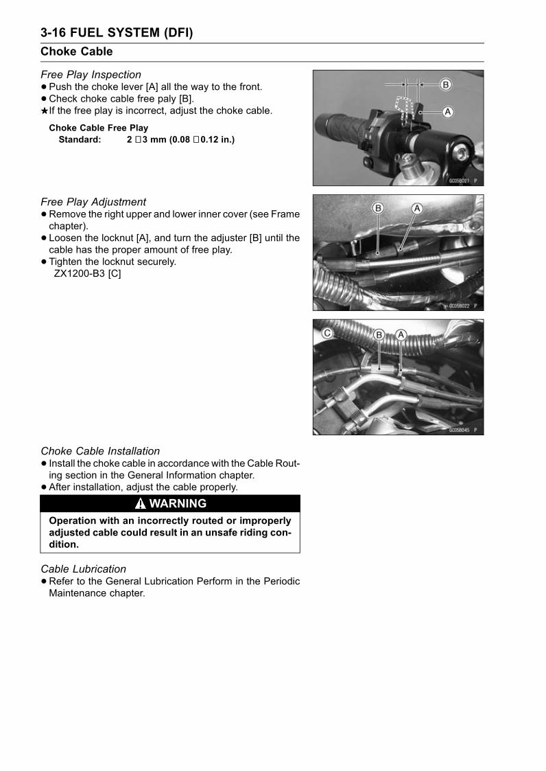
3-16 FUEL SYSTEM (DFI)
Choke Cable
Free Play Inspection
•Push the choke lever [A] all the way to the front.• Check choke cable free paly [B].If the free play is incorrect, adjust the choke cable.
Choke Cable Free PlayStandard: 2 ∼ 3 mm (0.08 ∼ 0.12 in.)
Free Play Adjustment
•Remove the right upper and lower inner cover (see Framechapter).
• Loosen the locknut [A], and turn the adjuster [B] until thecable has the proper amount of free play.
• Tighten the locknut securely.ZX1200-B3 [C]
Choke Cable Installation
• Install the choke cable in accordance with the Cable Rout-ing section in the General Information chapter.
• After installation, adjust the cable properly.WARNING
Operation with an incorrectly routed or improperlyadjusted cable could result in an unsafe riding con-dition.
Cable Lubrication
•Refer to the General Lubrication Perform in the PeriodicMaintenance chapter.
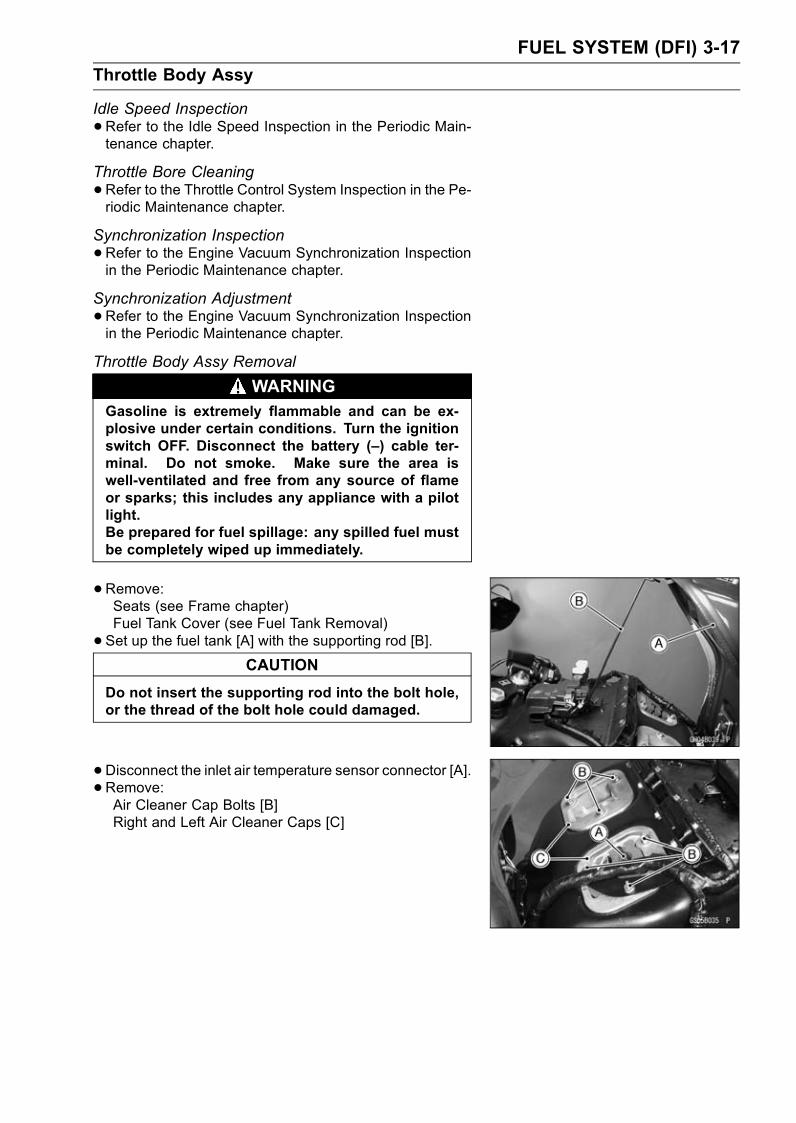
FUEL SYSTEM (DFI) 3-17
Throttle Body Assy
Idle Speed Inspection
•Refer to the Idle Speed Inspection in the Periodic Main-tenance chapter.
Throttle Bore Cleaning
•Refer to the Throttle Control System Inspection in the Pe-riodic Maintenance chapter.
Synchronization Inspection
•Refer to the Engine Vacuum Synchronization Inspectionin the Periodic Maintenance chapter.
Synchronization Adjustment
•Refer to the Engine Vacuum Synchronization Inspectionin the Periodic Maintenance chapter.
Throttle Body Assy Removal
WARNINGGasoline is extremely flammable and can be ex-plosive under certain conditions. Turn the ignitionswitch OFF. Disconnect the battery (–) cable ter-minal. Do not smoke. Make sure the area iswell-ventilated and free from any source of flameor sparks; this includes any appliance with a pilotlight.Be prepared for fuel spillage: any spilled fuel mustbe completely wiped up immediately.
•Remove:Seats (see Frame chapter)Fuel Tank Cover (see Fuel Tank Removal)
• Set up the fuel tank [A] with the supporting rod [B].CAUTION
Do not insert the supporting rod into the bolt hole,or the thread of the bolt hole could damaged.
•Disconnect the inlet air temperature sensor connector [A].• Remove:Air Cleaner Cap Bolts [B]Right and Left Air Cleaner Caps [C]
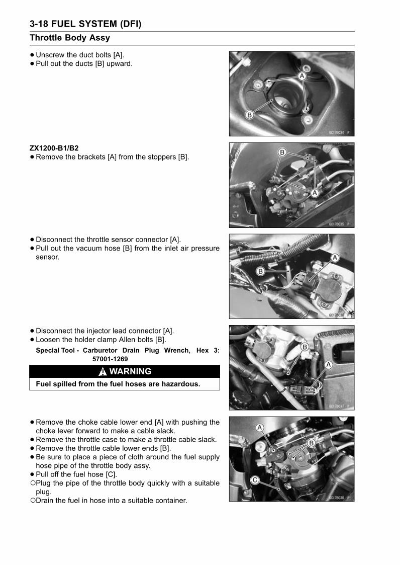
3-18 FUEL SYSTEM (DFI)
Throttle Body Assy
•Unscrew the duct bolts [A].• Pull out the ducts [B] upward.
ZX1200-B1/B2
•Remove the brackets [A] from the stoppers [B].
•Disconnect the throttle sensor connector [A].• Pull out the vacuum hose [B] from the inlet air pressuresensor.
•Disconnect the injector lead connector [A].• Loosen the holder clamp Allen bolts [B].Special Tool - Carburetor Drain Plug Wrench, Hex 3:
57001-1269
WARNINGFuel spilled from the fuel hoses are hazardous.
•Remove the choke cable lower end [A] with pushing thechoke lever forward to make a cable slack.
•Remove the throttle case to make a throttle cable slack.•Remove the throttle cable lower ends [B].• Be sure to place a piece of cloth around the fuel supplyhose pipe of the throttle body assy.
• Pull off the fuel hose [C].Plug the pipe of the throttle body quickly with a suitableplug.Drain the fuel in hose into a suitable container.
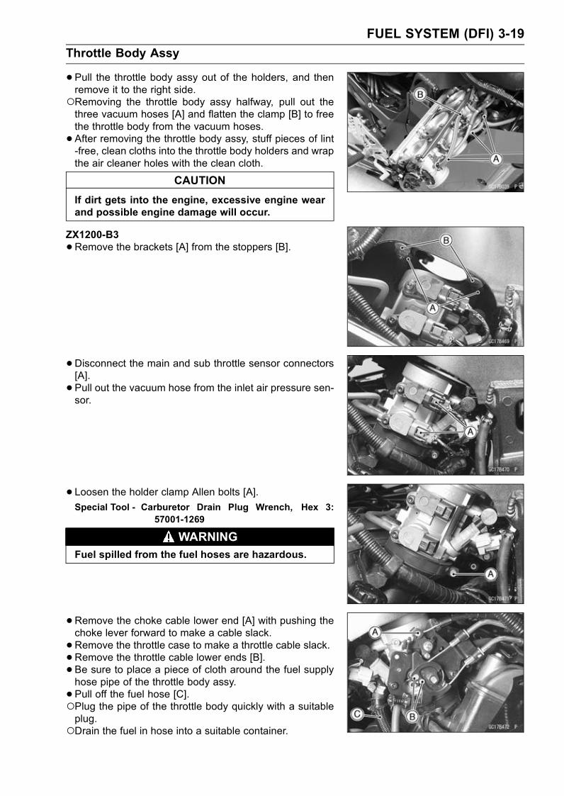
FUEL SYSTEM (DFI) 3-19
Throttle Body Assy
•Pull the throttle body assy out of the holders, and thenremove it to the right side.Removing the throttle body assy halfway, pull out thethree vacuum hoses [A] and flatten the clamp [B] to freethe throttle body from the vacuum hoses.
• After removing the throttle body assy, stuff pieces of lint-free, clean cloths into the throttle body holders and wrapthe air cleaner holes with the clean cloth.
CAUTION
If dirt gets into the engine, excessive engine wearand possible engine damage will occur.
ZX1200-B3
•Remove the brackets [A] from the stoppers [B].
•Disconnect the main and sub throttle sensor connectors[A].
• Pull out the vacuum hose from the inlet air pressure sen-sor.
• Loosen the holder clamp Allen bolts [A].Special Tool - Carburetor Drain Plug Wrench, Hex 3:
57001-1269
WARNINGFuel spilled from the fuel hoses are hazardous.
•Remove the choke cable lower end [A] with pushing thechoke lever forward to make a cable slack.
•Remove the throttle case to make a throttle cable slack.•Remove the throttle cable lower ends [B].• Be sure to place a piece of cloth around the fuel supplyhose pipe of the throttle body assy.
• Pull off the fuel hose [C].Plug the pipe of the throttle body quickly with a suitableplug.Drain the fuel in hose into a suitable container.
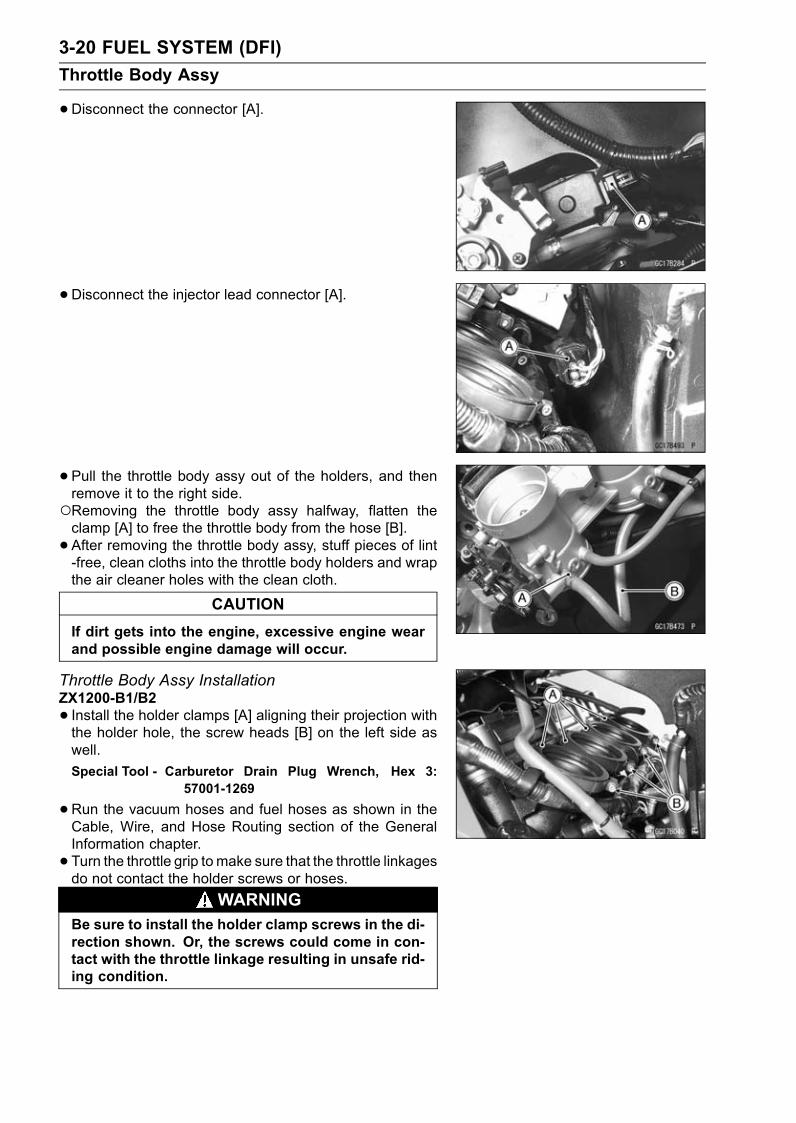
3-20 FUEL SYSTEM (DFI)
Throttle Body Assy
•Disconnect the connector [A].
• Disconnect the injector lead connector [A].
• Pull the throttle body assy out of the holders, and thenremove it to the right side.Removing the throttle body assy halfway, flatten theclamp [A] to free the throttle body from the hose [B].
• After removing the throttle body assy, stuff pieces of lint-free, clean cloths into the throttle body holders and wrapthe air cleaner holes with the clean cloth.
CAUTION
If dirt gets into the engine, excessive engine wearand possible engine damage will occur.
Throttle Body Assy InstallationZX1200-B1/B2
• Install the holder clamps [A] aligning their projection withthe holder hole, the screw heads [B] on the left side aswell.
Special Tool - Carburetor Drain Plug Wrench, Hex 3:57001-1269
•Run the vacuum hoses and fuel hoses as shown in theCable, Wire, and Hose Routing section of the GeneralInformation chapter.
• Turn the throttle grip tomake sure that the throttle linkagesdo not contact the holder screws or hoses.
WARNINGBe sure to install the holder clamp screws in the di-rection shown. Or, the screws could come in con-tact with the throttle linkage resulting in unsafe rid-ing condition.

FUEL SYSTEM (DFI) 3-21
Throttle Body Assy
•Be sure the fuel hose [A] are clamped securely to preventleaks.
WARNINGFuel spilled from the fuel hoses are hazardous.
•Adjust:Throttle Grip Free PlayChoke Lever Free PlayIdle Speed
ZX1200-B3
• Install the holder clamps [A] aligning their projection withthe holder hole, the screw heads [B] on the left side aswell.
Special Tool - Carburetor Drain Plug Wrench, Hex 3:57001-1269
•Run the vacuum hoses and fuel hoses as shown in theCable, Wire, and Hose Routing section of the GeneralInformation chapter.
• Turn the throttle grip tomake sure that the throttle linkagesdo not contact the holder screws or hoses.
WARNINGBe sure to install the holder clamp screws in the di-rection shown. Or, the screws could come in con-tact with the throttle linkage resulting in unsafe rid-ing condition.
•Be sure the fuel hose [A] are clamped securely to preventleaks.
WARNINGFuel spilled from the fuel hoses are hazardous.
•Adjust:Throttle Grip Free PlayChoke Lever Free PlayIdle Speed
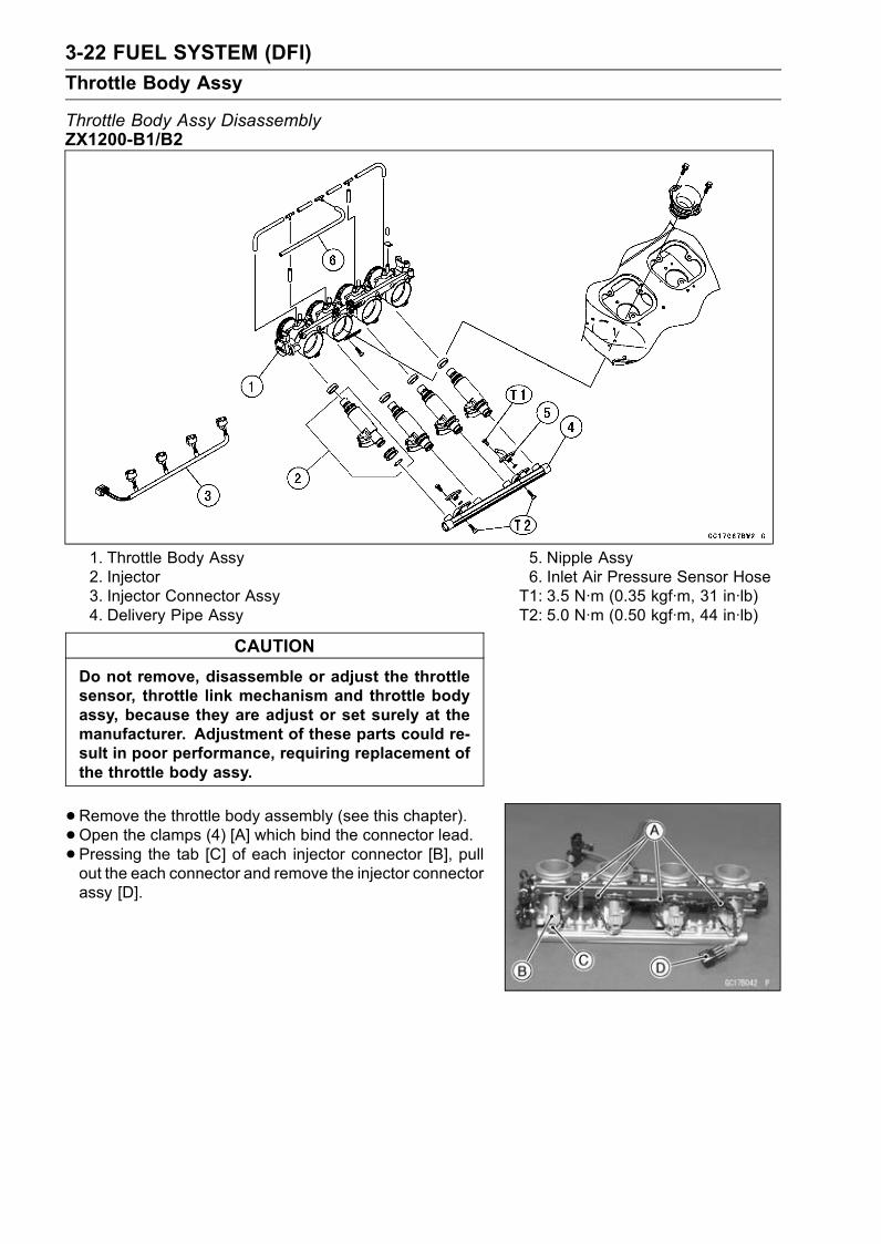
3-22 FUEL SYSTEM (DFI)
Throttle Body Assy
Throttle Body Assy DisassemblyZX1200-B1/B2
1. Throttle Body Assy2. Injector3. Injector Connector Assy4. Delivery Pipe Assy
5. Nipple Assy6. Inlet Air Pressure Sensor HoseT1: 3.5 N·m (0.35 kgf·m, 31 in·lb)T2: 5.0 N·m (0.50 kgf·m, 44 in·lb)
CAUTION
Do not remove, disassemble or adjust the throttlesensor, throttle link mechanism and throttle bodyassy, because they are adjust or set surely at themanufacturer. Adjustment of these parts could re-sult in poor performance, requiring replacement ofthe throttle body assy.
•Remove the throttle body assembly (see this chapter).•Open the clamps (4) [A] which bind the connector lead.• Pressing the tab [C] of each injector connector [B], pullout the each connector and remove the injector connectorassy [D].
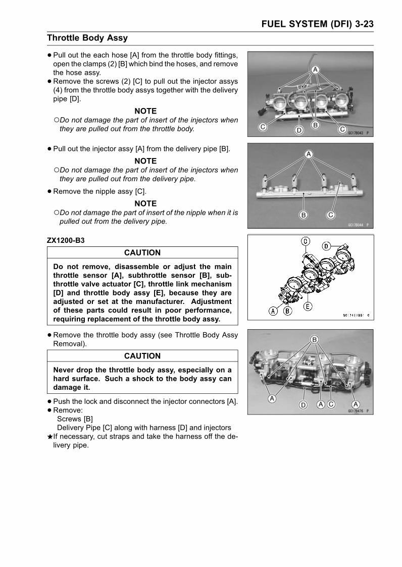
FUEL SYSTEM (DFI) 3-23
Throttle Body Assy
•Pull out the each hose [A] from the throttle body fittings,open the clamps (2) [B] which bind the hoses, and removethe hose assy.
•Remove the screws (2) [C] to pull out the injector assys(4) from the throttle body assys together with the deliverypipe [D].
NOTEDo not damage the part of insert of the injectors whenthey are pulled out from the throttle body.
•Pull out the injector assy [A] from the delivery pipe [B].NOTE
Do not damage the part of insert of the injectors whenthey are pulled out from the delivery pipe.
•Remove the nipple assy [C].NOTE
Do not damage the part of insert of the nipple when it ispulled out from the delivery pipe.
ZX1200-B3
CAUTION
Do not remove, disassemble or adjust the mainthrottle sensor [A], subthrottle sensor [B], sub-throttle valve actuator [C], throttle link mechanism[D] and throttle body assy [E], because they areadjusted or set at the manufacturer. Adjustmentof these parts could result in poor performance,requiring replacement of the throttle body assy.
•Remove the throttle body assy (see Throttle Body AssyRemoval).
CAUTION
Never drop the throttle body assy, especially on ahard surface. Such a shock to the body assy candamage it.
•Push the lock and disconnect the injector connectors [A].•Remove:Screws [B]Delivery Pipe [C] along with harness [D] and injectorsIf necessary, cut straps and take the harness off the de-livery pipe.
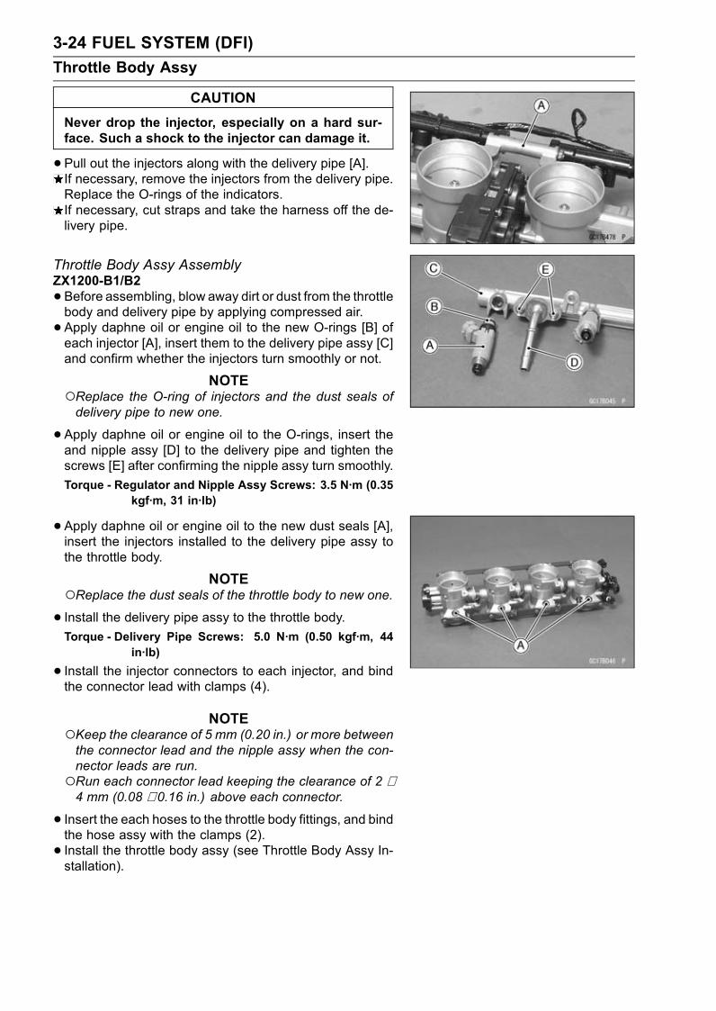
3-24 FUEL SYSTEM (DFI)
Throttle Body Assy
CAUTION
Never drop the injector, especially on a hard sur-face. Such a shock to the injector can damage it.
•Pull out the injectors along with the delivery pipe [A].If necessary, remove the injectors from the delivery pipe.Replace the O-rings of the indicators.If necessary, cut straps and take the harness off the de-livery pipe.
Throttle Body Assy AssemblyZX1200-B1/B2
•Before assembling, blow away dirt or dust from the throttlebody and delivery pipe by applying compressed air.
• Apply daphne oil or engine oil to the new O-rings [B] ofeach injector [A], insert them to the delivery pipe assy [C]and confirm whether the injectors turn smoothly or not.
NOTEReplace the O-ring of injectors and the dust seals ofdelivery pipe to new one.
•Apply daphne oil or engine oil to the O-rings, insert theand nipple assy [D] to the delivery pipe and tighten thescrews [E] after confirming the nipple assy turn smoothly.
Torque - Regulator and Nipple Assy Screws: 3.5 N·m (0.35kgf·m, 31 in·lb)
•Apply daphne oil or engine oil to the new dust seals [A],insert the injectors installed to the delivery pipe assy tothe throttle body.
NOTEReplace the dust seals of the throttle body to new one.• Install the delivery pipe assy to the throttle body.Torque - Delivery Pipe Screws: 5.0 N·m (0.50 kgf·m, 44
in·lb)
• Install the injector connectors to each injector, and bindthe connector lead with clamps (4).
NOTEKeep the clearance of 5 mm (0.20 in.) or more betweenthe connector lead and the nipple assy when the con-nector leads are run.Run each connector lead keeping the clearance of 2 ∼4 mm (0.08 ∼ 0.16 in.) above each connector.
• Insert the each hoses to the throttle body fittings, and bindthe hose assy with the clamps (2).
• Install the throttle body assy (see Throttle Body Assy In-stallation).
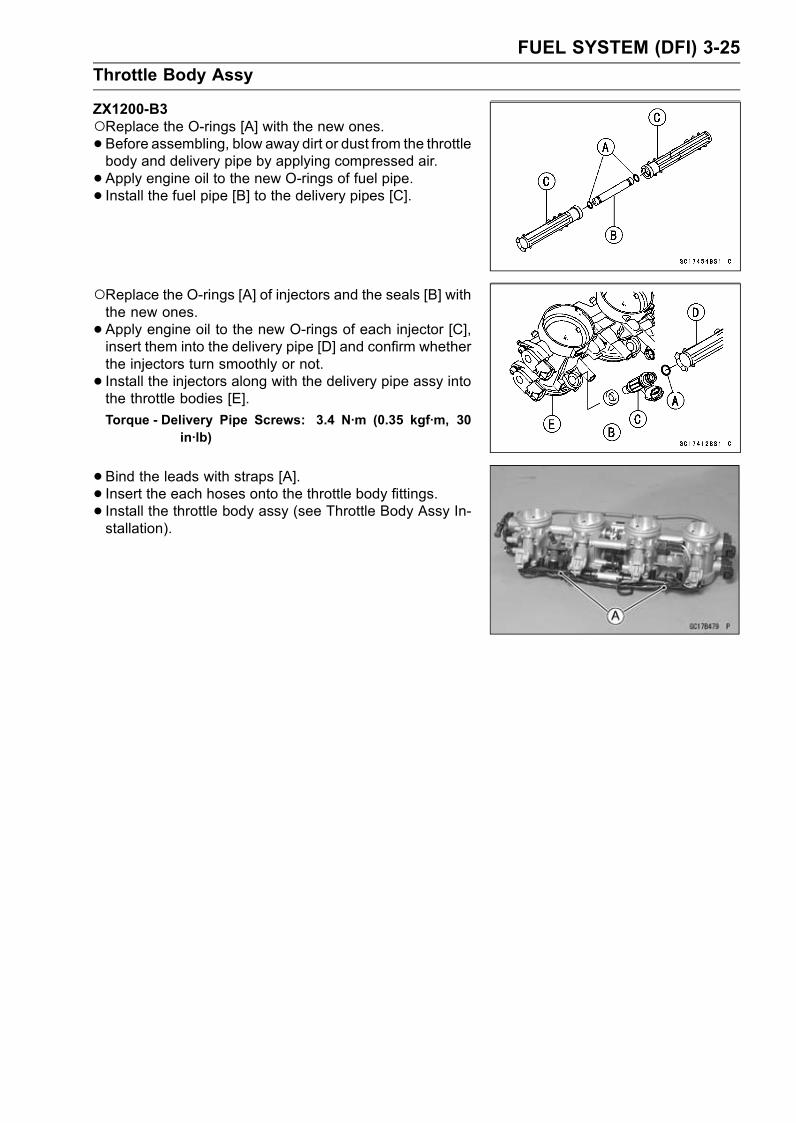
FUEL SYSTEM (DFI) 3-25
Throttle Body Assy
ZX1200-B3Replace the O-rings [A] with the new ones.• Before assembling, blow away dirt or dust from the throttlebody and delivery pipe by applying compressed air.
• Apply engine oil to the new O-rings of fuel pipe.• Install the fuel pipe [B] to the delivery pipes [C].
Replace the O-rings [A] of injectors and the seals [B] withthe new ones.
• Apply engine oil to the new O-rings of each injector [C],insert them into the delivery pipe [D] and confirm whetherthe injectors turn smoothly or not.
• Install the injectors along with the delivery pipe assy intothe throttle bodies [E].
Torque - Delivery Pipe Screws: 3.4 N·m (0.35 kgf·m, 30in·lb)
•Bind the leads with straps [A].• Insert the each hoses onto the throttle body fittings.• Install the throttle body assy (see Throttle Body Assy In-stallation).

3-26 FUEL SYSTEM (DFI)
Air Line
Element Removal
•Remove:Seats (see Frame chapter)Fuel Tank Cover (see Fuel Tank Removal)Supporting Rod (see Fuel Tank Removal)
• Set up the fuel tank [A] with the supporting rod [B].CAUTION
Do not insert the supporting rod into the bolt hole,or the thread of the bolt hole could be damaged.
•Unscrew the nuts [A] and remove the bolts.• Pull out the elements [B].
Element Installation
• Install the elements [A] with the mark side (FRONT) facingfront.
Air Cleaner Element Cleaning and Inspection
•Refer to the Air Cleaner Element Cleaning (ZX1200-B1/B2)/Element Replacement (ZX1200-B3) in the Peri-odic Maintenance chapter.
Oil DrainingA drain hose is connected to the bottom of the air cleaner
part to drain water or oil accumulated in the cleaner part.
• Visually check the catch tank [A] of the drain hose if thewater or oil accumulates in tank.If any water or oil accumulates in the tank, drain it bytaking off the drain plug [B] at the lower end of the drainhose.
WARNINGBe sure reinstall the plug in the drain hose afterdraining. Oil on tires will make them slippery andcan cause an accident and injury.
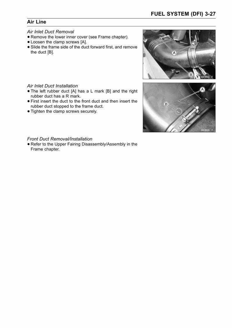
FUEL SYSTEM (DFI) 3-27
Air Line
Air Inlet Duct Removal
•Remove the lower inner cover (see Frame chapter).• Loosen the clamp screws [A].• Slide the frame side of the duct forward first, and removethe duct [B].
Air Inlet Duct Installation
•The left rubber duct [A] has a L mark [B] and the rightrubber duct has a R mark.
• First insert the duct to the front duct and then insert therubber duct stopped to the frame duct.
• Tighten the clamp screws securely.
Front Duct Removal/Installation
•Refer to the Upper Fairing Disassembly/Assembly in theFrame chapter.

3-28 FUEL SYSTEM (DFI)
Fuel Tank
Fuel Tank Removal
WARNINGGasoline is extremely flammable and can be explo-sive under certain conditions. Make sure the areais well-ventilated and free from any source of flameor sparks; this includes any appliance with a pilotlight. Do not smoke. Turn the ignition switch OFF.Be prepared for fuel spillage; any spilled fuel mustbe completely wiped up immediately.
CAUTION
For California model, if gasoline, solvent, water orany other liquid enters the canister, the canister’svapor absorbing capacity is greatly reduced. If thecanister does become contaminated, replace it witha new one.
•Remove:Rear Seat (see Frame chapter)Front Seat (see Frame chapter)Allen Bolts [A]Fuel Tank Cover Plate [B]
Screws [A]Allen Bolts [B]Fuel Tank Cover [C]
Bolt [A]
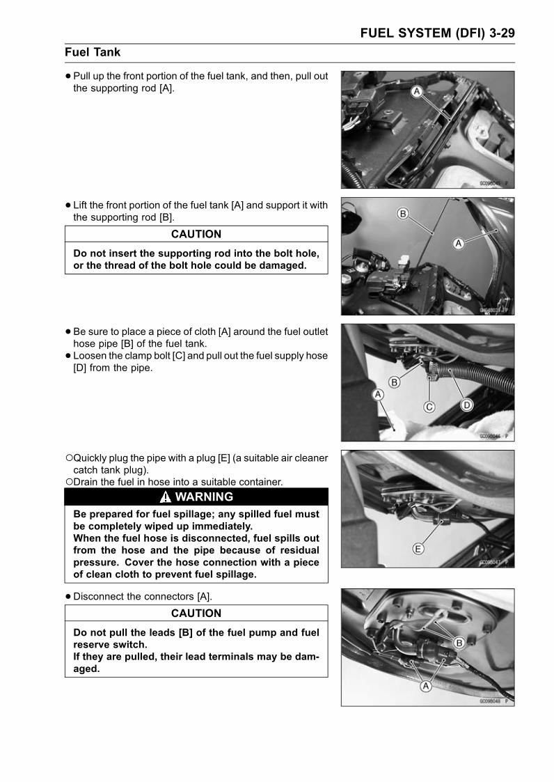
FUEL SYSTEM (DFI) 3-29
Fuel Tank
•Pull up the front portion of the fuel tank, and then, pull outthe supporting rod [A].
• Lift the front portion of the fuel tank [A] and support it withthe supporting rod [B].
CAUTION
Do not insert the supporting rod into the bolt hole,or the thread of the bolt hole could be damaged.
•Be sure to place a piece of cloth [A] around the fuel outlethose pipe [B] of the fuel tank.
• Loosen the clamp bolt [C] and pull out the fuel supply hose[D] from the pipe.
Quickly plug the pipe with a plug [E] (a suitable air cleanercatch tank plug).Drain the fuel in hose into a suitable container.
WARNINGBe prepared for fuel spillage; any spilled fuel mustbe completely wiped up immediately.When the fuel hose is disconnected, fuel spills outfrom the hose and the pipe because of residualpressure. Cover the hose connection with a pieceof clean cloth to prevent fuel spillage.
•Disconnect the connectors [A].CAUTION
Do not pull the leads [B] of the fuel pump and fuelreserve switch.If they are pulled, their lead terminals may be dam-aged.
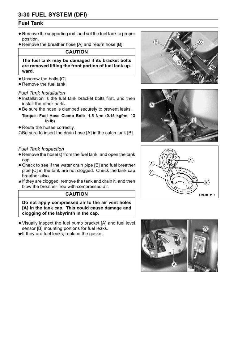
3-30 FUEL SYSTEM (DFI)
Fuel Tank
•Remove the supporting rod, and set the fuel tank to properposition.
•Remove the breather hose [A] and return hose [B].CAUTION
The fuel tank may be damaged if its bracket boltsare removed lifting the front portion of fuel tank up-ward.
•Unscrew the bolts [C].•Remove the fuel tank.Fuel Tank Installation
• Installation is the fuel tank bracket bolts first, and theninstall the other parts.
• Be sure the hose is clamped securely to prevent leaks.Torque - Fuel Hose Clamp Bolt: 1.5 N·m (0.15 kgf·m, 13
in·lb)
•Route the hoses correctly.Be sure to insert the drain hose [A] in the catch tank [B].
Fuel Tank Inspection
•Remove the hose(s) from the fuel tank, and open the tankcap.
•Check to see if the water drain pipe [B] and fuel breatherpipe [C] in the tank are not clogged. Check the tank capbreather also.If they are clogged, remove the tank and drain it, and thenblow the breather free with compressed air.
CAUTION
Do not apply compressed air to the air vent holes[A] in the tank cap. This could cause damage andclogging of the labyrinth in the cap.
•Visually inspect the fuel pump bracket [A] and fuel levelsensor [B] mounting portions for fuel leaks.If they are fuel leaks, replace the gasket.
FUEL SYSTEM (DFI) 3-31
Fuel Tank
Fuel Tank Cleaning
WARNINGClean the tank in a well-ventilated area, and takecare that there are no sparks or flame anywherenear the working area. Because of the danger orhighly flammable liquids, do not use gasoline or lowflash point solvents to clean the tank.
•Remove the fuel tank (see Fuel Tank Removal).• Drain the fuel.• Remove the fuel pump assy and fuel lever sensor.• Pour some high flash-point solvent into the fuel tank andshake the tank to remove dirt and fuel deposits.
• Pour the solvent over of the tank.•Dry the tank with compressed air.• Install the fuel pump assy (see Fuel Pump Installation)and fuel level sensor (see Electrical System chapter) inthe tank.
• Install the fuel tank (see Fuel Tank Installation).

3-32 FUEL SYSTEM (DFI)
DFI System
DFI System Wiring Diagram (ZX1200-B1/B2)
FUEL SYSTEM (DFI) 3-33
DFI System
Part Name1. ECU (Electric Control Unit)2. Gear Position Switch3. Inlet Air Pressure Sensor4. Throttle Sensor5. Water Temperature Sensor6. Camshaft Position Sensor7. Crankshaft Sensor8. Side Stand Switch9. Injector #410. Injector #311. Injector #212. Injector #113. Stick Coil #114. Stick Coil #215. Stick Coil #316. Stick Coil #417. Ignition Switch18. Starter Button19. Engine Stop Switch20. Tachometer21. FI Indicator LED Light22. Junction Box23. Ignition Fuse 10 A24. Starter Circuit Relay25. ECU Main Relay26. Fuel Pump Relay27. ECU Main Fuse 15 A28. Vehicle-down Sensor29. Starter Motor30. Starter Motor Relay31. Main Fuse 30 A32. Starter Lockout Switch33. Battery 12 V 12 Ah34. Fuel Pump35. Self-diagnosis Indicator Switch36. Open or Short Circuit Connector*
*Do not exchange the connector. To ensure optional ignition and fuel injection timing, the ECUand connector are combined.
ECU and Connector Combinations
ECU Part No. 21175-1087 21175-1089 21175-1090 21175-1091 21175-1092
Open Connector Short Circuit Connector The part number of the ECU is in the label on the ECU.37. Inlet Air Temperature Sensor38. Atmospheric Pressure Sensor39. Meter Assembly40. Speed Sensor
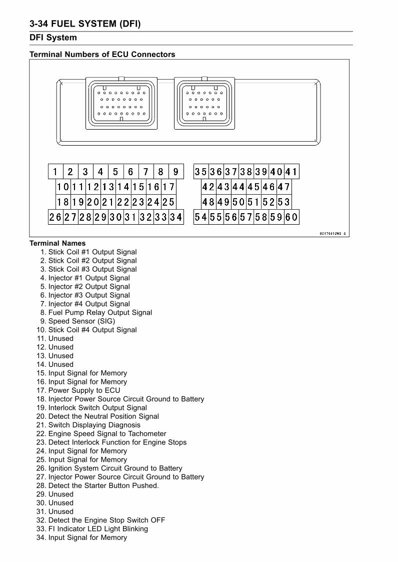
3-34 FUEL SYSTEM (DFI)
DFI System
Terminal Numbers of ECU Connectors
Terminal Names1. Stick Coil #1 Output Signal2. Stick Coil #2 Output Signal3. Stick Coil #3 Output Signal4. Injector #1 Output Signal5. Injector #2 Output Signal6. Injector #3 Output Signal7. Injector #4 Output Signal8. Fuel Pump Relay Output Signal9. Speed Sensor (SIG)10. Stick Coil #4 Output Signal11. Unused12. Unused13. Unused14. Unused15. Input Signal for Memory16. Input Signal for Memory17. Power Supply to ECU18. Injector Power Source Circuit Ground to Battery19. Interlock Switch Output Signal20. Detect the Neutral Position Signal21. Switch Displaying Diagnosis22. Engine Speed Signal to Tachometer23. Detect Interlock Function for Engine Stops24. Input Signal for Memory25. Input Signal for Memory26. Ignition System Circuit Ground to Battery27. Injector Power Source Circuit Ground to Battery28. Detect the Starter Button Pushed.29. Unused30. Unused31. Unused32. Detect the Engine Stop Switch OFF33. FI Indicator LED Light Blinking34. Input Signal for Memory

FUEL SYSTEM (DFI) 3-35
DFI System
35. ECU Power Source Circuit Ground to Battery36. Crankshaft Sensor (+) Output Signal37. Camshaft Position Sensor (+) Output Signal38. Power Source for External Diagnosis System39. Power Supply to ECU40. Vehicle-down Sensor Output Signal41. Power Source to Sensor System42. Power Supply to Injector and Fuel Pump43. Crankshaft Sensor (–) Output Signal44. Camshaft Position Sensor (–) Output Signal45. Atmospheric Pressure Sensor Output Signal46. Detect the 4th Gear Position Signal47. Detect the 1st Gear Position Signal48. Power Source to ECU49. Output Signal for External Diagnosis System50. Unused51. Inlet Air Pressure Sensor Output Signal52. Detect the 5th Gear Position Signal53. Detect the 2nd Gear Position Signal54. Sensor System Circuit Ground from ECU55. Ground for External Diagnosis System56. Throttle Sensor Output Signal57. Inlet Air Temperature Sensor Output Signal58. Water Temperature Sensor Output Signal59. Detect the 6th Gear Position Signal60. Detect the 3rd Gear Position Signal

3-36 FUEL SYSTEM (DFI)
DFI System
DFI System Wiring Diagram (ZX1200-B3)
FUEL SYSTEM (DFI) 3-37
DFI System
Part Name1. ECU (Electric Control Unit)2. Gear Position Switch3. Inlet Air Pressure Sensor4. Air Switching Valve5. Water Temperature Sensor6. Camshaft Position Sensor7. Crankshaft Sensor8. Side Stand Switch9. Injector #1, #2, #3, #410. Subthrottle Valve Actuator11. Subthrottle Sensor12. Main Throttle Sensor13. Stick Coil #1, #2, #3, #414. Atmospheric Pressure Sensor15. Meter Assembly16. Speed Sensor17. Ignition Switch18. Starter Button19. Engine Stop Switch20. Tachometer21. FI Indicator LED Light22. Junction Box23. Ignition Fuse 10 A24. Starter Circuit Relay25. ECU Main Relay26. Fuel Pump Relay27. ECU Main Fuse 15 A28. Vehicle-down Sensor29. Inlet Air Temperature Sensor30. Starter Relay31. Main Fuse 30 A32. Starter Lockout Switch33. Battery 12 V 12 Ah34. Fuel Pump35. Self-diagnosis Terminal36. Starter Motor

3-38 FUEL SYSTEM (DFI)
DFI System
Terminal Numbers of ECU Connectors
1. Subthrottle Valve Actuator Drive Signal2. Subthrottle Valve Actuator Drive Signal3. Unused4. Unused5. Unused6. Ignition Switch Signal7. Main Throttle Sensor Signal8. Inlet Air Pressure Sensor Signal9. Water Temperature Sensor Signal (+)10. Power Supply to Sensors11. Speed Sensor Signal12. Camshaft Position Sensor Signal (+)13. Crankshaft Sensor Signal (+)14. Immobilizer Communication Line15. Immobilizer Communication Line16. Battery Power ON-OFF Signal17. Power Supply to ECU, Injectors, and Fuel Pump18. Subthrottle Valve Actuator Drive Signal19. Subthrottle Valve Actuator Drive Signal20. Unused21. Unused22. Unused23. Vehicle-down Sensor Signal24. Subthrottle Sensor Signal25. Atmospheric Pressure Sensor Signal26. Inlet Air Temperature Sensor Signal (+)27. Unused28. Ground to Sensors29. Camshaft Position Sensor Signal (–)30. Crankshaft Sensor Signal (–)31. Immobilizer Communication Line32. External Diagnosis System Signal33. Power Supply to Injector and Fuel Pump34. ECU Power Source Circuit Ground to Battery (–) Terminal35. Detect the 3rd Gear Position Signal

FUEL SYSTEM (DFI) 3-39
DFI System
36. Detect the 2nd Gear Position Signal37. Detect the 1st Gear Position Signal38. FI Indicator LED Light Signal39. Tachometer Signal40. Electric Starter Button Signal41. Injector #4 Signal42. Injector #3 Signal43. Injector #2 Signal44. Injector #1 Signal45. Stick Coil #3 Signal46. Stick Coil #2 Signal47. Stick Coil #1 Signal48. Detect the 6th Gear Position Signal49. Detect the 5th Gear Position Signal50. Detect the 4th Gear Position Signal51. Self-diagnosis Signal (Generated by grounding this terminal and shown by FI indicator LED
light)52. Engine Stop Switch Signal53. Interlock Circuit Signal54. Starter Lockout Switch Signal55. Neutral Switch Signal56. Fuel Pump Relay Signal57. Air Switching Valve Signal58. DFI System Ground59. Ignition System Ground60. Stick Coil #4 Signal
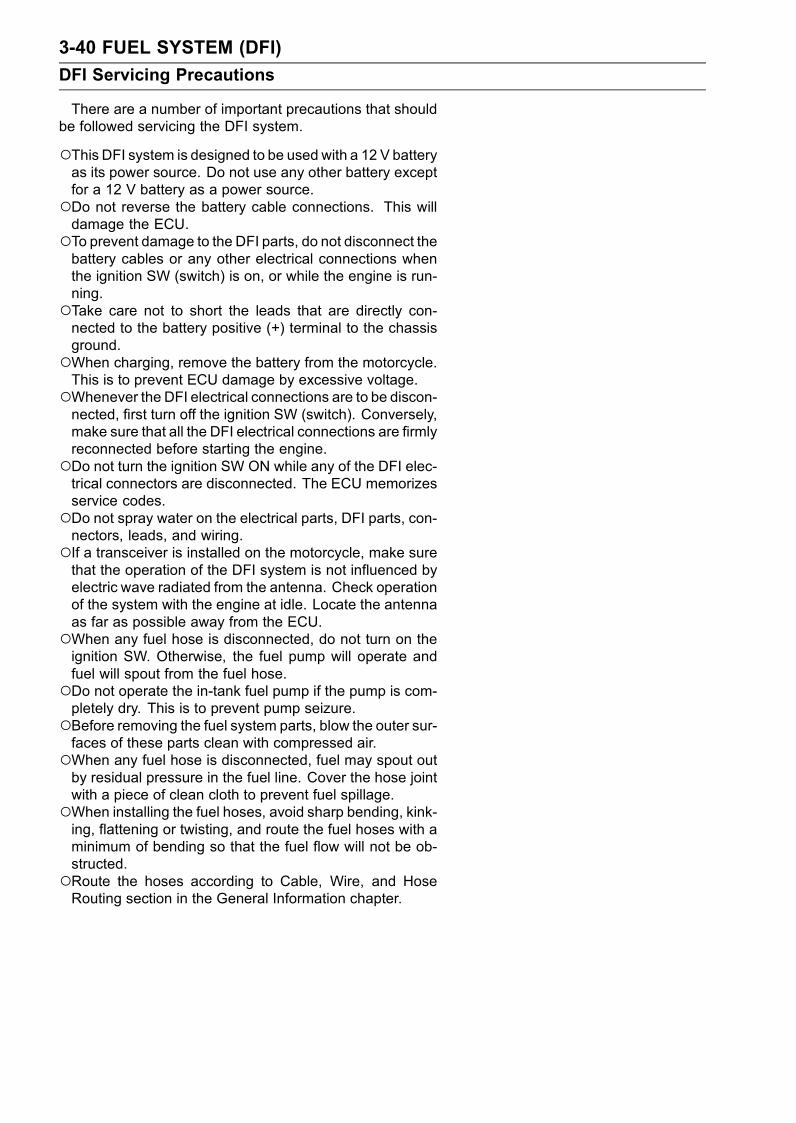
3-40 FUEL SYSTEM (DFI)
DFI Servicing Precautions
There are a number of important precautions that shouldbe followed servicing the DFI system.
This DFI system is designed to be used with a 12 V batteryas its power source. Do not use any other battery exceptfor a 12 V battery as a power source.Do not reverse the battery cable connections. This willdamage the ECU.To prevent damage to the DFI parts, do not disconnect thebattery cables or any other electrical connections whenthe ignition SW (switch) is on, or while the engine is run-ning.Take care not to short the leads that are directly con-nected to the battery positive (+) terminal to the chassisground.When charging, remove the battery from the motorcycle.This is to prevent ECU damage by excessive voltage.Whenever the DFI electrical connections are to be discon-nected, first turn off the ignition SW (switch). Conversely,make sure that all the DFI electrical connections are firmlyreconnected before starting the engine.Do not turn the ignition SW ON while any of the DFI elec-trical connectors are disconnected. The ECU memorizesservice codes.Do not spray water on the electrical parts, DFI parts, con-nectors, leads, and wiring.If a transceiver is installed on the motorcycle, make surethat the operation of the DFI system is not influenced byelectric wave radiated from the antenna. Check operationof the system with the engine at idle. Locate the antennaas far as possible away from the ECU.When any fuel hose is disconnected, do not turn on theignition SW. Otherwise, the fuel pump will operate andfuel will spout from the fuel hose.Do not operate the in-tank fuel pump if the pump is com-pletely dry. This is to prevent pump seizure.Before removing the fuel system parts, blow the outer sur-faces of these parts clean with compressed air.When any fuel hose is disconnected, fuel may spout outby residual pressure in the fuel line. Cover the hose jointwith a piece of clean cloth to prevent fuel spillage.When installing the fuel hoses, avoid sharp bending, kink-ing, flattening or twisting, and route the fuel hoses with aminimum of bending so that the fuel flow will not be ob-structed.Route the hoses according to Cable, Wire, and HoseRouting section in the General Information chapter.
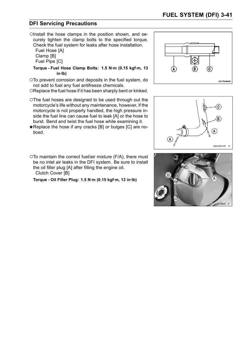
FUEL SYSTEM (DFI) 3-41
DFI Servicing Precautions
Install the hose clamps in the position shown, and se-curely tighten the clamp bolts to the specified torque.Check the fuel system for leaks after hose installation.Fuel Hose [A]Clamp [B]Fuel Pipe [C]
Torque - Fuel Hose Clamp Bolts: 1.5 N·m (0.15 kgf·m, 13in·lb)
To prevent corrosion and deposits in the fuel system, donot add to fuel any fuel antifreeze chemicals.Replace the fuel hose if it has been sharply bent or kinked.The fuel hoses are designed to be used through out themotorcycle’s life without any maintenance, however, if themotorcycle is not properly handled, the high pressure in-side the fuel line can cause fuel to leak [A] or the hose toburst. Bend and twist the fuel hose while examining it.Replace the hose if any cracks [B] or bulges [C] are no-ticed.
To maintain the correct fuel/air mixture (F/A), there mustbe no inlet air leaks in the DFI system. Be sure to installthe oil filler plug [A] after filling the engine oil.Clutch Cover [B]
Torque - Oil Filler Plug: 1.5 N·m (0.15 kgf·m, 13 in·lb)
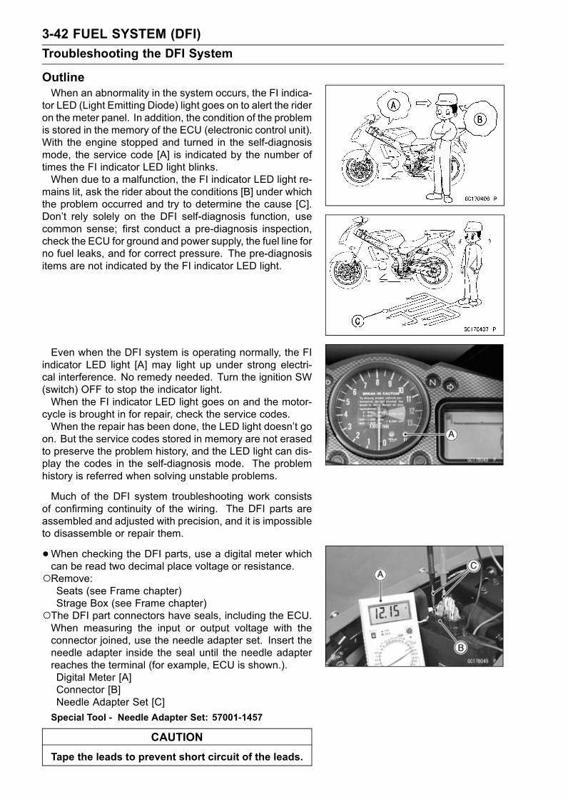
3-42 FUEL SYSTEM (DFI)
Troubleshooting the DFI System
OutlineWhen an abnormality in the system occurs, the FI indica-
tor LED (Light Emitting Diode) light goes on to alert the rideron the meter panel. In addition, the condition of the problemis stored in the memory of the ECU (electronic control unit).With the engine stopped and turned in the self-diagnosismode, the service code [A] is indicated by the number oftimes the FI indicator LED light blinks.When due to a malfunction, the FI indicator LED light re-
mains lit, ask the rider about the conditions [B] under whichthe problem occurred and try to determine the cause [C].Don’t rely solely on the DFI self-diagnosis function, usecommon sense; first conduct a pre-diagnosis inspection,check the ECU for ground and power supply, the fuel line forno fuel leaks, and for correct pressure. The pre-diagnosisitems are not indicated by the FI indicator LED light.
Even when the DFI system is operating normally, the FIindicator LED light [A] may light up under strong electri-cal interference. No remedy needed. Turn the ignition SW(switch) OFF to stop the indicator light.When the FI indicator LED light goes on and the motor-
cycle is brought in for repair, check the service codes.When the repair has been done, the LED light doesn’t go
on. But the service codes stored in memory are not erasedto preserve the problem history, and the LED light can dis-play the codes in the self-diagnosis mode. The problemhistory is referred when solving unstable problems.
Much of the DFI system troubleshooting work consistsof confirming continuity of the wiring. The DFI parts areassembled and adjusted with precision, and it is impossibleto disassemble or repair them.
•When checking the DFI parts, use a digital meter whichcan be read two decimal place voltage or resistance.Remove:Seats (see Frame chapter)Strage Box (see Frame chapter)
The DFI part connectors have seals, including the ECU.When measuring the input or output voltage with theconnector joined, use the needle adapter set. Insert theneedle adapter inside the seal until the needle adapterreaches the terminal (for example, ECU is shown.).Digital Meter [A]Connector [B]Needle Adapter Set [C]
Special Tool - Needle Adapter Set: 57001-1457
CAUTION
Tape the leads to prevent short circuit of the leads.
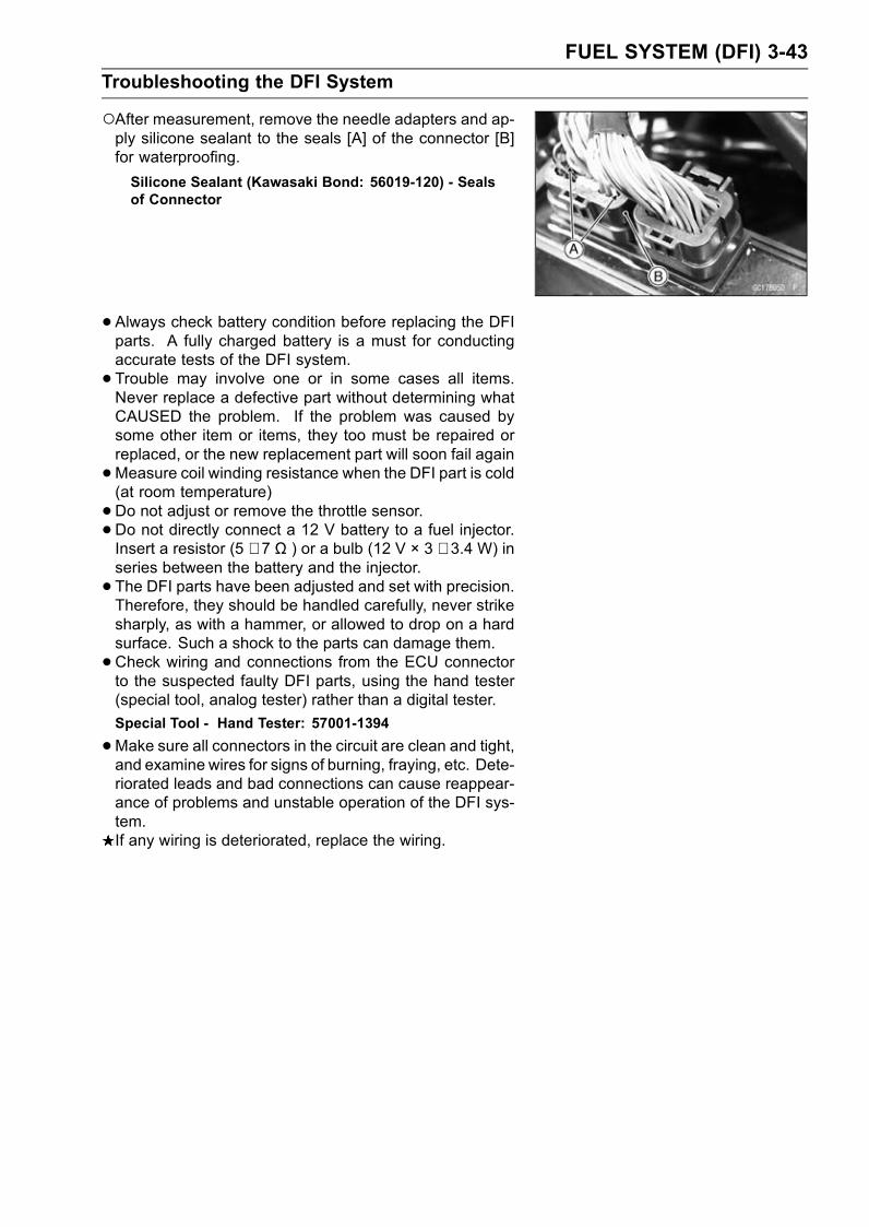
FUEL SYSTEM (DFI) 3-43
Troubleshooting the DFI System
After measurement, remove the needle adapters and ap-ply silicone sealant to the seals [A] of the connector [B]for waterproofing.
Silicone Sealant (Kawasaki Bond: 56019-120) - Sealsof Connector
•Always check battery condition before replacing the DFIparts. A fully charged battery is a must for conductingaccurate tests of the DFI system.
• Trouble may involve one or in some cases all items.Never replace a defective part without determining whatCAUSED the problem. If the problem was caused bysome other item or items, they too must be repaired orreplaced, or the new replacement part will soon fail again
•Measure coil winding resistance when the DFI part is cold(at room temperature)
•Do not adjust or remove the throttle sensor.•Do not directly connect a 12 V battery to a fuel injector.Insert a resistor (5 ∼ 7 Ω ) or a bulb (12 V × 3 ∼ 3.4 W) inseries between the battery and the injector.
• The DFI parts have been adjusted and set with precision.Therefore, they should be handled carefully, never strikesharply, as with a hammer, or allowed to drop on a hardsurface. Such a shock to the parts can damage them.
•Check wiring and connections from the ECU connectorto the suspected faulty DFI parts, using the hand tester(special tool, analog tester) rather than a digital tester.
Special Tool - Hand Tester: 57001-1394
•Make sure all connectors in the circuit are clean and tight,and examine wires for signs of burning, fraying, etc. Dete-riorated leads and bad connections can cause reappear-ance of problems and unstable operation of the DFI sys-tem.If any wiring is deteriorated, replace the wiring.
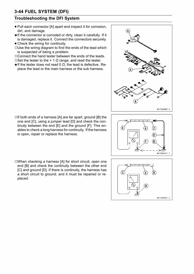
3-44 FUEL SYSTEM (DFI)
Troubleshooting the DFI System
•Pull each connector [A] apart and inspect it for corrosion,dirt, and damage.If the connector is corroded or dirty, clean it carefully. If itis damaged, replace it. Connect the connectors securely.
•Check the wiring for continuity.Use the wiring diagram to find the ends of the lead whichis suspected of being a problem.Connect the hand tester between the ends of the leads.Set the tester to the × 1 Ω range, and read the tester.If the tester does not read 0 Ω, the lead is defective. Re-place the lead or the main harness or the sub harness.
If both ends of a harness [A] are far apart, ground [B] theone end [C], using a jumper lead [D] and check the con-tinuity between the end [E] and the ground [F]. This en-ables to check a long harness for continuity. If the harnessis open, repair or replace the harness.
When checking a harness [A] for short circuit, open oneend [B] and check the continuity between the other end[C] and ground [D]. If there is continuity, the harness hasa short circuit to ground, and it must be repaired or re-placed.
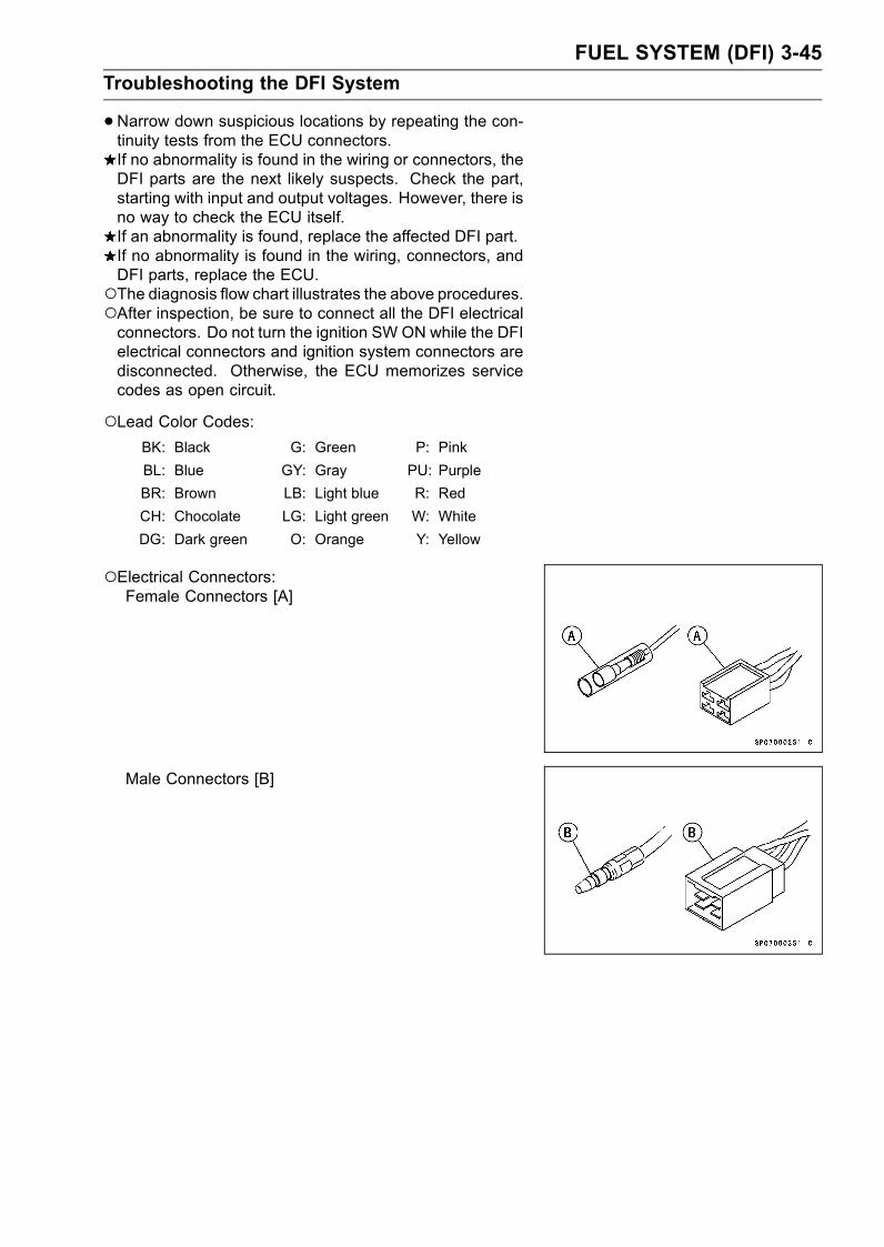
FUEL SYSTEM (DFI) 3-45
Troubleshooting the DFI System
•Narrow down suspicious locations by repeating the con-tinuity tests from the ECU connectors.If no abnormality is found in the wiring or connectors, theDFI parts are the next likely suspects. Check the part,starting with input and output voltages. However, there isno way to check the ECU itself.If an abnormality is found, replace the affected DFI part.If no abnormality is found in the wiring, connectors, andDFI parts, replace the ECU.The diagnosis flow chart illustrates the above procedures.After inspection, be sure to connect all the DFI electricalconnectors. Do not turn the ignition SW ON while the DFIelectrical connectors and ignition system connectors aredisconnected. Otherwise, the ECU memorizes servicecodes as open circuit.
Lead Color Codes:BK: Black G: Green P: Pink
BL: Blue GY: Gray PU: Purple
BR: Brown LB: Light blue R: Red
CH: Chocolate LG: Light green W: White
DG: Dark green O: Orange Y: Yellow
Electrical Connectors:Female Connectors [A]
Male Connectors [B]

3-46 FUEL SYSTEM (DFI)
Troubleshooting the DFI System
DFI Diagnosis Flow Chart
Inquiries to RiderEach rider reacts to problems in different ways, so it is important to confirm what kind of symptomsthe rider has encountered.Try to find out exactly what problem occurred under exactly what conditions by asking the rider;knowing this information may help you reproduce the problem.The diagnosis sheet will help prevent you from overlooking any areas, and will help you decide if itis a DFI system problem, or a general engine problem.

FUEL SYSTEM (DFI) 3-47
Troubleshooting the DFI System
Sample Diagnosis SheetRider Name: Registration No. (License Plate No.):
Year of Initial Registration: Model:
Engine No.: Frame No.:
Date Problem Occurred: Mileage:
Environment when problem occurred.
Weather fine, cloudy, rain, snow, always, other:Temperature hot, warm, cold, very cold, alwaysProblem Frequency chronic, often, onceRoad
street, highway, mountain road (uphill, downhill), bumpy,pebble
Altitude normal, high (about 1 000 m or more)
Motorcycle conditions when problem occurred.
light up immediately after ignition SW ON, and goes off after 1 ∼ 2seconds (normal).
FI Indicator LED Light
lights blinks immediately after ignition SW ON, and stays on (DFIproblem)
lights up immediately after ignition SW ON, but goes off after about 10seconds (DFI problem).
unlights (LED light, ECU or its wiring fault).sometimes lights up (probably wiring fault).starter motor not rotating.Starting Difficulty
starter motor rotating but engine doesn’t turn over.starter motor and engine don’t turn over.no fuel flow (no fuel in tank, no fuel pump sound).engine flooded (do not crank engine with throttle opened, which promotesengine flooding).
no spark.choke lever is not pulled fully when using the lever (pull it fully whenusing).
other:right after starting.Engine Stalls
when opening throttle grip.when closing throttle grip.when moving off.when stopping the motorcycle.when cruising.other:choke lever pulled out fully (push it in fully).very low choke speed.very low idle speed, very high idle speed, rough idle speed.
Poor Running at LowSpeed
battery voltage is low (charge the battery).spark plug loose (tighten it).spark plug dirty, broken, or gap maladjusted (remedy it).backfiring.after firing.
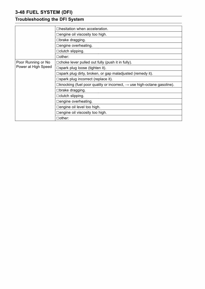
3-48 FUEL SYSTEM (DFI)
Troubleshooting the DFI System
hesitation when acceleration.engine oil viscosity too high.brake dragging.engine overheating.clutch slipping.other:choke lever pulled out fully (push it in fully).spark plug loose (tighten it).spark plug dirty, broken, or gap maladjusted (remedy it).spark plug incorrect (replace it).knocking (fuel poor quality or incorrect,→ use high-octane gasoline).
Poor Running or NoPower at High Speed
brake dragging.clutch slipping.engine overheating.engine oil level too high.engine oil viscosity too high.other:
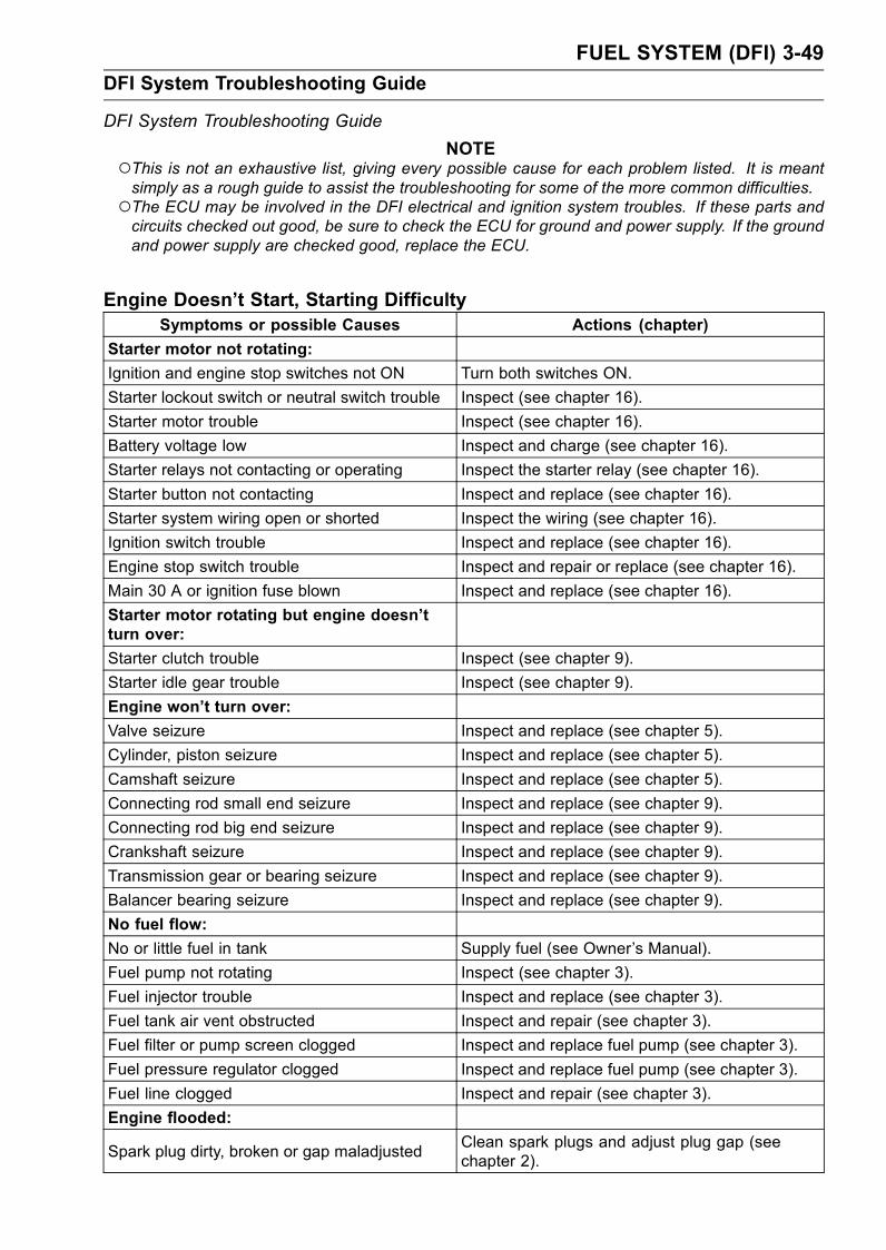
FUEL SYSTEM (DFI) 3-49
DFI System Troubleshooting Guide
DFI System Troubleshooting Guide
NOTEThis is not an exhaustive list, giving every possible cause for each problem listed. It is meantsimply as a rough guide to assist the troubleshooting for some of the more common difficulties.The ECU may be involved in the DFI electrical and ignition system troubles. If these parts andcircuits checked out good, be sure to check the ECU for ground and power supply. If the groundand power supply are checked good, replace the ECU.
Engine Doesn’t Start, Starting DifficultySymptoms or possible Causes Actions (chapter)
Starter motor not rotating:
Ignition and engine stop switches not ON Turn both switches ON.
Starter lockout switch or neutral switch trouble Inspect (see chapter 16).
Starter motor trouble Inspect (see chapter 16).
Battery voltage low Inspect and charge (see chapter 16).
Starter relays not contacting or operating Inspect the starter relay (see chapter 16).
Starter button not contacting Inspect and replace (see chapter 16).
Starter system wiring open or shorted Inspect the wiring (see chapter 16).
Ignition switch trouble Inspect and replace (see chapter 16).
Engine stop switch trouble Inspect and repair or replace (see chapter 16).
Main 30 A or ignition fuse blown Inspect and replace (see chapter 16).
Starter motor rotating but engine doesn’tturn over:
Starter clutch trouble Inspect (see chapter 9).
Starter idle gear trouble Inspect (see chapter 9).
Engine won’t turn over:
Valve seizure Inspect and replace (see chapter 5).
Cylinder, piston seizure Inspect and replace (see chapter 5).
Camshaft seizure Inspect and replace (see chapter 5).
Connecting rod small end seizure Inspect and replace (see chapter 9).
Connecting rod big end seizure Inspect and replace (see chapter 9).
Crankshaft seizure Inspect and replace (see chapter 9).
Transmission gear or bearing seizure Inspect and replace (see chapter 9).
Balancer bearing seizure Inspect and replace (see chapter 9).
No fuel flow:
No or little fuel in tank Supply fuel (see Owner’s Manual).
Fuel pump not rotating Inspect (see chapter 3).
Fuel injector trouble Inspect and replace (see chapter 3).
Fuel tank air vent obstructed Inspect and repair (see chapter 3).
Fuel filter or pump screen clogged Inspect and replace fuel pump (see chapter 3).
Fuel pressure regulator clogged Inspect and replace fuel pump (see chapter 3).
Fuel line clogged Inspect and repair (see chapter 3).
Engine flooded:
Spark plug dirty, broken or gap maladjustedClean spark plugs and adjust plug gap (seechapter 2).
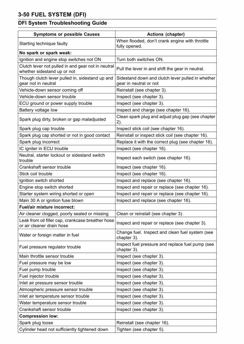
3-50 FUEL SYSTEM (DFI)
DFI System Troubleshooting Guide
Symptoms or possible Causes Actions (chapter)
Starting technique faultyWhen flooded, don’t crank engine with throttlefully opened.
No spark or spark weak:
Ignition and engine stop switches not ON Turn both switches ON.
Clutch lever not pulled in and gear not in neutralwhether sidestand up or not
Pull the lever in and shift the gear in neutral.
Though clutch lever pulled in, sidestand up andgear not in neutral
Sidestand down and clutch lever pulled in whethergear in neutral or not
Vehicle-down sensor coming off Reinstall (see chapter 3).
Vehicle-down sensor trouble Inspect (see chapter 3).
ECU ground or power supply trouble Inspect (see chapter 3).
Battery voltage low Inspect and charge (see chapter 16).
Spark plug dirty, broken or gap maladjustedClean spark plug and adjust plug gap (see chapter2).
Spark plug cap trouble Inspect stick coil (see chapter 16).
Spark plug cap shorted or not in good contact Reinstall or inspect stick coil (see chapter 16).
Spark plug incorrect Replace it with the correct plug (see chapter 16).
IC igniter in ECU trouble Inspect (see chapter 16).
Neutral, starter lockout or sidestand switchtrouble
Inspect each switch (see chapter 16).
Crankshaft sensor trouble Inspect (see chapter 16).
Stick coil trouble Inspect (see chapter 16).
Ignition switch shorted Inspect and replace (see chapter 16).
Engine stop switch shorted Inspect and repair or replace (see chapter 16).
Starter system wiring shorted or open Inspect and repair or replace (see chapter 16).
Main 30 A or ignition fuse blown Inspect and replace (see chapter 16).
Fuel/air mixture incorrect:
Air cleaner clogged, poorly sealed or missing Clean or reinstall (see chapter 3).
Leak from oil filler cap, crankcase breather hoseor air cleaner drain hose
Inspect and repair or replace (see chapter 3).
Water or foreign matter in fuelChange fuel. Inspect and clean fuel system (seechapter 3).
Fuel pressure regulator troubleInspect fuel pressure and replace fuel pump (seechapter 3).
Main throttle sensor trouble Inspect (see chapter 3).
Fuel pressure may be low Inspect (see chapter 3).
Fuel pump trouble Inspect (see chapter 3).
Fuel injector trouble Inspect (see chapter 3).
Inlet air pressure sensor trouble Inspect (see chapter 3).
Atmospheric pressure sensor trouble Inspect (see chapter 3).
Inlet air temperature sensor trouble Inspect (see chapter 3).
Water temperature sensor trouble Inspect (see chapter 3).
Crankshaft sensor trouble Inspect (see chapter 3).
Compression low:
Spark plug loose Reinstall (see chapter 16).
Cylinder head not sufficiently tightened down Tighten (see chapter 5).
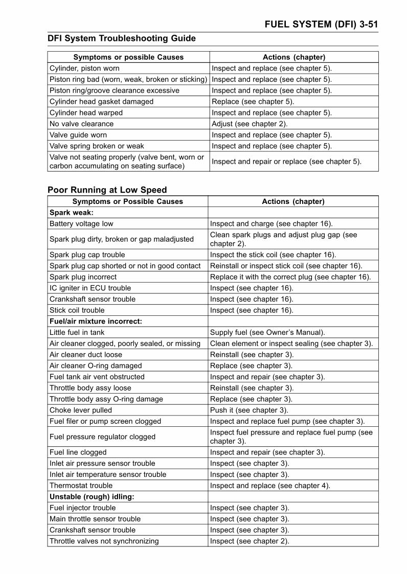
FUEL SYSTEM (DFI) 3-51
DFI System Troubleshooting Guide
Symptoms or possible Causes Actions (chapter)
Cylinder, piston worn Inspect and replace (see chapter 5).
Piston ring bad (worn, weak, broken or sticking) Inspect and replace (see chapter 5).
Piston ring/groove clearance excessive Inspect and replace (see chapter 5).
Cylinder head gasket damaged Replace (see chapter 5).
Cylinder head warped Inspect and replace (see chapter 5).
No valve clearance Adjust (see chapter 2).
Valve guide worn Inspect and replace (see chapter 5).
Valve spring broken or weak Inspect and replace (see chapter 5).
Valve not seating properly (valve bent, worn orcarbon accumulating on seating surface)
Inspect and repair or replace (see chapter 5).
Poor Running at Low SpeedSymptoms or Possible Causes Actions (chapter)
Spark weak:
Battery voltage low Inspect and charge (see chapter 16).
Spark plug dirty, broken or gap maladjustedClean spark plugs and adjust plug gap (seechapter 2).
Spark plug cap trouble Inspect the stick coil (see chapter 16).
Spark plug cap shorted or not in good contact Reinstall or inspect stick coil (see chapter 16).
Spark plug incorrect Replace it with the correct plug (see chapter 16).
IC igniter in ECU trouble Inspect (see chapter 16).
Crankshaft sensor trouble Inspect (see chapter 16).
Stick coil trouble Inspect (see chapter 16).
Fuel/air mixture incorrect:
Little fuel in tank Supply fuel (see Owner’s Manual).
Air cleaner clogged, poorly sealed, or missing Clean element or inspect sealing (see chapter 3).
Air cleaner duct loose Reinstall (see chapter 3).
Air cleaner O-ring damaged Replace (see chapter 3).
Fuel tank air vent obstructed Inspect and repair (see chapter 3).
Throttle body assy loose Reinstall (see chapter 3).
Throttle body assy O-ring damage Replace (see chapter 3).
Choke lever pulled Push it (see chapter 3).
Fuel filer or pump screen clogged Inspect and replace fuel pump (see chapter 3).
Fuel pressure regulator cloggedInspect fuel pressure and replace fuel pump (seechapter 3).
Fuel line clogged Inspect and repair (see chapter 3).
Inlet air pressure sensor trouble Inspect (see chapter 3).
Inlet air temperature sensor trouble Inspect (see chapter 3).
Thermostat trouble Inspect and replace (see chapter 4).
Unstable (rough) idling:
Fuel injector trouble Inspect (see chapter 3).
Main throttle sensor trouble Inspect (see chapter 3).
Crankshaft sensor trouble Inspect (see chapter 3).
Throttle valves not synchronizing Inspect (see chapter 2).
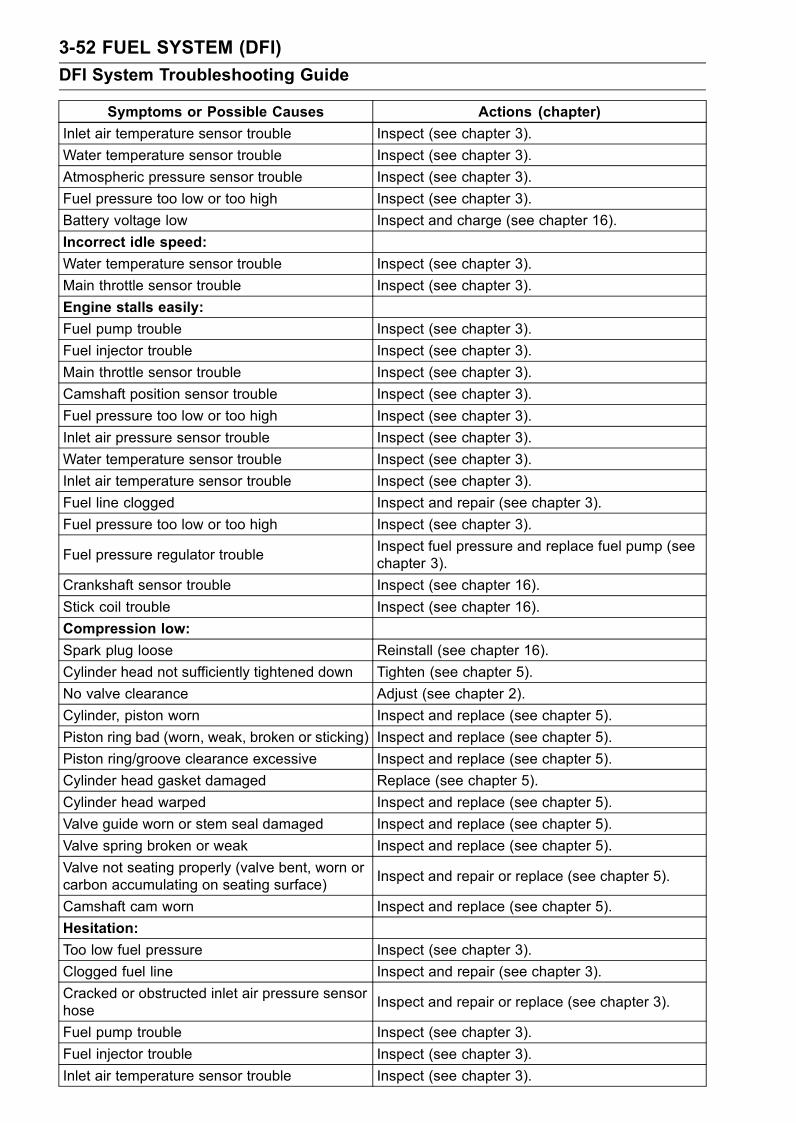
3-52 FUEL SYSTEM (DFI)
DFI System Troubleshooting Guide
Symptoms or Possible Causes Actions (chapter)
Inlet air temperature sensor trouble Inspect (see chapter 3).
Water temperature sensor trouble Inspect (see chapter 3).
Atmospheric pressure sensor trouble Inspect (see chapter 3).
Fuel pressure too low or too high Inspect (see chapter 3).
Battery voltage low Inspect and charge (see chapter 16).
Incorrect idle speed:
Water temperature sensor trouble Inspect (see chapter 3).
Main throttle sensor trouble Inspect (see chapter 3).
Engine stalls easily:
Fuel pump trouble Inspect (see chapter 3).
Fuel injector trouble Inspect (see chapter 3).
Main throttle sensor trouble Inspect (see chapter 3).
Camshaft position sensor trouble Inspect (see chapter 3).
Fuel pressure too low or too high Inspect (see chapter 3).
Inlet air pressure sensor trouble Inspect (see chapter 3).
Water temperature sensor trouble Inspect (see chapter 3).
Inlet air temperature sensor trouble Inspect (see chapter 3).
Fuel line clogged Inspect and repair (see chapter 3).
Fuel pressure too low or too high Inspect (see chapter 3).
Fuel pressure regulator troubleInspect fuel pressure and replace fuel pump (seechapter 3).
Crankshaft sensor trouble Inspect (see chapter 16).
Stick coil trouble Inspect (see chapter 16).
Compression low:
Spark plug loose Reinstall (see chapter 16).
Cylinder head not sufficiently tightened down Tighten (see chapter 5).
No valve clearance Adjust (see chapter 2).
Cylinder, piston worn Inspect and replace (see chapter 5).
Piston ring bad (worn, weak, broken or sticking) Inspect and replace (see chapter 5).
Piston ring/groove clearance excessive Inspect and replace (see chapter 5).
Cylinder head gasket damaged Replace (see chapter 5).
Cylinder head warped Inspect and replace (see chapter 5).
Valve guide worn or stem seal damaged Inspect and replace (see chapter 5).
Valve spring broken or weak Inspect and replace (see chapter 5).
Valve not seating properly (valve bent, worn orcarbon accumulating on seating surface)
Inspect and repair or replace (see chapter 5).
Camshaft cam worn Inspect and replace (see chapter 5).
Hesitation:
Too low fuel pressure Inspect (see chapter 3).
Clogged fuel line Inspect and repair (see chapter 3).
Cracked or obstructed inlet air pressure sensorhose
Inspect and repair or replace (see chapter 3).
Fuel pump trouble Inspect (see chapter 3).
Fuel injector trouble Inspect (see chapter 3).
Inlet air temperature sensor trouble Inspect (see chapter 3).
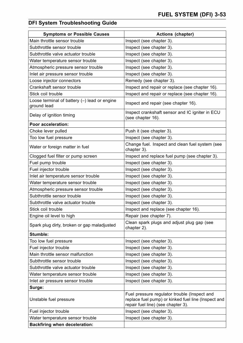
FUEL SYSTEM (DFI) 3-53
DFI System Troubleshooting Guide
Symptoms or Possible Causes Actions (chapter)
Main throttle sensor trouble Inspect (see chapter 3).
Subthrottle sensor trouble Inspect (see chapter 3).
Subthrottle valve actuator trouble Inspect (see chapter 3).
Water temperature sensor trouble Inspect (see chapter 3).
Atmospheric pressure sensor trouble Inspect (see chapter 3).
Inlet air pressure sensor trouble Inspect (see chapter 3).
Loose injector connectors Remedy (see chapter 3).
Crankshaft sensor trouble Inspect and repair or replace (see chapter 16).
Stick coil trouble Inspect and repair or replace (see chapter 16).
Loose terminal of battery (–) lead or engineground lead
Inspect and repair (see chapter 16).
Delay of ignition timingInspect crankshaft sensor and IC igniter in ECU(see chapter 16).
Poor acceleration:
Choke lever pulled Push it (see chapter 3).
Too low fuel pressure Inspect (see chapter 3).
Water or foreign matter in fuelChange fuel. Inspect and clean fuel system (seechapter 3).
Clogged fuel filter or pump screen Inspect and replace fuel pump (see chapter 3).
Fuel pump trouble Inspect (see chapter 3).
Fuel injector trouble Inspect (see chapter 3).
Inlet air temperature sensor trouble Inspect (see chapter 3).
Water temperature sensor trouble Inspect (see chapter 3).
Atmospheric pressure sensor trouble Inspect (see chapter 3).
Subthrottle sensor trouble Inspect (see chapter 3).
Subthrottle valve actuator trouble Inspect (see chapter 3).
Stick coil trouble Inspect and replace (see chapter 16).
Engine oil level to high Repair (see chapter 7).
Spark plug dirty, broken or gap maladjustedClean spark plugs and adjust plug gap (seechapter 2).
Stumble:
Too low fuel pressure Inspect (see chapter 3).
Fuel injector trouble Inspect (see chapter 3).
Main throttle sensor malfunction Inspect (see chapter 3).
Subthrottle sensor trouble Inspect (see chapter 3).
Subthrottle valve actuator trouble Inspect (see chapter 3).
Water temperature sensor trouble Inspect (see chapter 3).
Inlet air pressure sensor trouble Inspect (see chapter 3).
Surge:
Unstable fuel pressureFuel pressure regulator trouble (Inspect andreplace fuel pump) or kinked fuel line (Inspect andrepair fuel line) (see chapter 3).
Fuel injector trouble Inspect (see chapter 3).
Water temperature sensor trouble Inspect (see chapter 3).
Backfiring when deceleration:
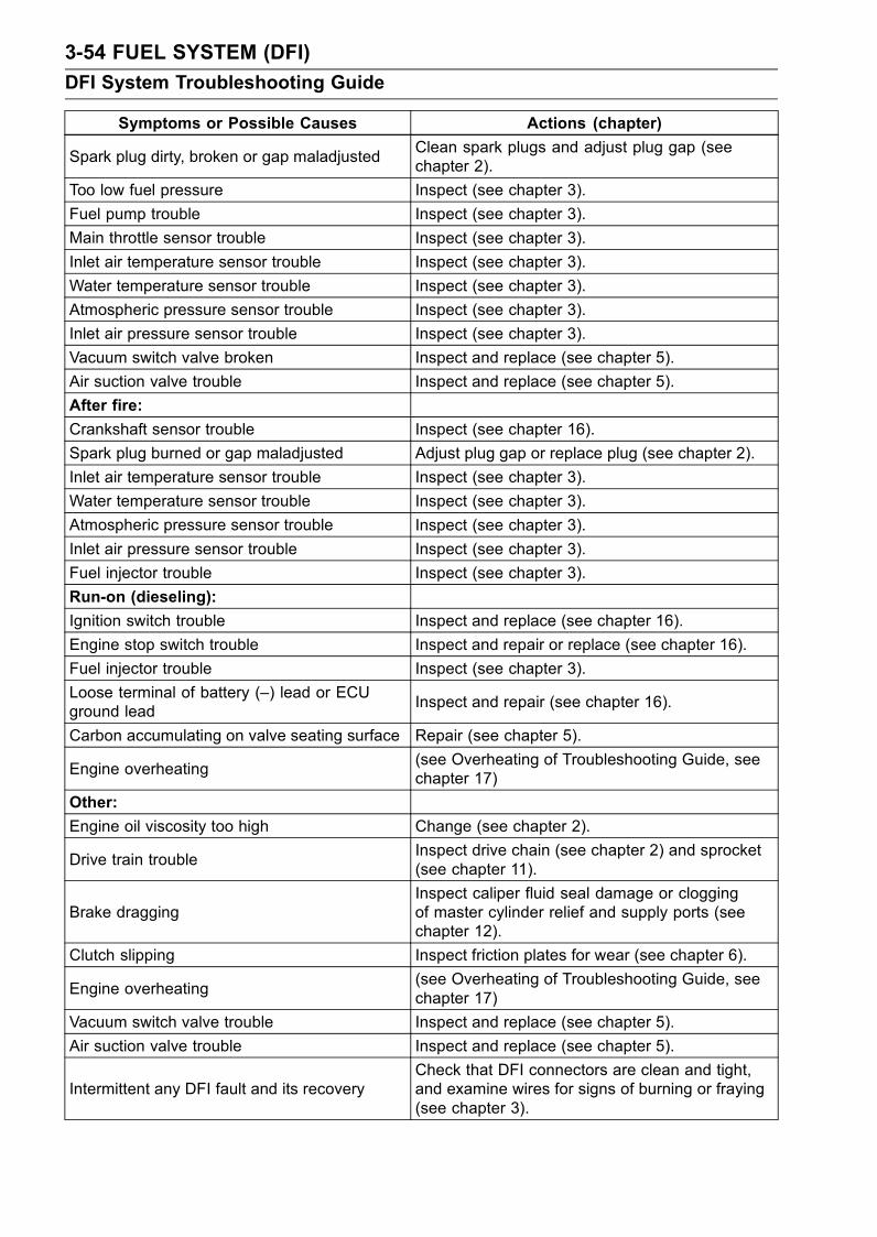
3-54 FUEL SYSTEM (DFI)
DFI System Troubleshooting Guide
Symptoms or Possible Causes Actions (chapter)
Spark plug dirty, broken or gap maladjustedClean spark plugs and adjust plug gap (seechapter 2).
Too low fuel pressure Inspect (see chapter 3).
Fuel pump trouble Inspect (see chapter 3).
Main throttle sensor trouble Inspect (see chapter 3).
Inlet air temperature sensor trouble Inspect (see chapter 3).
Water temperature sensor trouble Inspect (see chapter 3).
Atmospheric pressure sensor trouble Inspect (see chapter 3).
Inlet air pressure sensor trouble Inspect (see chapter 3).
Vacuum switch valve broken Inspect and replace (see chapter 5).
Air suction valve trouble Inspect and replace (see chapter 5).
After fire:
Crankshaft sensor trouble Inspect (see chapter 16).
Spark plug burned or gap maladjusted Adjust plug gap or replace plug (see chapter 2).
Inlet air temperature sensor trouble Inspect (see chapter 3).
Water temperature sensor trouble Inspect (see chapter 3).
Atmospheric pressure sensor trouble Inspect (see chapter 3).
Inlet air pressure sensor trouble Inspect (see chapter 3).
Fuel injector trouble Inspect (see chapter 3).
Run-on (dieseling):
Ignition switch trouble Inspect and replace (see chapter 16).
Engine stop switch trouble Inspect and repair or replace (see chapter 16).
Fuel injector trouble Inspect (see chapter 3).
Loose terminal of battery (–) lead or ECUground lead
Inspect and repair (see chapter 16).
Carbon accumulating on valve seating surface Repair (see chapter 5).
Engine overheating(see Overheating of Troubleshooting Guide, seechapter 17)
Other:
Engine oil viscosity too high Change (see chapter 2).
Drive train troubleInspect drive chain (see chapter 2) and sprocket(see chapter 11).
Brake draggingInspect caliper fluid seal damage or cloggingof master cylinder relief and supply ports (seechapter 12).
Clutch slipping Inspect friction plates for wear (see chapter 6).
Engine overheating(see Overheating of Troubleshooting Guide, seechapter 17)
Vacuum switch valve trouble Inspect and replace (see chapter 5).
Air suction valve trouble Inspect and replace (see chapter 5).
Intermittent any DFI fault and its recoveryCheck that DFI connectors are clean and tight,and examine wires for signs of burning or fraying(see chapter 3).

FUEL SYSTEM (DFI) 3-55
DFI System Troubleshooting Guide
Poor Running or No Power at High SpeedSymptoms or Possible Causes Actions (chapter)
Firing incorrect:
Spark plug dirty, broken or maladjustedClean spark plug and adjust plug gap (see chapter2).
Spark plug cap trouble Inspect stick coil (see chapter 16).
Spark plug cap shorted or not in good contact Reinstall or inspect stick coil (see chapter 16).
Spark plug incorrect Replace it with the correct plug (see chapter 16).
IC igniter in ECU trouble Inspect (see chapter 16).
Crankshaft sensor trouble Inspect (see chapter 16).
Stick coil trouble Inspect (see chapter 16).
Fuel/air mixture incorrect:
Choke lever pulled Push it (see chapter 3).
Air cleaner clogged, poorly sealed or missing Clean element or inspect sealing (see chapter 3).
Air cleaner duct loose Reinstall (see chapter 3).
Air cleaner O-ring damaged Replace (see chapter 3).
Water or foreign matter in fuelChange fuel. Inspect and clean fuel system (seechapter 3).
Throttle body assy loose Reinstall (see chapter 3).
Throttle body assy O-ring damaged Replace (see chapter 3).
Fuel tank air vent obstructed Inspect and repair (see chapter 3).
Fuel line clogged Inspect and repair (see chapter 3).
Fuel pump operates intermittently and oftenECU fuse blows.
Pump bearings may wear. Replace the pump (seechapter 3).
Fuel pump trouble Inspect (see chapter 3).
Inlet air temperature sensor trouble Inspect (see chapter 3).
Main throttle sensor trouble Inspect (see chapter 3).
Atmospheric pressure sensor trouble Inspect (see chapter 3).
Inlet air pressure sensor trouble Inspect (see chapter 3).
Cracked or obstructed inlet air pressure sensorhose
Inspect and repair or replace (see chapter 3).
Injector clogged Visually inspect and replace (see chapter 3).
Compression low:
Spark plug loose Reinstall (see chapter 16).
Cylinder head not sufficiently tightened down Tighten (see chapter 5).
No valve clearance Adjust (see chapter 2).
Cylinder, piston worn Inspect and replace (see chapter 5).
Piston ring bad (worn, weak, broken or sticking) Inspect and replace (see chapter 5).
Piston ring/groove clearance excessive Inspect and replace (see chapter 5).
Cylinder head gasket damaged Replace (see chapter 5).
Cylinder head warped Inspect and replace (see chapter 5).
Valve spring broken or weak Inspect and replace (see chapter 5).
Valve not seating properly (valve bent , worn orcarbon accumulating on the seating surface)
Inspect and repair or replace (see chapter 5).
Knocking:
Carbon built up in combustion chamber Repair (see chapter 5).
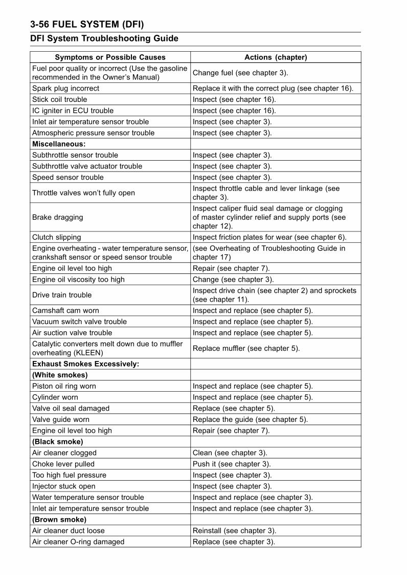
3-56 FUEL SYSTEM (DFI)
DFI System Troubleshooting Guide
Symptoms or Possible Causes Actions (chapter)
Fuel poor quality or incorrect (Use the gasolinerecommended in the Owner’s Manual)
Change fuel (see chapter 3).
Spark plug incorrect Replace it with the correct plug (see chapter 16).
Stick coil trouble Inspect (see chapter 16).
IC igniter in ECU trouble Inspect (see chapter 16).
Inlet air temperature sensor trouble Inspect (see chapter 3).
Atmospheric pressure sensor trouble Inspect (see chapter 3).
Miscellaneous:
Subthrottle sensor trouble Inspect (see chapter 3).
Subthrottle valve actuator trouble Inspect (see chapter 3).
Speed sensor trouble Inspect (see chapter 3).
Throttle valves won’t fully openInspect throttle cable and lever linkage (seechapter 3).
Brake draggingInspect caliper fluid seal damage or cloggingof master cylinder relief and supply ports (seechapter 12).
Clutch slipping Inspect friction plates for wear (see chapter 6).
Engine overheating - water temperature sensor,crankshaft sensor or speed sensor trouble
(see Overheating of Troubleshooting Guide inchapter 17)
Engine oil level too high Repair (see chapter 7).
Engine oil viscosity too high Change (see chapter 3).
Drive train troubleInspect drive chain (see chapter 2) and sprockets(see chapter 11).
Camshaft cam worn Inspect and replace (see chapter 5).
Vacuum switch valve trouble Inspect and replace (see chapter 5).
Air suction valve trouble Inspect and replace (see chapter 5).
Catalytic converters melt down due to muffleroverheating (KLEEN)
Replace muffler (see chapter 5).
Exhaust Smokes Excessively:
(White smokes)
Piston oil ring worn Inspect and replace (see chapter 5).
Cylinder worn Inspect and replace (see chapter 5).
Valve oil seal damaged Replace (see chapter 5).
Valve guide worn Replace the guide (see chapter 5).
Engine oil level too high Repair (see chapter 7).
(Black smoke)
Air cleaner clogged Clean (see chapter 3).
Choke lever pulled Push it (see chapter 3).
Too high fuel pressure Inspect (see chapter 3).
Injector stuck open Inspect (see chapter 3).
Water temperature sensor trouble Inspect and replace (see chapter 3).
Inlet air temperature sensor trouble Inspect and replace (see chapter 3).
(Brown smoke)
Air cleaner duct loose Reinstall (see chapter 3).
Air cleaner O-ring damaged Replace (see chapter 3).
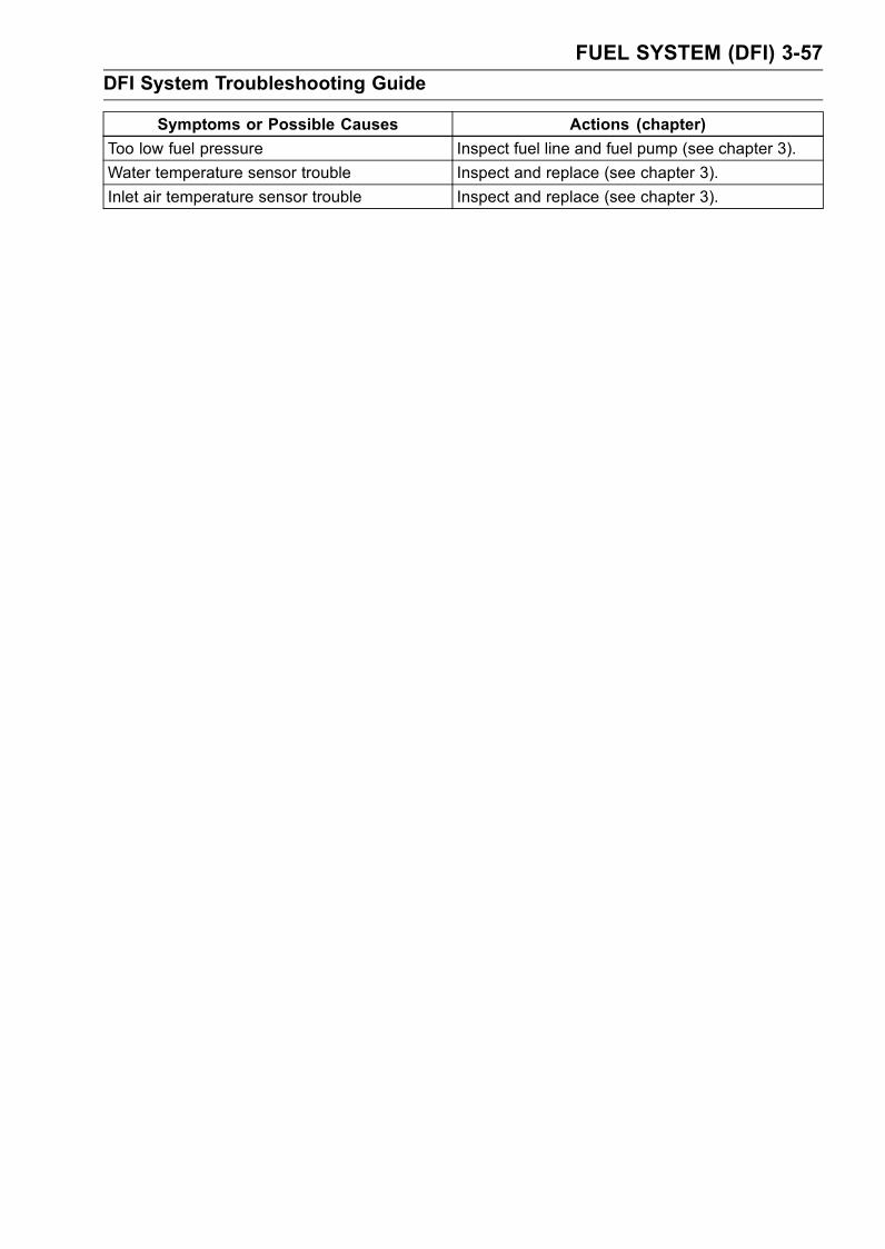
FUEL SYSTEM (DFI) 3-57
DFI System Troubleshooting Guide
Symptoms or Possible Causes Actions (chapter)
Too low fuel pressure Inspect fuel line and fuel pump (see chapter 3).
Water temperature sensor trouble Inspect and replace (see chapter 3).
Inlet air temperature sensor trouble Inspect and replace (see chapter 3).
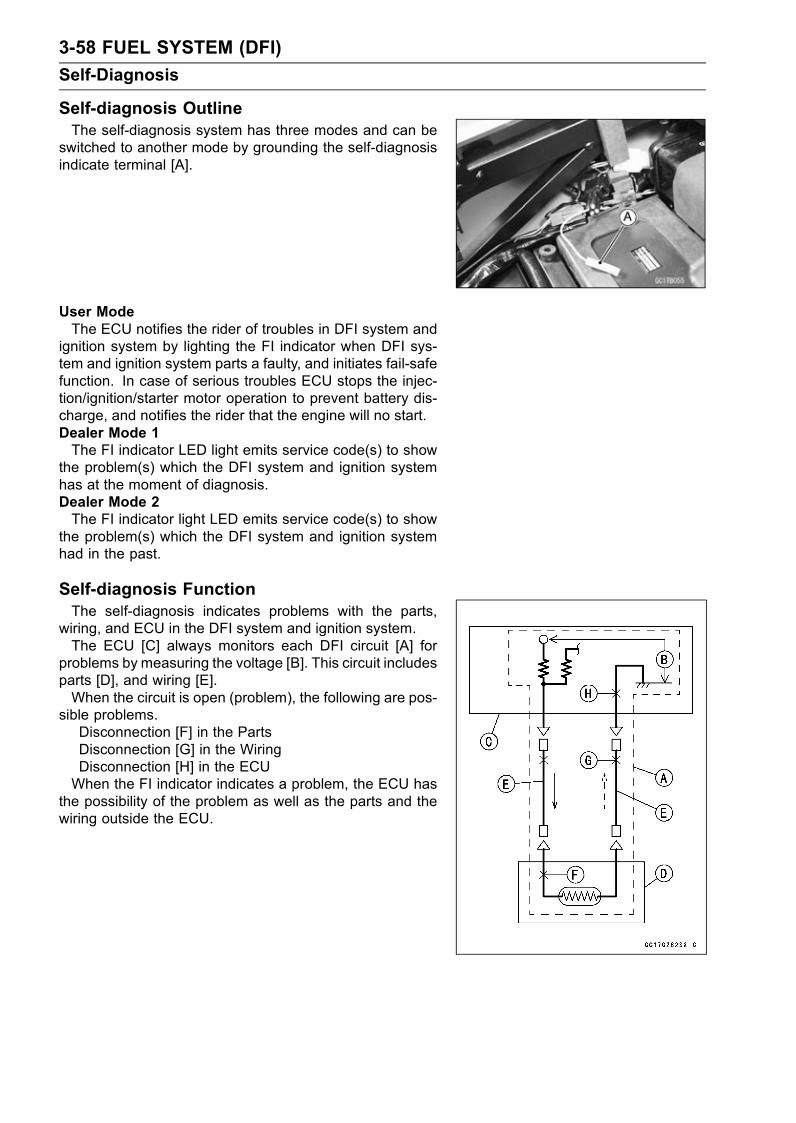
3-58 FUEL SYSTEM (DFI)
Self-Diagnosis
Self-diagnosis OutlineThe self-diagnosis system has three modes and can be
switched to another mode by grounding the self-diagnosisindicate terminal [A].
User ModeThe ECU notifies the rider of troubles in DFI system and
ignition system by lighting the FI indicator when DFI sys-tem and ignition system parts a faulty, and initiates fail-safefunction. In case of serious troubles ECU stops the injec-tion/ignition/starter motor operation to prevent battery dis-charge, and notifies the rider that the engine will no start.Dealer Mode 1The FI indicator LED light emits service code(s) to show
the problem(s) which the DFI system and ignition systemhas at the moment of diagnosis.Dealer Mode 2The FI indicator light LED emits service code(s) to show
the problem(s) which the DFI system and ignition systemhad in the past.
Self-diagnosis FunctionThe self-diagnosis indicates problems with the parts,
wiring, and ECU in the DFI system and ignition system.The ECU [C] always monitors each DFI circuit [A] for
problems by measuring the voltage [B]. This circuit includesparts [D], and wiring [E].When the circuit is open (problem), the following are pos-
sible problems.Disconnection [F] in the PartsDisconnection [G] in the WiringDisconnection [H] in the ECUWhen the FI indicator indicates a problem, the ECU has
the possibility of the problem as well as the parts and thewiring outside the ECU.
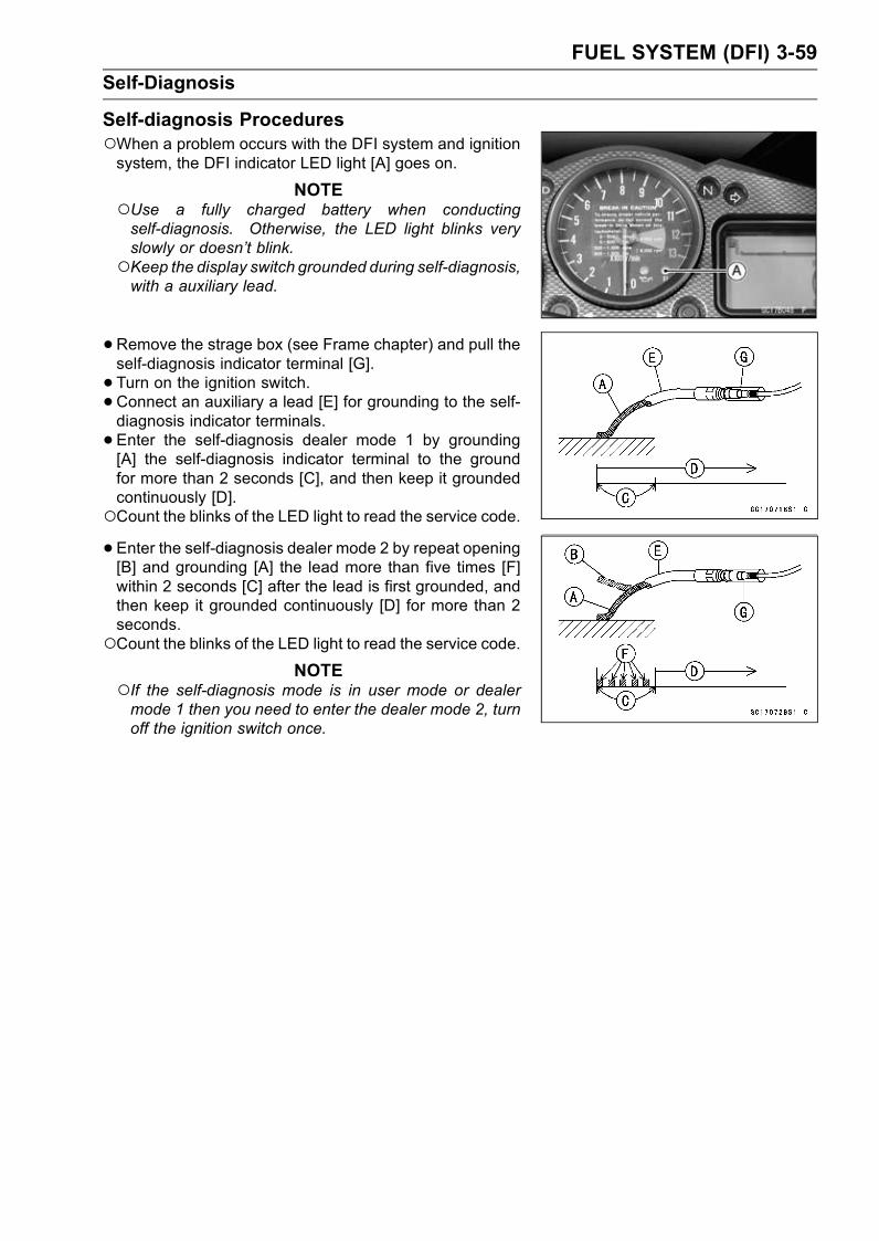
FUEL SYSTEM (DFI) 3-59
Self-Diagnosis
Self-diagnosis ProceduresWhen a problem occurs with the DFI system and ignitionsystem, the DFI indicator LED light [A] goes on.
NOTEUse a fully charged battery when conductingself-diagnosis. Otherwise, the LED light blinks veryslowly or doesn’t blink.Keep the display switch grounded during self-diagnosis,with a auxiliary lead.
•Remove the strage box (see Frame chapter) and pull theself-diagnosis indicator terminal [G].
• Turn on the ignition switch.•Connect an auxiliary a lead [E] for grounding to the self-diagnosis indicator terminals.
• Enter the self-diagnosis dealer mode 1 by grounding[A] the self-diagnosis indicator terminal to the groundfor more than 2 seconds [C], and then keep it groundedcontinuously [D].Count the blinks of the LED light to read the service code.• Enter the self-diagnosis dealer mode 2 by repeat opening[B] and grounding [A] the lead more than five times [F]within 2 seconds [C] after the lead is first grounded, andthen keep it grounded continuously [D] for more than 2seconds.Count the blinks of the LED light to read the service code.
NOTEIf the self-diagnosis mode is in user mode or dealermode 1 then you need to enter the dealer mode 2, turnoff the ignition switch once.

3-60 FUEL SYSTEM (DFI)
Self-Diagnosis
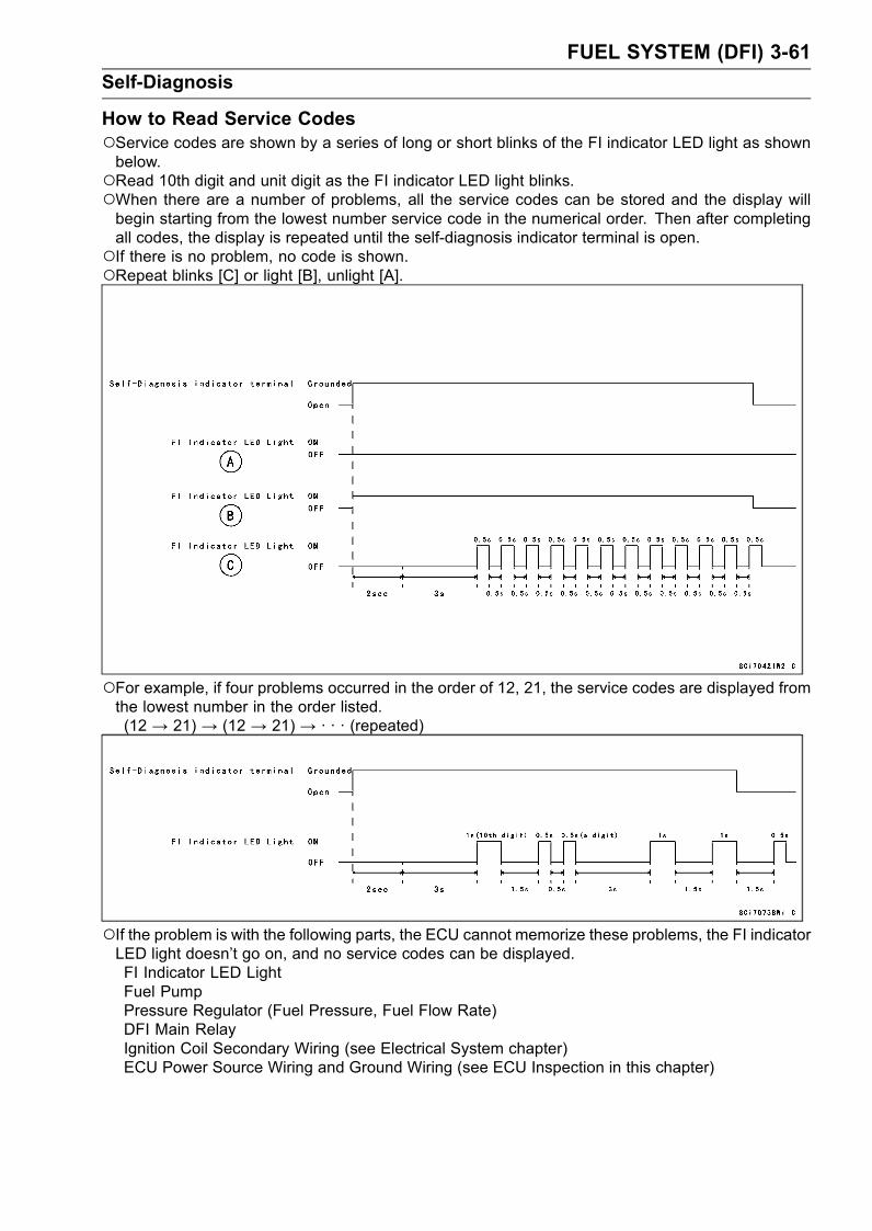
FUEL SYSTEM (DFI) 3-61
Self-Diagnosis
How to Read Service CodesService codes are shown by a series of long or short blinks of the FI indicator LED light as shownbelow.Read 10th digit and unit digit as the FI indicator LED light blinks.When there are a number of problems, all the service codes can be stored and the display willbegin starting from the lowest number service code in the numerical order. Then after completingall codes, the display is repeated until the self-diagnosis indicator terminal is open.If there is no problem, no code is shown.Repeat blinks [C] or light [B], unlight [A].
For example, if four problems occurred in the order of 12, 21, the service codes are displayed fromthe lowest number in the order listed.(12 → 21) → (12 → 21) → · · · (repeated)
If the problem is with the following parts, the ECU cannot memorize these problems, the FI indicatorLED light doesn’t go on, and no service codes can be displayed.FI Indicator LED LightFuel PumpPressure Regulator (Fuel Pressure, Fuel Flow Rate)DFI Main RelayIgnition Coil Secondary Wiring (see Electrical System chapter)ECU Power Source Wiring and Ground Wiring (see ECU Inspection in this chapter)
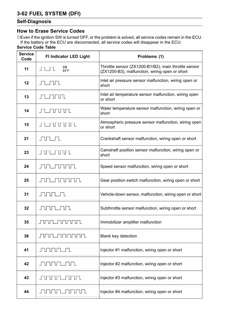
3-62 FUEL SYSTEM (DFI)
Self-Diagnosis
How to Erase Service CodesEven if the ignition SW is turned OFF, or the problem is solved, all service codes remain in the ECU.If the battery or the ECU are disconnected, all service codes will disappear in the ECU.
Service Code Table
ServiceCode
FI Indicator LED Light Problems (1)
11Throttle sensor (ZX1200-B1/B2), main throttle sensor(ZX1200-B3), malfunction, wiring open or short
12Inlet air pressure sensor malfunction, wiring open orshort
13Inlet air temperature sensor malfunction, wiring openor short
14Water temperature sensor malfunction, wiring open orshort
15Atmospheric pressure sensor malfunction, wiring openor short
21 Crankshaft sensor malfunction, wiring open or short
23Camshaft position sensor malfunction, wiring open orshort
24 Speed sensor malfunction, wiring open or short
25 Gear position switch malfunction, wiring open or short
31 Vehicle-down sensor, malfunction, wiring open or short
32 Subthrottle sensor malfunction, wiring open or short
35 Immobilizer amplifier malfunction
36 Blank key detection
41 Injector #1 malfunction, wiring open or short
42 Injector #2 malfunction, wiring open or short
43 Injector #3 malfunction, wiring open or short
44 Injector #4 malfunction, wiring open or short
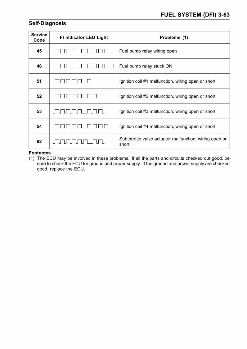
FUEL SYSTEM (DFI) 3-63
Self-Diagnosis
ServiceCode
FI Indicator LED Light Problems (1)
45 Fuel pump relay wiring open
46 Fuel pump relay stuck ON
51 Ignition coil #1 malfunction, wiring open or short
52 Ignition coil #2 malfunction, wiring open or short
53 Ignition coil #3 malfunction, wiring open or short
54 Ignition coil #4 malfunction, wiring open or short
62Subthrottle valve actuator malfunction, wiring open orshort
Footnotes(1) The ECU may be involved in these problems. If all the parts and circuits checked out good, be
sure to check the ECU for ground and power supply. If the ground and power supply are checkedgood, replace the ECU.

3-64 FUEL SYSTEM (DFI)
Self-Diagnosis
BackupsThe ECU takes the following measures to prevent engine damage when the DFI or the ignitionsystem parts have troubles.
ServiceCodes
PartsOutput Signal UsableRange or Criteria
Backups by ECU
11
ThrottleSensor(ZX1200-B1/B2),MainThrottleSensor
(ZX1200-B3)
ZX1200-B1/B2:Throttle Valve OpeningAngle θ = 6.5° ∼ + 86.5°ZX1200-B3:Main Throttle Sensor OutputVoltage0.2 ∼ 4.8 V
If the throttle sensor system fails (the signalis out of the usable range, wiring short oropen), the ECU locks ignition timing into theignition timing at closed throttle position andsets the DFI in the D-J method.Also, the throttle sensor system and inlet airpressure fails, the ECU locks ignition timinginto the ignition timing at closed throttleposition and sets the DFI in the α-N method.
12Inlet AirPressureSensor
Inlet Air Pressure (absolute)Pv = 100 mmHg ∼ 900 mmHg
If the inlet air pressure sensor system fails(the signal Pv is out of the usable range,wiring short or open), the ECU sets the DFIin the α - N method (1).
13Inlet Air
TemperatureSensor
Inlet Air TemperatureTa = – 47°C ∼ + 178°C
If the inlet air temperature sensor fails (thesignal is out of the usable range, wiringshort or open), the ECU sets Ta at 45°C.
14Water
TemperatureSensor
Water TemperatureTw = – 30C° ∼ + 120°C
If the water temperature sensor system fails(the signal is out of the usable range, wiringshort or open), the ECU sets Tw at 86°C.
15AtmosphericPressureSensor
Absolute AtmosphericPressurePa = 100 mmHg ∼ 900 mmHg
If the atmospheric pressure sensor systemfails (the signal is out of the usable range,wiring short or open), the ECU sets Paat 760 mmHg (the standard atmosphericpressure).
21CrankshaftSensor
Crankshaft sensor must sendsignals (output voltage) 8continuously to the ECU.
If crankshaft sensor generates less than 8or more signals, the engine stops by itself.
23CamshaftPositionSensor
Camshaft position sensormust send one signal (outputsignal) to the ECU at the twocranking
If the camshaft position sensor system fails(the signal is missing, wiring short or open),the ECU continues to ignite cylinders inthe same sequence following the last goodsignal.
24SpeedSensor
The output voltage of therectangular wave:Low Level: 1 V to 0High Level: 4 V to 5 V
If the speed sensor system fails (noconductivity, wiring short or open),revolution limiter begin to start beforegetting to the specified speed.
25GearPositionSwitch
Gear Position SwitchON = GroundOFF = 5 V or more (neutral),5 V or less
If the gear position switch system fails (thesignal is out of the usable range, wiringshort or open), the ECU locks in 6th gearposition.
31Vehicle-downSensor
Vehicle-down Sensor OutputVoltage (signal)Vd = 0.4 V ∼ 4.4 V
If the vehicle-down sensor system hasfailures (the output voltage Vd is out ofthe usable range, wiring short or open),the ECU shuts off the fuel pump, the fuelinjectors and the ignition system.
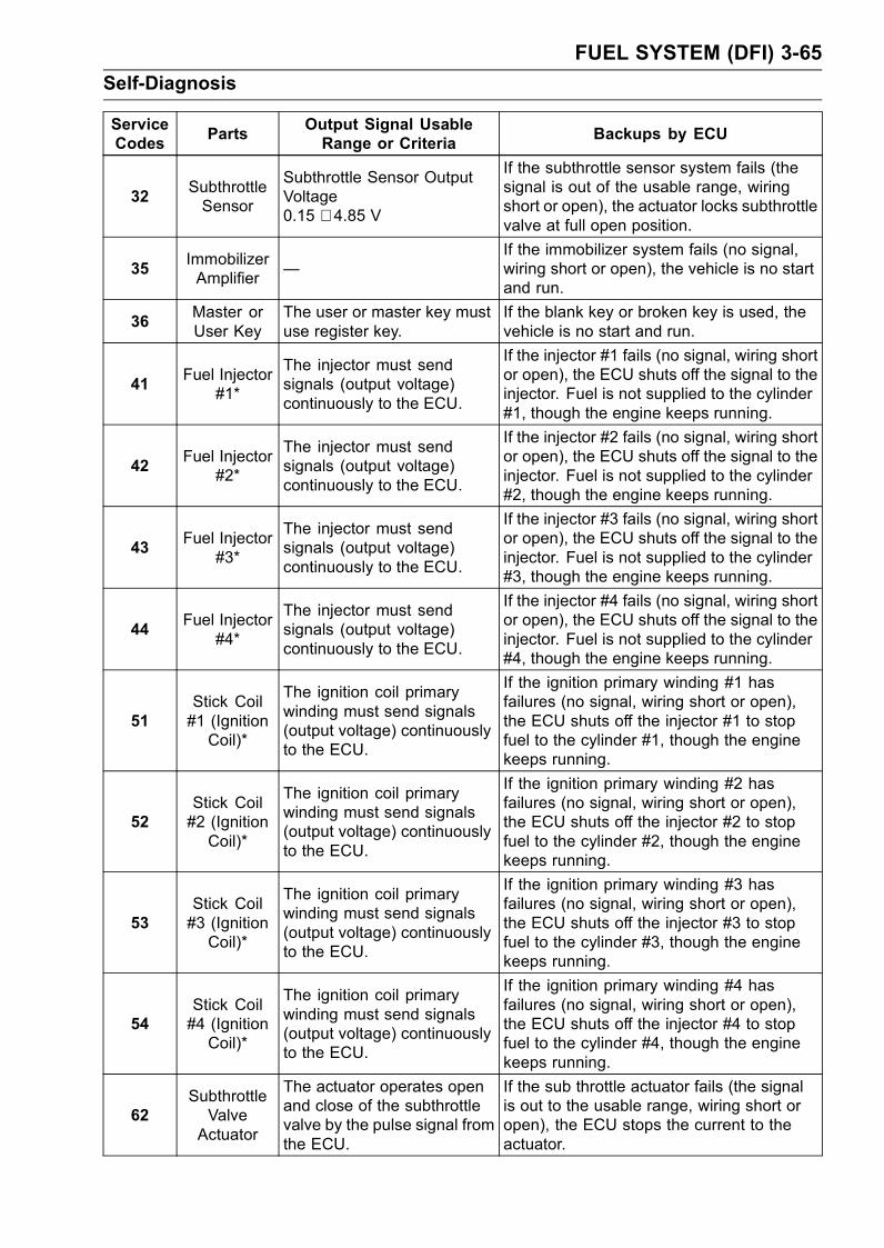
FUEL SYSTEM (DFI) 3-65
Self-Diagnosis
ServiceCodes
PartsOutput Signal UsableRange or Criteria
Backups by ECU
32SubthrottleSensor
Subthrottle Sensor OutputVoltage0.15 ∼ 4.85 V
If the subthrottle sensor system fails (thesignal is out of the usable range, wiringshort or open), the actuator locks subthrottlevalve at full open position.
35ImmobilizerAmplifier
—If the immobilizer system fails (no signal,wiring short or open), the vehicle is no startand run.
36Master orUser Key
The user or master key mustuse register key.
If the blank key or broken key is used, thevehicle is no start and run.
41Fuel Injector
#1*
The injector must sendsignals (output voltage)continuously to the ECU.
If the injector #1 fails (no signal, wiring shortor open), the ECU shuts off the signal to theinjector. Fuel is not supplied to the cylinder#1, though the engine keeps running.
42Fuel Injector
#2*
The injector must sendsignals (output voltage)continuously to the ECU.
If the injector #2 fails (no signal, wiring shortor open), the ECU shuts off the signal to theinjector. Fuel is not supplied to the cylinder#2, though the engine keeps running.
43Fuel Injector
#3*
The injector must sendsignals (output voltage)continuously to the ECU.
If the injector #3 fails (no signal, wiring shortor open), the ECU shuts off the signal to theinjector. Fuel is not supplied to the cylinder#3, though the engine keeps running.
44Fuel Injector
#4*
The injector must sendsignals (output voltage)continuously to the ECU.
If the injector #4 fails (no signal, wiring shortor open), the ECU shuts off the signal to theinjector. Fuel is not supplied to the cylinder#4, though the engine keeps running.
51Stick Coil#1 (IgnitionCoil)*
The ignition coil primarywinding must send signals(output voltage) continuouslyto the ECU.
If the ignition primary winding #1 hasfailures (no signal, wiring short or open),the ECU shuts off the injector #1 to stopfuel to the cylinder #1, though the enginekeeps running.
52Stick Coil#2 (IgnitionCoil)*
The ignition coil primarywinding must send signals(output voltage) continuouslyto the ECU.
If the ignition primary winding #2 hasfailures (no signal, wiring short or open),the ECU shuts off the injector #2 to stopfuel to the cylinder #2, though the enginekeeps running.
53Stick Coil#3 (IgnitionCoil)*
The ignition coil primarywinding must send signals(output voltage) continuouslyto the ECU.
If the ignition primary winding #3 hasfailures (no signal, wiring short or open),the ECU shuts off the injector #3 to stopfuel to the cylinder #3, though the enginekeeps running.
54Stick Coil#4 (IgnitionCoil)*
The ignition coil primarywinding must send signals(output voltage) continuouslyto the ECU.
If the ignition primary winding #4 hasfailures (no signal, wiring short or open),the ECU shuts off the injector #4 to stopfuel to the cylinder #4, though the enginekeeps running.
62SubthrottleValveActuator
The actuator operates openand close of the subthrottlevalve by the pulse signal fromthe ECU.
If the sub throttle actuator fails (the signalis out to the usable range, wiring short oropen), the ECU stops the current to theactuator.
3-66 FUEL SYSTEM (DFI)
Self-Diagnosis
Note:(1) α – N Method: the DFI control method from medium to heavy engine load. When the engine load
is light like at idling or low speed, the ECU determines the injection quantity by calculating from thethrottle vacuum (vacuum sensor output voltage) and engine speed (crankshaft sensor output voltage).This method is called D-J method. As the engine speed increases, and the engine load turns middleto heavy, the ECU determines the injection quantity by calculating from the throttle opening (throttlesensor output voltage) and the engine speed. This method is called α – N method.* This depends on the number of stopped cylinders.

FUEL SYSTEM (DFI) 3-67
Throttle Sensor (Service Code 11) (ZX1200-B1/B2)
The throttle sensor is a rotating variable resistor thatchange output voltage according to throttle operating.The ECU senses this voltage change and determines fuelinjection quantity, and ignition timing according to enginerpm, and throttle opening.Input Terminal [A]Output Terminal [B]Ground Terminal [C]Front [D]
Throttle Sensor Removal/Adjustment
CAUTION
Do not remove or adjust the throttle sensor [A]since it has been adjusted and set with precisionat the factory.Never drop the sensor, especially on a hard surface.Such a shock to the sensor can damage it.Do not connect the throttle sensor connector to theinlet air pressure sensor, because the inlet air pres-sure sensor is broken by opposite electrical con-nection.
Throttle Sensor Connector [B]
Input Voltage Inspection
NOTEBe sure the battery is fully charged.The inspection is the same as “Input Voltage Inspection”of the vacuum sensor and the atmospheric pressuresensor.
•Turn the ignition switch OFF.•Remove the ECU (see this chapter). Do not disconnectthe ECU connectors.
•Connect a digital voltmeter [A] to the connector [B], usingthe needle adapter set.
Special Tool - Needle Adapter Set: 57001-1457
•Measure the input voltage with the engine stopped, andwith the connectors joined.
Turn the ignition switch ON.
Throttle Sensor Input VoltageConnections to ECU Connector
Meter (+) → BL/W lead (terminal 41)
Meter (–)→ BR/BK lead (terminal 54)
Input Voltage at ECU Connector
Standard: 4.75 ∼ 5.25 V DC
•Turn the ignition switch OFF.If the reading of input voltage is less than the standard,check the ECU for its ground, power supply and wiringshorted.If the input voltage is within the standard range, check theinput voltage at the throttle sensor connector.
•Remove the left lower inner cover (see Frame chapter).
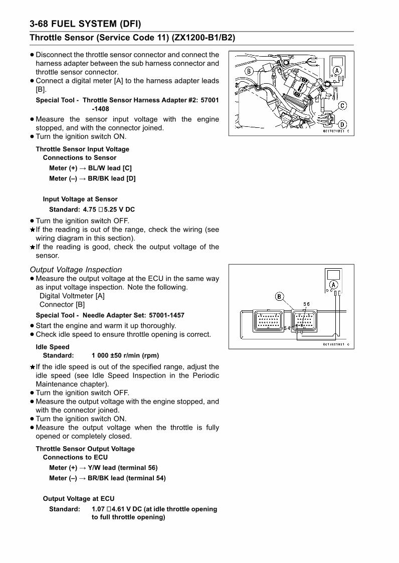
3-68 FUEL SYSTEM (DFI)
Throttle Sensor (Service Code 11) (ZX1200-B1/B2)
•Disconnect the throttle sensor connector and connect theharness adapter between the sub harness connector andthrottle sensor connector.
•Connect a digital meter [A] to the harness adapter leads[B].
Special Tool - Throttle Sensor Harness Adapter #2: 57001-1408
•Measure the sensor input voltage with the enginestopped, and with the connector joined.
• Turn the ignition switch ON.Throttle Sensor Input VoltageConnections to Sensor
Meter (+) → BL/W lead [C]
Meter (–) → BR/BK lead [D]
Input Voltage at Sensor
Standard: 4.75 ∼ 5.25 V DC
•Turn the ignition switch OFF.If the reading is out of the range, check the wiring (seewiring diagram in this section).If the reading is good, check the output voltage of thesensor.
Output Voltage Inspection
•Measure the output voltage at the ECU in the same wayas input voltage inspection. Note the following.Digital Voltmeter [A]Connector [B]
Special Tool - Needle Adapter Set: 57001-1457
•Start the engine and warm it up thoroughly.
•Check idle speed to ensure throttle opening is correct.Idle SpeedStandard: 1 000 ±50 r/min (rpm)
If the idle speed is out of the specified range, adjust theidle speed (see Idle Speed Inspection in the PeriodicMaintenance chapter).
• Turn the ignition switch OFF.•Measure the output voltage with the engine stopped, andwith the connector joined.
• Turn the ignition switch ON.•Measure the output voltage when the throttle is fullyopened or completely closed.
Throttle Sensor Output VoltageConnections to ECU
Meter (+) → Y/W lead (terminal 56)
Meter (–) → BR/BK lead (terminal 54)
Output Voltage at ECU
Standard: 1.07 ∼ 4.61 V DC (at idle throttle openingto full throttle opening)

FUEL SYSTEM (DFI) 3-69
Throttle Sensor (Service Code 11) (ZX1200-B1/B2)
NOTEThe throttle sensor is operating correctly if the followingvoltages are obtained:• 1.07 VDC (or slightly higher) with the throttle at the idleposition.• 4.61 VDC (or slightly lower) with the throttle at the fullyopen position.
CAUTION
Do not remove or adjust the throttle sensor. It hasbeen adjusted and set with precision at the factory.Never drop the sensor can especially on a hard sur-face. A shock to the sensor can damage it.
If the output voltage is within the standard range, checkthe ECU for a good ground, and power supply (see thischapter). If the ground and power supply are good, re-place the ECU.If the output voltage is far out of the standard range (e.g.when the wiring is open, the reading is 0 V), check theoutput voltage again at the sensor connector.
•Disconnect the throttle sensor connector and connect theharness adapter between the sub harness connector andthrottle sensor connector.
•Connect a digital meter [A] to the harness adapter leads[B].
Special Tool - Throttle Sensor Harness Adapter #2: 57001-1408
•Measure the sensor output voltage with the enginestopped, and with the connector joined.
• Turn the ignition switch ON.•Measure the output voltage when the throttle is fullyopened or completely closed.
Throttle Sensor Output VoltageConnections to Sensor
Meter (+) → Y/W lead [C]
Meter (–) → BR/BK lead [D]
Output Voltage at Sensor
Standard: 1.07 ∼ 4.61 V DC (at idle throttle openingto full throttle opening)
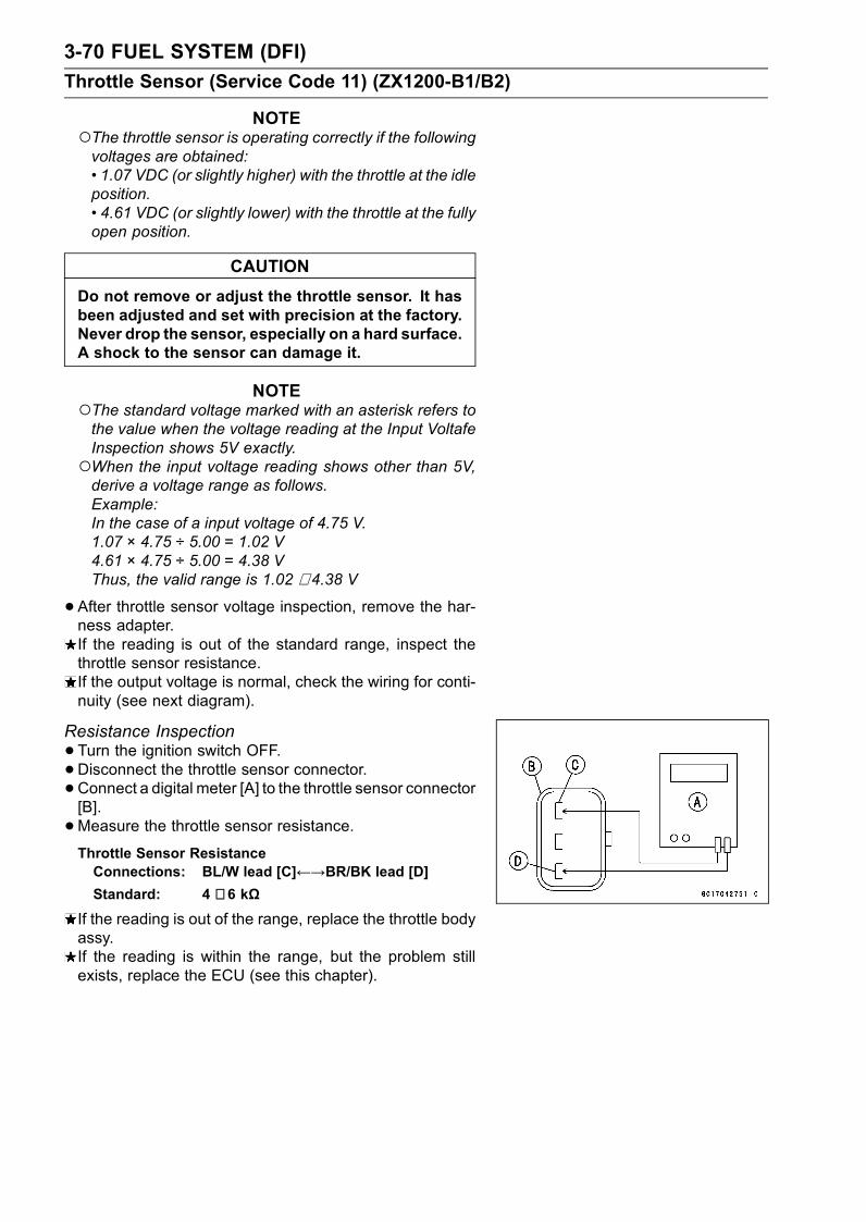
3-70 FUEL SYSTEM (DFI)
Throttle Sensor (Service Code 11) (ZX1200-B1/B2)
NOTEThe throttle sensor is operating correctly if the followingvoltages are obtained:• 1.07 VDC (or slightly higher) with the throttle at the idleposition.• 4.61 VDC (or slightly lower) with the throttle at the fullyopen position.
CAUTION
Do not remove or adjust the throttle sensor. It hasbeen adjusted and set with precision at the factory.Never drop the sensor, especially on a hard surface.A shock to the sensor can damage it.
NOTEThe standard voltage marked with an asterisk refers tothe value when the voltage reading at the Input VoltafeInspection shows 5V exactly.When the input voltage reading shows other than 5V,derive a voltage range as follows.Example:In the case of a input voltage of 4.75 V.1.07 × 4.75 ÷ 5.00 = 1.02 V4.61 × 4.75 ÷ 5.00 = 4.38 VThus, the valid range is 1.02 ∼ 4.38 V
•After throttle sensor voltage inspection, remove the har-ness adapter.If the reading is out of the standard range, inspect thethrottle sensor resistance.If the output voltage is normal, check the wiring for conti-nuity (see next diagram).
Resistance Inspection
•Turn the ignition switch OFF.•Disconnect the throttle sensor connector.•Connect a digital meter [A] to the throttle sensor connector[B].
•Measure the throttle sensor resistance.Throttle Sensor ResistanceConnections: BL/W lead [C]←→BR/BK lead [D]Standard: 4 ∼ 6 kΩ
If the reading is out of the range, replace the throttle bodyassy.If the reading is within the range, but the problem stillexists, replace the ECU (see this chapter).
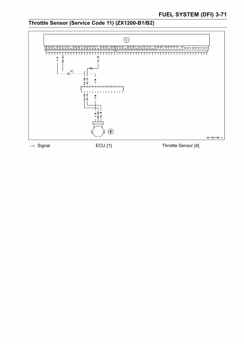
FUEL SYSTEM (DFI) 3-71
Throttle Sensor (Service Code 11) (ZX1200-B1/B2)
→: Signal ECU [1] Throttle Sensor [4]
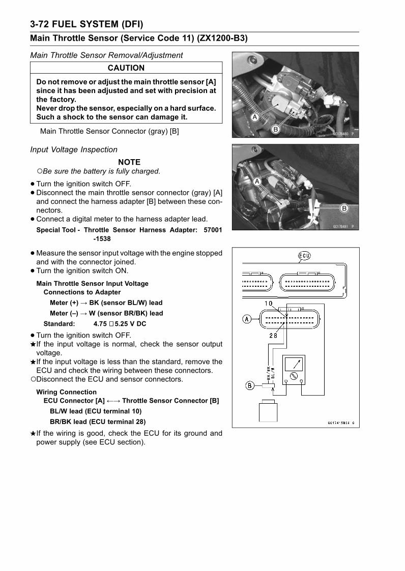
3-72 FUEL SYSTEM (DFI)
Main Throttle Sensor (Service Code 11) (ZX1200-B3)
Main Throttle Sensor Removal/Adjustment
CAUTION
Do not remove or adjust themain throttle sensor [A]since it has been adjusted and set with precision atthe factory.Never drop the sensor, especially on a hard surface.Such a shock to the sensor can damage it.
Main Throttle Sensor Connector (gray) [B]
Input Voltage Inspection
NOTEBe sure the battery is fully charged.•Turn the ignition switch OFF.•Disconnect the main throttle sensor connector (gray) [A]and connect the harness adapter [B] between these con-nectors.
•Connect a digital meter to the harness adapter lead.Special Tool - Throttle Sensor Harness Adapter: 57001
-1538
•Measure the sensor input voltage with the engine stoppedand with the connector joined.
• Turn the ignition switch ON.Main Throttle Sensor Input VoltageConnections to Adapter
Meter (+)→ BK (sensor BL/W) lead
Meter (–) → W (sensor BR/BK) lead
Standard: 4.75 ∼ 5.25 V DC
•Turn the ignition switch OFF.If the input voltage is normal, check the sensor outputvoltage.If the input voltage is less than the standard, remove theECU and check the wiring between these connectors.Disconnect the ECU and sensor connectors.Wiring ConnectionECU Connector [A]←→ Throttle Sensor Connector [B]
BL/W lead (ECU terminal 10)
BR/BK lead (ECU terminal 28)
If the wiring is good, check the ECU for its ground andpower supply (see ECU section).
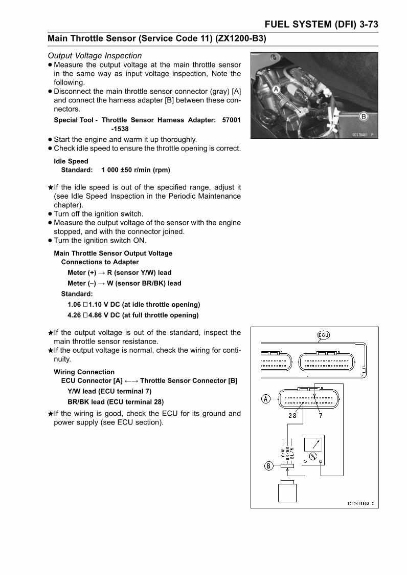
FUEL SYSTEM (DFI) 3-73
Main Throttle Sensor (Service Code 11) (ZX1200-B3)
Output Voltage Inspection
•Measure the output voltage at the main throttle sensorin the same way as input voltage inspection, Note thefollowing.
•Disconnect the main throttle sensor connector (gray) [A]and connect the harness adapter [B] between these con-nectors.
Special Tool - Throttle Sensor Harness Adapter: 57001-1538
•Start the engine and warm it up thoroughly.
•Check idle speed to ensure the throttle opening is correct.Idle SpeedStandard: 1 000 ±50 r/min (rpm)
If the idle speed is out of the specified range, adjust it(see Idle Speed Inspection in the Periodic Maintenancechapter).
• Turn off the ignition switch.•Measure the output voltage of the sensor with the enginestopped, and with the connector joined.
• Turn the ignition switch ON.Main Throttle Sensor Output VoltageConnections to Adapter
Meter (+)→ R (sensor Y/W) lead
Meter (–) → W (sensor BR/BK) lead
Standard:
1.06 ∼ 1.10 V DC (at idle throttle opening)4.26 ∼ 4.86 V DC (at full throttle opening)
If the output voltage is out of the standard, inspect themain throttle sensor resistance.If the output voltage is normal, check the wiring for conti-nuity.
Wiring ConnectionECU Connector [A]←→ Throttle Sensor Connector [B]
Y/W lead (ECU terminal 7)
BR/BK lead (ECU terminal 28)
If the wiring is good, check the ECU for its ground andpower supply (see ECU section).
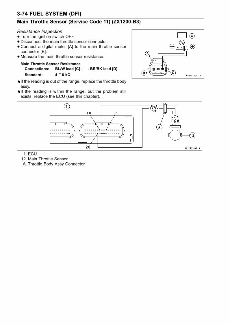
3-74 FUEL SYSTEM (DFI)
Main Throttle Sensor (Service Code 11) (ZX1200-B3)
Resistance Inspection
•Turn the ignition switch OFF.•Disconnect the main throttle sensor connector.•Connect a digital meter [A] to the main throttle sensorconnector [B].
•Measure the main throttle sensor resistance.Main Throttle Sensor ResistanceConnections: BL/W lead [C]←→ BR/BK lead [D]
Standard: 4 ∼ 6 kΩ
If the reading is out of the range, replace the throttle bodyassy.If the reading is within the range, but the problem stillexists, replace the ECU (see this chapter).
1. ECU12. Main Throttle SensorA. Throttle Body Assy Connector
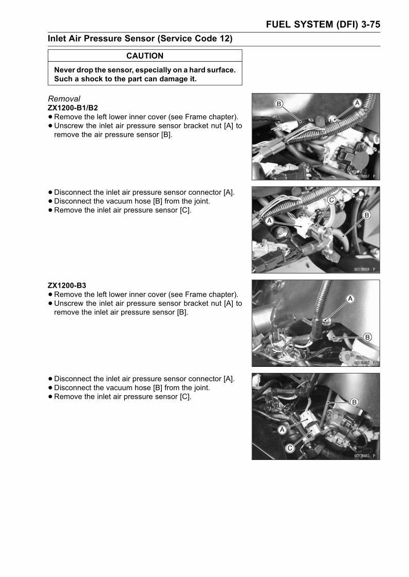
FUEL SYSTEM (DFI) 3-75
Inlet Air Pressure Sensor (Service Code 12)
CAUTION
Never drop the sensor, especially on a hard surface.Such a shock to the part can damage it.
RemovalZX1200-B1/B2
•Remove the left lower inner cover (see Frame chapter).• Unscrew the inlet air pressure sensor bracket nut [A] toremove the air pressure sensor [B].
• Disconnect the inlet air pressure sensor connector [A].• Disconnect the vacuum hose [B] from the joint.
• Remove the inlet air pressure sensor [C].
ZX1200-B3
•Remove the left lower inner cover (see Frame chapter).• Unscrew the inlet air pressure sensor bracket nut [A] toremove the inlet air pressure sensor [B].
• Disconnect the inlet air pressure sensor connector [A].• Disconnect the vacuum hose [B] from the joint.
• Remove the inlet air pressure sensor [C].
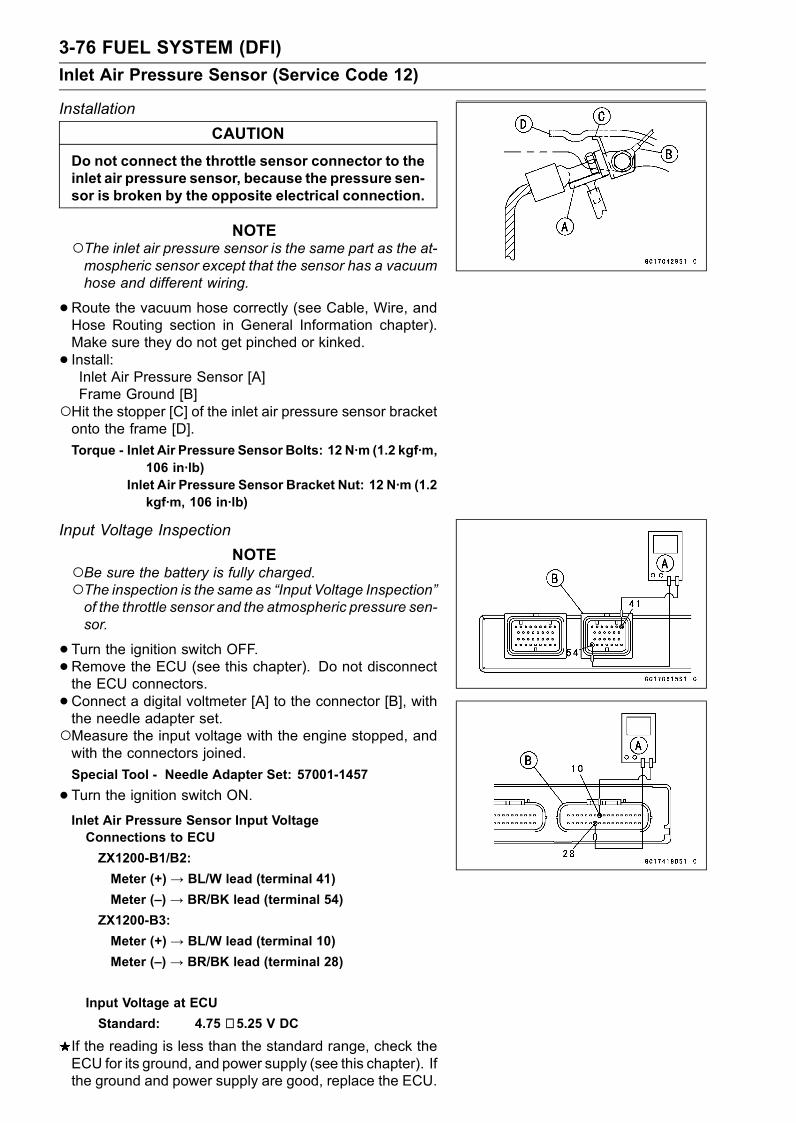
3-76 FUEL SYSTEM (DFI)
Inlet Air Pressure Sensor (Service Code 12)
Installation
CAUTION
Do not connect the throttle sensor connector to theinlet air pressure sensor, because the pressure sen-sor is broken by the opposite electrical connection.
NOTEThe inlet air pressure sensor is the same part as the at-mospheric sensor except that the sensor has a vacuumhose and different wiring.
•Route the vacuum hose correctly (see Cable, Wire, andHose Routing section in General Information chapter).Make sure they do not get pinched or kinked.
• Install:Inlet Air Pressure Sensor [A]Frame Ground [B]
Hit the stopper [C] of the inlet air pressure sensor bracketonto the frame [D].
Torque - Inlet Air Pressure Sensor Bolts: 12 N·m (1.2 kgf·m,106 in·lb)
Inlet Air Pressure Sensor Bracket Nut: 12 N·m (1.2kgf·m, 106 in·lb)
Input Voltage Inspection
NOTEBe sure the battery is fully charged.The inspection is the same as “Input Voltage Inspection”of the throttle sensor and the atmospheric pressure sen-sor.
•Turn the ignition switch OFF.•Remove the ECU (see this chapter). Do not disconnectthe ECU connectors.
•Connect a digital voltmeter [A] to the connector [B], withthe needle adapter set.Measure the input voltage with the engine stopped, andwith the connectors joined.
Special Tool - Needle Adapter Set: 57001-1457
•Turn the ignition switch ON.Inlet Air Pressure Sensor Input VoltageConnections to ECU
ZX1200-B1/B2:
Meter (+)→ BL/W lead (terminal 41)
Meter (–) → BR/BK lead (terminal 54)
ZX1200-B3:
Meter (+)→ BL/W lead (terminal 10)
Meter (–) → BR/BK lead (terminal 28)
Input Voltage at ECU
Standard: 4.75 ∼ 5.25 V DC
If the reading is less than the standard range, check theECU for its ground, and power supply (see this chapter). Ifthe ground and power supply are good, replace the ECU.
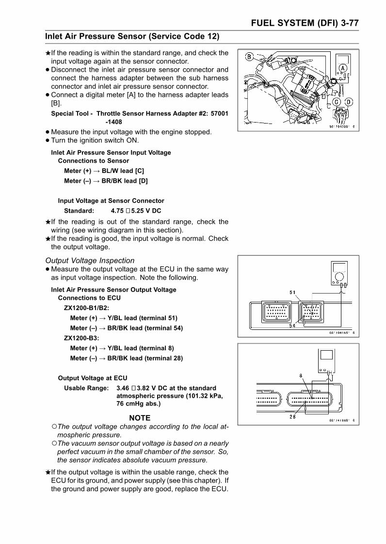
FUEL SYSTEM (DFI) 3-77
Inlet Air Pressure Sensor (Service Code 12)
If the reading is within the standard range, and check theinput voltage again at the sensor connector.
•Disconnect the inlet air pressure sensor connector andconnect the harness adapter between the sub harnessconnector and inlet air pressure sensor connector.
•Connect a digital meter [A] to the harness adapter leads[B].
Special Tool - Throttle Sensor Harness Adapter #2: 57001-1408
•Measure the input voltage with the engine stopped.• Turn the ignition switch ON.Inlet Air Pressure Sensor Input VoltageConnections to Sensor
Meter (+) → BL/W lead [C]
Meter (–) → BR/BK lead [D]
Input Voltage at Sensor Connector
Standard: 4.75 ∼ 5.25 V DC
If the reading is out of the standard range, check thewiring (see wiring diagram in this section).If the reading is good, the input voltage is normal. Checkthe output voltage.
Output Voltage Inspection
•Measure the output voltage at the ECU in the same wayas input voltage inspection. Note the following.
Inlet Air Pressure Sensor Output VoltageConnections to ECU
ZX1200-B1/B2:
Meter (+) → Y/BL lead (terminal 51)
Meter (–)→ BR/BK lead (terminal 54)
ZX1200-B3:
Meter (+)→ Y/BL lead (terminal 8)
Meter (–)→ BR/BK lead (terminal 28)
Output Voltage at ECU
Usable Range: 3.46 ∼ 3.82 V DC at the standardatmospheric pressure (101.32 kPa,76 cmHg abs.)
NOTEThe output voltage changes according to the local at-mospheric pressure.The vacuum sensor output voltage is based on a nearlyperfect vacuum in the small chamber of the sensor. So,the sensor indicates absolute vacuum pressure.
If the output voltage is within the usable range, check theECU for its ground, and power supply (see this chapter). Ifthe ground and power supply are good, replace the ECU.
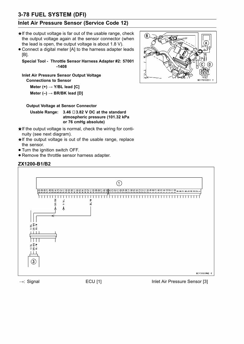
3-78 FUEL SYSTEM (DFI)
Inlet Air Pressure Sensor (Service Code 12)
If the output voltage is far out of the usable range, checkthe output voltage again at the sensor connector (whenthe lead is open, the output voltage is about 1.8 V).
•Connect a digital meter [A] to the harness adapter leads[B].
Special Tool - Throttle Sensor Harness Adapter #2: 57001-1408
Inlet Air Pressure Sensor Output VoltageConnections to Sensor
Meter (+) → Y/BL lead [C]
Meter (–) → BR/BK lead [D]
Output Voltage at Sensor Connector
Usable Range: 3.46 ∼ 3.82 V DC at the standardatmospheric pressure (101.32 kPaor 76 cmHg absolute)
If the output voltage is normal, check the wiring for conti-nuity (see next diagram).If the output voltage is out of the usable range, replacethe sensor.
• Turn the ignition switch OFF.•Remove the throttle sensor harness adapter.ZX1200-B1/B2
→: Signal ECU [1] Inlet Air Pressure Sensor [3]
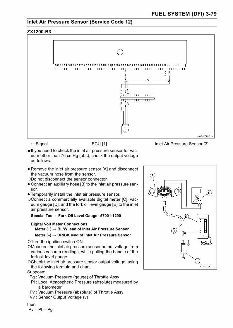
FUEL SYSTEM (DFI) 3-79
Inlet Air Pressure Sensor (Service Code 12)
ZX1200-B3
→: Signal ECU [1] Inlet Air Pressure Sensor [3]
If you need to check the inlet air pressure sensor for vac-uum other than 76 cmHg (abs), check the output voltageas follows:
•Remove the inlet air pressure sensor [A] and disconnectthe vacuum hose from the sensor.Do not disconnect the sensor connector.•Connect an auxiliary hose [B] to the inlet air pressure sen-sor.
• Temporarily install the inlet air pressure sensor.Connect a commercially available digital meter [C], vac-uum gauge [D], and the fork oil level gauge [E] to the inletair pressure sensor.
Special Tool - Fork Oil Level Gauge: 57001-1290
Digital Volt Meter ConnectionsMeter (+)→ BL/W lead of Inlet Air Pressure Sensor
Meter (–)→ BR/BK lead of Inlet Air Pressure Sensor
Turn the ignition switch ON.Measure the inlet air pressure sensor output voltage fromvarious vacuum readings, while pulling the handle of thefork oil level gauge.Check the inlet air pressure sensor output voltage, usingthe following formula and chart.
Suppose:Pg : Vacuum Pressure (gauge) of Throttle AssyPl : Local Atmospheric Pressure (absolute) measured by
a barometerPv : Vacuum Pressure (absolute) of Throttle AssyVv : Sensor Output Voltage (v)
thenPv = Pl – Pg
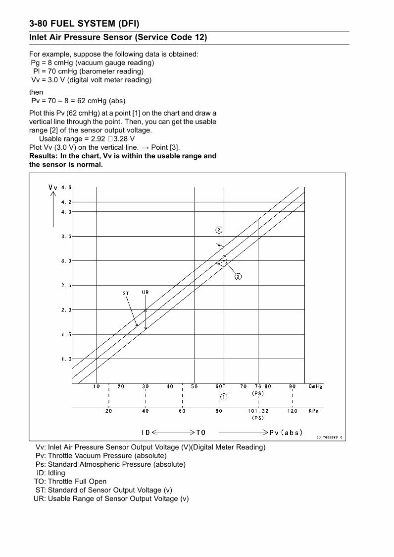
3-80 FUEL SYSTEM (DFI)
Inlet Air Pressure Sensor (Service Code 12)
For example, suppose the following data is obtained:Pg = 8 cmHg (vacuum gauge reading)Pl = 70 cmHg (barometer reading)Vv = 3.0 V (digital volt meter reading)
thenPv = 70 – 8 = 62 cmHg (abs)
Plot this Pv (62 cmHg) at a point [1] on the chart and draw avertical line through the point. Then, you can get the usablerange [2] of the sensor output voltage.Usable range = 2.92 ∼ 3.28 V
Plot Vv (3.0 V) on the vertical line. → Point [3].Results: In the chart, Vv is within the usable range andthe sensor is normal.
Vv: Inlet Air Pressure Sensor Output Voltage (V)(Digital Meter Reading)Pv: Throttle Vacuum Pressure (absolute)Ps: Standard Atmospheric Pressure (absolute)ID: IdlingTO: Throttle Full OpenST: Standard of Sensor Output Voltage (v)UR: Usable Range of Sensor Output Voltage (v)
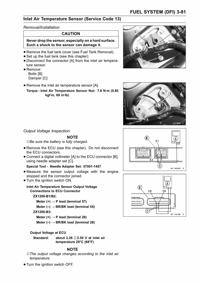
FUEL SYSTEM (DFI) 3-81
Inlet Air Temperature Sensor (Service Code 13)
Removal/Installation
CAUTION
Never drop the sensor, especially on a hard surface.Such a shock to the sensor can damage it.
•Remove the fuel tank cover (see Fuel Tank Removal).• Set up the fuel tank (see this chapter).• Disconnect the connector [A] from the inlet air tempera-ture sensor.
•Remove:Bolts [B]Damper [C]
•Remove the inlet air temperature sensor [A].Torque - Inlet Air Temperature Sensor Nut: 7.8 N·m (0.80
kgf·m, 69 in·lb)
Output Voltage Inspection
NOTEBe sure the battery is fully charged.•Remove the ECU (see this chapter). Do not disconnectthe ECU connectors.
•Connect a digital voltmeter [A] to the ECU connector [B],using needle adapter set [C].
Special Tool - Needle Adapter Set: 57001-1457
•Measure the sensor output voltage with the enginestopped and the connector joined.
• Turn the ignition switch ON.Inlet Air Temperature Sensor Output VoltageConnections to ECU Connector
ZX1200-B1/B2:
Meter (+) → P lead (terminal 57)
Meter (–)→ BR/BK lead (terminal 54)
ZX1200-B3:
Meter (+) → P lead (terminal 26)
Meter (–)→ BR/BK lead (terminal 28)
Output Voltage at ECU
Standard: about 2.26 ∼ 2.50 V at inlet airtemperature 20°C (68°F)
NOTEThe output voltage changes according to the inlet airtemperature.
•Turn the ignition switch OFF.

3-82 FUEL SYSTEM (DFI)
Inlet Air Temperature Sensor (Service Code 13)
If the output voltage is out of the specified, check the ECUfor its ground, and power supply (see ECU section in thischapter). If the ground and power supply are good, re-place the ECU.If the output voltage is far out of the specified (e.g. whenthe wiring is open, the voltage is about 4.6 V), remove thefuel tank cover, and check the wiring (see next diagram).
•Remove the needle adapter set, and apply siliconesealant to the seals of the connector for waterproofing.
Silicone Sealant (Kawasaki Bond: 56019-120)
- Seals of ECU Connectors
If the wiring is good, check the sensor resistance.
Sensor Resistance Inspection
•Remove the inlet air temperature sensor (see this sec-tion).
• Suspend the sensor [A] in a container of machine oil sothat the heat-sensitive portion and threaded portion aresubmerged.
• Suspend a thermometer [B] with the heat-sensitive por-tion [C] located in almost the same depth with the sensor.
NOTEThe sensor and thermometer must not touch the con-tainer side or bottom.
•Place the container over a source of heat and graduallyraise the temperature of the oil while stirring the oil gentlyfor even temperature.
•Using a digital meter, measure the internal resistanceof the sensor across the terminals at the temperaturesshown in the table.
Inlet Air Temperature Sensor ResistanceStandard: 657 ∼ 1 003 kΩ at 0°C (32°F)
68 ∼ 89 kΩ at 50°C (122°F)
11.95 ∼ 14.37 kΩ at 100°C (212°F)
If the measurement is out of the range, replace the sensor.If the measurement is within the specified, replace theECU.
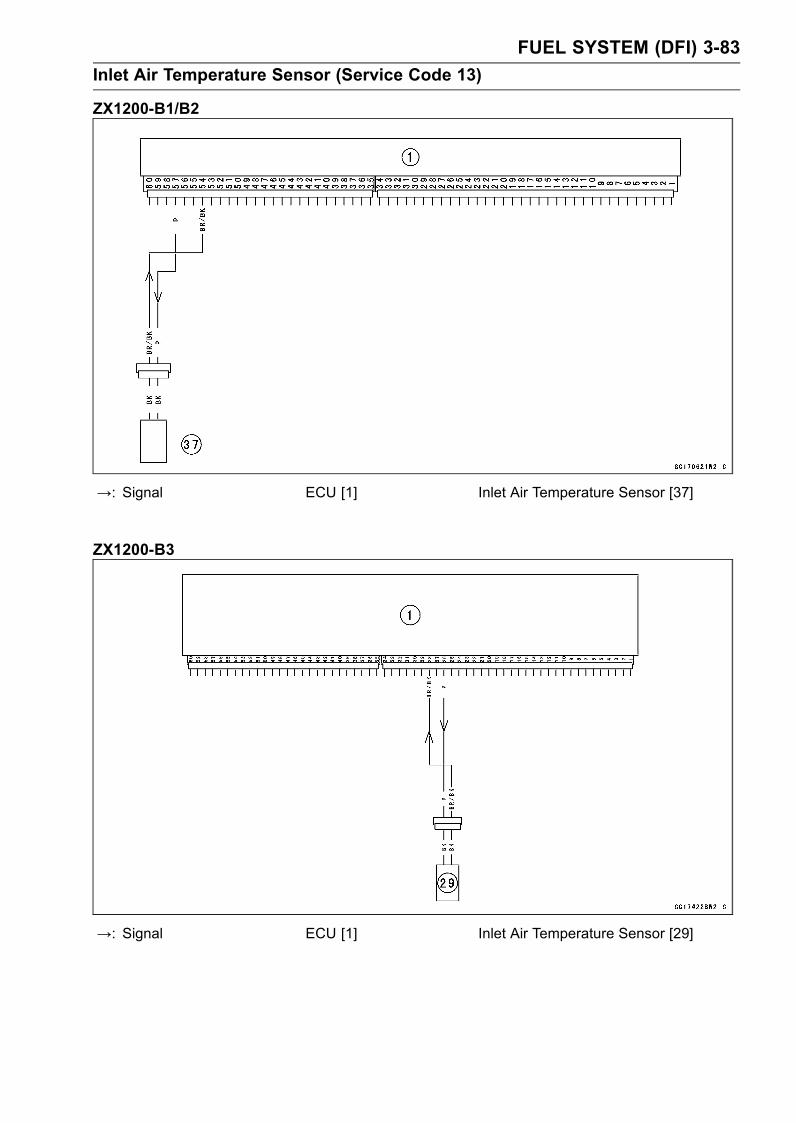
FUEL SYSTEM (DFI) 3-83
Inlet Air Temperature Sensor (Service Code 13)
ZX1200-B1/B2
→: Signal ECU [1] Inlet Air Temperature Sensor [37]
ZX1200-B3
→: Signal ECU [1] Inlet Air Temperature Sensor [29]
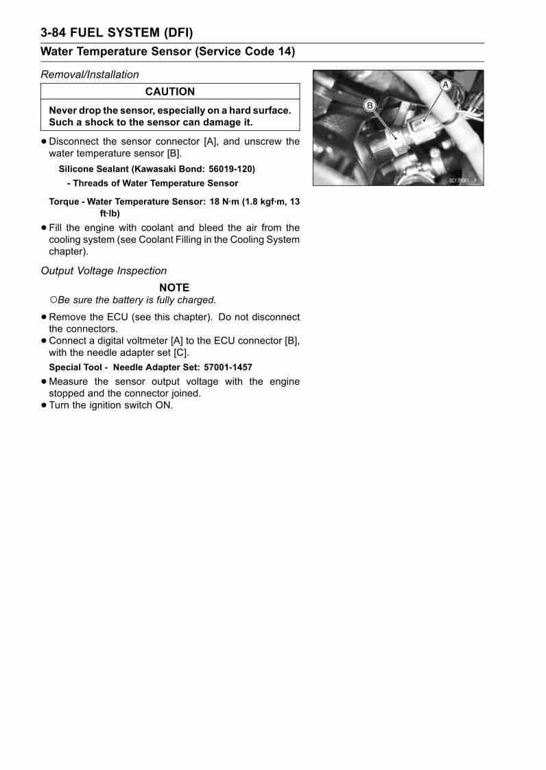
3-84 FUEL SYSTEM (DFI)
Water Temperature Sensor (Service Code 14)
Removal/Installation
CAUTION
Never drop the sensor, especially on a hard surface.Such a shock to the sensor can damage it.
•Disconnect the sensor connector [A], and unscrew thewater temperature sensor [B].
Silicone Sealant (Kawasaki Bond: 56019-120)
- Threads of Water Temperature Sensor
Torque - Water Temperature Sensor: 18 N·m (1.8 kgf·m, 13ft·lb)
•Fill the engine with coolant and bleed the air from thecooling system (see Coolant Filling in the Cooling Systemchapter).
Output Voltage Inspection
NOTEBe sure the battery is fully charged.•Remove the ECU (see this chapter). Do not disconnectthe connectors.
•Connect a digital voltmeter [A] to the ECU connector [B],with the needle adapter set [C].
Special Tool - Needle Adapter Set: 57001-1457
•Measure the sensor output voltage with the enginestopped and the connector joined.
• Turn the ignition switch ON.
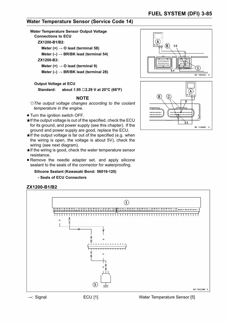
FUEL SYSTEM (DFI) 3-85
Water Temperature Sensor (Service Code 14)
Water Temperature Sensor Output VoltageConnections to ECU
ZX1200-B1/B2:
Meter (+) → O lead (terminal 58)
Meter (–)→ BR/BK lead (terminal 54)
ZX1200-B3:
Meter (+) → O lead (terminal 9)
Meter (–)→ BR/BK lead (terminal 28)
Output Voltage at ECU
Standard: about 1.95 ∼ 2.29 V at 20°C (68°F)
NOTEThe output voltage changes according to the coolanttemperature in the engine.
•Turn the ignition switch OFF.If the output voltage is out of the specified, check the ECUfor its ground, and power supply (see this chapter). If theground and power supply are good, replace the ECU.If the output voltage is far out of the specified (e.g. whenthe wiring is open, the voltage is about 5V), check thewiring (see next diagram).If the wiring is good, check the water temperature sensorresistance.
•Remove the needle adapter set, and apply siliconesealant to the seals of the connector for waterproofing.
Silicone Sealant (Kawasaki Bond: 56019-120)
- Seals of ECU Connectors
ZX1200-B1/B2
→: Signal ECU [1] Water Temperature Sensor [5]
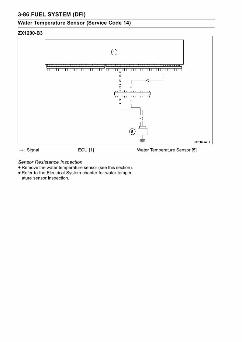
3-86 FUEL SYSTEM (DFI)
Water Temperature Sensor (Service Code 14)
ZX1200-B3
→: Signal ECU [1] Water Temperature Sensor [5]
Sensor Resistance Inspection
•Remove the water temperature sensor (see this section).•Refer to the Electrical System chapter for water temper-ature sensor inspection.
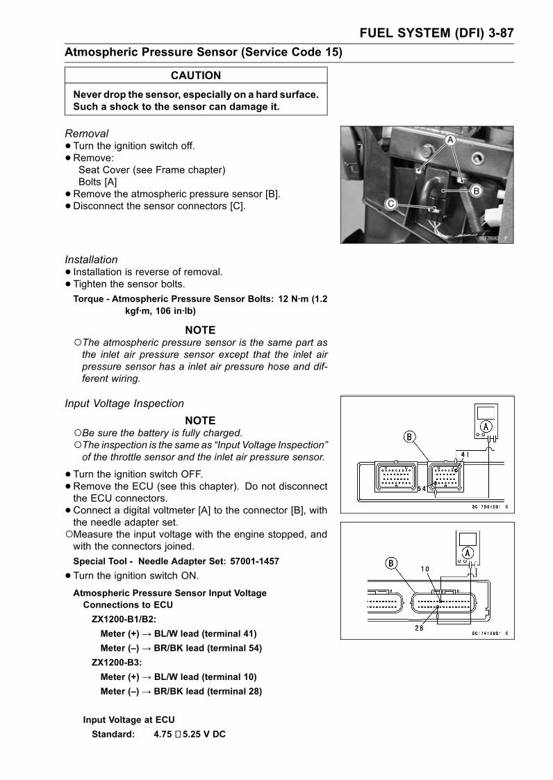
FUEL SYSTEM (DFI) 3-87
Atmospheric Pressure Sensor (Service Code 15)
CAUTION
Never drop the sensor, especially on a hard surface.Such a shock to the sensor can damage it.
Removal
•Turn the ignition switch off.• Remove:Seat Cover (see Frame chapter)Bolts [A]
•Remove the atmospheric pressure sensor [B].• Disconnect the sensor connectors [C].
Installation
• Installation is reverse of removal.• Tighten the sensor bolts.Torque - Atmospheric Pressure Sensor Bolts: 12 N·m (1.2
kgf·m, 106 in·lb)
NOTEThe atmospheric pressure sensor is the same part asthe inlet air pressure sensor except that the inlet airpressure sensor has a inlet air pressure hose and dif-ferent wiring.
Input Voltage Inspection
NOTEBe sure the battery is fully charged.The inspection is the same as “Input Voltage Inspection”of the throttle sensor and the inlet air pressure sensor.
•Turn the ignition switch OFF.•Remove the ECU (see this chapter). Do not disconnectthe ECU connectors.
•Connect a digital voltmeter [A] to the connector [B], withthe needle adapter set.Measure the input voltage with the engine stopped, andwith the connectors joined.
Special Tool - Needle Adapter Set: 57001-1457
•Turn the ignition switch ON.Atmospheric Pressure Sensor Input VoltageConnections to ECU
ZX1200-B1/B2:
Meter (+) → BL/W lead (terminal 41)
Meter (–)→ BR/BK lead (terminal 54)
ZX1200-B3:
Meter (+) → BL/W lead (terminal 10)
Meter (–)→ BR/BK lead (terminal 28)
Input Voltage at ECU
Standard: 4.75 ∼ 5.25 V DC
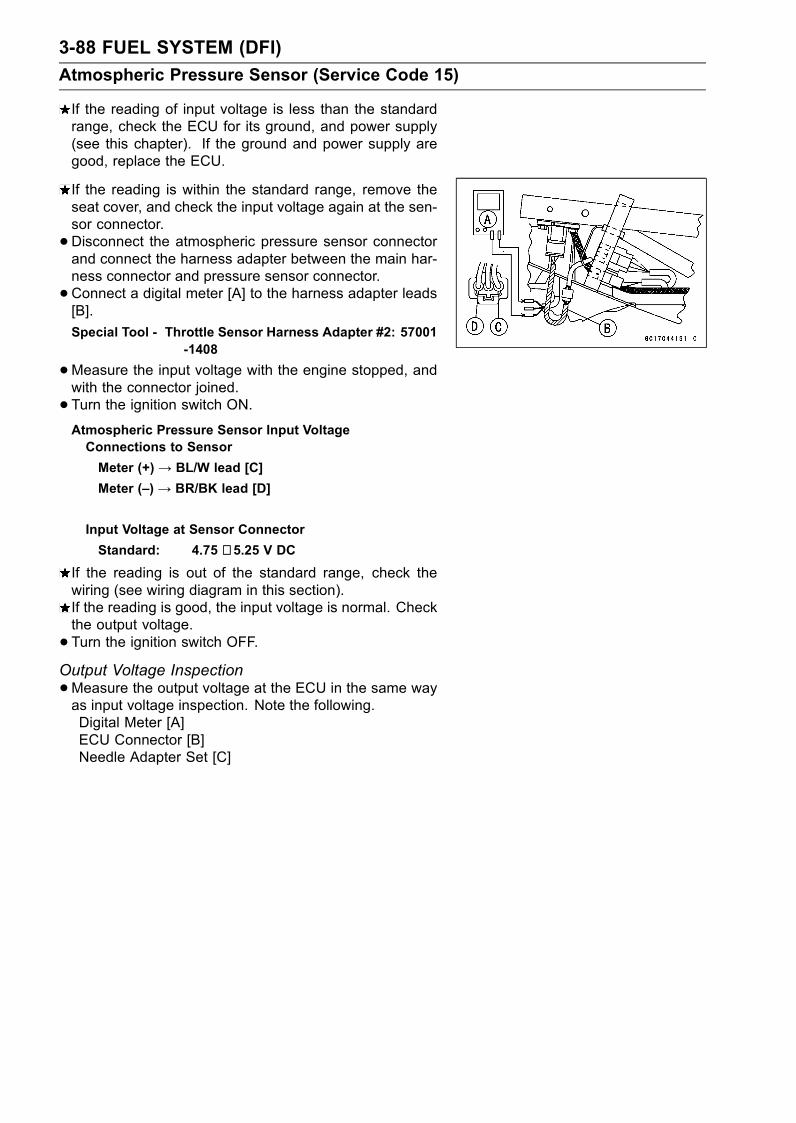
3-88 FUEL SYSTEM (DFI)
Atmospheric Pressure Sensor (Service Code 15)
If the reading of input voltage is less than the standardrange, check the ECU for its ground, and power supply(see this chapter). If the ground and power supply aregood, replace the ECU.
If the reading is within the standard range, remove theseat cover, and check the input voltage again at the sen-sor connector.
•Disconnect the atmospheric pressure sensor connectorand connect the harness adapter between the main har-ness connector and pressure sensor connector.
•Connect a digital meter [A] to the harness adapter leads[B].
Special Tool - Throttle Sensor Harness Adapter #2: 57001-1408
•Measure the input voltage with the engine stopped, andwith the connector joined.
• Turn the ignition switch ON.Atmospheric Pressure Sensor Input VoltageConnections to Sensor
Meter (+) → BL/W lead [C]
Meter (–) → BR/BK lead [D]
Input Voltage at Sensor Connector
Standard: 4.75 ∼ 5.25 V DC
If the reading is out of the standard range, check thewiring (see wiring diagram in this section).If the reading is good, the input voltage is normal. Checkthe output voltage.
• Turn the ignition switch OFF.Output Voltage Inspection
•Measure the output voltage at the ECU in the same wayas input voltage inspection. Note the following.Digital Meter [A]ECU Connector [B]Needle Adapter Set [C]
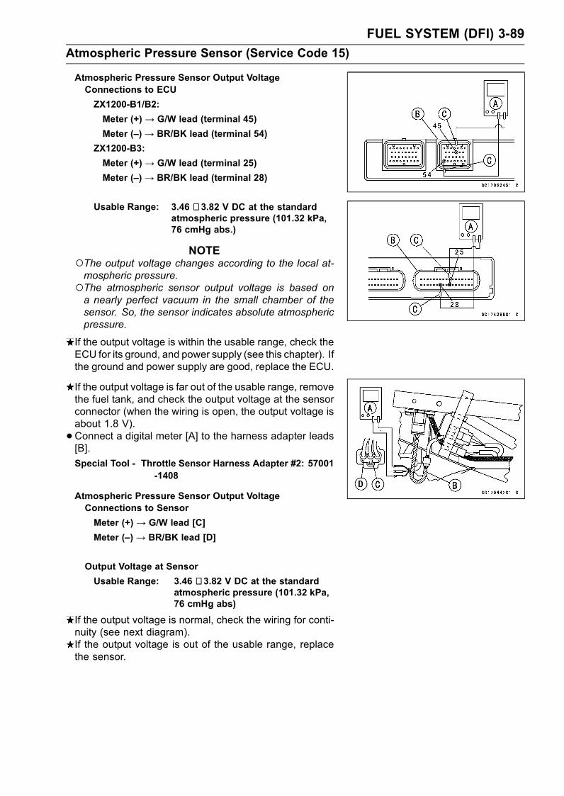
FUEL SYSTEM (DFI) 3-89
Atmospheric Pressure Sensor (Service Code 15)
Atmospheric Pressure Sensor Output VoltageConnections to ECU
ZX1200-B1/B2:
Meter (+) → G/W lead (terminal 45)
Meter (–)→ BR/BK lead (terminal 54)
ZX1200-B3:
Meter (+) → G/W lead (terminal 25)
Meter (–)→ BR/BK lead (terminal 28)
Usable Range: 3.46 ∼ 3.82 V DC at the standardatmospheric pressure (101.32 kPa,76 cmHg abs.)
NOTEThe output voltage changes according to the local at-mospheric pressure.The atmospheric sensor output voltage is based ona nearly perfect vacuum in the small chamber of thesensor. So, the sensor indicates absolute atmosphericpressure.
If the output voltage is within the usable range, check theECU for its ground, and power supply (see this chapter). Ifthe ground and power supply are good, replace the ECU.
If the output voltage is far out of the usable range, removethe fuel tank, and check the output voltage at the sensorconnector (when the wiring is open, the output voltage isabout 1.8 V).
•Connect a digital meter [A] to the harness adapter leads[B].
Special Tool - Throttle Sensor Harness Adapter #2: 57001-1408
Atmospheric Pressure Sensor Output VoltageConnections to Sensor
Meter (+) → G/W lead [C]
Meter (–) → BR/BK lead [D]
Output Voltage at Sensor
Usable Range: 3.46 ∼ 3.82 V DC at the standardatmospheric pressure (101.32 kPa,76 cmHg abs)
If the output voltage is normal, check the wiring for conti-nuity (see next diagram).If the output voltage is out of the usable range, replacethe sensor.
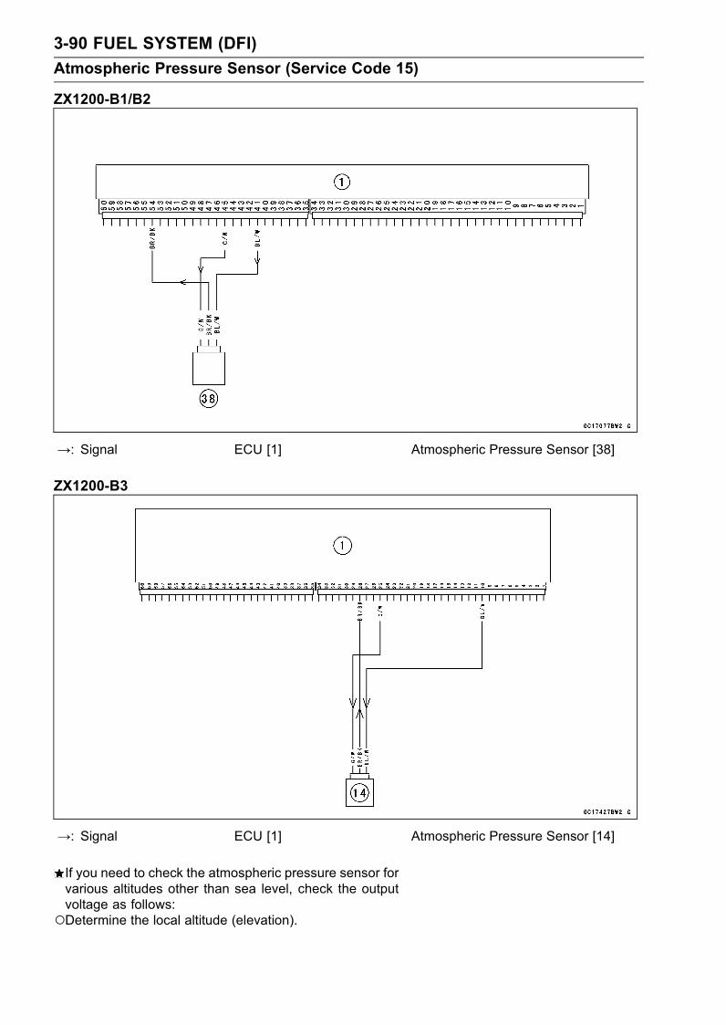
3-90 FUEL SYSTEM (DFI)
Atmospheric Pressure Sensor (Service Code 15)
ZX1200-B1/B2
→: Signal ECU [1] Atmospheric Pressure Sensor [38]
ZX1200-B3
→: Signal ECU [1] Atmospheric Pressure Sensor [14]
If you need to check the atmospheric pressure sensor forvarious altitudes other than sea level, check the outputvoltage as follows:Determine the local altitude (elevation).
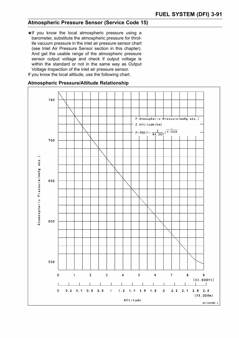
FUEL SYSTEM (DFI) 3-91
Atmospheric Pressure Sensor (Service Code 15)
If you know the local atmospheric pressure using abarometer, substitute the atmospheric pressure for throt-tle vacuum pressure in the inlet air pressure sensor chart(see Inlet Air Pressure Sensor section in this chapter).And get the usable range of the atmospheric pressuresensor output voltage and check if output voltage iswithin the standard or not in the same way as OutputVoltage Inspection of the inlet air pressure sensor.
If you know the local altitude, use the following chart.
Atmospheric Pressure/Altitude Relationship
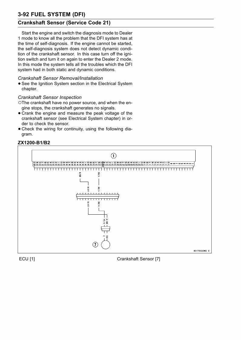
3-92 FUEL SYSTEM (DFI)
Crankshaft Sensor (Service Code 21)
Start the engine and switch the diagnosis mode to Dealer1 mode to know all the problem that the DFI system has atthe time of self-diagnosis. If the engine cannot be started,the self-diagnosis system does not detect dynamic condi-tion of the crankshaft sensor. In this case turn off the igni-tion switch and turn it on again to enter the Dealer 2 mode.In this mode the system tells all the troubles which the DFIsystem had in both static and dynamic conditions.
Crankshaft Sensor Removal/Installation
•See the Ignition System section in the Electrical Systemchapter.
Crankshaft Sensor InspectionThe crankshaft have no power source, and when the en-gine stops, the crankshaft generates no signals.
•Crank the engine and measure the peak voltage of thecrankshaft sensor (see Electrical System chapter) in or-der to check the sensor.
•Check the wiring for continuity, using the following dia-gram.
ZX1200-B1/B2
ECU [1] Crankshaft Sensor [7]
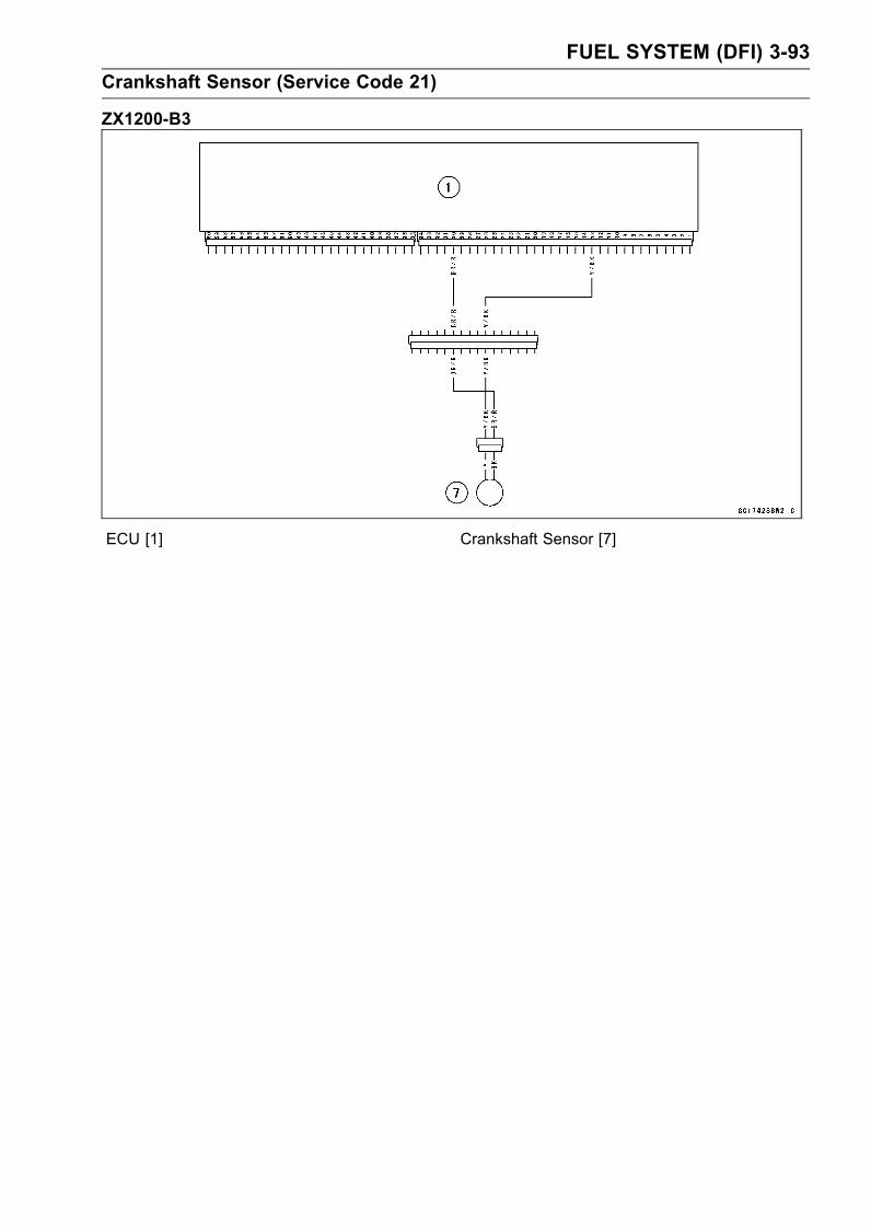
FUEL SYSTEM (DFI) 3-93
Crankshaft Sensor (Service Code 21)
ZX1200-B3
ECU [1] Crankshaft Sensor [7]
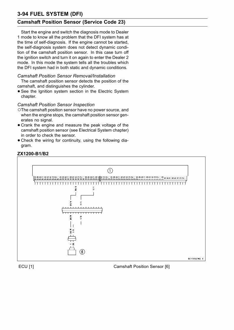
3-94 FUEL SYSTEM (DFI)
Camshaft Position Sensor (Service Code 23)
Start the engine and switch the diagnosis mode to Dealer1 mode to know all the problem that the DFI system has atthe time of self-diagnosis. If the engine cannot be started,the self-diagnosis system does not detect dynamic condi-tion of the camshaft position sensor. In this case turn offthe ignition switch and turn it on again to enter the Dealer 2mode. In this mode the system tells all the troubles whichthe DFI system had in both static and dynamic conditions.
Camshaft Position Sensor Removal/InstallationThe camshaft position sensor detects the position of the
camshaft, and distinguishes the cylinder.
• See the Ignition system section in the Electric Systemchapter.
Camshaft Position Sensor InspectionThe camshaft position sensor have no power source, andwhen the engine stops, the camshaft position sensor gen-erates no signal.
• Crank the engine and measure the peak voltage of thecamshaft position sensor (see Electrical System chapter)in order to check the sensor.
•Check the wiring for continuity, using the following dia-gram.
ZX1200-B1/B2
ECU [1] Camshaft Position Sensor [6]
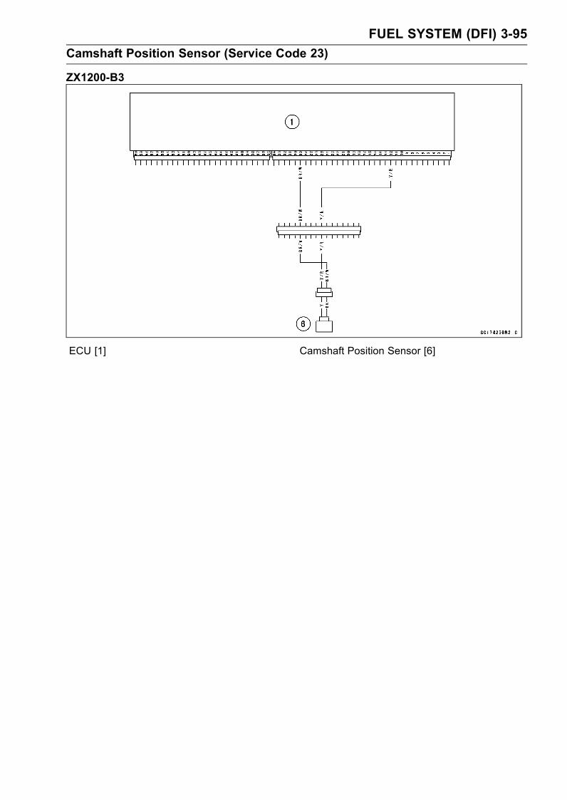
FUEL SYSTEM (DFI) 3-95
Camshaft Position Sensor (Service Code 23)
ZX1200-B3
ECU [1] Camshaft Position Sensor [6]

3-96 FUEL SYSTEM (DFI)
Speed Sensor (Service Code 24)
Speed Sensor Removal/Installation
•See the Electrical System.Speed Sensor Inspection
•See the Electrical System chapter as to the Speed Sen-sor.
Torque - Speed Sensor Bolt: 10 N·m (1.0 kgf·m, 89 in·lb)
NOTEBe sure the battery is fully charged.•Turn the ignition switch ON.•Remove the ECU (see this chapter) not to disconnect theECU connectors.
•Connect a digital voltmeter [A] leads to the connectors [B][C] as follows, with the needle adapter set [D], and checkthe conductivity between them.
ZX1200-B1/B2:
Meter (+) → Y Lead (terminal 9)
Meter (–) → Y Lead (12P connector)
ZX1200-B3:
Meter (+) → Y Lead (terminal 11)
Meter (–) → Y Lead (12P connector)
Special Tool - Needle Adapter Set: 57001-1457
If there is not a conductivity between the connector andthe ECU, check the speed sensor and wiring, or replacethe sensor and/or ECU.

FUEL SYSTEM (DFI) 3-97
Speed Sensor (Service Code 24)
ZX1200-B1/B2
ECU [1] Meter Assembly [39] Speed Sensor [40]
ZX1200-B3
ECU [1] Meter Assembly [15] Speed Sensor [16]
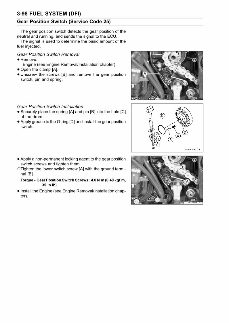
3-98 FUEL SYSTEM (DFI)
Gear Position Switch (Service Code 25)
The gear position switch detects the gear position of theneutral and running, and sends the signal to the ECU.The signal is used to determine the basic amount of the
fuel injected.
Gear Position Switch Removal
•Remove:Engine (see Engine Removal/Installation chapter)
•Open the clamp [A].•Unscrew the screws [B] and remove the gear positionswitch, pin and spring.
Gear Position Switch Installation
•Securely place the spring [A] and pin [B] into the hole [C]of the drum.
•Apply grease to the O-ring [D] and install the gear positionswitch.
• Apply a non-permanent locking agent to the gear positionswitch screws and tighten them.Tighten the lower switch screw [A] with the ground termi-nal [B].
Torque - Gear Position Switch Screws: 4.0 N·m (0.40 kgf·m,35 in·lb)
• Install the Engine (see Engine Removal/Installation chap-ter).

FUEL SYSTEM (DFI) 3-99
Gear Position Switch (Service Code 25)
Gear Position Switch Input Voltage Inspection
NOTEBe sure the battery is fully charged.•Turn the ignition switch OFF.•Remove the ECU (see this chapter). Do not disconnectthe ECU connectors.
•Connect a digital voltmeter [A] to the connector [B], withthe needle adapter set [C].Measure the input voltage with the engine stopped, andwith the connectors joined.
Special Tool - Needle Adapter Set: 57001-1457
•Turn the ignition switch ON.Gear Position Switch Input Voltage Connections to ECUZX1200-B1/B2:
Gear Position Tester (+) Tester (–)
Neutral Light Green Lead 20
1st Green/Red Lead 47
2nd Green/Blue Lead 53
3rd Green/Yellow Lead 60
4th Green Lead 46
5th Green/White Lead 52
6th Green/Black Lead 59
EngineGround
ZX1200-B3:
Gear Position Tester (+) Tester (–)
Neutral Light Green Lead 55
1st Green/Red Lead 37
2nd Green/Blue Lead 36
3rd Green/Yellow Lead 35
4th Green Lead 50
5th Green/White Lead 49
6th Yellow/Green Lead 48
EngineGround
Input Voltage at ECU (Except gear position)Standard: Neutral Battery Voltage (12.5 V or
more) other than Neutral less than 5 V
Input Voltage at ECU (Respective Gear Position)Standard: 0 V
If the reading of input voltage is out of the standard range,check the ECU for its ground, and power supply (see thischapter). If the ground and power supply are good, re-place the ECU.

3-100 FUEL SYSTEM (DFI)
Gear Position Switch (Service Code 25)
If the reading is within the standard range, set up the fueltank, and check the input voltage again at the sensor con-nector.
•Connect a digital voltmeter [H] to the connector [I], withthe needle adapter set.Measure the input voltage with the engine stopped, andwith the connector joined.
Special Tool - Needle Adapter Set: 57001-1457
•Turn the ignition switch ON.Gear Position Switch Input Voltage Connection to ECU
Gear Position Tester (+) Tester (–)
Neutral Light Green Lead [A]
1st Blue/Red Lead [B]
2nd Light Blue Lead [C]
3rd Red Lead [D]
4th Blue Lead [E]
5th Green/Red Lead [F]
6th Yellow/Green Lead [G]
Engine Ground
Input Voltage at Gear Position Switch Connector(Except Gear Position)Standard: Neutral Battery Voltage (12.5 V or
more) other than Neutral less than 5 V
Input Voltage at Gear Position Switch Connector(Respective Gear Position)Standard: 0 V
If the reading is out of the standard range, check thewiring (see wiring diagram in this section).If the reading is good, the input voltage is normal. Checkthe gear position switch.
• Turn the ignition switch OFF.•Remove the needle adapter set.
Gear Position Switch Inspection
•Set up the fuel tank.•Disconnect the gear position switch connector [A].
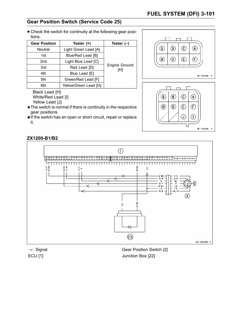
FUEL SYSTEM (DFI) 3-101
Gear Position Switch (Service Code 25)
•Check the switch for continuity at the following gear posi-tions.
Gear Position Tester (+) Tester (–)
Neutral Light Green Lead [A]
1st Blue/Red Lead [B]
2nd Light Blue Lead [C]
3rd Red Lead [D]
4th Blue Lead [E]
5th Green/Red Lead [F]
6th Yellow/Green Lead [G]
Engine Ground[H]
Black Lead [H]White/Red Lead [I]Yellow Lead [J]The switch is normal if there is continuity in the respectivegear positions.If the switch has an open or short circuit, repair or replaceit.
ZX1200-B1/B2
→: Signal Gear Position Switch [2]
ECU [1] Junction Box [22]
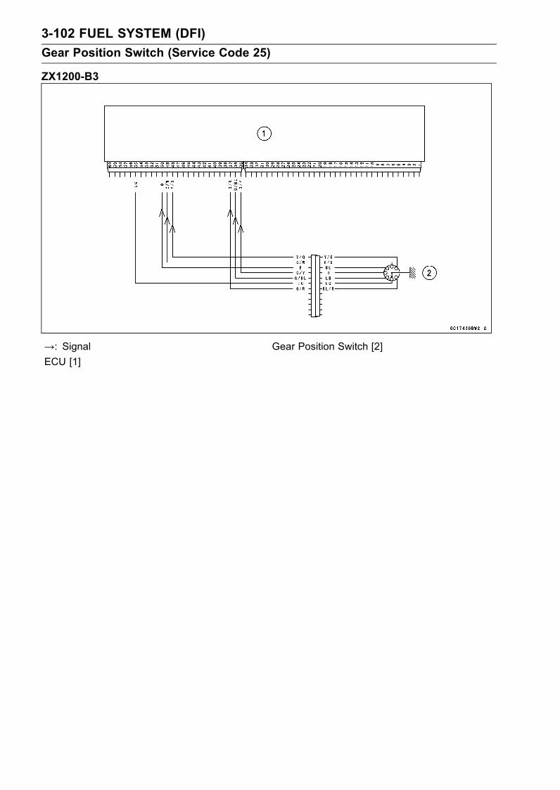
3-102 FUEL SYSTEM (DFI)
Gear Position Switch (Service Code 25)
ZX1200-B3
→: Signal Gear Position Switch [2]
ECU [1]

FUEL SYSTEM (DFI) 3-103
Vehicle-down Sensor (Service Code 31)
This sensor has a weight [A] with two magnets inside, andsends a signal to the ECU. But when the motorcycle banks60 ∼ 70° or more to either side (in fact falls down), the weightturns and shuts off the signal. The ECU senses this change,and stops the fuel pump, the fuel injectors, and the ignitionsystem.Hall IC [B]
When the motorcycle is down, the ignition switch is leftON. If the starter button is pushed, the electric starter turnsbut the engine doesn’t start. To start the engine again, raisethe motorcycle, turn the ignition switch OFF, and then ON.When the ignition switch is turned ON, current flows throughthe latch-up circuit and the transistor in the circuit is turnedON to unlock the latch-up circuit.Vehicle-down Sensor [A]Ground Terminal BK/Y [B]Output Terminal Y/G [C]Power Source Terminal BR [D]
Removal
CAUTION
Never drop the down-sensor, especially on a hardsurface. Such a shock to the sensor can damage it.
•Pull the battery tray (see Electrical System chapter).• Remove:Screw [A]Cover [B]
Turn Signal Relay [A]Screws [B]Vehicle-down Sensor [C]
• Push locks on center, and disconnect the connector [D].
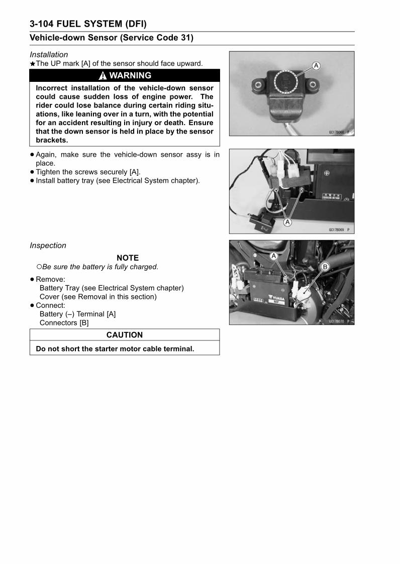
3-104 FUEL SYSTEM (DFI)
Vehicle-down Sensor (Service Code 31)
InstallationThe UP mark [A] of the sensor should face upward.
WARNINGIncorrect installation of the vehicle-down sensorcould cause sudden loss of engine power. Therider could lose balance during certain riding situ-ations, like leaning over in a turn, with the potentialfor an accident resulting in injury or death. Ensurethat the down sensor is held in place by the sensorbrackets.
•Again, make sure the vehicle-down sensor assy is inplace.
• Tighten the screws securely [A].• Install battery tray (see Electrical System chapter).
Inspection
NOTEBe sure the battery is fully charged.•Remove:Battery Tray (see Electrical System chapter)Cover (see Removal in this section)
•Connect:Battery (–) Terminal [A]Connectors [B]
CAUTION
Do not short the starter motor cable terminal.
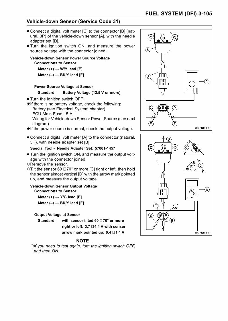
FUEL SYSTEM (DFI) 3-105
Vehicle-down Sensor (Service Code 31)
•Connect a digital volt meter [C] to the connector [B] (nat-ural, 3P) of the vehicle-down sensor [A], with the needleadapter set [D].
• Turn the ignition switch ON, and measure the powersource voltage with the connector joined.
Vehicle-down Sensor Power Source VoltageConnections to Sensor
Meter (+) → W/Y lead [E]
Meter (–) → BK/Y lead [F]
Power Source Voltage at Sensor
Standard: Battery Voltage (12.5 V or more)
•Turn the ignition switch OFF.If there is no battery voltage, check the following:Battery (see Electrical System chapter)ECU Main Fuse 15 AWiring for Vehicle-down Sensor Power Source (see nextdiagram)If the power source is normal, check the output voltage.
•Connect a digital volt meter [A] to the connector (natural,3P), with needle adapter set [B].
Special Tool - Needle Adapter Set: 57001-1457
•Turn the ignition switch ON, and measure the output volt-age with the connector joined.Remove the sensor.Tilt the sensor 60 ∼ 70° or more [C] right or left, then holdthe sensor almost vertical [D] with the arrow mark pointedup, and measure the output voltage.
Vehicle-down Sensor Output VoltageConnections to Sensor
Meter (+) → Y/G lead [E]
Meter (–) → BK/Y lead [F]
Output Voltage at Sensor
Standard: with sensor tilted 60 ∼ 70° or moreright or left: 3.7 ∼ 4.4 V with sensorarrow mark pointed up: 0.4 ∼ 1.4 V
NOTEIf you need to test again, turn the ignition switch OFF,and then ON.
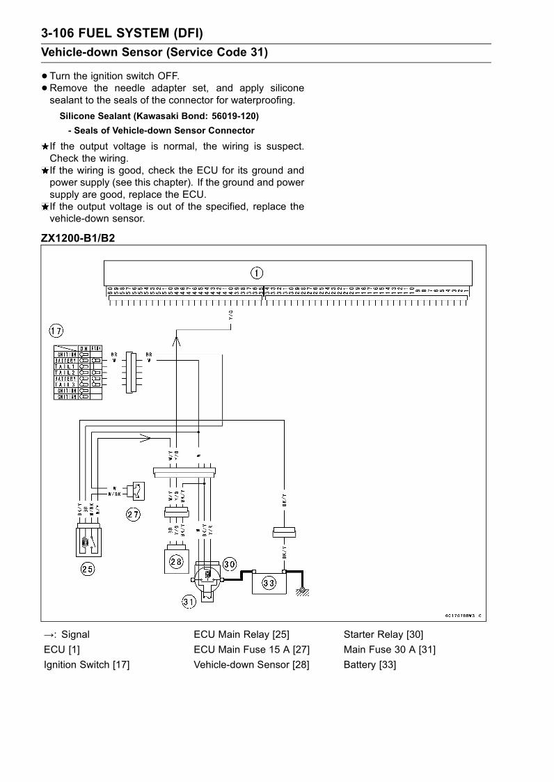
3-106 FUEL SYSTEM (DFI)
Vehicle-down Sensor (Service Code 31)
•Turn the ignition switch OFF.•Remove the needle adapter set, and apply siliconesealant to the seals of the connector for waterproofing.
Silicone Sealant (Kawasaki Bond: 56019-120)
- Seals of Vehicle-down Sensor Connector
If the output voltage is normal, the wiring is suspect.Check the wiring.If the wiring is good, check the ECU for its ground andpower supply (see this chapter). If the ground and powersupply are good, replace the ECU.If the output voltage is out of the specified, replace thevehicle-down sensor.
ZX1200-B1/B2
→: Signal ECU Main Relay [25] Starter Relay [30]
ECU [1] ECU Main Fuse 15 A [27] Main Fuse 30 A [31]
Ignition Switch [17] Vehicle-down Sensor [28] Battery [33]
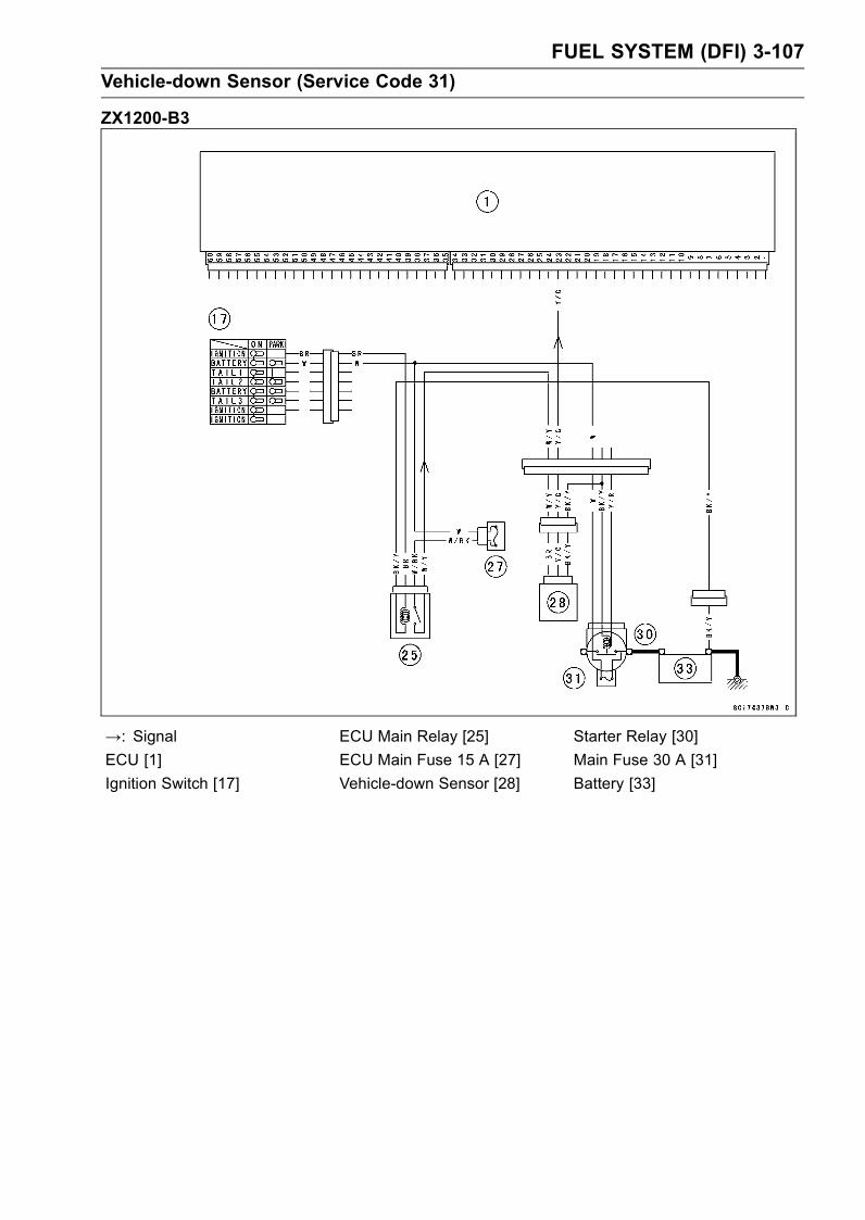
FUEL SYSTEM (DFI) 3-107
Vehicle-down Sensor (Service Code 31)
ZX1200-B3
→: Signal ECU Main Relay [25] Starter Relay [30]
ECU [1] ECU Main Fuse 15 A [27] Main Fuse 30 A [31]
Ignition Switch [17] Vehicle-down Sensor [28] Battery [33]
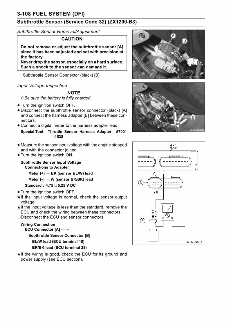
3-108 FUEL SYSTEM (DFI)
Subthrottle Sensor (Service Code 32) (ZX1200-B3)
Subthrottle Sensor Removal/Adjustment
CAUTION
Do not remove or adjust the subthrottle sensor [A]since it has been adjusted and set with precision atthe factory.Never drop the sensor, especially on a hard surface.Such a shock to the sensor can damage it.
Subthrottle Sensor Connector (black) [B]
Input Voltage Inspection
NOTEBe sure the battery is fully charged.•Turn the ignition switch OFF.•Disconnect the subthrottle sensor connector (black) [A]and connect the harness adapter [B] between these con-nectors.
•Connect a digital meter to the harness adapter lead.Special Tool - Throttle Sensor Harness Adapter: 57001
-1538
•Measure the sensor input voltage with the engine stoppedand with the connector joined.
• Turn the ignition switch ON.Subthrottle Sensor Input VoltageConnections to Adapter
Meter (+)→ BK (sensor BL/W) lead
Meter (–) → W (sensor BR/BK) lead
Standard : 4.75 ∼ 5.25 V DC
•Turn the ignition switch OFF.If the input voltage is normal, check the sensor outputvoltage.If the input voltage is less than the standard, remove theECU and check the wiring between these connectors.Disconnect the ECU and sensor connectors.Wiring ConnectionECU Connector [A] ←→Subthrottle Sensor Connector [B]
BL/W lead (ECU terminal 10)
BR/BK lead (ECU terminal 28)
If the wiring is good, check the ECU for its ground andpower supply (see ECU section).

FUEL SYSTEM (DFI) 3-109
Subthrottle Sensor (Service Code 32) (ZX1200-B3)
Output Voltage Inspection
•Measure the output voltage at the subthrottle sensor inthe same way as input voltage inspection. Note the fol-lowing.
•Disconnect the subthrottle sensor connector (black) [A]and connect the harness adapter [B] between these con-nectors.
Special Tool - Throttle Sensor Harness Adapter: 57001-1538
•Measure the output voltage of the sensor with the enginerunning, and with the connector joined.
• Turn the ignition switch ON.•Measure the output voltage when the subthrottle valve isfully opened or completely closed by hand.
Main Throttle Sensor Output VoltageConnections to Adapter
Meter (+) → R (sensor BR) lead
Meter (–) → W (sensor BR/BK) lead
Standard:
0.48 ∼ 0.52 V DC (at idle throttle opening)3.6 ∼ 4.0 V DC (at full throttle opening)
If the output voltage is out of the standard, inspect thesubthrottle sensor resistance.If the output voltage is normal, check the wiring for conti-nuity.
Wiring ConnectionECU Connector [A] ←→Subthrottle Sensor Connector [B]
BR lead (ECU terminal 24)
BR/BK lead (ECU terminal 28)
If the wiring is good, check the ECU for its ground andpower supply (see ECU section).

3-110 FUEL SYSTEM (DFI)
Subthrottle Sensor (Service Code 32) (ZX1200-B3)
Resistance Inspection
•Turn the ignition switch OFF.•Disconnect the subthrottle sensor connector.•Connect a digital meter [A] to the subthrottle sensor con-nector [B].
•Measure the subthrottle sensor resistance.Throttle Sensor ResistanceConnections: BL/W lead [C]←→ BR/BK lead [D]
Standard: 4 ∼ 6 kΩ
If the reading is out of the range, replace the throttle bodyassy.If the reading is within the range, but the problem stillexists, replace the ECU (see this chapter).
1. ECU10. Subthrottle Valve Actuator
11. Subthrottle SensorA. Throttle Body Assy Connector
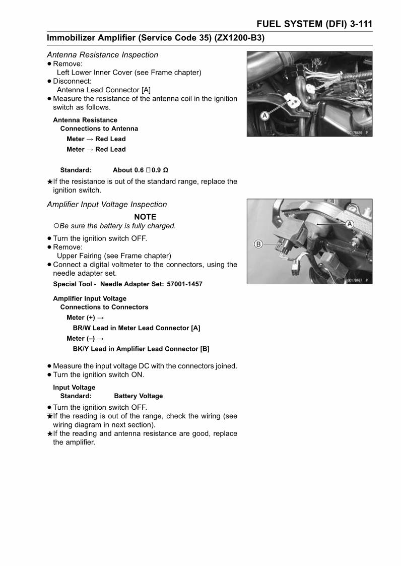
FUEL SYSTEM (DFI) 3-111
Immobilizer Amplifier (Service Code 35) (ZX1200-B3)
Antenna Resistance Inspection
•Remove:Left Lower Inner Cover (see Frame chapter)
•Disconnect:Antenna Lead Connector [A]
•Measure the resistance of the antenna coil in the ignitionswitch as follows.
Antenna ResistanceConnections to Antenna
Meter → Red Lead
Meter → Red Lead
Standard: About 0.6 ∼ 0.9 Ω
If the resistance is out of the standard range, replace theignition switch.
Amplifier Input Voltage Inspection
NOTEBe sure the battery is fully charged.•Turn the ignition switch OFF.•Remove:Upper Fairing (see Frame chapter)
•Connect a digital voltmeter to the connectors, using theneedle adapter set.
Special Tool - Needle Adapter Set: 57001-1457
Amplifier Input VoltageConnections to Connectors
Meter (+) →BR/W Lead in Meter Lead Connector [A]
Meter (–) →BK/Y Lead in Amplifier Lead Connector [B]
•Measure the input voltage DC with the connectors joined.• Turn the ignition switch ON.Input VoltageStandard: Battery Voltage
•Turn the ignition switch OFF.If the reading is out of the range, check the wiring (seewiring diagram in next section).If the reading and antenna resistance are good, replacethe amplifier.
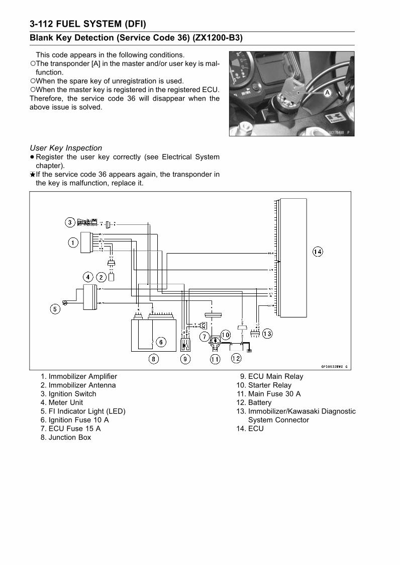
3-112 FUEL SYSTEM (DFI)
Blank Key Detection (Service Code 36) (ZX1200-B3)
This code appears in the following conditions.The transponder [A] in the master and/or user key is mal-function.When the spare key of unregistration is used.When the master key is registered in the registered ECU.Therefore, the service code 36 will disappear when theabove issue is solved.
User Key Inspection
•Register the user key correctly (see Electrical Systemchapter).If the service code 36 appears again, the transponder inthe key is malfunction, replace it.
1. Immobilizer Amplifier2. Immobilizer Antenna3. Ignition Switch4. Meter Unit5. FI Indicator Light (LED)6. Ignition Fuse 10 A7. ECU Fuse 15 A8. Junction Box
9. ECU Main Relay10. Starter Relay11. Main Fuse 30 A12. Battery13. Immobilizer/Kawasaki Diagnostic
System Connector14. ECU

FUEL SYSTEM (DFI) 3-113
Fuel Injectors (#1, #2, #3, #4: Service Code 41, 42, 43, 44)
Fuel Injector #1: (Service Code 41)Fuel Injector #2: (Service Code 42)Fuel Injector #3: (Service Code 43)Fuel Injector #4: (Service Code 44)
CAUTION
Never drop the injector, especially on a hard sur-face. Such a shock to the injector can damage it.
NOTEDo not remove the injectors from the throttle body.
Power Source Voltage Inspection
NOTEBe sure the battery is fully charged.•Turn the ignition switch OFF.•Remove the ECU (see this chapter). Do not disconnectthe ECU connectors.
•Connect a digital voltmeter [A] to the connector [B], withthe needle adapter set [C].Measure the power source voltage with the enginestopped, and with the connectors joined.
Special Tool - Needle Adapter Set: 57001-1457
•Turn the ignition switch ON.Injector Power Source Voltage at ECUConnections to ECU
ZX1200-B1/B2:
Meter (+) → W/R lead (terminal 42)
Meter (–) → Battery (–) Terminal
ZX1200-B3:
Meter (+) → W/R lead (terminal 33)
Meter (–) → Battery (–) Terminal
Power Source Voltage at ECU
Standard: Battery Voltage (12.5 V or more)
If the power source voltage is less than the standard,check the ECU for its ground, and power supply (see thischapter). If the ground and power supply are good, re-place the ECU.

3-114 FUEL SYSTEM (DFI)
Fuel Injectors (#1, #2, #3, #4: Service Code 41, 42, 43, 44)
If the reading is normal, check the power source voltageat the injector connector [B], with a digital volt meter [A].
•Measure the power source voltage with the enginestopped, and the connector joined, with a digital meterand needle adapter set [C].
• Turn the ignition switch ON.Injector #1 BL/R Lead [E]Injector #2 BL/G Lead [F]Injector #3 BL/BK Lead [G]Injector #4 BL/Y Lead [H]Injector Power Supply W/R Lead [I]
Injector Power Source Voltage at InjectorConnections to Injector #1, #2, #3, #4
Meter (+) → W/R lead [I]
Meter (–) → Battery (–) Terminal [D]
Power Source Voltage at Injector Connector
Standard: Battery Voltage (12.5 V or more)
•Turn the ignition switch OFF.If the reading is out of the standard, check the wiring (seewiring diagram in this section).If the reading is good, and the power source voltage isnormal, check the output voltage.

FUEL SYSTEM (DFI) 3-115
Fuel Injectors (#1, #2, #3, #4: Service Code 41, 42, 43, 44)
Output Voltage Inspection
•Measure the output voltage at the ECU connector in thesame way as power source voltage inspection. Note thefollowing.
Injector Output Voltage at ECUZX1200-B1/B2:
Connections for Injector #1
Meter (+) → BL/R lead (terminal 4)
Meter (–) → Battery (–) Terminal
Connections for Injector #2
Meter (+) → BL/G lead (terminal 5)
Meter (–) → Battery (–) Terminal
Connections for Injector #3
Meter (+) → BL/BK lead (terminal 6)
Meter (–) → Battery (–) Terminal
Connections for Injector #4
Meter (+) → BL/Y lead (terminal 7)
Meter (–) → Battery (–) Terminal
ZX1200-B3:
Connections for Injector #1
Meter (+) → BL/R lead (terminal 44)
Meter (–) → Battery (–) Terminal
Connections for Injector #2
Meter (+) → BL/G lead (terminal 43)
Meter (–) → Battery (–) Terminal
Connections for Injector #3
Meter (+) → BL/BK lead (terminal 42)
Meter (–) → Battery (–) Terminal
Connections for Injector #4
Meter (+) → BL/Y lead (terminal 41)
Meter (–) → Battery (–) Terminal
Output Voltage at ECU
Standard: Battery Voltage (12.5 V or more)
If the output voltage is normal, check the ECU for itsground, and power supply (see this chapter). If theground and power supply are good, replace the ECU.
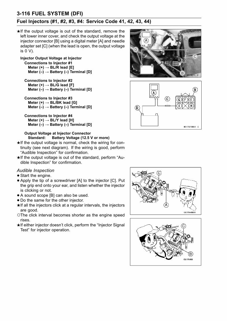
3-116 FUEL SYSTEM (DFI)
Fuel Injectors (#1, #2, #3, #4: Service Code 41, 42, 43, 44)
If the output voltage is out of the standard, remove theleft lower inner cover, and check the output voltage at theinjector connector [B] using a digital meter [A] and needleadapter set [C] (when the lead is open, the output voltageis 0 V).
Injector Output Voltage at InjectorConnections to Injector #1Meter (+) → BL/R lead [E]Meter (–) → Battery (–) Terminal [D]
Connections to Injector #2Meter (+) → BL/G lead [F]Meter (–) → Battery (–) Terminal [D]
Connections to Injector #3Meter (+) → BL/BK lead [G]Meter (–) → Battery (–) Terminal [D]
Connections to Injector #4Meter (+) → BL/Y lead [H]Meter (–) → Battery (–) Terminal [D]
Output Voltage at Injector ConnectorStandard: Battery Voltage (12.5 V or more)
If the output voltage is normal, check the wiring for con-tinuity (see next diagram). If the wiring is good, perform“Audible Inspection” for confirmation.If the output voltage is out of the standard, perform “Au-dible Inspection” for confirmation.
Audible Inspection
•Start the engine.• Apply the tip of a screwdriver [A] to the injector [C]. Putthe grip end onto your ear, and listen whether the injectoris clicking or not.
• A sound scope [B] can also be used.•Do the same for the other injector.If all the injectors click at a regular intervals, the injectorsare good.The click interval becomes shorter as the engine speedrises.If either injector doesn’t click, perform the “Injector SignalTest” for injector operation.
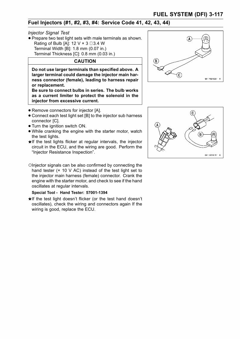
FUEL SYSTEM (DFI) 3-117
Fuel Injectors (#1, #2, #3, #4: Service Code 41, 42, 43, 44)
Injector Signal Test
•Prepare two test light sets with male terminals as shown.Rating of Bulb [A]: 12 V × 3 ∼ 3.4 WTerminal Width [B]: 1.8 mm (0.07 in.)Terminal Thickness [C]: 0.8 mm (0.03 in.)
CAUTION
Do not use larger terminals than specified above. Alarger terminal could damage the injector main har-ness connector (female), leading to harness repairor replacement.Be sure to connect bulbs in series. The bulb worksas a current limiter to protect the solenoid in theinjector from excessive current.
•Remove connectors for injector [A].• Connect each test light set [B] to the injector sub harnessconnector [C].
• Turn the ignition switch ON.•While cranking the engine with the starter motor, watchthe test lights.If the test lights flicker at regular intervals, the injectorcircuit in the ECU, and the wiring are good. Perform the“Injector Resistance Inspection”.
Injector signals can be also confirmed by connecting thehand tester (× 10 V AC) instead of the test light set tothe injector main harness (female) connector. Crank theengine with the starter motor, and check to see if the handoscillates at regular intervals.
Special Tool - Hand Tester: 57001-1394
If the test light doesn’t flicker (or the test hand doesn’toscillates), check the wiring and connectors again If thewiring is good, replace the ECU.
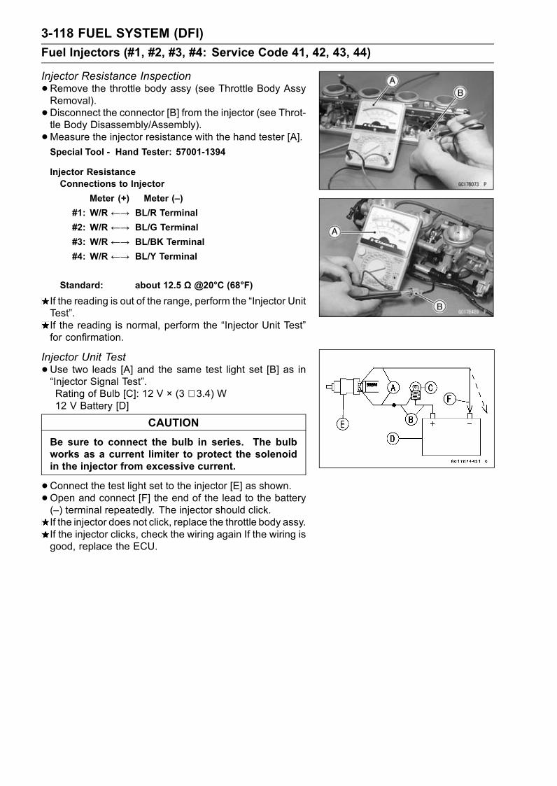
3-118 FUEL SYSTEM (DFI)
Fuel Injectors (#1, #2, #3, #4: Service Code 41, 42, 43, 44)
Injector Resistance Inspection
•Remove the throttle body assy (see Throttle Body AssyRemoval).
• Disconnect the connector [B] from the injector (see Throt-tle Body Disassembly/Assembly).
•Measure the injector resistance with the hand tester [A].Special Tool - Hand Tester: 57001-1394
Injector ResistanceConnections to Injector
Meter (+) Meter (–)
#1: W/R ←→ BL/R Terminal
#2: W/R ←→ BL/G Terminal
#3: W/R ←→ BL/BK Terminal
#4: W/R ←→ BL/Y Terminal
Standard: about 12.5 Ω @20°C (68°F)
If the reading is out of the range, perform the “Injector UnitTest”.If the reading is normal, perform the “Injector Unit Test”for confirmation.
Injector Unit Test
•Use two leads [A] and the same test light set [B] as in“Injector Signal Test”.Rating of Bulb [C]: 12 V × (3 ∼ 3.4) W12 V Battery [D]
CAUTION
Be sure to connect the bulb in series. The bulbworks as a current limiter to protect the solenoidin the injector from excessive current.
•Connect the test light set to the injector [E] as shown.•Open and connect [F] the end of the lead to the battery(–) terminal repeatedly. The injector should click.If the injector does not click, replace the throttle body assy.If the injector clicks, check the wiring again If the wiring isgood, replace the ECU.
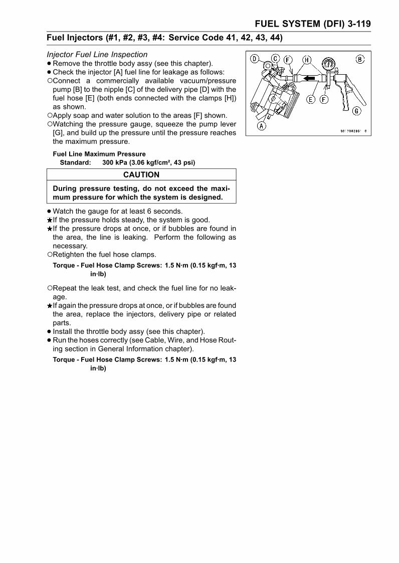
FUEL SYSTEM (DFI) 3-119
Fuel Injectors (#1, #2, #3, #4: Service Code 41, 42, 43, 44)
Injector Fuel Line Inspection
•Remove the throttle body assy (see this chapter).• Check the injector [A] fuel line for leakage as follows:Connect a commercially available vacuum/pressurepump [B] to the nipple [C] of the delivery pipe [D] with thefuel hose [E] (both ends connected with the clamps [H])as shown.Apply soap and water solution to the areas [F] shown.Watching the pressure gauge, squeeze the pump lever[G], and build up the pressure until the pressure reachesthe maximum pressure.
Fuel Line Maximum PressureStandard: 300 kPa (3.06 kgf/cm², 43 psi)
CAUTION
During pressure testing, do not exceed the maxi-mum pressure for which the system is designed.
•Watch the gauge for at least 6 seconds.If the pressure holds steady, the system is good.If the pressure drops at once, or if bubbles are found inthe area, the line is leaking. Perform the following asnecessary.Retighten the fuel hose clamps.Torque - Fuel Hose Clamp Screws: 1.5 N·m (0.15 kgf·m, 13
in·lb)
Repeat the leak test, and check the fuel line for no leak-age.If again the pressure drops at once, or if bubbles are foundthe area, replace the injectors, delivery pipe or relatedparts.
• Install the throttle body assy (see this chapter).• Run the hoses correctly (see Cable, Wire, and Hose Rout-ing section in General Information chapter).
Torque - Fuel Hose Clamp Screws: 1.5 N·m (0.15 kgf·m, 13in·lb)
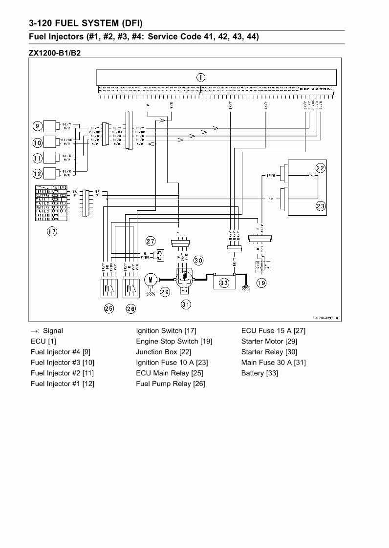
3-120 FUEL SYSTEM (DFI)
Fuel Injectors (#1, #2, #3, #4: Service Code 41, 42, 43, 44)
ZX1200-B1/B2
→: Signal Ignition Switch [17] ECU Fuse 15 A [27]
ECU [1] Engine Stop Switch [19] Starter Motor [29]
Fuel Injector #4 [9] Junction Box [22] Starter Relay [30]
Fuel Injector #3 [10] Ignition Fuse 10 A [23] Main Fuse 30 A [31]
Fuel Injector #2 [11] ECU Main Relay [25] Battery [33]
Fuel Injector #1 [12] Fuel Pump Relay [26]

FUEL SYSTEM (DFI) 3-121
Fuel Injectors (#1, #2, #3, #4: Service Code 41, 42, 43, 44)
ZX1200-B3
→: Signal Junction Box [22] Starter Relay [30]
ECU [1] Ignition Fuse 10 A [23] Main Fuse 30 A [31]
Fuel Injector #1, #2, #3, #4 [9] ECU Main Relay [25] Battery [33]
Ignition Switch [17] Fuel Pump Relay [26] Starter Motor [36]
Engine Stop Switch [19] ECU Fuse 15 A [27]
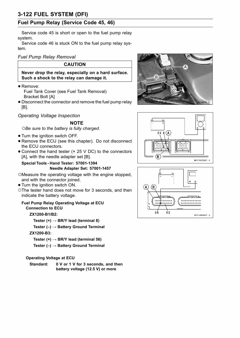
3-122 FUEL SYSTEM (DFI)
Fuel Pump Relay (Service Code 45, 46)
Service code 45 is short or open to the fuel pump relaysystem.Service code 46 is stuck ON to the fuel pump relay sys-
tem.
Fuel Pump Relay Removal
CAUTION
Never drop the relay, especially on a hard surface.Such a shock to the relay can damage it.
•Remove:Fuel Tank Cover (see Fuel Tank Removal)Bracket Bolt [A]
•Disconnect the connector and remove the fuel pump relay[B].
Operating Voltage Inspection
NOTEBe sure to the battery is fully charged.•Turn the ignition switch OFF.•Remove the ECU (see this chapter). Do not disconnectthe ECU connectors.
•Connect the hand tester (× 25 V DC) to the connectors[A], with the needle adapter set [B].
Special Tools - Hand Tester: 57001-1394Needle Adapter Set: 57001-1457
Measure the operating voltage with the engine stopped,and with the connector joined.
• Turn the ignition switch ON.The tester hand does not move for 3 seconds, and thenindicate the battery voltage.
Fuel Pump Relay Operating Voltage at ECUConnection to ECU
ZX1200-B1/B2:
Tester (+)→ BR/Y lead (terminal 8)
Tester (–)→ Battery Ground Terminal
ZX1200-B3:
Tester (+) → BR/Y lead (terminal 56)
Tester (–)→ Battery Ground Terminal
Operating Voltage at ECU
Standard: 0 V or 1 V for 3 seconds, and thenbattery voltage (12.5 V) or more
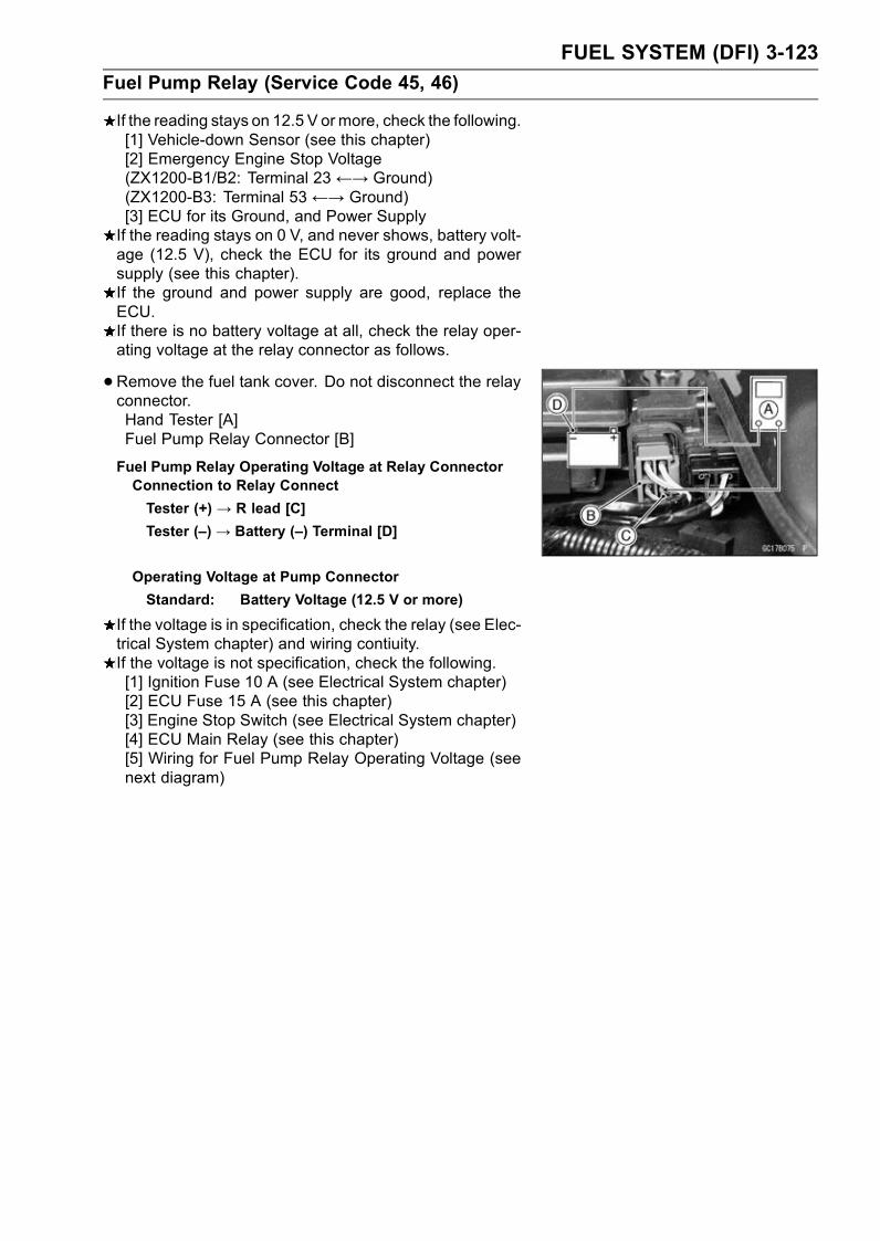
FUEL SYSTEM (DFI) 3-123
Fuel Pump Relay (Service Code 45, 46)
If the reading stays on 12.5 V ormore, check the following.[1] Vehicle-down Sensor (see this chapter)[2] Emergency Engine Stop Voltage(ZX1200-B1/B2: Terminal 23 ←→ Ground)(ZX1200-B3: Terminal 53 ←→ Ground)[3] ECU for its Ground, and Power SupplyIf the reading stays on 0 V, and never shows, battery volt-age (12.5 V), check the ECU for its ground and powersupply (see this chapter).If the ground and power supply are good, replace theECU.If there is no battery voltage at all, check the relay oper-ating voltage at the relay connector as follows.
•Remove the fuel tank cover. Do not disconnect the relayconnector.Hand Tester [A]Fuel Pump Relay Connector [B]
Fuel Pump Relay Operating Voltage at Relay ConnectorConnection to Relay Connect
Tester (+) → R lead [C]
Tester (–)→ Battery (–) Terminal [D]
Operating Voltage at Pump Connector
Standard: Battery Voltage (12.5 V or more)
If the voltage is in specification, check the relay (see Elec-trical System chapter) and wiring contiuity.If the voltage is not specification, check the following.[1] Ignition Fuse 10 A (see Electrical System chapter)[2] ECU Fuse 15 A (see this chapter)[3] Engine Stop Switch (see Electrical System chapter)[4] ECU Main Relay (see this chapter)[5] Wiring for Fuel Pump Relay Operating Voltage (seenext diagram)

3-124 FUEL SYSTEM (DFI)
Fuel Pump Relay (Service Code 45, 46)
Power Source Voltage Inspection
NOTEConfirm that the operation voltage is normal before in-specting the power source voltage.Be sure the battery is fully charged.•Connect the hand tester (× 25 V DC) [A] to the connector[B], with the needle adapter set [C].
Special Tools - Hand Tester: 57001-1394Needle Adapter Set: 57001-1457
Measure the power source voltage with the enginestopped, and with the connector joined.
• Turn the ignition switch ON.The tester hand should indicate battery voltage for 3 sec-onds, and then 0 V.
Relay Power Source VoltageConnections to ECU
ZX1200-B1/B2:
Tester (+)→ W/R lead (terminal 42)
Tester (–) → BK/Y lead (terminal 35)
ZX1200-B3:
Tester (+)→ W/R lead (terminal 33)
Tester (–) → BK/Y lead (terminal 34)
Power Source Voltage at ECU
Standard: Battery Voltage (12.5 V or more), andthe 0 V
If the power source voltage is less than the standard,check the ECU for its ground, and power supply (see thischapter).If the ground and power supply are good, replace theECU.If the reading stays on battery voltage, and never shows0 V, recheck the operating voltage or check the fuel pumprelay power source voltage at the relay connector.
•Connect the hand tester [A] to the fuel pump relay con-nector [B].Measure the power source voltage with the enginestopped, and with the relay connector joined.
• Turn the ignition switch ON.Fuel Pump Relay Power Source VoltageConnections to Relay Connector
Tester (+) → W/Y lead [C]
Tester (–) → Battery (–) Terminal [D]
Power Source Voltage at Relay Connector
Standard: Battery Voltage (12.5 V or more)
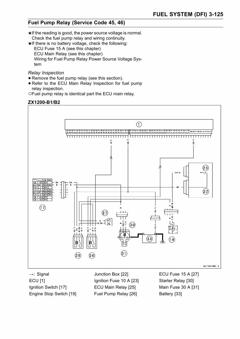
FUEL SYSTEM (DFI) 3-125
Fuel Pump Relay (Service Code 45, 46)
If the reading is good, the power source voltage is normal.Check the fuel pump relay and wiring continuity.If there is no battery voltage, check the following:ECU Fuse 15 A (see this chapter)ECU Main Relay (see this chapter)Wiring for Fuel Pump Relay Power Source Voltage Sys-tem
Relay Inspection
•Remove the fuel pump relay (see this section).•Refer to the ECU Main Relay Inspection for fuel pumprelay inspection.Fuel pump relay is identical part the ECU main relay.ZX1200-B1/B2
→: Signal Junction Box [22] ECU Fuse 15 A [27]
ECU [1] Ignition Fuse 10 A [23] Starter Relay [30]
Ignition Switch [17] ECU Main Relay [25] Main Fuse 30 A [31]
Engine Stop Switch [19] Fuel Pump Relay [26] Battery [33]
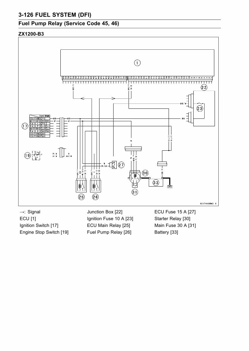
3-126 FUEL SYSTEM (DFI)
Fuel Pump Relay (Service Code 45, 46)
ZX1200-B3
→: Signal Junction Box [22] ECU Fuse 15 A [27]
ECU [1] Ignition Fuse 10 A [23] Starter Relay [30]
Ignition Switch [17] ECU Main Relay [25] Main Fuse 30 A [31]
Engine Stop Switch [19] Fuel Pump Relay [26] Battery [33]
FUEL SYSTEM (DFI) 3-127
Stick Coils (#1, #2, #3, #4: Service Code 51, 52, 53, 54)
Stick Coil #1: Ignition Coil (Service Code 51)Stick Coil #2: Ignition Coil (Service Code 52)Stick Coil #3: Ignition Coil (Service Code 53)Stick Coil #4: Ignition Coil (Service Code 54)
Removal/Installation
CAUTION
Never drop the ignition coils, especially on a hardsurface. Such a shock to the ignition coil can dam-age it.
•See Ignition System section in the Electrical Systemchapter.
Input Voltage Inspection
NOTEBe sure the battery is fully charged.

3-128 FUEL SYSTEM (DFI)
Stick Coils (#1, #2, #3, #4: Service Code 51, 52, 53, 54)
•Turn the ignition switch OFF.•Remove the ECU (see this chapter). Do not disconnectthe ECU connector.
•Connect a digital voltmeter [A] as shown, with the needleadapter set [B].Measure the input voltage to each primary winding of theignition coils with the engine stopped, and with the con-nectors joined.
• Turn the ignition switch ON.Stick Coil Input Voltage at ECUZX1200-B1/B2:
Connections for Stick Coil #1
Meter (+) → BK lead (terminal 1)
Meter (–) → BK/Y lead (terminal 26)
Connections for Stick Coil #2
Meter (+)→ BK/G lead (terminal 2)
Meter (–) → BK/Y lead (terminal 26)
Connections for Stick Coil #3
Meter (+) → BK/R lead (terminal 3)
Meter (–) → BK/Y lead (terminal 26)
Connections for Stick Coil #4
Meter (+)→ BK/O lead (terminal 10)
Meter (–) → BK/Y lead (terminal 26)
ZX1200-B3:
Connections for Stick Coil #1
Meter (+) → BK lead (terminal 47)
Meter (–) → BK/Y lead (terminal 59)
Connections for Stick Coil #2
Meter (+)→ BK/G lead (terminal 46)
Meter (–) → BK/Y lead (terminal 59)
Connections for Stick Coil #3
Meter (+)→ BK/R lead (terminal 45)
Meter (–) → BK/Y lead (terminal 59)
Connections for Stick Coil #4
Meter (+)→ BK/O lead (terminal 60)
Meter (–) → BK/Y lead (terminal 59)
Input Voltage at ECU
Standard: Battery Voltage (12.5 V or more)
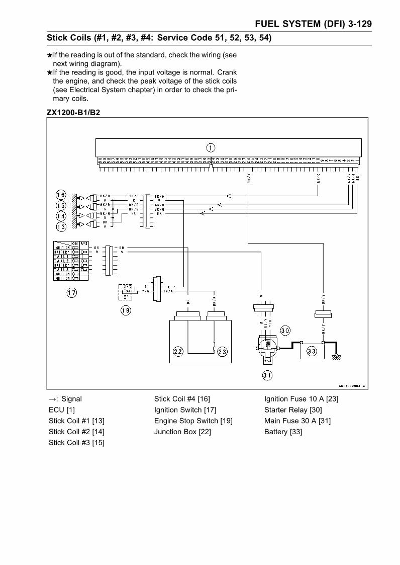
FUEL SYSTEM (DFI) 3-129
Stick Coils (#1, #2, #3, #4: Service Code 51, 52, 53, 54)
If the reading is out of the standard, check the wiring (seenext wiring diagram).If the reading is good, the input voltage is normal. Crankthe engine, and check the peak voltage of the stick coils(see Electrical System chapter) in order to check the pri-mary coils.
ZX1200-B1/B2
→: Signal Stick Coil #4 [16] Ignition Fuse 10 A [23]
ECU [1] Ignition Switch [17] Starter Relay [30]
Stick Coil #1 [13] Engine Stop Switch [19] Main Fuse 30 A [31]
Stick Coil #2 [14] Junction Box [22] Battery [33]
Stick Coil #3 [15]

3-130 FUEL SYSTEM (DFI)
Stick Coils (#1, #2, #3, #4: Service Code 51, 52, 53, 54)
ZX1200-B3
→: Signal Engine Stop Switch [19] Starter Relay [30]
ECU [1] Junction Box [22] Main Fuse 30 A [31]
Stick Coil #1, #2, #3, #4, [13] Ignition Fuse 10 A [23] Battery [33]
Ignition Switch [17]
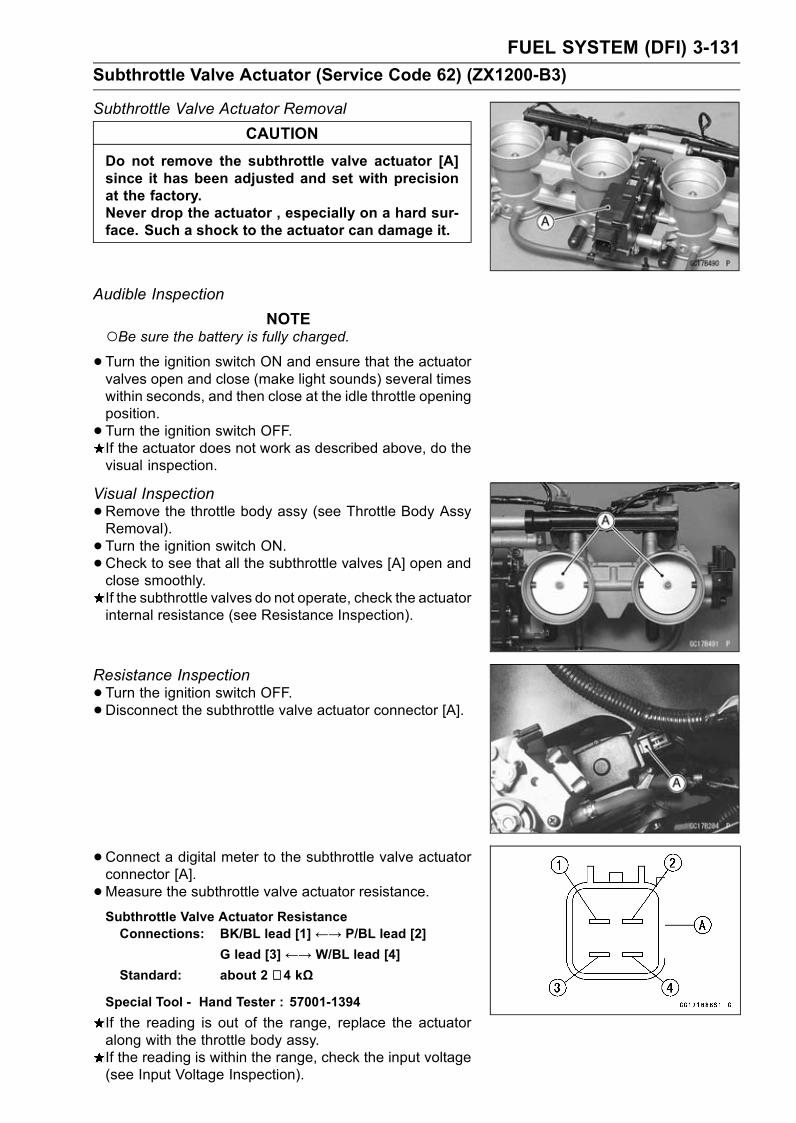
FUEL SYSTEM (DFI) 3-131
Subthrottle Valve Actuator (Service Code 62) (ZX1200-B3)
Subthrottle Valve Actuator Removal
CAUTION
Do not remove the subthrottle valve actuator [A]since it has been adjusted and set with precisionat the factory.Never drop the actuator , especially on a hard sur-face. Such a shock to the actuator can damage it.
Audible Inspection
NOTEBe sure the battery is fully charged.•Turn the ignition switch ON and ensure that the actuatorvalves open and close (make light sounds) several timeswithin seconds, and then close at the idle throttle openingposition.
• Turn the ignition switch OFF.If the actuator does not work as described above, do thevisual inspection.
Visual Inspection
•Remove the throttle body assy (see Throttle Body AssyRemoval).
• Turn the ignition switch ON.•Check to see that all the subthrottle valves [A] open andclose smoothly.If the subthrottle valves do not operate, check the actuatorinternal resistance (see Resistance Inspection).
Resistance Inspection
•Turn the ignition switch OFF.•Disconnect the subthrottle valve actuator connector [A].
• Connect a digital meter to the subthrottle valve actuatorconnector [A].
•Measure the subthrottle valve actuator resistance.Subthrottle Valve Actuator ResistanceConnections: BK/BL lead [1]←→ P/BL lead [2]
G lead [3] ←→ W/BL lead [4]
Standard: about 2 ∼ 4 kΩ
Special Tool - Hand Tester : 57001-1394
If the reading is out of the range, replace the actuatoralong with the throttle body assy.If the reading is within the range, check the input voltage(see Input Voltage Inspection).
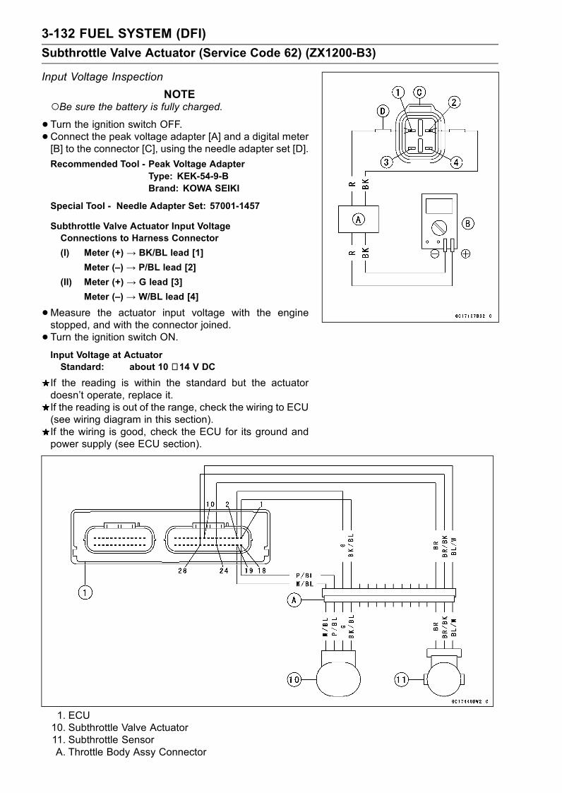
3-132 FUEL SYSTEM (DFI)
Subthrottle Valve Actuator (Service Code 62) (ZX1200-B3)
Input Voltage Inspection
NOTEBe sure the battery is fully charged.•Turn the ignition switch OFF.•Connect the peak voltage adapter [A] and a digital meter[B] to the connector [C], using the needle adapter set [D].
Recommended Tool - Peak Voltage AdapterType: KEK-54-9-BBrand: KOWA SEIKI
Special Tool - Needle Adapter Set: 57001-1457
Subthrottle Valve Actuator Input VoltageConnections to Harness Connector
(I) Meter (+) → BK/BL lead [1]
Meter (–) → P/BL lead [2]
(II) Meter (+) → G lead [3]
Meter (–) → W/BL lead [4]
•Measure the actuator input voltage with the enginestopped, and with the connector joined.
• Turn the ignition switch ON.Input Voltage at ActuatorStandard: about 10 ∼ 14 V DC
If the reading is within the standard but the actuatordoesn’t operate, replace it.If the reading is out of the range, check the wiring to ECU(see wiring diagram in this section).If the wiring is good, check the ECU for its ground andpower supply (see ECU section).
1. ECU10. Subthrottle Valve Actuator11. Subthrottle SensorA. Throttle Body Assy Connector
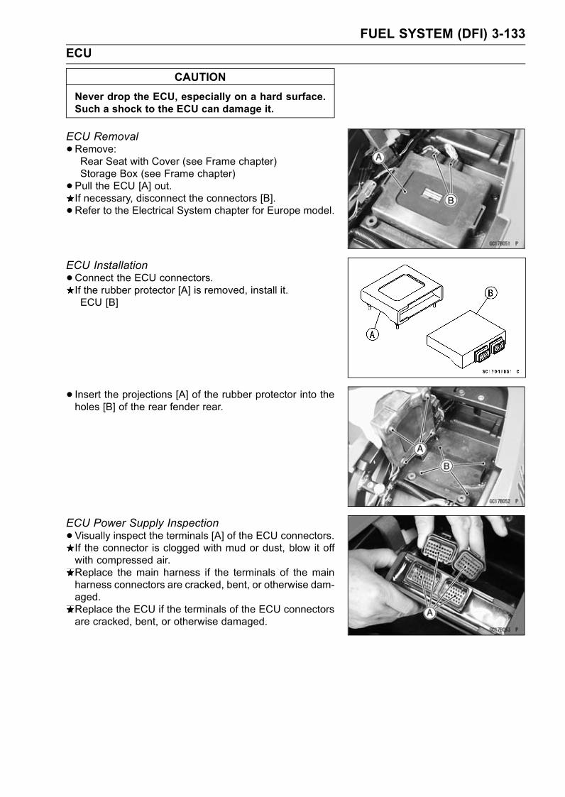
FUEL SYSTEM (DFI) 3-133
ECU
CAUTION
Never drop the ECU, especially on a hard surface.Such a shock to the ECU can damage it.
ECU Removal
•Remove:Rear Seat with Cover (see Frame chapter)Storage Box (see Frame chapter)
• Pull the ECU [A] out.If necessary, disconnect the connectors [B].
•Refer to the Electrical System chapter for Europe model.
ECU Installation
•Connect the ECU connectors.If the rubber protector [A] is removed, install it.ECU [B]
• Insert the projections [A] of the rubber protector into theholes [B] of the rear fender rear.
ECU Power Supply Inspection
•Visually inspect the terminals [A] of the ECU connectors.If the connector is clogged with mud or dust, blow it offwith compressed air.Replace the main harness if the terminals of the mainharness connectors are cracked, bent, or otherwise dam-aged.Replace the ECU if the terminals of the ECU connectorsare cracked, bent, or otherwise damaged.
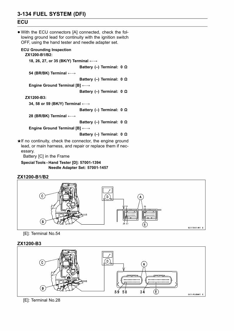
3-134 FUEL SYSTEM (DFI)
ECU
•With the ECU connectors [A] connected, check the fol-lowing ground lead for continuity with the ignition switchOFF, using the hand tester and needle adapter set.
ECU Grounding InspectionZX1200-B1/B2:
18, 26, 27, or 35 (BK/Y) Terminal←→Battery (–) Terminal: 0 Ω
54 (BR/BK) Terminal ←→Battery (–) Terminal: 0 Ω
Engine Ground Terminal [B] ←→Battery (–) Terminal: 0 Ω
ZX1200-B3:
34, 58 or 59 (BK/Y) Terminal ←→Battery (–) Terminal: 0 Ω
28 (BR/BK) Terminal ←→Battery (–) Terminal: 0 Ω
Engine Ground Terminal [B] ←→Battery (–) Terminal: 0 Ω
If no continuity, check the connector, the engine groundlead, or main harness, and repair or replace them if nec-essary.Battery [C] in the Frame
Special Tools - Hand Tester [D]: 57001-1394Needle Adapter Set: 57001-1457
ZX1200-B1/B2
[E]: Terminal No.54
ZX1200-B3
[E]: Terminal No.28
FUEL SYSTEM (DFI) 3-135
ECU
•Check the ECU power source voltage with the handtester.Position the terminal in accordance with terminal numbersof ECU connectors in this chapter figure.
ECU Power Source InspectionZX1200-B1/B2:
Tester Connections: between 17 (W/Y) Terminaland Battery (–) Terminalbetween 48 (W) Terminal andBattery (–) Terminal
Ignition SW OFF: 17 (W/Y) Terminal 0 V, 48 (W)Terminal 12.5 V or more
Ignition SW ON: Battery Voltage (12.5 V ormore)
ZX1200-B3:
Tester Connections: between 17 (W/Y) Terminaland Battery (–) Terminalbetween 16 (W) Terminal andBattery (–) Terminal
Ignition SW OFF: 17 (W/Y) Terminal 0 V, 16 (W)Terminal 12.5 V or more
Ignition SW ON: Battery Voltage (12.5 V ormore)
If the tester does not read as specified, check the follow-ing:Power Source Wiring (see wiring diagram below)ECU Fuse 15 A (see DFI Power Source section)ECU Main Relay (see DFI Power Source section)Ignition Fuse 10 A (see Electrical System chapter)Main Fuse 30 A (see Electrical System chapter)If the inspection checks good, the ECU is damaged. Re-place the ECU. The ECU itself cannot be checked or ser-viced.
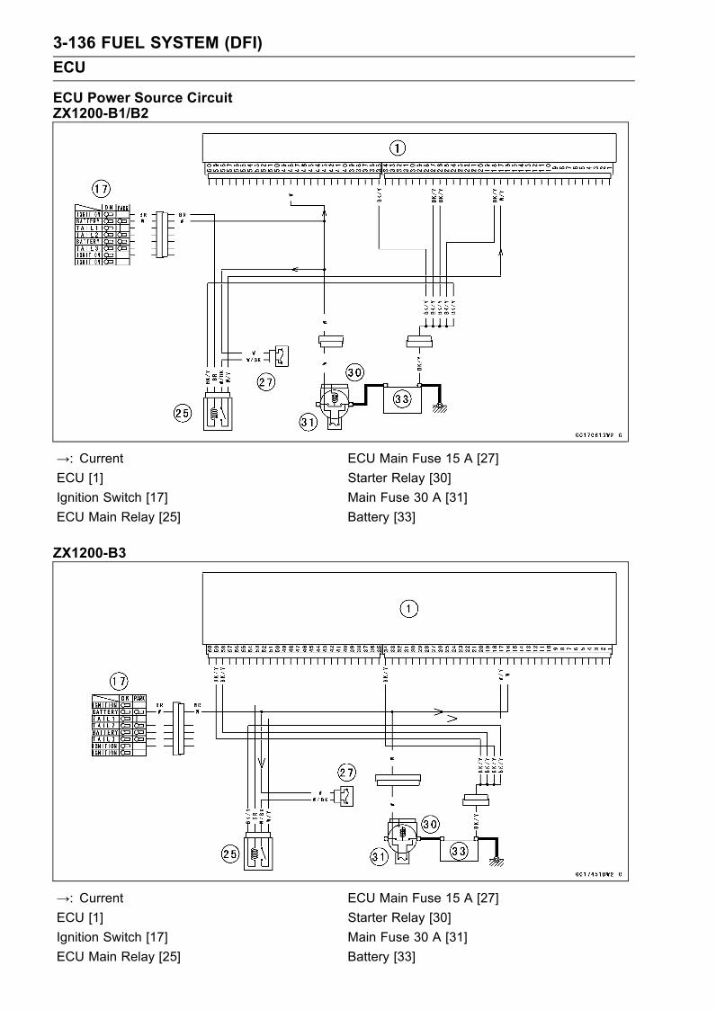
3-136 FUEL SYSTEM (DFI)
ECU
ECU Power Source CircuitZX1200-B1/B2
→: Current ECU Main Fuse 15 A [27]
ECU [1] Starter Relay [30]
Ignition Switch [17] Main Fuse 30 A [31]
ECU Main Relay [25] Battery [33]
ZX1200-B3
→: Current ECU Main Fuse 15 A [27]
ECU [1] Starter Relay [30]
Ignition Switch [17] Main Fuse 30 A [31]
ECU Main Relay [25] Battery [33]

FUEL SYSTEM (DFI) 3-137
DFI Power Source
ECU Fuse Removal
•Refer to the Electrical System chapter for the ECU fuseremoval.
ECU Fuse InstallationIf a fuse fails during operation, inspect the DFI system todetermine the cause, and then replace it with a new fuseof proper amperage.
•Refer to the Electrical System chapter for the ECU fuseinstallation.
ECU Fuse Inspection
•Refer to the Electrical System chapter for the ECU FuseInspection.
ECU Main Relay Removal
CAUTION
Never drop the relay, especially on a hard surface.Such a shock to the relay can damage it.
•Remove:Fuel Tank Cover (see Fuel Tank Removal)Bracket Bolt [A]
•Remove the ECU fuse [B].• Pull out the ECU main relay [C] from the bracket and dis-connect the connector.
ECU Main Relay Inspection
•Remove the ECU main relay (see above).•Connect the hand tester [A] and one 12 V battery [B] tothe relay connector [C] as shown.
Special Tool - Hand Tester: 57001-1394
Relay Coil Terminals [1] and [2]Relay Switch Terminals [3] and [4]
Testing RelayTester range: 1 Ω range
Criteria: When battery is connected→ 0 ΩWhen battery is disconnected→ ∞ Ω
If the relay does not work as specified, replace the relay.

3-138 FUEL SYSTEM (DFI)
FI Indicator LED Light
Inspection Flow Chart
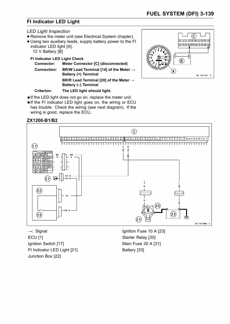
FUEL SYSTEM (DFI) 3-139
FI Indicator LED Light
LED Light Inspection
•Remove the meter unit (see Electrical System chapter).• Using two auxiliary leads, supply battery power to the FIindicator LED light [A].12 V Battery [B]
FI Indicator LED Light CheckConnector: Meter Connector [C] (disconnected)
Connection: BR/W Lead Terminal [14] of the Meter→Battery (+) Terminal
BR/R Lead Terminal [20] of the Meter→Battery (–) Terminal
Criterion: The LED light should light.
If the LED light does not go on, replace the meter unit.If the FI indicator LED light goes on, the wiring or ECUhas trouble. Check the wiring (see next diagram). If thewiring is good, replace the ECU.
ZX1200-B1/B2
→: Signal Ignition Fuse 10 A [23]
ECU [1] Starter Relay [30]
Ignition Switch [17] Main Fuse 30 A [31]
FI Indicator LED Light [21] Battery [33]
Junction Box [22]

3-140 FUEL SYSTEM (DFI)
FI Indicator LED Light
ZX1200-B3
→: Signal Ignition Fuse 10 A [23]
ECU [1] Starter Relay [30]
Ignition Switch [17] Main Fuse 30 A [31]
FI Indicator LED Light [21] Battery [33]
Junction Box [22]

FUEL SYSTEM (DFI) 3-141
Fuel Line
Fuel Pressure Inspection
NOTEBe sure the battery is fully charged.•Remove:Fuel Tank Cover (see Fuel Tank Removal)
• Be sure to place a piece of cloth around the fuel supplypipe of the throttle body assy.
• Loosen the clamp bolt and pull out the fuel supply hose[A].Quickly plug the pipe with a plug.
WARNINGBe prepared for fuel spillage; any spilled fuel mustbe completely wiped up immediately.When the fuel hose is disconnected, fuel spills outfrom the hose and the pipe because of residualpressure. Cover the hose connection with a pieceof clean cloth to prevent fuel spillage.
• Install the fuel pressure gauge adapter [A] between thefuel supply pipe [B] and the fuel supply hose [C].
•Connect the pressure gauge [D] to the fuel pressuregauge adapter.
Special Tools - Oil Pressure Gauge: 57001-125Fuel Pressure Gauge Adapter: 57001-1417
WARNINGDo not try to start the engine with the fuel hosesdisconnected.
•Turn the ignition switch ON. The fuel pump will turn for 3seconds, and then stop.
CAUTION
Do not drive the fuel pump 3 seconds or more with-out the fuel in the fuel tank. If the fuel pump is drivenwithout the fuel, it may be damaged.
•Measure the fuel pressure with the engine stopped.Fuel Pressureright after Ignition SW ON, with pump running for 3seconds:
Standard: 285 ∼ 315 kPa (2.91 ∼ 3.21 kgf/cm², 41∼ 46 psi)
NOTEThe gauge hand will fluctuate. Read the pressure at theaverage of the maximum and minimum indications.

3-142 FUEL SYSTEM (DFI)
Fuel Line
If the fuel pressure is much higher than the specified,check the following:Fuel Return Hose for Sharp Bend, Kinking, or CloggingIf the fuel pressure is much lower than specified, checkthe following:Fuel Line LeakageAmount of Fuel Flow (see Fuel Flow Rate Inspection)If the fuel pressure is much lower than specified, and ifinspection above checks out good, replace the throttlebody assy, or the fuel pump and measure the fuel pres-sure again
•Remove the fuel pressure gauge and adapter.•Run the fuel hoses in accordance with the Cable, Wire,and Hose Routing section in the General Informationchapter.
Torque - Fuel Hose Clamp Bolts: 1.5 N·m (0.15 kgf·m, 13in·lb)
Fuel Flow Rate Inspection
NOTEBe sure the battery is fully charged.
WARNINGGasoline is extremely flammable and can be explo-sive under certain conditions. Make sure the areais well-ventilated and free from any source of flameor sparks; this includes any appliance with a pilotlight. Do not smoke. Turn the ignition switch OFF.Be prepared for fuel spillage; any spilled fuel mustbe completely wiped up immediately.
•Turn the ignition switch, and engine stop switch OFF.•Wait until the engine cools down.• Set up the fuel tank (see this chapter).•Open the fuel tank cap [A] to lower the pressure in thetank.Front [B]

FUEL SYSTEM (DFI) 3-143
Fuel Line
•Prepare a measuring cylinder [A].• Disconnect the fuel supply hose [B] from the fuel outletpipe [C], and plug the outlet pipe with the rubber plugquickly.
•Connect the fuel pressure gauge adapter [D], and themeasuring cylinder as shown.
Special Tool - Fuel Pressure Gauge Adapter: 57001-1417
•Close the fuel tank cap.WARNING
Wipe off spilled out fuel immediately.Be sure to hold the measuring cylinder vertical.
•With the engine stopped, turn the ignition switch ON. Thefuel pump should operate for 3 seconds, and then shouldstop.
CAUTION
Do not drive the fuel pump 3 seconds or more with-out the fuel in the fuel tank. If the fuel pump is drivenwithout the fuel, it may be damaged.
•Measure the discharge for 3 seconds.Measure the fuel flow rate so that the adapter hose filledwith fuel.
Amount of Fuel FlowStandard: 83 mL (2.8 US oz) or more for 3 seconds
If the fuel flow is much less than the specified, check thefollowing:Fuel Pump (see Fuel Pump Inspection in this chapter)Pump Filter (see Pump Filter Cleaning in the In-tank FuelPump section).
• After inspection, connect the fuel hoses. (see Fuel TankInstallation).
• Start the engine and check for fuel leakage.
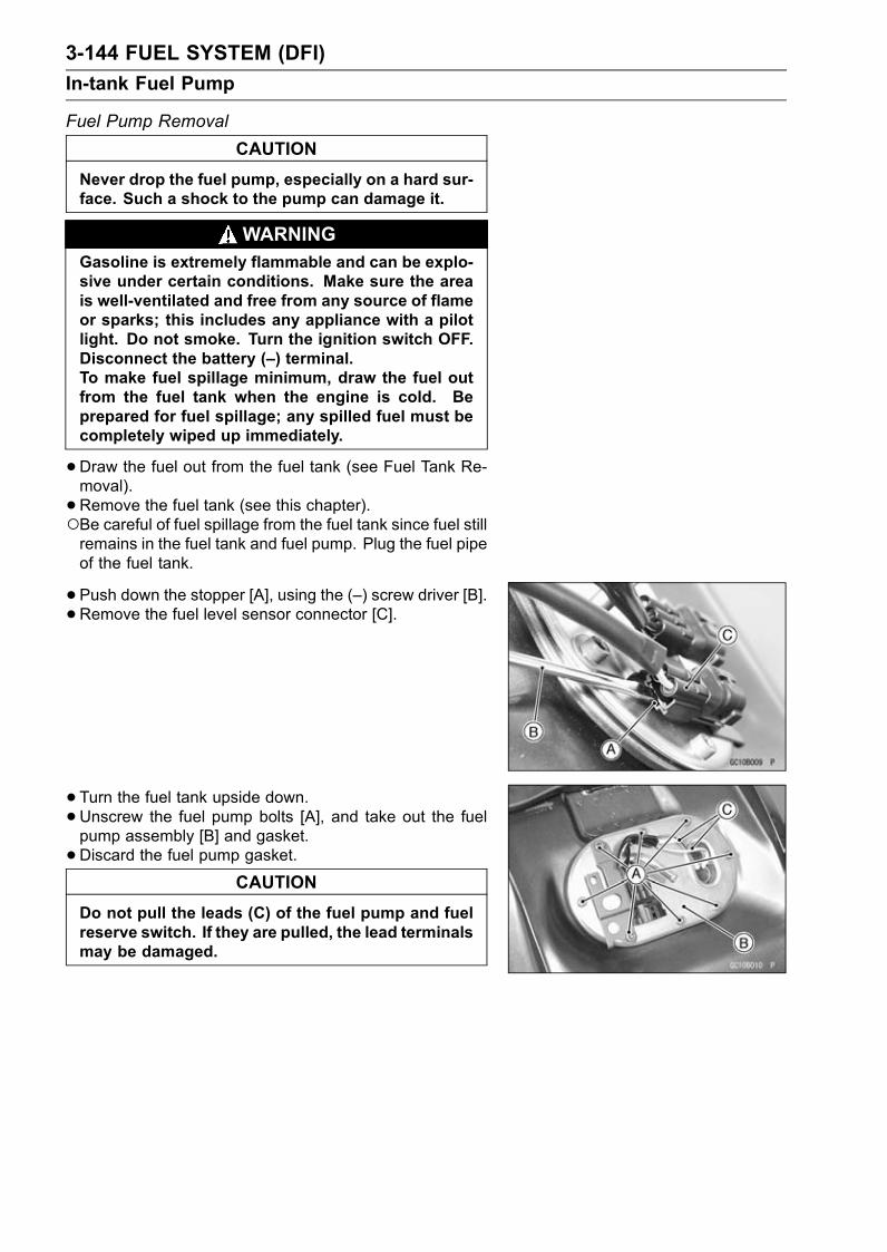
3-144 FUEL SYSTEM (DFI)
In-tank Fuel Pump
Fuel Pump Removal
CAUTION
Never drop the fuel pump, especially on a hard sur-face. Such a shock to the pump can damage it.
WARNINGGasoline is extremely flammable and can be explo-sive under certain conditions. Make sure the areais well-ventilated and free from any source of flameor sparks; this includes any appliance with a pilotlight. Do not smoke. Turn the ignition switch OFF.Disconnect the battery (–) terminal.To make fuel spillage minimum, draw the fuel outfrom the fuel tank when the engine is cold. Beprepared for fuel spillage; any spilled fuel must becompletely wiped up immediately.
•Draw the fuel out from the fuel tank (see Fuel Tank Re-moval).
• Remove the fuel tank (see this chapter).Be careful of fuel spillage from the fuel tank since fuel stillremains in the fuel tank and fuel pump. Plug the fuel pipeof the fuel tank.
• Push down the stopper [A], using the (–) screw driver [B].• Remove the fuel level sensor connector [C].
• Turn the fuel tank upside down.•Unscrew the fuel pump bolts [A], and take out the fuelpump assembly [B] and gasket.
•Discard the fuel pump gasket.CAUTION
Do not pull the leads (C) of the fuel pump and fuelreserve switch. If they are pulled, the lead terminalsmay be damaged.

FUEL SYSTEM (DFI) 3-145
In-tank Fuel Pump
Pump Screen Cleaning
WARNINGClean the pump screw in a well-ventilated area, andtake care that there are no sparks or flame any-where near the working area. Because of the dan-ger of highly flammable liquids, do not use gasolineor low-flash point solvent to clean the pump screen.
•Remove the fuel pump [A] along with the pump screen[B].
• Prepare a container [C] filled with a high-flash point sol-vent.
•Dip and shake the pump in the solvent to remove dirt andfuel deposits from the pump screen.
•Dry the pump and screen by lightly applying compressedair.
• Replace the fuel pump gasket with a new one.• Install the fuel pump (see this section).
Fuel Pump Installation
•Clean the pump screen (see Pump Filter Cleaning).•Remove dirt or dust from the fuel pump [A] by lightly ap-plying compressed air.
• Replace the fuel pump gasket with a new one.
•Check that the fuel pump terminals are in place.Pump Motor and Fuel Reserve Switch BK/W (–) Lead[A]Pump Motor Y/R (+) Lead [C]Fuel Reserve Switch R/BK (+) Lead [B]
• Apply a non-permanent locking agent to the threads ofthe fuel pump bolts.
• Tighten the fuel pump bolts to a snug fit following the tight-ening sequence shown.Install the fuel pump bolts [3, 4] with the bracket [D].• Following the tightening sequence, tighten the pump boltsto the specified torque.
Torque - Fuel Pump Bolts: 6.9 N·m (0.70 kgf·m, 61 in·lb)
•Tighten the pump bolts again to check the tightness in theorder shown.

3-146 FUEL SYSTEM (DFI)
In-tank Fuel Pump
•Secure the fuel level sensor connector [A], and fuel pumpconnector [B] on the bracket.
• Install the fuel tank (see this chapter).
Operation Inspection
NOTEBe sure the battery is fully charged.•Turn the ignition switch ON and make sure that the fuelpump operates (make light sounds) for 3 seconds, andthen stops.
• Turn the ignition switch OFF.If the pump does not work as described above, inspectthe operating voltage.
Operating Voltage Inspection
NOTEBe sure the battery is fully charged.•Turn the ignition switch OFF.•Set up the fuel tank.•Connect the hand tester [A] (25 V DC) to the connectors,with needle adapter set [B].
Special Tools - Hand Tester: 57001-1394Needle Adapter Set: 57001-1457
Measure the operating voltage with the engine stopped,and with the connector joined.
• Turn the ignition switch ON.The tester needle should indicate battery voltage for 3seconds, and then 0 V.
Pump Operating Voltage at PumpConnections to Pump Connectors
Tester (+) → Y/R Lead
Tester (–) → BK/W Lead
Operating Voltage at Pump Connector
Standard: Battery Voltage (12.5 V or more for 3seconds, and then 0 V.)
If the reading stays on battery voltage, and never shows0 V. Check the ECU and fuel pump relay.If the voltage is in specification, but the pump doesn’twork, replace the pump.If there is still no battery voltage, check the pump relay(see this chapter).

FUEL SYSTEM (DFI) 3-147
In-tank Fuel Pump
ZX1200-B1/B2
→: Current Fuel Pump Relay [26]
ECU [1] ECU Main Fuse 15 A [27]
Ignition Switch [17] Starter Motor [29]
Engine Stop Switch [19] Starter Relay [30]
Junction Box [22] Main Fuse 30 A [31]
Ignition Fuse 10 A [23] Battery [33]
ECU Main Relay [25] Fuel Pump [34]

3-148 FUEL SYSTEM (DFI)
In-tank Fuel Pump
ZX1200-B3
→: Current Fuel Pump Relay [26]
ECU [1] ECU Main Fuse 15 A [27]
Ignition Switch [17] Starter Relay [30]
Engine Stop Switch [19] Main Fuse 30 A [31]
Junction Box [22] Battery [33]
Ignition Fuse 10 A [23] Fuel Pump [34]
ECU Main Relay [25] Starter Motor [36]

FUEL SYSTEM (DFI) 3-149
Evaporative Emission Control System
The Evaporative Emission Control System routes fuel va-pors from the fuel system into the running engine or storesthe vapors in a canister when the engine is stopped. Al-though no adjustments are required, a thorough visual in-spection must be made at the intervals specified by the Pe-riodic Maintenance Chart.
Parts Removal/Installation
WARNINGGasoline is extremely flammable and can be ex-plosive under certain conditions. Turn the ignitionswitch OFF. Do not smoke. Make sure the area iswell-ventilated and free from any source of flameor sparks; this includes any appliance with a pilotlight.
CAUTION
If gasoline, solvent, water or any other liquid entersthe canister, the canister’s vapor absorbing capac-ity is greatly reduced. If the canister does becomecontaminated, replace it with a new one.
•To prevent the gasoline from flowing into or out of thecanister, hold the separator perpendicular to the ground.
•Connect the hoses according to the diagram of the sys-tem. Make sure they do not get pinched or kinked.
Hose Inspection
•Refer to the Evaporative Emission Control Stem Inspec-tion in the Periodic Maintenance chapter.
Separator Inspection
•Refer to the Evaporative Emission Control Stem Inspec-tion in the Periodic Maintenance chapter.
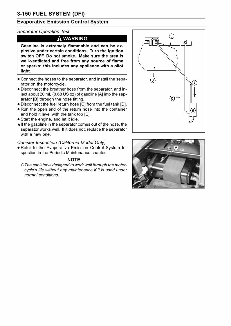
3-150 FUEL SYSTEM (DFI)
Evaporative Emission Control System
Separator Operation Test
WARNINGGasoline is extremely flammable and can be ex-plosive under certain conditions. Turn the ignitionswitch OFF. Do not smoke. Make sure the area iswell-ventilated and free from any source of flameor sparks; this includes any appliance with a pilotlight.
•Connect the hoses to the separator, and install the sepa-rator on the motorcycle.
•Disconnect the breather hose from the separator, and in-ject about 20 mL (0.68 US oz) of gasoline [A] into the sep-arator [B] through the hose fitting.
•Disconnect the fuel return hose [C] from the fuel tank [D].•Run the open end of the return hose into the containerand hold it level with the tank top [E].
• Start the engine, and let it idle.If the gasoline in the separator comes out of the hose, theseparator works well. If it does not, replace the separatorwith a new one.
Canister Inspection (California Model Only)
•Refer to the Evaporative Emission Control System In-spection in the Periodic Maintenance chapter.
NOTEThe canister is designed to work well through themotor-cycle’s life without any maintenance if it is used undernormal conditions.
COOLING SYSTEM 4-1
4
Cooling System
Table of Contents
Exploded View........................................................................................................................ 4-2Specifications ......................................................................................................................... 4-3Coolant Flow Chart................................................................................................................. 4-4Coolant ................................................................................................................................... 4-6
Coolant Deterioration Inspection....................................................................................... 4-6Coolant Level Inspection................................................................................................... 4-6Coolant Draining ............................................................................................................... 4-6Coolant Filling ................................................................................................................... 4-6Pressure Testing ............................................................................................................... 4-7Cooling System Flushing .................................................................................................. 4-7
Water Pump............................................................................................................................ 4-8Water Pump Removal ....................................................................................................... 4-8Water Pump Installation.................................................................................................... 4-9Water Pump Impeller Disassembly/Assembly .................................................................. 4-9Water Pump Inspection..................................................................................................... 4-9Water Pump Impeller Inspection....................................................................................... 4-10Water Pump Housing Disassembly .................................................................................. 4-10Water Pump Housing Assembly ....................................................................................... 4-10Mechanical Seal Inspection .............................................................................................. 4-11
Radiator, Radiator Fan ........................................................................................................... 4-12Radiator and Radiator Fan Removal ................................................................................ 4-12Radiator and Radiator Fan Installation ............................................................................. 4-13Radiator Inspection ........................................................................................................... 4-13Radiator Cap Inspection ................................................................................................... 4-14
Thermostat ............................................................................................................................. 4-15Thermostat Removal......................................................................................................... 4-15Thermostat Installation...................................................................................................... 4-15Thermostat Inspection ...................................................................................................... 4-15
Hose and Pipes ...................................................................................................................... 4-17Hose Installation ............................................................................................................... 4-17Hose Inspection ................................................................................................................ 4-17
Radiator Fan Switch, Water Temperature Sensor .................................................................. 4-18Radiator Fan Switch, Water Temperature SensorRemoval .............................................. 4-18Radiator Fan Switch, Water Temperature SensorInstallation ........................................... 4-18Radiator Fan Switch, Water Temperature SensorInspection ............................................ 4-18
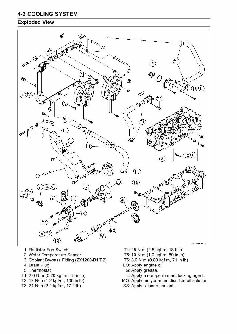
4-2 COOLING SYSTEM
Exploded View
1. Radiator Fan Switch2. Water Temperature Sensor3. Coolant By-pass Fitting (ZX1200-B1/B2)4. Drain Plug5. ThermostatT1: 2.0 N·m (0.20 kgf·m, 18 in·lb)T2: 12 N·m (1.2 kgf·m, 106 in·lb)T3: 24 N·m (2.4 kgf·m, 17 ft·lb)
T4: 25 N·m (2.5 kgf·m, 18 ft·lb)T5: 10 N·m (1.0 kgf·m, 89 in·lb)T6: 8.0 N·m (0.80 kgf·m, 71 in·lb)EO: Apply engine oil.G: Apply grease.L: Apply a non-permanent locking agent.
MO: Apply molybdenum disulfide oil solution.SS: Apply silicone sealant.
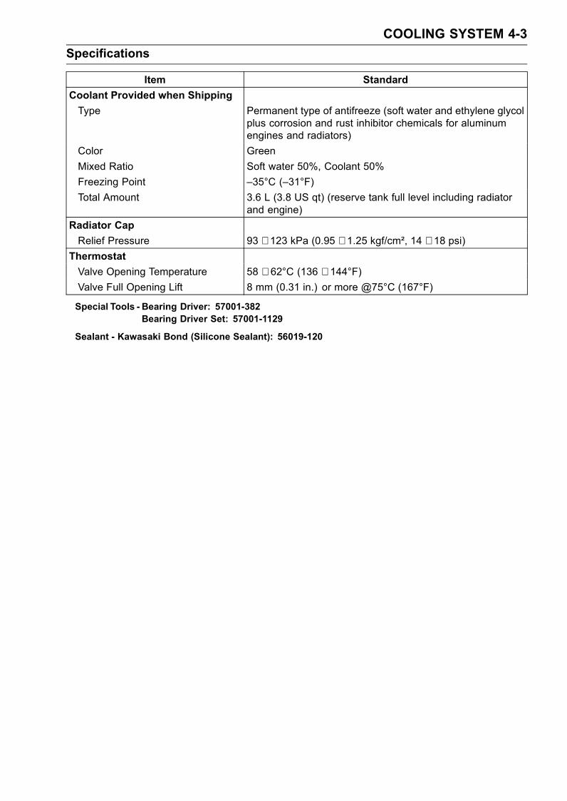
COOLING SYSTEM 4-3
Specifications
Item Standard
Coolant Provided when Shipping
Type Permanent type of antifreeze (soft water and ethylene glycolplus corrosion and rust inhibitor chemicals for aluminumengines and radiators)
Color Green
Mixed Ratio Soft water 50%, Coolant 50%
Freezing Point –35°C (–31°F)
Total Amount 3.6 L (3.8 US qt) (reserve tank full level including radiatorand engine)
Radiator Cap
Relief Pressure 93 ∼ 123 kPa (0.95 ∼ 1.25 kgf/cm², 14 ∼ 18 psi)Thermostat
Valve Opening Temperature 58 ∼ 62°C (136 ∼ 144°F)Valve Full Opening Lift 8 mm (0.31 in.) or more @75°C (167°F)
Special Tools - Bearing Driver: 57001-382Bearing Driver Set: 57001-1129
Sealant - Kawasaki Bond (Silicone Sealant): 56019-120
4-4 COOLING SYSTEM
Coolant Flow Chart
Permanent type antifreeze is used as a coolant to protect the cooling system from rust and corrosion.When the engine starts, the water pump turns and the coolant circulates.The thermostat is a wax pellet type which opens or closes with coolant temperature changes. The
thermostat continuously changes its valve opening to keep the coolant temperature at the proper level.When coolant temperature is 55°C (131°F) or more, the thermostat closes so that the coolant flow isrestricted through the air bleeder hole, causing the engine to warm up more quickly. When coolanttemperature is more than 58 ∼ 62°C (136 ∼ 144°F), the thermostat opens and the coolant flows.When the coolant temperature goes up beyond 95 ∼ 101°C (203 ∼ 214°F), the radiator fan switch
conducts to operate the radiator fan. The radiator fan draws air through the radiator core when thereis not sufficient air flow such as at low speeds. This increases up the cooling action of the radiator.When the coolant temperature goes down from the operation temperature by 3 ∼ 8°C (37 ∼ 46°F), thefan switch opens and the radiator fan stops.In this way, this system controls the engine temperature within narrow limits where the engine op-
erates most efficiently even if the engine load varies.The system is pressurized by the radiator cap to suppress boiling and the resultant air bubbles
which can cause engine overheating. As the engine warms up, the coolant in the radiator and thewater jacket expands. The excess coolant flows through the radiator cap and hose to the reserve tankto be stored there temporarily. Conversely, as the engine cools down, the coolant in the radiator andthe water jacket contracts, and the stored coolant flows back to the radiator from the reserve tank.The radiator cap has two valves. One is a pressure valve which holds the pressure in the system
when the engine is running. When the pressure exceeds 0.95 ∼ 1.25 kgf/m² (14 ∼ 18 psi), the pressurevalve opens and releases the pressure to the reserve tank. As soon as pressure escapes, the valvecloses, and keeps the pressure at 0.95 ∼ 1.25 kgf/m² (14 ∼ 18 psi). When the engine cools down,another small valve (vacuum valve) in the cap opens. As the coolant cools, the coolant contracts tofrom a vacuum in the system. The vacuum valve opens and allows the coolant from the reserve tankto enter the radiator.
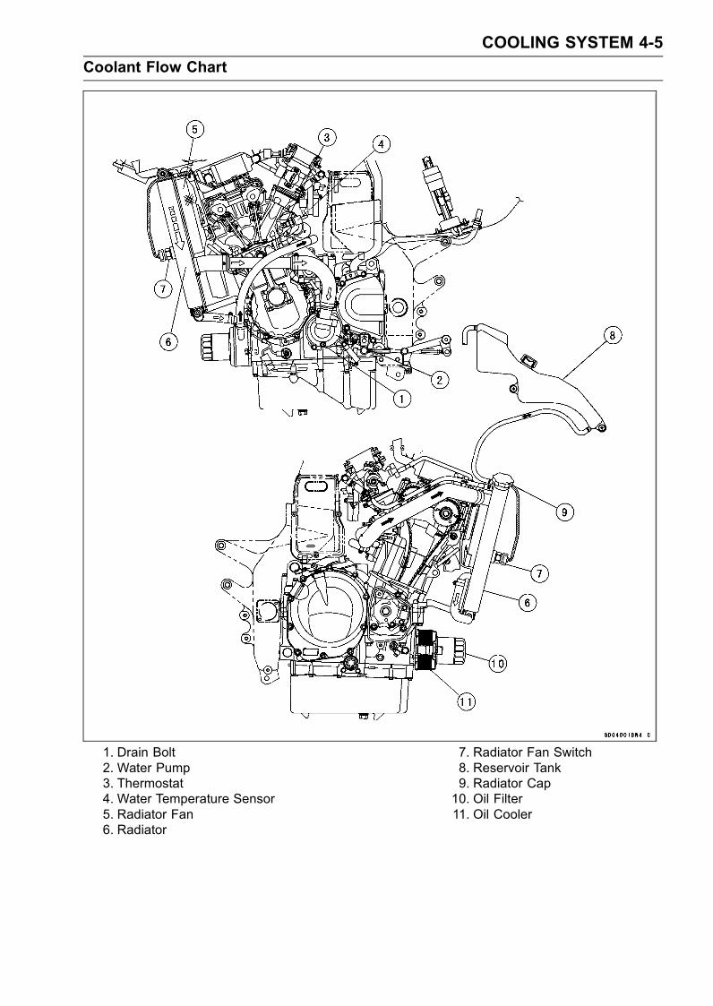
COOLING SYSTEM 4-5
Coolant Flow Chart
1. Drain Bolt2. Water Pump3. Thermostat4. Water Temperature Sensor5. Radiator Fan6. Radiator
7. Radiator Fan Switch8. Reservoir Tank9. Radiator Cap10. Oil Filter11. Oil Cooler
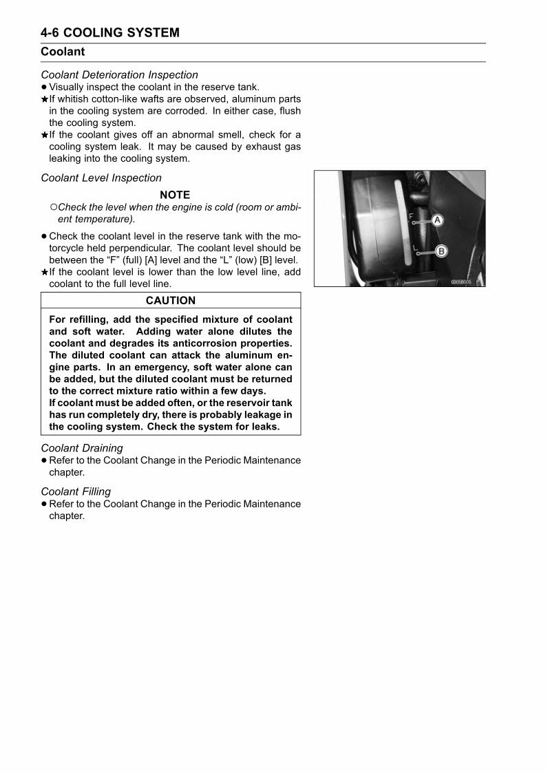
4-6 COOLING SYSTEM
Coolant
Coolant Deterioration Inspection
•Visually inspect the coolant in the reserve tank.If whitish cotton-like wafts are observed, aluminum partsin the cooling system are corroded. In either case, flushthe cooling system.If the coolant gives off an abnormal smell, check for acooling system leak. It may be caused by exhaust gasleaking into the cooling system.
Coolant Level Inspection
NOTECheck the level when the engine is cold (room or ambi-ent temperature).
•Check the coolant level in the reserve tank with the mo-torcycle held perpendicular. The coolant level should bebetween the “F” (full) [A] level and the “L” (low) [B] level.If the coolant level is lower than the low level line, addcoolant to the full level line.
CAUTION
For refilling, add the specified mixture of coolantand soft water. Adding water alone dilutes thecoolant and degrades its anticorrosion properties.The diluted coolant can attack the aluminum en-gine parts. In an emergency, soft water alone canbe added, but the diluted coolant must be returnedto the correct mixture ratio within a few days.If coolant must be added often, or the reservoir tankhas run completely dry, there is probably leakage inthe cooling system. Check the system for leaks.
Coolant Draining
•Refer to the Coolant Change in the Periodic Maintenancechapter.
Coolant Filling
•Refer to the Coolant Change in the Periodic Maintenancechapter.
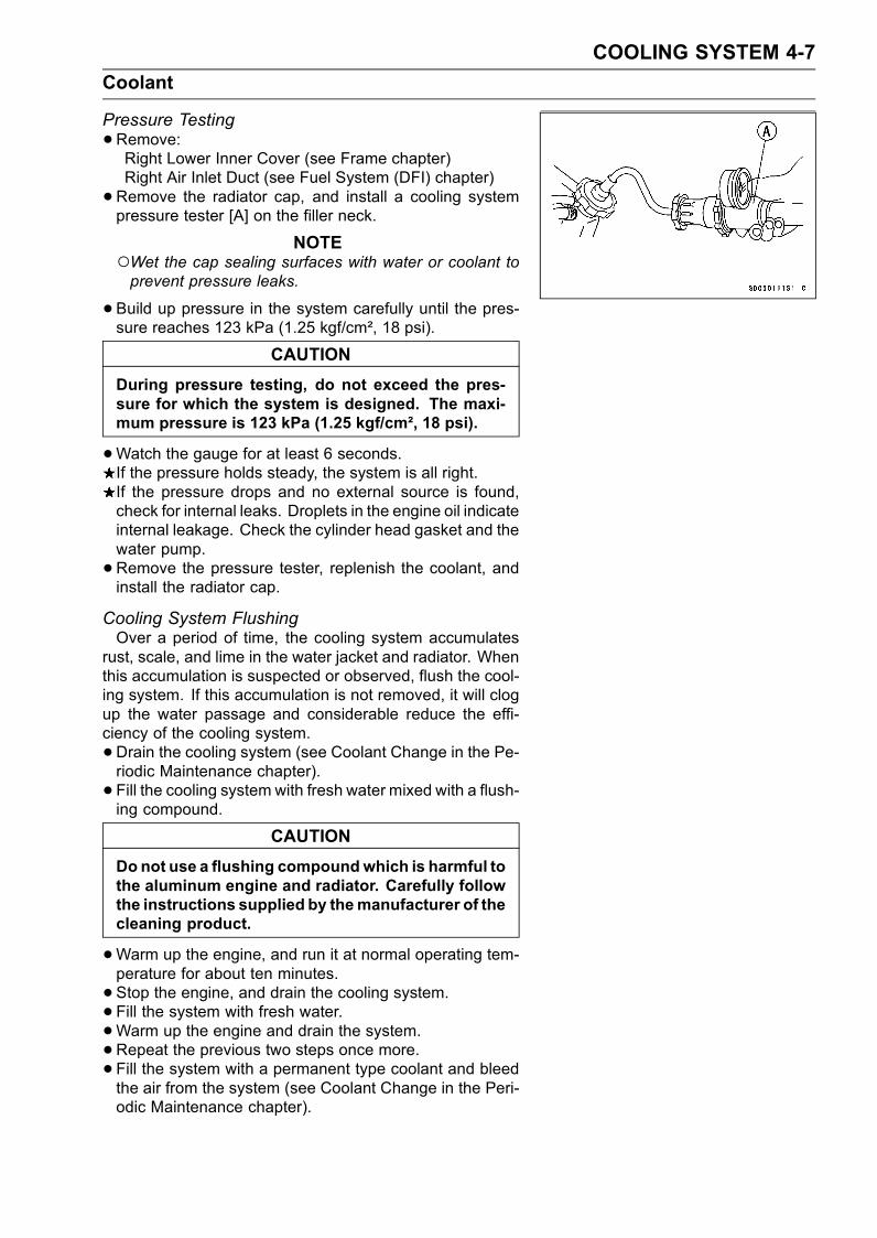
COOLING SYSTEM 4-7
Coolant
Pressure Testing
•Remove:Right Lower Inner Cover (see Frame chapter)Right Air Inlet Duct (see Fuel System (DFI) chapter)
•Remove the radiator cap, and install a cooling systempressure tester [A] on the filler neck.
NOTEWet the cap sealing surfaces with water or coolant toprevent pressure leaks.
•Build up pressure in the system carefully until the pres-sure reaches 123 kPa (1.25 kgf/cm², 18 psi).
CAUTION
During pressure testing, do not exceed the pres-sure for which the system is designed. The maxi-mum pressure is 123 kPa (1.25 kgf/cm², 18 psi).
•Watch the gauge for at least 6 seconds.If the pressure holds steady, the system is all right.If the pressure drops and no external source is found,check for internal leaks. Droplets in the engine oil indicateinternal leakage. Check the cylinder head gasket and thewater pump.
•Remove the pressure tester, replenish the coolant, andinstall the radiator cap.
Cooling System FlushingOver a period of time, the cooling system accumulates
rust, scale, and lime in the water jacket and radiator. Whenthis accumulation is suspected or observed, flush the cool-ing system. If this accumulation is not removed, it will clogup the water passage and considerable reduce the effi-ciency of the cooling system.
•Drain the cooling system (see Coolant Change in the Pe-riodic Maintenance chapter).
• Fill the cooling system with fresh water mixed with a flush-ing compound.
CAUTION
Donot use a flushing compoundwhich is harmful tothe aluminum engine and radiator. Carefully followthe instructions supplied by themanufacturer of thecleaning product.
•Warm up the engine, and run it at normal operating tem-perature for about ten minutes.
• Stop the engine, and drain the cooling system.• Fill the system with fresh water.
•Warm up the engine and drain the system.
•Repeat the previous two steps once more.• Fill the system with a permanent type coolant and bleedthe air from the system (see Coolant Change in the Peri-odic Maintenance chapter).
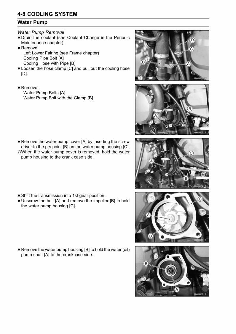
4-8 COOLING SYSTEM
Water Pump
Water Pump Removal
•Drain the coolant (see Coolant Change in the PeriodicMaintenance chapter).
• Remove:Left Lower Fairing (see Frame chapter)Cooling Pipe Bolt [A]Cooling Hose with Pipe [B]
• Loosen the hose clamp [C] and pull out the cooling hose[D].
•Remove:Water Pump Bolts [A]Water Pump Bolt with the Clamp [B]
•Remove the water pump cover [A] by inserting the screwdriver to the pry point [B] on the water pump housing [C].When the water pump cover is removed, hold the waterpump housing to the crank case side.
• Shift the transmission into 1st gear position.•Unscrew the bolt [A] and remove the impeller [B] to holdthe water pump housing [C].
•Remove the water pump housing [B] to hold the water (oil)pump shaft [A] to the crankcase side.

COOLING SYSTEM 4-9
Water Pump
Water Pump Installation
•Check to see that the knock pins [A].•Water pump housing [B] are in place to apply engine oilat O-ring.
• Apply molybdenum disulfide oil solution to the water (oil)pump shaft [C] to the journal portion (about 10 mm (0.4in.) [D]) of the water pump housing.
• Install the water pump housing.
•Clean the sliding surfaces [A] of the mechanical seal andimpeller with a high flash-point solvent.
• Apply little coolant to the sliding surfaces.•Check to see that the knock pins [B] is in place.• Shift the transmission into 1st gear position.• Install:ImpellerBolt
Torque - Water Pump Impeller Bolt: 10 N·m (1.0 kgf·m, 89in·lb)
•Apply high temperature grease to the O-ring of the coolingpipe.
• Install:Water Pump CoverBoltsCooling Hoses
Torque - Water Pump Cover Bolts: 12 N·m (1.2 kgf·m, 106in·lb)
Coolant Pipe Bolt: 12 N·m (1.2 kgf·m, 106 in·lb)
Water Pump Impeller Disassembly/Assembly
•The sealing seat and rubber seal may be removed easilyby hand.
• Apply coolant around the surfaces of the rubber seal andsealing seat.
• Install the rubber seal [A] and sealing seat [B] into theimpeller by pressing them by hand until the seat stops atthe bottom of the hole.
• Tighten the water pump impeller bolt by special torque.Torque - Water Pump Impeller Bolt: 10 N·m (1.0 kgf·m, 89
in·lb)
Water Pump Inspection
•Check the drainage outlet passage [A] at the bottom ofthe water pump body for coolant leaks.If the mechanical seal is damaged, the coolant leaksthrough the seal and drains through the passage. Re-place the mechanical seal unit.
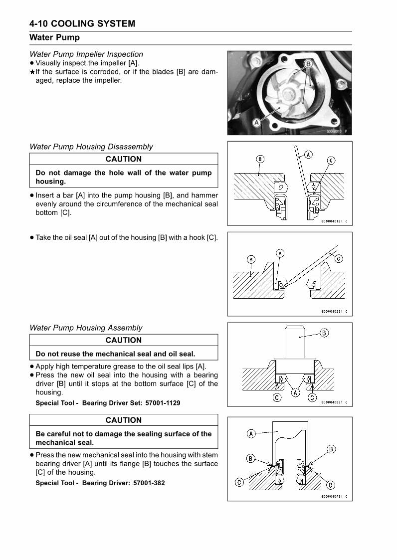
4-10 COOLING SYSTEM
Water Pump
Water Pump Impeller Inspection
•Visually inspect the impeller [A].If the surface is corroded, or if the blades [B] are dam-aged, replace the impeller.
Water Pump Housing Disassembly
CAUTION
Do not damage the hole wall of the water pumphousing.
• Insert a bar [A] into the pump housing [B], and hammerevenly around the circumference of the mechanical sealbottom [C].
• Take the oil seal [A] out of the housing [B] with a hook [C].
Water Pump Housing Assembly
CAUTION
Do not reuse the mechanical seal and oil seal.
•Apply high temperature grease to the oil seal lips [A].• Press the new oil seal into the housing with a bearingdriver [B] until it stops at the bottom surface [C] of thehousing.
Special Tool - Bearing Driver Set: 57001-1129
CAUTION
Be careful not to damage the sealing surface of themechanical seal.
•Press the new mechanical seal into the housing with stembearing driver [A] until its flange [B] touches the surface[C] of the housing.
Special Tool - Bearing Driver: 57001-382
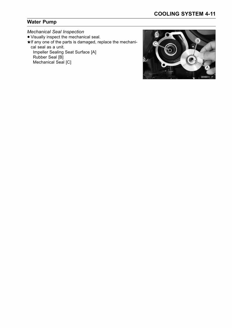
COOLING SYSTEM 4-11
Water Pump
Mechanical Seal Inspection
•Visually inspect the mechanical seal.If any one of the parts is damaged, replace the mechani-cal seal as a unit.Impeller Sealing Seat Surface [A]Rubber Seal [B]Mechanical Seal [C]

4-12 COOLING SYSTEM
Radiator, Radiator Fan
Radiator and Radiator Fan Removal
WARNINGThe radiator fan is connected directly to the bat-tery. The radiator fan may start even if the ignitionswitch is off. NEVER TOUCH THE RADIATOR FANUNTIL THE RADIATOR FAN CONNECTOR IS DIS-CONNECTED. TOUCHING THE FAN BEFORE THECONNECTOR IS DISCONNECTED COULD CAUSEINJURY FROM THE FAN BLADES.
•Remove:Lower Inner Covers (see Frame chapter)Air Inlet Ducts [A] (see Fuel System (DFI) chapter)Radiator Fan Connectors [B]Lower Fairings [C] with Lower Inner Fairing (see Framechapter)Coolant (drain, see Coolant Change in the PeriodicMaintenance chapter)
Fan Switch Lead Connector [A]
Radiator Mounting Bracket Bolts [A]Left Horn Bolt [B]Left Horn [C]Radiator Cooling Hose Clamp Bolts (loosen) [D]Radiator Cooling Hoses [E]Clamp [F]
Right Horn Bolt [A]Right Horn [B]
•Open the clamps [C] and remove the horn harness [D].
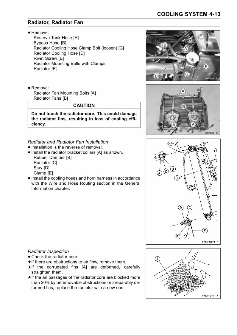
COOLING SYSTEM 4-13
Radiator, Radiator Fan
•Remove:Reserve Tank Hose [A]Bypass Hose [B]Radiator Cooling Hose Clamp Bolt (loosen) [C]Radiator Cooling Hose [D]Rivet Screw [E]Radiator Mounting Bolts with ClampsRadiator [F]
•Remove:Radiator Fan Mounting Bolts [A]Radiator Fans [B]
CAUTION
Do not touch the radiator core. This could damagethe radiator fins, resulting in loss of cooling effi-ciency.
Radiator and Radiator Fan Installation
• Installation is the reverse of removal.• Install the radiator bracket collars [A] as shown.Rubber Damper [B]Radiator [C]Stay [D]Clamp [E]
• Install the cooling hoses and horn harness in accordancewith the Wire and Hose Routing section in the GeneralInformation chapter.
Radiator Inspection
•Check the radiator core.If there are obstructions to air flow, remove them.If the corrugated fins [A] are deformed, carefullystraighten them.If the air passages of the radiator core are blocked morethan 20% by unremovable obstructions or irreparably de-formed fins, replace the radiator with a new one.
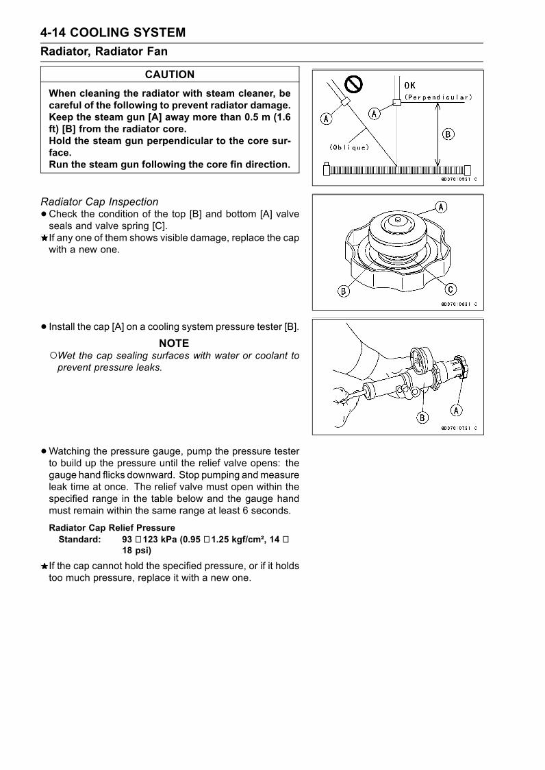
4-14 COOLING SYSTEM
Radiator, Radiator Fan
CAUTION
When cleaning the radiator with steam cleaner, becareful of the following to prevent radiator damage.Keep the steam gun [A] away more than 0.5 m (1.6ft) [B] from the radiator core.Hold the steam gun perpendicular to the core sur-face.Run the steam gun following the core fin direction.
Radiator Cap Inspection
•Check the condition of the top [B] and bottom [A] valveseals and valve spring [C].If any one of them shows visible damage, replace the capwith a new one.
• Install the cap [A] on a cooling system pressure tester [B].NOTE
Wet the cap sealing surfaces with water or coolant toprevent pressure leaks.
•Watching the pressure gauge, pump the pressure testerto build up the pressure until the relief valve opens: thegauge hand flicks downward. Stop pumping andmeasureleak time at once. The relief valve must open within thespecified range in the table below and the gauge handmust remain within the same range at least 6 seconds.
Radiator Cap Relief PressureStandard: 93 ∼ 123 kPa (0.95 ∼ 1.25 kgf/cm², 14 ∼
18 psi)
If the cap cannot hold the specified pressure, or if it holdstoo much pressure, replace it with a new one.

COOLING SYSTEM 4-15
Thermostat
Thermostat Removal
•Drain:Coolant (Cylinder) (see Coolant Change in the PeriodicMaintenance chapter)
•Remove:Lower Fairings (see Frame chapter)Fuel Hose (see Fuel System (DFI) chapter)Water Temperature Sensor ConnectorCooling HosesStarter Motor CableFitting Bolts [A]Cooling Hose Fitting [B]
•Remove:Thermostat Housing Cover Bolts [A]Thermostat Housing Cover [B]Thermostat
Thermostat Installation
• Install the thermostat [A] in the housing to that the airbleeder hole [B] is on top.
• Be sure to install the coolant-applied O-rings on the hous-ing cover and fitting.
• Tighten the housing cover and fitting bolts.Apply a non-permanent locking agent to the thermostathousing cover bolts.
Torque - Fitting Bolts: 12 N·m (1.2 kgf·m, 106 in·lb)Thermostat Housing Cover Bolts: 8.0 N·m (0.80kgf·m, 71 in·lb)
•Fill the radiator with coolant (see Coolant Change in thePeriodic Maintenance chapter).
Thermostat Inspection
•Remove the thermostat, and inspect the thermostat valve[A] at room temperature.If the valve is open, replace the thermostat with a newone.

4-16 COOLING SYSTEM
Thermostat
•To check valve opening temperature, suspend the ther-mostat [A] in a container of water and raise the tempera-ture of the water.The thermostat must be completely submerged and mustnot touch the container sides or bottom. Suspend an ac-curate thermometer [B] in the water. It must not touch thecontainer, either.If the measurement is out of the specified range, replacethe thermostat with a new one.
Thermostat Valve Opening TemperatureStandard: 58 ∼ 62°C (136 ∼ 144°F)
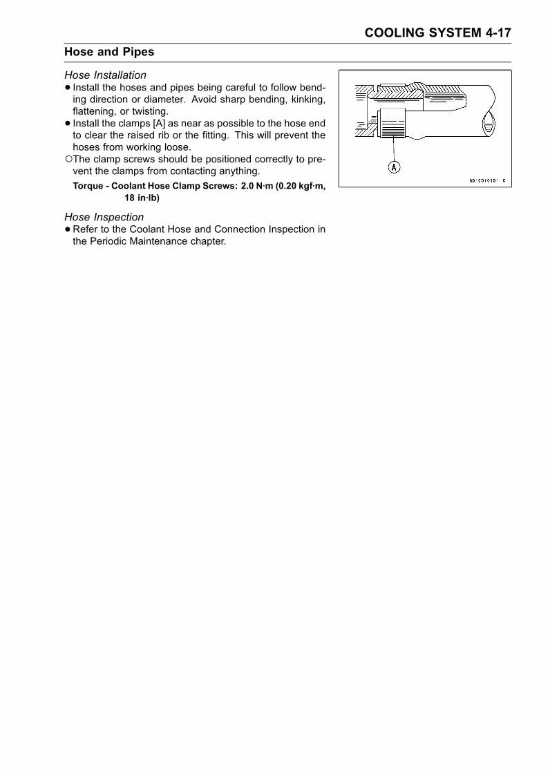
COOLING SYSTEM 4-17
Hose and Pipes
Hose Installation
• Install the hoses and pipes being careful to follow bend-ing direction or diameter. Avoid sharp bending, kinking,flattening, or twisting.
• Install the clamps [A] as near as possible to the hose endto clear the raised rib or the fitting. This will prevent thehoses from working loose.The clamp screws should be positioned correctly to pre-vent the clamps from contacting anything.
Torque - Coolant Hose Clamp Screws: 2.0 N·m (0.20 kgf·m,18 in·lb)
Hose Inspection
•Refer to the Coolant Hose and Connection Inspection inthe Periodic Maintenance chapter.
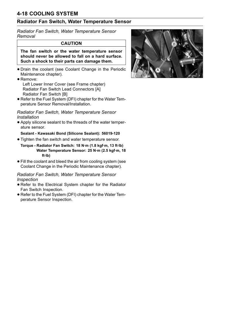
4-18 COOLING SYSTEM
Radiator Fan Switch, Water Temperature Sensor
Radiator Fan Switch, Water Temperature SensorRemoval
CAUTION
The fan switch or the water temperature sensorshould never be allowed to fall on a hard surface.Such a shock to their parts can damage them.
•Drain the coolant (see Coolant Change in the PeriodicMaintenance chapter).
• Remove:Left Lower Inner Cover (see Frame chapter)Radiator Fan Switch Lead Connectors [A]Radiator Fan Switch [B]
•Refer to the Fuel System (DFI) chapter for theWater Tem-perature Sensor Removal/Installation.
Radiator Fan Switch, Water Temperature SensorInstallation
•Apply silicone sealant to the threads of the water temper-ature sensor.
Sealant - Kawasaki Bond (Silicone Sealant): 56019-120
•Tighten the fan switch and water temperature sensor.Torque - Radiator Fan Switch: 18 N·m (1.8 kgf·m, 13 ft·lb)
Water Temperature Sensor: 25 N·m (2.5 kgf·m, 18ft·lb)
•Fill the coolant and bleed the air from cooling system (seeCoolant Change in the Periodic Maintenance chapter).
Radiator Fan Switch, Water Temperature SensorInspection
•Refer to the Electrical System chapter for the RadiatorFan Switch Inspection.
•Refer to the Fuel System (DFI) chapter for theWater Tem-perature Sensor Inspection.
ENGINE TOP END 5-1
5
Engine Top End
Table of Contents
Exploded View................................... 5-2Specifications .................................... 5-5Clean Air System............................... 5-8
Air Suction Valve Removal........... 5-8Air Suction Valve Installation........ 5-8Air Suction Valve Check............... 5-8Vacuum Switch Valve Removal(ZX1200-B1/B2) ........................ 5-9
Vacuum Switch Valve Installation(ZX1200-B1/B2) ........................ 5-9
Vacuum Switch Valve Test(ZX1200-B1/B2) ........................ 5-9
Air Switching Valve Removal(ZX1200-B3).............................. 5-10
Air Switching Valve Installation(ZX1200-B3).............................. 5-10
Air Switching Valve OperationTest (ZX1200-B3) ...................... 5-10
Air Switching Valve Unit Test(ZX1200-B3).............................. 5-10
Clean Air System HoseInspection.................................. 5-10
Cylinder Head Cover ......................... 5-11Cylinder Head Cover Removal .... 5-11Cylinder Head Cover Installation . 5-11
Camshaft Chain Tensioner ................ 5-13Camshaft Chain TensionerRemoval .................................... 5-13
Camshaft Chain TensionerInstallation ................................. 5-13
Camshaft, Camshaft Chain ............... 5-14Camshaft Removal ...................... 5-14Camshaft Installation ................... 5-14Camshaft, Camshaft Cap Wear ... 5-16Camshaft Runout ......................... 5-17Cam Wear.................................... 5-17Camshaft Chain Removal ............ 5-17
Cylinder Head.................................... 5-18Cylinder CompressionMeasurement ............................ 5-18
Cylinder Head Removal ............... 5-19Cylinder Head Installation ............ 5-20Cylinder Head Warp..................... 5-21
Valves ................................................ 5-22Valve Clearance Check................ 5-22Valve Removal ............................. 5-22Valve Installation .......................... 5-22Valve Guide Removal .................. 5-22Valve Guide Installation ............... 5-23Valve-to-Guide ClearanceMeasurement (WobbleMethod) ..................................... 5-23
Valve Seat Inspection .................. 5-24Valve Seat Repair ........................ 5-24
Cylinder, Pistons................................ 5-29Cylinder Removal......................... 5-29Cylinder Installation...................... 5-29Piston Removal............................ 5-30Piston Installation......................... 5-31Cylinder Wear .............................. 5-32Piston Wear ................................. 5-32Piston Ring, Piston Ring GrooveWear.......................................... 5-32
Piston Ring Groove Width............ 5-32Piston Ring Thickness ................. 5-33Piston Ring End Gap ................... 5-33
Throttle Body Holder.......................... 5-34Throttle Body Holder Installation.. 5-34
Muffler................................................ 5-35Muffler Removal........................... 5-35Muffler Installation........................ 5-35Muffler Body Removal.................. 5-35Muffler Body Installation............... 5-36

5-2 ENGINE TOP END
Exploded View
ZX1200-B1/B2
1. Closed coil end faces downward.T1: 13 N·m (1.3 kgf·m, 115 in·lb)T2: 34 N·m (3.5 kgf·m, 25 ft·lb)T3: 12 N·m (1.2 kgf·m, 106 in·lb)T4: 10 N·m (1.0 kgf·m, 89 in·lb)T5: 15 N·m (1.5 kgf·m, 11 ft·lb)T6: 25 N·m (2.5 kgf·m, 18 ft·lb)T7: 20 N·m (2.0 kgf·m, 15 ft·lb)T8: 59 N·m (6.0 kgf·m, 44 ft·lb)T9: 22 N·m (2.2 kgf·m, 16 ft·lb)
EO: Apply engine oil.G: Apply grease.L: Apply a non-permanent locking agent.M: Apply molybdenum disulfide grease.
MO: Apply molybdenum disulfide oil solution.R: Replacement PartsS: Follow the specific tightening sequence.SS: Apply silicone sealant.CAL: California Model only
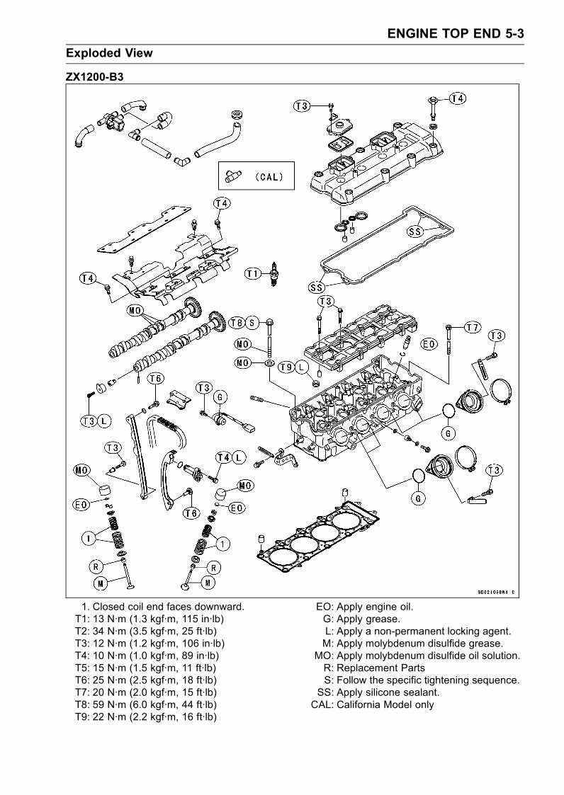
ENGINE TOP END 5-3
Exploded View
ZX1200-B3
1. Closed coil end faces downward.T1: 13 N·m (1.3 kgf·m, 115 in·lb)T2: 34 N·m (3.5 kgf·m, 25 ft·lb)T3: 12 N·m (1.2 kgf·m, 106 in·lb)T4: 10 N·m (1.0 kgf·m, 89 in·lb)T5: 15 N·m (1.5 kgf·m, 11 ft·lb)T6: 25 N·m (2.5 kgf·m, 18 ft·lb)T7: 20 N·m (2.0 kgf·m, 15 ft·lb)T8: 59 N·m (6.0 kgf·m, 44 ft·lb)T9: 22 N·m (2.2 kgf·m, 16 ft·lb)
EO: Apply engine oil.G: Apply grease.L: Apply a non-permanent locking agent.M: Apply molybdenum disulfide grease.
MO: Apply molybdenum disulfide oil solution.R: Replacement PartsS: Follow the specific tightening sequence.SS: Apply silicone sealant.CAL: California Model only

5-4 ENGINE TOP END
Exploded View
1. Muffler Cover (ZX1200-B1/B2)2. R marked side face up.3. RN marked side face up.4. A marking hollow facing forward.T1: 34 N·m (3.5 kgf·m, 25 ft·lb)T2: 12 N·m (1.2 kgf·m, 106 in·lb)T3: 10 N·m (1.0 kgf·m, 89 in·lb)
T4: 15 N·m (1.5 kgf·m, 11 ft·lb)EO: Apply engine oil.G: Apply grease.L: Apply a non-permanent locking agent.
MO: Apply molybdenum disulfide grease.R: Replacement Parts

ENGINE TOP END 5-5
Specifications
Item Standard Service Limit
Clean Air System (ZX1200-B1/B2)
Vacuum Switch Valve Closing Pressure Open → Close
41 ∼ 49 kPa (310 ∼ 370 mmHg) – – –
Camshafts
Cam Height:
Exhaust 36.643 ∼ 36.757 mm 36.54 mm
(1.4426 ∼ 1.4471 in.) (1.439 in.)
Inlet 37.043 ∼ 37.157 mm 36.94 mm
(1.4584 ∼ 1.4629 in.) (1.454 in.)
Camshaft Journal, Camshaft Cap Clearance 0.028 ∼ 0.071 mm 0.16 mm
(0.0011 ∼ 0.0028 in.) (0.006 in.)
Camshaft Journal Diameter 23.950 ∼ 23.972 mm 23.92 mm
(0.9429 ∼ 0.9438 in.) (0.942 in.)
Camshaft Bearing Inside Diameter 24.000 ∼ 24.021 mm 24.08 mm
(0.9449 ∼ 0.9457 in.) (0.948 in.)
Camshaft Runout TIR 0.02 mm (0.0008 in.) TIR 0.1 mm
or less (0.004 in.)
Cylinder Head
Cylinder Compression (usable range)
1 029 ∼ 1 568 kPa (10.5 ∼ 16kgf/cm², 149 ∼ 228 psi) @300r/min (rpm)
– – –
Cylinder Head Warp – – – 0.05 mm
(0.002 in.)
Valves
Valve Clearance:
Exhaust 0.22 ∼ 0.31 mm – – –
(0.0087 ∼ 0.012 in.)Inlet 0.15 ∼ 0.24 mm – – –
(0.0059 ∼ 0.0094 in.)Valve Head Thickness:
Exhaust 0.8 mm (0.03 in.) 0.5 mm
(0.02 in.)
Inlet 0.5 mm (0.02 in.) 0.25 mm
(0.0098 in.)
Valve Stem Bend TIR 0.01 mm (0.0004 in.) TIR 0.05 mm
or less (0.002 in.)
Valve Stem Diameter:
Exhaust 4.955 ∼ 4.970 mm 4.94 mm
(0.1951 ∼ 0.1957 in.) (0.194 in.)
Inlet 4.975 ∼ 4.990 mm 4.96 mm
(0.1959 ∼ 0.1965 in.) (0.195 in.)
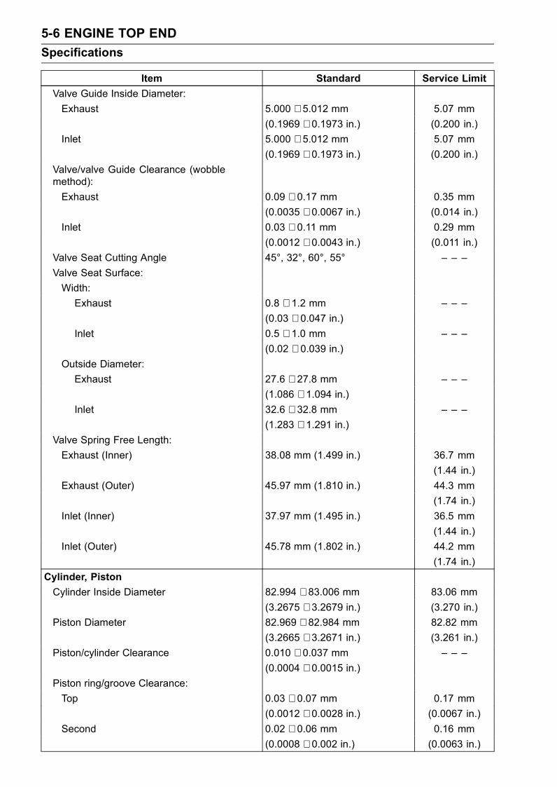
5-6 ENGINE TOP END
Specifications
Item Standard Service Limit
Valve Guide Inside Diameter:
Exhaust 5.000 ∼ 5.012 mm 5.07 mm
(0.1969 ∼ 0.1973 in.) (0.200 in.)
Inlet 5.000 ∼ 5.012 mm 5.07 mm
(0.1969 ∼ 0.1973 in.) (0.200 in.)
Valve/valve Guide Clearance (wobblemethod):
Exhaust 0.09 ∼ 0.17 mm 0.35 mm
(0.0035 ∼ 0.0067 in.) (0.014 in.)
Inlet 0.03 ∼ 0.11 mm 0.29 mm
(0.0012 ∼ 0.0043 in.) (0.011 in.)
Valve Seat Cutting Angle 45°, 32°, 60°, 55° – – –
Valve Seat Surface:
Width:
Exhaust 0.8 ∼ 1.2 mm – – –
(0.03 ∼ 0.047 in.)Inlet 0.5 ∼ 1.0 mm – – –
(0.02 ∼ 0.039 in.)Outside Diameter:
Exhaust 27.6 ∼ 27.8 mm – – –
(1.086 ∼ 1.094 in.)Inlet 32.6 ∼ 32.8 mm – – –
(1.283 ∼ 1.291 in.)Valve Spring Free Length:
Exhaust (Inner) 38.08 mm (1.499 in.) 36.7 mm
(1.44 in.)
Exhaust (Outer) 45.97 mm (1.810 in.) 44.3 mm
(1.74 in.)
Inlet (Inner) 37.97 mm (1.495 in.) 36.5 mm
(1.44 in.)
Inlet (Outer) 45.78 mm (1.802 in.) 44.2 mm
(1.74 in.)
Cylinder, Piston
Cylinder Inside Diameter 82.994 ∼ 83.006 mm 83.06 mm
(3.2675 ∼ 3.2679 in.) (3.270 in.)
Piston Diameter 82.969 ∼ 82.984 mm 82.82 mm
(3.2665 ∼ 3.2671 in.) (3.261 in.)
Piston/cylinder Clearance 0.010 ∼ 0.037 mm – – –
(0.0004 ∼ 0.0015 in.)Piston ring/groove Clearance:
Top 0.03 ∼ 0.07 mm 0.17 mm
(0.0012 ∼ 0.0028 in.) (0.0067 in.)
Second 0.02 ∼ 0.06 mm 0.16 mm
(0.0008 ∼ 0.002 in.) (0.0063 in.)
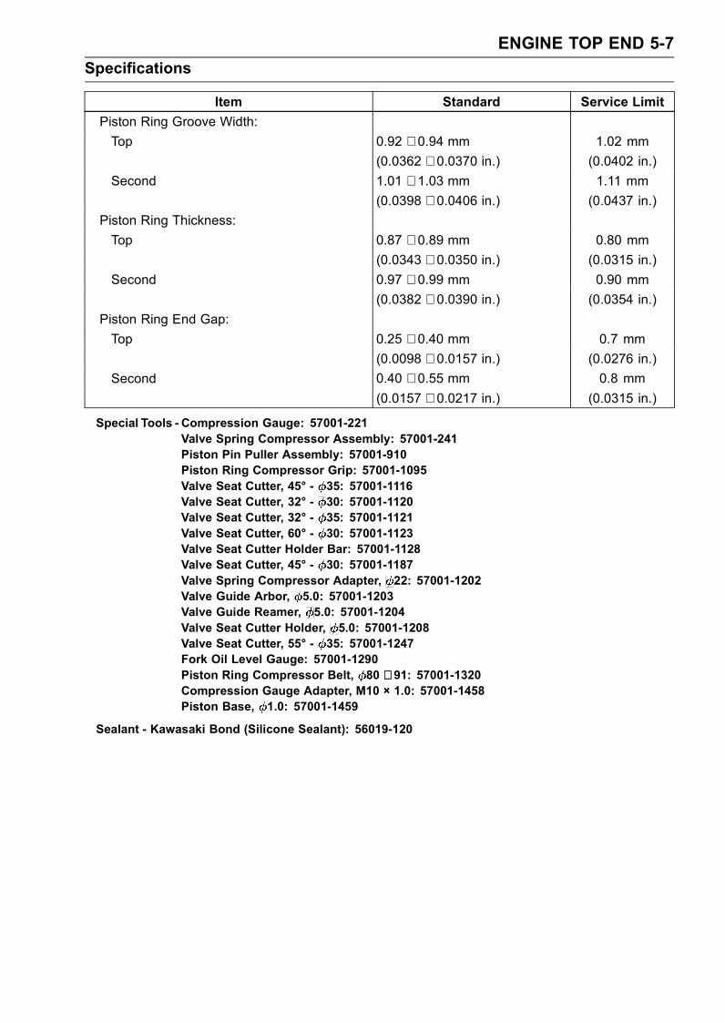
ENGINE TOP END 5-7
Specifications
Item Standard Service Limit
Piston Ring Groove Width:
Top 0.92 ∼ 0.94 mm 1.02 mm
(0.0362 ∼ 0.0370 in.) (0.0402 in.)
Second 1.01 ∼ 1.03 mm 1.11 mm
(0.0398 ∼ 0.0406 in.) (0.0437 in.)
Piston Ring Thickness:
Top 0.87 ∼ 0.89 mm 0.80 mm
(0.0343 ∼ 0.0350 in.) (0.0315 in.)
Second 0.97 ∼ 0.99 mm 0.90 mm
(0.0382 ∼ 0.0390 in.) (0.0354 in.)
Piston Ring End Gap:
Top 0.25 ∼ 0.40 mm 0.7 mm
(0.0098 ∼ 0.0157 in.) (0.0276 in.)
Second 0.40 ∼ 0.55 mm 0.8 mm
(0.0157 ∼ 0.0217 in.) (0.0315 in.)
Special Tools - Compression Gauge: 57001-221Valve Spring Compressor Assembly: 57001-241Piston Pin Puller Assembly: 57001-910Piston Ring Compressor Grip: 57001-1095Valve Seat Cutter, 45° - 35: 57001-1116Valve Seat Cutter, 32° - 30: 57001-1120Valve Seat Cutter, 32° - 35: 57001-1121Valve Seat Cutter, 60° - 30: 57001-1123Valve Seat Cutter Holder Bar: 57001-1128Valve Seat Cutter, 45° - 30: 57001-1187Valve Spring Compressor Adapter, 22: 57001-1202Valve Guide Arbor, 5.0: 57001-1203Valve Guide Reamer, 5.0: 57001-1204Valve Seat Cutter Holder, 5.0: 57001-1208Valve Seat Cutter, 55° - 35: 57001-1247Fork Oil Level Gauge: 57001-1290Piston Ring Compressor Belt, 80 ∼ 91: 57001-1320Compression Gauge Adapter, M10 × 1.0: 57001-1458Piston Base, 1.0: 57001-1459
Sealant - Kawasaki Bond (Silicone Sealant): 56019-120

5-8 ENGINE TOP END
Clean Air System
Air Suction Valve RemovalZX1200-B1/B2
•Remove:Lower Inner Covers (see Frame chapter)Vacuum Switch Valve HosesThrottle Cable and Choke Cable Lower Ends (for RightSide Air Suction Valve Removal) (see Fuel System (DFI)chapter)Air Suction Valve Cover Bolts [A]Clamp [B]Air Suction Valve Covers [C]Air Suction Valve Assembly [D]
ZX1200-B3
•Remove:Lower Inner Covers (see Frame chapter)
• Separate the hoses [A] from the air suction valve cover.•Remove:Air Suction Valve Cover Bolts [B]Air Suction Valve Cover [C]Air Suction Valve
Air Suction Valve InstallationZX1200-B1/B2
• Install the valve assembly [A] so that its reeds [B] sidefaces inside and it’s opening [C] side faces backward.
• Install the air suction valve covers.Torque - Air Suction Valve Cover Bolts: 12 N·m (1.2 kgf·m,
106 in·lb)
ZX1200-B3
• Install the air suction valve [A] so that its wider side [B] ofthe reed valve case faces the front.
• Tighten:Torque - Air Suction Valve Cover Bolts: 12 N·m (1.2 kgf·m,
106 in·lb)
Air Suction Valve Check
•Refer to the Air Suction Valve Inspection in the PeriodicMaintenance chapter.
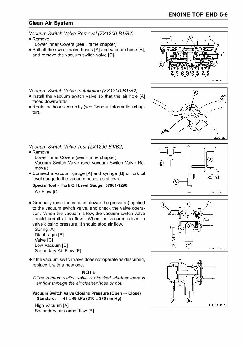
ENGINE TOP END 5-9
Clean Air System
Vacuum Switch Valve Removal (ZX1200-B1/B2)
•Remove:Lower Inner Covers (see Frame chapter)
• Pull off the switch valve hoses [A] and vacuum hose [B],and remove the vacuum switch valve [C].
Vacuum Switch Valve Installation (ZX1200-B1/B2)
• Install the vacuum switch valve so that the air hole [A]faces downwards.
•Route the hoses correctly (see General Information chap-ter).
Vacuum Switch Valve Test (ZX1200-B1/B2)
•Remove:Lower Inner Covers (see Frame chapter)Vacuum Switch Valve (see Vacuum Switch Valve Re-moval)
•Connect a vacuum gauge [A] and syringe [B] or fork oillevel gauge to the vacuum hoses as shown.
Special Tool - Fork Oil Level Gauge: 57001-1290
Air Flow [C]
•Gradually raise the vacuum (lower the pressure) appliedto the vacuum switch valve, and check the valve opera-tion. When the vacuum is low, the vacuum switch valveshould permit air to flow. When the vacuum raises tovalve closing pressure, it should stop air flow.Spring [A]Diaphragm [B]Valve [C]Low Vacuum [D]Secondary Air Flow [E]
If the vacuum switch valve does not operate as described,replace it with a new one.
NOTEThe vacuum switch valve is checked whether there isair flow through the air cleaner hose or not.
Vacuum Switch Valve Closing Pressure (Open→ Close)Standard: 41 ∼ 49 kPa (310 ∼ 370 mmHg)
High Vacuum [A]Secondary air cannot flow [B].
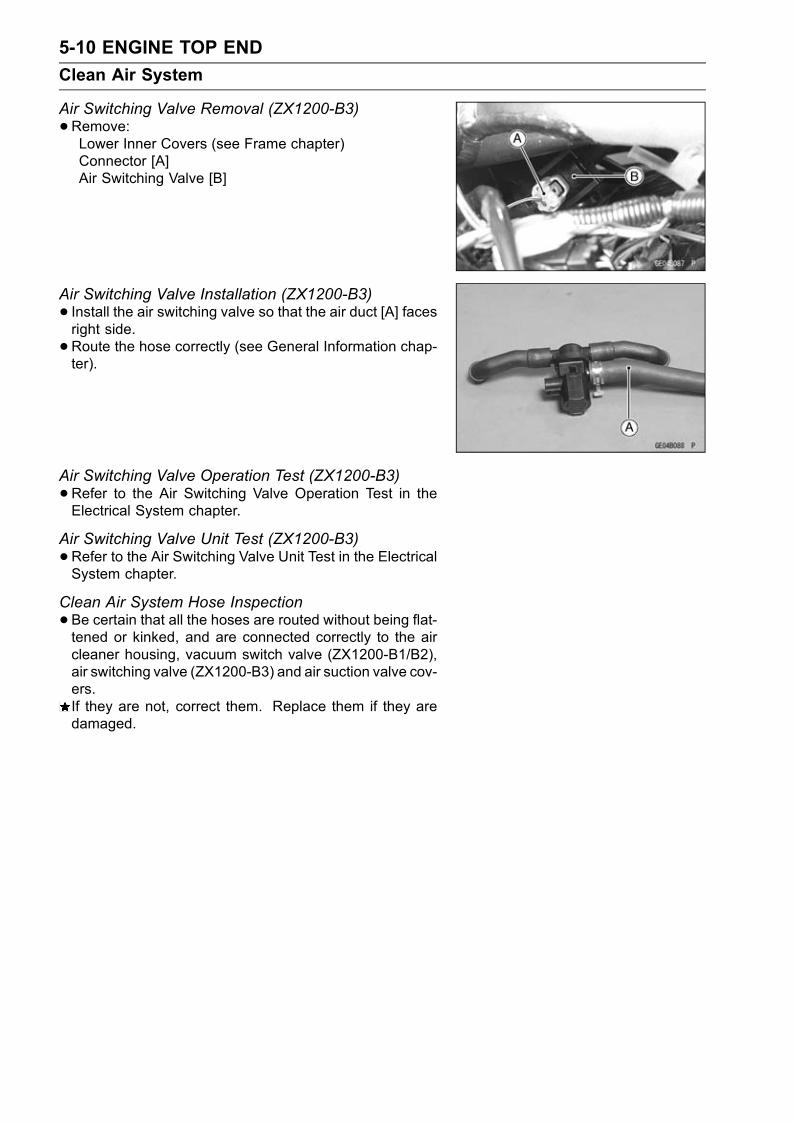
5-10 ENGINE TOP END
Clean Air System
Air Switching Valve Removal (ZX1200-B3)
•Remove:Lower Inner Covers (see Frame chapter)Connector [A]Air Switching Valve [B]
Air Switching Valve Installation (ZX1200-B3)
• Install the air switching valve so that the air duct [A] facesright side.
•Route the hose correctly (see General Information chap-ter).
Air Switching Valve Operation Test (ZX1200-B3)
•Refer to the Air Switching Valve Operation Test in theElectrical System chapter.
Air Switching Valve Unit Test (ZX1200-B3)
•Refer to the Air Switching Valve Unit Test in the ElectricalSystem chapter.
Clean Air System Hose Inspection
•Be certain that all the hoses are routed without being flat-tened or kinked, and are connected correctly to the aircleaner housing, vacuum switch valve (ZX1200-B1/B2),air switching valve (ZX1200-B3) and air suction valve cov-ers.If they are not, correct them. Replace them if they aredamaged.

ENGINE TOP END 5-11
Cylinder Head Cover
Cylinder Head Cover Removal
•Remove:Lower Fairings with Lower Inner Fairing (see Framechapter)Lower Inner Covers (see Frame chapter)Choke Cable Lower End (see Fuel System (DFI) chap-ter)Throttle Cable Lower Ends (see Fuel System (DFI) chap-ter)Camshaft Position Sensor ConnectorSwitch Housing Harness ConnectorsStarter Lockout Switch ConnectorIgnition Switch Harness Connector with ClampCoolant Reserve Tank (see Cooling System chapter)Inlet Air Pressure Sensor (see Fuel System (DFI) chap-ter)Vacuum Switch Valve [A] (ZX1200-B1/B2) and HosesAir Switching Valve [F] (ZX1200-B3) and HosesRubber Plate [B]Stick Coils [C]Baffle Plate Bolts [D]
•Remove the baffle plate [E] to the right side of the engine.NOTE
If the baffle plate cannot easily be removed, remove theair suction valve covers.
•Remove the cylinder head cover bolts [A] and take off thecover [B] to the left side of the engine.
Cylinder Head Cover Installation
•Be sure to install the pins [A] and rubber gaskets [B].
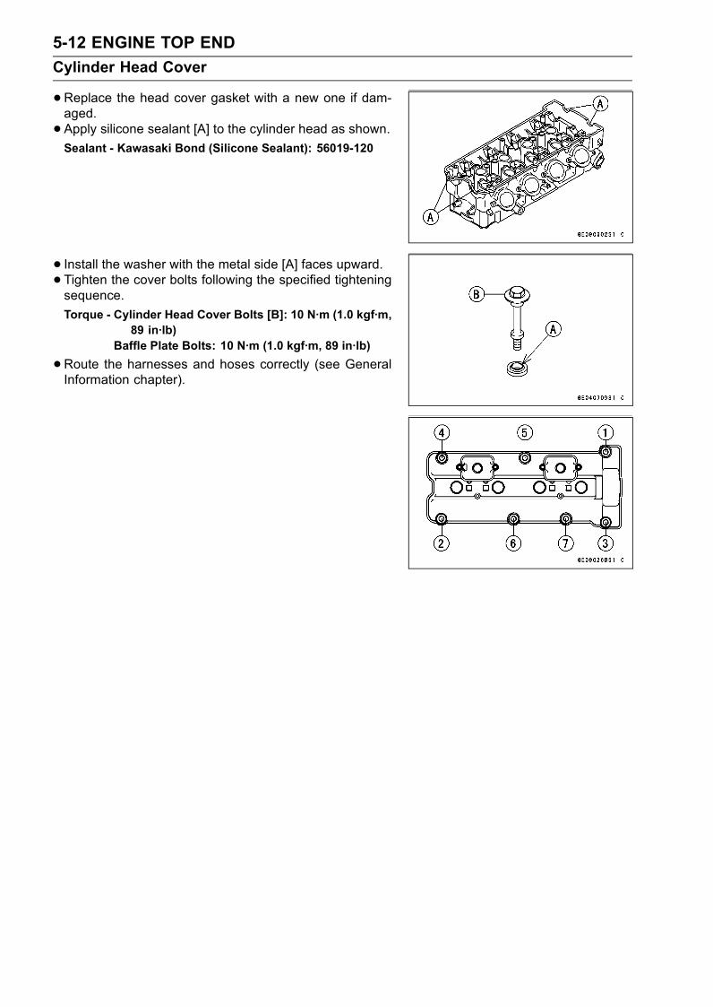
5-12 ENGINE TOP END
Cylinder Head Cover
•Replace the head cover gasket with a new one if dam-aged.
• Apply silicone sealant [A] to the cylinder head as shown.Sealant - Kawasaki Bond (Silicone Sealant): 56019-120
• Install the washer with the metal side [A] faces upward.• Tighten the cover bolts following the specified tighteningsequence.
Torque - Cylinder Head Cover Bolts [B]: 10 N·m (1.0 kgf·m,89 in·lb)
Baffle Plate Bolts: 10 N·m (1.0 kgf·m, 89 in·lb)
•Route the harnesses and hoses correctly (see GeneralInformation chapter).
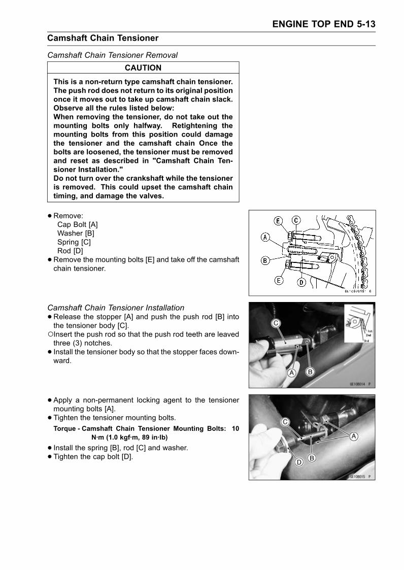
ENGINE TOP END 5-13
Camshaft Chain Tensioner
Camshaft Chain Tensioner Removal
CAUTION
This is a non-return type camshaft chain tensioner.The push rod does not return to its original positiononce it moves out to take up camshaft chain slack.Observe all the rules listed below:When removing the tensioner, do not take out themounting bolts only halfway. Retightening themounting bolts from this position could damagethe tensioner and the camshaft chain Once thebolts are loosened, the tensioner must be removedand reset as described in "Camshaft Chain Ten-sioner Installation."Do not turn over the crankshaft while the tensioneris removed. This could upset the camshaft chaintiming, and damage the valves.
•Remove:Cap Bolt [A]Washer [B]Spring [C]Rod [D]
•Remove the mounting bolts [E] and take off the camshaftchain tensioner.
Camshaft Chain Tensioner Installation
•Release the stopper [A] and push the push rod [B] intothe tensioner body [C].Insert the push rod so that the push rod teeth are leavedthree (3) notches.
• Install the tensioner body so that the stopper faces down-ward.
• Apply a non-permanent locking agent to the tensionermounting bolts [A].
• Tighten the tensioner mounting bolts.Torque - Camshaft Chain Tensioner Mounting Bolts: 10
N·m (1.0 kgf·m, 89 in·lb)
• Install the spring [B], rod [C] and washer.• Tighten the cap bolt [D].
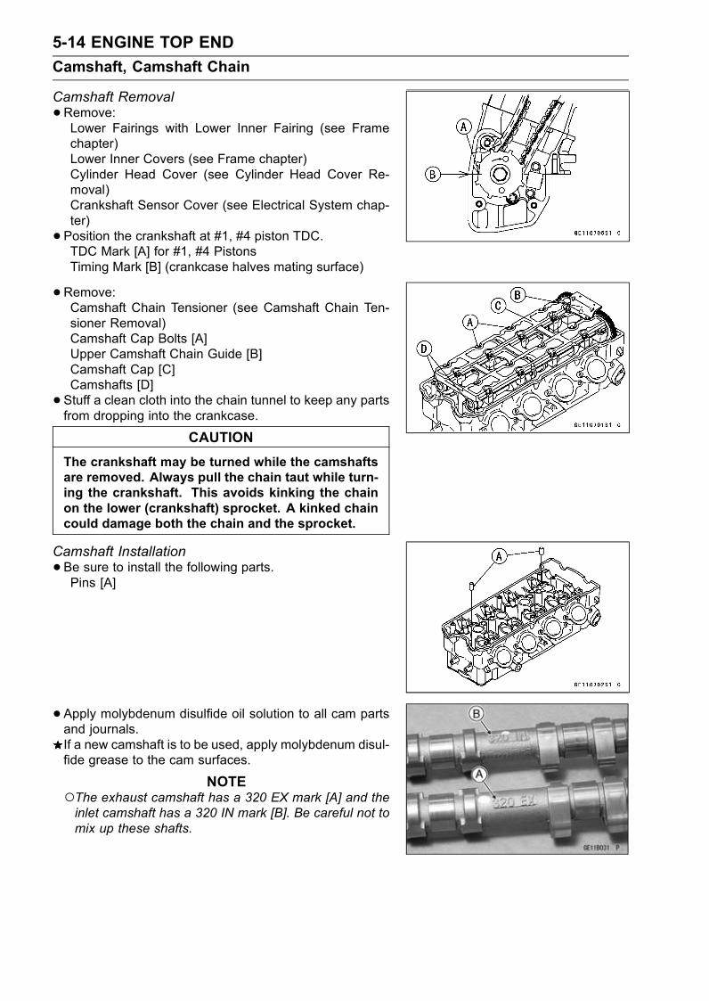
5-14 ENGINE TOP END
Camshaft, Camshaft Chain
Camshaft Removal
•Remove:Lower Fairings with Lower Inner Fairing (see Framechapter)Lower Inner Covers (see Frame chapter)Cylinder Head Cover (see Cylinder Head Cover Re-moval)Crankshaft Sensor Cover (see Electrical System chap-ter)
• Position the crankshaft at #1, #4 piston TDC.TDC Mark [A] for #1, #4 PistonsTiming Mark [B] (crankcase halves mating surface)
•Remove:Camshaft Chain Tensioner (see Camshaft Chain Ten-sioner Removal)Camshaft Cap Bolts [A]Upper Camshaft Chain Guide [B]Camshaft Cap [C]Camshafts [D]
• Stuff a clean cloth into the chain tunnel to keep any partsfrom dropping into the crankcase.
CAUTION
The crankshaft may be turned while the camshaftsare removed. Always pull the chain taut while turn-ing the crankshaft. This avoids kinking the chainon the lower (crankshaft) sprocket. A kinked chaincould damage both the chain and the sprocket.
Camshaft Installation
•Be sure to install the following parts.Pins [A]
• Apply molybdenum disulfide oil solution to all cam partsand journals.If a new camshaft is to be used, apply molybdenum disul-fide grease to the cam surfaces.
NOTEThe exhaust camshaft has a 320 EX mark [A] and theinlet camshaft has a 320 IN mark [B]. Be careful not tomix up these shafts.
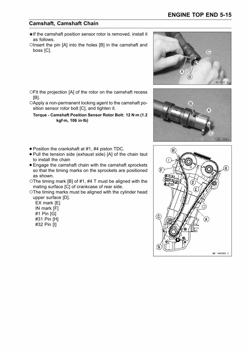
ENGINE TOP END 5-15
Camshaft, Camshaft Chain
If the camshaft position sensor rotor is removed, install itas follows.Insert the pin [A] into the holes [B] in the camshaft andboss [C].
Fit the projection [A] of the rotor on the camshaft recess[B].Apply a non-permanent locking agent to the camshaft po-sition sensor rotor bolt [C], and tighten it.
Torque - Camshaft Position Sensor Rotor Bolt: 12 N·m (1.2kgf·m, 106 in·lb)
•Position the crankshaft at #1, #4 piston TDC.•Pull the tension side (exhaust side) [A] of the chain tautto install the chain
•Engage the camshaft chain with the camshaft sprocketsso that the timing marks on the sprockets are positionedas shown.The timing mark [B] of #1, #4 T must be aligned with themating surface [C] of crankcase of rear side.The timing marks must be aligned with the cylinder headupper surface [D].EX mark [E]IN mark [F]#1 Pin [G]#31 Pin [H]#32 Pin [I]
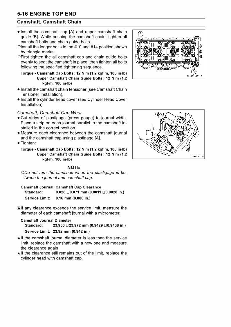
5-16 ENGINE TOP END
Camshaft, Camshaft Chain
• Install the camshaft cap [A] and upper camshaft chainguide [B]. While pushing the camshaft chain, tighten allcamshaft bolts and chain guide bolts.Install the longer bolts to the #10 and #14 position shownby triangle marks.First tighten the all camshaft cap and chain guide boltsevenly to seat the camshaft in place, then tighten all boltsfollowing the specified tightening sequence.
Torque - Camshaft Cap Bolts: 12 N·m (1.2 kgf·m, 106 in·lb)Upper Camshaft Chain Guide Bolts: 12 N·m (1.2kgf·m, 106 in·lb)
• Install the camshaft chain tensioner (see Camshaft ChainTensioner Installation).
• Install the cylinder head cover (see Cylinder Head CoverInstallation).
Camshaft, Camshaft Cap Wear
•Cut strips of plastigage (press gauge) to journal width.Place a strip on each journal parallel to the camshaft in-stalled in the correct position.
•Measure each clearance between the camshaft journaland the camshaft cap using plastigage [A].
• Tighten:Torque - Camshaft Cap Bolts: 12 N·m (1.2 kgf·m, 106 in·lb)
Upper Camshaft Chain Guide Bolts: 12 N·m (1.2kgf·m, 106 in·lb)
NOTEDo not turn the camshaft when the plastigage is be-tween the journal and camshaft cap.
Camshaft Journal, Camshaft Cap ClearanceStandard: 0.028 ∼ 0.071 mm (0.0011 ∼ 0.0028 in.)Service Limit: 0.16 mm (0.006 in.)
If any clearance exceeds the service limit, measure thediameter of each camshaft journal with a micrometer.
Camshaft Journal DiameterStandard: 23.950 ∼ 23.972 mm (0.9429 ∼ 0.9438 in.)Service Limit: 23.92 mm (0.942 in.)
If the camshaft journal diameter is less than the servicelimit, replace the camshaft with a new one and measurethe clearance againIf the clearance still remains out of the limit, replace thecylinder head with camshaft cap.

ENGINE TOP END 5-17
Camshaft, Camshaft Chain
Camshaft Runout
•Remove the camshaft (see Camshaft Removal).• Set the camshaft in a camshaft alignment jig or on Vblocks.
•Measure runout with a dial gauge at the specified placeas shown.If the runout exceeds the service limit, replace thecamshaft.
Camshaft RunoutStandard: TIR 0.02 mm (0.0008 in.) or less
Service Limit: TIR 0.1 mm (0.004 in.)
Cam Wear
•Remove the camshaft (see Camshaft Removal).•Measure the height [A] of each cam with a micrometer.If the cams are worn down past the service limit, replacethe camshaft.
Cam HeightStandard:
Exhaust 36.643 ∼ 36.757 mm (1.4426 ∼ 1.4471 in.)Inlet 37.043 ∼ 37.157 mm (1.4584 ∼ 1.4629 in.)
Service Limit:
Exhaust 36.54 mm (1.439 in.)
Inlet 36.94 mm (1.454 in.)
Camshaft Chain Removal
•Split the crankcase (see Crankshaft/Transmission chap-ter).
• Remove the camshaft chain [A] from the crankshaftsprocket.
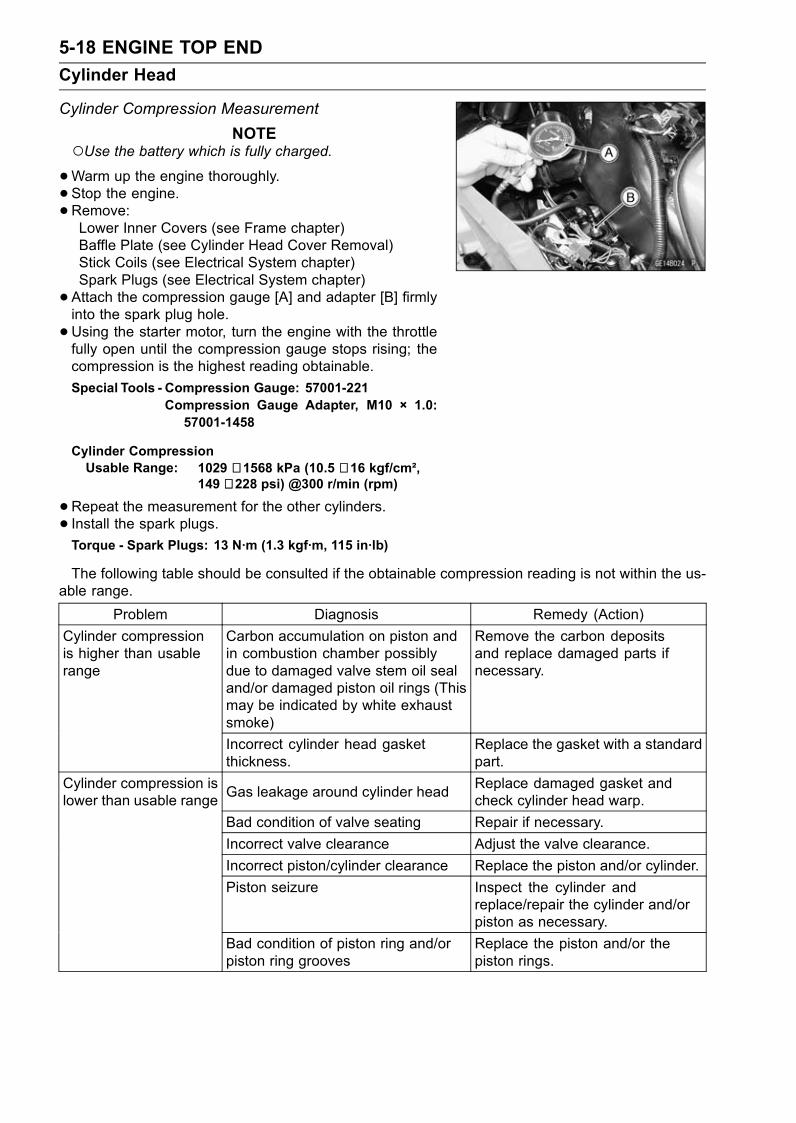
5-18 ENGINE TOP END
Cylinder Head
Cylinder Compression Measurement
NOTEUse the battery which is fully charged.•Warm up the engine thoroughly.
• Stop the engine.•Remove:Lower Inner Covers (see Frame chapter)Baffle Plate (see Cylinder Head Cover Removal)Stick Coils (see Electrical System chapter)Spark Plugs (see Electrical System chapter)
• Attach the compression gauge [A] and adapter [B] firmlyinto the spark plug hole.
•Using the starter motor, turn the engine with the throttlefully open until the compression gauge stops rising; thecompression is the highest reading obtainable.
Special Tools - Compression Gauge: 57001-221Compression Gauge Adapter, M10 × 1.0:57001-1458
Cylinder CompressionUsable Range: 1029 ∼ 1568 kPa (10.5 ∼ 16 kgf/cm²,
149 ∼ 228 psi) @300 r/min (rpm)
•Repeat the measurement for the other cylinders.• Install the spark plugs.Torque - Spark Plugs: 13 N·m (1.3 kgf·m, 115 in·lb)
The following table should be consulted if the obtainable compression reading is not within the us-able range.
Problem Diagnosis Remedy (Action)
Carbon accumulation on piston andin combustion chamber possiblydue to damaged valve stem oil sealand/or damaged piston oil rings (Thismay be indicated by white exhaustsmoke)
Remove the carbon depositsand replace damaged parts ifnecessary.
Cylinder compressionis higher than usablerange
Incorrect cylinder head gasketthickness.
Replace the gasket with a standardpart.
Gas leakage around cylinder headReplace damaged gasket andcheck cylinder head warp.
Bad condition of valve seating Repair if necessary.
Cylinder compression islower than usable range
Incorrect valve clearance Adjust the valve clearance.
Incorrect piston/cylinder clearance Replace the piston and/or cylinder.
Piston seizure Inspect the cylinder andreplace/repair the cylinder and/orpiston as necessary.
Bad condition of piston ring and/orpiston ring grooves
Replace the piston and/or thepiston rings.

ENGINE TOP END 5-19
Cylinder Head
Cylinder Head Removal
•Drain the coolant (see Coolant Change in the PeriodicMaintenance chapter).
• Remove:Radiator (see Cooling System chapter)Muffler (see Muffler Removal)Clutch Cable Lower End (see Clutch chapter)Engine Mounting Bolts [C]Engine Bracket Bolts [A]Engine Brackets [B]Throttle Body Assy (see Fuel System (DFI) chapter)Cylinder Head Cover (see Cylinder Head Cover Re-moval)Camshaft Position Sensor (see Electrical System chap-ter)Camshaft Chain Tensioner (see Camshaft Chain Ten-sioner Removal)Camshafts (see Camshaft Removal)
•Remove:Cooling Hose [A]
•Remove:Camshaft Chain Guide Bolts [A]Front and Rear Camshaft Chain Guides
Pull up the camshaft chain guides from the cylinder headwith plieres.
•Remove the M7 cylinder head bolts [A], and then the M11cylinder head bolts [B].
• Take off the cylinder head.
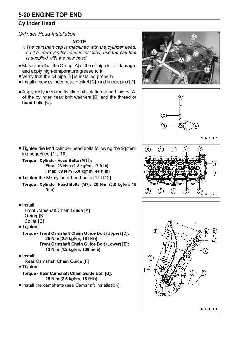
5-20 ENGINE TOP END
Cylinder Head
Cylinder Head Installation
NOTEThe camshaft cap is machined with the cylinder head,so if a new cylinder head is installed, use the cap thatis supplied with the new head.
•Make sure that the O-ring [A] of the oil pipe is not damage,and apply high-temperature grease to it.
• Verify that the oil pipe [B] is installed properly.• Install a new cylinder head gasket [C], and knock pins [D].• Apply molybdenum disulfide oil solution to both sides [A]of the cylinder head bolt washers [B] and the thread ofhead bolts [C].
• Tighten the M11 cylinder head bolts following the tighten-ing sequence [1 ∼ 10].Torque - Cylinder Head Bolts (M11):
First: 23 N·m (2.3 kgf·m, 17 ft·lb)Final: 59 N·m (6.0 kgf·m, 44 ft·lb)
•Tighten the M7 cylinder head bolts [11 ∼ 12].Torque - Cylinder Head Bolts (M7): 20 N·m (2.0 kgf·m, 15
ft·lb)
• Install:Front Camshaft Chain Guide [A]O-ring [B]Collar [C]
• Tighten:Torque - Front Camshaft Chain Guide Bolt (Upper) [D]:
25 N·m (2.5 kgf·m, 18 ft·lb)Front Camshaft Chain Guide Bolt (Lower) [E]:12 N·m (1.2 kgf·m, 106 in·lb)
• Install:Rear Camshaft Chain Guide [F]
• Tighten:Torque - Rear Camshaft Chain Guide Bolt [G]:
25 N·m (2.5 kgf·m, 18 ft·lb)
• Install the camshafts (see Camshaft Installation).

ENGINE TOP END 5-21
Cylinder Head
Cylinder Head Warp
•Clean the cylinder head.• Lay a straightedge across the lower surface of the cylinderhead at several positions.
•Measure the space between the straightedge [B] and thehead with a thickness gauge [A].
Cylinder Head WarpStandard: – – –
Service Limit: 0.05 mm (0.002 in.)
If the cylinder head is warped more than the service limit,replace it.If the cylinder head is warped less than the service limit,repair the head by rubbing the lower surface on emerypaper secured to a surface plate (first No. 200, then No.400).

5-22 ENGINE TOP END
Valves
Valve Clearance Check
•Refer to the Valve Clearance Inspection and Adjustmentin the Periodic Maintenance chapter (2nd chapter).
Valve Removal
•Remove the cylinder head (see Cylinder Head Removal).• Remove the valve lifter and shim.Mark and record the valve lifter and shim locations so theycan be installed in their original positions.
•Using the valve spring compressor assembly, remove thevalve.
Special Tools - Valve Spring Compressor Assembly: 57001-241 [A]
Adapter, 22: 57001-1202 [B]
Valve Installation
•Replace the oil seal with a new one.• Apply thin coat of molybdenum disulfide grease to thevalve stem before valve installation.
• Install the springs so that the closed coil end faces down-wards.
Valve Spring Paint Color: EX - Red
IN - Blue
Valve Stem [A]Oil Seal [B]Spring Seat [C]Closed Coil End [D]Valve Springs (Inner) [E]Valve Springs (Outer) [F]Retainer [G]Split Keepers [H]
Valve Guide Removal
•Remove:Valve (see Valve Removal)Oil SealSpring Seat
•Heat the area around the valve guide to 120 ∼ 150°C (248∼ 302°F), and hammer lightly on the valve guide arbor [A]to remove the guide from the top of the head.
CAUTION
Do not heat the cylinder head with a torch. This willwarp the cylinder head. Soak the cylinder head inoil and heat the oil.
Special Tool - Valve Guide Arbor, 5.0: 57001-1203

ENGINE TOP END 5-23
Valves
Valve Guide Installation
•Apply engine oil to the valve guide outer surface beforeinstallation.
•Heat the area around the valve guide hole to about 120 ∼150°C (248 ∼ 302°F).•Drive the valve guide in from the top of the head using thevalve guide arbor. The flange stops the guide from goingin too far.
Special Tool - Valve Guide Arbor, 5.0: 57001-1203
•Ream the valve guide with valve guide reamer [A] even ifthe old guide is reused.
Special Tool - Valve Guide Reamer, 5.0: 57001-1204
Valve-to-Guide Clearance Measurement (WobbleMethod)If a small bore gauge is not available, inspect the valve
guide wear by measuring the valve to valve guide clearancewith the wobble method as indicated below.
• Insert a new valve [A] into the guide [B] and set a dialgauge against the stem perpendicular to it as close aspossible to the cylinder head mating surface.
•Move the stem back and forth [C] to measure valve/valveguide clearance.
•Repeat the measurement in a direction at a right angle tothe first.If the reading exceeds the service limit, replace the guide.
NOTEThe reading is not actual valve/valve guide clearancebecause the measuring point is above the guide.
Valve/Valve Guide Clearance (Wobble Method)Standard:
Exhaust 0.09 ∼ 0.17 mm (0.0035 ∼ 0.0067 in.)Inlet 0.03 ∼ 0.11 mm (0.0012 ∼ 0.0043 in.)
Service Limit:
Exhaust 0.35 mm (0.014 in.)
Inlet 0.29 mm (0.011 in.)
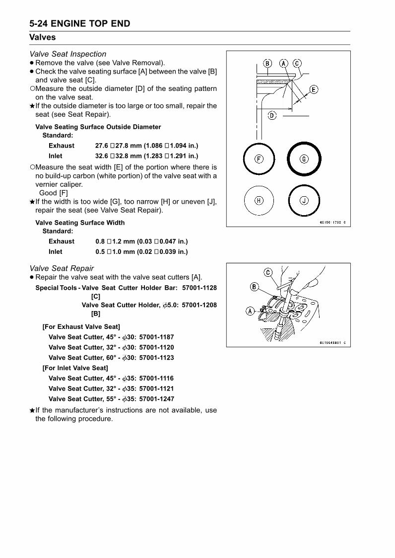
5-24 ENGINE TOP END
Valves
Valve Seat Inspection
•Remove the valve (see Valve Removal).• Check the valve seating surface [A] between the valve [B]and valve seat [C].Measure the outside diameter [D] of the seating patternon the valve seat.If the outside diameter is too large or too small, repair theseat (see Seat Repair).
Valve Seating Surface Outside DiameterStandard:
Exhaust 27.6 ∼ 27.8 mm (1.086 ∼ 1.094 in.)Inlet 32.6 ∼ 32.8 mm (1.283 ∼ 1.291 in.)
Measure the seat width [E] of the portion where there isno build-up carbon (white portion) of the valve seat with avernier caliper.Good [F]If the width is too wide [G], too narrow [H] or uneven [J],repair the seat (see Valve Seat Repair).
Valve Seating Surface WidthStandard:
Exhaust 0.8 ∼ 1.2 mm (0.03 ∼ 0.047 in.)Inlet 0.5 ∼ 1.0 mm (0.02 ∼ 0.039 in.)
Valve Seat Repair
•Repair the valve seat with the valve seat cutters [A].Special Tools - Valve Seat Cutter Holder Bar: 57001-1128
[C]Valve Seat Cutter Holder, 5.0: 57001-1208[B]
[For Exhaust Valve Seat]
Valve Seat Cutter, 45° - 30: 57001-1187
Valve Seat Cutter, 32° - 30: 57001-1120
Valve Seat Cutter, 60° - 30: 57001-1123
[For Inlet Valve Seat]
Valve Seat Cutter, 45° - 35: 57001-1116
Valve Seat Cutter, 32° - 35: 57001-1121
Valve Seat Cutter, 55° - 35: 57001-1247
If the manufacturer’s instructions are not available, usethe following procedure.
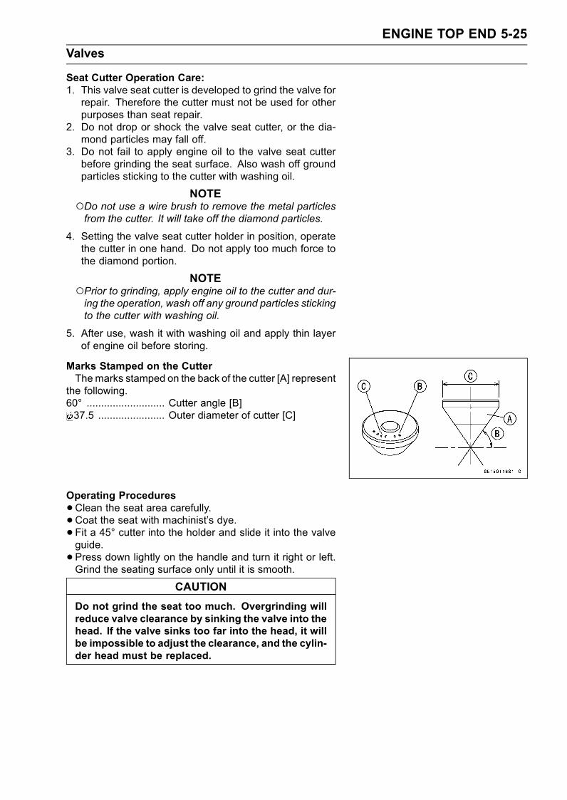
ENGINE TOP END 5-25
Valves
Seat Cutter Operation Care:1. This valve seat cutter is developed to grind the valve forrepair. Therefore the cutter must not be used for otherpurposes than seat repair.
2. Do not drop or shock the valve seat cutter, or the dia-mond particles may fall off.
3. Do not fail to apply engine oil to the valve seat cutterbefore grinding the seat surface. Also wash off groundparticles sticking to the cutter with washing oil.
NOTEDo not use a wire brush to remove the metal particlesfrom the cutter. It will take off the diamond particles.
4. Setting the valve seat cutter holder in position, operatethe cutter in one hand. Do not apply too much force tothe diamond portion.
NOTEPrior to grinding, apply engine oil to the cutter and dur-ing the operation, wash off any ground particles stickingto the cutter with washing oil.
5. After use, wash it with washing oil and apply thin layerof engine oil before storing.
Marks Stamped on the CutterThemarks stamped on the back of the cutter [A] represent
the following.60° ........................... Cutter angle [B]37.5 ....................... Outer diameter of cutter [C]
Operating Procedures
•Clean the seat area carefully.• Coat the seat with machinist’s dye.• Fit a 45° cutter into the holder and slide it into the valveguide.
• Press down lightly on the handle and turn it right or left.Grind the seating surface only until it is smooth.
CAUTION
Do not grind the seat too much. Overgrinding willreduce valve clearance by sinking the valve into thehead. If the valve sinks too far into the head, it willbe impossible to adjust the clearance, and the cylin-der head must be replaced.

5-26 ENGINE TOP END
Valves
•Measure the outside diameter of the seating surface witha vernier caliper.If the outside diameter of the seating surface is too small,repeat the 45° grind until the diameter is within the spec-ified range.Widened Width [A] of engagement by machining with45° cutterGround Volume [B] by 32° cutter32° [C]Correct Width [D]Ground Volume [E] by 60° or 55° cutter60° or 55° [F]
•Measure the outside diameter of the seating surface witha vernier caliper.If the outside diameter of the seating surface is too small,repeat the 45° grind [A] until the diameter is within thespecified range.Original Seating Surface [B]
NOTERemove all pittings of flaws from 45° ground surface.After grinding with 45° cutter, apply thin coat of machin-ist’s dye to seating surface. This makes seating surfacedistinct and 32° and 60° grinding operation easier.When the valve guide is replaced, be sure to grind with45° cutter for centering and good contact.
If the outside diameter [A] of the seating surface is toolarge, make the 32° grind described below.If the outside diameter of the seating surface is within thespecified range, measure the seat width as described be-low.
•Grind the seat at a 32° angle [B] until the seat O.D. iswithin the specified range.To make the 32° grind, fit a 32° cutter into the holder, andslide it into the valve guide.Turn the holder one turn at a time while pressing downvery lightly. Check the seat after each turn.
CAUTION
The 32° cutter removes material very quickly.Check the seat outside diameter frequently to pre-vent overgrinding.
After making the 32° grind, return to the seat O.D. mea-surement step above.
• To measure the seat width, use a vernier caliper to mea-sure the width of the 45° angle portion of the seat at sev-eral places around the seat.If the seat width is too narrow, repeat the 45° grind untilthe seat is slightly too wide, and then return to the seatO.D. measurement step above.

ENGINE TOP END 5-27
Valves
If the seat width is too wide, make the 60° or 55° [A] grinddescribed below.If the seat width is within the specified range, lap the valveto the seat as described below.
•Grind the seat at a 60° or 55° angle until the seat width iswithin the specified range.To make the 60° or 55° grind, fit 60° or 55° cutter into theholder, and slide it into the valve guide.Turn the holder, while pressing down lightly.After making the 60° or 55° grind, return to the seat widthmeasurement step above.Correct Width [B]
• Lap the valve to the seat, once the seat width and O.D.are within the ranges specified above.Put a little coarse grinding compound on the face of thevalve in a number of places around the valve head.Spin the valve against the seat until the grinding com-pound produces a smooth, matched surface on both theseat and the valve.Repeat the process with a fine grinding compound.Lapper [A]Valve Seat [B]Valve [C]
• The seating area should be marked about in the middleof the valve face.If the seat area is not in the right place on the valve, checkto be sure the valve is the correct part. If it is, it may havebeen refused too much; replace it.
• Be sure to remove all grinding compound before assem-bly.
•When the engine is assembled, be sure to adjust the valveclearance (see Valve Clearance Adjustment section ofPeriodic Maintenance chapter).

5-28 ENGINE TOP END
Valves

ENGINE TOP END 5-29
Cylinder, Pistons
Cylinder Removal
•Remove:Cylinder Head (see Cylinder Head Removal)Cooling Hoses [A]Oil Pipe [B]
•Remove the cylinder [C].
Cylinder Installation
NOTEIf a new cylinder is used, use new piston rings.If new pistons and/or a new cylinder are installed, applythin coat of molybdenum disulfide grease to the newpistons and cylinder bores.
•Replace the cylinder gasket with a new one, and installthe pins [A] and new cylinder gasket.
• Apply molybdenum disulfide oil solution to the cylinderbore, external of pistons and piston rings.
• The piston ring openings must be positioned as shown inthe figure. The openings of the oil ring steel rails must beabout 30 ∼ 40° of angle from the opening of the top ring.Top Ring [A]Second Ring [B]Oil Ring Steel Rails [C]Oil Ring Expander [D]Hollow [E]
• Insert the piston in the cylinder by two methods.With the Hand
•Position the crankshaft at #2, #3 piston TDC.• Install the two cylinder head bolts [A] diagonally in thecrankcase.
• Install the cylinder block [B].Pistons [C]
First insert the #2, #3 pistons, and then rotate the crank-shaft at 90° angle.Insert the piston rings with your thumbs or the thin (–)screw driver.

5-30 ENGINE TOP END
Cylinder, Pistons
With the Special Tools
• Install the two cylinder head bolts [A] diagonally in thecrankcase.
• Slip the piston bases [B] under the pistons to hold themlevel.
• Compress the piston rings using the piston ring compres-sor grips [C] and piston ring compressor belts [D] withchamfered side upward.
Special Tools - Piston Ring Compressor Grip: 57001-1095Piston Ring Compressor Belt, 80 ∼ 91:57001-1320
Piston Base, 1.0: 57001-1459
•Push down vigorously the cylinder aligning the cylinderbores with all the piston heads.
• Install the cylinder [A] so that its angle aligns the pistonangle after removing the piston ring compressor belts.
Piston Removal
•Remove the cylinder (see Cylinder Removal).• Place a clean cloth under the pistons and remove the pis-ton pin snap ring [A] from the outside of each piston.
CAUTION
Do not reuse the snap rings, as removal weakensdeforms then. They fall out and score the cylinderwall.
•Remove the piston pins with a piston pin puller [A].Special Tool - Piston Pin Puller Assembly: 57001-910
•Remove the pistons.
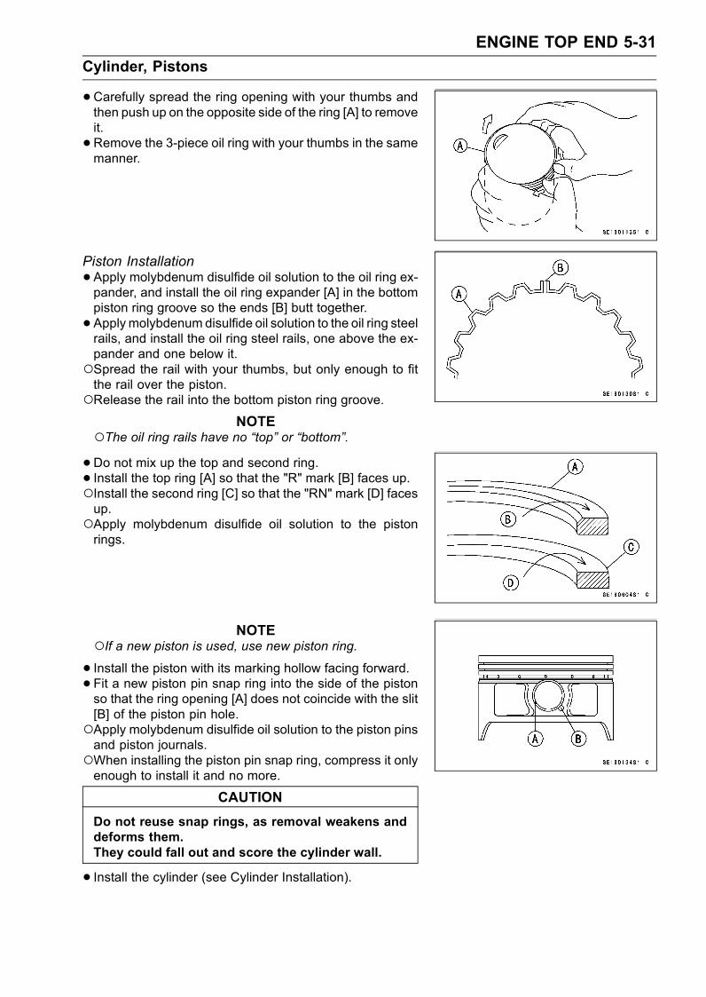
ENGINE TOP END 5-31
Cylinder, Pistons
•Carefully spread the ring opening with your thumbs andthen push up on the opposite side of the ring [A] to removeit.
• Remove the 3-piece oil ring with your thumbs in the samemanner.
Piston Installation
•Apply molybdenum disulfide oil solution to the oil ring ex-pander, and install the oil ring expander [A] in the bottompiston ring groove so the ends [B] butt together.
• Apply molybdenum disulfide oil solution to the oil ring steelrails, and install the oil ring steel rails, one above the ex-pander and one below it.Spread the rail with your thumbs, but only enough to fitthe rail over the piston.Release the rail into the bottom piston ring groove.
NOTEThe oil ring rails have no “top” or “bottom”.•Do not mix up the top and second ring.• Install the top ring [A] so that the "R" mark [B] faces up.Install the second ring [C] so that the "RN" mark [D] facesup.Apply molybdenum disulfide oil solution to the pistonrings.
NOTEIf a new piston is used, use new piston ring.• Install the piston with its marking hollow facing forward.• Fit a new piston pin snap ring into the side of the pistonso that the ring opening [A] does not coincide with the slit[B] of the piston pin hole.Apply molybdenum disulfide oil solution to the piston pinsand piston journals.When installing the piston pin snap ring, compress it onlyenough to install it and no more.
CAUTION
Do not reuse snap rings, as removal weakens anddeforms them.They could fall out and score the cylinder wall.
• Install the cylinder (see Cylinder Installation).
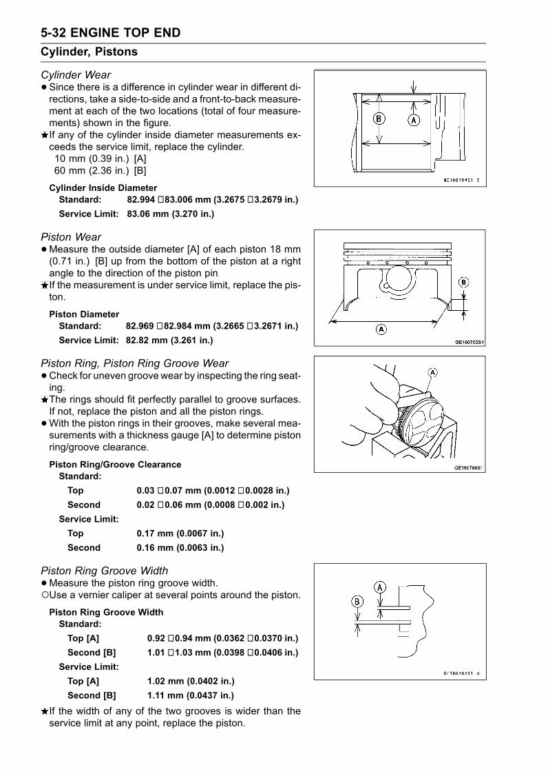
5-32 ENGINE TOP END
Cylinder, Pistons
Cylinder Wear
•Since there is a difference in cylinder wear in different di-rections, take a side-to-side and a front-to-back measure-ment at each of the two locations (total of four measure-ments) shown in the figure.If any of the cylinder inside diameter measurements ex-ceeds the service limit, replace the cylinder.10 mm (0.39 in.) [A]60 mm (2.36 in.) [B]
Cylinder Inside DiameterStandard: 82.994 ∼ 83.006 mm (3.2675 ∼ 3.2679 in.)Service Limit: 83.06 mm (3.270 in.)
Piston Wear
•Measure the outside diameter [A] of each piston 18 mm(0.71 in.) [B] up from the bottom of the piston at a rightangle to the direction of the piston pinIf the measurement is under service limit, replace the pis-ton.
Piston DiameterStandard: 82.969 ∼ 82.984 mm (3.2665 ∼ 3.2671 in.)Service Limit: 82.82 mm (3.261 in.)
Piston Ring, Piston Ring Groove Wear
•Check for uneven groove wear by inspecting the ring seat-ing.The rings should fit perfectly parallel to groove surfaces.If not, replace the piston and all the piston rings.
•With the piston rings in their grooves, make several mea-surements with a thickness gauge [A] to determine pistonring/groove clearance.
Piston Ring/Groove ClearanceStandard:
Top 0.03 ∼ 0.07 mm (0.0012 ∼ 0.0028 in.)Second 0.02 ∼ 0.06 mm (0.0008 ∼ 0.002 in.)
Service Limit:
Top 0.17 mm (0.0067 in.)
Second 0.16 mm (0.0063 in.)
Piston Ring Groove Width
•Measure the piston ring groove width.Use a vernier caliper at several points around the piston.Piston Ring Groove WidthStandard:
Top [A] 0.92 ∼ 0.94 mm (0.0362 ∼ 0.0370 in.)Second [B] 1.01 ∼ 1.03 mm (0.0398 ∼ 0.0406 in.)
Service Limit:
Top [A] 1.02 mm (0.0402 in.)
Second [B] 1.11 mm (0.0437 in.)
If the width of any of the two grooves is wider than theservice limit at any point, replace the piston.
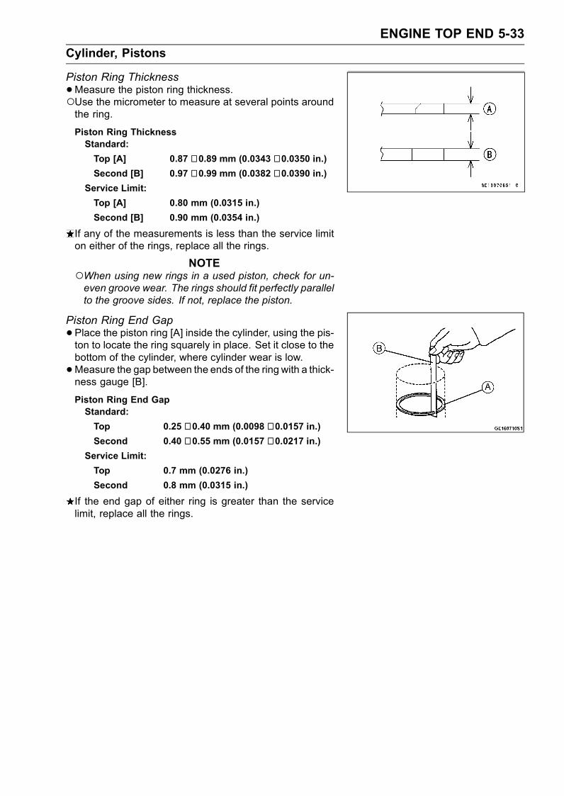
ENGINE TOP END 5-33
Cylinder, Pistons
Piston Ring Thickness
•Measure the piston ring thickness.Use the micrometer to measure at several points aroundthe ring.
Piston Ring ThicknessStandard:
Top [A] 0.87 ∼ 0.89 mm (0.0343 ∼ 0.0350 in.)Second [B] 0.97 ∼ 0.99 mm (0.0382 ∼ 0.0390 in.)
Service Limit:
Top [A] 0.80 mm (0.0315 in.)
Second [B] 0.90 mm (0.0354 in.)
If any of the measurements is less than the service limiton either of the rings, replace all the rings.
NOTEWhen using new rings in a used piston, check for un-even groove wear. The rings should fit perfectly parallelto the groove sides. If not, replace the piston.
Piston Ring End Gap
•Place the piston ring [A] inside the cylinder, using the pis-ton to locate the ring squarely in place. Set it close to thebottom of the cylinder, where cylinder wear is low.
•Measure the gap between the ends of the ring with a thick-ness gauge [B].
Piston Ring End GapStandard:
Top 0.25 ∼ 0.40 mm (0.0098 ∼ 0.0157 in.)Second 0.40 ∼ 0.55 mm (0.0157 ∼ 0.0217 in.)
Service Limit:
Top 0.7 mm (0.0276 in.)
Second 0.8 mm (0.0315 in.)
If the end gap of either ring is greater than the servicelimit, replace all the rings.
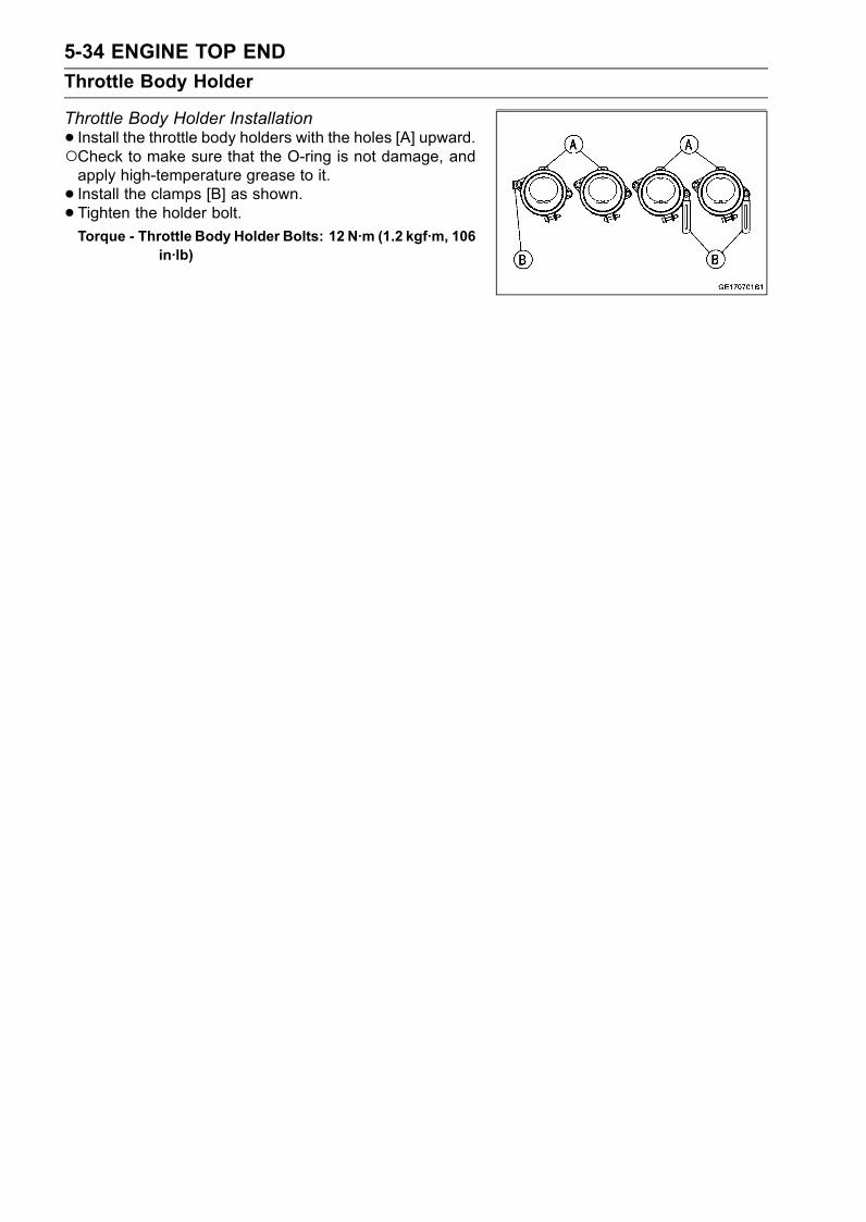
5-34 ENGINE TOP END
Throttle Body Holder
Throttle Body Holder Installation
• Install the throttle body holders with the holes [A] upward.Check to make sure that the O-ring is not damage, andapply high-temperature grease to it.
• Install the clamps [B] as shown.• Tighten the holder bolt.Torque - Throttle Body Holder Bolts: 12 N·m (1.2 kgf·m, 106
in·lb)

ENGINE TOP END 5-35
Muffler
WARNINGTo avoid a serious burn, do not remove the mufflerwhen the engine is still hot. Wait until the mufflercools down.
Muffler Removal
•Remove:Lower Fairings with Lower Inner Fairing (see Framechapter)Lower Inner Covers (see Frame chapter)Air Inlet Ducts (see Fuel System (DFI) chapter)Radiator (see Cooling System chapter)
•Muffler Body Mounting Nut [A]
•Remove:Exhaust Pipe Manifold Holder Nuts [A]
• Pull the muffler body mounting bolt and remove the muf-fler assembly.
Muffler Installation
•Replace the exhaust pipe gaskets with new ones.• Thoroughly warm up the engine, wait until the enginecools down, and retighten all the bolts and nuts.
Muffler Body Removal
•Unscrew the muffler body connection cover bolts [A] andremove the cover [B].
• Remove:Muffler Body Connection Nuts [A]Muffler Body Mounting Bolt and Nut [B]
• Pull the muffler body [C] backward.
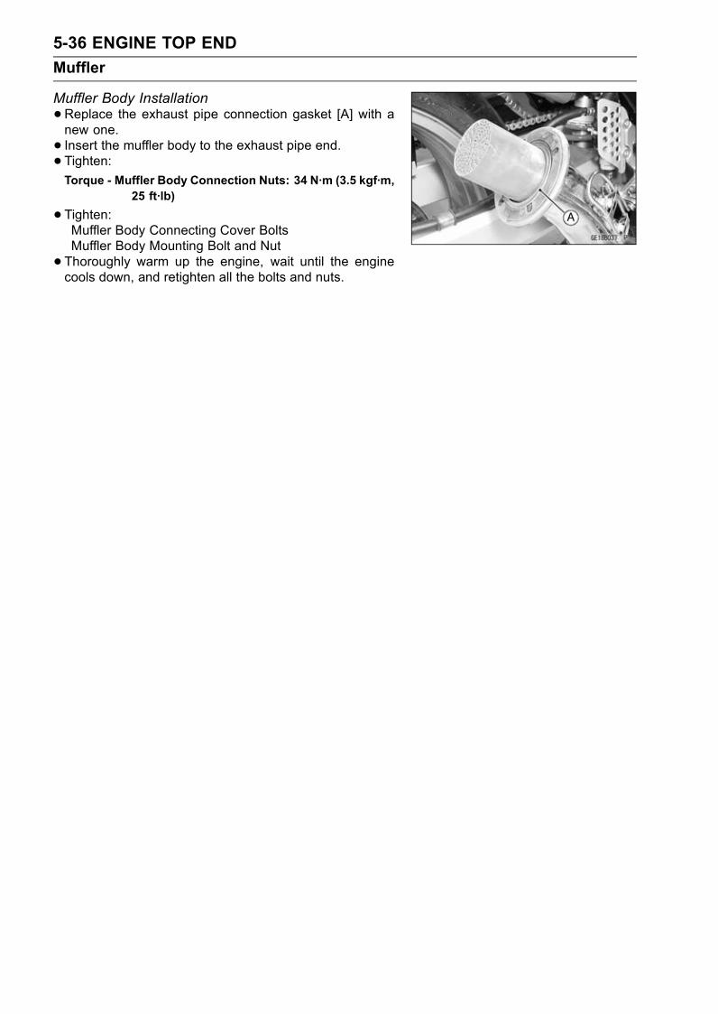
5-36 ENGINE TOP END
Muffler
Muffler Body Installation
•Replace the exhaust pipe connection gasket [A] with anew one.
• Insert the muffler body to the exhaust pipe end.• Tighten:Torque - Muffler Body Connection Nuts: 34 N·m (3.5 kgf·m,
25 ft·lb)
•Tighten:Muffler Body Connecting Cover BoltsMuffler Body Mounting Bolt and Nut
• Thoroughly warm up the engine, wait until the enginecools down, and retighten all the bolts and nuts.
CLUTCH 6-1
6
Clutch
Table of Contents
Exploded View........................................................................................................................ 6-2Specifications ......................................................................................................................... 6-3Clutch Lever and Cable .......................................................................................................... 6-4
Lever Free Play Inspection ............................................................................................... 6-4Lever Free Play Adjustment.............................................................................................. 6-4Cable Removal ................................................................................................................. 6-4Cable Installation .............................................................................................................. 6-4Cable Lubrication.............................................................................................................. 6-4Clutch Lever Installation.................................................................................................... 6-4
Clutch Cover........................................................................................................................... 6-5Clutch Cover Removal ...................................................................................................... 6-5Clutch Cover Installation ................................................................................................... 6-5Release Shaft Removal .................................................................................................... 6-6Release Shaft Installation ................................................................................................. 6-6Clutch Cover Disassembly................................................................................................ 6-6Clutch Cover Assembly..................................................................................................... 6-7
Clutch ..................................................................................................................................... 6-8Clutch Removal................................................................................................................. 6-8Clutch Installation.............................................................................................................. 6-9Clutch Plate Assembly Inspection..................................................................................... 6-11Clutch Plate Assembly Adjustment ................................................................................... 6-11Clutch Plate, Wear, Damage Inspection ........................................................................... 6-12Clutch Plate Warp Inspection............................................................................................ 6-12Clutch Spring Free Length Measurement ......................................................................... 6-12
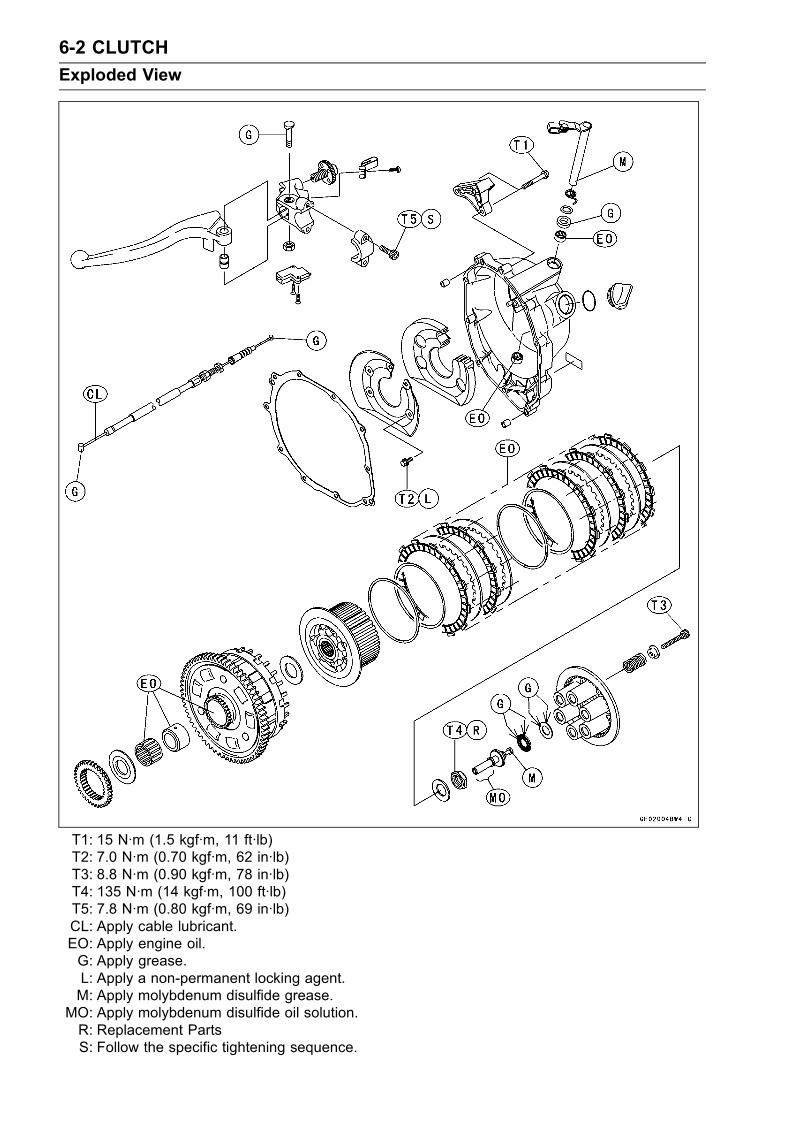
6-2 CLUTCH
Exploded View
T1: 15 N·m (1.5 kgf·m, 11 ft·lb)T2: 7.0 N·m (0.70 kgf·m, 62 in·lb)T3: 8.8 N·m (0.90 kgf·m, 78 in·lb)T4: 135 N·m (14 kgf·m, 100 ft·lb)T5: 7.8 N·m (0.80 kgf·m, 69 in·lb)CL: Apply cable lubricant.EO: Apply engine oil.G: Apply grease.L: Apply a non-permanent locking agent.M: Apply molybdenum disulfide grease.
MO: Apply molybdenum disulfide oil solution.R: Replacement PartsS: Follow the specific tightening sequence.
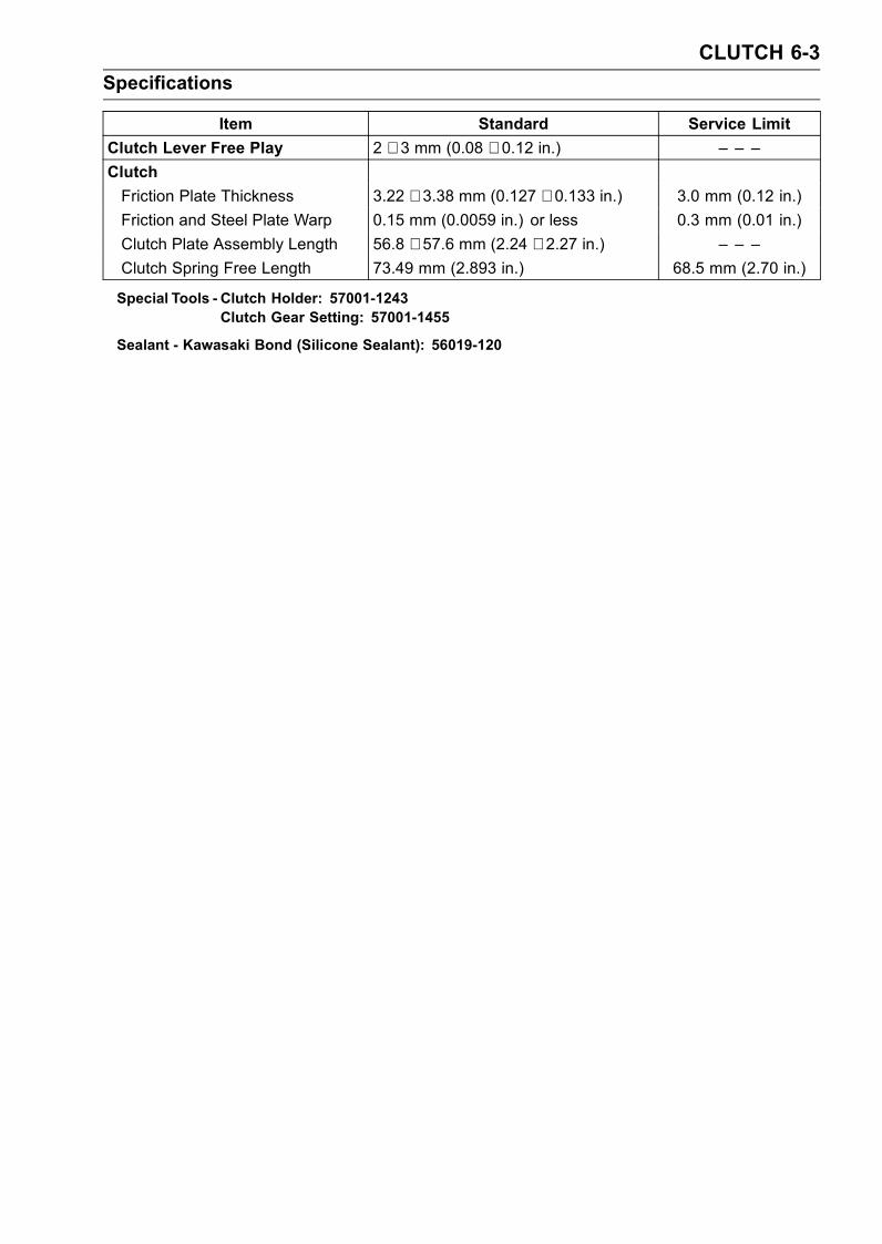
CLUTCH 6-3
Specifications
Item Standard Service Limit
Clutch Lever Free Play 2 ∼ 3 mm (0.08 ∼ 0.12 in.) – – –
Clutch
Friction Plate Thickness 3.22 ∼ 3.38 mm (0.127 ∼ 0.133 in.) 3.0 mm (0.12 in.)
Friction and Steel Plate Warp 0.15 mm (0.0059 in.) or less 0.3 mm (0.01 in.)
Clutch Plate Assembly Length 56.8 ∼ 57.6 mm (2.24 ∼ 2.27 in.) – – –
Clutch Spring Free Length 73.49 mm (2.893 in.) 68.5 mm (2.70 in.)
Special Tools - Clutch Holder: 57001-1243Clutch Gear Setting: 57001-1455
Sealant - Kawasaki Bond (Silicone Sealant): 56019-120
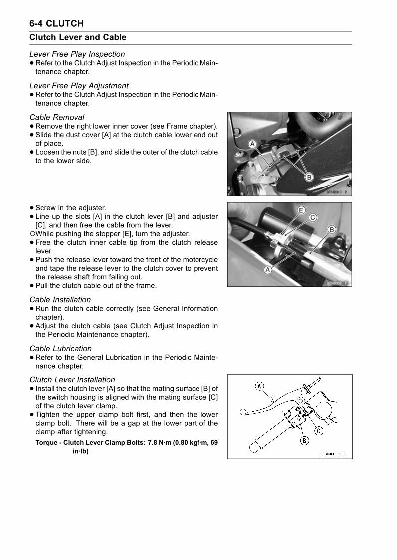
6-4 CLUTCH
Clutch Lever and Cable
Lever Free Play Inspection
•Refer to the Clutch Adjust Inspection in the Periodic Main-tenance chapter.
Lever Free Play Adjustment
•Refer to the Clutch Adjust Inspection in the Periodic Main-tenance chapter.
Cable Removal
•Remove the right lower inner cover (see Frame chapter).• Slide the dust cover [A] at the clutch cable lower end outof place.
• Loosen the nuts [B], and slide the outer of the clutch cableto the lower side.
• Screw in the adjuster.• Line up the slots [A] in the clutch lever [B] and adjuster[C], and then free the cable from the lever.While pushing the stopper [E], turn the adjuster.• Free the clutch inner cable tip from the clutch releaselever.
• Push the release lever toward the front of the motorcycleand tape the release lever to the clutch cover to preventthe release shaft from falling out.
• Pull the clutch cable out of the frame.Cable Installation
•Run the clutch cable correctly (see General Informationchapter).
• Adjust the clutch cable (see Clutch Adjust Inspection inthe Periodic Maintenance chapter).
Cable Lubrication
•Refer to the General Lubrication in the Periodic Mainte-nance chapter.
Clutch Lever Installation
• Install the clutch lever [A] so that the mating surface [B] ofthe switch housing is aligned with the mating surface [C]of the clutch lever clamp.
• Tighten the upper clamp bolt first, and then the lowerclamp bolt. There will be a gap at the lower part of theclamp after tightening.
Torque - Clutch Lever Clamp Bolts: 7.8 N·m (0.80 kgf·m, 69in·lb)

CLUTCH 6-5
Clutch Cover
Clutch Cover Removal
•Set the motorcycle on its side stand, squeeze the frontbrake lever, and hold it with a band [A] to prevent themotorcycle from running forward.
WARNINGBe sure to hold the front brake when removing theclutch, or the motorcycle may fall over. It couldcause an accident and injury.
CAUTION
Be sure to hold the front brake when removing theclutch, or the motorcycle may fall over. The motor-cycle could be damaged.
•Remove:Right Lower Fairing (see Frame chapter)Clutch Cover Mounting Bolts [B]Clutch Cable Bracket [C]Clutch Cable Lower End [A]
• Turn the release lever [B] toward the rear [C] as shown,and remove the clutch cover [A].
CAUTION
Do not remove the clutch release lever and shaftassembly unless it is absolutely necessary. If re-moved, the oil seal replacement may be required.
Clutch Cover Installation
•Apply silicone sealant to the area [A] where the matingsurface of the crankcase touches the clutch cover gasket.
• Be sure to install the pins [B].Sealant - Kawasaki Bond (Silicone Sealant): 56019-120
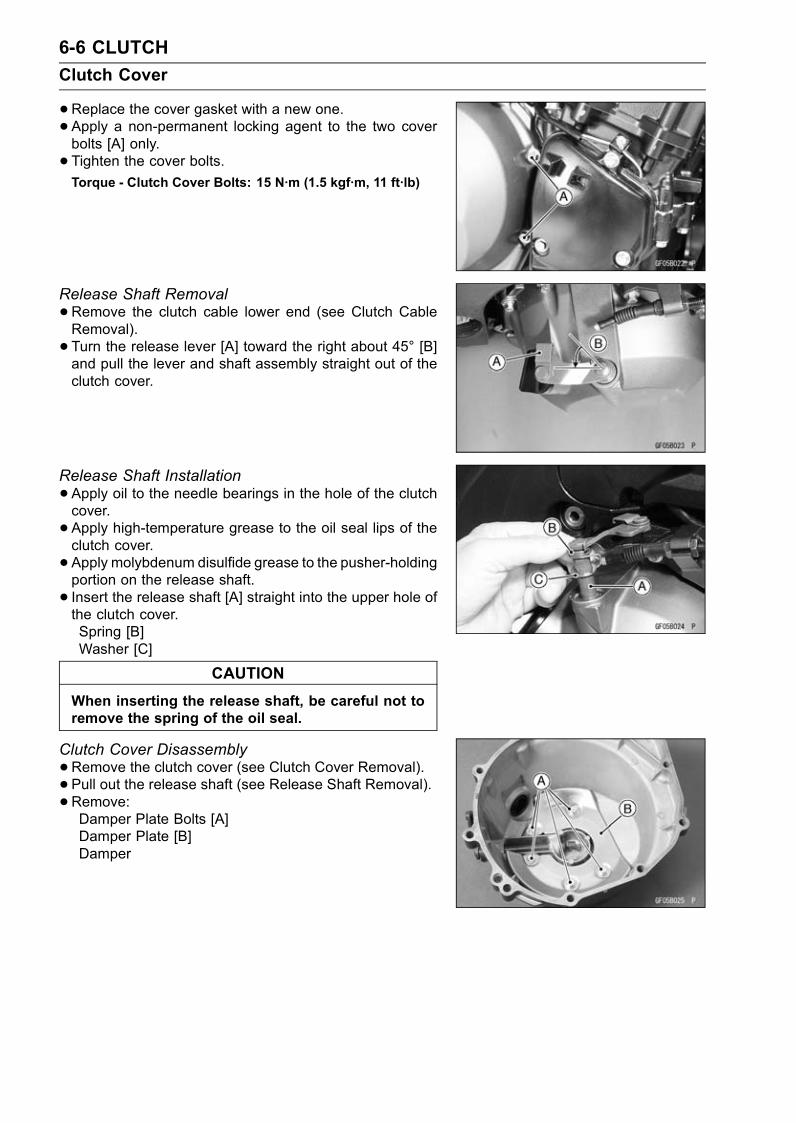
6-6 CLUTCH
Clutch Cover
•Replace the cover gasket with a new one.• Apply a non-permanent locking agent to the two coverbolts [A] only.
• Tighten the cover bolts.Torque - Clutch Cover Bolts: 15 N·m (1.5 kgf·m, 11 ft·lb)
Release Shaft Removal
•Remove the clutch cable lower end (see Clutch CableRemoval).
• Turn the release lever [A] toward the right about 45° [B]and pull the lever and shaft assembly straight out of theclutch cover.
Release Shaft Installation
•Apply oil to the needle bearings in the hole of the clutchcover.
• Apply high-temperature grease to the oil seal lips of theclutch cover.
• Apply molybdenum disulfide grease to the pusher-holdingportion on the release shaft.
• Insert the release shaft [A] straight into the upper hole ofthe clutch cover.Spring [B]Washer [C]
CAUTION
When inserting the release shaft, be careful not toremove the spring of the oil seal.
Clutch Cover Disassembly
•Remove the clutch cover (see Clutch Cover Removal).• Pull out the release shaft (see Release Shaft Removal).• Remove:Damper Plate Bolts [A]Damper Plate [B]Damper

CLUTCH 6-7
Clutch Cover
•Remove:Oil Seal [A]Needle Bearings [B]
Clutch Cover Assembly
•Replace the needle bearings and oil seal with new one.NOTE
Install the needle bearings so that the manufacturer’smark face out.
• Install the needle bearings [A] and oil seal [B] position asshown.
• Apply a non-permanent locking agent to the damper platebolts and tighten them.Confirm that the torque to fast tightened bolt.
Torque - Clutch Cover Damper Plate Bolts: 7.0 N·m (0.70kgf·m, 62 in·lb)
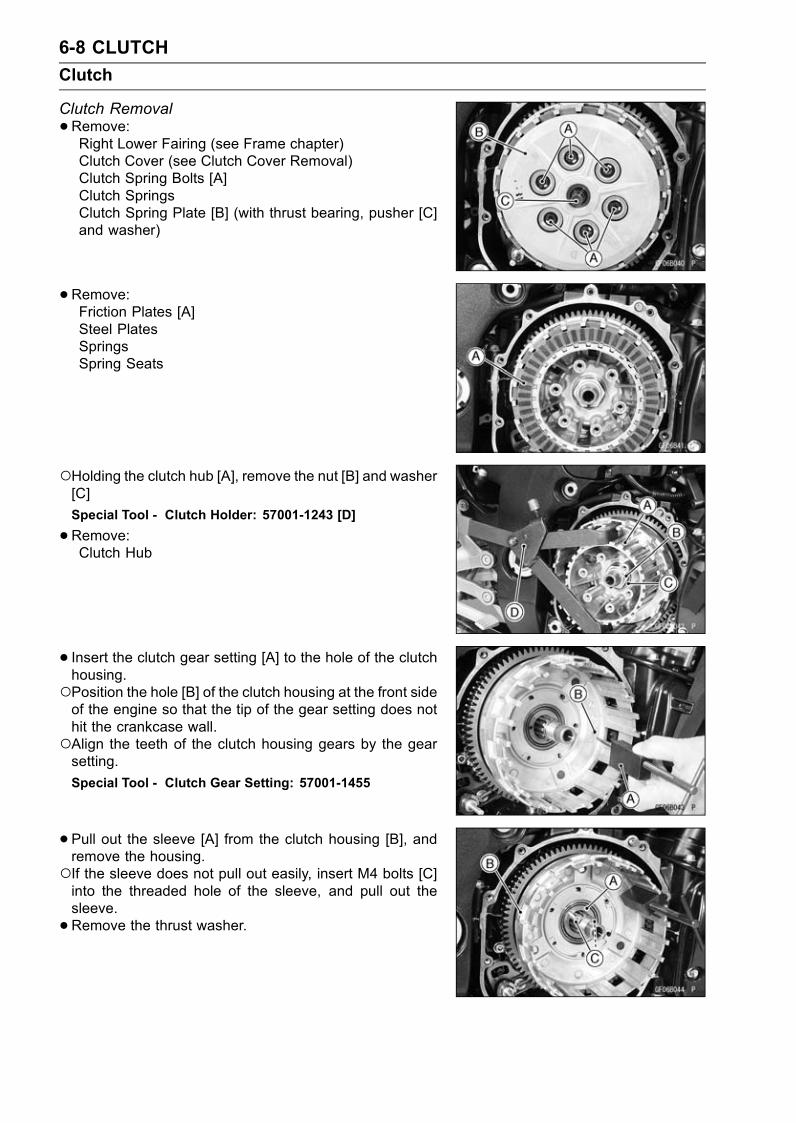
6-8 CLUTCH
Clutch
Clutch Removal
•Remove:Right Lower Fairing (see Frame chapter)Clutch Cover (see Clutch Cover Removal)Clutch Spring Bolts [A]Clutch SpringsClutch Spring Plate [B] (with thrust bearing, pusher [C]and washer)
•Remove:Friction Plates [A]Steel PlatesSpringsSpring Seats
Holding the clutch hub [A], remove the nut [B] and washer[C]
Special Tool - Clutch Holder: 57001-1243 [D]
•Remove:Clutch Hub
• Insert the clutch gear setting [A] to the hole of the clutchhousing.Position the hole [B] of the clutch housing at the front sideof the engine so that the tip of the gear setting does nothit the crankcase wall.Align the teeth of the clutch housing gears by the gearsetting.
Special Tool - Clutch Gear Setting: 57001-1455
•Pull out the sleeve [A] from the clutch housing [B], andremove the housing.If the sleeve does not pull out easily, insert M4 bolts [C]into the threaded hole of the sleeve, and pull out thesleeve.
•Remove the thrust washer.
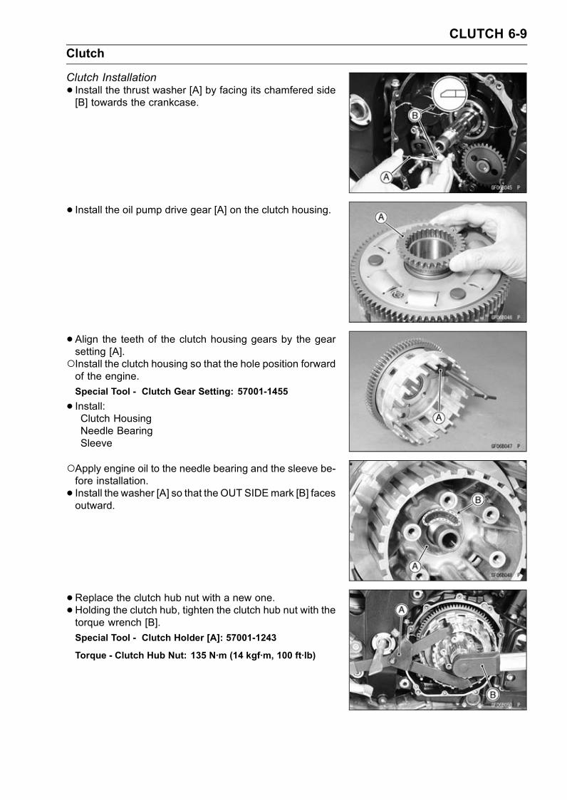
CLUTCH 6-9
Clutch
Clutch Installation
• Install the thrust washer [A] by facing its chamfered side[B] towards the crankcase.
• Install the oil pump drive gear [A] on the clutch housing.
• Align the teeth of the clutch housing gears by the gearsetting [A].Install the clutch housing so that the hole position forwardof the engine.
Special Tool - Clutch Gear Setting: 57001-1455
• Install:Clutch HousingNeedle BearingSleeve
Apply engine oil to the needle bearing and the sleeve be-fore installation.
• Install the washer [A] so that the OUT SIDEmark [B] facesoutward.
•Replace the clutch hub nut with a new one.•Holding the clutch hub, tighten the clutch hub nut with thetorque wrench [B].
Special Tool - Clutch Holder [A]: 57001-1243
Torque - Clutch Hub Nut: 135 N·m (14 kgf·m, 100 ft·lb)

6-10 CLUTCH
Clutch
• Install the spring seats [D] [F], springs [E], friction plates[A] [C] [H] and steel plates [B] as shown.
NOTEThe inside diameter of first and seventh friction platesare larger than the others because the spring seats andsprings are equipped to decrease the judder noise asshown.
Clutch Hub [G]
CAUTION
If new dry friction plates and steel plates are in-stalled, apply engine oil to the surfaces of eachplate to avoid clutch plate seizure.
Install outer-end friction plate, that has the narrowestgroove [A] among others.
Install the last friction plate [A] fitting the tangs in thegrooves in the housing as shown.
• Apply molybdenum disulfide oil solution [MO] to the out-side surface of the pusher [A], then install the pusher intothe drive shaft.
• Apply high-temperature grease [G] to both side of nee-dle bearing [B] and washer [C], then install them onto thepusher.
• Apply molybdenum disulfide grease [M] to the mating sur-face of the pusher.
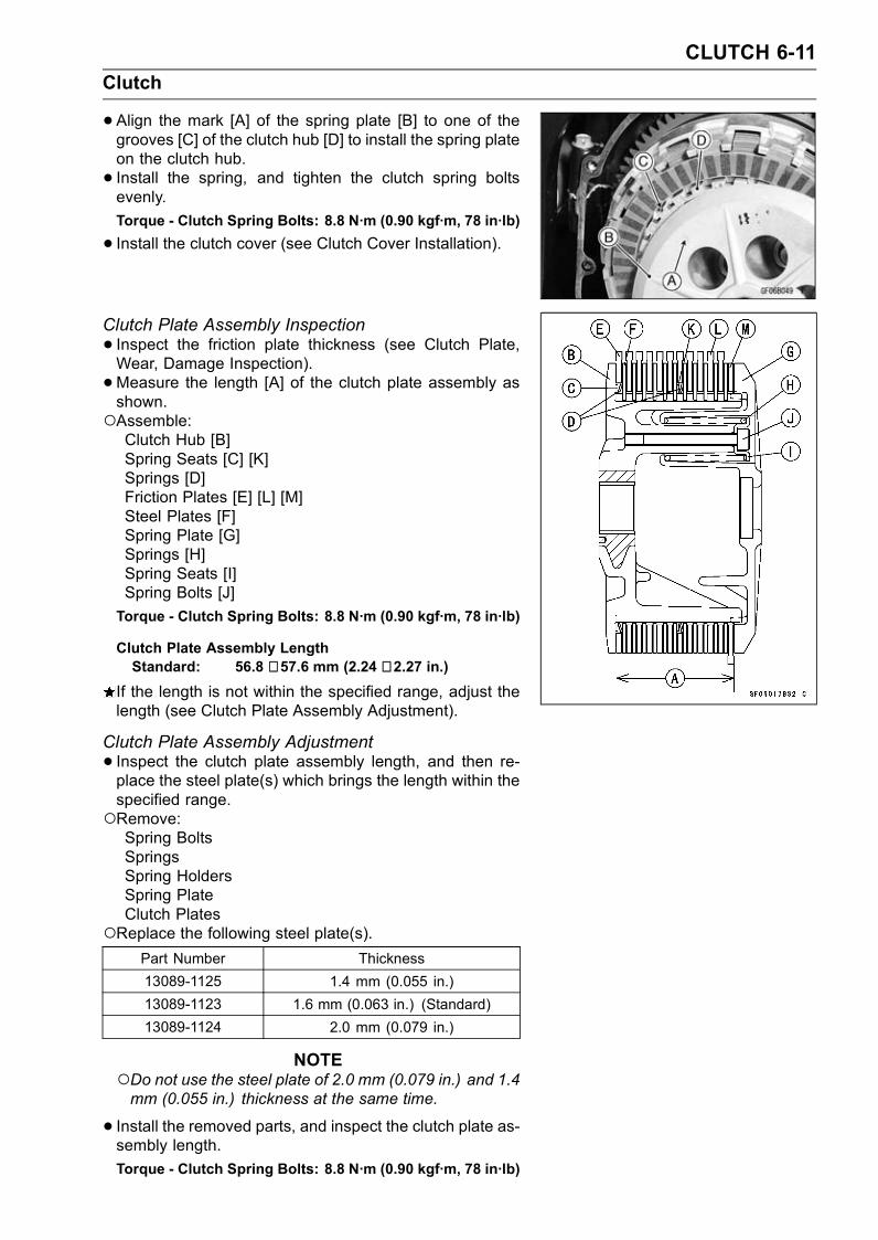
CLUTCH 6-11
Clutch
•Align the mark [A] of the spring plate [B] to one of thegrooves [C] of the clutch hub [D] to install the spring plateon the clutch hub.
• Install the spring, and tighten the clutch spring boltsevenly.
Torque - Clutch Spring Bolts: 8.8 N·m (0.90 kgf·m, 78 in·lb)
• Install the clutch cover (see Clutch Cover Installation).
Clutch Plate Assembly Inspection
• Inspect the friction plate thickness (see Clutch Plate,Wear, Damage Inspection).
•Measure the length [A] of the clutch plate assembly asshown.Assemble:Clutch Hub [B]Spring Seats [C] [K]Springs [D]Friction Plates [E] [L] [M]Steel Plates [F]Spring Plate [G]Springs [H]Spring Seats [I]Spring Bolts [J]
Torque - Clutch Spring Bolts: 8.8 N·m (0.90 kgf·m, 78 in·lb)
Clutch Plate Assembly LengthStandard: 56.8 ∼ 57.6 mm (2.24 ∼ 2.27 in.)
If the length is not within the specified range, adjust thelength (see Clutch Plate Assembly Adjustment).
Clutch Plate Assembly Adjustment
• Inspect the clutch plate assembly length, and then re-place the steel plate(s) which brings the length within thespecified range.Remove:Spring BoltsSpringsSpring HoldersSpring PlateClutch Plates
Replace the following steel plate(s).Part Number Thickness
13089-1125 1.4 mm (0.055 in.)
13089-1123 1.6 mm (0.063 in.) (Standard)
13089-1124 2.0 mm (0.079 in.)
NOTEDo not use the steel plate of 2.0 mm (0.079 in.) and 1.4mm (0.055 in.) thickness at the same time.
• Install the removed parts, and inspect the clutch plate as-sembly length.
Torque - Clutch Spring Bolts: 8.8 N·m (0.90 kgf·m, 78 in·lb)
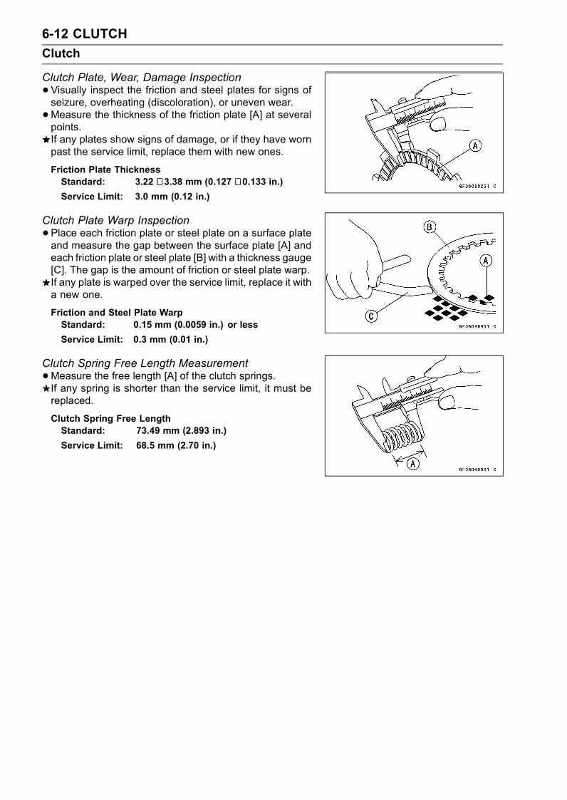
6-12 CLUTCH
Clutch
Clutch Plate, Wear, Damage Inspection
•Visually inspect the friction and steel plates for signs ofseizure, overheating (discoloration), or uneven wear.
•Measure the thickness of the friction plate [A] at severalpoints.If any plates show signs of damage, or if they have wornpast the service limit, replace them with new ones.
Friction Plate ThicknessStandard: 3.22 ∼ 3.38 mm (0.127 ∼ 0.133 in.)Service Limit: 3.0 mm (0.12 in.)
Clutch Plate Warp Inspection
•Place each friction plate or steel plate on a surface plateand measure the gap between the surface plate [A] andeach friction plate or steel plate [B] with a thickness gauge[C]. The gap is the amount of friction or steel plate warp.If any plate is warped over the service limit, replace it witha new one.
Friction and Steel Plate WarpStandard: 0.15 mm (0.0059 in.) or less
Service Limit: 0.3 mm (0.01 in.)
Clutch Spring Free Length Measurement
•Measure the free length [A] of the clutch springs.If any spring is shorter than the service limit, it must bereplaced.
Clutch Spring Free LengthStandard: 73.49 mm (2.893 in.)
Service Limit: 68.5 mm (2.70 in.)
ENGINE LUBRICATION SYSTEM 7-1
7
Engine Lubrication System
Table of Contents
Exploded View........................................................................................................................ 7-2Engine Oil Flow Chart............................................................................................................. 7-3Specifications ......................................................................................................................... 7-4Engine Oil and Oil Filter.......................................................................................................... 7-5
Oil Level Inspection........................................................................................................... 7-5Engine Oil Change............................................................................................................ 7-5Oil Filter Replacement ...................................................................................................... 7-5
Oil Cooler................................................................................................................................ 7-6Oil Cooler Removal........................................................................................................... 7-6Oil Cooler Installation........................................................................................................ 7-6
Oil Pan.................................................................................................................................... 7-7Oil Pan Removal ............................................................................................................... 7-7Oil Pan Installation............................................................................................................ 7-7
Oil Pump, Oil Pump Drive Gear and Oil Pressure Relief Valve.............................................. 7-9Oil Pump Removal ............................................................................................................ 7-9Oil Pump Installation ......................................................................................................... 7-9Oil Pump Inspection.......................................................................................................... 7-9Oil Pump Drive Gear Removal.......................................................................................... 7-10Oil Pump Drive Gear Installation....................................................................................... 7-10Oil Pressure Relief Valve Inspection................................................................................. 7-10
Oil Pressure Measurement..................................................................................................... 7-12Oil Pressure Measurement ............................................................................................... 7-12
Oil Pressure Switch ................................................................................................................ 7-13Oil Pressure Switch Removal ........................................................................................... 7-13Oil Pressure Switch Installation ........................................................................................ 7-13
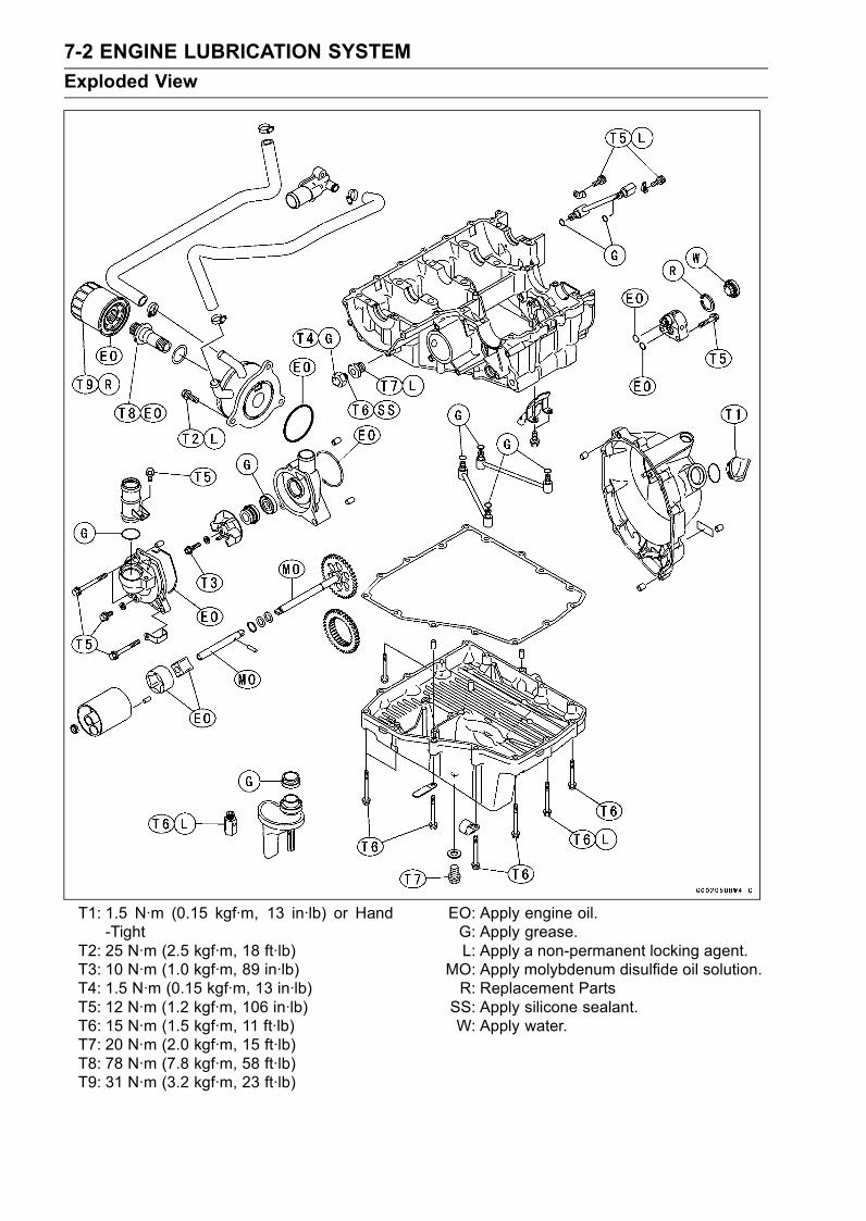
7-2 ENGINE LUBRICATION SYSTEM
Exploded View
T1: 1.5 N·m (0.15 kgf·m, 13 in·lb) or Hand-Tight
T2: 25 N·m (2.5 kgf·m, 18 ft·lb)T3: 10 N·m (1.0 kgf·m, 89 in·lb)T4: 1.5 N·m (0.15 kgf·m, 13 in·lb)T5: 12 N·m (1.2 kgf·m, 106 in·lb)T6: 15 N·m (1.5 kgf·m, 11 ft·lb)T7: 20 N·m (2.0 kgf·m, 15 ft·lb)T8: 78 N·m (7.8 kgf·m, 58 ft·lb)T9: 31 N·m (3.2 kgf·m, 23 ft·lb)
EO: Apply engine oil.G: Apply grease.L: Apply a non-permanent locking agent.
MO: Apply molybdenum disulfide oil solution.R: Replacement PartsSS: Apply silicone sealant.W: Apply water.

ENGINE LUBRICATION SYSTEM 7-3
Engine Oil Flow Chart
1. Camshaft Oil Passage2. Oil Pipe3. Main Oil Passage4. Crankshaft Oil Passage5. Oil Filter6. Oil Cooler7. Oil Pressure Switch8. Oil Pipe9. Oil Pump10. To Drive Shaft11. Oil Pipe12. To Output Shaft
13. Drive Shaft Oil Passage Hole14. Output Shaft Oil Passage Hole15. Inlet Camshaft16. Exhaust Camshaft17. To Air Cleaner18. Drive Shaft19. Relief Valve20. Oil Screen21. Oil Drain Plug22. Output Shaft23. Stater Clutch

7-4 ENGINE LUBRICATION SYSTEM
Specifications
Item Standard
Engine Oil
Grade API SE, SF, or SG
API SH or SJ with JASO MA
Viscosity SAE 10W-40
Capacity 2.5 L (2.6 US qt, when filter is not removed)
2.8 L (3.0 US qt, when filter is removed)
3.6 L (3.8 US qt, when engine is completely dry)
Level Between upper and lower level lines
Oil Pressure Measurement
Oil Pressure @4 000 r/min (rpm),Oil Temperature 90°C (194°F)
196 kPa (2.0 kgf/cm², 28 psi)
Special Tools - Outside Circlip Pliers: 57001-144Oil Pressure Gauge, 10 kgf/cm²: 57001-164Oil Pressure Gauge Adapter, PT 1/8: 57001-1033Oil Filter Wrench: 57001-1249
Sealant - Kawasaki Bond (Silicone Sealant): 56019-120
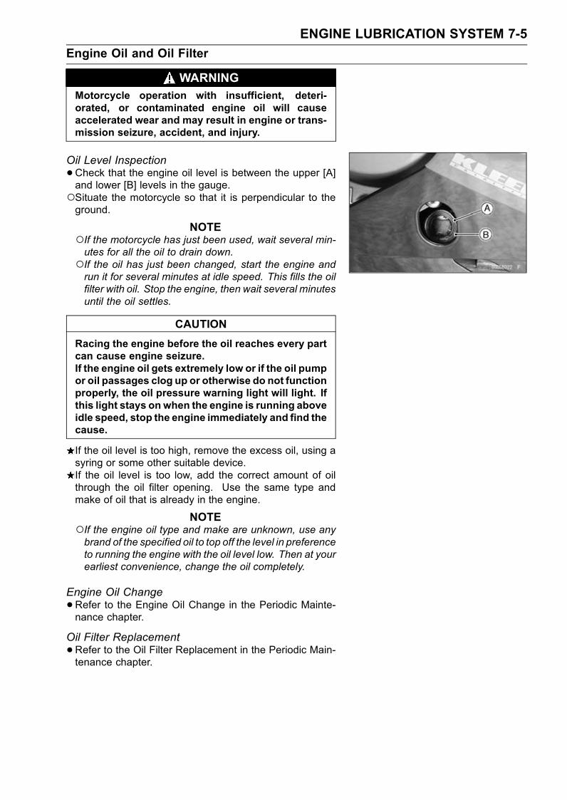
ENGINE LUBRICATION SYSTEM 7-5
Engine Oil and Oil Filter
WARNINGMotorcycle operation with insufficient, deteri-orated, or contaminated engine oil will causeaccelerated wear and may result in engine or trans-mission seizure, accident, and injury.
Oil Level Inspection
•Check that the engine oil level is between the upper [A]and lower [B] levels in the gauge.Situate the motorcycle so that it is perpendicular to theground.
NOTEIf the motorcycle has just been used, wait several min-utes for all the oil to drain down.If the oil has just been changed, start the engine andrun it for several minutes at idle speed. This fills the oilfilter with oil. Stop the engine, then wait several minutesuntil the oil settles.
CAUTION
Racing the engine before the oil reaches every partcan cause engine seizure.If the engine oil gets extremely low or if the oil pumpor oil passages clog up or otherwise do not functionproperly, the oil pressure warning light will light. Ifthis light stays onwhen the engine is running aboveidle speed, stop the engine immediately and find thecause.
If the oil level is too high, remove the excess oil, using asyring or some other suitable device.If the oil level is too low, add the correct amount of oilthrough the oil filter opening. Use the same type andmake of oil that is already in the engine.
NOTEIf the engine oil type and make are unknown, use anybrand of the specified oil to top off the level in preferenceto running the engine with the oil level low. Then at yourearliest convenience, change the oil completely.
Engine Oil Change
•Refer to the Engine Oil Change in the Periodic Mainte-nance chapter.
Oil Filter Replacement
•Refer to the Oil Filter Replacement in the Periodic Main-tenance chapter.

7-6 ENGINE LUBRICATION SYSTEM
Oil Cooler
Oil Cooler Removal
•Remove:Left Lower Fairing (see Frame chapter)
•Drain:Engine Oil (see Engine Oil Change in the Periodic Main-tenance chapter)Coolant (see Coolant Change in the Periodic Mainte-nance chapter)
• Loosen the clamp screws [A] and remove the oil coolerwater hoses [B] from the oil cooler.
•Remove the oil filter (see Oil Filter Replace in the PeriodicMaintenance chapter).
• Unscrew the oil cooler mounting bolts [A] and oil coolerpassage bolt [B] from the crankcase.
•Remove the oil cooler.•Drain the coolant and engine oil remaining in the oil coolerinto a suitable container.
Oil Cooler Installation
• Installation is the reverse of removal. Note the following.• Apply engine oil to the O-ring [A] before installation.
• Apply engine oil to the oil cooler passage bolt.• Apply a non-permanent locking agent to the oil coolermounting bolts and install the oil cooler temporarily withthe bolt.
• Install the oil cooler mounting bolts evenly.• Tighten the oil cooler passage bolt [A].Torque - Oil Cooler Passage Bolt: 78 N·m (7.8 kgf·m, 58
ft·lb)
•Tighten the oil cooler mounting bolts [B].Torque - Oil Cooler Mounting Bolts: 25 N·m (2.5 kgf·m, 18
ft·lb)
•Pour:Engine Oil (see Engine Oil Change in the Periodic Main-tenance chapter)Coolant (see Coolant Change in the Periodic Mainte-nance chapter)
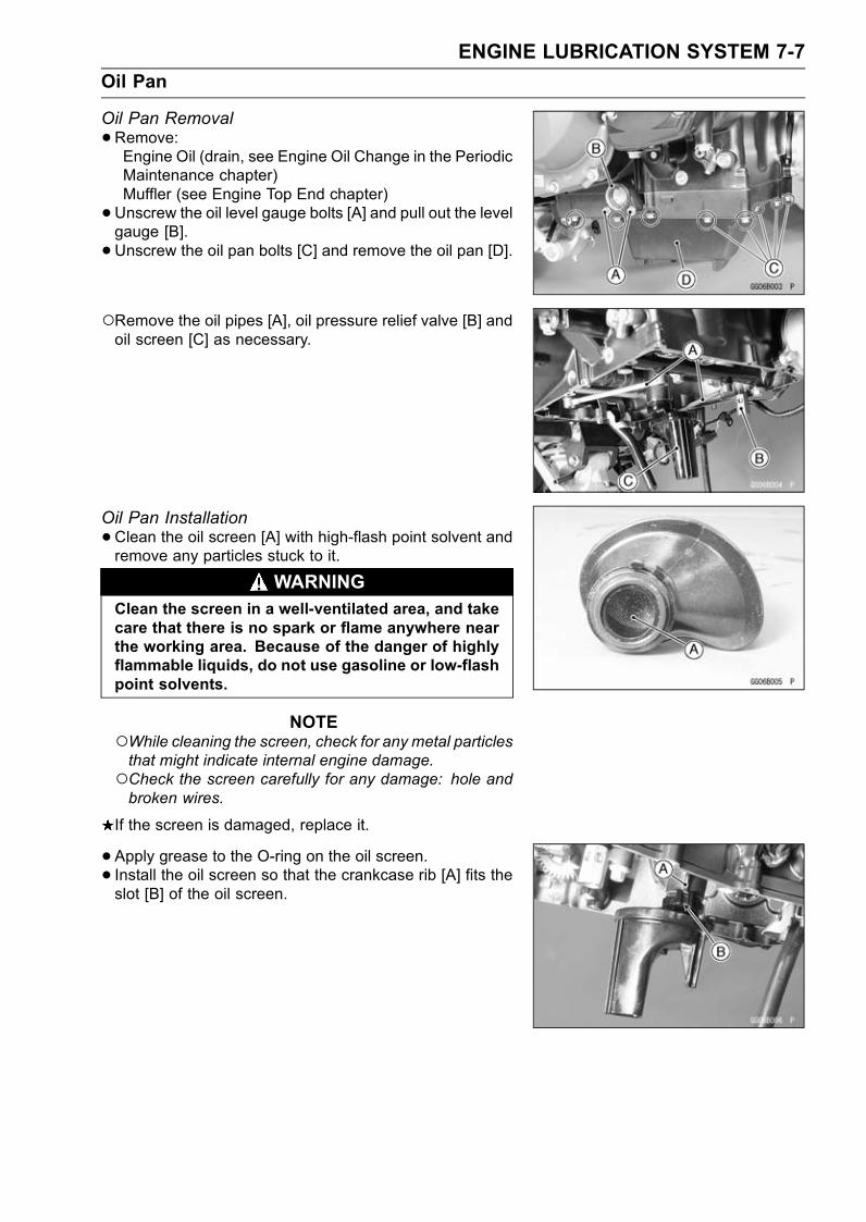
ENGINE LUBRICATION SYSTEM 7-7
Oil Pan
Oil Pan Removal
•Remove:Engine Oil (drain, see Engine Oil Change in the PeriodicMaintenance chapter)Muffler (see Engine Top End chapter)
•Unscrew the oil level gauge bolts [A] and pull out the levelgauge [B].
•Unscrew the oil pan bolts [C] and remove the oil pan [D].
Remove the oil pipes [A], oil pressure relief valve [B] andoil screen [C] as necessary.
Oil Pan Installation
•Clean the oil screen [A] with high-flash point solvent andremove any particles stuck to it.
WARNINGClean the screen in a well-ventilated area, and takecare that there is no spark or flame anywhere nearthe working area. Because of the danger of highlyflammable liquids, do not use gasoline or low-flashpoint solvents.
NOTEWhile cleaning the screen, check for any metal particlesthat might indicate internal engine damage.Check the screen carefully for any damage: hole andbroken wires.
If the screen is damaged, replace it.
• Apply grease to the O-ring on the oil screen.• Install the oil screen so that the crankcase rib [A] fits theslot [B] of the oil screen.
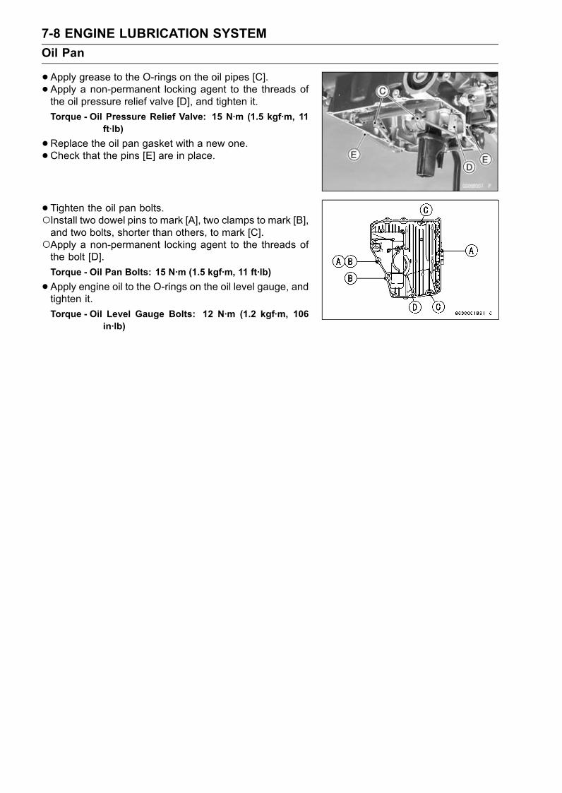
7-8 ENGINE LUBRICATION SYSTEM
Oil Pan
•Apply grease to the O-rings on the oil pipes [C].• Apply a non-permanent locking agent to the threads ofthe oil pressure relief valve [D], and tighten it.
Torque - Oil Pressure Relief Valve: 15 N·m (1.5 kgf·m, 11ft·lb)
•Replace the oil pan gasket with a new one.•Check that the pins [E] are in place.
• Tighten the oil pan bolts.Install two dowel pins to mark [A], two clamps to mark [B],and two bolts, shorter than others, to mark [C].Apply a non-permanent locking agent to the threads ofthe bolt [D].
Torque - Oil Pan Bolts: 15 N·m (1.5 kgf·m, 11 ft·lb)
•Apply engine oil to the O-rings on the oil level gauge, andtighten it.
Torque - Oil Level Gauge Bolts: 12 N·m (1.2 kgf·m, 106in·lb)
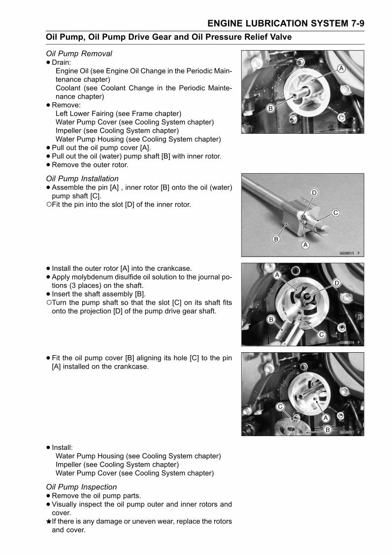
ENGINE LUBRICATION SYSTEM 7-9
Oil Pump, Oil Pump Drive Gear and Oil Pressure Relief Valve
Oil Pump Removal
•Drain:Engine Oil (see Engine Oil Change in the Periodic Main-tenance chapter)Coolant (see Coolant Change in the Periodic Mainte-nance chapter)
•Remove:Left Lower Fairing (see Frame chapter)Water Pump Cover (see Cooling System chapter)Impeller (see Cooling System chapter)Water Pump Housing (see Cooling System chapter)
• Pull out the oil pump cover [A].• Pull out the oil (water) pump shaft [B] with inner rotor.•Remove the outer rotor.Oil Pump Installation
•Assemble the pin [A] , inner rotor [B] onto the oil (water)pump shaft [C].Fit the pin into the slot [D] of the inner rotor.
• Install the outer rotor [A] into the crankcase.• Apply molybdenum disulfide oil solution to the journal po-tions (3 places) on the shaft.
• Insert the shaft assembly [B].Turn the pump shaft so that the slot [C] on its shaft fitsonto the projection [D] of the pump drive gear shaft.
• Fit the oil pump cover [B] aligning its hole [C] to the pin[A] installed on the crankcase.
• Install:Water Pump Housing (see Cooling System chapter)Impeller (see Cooling System chapter)Water Pump Cover (see Cooling System chapter)
Oil Pump Inspection
•Remove the oil pump parts.• Visually inspect the oil pump outer and inner rotors andcover.If there is any damage or uneven wear, replace the rotorsand cover.

7-10 ENGINE LUBRICATION SYSTEM
Oil Pump, Oil Pump Drive Gear and Oil Pressure Relief Valve
Oil Pump Drive Gear Removal
•Remove:Clutch (see Clutch chapter)Oil Pan (see Oil Pan Removal)Circlip [A] and Washer [B]
Special Tool - Outside Circlip Pliers: 57001-144
•Pull the oil pump drive gear [A] outside.
Oil Pump Drive Gear Installation
•Apply molybdenum disulfide oil solution to the journal po-tion on the oil pump gear shaft.
• Install the circlip [A] into the groove [B] of the oil pumpdrive gear shaft.
Special Tool - Outside Circlip Pliers: 57001-144
Oil Pressure Relief Valve Inspection
•Remove:Oil Pan (see Oil Pan Removal)Relief Valve [A]
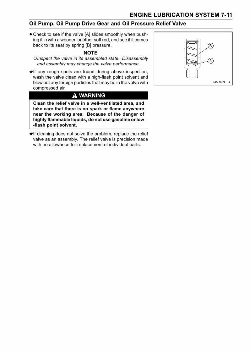
ENGINE LUBRICATION SYSTEM 7-11
Oil Pump, Oil Pump Drive Gear and Oil Pressure Relief Valve
•Check to see if the valve [A] slides smoothly when push-ing it in with a wooden or other soft rod, and see if it comesback to its seat by spring [B] pressure.
NOTEInspect the valve in its assembled state. Disassemblyand assembly may change the valve performance.
If any rough spots are found during above inspection,wash the valve clean with a high-flash point solvent andblow out any foreign particles that may be in the valve withcompressed air.
WARNINGClean the relief valve in a well-ventilated area, andtake care that there is no spark or flame anywherenear the working area. Because of the danger ofhighly flammable liquids, do not use gasoline or low-flash point solvent.
If cleaning does not solve the problem, replace the reliefvalve as an assembly. The relief valve is precision madewith no allowance for replacement of individual parts.
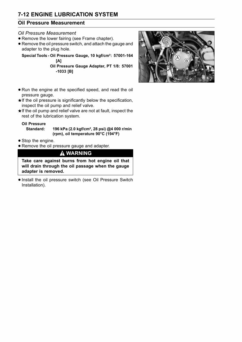
7-12 ENGINE LUBRICATION SYSTEM
Oil Pressure Measurement
Oil Pressure Measurement
•Remove the lower fairing (see Frame chapter).• Remove the oil pressure switch, and attach the gauge andadapter to the plug hole.
Special Tools - Oil Pressure Gauge, 10 kgf/cm²: 57001-164[A]
Oil Pressure Gauge Adapter, PT 1/8: 57001-1033 [B]
•Run the engine at the specified speed, and read the oilpressure gauge.If the oil pressure is significantly below the specification,inspect the oil pump and relief valve.If the oil pump and relief valve are not at fault, inspect therest of the lubrication system.
Oil PressureStandard: 196 kPa (2.0 kgf/cm², 28 psi) @4 000 r/min
(rpm), oil temperature 90°C (194°F)
•Stop the engine.•Remove the oil pressure gauge and adapter.
WARNINGTake care against burns from hot engine oil thatwill drain through the oil passage when the gaugeadapter is removed.
• Install the oil pressure switch (see Oil Pressure SwitchInstallation).
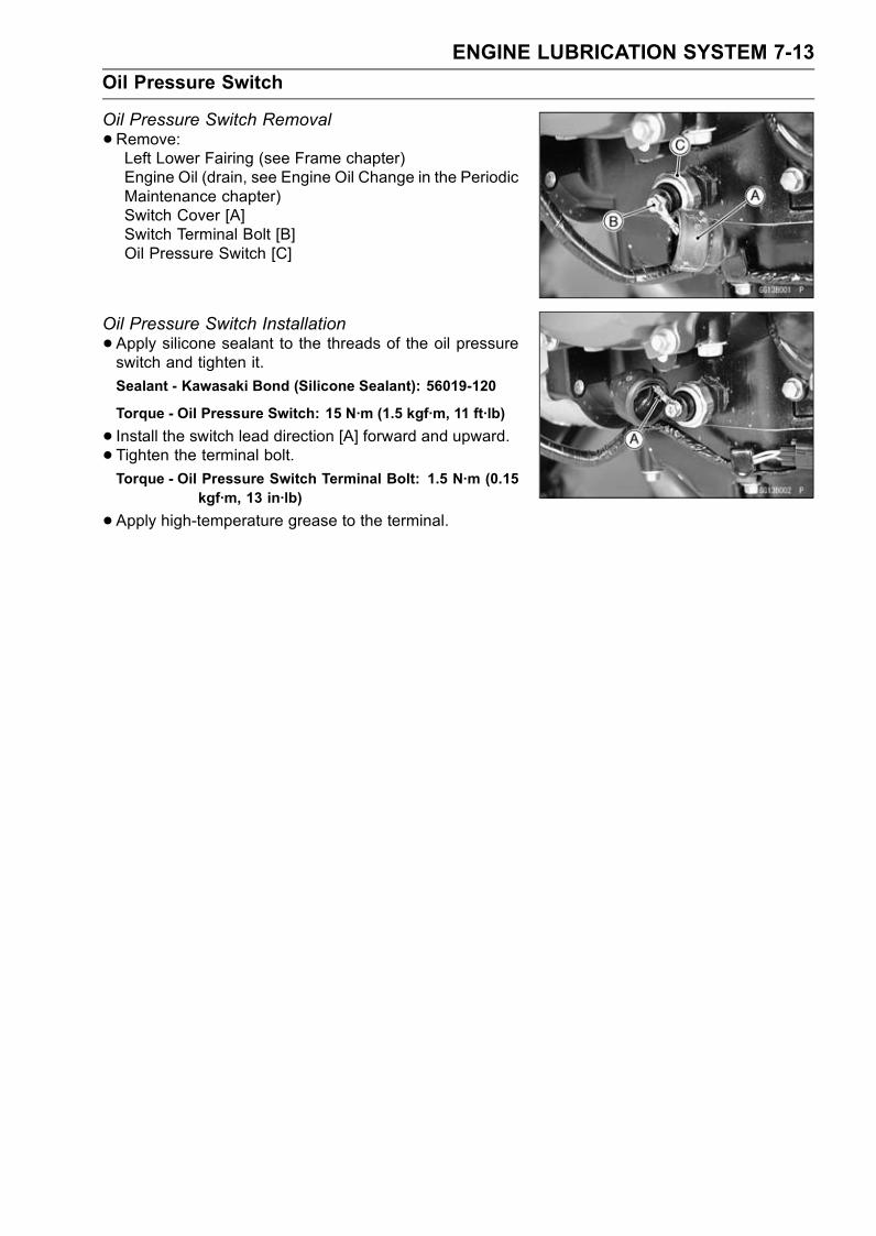
ENGINE LUBRICATION SYSTEM 7-13
Oil Pressure Switch
Oil Pressure Switch Removal
•Remove:Left Lower Fairing (see Frame chapter)Engine Oil (drain, see Engine Oil Change in the PeriodicMaintenance chapter)Switch Cover [A]Switch Terminal Bolt [B]Oil Pressure Switch [C]
Oil Pressure Switch Installation
•Apply silicone sealant to the threads of the oil pressureswitch and tighten it.
Sealant - Kawasaki Bond (Silicone Sealant): 56019-120
Torque - Oil Pressure Switch: 15 N·m (1.5 kgf·m, 11 ft·lb)
• Install the switch lead direction [A] forward and upward.• Tighten the terminal bolt.Torque - Oil Pressure Switch Terminal Bolt: 1.5 N·m (0.15
kgf·m, 13 in·lb)
•Apply high-temperature grease to the terminal.

ENGINE REMOVAL/INSTALLATION 8-1
8
Engine Removal/Installation
Table of Contents
Exploded View........................................................................................................................ 8-2Engine Removal/Installation ................................................................................................... 8-3
Engine Removal................................................................................................................ 8-3Engine Installation............................................................................................................. 8-5
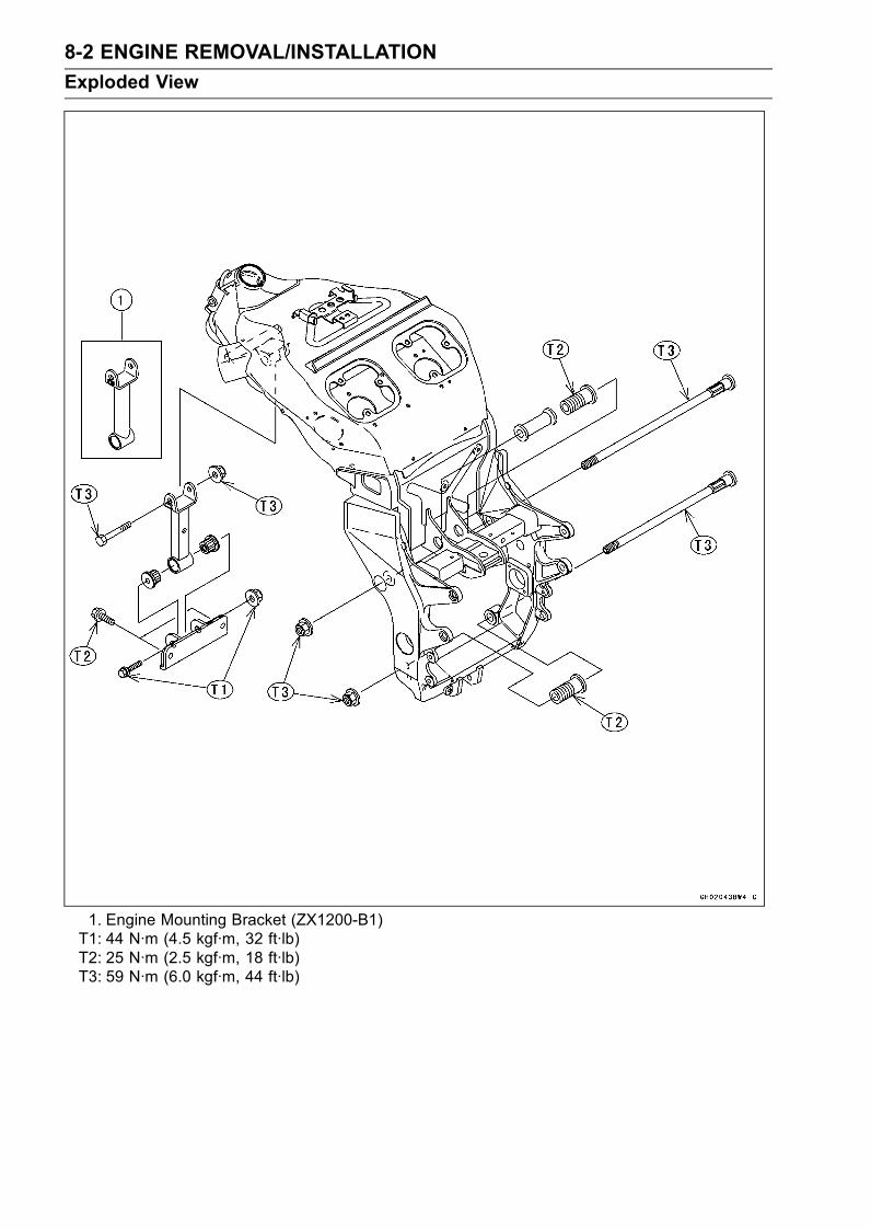
8-2 ENGINE REMOVAL/INSTALLATION
Exploded View
1. Engine Mounting Bracket (ZX1200-B1)T1: 44 N·m (4.5 kgf·m, 32 ft·lb)T2: 25 N·m (2.5 kgf·m, 18 ft·lb)T3: 59 N·m (6.0 kgf·m, 44 ft·lb)
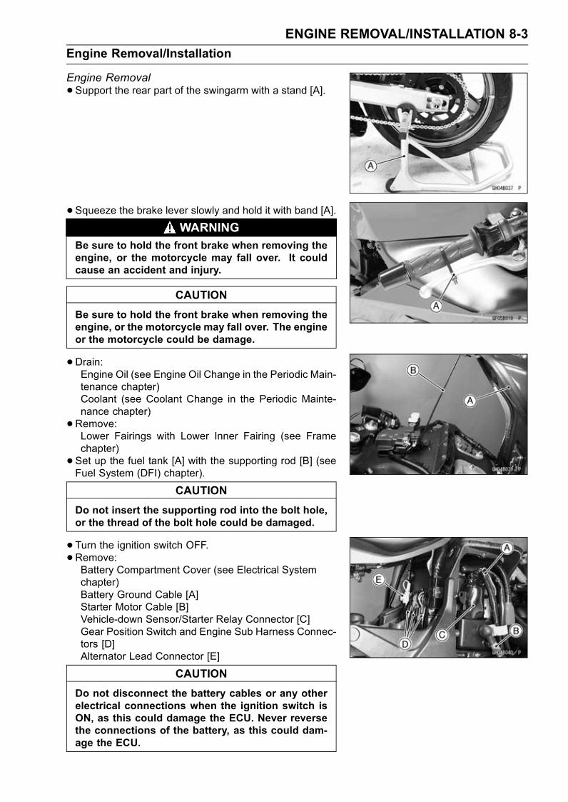
ENGINE REMOVAL/INSTALLATION 8-3
Engine Removal/Installation
Engine Removal
•Support the rear part of the swingarm with a stand [A].
• Squeeze the brake lever slowly and hold it with band [A].WARNING
Be sure to hold the front brake when removing theengine, or the motorcycle may fall over. It couldcause an accident and injury.
CAUTION
Be sure to hold the front brake when removing theengine, or the motorcycle may fall over. The engineor the motorcycle could be damage.
•Drain:Engine Oil (see Engine Oil Change in the Periodic Main-tenance chapter)Coolant (see Coolant Change in the Periodic Mainte-nance chapter)
•Remove:Lower Fairings with Lower Inner Fairing (see Framechapter)
• Set up the fuel tank [A] with the supporting rod [B] (seeFuel System (DFI) chapter).
CAUTION
Do not insert the supporting rod into the bolt hole,or the thread of the bolt hole could be damaged.
•Turn the ignition switch OFF.•Remove:Battery Compartment Cover (see Electrical Systemchapter)Battery Ground Cable [A]Starter Motor Cable [B]Vehicle-down Sensor/Starter Relay Connector [C]Gear Position Switch and Engine Sub Harness Connec-tors [D]Alternator Lead Connector [E]
CAUTION
Do not disconnect the battery cables or any otherelectrical connections when the ignition switch isON, as this could damage the ECU. Never reversethe connections of the battery, as this could dam-age the ECU.
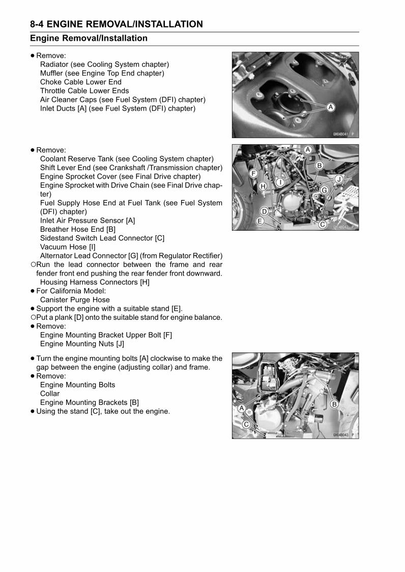
8-4 ENGINE REMOVAL/INSTALLATION
Engine Removal/Installation
•Remove:Radiator (see Cooling System chapter)Muffler (see Engine Top End chapter)Choke Cable Lower EndThrottle Cable Lower EndsAir Cleaner Caps (see Fuel System (DFI) chapter)Inlet Ducts [A] (see Fuel System (DFI) chapter)
•Remove:Coolant Reserve Tank (see Cooling System chapter)Shift Lever End (see Crankshaft /Transmission chapter)Engine Sprocket Cover (see Final Drive chapter)Engine Sprocket with Drive Chain (see Final Drive chap-ter)Fuel Supply Hose End at Fuel Tank (see Fuel System(DFI) chapter)Inlet Air Pressure Sensor [A]Breather Hose End [B]Sidestand Switch Lead Connector [C]Vacuum Hose [I]Alternator Lead Connector [G] (from Regulator Rectifier)
Run the lead connector between the frame and rearfender front end pushing the rear fender front downward.Housing Harness Connectors [H]
• For California Model:Canister Purge Hose
•Support the engine with a suitable stand [E].Put a plank [D] onto the suitable stand for engine balance.•Remove:Engine Mounting Bracket Upper Bolt [F]Engine Mounting Nuts [J]
• Turn the engine mounting bolts [A] clockwise to make thegap between the engine (adjusting collar) and frame.
•Remove:Engine Mounting BoltsCollarEngine Mounting Brackets [B]
•Using the stand [C], take out the engine.

ENGINE REMOVAL/INSTALLATION 8-5
Engine Removal/Installation
Engine Installation
CAUTION
Do not connect the throttle sensor connector to theinlet air pressure sensor, because the pressure sen-sor is broken by the opposite electrical connection.
•Before the engine installing, install the following parts.Engine Sub Harness [A]Gear Position Switch Harness [B]Alternator Leads [D]
•Confirm:Cooling Hoses [C] Position
•Confirm the leads and hoses position as shown.Clamps [A], [C]Alternator Lead (Yellow) [B]Alternator Lead (White) [D]Gear Position Switch Lead [E]Engine Sub Harness [F]Fuel Supply Hose [G]Tube [H]Tube [I] (for California Model)
• Tighten the adjusting collars [A] fully by hand.Crankcase [B]
• Support the engine with a suitable stand.•Hang the drive chain over the output shaft just beforemoving the engine into its final position in the frame.
• Insert the lower mounting bolt [A].• Set the collar [B] and insert the upper mounting bolt [C].
NOTEBefore inserting the engine mounting bolts, verify thatthe fuel hose and tubes (one tube for California modelonly), alternator lead connectors, gear position switchand engine sub harness connectors are clear an open-ing between the frame and engine.

8-6 ENGINE REMOVAL/INSTALLATION
Engine Removal/Installation
• Install the engine mounting bracket [A] to the engine.Torque - EngineMounting Bolts (M8) [B]: 25 N·m (2.5 kgf·m,
18 ft·lb)
• Install the engine mounting bracket [C] temporarily.Engine Mounting Bracket Bolt (M12) [D]Engine Mounting Bracket Bolt (M10) [E]
• Insert the mounting bolts [A] until they fit in the adjustingcollars [B].
• Turn the mounting bolts counterclockwise with specifiedtorque until the clearance [C] between the crankcase [D]and frame [E] come to zero mm [F].
Torque - Adjusting Collars: 25 N·m (2.5 kgf·m, 18 ft·lb)
•Hold the upper and lower engine mounting bolts withan Allen wrench, and tighten the nuts [A] with specifiedtorque.
Torque - Engine Mounting Nuts (M12): 59 N·m (6.0 kgf·m,44 ft·lb)
•Tighten the engine mounting bracket bolts [B] with thesequence lower and upper.Engine Mounting Bolts (M8) [C]
Torque - Lower Engine Mounting Bracket Bolt (M10): 44N·m (4.5 kgf·m, 32 ft·lb)
Upper Engine Mounting Bracket Bolt (M12): 59N·m (6.0 kgf·m, 44 ft·lb)
• Install the removed parts (see appropriate chapters).• Adjust:Throttle Cables (see Fuel System (DFI) chapter)Choke Cable (see Fuel System (DFI) chapter)Clutch Cable (see Clutch chapter)Drive Chain (see Final Drive chapter)
CRANKSHAFT/TRANSMISSION 9-1
9
Crankshaft/Transmission
Table of Contents
Exploded View................................... 9-2Specifications .................................... 9-4Crankcase Splitting............................ 9-7
Crankcase Splitting ...................... 9-7Crankcase Assembly ................... 9-7
Crankshaft and Connecting Rods...... 9-11Crankshaft Removal .................... 9-11Crankshaft Installation ................. 9-11Connecting Rod Removal ............ 9-11Connecting Rod Installation ......... 9-11Connecting Rod Bend.................. 9-13Connecting Rod Twist .................. 9-14Connecting Rod Big End SideClearance.................................. 9-14
Connecting Rod Big End BearingInsert/Crankpin Wear ................ 9-14
Crankshaft Main BearingInsert/Journal Wear................... 9-16
Crankshaft Side Clearance .......... 9-17Crankshaft Runout ....................... 9-18
Balancer ............................................ 9-19Balancer Removal........................ 9-19Balancer Installation..................... 9-19Balancer Damper Inspection........ 9-20
Starter Motor Clutch and TorqueLimiter ............................................. 9-21Starter MotorRemoval/Installation.................. 9-21
Starter Motor Clutch Removal...... 9-21
Starter Motor Clutch Installation... 9-21Starter Motor Clutch Disassembly 9-21Starter Motor Clutch Assembly .... 9-22Starter Clutch Inspection.............. 9-22Torque Limiter Removal ............... 9-23Torque Limiter Installation ............ 9-23
Transmission ..................................... 9-24Shift Pedal Removal .................... 9-24Shift Pedal Installation ................. 9-24External Shift MechanismRemoval .................................... 9-25
External Shift MechanismInstallation ................................. 9-26
External Shift MechanismInspection.................................. 9-26
Transmission Shaft Removal ....... 9-26Transmission Shaft Installation .... 9-27Transmission Disassembly .......... 9-27Transmission Assembly ............... 9-28Shift Drum and Fork Removal...... 9-30Shift Drum and Fork Installation... 9-31Shift Drum Disassembly............... 9-31Shift Drum Assembly ................... 9-32Shift Fork Bending ....................... 9-32Shift Fork/Gear Groove Wear ...... 9-32Shift Fork Guide Pin/DrumGroove Wear............................. 9-32
Gear Dog and Gear Dog HoleDamage..................................... 9-33

9-2 CRANKSHAFT/TRANSMISSION
Exploded View
1. Clamp (ZX1200-B1/B2)T1: 5.4 N·m (0.55 kgf·m, 48 in·lb)T2: 10 N·m (1.0 kgf·m, 89 in·lb)T3: 12 N·m (1.2 kgf·m, 106 in·lb)T4: 15 N·m (1.5 kgf·m, 11 ft·lb)T5: 20 N·m (2.0 kgf·m, 15 ft·lb)T6: 23 N·m (2.3 kgf·m, 17 ft·lb)T7: 39 N·m (4.0 kgf·m, 29 ft·lb)
T8: 30 N·m (3.0 kgf·m, 22 ft·lb)T9: See the text.T10: 50 N·m (5.0 kgf·m, 37 ft·lb)T11: 28 N·m (2.8 kgf·m, 21 ft·lb)T12: 25 N·m (2.5 kgf·m, 18 ft·lb)T13: 2.5 N·m (0.25 kgf·m, 22 in·lb)T14: 1.5 N·m (0.15 kgf·m, 13 in·lb)

CRANKSHAFT/TRANSMISSION 9-3
Exploded View
D: Do not apply any grease or oil.EO: Apply engine oil.G: Apply grease.L: Apply a non-permanent locking agent.
LG: Apply liquid gasket (Three Bond 1207B).M: Apply molybdenum disulfide grease.
MO: Apply molybdenum disulfide oil solution.R: Replacement PartsS: Follow the specific tightening sequence.SS: Apply silicone sealant.St: Stake the fasteners to prevent loosening.
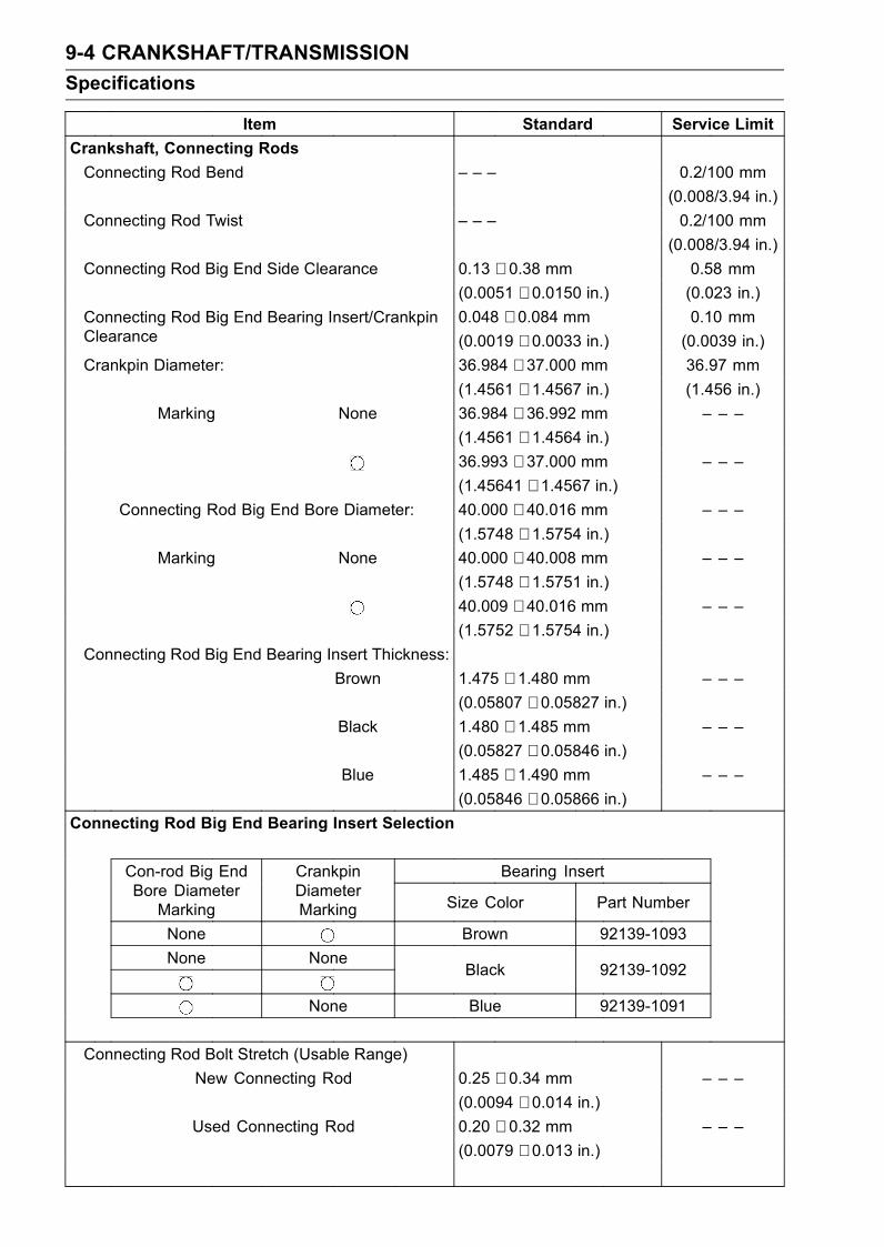
9-4 CRANKSHAFT/TRANSMISSION
Specifications
Item Standard Service Limit
Crankshaft, Connecting Rods
Connecting Rod Bend – – – 0.2/100 mm
(0.008/3.94 in.)
Connecting Rod Twist – – – 0.2/100 mm
(0.008/3.94 in.)
Connecting Rod Big End Side Clearance 0.13 ∼ 0.38 mm 0.58 mm
(0.0051 ∼ 0.0150 in.) (0.023 in.)
0.048 ∼ 0.084 mm 0.10 mmConnecting Rod Big End Bearing Insert/CrankpinClearance (0.0019 ∼ 0.0033 in.) (0.0039 in.)
Crankpin Diameter: 36.984 ∼ 37.000 mm 36.97 mm
(1.4561 ∼ 1.4567 in.) (1.456 in.)
Marking None 36.984 ∼ 36.992 mm – – –
(1.4561 ∼ 1.4564 in.)36.993 ∼ 37.000 mm – – –
(1.45641 ∼ 1.4567 in.)Connecting Rod Big End Bore Diameter: 40.000 ∼ 40.016 mm – – –
(1.5748 ∼ 1.5754 in.)Marking None 40.000 ∼ 40.008 mm – – –
(1.5748 ∼ 1.5751 in.)40.009 ∼ 40.016 mm – – –
(1.5752 ∼ 1.5754 in.)Connecting Rod Big End Bearing Insert Thickness:
Brown 1.475 ∼ 1.480 mm – – –
(0.05807 ∼ 0.05827 in.)Black 1.480 ∼ 1.485 mm – – –
(0.05827 ∼ 0.05846 in.)Blue 1.485 ∼ 1.490 mm – – –
(0.05846 ∼ 0.05866 in.)Connecting Rod Big End Bearing Insert Selection
Bearing InsertCon-rod Big EndBore Diameter
Marking
CrankpinDiameterMarking Size Color Part Number
None Brown 92139-1093
None NoneBlack 92139-1092
None Blue 92139-1091
Connecting Rod Bolt Stretch (Usable Range)
New Connecting Rod 0.25 ∼ 0.34 mm – – –
(0.0094 ∼ 0.014 in.)Used Connecting Rod 0.20 ∼ 0.32 mm – – –
(0.0079 ∼ 0.013 in.)
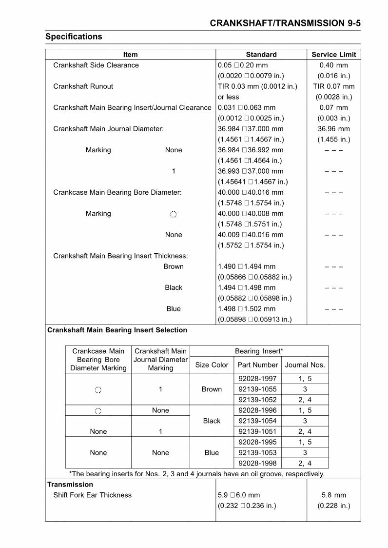
CRANKSHAFT/TRANSMISSION 9-5
Specifications
Item Standard Service Limit
Crankshaft Side Clearance 0.05 ∼ 0.20 mm 0.40 mm
(0.0020 ∼ 0.0079 in.) (0.016 in.)
Crankshaft Runout TIR 0.03 mm (0.0012 in.) TIR 0.07 mm
or less (0.0028 in.)
Crankshaft Main Bearing Insert/Journal Clearance 0.031 ∼ 0.063 mm 0.07 mm
(0.0012 ∼ 0.0025 in.) (0.003 in.)
Crankshaft Main Journal Diameter: 36.984 ∼ 37.000 mm 36.96 mm
(1.4561 ∼ 1.4567 in.) (1.455 in.)
Marking None 36.984 ∼ 36.992 mm – – –
(1.4561 ∼ 1.4564 in.)1 36.993 ∼ 37.000 mm – – –
(1.45641 ∼ 1.4567 in.)Crankcase Main Bearing Bore Diameter: 40.000 ∼ 40.016 mm – – –
(1.5748 ∼ 1.5754 in.)Marking 40.000 ∼ 40.008 mm – – –
(1.5748 ∼ 1.5751 in.)None 40.009 ∼ 40.016 mm – – –
(1.5752 ∼ 1.5754 in.)Crankshaft Main Bearing Insert Thickness:
Brown 1.490 ∼ 1.494 mm – – –
(0.05866 ∼ 0.05882 in.)Black 1.494 ∼ 1.498 mm – – –
(0.05882 ∼ 0.05898 in.)Blue 1.498 ∼ 1.502 mm – – –
(0.05898 ∼ 0.05913 in.)Crankshaft Main Bearing Insert Selection
Bearing Insert*Crankcase MainBearing Bore
Diameter Marking
Crankshaft MainJournal Diameter
Marking Size Color Part Number Journal Nos.
92028-1997 1, 5
1 Brown 92139-1055 3
92139-1052 2, 4
None 92028-1996 1, 5
Black 92139-1054 3
None 1 92139-1051 2, 4
92028-1995 1, 5
None None Blue 92139-1053 3
92028-1998 2, 4
*The bearing inserts for Nos. 2, 3 and 4 journals have an oil groove, respectively.
Transmission
Shift Fork Ear Thickness 5.9 ∼ 6.0 mm 5.8 mm
(0.232 ∼ 0.236 in.) (0.228 in.)
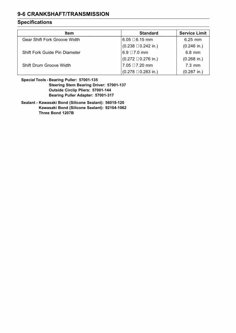
9-6 CRANKSHAFT/TRANSMISSION
Specifications
Item Standard Service Limit
Gear Shift Fork Groove Width 6.05 ∼ 6.15 mm 6.25 mm
(0.238 ∼ 0.242 in.) (0.246 in.)
Shift Fork Guide Pin Diameter 6.9 ∼ 7.0 mm 6.8 mm
(0.272 ∼ 0.276 in.) (0.268 in.)
Shift Drum Groove Width 7.05 ∼ 7.20 mm 7.3 mm
(0.278 ∼ 0.283 in.) (0.287 in.)
Special Tools - Bearing Puller: 57001-135Steering Stem Bearing Driver: 57001-137Outside Circlip Pliers: 57001-144Bearing Puller Adapter: 57001-317
Sealant - Kawasaki Bond (Silicone Sealant): 56019-120Kawasaki Bond (Silicone Sealant): 92104-1062Three Bond 1207B

CRANKSHAFT/TRANSMISSION 9-7
Crankcase Splitting
Crankcase Splitting
•Remove the engine (see Engine Removal/Installationchapter).
• Set the engine on a clean surface and hold the enginesteady while parts are being removed.
•Remove:Crankshaft Sensor (see Electrical System chapter)Clutch (see Clutch chapter)External Shift Mechanism (see External Shift Mecha-nism Removal)Starter Motor (see Electrical System chapter)Oil Pump (see Engine Lubrication System chapter)Alternator Rotor (see Electrical System chapter)Oil Filter (see Oil Filter Replace in the Periodic Mainte-nance chapter)Oil Cooler (see Engine Lubrication System chapter)If the crankshaft is to be removed, remove the pistons(see Engine Top End chapter).
• Remove the upper crankcase bolts.First loosen the M7 bolts.M7 Bolts [A]M8 Bolts [B]
•Remove the oil pan, relief valve, oil screen and oil pipes(see Engine Lubrication System chapter).
• Remove the lower crankcase bolts.First loosen the M7 bolts.M7 Bolts [A]M8 Bolts [B]M10 Bolts [C]
• Tap lightly around the crankcase mating surface with aplastic mallet, and split the crankcase. Take care not todamage the crankcase.
Crankcase Assembly
CAUTION
The upper and lower crankcase halves are ma-chined at the factory in the assembled state, so thecrankcase halves must be replaced as a set.
•With high-flash point solvent, clean off the mating sur-faces of the crankcases halves and wipe dry.
•Using compressed air, blow out the oil passages in thecrankcase halves.
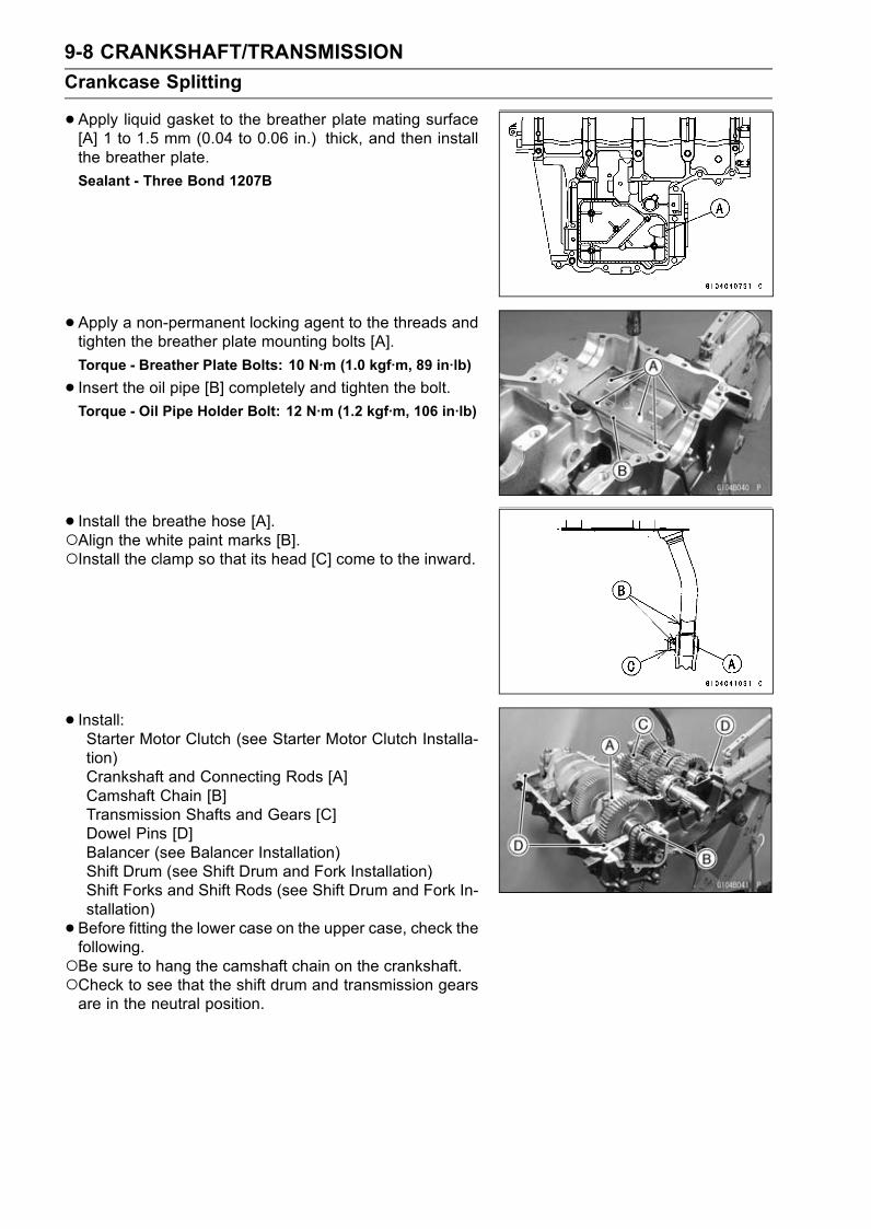
9-8 CRANKSHAFT/TRANSMISSION
Crankcase Splitting
•Apply liquid gasket to the breather plate mating surface[A] 1 to 1.5 mm (0.04 to 0.06 in.) thick, and then installthe breather plate.
Sealant - Three Bond 1207B
•Apply a non-permanent locking agent to the threads andtighten the breather plate mounting bolts [A].
Torque - Breather Plate Bolts: 10 N·m (1.0 kgf·m, 89 in·lb)
• Insert the oil pipe [B] completely and tighten the bolt.Torque - Oil Pipe Holder Bolt: 12 N·m (1.2 kgf·m, 106 in·lb)
• Install the breathe hose [A].Align the white paint marks [B].Install the clamp so that its head [C] come to the inward.
• Install:Starter Motor Clutch (see Starter Motor Clutch Installa-tion)Crankshaft and Connecting Rods [A]Camshaft Chain [B]Transmission Shafts and Gears [C]Dowel Pins [D]Balancer (see Balancer Installation)Shift Drum (see Shift Drum and Fork Installation)Shift Forks and Shift Rods (see Shift Drum and Fork In-stallation)
• Before fitting the lower case on the upper case, check thefollowing.Be sure to hang the camshaft chain on the crankshaft.Check to see that the shift drum and transmission gearsare in the neutral position.

CRANKSHAFT/TRANSMISSION 9-9
Crankcase Splitting
•Apply liquid gasket [A] to the mating surface of the lowercrankcase half.Pile up the gasket [B] to slot portions.
NOTEMake the application finish within 5 minutes whenthe liquid gasket to the mating surface of the lowercrankcase half is applied.Moreover fit the case and tighten the case bolts justafter finishing the application of the liquid gasket.
Sealant - Three Bond 1207B
CAUTION
Do not apply liquid gasket around the crankshaftmain bearing inserts, and oil passage holes.
•Position the crankshaft at #1, 4 position TDC.•Hold the balancer so that the punch mark [A] on the bal-ancer weight aligns with the projection [B] of the lowercrankcase.
• Fit the lower crankcase to the upper crankcase.
• Apply molybdenum disulfide oil solution to the seating sur-face of the M10 bolt heads.
• Tighten the lower crankcase bolts.Following the sequence numbers on the lower crankcasehalf, tighten the M10 bolts [1 ∼ 6] [C].Torque - Crankcase Bolts (M10): 50 N·m (5.0 kgf·m, 37 ft·lb)
Following the sequence numbers, tighten the M8 bolts [7∼ 10] [B].Torque - Lower Crankcase Bolts (M8): 23 N·m (2.3 kgf·m,
17 ft·lb)
Tighten the M7 bolts [A].Torque - Lower Crankcase Bolts (M7): 20 N·m (2.0 kgf·m,
15 ft·lb)
•Put the M8 bolts [A], M7 bolts [B], and the M7 bolt withthe washer [C] into the upper crankcase half as shown inthe figure, tighten the M8 bolts first, then the other bolts.
Torque - Upper Crankcase Bolts (M8): 28 N·m (2.8 kgf·m,21 ft·lb)
Upper Crankcase Bolts (M7): 25 N·m (2.5 kgf·m,18 ft·lb)
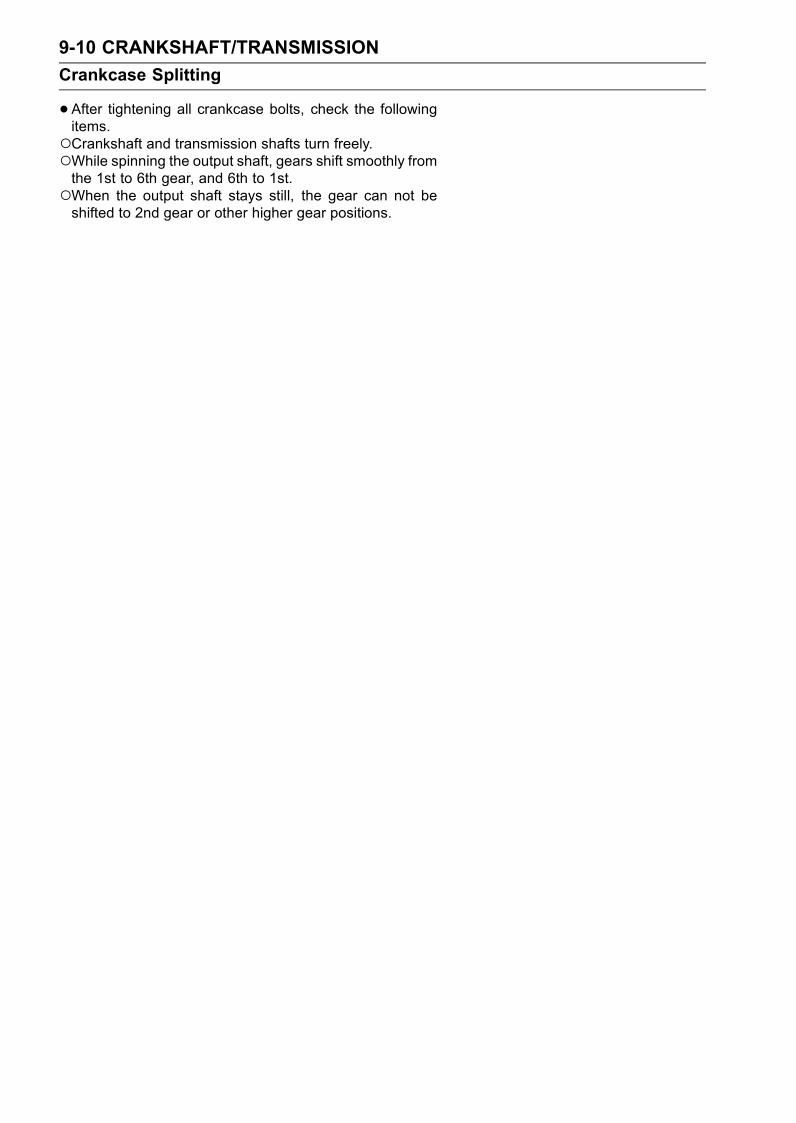
9-10 CRANKSHAFT/TRANSMISSION
Crankcase Splitting
•After tightening all crankcase bolts, check the followingitems.Crankshaft and transmission shafts turn freely.While spinning the output shaft, gears shift smoothly fromthe 1st to 6th gear, and 6th to 1st.When the output shaft stays still, the gear can not beshifted to 2nd gear or other higher gear positions.

CRANKSHAFT/TRANSMISSION 9-11
Crankshaft and Connecting Rods
Crankshaft Removal
•Split the crankcase (see Crankcase Splitting).•Remove the crankshaft.Crankshaft Installation
CAUTION
If the crankshaft, bearing inserts, or crankcasehalves are replaced with new ones, select the bear-ing inserts and check clearance with a plastigagebefore assembling engine to be sure the correctbearing inserts are installed.
•Apply molybdenum disulfide oil solution to the crankshaftmain bearing inserts.
• Install the crankshaft with the camshaft chain [A] hangingon it.
• Assemble the crankcase (see Crankcase Assembly).Connecting Rod Removal
•Split the crankcase (see Crankcase Splitting).•Remove the connecting rod nuts [A].•Remove the crankshaft.
NOTEMark and record the locations of the connecting rodsand their big end caps so that they can be reassembledin their original positions.
•Remove the connecting rods from the crankshaft.Connecting Rod Installation
WARNINGClean the crankshaft, bolts, nuts, and connectingrods in a well-ventilated area, and take care thatthere is no spark or flame anywhere near the work-ing area. This includes any appliance with a pilotlight. Because of the danger of highly flammableliquids, do not use gasoline or low-flash point sol-vents to clean them.
•After removing the connecting rods from the crankshaft,clean them with high-flash point solvent.
• Blow the crankshaft oil passages with compressed air toremove any foreign particles or residue that may haveaccumulated in the passages.
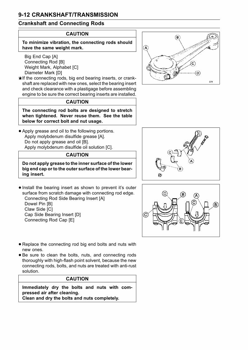
9-12 CRANKSHAFT/TRANSMISSION
Crankshaft and Connecting Rods
CAUTION
To minimize vibration, the connecting rods shouldhave the same weight mark.
Big End Cap [A]Connecting Rod [B]Weight Mark, Alphabet [C]Diameter Mark [D]If the connecting rods, big end bearing inserts, or crank-shaft are replaced with new ones, select the bearing insertand check clearance with a plastigage before assemblingengine to be sure the correct bearing inserts are installed.
CAUTION
The connecting rod bolts are designed to stretchwhen tightened. Never reuse them. See the tablebelow for correct bolt and nut usage.
•Apply grease and oil to the following portions.Apply molybdenum disulfide grease [A].Do not apply grease and oil [B].Apply molybdenum disulfide oil solution [C].
CAUTION
Do not apply grease to the inner surface of the lowerbig end cap or to the outer surface of the lower bear-ing insert.
• Install the bearing insert as shown to prevent it’s outersurface from scratch damage with connecting rod edge.Connecting Rod Side Bearing Insert [A]Dowel Pin [B]Claw Side [C]Cap Side Bearing Insert [D]Connecting Rod Cap [E]
•Replace the connecting rod big end bolts and nuts withnew ones.
• Be sure to clean the bolts, nuts, and connecting rodsthoroughly with high-flash point solvent, because the newconnecting rods, bolts, and nuts are treated with anti-rustsolution.
CAUTION
Immediately dry the bolts and nuts with com-pressed air after cleaning.Clean and dry the bolts and nuts completely.
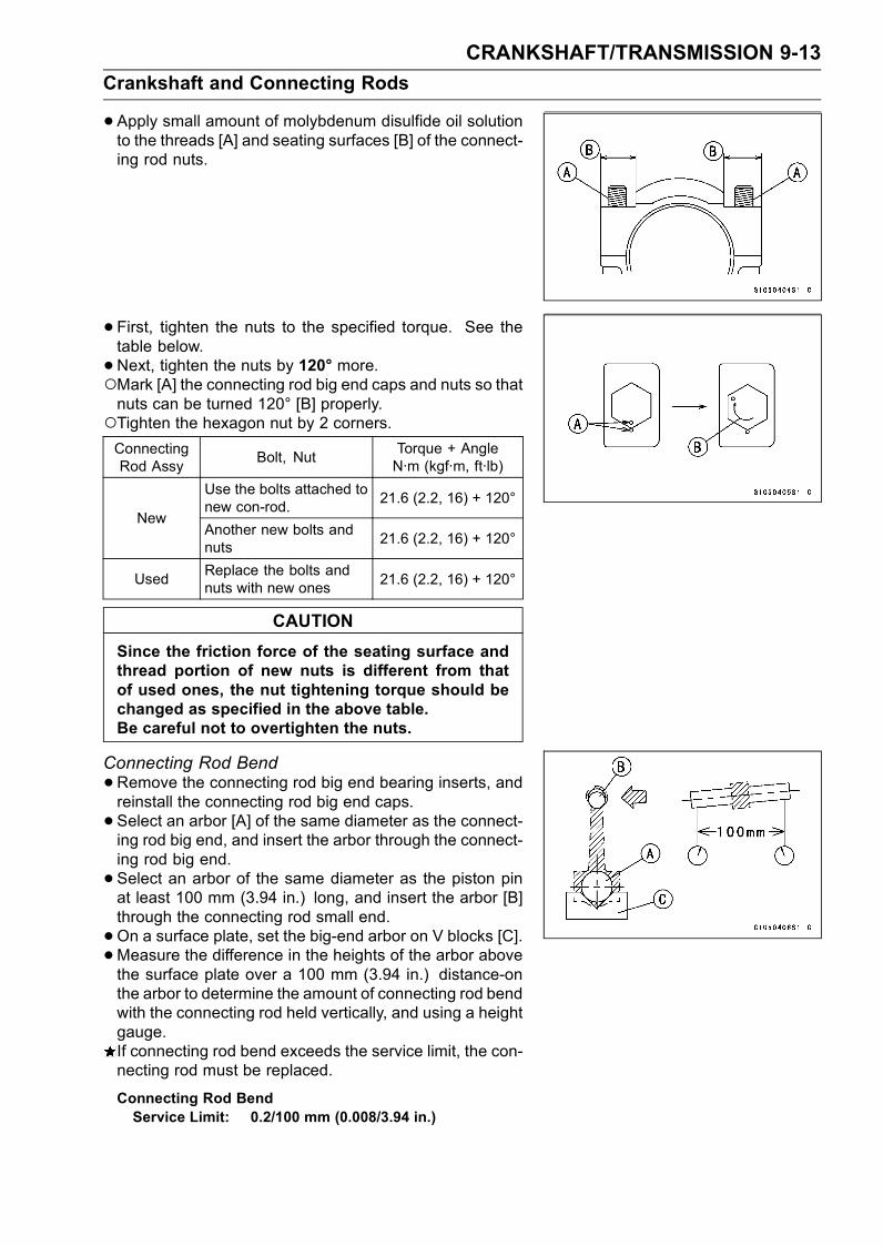
CRANKSHAFT/TRANSMISSION 9-13
Crankshaft and Connecting Rods
•Apply small amount of molybdenum disulfide oil solutionto the threads [A] and seating surfaces [B] of the connect-ing rod nuts.
• First, tighten the nuts to the specified torque. See thetable below.
•Next, tighten the nuts by 120° more.Mark [A] the connecting rod big end caps and nuts so thatnuts can be turned 120° [B] properly.Tighten the hexagon nut by 2 corners.ConnectingRod Assy
Bolt, NutTorque + AngleN·m (kgf·m, ft·lb)
Use the bolts attached tonew con-rod.
21.6 (2.2, 16) + 120°New
Another new bolts andnuts
21.6 (2.2, 16) + 120°
UsedReplace the bolts andnuts with new ones
21.6 (2.2, 16) + 120°
CAUTION
Since the friction force of the seating surface andthread portion of new nuts is different from thatof used ones, the nut tightening torque should bechanged as specified in the above table.Be careful not to overtighten the nuts.
Connecting Rod Bend
•Remove the connecting rod big end bearing inserts, andreinstall the connecting rod big end caps.
• Select an arbor [A] of the same diameter as the connect-ing rod big end, and insert the arbor through the connect-ing rod big end.
• Select an arbor of the same diameter as the piston pinat least 100 mm (3.94 in.) long, and insert the arbor [B]through the connecting rod small end.
•On a surface plate, set the big-end arbor on V blocks [C].•Measure the difference in the heights of the arbor abovethe surface plate over a 100 mm (3.94 in.) distance-onthe arbor to determine the amount of connecting rod bendwith the connecting rod held vertically, and using a heightgauge.If connecting rod bend exceeds the service limit, the con-necting rod must be replaced.
Connecting Rod BendService Limit: 0.2/100 mm (0.008/3.94 in.)

9-14 CRANKSHAFT/TRANSMISSION
Crankshaft and Connecting Rods
Connecting Rod Twist
•On surface plate, set the big-end arbor on V block [C].•Measure the difference in the heights of the arbor abovethe surface plate over a 100mm (3.94 in.) distance-on thearbor to determine the amount of connecting rod twist withthe connecting rod held horizontally, and using a heightgauge.If connecting rod twist exceeds the service limit, the con-necting rod must be replaced.
Connecting Rod TwistService Limit: 0.2/100 mm (0.008/3.94 in.)
Connecting Rod Big End Side Clearance
•Measure connecting rod big end side clearance [A].Insert a thickness gauge [B] between the big end and ei-ther crank web to determine clearance.
Connecting Rod Big End Side ClearanceStandard: 0.13 ∼ 0.38 mm (0.0051 ∼ 0.0150 in.)Service Limit: 0.58 mm (0.023 in.)
If the clearance exceeds the service limit, replace the con-necting rod with new one and then check clearance againIf clearance is too large after connecting rod replacement,the crankshaft also must be replaced.
Connecting Rod Big End Bearing Insert/CrankpinWear
•Measure the bearing insert/crankpin [B] clearance with aplastigage [A].
NOTETighten the connecting rod big end nuts to the specifiedtorque (see Connecting Rod Installation).Do not move the connecting rod and crankshaft duringclearance measurement.
Connecting Rod Big End Bearing Insert/CrankpinClearanceStandard: 0.048 ∼ 0.084 mm (0.0019 ∼ 0.0033 in.)Service Limit: 0.10 mm (0.0039 in.)
If clearance is within the standard, no bearing replace-ment is required.If clearance is between 0.085 mm (0.0033 in.) andthe service limit (0.10 mm, 0.0039 in.), replace thebearing inserts [A] with inserts painted blue [B]. Checkinsert/crankpin clearance with the plastigage. The clear-ance may exceed the standard slightly, but it must not beless than the minimum in order to avoid bearing seizure.If the clearance exceeds the service limit, measure thediameter of the crankpins.
Crankpin DiameterStandard: 36.984 ∼ 37.000 mm (1.4561 ∼ 1.4567 in.)Service Limit: 36.97 mm (1.456 in.)
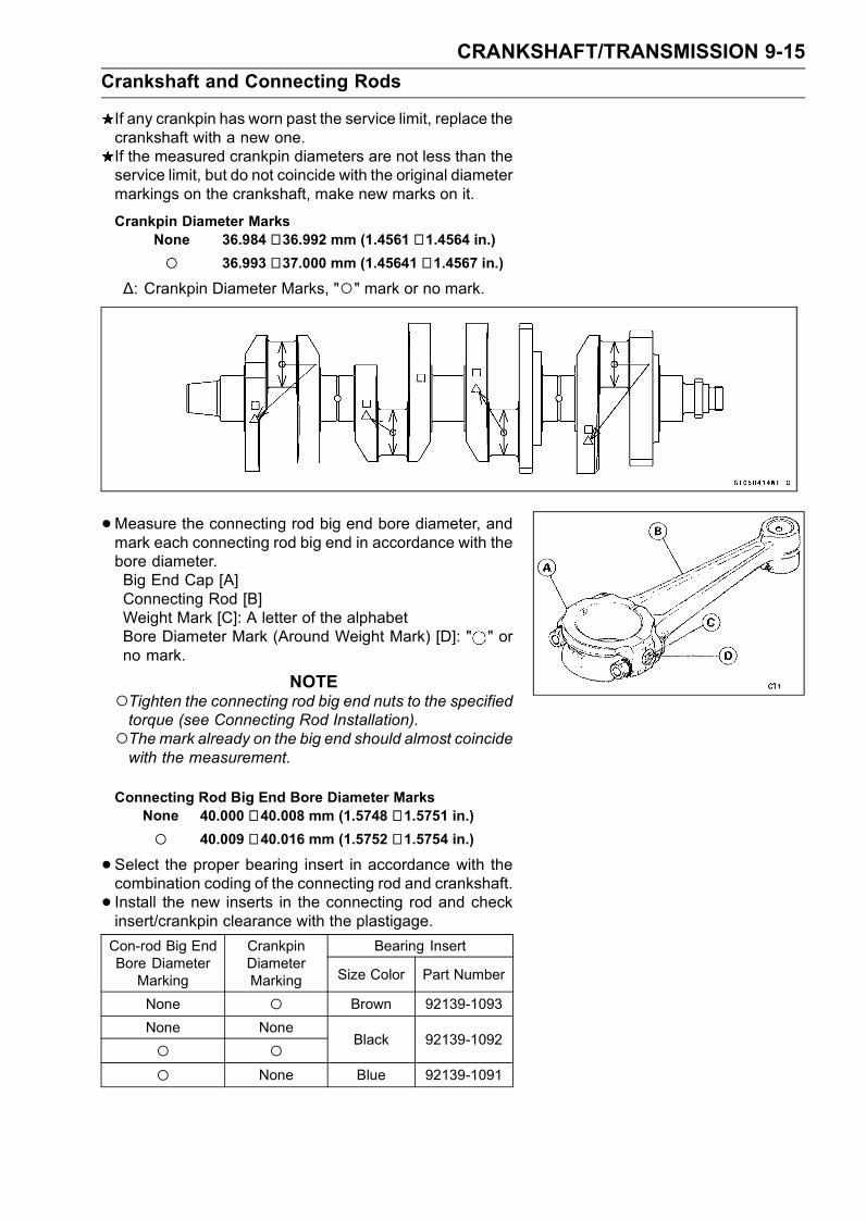
CRANKSHAFT/TRANSMISSION 9-15
Crankshaft and Connecting Rods
If any crankpin has worn past the service limit, replace thecrankshaft with a new one.If the measured crankpin diameters are not less than theservice limit, but do not coincide with the original diametermarkings on the crankshaft, make new marks on it.
Crankpin Diameter MarksNone 36.984 ∼ 36.992 mm (1.4561 ∼ 1.4564 in.)
36.993 ∼ 37.000 mm (1.45641 ∼ 1.4567 in.)
∆: Crankpin Diameter Marks, "" mark or no mark.
•Measure the connecting rod big end bore diameter, andmark each connecting rod big end in accordance with thebore diameter.Big End Cap [A]Connecting Rod [B]Weight Mark [C]: A letter of the alphabetBore Diameter Mark (Around Weight Mark) [D]: " " orno mark.
NOTETighten the connecting rod big end nuts to the specifiedtorque (see Connecting Rod Installation).The mark already on the big end should almost coincidewith the measurement.
Connecting Rod Big End Bore Diameter MarksNone 40.000 ∼ 40.008 mm (1.5748 ∼ 1.5751 in.)
40.009 ∼ 40.016 mm (1.5752 ∼ 1.5754 in.)
•Select the proper bearing insert in accordance with thecombination coding of the connecting rod and crankshaft.
• Install the new inserts in the connecting rod and checkinsert/crankpin clearance with the plastigage.
Bearing InsertCon-rod Big EndBore DiameterMarking
CrankpinDiameterMarking Size Color Part Number
None Brown 92139-1093
None None
Black 92139-1092
None Blue 92139-1091
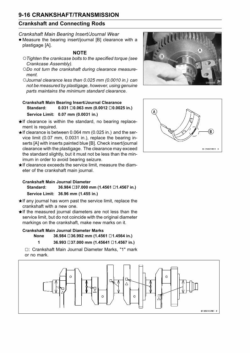
9-16 CRANKSHAFT/TRANSMISSION
Crankshaft and Connecting Rods
Crankshaft Main Bearing Insert/Journal Wear
•Measure the bearing insert/journal [B] clearance with aplastigage [A].
NOTETighten the crankcase bolts to the specified torque (seeCrankcase Assembly).Do not turn the crankshaft during clearance measure-ment.Journal clearance less than 0.025 mm (0.0010 in.) cannot bemeasured by plastigage, however, using genuineparts maintains the minimum standard clearance.
Crankshaft Main Bearing Insert/Journal ClearanceStandard: 0.031 ∼ 0.063 mm (0.0012 ∼ 0.0025 in.)Service Limit: 0.07 mm (0.0031 in.)
If clearance is within the standard, no bearing replace-ment is required.If clearance is between 0.064 mm (0.025 in.) and the ser-vice limit (0.07 mm, 0.0031 in.), replace the bearing in-serts [A] with inserts painted blue [B]. Check insert/journalclearance with the plastigage. The clearancemay exceedthe standard slightly, but it must not be less than the min-imum in order to avoid bearing seizure.If clearance exceeds the service limit, measure the diam-eter of the crankshaft main journal.
Crankshaft Main Journal DiameterStandard: 36.984 ∼ 37.000 mm (1.4561 ∼ 1.4567 in.)Service Limit: 36.96 mm (1.455 in.)
If any journal has worn past the service limit, replace thecrankshaft with a new one.If the measured journal diameters are not less than theservice limit, but do not coincide with the original diametermarkings on the crankshaft, make new marks on it.
Crankshaft Main Journal Diameter MarksNone 36.984 ∼ 36.992 mm (1.4561 ∼ 1.4564 in.)1 36.993 ∼ 37.000 mm (1.45641 ∼ 1.4567 in.)
: Crankshaft Main Journal Diameter Marks, "1" markor no mark.
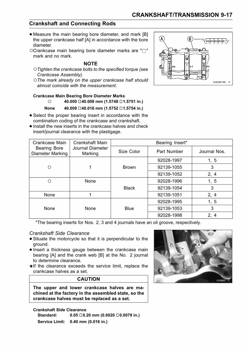
CRANKSHAFT/TRANSMISSION 9-17
Crankshaft and Connecting Rods
•Measure the main bearing bore diameter, and mark [B]the upper crankcase half [A] in accordance with the borediameter.Crankcase main bearing bore diameter marks are " "mark and no mark.
NOTETighten the crankcase bolts to the specified torque (seeCrankcase Assembly).The mark already on the upper crankcase half shouldalmost coincide with the measurement.
Crankcase Main Bearing Bore Diameter Marks
40.000 ∼ 40.008 mm (1.5748 ∼ 1.5751 in.)None 40.009 ∼ 40.016 mm (1.5752 ∼ 1.5754 in.)
•Select the proper bearing insert in accordance with thecombination coding of the crankcase and crankshaft.
• Install the new inserts in the crankcase halves and checkinsert/journal clearance with the plastigage.
Bearing Insert*Crankcase MainBearing Bore
Diameter Marking
Crankshaft MainJournal Diameter
Marking Size Color Part Number Journal Nos.
92028-1997 1, 5
1 Brown 92139-1055 3
92139-1052 2, 4
None 92028-1996 1, 5
Black 92139-1054 3
None 1 92139-1051 2, 4
92028-1995 1, 5
None None Blue 92139-1053 3
92028-1998 2, 4
*The bearing inserts for Nos. 2, 3 and 4 journals have an oil groove, respectively.
Crankshaft Side Clearance
•Situate the motorcycle so that it is perpendicular to theground.
• Insert a thickness gauge between the crankcase mainbearing [A] and the crank web [B] at the No. 2 journalto determine clearance.If the clearance exceeds the service limit, replace thecrankcase halves as a set.
CAUTION
The upper and lower crankcase halves are ma-chined at the factory in the assembled state, so thecrankcase halves must be replaced as a set.
Crankshaft Side ClearanceStandard: 0.05 ∼ 0.20 mm (0.0020 ∼ 0.0079 in.)Service Limit: 0.40 mm (0.016 in.)

9-18 CRANKSHAFT/TRANSMISSION
Crankshaft and Connecting Rods
Crankshaft Runout
•Measure the crankshaft runout.If the measurement exceeds the service limit, replace thecrankshaft.
Crankshaft RunoutStandard: TIR 0.03 mm (0.0012 in.) or less
Service Limit: TIR 0.07 mm (0.0028 in.)
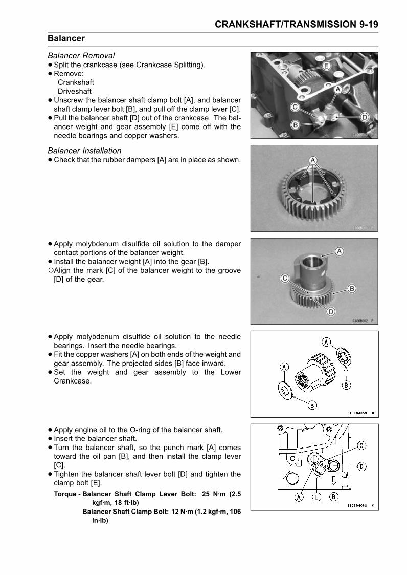
CRANKSHAFT/TRANSMISSION 9-19
Balancer
Balancer Removal
•Split the crankcase (see Crankcase Splitting).•Remove:CrankshaftDriveshaft
•Unscrew the balancer shaft clamp bolt [A], and balancershaft clamp lever bolt [B], and pull off the clamp lever [C].
• Pull the balancer shaft [D] out of the crankcase. The bal-ancer weight and gear assembly [E] come off with theneedle bearings and copper washers.
Balancer Installation
•Check that the rubber dampers [A] are in place as shown.
• Apply molybdenum disulfide oil solution to the dampercontact portions of the balancer weight.
• Install the balancer weight [A] into the gear [B].Align the mark [C] of the balancer weight to the groove[D] of the gear.
• Apply molybdenum disulfide oil solution to the needlebearings. Insert the needle bearings.
• Fit the copper washers [A] on both ends of the weight andgear assembly. The projected sides [B] face inward.
• Set the weight and gear assembly to the LowerCrankcase.
• Apply engine oil to the O-ring of the balancer shaft.• Insert the balancer shaft.• Turn the balancer shaft, so the punch mark [A] comestoward the oil pan [B], and then install the clamp lever[C].
• Tighten the balancer shaft lever bolt [D] and tighten theclamp bolt [E].
Torque - Balancer Shaft Clamp Lever Bolt: 25 N·m (2.5kgf·m, 18 ft·lb)
Balancer Shaft Clamp Bolt: 12 N·m (1.2 kgf·m, 106in·lb)
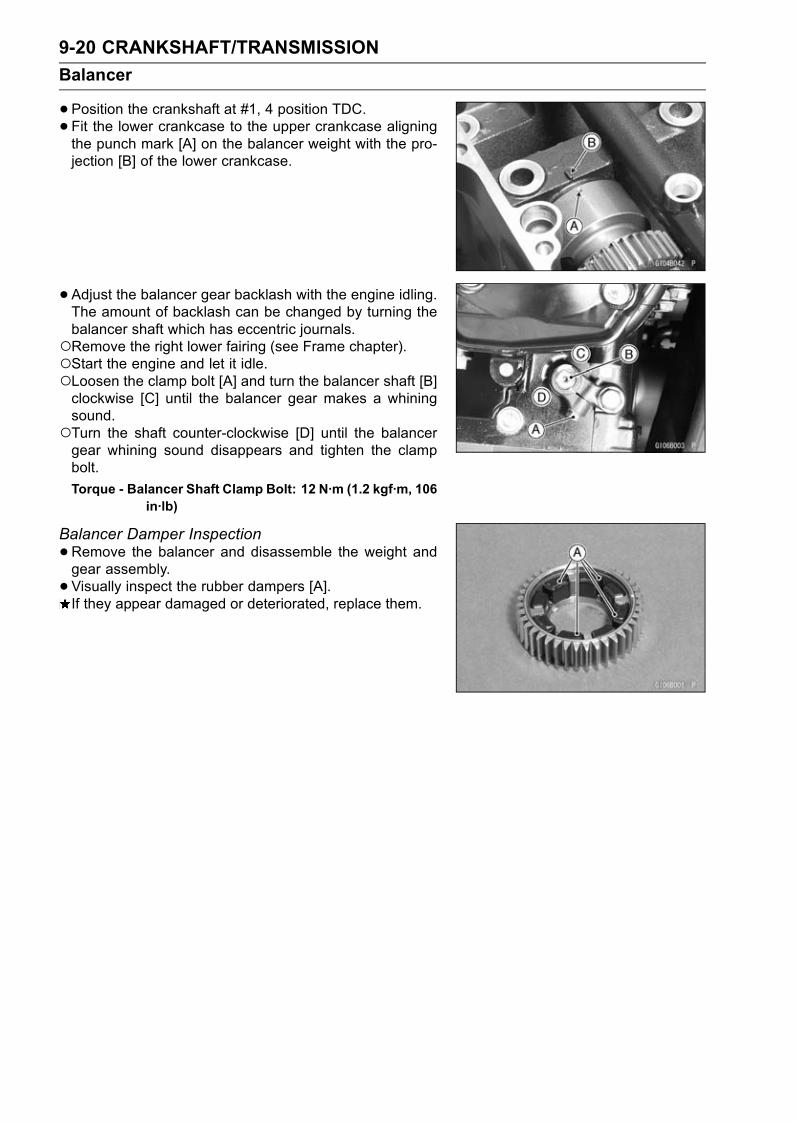
9-20 CRANKSHAFT/TRANSMISSION
Balancer
•Position the crankshaft at #1, 4 position TDC.• Fit the lower crankcase to the upper crankcase aligningthe punch mark [A] on the balancer weight with the pro-jection [B] of the lower crankcase.
• Adjust the balancer gear backlash with the engine idling.The amount of backlash can be changed by turning thebalancer shaft which has eccentric journals.Remove the right lower fairing (see Frame chapter).Start the engine and let it idle.Loosen the clamp bolt [A] and turn the balancer shaft [B]clockwise [C] until the balancer gear makes a whiningsound.Turn the shaft counter-clockwise [D] until the balancergear whining sound disappears and tighten the clampbolt.
Torque - Balancer Shaft Clamp Bolt: 12 N·m (1.2 kgf·m, 106in·lb)
Balancer Damper Inspection
•Remove the balancer and disassemble the weight andgear assembly.
• Visually inspect the rubber dampers [A].If they appear damaged or deteriorated, replace them.
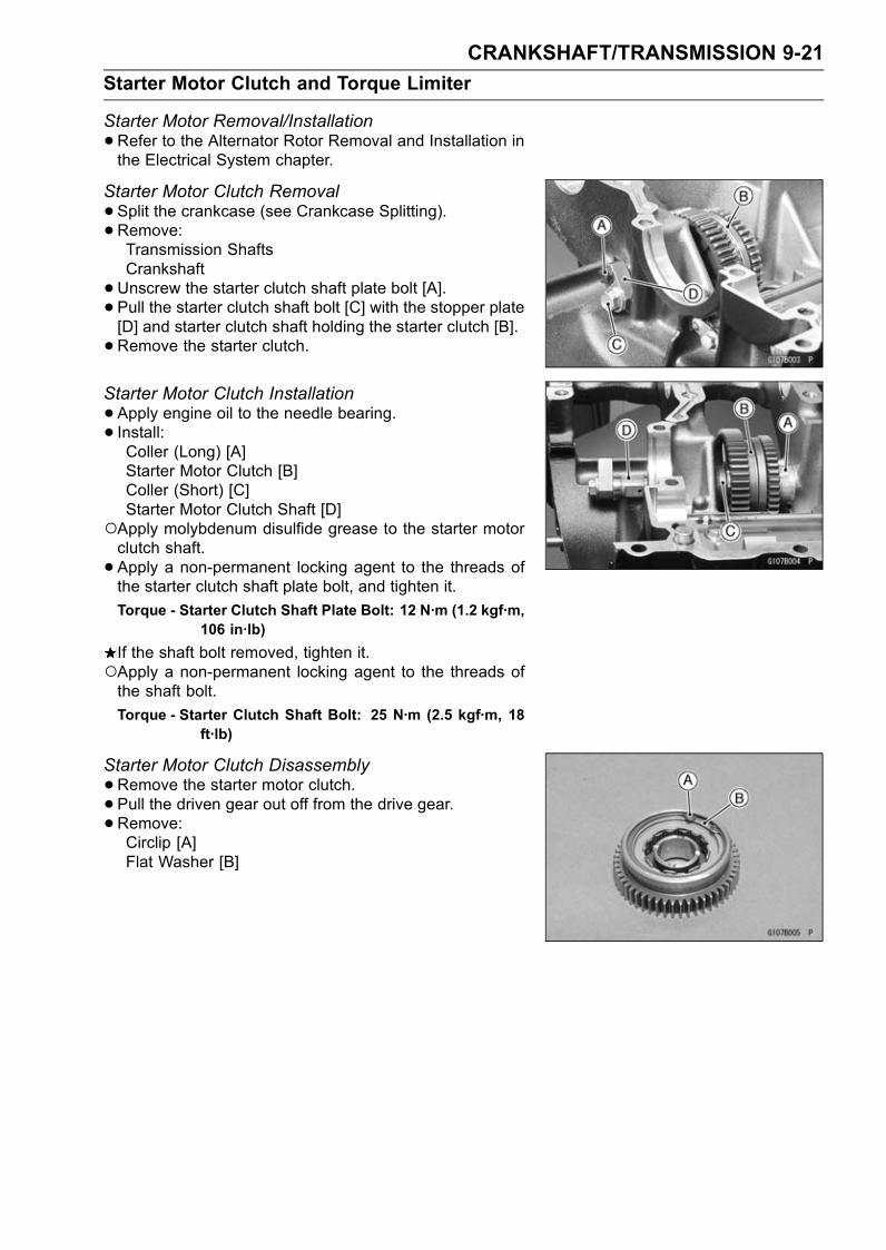
CRANKSHAFT/TRANSMISSION 9-21
Starter Motor Clutch and Torque Limiter
Starter Motor Removal/Installation
•Refer to the Alternator Rotor Removal and Installation inthe Electrical System chapter.
Starter Motor Clutch Removal
•Split the crankcase (see Crankcase Splitting).•Remove:Transmission ShaftsCrankshaft
•Unscrew the starter clutch shaft plate bolt [A].• Pull the starter clutch shaft bolt [C] with the stopper plate[D] and starter clutch shaft holding the starter clutch [B].
•Remove the starter clutch.
Starter Motor Clutch Installation
•Apply engine oil to the needle bearing.• Install:Coller (Long) [A]Starter Motor Clutch [B]Coller (Short) [C]Starter Motor Clutch Shaft [D]
Apply molybdenum disulfide grease to the starter motorclutch shaft.
• Apply a non-permanent locking agent to the threads ofthe starter clutch shaft plate bolt, and tighten it.
Torque - Starter Clutch Shaft Plate Bolt: 12 N·m (1.2 kgf·m,106 in·lb)
If the shaft bolt removed, tighten it.Apply a non-permanent locking agent to the threads ofthe shaft bolt.
Torque - Starter Clutch Shaft Bolt: 25 N·m (2.5 kgf·m, 18ft·lb)
Starter Motor Clutch Disassembly
•Remove the starter motor clutch.• Pull the driven gear out off from the drive gear.
•Remove:Circlip [A]Flat Washer [B]
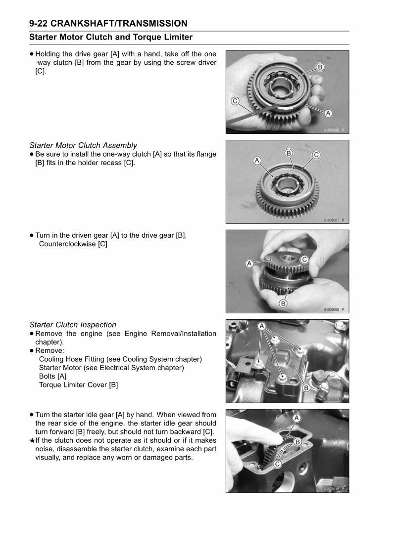
9-22 CRANKSHAFT/TRANSMISSION
Starter Motor Clutch and Torque Limiter
•Holding the drive gear [A] with a hand, take off the one-way clutch [B] from the gear by using the screw driver[C].
Starter Motor Clutch Assembly
•Be sure to install the one-way clutch [A] so that its flange[B] fits in the holder recess [C].
• Turn in the driven gear [A] to the drive gear [B].Counterclockwise [C]
Starter Clutch Inspection
•Remove the engine (see Engine Removal/Installationchapter).
• Remove:Cooling Hose Fitting (see Cooling System chapter)Starter Motor (see Electrical System chapter)Bolts [A]Torque Limiter Cover [B]
• Turn the starter idle gear [A] by hand. When viewed fromthe rear side of the engine, the starter idle gear shouldturn forward [B] freely, but should not turn backward [C].If the clutch does not operate as it should or if it makesnoise, disassemble the starter clutch, examine each partvisually, and replace any worn or damaged parts.

CRANKSHAFT/TRANSMISSION 9-23
Starter Motor Clutch and Torque Limiter
Torque Limiter Removal
•Remove:Starter Motor (see Electrical System chapter)Torque Limiter Cover (see Starter Motor Clutch Inspec-tion)
•Using the 5 mm (0.20 in.) bolt [A], pull out the torquelimiter shaft [B].
• Remove the torque limiter [C].
Torque Limiter Installation
• Inspect the O-ring, and replace it if it is damaged.• Apply engine oil to the O-ring.• Apply molybdenum disulfide grease to the torque limitershaft.
• Install the torque limiter cover bolts with clamps [A] asshown.Apply a non-permanent locking agent to the bolts.Torque - Torque Limiter Cover Bolts: 12 N·m (1.2 kgf·m, 106
in·lb)
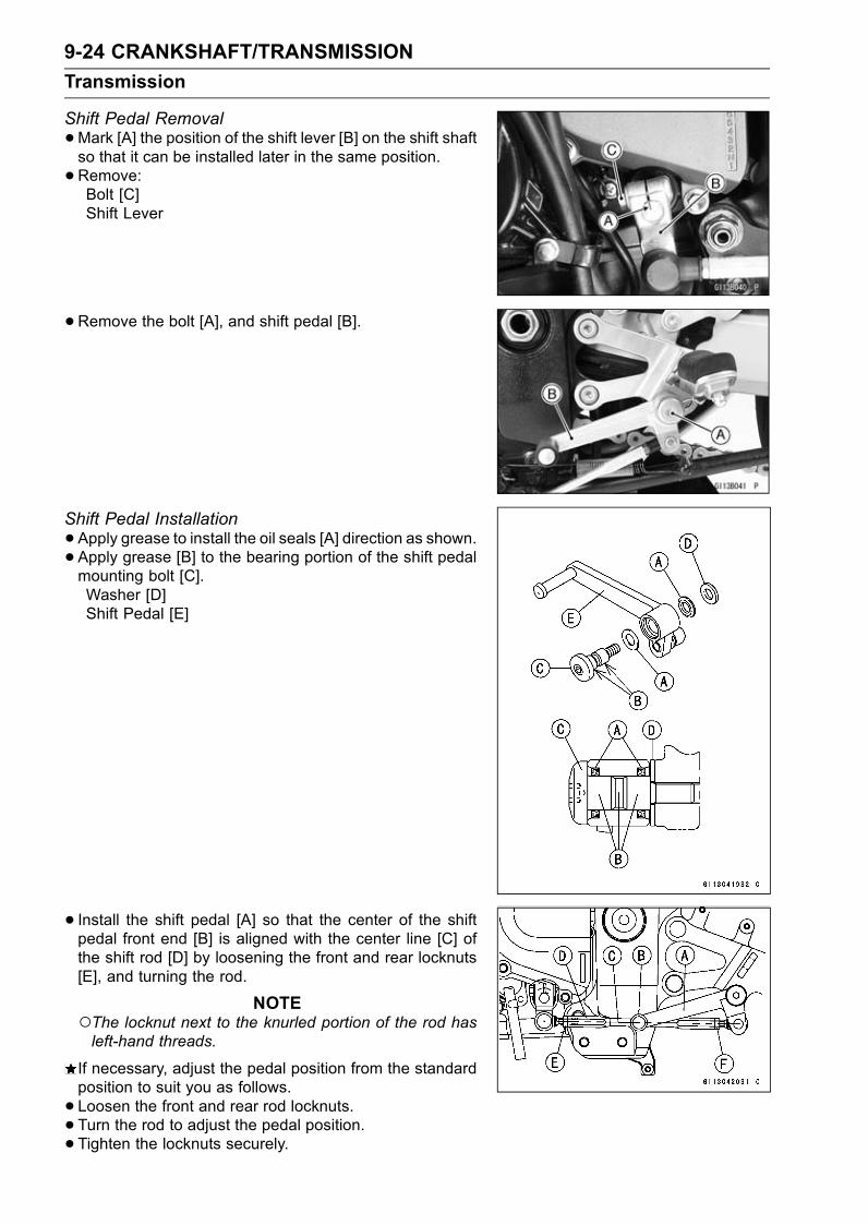
9-24 CRANKSHAFT/TRANSMISSION
Transmission
Shift Pedal Removal
•Mark [A] the position of the shift lever [B] on the shift shaftso that it can be installed later in the same position.
•Remove:Bolt [C]Shift Lever
•Remove the bolt [A], and shift pedal [B].
Shift Pedal Installation
•Apply grease to install the oil seals [A] direction as shown.• Apply grease [B] to the bearing portion of the shift pedalmounting bolt [C].Washer [D]Shift Pedal [E]
• Install the shift pedal [A] so that the center of the shiftpedal front end [B] is aligned with the center line [C] ofthe shift rod [D] by loosening the front and rear locknuts[E], and turning the rod.
NOTEThe locknut next to the knurled portion of the rod hasleft-hand threads.
If necessary, adjust the pedal position from the standardposition to suit you as follows.
• Loosen the front and rear rod locknuts.• Turn the rod to adjust the pedal position.• Tighten the locknuts securely.
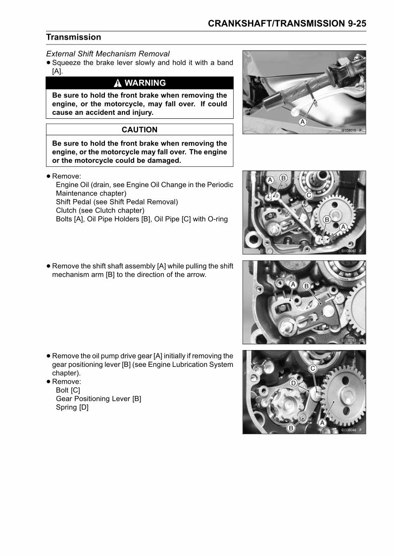
CRANKSHAFT/TRANSMISSION 9-25
Transmission
External Shift Mechanism Removal
•Squeeze the brake lever slowly and hold it with a band[A].
WARNINGBe sure to hold the front brake when removing theengine, or the motorcycle, may fall over. If couldcause an accident and injury.
CAUTION
Be sure to hold the front brake when removing theengine, or the motorcycle may fall over. The engineor the motorcycle could be damaged.
•Remove:Engine Oil (drain, see Engine Oil Change in the PeriodicMaintenance chapter)Shift Pedal (see Shift Pedal Removal)Clutch (see Clutch chapter)Bolts [A], Oil Pipe Holders [B], Oil Pipe [C] with O-ring
•Remove the shift shaft assembly [A] while pulling the shiftmechanism arm [B] to the direction of the arrow.
•Remove the oil pump drive gear [A] initially if removing thegear positioning lever [B] (see Engine Lubrication Systemchapter).
• Remove:Bolt [C]Gear Positioning Lever [B]Spring [D]

9-26 CRANKSHAFT/TRANSMISSION
Transmission
External Shift Mechanism Installation
•Replace the circlip that was removed with a new one andinstall the shift mechanism arm.
• Install the gear positioning lever [A] as shown.Spring [B]Collar [C]Bolt [D]
• Apply a non-permanent locking agent to the bolt andtighten it.
Torque - Gear Positioning Lever Bolt: 10 N·m (1.0 kgf·m, 89in·lb)
•Apply engine oil to the O-rings to install the oil pipe.• Apply a non-permanent locking agent to the oil pipe holderbolts and tighten them.
Torque - Oil Pipe Holder Bolts: 12 N·m (1.2 kgf·m, 106 in·lb)
External Shift Mechanism Inspection
•Examine the shift shaft [A] for any damage.If the shaft is bent, straighten or replace it.If the serration are damaged, replace the shaft.If the springs [B], [C] are damaged in any way, replacethem.If the shift mechanism arm [D] is damaged in any way,replace the arm.
•Check the return spring pin [A] is not loose.If it is loose, unscrew it, apply a non-permanent lockingagent to the threads, and tighten it.
Torque - Shift Shaft Return Spring Pin: 30 N·m (3.0 kgf·m,22 ft·lb)
•Check the gear positioning lever [B] and it spring forbreaks or distortion.If the lever or spring are damaged in any way, replacethem.
•Visually inspect the shift drum cam [C].If they are badly worn or if they show any damage, replaceit.
Transmission Shaft Removal
•Split the crankcase (see Crankcase Splitting).•Remove the drive shaft [A] and output shaft [B].

CRANKSHAFT/TRANSMISSION 9-27
Transmission
Transmission Shaft Installation
•Apply engine oil to the sliding surfaces of the shafts, gearsand bearings.
•Check to see that the set pins [A] and set rings [B] are inplace.
• Install the drive shaft and output shaft into the uppercrankcase half.Install the output shaft [A] first.
The bearing set pins and rings must match properly withthe holes or grooves in the bearing outer races. Whenthey are properly matched, there is no clearance betweenthe crankcase and the bearing outer races [A].
• Assemble the crankcase.• Press in the oil seal [A] onto coller [B] so that the surface[C] of the oil seal is flush with the counterbore bottomsurface [D] of the crankcase.
Transmission Disassembly
•Remove the transmission shafts (see Transmission ShaftRemoval).
• Remove the circlips, disassemble the transmissionshafts.
Special Tool - Outside Circlip pliers: 57001-144
•The 5th gear [A] on the output shaft has three steel ballsassembled into it for the positive neutral finder mecha-nism. Remove the 5th gear.Set the output shaft in a vertical position holding the 3rdgear [B].Spin the 5th gear quickly [C] and pull it off upward.
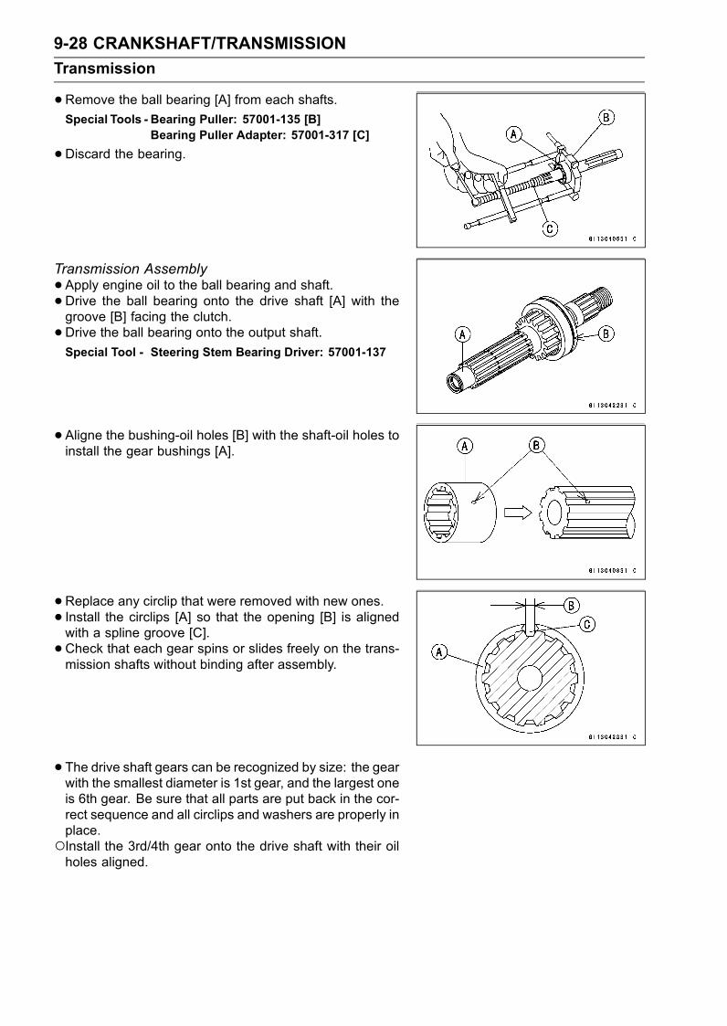
9-28 CRANKSHAFT/TRANSMISSION
Transmission
•Remove the ball bearing [A] from each shafts.
Special Tools - Bearing Puller: 57001-135 [B]Bearing Puller Adapter: 57001-317 [C]
•Discard the bearing.
Transmission Assembly
•Apply engine oil to the ball bearing and shaft.• Drive the ball bearing onto the drive shaft [A] with thegroove [B] facing the clutch.
•Drive the ball bearing onto the output shaft.Special Tool - Steering Stem Bearing Driver: 57001-137
•Aligne the bushing-oil holes [B] with the shaft-oil holes toinstall the gear bushings [A].
•Replace any circlip that were removed with new ones.• Install the circlips [A] so that the opening [B] is alignedwith a spline groove [C].
•Check that each gear spins or slides freely on the trans-mission shafts without binding after assembly.
• The drive shaft gears can be recognized by size: the gearwith the smallest diameter is 1st gear, and the largest oneis 6th gear. Be sure that all parts are put back in the cor-rect sequence and all circlips and washers are properly inplace.Install the 3rd/4th gear onto the drive shaft with their oilholes aligned.
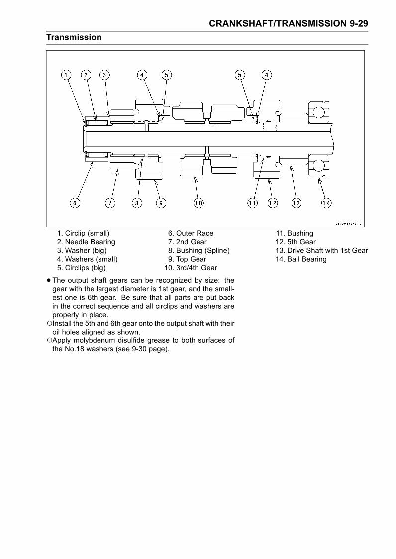
CRANKSHAFT/TRANSMISSION 9-29
Transmission
1. Circlip (small)2. Needle Bearing3. Washer (big)4. Washers (small)5. Circlips (big)
6. Outer Race7. 2nd Gear8. Bushing (Spline)9. Top Gear10. 3rd/4th Gear
11. Bushing12. 5th Gear13. Drive Shaft with 1st Gear14. Ball Bearing
• The output shaft gears can be recognized by size: thegear with the largest diameter is 1st gear, and the small-est one is 6th gear. Be sure that all parts are put backin the correct sequence and all circlips and washers areproperly in place.Install the 5th and 6th gear onto the output shaft with theiroil holes aligned as shown.Apply molybdenum disulfide grease to both surfaces ofthe No.18 washers (see 9-30 page).
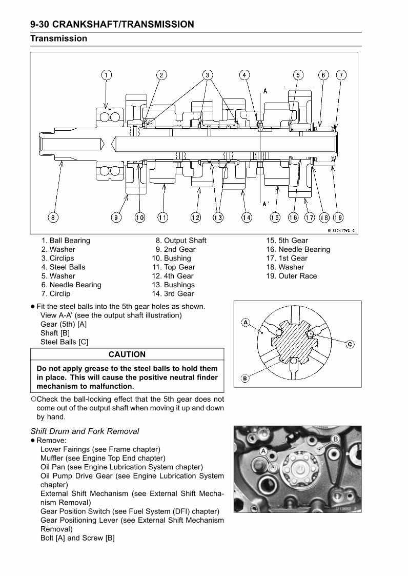
9-30 CRANKSHAFT/TRANSMISSION
Transmission
1. Ball Bearing2. Washer3. Circlips4. Steel Balls5. Washer6. Needle Bearing7. Circlip
8. Output Shaft9. 2nd Gear10. Bushing11. Top Gear12. 4th Gear13. Bushings14. 3rd Gear
15. 5th Gear16. Needle Bearing17. 1st Gear18. Washer19. Outer Race
• Fit the steel balls into the 5th gear holes as shown.View A-A’ (see the output shaft illustration)Gear (5th) [A]Shaft [B]Steel Balls [C]
CAUTION
Do not apply grease to the steel balls to hold themin place. This will cause the positive neutral findermechanism to malfunction.
Check the ball-locking effect that the 5th gear does notcome out of the output shaft when moving it up and downby hand.
Shift Drum and Fork Removal
•Remove:Lower Fairings (see Frame chapter)Muffler (see Engine Top End chapter)Oil Pan (see Engine Lubrication System chapter)Oil Pump Drive Gear (see Engine Lubrication Systemchapter)External Shift Mechanism (see External Shift Mecha-nism Removal)Gear Position Switch (see Fuel System (DFI) chapter)Gear Positioning Lever (see External Shift MechanismRemoval)Bolt [A] and Screw [B]
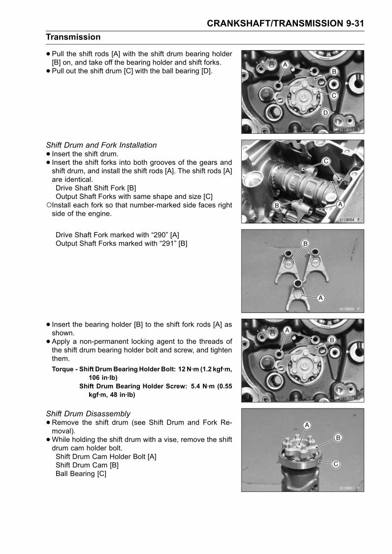
CRANKSHAFT/TRANSMISSION 9-31
Transmission
•Pull the shift rods [A] with the shift drum bearing holder[B] on, and take off the bearing holder and shift forks.
• Pull out the shift drum [C] with the ball bearing [D].
Shift Drum and Fork Installation
• Insert the shift drum.• Insert the shift forks into both grooves of the gears andshift drum, and install the shift rods [A]. The shift rods [A]are identical.Drive Shaft Shift Fork [B]Output Shaft Forks with same shape and size [C]
Install each fork so that number-marked side faces rightside of the engine.
Drive Shaft Fork marked with “290” [A]Output Shaft Forks marked with “291” [B]
• Insert the bearing holder [B] to the shift fork rods [A] asshown.
• Apply a non-permanent locking agent to the threads ofthe shift drum bearing holder bolt and screw, and tightenthem.
Torque - Shift DrumBearing Holder Bolt: 12 N·m (1.2 kgf·m,106 in·lb)
Shift Drum Bearing Holder Screw: 5.4 N·m (0.55kgf·m, 48 in·lb)
Shift Drum Disassembly
•Remove the shift drum (see Shift Drum and Fork Re-moval).
•While holding the shift drum with a vise, remove the shiftdrum cam holder bolt.Shift Drum Cam Holder Bolt [A]Shift Drum Cam [B]Ball Bearing [C]

9-32 CRANKSHAFT/TRANSMISSION
Transmission
Shift Drum Assembly
•Be sure to install the dowel pin [A].Align the dowel pin with the hole [B] of the shift drum camholder.
• Apply a non-permanent locking agent to the threads ofthe shift drum cam bolt, and tighten it.
Torque - Shift Drum Cam Bolt: 12 N·m (1.2 kgf·m, 106 in·lb)
Shift Fork Bending
•Visually inspect the shift forks, and replace any fork that isbent. A bent fork could cause difficulty in shifting, or allowthe transmission to jump out of gear when under power.90° [A]
Shift Fork/Gear Groove Wear
•Measure the thickness of the shift fork ears [A], and mea-sure the width [B] of the gear grooves.If the thickness of a shift fork ear is less than the servicelimit, the shift fork must be replaced.
Shift Fork Ear ThicknessStandard: 5.9 ∼ 6.0 mm (0.232 ∼ 0.236 in.)Service Limit: 5.8 mm (0.228 in.)
If the gear groove is worn over the service limit, the gearmust be replaced.
Gear Groove WidthStandard: 6.05 ∼ 6.15 mm (0.238 ∼ 0.242 in.)Service Limit: 6.25 mm (0.246 in.)
Shift Fork Guide Pin/Drum Groove Wear
•Measure the diameter of each shift fork guide pin [A], andmeasure the width [B] of each shift drum groove.If the guide pin on any shift fork is less than the servicelimit, the fork must be replace.
Shift Fork Guide Pin DiameterStandard: 6.9 ∼ 7.0 mm (0.272 ∼ 0.276 in.)Service Limit: 6.8 mm (0.268 in.)
If any shift drum groove is worn over the service limit, thedrum must be replaced.
Shift Drum Groove WidthStandard: 7.05 ∼ 7.20 mm (0.278 ∼ 0.283 in.)Service Limit: 7.3 mm (0.287 in.)
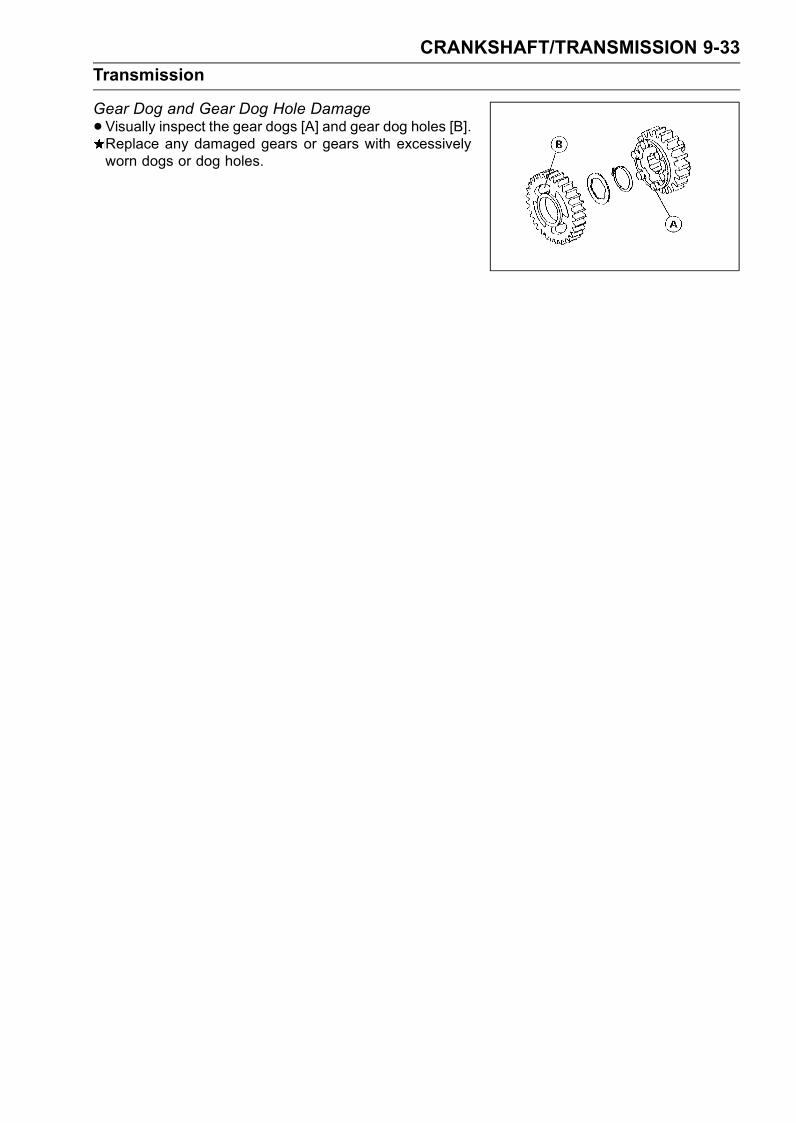
CRANKSHAFT/TRANSMISSION 9-33
Transmission
Gear Dog and Gear Dog Hole Damage
•Visually inspect the gear dogs [A] and gear dog holes [B].Replace any damaged gears or gears with excessivelyworn dogs or dog holes.

WHEELS/TIRES 10-1
10
Wheels/Tires
Table of Contents
Exploded View........................................................................................................................ 10-2Specifications ......................................................................................................................... 10-3Wheels (Rims) ........................................................................................................................ 10-4
Front Wheel Removal ....................................................................................................... 10-4Front Wheel Installation .................................................................................................... 10-4Rear Wheel Removal........................................................................................................ 10-6Rear Wheel Installation..................................................................................................... 10-7Wheel Inspection .............................................................................................................. 10-8Axle Inspection.................................................................................................................. 10-9Balance Inspection............................................................................................................ 10-9Balance Adjustment .......................................................................................................... 10-9Balance Weight Removal.................................................................................................. 10-10Balance Weight Installation............................................................................................... 10-10
Tires........................................................................................................................................ 10-12Air Pressure Inspection/Adjustment.................................................................................. 10-12Tire Inspection .................................................................................................................. 10-12Tire Removal..................................................................................................................... 10-12Tire Installation.................................................................................................................. 10-13Repair ............................................................................................................................... 10-15
Hub Bearings.......................................................................................................................... 10-16Hub Bearing Removal....................................................................................................... 10-16Hub Bearing Installation.................................................................................................... 10-16Hub Bearing Inspection..................................................................................................... 10-16
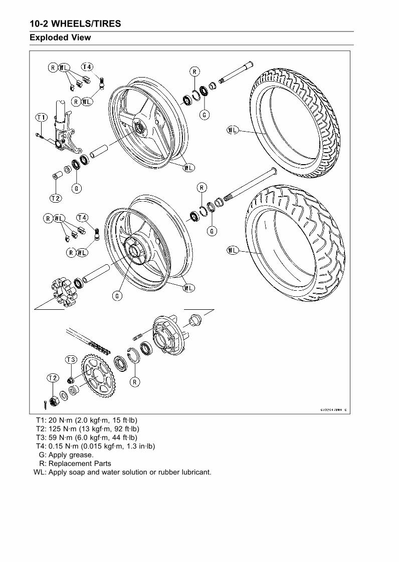
10-2 WHEELS/TIRES
Exploded View
T1: 20 N·m (2.0 kgf·m, 15 ft·lb)T2: 125 N·m (13 kgf·m, 92 ft·lb)T3: 59 N·m (6.0 kgf·m, 44 ft·lb)T4: 0.15 N·m (0.015 kgf·m, 1.3 in·lb)G: Apply grease.R: Replacement Parts
WL: Apply soap and water solution or rubber lubricant.
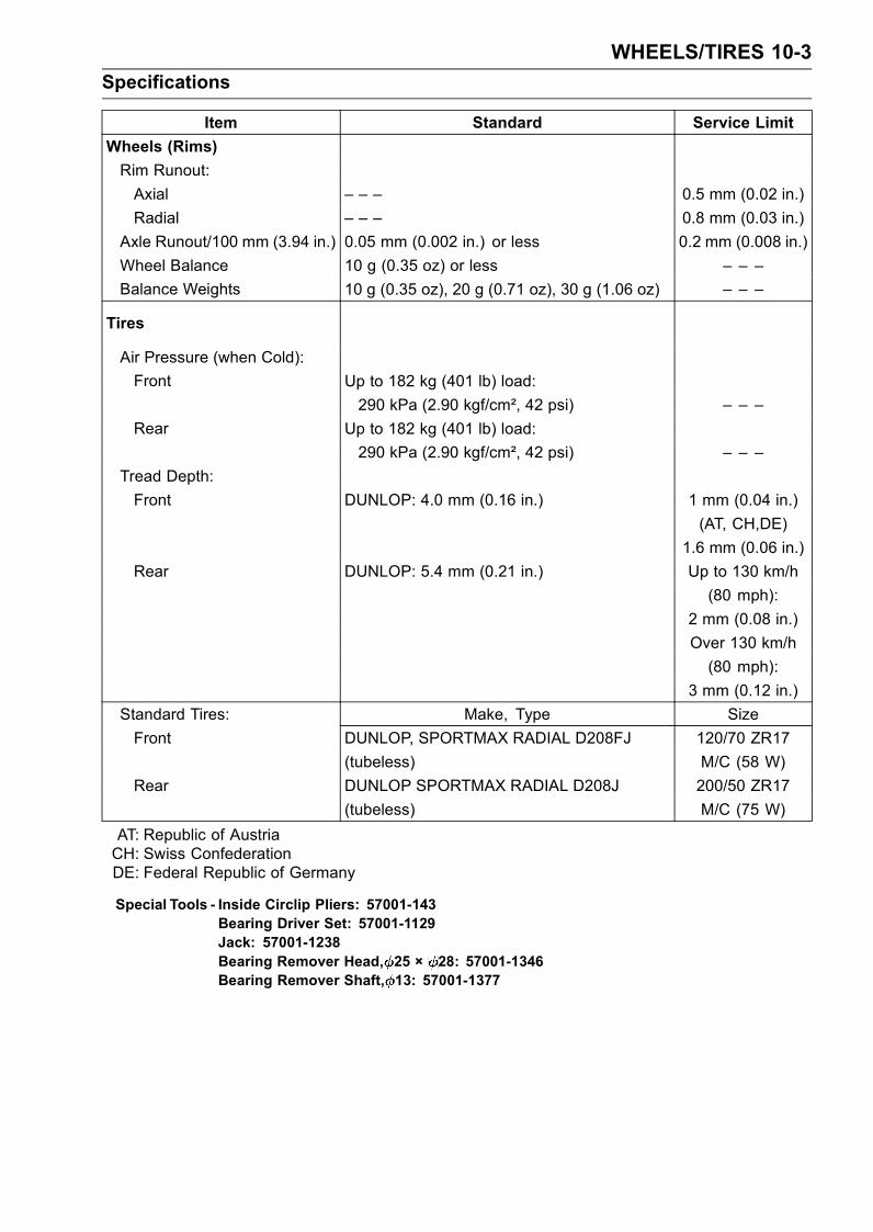
WHEELS/TIRES 10-3
Specifications
Item Standard Service Limit
Wheels (Rims)
Rim Runout:
Axial – – – 0.5 mm (0.02 in.)
Radial – – – 0.8 mm (0.03 in.)
Axle Runout/100 mm (3.94 in.) 0.05 mm (0.002 in.) or less 0.2 mm (0.008 in.)
Wheel Balance 10 g (0.35 oz) or less – – –
Balance Weights 10 g (0.35 oz), 20 g (0.71 oz), 30 g (1.06 oz) – – –
Tires
Air Pressure (when Cold):
Front Up to 182 kg (401 lb) load:
290 kPa (2.90 kgf/cm², 42 psi) – – –
Rear Up to 182 kg (401 lb) load:
290 kPa (2.90 kgf/cm², 42 psi) – – –
Tread Depth:
Front DUNLOP: 4.0 mm (0.16 in.) 1 mm (0.04 in.)
(AT, CH,DE)
1.6 mm (0.06 in.)
Rear DUNLOP: 5.4 mm (0.21 in.) Up to 130 km/h
(80 mph):
2 mm (0.08 in.)
Over 130 km/h
(80 mph):
3 mm (0.12 in.)
Standard Tires: Make, Type Size
Front DUNLOP, SPORTMAX RADIAL D208FJ 120/70 ZR17
(tubeless) M/C (58 W)
Rear DUNLOP SPORTMAX RADIAL D208J 200/50 ZR17
(tubeless) M/C (75 W)
AT: Republic of AustriaCH: Swiss ConfederationDE: Federal Republic of Germany
Special Tools - Inside Circlip Pliers: 57001-143Bearing Driver Set: 57001-1129Jack: 57001-1238Bearing Remover Head, 25 × 28: 57001-1346Bearing Remover Shaft, 13: 57001-1377

10-4 WHEELS/TIRES
Wheels (Rims)
Front Wheel Removal
•Remove:Lower Fairings (see Frame chapter)Brake Caliper Mounting Bolts [A]Refractors [B] (for the US and Canadian model)ZX1200-B1/B2 [C]ZX1200-B3 [D]
• Loosen:Right Side Axle Clamp Bolts [A]Axle [B]
•Raise the front wheel off the ground.Special Tool - Jack: 57001-1238 [A]
•Pull out the axle to the right and drop the front wheel outof the forks.
CAUTION
Do not lay the wheel down on one of the discs. Thiscan damage or warp the disc. Place blocks un-der the wheel so that the disc does not touch theground.
Front Wheel Installation
NOTEThe direction of the wheel rotation [A] is shown by anarrow [B] on the wheel spoke.
•Check the wheel rotation mark on the front wheel andinstall it.
• Fit the collars on the both sides of the hub.The collars are identical.• If the axle nut in the left fork leg is removed, install it onthe left fork leg from the left side.
• Tighten the axle nut.Torque - Front Axle Nut: 125 N·m (13 kgf·m, 92 ft·lb)
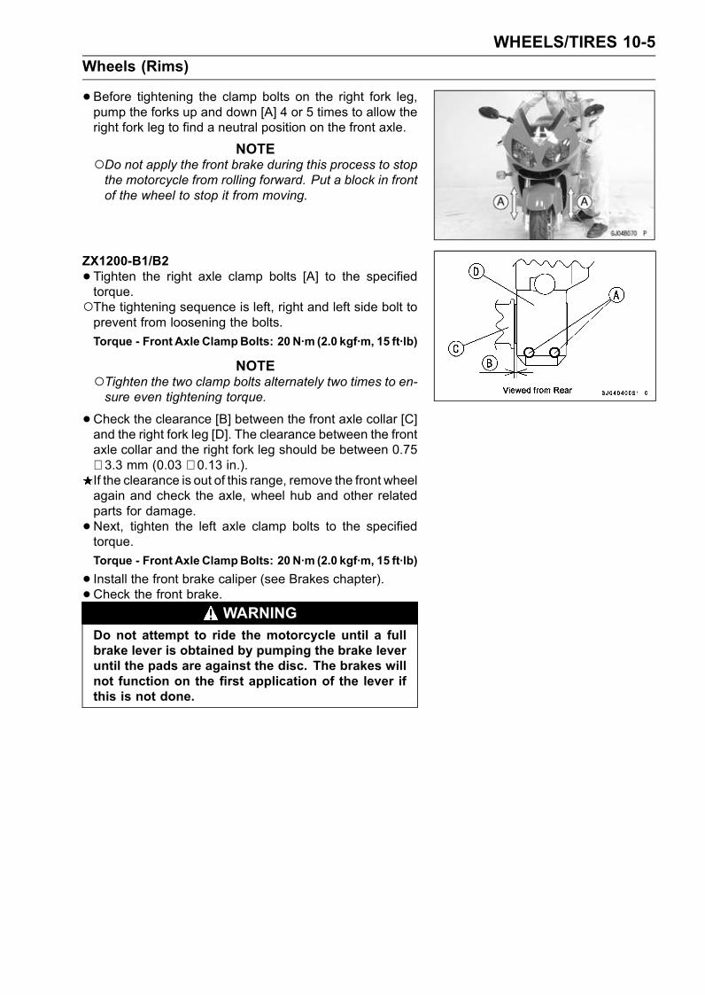
WHEELS/TIRES 10-5
Wheels (Rims)
•Before tightening the clamp bolts on the right fork leg,pump the forks up and down [A] 4 or 5 times to allow theright fork leg to find a neutral position on the front axle.
NOTEDo not apply the front brake during this process to stopthe motorcycle from rolling forward. Put a block in frontof the wheel to stop it from moving.
ZX1200-B1/B2
•Tighten the right axle clamp bolts [A] to the specifiedtorque.The tightening sequence is left, right and left side bolt toprevent from loosening the bolts.
Torque - Front Axle ClampBolts: 20 N·m (2.0 kgf·m, 15 ft·lb)
NOTETighten the two clamp bolts alternately two times to en-sure even tightening torque.
•Check the clearance [B] between the front axle collar [C]and the right fork leg [D]. The clearance between the frontaxle collar and the right fork leg should be between 0.75∼ 3.3 mm (0.03 ∼ 0.13 in.).If the clearance is out of this range, remove the front wheelagain and check the axle, wheel hub and other relatedparts for damage.
•Next, tighten the left axle clamp bolts to the specifiedtorque.
Torque - Front Axle ClampBolts: 20 N·m (2.0 kgf·m, 15 ft·lb)
• Install the front brake caliper (see Brakes chapter).• Check the front brake.
WARNINGDo not attempt to ride the motorcycle until a fullbrake lever is obtained by pumping the brake leveruntil the pads are against the disc. The brakes willnot function on the first application of the lever ifthis is not done.
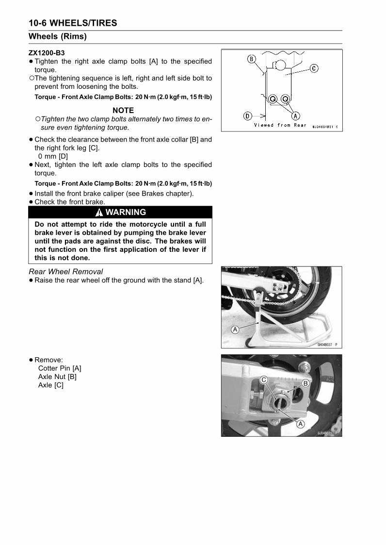
10-6 WHEELS/TIRES
Wheels (Rims)
ZX1200-B3
•Tighten the right axle clamp bolts [A] to the specifiedtorque.The tightening sequence is left, right and left side bolt toprevent from loosening the bolts.
Torque - Front Axle ClampBolts: 20 N·m (2.0 kgf·m, 15 ft·lb)
NOTETighten the two clamp bolts alternately two times to en-sure even tightening torque.
•Check the clearance between the front axle collar [B] andthe right fork leg [C].0 mm [D]
•Next, tighten the left axle clamp bolts to the specifiedtorque.
Torque - Front Axle ClampBolts: 20 N·m (2.0 kgf·m, 15 ft·lb)
• Install the front brake caliper (see Brakes chapter).• Check the front brake.
WARNINGDo not attempt to ride the motorcycle until a fullbrake lever is obtained by pumping the brake leveruntil the pads are against the disc. The brakes willnot function on the first application of the lever ifthis is not done.
Rear Wheel Removal
•Raise the rear wheel off the ground with the stand [A].
•Remove:Cotter Pin [A]Axle Nut [B]Axle [C]
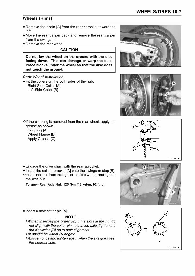
WHEELS/TIRES 10-7
Wheels (Rims)
•Remove the chain [A] from the rear sprocket toward theleft.
•Move the rear caliper back and remove the rear caliperfrom the swingarm.
•Remove the rear wheel.CAUTION
Do not lay the wheel on the ground with the discfacing down. This can damage or warp the disc.Place blocks under the wheel so that the disc doesnot touch the ground.
Rear Wheel Installation
•Fit the collers on the both sides of the hub.Right Side Coller [A]Left Side Coller [B]
If the coupling is removed from the rear wheel, apply thegrease as shown.Coupling [A]Wheel Flange [B]Apply Grease [C].
• Engage the drive chain with the rear sprocket.• Install the caliper bracket [A] onto the swingarm stop [B].Install the axle from the right side of the wheel, and tightenthe axle nut.
Torque - Rear Axle Nut: 125 N·m (13 kgf·m, 92 ft·lb)
• Insert a new cotter pin [A].NOTE
When inserting the cotter pin, if the slots in the nut donot align with the cotter pin hole in the axle, tighten thenut clockwise [B] up to next alignment.It should be within 30 degree.Loosen once and tighten again when the slot goes pastthe nearest hole.
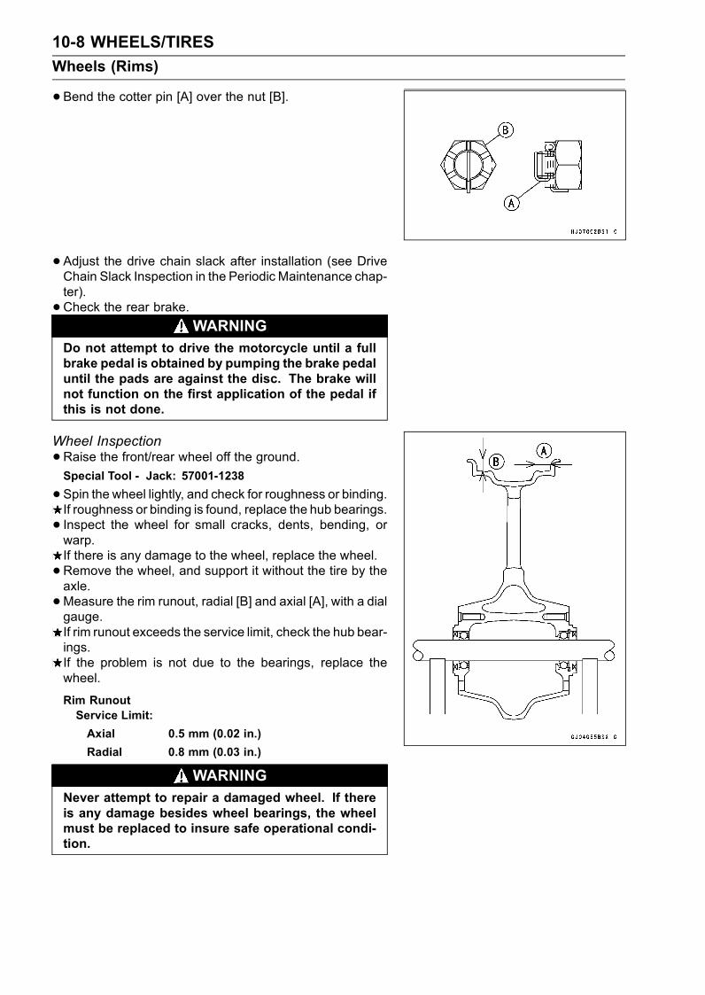
10-8 WHEELS/TIRES
Wheels (Rims)
•Bend the cotter pin [A] over the nut [B].
• Adjust the drive chain slack after installation (see DriveChain Slack Inspection in the Periodic Maintenance chap-ter).
• Check the rear brake.WARNING
Do not attempt to drive the motorcycle until a fullbrake pedal is obtained by pumping the brake pedaluntil the pads are against the disc. The brake willnot function on the first application of the pedal ifthis is not done.
Wheel Inspection
•Raise the front/rear wheel off the ground.Special Tool - Jack: 57001-1238
•Spin the wheel lightly, and check for roughness or binding.If roughness or binding is found, replace the hub bearings.
• Inspect the wheel for small cracks, dents, bending, orwarp.If there is any damage to the wheel, replace the wheel.
• Remove the wheel, and support it without the tire by theaxle.
•Measure the rim runout, radial [B] and axial [A], with a dialgauge.If rim runout exceeds the service limit, check the hub bear-ings.If the problem is not due to the bearings, replace thewheel.
Rim RunoutService Limit:
Axial 0.5 mm (0.02 in.)
Radial 0.8 mm (0.03 in.)
WARNINGNever attempt to repair a damaged wheel. If thereis any damage besides wheel bearings, the wheelmust be replaced to insure safe operational condi-tion.

WHEELS/TIRES 10-9
Wheels (Rims)
Axle Inspection
•Visually inspect the front and rear axle for damages.If the axle is damaged or bent, replace it.
• Place the axle in V blocks that are 100 mm (3.94 in.) [A]apart, and set a dial gauge [B] on the axle at a pointhalfway between the blocks. Turn [C] the axle to mea-sure the runout. The difference between the highest andlowest dial readings is the amount of runout.If axle runout exceeds the service limit, replace the axle.
Axle Runout/100 mm (3.94 in.)Standard: 0.05 mm (0.002 in.) or less
Service Limit: 0.2 mm (0.008 in.)
Balance Inspection
•Remove the wheel.• Support the wheel so that it can be spun freely.• Spin the wheel lightly, and mark [A] the wheel at the topwhen the wheel stops.Repeat this procedure several times. If the wheel stopsof its own accord in various positions, it is well balanced.If the wheel always stops in one position, adjust the wheelbalance.
Balance Adjustment
• If the wheel always stops in one position, provisionallyattach a balance weight [A] on the rim at themarking usingadhesive tape.
•Rotate the wheel 1/4 turn [B], and see whether or not thewheel stops in this position. If it does, the correct balanceweight is being used.If the wheel rotates and the weight goes up, replace theweight with the next heavier size. If the wheel rotates andthe weight goes down, replace the weight with the nextlighter size. Repeat these steps until the wheel remainsat rest after being rotated 1/4 turn.
•Rotate the wheel another 1/4 turn and then another 1/4turn to see if the wheel is correctly balanced.
•Repeat the entire procedure as many times as necessaryto achieve correct wheel balance.
• Permanently install the balance weight.Balance Weight
Part Number Weight
41075-1014 10 g (0.35 oz)
41075-1015 20 g (0.71 oz)
41075-1016 30 g (1.06 oz)
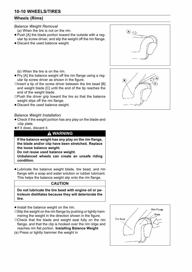
10-10 WHEELS/TIRES
Wheels (Rims)
Balance Weight Removal(a) When the tire is not on the rim.
• Push [A] the blade portion toward the outside with a reg-ular tip screw driver, and slip the weight off the rim flange.
•Discard the used balance weight.
(b) When the tire is on the rim.
• Pry [A] the balance weight off the rim flange using a reg-ular tip screw driver as shown in the figure.Insert a tip of the screw driver between the tire bead [B]and weight blade [C] until the end of the tip reaches theend of the weight blade.Push the driver grip toward the tire so that the balanceweight slips off the rim flange.
•Discard the used balance weight.
Balance Weight Installation
•Check if the weight portion has any play on the blade-and-clip plate.If it does, discard it.
WARNINGIf the balance weight has any play on the rim flange,the blade and/or clip have been stretched. Replacethe loose balance weight.Do not reuse used balance weight.Unbalanced wheels can create an unsafe ridingcondition.
•Lubricate the balance weight blade, tire bead, and rimflange with a soap and water solution or rubber lubricant.This helps the balance weight slip onto the rim flange.
CAUTION
Do not lubricate the tire bead with engine oil or pe-troleum distillates because they will deteriorate thetire.
• Install the balance weight on the rim.Slip the weight on the rim flange by pushing or lightly ham-mering the weight in the direction shown in the figure.Check that the blade and weight seat fully on the rimflange, and that the clip is hooked over the rim ridge andreaches rim flat portion. Installing Balance Weight
(a) Press or lightly hammer the weight in

WHEELS/TIRES 10-11
Wheels (Rims)
(b) Installation completed.
•When required total weight exceeds 20 g (0.71 oz), installbalance weight at both sides of rim flange as shown.
Weight SelectionRequired TotalWeight One Side [A] Other Side [B]
20 g (0.71 oz) 10 g (0.35 oz) 10 g (0.35 oz)
30 g (1.06 oz) 20 g (0.71 oz) 10 g (0.35 oz)
40 g (1.41 oz) 20 g (0.71 oz) 20 g (0.71 oz)
50 g (1.76 oz) 30 g (1.06 oz) 20 g (0.71 oz)
60 g (2.12 oz) 30 g (1.06 oz) 30 g (1.06 oz)
70 g (2.47 oz)20 g + 20 g
(0.71 oz + 0.71 oz)30 g (1.06 oz)
80 g (2.82 oz)20 g + 20 g
(0.71 oz + 0.71 oz)20 g + 20 g
(0.71 oz + 0.71 oz)
90 g (3.17 oz)20 g + 30 g
(0.71 oz + 1.06 oz)20 g + 20 g
(0.71 oz + 0.71 oz)
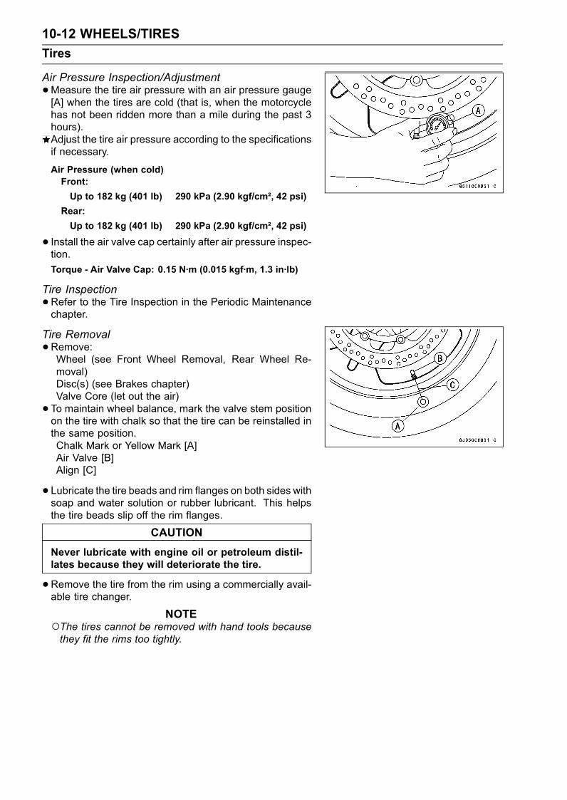
10-12 WHEELS/TIRES
Tires
Air Pressure Inspection/Adjustment
•Measure the tire air pressure with an air pressure gauge[A] when the tires are cold (that is, when the motorcyclehas not been ridden more than a mile during the past 3hours).Adjust the tire air pressure according to the specificationsif necessary.
Air Pressure (when cold)Front:
Up to 182 kg (401 lb) 290 kPa (2.90 kgf/cm², 42 psi)
Rear:
Up to 182 kg (401 lb) 290 kPa (2.90 kgf/cm², 42 psi)
• Install the air valve cap certainly after air pressure inspec-tion.
Torque - Air Valve Cap: 0.15 N·m (0.015 kgf·m, 1.3 in·lb)
Tire Inspection
•Refer to the Tire Inspection in the Periodic Maintenancechapter.
Tire Removal
•Remove:Wheel (see Front Wheel Removal, Rear Wheel Re-moval)Disc(s) (see Brakes chapter)Valve Core (let out the air)
• To maintain wheel balance, mark the valve stem positionon the tire with chalk so that the tire can be reinstalled inthe same position.Chalk Mark or Yellow Mark [A]Air Valve [B]Align [C]
• Lubricate the tire beads and rim flanges on both sides withsoap and water solution or rubber lubricant. This helpsthe tire beads slip off the rim flanges.
CAUTION
Never lubricate with engine oil or petroleum distil-lates because they will deteriorate the tire.
•Remove the tire from the rim using a commercially avail-able tire changer.
NOTEThe tires cannot be removed with hand tools becausethey fit the rims too tightly.
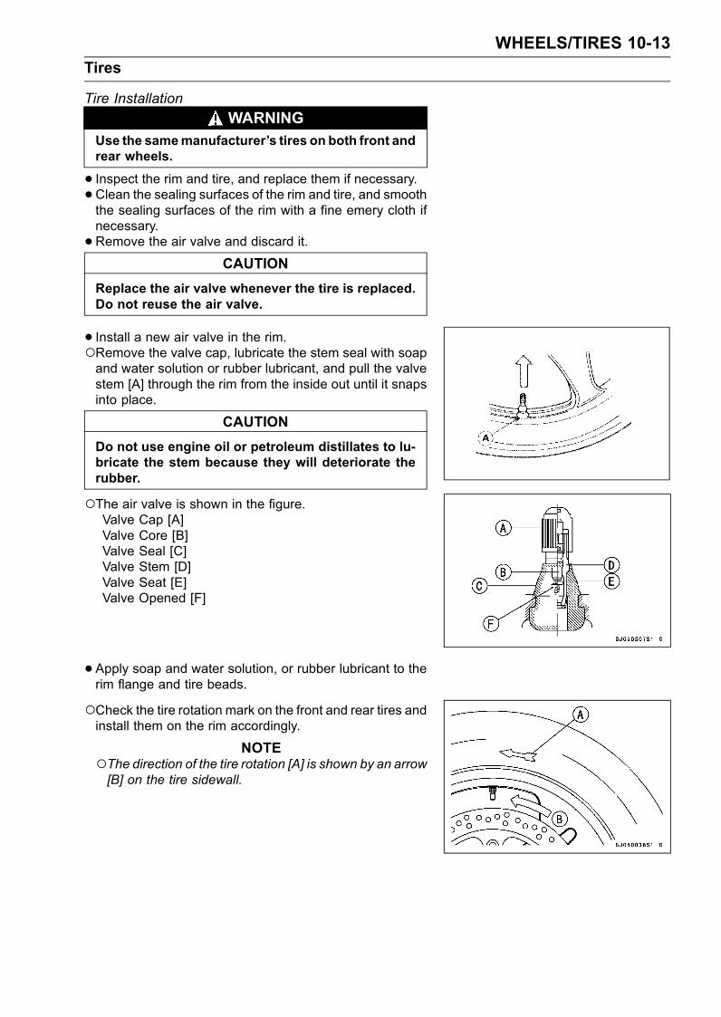
WHEELS/TIRES 10-13
Tires
Tire Installation
WARNINGUse the samemanufacturer’s tires on both front andrear wheels.
• Inspect the rim and tire, and replace them if necessary.•Clean the sealing surfaces of the rim and tire, and smooththe sealing surfaces of the rim with a fine emery cloth ifnecessary.
•Remove the air valve and discard it.CAUTION
Replace the air valve whenever the tire is replaced.Do not reuse the air valve.
• Install a new air valve in the rim.Remove the valve cap, lubricate the stem seal with soapand water solution or rubber lubricant, and pull the valvestem [A] through the rim from the inside out until it snapsinto place.
CAUTION
Do not use engine oil or petroleum distillates to lu-bricate the stem because they will deteriorate therubber.
The air valve is shown in the figure.Valve Cap [A]Valve Core [B]Valve Seal [C]Valve Stem [D]Valve Seat [E]Valve Opened [F]
• Apply soap and water solution, or rubber lubricant to therim flange and tire beads.
Check the tire rotation mark on the front and rear tires andinstall them on the rim accordingly.
NOTEThe direction of the tire rotation [A] is shown by an arrow[B] on the tire sidewall.
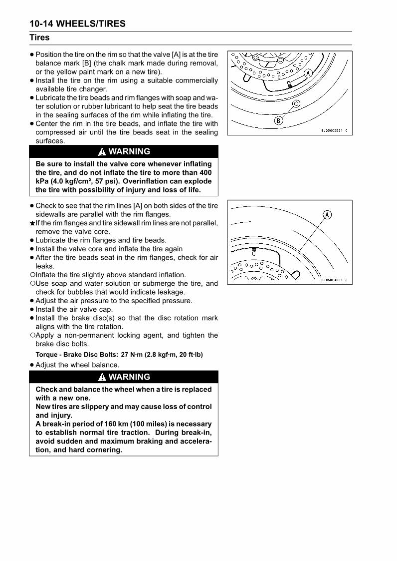
10-14 WHEELS/TIRES
Tires
•Position the tire on the rim so that the valve [A] is at the tirebalance mark [B] (the chalk mark made during removal,or the yellow paint mark on a new tire).
• Install the tire on the rim using a suitable commerciallyavailable tire changer.
• Lubricate the tire beads and rim flanges with soap andwa-ter solution or rubber lubricant to help seat the tire beadsin the sealing surfaces of the rim while inflating the tire.
•Center the rim in the tire beads, and inflate the tire withcompressed air until the tire beads seat in the sealingsurfaces.
WARNINGBe sure to install the valve core whenever inflatingthe tire, and do not inflate the tire to more than 400kPa (4.0 kgf/cm², 57 psi). Overinflation can explodethe tire with possibility of injury and loss of life.
•Check to see that the rim lines [A] on both sides of the tiresidewalls are parallel with the rim flanges.If the rim flanges and tire sidewall rim lines are not parallel,remove the valve core.
• Lubricate the rim flanges and tire beads.
• Install the valve core and inflate the tire again•After the tire beads seat in the rim flanges, check for airleaks.Inflate the tire slightly above standard inflation.Use soap and water solution or submerge the tire, andcheck for bubbles that would indicate leakage.
• Adjust the air pressure to the specified pressure.• Install the air valve cap.• Install the brake disc(s) so that the disc rotation markaligns with the tire rotation.Apply a non-permanent locking agent, and tighten thebrake disc bolts.
Torque - Brake Disc Bolts: 27 N·m (2.8 kgf·m, 20 ft·lb)
•Adjust the wheel balance.WARNING
Check and balance the wheel when a tire is replacedwith a new one.New tires are slippery andmay cause loss of controland injury.A break-in period of 160 km (100miles) is necessaryto establish normal tire traction. During break-in,avoid sudden and maximum braking and accelera-tion, and hard cornering.
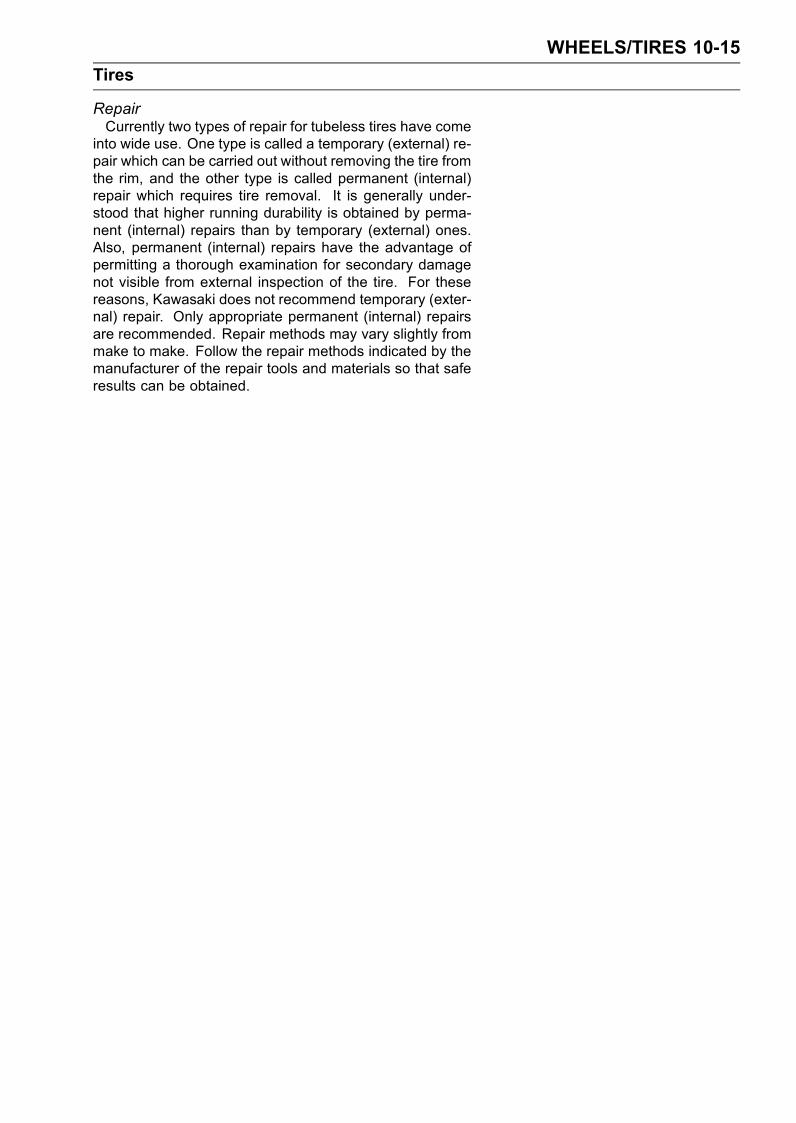
WHEELS/TIRES 10-15
Tires
RepairCurrently two types of repair for tubeless tires have come
into wide use. One type is called a temporary (external) re-pair which can be carried out without removing the tire fromthe rim, and the other type is called permanent (internal)repair which requires tire removal. It is generally under-stood that higher running durability is obtained by perma-nent (internal) repairs than by temporary (external) ones.Also, permanent (internal) repairs have the advantage ofpermitting a thorough examination for secondary damagenot visible from external inspection of the tire. For thesereasons, Kawasaki does not recommend temporary (exter-nal) repair. Only appropriate permanent (internal) repairsare recommended. Repair methods may vary slightly frommake to make. Follow the repair methods indicated by themanufacturer of the repair tools and materials so that saferesults can be obtained.
10-16 WHEELS/TIRES
Hub Bearings
Hub Bearing Removal
•Remove the wheel, and take out the following.CollarsCoupling (Out of rear hub)Grease SealsCirclip
Special Tool - Inside Circlip Pliers: 57001-143
•Take the bearings [A] out of the hub.CAUTION
Do not lay the wheel on the ground with the discfacing down. This can damage or warp the disc.Please blocks under the wheel so that the disc doesnot touch the ground.
Special Tools - Bearing Remover Head, 25 × 28: 57001-1346 [C]
Bearing Remover Shaft, 13: 57001-1377[B]
Hub Bearing Installation
•Before installing the wheel bearings, blow any dirt or for-eign particles out of the hub with compressed air to pre-vent contamination of the bearings.
•Replace the bearings with new ones.Press in each right the bearing [A] until they are bottomed.Special Tool - Bearing Driver Set: 57001-1129 [B]
NOTEInstall the bearings so that the marked side faces out.Replace the circlips with new ones.Special Tool - Inside Circlip Pliers: 57001-143
•Replace the grease seals with new ones.• Press in the grease seals [A] so that the seal surface flush[B] with the end of the hole.Apply high temperature grease to the grease seal lips.Special Tool - Bearing Driver Set: 57001-1129 [C]
Hub Bearing Inspection
NOTEIt is not necessary to remove any bearings for inspec-tion. If any bearings are removed, they will need to bereplaced with new ones.
•Spin [A] it by hand to check its condition.If it is noisy, does not spin smoothly, or has any roughspots, it must be replaced.
• Examine the bearing seal [B] for tears or leakage.If the seal is torn or is leaking, replace the bearing.
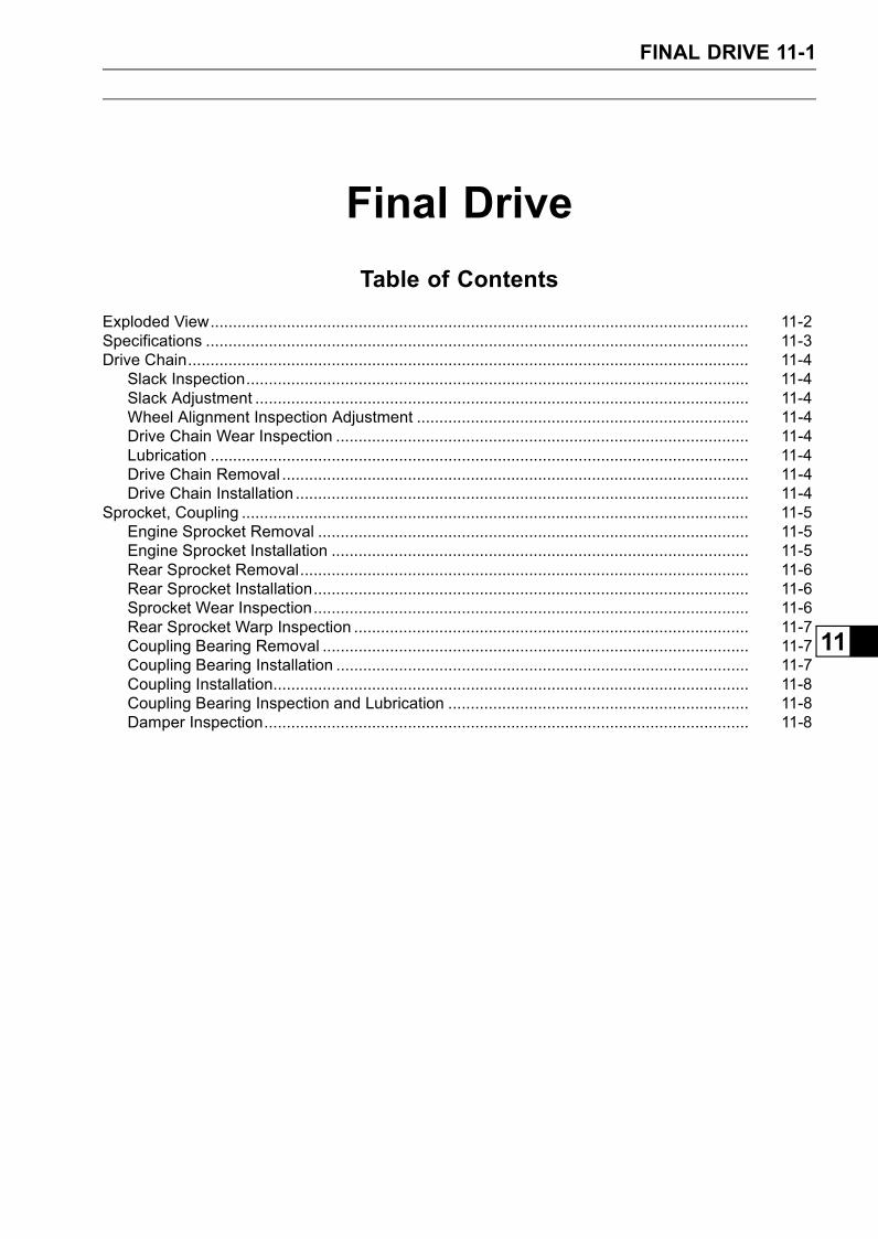
FINAL DRIVE 11-1
11
Final Drive
Table of Contents
Exploded View........................................................................................................................ 11-2Specifications ......................................................................................................................... 11-3Drive Chain............................................................................................................................. 11-4
Slack Inspection................................................................................................................ 11-4Slack Adjustment .............................................................................................................. 11-4Wheel Alignment Inspection Adjustment .......................................................................... 11-4Drive Chain Wear Inspection ............................................................................................ 11-4Lubrication ........................................................................................................................ 11-4Drive Chain Removal ........................................................................................................ 11-4Drive Chain Installation ..................................................................................................... 11-4
Sprocket, Coupling ................................................................................................................. 11-5Engine Sprocket Removal ................................................................................................ 11-5Engine Sprocket Installation ............................................................................................. 11-5Rear Sprocket Removal.................................................................................................... 11-6Rear Sprocket Installation................................................................................................. 11-6Sprocket Wear Inspection................................................................................................. 11-6Rear Sprocket Warp Inspection ........................................................................................ 11-7Coupling Bearing Removal ............................................................................................... 11-7Coupling Bearing Installation ............................................................................................ 11-7Coupling Installation.......................................................................................................... 11-8Coupling Bearing Inspection and Lubrication ................................................................... 11-8Damper Inspection............................................................................................................ 11-8

11-2 FINAL DRIVE
Exploded View
T1: 12 N·m (1.2 kgf·m, 106 in·lb)T2: 59 N·m (6.0 kgf·m, 44 ft·lb)T3: 125 N·m (13 kgf·m, 92 ft·lb)T4: 127 N·m (13 kgf·m, 94 ft·lb)G: Apply grease.HO: Apply heavy oil.L: Apply a non-permanent locking agent.
MO: Apply molybdenum disulfide oil solution.R: Replacement Parts
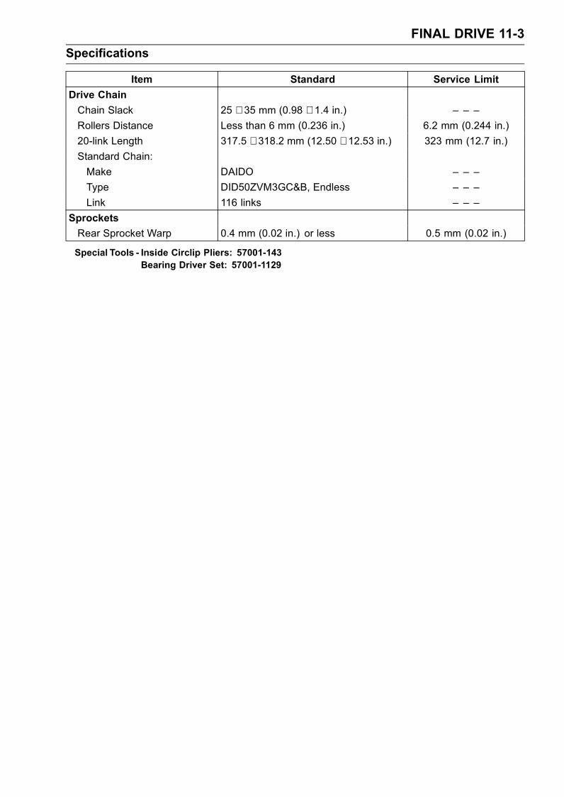
FINAL DRIVE 11-3
Specifications
Item Standard Service Limit
Drive Chain
Chain Slack 25 ∼ 35 mm (0.98 ∼ 1.4 in.) – – –
Rollers Distance Less than 6 mm (0.236 in.) 6.2 mm (0.244 in.)
20-link Length 317.5 ∼ 318.2 mm (12.50 ∼ 12.53 in.) 323 mm (12.7 in.)
Standard Chain:
Make DAIDO – – –
Type DID50ZVM3GC&B, Endless – – –
Link 116 links – – –
Sprockets
Rear Sprocket Warp 0.4 mm (0.02 in.) or less 0.5 mm (0.02 in.)
Special Tools - Inside Circlip Pliers: 57001-143Bearing Driver Set: 57001-1129

11-4 FINAL DRIVE
Drive Chain
Slack Inspection
•Refer to the Drive Chain Inspection in the Periodic Main-tenance chapter.
Slack Adjustment
•Refer to the Drive Chain Inspection in the Periodic Main-tenance chapter.
Wheel Alignment Inspection Adjustment
•Refer to the Drive Chain Inspection in the Periodic Main-tenance chapter.
Drive Chain Wear Inspection
•Refer to the Drive Chain Wear Inspection in the PeriodicMaintenance chapter.
Lubrication
•Refer to the Drive Chain Lubrication in the Periodic Main-tenance chapter.
Drive Chain Removal
•Remove:Rear Wheel (see Wheels/Tires chapter)Chain Cover Screws [A]Chain Cover [B]Brake Hose Clamp Screw [C] and Bolts [D]Swingarm (see Suspension chapter)Engine Sprocket Cover (see this chapter)
•Disengage the drive chain [A] from the engine sprocket[B], and take it off the chassis.
Drive Chain Installation
•Engage the drive chain to the engine sprocket.• Install:Swingarm (see Suspension chapter)Rear Wheel (see Wheels/Tires chapter)Engine Sprocket Cover (see Engine Sprocket Installa-tion)Chain Cover
• Adjust the chain slack after installing the chain (see DriveChain Inspection in the Periodic Maintenance chapter).
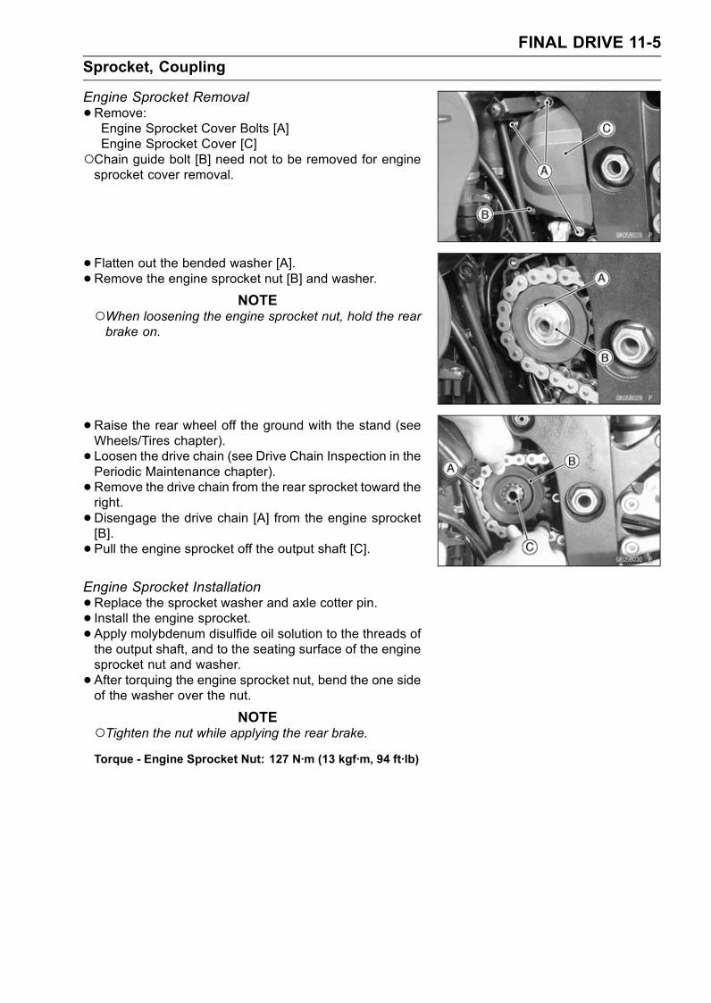
FINAL DRIVE 11-5
Sprocket, Coupling
Engine Sprocket Removal
•Remove:Engine Sprocket Cover Bolts [A]Engine Sprocket Cover [C]
Chain guide bolt [B] need not to be removed for enginesprocket cover removal.
• Flatten out the bended washer [A].• Remove the engine sprocket nut [B] and washer.
NOTEWhen loosening the engine sprocket nut, hold the rearbrake on.
•Raise the rear wheel off the ground with the stand (seeWheels/Tires chapter).
• Loosen the drive chain (see Drive Chain Inspection in thePeriodic Maintenance chapter).
• Remove the drive chain from the rear sprocket toward theright.
• Disengage the drive chain [A] from the engine sprocket[B].
• Pull the engine sprocket off the output shaft [C].
Engine Sprocket Installation
•Replace the sprocket washer and axle cotter pin.• Install the engine sprocket.• Apply molybdenum disulfide oil solution to the threads ofthe output shaft, and to the seating surface of the enginesprocket nut and washer.
• After torquing the engine sprocket nut, bend the one sideof the washer over the nut.
NOTETighten the nut while applying the rear brake.Torque - Engine Sprocket Nut: 127 N·m (13 kgf·m, 94 ft·lb)
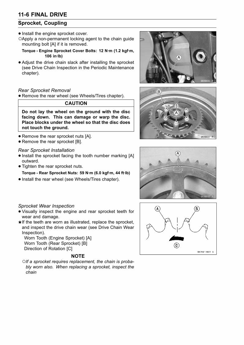
11-6 FINAL DRIVE
Sprocket, Coupling
• Install the engine sprocket cover.Apply a non-permanent locking agent to the chain guidemounting bolt [A] if it is removed.
Torque - Engine Sprocket Cover Bolts: 12 N·m (1.2 kgf·m,106 in·lb)
•Adjust the drive chain slack after installing the sprocket(see Drive Chain Inspection in the Periodic Maintenancechapter).
Rear Sprocket Removal
•Remove the rear wheel (see Wheels/Tires chapter).CAUTION
Do not lay the wheel on the ground with the discfacing down. This can damage or warp the disc.Place blocks under the wheel so that the disc doesnot touch the ground.
•Remove the rear sprocket nuts [A].•Remove the rear sprocket [B].Rear Sprocket Installation
• Install the sprocket facing the tooth number marking [A]outward.
• Tighten the rear sprocket nuts.Torque - Rear Sprocket Nuts: 59 N·m (6.0 kgf·m, 44 ft·lb)
• Install the rear wheel (see Wheels/Tires chapter).
Sprocket Wear Inspection
•Visually inspect the engine and rear sprocket teeth forwear and damage.If the teeth are worn as illustrated, replace the sprocket,and inspect the drive chain wear (see Drive Chain WearInspection).Worn Tooth (Engine Sprocket) [A]Worn Tooth (Rear Sprocket) [B]Direction of Rotation [C]
NOTEIf a sprocket requires replacement, the chain is proba-bly worn also. When replacing a sprocket, inspect thechain

FINAL DRIVE 11-7
Sprocket, Coupling
Rear Sprocket Warp Inspection
•Raise the rear wheel off the ground (see Wheels/Tireschapter) so that it will turn freely.
• Set a dial gauge [A] against the rear sprocket [B] near theteeth as shown, and rotate [C] the rear wheel to measurethe sprocket runout (warp). The difference between thehighest and lowest dial gauge readings is the amount ofrunout (warp).If the runout exceeds the service limit, replace the rearsprocket.
Rear Sprocket WarpStandard: 0.4 mm (0.02 in.) or less
Service Limit: 0.5 mm (0.02 in.)
Coupling Bearing Removal
•Remove the rear wheel (see Wheels/Tires chapter).• Remove:CouplingGrease SealCirclip [A]
Special Tool - Inside Circlip Pliers: 57001-143 [B]
•Remove the bearing [A] by tapping from the wheel side.Special Tool - Bearing Driver Set: 57001-1129 [B]
Coupling Bearing Installation
•Replace the bearing with a new one.• Press in the bearing [A] until it is bottomed.Special Tool - Bearing Driver Set: 57001-1129 [B]
•Pack the bearing with high temperature grease.•Replace the circlip with a new one.Special Tool - Inside Circlip Pliers: 57001-143
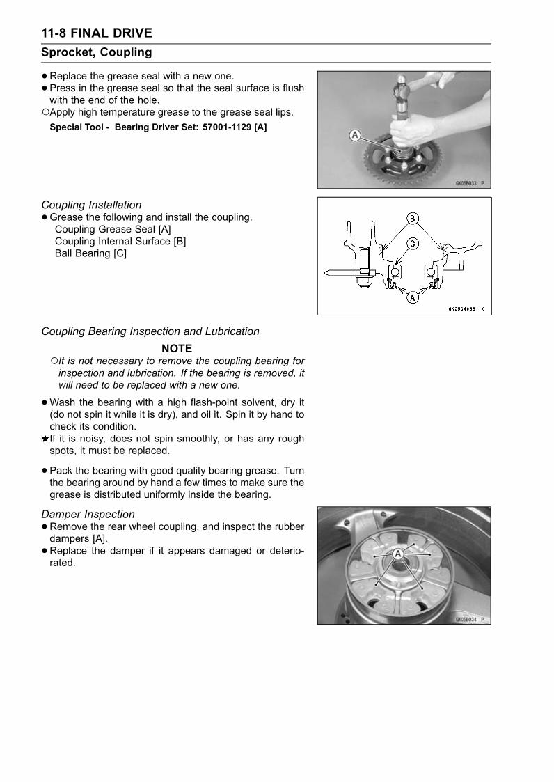
11-8 FINAL DRIVE
Sprocket, Coupling
•Replace the grease seal with a new one.• Press in the grease seal so that the seal surface is flushwith the end of the hole.Apply high temperature grease to the grease seal lips.Special Tool - Bearing Driver Set: 57001-1129 [A]
Coupling Installation
•Grease the following and install the coupling.Coupling Grease Seal [A]Coupling Internal Surface [B]Ball Bearing [C]
Coupling Bearing Inspection and Lubrication
NOTEIt is not necessary to remove the coupling bearing forinspection and lubrication. If the bearing is removed, itwill need to be replaced with a new one.
•Wash the bearing with a high flash-point solvent, dry it(do not spin it while it is dry), and oil it. Spin it by hand tocheck its condition.If it is noisy, does not spin smoothly, or has any roughspots, it must be replaced.
• Pack the bearing with good quality bearing grease. Turnthe bearing around by hand a few times to make sure thegrease is distributed uniformly inside the bearing.
Damper Inspection
•Remove the rear wheel coupling, and inspect the rubberdampers [A].
•Replace the damper if it appears damaged or deterio-rated.

BRAKES 12-1
12
Brakes
Table of Contents
Exploded View................................... 12-2Specifications .................................... 12-8Brake Pedal ....................................... 12-9
Brake Lever Position Adjustment. 12-9Brake Pedal Position Adjustment. 12-9
Brake Lever, Brake Pedal.................. 12-10Brake Pedal Removal .................. 12-10Brake Pedal Installation ............... 12-10
Calipers ............................................. 12-11Front Caliper Removal ................. 12-11Rear Caliper Removal.................. 12-11Caliper Installation ....................... 12-11Front Caliper Disassembly........... 12-12Front Caliper Assembly................ 12-13Rear Caliper Disassembly ........... 12-14Rear Caliper Assembly ................ 12-15Caliper Fluid Seal Damage.......... 12-16Caliper Dust Seal Damage .......... 12-17Caliper Piston and CylinderDamage..................................... 12-17
Brake Pads........................................ 12-18Front Brake Pad Removal............ 12-18Front Brake Pad Installation......... 12-19Rear Brake Pad Removal ............ 12-19Rear Brake Pad Installation ......... 12-20
Brake Pad Lining Wear ................ 12-20Master Cylinder ................................. 12-21
Front Master Cylinder Removal ... 12-21Front Master Cylinder Installation 12-21Rear Master Cylinder Removal.... 12-22Rear Master Cylinder Installation. 12-22Front Master CylinderDisassembly.............................. 12-22
Rear Master CylinderDisassembly.............................. 12-23
Master Cylinder Assembly ........... 12-23Master Cylinder Inspection (VisualInspection)................................. 12-24
Brake Discs ....................................... 12-25Brake Disc Removal .................... 12-25Brake Disc Installation ................. 12-25Brake Disc Wear .......................... 12-25Brake Disc Warp .......................... 12-25
Brake Fluid ........................................ 12-26Brake Fluid Level Inspection........ 12-26Brake Fluid Change ..................... 12-26Bleeding the Brake Line............... 12-26
Brake Hoses...................................... 12-29Brake Hose Removal/Installation. 12-29Brake Hose Inspection................. 12-29
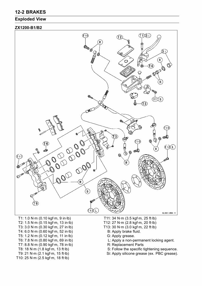
12-2 BRAKES
Exploded View
ZX1200-B1/B2
T1: 1.0 N·m (0.10 kgf·m, 9 in·lb)T2: 1.5 N·m (0.15 kgf·m, 13 in·lb)T3: 3.0 N·m (0.30 kgf·m, 27 in·lb)T4: 6.0 N·m (0.60 kgf·m, 52 in·lb)T5: 1.2 N·m (0.12 kgf·m, 11 in·lb)T6: 7.8 N·m (0.80 kgf·m, 69 in·lb)T7: 8.8 N·m (0.90 kgf·m, 78 in·lb)T8: 18 N·m (1.8 kgf·m, 13 ft·lb)T9: 21 N·m (2.1 kgf·m, 15 ft·lb)T10: 25 N·m (2.5 kgf·m, 18 ft·lb)
T11: 34 N·m (3.5 kgf·m, 25 ft·lb)T12: 27 N·m (2.8 kgf·m, 20 ft·lb)T13: 30 N·m (3.0 kgf·m, 22 ft·lb)B: Apply brake fluid.G: Apply grease.L: Apply a non-permanent locking agent.R: Replacement PartsS: Follow the specific tightening sequence.Si: Apply silicone grease (ex. PBC grease).
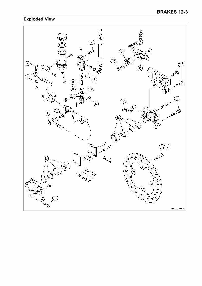
BRAKES 12-3
Exploded View

12-4 BRAKES
Exploded View
ZX1200-B3
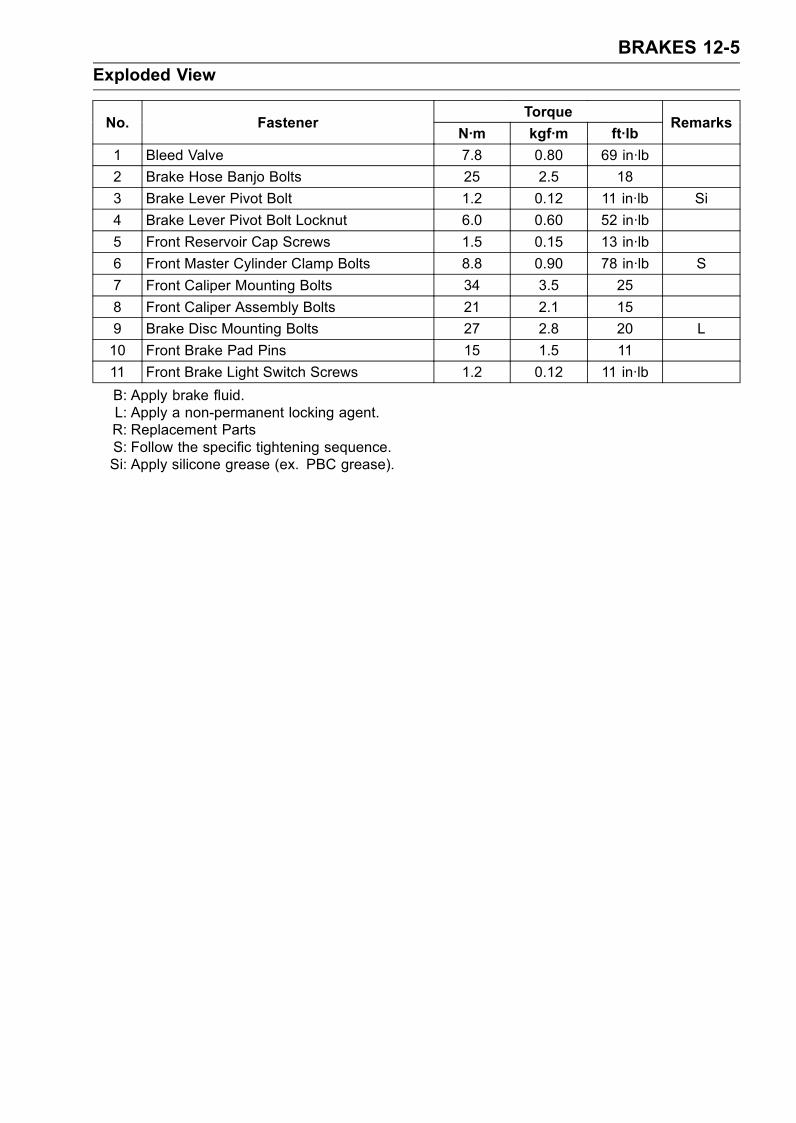
BRAKES 12-5
Exploded View
TorqueNo. Fastener
N·m kgf·m ft·lbRemarks
1 Bleed Valve 7.8 0.80 69 in·lb
2 Brake Hose Banjo Bolts 25 2.5 18
3 Brake Lever Pivot Bolt 1.2 0.12 11 in·lb Si
4 Brake Lever Pivot Bolt Locknut 6.0 0.60 52 in·lb
5 Front Reservoir Cap Screws 1.5 0.15 13 in·lb
6 Front Master Cylinder Clamp Bolts 8.8 0.90 78 in·lb S
7 Front Caliper Mounting Bolts 34 3.5 25
8 Front Caliper Assembly Bolts 21 2.1 15
9 Brake Disc Mounting Bolts 27 2.8 20 L
10 Front Brake Pad Pins 15 1.5 11
11 Front Brake Light Switch Screws 1.2 0.12 11 in·lb
B: Apply brake fluid.L: Apply a non-permanent locking agent.R: Replacement PartsS: Follow the specific tightening sequence.Si: Apply silicone grease (ex. PBC grease).
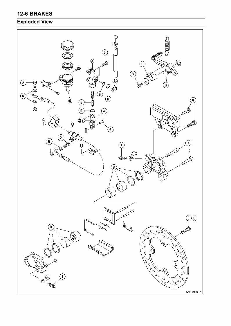
12-6 BRAKES
Exploded View
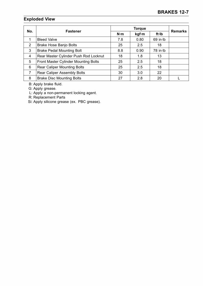
BRAKES 12-7
Exploded View
TorqueNo. Fastener
N·m kgf·m ft·lbRemarks
1 Bleed Valve 7.8 0.80 69 in·lb
2 Brake Hose Banjo Bolts 25 2.5 18
3 Brake Pedal Mounting Bolt 8.8 0.90 78 in·lb
4 Rear Master Cylinder Push Rod Locknut 18 1.8 13
5 Front Master Cylinder Mounting Bolts 25 2.5 18
6 Rear Caliper Mounting Bolts 25 2.5 18
7 Rear Caliper Assembly Bolts 30 3.0 22
8 Brake Disc Mounting Bolts 27 2.8 20 L
B: Apply brake fluid.G: Apply grease.L: Apply a non-permanent locking agent.R: Replacement PartsSi: Apply silicone grease (ex. PBC grease).
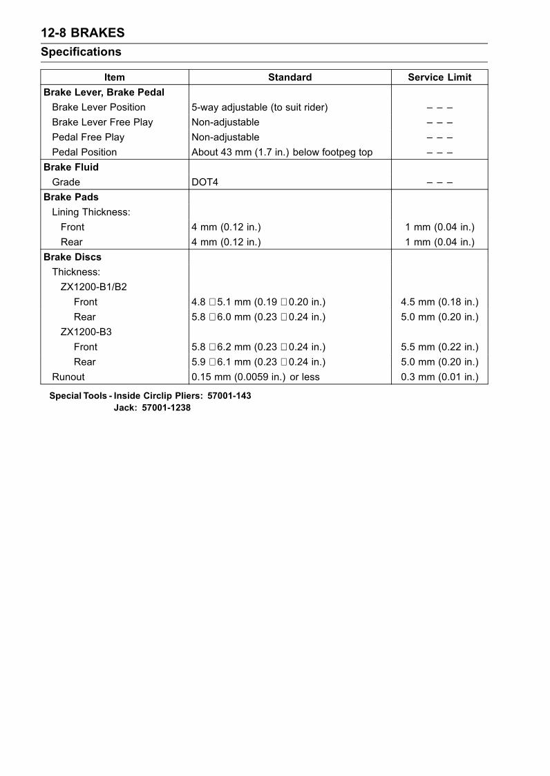
12-8 BRAKES
Specifications
Item Standard Service Limit
Brake Lever, Brake Pedal
Brake Lever Position 5-way adjustable (to suit rider) – – –
Brake Lever Free Play Non-adjustable – – –
Pedal Free Play Non-adjustable – – –
Pedal Position About 43 mm (1.7 in.) below footpeg top – – –
Brake Fluid
Grade DOT4 – – –
Brake Pads
Lining Thickness:
Front 4 mm (0.12 in.) 1 mm (0.04 in.)
Rear 4 mm (0.12 in.) 1 mm (0.04 in.)
Brake Discs
Thickness:
ZX1200-B1/B2
Front 4.8 ∼ 5.1 mm (0.19 ∼ 0.20 in.) 4.5 mm (0.18 in.)
Rear 5.8 ∼ 6.0 mm (0.23 ∼ 0.24 in.) 5.0 mm (0.20 in.)
ZX1200-B3
Front 5.8 ∼ 6.2 mm (0.23 ∼ 0.24 in.) 5.5 mm (0.22 in.)
Rear 5.9 ∼ 6.1 mm (0.23 ∼ 0.24 in.) 5.0 mm (0.20 in.)
Runout 0.15 mm (0.0059 in.) or less 0.3 mm (0.01 in.)
Special Tools - Inside Circlip Pliers: 57001-143Jack: 57001-1238
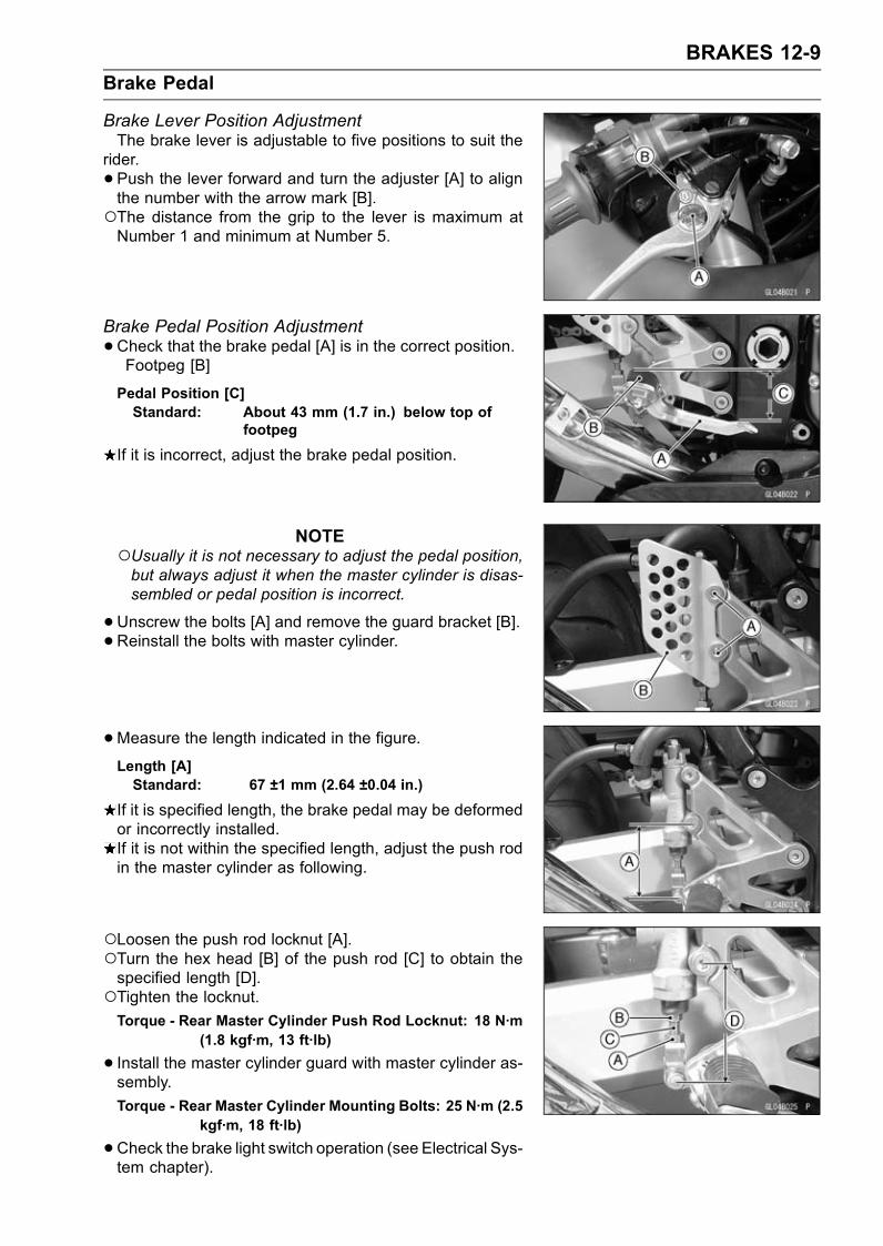
BRAKES 12-9
Brake Pedal
Brake Lever Position AdjustmentThe brake lever is adjustable to five positions to suit the
rider.
• Push the lever forward and turn the adjuster [A] to alignthe number with the arrow mark [B].The distance from the grip to the lever is maximum atNumber 1 and minimum at Number 5.
Brake Pedal Position Adjustment
•Check that the brake pedal [A] is in the correct position.Footpeg [B]
Pedal Position [C]Standard: About 43 mm (1.7 in.) below top of
footpeg
If it is incorrect, adjust the brake pedal position.
NOTEUsually it is not necessary to adjust the pedal position,but always adjust it when the master cylinder is disas-sembled or pedal position is incorrect.
•Unscrew the bolts [A] and remove the guard bracket [B].• Reinstall the bolts with master cylinder.
•Measure the length indicated in the figure.Length [A]Standard: 67 ±1 mm (2.64 ±0.04 in.)
If it is specified length, the brake pedal may be deformedor incorrectly installed.If it is not within the specified length, adjust the push rodin the master cylinder as following.
Loosen the push rod locknut [A].Turn the hex head [B] of the push rod [C] to obtain thespecified length [D].Tighten the locknut.Torque - Rear Master Cylinder Push Rod Locknut: 18 N·m
(1.8 kgf·m, 13 ft·lb)
• Install the master cylinder guard with master cylinder as-sembly.
Torque - Rear Master Cylinder Mounting Bolts: 25 N·m (2.5kgf·m, 18 ft·lb)
•Check the brake light switch operation (see Electrical Sys-tem chapter).
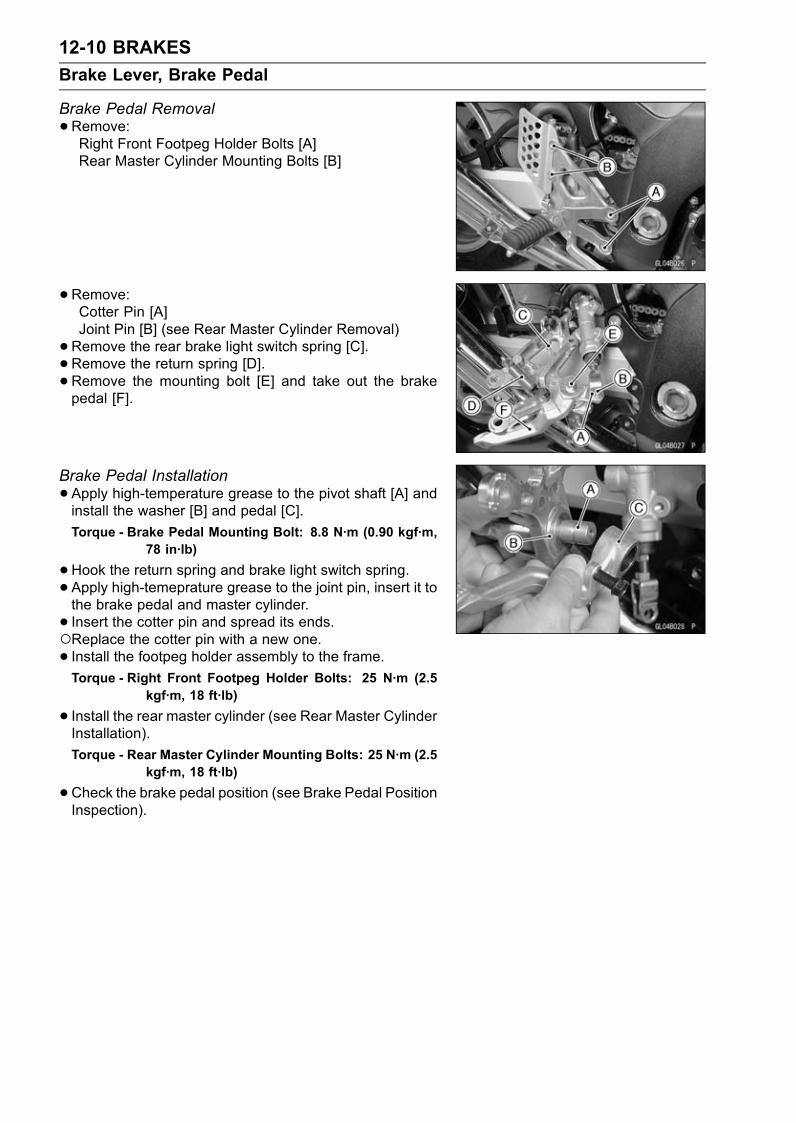
12-10 BRAKES
Brake Lever, Brake Pedal
Brake Pedal Removal
•Remove:Right Front Footpeg Holder Bolts [A]Rear Master Cylinder Mounting Bolts [B]
•Remove:Cotter Pin [A]Joint Pin [B] (see Rear Master Cylinder Removal)
•Remove the rear brake light switch spring [C].•Remove the return spring [D].•Remove the mounting bolt [E] and take out the brakepedal [F].
Brake Pedal Installation
•Apply high-temperature grease to the pivot shaft [A] andinstall the washer [B] and pedal [C].
Torque - Brake Pedal Mounting Bolt: 8.8 N·m (0.90 kgf·m,78 in·lb)
•Hook the return spring and brake light switch spring.• Apply high-temeprature grease to the joint pin, insert it tothe brake pedal and master cylinder.
• Insert the cotter pin and spread its ends.Replace the cotter pin with a new one.• Install the footpeg holder assembly to the frame.Torque - Right Front Footpeg Holder Bolts: 25 N·m (2.5
kgf·m, 18 ft·lb)
• Install the rear master cylinder (see Rear Master CylinderInstallation).
Torque - Rear Master Cylinder Mounting Bolts: 25 N·m (2.5kgf·m, 18 ft·lb)
•Check the brake pedal position (see Brake Pedal PositionInspection).
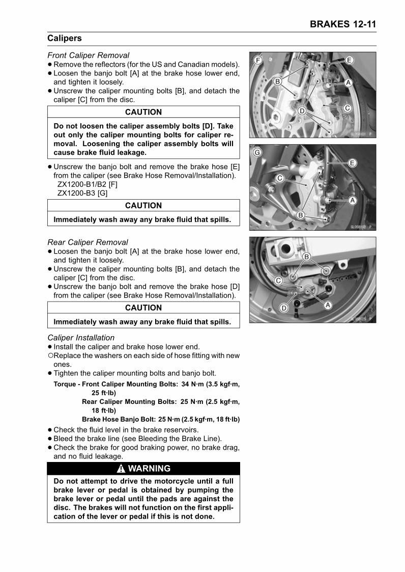
BRAKES 12-11
Calipers
Front Caliper Removal
•Remove the reflectors (for the US and Canadian models).• Loosen the banjo bolt [A] at the brake hose lower end,and tighten it loosely.
•Unscrew the caliper mounting bolts [B], and detach thecaliper [C] from the disc.
CAUTION
Do not loosen the caliper assembly bolts [D]. Takeout only the caliper mounting bolts for caliper re-moval. Loosening the caliper assembly bolts willcause brake fluid leakage.
•Unscrew the banjo bolt and remove the brake hose [E]from the caliper (see Brake Hose Removal/Installation).ZX1200-B1/B2 [F]ZX1200-B3 [G]
CAUTION
Immediately wash away any brake fluid that spills.
Rear Caliper Removal
•Loosen the banjo bolt [A] at the brake hose lower end,and tighten it loosely.
•Unscrew the caliper mounting bolts [B], and detach thecaliper [C] from the disc.
•Unscrew the banjo bolt and remove the brake hose [D]from the caliper (see Brake Hose Removal/Installation).
CAUTION
Immediately wash away any brake fluid that spills.
Caliper Installation
• Install the caliper and brake hose lower end.Replace the washers on each side of hose fitting with newones.
• Tighten the caliper mounting bolts and banjo bolt.Torque - Front Caliper Mounting Bolts: 34 N·m (3.5 kgf·m,
25 ft·lb)Rear Caliper Mounting Bolts: 25 N·m (2.5 kgf·m,18 ft·lb)
Brake Hose Banjo Bolt: 25 N·m (2.5 kgf·m, 18 ft·lb)
•Check the fluid level in the brake reservoirs.• Bleed the brake line (see Bleeding the Brake Line).•Check the brake for good braking power, no brake drag,and no fluid leakage.
WARNINGDo not attempt to drive the motorcycle until a fullbrake lever or pedal is obtained by pumping thebrake lever or pedal until the pads are against thedisc. The brakes will not function on the first appli-cation of the lever or pedal if this is not done.
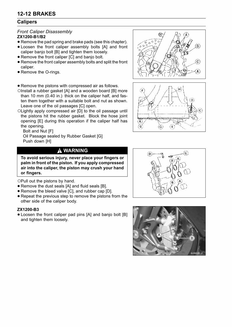
12-12 BRAKES
Calipers
Front Caliper DisassemblyZX1200-B1/B2
•Remove the pad spring and brake pads (see this chapter).• Loosen the front caliper assembly bolts [A] and frontcaliper banjo bolt [B] and tighten them loosely.
•Remove the front caliper [C] and banjo bolt.• Remove the front caliper assembly bolts and split the frontcaliper.
•Remove the O-rings.
•Remove the pistons with compressed air as follows.Install a rubber gasket [A] and a wooden board [B] morethan 10 mm (0.40 in.) thick on the caliper half, and fas-ten them together with a suitable bolt and nut as shown.Leave one of the oil passages [C] open.Lightly apply compressed air [D] to the oil passage untilthe pistons hit the rubber gasket. Block the hose jointopening [E] during this operation if the caliper half hasthe opening.Bolt and Nut [F]Oil Passage sealed by Rubber Gasket [G]Push down [H]
WARNINGTo avoid serious injury, never place your fingers orpalm in front of the piston. If you apply compressedair into the caliper, the piston may crush your handor fingers.
Pull out the pistons by hand.•Remove the dust seals [A] and fluid seals [B].• Remove the bleed valve [C], and rubber cap [D].•Repeat the previous step to remove the pistons from theother side of the caliper body.
ZX1200-B3
•Loosen the front caliper pad pins [A] and banjo bolt [B]and tighten them loosely.
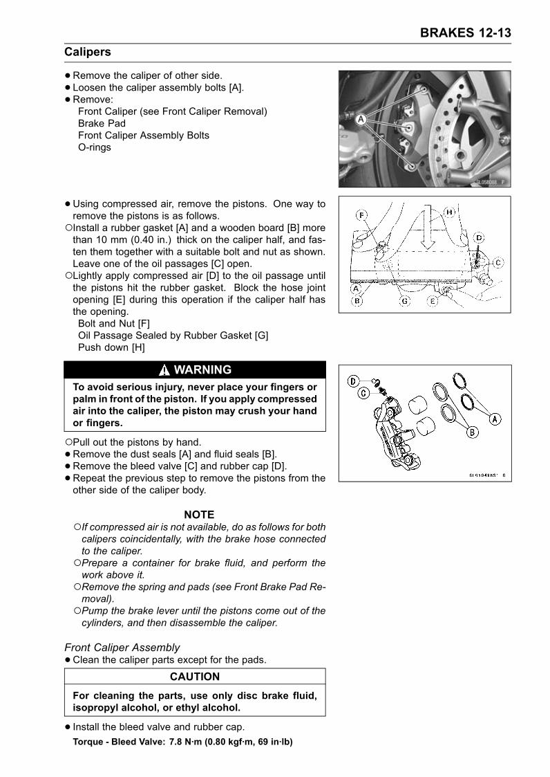
BRAKES 12-13
Calipers
•Remove the caliper of other side.• Loosen the caliper assembly bolts [A].• Remove:Front Caliper (see Front Caliper Removal)Brake PadFront Caliper Assembly BoltsO-rings
•Using compressed air, remove the pistons. One way toremove the pistons is as follows.Install a rubber gasket [A] and a wooden board [B] morethan 10 mm (0.40 in.) thick on the caliper half, and fas-ten them together with a suitable bolt and nut as shown.Leave one of the oil passages [C] open.Lightly apply compressed air [D] to the oil passage untilthe pistons hit the rubber gasket. Block the hose jointopening [E] during this operation if the caliper half hasthe opening.Bolt and Nut [F]Oil Passage Sealed by Rubber Gasket [G]Push down [H]
WARNINGTo avoid serious injury, never place your fingers orpalm in front of the piston. If you apply compressedair into the caliper, the piston may crush your handor fingers.
Pull out the pistons by hand.•Remove the dust seals [A] and fluid seals [B].• Remove the bleed valve [C] and rubber cap [D].•Repeat the previous step to remove the pistons from theother side of the caliper body.
NOTEIf compressed air is not available, do as follows for bothcalipers coincidentally, with the brake hose connectedto the caliper.Prepare a container for brake fluid, and perform thework above it.Remove the spring and pads (see Front Brake Pad Re-moval).Pump the brake lever until the pistons come out of thecylinders, and then disassemble the caliper.
Front Caliper Assembly
•Clean the caliper parts except for the pads.CAUTION
For cleaning the parts, use only disc brake fluid,isopropyl alcohol, or ethyl alcohol.
• Install the bleed valve and rubber cap.Torque - Bleed Valve: 7.8 N·m (0.80 kgf·m, 69 in·lb)

12-14 BRAKES
Calipers
•Replace the fluid seals [A] with new ones.Apply brake fluid to the fluid seals, and install them intothe cylinders by hand.
•Replace the dust seals [B] with new ones if they are dam-aged.Apply brake fluid to the dust seals, and install them intothe cylinders by hand.
ZX1200-B1/B2
•Replace the O-rings [A] if they are damaged.• Apply brake fluid to the outside of the pistons, and pushthem into each cylinder by hand.
• Be sure to install the O-rings.• Tighten the caliper assembly bolts.Torque - Front Caliper Assembly Bolts: 21 N·m (2.1 kgf·m,
15 ft·lb)
• Install the pads (see Front Brake Pad Installation).•Wipe up any spilled brake fluid on the caliper with wetcloth.
• Install the front calipers (see Front Caliper Installation).ZX1200-B3
•Replace the O-ring [A].• Apply brake fluid to the outside of the pistons, and pushthem into each cylinder by hand.
• Be sure to install the O-rings.• Tighten the caliper assembly bolts.Torque - Front Caliper Assembly Bolts: 21 N·m (2.1 kgf·m,
15 ft·lb)
• Install the pads (see Front Brake Pad Installation).•Wipe up any spilled brake fluid on the caliper with wetcloth.
• Install the front calipers (see Front Caliper Installation).Rear Caliper Disassembly
•Loosen the banjo bolt [A] and rear caliper assembly bolts[B], and tighten them loosely.
•Remove:Rear Caliper (see Rear Caliper Removal)Brake Pads (see Rear Brake Pad Removal)Rear Caliper Assembly BoltsO-rings

BRAKES 12-15
Calipers
•Remove the pistons, dust seals and fluid seals as sameas front caliper disassembly.Piston Completes [A]Dust Seals [B]Fluid Seals [C]O-rings [D]Caliper Body [E]Caliper Assembly Bolts [F]Bleed Valves [G]Rubber Caps [H]
WARNINGTo avoid serious injury, never place your fingers orpalm in rear of the piston. If you apply compressedair into the caliper, the piston may crush your handof fingers.
Rear Caliper Assembly
•Clean the caliper parts except for the pads.CAUTION
For cleaning the parts, use only disc brake fluid,isopropyl alcohol, or ethyl alcohol.
• Install the bleed valve and rubber cap.Torque - Bleed Valve: 7.8 N·m (0.80 kgf·m, 69 in·lb)
•Replace the fluid seal [A] with a new one.Apply brake fluid to the fluid seal, and install it into thecylinder by hand.
•Replace the dust seal [B] with a new one if it is damaged.Apply brake fluid to the dust seal, and install it into thecylinder by hand.
•Replace the O-ring [A] if it is damaged.• Apply brake fluid to the outside of the piston, and push itinto the cylinder by hand.
• Install the piston insulator.• Tighten the caliper assembly bolts.Torque - Rear Caliper Assembly Bolts: 30 N·m (3.0 kgf·m,
22 ft·lb)
• Install the pads (see Rear Brake Pad Installation).•Wipe up any spilled brake fluid on the caliper with wetcloth.
• Install the rear caliper (see Rear Caliper Installation).

12-16 BRAKES
Calipers
Caliper Fluid Seal DamageZX1200-B1/B2The fluid seals [C] around the pistons [A] maintain the
proper pad/disc clearance. If the seals are not satisfactory,pad wear will increase, and constant pad drag on the discwill raise brake and brake fluid temperature.
•Replace the fluid seals under any of the following condi-tions; (a) fluid leakage around the pad; (b) brakes over-heat (c) there is a large difference in inner and outer padwear; (d) the seal is stuck to the piston.If the fluid seal is replace, replace the dust seal [B] aswell. Also, replace all seals every other time the pads arechanged.
ZX1200-B3The fluid seals (piston seal) [A] is placed around the pis-
ton to maintain clearance between the pad and the disc. Ifthe seal is in a poor condition, it could lead the pad to wearexcessively or the brake to drag, which may cause the tem-perature of the discs or the brake fluid to increase.
•Replace the fluid seal if it exhibits any of the conditionslisted below.Brake fluid leakage around the pad.Brakes overheat.Considerable difference in inner and outer pad wear.Seal and piston are stuck together.If the fluid seal is replaced, replace the dust seals [B] aswell. Also, replace all seals every other time the pads arechanged.
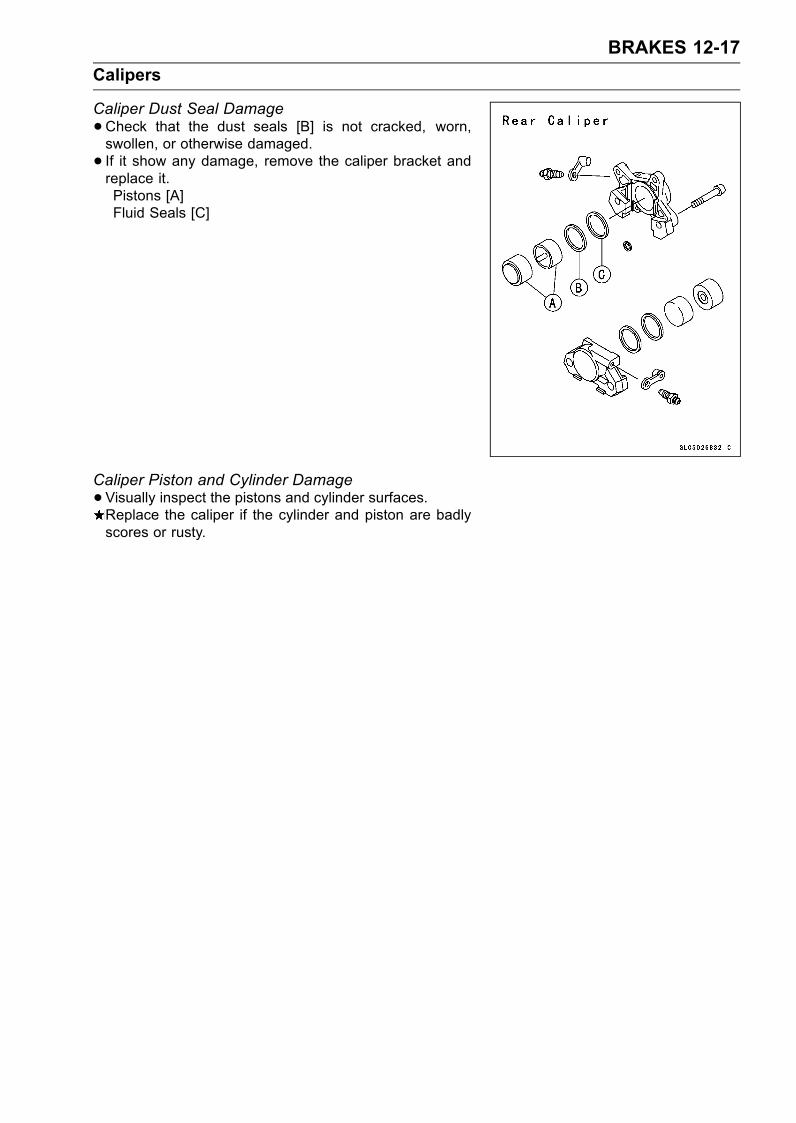
BRAKES 12-17
Calipers
Caliper Dust Seal Damage
•Check that the dust seals [B] is not cracked, worn,swollen, or otherwise damaged.
• If it show any damage, remove the caliper bracket andreplace it.Pistons [A]Fluid Seals [C]
Caliper Piston and Cylinder Damage
•Visually inspect the pistons and cylinder surfaces.Replace the caliper if the cylinder and piston are badlyscores or rusty.
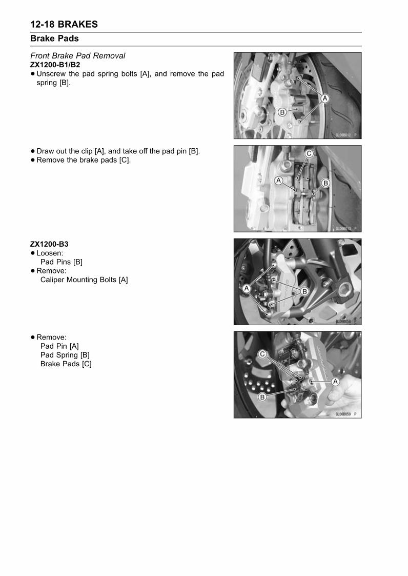
12-18 BRAKES
Brake Pads
Front Brake Pad RemovalZX1200-B1/B2
•Unscrew the pad spring bolts [A], and remove the padspring [B].
•Draw out the clip [A], and take off the pad pin [B].•Remove the brake pads [C].
ZX1200-B3
•Loosen:Pad Pins [B]
•Remove:Caliper Mounting Bolts [A]
•Remove:Pad Pin [A]Pad Spring [B]Brake Pads [C]

BRAKES 12-19
Brake Pads
Front Brake Pad InstallationZX1200-B1/B2
•Push the caliper pistons in by hand as far as they will go.• Install the brake pads.• Install the pad pin and clip. The clip must be "outside" ofthe pads.
• Install the caliper (see Front Caliper Installation).Torque - Front Brake Pad Spring Bolts: 3.0 N·m (0.30 kgf·m,
27 in·lb)
WARNINGDo not attempt to drive the motorcycle until a fullbrake lever is obtained by pumping the brake leveruntil the pads are against the disc. The brake willnot function on the first application of the lever ifthis is not done.
ZX1200-B3
•Push the caliper pistons in by hand as far as they will go.• Install the outside pad [A] and insert the pin [B] as shown.
• Set:Inside Pad [A]Pad Spring [B]
Pushing the pin holder [C] to hole of the pad and insertthe pin.
Torque - Front Brake Pad Pins: 15 N·m (1.5 kgf·m, 11 ft·lb)
WARNINGDo not attempt to drive the motorcycle until a fullbrake lever is obtained by pumping the brake leverand the pads are against the disc. The brake willnot function on the first application of the lever ifthis is not done.
Rear Brake Pad Removal
•Unscrew the caliper mounting bolts.•Detach the caliper from the disc.
•Remove the piston pad cover [A].• Draw out the clip [B] upward.

12-20 BRAKES
Brake Pads
•Pushing either ends [A] of the pad spring lightly, take offthe pad pins [B] one by one.
•Remove the pad springs [C] and brake pads.
Rear Brake Pad Installation
•Push the caliper piston in by hand as far as it will go.• Put the pads [A] in the caliper to insert either pin [B] intoboth holes of pad.
• Put the anti-rattle springs [C] under inserted pins.• Insert other side pad pin [E] into both holes of pad withpushing both spring ends [D].
• Insert the clip [A]. The clip must be "outside" of the pads.• Install the caliper (see Rear Caliper Installation).
WARNINGDo not attempt to drive the motorcycle until a fullbrake pedal is obtained by pumping the brake pedaluntil the pads are against the disc. The brake willnot function on the first application of the pedal ifthis is not done.
Brake Pad Lining Wear
•Refer to the Brake Pad Wear Inspection in the PeriodicMaintenance chapter.
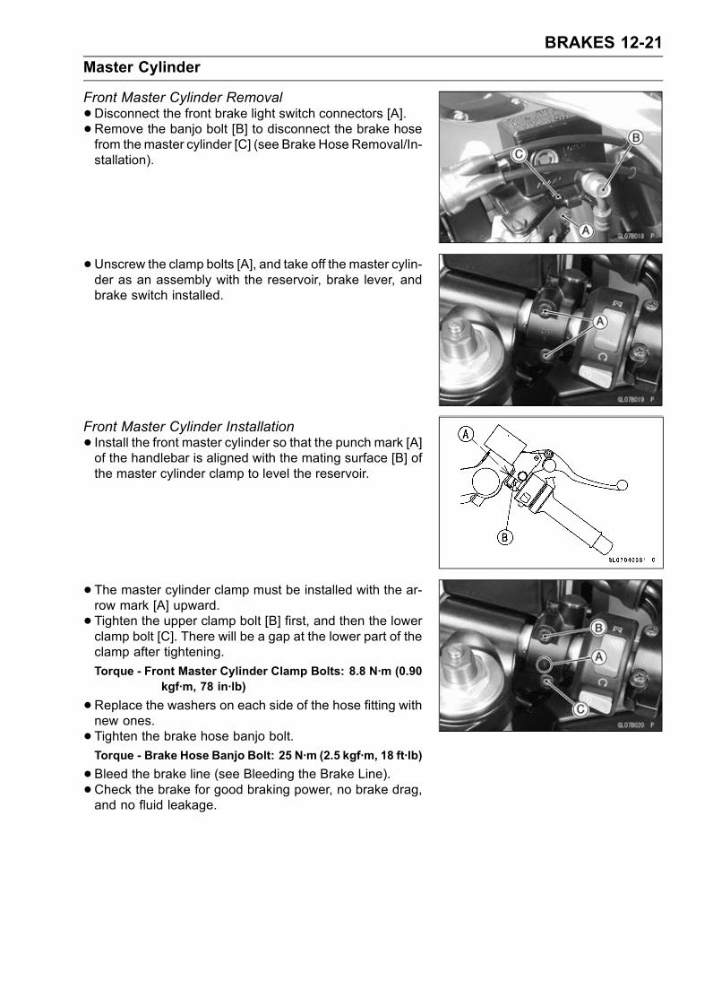
BRAKES 12-21
Master Cylinder
Front Master Cylinder Removal
•Disconnect the front brake light switch connectors [A].•Remove the banjo bolt [B] to disconnect the brake hosefrom themaster cylinder [C] (see Brake Hose Removal/In-stallation).
•Unscrew the clamp bolts [A], and take off the master cylin-der as an assembly with the reservoir, brake lever, andbrake switch installed.
Front Master Cylinder Installation
• Install the front master cylinder so that the punch mark [A]of the handlebar is aligned with the mating surface [B] ofthe master cylinder clamp to level the reservoir.
• The master cylinder clamp must be installed with the ar-row mark [A] upward.
• Tighten the upper clamp bolt [B] first, and then the lowerclamp bolt [C]. There will be a gap at the lower part of theclamp after tightening.
Torque - Front Master Cylinder Clamp Bolts: 8.8 N·m (0.90kgf·m, 78 in·lb)
•Replace the washers on each side of the hose fitting withnew ones.
• Tighten the brake hose banjo bolt.Torque - Brake Hose Banjo Bolt: 25 N·m (2.5 kgf·m, 18 ft·lb)
•Bleed the brake line (see Bleeding the Brake Line).•Check the brake for good braking power, no brake drag,and no fluid leakage.
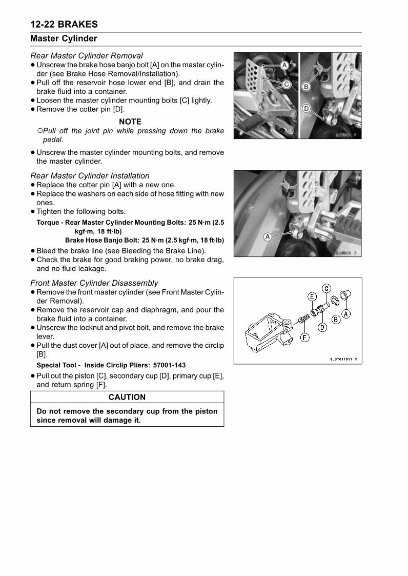
12-22 BRAKES
Master Cylinder
Rear Master Cylinder Removal
•Unscrew the brake hose banjo bolt [A] on themaster cylin-der (see Brake Hose Removal/Installation).
• Pull off the reservoir hose lower end [B], and drain thebrake fluid into a container.
• Loosen the master cylinder mounting bolts [C] lightly.•Remove the cotter pin [D].
NOTEPull off the joint pin while pressing down the brakepedal.
•Unscrew the master cylinder mounting bolts, and removethe master cylinder.
Rear Master Cylinder Installation
•Replace the cotter pin [A] with a new one.•Replace the washers on each side of hose fitting with newones.
• Tighten the following bolts.Torque - Rear Master Cylinder Mounting Bolts: 25 N·m (2.5
kgf·m, 18 ft·lb)Brake Hose Banjo Bolt: 25 N·m (2.5 kgf·m, 18 ft·lb)
•Bleed the brake line (see Bleeding the Brake Line).•Check the brake for good braking power, no brake drag,and no fluid leakage.
Front Master Cylinder Disassembly
•Remove the front master cylinder (see Front Master Cylin-der Removal).
• Remove the reservoir cap and diaphragm, and pour thebrake fluid into a container.
•Unscrew the locknut and pivot bolt, and remove the brakelever.
• Pull the dust cover [A] out of place, and remove the circlip[B].
Special Tool - Inside Circlip Pliers: 57001-143
•Pull out the piston [C], secondary cup [D], primary cup [E],and return spring [F].
CAUTION
Do not remove the secondary cup from the pistonsince removal will damage it.

BRAKES 12-23
Master Cylinder
Rear Master Cylinder Disassembly
•Remove the rear master cylinder (see Rear Master Cylin-der Removal).
• Slide the dust cover [F] on the push rod out of place, andremove the circlip [E].
Special Tool - Inside Circlip Pliers: 57001-143
NOTEDo not remove the push rod clevis [G] for master cylin-der disassembly since removal requires brake pedal po-sition adjustment.
•Pull out the push rod with the piston stop.• Take off the piston [A], secondary cup [B], primary cup [C],and return spring [D].
CAUTION
Do not remove the secondary cup from the pistonsince removal will damage it.
Master Cylinder Assembly
•Before assembly, clean all parts including the mastercylinder with brake fluid or alcohol.
CAUTION
Except for the disc pads and disc, use only discbrake fluid, isopropyl alcohol, or ethyl alcohol forcleaning brake parts. Do not use any other fluid forcleaning these parts, Gasoline, engine oil, or anyother petroleum distillate will cause deterioration ofthe rubber parts. Oil Spilled on any part will be dif-ficult to wash off completely, and will eventually de-teriorate the rubber used in the disc brake.
•Apply brake fluid to the removed parts and to the innerwall of the cylinder.
• Take care not to scratch the piston or the inner wall of thecylinder.
• Apply silicone grease (ex. PBC grease) to the push rodend, the brake lever end (piston contact portion) and thebrake lever pivot bolt journal.
• Tighten the brake lever pivot bolt and the locknut.Torque - Brake Lever Pivot Bolt: 1.0 N·m (0.10 kgf·m, 9
in·lb)Brake Lever Pivot Bolt Locknut: 6.0 N·m (0.60kgf·m, 52 in·lb)

12-24 BRAKES
Master Cylinder
Master Cylinder Inspection (Visual Inspection)
•Disassemble the front and rear master cylinders.•Check that there are no scratches, rust or pitting on theinner wall of each master cylinder [A] and on the outsideof each piston [B].If a master cylinder or piston shows any damage, replacethem.
• Inspect the primary [C] and secondary [D] cups.If a cup is worn, damaged, softened (rotted), or swollen,the piston assembly should be replaced to renew thecups.If fluid leakage is noted at the brake lever, the piston as-sembly should be replaced to renew the cups.Front Master Cylinder [J]
•Check the dust covers [E] for damage.If they are damaged, replace them.
•Check the piston return springs [F] for any damage.If the springs are damaged, replace them.
•Check that relief [G] and supply [H] ports are not plugged.If the relief port becomes plugged, the brake pads willdrag on the disc. Blow the ports clean with compressedair.Rear Master Cylinder [K]

BRAKES 12-25
Brake Discs
Brake Disc Removal
•Remove the wheel (see Wheels/Tires chapter).• Unscrew the mounting bolts [A], and take off the disc [B].
Brake Disc Installation
• Install the brake disc on the wheel so that the marked [A]side faces out.
• Apply a non-permanent locking agent to the threads ofthe rear brake disc mounting bolts.
• Tighten the mounting bolts [B].Torque - Brake Disc Mounting Bolts: 27 N·m (2.8 kgf·m, 20
ft·lb)
Brake Disc Wear
•Measure the thickness of each disc at the point where ithas worn the most.Replace the disc [A] if it has worn past the service limit.Measuring Area [B]
Front Disc ThicknessStandard:
ZX1200-B1/B2 4.8 ∼ 5.1 mm (0.19 ∼ 0.20 in.)ZX1200-B3 5.8 ∼ 6.2 mm (0.23 ∼ 0.24 in.)
Service Limit:
ZX1200-B1/B2 4.5 mm (0.18 in.)
ZX1200-B3 5.5 mm (0.22 in.)
Rear Disc ThicknessStandard:
ZX1200-B1/B2 5.8 ∼ 6.0 mm (0.23 ∼ 0.24 in.)ZX1200-B3 5.9 ∼ 6.1 mm (0.23 ∼ 0.24 in.)
Service Limit: 5.0 mm (0.20 in.)
Brake Disc Warp
• Jack up the motorcycle so that the wheel is off the ground.Special Tool - Jack: 57001-1238
•For front disc inspection, turn the handlebar fully to oneside.
• Set up a dial gauge against the disc [A] as shown andmeasure disc runout.Turn the wheel by hand. [B]If runout exceeds the service limit, replace the disc.
Disc RunoutStandard: 0.15 mm (0.0059 in.) or less
Service Limit: 0.3 mm (0.01 in.)

12-26 BRAKES
Brake Fluid
Brake Fluid Level Inspection
•Refer to the Brake Fluid Level Inspection in the PeriodicMaintenance chapter.
Brake Fluid Change
•Refer to the Brake Fluid Change in the Periodic Mainte-nance chapter.
Bleeding the Brake LineThe brake fluid has a very low compression coefficient so
that almost all the movement of the brake lever or pedalis transmitted directly to the caliper for braking action. Air,however, is easily compressed. When air enters the brakelines, brake lever or pedal movement will be partially usedin compressing the air. This will make the lever or pedal feelspongy, and there will be a loss in braking power.
WARNINGBe sure to bleed the air from the brake line when-ever brake lever or pedal action feels soft orspongy after the brake fluid is changed, or when-ever a brake line fitting has been loosened for anyreason.
NOTEThe procedure to bleed the front brake line is as follows.Bleeding the rear brake line is the same as for the frontbrake.
•Remove the reservoir cap, and diaphragm.• Fill the reservoir with fresh brake fluid to the upper levelline in the reservoir.
•With the reservoir cap off, slowly pump the brake leverseveral times until no air bubbles can be seen rising upthrough the fluid from the holes at the bottom of the reser-voir.Bleed the air completely from the master cylinder by thisoperation.
•Remove the rubber cap from the bleed valve on thecaliper.
• Attach a clear plastic hose to the bleed valve, and run theother end of the hose into a container.
• Bleed the brake line and the caliper as follows:Repeat this operation until no more air can be seen com-ing out into the plastic hose.
1. Pump the brake lever until it becomes hard, and applythe brake and hold it [A].
2. Quickly open and close [B] the bleed valve while holdingthe brake applied.
3. Release the brake [C].

BRAKES 12-27
Brake Fluid
NOTEThe fluid level must be checked often during the bleed-ing operation and replenished with fresh brake fluid asnecessary. If the fluid in the reservoir runs completelyout any time during bleeding, the bleeding operationmust be done over again from the beginning since airwill have entered the line.Tap the brake hose lightly from the caliper to the reser-voir for more complete bleeding.Front Brake: Repeat the above steps for the othercaliper.Rear Brake: Repeat the above steps for the other bleedvalve.
•Remove the clear plastic hose.• Install the reservoir cap.• Tighten the front reservoir cap screws.Torque - Front Reservoir Cap Screws: 1.5 N·m (0.15 kgf·m,
13 in·lb)
•Tighten the bleed valve, and install the rubber cap.Torque - Bleed Valve: 7.8 N·m (0.80 kgf·m, 69 in·lb)
•Check the fluid level.• After bleeding is done, check the brake for good brakingpower, no brake drag, and no fluid leakage.

12-28 BRAKES
Brake Fluid
WARNINGWhen working with the disc brake, observe the pre-cautions listed below.1. Never reuse old brake fluid.2. Do not use fluid from a container that has been leftunsealed or that has been open for a long time.
3. Do not mix two types and brands of fluid for use inthe brake. This lowers the brake fluid boiling pointand could cause the brake to be ineffective. It mayalso cause the rubber brake parts to deteriorate.
4. Don’t leave the reservoir cap off for any length oftime to avoid moisture contamination of the fluid.
5. Don’t change the fluid in the rain or when a strongwind is blowing.
6. Except for the disc pads and disc, use only discbrake fluid, isopropyl alcohol, or ethyl alcohol forcleaning brake parts. Do not use any other fluid forcleaning these parts. Gasoline, engine oil, or anyother petroleum distillate will cause deterioration ofthe rubber parts. Oil spilled on any part will be diffi-cult to wash off completely and will eventually dete-riorate the rubber used in the disc brake.
7. When handing the disc pads or disc, be careful thatno disc brake fluid or any oil gets on them. Clean offany fluid or oil that inadvertently gets on the pads ordisc with a high-flash point solvent. Do not use onewhich will leave an oily residue. Replace the padswith new ones if they cannot be cleaned satisfacto-rily.
8. Brake fluid quickly ruins painted surfaces; anyspilled fluid should be completely wiped up imme-diately.
9. If any of the brake line fittings or the bleed valve isopened at any time, theAIRMUSTBEBLED FROMTHE BRAKE LINE.
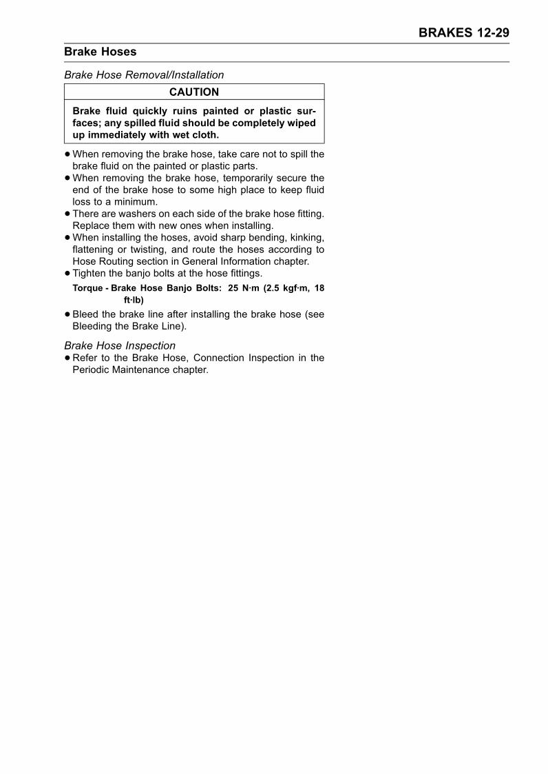
BRAKES 12-29
Brake Hoses
Brake Hose Removal/Installation
CAUTION
Brake fluid quickly ruins painted or plastic sur-faces; any spilled fluid should be completely wipedup immediately with wet cloth.
•When removing the brake hose, take care not to spill thebrake fluid on the painted or plastic parts.
•When removing the brake hose, temporarily secure theend of the brake hose to some high place to keep fluidloss to a minimum.
• There are washers on each side of the brake hose fitting.Replace them with new ones when installing.
•When installing the hoses, avoid sharp bending, kinking,flattening or twisting, and route the hoses according toHose Routing section in General Information chapter.
• Tighten the banjo bolts at the hose fittings.Torque - Brake Hose Banjo Bolts: 25 N·m (2.5 kgf·m, 18
ft·lb)
•Bleed the brake line after installing the brake hose (seeBleeding the Brake Line).
Brake Hose Inspection
•Refer to the Brake Hose, Connection Inspection in thePeriodic Maintenance chapter.

SUSPENSION 13-1
13
Suspension
Table of Contents
Exploded View........................................................................................................................ 13-2Specifications ......................................................................................................................... 13-4Front Fork ............................................................................................................................... 13-5
Rebound Damping Force Adjustment............................................................................... 13-5Compression Damping Force Adjustment ........................................................................ 13-5Spring Preload Adjustment ............................................................................................... 13-6Front Fork Removal (each fork leg) .................................................................................. 13-7Front Fork Installation ....................................................................................................... 13-7Fork Oil Change................................................................................................................ 13-7Front Fork Disassembly .................................................................................................... 13-8Front Fork Assembly......................................................................................................... 13-8Inner Tube Inspection ....................................................................................................... 13-9Dust Seal Inspection ......................................................................................................... 13-10Spring Tension .................................................................................................................. 13-10
Rear Shock Absorber ............................................................................................................. 13-11Rebound Damping Force Adjustment............................................................................... 13-11Compression Damping Force Adjustment ........................................................................ 13-11Spring Preload Adjustment ............................................................................................... 13-12Rear Shock Absorber Removal ........................................................................................ 13-12Rear Shock Absorber Installation ..................................................................................... 13-13Rear Shock Absorber Scrapping ...................................................................................... 13-13
Swingarm................................................................................................................................ 13-14Swingarm Removal........................................................................................................... 13-14Swingarm Installation........................................................................................................ 13-15Swingarm Bearing Removal ............................................................................................. 13-15Swingarm Bearing Installation .......................................................................................... 13-16Swingarm Bearing, Sleeve Inspection .............................................................................. 13-16Swingarm Pivot Lubrication .............................................................................................. 13-16Chain Slider Inspection ..................................................................................................... 13-16
Tie-Rod, Rocker Arm.............................................................................................................. 13-17Tie-Rod Removal .............................................................................................................. 13-17Tie-Rod Installation ........................................................................................................... 13-17Rocker Arm Removal........................................................................................................ 13-17Rocker Arm Installation..................................................................................................... 13-17Needle Bearing Inspection................................................................................................ 13-18Tie-Rod, Rocker Arm Sleeve Inspection........................................................................... 13-18Uni-track Linkage Lubrication ........................................................................................... 13-18

13-2 SUSPENSION
Exploded View
T1: 20 N·m (2.0 kgf·m, 15 ft·lb)T2: 23 N·m (2.3 kgf·m, 17 ft·lb)T3: 28 N·m (2.8 kgf·m, 21 ft·lb)T4: 40 N·m (4.0 kgf·m, 30 ft·lb)AL: Tighten the two clamp bolts alternately two times to ensure even tightening torque.L: Apply a non-permanent locking agent.R: Replacement Parts

SUSPENSION 13-3
Exploded View
T5: 34 N·m (3.5 kgf·m, 25 ft·lb)T6: 98 N·m (10 kgf·m, 72 ft·lb)T7: 125 N·m (13 kgf·m, 92 ft·lb)T8: 59 N·m (6.0 kgf·m, 44 ft·lb)G: Apply grease.
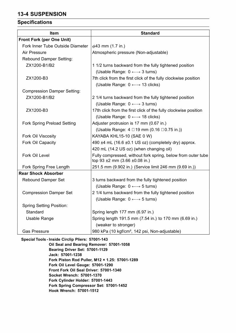
13-4 SUSPENSION
Specifications
Item Standard
Front Fork (per One Unit)
Fork Inner Tube Outside Diameter 43 mm (1.7 in.)
Air Pressure Atmospheric pressure (Non-adjustable)
Rebound Damper Setting:
ZX1200-B1/B2 1 1/2 turns backward from the fully tightened position
(Usable Range: 0 ←→ 3 turns)
ZX1200-B3 7th click from the first click of the fully clockwise position
(Usable Range: 0 ←→ 13 clicks)
Compression Damper Setting:
ZX1200-B1/B2 2 1/4 turns backward from the fully tightened position
(Usable Range: 0 ←→ 3 turns)
ZX1200-B3 17th click from the first click of the fully clockwise position
(Usable Range: 0 ←→ 18 clicks)
Fork Spring Preload Setting Adjuster protrusion is 17 mm (0.67 in.)
(Usable Range: 4 ∼ 19 mm (0.16 ∼ 0.75 in.))Fork Oil Viscosity KAYABA KHL15-10 (SAE 0 W)
Fork Oil Capacity 490 ±4 mL (16.6 ±0.1 US oz) (completely dry) approx.
420 mL (14.2 US oz) (when changing oil)
Fork Oil Level Fully compressed, without fork spring, below from outer tubetop 93 ±2 mm (3.66 ±0.08 in.)
Fork Spring Free Length 251.5 mm (9.902 in.) (Service limit 246 mm (9.69 in.))
Rear Shock Absorber
Rebound Damper Set 3 turns backward from the fully tightened position
(Usable Range: 0 ←→ 5 turns)
Compression Damper Set 2 1/4 turns backward from the fully tightened position
(Usable Range: 0 ←→ 5 turns)
Spring Setting Position:
Standard Spring length 177 mm (6.97 in.)
Usable Range Spring length 191.5 mm (7.54 in.) to 170 mm (6.69 in.)
(weaker to stronger)
Gas Pressure 980 kPa (10 kgf/cm², 142 psi, Non-adjustable)
Special Tools - Inside Circlip Pliers: 57001-143Oil Seal and Bearing Remover: 57001-1058Bearing Driver Set: 57001-1129Jack: 57001-1238Fork Piston Rod Puller, M12 × 1.25: 57001-1289Fork Oil Level Gauge: 57001-1290Front Fork Oil Seal Driver: 57001-1340Socket Wrench: 57001-1370Fork Cylinder Holder: 57001-1443Fork Spring Compressor Set: 57001-1452Hook Wrench: 57001-1512

SUSPENSION 13-5
Front Fork
Rebound Damping Force Adjustment
•To adjust the rebound damping force, turn the rebounddamping adjuster [A] to suit you best.The standard adjuster setting for the average-build riderof 68 kg (150 lb) with no passenger and no accessories isthe 1 1/2 turns backward from the fully tightened position(ZX1200-B1/B2).The standard adjuster setting for the average-build riderof 68 kg (150 lb) with no passenger and no accessoriesis the 7th click from the first click of the fully clockwiseposition (ZX1200-B3).
WARNINGIf both adjusters are not adjusted equally, handlingmay be impaired and a hazardous condition mayresult.
The damping force can be left soft for average riding. Butit should be adjusted harder for high speed riding or ridingwith a passenger. If the damping feels too soft or too stiff,adjust it in accordance with the following table.
Rebound Damping Force AdjustmentZX1200-B1/B2
AdjusterPosition
DampingForce
Setting Load Road Speed
3 Weak Soft Light Good Low
↑ ↑ ↑ ↑ ↑ ↑↓ ↓ ↓ ↓ ↓ ↓0 Strong Hard Heavy Bad High
ZX1200-B3
AdjusterPosition
DampingForce
Setting Load Road Speed
13 Weak Soft Light Good Low
↑ ↑ ↑ ↑ ↑ ↑↓ ↓ ↓ ↓ ↓ ↓0 Strong Hard Heavy Bad High
Compression Damping Force Adjustment
•To adjust the compression damping force, turn the com-pression damping adjuster [A] to suit you best.The standard adjuster setting for the average-build riderof 68 kg (150 lb) with no passenger and no accessories isthe 2 1/4 turns backward from the fully tightened position(ZX1200-B1/B2).The standard adjuster setting for the average-build riderof 68 kg (150 lb) with no passenger and no accessoriesis the 17th click from the first click of the fully clockwiseposition (ZX1200-B3).
WARNINGIf both adjusters are not adjusted equally, handlingmay be impaired and a hazardous condition mayresult.
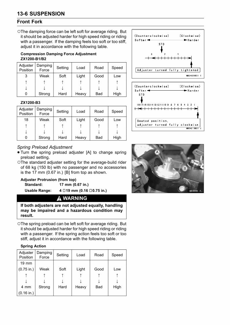
13-6 SUSPENSION
Front Fork
The damping force can be left soft for average riding. Butit should be adjusted harder for high speed riding or ridingwith a passenger. If the damping feels too soft or too stiff,adjust it in accordance with the following table.
Compression Damping Force AdjustmentZX1200-B1/B2
AdjusterPosition
DampingForce
Setting Load Road Speed
3 Weak Soft Light Good Low
↑ ↑ ↑ ↑ ↑ ↑↓ ↓ ↓ ↓ ↓ ↓0 Strong Hard Heavy Bad High
ZX1200-B3
AdjusterPosition
DampingForce
Setting Load Road Speed
18 Weak Soft Light Good Low
↑ ↑ ↑ ↑ ↑ ↑↓ ↓ ↓ ↓ ↓ ↓0 Strong Hard Heavy Bad High
Spring Preload Adjustment
•Turn the spring preload adjuster [A] to change springpreload setting.The standard adjuster setting for the average-build riderof 68 kg (150 lb) with no passenger and no accessoriesis the 17 mm (0.67 in.) [B] from top as shown.
Adjuster Protrusion (from top)Standard: 17 mm (0.67 in.)
Usable Range: 4 ∼ 19 mm (0.16 ∼ 0.75 in.)
WARNINGIf both adjusters are not adjusted equally, handlingmay be impaired and a hazardous condition mayresult.
The spring preload can be left soft for average riding. Butit should be adjusted harder for high speed riding or ridingwith a passenger. If the spring action feels too soft or toostiff, adjust it in accordance with the following table.
Spring Action
AdjusterPosition
DampingForce
Setting Load Road Speed
19 mm
(0.75 in.) Weak Soft Light Good Low
↑ ↑ ↑ ↑ ↑ ↑↓ ↓ ↓ ↓ ↓ ↓
4 mm Strong Hard Heavy Bad High
(0.16 in.)

SUSPENSION 13-7
Front Fork
Front Fork Removal (each fork leg)
•Remove:Front Wheel (see Wheels/Tires chapter)Front Fender (see Frame chapter)Loosen the upper fork clamp bolt [B] and fork top plug [A]beforehand if the fork leg is to be disassembled.
NOTELoosen the top plug after loosening the upper forkclamp bolt.
•Loosen the upper fork clamp bolt [A] and lower fork clampbolts [B].
•With a twisting motion, work the fork leg down and out.
Front Fork Installation
• Install the fork so that the top end [A] of the outer tube isflush with the upper surface [B] of the steering stem headbracket.
• Tighten the lower fork clamp bolts and fork top plug.Torque - Front Fork Clamp Bolts (Lower): 20 N·m (2.0
kgf·m, 15 ft·lb)Front Fork Top Plug: 23 N·m (2.3 kgf·m, 17 ft·lb)
NOTETighten the two clamp bolts alternately two times to en-sure even tightening torque.
•Tighten the upper fork clamp bolt.Torque - Front Fork Clamp Bolt (Upper): 20 N·m (2.0 kgf·m,
15 ft·lb)
NOTETighten the top plug before tightening the upper forkclamp bolt.
• Install the removed parts (see appropriate chapters).• Adjust the spring preload and the damping force.Fork Oil ChangeThe oil should be change in accordance with the Periodic
Maintenance chapter.
•Refer to the Front Fork Oil Change in the Periodic Main-tenance chapter.

13-8 SUSPENSION
Front Fork
Front Fork Disassembly
•Remove the front fork (see Front Fork Removal).• Drain the fork oil (see Fork Oil Change in the PeriodicMaintenance chapter).
• Hold the front fork in a vise [A].• Stop the cylinder [B] from turning by using the fork cylinderholder [C].
Special Tool - Fork Cylinder Holder: 57001-1443
•Unscrew the Allen bolt [D], then take the bolt and gasketout of the bottom of the inner tube.
• Take the cylinder unit [A].Do not disassemble the cylinder unit.
• Separate the outer tube from the inner tube.
• Pull out the dust seal.• Remove the retaining ring [A] from the outer tube.
•Remove the oil seal [B] and washer [C].
Front Fork Assembly
•Replace the following parts with a new one.Oil SealBottom Allen Bolt Gasket
• Insert the cylinder unit [A] into the inner tube [B].• Stop the cylinder from turning by using the fork cylinderholder.
Special Tool - Fork Cylinder Holder: 57001-1443
•Apply a non-permanent locking agent to the Allen bolt andtighten it.
Torque - Front Fork Bottom Allen Bolt: 40 N·m (4.0 kgf·m,30 ft·lb)
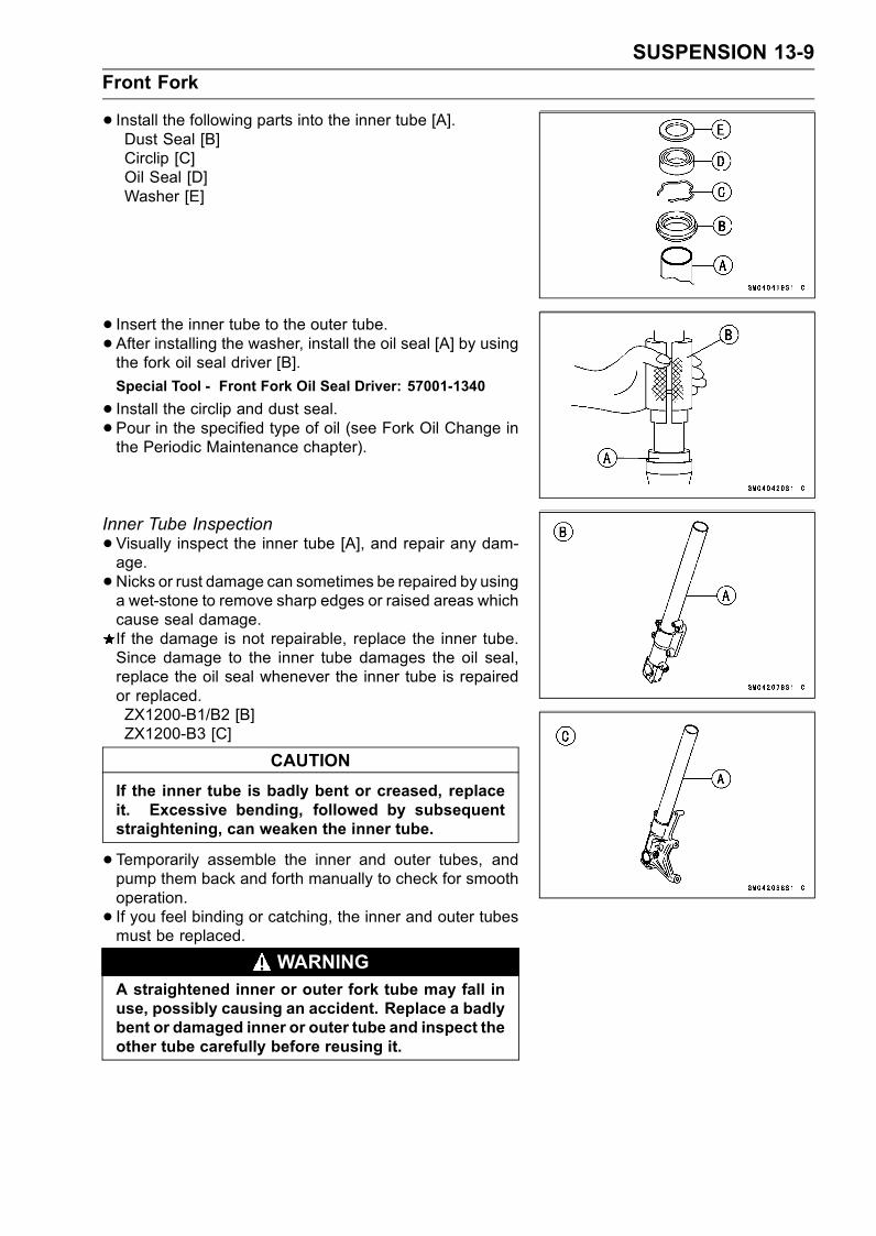
SUSPENSION 13-9
Front Fork
• Install the following parts into the inner tube [A].Dust Seal [B]Circlip [C]Oil Seal [D]Washer [E]
• Insert the inner tube to the outer tube.• After installing the washer, install the oil seal [A] by usingthe fork oil seal driver [B].
Special Tool - Front Fork Oil Seal Driver: 57001-1340
• Install the circlip and dust seal.• Pour in the specified type of oil (see Fork Oil Change inthe Periodic Maintenance chapter).
Inner Tube Inspection
•Visually inspect the inner tube [A], and repair any dam-age.
•Nicks or rust damage can sometimes be repaired by usinga wet-stone to remove sharp edges or raised areas whichcause seal damage.If the damage is not repairable, replace the inner tube.Since damage to the inner tube damages the oil seal,replace the oil seal whenever the inner tube is repairedor replaced.ZX1200-B1/B2 [B]ZX1200-B3 [C]
CAUTION
If the inner tube is badly bent or creased, replaceit. Excessive bending, followed by subsequentstraightening, can weaken the inner tube.
•Temporarily assemble the inner and outer tubes, andpump them back and forth manually to check for smoothoperation.
• If you feel binding or catching, the inner and outer tubesmust be replaced.
WARNINGA straightened inner or outer fork tube may fall inuse, possibly causing an accident. Replace a badlybent or damaged inner or outer tube and inspect theother tube carefully before reusing it.

13-10 SUSPENSION
Front Fork
Dust Seal Inspection
• Inspect the dust seals [A] for any signs of deterioration ordamage.Replace it if necessary.
Spring Tension
•Since a spring becomes shorter as it weakens, check itsfree length [A] to determine its condition.If the spring of either fork leg is shorter than the servicelimit, it must be replaced. If the length of a replacementspring and that of the remaining spring vary greatly, theremaining spring should also be replaced in order to keepthe fork legs balanced for motorcycle stability.
Spring Free LengthStandard: 251.5 mm (9.902 in.)
Service Limit: 246 mm (9.69 in.)

SUSPENSION 13-11
Rear Shock Absorber
Rebound Damping Force Adjustment
•To adjust the rebound damping force, turn the rebounddamping adjuster [A] to suit you best.The standard adjuster setting for an average-build riderof 68 kg (150 lb) with no passenger and no accessoriesis the 3 turns backward from the fully tightened position.If the damping feels too soft or too stiff, adjust it.
Rebound Damping Force Adjustment
AdjusterPosition
DampingForce
Setting Load Road Speed
5 Weak Soft Light Good Low
↑ ↑ ↑ ↑ ↑ ↑↓ ↓ ↓ ↓ ↓ ↓0 Strong Hard Heavy Bad High
Compression Damping Force Adjustment
•To adjust the compression damping force, turn the com-pression damping adjuster [A] on the gas reservoir to suityou best.The standard adjuster setting for the average-build riderof 68 kg (150 lb) with no passenger and no accessoriesis the 2 1/4 turns backward from the fully tightened po-sition.The damping force can be left soft for average riding. Butit should be adjusted harder for high speed riding or ridingwith a passenger. If the damping feels too soft or too stiff,adjust it in accordance with the following table.
Compression Damping Force Adjustment
AdjusterPosition
DampingForce
Setting Load Road Speed
5 Weak Soft Light Good Low
↑ ↑ ↑ ↑ ↑ ↑↓ ↓ ↓ ↓ ↓ ↓0 Strong Hard Heavy Bad High
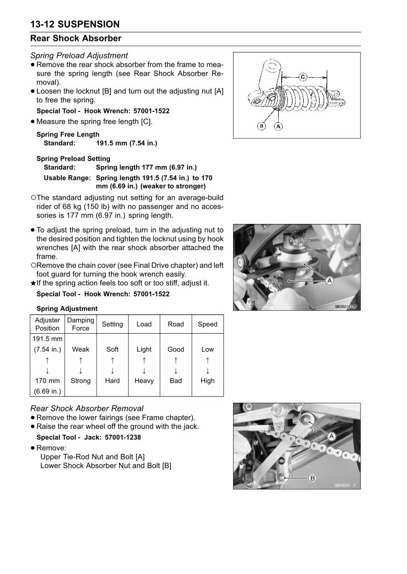
13-12 SUSPENSION
Rear Shock Absorber
Spring Preload Adjustment
•Remove the rear shock absorber from the frame to mea-sure the spring length (see Rear Shock Absorber Re-moval).
• Loosen the locknut [B] and turn out the adjusting nut [A]to free the spring.
Special Tool - Hook Wrench: 57001-1522
•Measure the spring free length [C].Spring Free LengthStandard: 191.5 mm (7.54 in.)
Spring Preload SettingStandard: Spring length 177 mm (6.97 in.)
Usable Range: Spring length 191.5 (7.54 in.) to 170mm (6.69 in.) (weaker to stronger)
The standard adjusting nut setting for an average-buildrider of 68 kg (150 lb) with no passenger and no acces-sories is 177 mm (6.97 in.) spring length.
• To adjust the spring preload, turn in the adjusting nut tothe desired position and tighten the locknut using by hookwrenches [A] with the rear shock absorber attached theframe.Remove the chain cover (see Final Drive chapter) and leftfoot guard for turning the hook wrench easily.If the spring action feels too soft or too stiff, adjust it.
Special Tool - Hook Wrench: 57001-1522
Spring Adjustment
AdjusterPosition
DampingForce
Setting Load Road Speed
191.5 mm
(7.54 in.) Weak Soft Light Good Low
↑ ↑ ↑ ↑ ↑ ↑↓ ↓ ↓ ↓ ↓ ↓
170 mm Strong Hard Heavy Bad High
(6.69 in.)
Rear Shock Absorber Removal
•Remove the lower fairings (see Frame chapter).• Raise the rear wheel off the ground with the jack.Special Tool - Jack: 57001-1238
•Remove:Upper Tie-Rod Nut and Bolt [A]Lower Shock Absorber Nut and Bolt [B]
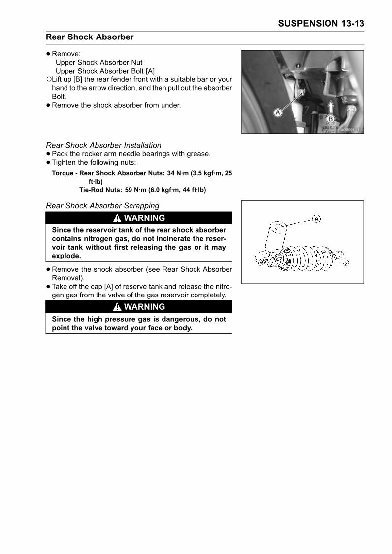
SUSPENSION 13-13
Rear Shock Absorber
•Remove:Upper Shock Absorber NutUpper Shock Absorber Bolt [A]
Lift up [B] the rear fender front with a suitable bar or yourhand to the arrow direction, and then pull out the absorberBolt.
• Remove the shock absorber from under.
Rear Shock Absorber Installation
•Pack the rocker arm needle bearings with grease.
• Tighten the following nuts:Torque - Rear Shock Absorber Nuts: 34 N·m (3.5 kgf·m, 25
ft·lb)Tie-Rod Nuts: 59 N·m (6.0 kgf·m, 44 ft·lb)
Rear Shock Absorber Scrapping
WARNINGSince the reservoir tank of the rear shock absorbercontains nitrogen gas, do not incinerate the reser-voir tank without first releasing the gas or it mayexplode.
•Remove the shock absorber (see Rear Shock AbsorberRemoval).
• Take off the cap [A] of reserve tank and release the nitro-gen gas from the valve of the gas reservoir completely.
WARNINGSince the high pressure gas is dangerous, do notpoint the valve toward your face or body.
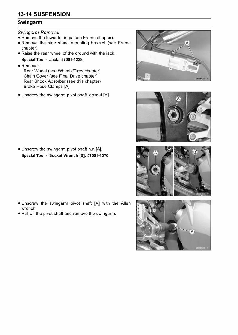
13-14 SUSPENSION
Swingarm
Swingarm Removal
•Remove the lower fairings (see Frame chapter).• Remove the side stand mounting bracket (see Framechapter).
• Raise the rear wheel of the ground with the jack.Special Tool - Jack: 57001-1238
•Remove:Rear Wheel (see Wheels/Tires chapter)Chain Cover (see Final Drive chapter)Rear Shock Absorber (see this chapter)Brake Hose Clamps [A]
•Unscrew the swingarm pivot shaft locknut [A].
• Unscrew the swingarm pivot shaft nut [A].
Special Tool - Socket Wrench [B]: 57001-1370
•Unscrew the swingarm pivot shaft [A] with the Allenwrench.
• Pull off the pivot shaft and remove the swingarm.

SUSPENSION 13-15
Swingarm
Swingarm Installation
•Apply plenty of grease to the ball bearing, needle bearingsand grease seals.
• Install the collars [A].
Place the right collar [A] on the stopper [B] inside theframe [C].
• Insert the pivot shaft into the frame from the right side.• Tighten the pivot shaft so that the clearance between thecollar and the frame come to zero mm [D].
• Tighten the pivot nut.Torque - Swingarm Pivot Nut: 125 N·m (13 kgf·m, 92 ft·lb)
•Tighten the pivot locknut.Torque - Swingarm Pivot Shaft Locknut: 98 N·m (10 kgf·m,
72 ft·lb)
• Install the side stand bracket.Torque - Side Stand Mounting Bracket Bolts: 49 N·m (5.0
kgf·m, 36 ft·lb)
• Install the removed parts (see appropriate chapters).Swingarm Bearing Removal
•Remove:SwingarmCollars [A]Grease Seals [B]Sleeve [C]Circlip (right side) [D]
Special Tool - Inside Circlip Pliers: 57001-143
•Remove the ball bearing and needle bearings using theoil seal & bearing remover [A].
Special Tool - Oil Seal & Bearing Remover: 57001-1058

13-16 SUSPENSION
Swingarm
Swingarm Bearing Installation
•Apply plenty of grease to the ball bearing and needlebearings.
• Install the needle bearings so that the manufacturer’smarks face out.
• Install the ball bearing so that the manufacturer’s marksfaces out.
Special Tool - Bearing Driver Set: 57001-1129 [A]
Swingarm Bearing, Sleeve Inspection
CAUTION
Do not remove the bearings for inspection. Re-moval may damage them.
• Inspect the needle bearings [A] and ball bearing [B] in-stalled in the swingarm.The rollers and ball in a bearing normally wear very little,and wear is difficult to measure. Instead of measuring,visually inspect the bearing for abrasion, discoloration, orother damage.If the needle bearing, ball bearing, and sleeve show anysings of abnormal wear, discoloration, or damage, re-place them as a set.
Swingarm Pivot Lubrication
•Refer to the Swingarm Pivot Lubrication in the PeriodicMaintenance chapter.
Chain Slider Inspection
•Visually inspect the chain slider [A].Replace the chain slider if it shows any signs of abnormalwear or damage.

SUSPENSION 13-17
Tie-Rod, Rocker Arm
Tie-Rod Removal
•Remove the lower fairings (see Frame chapter).• Remove the side stand mounting bracket (see Framechapter).
• Raise the rear wheel off the ground with the jack.Special Tool - Jack: 57001-1238
•Remove:Upper Tie-Rod Bolts and Nut [A]Lower Rear Shock Absorber Bolt and Nut [B]
•Remove:Lower Tie-Rod Nut [A]Rocker Arm nut [B]
•Remove the muffler body mounting bolt (see Engine TopEnd chapter).
• Remove the rocker arm bolt pushing down the muffler.
• Pull out the lower tie-rod bolt from the rocker arm.
Tie-Rod Installation
•Apply grease to the inside of the needle bearings and oilseals.
• Install the tie-rods so that the marked side faces outerside.
• Tighten each bolts.Torque - Rocker Arm Nut: 34 N·m (3.5 kgf·m, 25 ft·lb)
Tie-Rod Nuts: 59 N·m (6.0 kgf·m, 44 ft·lb)Lower Rear Shock Absorber Nut: 34 N·m (3.5kgf·m, 25 ft·lb)
Rocker Arm Removal
•Remove the lower fairings (see Frame chapter).• Remove the side stand mounting bracket (see Framechapter).
• Raise the rear wheel off the ground with the jack.Special Tool - Jack: 57001-1238
•Remove:Upper Tie-Rod Bolt and NutLower Rear Shock Absorber Bolt and NutMuffler Body Mounting BoltLower Tie-Rod Nut [A]Rocker Arm Bolt and Nut [B]Rocker Arm [C]
Remove the rocker arm bolt pushing down the muffler.
Rocker Arm Installation
•Apply grease to the inside of the needle bearings and oilseal lips, and add grease to the grease nipple.
• Tighten the rocker arm nut, tie-rod nut and shock absorberlower nut.
Torque - Rocker Arm Nut: 34 N·m (3.5 kgf·m, 25 ft·lb)Tie-Rod Nuts: 59 N·m (6.0 kgf·m, 44 ft·lb)Lower Rear Shock Absorber Nut: 34 N·m (3.5kgf·m, 25 ft·lb)

13-18 SUSPENSION
Tie-Rod, Rocker Arm
Needle Bearing InspectionIf there is any doubt as to the condition of either needlebearing, replace the bearing and sleeve as a set, and/oradd grease to the grease nipple.
Tie-Rod, Rocker Arm Sleeve InspectionIf there is visible damage, replace the sleeve and needlebearing as a set.
Uni-track Linkage Lubrication
•Refer to the Uni-track Linkage Lubricate in the PeriodicMaintenance chapter.
STEERING 14-1
14
Steering
Table of Contents
Exploded View........................................................................................................................ 14-2Specifications ......................................................................................................................... 14-3Steering .................................................................................................................................. 14-4
Steering Inspection ........................................................................................................... 14-4Steering Adjustment.......................................................................................................... 14-4
Steering Stem......................................................................................................................... 14-5Stem, Stem Bearing Removal........................................................................................... 14-5Stem, Stem Bearing Installation........................................................................................ 14-6Steering Bearing Lubrication and Inspection .................................................................... 14-9Steering Stem Warp.......................................................................................................... 14-9
Handlebar ............................................................................................................................... 14-10Handlebar Removal .......................................................................................................... 14-10Handlebar Installation ....................................................................................................... 14-10

14-2 STEERING
Exploded View
1. ZX1200-B1/B2T1: 3.5 N·m (0.36 kgf·m, 31 in·lb)T2: 20 N·m (2.0 kgf·m, 15 ft·lb)T3: 34 N·m (3.5 kgf·m, 25 ft·lb)T4: 54 N·m (5.5 kgf·m, 40 ft·lb) (ZX1200-B1/B2)
78 N·m (8.0 kgf·m, 57 ft·lb) (ZX1200-B3)AD: Apply adhesive.AL: Tighten the two clamp bolts alternately two times to ensure even tightening torque.G: Apply grease.L: Apply a non-permanent locking agent.

STEERING 14-3
Specifications
Special Tools - Head Pipe Outer Race Press Shaft: 57001-1075Steering Stem Nut Wrench: 57001-1100Head Pipe Outer Race Remover: 57001-1107Jack: 57001-1238Steering Stem Bearing Driver: 57001-1344Steering Stem Bearing Driver Adapter: 57001-1345Head Pipe Outer Race Driver 55: 57001-1446Head Pipe Outer Race Driver 47: 57001-1447

14-4 STEERING
Steering
Steering Inspection
•Refer to the Steering Inspection in the Periodic Mainte-nance chapter.
Steering Adjustment
•Refer to the Steering Inspection in the Periodic Mainte-nance chapter.

STEERING 14-5
Steering Stem
Stem, Stem Bearing Removal
•Remove:Brake Hose Joint Cover Screws [A]Front Wheel (see Wheels/Tires chapter)Front Fork (see Suspension chapter)Steering Stem Head Nut and WasherSteering Stem Head with Handlebars
•Remove the brake hose joint bolt [A].
ZX1200-B1/B2
•Take off the lock washer [A] to remove the steering stemnut [B] and pull the steering stem [C] with the bearing andoil seal downward.
Special Tool - Steering Stem Nut Wrench: 57001-1100
•Remove the oil seal, bearing inner race and ball bearingassy from the upper head pipe.
ZX1200-B3
•Bend the claw washer tabs [A].•Remove the steering stem locknut [B].
Special Tool - Steering Stem Nut Wrench: 57001-1100
•Remove the claw washer [A].
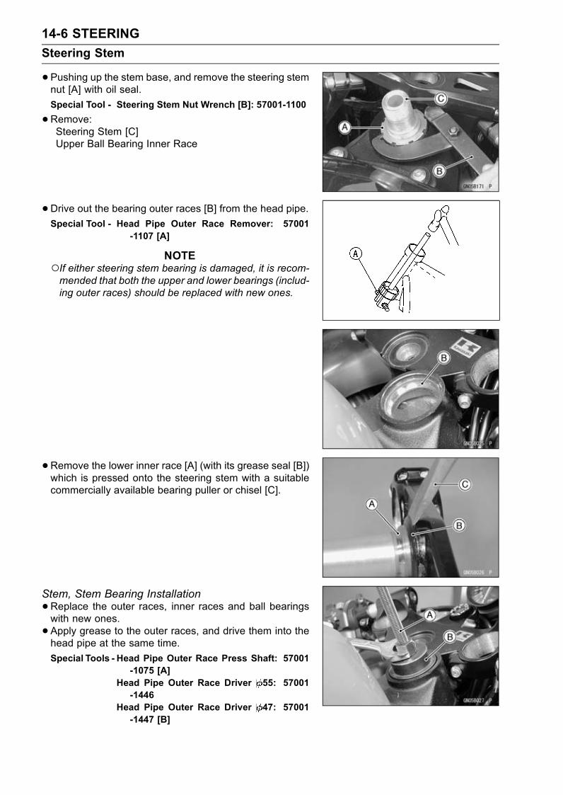
14-6 STEERING
Steering Stem
•Pushing up the stem base, and remove the steering stemnut [A] with oil seal.
Special Tool - Steering Stem Nut Wrench [B]: 57001-1100
•Remove:Steering Stem [C]Upper Ball Bearing Inner Race
•Drive out the bearing outer races [B] from the head pipe.Special Tool - Head Pipe Outer Race Remover: 57001
-1107 [A]
NOTEIf either steering stem bearing is damaged, it is recom-mended that both the upper and lower bearings (includ-ing outer races) should be replaced with new ones.
•Remove the lower inner race [A] (with its grease seal [B])which is pressed onto the steering stem with a suitablecommercially available bearing puller or chisel [C].
Stem, Stem Bearing Installation
•Replace the outer races, inner races and ball bearingswith new ones.
• Apply grease to the outer races, and drive them into thehead pipe at the same time.
Special Tools - Head Pipe Outer Race Press Shaft: 57001-1075 [A]
Head Pipe Outer Race Driver 55: 57001-1446
Head Pipe Outer Race Driver 47: 57001-1447 [B]

STEERING 14-7
Steering Stem
• Install the oil seal [A] on the steering stem, and drive thelower ball bearing inner race [B] applied the grease on tothe stem.
Special Tools - Steering Stem Bearing Driver: 57001-1344[C]
Steering Stem Bearing Driver Adapter:57001-1345 [D]
• Install the lower ball bearing [A] onto the stem.•Apply grease to the lower and upper ball bearings [B] andouter races.
• Install the stem [A] through the head pipe and install theball bearing [B] and inner race [C] on it.
• Install the oil seal [D] and steering stem nut.Stem Nut (ZX1200-B1/B2) [E]Stem Nut (ZX1200-B3) [F]
• Settle the inner races in place as follows:Tighten the steering stem nut with 20 N·m (2.0 kgf·m, 15ft·lb) of torque first, and loosen it a fraction of a turn untilit turns lightly. Afterward tighten it again with specifiedtorque using the stem nut wrench [A].Check that there is no play and the steering stem turnssmoothly without rattles. If not, the bearings on the innerraces may be damaged.
Special Tool - Steering Stem Nut Wrench: 57001-1100
Torque - Steering Stem Nut: 20 N·m (2.0 kgf·m, 15 ft·lb)

14-8 STEERING
Steering Stem
ZX1200-B1/B2
• Install the lock washer.• Install the stem head.
• Install the washer, and tighten the stem head nut withspecified torque.
• Install the front fork (see Suspension chapter).NOTE
Tighten the fork upper clamp bolts first, next the stemhead nut, last the fork lower clamp bolts.Tighten the two clamp bolts alternately two times to en-sure even tightening torque.
Torque - Steering Stem Head Nut: 54 N·m (5.5 kgf·m, 40ft·lb)
Front Fork Clamp Bolts (Upper): 20 N·m (2.0kgf·m, 15 ft·lb)
Front Fork Clamp Bolts (Lower): 20 N·m (2.0kgf·m, 15 ft·lb)
WARNINGDo not impede the handlebar turning by routing thecables, harnesses and hoses improperly (see Gen-eral Information chapter).
• Install the removed parts (see appropriate chapters).ZX1200-B3
• Install the claw washer [A] so that its bent side [B] facesupward, and engage the bent claws with the grooves ofstem locknut [C].
•Hand tighten the stem locknut until it touches the clawwasher.
• Tighten the stem locknut clockwise until the claws arealigned with the grooves of stem nut [D], and bend the2 claws downward [E].
• Install the stem head.
• Install the washer, and tighten the stem head nut withspecified torque.
• Install the front fork (see Suspension chapter).
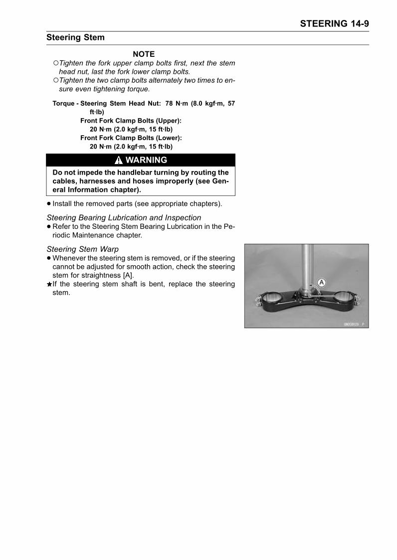
STEERING 14-9
Steering Stem
NOTETighten the fork upper clamp bolts first, next the stemhead nut, last the fork lower clamp bolts.Tighten the two clamp bolts alternately two times to en-sure even tightening torque.
Torque - Steering Stem Head Nut: 78 N·m (8.0 kgf·m, 57ft·lb)
Front Fork Clamp Bolts (Upper):20 N·m (2.0 kgf·m, 15 ft·lb)
Front Fork Clamp Bolts (Lower):20 N·m (2.0 kgf·m, 15 ft·lb)
WARNINGDo not impede the handlebar turning by routing thecables, harnesses and hoses improperly (see Gen-eral Information chapter).
• Install the removed parts (see appropriate chapters).Steering Bearing Lubrication and Inspection
•Refer to the Steering Stem Bearing Lubrication in the Pe-riodic Maintenance chapter.
Steering Stem Warp
•Whenever the steering stem is removed, or if the steeringcannot be adjusted for smooth action, check the steeringstem for straightness [A].If the steering stem shaft is bent, replace the steeringstem.
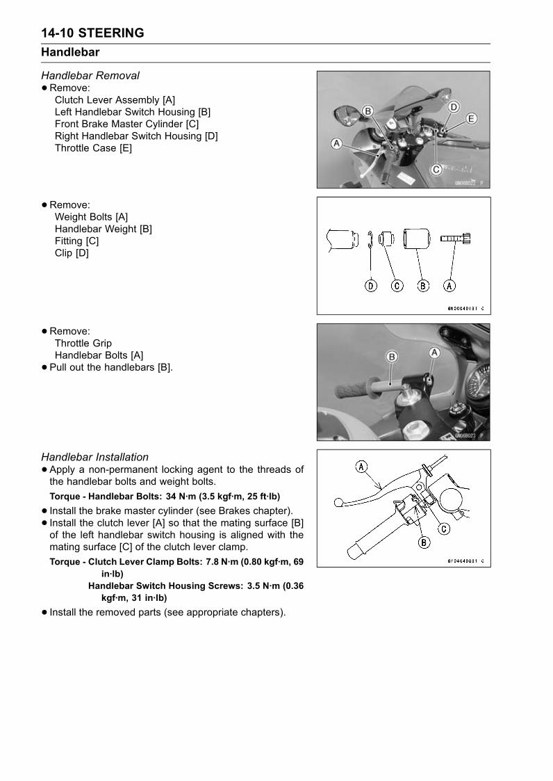
14-10 STEERING
Handlebar
Handlebar Removal
•Remove:Clutch Lever Assembly [A]Left Handlebar Switch Housing [B]Front Brake Master Cylinder [C]Right Handlebar Switch Housing [D]Throttle Case [E]
•Remove:Weight Bolts [A]Handlebar Weight [B]Fitting [C]Clip [D]
•Remove:Throttle GripHandlebar Bolts [A]
• Pull out the handlebars [B].
Handlebar Installation
•Apply a non-permanent locking agent to the threads ofthe handlebar bolts and weight bolts.
Torque - Handlebar Bolts: 34 N·m (3.5 kgf·m, 25 ft·lb)
• Install the brake master cylinder (see Brakes chapter).• Install the clutch lever [A] so that the mating surface [B]of the left handlebar switch housing is aligned with themating surface [C] of the clutch lever clamp.
Torque - Clutch Lever Clamp Bolts: 7.8 N·m (0.80 kgf·m, 69in·lb)
Handlebar Switch Housing Screws: 3.5 N·m (0.36kgf·m, 31 in·lb)
• Install the removed parts (see appropriate chapters).

FRAME 15-1
15
Frame
Table of Contents
Exploded View................................... 15-2Seats ................................................. 15-5
Rear Seat Removal...................... 15-5Rear Seat Installation................... 15-5Rear Seat Cover Removal ........... 15-5Rear Seat Cover Installation ........ 15-6Front Seat Removal ..................... 15-6Front Seat Installation .................. 15-6
Seat Cover......................................... 15-7Seat Cover Removal.................... 15-7Seat Cover Installation................. 15-7
Fairings.............................................. 15-8Lower Fairings (Left and Right)Removal .................................... 15-8
Lower Fairings (Left and Right)Installation ................................. 15-8
Lower Inner Fairing Removal....... 15-9Lower Inner Fairing Installation.... 15-9Upper Inner Fairings (Left andRight) Removal ......................... 15-9
Upper Inner Fairings (Left andRight) Installation ...................... 15-9
Wind Shield Removal................... 15-10Wind Shield Installation................ 15-10Upper Inner Covers (Left andRight) Removal ......................... 15-10
Upper Inner Covers (Left andRight) Installation ...................... 15-10
Lower Inner Covers (Left andRight) Removal ......................... 15-10
Lower Inner Covers (Left andRight) Installation ...................... 15-11
Upper Fairing Removal ................ 15-11Upper Fairing Disassembly.......... 15-12Upper Fairing Assembly............... 15-13Hot Wind Cover Installation ......... 15-14
Fenders ............................................. 15-15Front Fender Removal ................. 15-15Front Fender Installation .............. 15-15Rear Fender Rear Removal......... 15-15Rear Fender Rear Installation...... 15-15Rear Fender Front Removal ........ 15-16Rear Fender Front Installation ..... 15-16
Rear Frame ....................................... 15-17Rear Frame Removal................... 15-17Rear Frame Installation................ 15-17Frame Inspection ......................... 15-17
Storage Box....................................... 15-18Storage Box Removal .................. 15-18Storage Box Installation ............... 15-18
Side Stand......................................... 15-19Side Stand Removal .................... 15-19Side Stand Installation ................. 15-19
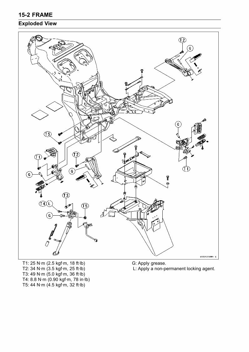
15-2 FRAME
Exploded View
T1: 25 N·m (2.5 kgf·m, 18 ft·lb)T2: 34 N·m (3.5 kgf·m, 25 ft·lb)T3: 49 N·m (5.0 kgf·m, 36 ft·lb)T4: 8.8 N·m (0.90 kgf·m, 78 in·lb)T5: 44 N·m (4.5 kgf·m, 32 ft·lb)
G: Apply grease.L: Apply a non-permanent locking agent.
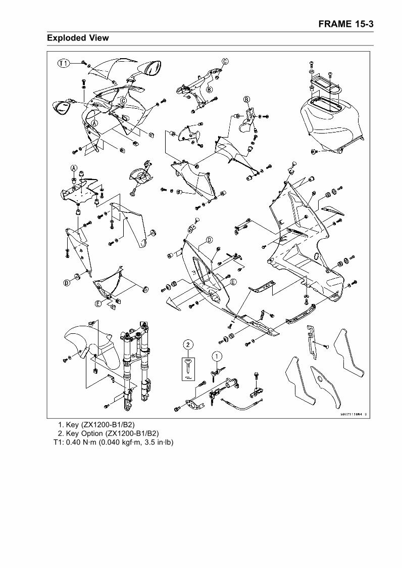
FRAME 15-3
Exploded View
1. Key (ZX1200-B1/B2)2. Key Option (ZX1200-B1/B2)T1: 0.40 N·m (0.040 kgf·m, 3.5 in·lb)
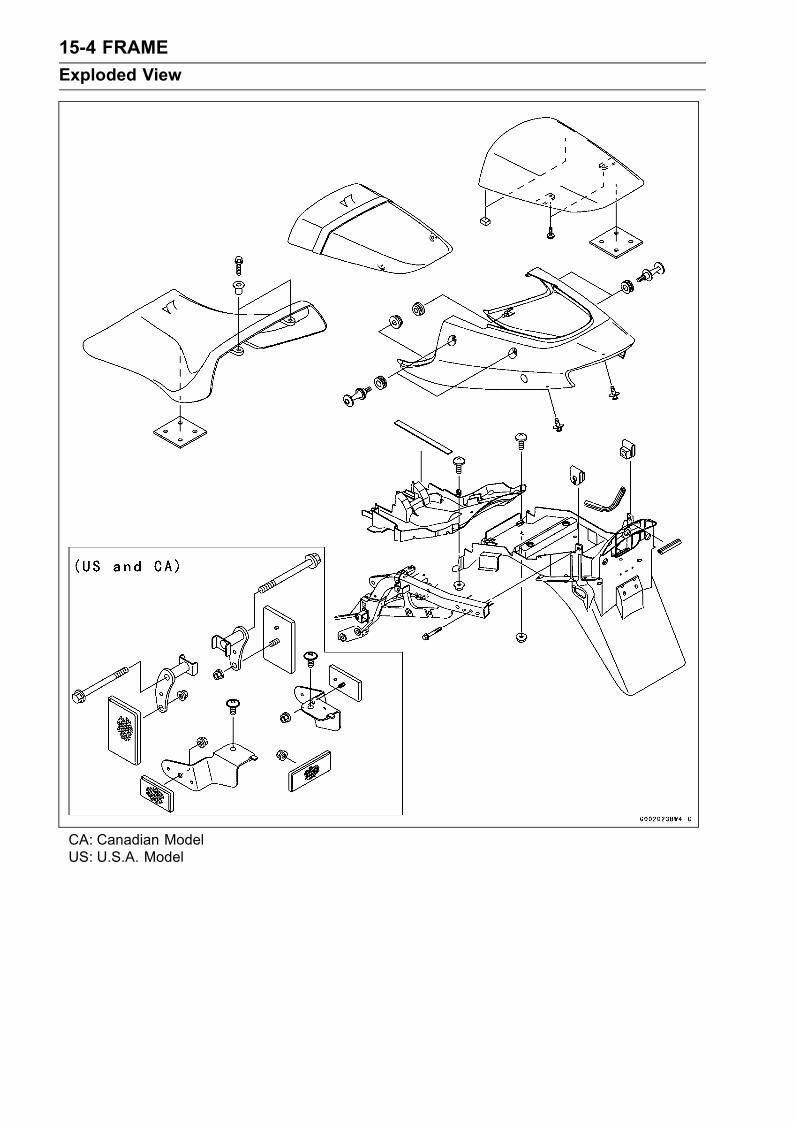
15-4 FRAME
Exploded View
CA: Canadian ModelUS: U.S.A. Model

FRAME 15-5
Seats
Rear Seat Removal
• Insert the ignition switch key into the seat lock [A], turningthe key clockwise, pulling up on the rear of the seat withseat cover [B], and pulling the seat backward.
Rear Seat Installation
•Slip the rear seat hooks [A] into the hollow-cubic brackets[B] on the frame.
• Insert the seat projection [C] into the latch hole [D].• Push down the rear part of the seat until the lock clicks.
Rear Seat Cover Removal
•Remove:Rear SeatScrews [A]
•Remove the front bracket portions [A] from the projection[B] of the seat.
•Clear the bracket portions [A] from the seat band [B].• Pull the seat cover [C] out.
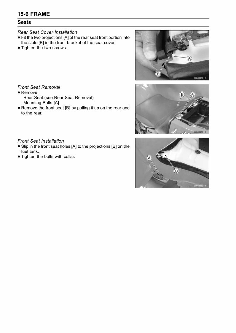
15-6 FRAME
Seats
Rear Seat Cover Installation
•Fit the two projections [A] of the rear seat front portion intothe slots [B] in the front bracket of the seat cover.
• Tighten the two screws.
Front Seat Removal
•Remove:Rear Seat (see Rear Seat Removal)Mounting Bolts [A]
•Remove the front seat [B] by pulling it up on the rear andto the rear.
Front Seat Installation
•Slip in the front seat holes [A] to the projections [B] on thefuel tank.
• Tighten the bolts with collar.
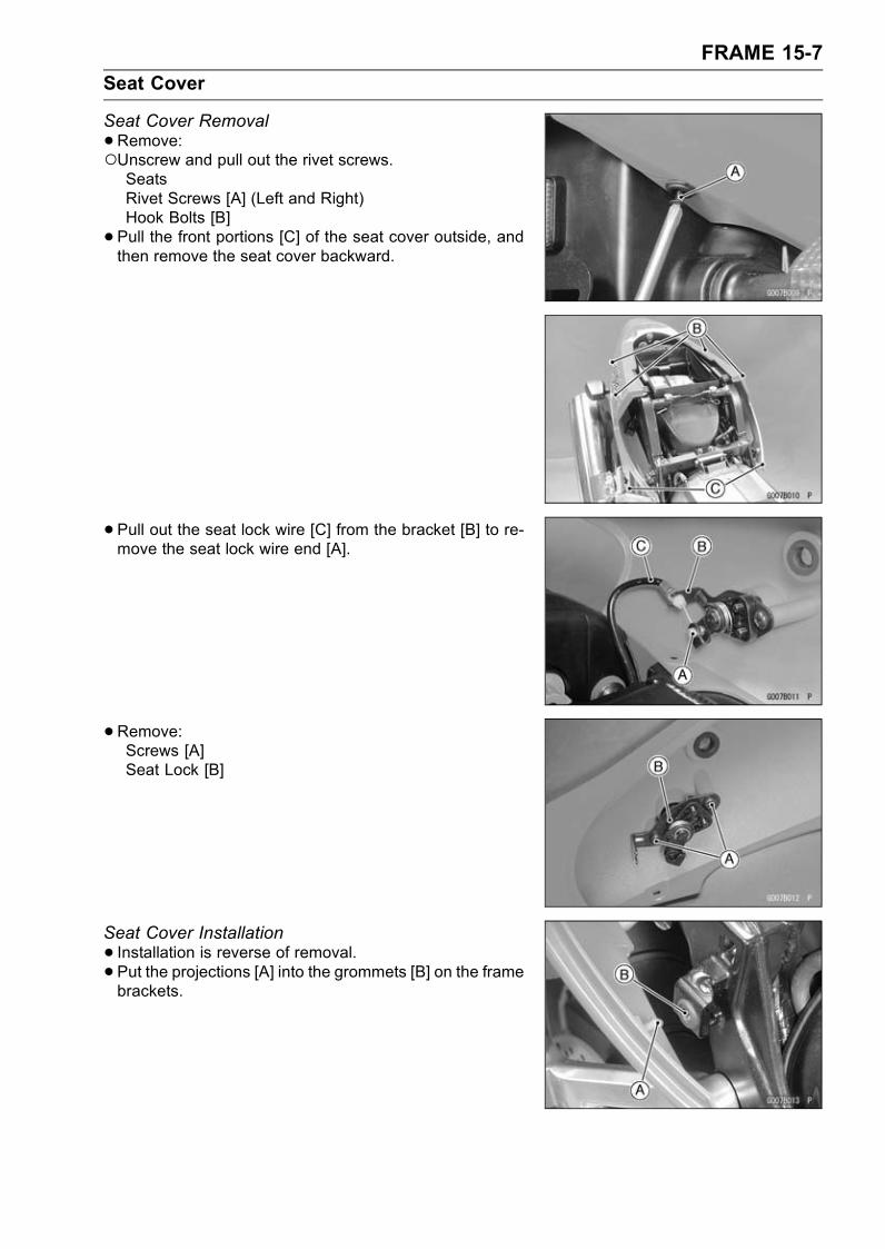
FRAME 15-7
Seat Cover
Seat Cover Removal
•Remove:Unscrew and pull out the rivet screws.SeatsRivet Screws [A] (Left and Right)Hook Bolts [B]
• Pull the front portions [C] of the seat cover outside, andthen remove the seat cover backward.
• Pull out the seat lock wire [C] from the bracket [B] to re-move the seat lock wire end [A].
•Remove:Screws [A]Seat Lock [B]
Seat Cover Installation
• Installation is reverse of removal.• Put the projections [A] into the grommets [B] on the framebrackets.
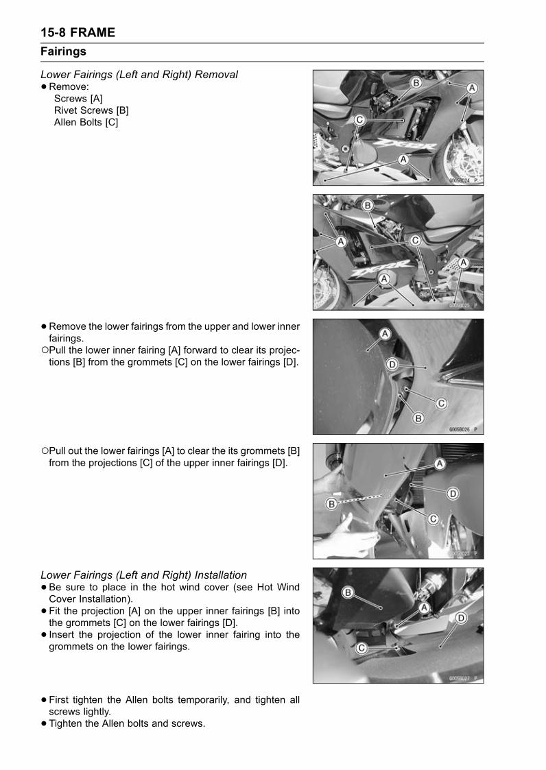
15-8 FRAME
Fairings
Lower Fairings (Left and Right) Removal
•Remove:Screws [A]Rivet Screws [B]Allen Bolts [C]
•Remove the lower fairings from the upper and lower innerfairings.Pull the lower inner fairing [A] forward to clear its projec-tions [B] from the grommets [C] on the lower fairings [D].
Pull out the lower fairings [A] to clear the its grommets [B]from the projections [C] of the upper inner fairings [D].
Lower Fairings (Left and Right) Installation
•Be sure to place in the hot wind cover (see Hot WindCover Installation).
• Fit the projection [A] on the upper inner fairings [B] intothe grommets [C] on the lower fairings [D].
• Insert the projection of the lower inner fairing into thegrommets on the lower fairings.
• First tighten the Allen bolts temporarily, and tighten allscrews lightly.
• Tighten the Allen bolts and screws.
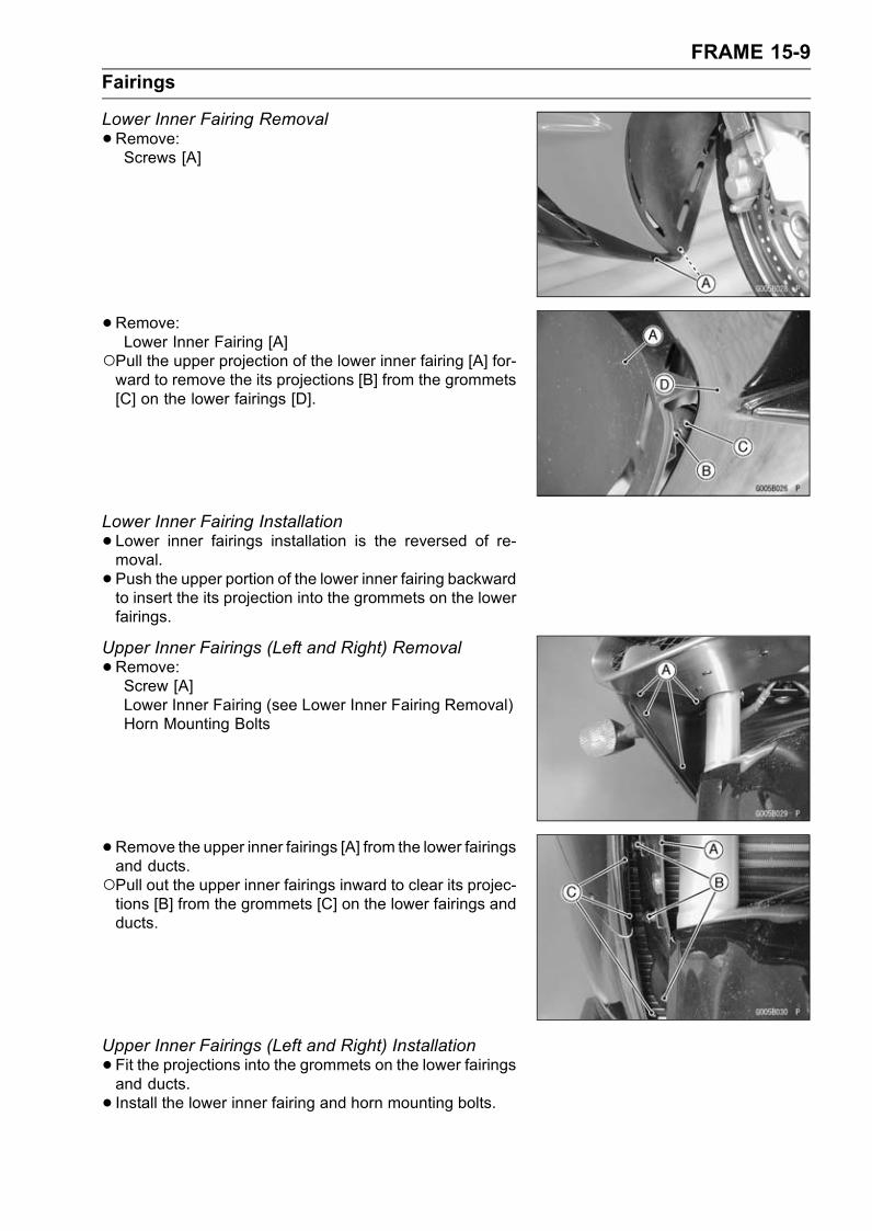
FRAME 15-9
Fairings
Lower Inner Fairing Removal
•Remove:Screws [A]
•Remove:Lower Inner Fairing [A]
Pull the upper projection of the lower inner fairing [A] for-ward to remove the its projections [B] from the grommets[C] on the lower fairings [D].
Lower Inner Fairing Installation
•Lower inner fairings installation is the reversed of re-moval.
• Push the upper portion of the lower inner fairing backwardto insert the its projection into the grommets on the lowerfairings.
Upper Inner Fairings (Left and Right) Removal
•Remove:Screw [A]Lower Inner Fairing (see Lower Inner Fairing Removal)Horn Mounting Bolts
•Remove the upper inner fairings [A] from the lower fairingsand ducts.Pull out the upper inner fairings inward to clear its projec-tions [B] from the grommets [C] on the lower fairings andducts.
Upper Inner Fairings (Left and Right) Installation
•Fit the projections into the grommets on the lower fairingsand ducts.
• Install the lower inner fairing and horn mounting bolts.
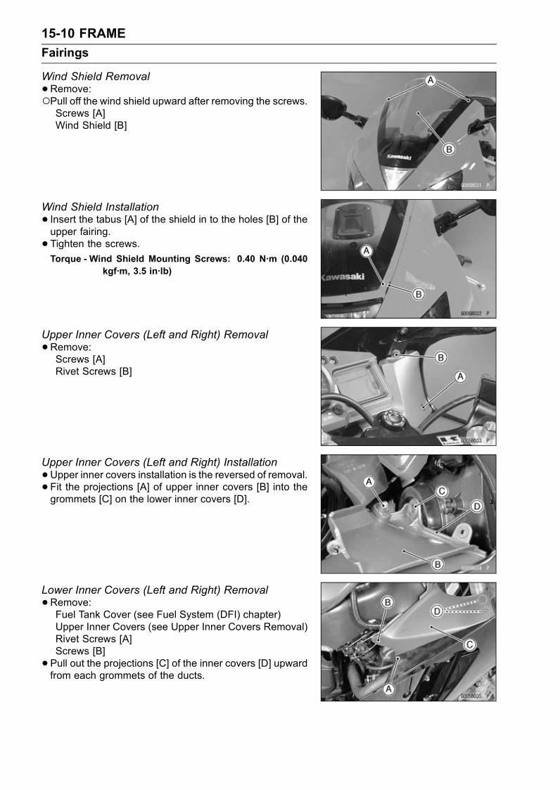
15-10 FRAME
Fairings
Wind Shield Removal
•Remove:Pull off the wind shield upward after removing the screws.Screws [A]Wind Shield [B]
Wind Shield Installation
• Insert the tabus [A] of the shield in to the holes [B] of theupper fairing.
• Tighten the screws.Torque - Wind Shield Mounting Screws: 0.40 N·m (0.040
kgf·m, 3.5 in·lb)
Upper Inner Covers (Left and Right) Removal
•Remove:Screws [A]Rivet Screws [B]
Upper Inner Covers (Left and Right) Installation
•Upper inner covers installation is the reversed of removal.• Fit the projections [A] of upper inner covers [B] into thegrommets [C] on the lower inner covers [D].
Lower Inner Covers (Left and Right) Removal
•Remove:Fuel Tank Cover (see Fuel System (DFI) chapter)Upper Inner Covers (see Upper Inner Covers Removal)Rivet Screws [A]Screws [B]
• Pull out the projections [C] of the inner covers [D] upwardfrom each grommets of the ducts.

FRAME 15-11
Fairings
Lower Inner Covers (Left and Right) Installation
•Lower inner covers installation is the reverse of removal.• Insert the projections [A] of the lower inner covers into theholes [B] on the ducts.
Upper Fairing Removal
•Remove:Upper and Lower Inner Covers (see Upper and LowerInner Covers Removal)Wind Shield (see Wind Shield Removal)
•Remove the mounting screws [A] of left and right fairings.
• Loosen the left and right air inlet duct clamp screws [A].
•Remove the nuts [A] and take off the left and right rearview mirrors.
•Remove the projections [A] on the left and right upperinner fairings [B] from the grommets [C] on the left andright lower fairings [D] pulling out the lower portion inwardof the upper inner fairings.

15-12 FRAME
Fairings
•Pull the upper fairing assembly forward and disconnectthe headlight harness connector [A].
Upper Fairing Disassembly
•Remove the upper inner fairings [B] with loosening thescrews [A].
•Remove:Front Turn Signal Connectors [A]Headlight Connectors [B]City Light Connector [C]Headlight Harness Bracket [D]
•Remove:Headlight Mounting Bolts [A]Headlight Mounting Screws [B]Headlight Assembly [C]
•Remove:Screws [A]City Light Assembly [B]

FRAME 15-13
Fairings
•Remove the ducts [B] with the screws [A] taken off.
• Take off the screw [A] to remove the air inlet [B].
• Remove the screw [A] to take off the plate [B] and turnsignal light.
Upper Fairing Assembly
•Upper fairing assembly is the reversed of disassembly.• Insert the projections [A] of the air inlet into the holes [B]of the upper fairing.

15-14 FRAME
Fairings
Hot Wind Cover Installation
• Install the hot wind cover [A] following the below.Cooling Hose [B]Clutch Cable [C]Crankshaft Sensor Lead [J]
Put in the lower part of the cover between the ribs [G] onthe crankshaft sensor cover [H].Insert the pin [D] through the cover hole [E] to the bracket[F].
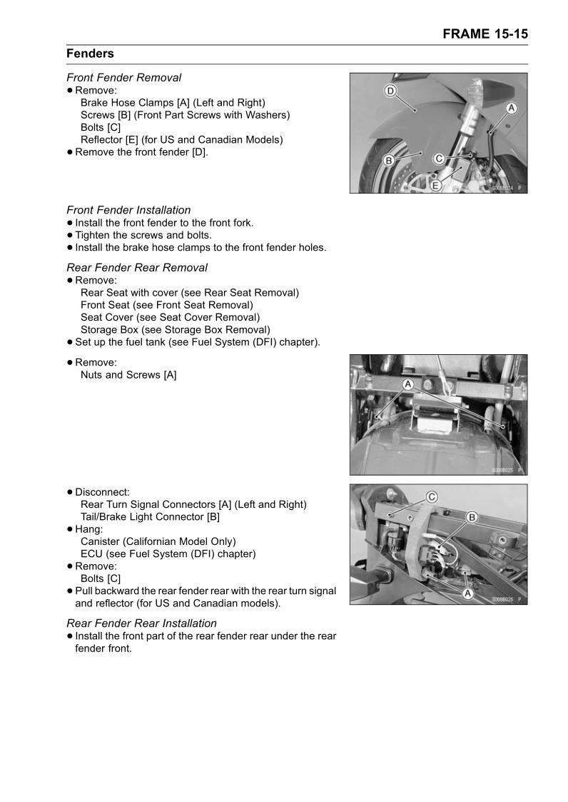
FRAME 15-15
Fenders
Front Fender Removal
•Remove:Brake Hose Clamps [A] (Left and Right)Screws [B] (Front Part Screws with Washers)Bolts [C]Reflector [E] (for US and Canadian Models)
•Remove the front fender [D].
Front Fender Installation
• Install the front fender to the front fork.• Tighten the screws and bolts.• Install the brake hose clamps to the front fender holes.Rear Fender Rear Removal
•Remove:Rear Seat with cover (see Rear Seat Removal)Front Seat (see Front Seat Removal)Seat Cover (see Seat Cover Removal)Storage Box (see Storage Box Removal)
• Set up the fuel tank (see Fuel System (DFI) chapter).
• Remove:Nuts and Screws [A]
•Disconnect:Rear Turn Signal Connectors [A] (Left and Right)Tail/Brake Light Connector [B]
•Hang:Canister (Californian Model Only)ECU (see Fuel System (DFI) chapter)
•Remove:Bolts [C]
• Pull backward the rear fender rear with the rear turn signaland reflector (for US and Canadian models).
Rear Fender Rear Installation
• Install the front part of the rear fender rear under the rearfender front.
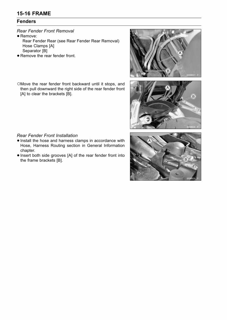
15-16 FRAME
Fenders
Rear Fender Front Removal
•Remove:Rear Fender Rear (see Rear Fender Rear Removal)Hose Clamps [A]Separator [B]
•Remove the rear fender front.
Move the rear fender front backward until it stops, andthen pull downward the right side of the rear fender front[A] to clear the brackets [B].
Rear Fender Front Installation
• Install the hose and harness clamps in accordance withHose, Harness Routing section in General Informationchapter.
• Insert both side grooves [A] of the rear fender front intothe frame brackets [B].
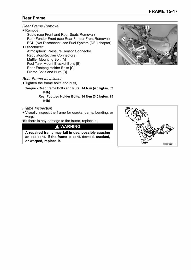
FRAME 15-17
Rear Frame
Rear Frame Removal
•Remove:Seats (see Front and Rear Seats Removal)Rear Fender Front (see Rear Fender Front Removal)ECU (Not Disconnect, see Fuel System (DFI) chapter)
•Disconnect:Atmospheric Pressure Sensor ConnectorRegulator/Rectifier ConnectorsMuffler Mounting Bolt [A]Fuel Tank Mount Bracket Bolts [B]Rear Footpeg Holder Bolts [C]Frame Bolts and Nuts [D]
Rear Frame Installation
•Tighten the frame bolts and nuts,Torque - Rear Frame Bolts and Nuts: 44 N·m (4.5 kgf·m, 32
ft·lb)Rear Footpeg Holder Bolts: 34 N·m (3.5 kgf·m, 25ft·lb)
Frame Inspection
•Visually inspect the frame for cracks, dents, bending, orwarp.If there is any damage to the frame, replace it.
WARNINGA repaired frame may fail in use, possibly causingan accident. If the frame is bent, dented, cracked,or warped, replace it.
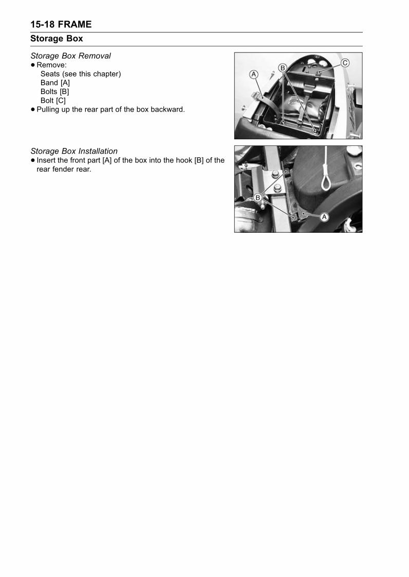
15-18 FRAME
Storage Box
Storage Box Removal
•Remove:Seats (see this chapter)Band [A]Bolts [B]Bolt [C]
• Pulling up the rear part of the box backward.
Storage Box Installation
• Insert the front part [A] of the box into the hook [B] of therear fender rear.
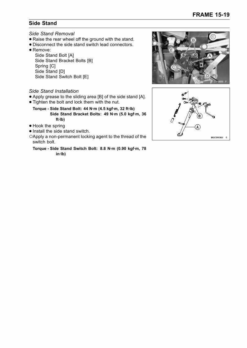
FRAME 15-19
Side Stand
Side Stand Removal
•Raise the rear wheel off the ground with the stand.•Disconnect the side stand switch lead connectors.•Remove:Side Stand Bolt [A]Side Stand Bracket Bolts [B]Spring [C]Side Stand [D]Side Stand Switch Bolt [E]
Side Stand Installation
•Apply grease to the sliding area [B] of the side stand [A].• Tighten the bolt and lock them with the nut.
Torque - Side Stand Bolt: 44 N·m (4.5 kgf·m, 32 ft·lb)Side Stand Bracket Bolts: 49 N·m (5.0 kgf·m, 36ft·lb)
•Hook the spring• Install the side stand switch.Apply a non-permanent locking agent to the thread of theswitch bolt.
Torque - Side Stand Switch Bolt: 8.8 N·m (0.90 kgf·m, 78in·lb)

ELECTRICAL SYSTEM 16-1
16
Electrical System
Table of Contents
Exploded View................................... 16-3Specifications .................................... 16-8Parts Location.................................... 16-10Precautions........................................ 16-11Electrical Wiring................................. 16-13
Wiring Inspection ......................... 16-13Battery ............................................... 16-14
Battery Removal .......................... 16-14Battery Installation ....................... 16-15Electrolyte Filling.......................... 16-16Initial Charge................................ 16-18Precautions .................................. 16-18Interchange .................................. 16-19Charging Condition Inspection..... 16-19Refreshing Charge....................... 16-19
Charging System............................... 16-21Alternator Cover Removal............ 16-21Alternator Cover Installation......... 16-21Stator Coil Removal ..................... 16-21Stator Coil Installation .................. 16-22Alternator Rotor Removal ............ 16-23Alternator Rotor Installation ......... 16-23Alternator Inspection .................... 16-24Regulator/Rectifier Inspection...... 16-25Regulator/Rectifier OutputVoltage Inspection..................... 16-28
Ignition System.................................. 16-31Crankshaft Sensor Removal ........ 16-31Crankshaft Sensor Installation ..... 16-32Crankshaft Sensor Inspection...... 16-32Crankshaft Sensor Peak VoltageInspection.................................. 16-32
Camshaft Position SensorRemoval .................................... 16-33
Camshaft Position SensorInstallation ................................. 16-33
Camshaft Position SensorInspection.................................. 16-34
Camshaft Position Sensor PeakVoltage Inspection..................... 16-34
Stick Coil (Ignition Coil togetherwith Spark Plug Cap) Removal . 16-35
Stick Coil (Ignition Coil togetherwith Spark Plug Cap)Installation ................................. 16-35
Stick Coil (Ignition Coil togetherwith Spark Plug Cap) Inspection 16-35
Stick Coil Primary Peak VoltageInspection.................................. 16-36
Spark Plug Removal .................... 16-36Spark Plug Installation ................. 16-37Spark Plug Cleaning andInspection.................................. 16-37
Spark Plug Gap Inspection .......... 16-37Interlock Operation Inspection ..... 16-37IC Igniter Inspection ..................... 16-38Ignition System Inspection ........... 16-39
Electric Starter System...................... 16-42Starter Motor Removal................. 16-42Starter Motor Installation.............. 16-42Starter Motor Disassembly........... 16-43Starter Motor Assembly ............... 16-43Brush Inspection .......................... 16-44Commutator Cleaning andInspection.................................. 16-44
Armature Inspection..................... 16-45Brush Lead Inspection ................. 16-45Brush Plate and Terminal BoltInspection.................................. 16-45
Starter Relay Inspection............... 16-45Lighting System................................. 16-49
Headlight BeamHorizontal/Vertical Adjustment .. 16-49
Headlight Bulbs (Left and Right)Replacement ............................. 16-50
City Light Bulb Replacement........ 16-50Tail/Brake Light BulbsReplacement ............................. 16-51
Tail/Brake Light Lens AssemblyReplacement ............................. 16-51
Headlight Relays (High/Low)Inspection.................................. 16-52
Turn Signal Relay Inspection ....... 16-54Air Switching Valve (ZX1200-B3) ...... 16-57
Air Switching Valve OperationTest............................................ 16-57
Air Switching Valve Unit Test ....... 16-57Radiator Fan System......................... 16-58
Fan System Circuit Inspection ..... 16-58Fan Motors Inspection ................. 16-58Fan Relay Removal ..................... 16-58
16-2 ELECTRICAL SYSTEM
Fan Relay Inspection ................... 16-59Meter ................................................. 16-60
Meter Unit Removal ..................... 16-60Meter Unit Disassembly ............... 16-60Bulbs Replacement...................... 16-60Meter Unit Inspection ................... 16-61
Immobilizer System (EquippedModels) (ZX1200-B3) ..................... 16-70Operational Cautions ................... 16-70Key Registration........................... 16-70Immobilizer System PartsReplacement ............................. 16-86
Immobilizer System Inspection .... 16-88Switches and Sensors ....................... 16-89
Front Brake Light SwitchInspection.................................. 16-89
Rear Brake Light SwitchCheck/Adjustment ..................... 16-89
Switch Inspection ......................... 16-89Radiator Fan Switch Inspection ... 16-90Water Temperature SensorInspection.................................. 16-91
Speed Sensor Removal ............... 16-91Speed Sensor Installation ............ 16-92Speed Sensor Inspection............. 16-92Fuel Level Sensor Inspection....... 16-92Fuel Reserve Switch Inspection(1).............................................. 16-93
Fuel Reserve Switch Inspection(2).............................................. 16-94
Junction Box...................................... 16-95Junction Box Fuse CircuitInspection.................................. 16-95
Starter Circuit/Headlight RelayInspection.................................. 16-95
Diode Circuit Inspection ............... 16-96Fuse................................................... 16-98
30 A Main Fuse Removal............. 16-9830 A Headlight/Fan FuseRemoval .................................... 16-98
Junction Box Fuse Removal ........ 16-9815 A ECU Fuse Removal............. 16-99Fuse Installation........................... 16-99Fuse Inspection............................ 16-99
Wiring Diagram (U.S.A. and Canada) 16-100Wiring Diagram(Australia/ZX1200-B2: H,HU, HR models).............................. 16-102
Wiring Diagram (Malaysia) ................ 16-104Wiring Diagram (Other than U.S.A.,Canada, Australia, and Malaysia)... 16-106
Wiring Diagram (ZX1200-B3: U.S.A.,and Canada) ................................... 16-108
Wiring Diagram (ZX1200-B3: Otherthan U.S.A., Canada, Hong Kong,Kuwait and Malaysia)...................... 16-110
Wiring Diagram (ZX1200-B3: HongKong, Kuwait) ................................. 16-112
Wiring Diagram (ZX1200-B3:Malaysia) ........................................ 16-114
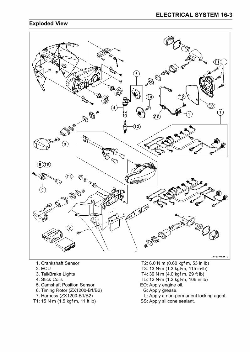
ELECTRICAL SYSTEM 16-3
Exploded View
1. Crankshaft Sensor2. ECU3. Tail/Brake Lights4. Stick Coils5. Camshaft Position Sensor6. Timing Rotor (ZX1200-B1/B2)7. Harness (ZX1200-B1/B2)T1: 15 N·m (1.5 kgf·m, 11 ft·lb)
T2: 6.0 N·m (0.60 kgf·m, 53 in·lb)T3: 13 N·m (1.3 kgf·m, 115 in·lb)T4: 39 N·m (4.0 kgf·m, 29 ft·lb)T5: 12 N·m (1.2 kgf·m, 106 in·lb)EO: Apply engine oil.G: Apply grease.L: Apply a non-permanent locking agent.
SS: Apply silicone sealant.

16-4 ELECTRICAL SYSTEM
Exploded View
1. Regulator/rectifier (ZX1200-B1/B2)2. Front Brake Light Switch3. Starter Relay/Main Fuse4. Starter Lockout Switch5. Oil Pressure Switch6. Stator (ZX1200-B1/B2)T1: 3.5 N·m (0.36 kgf·m, 31 in·lb)T2: 8.5 N·m (0.87 kgf·m, 75 in·lb)T3: 22 N·m (2.2 kgf·m, 16 ft·lb)
T4: 12 N·m (1.2 kgf·m, 106 in·lb)T5: 15 N·m (1.5 kgf·m, 11 ft·lb)T6: 110 N·m (11 kgf·m, 81 ft·lb)T7: 1.5 N·m (0.15 kgf·m, 13 in·lb)T8: 20 N·m (2.0 kgf·m, 15 ft·lb)G: Apply grease.L: Apply a non-permanent locking agent.
SS: Apply silicone sealant.

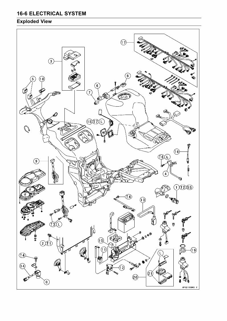
16-6 ELECTRICAL SYSTEM
Exploded View
ELECTRICAL SYSTEM 16-7
Exploded View
1. Water Temperature Sensor2. Radiator Fan Switch3. Junction Box4. Side Stand Switch5. Headlight Relays6. Fuel Pump Relay7. Fan Relay8. ECU Relay9. Gear Position Switch (ZX1200-B1/B2)10. Turn Signal Relay11. Starter Relay and Main Fuse12. Vehicle-down Sensor13. Jump Starting Cable14. Speed Sensor15. Fuel Level Sensor16. Rear Brake Light Switch17. Main Harness (ZX1200-B1/B2)18. Immobilizer Amplifier19. Immobilizer Antenna20. Immobilizer Models21. European Model onlyT1: 24 N·m (2.4 kgf·m, 17 ft·lb)T2: 25 N·m (2.5 kgf·m, 18 ft·lb)T3: 4.0 N·m (0.40 kgf·m, 35 in·lb)T4: 10 N·m (1.0 kgf·m, 89 in·lb)T5: 12 N·m (1.2 kgf·m, 106 in·lb)T6: 8.8 N·m (0.90 kgf·m, 78 in·lb)T7: 6.9 N·m (0.70 kgf·m, 61 in·lb)G: Apply grease.L: Apply a non-permanent locking agent.
SS: Apply silicone sealant.
16-8 ELECTRICAL SYSTEM
Specifications
Item Standard
Battery
Type Sealed battery
Capacity 12 V 12 Ah
Voltage 12.6 V or more
Charging System
Type Three-phase AC
Alternator Output Voltage 85 ∼ 120 V @4 000 r/min (rpm)Stator Coil Resistance 0.3 ∼ 0.5 Ω @20°C (68°F)Charging Voltage 14.2 ∼ 15.2 V(Regulator/rectifier Output Voltage)
Ignition System
Crankshaft Sensor Resistance 423 ∼ 517 ΩCrankshaft Sensor Peak Voltage 3.6 V or more
Camshaft Position Sensor Resistance 400 ∼ 460 ΩCamshaft Position Sensor Peak Voltage 0.2 V or more
Interlock Operation Voltage 4 V or more
Stick Coil:
Primary Winding Resistance
ZX1200-B1/B2 0.85 ∼ 1.15 ΩZX1200-B3 1.04 ∼ 1.56 Ω
Secondary Winding Resistance
ZX1200-B1/B2 9.2 ∼ 13.8 kΩZX1200-B3 10.8 ∼ 16.2 kΩ
Primary Peak Voltage
ZX1200-B1/B2 80 V or more
ZX1200-B3 88 V or more
Spark Plug:
Spark Plug Gap 0.7 ∼ 0.9 mm (0.028 ∼ 0.035 in.)Electric Starter System
Starter Motor:
Brush Length 12 mm (0.47 in.), Service limit 8.5 mm (0.33 in.)
Commutator Diameter 28 mm (1.10 in.), Service limit 27 mm (1.06 in.)
Switch and Sensor
Rear Brake Light Switch Timing ON after about 10 mm (0.39 in.) pedal travel
Engine Oil Pressure Switch Connections When engine is stopped: ON
When engine is running: OFF
Fan Switch Resistance:
Rising Temperature From OFF to ON @ 93 ∼ 103°C (199 ∼ 217°F)Falling Temperature Fan stops with the temperature 3 ∼ 8°C (38 ∼ 46°F)
lower than the operation temperature range.
ON: Less than 0.5 ΩOFF: More than 10 MΩ
Water Temperature Sensor Resistance in the text
ELECTRICAL SYSTEM 16-9
Specifications
Item Standard
Fuel Level Sensor Resistance:
Full Position 8 ∼ 10 ΩEmpty Position 122 ∼ 126 Ω
Special Tools - Rotor Puller: 57001-1216Flywheel Holder: 57001-1313Flywheel and Pulley Holder: 57001-1343Hand Tester: 57001-1394Flywheel Puller Assembly: 57001-1405Lead Wire – Voltage Regulator Adapter: 57001-1448Lead Wire – Peak Voltage Adapter: 57001-1449Needle Adapter Set: 57001-1457Key Registration Unit: 57001-1582Pulley Holder, Grip: 57001-1591Rotor Holder: 57001-1592
Sealant - Kawasaki Bond (Silicone Sealant): 56019-120
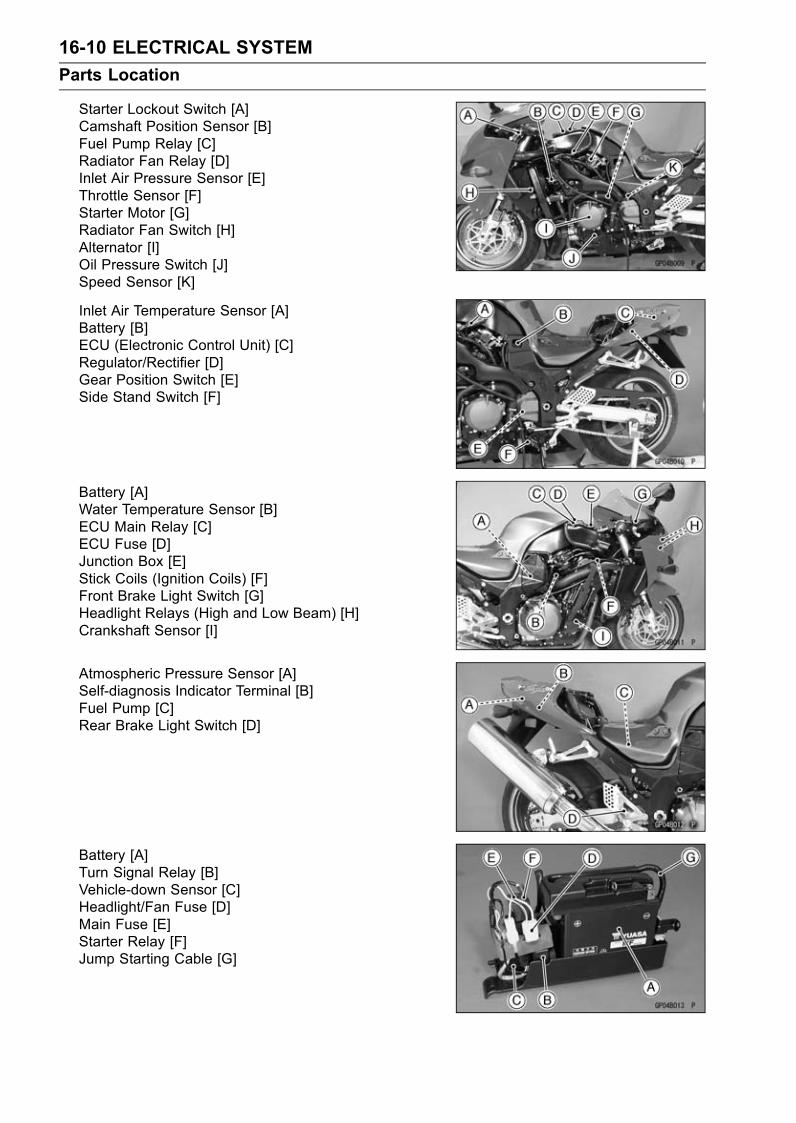
16-10 ELECTRICAL SYSTEM
Parts Location
Starter Lockout Switch [A]Camshaft Position Sensor [B]Fuel Pump Relay [C]Radiator Fan Relay [D]Inlet Air Pressure Sensor [E]Throttle Sensor [F]Starter Motor [G]Radiator Fan Switch [H]Alternator [I]Oil Pressure Switch [J]Speed Sensor [K]
Inlet Air Temperature Sensor [A]Battery [B]ECU (Electronic Control Unit) [C]Regulator/Rectifier [D]Gear Position Switch [E]Side Stand Switch [F]
Battery [A]Water Temperature Sensor [B]ECU Main Relay [C]ECU Fuse [D]Junction Box [E]Stick Coils (Ignition Coils) [F]Front Brake Light Switch [G]Headlight Relays (High and Low Beam) [H]Crankshaft Sensor [I]
Atmospheric Pressure Sensor [A]Self-diagnosis Indicator Terminal [B]Fuel Pump [C]Rear Brake Light Switch [D]
Battery [A]Turn Signal Relay [B]Vehicle-down Sensor [C]Headlight/Fan Fuse [D]Main Fuse [E]Starter Relay [F]Jump Starting Cable [G]

ELECTRICAL SYSTEM 16-11
Precautions
There are a number of important precautions that shouldbe followed servicing electrical systems.Do not reverse the battery cable connections. This willburn out the diodes on the electrical parts.Always check battery condition before condemning otherparts of an electrical system. A fully charged battery is amust for conducting accurate electrical system tests.The electrical parts should never be struck sharply, aswith a hammer, or allowed to fall on a hard surface. Sucha shock to the parts can damage them.To prevent damage to electrical parts, do not disconnectthe battery cables or any other electrical connectionswhen the ignition switch is on, or while the engine isrunning.Because of the large amount of current, never keep thestarter button pushed when the starter motor will not turnover, or the current may burn out the starter motor wind-ings.Do not use a meter illumination bulb rated for other thanvoltage or wattage specified in the wiring diagram, as themeter or gauge panel could be warped by excessive heatradiated from the bulb.Take care not to short the leads that are directly con-nected to the battery positive (+) terminal to the chassisground.Troubles may involve one or in some cases all items.Never replace a defective part without determining whatCAUSED the failure. If the failure was caused by someother item or items, they must be repaired or replaced, orthe new replacement will soon fail againMake sure all connectors in the circuit are clean and tight,and examine leads for signs of burning, fraying, etc. Poorleads and bad connections will affect electrical systemoperation.Measure coil and winding resistance when the part is cold(at room temperature).Color Codes:
BK: Black G: Green P: Pink
BL: Blue GY: Gray PU: Purple
BR: Brown LB: Light blue R: Red
CH: Chocolate LG: Light green W: White
DG: Dark green O: Orange Y: Yellow
Electrical ConnectorsFemale Connectors [A]
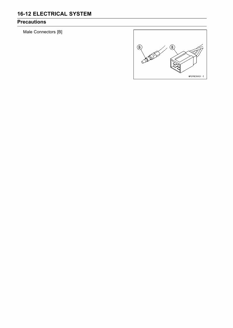
16-12 ELECTRICAL SYSTEM
Precautions
Male Connectors [B]

ELECTRICAL SYSTEM 16-13
Electrical Wiring
Wiring Inspection
•Visually inspect the wiring for signs of burning, fraying,etc.If any wiring is poor, replace the damaged wiring.
• Pull each connector [A] apart and inspect it for corrosion,dirt, and damage.If the connector is corroded or dirty, clean it carefully. If itis damaged, replace it.
• Check the wiring for continuity.Use the wiring diagram to find the ends of the lead whichis suspected of being a problem.Connect the hand tester between the ends of the leads.Special Tool - Hand Tester: 57001-1394
Set the tester to the × 1 Ω range, and read the tester.If the tester does not read 0 Ω, the lead is defective. Re-place the lead or the wiring harness [B] if necessary.

16-14 ELECTRICAL SYSTEM
Battery
Battery Removal
CAUTION
Do not disconnect the battery cables or any otherelectrical connections when the ignition switch isON, as this could damage the ECU (Electronic Con-trol Unit).Never reverse the connections of the battery, thiscould damage the ECU.
•Turn off the ignition switch.•Remove:Seats (see Frame chapter)Fuel Tank Cover (see Fuel System (DFI) chapter)Battery Compartment Cover Bolts [A]Battery Compartment Cover [B]
• Slightly pull out the battery tray [A].• Slide out terminal cover [B] to disconnect the negative (–)cable [C] and release the leads and cable from the clamp[D] on the battery tray.
• Slide out covers [A] and [C] to disconnect the startermotorcable [B] and main harness connector [D].
•Disconnect the main negative harness connector [E].
• Remove the battery tray along with the battery from thebattery compartment.
•Unhook the rubber band [B] and remove the battery cover[A].
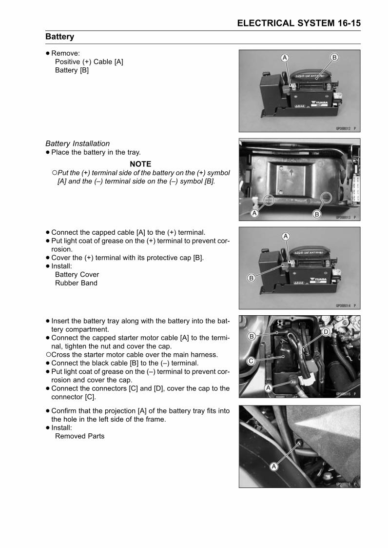
ELECTRICAL SYSTEM 16-15
Battery
•Remove:Positive (+) Cable [A]Battery [B]
Battery Installation
•Place the battery in the tray.NOTE
Put the (+) terminal side of the battery on the (+) symbol[A] and the (–) terminal side on the (–) symbol [B].
•Connect the capped cable [A] to the (+) terminal.• Put light coat of grease on the (+) terminal to prevent cor-rosion.
•Cover the (+) terminal with its protective cap [B].• Install:Battery CoverRubber Band
• Insert the battery tray along with the battery into the bat-tery compartment.
•Connect the capped starter motor cable [A] to the termi-nal, tighten the nut and cover the cap.Cross the starter motor cable over the main harness.•Connect the black cable [B] to the (–) terminal.• Put light coat of grease on the (–) terminal to prevent cor-rosion and cover the cap.
•Connect the connectors [C] and [D], cover the cap to theconnector [C].
•Confirm that the projection [A] of the battery tray fits intothe hole in the left side of the frame.
• Install:Removed Parts
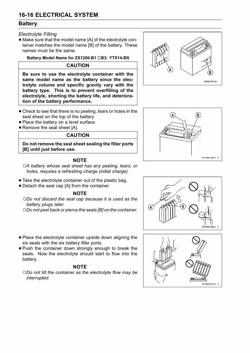
16-16 ELECTRICAL SYSTEM
Battery
Electrolyte Filling
•Make sure that the model name [A] of the electrolyte con-tainer matches the model name [B] of the battery. Thesenames must be the same.
Battery Model Name for ZX1200-B1 ∼ B3: YTX14-BS
CAUTION
Be sure to use the electrolyte container with thesame model name as the battery since the elec-trolyte volume and specific gravity vary with thebattery type. This is to prevent overfilling of theelectrolyte, shorting the battery life, and deteriora-tion of the battery performance.
•Check to see that there is no peeling, tears or holes in theseal sheet on the top of the battery.
• Place the battery on a level surface.•Remove the seal sheet [A].
CAUTION
Do not remove the seal sheet sealing the filler ports[B] until just before use.
NOTEA battery whose seal sheet has any peeling, tears, orholes, requires a refreshing charge (initial charge).
•Take the electrolyte container out of the plastic bag.•Detach the seal cap [A] from the container.
NOTEDo not discard the seal cap because it is used as thebattery plugs later.Do not peel back or pierce the seals [B] on the container.
•Place the electrolyte container upside down aligning thesix seals with the six battery filler ports.
• Push the container down strongly enough to break theseals. Now the electrolyte should start to flow into thebattery.
NOTEDo not tilt the container as the electrolyte flow may beinterrupted.

ELECTRICAL SYSTEM 16-17
Battery
•Make sure air bubbles [A] are coming up from all six fillerports.Leave the container this way for 5 minutes or longer.
NOTEIf no air bubbles are coming up from a filler port, tap [B]the bottom of the container two or three times. Neverremove the container from the battery.
CAUTION
Fill the electrolyte into the battery until the con-tainer is completely emptied.
•Be certain that all the electrolyte has flowed out.• Tap the bottom the same way as above if there is anyelectrolyte left in the container.
•Now pull the container gently out of the battery.• Let the battery sit for 20 minutes. During this time, theelectrolyte permeates the special separators and the gasgenerated by chemical reaction is released.
• Fit the seal cap [A] tightly into the filler ports until the sealcap is at the same level as the top of the battery.
NOTEDo not hammer. Press down evenly with both hands.
WARNINGOnce you installed the seal cap after filling the bat-tery, never remove it, nor add any water or elec-trolyte.
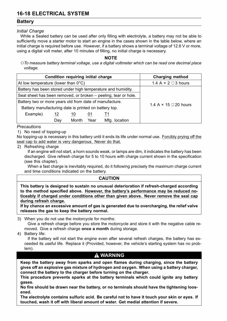
16-18 ELECTRICAL SYSTEM
Battery
Initial ChargeWhile a Sealed battery can be used after only filling with electrolyte, a battery may not be able to
sufficiently move a starter motor to start an engine in the cases shown in the table below, where aninitial charge is required before use. However, if a battery shows a terminal voltage of 12.6 V or more,using a digital volt meter, after 10 minutes of filling, no initial charge is necessary.
NOTETo measure battery terminal voltage, use a digital voltmeter which can be read one decimal placevoltage.
Condition requiring initial charge Charging method
At low temperature (lower than 0°C) 1.4 A × 2 ∼ 3 hoursBattery has been stored under high temperature and humidity.
Seal sheet has been removed, or broken – peeling, tear or hole.
Battery two or more years old from date of manufacture.
Battery manufacturing date is printed on battery top.
Example) 12 10 01 T1
Day Month Year Mfg. location
1.4 A × 15 ∼ 20 hours
Precautions1) No need of topping-upNo topping-up is necessary in this battery until it ends its life under normal use. Forcibly prying off theseal cap to add water is very dangerous. Never do that.2) Refreshing charge
If an engine will not start, a horn sounds weak, or lamps are dim, it indicates the battery has beendischarged. Give refresh charge for 5 to 10 hours with charge current shown in the specification(see this chapter).When a fast charge is inevitably required, do it following precisely the maximum charge current
and time conditions indicated on the battery.
CAUTION
This battery is designed to sustain no unusual deterioration if refresh-charged accordingto the method specified above. However, the battery’s performance may be reduced no-ticeably if charged under conditions other than given above. Never remove the seal capduring refresh charge.If by chance an excessive amount of gas is generated due to overcharging, the relief valvereleases the gas to keep the battery normal.
3) When you do not use the motorcycle for months:Give a refresh charge before you store the motorcycle and store it with the negative cable re-
moved. Give a refresh charge once a month during storage.4) Battery life:
If the battery will not start the engine even after several refresh charges, the battery has ex-ceeded its useful life. Replace it (Provided, however, the vehicle’s starting system has no prob-lem).
WARNINGKeep the battery away from sparks and open flames during charging, since the batterygives off an explosive gas mixture of hydrogen and oxygen. When using a battery charger,connect the battery to the charger before turning on the charger.This procedure prevents sparks at the battery terminals which could ignite any batterygases.No fire should be drawn near the battery, or no terminals should have the tightening loos-ened.The electrolyte contains sulfuric acid. Be careful not to have it touch your skin or eyes. Iftouched, wash it off with liberal amount of water. Get medial attention if severe.

ELECTRICAL SYSTEM 16-19
Battery
InterchangeThe sealed battery can fully display its performance only when combined with a proper vehicle elec-
tric system. Therefore, replace the sealed battery only on a motorcycle which was originally equippedwith the sealed battery.Be careful, if the sealed battery is installed on a motorcycle which had an ordinary battery as original
equipment, the sealed battery’s life will be shortened.
Charging Condition InspectionBattery charging condition can be checked by measuring
battery terminal voltage.
•Remove the battery (see Battery Removal).•Measure the battery terminal voltage.
NOTEMeasure with a digital voltmeter [A] which can be readone decimal place voltage.
If the reading is below the specified, refreshing charge isrequired.
Battery Terminal VoltageStandard: 12.6 V or more
Refreshing Charge
•Remove the battery [A] (see Battery Removal).• Refresh–charge by followingmethod according to the bat-tery terminal voltage.
WARNINGThis battery is sealed type. Never remove seal cap[B] even at charging. Never add water. Charge withcurrent and time as stated below.
Terminal Voltage: 11.5 ∼ less than 12.6 VStandard Charge: 1.4 A × 5 ∼ 10 h (see following
chart)
Quick Charge: 6.0 A × 1 h
CAUTION
If possible, do not quick charge. If the quick chargeis done due to unavoidable circumstances, do stan-dard charge later on.
Terminal Voltage: less than 11.5 VCharging Method: 1.4 A × 20 h
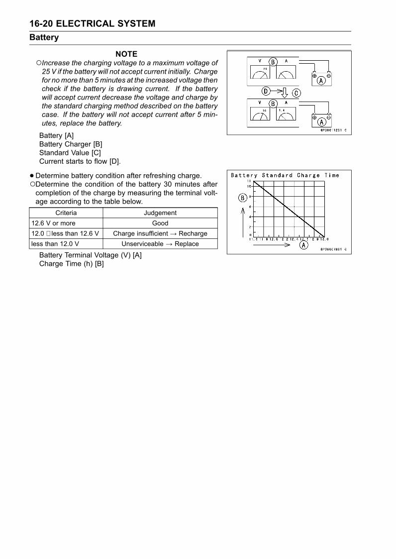
16-20 ELECTRICAL SYSTEM
Battery
NOTEIncrease the charging voltage to a maximum voltage of25 V if the battery will not accept current initially. Chargefor nomore than 5minutes at the increased voltage thencheck if the battery is drawing current. If the batterywill accept current decrease the voltage and charge bythe standard charging method described on the batterycase. If the battery will not accept current after 5 min-utes, replace the battery.
Battery [A]Battery Charger [B]Standard Value [C]Current starts to flow [D].
•Determine battery condition after refreshing charge.Determine the condition of the battery 30 minutes aftercompletion of the charge by measuring the terminal volt-age according to the table below.
Criteria Judgement
12.6 V or more Good
12.0 ∼ less than 12.6 V Charge insufficient → Recharge
less than 12.0 V Unserviceable → Replace
Battery Terminal Voltage (V) [A]Charge Time (h) [B]
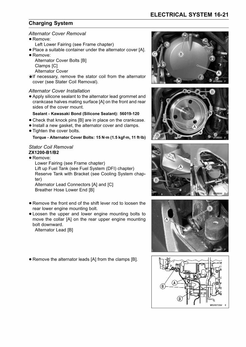
ELECTRICAL SYSTEM 16-21
Charging System
Alternator Cover Removal
•Remove:Left Lower Fairing (see Frame chapter)
• Place a suitable container under the alternator cover [A].• Remove:Alternator Cover Bolts [B]Clamps [C]Alternator CoverIf necessary, remove the stator coil from the alternatorcover (see Stater Coil Removal).
Alternator Cover Installation
•Apply silicone sealant to the alternator lead grommet andcrankcase halves mating surface [A] on the front and rearsides of the cover mount.
Sealant - Kawasaki Bond (Silicone Sealant): 56019-120
•Check that knock pins [B] are in place on the crankcase.• Install a new gasket, the alternator cover and clamps.• Tighten the cover bolts.Torque - Alternator Cover Bolts: 15 N·m (1.5 kgf·m, 11 ft·lb)
Stator Coil RemovalZX1200-B1/B2
•Remove:Lower Fairing (see Frame chapter)Lift up Fuel Tank (see Fuel System (DFI) chapter)Reserve Tank with Bracket (see Cooling System chap-ter)Alternator Lead Connectors [A] and [C]Breather Hose Lower End [B]
•Remove the front end of the shift lever rod to loosen therear lower engine mounting bolt.
• Loosen the upper and lower engine mounting bolts tomove the collar [A] on the rear upper engine mountingbolt downward.Alternator Lead [B]
•Remove the alternator leads [A] from the clamps [B].
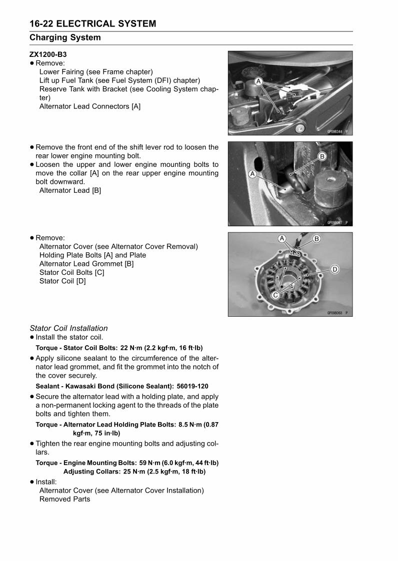
16-22 ELECTRICAL SYSTEM
Charging System
ZX1200-B3
•Remove:Lower Fairing (see Frame chapter)Lift up Fuel Tank (see Fuel System (DFI) chapter)Reserve Tank with Bracket (see Cooling System chap-ter)Alternator Lead Connectors [A]
•Remove the front end of the shift lever rod to loosen therear lower engine mounting bolt.
• Loosen the upper and lower engine mounting bolts tomove the collar [A] on the rear upper engine mountingbolt downward.Alternator Lead [B]
•Remove:Alternator Cover (see Alternator Cover Removal)Holding Plate Bolts [A] and PlateAlternator Lead Grommet [B]Stator Coil Bolts [C]Stator Coil [D]
Stator Coil Installation
• Install the stator coil.Torque - Stator Coil Bolts: 22 N·m (2.2 kgf·m, 16 ft·lb)
•Apply silicone sealant to the circumference of the alter-nator lead grommet, and fit the grommet into the notch ofthe cover securely.
Sealant - Kawasaki Bond (Silicone Sealant): 56019-120
•Secure the alternator lead with a holding plate, and applya non-permanent locking agent to the threads of the platebolts and tighten them.
Torque - Alternator Lead Holding Plate Bolts: 8.5 N·m (0.87kgf·m, 75 in·lb)
•Tighten the rear engine mounting bolts and adjusting col-lars.
Torque - EngineMounting Bolts: 59 N·m (6.0 kgf·m, 44 ft·lb)Adjusting Collars: 25 N·m (2.5 kgf·m, 18 ft·lb)
• Install:Alternator Cover (see Alternator Cover Installation)Removed Parts
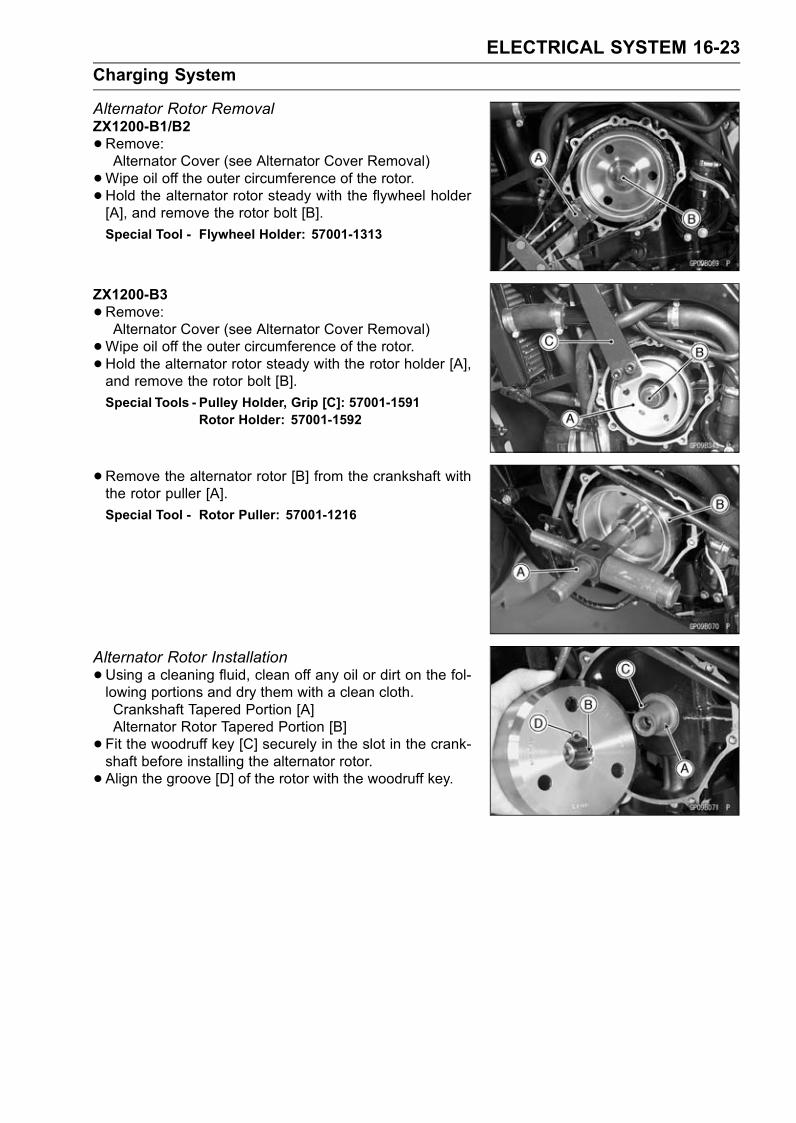
ELECTRICAL SYSTEM 16-23
Charging System
Alternator Rotor RemovalZX1200-B1/B2
•Remove:Alternator Cover (see Alternator Cover Removal)
•Wipe oil off the outer circumference of the rotor.•Hold the alternator rotor steady with the flywheel holder[A], and remove the rotor bolt [B].
Special Tool - Flywheel Holder: 57001-1313
ZX1200-B3
•Remove:Alternator Cover (see Alternator Cover Removal)
•Wipe oil off the outer circumference of the rotor.•Hold the alternator rotor steady with the rotor holder [A],and remove the rotor bolt [B].
Special Tools - Pulley Holder, Grip [C]: 57001-1591Rotor Holder: 57001-1592
•Remove the alternator rotor [B] from the crankshaft withthe rotor puller [A].
Special Tool - Rotor Puller: 57001-1216
Alternator Rotor Installation
•Using a cleaning fluid, clean off any oil or dirt on the fol-lowing portions and dry them with a clean cloth.Crankshaft Tapered Portion [A]Alternator Rotor Tapered Portion [B]
• Fit the woodruff key [C] securely in the slot in the crank-shaft before installing the alternator rotor.
• Align the groove [D] of the rotor with the woodruff key.

16-24 ELECTRICAL SYSTEM
Charging System
NOTEConfirm the alternator rotor fit or not to the crankshaftbefore tightening it with specified torque.
Install the rotor and tighten it with 70 N·m (7.0 kgf·m, 52ft·lb) of torque.Remove the rotor bolt.Check the drawing torque with the part (bolt) of the fly-wheel puller.
Special Tool - Flywheel Puller Assembly: 57001-1405
If the rotor is not pulled out with 20 N·m (2.0 kgf·m, 15ft·lb) of drawing torque, it is installed correctly.If the rotor is pulled out with under 20 N·m (2.0 kgf·m, 15ft·lb) of drawing torque, clean off any oil dirt or flaw of thecrankshaft and rotor tapered portion, and dry them witha clean cloth. Then, confirm that it is not pulled out withabove torque.
• Tighten the alternator rotor bolt while holding the alterna-tor rotor steady with the flywheel holder.
Special Tool - Flywheel Holder: 57001-1313
Torque - Alternator Rotor Bolt: 110 N·m (11 kgf·m, 81 ft·lb)
• Install the alternator cover (see Alternator Cover Installa-tion).
Alternator InspectionThere are three types of alternator failures: short, open
(lead burned out), or loss in rotor magnetism. A short oropen in one of the stator coil leads will result in either alow output, or no output at all. A loss in rotor magnetism,which may be caused by dropping or hitting the alternator,by leaving it near an electromagnetic field, or just by aging,will result in low output.
• To check the alternator output voltage, do the followingprocedures.Turn off the ignition switch.Remove the seat cover (see Frame chapter).
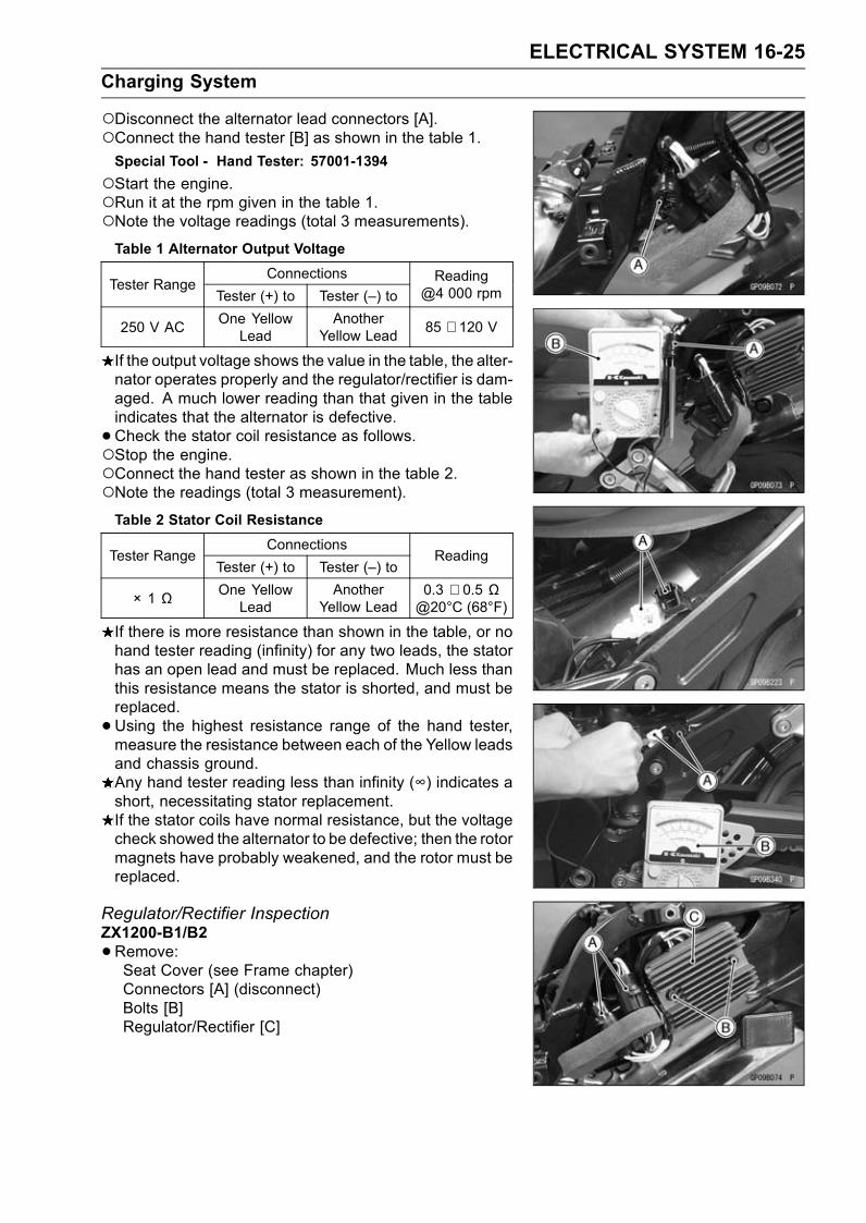
ELECTRICAL SYSTEM 16-25
Charging System
Disconnect the alternator lead connectors [A].Connect the hand tester [B] as shown in the table 1.Special Tool - Hand Tester: 57001-1394
Start the engine.Run it at the rpm given in the table 1.Note the voltage readings (total 3 measurements).Table 1 Alternator Output Voltage
ConnectionsTester Range
Tester (+) to Tester (–) to
Reading@4 000 rpm
250 V ACOne YellowLead
AnotherYellow Lead
85 ∼ 120 V
If the output voltage shows the value in the table, the alter-nator operates properly and the regulator/rectifier is dam-aged. A much lower reading than that given in the tableindicates that the alternator is defective.
•Check the stator coil resistance as follows.Stop the engine.Connect the hand tester as shown in the table 2.Note the readings (total 3 measurement).Table 2 Stator Coil Resistance
ConnectionsTester Range
Tester (+) to Tester (–) toReading
× 1 Ω One YellowLead
AnotherYellow Lead
0.3 ∼ 0.5 Ω@20°C (68°F)
If there is more resistance than shown in the table, or nohand tester reading (infinity) for any two leads, the statorhas an open lead and must be replaced. Much less thanthis resistance means the stator is shorted, and must bereplaced.
•Using the highest resistance range of the hand tester,measure the resistance between each of the Yellow leadsand chassis ground.Any hand tester reading less than infinity (∞) indicates ashort, necessitating stator replacement.If the stator coils have normal resistance, but the voltagecheck showed the alternator to be defective; then the rotormagnets have probably weakened, and the rotor must bereplaced.
Regulator/Rectifier InspectionZX1200-B1/B2
•Remove:Seat Cover (see Frame chapter)Connectors [A] (disconnect)Bolts [B]Regulator/Rectifier [C]
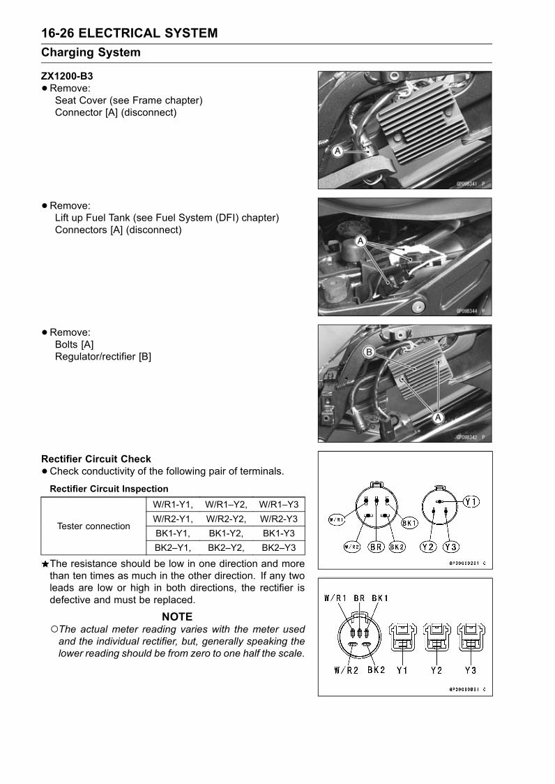
16-26 ELECTRICAL SYSTEM
Charging System
ZX1200-B3
•Remove:Seat Cover (see Frame chapter)Connector [A] (disconnect)
•Remove:Lift up Fuel Tank (see Fuel System (DFI) chapter)Connectors [A] (disconnect)
•Remove:Bolts [A]Regulator/rectifier [B]
Rectifier Circuit Check
•Check conductivity of the following pair of terminals.Rectifier Circuit Inspection
W/R1-Y1, W/R1–Y2, W/R1–Y3
W/R2-Y1, W/R2-Y2, W/R2-Y3Tester connection
BK1-Y1, BK1-Y2, BK1-Y3
BK2–Y1, BK2–Y2, BK2–Y3
The resistance should be low in one direction and morethan ten times as much in the other direction. If any twoleads are low or high in both directions, the rectifier isdefective and must be replaced.
NOTEThe actual meter reading varies with the meter usedand the individual rectifier, but, generally speaking thelower reading should be from zero to one half the scale.
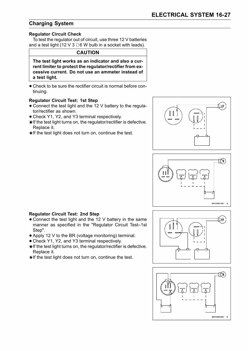
ELECTRICAL SYSTEM 16-27
Charging System
Regulator Circuit CheckTo test the regulator out of circuit, use three 12 V batteries
and a test light (12 V 3 ∼ 6 W bulb in a socket with leads).
CAUTION
The test light works as an indicator and also a cur-rent limiter to protect the regulator/rectifier from ex-cessive current. Do not use an ammeter instead ofa test light.
•Check to be sure the rectifier circuit is normal before con-tinuing.
Regulator Circuit Test: 1st Step
•Connect the test light and the 12 V battery to the regula-tor/rectifier as shown.
•Check Y1, Y2, and Y3 terminal respectively.If the test light turns on, the regulator/rectifier is defective.Replace it.If the test light does not turn on, continue the test.
Regulator Circuit Test: 2nd Step
•Connect the test light and the 12 V battery in the samemanner as specified in the "Regulator Circuit Test–1stStep".
• Apply 12 V to the BR (voltage monitoring) terminal.• Check Y1, Y2, and Y3 terminal respectively.If the test light turns on, the regulator/rectifier is defective.Replace it.If the test light does not turn on, continue the test.

16-28 ELECTRICAL SYSTEM
Charging System
Regulator Circuit Test: 3rd Step
•Connect the test light and the 12 V battery in the samemanner as specified in the "Regulator Circuit Test–1stStep".
•Momentarily apply 24 V to the BR terminal by adding a 12V battery.
•Check Y1, Y2, and Y3 terminals respectively.CAUTION
Do not apply more than 24 V to the regulator/recti-fier and do not leave the 24 V applied for more thana few seconds, or the unit will be damaged.
If the test light did not light when the 24 V was appliedmomentarily to the BR terminal, the regulator/rectifier isdefective. Replace it.If the regulator/rectifier passes all of the tests described,it may still be defective. If the charging system still doesnot work properly after checking all of the componentsand the battery, test the regulator/rectifier by replacing itwith a known good unit.
Regulator/Rectifier Output Voltage InspectionZX1200-B1/B2
•Check the battery condition (see Battery section).•Remove the seat cover (see Frame chapter).•Warm up the engine to obtain actual alternator operatingconditions.
• Turn off the ignition switch, and connect the lead wire-voltage regulator adapter [A] between the regulator/rec-tifier lead 5 pins connectors [B] as shown in the figure.
•Connect the hand tester to the connector [C] of theadapter as shown in the table.
• Start the engine, and note the voltage readings at vari-ous engine speeds with the headlight turned on and thenturned off. (To turn off the headlight of U.S.A., Canadian,Australian and Malaysian models, disconnect the head-light connector in the upper fairing.) The readings shouldshow nearly battery voltage when the engine speed is low,and as the engine speed rises, the readings should alsorise. But they must be kept under the specified voltage.
Regulator/Rectifier Output Voltage
ConnectionsTester Range
Tester (+) to Tester (–) toReading
25 V DC White/Red Black 14.2 ∼ 15.2 V
Special Tools - Hand Tester: 57001-1394Lead Wire - Voltage Regulator Adapter:57001-1448
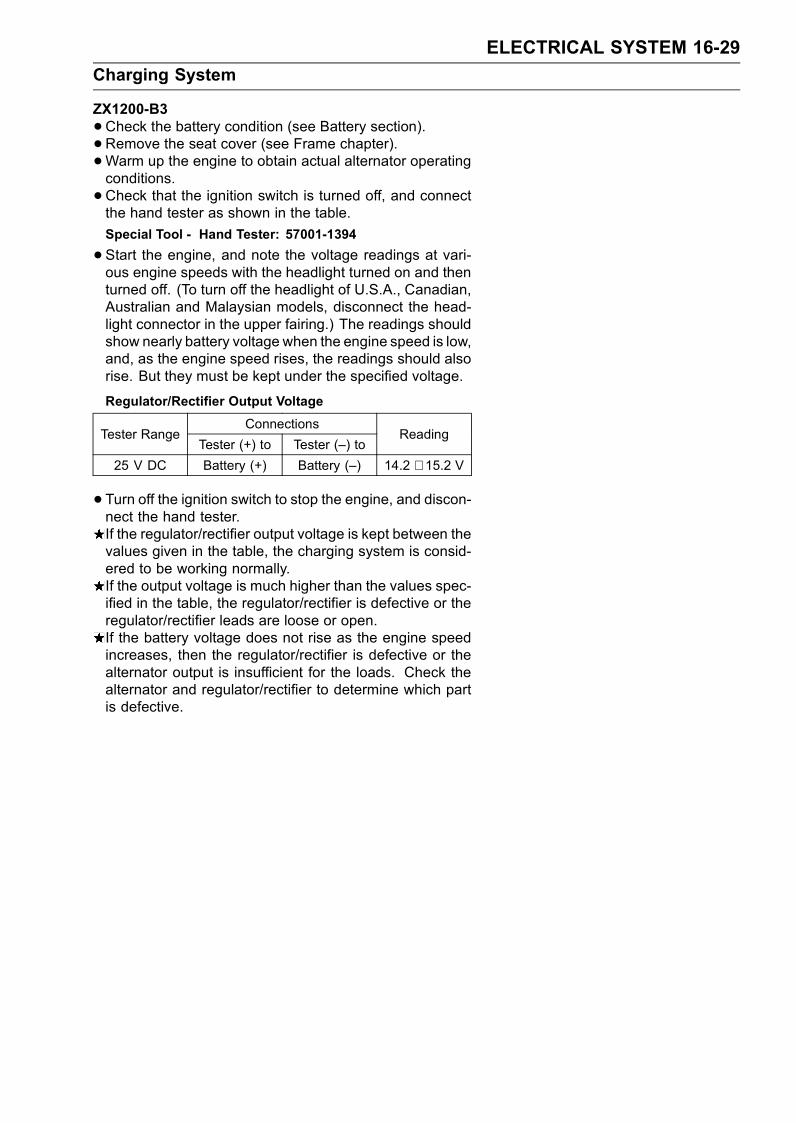
ELECTRICAL SYSTEM 16-29
Charging System
ZX1200-B3
•Check the battery condition (see Battery section).•Remove the seat cover (see Frame chapter).•Warm up the engine to obtain actual alternator operatingconditions.
•Check that the ignition switch is turned off, and connectthe hand tester as shown in the table.
Special Tool - Hand Tester: 57001-1394
•Start the engine, and note the voltage readings at vari-ous engine speeds with the headlight turned on and thenturned off. (To turn off the headlight of U.S.A., Canadian,Australian and Malaysian models, disconnect the head-light connector in the upper fairing.) The readings shouldshow nearly battery voltage when the engine speed is low,and, as the engine speed rises, the readings should alsorise. But they must be kept under the specified voltage.
Regulator/Rectifier Output Voltage
ConnectionsTester Range
Tester (+) to Tester (–) toReading
25 V DC Battery (+) Battery (–) 14.2 ∼ 15.2 V
• Turn off the ignition switch to stop the engine, and discon-nect the hand tester.If the regulator/rectifier output voltage is kept between thevalues given in the table, the charging system is consid-ered to be working normally.If the output voltage is much higher than the values spec-ified in the table, the regulator/rectifier is defective or theregulator/rectifier leads are loose or open.If the battery voltage does not rise as the engine speedincreases, then the regulator/rectifier is defective or thealternator output is insufficient for the loads. Check thealternator and regulator/rectifier to determine which partis defective.
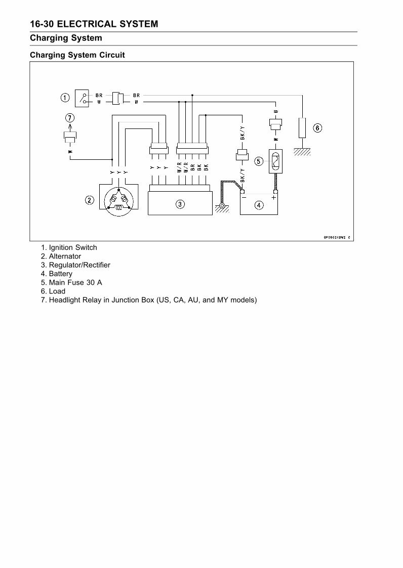
16-30 ELECTRICAL SYSTEM
Charging System
Charging System Circuit
1. Ignition Switch2. Alternator3. Regulator/Rectifier4. Battery5. Main Fuse 30 A6. Load7. Headlight Relay in Junction Box (US, CA, AU, and MY models)

ELECTRICAL SYSTEM 16-31
Ignition System
WARNINGThe ignition system produces extremely high volt-age. Do not touch the spark plugs or stick coilswhile the engine is running, or you could receivea severe electrical shock.
CAUTION
Do not disconnect the battery cables or any otherelectrical connections when the ignition switch ison, or while the engine is running. This is to preventECU (Electronic Control Unit) damage.Do not install the battery backwards. The negativeside is grounded. This is to prevent damage to thediodes and ECU.
Crankshaft Sensor Removal
•Remove:Left Lower Fairing (see Frame chapter)Crankshaft Sensor Lead Connector [A]Hot Wind Cover (see Frame chapter)
Pull the connector forward.
•Remove:Crankshaft Sensor Cover Bolts [A] with Clamp [B]Crankshaft Sensor Cover [C]
•Remove:Crankshaft Sensor Bolts [A]Crankshaft Sensor [B]
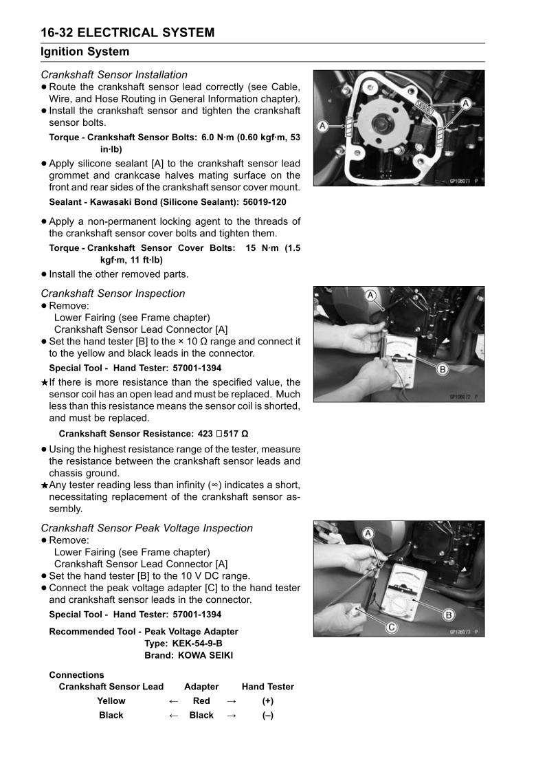
16-32 ELECTRICAL SYSTEM
Ignition System
Crankshaft Sensor Installation
•Route the crankshaft sensor lead correctly (see Cable,Wire, and Hose Routing in General Information chapter).
• Install the crankshaft sensor and tighten the crankshaftsensor bolts.
Torque - Crankshaft Sensor Bolts: 6.0 N·m (0.60 kgf·m, 53in·lb)
•Apply silicone sealant [A] to the crankshaft sensor leadgrommet and crankcase halves mating surface on thefront and rear sides of the crankshaft sensor cover mount.
Sealant - Kawasaki Bond (Silicone Sealant): 56019-120
•Apply a non-permanent locking agent to the threads ofthe crankshaft sensor cover bolts and tighten them.
Torque - Crankshaft Sensor Cover Bolts: 15 N·m (1.5kgf·m, 11 ft·lb)
• Install the other removed parts.Crankshaft Sensor Inspection
•Remove:Lower Fairing (see Frame chapter)Crankshaft Sensor Lead Connector [A]
• Set the hand tester [B] to the × 10 Ω range and connect itto the yellow and black leads in the connector.
Special Tool - Hand Tester: 57001-1394
If there is more resistance than the specified value, thesensor coil has an open lead andmust be replaced. Muchless than this resistance means the sensor coil is shorted,and must be replaced.
Crankshaft Sensor Resistance: 423 ∼ 517 Ω
•Using the highest resistance range of the tester, measurethe resistance between the crankshaft sensor leads andchassis ground.Any tester reading less than infinity (∞) indicates a short,necessitating replacement of the crankshaft sensor as-sembly.
Crankshaft Sensor Peak Voltage Inspection
•Remove:Lower Fairing (see Frame chapter)Crankshaft Sensor Lead Connector [A]
• Set the hand tester [B] to the 10 V DC range.•Connect the peak voltage adapter [C] to the hand testerand crankshaft sensor leads in the connector.
Special Tool - Hand Tester: 57001-1394
Recommended Tool - Peak Voltage AdapterType: KEK-54-9-BBrand: KOWA SEIKI
ConnectionsCrankshaft Sensor Lead Adapter Hand Tester
Yellow ← Red → (+)
Black ← Black → (–)
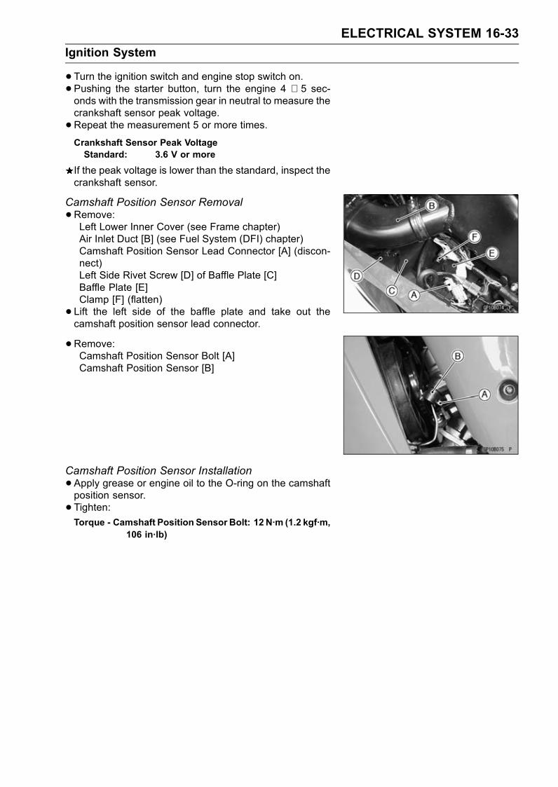
ELECTRICAL SYSTEM 16-33
Ignition System
•Turn the ignition switch and engine stop switch on.• Pushing the starter button, turn the engine 4 ∼ 5 sec-onds with the transmission gear in neutral to measure thecrankshaft sensor peak voltage.
•Repeat the measurement 5 or more times.Crankshaft Sensor Peak VoltageStandard: 3.6 V or more
If the peak voltage is lower than the standard, inspect thecrankshaft sensor.
Camshaft Position Sensor Removal
•Remove:Left Lower Inner Cover (see Frame chapter)Air Inlet Duct [B] (see Fuel System (DFI) chapter)Camshaft Position Sensor Lead Connector [A] (discon-nect)Left Side Rivet Screw [D] of Baffle Plate [C]Baffle Plate [E]Clamp [F] (flatten)
• Lift the left side of the baffle plate and take out thecamshaft position sensor lead connector.
•Remove:Camshaft Position Sensor Bolt [A]Camshaft Position Sensor [B]
Camshaft Position Sensor Installation
•Apply grease or engine oil to the O-ring on the camshaftposition sensor.
• Tighten:Torque - Camshaft Position Sensor Bolt: 12 N·m (1.2 kgf·m,
106 in·lb)
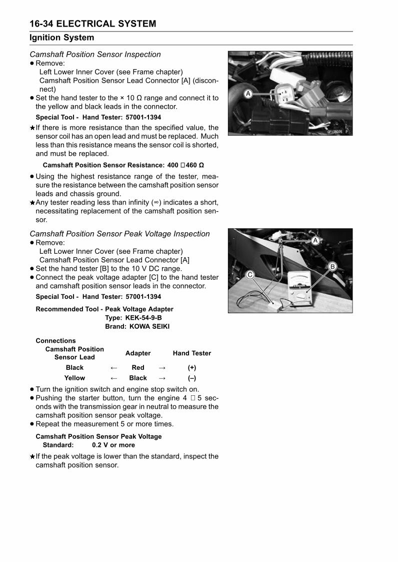
16-34 ELECTRICAL SYSTEM
Ignition System
Camshaft Position Sensor Inspection
•Remove:Left Lower Inner Cover (see Frame chapter)Camshaft Position Sensor Lead Connector [A] (discon-nect)
• Set the hand tester to the × 10 Ω range and connect it tothe yellow and black leads in the connector.
Special Tool - Hand Tester: 57001-1394
If there is more resistance than the specified value, thesensor coil has an open lead andmust be replaced. Muchless than this resistance means the sensor coil is shorted,and must be replaced.
Camshaft Position Sensor Resistance: 400 ∼ 460 Ω
•Using the highest resistance range of the tester, mea-sure the resistance between the camshaft position sensorleads and chassis ground.Any tester reading less than infinity (∞) indicates a short,necessitating replacement of the camshaft position sen-sor.
Camshaft Position Sensor Peak Voltage Inspection
•Remove:Left Lower Inner Cover (see Frame chapter)Camshaft Position Sensor Lead Connector [A]
• Set the hand tester [B] to the 10 V DC range.•Connect the peak voltage adapter [C] to the hand testerand camshaft position sensor leads in the connector.
Special Tool - Hand Tester: 57001-1394
Recommended Tool - Peak Voltage AdapterType: KEK-54-9-BBrand: KOWA SEIKI
ConnectionsCamshaft PositionSensor Lead
Adapter Hand Tester
Black ← Red → (+)
Yellow ← Black → (–)
•Turn the ignition switch and engine stop switch on.• Pushing the starter button, turn the engine 4 ∼ 5 sec-onds with the transmission gear in neutral to measure thecamshaft position sensor peak voltage.
•Repeat the measurement 5 or more times.Camshaft Position Sensor Peak VoltageStandard: 0.2 V or more
If the peak voltage is lower than the standard, inspect thecamshaft position sensor.

ELECTRICAL SYSTEM 16-35
Ignition System
Stick Coil (Ignition Coil together with Spark Plug Cap)Removal
•Remove:Inner Lower Covers (see Frame chapter)Baffle Plate
•Disconnect the stick coil connectors [B].• Pull the stick coils [A] off the spark plugs.
CAUTION
Do not pry the connector part of the coil while re-moving the coil.
Stick Coil (Ignition Coil together with Spark Plug Cap)Installation
• Install the coil with following steps.Connect the connector.Insert the coil as shown being careful of the coil headdirection.Be sure the stick coils are installed securely by pulling upit lightly.
CAUTION
Do not tap the coil head while installing the coil.
Stick Coil (Ignition Coil together with Spark Plug Cap)Inspection
•Remove the stick coils (see Stick Coil Removal).•Measure the primary winding resistance [A] as follows.Connect the hand tester between the coil terminals.Set the tester to the × 1 Ω range, and read the tester.•Measure the secondary winding resistance [B] as follows.Connect the tester between the plug terminal and (–) coilterminal.Set the tester to the × 1 kΩ range and read the tester.Stick Coil Winding ResistancePrimary Windings:
ZX1200-B1/B2 0.85 ∼ 1.15 ΩZX1200-B3 1.04 ∼ 1.56 Ω
Secondary Windings:
ZX1200-B1/B2 9.2 ∼ 13.8 kΩZX1200-B3 10.8 ∼ 16.2 kΩ
If the tester does not read as specified, replace the coil.

16-36 ELECTRICAL SYSTEM
Ignition System
Stick Coil Primary Peak Voltage Inspection
NOTEBe sure the battery is fully charged.•Remove the stick coils (see Stick Coil Removal), but donot remove the spark plugs.
•Measure the primary peak voltage as follows.Disconnect the stick coil connector, and connect the leadwire-peak voltage adapter [A] between the stick coil con-nector and stick coil.Connect a commercially peak voltage adapter [B] be-tween the lead wire-peak voltage adapter and the handtester [C] which is set to the 250 V DC range.Install the new spark plug [D] into each stick coil [E], andground them onto the engine.ECU [F]Battery [G]
Recommended Tool - Peak Voltage AdapterType: KEK-54-9-BBrand: KOWA SEIKI
Special Tools - Hand Tester: 57001-1394Lead Wire-Peak Voltage Adapter: 57001-1449
Primary Lead ConnectionAdapter (R, +) to lead wire-peak voltage adapter (W)
Adapter (BK, –) to lead wire-peak voltage adapter (R)
WARNINGTo avoid extremely high voltage shocks, do nottouch the spark plugs or tester connections.
•Turn the ignition switch and the engine stop switch ON.•Pushing the starter button, turn the engine 4 ∼ 5 secondswith the transmission in neutral to measure the primarypeak voltage.
•Repeat the measurements 5 times for one stick coil.Stick Coil Primary Peak VoltageStandard:
ZX1200-B1/B2: 80 V or more
ZX1200-B3: 88 V or more
•Repeat the test for the other stick coil.If the reading is less than the specified value, check thefollowing.Stick Coils (see Stick Coil Inspection)Crankshaft Sensor (see Crankshaft Sensor Inspection)If the stick coils and crankshaft sensor are normal, checkthe ECU (see Fuel System (DFI) chapter).
Spark Plug Removal
•Remove:Stick Coils (see Stick Coil Removal)
•Remove the spark plugs with the 16 mm plug wrench.Owner’s Tool - Spark Plug Wrench, 16 mm: 92110-1132
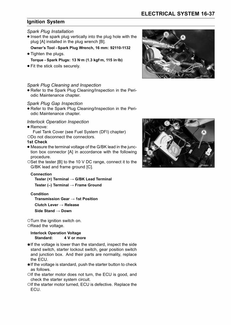
ELECTRICAL SYSTEM 16-37
Ignition System
Spark Plug Installation
• Insert the spark plug vertically into the plug hole with theplug [A] installed in the plug wrench [B].
Owner’s Tool - Spark Plug Wrench, 16 mm: 92110-1132
•Tighten the plugs.Torque - Spark Plugs: 13 N·m (1.3 kgf·m, 115 in·lb)
•Fit the stick coils securely.
Spark Plug Cleaning and Inspection
•Refer to the Spark Plug Cleaning/Inspection in the Peri-odic Maintenance chapter.
Spark Plug Gap Inspection
•Refer to the Spark Plug Cleaning/Inspection in the Peri-odic Maintenance chapter.
Interlock Operation Inspection
•Remove:Fuel Tank Cover (see Fuel System (DFI) chapter)
Do not disconnect the connectors.1st Check
•Measure the terminal voltage of the G/BK lead in the junc-tion box connector [A] in accordance with the followingprocedure.Set the tester [B] to the 10 V DC range, connect it to theG/BK lead and frame ground [C].
ConnectionTester (+) Terminal → G/BK Lead Terminal
Tester (–) Terminal → Frame Ground
ConditionTransmission Gear → 1st Position
Clutch Lever → Release
Side Stand → Down
Turn the ignition switch on.Read the voltage.Interlock Operation VoltageStandard: 4 V or more
If the voltage is lower than the standard, inspect the sidestand switch, starter lockout switch, gear position switchand junction box. And their parts are normality, replacethe ECU.If the voltage is standard, push the starter button to checkas follows.If the starter motor does not turn, the ECU is good, andcheck the starter system circuit.If the starter motor turned, ECU is defective. Replace theECU.

16-38 ELECTRICAL SYSTEM
Ignition System
2nd CheckRaise the rear wheel off the ground with a stand.
• Inspect the engine for its secure stop after the followingoperations are completed.
•Run the engine to the following conditions.ConditionTransmission Gear→ 1st Position
Clutch Lever → Pull in
Side Stand → Up or Down
•Gradually release the clutch lever, then the engine willstop.
•Run the engine to the following conditions.ConditionTransmission Gear→ 1st Position
Clutch Lever → Release
Side Stand → Up
•Set the side stand on the ground, then the engine willstop.If whichever may not be stopped, inspect the gear posi-tion switch, starter lockout switch, side stand switch andjunction box.If their parts are normality, replace the ECU.
IC Igniter InspectionThe IC igniter is built in the ECU [A].•Refer to the Interlock Operation Inspection, Ignition Sys-tem Troubleshooting chart and Fuel System (DFI) chapterfor ECU Inspection.

ELECTRICAL SYSTEM 16-39
Ignition System
Ignition System Inspection
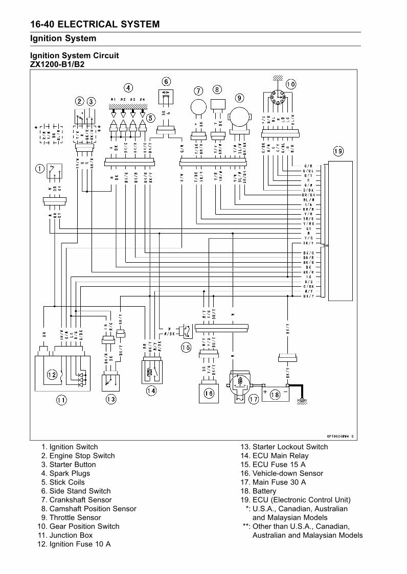
16-40 ELECTRICAL SYSTEM
Ignition System
Ignition System CircuitZX1200-B1/B2
1. Ignition Switch2. Engine Stop Switch3. Starter Button4. Spark Plugs5. Stick Coils6. Side Stand Switch7. Crankshaft Sensor8. Camshaft Position Sensor9. Throttle Sensor10. Gear Position Switch11. Junction Box12. Ignition Fuse 10 A
13. Starter Lockout Switch14. ECU Main Relay15. ECU Fuse 15 A16. Vehicle-down Sensor17. Main Fuse 30 A18. Battery19. ECU (Electronic Control Unit)*: U.S.A., Canadian, Australianand Malaysian Models
**: Other than U.S.A., Canadian,Australian and Malaysian Models
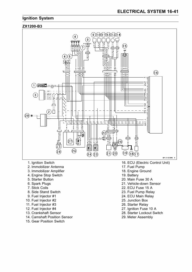
ELECTRICAL SYSTEM 16-41
Ignition System
ZX1200-B3
1. Ignition Switch2. Immobilizer Antenna3. Immobilizer Amplifier4. Engine Stop Switch5. Starter Button6. Spark Plugs7. Stick Coils8. Side Stand Switch9. Fuel Injector #110. Fuel Injector #211. Fuel Injector #312. Fuel Injector #413. Crankshaft Sensor14. Camshaft Position Sensor15. Gear Position Switch
16. ECU (Electric Control Unit)17. Fuel Pump18. Engine Ground19. Battery20. Main Fuse 30 A21. Vehicle-down Sensor22. ECU Fuse 15 A23. Fuel Pump Relay24. ECU Main Relay25. Junction Box26. Starter Relay27. Ignition Fuse 10 A28. Starter Lockout Switch29. Meter Assembly

16-42 ELECTRICAL SYSTEM
Electric Starter System
Starter Motor Removal
•Remove:Battery Compartment Cover (see Battery Removal)Terminal Nut [A]Starter Motor Cable [B]
•Remove:Lower Fairing (see Frame chapter)Coolant Reserve TankStarter Motor Mounting Bolts [A]
• Pull out the starter motor [A].• Remove:Terminal Nut [B]Starter Motor Cable [C]
Starter Motor Installation
CAUTION
Do not tap the starter motor shaft or body. Tappingthe shaft or body could damage the motor.
•When installing the starter motor, clean the starter mo-tor legs [A] and crankcase [B] where the starter motor isgrounded.
• Apply small amount of engine oil or grease to the O-ring[A].
• Install the starter motor and tighten the mounting bolts.Torque - Starter Motor Mounting Bolts: 12 N·m (1.2 kgf·m,
106 in·lb)
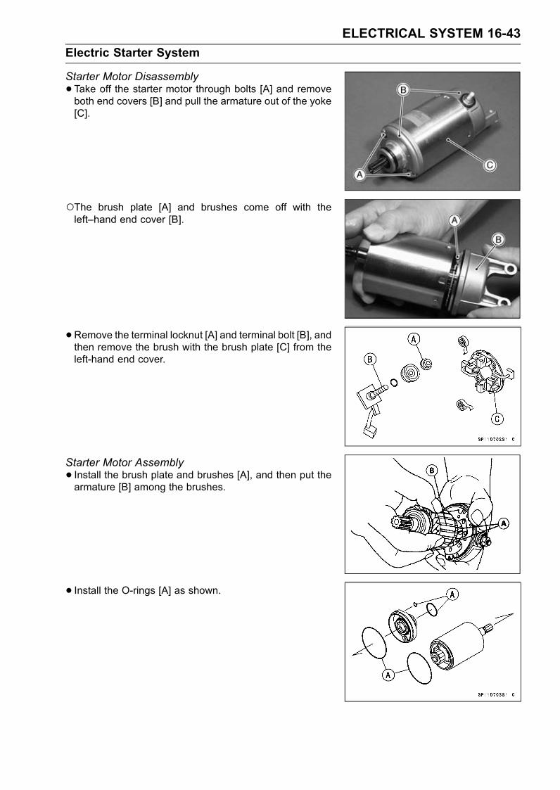
ELECTRICAL SYSTEM 16-43
Electric Starter System
Starter Motor Disassembly
•Take off the starter motor through bolts [A] and removeboth end covers [B] and pull the armature out of the yoke[C].
The brush plate [A] and brushes come off with theleft–hand end cover [B].
• Remove the terminal locknut [A] and terminal bolt [B], andthen remove the brush with the brush plate [C] from theleft-hand end cover.
Starter Motor Assembly
• Install the brush plate and brushes [A], and then put thearmature [B] among the brushes.
• Install the O-rings [A] as shown.
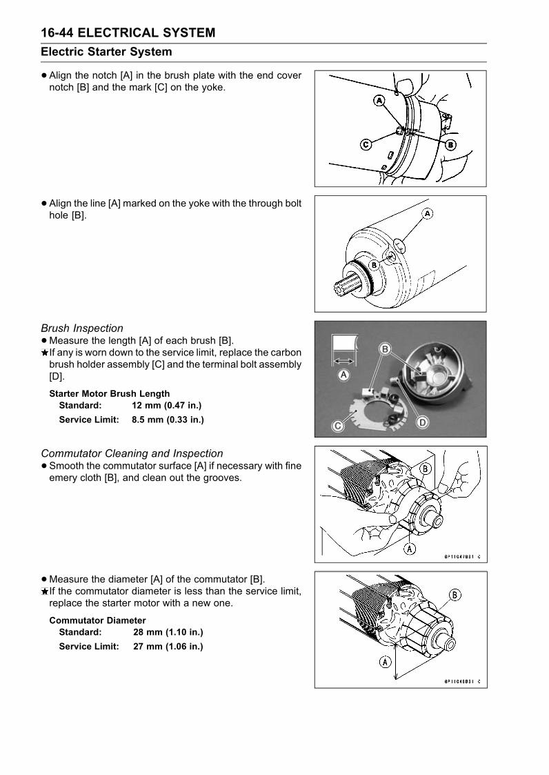
16-44 ELECTRICAL SYSTEM
Electric Starter System
•Align the notch [A] in the brush plate with the end covernotch [B] and the mark [C] on the yoke.
• Align the line [A] marked on the yoke with the through bolthole [B].
Brush Inspection
•Measure the length [A] of each brush [B].If any is worn down to the service limit, replace the carbonbrush holder assembly [C] and the terminal bolt assembly[D].
Starter Motor Brush LengthStandard: 12 mm (0.47 in.)
Service Limit: 8.5 mm (0.33 in.)
Commutator Cleaning and Inspection
•Smooth the commutator surface [A] if necessary with fineemery cloth [B], and clean out the grooves.
•Measure the diameter [A] of the commutator [B].If the commutator diameter is less than the service limit,replace the starter motor with a new one.
Commutator DiameterStandard: 28 mm (1.10 in.)
Service Limit: 27 mm (1.06 in.)

ELECTRICAL SYSTEM 16-45
Electric Starter System
Armature Inspection
•Using the × 1 Ω hand tester range, measure the resis-tance between any two commutator segments [A].If there is a high resistance or no reading (∞) between anytwo segments, a winding is open and the starter motormust be replaced.
•Using the highest hand tester range, measure the resis-tance between the segments and the shaft [B].If there is any reading at all, the armature has a short andthe starter motor must be replaced.
NOTEEven if the foregoing checks show the armature to begood, it may be defective in some manner not readilydetectable with the hand tester. If all other starter motorand starter motor circuit components check good, butthe starter motor still does not turn over or only turnsover weakly, replace the starter motor with a new one.
Brush Lead Inspection
•Using the × 1 Ω hand tester range, measure the resis-tance as shown.Terminal Bolt and Positive Brush [A]Brush Plate and Negative Brush [B]If there is not close to zero ohms, the brush lead hasan open. Replace the terminal bolt assembly and/or thebrush holder assembly.
Brush Plate and Terminal Bolt Inspection
•Using the highest hand tester range, measure the resis-tance as shown.Terminal Bolt and Brush Plate [A]Terminal Bolt and Left–hand End Cover [B]If there is any reading, the brush holder assembly and/orterminal bolt assembly have a short. Replace the brushholder assembly and the terminal bolt assembly.
Starter Relay Inspection
•Remove:Battery Tray (see Battery Removal)Screw [A]Cover [B]

16-46 ELECTRICAL SYSTEM
Electric Starter System
•Remove:Starter Cable [A]Battery Cable [B] (disconnect)Connector [C]Starter Relay [D]
•Connect the hand tester [A] and 12 V battery [B] to thestarter relay [C] as shown.If the relay does not work as specified, the relay is defec-tive. Replace the relay.
Testing RelayTester Range: × 1 Ω range
Criteria: When battery is connected→ 0 ΩWhen battery is disconnected→ ∞ Ω
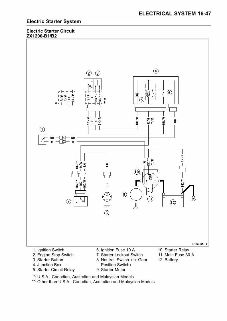
ELECTRICAL SYSTEM 16-47
Electric Starter System
Electric Starter CircuitZX1200-B1/B2
1. Ignition Switch2. Engine Stop Switch3. Starter Button4. Junction Box5. Starter Circuit Relay
6. Ignition Fuse 10 A7. Starter Lockout Switch8. Neutral Switch (in GearPosition Switch)
9. Starter Motor
10. Starter Relay11. Main Fuse 30 A12. Battery
*: U.S.A., Canadian, Australian and Malaysian Models**: Other than U.S.A., Canadian, Australian and Malaysian Models
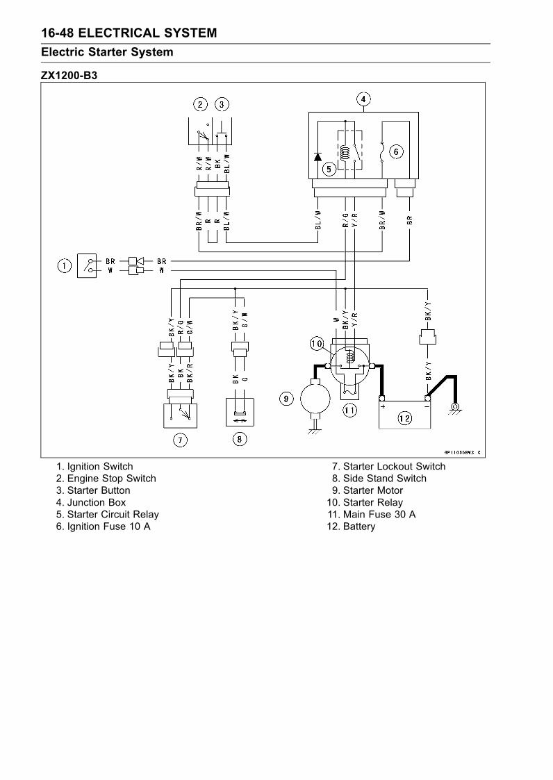
16-48 ELECTRICAL SYSTEM
Electric Starter System
ZX1200-B3
1. Ignition Switch2. Engine Stop Switch3. Starter Button4. Junction Box5. Starter Circuit Relay6. Ignition Fuse 10 A
7. Starter Lockout Switch8. Side Stand Switch9. Starter Motor10. Starter Relay11. Main Fuse 30 A12. Battery
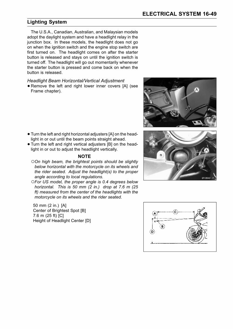
ELECTRICAL SYSTEM 16-49
Lighting System
The U.S.A., Canadian, Australian, and Malaysian modelsadopt the daylight system and have a headlight relay in thejunction box. In these models, the headlight does not goon when the ignition switch and the engine stop switch arefirst turned on. The headlight comes on after the starterbutton is released and stays on until the ignition switch isturned off. The headlight will go out momentarily wheneverthe starter button is pressed and come back on when thebutton is released.
Headlight Beam Horizontal/Vertical Adjustment
•Remove the left and right lower inner covers [A] (seeFrame chapter).
• Turn the left and right horizontal adjusters [A] on the head-light in or out until the beam points straight ahead.
• Turn the left and right vertical adjusters [B] on the head-light in or out to adjust the headlight vertically.
NOTEOn high beam, the brightest points should be slightlybelow horizontal with the motorcycle on its wheels andthe rider seated. Adjust the headlight(s) to the properangle according to local regulations.For US model, the proper angle is 0.4 degrees belowhorizontal. This is 50 mm (2 in.) drop at 7.6 m (25ft) measured from the center of the headlights with themotorcycle on its wheels and the rider seated.
50 mm (2 in.) [A]Center of Brightest Spot [B]7.6 m (25 ft) [C]Height of Headlight Center [D]

16-50 ELECTRICAL SYSTEM
Lighting System
Headlight Bulbs (Left and Right) Replacement
•Remove:Left and Right Lower Inner CoversHeadlight ConnectorsHeadlight Bulb Dust CoversHooks [A]Headlight Bulbs [B]
CAUTION
When handling the quartz–halogen bulb, nevertouch the glass portion with bare hands. Alwaysuse a clean cloth. Oil contamination from hands ordirty rags can reduce bulb life or cause the bulb toexplode.
•Replace the headlight bulbs.• Fit the dust cover [A] with the Top mark [B] upward ontothe bulb [C] firmly as shown.
• After installation, adjust the headlight aim (see HeadlightBeam Adjustment).
City Light Bulb Replacement
•Remove:Wind Shield (see Frame chapter)
• Turn the socket [A] counterclockwise, and remove thesocket and bulb.
• Pull the bulb [A] out of the socket.CAUTION
Do not turn the bulb. Pull the bulb out to preventdamage to the bulb. Do not use bulb rated forgreater wattage than the specified value.
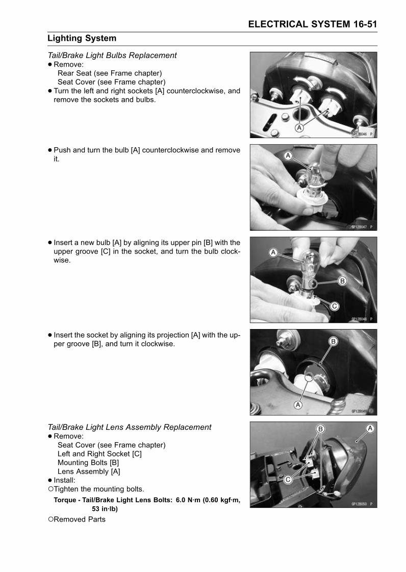
ELECTRICAL SYSTEM 16-51
Lighting System
Tail/Brake Light Bulbs Replacement
•Remove:Rear Seat (see Frame chapter)Seat Cover (see Frame chapter)
• Turn the left and right sockets [A] counterclockwise, andremove the sockets and bulbs.
• Push and turn the bulb [A] counterclockwise and removeit.
• Insert a new bulb [A] by aligning its upper pin [B] with theupper groove [C] in the socket, and turn the bulb clock-wise.
• Insert the socket by aligning its projection [A] with the up-per groove [B], and turn it clockwise.
Tail/Brake Light Lens Assembly Replacement
•Remove:Seat Cover (see Frame chapter)Left and Right Socket [C]Mounting Bolts [B]Lens Assembly [A]
• Install:Tighten the mounting bolts.Torque - Tail/Brake Light Lens Bolts: 6.0 N·m (0.60 kgf·m,
53 in·lb)
Removed Parts
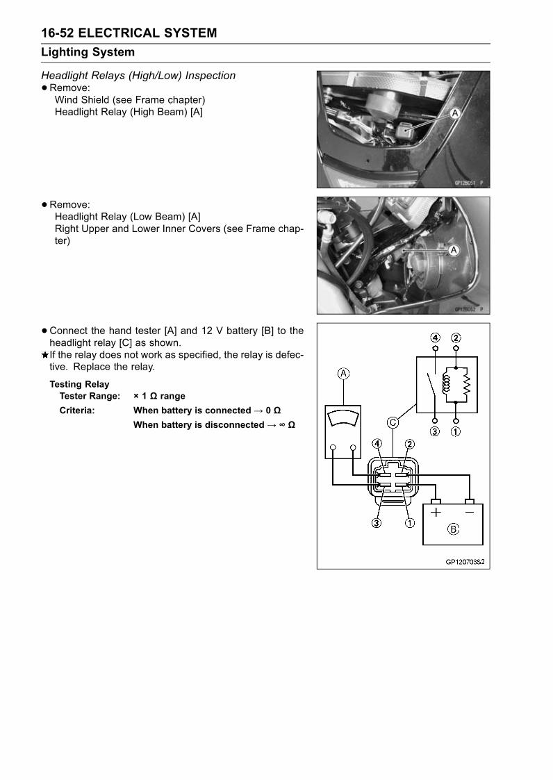
16-52 ELECTRICAL SYSTEM
Lighting System
Headlight Relays (High/Low) Inspection
•Remove:Wind Shield (see Frame chapter)Headlight Relay (High Beam) [A]
•Remove:Headlight Relay (Low Beam) [A]Right Upper and Lower Inner Covers (see Frame chap-ter)
•Connect the hand tester [A] and 12 V battery [B] to theheadlight relay [C] as shown.If the relay does not work as specified, the relay is defec-tive. Replace the relay.
Testing RelayTester Range: × 1 Ω range
Criteria: When battery is connected→ 0 ΩWhen battery is disconnected→ ∞ Ω
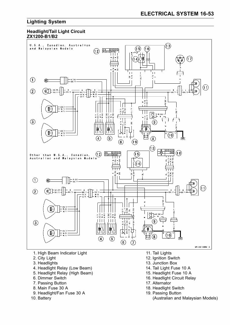
ELECTRICAL SYSTEM 16-53
Lighting System
Headlight/Tail Light CircuitZX1200-B1/B2
1. High Beam Indicator Light2. City Light3. Headlights4. Headlight Relay (Low Beam)5. Headlight Relay (High Beam)6. Dimmer Switch7. Passing Button8. Main Fuse 30 A9. Headlight/Fan Fuse 30 A10. Battery
11. Tail Lights12. Ignition Switch13. Junction Box14. Tail Light Fuse 10 A15. Headlight Fuse 10 A16. Headlight Circuit Relay17. Alternator18. Headlight Switch19. Passing Button
(Australian and Malaysian Models)
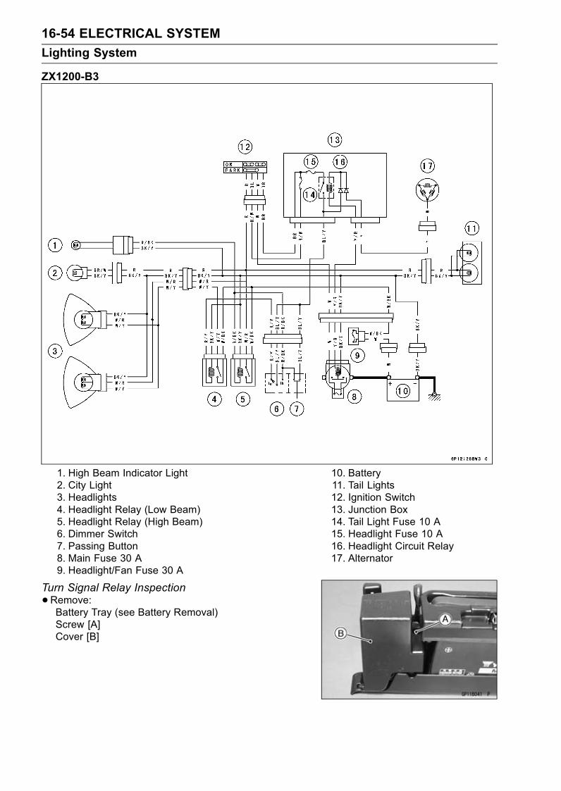
16-54 ELECTRICAL SYSTEM
Lighting System
ZX1200-B3
1. High Beam Indicator Light2. City Light3. Headlights4. Headlight Relay (Low Beam)5. Headlight Relay (High Beam)6. Dimmer Switch7. Passing Button8. Main Fuse 30 A9. Headlight/Fan Fuse 30 A
10. Battery11. Tail Lights12. Ignition Switch13. Junction Box14. Tail Light Fuse 10 A15. Headlight Fuse 10 A16. Headlight Circuit Relay17. Alternator
Turn Signal Relay Inspection
•Remove:Battery Tray (see Battery Removal)Screw [A]Cover [B]
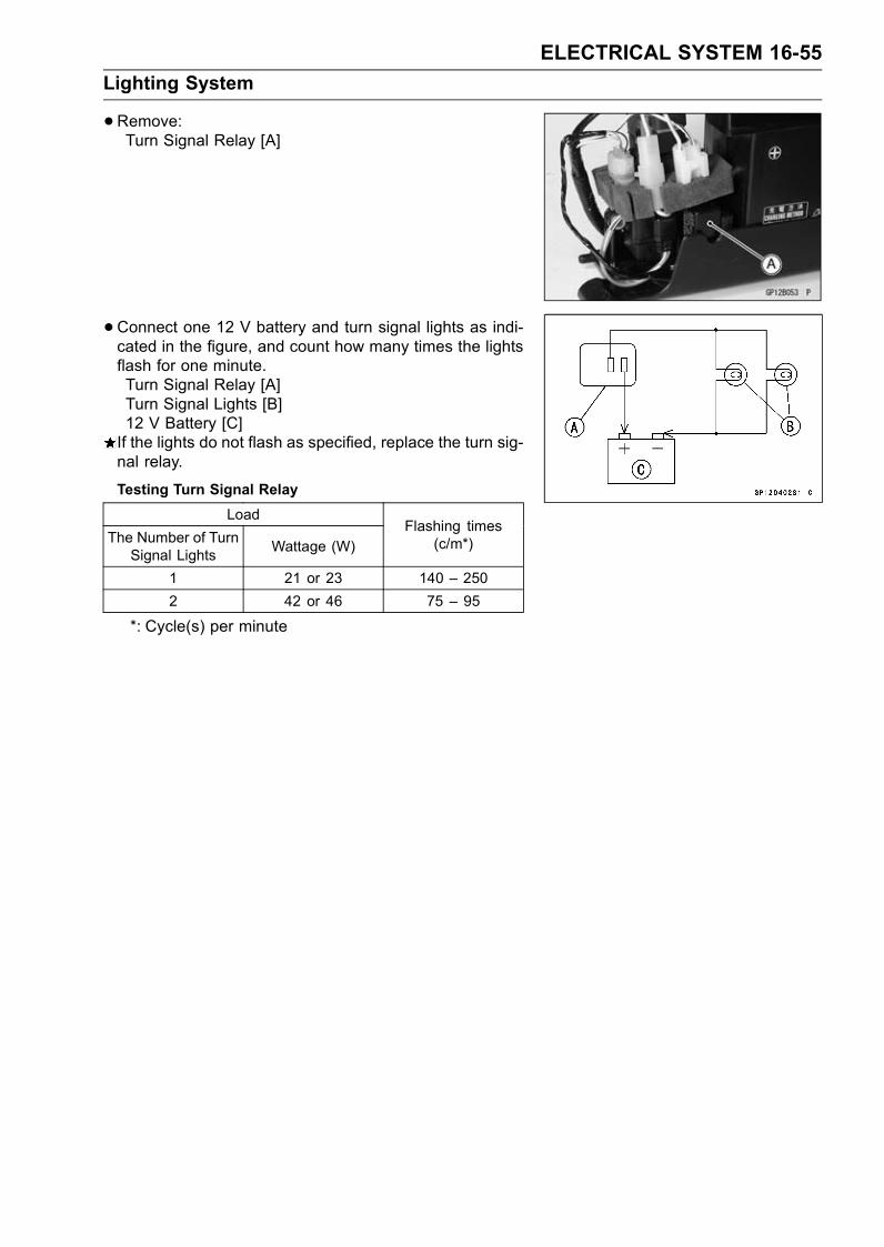
ELECTRICAL SYSTEM 16-55
Lighting System
•Remove:Turn Signal Relay [A]
•Connect one 12 V battery and turn signal lights as indi-cated in the figure, and count how many times the lightsflash for one minute.Turn Signal Relay [A]Turn Signal Lights [B]12 V Battery [C]If the lights do not flash as specified, replace the turn sig-nal relay.
Testing Turn Signal Relay
Load
The Number of TurnSignal Lights
Wattage (W)Flashing times
(c/m*)
1 21 or 23 140 – 250
2 42 or 46 75 – 95
*: Cycle(s) per minute
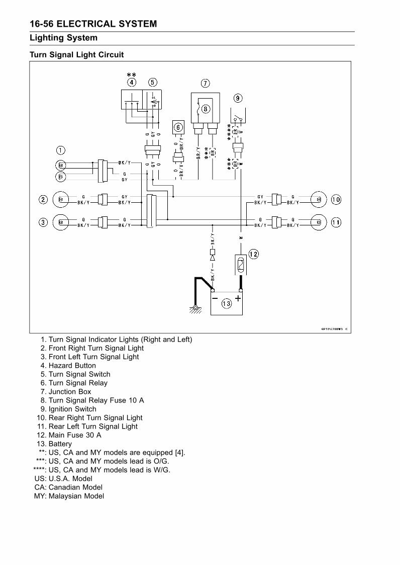
16-56 ELECTRICAL SYSTEM
Lighting System
Turn Signal Light Circuit
1. Turn Signal Indicator Lights (Right and Left)2. Front Right Turn Signal Light3. Front Left Turn Signal Light4. Hazard Button5. Turn Signal Switch6. Turn Signal Relay7. Junction Box8. Turn Signal Relay Fuse 10 A9. Ignition Switch10. Rear Right Turn Signal Light11. Rear Left Turn Signal Light12. Main Fuse 30 A13. Battery**: US, CA and MY models are equipped [4].***: US, CA and MY models lead is O/G.****: US, CA and MY models lead is W/G.US: U.S.A. ModelCA: Canadian ModelMY: Malaysian Model
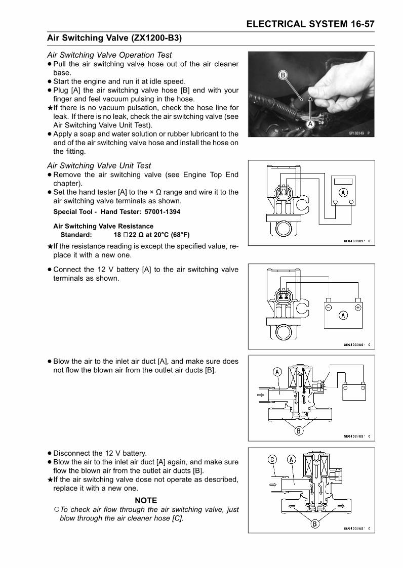
ELECTRICAL SYSTEM 16-57
Air Switching Valve (ZX1200-B3)
Air Switching Valve Operation Test
•Pull the air switching valve hose out of the air cleanerbase.
• Start the engine and run it at idle speed.• Plug [A] the air switching valve hose [B] end with yourfinger and feel vacuum pulsing in the hose.If there is no vacuum pulsation, check the hose line forleak. If there is no leak, check the air switching valve (seeAir Switching Valve Unit Test).
• Apply a soap and water solution or rubber lubricant to theend of the air switching valve hose and install the hose onthe fitting.
Air Switching Valve Unit Test
•Remove the air switching valve (see Engine Top Endchapter).
• Set the hand tester [A] to the × Ω range and wire it to theair switching valve terminals as shown.
Special Tool - Hand Tester: 57001-1394
Air Switching Valve ResistanceStandard: 18 ∼ 22 Ω at 20°C (68°F)
If the resistance reading is except the specified value, re-place it with a new one.
•Connect the 12 V battery [A] to the air switching valveterminals as shown.
• Blow the air to the inlet air duct [A], and make sure doesnot flow the blown air from the outlet air ducts [B].
• Disconnect the 12 V battery.• Blow the air to the inlet air duct [A] again, and make sureflow the blown air from the outlet air ducts [B].If the air switching valve dose not operate as described,replace it with a new one.
NOTETo check air flow through the air switching valve, justblow through the air cleaner hose [C].
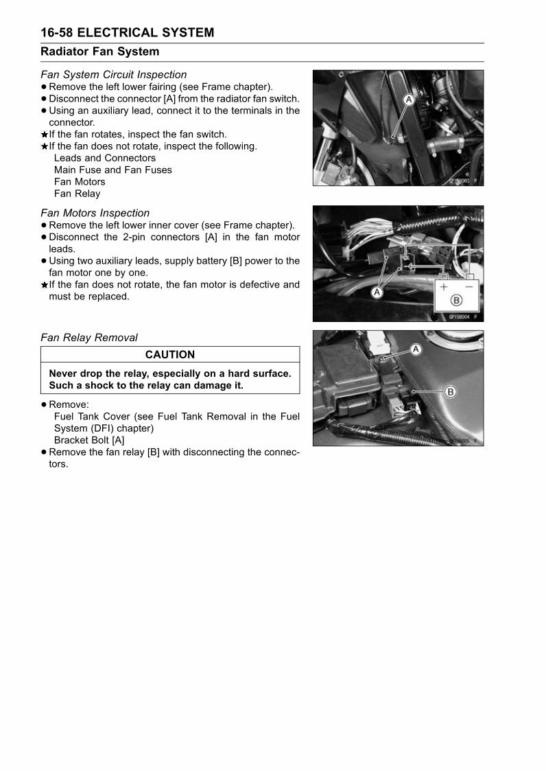
16-58 ELECTRICAL SYSTEM
Radiator Fan System
Fan System Circuit Inspection
•Remove the left lower fairing (see Frame chapter).• Disconnect the connector [A] from the radiator fan switch.•Using an auxiliary lead, connect it to the terminals in theconnector.If the fan rotates, inspect the fan switch.If the fan does not rotate, inspect the following.Leads and ConnectorsMain Fuse and Fan FusesFan MotorsFan Relay
Fan Motors Inspection
•Remove the left lower inner cover (see Frame chapter).• Disconnect the 2-pin connectors [A] in the fan motorleads.
•Using two auxiliary leads, supply battery [B] power to thefan motor one by one.If the fan does not rotate, the fan motor is defective andmust be replaced.
Fan Relay Removal
CAUTION
Never drop the relay, especially on a hard surface.Such a shock to the relay can damage it.
•Remove:Fuel Tank Cover (see Fuel Tank Removal in the FuelSystem (DFI) chapter)Bracket Bolt [A]
•Remove the fan relay [B] with disconnecting the connec-tors.
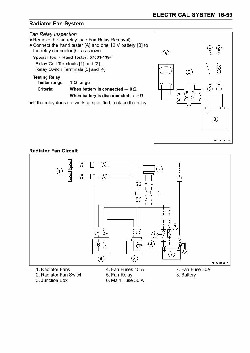
ELECTRICAL SYSTEM 16-59
Radiator Fan System
Fan Relay Inspection
•Remove the fan relay (see Fan Relay Removal).• Connect the hand tester [A] and one 12 V battery [B] tothe relay connector [C] as shown.
Special Tool - Hand Tester: 57001-1394
Relay Coil Terminals [1] and [2]Relay Switch Terminals [3] and [4]
Testing RelayTester range: 1 Ω range
Criteria: When battery is connected→ 0 ΩWhen battery is disconnected→ ∞ Ω
If the relay does not work as specified, replace the relay.
Radiator Fan Circuit
1. Radiator Fans2. Radiator Fan Switch3. Junction Box
4. Fan Fuses 15 A5. Fan Relay6. Main Fuse 30 A
7. Fan Fuse 30A8. Battery
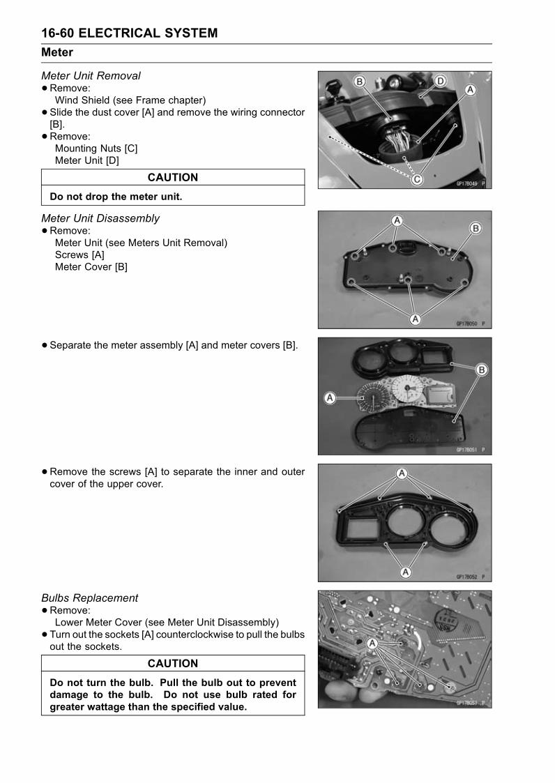
16-60 ELECTRICAL SYSTEM
Meter
Meter Unit Removal
•Remove:Wind Shield (see Frame chapter)
• Slide the dust cover [A] and remove the wiring connector[B].
• Remove:Mounting Nuts [C]Meter Unit [D]
CAUTION
Do not drop the meter unit.
Meter Unit Disassembly
•Remove:Meter Unit (see Meters Unit Removal)Screws [A]Meter Cover [B]
• Separate the meter assembly [A] and meter covers [B].
•Remove the screws [A] to separate the inner and outercover of the upper cover.
Bulbs Replacement
•Remove:Lower Meter Cover (see Meter Unit Disassembly)
• Turn out the sockets [A] counterclockwise to pull the bulbsout the sockets.
CAUTION
Do not turn the bulb. Pull the bulb out to preventdamage to the bulb. Do not use bulb rated forgreater wattage than the specified value.
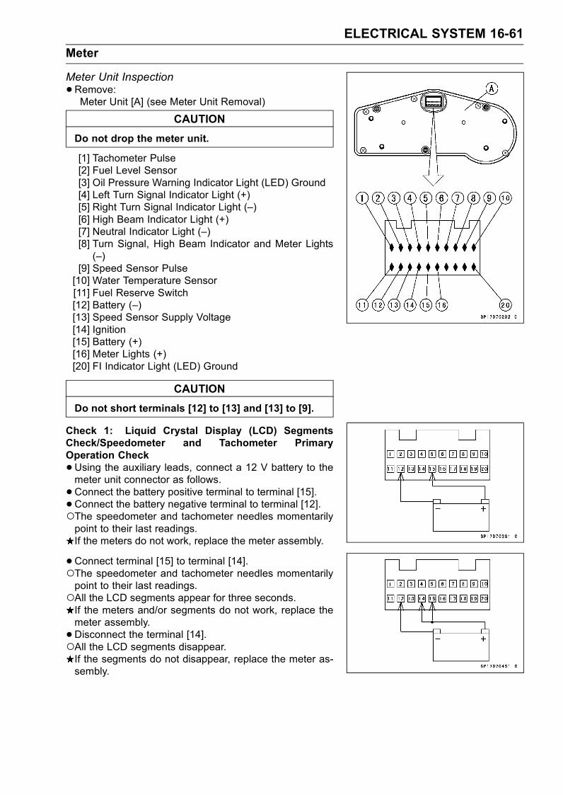
ELECTRICAL SYSTEM 16-61
Meter
Meter Unit Inspection
•Remove:Meter Unit [A] (see Meter Unit Removal)
CAUTION
Do not drop the meter unit.
[1] Tachometer Pulse[2] Fuel Level Sensor[3] Oil Pressure Warning Indicator Light (LED) Ground[4] Left Turn Signal Indicator Light (+)[5] Right Turn Signal Indicator Light (–)[6] High Beam Indicator Light (+)[7] Neutral Indicator Light (–)[8] Turn Signal, High Beam Indicator and Meter Lights(–)
[9] Speed Sensor Pulse[10] Water Temperature Sensor[11] Fuel Reserve Switch[12] Battery (–)[13] Speed Sensor Supply Voltage[14] Ignition[15] Battery (+)[16] Meter Lights (+)[20] FI Indicator Light (LED) Ground
CAUTION
Do not short terminals [12] to [13] and [13] to [9].
Check 1: Liquid Crystal Display (LCD) SegmentsCheck/Speedometer and Tachometer PrimaryOperation Check
•Using the auxiliary leads, connect a 12 V battery to themeter unit connector as follows.
•Connect the battery positive terminal to terminal [15].• Connect the battery negative terminal to terminal [12].The speedometer and tachometer needles momentarilypoint to their last readings.If the meters do not work, replace the meter assembly.
•Connect terminal [15] to terminal [14].The speedometer and tachometer needles momentarilypoint to their last readings.All the LCD segments appear for three seconds.If the meters and/or segments do not work, replace themeter assembly.
•Disconnect the terminal [14].All the LCD segments disappear.If the segments do not disappear, replace the meter as-sembly.

16-62 ELECTRICAL SYSTEM
Meter
Check 2: CLOCK/TRIP A and ODO/TRIP B ButtonOperation Check
•Connect the leads in the same circuit as for the Check 1.•Check that when the CLOCK/TRIP A button [A] is pushedwithin two seconds, the display [B] cycles through the twomodes.
CLOCK → TRIP A → CLOCK
If this display function does not work, replace the meterassembly.
•Cycle the display to the CLOCK mode [A].•Check that when the CLOCK/TRIP A button [B] is pushedfor more than two seconds, the display changes to theclock set mode.
•Check that when the clock set mode, it is possible to ad-just the hours and minutes.If this display function does not work and adjust, replacethe meter assembly.
•Cycle the display to the TRIP A mode [A].•Check that when the CLOCK/TRIP A button [B] is pushedfor more than two seconds, the display turns to 0.0.If this display function does not indicate 0.0, replace themeter assembly.
•Check that when the ODO/TRIP B button [A] is pushedwithin two seconds, the display [B] cycles through the twomodes.
ODO → TRIP B → ODO
If this display function does not work, replace the meterassembly.
•Cycle the display to the TRIP B mode [A].•Check that when the ODO/TRIP B button [B] is pushedfor more than two seconds, the display turns to 0.If this display function does not indicate 0, replace themeter assembly.
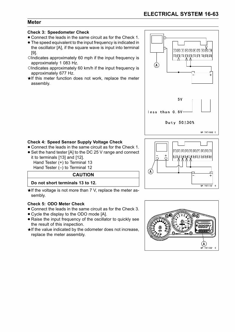
ELECTRICAL SYSTEM 16-63
Meter
Check 3: Speedometer Check
•Connect the leads in the same circuit as for the Check 1.• The speed equivalent to the input frequency is indicated inthe oscillator [A], if the square wave is input into terminal[9].Indicates approximately 60 mph if the input frequency isapproximately 1 083 Hz.Indicates approximately 60 km/h if the input frequency isapproximately 677 Hz.If this meter function does not work, replace the meterassembly.
Check 4: Speed Sensor Supply Voltage Check
•Connect the leads in the same circuit as for the Check 1.• Set the hand tester [A] to the DC 25 V range and connectit to terminals [13] and [12].Hand Tester (+) to Terminal 13Hand Tester (–) to Terminal 12
CAUTION
Do not short terminals 13 to 12.
If the voltage is not more than 7 V, replace the meter as-sembly.
Check 5: ODO Meter Check
•Connect the leads in the same circuit as for the Check 3.•Cycle the display to the ODO mode [A].•Raise the input frequency of the oscillator to quickly seethe result of this inspection.If the value indicated by the odometer does not increase,replace the meter assembly.
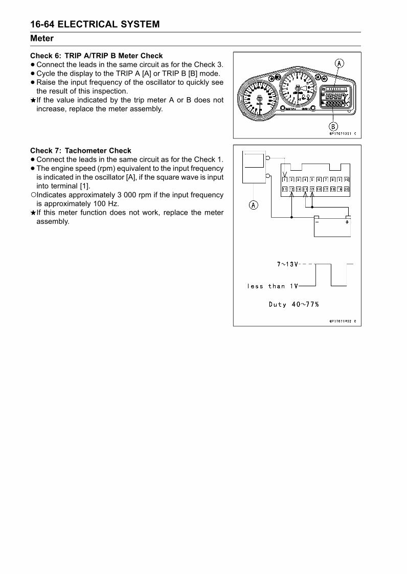
16-64 ELECTRICAL SYSTEM
Meter
Check 6: TRIP A/TRIP B Meter Check
•Connect the leads in the same circuit as for the Check 3.•Cycle the display to the TRIP A [A] or TRIP B [B] mode.•Raise the input frequency of the oscillator to quickly seethe result of this inspection.If the value indicated by the trip meter A or B does notincrease, replace the meter assembly.
Check 7: Tachometer Check
•Connect the leads in the same circuit as for the Check 1.• The engine speed (rpm) equivalent to the input frequencyis indicated in the oscillator [A], if the square wave is inputinto terminal [1].Indicates approximately 3 000 rpm if the input frequencyis approximately 100 Hz.If this meter function does not work, replace the meterassembly.

ELECTRICAL SYSTEM 16-65
Meter
Check 8: Coolant Temperature Gauge Inspection
•Connect the leads in the same circuit as for the Check 1.•Connect a variable rheostat [A] to terminal [10] and [12]as shown.
•Check that the position of segment [B] matches the resis-tance value of the variable rheostat.
B1 Model
Resistance(Ω)
Position ofSegment
Coolant Temperature(Reference)
16 500 1st less than 30°C (86°F)
11 000 2nd 30°C (86°F) ∼ 50°C (122°F)6 200 3rd 50°C (122°F) ∼ 60°C (140°F)3 800 4th 60°C (140°F) ∼ 80°C (176°F)1 800 5th 80°C (176°F) ∼ 100°C (212°F)1 100 6th 100°C (212°F) ∼ 110°C (230°F)850 7th 110°C (230°F) ∼ 115°C (239°F)740 8th 115°C (239°F) ∼ 120°C (248°F)660 9 (All, Flash) 120°C (248°F) or more
B2/B3 Model
Resistance(Ω)
Position ofSegment
Coolant Temperature(Reference)
14 200 1st less than 34°C (93°F)
10 200 2nd 34°C (93°F) ∼ 53°C (127°F)5 200 3rd 53°C (127°F) ∼ 64°C (147°F)3 100 4th 64°C (147°F) ∼ 84°C (183°F)1 600 5th 84°C (183°F) ∼ 105°C (221°F)900 6th 105°C (221°F) ∼ 115°C (239°F)740 7th 115°C (239°F) ∼ 120°C (248°F)650 8th 120°C (248°F) ∼ 125°C (257°F)600 All, Flash 125°C (257°F) or more
Resistance values are standard and they have tolerance.If this display function does not work, replace the meterassembly.

16-66 ELECTRICAL SYSTEM
Meter
Check 9: Fuel Gauge Inspection
•Connect the leads in the same circuit as for the Check 1.•Connect a variable rheostat [A] to terminal [2] and [12] asshown.
•Check that the number of segment [B] matches the resis-tance value of the variable rheostat.
Resistance (Ω) Number ofSegments
Fuel Amount(Reference) (L)
10 8 20
30 7 18
40 6 16
65 5 13
75 4 11
90 3 9
100 2 7
120 1 5
Resistance values are standard and they have tolerance.If this display function does not work, replace the meterassembly.
•Connect an other variable rheostat [C] to terminal [11] and[12].
• Set the hand tester [D] to the DC 10 V range and connectit to terminals of the variable rheostat as shown.
•When the 1 segment [E] appears, adjust the variablerheostat [C] so that the terminal voltage is less than 5.7 V.Then the segment should flush.If this display function does not flush, replace the meterassembly.
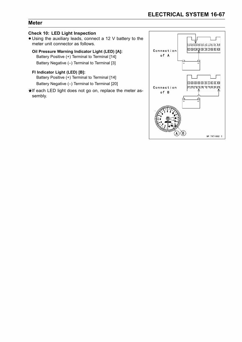
ELECTRICAL SYSTEM 16-67
Meter
Check 10: LED Light Inspection
•Using the auxiliary leads, connect a 12 V battery to themeter unit connector as follows.
Oil Pressure Warning Indicator Light (LED) [A]:Battery Positive (+) Terminal to Terminal [14]
Battery Negative (–) Terminal to Terminal [3]
FI Indicator Light (LED) [B]:Battery Positive (+) Terminal to Terminal [14]
Battery Negative (–) Terminal to Terminal [20]
If each LED light does not go on, replace the meter as-sembly.
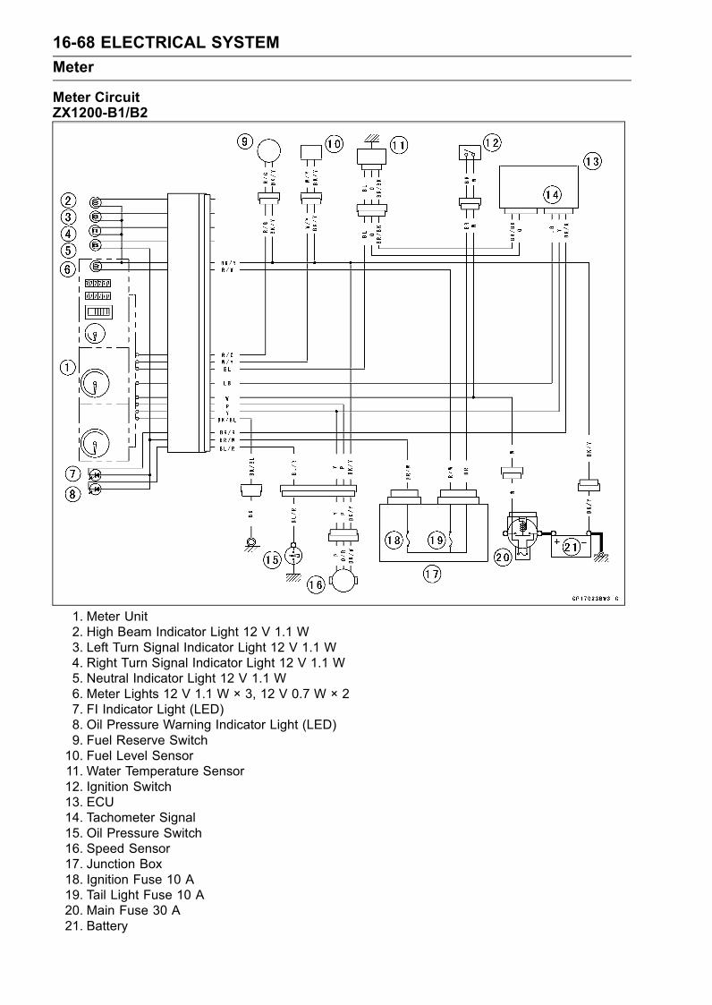
16-68 ELECTRICAL SYSTEM
Meter
Meter CircuitZX1200-B1/B2
1. Meter Unit2. High Beam Indicator Light 12 V 1.1 W3. Left Turn Signal Indicator Light 12 V 1.1 W4. Right Turn Signal Indicator Light 12 V 1.1 W5. Neutral Indicator Light 12 V 1.1 W6. Meter Lights 12 V 1.1 W × 3, 12 V 0.7 W × 27. FI Indicator Light (LED)8. Oil Pressure Warning Indicator Light (LED)9. Fuel Reserve Switch10. Fuel Level Sensor11. Water Temperature Sensor12. Ignition Switch13. ECU14. Tachometer Signal15. Oil Pressure Switch16. Speed Sensor17. Junction Box18. Ignition Fuse 10 A19. Tail Light Fuse 10 A20. Main Fuse 30 A21. Battery
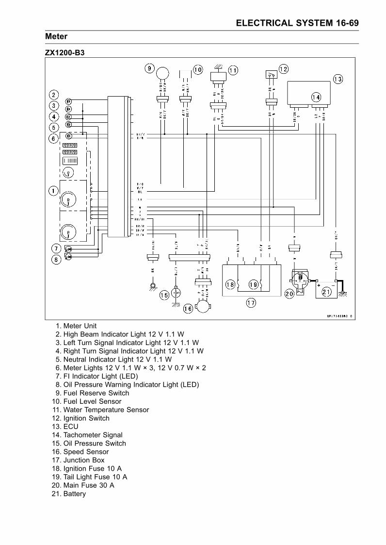
ELECTRICAL SYSTEM 16-69
Meter
ZX1200-B3
1. Meter Unit2. High Beam Indicator Light 12 V 1.1 W3. Left Turn Signal Indicator Light 12 V 1.1 W4. Right Turn Signal Indicator Light 12 V 1.1 W5. Neutral Indicator Light 12 V 1.1 W6. Meter Lights 12 V 1.1 W × 3, 12 V 0.7 W × 27. FI Indicator Light (LED)8. Oil Pressure Warning Indicator Light (LED)9. Fuel Reserve Switch10. Fuel Level Sensor11. Water Temperature Sensor12. Ignition Switch13. ECU14. Tachometer Signal15. Oil Pressure Switch16. Speed Sensor17. Junction Box18. Ignition Fuse 10 A19. Tail Light Fuse 10 A20. Main Fuse 30 A21. Battery
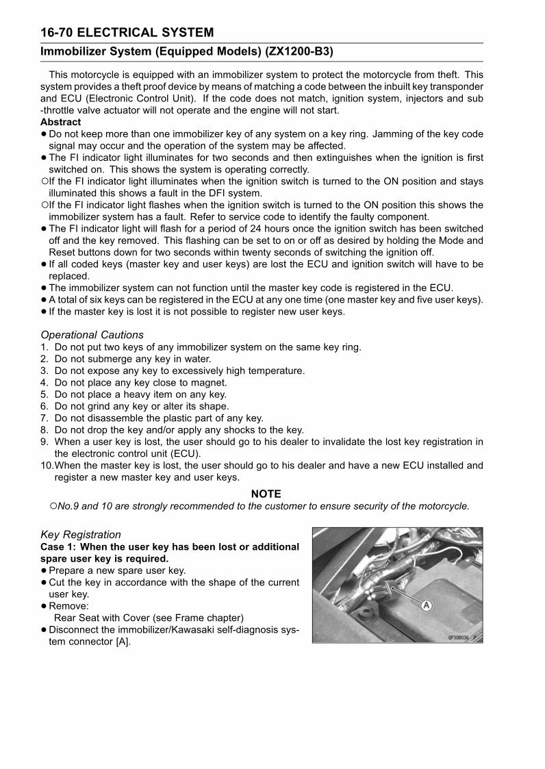
16-70 ELECTRICAL SYSTEM
Immobilizer System (Equipped Models) (ZX1200-B3)
This motorcycle is equipped with an immobilizer system to protect the motorcycle from theft. Thissystem provides a theft proof device by means of matching a code between the inbuilt key transponderand ECU (Electronic Control Unit). If the code does not match, ignition system, injectors and sub-throttle valve actuator will not operate and the engine will not start.Abstract
•Do not keep more than one immobilizer key of any system on a key ring. Jamming of the key codesignal may occur and the operation of the system may be affected.
• The FI indicator light illuminates for two seconds and then extinguishes when the ignition is firstswitched on. This shows the system is operating correctly.If the FI indicator light illuminates when the ignition switch is turned to the ON position and staysilluminated this shows a fault in the DFI system.If the FI indicator light flashes when the ignition switch is turned to the ON position this shows theimmobilizer system has a fault. Refer to service code to identify the faulty component.
• The FI indicator light will flash for a period of 24 hours once the ignition switch has been switchedoff and the key removed. This flashing can be set to on or off as desired by holding the Mode andReset buttons down for two seconds within twenty seconds of switching the ignition off.
• If all coded keys (master key and user keys) are lost the ECU and ignition switch will have to bereplaced.
• The immobilizer system can not function until the master key code is registered in the ECU.•A total of six keys can be registered in the ECU at any one time (one master key and five user keys).• If the master key is lost it is not possible to register new user keys.Operational Cautions1. Do not put two keys of any immobilizer system on the same key ring.2. Do not submerge any key in water.3. Do not expose any key to excessively high temperature.4. Do not place any key close to magnet.5. Do not place a heavy item on any key.6. Do not grind any key or alter its shape.7. Do not disassemble the plastic part of any key.8. Do not drop the key and/or apply any shocks to the key.9. When a user key is lost, the user should go to his dealer to invalidate the lost key registration inthe electronic control unit (ECU).
10.When the master key is lost, the user should go to his dealer and have a new ECU installed andregister a new master key and user keys.
NOTENo.9 and 10 are strongly recommended to the customer to ensure security of the motorcycle.
Key RegistrationCase 1: When the user key has been lost or additionalspare user key is required.
•Prepare a new spare user key.•Cut the key in accordance with the shape of the currentuser key.
•Remove:Rear Seat with Cover (see Frame chapter)
•Disconnect the immobilizer/Kawasaki self-diagnosis sys-tem connector [A].

ELECTRICAL SYSTEM 16-71
Immobilizer System (Equipped Models) (ZX1200-B3)
•Connect the key registration unit [A].Special Tool - Key Registration Unit: 57001-1582
• Insert the master key to the ignition switch and turn it ON.VerifiedThe FI indicator light [A] blinks to display the registrationmode (go to the next step).
Not VerifiedThe FI indicator light [A] blinks to display the collation error(refer to the following failure illustrations).Immobilizer Amplifier Failure
Master Key Collation Error
• Turn the master key OFF and remove the master key.The FI indicator light [A] blinks continuously to display thatthe ECU is in the registration mode for 15 seconds.
NOTEInsert next key and turn ON within 15 seconds after pre-vious key is turned off and removed otherwise registra-tion mode will be ended and the FI indicator light stopsflashing.To return to the registration mode start the master keyverification procedure. This applies to all user key reg-istration.
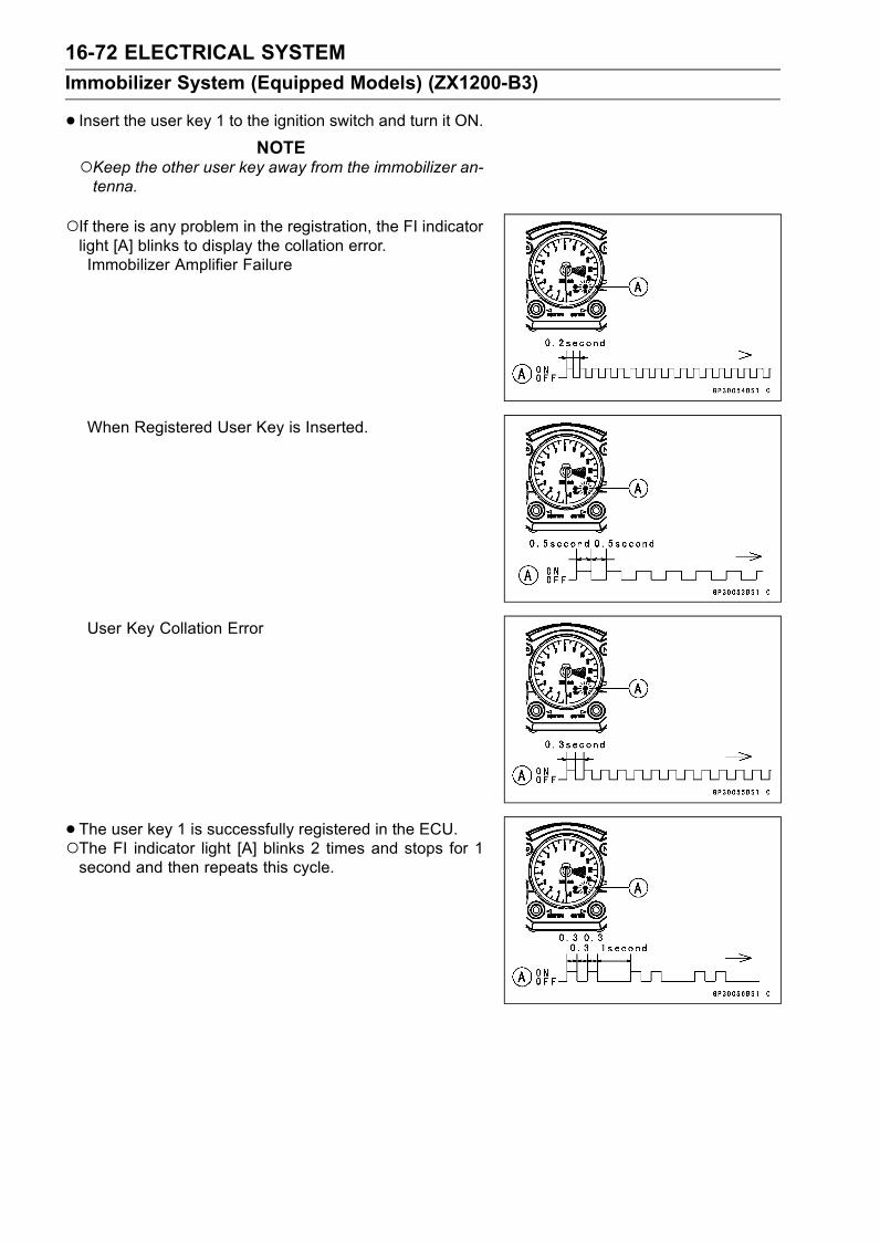
16-72 ELECTRICAL SYSTEM
Immobilizer System (Equipped Models) (ZX1200-B3)
• Insert the user key 1 to the ignition switch and turn it ON.NOTE
Keep the other user key away from the immobilizer an-tenna.
If there is any problem in the registration, the FI indicatorlight [A] blinks to display the collation error.Immobilizer Amplifier Failure
When Registered User Key is Inserted.
User Key Collation Error
• The user key 1 is successfully registered in the ECU.The FI indicator light [A] blinks 2 times and stops for 1second and then repeats this cycle.

ELECTRICAL SYSTEM 16-73
Immobilizer System (Equipped Models) (ZX1200-B3)
•Turn the user key 1 OFF and remove off the user key 1.The FI indicator light [A] blinks to display the registrationmode.
NOTETurn off the ignition switch and wait for the period of 15seconds or more. The registration mode automaticallyfinishes and the FI indicator light will switch off.This procedure registered the master key and one userkey.Continue with the procedure to register the second andlater keys before the 15 seconds period has elapsed.
• Insert the user key 2 to the ignition switch and turn it ON.If there is any problem in the registration, the FI indicatorlight [A] blinks to display the collation error.Immobilizer Amplifier Failure
When Registered User Key is Inserted.
User Key Collation Error

16-74 ELECTRICAL SYSTEM
Immobilizer System (Equipped Models) (ZX1200-B3)
•The user key 2 is registered in the ECU.The FI indicator light [A] blinks 3 times and stops for 1second and then repeats this cycle.This procedure has registered the master key and 2 userkeys.
•Continue with the procedure to register an additional 3user keys.
NOTEThe ECU can store up the six key codes (master key ×1 and user key × 5).
User Key Indicator Flashes
FI IndicatorLight Blinks
FI IndicatorLight Stop
Remarks
User Key 3 4 times 1 seconds Repeat
User Key 4 5 times 1 seconds Repeat
User Key 5 6 times 1 seconds Repeat
• Turn OFF the ignition switch and wait for period of morethan 15 seconds.
• The registration mode automatically ends.• FI indicator light goes off [A].
• Remove the key registration unit and connect the immo-bilizer Kawasaki self-diagnostic system connector.
NOTETurn the ignition switch ON with the registered user key.Check that the engine can be started using all regis-tered user keys.

ELECTRICAL SYSTEM 16-75
Immobilizer System (Equipped Models) (ZX1200-B3)
Spare User Key Registration Flow Chart
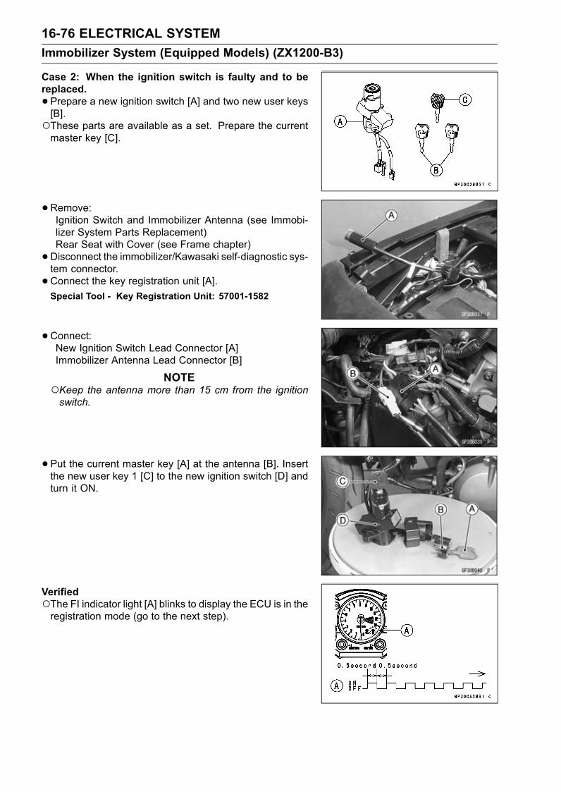
16-76 ELECTRICAL SYSTEM
Immobilizer System (Equipped Models) (ZX1200-B3)
Case 2: When the ignition switch is faulty and to bereplaced.
•Prepare a new ignition switch [A] and two new user keys[B].These parts are available as a set. Prepare the currentmaster key [C].
•Remove:Ignition Switch and Immobilizer Antenna (see Immobi-lizer System Parts Replacement)Rear Seat with Cover (see Frame chapter)
•Disconnect the immobilizer/Kawasaki self-diagnostic sys-tem connector.
•Connect the key registration unit [A].Special Tool - Key Registration Unit: 57001-1582
•Connect:New Ignition Switch Lead Connector [A]Immobilizer Antenna Lead Connector [B]
NOTEKeep the antenna more than 15 cm from the ignitionswitch.
•Put the current master key [A] at the antenna [B]. Insertthe new user key 1 [C] to the new ignition switch [D] andturn it ON.
VerifiedThe FI indicator light [A] blinks to display the ECU is in theregistration mode (go to the next step).
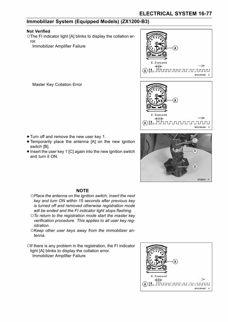
ELECTRICAL SYSTEM 16-77
Immobilizer System (Equipped Models) (ZX1200-B3)
Not VerifiedThe FI indicator light [A] blinks to display the collation er-ror.Immobilizer Amplifier Failure
Master Key Collation Error
• Turn off and remove the new user key 1.• Temporarily place the antenna [A] on the new ignitionswitch [B].
• Insert the user key 1 [C] again into the new ignition switchand turn it ON.
NOTEPlace the antenna on the ignition switch, insert the nextkey and turn ON within 15 seconds after previous keyis turned off and removed otherwise registration modewill be ended and the FI indicator light stops flashing.To return to the registration mode start the master keyverification procedure. This applies to all user key reg-istration.Keep other user keys away from the immobilizer an-tenna.
If there is any problem in the registration, the FI indicatorlight [A] blinks to display the collation error.Immobilizer Amplifier Failure
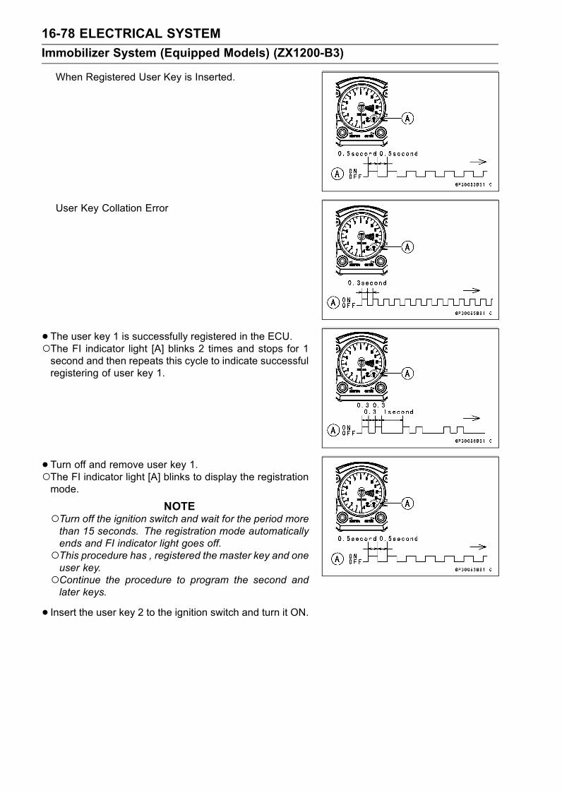
16-78 ELECTRICAL SYSTEM
Immobilizer System (Equipped Models) (ZX1200-B3)
When Registered User Key is Inserted.
User Key Collation Error
• The user key 1 is successfully registered in the ECU.The FI indicator light [A] blinks 2 times and stops for 1second and then repeats this cycle to indicate successfulregistering of user key 1.
• Turn off and remove user key 1.The FI indicator light [A] blinks to display the registrationmode.
NOTETurn off the ignition switch and wait for the period morethan 15 seconds. The registration mode automaticallyends and FI indicator light goes off.This procedure has , registered the master key and oneuser key.Continue the procedure to program the second andlater keys.
• Insert the user key 2 to the ignition switch and turn it ON.
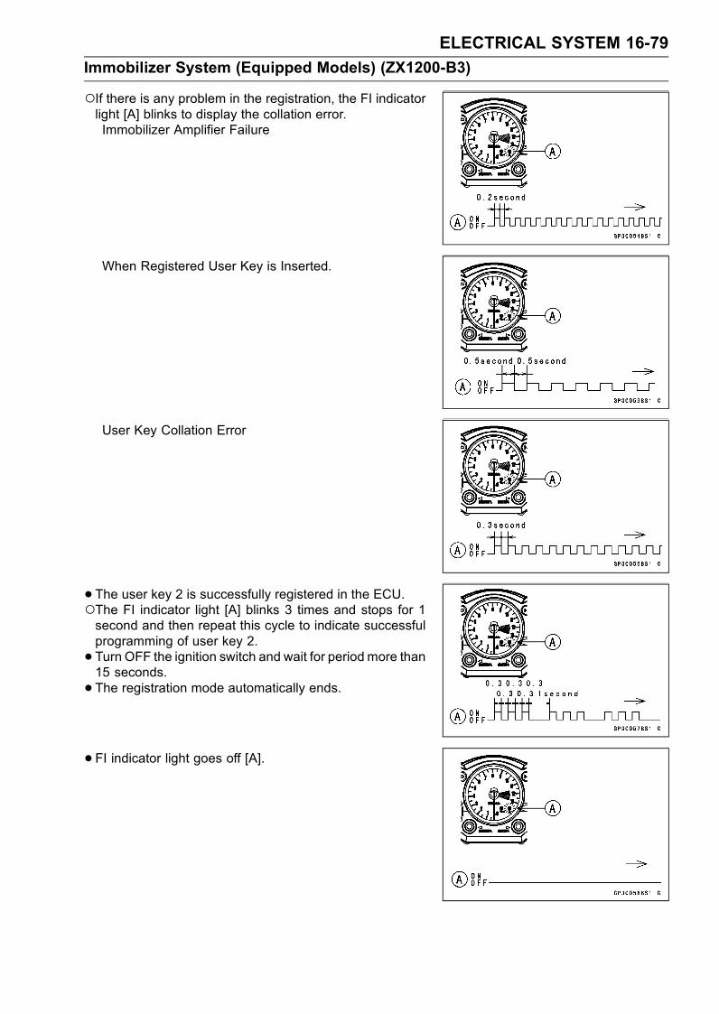
ELECTRICAL SYSTEM 16-79
Immobilizer System (Equipped Models) (ZX1200-B3)
If there is any problem in the registration, the FI indicatorlight [A] blinks to display the collation error.Immobilizer Amplifier Failure
When Registered User Key is Inserted.
User Key Collation Error
• The user key 2 is successfully registered in the ECU.The FI indicator light [A] blinks 3 times and stops for 1second and then repeat this cycle to indicate successfulprogramming of user key 2.
• Turn OFF the ignition switch and wait for period more than15 seconds.
• The registration mode automatically ends.
• FI indicator light goes off [A].
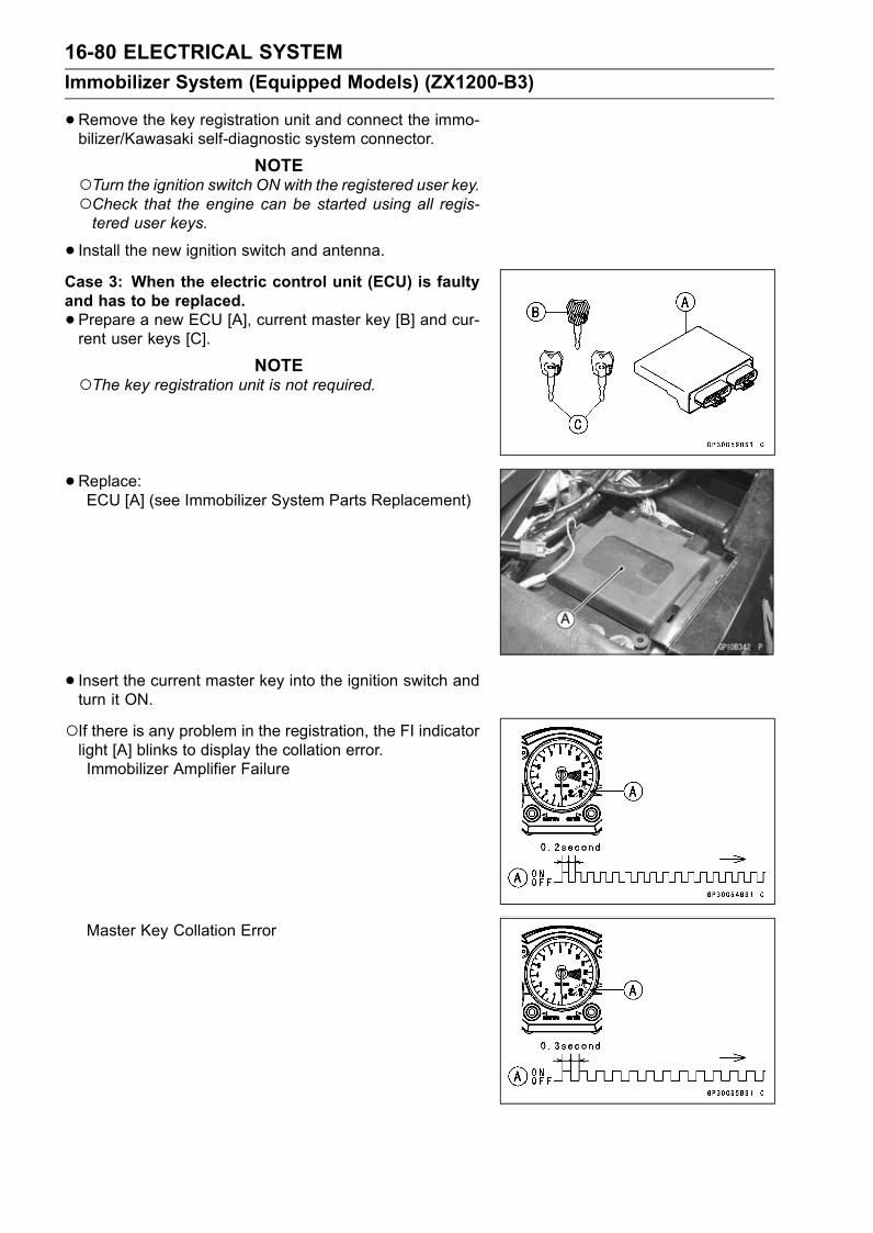
16-80 ELECTRICAL SYSTEM
Immobilizer System (Equipped Models) (ZX1200-B3)
•Remove the key registration unit and connect the immo-bilizer/Kawasaki self-diagnostic system connector.
NOTETurn the ignition switch ON with the registered user key.Check that the engine can be started using all regis-tered user keys.
• Install the new ignition switch and antenna.Case 3: When the electric control unit (ECU) is faultyand has to be replaced.
•Prepare a new ECU [A], current master key [B] and cur-rent user keys [C].
NOTEThe key registration unit is not required.
•Replace:ECU [A] (see Immobilizer System Parts Replacement)
• Insert the current master key into the ignition switch andturn it ON.
If there is any problem in the registration, the FI indicatorlight [A] blinks to display the collation error.Immobilizer Amplifier Failure
Master Key Collation Error

ELECTRICAL SYSTEM 16-81
Immobilizer System (Equipped Models) (ZX1200-B3)
•The master key is registered in the ECU.The FI indicator light [A] blinks 1 time and stops for 1second and the repeats this cycle to indicate successfulregistration of the master key.
• Turn of the master key and remove it.The FI indicator light [A] blinks to display the registrationmode.
NOTEInsert next key and turn ON within 15 seconds after pre-vious key is turned off and removed otherwise registra-tion mode will be ended and the FI indicator light goesoff.To return to the registration mode start the master keyverification procedure. This applies to all user key reg-istration.
• Insert the user key 1 to the ignition switch and turn it ON.NOTE
Keep the other user keys away from the immobilizerantenna.
If there is any problem in the registration, the FI indicatorlight [A] blinks to display the collation error.Immobilizer Amplifier Failure
When Registered User Key is Inserted.

16-82 ELECTRICAL SYSTEM
Immobilizer System (Equipped Models) (ZX1200-B3)
User Key Collation Error
• The user key 1 is registered in the ECU.The FI indicator light [A] blinks 2 times and stops for 1second and then repeats this cycle to indicate successfulregistration of user key.
• Turn off and remove the user key 1.The FI indicator light [A] blinks to display the registrationmode codes.
NOTEInsert next key and turn ON within 15 seconds after pre-vious key is turned off and removed otherwise registra-tion mode will be ended and the FI indicator light goesoff.To return to the registration mode start the master keyverification procedure. This applies to all user key reg-istration.
• Insert the user key 2 to the ignition switch and turn it ON.If there is any problem in the registration, the FI indicatorlight [A] blinks to display the collation error code.Immobilizer Amplifier Failure

ELECTRICAL SYSTEM 16-83
Immobilizer System (Equipped Models) (ZX1200-B3)
When Registered User Key is Inserted.
User Key Collation Error
• The user key 2 is registered in the ECU.The FI indicator light [A] blinks 3 times and stops for 1second and then repeats this cycle to indicate successfulregistration of user key 2.
• Turn OFF the ignition switch and wait for period more than15 seconds.
• The registration mode automatically ends.
• FI indicator light goes off [A].
NOTETurn the ignition switch ON with the registered user key.Check that the engine can be started using all regis-tered user keys.
Case 4: When master key is faulty or lost.Themaster key replacement is considered very rare case.
However if it is required, the following is necessary.
NOTEThe ECU must be replaced with a new one because themaster key code that is registered in the current ECUcan not be rewritten.
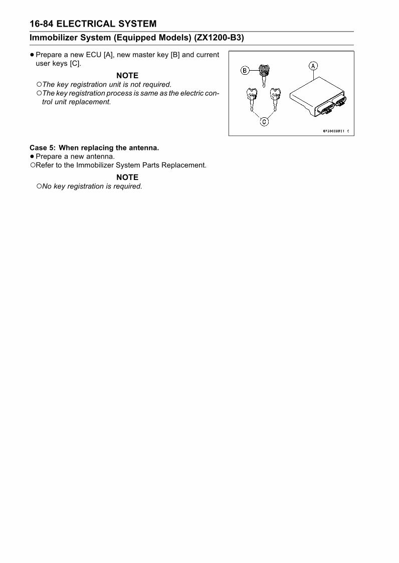
16-84 ELECTRICAL SYSTEM
Immobilizer System (Equipped Models) (ZX1200-B3)
•Prepare a new ECU [A], new master key [B] and currentuser keys [C].
NOTEThe key registration unit is not required.The key registration process is same as the electric con-trol unit replacement.
Case 5: When replacing the antenna.
•Prepare a new antenna.Refer to the Immobilizer System Parts Replacement.
NOTENo key registration is required.

ELECTRICAL SYSTEM 16-85
Immobilizer System (Equipped Models) (ZX1200-B3)
All Keys Initial Registration Flow Chart
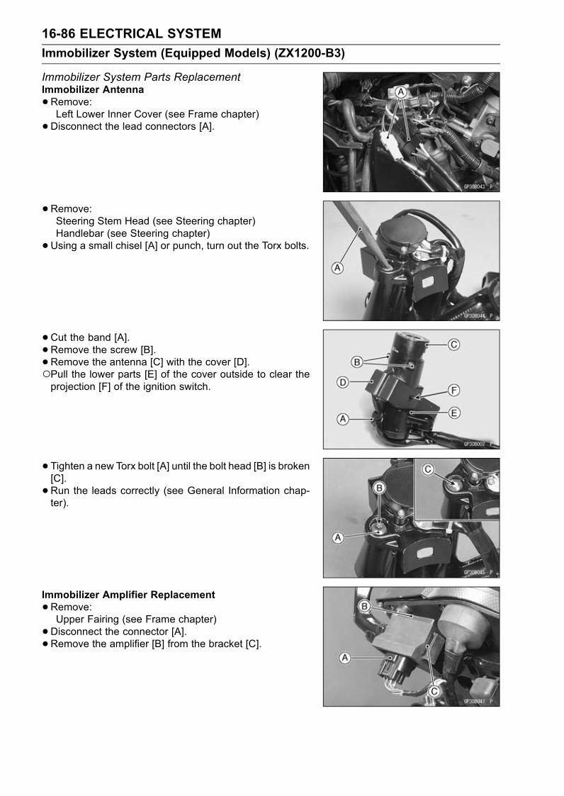
16-86 ELECTRICAL SYSTEM
Immobilizer System (Equipped Models) (ZX1200-B3)
Immobilizer System Parts ReplacementImmobilizer Antenna
•Remove:Left Lower Inner Cover (see Frame chapter)
•Disconnect the lead connectors [A].
•Remove:Steering Stem Head (see Steering chapter)Handlebar (see Steering chapter)
•Using a small chisel [A] or punch, turn out the Torx bolts.
•Cut the band [A].•Remove the screw [B].•Remove the antenna [C] with the cover [D].Pull the lower parts [E] of the cover outside to clear theprojection [F] of the ignition switch.
• Tighten a new Torx bolt [A] until the bolt head [B] is broken[C].
•Run the leads correctly (see General Information chap-ter).
Immobilizer Amplifier Replacement
•Remove:Upper Fairing (see Frame chapter)
•Disconnect the connector [A].• Remove the amplifier [B] from the bracket [C].
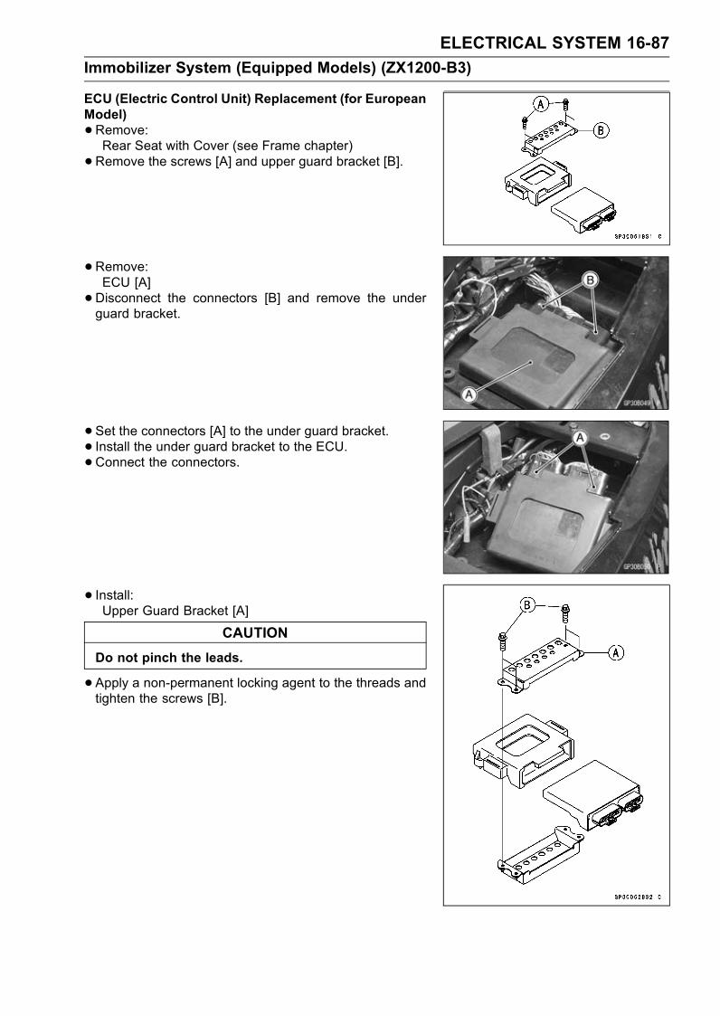
ELECTRICAL SYSTEM 16-87
Immobilizer System (Equipped Models) (ZX1200-B3)
ECU (Electric Control Unit) Replacement (for EuropeanModel)
•Remove:Rear Seat with Cover (see Frame chapter)
•Remove the screws [A] and upper guard bracket [B].
• Remove:ECU [A]
•Disconnect the connectors [B] and remove the underguard bracket.
• Set the connectors [A] to the under guard bracket.• Install the under guard bracket to the ECU.•Connect the connectors.
• Install:Upper Guard Bracket [A]
CAUTION
Do not pinch the leads.
•Apply a non-permanent locking agent to the threads andtighten the screws [B].
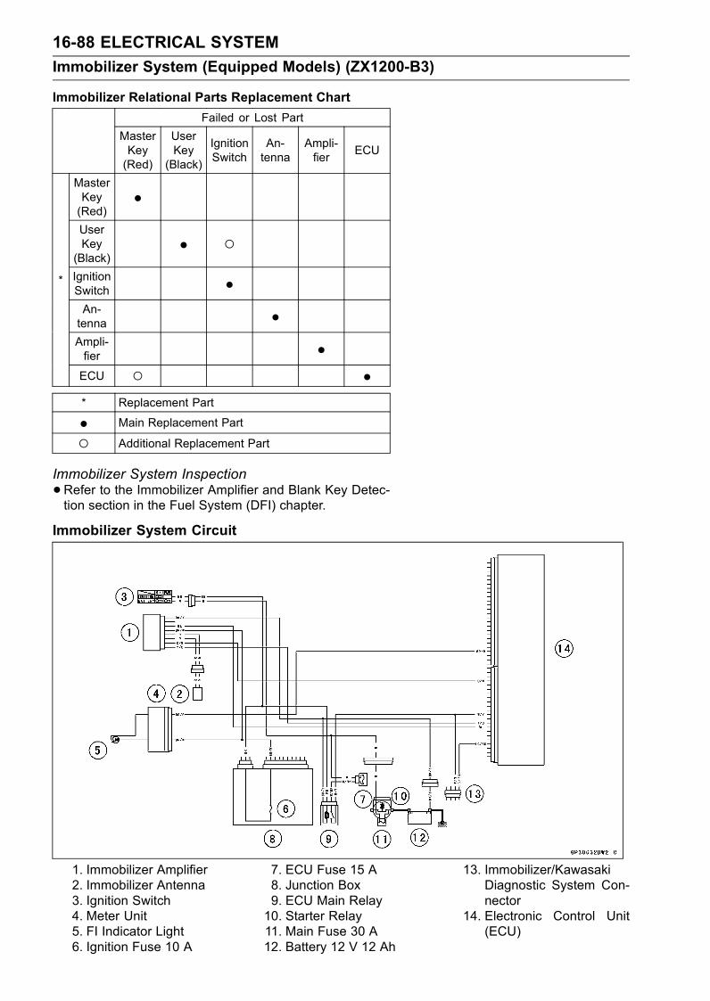
16-88 ELECTRICAL SYSTEM
Immobilizer System (Equipped Models) (ZX1200-B3)
Immobilizer Relational Parts Replacement Chart
Failed or Lost Part
MasterKey(Red)
UserKey(Black)
IgnitionSwitch
An-tenna
Ampli-fier
ECU
MasterKey(Red)
•UserKey(Black)
• IgnitionSwitch •An-tenna •Ampli-fier •
*
ECU •* Replacement Part
• Main Replacement Part
Additional Replacement Part
Immobilizer System Inspection
•Refer to the Immobilizer Amplifier and Blank Key Detec-tion section in the Fuel System (DFI) chapter.
Immobilizer System Circuit
1. Immobilizer Amplifier2. Immobilizer Antenna3. Ignition Switch4. Meter Unit5. FI Indicator Light6. Ignition Fuse 10 A
7. ECU Fuse 15 A8. Junction Box9. ECU Main Relay10. Starter Relay11. Main Fuse 30 A12. Battery 12 V 12 Ah
13. Immobilizer/KawasakiDiagnostic System Con-nector
14. Electronic Control Unit(ECU)
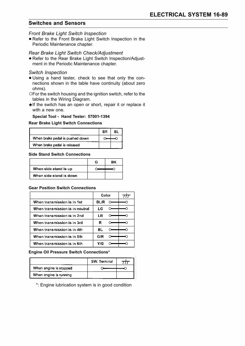
ELECTRICAL SYSTEM 16-89
Switches and Sensors
Front Brake Light Switch Inspection
•Refer to the Front Brake Light Switch Inspection in thePeriodic Maintenance chapter.
Rear Brake Light Switch Check/Adjustment
•Refer to the Rear Brake Light Switch Inspection/Adjust-ment in the Periodic Maintenance chapter.
Switch Inspection
•Using a hand tester, check to see that only the con-nections shown in the table have continuity (about zeroohms).For the switch housing and the ignition switch, refer to thetables in the Wiring Diagram.If the switch has an open or short, repair it or replace itwith a new one.
Special Tool - Hand Tester: 57001-1394
Rear Brake Light Switch Connections
Side Stand Switch Connections
Gear Position Switch Connections
Engine Oil Pressure Switch Connections*
*: Engine lubrication system is in good condition
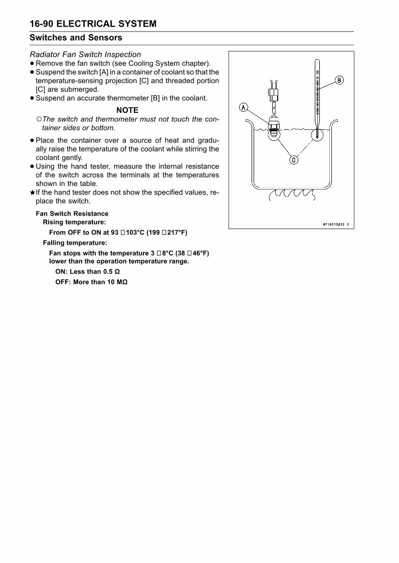
16-90 ELECTRICAL SYSTEM
Switches and Sensors
Radiator Fan Switch Inspection
•Remove the fan switch (see Cooling System chapter).• Suspend the switch [A] in a container of coolant so that thetemperature-sensing projection [C] and threaded portion[C] are submerged.
• Suspend an accurate thermometer [B] in the coolant.NOTE
The switch and thermometer must not touch the con-tainer sides or bottom.
•Place the container over a source of heat and gradu-ally raise the temperature of the coolant while stirring thecoolant gently.
•Using the hand tester, measure the internal resistanceof the switch across the terminals at the temperaturesshown in the table.If the hand tester does not show the specified values, re-place the switch.
Fan Switch ResistanceRising temperature:
From OFF to ON at 93 ∼ 103°C (199 ∼ 217°F)Falling temperature:
Fan stops with the temperature 3 ∼ 8°C (38 ∼ 46°F)lower than the operation temperature range.
ON: Less than 0.5 ΩOFF: More than 10 MΩ
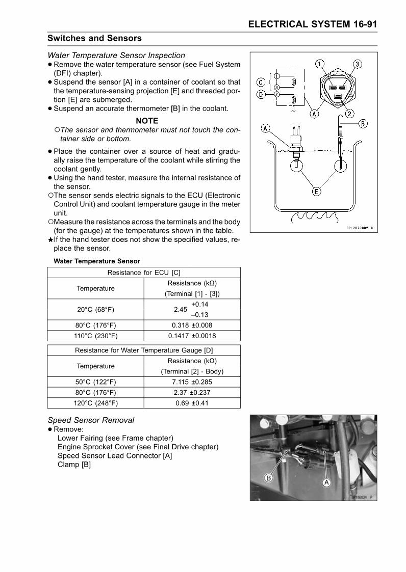
ELECTRICAL SYSTEM 16-91
Switches and Sensors
Water Temperature Sensor Inspection
•Remove the water temperature sensor (see Fuel System(DFI) chapter).
• Suspend the sensor [A] in a container of coolant so thatthe temperature-sensing projection [E] and threaded por-tion [E] are submerged.
• Suspend an accurate thermometer [B] in the coolant.NOTE
The sensor and thermometer must not touch the con-tainer side or bottom.
•Place the container over a source of heat and gradu-ally raise the temperature of the coolant while stirring thecoolant gently.
•Using the hand tester, measure the internal resistance ofthe sensor.The sensor sends electric signals to the ECU (ElectronicControl Unit) and coolant temperature gauge in the meterunit.Measure the resistance across the terminals and the body(for the gauge) at the temperatures shown in the table.If the hand tester does not show the specified values, re-place the sensor.
Water Temperature Sensor
Resistance for ECU [C]
Resistance (kΩ)Temperature
(Terminal [1] - [3])
+0.1420°C (68°F) 2.45
–0.13
80°C (176°F) 0.318 ±0.008
110°C (230°F) 0.1417 ±0.0018
Resistance for Water Temperature Gauge [D]
Resistance (kΩ)Temperature
(Terminal [2] - Body)
50°C (122°F) 7.115 ±0.285
80°C (176°F) 2.37 ±0.237
120°C (248°F) 0.69 ±0.41
Speed Sensor Removal
•Remove:Lower Fairing (see Frame chapter)Engine Sprocket Cover (see Final Drive chapter)Speed Sensor Lead Connector [A]Clamp [B]
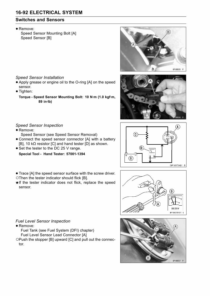
16-92 ELECTRICAL SYSTEM
Switches and Sensors
•Remove:Speed Sensor Mounting Bolt [A]Speed Sensor [B]
Speed Sensor Installation
•Apply grease or engine oil to the O-ring [A] on the speedsensor.
• Tighten:Torque - Speed Sensor Mounting Bolt: 10 N·m (1.0 kgf·m,
89 in·lb)
Speed Sensor Inspection
•Remove:Speed Sensor (see Speed Sensor Removal)
•Connect the speed sensor connector [A] with a battery[B], 10 kΩ resistor [C] and hand tester [D] as shown.• Set the tester to the DC 25 V range.Special Tool - Hand Tester: 57001-1394
•Trace [A] the speed sensor surface with the screw driver.Then the tester indicator should flick [B].If the tester indicator does not flick, replace the speedsensor.
Fuel Level Sensor Inspection
•Remove:Fuel Tank (see Fuel System (DFI) chapter)Fuel Level Sensor Lead Connector [A]
Push the stopper [B] upward [C] and pull out the connec-tor.

ELECTRICAL SYSTEM 16-93
Switches and Sensors
•Remove:Bolts [A]Fuel Level Sensor [B]
•Check that the float moves up and down smoothly withoutbinding. It should go down under its own weight.If the float does not move smoothly, replace the sensor.Float in Full Position [A]Float in Empty Position [B]Float Arm Stoppers [C]
•Using the hand tester, measure the resistance across theterminals in the fuel level sensor lead connector [D].
Special Tool - Hand Tester: 57001-1394
If the tester readings are not as specified, or do notchange smoothly according as the float moves up anddown, replace the sensor.
Fuel Level Sensor ResistanceStandard: Full position: 8 ∼ 10 Ω
Empty position: 122 ∼ 126 Ω
•Apply a non-permanent locking agent to the threads ofthe level sensor mounting bolts and tighten it.
Torque - Fuel Level Sensor Bolts: 6.9 N·m (0.70 kgf·m, 61in·lb)
Fuel Reserve Switch Inspection (1)
•Fill the fuel tank with fuel.• Close the fuel tank cap surely.•Remove the fuel tank (see Fuel System (DFI) chapter).• Connect the test light [A] (12 V 3.4 W bulb a socket withleads) and the 12 V battery [B] to the fuel pump connector[C].
Connections:Battery (+) → 12 V 3.4 W Bulb (one side)12 V 3.4 W Bulb (other side)→ R/BK Lead TerminalBattery (–) → BK/W Lead Terminal
Special Tool - Needle Adapter Set: 57001-1457
If the test light turn on, the reverse switch is defective.Replace the fuel pump.
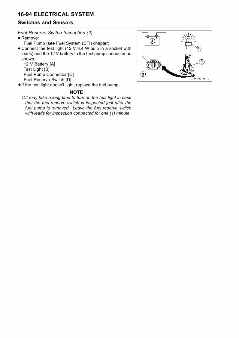
16-94 ELECTRICAL SYSTEM
Switches and Sensors
Fuel Reserve Switch Inspection (2)
•Remove:Fuel Pump (see Fuel System (DFI) chapter)
•Connect the test light (12 V 3.4 W bulb in a socket withleads) and the 12 V battery to the fuel pump connector asshown.12 V Battery [A]Test Light [B]Fuel Pump Connector [C]Fuel Reserve Switch [D]If the test light doesn’t light, replace the fuel pump.
NOTEIt may take a long time to turn on the test light in casethat the fuel reserve switch is inspected just after thefuel pump is removed. Leave the fuel reserve switchwith leads for inspection connected for one (1) minute.
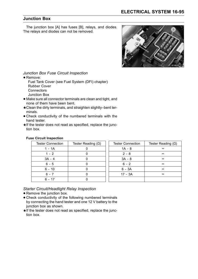
ELECTRICAL SYSTEM 16-95
Junction Box
The junction box [A] has fuses [B], relays, and diodes.The relays and diodes can not be removed.
Junction Box Fuse Circuit Inspection
•Remove:Fuel Tank Cover (see Fuel System (DFI) chapter)Rubber CoverConnectorsJunction Box
•Make sure all connector terminals are clean and tight, andnone of them have been bent.Clean the dirty terminals, and straighten slightly–bent ter-minals.
•Check conductivity of the numbered terminals with thehand tester.If the tester does not read as specified, replace the junc-tion box.
Fuse Circuit Inspection
Tester Connection Tester Reading (Ω) Tester Connection Tester Reading (Ω)1 - 1A 0 1A - 8 ∞1 - 2 0 2 - 8 ∞3A - 4 0 3A - 8 ∞6 - 5 0 6 - 2 ∞6 - 10 0 6 - 3A ∞6 - 7 0 17 - 3A ∞6 - 17 0
Starter Circuit/Headlight Relay Inspection
•Remove the junction box.•Check conductivity of the following numbered terminalsby connecting the hand tester and one 12 V battery to thejunction box as shown.If the tester does not read as specified, replace the junc-tion box.
16-96 ELECTRICAL SYSTEM
Junction Box
Relay Circuit Inspection (with the battery disconnected)
Tester Connection Tester Reading (Ω) Tester Connection Tester Reading (Ω)*7 - 8 ∞ 9 - 11 ∞*7 - 13 ∞ 12 - 13 ∞Head-
light Re-lay (+) (–)
*13 - 9Not ∞ **
(+) (–)13 - 11
∞StarterCircuitRelay
(+) (–)12 - 11
Not ∞ **
*: U.S.A, Canadian, Australian, and Malaysian Modelsonly
**: The actual reading varies with the hand tester used.
(+): Apply tester positive lead.(–): Apply tester negative lead.
Relay Circuit Inspection (with the battery connected)
BatteryConnection(+) (–)
TesterConnection
TesterReading(Ω)
Headlight Relay *9 – 13 *7 – 8 0
Starter Circuit Relay 11 – 12(+) (–)13 – 11
Not ∞ **
*: U.S.A., Canadian, Australian, and Malaysian Modelsonly
**: The actual reading varies with the hand tester used.(+): Apply tester positive lead.(–): Apply tester negative lead.
Diode Circuit Inspection
•Remove the junction box.•Check conductivity of the following pairs of terminals.Diode Circuit Inspection
*13–8, *13–9, 12–11, 12–14,Tester Connection
15–14, 16–14
*: U.S.A., Canadian, Australian, and Malaysian Modelsonly
The resistance should be low in one direction and morethan ten times as much in the other direction. If any diodeshows low or high in both directions, the diode is defectiveand the junction box must be replaced.
NOTEThe actual meter reading varies with the meter usedand the individual diodes, but, generally speaking, thelower reading should be from zero to one half the scale.

ELECTRICAL SYSTEM 16-97
Junction Box
Junction Box Internal Circuit (U.S.A., Canadian, Australian, andMalaysian/ZX1200-B2/B3 Models)
Junction Box Internal Circuit (Other than U.S.A., Canadian, Australian, and MalaysianModels)
A. Fan Fuse 15 AB. Fan Fuse 15 AC. Turn Signal Relay Fuse 10 AD. Horn Fuse 10 AE. Ignition Fuse 10 AF. Headlight Fuse 10 A
G. Headlight RelayH. Headlight DiodesI. Starter DiodeJ. Starter Circuit RelayK. Interlock DiodesL. Tail Light Fuse 10 A
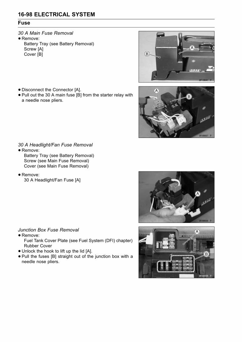
16-98 ELECTRICAL SYSTEM
Fuse
30 A Main Fuse Removal
•Remove:Battery Tray (see Battery Removal)Screw [A]Cover [B]
•Disconnect the Connector [A].• Pull out the 30 A main fuse [B] from the starter relay witha needle nose pliers.
30 A Headlight/Fan Fuse Removal
•Remove:Battery Tray (see Battery Removal)Screw (see Main Fuse Removal)Cover (see Main Fuse Removal)
•Remove:30 A Headlight/Fan Fuse [A]
Junction Box Fuse Removal
•Remove:Fuel Tank Cover Plate (see Fuel System (DFI) chapter)Rubber Cover
•Unlock the hook to lift up the lid [A].• Pull the fuses [B] straight out of the junction box with aneedle nose pliers.

ELECTRICAL SYSTEM 16-99
Fuse
15 A ECU Fuse Removal
•Remove:Fuel Tank Cover Plate (see Fuel System (DFI) chapter)15 A ECU Fuse [A]
Fuse InstallationIf a fuse fails during operation, inspect the electrical sys-tem to determine the cause, and then replace it with anew fuse of proper amperage.
• Install the junction box fuses on the original position asspecified on the lid.
Fuse Inspection
•Remove the fuse.• Inspect the fuse element.If it is blown out, replace the fuse. Before replacing ablown fuse, always check the amperage in the affectedcircuit. If the amperage is equal to or greater than thefuse rating, check the wiring and related components fora short circuit.Housing [A]Fuse Element [B]Terminals [C]Blown Element [D]
NOTEA mass current flows to the battery according to thestate of the battery which needs refreshing charge whenthe engine is turned causing main fuse blown out.
CAUTION
When replacing a fuse, be sure the new fusematches the specified fuse rating for that circuit.Installation of a fuse with a higher rating may causedamage to wiring and components.

16-100 ELECTRICAL SYSTEM
Wiring Diagram (U.S.A. and Canada)
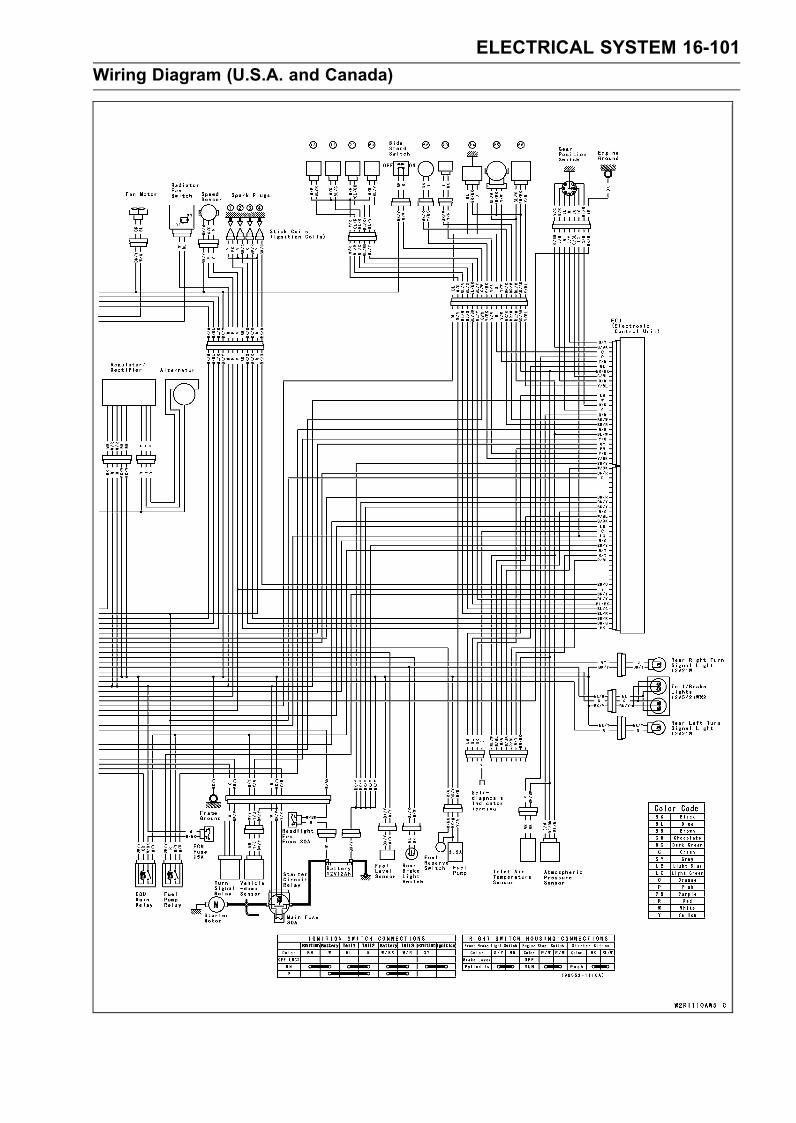
ELECTRICAL SYSTEM 16-101
Wiring Diagram (U.S.A. and Canada)

16-102 ELECTRICAL SYSTEM
Wiring Diagram (Australia/ZX1200-B2: H, HU, HR models)

ELECTRICAL SYSTEM 16-103
Wiring Diagram (Australia/ZX1200-B2: H, HU, HR models)

16-104 ELECTRICAL SYSTEM
Wiring Diagram (Malaysia)
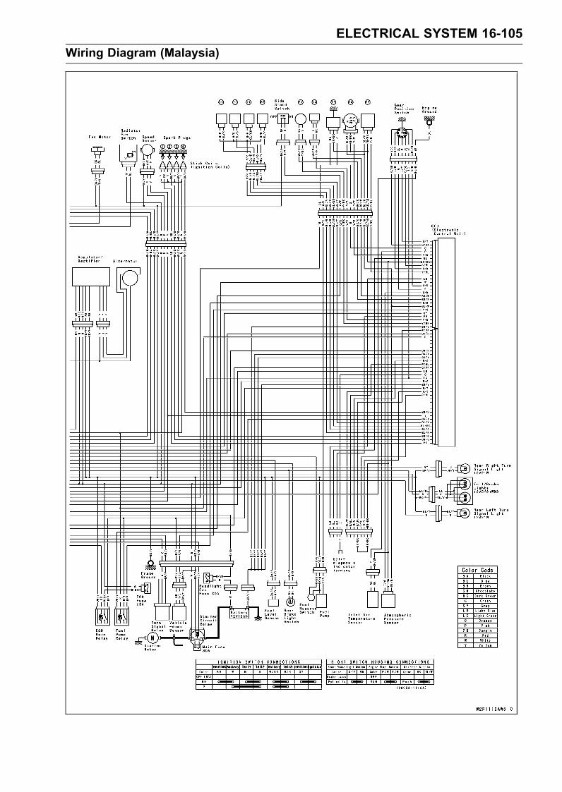
ELECTRICAL SYSTEM 16-105
Wiring Diagram (Malaysia)
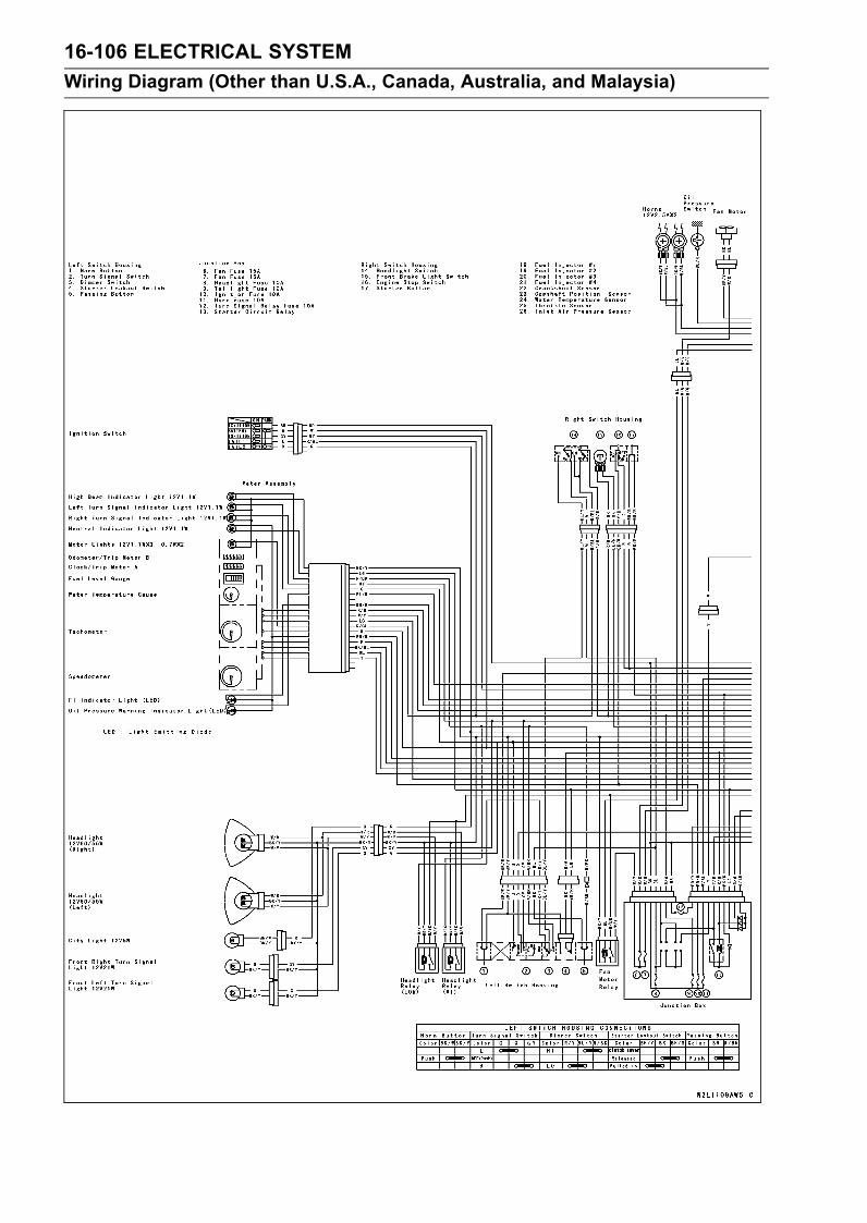
16-106 ELECTRICAL SYSTEM
Wiring Diagram (Other than U.S.A., Canada, Australia, and Malaysia)
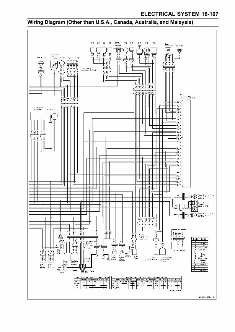
ELECTRICAL SYSTEM 16-107
Wiring Diagram (Other than U.S.A., Canada, Australia, and Malaysia)
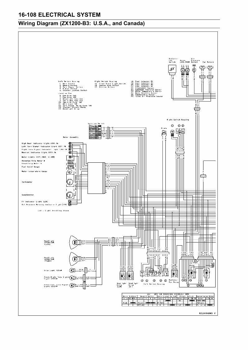
16-108 ELECTRICAL SYSTEM
Wiring Diagram (ZX1200-B3: U.S.A., and Canada)
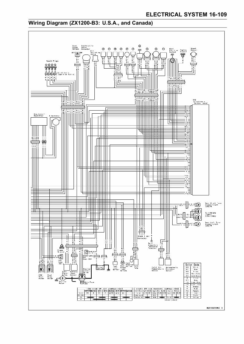
ELECTRICAL SYSTEM 16-109
Wiring Diagram (ZX1200-B3: U.S.A., and Canada)
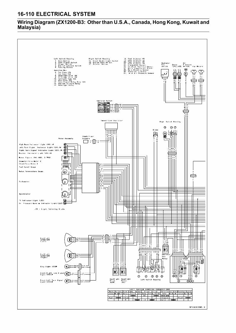
16-110 ELECTRICAL SYSTEM
Wiring Diagram (ZX1200-B3: Other than U.S.A., Canada, Hong Kong, Kuwait andMalaysia)
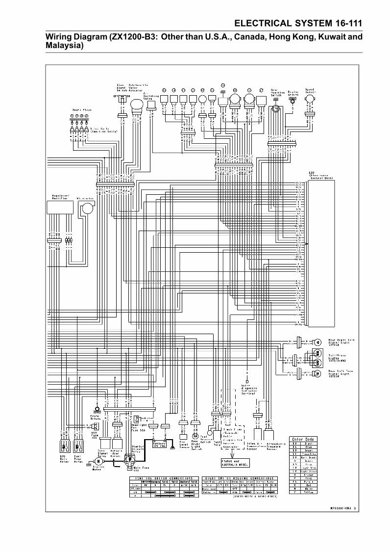
ELECTRICAL SYSTEM 16-111
Wiring Diagram (ZX1200-B3: Other than U.S.A., Canada, Hong Kong, Kuwait andMalaysia)

16-112 ELECTRICAL SYSTEM
Wiring Diagram (ZX1200-B3: Hong Kong, Kuwait)
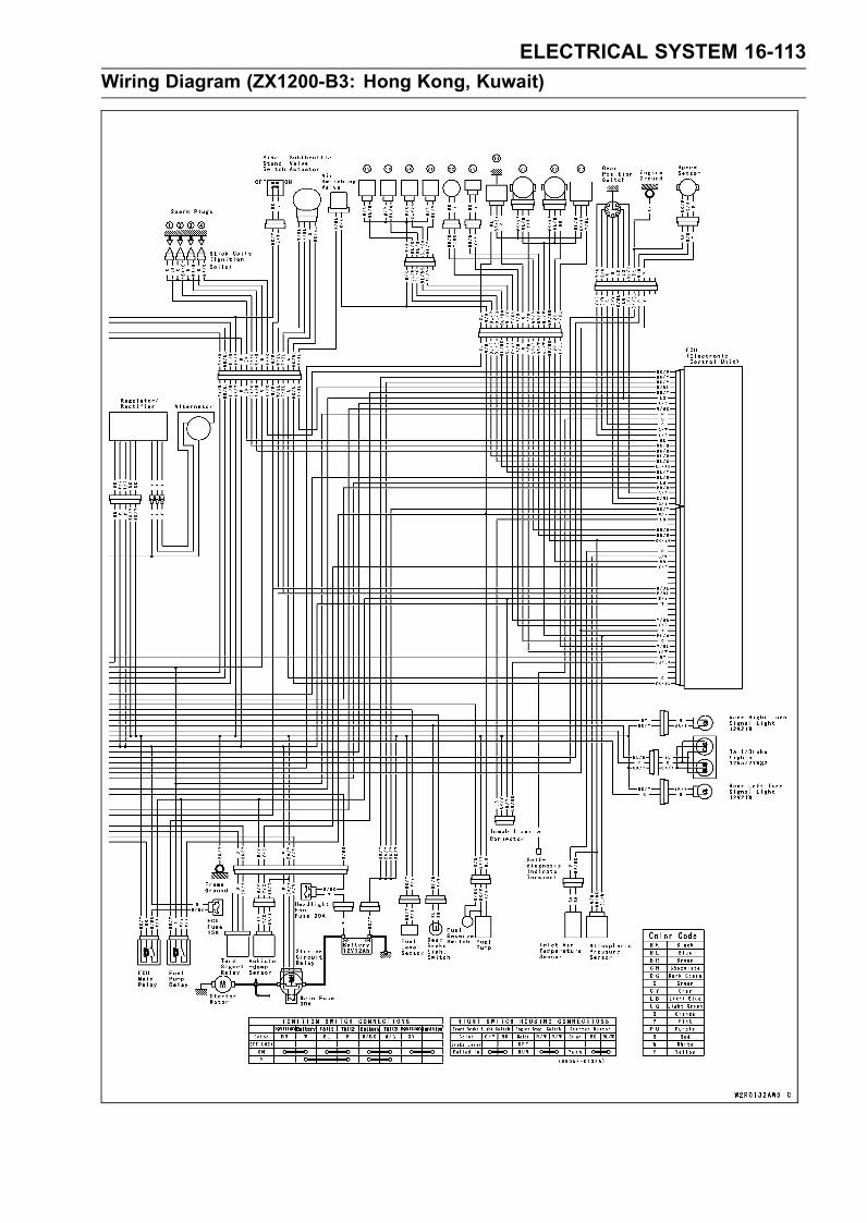
ELECTRICAL SYSTEM 16-113
Wiring Diagram (ZX1200-B3: Hong Kong, Kuwait)
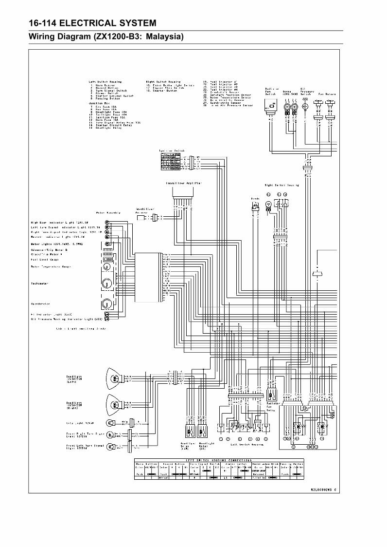
16-114 ELECTRICAL SYSTEM
Wiring Diagram (ZX1200-B3: Malaysia)

ELECTRICAL SYSTEM 16-115
Wiring Diagram (ZX1200-B3: Malaysia)


TROUBLESHOOTING 17-1
17
Troubleshooting
Table of Contents
Troubleshooting Guide ........................................................................................................... 17-2

17-2 TROUBLESHOOTING
Troubleshooting Guide
NOTERefer to the Fuel System chapter for mostof DFI trouble shooting guide.This is not an exhaustive list, giving everypossible cause for each problem listed. Itis meant simply as a rough guide to assistthe troubleshooting for some of the morecommon difficulties.
Engine Doesn’t Start, StartingDifficulty:Starter motor not rotating:Starter lockout switch or neutral switch trou-ble
Starter motor troubleBattery voltage lowStarter relay not contacting or operatingStarter button not contactingWiring open or shortedIgnition switch troubleEngine stop switch troubleFuse blown
Starter motor rotating but engine doesn’tturn over:Immobilizer system trouble (ZX1200-B3)Starter clutch troubleVehicle-down sensor (DFI) coming off
Engine won’t turn over:Valve seizureValve lifter seizureCylinder, piston seizureCrankshaft seizureConnecting rod small end seizureConnecting rod big end seizureTransmission gear or bearing seizureCamshaft seizureStarter idle gear seizure
No fuel flow:No fuel in tankFuel pump troubleFuel tank air vent obstructedFuel filter cloggedFuel line clogged
Engine flooded:Clean spark plug and adjust plug gapStarting technique faulty(When flooded, do not crank the engine withthe throttle fully opened. This promotesengine flood because more fuel is sup-plied automatically by DFI.)
No spark; spark weak:Vehicle-down sensor (DFI) coming offIgnition switch not ONEngine stop switch turned OFFClutch lever not pulled in or gear not in neu-tral
Battery voltage low
Immobilizer system trouble (ZX1200-B3)Spark plug dirty, broken, or gap malad-justed
Stick coil shorted or not in good contactStick coil troubleSpark plug incorrectIC igniter in ECU troubleCamshaft position sensor troubleNeutral, starter lockout, or sidestand switchtrouble
Crankshaft sensor troubleIgnition switch or engine stop switchshorted
Wiring shorted or openFuse blown
Fuel/air mixture incorrect:Bypass screw and/or idle adjusting screwmaladjusted
Air passage cloggedAir cleaner clogged, poorly sealed, or miss-ing
Compression Low:Spark plug looseCylinder head not sufficiently tighteneddown
No valve clearanceCylinder, piston wornPiston ring bad (worn, weak, broken, orsticking)
Piston ring/groove clearance excessiveCylinder head gasket damagedCylinder head warpedValve spring broken or weakValve not seating properly (valve bent,worn, or carbon accumulation on theseating surface)
Poor Running at Low Speed:Spark weak:Battery voltage lowSpark plug dirty, broken, or maladjustedStick coil wiring troubleStick coil not in good contactSpark plug incorrectIC igniter in ECU troubleCamshaft position sensor troubleCrankshaft sensor troubleStick coil troubleImmobilizer system trouble (ZX1200-B3)
Fuel/air mixture incorrect:Bypass screw maladjustedAir passage cloggedAir bleed pipe bleed holes cloggedPilot passage cloggedAir cleaner clogged, poorly sealed, or miss-ing
Fuel tank air vent obstructed
TROUBLESHOOTING 17-3
Troubleshooting Guide
Fuel pump troubleThrottle body assy holder looseAir cleaner duct loose
Compression low:Spark plug looseCylinder head not sufficiently tighteneddown
No valve clearanceCylinder, piston wornPiston ring bad (worn, weak, broken, orsticking)
Piston ring/groove clearance excessiveCylinder head warpedCylinder head gasket damagedValve spring broken or weakValve not seating properly (valve bent,worn, or carbon accumulation on theseating surface)
Other:IC igniter in ECU troubleThrottle body assy not synchronizingEngine oil viscosity too highDrive train troubleBrake draggingAir suction valve troubleVacuum switch valve trouble (ZX1200-B1/B2)
Air switching valve trouble (ZX1200-B3)Engine overheatingClutch slipping
Poor Running or No Power at HighSpeed:Firing incorrect:Spark plug dirty, broken, or maladjustedStick coil wiring troubleStick coil not in good contactSpark plug incorrectCamshaft position sensor troubleIC igniter in ECU troubleCrankshaft sensor troubleStick coil trouble
Fuel/air mixture incorrect:Air cleaner clogged, poorly sealed, or miss-ing
Air cleaner duct looseWater or foreign matter in fuelThrottle body assy holder looseFuel to injector insufficient (DFI)Fuel tank air vent obstructedFuel line cloggedFuel pump trouble (DFI)
Compression low:Spark plug looseCylinder head not sufficiently tighteneddown
No valve clearance
Cylinder, piston wornPiston ring bad (worn, weak, broken, orsticking)
Piston ring/groove clearance excessiveCylinder head gasket damagedCylinder head warpedValve spring broken or weakValve not seating properly (valve bent,worn, or carbon accumulation on theseating surface.)
Knocking:Carbon built up in combustion chamberFuel poor quality or incorrectSpark plug incorrectIC igniter in ECU troubleCamshaft position sensor troubleCrankshaft sensor trouble
Miscellaneous:Throttle valve won’t fully openBrake draggingClutch slippingEngine overheatingEngine oil level too highEngine oil viscosity too highDrive train troubleAir suction valve troubleVacuum switch valve trouble (ZX1200-B1/B2)
Air switching valve trouble (ZX1200-B3)Catalytic converter melt down due to muffleroverheating (KLEEN)
Overheating:Firing incorrect:Spark plug dirty, broken, or maladjustedSpark plug incorrectIC igniter in ECU trouble
Muffler overheating:For KLEEN, do not run the engine even ifwith only one cylinder misfiring or poorrunning (Request the nearest service fa-cility to correct it)
For KLEEN, do not push-start with a deadbattery (Connect another full-chargedbattery with jumper cables, and start theengine using the electric starter)
For KLEEN, do not start the engine undermisfire due to spark plug fouling or poorconnection of the stick coil
For KLEEN, do not coast the motorcyclewith the ignition switch off (Turn the igni-tion switch ON and run the engine)
IC igniter in ECU troubleFuel/air mixture incorrect:Throttle body assy holder looseAir cleaner duct looseAir cleaner poorly sealed, or missing
17-4 TROUBLESHOOTING
Troubleshooting Guide
Air cleaner cloggedCompression high:Carbon built up in combustion chamber
Engine load faulty:Clutch slippingEngine oil level too highEngine oil viscosity too highDrive train troubleBrake dragging
Lubrication inadequate:Engine oil level too lowEngine oil poor quality or incorrect
Gauge incorrect:Water temperature gauge brokenWater temperature sensor broken
Coolant incorrect:Coolant level too lowCoolant deterioratedWrong coolant mixed ratio
Cooling system component incorrect:Radiator fin damagedRadiator cloggedThermostat troubleRadiator cap troubleRadiator fan switch troubleRadiator fan relay troubleFan motor brokenFan blade damagedWater pump not turningWater pump impeller damaged
Over Cooling:Gauge incorrect:Water temperature gauge brokenWater temperature sensor broken
Cooling system component incorrect:Radiator fan switch troubleThermostat trouble
Clutch Operation Faulty:Clutch slipping:Friction plate worn or warpedSteel plate worn or warpedClutch spring broken or weakClutch hub or housing unevenly wornNo clutch lever playClutch inner cable troubleClutch release mechanism trouble
Clutch not disengaging properly:Clutch plate warped or too roughClutch spring compression unevenEngine oil deterioratedEngine oil viscosity too highEngine oil level too highClutch housing frozen on drive shaftClutch hub nut looseClutch hub spline damaged
Clutch friction plate installed wrongClutch lever play excessiveClutch release mechanism trouble
Gear Shifting Faulty:Doesn’t go into gear; shift pedal doesn’treturn:Clutch not disengagingShift fork bent or seizedGear stuck on the shaftGear positioning lever bindingShift return spring weak or brokenShift return spring pin looseShift mechanism arm spring brokenShift mechanism arm brokenShift pawl broken
Jumps out of gear:Shift fork ear worn, bentGear groove wornGear dogs and/or dog holes wornShift drum groove wornGear positioning lever spring weak or bro-ken
Shift fork guide pin wornDrive shaft, output shaft, and/or gearsplines worn
Overshifts:Gear positioning lever spring weak or bro-ken
Shift mechanism arm spring broken
Abnormal Engine Noise:Knocking:IC igniter in ECU troubleCarbon built up in combustion chamberFuel poor quality or incorrectSpark plug incorrectOverheating
Piston slap:Cylinder/piston clearance excessiveCylinder, piston wornConnecting rod bentPiston pin, piston pin hole worn
Valve noise:Valve clearance incorrectValve spring broken or weakCamshaft bearing wornValve lifter worn
Other noise:Connecting rod small end clearance exces-sive
Connecting rod big end clearance exces-sive
Piston ring/groove clearance excessivePiston ring worn, broken, or stuckPiston ring groove wornPiston seizure, damage

TROUBLESHOOTING 17-5
Troubleshooting Guide
Cylinder head gasket leakingExhaust pipe leaking at cylinder head con-nection
Crankshaft runout excessiveEngine mount looseCrankshaft bearing wornPrimary gear worn or chippedCamshaft chain tensioner troubleCamshaft chain, sprocket, guide wornAir suction valve damagedVacuum switch valve damaged (ZX1200-B1/B2)
Air switching valve damage (ZX1200-B3)Alternator rotor looseCatalytic converter melt down due tomuffleroverheating (KLEEN)
Balancer gear worn or chippedBalancer shaft position maladjustedBalancer bearing wornBalancer shaft coupling rubber damperdamaged
Abnormal Drive Train Noise:Clutch noise:Clutch damper weak or damagedClutch housing/friction plate clearance ex-cessive
Clutch housing gear wornWrong installation of outside friction plate
Transmission noise:Bearings wornTransmission gear worn or chippedMetal chips jammed in gear teethEngine oil insufficient
Drive line noise:Drive chain adjusted improperlyDrive chain wornRear and/or engine sprocket wornChain lubrication insufficientRear wheel misaligned
Abnormal Frame Noise:Front fork noise:Oil insufficient or too thinSpring weak or broken
Rear shock absorber noise:Shock absorber damaged
Disc brake noise:Pad installed incorrectlyPad surface glazedDisc warpedCaliper trouble
Other noise:Bracket, nut, bolt, etc. not properlymounted or tightened
Oil Pressure Warning Light Goes On:Engine oil pump damagedEngine oil screen cloggedEngine oil filter cloggedEngine oil level too lowEngine oil viscosity too lowCamshaft bearing wornCrankshaft bearing wornOil pressure switch damagedWiring faultyRelief valve stuck openO-ring at the oil passage in the crankcasedamaged
Exhaust Smokes Excessively:White smoke:Piston oil ring wornCylinder wornValve oil seal damagedValve guide wornEngine oil level too high
Black smoke:Air cleaner clogged
Brown smoke:Air cleaner duct looseAir cleaner poorly sealed or missing
Handling and/or StabilityUnsatisfactory:Handlebar hard to turn:Cable routing incorrectHose routing incorrectWiring routing incorrectSteering stem nut too tightSteering stem bearing damagedSteering stem bearing lubrication inade-quate
Steering stem bentTire air pressure too low
Handlebar shakes or excessively vibrates:Tire wornSwingarm pivot bearing wornRim warped, or not balancedWheel bearing wornHandlebar clamp bolt looseSteering stem nut looseFront, rear axle runout excessiveEngine mounting bolt loose
Handlebar pulls to one side:Frame bentWheel misalignmentSwingarm bent or twistedSwingarm pivot shaft runout excessiveSteering maladjustedFront fork bentRight and left front fork oil level uneven
17-6 TROUBLESHOOTING
Troubleshooting Guide
Shock absorption unsatisfactory:(Too hard)Front fork oil excessiveFront fork oil viscosity too highRear shock absorber adjustment too hardTire air pressure too highFront fork bent(Too soft)Tire air pressure too lowFront fork oil insufficient and/or leakingFront fork oil viscosity too lowRear shock adjustment too softFront fork, rear shock absorber spring weakRear shock absorber oil leaking
Brake Doesn’t Hold:Air in the brake linePad or disc wornBrake fluid leakageDisc warpedContaminated pad
Brake fluid deterioratedPrimary or secondary cup damaged in mastercylinder
Master cylinder scratched inside
Battery Trouble:Battery discharged:Charge insufficientBattery faulty (too low terminal voltage)Battery lead making poor contactLoad excessive (e.g., bulb of excessivewattage)
Ignition switch troubleAlternator troubleWiring faultyRegulator/rectifier trouble
Battery overcharged:Alternator troubleRegulator/rectifier troubleBattery faulty

MODEL APPLICATIONYear Model Beginning Frame No.
2002 ZX1200-B1
JKAZX9B12A000001 orJKAZXT20ABA035001 orJKAZX9B1 2A035001 orJKAZX9B12A000001 orZXT20B-000001
2003 ZX1200-B2JKAZX9B13A008001 orJKAZXT20ABA041001 orZXT20B-008001
2004 ZX1200-B3JKAZX9B14A012001 orJKAZXT20ABA045001 orZXT20B-012001
:This digit in the frame number changes from one machine to another.
Part No.99924-1278-03 Printed in Japan