momentum transport balance wk
TRANSCRIPT

2. Momentum Transport Balance
CDB 3033
TRANSPORT PHENOMENA

2
Recap…Momentum Transport Balance
There are two mechanisms :1. Molecular transport. 2. Convective transport
Combined momentum flux
= molecular stress+ convective stress

3
There are two mechanisms :1. Molecular transport. 2. Convective transport
Convective transport
Molecular transport
rvv
p = pd + t
Combined momentum flux = p +rvv
Momentum Transport Balance

6. Describe shell balance technique to solve
momentum transfer balance equation.
Lesson outcomes
4
5
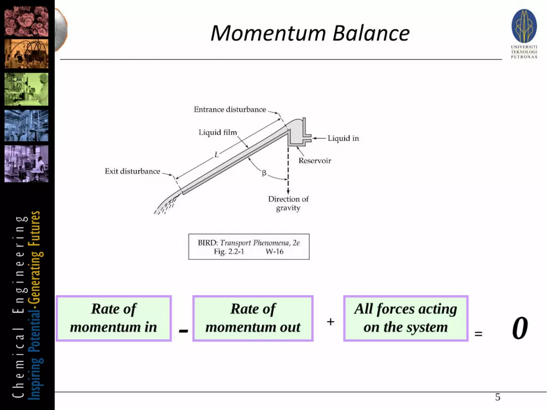
Momentum Balance
Rate of
momentum in
Rate of
momentum out-All forces acting
on the system+= 0

6
Momentum Balance
Rate of
momentum in
Rate of
momentum out- All forces acting
on the system+
= 0
Rate of
momentum in
by conv.
transport
Rate of
momentum out
by conv.
transport
0=
-Rate of
momentum in by
molec. transport+
Rate of
momentum out
by molec.
transport
-
+Force of gravity
acting on the
system

7
Momentum Balance
Shell Balance Technique
How to solve the equation?
Set up momentum balance over a thin ‘shell’
9 Steps

Procedure of transport analysis
8
1. Draw a physical diagram
2. Identify all transport mechanisms.
3. Set a frame of coordinates and draw the direction of all
transport processes which identified in step 2.
4. Draw a shell, such as that its surface perpendicular to
the transport dir.
5. Carry out the momentum shell balance as below:
This should give a first order ODE in terms of shear stress.
Rate of
momentum in
Rate of
momentum out-All forces acting
on the system+= 0
Procedure of transport analysis
9
6. If the fluid is Newtonian, apply the Newton law.
However if the fluid is non-Newtonian, apply appropriate
non-Newtonian law empirical equation. This should give a
2nd Order ODE in term of velocity.
7. Impose physical constraint on the boundary of the
physical system . This give rise to boundary conditions.
8. Solve the equation for the velocity distribution.
9. Then obtain the mean velocity, flow rate and etc.

Boundary Conditions (BC)
10
1. Solid-liquid interface, the fluid velocity equals to the
equals velocity of the solid surface.
2. Gas-liquid interface, the shear stress is zero owing to
the fact that the gas viscosity is low.
3. Liquid-liquid interface, the shear stresses and the
velocities are continuous across the interface.
Example :- A pair of large parallel plates, each one withare A, is separated by a distance . The space betweenthem is filled with Newtonian fluid. The lower plate ismoving horizontally with a velocity of v0 parallel to theupper plate. Determine the velocity profile of the fluidat steady state assuming laminar flow condition.
11

12
Momentum Shell Balance Technique
Shell Balance Step 1-21. Draw a physical diagram
2. Identify all transport mechanisms
13
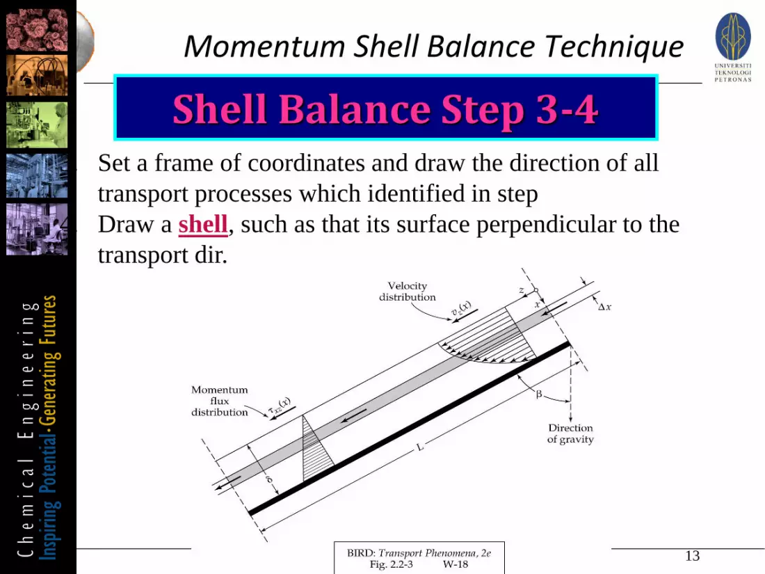
Momentum Shell Balance Technique
Shell Balance Step 3-43. Set a frame of coordinates and draw the direction of all
transport processes which identified in step
4. Draw a shell, such as that its surface perpendicular to the
transport dir.
14
Momentum Shell Balance Technique
Shell Balance Step 5
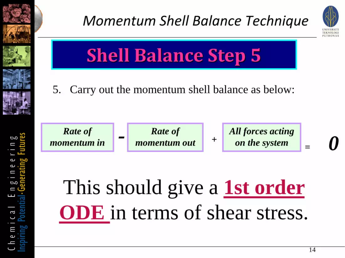
5. Carry out the momentum shell balance as below:
Rate of
momentum in
Rate of
momentum out- All forces acting
on the system+= 0
This should give a 1st order
ODE in terms of shear stress.

15
Momentum Shell Balance Technique
Shell Balance Step 6
6. If the fluid is Newtonian, apply the Newton’s law.
However if the fluid is non-Newtonian, apply appropriate
non-Newtonian law empirical equation.
This should give a 2nd Order
ODE in term of velocity.
16
Momentum Shell Balance Technique
Shell Balance Step 7
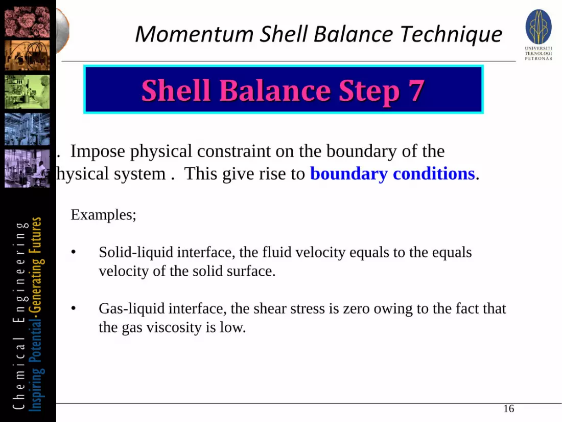
7. Impose physical constraint on the boundary of the
physical system . This give rise to boundary conditions.
Examples;
• Solid-liquid interface, the fluid velocity equals to the equals
velocity of the solid surface.
• Gas-liquid interface, the shear stress is zero owing to the fact that
the gas viscosity is low.
17
Momentum Shell Balance Technique
Shell Balance Step 8
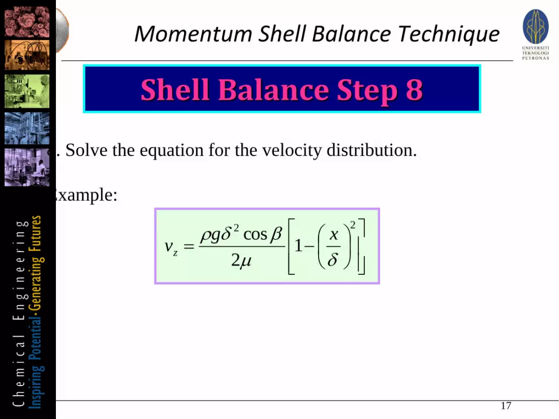
8. Solve the equation for the velocity distribution.
Example:
22
12
cos
d
dr xgvz
18
Momentum Shell Balance Technique
Shell Balance Step 9
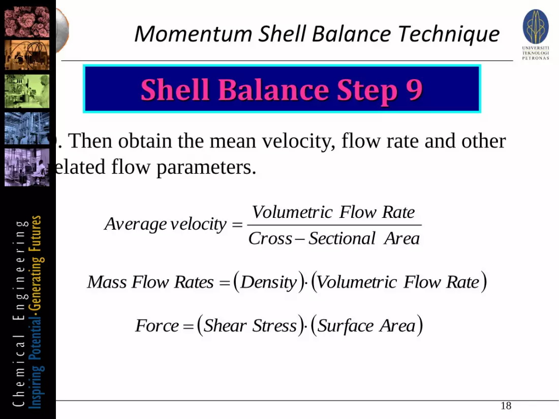
9. Then obtain the mean velocity, flow rate and other
related flow parameters.
AreaSectionalCross
RateFlowVolumetricvelocityAverage
RateFlowVolumetricDensityRatesFlowMass
AreaSurfaceStressShearForce
6. Describe shell balance technique to solve
momentum transfer balance equation.
Lesson outcomes
19