modulus - society of structural engineers – sri lanka
TRANSCRIPT
MODULUSSociety of Structural Engineers - Sri LankaSociety of Structural Engineers - Sri Lanka
Established in July 1993incorporated by parliament act. No. 40 in 2009
Established in July 1993incorporated by parliament act. No. 40 in 2009
Society News & Technical PapersSociety News & Technical PapersVol.31, No.1 MARCH 2021

MODULUS | March 2021Vol. 31 | No. 01
1SOCIETY OF STRUCTURAL ENGINEERS SRI LANKA
EDITOR’S MESSAGEMODULUS | March 2021 Vol.31 No. 01
SOCIETY OF STRUCTURAL ENGINEERS SRI LANKA
EDITOR’S MESSAGE
EDITOR’S MESSAGE Structural Engineer’s Role in Sustainable Development
“Wild life and Forest Conservation” and “Environmental Preservation” are key words that are heard and spoken frequently in the current context. The controversial recent incidents that took place in the country have created a buzz in the social and public media as on to how the construction and development of infrastructure projects influence deforestation and destruction of flora and fauna. Civil Engineering; the significant keystone of civilization, is always recognized as the starting point of infrastructure development. Of the wider scope of Civil Engineering, Structural Engineering being a main branch, is anticipated to ensure safe designs and physical integrity of buildings and large structures such as tunnels, dams, bridges, etc. The work of Structural Engineers is inseparable from people’s day to day life. Sky-scrapes visible in every nook and corner of the country, aesthetically appealing iconic bridge designs, solid fortress- like irrigation facilities are indispensable in the history of modern civilization of the human race. Hence there is no astonishment that Structural Engineers are also being held partly responsible for the repercussions of environmental destruction in the present scenario.
It is undoubted that rapid infrastructure development is like a double edge sword which earns us tremendous amount of wealth, while causes deterioration of the ecological environment. We as Structural Engineers have trained our attitude and mindset to make sure the designs that we produce are safe, stable, durable and economical. All elements are checked for the adequacy of strength and overall stability of the structure. Selection of materials will also be based on the strength, durability, serviceability and economic conditions of the project. While doing all these to achieve the most optimum structural and economical solution for a particular project, sometimes we have unknowingly sacrificed a hefty amount of natural resources and left many ecological friendly options untouched and ignored.
Poor planning plays the role of the culprit in these situations. Sometimes a vast area of land is used to build a single building; infrastructure such as tunnels, roads and expressways planned imprudently ending up with utilizing the land areas thriftlessly; removing vegetation and top soil from construction sites causing soil erosion, poor quality construction methods and under maintained equipment adding noise and vibration effects to the environment, while polluting the air and water in numerous ways. Besides, removal of exquisite or indigenous flora and destructing the entire natural habitat of fauna to make room for predetermined infrastructure projects such as roads, railways or a power line may provide convenience to human life while devastating the wild life.
The present generation seems to be manipulating
the natural resources lavishly at a rate closer to 1.5 times the rate that a sustainable environment is expected to use. With the loss of bio diversity, increased environmental pollution and the depletion of forests due to poor planning in rapid infrastructure development projects, there is no guarantee that our children will enjoy the nature gifted benefits as much as we do now. They will be deprived of the quality of life we enjoy today.
With all dots connected, the conclusion to be drawn is that there should be a balance between planning of infrastructure or building projects along with environmental preservation. There will be no project that can claim to have caused zero impact to the environment, but could be possible to plan in a meticulous way that detrimental effects caused to the environment is minimized and mitigated. True this cannot be achieved by an individual or a single entity, but should be a group effort to be put forward at the inception phase of a project and carried out through all stages of the project until the phase of termination. Within the team, the Structural Engineer should play a vital role in making sure the structural design provided by him or her is not only safe proof and durable but also making extra efforts in the exercise protecting the environment. With time the responsibility of the Structural Engineer should also incorporate an environmental component which can produce a design that is not only economical but also environmentally and socially sustainable.
In summary, it is high time that we pay attention towards the deforestation and environmental pollution that has occurred globally in the name of rapid development. Taking leadership in this matter will not only pave the path for Structural Engineers to identify their strengths and opportunities to cope with the issue, but also to sharpen their practical and theoretical knowledge in order to cater to the new requirement. Thus new, innovative and alternative designs could be introduced and made use in near future, to be frontliners of creating a more sustainable built environment for the better interest of our profession as well as for the interest of the future generations.
Eng. S.S.A.Kalugaldeniya, B.Sc.Eng (Hons), M. Sc. (TUT- Japan), C. Eng, MIE(SL), MSSE(SL) Editor, Society of Structural Engineers, Sri Lanka. Email : [email protected]
MODULUS | March 2021Vol. 31 | No. 01
2 SOCIETY OF STRUCTURAL ENGINEERS SRI LANKA
ACKNOWLEDGEMENT & CONTENTMODULUS | March 2021 Vol.31 No. 01
SOCIETY OF STRUCTURAL ENGINEERS SRI LANKA
ACKNOWLEDGEMENT & CONTENT
ACKNOWLEDGEMENT
CONTENT Cover Story
03
Society News a. Seminar on Advances in Structural Materials b. Course on Structural Design of Multi Storied
Buildings c. AGM - Associate Member Chapter SSESL d. Online Platforms e. Best technical paper for the Annual Sessions
2020 f. Code of Conduct and Guidance Notes –
SSESL g. SSESL Event Calendar - 2021
04
05 06 06 06
07-10
10
President’s Message
11
Research Forum a. Post-Installed Retrofitting System for
Improving the Punching Shear Capacity of Reinforced Concrete Elements J. Buhler
b. Feasibility of Using 3D Point Cloud
Technologies in Sri Lankan Civil Engineering Industry R. Subakaran, H.M.S.T Herath
Engineer’s Forum
c. Seismic Retrofitting of Reinforced Concrete Structures Using Concrete Jacketing – A Review and Application
H. A. D. S. Buddika, D. M. A. G. B. Dissanayake, P. B. R. Dissanayake
12-18
19-25
26-32
The Editor wishes to thank authors of the research articles, Eng. Kaveesh Abeysuriya for providing the write up for the cover story, Eng. N.Abeysuriya, President of SSESL, Eng. N.A. Amarasinghe, Ms. Nimesha Katuwala and the Associate Member Chapter for their contribution in preparing the Modulus.
The statements made or opinions expressed in the Modulus do not necessarily reflect the views of the Society of Structural Engineers, Sri Lanka the Modulus.
MODULUS | March 2021Vol. 31 | No. 01
3SOCIETY OF STRUCTURAL ENGINEERS SRI LANKA
COVER STORYMODULUS | March 2021 Vol.31 No. 01
SOCIETY OF STRUCTURAL ENGINEERS SRI LANKA
COVER STORY
COVER STORY
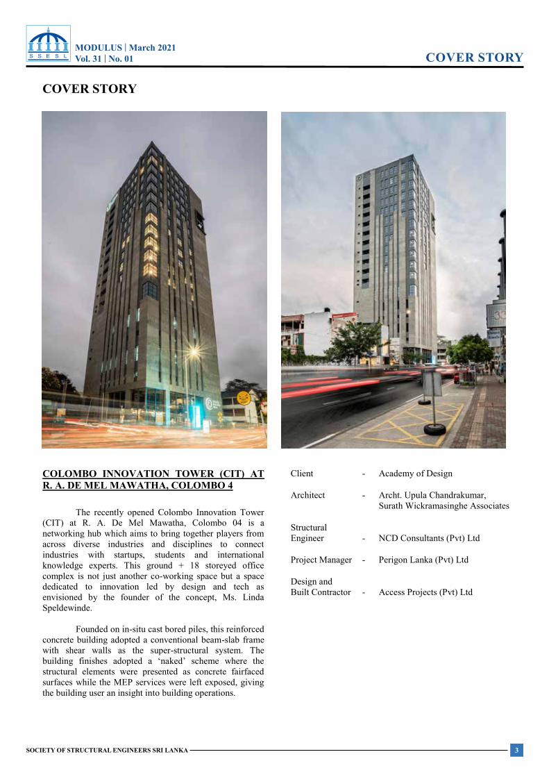
COLOMBO INNOVATION TOWER (CIT) AT R. A. DE MEL MAWATHA, COLOMBO 4
The recently opened Colombo Innovation Tower (CIT) at R. A. De Mel Mawatha, Colombo 04 is a networking hub which aims to bring together players from across diverse industries and disciplines to connect industries with startups, students and international knowledge experts. This ground + 18 storeyed office complex is not just another co-working space but a space dedicated to innovation led by design and tech as envisioned by the founder of the concept, Ms. Linda Speldewinde.
Founded on in-situ cast bored piles, this reinforced concrete building adopted a conventional beam-slab frame with shear walls as the super-structural system. The building finishes adopted a ‘naked’ scheme where the structural elements were presented as concrete fairfaced surfaces while the MEP services were left exposed, giving the building user an insight into building operations.
Client
- Academy of Design
Architect - Archt. Upula Chandrakumar, Surath Wickramasinghe Associates
Structural Engineer
-
NCD Consultants (Pvt) Ltd
Project Manager - Perigon Lanka (Pvt) Ltd
Design and Built Contractor
-
Access Projects (Pvt) Ltd
MODULUS | March 2021Vol. 31 | No. 01
4 SOCIETY OF STRUCTURAL ENGINEERS SRI LANKA
SOCIETY NEWS MODULUS | March 2021 Vol.31 No. 01
SOCIETY OF STRUCTURAL ENGINEERS SRI LANKA
SOCIETY NEWS
SOCIETY NEWS Seminar on Advances in Structural Materials
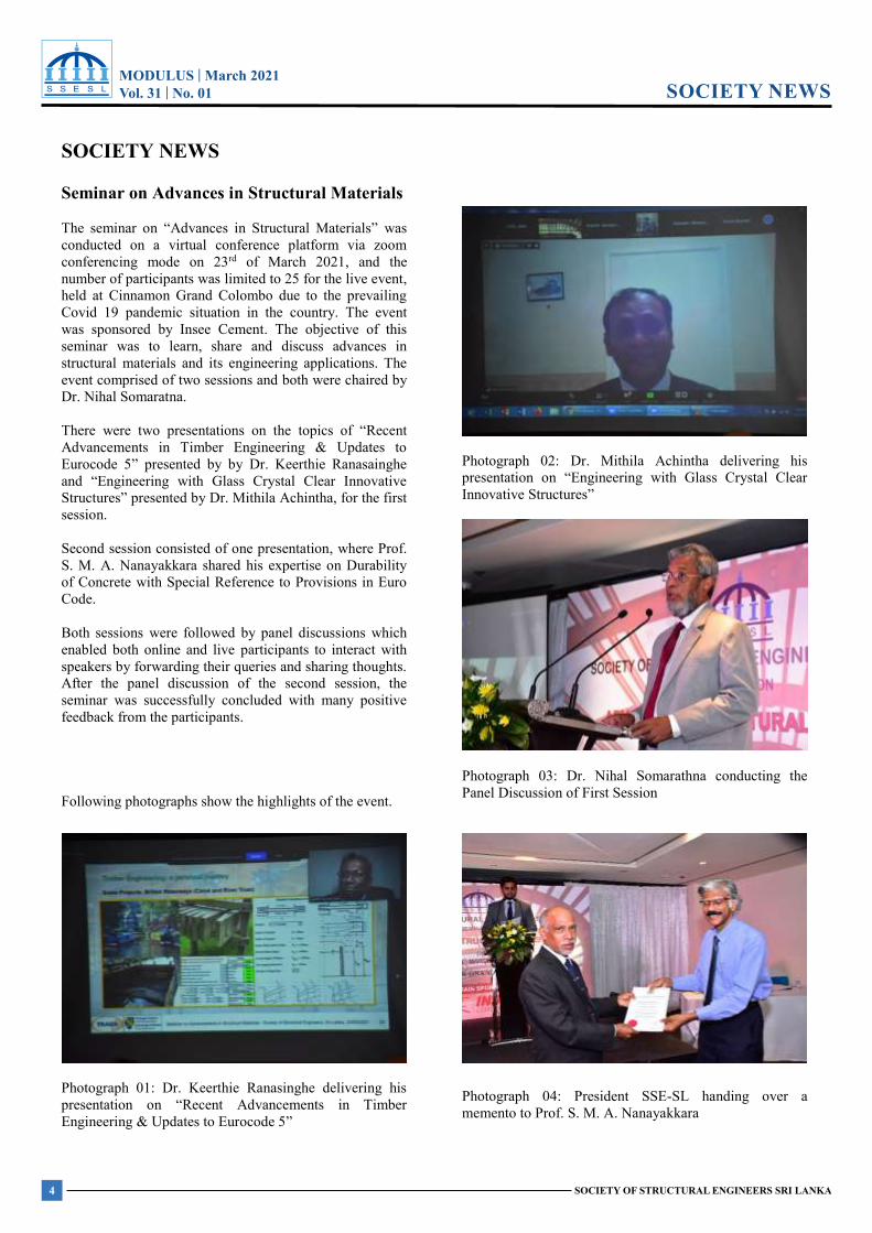
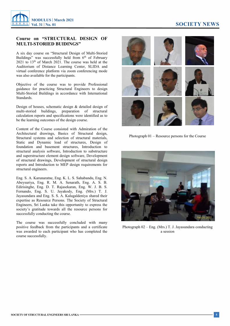
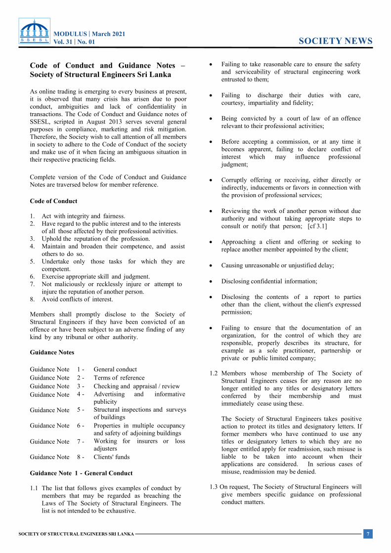
The seminar on “Advances in Structural Materials” was conducted on a virtual conference platform via zoom conferencing mode on 23rd of March 2021, and the number of participants was limited to 25 for the live event, held at Cinnamon Grand Colombo due to the prevailing Covid 19 pandemic situation in the country. The event was sponsored by Insee Cement. The objective of this seminar was to learn, share and discuss advances in structural materials and its engineering applications. The event comprised of two sessions and both were chaired by Dr. Nihal Somaratna. There were two presentations on the topics of “Recent Advancements in Timber Engineering & Updates to Eurocode 5” presented by by Dr. Keerthie Ranasainghe and “Engineering with Glass Crystal Clear Innovative Structures” presented by Dr. Mithila Achintha, for the first session. Second session consisted of one presentation, where Prof. S. M. A. Nanayakkara shared his expertise on Durability of Concrete with Special Reference to Provisions in Euro Code. Both sessions were followed by panel discussions which enabled both online and live participants to interact with speakers by forwarding their queries and sharing thoughts. After the panel discussion of the second session, the seminar was successfully concluded with many positive feedback from the participants. Following photographs show the highlights of the event.
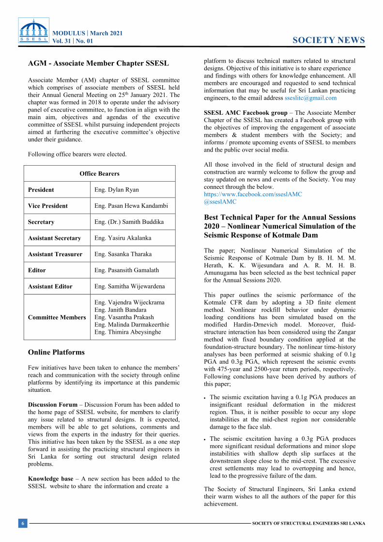
Photograph 01: Dr. Keerthie Ranasinghe delivering his presentation on “Recent Advancements in Timber Engineering & Updates to Eurocode 5”
Photograph 02: Dr. Mithila Achintha delivering his presentation on “Engineering with Glass Crystal Clear Innovative Structures”
Photograph 03: Dr. Nihal Somarathna conducting the Panel Discussion of First Session
Photograph 04: President SSE-SL handing over a memento to Prof. S. M. A. Nanayakkara
MODULUS | March 2021Vol. 31 | No. 01
5SOCIETY OF STRUCTURAL ENGINEERS SRI LANKA
SOCIETY NEWSMODULUS | March 2021 Vol.31 No. 01
SOCIETY OF STRUCTURAL ENGINEERS SRI LANKA
SOCIETY NEWS
Course on “STRUCTURAL DESIGN OF MULTI-STORIED BUIDINGS”
A six day course on “Structural Design of Multi-Storied Buildings” was successfully held from 6th of February 2021 to 13th of March 2021. The course was held at the Auditorium of Distance Learning Center, SLIDA and virtual conference platform via zoom conferencing mode was also available for the participants. Objective of the course was to provide Professional guidance for practicing Structural Engineers to design Multi-Storied Buildings in accordance with International Standards. Design of houses, schematic design & detailed design of multi-storied buildings, preparation of structural calculation reports and specifications were identified as to be the learning outcomes of the design course. Content of the Course consisted with Admiration of the Architectural drawings, Basics of Structural design, Structural systems and selection of structural materials, Static and Dynamic load of structures, Design of foundation and basement structures, Introduction to structural analysis software, Introduction to substructure and superstructure element design software, Development of structural drawings, Development of structural design reports and Introduction to MEP design requirements for structural engineers. Eng. S. A. Karunaratne, Eng. K. L. S. Sahabandu, Eng. N. Abeysuriya, Eng. R. M. A. Senarath, Eng. A. S. B. Edirisinghe, Eng. D. T. Rajasekaran, Eng. W. J. B. S. Fernando, Eng. S. U. Jayakody, Eng. (Mrs.) T. J. Jayasundara and Eng. S. S. A. Kalugaldeniya shared their expertise as Resource Persons. The Society of Structural Engineers, Sri Lanka take this opportunity to express the society’s gratitude towards all the resource persons for successfully conducting the course. The course was successfully concluded with many positive feedback from the participants and a certificate was awarded to each participant who has completed the course successfully.
Photograph 01 – Resource persons for the Course
Photograph 02 – Eng. (Mrs.) T. J. Jayasundara conducting a session
MODULUS | March 2021Vol. 31 | No. 01
6 SOCIETY OF STRUCTURAL ENGINEERS SRI LANKA
SOCIETY NEWSMODULUS | March 2021 Vol.31 No. 01
SOCIETY OF STRUCTURAL ENGINEERS SRI LANKA
SOCIETY NEWS
AGM - Associate Member Chapter SSESL Associate Member (AM) chapter of SSESL committee which comprises of associate members of SSESL held their Annual General Meeting on 25th January 2021. The chapter was formed in 2018 to operate under the advisory panel of executive committee, to function in align with the main aim, objectives and agendas of the executive committee of SSESL whilst pursuing independent projects aimed at furthering the executive committee’s objective under their guidance. Following office bearers were elected.
Office Bearers
President Eng. Dylan Ryan
Vice President Eng. Pasan Hewa Kandambi
Secretary Eng. (Dr.) Samith Buddika
Assistant Secretary Eng. Yasiru Akalanka
Assistant Treasurer Eng. Sasanka Tharaka
Editor Eng. Pasansith Gamalath
Assistant Editor Eng. Samitha Wijewardena
Committee Members
Eng. Vajendra Wijeckrama Eng. Janith Bandara Eng. Vasantha Prakash Eng. Malinda Darmakeerthie Eng. Thimira Abeysinghe
Online Platforms
Few initiatives have been taken to enhance the members’ reach and communication with the society through online platforms by identifying its importance at this pandemic situation. Discussion Forum – Discussion Forum has been added to the home page of SSESL website, for members to clarify any issue related to structural designs. It is expected, members will be able to get solutions, comments and views from the experts in the industry for their queries. This initiative has been taken by the SSESL as a one step forward in assisting the practicing structural engineers in Sri Lanka for sorting out structural design related problems. Knowledge base – A new section has been added to the SSESL website to share the information and create a
platform to discuss technical matters related to structural designs. Objective of this initiative is to share experience and findings with others for knowledge enhancement. All members are encouraged and requested to send technical information that may be useful for Sri Lankan practicing engineers, to the email address [email protected] SSESL AMC Facebook group – The Associate Member Chapter of the SSESL has created a Facebook group with the objectives of improving the engagement of associate members & student members with the Society; and informs / promote upcoming events of SSESL to members and the public over social media. All those involved in the field of structural design and construction are warmly welcome to follow the group and stay updated on news and events of the Society. You may connect through the below. https://www.facebook.com/sseslAMC @sseslAMC Best Technical Paper for the Annual Sessions 2020 – Nonlinear Numerical Simulation of the Seismic Response of Kotmale Dam
The paper; Nonlinear Numerical Simulation of the Seismic Response of Kotmale Dam by B. H. M. M. Herath, K. K. Wijesundara and A. R. M. H. B. Amunugama has been selected as the best technical paper for the Annual Sessions 2020. This paper outlines the seismic performance of the Kotmale CFR dam by adopting a 3D finite element method. Nonlinear rockfill behavior under dynamic loading conditions has been simulated based on the modified Hardin-Drnevich model. Moreover, fluid-structure interaction has been considered using the Zangar method with fixed boundary condition applied at the foundation-structure boundary. The nonlinear time-history analyses has been performed at seismic shaking of 0.1g PGA and 0.3g PGA, which represent the seismic events with 475-year and 2500-year return periods, respectively. Following conclusions have been derived by authors of this paper; The seismic excitation having a 0.1g PGA produces an
insignificant residual deformation in the midcrest region. Thus, it is neither possible to occur any slope instabilities at the mid-chest region nor considerable damage to the face slab.
The seismic excitation having a 0.3g PGA produces more significant residual deformations and minor slope instabilities with shallow depth slip surfaces at the downstream slope close to the mid-crest. The excessive crest settlements may lead to overtopping and hence, lead to the progressive failure of the dam.
The Society of Structural Engineers, Sri Lanka extend their warm wishes to all the authors of the paper for this achievement.
MODULUS | March 2021Vol. 31 | No. 01
7SOCIETY OF STRUCTURAL ENGINEERS SRI LANKA
SOCIETY NEWSMODULUS | March 2021 Vol.31 No. 01
SOCIETY OF STRUCTURAL ENGINEERS SRI LANKA
SOCIETY NEWS
Code of Conduct and Guidance Notes – Society of Structural Engineers Sri Lanka As online trading is emerging to every business at present, it is observed that many crisis has arisen due to poor conduct, ambiguities and lack of confidentiality in transactions. The Code of Conduct and Guidance notes of SSESL, scripted in August 2013 serves several general purposes in compliance, marketing and risk mitigation. Therefore, the Society wish to call attention of all members in society to adhere to the Code of Conduct of the society and make use of it when facing an ambiguous situation in their respective practicing fields. Complete version of the Code of Conduct and Guidance Notes are traversed below for member reference. Code of Conduct 1. Act with integrity and fairness. 2. Have regard to the public interest and to the interests
of all those affected by their professional activities. 3. Uphold the reputation of the profession. 4. Maintain and broaden their competence, and assist
others to do so. 5. Undertake only those tasks for which they are
competent. 6. Exercise appropriate skill and judgment. 7. Not maliciously or recklessly injure or attempt to
injure the reputation of another person. 8. Avoid conflicts of interest. Members shall promptly disclose to the Society of Structural Engineers if they have been convicted of an offence or have been subject to an adverse finding of any kind by any tribunal or other authority. Guidance Notes Guidance Note 1 - General conduct Guidance Note 2 - Terms of reference Guidance Note 3 - Checking and appraisal / review Guidance Note 4 - Advertising and informative
publicity Guidance Note 5 - Structural inspections and surveys
of buildings Guidance Note 6 - Properties in multiple occupancy
and safety of adjoining buildings Guidance Note 7 - Working for insurers or loss
adjusters Guidance Note 8 - Clients' funds Guidance Note 1 - General Conduct 1.1 The list that follows gives examples of conduct by
members that may be regarded as breaching the Laws of The Society of Structural Engineers. The list is not intended to be exhaustive.
Failing to take reasonable care to ensure the safety and serviceability of structural engineering work entrusted to them;
Failing to discharge their duties with care,
courtesy, impartiality and fidelity; Being convicted by a court of law of an offence
relevant to their professional activities; Before accepting a commission, or at any time it
becomes apparent, failing to declare conflict of interest which may influence professional judgment;
Corruptly offering or receiving, either directly or
indirectly, inducements or favors in connection with the provision of professional services;
Reviewing the work of another person without due
authority and without taking appropriate steps to consult or notify that person; [cf 3.1]
Approaching a client and offering or seeking to
replace another member appointed by the client; Causing unreasonable or unjustified delay; Disclosing confidential information; Disclosing the contents of a report to parties
other than the client, without the client's expressed permission;
Failing to ensure that the documentation of an
organization, for the control of which they are responsible, properly describes its structure, for example as a sole practitioner, partnership or private or public limited company;
1.2 Members whose membership of The Society of
Structural Engineers ceases for any reason are no longer entitled to any titles or designatory letters conferred by their membership and must immediately cease using these.
The Society of Structural Engineers takes positive action to protect its titles and designatory letters. If former members who have continued to use any titles or designatory letters to which they are no longer entitled apply for readmission, such misuse is liable to be taken into account when their applications are considered. In serious cases of misuse, readmission may be denied.
1.3 On request, The Society of Structural Engineers will
give members specific guidance on professional conduct matters.
MODULUS | March 2021Vol. 31 | No. 01
8 SOCIETY OF STRUCTURAL ENGINEERS SRI LANKA
SOCIETY NEWSMODULUS | March 2021 Vol.31 No. 01
SOCIETY OF STRUCTURAL ENGINEERS SRI LANKA
SOCIETY NEWS
Guidance Note 2 - Terms of Reference 2.1 The engineer should take all reasonable steps to
ensure that the client understands the scope and limitations of the service to be provided. The urgency with which work is often required should not be allowed to override the need for written clarification of the brief.
2.2 When an approach is received from a potential client,
engineers should take all reasonable steps to understand and define the brief with the client. Engineers should be particularly careful to make the client aware that they will not be offering a service in matters lying outside their competence. If other professional advice is required the client should be informed.
2.3 Engineers should ensure that their brief and terms
of payment are agreed by the client and should obtain written acceptance prior to commencement of work. If it becomes apparent that the scope of work, and fee eventually chargeable, will be greater than originally estimated, the client should be advised of this at the earliest opportunity.
Guidance Note 3 - Checking and Appraisal / Review 3.1 The checking engineer (or verification engineer)
should have full regard to the public interest. It is preferable that (subject to the consent of the client) the checking engineer should inform the designer of their appointment and have access to all those responsible for the original design, and that they are able to freely discuss, and resolve, all pertinent matters with the designer. The checking engineer should remain impartial and objective and avoid being influenced by the designer.
3.2 There should be a formal agreement between the
checking engineer and the client, defining the extent and scope of the check and making provision for effective communication between the checking engineer and the designer. It may be appropriate to include in this a statement detailing the obligations of the designer to the client.
3.3 If the checking engineer finds a problem in a design
which they are unable to resolve, they should state clearly why it is a problem and should not hesitate to advise the client accordingly.
3.4 The checking engineer should obtain another
opinion if the original design is considered to be seriously at fault.
3.5 The checking engineer should not offer themselves
for any remedial works to be undertaken, but if the client wishes to instruct the checking engineer to supervise those works, the client should first inform the designer.
3.6 In the public as well as in the client's interest, an engineer may accept appointment in replacement of another engineer, but not until the replacing engineer is satisfied that the appointment of the previous engineer has been terminated and also that steps are in hand to resolve any outstanding matters between the client and the previous engineer.
Guidance Note 4 - Advertising and Informative Publicity 4.1 Advertising and informative publicity should be
helpful to the public, while upholding the reputation of the profession.
4.2 Factual statements may be made including the
professional qualifications of members of an organization and giving a description of the services available. Extravagant or self laudatory language should not be used. Members should ensure that the information provided is neither misleading nor unfair to other members of The Society of Structural Engineers or to other professions.
4.3 Personally addressed letters sent to those who may
have an interest in receiving details of services offered may describe those services fully.
4.4 With regard to circulars which are not personally
addressed, provided there is no reference to The Society of Structural Engineers in such documents, they will not be regarded as unprofessional. Accordingly, members wishing to issue such material should ensure that there is no reference to The Society of Structural Engineers by the use of designatory letters of the Society or The Society of Structural Engineers' logo.
Guidance Note 5 - Structural Inspections and Surveys of Buildings 5.1 A structural inspection is a survey relevant to the
structure of a building or specific elements of it. By contrast, a building survey will normally include an investigation and assessment of the construction and condition of a building, including its structure and fabric.
Members should be cautious when a client seeks to receive a comprehensive report, for which the structural engineer is expected to take full legal responsibility, covering every aspect of the property.
5.2 The intended scope and purpose of the report should
be incorporated in a letter either of appointment or of acceptance of appointment, and should be repeated in the text of the report itself. In this way the extent of the responsibilities accepted by a member will be properly recorded.
MODULUS | March 2021Vol. 31 | No. 01
9SOCIETY OF STRUCTURAL ENGINEERS SRI LANKA
SOCIETY NEWSMODULUS | March 2021 Vol.31 No. 01
SOCIETY OF STRUCTURAL ENGINEERS SRI LANKA
SOCIETY NEWS
5.3 Difficulties may arise where the engineer, given a
limited brief, examines a property in which defects are observed outside the scope of the commission. If these matters may endanger health or safety or, if not attended to, may result in financial loss, a duty of care requires the engineer to bring them to the attention of the client or any other party likely to be immediately affected or to the appropriate authority, Where matters are of lesser consequence are concerned, the engineer must apply the dictates of common sense.
5.4 In preparing a report following a surveyor
inspection, the findings, conclusions and recommendations should be given clearly and, where appropriate, in layman's terms, and evidence from which conclusions are drawn should be stated.
Guidance Note 6 - Properties in Multiple Occupancy and Safety o f Adjoining Buildings 6.1 Members may be asked to report or undertake work
on a property that adjoins or is above or b eneath a property in different ownership.
6.2 The client should be advised of the effects that
adjacent properties may have on the property concerned. Consideration should be given to the state of the whole building or block of buildings, particularly in respect to overall stability. Modest alterations by adjacent owners may, when taken together, have a significant effect on the total structure and may affect the right of support. It may be desirable, subject to the client's prior agreement, to seek permission to make a detailed inspection of an adjacent property or even the whole building.
6.3 If approaches to adjacent owners are ruled out, for
example by the client's requirement of commercial confidentiality, the limitations that such a restriction may impose on the advice given should be clearly stated by the engineer.
6.4 Inspection of adjacent properties should be conducted
with care and tact. The engineer should not breach the client's confidentiality and should not cause concern to the adjacent owner. The engineer should avoid being drawn into discussion or correspondence with adjacent owners: this may blur the engineer's responsibilities to the client. If such communication is unavoidable the client should be informed.
6.5 Permission should be obtained before entering an
adjacent property.
Unauthorized inspections even of empty property are inadvisable.
6.6 If, on inspection of an adjacent property, it is apparent that there are factors that could affect the client's property then the client should be so advised.
6.7 Should the engineer conclude that the property may
be unsafe, the engineer should notify those concerned: this may include the appropriate authority.
6.8 An adjacent owner may have appointed their own
engineer. If both clients so wish, discussion of any technical problems on an engineer- to-engineer basis would be an appropriate way forward with a view to a mutually-agreed course of action.
6.9 Reports should be clear and concise. In particular
any assumptions made in respect of adjacent properties should be clearly stated. There is no guarantee that a confidential report to the client will not be passed to others, including the owners of adjacent properties,
6.10 The engineer has a duty to care to ensure that the
work he is responsible for does not adversely affect any adjacent buildings and foundations. Necessary investigations should be carried out and taken into account in his design.
Guidance Note 7 - Working for Insurers or Loss Adjusters 7.1 A significant duty of a professional adviser is to
their client, but in fulfilling this duty members must conduct themselves in a professional and responsible manner as regards all other parties or advisers involved with the matter.
7.2 Members should not object either to a client
requesting a second opinion on advice given, or to another party to an issue engaging their own professional adviser. In the interests of their respective clients all advisers should seek to cooperate to achieve a satisfactory resolution to the issue.
7.3 The client should be made aware by the structural
engineer to be appointed that it is the responsibility of the client to pay the agreed professional fees of their engineer. It should not be assumed that the insurer will pay fees incurred by the insured unless such an agreement has been reached beforehand between the insured and the insurer. Insurance policies usually lay down procedures for the conduct of claims. In any case, the fee arrangement should be clarified as soon as possible.
7.4 The member should explain the technical aspects of
the problem in simple terms to the insured and in particular the timescales which may be involved. Insurers or their loss adjusters are responsible for answering any questions on insurance matters.
MODULUS | March 2021Vol. 31 | No. 01
10 SOCIETY OF STRUCTURAL ENGINEERS SRI LANKA
SOCIETY NEWSMODULUS | March 2021 Vol.31 No. 01
SOCIETY OF STRUCTURAL ENGINEERS SRI LANKA
SOCIETY NEWS
Guidance Note 8 - Clients' Funds 8.1 Monies entrusted by a client to a member must be
handled with full regard to the client's interests. 8.2 Such monies must be paid promptly into a separate
client account, be accurately recorded in the member's accounts, and be readily available for their intended purpose.
8.3 The member must obtain the prior written authority
of the client for payments from the account. 8.4 If such monies are placed in an interest-bearing
account, the interest may not be retained by the member.
8.5 Where appropriate, advice should be sought from an
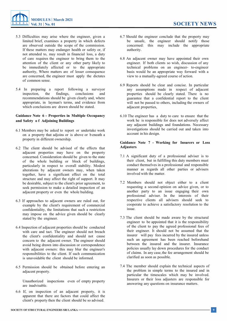
accountant, lawyer or other qualified person. SSESL Event Calendar – 2021
Month Date Event January 26th Question Time February 06th Design Course A
23rd Question Time March 23rd Seminar 1
30th Question Time April 27th Question Time May 22nd Design Course B
25th Question Time June 22nd Workshop A
29th Question Time July 28th Question Time August 24th Annual Sessions
31st Question Time September 28th Question Time October 28th Question Time November 30th Question Time December 14th Annual General Meeting Note: Dates are susceptible to changes due to the prevailing situation in the country. Any alterations to the events of the schedule planned for 2021 will be notified to the members via emails. Events will be conducted adhering to the health standards endorsed by the Government.

MODULUS | March 2021Vol. 31 | No. 01
11SOCIETY OF STRUCTURAL ENGINEERS SRI LANKA
PRESIDENT’S MESSAGE
MODULUS | March 2021 Vol.31 No. 01
SOCIETY OF STRUCTURAL ENGINEERS SRI LANKA
PRESIDENT’S MESSAGE
PRESIDENT’S MESSAGE
I am pleased to present the President’s Message for the first issue of the quarterly publication of MODULUS, for the year 2021. The year 2021 is a continuation of challenges our members faced in the year 2020 due to the COVID 19 pandemic situation globally and in particular in Sri Lanka.
The MODULUS is a platform to share new developments in the Structural Engineering and the construction industry. A lot of research works should proceed despite of the situations with special focus on sustainability. Consideration of locally available materials and researching on the high performance and efficient use of them is one way forward. We have a common target of refining our design processes to use the most cost effective designs at the eve of this global crisis.
The smooth functioning of design offices and
construction sites have been repeatedly interrupted and our structural Engineers are finding it difficult to do the day to day operations due to financial and other barriers. However, maintaining our professional conduct and ethics is paramount for the sustainability of our professional practices. It has been reported recently that a few professionally qualified persons and practices are making such unprincipled approaches to secure jobs and projects, pushing the rest of the qualified persons into unhealthy challenges, hence tarnishing the reputation of this esteemed profession.
The society of structural Engineers – Sri Lanka takes such matters seriously and is ready to prompt actions if such unethical practices are done by our own members.
The executive committee is always ready to help our members in all possible ways. The society has taken many steps to improve the dialog between members via the website and other social media platforms. The member could enjoy the new forum available in the society website to share their technical issues which will be studied and responded by experts in the field. Let us use more and more online technology and facilities to enhance our knowledge, and face all the challenges together.
I wish all our members and their loved once a safe and healthy year 2021.
Eng. N. Abeysuriya BSc.Eng (Hons), CEng, FIE(SL), FSSE(SL), IntPE(SL), MEng (Struct. Eng. Design), MConsE(SL) President, Society of Structural Engineers, Sri Lanka. Email: [email protected]
MODULUS | March 2021Vol. 31 | No. 01
12 SOCIETY OF STRUCTURAL ENGINEERS SRI LANKA
RESEARCH FORUMMODULUS | March 2021 Vol.31 No. 01
SOCIETY OF STRUCTURAL ENGINEERS SRI LANKA
RESEARCH FORUM
Post-Installed Retrofitting System for Improving the Punching Shear Capacity of Reinforced Concrete Elements
Dr. J. Buhler 1
Abstract
Finding appropriate strengthening solutions for existing reinforced concrete (RC) elements is always a challenge for structural engineers. Additional load capacity may be needed as the change of type of occupancy and more restrictive design standards require higher load levels or different detailing of reinforcement. Growing traffic volume would be a main topic in bridge design. This very often affects the shear and the punching shear and its reinforcement level. This paper introduces a post-installed retrofitting system consisting of an adhesive and a concrete screw anchor that can be used to improve either the pure shear capacity or the punching shear capacity of a RC beam or slab. This post-installed retrofitting system acts as shear reinforcement that can be installed with relatively minimal disruption as it is only installed at the soffit of the RC element being strengthened. The system was tested for its suitability and the results were approved by the German Construction Authority DIBt with a National Technical Approval. Published parameters are used for the standard methods of detailing shear and punching shear of a RC element according to EN1992-1 and EN1992-2. Calculations and tests have shown that with the use of this post-installed retrofitting system, the shear strength of existing concrete elements can increase by up to 100% and consequently increase the lifetime of a structure. This paper also discusses the test methods employed, the test results, and sample projects that made use of the said system. Another important finding is the substantial savings in project cost attributed to the installation methodology that comes with the system. Demolition of old structures, and building a new one is no longer the only feasible option
1. The Post-Installed Retrofitting System
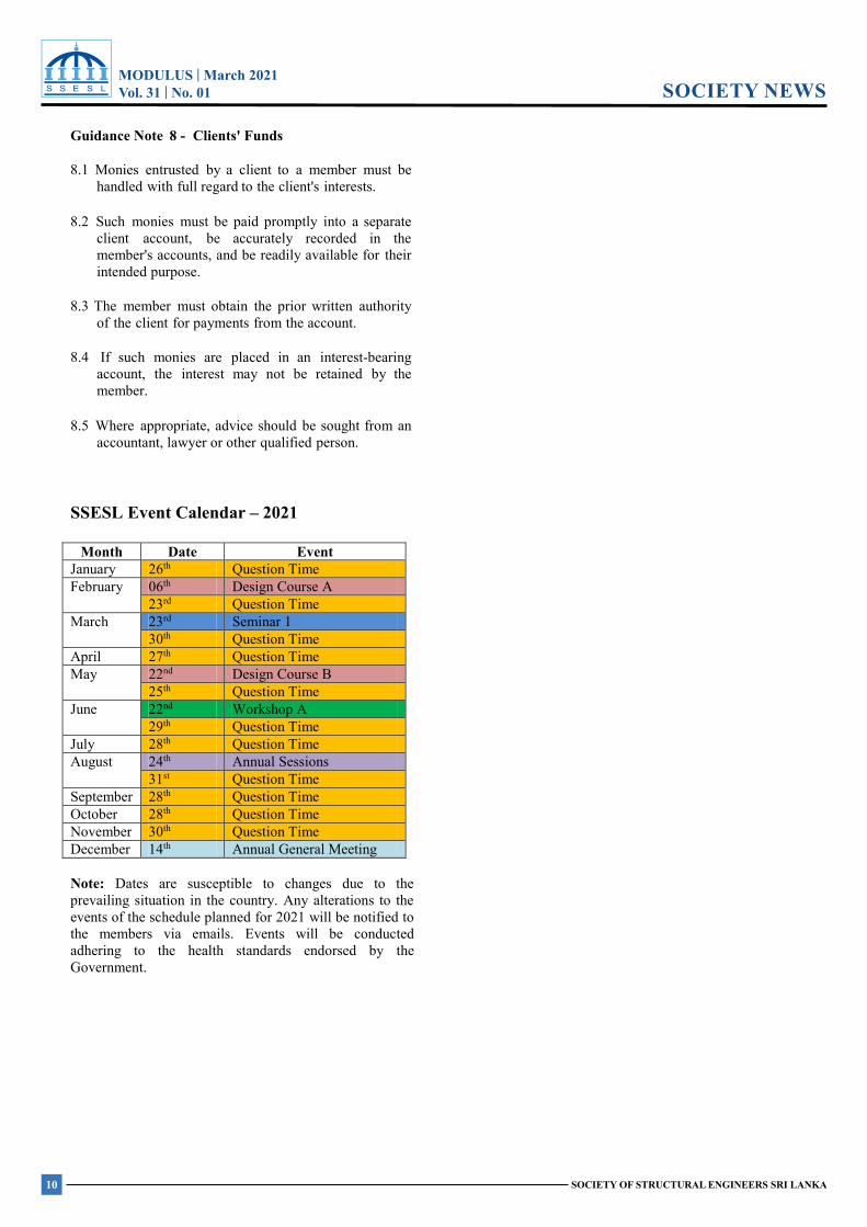
1.1 Description of the System
The post-installed retrofitting system employs bonded concrete screw anchors. This system consists of two essential components, a self-tapping concrete screw anchor and a two-component injectable organic adhesive, as shown in Figure 1. The concrete screw anchor transfers forces to the concrete member via a mechanical interlock between the screw anchor thread and the hole cavity. This mechanical interlock is achieved during the installation of the screw anchor, where thread tapping into the wall of a pre-drilled hole occurs. The adhesive, on the other hand, bonds the screw anchor to the hole cavity. Mechanical interlock transfers loads immediately after installation, while the bond effectively adds capacity after the adhesive becomes fully cured.
Although the system is composed of known post-installed anchor components, it is not considered as a post-installed anchor. Its evaluation and force- transfer mechanism is like a cast-in rebar.
Dr. J. Buhler1 1Adolf Würth GmbH & Co.KG, Germany Würth Lanka (Pvt) Ltd, jochen.buhler”wuerth.com
As such, the related design approach is therefore not covered in EN 1992-4:2018 “Design of post- installed and cast-in fastenings in concrete”.
However, EN 1992-1 ”Design of concrete structures – Part 1-1: General rules and rules for buildings” and in EN 1992-2 “Design of concrete structures – Part 2: Concrete bridges – Design and detailing rules” provide guidance for designing shear and punching shear using the hybrid post-installed retrofitting system.
Figure 1: Bonded screw anchor and its load-transfer mechanism
1.2 Scientific Research, Test and Assessment, Technical Product Specification
The components that make up the hybrid post-installed retrofitting system are post-installed anchors which were successfully assessed and granted construction approval many years back in Europe. The European assessment covers the following aspects:
MODULUS | March 2021Vol. 31 | No. 01
13SOCIETY OF STRUCTURAL ENGINEERS SRI LANKA
RESEARCH FORUMMODULUS | March 2021 Vol.31 No. 01
SOCIETY OF STRUCTURAL ENGINEERS SRI LANKA
RESEARCH FORUM
1. characteristic resistance to tension or shear, 2. sensitivity to different installation and service
temperatures, 3. freeze/thaw conditions, 4. increased concrete crack width, 5. crack cycling under load, 6. repeated loads, 7. sustained loads, 8. various environmental exposure such as high
alkalinity and sulphurous atmosphere, 9. the robustness of the anchor when installed in
dry and water saturated concrete with different installation directions.
The mentioned approval, enabled the anchor to
be designed and used in various structural anchoring applications successfully.
Since the system’s ‘retrofitting use’ do not fully align with post-installed anchoring models, additional tests and assessments were conducted to get construction approval for retrofitting applications. During a period of approximately 7 years, a number of large scale tests helped to investigate the real behaviour of the the hybrid post-installed retrofitting system.
Real-life retro-fitting on several bridges and buildings in Germany and Austria demonstrated the practicability of the system.
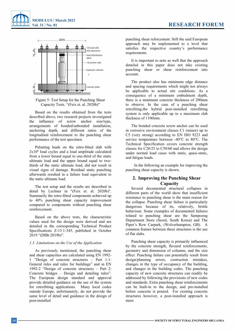
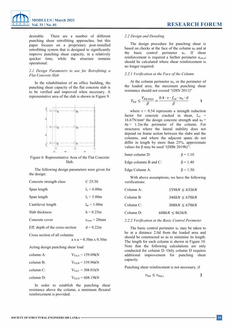
The additional large scale tests were conducted at the University of Innsbruch and at the Universität der Bundeswehr München (Fig. 2 and 3.).
Figure 2: Large Scale Shear tests. "(Feix et. al. 2019a)"
Figure 3: Large Scale Punching Shear tests. "(Feix et. al. 2019a)"
1.2.1 Laboratory Tests Related to the Shear Capacity
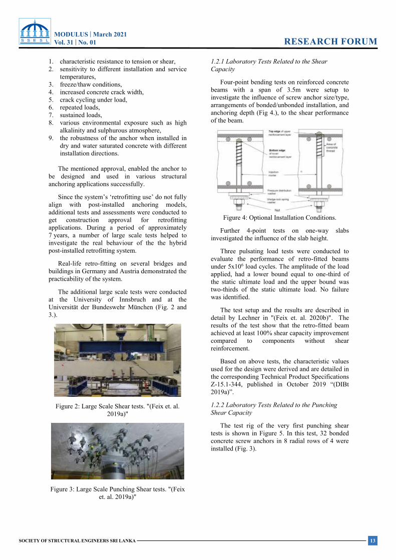
Four-point bending tests on reinforced concrete beams with a span of 3.5m were setup to investigate the influence of screw anchor size/type, arrangements of bonded/unbonded installation, and anchoring depth (Fig 4.), to the shear performance of the beam.
Figure 4: Optional Installation Conditions.
Further 4-point tests on one-way slabs investigated the influence of the slab height.
Three pulsating load tests were conducted to evaluate the performance of retro-fitted beams under 5x10⁶ load cycles. The amplitude of the load applied, had a lower bound equal to one-third of the static ultimate load and the upper bound was two-thirds of the static ultimate load. No failure was identified.
The test setup and the results are described in detail by Lechner in "(Feix et. al. 2020b)". The results of the test show that the retro-fitted beam achieved at least 100% shear capacity improvement compared to components without shear reinforcement.
Based on above tests, the characteristic values used for the design were derived and are detailed in the corresponding Technical Product Specifications Z-15.1-344, published in October 2019 “(DIBt 2019a)”.
1.2.2 Laboratory Tests Related to the Punching Shear Capacity
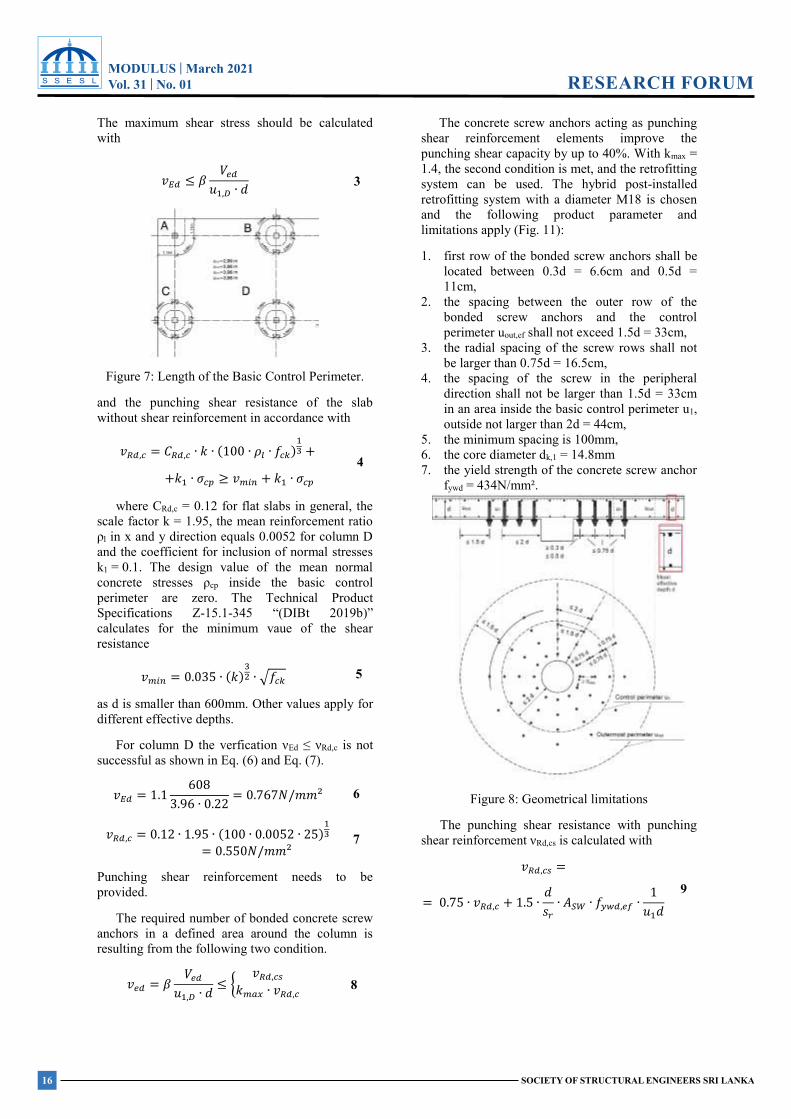
The test rig of the very first punching shear tests is shown in Figure 5. In this test, 32 bonded concrete screw anchors in 8 radial rows of 4 were installed (Fig. 3).
MODULUS | March 2021Vol. 31 | No. 01
14 SOCIETY OF STRUCTURAL ENGINEERS SRI LANKA
RESEARCH FORUMMODULUS | March 2021 Vol.31 No. 01
SOCIETY OF STRUCTURAL ENGINEERS SRI LANKA
RESEARCH FORUM
Figure 5: Test Setup for the Punching Shear Capacity Tests. “(Feix et. al. 2020b)"
Based on the results obtained from the tests described above, two research projects investigated the influence of screw anchor size/type, arrangements of bonded/unbonded installation, anchoring depth, and different ratios of the longitudinal reinforcement to the punching shear performance of the test specimen.
Pulsating loads on the retro-fitted slab with 2x10⁶ load cycles and a load amplitude calculated from a lower bound equal to one-third of the static ultimate load and the upper bound equal to two-thirds of the static ultimate load, did not result in visual signs of damage. Residual static punching afterwards resulted in a failure load equivalent to the static ultimate load.
The test setup and the results are described in detail by Lechner in "(Feix et. al. 2020b)". Summarily the retro-fitted components achieved up to 40% punching shear capacity improvement compared to components without punching shear reinforcement.
Based on the above tests, the characteristic values used for the design were derived and are detailed in the corresponding Technical Product Specifications Z-15.1-345, published in October 2019 “(DIBt 2019b)”.
1.3 Limitations on the Use of the Application
As previously mentioned, the punching shear and shear capacities are calculated using EN 1992-1 ”Design of concrete structures – Part 1-1: General rules and rules for buildings” and in EN 1992-2 “Design of concrete structures – Part 2: Concrete bridges – Design and detailing rules”. The European design standard and approval provide detailed guidance on the use of the system for retrofitting applications. Many local codes outside Europe, unfortunately, do not provide the same level of detail and guidance in the design of post-installed
punching shear reforcement. Still the said European approach may be implemented to a level that satisfies the respective country’s performance requirements.
It is important to note as well that the approach detailed in this paper does not take existing punching shear or shear reinforcement into account.
The product also has minimum edge distance and spacing requirements which might not always be applicable to actual site conditions. As a consequence of a minimum embedment depth, there is a minimum concrete thickness of 200mm to observe. In the case of a punching shear retrofiting,the hybrid post-installed retrofitting system is only applicable up to a maximum slab thickness of 1100mm.
The bonded concrete screw anchor can be used in corrosive environment classes C1 (minor) up to C5 (very strong) according to EN ISO 9223 and service temperature between -40°C to 80°C. The Technical Specification covers concrete strength classes for C20/25 to C50/60 and allows the design under normal load cases with static, quasi-static, and fatigue loads.
In the following an example for improving the punching shear capacity is shown.
2. Improving the Punching Shear Capacity
Several documented structural collapses in different parts of the world show that insufficient resistance to punching shear is the main reason for the collapse. Punching shear failure is particularly dangerous because of its, relatively, brittle behaviour. Some examples of documented failures related to punching shear are the Sampoong Department Store (Seoul, South Korea) and The Piper’s Row Carpark, (Wolverhampton, GB). A common feature between these structures is the use of flat slabs.
Punching shear capacity is primarily influenced by the concrete strength, flexural reinforcements, geometry and dimension of columns, and the size effect. Punching failure can potentially result from design/planning errors, costruction mistakes, changes in the type of occupancy of the building, and changes in the building codes. The punching capacity of new concrete structures can readily be addressed by following the provisions of new codes and standards. Extra punching shear reinforcements can be built-in to the design, and pre-installed before concrete is poured. For existing concrete structures however, a post-installed approach is more
MODULUS | March 2021Vol. 31 | No. 01
15SOCIETY OF STRUCTURAL ENGINEERS SRI LANKA
RESEARCH FORUMMODULUS | March 2021 Vol.31 No. 01
SOCIETY OF STRUCTURAL ENGINEERS SRI LANKA
RESEARCH FORUM
desirable. There are a number of different punching shear retrofitting approaches, but this paper focuses on a proprietary post-installed retrofitting system that is designed to significantly improve punching shear capacity, in a relatively quicker time, while the structure remains operational.
2.1 Design Parameters to use for Retrofitting a Flat Concrete Slab
In the rehabilitation of an office building, the punching shear capacity of the flat concrete slab is to be verified and improved when necessary. A representative area of the slab is shown in Figure 9.
Figure 6: Representative Area of the Flat Concrete Slab.
The following design parameters were given for the design:
Concrete strength class C 25/30
Span length lx = 6.00m
Span length ly = 5.00m
Cantilever length lpr = 1.00m
Slab thickness h = 0.25m
Concrete cover cnom = 20mm
Eff. depth of the cross-section d = 0.22m
Cross section of all columns a x a = 0.30m x 0.30m
Acting design punching shear load
column A: VEd,A = 159.09kN
column B: VEd,B = 339.96kN
column C: VEd,C = 308.01kN
column D: VEd,D = 608.19kN
In order to establish the punching shear resistance above the column, a minimum flexural reinforcement is provided.
2.2 Design and Detailing
The design procedure for punching shear is based on checks at the face of the column u0 and at the basic control perimeter u1. If shear reinforcement is required a further perimeter uout,ef should be calculated where shear reinforcement is no longer required.
2.2.1 Verification at the Face of the Column
At the column perimeter u0, or the perimeter of the loaded area, the maximum punching shear resistance should not exceed “(DIN 2011)"
𝑉𝑉𝐸𝐸𝐸𝐸 ≤𝑉𝑉𝑅𝑅𝐸𝐸,𝑚𝑚𝑚𝑚𝑚𝑚
𝛽𝛽 = 0.4 ∙ 𝜈𝜈 ∙ 𝑓𝑓𝑐𝑐𝐸𝐸 ∙ 𝑢𝑢0 ∙ 𝑑𝑑𝛽𝛽 1
where ν = 0.54 represents a strength reduction factor for concrete cracked in shear, fcd = 16.67N/mm² the design concrete strength and u0 = 4a = 1.2m the perimeter of the column. For structures where the lateral stability does not depend on frame action between the slabs and the columns, and where the adjacent spans do not differ in length by more than 25%, approximate values for β may be used “(DIBt 2019b)”:
Inner column D: β = 1.10
Edge columns B and C: β = 1.40
Edge Column A: β = 1.50.
With above assumptions, we have the following verifications:
Column A: 159𝑘𝑘𝑘𝑘 ≤ 633𝑘𝑘𝑘𝑘
Column B: 340𝑘𝑘𝑘𝑘 ≤ 678𝑘𝑘𝑘𝑘
Column C: 308𝑘𝑘𝑘𝑘 ≤ 678𝑘𝑘𝑘𝑘
Column D: 608𝑘𝑘𝑘𝑘 ≤ 863𝑘𝑘𝑘𝑘.
2.2.2 Verification at the Basic Control Perimeter
The basic control perimeter u1 may be taken to be at a distance 2.0d from the loaded area and should be constructed so as to minimise its length. The length for each column is shown in Figure 10. Note that the following calculations are only conducted for column D. Only column D requires additional improvement for punching shear capacity.
Punching shear reinforcment is not necessary, if
𝑣𝑣𝐸𝐸𝐸𝐸 ≤ 𝑣𝑣𝑅𝑅𝐸𝐸,𝑐𝑐 2
MODULUS | March 2021Vol. 31 | No. 01
16 SOCIETY OF STRUCTURAL ENGINEERS SRI LANKA
RESEARCH FORUMMODULUS | March 2021 Vol.31 No. 01
SOCIETY OF STRUCTURAL ENGINEERS SRI LANKA
RESEARCH FORUM
The maximum shear stress should be calculated with
Figure 7: Length of the Basic Control Perimeter.
and the punching shear resistance of the slab without shear reinforcement in accordance with
𝑣𝑣𝑅𝑅𝑅𝑅,𝑐𝑐 = 𝐶𝐶𝑅𝑅𝑅𝑅,𝑐𝑐 ∙ 𝑘𝑘 ∙ (100 ∙ 𝜌𝜌𝑙𝑙 ∙ 𝑓𝑓𝑐𝑐𝑐𝑐)13 +
+𝑘𝑘1 ∙ 𝜎𝜎𝑐𝑐𝑐𝑐 ≥ 𝑣𝑣𝑚𝑚𝑚𝑚𝑚𝑚 + 𝑘𝑘1 ∙ 𝜎𝜎𝑐𝑐𝑐𝑐 4
where CRd,c = 0.12 for flat slabs in general, the scale factor k = 1.95, the mean reinforcement ratio ρl in x and y direction equals 0.0052 for column D and the coefficient for inclusion of normal stresses k1 = 0.1. The design value of the mean normal concrete stresses ρcp inside the basic control perimeter are zero. The Technical Product Specifications Z-15.1-345 “(DIBt 2019b)” calculates for the minimum vaue of the shear resistance
𝑣𝑣𝑚𝑚𝑚𝑚𝑚𝑚 = 0.035 ∙ (𝑘𝑘)32 ∙ √𝑓𝑓𝑐𝑐𝑐𝑐 5
as d is smaller than 600mm. Other values apply for different effective depths.
For column D the verfication νEd ≤ νRd,c is not successful as shown in Eq. (6) and Eq. (7).
𝑣𝑣𝐸𝐸𝑅𝑅 = 1.1 6083.96 ∙ 0.22 = 0.767𝑁𝑁/𝑚𝑚𝑚𝑚² 6
𝑣𝑣𝑅𝑅𝑅𝑅,𝑐𝑐 = 0.12 ∙ 1.95 ∙ (100 ∙ 0.0052 ∙ 25)13
= 0.550𝑁𝑁/𝑚𝑚𝑚𝑚² 7
Punching shear reinforcement needs to be provided.
The required number of bonded concrete screw anchors in a defined area around the column is resulting from the following two condition.
𝑣𝑣𝑒𝑒𝑅𝑅 = 𝛽𝛽 𝑉𝑉𝑒𝑒𝑅𝑅𝑢𝑢1,𝐷𝐷 ∙ 𝑑𝑑 ≤ {
𝑣𝑣𝑅𝑅𝑅𝑅,𝑐𝑐𝑐𝑐𝑘𝑘𝑚𝑚𝑚𝑚𝑚𝑚 ∙ 𝑣𝑣𝑅𝑅𝑅𝑅,𝑐𝑐
8
The concrete screw anchors acting as punching shear reinforcement elements improve the punching shear capacity by up to 40%. With kmax = 1.4, the second condition is met, and the retrofitting system can be used. The hybrid post-installed retrofitting system with a diameter M18 is chosen and the following product parameter and limitations apply (Fig. 11):
1. first row of the bonded screw anchors shall be located between 0.3d = 6.6cm and 0.5d = 11cm,
2. the spacing between the outer row of the bonded screw anchors and the control perimeter uout,ef shall not exceed 1.5d = 33cm,
3. the radial spacing of the screw rows shall not be larger than 0.75d = 16.5cm,
4. the spacing of the screw in the peripheral direction shall not be larger than 1.5d = 33cm in an area inside the basic control perimeter u1, outside not larger than 2d = 44cm,
5. the minimum spacing is 100mm, 6. the core diameter dk,1 = 14.8mm 7. the yield strength of the concrete screw anchor
fywd = 434N/mm².
Figure 8: Geometrical limitations
The punching shear resistance with punching shear reinforcement νRd,cs is calculated with
𝑣𝑣𝑅𝑅𝑅𝑅,𝑐𝑐𝑐𝑐 =
= 0.75 ∙ 𝑣𝑣𝑅𝑅𝑅𝑅,𝑐𝑐 + 1.5 ∙ 𝑑𝑑𝑠𝑠𝑟𝑟
∙ 𝐴𝐴𝑆𝑆𝑆𝑆 ∙ 𝑓𝑓𝑦𝑦𝑦𝑦𝑅𝑅,𝑒𝑒𝑒𝑒 ∙ 1𝑢𝑢1𝑑𝑑
9
𝑣𝑣𝐸𝐸𝑅𝑅 ≤ 𝛽𝛽 𝑉𝑉𝑒𝑒𝑅𝑅𝑢𝑢1,𝐷𝐷 ∙ 𝑑𝑑 3
MODULUS | March 2021Vol. 31 | No. 01
17SOCIETY OF STRUCTURAL ENGINEERS SRI LANKA
RESEARCH FORUMMODULUS | March 2021 Vol.31 No. 01
SOCIETY OF STRUCTURAL ENGINEERS SRI LANKA
RESEARCH FORUM
where the allowable cross-section area of the punching shear reinforcement in one row around the column is the minimum of
For the verification we chose 5 rows with a radial spacing of sr = 15cm and 12 anchors per row. The spacing of the first row to the column equals 10cm. The cross section area in any row around the column is Asw,i = 20.64cm². The entire cross sectional area between 0.3d = 6.6cm and 1.5d= 33cm calculates from the cross section of 3 rows ASW,1.5d = 61.92cm² and ASW = 20.64cm² .
The design value of the active stress in the punching shear reinforcement is calculated with
𝑓𝑓𝑦𝑦𝑦𝑦𝑦𝑦,𝑒𝑒𝑒𝑒 = 5.5 ∙ 𝑘𝑘𝑚𝑚𝑚𝑚𝑚𝑚𝛾𝛾𝑠𝑠
∙ 𝑦𝑦𝑦𝑦𝑘𝑘,1
=
= 5.5 ∙ 1.41.15 ∙ 22
1.48 =
= 99.53𝑁𝑁/𝑚𝑚𝑚𝑚² ≤ 217𝑁𝑁/𝑚𝑚𝑚𝑚²
11
The punching shear resistance with punching shear reinforcement equals νRd,cs = 0.93N/mm² and succesfully verified as it is greater than the acting shear of νEd = 0.77N/mm².
The perimeter uout,ef, where shear reinforcement is no longer required is calculated with
𝑢𝑢𝑜𝑜𝑜𝑜𝑜𝑜,𝑒𝑒𝑒𝑒 = 𝛽𝛽 𝑉𝑉𝑒𝑒𝑦𝑦𝑣𝑣𝑅𝑅𝑦𝑦,𝑐𝑐 ∙ 𝑑𝑑 = 1.1 ∙ 608
550 ∙ 0.22
= 5.52𝑚𝑚
12
which equals an outer radius rout,ef = 88cm.
For the above calculated 60 bonded concrete screw anchors 16 with a metric thread M18, the rules for the geometrical composition are successfully checked
1. The first row of the bonded screw anchors is located at 10cm from the column which is between the required 0.3d = 6.6cm and 0.5d = 11cm. The respective radius ra equals 25cm,
2. The perimeter of the first row equals 157cm which makes with 12 screw anchors a spacing of 130.9mm which is greater than the required minimum spacing of 100mm.
3. The radial spacing of 15cm is less than the required 0.75d = 16.5cm,
4. The length of the basic control perimeter equals 339cm and is filled with 12 anchors at spacings of 28.25cm in the peripheral direction
which is less than 1.5d = 33cm, the last row of the 5 radial rows has a radius rout = 85cm and gives a spacing of 3cm to rout,ef = 88cm, which does not exceed required maximum spacing of 1.5d = 33cm
5. The perimeter length of the last row equals 534cm and is filled with 12 anchors at spacings of 44.0cm in the peripheral direction which is lesser than 2d = 44cm.
Each bonded concrete screw anchor is installed with a embedment depth of hnom = 160mm and provides a minimum for the projected thread length of tüb ≥ 47mm to accommodate the big washer, the wedge-lock spring washer and the nut.
3. Summary The two design examples show that the hybrid
post-installed retrofitting system improves the shear or punching shear capacity with a practicable number of bonded concrete screw anchors. The number of screws is not much different from the number of cast-in shear or punching shear reinforcement which would have been provided for a new structure. Thus, the provided solution is economically feasible and provides additional benefits from having to access only the soffit of the structure for installing the system. In many cases, occupancy could continue in the area above where installation is being done.
The design approach utilizes existing formulas of an established European Code, and provides modification parameters as necessary. As the design does not take existing shear and punching shear reinforcement into account, the described approach can be used when codes do not provide the same level of detail and guidance in the design.
4. References [1] Feix, Jürgen and Lechner, Johannes, "RELAST.
Betonschrauben zur nachträglichen Bauwerksverstärkung", Würth Internal Presentation citing from various papers, 2019.
[2] Feix, Jürgen and Lechner, Johannes, "Das neue Bauaufsichtlich zugelassene System RELAST zur nachträglichen Bauwerksverstärkung; Von der Grundidee über wissenschaftliche Forschung zur Zulassung. [engl. The new technically approved RELAST system for post-installed structural reinforcement; from the basic idea to scientific research for approval]", ql²⁄8 - Das Planermagazin für Ingenieure, Architekten und Planer. No. 19, Issue 14, March 2020.
[3] Deutsches Institut für Bautechnik (DIBt), "Würth RELAST bonded screw anchor with a
𝐴𝐴𝑆𝑆𝑆𝑆 = 𝑚𝑚𝑚𝑚𝑚𝑚 {𝐴𝐴𝑆𝑆𝑆𝑆,𝑖𝑖
𝐴𝐴𝑆𝑆𝑆𝑆,1.5𝑑𝑑1.5∙𝑦𝑦 ∙ 𝑠𝑠𝑟𝑟
10
MODULUS | March 2021Vol. 31 | No. 01
18 SOCIETY OF STRUCTURAL ENGINEERS SRI LANKA
RESEARCH FORUMMODULUS | March 2021 Vol.31 No. 01
SOCIETY OF STRUCTURAL ENGINEERS SRI LANKA
RESEARCH FORUM
diameter of 16mm and 22mm for use as post-installed shear reinforcement.", National technical approval Z-15.1-344, October 2019.
[4]Deutsches Institut für Bautechnik (DIBt), "Würth RELAST bonded screw anchor with a diameter of 16mm and 22mm for use as post-installed punching shear reinforcement.", National technical approval Z-15.1-345, October 2019.
[5] Deutsches Institut für Normung e. V. (DIN), " Eurocode 2: Design of concrete structures – Part 1-1: General rules and rules for buildings; German version EN 1992-1-1:2004 + AC:2010", German National Code, January 2011.
5. Biography
Dr. Jochen Buhler
[1] Since 2011 Würth Group: Head of Engineering, Business Development Post-Installed Anchors.
[2] 1997 - 2011 Various positions related to anchor technology, including university lecturing assignments in Europe and Asia.
[3] Since 2000 Member of various Associations and Technical Committees related to anchor technology.
[4] 1991 - 1997 University of Stuttgart, Inst. of theoretical and applied mechanics in construction: Ph.D. student.
MODULUS | March 2021Vol. 31 | No. 01
19SOCIETY OF STRUCTURAL ENGINEERS SRI LANKA
ENGINEERS’ FORUMMODULUS | March 2021 Vol.31 No. 01
SOCIETY OF STRUCTURAL ENGINEERS SRI LANKA
RESEARCH FORUM
Feasibility of Using 3D Point Cloud Technologies in Sri Lankan Civil Engineering Industry R. Subakaran1, H.M.S.T Herath1
Abstract
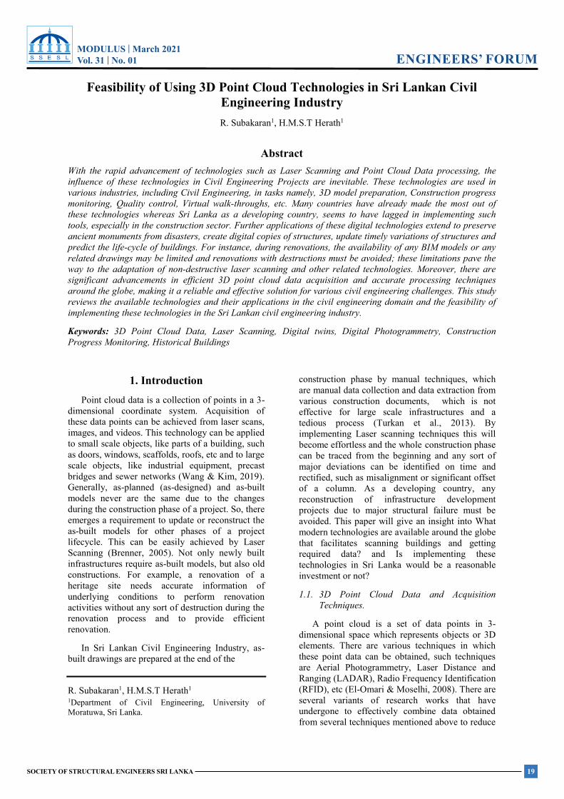
With the rapid advancement of technologies such as Laser Scanning and Point Cloud Data processing, the influence of these technologies in Civil Engineering Projects are inevitable. These technologies are used in various industries, including Civil Engineering, in tasks namely, 3D model preparation, Construction progress monitoring, Quality control, Virtual walk-throughs, etc. Many countries have already made the most out of these technologies whereas Sri Lanka as a developing country, seems to have lagged in implementing such tools, especially in the construction sector. Further applications of these digital technologies extend to preserve ancient monuments from disasters, create digital copies of structures, update timely variations of structures and predict the life-cycle of buildings. For instance, during renovations, the availability of any BIM models or any related drawings may be limited and renovations with destructions must be avoided; these limitations pave the way to the adaptation of non-destructive laser scanning and other related technologies. Moreover, there are significant advancements in efficient 3D point cloud data acquisition and accurate processing techniques around the globe, making it a reliable and effective solution for various civil engineering challenges. This study reviews the available technologies and their applications in the civil engineering domain and the feasibility of implementing these technologies in the Sri Lankan civil engineering industry.
Keywords: 3D Point Cloud Data, Laser Scanning, Digital twins, Digital Photogrammetry, Construction Progress Monitoring, Historical Buildings
1. Introduction Point cloud data is a collection of points in a 3-
dimensional coordinate system. Acquisition of these data points can be achieved from laser scans, images, and videos. This technology can be applied to small scale objects, like parts of a building, such as doors, windows, scaffolds, roofs, etc and to large scale objects, like industrial equipment, precast bridges and sewer networks (Wang & Kim, 2019). Generally, as-planned (as-designed) and as-built models never are the same due to the changes during the construction phase of a project. So, there emerges a requirement to update or reconstruct the as-built models for other phases of a project lifecycle. This can be easily achieved by Laser Scanning (Brenner, 2005). Not only newly built infrastructures require as-built models, but also old constructions. For example, a renovation of a heritage site needs accurate information of underlying conditions to perform renovation activities without any sort of destruction during the renovation process and to provide efficient renovation.
In Sri Lankan Civil Engineering Industry, as-built drawings are prepared at the end of the
R. Subakaran1, H.M.S.T Herath1
1Department of Civil Engineering, University of Moratuwa, Sri Lanka.
construction phase by manual techniques, which are manual data collection and data extraction from various construction documents, which is not effective for large scale infrastructures and a tedious process (Turkan et al., 2013). By implementing Laser scanning techniques this will become effortless and the whole construction phase can be traced from the beginning and any sort of major deviations can be identified on time and rectified, such as misalignment or significant offset of a column. As a developing country, any reconstruction of infrastructure development projects due to major structural failure must be avoided. This paper will give an insight into What modern technologies are available around the globe that facilitates scanning buildings and getting required data? and Is implementing these technologies in Sri Lanka would be a reasonable investment or not?
1.1. 3D Point Cloud Data and Acquisition Techniques.
A point cloud is a set of data points in 3-dimensional space which represents objects or 3D elements. There are various techniques in which these point data can be obtained, such techniques are Aerial Photogrammetry, Laser Distance and Ranging (LADAR), Radio Frequency Identification (RFID), etc (El-Omari & Moselhi, 2008). There are several variants of research works that have undergone to effectively combine data obtained from several techniques mentioned above to reduce
MODULUS | March 2021Vol. 31 | No. 01
20 SOCIETY OF STRUCTURAL ENGINEERS SRI LANKA
ENGINEERS’ FORUMMODULUS | March 2021 Vol.31 No. 01
SOCIETY OF STRUCTURAL ENGINEERS SRI LANKA
RESEARCH FORUM
(a) (b)
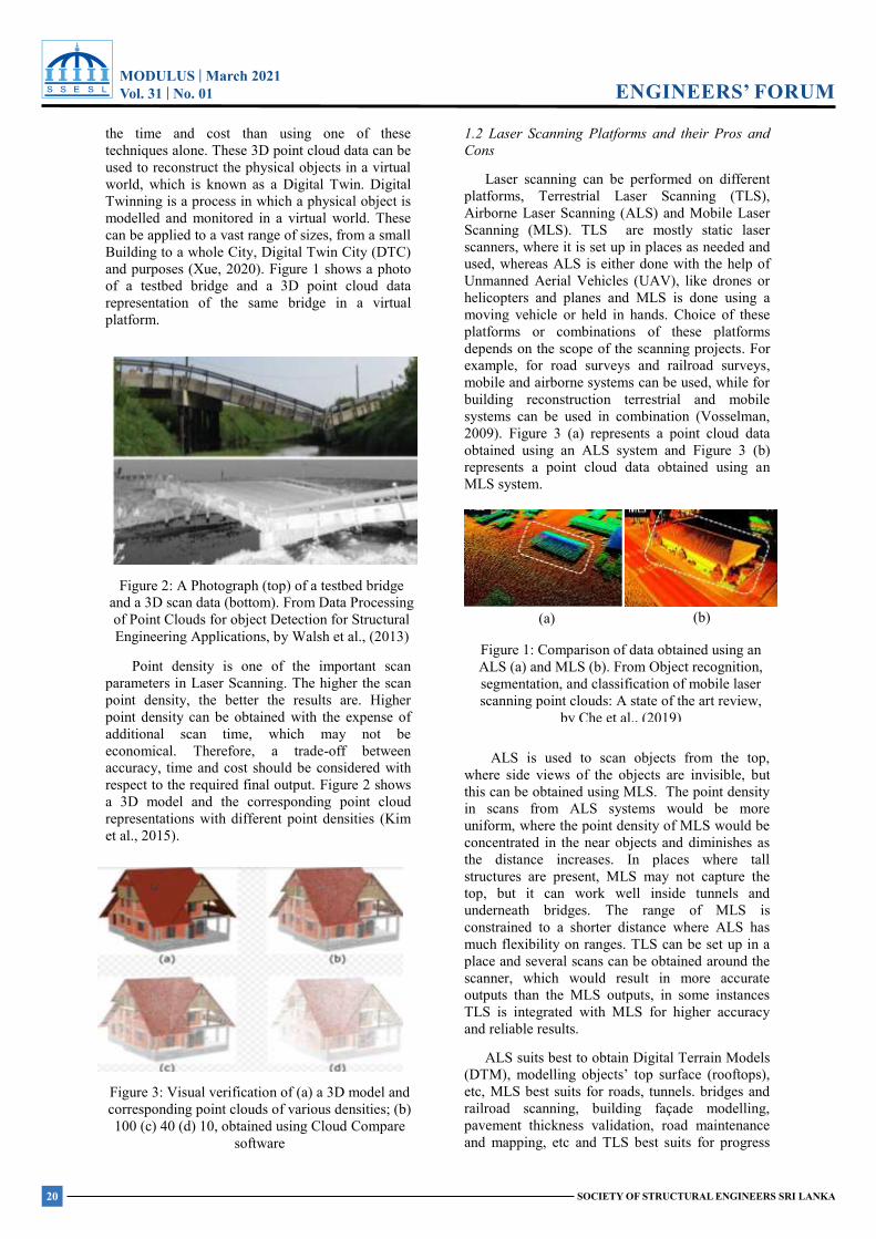
the time and cost than using one of these techniques alone. These 3D point cloud data can be used to reconstruct the physical objects in a virtual world, which is known as a Digital Twin. Digital Twinning is a process in which a physical object is modelled and monitored in a virtual world. These can be applied to a vast range of sizes, from a small Building to a whole City, Digital Twin City (DTC) and purposes (Xue, 2020). Figure 1 shows a photo of a testbed bridge and a 3D point cloud data representation of the same bridge in a virtual platform.
Point density is one of the important scan parameters in Laser Scanning. The higher the scan point density, the better the results are. Higher point density can be obtained with the expense of additional scan time, which may not be economical. Therefore, a trade-off between accuracy, time and cost should be considered with respect to the required final output. Figure 2 shows a 3D model and the corresponding point cloud representations with different point densities (Kim et al., 2015).
1.2 Laser Scanning Platforms and their Pros and Cons
Laser scanning can be performed on different platforms, Terrestrial Laser Scanning (TLS), Airborne Laser Scanning (ALS) and Mobile Laser Scanning (MLS). TLS are mostly static laser scanners, where it is set up in places as needed and used, whereas ALS is either done with the help of Unmanned Aerial Vehicles (UAV), like drones or helicopters and planes and MLS is done using a moving vehicle or held in hands. Choice of these platforms or combinations of these platforms depends on the scope of the scanning projects. For example, for road surveys and railroad surveys, mobile and airborne systems can be used, while for building reconstruction terrestrial and mobile systems can be used in combination (Vosselman, 2009). Figure 3 (a) represents a point cloud data obtained using an ALS system and Figure 3 (b) represents a point cloud data obtained using an MLS system.
ALS is used to scan objects from the top, where side views of the objects are invisible, but this can be obtained using MLS. The point density in scans from ALS systems would be more uniform, where the point density of MLS would be concentrated in the near objects and diminishes as the distance increases. In places where tall structures are present, MLS may not capture the top, but it can work well inside tunnels and underneath bridges. The range of MLS is constrained to a shorter distance where ALS has much flexibility on ranges. TLS can be set up in a place and several scans can be obtained around the scanner, which would result in more accurate outputs than the MLS outputs, in some instances TLS is integrated with MLS for higher accuracy and reliable results.
ALS suits best to obtain Digital Terrain Models (DTM), modelling objects’ top surface (rooftops), etc, MLS best suits for roads, tunnels. bridges and railroad scanning, building façade modelling, pavement thickness validation, road maintenance and mapping, etc and TLS best suits for progress
Figure 2: A Photograph (top) of a testbed bridge and a 3D scan data (bottom). From Data Processing of Point Clouds for object Detection for Structural Engineering Applications, by Walsh et al., (2013)
Figure 3: Visual verification of (a) a 3D model and corresponding point clouds of various densities; (b) 100 (c) 40 (d) 10, obtained using Cloud Compare
software
Figure 1: Comparison of data obtained using an ALS (a) and MLS (b). From Object recognition, segmentation, and classification of mobile laser scanning point clouds: A state of the art review,
by Che et al., (2019)
MODULUS | March 2021Vol. 31 | No. 01
21SOCIETY OF STRUCTURAL ENGINEERS SRI LANKA
ENGINEERS’ FORUMMODULUS | March 2021 Vol.31 No. 01
SOCIETY OF STRUCTURAL ENGINEERS SRI LANKA
RESEARCH FORUM
Figure 5: 3D model of Hetadage, Polonnaruwa, prepared by Zamani Project in 2019. From https://sketchfab.com/3d-models/hatadage-
colour-quadrangle-polonnaruwa-6d021b6926124e90bce11c33a8d516e6
Figure 4: (a) Segmented point cloud. (b) Classified segments, walls by Blue and Dark Grey, Doors by
Orange and Grey, Roof by Yellow and Grey, Ground by Green and Grey. (c) Textured building model. From Advanced point cloud processing, by
Vosselman (2009)
(a) (b) (c)
monitoring, settlement or deformation monitoring, etc and combinations of scanning systems can also be used for various purposes (Che et al., 2019).
1.3 Point Cloud Data Processing Workflow
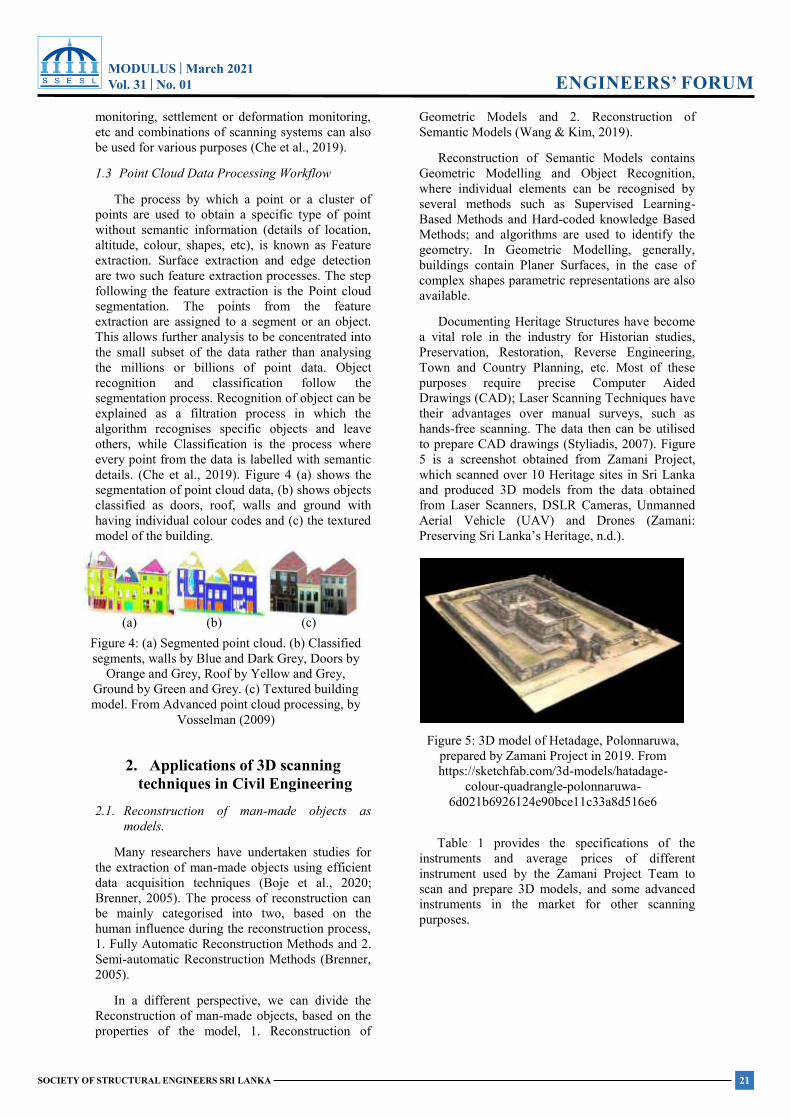
The process by which a point or a cluster of points are used to obtain a specific type of point without semantic information (details of location, altitude, colour, shapes, etc), is known as Feature extraction. Surface extraction and edge detection are two such feature extraction processes. The step following the feature extraction is the Point cloud segmentation. The points from the feature extraction are assigned to a segment or an object. This allows further analysis to be concentrated into the small subset of the data rather than analysing the millions or billions of point data. Object recognition and classification follow the segmentation process. Recognition of object can be explained as a filtration process in which the algorithm recognises specific objects and leave others, while Classification is the process where every point from the data is labelled with semantic details. (Che et al., 2019). Figure 4 (a) shows the segmentation of point cloud data, (b) shows objects classified as doors, roof, walls and ground with having individual colour codes and (c) the textured model of the building.
2. Applications of 3D scanning techniques in Civil Engineering
2.1. Reconstruction of man-made objects as models.
Many researchers have undertaken studies for the extraction of man-made objects using efficient data acquisition techniques (Boje et al., 2020; Brenner, 2005). The process of reconstruction can be mainly categorised into two, based on the human influence during the reconstruction process, 1. Fully Automatic Reconstruction Methods and 2. Semi-automatic Reconstruction Methods (Brenner, 2005).
In a different perspective, we can divide the Reconstruction of man-made objects, based on the properties of the model, 1. Reconstruction of
Geometric Models and 2. Reconstruction of Semantic Models (Wang & Kim, 2019).
Reconstruction of Semantic Models contains Geometric Modelling and Object Recognition, where individual elements can be recognised by several methods such as Supervised Learning-Based Methods and Hard-coded knowledge Based Methods; and algorithms are used to identify the geometry. In Geometric Modelling, generally, buildings contain Planer Surfaces, in the case of complex shapes parametric representations are also available.
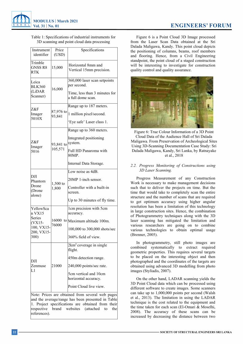
Documenting Heritage Structures have become a vital role in the industry for Historian studies, Preservation, Restoration, Reverse Engineering, Town and Country Planning, etc. Most of these purposes require precise Computer Aided Drawings (CAD); Laser Scanning Techniques have their advantages over manual surveys, such as hands-free scanning. The data then can be utilised to prepare CAD drawings (Styliadis, 2007). Figure 5 is a screenshot obtained from Zamani Project, which scanned over 10 Heritage sites in Sri Lanka and produced 3D models from the data obtained from Laser Scanners, DSLR Cameras, Unmanned Aerial Vehicle (UAV) and Drones (Zamani: Preserving Sri Lanka’s Heritage, n.d.).
Table 1 provides the specifications of the instruments and average prices of different instrument used by the Zamani Project Team to scan and prepare 3D models, and some advanced instruments in the market for other scanning purposes.
MODULUS | March 2021Vol. 31 | No. 01
22 SOCIETY OF STRUCTURAL ENGINEERS SRI LANKA
ENGINEERS’ FORUMMODULUS | March 2021 Vol.31 No. 01
SOCIETY OF STRUCTURAL ENGINEERS SRI LANKA
RESEARCH FORUM
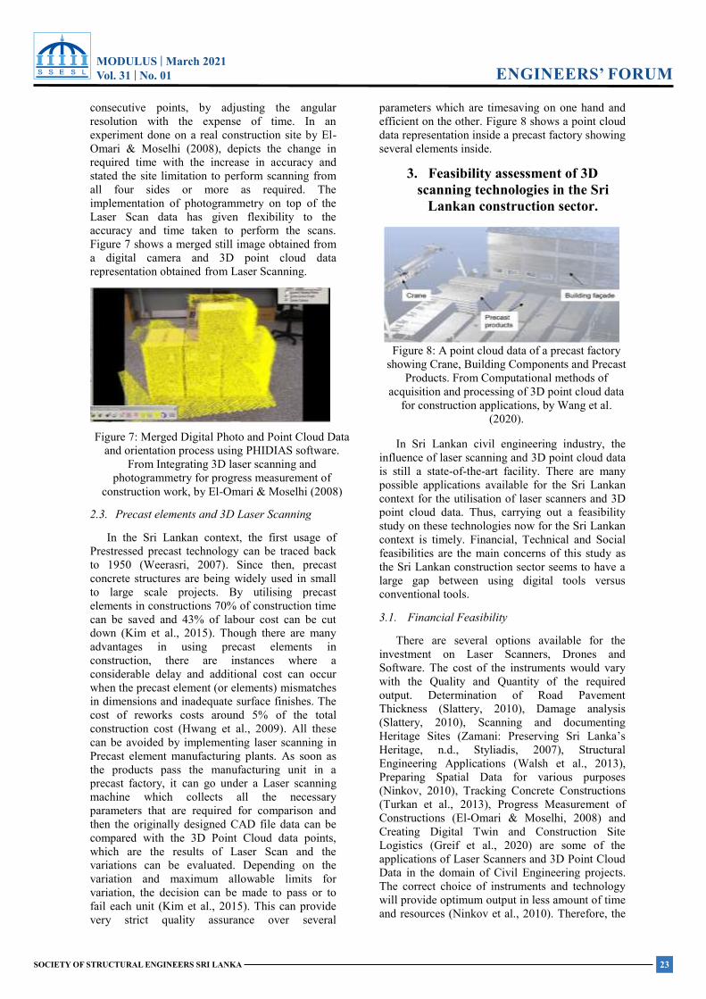
Table 1: Specifications of industrial instruments for 3D scanning and point cloud data processing
Instrument identifier
Price (USD)
Specifications
Trimble GNSS R8 RTK
15,000 Horizontal 8mm and Vertical 15mm precision.
Leica BLK360 (LiDAR Scanner)
16,000
360,000 laser scan setpoints per second.
Time, less than 3 minutes for a full dome scan.
Z&F Imager 5010X
87,976 to 93,841
Range up to 187 meters.
1 million pixel/second.
‘Eye safe’ Laser class 1.
Z&F Imager 5016
93,841 to 105,571
Range up to 360 meters.
Integrated positioning system.
Full HD Panaroma with 80MP.
Internal Data Storage.
DJI Phantom Drone (Drone alone)
1,500 to 1,800
Low noise as 4dB.
20MP 1-inch sensor.
Controller with a built-in screen.
Up to 30 minutes of fly time.
YellowScan VX15 Series (VX15- 100, VX15- 200, VX15- 300)
16000 to 76000
1cm precision with 5cm accuracy.
Maximum altitude 100m.
100,000 to 300,000 shots/sec
360% field of view.
DJI Zenmuse L1
21000
2km2 coverage in single flight.
450m detection range.
240,000 points/sec rate.
5cm vertical and 10cm horizontal accuracy.
Point Cloud live view.
Note: Prices are obtained from several web pages and the average/range has been presented in Table 1. Project specifications are obtained from their respective brand websites (attached to the references).
Figure 6 is a Point Cloud 3D Image processed from the Laser Scan Data obtained at the Sri Dalada Maligawa, Kandy. This point cloud depicts the positioning of columns, beams, roof members and flooring. Hence, from a Civil Engineering standpoint, the point cloud of a staged construction will be interesting to investigate for construction quality control and quality assurance.
2.2. Progress Monitoring of Constructions using 3D Laser Scanning.
Progress Measurement of any Construction Work is necessary to make management decisions such that to deliver the projects on time. But the time that would take to completely scan the entire structure and the number of scans that are required to get optimum accuracy using higher angular resolution has been a limitation of this technology in large construction sites. Hence, the combination of Photogrammetry techniques along with the 3D laser scanning has mitigated the limitation and various researchers are going on to combine various technologies to obtain optimal usage (Brenner, 2005).
In photogrammetry, still photo images are combined systematically to extract required geometric properties. This requires several targets to be placed on the interesting object and then photographed and the coordinates of the targets are obtained using advanced 3D modelling from photo images (Styliadis, 2007).
On the other hand, LADAR scanning yields the 3D Point Cloud data which can be processed using different software to create images. Some scanners can take up to 1,000,000 points per second (Walsh et al., 2013). The limitation in using the LADAR technique is the cost related to the equipment and the time taken for each scan (El-Omari & Moselhi, 2008). The accuracy of these scans can be increased by decreasing the distance between two
Figure 6: True Colour Information of a 3D Point Cloud Data of the Audience Hall of Sri Dalada
Maligawa. From Preservation of Archeological Sites Using 3D-Scanning Documentation Case Study: Sri Dalada Maligawa, Kandy, Sri Lanka, by Ratnayake
et al., 2018
MODULUS | March 2021Vol. 31 | No. 01
23SOCIETY OF STRUCTURAL ENGINEERS SRI LANKA
ENGINEERS’ FORUMMODULUS | March 2021 Vol.31 No. 01
SOCIETY OF STRUCTURAL ENGINEERS SRI LANKA
RESEARCH FORUM
consecutive points, by adjusting the angular resolution with the expense of time. In an experiment done on a real construction site by El-Omari & Moselhi (2008), depicts the change in required time with the increase in accuracy and stated the site limitation to perform scanning from all four sides or more as required. The implementation of photogrammetry on top of the Laser Scan data has given flexibility to the accuracy and time taken to perform the scans. Figure 7 shows a merged still image obtained from a digital camera and 3D point cloud data representation obtained from Laser Scanning.
2.3. Precast elements and 3D Laser Scanning
In the Sri Lankan context, the first usage of Prestressed precast technology can be traced back to 1950 (Weerasri, 2007). Since then, precast concrete structures are being widely used in small to large scale projects. By utilising precast elements in constructions 70% of construction time can be saved and 43% of labour cost can be cut down (Kim et al., 2015). Though there are many advantages in using precast elements in construction, there are instances where a considerable delay and additional cost can occur when the precast element (or elements) mismatches in dimensions and inadequate surface finishes. The cost of reworks costs around 5% of the total construction cost (Hwang et al., 2009). All these can be avoided by implementing laser scanning in Precast element manufacturing plants. As soon as the products pass the manufacturing unit in a precast factory, it can go under a Laser scanning machine which collects all the necessary parameters that are required for comparison and then the originally designed CAD file data can be compared with the 3D Point Cloud data points, which are the results of Laser Scan and the variations can be evaluated. Depending on the variation and maximum allowable limits for variation, the decision can be made to pass or to fail each unit (Kim et al., 2015). This can provide very strict quality assurance over several
parameters which are timesaving on one hand and efficient on the other. Figure 8 shows a point cloud data representation inside a precast factory showing several elements inside.
3. Feasibility assessment of 3D scanning technologies in the Sri
Lankan construction sector.
In Sri Lankan civil engineering industry, the influence of laser scanning and 3D point cloud data is still a state-of-the-art facility. There are many possible applications available for the Sri Lankan context for the utilisation of laser scanners and 3D point cloud data. Thus, carrying out a feasibility study on these technologies now for the Sri Lankan context is timely. Financial, Technical and Social feasibilities are the main concerns of this study as the Sri Lankan construction sector seems to have a large gap between using digital tools versus conventional tools.
3.1. Financial Feasibility
There are several options available for the investment on Laser Scanners, Drones and Software. The cost of the instruments would vary with the Quality and Quantity of the required output. Determination of Road Pavement Thickness (Slattery, 2010), Damage analysis (Slattery, 2010), Scanning and documenting Heritage Sites (Zamani: Preserving Sri Lanka’s Heritage, n.d., Styliadis, 2007), Structural Engineering Applications (Walsh et al., 2013), Preparing Spatial Data for various purposes (Ninkov, 2010), Tracking Concrete Constructions (Turkan et al., 2013), Progress Measurement of Constructions (El-Omari & Moselhi, 2008) and Creating Digital Twin and Construction Site Logistics (Greif et al., 2020) are some of the applications of Laser Scanners and 3D Point Cloud Data in the domain of Civil Engineering projects. The correct choice of instruments and technology will provide optimum output in less amount of time and resources (Ninkov et al., 2010). Therefore, the
Figure 7: Merged Digital Photo and Point Cloud Data and orientation process using PHIDIAS software.
From Integrating 3D laser scanning and photogrammetry for progress measurement of
construction work, by El-Omari & Moselhi (2008)
Figure 8: A point cloud data of a precast factory showing Crane, Building Components and Precast
Products. From Computational methods of acquisition and processing of 3D point cloud data
for construction applications, by Wang et al. (2020).
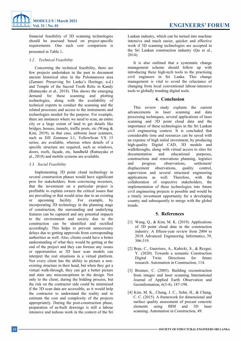
MODULUS | March 2021Vol. 31 | No. 01
24 SOCIETY OF STRUCTURAL ENGINEERS SRI LANKA
ENGINEERS’ FORUMMODULUS | March 2021 Vol.31 No. 01
SOCIETY OF STRUCTURAL ENGINEERS SRI LANKA
RESEARCH FORUM
financial feasibility of 3D scanning technologies should be assessed based on project-specific requirements. One such cost comparison is presented in Table 1. 3.2. Technical Feasibility
Concerning the technical feasibility, there are few projects undertaken in the past to document ancient historical sites in the Polonnaruwa area (Zamani: Preserving Sri Lanka’s Heritage, n.d.) and Temple of the Sacred Tooth Relic in Kandy (Ratnayake et al., 2018). This shows the emerging demand for these scanning and plotting technologies, along with the availability of technical experts to conduct the scanning and the related processes and access to the instruments and technologies needed for the purpose. For example, there are instances where we need to scan, an entire city or a large extent of land to get details like bridges, houses, tunnels, traffic posts, etc (Wang & Kim, 2019), in that case, airborne laser scanners, such as DJI Zenmuse L1, YellowScan VX 15 series, are available, whereas when details of a specific structure are required, such as windows, doors, roofs, façade, etc, handheld (Ratnayake et al., 2018) and mobile systems are available.
3.3. Social Feasibility
Implementing 3D point cloud technology in several construction phases would have significant pros for stakeholders; from convincing investors, that the investment on a particular project is profitable to explain owners the critical issues that are prevailing or that would arise due to an existing or upcoming facility. For example, by incorporating 3D technology in the planning stage of construction, the surrounding and underlying features can be captured and any potential impacts to the environment and society due to the construction can be identified and rectified accordingly. This helps to prevent unnecessary delays due to getting approvals from corresponding authorities as well. Also, clients could have a better understanding of what they would be getting at the end of the project and they can foresee any issues or opportunities as 3D laser scan models can interpret the real situations in a virtual platform. Not every client has the ability to picture a non-existing structure in their head, but when they get a virtual walk-through, they can get a better picture and state any misconceptions in the design. Not only to the client, during the bidding process, but the risk on the contractor side could be minimised if the 3D scan data are accessible, as it would help the contractor to understand the reality and to estimate the cost and complexity of the projects appropriately. During the post-construction phase, preparation of as-built drawings is still a labour intensive and tedious work in the context of the Sri
Lankan industry, which can be turned into machine intensive and much easier, quicker and effective work if 3D scanning technologies are accepted in the Sri Lankan construction industry (Qu et al., 2014).
It is also outlined that a systematic change management scheme should follow up with introducing these high-tech tools to the practising civil engineers in Sri Lanka. This change management is vital to avoid the reluctance of changing from local conventional labour-intensive tools to globally trending digital tools.
4. Conclusion This review study explains the current
advancements in laser scanning and data processing techniques, several applications of laser scanning and 3D point cloud data and the importance of these technologies in the Sri Lankan civil engineering context. It is concluded that considerable time and resources can be saved with an expense of high initial investment, by producing high-quality Digital CAD, 3D models and walkthroughs, along with virtual access to sites for documentation and educational purposes, constructions and renovations planning, logistics and progress observations, settlement/ displacement observations, quality control, supervision and several structural engineering applications as well. Therefore, with the collaboration of respective stakeholders, the implementation of these technologies into future civil engineering projects is possible and would be a timely investment opportunity for a developing country and subsequently to merge with the global trends.
5. References
[1] Wang, Q., & Kim, M. K. (2019). Applications of 3D point cloud data in the construction industry: A fifteen-year review from 2004 to 2018. Advanced Engineering Informatics, 39, 306-319.
[2] Boje, C., Guerriero, A., Kubicki, S., & Rezgui, Y. (2020). Towards a semantic Construction Digital Twin: Directions for future research. Automation in Construction, 114.
[3] Brenner, C. (2005). Building reconstruction from images and laser scanning. International Journal of Applied Earth Observation and Geoinformation, 6(3-4), 187-198.
[4] Kim, M. K., Cheng, J. C., Sohn, H., & Chang, C. C. (2015). A framework for dimensional and surface quality assessment of precast concrete elements using BIM and 3D laser scanning. Automation in Construction, 49.
MODULUS | March 2021Vol. 31 | No. 01
25SOCIETY OF STRUCTURAL ENGINEERS SRI LANKA
ENGINEERS’ FORUMMODULUS | March 2021 Vol.31 No. 01
SOCIETY OF STRUCTURAL ENGINEERS SRI LANKA
RESEARCH FORUM
[5] Weerasri, K. R. R. D. (2007). Survey on Precast Concrete Industry in Sri Lanka. [Masters thesis, University of Moratuwa]. Digital Library University of Moratuwa
[6] Construction Industry Institute (CII), Making zero rework a reality, The Univ. of Texas at Austin, Report 203-1, 2005.
[7] El-Omari, S., & Moselhi, O. (2008). Integrating 3D laser scanning and photogrammetry for progress measurement of construction work. Automation in construction, 18(1), 1-9.
[8] Xue, F., Lu, W., Chen, Z., & Webster, C. J. (2020). From LiDAR point cloud towards digital twin city: Clustering city objects based on Gestalt principles. ISPRS Journal of Photogrammetry and Remote Sensing, 167.
[9] Styliadis, A. D. (2007). Digital documentation of historical buildings with 3-d modeling functionality. Automation in Construction.
[10]Walsh, S. B., Borello, D. J., Guldur, B., & Hajjar, J. F. (2013). Data processing of point clouds for object detection for structural engineering applications. Computer‐Aided Civil and Infrastructure Engineering, 28(7), 495-508.
[11]Turkan, Y., Bosché, F., Haas, C. T., & Haas, R. (2013). Tracking secondary and temporary concrete construction objects using 3D imaging technologies. In Computing in Civil Engineering (2013) (pp. 749-756).
[12]Wang, Q., Tan, Y., & Mei, Z. (2020). Computational methods of acquisition and processing of 3D point cloud data for construction applications. Archives of Computational Methods in Engineering, 27(2), 479-499.
[13] Zamani: Preserving Sri Lanka’s heritage. (n.d.). CapturingReality. Retrieved March 25, 2021, from https://www.capturingreality.com
[14]Slattery, D. K., & Slattery, K. T. (2010). Evaluation of 3-D laser scanning for construction application.
[15]Ninkov, T., Bulatović, V., Sušić, Z., & Vasić, D. (2010, April). Application of laser scanning technology for civil engineering projects in Serbia. In FIG Congress (pp. 11-16).
[16]Greif, T., Stein, N., & Flath, C. M. (2020). Peeking into the void: Digital twins for construction site logistics. Computers in Industry, 121, 103264
[17]Ratnayake, A., Ine, M. R., & Drewello, R. (2018, October). Preservation of Archeological Sites Using 3D-Scanning Documentation Case
Study: Sri Dalada Maligawa, Kandy, Sri Lanka. In 2018 National Information Technology Conference (NITC) (pp. 1-8). IEEE.
[18]Hwang, B. G., Thomas, S. R., Haas, C. T., & Caldas, C. H. (2009). Measuring the impact of rework on construction cost performance. Journal of construction engineering and management, 135(3), 187-198.
[19]Zenmuse L1 - Lidar + RGB Surveying Solution. (n.d.). DJI. Retrieved March 31, 2021, from https://www.dji.com/zenmuse-l1
[20]UAV LiDAR mapping systems for Civil engineering. (n.d.). YellowScan. Retrieved March 31, 2021, from https://www.yellowscan-lidar.com/applications/civil-engineering/
[21]Vx15 - RIEGL miniVUX-1, 2 & 3 LiDAR sensors for mapping. (n.d.). YellowScan. Retrieved March 31, 2021, from https://www.yellowscan-lidar.com/products
[22]ZF-Laser - Z+F IMAGER® 5016, 3D Laser Scanner. (n.d.). (c) 2012 - 2020. Retrieved March 31, 2021, from https://www.zf-laser.com/Z-F-IMAGER-R-5016.184.0.html?&L=1
[23]ZF-Laser - Z+F IMAGER® 5010X, 3D Laser Scanner. (n.d.). (c) 2012 - 2020. Retrieved March 31, 2021, from https://www.zf-laser.com/Z-F-IMAGER-R-5010X.3d_laser_scanner.0.html?&L=1
[24]Phantom 4 Pro - DJI. (n.d.). DJI Official. Retrieved March 31, 2021, from https://www.dji.com/phantom-4-pro
[25]DJI Zenmuse L1. (n.d.). HeliguyTM. Retrieved April 1, 2021, from https://www.heliguy.com/products/dji-zenmuse-l1-lidar-sensor
[26]Vosselman, G. (2009, September). Advanced point cloud processing. In Photogrammetric week (Vol. 9, pp. 137-146). University of Stuttgart Stuttgart, Germany.
[27]Che, E., Jung, J., & Olsen, M. J. (2019). Object recognition, segmentation, and classification of mobile laser scanning point clouds: A state of the art review. Sensors, 19(4), 810.
[28]Qu, T., Coco, J., Rönnäng, M., & Sun, W. (2014). Challenges and trends of implementation of 3D point cloud technologies in building information modeling (BIM): case studies. In Computing in Civil and Building Engineering (2014) (pp. 809-816).
MODULUS | March 2021Vol. 31 | No. 01
26 SOCIETY OF STRUCTURAL ENGINEERS SRI LANKA
ENGINEERS’ FORUMMODULUS | March 2021 Vol.31 No. 01
SOCIETY OF STRUCTURAL ENGINEERS SRI LANKA
ENGINEERS’ FORUM
Dr. H. A. D. Samith Buddika1, D. M. A. G. B. Dissanayake2, , Prof. P.B.R. Dissanayake3
1AMSSESL, AEng, BSc Eng. (Hons) (Peradeniya), MEng (Tokyo Tech), PhD (Tokyo Tech), Senior Lecturer, Department of Civil Engineering, University of Peradeniya, Peradeniya. 2C. Eng., MIE (SL), BSc Eng. (Hons) (Peradeniya), MPhill (Peradeniya), Structural Engineer, ICB (Pvt) Ltd. 3C. Eng., FIE(SL), BSc Eng. (Hons) (Peradeniya), MSc (Ehime), PhD (Ehime), Senior Professor, Department of Civil Engineering, University of Peradeniya, Peradeniya.
Seismic Retrofitting of Reinforced Concrete Structures Using Concrete Jacketing- A Review and Application
H. A. D. S. Buddika1, D. M. A. G. B. Dissanayake2, P. B. R. Dissanayake3
Abstract
The contemporary design and construction industry in Sri Lanka should be updated to cater for future earthquake challenges and natural disasters. Structures such as schools and hospitals are to be survived and serviceable under disastrous situation as they mean to function at a post-disaster stage to carry out relief operations. But, related knowledge with technology to ensure the safety of those existing structures under earthquakes has not yet been fully established in Sri Lanka. As a remedy, this paper describes concrete jacketing of structural members which can be employed for seismic retrofitting of RC Low-rise buildings in Sri Lanka. Keywords: Structural assessment, retrofitting, design, construction, concrete jacketing, ductility
1. Introduction Most of the existing low-rise buildings in Sri
Lanka are not designed for earthquake loading. Public buildings such as schools and hospitals considered as the most important structures to be survived under disasters as those to function as the service hubs in post-disastrous situations to carry out relief operations. Considering the economic situation in the country, complete replacement of gravity designed buildings may not always be possible. Hence, retrofitting of the existing buildings should be carried out to withstand future earthquakes.
The selection of the appropriate retrofitting strategy should be guided by the results of a detailed assessment of the building, and optimal retrofitting should be conducted cost-effectively. The retrofitting could be varying from modification of the individual members or connections, modification of selected part of the structure, or combination of both. It is noted that, sometimes, more conventional approaches to reduce seismic demands on structures such as reduction of seismic mass by demolishing a certain part of the structure
identified during the detail structural analysis or rational approached such as the installation of energy dissipation components should entertain where ever necessary.
Basic issues that might arise while retrofitting a building are Socio-cultural issues, Economic issues, Technical issues, and Legal issues. Retrofitting is undertaken to enhance the building strength and ductility to the current requirement so that the desired protection of lives can be guaranteed as per the current codes of practice against possible future hazards. In force-based design the ductility of the structure is taken into account by the behaviour factors, in the EC8 Part 1 (ECN 2004) “q”, equal to the whole structure, i.e., the global ductility. In a displacement-based design, like it’s proposed in the EC8 part 3 (CEN 2005), the ductility is also taken in account in the element level, i.e., local ductility. The ATC 40 (ATC 1996) document comprises a practical guide to the entire evaluation and retrofit process. Moreover, it recommended minimum seismic performance design objectives for buildings. More details regarding, demand and capacity evaluation of RC members can be found in Romão et al. (2010). It is important to note that, only a limited study have been carried out regarding seismic retrofitting of existing concrete buildings in Sri Lanka.
This paper describes, in particular, concrete jacketing of structural members that could be employed in Sri Lankan construction industry. The paper also consists of examples of some of the retrofitting projects carried out by the authors.
2. Concrete Jacketing Jacketing of reinforced concrete structural
element is one of the most widely used method of retrofitting adopted in Sri Lanka based on the
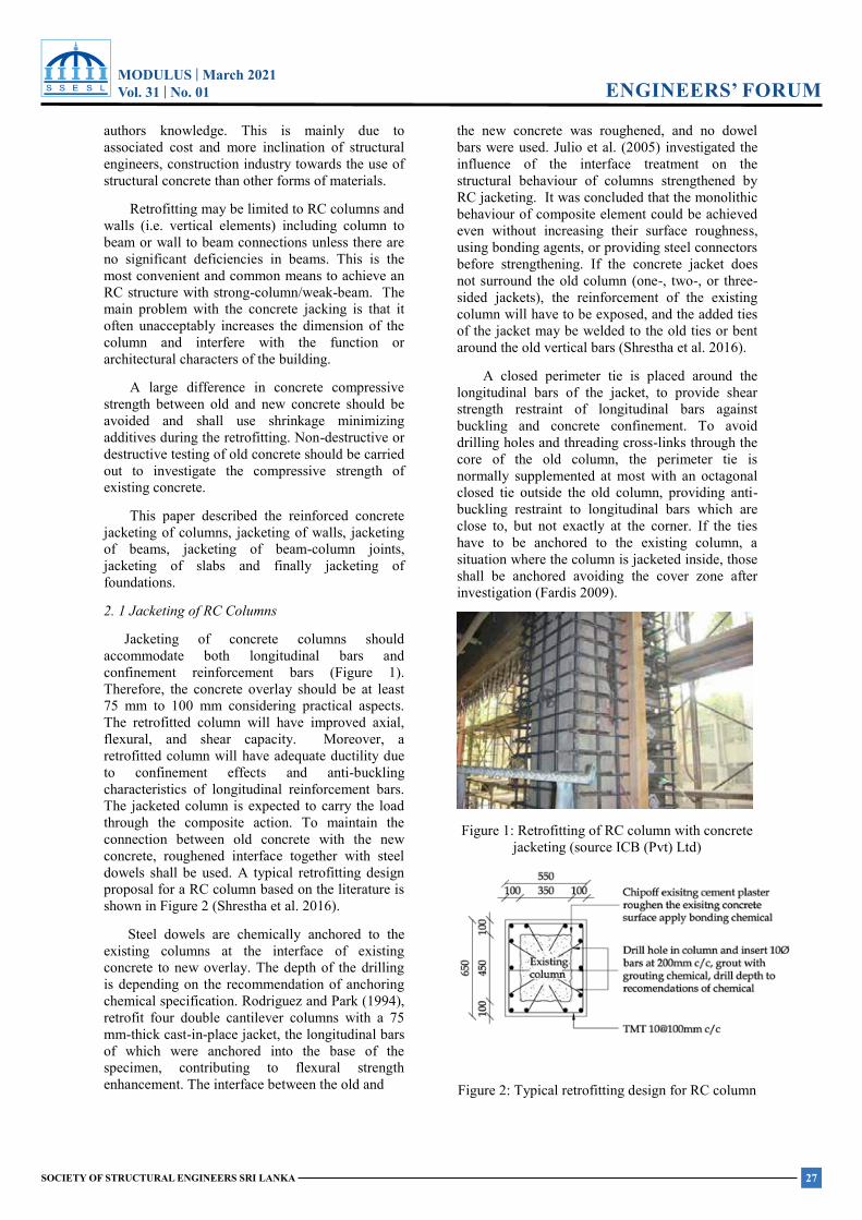
MODULUS | March 2021Vol. 31 | No. 01
27SOCIETY OF STRUCTURAL ENGINEERS SRI LANKA
ENGINEERS’ FORUMMODULUS | March 2021 Vol.31 No. 01
SOCIETY OF STRUCTURAL ENGINEERS SRI LANKA
ENGINEERS’ FORUM
authors knowledge. This is mainly due to associated cost and more inclination of structural engineers, construction industry towards the use of structural concrete than other forms of materials.
Retrofitting may be limited to RC columns and walls (i.e. vertical elements) including column to beam or wall to beam connections unless there are no significant deficiencies in beams. This is the most convenient and common means to achieve an RC structure with strong-column/weak-beam. The main problem with the concrete jacking is that it often unacceptably increases the dimension of the column and interfere with the function or architectural characters of the building.
A large difference in concrete compressive strength between old and new concrete should be avoided and shall use shrinkage minimizing additives during the retrofitting. Non-destructive or destructive testing of old concrete should be carried out to investigate the compressive strength of existing concrete.
This paper described the reinforced concrete jacketing of columns, jacketing of walls, jacketing of beams, jacketing of beam-column joints, jacketing of slabs and finally jacketing of foundations.
2. 1 Jacketing of RC Columns
Jacketing of concrete columns should accommodate both longitudinal bars and confinement reinforcement bars (Figure 1). Therefore, the concrete overlay should be at least 75 mm to 100 mm considering practical aspects. The retrofitted column will have improved axial, flexural, and shear capacity. Moreover, a retrofitted column will have adequate ductility due to confinement effects and anti-buckling characteristics of longitudinal reinforcement bars. The jacketed column is expected to carry the load through the composite action. To maintain the connection between old concrete with the new concrete, roughened interface together with steel dowels shall be used. A typical retrofitting design proposal for a RC column based on the literature is shown in Figure 2 (Shrestha et al. 2016).
Steel dowels are chemically anchored to the existing columns at the interface of existing concrete to new overlay. The depth of the drilling is depending on the recommendation of anchoring chemical specification. Rodriguez and Park (1994), retrofit four double cantilever columns with a 75 mm-thick cast-in-place jacket, the longitudinal bars of which were anchored into the base of the specimen, contributing to flexural strength enhancement. The interface between the old and
the new concrete was roughened, and no dowel bars were used. Julio et al. (2005) investigated the influence of the interface treatment on the structural behaviour of columns strengthened by RC jacketing. It was concluded that the monolithic behaviour of composite element could be achieved even without increasing their surface roughness, using bonding agents, or providing steel connectors before strengthening. If the concrete jacket does not surround the old column (one-, two-, or three-sided jackets), the reinforcement of the existing column will have to be exposed, and the added ties of the jacket may be welded to the old ties or bent around the old vertical bars (Shrestha et al. 2016).
A closed perimeter tie is placed around the longitudinal bars of the jacket, to provide shear strength restraint of longitudinal bars against buckling and concrete confinement. To avoid drilling holes and threading cross-links through the core of the old column, the perimeter tie is normally supplemented at most with an octagonal closed tie outside the old column, providing anti-buckling restraint to longitudinal bars which are close to, but not exactly at the corner. If the ties have to be anchored to the existing column, a situation where the column is jacketed inside, those shall be anchored avoiding the cover zone after investigation (Fardis 2009).
Figure 1: Retrofitting of RC column with concrete jacketing (source ICB (Pvt) Ltd)
Figure 2: Typical retrofitting design for RC column
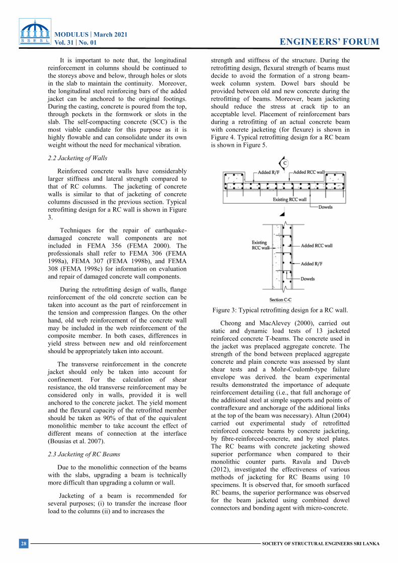
MODULUS | March 2021Vol. 31 | No. 01
28 SOCIETY OF STRUCTURAL ENGINEERS SRI LANKA
ENGINEERS’ FORUMMODULUS | March 2021 Vol.31 No. 01
SOCIETY OF STRUCTURAL ENGINEERS SRI LANKA
ENGINEERS’ FORUM
It is important to note that, the longitudinal reinforcement in columns should be continued to the storeys above and below, through holes or slots in the slab to maintain the continuity. Moreover, the longitudinal steel reinforcing bars of the added jacket can be anchored to the original footings. During the casting, concrete is poured from the top, through pockets in the formwork or slots in the slab. The self-compacting concrete (SCC) is the most viable candidate for this purpose as it is highly flowable and can consolidate under its own weight without the need for mechanical vibration.
2.2 Jacketing of Walls
Reinforced concrete walls have considerably larger stiffness and lateral strength compared to that of RC columns. The jacketing of concrete walls is similar to that of jacketing of concrete columns discussed in the previous section. Typical retrofitting design for a RC wall is shown in Figure 3.
Techniques for the repair of earthquake-damaged concrete wall components are not included in FEMA 356 (FEMA 2000). The professionals shall refer to FEMA 306 (FEMA 1998a), FEMA 307 (FEMA 1998b), and FEMA 308 (FEMA 1998c) for information on evaluation and repair of damaged concrete wall components.
During the retrofitting design of walls, flange reinforcement of the old concrete section can be taken into account as the part of reinforcement in the tension and compression flanges. On the other hand, old web reinforcement of the concrete wall may be included in the web reinforcement of the composite member. In both cases, differences in yield stress between new and old reinforcement should be appropriately taken into account.
The transverse reinforcement in the concrete jacket should only be taken into account for confinement. For the calculation of shear resistance, the old transverse reinforcement may be considered only in walls, provided it is well anchored to the concrete jacket. The yield moment and the flexural capacity of the retrofitted member should be taken as 90% of that of the equivalent monolithic member to take account the effect of different means of connection at the interface (Bousias et al. 2007).
2.3 Jacketing of RC Beams
Due to the monolithic connection of the beams with the slabs, upgrading a beam is technically more difficult than upgrading a column or wall.
Jacketing of a beam is recommended for several purposes; (i) to transfer the increase floor load to the columns (ii) and to increases the
strength and stiffness of the structure. During the retrofitting design, flexural strength of beams must decide to avoid the formation of a strong beam-week column system. Dowel bars should be provided between old and new concrete during the retrofitting of beams. Moreover, beam jacketing should reduce the stress at crack tip to an acceptable level. Placement of reinforcement bars during a retrofitting of an actual concrete beam with concrete jacketing (for flexure) is shown in Figure 4. Typical retrofitting design for a RC beam is shown in Figure 5.
Figure 3: Typical retrofitting design for a RC wall.
Cheong and MacAlevey (2000), carried out static and dynamic load tests of 13 jacketed reinforced concrete T-beams. The concrete used in the jacket was preplaced aggregate concrete. The strength of the bond between preplaced aggregate concrete and plain concrete was assessed by slant shear tests and a Mohr-Coulomb-type failure envelope was derived. the beam experimental results demonstrated the importance of adequate reinforcement detailing (i.e., that full anchorage of the additional steel at simple supports and points of contraflexure and anchorage of the additional links at the top of the beam was necessary). Altun (2004) carried out experimental study of retrofitted reinforced concrete beams by concrete jacketing, by fibre-reinforced-concrete, and by steel plates. The RC beams with concrete jacketing showed superior performance when compared to their monolithic counter parts. Ravala and Daveb (2012), investigated the effectiveness of various methods of jacketing for RC Beams using 10 specimens. It is observed that, for smooth surfaced RC beams, the superior performance was observed for the beam jacketed using combined dowel connectors and bonding agent with micro-concrete.
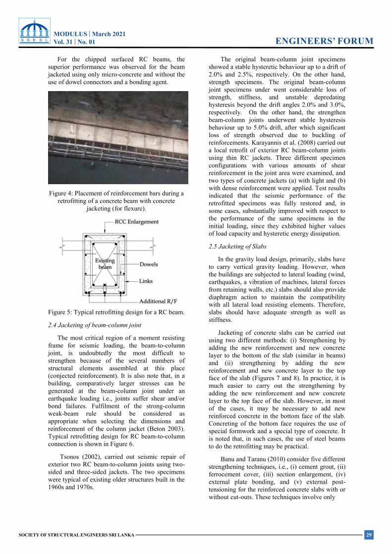
MODULUS | March 2021Vol. 31 | No. 01
29SOCIETY OF STRUCTURAL ENGINEERS SRI LANKA
ENGINEERS’ FORUMMODULUS | March 2021 Vol.31 No. 01
SOCIETY OF STRUCTURAL ENGINEERS SRI LANKA
ENGINEERS’ FORUM
For the chipped surfaced RC beams, the superior performance was observed for the beam jacketed using only micro-concrete and without the use of dowel connectors and a bonding agent.
Figure 4: Placement of reinforcement bars during a retrofitting of a concrete beam with concrete
jacketing (for flexure).
Figure 5: Typical retrofitting design for a RC beam.
2.4 Jacketing of beam-column joint
The most critical region of a moment resisting frame for seismic loading, the beam-to-column joint, is undoubtedly the most difficult to strengthen because of the several numbers of structural elements assembled at this place (conjected reinforcement). It is also note that, in a building, comparatively larger stresses can be generated at the beam-column joint under an earthquake loading i.e., joints suffer shear and/or bond failures. Fulfilment of the strong-column weak-beam rule should be considered as appropriate when selecting the dimensions and reinforcement of the column jacket (Beton 2003). Typical retrofitting design for RC beam-to-column connection is shown in Figure 6.
Tsonos (2002), carried out seismic repair of exterior two RC beam-to-column joints using two-sided and three-sided jackets. The two specimens were typical of existing older structures built in the 1960s and 1970s.
The original beam-column joint specimens showed a stable hysteretic behaviour up to a drift of 2.0% and 2.5%, respectively. On the other hand, strength specimens. The original beam-column joint specimens under went considerable loss of strength, stiffness, and unstable depredating hysteresis beyond the drift angles 2.0% and 3.0%, respectively. On the other hand, the strengthen beam-column joints underwent stable hysteresis behaviour up to 5.0% drift, after which significant loss of strength observed due to buckling of reinforcements. Karayannis et al. (2008) carried out a local retrofit of exterior RC beam-column joints using thin RC jackets. Three different specimen configurations with various amounts of shear reinforcement in the joint area were examined, and two types of concrete jackets (a) with light and (b) with dense reinforcement were applied. Test results indicated that the seismic performance of the retrofitted specimens was fully restored and, in some cases, substantially improved with respect to the performance of the same specimens in the initial loading, since they exhibited higher values of load capacity and hysteretic energy dissipation.
2.5 Jacketing of Slabs
In the gravity load design, primarily, slabs have to carry vertical gravity loading. However, when the buildings are subjected to lateral loading (wind, earthquakes, a vibration of machines, lateral forces from retaining walls, etc.) slabs should also provide diaphragm action to maintain the compatibility with all lateral load resisting elements. Therefore, slabs should have adequate strength as well as stiffness.
Jacketing of concrete slabs can be carried out using two different methods: (i) Strengthening by adding the new reinforcement and new concrete layer to the bottom of the slab (similar in beams) and (ii) strengthening by adding the new reinforcement and new concrete layer to the top face of the slab (Figures 7 and 8). In practice, it is much easier to carry out the strengthening by adding the new reinforcement and new concrete layer to the top face of the slab. However, in most of the cases, it may be necessary to add new reinforced concrete in the bottom face of the slab. Concreting of the bottom face requires the use of special formwork and a special type of concrete. It is noted that, in such cases, the use of steel beams to do the retrofitting may be practical.
Banu and Taranu (2010) consider five different strengthening techniques, i.e., (i) cement grout, (ii) ferrocement cover, (iii) section enlargement, (iv) external plate bonding, and (v) external post-tensioning for the reinforced concrete slabs with or without cut-outs. These techniques involve only
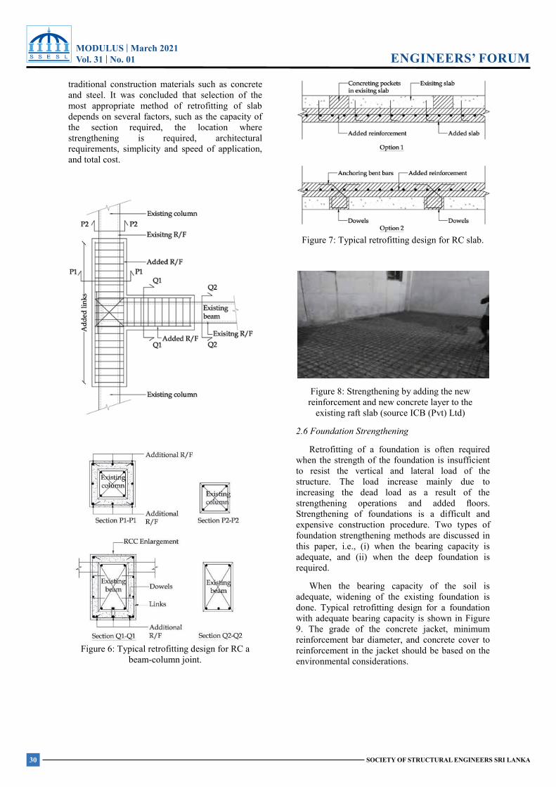
MODULUS | March 2021Vol. 31 | No. 01
30 SOCIETY OF STRUCTURAL ENGINEERS SRI LANKA
ENGINEERS’ FORUMMODULUS | March 2021 Vol.31 No. 01
SOCIETY OF STRUCTURAL ENGINEERS SRI LANKA
ENGINEERS’ FORUM
traditional construction materials such as concrete and steel. It was concluded that selection of the most appropriate method of retrofitting of slab depends on several factors, such as the capacity of the section required, the location where strengthening is required, architectural requirements, simplicity and speed of application, and total cost.
Figure 6: Typical retrofitting design for RC a beam-column joint.
Figure 7: Typical retrofitting design for RC slab.
Figure 8: Strengthening by adding the new reinforcement and new concrete layer to the
existing raft slab (source ICB (Pvt) Ltd)
2.6 Foundation Strengthening
Retrofitting of a foundation is often required when the strength of the foundation is insufficient to resist the vertical and lateral load of the structure. The load increase mainly due to increasing the dead load as a result of the strengthening operations and added floors. Strengthening of foundations is a difficult and expensive construction procedure. Two types of foundation strengthening methods are discussed in this paper, i.e., (i) when the bearing capacity is adequate, and (ii) when the deep foundation is required.
When the bearing capacity of the soil is adequate, widening of the existing foundation is done. Typical retrofitting design for a foundation with adequate bearing capacity is shown in Figure 9. The grade of the concrete jacket, minimum reinforcement bar diameter, and concrete cover to reinforcement in the jacket should be based on the environmental considerations.
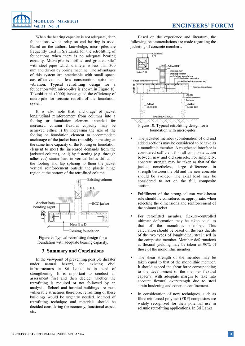
MODULUS | March 2021Vol. 31 | No. 01
31SOCIETY OF STRUCTURAL ENGINEERS SRI LANKA
ENGINEERS’ FORUMMODULUS | March 2021 Vol.31 No. 01
SOCIETY OF STRUCTURAL ENGINEERS SRI LANKA
ENGINEERS’ FORUM
When the bearing capacity is not adequate, deep foundations which relay on end bearing is used. Based on the authors knowledge, micro-piles are frequently used in Sri Lanka for the retrofitting of foundations when there is no adequate bearing capacity. Micro-pile is “drilled and grouted pile” with steel pipes which diameter is less than 300 mm and driven by boring machine. The advantages of this system are practicable with small space, cost-effective and less construction noise and vibration. Typical retrofitting design for a foundation with micro-piles is shown in Figure 10. Takashi et al. (2000) investigated the efficiency of micro-pile for seismic retrofit of the foundation system.
It is also note that, anchorage of jacket longitudinal reinforcement from columns into a footing or foundation element intended for increased column flexural capacity may be achieved either: i) by increasing the size of the footing or foundation element to accommodate anchorage of the jacket bars (possibly increasing at the same time capacity of the footing or foundation element to meet the increased demands from the jacketed column), or ii) by fastening (e.g. through adhesives) starter bars in vertical holes drilled in the footing and lap splicing to them the jacket vertical reinforcement outside the plastic hinge region at the bottom of the retrofitted column.
Figure 9: Typical retrofitting design for a foundation with adequate bearing capacity.
3. Summary and Conclusions In the viewpoint of preventing possible disaster
under natural hazard, the existing civil infrastructures in Sri Lanka is in need of strengthening. It is important to conduct an assessment first and then decide, whether the retrofitting is required or not followed by an analysis. School and hospital buildings are most vulnerable structures therefore; retrofitting of these buildings would be urgently needed. Method of retrofitting technique and materials should be decided considering the economy, functional aspect etc.
Based on the experience and literature, the following recommendations are made regarding the jacketing of concrete members.
Figure 10: Typical retrofitting design for a foundation with micro-piles.
• The jacketed member (combination of old and added section) may be considered to behave as a monolithic member. A roughened interface is considered sufficient for full composite action between new and old concrete. For simplicity, concrete strength may be taken as that of the jacket; nonetheless, large differences in strength between the old and the new concrete should be avoided. The axial load may be considered to act on the full, composite section.
• Fulfillment of the strong-column weak-beam rule should he considered as appropriate, when selecting the dimensions and reinforcement of the column jacket.
• For retrofitted member, flexure-controlled ultimate deformation may be taken equal to that of the monolithic member. This calculation should be based on the less ductile of the two types of longitudinal steel used in the composite member. Member deformations at flexural yielding may be taken as 90% of those of the monolithic member.
• The shear strength of the member may be taken equal to that of the monolithic member. It should exceed the shear force corresponding to the development of the member flexural capacity, with adequate margin to take into account flexural overstrength due to steel strain hardening and concrete confinement.
• In consideration of new techniques, such as fibre-reinforced-polymer (FRP) composites are widely recognized for their potential use in seismic retrofitting applications. In Sri Lanka
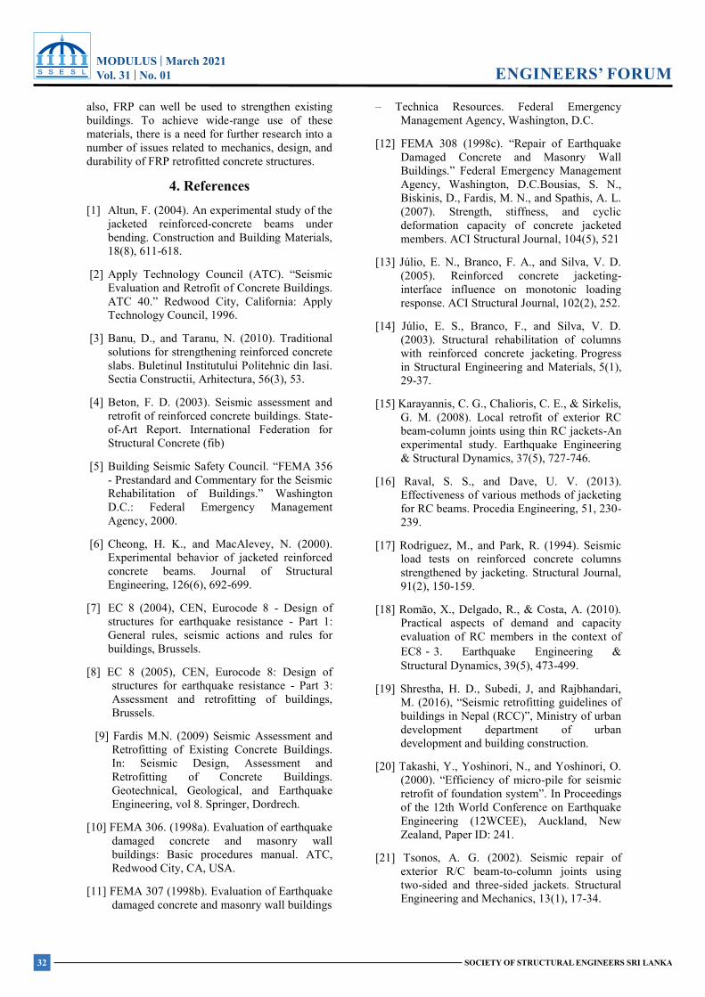
MODULUS | March 2021Vol. 31 | No. 01
32 SOCIETY OF STRUCTURAL ENGINEERS SRI LANKA
ENGINEERS’ FORUMMODULUS | March 2021 Vol.31 No. 01
SOCIETY OF STRUCTURAL ENGINEERS SRI LANKA
ENGINEERS’ FORUM
also, FRP can well be used to strengthen existing buildings. To achieve wide-range use of these materials, there is a need for further research into a number of issues related to mechanics, design, and durability of FRP retrofitted concrete structures.
4. References [1] Altun, F. (2004). An experimental study of the
jacketed reinforced-concrete beams under bending. Construction and Building Materials, 18(8), 611-618.
[2] Apply Technology Council (ATC). “Seismic Evaluation and Retrofit of Concrete Buildings. ATC 40.” Redwood City, California: Apply Technology Council, 1996.
[3] Banu, D., and Taranu, N. (2010). Traditional solutions for strengthening reinforced concrete slabs. Buletinul Institutului Politehnic din Iasi. Sectia Constructii, Arhitectura, 56(3), 53.
[4] Beton, F. D. (2003). Seismic assessment and retrofit of reinforced concrete buildings. State-of-Art Report. International Federation for Structural Concrete (fib)
[5] Building Seismic Safety Council. “FEMA 356 - Prestandard and Commentary for the Seismic Rehabilitation of Buildings.” Washington D.C.: Federal Emergency Management Agency, 2000.
[6] Cheong, H. K., and MacAlevey, N. (2000). Experimental behavior of jacketed reinforced concrete beams. Journal of Structural Engineering, 126(6), 692-699.
[7] EC 8 (2004), CEN, Eurocode 8 - Design of structures for earthquake resistance - Part 1: General rules, seismic actions and rules for buildings, Brussels.
[8] EC 8 (2005), CEN, Eurocode 8: Design of structures for earthquake resistance - Part 3: Assessment and retrofitting of buildings, Brussels.
[9] Fardis M.N. (2009) Seismic Assessment and Retrofitting of Existing Concrete Buildings. In: Seismic Design, Assessment and Retrofitting of Concrete Buildings. Geotechnical, Geological, and Earthquake Engineering, vol 8. Springer, Dordrech.
[10] FEMA 306. (1998a). Evaluation of earthquake damaged concrete and masonry wall buildings: Basic procedures manual. ATC, Redwood City, CA, USA.
[11] FEMA 307 (1998b). Evaluation of Earthquake damaged concrete and masonry wall buildings
– Technica Resources. Federal Emergency Management Agency, Washington, D.C.
[12] FEMA 308 (1998c). “Repair of Earthquake Damaged Concrete and Masonry Wall Buildings.” Federal Emergency Management Agency, Washington, D.C.Bousias, S. N., Biskinis, D., Fardis, M. N., and Spathis, A. L. (2007). Strength, stiffness, and cyclic deformation capacity of concrete jacketed members. ACI Structural Journal, 104(5), 521
[13] Júlio, E. N., Branco, F. A., and Silva, V. D. (2005). Reinforced concrete jacketing-interface influence on monotonic loading response. ACI Structural Journal, 102(2), 252.
[14] Júlio, E. S., Branco, F., and Silva, V. D. (2003). Structural rehabilitation of columns with reinforced concrete jacketing. Progress in Structural Engineering and Materials, 5(1), 29-37.
[15] Karayannis, C. G., Chalioris, C. E., & Sirkelis, G. M. (2008). Local retrofit of exterior RC beam-column joints using thin RC jackets-An experimental study. Earthquake Engineering & Structural Dynamics, 37(5), 727-746.
[16] Raval, S. S., and Dave, U. V. (2013). Effectiveness of various methods of jacketing for RC beams. Procedia Engineering, 51, 230-239.
[17] Rodriguez, M., and Park, R. (1994). Seismic load tests on reinforced concrete columns strengthened by jacketing. Structural Journal, 91(2), 150-159.
[18] Romão, X., Delgado, R., & Costa, A. (2010). Practical aspects of demand and capacity evaluation of RC members in the context of EC8‐3. Earthquake Engineering & Structural Dynamics, 39(5), 473-499.
[19] Shrestha, H. D., Subedi, J, and Rajbhandari, M. (2016), “Seismic retrofitting guidelines of buildings in Nepal (RCC)”, Ministry of urban development department of urban development and building construction.
[20] Takashi, Y., Yoshinori, N., and Yoshinori, O. (2000). “Efficiency of micro-pile for seismic retrofit of foundation system”. In Proceedings of the 12th World Conference on Earthquake Engineering (12WCEE), Auckland, New Zealand, Paper ID: 241.
[21] Tsonos, A. G. (2002). Seismic repair of exterior R/C beam-to-column joints using two-sided and three-sided jackets. Structural Engineering and Mechanics, 13(1), 17-34.


Published by
Society of Structural Engineers - Sri Lanka (SSESL)nd2 Floor ,The Institution of Engineers Sri Lanka ,Vidya Mawatha, 120/15,Wijerama Mawatha,Colombo 07,Sri Lanka.
Tel/Fax: +0112 698 726 , Email: [email protected]