modified switching-table strategy for reduction of current harmonics in direct torque controlled...
TRANSCRIPT

The following paper posted here is not the official IET Electric Power Applications
published version. The final published version of this paper can be found in the
IET Electric Power Applications, volume 9, issue 1, pp. 10- 19, January 2015
Original citation:
K. D. Hoang, Y. Ren, Z. Q. Zhu, and M. Foster, “Modified switching-table
strategy for reduction of current harmonics in direct torque controlled dual-three-
phase permanent magnet synchronous machine drives,” IET Electric Power
Applications, vol. 9, no. 1, pp. 10-19, Jan. 2015.
Link to the official URL:
http://dx.doi.org/10.1049/iet-epa.2013.0388
Copyright © 2015 IET Copyright information can be found at (accessed 28 January 2015)
http://digital-library.theiet.org/journals/author-guide
"This paper is a postprint of a paper submitted to and accepted for
publication in IET Electric Power Applications journal and is subject to
Institution of Engineering and Technology Copyright. The copy of record is
available at IET Digital Library"
This is the author manuscript which may differ from the final published version.
Please cite this article as the above original citation.

1
K. D. Hoang, Y. Ren, Z.Q.Zhu*, M. Foster
Abstract—The switching-table-based direct torque control strategies (ST-DTC) of dual-three phase permanent magnet
synchronous machine (PMSM) drives are investigated in this paper. Owing to its inherited advantage of suppression of
sixth harmonic torque pulsation, dual-three phase machine has attracted more and more interests among various sorts of
multi-phase machines. However, unexpected stator harmonic currents are often observed in the classical ST-DTC
strategy for dual-three phase PMSM drives, which cause large losses and decrease the efficiency of the drive system. An
optimized ST-DTC strategy which consists a two-step process to determinate the most appropriate inverter voltage
vector is proposed to reduce the stator harmonic currents. The merits of the classical direct torque control, i.e. simple
structure and good dynamic performance, are still preserved. The experimental results verify that the proposed method
can significantly reduce the current harmonics.
Index Terms— direct torque control (DTC), dual-three phase, harmonic stator currents, permanent magnet
synchronous machines (PMSM).
The authors are with the Department of Electronic and Electrical Engineering, University of Sheffield, Sheffield, S1 3JD, U.K.
(E-mail: [email protected]; [email protected]; [email protected], Tel: +44(0)1142225360,
Fax: +44(0)1142225196; [email protected]).
Modified Switching-Table Strategy for
Reduction of Current Harmonics in Direct
Torque Controlled Dual-three Phase
Permanent Magnet Synchronous Machine
Drives
IET Electric Power Applications
2
Nomenclature
Gi Voltage vector group
Ls α and β axis inductance
Lls Stator leakage inductance
Lm Magnetizing inductance in αβ subspace
P Number of pole pairs
Rs Stator resistance
Te Electromagnetic torque
Ts Sampling period
Vsαβ, ψsαβ, Isαβ Stator voltage, flux and current vectors in αβ subspace
Vsz1z2, ψsz1z2, Isz1z2 Stator voltage, flux and current vectors in z1z2 subspace
Vso1o2, ψso1o2, Iso1o2 Stator voltage, flux and current vectors in o1o2 subspace
ω1 Machine angular velocity
εψ ,εT Stator flux and torque control signals
θr Electrical rotor position
θsαβ, θsz1z2 Position of stator flux vector in αβ subspace and z1z2 subspace
ψrαβ Rotor flux vectors in αβ subspace
ψs, ψr Amplitude of stator and rotor flux vector in αβ subspace
ψs_ripple, Te_ripple Ripple of stator flux and torque
1 Introduction
Recently, the interest in multiphase machine drives has considerably increased, especially for high-power and/or high-current
applications such as aerospace applications, ship propulsion, electric/hybrid vehicles, and renewable energy generation. In these
applications, the controlled power can be shared by more inverter legs to reduce the current stress of each semiconductor device
compared to three-phase converters [1]. Other potential advantages of the multiphase machine drives are higher reliability at the
system level, lower torque pulsations, and lower dc-link voltage requirement [2, 3].
A very interesting and well-discussed type of multiphase machines is the dual-three phase machine having two sets of three-
phase windings spatially shifted by 30 electrical degrees, as shown in Fig.1. In the dual-three phase machine, the sixth harmonic
torque pulsation, which is predominant in the three-phase systems, will be completely absent because of the opposition of these
IET Electric Power Applications

3
components produced by two sets of windings [4]. Nevertheless, large stator circulating harmonic currents will occur in the
voltage-source-inverter (VSI) fed dual-three phase machine since the machine impedance associated with these harmonics is
very small - only composed of the stator resistance and leakage inductance, according to the machine model using vector space
decomposition approach (VSD) [5]. These unexpected harmonic currents cause extra losses and require higher semiconductor
device ratings [6].
Fig. 1. Voltage-source-inverter-fed dual-three phase PMSM and drive
Previous investigations have been conducted to explore vector control using suitable pulse-width-modulation (PWM)
techniques and to extend its theory for dual-three phase machine drives [1, 7]. Although unexpected stator harmonic currents can
be minimized under these strategies, complicated and time-consuming calculation is essentially required.
On the other hand, direct torque control (DTC) strategy is an applicable alternative because of its simple structure, excellent
transient response and good robustness against machine parameters. Based on the vector space decomposition technique [5], only
the variables in αβ subspace in the dual-three phase system relate to the torque, which is similar to the case in three phase drives.
Therefore, the classical switching-table-based DTC (ST-DTC) strategy can be easily extrapolated to dual-three phase drives.
However, the classical DTC strategy suffers from the aforementioned large stator harmonic currents because of lacking
controlling of harmonic components in z1z2 subspace. Hatua etc. [8] develops two new methods of ST-DTC technique, called
Resultant Flux Control Method and Individual Flux Control Method, for the dual-three phase machine drive to reduce the torque
ripple, however, the unexpected stator harmonic currents still exist. Harmonic suppression schemes have been dedicated for the
ST-DTC of five-phase machines [9-11].
This paper aims to reduce the stator harmonic currents in the classical ST-DTC strategy for dual-three phase PMSM drives,
IET Electric Power Applications
4
while preserving its advantages, such as simple structure and good robustness. This paper is based on [12], much more clear
description of the two-step process is proposed, and detailed experimental results have been shown to verify the proposed
method. The remainder of this paper consists of the following sections. In section 2, machine modeling and analysis based on the
vector space decomposition technique is described. In section 3, basic principle of switching-table-based DTC strategy for dual-
three phase drives is exposed. Then a two-step process to select the most appropriate voltage vector is presented in section 4:
firstly, according to the classical switching table and outputs of the hysteresis regulators, selecting the voltage vector group to
meet the requirement of torque and flux control, secondly, choosing the most suitable voltage vector from that group, basing on
the position of the harmonic stator flux, to reduce the harmonic currents. Experimental results are provided in section 5 to
demonstrate the validity of the proposed solutions.
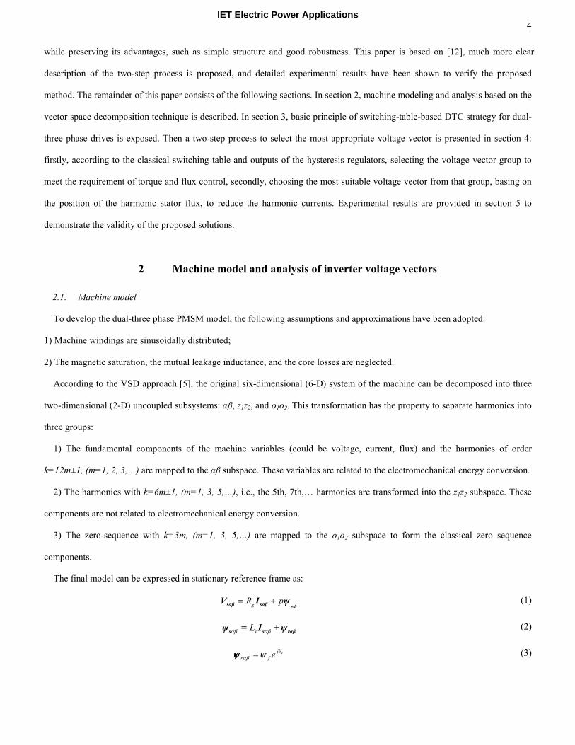
2 Machine model and analysis of inverter voltage vectors
2.1. Machine model
To develop the dual-three phase PMSM model, the following assumptions and approximations have been adopted:
1) Machine windings are sinusoidally distributed;
2) The magnetic saturation, the mutual leakage inductance, and the core losses are neglected.
According to the VSD approach [5], the original six-dimensional (6-D) system of the machine can be decomposed into three
two-dimensional (2-D) uncoupled subsystems: αβ, z1z2, and o1o2. This transformation has the property to separate harmonics into
three groups:
1) The fundamental components of the machine variables (could be voltage, current, flux) and the harmonics of order
k=12m±1, (m=1, 2, 3,…) are mapped to the αβ subspace. These variables are related to the electromechanical energy conversion.
2) The harmonics with k=6m±1, (m=1, 3, 5,…), i.e., the 5th, 7th,… harmonics are transformed into the z1z2 subspace. These
components are not related to electromechanical energy conversion.
3) The zero-sequence with k=3m, (m=1, 3, 5,…) are mapped to the o1o2 subspace to form the classical zero sequence
components.
The final model can be expressed in stationary reference frame as:
sR p= +
sαβsαβ sαβV I ψ (1)
sLαβ αβs s rαβψ = I + ψ (2)
rj
r f eθ
αβ ψ=ψψψψ (3)
IET Electric Power Applications

5
sR p= +1 2 1 2 1 2sz z sz z sz z
V I ψ (4)
lsL=1 2 1 2sz z sz z
ψ I (5)
sR p= +1 2 1 2 1 2so o so o so o
V I ψ (6)
lsL=1 2 1 2so o so o
ψ I (7)
3 ( )e s s s sT P i iα β β αψ ψ= − (8)
where, Ls=Lls+3Lm is the stator inductance.
It should be mentioned that, if the two stator sets have isolated neutral points, as shown in Fig. 1, it can be deduced that all the
vectors of o1o2 subspace are mapped to the origin, hence no currents flow in the o1o2 subspace according to (6) and (7).
Therefore, the machine model can be reduced to two sets of decoupled equations corresponding to the machine αβ and z1z2
subspaces. The detailed derivation can be found in [5].
Based on (8), after using VSD approach, torque and flux production involves only αβ components, which makes the machine
control as simple as the case of three phase machine. However, it also can be seen from (4) and (5) that the z1z2 components are
responsible for the large circulating harmonic currents because of the small impedance in the z1z2 subspace. Therefore, the
applied voltage vectors should contain not only the voltage commands in αβ components but also the voltage commands to
minimize the average amplitude of z1z2 components.
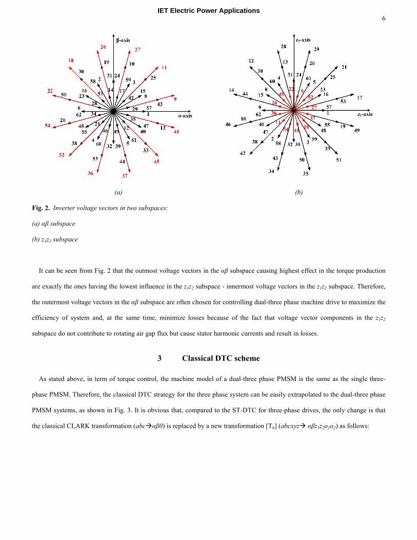
2.2. Analysis of the inverter voltage vectors
Owing to its six inverter legs, dual-three phase system contains 26=64 inverter voltage vectors, much more than three phase
system. By neglecting the zero voltage vectors, the αβ and z1z2 subspace voltage vectors can be shown in Figs. 2 (a) and (b),
respectively. It should note that voltage vector number in Fig. 2 is termed based on binary value of Vi=SZSYSXSCSBSA considering
Vi as a 6-digit binary number, where value of each phase switching component Si is set as “1” when its equivalent stator terminal
is connected to DC link voltage rail and “0” if it is linked to zero voltage rail.
IET Electric Power Applications
6
(a) (b)
Fig. 2. Inverter voltage vectors in two subspaces:
(a) αβ subspace
(b) z1z2 subspace
It can be seen from Fig. 2 that the outmost voltage vectors in the αβ subspace causing highest effect in the torque production
are exactly the ones having the lowest influence in the z1z2 subspace - innermost voltage vectors in the z1z2 subspace. Therefore,
the outermost voltage vectors in the αβ subspace are often chosen for controlling dual-three phase machine drive to maximize the
efficiency of system and, at the same time, minimize losses because of the fact that voltage vector components in the z1z2
subspace do not contribute to rotating air gap flux but cause stator harmonic currents and result in losses.
3 Classical DTC scheme
As stated above, in term of torque control, the machine model of a dual-three phase PMSM is the same as the single three-
phase PMSM. Therefore, the classical DTC strategy for the three phase system can be easily extrapolated to the dual-three phase
PMSM systems, as shown in Fig. 3. It is obvious that, compared to the ST-DTC for three-phase drives, the only change is that
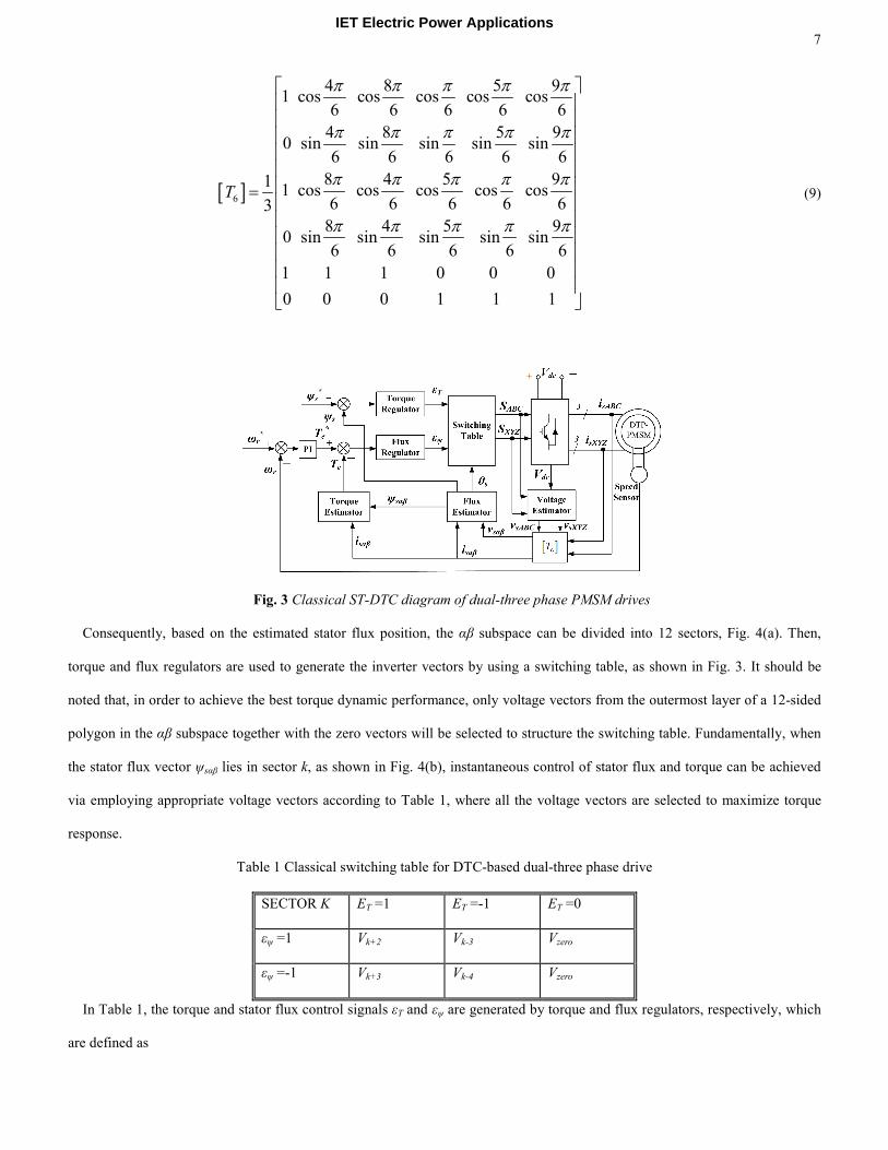
the classical CLARK transformation (abcαβ0) is replaced by a new transformation [T6] (abcxyz αβz1z2o1o2) as follows:
IET Electric Power Applications
7
[ ]6
4 8 5 91 cos cos cos cos cos
6 6 6 6 6
4 8 5 90 sin sin sin sin sin
6 6 6 6 6
8 4 5 911 cos cos cos cos cos
6 6 6 6 63
8 4 5 90 sin sin sin sin sin
6 6 6 6 6
1 1 1
T
π π π π π
π π π π π
π π π π π
π π π π π
=
0 0 0
0 0 0 1 1 1
(9)
Fig. 3 Classical ST-DTC diagram of dual-three phase PMSM drives
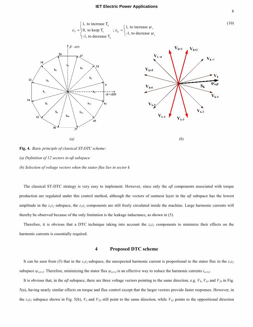
Consequently, based on the estimated stator flux position, the αβ subspace can be divided into 12 sectors, Fig. 4(a). Then,
torque and flux regulators are used to generate the inverter vectors by using a switching table, as shown in Fig. 3. It should be
noted that, in order to achieve the best torque dynamic performance, only voltage vectors from the outermost layer of a 12-sided
polygon in the αβ subspace together with the zero vectors will be selected to structure the switching table. Fundamentally, when
the stator flux vector ψsαβ lies in sector k, as shown in Fig. 4(b), instantaneous control of stator flux and torque can be achieved
via employing appropriate voltage vectors according to Table 1, where all the voltage vectors are selected to maximize torque
response.
Table 1 Classical switching table for DTC-based dual-three phase drive
SECTOR K ΕT =1 ΕT =-1 ΕT =0
εψ =1 Vk+2 Vk-3 Vzero
εψ =-1 Vk+3 Vk-4 Vzero
In Table 1, the torque and stator flux control signals εT and εψ are generated by torque and flux regulators, respectively, which
are defined as
IET Electric Power Applications
8
e
e
e
1, to increase T1, to increase
0, to keep T ; -1, to decrease
-1, to decrease T
s
T
s
ψ
ψε ε
ψ
= =
(10)
(a) (b)
Fig. 4. Basic principle of classical ST-DTC scheme:
(a) Definition of 12 sectors in αβ subspace
(b) Selection of voltage vectors when the stator flux lies in sector k
The classical ST-DTC strategy is very easy to implement. However, since only the αβ components associated with torque
production are regulated under this control method, although the vectors of outmost layer in the αβ subspace has the lowest
amplitude in the z1z2 subspace, the z1z2 components are still freely circulated inside the machine. Large harmonic currents will
thereby be observed because of the only limitation is the leakage inductance, as shown in (5).
Therefore, it is obvious that a DTC technique taking into account the z1z2 components to minimize their effects on the
harmonic currents is essentially required.
4 Proposed DTC scheme
It can be seen from (5) that in the z1z2 subspace, the unexpected harmonic current is proportional to the stator flux in the z1z2
subspace ψsz1z2. Therefore, minimizing the stator flux ψsz1z2 is an effective way to reduce the harmonic currents isz1z2.
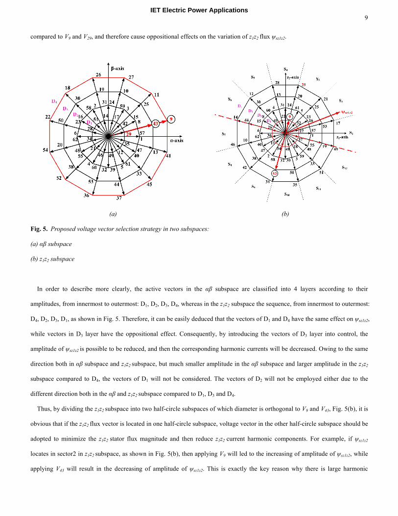
It is obvious that, in the αβ subspace, there are three voltage vectors pointing to the same direction, e.g. V9, V43 and V29 in Fig.
5(a), having nearly similar effects on torque and flux control except that the larger vectors provide faster responses. However, in
the z1z2 subspace shown in Fig. 5(b), V9 and V29 still point to the same direction, while V43 points to the oppositional direction
IET Electric Power Applications
9
compared to V9 and V29, and therefore cause oppositional effects on the variation of z1z2 flux ψsz1z2.
(a) (b)
Fig. 5. Proposed voltage vector selection strategy in two subspaces:
(a) αβ subspace
(b) z1z2 subspace
In order to describe more clearly, the active vectors in the αβ subspace are classified into 4 layers according to their
amplitudes, from innermost to outermost: D1, D2, D3, D4, whereas in the z1z2 subspace the sequence, from innermost to outermost:
D4, D2, D3, D1, as shown in Fig. 5. Therefore, it can be easily deduced that the vectors of D1 and D4 have the same effect on ψsz1z2,
while vectors in D3 layer have the oppositional effect. Consequently, by introducing the vectors of D3 layer into control, the
amplitude of ψsz1z2 is possible to be reduced, and then the corresponding harmonic currents will be decreased. Owing to the same
direction both in αβ subspace and z1z2 subspace, but much smaller amplitude in the αβ subspace and larger amplitude in the z1z2
subspace compared to D4, the vectors of D1 will not be considered. The vectors of D2 will not be employed either due to the
different direction both in the αβ and z1z2 subspace compared to D1, D3 and D4.
Thus, by dividing the z1z2 subspace into two half-circle subspaces of which diameter is orthogonal to V9 and V43, Fig. 5(b), it is
obvious that if the z1z2 flux vector is located in one half-circle subspace, voltage vector in the other half-circle subspace should be
adopted to minimize the z1z2 stator flux magnitude and then reduce z1z2 current harmonic components. For example, if ψsz1z2
locates in sector2 in z1z2 subspace, as shown in Fig. 5(b), then applying V9 will led to the increasing of amplitude of ψsz1z2, while
applying V43 will result in the decreasing of amplitude of ψsz1z2. This is exactly the key reason why there is large harmonic
IET Electric Power Applications
10
currents in the classical ST-DTC controlled dual-three phase machines, although the vectors of outmost layer in the αβ subspace
has the lowest amplitude in the z1z2 subspace. Hence, V43, instead of V9, should be employed as that in the classical ST-DTC
strategy. Similar results can be extended to other sectors. It should be pointed out that, as shown in Fig. 5(b) and Fig. 4(a), the
definition of the sectors of z1z2 subspace is the same as that of αβ subspace, i.e.,
Sector k:
1 2( 1) , ( 1), 1, 2,...12
12 6 12 6s sz z
k k kαβ
π π π πθ θ− + − ≤ < + − =
(11)
Consequently, based on the principle above, there are two steps to pick an appropriate voltage vector.
1) According to the sector of ψsαβ in the αβ subspace and the outputs of hysteresis comparators, one vector in D3 and one vector
in D4, which have the same direction in the αβ subspace and are defined as one group in this paper, are chose as candidates;
2) Based on the position of ψsz1z2 in the z1z2 subspace, the vector which can reduce the amplitude of ψsz1z2 will be chosen from the
selected group.
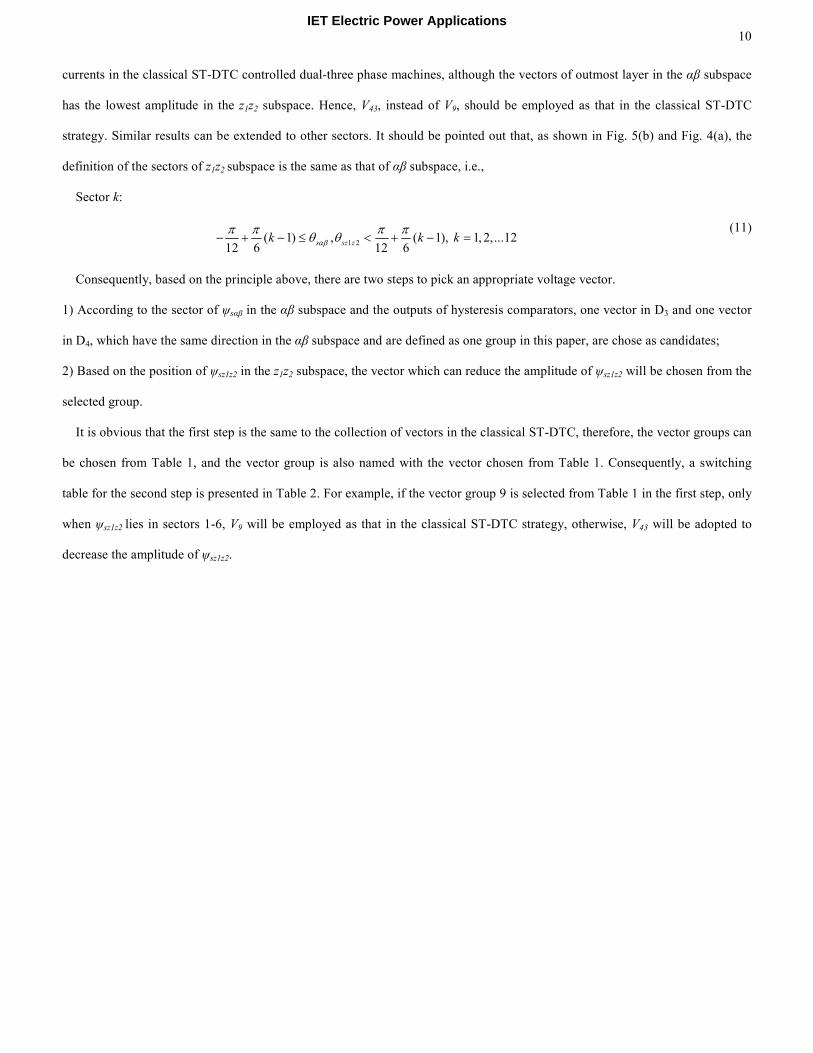
It is obvious that the first step is the same to the collection of vectors in the classical ST-DTC, therefore, the vector groups can
be chosen from Table 1, and the vector group is also named with the vector chosen from Table 1. Consequently, a switching
table for the second step is presented in Table 2. For example, if the vector group 9 is selected from Table 1 in the first step, only
when ψsz1z2 lies in sectors 1-6, V9 will be employed as that in the classical ST-DTC strategy, otherwise, V43 will be adopted to
decrease the amplitude of ψsz1z2.
IET Electric Power Applications
11
Table 2 Switching table for step two in the proposed DTC of dual-three phase drive
VECTOR GROUP
GI
SECTOR OF
ΨSZ1Z2
SELECTED
VECTOR
VECTOR GROUP
GI
SECTOR OF
ΨSZ1Z2
SELECTED
VECTOR
9 7,8,9,10,11,12 V9 54 1,2,3,4,5,6 V54
1,2,3,4,5,6 V43 7,8,9,10,11,12 V20
11 12,1,2,3,4,5 V11 52 6,7,8,9,10,11 V52
6,7,8,9,10,11 V25 12,1,2,3,4,5 V38
27 5,6,7,8,9,10 V27 36 11,12,1,2,3,4 V36
11,12,1,2,3,4 V10 5,6,7,8,9,10 V53
26 10,11,12,1,2,3 V26 37 4,5,6,7,8,9 V37
4,5,6,7,8,9 V19 10,11,12,1,2,3 V44
18 3,4,5,6,7,8 V18 45 9,10,11,12,1,2 V45
9,10,11,12,1,2 V30 3,4,5,6,7,8 V33
22 8,9,10,11,12,1 V22 41 2,3,4,5,6,7 V41
2,3,4,5,6,7 V50 8,9,10,11,12,1 V13
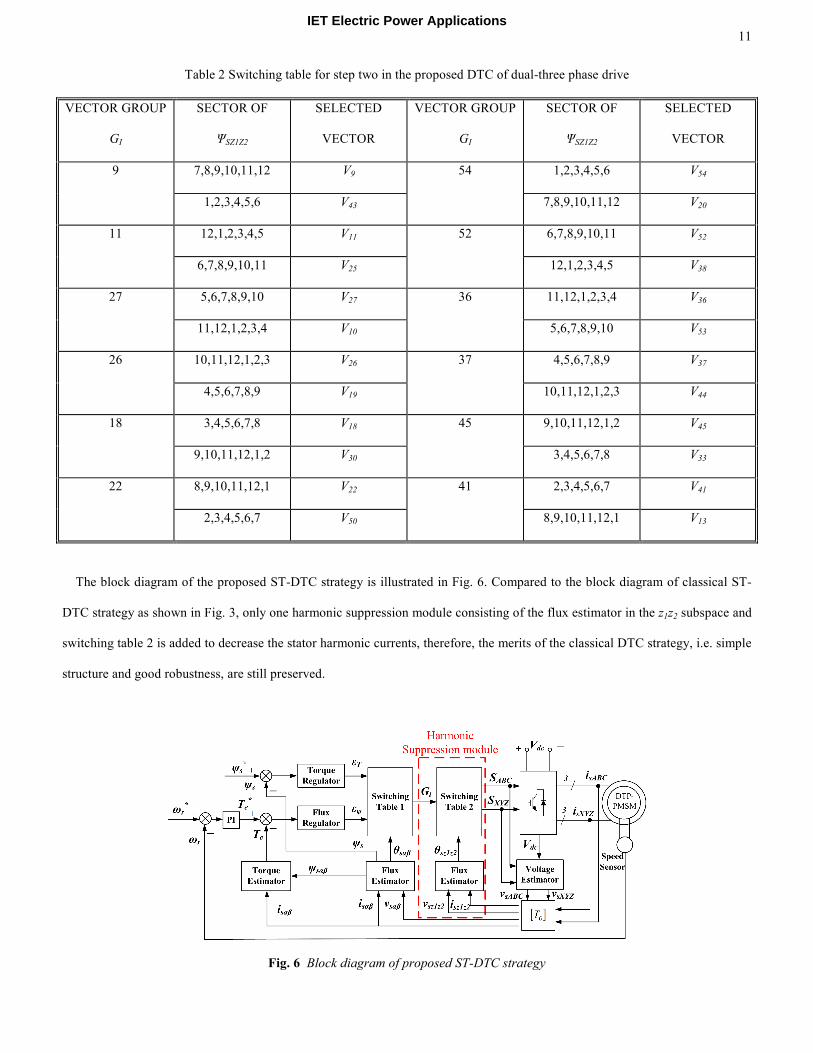
The block diagram of the proposed ST-DTC strategy is illustrated in Fig. 6. Compared to the block diagram of classical ST-
DTC strategy as shown in Fig. 3, only one harmonic suppression module consisting of the flux estimator in the z1z2 subspace and
switching table 2 is added to decrease the stator harmonic currents, therefore, the merits of the classical DTC strategy, i.e. simple
structure and good robustness, are still preserved.
Fig. 6 Block diagram of proposed ST-DTC strategy
IET Electric Power Applications
12
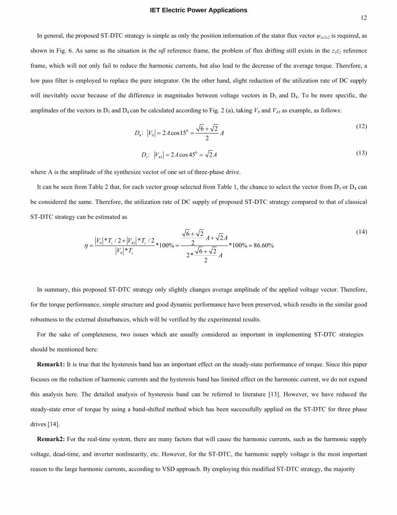
In general, the proposed ST-DTC strategy is simple as only the position information of the stator flux vector ψsz1z2 is required, as
shown in Fig. 6. As same as the situation in the αβ reference frame, the problem of flux drifting still exists in the z1z2 reference
frame, which will not only fail to reduce the harmonic currents, but also lead to the decrease of the average torque. Therefore, a
low pass filter is employed to replace the pure integrator. On the other hand, slight reduction of the utilization rate of DC supply
will inevitably occur because of the difference in magnitudes between voltage vectors in D3 and D4. To be more specific, the
amplitudes of the vectors in D3 and D4 can be calculated according to Fig. 2 (a), taking V9 and V43 as example, as follows:
0
4 9
6 2: 2 cos15
2D V A A
+= =
(12)
0
3 43: 2 cos 45 2D V A A= = (13)
where A is the amplitude of the synthesize vector of one set of three-phase drive.
It can be seen from Table 2 that, for each vector group selected from Table 1, the chance to select the vector from D3 or D4 can
be considered the same. Therefore, the utilization rate of DC supply of proposed ST-DTC strategy compared to that of classical
ST-DTC strategy can be estimated as
9 43
9
6 22* / 2 * / 2 2*100% *100% 86.60%
* 6 22*
2
s s
s
A AV T V T
V TA
η
+++
= = =+
(14)
In summary, this proposed ST-DTC strategy only slightly changes average amplitude of the applied voltage vector. Therefore,
for the torque performance, simple structure and good dynamic performance have been preserved, which results in the similar good
robustness to the external disturbances, which will be verified by the experimental results.
For the sake of completeness, two issues which are usually considered as important in implementing ST-DTC strategies
should be mentioned here:
Remark1: It is true that the hysteresis band has an important effect on the steady-state performance of torque. Since this paper
focuses on the reduction of harmonic currents and the hysteresis band has limited effect on the harmonic current, we do not expand
this analysis here. The detailed analysis of hysteresis band can be referred to literature [13]. However, we have reduced the
steady-state error of torque by using a band-shifted method which has been successfully applied on the ST-DTC for three phase
drives [14].
Remark2: For the real-time system, there are many factors that will cause the harmonic currents, such as the harmonic supply
voltage, dead-time, and inverter nonlinearity, etc. However, for the ST-DTC, the harmonic supply voltage is the most important
reason to the large harmonic currents, according to VSD approach. By employing this modified ST-DTC strategy, the majority
IET Electric Power Applications
13
of the harmonic currents have been suppressed, and at the same time, the merits of the classical direct torque control, i.e. simple
structure and good dynamic performance, are still preserved. Therefore, for the sake of simplicity and parameter independence,
other factors are not compensated in this paper.
5 Experimental Results
The experimental setup consists of a DC power supply, a dual-three phase inverter, a dSPACE DS1005 digital controller, and
a laboratory prototype of the dual-three phase PMSM. The parameters of test machine are listed in Table 3. The overall control
schemes with classical and proposed DTC strategies are shown in Figs. 3 and 6, respectively. The sample frequency is 10 kHz,
and the DC-Bus voltage is set to 40V. All the results were captured using dSPACE software, and then plotted using Matlab.
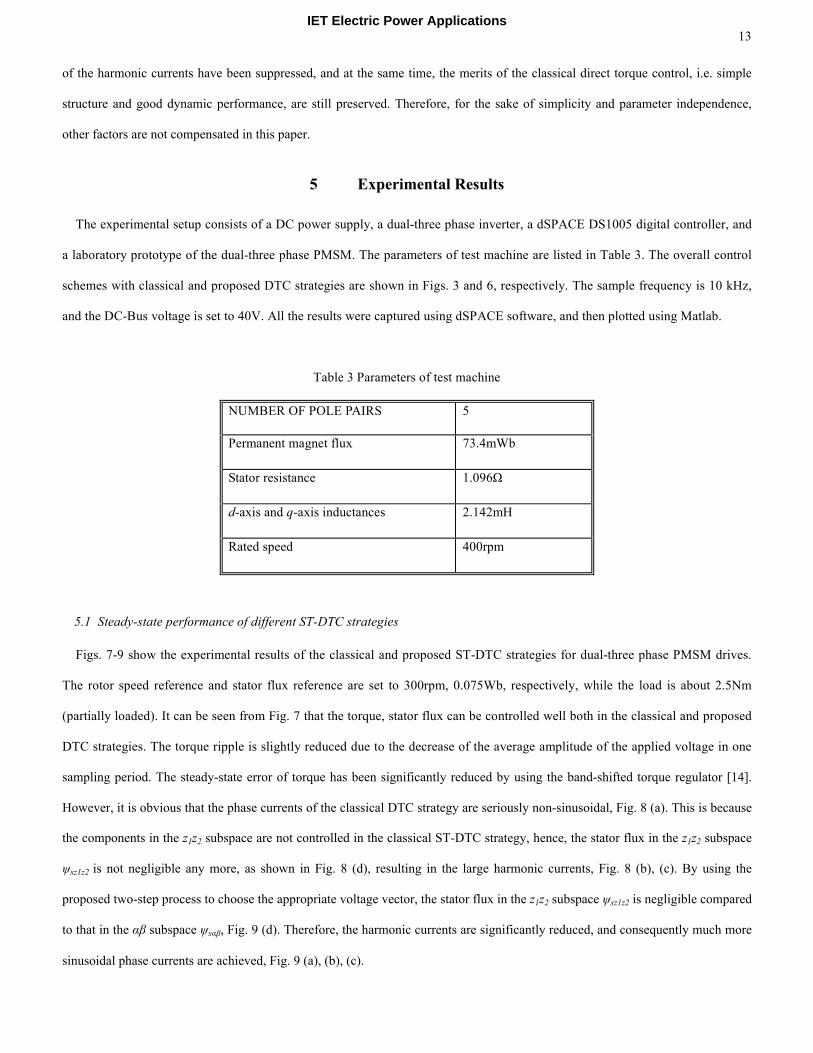
Table 3 Parameters of test machine
NUMBER OF POLE PAIRS 5
Permanent magnet flux 73.4mWb
Stator resistance 1.096Ω
d-axis and q-axis inductances 2.142mH
Rated speed 400rpm
5.1 Steady-state performance of different ST-DTC strategies
Figs. 7-9 show the experimental results of the classical and proposed ST-DTC strategies for dual-three phase PMSM drives.
The rotor speed reference and stator flux reference are set to 300rpm, 0.075Wb, respectively, while the load is about 2.5Nm
(partially loaded). It can be seen from Fig. 7 that the torque, stator flux can be controlled well both in the classical and proposed
DTC strategies. The torque ripple is slightly reduced due to the decrease of the average amplitude of the applied voltage in one
sampling period. The steady-state error of torque has been significantly reduced by using the band-shifted torque regulator [14].
However, it is obvious that the phase currents of the classical DTC strategy are seriously non-sinusoidal, Fig. 8 (a). This is because
the components in the z1z2 subspace are not controlled in the classical ST-DTC strategy, hence, the stator flux in the z1z2 subspace
ψsz1z2 is not negligible any more, as shown in Fig. 8 (d), resulting in the large harmonic currents, Fig. 8 (b), (c). By using the
proposed two-step process to choose the appropriate voltage vector, the stator flux in the z1z2 subspace ψsz1z2 is negligible compared
to that in the αβ subspace ψsαβ, Fig. 9 (d). Therefore, the harmonic currents are significantly reduced, and consequently much more
sinusoidal phase currents are achieved, Fig. 9 (a), (b), (c).
IET Electric Power Applications

14
(a) (b)
Fig. 7. Steady-state performance of torque and stator flux using different DTC strategies.
(a) Classical ST-DTC strategy
(b) Proposed ST-DTC strategy
(a) (a)
(b) (b)
IET Electric Power Applications

15
(c) (c)
(d) (d)
Fig. 8. Steady-state performance of classical ST-DTC strategy
(a) Phase currents
(b) αβ and z1z2 current circles
(c) Phase current harmonic spectrum
(d) Stator flux circle
Fig. 9. Steady-state performance of proposed ST-DTC strategy
(a) Phase currents
(b) αβ and z1z2 current circles
(c) Phase current harmonic spectrum
(d) Stator flux circle
Since the harmonic components do not contribute the electromechanical energy conversion, both the stator flux ripple in the
αβ subspace and the torque ripple are almost equal to those using classical ST-DTC strategy. Detailed quantitative results are
given in Table 4, where the torque and stator flux ripples are calculated as
2
_ _ _
1
1( )
n
s ripple s i s av
inψ ψ ψ
=
= −∑(15)
2
_ _ _
1
1( )
n
e ripple e i e av
i
T T Tn =
= −∑(16)
where Te_i and ψs_i are the instant value of torque and stator flux, respectively, whist Te_av and ψs_av are the average values of
IET Electric Power Applications
16
torque and stator flux, respectively.
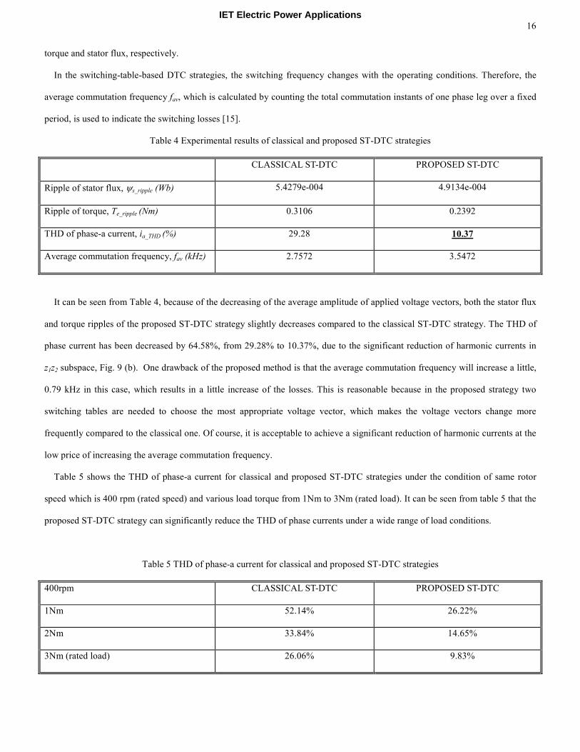
In the switching-table-based DTC strategies, the switching frequency changes with the operating conditions. Therefore, the
average commutation frequency fav, which is calculated by counting the total commutation instants of one phase leg over a fixed
period, is used to indicate the switching losses [15].
Table 4 Experimental results of classical and proposed ST-DTC strategies
CLASSICAL ST-DTC PROPOSED ST-DTC
Ripple of stator flux, ψs_ripple (Wb) 5.4279e-004 4.9134e-004
Ripple of torque, Te_ripple (Nm) 0.3106 0.2392
THD of phase-a current, ia_THD (%) 29.28 10.37
Average commutation frequency, fav (kHz) 2.7572 3.5472
It can be seen from Table 4, because of the decreasing of the average amplitude of applied voltage vectors, both the stator flux
and torque ripples of the proposed ST-DTC strategy slightly decreases compared to the classical ST-DTC strategy. The THD of
phase current has been decreased by 64.58%, from 29.28% to 10.37%, due to the significant reduction of harmonic currents in
z1z2 subspace, Fig. 9 (b). One drawback of the proposed method is that the average commutation frequency will increase a little,
0.79 kHz in this case, which results in a little increase of the losses. This is reasonable because in the proposed strategy two
switching tables are needed to choose the most appropriate voltage vector, which makes the voltage vectors change more
frequently compared to the classical one. Of course, it is acceptable to achieve a significant reduction of harmonic currents at the
low price of increasing the average commutation frequency.
Table 5 shows the THD of phase-a current for classical and proposed ST-DTC strategies under the condition of same rotor
speed which is 400 rpm (rated speed) and various load torque from 1Nm to 3Nm (rated load). It can be seen from table 5 that the
proposed ST-DTC strategy can significantly reduce the THD of phase currents under a wide range of load conditions.
Table 5 THD of phase-a current for classical and proposed ST-DTC strategies
400rpm CLASSICAL ST-DTC PROPOSED ST-DTC
1Nm 52.14% 26.22%
2Nm 33.84% 14.65%
3Nm (rated load) 26.06% 9.83%
IET Electric Power Applications
17
5.2 Dynamic performance of inner torque loop control for conventional and proposed DTC
As mentioned above, the utilization rate of DC supply is slightly reduced in the proposed DTC strategy. Therefore, it is
necessary to check whether the dynamic performance of torque control will deteriorate accordingly.
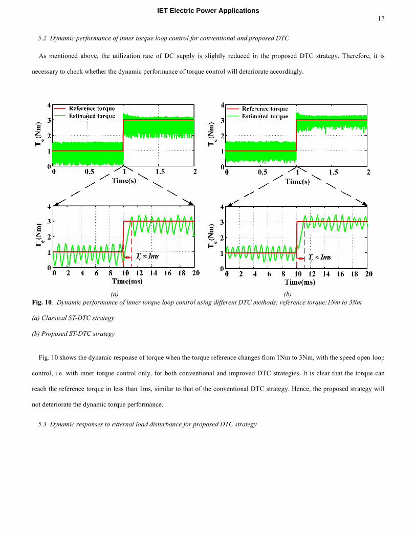
(a) (b)
Fig. 10. Dynamic performance of inner torque loop control using different DTC methods: reference torque:1Nm to 3Nm
(a) Classical ST-DTC strategy
(b) Proposed ST-DTC strategy
Fig. 10 shows the dynamic response of torque when the torque reference changes from 1Nm to 3Nm, with the speed open-loop
control, i.e. with inner torque control only, for both conventional and improved DTC strategies. It is clear that the torque can
reach the reference torque in less than 1ms, similar to that of the conventional DTC strategy. Hence, the proposed strategy will
not deteriorate the dynamic torque performance.
5.3 Dynamic responses to external load disturbance for proposed DTC strategy
IET Electric Power Applications
18
(a) (b)
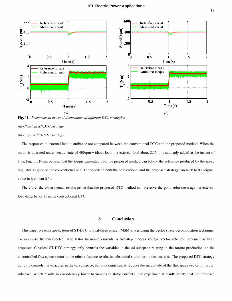
Fig. 11. Responses to external disturbance of different DTC strategies.
(a) Classical ST-DTC strategy
(b) Proposed ST-DTC strategy
The responses to external load disturbance are compared between the conventional DTC and the proposed method. When the
motor is operated under steady-state of 400rpm without load, the external load about 2.5Nm is suddenly added at the instant of
1.0s, Fig. 11. It can be seen that the torque generated with the proposed method can follow the reference produced by the speed
regulator as good as the conventional one. The speeds in both the conventional and the proposed strategy can back to its original
value in less than 0.3s.
Therefore, the experimental results prove that the proposed DTC method can preserve the good robustness against external
load disturbance as in the conventional DTC.
6 Conclusion
This paper presents application of ST-DTC to dual-three phase PMSM drives using the vector space decomposition technique.
To minimize the unexpected large stator harmonic currents, a two-step process voltage vector selection scheme has been
proposed. Classical ST-DTC strategy only controls the variables in the αβ subspace relating to the torque production, so the
uncontrolled flux space vector in the other subspace results in substantial stator harmonics currents. The proposed DTC strategy
not only controls the variables in the αβ subspace, but also significantly reduces the magnitude of the flux space vector in the z1z2
subspace, which results in considerably lower harmonics in stator currents. The experimental results verify that the proposed
IET Electric Power Applications

IET Electric Power Applications 19
methods can significantly reduce the stator current harmonics. Furthermore, since only one harmonic suppression module
consisting of the flux estimator in the z1z2 subspace and a switching table is added, the merits of the classical direct torque control,
i.e. simple structure and good robustness, are still preserved.
7 References
[1] Bojoi, R., Lazzari, M., Profumo, F., and Tenconi, A.: ‘Digital field-oriented control for dual three-phase induction motor drives,’ IEEE Trans.Ind. Appl., 2003, 39, (3), pp. 752-760.
[2] Bojoi, R., Farina, F., Griva, G., Profumo, F., and Tenconi, A.: ‘Direct torque control for dual three-phase induction motor drives,’ IEEE Trans.Ind. Appl., 2005, 41, (6), pp. 1627-1636.
[3] Levi, E.: ‘Multiphase electric machines for variable-speed applications,’ IEEE Trans.Ind. Electron., 2008, 55, (5), pp. 1893-1909. [4] Gopakumar, K., Sathiakumar, S., Biswas, S. K., and Vithayathil J.: ‘Modified current source inverter fed induction-motor drive with reduced torque
pulsations,’ Iee Proceedings-B Electr. Power Appl., 1984, 131, pp. 159-164. [5] Zhao, Y. and Lipo, T. A.: ‘Space vector pwm control of dual three-phase induction machine using vector space decomposition,’ IEEE Trans.Ind. Appl.,
1995, 31, (5), pp. 1100-1109. [6] Abbas, M. A., Christen, R., and Jahns, T. M.: ‘Six-phase voltage source inverter driven induction motor,’ IEEE Trans.Ind. Appl., 1984, 20, (5), pp. 1251-
1259. [7] Hadiouche, D., Baghli, L., and Rezzoug, A.: ‘Space-vector pwm techniques for dual three-phase ac machine: Analysis, performance evaluation, and dsp
implementation,’ IEEE Trans.Ind. Appl., 2006, 42, (4), pp. 1112-1122. [8] Hatua, K. and Ranganathan, V. T.: ‘Direct torque control schemes for split-phase induction machine,’ IEEE Trans.Ind. Appl., 2005, 41, (5), pp. 1243-1254. [9] Gao, Y. and Parsa, L.: ‘Modified direct torque control of five-phase permanent magnet synchronous motor drives,’ Applied Power Electronics Conference,
APEC 2007 - Twenty Second Annual IEEE, 2007, pp. 1428-1433. [10] Zheng, L. B., Fletcher, J. E., Williams, B. W., and He, X. N.: ‘A novel direct torque control scheme for a sensorless five-phase induction motor drive,’
IEEE Trans. Ind. Electron., 2011, 58, (2), pp. 503-513. [11] Gao, L. L., Fletcher, J. E., and Zheng, L. B.,: ‘Low-speed control improvements for a two-level five-phase inverter-fed induction machine using classic
direct torque control,’ IEEE Trans. Ind. Electron., 2011, 58, (7), pp. 2744-2754. [12] Hoang, K. D., Zhu, Z. Q., and Foster, M.: ‘Optimum look-up table for reduction of current harmonics in direct torque controlled dual three-phase
permanent magnet brushless ac machine drives,’ 6th IET International Conference on Power Electronics, Machines and Drives,, 2012, pp. 1-6. [13] Mathapati, S. and Bocker, J.: ‘Analytical and offline approach to select optimal hysteresis bands of dtc for pmsm,’ IEEE Trans. Ind. Electron., 2013, 60, (3),
pp. 885-895. [14] Zhu, Z. Q., Ren, Y., and Liu, J. M.: ‘Improved torque regulator to reduce steady-state error of torque response for direct torque control of permanent
magnet synchronous machine drives,’ IET, Electr. Power Appl., 2014, 8, (3), pp. 108-116. [15] Zhang, Y. and Zhu, J.: ‘Direct torque control of permanent magnet synchronous motor with reduced torque ripple and commutation frequency,’ IEEE Trans.
Power Electron., 2011, 26, (1), pp. 235-248.