modification record of product specification - mouser
TRANSCRIPT
Modification Record of Product Specification
No, DSP-14 1303 Product Name SRV Connector Systems
Note
Rev. No, Reason Place Date Engineer
R0 Initial Release DEC 2.19.14 A.M.
Page 1/17
This is our exclusive property. It is not to be copied, reprinted or disclosed to a third party, not used for m
anufacturing, without our w
ritten consent, and has to be returned to us.
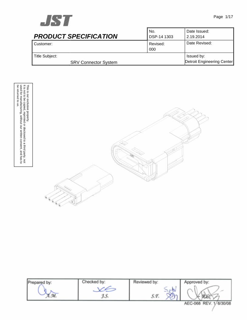
PRODUCT SPECIFICATION No. DSP-14 1303
Date Issued: 2.19.2014
Customer:
Revised: 000
Date Revised:
Title Subject: SRV Connector System
Issued by: Detroit Engineering Center
Prepared by:
Checked by: Reviewed by: Approved by:
AEC-068 REV. 1 6/30/08
P.C. S.F. J.S. A.M.
Page 2/17
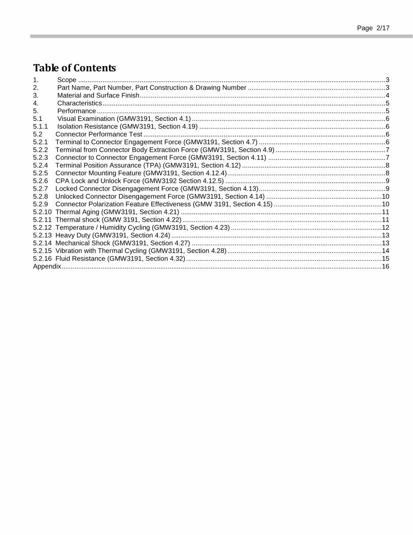
Table of Contents 1. Scope ..................................................................................................................................................................... 3 2. Part Name, Part Number, Part Construction & Drawing Number .......................................................................... 3 3. Material and Surface Finish .................................................................................................................................... 4 4. Characteristics ........................................................................................................................................................ 5 5. Performance ........................................................................................................................................................... 5 5.1 Visual Examination (GMW3191, Section 4.1) ........................................................................................................ 6 5.1.1 Isolation Resistance (GMW3191, Section 4.19) .................................................................................................... 6 5.2 Connector Performance Test .................................................................................................................................. 6 5.2.1 Terminal to Connector Engagement Force (GMW3191, Section 4.7) .................................................................... 6 5.2.2 Terminal from Connector Body Extraction Force (GMW3191, Section 4.9) ........................................................... 7 5.2.3 Connector to Connector Engagement Force (GMW3191, Section 4.11) ............................................................... 7 5.2.4 Terminal Position Assurance (TPA) (GMW3191, Section 4.12) ............................................................................. 8 5.2.5 Connector Mounting Feature (GMW3191, Section 4.12.4) ..................................................................................... 8 5.2.6 CPA Lock and Unlock Force (GMW3192 Section 4.12.5) ...................................................................................... 9 5.2.7 Locked Connector Disengagement Force (GMW3191, Section 4.13) .................................................................... 9 5.2.8 Unlocked Connector Disengagement Force (GMW3191, Section 4.14) .............................................................. 10 5.2.9 Connector Polarization Feature Effectiveness (GMW 3191, Section 4.15) .......................................................... 10 5.2.10 Thermal Aging (GMW3191, Section 4.21) ............................................................................................................ 11 5.2.11 Thermal shock (GMW 3191, Section 4.22) ........................................................................................................... 11 5.2.12 Temperature / Humidity Cycling (GMW3191, Section 4.23) ................................................................................. 12 5.2.13 Heavy Duty (GMW3191, Section 4.24) ................................................................................................................. 13 5.2.14 Mechanical Shock (GMW3191, Section 4.27) ...................................................................................................... 13 5.2.15 Vibration with Thermal Cycling (GMW3191, Section 4.28) ................................................................................... 14 5.2.16 Fluid Resistance (GMW3191, Section 4.32) ......................................................................................................... 15 Appendix ............................................................................................................................................................................ 16
Page 3/17
1. Scope
This document specifies product specification and performance information of SRV connector complied with the standard below. TEST STANDARD: GM Worldwide Engineering Standard, GMW 3191 Connector Test and Validation Specification
(December 2007 release), Table 29: Connector Validation Test Matrix, New Sealed Connector, GMW3191 Approved Terminal System
Temperature Class: Class 3 (-40°C ~ 125°C) Vibration Class: Class 1 (on body or chassis) Sealing Class: Class 3 (High pressure spray expected) Mating Class Class 2 (≤45N)
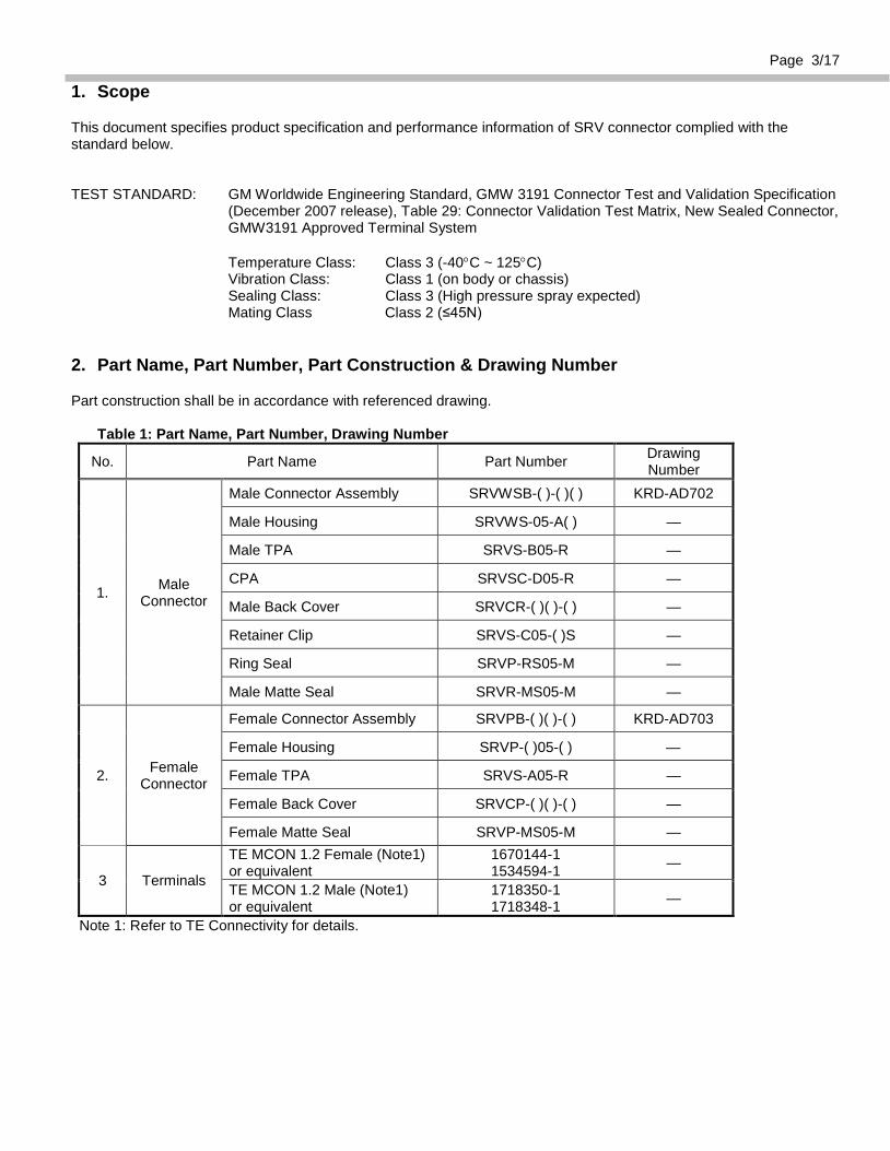
2. Part Name, Part Number, Part Construction & Drawing Number
Part construction shall be in accordance with referenced drawing.
Table 1: Part Name, Part Number, Drawing Number
No. Part Name Part Number Drawing Number
1. Male Connector
Male Connector Assembly SRVWSB-( )-( )( ) KRD-AD702
Male Housing SRVWS-05-A( ) —
Male TPA SRVS-B05-R —
CPA SRVSC-D05-R —
Male Back Cover SRVCR-( )( )-( ) —
Retainer Clip SRVS-C05-( )S —
Ring Seal SRVP-RS05-M —
Male Matte Seal SRVR-MS05-M —
2. Female Connector
Female Connector Assembly SRVPB-( )( )-( ) KRD-AD703
Female Housing SRVP-( )05-( ) —
Female TPA SRVS-A05-R —
Female Back Cover SRVCP-( )( )-( ) —
Female Matte Seal SRVP-MS05-M —
3 Terminals
TE MCON 1.2 Female (Note1) or equivalent
1670144-1 1534594-1 —
TE MCON 1.2 Male (Note1) or equivalent
1718350-1 1718348-1 —
Note 1: Refer to TE Connectivity for details.
Page 4/17
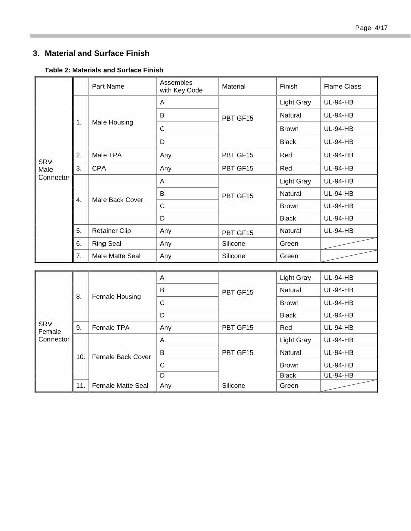
3. Material and Surface Finish
Table 2: Materials and Surface Finish
SRV Male Connector
Part Name Assembles with Key Code Material Finish Flame Class
1. Male Housing
A
PBT GF15
Light Gray UL-94-HB
B Natural UL-94-HB
C Brown UL-94-HB
D Black UL-94-HB
2. Male TPA Any PBT GF15 Red UL-94-HB
3. CPA Any PBT GF15 Red UL-94-HB
4. Male Back Cover
A
PBT GF15
Light Gray UL-94-HB
B Natural UL-94-HB
C Brown UL-94-HB
D Black UL-94-HB
5. Retainer Clip Any PBT GF15 Natural UL-94-HB
6. Ring Seal Any Silicone Green
7. Male Matte Seal Any Silicone Green
SRV Female Connector
8. Female Housing
A
PBT GF15
Light Gray UL-94-HB
B Natural UL-94-HB
C Brown UL-94-HB
D Black UL-94-HB
9. Female TPA Any PBT GF15 Red UL-94-HB
10. Female Back Cover
A
PBT GF15
Light Gray UL-94-HB
B Natural UL-94-HB
C Brown UL-94-HB D Black UL-94-HB
11. Female Matte Seal Any Silicone Green

Page 5/17
4. Characteristics
Table 3: Specifications Item Specification
Current Rating (Note 1) 7A DC max Voltage Rating 14V DC Temperature Range (Note 2) -40°C to +125°C
Storage Temperature Range (Note 3) Temperature Humidity
(-5 ~ 40℃) (40 ~ 60% R.H.)
Isolation Resistance 100MΩ min Dielectric Withstanding Voltage 1,000V/minute AC
Applicable Wire (Note4) Conductor Size (0.35 mm2 – 0.75 mm2) Max Insulation Diameter Φ1.9mm
Note 1. The temperature should be 23±5℃ when a single electrode is applied to a single cavity. Note 2. The temperature range includes the temperature rise when an electrical current is applied. Note 3. If a connector is packed in a box for shipment, keep it out of direct sunlight and store it in a room where there
shall be no shock, condensation, or other harmful elements. If a connector is stored at a low temperature, bring to room temperature and ensure there is no condensation before .
Note 4. For more details contact Terminal Supplier
5. Performance Performance should satisfy the acceptance criteria of each test specified with GMW3191, Table 29. All evaluation tests shall comply with the default test tolerances and conditions unless specified otherwise. Default Test Tolerances: Temperature: ± 3° C Voltage: ± 1 % Current: ± 1 % Resistance: ± 1 %
Length: ± 1 % Time: ± 5 % Force: ± 5 % Frequency: ± 5 % Distance: ± 1 % Flow Rate: ± 5 % Relative Velocity: (50 ±10) mm/min Default Test Conditions: Room Temperature: 23 ± 5° C Relative Humidity: Ambient
Page 6/17
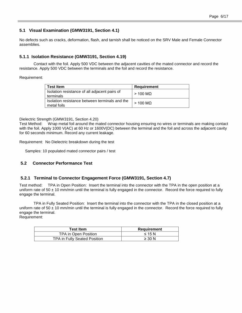
5.1 Visual Examination (GMW3191, Section 4.1)
No defects such as cracks, deformation, flash, and tarnish shall be noticed on the SRV Male and Female Connector assemblies.
5.1.1 Isolation Resistance (GMW3191, Section 4.19) Contact with the foil. Apply 500 VDC between the adjacent cavities of the mated connector and record the resistance. Apply 500 VDC between the terminals and the foil and record the resistance. Requirement:
Test Item Requirement Isolation resistance of all adjacent pairs of terminals > 100 MΩ
Isolation resistance between terminals and the metal foils > 100 MΩ
Dielectric Strength (GMW3191, Section 4.20) Test Method: Wrap metal foil around the mated connector housing ensuring no wires or terminals are making contact with the foil. Apply 1000 V(AC) at 60 Hz or 1600V(DC) between the terminal and the foil and across the adjacent cavity for 60 seconds minimum. Record any current leakage. Requirement: No Dielectric breakdown during the test
Samples: 10 populated mated connector pairs / test
5.2 Connector Performance Test
5.2.1 Terminal to Connector Engagement Force (GMW3191, Section 4.7) Test method: TPA in Open Position: Insert the terminal into the connector with the TPA in the open position at a uniform rate of 50 ± 10 mm/min until the terminal is fully engaged in the connector. Record the force required to fully engage the terminal. TPA in Fully Seated Position: Insert the terminal into the connector with the TPA in the closed position at a uniform rate of 50 ± 10 mm/min until the terminal is fully engaged in the connector. Record the force required to fully engage the terminal. Requirement:
Test Item Requirement TPA in Open Position ≤ 15 N
TPA in Fully Seated Position ≥ 30 N
Page 7/17
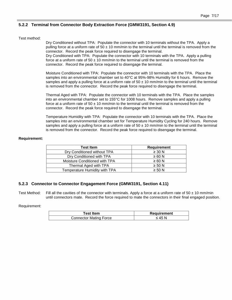
5.2.2 Terminal from Connector Body Extraction Force (GMW3191, Section 4.9)
Test method: Dry Conditioned without TPA: Populate the connector with 10 terminals without the TPA. Apply a
pulling force at a uniform rate of 50 ± 10 mm/min to the terminal until the terminal is removed from the connector. Record the peak force required to disengage the terminal.
Dry Conditioned with TPA: Populate the connector with 10 terminals with the TPA. Apply a pulling force at a uniform rate of 50 ± 10 mm/min to the terminal until the terminal is removed from the connector. Record the peak force required to disengage the terminal.
Moisture Conditioned with TPA: Populate the connector with 10 terminals with the TPA. Place the
samples into an environmental chamber set to 40°C at 95%-98% Humidity for 6 hours. Remove the samples and apply a pulling force at a uniform rate of 50 ± 10 mm/min to the terminal until the terminal is removed from the connector. Record the peak force required to disengage the terminal.
Thermal Aged with TPA: Populate the connector with 10 terminals with the TPA. Place the samples
into an environmental chamber set to 155°C for 1008 hours. Remove samples and apply a pulling force at a uniform rate of 50 ± 10 mm/min to the terminal until the terminal is removed from the connector. Record the peak force required to disengage the terminal.
Temperature Humidity with TPA: Populate the connector with 10 terminals with the TPA. Place the
samples into an environmental chamber set for Temperature Humidity Cycling for 240 hours. Remove samples and apply a pulling force at a uniform rate of 50 ± 10 mm/min to the terminal until the terminal is removed from the connector. Record the peak force required to disengage the terminal.
Requirement:
Test Item Requirement
Dry Conditioned without TPA ≥ 30 N Dry Conditioned with TPA ≥ 60 N
Moisture Conditioned with TPA ≥ 60 N Thermal Aged with TPA ≥ 50 N
Temperature Humidity with TPA ≥ 50 N
5.2.3 Connector to Connector Engagement Force (GMW3191, Section 4.11)
Test Method: Fill all the cavities of the connector with terminals. Apply a force at a uniform rate of 50 ± 10 mm/min until connectors mate. Record the force required to mate the connectors in their final engaged position.
Requirement:
Test Item Requirement
Connector Mating Force ≤ 45 N
Page 8/17
5.2.4 Terminal Position Assurance (TPA) (GMW3191, Section 4.12)
Test Method: Pre Lock Force: Pull the TPA from the connector at a uniform rate of 50 ± 10mm/min until 20N is applied.
Closing Force with Properly Assembled Terminals: With all wires and terminals installed correctly, insert the TPA at a uniform rate of 50 ± 10 mm/min. Record the force required to insert the TPA into its final engaged position.
Closing Force with Improperly Assembled Terminals: With all but one wire and terminal installed correctly, insert the TPA at a uniform rate of 50 ± 10 mm/min. Record the force required to insert the TPA into its final engaged position.
Closed TPA Locking Force: Pull the TPA from the connector at a uniform rate of 50 ± 10 mm/min until 25N is applied.
Requirement:
Test Item Requirement
TPA Pre-lock Force ≥ 20 N TPA Closing Force w/ Properly Assembled
Terminals ≤ 30 N
TPA Closing Force w/ Improperly Assembled Terminals ≥ 60 N
Closed TPA Locking Force ≥ 25 N
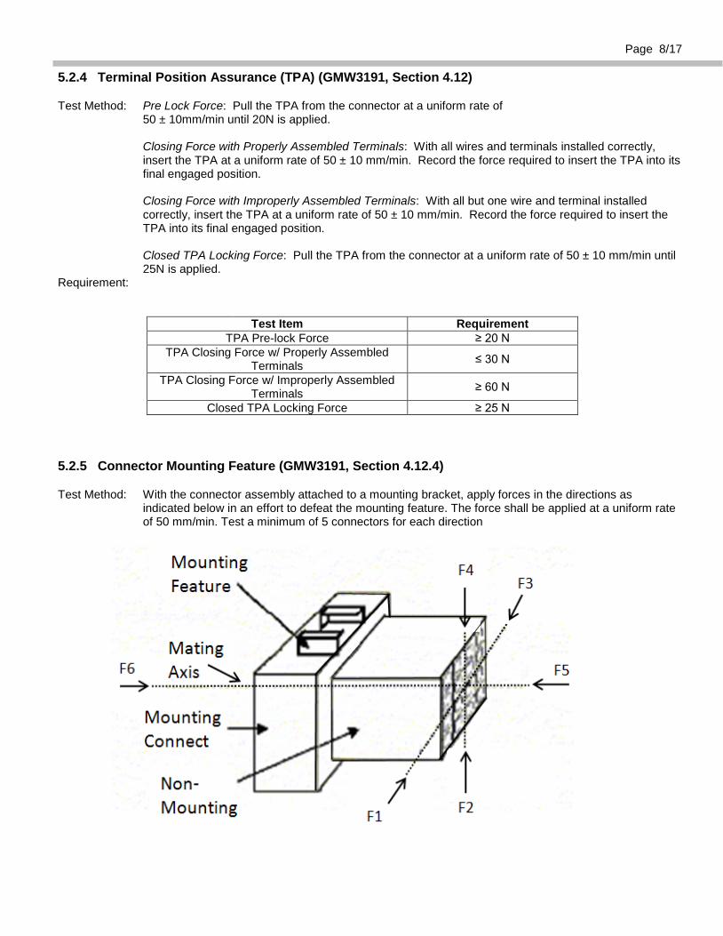
5.2.5 Connector Mounting Feature (GMW3191, Section 4.12.4)
Test Method: With the connector assembly attached to a mounting bracket, apply forces in the directions as indicated below in an effort to defeat the mounting feature. The force shall be applied at a uniform rate of 50 mm/min. Test a minimum of 5 connectors for each direction
Page 9/17
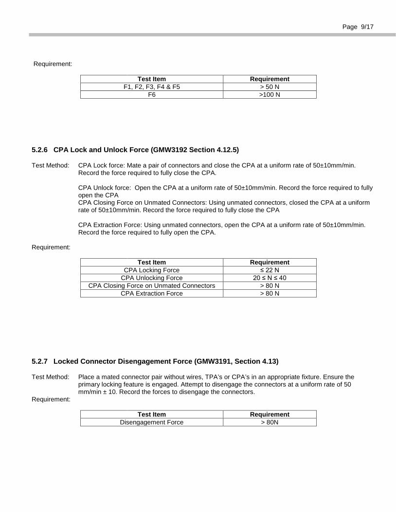
Requirement:
Test Item Requirement
F1, F2, F3, F4 & F5 > 50 N F6 >100 N
5.2.6 CPA Lock and Unlock Force (GMW3192 Section 4.12.5)
Test Method: CPA Lock force: Mate a pair of connectors and close the CPA at a uniform rate of 50±10mm/min. Record the force required to fully close the CPA.
CPA Unlock force: Open the CPA at a uniform rate of 50±10mm/min. Record the force required to fully
open the CPA CPA Closing Force on Unmated Connectors: Using unmated connectors, closed the CPA at a uniform
rate of 50±10mm/min. Record the force required to fully close the CPA CPA Extraction Force: Using unmated connectors, open the CPA at a uniform rate of 50±10mm/min.
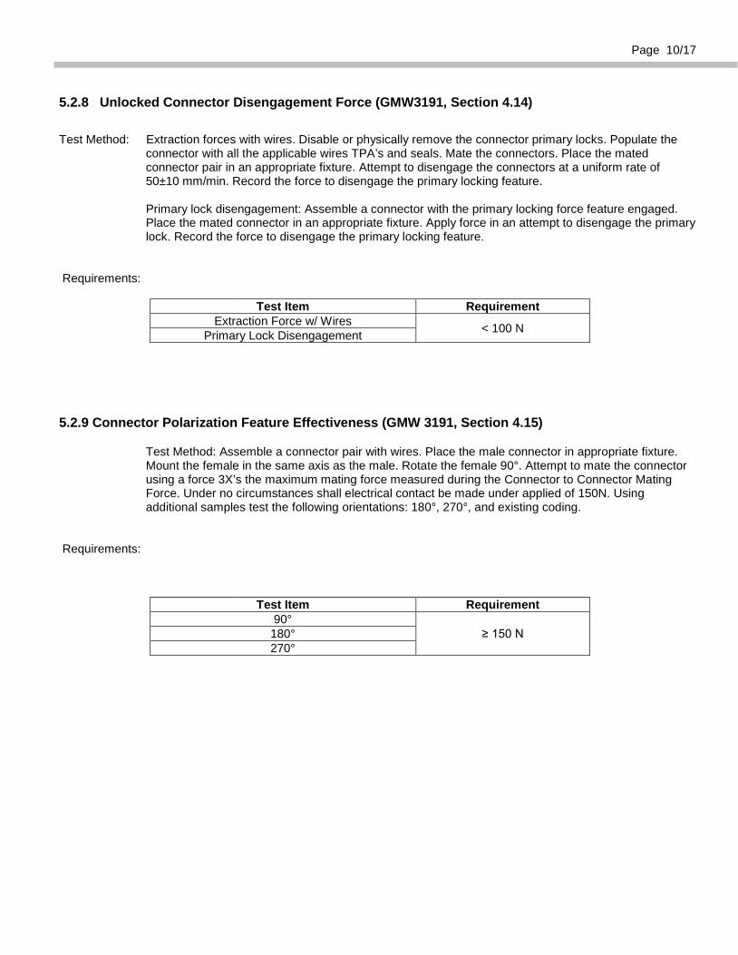
Record the force required to fully open the CPA. Requirement:
Test Item Requirement
CPA Locking Force ≤ 22 N CPA Unlocking Force 20 ≤ N ≤ 40
CPA Closing Force on Unmated Connectors > 80 N CPA Extraction Force > 80 N
5.2.7 Locked Connector Disengagement Force (GMW3191, Section 4.13)
Test Method: Place a mated connector pair without wires, TPA’s or CPA’s in an appropriate fixture. Ensure the primary locking feature is engaged. Attempt to disengage the connectors at a uniform rate of 50 mm/min ± 10. Record the forces to disengage the connectors.
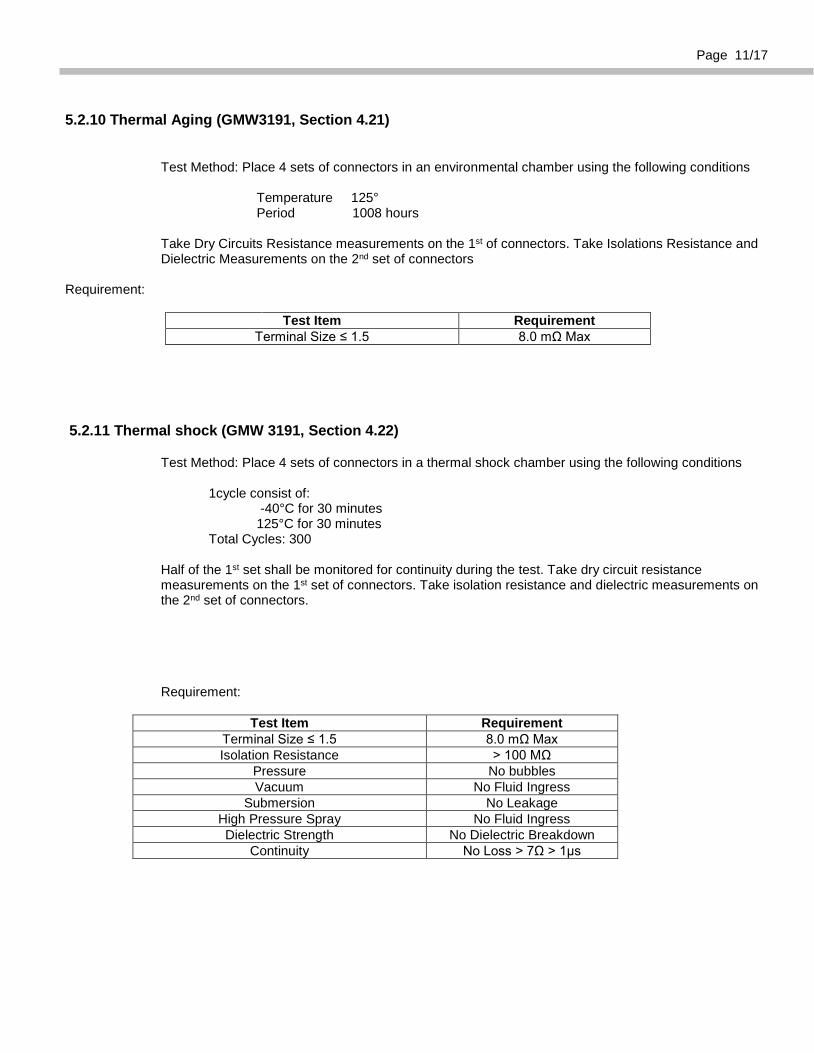
Requirement:
Test Item Requirement Disengagement Force > 80N
Page 10/17
5.2.8 Unlocked Connector Disengagement Force (GMW3191, Section 4.14) Test Method: Extraction forces with wires. Disable or physically remove the connector primary locks. Populate the
connector with all the applicable wires TPA’s and seals. Mate the connectors. Place the mated connector pair in an appropriate fixture. Attempt to disengage the connectors at a uniform rate of 50±10 mm/min. Record the force to disengage the primary locking feature.
Primary lock disengagement: Assemble a connector with the primary locking force feature engaged.
Place the mated connector in an appropriate fixture. Apply force in an attempt to disengage the primary lock. Record the force to disengage the primary locking feature.
Requirements:
Test Item Requirement
Extraction Force w/ Wires < 100 N Primary Lock Disengagement
5.2.9 Connector Polarization Feature Effectiveness (GMW 3191, Section 4.15)
Test Method: Assemble a connector pair with wires. Place the male connector in appropriate fixture. Mount the female in the same axis as the male. Rotate the female 90°. Attempt to mate the connector using a force 3X’s the maximum mating force measured during the Connector to Connector Mating Force. Under no circumstances shall electrical contact be made under applied of 150N. Using additional samples test the following orientations: 180°, 270°, and existing coding.
Requirements:
Test Item Requirement
90° ≥ 150 N 180°
270°
Page 11/17
5.2.10 Thermal Aging (GMW3191, Section 4.21)
Test Method: Place 4 sets of connectors in an environmental chamber using the following conditions Temperature 125° Period 1008 hours Take Dry Circuits Resistance measurements on the 1st of connectors. Take Isolations Resistance and Dielectric Measurements on the 2nd set of connectors
Requirement:
Test Item Requirement
Terminal Size ≤ 1.5 8.0 mΩ Max
5.2.11 Thermal shock (GMW 3191, Section 4.22)
Test Method: Place 4 sets of connectors in a thermal shock chamber using the following conditions 1cycle consist of: -40°C for 30 minutes 125°C for 30 minutes Total Cycles: 300 Half of the 1st set shall be monitored for continuity during the test. Take dry circuit resistance measurements on the 1st set of connectors. Take isolation resistance and dielectric measurements on the 2nd set of connectors.
Requirement:
Test Item Requirement Terminal Size ≤ 1.5 8.0 mΩ Max Isolation Resistance > 100 MΩ
Pressure No bubbles Vacuum No Fluid Ingress
Submersion No Leakage High Pressure Spray No Fluid Ingress Dielectric Strength No Dielectric Breakdown
Continuity No Loss > 7Ω > 1µs
Page 12/17
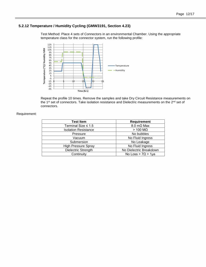
5.2.12 Temperature / Humidity Cycling (GMW3191, Section 4.23)
Test Method: Place 4 sets of Connectors in an environmental Chamber. Using the appropriate temperature class for the connector system, run the following profile:
Repeat the profile 10 times. Remove the samples and take Dry Circuit Resistance measurements on the 1st set of connectors. Take isolation resistance and Dielectric measurements on the 2nd set of connectors.
Requirement:
Test Item Requirement Terminal Size ≤ 1.5 8.0 mΩ Max Isolation Resistance > 100 MΩ
Pressure No bubbles Vacuum No Fluid Ingress
Submersion No Leakage High Pressure Spray No Fluid Ingress Dielectric Strength No Dielectric Breakdown
Continuity No Loss > 7Ω > 1µs
Page 13/17
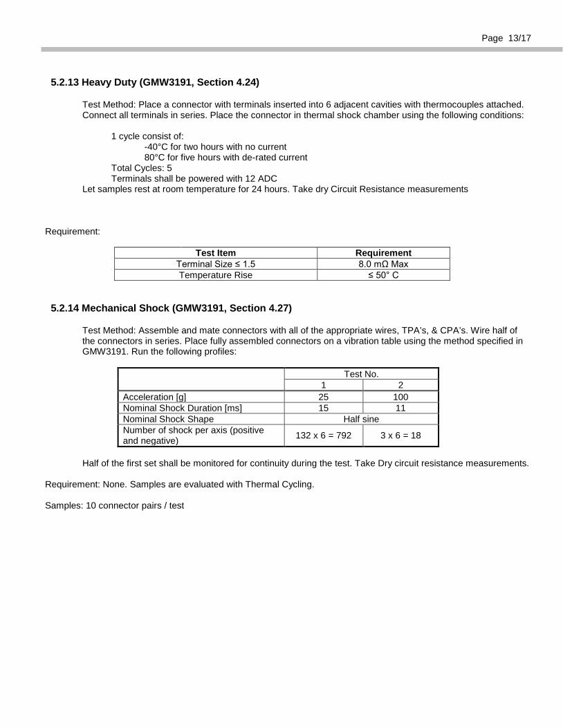
5.2.13 Heavy Duty (GMW3191, Section 4.24)
Test Method: Place a connector with terminals inserted into 6 adjacent cavities with thermocouples attached. Connect all terminals in series. Place the connector in thermal shock chamber using the following conditions: 1 cycle consist of: -40°C for two hours with no current 80°C for five hours with de-rated current Total Cycles: 5 Terminals shall be powered with 12 ADC Let samples rest at room temperature for 24 hours. Take dry Circuit Resistance measurements
Requirement:
Test Item Requirement
Terminal Size ≤ 1.5 8.0 mΩ Max Temperature Rise ≤ 50° C
5.2.14 Mechanical Shock (GMW3191, Section 4.27)
Test Method: Assemble and mate connectors with all of the appropriate wires, TPA’s, & CPA’s. Wire half of the connectors in series. Place fully assembled connectors on a vibration table using the method specified in GMW3191. Run the following profiles:
Test No. 1 2
Acceleration [g] 25 100 Nominal Shock Duration [ms] 15 11 Nominal Shock Shape Half sine Number of shock per axis (positive and negative) 132 x 6 = 792 3 x 6 = 18
Half of the first set shall be monitored for continuity during the test. Take Dry circuit resistance measurements.
Requirement: None. Samples are evaluated with Thermal Cycling. Samples: 10 connector pairs / test
Page 14/17
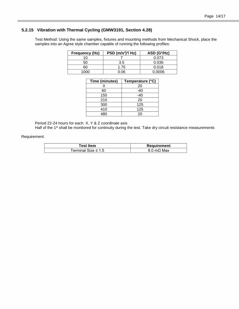
5.2.15 Vibration with Thermal Cycling (GMW3191, Section 4.28)
Test Method: Using the same samples, fixtures and mounting methods from Mechanical Shock, place the samples into an Agree style chamber capable of running the following profiles:
Frequency (Hz) PSD (m/s²)²/ Hz) ASD (G²/Hz) 10 7 0.073 50 3.5 0.036 60 1.75 0.018
1000 0.06 0.0006
Time (minutes) Temperature (°C) 0 20
60 -40 150 -40 210 20 300 125 410 125 480 20
Period 22-24 hours for each. X, Y & Z coordinate axis Half of the 1st shall be monitored for continuity during the test. Take dry circuit resistance measurements Requirement:
Test Item Requirement
Terminal Size ≤ 1.5 8.0 mΩ Max
Page 15/17
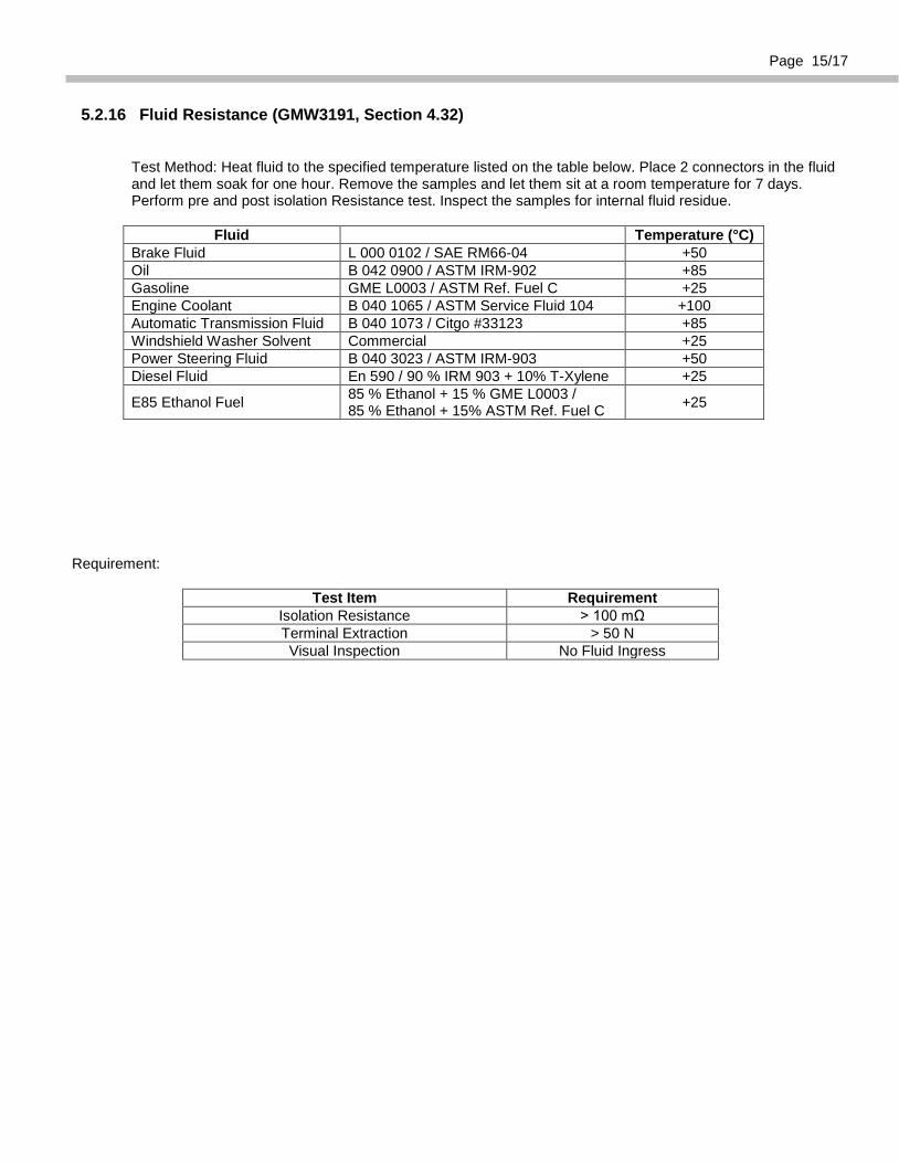
5.2.16 Fluid Resistance (GMW3191, Section 4.32)
Test Method: Heat fluid to the specified temperature listed on the table below. Place 2 connectors in the fluid and let them soak for one hour. Remove the samples and let them sit at a room temperature for 7 days. Perform pre and post isolation Resistance test. Inspect the samples for internal fluid residue.
Fluid Temperature (°C)
Brake Fluid L 000 0102 / SAE RM66-04 +50 Oil B 042 0900 / ASTM IRM-902 +85 Gasoline GME L0003 / ASTM Ref. Fuel C +25 Engine Coolant B 040 1065 / ASTM Service Fluid 104 +100 Automatic Transmission Fluid B 040 1073 / Citgo #33123 +85 Windshield Washer Solvent Commercial +25 Power Steering Fluid B 040 3023 / ASTM IRM-903 +50 Diesel Fluid En 590 / 90 % IRM 903 + 10% T-Xylene +25
E85 Ethanol Fuel 85 % Ethanol + 15 % GME L0003 / 85 % Ethanol + 15% ASTM Ref. Fuel C +25
Requirement:
Test Item Requirement
Isolation Resistance > 100 mΩ Terminal Extraction > 50 N Visual Inspection No Fluid Ingress
Page 16/17
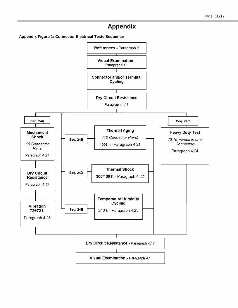
Appendix Appendix Figure 1: Connector Electrical Tests Sequence
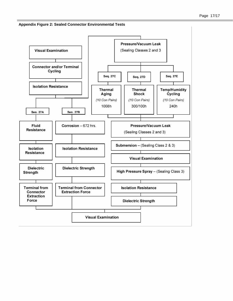
Page 17/17 Appendix Figure 2: Sealed Connector Environmental Tests