modelling of failure mode transition in ballistic penetration with a continuum model describing...
TRANSCRIPT

INTERNATIONAL JOURNAL FOR NUMERICAL METHODS IN ENGINEERINGInt. J. Numer. Meth. Engng 2002; 54:365–398 (DOI: 10.1002/nme.427)
Modelling of failure mode transition in ballistic penetrationwith a continuum model describing microcracking
and �ow of pulverized media
Benjamin A. Gailly1 and Horacio D. Espinosa2;∗;†
1D�el�egation G�en�erale pour l’Armement=Etablissement Technique de Bourges; Route de Guerry;18015 Bourges C�edex; France
2Department of Mechanical Engineering; Northwestern University; 2145 Sheridan Road;Evanston; IL 60208-3111; U.S.A.
SUMMARY
A new continuum model to describe damage, fragmentation and large deformation of pulverized brittlematerials is presented. The multiple-plane-microcracking (MPM) model, developed by Espinosa, hasbeen modi�ed to track microcracking on 13 orientations under high pressure, high strain rate and highdeformation. This model provides the elastic and inelastic response of the material before massive crackcoalescence. When pulverization occurs, the constitutive response is modelled by means of a visco-plastic model for granular material, which is a generalization to three dimensions of the double-slidingtheory augmented by a consolidation mechanism. The initialization of the granular model is governedby a yield surface at the onset of massive crack coalescence. This is accomplished by examininga representative volume element, modelled using the MPM model, in compression-shear. The mainadvantage of this approach is to keep a continuum model at all stages of the deformation process andthus avoid the di�culties of crack representation in a discrete �nite element code. This model hasbeen implemented in LS-DYNA and used to examine interface defeat of long rod penetrators by acon�ned ceramic plate. The numerical simulations are compared to experiments in order to identifyfailure modes. The model parameters were obtained independently by simulating plate and rod impactexperiments. The proposed model captures most of the physical observations as well as failure modetransition, from interface defeat to full penetration, with increasing impact velocity. Copyright ? 2002John Wiley & Sons, Ltd.
KEY WORDS: granular materials; brittle materials; constitutive modelling; impact; ballistic penetration;damage; visco-plasticity
∗Correspondence to: Horacio D. Espinosa, Department of Mechanical Engineering, Northwestern University, 2145Sheridan Road, Evanston, IL 60208-3111, U.S.A.
†E-mail: [email protected]
Contract=grant sponsor: Army Research O�ce; contract=grant number: DAAH04-96-1-0331Contract=grant sponsor: Delegation Generale pour L’Armement; contract=grant number: 21132=DGA=DSP=D
Received 9 July 2000Copyright ? 2002 John Wiley & Sons, Ltd. Revised 10 May 2001

366 B. A. GAILLY AND H. D. ESPINOSA
1. INTRODUCTION
Ceramics present a high potential as armour materials. Their high compressive strength andlow thermal conductivity could be used to defeat, not only low speed rigid body projectiles,but also high speed, heavy alloy, long rods. Unfortunately, hardness is often associated withbrittleness and ceramics can undergo fragmentation when subjected to multiaxial loading. Itis now well known that, during a high velocity impact event, a comminuted zone also calledMescall zone, Mescall and Weiss [1], appears under the projectile nose. The penetrationof the projectile is controlled by the behaviour of the granular material and the intact sur-rounding ceramic, Shockey et al. [2]. Based on this understanding, a new armour concepthas been proposed and improved by Hauver et al. [3; 4], Bless et al. [5], Rapacki et al.[6], Espinosa et al. [7] and Malaise et al. [8] in order to block the motion of the ceramicfragments.During the same period, Orphal et al. [9–11] studied the response of con�ned AlN, SiC
and B4C ceramics during long rod penetration at velocities ranging from 1.5 to 5 km=s. Theymeasured substantial data with the help of �ash X-ray, e.g. penetration depth, rate of rodconsumption, mass e�ciency of the ceramic target, etc. All this information is extremelyvaluable in the development of advanced computational algorithms.The interface defeat (ID) design was later improved by Bruchey et al. [12]. In this con�g-
uration, the ceramic tile is encapsulated in a titanium alloy structure that increases the masse�ciency of the target. In this particular con�guration, the graphite plate is not needed toinitiate the ID of the projectile.More recently, Lundberg et al. [13] estimated the upper and lower bounds for the transition
impact velocity between ID and normal penetration for steel and tungsten alloy projectiles andfor two types of SiC, B4C, TiB2 and a polycrystalline diamond composite target materials.They also provided valuable X-ray pictures of the projectile inside the ceramic during thepenetration process from which they extrapolated the projectile nose velocity.In most of the ballistic experiments performed in the past the target con�guration has a big
in�uence on the establishment of ID phenomena. Malaise et al. [8] proposed an alternate con-�guration of impact resulting in the same physical phenomenon. The target con�guration is thedepth of penetration (DOP) con�guration, but ID can be achieved by encapsulating the projec-tile in a polycarbonate cylinder. This con�guration can be advantageously used to separate thein�uence of di�erent parameters such as projectile velocity, mechanical characteristics of theceramic and damage kinetics resulting from the separation between normal and shear waves.Furthermore, this con�guration is easier to model when Lagrangian codes, using remeshing, areemployed.Although numerical analyses of high velocity impact and penetration have been carried out
for quite some time, few applications to the response of ceramic targets have been made.The key issue is the appropriate modelling of the complex constitutive behaviour of ceramicsin the presence of micro and macrocracks. Attempts have been made to model the inelasticconstitutive behaviour of ceramics in the presence of cracks, and to validate the modelsthrough simulation of plate and rod impact experiments. Addesio and Johnson [14] presenteda microphysical model to describe the con�ned behaviour of ceramics. The inelastic strainsin their model are caused by microcracking. Cracks are allowed to slide under compressionand open under tension. Damage is determined in terms of a crack density parameter whoseevolution is described through a failure surface based on energy balance.
Copyright ? 2002 John Wiley & Sons, Ltd. Int. J. Numer. Meth. Engng 2002; 54:365–398

MODELLING OF FAILURE MODE TRANSITION 367
Rajendran and Grove [15] proposed a model considering microcrack nucleation and growth,and pore collapse. Damage is de�ned in terms of an average crack density, which is treatedas an internal variable. The reduction in sti�ness due to microcracking is modelled usingdamage moduli whose evolution under compressive as well as tensile loading is formulatedbased on the generalized Gri�th criterion. Pore collapse is modelled using viscoplastic equa-tions derived from Gurson’s pressure dependant yield function, Gurson [16]. The Hugoniotelastic limit (HEL) scaled by a rate-dependant formulation gives the yield surface. Due tothe isotropic formulation, this model is not capable of capturing anisotropic damage that de-velops especially under oblique impact. The material collapse occurs at deviatoric stressesabove the HEL and does not take into account the porosity created by shearing of the pul-verized ceramic. Moreover, the friction between fragments is not considered. Nevertheless,this model reproduces, with a good accuracy, the tension fracture occurring in normal plateimpact experiments.Based on dislocation theory, Curran et al. [17] proposed a computational model to describe
penetration of ceramic targets through a multiple-plane phenomenological model. In theirmodel, the deviatoric stress in the comminuted material is used to describe inelasticity and�ow. Pressure is calculated by means of the standard Mie–Gruneisen equation of state forthe intact material. A continuum porous compaction model accounting for the applied shearstrain is used in the comminuted zone. Their yield function accounts for damage as well asCoulomb’s friction. A tensile fracture model is used to allow the separation of fragmentedparticles. Curran and co-workers identi�ed their model parameters from pressure–shear impactexperiments and performed simulations of the con�ned ceramic targets tested by Shockey et al.[2]. Based on the simulations, they concluded that con�ning pressure and intergranular frictionin the comminuted material are the key factors governing the penetration resistance of con�nedceramics but they did not manage to simulate all the experimentally observed features. Oneof the major disadvantages in the use of this model is that the phenomenological parametersintroduced to describe the various inelastic processes are di�cult to identify experimentally.Moreover, they used nine planes to describe the deformation of the comminuted ceramic butit appears that the slip planes chosen are not isotropic by rotation and do not necessarilycorrespond to the maximum shearing plane in the material.Johnson and Holmquist [18] proposed a more general model to represent the behaviour of
brittle materials and transition between the intact and granular media. It assumes an elasto-plastic behaviour with a yield stress that depends on pressure and damage. The yield stressis interpolated between the yield stress of the intact ceramic and the yield stress of thefragmented ceramic. Both yield stresses are linear functions of the applied pressure whilethe damage parameter is related to the accumulated plastic strain normalized by the strain atrupture, which is also a function of pressure. Despite the pressure dependence of the model,Malaise et al. [8] has shown that this model cannot capture the transition between penetrationand ID. The reason advanced is that compaction of the granular ceramic is not properlyaccounted for and that damage under tension is overestimated.Enhancing the model of Johnson and Holmquist [18], Collombet et al. [19] developed
an engineering model, which was implemented in a Eulerian code. Their model describesfragmentation and separation of fragments by two distinct damage variables. One such variableis the function of plastic shear strain to account for microcrack nucleation resulting fromplastic deformation. When this damage parameter reaches a percolation value, the media isconsidered fully fractured. The tensile damage variable is related to the sum of the principal
Copyright ? 2002 John Wiley & Sons, Ltd. Int. J. Numer. Meth. Engng 2002; 54:365–398

368 B. A. GAILLY AND H. D. ESPINOSA
tensile strains and assumes that initial porosity is very small; hence, compaction is not possible.The yield stress of the damaged ceramic has a linear dependency on pressure until it reachesthe HEL where the ceramic becomes fully plastic. The yield function of the fragmentedceramic is a Mohr–Coulomb type yield surface. Despite the fact that dilatancy is not taken intoaccount, this model has been used to reproduce ID in the con�guration proposed by Malaiseet al. [8]. Nevertheless, Malaise considered that friction between fragments in the comminutedzone is very small (�=10−3) which contradicts the measurement of � in pressure–shear plateimpact experiments performed by Klopp and Shockey [20] and Sairam and Clifton [21].Moreover, the model is fully isotropic and therefore cannot capture damage anisotropy asobserved in oblique impact.To overcome the limitation of the phenomenological models previously mentioned and in
particular, damage anisotropy as well as di�culties in determining model parameters, Espinosa[22] developed a multi-plane microcracking (MPM) model based on the theory of microme-chanics of solids. In the MPM model, the constitutive response of the material is obtainedfrom fundamental quantities that can be determined experimentally such as grain size andfracture toughness. In addition, since dynamic growth of microcracks is described indepen-dently on each orientation, damage anisotropy and rate e�ects are naturally incorporated inthe model. This model does not include crack coalescence. Therefore, it cannot fully cap-ture the constitutive behaviour of pulverized ceramics. However, it provides the deformationhistory leading to ceramic powders.Camacho and Ortiz [23] and Ortiz [24] modelled ballistic penetration of ceramic targets
based on a discrete fragmentation approach. In this approach, each crack is followed as itnucleates, propagates and coalesces during the deformation process. Cracks can nucleate at thenodes of a �nite element mesh as soon as the resolved e�ective stress exceeds the e�ectivefracture stress. The crack is nucleated in the solid by duplicating nodes and can propagatealong element boundaries. Adaptive remeshing is used to reach enough sets of possible fracturepaths around the crack tip. Following this procedure, fragments are generated as the crackscoalesce and bound a sub-body. The models and algorithms developed by Ortiz’s group havebeen very successful in capturing penetration modes. They have shown that mushrooming andpetaling of the tip of WHA penetrators, plus some sloughing of fragments, are the dominantdeformation mechanisms controlling the penetration process.Espinosa et al. [25] showed that pure discrete cohesive models may not be able to capture
the right amount of energy dissipation unless the two size scales, involving fracture, areproperly captured. These are short microcracks within fragments and coalesced microcracksforming the fragments, see Reference [25]. Consequently, a discrete cohesive model requires amesh size consistent with the maximum possible surface energy per unit volume the materialis capable of dissipating. Recently, powerful methods to capture arbitrary three dimensionaldynamic propagation of cracks in elastic solids were developed by Belytschko et al. [26; 27].Here, we examine an alternative approach to the discrete cohesive model in relation to thephysical modelling of ballistic penetration of multi-layered targets.Gu et al. [28] formulated a model for granular materials that we will make use of in this
article. The model has a two-mechanism yield surface accounting for material �ow undershearing and consolidation under pressure. The distortion mechanism is a Mohr–Coulombtype with a shear stress limitation at high pressure to take into account plastic deformationof the particles. Dilatancy and cohesion are included and depend on friction coe�cient andon void ratio. The friction coe�cient has an evolution law that can be easily determined
Copyright ? 2002 John Wiley & Sons, Ltd. Int. J. Numer. Meth. Engng 2002; 54:365–398

MODELLING OF FAILURE MODE TRANSITION 369
and mainly depends on void ratio. A quarter elliptical pressure cap mathematically describesthe consolidation mechanism. This mechanism accounts for void collapse. The pressure capdepends only on void ratio.One of the di�culties in describing the comminuted zone in a ceramic by a granular
model is that the characteristics of the powder, e.g., average size, often has to be assumedbefore carrying on the computation. Hence, the description of the powder state is somewhatarbitrary. Moreover, the void ratio in the fragmented ceramic is very low and determination ofan initial friction coe�cient in the comminuted ceramic cannot be easily performed. Here, wedescribe a computational scheme that bridges the MPM and granular models and overcomesthese di�culties. Standard homogenization techniques and the MPM are used for this purpose.Damage initiation and material pulverization are captured in a single continuum theory.The organization of the paper is as follows. In Section 2, we describe the MPM model, the
extension of the granular model proposed by Anand and its use in conjunction with the MPMmodel. The main idea is to follow the fracture process by the MPM model until fragmentsdue to crack coalescence are formed. The motion of the fragments is then computed with themodi�ed granular model. The key point is that the characteristic of the powder is not assumedbut computed from the ceramic response. The initial parameters of the granular model aredetermined by interrogating a representative volume element described by the MPM model.The only required parameters in the granular model are those describing the evolution of theinternal quantities. These parameters were determined independently by models performed onceramic powders with a known void ratio, Espinosa and Gailly [29]. In Section 3, we usethis model to simulate the encapsulated rod experiments proposed by Malaise et al. [8]. Thesimulations are complemented by a parametric study on the e�ect of the various materialproperties on ballistic penetration.
2. CONSTITUTIVE EQUATIONS
2.1. Multi-plane microcracking model
The large deformation constitutive response of ceramics in the presence of microcracks isdescribed through a microcracking multiple-plane model based on a dilute approximation,Dienes [30], Bazant and co-workers [31], Espinosa [32] and Espinosa et al. [22; 25; 33].The basic assumption is that microcracking and=or slip can occur on a discrete number oforientations (see Figure 1). Microcrack plane properties (friction, initial size, density, etc.) andtheir evolution are independently computed on each plane. The macroscopic response of thematerial is computed by additive decomposition of the strain rate tensor, D, into elastic, De,and inelastic parts, Dc. The inelastic strains are assumed to be caused solely by the presenceof microcracks in the solid.Using a corrotational Cauchy stress measure, T∇, the constitutive behaviour of the ceramic
is given by
T∇=C�D −Dc� (1a)
where C is the fourth order elasticity tensor of the polycrystalline ceramic material.For a representative volume B0, in the undeformed con�guration, of an elastic solid con-
taining penny-shaped microcracks with a density N (k), the average inelastic strain rate tensor
Copyright ? 2002 John Wiley & Sons, Ltd. Int. J. Numer. Meth. Engng 2002; 54:365–398

370 B. A. GAILLY AND H. D. ESPINOSA
1
23
4
5
6 7
1312 10
119 8
YZ
X
45o45o
45o
45o
Figure 1. Unit sphere containing 13 microcracking orientations. Each orientation has a density N (k).
can be written as
Dcij=13∑k=1N (k)�
(a(k))2 12
(�b(k)i n
(k)j + n(k)i �b
(k)j
)+
13∑k=1N (k)�a(k)a(k)
12
(�b(k)i n
(k)j + n(k)i �b(k)j
)(1b)
where the subindex k is used to label the orientations. In the above equation, a(k) and a(k)
denote, respectively, the microcrack radius and its rate of growth on orientation k, n(k) is thecorresponding unit normal, and �b(k) and �b(k) are the average displacement jump vectors acrossthe surface A(k) and its rate.The average displacement jump vector resulting from an applied Cauchy stress �eld T is
given by Equation (2a) in tension and Equation (2b) in compression, viz.
�b(k)i =1A(k)
∫A(k)b(k)i dA=
16(1− �2)3�E(2− �)a
(k)(2Tijn
(k)j
)− �Tjln(k)j n(k)l n(k)i (2a)
�b(k)i =32(1− �2)3�E(2− �)a
k (�k + �(k)�kn ) (n�)ki (2b)
in which E and � are Young’s modulus and Poisson’s ratio of the uncracked solid, �k and�kn are the resolved shear stress and the normal stress acting on microcracks with orientationk, and nk� is the unit vector in the direction of the resolved shear traction. In Equation (2b),�(�) is the friction coe�cient on the microcrack faces. Its dependence on the normal stress,
Copyright ? 2002 John Wiley & Sons, Ltd. Int. J. Numer. Meth. Engng 2002; 54:365–398

MODELLING OF FAILURE MODE TRANSITION 371
applied on the crack faces, is given by
�(k) =�min + (�max − �min) 2� arctan(−�(k)n
p�
)if �(k)n 60
�(k) =�min if �(k)n ¿0
(3)
where �min and �max are, respectively, the friction coe�cients for a null normal stress and ahigh normal compression stress and p� is the normal stress for which �(�) = 0:78�max.If �(k)6−�(k)�(k)n , then a sticking condition occurs. Hence, irreversible displacement jumps
develop making the deformation process strongly non-linear and history dependant. It shouldalso be pointed out that, because of the dependence of the friction coe�cient on the normalstress, the sticking condition can prevent the propagation of microcracks under high compres-sion stress states.In order to compute the inelastic strain tensor, it becomes necessary to follow the evolution
of the microcrack radius a in the selected orientations. Following Freund [34], an equation ofevolution for a in the case of mixed mode loading can be derived as,
a(k) =m±cR
1−
(KIcK (k)e�
)n±¿0 (4)
in which n± and m± are phenomenological material constants which may have di�erentvalues in tension and compression. They are used to describe terminal crack speeds of about30 per cent the Rayleigh wave speed, CR. KIc is the material toughness and Ke� is thee�ective stress intensity factor. For mixed mode conditions, Ke� for the particular orientationk is derived by considering the average energy release rate G associated with the increase inthe radius of the microcrack whose radius is a. It is given by
G (k) =12�
∫ 2�
0
1− �2E
[K2I + K2II + K
2III(1− �)] (5)
from which the following expression for Ke� is obtained:
K (k)e� =
√G (k)E1− �2 (6)
The general structure of these constitutive equations corresponds to that of a solid witha damage-induced anisotropic stress–strain relation with elastic degradation. The rate depen-dence is due to crack kinetics e�ects. From a computational standpoint, this ensures numericalreliability and mesh independence, Needleman [35]. Details about the stress update algorithmcan be found in Espinosa [22]. It should be pointed out that this inelastic model is a contin-uum model in which material damage results from microcracking. If the material is subjectedto a predominantly tensile stress state, then microcracks along orientations perpendicular tothe direction of maximum tensile stresses will grow according to Equation (3). In this case,signi�cant dilation is expected due to mode I crack opening. If a predominantly compres-sive state of stress with shear is imposed, then crack opening is inhibited but inelasticity ismanifested by the growth of penny-shaped cracks in modes II and III (shear modes).
Copyright ? 2002 John Wiley & Sons, Ltd. Int. J. Numer. Meth. Engng 2002; 54:365–398

372 B. A. GAILLY AND H. D. ESPINOSA
2.2. Granular model
Here, we describe a two-mechanism constitutive model previously developed by Anand andco-workers [2] to describe the isothermal deformation of granulated media. The model isextended to the visco-plastic regime using the Duvaut Lions scheme, see Simo et al. [36].Using a corrotational Cauchy stress measure, the constitutive behaviour of the powder is
given by
T∇=C(T; �)[D −Dp] (7a)
where C is the fourth order elasticity tensor that depends on the relative density �=�=�s.Here, � is the mass density of the granular material and �s is the mass density of solidparticles. D and Dp are, respectively, the deformation rate tensor and the plastic deformationrate tensor, which is the sum of the contribution of the two mechanisms. In this model it isassumed that the plastic spin, WP, is zero. For a justi�cation on this assumption, see Anandand Gu [28]. The symmetric Cauchy stress tensor can be written in terms of its spectralcomponents, namely,
T=
�1
˙e1⊗ ˙e1 +�2˙e2 ⊗ ˙e2 +�3
˙e3 ⊗ ˙e3 if �1¿�2¿�3
�1˙e1⊗ ˙e1 +�3(1− ˙e1⊗ ˙e1) if �1¿�2 =�3
�3˙e3⊗ ˙e3 +�1(1− ˙e3⊗ ˙e3) if �1 =�2¿�3
(7b)
where {�i | i=1; 2; 3} are the principal stresses and {˙e1 | i=1; 2; 3} are the principal directionsof stress. The usual solid mechanics convention of sign is employed, i.e. positive valuescorrespond to tensile stresses.The elastic properties of the granular material, i.e. Young’s modulus, E, and Poisson’s ratio,
�, are predetermined by means of the self-consistency method proposed by Budianski [37],and then �tted to the functions,
E=E1eE2� (8)
�= �1e−�2� (9)
These quantities fully de�ne C(T; �) given in Equation (7a).The �rst mechanism called distortion employs a pressure-sensitive, Mohr–Coulomb type
yield condition with a non-associated �ow rule, i.e.
(1) = {�− s(�)}60 with s(�)= c+ s∗{tanh
(��s∗)}
(10)
where � and � represent, respectively, the resolved shear stress and the normal stress on apreferred slip plane, s(�) is a function that describes the sensitivity of the yield surface tothe cohesion of the material, c, and s∗ is the shear strength of the powder at high pressure.This shear strength is considered a constant.A pair of orthonormal vectors (m(); n()) de�ne each slip plane, as explained in Gu et al.
[28]. The potential slip systems are chosen such that the yield function (1) is a maximum.
Copyright ? 2002 John Wiley & Sons, Ltd. Int. J. Numer. Meth. Engng 2002; 54:365–398

MODELLING OF FAILURE MODE TRANSITION 373
This results in
�= 12 sin(2�)(�1 − �3)¿0 (11)
�=− 12 (�1 + �3) +
12 cos(2�)(�1 − �3) (12)
with
�= ±{�4+2
}
in which = arctan(�), and
�=dsd�={
�cosh2
(��=s∗)}
(13)
in the above equations, �1 and �3 are the �rst and third principal stresses.The cohesive strength depends only on the relative density � and is given by the following
functional relation:
c=
A�
m (�− �m)(1− �m) if �¿�m
0 if �6�m(14)
A and m are material constants and �m is a characteristic density.The friction coe�cient � depends on � and the plastic deformation. Its evolution equation
is given by
�= h(�)�(1) with the initial condition �(0)=�0 (15)
h(�) = h�
∣∣∣∣(1− �
�s
)∣∣∣∣p
sign(1− �
�s
)(16)
�s =
{�c� + b(�− �cr)q if �¿�cr�c� if �6�cr
(17)
where �s is the saturation value of �.Quantities p; q; b; �cr ; �c� and h� are material parameters. The plastic shear strain rate
�(1) is determined by the �ow rule
Dp(1) = �(1)M (1) (18)
M(1) =P+ N
‖P+ N‖ (19)
= h (� − �c�) (20)
Copyright ? 2002 John Wiley & Sons, Ltd. Int. J. Numer. Meth. Engng 2002; 54:365–398

374 B. A. GAILLY AND H. D. ESPINOSA
σ1
σ2
σ3
Distortion surface
Consolidation surface
σ1=σ2=σ3=p
τ
Figure 2. Yield surfaces for the granular model. There is a non-smoothintersection between the two surfaces.
in which h is another material parameter. The two tensors P and N are given in terms ofm() and n(), viz.
P=sym(m()⊗n()); N= n()⊗n() (21)
Since m() and n() are a function of the principal stresses, three cases need to be considered:
Case (i): �1¿�2¿�3
P=(12) sin(2�){˙e1⊗ ˙e1 − ˙e3⊗ ˙e3} (22)
N= {sin2 � ˙e1⊗ ˙e1 + cos2 �˙e3⊗ ˙e3} (23)
Case (ii): �1¿�2 =�3
P= (12) sin(2�){˙e1⊗ ˙e1 −( 12 )(1−
˙e1⊗ ˙e1)} (24)
N= {( 12 ) sin2 �˙e1⊗ ˙e1 +(12) cos
2 �(1− ˙e1⊗ ˙e1)} (25)
Case (iii): �1 =�2¿�3
P= (12) sin(2�){( 12 )(1−˙e3⊗ ˙e3)− ˙e3⊗ ˙e3)} (26)
N= (12){( 12 ) sin2 �(1−˙e3⊗ ˙e3) + cos2 �
˙e3⊗ ˙e3} (27)
The second mechanism, called consolidation represents the hardening of the media whenvoids collapse. It has a quarter-elliptical yield surface in the plane ( �p; ��), where �p and ��are, respectively, the mean pressure and the equivalent shear stress (see Figure 2). The yield
Copyright ? 2002 John Wiley & Sons, Ltd. Int. J. Numer. Meth. Engng 2002; 54:365–398

MODELLING OF FAILURE MODE TRANSITION 375
condition in this case is
(2) =
√(�p− pc
2
)2+(��M
)2− pc260 for �p¿
pc2
(28)
in which pc is a limiting pressure that depends on the relative density � and M which is ashape parameter that depends on the material. In this formulation, pc is assumed as
pc =
B�
n (�− �m)1− � if �¿�m
0 if �6�m(29)
This equation for the pressure cap has been modi�ed from the original function reportedin Gu et al. [28] to take into account that, in our application, the material evolves from afully dense solid to a pulverized media. Note that pc→∞ when �→ 1 taking into accountthat pore collapse cannot occur on a fully dense powder.The �ow rule for the consolidation mechanism is an associated �ow rule, namely,
Dp(2) = �(2)M(2); M(2) = @(2)=@T (30)
see Gu et al. [28] for additional details.In addition, the relative density � is calculated from balance of mass, viz.
�=−� trace(Dp(1) +Dp(2) ); �(0)= �0 (31)
The granular model developed by Gu et al. [28] has been primarily de�ned for compressivestress states. Here it is extended to tensile stress states by considering that the mean tensilestress in the material is limited by a value −p0 for which the shear stress is null. Theexpression for this tensile mean stress is
p0 =−s∗
�tanh−1
( cs∗)
(32)
An extended Duvaut–Lions viscoplasticity model [36] is used to introduce rate dependencein the above plasticity model. In this case, the viscoplastic strain rate and internal variablesare given by
D�p =C−1{T− �TTR
}; q=−
{q − �qTR
}(33)
where
( �T; �q)=
{(T; q) if (1−2)¡0
P(T; q) otherwise
}
In these equations, q designates the internal variables vector, P is the closest point projectionoperator and TR is a viscosity coe�cient that plays the role of a relaxation time. The visco-plastic deformation rate tensor is proportional to the distance between the stress state T andits projection onto the yield surface. Integration of the above equation leads to the following
Copyright ? 2002 John Wiley & Sons, Ltd. Int. J. Numer. Meth. Engng 2002; 54:365–398

376 B. A. GAILLY AND H. D. ESPINOSA
discrete expressions for the viscoplastic stress and internal variables, viz.
Tn+1 = exp(−�t=TR)Tn + [1− exp(−�t=TR)]( �Tn+1 + TtrialTR=�t) (34)
qn+1 = exp(−�t=TR)qn + [1− exp(−�t=TR)]�qn+1 (35)
where �t is the time increment, Ttrial is the trial stress obtained by assuming elastic responsein the increment, and �T and �q are obtained from the solution of the rate-independent plas-ticity problem. Note that for TR→∞ the elastic case is obtained while for TR→ 0 the rateindependent plasticity solution is recovered.
2.3. Transition between damaged material represented by the MPM model to pulverizedmaterial represented by the granular model
Several criteria have been examined to switch from one model to the other. The relativedensity by itself is not a good parameter because under compression and shearing cracks cangrow without any signi�cant normal opening so � remains closer to 1. The sum of the cracklength over the 13 orientations seems to be a better choice. If the cracks propagate alongthe 13 orientations then small fragments will be formed. If, on the contrary, there is one orfew orientations in which crack growth occurs, then one can assume that bigger fragmentswill be formed and the total length of the cracks will remain approximately constant. In thiscriterion, the crack opening is not taken into account. The cracking e�ective strain is also agood candidate because it describes damage due to propagation and opening of microcracks.However, very large cracks can result while the cracking e�ective strain may still be small.To avoid this problem it has been decided to associate this last criterion with a limiting lengthof any microcrack on any orientation.To ensure consistency during the transition, the initial values of the internal variables as-
sociated with the two mechanisms of the granular model must be obtained from the last statecomputed with the MPM model. For the distortion mechanism, these values are the initialrelative density �0, the initial friction coe�cient �0, the cohesion of the fragmented ceramic,c0, and the shear stress at high pressure, s∗ + c. For the consolidation mechanism they arethe initial pressure cap pc and the shape parameter M.Based on the values of crack radius a(k), the normal average displacements jump �b
(k)n and
the density of microcracks N (k) along each orientation k, it is possible to compute the relativedensity � of the cracked material compared to the uncracked material. For penny-shapedmicrocracks � is given by
�=1−13∑k=1N (k)2�a(k)
2 �b(k)n (36)
Furthermore, for small and moderate pressures, the friction coe�cient is the slope of theyield curve in the space (��; �p). By quasi-statically examining a representative volume ele-ment, for di�erent shear=pressure ratios, until the growth of a microcrack on any of the 13orientations is detected, the yield surface and its slope are determined (see Figure 3). Inthis calculation, a representative volume element with internal variables obtained from theMPM model is utilized. The cohesion is deduced from Equation (10) for a null pressure. Forhigh pressure, the MPM model and the granular model predict that the shear stress has a
Copyright ? 2002 John Wiley & Sons, Ltd. Int. J. Numer. Meth. Engng 2002; 54:365–398

MODELLING OF FAILURE MODE TRANSITION 377
RVE
τ
p0
c µ E; ν
s*+c
p
τ
p1 p2
τ1 τ2
Pressure cap
p
p
p
Figure 3. Interrogation of a representative volume element (RVE). States (�1; p1) and (�2; p2)are used to determine � and c. The elastic properties E and � are computed for the maximum
shear stress that does not lead to microcrack propagation.
limiting value, s∗ + c. A high pressure is applied to the representative volume element andthe shear=pressure ratio is increased until the yield surface is reached. By interrogating therepresentative volume element at high pressures, parameter s∗ is determined.The consolidation mechanism describes the collapsing of voids in the granular media. The
shape parameter M is a constant while the pressure cap parameter pc described a mechanismnot taken into account in the MPM model. Hence, these two parameters are left as quantitiesto be identi�ed by other means.Finally, the Young’s modulus and Poisson’s ratio are initialized to the apparent Young’s
modulus and Poisson’s ratio of the damaged ceramic by adjusting the values of E1 and �1.Thus, it is supposed that the shapes of Equations (8) and (9) remain the same when crackspropagate, while the initial apparent modules are degraded. The apparent elastic properties aredetermined during the search of the yield surface at low pressures. The bulk modulus is �rstcalculated to average the anisotropy of the MPM model. Then, the shear modulus is obtainedfrom the ratio �12=�12. In the current implementation only one shearing direction is testedbecause all calculations have been performed in an axial–symmetric con�guration. There areno di�culties in extending this scheme to 3D, by also testing the shearing direction 13 and23 and averaging the shear modulus over the three directions.
3. ANALYSES AND RESULTS
The constitutive equations described in the previous section have been implemented in theLagragian=ALE code LS-DYNA. They have been used to carry out axisymmetric two-dimen-sional analysis of high velocity impact (1450–1900m=s) and penetration of multi-layered ce-ramic target plates in DOP and ID con�gurations reported by Malaise et al. [28]. Then a para-metric study has been conducted to determine the e�ect of material parameters on the results.Despite the axial symmetry, the number of active planes is maintained equal to 13 but the
density of crack in opposite planes has been set equal. Opposite planes are de�ned regardingsymmetry with respect to the plane (O; x; y) when Oy is the axis of revolution. This way,crack extensions also remain equal in the opposite direction. Then, total shear stresses in the(O; x; z) and (O; y; z) planes are null. From a cell point of view, the axial symmetry conditionis not violated and the in�uence of all planes is retained.
Copyright ? 2002 John Wiley & Sons, Ltd. Int. J. Numer. Meth. Engng 2002; 54:365–398

378 B. A. GAILLY AND H. D. ESPINOSA
Figure 4. Multi-layered target used in DOP and ID con�gurations [3].
3.1. Con�gurations and material properties
The multi-layered target used in both, depth of penetration and ID con�gurations, is shownin Figure 4. The model previously discussed mathematically describes the ceramic elastic andinelastic behavior. The coe�cients used in the simulations are summarized in Table I. Noremeshing is allowed in the ceramic plate.The steel used as a back plate is RHA steel while the lateral con�nement is a mild steel
ring. The properties of these materials are listed in Table II. In the simulations, an elasticconstitutive behaviour is used for these two materials. The back steel plate thickness andlateral dimensions are the dimensions reported by Malaise et al. [28].The projectiles simulated in the penetration con�guration and in the ID con�guration are
shown, respectively, in Figures 5 and 6. In the penetration experiment, the projectile is notbacked by a steel plate but by a titanium �yer. However, a steel back plate has been usedin the simulations to limit the number of varying factors between the depth of penetrationand the ID con�gurations. The steel back plate is simulated with an elastic constitutive lawwhile the Johnson–Cook law [38] is used to model the tungsten heavy alloy (WHA) rod andthe polycarbonate cylinder. The pressure in the rod and its con�nement are computed witha Mie–Gruneisen type equation of state. The strain rate used in the Johnson–Cook laws iscomputed using a fully viscoplastic formulation. The plastic strain is obtained with a semi-implicit algorithm. The ALE feature of LS-DYNA models the WHA rod and its con�nement.This avoids the problem of excessive element distortion.
3.2. Simulation results and comparison with experiments
Malaise’s experiments have been carried out at a velocity of approximately 1450 m=s. X-raypictures were obtained during the interaction between projectile and target. The e�ciency ofthe con�guration was characterized by the depth of penetration in the ceramic and eventuallyin the steel back-plate. Results and conditions of impact are summarized in Table III, Malaiseet al. [28].Utilization of the DOP con�guration resulted in a complete penetration of the ceramic. On
the contrary, the encapsulated WHA rod was completely defeated by the target at about thesame impact velocity, see Table III. It has been veri�ed that the impact of the polycarbonate
Copyright ? 2002 John Wiley & Sons, Ltd. Int. J. Numer. Meth. Engng 2002; 54:365–398

MODELLING OF FAILURE MODE TRANSITION 379
Table I. Material parameters for SiC used in the analyses.
Material’s properties Symbol Units SiC
Initial Young’s modulus E GPa 420Initial Poisson’s ratio � — 0.1624Initial density � kg=m3 3177Minimum internal friction coe�cient ���� — 0.1Maximum internal friction coe�cient �max — 0.6Normal stress shape P� GPa 15.0Rayleigh wave speed CR m=s 6871Tenacity KIC MPa
√m 3.79
Initial crack radius a0 �m 1Crack density in each orientation N (k) =mm3 1000Crack velocity limitation factor in tension m+ — 0.3Crack velocity limitation factor in compression m− — 0.3Crack velocity power in tension n+ — 0.3Crack velocity power in compression n− — 0.3Maximum length of microcracks amax �m 500Shape parameter for Young’s modulus E2 — 5.0Shape parameter for Poisson’s ratio �2 — 0.412236Consolidation mechanism B MPa 500.0
n — 2.84�m — 0.3M — 1.2
Distortion mechanism m — 3.0h� — 300.0p — 1.88�c� — 0.05b — 0.071q — 1.0�cr — 0.3h — 2.0
Relaxation time TR �s 10−13
Limiting cracking strain �cl — 0.15
cylinder alone causes no damage in the ceramic plate. All the computer simulations wereperformed with a velocity of 1450 m=s. The simulated penetration depths are summarized inTable IV. The end of computation refers to the time after impact of the rod on the front faceof the ceramic. In the DOP con�guration, usually the computation fails when elements in theceramic plate are too distorted and the anti-hourglass algorithm becomes ine�ective. In theID con�guration, however, the distortion remains low and the computations are stopped whenthe penetration velocity is null for several microseconds.From the penetration depths shown in Table IV, it can be inferred that the model reproduces
most of the phenomena experimentally observed. These results are the �rst of their kind inthe sense that the physically based model, parametrically adjusted with other experimentalcon�gurations, can reproduce the observed failure mode transition.In the depth of penetration con�guration, the ceramic is pulverized by the impact and
fragments are ejected as shown in Figure 7. The penetration history is shown in Figure 8.Although the computation stops after only a few microseconds, the process seems to reacha steady state. The penetration velocity is not strictly constant but oscillates between 600
Copyright ? 2002 John Wiley & Sons, Ltd. Int. J. Numer. Meth. Engng 2002; 54:365–398

380 B. A. GAILLY AND H. D. ESPINOSA
Table II. Material properties of projectile and steel target plates used in analyses with LS-DYNA.
Material properties Symbol Units WHA RHA steel Mild steel Polycarbonate
Density � kg=m3 17.30 7.85 7.85 1.19Young’s modulus E GPa 347 210 210 6Poisson’s ratio � — 0.3 0.3 0.3 0.28
Johnson–Cook model (1983)
�= �C1 + C2�n�[1 + C3 ln �∗]�1− T∗m��∗= �=�0; �0 = 1 s−1
T∗=(T − Troom)=(Tmelt − Troom)
Model constants C1 Mpa 926 — — 420C2 Mpa 843 — — 343C3 — 0.0385 — — 0.01n — 0.4 — — 0.134m — 0.5727 — — 1.0Tmelt K 3000 — — 388Troom K 295 — — 295
P=�0C2�[1 + (1− �0=2)� − (a=2)�2]
[1− (S1 − 1)� − S2�2=(� + 1)− S3�3=(� + 1)2] + (�0 + a�)En for compressed materials
P= �0C2� + (�0 + a�)En for expanded materials�= �=�0 − 1
EOS parameters C m=s 5196 — — 1933S1 — −3:047 — — −3:49S2 — 3.31 — — 8.2S3 — −2:018 — — −9:6�0 — 1.58 — — 0.61a — 0 — — 0En0 J=kg 0 — — 0
Linear arti�cial viscosity CL — 1.5 1.5 1.5 1.5Quadratic arti�cial viscosity CQ — 0.06 0.06 0.06 0.06Speci�c heat Cp J=kg=K 134.5 — — 125.6
Table III. Experimental con�gurations and penetration depth in SiC=steel plates [3].
Projectile con�guration Vimpact (m=s) Yaw(◦) PSiC (mm) Psteel (mm)
Encapsulated WHA rod 1449 0.7 3 0WHA rod 1462 2.7 30 4.5PC cylinder=no rod ? 3.8 0 0
and 50 m=s as fragments are formed and ejected. During the �rst 5 �s; the pressure at theinterface between the projectile and the ceramic is about 2 GPa (see Figure 9). This lowpressure is the result of ejection of fragments and the low ceramic con�nement. When acrater is formed and the ceramic is compacted on its edges, the pressure at the bottom of
Copyright ? 2002 John Wiley & Sons, Ltd. Int. J. Numer. Meth. Engng 2002; 54:365–398

MODELLING OF FAILURE MODE TRANSITION 381
∅ 5 mm
50 mm
5 mm
∅ 20 mm
steel
WHA
Figure 5. Projectile geometry used in the depth of penetration con�guration.
Figure 6. Projectile geometry used in the ID con�guration.
Table IV. Simulated penetration depths for all con�gurations.
Penetration End ofProjectile con�guration PSiC (mm) velocity (m=s) computation (�s)
Encapsulated WHA rod 2.8 0 18.5WHA rod 7.6 550 12.0PC cylinder=no rod 0 0 45.0
Copyright ? 2002 John Wiley & Sons, Ltd. Int. J. Numer. Meth. Engng 2002; 54:365–398

382 B. A. GAILLY AND H. D. ESPINOSA
0
5000
10000
15000
20000
25000
30000
-5 0 5 10 15 20 25
Time (ms)
Pressure (MPa)
Penetration 1450 m/sI.D. configuration 1450 m/sI.D. configuration 1900 m/s
Figure 7. Simulation of depth of penetration con�guration. Impact velocity 1400 m=s. Ejection offragments is captured by the MPM-GRANULAR model. Shaded elements, at the penetrator–ceramic
interface, are integrated using the granular model.
the crater increases to 8 GPa; see Figure 9. The projectile mushrooms and is ejected with avelocity approximately equals to −Vimpact=2. The penetration velocity decreases to 600 m=s.Extrapolating the penetration depth to the entire projectile consumption gives a penetrationdepth between 24 and 27 mm. This is similar to the experimental result if we consider thatthe penetration, in the steel plate, should have been made by the ceramic fragments and notby the projectile itself.On the contrary, in the ID con�guration, the pressure applied at the projectile=ceramic
interface is equal to 5 GPa when the rod impacts. The fragments cannot be ejected andthere is a pressure rise up to 20 GPa; see Figure 9. As the projectile �ows on the frontface of the ceramic, the pressure gradually decreases to 5 GPa. The projectile kinetic energyis not redirected forward but is applied on a larger area of the ceramic. Thisprevents the unstable propagation of cracks and results in less fragments being formed(see Figures 10–14). These fragments cannot be ejected because of the front con�nement,so they contribute to the resistance to penetration. The projectile is soon defeated and thepenetration velocity falls to zero.It is worth noticing that the damage in the ceramic does not evolve when the ID phe-
nomenon is established. The main implication is that the ratio L=D of the projectile shouldnot have any in�uence on the e�ciency of the target.A beginning of spall plane can be seen and should be compared with the crack pattern
on the recovered sample [28]. The total spall plane is not reproduced because a microcrackcannot propagate from one cell to its neighbours. Moreover, this is a typically discrete processthat cannot be reproduced by the proposed model. Nevertheless, one cannot be sure that thespalling process occurs during the �rst stages of the impact or during the later ones, whenthe rarefaction waves arrive.Just under the impact point, the ceramic seems to remain undamaged in this con�guration.
In the simulation, the relative density is everywhere higher than 0.95, which means that very
Copyright ? 2002 John Wiley & Sons, Ltd. Int. J. Numer. Meth. Engng 2002; 54:365–398
MODELLING OF FAILURE MODE TRANSITION 383
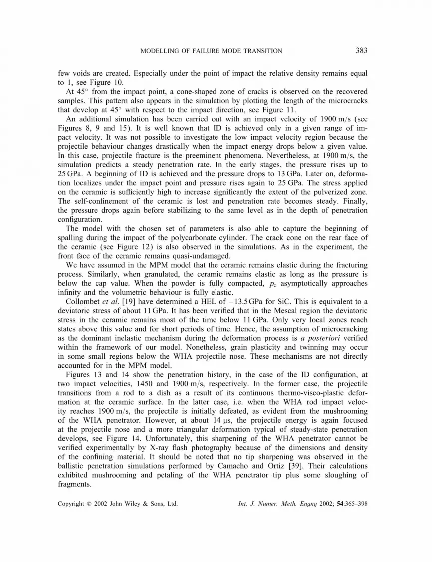
few voids are created. Especially under the point of impact the relative density remains equalto 1, see Figure 10.At 45◦ from the impact point, a cone-shaped zone of cracks is observed on the recovered
samples. This pattern also appears in the simulation by plotting the length of the microcracksthat develop at 45◦ with respect to the impact direction, see Figure 11.An additional simulation has been carried out with an impact velocity of 1900 m=s (see
Figures 8, 9 and 15). It is well known that ID is achieved only in a given range of im-pact velocity. It was not possible to investigate the low impact velocity region because theprojectile behaviour changes drastically when the impact energy drops below a given value.In this case, projectile fracture is the preeminent phenomena. Nevertheless, at 1900 m=s; thesimulation predicts a steady penetration rate. In the early stages, the pressure rises up to25GPa. A beginning of ID is achieved and the pressure drops to 13GPa. Later on, deforma-tion localizes under the impact point and pressure rises again to 25 GPa. The stress appliedon the ceramic is su�ciently high to increase signi�cantly the extent of the pulverized zone.The self-con�nement of the ceramic is lost and penetration rate becomes steady. Finally,the pressure drops again before stabilizing to the same level as in the depth of penetrationcon�guration.The model with the chosen set of parameters is also able to capture the beginning of
spalling during the impact of the polycarbonate cylinder. The crack cone on the rear face ofthe ceramic (see Figure 12) is also observed in the simulations. As in the experiment, thefront face of the ceramic remains quasi-undamaged.We have assumed in the MPM model that the ceramic remains elastic during the fracturing
process. Similarly, when granulated, the ceramic remains elastic as long as the pressure isbelow the cap value. When the powder is fully compacted, pc asymptotically approachesin�nity and the volumetric behaviour is fully elastic.Collombet et al. [19] have determined a HEL of −13:5GPa for SiC. This is equivalent to a
deviatoric stress of about 11GPa. It has been veri�ed that in the Mescal region the deviatoricstress in the ceramic remains most of the time below 11 GPa. Only very local zones reachstates above this value and for short periods of time. Hence, the assumption of microcrackingas the dominant inelastic mechanism during the deformation process is a posteriori veri�edwithin the framework of our model. Nonetheless, grain plasticity and twinning may occurin some small regions below the WHA projectile nose. These mechanisms are not directlyaccounted for in the MPM model.Figures 13 and 14 show the penetration history, in the case of the ID con�guration, at
two impact velocities, 1450 and 1900 m=s; respectively. In the former case, the projectiletransitions from a rod to a dish as a result of its continuous thermo-visco-plastic defor-mation at the ceramic surface. In the latter case, i.e. when the WHA rod impact veloc-ity reaches 1900 m=s; the projectile is initially defeated, as evident from the mushroomingof the WHA penetrator. However, at about 14 �s; the projectile energy is again focusedat the projectile nose and a more triangular deformation typical of steady-state penetrationdevelops, see Figure 14. Unfortunately, this sharpening of the WHA penetrator cannot beveri�ed experimentally by X-ray �ash photography because of the dimensions and densityof the con�ning material. It should be noted that no tip sharpening was observed in theballistic penetration simulations performed by Camacho and Ortiz [39]. Their calculationsexhibited mushrooming and petaling of the WHA penetrator tip plus some sloughing offragments.
Copyright ? 2002 John Wiley & Sons, Ltd. Int. J. Numer. Meth. Engng 2002; 54:365–398

384 B. A. GAILLY AND H. D. ESPINOSA
Figure 8. Depth of penetration versus time in the penetration and ID con�gurations. ForVimpact = 1900 m=s, the projectile penetrates in the ID con�guration. Time=0 refers to
the time at which the rod impacts the target.
Copyright ? 2002 John Wiley & Sons, Ltd. Int. J. Numer. Meth. Engng 2002; 54:365–398
MODELLING OF FAILURE MODE TRANSITION 385
-10
-9
-8
-7
-6
-5
-4
-3
-2
-1
0
-5 0 5 10 15 20 25
Time (ms)
Depth of penetration (mm)
Penetration 1450 m/sI. D. configuration 1450 m/sI.D. configuration 1900 m/s
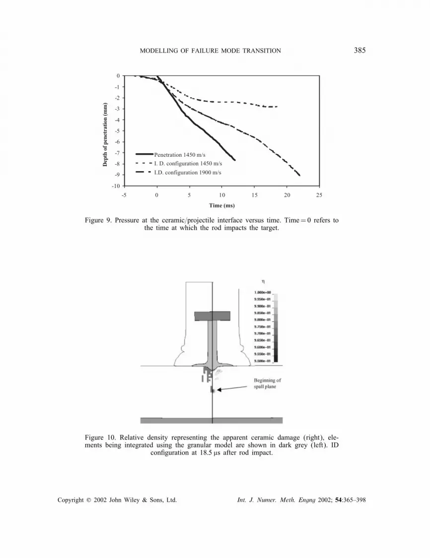
Figure 9. Pressure at the ceramic=projectile interface versus time. Time=0 refers tothe time at which the rod impacts the target.
Figure 10. Relative density representing the apparent ceramic damage (right), ele-ments being integrated using the granular model are shown in dark grey (left). ID
con�guration at 18:5 �s after rod impact.
Copyright ? 2002 John Wiley & Sons, Ltd. Int. J. Numer. Meth. Engng 2002; 54:365–398

386 B. A. GAILLY AND H. D. ESPINOSA
Figure 11. Contours of microcrack length at 90◦ (left) and 45◦ (right) from the direction of theprojectile axis at 18:5 �s after rod impact.
Figure 12. Polycarbonate cylinder con�guration at 45 �s after impact. Inelastic e�ective strain (right)shows microdamage at the projectile–ceramic interface. Beginning of two spall planes and microcrack
cone is observed. Element integrated using the granular model is shown in grey (left).
Copyright ? 2002 John Wiley & Sons, Ltd. Int. J. Numer. Meth. Engng 2002; 54:365–398

MODELLING OF FAILURE MODE TRANSITION 387
Figure 13. Simulation of the ID con�guration. Vimpact = 1450m=s. Elements in dark grey areintegrated using the granular model.
Copyright ? 2002 John Wiley & Sons, Ltd. Int. J. Numer. Meth. Engng 2002; 54:365–398

388 B. A. GAILLY AND H. D. ESPINOSA
Figure 14. Simulation of the ID con�guration. Vimpact = 1900m=s. Elements in dark grey areintegrated using the granular model.
Copyright ? 2002 John Wiley & Sons, Ltd. Int. J. Numer. Meth. Engng 2002; 54:365–398

MODELLING OF FAILURE MODE TRANSITION 389
-8
-7
-6
-5
-4
-3
-2
-1
0
-5 0 5 10 15 20 25
Time (µs)
Depth of penetration (mm)
+
-
N(k)
a0
Reference
Figure 15. Depth of penetration versus time for di�erent initial ceramic microstructures.+ (respectively, −) indicates an increased (respectively, decreased) parameter relative to
the reference case.
4. STUDY ON THE EFFECT OF MATERIAL PROPERTIESIN PENETRATION MECHANICS
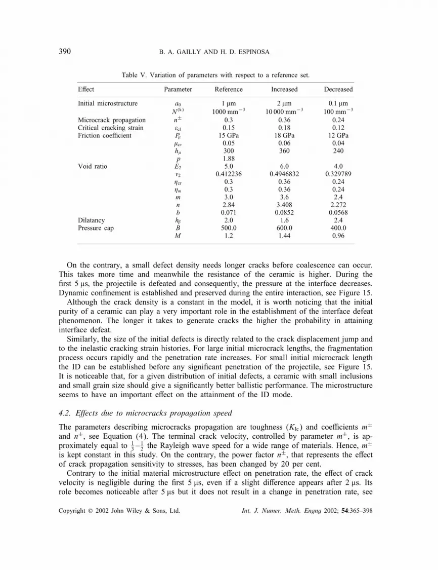
A parametric study on the in�uence of the material properties has been carried out. Thevariation of each parameter is reported in Table V. We de�ne as reference the value of theparameters previously identi�ed and discussed. Meaningfully, variations are considered aboveand below the reference values.
4.1. E�ects due to initial material microstructure
In the MPM model, microcracks density and initial length, on the various orientations, dependon ceramic initial microstructure. In the present case, the ceramic is considered isotropic inits initial state, i.e. microcrack length and density are supposed to be equal in all 13 planesdescribing the microstructure. The microcrack length and density used in the simulations arereported in Table V. As a measure of the model parameters e�ects, the depth of penetrationversus time is plotted. In Figure 15, depth of penetration histories, when a0 and N are increasedor decreased with respect to a reference value, are shown. The time origin is the time at whichthe WHA rod impacts the ceramic front face.There is no appreciable di�erence in the target behaviour during the early interaction of the
polycarbonate sabot and the ceramic target. Similarly, in the �rst few microseconds of inter-action between the rod and the ceramic, the penetration history shows no signi�cant di�erencesince at the point of contact the ceramic is instantly pulverized. After 2 �s the surroundingceramic begins to play an important role as cracks propagate and the plate is fragmented.The initial crack density directly a�ects the elastic cracking strain history. High initial
density of defects results in ceramic fragmentation at early stages. As a result, displacementof fragments, at the penetrator tip occurs earlier. Furthermore, degradation of elastic moduliis accelerated, con�nement of surrounding ceramic is decreased and projectile penetration isfacilitated. Both these e�ects combine to control penetration rate. After a crater begins toform, the pressure at the interface remains higher than in the reference case.
Copyright ? 2002 John Wiley & Sons, Ltd. Int. J. Numer. Meth. Engng 2002; 54:365–398
390 B. A. GAILLY AND H. D. ESPINOSA
Table V. Variation of parameters with respect to a reference set.
E�ect Parameter Reference Increased Decreased
Initial microstructure a0 1 �m 2 �m 0:1 �mN (k) 1000 mm−3 10 000 mm−3 100 mm−3
Microcrack propagation n± 0.3 0.36 0.24Critical cracking strain �cl 0.15 0.18 0.12Friction coe�cient P� 15 GPa 18 GPa 12 GPa
�c� 0.05 0.06 0.04h� 300 360 240p 1.88
Void ratio E2 5.0 6.0 4.0�2 0.412236 0.4946832 0.329789�cr 0.3 0.36 0.24�m 0.3 0.36 0.24m 3.0 3.6 2.4n 2.84 3.408 2.272b 0.071 0.0852 0.0568
Dilatancy h 2.0 1.6 2.4Pressure cap B 500.0 600.0 400.0
M 1.2 1.44 0.96
On the contrary, a small defect density needs longer cracks before coalescence can occur.This takes more time and meanwhile the resistance of the ceramic is higher. During the�rst 5 �s; the projectile is defeated and consequently, the pressure at the interface decreases.Dynamic con�nement is established and preserved during the entire interaction, see Figure 15.Although the crack density is a constant in the model, it is worth noticing that the initial
purity of a ceramic can play a very important role in the establishment of the interface defeatphenomenon. The longer it takes to generate cracks the higher the probability in attaininginterface defeat.Similarly, the size of the initial defects is directly related to the crack displacement jump and
to the inelastic cracking strain histories. For large initial microcrack lengths, the fragmentationprocess occurs rapidly and the penetration rate increases. For small initial microcrack lengththe ID can be established before any signi�cant penetration of the projectile, see Figure 15.It is noticeable that, for a given distribution of initial defects, a ceramic with small inclusionsand small grain size should give a signi�cantly better ballistic performance. The microstructureseems to have an important e�ect on the attainment of the ID mode.
4.2. E�ects due to microcracks propagation speed
The parameters describing microcracks propagation are toughness (KIc) and coe�cients m±
and n±; see Equation (4). The terminal crack velocity, controlled by parameter m±; is ap-proximately equal to 1
3 –12 the Rayleigh wave speed for a wide range of materials. Hence, m
±
is kept constant in this study. On the contrary, the power factor n±; that represents the e�ectof crack propagation sensitivity to stresses, has been changed by 20 per cent.Contrary to the initial material microstructure e�ect on penetration rate, the e�ect of crack
velocity is negligible during the �rst 5 �s; even if a slight di�erence appears after 2 �s. Itsrole becomes noticeable after 5 �s but it does not result in a change in penetration rate, see
Copyright ? 2002 John Wiley & Sons, Ltd. Int. J. Numer. Meth. Engng 2002; 54:365–398
MODELLING OF FAILURE MODE TRANSITION 391
-3.5
-3.0
-2.5
-2.0
-1.5
-1.0
-0.5
0.0
-5 0 5 10 15 20 25
Time (µs)
Depth of penetration (mm) .
-
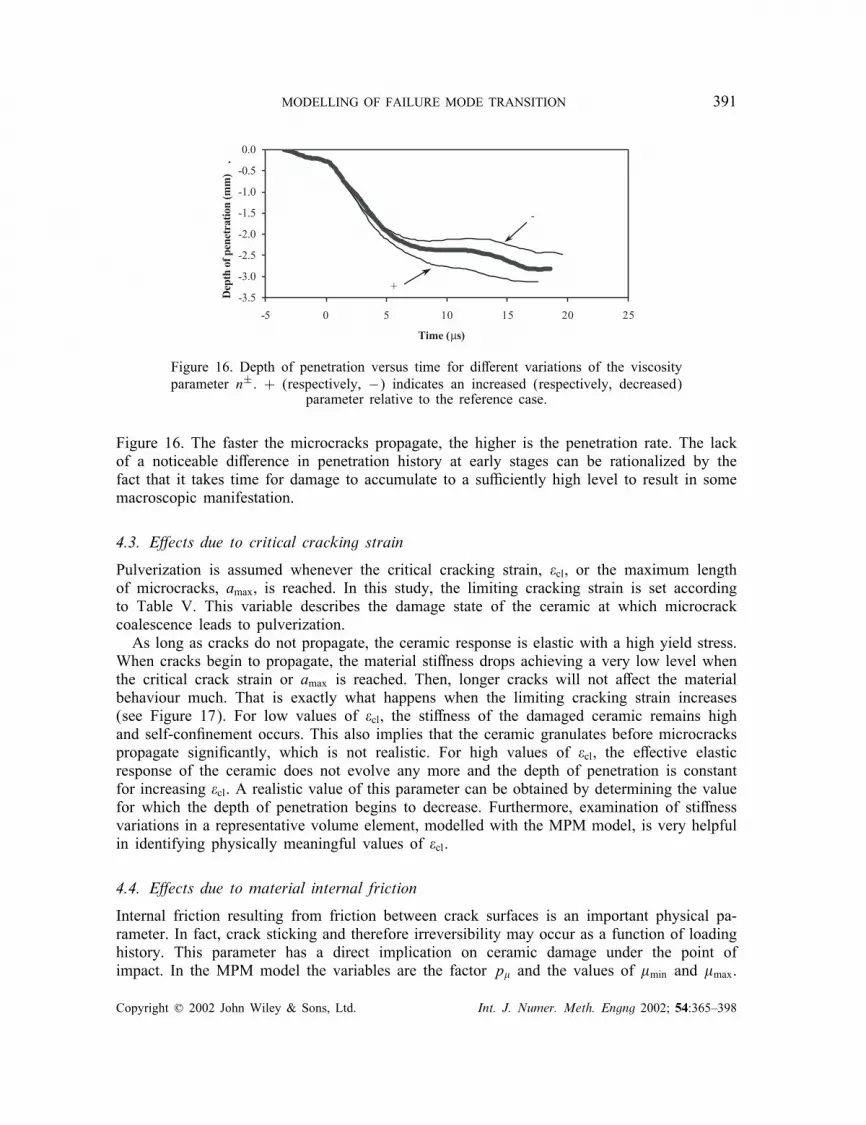
+
Figure 16. Depth of penetration versus time for di�erent variations of the viscosityparameter n±. + (respectively, −) indicates an increased (respectively, decreased)
parameter relative to the reference case.
Figure 16. The faster the microcracks propagate, the higher is the penetration rate. The lackof a noticeable di�erence in penetration history at early stages can be rationalized by thefact that it takes time for damage to accumulate to a su�ciently high level to result in somemacroscopic manifestation.
4.3. E�ects due to critical cracking strain
Pulverization is assumed whenever the critical cracking strain, �cl; or the maximum lengthof microcracks, amax; is reached. In this study, the limiting cracking strain is set accordingto Table V. This variable describes the damage state of the ceramic at which microcrackcoalescence leads to pulverization.As long as cracks do not propagate, the ceramic response is elastic with a high yield stress.
When cracks begin to propagate, the material sti�ness drops achieving a very low level whenthe critical crack strain or amax is reached. Then, longer cracks will not a�ect the materialbehaviour much. That is exactly what happens when the limiting cracking strain increases(see Figure 17). For low values of �cl; the sti�ness of the damaged ceramic remains highand self-con�nement occurs. This also implies that the ceramic granulates before microcrackspropagate signi�cantly, which is not realistic. For high values of �cl; the e�ective elasticresponse of the ceramic does not evolve any more and the depth of penetration is constantfor increasing �cl. A realistic value of this parameter can be obtained by determining the valuefor which the depth of penetration begins to decrease. Furthermore, examination of sti�nessvariations in a representative volume element, modelled with the MPM model, is very helpfulin identifying physically meaningful values of �cl.
4.4. E�ects due to material internal friction
Internal friction resulting from friction between crack surfaces is an important physical pa-rameter. In fact, crack sticking and therefore irreversibility may occur as a function of loadinghistory. This parameter has a direct implication on ceramic damage under the point ofimpact. In the MPM model the variables are the factor p� and the values of �min and �max.
Copyright ? 2002 John Wiley & Sons, Ltd. Int. J. Numer. Meth. Engng 2002; 54:365–398

392 B. A. GAILLY AND H. D. ESPINOSA
-3.0
-2.5
-2.0
-1.5
-1.0
-0.5
0.0
-5 0 5 10 15 20 25
Time (µs)
Depth of penetration (mm)
+
-
Figure 17. Depth of penetration versus time for di�erent variations of the limiting cracking strain �cl. +(respectively, −) indicates an increased (respectively, decreased) parameter relative to the reference case.
The minimum and maximum values of � are the known values for ceramic materials. Onlythe dependence of the pressure factor is examined according to Table V.When p� increases, � becomes less dependant on the normal stress, sticking of crack sur-
faces occurs later in the process and the ceramic is subjected to more damage. This meansthat the ceramic o�ers not only less resistance to penetration but also that a larger volumeof material is damaged. The self-con�nement of the ceramic is then less e�cient and frag-ments can be ejected. As a consequence, the depth of penetration increases as p� increases(see Figure 18). This can be su�cient to interfere with the beginning of the ID mode andthe projectile may not be defeated. On the contrary, decreasing p� decreases the depth ofpenetration and the volume of damaged ceramic. This e�ect takes place only after 5 �s whenID occurs, see Figure 18.An internal friction coe�cient is also used in the granular model corresponding to the
frictional e�ect between fragments. Its evolution depends on the current friction coe�cient,the relative density and the plastic deformation due to the distortion mechanism. The materialparameters are �c�; h� and p. It is di�cult to extract the exact in�uence of these parametersas the equation of evolution for � is coupled with the plastic deformation.The parameters h� and p have an in�uence on the hardening coe�cient h, which determines
the rate of change of �. When h� increases or when p decreases, the hardening coe�cientincreases. Therefore, it results in an increasing friction coe�cient between fragments. Hence,self-con�nement of the ceramic is certainly more e�cient and the �nal penetration depthsmaller. By contrast, an opposite change of the hardening modulus does not seem to a�ectthe depth of penetration.There is also a paradox in the in�uence of the parameter �c�. The depth of penetration
increases when �c� increases. It should be noted that �c� is the minimum value of � whenthe relative density decreases to �cr. It is possible that this evolution is a modelling artefact.Note that these three coe�cients neither interfere with the establishment nor the ID mode.
4.5. E�ects due to fragmented material void ratio
The fragmented material void ratio has an in�uence on three well-de�ned aspects. First,it controls the elastic properties of the fragmented ceramic. Recall that Young’s modulus
Copyright ? 2002 John Wiley & Sons, Ltd. Int. J. Numer. Meth. Engng 2002; 54:365–398
MODELLING OF FAILURE MODE TRANSITION 393
-4.5-4.0-3.5-3.0-2.5-2.0-1.5-1.0-0.50.0
-5 0 5 10 15 20 25Time (µs)
Depth of penetration (mm)
µcvPµ
+
-
-3.5
-3.0
-2.5
-2.0
-1.5
-1.0
-0.5
0.0
-5 0 5 10 15 20 25Time (µs)
Depth of penetration
(mm)
+
-
p
-hµ
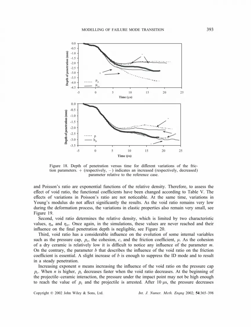
Figure 18. Depth of penetration versus time for di�erent variations of the fric-tion parameters. + (respectively, −) indicates an increased (respectively, decreased)
parameter relative to the reference case.
and Poisson’s ratio are exponential functions of the relative density. Therefore, to assess thee�ect of void ratio, the functional coe�cients have been changed according to Table V. Thee�ects of variations in Poisson’s ratio are not noticeable. At the same time, variations inYoung’s modulus do not a�ect signi�cantly the results. As the void ratio remains very lowduring the deformation process, the variations in elastic properties also remain very small, seeFigure 19.Second, void ratio determines the relative density, which is limited by two characteristic
values, �m and �cr. Once again, in the simulations, these values are never reached and theirin�uence on the �nal penetration depth is negligible, see Figure 20.Third, void ratio has a considerable in�uence on the evolution of some internal variables
such as the pressure cap, pc, the cohesion, c, and the friction coe�cient, �. As the cohesionof a dry ceramic is relatively low it is di�cult to notice any in�uence of the parameter m.On the contrary, the parameter b that describes the in�uence of the void ratio on the frictioncoe�cient is essential. A slight increase of b is enough to suppress the ID mode and to resultin a steady penetration.Increasing exponent n means increasing the in�uence of the void ratio on the pressure cap
pc. When n is higher, pc decreases faster when the void ratio decreases. At the beginning ofthe projectile–ceramic interaction, the pressure under the impact point may not be high enoughto reach the value of pc and the projectile is arrested. After 10 �s, the pressure decreases
Copyright ? 2002 John Wiley & Sons, Ltd. Int. J. Numer. Meth. Engng 2002; 54:365–398

394 B. A. GAILLY AND H. D. ESPINOSA
-3.0
-2.5
-2.0
-1.5
-1.0
-0.5
0.0
-5 0 5 10 15 20 25
Time (µs)
Depth of penetration (mm) .
+
-
Figure 19. Depth of penetration versus time for di�erent variations of the elastic properties as a functionof relative density. Parameters E2 and �2. + (respectively, −) indicates an increased (respectively,
decreased) parameter relative to the reference case.
-3.0
-2.5
-2.0
-1.5
-1.0
-0.5
0.0
-5 0 5 10 15 20 25
Time (µs)
Depth of penetration (mm)
+
-ηcrηm
Figure 20. Depth of penetration versus time for di�erent variations of relative densitylimits. Parameters �cr and �m + (respectively, −) indicate an increased (respectively,
decreased) parameter relative to the reference case.
enough to allow the creation of voids in the ceramic. If the value of pc decreasesenough, then inelastic deformation can occur and the projectile begins to penetrate, seeFigure 21. The ID mode is discontinued and a penetration mode is started. On the contrary,if pc remains high, then the ID mode continues.
4.6. E�ects due to material dilatancy
Dilatancy is controlled by the factor h and may be important in predicting shear localization inceramic powders, see Espinosa and Gailly [29]. A variation of ±20 per cent in this parameteris examined, see Table V. As shown in Figure 22, the variation does not a�ect signi�cantlythe depth of penetration in the ID con�guration. For a friction coe�cient of about 0.2 and�c�=0:05, the change in h represents a change in dilatancy angle of about 20 per cent. Itis interesting to note that when dilatancy increases, the projectile is defeated during a longerperiod of time. This �rst stage is followed by a small steady penetration mode as the pressureunder the tip of the projectile increases, see Figure 22. The di�erence in penetration depth
Copyright ? 2002 John Wiley & Sons, Ltd. Int. J. Numer. Meth. Engng 2002; 54:365–398
MODELLING OF FAILURE MODE TRANSITION 395
-8
-7
-6
-5
-4
-3
-2
-1
0
-5 0 5 10 15 20 25
Time (µs)
Depth of penetration (mm)
+
-
-
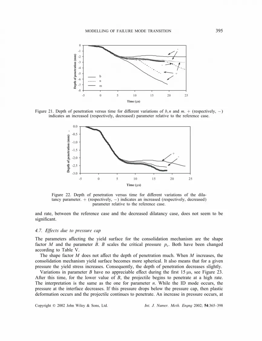
bnm
Figure 21. Depth of penetration versus time for di�erent variations of b; n and m. + (respectively, −)indicates an increased (respectively, decreased) parameter relative to the reference case.
-3.0
-2.5
-2.0
-1.5
-1.0
-0.5
0.0
-5 0 5 10 15 20 25
Time (µs)
Depth of penetration (mm) .
-+
Figure 22. Depth of penetration versus time for di�erent variations of the dila-tancy parameter. + (respectively, −) indicates an increased (respectively, decreased)
parameter relative to the reference case.
and rate, between the reference case and the decreased dilatancy case, does not seem to besigni�cant.
4.7. E�ects due to pressure cap
The parameters a�ecting the yield surface for the consolidation mechanism are the shapefactor M and the parameter B. B scales the critical pressure pc. Both have been changedaccording to Table V.The shape factor M does not a�ect the depth of penetration much. When M increases, the
consolidation mechanism yield surface becomes more spherical. It also means that for a givenpressure the yield stress increases. Consequently, the depth of penetration decreases slightly.Variations in parameter B have no appreciable e�ect during the �rst 15 �s, see Figure 23.
After this time, for the lower value of B, the projectile begins to penetrate at a high rate.The interpretation is the same as the one for parameter n. While the ID mode occurs, thepressure at the interface decreases. If this pressure drops below the pressure cap, then plasticdeformation occurs and the projectile continues to penetrate. An increase in pressure occurs, at
Copyright ? 2002 John Wiley & Sons, Ltd. Int. J. Numer. Meth. Engng 2002; 54:365–398

396 B. A. GAILLY AND H. D. ESPINOSA
-5-5-4-4-3-3-2-2-1-10
-5 0 5 10 15 20 25
Time (µs)
Depth of penetration (mm)
+
-BM
Figure 23. Depth of penetration versus time for di�erent variations of the pressurecap parameters. + (respectively, −) indicates an increased (respectively, decreased)
parameter relative to the reference case.
a later time, and its e�ect is to cause additional damage in the ceramic; hence, the penetrationprocess cannot be stopped.
5. CONCLUDING REMARKS AND DISCUSSION
A new continuum model describing microcracking and �ow of pulverized ceramic is presented.This deformation mode is observed experimentally in ballistic penetration of ceramic targets.The problem is extremely challenging from a computational standpoint, because it consists ofthe transition of material from its pristine state to a powder as a consequence of nucleation,propagation and coalescence of microcracks. Many models have been proposed in the literatureto capture this physical phenomenon. However, none has successfully reproduced the observedfailure modes as a function of ceramic con�nement. Here, for the �rst time, penetration andID of long rods striking multi-layered targets is captured computationally by a model whoseparameters have been identi�ed using other experimental con�gurations, namely, plate androd impact experiments and cylinder collapse of ceramic powders.In our model, damage in the ceramic is modelled by an elastic anisotropic formulation over
13 microcrack orientations. Flow of the pulverized media is modelled by two visco-plasticmechanisms with a non-associated �ow rule. The transition between both models is realizedwhen the inelastic cracking strain reaches a given critical value. The onset of pulverization,as determined by the response of a representative volume element modelled with the MPMmodel, provides key initial material properties needed in the granular model and a consistenttransition between models.The MPM=granular model has been implemented in the Lagrangian code LS-DYNA and
used to reproduce the ID transition of an impacting tungsten long rod on a ceramic tile.Remeshing is used in the projectile to avoid the need of erosion. Penetration distances indepth of penetration and ID con�gurations proposed by Malaise et al. [8] are correctly re-produced. The extent of damage in the ceramic, under the point of impact, is in agreementwith experimental observations. Furthermore, the velocity transition for change in penetrationmode is also predicted.
Copyright ? 2002 John Wiley & Sons, Ltd. Int. J. Numer. Meth. Engng 2002; 54:365–398

MODELLING OF FAILURE MODE TRANSITION 397
Our simulations show that the prerequisite for penetration is the formation of a denselycracked zone in the ceramic ahead of the penetrator. The application of a high compressivestress in the front face of the ceramic limits the �ow of damaged ceramic and leads to theonset of ID. The simulations also indicate that the formation of fragments is not su�cientto ensure continuous penetration since a compact granulated ceramic can self-con�ne. Theejection of previously formed fragments is also necessary for the projectile to penetrate. Thepressure at the penetrator–ceramic interface seems to have a well-de�ned history as a functionof projectile deformation mode. If the front face of the ceramic is con�ned, then the pressureremains high during the �rst few microseconds of interaction. This could be su�cient to keepthe fragments closely packed. When the ID process starts the pressure drops to a lower leveland the amount of damage in the ceramic does not grow signi�cantly. On the contrary, if thefront face of the ceramic is not con�ned or if the extent of the damage zone is large enough,then fragments are laterally displaced and ejected.A parametric study was conducted to assess the e�ect of material microstructure, tough-
ness, chemical purity, strength and sti�ness on ballistic penetration mechanics. These sensitiv-ity studies provide unique information on brittle materials response under various geometriccon�gurations, i.e., degree of con�nement. Our simulations show that the ID phenomenon isnot very sensitive to the elastic properties of the ceramic. However, its microstructure, i.e.initial crack density, defects and grain sizes, are essential parameters. High purity ceramicswith strong interfaces, low density of initial defects and small grain size appear to be the bestcandidates for armor design.
ACKNOWLEDGEMENTS
This research was supported by the Army Research O�ce through ARO-MURI Award No. DAAH04-96-1-0331 and by the Delegation Generale pour l’Armement through decision No.21132=DGA=DSP=D.The authors would like to convey these special thanks to Lallit Anand for providing the latest theoreticaldevelopments of his granular model.
REFERENCES
1. Mescall J, Weiss V. Materials behavior under high stress and ultrahigh loading rates—Part II. Proceeding of the29th Sagamore Army Conference, Army Materials and Mechanics Research Center: Watertown, MA, U.S.A.,1984.
2. Shockey DA, Marchard AH, Skaggs SR et al. Failure phenomenology of con�ned ceramic targets and impactingrods. International Journal of Impact Engineering 1990; 9(3):263–275.
3. Hauver G, Netherwood P, Benck R, Kecskes L. Ballistic performance of ceramic targets. Proceedings of theArmy Symposium on Solid Mechanics, Plymouth, MA, U.S.A., 1993.
4. Hauver G, Netherwood P, Benck R, Kecskes L. Enhanced ballistic performance of ceramics. Proceedings ofthe 19th Army Science Conference, Orlando, FL, U.S.A., 1994.
5. Bless S, Ben-yami M, Apgar L, Eylon D. Impenetrable targets struck by high velocity tungsten long rods.Proceeding of the 2nd Conference on Structures under Shock and Impact, Portsmouth, U.K., 1992.
6. Rapacki E, Hauver G, Netherwood P, Benck R. Ceramic for armors—a material system perspective. Proceedingof the 7th Annual TARDEC Ground Vehicle Survivability Symposium, 1996.
7. Espinosa HD, Brar NS, Yuan G, Xu Y, Arrieta V. Enhanced ballistic performance of con�ned multi-layeredceramic targets against long rod penetrators through interface defeat. International Journal of Structures 2000;37(36):4893–4914.
8. Malaise F, Tranchet JY, Collombet F. An experimental investigation of ceramic block impenetrability tohigh velocity long rod impact. Proceeding of the 6th International Conference on Mechanical and PhysicalBehaviour of Materials under Dynamic Loading, Cracow, Poland, 2000.
9. Orphal DL, Franzen, RR, Piekutowski AJ et al. Penetration of con�ned aluminum nitride targets by tungstenlong rods at 1.5–4:5 km=s. International Journal of Impact Engineering 1996; 18(4):355–368.
10. Orphal DL, Franzen RR. Penetration of con�ned silicon carbide targets by tungsten long rods at impact velocitiesfrom 1.5 to 4:6 km=s. International Journal of Impact Engineering 1997; 19(1):1–13.
Copyright ? 2002 John Wiley & Sons, Ltd. Int. J. Numer. Meth. Engng 2002; 54:365–398

398 B. A. GAILLY AND H. D. ESPINOSA
11. Orphal DL, Franzen RR, Charters AC et al. Penetration of con�ned boron carbide targets by tungsten longrods at impact velocities from 1.5 to 5:0 km=s. International Journal of Impact Engineering 1997; 19(1):15–29.
12. Bruchey WJ, Horwath EJ. System considerations concerning the development of high-e�ciency ceramic armors.Proceeding of 17th International Symposium on Ballistics. Midrand, South Africa, 1998.
13. Lundberg P, Renstrom R, Lundberg B. Impact of metallic projectiles on ceramic targets: transition betweeninterface deformation and penetration. International Journal of Impact Engineering 2000; 24:259–275.
14. Addesio FL, Johnson JN. A constitutive model for the dynamic reponse of brittle materials. LA-UR-89-2651,Los Alamos National Laboratory: Los Alamos, NM, U.S.A., 1989.
15. Rajendran AM, Grove DJ. Modelling the shock response of silicon carbide, boron carbide and titanium diboride.International Journal of Impact Engineering 1996; 18(6):611–631.
16. Gurson AL. Porous rigid-plastic materials containing rigid inclusions-yield function, plastic potential and voidnucleation. Advances in the Research of Strength and Fracture of Materials. vol. 2a. D.M.R. Tablin, PergamonPress: NY, U.S.A., 1977.
17. Curran DR, Seaman L, Cooper T, Shockey DA. Micromechanical model for comminution and granular �owof brittle material under high strain rate application to penetration of ceramic targets. International Journal ofImpact Engineering 1993; 13:53–83.
18. Johnson GR, Holmquist TJ. An improved computational constitutive model for brittle materials. High PressureScience and Technologies, vol. 2. AIP Press: Woodbury, NY, 1994; 981–984.
19. Collombet F, Malaise F, Tranchet JY. A numerical investigation of high velocity impact onto a ceramic block.Proceeding of the 6th International Conference on Mechanical and Physical Behaviour of Materials underDynamic Loading, Cracow, Poland, 2000.
20. Klopp RW, Shockey DA, The strength behavior of granulated silicon carbide at high strain rates and con�ningpressure. Journal of Applied Physics 1991; 70(12):7318–7326.
21. Sairam S, Clifton RJ. Pressure–shear impact investigation of dynamic fragmentation and �ow of ceramics.ASME AMD, vol. 197, Mechanical Testing of Ceramics and Ceramic Composites, 1994.
22. Espinosa HD. On the dynamic shear resistance of ceramic composites and its dependence on applied multiaxialdeformation. International Journal of Solids and Structures 1995; 32:3105–3128.
23. Camacho GT, Ortiz M. Computational modeling of impact damage in brittle materials. International Journalof Solids and Structures 1996; 33:2899–2938.
24. Ortiz M. Computational micromechanics. Computational Mechanics 1996; 18(5):321–338.25. Espinosa HD, Zavattieri PD, Dwivedi SK. A �nite deformation continuum=discrete model for the description
of fragmentation and damage in brittle materials. Journal of the Mechanics and Physics of Solids 1998;46(10):1909–1942.
26. Krysl P, Belytschko T. The element free galerkin method for dynamic propagation of arbitrary 3-D cracks.International Journal of Numerical Methods in Engineering 1999; 44:767–800.
27. Belytschko T, Moes N, Usui S, Parimi C. Arbitrary discontinuities in �nite elements. International Journal ofNumerical Methods in Engineering 2001; 50:993–1013.
28. Gu C, Kim M, Anand L. Constitutive equations for powder metals: application to powder forming processes.Report of Research in Mechanics of Materials. Department of Mechanical Engineering, MIT: Cambridge,MA 02139, U.S.A., 1999.
29. Espinosa HD, Gailly BA. Modeling of the shear instabilities observed in cylinder collapse experiments performedon ceramic powders. Acta Materialia 2001; 49:4135–4147.
30. Dienes, John K. Statistical theory of fragmentation processes. Mechanics of Materials 1984; 4(3–4):325–335.31. Bazant ZP, Oh BH. Microplane model for progressive fracture of concrete and rock. Journal of Engineering
Mechanics, ASCE 1985; 111(4):559.32. Espinosa HD. Micromechanics of the dynamic response of ceramics and ceramic composites. Ph.D. Thesis,
Brown University: Providence, RI, 1992.33. Espinosa HD, Raiser G, Clifton RJ, Ortiz M. Experimental observations and numerical modeling of inelasticity
in dynamically loaded ceramics. Journal of Hard Materials 1992; 3(3–4):285–313.34. Freund LB. Dynamic Fracture Mechanics. Cambridge University Press: Cambridge, 1990.35. Needleman A. Material rate dependence and mesh sensitivity in localization problems. Computer Methods in
Applied Mechanics and Engineering 1998; 67:69–85.36. Simo JC, Kennedy JG, Govindjee S. Non-smooth multisurface plasticity and viscoplasticity. Loading=unloading
conditions and numerical algorithms. International Journal for Numerical Methods in Engineering 1988;26:2161–2185.
37. Budianski B. Thermal and thermoelastic properties of isotropic composites. Journal of Composites 1970; 4:286–295.
38. Johnson GR, Cook WH. A constitutive model and data for metals subjected to large strains, high strain rates andhigh temperature. Proceedings of the 7th International Symposium on Ballistics, La Hague, 1983; 541–547.
39. Camacho GT, Ortiz M. Adaptive Lagrangian modeling of ballistic penetration of metallic targets. ComputationalMethods and Applied Mechanics 1997; 142(3–4):260–301.
Copyright ? 2002 John Wiley & Sons, Ltd. Int. J. Numer. Meth. Engng 2002; 54:365–398