ing coil ballistic galvanometer. the ... - zenodo
TRANSCRIPT
No. 5-] MEASUREMENTS WITH GALVANOMETER. 399
ON PRECISION MEASUREMENTS WITH T H E MOVING COIL BALLISTIC GALVANOMETER.
B Y A N T H O N Y ZELENY.
TH E moving coil ballistic galvanometer possesses an important advantage over the stationary coil type in that it is free from
ordinary external magnetic disturbances, but it presents a number of difficulties for work of high precision. It is the object of this paper to show how these difficulties may be overcome so that measurements with this galvanometer can be made to as high a degree of accuracy as is attainable with direct deflection methods. The various details, many of which are well known and are included only for the purpose of completeness, will be considered under the following subdivisions.
§ 1. Set in the fiber, hysteresis, and zero or null point readings. (d) In ballistic wrork. (b) With continuous currents. (c) Choice of suspension fiber.
§ 2. Damping on closed circuit. § 3. Adjustment for equal deflections. Circular scale.
Increase of period. Shunting of galvanometer. § 4. Methods of bringing the coil to rest.
(a) In open circuit work. (fr) In closed circuit work.
§ 5. Throws from a vibrating coil. § 6. The variation of the constant. The damping factor. § 7. Methods of determining the constant.
(a) The figure of merit and period of vibration method. (b) The earth inductor method. (c) The standard solenoid method. (d) The standard condenser method.
§ 8. The standard mutual inductance coil.
400 ANTHONY ZELEN\. [VOL. XXIII.
§ 9. Correction for thermo-electric currents.
(a) Changing from closed to open circuit.
(b) Changing from open to closed circuit.
§ 10. Galvanometer resistance by a method of damping.
§ 11. Conclusion.
§1 . S E T IN THE F I B E R , " H Y S T E R E S I S , " AND ZERO OR N U L L POINT
READINGS.
When a set is "given to a fiber" during an observation, so that
the coil does not return to its original position, the error due to it
may be avoided in the following manner :
(a) In Ballistic Work. — A throw that is at least equal to the
maximum to be used is given to the coil, so that a set is affected
in the direction of the throws which are to follow. The coil on re
turning to the null point must not be allowed to move past it (see
§4), as otherwise a part of the set is removed.1 Subsequent throws
in the same direction cause little or no additional set. It rarely
happens that an additional set is given, and if any is observed the
throw producing it must be discarded.
(a) With Continuous Currents.—The correction for the set is
avoided in the same way as in ballistic work. To note the amount
of the set the coil must here also be brought aperiodically to the
null point. The null reading observed after the deflection and not
the original one, if it differs from it, must be employed in the calcu
lation of the deflection.
In comparing currents which are not of approximately the same
strength regard must be taken for an apparent " hysteresis " which
exists in many if not all moving coil galvanometers. The same
current produces a different deflection depending on whether it has
increased from zero or decreased from a larger value. The obser
vations of Table I. indicate the amount of this variation in the
case of two galvanometers. The null point after the larger reading
remained the same as that after the lesser one in each case. Dif-
1 In most galvanometers the coil can move beyond the null point an amount equivalent to two or three centimeters on the scale without producing an appreciable effect on the set or the magnetic hysteresis of the coil.
No. 5.] MEASUREMENTS WITH GALVANOMETER. 4.OI
ferent currents were used in the three cases given, so as to make the deflections in all of them about the same.
TABLE I.
Galvanometer.
An open coil type. (Leeds & Northrup " H " Type.)
A cylindrical coil type. (Made in the laboratory. Coil of special "iron free" wire on wooden spool.)
Suspension.
Phosphor-bronze. Steel.
Phosphor-bronze.
Deflection in Cm. Current
Increased from Null Reading.
10.91
12.64
10.42
Deflection in Cm. Current
Decreased from Twice Its
Value.
11.00 12.69
10.68
Variation.
0.8 % 0.4 %
2.0 %
These variations are not due to changes produced by the larger current heating the fiber, for the deflection taken again from the null position is the same as it was in the first case. They are probably due to changes in the direction of magnetization of the magnetic impurities within the coil.
Whatever may be the cause of this hysteresis observed when employing continuous currents, it is probable that ballistic throws of unequal magnitude are not proportionally affected by it. This hysteresis even affects throws of equal magnitude. After some period of rest the first throw differs from the following ones obtained for the same quantity by an amount usually exceeding 0.2 per cent, and therefore should always be discarded.
(c) Choice of Suspension Fiber. — It is desirable to choose the suspension fiber ] which gives the least amount of set after reversal of deflection. A phosphor-bronze strip that gives a set of several millimeters can often be replaced by a phospor-bronze wire, a coarser strip or a steel fiber giving much less set. In each case, however, this is accomplished at the expense of sensitiveness, as shown in Table II., so that in many cases the 1.5 mil phosphor-bronze strip is selected. In the observations given in Table II., the
1 W. E. Ayrton, Phil. Mag., 1890, Vol. 30, p. 58; Electrical World, 1892, Vol. 19, p. 178.
4-02 ANTHONY ZELENY. [ V O L . XX11I.
lower suspension was the same phosphor-bronze spiral in each case,
the upper suspension only being changed.
T A B L E II .
Upper Suspensions
of Equal Length.
1.5 mil phosphor-bronze strip.
1.5 mil phosphor-bronze wire.
3 mil phosphor-bronze strip.
A steel strip.
Sensibility in
' Megohms."
252.0
109.6
47.8 23.1
Time of Double Vibration
on Open Circuit.
Ballistic Throw for Equal
Quantities.
17.88 sec.
12.00 «
7.80 " 5.44 "
9.03 cm.
5.80 "
3.77 " 2.60 "
Set in Fiber on Reversal After
Full Scale Deflection of 25 Cm.
= 14°.
0.27 cm.
0.06 "
0.04 » 0.00 "
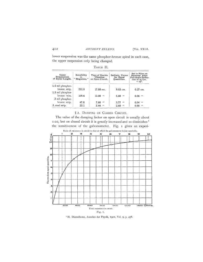
§ 2. DAMPING ON CLOSED CIRCUIT.
The value of the damping factor on open circuit is usually about
1.02, but on closed circuit it is greatly increased and so diminishes 1
the sensitiveness of the galvanometer. Fig. 1 gives an experi-
i E 0
©
e
7
€>
A-
3
5.
R 1
atio of resistance in circuit 2 -&
to that at which the galvanometer is just aperiodic.
A B <S 7 6 Q 1
1
1 1
l o
\ \
&00 &cx> too© Total resistance in circuit.
l 4 o o O h m s .
F i ^ . 1.
1 H . Diesselhorst, Annalen der Physik, 1902, Vol. 9, p. 458.
No. 5.] MEASUREMENTS WITH GALVANOMETER. 4 0 3
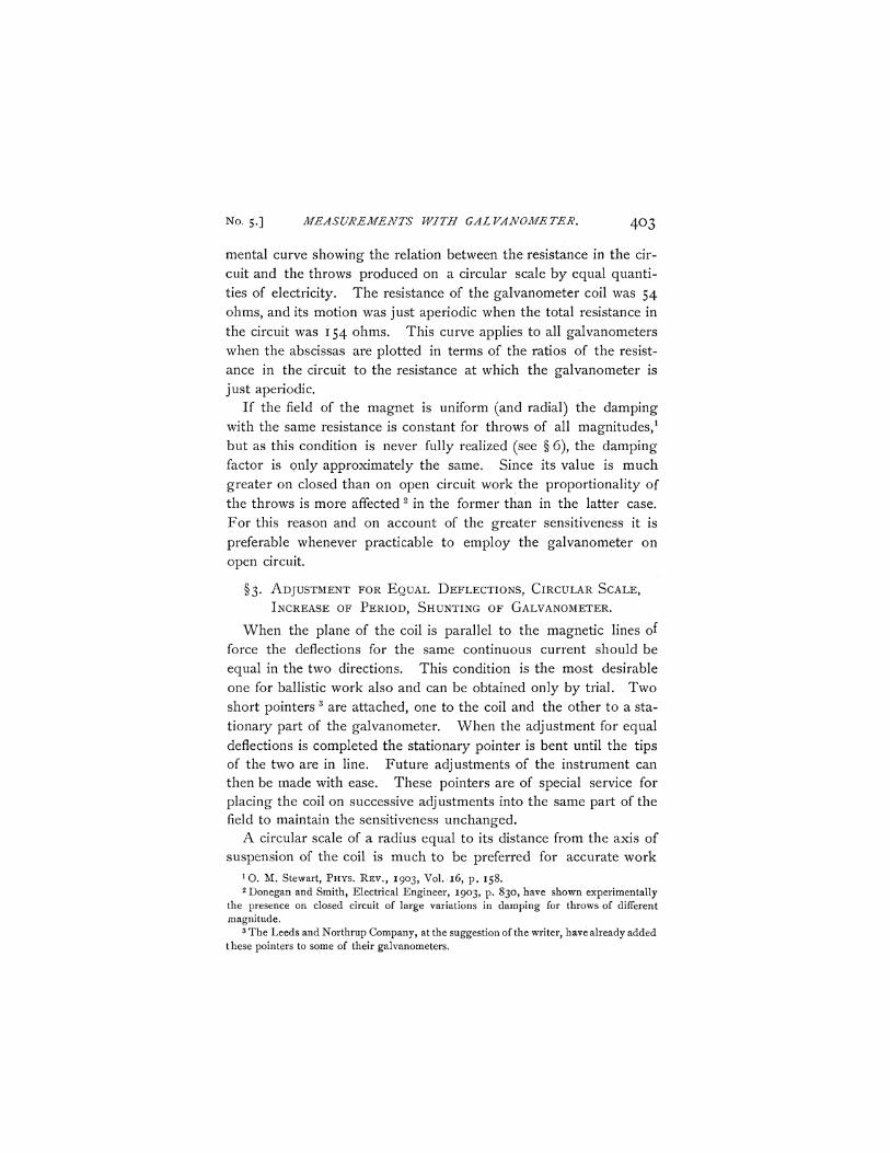
mental curve showing the relation between the resistance in the circuit and the throws produced on a circular scale by equal quantities of electricity. The resistance of the galvanometer coil was 54 ohms, and its motion was just aperiodic when the total resistance in the circuit was 154 ohms. This curve applies to all galvanometers when the abscissas are plotted in terms of the ratios of the resistance in the circuit to the resistance at which the galvanometer is just aperiodic.
If the field of the magnet is uniform (and radial) the damping with the same resistance is constant for throws of all magnitudes,1
but as this condition is never fully realized (see § 6), the damping factor is only approximately the same. Since its value is much greater on closed than on open circuit work the proportionality of the throws is more affected 2 in the former than in the latter case. For this reason and on account of the greater sensitiveness it is preferable whenever practicable to employ the galvanometer on open circuit.
§3. ADJUSTMENT FOR EQUAL DEFLECTIONS, CIRCULAR SCALE,
INCREASE OF PERIOD, SHUNTING OF GALVANOMETER.
When the plane of the coil is parallel to the magnetic lines of force the deflections for the same continuous current should be equal in the two directions. This condition is the most desirable one for ballistic work also and can be obtained only by trial. Two short pointers 3 are attached, one to the coil and the other to a stationary part of the galvanometer. When the adjustment for equal deflections is completed the stationary pointer is bent until the tips of the two are in line. Future adjustments of the instrument can then be made with ease. These pointers are of special service for placing the coil on successive adjustments into the same part of the field to maintain the sensitiveness unchanged.
A circular scale of a radius equal to its distance from the axis of suspension of the coil is much to be preferred for accurate work
1 0 . M. Stewart, PHYS. REV., 1903, Vol.-16, p . 158. 2 Donegan and Smith, Electrical Engineer, 1903, p. 830, have shown experimentally
the presence on closed circuit of large variations in damping for throws of different magnitude.
3 The Leeds and Northrup Company, at the suggestion of the writer, have already added these pointers to some of their galvanometers.
404 ANTHONY ZEZENY [ V O L . X X I I I .
because the telescope is then in focus for all parts of the scale and
the usual parallax is avoided. For ballistic throws the necessity of
changing scale readings to angular measure or to equivalent l cir
cular scale readings is also avoided.
A convenient way of changing the period of the galvanometer
without changing the fiber or the coil is as follows : A brass wire
with two lead balls attached to its extremities is bent in such a man
ner as to clamp easily onto the lower end of the coil. The moment
of inertia of the system can be changed readily by bending the wire
so as to alter the distance between the lead balls. A n y desired
period can be attained in this manner.2
In this type of galvanometers the constant is changed after an
abnormally large deflection (see § 6). For this reason where large
currents are liable to enter as in experiments requiring the balanc
ing of the wheatstone bridge the shunting of the galvanometer
must be made with special care while the balancing is in progress.
§ 4. M E T H O D S OF BRINGING T H E C O I L TO R E S T .
As shown in § 1, the coil must return to the null position without
crossing it more than a small amount. This is accomplished in
the following manner :
(a) In Open Circuit Work. — If the galvanometer is aperiodic on
closed circuit the coil is short-circuited after the throw at some point
on its return, depending on the amount of damping present. If this
is made at the proper place the coil reaches the null reading in the
least possible time. Sometimes it is more convenient to close and
open the circuit several times while the coil is in motion.
When the coil is finally at rest on the closed circuit, it is usually
not at its true null point. A thermo-electric current existing in the
circuit is deflecting the coil so that when the circuit is opened a
vibration of several millimeters may occur. This is checked by
quickly tapping the short-circuiting key while the coil is passing
through the null point from the deflected position. In some cases
^ o h l r a u s c h , Physical Measurements, 1894, p. 446. 2 Since the writing of this paper a galvanometer made by Hartmann and Braun has
been described in Biddle's Bulletin, Sept., 1906, which has attached to a pillar at the lower end of the coil a cross arm carrying at either end a small pan. Weights placed into these pans alter the moment of inertia of the system.
No. 5.] MEASUREMENTS WITH GALVANOMETER. 4 0 5
this is better accomplished by tapping several times while the coil is
moving to the null point and checking the motion a little at a time,
as in the case above.
If the galvanometer is not aperiodic on closed circuit the usual
inductance coil is introduced and the motion checked by the move
ment of a magnet within this coil. To avoid the motion due to the
thermo-electric currents the writer has for some years introduced
a thermo-electric couple into the galvanometer circuit in addition
to the inductance coil. By means of this the galvanometer is
brought to the true null point before the circuit is opened. The
thermo-electric couple suited for this purpose is one of brass wire,
having the temper of a portion changed by heating to white heat.
This portion forms a thermo-electric element with the remainder of
the brass, so that by holding one's fingers on one side or the other
it gives the proper thermo-electromotive force to overcome that
in the circuit. Changing the pressure of the fingers upon the
junction alters the thermo-electromotive force within the proper
limits. Some, including the writer, prefer to use the inductance coil
for this adjustment also, al though it may require longer practice to
attain ease in manipulation.
(b) In Closed Circuit Work. — On closed circuit work the best
condition exists when the galvanometer is just aperiodic, requiring
no attention to bring the coil properly to the null point. If the coil
is over-damped a resistance can be temporarily introduced to lessen
the damping. It must be removed, however, before the final read
ing is taken, as it alters the thermo-electric current in the circuit,
causing a change in the null reading which in this case must be
taken while the circuit is closed. If the coil is not damped suffi
ciently the inductance coil and magnet method must be employed
as in part (a) above.
§ 5. T H R O W S FROM A VIBRATING COIL.
When a ballistic throw is to be taken while the coil is not entirely
at rest the discharge must be made when the coil is at either turning
point of its motion. The throw in either case must be computed
from the natural null point and not from the point at which the
throw originated as is sometimes stated. This is true for vibrations
406 ANTHONY ZELENY. [VOL. XXIII .
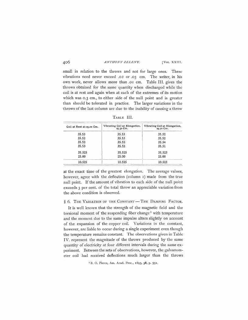
small in relation to the throwrs and not for large ones. These vibrations need never exceed .02 or .03 cm. The writer, in his own work, never allows more than .01 cm. Table III. gives the throws obtained for the same quantity when discharged while the coil is at rest and again when at each of the extremes of its motion which was 0.3 cm., to either side of the null point and is greater than should be tolerated in practice. The larger variations in the throws of the last column are due to the inability of causing a throw
TABLE III.
Coil at Rest at 25.00 Cm.
35.53 35.52 35.52 35.53
35.525 25.00
10.525
Vibrating Coil at Elongation. 25.30 Cm.
35.53 35.53 35.52 35.52
35.525 25.00
10.525
Vibrating Coil at Elongation. 24.70 Cm.
35.52 35.52 35.54 35.51
35.523 25.00
10.523
at the exact time of the greatest elongation. The average values, however, agree with the deflection (column i) made from the true null point. If the amount of vibration to each side of the null point exceeds 3 per cent, of the total throw an appreciable variation from the above condition is observed.
§ 6. T H E VARIATION OF THE CONSTANT — T H E DAMPING FACTOR.
It is well known that the strength of the magnetic field and the torsional moment of the suspending fiber changex with temperature and the moment due to the same impulse alters slightly on account of the expansion of the copper coil. Variations in the constant, however, are liable to occur during a single experiment even though the temperature remains constant. The observations given in Table IV. represent the magnitude of the throws produced by the same quantity of electricity at four different intervals during the same experiment. Between the sets of observations, however, the galvanometer coil had received deflections much larger than the throws
1 B. O. Pierce, Am. Acad. Proc, 1893, 38> P- 55*•
No. 5.] MEASUREMENTS WITH GALVANOMETER. 407
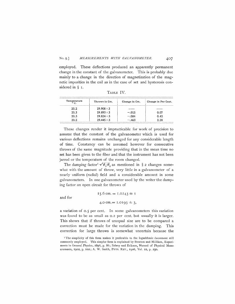
employed. These deflections produced an apparently permanent change in the constant of the galvanometer. This is probably due mainly to a change in the direction of magnetization of the magnetic impurities in the coil as in the case of set and hysteresis considered in § 1.
TABLE IV.
Temperature °C .
20.2 20.3 20.3 20.2
Throws in Cm.
19.908 ±3 19.893 ±3 19.824 ±3 19.445 ± 3
Change in Cm.
- .015 - .084 - .463
Change in Per Cent.
0.07 0.42 2.28
These changes render it impracticable for work of precision to assume that the constant of the galvanometer which is used for various deflections remains unchanged for any considerable length of time. Constancy can be assumed however for consecutive throws of the same magnitude providing that in the mean time no set has been given to the fiber and that the instrument has not been jarred or the temperature of the room changed.
The damping factor1 ^OJ02 as mentioned in § 2 changes somewhat with the amount of throw, very little in a galvanometer of a nearly uniform (radial) field and a considerable amount in some galvanometers. In one galvanometer used by the writer the damping factor on open circuit for throws of
15.6 cm. = 1.0243 =fc 1 and for
4 .ocm.= 1.0193 dz 3,
a variation of 0.5 per cent. In some galvanometers this variation was found to be as small as 0.2 per cent, but usually it is larger. This shows that if throws of unequal size are to be compared a correction must be made for the variation in the damping. This correction for large throws is somewhat uncertain because the
1 The simplicity of this form makes it preferable to the logarithmic decrement still commonly employed. This simpler form is explained by Stratton and Milliken, Experiments in General.Physics, 1896, p. 86 ; Zeleny and Erikson, Manual of Physical Measurements, 1902, p. 102 ; A. W. Smith, P H Y S . R E V . , 1906, Vol. 22, p . 250.
408 ANTHONY ZELENY. [VOL. XXIII.
amount of set in the fiber changes in the consecutive unequal vibra
tions to the opposite sides of the null point. It is therefore desir
able whenever practicable to make the quantities compared nearly
equal rendering this correction unnecessary and avoiding the usual
requirement of an accurate adjustment of the scale with respect to
the normal to the mirror.
§ 7. M E T H O D S OF DETERMINING T H E CONSTANT.
Since in this type of galvanometers, as was shown in § 6, the
constant varies and must therefore be redetermined frequently, it is
especially desirable that the method employed for its determination
should be one which for the same degree of accuracy requires the
least time. The four usual methods l are considered separately.
(a) The " Figure of Merit and Period of Vibration Method " can
be employed in open circuit work only and usually is of little
value where an accuracy greater than one half of one per cent, is
required. The deflected coil is in a field of a different strength
than when in its null position and therefore the figure of merit ob
tained from a continuous current has a value different from the one
required for the ballistic constant. The length of time necessary
for a determination of the constant and the uncertainty of the effect
of the set in the fiber and of the hysteresis are additional reasons
for discarding this method in work of precision.
(b) The Earth Inductor Method can be employed for determin
ing the constant on closed circuit and by special construction on
open circuit also. The determination of the strength of the mag
netic field and of its variation in direction and intensity, especially in
modern cities, render this method too difficult if not impracticable
for the kind of work under consideration.
(c) The Standard Solenoid Method is the most practical of the
three direct methods. The constant can be determined on either
closed or open circuit and with an accuracy limited only by that
with which the constants of the solenoid can be measured. The
large size of the coil and the accuracy of construction required for
work of the highest precision are its chief objections. (See § 8 and
§ 9(*)0 1 Henderson, Practical Electricity and Magnetism, 1898, pp. 211-229.
No. 5.] MEASUREMENTS WITH GALVANOMETER. 4 0 9
(d) The standard condenser method, al though an indirect one, is
by far the most convenient of all the known methods. If the ca
pacity 1 (free charge) and the temperature coefficient are accurately
known it is capable of the highest attainable precision.
For open circuit work the condenser is charged by means of a
standard cell and immediately discharged through the galvanom
eter, the circuit being opened before a measurable amount of the
absorbed charge is liberated. This can be accomplished most con
veniently by means of a special key, a Pohl commutator properly
arranged as described in a previous paper above referred to, or by
means of keys operated by a swinging pendulum. A single tap on
an ordinary discharge key will also accomplish the same result with
fair accuracy.
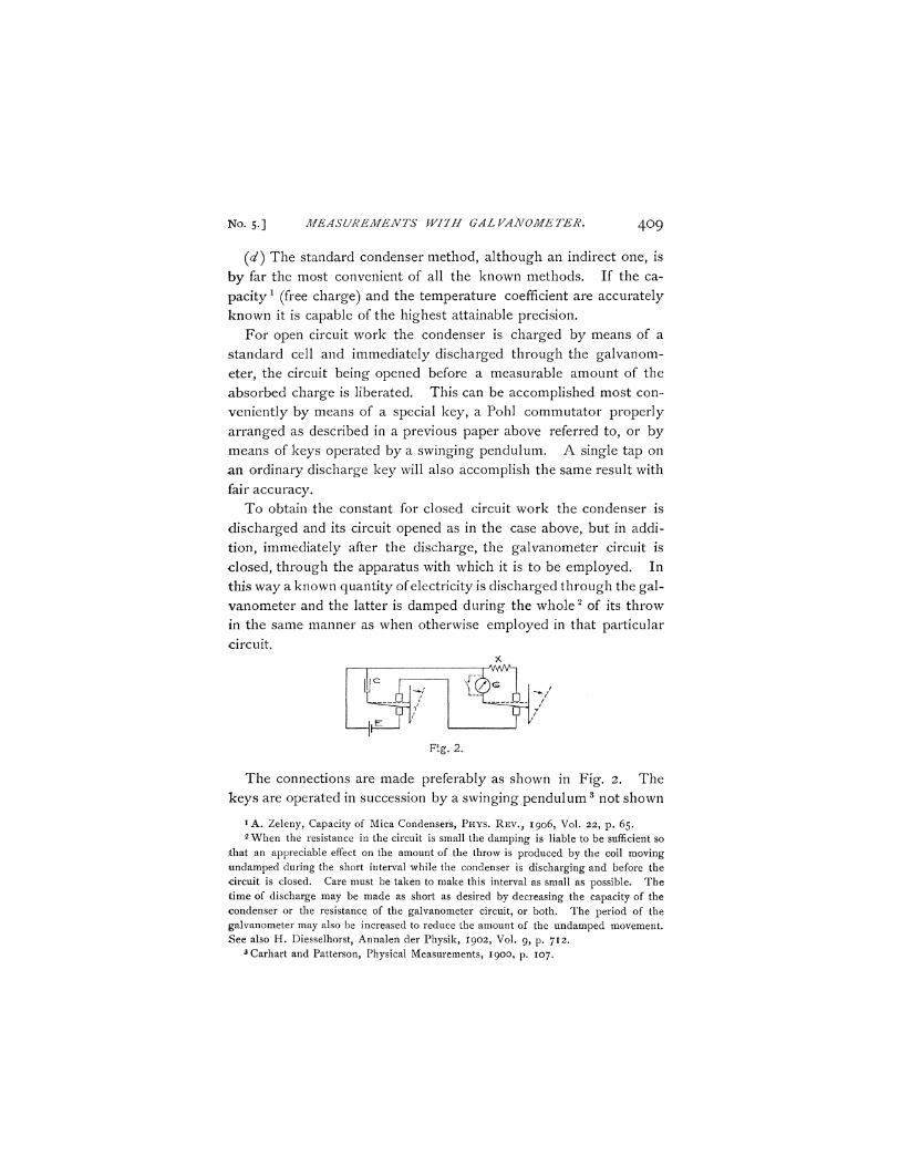
To obtain the constant for closed circuit work the condenser is
discharged and its circuit opened as in the case above, but in addi
tion, immediately after the discharge, the galvanometer circuit is
closed, through the apparatus with which it is to be employed. In
this way a known quantity of electricity is discharged through the gal
vanometer and the latter is damped during the whole 2 of its throw
in the same manner as when otherwise employed in that particular
circuit. x
I 1 T - W V H
Fig. 2.
The connections are made preferably as shown in Fig. 2. The
keys are operated in succession by a swinging pendu lum 3 not shown
1 A. Zeleny, Capacity of Mica Condensers, PHYS. REV., 1906, Vol. 22, p. 65. 2 When the resistance in the circuit is small the damping is liable to be sufficient so
that an appreciable effect on the amount of the throw is produced by the coil moving tmdamped during the short interval while the condenser is discharging and before the -circuit is closed. Care must be taken to make this interval as small as possible. The time of discharge may be made as short as desired by decreasing the capacity of the condenser or the resistance of the galvanometer circuit, or both. The period of the galvanometer may also be increased to reduce the amount of the undamped movement. See also H. Diesselhorst, Annalen der Physik, 1902, Vol. 9, p. 712.
3Carhart and Patterson, Physical Measurements, 1900, p. 107.
4 i o ANTHONY ZELENY. [VOL. XXIII.
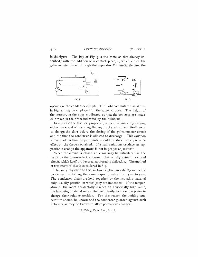
in the figure. The key of Fig. 3 is the same as that already described,1 with the addition of a contact piece, 5, which closes the galvanometer circuit through the apparatus X immediately after the
Fig. 3. Fig. 4.
opening of the condenser circuit. The Pohl commutator, as shown in Fig. 4, may be employed for the same purpose. The height of the mercury in the cups is adjusted so that the contacts are made or broken in the order indicated by the numerals.
In any case the test for proper adjustment is made by varying either the speed of operating the key or the adjustment itself, so as to change the time before the closing of the galvanometer circuit and the time the condenser is allowed to discharge. This variation when made within proper limits should produce no appreciable effect on the throws obtained. If small variations produce an appreciable change the apparatus is not in proper adjustment.
When the circuit is closed an error may be introduced in the result by the thermo-electric current that usually exists in a closed circuit, which itself produces an appreciable deflection. The method of treatment of this is considered in § 9.
The only objection to this method is [the uncertainty as to the condenser maintaining the same capacity value from year to year. The condenser plates are held together by the insulating material only, usually paraffin, in which ;they are imbedded. If the temperature of the room accidentally reaches an abnormally high value, the insulating material may soften sufficiently to allow the plates to change their relative position. For this reason the limiting temperature should be known and the condenser guarded against such extremes as may be known to affect permanent changes.
1 A. Zeleny, PHYS. REV. , loc. cit.
I—U.
^ T 0>
No. 5.] MEASUREMENTS WITH GALVANOMETER. 4 1 I
In the present state of our knowledge of condensers more or less doubt must exist as to their constancy for work of precision. When the condenser has not been exposed to abnormal influences, its capacity is known to remain constant for at least a considerable length of time. This makes it available as a working standard of the highest precision. Under present conditions, however, it must be tested from time to time. Since it is not practicable to send it often to the Bureau of Standards, a method of testing its constancy must be employed which is sufficiently simple to enable the determination to be made with ease and precision in any laboratory. The writer has employed for this purpose what he terms a " Standard Mutual Inductance Coil" (see § 8), which has proved to be very satisfactory.
8. T H E STANDARD MUTUAL INDUCTANCE COIL.
Two coils are wound one within the other on the same spool of specially well seasoned wood.1 They are properly insulated and saturated in an insulating compound to prevent any displacement of the wire or any moisture entering the wood. When the coefficient of mutual inductance of these coils is once determined they can be employed in the same manner as a standard solenoid and make a much simpler and cheaper piece of apparatus, capable of at least as high a degree of accuracy.
The coefficient of mutual inductance is determined by comparison with the standard condenser to which it is intended to be a supplement employing the well-known relation2
Q = M^. s
1 Some other material may prove superior to wood. Rosa and Grover, Bulletin No. 3, Vol. 1, Bureau of Standards, have shown serpentine to possess magnetic impurities. Other similar substances must be proved free from them before being employed in standards.
Since the above footnote was written, J. G. Coffin, in the Bulletin of the Bureau of Standards, Vol. 2, p. 89, states that glass and plaster of paris are excellent materials for coils of small size and also gives the advantages of the use of marble. The writer, however, is aware that in at least some grades of marble there are veins of magnetic material.
2 E. L. Nichols, Lab. Manual of Physics and Applied Electricity, 1894, Vol. I, p. 243; Zeleny and Erikson, loc. cit, p. I I I .
412 ANTHONY ZELENY. [VOL. XXIII.
The current Ip in the primary coil is adjusted until the quantity Qs
in the secondary circuit is nearly the same as that given by the
standard condenser. On account of the damping on closed circuit
(see § 2 and § 9), the secondary circuit is opened by means of a
proper key (Figs. 2, 3 or 4 modified), immediately after the passage l
of the induced charge. When the resistance Rs in the secondary
circuit is known the coefficient of mutual inductance M can be cal
culated and its true value obtained to within i / i oo th per cent. This
determination should be made before any possible change can occur
in the value of the capacity as it had been standardized.
Future comparisons are made by assuming the coefficient of self-
inductance to remain unchanged and the coil is used as a standard
to determine the quantity discharged from the condenser, from which
the value of the capacity is obtained in the usual manner,
CE = Ql = Kdx
Q2-Kd2
dxMI?
d2 RE
When this value is the same as the original one the constancy of
the capacity value is assured. Should any variation be detected it
is reasonable to expect that the change occurs in the condenser.
To avoid any uncertainty in such a case it is preferable to have two
such standards of inductance wound in a different manner on separate
spools of unequal diameters. The temperature coefficient of these
standards, al though very small, should be known or the observa
tions must be taken always at nearly the same temperature.
This Standard Mutual Inductance coil may be used in the same
manner as the standard solenoid for the measurement of quantities,
in place of the condenser, but possesses the same disadvantage as
the standard solenoid in requiring the determination of the value of xThe adjustment of the key is readily made on account of the very short time required
for the discharge. It has been shown experimentally by E. Rutherford, Trans. New-Zealand Institute, 1895, p. 182, that all the measurable part of the induced electricity passes in a few thousandths of a second.
R ~ s
C =
No. 5-] MEASUREMENTS WITH GALVANOMETER. 413
a current and of a resistance for each observation, which renders it
much less convenient for a working standard than the condenser.
It is desirable therefore to use it only as a check on the constancy
of the condenser.
§ 9. CORRECTION FOR T H E R M O - E L E C T R I C CURRENTS.
Electrical circuits containing a galvanometer of the moving coil
type are specially liable to thermo-electric currents. These can
often be reduced in value and sometimes entirely avoided by screen
ing the galvanometer from heat radiations and from air currents.
Since these thermo-electric currents modify the amount of the bal
listic throw they should be entirely eliminated. The writer has
found the following method of removing them a most satisfactory
one :
A secondary circuit P containing the storage cell E and a vari
able resistance box R, also includes a small part *S of the galva
nometer circuit. This part is composed of a few centimeters of the
copper connecting wire. The resistance in R is adjusted until the
electromotive force at the extremities of 5 is equal and opposite to
the thermo-electromotive force in the circuit. This condition is
tested by closing and opening the key K.
When it is not convenient to use this method the following cor
rections may be employed with a high degree of accuracy.
f-rm—I p
IHIETU
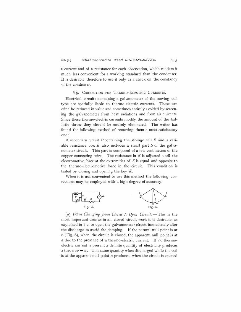
Fig. 5. Fig. 6.
(a) When Changing from Closed to Open Circuit. — This is the
most important case as in all closed circuit work it is desirable, as
explained in § 2, to open the galvanometer circuit immediately after
the discharge to avoid the damping. If the natural null point is at
o (Fig. 6), when the circuit is closed, the apparent null point is at
a due to the presence of a thermo-electric current. If no thermo
electric current is present a definite quantity of electricity produces
a throw ob = oc. This same quantity when discharged while the coil
is at the apparent null point a produces, when the circuit is opened
414 ANTHONY ZELENY. [VOL. XXIII.
immediately, an apparent throw of ab on one side and ac on the other. The throws therefore must be calculated from the true null point, o, as it is on open circuit, and not from the apparent one, #, observed on closed circuit.
The case is practically the same as that of the throw obtained from the maximum elongation of a vibrating coil as described in § 5-
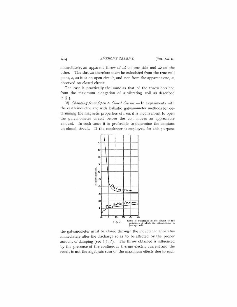
($) Changing from Open to Closed Circuit. — In experiments with the earth inductor and with ballistic galvanometer methods for determining the magnetic properties of iron, it is inconvenient to open the galvanometer circuit before the coil moves an appreciable amount. In such cases it is preferable to determine the constant on closed circuit. If the condenser is employed for this purpose
Ratio of resistance in the circuit to the resistance at which the galvanometer is just aperiodic.
the galvanometer must be closed through the inductance apparatus immediately after the discharge so as to be affected by the proper amount of damping (see § 7, d). The throw obtained is influenced by the presence of the continuous thermo-electric current and the result is not the algebraic sum of the maximum effects due to each
No. 5-] MEASUREMENTS WITH GALVANOMETER. 4 1 5
quantity acting alone because the period of the coil is different for continuous currents and for the ballistic throws. The relation of the periods is roughly shown in Fig. 7 for different values of the resistance in the circuit. The value of the correction to be made for the presence of the thermo-electric current depends upon the amount of damping and can be obtained by aid of the curves of Fig. 9 or from the curve of Fig. 10.
. The method by which these curves were obtained is as follows : The data were taken from a Leeds and Northrup open-coil gal
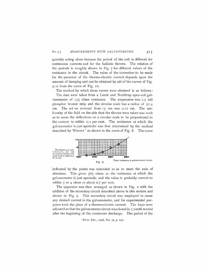
vanometer of 135 ohms resistance. The suspension was 1.5 mil phosphor bronze strip and the circular scale has a radius of 51.4 cm. The set on reversal from 15 cm. was 0.22 cm. The uniformity of the field on the side that the throws were taken was such as to cause the deflections on a circular scale to be proportional to the current to within o. I per cent. The resistance at which the galvanometer is just aperiodic was first determined by the method described by Wenner ] as shown in the curve of Fig. 8. The curve
The distance, in mil-1 i m e t e r s , the coil moved beyond the null point from a deflection of 20 cm.
<g£ m
BGO &70
Fig. 8.
5 0 0 S90 Total resistance in galvanometer circuit.
indicated by the points was extended so as to meet the axis of abscissas. This gives 565 ohms as the resistance at which the galvanometer is just aperiodic and the value is probably correct to within 3 or 4 ohms or about 0.7 per cent.
The apparatus was then arranged as shown in Fig. 2 with the addition of the secondary circuit described above in this section and shown in Fig. 5. This secondary circuit was employed to cause any desired current in the galvanometer, and for experimental purposes took the place of a thermo-electric current. The keys were adjusted so that the galvanometer circuit was closed in i/iooth second after the beginning of the condenser discharge. The period of the
1 P H Y S . R E V . , 1906, Vol. 22, p. 192.
416 ANTHONY ZELENY. [VOL. XXIII .
throw on open circuit was 4.8 seconds and on closed circuit, containing the galvanometer only, it was 4.4 seconds.
It was shown that for small currents giving a deflection of less than 5 millimeters the value of the correction in per cent, of the total deflection given by the current was numerically the same, near enough for the required purpose, whether the throw was large or small l and whatever the direction of the thermo-electric current with respect to the throw. The correction, however, is to be added to or subtracted from the observed throw depending upon whether the electric current is in the opposite or in the same direction as the throw.
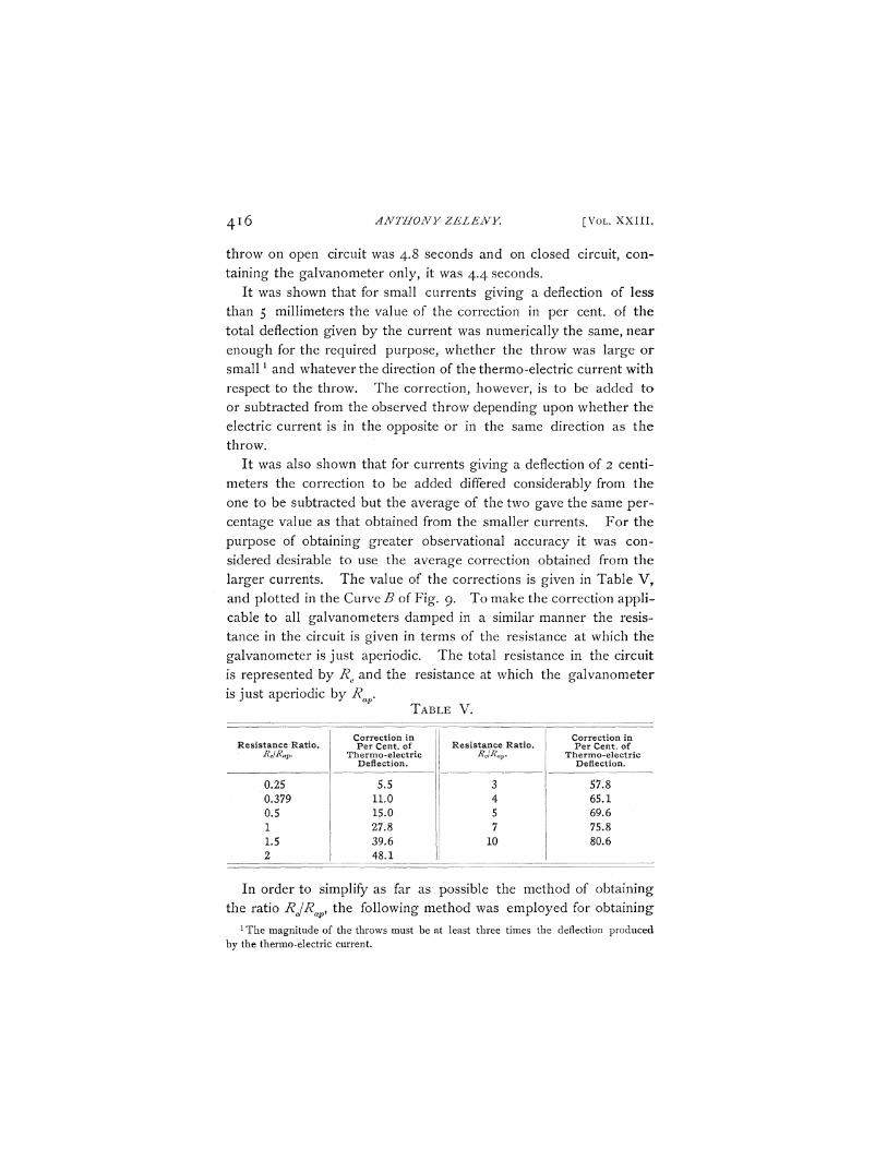
It was also shown that for currents giving a deflection of 2 centimeters the correction to be added differed considerably from the one to be subtracted but the average of the two gave the same percentage value as that obtained from the smaller currents. For the purpose of obtaining greater observational accuracy it was considered desirable to use the average correction obtained from the larger currents. The value of the corrections is given in Table V, and plotted in the Curve B of Fig. 9. To make the correction applicable to all galvanometers damped in a similar manner the resistance in the circuit is given in terms of the resistance at which the galvanometer is just aperiodic. The total resistance in the circuit is represented by Rc and the resistance at which the galvanometer
is just aperiodic by Rap. TABLE V.
Resistance Ratio. RclRav
0.25 0.379 0.5 1 1.5 2
Correction in Per Cent, of
Thermo-electric j Deflection.
5.5 11.0 15.0 27.8 39.6 48.1
Resistance Ratio. Rc\Rap<
3 4 5 7
10
Correction in Per Cent, of
Thermo-electric Deflection.
57.8 65.1 69.6 75.8 80.6
In order to simplify as far as possible the method of obtaining the ratio RJRap, the following method was employed for obtaining:
1 The magnitude of the throws must be at least three times the deflection produced by the thermo-electric current.
No. 5.] MEASUREMENTS WITH GALVAN0ME1ER. 4 1 7
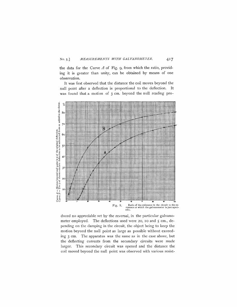
the data for the Curve A of Fig. 9, from which the ratio, provid
ing it is greater than unity, can be obtained by means of one
observation.
It was first observed that the distance the coil moves beyond the
null point after a deflection is proportional to the deflection. It
was found that a motion of 3 cm. beyond the null reading pro-
Ratio of the resistance in the circuit to the resistance at which the galvanometer is just aperiodic.
duced no appreciable set by the reversal, in the particular galvano
meter employed. The deflections used were 20, 10 and 5 cm., de
pending on the damping in the circuit, the object being to keep the
motion beyond the null point as large as possible without exceed
ing 3 cm. The apparatus was the same as in the case above, but
the deflecting currents from the secondary circuits were made
larger. This secondary circuit was opened and the distance the
coil moved beyond the null point was observed with various resist-
418 ANTHONY ZELENY. [VOL. XXIII.
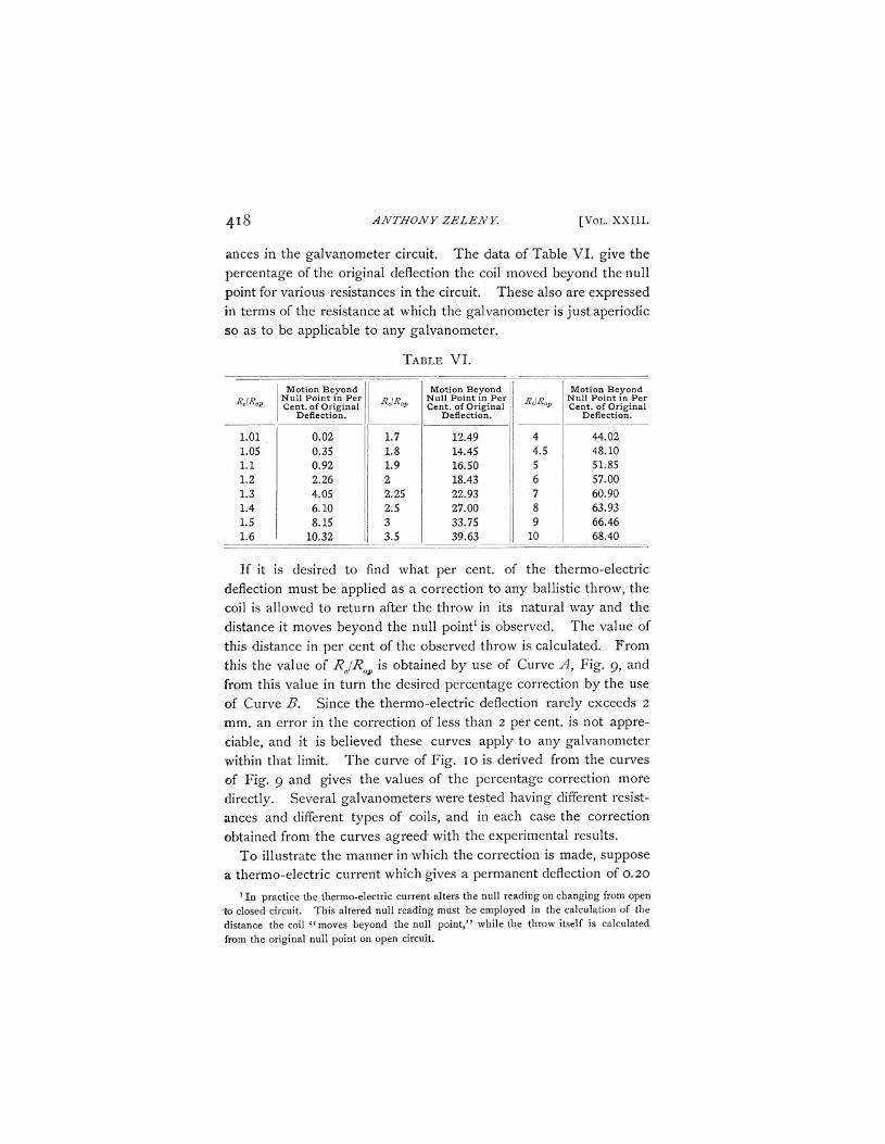
ances in the galvanometer circuit. The data of Table VI. give the percentage of the original deflection the coil moved beyond the null point for various resistances in the circuit. These also are expressed in terms of the resistance at which the galvanometer is just aperiodic so as to be applicable to any galvanometer.
TABLE VI.
RJRap
1.01 1.05 1.1 1.2 1.3 1.4 1.5 1.6
Motion Beyond Null Point in Per Cent, of Original
Deflection.
0.02 0.35 0.92 1 2.26 4.05 6.10 8.15
10.32
RJRap
\ L 7
1.8 1.9 2 2.25 2.5
| 3 3.5
Motion Beyond Null Point in Per Cent, of Original
Deflection.
12.49 14.45 16.50 18.43 22.93 27.00 33.75 39.63
RJRap
4 4.5 5 6
•7
8 9
| 10
Motion Beyond Null Point in Per Cent, of Original
Deflection.
44.02 48.10 51.85 57.00 60.90 63.93 66.46 68.40
If it is desired to find what per cent, of the thermo-electric deflection must be applied as a correction to any ballistic throw, the coil is allowed to return after the throw in its natural way and the distance it moves beyond the null point1 is observed. The value of this distance in per cent of the observed throw is calculated. From this the value of RjRa is obtained by use of Curve A, Fig. 9, and from this value in turn the desired percentage correction by the use of Curve B. Since the thermo-electric deflection rarely exceeds 2 mm. an error in the correction of less than 2 percent, is not appreciable, and it is believed these curves apply to any galvanometer within that limit. The curve of Fig. 10 is derived from the curves of Fig. 9 and gives the values of the percentage correction more directly. Several galvanometers were tested having different resistances and different types of coils, and in each case the correction obtained from the curves agreed with the experimental results.
To illustrate the manner in which the correction is made, suppose a thermo-electric current which gives a permanent deflection of 0.20
1 In practice the thermo-electric current alters the null reading on changing from open to closed circuit. This altered null reading must be employed in the calculation of the distance the coil " moves beyond the null point," while the throw itself is calculated from the original null point on open circuit.
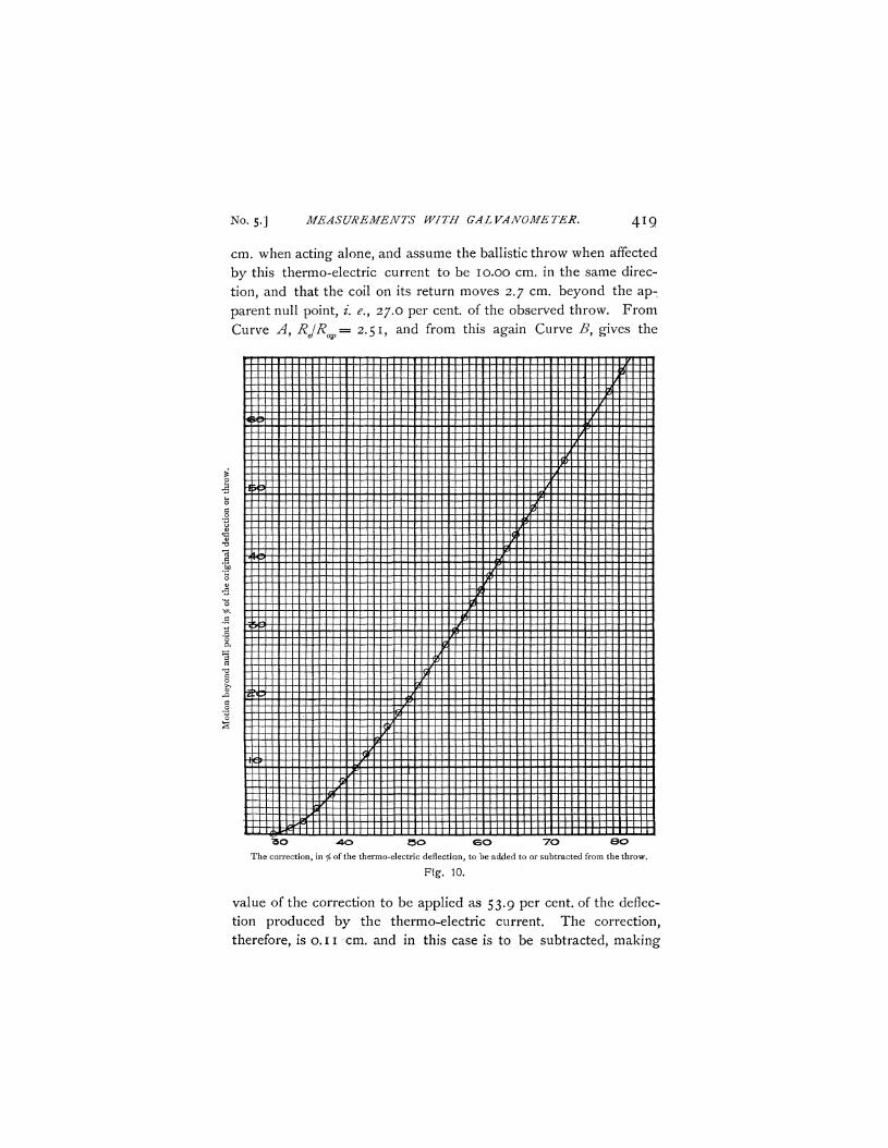
No. 5.] MEASUREMENTS WITH GAL VANOME TER. 4 1 9
cm. when acting alone, and assume the ballistic throw when affected
by this thermo-electric current to be 10.00 cm. in the same direc
tion, and that the coil on its return moves 2.7 cm. beyond the ap
parent null point, i. e., 27.0 per cent, of the observed throw. F rom
Curve A, RJRa = 2.51, and from this again Curve B, gives the
I ft m
•&Pr
iff
W *
I ^Pt
I
"SO 4 0 S O C O TO 0 O
The correction, in f0 of the thermo-electric deflection, to be added to or subtracted from the throw.
Fig. 10.
value of the correction to be applied as 53.9 per cent, of the deflec
tion produced by the thermo-electric current. The correction,
therefore, is o. 11 cm. and in this case is to be subtracted, making
420 ANTHONY ZELENY [VOL. XXIII.
the corrected throw = 9.89 cm. From the curve of Fig. 10 the 27.0 per cent, gives the correction of 53.9 per cent, more directly, and this is the curve to be employed in practice.
§10. GALVANOMETER RESISTANCE BY A METHOD OF DAMPING.
The Curve A, Fig. 9, may also be employed for an approximate determination of the galvanometer resistance.1 The distance the coil moves beyond the null point is observed on closed circuit, and again with an additional known resistance. If on closed circuit the coil moves n per cent, of the original deflection beyond the null point, from Curve A, RjRap = #. If an additional resistance of R ohms causes the distance the coil moves beyond the null point to increase to m per cent.,
Then Rc a
irtR-y and Rc, the resistance of the original galvanometer circuit = aR\(b — a). This is often a very convenient method and gives the resistance with sufficient accuracy for many purposes.
§ 11. CONCLUSION.
The constant of a moving-coil galvanometer is a variable quantity depending on several conditions. For work of the highest precision the unknown quantity must be compared with a known one of nearly equal magnitude and the two throws must be obtained in immediate succession. A set in the fiber must be avoided by always taking the throws in the same direction and stopping the motion of the coil on its return before it crosses the null point. The first throw taken after a period of rest and any throw after which a change in the null reading is observed must be discarded. In the latter case the readings following must not be compared with those taken before. Whenever it is practi-
1 The results obtained for various types of galvanometers by using this method, agree
to within I per cent, of the true values. On account of the variations in the intensity of the magnetic field being different in different galvanometers it was not considered practical to attempt measurements with a greater accuracy.
No. 5-] MEASUREMENTS WITH GALVANOMETER, 4 2 1
cable the galvanometer should be used on open circuit. It is then more sensitive and the quantities more nearly proportional to the throws.
The mica condenser (free charge capacity) is by far the most convenient working standard for the comparison of electrical quantities. Its capacity should be tested from time to time on account of possible permanent changes. This is most conveniently accomplished by means of a standard mutual inductance coil whose coefficient is determined by comparison with the condenser when its capacity is first measured.
On closed circuit work, whenever it is practicable, the galvanometer circuit should be opened immediately after all the measure-able part of the electrical discharge has passed through it. The quantities are then compared with the galvanometer on open circuit. When it is necessary to leave the galvanometer circuit closed during a throw the induced quantity can be compared with the known one from the condenser by discharging the condenser through the galvanometer and then immediately closing the circuit.
When during a comparison of the quantities the circuit is changed from a closed to an open one or the reverse, the thermo-electric currents of the circuit must first be eliminated or a correction made for their effect.
Observing the precautions and using the methods described in this paper, the moving-coil galvanometer can be employed with ease for measuring electrical quantities to the highest degree of accuracy attainable with direct deflection methods.
PHYSICAL LABORATORY,
T H E UNIVERSITY OF MINNESOTA,
June 12, 1906.