miniaturized microparticle trapping setup with variable frequency
TRANSCRIPT
ROMANIAN ACADEMY
PHYSICS
ROMANIANREPORTSIN
V O L U M E 5 3N U M B E R S 3 - 8
2001
REPRINT
mtulrotruEn ncnoerutEt nou{lqrBUCURE$TI

Romanian Reports in Physics, Vol. 53, Nos. 3-& P. 275-280,2001
MINIATURIZED MICROPARTICLE TRAPPING SETUP WITHVARIABLE FREQUENCY
O. S. STOICAN, B. MIHALCEA, VTORICA GHEORGHE
Natiiionat lnstitute for Laser, Plasrna and Radi.ation PhysicsBucharest-Magurele, P. O. Box MG-36, Rotnania
(Received July 25, 2001) l
Abstrad. A miniaturized microparticle trapping setup with variable frequency is reported. The
setup is intended to be used in order to study the trapping phenomenon for charged microparticles inquadrupolar electromagnetic fields and to'achieve stable ordered structures. ; "
Key words: electromagnetic quadrupolar trap, micoparticles confinement, ordered structures.
l.INTRODUCTION
The setup we designed and realized allows to study the trapping phenomenon of
charged rnicroparticles in quadrupolar elecfro.magnetic traps and the appearance of
stable, ordered structures. A simpte and low-cbst trapping setup can help in drawing
conclusions about charged particle evolution in an ion trap. The laws describing the
trapped microparticle motion in air are almost identical with those accounting for
stoied atomic ion motion in ultrahigh vacuum: Microparticle breaking via air friction
is analogous with ion coolingvia buffer gas molecules collision.The setup is equipped with two trap geometries: a linear one and an annular
one. The linear trap (with a fixed length) consists of four parallel metallic rods and
two "endcap" electrodes. Upon request, a linear trap with variable length can be
realized. The annular trap comprises one central electrode and two "endcap"
electrodes, coaxially arranged. Depending on the trap geometry, different patterns
of ordered structures (planar and linear strings, zigzag structures) can be observed
with bare eyes. The diagnosis of a trappid microparticle is achieved by means of a
d.c. voltage with known Polarity.Expenmental setups for microscopic particles confinement in Paul traps,
operating at standard temperature and pressure (STP) and 50 Hz frequency,
targeted- for mass and charge, vapour pressure, viscosity and surface tension
measurements or for didactical demonstrative purposes, have been previously
reported [1],t21. For other possible applications, working with a variable length

276 O.S. Stoican, B. Mihalcea, Viorica Gheorghe
linear trap at STP conditions, for different drive frequencies, is expected to yieldimportant results. In [3], several experimental results achieved with such a variabletrap are reported.
2. TECHNICAL DESCRIPTION
The setup consists of the following main blocks:I ) the particle trap with two different geometries (linear and annulargeometry, respectively);2) the electronic supply block generating the a.c. variable frequency trapping
voltage, the d.c. trapping voltages and the a.c. parametrical excitation voltage;3) the trapped particles illumination system.The linear geometry trap consists of foul parallel brass rods (Fig. 1),
equidistantly spaced on an afproximately 10 ** radius, and two "endcap"electrodes. The rod diameter and length are 10 mm and 70 mm, respectively. Thedistance 2zqbetween the upper and lower trap electrodes is l0 mm.
Sedion A - A
Fig. 1 - Sketch of the linear trap,geometry.
The annular geometry trap comprises one central cylindrical electrode andtwo annular "endcap" electrodes (Fig. 2). The two annular "endcap" electrodes arecovered with a thin metallic grid for certain versions of the setup. The'annularelectrodes inner diameter and thickness are 24 mm and 7 mm, respectively. Thedistance 2zobetween the upper and lower trap electrodes is 25 mm.
A-l

Miniaturized migroparticle trappi
Fig. 2 - Sketch of the annular trap. geometry.
Side view Top view
The electronic supply unit (Fig. 3) delivers the following trapping voltagesapplied on the trap electrodes:a) An a.c. variable voltage Uo (A - 2.5 kV ), with variable frequency eJ2nin the
50-800 Hz range;b) A parametrical excitation variable voltage U,,,(0-250 V), with variable
frequency a/2nin rhe 0-250 Hz range;c) A d.c. diagnosis voltage with switching polarity Q, whose range lies between
0 and 700 V; i..d) A d.c. voltage U,, needed for axial confinement (only for linear trap) whose
range lies between 0 and 700 V.The Ol oscillator delivers an a.c, voltage of Ql2nfrequency (drive
frequency) and the 02 oscillator delivers an a.c. voltage of a/2nfrequency. Bothvoltage amplitudes are variable. An operational amplifier adds the two voltages,while the resulting signal is applied to the input of a power,amplifier. The highvoltage transformer block rises up the a.c. voltage delivered fromihe output of thepower amptifier (max. 6 Vnr,4s) to a2.5kV value.
(I?*mntrol
Fig. 3 - Power supply unit-blockdiagram.
Qb,c
olll*mrtrol
278 0.S. Stoican, B. Mihalcea, Viorica Gheorghe
A 3-digit display placed on the front panel of the setup displays the values ofthe dU2r, cil2n frequencies and of the Uo,, U, or U, voltages. The whole setupforms a single block
The trap illumination system contains a halogen lamp (220 V, 50 Hz, 20 W)common for both traps and a laser diode which assures illumination along thehorizontal axis (x-a,ris) only for the linear trap.
Trapped microparticles can be observed with bare eyes, eventually using amagnifying lens.
The electronic supply unit ip connected to the main power supply220Y150H2. The power consumptiori does not exceed 50 W. The whole setupweight is about 15 kg.
3. TIIEORY AND RESULTS
The Lc. voltage Uo, with dA2zrfrequency (drive frequency) is appliedbetween the (c),(c') and (a), (b) electrodes, in order to achieve microparticleconfinement. A d.c- voltage Q is applied between the (a) and (b) electrodes, rhusshifting the microparticle position along the vertical axis. In the case of the lineartrap, a d.c. voltage Unis also applied between the (d), (d') electrodes and the ground.
The equation of motion for a particle of mass M and charge Q within the trapvolume is:
. . P=QE - Kdrld1 + Mg +QE, (l)
,where r = (x, !, z) is the particle vector position, x, l, zare the particle coordinatesand K {,K>0) represents the coefficient describing the aerodynarnical drag force. Eis the electric field produced by the a.c. voltage, Mg is the gravitational force andE, - U/2ro is the magnitude of the electric field produced by applying a staticpotential difference U. between the upper and lower trap electrodes, separated at2zo, rfi order to shift the particles towards the trap center. We introduce the c = Q,r /2and ,,1-- I(MQ parameters, where O is the drive angular frequency. By definingX= eA'x, Y- e^'y and Z= etuz, the Mathieu equations describing the trappingprocess are homogeneous on the X and Y axes, with the well-known solutions andstability domains t4l. The z-axis motion is described by an inhomogeneousMathieu equation. In this case, the stability regions for solutions of theinhomogeneous equations of rnotion in the presence of drag forces include not onlythe stability regions of the homogeneous equations, but also a part of the instabilityregions, being consequently larger. One up to thousands of microparticles can be
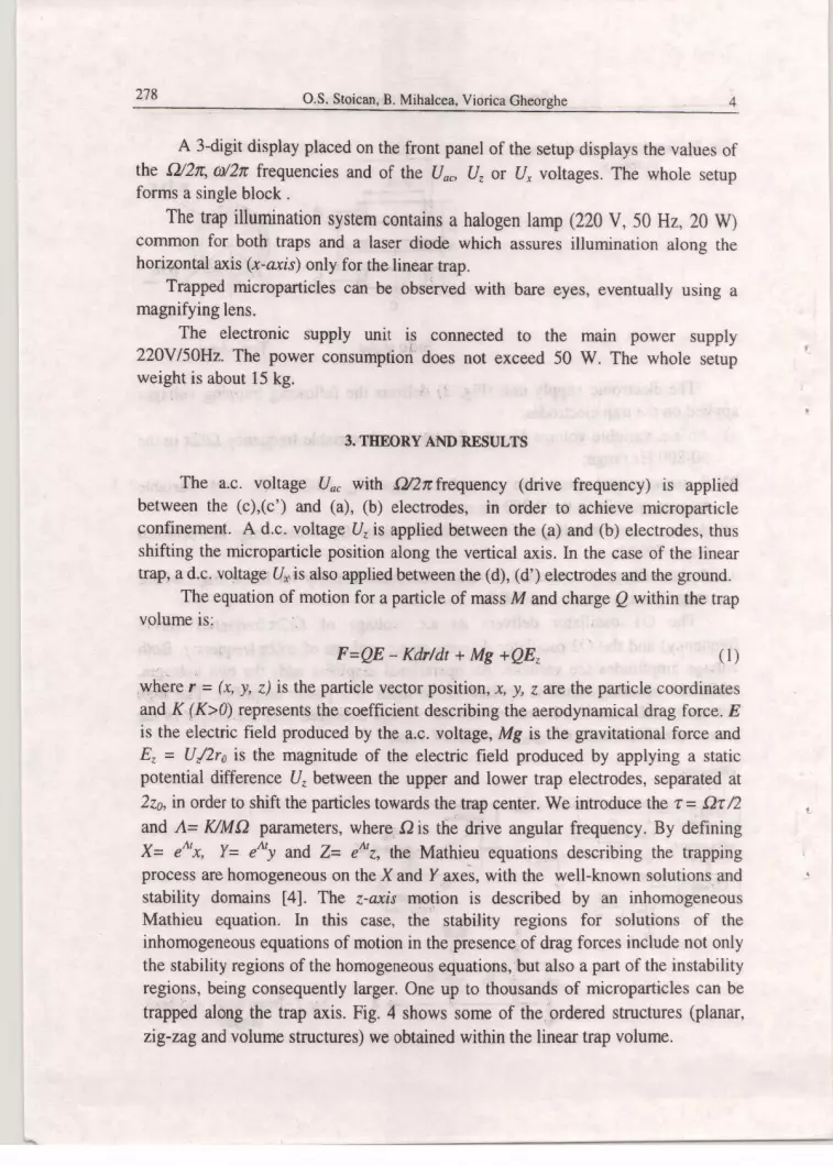
trapped along the trap axis. Fig. 4 shows some of the ordered structures (planar,
zig-zagand volume structures) we obtained within the linear trap volume.
Mi ni qturized microparticle
Fig. 4 - ordered structures photographed inside the linear,trap.
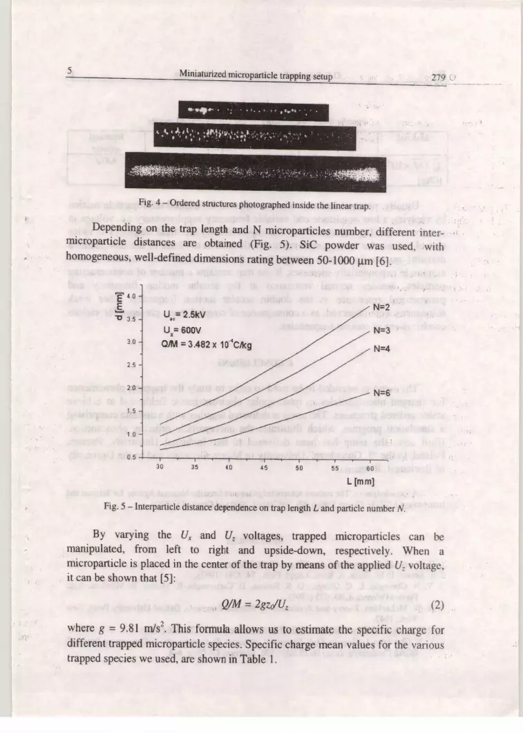
Depending on the trap length and N microparticles number, different inter-microparticle distances are obtained (Fig. S).-t SiC powder was used, ,withhomogeneous, well-defined dimensions rating between 50-1000 pm [6].
8 4 0E.rf 3.s
N=2
N=3
N=4
N=62 ,8
3 .0
2.5
1 . 5
1 . 0
0 .5
r rmmlFig. 5 - Interparticle distance dependence on trap length L andparticle number N,
By varying the U, and (Iz voltages, trapped microparticles can bemanipulated, from left to right and upside-down, respectively. when amicroparticle is placed in the center of the trap by means of the applied U. voltage,it can be shown that [5]:
,, AM = Zgz/U, (2)
where 8 = 9.81 m/s2, This formula allows us to estimate the specific charge fordifferent trapped rnicroparticle species. Specific charge rrcan values for the varioustrapped species we used, are shown in Table 1.
U.,= 2.5kV
Ur= 5o0VQrM = 3.482 x

280 O.S. Stoican, B. Mihalcea, Viorica Gheorghe
Material sic Anthracene Alumina Hydroxylappatite
0 tu x lo4lC/ksl
3.482 ;ii 4.147
'.' :4.873
:i, Table I :'.
. l
Specific charge mean values for the various trapped species
Usually, parametrical excitation is achieved for trapped microparticle motionby applying a low amplitude and variable frequency supplementary a.c. volrage inseries with the Uo" voltage. When the supplernentary a.c. field frequency is twicethat of the secular motion, microparticles (located at the limit of the first Mathieudomain) resonantly absorb energy from the field, while their secular motionamplitude exponentially increases. If the trap contains a number of noninteractingparticles, besides normal resonance at the secular motion frequency andpararnetrical resonance at the double secular motion frequency, other weakresonances were observed, as a consequence of coupled terms presence for variouscombinations of motion frequencies. :
4. CONCLUSIONS - .
The setup is intended to be used in order to study the trapping phenomenonfor charged microparticles in quadrupolar electromagnetic fields and to achievestable ordered structures. The setup is delivered together with a diskette comprisinga simulation program, which illustrates the microparticle ordering phenomenon.Until now, the setup has been delivered to the Technical University, Poznan,Poland, to the "J. Gutenberg" University in Mainz, Germany and to the Universityof Bucharest, Romania.
Acknowledgment.The authors acknowledge support from the National Agency for Science andInnovation (ANSTI): Grants 5086/1 999, 5087/ I 999-2000 and Grant 6t s7 lzCf:fl..
REFERENCES
l. H. Winter, H. W. Ortjohann, Am.J.Phys., 59, 807 (1991). :r :2. S. Arnold, L. M. Folan, A. Korn, J.Appl. Phys., 74,4291(1993). :3. V. N. Gheorghe, L, C. Giurgiu, O. S. Stoican, D. Cacicovschi, R. Molnar, B. Mihalcea, Acta
Phisica PolonicaA, 93,625 (1998).4. N. W. Mclachlan, Theory and Application of Mathicu Functions, Oxford University Press, New
York, 1947.5. E. J. Davis, A. K. Ray, Joumal of Colloid and Interface Science,70,556 (1980).6. V. N. Gheorghe, L .Giurgiu, O. S. Stoican, B. Mihalcea, D. Cacicovschi, S. Comanescu, Proc 28&
EGAS Conference, Graz,l6-19 July 1996, Abstrrcts Dz$-09, p, M4. i