mini8 - 8 loop process controller - e-therm as
TRANSCRIPT
Mini8 Controller Engineering Handbook
Part No HA028581 Issue 1 Jun-04 1
Mini8 - 8 Loop Process Controller
1. CHAPTER 1 INSTALLATION AND OPERATION...............................7 1.1 WHAT INSTRUMENT DO I HAVE?....................................................................................7 1.2 MINI8 ORDERING CODE .....................................................................................................8 1.3 HOW TO INSTALL THE CONTROLLER...........................................................................9 1.3.1 Dimensions 9 1.3.2 To Install the Controller 9 1.3.3 Environmental Requirements 9 1.4 ELECTRICAL CONNECTIONS..........................................................................................10 1.4.1 Power Supply 10 1.4.2 Fixed IO Connections 11 1.4.3 Digital Communications Connections 11 1.4.4 Configuration Port 11 1.4.5 Modbus 11 1.4.6 DeviceNet 13 1.4.7 Typical DeviceNet Wiring Diagram 14 1.4.8 Thermocouple Input TC8 15 1.4.9 Logic Output DO8 16 1.4.10 Analogue Output AO8 17 1.4.11 Current Transformer input Module CT3 18 1.5 ADDING OR REPLACING AN IO MODULE. ..................................................................19 1.6 MINI 8 LED INDICATORS ..................................................................................................20
2. CHAPTER 2 USING THE MINI8.........................................................21 2.1 iTOOLS....................................................................................................................................21 2.1.1 iTools OPC Open server 21 2.2 MODBUS, SINGLE REGISTER, SCADA ADDRESSING................................................21 2.3 MODBUS (FLOATING POINT)...........................................................................................21 2.4 FIELDBUS...............................................................................................................................22 2.5 MINI8 EXECUTION..............................................................................................................22 2.6 THE iTOOLS OPERATOR INTERFACE ..........................................................................23 2.6.1 Scanning 23 2.6.2 Browsing and Changing Parameter Values 23 2.7 RECIPE EDITOR...................................................................................................................25 2.7.1 Recipe Menu Commands 25 2.8 OPCSCOPE.............................................................................................................................26 2.8.1 OPC Scope List Window Context Menu 27 2.8.2 OPC Scope Chart Window 27 2.8.3 OPC Server 29
3. CHAPTER 3 CONFIGURATION USING iTOOLS..............................30 3.1 CONFIGURATION................................................................................................................30 3.1.1 On-Line/Off-line Configuration 30 3.2 CONNECTING A PC TO THE MINI8 CONTROLLER...................................................30 3.2.1 Configuration Cable and Clip 30 3.2.2 Scanning 30 3.3 CONFIGURING THE MINI8 ...............................................................................................31 3.3.1 Function Blocks 31 3.3.2 Soft Wiring 32 3.4 SIMPLE WORKED EXAMPLE...........................................................................................33 3.4.1 The I/O 33 3.4.2 Wiring 35 3.5 GRAPHICAL WIRING EDITOR.........................................................................................38
Engineering Handbook Mini8 Controller
2 Part No HA028581 Issue 1 Jun-04
3.5.1 Graphical Wiring Toolbar 39 3.5.2 Function Block 39 3.5.3 Wire 39 3.5.4 Block Execution Order 39 3.5.5 Using Function Blocks 39 3.5.6 Tooltips 40 3.5.7 Function Block State 41 3.5.8 Using Wires 42 3.5.9 Using Comments 43 3.5.10 Using Monitors 44 3.5.11 Downloading 44 3.5.12 Selections 44 3.5.13 Colours 45 3.6 DIAGRAM CONTEXT MENU.............................................................................................45 3.6.1 Wiring Floats with Status Information 46 3.6.2 Edge Wires 47
4. CHAPTER 4 MINI8 OVERVIEW........................................................ 48 4.1 COMPLETE LIST OF FUNCTION BLOCKS. ..................................................................49
5. CHAPTER 5 ACCESS FOLDER....................................................... 50
6. CHAPTER 6 INSTRUMENT FOLDER .............................................. 51 6.1 INSTRUMENT / OPTIONS...................................................................................................51 6.2 INSTRUMENT / INSTINFO .................................................................................................52 6.3 INSTRUMENT / DIAGNOSTICS.........................................................................................53
7. CHAPTER 7 I/O FOLDER................................................................. 55 7.1 MODULE ID ...........................................................................................................................55 7.1.1 Modules 55 7.2 LOGIC OUTPUT....................................................................................................................56 7.2.1 Logic Out Parameters 56 7.2.2 Logic Output Scaling 56 7.2.3 Example: To Scale a Proportioning Logic Output 57 7.3 THERMOCOUPLE INPUT ..................................................................................................58 7.3.1 Thermocouple Input Parameters 58 7.3.2 Linearisation Types and Ranges 59 7.3.3 CJC Type 59 7.3.4 Sensor Break Value 60 7.3.5 Fallback 61 7.3.6 PV Offset 61 7.3.7 Using TC8 input as a mV input 61 7.4 ANALOGUE OUTPUT..........................................................................................................62 7.4.1 Example – 4 to 20mA Analogue Output 62 7.5 FIXED IO ................................................................................................................................63 7.6 CURRENT MONITOR..........................................................................................................64 7.6.2 Single Phase Configurations 65 7.6.3 Three Phase Configuration 67 7.6.4 Parameter Configuration 68 7.6.5 Commissioning 69 7.6.6 Calibration 71
8. CHAPTER 8 ALARMS ...................................................................... 72 8.1 FURTHER ALARM DEFINITIONS....................................................................................72
Mini8 Controller Engineering Handbook
Part No HA028581 Issue 1 Jun-04 3
8.2 ANALOGUE ALARMS .........................................................................................................73 8.2.1 Analogue Alarm Types 73 8.3 DIGITAL ALARMS ...............................................................................................................74 8.3.1 Digital Alarm Types 74 8.4 ALARM OUTPUTS................................................................................................................74 8.4.1 How Alarms are Indicated 74 8.4.2 To Acknowledge an Alarm 74 8.5 ALARM PARAMETERS.......................................................................................................75 8.5.1 Example: To Configure Alarm 1 76 8.6 DIGITAL ALARM PARAMETERS ....................................................................................77 8.6.1 Example: To Configure DigAlarm 1 78 8.7 ALARM SUMMARY .............................................................................................................79 8.8 ALARM LOG..........................................................................................................................81
9. CHAPTER 9 BCD INPUT ...................................................................82 9.1 BCD PARAMETERS .............................................................................................................82 9.1.1 Example: To wire a BCD Input 83
10. CHAPTER 10 DIGITAL COMMUNICATIONS....................................84 10.1 CONFIGURATION PORT ...............................................................................................84 10.1.1 Configuration Communications Parameters 84 10.2 FIELD COMMUNICATIONS PORT ..............................................................................85 10.3 MODBUS.............................................................................................................................85 10.3.1 Modbus Connections 85 10.3.2 Modbus Communications Parameters 86 10.3.3 Communications Identity 86 10.3.4 Modbus Address Switch 87 10.3.5 Baud Rate 87 10.3.6 Parity 87 10.3.7 RX/TX Delay Time 87 10.4 MODBUS BROADCAST MASTER COMMUNICATIONS.........................................88 10.4.1 Mini8 Broadcast Master 88 10.4.2 Wiring Connections 89 10.5 DEVICENET.......................................................................................................................90
11. CH. 11 COUNTERS, TIMERS, TOTALISERS, RT CLOCK ................91 11.1 COUNTERS ........................................................................................................................91 11.1.1 Counter Parameters 92 11.2 TIMERS ..............................................................................................................................93 11.2.1 Timer Types 93 11.2.2 On Pulse Timer Mode 93 11.2.3 Off Delay Timer Mode 94 11.2.4 One Shot Timer Mode 95 11.2.5 Compressor or Minimum On Timer Mode 96 11.2.6 Timer Parameters 97 11.3 TOTALISERS.....................................................................................................................98 11.3.1 Totaliser Parameters 99 11.4 REAL TIME CLOCK......................................................................................................100 11.4.1 Real Time Clock Parameters 100
12. CHAPTER 12 HUMIDITY CONTROL................................................101 12.1.1 Overview 101 12.1.2 Temperature Control of an Environmental Chamber 101 12.1.3 Humidity Control of an Environmental Chamber 101 12.2 HUMIDITY PARAMETERS ..........................................................................................102
Engineering Handbook Mini8 Controller
4 Part No HA028581 Issue 1 Jun-04
13. CHAPTER 13 INPUT MONITOR...................................................... 103 13.1.1 Maximum Detect 103 13.1.2 Minimum Detect 103 13.1.3 Time Above Threshold 103 13.2 INPUT MONITOR PARAMETERS ..............................................................................104
14. CHAPTER 14 LOGIC AND MATHS OPERATORS. ....................... 105 14.1 LOGIC OPERATORS .....................................................................................................105 14.1.1 Logic 8 105 14.1.2 2 input Logic Operations 106 14.1.3 Logic Operator Parameters 107 14.2 EIGHT INPUT LOGIC OPERATORS..........................................................................108 14.3 MATHS OPERATORS....................................................................................................109 14.3.1 Math Operations 110 14.3.2 Math Operator Parameters 111 14.3.3 Sample and Hold Operation 112 14.4 EIGHT INPUT ANALOG MULTIPLEXERS ..............................................................113 14.4.1 Fallback 113
15. CHAPTER 15 INPUT CHARACTERISATION................................. 114 15.1 INPUT LINEARISATION...............................................................................................114 15.1.1 Compensation for Sensor Non-Linearities 115 15.1.2 Input Linearisation Parameters 116 15.2 POLYNOMIAL ................................................................................................................117
16. CHAPTER 16 LOAD ....................................................................... 119 16.1 LOAD PARAMETERS....................................................................................................119
17. CHAPTER 17 CONTROL LOOP SET UP....................................... 121 17.1 WHAT IS A CONTROL LOOP?....................................................................................121 17.2 LOOP PARAMETERS - MAIN......................................................................................122 17.3 LOOP SET UP ..................................................................................................................122 17.3.1 Types of Control Loop 123 17.4 PID CONTROL ................................................................................................................123 17.4.1 Proportional Term 124 17.4.2 Integral Term 124 17.4.3 Derivative Term 124 17.4.4 High and Low Cutback 125 17.4.5 Integral action and manual reset 125 17.4.6 Relative Cool Gain 125 17.4.7 Loop Break Time 125 17.4.8 Cooling Algorithm 125 17.4.9 Gain Scheduling 126 17.4.10 PID Parameters 127 17.5 TUNING ............................................................................................................................128 17.5.1 Automatic Tuning 128 17.5.2 One-shot Tuning 128 17.5.3 Calculation of the cutback values 128 17.5.4 Manual Tuning 129 17.5.5 Setting the Cutback Values 129 17.5.6 Multi-zone applications. 130 17.5.7 Tune Parameters 130 17.6 SETPOINT FUNCTION BLOCK ..................................................................................131 17.6.1 Setpoint Function Block 131 17.6.2 SP Tracking 132
Mini8 Controller Engineering Handbook
Part No HA028581 Issue 1 Jun-04 5
17.6.3 Manual Tracking 132 17.6.4 Rate Limit 132 17.6.5 Setpoint Parameters 132 17.7 OUTPUT FUNCTION BLOCK ......................................................................................134 17.7.1 Effect of Control Action, Hysteresis and Deadband 136
18. SETPOINT PROGRAMMER .............................................................137 18.1 PROGRAMMER OPERATING STATES.....................................................................138 18.1.1 Reset 138 18.1.2 Run 138 18.1.3 Hold 138 18.1.4 Program Cycles 138 18.1.5 Servo 138 18.1.6 Skip Segment 138 18.1.7 Advance Segment 138 18.1.8 Fast x10 mode 138 18.1.9 Sensor break recovery 138 18.1.10 Holdback (Guaranteed Soak) 139 18.1.11 Segment Types 140 18.1.12 Power Fail Recovery 141 18.1.13 Sync mode 142 18.2 CONFIGURING THE PROGRAMMER ......................................................................143 18.3 TO SELECT, RUN, HOLD OR RESET A PROGRAM...............................................144 18.4 CREATING A PROGRAM.............................................................................................145 18.5 PROGRAM EDITOR ......................................................................................................145 18.5.1 Analog View 145 18.5.2 Digital View 147 18.5.3 Printing a Program 148 18.6 WIRING THE PROGRAMMER FUNCTION BLOCK. .............................................149
19. CHAPTER 19 SWITCH OVER ........................................................150 19.1.1 Example: To Set the Switch Over Levels 150 19.1.2 Switch Over Parameters 151
20. CHAPTER 20 TRANSDUCER SCALING........................................152 20.1 AUTO-TARE CALIBRATION.......................................................................................152 20.2 LOAD CELL.....................................................................................................................153 20.3 COMPARISON CALIBRATION...................................................................................153 20.4 TRANSDUCER SCALING PARAMETERS.................................................................153 20.4.1 Parameter Notes 155 20.4.2 Tare Calibration 155 20.4.3 Load Cell 156 20.4.4 Comparison Calibration 156
21. CHAPTER 21 USER VALUES ........................................................157 21.1 USER VALUE PARAMETERS......................................................................................157
22. CHAPTER 22 CALIBRATION .........................................................158 22.1 USER CALIBRATION ....................................................................................................158 22.1.1 Set Up 158 22.1.2 Zero Calibration 158 22.1.3 Voltage Calibration 158 22.1.4 CJC Calibration 158 22.1.5 Sensor-Break Limit Check 158
Engineering Handbook Mini8 Controller
6 Part No HA028581 Issue 1 Jun-04
22.2 TO RETURN TO FACTORY CALIBRATION............................................................158 22.3 CALIBRATION PARAMETERS...................................................................................159
23. APPENDIX A MODBUS SCADA TABLE ....................................... 160 23.1 COMMS TABLE..............................................................................................................160 23.2 SCADA TABLE................................................................................................................160
24. APPENDIX B DEVICENET PARAMETER TABLES....................... 183 24.1 IO RE-MAPPING OBJECT............................................................................................183 24.2 APPLICATION VARIABLES OBJECT .......................................................................184 24.2.1 Table Modification 188
25. APPENDIX C SAFETY AND EMC INFORMATION........................ 189
26. APPENDIX D TECHNICAL SPECIFICATION................................. 192 26.1 ENVIRONMENTAL SPECIFICATION .......................................................................192 26.2 NETWORK COMMUNICATIONS SUPPORT ...........................................................192 26.3 CONFIGURATION COMMUNICATIONS SUPPORT..............................................192 26.4 FIXED I/O RESOURCES................................................................................................192 26.5 TC8 8-CHANNEL TC INPUT CARD............................................................................193 26.6 DO8 8-CHANNEL DIGITAL OUTPUT CARD............................................................193 26.7 TOOLKIT BLOCKS........................................................................................................194 26.8 CT3 3-CHANNEL CURRENT-TRANSFORMER INPUT CARD .............................195 26.9 LOAD FAILURE DETECTION.....................................................................................195 26.10 AO8 8 CHANNEL 4-20MA OUTPUT CARD ...............................................................195 26.11 PID CONTROL LOOP BLOCKS ..................................................................................195 26.12 PROCESS ALARMS........................................................................................................196 26.13 SETPOINT PROGRAMMER.........................................................................................196 26.14 RECIPES...........................................................................................................................196
Issue Status of This Manual
Issue A of this manual applies to software version 1.04.
Mini8 Controller Engineering Handbook
Part No HA028581 Issue 1 Jun-04 7
Mini8 8 Loop Process Controller
1. CHAPTER 1 INSTALLATION AND OPERATION
1.1 What Instrument Do I Have?
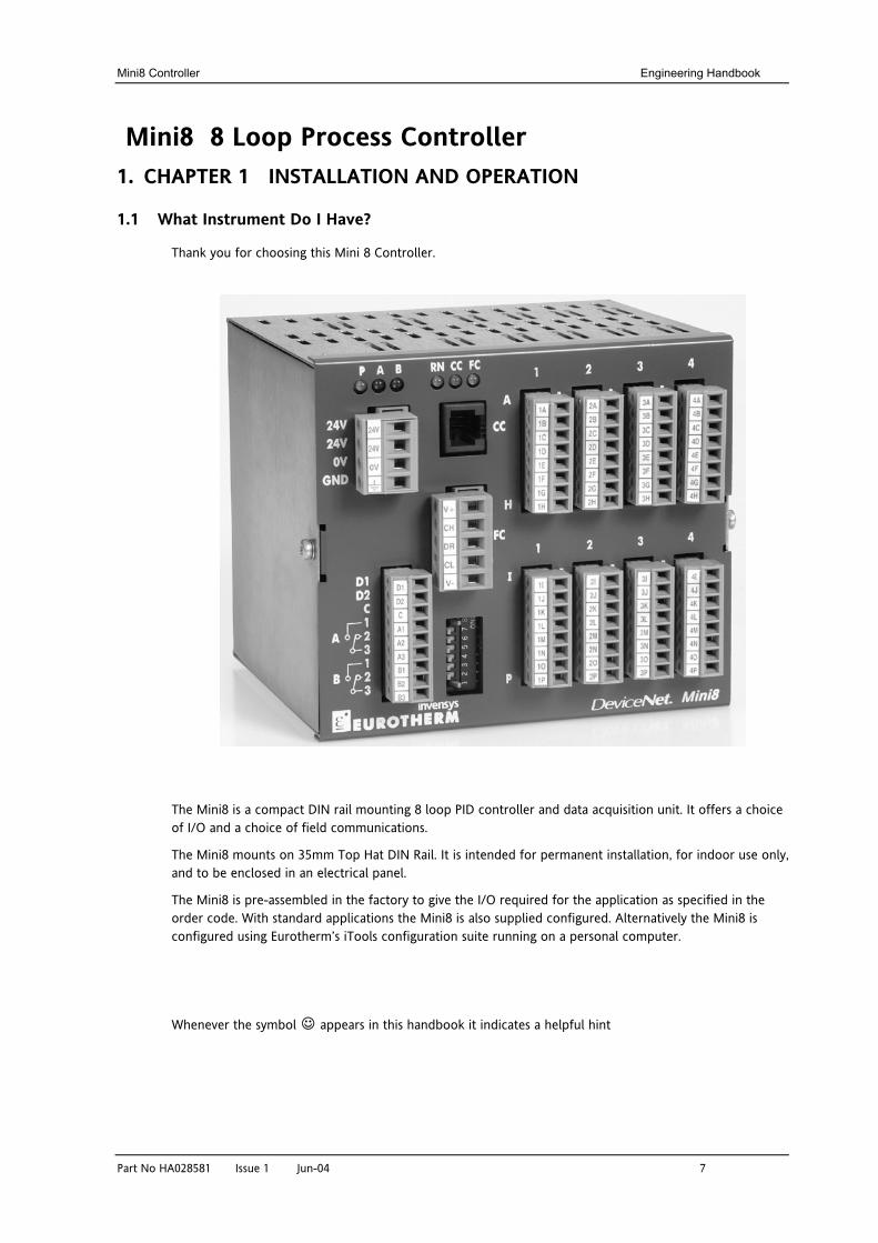
Thank you for choosing this Mini 8 Controller.
The Mini8 is a compact DIN rail mounting 8 loop PID controller and data acquisition unit. It offers a choice of I/O and a choice of field communications.
The Mini8 mounts on 35mm Top Hat DIN Rail. It is intended for permanent installation, for indoor use only, and to be enclosed in an electrical panel.
The Mini8 is pre-assembled in the factory to give the I/O required for the application as specified in the order code. With standard applications the Mini8 is also supplied configured. Alternatively the Mini8 is configured using Eurotherm’s iTools configuration suite running on a personal computer. Whenever the symbol appears in this handbook it indicates a helpful hint
Engineering Handbook Mini8 Controller
8 Part No HA028581 Issue 1 Jun-04
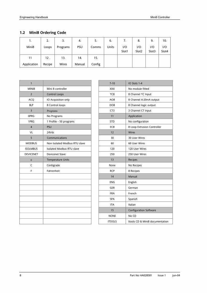
1.2 Mini8 Ordering Code
1.
Mini8
2.
Loops
3.
Programs
4.
PSU
5.
Comms
6.
Units
7.
I/O Slot1
8.
I/O Slot2
9.
I/O Slot3
10.
I/O Slot4
11
Application
12 .
Recipe
13.
Wires
14.
Manual
15.
Config
1 7-10 IO Slots 1-4
MINI8 Mini 8 controller XXX No module fitted
2 Control Loops TC8 8 Channel TC Input
ACQ IO Acquisition only AO8 8 Channel 4-20mA output
8LP 8 Control loops DO8 8 Channel logic output
3 Programs CT3 3 Channel CT input
0PRG No Programs 11 Application
1PRG 1 Profile - 50 programs STD No configuration
4 PSU EC8 8 Loop Extrusion Controller
VL 24Vdc 12 Wires
5 Communications 30 30 User Wires
MODBUS Non Isolated Modbus RTU slave 60 60 User Wires
ISOLMBUS Isolated Modbus RTU slave 120 120 User Wires
DEVICENET Devicenet Slave 250 250 User Wires
6 Temperature Units 13 Recipes
C Centigrade None No Recipes
F Fahrenheit RCP 8 Recipes
14 Manual
ENG English
GER German
FRA French
SPA Spanish
ITA Italian
15 Configuration Software
NONE No CD
ITOOLS Itools CD & Mini8 documentation
Mini8 Controller Engineering Handbook
Part No HA028581 Issue 1 Jun-04 9
1.3 How to Install the Controller
This instrument is intended for permanent installation, for indoor use only, and to be enclosed in an electrical panel.
Select a location where minimum vibrations are present and the ambient temperature is within 0 and 50oC (32 and 122oF).
Please read the safety information, Appendix C at the end of this guide, before proceeding and refer to the EMC Booklet part number HA025497 for further information.
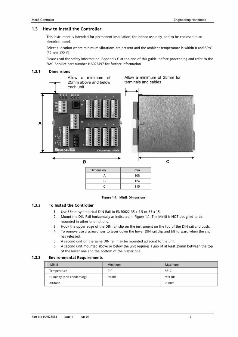
1.3.1 Dimensions
Dimension mm
A 108
B 124
C 115
Figure 1-1: Mini8 Dimensions
1.3.2 To Install the Controller 1. Use 35mm symmetrical DIN Rail to EN50022-35 x 7.5 or 35 x 15, 2. Mount the DIN Rail horizontally as indicated in Figure 1.1. The Mini8 is NOT designed to be
mounted in other orientations. 3. Hook the upper edge of the DIN rail clip on the instrument on the top of the DIN rail and push. 4. To remove use a screwdriver to lever down the lower DIN rail clip and lift forward when the clip
has released. 5. A second unit on the same DIN rail may be mounted adjacent to the unit. 6. A second unit mounted above or below the unit requires a gap of at least 25mm between the top
of the lower one and the bottom of the higher one.
1.3.3 Environmental Requirements Mini8 Minimum Maximum
Temperature 0°C 55°C
Humidity (non condensing) 5% RH 95% RH
Altitude 2000m
Allow a minimum of 25mm above and below each unit
Allow a minimum of 25mm for terminals and cables
C B
A
Engineering Handbook Mini8 Controller
10 Part No HA028581 Issue 1 Jun-04
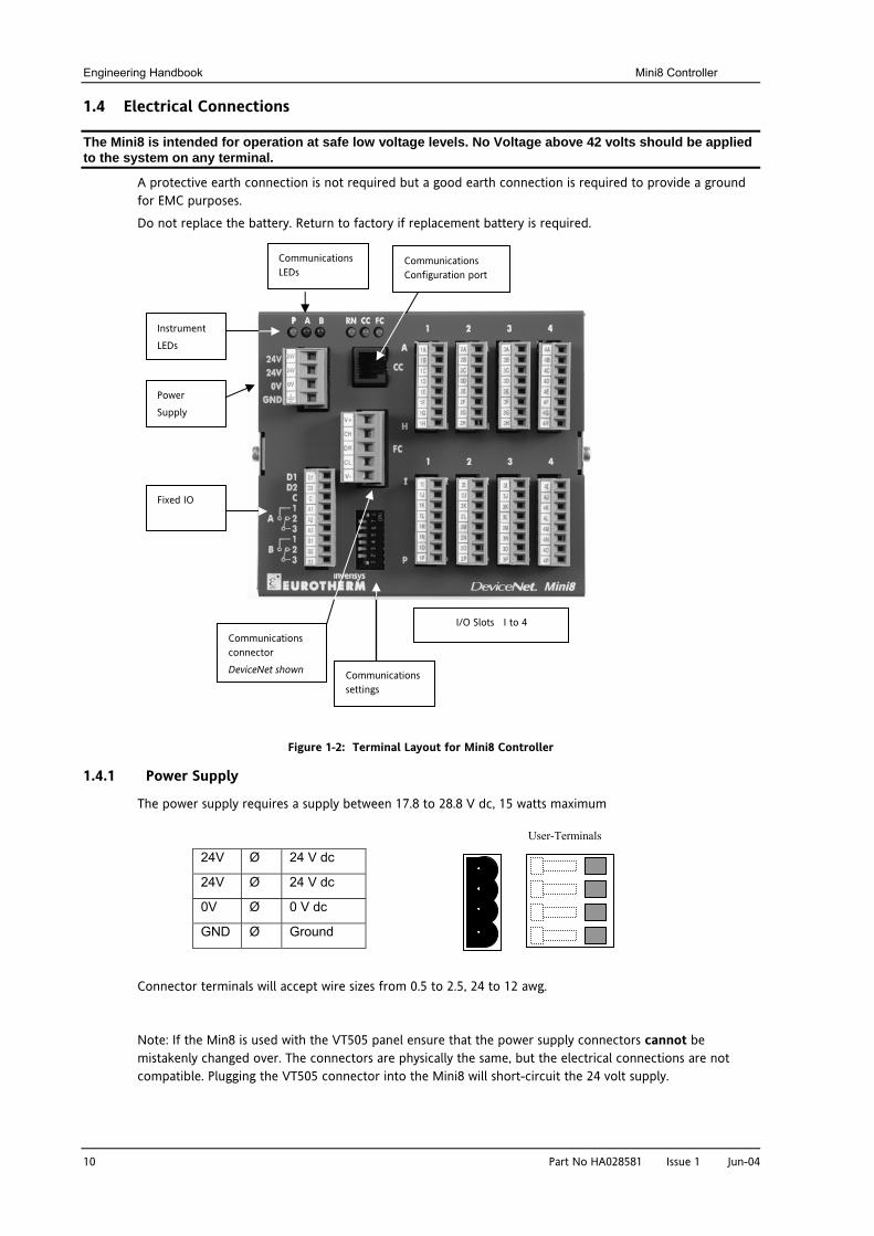
1.4 Electrical Connections
The Mini8 is intended for operation at safe low voltage levels. No Voltage above 42 volts should be applied to the system on any terminal.
A protective earth connection is not required but a good earth connection is required to provide a ground for EMC purposes.
Do not replace the battery. Return to factory if replacement battery is required.
Figure 1-2: Terminal Layout for Mini8 Controller
1.4.1 Power Supply
The power supply requires a supply between 17.8 to 28.8 V dc, 15 watts maximum
Connector terminals will accept wire sizes from 0.5 to 2.5, 24 to 12 awg.
Note: If the Min8 is used with the VT505 panel ensure that the power supply connectors cannot be mistakenly changed over. The connectors are physically the same, but the electrical connections are not compatible. Plugging the VT505 connector into the Mini8 will short-circuit the 24 volt supply.
24V Ø 24 V dc
24V Ø 24 V dc
0V Ø 0 V dc
GND Ø Ground
User-Terminals
Power Supply
Fixed IO
Instrument LEDs
Communications LEDs
I/O Slots I to 4 Communications connector DeviceNet shown Communications
settings
Communications Configuration port
Mini8 Controller Engineering Handbook
Part No HA028581 Issue 1 Jun-04 11
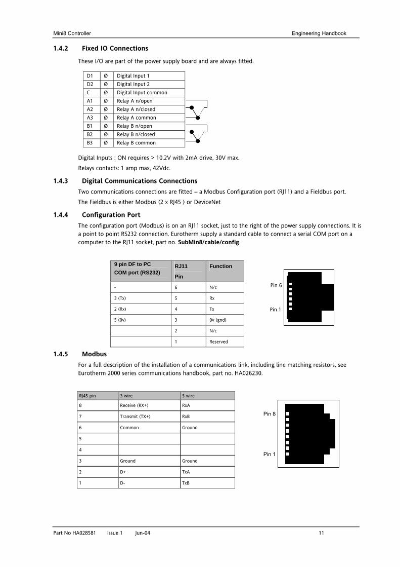
1.4.2 Fixed IO Connections
These I/O are part of the power supply board and are always fitted.
Digital Inputs : ON requires > 10.2V with 2mA drive, 30V max.
Relays contacts: 1 amp max, 42Vdc.
1.4.3 Digital Communications Connections Two communications connections are fitted – a Modbus Configuration port (RJ11) and a Fieldbus port.
The Fieldbus is either Modbus (2 x RJ45 ) or DeviceNet
1.4.4 Configuration Port The configuration port (Modbus) is on an RJ11 socket, just to the right of the power supply connections. It is a point to point RS232 connection. Eurotherm supply a standard cable to connect a serial COM port on a computer to the RJ11 socket, part no. SubMin8/cable/config.
9 pin DF to PC COM port (RS232)
RJ11
Pin
Function
- 6 N/c
3 (Tx) 5 Rx
2 (Rx) 4 Tx
5 (0v) 3 0v (gnd)
2 N/c
1 Reserved
1.4.5 Modbus For a full description of the installation of a communications link, including line matching resistors, see Eurotherm 2000 series communications handbook, part no. HA026230.
RJ45 pin 3 wire 5 wire
8 Receive (RX+) RxA
7 Transmit (TX+) RxB
6 Common Ground
5
4
3 Ground Ground
2 D+ TxA
1 D- TxB
D1 Ø Digital Input 1 D2 Ø Digital Input 2 C Ø Digital Input common A1 Ø Relay A n/open A2 Ø Relay A n/closed A3 Ø Relay A common B1 Ø Relay B n/open B2 Ø Relay B n/closed B3 Ø Relay B common
Pin 8
Pin 1
Pin 1
Pin 6
Engineering Handbook Mini8 Controller
12 Part No HA028581 Issue 1 Jun-04
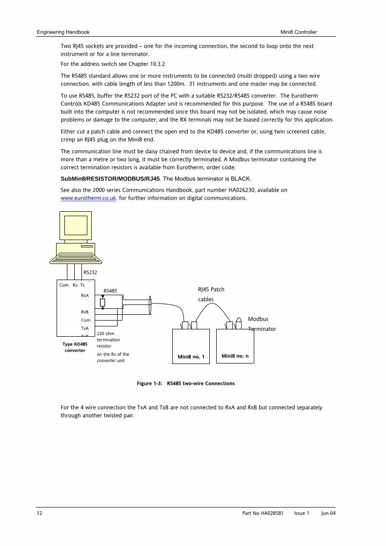
Two RJ45 sockets are provided – one for the incoming connection, the second to loop onto the next instrument or for a line terminator.
For the address switch see Chapter 10.3.2
The RS485 standard allows one or more instruments to be connected (multi dropped) using a two wire connection, with cable length of less than 1200m. 31 instruments and one master may be connected.
To use RS485, buffer the RS232 port of the PC with a suitable RS232/RS485 converter. The Eurotherm Controls KD485 Communications Adapter unit is recommended for this purpose. The use of a RS485 board built into the computer is not recommended since this board may not be isolated, which may cause noise problems or damage to the computer, and the RX terminals may not be biased correctly for this application.
Either cut a patch cable and connect the open end to the KD485 converter or, using twin screened cable, crimp an RJ45 plug on the Mini8 end.
The communication line must be daisy chained from device to device and, if the communications line is more than a metre or two long, it must be correctly terminated. A Modbus terminator containing the correct termination resistors is available from Eurotherm, order code:
SubMin8/RESISTOR/MODBUS/RJ45. The Modbus terminator is BLACK.
See also the 2000 series Communications Handbook, part number HA026230, available on www.eurotherm.co.uk. for further information on digital communications.
Figure 1-3: RS485 two-wire Connections
For the 4 wire connection the TxA and TxB are not connected to RxA and RxB but connected separately through another twisted pair.
220 ohm termination resistor
on the Rx of the converter unit
Com Rx Tx
RxA
RxB
Com
TxA
TxB Type KD485 converter
RS232
RS485
Mini8 no. 1 Mini8 no. n
Modbus
Terminator
RJ45 Patch
cables
Mini8 Controller Engineering Handbook
Part No HA028581 Issue 1 Jun-04 13
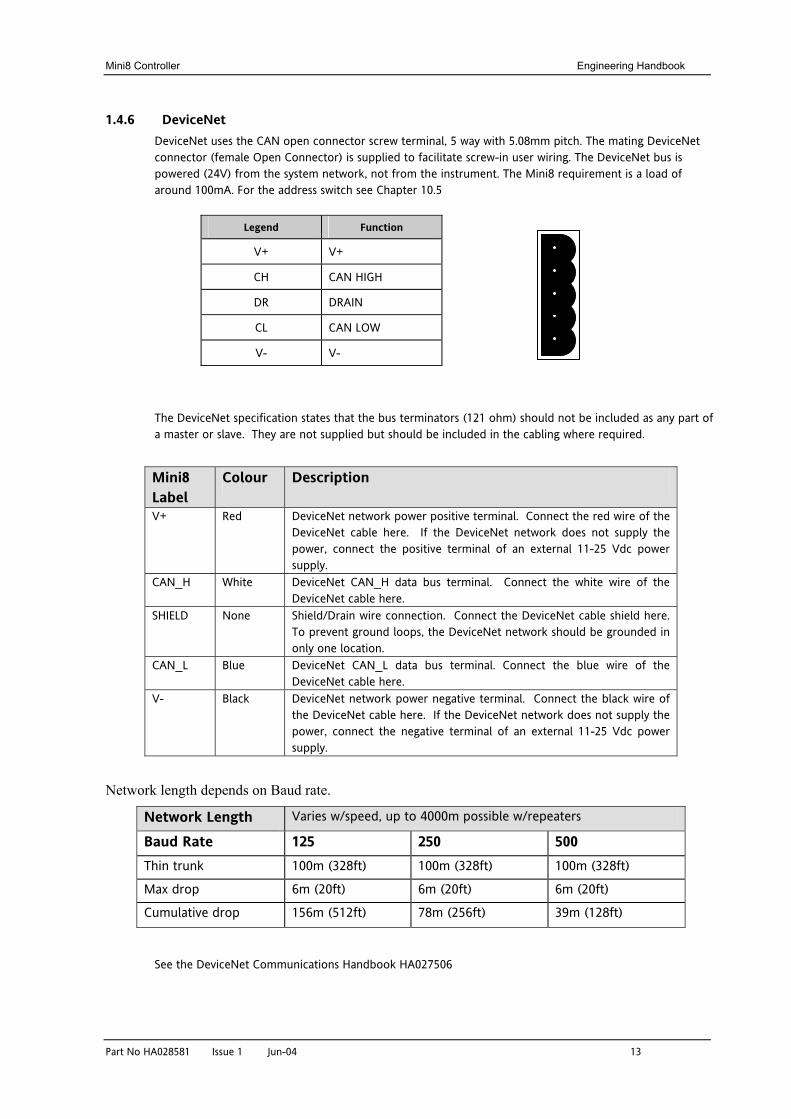
1.4.6 DeviceNet DeviceNet uses the CAN open connector screw terminal, 5 way with 5.08mm pitch. The mating DeviceNet connector (female Open Connector) is supplied to facilitate screw-in user wiring. The DeviceNet bus is powered (24V) from the system network, not from the instrument. The Mini8 requirement is a load of around 100mA. For the address switch see Chapter 10.5
The DeviceNet specification states that the bus terminators (121 ohm) should not be included as any part of a master or slave. They are not supplied but should be included in the cabling where required.
Mini8 Label
Colour Description
V+ Red DeviceNet network power positive terminal. Connect the red wire of the DeviceNet cable here. If the DeviceNet network does not supply the power, connect the positive terminal of an external 11-25 Vdc power supply.
CAN_H White DeviceNet CAN_H data bus terminal. Connect the white wire of the DeviceNet cable here.
SHIELD None Shield/Drain wire connection. Connect the DeviceNet cable shield here. To prevent ground loops, the DeviceNet network should be grounded in only one location.
CAN_L Blue DeviceNet CAN_L data bus terminal. Connect the blue wire of the DeviceNet cable here.
V- Black DeviceNet network power negative terminal. Connect the black wire of the DeviceNet cable here. If the DeviceNet network does not supply the power, connect the negative terminal of an external 11-25 Vdc power supply.
Network length depends on Baud rate.
Network Length Varies w/speed, up to 4000m possible w/repeaters
Baud Rate 125 250 500 Thin trunk 100m (328ft) 100m (328ft) 100m (328ft)
Max drop 6m (20ft) 6m (20ft) 6m (20ft)
Cumulative drop 156m (512ft) 78m (256ft) 39m (128ft)
See the DeviceNet Communications Handbook HA027506
Legend Function
V+ V+
CH CAN HIGH
DR DRAIN
CL CAN LOW
V- V-
Engineering Handbook Mini8 Controller
14 Part No HA028581 Issue 1 Jun-04
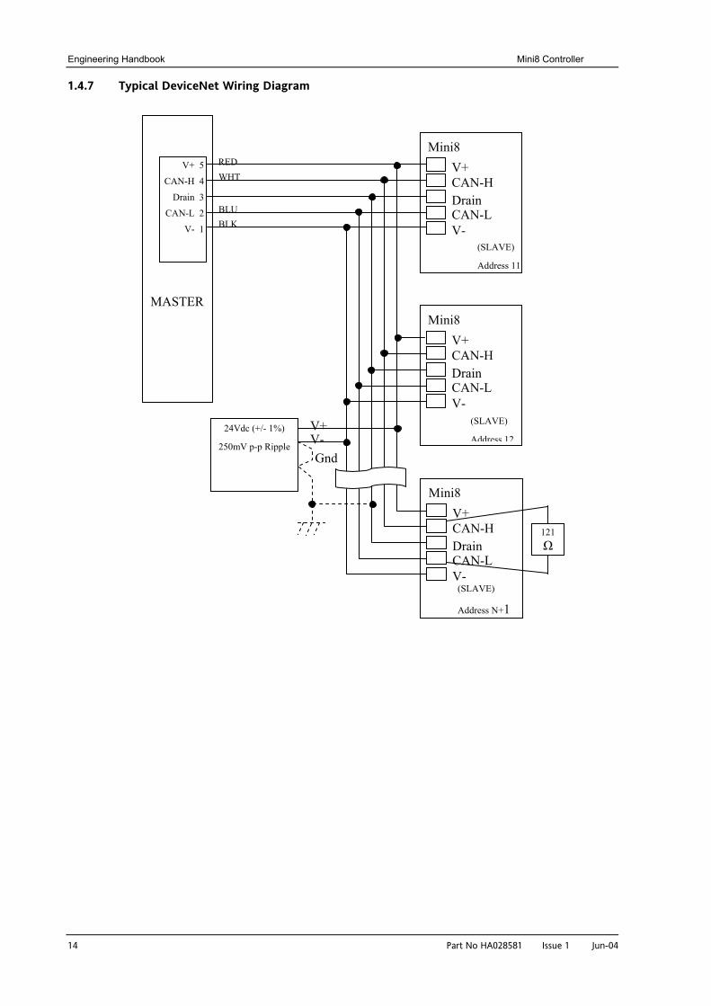
1.4.7 Typical DeviceNet Wiring Diagram
Mini8 V+CAN-HDrainCAN-LV-
(SLAVE)
Address 11
V+ 5
CAN-H 4
Drain 3
CAN-L 2
V- 1
RED WHT
BLU BLK
Mini8 V+CAN-HDrainCAN-LV-
(SLAVE)
Address 12
Mini8 V+CAN-HDrainCAN-LV-
(SLAVE)
Address N+1
121 Ω
V+V-Gnd
24Vdc (+/- 1%)
250mV p-p Ripple
MASTER
Mini8 Controller Engineering Handbook
Part No HA028581 Issue 1 Jun-04 15
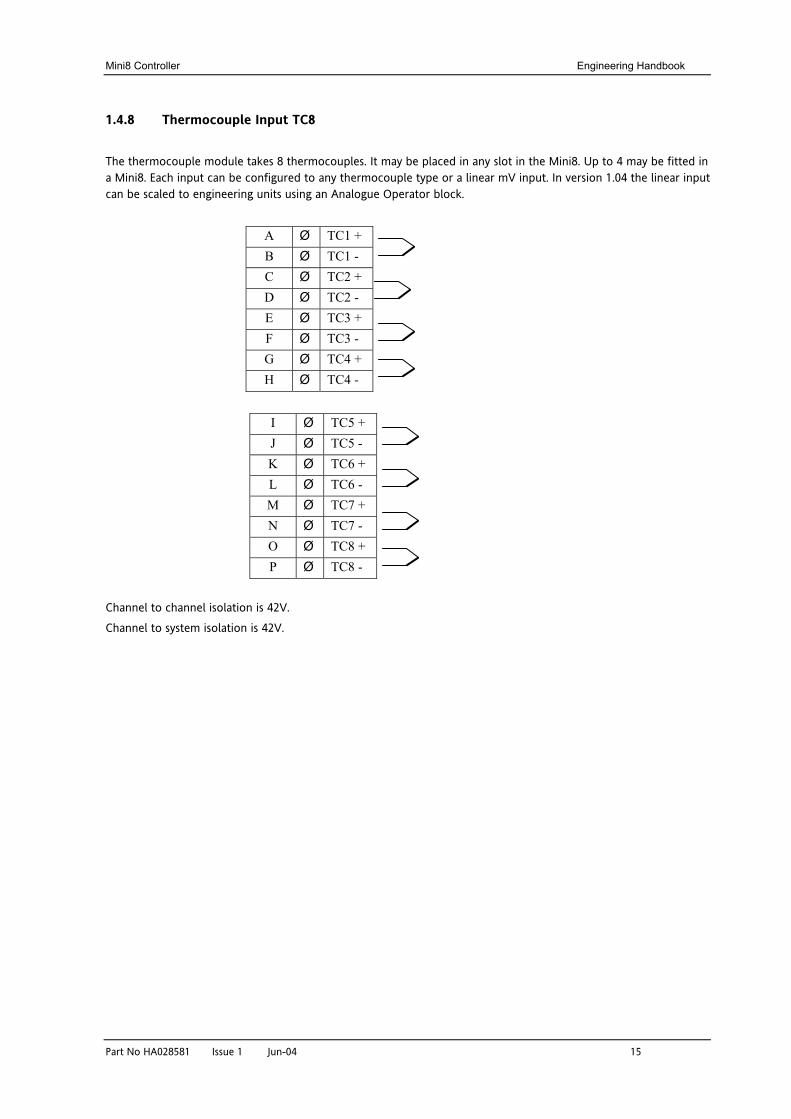
1.4.8 Thermocouple Input TC8
The thermocouple module takes 8 thermocouples. It may be placed in any slot in the Mini8. Up to 4 may be fitted in a Mini8. Each input can be configured to any thermocouple type or a linear mV input. In version 1.04 the linear input can be scaled to engineering units using an Analogue Operator block.
A Ø TC1 + B Ø TC1 - C Ø TC2 + D Ø TC2 - E Ø TC3 + F Ø TC3 - G Ø TC4 + H Ø TC4 -
I Ø TC5 + J Ø TC5 - K Ø TC6 + L Ø TC6 - M Ø TC7 + N Ø TC7 - O Ø TC8 + P Ø TC8 -
Channel to channel isolation is 42V.
Channel to system isolation is 42V.
Engineering Handbook Mini8 Controller
16 Part No HA028581 Issue 1 Jun-04
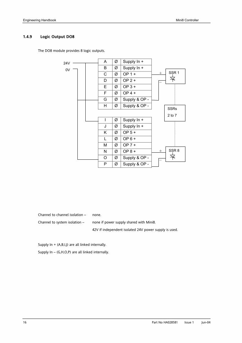
1.4.9 Logic Output DO8
The DO8 module provides 8 logic outputs.
Channel to channel isolation – none.
Channel to system isolation – none if power supply shared with Mini8.
42V if independent isolated 24V power supply is used.
Supply In + (A,B,I,J) are all linked internally.
Supply In – (G,H,O,P) are all linked internally.
A Ø Supply In + B Ø Supply In + C Ø OP 1 + D Ø OP 2 + E Ø OP 3 + F Ø OP 4 + G Ø Supply & OP - H Ø Supply & OP -
I Ø Supply In + J Ø Supply In + K Ø OP 5 + L Ø OP 6 + M Ø OP 7 + N Ø OP 8 + O Ø Supply & OP - P Ø Supply & OP -
24V
0V SSR 1 +
–
SSR 8 +
–
SSRs
2 to 7
Mini8 Controller Engineering Handbook
Part No HA028581 Issue 1
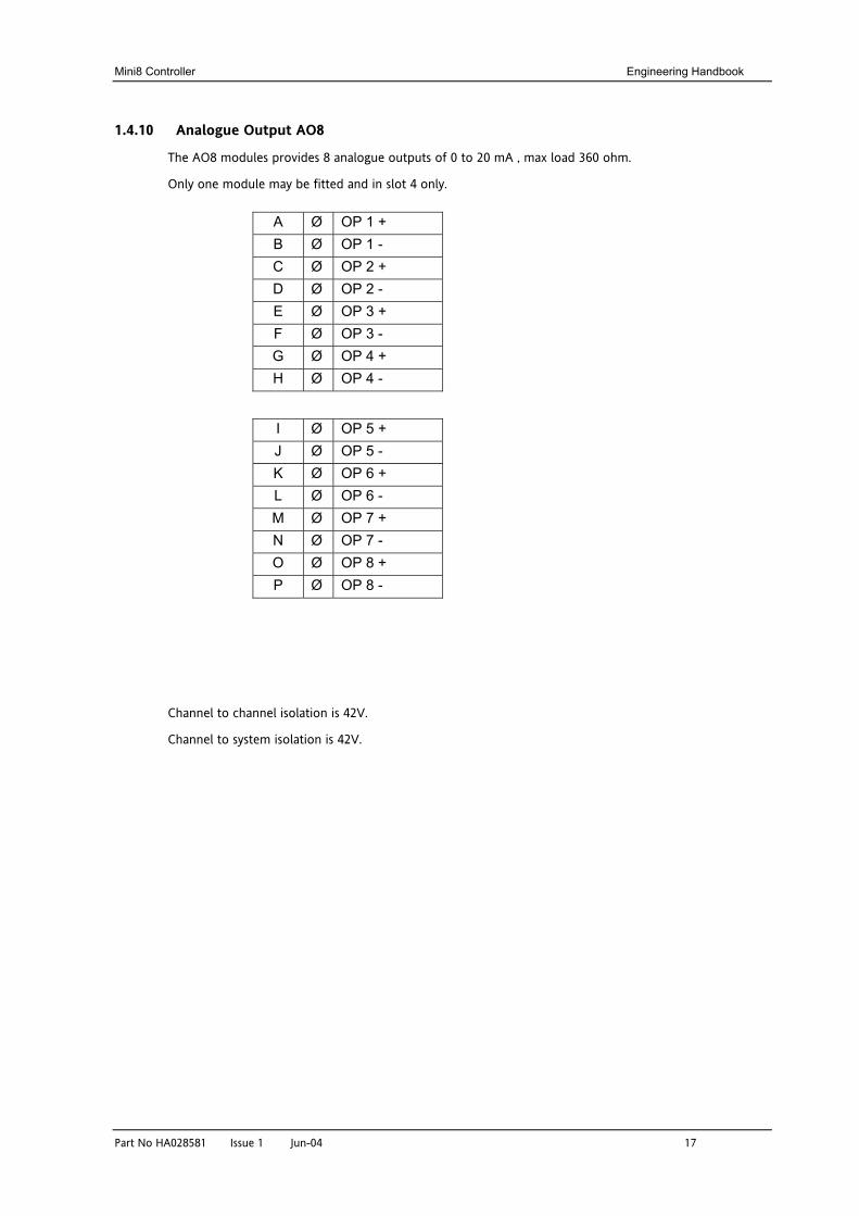
1.4.10 Analogue Output AO8
The AO8 modules provides 8 analogue outputs of 0 to 20 mA , max load 360 ohm.
Only one module may be fitted and in slot 4 only.
Channel to chann
Channel to system
A Ø OP 1 + B Ø OP 1 - C Ø OP 2 + D Ø OP 2 - E Ø OP 3 + F Ø OP 3 - G Ø OP 4 + H Ø OP 4 -
I Ø OP 5 + J Ø OP 5 - K Ø OP 6 + L Ø OP 6 - M Ø OP 7 + N Ø OP 7 - O Ø OP 8 + P Ø OP 8 -
Jun-04 17
el isolation is 42V.
isolation is 42V.
Engineering Handbook Mini8 Controller
18 Part No HA028581 Issue 1 Jun-04
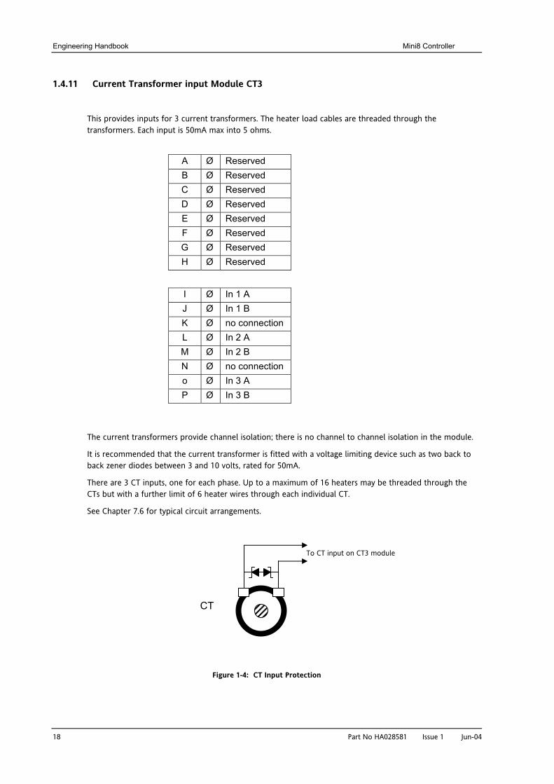
1.4.11 Current Transformer input Module CT3
This provides inputs for 3 current transformers. The heater load cables are threaded through the transformers. Each input is 50mA max into 5 ohms.
The current transformers provide channel isolation; there is no channel to channel isolation in the module.
It is recommended that the current transformer is fitted with a voltage limiting device such as two back to back zener diodes between 3 and 10 volts, rated for 50mA.
There are 3 CT inputs, one for each phase. Up to a maximum of 16 heaters may be threaded through the CTs but with a further limit of 6 heater wires through each individual CT.
See Chapter 7.6 for typical circuit arrangements.
Figure 1-4: CT Input Protection
A Ø Reserved B Ø Reserved C Ø Reserved D Ø Reserved E Ø Reserved F Ø Reserved G Ø Reserved H Ø Reserved
I Ø In 1 A J Ø In 1 B K Ø no connection L Ø In 2 A M Ø In 2 B N Ø no connection o Ø In 3 A P Ø In 3 B
CT
To CT input on CT3 module
Mini8 Controller Engineering Handbook
Part No HA028581 Issue 1 Jun-04 19
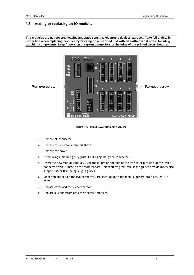
1.5 Adding or replacing an IO module.
The modules are not covered leaving antistatic sensitive electronic devices exposed. Take full antistatic protection when replacing modules by working on an earthed mat with an earthed wrist strap. Avoiding touching components, keep fingers on the green connectors or the edge of the printed circuit boards.
Figure 1-5: Mini8 Cover Retaining Screws
1. Remove all connectors.
2. Remove the 2 screws indicated above
3. Remove the cover.
4. If removing a module gently prise it out using the green connectors.
5. Insert the new module carefully using the guides on the side of the case to help to line up the lower connector with its mate on the motherboard. This requires great care as the guides provide mechanical support rather than being plug in guides.
6. Once you are certain the two connectors are lined up, push the module gently into place. Do NOT force.
7. Replace cover and the 2 cover screws.
8. Replace all connectors onto their correct modules.
Remove screw → ← Remove screw
Engineering Handbook Mini8 Controller
20 Part No HA028581 Issue 1 Jun-04
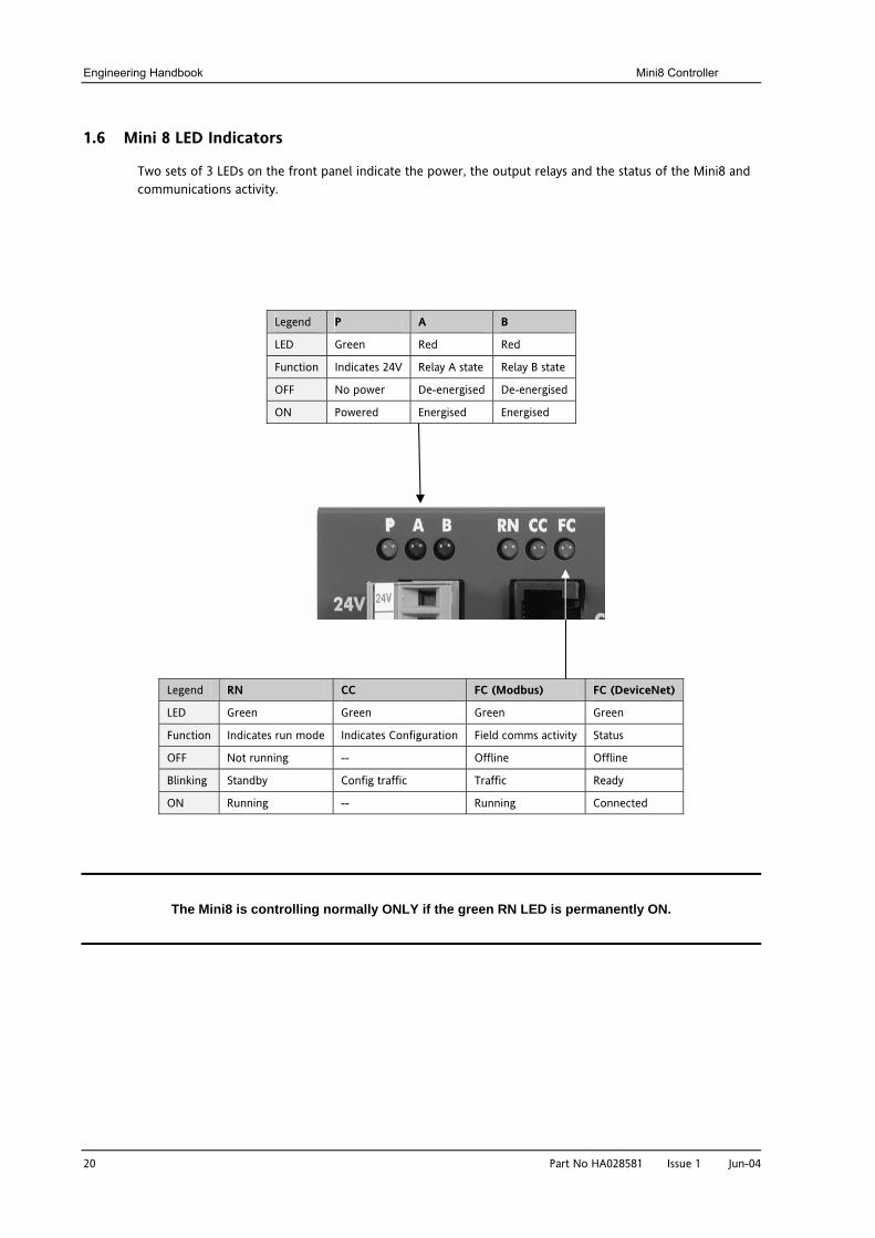
1.6 Mini 8 LED Indicators
Two sets of 3 LEDs on the front panel indicate the power, the output relays and the status of the Mini8 and communications activity.
Legend P A B
LED Green Red Red
Function Indicates 24V Relay A state Relay B state
OFF No power De-energised De-energised
ON Powered Energised Energised
Legend RN CC FC (Modbus) FC (DeviceNet)
LED Green Green Green Green
Function Indicates run mode Indicates Configuration Field comms activity Status
OFF Not running -- Offline Offline
Blinking Standby Config traffic Traffic Ready
ON Running -- Running Connected
The Mini8 is controlling normally ONLY if the green RN LED is permanently ON.
Mini8 Controller Engineering Handbook
Part No HA028581 Issue 1 Jun-04 21
2. CHAPTER 2 USING THE MINI8 The Mini8 Controller does not have a display. The only means of configuring it, and of interfacing with it during normal operation is via communications.
The auxiliary communications port (RJ11) gives a Modbus interface, usually connected to iTools for configuration and commissioning.
The main configuration port offers Modbus or DeviceNet, normally connected to the system of which the Mini8 is part, and is the means by which the Mini8 is operated.
Here are ways the Mini8 may be used in a system. iTools is the best PC based solution. The Modbus single register addressing is best for Operator panels, PLCs where floating point may not be available or necessary. Use the Modbus floating point addressing with care.
2.1 iTools
iTools offers a pc based solution. The iTools suite allows configuration, commissioning, trend graphs and logging with OPC Scope, Program Editing, Recipes and User pages with View Builder.
2.1.1 iTools OPC Open server
With an OPEN OPC server running on a PC all the Mini8 parameters are available to any third party package with an OPC client. The advantage of this is that all the parameters are addressed by name – the iTools OPC server handles all the physical communication addresses. An example would be with Wonderware inTouch using OPCLink. In this situation the user would not have to know any of the parameter addresses, and would just select a parameter by browsing through the namespace.
e.g. Eurotherm.ModbusServer.1.COM1.ID001-Mini8.Loop.1.Main.PV
2.2 Modbus, single register, SCADA addressing
The key parameters of the Mini8 are available at a fixed address, independent of its configuration. This can be used with any device with a serial Modbus master (Modbus function 4). The parameters are listed in full with their addresses in Appendix A.
This area does not have all the parameters within the instrument. If other parameters are required they can be obtained by using the Commstab folder. This allows up to 250 other parameters to be made available using indirection addressing. This is explained in Appendix A.
Also note that in this area the resolution (number of decimal points) has to be configured and the serial Master has to scale the parameter correctly. Again the Commstab folder offers an alternative solution where a parameter can be indirectly addressed and configured as a floating point or double register value.
2.3 Modbus (Floating Point)
During configuration the Modbus addresses of the parameters required by the system can be obtained from iTools in decimal or in hex format. This can be used with any device e.g. PC or plc, with a serial Modbus master, able to decode double register for floating point numbers (Modbus function 7) and long integers (Modbus function 8). These parameters are displayed on the iTools parameter lists.
Use this method with care. These parameter addresses are not fixed – a common parameter on two differently configured Mini8s may be at a different address. Similarly if the configuration of a Mini8 is changed, the addresses of some of the parameters may also have changed.
Engineering Handbook Mini8 Controller
22 Part No HA028581 Issue 1 Jun-04
2.4 Fieldbus
The Mini8 may be ordered with the option of a DeviceNet slave. This comes pre-configured with the key parameters of the 8 PID loops and alarms (60 input parameters process variables, alarm status etc and 60 output parameters – setpoints etc.). See Appendix B.
2.5 Mini8 Execution
The nominal update of all inputs and function blocks is 110ms. However, in complex applications the Mini8 will automatically extend this time in multiples of 110ms.
For example, eight simple heat/cool loops each with two alarms (40 wires) will run at 110ms, while the full EC8 configuration will run at 220ms because of the extra wiring and functionality.
The communications traffic will also have some effect on the update rate.
For example, an application using every function block and all 250 wires will run at 220ms with light communications traffic but may be slowed to 330ms with heavy traffic.
Note that as loading changes, the sample rate may increase or decrease automatically. In order to recover to a faster sample rate, the Mini8 must be running consistently with processing power to spare for at least 30s.
Mini8 Controller Engineering Handbook
Part No HA028581 Issue 1 Jun-04 23
2.6 The iTools Operator Interface
Much of this manual is about configuring the Mini8 with iTools. However iTools also provides an excellent commissioning tool and can be used as a long-term operator view if convenient.
First it is necessary to go ‘on-line’ to the Mini8(s). This assumes the communication ports have been wired up to the COM port on the iTools computer (Chapter 10).
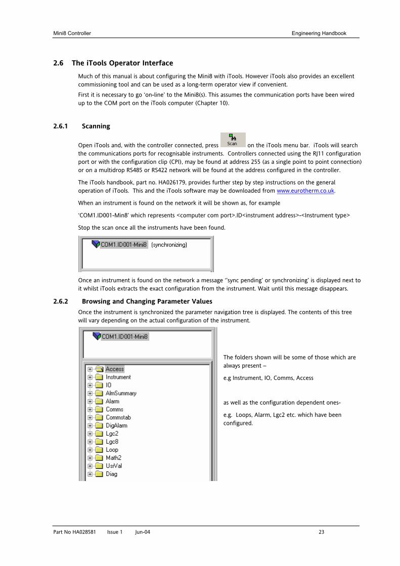
2.6.1 Scanning
Open iTools and, with the controller connected, press on the iTools menu bar. iTools will search the communications ports for recognisable instruments. Controllers connected using the RJ11 configuration port or with the configuration clip (CPI), may be found at address 255 (as a single point to point connection) or on a multidrop RS485 or RS422 network will be found at the address configured in the controller.
The iTools handbook, part no. HA026179, provides further step by step instructions on the general operation of iTools. This and the iTools software may be downloaded from www.eurotherm.co.uk.
When an instrument is found on the network it will be shown as, for example
‘COM1.ID001-Min8’ which represents <computer com port>.ID<instrument address>-<Instrument type>
Stop the scan once all the instruments have been found.
Once an instrument is found on the network a message ‘’sync pending’ or synchronizing’ is displayed next to it whilst iTools extracts the exact configuration from the instrument. Wait until this message disappears.
2.6.2 Browsing and Changing Parameter Values Once the instrument is synchronized the parameter navigation tree is displayed. The contents of this tree will vary depending on the actual configuration of the instrument.
The folders shown will be some of those which are always present –
e.g Instrument, IO, Comms, Access
as well as the configuration dependent ones-
e.g. Loops, Alarm, Lgc2 etc. which have been configured.
Engineering Handbook Mini8 Controller
24 Part No HA028581 Issue 1 Jun-04
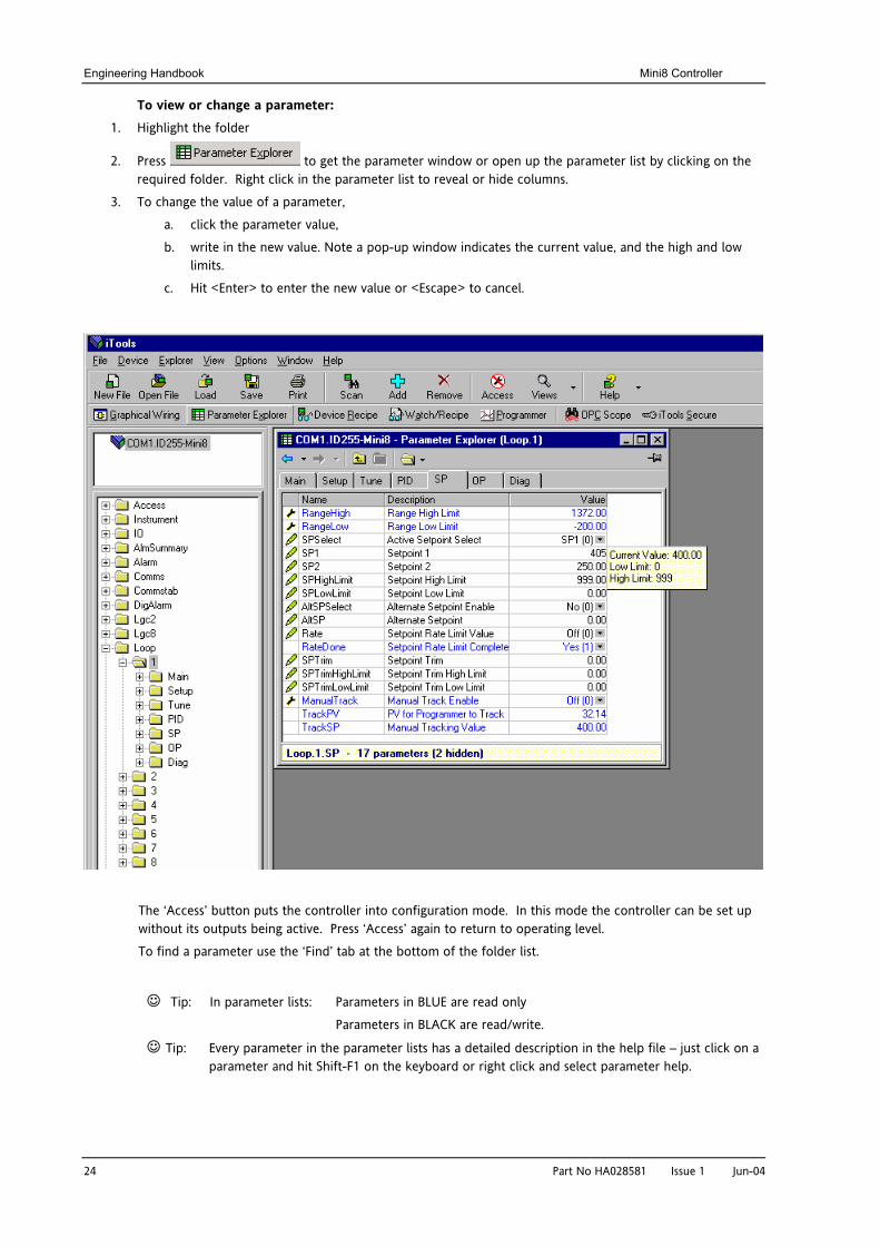
To view or change a parameter: 1. Highlight the folder
2. Press to get the parameter window or open up the parameter list by clicking on the required folder. Right click in the parameter list to reveal or hide columns.
3. To change the value of a parameter,
a. click the parameter value,
b. write in the new value. Note a pop-up window indicates the current value, and the high and low limits.
c. Hit <Enter> to enter the new value or <Escape> to cancel.
The ‘Access’ button puts the controller into configuration mode. In this mode the controller can be set up without its outputs being active. Press ‘Access’ again to return to operating level.
To find a parameter use the ‘Find’ tab at the bottom of the folder list.
Tip: In parameter lists: Parameters in BLUE are read only
Parameters in BLACK are read/write.
Tip: Every parameter in the parameter lists has a detailed description in the help file – just click on a parameter and hit Shift-F1 on the keyboard or right click and select parameter help.
Mini8 Controller Engineering Handbook
Part No HA028581 Issue 1 Jun-04 25
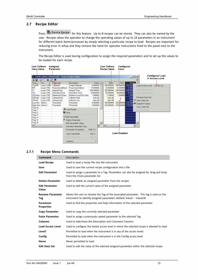
2.7 Recipe Editor
Press for this feature. Up to 8 recipes can be stored. They can also be named by the user. Recipes allow the operator to change the operating values of up to 24 parameters in an instrument for different batch items/processes by simply selecting a particular recipe to load. Recipes are important for reducing error in setup and they remove the need for operator instructions fixed to the panel next to the instrument.
The Recipe Editor is used during configuration to assign the required parameters and to set up the values to be loaded for each recipe.
2.7.1 Recipe Menu Commands Command Description
Load Recipe Used to load a recipe file into the instrument
Save Used to save the current recipe configuration into a file
Edit Parameter Used to assign a parameter to a Tag. Parameters can also be assigned by 'drag and drop' from the iTools parameter list
Delete Parameter Used to delete an assigned parameter from the recipes
Edit Parameter Value
Used to edit the current value of the assigned parameter
Rename Parameter Tag
Allows the user to rename the Tag of the associated parameter. This tag is used on the instrument to identify assigned parameters (default Value1 - Value24)
Parameter Properties
Used to find the properties and help information of the selected parameter
Copy Parameter Used to copy the currently selected parameter
Paste Parameter Used to assign a previously copied parameter to the selected Tag
Columns Used to hide/show the Description and Comment Columns
Load Access Level Used to configure the lowest access level in which the selected recipe is allowed to load
Level1 Permitted to load when the instrument is in any of the access levels
Config Permitted to load when the instrument is in the Config access level
Never Never permitted to load
Edit Data Set Used to edit the value of the selected assigned parameter within the selected recipe.
Engineering Handbook Mini8 Controller
26 Part No HA028581 Issue 1 Jun-04
Command Description Value Values can also be edited via double left clicking the value itself
Clear Data Set Value
Used to clear the value of the selected assigned parameter within the selected recipe, thus disabling it from loading when the recipe is selected to load
Rename Data Set Allows the user to rename the selected recipe. This name is used to identify individual recipes (default Set1 - Set8). Note: Number of recipes dependent upon features
Clear Data Set Used to clear all values in the selected recipe, thus disabling all from loading when the recipe is selected to load
Snapshot Values
Used to copy all of the assigned parameters current values into the selected recipe
Copy Data Set Used to copy all values of the selected recipe
Paste Data Set Used to paste all values of a previously copied recipe into the selected recipe
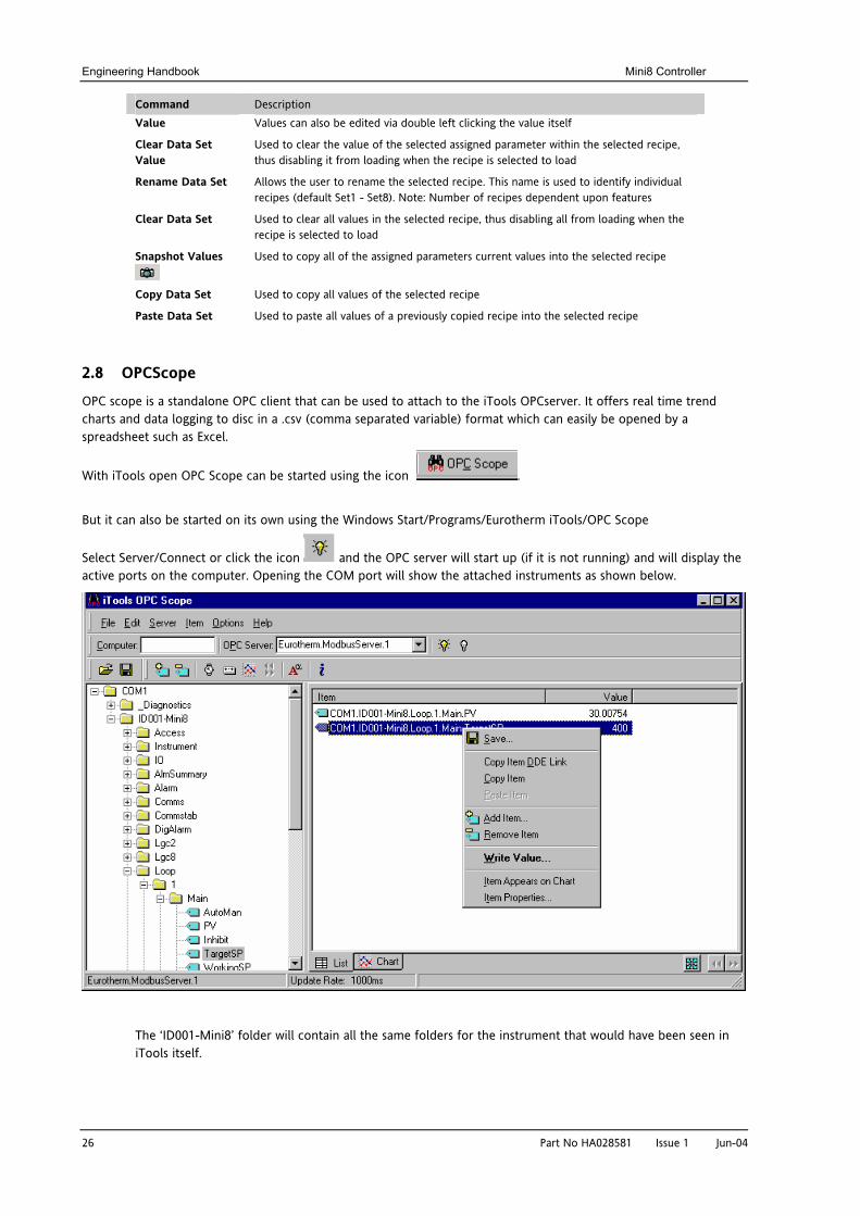
2.8 OPCScope
OPC scope is a standalone OPC client that can be used to attach to the iTools OPCserver. It offers real time trend charts and data logging to disc in a .csv (comma separated variable) format which can easily be opened by a spreadsheet such as Excel.
With iTools open OPC Scope can be started using the icon .
But it can also be started on its own using the Windows Start/Programs/Eurotherm iTools/OPC Scope
Select Server/Connect or click the icon and the OPC server will start up (if it is not running) and will display the active ports on the computer. Opening the COM port will show the attached instruments as shown below.
The ‘ID001-Mini8’ folder will contain all the same folders for the instrument that would have been seen in iTools itself.
Mini8 Controller Engineering Handbook
Part No HA028581 Issue 1 Jun-04 27
Expand the folder and double click on the blue item tag to add to the List Window. The List Window shows all the selected parameters and their current value.
Right click on a parameter to get the context menu.
2.8.1 OPC Scope List Window Context Menu Command Description
Save Saves the OPC Scope configuration as <filename>.uix See Section 2.8.3
Copy Item DDE link Saves the DDE path to the clipboard.
‘Paste Special’ in an Excel cell and select ‘Paste Link’ and the current parameter value will be displayed in the cell.
Copy/Paste Item Copy & Paste
Add Item Add a new variable by name (easier to browse the navigation tree)
Remove Item Remove the selected item.
Write Value Write a new value (not if the item is Read Only).
Item appears on Chart Up to 8 items can be tended on the Chart Window
Item Properties Gives the item properties as seen by OPC
The OPC List can contain parameters from any instrument attached to the Modbus network.
If you have iTools Open (not iTools Standard) then OPC Scope can run on a remote networked computer. Enter the name of the server computer (attached to the instruments) the ‘Computer’ window and browse for the ‘Eurotherm.ModbusServer1’.
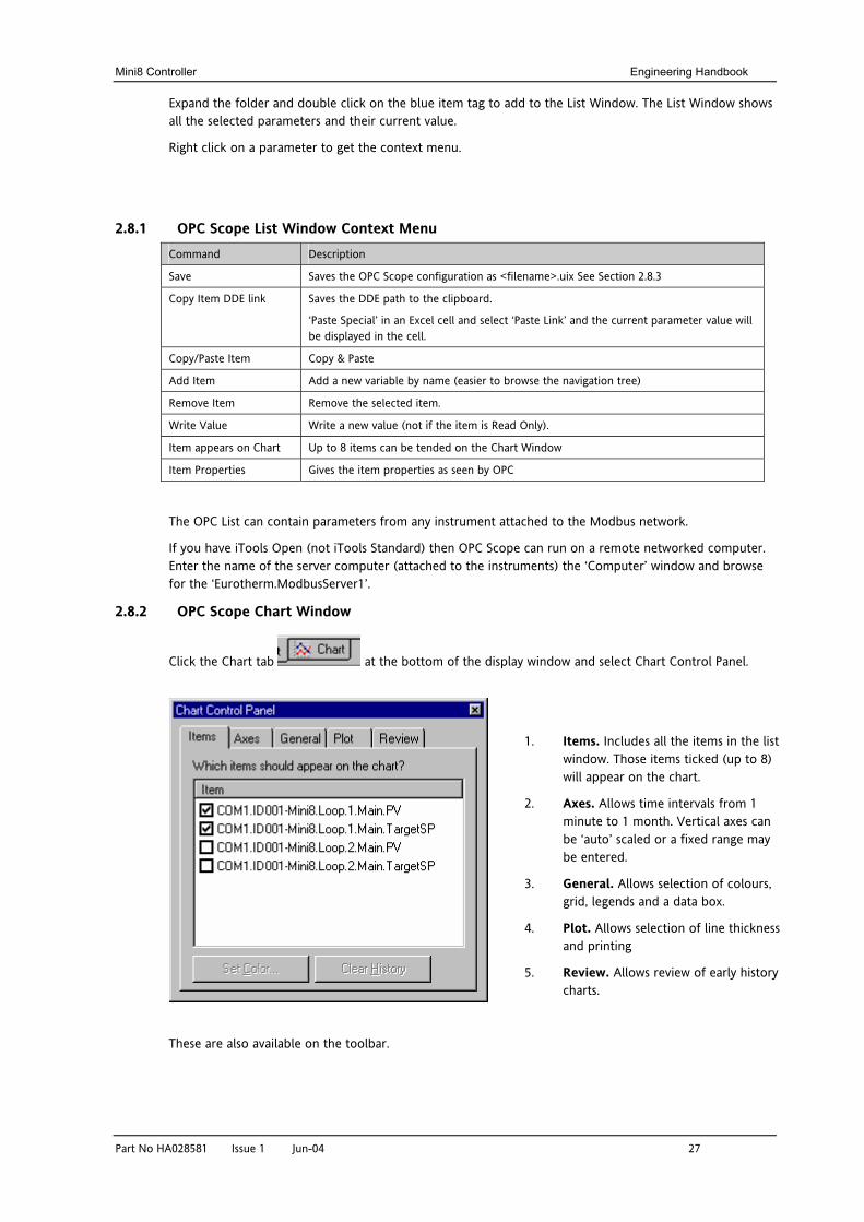
2.8.2 OPC Scope Chart Window
Click the Chart tab at the bottom of the display window and select Chart Control Panel.
1. Items. Includes all the items in the list window. Those items ticked (up to 8) will appear on the chart.
2. Axes. Allows time intervals from 1 minute to 1 month. Vertical axes can be ‘auto’ scaled or a fixed range may be entered.
3. General. Allows selection of colours, grid, legends and a data box.
4. Plot. Allows selection of line thickness and printing
5. Review. Allows review of early history charts.
These are also available on the toolbar.
Engineering Handbook Mini8 Controller
28 Part No HA028581 Issue 1 Jun-04
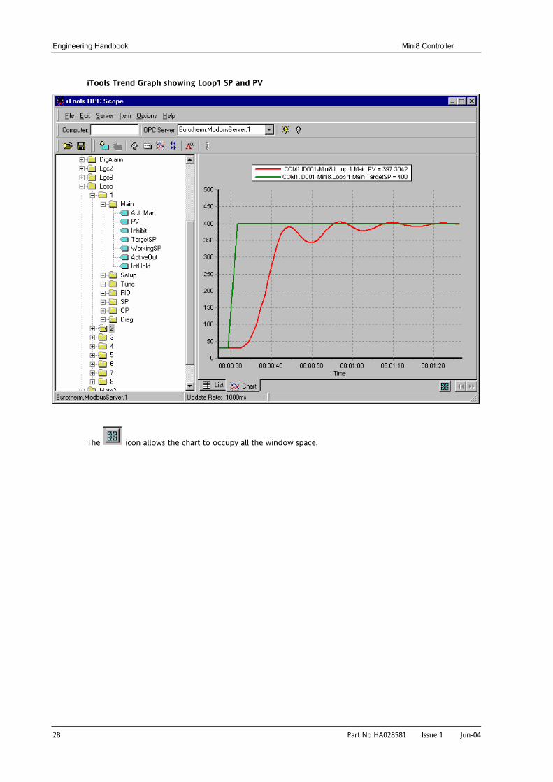
iTools Trend Graph showing Loop1 SP and PV
The icon allows the chart to occupy all the window space.
Mini8 Controller Engineering Handbook
Part No HA028581 Issue 1 Jun-04 29
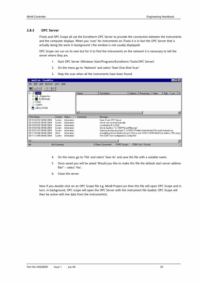
2.8.3 OPC Server
ITools and OPC Scope all use the Eurotherm OPC Server to provide the connection between the instruments and the computer displays. When you ‘scan’ for instruments on iTools it is in fact the OPC Server that is actually doing the work in background ( the window is not usually displayed).
OPC Scope can run on its own but for it to find the instruments on the network it is necessary to tell the server where they are.
1. Start OPC Server (Windows Start/Programs/Eurotherm iTools/OPC Server)
2. On the menu go to ‘Network’ and select ‘Start One-Shot Scan’
3. Stop the scan when all the instruments have been found.
4. On the menu go to ‘File’ and select ‘Save As’ and save the file with a suitable name.
5. Once saved you will be asked ‘Would you like to make this file the default start server address file?’ – select ‘Yes’.
6. Close the server.
Now if you double click on an OPC Scope file e.g. Mini8 Project.uix then this file will open OPC Scope and in turn, in background, OPC scope will open the OPC Server with this instrument file loaded. OPC Scope will then be active with live data from the instrument(s).
Engineering Handbook Mini8 Controller
30 Part No HA028581 Issue 1 Jun-04
3. CHAPTER 3 CONFIGURATION USING iTOOLS
WARNING
Configuration level gives access to a wide range of parameters that match the controller to the process. Incorrect configuration could result in damage to the process being controlled and/or personal injury. It is the responsibility of the person commissioning the process to ensure that the configuration is correct.
In configuration level the controller is not controlling the process or providing alarm indication. Do not select configuration level on a live process.
3.1 Configuration
The Mini8 is supplied unconfigured, unless ordered preconfigured, e.g. EC8. An unconfigured Mini8 has to be configured for use in an application. This is performed using iTools.
The iTools handbook, part no. HA026179 provides further step by step instructions on the general operation of iTools. This and the iTools software may be downloaded from www.eurotherm.co.uk.
3.1.1 On-Line/Off-line Configuration If iTools is connected to a real Mini8 then all the parameter changes made will be written to the device immediately. Once the Mini8 is configured and working as required, its final configuration can be saved to disk as a ‘clone’ file of the format <name>.uic.
Alternatively iTools can be used ‘off-line’ without a real Mini8 connected at all. This virtual Mini8 can be created in iTools and again saved to disk as a clone file. This file can later be loaded into a real Mini8 to create the required real application.
3.2 Connecting a PC to the Mini8 Controller
3.2.1 Configuration Cable and Clip
The controller may be connected to the PC running iTools using the Eurotherm cable SubMin8/Cable/Config from the RJ11 port connecting to a serial port on the PC.
Alternatively a Configuration Clip is available from Eurotherm that can be fitted into the rear of the controller.
The benefit of using this arrangement is that it is not necessary to power the controller, since the clip provides the power to the internal memory of the controller.
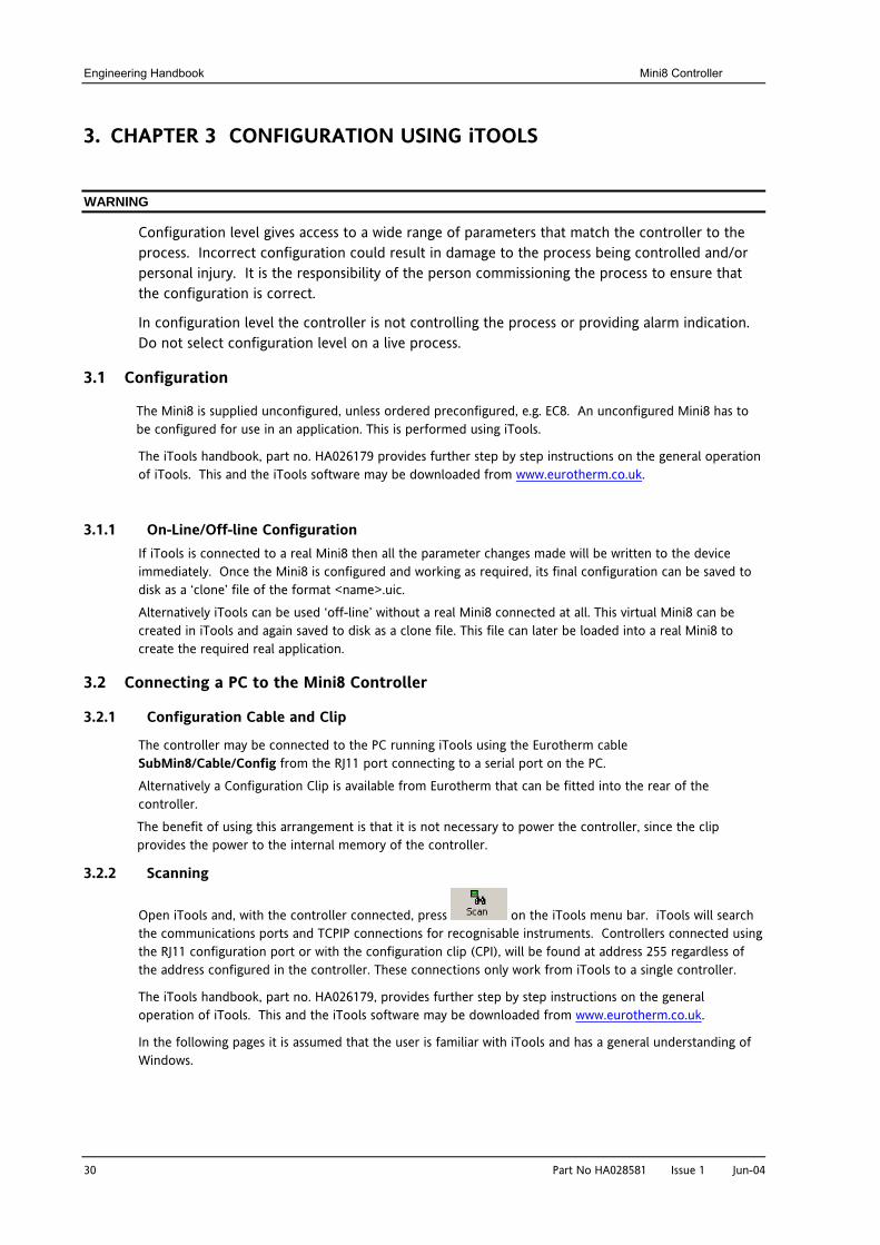
3.2.2 Scanning
Open iTools and, with the controller connected, press on the iTools menu bar. iTools will search the communications ports and TCPIP connections for recognisable instruments. Controllers connected using the RJ11 configuration port or with the configuration clip (CPI), will be found at address 255 regardless of the address configured in the controller. These connections only work from iTools to a single controller.
The iTools handbook, part no. HA026179, provides further step by step instructions on the general operation of iTools. This and the iTools software may be downloaded from www.eurotherm.co.uk.
In the following pages it is assumed that the user is familiar with iTools and has a general understanding of Windows.
Mini8 Controller Engineering Handbook
Part No HA028581 Issue 1 Jun-04 31
3.3 Configuring the Mini8
Once iTools is successfully connected to a Mini8, it can be configured for the application in hand. Configuration involves selection of the required elements of functionality called ‘function blocks’ and setting their parameters to the correct values. The next stage is to connect all the function blocks together to create the required strategy of control for the application.
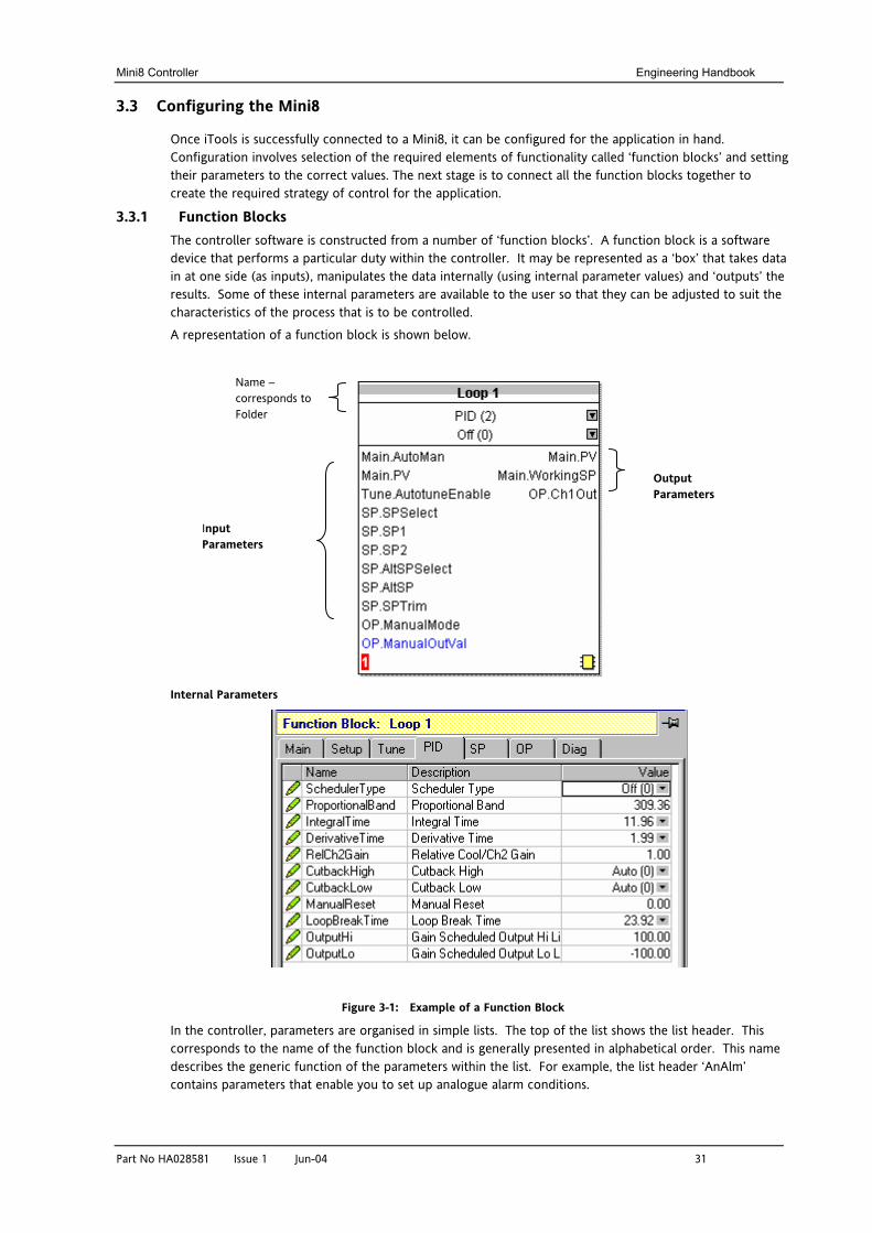
3.3.1 Function Blocks The controller software is constructed from a number of ‘function blocks’. A function block is a software device that performs a particular duty within the controller. It may be represented as a ‘box’ that takes data in at one side (as inputs), manipulates the data internally (using internal parameter values) and ‘outputs’ the results. Some of these internal parameters are available to the user so that they can be adjusted to suit the characteristics of the process that is to be controlled.
A representation of a function block is shown below.
Internal Parameters
Figure 3-1: Example of a Function Block
In the controller, parameters are organised in simple lists. The top of the list shows the list header. This corresponds to the name of the function block and is generally presented in alphabetical order. This name describes the generic function of the parameters within the list. For example, the list header ‘AnAlm’ contains parameters that enable you to set up analogue alarm conditions.
Input Parameters
Output Parameters
Name – corresponds to Folder
Engineering Handbook Mini8 Controller
32 Part No HA028581 Issue 1 Jun-04
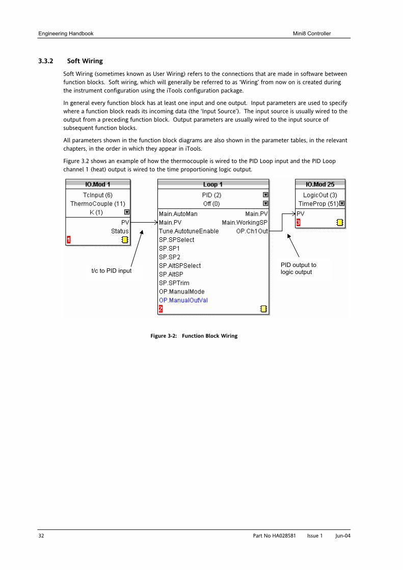
3.3.2 Soft Wiring
Soft Wiring (sometimes known as User Wiring) refers to the connections that are made in software between function blocks. Soft wiring, which will generally be referred to as ‘Wiring’ from now on is created during the instrument configuration using the iTools configuration package.
In general every function block has at least one input and one output. Input parameters are used to specify where a function block reads its incoming data (the ‘Input Source’). The input source is usually wired to the output from a preceding function block. Output parameters are usually wired to the input source of subsequent function blocks.
All parameters shown in the function block diagrams are also shown in the parameter tables, in the relevant chapters, in the order in which they appear in iTools.
Figure 3.2 shows an example of how the thermocouple is wired to the PID Loop input and the PID Loop channel 1 (heat) output is wired to the time proportioning logic output.
Figure 3-2: Function Block Wiring
t/c to PID input PID output to logic output
Mini8 Controller Engineering Handbook
Part No HA028581 Issue 1 Jun-04 33
3.4 Simple Worked Example
Using function blocks and wiring the following sections will show a blank Mini8 being configured to have one PID loop.
3.4.1 The I/O
With the Mini8 successfully connected to iTools configuration can begin.
Tip: In parameter lists:
Parameters in BLUE are read only
Parameters in BLACK are read/write.
Tip: Every parameter in the parameter lists has a detailed description in the help file – just click on a parameter and hit Shift-F1 on the keyboard or right click and select parameter help.
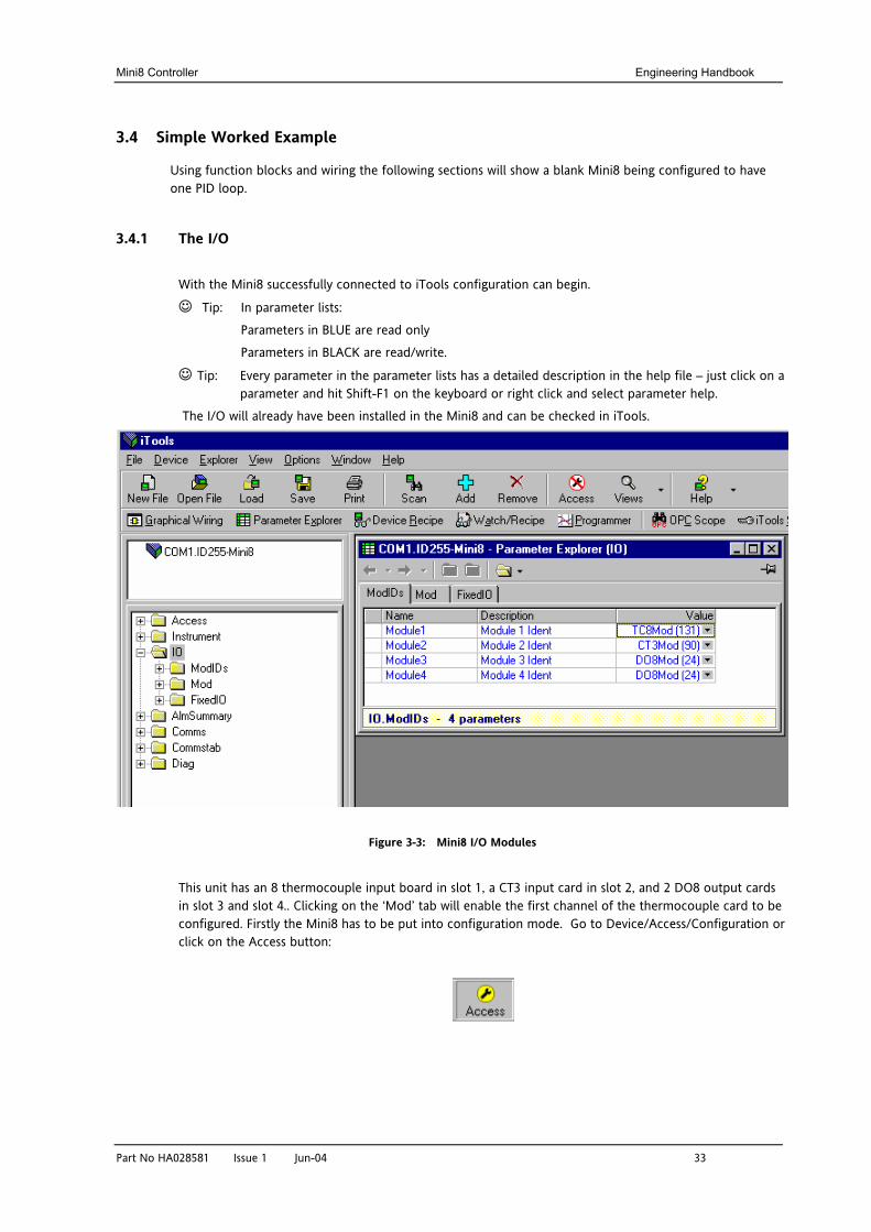
The I/O will already have been installed in the Mini8 and can be checked in iTools.
Figure 3-3: Mini8 I/O Modules
This unit has an 8 thermocouple input board in slot 1, a CT3 input card in slot 2, and 2 DO8 output cards in slot 3 and slot 4.. Clicking on the ‘Mod’ tab will enable the first channel of the thermocouple card to be configured. Firstly the Mini8 has to be put into configuration mode. Go to Device/Access/Configuration or click on the Access button:
Engineering Handbook Mini8 Controller
34 Part No HA028581 Issue 1 Jun-04
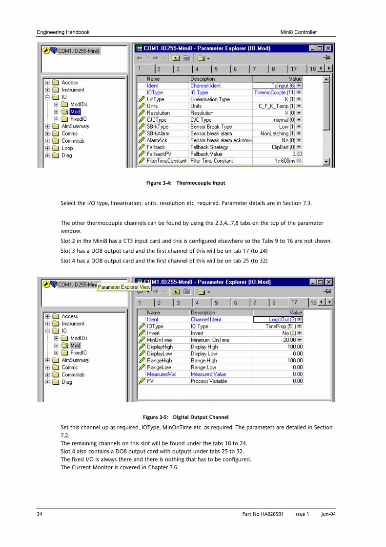
Figure 3-4: Thermocouple Input
Select the I/O type, linearisation, units, resolution etc. required. Parameter details are in Section 7.3.
The other thermocouple channels can be found by using the 2,3,4…7,8 tabs on the top of the parameter window.
Slot 2 in the Mini8 has a CT3 input card and this is configured elsewhere so the Tabs 9 to 16 are not shown.
Slot 3 has a DO8 output card and the first channel of this will be on tab 17 (to 24)
Slot 4 has a DO8 output card and the first channel of this will be on tab 25 (to 32)
Figure 3-5: Digital Output Channel
Set this channel up as required, IOType, MinOnTime etc. as required. The parameters are detailed in Section 7.2. The remaining channels on this slot will be found under the tabs 18 to 24. Slot 4 also contains a DO8 output card with outputs under tabs 25 to 32. The fixed I/O is always there and there is nothing that has to be configured. The Current Monitor is covered in Chapter 7.6.
Mini8 Controller Engineering Handbook
Part No HA028581 Issue 1 Jun-04 35
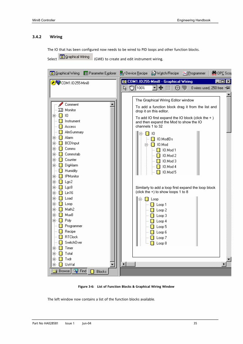
3.4.2 Wiring
The IO that has been configured now needs to be wired to PID loops and other function blocks.
Select (GWE) to create and edit instrument wiring.
Figure 3-6: List of Function Blocks & Graphical Wiring Window
The left window now contains a list of the function blocks available.
The Graphical Wiring Editor window
To add a function block drag it from the list and drop it on this editor.
To add IO first expand the IO block (click the + ) and then expand the Mod to show the IO channels 1 to 32
Similarly to add a loop first expand the loop block (click the +) to show loops 1 to 8
Engineering Handbook Mini8 Controller
36
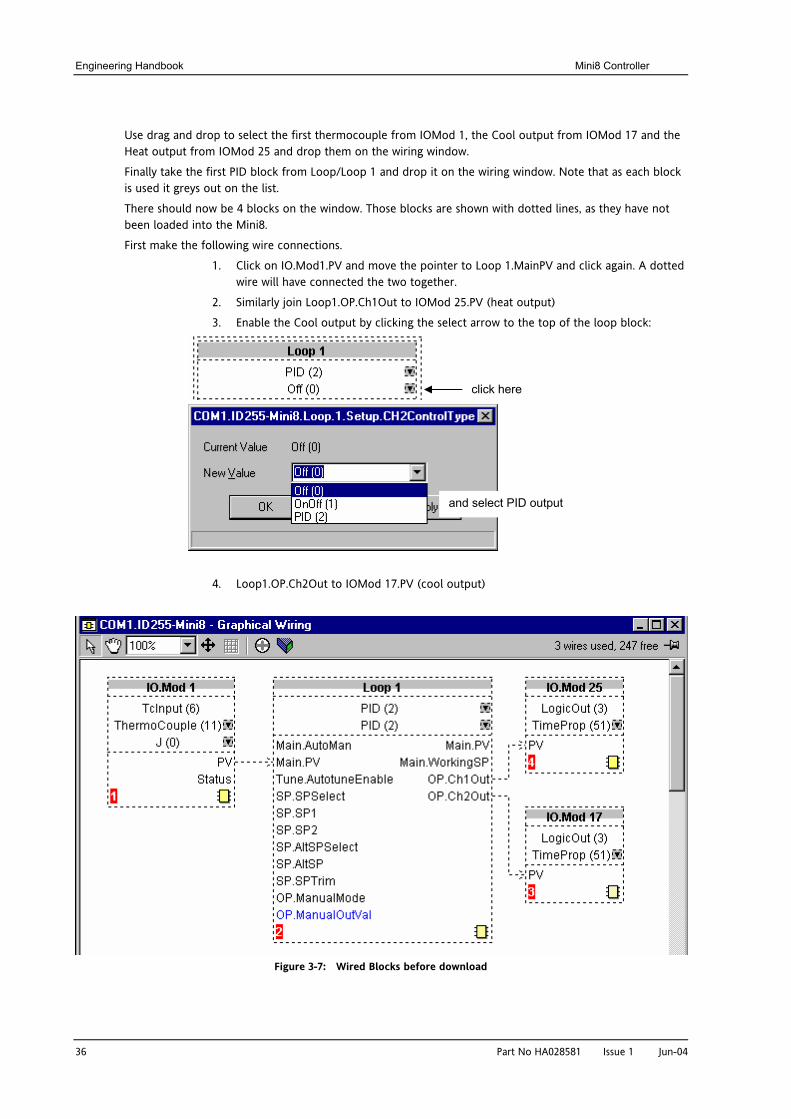
Use drag and drop to select the first thermocouple from IOMod 1, the Cool output from IOMod 17 and the Heat output from IOMod 25 and drop them on the wiring window.
Finally take the first PID block from Loop/Loop 1 and drop it on the wiring window. Note that as each block is used it greys out on the list.
There should now be 4 blocks on the window. Those blocks are shown with dotted lines, as they have not been loaded into the Mini8.
First make the following wire connections.
1. Click on IO.Mod1.PV and move the pointer to Loop 1.MainPV and click again. A dotted wire will have connected the two together.
2. Similarly join Loop1.OP.Ch1Out to IOMod 25.PV (heat output)
3. Enable the Cool output by clicking the select arrow to the top of the loop block:
4. Loop1.OP.Ch2Out to IOMod 17.PV (cool out
Figure 3-7: Wired Blocks before down
click here and select PID outputPart No HA028581 Issue 1 Jun-04
put)
load
Mini8 Controller Engineering Handbook
Part No HA028581 Issue 1 Jun-04 37
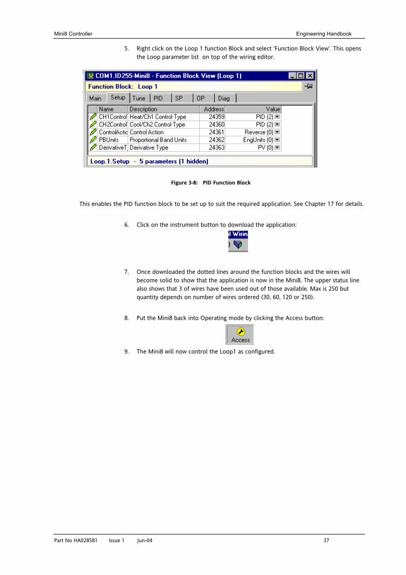
5. Right click on the Loop 1 function Block and select ‘Function Block View’. This opens the Loop parameter list on top of the wiring editor.
Figure 3-8: PID Function Block
This enables the PID function block to be set up to suit the required application. See Chapter 17 for details.
6. Click on the instrument button to download the application:
7. Once downloaded the dotted lines around the function blocks and the wires will become solid to show that the application is now in the Mini8. The upper status line also shows that 3 of wires have been used out of those available. Max is 250 but quantity depends on number of wires ordered (30, 60, 120 or 250).
8. Put the Mini8 back into Operating mode by clicking the Access button:
9. The Mini8 will now control the Loop1 as configured.
Engineering Handbook Mini8 Controller
38 Part No HA028581 Issue 1 Jun-04
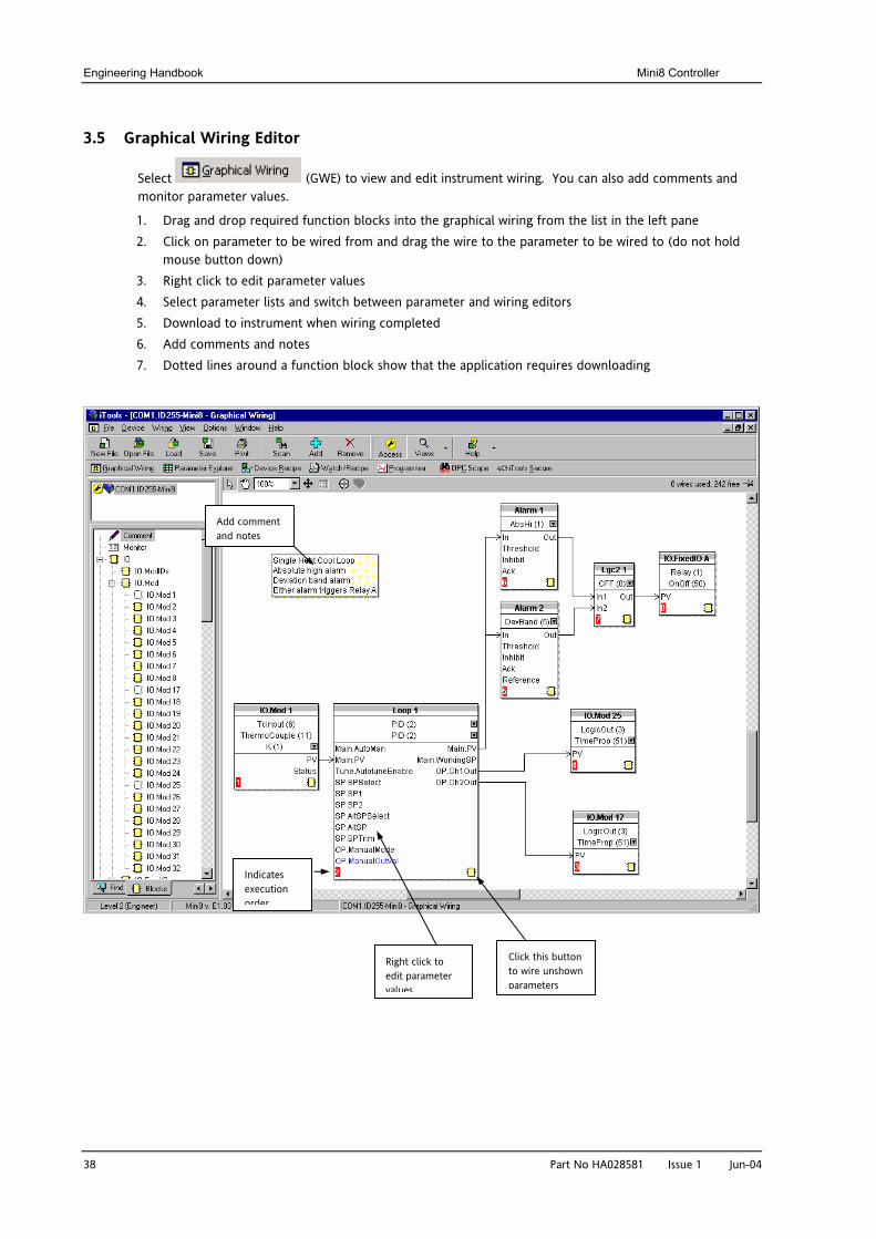
3.5 Graphical Wiring Editor
Select (GWE) to view and edit instrument wiring. You can also add comments and monitor parameter values.
1. Drag and drop required function blocks into the graphical wiring from the list in the left pane 2. Click on parameter to be wired from and drag the wire to the parameter to be wired to (do not hold
mouse button down) 3. Right click to edit parameter values 4. Select parameter lists and switch between parameter and wiring editors 5. Download to instrument when wiring completed 6. Add comments and notes 7. Dotted lines around a function block show that the application requires downloading
Add comment and notes
Right click to edit parameter values
Click this button to wire unshown parameters
Indicates execution order
Mini8 Controller Engineering Handbook
Part No HA028581 Issue 1 Jun-04 39
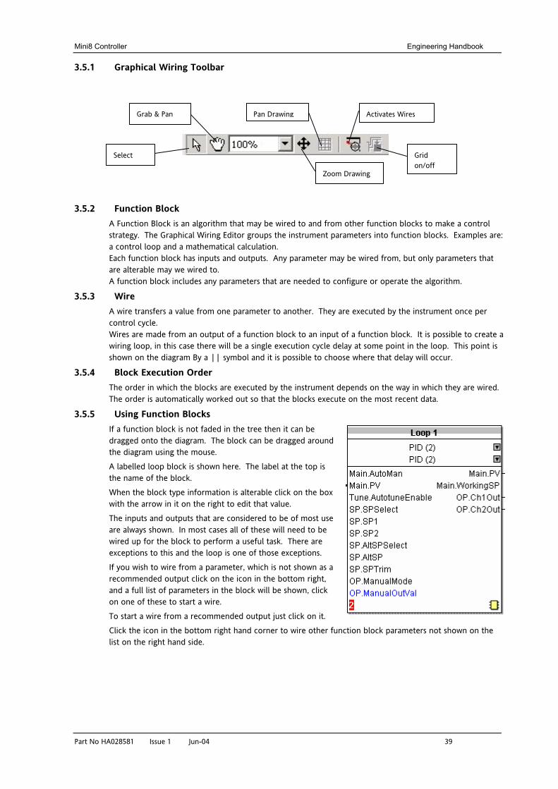
3.5.1 Graphical Wiring Toolbar
3.5.2 Function Block A Function Block is an algorithm that may be wired to and from other function blocks to make a control strategy. The Graphical Wiring Editor groups the instrument parameters into function blocks. Examples are: a control loop and a mathematical calculation. Each function block has inputs and outputs. Any parameter may be wired from, but only parameters that are alterable may we wired to. A function block includes any parameters that are needed to configure or operate the algorithm.
3.5.3 Wire A wire transfers a value from one parameter to another. They are executed by the instrument once per control cycle. Wires are made from an output of a function block to an input of a function block. It is possible to create a wiring loop, in this case there will be a single execution cycle delay at some point in the loop. This point is shown on the diagram By a || symbol and it is possible to choose where that delay will occur.
3.5.4 Block Execution Order The order in which the blocks are executed by the instrument depends on the way in which they are wired. The order is automatically worked out so that the blocks execute on the most recent data.
3.5.5 Using Function Blocks If a function block is not faded in the tree then it can be dragged onto the diagram. The block can be dragged around the diagram using the mouse.
A labelled loop block is shown here. The label at the top is the name of the block.
When the block type information is alterable click on the box with the arrow in it on the right to edit that value.
The inputs and outputs that are considered to be of most use are always shown. In most cases all of these will need to be wired up for the block to perform a useful task. There are exceptions to this and the loop is one of those exceptions.
If you wish to wire from a parameter, which is not shown as a recommended output click on the icon in the bottom right, and a full list of parameters in the block will be shown, click on one of these to start a wire.
To start a wire from a recommended output just click on it.
Click the icon in the bottom right hand corner to wire other function block parameters not shown on the list on the right hand side.
Activates Wires
Grid on/off
Pan Drawing
Zoom Drawing
Grab & Pan
Select
Engineering Handbook Mini8 Controller
40 Part No HA028581 Issue 1 Jun-04
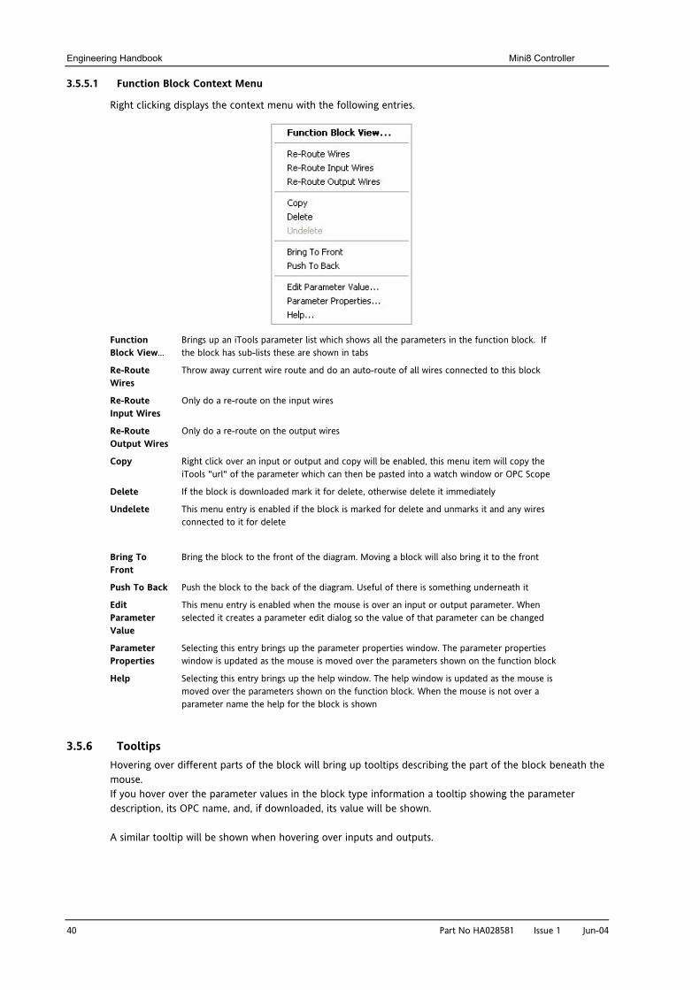
3.5.5.1 Function Block Context Menu
Right clicking displays the context menu with the following entries.
Function Block View…
Brings up an iTools parameter list which shows all the parameters in the function block. If the block has sub-lists these are shown in tabs
Re-Route Wires
Throw away current wire route and do an auto-route of all wires connected to this block
Re-Route Input Wires
Only do a re-route on the input wires
Re-Route Output Wires
Only do a re-route on the output wires
Copy Right click over an input or output and copy will be enabled, this menu item will copy the iTools "url" of the parameter which can then be pasted into a watch window or OPC Scope
Delete If the block is downloaded mark it for delete, otherwise delete it immediately
Undelete This menu entry is enabled if the block is marked for delete and unmarks it and any wires connected to it for delete
Bring To Front
Bring the block to the front of the diagram. Moving a block will also bring it to the front
Push To Back Push the block to the back of the diagram. Useful of there is something underneath it
Edit Parameter Value
This menu entry is enabled when the mouse is over an input or output parameter. When selected it creates a parameter edit dialog so the value of that parameter can be changed
Parameter Properties
Selecting this entry brings up the parameter properties window. The parameter properties window is updated as the mouse is moved over the parameters shown on the function block
Help Selecting this entry brings up the help window. The help window is updated as the mouse is moved over the parameters shown on the function block. When the mouse is not over a parameter name the help for the block is shown
3.5.6 Tooltips Hovering over different parts of the block will bring up tooltips describing the part of the block beneath the mouse. If you hover over the parameter values in the block type information a tooltip showing the parameter description, its OPC name, and, if downloaded, its value will be shown. A similar tooltip will be shown when hovering over inputs and outputs.
Mini8 Controller Engineering Handbook
Part No HA028581 Issue 1 Jun-04 41
3.5.7 Function Block State
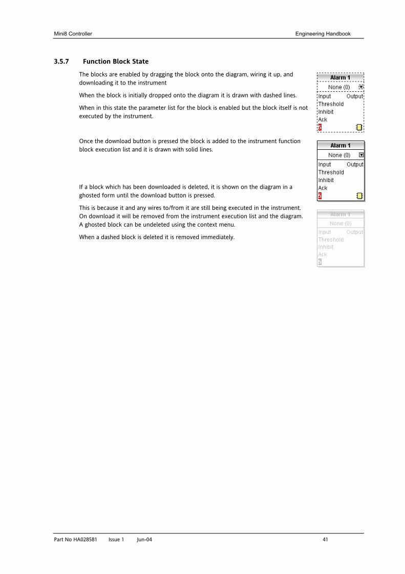
The blocks are enabled by dragging the block onto the diagram, wiring it up, and downloading it to the instrument
When the block is initially dropped onto the diagram it is drawn with dashed lines.
When in this state the parameter list for the block is enabled but the block itself is not executed by the instrument.
Once the download button is pressed the block is added to the instrument function block execution list and it is drawn with solid lines.
If a block which has been downloaded is deleted, it is shown on the diagram in a ghosted form until the download button is pressed.
This is because it and any wires to/from it are still being executed in the instrument. On download it will be removed from the instrument execution list and the diagram. A ghosted block can be undeleted using the context menu.
When a dashed block is deleted it is removed immediately.

Engineering Handbook Mini8 Controller
42 Part No HA028581 Issue 1 Jun-04
3.5.8 Using Wires
3.5.8.1 Making A Wire Between Two Blocks
• Drag two blocks onto the diagram from the function block tree.
• Start a wire by either clicking on a recommended output or clicking on the icon at the bottom right corner of the block to bring up the connection dialog. The connection dialog shows all the connectable parameters for the block, if the block has sub-lists the parameters are shown in a tree. If you wish to wire a parameter which is not currently available click the red button at the bottom of the connection dialog. Recommended connections are shown with a green plug, other parameters which are available are yellow and if you click the red button the unavailable parameters are shown red. To dismiss the connection dialog either press the escape key on the keyboard or click the cross at the bottom left of the dialog.
• Once the wire has started the cursor will change and a dotted wire will be drawn from the output to the current mouse position.
• To make the wire either click on a recommended input to make a wire to that parameter or click anywhere except on a recommended input to bring up the connection dialog. Choose from the connection dialog as described above.
• The wire will now be auto-routed between the blocks.
New wires are shown dotted until they are downloaded
3.5.8.2 Wire Context Menu
The wire block context menu has the following entries on it.
Force Exec Break If wires form a loop a break point has to be found where the value which is written to the block input comes from a block which was last executed during the previous instrument execute cycle thus introducing a delay. This option tells the instrument that if it needs to make a break it should be on this wire
Re-Route Wire Throw away wire route and generate an automatic route from scratch
Use Tags If a wire is between blocks which are a long way apart, then, rather than drawing the wire, the name of the wired to/from parameter can be shown in a tag next to the block. Draw the wire first then use this menu to toggle this wire between drawing the whole wire and drawing it as tags
Delete If the wire is downloaded mark it for delete, otherwise delete it immediately
Undelete This menu entry is enabled if the wire is marked for delete and unmarks it for delete
Bring To Front Bring the wire to the front of the diagram. Moving a wire will also bring it to the front
Push To Back Push the wire to the back of the diagram
Mini8 Controller Engineering Handbook
Part No HA028581 Issue 1 Jun-04 43
3.5.8.3 Wire Colours
Wires can be the following colours:
Black Normal functioning wire.
Red The wire is connected to an input which is not alterable when the instrument is in operator mode and so values which travel along that wire will be rejected by the receiving block
Blue The mouse is hovering over the wire, or the block to which it is connected it selected. Useful for tracing densely packed wires
Purple The mouse is hovering over a 'red' wire
3.5.8.4 Routing Wires
When a wire is placed it is auto-routed. The auto routing algorithm searches for a clear path between the two blocks. A wire can be auto-routed again using the context menus or by double clicking the wire.
If you click on a wire segment you can drag it to manually route it. Once you have done this it is marked as a manually routed wire and will retain it's current shape. If you move the block to which it is connected the end of the wire will be moved but as much of the path as possible of the wire will be preserved.
If you select a wire by clicking on it, it will be drawn with small boxes on it's corners.
3.5.8.5 Tooltips
Hover the mouse over a wire and a tooltip showing the names of the parameters which are wired and, if downloaded, their current values will also be shown.
3.5.9 Using Comments
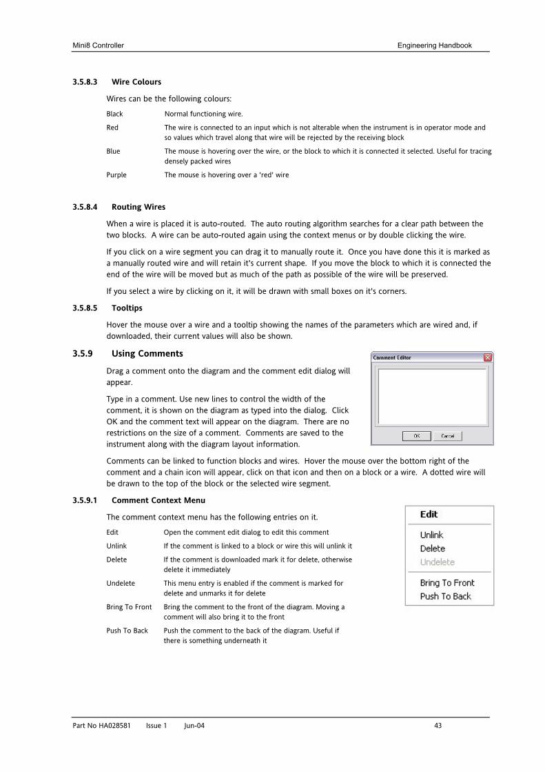
Drag a comment onto the diagram and the comment edit dialog will appear.
Type in a comment. Use new lines to control the width of the comment, it is shown on the diagram as typed into the dialog. Click OK and the comment text will appear on the diagram. There are no restrictions on the size of a comment. Comments are saved to the instrument along with the diagram layout information.
Comments can be linked to function blocks and wires. Hover the mouse over the bottom right of the comment and a chain icon will appear, click on that icon and then on a block or a wire. A dotted wire will be drawn to the top of the block or the selected wire segment.
3.5.9.1 Comment Context Menu
The comment context menu has the following entries on it.
Edit Open the comment edit dialog to edit this comment
Unlink If the comment is linked to a block or wire this will unlink it
Delete If the comment is downloaded mark it for delete, otherwise delete it immediately
Undelete This menu entry is enabled if the comment is marked for delete and unmarks it for delete
Bring To Front Bring the comment to the front of the diagram. Moving a comment will also bring it to the front
Push To Back Push the comment to the back of the diagram. Useful if there is something underneath it
Engineering Handbook Mini8 Controller
44 Part No HA028581 Issue 1 Jun-04
3.5.10 Using Monitors
Drag a monitor onto the diagram and connect it to a block input or output or a wire as described in ‘Using Comments’.
The current value (updated at the iTools parameter list update rate) will be shown in the monitor. By default the name of the parameter is shown, double click or use the context menu to not show the parameter name.
3.5.10.1 Monitor Context Menu
The monitor context menu has the following entries on it.
Show Names Show parameter names as well as values
Unlink If the monitor is linked to a block or wire this will unlink it
Delete If the monitor is downloaded mark it for delete, otherwise delete it immediately
Undelete This menu entry is enabled if the monitor is marked for delete and unmarks it for delete
Bring To Front Bring the monitor to the front of the diagram. Moving a monitor will also bring it to the front
Push To Back Push the monitor to the back of the diagram. Useful if there is something underneath it
3.5.11 Downloading
The wires have to be downloaded to the instrument together. When the wiring editor is opened the current wiring and diagram layout is read from the instrument. No changes are made to the instrument function block execution or wiring until the download button is pressed. Any changes made using the instrument front panel after the editor is opened will be lost on download.
When a block is dropped on the diagram instrument parameters are changed to make the parameters for that block available. If you make changes and close the editor without saving them there will be a delay while the editor clears these parameters.
When you download, the wiring is written to the instrument that then calculates the block execution order and starts executing the blocks. The diagram layout including comments and monitors is then written into instrument flash memory along with the current editor settings. When you reopen the editor the diagram will be shown positioned the same as when you last downloaded.
3.5.12 Selections
Wires are shown with small blocks at their corners when selected. All other items have a dotted line drawn round them when they are selected.
3.5.12.1 Selecting Individual Items
Clicking on an item on the drawing will select it.
3.5.12.2 Multiple Selection
Control click an unselected item to add it to the selection, doing the same on a selected item unselects it.
Alternatively, hold the mouse down on the background and wipe it to create a rubber band, anything which isn't a wire inside the rubber band will be selected.
Selecting two function blocks also selects any wires which join them. This means that if you select more than one function block using the rubber band method any wires between them will also be selected.
Pressing Ctrl-A selects all blocks and wires.
Mini8 Controller Engineering Handbook
Part No HA028581 Issue 1 Jun-04 45
3.5.13 Colours
Items on the diagram are coloured as follows:
Red Function blocks, comments and monitors which partially obscure or are partially obscured by other items are drawn red. If a large function block like the loop is covering a small one like a math2 the loop will be drawn red to show that it is covering another function block. Wires are drawn red when they are connected to an input which is currently unalterable. Parameters in function blocks are coloured red if they are unalterable and the mouse pointer is over them
Blue Function blocks, comments and monitors which are not coloured red are coloured blue when the mouse pointer is over them. Wires are coloured blue when a block to which the wire is connected is selected or the mouse pointer is over it. Parameters in function blocks are coloured blue if they are alterable and the mouse pointer is over them
Purple A wire which is connected to an input which is currently unalterable and a block to which the wire is connected is selected or the mouse pointer is over it is coloured purple (red + blue)
3.6 Diagram Context Menu
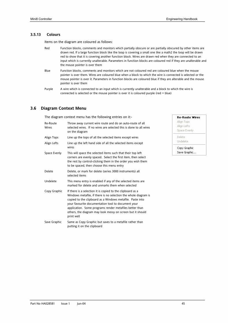
The diagram context menu has the following entries on it:-
Re-Route Wires
Throw away current wire route and do an auto-route of all selected wires. If no wires are selected this is done to all wires on the diagram
Align Tops Line up the tops of all the selected items except wires
Align Lefts Line up the left hand side of all the selected items except wires
Space Evenly This will space the selected items such that their top left corners are evenly spaced. Select the first item, then select the rest by control-clicking them in the order you wish them to be spaced, then choose this menu entry
Delete Delete, or mark for delete (series 3000 instruments) all selected items
Undelete This menu entry is enabled if any of the selected items are marked for delete and unmarks them when selected
Copy Graphic If there is a selection it is copied to the clipboard as a Windows metafile, if there is no selection the whole diagram is copied to the clipboard as a Windows metafile. Paste into your favourite documentation tool to document your application. Some programs render metafiles better than others, the diagram may look messy on screen but it should print well
Save Graphic Same as Copy Graphic but saves to a metafile rather than putting it on the clipboard
Engineering Handbook Mini8 Controller
46 Part No HA028581 Issue 1 Jun-04
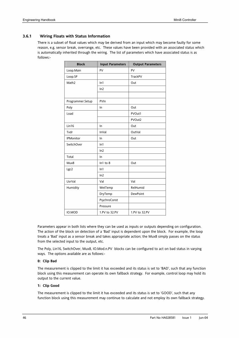
3.6.1 Wiring Floats with Status Information There is a subset of float values which may be derived from an input which may become faulty for some reason, e.g. sensor break, overrange, etc. These values have been provided with an associated status which is automatically inherited through the wiring. The list of parameters which have associated status is as follows:-
Block Input Parameters Output Parameters
Loop.Main PV PV
Loop.SP TrackPV
In1 Out
In2
Math2
Programmer.Setup PVIn
Poly In Out
PVOut1 Load
PVOut2
Lin16 In Out
Txdr InVal OutVal
IPMonitor In Out
In1 SwitchOver
In2
Total In
Mux8 In1 to 8 Out
In1 Lgc2
In2
UsrVal Val Val
WetTemp RelHumid
DryTemp DewPoint
PsychroConst
Humidity
Pressure
IO.MOD 1.PV to 32.PV 1.PV to 32.PV
Parameters appear in both lists where they can be used as inputs or outputs depending on configuration. The action of the block on detection of a ‘Bad’ input is dependent upon the block. For example, the loop treats a ‘Bad’ input as a sensor break and takes appropriate action; the Mux8 simply passes on the status from the selected input to the output, etc.
The Poly, Lin16, SwitchOver, Mux8, IO.Mod.n.PV blocks can be configured to act on bad status in varying ways. The options available are as follows:-
0: Clip Bad
The measurement is clipped to the limit it has exceeded and its status is set to ‘BAD’, such that any function block using this measurement can operate its own fallback strategy. For example, control loop may hold its output to the current value.
1: Clip Good
The measurement is clipped to the limit it has exceeded and its status is set to ‘GOOD’, such that any function block using this measurement may continue to calculate and not employ its own fallback strategy.
Mini8 Controller Engineering Handbook
Part No HA028581 Issue 1 Jun-04 47
2: Fallback Bad The measurement will adopt the configured fallback value that has been set by the user. In addition the status of the measured value will be set to ‘BAD’, such that any function block using this measurement can operate its own fallback strategy. For example, control loop may hold its output to the current value.
3: Fallback Good The measurement will adopt the configured fallback value that has been set by the user. In addition the status of the measured value will be set to ‘GOOD’, such that any function block using this measurement may continue to calculate and not employ its own fallback strategy
4: Up Scale The measurement will be forced to adopt its high limit. This is like having a resistive pull up on an input circuit. In addition the status of the measured value will be set to ‘BAD’, such that any function block using this measurement can operate its own fallback strategy. For example, the control loop may hold its output to the current value.
5: Down Scale The measurement will be forced to adopt its low limit. This is like having a resistive pull down on an input circuit. In addition the status of the measured value will be set to ‘BAD’, such that any function block using this measurement can operate its own fallback strategy. For example, the control loop may hold its output to the current value.
3.6.2 Edge Wires If the Loop.Main.AutoMan parameter were wired from a logic input in the conventional manner it would be impossible to put the instrument into manual via communications. Other parameters need to be controlled by wiring but also need to be able to change under other circumstances, e.g. Alarm Acknowledgements. for this reason some Boolean parameters are wired in an alternative way. These are listed as follows:-
SET DOMINANT When the wired in value is 1 the parameter is always updated. This will have the effect of overriding any changes through digital communications. When the wired in value changes to 0 the parameter is initially changed to 0 but is not continuously updated. This permits the value to be changed through digital communications.
Loop.Main.AutoMan Programmer.Setup.ProgHold Access.StandBy
RISING EDGE When the wired in value changes from 0 to 1, a 1 is written to the parameter. At all other times the wire does not update the parameter. This type of wiring is used for parameters that start an action and when once completed the block clears the parameter. When wired to, these parameters can still be operated via digital communications.
Loop.Tune.AutotuneEnable Txdr.ClearCal Alarm.Ack Txdr.StartCal DigAlarm.Ack Programmer.Setup.ProgRun Txdr.StartHighCal AlmSummary.GlobalAck Programmer.Setup.AdvSeg Txdr.StartTare Programmer.Setup.SkipSeg Instrument.Diagnostics.
ClearStats IPMonitor.Reset
BOTH EDGE This type of edge is used for parameters which may need to be controlled by wiring or but should also be able to be controlled through digital communications. If the wired in value changes then the new value is written to the parameter by the wire. At all other times the parameter is free to be edited through digital communications.
Loop.SP.RateDisable Loop.OP.RateDisable
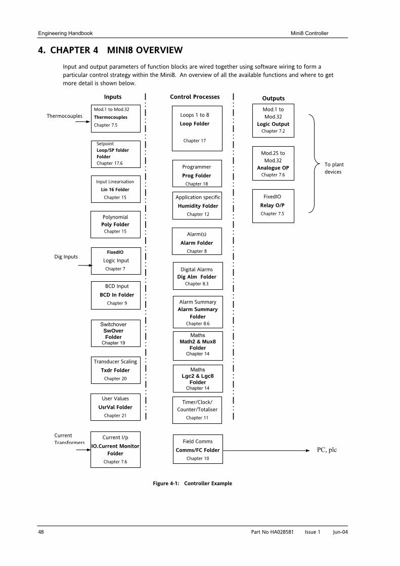
Engineering Handbook Mini8 Controller
48 Part No HA028581 Issu
4. CHAPTER 4 MINI8 OVERVIEW Input and output parameters of function blocks are wired together using software wiring to form a particular control strategy within the Mini8. An overview of all the available functions and where to get more detail is shown below.
Figure 4-1: Controller Example
Thermocouples
Outputs
FixedIO
Logic Input Chapter 7
Setpoint Loop/SP folder Folder Chapter 17.6
Mod.25 to Mod.32
Analogue OP Chapter 7.6
To plant devices
Mod.1 to Mod.32 Thermocouples Chapter 7.5
Loops 1 to 8 Loop Folder
Chapter 17
Mod.1 to Mod.32
Logic Output Chapter 7.2
Alarm(s) Alarm Folder
Chapter 8
Timer/Clock/ Counter/Totaliser
Chapter 11
Field Comms Comms/FC Folder
Chapter 10 c
Inputs Control Processes
FixedIO Relay O/P Chapter 7.5
Digital Alarms Dig Alm Folder
Chapter 8.3
Application specific Humidity Folder
Chapter 12
Programmer Prog Folder
Chapter 18
BCD Input BCD In Folder
Chapter 9
Input Linearisation Lin 16 Folder
Chapter 15
Maths Math2 & Mux8
Folder Chapter 14
Polynomial Poly Folder
Chapter 15
Switchover SwOver Folder
Chapter 19
Transducer Scaling Txdr Folder
Chapter 20
User Values UsrVal Folder
Chapter 21
Maths Lgc2 & Lgc8
Folder Chapter 14
IO.
Alarm Summary Alarm Summary
Folder Chapter 8.6
Dig Inputs
PC, plCurrent I/p Current Monitor
Folder Chapter 7.6
Current Transformers
e 1 Jun-04
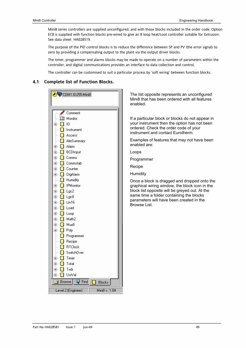
Mini8 Controller Engineering Handbook
Part No HA028581 Issue 1 Jun-04 49
Mini8 series controllers are supplied unconfigured, and with those blocks included in the order code. Option EC8 is supplied with function blocks pre-wired to give an 8 loop heat/cool controller suitable for Extrusion. See data sheet HA028519.
The purpose of the PID control blocks is to reduce the difference between SP and PV (the error signal) to zero by providing a compensating output to the plant via the output driver blocks.
The timer, programmer and alarms blocks may be made to operate on a number of parameters within the controller, and digital communications provides an interface to data collection and control.
The controller can be customised to suit a particular process by ‘soft wiring’ between function blocks.
4.1 Complete list of Function Blocks.
The list opposite represents an unconfigured Mini8 that has been ordered with all features enabled.
If a particular block or blocks do not appear in your instrument then the option has not been ordered. Check the order code of your instrument and contact Eurotherm.
Examples of features that may not have been enabled are:
Loops
Programmer
Recipe
Humidity
Once a block is dragged and dropped onto the graphical wiring window, the block icon in the block list opposite will be greyed out. At the same time a folder containing the blocks parameters will have been created in the Browse List.
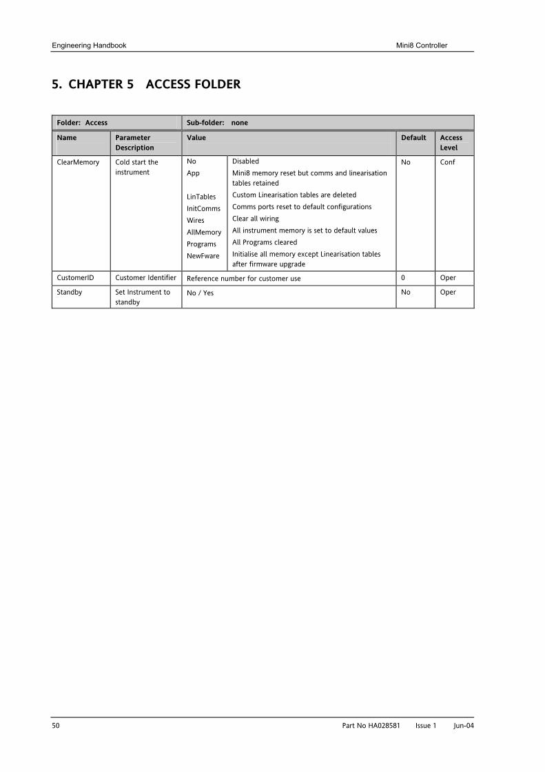
Engineering Handbook Mini8 Controller
50 Part No HA028581 Issue 1 Jun-04
5. CHAPTER 5 ACCESS FOLDER
Folder: Access Sub-folder: none
Name
Parameter Description
Value
Default Access Level
ClearMemory Cold start the instrument
No App LinTables InitComms Wires AllMemory Programs NewFware
Disabled Mini8 memory reset but comms and linearisation tables retained Custom Linearisation tables are deleted Comms ports reset to default configurations Clear all wiring All instrument memory is set to default values All Programs cleared Initialise all memory except Linearisation tables after firmware upgrade
No Conf
CustomerID Customer Identifier Reference number for customer use 0 Oper
Standby Set Instrument to standby
No / Yes No Oper
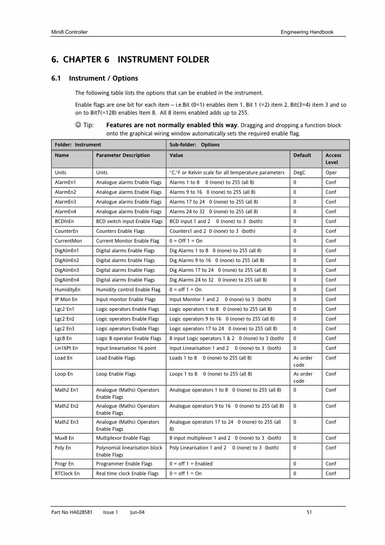
Mini8 Controller Engineering Handbook
Part No HA028581 Issue 1 Jun-04 51
6. CHAPTER 6 INSTRUMENT FOLDER
6.1 Instrument / Options
The following table lists the options that can be enabled in the instrument.
Enable flags are one bit for each item – i.e.Bit (0=1) enables item 1, Bit 1 (=2) item 2, Bit(3=4) item 3 and so on to Bit7(=128) enables Item 8. All 8 items enabled adds up to 255.
Tip: Features are not normally enabled this way. Dragging and dropping a function block onto the graphical wiring window automatically sets the required enable flag.
Folder: Instrument Sub-folder: Options
Name
Parameter Description Value
Default Access Level
Units Units °C,°F or Kelvin scale for all temperature parameters DegC Oper
AlarmEn1 Analogue alarms Enable Flags Alarms 1 to 8 0 (none) to 255 (all 8) 0 Conf
AlarmEn2 Analogue alarms Enable Flags Alarms 9 to 16 0 (none) to 255 (all 8) 0 Conf
AlarmEn3 Analogue alarms Enable Flags Alarms 17 to 24 0 (none) to 255 (all 8) 0 Conf
AlarmEn4 Analogue alarms Enable Flags Alarms 24 to 32 0 (none) to 255 (all 8) 0 Conf
BCDInEn BCD switch input Enable Flags BCD input 1 and 2 0 (none) to 3 (both) 0 Conf
CounterEn Counters Enable Flags Counters1 and 2 0 (none) to 3 (both) 0 Conf
CurrentMon Current Monitor Enable Flag 0 = Off 1 = On 0 Conf
DigAlmEn1 Digital alarms Enable Flags Dig Alarms 1 to 8 0 (none) to 255 (all 8) 0 Conf
DigAlmEn2 Digital alarms Enable Flags Dig Alarms 9 to 16 0 (none) to 255 (all 8) 0 Conf
DigAlmEn3 Digital alarms Enable Flags Dig Alarms 17 to 24 0 (none) to 255 (all 8) 0 Conf
DigAlmEn4 Digital alarms Enable Flags Dig Alarms 24 to 32 0 (none) to 255 (all 8) 0 Conf
HumidityEn Humidity control Enable Flag 0 = off 1 = On 0 Conf
IP Mon En Input monitor Enable Flags Input Monitor 1 and 2 0 (none) to 3 (both) 0 Conf
Lgc2 En1 Logic operators Enable Flags Logic operators 1 to 8 0 (none) to 255 (all 8) 0 Conf
Lgc2 En2 Logic operators Enable Flags Logic operators 9 to 16 0 (none) to 255 (all 8) 0 Conf
Lgc2 En3 Logic operators Enable Flags Logic operators 17 to 24 0 (none) to 255 (all 8) 0 Conf
Lgc8 En Logic 8 operator Enable Flags 8 input Logic operators 1 & 2 0 (none) to 3 (both) 0 Conf
Lin16Pt En Input linearisation 16 point Input Linearisation 1 and 2 0 (none) to 3 (both) 0 Conf
Load En Load Enable Flags Loads 1 to 8 0 (none) to 255 (all 8) As order code
Conf
Loop En Loop Enable Flags Loops 1 to 8 0 (none) to 255 (all 8) As order code
Conf
Math2 En1 Analogue (Maths) Operators Enable Flags
Analogue operators 1 to 8 0 (none) to 255 (all 8) 0 Conf
Math2 En2 Analogue (Maths) Operators Enable Flags
Analogue operators 9 to 16 0 (none) to 255 (all 8) 0 Conf
Math2 En3 Analogue (Maths) Operators Enable Flags
Analogue operators 17 to 24 0 (none) to 255 (all 8)
0 Conf
Mux8 En Multiplexor Enable Flags 8 input multiplexor 1 and 2 0 (none) to 3 (both) 0 Conf
Poly En Polynomial linearisation block Enable Flags
Poly Linearisation 1 and 2 0 (none) to 3 (both) 0 Conf
Progr En Programmer Enable Flags 0 = off 1 = Enabled 0 Conf
RTClock En Real time clock Enable Flags 0 = off 1 = On 0 Conf
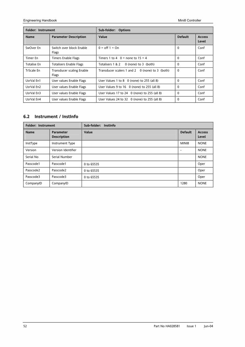
Engineering Handbook Mini8 Controller
52 Part No HA028581 Issue 1 Jun-04
Folder: Instrument Sub-folder: Options
Name
Parameter Description Value
Default Access Level
SwOver En Switch over block Enable Flags
0 = off 1 = On 0 Conf
Timer En Timers Enable Flags Timers 1 to 4 0 = none to 15 = 4 0 Conf
Totalise En Totalisers Enable Flags Totalisers 1 & 2 0 (none) to 3 (both) 0 Conf
TrScale En Transducer scaling Enable Flags
Transducer scalers 1 and 2 0 (none) to 3 (both) 0 Conf
UsrVal En1 User values Enable Flags User Values 1 to 8 0 (none) to 255 (all 8) 0 Conf
UsrVal En2 User values Enable Flags User Values 9 to 16 0 (none) to 255 (all 8) 0 Conf
UsrVal En3 User values Enable Flags User Values 17 to 24 0 (none) to 255 (all 8) 0 Conf
UsrVal En4 User values Enable Flags User Values 24 to 32 0 (none) to 255 (all 8) 0 Conf
6.2 Instrument / InstInfo
Folder: Instrument Sub-folder: InstInfo
Name
Parameter Description
Value
Default Access Level
InstType Instrument Type MINI8 NONE
Version Version Identifier - NONE
Serial No Serial Number NONE
Passcode1 Passcode1 0 to 65535 Oper
Passcode2 Passcode2 0 to 65535 Oper
Passcode3 Passcode3 0 to 65535 Oper
CompanyID CompanyID 1280 NONE
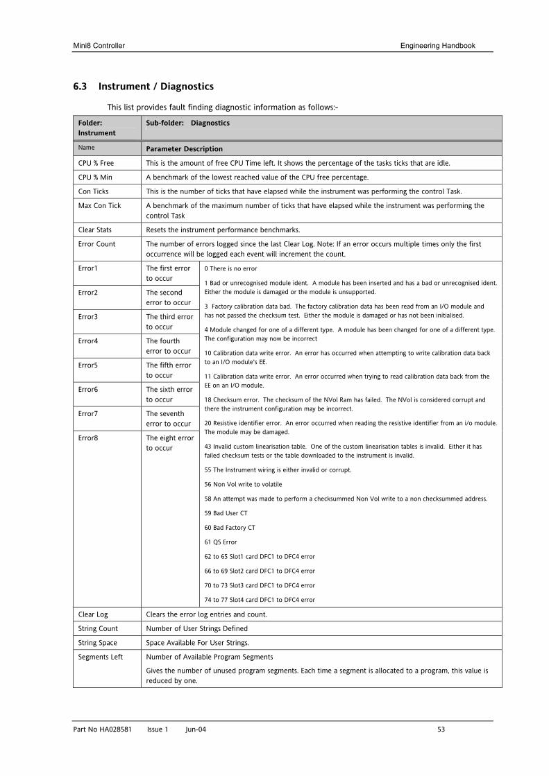
Mini8 Controller Engineering Handbook
Part No HA028581 Issue 1 Jun-04 53
6.3 Instrument / Diagnostics
This list provides fault finding diagnostic information as follows:-
Folder: Instrument
Sub-folder: Diagnostics
Name Parameter Description
CPU % Free This is the amount of free CPU Time left. It shows the percentage of the tasks ticks that are idle.
CPU % Min A benchmark of the lowest reached value of the CPU free percentage.
Con Ticks This is the number of ticks that have elapsed while the instrument was performing the control Task.
Max Con Tick A benchmark of the maximum number of ticks that have elapsed while the instrument was performing the control Task
Clear Stats Resets the instrument performance benchmarks.
Error Count The number of errors logged since the last Clear Log. Note: If an error occurs multiple times only the first occurrence will be logged each event will increment the count.
Error1 The first error to occur
Error2 The second error to occur
Error3 The third error to occur
Error4 The fourth error to occur
Error5 The fifth error to occur
Error6 The sixth error to occur
Error7 The seventh error to occur
Error8 The eight error to occur
0 There is no error 1 Bad or unrecognised module ident. A module has been inserted and has a bad or unrecognised ident. Either the module is damaged or the module is unsupported.
3 Factory calibration data bad. The factory calibration data has been read from an I/O module and has not passed the checksum test. Either the module is damaged or has not been initialised.
4 Module changed for one of a different type. A module has been changed for one of a different type. The configuration may now be incorrect
10 Calibration data write error. An error has occurred when attempting to write calibration data back to an I/O module's EE.
11 Calibration data write error. An error occurred when trying to read calibration data back from the EE on an I/O module.
18 Checksum error. The checksum of the NVol Ram has failed. The NVol is considered corrupt and there the instrument configuration may be incorrect.
20 Resistive identifier error. An error occurred when reading the resistive identifier from an i/o module. The module may be damaged.
43 Invalid custom linearisation table. One of the custom linearisation tables is invalid. Either it has failed checksum tests or the table downloaded to the instrument is invalid.
55 The Instrument wiring is either invalid or corrupt.
56 Non Vol write to volatile
58 An attempt was made to perform a checksummed Non Vol write to a non checksummed address.
59 Bad User CT
60 Bad Factory CT
61 QS Error
62 to 65 Slot1 card DFC1 to DFC4 error
66 to 69 Slot2 card DFC1 to DFC4 error
70 to 73 Slot3 card DFC1 to DFC4 error
74 to 77 Slot4 card DFC1 to DFC4 error
Clear Log Clears the error log entries and count.
String Count Number of User Strings Defined
String Space Space Available For User Strings.
Segments Left Number of Available Program Segments
Gives the number of unused program segments. Each time a segment is allocated to a program, this value is reduced by one.
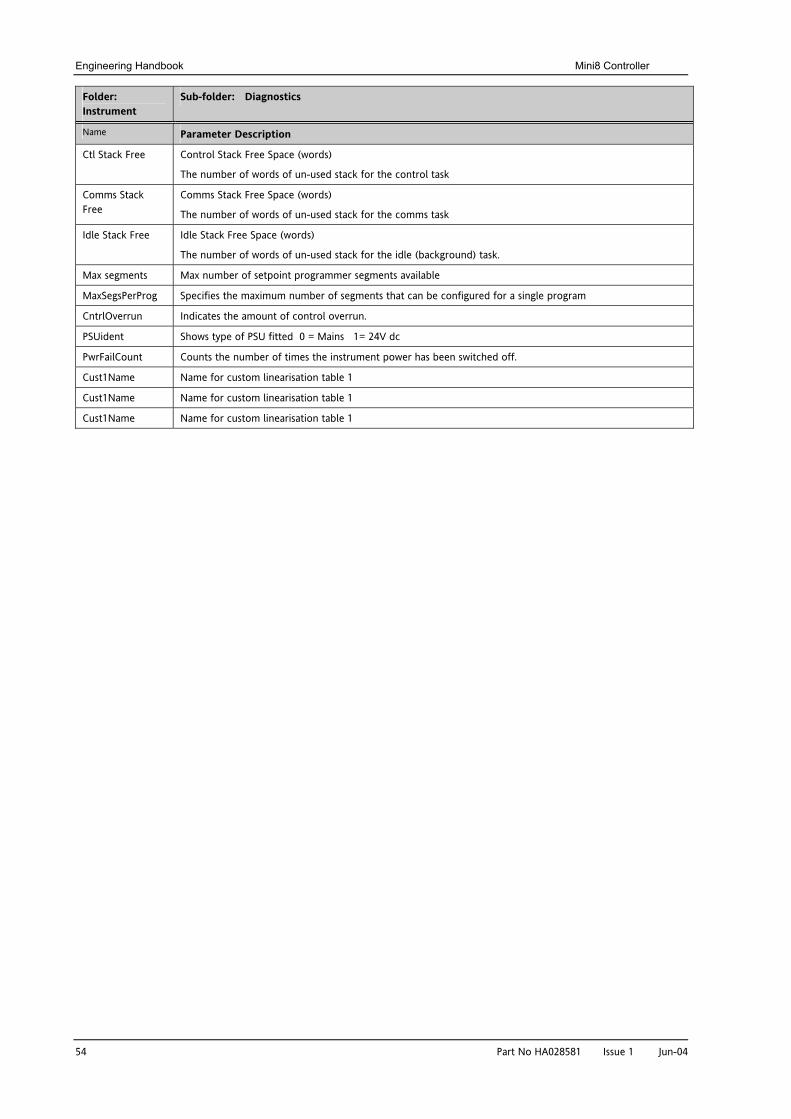
Engineering Handbook Mini8 Controller
54 Part No HA028581 Issue 1 Jun-04
Folder: Instrument
Sub-folder: Diagnostics
Name Parameter Description
Ctl Stack Free Control Stack Free Space (words)
The number of words of un-used stack for the control task
Comms Stack Free
Comms Stack Free Space (words)
The number of words of un-used stack for the comms task
Idle Stack Free Idle Stack Free Space (words)
The number of words of un-used stack for the idle (background) task.
Max segments Max number of setpoint programmer segments available
MaxSegsPerProg Specifies the maximum number of segments that can be configured for a single program
CntrlOverrun Indicates the amount of control overrun.
PSUident Shows type of PSU fitted 0 = Mains 1= 24V dc
PwrFailCount Counts the number of times the instrument power has been switched off.
Cust1Name Name for custom linearisation table 1
Cust1Name Name for custom linearisation table 1
Cust1Name Name for custom linearisation table 1
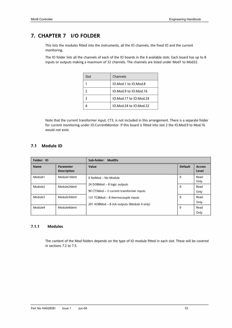
Mini8 Controller Engineering Handbook
Part No HA028581 Issue 1 Jun-04 55
7. CHAPTER 7 I/O FOLDER This lists the modules fitted into the instruments, all the IO channels, the fixed IO and the current monitoring.
The IO folder lists all the channels of each of the IO boards in the 4 available slots. Each board has up to 8 inputs or outputs making a maximum of 32 channels. The channels are listed under Mod1 to Mod32.
Slot Channels
1 IO.Mod.1 to IO.Mod.8
2 IO.Mod.9 to IO.Mod.16
3 IO.Mod.17 to IO.Mod.24
4 IO.Mod.24 to IO.Mod.32
Note that the current transformer input, CT3, is not included in this arrangement. There is a separate folder for current monitoring under IO.CurrentMonitor. If this board is fitted into slot 2 the IO.Mod.9 to Mod.16 would not exist.
7.1 Module ID
Folder: IO Sub-folder: ModIDs
Name
Parameter Description
Value
Default Access Level
Module1 Module1Ident 0 Read Only
Module2 Module2Ident 0 Read Only
Module3 Module3Ident 0 Read Only
Module4 Module4Ident
0 NoMod – No Module
24 DO8Mod – 8 logic outputs
90 CT3Mod – 3 current transformer inputs
131 TC8Mod – 8 thermocouple inputs
201 AO8Mod – 8 mA outputs (Module 4 only) 0 Read
Only
7.1.1 Modules
The content of the Mod folders depends on the type of IO module fitted in each slot. These will be covered in sections 7.2 to 7.5.
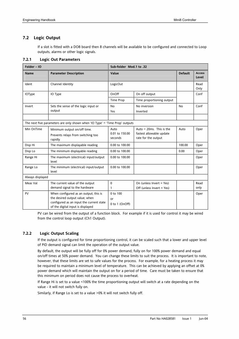
Engineering Handbook Mini8 Controller
56 Part No HA028581 Issue 1 Jun-04
7.2 Logic Output
If a slot is fitted with a DO8 board then 8 channels will be available to be configured and connected to Loop outputs, alarms or other logic signals.
7.2.1 Logic Out Parameters
Folder – IO Sub-folder Mod.1 to .32
Name
Parameter Description Value
Default Access Level
Ident Channel Identity LogicOut Read Only
OnOff On off output IOType IO Type
Time Prop Time proportioning output
Conf
Invert Sets the sense of the logic input or output
No Yes
No inversion Inverted
No Conf
The next five parameters are only shown when ‘IO Type’ = ‘Time Prop’ outputs
Min OnTime Minimum output on/off time.
Prevents relays from switching too rapidly
Auto 0.01 to 150.00 seconds
Auto = 20ms. This is the fastest allowable update rate for the output
Auto Oper
Disp Hi The maximum displayable reading 0.00 to 100.00 100.00 Oper
Disp Lo The minimum displayable reading 0.00 to 100.00 0.00 Oper
Range Hi The maximum (electrical) input/output level
0.00 to 100.00 Oper
Range Lo The minimum (electrical) input/output level
0.00 to 100.00 Oper
Always displayed
Meas Val The current value of the output demand signal to the hardware
0 1
On (unless Invert = Yes) Off (unless Invert = Yes)
Read only
PV When configured as an output, this is the desired output value; when configured as an input the current state of the digital input is displayed
0 to 100 or 0 to 1 (OnOff)
Oper
PV can be wired from the output of a function block. For example if it is used for control it may be wired from the control loop output (Ch1 Output).
7.2.2 Logic Output Scaling If the output is configured for time proportioning control, it can be scaled such that a lower and upper level of PID demand signal can limit the operation of the output value.
By default, the output will be fully off for 0% power demand, fully on for 100% power demand and equal on/off times at 50% power demand. You can change these limits to suit the process. It is important to note, however, that these limits are set to safe values for the process. For example, for a heating process it may be required to maintain a minimum level of temperature. This can be achieved by applying an offset at 0% power demand which will maintain the output on for a period of time. Care must be taken to ensure that this minimum on period does not cause the process to overheat.
If Range Hi is set to a value <100% the time proportioning output will switch at a rate depending on the value - it will not switch fully on.
Similarly, if Range Lo is set to a value >0% it will not switch fully off.
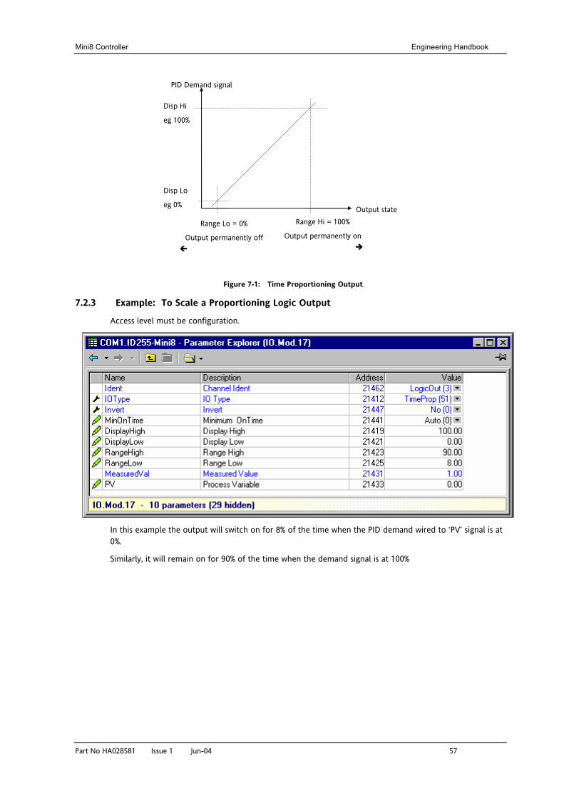
Mini8 Controller Engineering Handbook
Part No HA028581 Issue 1 Jun-04 57
Figure 7-1: Time Proportioning Output
7.2.3 Example: To Scale a Proportioning Logic Output
Access level must be configuration.
In this example the output will switch on for 8% of the time when the PID demand wired to ‘PV’ signal is at 0%.
Similarly, it will remain on for 90% of the time when the demand signal is at 100%
Range Lo = 0%
Output permanently off
Output state
PID Demand signal
Disp Hi
eg 100%
Disp Lo
eg 0%
Range Hi = 100%
Output permanently on
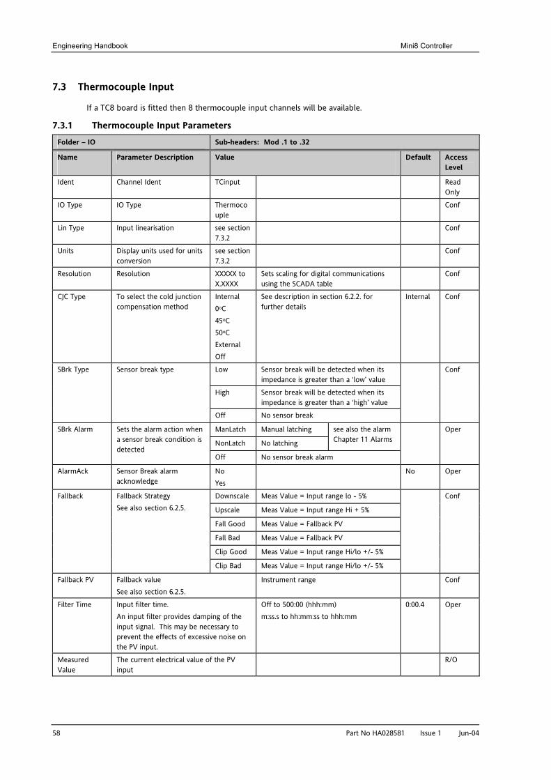
Engineering Handbook Mini8 Controller
58 Part No HA028581 Issue 1 Jun-04
7.3 Thermocouple Input
If a TC8 board is fitted then 8 thermocouple input channels will be available.
7.3.1 Thermocouple Input Parameters
Folder – IO Sub-headers: Mod .1 to .32
Name
Parameter Description Value
Default Access Level
Ident Channel Ident TCinput Read Only
IO Type IO Type Thermocouple
Conf
Lin Type Input linearisation see section 7.3.2
Conf
Units Display units used for units conversion
see section 7.3.2
Conf
Resolution Resolution XXXXX to X.XXXX
Sets scaling for digital communications using the SCADA table
Conf
CJC Type To select the cold junction compensation method
Internal 0oC 45oC 50oC External Off
See description in section 6.2.2. for further details
Internal Conf
Low Sensor break will be detected when its impedance is greater than a ‘low’ value
High Sensor break will be detected when its impedance is greater than a ‘high’ value
SBrk Type Sensor break type
Off No sensor break
Conf
ManLatch Manual latching
NonLatch No latching
see also the alarm Chapter 11 Alarms
SBrk Alarm Sets the alarm action when a sensor break condition is detected
Off No sensor break alarm
Oper
AlarmAck Sensor Break alarm acknowledge
No Yes
No Oper
Downscale Meas Value = Input range lo - 5%
Upscale Meas Value = Input range Hi + 5%
Fall Good Meas Value = Fallback PV
Fall Bad Meas Value = Fallback PV
Clip Good Meas Value = Input range Hi/lo +/- 5%
Fallback Fallback Strategy See also section 6.2.5.
Clip Bad Meas Value = Input range Hi/lo +/- 5%
Conf
Fallback PV Fallback value See also section 6.2.5.
Instrument range Conf
Filter Time Input filter time. An input filter provides damping of the input signal. This may be necessary to prevent the effects of excessive noise on the PV input.
Off to 500:00 (hhh:mm) m:ss.s to hh:mm:ss to hhh:mm
0:00.4 Oper
Measured Value
The current electrical value of the PV input
R/O
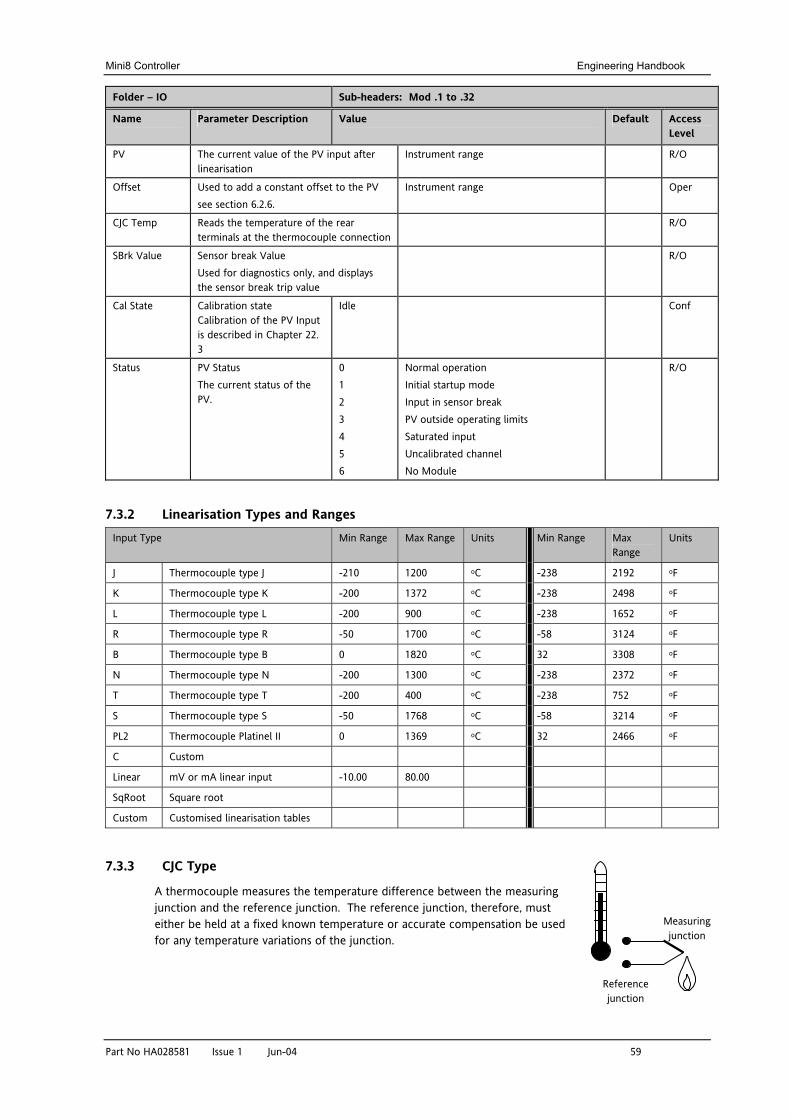
Mini8 Controller Engineering Handbook
Part No HA028581 Issue 1 Jun-04 59
Folder – IO Sub-headers: Mod .1 to .32
Name
Parameter Description Value
Default Access Level
PV The current value of the PV input after linearisation
Instrument range R/O
Offset Used to add a constant offset to the PV see section 6.2.6.
Instrument range Oper
CJC Temp Reads the temperature of the rear terminals at the thermocouple connection
R/O
SBrk Value Sensor break Value Used for diagnostics only, and displays the sensor break trip value
R/O
Cal State Calibration state Calibration of the PV Input is described in Chapter 22. 3
Idle Conf
Status PV Status The current status of the PV.
0 1 2 3 4 5 6
Normal operation Initial startup mode Input in sensor break PV outside operating limits Saturated input Uncalibrated channel No Module
R/O
7.3.2 Linearisation Types and Ranges Input Type Min Range Max Range Units Min Range Max
Range Units
J Thermocouple type J -210 1200 oC -238 2192 oF
K Thermocouple type K -200 1372 oC -238 2498 oF
L Thermocouple type L -200 900 oC -238 1652 oF
R Thermocouple type R -50 1700 oC -58 3124 oF
B Thermocouple type B 0 1820 oC 32 3308 oF
N Thermocouple type N -200 1300 oC -238 2372 oF
T Thermocouple type T -200 400 oC -238 752 oF
S Thermocouple type S -50 1768 oC -58 3214 oF
PL2 Thermocouple Platinel II 0 1369 oC 32 2466 oF
C Custom
Linear mV or mA linear input -10.00 80.00
SqRoot Square root
Custom Customised linearisation tables
7.3.3 CJC Type
A thermocouple measures the temperature difference between the measuring junction and the reference junction. The reference junction, therefore, must either be held at a fixed known temperature or accurate compensation be used for any temperature variations of the junction.
Measuring junction
Reference junction
Engineering Handbook Mini8 Controller
60 Part No HA028581 Issue 1 Jun-04
7.3.3.1 Internal Compensation
The controller is provided with a temperature sensing device which senses the temperature at the point where the thermocouple is joined to the copper wiring of the instrument and applies a corrective signal.
Where very high accuracy is needed and to accommodate multi-thermocouple installations, larger reference units are used which can achieve an accuracy of ±0.1°C or better. These units also allow the cables to the instrumentation to be run in copper. The reference units are contained basically under three techniques, Ice-Point, Hot Box and Isothermal.
7.3.3.2 The Ice-Point There are usually two methods of feeding the EMF from the thermocouple to the measuring instrumentation via the ice-point reference, the bellows type and the temperature sensor type.
The bellows type utilises the precise volumetric increase which occurs when a known quantity of ultra pure water changes state from liquid to solid. A precision cylinder actuates expansion bellows which control power to a thermoelectric cooling device. The temperature sensor type uses a metal block of high thermal conductance and mass, which is thermally insulated from ambient temperatures. The block temperature is lowered to 0°C by a cooling element, and maintained there by a temperature sensing device.
Special thermometers are obtainable for checking the 0°C reference units and alarm circuits that detect any movement from the zero position can be fitted.
7.3.3.3 The Hot Box
Thermocouples are calibrated in terms of EMF generated by the measuring junctions relative to the reference junction at 0°C. Different reference points can produce different characteristics of thermocouples, therefore referencing at another temperature does present problems. However, the ability of the hot box to work at very high ambient temperatures, plus a good reliability factor has led to an increase in its usage. The unit can consist of a thermally insulated solid aluminium block in which the reference junctions are embedded.
The block temperature is controlled by a closed loop system, and a heater is used as a booster when initially switching on. This booster drops out before the reference temperature, usually between 55°C and 65°C, is reached, but the stability of the hot box temperature is now important. Measurements cannot be taken until the hot box reaches the correct temperature.
7.3.3.4 Isothermal Systems
The thermocouple junctions being referenced are contained in a block which is heavily thermally insulated. The junctions are allowed to follow the mean ambient temperature, which varies slowly. This variation is accurately sensed by electronic means, and a signal is produced for the associated instrumentation. The high reliability factor of this method has favoured its use for long term monitoring.
7.3.3.5 CJC Options in Mini8 Series 0: CJC measurement at instrument terminals 1: CJC based on external junctions kept at 0C (Ice Point) 2: CJC based on external junctions kept at 45C (Hot Box) 3: CJC based on external junctions kept at 50C (Hot Box) 4: CJC based on independent external measurement 5: CJC switched off
7.3.4 Sensor Break Value The controller continuously monitors the impedance of a transducer or sensor connected to any analogue input. This impedance, expressed as a % of the impedance which causes the sensor break flag to trip, is a parameter called ‘SBrk Trip Imp’ and is available in the parameter lists associated with analogue inputs. The table below shows the typical impedance which causes sensor break to trip for various types of input and high and low SBrk Impedance parameter settings. The impedance values are only approximate (±25%) as they are not factory calibrated.
TC8 Input Range -77 to +77mV
SBrk Impedance – High SBrk Impedance – Low
~ 12KΩ ~ 3KΩ
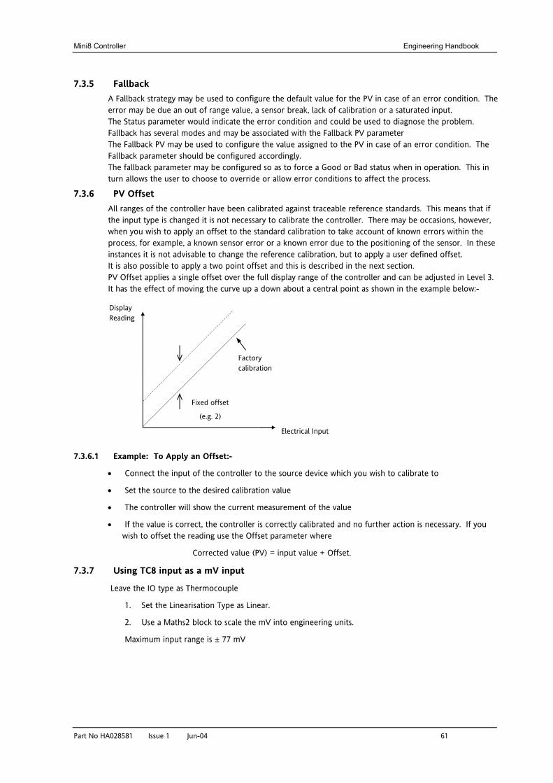
Mini8 Controller Engineering Handbook
Part No HA028581 Issue 1 Jun-04 61
7.3.5 Fallback A Fallback strategy may be used to configure the default value for the PV in case of an error condition. The error may be due an out of range value, a sensor break, lack of calibration or a saturated input. The Status parameter would indicate the error condition and could be used to diagnose the problem. Fallback has several modes and may be associated with the Fallback PV parameter The Fallback PV may be used to configure the value assigned to the PV in case of an error condition. The Fallback parameter should be configured accordingly. The fallback parameter may be configured so as to force a Good or Bad status when in operation. This in turn allows the user to choose to override or allow error conditions to affect the process.
7.3.6 PV Offset All ranges of the controller have been calibrated against traceable reference standards. This means that if the input type is changed it is not necessary to calibrate the controller. There may be occasions, however, when you wish to apply an offset to the standard calibration to take account of known errors within the process, for example, a known sensor error or a known error due to the positioning of the sensor. In these instances it is not advisable to change the reference calibration, but to apply a user defined offset. It is also possible to apply a two point offset and this is described in the next section. PV Offset applies a single offset over the full display range of the controller and can be adjusted in Level 3. It has the effect of moving the curve up a down about a central point as shown in the example below:-
7.3.6.1 Example: To Apply an Offset:-
• Connect the input of the controller to the source device which you wish to calibrate to
• Set the source to the desired calibration value
• The controller will show the current measurement of the value
• If the value is correct, the controller is correctly calibrated and no further action is necessary. If you wish to offset the reading use the Offset parameter where
Corrected value (PV) = input value + Offset.
7.3.7 Using TC8 input as a mV input
Leave the IO type as Thermocouple
1. Set the Linearisation Type as Linear.
2. Use a Maths2 block to scale the mV into engineering units.
Maximum input range is ± 77 mV
Electrical Input
Display Reading
Fixed offset
(e.g. 2)
Factory calibration
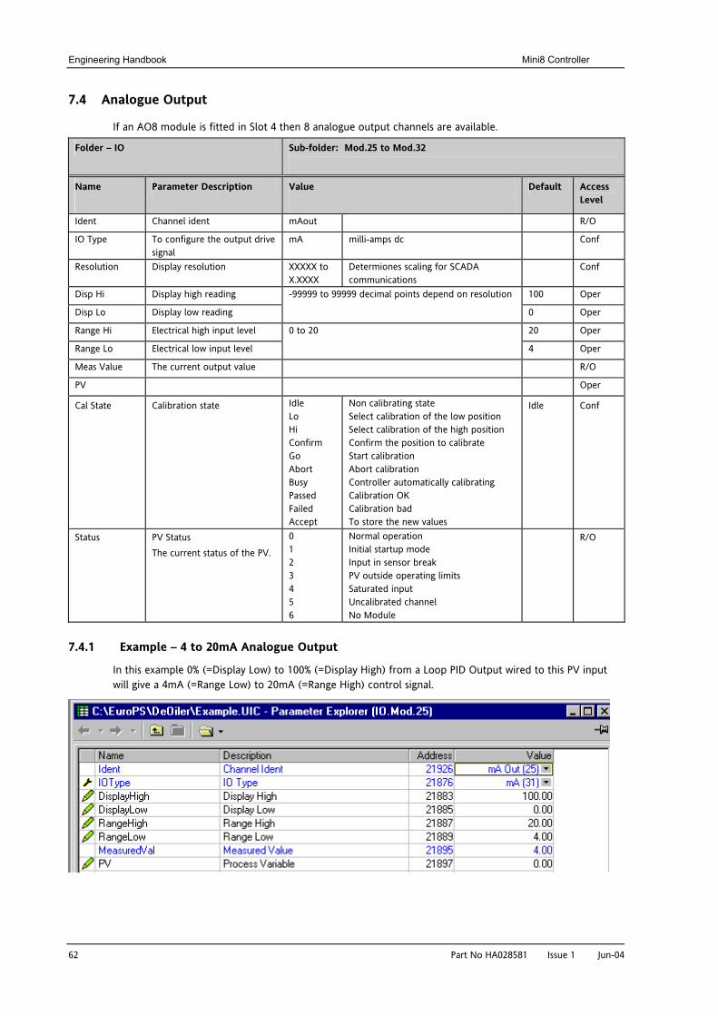
Engineering Handbook Mini8 Controller
62 Part No HA028581 Issue 1 Jun-04
7.4 Analogue Output
If an AO8 module is fitted in Slot 4 then 8 analogue output channels are available.
Folder – IO Sub-folder: Mod.25 to Mod.32
Name
Parameter Description Value
Default Access Level
Ident Channel ident mAout R/O
IO Type To configure the output drive signal
mA milli-amps dc Conf
Resolution Display resolution XXXXX to X.XXXX
Determiones scaling for SCADA communications
Conf
Disp Hi Display high reading 100 Oper
Disp Lo Display low reading
-99999 to 99999 decimal points depend on resolution 0 Oper
Range Hi Electrical high input level 20 Oper
Range Lo Electrical low input level
0 to 20
4 Oper
Meas Value The current output value R/O
PV Oper
Cal State Calibration state Idle Lo Hi Confirm Go Abort Busy Passed Failed Accept
Non calibrating state Select calibration of the low position Select calibration of the high position Confirm the position to calibrate Start calibration Abort calibration Controller automatically calibrating Calibration OK Calibration bad To store the new values
Idle Conf
Status PV Status The current status of the PV.
0 1 2 3 4 5 6
Normal operation Initial startup mode Input in sensor break PV outside operating limits Saturated input Uncalibrated channel No Module
R/O
7.4.1 Example – 4 to 20mA Analogue Output
In this example 0% (=Display Low) to 100% (=Display High) from a Loop PID Output wired to this PV input will give a 4mA (=Range Low) to 20mA (=Range High) control signal.
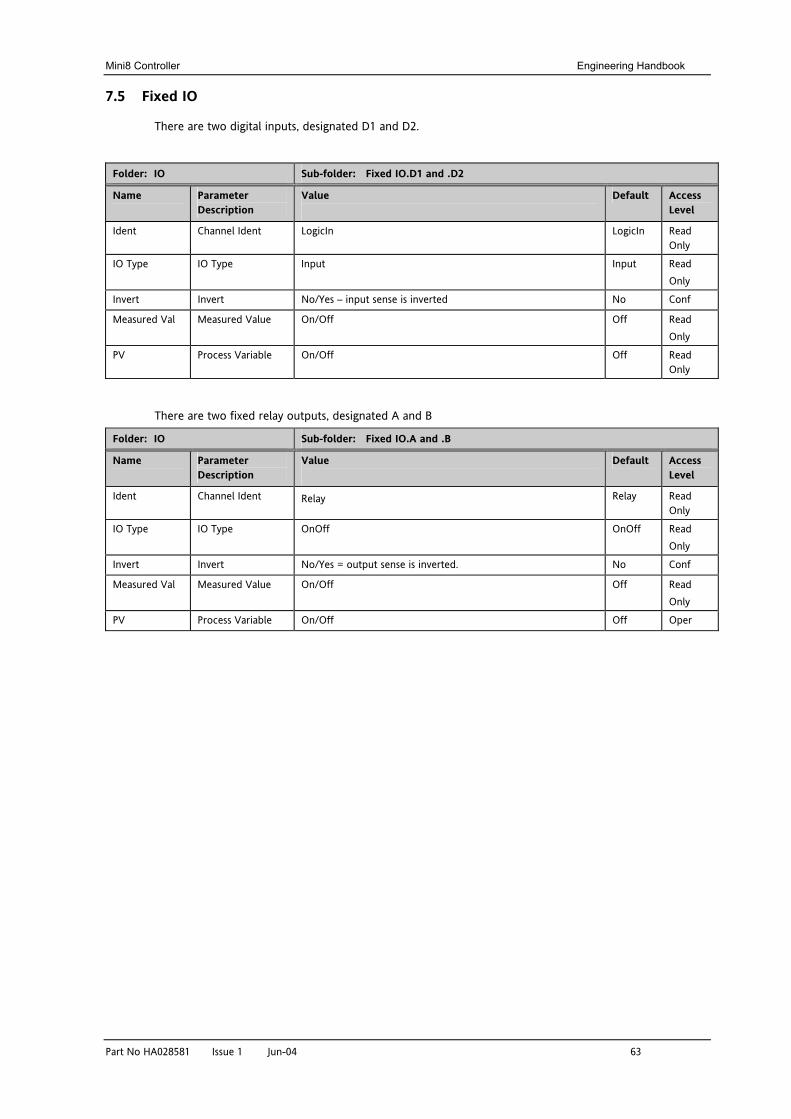
Mini8 Controller Engineering Handbook
Part No HA028581 Issue 1 Jun-04 63
7.5 Fixed IO
There are two digital inputs, designated D1 and D2.
Folder: IO Sub-folder: Fixed IO.D1 and .D2
Name
Parameter Description
Value
Default Access Level
Ident Channel Ident LogicIn LogicIn Read Only
IO Type IO Type Input Input Read Only
Invert Invert No/Yes – input sense is inverted No Conf
Measured Val Measured Value On/Off Off Read Only
PV Process Variable On/Off Off Read Only
There are two fixed relay outputs, designated A and B
Folder: IO Sub-folder: Fixed IO.A and .B
Name
Parameter Description
Value
Default Access Level
Ident Channel Ident Relay Relay Read Only
IO Type IO Type OnOff OnOff Read Only
Invert Invert No/Yes = output sense is inverted. No Conf
Measured Val Measured Value On/Off Off Read Only
PV Process Variable On/Off Off Oper
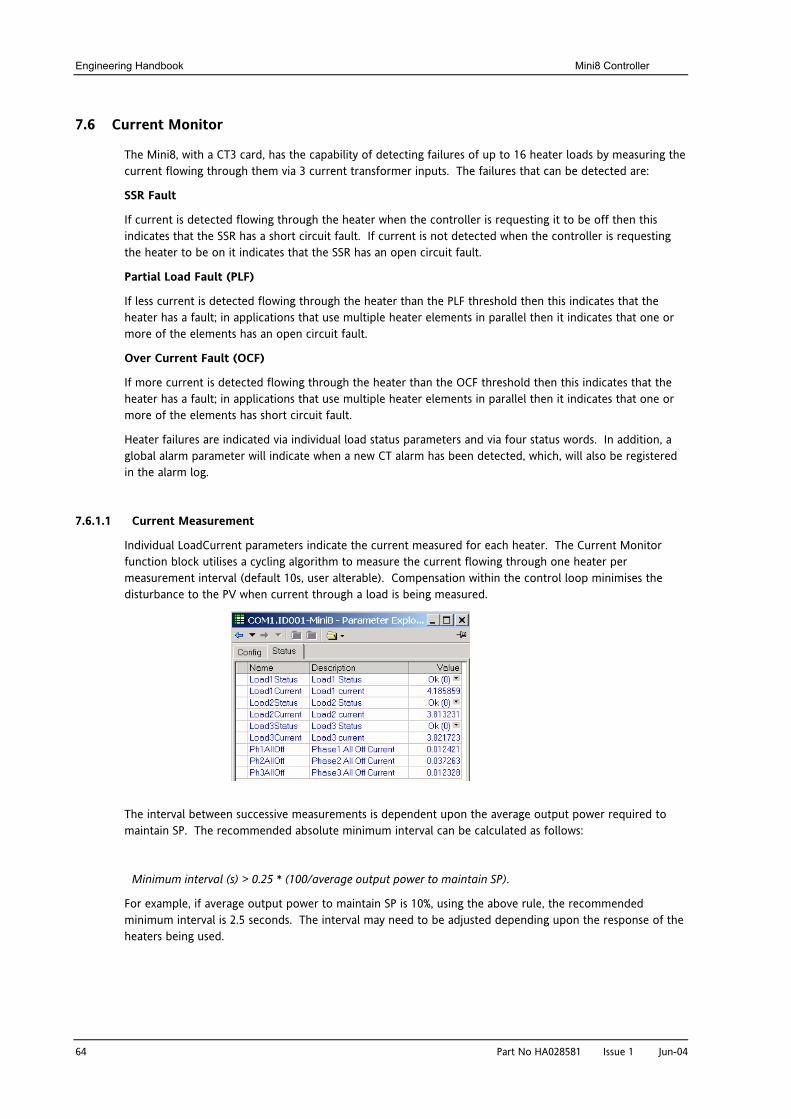
Engineering Handbook Mini8 Controller
64 Part No HA028581 Issue 1 Jun-04
7.6 Current Monitor
The Mini8, with a CT3 card, has the capability of detecting failures of up to 16 heater loads by measuring the current flowing through them via 3 current transformer inputs. The failures that can be detected are:
SSR Fault
If current is detected flowing through the heater when the controller is requesting it to be off then this indicates that the SSR has a short circuit fault. If current is not detected when the controller is requesting the heater to be on it indicates that the SSR has an open circuit fault.
Partial Load Fault (PLF)
If less current is detected flowing through the heater than the PLF threshold then this indicates that the heater has a fault; in applications that use multiple heater elements in parallel then it indicates that one or more of the elements has an open circuit fault.
Over Current Fault (OCF)
If more current is detected flowing through the heater than the OCF threshold then this indicates that the heater has a fault; in applications that use multiple heater elements in parallel then it indicates that one or more of the elements has short circuit fault.
Heater failures are indicated via individual load status parameters and via four status words. In addition, a global alarm parameter will indicate when a new CT alarm has been detected, which, will also be registered in the alarm log.
7.6.1.1 Current Measurement
Individual LoadCurrent parameters indicate the current measured for each heater. The Current Monitor function block utilises a cycling algorithm to measure the current flowing through one heater per measurement interval (default 10s, user alterable). Compensation within the control loop minimises the disturbance to the PV when current through a load is being measured.
The interval between successive measurements is dependent upon the average output power required to maintain SP. The recommended absolute minimum interval can be calculated as follows:
Minimum interval (s) > 0.25 * (100/average output power to maintain SP).
For example, if average output power to maintain SP is 10%, using the above rule, the recommended minimum interval is 2.5 seconds. The interval may need to be adjusted depending upon the response of the heaters being used.
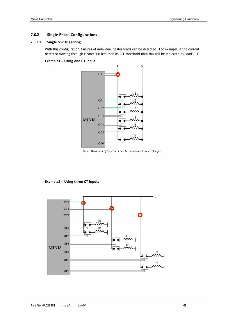
Mini8 Controller Engineering Handbook
Part No HA028581 Issue 1 Jun-04 65
7.6.2 Single Phase Configurations
7.6.2.1 Single SSR triggering
With this configuration, failures of individual heater loads can be detected. For example, if the current detected flowing through Heater 3 is less than its PLF threshold then this will be indicated as Load3PLF
Example1 – Using one CT input
Example2 – Using three CT inputs
CT1
H1
H2
H3
OP1
OP2
OP3
OP4
OP5
OP6
MINI8
L
H4
H5
H6
N
Note: Maximum of 6 Heaters can be connected to one CT input
CT1
H1
H2
H3
OP1
OP2
OP3
OP4
OP5
OP6
MINI8
L
H4
H5
H6
CT1
CT1
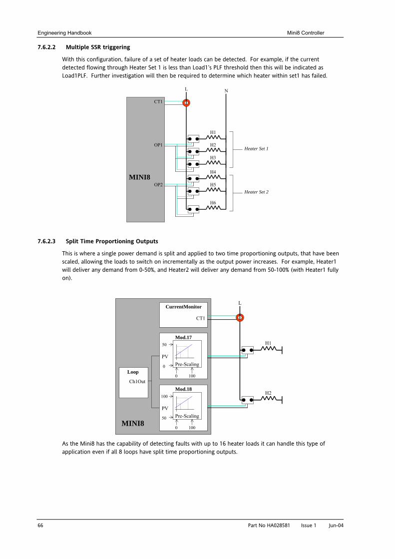
Engineering Handbook Mini8 Controller
66 Part No HA028581 Issue 1 Jun-04
7.6.2.2 Multiple SSR triggering
With this configuration, failure of a set of heater loads can be detected. For example, if the current detected flowing through Heater Set 1 is less than Load1’s PLF threshold then this will be indicated as Load1PLF. Further investigation will then be required to determine which heater within set1 has failed.
7.6.2.3 Split Time Proportioning Outputs
This is where a single power demand is split and applied to two time proportioning outputs, that have been scaled, allowing the loads to switch on incrementally as the output power increases. For example, Heater1 will deliver any demand from 0-50%, and Heater2 will deliver any demand from 50-100% (with Heater1 fully on).
As the Mini8 has the capability of detecting faults with up to 16 heater loads it can handle this type of application even if all 8 loops have split time proportioning outputs.
CT1
H1
H2
H3
OP1
OP2MINI8
L
H4
H5
H6
N
Heater Set 1
Heater Set 2
H1
MINI8
L
Loop
Mod.17
Mod.18
Pre-Scaling
0 100
Ch1Out
PV
H2
CurrentMonitor
CT1
100
50
Pre-Scaling
0 100
PV
50
0
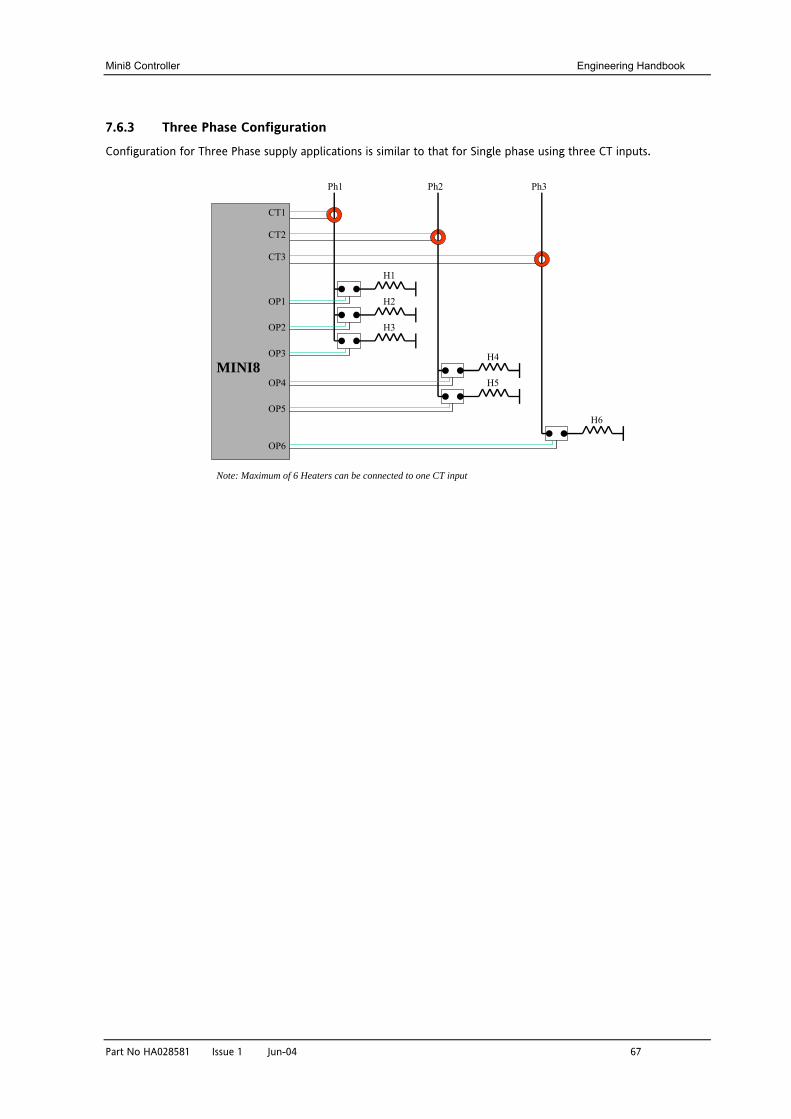
Mini8 Controller Engineering Handbook
Part No HA028581 Issue 1 Jun-04 67
7.6.3 Three Phase Configuration
Configuration for Three Phase supply applications is similar to that for Single phase using three CT inputs.
CT1
CT2
CT3
H1
H2
H3
H4
H5
H6
OP1
OP2
OP3
OP4
OP5
OP6
MINI8
Ph1 Ph2 Ph3
Note: Maximum of 6 Heaters can be connected to one CT input
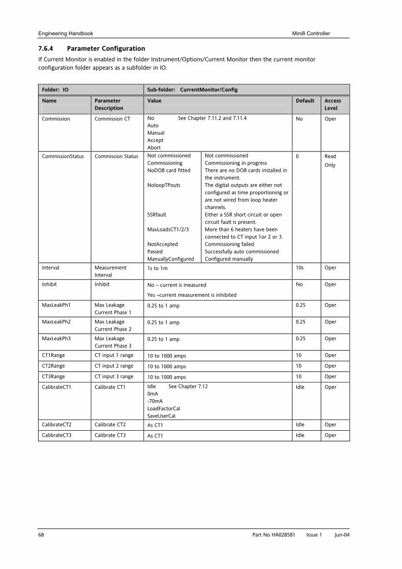
Engineering Handbook Mini8 Controller
68 Part No HA028581 Issue 1 Jun-04
7.6.4 Parameter Configuration If Current Monitor is enabled in the folder Instrument/Options/Current Monitor then the current monitor configuration folder appears as a subfolder in IO.
Folder: IO Sub-folder: CurrentMonitor/Config
Name
Parameter Description
Value
Default Access Level
Commission Commission CT No See Chapter 7.11.2 and 7.11.4 Auto Manual Accept Abort
No Oper
CommissionStatus Commission Status Not commissioned Commissioning NoDO8 card fitted NoloopTPouts SSRfault MaxLoadsCT1/2/3 NotAccepted Passed ManuallyConfigured
Not commissioned Commissioning in progress There are no DO8 cards installed in the instrument. The digital outputs are either not configured as time proportioning or are not wired from loop heater channels. Either a SSR short circuit or open circuit fault is present. More than 6 heaters have been connected to CT input 1or 2 or 3. Commissioning failed Successfully auto commissioned Configured manually
0 Read Only
Interval Measurement Interval
1s to 1m 10s Oper
Inhibit Inhibit No – current is measured
Yes –current measurement is inhibited
No Oper
MaxLeakPh1 Max Leakage Current Phase 1
0.25 to 1 amp 0.25 Oper
MaxLeakPh2 Max Leakage Current Phase 2
0.25 to 1 amp 0.25 Oper
MaxLeakPh3 Max Leakage Current Phase 3
0.25 to 1 amp 0.25 Oper
CT1Range CT input 1 range 10 to 1000 amps 10 Oper
CT2Range CT input 2 range 10 to 1000 amps 10 Oper
CT3Range CT input 3 range 10 to 1000 amps 10 Oper
CalibrateCT1 Calibrate CT1 Idle See Chapter 7.12 0mA -70mA LoadFactorCal SaveUserCal
Idle Oper
CalibrateCT2 Calibrate CT2 As CT1 Idle Oper
CalibrateCT3 Calibrate CT3 As CT1 Idle Oper
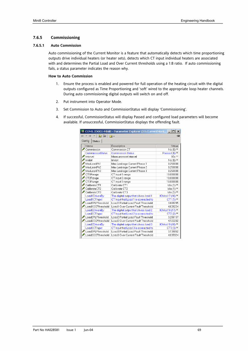
Mini8 Controller Engineering Handbook
Part No HA028581 Issue 1 Jun-04 69
7.6.5 Commissioning
7.6.5.1 Auto Commission
Auto commissioning of the Current Monitor is a feature that automatically detects which time proportioning outputs drive individual heaters (or heater sets), detects which CT input individual heaters are associated with and determines the Partial Load and Over Current thresholds using a 1:8 ratio. If auto commissioning fails, a status parameter indicates the reason why.
How to Auto Commission
1. Ensure the process is enabled and powered for full operation of the heating circuit with the digital outputs configured as Time Proportioning and ‘soft’ wired to the appropriate loop heater channels. During auto commissioning digital outputs will switch on and off.
2. Put instrument into Operator Mode.
3. Set Commission to Auto and CommissionStatus will display ‘Commissioning’.
4. If successful, CommissionStatus will display Passed and configured load parameters will become available. If unsuccessful, CommissionStatus displays the offending fault.
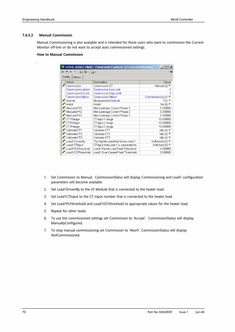
Engineering Handbook Mini8 Controller
70 Part No HA028581 Issue 1 Jun-04
7.6.5.2 Manual Commission
Manual Commissioning is also available and is intended for those users who want to commission the Current Monitor off-line or do not want to accept auto commissioned settings.
How to Manual Commission
.
1. Set Commission to Manual. CommissionStatus will display Commissioning and Load1 configuration parameters will become available
2. Set Load1DrivenBy to the IO Module that is connected to the heater load.
3. Set Load1CTInput to the CT input number that is connected to the heater load.
4. Set Load1PLFthreshold and Load1OCFthreshold to appropriate values for the heater load.
5. Repeat for other loads.
6. To use the commissioned settings set Commission to ‘Accept’. CommissionStatus will display ManuallyConfigured.
7. To stop manual commissioning set Commission to ‘Abort’. CommissionStatus will display NotCommissioned.
Mini8 Controller Engineering Handbook
Part No HA028581 Issue 1 Jun-04 71
7.6.6 Calibration
A Mini8 supplied from factory with the CT3 card already installed the CT inputs will have been factory calibrated. If the CT3 card is installed at a later date then default calibration values are automatically loaded into the instrument. However, three calibration parameters, one for each CT input, are provided to allow the inputs to be calibrated in the field.
Note: DC Current Source, capable of outputting a –70mA signal, is required to calibrate the inputs.
The CT inputs are calibrated individually.
How to Calibrate
1. Apply the stimulus (0mA or –70mA) from the DC current source to the CT input to be calibrated.
2. Set CalibrateCT1, to reflect the stimulus being applied to the input.
3. CalibrateCT1 displays ‘Confirm’. Select ‘Go’ to proceed with the calibration process.
4. After selecting Go, CalibrateCT1 displays ‘Calibrating’.
5. If calibration was successful, CalibrateCT1 displays ‘Passed’. Select ‘Accept’ to keep the calibration values.
6. If calibration was unsuccessful, CalibrateCT1 displays ‘Failed’. Select ‘Abort’ to reject the calibration.
7. Select ‘SaveUserCal’ to save the calibration values into non-volatile memory.
8. Select ‘LoadFactCal’ to restore calibration values to the factory calibrated or default settings.
9. Note: It is possible to stop the calibration process at anytime by selecting ‘Abort’.
Follow the same procedure for CT2 and CT3.
Engineering Handbook Mini8 Controller
72 Part No HA028581 Issue 1 Jun-04
8. CHAPTER 8 ALARMS Alarms are used to alert the system when a pre-set level has been exceeded or a particular condition has changed state. As the Mini8 has no display to show alarms the alarm flags are all available over communications in status words See Alarm Summary (Section 8.7) . They may also be wired directly or via logic to an output such as a relay.
Alarms can be divided into two main types. These are:-
Analogue alarms - operate by monitoring an analogue variable such as the process variable and comparing it with a set threshold.
Digital alarms – operate when the state of a boolean variable changes, for example, sensor break.
Number of Alarms - up to 32 analogue and 32 digital alarms may be configured.
8.1 Further Alarm Definitions
Hysteresis is the difference between the point at which the alarm switches ‘ON’ and the point at which it switches ‘OFF’. It is used to provide a definite indication of the alarm condition and to prevent alarm relay chatter.
Latching Alarm
used to hold the alarm condition once an alarm has been detected. It may be configured as:-
None Non latching
A non latching alarm will reset itself when the alarm condition is removed
Auto Automatic An auto latching alarm requires acknowledgement before it is reset. The acknowledgement can occur BEFORE the condition causing the alarm is removed.
Manual Manual The alarm continues to be active until both the alarm condition is removed AND the alarm is acknowledged. The acknowledgement can only occur AFTER the condition causing the alarm is removed.
Event Event Alarm output will activate.
Blocking Alarms
The alarm may be masked during start up. Blocking prevents the alarm from being activated until the process has first achieved a safe state. It is used, for example, to ignore start up conditions which are not representative of running conditions. A blocking alarm is re-initiated after a setpoint change.
Delay A short time can be set for each alarm which prevents the output from going into the alarm state. The alarm is still detected as soon as it occurs, but if it cancels before the end of the delay period then no output is triggered. The timer for the delay is then reset. It is also reset if an alarm is changed from being inhibited to uninhibited.
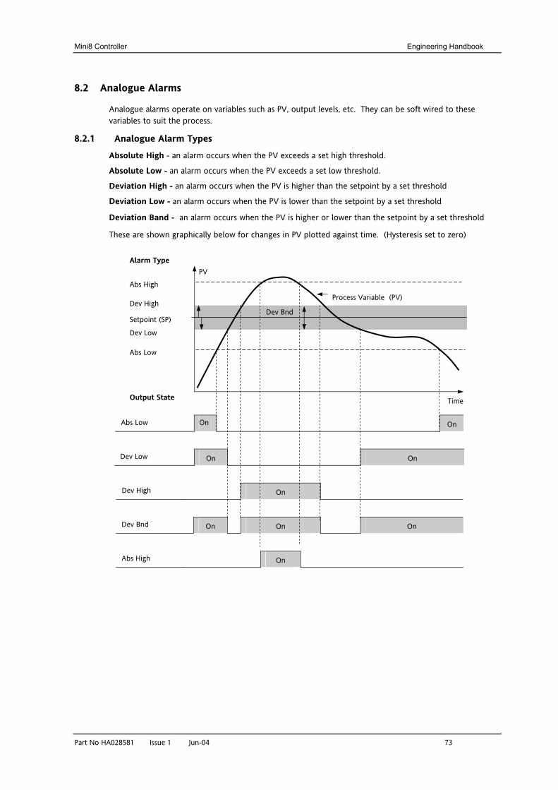
Mini8 Controller Engineering Handbook
Part No HA028581 Issue 1 Jun-04 73
8.2 Analogue Alarms
Analogue alarms operate on variables such as PV, output levels, etc. They can be soft wired to these variables to suit the process.
8.2.1 Analogue Alarm Types
Absolute High - an alarm occurs when the PV exceeds a set high threshold.
Absolute Low - an alarm occurs when the PV exceeds a set low threshold.
Deviation High - an alarm occurs when the PV is higher than the setpoint by a set threshold
Deviation Low - an alarm occurs when the PV is lower than the setpoint by a set threshold
Deviation Band - an alarm occurs when the PV is higher or lower than the setpoint by a set threshold
These are shown graphically below for changes in PV plotted against time. (Hysteresis set to zero)
Abs Low On On
Dev Low On On
Dev High On
Dev Bnd On On On
Abs High On
Time
Setpoint (SP)
Abs High
Abs Low
Dev High
Dev Low
Dev Bnd
PV
Process Variable (PV)
Alarm Type
Output State
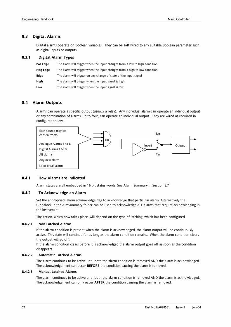
Engineering Handbook Mini8 Controller
74 Part No HA028581 Issue 1 Jun-04
8.3 Digital Alarms
Digital alarms operate on Boolean variables. They can be soft wired to any suitable Boolean parameter such as digital inputs or outputs.
8.3.1 Digital Alarm Types Pos Edge The alarm will trigger when the input changes from a low to high condition
Neg Edge The alarm will trigger when the input changes from a high to low condition
Edge The alarm will trigger on any change of state of the input signal
High The alarm will trigger when the input signal is high
Low The alarm will trigger when the input signal is low
8.4 Alarm Outputs
Alarms can operate a specific output (usually a relay). Any individual alarm can operate an individual output or any combination of alarms, up to four, can operate an individual output. They are wired as required in configuration level.
8.4.1 How Alarms are Indicated
Alarm states are all embedded in 16 bit status words. See Alarm Summary in Section 8.7
8.4.2 To Acknowledge an Alarm
Set the appropriate alarm acknowledge flag to acknowledge that particular alarm. Alternatively the GlobalAck in the AlmSummary folder can be used to acknowledge ALL alarms that require acknowledging in the instrument.
The action, which now takes place, will depend on the type of latching, which has been configured
8.4.2.1 Non Latched Alarms If the alarm condition is present when the alarm is acknowledged, the alarm output will be continuously active. This state will continue for as long as the alarm condition remains. When the alarm condition clears the output will go off.. If the alarm condition clears before it is acknowledged the alarm output goes off as soon as the condition disappears.
8.4.2.2 Automatic Latched Alarms The alarm continues to be active until both the alarm condition is removed AND the alarm is acknowledged. The acknowledgement can occur BEFORE the condition causing the alarm is removed.
8.4.2.3 Manual Latched Alarms The alarm continues to be active until both the alarm condition is removed AND the alarm is acknowledged. The acknowledgement can only occur AFTER the condition causing the alarm is removed.
OR
Invert Output
No
Yes
Each source may be chosen from:-
Analogue Alarms 1 to 8
Digital Alarms 1 to 8
All alarms
Any new alarm
Loop break alarm
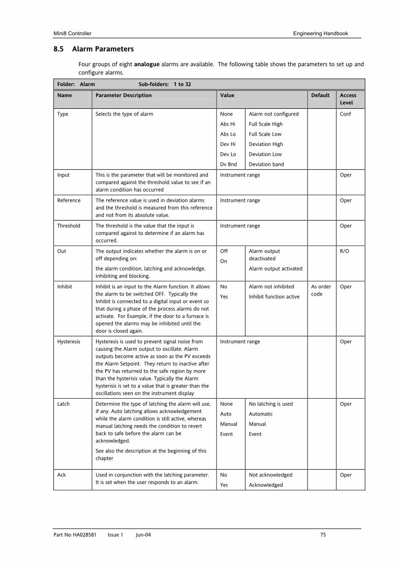
Mini8 Controller Engineering Handbook
Part No HA028581 Issue 1 Jun-04 75
8.5 Alarm Parameters
Four groups of eight analogue alarms are available. The following table shows the parameters to set up and configure alarms.
Folder: Alarm Sub-folders: 1 to 32
Name
Parameter Description Value
Default Access Level
Type Selects the type of alarm None
Abs Hi
Abs Lo
Dev Hi
Dev Lo
Dv Bnd
Alarm not configured
Full Scale High
Full Scale Low
Deviation High
Deviation Low
Deviation band
Conf
Input This is the parameter that will be monitored and compared against the threshold value to see if an alarm condition has occurred
Instrument range Oper
Reference The reference value is used in deviation alarms and the threshold is measured from this reference and not from its absolute value.
Instrument range Oper
Threshold The threshold is the value that the input is compared against to determine if an alarm has occurred.
Instrument range Oper
Out The output indicates whether the alarm is on or off depending on:
the alarm condition, latching and acknowledge, inhibiting and blocking.
Off
On
Alarm output deactivated
Alarm output activated
R/O
Inhibit Inhibit is an input to the Alarm function. It allows the alarm to be switched OFF. Typically the Inhibit is connected to a digital input or event so that during a phase of the process alarms do not activate. For Example, if the door to a furnace is opened the alarms may be inhibited until the door is closed again.
No
Yes
Alarm not inhibited
Inhibit function active
As order code
Oper
Hysteresis Hysteresis is used to prevent signal noise from causing the Alarm output to oscillate. Alarm outputs become active as soon as the PV exceeds the Alarm Setpoint. They return to inactive after the PV has returned to the safe region by more than the hysterisis value. Typically the Alarm hysterisis is set to a value that is greater than the oscillations seen on the instrument display
Instrument range Oper
Latch Determine the type of latching the alarm will use, if any. Auto latching allows acknowledgement while the alarm condition is still active, whereas manual latching needs the condition to revert back to safe before the alarm can be acknowledged.
See also the description at the beginning of this chapter
None
Auto
Manual
Event
No latching is used
Automatic
Manual
Event
Oper
Ack Used in conjunction with the latching parameter. It is set when the user responds to an alarm.
No
Yes
Not acknowledged
Acknowledged
Oper
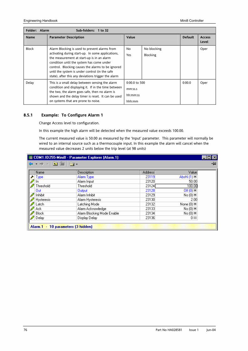
Engineering Handbook Mini8 Controller
76 Part No HA028581 Issue 1 Jun-04
Folder: Alarm Sub-folders: 1 to 32
Name
Parameter Description Value
Default Access Level
Block Alarm Blocking is used to prevent alarms from activating during start-up. In some applications, the measurement at start-up is in an alarm condition until the system has come under control. Blocking causes the alarms to be ignored until the system is under control (in the safe state), after this any deviations trigger the alarm
No
Yes
No blocking
Blocking
Oper
Delay This is a small delay between sensing the alarm condition and displaying it. If in the time between the two, the alarm goes safe, then no alarm is shown and the delay timer is reset. It can be used on systems that are prone to noise.
0:00.0 to 500
mm:ss.s
hh:mm:ss
hhh:mm
0:00.0 Oper
8.5.1 Example: To Configure Alarm 1
Change Access level to configuration.
In this example the high alarm will be detected when the measured value exceeds 100.00.
The current measured value is 50.00 as measured by the ‘Input’ parameter. This parameter will normally be wired to an internal source such as a thermocouple input. In this example the alarm will cancel when the measured value decreases 2 units below the trip level (at 98 units)
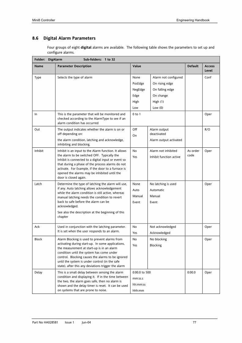
Mini8 Controller Engineering Handbook
Part No HA028581 Issue 1 Jun-04 77
8.6 Digital Alarm Parameters
Four groups of eight digital alarms are available. The following table shows the parameters to set up and configure alarms.
Folder: DigAlarm Sub-folders: 1 to 32
Name
Parameter Description Value
Default Access Level
Type Selects the type of alarm None
PosEdge
NegEdge
Edge
High
Low
Alarm not configured
On rising edge
On falling edge
On change
High (1)
Low (0)
Conf
In This is the parameter that will be monitored and checked according to the AlarmType to see if an alarm condition has occurred
0 to 1 Oper
Out The output indicates whether the alarm is on or off depending on:
the alarm condition, latching and acknowledge, inhibiting and blocking.
Off
On
Alarm output deactivated
Alarm output activated
R/O
Inhibit Inhibit is an input to the Alarm function. It allows the alarm to be switched OFF. Typically the Inhibit is connected to a digital input or event so that during a phase of the process alarms do not activate. For Example, if the door to a furnace is opened the alarms may be inhibited until the door is closed again.
No
Yes
Alarm not inhibited
Inhibit function active
As order code
Oper
Latch Determine the type of latching the alarm will use, if any. Auto latching allows acknowledgement while the alarm condition is still active, whereas manual latching needs the condition to revert back to safe before the alarm can be acknowledged.
See also the description at the beginning of this chapter
None
Auto
Manual
Event
No latching is used
Automatic
Manual
Event
Oper
Ack Used in conjunction with the latching parameter. It is set when the user responds to an alarm.
No
Yes
Not acknowledged
Acknowledged
Oper
Block Alarm Blocking is used to prevent alarms from activating during start-up. In some applications, the measurement at start-up is in an alarm condition until the system has come under control. Blocking causes the alarms to be ignored until the system is under control (in the safe state), after this any deviations trigger the alarm
No
Yes
No blocking
Blocking
Oper
Delay This is a small delay between sensing the alarm condition and displaying it. If in the time between the two, the alarm goes safe, then no alarm is shown and the delay timer is reset. It can be used on systems that are prone to noise.
0:00.0 to 500
mm:ss.s
hh:mm:ss
hhh:mm
0:00.0 Oper
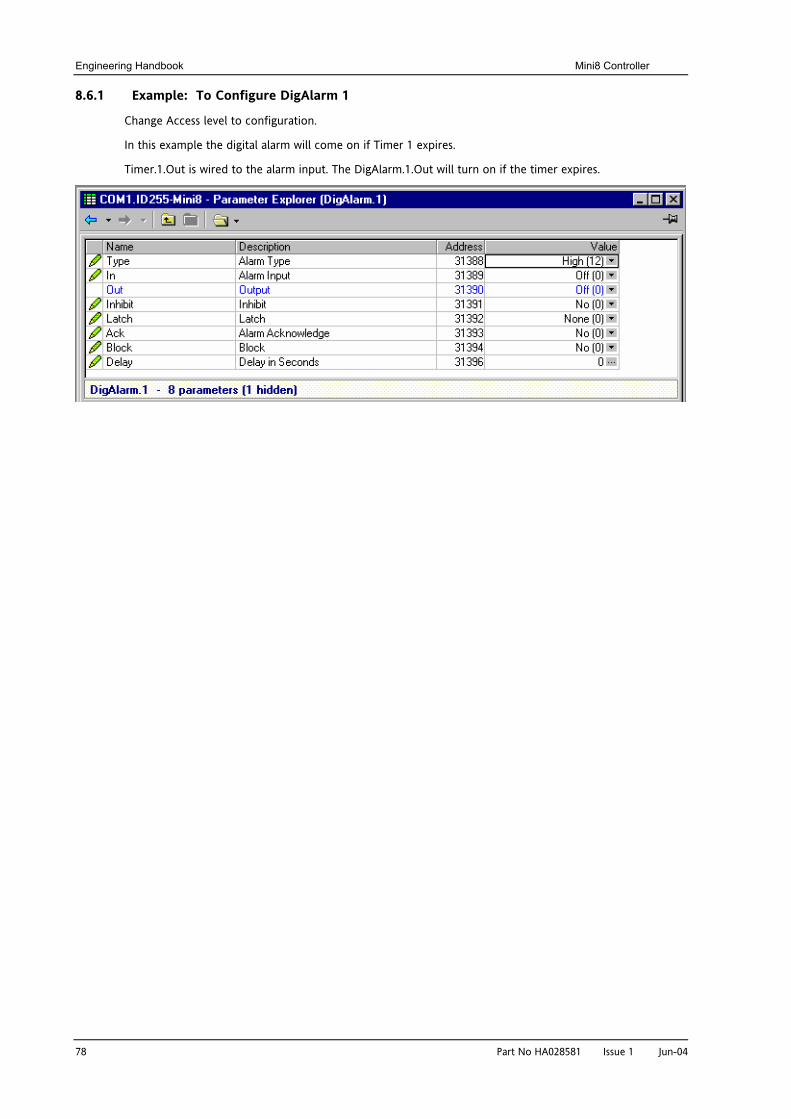
Engineering Handbook Mini8 Controller
78 Part No HA028581 Issue 1 Jun-04
8.6.1 Example: To Configure DigAlarm 1
Change Access level to configuration.
In this example the digital alarm will come on if Timer 1 expires.
Timer.1.Out is wired to the alarm input. The DigAlarm.1.Out will turn on if the timer expires.
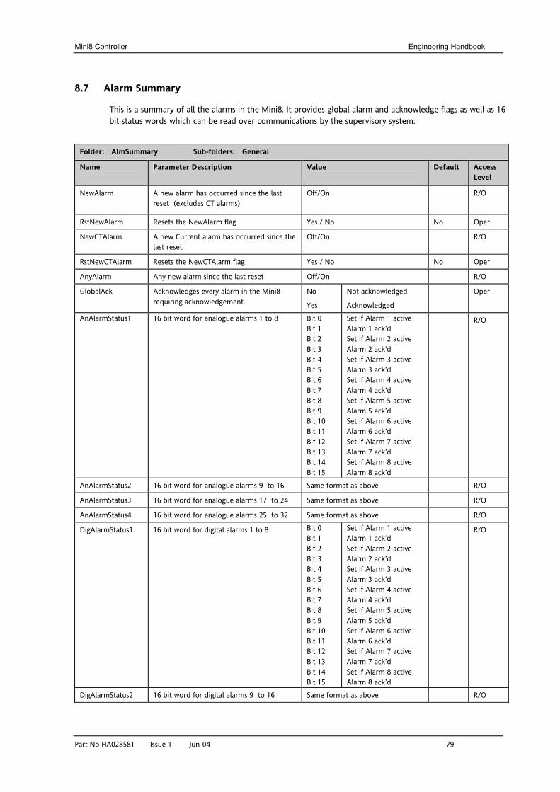
Mini8 Controller Engineering Handbook
Part No HA028581 Issue 1 Jun-04 79
8.7 Alarm Summary
This is a summary of all the alarms in the Mini8. It provides global alarm and acknowledge flags as well as 16 bit status words which can be read over communications by the supervisory system.
Folder: AlmSummary Sub-folders: General
Name
Parameter Description Value
Default Access Level
NewAlarm A new alarm has occurred since the last reset (excludes CT alarms)
Off/On R/O
RstNewAlarm Resets the NewAlarm flag Yes / No No Oper
NewCTAlarm A new Current alarm has occurred since the last reset
Off/On R/O
RstNewCTAlarm Resets the NewCTAlarm flag Yes / No No Oper
AnyAlarm Any new alarm since the last reset Off/On R/O
GlobalAck Acknowledges every alarm in the Mini8 requiring acknowledgement.
No
Yes
Not acknowledged
Acknowledged
Oper
AnAlarmStatus1 16 bit word for analogue alarms 1 to 8 Bit 0 Bit 1 Bit 2 Bit 3 Bit 4 Bit 5 Bit 6 Bit 7 Bit 8 Bit 9 Bit 10 Bit 11 Bit 12 Bit 13 Bit 14 Bit 15
Set if Alarm 1 active Alarm 1 ack’d Set if Alarm 2 active Alarm 2 ack’d Set if Alarm 3 active Alarm 3 ack’d Set if Alarm 4 active Alarm 4 ack’d Set if Alarm 5 active Alarm 5 ack’d Set if Alarm 6 active Alarm 6 ack’d Set if Alarm 7 active Alarm 7 ack’d Set if Alarm 8 active Alarm 8 ack’d
R/O
AnAlarmStatus2 16 bit word for analogue alarms 9 to 16 Same format as above R/O
AnAlarmStatus3 16 bit word for analogue alarms 17 to 24 Same format as above R/O
AnAlarmStatus4 16 bit word for analogue alarms 25 to 32 Same format as above R/O
DigAlarmStatus1 16 bit word for digital alarms 1 to 8 Bit 0 Bit 1 Bit 2 Bit 3 Bit 4 Bit 5 Bit 6 Bit 7 Bit 8 Bit 9 Bit 10 Bit 11 Bit 12 Bit 13 Bit 14 Bit 15
Set if Alarm 1 active Alarm 1 ack’d Set if Alarm 2 active Alarm 2 ack’d Set if Alarm 3 active Alarm 3 ack’d Set if Alarm 4 active Alarm 4 ack’d Set if Alarm 5 active Alarm 5 ack’d Set if Alarm 6 active Alarm 6 ack’d Set if Alarm 7 active Alarm 7 ack’d Set if Alarm 8 active Alarm 8 ack’d
R/O
DigAlarmStatus2 16 bit word for digital alarms 9 to 16 Same format as above R/O
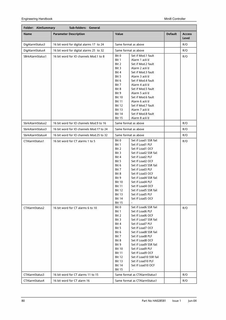
Engineering Handbook Mini8 Controller
80 Part No HA028581 Issue 1 Jun-04
Folder: AlmSummary Sub-folders: General
Name
Parameter Description Value
Default Access Level
DigAlarmStatus3 16 bit word for digital alarms 17 to 24 Same format as above R/O
DigAlarmStatus4 16 bit word for digital alarms 25 to 32 Same format as above R/O
SBrkAlarmStatus1 16 bit word for IO channels Mod.1 to 8 Bit 0 Bit 1 Bit 2 Bit 3 Bit 4 Bit 5 Bit 6 Bit 7 Bit 8 Bit 9 Bit 10 Bit 11 Bit 12 Bit 13 Bit 14 Bit 15
Set if Mod.1 fault Alarm 1 ack’d Set if Mod.2 fault Alarm 2 ack’d Set if Mod.3 fault Alarm 3 ack’d Set if Mod.4 fault Alarm 4 ack’d Set if Mod.5 fault Alarm 5 ack’d Set if Mod.6 fault Alarm 6 ack’d Set if Mod.7 fault Alarm 7 ack’d Set if Mod.8 fault Alarm 8 ack’d
R/O
SbrkAlarmStatus2 16 bit word for IO channels Mod.9 to 16 Same format as above R/O
SbrkAlarmStatus3 16 bit word for IO channels Mod.17 to 24 Same format as above R/O
SbrkAlarmStatus4 16 bit word for IO channels Mod.25 to 32 Same format as above R/O
CTAlarmStatus1 16 bit word for CT alarms 1 to 5 Bit 0 Bit 1 Bit 2 Bit 3 Bit 4 Bit 5 Bit 6 Bit 7 Bit 8 Bit 9 Bit 10 Bit 11 Bit 12 Bit 13 Bit 14 Bit 15
Set if Load1 SSR fail Set if Load1 PLF Set If Load1 OCF Set if Load2 SSR fail Set if Load2 PLF Set If Load2 OCF Set if Load3 SSR fail Set if Load3 PLF Set If Load3 OCF Set if Load4 SSR fail Set if Load4 PLF Set If Load4 OCF Set if Load5 SSR fail Set if Load5 PLF Set If Load5 OCF -
R/O
CTAlarmStatus2 16 bit word for CT alarms 6 to 10 Bit 0 Bit 1 Bit 2 Bit 3 Bit 4 Bit 5 Bit 6 Bit 7 Bit 8 Bit 9 Bit 10 Bit 11 Bit 12 Bit 13 Bit 14 Bit 15
Set if Load6 SSR fail Set if Load6 PLF Set If Load6 OCF Set if Load7 SSR fail Set if Load7 PLF Set If Load7 OCF Set if Load8 SSR fail Set if Load8 PLF Set If Load8 OCF Set if Load9 SSR fail Set if Load9 PLF Set If Load9 OCF Set if Load10 SSR fail Set if Load10 PLF Set If Load10 OCF -
R/O
CTAlarmStatus3 16 bit word for CT alarms 11 to 15 Same format as CTAlarmStatus1 R/O
CTAlarmStatus4 16 bit word for CT alarm 16 Same format as CTAlarmStatus1 R/O
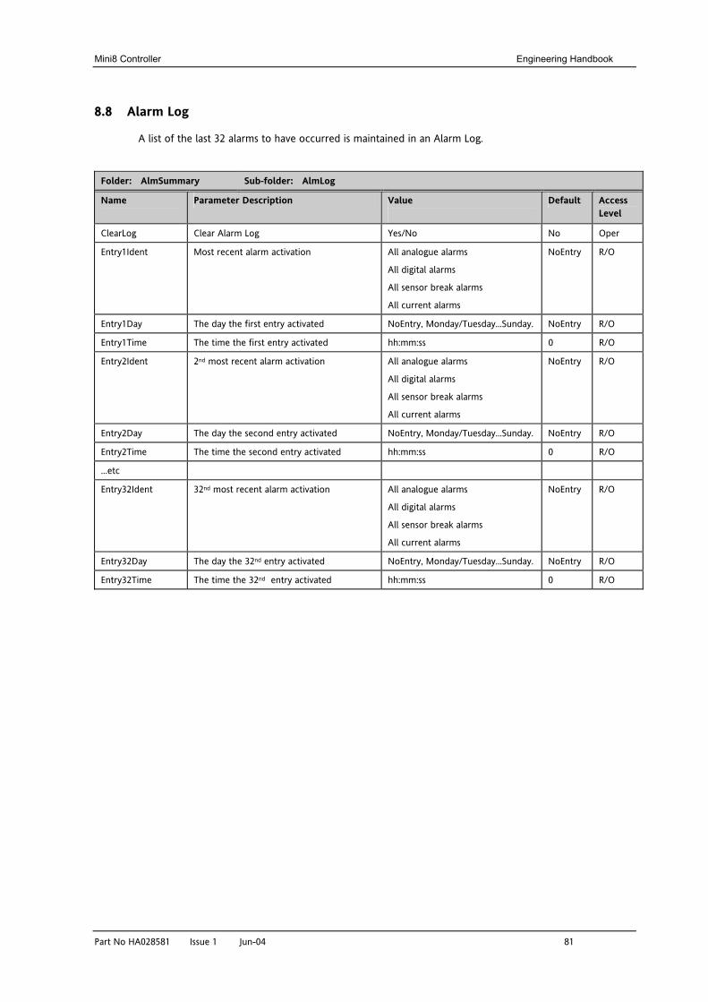
Mini8 Controller Engineering Handbook
Part No HA028581 Issue 1 Jun-04 81
8.8 Alarm Log
A list of the last 32 alarms to have occurred is maintained in an Alarm Log.
Folder: AlmSummary Sub-folder: AlmLog
Name
Parameter Description Value
Default Access Level
ClearLog Clear Alarm Log Yes/No No Oper
Entry1Ident Most recent alarm activation All analogue alarms
All digital alarms
All sensor break alarms
All current alarms
NoEntry R/O
Entry1Day The day the first entry activated NoEntry, Monday/Tuesday…Sunday. NoEntry R/O
Entry1Time The time the first entry activated hh:mm:ss 0 R/O
Entry2Ident 2nd most recent alarm activation All analogue alarms
All digital alarms
All sensor break alarms
All current alarms
NoEntry R/O
Entry2Day The day the second entry activated NoEntry, Monday/Tuesday…Sunday. NoEntry R/O
Entry2Time The time the second entry activated hh:mm:ss 0 R/O
…etc
Entry32Ident 32nd most recent alarm activation All analogue alarms
All digital alarms
All sensor break alarms
All current alarms
NoEntry R/O
Entry32Day The day the 32nd entry activated NoEntry, Monday/Tuesday…Sunday. NoEntry R/O
Entry32Time The time the 32nd entry activated hh:mm:ss 0 R/O
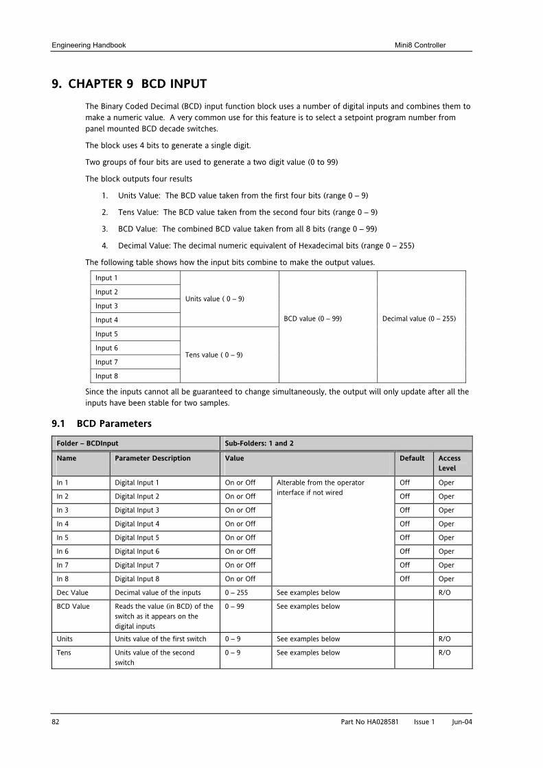
Engineering Handbook Mini8 Controller
82 Part No HA028581 Issue 1 Jun-04
9. CHAPTER 9 BCD INPUT The Binary Coded Decimal (BCD) input function block uses a number of digital inputs and combines them to make a numeric value. A very common use for this feature is to select a setpoint program number from panel mounted BCD decade switches.
The block uses 4 bits to generate a single digit.
Two groups of four bits are used to generate a two digit value (0 to 99)
The block outputs four results
1. Units Value: The BCD value taken from the first four bits (range 0 – 9)
2. Tens Value: The BCD value taken from the second four bits (range 0 – 9)
3. BCD Value: The combined BCD value taken from all 8 bits (range 0 – 99)
4. Decimal Value: The decimal numeric equivalent of Hexadecimal bits (range 0 – 255)
The following table shows how the input bits combine to make the output values.
Input 1
Input 2
Input 3
Input 4
Units value ( 0 – 9)
Input 5
Input 6
Input 7
Input 8
Tens value ( 0 – 9)
BCD value (0 – 99)
Decimal value (0 – 255)
Since the inputs cannot all be guaranteed to change simultaneously, the output will only update after all the inputs have been stable for two samples.
9.1 BCD Parameters
Folder – BCDInput Sub-Folders: 1 and 2
Name
Parameter Description Value
Default Access Level
In 1 Digital Input 1 On or Off Off Oper
In 2 Digital Input 2 On or Off Off Oper
In 3 Digital Input 3 On or Off Off Oper
In 4 Digital Input 4 On or Off Off Oper
In 5 Digital Input 5 On or Off Off Oper
In 6 Digital Input 6 On or Off Off Oper
In 7 Digital Input 7 On or Off Off Oper
In 8 Digital Input 8 On or Off
Alterable from the operator interface if not wired
Off Oper
Dec Value Decimal value of the inputs 0 – 255 See examples below R/O
BCD Value Reads the value (in BCD) of the switch as it appears on the digital inputs
0 – 99 See examples below
Units Units value of the first switch 0 – 9 See examples below R/O
Tens Units value of the second switch
0 – 9 See examples below R/O
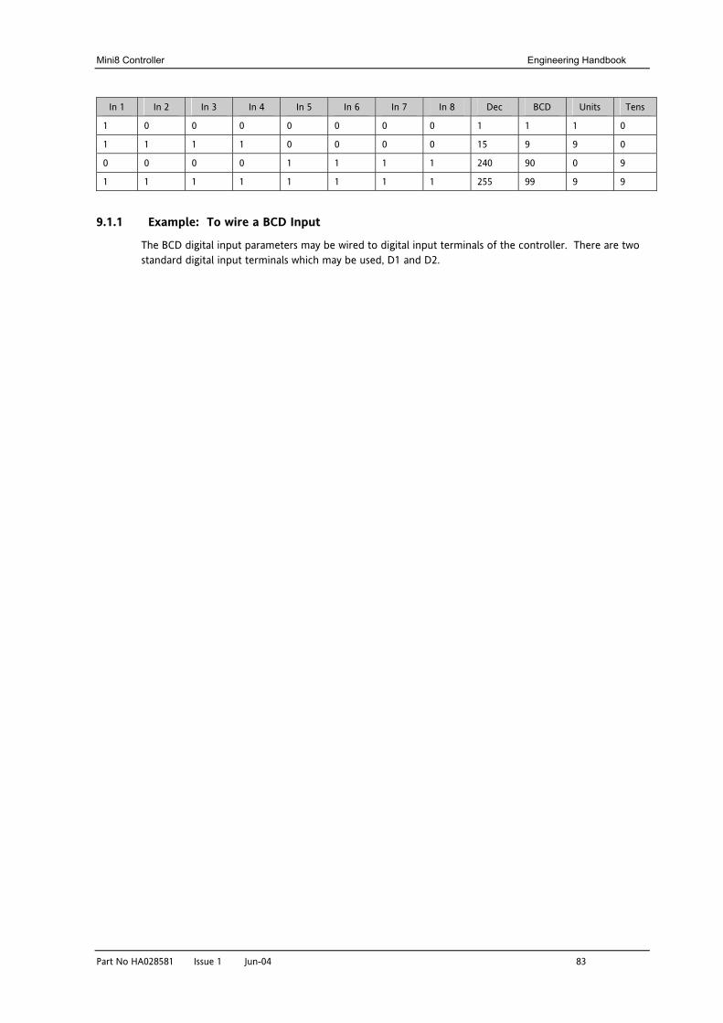
Mini8 Controller Engineering Handbook
Part No HA028581 Issue 1 Jun-04 83
In 1 In 2 In 3 In 4 In 5 In 6 In 7 In 8 Dec BCD Units Tens
1 0 0 0 0 0 0 0 1 1 1 0
1 1 1 1 0 0 0 0 15 9 9 0
0 0 0 0 1 1 1 1 240 90 0 9
1 1 1 1 1 1 1 1 255 99 9 9
9.1.1 Example: To wire a BCD Input
The BCD digital input parameters may be wired to digital input terminals of the controller. There are two standard digital input terminals which may be used, D1 and D2.
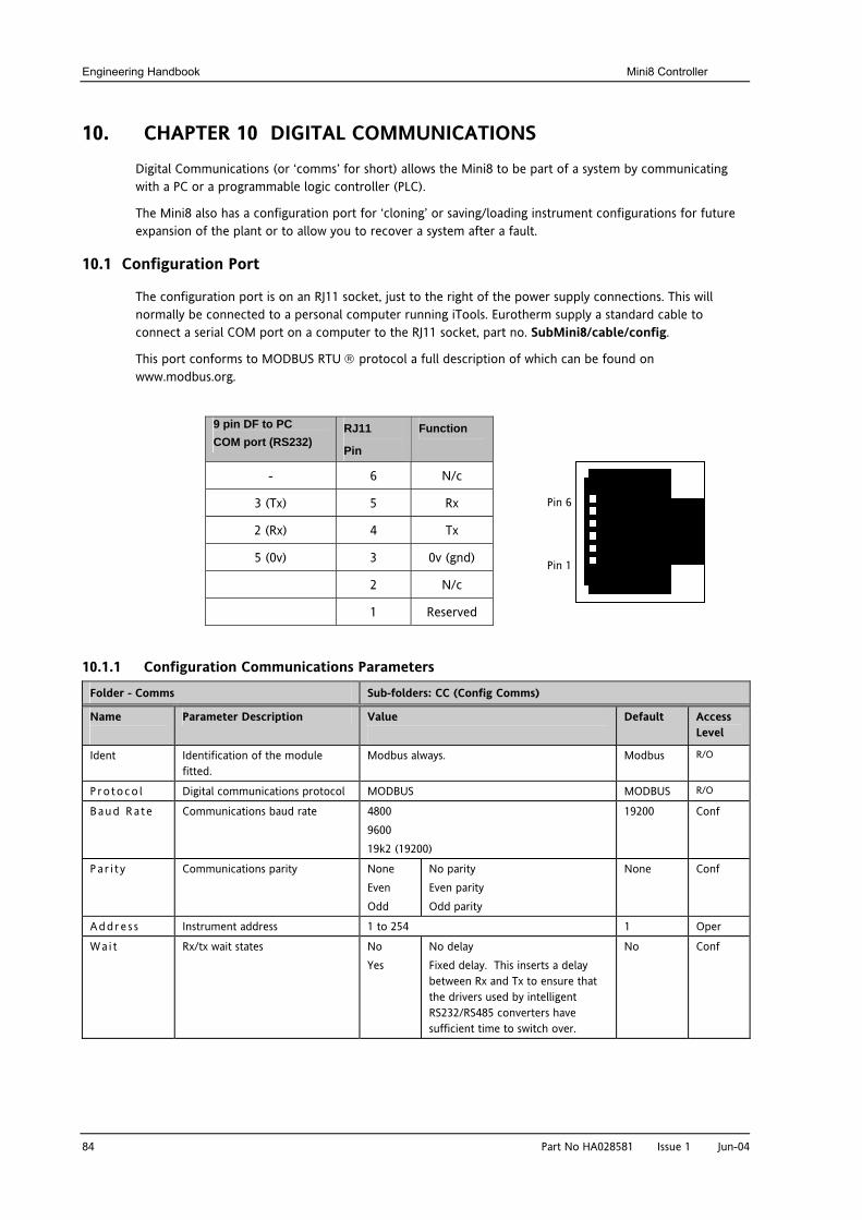
Engineering Handbook Mini8 Controller
84 Part No HA028581 Issue 1 Jun-04
10. CHAPTER 10 DIGITAL COMMUNICATIONS Digital Communications (or ‘comms’ for short) allows the Mini8 to be part of a system by communicating with a PC or a programmable logic controller (PLC).
The Mini8 also has a configuration port for ‘cloning’ or saving/loading instrument configurations for future expansion of the plant or to allow you to recover a system after a fault.
10.1 Configuration Port
The configuration port is on an RJ11 socket, just to the right of the power supply connections. This will normally be connected to a personal computer running iTools. Eurotherm supply a standard cable to connect a serial COM port on a computer to the RJ11 socket, part no. SubMini8/cable/config.
This port conforms to MODBUS RTU ® protocol a full description of which can be found on www.modbus.org.
9 pin DF to PC COM port (RS232)
RJ11
Pin
Function
- 6 N/c
3 (Tx) 5 Rx
2 (Rx) 4 Tx
5 (0v) 3 0v (gnd)
2 N/c
1 Reserved
10.1.1 Configuration Communications Parameters
Folder - Comms Sub-folders: CC (Config Comms)
Name
Parameter Description Value
Default Access Level
Ident Identification of the module fitted.
Modbus always. Modbus R/O
P ro toco l Digital communications protocol MODBUS MODBUS R/O
Baud Ra te Communications baud rate 4800 9600 19k2 (19200)
19200 Conf
Pa r i t y Communications parity None Even Odd
No parity Even parity Odd parity
None Conf
Addre s s Instrument address 1 to 254 1 Oper
Wa i t Rx/tx wait states No Yes
No delay Fixed delay. This inserts a delay between Rx and Tx to ensure that the drivers used by intelligent RS232/RS485 converters have sufficient time to switch over.
No Conf
Pin 1
Pin 6
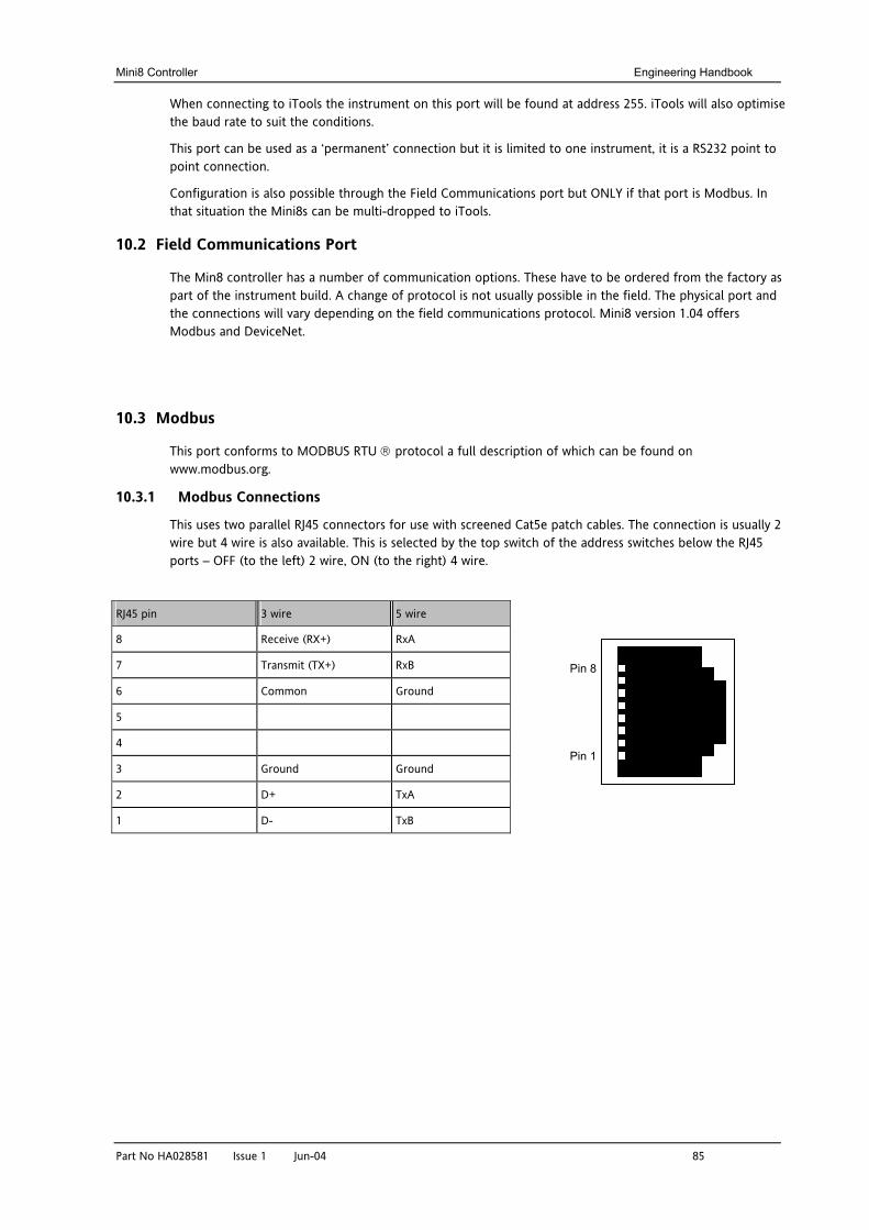
Mini8 Controller Engineering Handbook
Part No HA028581 Issue 1 Jun-04 85
When connecting to iTools the instrument on this port will be found at address 255. iTools will also optimise the baud rate to suit the conditions.
This port can be used as a ‘permanent’ connection but it is limited to one instrument, it is a RS232 point to point connection.
Configuration is also possible through the Field Communications port but ONLY if that port is Modbus. In that situation the Mini8s can be multi-dropped to iTools.
10.2 Field Communications Port
The Min8 controller has a number of communication options. These have to be ordered from the factory as part of the instrument build. A change of protocol is not usually possible in the field. The physical port and the connections will vary depending on the field communications protocol. Mini8 version 1.04 offers Modbus and DeviceNet.
10.3 Modbus
This port conforms to MODBUS RTU ® protocol a full description of which can be found on www.modbus.org.
10.3.1 Modbus Connections
This uses two parallel RJ45 connectors for use with screened Cat5e patch cables. The connection is usually 2 wire but 4 wire is also available. This is selected by the top switch of the address switches below the RJ45 ports – OFF (to the left) 2 wire, ON (to the right) 4 wire.
RJ45 pin 3 wire 5 wire
8 Receive (RX+) RxA
7 Transmit (TX+) RxB
6 Common Ground
5
4
3 Ground Ground
2 D+ TxA
1 D- TxB
Pin 8
Pin 1
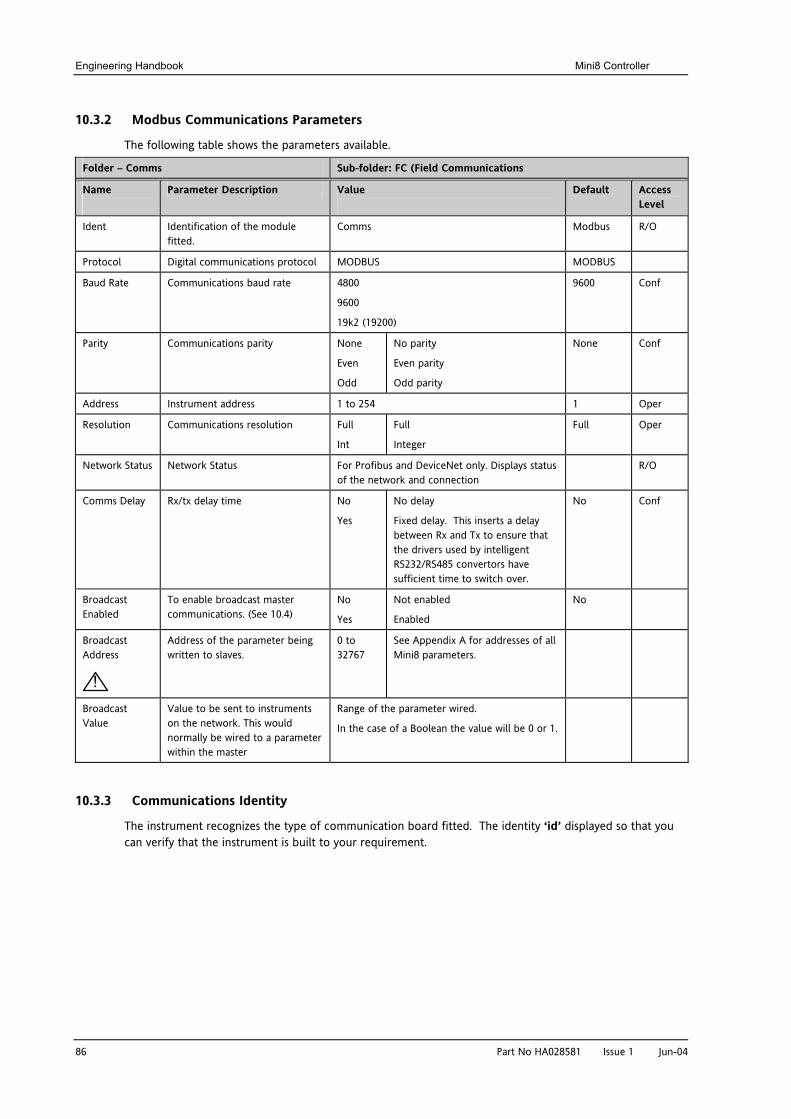
Engineering Handbook Mini8 Controller
86 Part No HA028581 Issue 1 Jun-04
10.3.2 Modbus Communications Parameters
The following table shows the parameters available.
Folder – Comms Sub-folder: FC (Field Communications
Name
Parameter Description Value
Default Access Level
Ident Identification of the module fitted.
Comms Modbus R/O
Protocol Digital communications protocol MODBUS MODBUS
Baud Rate Communications baud rate 4800
9600
19k2 (19200)
9600 Conf
Parity Communications parity None
Even
Odd
No parity
Even parity
Odd parity
None Conf
Address Instrument address 1 to 254 1 Oper
Resolution Communications resolution Full
Int
Full
Integer
Full Oper
Network Status Network Status For Profibus and DeviceNet only. Displays status of the network and connection
R/O
Comms Delay Rx/tx delay time No
Yes
No delay
Fixed delay. This inserts a delay between Rx and Tx to ensure that the drivers used by intelligent RS232/RS485 convertors have sufficient time to switch over.
No Conf
Broadcast Enabled
To enable broadcast master communications. (See 10.4)
No
Yes
Not enabled
Enabled
No
Broadcast Address
!
Address of the parameter being written to slaves.
0 to 32767
See Appendix A for addresses of all Mini8 parameters.
Broadcast Value
Value to be sent to instruments on the network. This would normally be wired to a parameter within the master
Range of the parameter wired.
In the case of a Boolean the value will be 0 or 1.
10.3.3 Communications Identity
The instrument recognizes the type of communication board fitted. The identity ‘id’ displayed so that you can verify that the instrument is built to your requirement.
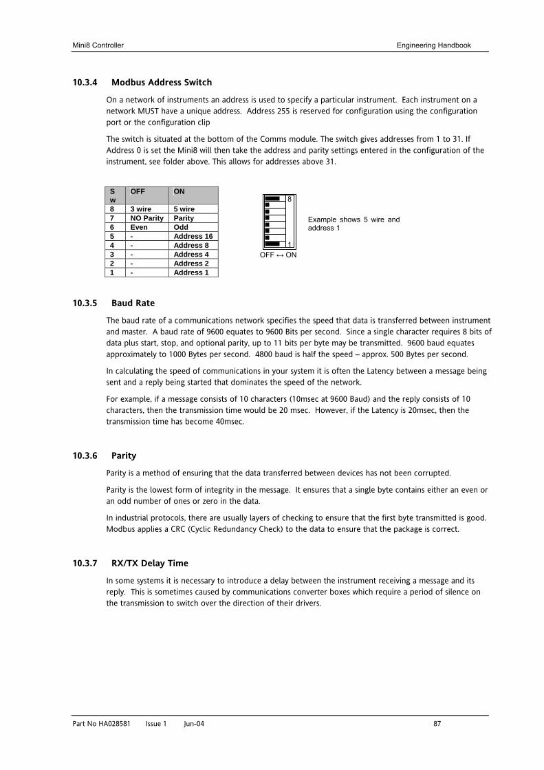
Mini8 Controller Engineering Handbook
Part No HA028581 Issue 1 Jun-04 87
10.3.4 Modbus Address Switch
On a network of instruments an address is used to specify a particular instrument. Each instrument on a network MUST have a unique address. Address 255 is reserved for configuration using the configuration port or the configuration clip
The switch is situated at the bottom of the Comms module. The switch gives addresses from 1 to 31. If Address 0 is set the Mini8 will then take the address and parity settings entered in the configuration of the instrument, see folder above. This allows for addresses above 31.
Sw
OFF ON
8 3 wire 5 wire 7 NO Parity Parity 6 Even Odd 5 - Address 16 4 - Address 8 3 - Address 4 2 - Address 2 1 - Address 1
10.3.5 Baud Rate
The baud rate of a communications network specifies the speed that data is transferred between instrument and master. A baud rate of 9600 equates to 9600 Bits per second. Since a single character requires 8 bits of data plus start, stop, and optional parity, up to 11 bits per byte may be transmitted. 9600 baud equates approximately to 1000 Bytes per second. 4800 baud is half the speed – approx. 500 Bytes per second.
In calculating the speed of communications in your system it is often the Latency between a message being sent and a reply being started that dominates the speed of the network.
For example, if a message consists of 10 characters (10msec at 9600 Baud) and the reply consists of 10 characters, then the transmission time would be 20 msec. However, if the Latency is 20msec, then the transmission time has become 40msec.
10.3.6 Parity
Parity is a method of ensuring that the data transferred between devices has not been corrupted.
Parity is the lowest form of integrity in the message. It ensures that a single byte contains either an even or an odd number of ones or zero in the data.
In industrial protocols, there are usually layers of checking to ensure that the first byte transmitted is good. Modbus applies a CRC (Cyclic Redundancy Check) to the data to ensure that the package is correct.
10.3.7 RX/TX Delay Time
In some systems it is necessary to introduce a delay between the instrument receiving a message and its reply. This is sometimes caused by communications converter boxes which require a period of silence on the transmission to switch over the direction of their drivers.
8
1 OFF ↔ ON
Example shows 5 wire and address 1
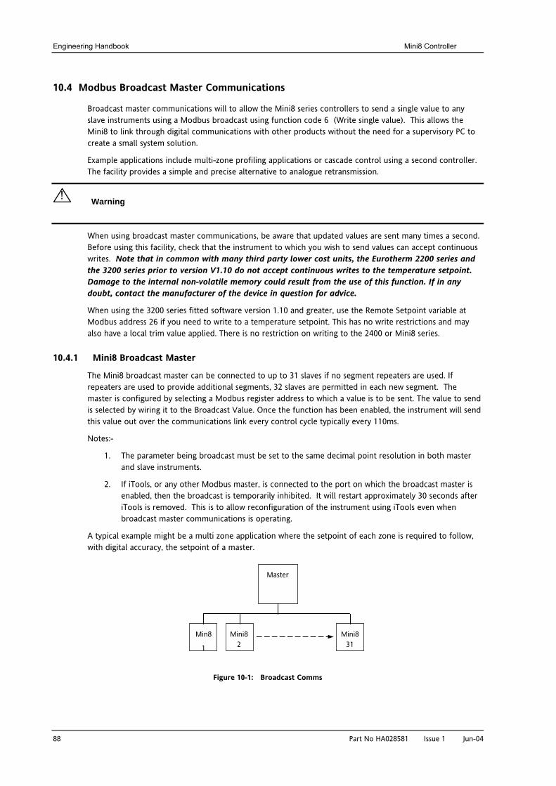
Engineering Handbook Mini8 Controller
88 Part No HA028581 Issue 1 Jun-04
10.4 Modbus Broadcast Master Communications
Broadcast master communications will to allow the Mini8 series controllers to send a single value to any slave instruments using a Modbus broadcast using function code 6 (Write single value). This allows the Mini8 to link through digital communications with other products without the need for a supervisory PC to create a small system solution.
Example applications include multi-zone profiling applications or cascade control using a second controller. The facility provides a simple and precise alternative to analogue retransmission.
! Warning
When using broadcast master communications, be aware that updated values are sent many times a second. Before using this facility, check that the instrument to which you wish to send values can accept continuous writes. Note that in common with many third party lower cost units, the Eurotherm 2200 series and the 3200 series prior to version V1.10 do not accept continuous writes to the temperature setpoint. Damage to the internal non-volatile memory could result from the use of this function. If in any doubt, contact the manufacturer of the device in question for advice.
When using the 3200 series fitted software version 1.10 and greater, use the Remote Setpoint variable at Modbus address 26 if you need to write to a temperature setpoint. This has no write restrictions and may also have a local trim value applied. There is no restriction on writing to the 2400 or Mini8 series.
10.4.1 Mini8 Broadcast Master
The Mini8 broadcast master can be connected to up to 31 slaves if no segment repeaters are used. If repeaters are used to provide additional segments, 32 slaves are permitted in each new segment. The master is configured by selecting a Modbus register address to which a value is to be sent. The value to send is selected by wiring it to the Broadcast Value. Once the function has been enabled, the instrument will send this value out over the communications link every control cycle typically every 110ms.
Notes:-
1. The parameter being broadcast must be set to the same decimal point resolution in both master and slave instruments.
2. If iTools, or any other Modbus master, is connected to the port on which the broadcast master is enabled, then the broadcast is temporarily inhibited. It will restart approximately 30 seconds after iTools is removed. This is to allow reconfiguration of the instrument using iTools even when broadcast master communications is operating.
A typical example might be a multi zone application where the setpoint of each zone is required to follow, with digital accuracy, the setpoint of a master.
Figure 10-1: Broadcast Comms
Master
Min8
1
Mini8 2
Mini8 31
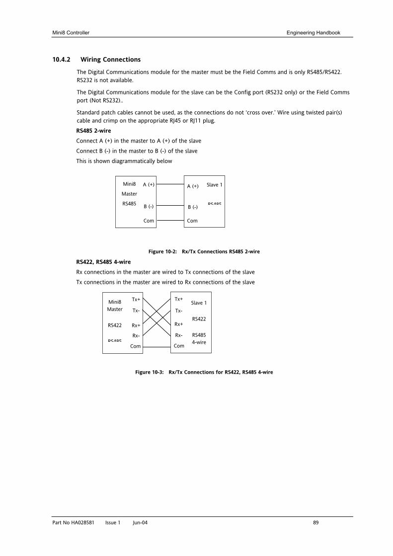
Mini8 Controller Engineering Handbook
Part No HA028581 Issue 1 Jun-04 89
10.4.2 Wiring Connections
The Digital Communications module for the master must be the Field Comms and is only RS485/RS422. RS232 is not available.
The Digital Communications module for the slave can be the Config port (RS232 only) or the Field Comms port (Not RS232)..
Standard patch cables cannot be used, as the connections do not ‘cross over.’ Wire using twisted pair(s) cable and crimp on the appropriate RJ45 or RJ11 plug.
RS485 2-wire Connect A (+) in the master to A (+) of the slave
Connect B (-) in the master to B (-) of the slave This is shown diagrammatically below
Figure 10-2: Rx/Tx Connections RS485 2-wire
RS422, RS485 4-wire Rx connections in the master are wired to Tx connections of the slave
Tx connections in the master are wired to Rx connections of the slave
Figure 10-3: Rx/Tx Connections for RS422, RS485 4-wire
Mini8
Master
RS485 B (-)
A (+) Slave 1
RS485 B (-)
A (+)
Com Com
Mini8 Master
RS422
RS485
Rx+
Rx-
Tx+
Tx- Slave 1
RS422
RS485 4-wire
Rx+
Rx-
Tx+
Tx-
Com Com
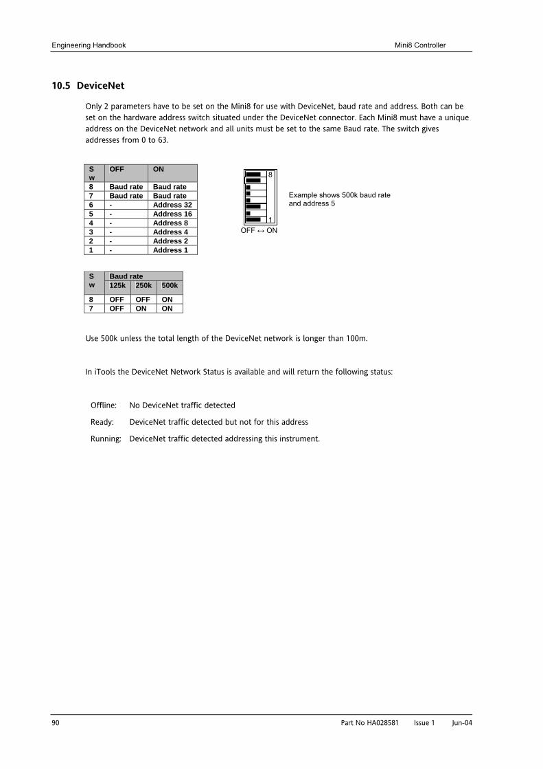
Engineering Handbook Mini8 Controller
90 Part No HA028581 Issue 1 Jun-04
10.5 DeviceNet
Only 2 parameters have to be set on the Mini8 for use with DeviceNet, baud rate and address. Both can be set on the hardware address switch situated under the DeviceNet connector. Each Mini8 must have a unique address on the DeviceNet network and all units must be set to the same Baud rate. The switch gives addresses from 0 to 63.
Sw
OFF ON
8 Baud rate Baud rate 7 Baud rate Baud rate 6 - Address 32 5 - Address 16 4 - Address 8 3 - Address 4 2 - Address 2 1 - Address 1
Baud rate S
w 125k 250k 500k
8 OFF OFF ON 7 OFF ON ON
Use 500k unless the total length of the DeviceNet network is longer than 100m.
In iTools the DeviceNet Network Status is available and will return the following status:
Offline: No DeviceNet traffic detected
Ready: DeviceNet traffic detected but not for this address
Running: DeviceNet traffic detected addressing this instrument.
8
1 OFF ↔ ON
Example shows 500k baud rate and address 5
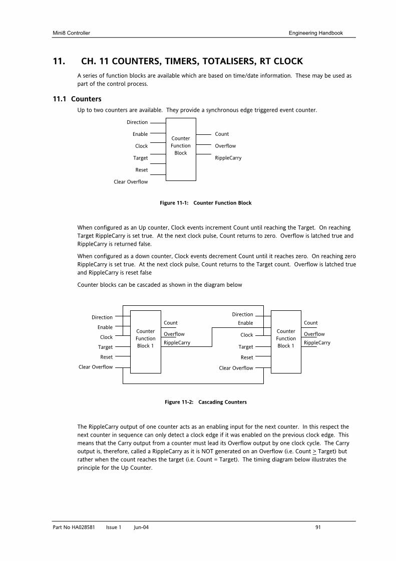
Mini8 Controller Engineering Handbook
Part No HA028581 Issue 1 Jun-04 91
11. CH. 11 COUNTERS, TIMERS, TOTALISERS, RT CLOCK A series of function blocks are available which are based on time/date information. These may be used as part of the control process.
11.1 Counters Up to two counters are available. They provide a synchronous edge triggered event counter.
Figure 11-1: Counter Function Block
When configured as an Up counter, Clock events increment Count until reaching the Target. On reaching Target RippleCarry is set true. At the next clock pulse, Count returns to zero. Overflow is latched true and RippleCarry is returned false.
When configured as a down counter, Clock events decrement Count until it reaches zero. On reaching zero RippleCarry is set true. At the next clock pulse, Count returns to the Target count. Overflow is latched true and RippleCarry is reset false
Counter blocks can be cascaded as shown in the diagram below
Figure 11-2: Cascading Counters
The RippleCarry output of one counter acts as an enabling input for the next counter. In this respect the next counter in sequence can only detect a clock edge if it was enabled on the previous clock edge. This means that the Carry output from a counter must lead its Overflow output by one clock cycle. The Carry output is, therefore, called a RippleCarry as it is NOT generated on an Overflow (i.e. Count > Target) but rather when the count reaches the target (i.e. Count = Target). The timing diagram below illustrates the principle for the Up Counter.
Direction
Enable
Clock
Target
Reset
Clear Overflow
Count
Overflow
RippleCarry
Counter Function
Block
Count
Overflow RippleCarry
Direction
Enable
Clock
Target
Reset
Clear Overflow
Counter Function Block 1
Direction Enable
Clock
Target
Reset
Clear Overflow
Counter Function Block 1
Count
Overflow RippleCarry
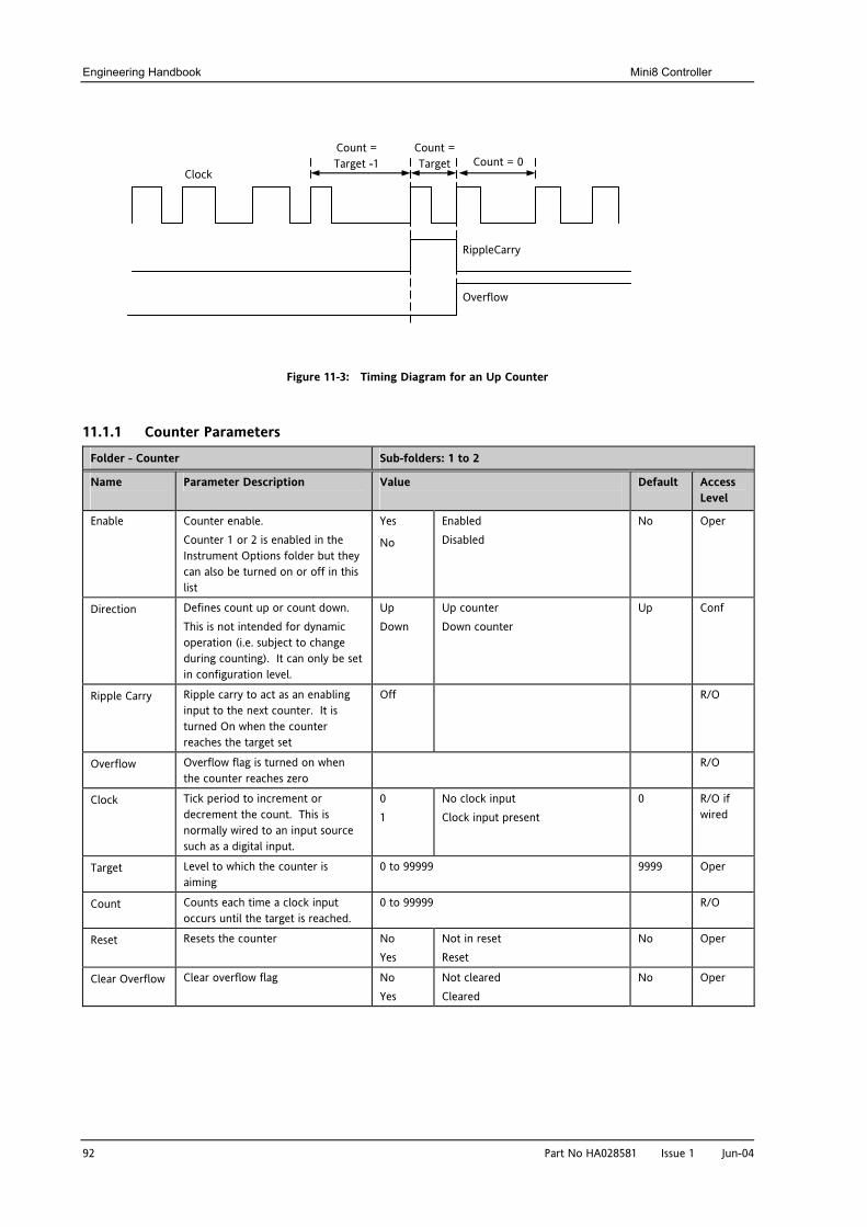
Engineering Handbook Mini8 Controller
92 Part No HA028581 Issue 1 Jun-04
Figure 11-3: Timing Diagram for an Up Counter
11.1.1 Counter Parameters
Folder - Counter Sub-folders: 1 to 2
Name
Parameter Description Value
Default Access Level
Enable Counter enable. Counter 1 or 2 is enabled in the Instrument Options folder but they can also be turned on or off in this list
Yes
No
Enabled Disabled
No Oper
Direction Defines count up or count down. This is not intended for dynamic operation (i.e. subject to change during counting). It can only be set in configuration level.
Up Down
Up counter Down counter
Up Conf
Ripple Carry Ripple carry to act as an enabling input to the next counter. It is turned On when the counter reaches the target set
Off R/O
Overflow Overflow flag is turned on when the counter reaches zero
R/O
Clock Tick period to increment or decrement the count. This is normally wired to an input source such as a digital input.
0 1
No clock input Clock input present
0 R/O if wired
Target Level to which the counter is aiming
0 to 99999 9999 Oper
Count Counts each time a clock input occurs until the target is reached.
0 to 99999 R/O
Reset Resets the counter No Yes
Not in reset Reset
No Oper
Clear Overflow Clear overflow flag No Yes
Not cleared Cleared
No Oper
Clock
Count = Target -1
Count = Target Count = 0
RippleCarry
Overflow
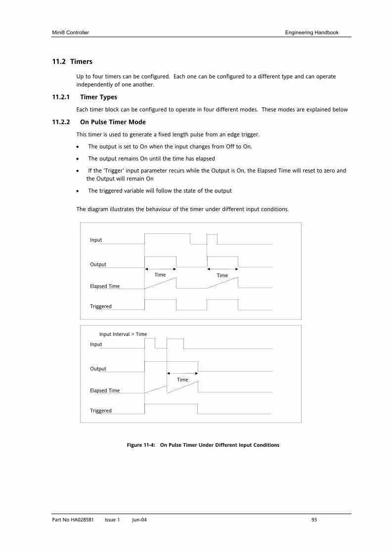
Mini8 Controller Engineering Handbook
Part No HA028581 Issue 1 Jun-04 93
11.2 Timers
Up to four timers can be configured. Each one can be configured to a different type and can operate independently of one another.
11.2.1 Timer Types
Each timer block can be configured to operate in four different modes. These modes are explained below
11.2.2 On Pulse Timer Mode
This timer is used to generate a fixed length pulse from an edge trigger.
• The output is set to On when the input changes from Off to On.
• The output remains On until the time has elapsed
• If the ‘Trigger’ input parameter recurs while the Output is On, the Elapsed Time will reset to zero and the Output will remain On
• The triggered variable will follow the state of the output
The diagram illustrates the behaviour of the timer under different input conditions.
Figure 11-4: On Pulse Timer Under Different Input Conditions
Input
Output
Elapsed Time
Triggered
Time Time
Input
Output
Elapsed Time
Triggered
Time
Input Interval > Time
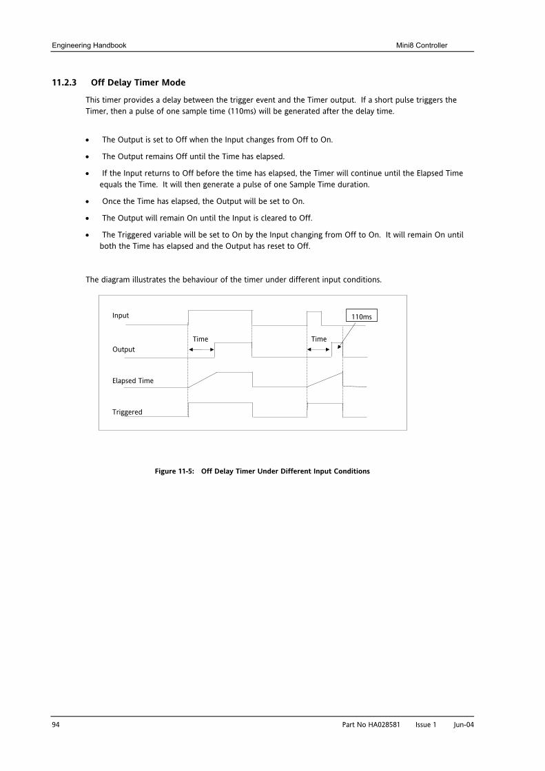
Engineering Handbook Mini8 Controller
94 Part No HA028581 Issue 1 Jun-04
11.2.3 Off Delay Timer Mode
This timer provides a delay between the trigger event and the Timer output. If a short pulse triggers the Timer, then a pulse of one sample time (110ms) will be generated after the delay time.
• The Output is set to Off when the Input changes from Off to On.
• The Output remains Off until the Time has elapsed.
• If the Input returns to Off before the time has elapsed, the Timer will continue until the Elapsed Time equals the Time. It will then generate a pulse of one Sample Time duration.
• Once the Time has elapsed, the Output will be set to On.
• The Output will remain On until the Input is cleared to Off.
• The Triggered variable will be set to On by the Input changing from Off to On. It will remain On until both the Time has elapsed and the Output has reset to Off.
The diagram illustrates the behaviour of the timer under different input conditions.
Figure 11-5: Off Delay Timer Under Different Input Conditions
Input
Output
Elapsed Time
Triggered
Time Time
110ms
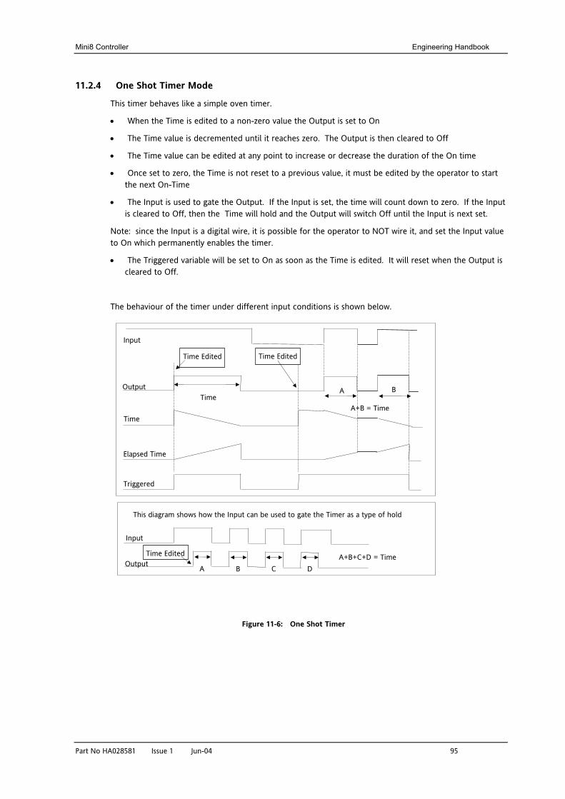
Mini8 Controller Engineering Handbook
Part No HA028581 Issue 1 Jun-04 95
11.2.4 One Shot Timer Mode
This timer behaves like a simple oven timer.
• When the Time is edited to a non-zero value the Output is set to On
• The Time value is decremented until it reaches zero. The Output is then cleared to Off
• The Time value can be edited at any point to increase or decrease the duration of the On time
• Once set to zero, the Time is not reset to a previous value, it must be edited by the operator to start the next On-Time
• The Input is used to gate the Output. If the Input is set, the time will count down to zero. If the Input is cleared to Off, then the Time will hold and the Output will switch Off until the Input is next set.
Note: since the Input is a digital wire, it is possible for the operator to NOT wire it, and set the Input value to On which permanently enables the timer.
• The Triggered variable will be set to On as soon as the Time is edited. It will reset when the Output is cleared to Off.
The behaviour of the timer under different input conditions is shown below.
Figure 11-6: One Shot Timer
Input
Output
Elapsed Time
Triggered
Time
Time Edited
Time
Time Edited
Input
Output A D C B
Time Edited A+B+C+D = Time
This diagram shows how the Input can be used to gate the Timer as a type of hold
A B
A+B = Time
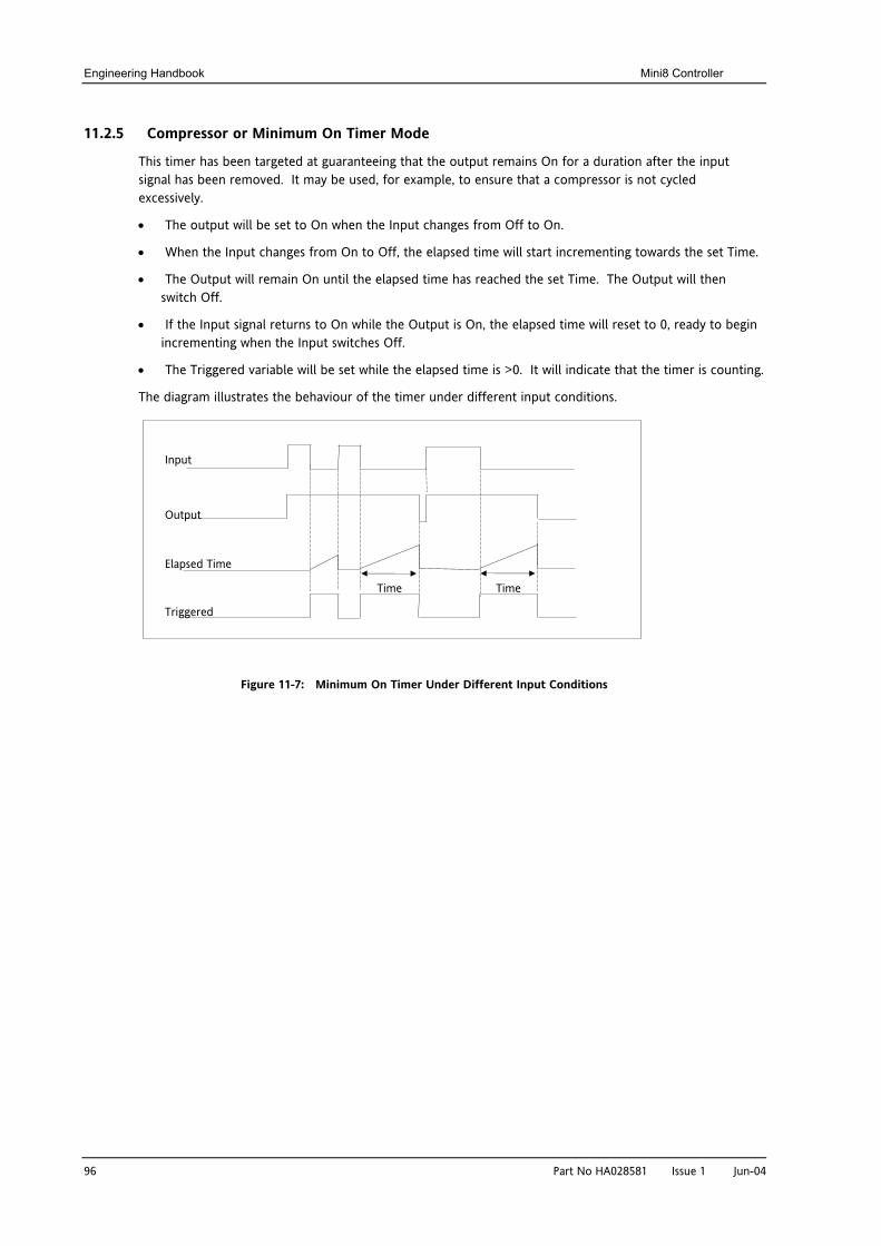
Engineering Handbook Mini8 Controller
96 Part No HA028581 Issue 1 Jun-04
11.2.5 Compressor or Minimum On Timer Mode
This timer has been targeted at guaranteeing that the output remains On for a duration after the input signal has been removed. It may be used, for example, to ensure that a compressor is not cycled excessively.
• The output will be set to On when the Input changes from Off to On.
• When the Input changes from On to Off, the elapsed time will start incrementing towards the set Time.
• The Output will remain On until the elapsed time has reached the set Time. The Output will then switch Off.
• If the Input signal returns to On while the Output is On, the elapsed time will reset to 0, ready to begin incrementing when the Input switches Off.
• The Triggered variable will be set while the elapsed time is >0. It will indicate that the timer is counting.
The diagram illustrates the behaviour of the timer under different input conditions.
Figure 11-7: Minimum On Timer Under Different Input Conditions
Input
Output
Elapsed Time
Triggered
Time Time
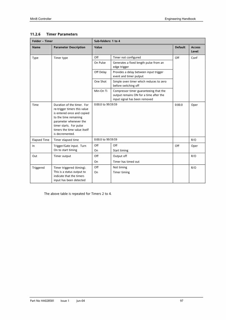
Mini8 Controller Engineering Handbook
Part No HA028581 Issue 1 Jun-04 97
11.2.6 Timer Parameters
Folder – Timer Sub-folders: 1 to 4
Name
Parameter Description Value
Default Access Level
Off Timer not configured
On Pulse Generates a fixed length pulse from an edge trigger
Off Delay Provides a delay between input trigger event and timer putput
One Shot Simple oven timer which reduces to zero before switching off
Type Timer type
Min-On Ti Compressor timer guaranteeing that the output remains ON for a time after the input signal has been removed
Off Conf
Time Duration of the timer. For re-trigger timers this value is entered once and copied to the time remaining parameter whenever the timer starts. For pulse timers the time value itself is decremented.
0:00.0 to 99:59:59 0:00.0 Oper
Elapsed Time Timer elapsed time 0:00.0 to 99:59:59 R/O
In Trigger/Gate input. Turn On to start timing
Off On
Off Start timing
Off Oper
Out Timer output Off
On
Output off
Timer has timed out
R/O
Triggered Timer triggered (timing). This is a status output to indicate that the timers input has been detected
Off On
Not timing Timer timing
R/O
The above table is repeated for Timers 2 to 4.
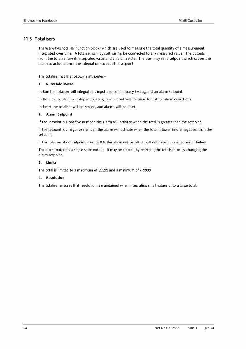
Engineering Handbook Mini8 Controller
98 Part No HA028581 Issue 1 Jun-04
11.3 Totalisers
There are two totaliser function blocks which are used to measure the total quantity of a measurement integrated over time. A totaliser can, by soft wiring, be connected to any measured value. The outputs from the totaliser are its integrated value and an alarm state. The user may set a setpoint which causes the alarm to activate once the integration exceeds the setpoint.
The totaliser has the following attributes:-
1. Run/Hold/Reset
In Run the totaliser will integrate its input and continuously test against an alarm setpoint.
In Hold the totaliser will stop integrating its input but will continue to test for alarm conditions.
In Reset the totaliser will be zeroed, and alarms will be reset.
2. Alarm Setpoint
If the setpoint is a positive number, the alarm will activate when the total is greater than the setpoint.
If the setpoint is a negative number, the alarm will activate when the total is lower (more negative) than the setpoint.
If the totaliser alarm setpoint is set to 0.0, the alarm will be off. It will not detect values above or below.
The alarm output is a single state output. It may be cleared by resetting the totaliser, or by changing the alarm setpoint.
3. Limits
The total is limited to a maximum of 99999 and a minimum of -19999.
4. Resolution
The totaliser ensures that resolution is maintained when integrating small values onto a large total.
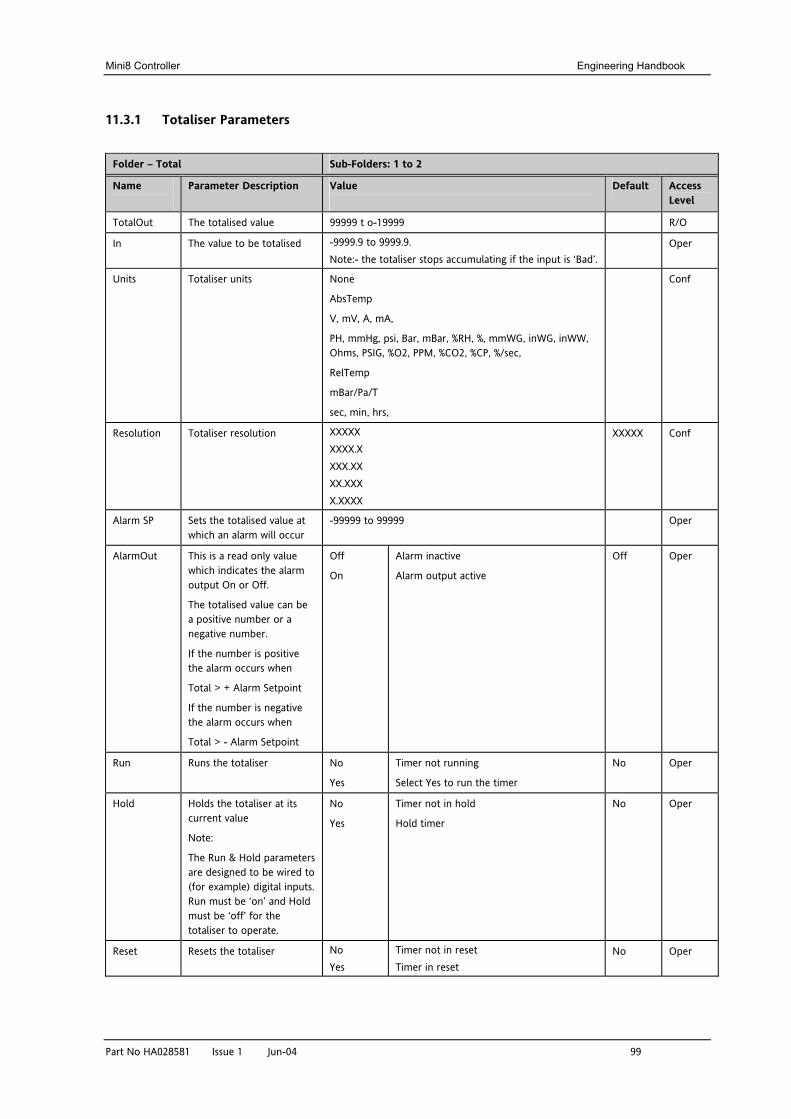
Mini8 Controller Engineering Handbook
Part No HA028581 Issue 1 Jun-04 99
11.3.1 Totaliser Parameters
Folder – Total Sub-Folders: 1 to 2
Name
Parameter Description Value
Default Access Level
TotalOut The totalised value 99999 t o-19999 R/O
In The value to be totalised -9999.9 to 9999.9. Note:- the totaliser stops accumulating if the input is ‘Bad’.
Oper
Units Totaliser units None
AbsTemp
V, mV, A, mA,
PH, mmHg, psi, Bar, mBar, %RH, %, mmWG, inWG, inWW, Ohms, PSIG, %O2, PPM, %CO2, %CP, %/sec,
RelTemp
mBar/Pa/T
sec, min, hrs,
Conf
Resolution Totaliser resolution XXXXX XXXX.X XXX.XX XX.XXX X.XXXX
XXXXX Conf
Alarm SP Sets the totalised value at which an alarm will occur
-99999 to 99999 Oper
AlarmOut This is a read only value which indicates the alarm output On or Off.
The totalised value can be a positive number or a negative number.
If the number is positive the alarm occurs when
Total > + Alarm Setpoint
If the number is negative the alarm occurs when
Total > - Alarm Setpoint
Off
On
Alarm inactive
Alarm output active
Off Oper
Run Runs the totaliser No
Yes
Timer not running
Select Yes to run the timer
No Oper
Hold Holds the totaliser at its current value
Note:
The Run & Hold parameters are designed to be wired to (for example) digital inputs. Run must be ‘on’ and Hold must be ‘off’ for the totaliser to operate.
No
Yes
Timer not in hold
Hold timer
No Oper
Reset Resets the totaliser No Yes
Timer not in reset Timer in reset
No Oper
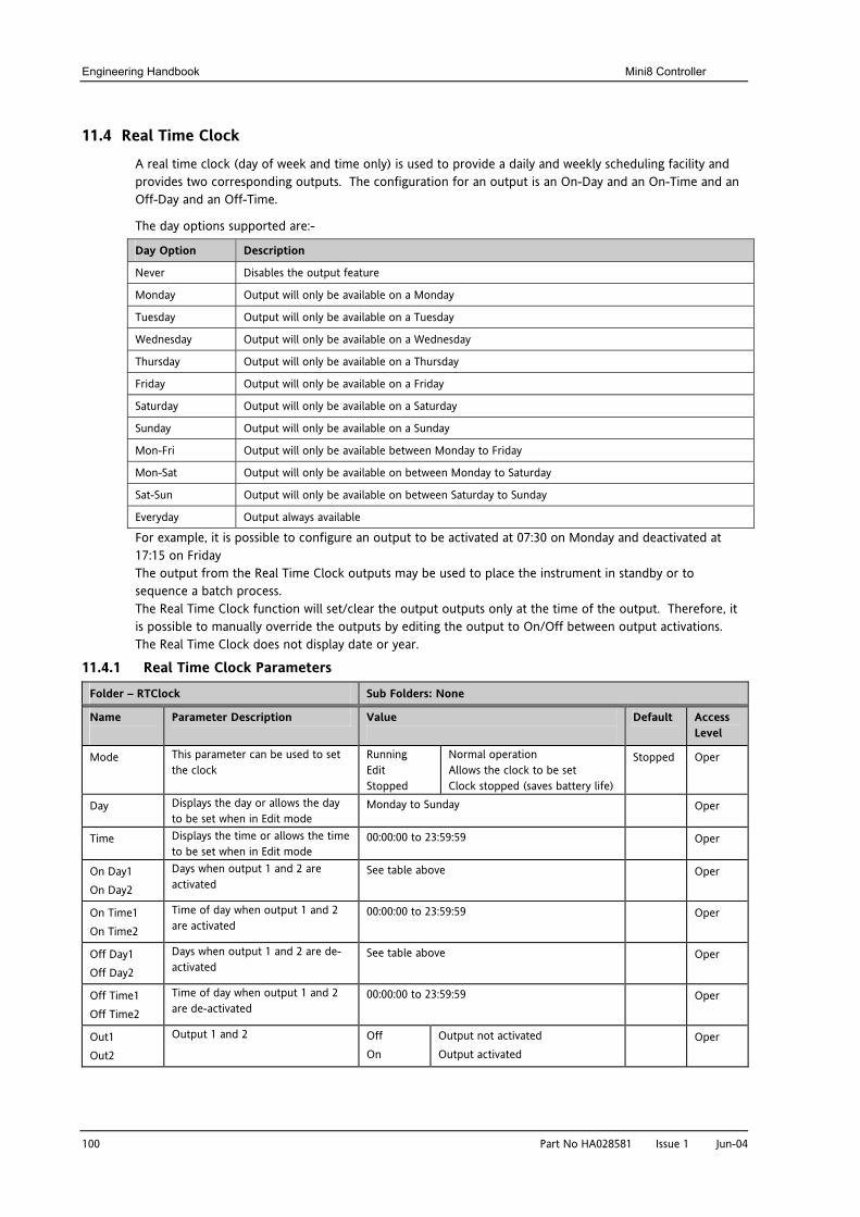
Engineering Handbook Mini8 Controller
100 Part No HA028581 Issue 1 Jun-04
11.4 Real Time Clock
A real time clock (day of week and time only) is used to provide a daily and weekly scheduling facility and provides two corresponding outputs. The configuration for an output is an On-Day and an On-Time and an Off-Day and an Off-Time.
The day options supported are:-
Day Option Description
Never Disables the output feature
Monday Output will only be available on a Monday
Tuesday Output will only be available on a Tuesday
Wednesday Output will only be available on a Wednesday
Thursday Output will only be available on a Thursday
Friday Output will only be available on a Friday
Saturday Output will only be available on a Saturday
Sunday Output will only be available on a Sunday
Mon-Fri Output will only be available between Monday to Friday
Mon-Sat Output will only be available on between Monday to Saturday
Sat-Sun Output will only be available on between Saturday to Sunday
Everyday Output always available
For example, it is possible to configure an output to be activated at 07:30 on Monday and deactivated at 17:15 on Friday The output from the Real Time Clock outputs may be used to place the instrument in standby or to sequence a batch process. The Real Time Clock function will set/clear the output outputs only at the time of the output. Therefore, it is possible to manually override the outputs by editing the output to On/Off between output activations. The Real Time Clock does not display date or year.
11.4.1 Real Time Clock Parameters
Folder – RTClock Sub Folders: None
Name
Parameter Description Value
Default Access Level
Mode This parameter can be used to set the clock
Running Edit Stopped
Normal operation Allows the clock to be set Clock stopped (saves battery life)
Stopped Oper
Day Displays the day or allows the day to be set when in Edit mode
Monday to Sunday Oper
Time Displays the time or allows the time to be set when in Edit mode
00:00:00 to 23:59:59 Oper
On Day1 On Day2
Days when output 1 and 2 are activated
See table above Oper
On Time1 On Time2
Time of day when output 1 and 2 are activated
00:00:00 to 23:59:59 Oper
Off Day1 Off Day2
Days when output 1 and 2 are de-activated
See table above Oper
Off Time1 Off Time2
Time of day when output 1 and 2 are de-activated
00:00:00 to 23:59:59 Oper
Out1 Out2
Output 1 and 2 Off On
Output not activated Output activated
Oper
Mini8 Controller Engineering Handbook
Part No HA028581 Issue 1 Jun-04 101
12. CHAPTER 12 HUMIDITY CONTROL
12.1.1 Overview
Humidity (and altitude) control is a standard feature of the Mini8 controller. In these applications the controller may be configured to generate a setpoint profile (see Chapter 18 ‘Programmer Operation’).
Also the controller may be configured to measure humidity using either the traditional Wet/Dry bulb method or it may be interfaced to a solid state sensor.
The controller output may be configured to turn a refrigeration compressor on and off, operate a bypass valve, and possibly operate two stages of heating and/or cooling
12.1.2 Temperature Control of an Environmental Chamber
The temperature of an environmental chamber is controlled as a single loop with two control outputs. The heating output time proportions electric heaters, usually via a solid state relay. The cooling output operates a refrigerant valve which introduces cooling into the chamber. The controller automatically calculates when heating or cooling is required.
12.1.3 Humidity Control of an Environmental Chamber
Humidity in a chamber is controlled by adding or removing water vapour. Like the temperature control loop two control outputs are required, i.e. Humidify and Dehumidify.
To humidify the chamber water vapour may be added by a boiler, an evaporating pan or by direct injection of atomised water.
If a boiler is being used adding steam increases the humidity level. The humidify output from the controller regulates the amount of steam from the boiler that is allowed into the chamber.
An evaporating pan is a pan of water warmed by a heater. The humidify output from the controller humidity regulates the temperature of the water.
An atomisation system uses compressed air to spray water vapour directly into the chamber. The humidify output of the controller turns on or off a solenoid valve.
Dehumidification may be accomplished by using the same compressor used for cooling the chamber. The dehumidify output from the controller may control a separate control valve connected to a set of heat exchanger coils.
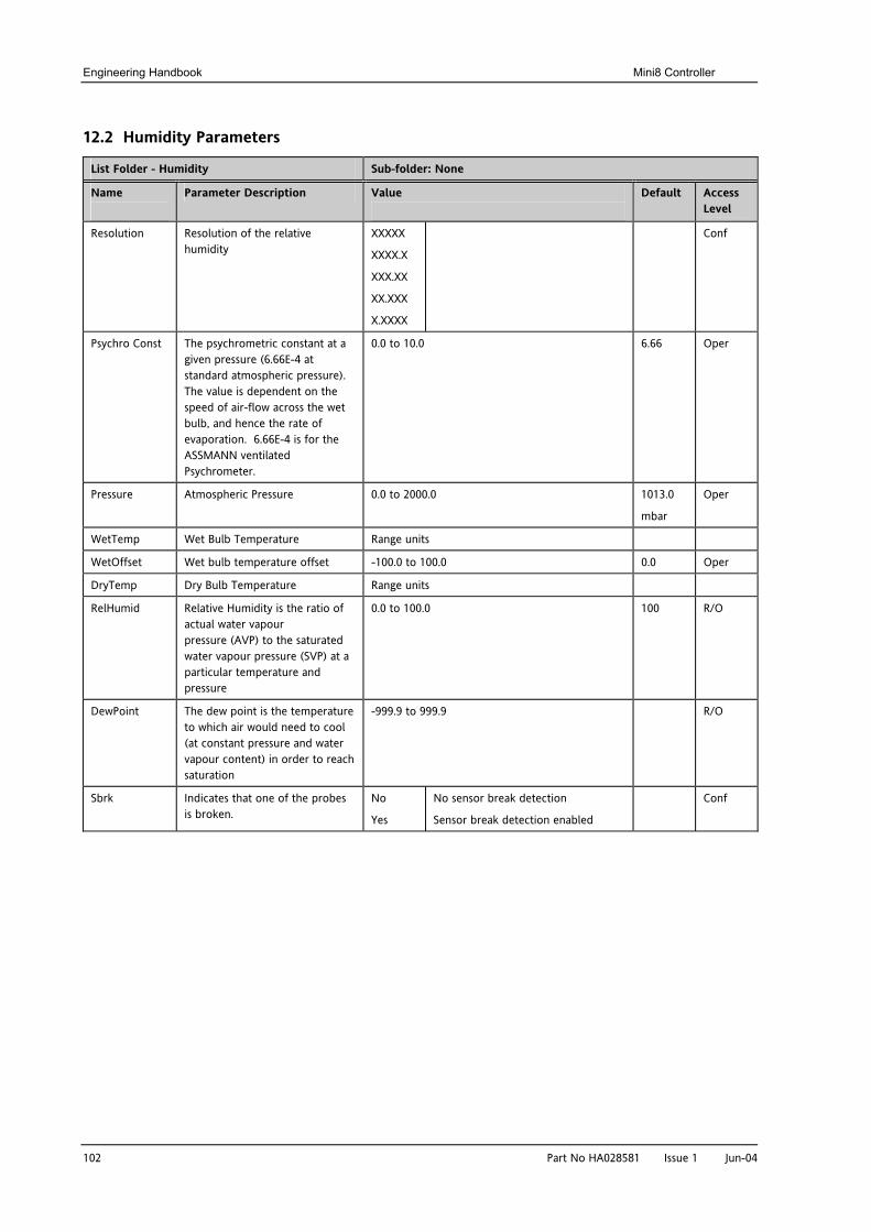
Engineering Handbook Mini8 Controller
102 Part No HA028581 Issue 1 Jun-04
12.2 Humidity Parameters
List Folder - Humidity Sub-folder: None
Name
Parameter Description Value
Default Access Level
Resolution Resolution of the relative humidity
XXXXX
XXXX.X
XXX.XX
XX.XXX
X.XXXX
Conf
Psychro Const The psychrometric constant at a given pressure (6.66E-4 at standard atmospheric pressure). The value is dependent on the speed of air-flow across the wet bulb, and hence the rate of evaporation. 6.66E-4 is for the ASSMANN ventilated Psychrometer.
0.0 to 10.0 6.66 Oper
Pressure Atmospheric Pressure 0.0 to 2000.0 1013.0
mbar
Oper
WetTemp Wet Bulb Temperature Range units
WetOffset Wet bulb temperature offset -100.0 to 100.0 0.0 Oper
DryTemp Dry Bulb Temperature Range units
RelHumid Relative Humidity is the ratio of actual water vapour pressure (AVP) to the saturated water vapour pressure (SVP) at a particular temperature and pressure
0.0 to 100.0 100 R/O
DewPoint The dew point is the temperature to which air would need to cool (at constant pressure and water vapour content) in order to reach saturation
-999.9 to 999.9 R/O
Sbrk Indicates that one of the probes is broken.
No
Yes
No sensor break detection
Sensor break detection enabled
Conf
Mini8 Controller Engineering Handbook
Part No HA028581 Issue 1 Jun-04 103
13. CHAPTER 13 INPUT MONITOR There are two Input monitors. Each input monitor may be wired to any variable in the controller. It then provides three functions:-
1. Maximum detect
2. Minimum detect
3. Time above threshold
13.1.1 Maximum Detect
This function continuously monitors the input value. If the value is higher than the previously recorded maximum, it becomes the new maximum.
This value is retained following a power fail.
13.1.2 Minimum Detect
This function continuously monitors the input value. If the value is lower than the previously recorded minimum, it becomes the new minimum.
This value is retained following a power fail.
13.1.3 Time Above Threshold
This function increments a timer whenever the input is above a threshold value. If the timer exceeds 24 hours per day, a counter is incremented. The maximum number of days is limited to 255. A time alarm can be set on the timer so that once the input has been above a threshold for a period, an alarm output is given.
Applications include:-
• Service interval alarms. This sets an output when the system has been running for a number of days (up to 90 years)
• Material stress alarms - if the process cannot tolerate being above a level for a period. This is a style of ‘policeman’ for processes where the high operating point degrades the life of the machine.
• In internal wiring applications in the controller
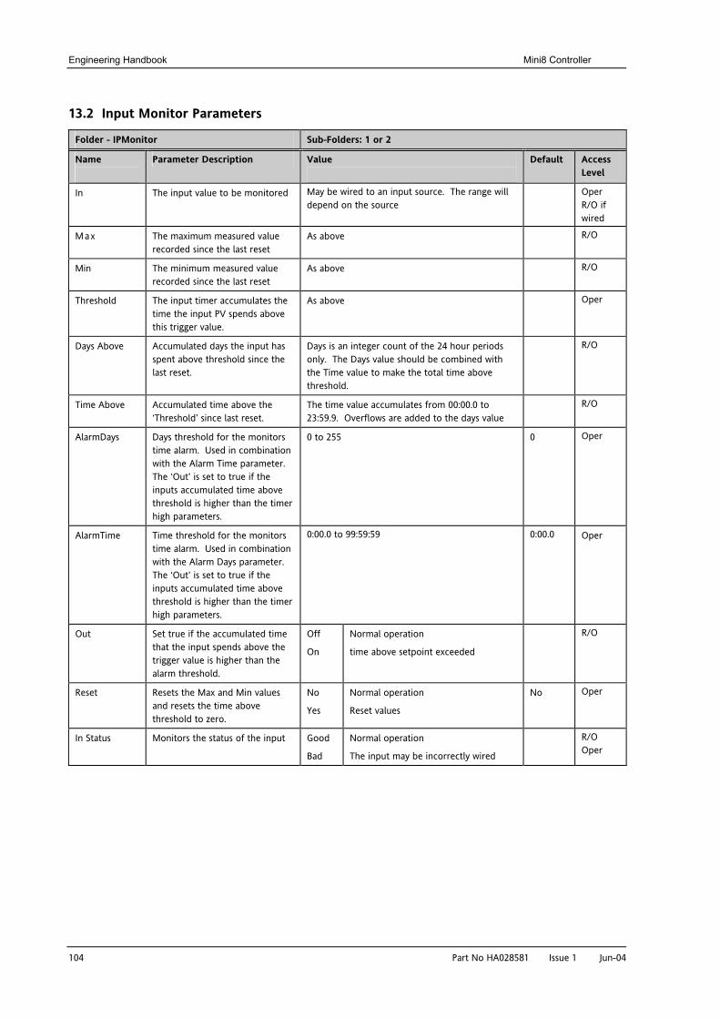
Engineering Handbook Mini8 Controller
104 Part No HA028581 Issue 1 Jun-04
13.2 Input Monitor Parameters
Folder - IPMonitor Sub-Folders: 1 or 2
Name
Parameter Description Value
Default Access Level
In The input value to be monitored May be wired to an input source. The range will depend on the source
Oper R/O if wired
Max The maximum measured value recorded since the last reset
As above R/O
Min The minimum measured value recorded since the last reset
As above R/O
Threshold The input timer accumulates the time the input PV spends above this trigger value.
As above Oper
Days Above Accumulated days the input has spent above threshold since the last reset.
Days is an integer count of the 24 hour periods only. The Days value should be combined with the Time value to make the total time above threshold.
R/O
Time Above Accumulated time above the ‘Threshold’ since last reset.
The time value accumulates from 00:00.0 to 23:59.9. Overflows are added to the days value
R/O
AlarmDays Days threshold for the monitors time alarm. Used in combination with the Alarm Time parameter. The ‘Out’ is set to true if the inputs accumulated time above threshold is higher than the timer high parameters.
0 to 255 0 Oper
AlarmTime Time threshold for the monitors time alarm. Used in combination with the Alarm Days parameter. The ‘Out’ is set to true if the inputs accumulated time above threshold is higher than the timer high parameters.
0:00.0 to 99:59:59 0:00.0 Oper
Out Set true if the accumulated time that the input spends above the trigger value is higher than the alarm threshold.
Off
On
Normal operation
time above setpoint exceeded
R/O
Reset Resets the Max and Min values and resets the time above threshold to zero.
No
Yes
Normal operation
Reset values
No Oper
In Status Monitors the status of the input Good
Bad
Normal operation
The input may be incorrectly wired
R/O Oper
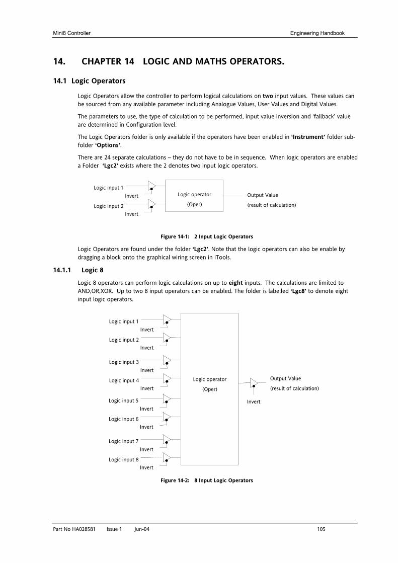
Mini8 Controller Engineering Handbook
Part No HA028581 Issue 1 Jun-04 105
14. CHAPTER 14 LOGIC AND MATHS OPERATORS.
14.1 Logic Operators
Logic Operators allow the controller to perform logical calculations on two input values. These values can be sourced from any available parameter including Analogue Values, User Values and Digital Values.
The parameters to use, the type of calculation to be performed, input value inversion and ‘fallback’ value are determined in Configuration level.
The Logic Operators folder is only available if the operators have been enabled in ‘Instrument’ folder sub-folder ‘Options’.
There are 24 separate calculations – they do not have to be in sequence. When logic operators are enabled a Folder ‘Lgc2’ exists where the 2 denotes two input logic operators.
Figure 14-1: 2 Input Logic Operators
Logic Operators are found under the folder ‘Lgc2’. Note that the logic operators can also be enable by dragging a block onto the graphical wiring screen in iTools.
14.1.1 Logic 8
Logic 8 operators can perform logic calculations on up to eight inputs. The calculations are limited to AND,OR,XOR. Up to two 8 input operators can be enabled. The folder is labelled ‘Lgc8’ to denote eight input logic operators.
Figure 14-2: 8 Input Logic Operators
Logic input 1
Logic input 2
Output Value
(result of calculation)
Logic operator
(Oper) Invert
Invert
Logic input 1
Logic input 2
Output Value
(result of calculation)
Logic operator
(Oper)
Invert
Invert
Logic input 3
Logic input 4
Invert
Invert
Logic input 5
Logic input 6
Invert
Invert
Logic input 7
Logic input 8
Invert
Invert
Invert
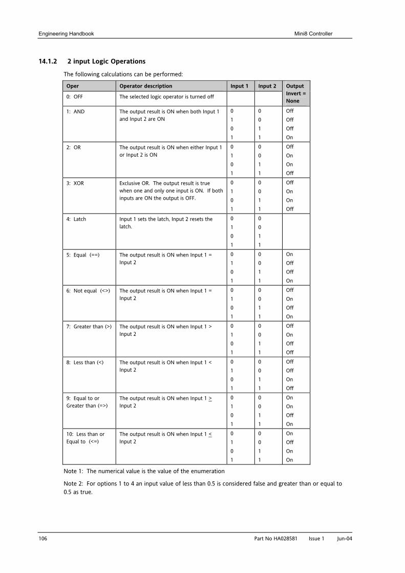
Engineering Handbook Mini8 Controller
106 Part No HA028581 Issue 1 Jun-04
14.1.2 2 input Logic Operations
The following calculations can be performed:
Oper Operator description Input 1 Input 2
0: OFF The selected logic operator is turned off
Output Invert = None
1: AND The output result is ON when both Input 1 and Input 2 are ON
0 1 0 1
0 0 1 1
Off Off Off On
2: OR The output result is ON when either Input 1 or Input 2 is ON
0 1 0 1
0 0 1 1
Off On On Off
3: XOR Exclusive OR. The output result is true when one and only one input is ON. If both inputs are ON the output is OFF.
0 1 0 1
0 0 1 1
Off On On Off
4: Latch Input 1 sets the latch, Input 2 resets the latch.
0 1 0 1
0 0 1 1
5: Equal (==) The output result is ON when Input 1 = Input 2
0 1 0 1
0 0 1 1
On Off Off On
6: Not equal (<>) The output result is ON when Input 1 = Input 2
0 1 0 1
0 0 1 1
Off On Off On
7: Greater than (>) The output result is ON when Input 1 > Input 2
0 1 0 1
0 0 1 1
Off On Off Off
8: Less than (<) The output result is ON when Input 1 < Input 2
0 1 0 1
0 0 1 1
Off Off On Off
9: Equal to or Greater than (=>)
The output result is ON when Input 1 > Input 2
0 1 0 1
0 0 1 1
On On Off On
10: Less than or Equal to (<=)
The output result is ON when Input 1 < Input 2
0 1 0 1
0 0 1 1
On Off On On
Note 1: The numerical value is the value of the enumeration
Note 2: For options 1 to 4 an input value of less than 0.5 is considered false and greater than or equal to 0.5 as true.
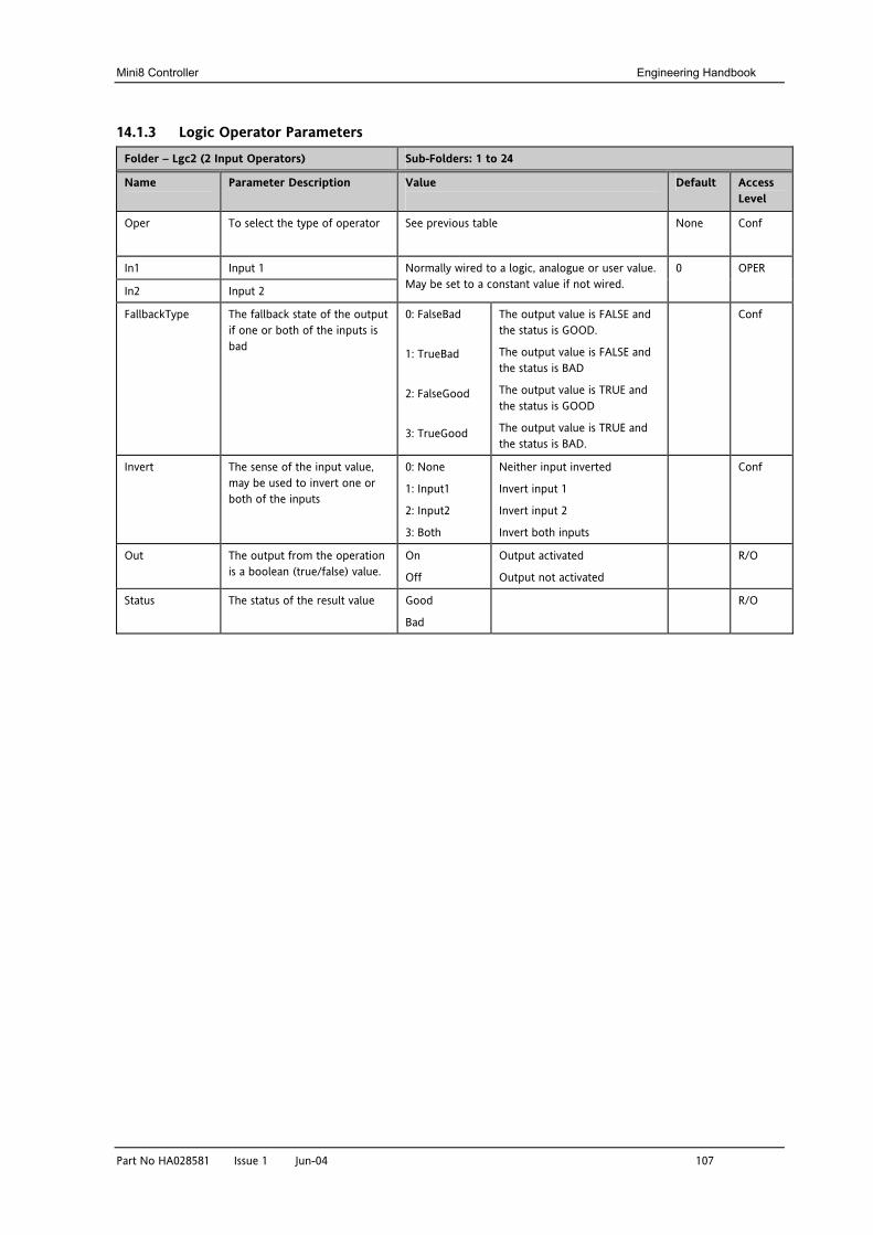
Mini8 Controller Engineering Handbook
Part No HA028581 Issue 1 Jun-04 107
14.1.3 Logic Operator Parameters
Folder – Lgc2 (2 Input Operators) Sub-Folders: 1 to 24
Name
Parameter Description Value
Default Access Level
Oper To select the type of operator See previous table None Conf
In1 Input 1
In2 Input 2
Normally wired to a logic, analogue or user value. May be set to a constant value if not wired.
0 OPER
FallbackType The fallback state of the output if one or both of the inputs is bad
0: FalseBad
1: TrueBad
2: FalseGood
3: TrueGood
The output value is FALSE and the status is GOOD.
The output value is FALSE and the status is BAD
The output value is TRUE and the status is GOOD
The output value is TRUE and the status is BAD.
Conf
Invert The sense of the input value, may be used to invert one or both of the inputs
0: None
1: Input1
2: Input2
3: Both
Neither input inverted
Invert input 1
Invert input 2
Invert both inputs
Conf
Out The output from the operation is a boolean (true/false) value.
On
Off
Output activated
Output not activated
R/O
Status The status of the result value Good
Bad
R/O
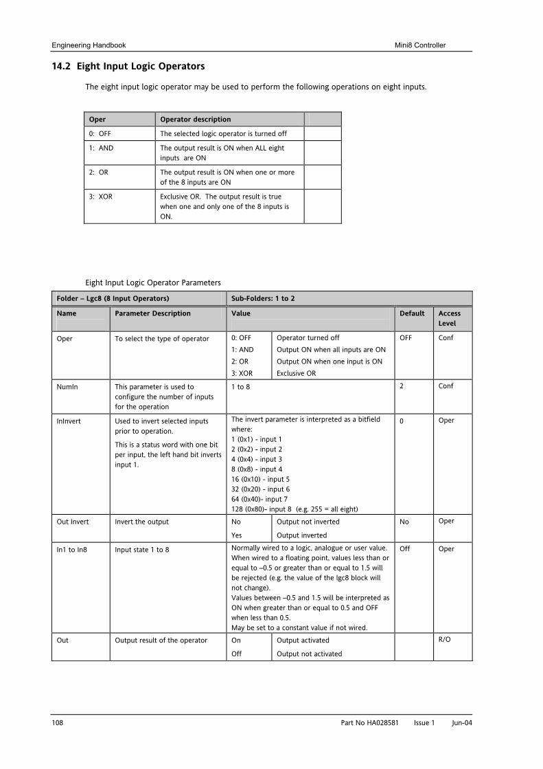
Engineering Handbook Mini8 Controller
108 Part No HA028581 Issue 1 Jun-04
14.2 Eight Input Logic Operators
The eight input logic operator may be used to perform the following operations on eight inputs.
Oper Operator description
0: OFF The selected logic operator is turned off
1: AND The output result is ON when ALL eight inputs are ON
2: OR The output result is ON when one or more of the 8 inputs are ON
3: XOR Exclusive OR. The output result is true when one and only one of the 8 inputs is ON.
Eight Input Logic Operator Parameters
Folder – Lgc8 (8 Input Operators) Sub-Folders: 1 to 2
Name
Parameter Description Value
Default Access Level
Oper To select the type of operator 0: OFF 1: AND 2: OR 3: XOR
Operator turned off Output ON when all inputs are ON Output ON when one input is ON Exclusive OR
OFF Conf
NumIn This parameter is used to configure the number of inputs for the operation
1 to 8 2 Conf
InInvert Used to invert selected inputs prior to operation.
This is a status word with one bit per input, the left hand bit inverts input 1.
The invert parameter is interpreted as a bitfield where: 1 (0x1) - input 1 2 (0x2) - input 2 4 (0x4) - input 3 8 (0x8) - input 4 16 (0x10) - input 5 32 (0x20) - input 6 64 (0x40)- input 7 128 (0x80)- input 8 (e.g. 255 = all eight)
0 Oper
Out Invert Invert the output No
Yes
Output not inverted
Output inverted
No Oper
In1 to In8 Input state 1 to 8 Normally wired to a logic, analogue or user value. When wired to a floating point, values less than or equal to –0.5 or greater than or equal to 1.5 will be rejected (e.g. the value of the lgc8 block will not change). Values between –0.5 and 1.5 will be interpreted as ON when greater than or equal to 0.5 and OFF when less than 0.5. May be set to a constant value if not wired.
Off Oper
Out Output result of the operator On
Off
Output activated
Output not activated
R/O
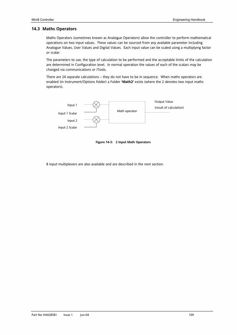
Mini8 Controller Engineering Handbook
Part No HA028581 Issue 1 Jun-04 109
14.3 Maths Operators
Maths Operators (sometimes known as Analogue Operators) allow the controller to perform mathematical operations on two input values. These values can be sourced from any available parameter including Analogue Values, User Values and Digital Values. Each input value can be scaled using a multiplying factor or scalar.
The parameters to use, the type of calculation to be performed and the acceptable limits of the calculation are determined in Configuration level. In normal operation the values of each of the scalars may be changed via communications or iTools.
There are 24 separate calculations – they do not have to be in sequence. When maths operators are enabled (in Instrument/Options folder) a Folder ‘Math2’ exists (where the 2 denotes two input maths operators).
Figure 14-3: 2 Input Math Operators
8 input multiplexers are also available and are described in the next section.
Output Value
(result of calculation) Input 1
Input 2
Math operator
Input 1 Scalar
Input 2 Scalar
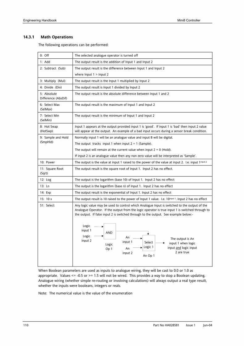
Engineering Handbook Mini8 Controller
110 Part No HA028581 Issue 1 Jun-04
14.3.1 Math Operations
The following operations can be performed:
0: Off The selected analogue operator is turned off
1: Add The output result is the addition of Input 1 and Input 2
2: Subtract (Sub) The output result is the difference between Input 1 and Input 2
where Input 1 > Input 2
3: Multiply (Mul) The output result is the Input 1 multiplied by Input 2
4: Divide (Div) The output result is Input 1 divided by Input 2
5: Absolute Difference (AbsDif)
The output result is the absolute difference between Input 1 and 2
6: Select Max (SelMax)
The output result is the maximum of Input 1 and Input 2
7: Select Min (SelMin)
The output result is the minimum of Input 1 and Input 2
8: Hot Swap (HotSwp)
Input 1 appears at the output provided input 1 is ‘good’. If input 1 is ‘bad’ then input 2 value will appear at the output. An example of a bad input occurs during a sensor break condition.
9: Sample and Hold (SmpHld)
Normally input 1 will be an analogue value and input B will be digital.
The output tracks input 1 when input 2 = 1 (Sample).
The output will remain at the current value when input 2 = 0 (Hold).
If input 2 is an analogue value then any non zero value will be interpreted as ‘Sample’.
10: Power The output is the value at input 1 raised to the power of the value at input 2. I.e. input 1input 2
11: Square Root (Sqrt)
The output result is the square root of Input 1. Input 2 has no effect.
12: Log The output is the logarithm (base 10) of Input 1. Input 2 has no effect
13: Ln The output is the logarithm (base n) of Input 1. Input 2 has no effect
14: Exp The output result is the exponential of Input 1. Input 2 has no effect
15: 10 x The output result is 10 raised to the power of Input 1 value. I.e. 10input 1. Input 2 has no effect
51: Select Any logic value may be used to control which Analogue Input is switched to the output of the Analogue Operator. If the output from the logic operator is true input 1 is switched through to the output. If false input 2 is switched through to the output. See example below:-
When Boolean parameters are used as inputs to analogue wiring, they will be cast to 0.0 or 1.0 as appropriate. Values <= -0.5 or >= 1.5 will not be wired. This provides a way to stop a Boolean updating. Analogue wiring (whether simple re-routing or involving calculations) will always output a real type result, whether the inputs were booleans, integers or reals.
Note: The numerical value is the value of the enumeration
The output is An input 1 when logic
input and logic input 2 are true
Logic input 2
Logic input 1
Logic Op 1
An Op 1
Select Logic 1
An input 1
AND
An input 2
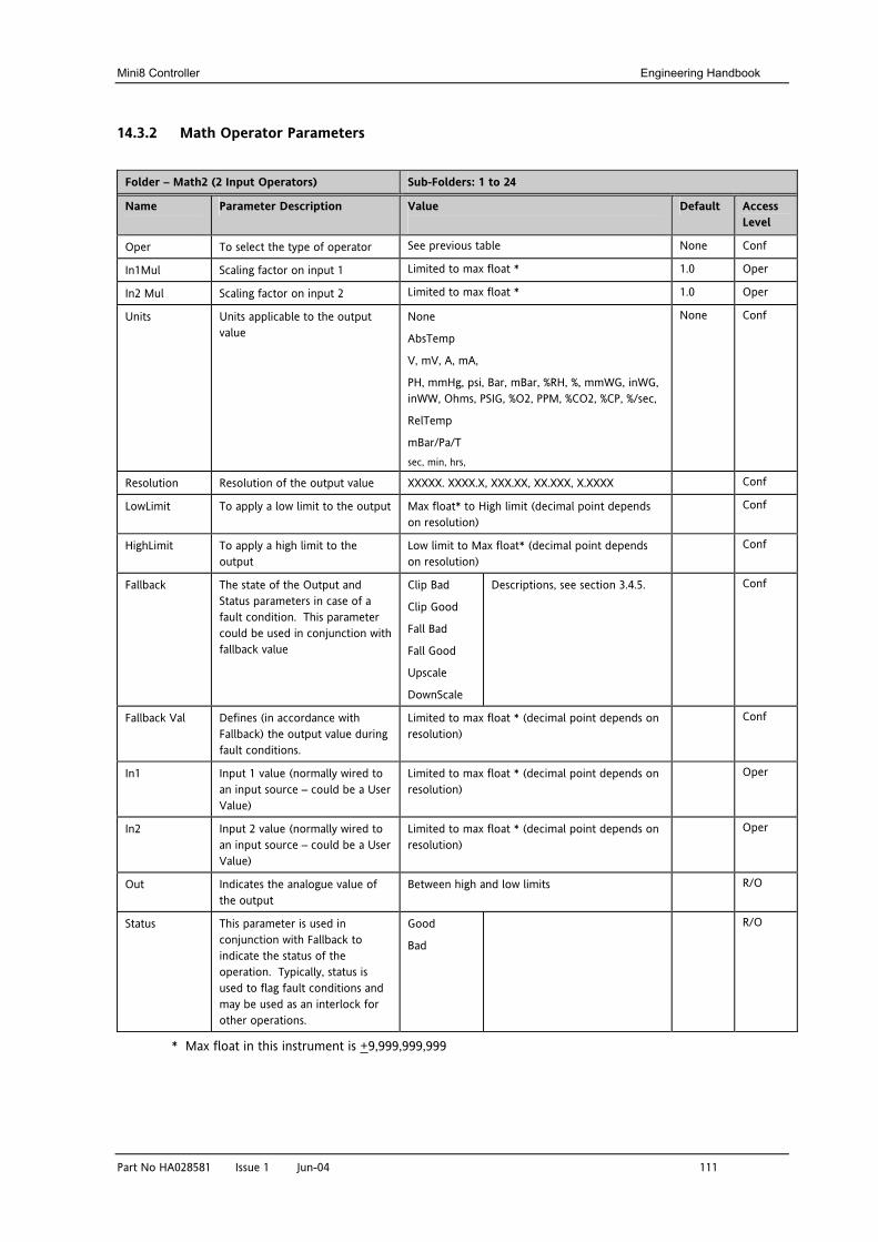
Mini8 Controller Engineering Handbook
Part No HA028581 Issue 1 Jun-04 111
14.3.2 Math Operator Parameters
Folder – Math2 (2 Input Operators) Sub-Folders: 1 to 24
Name
Parameter Description Value
Default Access Level
Oper To select the type of operator See previous table None Conf
In1Mul Scaling factor on input 1 Limited to max float * 1.0 Oper
In2 Mul Scaling factor on input 2 Limited to max float * 1.0 Oper
Units Units applicable to the output value
None
AbsTemp
V, mV, A, mA,
PH, mmHg, psi, Bar, mBar, %RH, %, mmWG, inWG, inWW, Ohms, PSIG, %O2, PPM, %CO2, %CP, %/sec,
RelTemp
mBar/Pa/T sec, min, hrs,
None Conf
Resolution Resolution of the output value XXXXX. XXXX.X, XXX.XX, XX.XXX, X.XXXX Conf
LowLimit To apply a low limit to the output Max float* to High limit (decimal point depends on resolution)
Conf
HighLimit To apply a high limit to the output
Low limit to Max float* (decimal point depends on resolution)
Conf
Fallback The state of the Output and Status parameters in case of a fault condition. This parameter could be used in conjunction with fallback value
Clip Bad
Clip Good
Fall Bad
Fall Good
Upscale
DownScale
Descriptions, see section 3.4.5. Conf
Fallback Val Defines (in accordance with Fallback) the output value during fault conditions.
Limited to max float * (decimal point depends on resolution)
Conf
In1 Input 1 value (normally wired to an input source – could be a User Value)
Limited to max float * (decimal point depends on resolution)
Oper
In2 Input 2 value (normally wired to an input source – could be a User Value)
Limited to max float * (decimal point depends on resolution)
Oper
Out Indicates the analogue value of the output
Between high and low limits R/O
Status This parameter is used in conjunction with Fallback to indicate the status of the operation. Typically, status is used to flag fault conditions and may be used as an interlock for other operations.
Good
Bad
R/O
* Max float in this instrument is +9,999,999,999
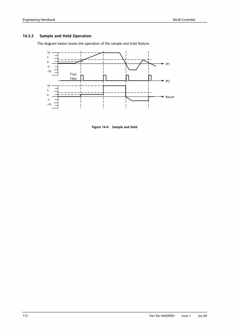
Engineering Handbook Mini8 Controller
112 Part No HA028581 Issue 1 Jun-04
14.3.3 Sample and Hold Operation
The diagram below shows the operation of the sample and hold feature.
Figure 14-4: Sample and Hold
10 5 0 -5 -10
10 5 0 -5 -10
IP1
IP2
Result
True False
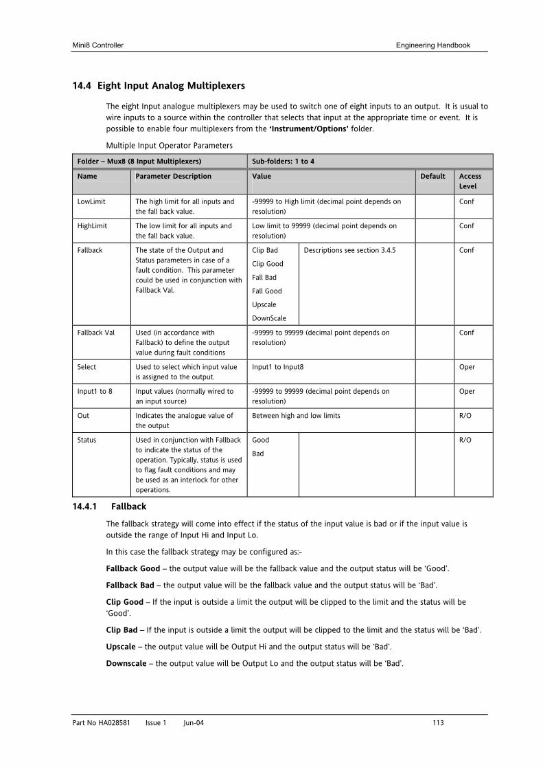
Mini8 Controller Engineering Handbook
Part No HA028581 Issue 1 Jun-04 113
14.4 Eight Input Analog Multiplexers
The eight Input analogue multiplexers may be used to switch one of eight inputs to an output. It is usual to wire inputs to a source within the controller that selects that input at the appropriate time or event. It is possible to enable four multiplexers from the ‘Instrument/Options’ folder.
Multiple Input Operator Parameters
Folder – Mux8 (8 Input Multiplexers) Sub-folders: 1 to 4
Name
Parameter Description Value
Default Access Level
LowLimit The high limit for all inputs and the fall back value.
-99999 to High limit (decimal point depends on resolution)
Conf
HighLimit The low limit for all inputs and the fall back value.
Low limit to 99999 (decimal point depends on resolution)
Conf
Fallback The state of the Output and Status parameters in case of a fault condition. This parameter could be used in conjunction with Fallback Val.
Clip Bad
Clip Good
Fall Bad
Fall Good
Upscale
DownScale
Descriptions see section 3.4.5 Conf
Fallback Val Used (in accordance with Fallback) to define the output value during fault conditions
-99999 to 99999 (decimal point depends on resolution)
Conf
Select Used to select which input value is assigned to the output.
Input1 to Input8 Oper
Input1 to 8 Input values (normally wired to an input source)
-99999 to 99999 (decimal point depends on resolution)
Oper
Out Indicates the analogue value of the output
Between high and low limits R/O
Status Used in conjunction with Fallback to indicate the status of the operation. Typically, status is used to flag fault conditions and may be used as an interlock for other operations.
Good
Bad
R/O
14.4.1 Fallback
The fallback strategy will come into effect if the status of the input value is bad or if the input value is outside the range of Input Hi and Input Lo.
In this case the fallback strategy may be configured as:-
Fallback Good – the output value will be the fallback value and the output status will be ‘Good’.
Fallback Bad – the output value will be the fallback value and the output status will be ‘Bad’.
Clip Good – If the input is outside a limit the output will be clipped to the limit and the status will be ‘Good’.
Clip Bad – If the input is outside a limit the output will be clipped to the limit and the status will be ‘Bad’.
Upscale – the output value will be Output Hi and the output status will be ‘Bad’.
Downscale – the output value will be Output Lo and the output status will be ‘Bad’.
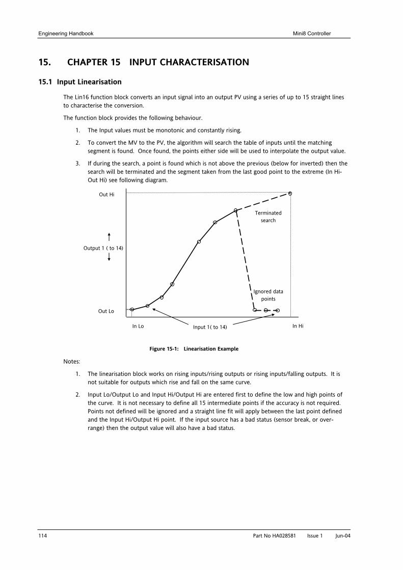
Engineering Handbook Mini8 Controller
114 Part No HA028581 Issue 1 Jun-04
15. CHAPTER 15 INPUT CHARACTERISATION
15.1 Input Linearisation
The Lin16 function block converts an input signal into an output PV using a series of up to 15 straight lines to characterise the conversion.
The function block provides the following behaviour.
1. The Input values must be monotonic and constantly rising.
2. To convert the MV to the PV, the algorithm will search the table of inputs until the matching segment is found. Once found, the points either side will be used to interpolate the output value.
3. If during the search, a point is found which is not above the previous (below for inverted) then the search will be terminated and the segment taken from the last good point to the extreme (In Hi-Out Hi) see following diagram.
Figure 15-1: Linearisation Example
Notes:
1. The linearisation block works on rising inputs/rising outputs or rising inputs/falling outputs. It is not suitable for outputs which rise and fall on the same curve.
2. Input Lo/Output Lo and Input Hi/Output Hi are entered first to define the low and high points of the curve. It is not necessary to define all 15 intermediate points if the accuracy is not required. Points not defined will be ignored and a straight line fit will apply between the last point defined and the Input Hi/Output Hi point. If the input source has a bad status (sensor break, or over-range) then the output value will also have a bad status.
Output 1 ( to 14)
Out Hi
Out Lo
In Hi In Lo Input 1( to 14)
Ignored data points
Terminated search
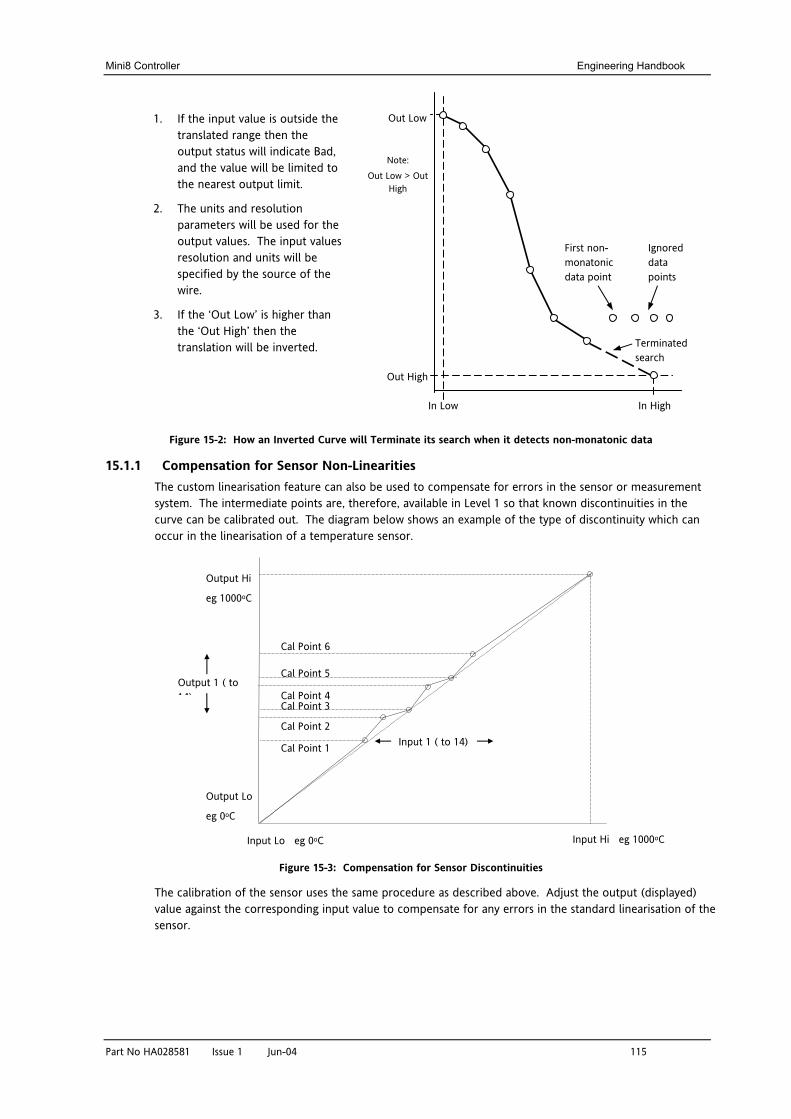
Mini8 Controller Engineering Handbook
Part No HA028581 Issue 1 Jun-04 115
1. If the input value is outside the translated range then the output status will indicate Bad, and the value will be limited to the nearest output limit.
2. The units and resolution parameters will be used for the output values. The input values resolution and units will be specified by the source of the wire.
3. If the ‘Out Low’ is higher than the ‘Out High’ then the translation will be inverted.
Figure 15-2: How an Inverted Curve will Terminate its search when it detects non-monatonic data
15.1.1 Compensation for Sensor Non-Linearities The custom linearisation feature can also be used to compensate for errors in the sensor or measurement system. The intermediate points are, therefore, available in Level 1 so that known discontinuities in the curve can be calibrated out. The diagram below shows an example of the type of discontinuity which can occur in the linearisation of a temperature sensor.
Figure 15-3: Compensation for Sensor Discontinuities
The calibration of the sensor uses the same procedure as described above. Adjust the output (displayed) value against the corresponding input value to compensate for any errors in the standard linearisation of the sensor.
First non-monatonic data point
Ignored data points
Terminated search
In High In Low
Out High
Out Low
Note: Out Low > Out
High
Output Hi
eg 1000oC
Output Lo
eg 0oC
Output 1 ( to 14)
Input Hi eg 1000oC Input Lo eg 0oC
Input 1 ( to 14)
Cal Point 6
Cal Point 5
Cal Point 4 Cal Point 3
Cal Point 2
Cal Point 1
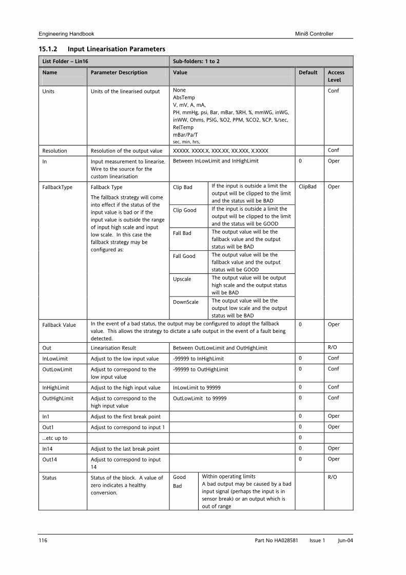
Engineering Handbook Mini8 Controller
116 Part No HA028581 Issue 1 Jun-04
15.1.2 Input Linearisation Parameters
List Folder – Lin16 Sub-folders: 1 to 2
Name
Parameter Description Value
Default Access Level
Units Units of the linearised output None AbsTemp V, mV, A, mA, PH, mmHg, psi, Bar, mBar, %RH, %, mmWG, inWG, inWW, Ohms, PSIG, %O2, PPM, %CO2, %CP, %/sec, RelTemp mBar/Pa/T sec, min, hrs,
Conf
Resolution Resolution of the output value XXXXX. XXXX.X, XXX.XX, XX.XXX, X.XXXX Conf
In Input measurement to linearise. Wire to the source for the custom linearisation
Between InLowLimit and InHighLimit 0 Oper
Clip Bad If the input is outside a limit the output will be clipped to the limit and the status will be BAD
Clip Good If the input is outside a limit the output will be clipped to the limit and the status will be GOOD
Fall Bad The output value will be the fallback value and the output status will be BAD
Fall Good The output value will be the fallback value and the output status will be GOOD
Upscale The output value will be output high scale and the output status will be BAD
FallbackType Fallback Type
The fallback strategy will come into effect if the status of the input value is bad or if the input value is outside the range of input high scale and input low scale. In this case the fallback strategy may be configured as:
DownScale The output value will be the output low scale and the output status will be BAD
ClipBad Oper
Fallback Value In the event of a bad status, the output may be configured to adopt the fallback value. This allows the strategy to dictate a safe output in the event of a fault being detected.
0 Oper
Out Linearisation Result Between OutLowLimit and OutHighLimit R/O
InLowLimit Adjust to the low input value -99999 to InHighLimit 0 Conf
OutLowLimit Adjust to correspond to the low input value
-99999 to OutHighLimit 0 Conf
InHighLimit Adjust to the high input value InLowLimit to 99999 0 Conf
OutHighLimit Adjust to correspond to the high input value
OutLowLimit to 99999 0 Conf
In1 Adjust to the first break point 0 Oper
Out1 Adjust to correspond to input 1 0 Oper
…etc up to 0
In14 Adjust to the last break point 0 Oper
Out14 Adjust to correspond to input 14
0 Oper
Status Status of the block. A value of zero indicates a healthy conversion.
Good Bad
Within operating limits A bad output may be caused by a bad input signal (perhaps the input is in sensor break) or an output which is out of range
R/O
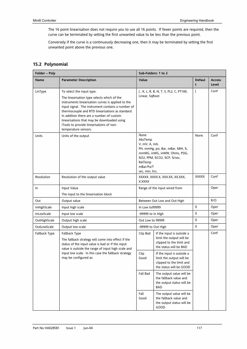
Mini8 Controller Engineering Handbook
Part No HA028581 Issue 1 Jun-04 117
The 16 point linearisation does not require you to use all 16 points. If fewer points are required, then the curve can be terminated by setting the first unwanted value to be less than the previous point.
Conversely if the curve is a continuously decreasing one, then it may be terminated by setting the first unwanted point above the previous one.
15.2 Polynomial
Folder – Poly Sub-Folders: 1 to 2
Name
Parameter Description Value
Default
Access Level
LinType To select the input type.
The linearisation type selects which of the instruments linearisation curves is applied to the input signal. The instrument contains a number of thermocouple and RTD linearisations as standard. In addition there are a number of custom linearisations that may be downloaded using iTools to provide linearisations of non-temperature sensors.
J , K, L, R, B, N, T, S, PL2, C, PT100, Linear, SqRoot
J Conf
Units Units of the output None AbsTemp V, mV, A, mA, PH, mmHg, psi, Bar, mBar, %RH, %, mmWG, inWG, inWW, Ohms, PSIG, %O2, PPM, %CO2, %CP, %/sec, RelTemp mBar/Pa/T sec, min, hrs,
None Conf
Resolution Resolution of the output value XXXXX. XXXX.X, XXX.XX, XX.XXX, X.XXXX
XXXXX Conf
In Input Value
The input to the linearisation block
Range of the input wired from Oper
Out Output value Between Out Low and Out High R/O
InHighScale Input high scale In Low to99999 0 Oper
InLowScale Input low scale -99999 to In High 0 Oper
OutHighScale Output high scale Out Low to 99999 0 Oper
OutLowScale Output low scale -99999 to Out High 0 Oper
Clip Bad If the input is outside a limit the output will be clipped to the limit and the status will be BAD
Clip Good
If the input is outside a limit the output will be clipped to the limit and the status will be GOOD
Fall Bad The output value will be the fallback value and the output status will be BAD
Fallback Type Fallback Type
The fallback strategy will come into effect if the status of the input value is bad or if the input value is outside the range of input high scale and input low scale. In this case the fallback strategy may be configured as:
Fall Good
The output value will be the fallback value and the output status will be GOOD
Conf
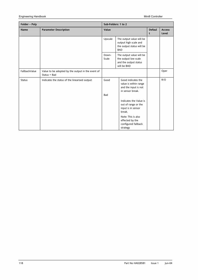
Engineering Handbook Mini8 Controller
118 Part No HA028581 Issue 1 Jun-04
Folder – Poly Sub-Folders: 1 to 2
Name
Parameter Description Value
Default
Access Level
Upscale The output value will be output high scale and the output status will be BAD
Down-Scale
The output value will be the output low scale and the output status will be BAD
FallbackValue Value to be adopted by the output in the event of Status = Bad
Oper
Status Indicates the status of the linearised output:
Good
Bad
Good indicates the value is within range and the input is not in sensor break.
Indicates the Value is out of range or the input is in sensor break.
Note: This is also effected by the configured fallback strategy
R/O
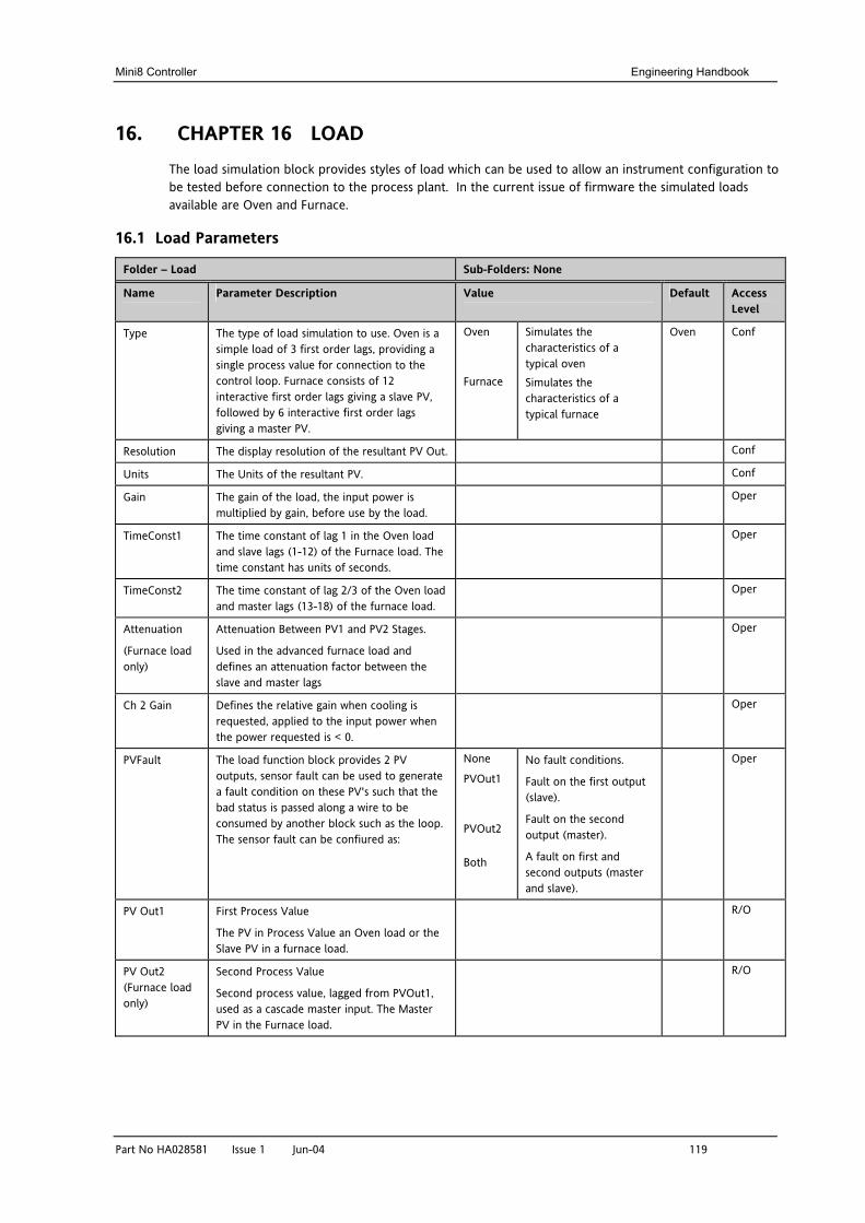
Mini8 Controller Engineering Handbook
Part No HA028581 Issue 1 Jun-04 119
16. CHAPTER 16 LOAD The load simulation block provides styles of load which can be used to allow an instrument configuration to be tested before connection to the process plant. In the current issue of firmware the simulated loads available are Oven and Furnace.
16.1 Load Parameters
Folder – Load Sub-Folders: None
Name
Parameter Description Value
Default Access Level
Type The type of load simulation to use. Oven is a simple load of 3 first order lags, providing a single process value for connection to the control loop. Furnace consists of 12 interactive first order lags giving a slave PV, followed by 6 interactive first order lags giving a master PV.
Oven
Furnace
Simulates the characteristics of a typical oven Simulates the characteristics of a typical furnace
Oven Conf
Resolution The display resolution of the resultant PV Out. Conf
Units The Units of the resultant PV. Conf
Gain The gain of the load, the input power is multiplied by gain, before use by the load.
Oper
TimeConst1 The time constant of lag 1 in the Oven load and slave lags (1-12) of the Furnace load. The time constant has units of seconds.
Oper
TimeConst2 The time constant of lag 2/3 of the Oven load and master lags (13-18) of the furnace load.
Oper
Attenuation
(Furnace load only)
Attenuation Between PV1 and PV2 Stages.
Used in the advanced furnace load and defines an attenuation factor between the slave and master lags
Oper
Ch 2 Gain Defines the relative gain when cooling is requested, applied to the input power when the power requested is < 0.
Oper
PVFault The load function block provides 2 PV outputs, sensor fault can be used to generate a fault condition on these PV's such that the bad status is passed along a wire to be consumed by another block such as the loop. The sensor fault can be confiured as:
None
PVOut1
PVOut2
Both
No fault conditions.
Fault on the first output (slave).
Fault on the second output (master).
A fault on first and second outputs (master and slave).
Oper
PV Out1 First Process Value
The PV in Process Value an Oven load or the Slave PV in a furnace load.
R/O
PV Out2 (Furnace load only)
Second Process Value
Second process value, lagged from PVOut1, used as a cascade master input. The Master PV in the Furnace load.
R/O
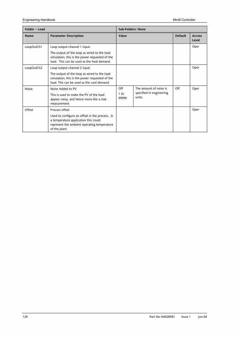
Engineering Handbook Mini8 Controller
120 Part No HA028581 Issue 1 Jun-04
Folder – Load Sub-Folders: None
Name
Parameter Description Value
Default Access Level
LoopOutCh1 Loop output channel 1 input.
The output of the loop as wired to the load simulation, this is the power requested of the load. This can be used as the heat demand.
Oper
LoopOutCh2 Loop output channel 2 input.
The output of the loop as wired to the load simulation, this is the power requested of the load. This can be used as the cool demand.
Oper
Noise Noise Added to PV
This is used to make the PV of the load appear noisy, and hence more like a real measurement.
Off 1 to 99999
The amount of noise is specified in engineering units.
Off Oper
Offset Process offset
Used to configure an offset in the process. In a temperature application this could represent the ambient operating temperature of the plant.
Oper
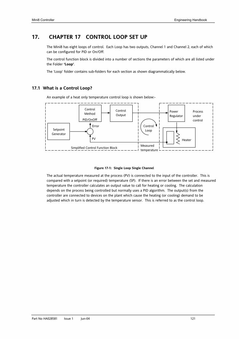
Mini8 Controller Engineering Handbook
Part No HA028581 Issue 1 Jun-04 121
17. CHAPTER 17 CONTROL LOOP SET UP The Mini8 has eight loops of control. Each Loop has two outputs, Channel 1 and Channel 2, each of which can be configured for PID or On/Off.
The control function block is divided into a number of sections the parameters of which are all listed under the Folder ‘Loop’.
The ‘Loop’ folder contains sub-folders for each section as shown diagrammatically below.
17.1 What is a Control Loop?
An example of a heat only temperature control loop is shown below:-
Figure 17-1: Single Loop Single Channel
The actual temperature measured at the process (PV) is connected to the input of the controller. This is compared with a setpoint (or required) temperature (SP). If there is an error between the set and measured temperature the controller calculates an output value to call for heating or cooling. The calculation depends on the process being controlled but normally uses a PID algorithm. The output(s) from the controller are connected to devices on the plant which cause the heating (or cooling) demand to be adjusted which in turn is detected by the temperature sensor. This is referred to as the control loop.
Measured temperature
Heater
Control Output
Setpoint Generator
Control Method
PID/OnOff
PV
Error
Power Regulator
Control Loop
Process under control
Simplified Control Function Block
Engineering Handbook Mini8 Controller
122 Part No HA028581 Issue 1 Jun-04
17.2 Loop Parameters - Main
Folder – Loop.1 to Loop.8 Sub-Folder: Main
Name
Parameter Description Value
Default Access Level
AutoMan To select Auto or Manual operation. Auto
Man
Automatic (closed loop) operation Manual (output power adjusted by the user) operation
Auto Oper
PV The process variable input value. This is typically wired from an analogue input.
Range of the input source Oper
Inhibit Used to stop the loop controlling. If enabled the loop will stop control and the output of the loop will be set to the safe output value. On exit from inhibit the transfer will be bumpless. This may be wired to an external source
No Yes
Inhibit disabled Inhibit enabled
No Oper
TargetSP The value of setpoint at which the control loop is aiming. It may come from a number of different sources, such as internal SP and remote SP.
Between setpoint limits Oper
WorkingSP The current value of the setpoint being used by the control loop. It may come from a number of different sources, such as internal SP and Remote SP. The working setpoint is always read-only as it is derived from other sources.
Between setpoint limits R/O
ActiveOut The actual output of the loop before it is split into the channel 1 and channel 2 outputs.
R/O
IntHold Stops Integral action No Oper
17.3 Loop Set up
These parameters configure the type of control.
Folder – Loop.1 to Loop.8 Sub-folder: Setup
Name
Parameter Description Value
Default Access Level
Ch1
ControlType
Selects the channel 1 control algorithm. You may select different algorithms for channels 1 and 2. In temperature control applications, Ch1 is usually the heating channel, Ch2 is the cooling channel.
Ch2 ControlType
Control type for channel 2
Off OnOff PID
Channel turned off On/off control 3 term or PID control
PID Conf
Control Action Control Action Rev
Dir
Reverse acting. The output increases when the PV is below SP. This is the best setting for heating control. Direct acting. The output increases when the PV is above SP. This is the best setting for cooling control
Rev Conf
PB Units Proportional band units.
Eng Percent
Engineering units eg C or F Per cent of loop span (range Hi - Range Lo)
Eng Conf
Mini8 Controller Engineering Handbook
Part No HA028581 Issue 1 Jun-04 123
Derivative
Type
Selects whether the derivative acts only on PV changes or on Error (either PV or Setpoint changes).
PV
Error
Only changes in PV cause changes to the derivative output.
Changes to either PV or SP will cause a derivative output.
PV Conf
The above two parameters do not appear if either Ch1 or Ch2 are configured for Off or OnOff control
17.3.1 Types of Control Loop
17.3.1.1 On/Off Control
On/Off control simply turns heating power on when the PV is below setpoint and off when it is above setpoint. If cooling is used, cooling power is turned on when the PV is above setpoint and off when it is below. The outputs of such a controller will normally be connected to relays – hysteresis may be set as described in the Alarms section to prevent relay chatter or to provide a delay in the control output action.
17.3.1.2 PID Control
PID control, also referred to as ‘Three Term Control’, is a technique used to achieve stable straight line control at the required setpoint. The three terms are:
P = Proportional band I = Integral time D = Derivative time
The output from the controller is the sum of the contributions from these three terms. The combined output is a function of the magnitude and duration of the error signal, and the rate of change of the process value. It is possible to turn off integral and derivative terms and control on only proportional, proportional plus integral or proportional plus derivative.
17.4 PID Control
The PID controller consists of the following parameters:-
Parameter Meaning or Function
Proportional Band ‘PB’
The proportional term, in display units or %, delivers an output that is proportional to the size of the error signal.
Integral Time ‘Ti’ Removes steady state control offsets by ramping the output up or down in proportion to the amplitude and duration of the error signal.
Derivative Time ‘Td’
Determines how strongly the controller will react to the rate of change in the measured value. It is used to prevent overshoot and undershoot and to restore the PV rapidly if there is a sudden change in demand.
High Cutback ‘CBH’
The number of display units, above setpoint, at which the controller will increase the output power, in order to prevent undershoot on cool down.
Low Cutback ‘CBL’
The number of display units, below setpoint, at which the controller will cutback the output power, in order to prevent overshoot on heat up.
Relative Cool Gain ‘R2G’
Only present if cooling has been configured. Sets the cooling proportional band, which equals the heat proportional band value divided by the cool gain value.
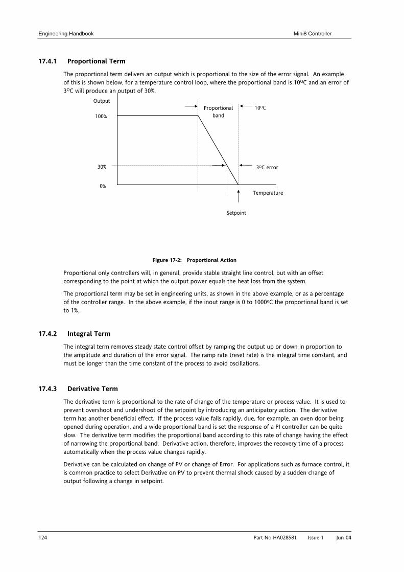
Engineering Handbook Mini8 Controller
124 Part No HA028581 Issue 1 Jun-04
17.4.1 Proportional Term
The proportional term delivers an output which is proportional to the size of the error signal. An example of this is shown below, for a temperature control loop, where the proportional band is 10OC and an error of 3OC will produce an output of 30%.
Figure 17-2: Proportional Action
Proportional only controllers will, in general, provide stable straight line control, but with an offset corresponding to the point at which the output power equals the heat loss from the system.
The proportional term may be set in engineering units, as shown in the above example, or as a percentage of the controller range. In the above example, if the inout range is 0 to 1000oC the proportional band is set to 1%.
17.4.2 Integral Term
The integral term removes steady state control offset by ramping the output up or down in proportion to the amplitude and duration of the error signal. The ramp rate (reset rate) is the integral time constant, and must be longer than the time constant of the process to avoid oscillations.
17.4.3 Derivative Term
The derivative term is proportional to the rate of change of the temperature or process value. It is used to prevent overshoot and undershoot of the setpoint by introducing an anticipatory action. The derivative term has another beneficial effect. If the process value falls rapidly, due, for example, an oven door being opened during operation, and a wide proportional band is set the response of a PI controller can be quite slow. The derivative term modifies the proportional band according to this rate of change having the effect of narrowing the proportional band. Derivative action, therefore, improves the recovery time of a process automatically when the process value changes rapidly.
Derivative can be calculated on change of PV or change of Error. For applications such as furnace control, it is common practice to select Derivative on PV to prevent thermal shock caused by a sudden change of output following a change in setpoint.
Proportional band
3OC error
Temperature
Setpoint
10OC Output
100%
0%
30%
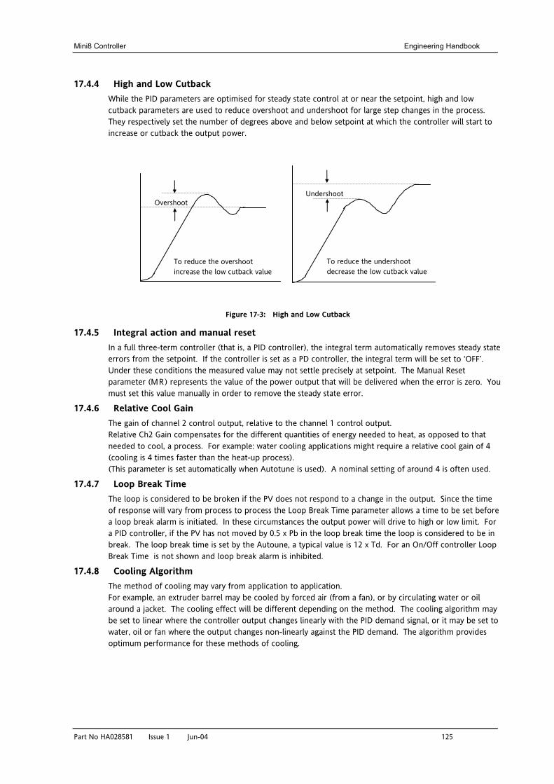
Mini8 Controller Engineering Handbook
Part No HA028581 Issue 1 Jun-04 125
17.4.4 High and Low Cutback While the PID parameters are optimised for steady state control at or near the setpoint, high and low cutback parameters are used to reduce overshoot and undershoot for large step changes in the process. They respectively set the number of degrees above and below setpoint at which the controller will start to increase or cutback the output power.
Figure 17-3: High and Low Cutback
17.4.5 Integral action and manual reset In a full three-term controller (that is, a PID controller), the integral term automatically removes steady state errors from the setpoint. If the controller is set as a PD controller, the integral term will be set to ‘OFF’. Under these conditions the measured value may not settle precisely at setpoint. The Manual Reset parameter (MR) represents the value of the power output that will be delivered when the error is zero. You must set this value manually in order to remove the steady state error.
17.4.6 Relative Cool Gain The gain of channel 2 control output, relative to the channel 1 control output. Relative Ch2 Gain compensates for the different quantities of energy needed to heat, as opposed to that needed to cool, a process. For example: water cooling applications might require a relative cool gain of 4 (cooling is 4 times faster than the heat-up process). (This parameter is set automatically when Autotune is used). A nominal setting of around 4 is often used.
17.4.7 Loop Break Time The loop is considered to be broken if the PV does not respond to a change in the output. Since the time of response will vary from process to process the Loop Break Time parameter allows a time to be set before a loop break alarm is initiated. In these circumstances the output power will drive to high or low limit. For a PID controller, if the PV has not moved by 0.5 x Pb in the loop break time the loop is considered to be in break. The loop break time is set by the Autoune, a typical value is 12 x Td. For an On/Off controller Loop Break Time is not shown and loop break alarm is inhibited.
17.4.8 Cooling Algorithm The method of cooling may vary from application to application. For example, an extruder barrel may be cooled by forced air (from a fan), or by circulating water or oil around a jacket. The cooling effect will be different depending on the method. The cooling algorithm may be set to linear where the controller output changes linearly with the PID demand signal, or it may be set to water, oil or fan where the output changes non-linearly against the PID demand. The algorithm provides optimum performance for these methods of cooling.
Overshoot
To reduce the overshoot increase the low cutback value
Undershoot
To reduce the undershoot decrease the low cutback value
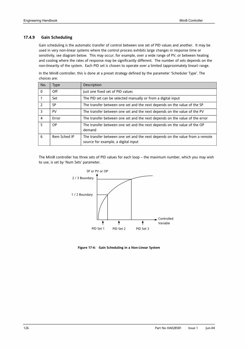
Engineering Handbook Mini8 Controller
126 Part No HA028581 Issue 1 Jun-04
17.4.9 Gain Scheduling
Gain scheduling is the automatic transfer of control between one set of PID values and another. It may be used in very non-linear systems where the control process exhibits large changes in response time or sensitivity, see diagram below. This may occur, for example, over a wide range of PV, or between heating and cooling where the rates of response may be significantly different. The number of sets depends on the non-linearity of the system. Each PID set is chosen to operate over a limited (approximately linear) range.
In the Mini8 controller, this is done at a preset strategy defined by the parameter ‘Scheduler Type’. The choices are:
No. Type Description
0 Off Just one fixed set of PID values
1 Set The PID set can be selected manually or from a digital input
2 SP The transfer between one set and the next depends on the value of the SP
3 PV The transfer between one set and the next depends on the value of the PV
4 Error The transfer between one set and the next depends on the value of the error
5 OP The transfer between one set and the next depends on the value of the OP demand
6 Rem Sched IP The transfer between one set and the next depends on the value from a remote source for example, a digital input
The Mini8 controller has three sets of PID values for each loop – the maximum number, which you may wish to use, is set by ‘Num Sets’ parameter.
Figure 17-4: Gain Scheduling in a Non-Linear System
SP or PV or OP
Controlled Variable
PID Set 1 PID Set 2 PID Set 3
1 / 2 Boundary
2 / 3 Boundary
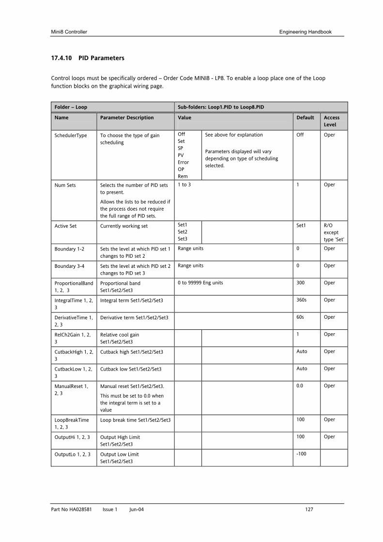
Mini8 Controller Engineering Handbook
Part No HA028581 Issue 1 Jun-04 127
17.4.10 PID Parameters
Control loops must be specifically ordered – Order Code MINI8 - LP8. To enable a loop place one of the Loop function blocks on the graphical wiring page.
Folder – Loop Sub-folders: Loop1.PID to Loop8.PID
Name
Parameter Description Value
Default Access Level
SchedulerType To choose the type of gain scheduling
Off Set SP PV Error OP Rem
See above for explanation Parameters displayed will vary depending on type of scheduling selected.
Off Oper
Num Sets Selects the number of PID sets to present.
Allows the lists to be reduced if the process does not require the full range of PID sets.
1 to 3 1 Oper
Active Set Currently working set Set1 Set2 Set3
Set1 R/O except type ’Set’
Boundary 1-2 Sets the level at which PID set 1 changes to PID set 2
Range units 0 Oper
Boundary 3-4 Sets the level at which PID set 2 changes to PID set 3
Range units 0 Oper
ProportionalBand1, 2, 3
Proportional band Set1/Set2/Set3
0 to 99999 Eng units 300 Oper
IntegralTime 1, 2, 3
Integral term Set1/Set2/Set3 360s Oper
DerivativeTime 1, 2, 3
Derivative term Set1/Set2/Set3 60s Oper
RelCh2Gain 1, 2, 3
Relative cool gain Set1/Set2/Set3
1 Oper
CutbackHigh 1, 2, 3
Cutback high Set1/Set2/Set3 Auto Oper
CutbackLow 1, 2, 3
Cutback low Set1/Set2/Set3 Auto Oper
ManualReset 1, 2, 3
Manual reset Set1/Set2/Set3.
This must be set to 0.0 when the integral term is set to a value
0.0 Oper
LoopBreakTime 1, 2, 3
Loop break time Set1/Set2/Set3 100 Oper
OutputHi 1, 2, 3 Output High Limit Set1/Set2/Set3
100 Oper
OutputLo 1, 2, 3 Output Low Limit Set1/Set2/Set3
-100
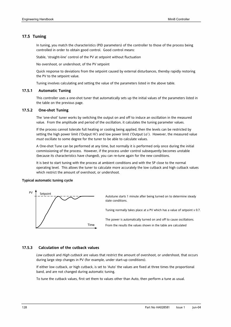
Engineering Handbook Mini8 Controller
128 Part No HA028581 Issue 1 Jun-04
17.5 Tuning
In tuning, you match the characteristics (PID parameters) of the controller to those of the process being controlled in order to obtain good control. Good control means:
Stable, ‘straight-line’ control of the PV at setpoint without fluctuation
No overshoot, or undershoot, of the PV setpoint
Quick response to deviations from the setpoint caused by external disturbances, thereby rapidly restoring the PV to the setpoint value.
Tuning involves calculating and setting the value of the parameters listed in the above table.
17.5.1 Automatic Tuning
This controller uses a one-shot tuner that automatically sets up the initial values of the parameters listed in the table on the previous page.
17.5.2 One-shot Tuning
The ‘one-shot’ tuner works by switching the output on and off to induce an oscillation in the measured value. From the amplitude and period of the oscillation, it calculates the tuning parameter values.
If the process cannot tolerate full heating or cooling being applied, then the levels can be restricted by setting the high power limit (‘Output Hi’) and low power limit (‘Output Lo’ ). However, the measured value must oscillate to some degree for the tuner to be able to calculate values.
A One-shot Tune can be performed at any time, but normally it is performed only once during the initial commissioning of the process. However, if the process under control subsequently becomes unstable (because its characteristics have changed), you can re-tune again for the new conditions.
It is best to start tuning with the process at ambient conditions and with the SP close to the normal operating level. This allows the tuner to calculate more accurately the low cutback and high cutback values which restrict the amount of overshoot, or undershoot.
Typical automatic tuning cycle
17.5.3 Calculation of the cutback values
Low cutback and High cutback are values that restrict the amount of overshoot, or undershoot, that occurs during large step changes in PV (for example, under start-up conditions).
If either low cutback, or high cutback, is set to ‘Auto’ the values are fixed at three times the proportional band, and are not changed during automatic tuning.
To tune the cutback values, first set them to values other than Auto, then perform a tune as usual.
Time
Setpoint PV Autotune starts 1 minute after being turned on to determine steady state conditions.
Tuning normally takes place at a PV which has a value of setpoint x 0.7.
The power is automatically turned on and off to cause oscillations.
From the results the values shown in the table are calculated
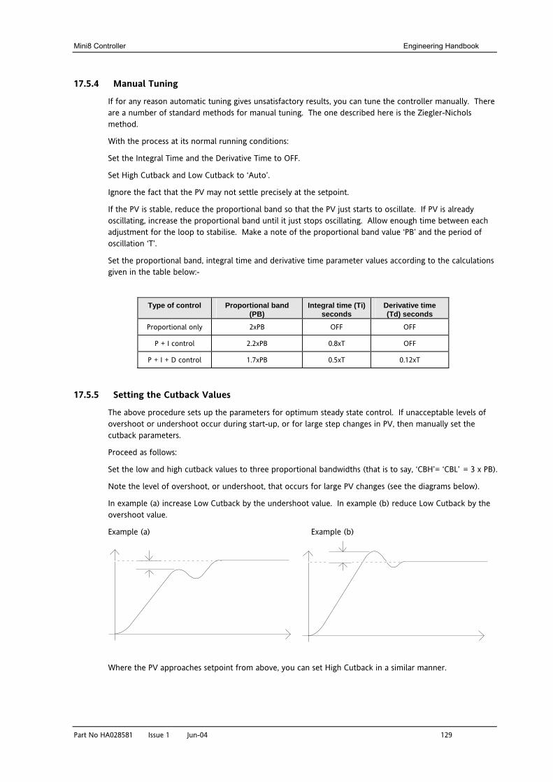
Mini8 Controller Engineering Handbook
Part No HA028581 Issue 1 Jun-04 129
17.5.4 Manual Tuning
If for any reason automatic tuning gives unsatisfactory results, you can tune the controller manually. There are a number of standard methods for manual tuning. The one described here is the Ziegler-Nichols method.
With the process at its normal running conditions:
Set the Integral Time and the Derivative Time to OFF.
Set High Cutback and Low Cutback to ‘Auto’.
Ignore the fact that the PV may not settle precisely at the setpoint.
If the PV is stable, reduce the proportional band so that the PV just starts to oscillate. If PV is already oscillating, increase the proportional band until it just stops oscillating. Allow enough time between each adjustment for the loop to stabilise. Make a note of the proportional band value ‘PB’ and the period of oscillation ‘T’.
Set the proportional band, integral time and derivative time parameter values according to the calculations given in the table below:-
Type of control Proportional band (PB)
Integral time (Ti) seconds
Derivative time (Td) seconds
Proportional only 2xPB OFF OFF
P + I control 2.2xPB 0.8xT OFF
P + I + D control 1.7xPB 0.5xT 0.12xT
17.5.5 Setting the Cutback Values
The above procedure sets up the parameters for optimum steady state control. If unacceptable levels of overshoot or undershoot occur during start-up, or for large step changes in PV, then manually set the cutback parameters.
Proceed as follows:
Set the low and high cutback values to three proportional bandwidths (that is to say, ‘CBH’= ‘CBL’ = 3 x PB).
Note the level of overshoot, or undershoot, that occurs for large PV changes (see the diagrams below).
In example (a) increase Low Cutback by the undershoot value. In example (b) reduce Low Cutback by the overshoot value.
Example (a) Example (b)
Where the PV approaches setpoint from above, you can set High Cutback in a similar manner.
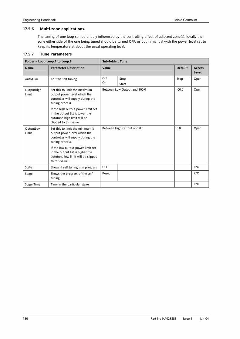
Engineering Handbook Mini8 Controller
130 Part No HA028581 Issue 1 Jun-04
17.5.6 Multi-zone applications.
The tuning of one loop can be unduly influenced by the controlling effect of adjacent zone(s). Ideally the zone either side of the one being tuned should be turned OFF, or put in manual with the power level set to keep its temperature at about the usual operating level.
17.5.7 Tune Parameters
Folder – Loop.Loop.1 to Loop.8 Sub-folder: Tune
Name
Parameter Description Value
Default Access Level
AutoTune To start self tuning Off On
Stop Start
Stop Oper
OutputHigh Limit
Set this to limit the maximum output power level which the controller will supply during the tuning process.
If the high output power limit set in the output list is lower the autotune high limit will be clipped to this value.
Between Low Output and 100.0 !00.0 Oper
OutputLow Limit
Set this to limit the minimum % output power level which the controller will supply during the tuning process.
If the low output power limit set in the output list is higher the autotune low limit will be clipped to this value.
Between High Output and 0.0 0.0 Oper
State Shows if self tuning is in progress OFF R/O
Stage Shows the progress of the self tuning
Reset R/O
Stage Time Time in the particular stage R/O
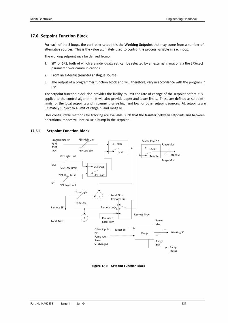
Mini8 Controller Engineering Handbook
Part No HA028581 Issue 1 Jun-04 131
17.6 Setpoint Function Block
For each of the 8 loops, the controller setpoint is the Working Setpoint that may come from a number of alternative sources. This is the value ultimately used to control the process variable in each loop.
The working setpoint may be derived from:-
1. SP1 or SP2, both of which are individually set, can be selected by an external signal or via the SPSelect parameter over communications.
2. From an external (remote) analogue source
3. The output of a programmer function block and will, therefore, vary in accordance with the program in use.
The setpoint function block also provides the facility to limit the rate of change of the setpoint before it is applied to the control algorithm. It will also provide upper and lower limits. These are defined as setpoint limits for the local setpoints and instrument range high and low for other setpoint sources. All setpoints are ultimately subject to a limit of range hi and range lo.
User configurable methods for tracking are available, such that the transfer between setpoints and between operational modes will not cause a bump in the setpoint.
17.6.1 Setpoint Function Block
Figure 17-5: Setpoint Function Block
Target SP
Programmer SP PSP1 PSP2 PSP3
Range Max
Range Min
Remote SP
PSP High Lim
PSP Low Lim
SP2 Enab
SP1 Enab SP1 High Limit
SP1 Low Limit
SP2
SP1
SP2 High Limit
SP2 Low Limit
Remote + Local Trim
Prog
Local
+ Local Trim
Remote
Local
Trim High
Trim Low
Local SP + RemoteTrim
Remote only
+
Ramp Other inputs: PV Ramp rate Servo SP changed
Range Max
Range Min
Working SP Target SP
Ramp Status
Enable Rem SP
Remote Type
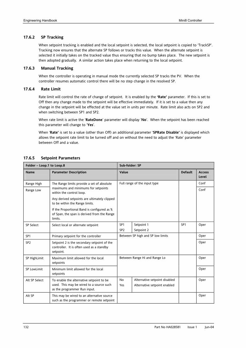
Engineering Handbook Mini8 Controller
132 Part No HA028581 Issue 1 Jun-04
17.6.2 SP Tracking
When setpoint tracking is enabled and the local setpoint is selected, the local setpoint is copied to ‘TrackSP’. Tracking now ensures that the alternate SP follows or tracks this value. When the alternate setpoint is selected it initially takes on the tracked value thus ensuring that no bump takes place. The new setpoint is then adopted gradually. A similar action takes place when returning to the local setpoint.
17.6.3 Manual Tracking
When the controller is operating in manual mode the currently selected SP tracks the PV. When the controller resumes automatic control there will be no step change in the resolved SP.
17.6.4 Rate Limit
Rate limit will control the rate of change of setpoint. It is enabled by the ‘Rate’ parameter. If this is set to Off then any change made to the setpoint will be effective immediately. If it is set to a value then any change in the setpoint will be effected at the value set in units per minute. Rate limit also acts on SP2 and when switching between SP1 and SP2.
When rate limit is active the ‘RateDone’ parameter will display ‘No’. When the setpoint has been reached this parameter will change to ‘Yes’.
When ‘Rate’ is set to a value (other than Off) an additional parameter ‘SPRate Disable’ is displayed which allows the setpoint rate limit to be turned off and on without the need to adjust the ‘Rate’ parameter between Off and a value.
17.6.5 Setpoint Parameters
Folder – Loop.1 to Loop.8 Sub-folder: SP
Name
Parameter Description Value
Default Access Level
Range High Conf
Range Low
The Range limits provide a set of absolute maximums and minimums for setpoints within the control loop.
Any derived setpoints are ultimately clipped to be within the Range limits.
If the Proportional Band is configured as % of Span, the span is derived from the Range limits.
Full range of the input type
Conf
SP Select Select local or alternate setpoint SP1 SP2
Setpoint 1 Setpoint 2
SP1 Oper
SP1 Primary setpoint for the controller Oper
SP2 Setpoint 2 is the secondary setpoint of the controller. It is often used as a standby setpoint.
Between SP high and SP low limits
Oper
SP HighLimit Maximum limit allowed for the local setpoints
Oper
SP LowLimit Minimum limit allowed for the local setpoints
Between Range Hi and Range Lo
Oper
Alt SP Select To enable the alternative setpoint to be used. This may be wired to a source such as the programmer Run input.
No Yes
Alternative setpoint disabled Alternative setpoint enabled
Oper
Alt SP This may be wired to an alternative source such as the programmer or remote setpoint
Oper
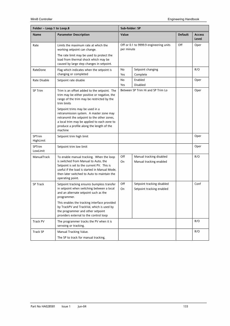
Mini8 Controller Engineering Handbook
Part No HA028581 Issue 1 Jun-04 133
Folder – Loop.1 to Loop.8 Sub-folder: SP
Name
Parameter Description Value
Default Access Level
Rate Limits the maximum rate at which the working setpoint can change.
The rate limit may be used to protect the load from thermal shock which may be caused by large step changes in setpoint.
Off or 0.1 to 9999.9 engineering units per minute
Off Oper
RateDone Flag which indicates when the setpoint is changing or completed
No Yes
Setpoint changing Complete
R/O
Rate Disable Setpoint rate disable No Yes
Enabled Disabled
Oper
SP Trim Trim is an offset added to the setpoint. The trim may be either positive or negative, the range of the trim may be restricted by the trim limits
Setpoint trims may be used in a retransmission system. A master zone may retransmit the setpoint to the other zones, a local trim may be applied to each zone to produce a profile along the length of the machine
Between SP Trim Hi and SP Trim Lo Oper
SPTrim HighLimit
Setpoint trim high limit Oper
SPTrim LowLimit
Setpoint trim low limit Oper
ManualTrack To enable manual tracking. When the loop is switched from Manual to Auto, the Setpoint is set to the current PV. This is useful if the load is started in Manual Mode, then later switched to Auto to maintain the operating point.
Off On
Manual tracking disabled Manual tracking enabled
R/O
SP Track Setpoint tracking ensures bumpless transfer in setpoint when switching between a local and an alternate setpoint such as the programmer.
This enables the tracking interface provided by TrackPV and TrackVal, which is used by the programmer and other setpoint providers external to the control loop
Off On
Setpoint tracking disabled Setpoint tracking enabled
Conf
Track PV The programmer tracks the PV when it is servoing or tracking.
R/O
Track SP Manual Tracking Value.
The SP to track for manual tracking.
R/O
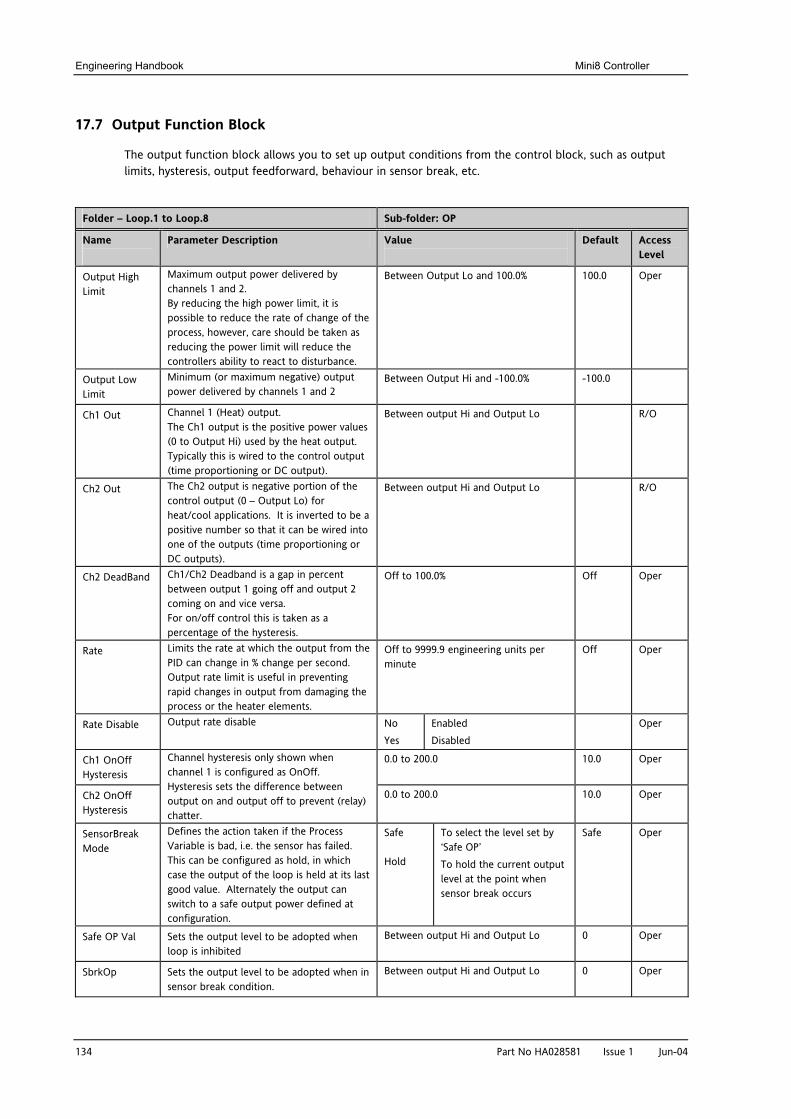
Engineering Handbook Mini8 Controller
134 Part No HA028581 Issue 1 Jun-04
17.7 Output Function Block
The output function block allows you to set up output conditions from the control block, such as output limits, hysteresis, output feedforward, behaviour in sensor break, etc.
Folder – Loop.1 to Loop.8 Sub-folder: OP
Name
Parameter Description Value
Default Access Level
Output High Limit
Maximum output power delivered by channels 1 and 2. By reducing the high power limit, it is possible to reduce the rate of change of the process, however, care should be taken as reducing the power limit will reduce the controllers ability to react to disturbance.
Between Output Lo and 100.0% 100.0 Oper
Output Low Limit
Minimum (or maximum negative) output power delivered by channels 1 and 2
Between Output Hi and -100.0% -100.0
Ch1 Out Channel 1 (Heat) output. The Ch1 output is the positive power values (0 to Output Hi) used by the heat output. Typically this is wired to the control output (time proportioning or DC output).
Between output Hi and Output Lo R/O
Ch2 Out The Ch2 output is negative portion of the control output (0 – Output Lo) for heat/cool applications. It is inverted to be a positive number so that it can be wired into one of the outputs (time proportioning or DC outputs).
Between output Hi and Output Lo R/O
Ch2 DeadBand Ch1/Ch2 Deadband is a gap in percent between output 1 going off and output 2 coming on and vice versa. For on/off control this is taken as a percentage of the hysteresis.
Off to 100.0% Off Oper
Rate Limits the rate at which the output from the PID can change in % change per second. Output rate limit is useful in preventing rapid changes in output from damaging the process or the heater elements.
Off to 9999.9 engineering units per minute
Off Oper
Rate Disable Output rate disable No Yes
Enabled Disabled
Oper
Ch1 OnOff Hysteresis
0.0 to 200.0 10.0 Oper
Ch2 OnOff Hysteresis
Channel hysteresis only shown when channel 1 is configured as OnOff. Hysteresis sets the difference between output on and output off to prevent (relay) chatter.
0.0 to 200.0 10.0 Oper
SensorBreak Mode
Defines the action taken if the Process Variable is bad, i.e. the sensor has failed. This can be configured as hold, in which case the output of the loop is held at its last good value. Alternately the output can switch to a safe output power defined at configuration.
Safe
Hold
To select the level set by ‘Safe OP’ To hold the current output level at the point when sensor break occurs
Safe Oper
Safe OP Val Sets the output level to be adopted when loop is inhibited
Between output Hi and Output Lo 0 Oper
SbrkOp Sets the output level to be adopted when in sensor break condition.
Between output Hi and Output Lo 0 Oper
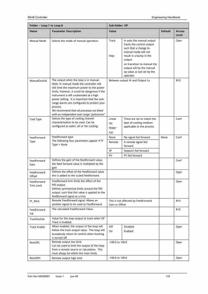
Mini8 Controller Engineering Handbook
Part No HA028581 Issue 1 Jun-04 135
Folder – Loop.1 to Loop.8 Sub-folder: OP
Name
Parameter Description Value
Default Access Level
Manual Mode Selects the mode of manual operation. Track
Step
In auto the manual output tracks the control output such that a change to manual mode will not result in a bump in the output. on transition to manual the output will be the manual op value as last set by the operator.
Oper
ManualOutVal The output when the loop is in manual. Note: In manual mode the controller will still limit the maximum power to the power limits, however, it could be dangerous if the instrument is left unattended at a high power setting. It is important that the over range alarms are configured to protect your process. We recommend that all processes are fitted with an independent over range "policeman"
Between output Hi and Output Lo R/O
Cool Type Selects the type of cooling channel characterisation to be used. Can be configured as water, oil or fan cooling.
Linear Oil Water Fan
These are set to match the type of cooling medium applicable to the process
Conf
None No signal fed forward
Remote A remote signal fed forward
SP Setpoint fed forward
FeedForward Type
Feedforward type The following four parameters appear if FF Type ≠ None
PV PV fed forward
None Conf
FeedForward Gain
Defines the gain of the feedforward value, the feed forward value is multiplied by the gain
Conf
FeedForward Offset
Defines the offset of the feedforward value this is added to the scaled feedforward.
Oper
FeedForward Trim Limit
Feedforward trim limits the effect of the PID output. Defines symmetrical limits around the PID output, such that this value is applied to the feedforward signal as a trim.
Oper
FF_Rem Remote Feedforward signal. Allows an another signal to be used as Feedforward.
This is not affected by FeedForward Gain or Offset
R/O
FeedForward Val
The calculated Feedforward Value. R/O
TrackOutVal Value for the loop output to track when OP Track is Enabled.
Track Enable When enabled, the output of the loop will follow the track output value. The loop will bumplessly return to control when tracking is turned off.
Off On
Disabled Enabled
Oper
RemOPL Remote output low limit. Can be used to limit the output of the loop from a remote source or calculation. This must always be within the main limits.
-100.0 to 100.0 Oper
RemOPH Remote output high limit -100.0 to 100.0 Oper
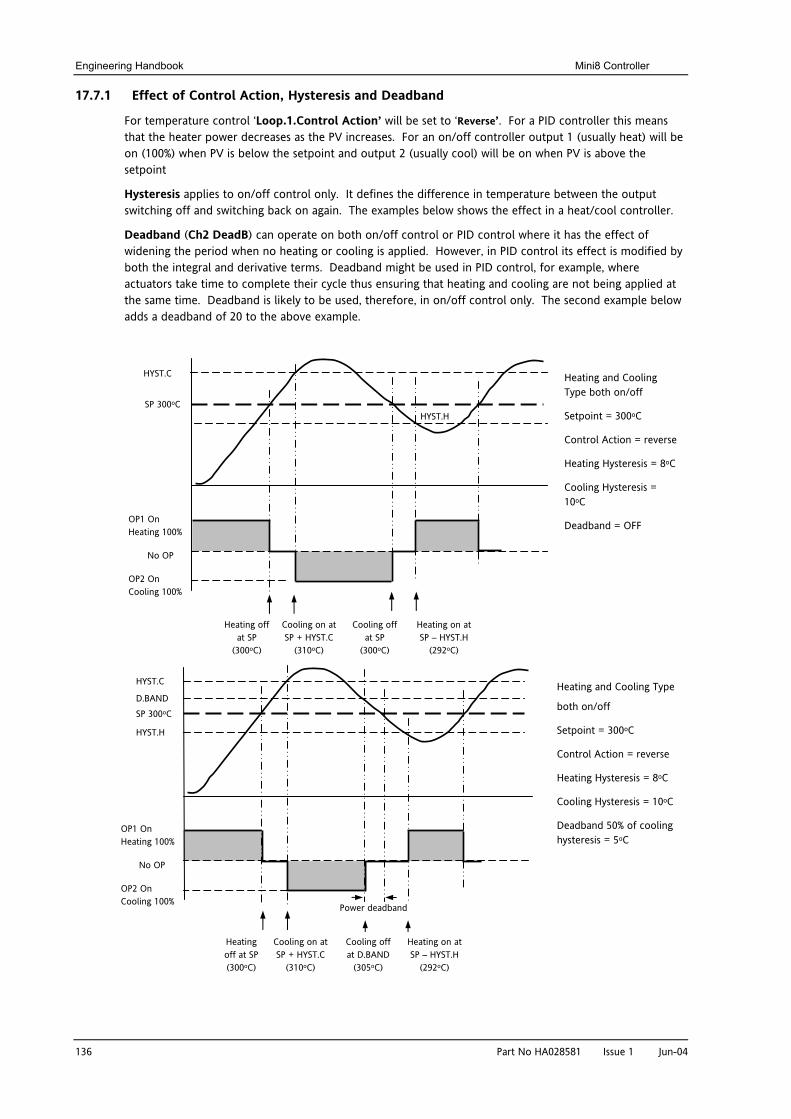
Engineering Handbook Mini8 Controller
136 Part No HA028581 Issue 1 Jun-04
17.7.1 Effect of Control Action, Hysteresis and Deadband
For temperature control ‘Loop.1.Control Action’ will be set to ‘Reverse’. For a PID controller this means that the heater power decreases as the PV increases. For an on/off controller output 1 (usually heat) will be on (100%) when PV is below the setpoint and output 2 (usually cool) will be on when PV is above the setpoint
Hysteresis applies to on/off control only. It defines the difference in temperature between the output switching off and switching back on again. The examples below shows the effect in a heat/cool controller.
Deadband (Ch2 DeadB) can operate on both on/off control or PID control where it has the effect of widening the period when no heating or cooling is applied. However, in PID control its effect is modified by both the integral and derivative terms. Deadband might be used in PID control, for example, where actuators take time to complete their cycle thus ensuring that heating and cooling are not being applied at the same time. Deadband is likely to be used, therefore, in on/off control only. The second example below adds a deadband of 20 to the above example.
SP 300oC
HYST.C
HYST.H
OP1 On Heating 100%
No OP
OP2 On Cooling 100%
Heating and Cooling Type both on/off
Setpoint = 300oC
Control Action = reverse
Heating Hysteresis = 8oC
Cooling Hysteresis = 10oC
Deadband = OFF
Heating off at SP
(300oC)
Cooling on at SP + HYST.C
(310oC)
Cooling off at SP
(300oC)
Heating on at SP – HYST.H
(292oC)
SP 300oC
HYST.C
HYST.H
Heating and Cooling Type
both on/off
Setpoint = 300oC
Control Action = reverse
Heating Hysteresis = 8oC
Cooling Hysteresis = 10oC
Deadband 50% of cooling hysteresis = 5oC
Heating off at SP (300oC)
Cooling on at SP + HYST.C
(310oC)
Cooling off at D.BAND
(305oC)
Heating on at SP – HYST.H
(292oC)
D.BAND
OP1 On Heating 100%
No OP
OP2 On Cooling 100%
Power deadband
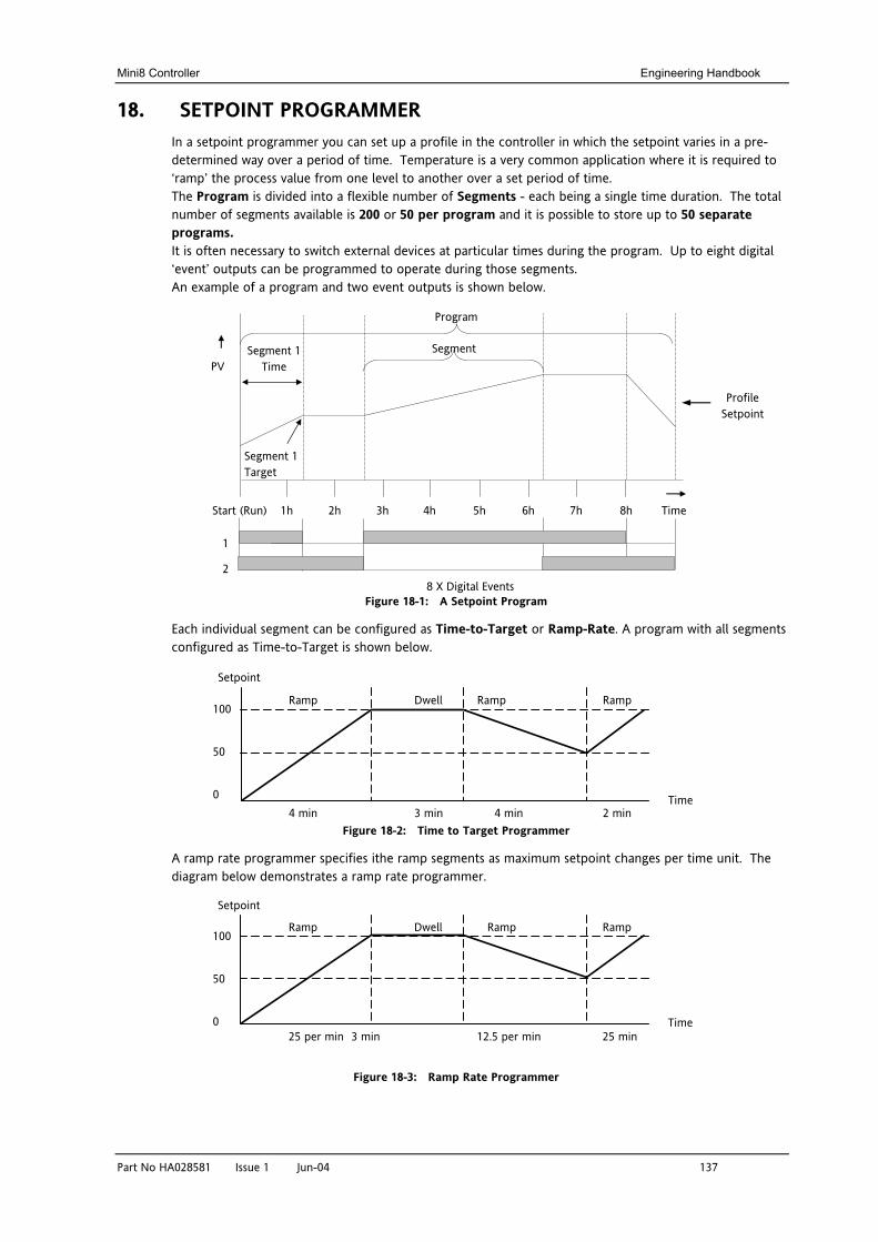
Mini8 Controller Engineering Handbook
Part No HA028581 Issue 1 Jun-04 137
18. SETPOINT PROGRAMMER In a setpoint programmer you can set up a profile in the controller in which the setpoint varies in a pre-determined way over a period of time. Temperature is a very common application where it is required to ‘ramp’ the process value from one level to another over a set period of time. The Program is divided into a flexible number of Segments - each being a single time duration. The total number of segments available is 200 or 50 per program and it is possible to store up to 50 separate programs. It is often necessary to switch external devices at particular times during the program. Up to eight digital ‘event’ outputs can be programmed to operate during those segments. An example of a program and two event outputs is shown below.
Figure 18-1: A Setpoint Program
Each individual segment can be configured as Time-to-Target or Ramp-Rate. A program with all segments configured as Time-to-Target is shown below.
Figure 18-2: Time to Target Programmer
A ramp rate programmer specifies ithe ramp segments as maximum setpoint changes per time unit. The diagram below demonstrates a ramp rate programmer.
Figure 18-3: Ramp Rate Programmer
Segment
Profile Setpoint
Start (Run) 2h 1h 3h 4h 5h 6h 7h 8h Time
Program
2
1
8 X Digital Events
PV
Segment 1 Target
Segment 1 Time
4 min 3 min 4 min 2 min
Ramp Dwell Ramp Ramp 100
50
0
Setpoint
Time
25 per min 3 min 12.5 per min 25 min
Ramp Dwell Ramp Ramp 100
50
0
Setpoint
Time
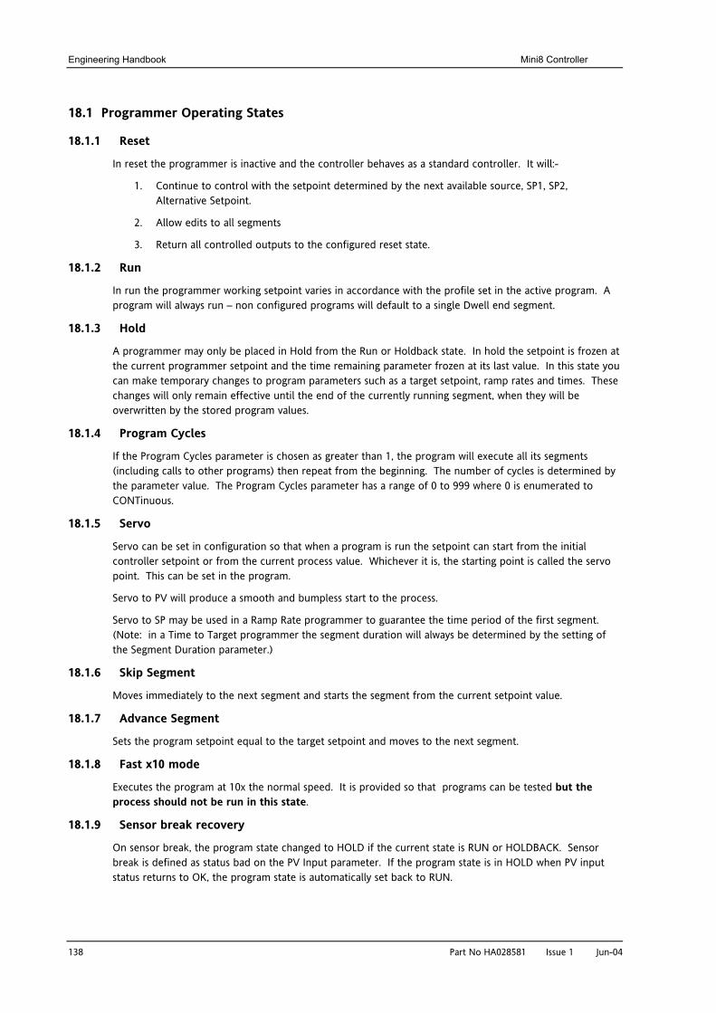
Engineering Handbook Mini8 Controller
138 Part No HA028581 Issue 1 Jun-04
18.1 Programmer Operating States
18.1.1 Reset
In reset the programmer is inactive and the controller behaves as a standard controller. It will:-
1. Continue to control with the setpoint determined by the next available source, SP1, SP2, Alternative Setpoint.
2. Allow edits to all segments
3. Return all controlled outputs to the configured reset state.
18.1.2 Run
In run the programmer working setpoint varies in accordance with the profile set in the active program. A program will always run – non configured programs will default to a single Dwell end segment.
18.1.3 Hold
A programmer may only be placed in Hold from the Run or Holdback state. In hold the setpoint is frozen at the current programmer setpoint and the time remaining parameter frozen at its last value. In this state you can make temporary changes to program parameters such as a target setpoint, ramp rates and times. These changes will only remain effective until the end of the currently running segment, when they will be overwritten by the stored program values.
18.1.4 Program Cycles
If the Program Cycles parameter is chosen as greater than 1, the program will execute all its segments (including calls to other programs) then repeat from the beginning. The number of cycles is determined by the parameter value. The Program Cycles parameter has a range of 0 to 999 where 0 is enumerated to CONTinuous.
18.1.5 Servo
Servo can be set in configuration so that when a program is run the setpoint can start from the initial controller setpoint or from the current process value. Whichever it is, the starting point is called the servo point. This can be set in the program.
Servo to PV will produce a smooth and bumpless start to the process.
Servo to SP may be used in a Ramp Rate programmer to guarantee the time period of the first segment. (Note: in a Time to Target programmer the segment duration will always be determined by the setting of the Segment Duration parameter.)
18.1.6 Skip Segment
Moves immediately to the next segment and starts the segment from the current setpoint value.
18.1.7 Advance Segment
Sets the program setpoint equal to the target setpoint and moves to the next segment.
18.1.8 Fast x10 mode
Executes the program at 10x the normal speed. It is provided so that programs can be tested but the process should not be run in this state.
18.1.9 Sensor break recovery
On sensor break, the program state changed to HOLD if the current state is RUN or HOLDBACK. Sensor break is defined as status bad on the PV Input parameter. If the program state is in HOLD when PV input status returns to OK, the program state is automatically set back to RUN.
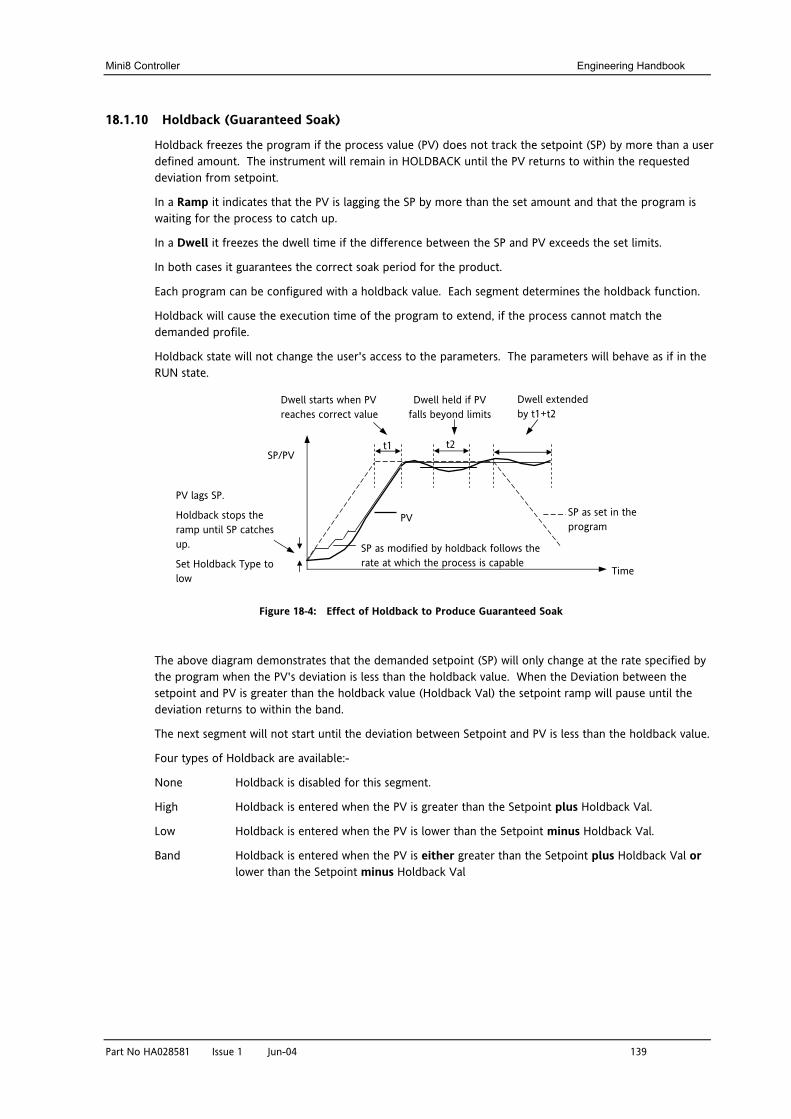
Mini8 Controller Engineering Handbook
Part No HA028581 Issue 1 Jun-04 139
18.1.10 Holdback (Guaranteed Soak)
Holdback freezes the program if the process value (PV) does not track the setpoint (SP) by more than a user defined amount. The instrument will remain in HOLDBACK until the PV returns to within the requested deviation from setpoint.
In a Ramp it indicates that the PV is lagging the SP by more than the set amount and that the program is waiting for the process to catch up.
In a Dwell it freezes the dwell time if the difference between the SP and PV exceeds the set limits.
In both cases it guarantees the correct soak period for the product.
Each program can be configured with a holdback value. Each segment determines the holdback function.
Holdback will cause the execution time of the program to extend, if the process cannot match the demanded profile.
Holdback state will not change the user's access to the parameters. The parameters will behave as if in the RUN state.
Figure 18-4: Effect of Holdback to Produce Guaranteed Soak
The above diagram demonstrates that the demanded setpoint (SP) will only change at the rate specified by the program when the PV's deviation is less than the holdback value. When the Deviation between the setpoint and PV is greater than the holdback value (Holdback Val) the setpoint ramp will pause until the deviation returns to within the band.
The next segment will not start until the deviation between Setpoint and PV is less than the holdback value.
Four types of Holdback are available:-
None Holdback is disabled for this segment.
High Holdback is entered when the PV is greater than the Setpoint plus Holdback Val.
Low Holdback is entered when the PV is lower than the Setpoint minus Holdback Val.
Band Holdback is entered when the PV is either greater than the Setpoint plus Holdback Val or lower than the Setpoint minus Holdback Val
SP as set in the program
SP as modified by holdback follows the rate at which the process is capable
PV
PV lags SP.
Holdback stops the ramp until SP catches up.
Set Holdback Type to low
Dwell starts when PV reaches correct value
Dwell held if PV falls beyond limits
Dwell extended by t1+t2
t1 t2 SP/PV
Time
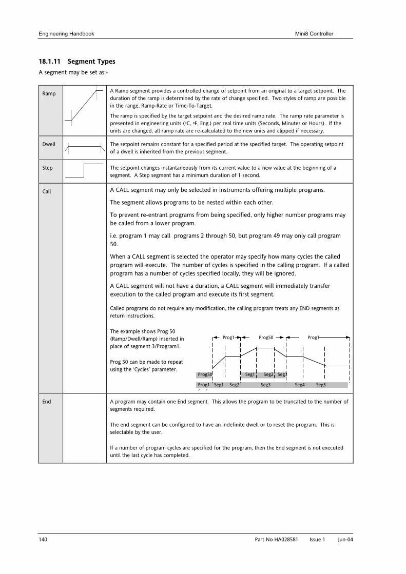
Engineering Handbook Mini8 Controller
140 Part No HA028581 Issue 1 Jun-04
18.1.11 Segment Types A segment may be set as:-
Ramp
A Ramp segment provides a controlled change of setpoint from an original to a target setpoint. The duration of the ramp is determined by the rate of change specified. Two styles of ramp are possible in the range, Ramp-Rate or Time-To-Target.
The ramp is specified by the target setpoint and the desired ramp rate. The ramp rate parameter is presented in engineering units (oC, oF, Eng.) per real time units (Seconds, Minutes or Hours). If the units are changed, all ramp rate are re-calculated to the new units and clipped if necessary.
Dwell The setpoint remains constant for a specified period at the specified target. The operating setpoint of a dwell is inherited from the previous segment.
Step The setpoint changes instantaneously from its current value to a new value at the beginning of a segment. A Step segment has a minimum duration of 1 second.
Call A CALL segment may only be selected in instruments offering multiple programs.
The segment allows programs to be nested within each other.
To prevent re-entrant programs from being specified, only higher number programs may be called from a lower program.
i.e. program 1 may call programs 2 through 50, but program 49 may only call program 50.
When a CALL segment is selected the operator may specify how many cycles the called program will execute. The number of cycles is specified in the calling program. If a called program has a number of cycles specified locally, they will be ignored.
A CALL segment will not have a duration, a CALL segment will immediately transfer execution to the called program and execute its first segment.
Called programs do not require any modification, the calling program treats any END segments as return instructions.
The example shows Prog 50 (Ramp/Dwell/Ramp) inserted in place of segment 3/Program1.
Prog 50 can be made to repeat using the ‘Cycles’ parameter.
End A program may contain one End segment. This allows the program to be truncated to the number of segments required.
The end segment can be configured to have an indefinite dwell or to reset the program. This is selectable by the user.
If a number of program cycles are specified for the program, then the End segment is not executed until the last cycle has completed.
Prog50 Seg1 Seg2 Seg3
Prog1 Seg1 Seg2 Seg3 Seg4 Seg5 Seg6
Prog1 Prog50 Prog1
Mini8 Controller Engineering Handbook
Part No HA028581 Issue 1 Jun-04
18.1.12 Power Fail Recovery
In the event of power fail to the controller, a strategy may be set in configuration level, which defines how the controller behaves on restoration of the power. These strategies include:
Continue The program setpoint returns immediately to its last value prior to the power down. This may cause full power to be applied to the process for a short period to heat the process back to its value prior to the power failure.
Ramp back This will servo the program setpoint to the measured value (the PV Input parameter value), then return to the target setpoint at the current (or previous) ramp rate. The setpoint is not allowed to step change the program setpoint. The outputs will take the state of the segment which was active before power was interrupted.
Reset The process is aborted by resetting the program. All event outputs will take the reset state.
18.1.12.1 Ramp back (Power fail during Dwell segments.)
If the interrupted segment was a Dwell, then the ramp rate will be determined by the previous ramp segment.
On achieving the Dwell setpoint, the dwell will continue from the point at which the power was interrupted.
Note: If a previous ramp segment does not exist, i.e. the first segment of a program is a dwell, then the Dwell will continue at the "servo to PV" setpoint.
18.1.12.2 Ramp back (power fail during Ramp segments)
If the interrupted segment was a ramp, then the programmer will servo the program setpoint to the PV, then ramp towards the target setpoint at the previous ramp rate. Previous ramp rate is the ramp rate at power fail.
18.1.12.3 Ramp back (power fail during Time-to-target segments)
If the programmer was defined as a Time-to-Target programmer then when the power is returned the previous ramp rate will be recovered. The Time remaining will be recalculated. The rule is to maintain RAMP RATE, but alter TIME REMAINING.
T1 + T2 = segment Dwell timeSetpoint
T1 T2
TimePower Off
Seg n Seg n+1
gt Setpoint
Setpoint
Power Off Time
Servo to new PV lev
T
141
Tgt Setpoint
Setpoint
Power Off Time
Servo to PV level
Ramp Rate d
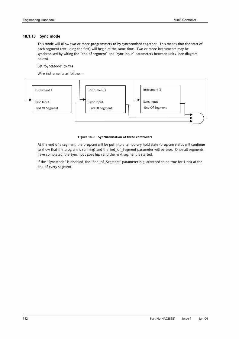
Engineering Handbook Mini8 Controller
142
18.1.13 Sync mode
This mode will allow two or more programmers to by synchronised together. This means that the start of each segment (excluding the first) will begin at the same time. Two or more instruments may be synchronised by wiring the “end of segment” and “sync input” parameters between units. (see diagram below).
Set “SyncMode” to Yes
Wire instruments as follows :-
Instrument 1
Sync Input
End Of Segment
Figure
At the end of a segment, the prto show that the program is runhave completed, the SyncInput
If the “SyncMode” is disabled, tend of every segment.
Instrument 2
Sync Input
End Of Segment
18-5: Synchronisation of three con
ogram will be put into a temporaryning) and the End_of_Segment pagoes high and the next segment is
he “End_of_Segment” parameter is
Instrument 3
Sync Input
End Of Segment
Part No HA028581 Issue 1 Jun-04
trollers
hold state (program status will continue rameter will be true. Once all segments started.
guaranteed to be true for 1 tick at the
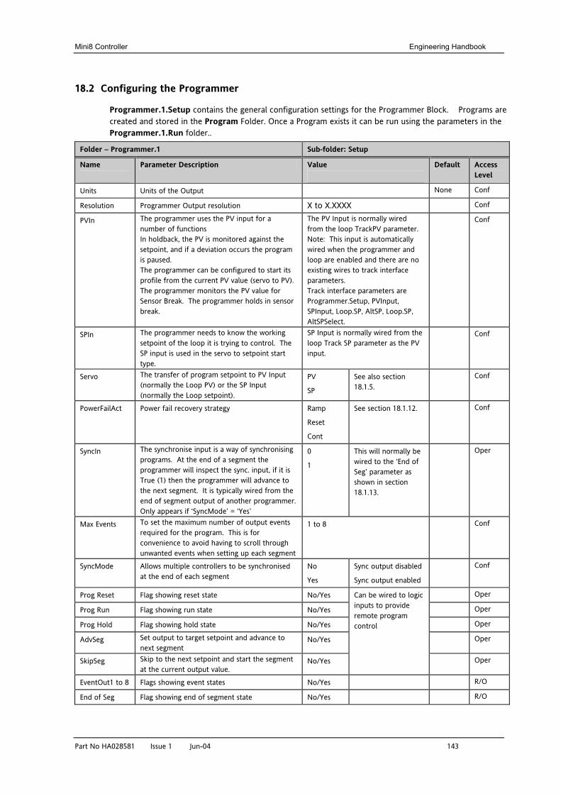
Mini8 Controller Engineering Handbook
Part No HA028581 Issue 1 Jun-04 143
18.2 Configuring the Programmer
Programmer.1.Setup contains the general configuration settings for the Programmer Block. Programs are created and stored in the Program Folder. Once a Program exists it can be run using the parameters in the Programmer.1.Run folder..
Folder – Programmer.1 Sub-folder: Setup
Name
Parameter Description Value
Default Access Level
Units Units of the Output None Conf
Resolution Programmer Output resolution X to X.XXXX Conf
PVIn The programmer uses the PV input for a number of functions In holdback, the PV is monitored against the setpoint, and if a deviation occurs the program is paused. The programmer can be configured to start its profile from the current PV value (servo to PV). The programmer monitors the PV value for Sensor Break. The programmer holds in sensor break.
The PV Input is normally wired from the loop TrackPV parameter. Note: This input is automatically wired when the programmer and loop are enabled and there are no existing wires to track interface parameters. Track interface parameters are Programmer.Setup, PVInput, SPInput, Loop.SP, AltSP, Loop.SP, AltSPSelect.
Conf
SPIn The programmer needs to know the working setpoint of the loop it is trying to control. The SP input is used in the servo to setpoint start type.
SP Input is normally wired from the loop Track SP parameter as the PV input.
Conf
Servo The transfer of program setpoint to PV Input (normally the Loop PV) or the SP Input (normally the Loop setpoint).
PV
SP
See also section 18.1.5.
Conf
PowerFailAct Power fail recovery strategy Ramp
Reset
Cont
See section 18.1.12. Conf
SyncIn The synchronise input is a way of synchronising programs. At the end of a segment the programmer will inspect the sync. input, if it is True (1) then the programmer will advance to the next segment. It is typically wired from the end of segment output of another programmer. Only appears if ‘SyncMode’ = ‘Yes’
0
1
This will normally be wired to the ‘End of Seg’ parameter as shown in section 18.1.13.
Oper
Max Events To set the maximum number of output events required for the program. This is for convenience to avoid having to scroll through unwanted events when setting up each segment
1 to 8 Conf
SyncMode Allows multiple controllers to be synchronised at the end of each segment
No
Yes
Sync output disabled
Sync output enabled
Conf
Prog Reset Flag showing reset state No/Yes Oper
Prog Run Flag showing run state No/Yes Oper
Prog Hold Flag showing hold state No/Yes Oper
AdvSeg Set output to target setpoint and advance to next segment
No/Yes Oper
SkipSeg Skip to the next setpoint and start the segment at the current output value.
No/Yes
Can be wired to logic inputs to provide remote program control
Oper
EventOut1 to 8 Flags showing event states No/Yes R/O
End of Seg Flag showing end of segment state No/Yes R/O
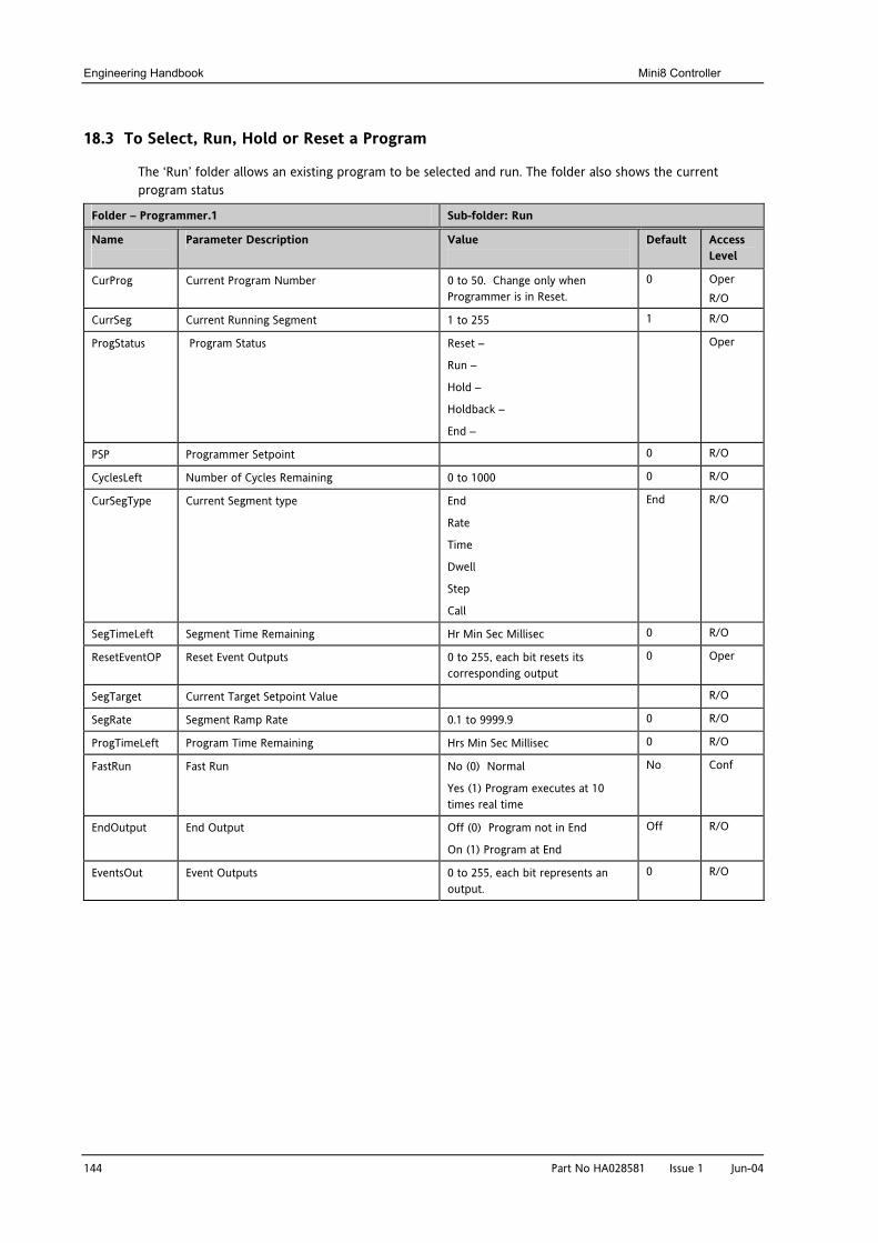
Engineering Handbook Mini8 Controller
144 Part No HA028581 Issue 1 Jun-04
18.3 To Select, Run, Hold or Reset a Program
The ‘Run’ folder allows an existing program to be selected and run. The folder also shows the current program status
Folder – Programmer.1 Sub-folder: Run
Name
Parameter Description Value
Default Access Level
CurProg Current Program Number 0 to 50. Change only when Programmer is in Reset.
0 Oper R/O
CurrSeg Current Running Segment 1 to 255 1 R/O
ProgStatus Program Status Reset –
Run –
Hold –
Holdback –
End –
Oper
PSP Programmer Setpoint 0 R/O
CyclesLeft Number of Cycles Remaining 0 to 1000 0 R/O
CurSegType Current Segment type End
Rate
Time
Dwell
Step
Call
End R/O
SegTimeLeft Segment Time Remaining Hr Min Sec Millisec 0 R/O
ResetEventOP Reset Event Outputs 0 to 255, each bit resets its corresponding output
0 Oper
SegTarget Current Target Setpoint Value R/O
SegRate Segment Ramp Rate 0.1 to 9999.9 0 R/O
ProgTimeLeft Program Time Remaining Hrs Min Sec Millisec 0 R/O
FastRun Fast Run No (0) Normal
Yes (1) Program executes at 10 times real time
No Conf
EndOutput End Output Off (0) Program not in End
On (1) Program at End
Off R/O
EventsOut Event Outputs 0 to 255, each bit represents an output.
0 R/O
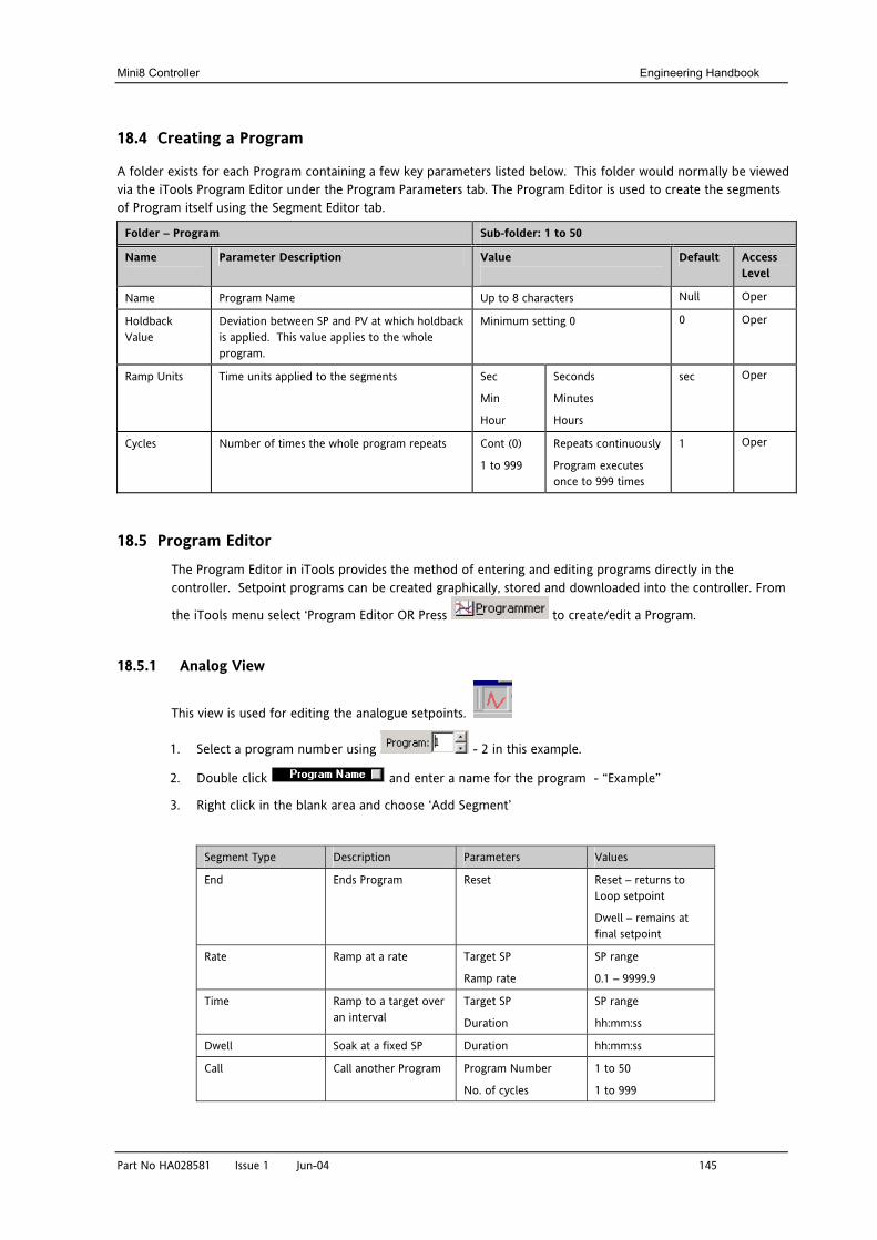
Mini8 Controller Engineering Handbook
Part No HA028581 Issue 1 Jun-04 145
18.4 Creating a Program
A folder exists for each Program containing a few key parameters listed below. This folder would normally be viewed via the iTools Program Editor under the Program Parameters tab. The Program Editor is used to create the segments of Program itself using the Segment Editor tab.
Folder – Program Sub-folder: 1 to 50
Name
Parameter Description Value
Default Access Level
Name Program Name Up to 8 characters Null Oper
Holdback Value
Deviation between SP and PV at which holdback is applied. This value applies to the whole program.
Minimum setting 0 0 Oper
Ramp Units Time units applied to the segments Sec
Min
Hour
Seconds
Minutes
Hours
sec Oper
Cycles Number of times the whole program repeats Cont (0)
1 to 999
Repeats continuously
Program executes once to 999 times
1 Oper
18.5 Program Editor
The Program Editor in iTools provides the method of entering and editing programs directly in the controller. Setpoint programs can be created graphically, stored and downloaded into the controller. From
the iTools menu select ‘Program Editor OR Press to create/edit a Program.
18.5.1 Analog View
This view is used for editing the analogue setpoints.
1. Select a program number using - 2 in this example.
2. Double click and enter a name for the program - “Example”
3. Right click in the blank area and choose ‘Add Segment’
Segment Type Description Parameters Values
End Ends Program Reset Reset – returns to Loop setpoint
Dwell – remains at final setpoint
Rate Ramp at a rate Target SP
Ramp rate
SP range
0.1 – 9999.9
Time Ramp to a target over an interval
Target SP
Duration
SP range
hh:mm:ss
Dwell Soak at a fixed SP Duration hh:mm:ss
Call Call another Program Program Number
No. of cycles
1 to 50
1 to 999
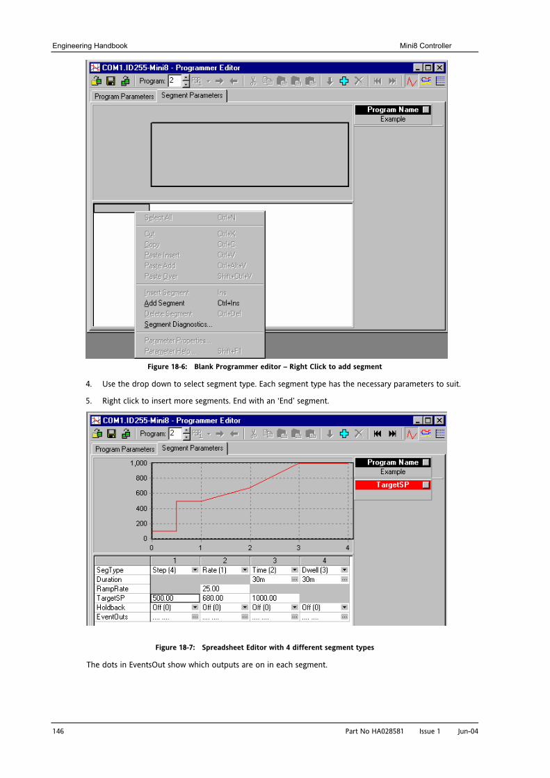
Engineering Handbook Mini8 Controller
146 Part No HA028581 Issue 1 Jun-04
Figure 18-6: Blank Programmer editor – Right Click to add segment
4. Use the drop down to select segment type. Each segment type has the necessary parameters to suit.
5. Right click to insert more segments. End with an ‘End’ segment.
Figure 18-7: Spreadsheet Editor with 4 different segment types
The dots in EventsOut show which outputs are on in each segment.
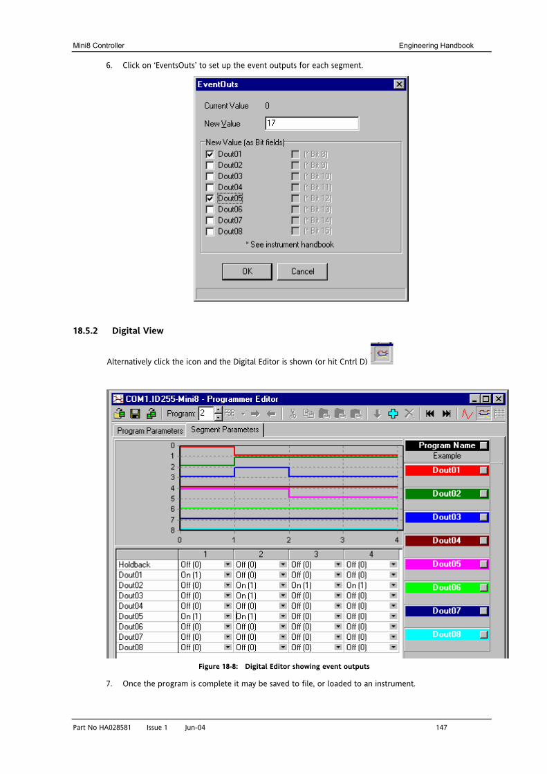
Mini8 Controller Engineering Handbook
Part No HA028581 Issue 1 Jun-04 147
6. Click on ‘EventsOuts’ to set up the event outputs for each segment.
18.5.2 Digital View
Alternatively click the icon and the Digital Editor is shown (or hit Cntrl D)
Figure 18-8: Digital Editor showing event outputs
7. Once the program is complete it may be saved to file, or loaded to an instrument.

Engineering Handbook Mini8 Controller
148 Part No HA028581 Issue 1 Jun-04
If you are online to an instrument the program is already ‘loaded’. The only option is to save it to file. This example would be saved as ‘Example.uip’
If you are working offline a program can be loaded from or saved to disk. If there are instruments connected the program can be sent to them one by one.
18.5.3 Printing a Program
If you select all segments, Cntrl N (or right click ‘Select All’) and copy spreadsheet cells they are put on the clipboard as tab separated values which can be pasted into Microsoft Excel.
There is no direct printing support in the Programmer Editor, but you can generate a report using Microsoft Excel as follows:
• Right click on the graph and choose 'Copy Chart'.
• Open a new spreadsheet in Excel and paste the chart, position to taste.
• Go back to the Programmer Editor and Choose 'Edit|Select All' followed by 'Edit|Copy'.
• Switch to Excel, choose the top left cell for the segment data and then choose 'Edit|Paste'.
• Optionally delete any columns that have no settings and format the cells.
• Print the spreadsheet.
The program is listed down rather than across the page so long programs can be printed.
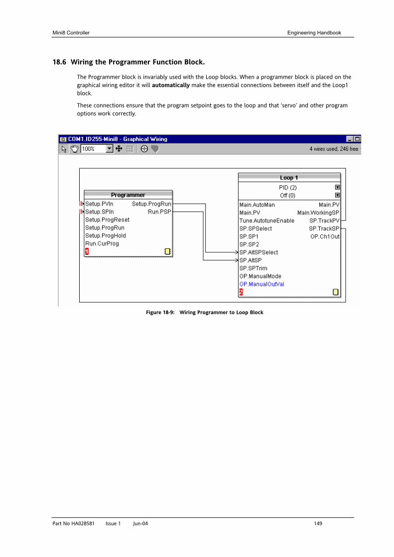
Mini8 Controller Engineering Handbook
Part No HA028581 Issue 1 Jun-04 149
18.6 Wiring the Programmer Function Block.
The Programmer block is invariably used with the Loop blocks. When a programmer block is placed on the graphical wiring editor it will automatically make the essential connections between itself and the Loop1 block.
These connections ensure that the program setpoint goes to the loop and that ‘servo’ and other program options work correctly.
Figure 18-9: Wiring Programmer to Loop Block
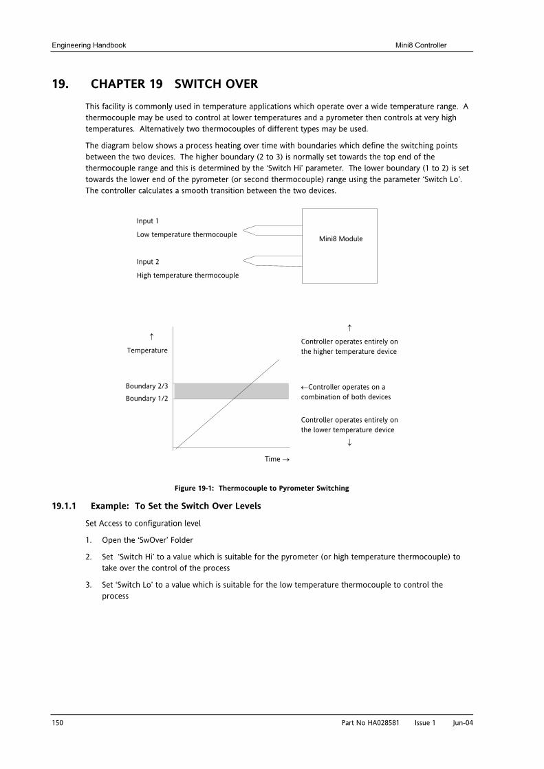
Engineering Handbook Mini8 Controller
150 Part No HA028581 Issue 1 Jun-04
19. CHAPTER 19 SWITCH OVER This facility is commonly used in temperature applications which operate over a wide temperature range. A thermocouple may be used to control at lower temperatures and a pyrometer then controls at very high temperatures. Alternatively two thermocouples of different types may be used.
The diagram below shows a process heating over time with boundaries which define the switching points between the two devices. The higher boundary (2 to 3) is normally set towards the top end of the thermocouple range and this is determined by the ‘Switch Hi’ parameter. The lower boundary (1 to 2) is set towards the lower end of the pyrometer (or second thermocouple) range using the parameter ‘Switch Lo’. The controller calculates a smooth transition between the two devices.
Figure 19-1: Thermocouple to Pyrometer Switching
19.1.1 Example: To Set the Switch Over Levels
Set Access to configuration level
1. Open the ‘SwOver’ Folder
2. Set ‘Switch Hi’ to a value which is suitable for the pyrometer (or high temperature thermocouple) to take over the control of the process
3. Set ‘Switch Lo’ to a value which is suitable for the low temperature thermocouple to control the process
Input 1
Low temperature thermocouple
Input 2
High temperature thermocouple
Mini8 Module
Boundary 2/3
Boundary 1/2
↑
Temperature
Time →
↑
Controller operates entirely on the higher temperature device
Controller operates entirely on the lower temperature device
↓
←Controller operates on a combination of both devices
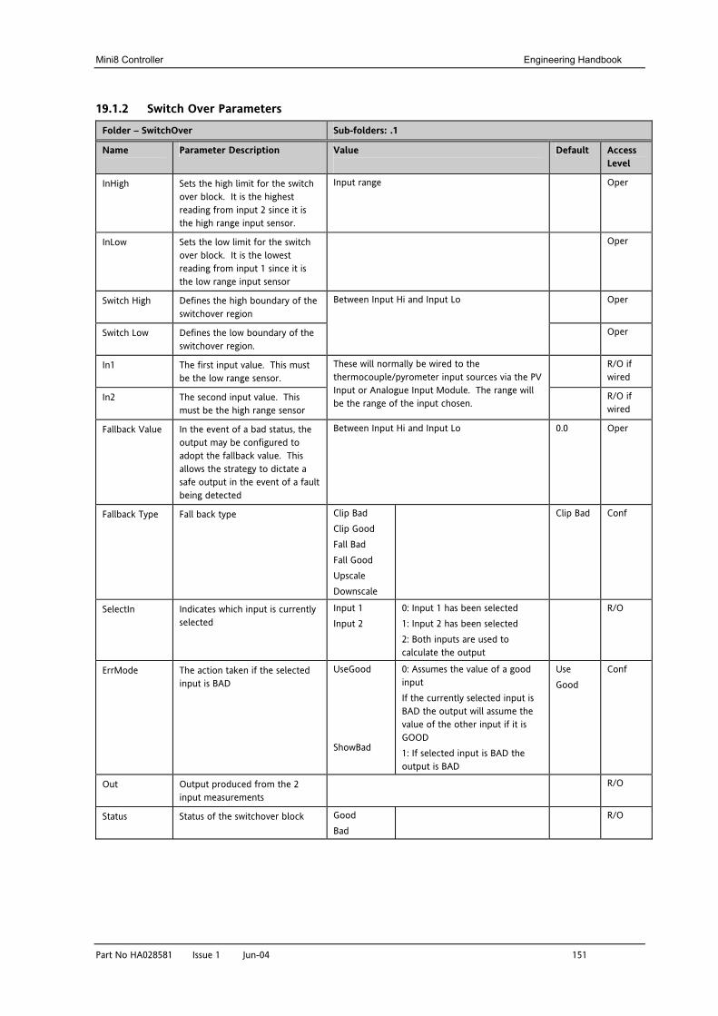
Mini8 Controller Engineering Handbook
Part No HA028581 Issue 1 Jun-04 151
19.1.2 Switch Over Parameters
Folder – SwitchOver Sub-folders: .1
Name
Parameter Description Value
Default Access Level
InHigh Sets the high limit for the switch over block. It is the highest reading from input 2 since it is the high range input sensor.
Input range Oper
InLow Sets the low limit for the switch over block. It is the lowest reading from input 1 since it is the low range input sensor
Oper
Switch High Defines the high boundary of the switchover region
Oper
Switch Low Defines the low boundary of the switchover region.
Between Input Hi and Input Lo
Oper
In1 The first input value. This must be the low range sensor.
R/O if wired
In2 The second input value. This must be the high range sensor
These will normally be wired to the thermocouple/pyrometer input sources via the PV Input or Analogue Input Module. The range will be the range of the input chosen.
R/O if wired
Fallback Value In the event of a bad status, the output may be configured to adopt the fallback value. This allows the strategy to dictate a safe output in the event of a fault being detected
Between Input Hi and Input Lo 0.0 Oper
Fallback Type Fall back type Clip Bad Clip Good Fall Bad Fall Good Upscale Downscale
Clip Bad Conf
SelectIn Indicates which input is currently selected
Input 1 Input 2
0: Input 1 has been selected 1: Input 2 has been selected 2: Both inputs are used to calculate the output
R/O
ErrMode The action taken if the selected input is BAD
UseGood ShowBad
0: Assumes the value of a good input If the currently selected input is BAD the output will assume the value of the other input if it is GOOD 1: If selected input is BAD the output is BAD
Use Good
Conf
Out Output produced from the 2 input measurements
R/O
Status Status of the switchover block Good Bad
R/O
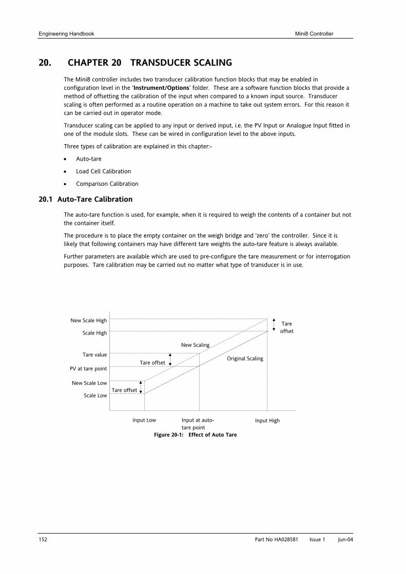
Engineering Handbook Mini8 Controller
152 Part No HA028581 Issue 1 Jun-04
20. CHAPTER 20 TRANSDUCER SCALING The Mini8 controller includes two transducer calibration function blocks that may be enabled in configuration level in the ‘Instrument/Options’ folder. These are a software function blocks that provide a method of offsetting the calibration of the input when compared to a known input source. Transducer scaling is often performed as a routine operation on a machine to take out system errors. For this reason it can be carried out in operator mode.
Transducer scaling can be applied to any input or derived input, i.e. the PV Input or Analogue Input fitted in one of the module slots. These can be wired in configuration level to the above inputs.
Three types of calibration are explained in this chapter:-
• Auto-tare
• Load Cell Calibration
• Comparison Calibration
20.1 Auto-Tare Calibration
The auto-tare function is used, for example, when it is required to weigh the contents of a container but not the container itself.
The procedure is to place the empty container on the weigh bridge and ‘zero’ the controller. Since it is likely that following containers may have different tare weights the auto-tare feature is always available.
Further parameters are available which are used to pre-configure the tare measurement or for interrogation purposes. Tare calibration may be carried out no matter what type of transducer is in use.
Figure 20-1: Effect of Auto Tare
Input Low Input High Input at auto-tare point
New Scale High
Scale High
Tare value
PV at tare point
New Scale Low
Scale Low
Tare offset
Tare offset
Tare offset
Original Scaling
New Scaling
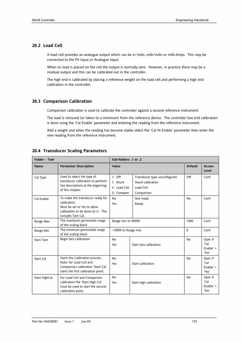
Mini8 Controller Engineering Handbook
Part No HA028581 Issue 1 Jun-04 153
20.2 Load Cell
A load cell provides an analogue output which can be in Volts, milli-Volts or milli-Amps. This may be connected to the PV Input or Analogue Input.
When no load is placed on the cell the output is normally zero. However, in practice there may be a residual output and this can be calibrated out in the controller.
The high end is calibrated by placing a reference weight on the load cell and performing a high end calibration in the controller.
20.3 Comparison Calibration
Comparison calibration is used to calibrate the controller against a second reference instrument.
The load is removed (or taken to a minimum) from the reference device. The controller low end calibration is done using the ‘Cal Enable’ parameter and entering the reading from the reference instrument.
Add a weight and when the reading has become stable select the ‘Cal Hi Enable’ parameter then enter the new reading from the reference instrument.
20.4 Transducer Scaling Parameters
Folder – Txdr Sub-folders: .1 or .2
Name
Parameter Description Value
Default Access Level
Cal Type Used to select the type of transducer calibration to perform See descriptions at the beginning of this chapter.
1: Off 1: Shunt 2: Load Cell 3: Compare
Transducer type unconfigured Shunt calibration Load Cell Comparison
Off Conf
Cal Enable To make the transducer ready for calibration. Must be set to Yes to allow calibration to be done at L1. This includes Tare Cal.
No Yes
Not ready Ready
No Conf
Range Max The maximum permissible range of the scaling block
Range min to 99999 1000 Conf
Range Min The minimum permissible range of the scaling block
-19999 to Range max 0 Conf
Start Tare Begin tare calibration No Yes
Start tare calibration
No Oper if ‘Cal Enable’ = ‘Yes’
Start Cal Starts the Calibration process. Note: for Load Cell and Comparison calibration ‘Start Cal’ starts the first calibration point.
No Yes
Start calibration
No Oper if ‘Cal Enable’ = ‘Yes’
Start HighCal For Load Cell and Comparison calibration the ‘Start High Cal’ must be used to start the second calibration point.
No Yes
Start high calibration
No Oper if ‘Cal Enable’ = ‘Yes’
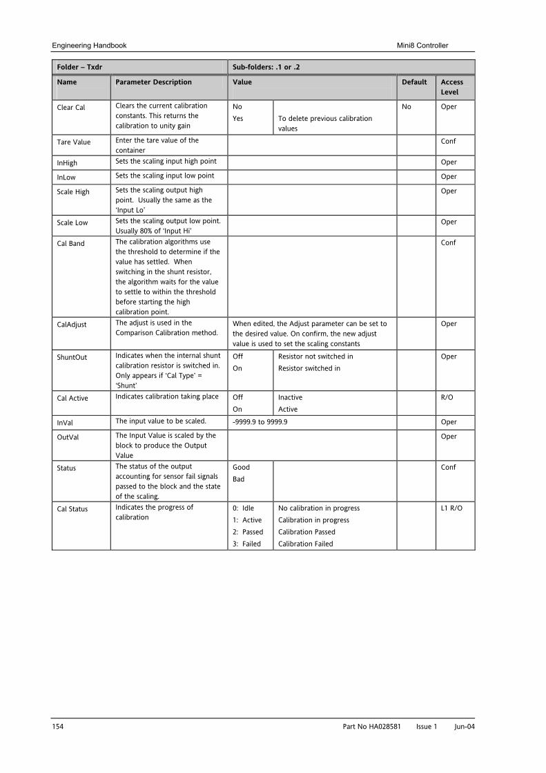
Engineering Handbook Mini8 Controller
154 Part No HA028581 Issue 1 Jun-04
Folder – Txdr Sub-folders: .1 or .2
Name
Parameter Description Value
Default Access Level
Clear Cal Clears the current calibration constants. This returns the calibration to unity gain
No Yes
To delete previous calibration values
No Oper
Tare Value Enter the tare value of the container
Conf
InHigh Sets the scaling input high point Oper
InLow Sets the scaling input low point Oper
Scale High Sets the scaling output high point. Usually the same as the ‘Input Lo’
Oper
Scale Low Sets the scaling output low point. Usually 80% of ‘Input Hi’
Oper
Cal Band The calibration algorithms use the threshold to determine if the value has settled. When switching in the shunt resistor, the algorithm waits for the value to settle to within the threshold before starting the high calibration point.
Conf
CalAdjust The adjust is used in the Comparison Calibration method.
When edited, the Adjust parameter can be set to the desired value. On confirm, the new adjust value is used to set the scaling constants
Oper
ShuntOut Indicates when the internal shunt calibration resistor is switched in. Only appears if ‘Cal Type’ = ‘Shunt’
Off On
Resistor not switched in Resistor switched in
Oper
Cal Active Indicates calibration taking place Off On
Inactive Active
R/O
InVal The input value to be scaled. -9999.9 to 9999.9 Oper
OutVal The Input Value is scaled by the block to produce the Output Value
Oper
Status The status of the output accounting for sensor fail signals passed to the block and the state of the scaling.
Good Bad
Conf
Cal Status Indicates the progress of calibration
0: Idle 1: Active 2: Passed 3: Failed
No calibration in progress Calibration in progress Calibration Passed Calibration Failed
L1 R/O
Mini8 Controller Engineering Handbook
Part No HA028581 Issue 1 Jun-04 155
20.4.1 Parameter Notes
Enable Cal This may be wired to a digital input for an external switch. If not wired, then the value may be changed.
When enabled the transducer parameters may be altered as described in the previous sections. When the parameter has been turned On it will remain on until turned off manually even if the controller is powered cycled.
Start Tare This may be wired to a digital input for an external switch. If not wired, then the value may be changed.
Start Cal This may be wired to a digital input for an external switch. If not wired, then the value may be changed.
It starts the calibration procedure for:
Shunt Calibration
The low point for Load Cell Calibration
The low point for Comparison Calibration
Start Hi Cal This may be wired to a digital input for an external switch. If not wired, then the value may be changed.
It starts:-
The high point for Load Cell Calibration
The high point for Comparison Calibration
Clear Cal This may be wired to a digital input for an external switch. If not wired, then the value may be changed.
When enabled the input will reset to default values. A new calibration will overwrite the previous calibration values if Clear Cal is not enabled between calibrations.
20.4.2 Tare Calibration
The Mini8 controller has an auto-tare function that is used, for example, when it is required to weigh the contents of a container but not the container itself.
The procedure is to place the empty container on the weighbridge and ‘zero’ the controller. The procedure is as follows:-
1. Place container on weighbridge
2. Go to Txdr.1 (or .2) Folder.
3. Transducer calibration Type must be ‘Load Cell’.
4. CalEnable must be set to ‘Yes’.
5. Set StartTare to ‘yes’
6. The controller automatically calibrates the to the tare weight which is measured by the transducer and stores this value.
7. During this measurement Cal Status will show progress. If the cal fails it is probably an ‘out of range’ problem.
Engineering Handbook Mini8 Controller
156 Part No HA028581 Issue 1 Jun-04
20.4.3 Load Cell
A load cell output must be within the range 0 to 77 mV to go into a TC8 input. Use a shunt for mA inputs, mV can possibly go direct, Volt inputs must use a potential divider.
To calibrate a load cell.
1. Remove all load from the transducer to establish a zero reference.
2. Go to Txdr.1 (or .2) Folder.
3. Transducer calibration Type must be ‘Load Cell’.
4. CalEnable must be set to ‘Yes’.
5. Set Start Cal to ‘yes’
6. The controller will calibrate the low point.
7. Set StartHighCal to ‘yes’
8. The controller will calibrate the high point.
Cal Status advises progress and result.
20.4.4 Comparison Calibration
Comparison calibration is used to calibrate the input against a second reference instrument. Typically this might be a local display on the weighing device itself.
To calibrate against a known reference source:-
1. Add a load at the low end of the scale range
2. Go to Txdr.1 (or .2) Folder.
3. Transducer calibration Type must be ‘Comparision’.
4. CalEnable must be set to ‘Yes’.
5. Enter the reading from the reference instrument into ‘Cal Adjust’.
6. Add a load at the high end of the scale.
7. Set StartHighCal to ‘yes’
8. The controller will calibrate the high point.
Cal Status advises progress and result.
Mini8 Controller Engineering Handbook
Part No HA028581 Issue 1 Jun-04 157
21. CHAPTER 21 USER VALUES User values are registers provided for use in calculations. They may be used as constants in equations or temporary storage in extended calculations. Up to 32 User Values are available provided they have been enabled in the ‘’Instrument/Options’ folder. They are arranged in 4 groups of 8. Each User Value can then be set up in the ‘UserVal’ folder.
21.1 User Value Parameters
Folder – UsrVal Sub-Folders: .1 to .32
Name
Parameter Description Value
Default Access Level
Units Units assigned to the User Value None
Abs Temp oC/oF/oK,
V, mV, A, mA,
PH, mmHg, psi, Bar, mBar, %RH, %, mmWG, inWG, inWW, Ohms, PSIG, %O2, PPM, %CO2, %CP, %/sec,
RelTemp oC\oF\oK(rel),
Custom 1, Custom 2, Custom 3, Custom 4, Custom 5, Custom 6,
sec, min, hrs,
Conf
Resolution Resolution of the User Value XXXXX to X.XXXX Conf
High Limit The high limit may be set for each user value to prevent the value being set to an out-of-bounds value.
Oper
Low Limit The low limit of the user value may be set to prevent the user value from being edited to an illegal value. This is important if the user value is to be used as a setpoint.
Oper
Val To set the value within the range limits
See note 1 Oper
Status Can be used to force a good or bad status onto a user value. This is useful for testing status inheritance and fallback strategies.
Good Bad
See note 1 Oper
Note 1.
If ‘Val’ is wired into but ‘Status’ is not, then, instead of being used to force the Status it will indicate the status of the value as inherited form the wired connection to ‘Val’.
Engineering Handbook Mini8 Controller
158 Part No HA028581 Issue 1 Jun-04
22. CHAPTER 22 CALIBRATION In this chapter calibration refers to calibration of the TC input of the TC8 module. Calibration is accessed using the ‘Cal State’ parameter that is only available in configuration level. Since the controller is calibrated during manufacture to traceable standards for every input range, it is not necessary to calibrate the controller when changing ranges. Furthermore, a continuous automatic check and correction of the calibration during the controllers’ normal operation means that it is calibrated for life. However, it is recognised that, for operational reasons, it may be a requirement to check or re-calibrate the controller. This new calibration is saved as a User Calibration. It is always possible to revert to the factory calibration if necessary.
Tip: Consider using the ‘Offset’ parameter for User Cal (e.g. Mod.1.Offset). This can be set to correct any measured difference between the Mini8 given PV and a calibration value obtained from another source.
22.1 User calibration
22.1.1 Set Up No pre-calibration warm-up is required. As calibration is a single-point on 8 channels, quick enough (a few minutes) to avoid self-heating effects, there are no special environmental, mounting position or ventilation requirements for calibration. Calibration should be performed at a reasonable ambient temperature (15oC to 35oC). Calibration outside these limits will compromise the expected working accuracy. Every channel of every TC8 card must be individually connected to the calibrator source using thick copper wire (so the sensor-break voltage drop in the wires and source impedance is minimal). The voltage source, monitor DVM and the target Mini8 should be at the same temperature (to eliminate added series e.m.f. due to thermocouple effects). The Mini8 must be in Configuration Mode.
22.1.2 Zero Calibration
No “zero” calibration point is required.
22.1.3 Voltage Calibration 1. Set the Calibrator voltage source to an accurate 50.005mV. (The extra 5uV is to compensate for self-
heating tempco effect). 2. Connect the 50mV to channel 1 3. Set Mod.1.CalState to HiCal (23) and then select ‘Confirm’ 4. When complete set CalState to SaveUser(25)
22.1.4 CJC Calibration
No CJC calibration required; the sampled values are ratiometric, providing uncalibrated uncertainty of ±1oC.
22.1.5 Sensor-Break Limit Check
Apply a 900Ω resistor to each channel in turn, Sensor Break Type to ‘Low’, filter to off (0). Verify the SBrkValue is greater than 24.0 and less than 61.0
22.2 To Return to Factory Calibration
To clear the User calibration and restore the calibration from the factory.
1. Put Mini8 into Configuration Mode
2. Set the ‘Mod.1.Calibration State’ to LoadFact (25).
3. Return Instrument to Operating Mode.
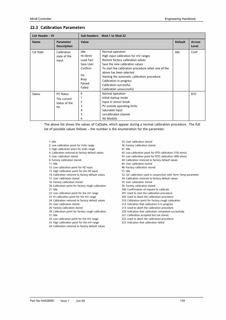
Mini8 Controller Engineering Handbook
Part No HA028581 Issue 1 Jun-04 159
22.3 Calibration Parameters
List Header - IO Sub-headers: Mod.1 to Mod.32
Name
Parameter Description
Value
Default Access Level
Cal State Calibration state of the input
Idle Hi-50mV Load Fact Save User Confirm
Go Busy Passed Failed
Normal operation High input calibration for mV ranges Restore factory calibration values Save the new calibration values To start the calibration procedure when one of the above has been selected Starting the automatic calibration procedure Calibration in progress Calibration successful Calibration unsuccessful
Idle Conf
Status PV Status The current status of the PV.
0 1 2 3 4 5 6
Normal operation Initial startup mode Input in sensor break PV outside operating limits Saturated input Uncalibrated channel No Module
R/O
The above list shows the values of CalState, which appear during a normal calibration procedure. The full list of possible values follows – the number is the enumeration for the parameter.
1: Idle 35: User calibration stored 2: Low calibration point for Volts range 36: Factory calibration stored 3: High calibration point for Volts range 41: Idle 4: Calibration restored to factory default values 42: Low calibration point for RTD calibration (150 ohms) 5: User calibration stored 43: Low calibration point for RTD calibration (400 ohms) 6: Factory calibration stored 44: Calibration restored to factory default values 11: Idle 45: User calibration stored 12: Low calibration point for HZ input 46: Factory calibration stored 13: High calibration point for the HZ input 51: Idle 14: Calibration restored to factory default values 52: CJC calibration used in conjunction with Term Temp parameter 15: User calibration stored 54: Calibration restored to factory default values 16: Factory calibration stored 55: User calibration stored 20: Calibration point for factory rough calibration 56: Factory calibration stored 21: Idle 200: Confirmation of request to calibrate 22: Low calibration point for the mV range 201: Used to start the calibration procedure 23: Hi calibration point for the mV range 202: Used to abort the calibration procedure 24: Calibration restored to factory default values 210: Calibration point for factory rough calibration 25: User calibration stored 212: Indication that calibration is in progress 26: Factory calibration stored 213: Used to abort the calibration procedure 30: Calibration point for factory rough calibration 220: Indication that calibration completed successfully 31: Idle 221: Calibration accepted but not stored 32: Low calibration point for the mV range 222: Used to abort the calibration procedure 33: High calibration point for the mV range 223: Indication that calibration failed 34: Calibration restored to factory default values
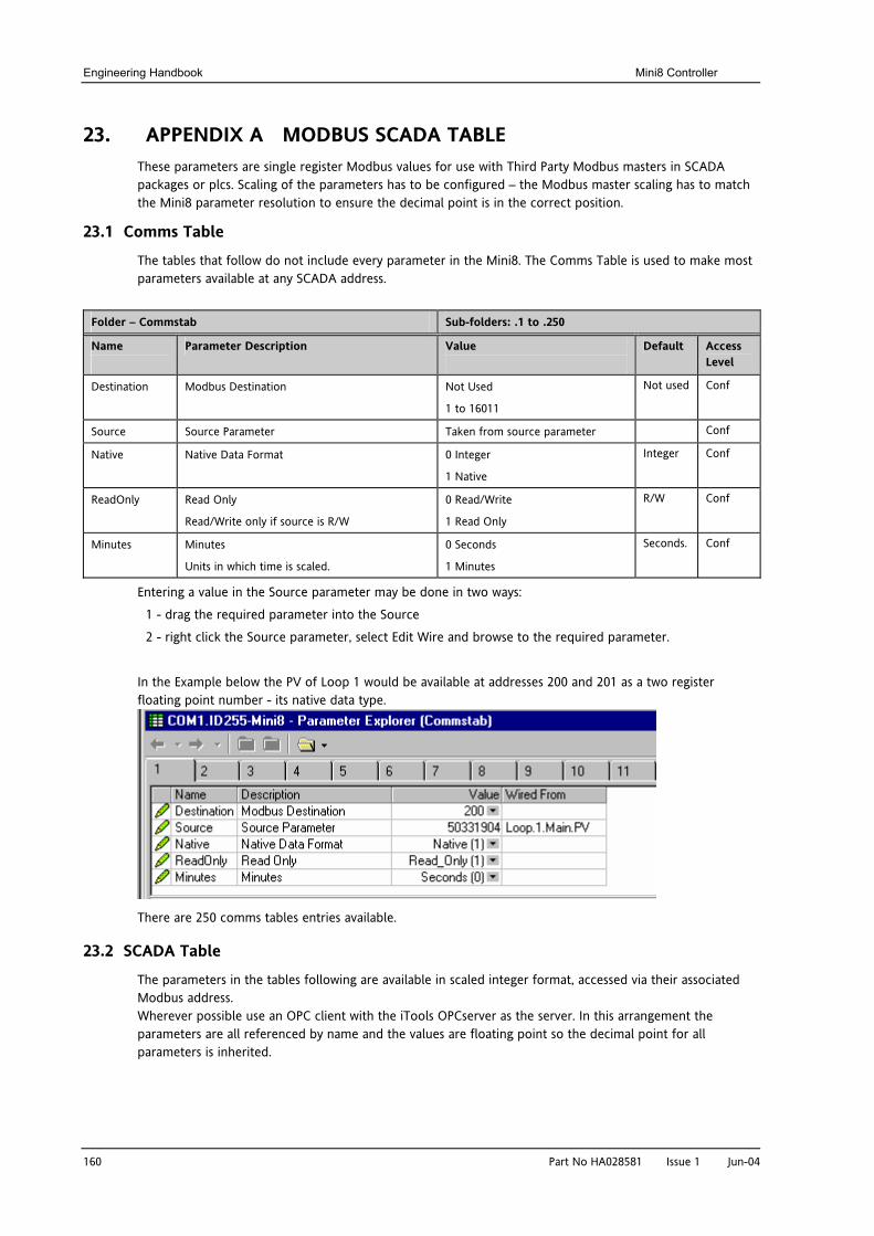
Engineering Handbook Mini8 Controller
160 Part No HA028581 Issue 1 Jun-04
23. APPENDIX A MODBUS SCADA TABLE These parameters are single register Modbus values for use with Third Party Modbus masters in SCADA packages or plcs. Scaling of the parameters has to be configured – the Modbus master scaling has to match the Mini8 parameter resolution to ensure the decimal point is in the correct position.
23.1 Comms Table
The tables that follow do not include every parameter in the Mini8. The Comms Table is used to make most parameters available at any SCADA address.
Folder – Commstab Sub-folders: .1 to .250
Name
Parameter Description Value
Default Access Level
Destination Modbus Destination Not Used
1 to 16011
Not used Conf
Source Source Parameter Taken from source parameter Conf
Native Native Data Format 0 Integer
1 Native
Integer Conf
ReadOnly Read Only
Read/Write only if source is R/W
0 Read/Write
1 Read Only
R/W Conf
Minutes Minutes
Units in which time is scaled.
0 Seconds
1 Minutes
Seconds. Conf
Entering a value in the Source parameter may be done in two ways:
1 - drag the required parameter into the Source
2 - right click the Source parameter, select Edit Wire and browse to the required parameter.
In the Example below the PV of Loop 1 would be available at addresses 200 and 201 as a two register floating point number - its native data type.
There are 250 comms tables entries available.
23.2 SCADA Table
The parameters in the tables following are available in scaled integer format, accessed via their associated Modbus address. Wherever possible use an OPC client with the iTools OPCserver as the server. In this arrangement the parameters are all referenced by name and the values are floating point so the decimal point for all parameters is inherited.

Mini8 Controller Engineering Handbook
Part No HA028581 Issue 1 Jun-04 161
Description ModBus HEXAccess.CustomerID 4739 1283Access.InstrumentMode 199 00c7Alarm.1.Ack 10250 280aAlarm.1.Block 10246 2806Alarm.1.Delay 10248 2808Alarm.1.Hysteresis 10242 2802Alarm.1.Inhibit 10247 2807Alarm.1.Latch 10244 2804Alarm.1.Out 10249 2809Alarm.1.Reference 10243 2803Alarm.1.Threshold 10241 2801Alarm.1.Type 10240 2800Alarm.2.Ack 10266 281aAlarm.2.Block 10262 2816Alarm.2.Delay 10264 2818Alarm.2.Hysteresis 10258 2812Alarm.2.Inhibit 10263 2817Alarm.2.Latch 10260 2814Alarm.2.Out 10265 2819Alarm.2.Reference 10259 2813Alarm.2.Threshold 10257 2811Alarm.2.Type 10256 2810Alarm.3.Ack 10282 282aAlarm.3.Block 10278 2826Alarm.3.Delay 10280 2828Alarm.3.Hysteresis 10274 2822Alarm.3.Inhibit 10279 2827Alarm.3.Latch 10276 2824Alarm.3.Out 10281 2829Alarm.3.Reference 10275 2823Alarm.3.Threshold 10273 2821Alarm.3.Type 10272 2820Alarm.4.Ack 10298 283aAlarm.4.Block 10294 2836Alarm.4.Delay 10296 2838Alarm.4.Hysteresis 10290 2832Alarm.4.Inhibit 10295 2837Alarm.4.Latch 10292 2834Alarm.4.Out 10297 2839Alarm.4.Reference 10291 2833Alarm.4.Threshold 10289 2831Alarm.4.Type 10288 2830Alarm.5.Ack 10314 284aAlarm.5.Block 10310 2846Alarm.5.Delay 10312 2848Alarm.5.Hysteresis 10306 2842Alarm.5.Inhibit 10311 2847Alarm.5.Latch 10308 2844Alarm.5.Out 10313 2849Alarm.5.Reference 10307 2843Alarm.5.Threshold 10305 2841Alarm.5.Type 10304 2840Alarm.6.Ack 10330 285aAlarm.6.Block 10326 2856Alarm.6.Delay 10328 2858Alarm.6.Hysteresis 10322 2852Alarm.6.Inhibit 10327 2857Alarm.6.Latch 10324 2854
Description ModBus HEXAlarm.6.Out 10329 2859Alarm.6.Reference 10323 2853Alarm.6.Threshold 10321 2851Alarm.6.Type 10320 2850Alarm.7.Ack 10346 286aAlarm.7.Block 10342 2866Alarm.7.Delay 10344 2868Alarm.7.Hysteresis 10338 2862Alarm.7.Inhibit 10343 2867Alarm.7.Latch 10340 2864Alarm.7.Out 10345 2869Alarm.7.Reference 10339 2863Alarm.7.Threshold 10337 2861Alarm.7.Type 10336 2860Alarm.8.Ack 10362 287aAlarm.8.Block 10358 2876Alarm.8.Delay 10360 2878Alarm.8.Hysteresis 10354 2872Alarm.8.Inhibit 10359 2877Alarm.8.Latch 10356 2874Alarm.8.Out 10361 2879Alarm.8.Reference 10355 2873Alarm.8.Threshold 10353 2871Alarm.8.Type 10352 2870Alarm.9.Ack 10378 288aAlarm.9.Block 10374 2886Alarm.9.Delay 10376 2888Alarm.9.Hysteresis 10370 2882Alarm.9.Inhibit 10375 2887Alarm.9.Latch 10372 2884Alarm.9.Out 10377 2889Alarm.9.Reference 10371 2883Alarm.9.Threshold 10369 2881Alarm.9.Type 10368 2880Alarm.10.Ack 10394 289aAlarm.10.Block 10390 2896Alarm.10.Delay 10392 2898Alarm.10.Hysteresis 10386 2892Alarm.10.Inhibit 10391 2897Alarm.10.Latch 10388 2894Alarm.10.Out 10393 2899Alarm.10.Reference 10387 2893Alarm.10.Threshold 10385 2891Alarm.10.Type 10384 2890Alarm.11.Ack 10410 28aaAlarm.11.Block 10406 28a6Alarm.11.Delay 10408 28a8Alarm.11.Hysteresis 10402 28a2Alarm.11.Inhibit 10407 28a7Alarm.11.Latch 10404 28a4Alarm.11.Out 10409 28a9Alarm.11.Reference 10403 28a3Alarm.11.Threshold 10401 28a1Alarm.11.Type 10400 28a0Alarm.12.Ack 10426 28baAlarm.12.Block 10422 28b6Alarm.12.Delay 10424 28b8Alarm.12.Hysteresis 10418 28b2

Engineering Handbook Mini8 Controller
162 Part No HA028581 Issue 1 Jun-04
Description ModBus HEXAlarm.12.Inhibit 10423 28b7Alarm.12.Latch 10420 28b4Alarm.12.Out 10425 28b9Alarm.12.Reference 10419 28b3Alarm.12.Threshold 10417 28b1Alarm.12.Type 10416 28b0Alarm.13.Ack 10442 28caAlarm.13.Block 10438 28c6Alarm.13.Delay 10440 28c8Alarm.13.Hysteresis 10434 28c2Alarm.13.Inhibit 10439 28c7Alarm.13.Latch 10436 28c4Alarm.13.Out 10441 28c9Alarm.13.Reference 10435 28c3Alarm.13.Threshold 10433 28c1Alarm.13.Type 10432 28c0Alarm.14.Ack 10458 28daAlarm.14.Block 10454 28d6Alarm.14.Delay 10456 28d8Alarm.14.Hysteresis 10450 28d2Alarm.14.Inhibit 10455 28d7Alarm.14.Latch 10452 28d4Alarm.14.Out 10457 28d9Alarm.14.Reference 10451 28d3Alarm.14.Threshold 10449 28d1Alarm.14.Type 10448 28d0Alarm.15.Ack 10474 28eaAlarm.15.Block 10470 28e6Alarm.15.Delay 10472 28e8Alarm.15.Hysteresis 10466 28e2Alarm.15.Inhibit 10471 28e7Alarm.15.Latch 10468 28e4Alarm.15.Out 10473 28e9Alarm.15.Reference 10467 28e3Alarm.15.Threshold 10465 28e1Alarm.15.Type 10464 28e0Alarm.16.Ack 10490 28faAlarm.16.Block 10486 28f6Alarm.16.Delay 10488 28f8Alarm.16.Hysteresis 10482 28f2Alarm.16.Inhibit 10487 28f7Alarm.16.Latch 10484 28f4Alarm.16.Out 10489 28f9Alarm.16.Reference 10483 28f3Alarm.16.Threshold 10481 28f1Alarm.16.Type 10480 28f0Alarm.17.Ack 10506 290aAlarm.17.Block 10502 2906Alarm.17.Delay 10504 2908Alarm.17.Hysteresis 10498 2902Alarm.17.Inhibit 10503 2907Alarm.17.Latch 10500 2904Alarm.17.Out 10505 2909Alarm.17.Reference 10499 2903Alarm.17.Threshold 10497 2901Alarm.17.Type 10496 2900Alarm.18.Ack 10522 291aAlarm.18.Block 10518 2916
Description ModBus HEXAlarm.18.Delay 10520 2918Alarm.18.Hysteresis 10514 2912Alarm.18.Inhibit 10519 2917Alarm.18.Latch 10516 2914Alarm.18.Out 10521 2919Alarm.18.Reference 10515 2913Alarm.18.Threshold 10513 2911Alarm.18.Type 10512 2910Alarm.19.Ack 10538 292aAlarm.19.Block 10534 2926Alarm.19.Delay 10536 2928Alarm.19.Hysteresis 10530 2922Alarm.19.Inhibit 10535 2927Alarm.19.Latch 10532 2924Alarm.19.Out 10537 2929Alarm.19.Reference 10531 2923Alarm.19.Threshold 10529 2921Alarm.19.Type 10528 2920Alarm.20.Ack 10554 293aAlarm.20.Block 10550 2936Alarm.20.Delay 10552 2938Alarm.20.Hysteresis 10546 2932Alarm.20.Inhibit 10551 2937Alarm.20.Latch 10548 2934Alarm.20.Out 10553 2939Alarm.20.Reference 10547 2933Alarm.20.Threshold 10545 2931Alarm.20.Type 10544 2930Alarm.21.Ack 10570 294aAlarm.21.Block 10566 2946Alarm.21.Delay 10568 2948Alarm.21.Hysteresis 10562 2942Alarm.21.Inhibit 10567 2947Alarm.21.Latch 10564 2944Alarm.21.Out 10569 2949Alarm.21.Reference 10563 2943Alarm.21.Threshold 10561 2941Alarm.21.Type 10560 2940Alarm.22.Ack 10586 295aAlarm.22.Block 10582 2956Alarm.22.Delay 10584 2958Alarm.22.Hysteresis 10578 2952Alarm.22.Inhibit 10583 2957Alarm.22.Latch 10580 2954Alarm.22.Out 10585 2959Alarm.22.Reference 10579 2953Alarm.22.Threshold 10577 2951Alarm.22.Type 10576 2950Alarm.23.Ack 10602 296aAlarm.23.Block 10598 2966Alarm.23.Delay 10600 2968Alarm.23.Hysteresis 10594 2962Alarm.23.Inhibit 10599 2967Alarm.23.Latch 10596 2964Alarm.23.Out 10601 2969Alarm.23.Reference 10595 2963Alarm.23.Threshold 10593 2961Alarm.23.Type 10592 2960
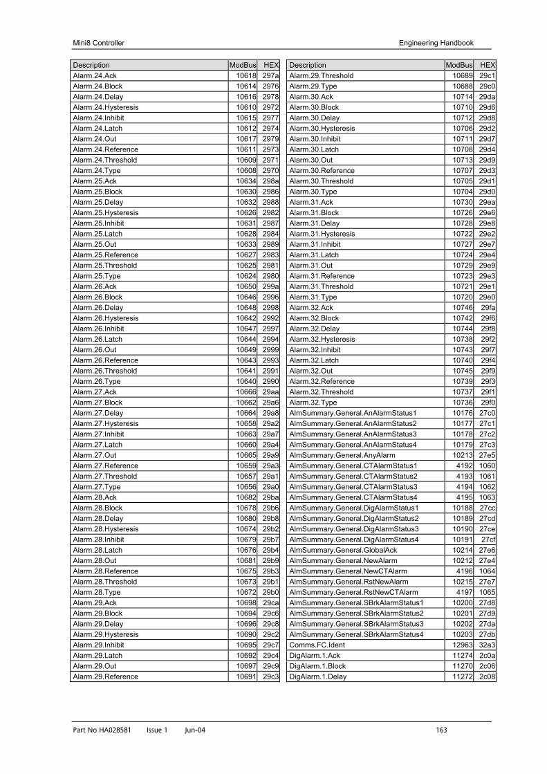
Mini8 Controller Engineering Handbook
Part No HA028581 Issue 1 Jun-04 163
Description ModBus HEXAlarm.24.Ack 10618 297aAlarm.24.Block 10614 2976Alarm.24.Delay 10616 2978Alarm.24.Hysteresis 10610 2972Alarm.24.Inhibit 10615 2977Alarm.24.Latch 10612 2974Alarm.24.Out 10617 2979Alarm.24.Reference 10611 2973Alarm.24.Threshold 10609 2971Alarm.24.Type 10608 2970Alarm.25.Ack 10634 298aAlarm.25.Block 10630 2986Alarm.25.Delay 10632 2988Alarm.25.Hysteresis 10626 2982Alarm.25.Inhibit 10631 2987Alarm.25.Latch 10628 2984Alarm.25.Out 10633 2989Alarm.25.Reference 10627 2983Alarm.25.Threshold 10625 2981Alarm.25.Type 10624 2980Alarm.26.Ack 10650 299aAlarm.26.Block 10646 2996Alarm.26.Delay 10648 2998Alarm.26.Hysteresis 10642 2992Alarm.26.Inhibit 10647 2997Alarm.26.Latch 10644 2994Alarm.26.Out 10649 2999Alarm.26.Reference 10643 2993Alarm.26.Threshold 10641 2991Alarm.26.Type 10640 2990Alarm.27.Ack 10666 29aaAlarm.27.Block 10662 29a6Alarm.27.Delay 10664 29a8Alarm.27.Hysteresis 10658 29a2Alarm.27.Inhibit 10663 29a7Alarm.27.Latch 10660 29a4Alarm.27.Out 10665 29a9Alarm.27.Reference 10659 29a3Alarm.27.Threshold 10657 29a1Alarm.27.Type 10656 29a0Alarm.28.Ack 10682 29baAlarm.28.Block 10678 29b6Alarm.28.Delay 10680 29b8Alarm.28.Hysteresis 10674 29b2Alarm.28.Inhibit 10679 29b7Alarm.28.Latch 10676 29b4Alarm.28.Out 10681 29b9Alarm.28.Reference 10675 29b3Alarm.28.Threshold 10673 29b1Alarm.28.Type 10672 29b0Alarm.29.Ack 10698 29caAlarm.29.Block 10694 29c6Alarm.29.Delay 10696 29c8Alarm.29.Hysteresis 10690 29c2Alarm.29.Inhibit 10695 29c7Alarm.29.Latch 10692 29c4Alarm.29.Out 10697 29c9Alarm.29.Reference 10691 29c3
Description ModBus HEXAlarm.29.Threshold 10689 29c1Alarm.29.Type 10688 29c0Alarm.30.Ack 10714 29daAlarm.30.Block 10710 29d6Alarm.30.Delay 10712 29d8Alarm.30.Hysteresis 10706 29d2Alarm.30.Inhibit 10711 29d7Alarm.30.Latch 10708 29d4Alarm.30.Out 10713 29d9Alarm.30.Reference 10707 29d3Alarm.30.Threshold 10705 29d1Alarm.30.Type 10704 29d0Alarm.31.Ack 10730 29eaAlarm.31.Block 10726 29e6Alarm.31.Delay 10728 29e8Alarm.31.Hysteresis 10722 29e2Alarm.31.Inhibit 10727 29e7Alarm.31.Latch 10724 29e4Alarm.31.Out 10729 29e9Alarm.31.Reference 10723 29e3Alarm.31.Threshold 10721 29e1Alarm.31.Type 10720 29e0Alarm.32.Ack 10746 29faAlarm.32.Block 10742 29f6Alarm.32.Delay 10744 29f8Alarm.32.Hysteresis 10738 29f2Alarm.32.Inhibit 10743 29f7Alarm.32.Latch 10740 29f4Alarm.32.Out 10745 29f9Alarm.32.Reference 10739 29f3Alarm.32.Threshold 10737 29f1Alarm.32.Type 10736 29f0AlmSummary.General.AnAlarmStatus1 10176 27c0AlmSummary.General.AnAlarmStatus2 10177 27c1AlmSummary.General.AnAlarmStatus3 10178 27c2AlmSummary.General.AnAlarmStatus4 10179 27c3AlmSummary.General.AnyAlarm 10213 27e5AlmSummary.General.CTAlarmStatus1 4192 1060AlmSummary.General.CTAlarmStatus2 4193 1061AlmSummary.General.CTAlarmStatus3 4194 1062AlmSummary.General.CTAlarmStatus4 4195 1063AlmSummary.General.DigAlarmStatus1 10188 27ccAlmSummary.General.DigAlarmStatus2 10189 27cdAlmSummary.General.DigAlarmStatus3 10190 27ceAlmSummary.General.DigAlarmStatus4 10191 27cfAlmSummary.General.GlobalAck 10214 27e6AlmSummary.General.NewAlarm 10212 27e4AlmSummary.General.NewCTAlarm 4196 1064AlmSummary.General.RstNewAlarm 10215 27e7AlmSummary.General.RstNewCTAlarm 4197 1065AlmSummary.General.SBrkAlarmStatus1 10200 27d8AlmSummary.General.SBrkAlarmStatus2 10201 27d9AlmSummary.General.SBrkAlarmStatus3 10202 27daAlmSummary.General.SBrkAlarmStatus4 10203 27dbComms.FC.Ident 12963 32a3DigAlarm.1.Ack 11274 2c0aDigAlarm.1.Block 11270 2c06DigAlarm.1.Delay 11272 2c08
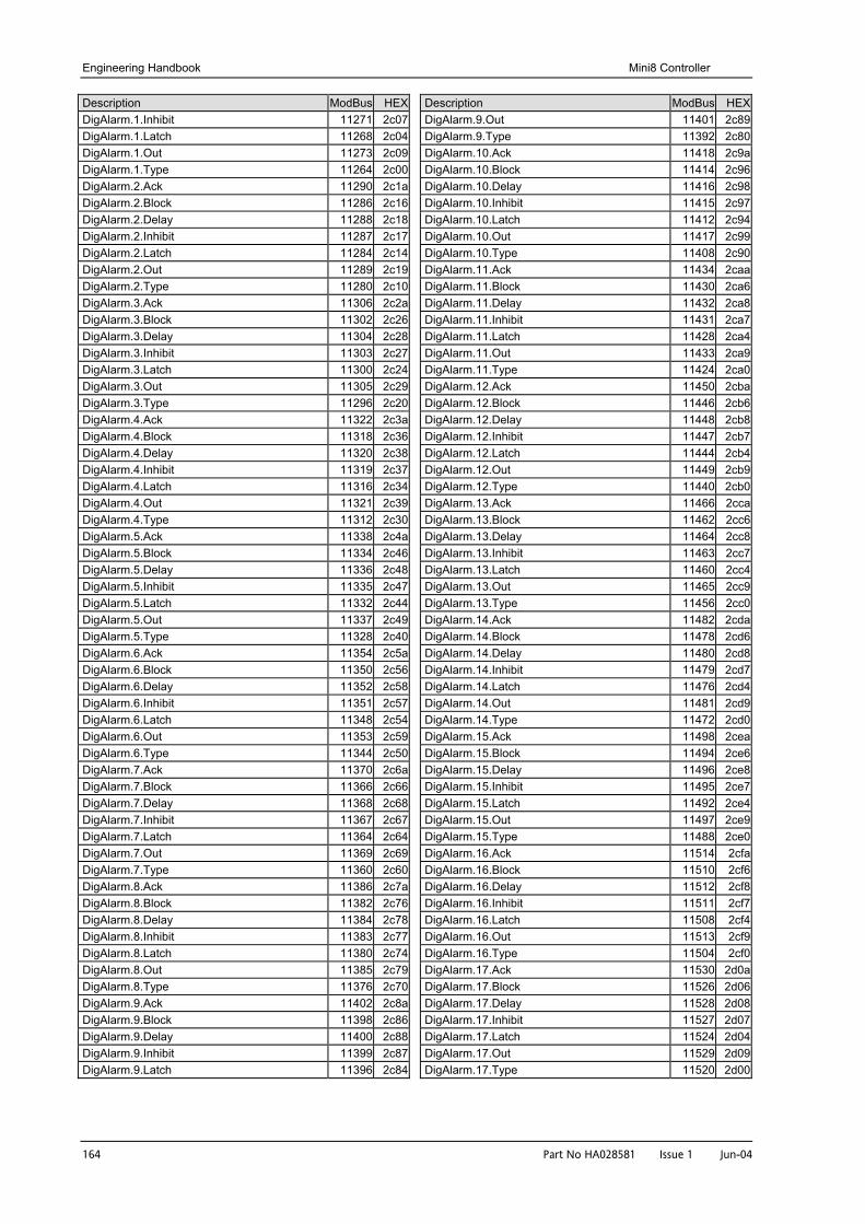
Engineering Handbook Mini8 Controller
164 Part No HA028581 Issue 1 Jun-04
Description ModBus HEXDigAlarm.1.Inhibit 11271 2c07DigAlarm.1.Latch 11268 2c04DigAlarm.1.Out 11273 2c09DigAlarm.1.Type 11264 2c00DigAlarm.2.Ack 11290 2c1aDigAlarm.2.Block 11286 2c16DigAlarm.2.Delay 11288 2c18DigAlarm.2.Inhibit 11287 2c17DigAlarm.2.Latch 11284 2c14DigAlarm.2.Out 11289 2c19DigAlarm.2.Type 11280 2c10DigAlarm.3.Ack 11306 2c2aDigAlarm.3.Block 11302 2c26DigAlarm.3.Delay 11304 2c28DigAlarm.3.Inhibit 11303 2c27DigAlarm.3.Latch 11300 2c24DigAlarm.3.Out 11305 2c29DigAlarm.3.Type 11296 2c20DigAlarm.4.Ack 11322 2c3aDigAlarm.4.Block 11318 2c36DigAlarm.4.Delay 11320 2c38DigAlarm.4.Inhibit 11319 2c37DigAlarm.4.Latch 11316 2c34DigAlarm.4.Out 11321 2c39DigAlarm.4.Type 11312 2c30DigAlarm.5.Ack 11338 2c4aDigAlarm.5.Block 11334 2c46DigAlarm.5.Delay 11336 2c48DigAlarm.5.Inhibit 11335 2c47DigAlarm.5.Latch 11332 2c44DigAlarm.5.Out 11337 2c49DigAlarm.5.Type 11328 2c40DigAlarm.6.Ack 11354 2c5aDigAlarm.6.Block 11350 2c56DigAlarm.6.Delay 11352 2c58DigAlarm.6.Inhibit 11351 2c57DigAlarm.6.Latch 11348 2c54DigAlarm.6.Out 11353 2c59DigAlarm.6.Type 11344 2c50DigAlarm.7.Ack 11370 2c6aDigAlarm.7.Block 11366 2c66DigAlarm.7.Delay 11368 2c68DigAlarm.7.Inhibit 11367 2c67DigAlarm.7.Latch 11364 2c64DigAlarm.7.Out 11369 2c69DigAlarm.7.Type 11360 2c60DigAlarm.8.Ack 11386 2c7aDigAlarm.8.Block 11382 2c76DigAlarm.8.Delay 11384 2c78DigAlarm.8.Inhibit 11383 2c77DigAlarm.8.Latch 11380 2c74DigAlarm.8.Out 11385 2c79DigAlarm.8.Type 11376 2c70DigAlarm.9.Ack 11402 2c8aDigAlarm.9.Block 11398 2c86DigAlarm.9.Delay 11400 2c88DigAlarm.9.Inhibit 11399 2c87DigAlarm.9.Latch 11396 2c84
Description ModBus HEXDigAlarm.9.Out 11401 2c89DigAlarm.9.Type 11392 2c80DigAlarm.10.Ack 11418 2c9aDigAlarm.10.Block 11414 2c96DigAlarm.10.Delay 11416 2c98DigAlarm.10.Inhibit 11415 2c97DigAlarm.10.Latch 11412 2c94DigAlarm.10.Out 11417 2c99DigAlarm.10.Type 11408 2c90DigAlarm.11.Ack 11434 2caaDigAlarm.11.Block 11430 2ca6DigAlarm.11.Delay 11432 2ca8DigAlarm.11.Inhibit 11431 2ca7DigAlarm.11.Latch 11428 2ca4DigAlarm.11.Out 11433 2ca9DigAlarm.11.Type 11424 2ca0DigAlarm.12.Ack 11450 2cbaDigAlarm.12.Block 11446 2cb6DigAlarm.12.Delay 11448 2cb8DigAlarm.12.Inhibit 11447 2cb7DigAlarm.12.Latch 11444 2cb4DigAlarm.12.Out 11449 2cb9DigAlarm.12.Type 11440 2cb0DigAlarm.13.Ack 11466 2ccaDigAlarm.13.Block 11462 2cc6DigAlarm.13.Delay 11464 2cc8DigAlarm.13.Inhibit 11463 2cc7DigAlarm.13.Latch 11460 2cc4DigAlarm.13.Out 11465 2cc9DigAlarm.13.Type 11456 2cc0DigAlarm.14.Ack 11482 2cdaDigAlarm.14.Block 11478 2cd6DigAlarm.14.Delay 11480 2cd8DigAlarm.14.Inhibit 11479 2cd7DigAlarm.14.Latch 11476 2cd4DigAlarm.14.Out 11481 2cd9DigAlarm.14.Type 11472 2cd0DigAlarm.15.Ack 11498 2ceaDigAlarm.15.Block 11494 2ce6DigAlarm.15.Delay 11496 2ce8DigAlarm.15.Inhibit 11495 2ce7DigAlarm.15.Latch 11492 2ce4DigAlarm.15.Out 11497 2ce9DigAlarm.15.Type 11488 2ce0DigAlarm.16.Ack 11514 2cfaDigAlarm.16.Block 11510 2cf6DigAlarm.16.Delay 11512 2cf8DigAlarm.16.Inhibit 11511 2cf7DigAlarm.16.Latch 11508 2cf4DigAlarm.16.Out 11513 2cf9DigAlarm.16.Type 11504 2cf0DigAlarm.17.Ack 11530 2d0aDigAlarm.17.Block 11526 2d06DigAlarm.17.Delay 11528 2d08DigAlarm.17.Inhibit 11527 2d07DigAlarm.17.Latch 11524 2d04DigAlarm.17.Out 11529 2d09DigAlarm.17.Type 11520 2d00
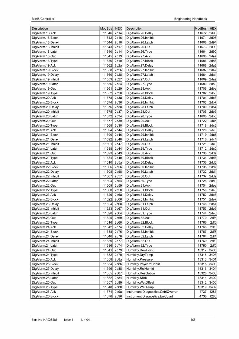
Mini8 Controller Engineering Handbook
Part No HA028581 Issue 1 Jun-04 165
Description ModBus HEXDigAlarm.18.Ack 11546 2d1aDigAlarm.18.Block 11542 2d16DigAlarm.18.Delay 11544 2d18DigAlarm.18.Inhibit 11543 2d17DigAlarm.18.Latch 11540 2d14DigAlarm.18.Out 11545 2d19DigAlarm.18.Type 11536 2d10DigAlarm.19.Ack 11562 2d2aDigAlarm.19.Block 11558 2d26DigAlarm.19.Delay 11560 2d28DigAlarm.19.Inhibit 11559 2d27DigAlarm.19.Latch 11556 2d24DigAlarm.19.Out 11561 2d29DigAlarm.19.Type 11552 2d20DigAlarm.20.Ack 11578 2d3aDigAlarm.20.Block 11574 2d36DigAlarm.20.Delay 11576 2d38DigAlarm.20.Inhibit 11575 2d37DigAlarm.20.Latch 11572 2d34DigAlarm.20.Out 11577 2d39DigAlarm.20.Type 11568 2d30DigAlarm.21.Ack 11594 2d4aDigAlarm.21.Block 11590 2d46DigAlarm.21.Delay 11592 2d48DigAlarm.21.Inhibit 11591 2d47DigAlarm.21.Latch 11588 2d44DigAlarm.21.Out 11593 2d49DigAlarm.21.Type 11584 2d40DigAlarm.22.Ack 11610 2d5aDigAlarm.22.Block 11606 2d56DigAlarm.22.Delay 11608 2d58DigAlarm.22.Inhibit 11607 2d57DigAlarm.22.Latch 11604 2d54DigAlarm.22.Out 11609 2d59DigAlarm.22.Type 11600 2d50DigAlarm.23.Ack 11626 2d6aDigAlarm.23.Block 11622 2d66DigAlarm.23.Delay 11624 2d68DigAlarm.23.Inhibit 11623 2d67DigAlarm.23.Latch 11620 2d64DigAlarm.23.Out 11625 2d69DigAlarm.23.Type 11616 2d60DigAlarm.24.Ack 11642 2d7aDigAlarm.24.Block 11638 2d76DigAlarm.24.Delay 11640 2d78DigAlarm.24.Inhibit 11639 2d77DigAlarm.24.Latch 11636 2d74DigAlarm.24.Out 11641 2d79DigAlarm.24.Type 11632 2d70DigAlarm.25.Ack 11658 2d8aDigAlarm.25.Block 11654 2d86DigAlarm.25.Delay 11656 2d88DigAlarm.25.Inhibit 11655 2d87DigAlarm.25.Latch 11652 2d84DigAlarm.25.Out 11657 2d89DigAlarm.25.Type 11648 2d80DigAlarm.26.Ack 11674 2d9aDigAlarm.26.Block 11670 2d96
Description ModBus HEXDigAlarm.26.Delay 11672 2d98DigAlarm.26.Inhibit 11671 2d97DigAlarm.26.Latch 11668 2d94DigAlarm.26.Out 11673 2d99DigAlarm.26.Type 11664 2d90DigAlarm.27.Ack 11690 2daaDigAlarm.27.Block 11686 2da6DigAlarm.27.Delay 11688 2da8DigAlarm.27.Inhibit 11687 2da7DigAlarm.27.Latch 11684 2da4DigAlarm.27.Out 11689 2da9DigAlarm.27.Type 11680 2da0DigAlarm.28.Ack 11706 2dbaDigAlarm.28.Block 11702 2db6DigAlarm.28.Delay 11704 2db8DigAlarm.28.Inhibit 11703 2db7DigAlarm.28.Latch 11700 2db4DigAlarm.28.Out 11705 2db9DigAlarm.28.Type 11696 2db0DigAlarm.29.Ack 11722 2dcaDigAlarm.29.Block 11718 2dc6DigAlarm.29.Delay 11720 2dc8DigAlarm.29.Inhibit 11719 2dc7DigAlarm.29.Latch 11716 2dc4DigAlarm.29.Out 11721 2dc9DigAlarm.29.Type 11712 2dc0DigAlarm.30.Ack 11738 2ddaDigAlarm.30.Block 11734 2dd6DigAlarm.30.Delay 11736 2dd8DigAlarm.30.Inhibit 11735 2dd7DigAlarm.30.Latch 11732 2dd4DigAlarm.30.Out 11737 2dd9DigAlarm.30.Type 11728 2dd0DigAlarm.31.Ack 11754 2deaDigAlarm.31.Block 11750 2de6DigAlarm.31.Delay 11752 2de8DigAlarm.31.Inhibit 11751 2de7DigAlarm.31.Latch 11748 2de4DigAlarm.31.Out 11753 2de9DigAlarm.31.Type 11744 2de0DigAlarm.32.Ack 11770 2dfaDigAlarm.32.Block 11766 2df6DigAlarm.32.Delay 11768 2df8DigAlarm.32.Inhibit 11767 2df7DigAlarm.32.Latch 11764 2df4DigAlarm.32.Out 11769 2df9DigAlarm.32.Type 11760 2df0Humidity.DewPoint 13317 3405Humidity.DryTemp 13318 3406Humidity.Pressure 13313 3401Humidity.PsychroConst 13315 3403Humidity.RelHumid 13316 3404Humidity.Resolution 13320 3408Humidity.SBrk 13314 3402Humidity.WetOffset 13312 3400Humidity.WetTemp 13319 3407Instrument.Diagnostics.CntrlOverrun 4737 1281Instrument.Diagnostics.ErrCount 4736 1280
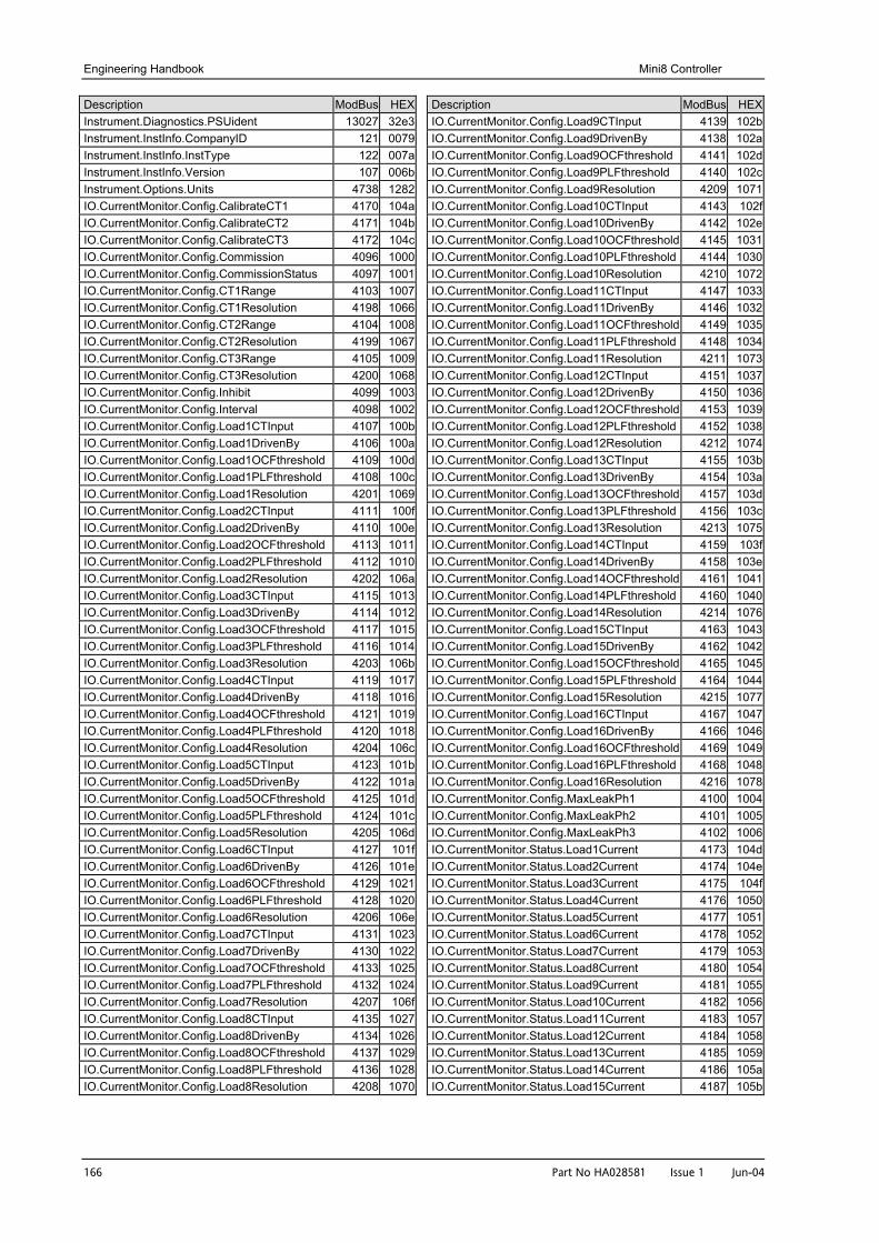
Engineering Handbook Mini8 Controller
166 Part No HA028581 Issue 1 Jun-04
Description ModBus HEXInstrument.Diagnostics.PSUident 13027 32e3Instrument.InstInfo.CompanyID 121 0079Instrument.InstInfo.InstType 122 007aInstrument.InstInfo.Version 107 006bInstrument.Options.Units 4738 1282IO.CurrentMonitor.Config.CalibrateCT1 4170 104aIO.CurrentMonitor.Config.CalibrateCT2 4171 104bIO.CurrentMonitor.Config.CalibrateCT3 4172 104cIO.CurrentMonitor.Config.Commission 4096 1000IO.CurrentMonitor.Config.CommissionStatus 4097 1001IO.CurrentMonitor.Config.CT1Range 4103 1007IO.CurrentMonitor.Config.CT1Resolution 4198 1066IO.CurrentMonitor.Config.CT2Range 4104 1008IO.CurrentMonitor.Config.CT2Resolution 4199 1067IO.CurrentMonitor.Config.CT3Range 4105 1009IO.CurrentMonitor.Config.CT3Resolution 4200 1068IO.CurrentMonitor.Config.Inhibit 4099 1003IO.CurrentMonitor.Config.Interval 4098 1002IO.CurrentMonitor.Config.Load1CTInput 4107 100bIO.CurrentMonitor.Config.Load1DrivenBy 4106 100aIO.CurrentMonitor.Config.Load1OCFthreshold 4109 100dIO.CurrentMonitor.Config.Load1PLFthreshold 4108 100cIO.CurrentMonitor.Config.Load1Resolution 4201 1069IO.CurrentMonitor.Config.Load2CTInput 4111 100fIO.CurrentMonitor.Config.Load2DrivenBy 4110 100eIO.CurrentMonitor.Config.Load2OCFthreshold 4113 1011IO.CurrentMonitor.Config.Load2PLFthreshold 4112 1010IO.CurrentMonitor.Config.Load2Resolution 4202 106aIO.CurrentMonitor.Config.Load3CTInput 4115 1013IO.CurrentMonitor.Config.Load3DrivenBy 4114 1012IO.CurrentMonitor.Config.Load3OCFthreshold 4117 1015IO.CurrentMonitor.Config.Load3PLFthreshold 4116 1014IO.CurrentMonitor.Config.Load3Resolution 4203 106bIO.CurrentMonitor.Config.Load4CTInput 4119 1017IO.CurrentMonitor.Config.Load4DrivenBy 4118 1016IO.CurrentMonitor.Config.Load4OCFthreshold 4121 1019IO.CurrentMonitor.Config.Load4PLFthreshold 4120 1018IO.CurrentMonitor.Config.Load4Resolution 4204 106cIO.CurrentMonitor.Config.Load5CTInput 4123 101bIO.CurrentMonitor.Config.Load5DrivenBy 4122 101aIO.CurrentMonitor.Config.Load5OCFthreshold 4125 101dIO.CurrentMonitor.Config.Load5PLFthreshold 4124 101cIO.CurrentMonitor.Config.Load5Resolution 4205 106dIO.CurrentMonitor.Config.Load6CTInput 4127 101fIO.CurrentMonitor.Config.Load6DrivenBy 4126 101eIO.CurrentMonitor.Config.Load6OCFthreshold 4129 1021IO.CurrentMonitor.Config.Load6PLFthreshold 4128 1020IO.CurrentMonitor.Config.Load6Resolution 4206 106eIO.CurrentMonitor.Config.Load7CTInput 4131 1023IO.CurrentMonitor.Config.Load7DrivenBy 4130 1022IO.CurrentMonitor.Config.Load7OCFthreshold 4133 1025IO.CurrentMonitor.Config.Load7PLFthreshold 4132 1024IO.CurrentMonitor.Config.Load7Resolution 4207 106fIO.CurrentMonitor.Config.Load8CTInput 4135 1027IO.CurrentMonitor.Config.Load8DrivenBy 4134 1026IO.CurrentMonitor.Config.Load8OCFthreshold 4137 1029IO.CurrentMonitor.Config.Load8PLFthreshold 4136 1028IO.CurrentMonitor.Config.Load8Resolution 4208 1070
Description ModBus HEXIO.CurrentMonitor.Config.Load9CTInput 4139 102bIO.CurrentMonitor.Config.Load9DrivenBy 4138 102aIO.CurrentMonitor.Config.Load9OCFthreshold 4141 102dIO.CurrentMonitor.Config.Load9PLFthreshold 4140 102cIO.CurrentMonitor.Config.Load9Resolution 4209 1071IO.CurrentMonitor.Config.Load10CTInput 4143 102fIO.CurrentMonitor.Config.Load10DrivenBy 4142 102eIO.CurrentMonitor.Config.Load10OCFthreshold 4145 1031IO.CurrentMonitor.Config.Load10PLFthreshold 4144 1030IO.CurrentMonitor.Config.Load10Resolution 4210 1072IO.CurrentMonitor.Config.Load11CTInput 4147 1033IO.CurrentMonitor.Config.Load11DrivenBy 4146 1032IO.CurrentMonitor.Config.Load11OCFthreshold 4149 1035IO.CurrentMonitor.Config.Load11PLFthreshold 4148 1034IO.CurrentMonitor.Config.Load11Resolution 4211 1073IO.CurrentMonitor.Config.Load12CTInput 4151 1037IO.CurrentMonitor.Config.Load12DrivenBy 4150 1036IO.CurrentMonitor.Config.Load12OCFthreshold 4153 1039IO.CurrentMonitor.Config.Load12PLFthreshold 4152 1038IO.CurrentMonitor.Config.Load12Resolution 4212 1074IO.CurrentMonitor.Config.Load13CTInput 4155 103bIO.CurrentMonitor.Config.Load13DrivenBy 4154 103aIO.CurrentMonitor.Config.Load13OCFthreshold 4157 103dIO.CurrentMonitor.Config.Load13PLFthreshold 4156 103cIO.CurrentMonitor.Config.Load13Resolution 4213 1075IO.CurrentMonitor.Config.Load14CTInput 4159 103fIO.CurrentMonitor.Config.Load14DrivenBy 4158 103eIO.CurrentMonitor.Config.Load14OCFthreshold 4161 1041IO.CurrentMonitor.Config.Load14PLFthreshold 4160 1040IO.CurrentMonitor.Config.Load14Resolution 4214 1076IO.CurrentMonitor.Config.Load15CTInput 4163 1043IO.CurrentMonitor.Config.Load15DrivenBy 4162 1042IO.CurrentMonitor.Config.Load15OCFthreshold 4165 1045IO.CurrentMonitor.Config.Load15PLFthreshold 4164 1044IO.CurrentMonitor.Config.Load15Resolution 4215 1077IO.CurrentMonitor.Config.Load16CTInput 4167 1047IO.CurrentMonitor.Config.Load16DrivenBy 4166 1046IO.CurrentMonitor.Config.Load16OCFthreshold 4169 1049IO.CurrentMonitor.Config.Load16PLFthreshold 4168 1048IO.CurrentMonitor.Config.Load16Resolution 4216 1078IO.CurrentMonitor.Config.MaxLeakPh1 4100 1004IO.CurrentMonitor.Config.MaxLeakPh2 4101 1005IO.CurrentMonitor.Config.MaxLeakPh3 4102 1006IO.CurrentMonitor.Status.Load1Current 4173 104dIO.CurrentMonitor.Status.Load2Current 4174 104eIO.CurrentMonitor.Status.Load3Current 4175 104fIO.CurrentMonitor.Status.Load4Current 4176 1050IO.CurrentMonitor.Status.Load5Current 4177 1051IO.CurrentMonitor.Status.Load6Current 4178 1052IO.CurrentMonitor.Status.Load7Current 4179 1053IO.CurrentMonitor.Status.Load8Current 4180 1054IO.CurrentMonitor.Status.Load9Current 4181 1055IO.CurrentMonitor.Status.Load10Current 4182 1056IO.CurrentMonitor.Status.Load11Current 4183 1057IO.CurrentMonitor.Status.Load12Current 4184 1058IO.CurrentMonitor.Status.Load13Current 4185 1059IO.CurrentMonitor.Status.Load14Current 4186 105aIO.CurrentMonitor.Status.Load15Current 4187 105b
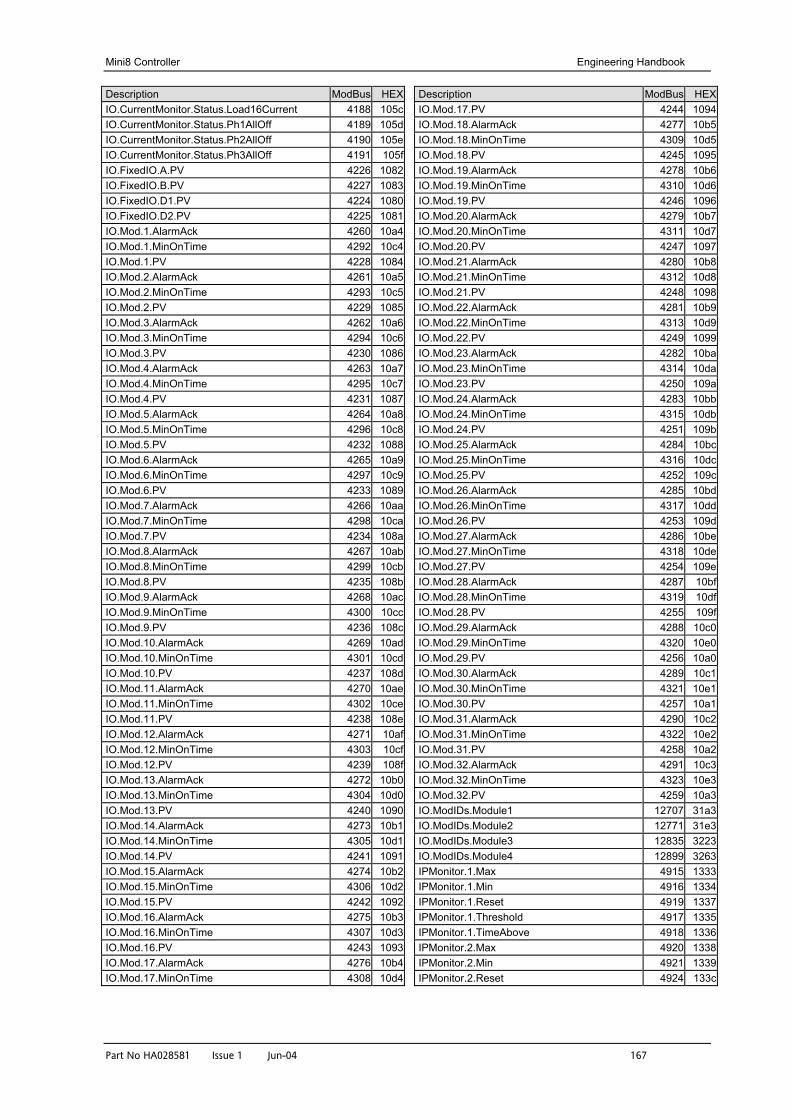
Mini8 Controller Engineering Handbook
Part No HA028581 Issue 1 Jun-04 167
Description ModBus HEXIO.CurrentMonitor.Status.Load16Current 4188 105cIO.CurrentMonitor.Status.Ph1AllOff 4189 105dIO.CurrentMonitor.Status.Ph2AllOff 4190 105eIO.CurrentMonitor.Status.Ph3AllOff 4191 105fIO.FixedIO.A.PV 4226 1082IO.FixedIO.B.PV 4227 1083IO.FixedIO.D1.PV 4224 1080IO.FixedIO.D2.PV 4225 1081IO.Mod.1.AlarmAck 4260 10a4IO.Mod.1.MinOnTime 4292 10c4IO.Mod.1.PV 4228 1084IO.Mod.2.AlarmAck 4261 10a5IO.Mod.2.MinOnTime 4293 10c5IO.Mod.2.PV 4229 1085IO.Mod.3.AlarmAck 4262 10a6IO.Mod.3.MinOnTime 4294 10c6IO.Mod.3.PV 4230 1086IO.Mod.4.AlarmAck 4263 10a7IO.Mod.4.MinOnTime 4295 10c7IO.Mod.4.PV 4231 1087IO.Mod.5.AlarmAck 4264 10a8IO.Mod.5.MinOnTime 4296 10c8IO.Mod.5.PV 4232 1088IO.Mod.6.AlarmAck 4265 10a9IO.Mod.6.MinOnTime 4297 10c9IO.Mod.6.PV 4233 1089IO.Mod.7.AlarmAck 4266 10aaIO.Mod.7.MinOnTime 4298 10caIO.Mod.7.PV 4234 108aIO.Mod.8.AlarmAck 4267 10abIO.Mod.8.MinOnTime 4299 10cbIO.Mod.8.PV 4235 108bIO.Mod.9.AlarmAck 4268 10acIO.Mod.9.MinOnTime 4300 10ccIO.Mod.9.PV 4236 108cIO.Mod.10.AlarmAck 4269 10adIO.Mod.10.MinOnTime 4301 10cdIO.Mod.10.PV 4237 108dIO.Mod.11.AlarmAck 4270 10aeIO.Mod.11.MinOnTime 4302 10ceIO.Mod.11.PV 4238 108eIO.Mod.12.AlarmAck 4271 10afIO.Mod.12.MinOnTime 4303 10cfIO.Mod.12.PV 4239 108fIO.Mod.13.AlarmAck 4272 10b0IO.Mod.13.MinOnTime 4304 10d0IO.Mod.13.PV 4240 1090IO.Mod.14.AlarmAck 4273 10b1IO.Mod.14.MinOnTime 4305 10d1IO.Mod.14.PV 4241 1091IO.Mod.15.AlarmAck 4274 10b2IO.Mod.15.MinOnTime 4306 10d2IO.Mod.15.PV 4242 1092IO.Mod.16.AlarmAck 4275 10b3IO.Mod.16.MinOnTime 4307 10d3IO.Mod.16.PV 4243 1093IO.Mod.17.AlarmAck 4276 10b4IO.Mod.17.MinOnTime 4308 10d4
Description ModBus HEXIO.Mod.17.PV 4244 1094IO.Mod.18.AlarmAck 4277 10b5IO.Mod.18.MinOnTime 4309 10d5IO.Mod.18.PV 4245 1095IO.Mod.19.AlarmAck 4278 10b6IO.Mod.19.MinOnTime 4310 10d6IO.Mod.19.PV 4246 1096IO.Mod.20.AlarmAck 4279 10b7IO.Mod.20.MinOnTime 4311 10d7IO.Mod.20.PV 4247 1097IO.Mod.21.AlarmAck 4280 10b8IO.Mod.21.MinOnTime 4312 10d8IO.Mod.21.PV 4248 1098IO.Mod.22.AlarmAck 4281 10b9IO.Mod.22.MinOnTime 4313 10d9IO.Mod.22.PV 4249 1099IO.Mod.23.AlarmAck 4282 10baIO.Mod.23.MinOnTime 4314 10daIO.Mod.23.PV 4250 109aIO.Mod.24.AlarmAck 4283 10bbIO.Mod.24.MinOnTime 4315 10dbIO.Mod.24.PV 4251 109bIO.Mod.25.AlarmAck 4284 10bcIO.Mod.25.MinOnTime 4316 10dcIO.Mod.25.PV 4252 109cIO.Mod.26.AlarmAck 4285 10bdIO.Mod.26.MinOnTime 4317 10ddIO.Mod.26.PV 4253 109dIO.Mod.27.AlarmAck 4286 10beIO.Mod.27.MinOnTime 4318 10deIO.Mod.27.PV 4254 109eIO.Mod.28.AlarmAck 4287 10bfIO.Mod.28.MinOnTime 4319 10dfIO.Mod.28.PV 4255 109fIO.Mod.29.AlarmAck 4288 10c0IO.Mod.29.MinOnTime 4320 10e0IO.Mod.29.PV 4256 10a0IO.Mod.30.AlarmAck 4289 10c1IO.Mod.30.MinOnTime 4321 10e1IO.Mod.30.PV 4257 10a1IO.Mod.31.AlarmAck 4290 10c2IO.Mod.31.MinOnTime 4322 10e2IO.Mod.31.PV 4258 10a2IO.Mod.32.AlarmAck 4291 10c3IO.Mod.32.MinOnTime 4323 10e3IO.Mod.32.PV 4259 10a3IO.ModIDs.Module1 12707 31a3IO.ModIDs.Module2 12771 31e3IO.ModIDs.Module3 12835 3223IO.ModIDs.Module4 12899 3263IPMonitor.1.Max 4915 1333IPMonitor.1.Min 4916 1334IPMonitor.1.Reset 4919 1337IPMonitor.1.Threshold 4917 1335IPMonitor.1.TimeAbove 4918 1336IPMonitor.2.Max 4920 1338IPMonitor.2.Min 4921 1339IPMonitor.2.Reset 4924 133c
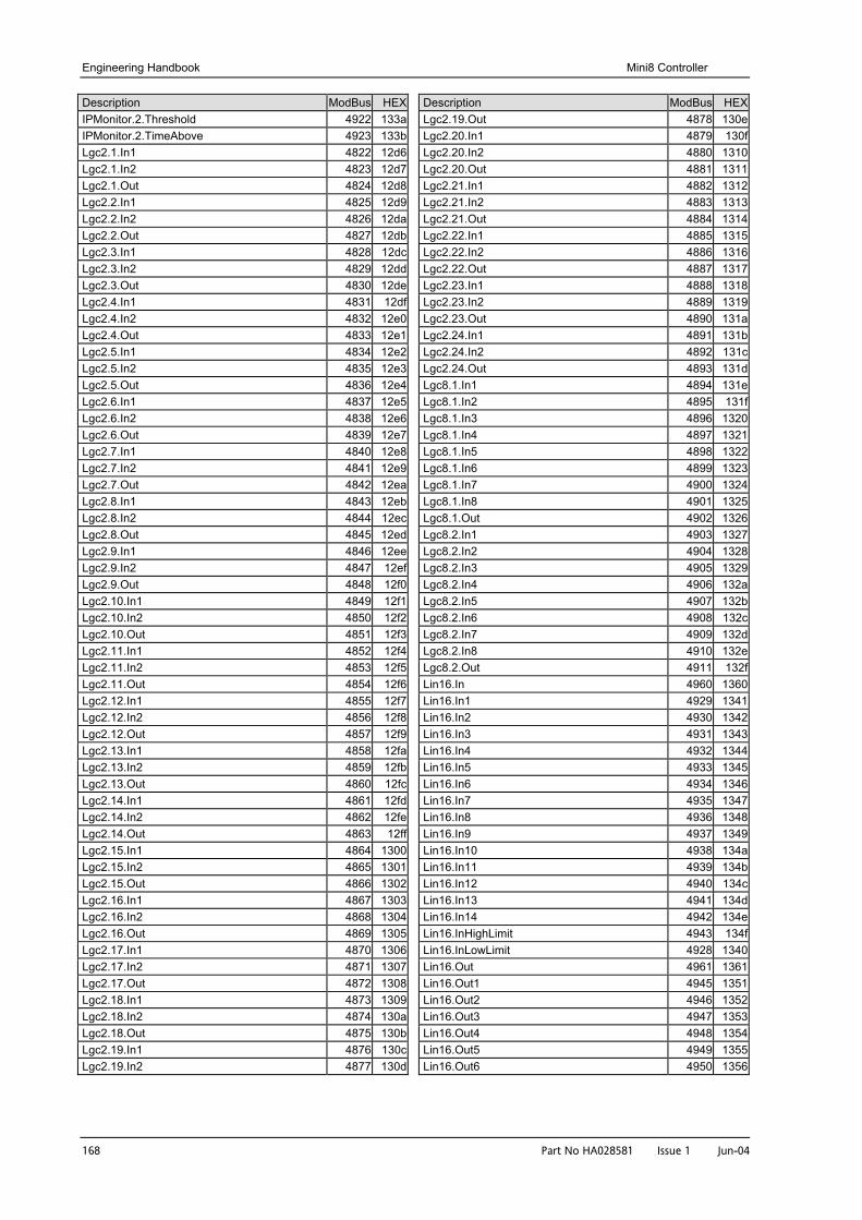
Engineering Handbook Mini8 Controller
168 Part No HA028581 Issue 1 Jun-04
Description ModBus HEXIPMonitor.2.Threshold 4922 133aIPMonitor.2.TimeAbove 4923 133bLgc2.1.In1 4822 12d6Lgc2.1.In2 4823 12d7Lgc2.1.Out 4824 12d8Lgc2.2.In1 4825 12d9Lgc2.2.In2 4826 12daLgc2.2.Out 4827 12dbLgc2.3.In1 4828 12dcLgc2.3.In2 4829 12ddLgc2.3.Out 4830 12deLgc2.4.In1 4831 12dfLgc2.4.In2 4832 12e0Lgc2.4.Out 4833 12e1Lgc2.5.In1 4834 12e2Lgc2.5.In2 4835 12e3Lgc2.5.Out 4836 12e4Lgc2.6.In1 4837 12e5Lgc2.6.In2 4838 12e6Lgc2.6.Out 4839 12e7Lgc2.7.In1 4840 12e8Lgc2.7.In2 4841 12e9Lgc2.7.Out 4842 12eaLgc2.8.In1 4843 12ebLgc2.8.In2 4844 12ecLgc2.8.Out 4845 12edLgc2.9.In1 4846 12eeLgc2.9.In2 4847 12efLgc2.9.Out 4848 12f0Lgc2.10.In1 4849 12f1Lgc2.10.In2 4850 12f2Lgc2.10.Out 4851 12f3Lgc2.11.In1 4852 12f4Lgc2.11.In2 4853 12f5Lgc2.11.Out 4854 12f6Lgc2.12.In1 4855 12f7Lgc2.12.In2 4856 12f8Lgc2.12.Out 4857 12f9Lgc2.13.In1 4858 12faLgc2.13.In2 4859 12fbLgc2.13.Out 4860 12fcLgc2.14.In1 4861 12fdLgc2.14.In2 4862 12feLgc2.14.Out 4863 12ffLgc2.15.In1 4864 1300Lgc2.15.In2 4865 1301Lgc2.15.Out 4866 1302Lgc2.16.In1 4867 1303Lgc2.16.In2 4868 1304Lgc2.16.Out 4869 1305Lgc2.17.In1 4870 1306Lgc2.17.In2 4871 1307Lgc2.17.Out 4872 1308Lgc2.18.In1 4873 1309Lgc2.18.In2 4874 130aLgc2.18.Out 4875 130bLgc2.19.In1 4876 130cLgc2.19.In2 4877 130d
Description ModBus HEXLgc2.19.Out 4878 130eLgc2.20.In1 4879 130fLgc2.20.In2 4880 1310Lgc2.20.Out 4881 1311Lgc2.21.In1 4882 1312Lgc2.21.In2 4883 1313Lgc2.21.Out 4884 1314Lgc2.22.In1 4885 1315Lgc2.22.In2 4886 1316Lgc2.22.Out 4887 1317Lgc2.23.In1 4888 1318Lgc2.23.In2 4889 1319Lgc2.23.Out 4890 131aLgc2.24.In1 4891 131bLgc2.24.In2 4892 131cLgc2.24.Out 4893 131dLgc8.1.In1 4894 131eLgc8.1.In2 4895 131fLgc8.1.In3 4896 1320Lgc8.1.In4 4897 1321Lgc8.1.In5 4898 1322Lgc8.1.In6 4899 1323Lgc8.1.In7 4900 1324Lgc8.1.In8 4901 1325Lgc8.1.Out 4902 1326Lgc8.2.In1 4903 1327Lgc8.2.In2 4904 1328Lgc8.2.In3 4905 1329Lgc8.2.In4 4906 132aLgc8.2.In5 4907 132bLgc8.2.In6 4908 132cLgc8.2.In7 4909 132dLgc8.2.In8 4910 132eLgc8.2.Out 4911 132fLin16.In 4960 1360Lin16.In1 4929 1341Lin16.In2 4930 1342Lin16.In3 4931 1343Lin16.In4 4932 1344Lin16.In5 4933 1345Lin16.In6 4934 1346Lin16.In7 4935 1347Lin16.In8 4936 1348Lin16.In9 4937 1349Lin16.In10 4938 134aLin16.In11 4939 134bLin16.In12 4940 134cLin16.In13 4941 134dLin16.In14 4942 134eLin16.InHighLimit 4943 134fLin16.InLowLimit 4928 1340Lin16.Out 4961 1361Lin16.Out1 4945 1351Lin16.Out2 4946 1352Lin16.Out3 4947 1353Lin16.Out4 4948 1354Lin16.Out5 4949 1355Lin16.Out6 4950 1356
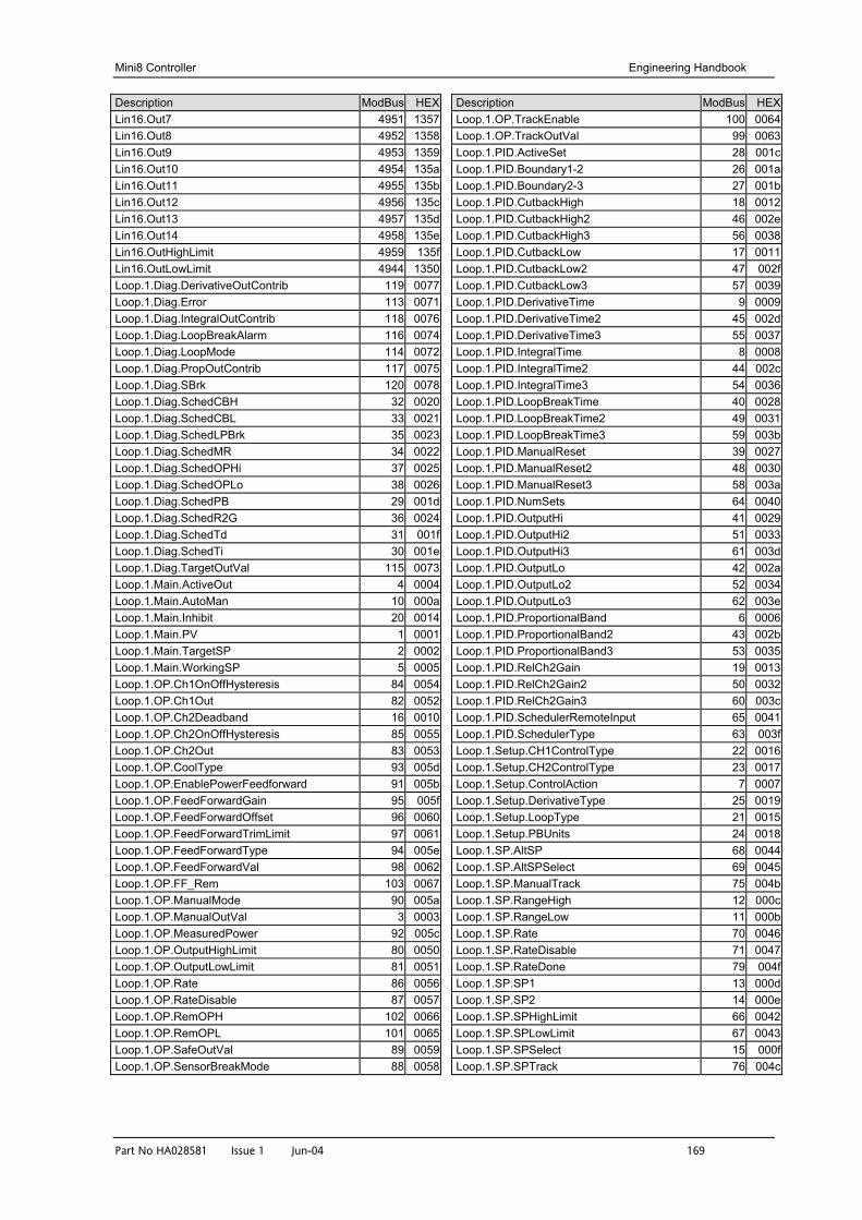
Mini8 Controller Engineering Handbook
Part No HA028581 Issue 1 Jun-04 169
Description ModBus HEXLin16.Out7 4951 1357Lin16.Out8 4952 1358Lin16.Out9 4953 1359Lin16.Out10 4954 135aLin16.Out11 4955 135bLin16.Out12 4956 135cLin16.Out13 4957 135dLin16.Out14 4958 135eLin16.OutHighLimit 4959 135fLin16.OutLowLimit 4944 1350Loop.1.Diag.DerivativeOutContrib 119 0077Loop.1.Diag.Error 113 0071Loop.1.Diag.IntegralOutContrib 118 0076Loop.1.Diag.LoopBreakAlarm 116 0074Loop.1.Diag.LoopMode 114 0072Loop.1.Diag.PropOutContrib 117 0075Loop.1.Diag.SBrk 120 0078Loop.1.Diag.SchedCBH 32 0020Loop.1.Diag.SchedCBL 33 0021Loop.1.Diag.SchedLPBrk 35 0023Loop.1.Diag.SchedMR 34 0022Loop.1.Diag.SchedOPHi 37 0025Loop.1.Diag.SchedOPLo 38 0026Loop.1.Diag.SchedPB 29 001dLoop.1.Diag.SchedR2G 36 0024Loop.1.Diag.SchedTd 31 001fLoop.1.Diag.SchedTi 30 001eLoop.1.Diag.TargetOutVal 115 0073Loop.1.Main.ActiveOut 4 0004Loop.1.Main.AutoMan 10 000aLoop.1.Main.Inhibit 20 0014Loop.1.Main.PV 1 0001Loop.1.Main.TargetSP 2 0002Loop.1.Main.WorkingSP 5 0005Loop.1.OP.Ch1OnOffHysteresis 84 0054Loop.1.OP.Ch1Out 82 0052Loop.1.OP.Ch2Deadband 16 0010Loop.1.OP.Ch2OnOffHysteresis 85 0055Loop.1.OP.Ch2Out 83 0053Loop.1.OP.CoolType 93 005dLoop.1.OP.EnablePowerFeedforward 91 005bLoop.1.OP.FeedForwardGain 95 005fLoop.1.OP.FeedForwardOffset 96 0060Loop.1.OP.FeedForwardTrimLimit 97 0061Loop.1.OP.FeedForwardType 94 005eLoop.1.OP.FeedForwardVal 98 0062Loop.1.OP.FF_Rem 103 0067Loop.1.OP.ManualMode 90 005aLoop.1.OP.ManualOutVal 3 0003Loop.1.OP.MeasuredPower 92 005cLoop.1.OP.OutputHighLimit 80 0050Loop.1.OP.OutputLowLimit 81 0051Loop.1.OP.Rate 86 0056Loop.1.OP.RateDisable 87 0057Loop.1.OP.RemOPH 102 0066Loop.1.OP.RemOPL 101 0065Loop.1.OP.SafeOutVal 89 0059Loop.1.OP.SensorBreakMode 88 0058
Description ModBus HEXLoop.1.OP.TrackEnable 100 0064Loop.1.OP.TrackOutVal 99 0063Loop.1.PID.ActiveSet 28 001cLoop.1.PID.Boundary1-2 26 001aLoop.1.PID.Boundary2-3 27 001bLoop.1.PID.CutbackHigh 18 0012Loop.1.PID.CutbackHigh2 46 002eLoop.1.PID.CutbackHigh3 56 0038Loop.1.PID.CutbackLow 17 0011Loop.1.PID.CutbackLow2 47 002fLoop.1.PID.CutbackLow3 57 0039Loop.1.PID.DerivativeTime 9 0009Loop.1.PID.DerivativeTime2 45 002dLoop.1.PID.DerivativeTime3 55 0037Loop.1.PID.IntegralTime 8 0008Loop.1.PID.IntegralTime2 44 002cLoop.1.PID.IntegralTime3 54 0036Loop.1.PID.LoopBreakTime 40 0028Loop.1.PID.LoopBreakTime2 49 0031Loop.1.PID.LoopBreakTime3 59 003bLoop.1.PID.ManualReset 39 0027Loop.1.PID.ManualReset2 48 0030Loop.1.PID.ManualReset3 58 003aLoop.1.PID.NumSets 64 0040Loop.1.PID.OutputHi 41 0029Loop.1.PID.OutputHi2 51 0033Loop.1.PID.OutputHi3 61 003dLoop.1.PID.OutputLo 42 002aLoop.1.PID.OutputLo2 52 0034Loop.1.PID.OutputLo3 62 003eLoop.1.PID.ProportionalBand 6 0006Loop.1.PID.ProportionalBand2 43 002bLoop.1.PID.ProportionalBand3 53 0035Loop.1.PID.RelCh2Gain 19 0013Loop.1.PID.RelCh2Gain2 50 0032Loop.1.PID.RelCh2Gain3 60 003cLoop.1.PID.SchedulerRemoteInput 65 0041Loop.1.PID.SchedulerType 63 003fLoop.1.Setup.CH1ControlType 22 0016Loop.1.Setup.CH2ControlType 23 0017Loop.1.Setup.ControlAction 7 0007Loop.1.Setup.DerivativeType 25 0019Loop.1.Setup.LoopType 21 0015Loop.1.Setup.PBUnits 24 0018Loop.1.SP.AltSP 68 0044Loop.1.SP.AltSPSelect 69 0045Loop.1.SP.ManualTrack 75 004bLoop.1.SP.RangeHigh 12 000cLoop.1.SP.RangeLow 11 000bLoop.1.SP.Rate 70 0046Loop.1.SP.RateDisable 71 0047Loop.1.SP.RateDone 79 004fLoop.1.SP.SP1 13 000dLoop.1.SP.SP2 14 000eLoop.1.SP.SPHighLimit 66 0042Loop.1.SP.SPLowLimit 67 0043Loop.1.SP.SPSelect 15 000fLoop.1.SP.SPTrack 76 004c
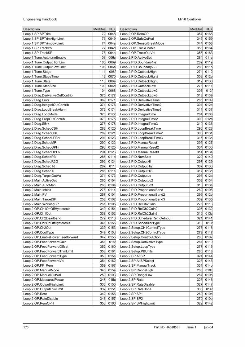
Engineering Handbook Mini8 Controller
170 Part No HA028581 Issue 1 Jun-04
Description ModBus HEXLoop.1.SP.SPTrim 72 0048Loop.1.SP.SPTrimHighLimit 73 0049Loop.1.SP.SPTrimLowLimit 74 004aLoop.1.SP.TrackPV 77 004dLoop.1.SP.TrackSP 78 004eLoop.1.Tune.AutotuneEnable 108 006cLoop.1.Tune.OutputHighLimit 105 0069Loop.1.Tune.OutputLowLimit 106 006aLoop.1.Tune.Stage 111 006fLoop.1.Tune.StageTime 112 0070Loop.1.Tune.State 110 006eLoop.1.Tune.StepSize 109 006dLoop.1.Tune.Type 104 0068Loop.2.Diag.DerivativeOutContrib 375 0177Loop.2.Diag.Error 369 0171Loop.2.Diag.IntegralOutContrib 374 0176Loop.2.Diag.LoopBreakAlarm 372 0174Loop.2.Diag.LoopMode 370 0172Loop.2.Diag.PropOutContrib 373 0175Loop.2.Diag.SBrk 376 0178Loop.2.Diag.SchedCBH 288 0120Loop.2.Diag.SchedCBL 289 0121Loop.2.Diag.SchedLPBrk 291 0123Loop.2.Diag.SchedMR 290 0122Loop.2.Diag.SchedOPHi 293 0125Loop.2.Diag.SchedOPLo 294 0126Loop.2.Diag.SchedPB 285 011dLoop.2.Diag.SchedR2G 292 0124Loop.2.Diag.SchedTd 287 011fLoop.2.Diag.SchedTi 286 011eLoop.2.Diag.TargetOutVal 371 0173Loop.2.Main.ActiveOut 260 0104Loop.2.Main.AutoMan 266 010aLoop.2.Main.Inhibit 276 0114Loop.2.Main.PV 257 0101Loop.2.Main.TargetSP 258 0102Loop.2.Main.WorkingSP 261 0105Loop.2.OP.Ch1OnOffHysteresis 340 0154Loop.2.OP.Ch1Out 338 0152Loop.2.OP.Ch2Deadband 272 0110Loop.2.OP.Ch2OnOffHysteresis 341 0155Loop.2.OP.Ch2Out 339 0153Loop.2.OP.CoolType 349 015dLoop.2.OP.EnablePowerFeedforward 347 015bLoop.2.OP.FeedForwardGain 351 015fLoop.2.OP.FeedForwardOffset 352 0160Loop.2.OP.FeedForwardTrimLimit 353 0161Loop.2.OP.FeedForwardType 350 015eLoop.2.OP.FeedForwardVal 354 0162Loop.2.OP.FF_Rem 359 0167Loop.2.OP.ManualMode 346 015aLoop.2.OP.ManualOutVal 259 0103Loop.2.OP.MeasuredPower 348 015cLoop.2.OP.OutputHighLimit 336 0150Loop.2.OP.OutputLowLimit 337 0151Loop.2.OP.Rate 342 0156Loop.2.OP.RateDisable 343 0157Loop.2.OP.RemOPH 358 0166
Description ModBus HEXLoop.2.OP.RemOPL 357 0165Loop.2.OP.SafeOutVal 345 0159Loop.2.OP.SensorBreakMode 344 0158Loop.2.OP.TrackEnable 356 0164Loop.2.OP.TrackOutVal 355 0163Loop.2.PID.ActiveSet 284 011cLoop.2.PID.Boundary1-2 282 011aLoop.2.PID.Boundary2-3 283 011bLoop.2.PID.CutbackHigh 274 0112Loop.2.PID.CutbackHigh2 302 012eLoop.2.PID.CutbackHigh3 312 0138Loop.2.PID.CutbackLow 273 0111Loop.2.PID.CutbackLow2 303 012fLoop.2.PID.CutbackLow3 313 0139Loop.2.PID.DerivativeTime 265 0109Loop.2.PID.DerivativeTime2 301 012dLoop.2.PID.DerivativeTime3 311 0137Loop.2.PID.IntegralTime 264 0108Loop.2.PID.IntegralTime2 300 012cLoop.2.PID.IntegralTime3 310 0136Loop.2.PID.LoopBreakTime 296 0128Loop.2.PID.LoopBreakTime2 305 0131Loop.2.PID.LoopBreakTime3 315 013bLoop.2.PID.ManualReset 295 0127Loop.2.PID.ManualReset2 304 0130Loop.2.PID.ManualReset3 314 013aLoop.2.PID.NumSets 320 0140Loop.2.PID.OutputHi 297 0129Loop.2.PID.OutputHi2 307 0133Loop.2.PID.OutputHi3 317 013dLoop.2.PID.OutputLo 298 012aLoop.2.PID.OutputLo2 308 0134Loop.2.PID.OutputLo3 318 013eLoop.2.PID.ProportionalBand 262 0106Loop.2.PID.ProportionalBand2 299 012bLoop.2.PID.ProportionalBand3 309 0135Loop.2.PID.RelCh2Gain 275 0113Loop.2.PID.RelCh2Gain2 306 0132Loop.2.PID.RelCh2Gain3 316 013cLoop.2.PID.SchedulerRemoteInput 321 0141Loop.2.PID.SchedulerType 319 013fLoop.2.Setup.CH1ControlType 278 0116Loop.2.Setup.CH2ControlType 279 0117Loop.2.Setup.ControlAction 263 0107Loop.2.Setup.DerivativeType 281 0119Loop.2.Setup.LoopType 277 0115Loop.2.Setup.PBUnits 280 0118Loop.2.SP.AltSP 324 0144Loop.2.SP.AltSPSelect 325 0145Loop.2.SP.ManualTrack 331 014bLoop.2.SP.RangeHigh 268 010cLoop.2.SP.RangeLow 267 010bLoop.2.SP.Rate 326 0146Loop.2.SP.RateDisable 327 0147Loop.2.SP.RateDone 335 014fLoop.2.SP.SP1 269 010dLoop.2.SP.SP2 270 010eLoop.2.SP.SPHighLimit 322 0142
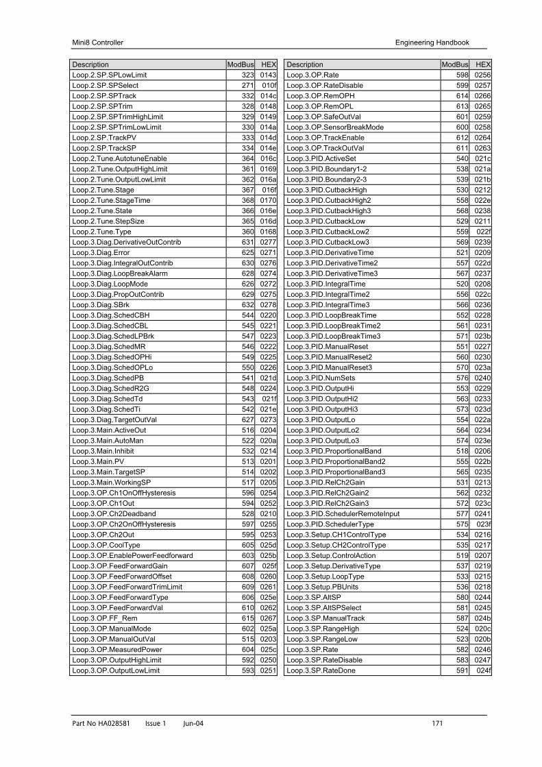
Mini8 Controller Engineering Handbook
Part No HA028581 Issue 1 Jun-04 171
Description ModBus HEXLoop.2.SP.SPLowLimit 323 0143Loop.2.SP.SPSelect 271 010fLoop.2.SP.SPTrack 332 014cLoop.2.SP.SPTrim 328 0148Loop.2.SP.SPTrimHighLimit 329 0149Loop.2.SP.SPTrimLowLimit 330 014aLoop.2.SP.TrackPV 333 014dLoop.2.SP.TrackSP 334 014eLoop.2.Tune.AutotuneEnable 364 016cLoop.2.Tune.OutputHighLimit 361 0169Loop.2.Tune.OutputLowLimit 362 016aLoop.2.Tune.Stage 367 016fLoop.2.Tune.StageTime 368 0170Loop.2.Tune.State 366 016eLoop.2.Tune.StepSize 365 016dLoop.2.Tune.Type 360 0168Loop.3.Diag.DerivativeOutContrib 631 0277Loop.3.Diag.Error 625 0271Loop.3.Diag.IntegralOutContrib 630 0276Loop.3.Diag.LoopBreakAlarm 628 0274Loop.3.Diag.LoopMode 626 0272Loop.3.Diag.PropOutContrib 629 0275Loop.3.Diag.SBrk 632 0278Loop.3.Diag.SchedCBH 544 0220Loop.3.Diag.SchedCBL 545 0221Loop.3.Diag.SchedLPBrk 547 0223Loop.3.Diag.SchedMR 546 0222Loop.3.Diag.SchedOPHi 549 0225Loop.3.Diag.SchedOPLo 550 0226Loop.3.Diag.SchedPB 541 021dLoop.3.Diag.SchedR2G 548 0224Loop.3.Diag.SchedTd 543 021fLoop.3.Diag.SchedTi 542 021eLoop.3.Diag.TargetOutVal 627 0273Loop.3.Main.ActiveOut 516 0204Loop.3.Main.AutoMan 522 020aLoop.3.Main.Inhibit 532 0214Loop.3.Main.PV 513 0201Loop.3.Main.TargetSP 514 0202Loop.3.Main.WorkingSP 517 0205Loop.3.OP.Ch1OnOffHysteresis 596 0254Loop.3.OP.Ch1Out 594 0252Loop.3.OP.Ch2Deadband 528 0210Loop.3.OP.Ch2OnOffHysteresis 597 0255Loop.3.OP.Ch2Out 595 0253Loop.3.OP.CoolType 605 025dLoop.3.OP.EnablePowerFeedforward 603 025bLoop.3.OP.FeedForwardGain 607 025fLoop.3.OP.FeedForwardOffset 608 0260Loop.3.OP.FeedForwardTrimLimit 609 0261Loop.3.OP.FeedForwardType 606 025eLoop.3.OP.FeedForwardVal 610 0262Loop.3.OP.FF_Rem 615 0267Loop.3.OP.ManualMode 602 025aLoop.3.OP.ManualOutVal 515 0203Loop.3.OP.MeasuredPower 604 025cLoop.3.OP.OutputHighLimit 592 0250Loop.3.OP.OutputLowLimit 593 0251
Description ModBus HEXLoop.3.OP.Rate 598 0256Loop.3.OP.RateDisable 599 0257Loop.3.OP.RemOPH 614 0266Loop.3.OP.RemOPL 613 0265Loop.3.OP.SafeOutVal 601 0259Loop.3.OP.SensorBreakMode 600 0258Loop.3.OP.TrackEnable 612 0264Loop.3.OP.TrackOutVal 611 0263Loop.3.PID.ActiveSet 540 021cLoop.3.PID.Boundary1-2 538 021aLoop.3.PID.Boundary2-3 539 021bLoop.3.PID.CutbackHigh 530 0212Loop.3.PID.CutbackHigh2 558 022eLoop.3.PID.CutbackHigh3 568 0238Loop.3.PID.CutbackLow 529 0211Loop.3.PID.CutbackLow2 559 022fLoop.3.PID.CutbackLow3 569 0239Loop.3.PID.DerivativeTime 521 0209Loop.3.PID.DerivativeTime2 557 022dLoop.3.PID.DerivativeTime3 567 0237Loop.3.PID.IntegralTime 520 0208Loop.3.PID.IntegralTime2 556 022cLoop.3.PID.IntegralTime3 566 0236Loop.3.PID.LoopBreakTime 552 0228Loop.3.PID.LoopBreakTime2 561 0231Loop.3.PID.LoopBreakTime3 571 023bLoop.3.PID.ManualReset 551 0227Loop.3.PID.ManualReset2 560 0230Loop.3.PID.ManualReset3 570 023aLoop.3.PID.NumSets 576 0240Loop.3.PID.OutputHi 553 0229Loop.3.PID.OutputHi2 563 0233Loop.3.PID.OutputHi3 573 023dLoop.3.PID.OutputLo 554 022aLoop.3.PID.OutputLo2 564 0234Loop.3.PID.OutputLo3 574 023eLoop.3.PID.ProportionalBand 518 0206Loop.3.PID.ProportionalBand2 555 022bLoop.3.PID.ProportionalBand3 565 0235Loop.3.PID.RelCh2Gain 531 0213Loop.3.PID.RelCh2Gain2 562 0232Loop.3.PID.RelCh2Gain3 572 023cLoop.3.PID.SchedulerRemoteInput 577 0241Loop.3.PID.SchedulerType 575 023fLoop.3.Setup.CH1ControlType 534 0216Loop.3.Setup.CH2ControlType 535 0217Loop.3.Setup.ControlAction 519 0207Loop.3.Setup.DerivativeType 537 0219Loop.3.Setup.LoopType 533 0215Loop.3.Setup.PBUnits 536 0218Loop.3.SP.AltSP 580 0244Loop.3.SP.AltSPSelect 581 0245Loop.3.SP.ManualTrack 587 024bLoop.3.SP.RangeHigh 524 020cLoop.3.SP.RangeLow 523 020bLoop.3.SP.Rate 582 0246Loop.3.SP.RateDisable 583 0247Loop.3.SP.RateDone 591 024f
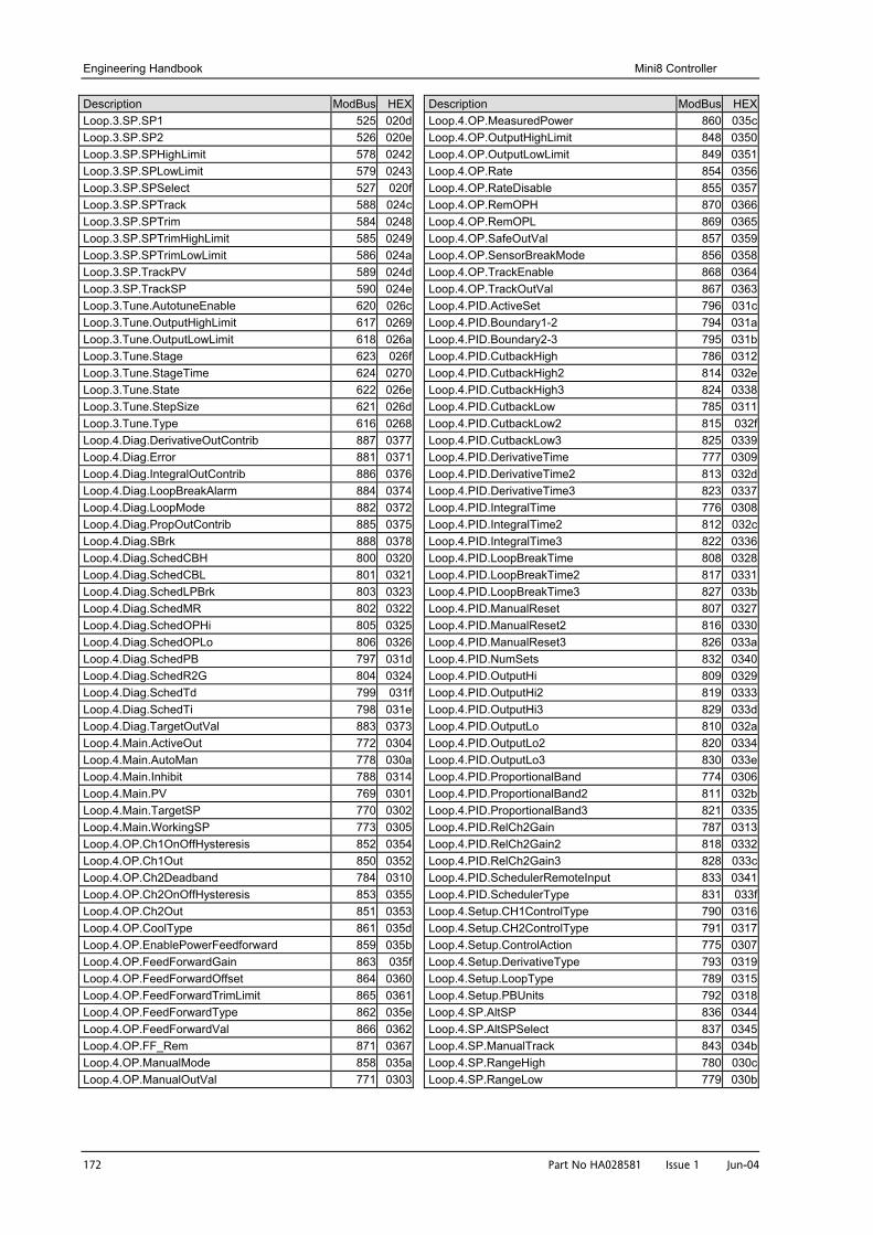
Engineering Handbook Mini8 Controller
172 Part No HA028581 Issue 1 Jun-04
Description ModBus HEXLoop.3.SP.SP1 525 020dLoop.3.SP.SP2 526 020eLoop.3.SP.SPHighLimit 578 0242Loop.3.SP.SPLowLimit 579 0243Loop.3.SP.SPSelect 527 020fLoop.3.SP.SPTrack 588 024cLoop.3.SP.SPTrim 584 0248Loop.3.SP.SPTrimHighLimit 585 0249Loop.3.SP.SPTrimLowLimit 586 024aLoop.3.SP.TrackPV 589 024dLoop.3.SP.TrackSP 590 024eLoop.3.Tune.AutotuneEnable 620 026cLoop.3.Tune.OutputHighLimit 617 0269Loop.3.Tune.OutputLowLimit 618 026aLoop.3.Tune.Stage 623 026fLoop.3.Tune.StageTime 624 0270Loop.3.Tune.State 622 026eLoop.3.Tune.StepSize 621 026dLoop.3.Tune.Type 616 0268Loop.4.Diag.DerivativeOutContrib 887 0377Loop.4.Diag.Error 881 0371Loop.4.Diag.IntegralOutContrib 886 0376Loop.4.Diag.LoopBreakAlarm 884 0374Loop.4.Diag.LoopMode 882 0372Loop.4.Diag.PropOutContrib 885 0375Loop.4.Diag.SBrk 888 0378Loop.4.Diag.SchedCBH 800 0320Loop.4.Diag.SchedCBL 801 0321Loop.4.Diag.SchedLPBrk 803 0323Loop.4.Diag.SchedMR 802 0322Loop.4.Diag.SchedOPHi 805 0325Loop.4.Diag.SchedOPLo 806 0326Loop.4.Diag.SchedPB 797 031dLoop.4.Diag.SchedR2G 804 0324Loop.4.Diag.SchedTd 799 031fLoop.4.Diag.SchedTi 798 031eLoop.4.Diag.TargetOutVal 883 0373Loop.4.Main.ActiveOut 772 0304Loop.4.Main.AutoMan 778 030aLoop.4.Main.Inhibit 788 0314Loop.4.Main.PV 769 0301Loop.4.Main.TargetSP 770 0302Loop.4.Main.WorkingSP 773 0305Loop.4.OP.Ch1OnOffHysteresis 852 0354Loop.4.OP.Ch1Out 850 0352Loop.4.OP.Ch2Deadband 784 0310Loop.4.OP.Ch2OnOffHysteresis 853 0355Loop.4.OP.Ch2Out 851 0353Loop.4.OP.CoolType 861 035dLoop.4.OP.EnablePowerFeedforward 859 035bLoop.4.OP.FeedForwardGain 863 035fLoop.4.OP.FeedForwardOffset 864 0360Loop.4.OP.FeedForwardTrimLimit 865 0361Loop.4.OP.FeedForwardType 862 035eLoop.4.OP.FeedForwardVal 866 0362Loop.4.OP.FF_Rem 871 0367Loop.4.OP.ManualMode 858 035aLoop.4.OP.ManualOutVal 771 0303
Description ModBus HEXLoop.4.OP.MeasuredPower 860 035cLoop.4.OP.OutputHighLimit 848 0350Loop.4.OP.OutputLowLimit 849 0351Loop.4.OP.Rate 854 0356Loop.4.OP.RateDisable 855 0357Loop.4.OP.RemOPH 870 0366Loop.4.OP.RemOPL 869 0365Loop.4.OP.SafeOutVal 857 0359Loop.4.OP.SensorBreakMode 856 0358Loop.4.OP.TrackEnable 868 0364Loop.4.OP.TrackOutVal 867 0363Loop.4.PID.ActiveSet 796 031cLoop.4.PID.Boundary1-2 794 031aLoop.4.PID.Boundary2-3 795 031bLoop.4.PID.CutbackHigh 786 0312Loop.4.PID.CutbackHigh2 814 032eLoop.4.PID.CutbackHigh3 824 0338Loop.4.PID.CutbackLow 785 0311Loop.4.PID.CutbackLow2 815 032fLoop.4.PID.CutbackLow3 825 0339Loop.4.PID.DerivativeTime 777 0309Loop.4.PID.DerivativeTime2 813 032dLoop.4.PID.DerivativeTime3 823 0337Loop.4.PID.IntegralTime 776 0308Loop.4.PID.IntegralTime2 812 032cLoop.4.PID.IntegralTime3 822 0336Loop.4.PID.LoopBreakTime 808 0328Loop.4.PID.LoopBreakTime2 817 0331Loop.4.PID.LoopBreakTime3 827 033bLoop.4.PID.ManualReset 807 0327Loop.4.PID.ManualReset2 816 0330Loop.4.PID.ManualReset3 826 033aLoop.4.PID.NumSets 832 0340Loop.4.PID.OutputHi 809 0329Loop.4.PID.OutputHi2 819 0333Loop.4.PID.OutputHi3 829 033dLoop.4.PID.OutputLo 810 032aLoop.4.PID.OutputLo2 820 0334Loop.4.PID.OutputLo3 830 033eLoop.4.PID.ProportionalBand 774 0306Loop.4.PID.ProportionalBand2 811 032bLoop.4.PID.ProportionalBand3 821 0335Loop.4.PID.RelCh2Gain 787 0313Loop.4.PID.RelCh2Gain2 818 0332Loop.4.PID.RelCh2Gain3 828 033cLoop.4.PID.SchedulerRemoteInput 833 0341Loop.4.PID.SchedulerType 831 033fLoop.4.Setup.CH1ControlType 790 0316Loop.4.Setup.CH2ControlType 791 0317Loop.4.Setup.ControlAction 775 0307Loop.4.Setup.DerivativeType 793 0319Loop.4.Setup.LoopType 789 0315Loop.4.Setup.PBUnits 792 0318Loop.4.SP.AltSP 836 0344Loop.4.SP.AltSPSelect 837 0345Loop.4.SP.ManualTrack 843 034bLoop.4.SP.RangeHigh 780 030cLoop.4.SP.RangeLow 779 030b
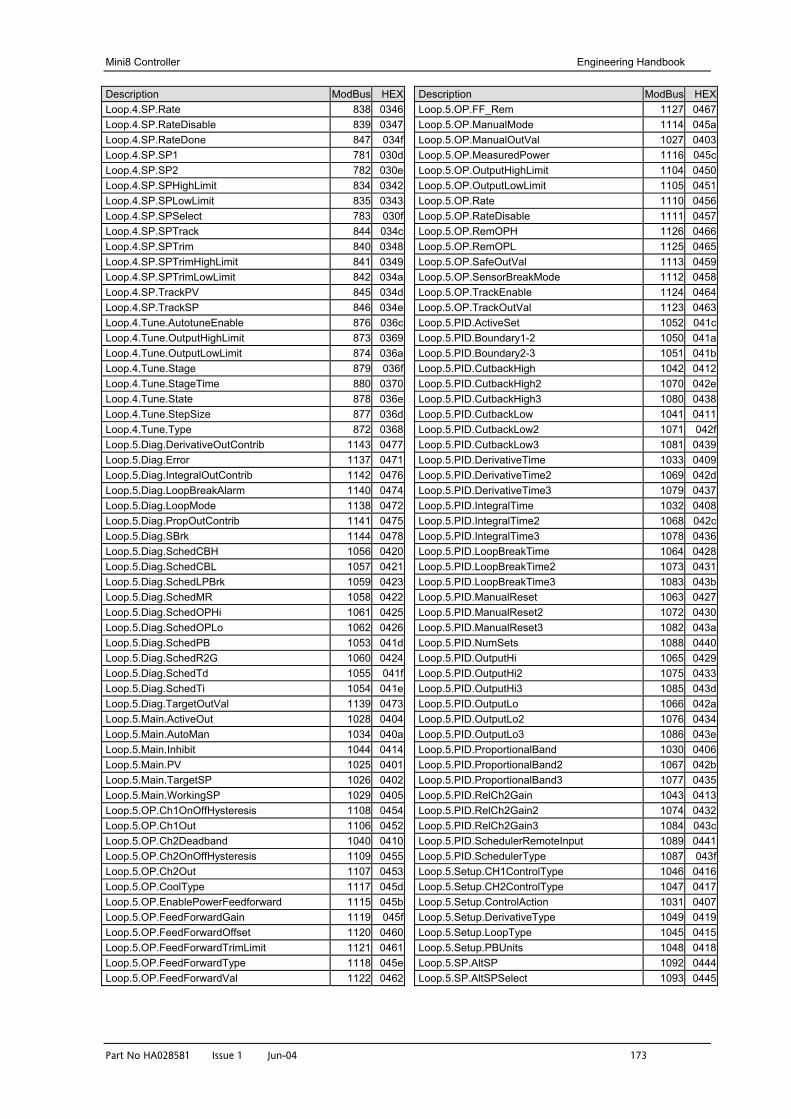
Mini8 Controller Engineering Handbook
Part No HA028581 Issue 1 Jun-04 173
Description ModBus HEXLoop.4.SP.Rate 838 0346Loop.4.SP.RateDisable 839 0347Loop.4.SP.RateDone 847 034fLoop.4.SP.SP1 781 030dLoop.4.SP.SP2 782 030eLoop.4.SP.SPHighLimit 834 0342Loop.4.SP.SPLowLimit 835 0343Loop.4.SP.SPSelect 783 030fLoop.4.SP.SPTrack 844 034cLoop.4.SP.SPTrim 840 0348Loop.4.SP.SPTrimHighLimit 841 0349Loop.4.SP.SPTrimLowLimit 842 034aLoop.4.SP.TrackPV 845 034dLoop.4.SP.TrackSP 846 034eLoop.4.Tune.AutotuneEnable 876 036cLoop.4.Tune.OutputHighLimit 873 0369Loop.4.Tune.OutputLowLimit 874 036aLoop.4.Tune.Stage 879 036fLoop.4.Tune.StageTime 880 0370Loop.4.Tune.State 878 036eLoop.4.Tune.StepSize 877 036dLoop.4.Tune.Type 872 0368Loop.5.Diag.DerivativeOutContrib 1143 0477Loop.5.Diag.Error 1137 0471Loop.5.Diag.IntegralOutContrib 1142 0476Loop.5.Diag.LoopBreakAlarm 1140 0474Loop.5.Diag.LoopMode 1138 0472Loop.5.Diag.PropOutContrib 1141 0475Loop.5.Diag.SBrk 1144 0478Loop.5.Diag.SchedCBH 1056 0420Loop.5.Diag.SchedCBL 1057 0421Loop.5.Diag.SchedLPBrk 1059 0423Loop.5.Diag.SchedMR 1058 0422Loop.5.Diag.SchedOPHi 1061 0425Loop.5.Diag.SchedOPLo 1062 0426Loop.5.Diag.SchedPB 1053 041dLoop.5.Diag.SchedR2G 1060 0424Loop.5.Diag.SchedTd 1055 041fLoop.5.Diag.SchedTi 1054 041eLoop.5.Diag.TargetOutVal 1139 0473Loop.5.Main.ActiveOut 1028 0404Loop.5.Main.AutoMan 1034 040aLoop.5.Main.Inhibit 1044 0414Loop.5.Main.PV 1025 0401Loop.5.Main.TargetSP 1026 0402Loop.5.Main.WorkingSP 1029 0405Loop.5.OP.Ch1OnOffHysteresis 1108 0454Loop.5.OP.Ch1Out 1106 0452Loop.5.OP.Ch2Deadband 1040 0410Loop.5.OP.Ch2OnOffHysteresis 1109 0455Loop.5.OP.Ch2Out 1107 0453Loop.5.OP.CoolType 1117 045dLoop.5.OP.EnablePowerFeedforward 1115 045bLoop.5.OP.FeedForwardGain 1119 045fLoop.5.OP.FeedForwardOffset 1120 0460Loop.5.OP.FeedForwardTrimLimit 1121 0461Loop.5.OP.FeedForwardType 1118 045eLoop.5.OP.FeedForwardVal 1122 0462
Description ModBus HEXLoop.5.OP.FF_Rem 1127 0467Loop.5.OP.ManualMode 1114 045aLoop.5.OP.ManualOutVal 1027 0403Loop.5.OP.MeasuredPower 1116 045cLoop.5.OP.OutputHighLimit 1104 0450Loop.5.OP.OutputLowLimit 1105 0451Loop.5.OP.Rate 1110 0456Loop.5.OP.RateDisable 1111 0457Loop.5.OP.RemOPH 1126 0466Loop.5.OP.RemOPL 1125 0465Loop.5.OP.SafeOutVal 1113 0459Loop.5.OP.SensorBreakMode 1112 0458Loop.5.OP.TrackEnable 1124 0464Loop.5.OP.TrackOutVal 1123 0463Loop.5.PID.ActiveSet 1052 041cLoop.5.PID.Boundary1-2 1050 041aLoop.5.PID.Boundary2-3 1051 041bLoop.5.PID.CutbackHigh 1042 0412Loop.5.PID.CutbackHigh2 1070 042eLoop.5.PID.CutbackHigh3 1080 0438Loop.5.PID.CutbackLow 1041 0411Loop.5.PID.CutbackLow2 1071 042fLoop.5.PID.CutbackLow3 1081 0439Loop.5.PID.DerivativeTime 1033 0409Loop.5.PID.DerivativeTime2 1069 042dLoop.5.PID.DerivativeTime3 1079 0437Loop.5.PID.IntegralTime 1032 0408Loop.5.PID.IntegralTime2 1068 042cLoop.5.PID.IntegralTime3 1078 0436Loop.5.PID.LoopBreakTime 1064 0428Loop.5.PID.LoopBreakTime2 1073 0431Loop.5.PID.LoopBreakTime3 1083 043bLoop.5.PID.ManualReset 1063 0427Loop.5.PID.ManualReset2 1072 0430Loop.5.PID.ManualReset3 1082 043aLoop.5.PID.NumSets 1088 0440Loop.5.PID.OutputHi 1065 0429Loop.5.PID.OutputHi2 1075 0433Loop.5.PID.OutputHi3 1085 043dLoop.5.PID.OutputLo 1066 042aLoop.5.PID.OutputLo2 1076 0434Loop.5.PID.OutputLo3 1086 043eLoop.5.PID.ProportionalBand 1030 0406Loop.5.PID.ProportionalBand2 1067 042bLoop.5.PID.ProportionalBand3 1077 0435Loop.5.PID.RelCh2Gain 1043 0413Loop.5.PID.RelCh2Gain2 1074 0432Loop.5.PID.RelCh2Gain3 1084 043cLoop.5.PID.SchedulerRemoteInput 1089 0441Loop.5.PID.SchedulerType 1087 043fLoop.5.Setup.CH1ControlType 1046 0416Loop.5.Setup.CH2ControlType 1047 0417Loop.5.Setup.ControlAction 1031 0407Loop.5.Setup.DerivativeType 1049 0419Loop.5.Setup.LoopType 1045 0415Loop.5.Setup.PBUnits 1048 0418Loop.5.SP.AltSP 1092 0444Loop.5.SP.AltSPSelect 1093 0445
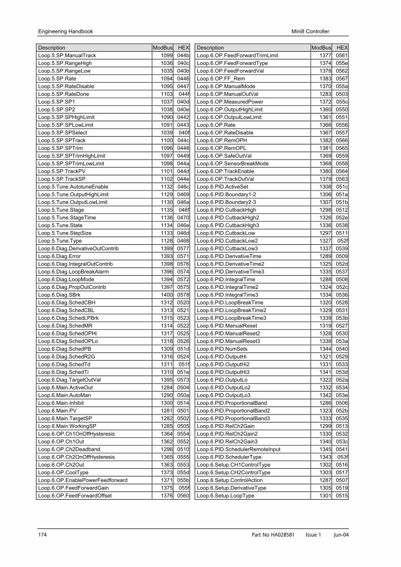
Engineering Handbook Mini8 Controller
174 Part No HA028581 Issue 1 Jun-04
Description ModBus HEXLoop.5.SP.ManualTrack 1099 044bLoop.5.SP.RangeHigh 1036 040cLoop.5.SP.RangeLow 1035 040bLoop.5.SP.Rate 1094 0446Loop.5.SP.RateDisable 1095 0447Loop.5.SP.RateDone 1103 044fLoop.5.SP.SP1 1037 040dLoop.5.SP.SP2 1038 040eLoop.5.SP.SPHighLimit 1090 0442Loop.5.SP.SPLowLimit 1091 0443Loop.5.SP.SPSelect 1039 040fLoop.5.SP.SPTrack 1100 044cLoop.5.SP.SPTrim 1096 0448Loop.5.SP.SPTrimHighLimit 1097 0449Loop.5.SP.SPTrimLowLimit 1098 044aLoop.5.SP.TrackPV 1101 044dLoop.5.SP.TrackSP 1102 044eLoop.5.Tune.AutotuneEnable 1132 046cLoop.5.Tune.OutputHighLimit 1129 0469Loop.5.Tune.OutputLowLimit 1130 046aLoop.5.Tune.Stage 1135 046fLoop.5.Tune.StageTime 1136 0470Loop.5.Tune.State 1134 046eLoop.5.Tune.StepSize 1133 046dLoop.5.Tune.Type 1128 0468Loop.6.Diag.DerivativeOutContrib 1399 0577Loop.6.Diag.Error 1393 0571Loop.6.Diag.IntegralOutContrib 1398 0576Loop.6.Diag.LoopBreakAlarm 1396 0574Loop.6.Diag.LoopMode 1394 0572Loop.6.Diag.PropOutContrib 1397 0575Loop.6.Diag.SBrk 1400 0578Loop.6.Diag.SchedCBH 1312 0520Loop.6.Diag.SchedCBL 1313 0521Loop.6.Diag.SchedLPBrk 1315 0523Loop.6.Diag.SchedMR 1314 0522Loop.6.Diag.SchedOPHi 1317 0525Loop.6.Diag.SchedOPLo 1318 0526Loop.6.Diag.SchedPB 1309 051dLoop.6.Diag.SchedR2G 1316 0524Loop.6.Diag.SchedTd 1311 051fLoop.6.Diag.SchedTi 1310 051eLoop.6.Diag.TargetOutVal 1395 0573Loop.6.Main.ActiveOut 1284 0504Loop.6.Main.AutoMan 1290 050aLoop.6.Main.Inhibit 1300 0514Loop.6.Main.PV 1281 0501Loop.6.Main.TargetSP 1282 0502Loop.6.Main.WorkingSP 1285 0505Loop.6.OP.Ch1OnOffHysteresis 1364 0554Loop.6.OP.Ch1Out 1362 0552Loop.6.OP.Ch2Deadband 1296 0510Loop.6.OP.Ch2OnOffHysteresis 1365 0555Loop.6.OP.Ch2Out 1363 0553Loop.6.OP.CoolType 1373 055dLoop.6.OP.EnablePowerFeedforward 1371 055bLoop.6.OP.FeedForwardGain 1375 055fLoop.6.OP.FeedForwardOffset 1376 0560
Description ModBus HEXLoop.6.OP.FeedForwardTrimLimit 1377 0561Loop.6.OP.FeedForwardType 1374 055eLoop.6.OP.FeedForwardVal 1378 0562Loop.6.OP.FF_Rem 1383 0567Loop.6.OP.ManualMode 1370 055aLoop.6.OP.ManualOutVal 1283 0503Loop.6.OP.MeasuredPower 1372 055cLoop.6.OP.OutputHighLimit 1360 0550Loop.6.OP.OutputLowLimit 1361 0551Loop.6.OP.Rate 1366 0556Loop.6.OP.RateDisable 1367 0557Loop.6.OP.RemOPH 1382 0566Loop.6.OP.RemOPL 1381 0565Loop.6.OP.SafeOutVal 1369 0559Loop.6.OP.SensorBreakMode 1368 0558Loop.6.OP.TrackEnable 1380 0564Loop.6.OP.TrackOutVal 1379 0563Loop.6.PID.ActiveSet 1308 051cLoop.6.PID.Boundary1-2 1306 051aLoop.6.PID.Boundary2-3 1307 051bLoop.6.PID.CutbackHigh 1298 0512Loop.6.PID.CutbackHigh2 1326 052eLoop.6.PID.CutbackHigh3 1336 0538Loop.6.PID.CutbackLow 1297 0511Loop.6.PID.CutbackLow2 1327 052fLoop.6.PID.CutbackLow3 1337 0539Loop.6.PID.DerivativeTime 1289 0509Loop.6.PID.DerivativeTime2 1325 052dLoop.6.PID.DerivativeTime3 1335 0537Loop.6.PID.IntegralTime 1288 0508Loop.6.PID.IntegralTime2 1324 052cLoop.6.PID.IntegralTime3 1334 0536Loop.6.PID.LoopBreakTime 1320 0528Loop.6.PID.LoopBreakTime2 1329 0531Loop.6.PID.LoopBreakTime3 1339 053bLoop.6.PID.ManualReset 1319 0527Loop.6.PID.ManualReset2 1328 0530Loop.6.PID.ManualReset3 1338 053aLoop.6.PID.NumSets 1344 0540Loop.6.PID.OutputHi 1321 0529Loop.6.PID.OutputHi2 1331 0533Loop.6.PID.OutputHi3 1341 053dLoop.6.PID.OutputLo 1322 052aLoop.6.PID.OutputLo2 1332 0534Loop.6.PID.OutputLo3 1342 053eLoop.6.PID.ProportionalBand 1286 0506Loop.6.PID.ProportionalBand2 1323 052bLoop.6.PID.ProportionalBand3 1333 0535Loop.6.PID.RelCh2Gain 1299 0513Loop.6.PID.RelCh2Gain2 1330 0532Loop.6.PID.RelCh2Gain3 1340 053cLoop.6.PID.SchedulerRemoteInput 1345 0541Loop.6.PID.SchedulerType 1343 053fLoop.6.Setup.CH1ControlType 1302 0516Loop.6.Setup.CH2ControlType 1303 0517Loop.6.Setup.ControlAction 1287 0507Loop.6.Setup.DerivativeType 1305 0519Loop.6.Setup.LoopType 1301 0515
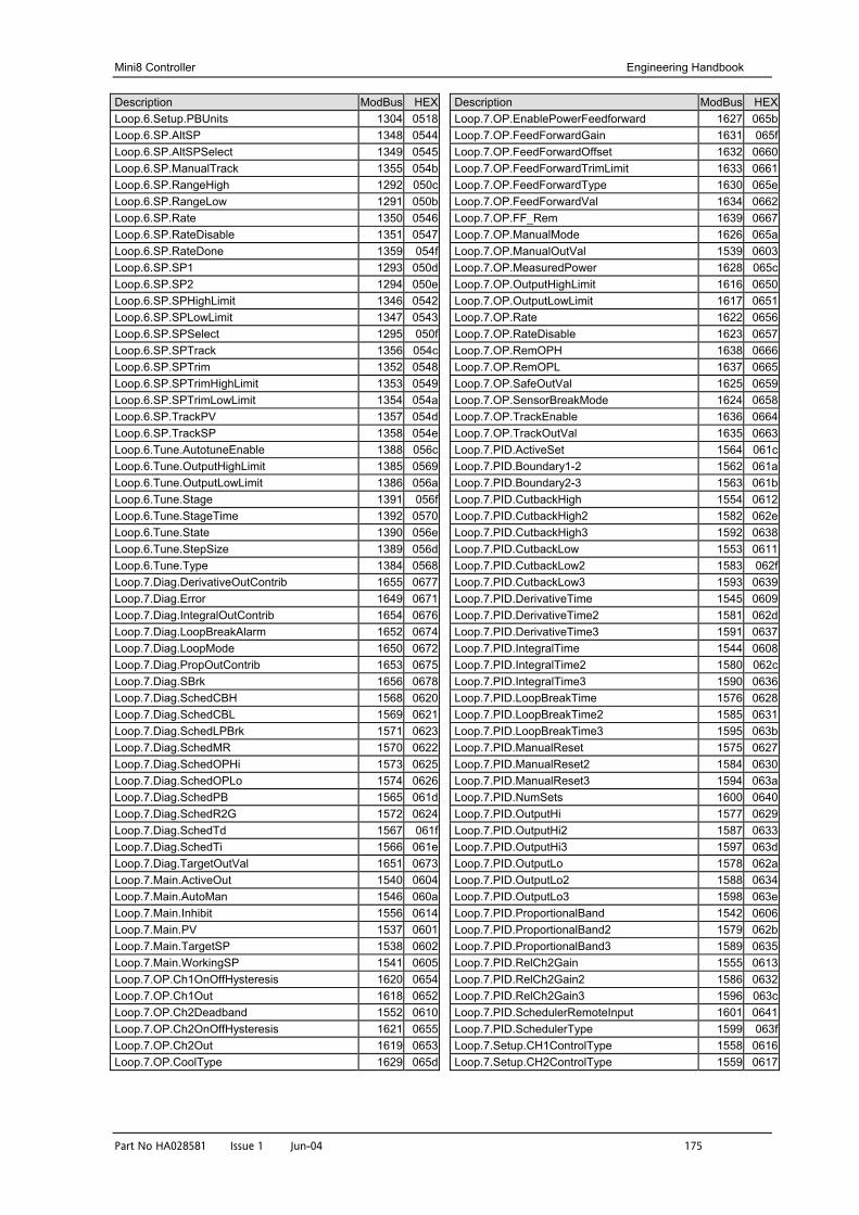
Mini8 Controller Engineering Handbook
Part No HA028581 Issue 1 Jun-04 175
Description ModBus HEXLoop.6.Setup.PBUnits 1304 0518Loop.6.SP.AltSP 1348 0544Loop.6.SP.AltSPSelect 1349 0545Loop.6.SP.ManualTrack 1355 054bLoop.6.SP.RangeHigh 1292 050cLoop.6.SP.RangeLow 1291 050bLoop.6.SP.Rate 1350 0546Loop.6.SP.RateDisable 1351 0547Loop.6.SP.RateDone 1359 054fLoop.6.SP.SP1 1293 050dLoop.6.SP.SP2 1294 050eLoop.6.SP.SPHighLimit 1346 0542Loop.6.SP.SPLowLimit 1347 0543Loop.6.SP.SPSelect 1295 050fLoop.6.SP.SPTrack 1356 054cLoop.6.SP.SPTrim 1352 0548Loop.6.SP.SPTrimHighLimit 1353 0549Loop.6.SP.SPTrimLowLimit 1354 054aLoop.6.SP.TrackPV 1357 054dLoop.6.SP.TrackSP 1358 054eLoop.6.Tune.AutotuneEnable 1388 056cLoop.6.Tune.OutputHighLimit 1385 0569Loop.6.Tune.OutputLowLimit 1386 056aLoop.6.Tune.Stage 1391 056fLoop.6.Tune.StageTime 1392 0570Loop.6.Tune.State 1390 056eLoop.6.Tune.StepSize 1389 056dLoop.6.Tune.Type 1384 0568Loop.7.Diag.DerivativeOutContrib 1655 0677Loop.7.Diag.Error 1649 0671Loop.7.Diag.IntegralOutContrib 1654 0676Loop.7.Diag.LoopBreakAlarm 1652 0674Loop.7.Diag.LoopMode 1650 0672Loop.7.Diag.PropOutContrib 1653 0675Loop.7.Diag.SBrk 1656 0678Loop.7.Diag.SchedCBH 1568 0620Loop.7.Diag.SchedCBL 1569 0621Loop.7.Diag.SchedLPBrk 1571 0623Loop.7.Diag.SchedMR 1570 0622Loop.7.Diag.SchedOPHi 1573 0625Loop.7.Diag.SchedOPLo 1574 0626Loop.7.Diag.SchedPB 1565 061dLoop.7.Diag.SchedR2G 1572 0624Loop.7.Diag.SchedTd 1567 061fLoop.7.Diag.SchedTi 1566 061eLoop.7.Diag.TargetOutVal 1651 0673Loop.7.Main.ActiveOut 1540 0604Loop.7.Main.AutoMan 1546 060aLoop.7.Main.Inhibit 1556 0614Loop.7.Main.PV 1537 0601Loop.7.Main.TargetSP 1538 0602Loop.7.Main.WorkingSP 1541 0605Loop.7.OP.Ch1OnOffHysteresis 1620 0654Loop.7.OP.Ch1Out 1618 0652Loop.7.OP.Ch2Deadband 1552 0610Loop.7.OP.Ch2OnOffHysteresis 1621 0655Loop.7.OP.Ch2Out 1619 0653Loop.7.OP.CoolType 1629 065d
Description ModBus HEXLoop.7.OP.EnablePowerFeedforward 1627 065bLoop.7.OP.FeedForwardGain 1631 065fLoop.7.OP.FeedForwardOffset 1632 0660Loop.7.OP.FeedForwardTrimLimit 1633 0661Loop.7.OP.FeedForwardType 1630 065eLoop.7.OP.FeedForwardVal 1634 0662Loop.7.OP.FF_Rem 1639 0667Loop.7.OP.ManualMode 1626 065aLoop.7.OP.ManualOutVal 1539 0603Loop.7.OP.MeasuredPower 1628 065cLoop.7.OP.OutputHighLimit 1616 0650Loop.7.OP.OutputLowLimit 1617 0651Loop.7.OP.Rate 1622 0656Loop.7.OP.RateDisable 1623 0657Loop.7.OP.RemOPH 1638 0666Loop.7.OP.RemOPL 1637 0665Loop.7.OP.SafeOutVal 1625 0659Loop.7.OP.SensorBreakMode 1624 0658Loop.7.OP.TrackEnable 1636 0664Loop.7.OP.TrackOutVal 1635 0663Loop.7.PID.ActiveSet 1564 061cLoop.7.PID.Boundary1-2 1562 061aLoop.7.PID.Boundary2-3 1563 061bLoop.7.PID.CutbackHigh 1554 0612Loop.7.PID.CutbackHigh2 1582 062eLoop.7.PID.CutbackHigh3 1592 0638Loop.7.PID.CutbackLow 1553 0611Loop.7.PID.CutbackLow2 1583 062fLoop.7.PID.CutbackLow3 1593 0639Loop.7.PID.DerivativeTime 1545 0609Loop.7.PID.DerivativeTime2 1581 062dLoop.7.PID.DerivativeTime3 1591 0637Loop.7.PID.IntegralTime 1544 0608Loop.7.PID.IntegralTime2 1580 062cLoop.7.PID.IntegralTime3 1590 0636Loop.7.PID.LoopBreakTime 1576 0628Loop.7.PID.LoopBreakTime2 1585 0631Loop.7.PID.LoopBreakTime3 1595 063bLoop.7.PID.ManualReset 1575 0627Loop.7.PID.ManualReset2 1584 0630Loop.7.PID.ManualReset3 1594 063aLoop.7.PID.NumSets 1600 0640Loop.7.PID.OutputHi 1577 0629Loop.7.PID.OutputHi2 1587 0633Loop.7.PID.OutputHi3 1597 063dLoop.7.PID.OutputLo 1578 062aLoop.7.PID.OutputLo2 1588 0634Loop.7.PID.OutputLo3 1598 063eLoop.7.PID.ProportionalBand 1542 0606Loop.7.PID.ProportionalBand2 1579 062bLoop.7.PID.ProportionalBand3 1589 0635Loop.7.PID.RelCh2Gain 1555 0613Loop.7.PID.RelCh2Gain2 1586 0632Loop.7.PID.RelCh2Gain3 1596 063cLoop.7.PID.SchedulerRemoteInput 1601 0641Loop.7.PID.SchedulerType 1599 063fLoop.7.Setup.CH1ControlType 1558 0616Loop.7.Setup.CH2ControlType 1559 0617
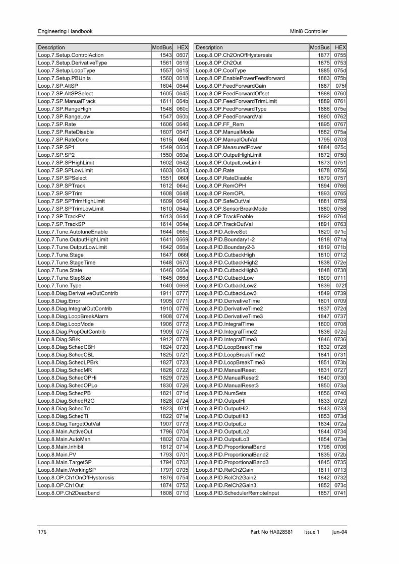
Engineering Handbook Mini8 Controller
176 Part No HA028581 Issue 1 Jun-04
Description ModBus HEXLoop.7.Setup.ControlAction 1543 0607Loop.7.Setup.DerivativeType 1561 0619Loop.7.Setup.LoopType 1557 0615Loop.7.Setup.PBUnits 1560 0618Loop.7.SP.AltSP 1604 0644Loop.7.SP.AltSPSelect 1605 0645Loop.7.SP.ManualTrack 1611 064bLoop.7.SP.RangeHigh 1548 060cLoop.7.SP.RangeLow 1547 060bLoop.7.SP.Rate 1606 0646Loop.7.SP.RateDisable 1607 0647Loop.7.SP.RateDone 1615 064fLoop.7.SP.SP1 1549 060dLoop.7.SP.SP2 1550 060eLoop.7.SP.SPHighLimit 1602 0642Loop.7.SP.SPLowLimit 1603 0643Loop.7.SP.SPSelect 1551 060fLoop.7.SP.SPTrack 1612 064cLoop.7.SP.SPTrim 1608 0648Loop.7.SP.SPTrimHighLimit 1609 0649Loop.7.SP.SPTrimLowLimit 1610 064aLoop.7.SP.TrackPV 1613 064dLoop.7.SP.TrackSP 1614 064eLoop.7.Tune.AutotuneEnable 1644 066cLoop.7.Tune.OutputHighLimit 1641 0669Loop.7.Tune.OutputLowLimit 1642 066aLoop.7.Tune.Stage 1647 066fLoop.7.Tune.StageTime 1648 0670Loop.7.Tune.State 1646 066eLoop.7.Tune.StepSize 1645 066dLoop.7.Tune.Type 1640 0668Loop.8.Diag.DerivativeOutContrib 1911 0777Loop.8.Diag.Error 1905 0771Loop.8.Diag.IntegralOutContrib 1910 0776Loop.8.Diag.LoopBreakAlarm 1908 0774Loop.8.Diag.LoopMode 1906 0772Loop.8.Diag.PropOutContrib 1909 0775Loop.8.Diag.SBrk 1912 0778Loop.8.Diag.SchedCBH 1824 0720Loop.8.Diag.SchedCBL 1825 0721Loop.8.Diag.SchedLPBrk 1827 0723Loop.8.Diag.SchedMR 1826 0722Loop.8.Diag.SchedOPHi 1829 0725Loop.8.Diag.SchedOPLo 1830 0726Loop.8.Diag.SchedPB 1821 071dLoop.8.Diag.SchedR2G 1828 0724Loop.8.Diag.SchedTd 1823 071fLoop.8.Diag.SchedTi 1822 071eLoop.8.Diag.TargetOutVal 1907 0773Loop.8.Main.ActiveOut 1796 0704Loop.8.Main.AutoMan 1802 070aLoop.8.Main.Inhibit 1812 0714Loop.8.Main.PV 1793 0701Loop.8.Main.TargetSP 1794 0702Loop.8.Main.WorkingSP 1797 0705Loop.8.OP.Ch1OnOffHysteresis 1876 0754Loop.8.OP.Ch1Out 1874 0752Loop.8.OP.Ch2Deadband 1808 0710
Description ModBus HEXLoop.8.OP.Ch2OnOffHysteresis 1877 0755Loop.8.OP.Ch2Out 1875 0753Loop.8.OP.CoolType 1885 075dLoop.8.OP.EnablePowerFeedforward 1883 075bLoop.8.OP.FeedForwardGain 1887 075fLoop.8.OP.FeedForwardOffset 1888 0760Loop.8.OP.FeedForwardTrimLimit 1889 0761Loop.8.OP.FeedForwardType 1886 075eLoop.8.OP.FeedForwardVal 1890 0762Loop.8.OP.FF_Rem 1895 0767Loop.8.OP.ManualMode 1882 075aLoop.8.OP.ManualOutVal 1795 0703Loop.8.OP.MeasuredPower 1884 075cLoop.8.OP.OutputHighLimit 1872 0750Loop.8.OP.OutputLowLimit 1873 0751Loop.8.OP.Rate 1878 0756Loop.8.OP.RateDisable 1879 0757Loop.8.OP.RemOPH 1894 0766Loop.8.OP.RemOPL 1893 0765Loop.8.OP.SafeOutVal 1881 0759Loop.8.OP.SensorBreakMode 1880 0758Loop.8.OP.TrackEnable 1892 0764Loop.8.OP.TrackOutVal 1891 0763Loop.8.PID.ActiveSet 1820 071cLoop.8.PID.Boundary1-2 1818 071aLoop.8.PID.Boundary2-3 1819 071bLoop.8.PID.CutbackHigh 1810 0712Loop.8.PID.CutbackHigh2 1838 072eLoop.8.PID.CutbackHigh3 1848 0738Loop.8.PID.CutbackLow 1809 0711Loop.8.PID.CutbackLow2 1839 072fLoop.8.PID.CutbackLow3 1849 0739Loop.8.PID.DerivativeTime 1801 0709Loop.8.PID.DerivativeTime2 1837 072dLoop.8.PID.DerivativeTime3 1847 0737Loop.8.PID.IntegralTime 1800 0708Loop.8.PID.IntegralTime2 1836 072cLoop.8.PID.IntegralTime3 1846 0736Loop.8.PID.LoopBreakTime 1832 0728Loop.8.PID.LoopBreakTime2 1841 0731Loop.8.PID.LoopBreakTime3 1851 073bLoop.8.PID.ManualReset 1831 0727Loop.8.PID.ManualReset2 1840 0730Loop.8.PID.ManualReset3 1850 073aLoop.8.PID.NumSets 1856 0740Loop.8.PID.OutputHi 1833 0729Loop.8.PID.OutputHi2 1843 0733Loop.8.PID.OutputHi3 1853 073dLoop.8.PID.OutputLo 1834 072aLoop.8.PID.OutputLo2 1844 0734Loop.8.PID.OutputLo3 1854 073eLoop.8.PID.ProportionalBand 1798 0706Loop.8.PID.ProportionalBand2 1835 072bLoop.8.PID.ProportionalBand3 1845 0735Loop.8.PID.RelCh2Gain 1811 0713Loop.8.PID.RelCh2Gain2 1842 0732Loop.8.PID.RelCh2Gain3 1852 073cLoop.8.PID.SchedulerRemoteInput 1857 0741
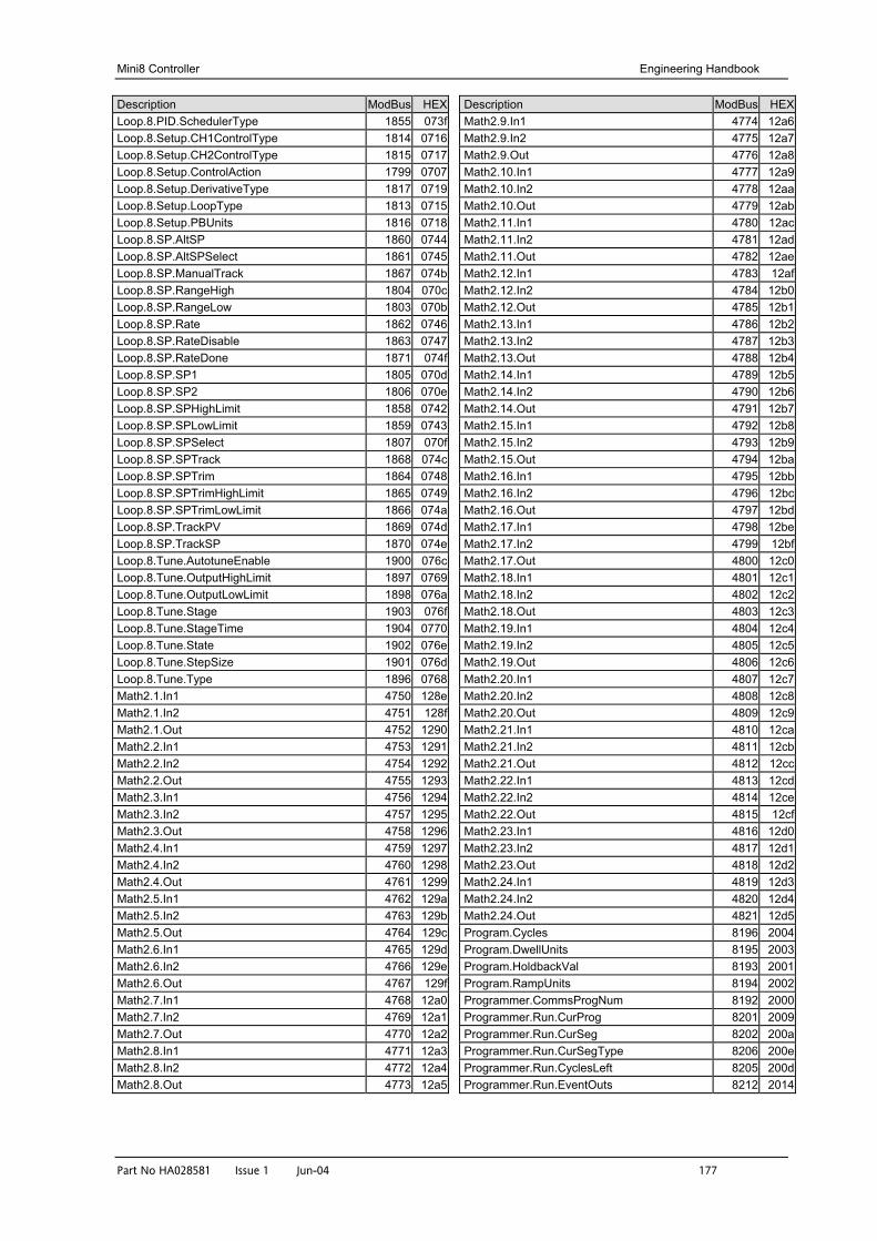
Mini8 Controller Engineering Handbook
Part No HA028581 Issue 1 Jun-04 177
Description ModBus HEXLoop.8.PID.SchedulerType 1855 073fLoop.8.Setup.CH1ControlType 1814 0716Loop.8.Setup.CH2ControlType 1815 0717Loop.8.Setup.ControlAction 1799 0707Loop.8.Setup.DerivativeType 1817 0719Loop.8.Setup.LoopType 1813 0715Loop.8.Setup.PBUnits 1816 0718Loop.8.SP.AltSP 1860 0744Loop.8.SP.AltSPSelect 1861 0745Loop.8.SP.ManualTrack 1867 074bLoop.8.SP.RangeHigh 1804 070cLoop.8.SP.RangeLow 1803 070bLoop.8.SP.Rate 1862 0746Loop.8.SP.RateDisable 1863 0747Loop.8.SP.RateDone 1871 074fLoop.8.SP.SP1 1805 070dLoop.8.SP.SP2 1806 070eLoop.8.SP.SPHighLimit 1858 0742Loop.8.SP.SPLowLimit 1859 0743Loop.8.SP.SPSelect 1807 070fLoop.8.SP.SPTrack 1868 074cLoop.8.SP.SPTrim 1864 0748Loop.8.SP.SPTrimHighLimit 1865 0749Loop.8.SP.SPTrimLowLimit 1866 074aLoop.8.SP.TrackPV 1869 074dLoop.8.SP.TrackSP 1870 074eLoop.8.Tune.AutotuneEnable 1900 076cLoop.8.Tune.OutputHighLimit 1897 0769Loop.8.Tune.OutputLowLimit 1898 076aLoop.8.Tune.Stage 1903 076fLoop.8.Tune.StageTime 1904 0770Loop.8.Tune.State 1902 076eLoop.8.Tune.StepSize 1901 076dLoop.8.Tune.Type 1896 0768Math2.1.In1 4750 128eMath2.1.In2 4751 128fMath2.1.Out 4752 1290Math2.2.In1 4753 1291Math2.2.In2 4754 1292Math2.2.Out 4755 1293Math2.3.In1 4756 1294Math2.3.In2 4757 1295Math2.3.Out 4758 1296Math2.4.In1 4759 1297Math2.4.In2 4760 1298Math2.4.Out 4761 1299Math2.5.In1 4762 129aMath2.5.In2 4763 129bMath2.5.Out 4764 129cMath2.6.In1 4765 129dMath2.6.In2 4766 129eMath2.6.Out 4767 129fMath2.7.In1 4768 12a0Math2.7.In2 4769 12a1Math2.7.Out 4770 12a2Math2.8.In1 4771 12a3Math2.8.In2 4772 12a4Math2.8.Out 4773 12a5
Description ModBus HEXMath2.9.In1 4774 12a6Math2.9.In2 4775 12a7Math2.9.Out 4776 12a8Math2.10.In1 4777 12a9Math2.10.In2 4778 12aaMath2.10.Out 4779 12abMath2.11.In1 4780 12acMath2.11.In2 4781 12adMath2.11.Out 4782 12aeMath2.12.In1 4783 12afMath2.12.In2 4784 12b0Math2.12.Out 4785 12b1Math2.13.In1 4786 12b2Math2.13.In2 4787 12b3Math2.13.Out 4788 12b4Math2.14.In1 4789 12b5Math2.14.In2 4790 12b6Math2.14.Out 4791 12b7Math2.15.In1 4792 12b8Math2.15.In2 4793 12b9Math2.15.Out 4794 12baMath2.16.In1 4795 12bbMath2.16.In2 4796 12bcMath2.16.Out 4797 12bdMath2.17.In1 4798 12beMath2.17.In2 4799 12bfMath2.17.Out 4800 12c0Math2.18.In1 4801 12c1Math2.18.In2 4802 12c2Math2.18.Out 4803 12c3Math2.19.In1 4804 12c4Math2.19.In2 4805 12c5Math2.19.Out 4806 12c6Math2.20.In1 4807 12c7Math2.20.In2 4808 12c8Math2.20.Out 4809 12c9Math2.21.In1 4810 12caMath2.21.In2 4811 12cbMath2.21.Out 4812 12ccMath2.22.In1 4813 12cdMath2.22.In2 4814 12ceMath2.22.Out 4815 12cfMath2.23.In1 4816 12d0Math2.23.In2 4817 12d1Math2.23.Out 4818 12d2Math2.24.In1 4819 12d3Math2.24.In2 4820 12d4Math2.24.Out 4821 12d5Program.Cycles 8196 2004Program.DwellUnits 8195 2003Program.HoldbackVal 8193 2001Program.RampUnits 8194 2002Programmer.CommsProgNum 8192 2000Programmer.Run.CurProg 8201 2009Programmer.Run.CurSeg 8202 200aProgrammer.Run.CurSegType 8206 200eProgrammer.Run.CyclesLeft 8205 200dProgrammer.Run.EventOuts 8212 2014

Engineering Handbook Mini8 Controller
178 Part No HA028581 Issue 1 Jun-04
Description ModBus HEXProgrammer.Run.FastRun 8216 2018Programmer.Run.ProgStatus 8203 200bProgrammer.Run.ProgTimeLeft 8209 2011Programmer.Run.PSP 8204 200cProgrammer.Run.ResetEventOuts 8200 2008Programmer.Run.SegRate 8208 2010Programmer.Run.SegTarget 8207 200fProgrammer.Run.SegTimeLeft 8213 2015Programmer.Setup.AdvSeg 8217 2019Programmer.Setup.EndOfSeg 8214 2016Programmer.Setup.PowerFailAct 8197 2005Programmer.Setup.PVIn 8210 2012Programmer.Setup.Servo 8198 2006Programmer.Setup.SkipSeg 8218 201aProgrammer.Setup.SPIn 8211 2013Programmer.Setup.SyncIn 8215 2017Programmer.Setup.SyncMode 8199 2007Recipe.LastDataset 4913 1331Recipe.LoadingStatus 4914 1332Recipe.RecipeSelect 4912 1330Segment.1.CallCycles 8259 2043Segment.1.CallProg 8258 2042Segment.1.Duration 8260 2044Segment.1.EndType 8263 2047Segment.1.EventOuts 8264 2048Segment.1.Holdback 8257 2041Segment.1.RampRate 8261 2045Segment.1.SegType 8256 2040Segment.1.TargetSP 8262 2046Segment.2.CallCycles 8275 2053Segment.2.CallProg 8274 2052Segment.2.Duration 8276 2054Segment.2.EndType 8279 2057Segment.2.EventOuts 8280 2058Segment.2.Holdback 8273 2051Segment.2.RampRate 8277 2055Segment.2.SegType 8272 2050Segment.2.TargetSP 8278 2056Segment.3.CallCycles 8291 2063Segment.3.CallProg 8290 2062Segment.3.Duration 8292 2064Segment.3.EndType 8295 2067Segment.3.EventOuts 8296 2068Segment.3.Holdback 8289 2061Segment.3.RampRate 8293 2065Segment.3.SegType 8288 2060Segment.3.TargetSP 8294 2066Segment.4.CallCycles 8307 2073Segment.4.CallProg 8306 2072Segment.4.Duration 8308 2074Segment.4.EndType 8311 2077Segment.4.EventOuts 8312 2078Segment.4.Holdback 8305 2071Segment.4.RampRate 8309 2075Segment.4.SegType 8304 2070Segment.4.TargetSP 8310 2076Segment.5.CallCycles 8323 2083Segment.5.CallProg 8322 2082
Description ModBus HEXSegment.5.Duration 8324 2084Segment.5.EndType 8327 2087Segment.5.EventOuts 8328 2088Segment.5.Holdback 8321 2081Segment.5.RampRate 8325 2085Segment.5.SegType 8320 2080Segment.5.TargetSP 8326 2086Segment.6.CallCycles 8339 2093Segment.6.CallProg 8338 2092Segment.6.Duration 8340 2094Segment.6.EndType 8343 2097Segment.6.EventOuts 8344 2098Segment.6.Holdback 8337 2091Segment.6.RampRate 8341 2095Segment.6.SegType 8336 2090Segment.6.TargetSP 8342 2096Segment.7.CallCycles 8355 20a3Segment.7.CallProg 8354 20a2Segment.7.Duration 8356 20a4Segment.7.EndType 8359 20a7Segment.7.EventOuts 8360 20a8Segment.7.Holdback 8353 20a1Segment.7.RampRate 8357 20a5Segment.7.SegType 8352 20a0Segment.7.TargetSP 8358 20a6Segment.8.CallCycles 8371 20b3Segment.8.CallProg 8370 20b2Segment.8.Duration 8372 20b4Segment.8.EndType 8375 20b7Segment.8.EventOuts 8376 20b8Segment.8.Holdback 8369 20b1Segment.8.RampRate 8373 20b5Segment.8.SegType 8368 20b0Segment.8.TargetSP 8374 20b6Segment.9.CallCycles 8387 20c3Segment.9.CallProg 8386 20c2Segment.9.Duration 8388 20c4Segment.9.EndType 8391 20c7Segment.9.EventOuts 8392 20c8Segment.9.Holdback 8385 20c1Segment.9.RampRate 8389 20c5Segment.9.SegType 8384 20c0Segment.9.TargetSP 8390 20c6Segment.10.CallCycles 8403 20d3Segment.10.CallProg 8402 20d2Segment.10.Duration 8404 20d4Segment.10.EndType 8407 20d7Segment.10.EventOuts 8408 20d8Segment.10.Holdback 8401 20d1Segment.10.RampRate 8405 20d5Segment.10.SegType 8400 20d0Segment.10.TargetSP 8406 20d6Segment.11.CallCycles 8419 20e3Segment.11.CallProg 8418 20e2Segment.11.Duration 8420 20e4Segment.11.EndType 8423 20e7Segment.11.EventOuts 8424 20e8Segment.11.Holdback 8417 20e1

Mini8 Controller Engineering Handbook
Part No HA028581 Issue 1 Jun-04 179
Description ModBus HEXSegment.11.RampRate 8421 20e5Segment.11.SegType 8416 20e0Segment.11.TargetSP 8422 20e6Segment.12.CallCycles 8435 20f3Segment.12.CallProg 8434 20f2Segment.12.Duration 8436 20f4Segment.12.EndType 8439 20f7Segment.12.EventOuts 8440 20f8Segment.12.Holdback 8433 20f1Segment.12.RampRate 8437 20f5Segment.12.SegType 8432 20f0Segment.12.TargetSP 8438 20f6Segment.13.CallCycles 8451 2103Segment.13.CallProg 8450 2102Segment.13.Duration 8452 2104Segment.13.EndType 8455 2107Segment.13.EventOuts 8456 2108Segment.13.Holdback 8449 2101Segment.13.RampRate 8453 2105Segment.13.SegType 8448 2100Segment.13.TargetSP 8454 2106Segment.14.CallCycles 8467 2113Segment.14.CallProg 8466 2112Segment.14.Duration 8468 2114Segment.14.EndType 8471 2117Segment.14.EventOuts 8472 2118Segment.14.Holdback 8465 2111Segment.14.RampRate 8469 2115Segment.14.SegType 8464 2110Segment.14.TargetSP 8470 2116Segment.15.CallCycles 8483 2123Segment.15.CallProg 8482 2122Segment.15.Duration 8484 2124Segment.15.EndType 8487 2127Segment.15.EventOuts 8488 2128Segment.15.Holdback 8481 2121Segment.15.RampRate 8485 2125Segment.15.SegType 8480 2120Segment.15.TargetSP 8486 2126Segment.16.CallCycles 8499 2133Segment.16.CallProg 8498 2132Segment.16.Duration 8500 2134Segment.16.EndType 8503 2137Segment.16.EventOuts 8504 2138Segment.16.Holdback 8497 2131Segment.16.RampRate 8501 2135Segment.16.SegType 8496 2130Segment.16.TargetSP 8502 2136Segment.17.CallCycles 8515 2143Segment.17.CallProg 8514 2142Segment.17.Duration 8516 2144Segment.17.EndType 8519 2147Segment.17.EventOuts 8520 2148Segment.17.Holdback 8513 2141Segment.17.RampRate 8517 2145Segment.17.SegType 8512 2140Segment.17.TargetSP 8518 2146Segment.18.CallCycles 8531 2153
Description ModBus HEXSegment.18.CallProg 8530 2152Segment.18.Duration 8532 2154Segment.18.EndType 8535 2157Segment.18.EventOuts 8536 2158Segment.18.Holdback 8529 2151Segment.18.RampRate 8533 2155Segment.18.SegType 8528 2150Segment.18.TargetSP 8534 2156Segment.19.CallCycles 8547 2163Segment.19.CallProg 8546 2162Segment.19.Duration 8548 2164Segment.19.EndType 8551 2167Segment.19.EventOuts 8552 2168Segment.19.Holdback 8545 2161Segment.19.RampRate 8549 2165Segment.19.SegType 8544 2160Segment.19.TargetSP 8550 2166Segment.20.CallCycles 8563 2173Segment.20.CallProg 8562 2172Segment.20.Duration 8564 2174Segment.20.EndType 8567 2177Segment.20.EventOuts 8568 2178Segment.20.Holdback 8561 2171Segment.20.RampRate 8565 2175Segment.20.SegType 8560 2170Segment.20.TargetSP 8566 2176Segment.21.CallCycles 8579 2183Segment.21.CallProg 8578 2182Segment.21.Duration 8580 2184Segment.21.EndType 8583 2187Segment.21.EventOuts 8584 2188Segment.21.Holdback 8577 2181Segment.21.RampRate 8581 2185Segment.21.SegType 8576 2180Segment.21.TargetSP 8582 2186Segment.22.CallCycles 8595 2193Segment.22.CallProg 8594 2192Segment.22.Duration 8596 2194Segment.22.EndType 8599 2197Segment.22.EventOuts 8600 2198Segment.22.Holdback 8593 2191Segment.22.RampRate 8597 2195Segment.22.SegType 8592 2190Segment.22.TargetSP 8598 2196Segment.23.CallCycles 8611 21a3Segment.23.CallProg 8610 21a2Segment.23.Duration 8612 21a4Segment.23.EndType 8615 21a7Segment.23.EventOuts 8616 21a8Segment.23.Holdback 8609 21a1Segment.23.RampRate 8613 21a5Segment.23.SegType 8608 21a0Segment.23.TargetSP 8614 21a6Segment.24.CallCycles 8627 21b3Segment.24.CallProg 8626 21b2Segment.24.Duration 8628 21b4Segment.24.EndType 8631 21b7Segment.24.EventOuts 8632 21b8
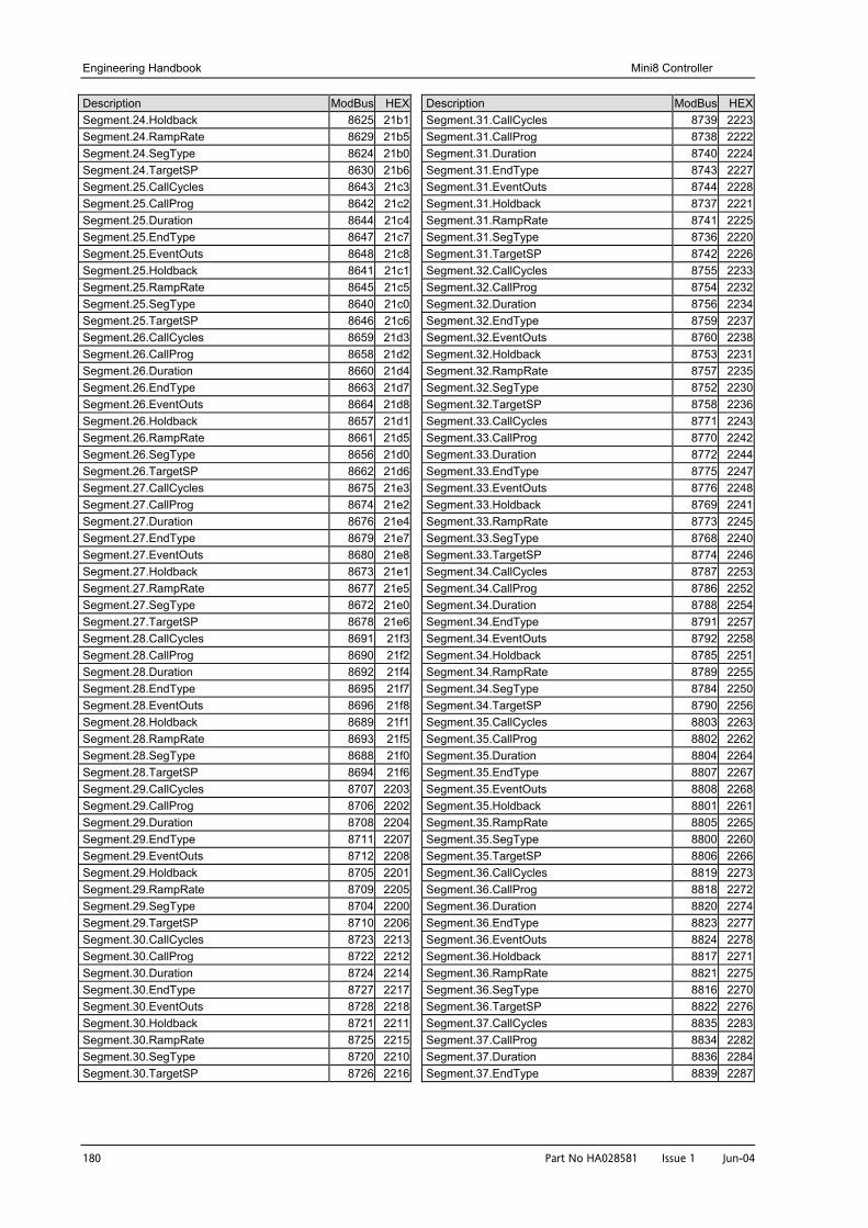
Engineering Handbook Mini8 Controller
180 Part No HA028581 Issue 1 Jun-04
Description ModBus HEXSegment.24.Holdback 8625 21b1Segment.24.RampRate 8629 21b5Segment.24.SegType 8624 21b0Segment.24.TargetSP 8630 21b6Segment.25.CallCycles 8643 21c3Segment.25.CallProg 8642 21c2Segment.25.Duration 8644 21c4Segment.25.EndType 8647 21c7Segment.25.EventOuts 8648 21c8Segment.25.Holdback 8641 21c1Segment.25.RampRate 8645 21c5Segment.25.SegType 8640 21c0Segment.25.TargetSP 8646 21c6Segment.26.CallCycles 8659 21d3Segment.26.CallProg 8658 21d2Segment.26.Duration 8660 21d4Segment.26.EndType 8663 21d7Segment.26.EventOuts 8664 21d8Segment.26.Holdback 8657 21d1Segment.26.RampRate 8661 21d5Segment.26.SegType 8656 21d0Segment.26.TargetSP 8662 21d6Segment.27.CallCycles 8675 21e3Segment.27.CallProg 8674 21e2Segment.27.Duration 8676 21e4Segment.27.EndType 8679 21e7Segment.27.EventOuts 8680 21e8Segment.27.Holdback 8673 21e1Segment.27.RampRate 8677 21e5Segment.27.SegType 8672 21e0Segment.27.TargetSP 8678 21e6Segment.28.CallCycles 8691 21f3Segment.28.CallProg 8690 21f2Segment.28.Duration 8692 21f4Segment.28.EndType 8695 21f7Segment.28.EventOuts 8696 21f8Segment.28.Holdback 8689 21f1Segment.28.RampRate 8693 21f5Segment.28.SegType 8688 21f0Segment.28.TargetSP 8694 21f6Segment.29.CallCycles 8707 2203Segment.29.CallProg 8706 2202Segment.29.Duration 8708 2204Segment.29.EndType 8711 2207Segment.29.EventOuts 8712 2208Segment.29.Holdback 8705 2201Segment.29.RampRate 8709 2205Segment.29.SegType 8704 2200Segment.29.TargetSP 8710 2206Segment.30.CallCycles 8723 2213Segment.30.CallProg 8722 2212Segment.30.Duration 8724 2214Segment.30.EndType 8727 2217Segment.30.EventOuts 8728 2218Segment.30.Holdback 8721 2211Segment.30.RampRate 8725 2215Segment.30.SegType 8720 2210Segment.30.TargetSP 8726 2216
Description ModBus HEXSegment.31.CallCycles 8739 2223Segment.31.CallProg 8738 2222Segment.31.Duration 8740 2224Segment.31.EndType 8743 2227Segment.31.EventOuts 8744 2228Segment.31.Holdback 8737 2221Segment.31.RampRate 8741 2225Segment.31.SegType 8736 2220Segment.31.TargetSP 8742 2226Segment.32.CallCycles 8755 2233Segment.32.CallProg 8754 2232Segment.32.Duration 8756 2234Segment.32.EndType 8759 2237Segment.32.EventOuts 8760 2238Segment.32.Holdback 8753 2231Segment.32.RampRate 8757 2235Segment.32.SegType 8752 2230Segment.32.TargetSP 8758 2236Segment.33.CallCycles 8771 2243Segment.33.CallProg 8770 2242Segment.33.Duration 8772 2244Segment.33.EndType 8775 2247Segment.33.EventOuts 8776 2248Segment.33.Holdback 8769 2241Segment.33.RampRate 8773 2245Segment.33.SegType 8768 2240Segment.33.TargetSP 8774 2246Segment.34.CallCycles 8787 2253Segment.34.CallProg 8786 2252Segment.34.Duration 8788 2254Segment.34.EndType 8791 2257Segment.34.EventOuts 8792 2258Segment.34.Holdback 8785 2251Segment.34.RampRate 8789 2255Segment.34.SegType 8784 2250Segment.34.TargetSP 8790 2256Segment.35.CallCycles 8803 2263Segment.35.CallProg 8802 2262Segment.35.Duration 8804 2264Segment.35.EndType 8807 2267Segment.35.EventOuts 8808 2268Segment.35.Holdback 8801 2261Segment.35.RampRate 8805 2265Segment.35.SegType 8800 2260Segment.35.TargetSP 8806 2266Segment.36.CallCycles 8819 2273Segment.36.CallProg 8818 2272Segment.36.Duration 8820 2274Segment.36.EndType 8823 2277Segment.36.EventOuts 8824 2278Segment.36.Holdback 8817 2271Segment.36.RampRate 8821 2275Segment.36.SegType 8816 2270Segment.36.TargetSP 8822 2276Segment.37.CallCycles 8835 2283Segment.37.CallProg 8834 2282Segment.37.Duration 8836 2284Segment.37.EndType 8839 2287
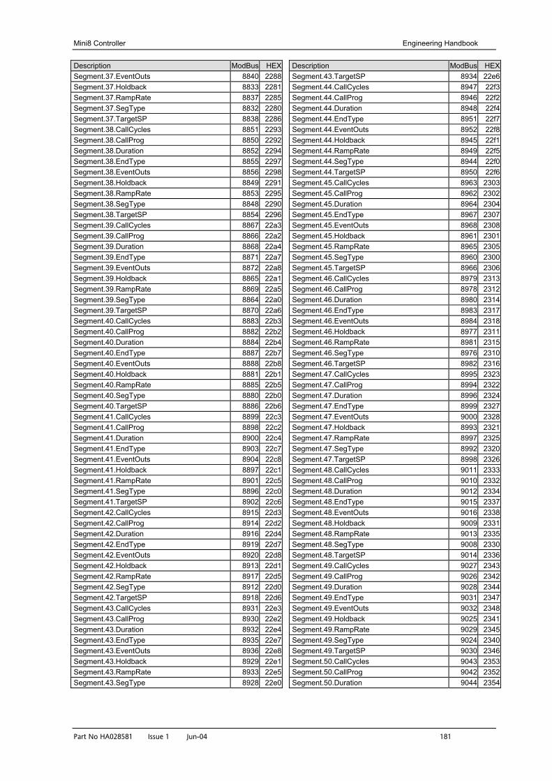
Mini8 Controller Engineering Handbook
Part No HA028581 Issue 1 Jun-04 181
Description ModBus HEXSegment.37.EventOuts 8840 2288Segment.37.Holdback 8833 2281Segment.37.RampRate 8837 2285Segment.37.SegType 8832 2280Segment.37.TargetSP 8838 2286Segment.38.CallCycles 8851 2293Segment.38.CallProg 8850 2292Segment.38.Duration 8852 2294Segment.38.EndType 8855 2297Segment.38.EventOuts 8856 2298Segment.38.Holdback 8849 2291Segment.38.RampRate 8853 2295Segment.38.SegType 8848 2290Segment.38.TargetSP 8854 2296Segment.39.CallCycles 8867 22a3Segment.39.CallProg 8866 22a2Segment.39.Duration 8868 22a4Segment.39.EndType 8871 22a7Segment.39.EventOuts 8872 22a8Segment.39.Holdback 8865 22a1Segment.39.RampRate 8869 22a5Segment.39.SegType 8864 22a0Segment.39.TargetSP 8870 22a6Segment.40.CallCycles 8883 22b3Segment.40.CallProg 8882 22b2Segment.40.Duration 8884 22b4Segment.40.EndType 8887 22b7Segment.40.EventOuts 8888 22b8Segment.40.Holdback 8881 22b1Segment.40.RampRate 8885 22b5Segment.40.SegType 8880 22b0Segment.40.TargetSP 8886 22b6Segment.41.CallCycles 8899 22c3Segment.41.CallProg 8898 22c2Segment.41.Duration 8900 22c4Segment.41.EndType 8903 22c7Segment.41.EventOuts 8904 22c8Segment.41.Holdback 8897 22c1Segment.41.RampRate 8901 22c5Segment.41.SegType 8896 22c0Segment.41.TargetSP 8902 22c6Segment.42.CallCycles 8915 22d3Segment.42.CallProg 8914 22d2Segment.42.Duration 8916 22d4Segment.42.EndType 8919 22d7Segment.42.EventOuts 8920 22d8Segment.42.Holdback 8913 22d1Segment.42.RampRate 8917 22d5Segment.42.SegType 8912 22d0Segment.42.TargetSP 8918 22d6Segment.43.CallCycles 8931 22e3Segment.43.CallProg 8930 22e2Segment.43.Duration 8932 22e4Segment.43.EndType 8935 22e7Segment.43.EventOuts 8936 22e8Segment.43.Holdback 8929 22e1Segment.43.RampRate 8933 22e5Segment.43.SegType 8928 22e0
Description ModBus HEXSegment.43.TargetSP 8934 22e6Segment.44.CallCycles 8947 22f3Segment.44.CallProg 8946 22f2Segment.44.Duration 8948 22f4Segment.44.EndType 8951 22f7Segment.44.EventOuts 8952 22f8Segment.44.Holdback 8945 22f1Segment.44.RampRate 8949 22f5Segment.44.SegType 8944 22f0Segment.44.TargetSP 8950 22f6Segment.45.CallCycles 8963 2303Segment.45.CallProg 8962 2302Segment.45.Duration 8964 2304Segment.45.EndType 8967 2307Segment.45.EventOuts 8968 2308Segment.45.Holdback 8961 2301Segment.45.RampRate 8965 2305Segment.45.SegType 8960 2300Segment.45.TargetSP 8966 2306Segment.46.CallCycles 8979 2313Segment.46.CallProg 8978 2312Segment.46.Duration 8980 2314Segment.46.EndType 8983 2317Segment.46.EventOuts 8984 2318Segment.46.Holdback 8977 2311Segment.46.RampRate 8981 2315Segment.46.SegType 8976 2310Segment.46.TargetSP 8982 2316Segment.47.CallCycles 8995 2323Segment.47.CallProg 8994 2322Segment.47.Duration 8996 2324Segment.47.EndType 8999 2327Segment.47.EventOuts 9000 2328Segment.47.Holdback 8993 2321Segment.47.RampRate 8997 2325Segment.47.SegType 8992 2320Segment.47.TargetSP 8998 2326Segment.48.CallCycles 9011 2333Segment.48.CallProg 9010 2332Segment.48.Duration 9012 2334Segment.48.EndType 9015 2337Segment.48.EventOuts 9016 2338Segment.48.Holdback 9009 2331Segment.48.RampRate 9013 2335Segment.48.SegType 9008 2330Segment.48.TargetSP 9014 2336Segment.49.CallCycles 9027 2343Segment.49.CallProg 9026 2342Segment.49.Duration 9028 2344Segment.49.EndType 9031 2347Segment.49.EventOuts 9032 2348Segment.49.Holdback 9025 2341Segment.49.RampRate 9029 2345Segment.49.SegType 9024 2340Segment.49.TargetSP 9030 2346Segment.50.CallCycles 9043 2353Segment.50.CallProg 9042 2352Segment.50.Duration 9044 2354
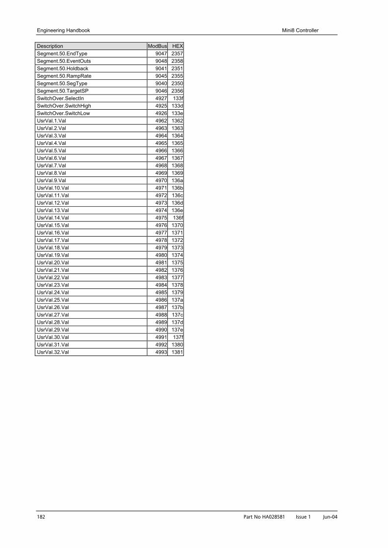
Engineering Handbook Mini8 Controller
182 Part No HA028581 Issue 1 Jun-04
Description ModBus HEXSegment.50.EndType 9047 2357Segment.50.EventOuts 9048 2358Segment.50.Holdback 9041 2351Segment.50.RampRate 9045 2355Segment.50.SegType 9040 2350Segment.50.TargetSP 9046 2356SwitchOver.SelectIn 4927 133fSwitchOver.SwitchHigh 4925 133dSwitchOver.SwitchLow 4926 133eUsrVal.1.Val 4962 1362UsrVal.2.Val 4963 1363UsrVal.3.Val 4964 1364UsrVal.4.Val 4965 1365UsrVal.5.Val 4966 1366UsrVal.6.Val 4967 1367UsrVal.7.Val 4968 1368UsrVal.8.Val 4969 1369UsrVal.9.Val 4970 136aUsrVal.10.Val 4971 136bUsrVal.11.Val 4972 136cUsrVal.12.Val 4973 136dUsrVal.13.Val 4974 136eUsrVal.14.Val 4975 136fUsrVal.15.Val 4976 1370UsrVal.16.Val 4977 1371UsrVal.17.Val 4978 1372UsrVal.18.Val 4979 1373UsrVal.19.Val 4980 1374UsrVal.20.Val 4981 1375UsrVal.21.Val 4982 1376UsrVal.22.Val 4983 1377UsrVal.23.Val 4984 1378UsrVal.24.Val 4985 1379UsrVal.25.Val 4986 137aUsrVal.26.Val 4987 137bUsrVal.27.Val 4988 137cUsrVal.28.Val 4989 137dUsrVal.29.Val 4990 137eUsrVal.30.Val 4991 137fUsrVal.31.Val 4992 1380UsrVal.32.Val 4993 1381
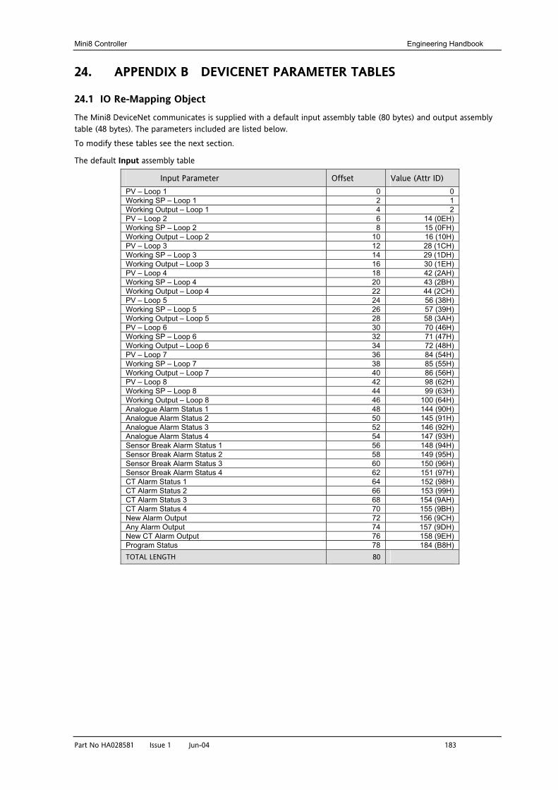
Mini8 Controller Engineering Handbook
Part No HA028581 Issue 1 Jun-04 183
24. APPENDIX B DEVICENET PARAMETER TABLES
24.1 IO Re-Mapping Object
The Mini8 DeviceNet communicates is supplied with a default input assembly table (80 bytes) and output assembly table (48 bytes). The parameters included are listed below.
To modify these tables see the next section.
The default Input assembly table
Input Parameter Offset Value (Attr ID) PV – Loop 1 0 0 Working SP – Loop 1 2 1 Working Output – Loop 1 4 2 PV – Loop 2 6 14 (0EH) Working SP – Loop 2 8 15 (0FH) Working Output – Loop 2 10 16 (10H) PV – Loop 3 12 28 (1CH) Working SP – Loop 3 14 29 (1DH) Working Output – Loop 3 16 30 (1EH) PV – Loop 4 18 42 (2AH) Working SP – Loop 4 20 43 (2BH) Working Output – Loop 4 22 44 (2CH) PV – Loop 5 24 56 (38H) Working SP – Loop 5 26 57 (39H) Working Output – Loop 5 28 58 (3AH) PV – Loop 6 30 70 (46H) Working SP – Loop 6 32 71 (47H) Working Output – Loop 6 34 72 (48H) PV – Loop 7 36 84 (54H) Working SP – Loop 7 38 85 (55H) Working Output – Loop 7 40 86 (56H) PV – Loop 8 42 98 (62H) Working SP – Loop 8 44 99 (63H) Working Output – Loop 8 46 100 (64H) Analogue Alarm Status 1 48 144 (90H) Analogue Alarm Status 2 50 145 (91H) Analogue Alarm Status 3 52 146 (92H) Analogue Alarm Status 4 54 147 (93H) Sensor Break Alarm Status 1 56 148 (94H) Sensor Break Alarm Status 2 58 149 (95H) Sensor Break Alarm Status 3 60 150 (96H) Sensor Break Alarm Status 4 62 151 (97H) CT Alarm Status 1 64 152 (98H) CT Alarm Status 2 66 153 (99H) CT Alarm Status 3 68 154 (9AH) CT Alarm Status 4 70 155 (9BH) New Alarm Output 72 156 (9CH) Any Alarm Output 74 157 (9DH) New CT Alarm Output 76 158 (9EH) Program Status 78 184 (B8H) TOTAL LENGTH 80
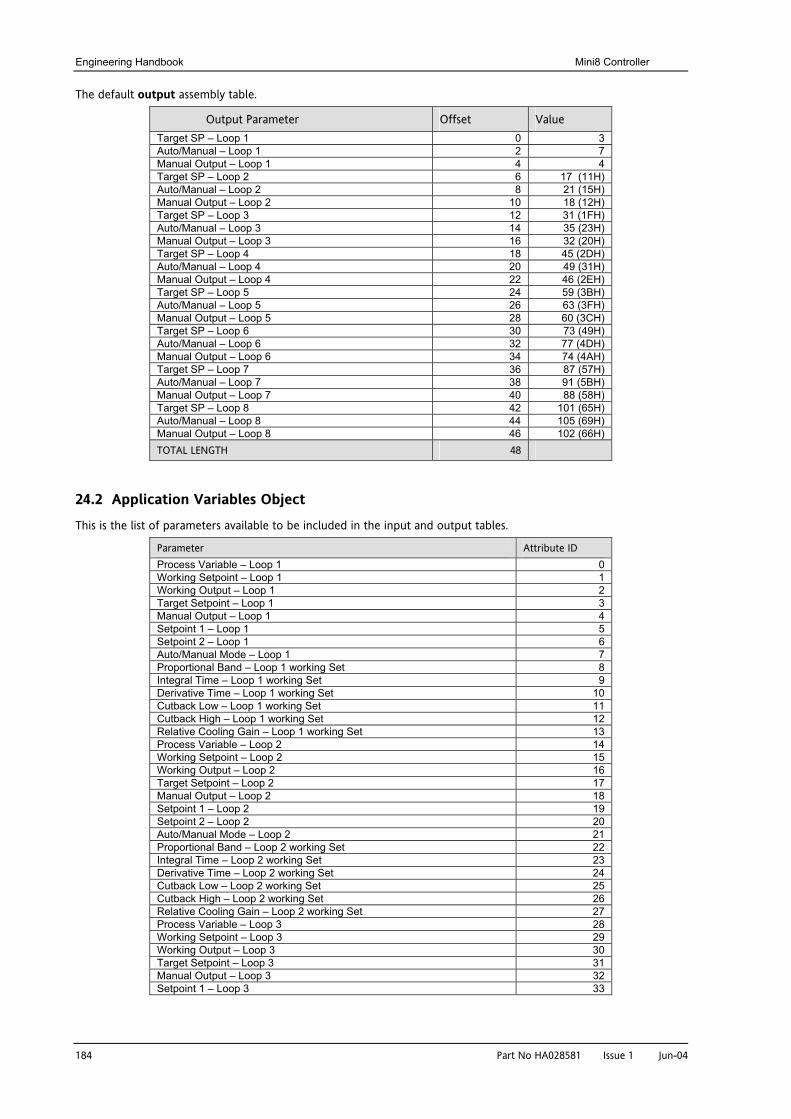
Engineering Handbook Mini8 Controller
184 Part No HA028581 Issue 1 Jun-04
The default output assembly table.
Output Parameter Offset Value Target SP – Loop 1 0 3 Auto/Manual – Loop 1 2 7 Manual Output – Loop 1 4 4 Target SP – Loop 2 6 17 (11H) Auto/Manual – Loop 2 8 21 (15H) Manual Output – Loop 2 10 18 (12H) Target SP – Loop 3 12 31 (1FH) Auto/Manual – Loop 3 14 35 (23H) Manual Output – Loop 3 16 32 (20H) Target SP – Loop 4 18 45 (2DH) Auto/Manual – Loop 4 20 49 (31H) Manual Output – Loop 4 22 46 (2EH) Target SP – Loop 5 24 59 (3BH) Auto/Manual – Loop 5 26 63 (3FH) Manual Output – Loop 5 28 60 (3CH) Target SP – Loop 6 30 73 (49H) Auto/Manual – Loop 6 32 77 (4DH) Manual Output – Loop 6 34 74 (4AH) Target SP – Loop 7 36 87 (57H) Auto/Manual – Loop 7 38 91 (5BH) Manual Output – Loop 7 40 88 (58H) Target SP – Loop 8 42 101 (65H) Auto/Manual – Loop 8 44 105 (69H) Manual Output – Loop 8 46 102 (66H) TOTAL LENGTH 48
24.2 Application Variables Object
This is the list of parameters available to be included in the input and output tables.
Parameter Attribute ID Process Variable – Loop 1 0 Working Setpoint – Loop 1 1 Working Output – Loop 1 2 Target Setpoint – Loop 1 3 Manual Output – Loop 1 4 Setpoint 1 – Loop 1 5 Setpoint 2 – Loop 1 6 Auto/Manual Mode – Loop 1 7 Proportional Band – Loop 1 working Set 8 Integral Time – Loop 1 working Set 9 Derivative Time – Loop 1 working Set 10 Cutback Low – Loop 1 working Set 11 Cutback High – Loop 1 working Set 12 Relative Cooling Gain – Loop 1 working Set 13 Process Variable – Loop 2 14 Working Setpoint – Loop 2 15 Working Output – Loop 2 16 Target Setpoint – Loop 2 17 Manual Output – Loop 2 18 Setpoint 1 – Loop 2 19 Setpoint 2 – Loop 2 20 Auto/Manual Mode – Loop 2 21 Proportional Band – Loop 2 working Set 22 Integral Time – Loop 2 working Set 23 Derivative Time – Loop 2 working Set 24 Cutback Low – Loop 2 working Set 25 Cutback High – Loop 2 working Set 26 Relative Cooling Gain – Loop 2 working Set 27 Process Variable – Loop 3 28 Working Setpoint – Loop 3 29 Working Output – Loop 3 30 Target Setpoint – Loop 3 31 Manual Output – Loop 3 32 Setpoint 1 – Loop 3 33
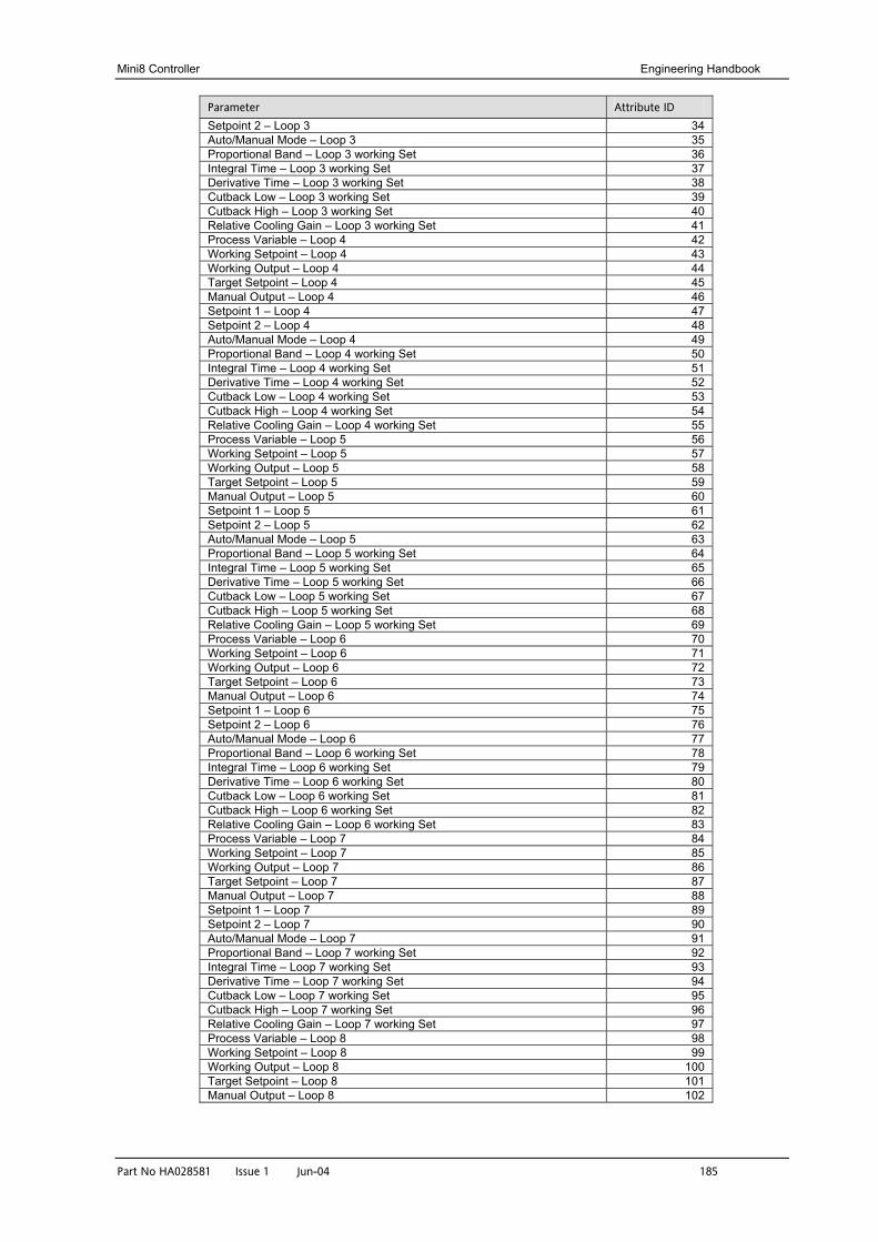
Mini8 Controller Engineering Handbook
Part No HA028581 Issue 1 Jun-04 185
Parameter Attribute ID Setpoint 2 – Loop 3 34 Auto/Manual Mode – Loop 3 35 Proportional Band – Loop 3 working Set 36 Integral Time – Loop 3 working Set 37 Derivative Time – Loop 3 working Set 38 Cutback Low – Loop 3 working Set 39 Cutback High – Loop 3 working Set 40 Relative Cooling Gain – Loop 3 working Set 41 Process Variable – Loop 4 42 Working Setpoint – Loop 4 43 Working Output – Loop 4 44 Target Setpoint – Loop 4 45 Manual Output – Loop 4 46 Setpoint 1 – Loop 4 47 Setpoint 2 – Loop 4 48 Auto/Manual Mode – Loop 4 49 Proportional Band – Loop 4 working Set 50 Integral Time – Loop 4 working Set 51 Derivative Time – Loop 4 working Set 52 Cutback Low – Loop 4 working Set 53 Cutback High – Loop 4 working Set 54 Relative Cooling Gain – Loop 4 working Set 55 Process Variable – Loop 5 56 Working Setpoint – Loop 5 57 Working Output – Loop 5 58 Target Setpoint – Loop 5 59 Manual Output – Loop 5 60 Setpoint 1 – Loop 5 61 Setpoint 2 – Loop 5 62 Auto/Manual Mode – Loop 5 63 Proportional Band – Loop 5 working Set 64 Integral Time – Loop 5 working Set 65 Derivative Time – Loop 5 working Set 66 Cutback Low – Loop 5 working Set 67 Cutback High – Loop 5 working Set 68 Relative Cooling Gain – Loop 5 working Set 69 Process Variable – Loop 6 70 Working Setpoint – Loop 6 71 Working Output – Loop 6 72 Target Setpoint – Loop 6 73 Manual Output – Loop 6 74 Setpoint 1 – Loop 6 75 Setpoint 2 – Loop 6 76 Auto/Manual Mode – Loop 6 77 Proportional Band – Loop 6 working Set 78 Integral Time – Loop 6 working Set 79 Derivative Time – Loop 6 working Set 80 Cutback Low – Loop 6 working Set 81 Cutback High – Loop 6 working Set 82 Relative Cooling Gain – Loop 6 working Set 83 Process Variable – Loop 7 84 Working Setpoint – Loop 7 85 Working Output – Loop 7 86 Target Setpoint – Loop 7 87 Manual Output – Loop 7 88 Setpoint 1 – Loop 7 89 Setpoint 2 – Loop 7 90 Auto/Manual Mode – Loop 7 91 Proportional Band – Loop 7 working Set 92 Integral Time – Loop 7 working Set 93 Derivative Time – Loop 7 working Set 94 Cutback Low – Loop 7 working Set 95 Cutback High – Loop 7 working Set 96 Relative Cooling Gain – Loop 7 working Set 97 Process Variable – Loop 8 98 Working Setpoint – Loop 8 99 Working Output – Loop 8 100 Target Setpoint – Loop 8 101 Manual Output – Loop 8 102
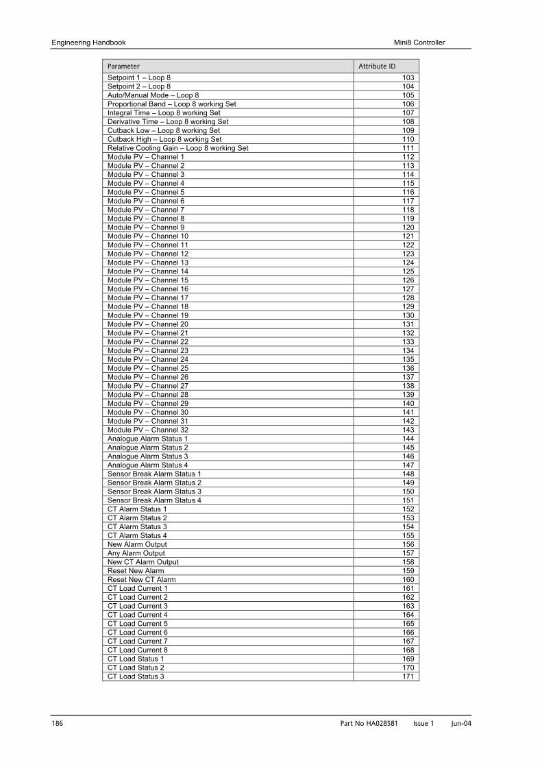
Engineering Handbook Mini8 Controller
186 Part No HA028581 Issue 1 Jun-04
Parameter Attribute ID Setpoint 1 – Loop 8 103 Setpoint 2 – Loop 8 104 Auto/Manual Mode – Loop 8 105 Proportional Band – Loop 8 working Set 106 Integral Time – Loop 8 working Set 107 Derivative Time – Loop 8 working Set 108 Cutback Low – Loop 8 working Set 109 Cutback High – Loop 8 working Set 110 Relative Cooling Gain – Loop 8 working Set 111 Module PV – Channel 1 112 Module PV – Channel 2 113 Module PV – Channel 3 114 Module PV – Channel 4 115 Module PV – Channel 5 116 Module PV – Channel 6 117 Module PV – Channel 7 118 Module PV – Channel 8 119 Module PV – Channel 9 120 Module PV – Channel 10 121 Module PV – Channel 11 122 Module PV – Channel 12 123 Module PV – Channel 13 124 Module PV – Channel 14 125 Module PV – Channel 15 126 Module PV – Channel 16 127 Module PV – Channel 17 128 Module PV – Channel 18 129 Module PV – Channel 19 130 Module PV – Channel 20 131 Module PV – Channel 21 132 Module PV – Channel 22 133 Module PV – Channel 23 134 Module PV – Channel 24 135 Module PV – Channel 25 136 Module PV – Channel 26 137 Module PV – Channel 27 138 Module PV – Channel 28 139 Module PV – Channel 29 140 Module PV – Channel 30 141 Module PV – Channel 31 142 Module PV – Channel 32 143 Analogue Alarm Status 1 144 Analogue Alarm Status 2 145 Analogue Alarm Status 3 146 Analogue Alarm Status 4 147 Sensor Break Alarm Status 1 148 Sensor Break Alarm Status 2 149 Sensor Break Alarm Status 3 150 Sensor Break Alarm Status 4 151 CT Alarm Status 1 152 CT Alarm Status 2 153 CT Alarm Status 3 154 CT Alarm Status 4 155 New Alarm Output 156 Any Alarm Output 157 New CT Alarm Output 158 Reset New Alarm 159 Reset New CT Alarm 160 CT Load Current 1 161 CT Load Current 2 162 CT Load Current 3 163 CT Load Current 4 164 CT Load Current 5 165 CT Load Current 6 166 CT Load Current 7 167 CT Load Current 8 168 CT Load Status 1 169 CT Load Status 2 170 CT Load Status 3 171
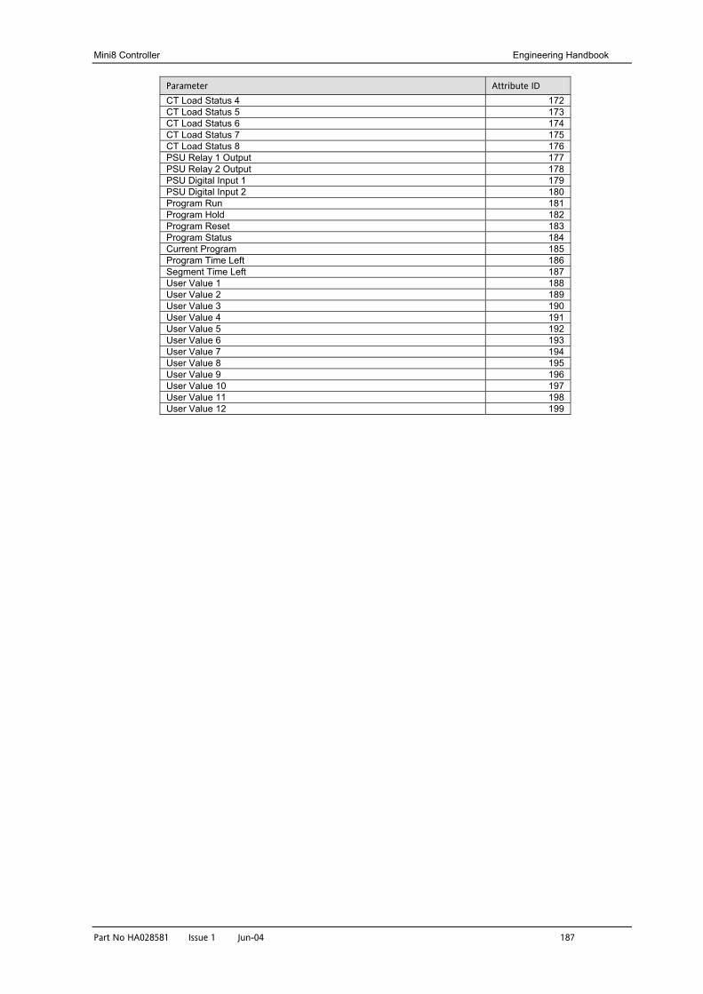
Mini8 Controller Engineering Handbook
Part No HA028581 Issue 1 Jun-04 187
Parameter Attribute ID CT Load Status 4 172 CT Load Status 5 173 CT Load Status 6 174 CT Load Status 7 175 CT Load Status 8 176 PSU Relay 1 Output 177 PSU Relay 2 Output 178 PSU Digital Input 1 179 PSU Digital Input 2 180 Program Run 181 Program Hold 182 Program Reset 183 Program Status 184 Current Program 185 Program Time Left 186 Segment Time Left 187 User Value 1 188 User Value 2 189 User Value 3 190 User Value 4 191 User Value 5 192 User Value 6 193 User Value 7 194 User Value 8 195 User Value 9 196 User Value 10 197 User Value 11 198 User Value 12 199
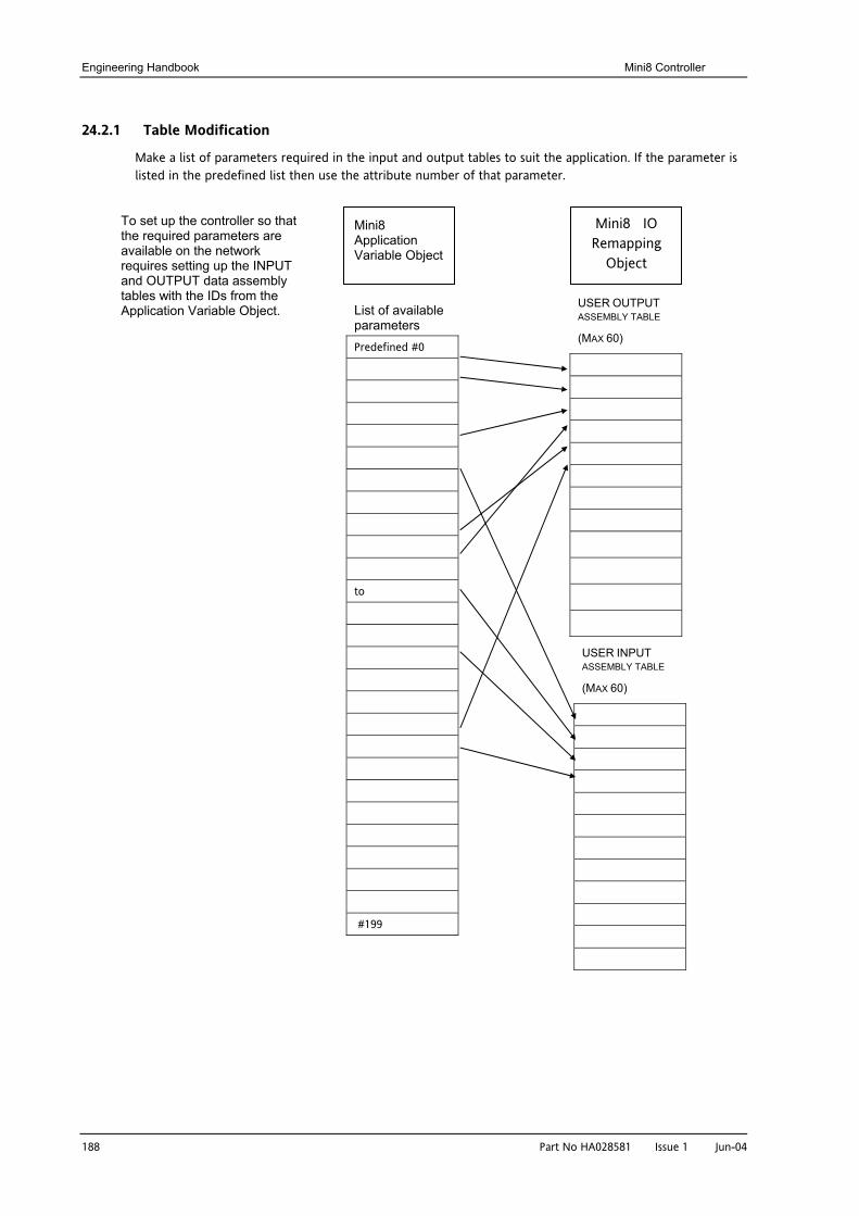
Engineering Handbook Mini8 Controller
188 Part N
24.2.1 Table Modification
Make a list of parameters required in the input and output tables to suit the application. If the parameter is listed in the predefined list then use the attribute number of that parameter.
Mini8 Application Variable Object
Mini8 IO Remapping
Object
To set up the controller so that the required parameters are available on the network requires setting up the INPUT and OUTPUT data assembly tables with the IDs from the Application Variable Object.
USER OUTPUT ASSEMBLY TABLE
(MAX 60)
USER INPUT ASSEMBLY TABLE(MAX 60)
List of available parameters Predefined #0
to
#199
o HA028581 Issue 1 Jun-04
Mini8 Controller Engineering Handbook
Part No HA028581 Issue 1 Jun-04 189
25. APPENDIX C SAFETY AND EMC INFORMATION Eurotherm Controls Ltd manufactures this controller in the UK.
Please read this section carefully before installing the controller
This controller is intended for industrial temperature and process control applications when it will meet the requirements of the European Directives on Safety and EMC. Use in other applications, or failure to observe the installation instructions of this handbook may impair safety or EMC. The installer must ensure the safety and EMC of any particular installation.
Safety
This controller complies with the European Low Voltage Directive 73/23/EEC, by the application of the safety standard EN 61010.
Electromagnetic compatibility
This controller conforms with the essential protection requirements of the EMC Directive 89/336/EEC, by the application of EMC standard EN61326
GENERAL
The information contained in this manual is subject to change without notice. While every effort has been made to ensure the accuracy of the information, your supplier shall not be held liable for errors contained herein.
Unpacking and storage
The packaging should contain an instrument and an Installation guide. It may contain a CD.
If on receipt, the packaging or the instrument are damaged, do not install the product but contact your supplier. If the instrument is to be stored before use, protect from humidity and dust in an ambient temperature range of -10oC to +70oC.
SERVICE AND REPAIR
This controller has no user serviceable parts. Contact your supplier for repair.
Cleaning
Do not use water or water based products to clean labels or they will become illegible. Isopropyl alcohol may be used to clean labels. A mild soap solution may be used to clean other exterior surfaces of the product.
Engineering Handbook Mini8 Controller
190 Part No HA028581 Issue 1 Jun-04
INSTALLATION SAFETY REQUIREMENTS
Personnel
Installation must only be carried out by suitably qualified personnel.
Wiring
It is important to connect the controller in accordance with the wiring data given in this guide. Take particular care not to connect AC supplies to the low voltage sensor input or other low level inputs and outputs. Only use copper conductors for connections (except thermocouple inputs) and ensure that the wiring of installations comply with all local wiring regulations. For example in the UK use the latest version of the IEE wiring regulations, (BS7671). In the USA use NEC Class 1 wiring methods.
Power Isolation
The installation must include a power isolating switch or circuit breaker. The device should be mounted in close proximity to the controller, within easy reach of the operator and marked as the disconnecting device for the instrument.
Overcurrent protection
The power supply to the system should be fused appropriately to protect the cabling to the units.
Voltage rating
The maximum continuous voltage applied between any of the following terminals must not exceed 33Vac:
• relay output to logic, dc or sensor connections;
• any connection to ground.
The controller must not be wired to a three phase supply with an unearthed star connection. Under fault conditions such a supply could rise above 264Vac with respect to ground and the product would not be safe.
Conductive pollution
Electrically conductive pollution must be excluded from the cabinet in which the controller is mounted. For example, carbon dust is a form of electrically conductive pollution. To secure a suitable atmosphere, install an air filter to the air intake of the cabinet. Where condensation is likely, for example at low temperatures, include a thermostatically controlled heater in the cabinet.
This product has been designed to conform to BSEN61010 installation category II, pollution degree 2. These are defined as follows:-
Installation Category II
The rated impulse voltage for equipment on nominal 24V dc supply is 800V. Pollution Degree 2
Normally only non conductive pollution occurs. Occasionally, however, a temporary conductivity caused by condensation shall be expected.
Grounding of the temperature sensor shield
In some installations it is common practice to replace the temperature sensor while the controller is still powered up. Under these conditions, as additional protection against electric shock, we recommend that the shield of the temperature sensor is grounded. Do not rely on grounding through the framework of the machine.
Mini8 Controller Engineering Handbook
Part No HA028581 Issue 1 Jun-04 191
Over-Temperature Protection
When designing any control system it is essential to consider what will happen if any part of the system should fail. In temperature control applications the primary danger is that the heating will remain constantly on. Apart from spoiling the product, this could damage any process machinery being controlled, or even cause a fire.
Reasons why the heating might remain constantly on include:
• the temperature sensor becoming detached from the process
• thermocouple wiring becoming short circuit;
• the controller failing with its heating output constantly on
• an external valve or contactor sticking in the heating condition
• the controller setpoint set too high.
Where damage or injury is possible, we recommend fitting a separate over-temperature protection unit, with an independent temperature sensor, which will isolate the heating circuit.
Please note that the alarm relays within the controller will not give protection under all failure conditions.
INSTALLATION REQUIREMENTS FOR EMC
To ensure compliance with the European EMC directive certain installation precautions are necessary as follows:
• For general guidance refer to EMC Installation Guide, HA025464.
• When using relay outputs it may be necessary to fit a filter suitable for suppressing the conducted emissions. The filter requirements will depend on the type of load. For typical applications we recommend Schaffner FN321 or FN612.
• If the unit is used in table top equipment which is plugged into a standard power socket, then it is likely that compliance to the commercial and light industrial emissions standard is required. In this case to meet the conducted emissions requirement, a suitable mains filter should be installed. We recommend Schaffner types FN321 and FN612.
Routing of wires
To minimise the pick-up of electrical noise, the low voltage DC connections and the sensor input wiring should be routed away from high-current power cables. Where it is impractical to do this, use shielded cables with the shield grounded at both ends. In general keep cable lengths to a minimum.
Engineering Handbook Mini8 Controller
192 Part No HA028581 Issue 1 Jun-04
26. APPENDIX D TECHNICAL SPECIFICATION The I/O electrical specifications are quoted as factory calibrated worst-case; for life, over full ambient temperature range and supply voltage. Any “typical” figures quoted are the expected values at 25°C ambient and 24Vdc supply. The nominal update of all inputs and function blocks is every 110ms. However, in complex applications the Mini8 will automatically extend this time in multiples of 110ms.
26.1 Environmental Specification
Power Supply Voltage: 17.8Vdc min to 28.8Vdc max.
Supply Ripple: 2Vp-p max.
Power Consumption: 15W max.
Operating Temperature: 0 to 55°C
Storage Temperature: -10°C to +70°C
Operating Humidity: 5% to 95% RH non-condensing
EMC: EN61326 for Industrial Environments
Safety: Meets EN61010, installation category II, pollution degree 2.
Max. applied voltage any terminal: 42Vpk.
The Mini8 must be mounted in a protective enclosure.
26.2 Network Communications Support
Modbus RTU: RS485, 2 x RJ45, user select switch for 3-wire or 5-wire.
Baud rates: 4800, 9600, 19200
DeviceNet: CAN, 5-pin standard "open connector" with screw terminals.
Baud rates: 125k, 250k, 500k
Modbus and DeviceNet are mutually exclusive options; refer to the Mini8 order code document.
26.3 Configuration Communications Support
Modbus RTU: 3-wire RS232, through RJ11 configuration port.
Baud rates: 4800, 9600, 19200
All versions of Mini8 support one configuration port.
The configuration port can be used simultaneously with the network link.
26.4 Fixed I/O Resources
The PSU card supports 2 independent and isolated relay contacts
Relay Output Types: On/Off (C/O contacts, "On" closing the N/O pair)
Contact Current: <1A (resistive loads)
Terminal Voltage: <42Vpk
Contact Material: Gold
Snubbers: Snubber networks are NOT fitted.
Contact Isolation: 42Vpkmax.
Mini8 Controller Engineering Handbook
Part No HA028581 Issue 1 Jun-04 193
The PSU card supports 2 independent and isolated logic inputs
Input Types: Logic (24Vdc)
Input Logic 0 (off): < 5Vdc.
Input Logic 1 (on): > 10.8Vdc.
Input Operating Range: -30Vdc to +30Vdc.
Input Current: 2.5mA (approx.) at 10.5V; 10mA max @ 30V supply.
Detectable Pulse Width: 110ms min.
Isolation to system: 42Vpkmax.
26.5 TC8 8-Channel TC Input Card
The TC8 supports 8 independently programmable and electrically isolated channels, catering for all standard and custom thermocouple types.
Channel Types: TC, mV Input Range: -77mV to +77mV.
Resolution: 20 bit ( Σ∆ converter), 1.6µV with 1.6s filter time
Temperature Coefficient: < ±50ppm (0.005%) of reading/ °C
Cold Junction Range: -10°C to +70°C
CJ Rejection: > 30:1
CJ Accuracy: ± 1°C
Linearisation Types: C, J, K, L, R, B, N, T, S, LINEAR mV, custom.
Total accuracy: ± 1°C ± 0.1% of reading (using internal CJC)
Channel PV Filter: 0.0 seconds (off) to 999.9 seconds, 1st order low-pass.
Sensor Break: AC detector: Off, Low or High resistance trip levels.
Input Resistance : >100 M
Input Leakage Current: <100nA (1nA typical).
Common mode rejection: >120dB, 47 - 63Hz
Series mode rejection: >60dB, 47 - 63Hz
Isolation channel-channel: 42Vpkmax
Isolation to system: 42Vpkmax
26.6 DO8 8-Channel Digital Output Card
The DO8 supports 8 independently programmable channels, the output switches requiring external power supply. Each channel is current and temperature protected, holdback limiting occurring at about 100mA.
The supply line is protected to limit total card current to 200mA. The 8 channels are isolated from the system (but not from each other). To maintain isolation it is essential to use an independent and isolated PSU. Channel Types: On/Off, Time Proportioned
Channel Supply (Vcs): 15Vdc to 30Vdc
Logic 1 Voltage Output: > (Vcs - 3V) (not in power limiting)
Logic 0 Voltage Output: < 1.2Vdc no-load, 0.9V typical
Logic 1 Current Output: 100mA max. (not in power limiting)
Min. Pulse Time: 20ms
Channel Power Limiting: Current limiting capable of driving short-circuit load
Terminal Supply Protection: Card supply is protected by 200mA self-healing fuse
Isolation (channel-channel): N/A (Channels share common connections)
Isolation to system: 42Vac/dc max.
Engineering Handbook Mini8 Controller
194 Part No HA028581 Issue 1 Jun-04
26.7 Toolkit Blocks
User Wires: Orderable options of 30, 60 120 or 250
User values: 32 real values
2 Input Maths: 24 blocks
Add, subtract, multiply, divide, absolute difference, maximum, minimum, hot swap, sample and hold, power, square root, Log, Ln, exponential, switch
2 Input Logic: 24 blocks
AND, OR, XOR, latch, equal, not equal, greater than, less than, greater than or equal to, less than or equal to
8 Input Logic: 2 blocks
AND, OR, XOR
8 Input Multiplexer: 4 blocks
8 sets of 8 values selected by input parameter
BCD Input: 2 blocks
2 decades (8 inputs giving 0 to 99).
Input monitor: 2 blocks
Max, min, time above threshold
16 Point Linearisation: 2 blocks
16-point linearisation fit
Polynomial Fit: 2 blocks
Characterisation by Poly Fit table
Switchover: 1 block
Smooth transition between two input values
Timer blocks: 4 blocks
OnPulse, OnDelay, OneShot, MinOn Time
Counter blocks: 2 blocks
Up or down, Directional flag
Totaliser blocks: 2 blocks
Alarm at Threshold value
Real time clock: 1 block
Day & time, 2 time based alarms
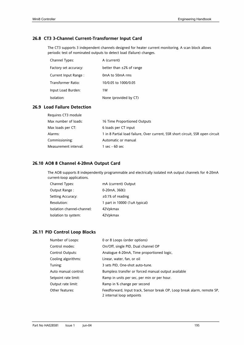
Mini8 Controller Engineering Handbook
Part No HA028581 Issue 1 Jun-04 195
26.8 CT3 3-Channel Current-Transformer Input Card
The CT3 supports 3 independent channels designed for heater current monitoring. A scan block allows periodic test of nominated outputs to detect load (failure) changes.
Channel Types: A (current)
Factory set accuracy: better than ±2% of range
Current Input Range : 0mA to 50mA rms
Transformer Ratio: 10/0.05 to 1000/0.05
Input Load Burden: 1W
Isolation: None (provided by CT)
26.9 Load Failure Detection
Requires CT3 module
Max number of loads: 16 Time Proportioned Outputs
Max loads per CT: 6 loads per CT input
Alarms: 1 in 8 Partial load failure, Over current, SSR short circuit, SSR open circuit
Commissioning: Automatic or manual
Measurement interval: 1 sec - 60 sec
26.10 AO8 8 Channel 4-20mA Output Card
The AO8 supports 8 independently programmable and electrically isolated mA output channels for 4-20mA current-loop applications.
Channel Types: mA (current) Output
Output Range : 0-20mA, 360Ω
Setting Accuracy: ±0.1% of reading
Resolution: 1 part in 10000 (1uA typical)
Isolation channel-channel: 42Vpkmax
Isolation to system: 42Vpkmax
26.11 PID Control Loop Blocks
Number of Loops: 0 or 8 Loops (order options)
Control modes: On/Off, single PID, Dual channel OP
Control Outputs: Analogue 4-20mA, Time proportioned logic,
Cooling algorithms: Linear, water, fan, or oil
Tuning: 3 sets PID, One-shot auto-tune.
Auto manual control: Bumpless transfer or forced manual output available
Setpoint rate limit: Ramp in units per sec, per min or per hour.
Output rate limit: Ramp in % change per second
Other features: Feedforward, Input track, Sensor break OP, Loop break alarm, remote SP, 2 internal loop setpoints
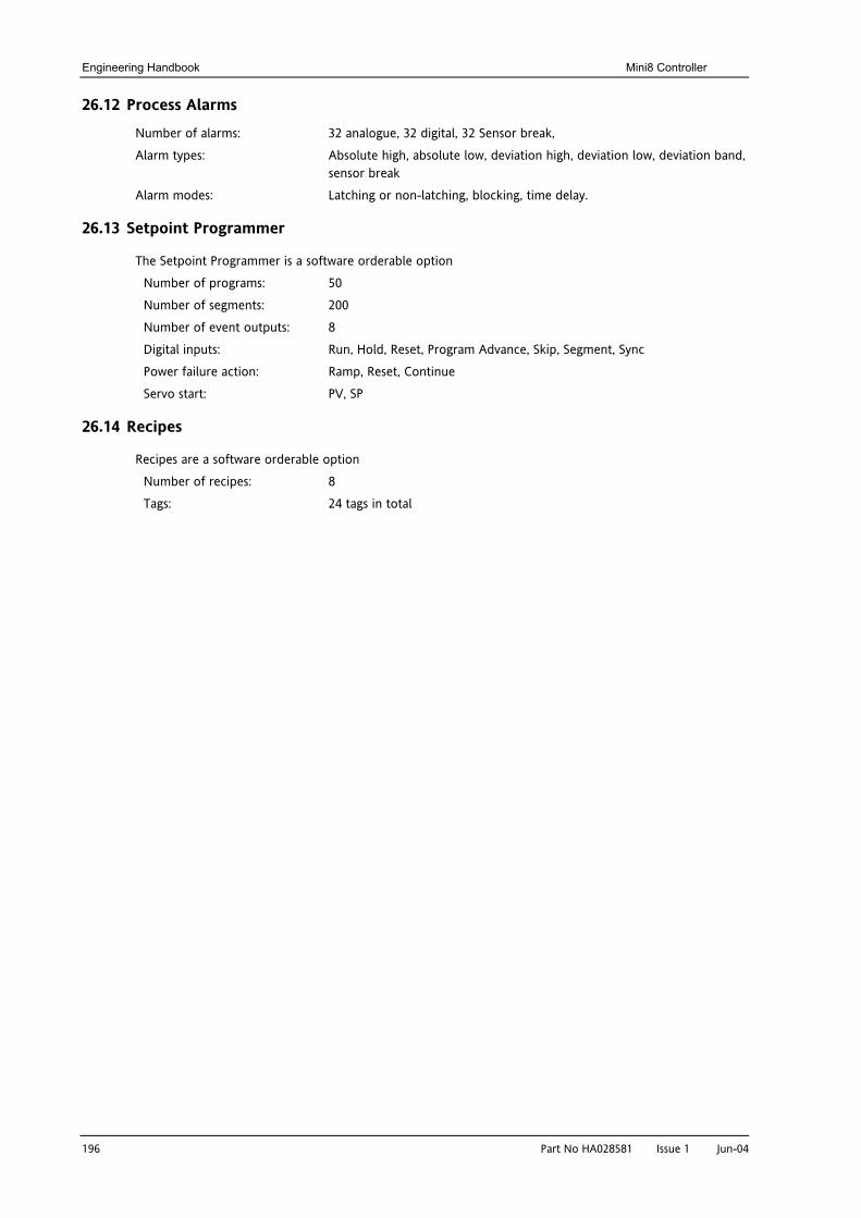
Engineering Handbook Mini8 Controller
196 Part No HA028581 Issue 1 Jun-04
26.12 Process Alarms
Number of alarms: 32 analogue, 32 digital, 32 Sensor break,
Alarm types: Absolute high, absolute low, deviation high, deviation low, deviation band, sensor break
Alarm modes: Latching or non-latching, blocking, time delay.
26.13 Setpoint Programmer
The Setpoint Programmer is a software orderable option
Number of programs: 50
Number of segments: 200
Number of event outputs: 8
Digital inputs: Run, Hold, Reset, Program Advance, Skip, Segment, Sync
Power failure action: Ramp, Reset, Continue
Servo start: PV, SP
26.14 Recipes
Recipes are a software orderable option
Number of recipes: 8
Tags: 24 tags in total