mild wear prediction of boundary-lubricated contacts
TRANSCRIPT
ORIGINAL PAPER
Mild Wear Prediction of Boundary-Lubricated Contacts
R. Bosman • D. J. Schipper
Received: 28 October 2010 / Accepted: 31 January 2011 / Published online: 17 February 2011
� The Author(s) 2011. This article is published with open access at Springerlink.com
Abstract In this paper, a wear model is introduced for the
mild wear present in boundary-lubricated systems pro-
tected by additive-rich lubricants. The model is based on
the hypothesis that the mild wear is mainly originating
from the removal of the sacrificial layer formed by a
chemical reaction between the base material and the
additive packages present in the lubricant. By removing a
part of this layer, the chemical balance of the system is
disturbed and the system will try to restore the balance for
which it uses base material. In this study, mechanical
properties reported throughout literature are included into
the wear model based on observed phenomena for this type
of systems. The model is validated by model experiments
and the results are in very good agreement, suggesting that
the model is able to simulate wear having a predictive
nature rather than on empirical-based relationships as
Archard’s linear wear model. Also a proposal is made to
include the transition from mild to severe wear into the
model creating a complete wear map.
Keywords Antiwear additives � Boundary lubrication
wear � Corrosive wear � Wear mechanisms
1 Introduction
Wear is a topic that received a lot of attention in the past
decades; however, still the most commonly used wear
model is the linear wear law of Archard [1]. To model wear
in more detail, Archard’s original model is combined with
numerical methods to obtain the local variation in contact
conditions and wear, see, for example, [2–4]; however, the
basic principle is the same. And as an input, these methods
use empirical determined values that are determined for
one combination of bodies, lubricant and a limited load,
and velocity range, and thus lack a predictive nature as
there is no descriptive nature in the treatment of wear. In
this study, a hypothesis for a wear model based on
observed phenomena in mild wearing boundary-lubricated
systems is suggested. This lubrication region is of
increasing importance because many systems are running
under starved conditions because of the increasing demand
for smaller efficient components. To optimize systems
running under these conditions without loss of lifetime, it is
of crucial importance to understand the wear mechanism
dominant in these systems and what kind of mechanical
principle is causing the wear. Therefore, this article dis-
cusses a general hypothesis how to deal with mild
(oxidative) wear in boundary-lubricated systems lubricated
by additive-rich oils and running under mild conditions,
which is applicable in a very wide range of applications
and conditions.
The thought behind the model is the protection provided
by the additive package originates from the chemical
deposit/reaction it leaves on the surface, which acts as a
sacrificial layer and is typically an amorphous glassy type
of layer [5]. This layer is in chemical balance, which is
then disturbed by mechanical removal of a part of the layer.
To restore the chemical balance, base material is used. A
commonly used additive is ZDDP, which is used as an
antiwear agent in most engine lubricants. Because of the
fact that the environmental regulations are becoming more
restrictive concerning phosphorous and sulphur containing
additives [6], the usage of ZDDP is restricted more and
more. This results in the fact that a lot of research is
R. Bosman (&) � D. J. Schipper
University of Twente, Drienerlolaan 5, 7500 AE Enschede,
The Netherlands
e-mail: [email protected]
123
Tribol Lett (2011) 42:169–178
DOI 10.1007/s11249-011-9760-3
currently done in understanding the mechanism behind the
excellent antiwear properties of this additive [7–22] to
eventually produce a more environment-friendly additive
with the same excellent wear protection like ZDDP. These
studies give a good overview of the film formed by this
specific additive package; however, up to now, only little
of this information is indeed used to model mild wear
present in systems lubricated using a lubricant containing
ZDDP.
2 Model
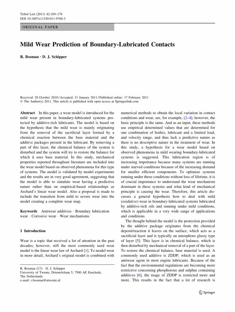
The model discussed here is based on some basic
assumptions made in [23], where it is assumed that a
boundary-lubricated system’s main protection mechanism
is the chemical reaction layer on top of the surface in a
system schematically depicted in Fig. 1. If it is now
assumed that for only mild wear to take place, it is nec-
essary that the shearing, which is needed for the accom-
modation of the velocity difference between the two
contacting bodies, is located mainly in the chemically/
physically adsorbed layer as well as the chemical reaction
layer a first step in modeling mild wear can be made. This
assumption concurs very well with TEM studies done on
particles originating from systems running under mild
conditions in the boundary lubrication regime; see, for
example, [9]. Here, the thickness of the wear particles is
less than the overall thickness of the chemical layer and the
main components of the wear particles are chemical
products originating from the additive packages present in
the lubricant, rather than from wear particles ‘‘broken’’ out
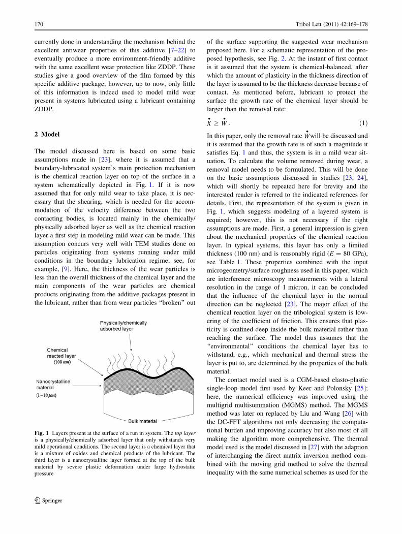
of the surface supporting the suggested wear mechanism
proposed here. For a schematic representation of the pro-
posed hypothesis, see Fig. 2. At the instant of first contact
is it assumed that the system is chemical-balanced, after
which the amount of plasticity in the thickness direction of
the layer is assumed to be the thickness decrease because of
contact. As mentioned before, lubricant to protect the
surface the growth rate of the chemical layer should be
larger than the removal rate:
X�� W
�: ð1Þ
In this paper, only the removal rate W�
will be discussed and
it is assumed that the growth rate is of such a magnitude it
satisfies Eq. 1 and thus, the system is in a mild wear sit-
uation. To calculate the volume removed during wear, a
removal model needs to be formulated. This will be done
on the basic assumptions discussed in studies [23, 24],
which will shortly be repeated here for brevity and the
interested reader is referred to the indicated references for
details. First, the representation of the system is given in
Fig. 1, which suggests modeling of a layered system is
required; however, this is not necessary if the right
assumptions are made. First, a general impression is given
about the mechanical properties of the chemical reaction
layer. In typical systems, this layer has only a limited
thickness (100 nm) and is reasonably rigid (E = 80 GPa),
see Table 1. These properties combined with the input
microgeometry/surface roughness used in this paper, which
are interference microscopy measurements with a lateral
resolution in the range of 1 micron, it can be concluded
that the influence of the chemical layer in the normal
direction can be neglected [23]. The major effect of the
chemical reaction layer on the tribological system is low-
ering of the coefficient of friction. This ensures that plas-
ticity is confined deep inside the bulk material rather than
reaching the surface. The model thus assumes that the
‘‘environmental’’ conditions the chemical layer has to
withstand, e.g., which mechanical and thermal stress the
layer is put to, are determined by the properties of the bulk
material.
The contact model used is a CGM-based elasto-plastic
single-loop model first used by Keer and Polonsky [25];
here, the numerical efficiency was improved using the
multigrid multisummation (MGMS) method. The MGMS
method was later on replaced by Liu and Wang [26] with
the DC-FFT algorithms not only decreasing the computa-
tional burden and improving accuracy but also most of all
making the algorithm more comprehensive. The thermal
model used is the model discussed in [27] with the adaption
of interchanging the direct matrix inversion method com-
bined with the moving grid method to solve the thermal
inequality with the same numerical schemes as used for the
Fig. 1 Layers present at the surface of a run in system. The top layeris a physically/chemically adsorbed layer that only withstands very
mild operational conditions. The second layer is a chemical layer that
is a mixture of oxides and chemical products of the lubricant. The
third layer is a nanocrystalline layer formed at the top of the bulk
material by severe plastic deformation under large hydrostatic
pressure
170 Tribol Lett (2011) 42:169–178
123
contact solver rendering it possible to use larger grids
without memory problems.
From the contact simulation, the stresses and dis-
placements at the surface of the bulk material are known.
The chemical layer is formed by the additives that reacted
with the surface material and thus it can be assumed that
the layer is mechanically bonded to the surface. There-
fore, a nonslip condition at the interface between the base
material and the chemical reaction layer is assumed.
Because of the very limited thickness of the layer, the
layer is in the plain stress condition, i.e. orij
�oz ¼ 0.
Using these assumptions and the strain at the surface of
the bulk material, the stresses put on the chemical layer
by the deformation of the bulk material can be expressed
as follows:
r�iilayer¼ Elayer
1þ mlayer
� �eiibulk
þ mlayerElayer
1þ mlayer
� �1� 2mlayer
� � eiibulkþ ejjbulk
þ ekkbulk
� �:
ð2Þ
The stress put on the layer by the ‘‘environment’’ are the
stress and shear because of the contact conditions giving:
rzzlayer¼ r�zzlayer
þ p; ð3Þ
rxzlayer¼ l p: ð4Þ
Fig. 2 a Asperities come into
contact. b Part of the chemical
layer is sheared of c Removed
film is build up again from bulk
and additives. d The geometry
is changed and wear has
occurred
Table 1 Results for thickness and Young’s modulus for the chemical reaction layer retrieved from literature resulting from rubbing experiments
in ZDDP rich oils
Reference # p (MPa) V (m/s) Tbath (�C) hbalance (nm) Eridge (GPa) Evalley (GPa)
[28] 504 0.3 100 115 85–75 25–30
[22] 504 0.3 100 60–120 – –
[29] 700 0.03 83 40–100 – –
[13] 700 – 83 100 – –
[11] 500 *0.3 100 30–60 – –
[30] – – – 100 81 25
[7] 400 *0.3 100 70 96 –
[31] 500 *0.3 100 300 120–90 –
[32] *300–500 0.03 83 \100 130 –
[10] 10–50 0.25–55 100 \100 –
[5] 360 – 100 140 90 –
[33] *425 0.34 100 160[ 122.7 –
[21] 590 *0.3 100 *160 81 36
[15] 600 0.01 80 \60 – –
[34] 135 *0.35 100 60–180 90–120
[35] 300 *0.3 100 30–60 – –
[20] 950 0.1 100 120 – –
Tribol Lett (2011) 42:169–178 171
123
Using these conditions, the plastic yield of the layer can be
calculated using a return-mapping algorithm.
Now, the contact conditions can be determined, the
response of the chemical layer to these conditions is known
if the mechanical properties of the layer are evaluated. To
retrieve these parameters, a wide literature research was
done on the properties of the chemical-reacted layer and a
short summary is given in Table 1.
Table 1 gives a good first representation of the proper-
ties of a tribo-chemical layer present in a run-in system;
however, there are some important effects missing. At first,
the effect of the hydrostatic pressure on the properties will
be discussed followed by the effect of the temperature.
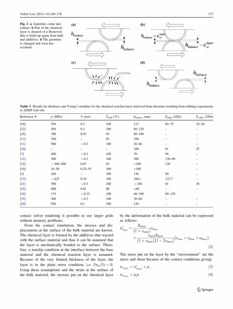
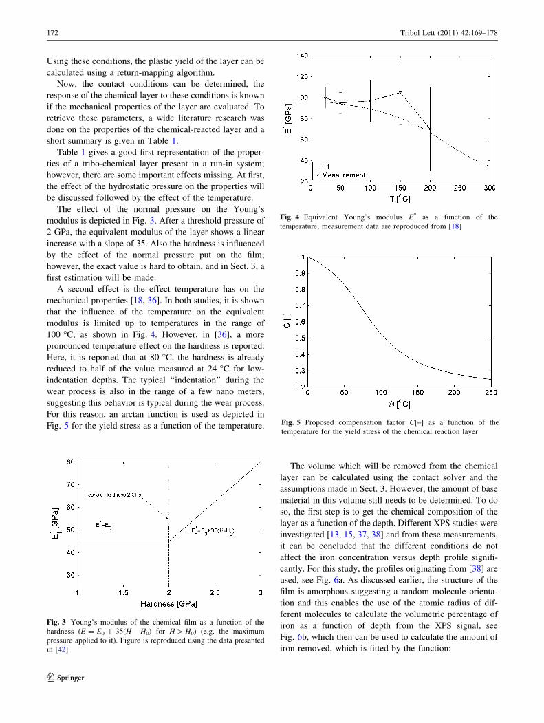
The effect of the normal pressure on the Young’s
modulus is depicted in Fig. 3. After a threshold pressure of
2 GPa, the equivalent modulus of the layer shows a linear
increase with a slope of 35. Also the hardness is influenced
by the effect of the normal pressure put on the film;
however, the exact value is hard to obtain, and in Sect. 3, a
first estimation will be made.
A second effect is the effect temperature has on the
mechanical properties [18, 36]. In both studies, it is shown
that the influence of the temperature on the equivalent
modulus is limited up to temperatures in the range of
100 �C, as shown in Fig. 4. However, in [36], a more
pronounced temperature effect on the hardness is reported.
Here, it is reported that at 80 �C, the hardness is already
reduced to half of the value measured at 24 �C for low-
indentation depths. The typical ‘‘indentation’’ during the
wear process is also in the range of a few nano meters,
suggesting this behavior is typical during the wear process.
For this reason, an arctan function is used as depicted in
Fig. 5 for the yield stress as a function of the temperature.
The volume which will be removed from the chemical
layer can be calculated using the contact solver and the
assumptions made in Sect. 3. However, the amount of base
material in this volume still needs to be determined. To do
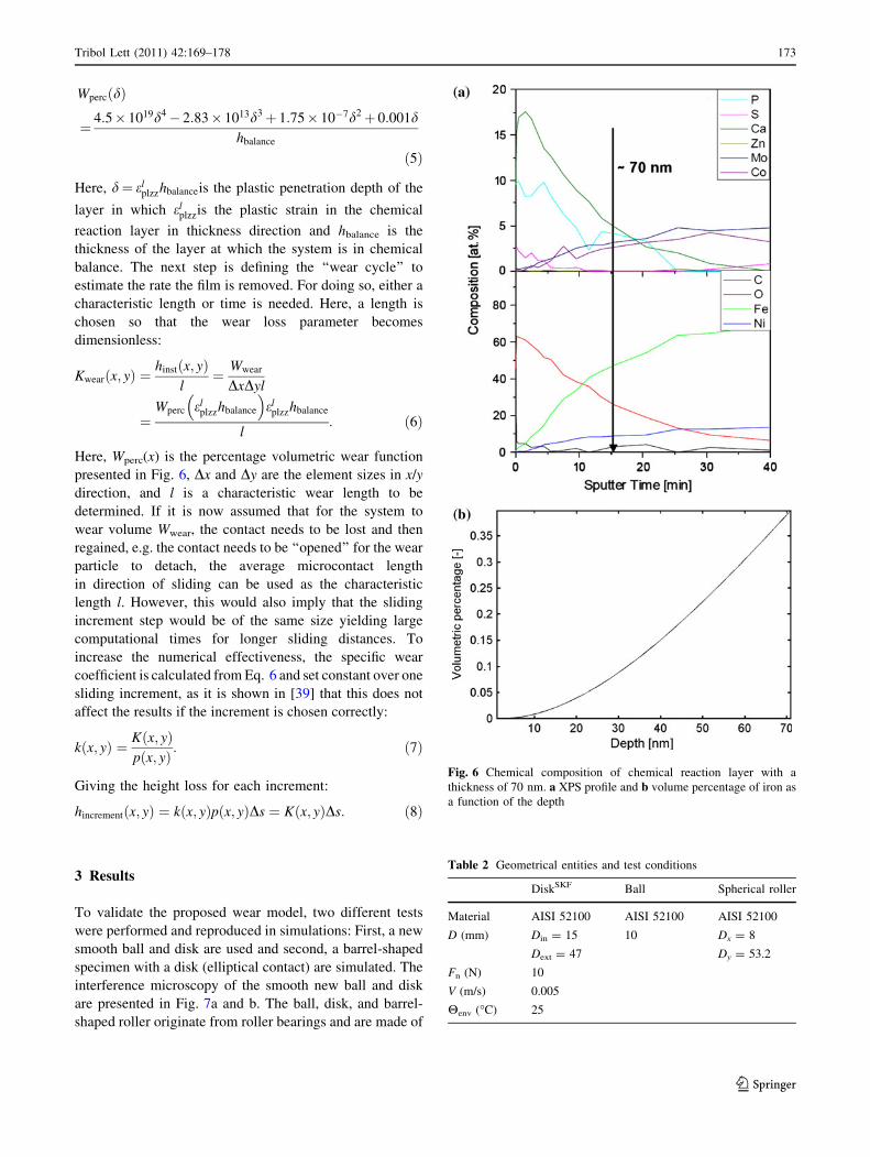
so, the first step is to get the chemical composition of the
layer as a function of the depth. Different XPS studies were
investigated [13, 15, 37, 38] and from these measurements,
it can be concluded that the different conditions do not
affect the iron concentration versus depth profile signifi-
cantly. For this study, the profiles originating from [38] are
used, see Fig. 6a. As discussed earlier, the structure of the
film is amorphous suggesting a random molecule orienta-
tion and this enables the use of the atomic radius of dif-
ferent molecules to calculate the volumetric percentage of
iron as a function of depth from the XPS signal, see
Fig. 6b, which then can be used to calculate the amount of
iron removed, which is fitted by the function:
Fig. 3 Young’s modulus of the chemical film as a function of the
hardness (E = E0 ? 35(H – H0) for H [ H0) (e.g. the maximum
pressure applied to it). Figure is reproduced using the data presented
in [42]
Fig. 4 Equivalent Young’s modulus E* as a function of the
temperature, measurement data are reproduced from [18]
Fig. 5 Proposed compensation factor C[–] as a function of the
temperature for the yield stress of the chemical reaction layer
172 Tribol Lett (2011) 42:169–178
123
WpercðdÞ
¼ 4:5� 1019d4� 2:83� 1013d3þ 1:75� 10�7d2þ 0:001dhbalance
ð5Þ
Here, d¼ elplzzhbalanceis the plastic penetration depth of the
layer in which elplzzis the plastic strain in the chemical
reaction layer in thickness direction and hbalance is the
thickness of the layer at which the system is in chemical
balance. The next step is defining the ‘‘wear cycle’’ to
estimate the rate the film is removed. For doing so, either a
characteristic length or time is needed. Here, a length is
chosen so that the wear loss parameter becomes
dimensionless:
Kwearðx; yÞ ¼hinstðx; yÞ
l¼ Wwear
DxDyl
¼Wperc el
plzzhbalance
� �el
plzzhbalance
l: ð6Þ
Here, Wperc(x) is the percentage volumetric wear function
presented in Fig. 6, Dx and Dy are the element sizes in x/y
direction, and l is a characteristic wear length to be
determined. If it is now assumed that for the system to
wear volume Wwear, the contact needs to be lost and then
regained, e.g. the contact needs to be ‘‘opened’’ for the wear
particle to detach, the average microcontact length
in direction of sliding can be used as the characteristic
length l. However, this would also imply that the sliding
increment step would be of the same size yielding large
computational times for longer sliding distances. To
increase the numerical effectiveness, the specific wear
coefficient is calculated from Eq. 6 and set constant over one
sliding increment, as it is shown in [39] that this does not
affect the results if the increment is chosen correctly:
kðx; yÞ ¼ Kðx; yÞpðx; yÞ : ð7Þ
Giving the height loss for each increment:
hincrementðx; yÞ ¼ kðx; yÞpðx; yÞDs ¼ Kðx; yÞDs: ð8Þ
3 Results
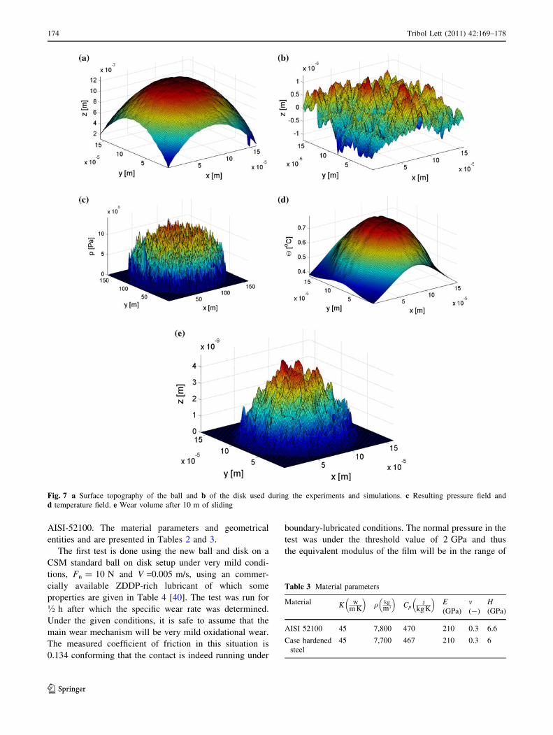
To validate the proposed wear model, two different tests
were performed and reproduced in simulations: First, a new
smooth ball and disk are used and second, a barrel-shaped
specimen with a disk (elliptical contact) are simulated. The
interference microscopy of the smooth new ball and disk
are presented in Fig. 7a and b. The ball, disk, and barrel-
shaped roller originate from roller bearings and are made of
Fig. 6 Chemical composition of chemical reaction layer with a
thickness of 70 nm. a XPS profile and b volume percentage of iron as
a function of the depth
Table 2 Geometrical entities and test conditions
DiskSKF Ball Spherical roller
Material AISI 52100 AISI 52100 AISI 52100
D (mm) Din = 15
Dext = 47
10 Dx = 8
Dy = 53.2
Fn (N) 10
V (m/s) 0.005
Henv (�C) 25
Tribol Lett (2011) 42:169–178 173
123
AISI-52100. The material parameters and geometrical
entities and are presented in Tables 2 and 3.
The first test is done using the new ball and disk on a
CSM standard ball on disk setup under very mild condi-
tions, Fn = 10 N and V =0.005 m/s, using an commer-
cially available ZDDP-rich lubricant of which some
properties are given in Table 4 [40]. The test was run for
� h after which the specific wear rate was determined.
Under the given conditions, it is safe to assume that the
main wear mechanism will be very mild oxidational wear.
The measured coefficient of friction in this situation is
0.134 conforming that the contact is indeed running under
boundary-lubricated conditions. The normal pressure in the
test was under the threshold value of 2 GPa and thus
the equivalent modulus of the film will be in the range of
Fig. 7 a Surface topography of the ball and b of the disk used during the experiments and simulations. c Resulting pressure field and
d temperature field. e Wear volume after 10 m of sliding
Table 3 Material parameters
Material K W
mK
� �q kg
m3
� �Cp
J
kgK
� �E(GPa)
v(-)
H(GPa)
AISI 52100 45 7,800 470 210 0.3 6.6
Case hardened
steel
45 7,700 467 210 0.3 6
174 Tribol Lett (2011) 42:169–178
123
35–40 GPa, because the ‘‘anvil effect’’ is not triggered at
this pressure. The temperature rise inside the contact is less
then 1 �C as shown in Fig. 7d, e.g. the reference hardness
of 1 GPa [5] can be used for the chemical layer, because
the contact conditions are very mild.
The measured specific wear rate during the test was
found to be 8 9 10-9 mm3 N m-1. If the same sliding
distance is modeled using 100 increment steps and the
layer thickness (hbalance) is set to 70 nm, as measured for
this type of system, the specific wear rate calculated is
4 9 10-9 mm3 N m-1, which is determined using the
calculated wear profile shown in Fig. 7e. This value is in
the same range as the measured one, indicating the pro-
posed wear model is capable of determining the specific
wear rate for mild wearing point contacts.
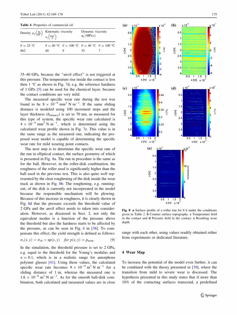
The next step is to determine the specific wear rate of
the run in elliptical contact, the surface geometry of which
is presented in Fig. 8a. The run in procedure is the same as
for the ball. However, in the roller-disk combination, the
roughness of the roller used is significantly higher than the
ball used in the previous test. This is also quite well rep-
resented by the clear roughening of the disk inside the wear
track as shown in Fig. 8b. The roughening, e.g. running-
out, of the disk is currently not incorporated in the model
because the responsible mechanism will be plowing.
Because of this increase in roughness, it is clearly shown in
Fig. 8d that the pressure exceeds the threshold value of
2 GPa and the anvil effect needs to taken into consider-
ation. However, as discussed in Sect. 2, not only the
equivalent modus is a function of the pressure above
the threshold but also the hardness starts to be affected by
the pressure, as can be seen in Fig. 4 in [36]. To com-
pensate this effect, the yield strength is defined as follows:
ryðx; yÞ ¼ ry0 þ apðx; yÞ for pðx; yÞ[ ptresh: ð9Þ
In the simulation, the threshold pressure is set to 2 GPa,
e.g. equal to the threshold for the Young’s modulus and
a = 0.1, which is in a realistic range for amorphous
polymer glasses [41]. Using these values, the calculated
specific wear rate becomes 9 9 10-9 m3 N m-1 for a
sliding distance of 1 m, whereas the measured one is
1.6 9 10-8 m3 N m-1. As for the smooth ball-disk com-
bination, both calculated and measured values are in close
range with each other, using values readily obtained either
from experiments or dedicated literature.
4 Wear Map
To increase the potential of the model even further, it can
be combined with the theory presented in [39], where the
transition from mild to severe wear is discussed. The
hypothesis presented in this study states that if more than
10% of the contacting surfaces transcend, a predefined
Table 4 Properties of commercial oil
Density qdkg
m3
� �Kinematic viscosity
mkmm2
s
� � Dynamic viscosity
g0 MPa sð Þ
h = 25 �C h = 40 �C h = 100 �C h = 40 �C h = 100 �C
862 40 9 35 7
Fig. 8 a Surface profile of a roller run for 8 h under the conditions
given in Table 2. b Counter surface topography. c Temperature field
in the contact and d Pressure field in the contact. e Resulting wear
depth
Tribol Lett (2011) 42:169–178 175
123
critical temperature severe adhesive wear will occur. In
principle, this theory is inline with the current model,
which states that the chemical layer softens under the
influence of increasing temperature. If now the temperature
is increased to far, the chemical layer will not be able to
protect the surface against metal to metal contact and local
adhesive wear will occur, increasing the temperature in the
contact even further introducing complete failure of the
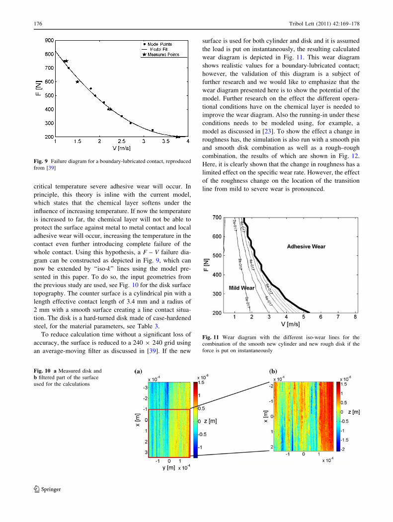
whole contact. Using this hypothesis, a F – V failure dia-
gram can be constructed as depicted in Fig. 9, which can
now be extended by ‘‘iso-k’’ lines using the model pre-
sented in this paper. To do so, the input geometries from
the previous study are used, see Fig. 10 for the disk surface
topography. The counter surface is a cylindrical pin with a
length effective contact length of 3.4 mm and a radius of
2 mm with a smooth surface creating a line contact situa-
tion. The disk is a hard-turned disk made of case-hardened
steel, for the material parameters, see Table 3.
To reduce calculation time without a significant loss of
accuracy, the surface is reduced to a 240 9 240 grid using
an average-moving filter as discussed in [39]. If the new
surface is used for both cylinder and disk and it is assumed
the load is put on instantaneously, the resulting calculated
wear diagram is depicted in Fig. 11. This wear diagram
shows realistic values for a boundary-lubricated contact;
however, the validation of this diagram is a subject of
further research and we would like to emphasize that the
wear diagram presented here is to show the potential of the
model. Further research on the effect the different opera-
tional conditions have on the chemical layer is needed to
improve the wear diagram. Also the running-in under these
conditions needs to be modeled using, for example, a
model as discussed in [23]. To show the effect a change in
roughness has, the simulation is also run with a smooth pin
and smooth disk combination as well as a rough–rough
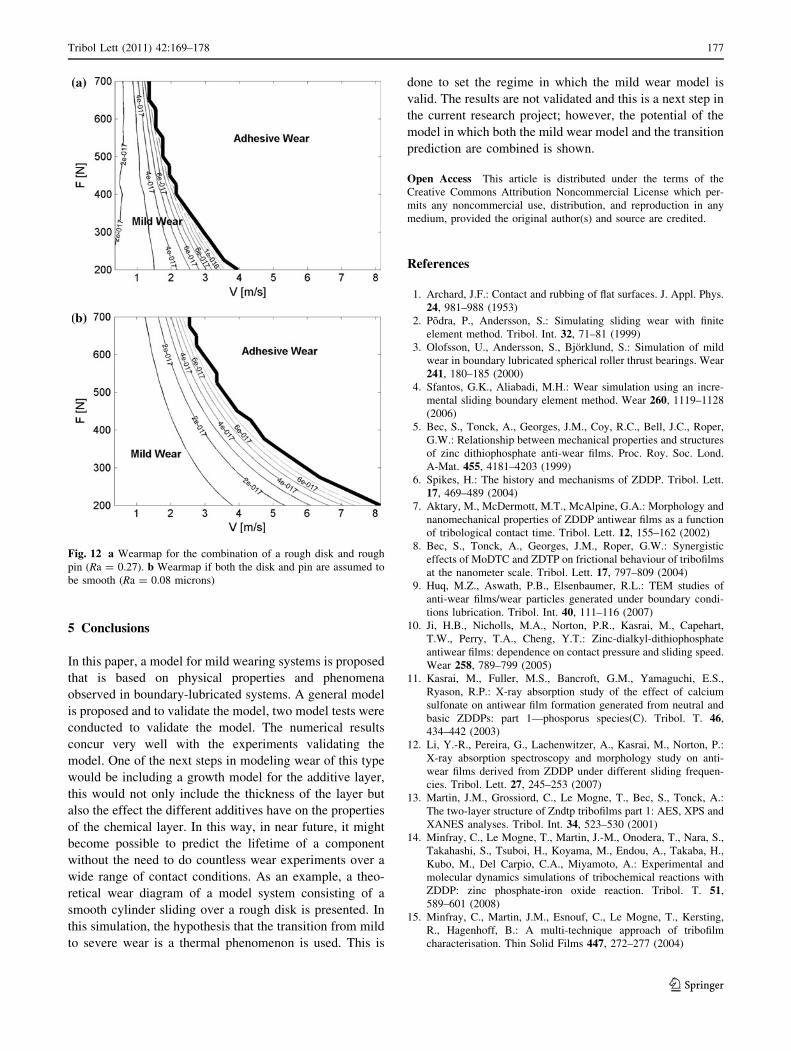
combination, the results of which are shown in Fig. 12.
Here, it is clearly shown that the change in roughness has a
limited effect on the specific wear rate. However, the effect
of the roughness change on the location of the transition
line from mild to severe wear is pronounced.
Fig. 9 Failure diagram for a boundary-lubricated contact, reproduced
from [39]
Fig. 10 a Measured disk and
b filtered part of the surface
used for the calculations
Fig. 11 Wear diagram with the different iso-wear lines for the
combination of the smooth new cylinder and new rough disk if the
force is put on instantaneously
176 Tribol Lett (2011) 42:169–178
123
5 Conclusions
In this paper, a model for mild wearing systems is proposed
that is based on physical properties and phenomena
observed in boundary-lubricated systems. A general model
is proposed and to validate the model, two model tests were
conducted to validate the model. The numerical results
concur very well with the experiments validating the
model. One of the next steps in modeling wear of this type
would be including a growth model for the additive layer,
this would not only include the thickness of the layer but
also the effect the different additives have on the properties
of the chemical layer. In this way, in near future, it might
become possible to predict the lifetime of a component
without the need to do countless wear experiments over a
wide range of contact conditions. As an example, a theo-
retical wear diagram of a model system consisting of a
smooth cylinder sliding over a rough disk is presented. In
this simulation, the hypothesis that the transition from mild
to severe wear is a thermal phenomenon is used. This is
done to set the regime in which the mild wear model is
valid. The results are not validated and this is a next step in
the current research project; however, the potential of the
model in which both the mild wear model and the transition
prediction are combined is shown.
Open Access This article is distributed under the terms of the
Creative Commons Attribution Noncommercial License which per-
mits any noncommercial use, distribution, and reproduction in any
medium, provided the original author(s) and source are credited.
References
1. Archard, J.F.: Contact and rubbing of flat surfaces. J. Appl. Phys.
24, 981–988 (1953)
2. Podra, P., Andersson, S.: Simulating sliding wear with finite
element method. Tribol. Int. 32, 71–81 (1999)
3. Olofsson, U., Andersson, S., Bjorklund, S.: Simulation of mild
wear in boundary lubricated spherical roller thrust bearings. Wear
241, 180–185 (2000)
4. Sfantos, G.K., Aliabadi, M.H.: Wear simulation using an incre-
mental sliding boundary element method. Wear 260, 1119–1128
(2006)
5. Bec, S., Tonck, A., Georges, J.M., Coy, R.C., Bell, J.C., Roper,
G.W.: Relationship between mechanical properties and structures
of zinc dithiophosphate anti-wear films. Proc. Roy. Soc. Lond.
A-Mat. 455, 4181–4203 (1999)
6. Spikes, H.: The history and mechanisms of ZDDP. Tribol. Lett.
17, 469–489 (2004)
7. Aktary, M., McDermott, M.T., McAlpine, G.A.: Morphology and
nanomechanical properties of ZDDP antiwear films as a function
of tribological contact time. Tribol. Lett. 12, 155–162 (2002)
8. Bec, S., Tonck, A., Georges, J.M., Roper, G.W.: Synergistic
effects of MoDTC and ZDTP on frictional behaviour of tribofilms
at the nanometer scale. Tribol. Lett. 17, 797–809 (2004)
9. Huq, M.Z., Aswath, P.B., Elsenbaumer, R.L.: TEM studies of
anti-wear films/wear particles generated under boundary condi-
tions lubrication. Tribol. Int. 40, 111–116 (2007)
10. Ji, H.B., Nicholls, M.A., Norton, P.R., Kasrai, M., Capehart,
T.W., Perry, T.A., Cheng, Y.T.: Zinc-dialkyl-dithiophosphate
antiwear films: dependence on contact pressure and sliding speed.
Wear 258, 789–799 (2005)
11. Kasrai, M., Fuller, M.S., Bancroft, G.M., Yamaguchi, E.S.,
Ryason, R.P.: X-ray absorption study of the effect of calcium
sulfonate on antiwear film formation generated from neutral and
basic ZDDPs: part 1—phosporus species(C). Tribol. T. 46,
434–442 (2003)
12. Li, Y.-R., Pereira, G., Lachenwitzer, A., Kasrai, M., Norton, P.:
X-ray absorption spectroscopy and morphology study on anti-
wear films derived from ZDDP under different sliding frequen-
cies. Tribol. Lett. 27, 245–253 (2007)
13. Martin, J.M., Grossiord, C., Le Mogne, T., Bec, S., Tonck, A.:
The two-layer structure of Zndtp tribofilms part 1: AES, XPS and
XANES analyses. Tribol. Int. 34, 523–530 (2001)
14. Minfray, C., Le Mogne, T., Martin, J.-M., Onodera, T., Nara, S.,
Takahashi, S., Tsuboi, H., Koyama, M., Endou, A., Takaba, H.,
Kubo, M., Del Carpio, C.A., Miyamoto, A.: Experimental and
molecular dynamics simulations of tribochemical reactions with
ZDDP: zinc phosphate-iron oxide reaction. Tribol. T. 51,
589–601 (2008)
15. Minfray, C., Martin, J.M., Esnouf, C., Le Mogne, T., Kersting,
R., Hagenhoff, B.: A multi-technique approach of tribofilm
characterisation. Thin Solid Films 447, 272–277 (2004)
Fig. 12 a Wearmap for the combination of a rough disk and rough
pin (Ra = 0.27). b Wearmap if both the disk and pin are assumed to
be smooth (Ra = 0.08 microns)
Tribol Lett (2011) 42:169–178 177
123
16. Minfray, C., Martin, J.M., Lubrecht, T., Belin, M., Mogne, T.L.,
D. Dowson, M.P.G.D.: A novel experimental analysis of the
rheology of ZDDP tribofilms, Tribology and Interface Engi-
neering Series, pp. 807–817. Elsevier, the Netherlands (2003)
17. Mosey, N.J., Woo, T.K., Kasrai, M., Norton, P.R., Bancroft,
G.M., Muser, M.H.: Interpretation of experiments on ZDDP anti-
wear films through pressure-induced cross-linking. Tribol. Lett.
24, 105–114 (2006)
18. Pereira, G., Munoz-Paniagua, D., Lachenwitzer, A., Kasrai, M.,
Norton, P.R., Capehart, T.W., Perry, T.A., Cheng, Y.-T.: A var-
iable temperature mechanical analysis of ZDDP-derived antiwear
films formed on 52100 steel. Wear 262, 461–470 (2007)
19. Tonck, A., Bec, S., Georges, J.M., Coy, R.C., Bell, J.C., Roper,
G.W.: Structure and mechanical properties of ZDTP films in oil,
Tribology Series, pp. 39–47. Elsevier, Amsterdam, the Nether-
lands (1999)
20. Topolovec-Miklozic, K., Forbus, T., Spikes, H.: Film thickness
and roughness of ZDDP antiwear films. Tribol. Lett. 26, 161–171
(2007)
21. Warren, O.L.: Nanomechanical properties of films derived from
zinc dialkyldithiophosphate. Tribol. Lett. 4, 189–198 (1998)
22. Zhang, Z.: Tribofilms generated from ZDDP and DDP on steel
surfaces: part I. Tribol. Lett. 17, 211–220 (2005)
23. Bosman, R., Schipper, D.J.: Running in of systems protected by
additive rich oils: Tribol. Lett. (2010, in press)
24. Bosman, R., Schipper, D.J.: Running in of metallic surfaces in the
boundary lubricated regime. Wear (2010, submitted)
25. Polonsky, I.A., Keer, L.M.: A numerical method for solving rough
contact problems based on the multi-level multi-summation and
conjugate gradient techniques. Wear 231, 206–219 (1999)
26. Liu, S., Wang, Q.: A three-dimensional thermomechanical model
of contact between non-conforming rough surfaces. J. Tribol.
123, 17–26 (2001)
27. Bosman, R., Rooij, M.B.: Transient thermal effects and heat
partition in sliding contacts. J. Tribol. 132, 021401 (2010)
28. Nicholls, M.A., Norton, P.R., Bancroft, G.M., Kasrai, M., Do, T.,
Frazer, B.H., Stasio, G.D.: Nanometer scale chemomechanical
characterizaton of antiwear films. Tribol. Lett. 17, 205–336
(2003)
29. Ye, J.P., Araki, S., Kano, M., Yasuda, Y.: Nanometer-scale
mechanical/structural properties of molybdenum dithiocarbamate
and zinc dialkylsithiophosphate tribofilms and friction reduction
mechanism. Jpn. J. Appl. Phys. 1 44, 5358–5361 (2005)
30. Nicholls, M.A., Do, T., Norton, P.R., Kasrai, M., Bancroft, G.M.:
Review of the lubrication of metallic surfaces by zinc dialkyl-
dithiophosphates. Tribol. Int. 38, 15–39 (2005)
31. Nicholls, M.A., Bancroft, G.M., Norton, P.R., Kasrai, M., De
Stasio, G., Frazer, B.H., Wiese, L.M.: Chemomechanical prop-
erties of antiwear films using X-ray absorption microscopy and
nanoindentation techniques. Tribol. Lett. 17, 245–259 (2004)
32. Ye, J.P., Kano, M., Yasuda, Y.: Evaluation of nanoscale friction
depth distribution in ZDDP and MoDTC tribochemical reacted
films using a nanoscratch method. Tribol. Lett. 16, 107–112
(2004)
33. Komvopoulos, K., Do, V., Yamaguchi, E.S., Ryason, P.R.:
Nanomechanical and nanotribological properties of an antiwear
tribofilm produced from phosphorus-containing additives on
boundary-lubricated steel surfaces. J. Tribol.-T. ASME 126,
775–780 (2004)
34. Pereira, G.: A variable temperature mechanical analysis of
ZDDP-derived antiwear films formed on 52100 steel. Wear
262(3–4), 461–470 (2006)
35. Bancroft, G.M., Kasrai, M., Fuller, M., Yin, Z., Fyfe, K., Tan,
K.H.: Mechanisms of tribochemical film formation: stability of
tribo- and thermally-generated ZDDP films. Tribol. Lett. 3, 47–51
(1997)
36. Demmou, K., Bec, S., Loubet, J.-L., Martin, J.-M.: Temperature
effects on mechanical properties of zinc dithiophosphate tribo-
films. Tribol. Int. 39, 1558–1563 (2006)
37. Minfray, C., Martin, J.M., De Barros, M.I., Mogne, T.L., Ker-
sting, R., Hagenhoff, B.: Chemistry of ZDDP tribofilm by ToF-
SIMS. Tribol. Lett. 17, 351–357 (2004)
38. Voght, A.: Tribological Reactions Layers in CVT Contacts
Internal. Reportnr: 102801-0027, Bosh-CR, Schillerhohe (2008)
39. Bosman, R., Schipper, D.J.: On the transition from mild to severe
wear of lubricated, concentrated contacts: the IRG (OECD)
transition diagram. Wear 269, 581–589 (2010)
40. Cracoanu, I.: Effect of macroscopic wear on the friction in
lubricated concentrated contacts. PhD thesis, University of
Twente (www.tr.ctw.utwente.nl) (2010)
41. Rottler, J., Robbins, M.O.: Yield conditions for deformation of
amorphous polymer glasses. Phys. Rev. E 64, 051801 (2001)
42. Demmou, K., Bec, S., Loubet, J.L.: Effect of hydrostatic pressure
on the elastic properties of ZDTP tribofilms. (http://arxiv.org/
ftp/arxiv/papers/0706/0706.4235.pdf) Cornell University Library
(2007). Accessed 6 May 2010
178 Tribol Lett (2011) 42:169–178
123