micro thermo wiring standard guide - parker sporlan
TRANSCRIPT

M I C R O T H E R M O T E C H N O L O G I E S T M
Micro Thermo Standard Wiring Guide
Document No.70-PHW-1003-R1.0 MTA V7.0 No part of this publication may be reproduced, stored in a retrieval system, or transmitted, in any form or by any means, electronic, mechanical, photocopying, recording, or otherwise, without the prior written permission of Parker Hannifin Canada. © 1997-2018 by Parker Hannifin Canada. All rights reserved worldwide.
Local Phone: (450) 668-3033 | Fax: (450)668-2695 Toll Free Canada: 1-888-664-1406 | Toll Free USA: 1-888-920-6284
www.sporlanonline.com/micro-thermo

70-PHW-1003-R1.0 Micro Thermo standard wiring guide.doc i
Table of Contents
1 Introduction .............................................................................................................. 1
1.1 Using this document ............................................................................................................. 1 1.2 Conventions used in this document ................................................................................... 1
2 System Overview ....................................................................................................... 2 3 Power ........................................................................................................................ 3
3.1 Transformer for MT-500 nodes ......................................................................................... 3 3.2 Transformer for MT-700 nodes ......................................................................................... 3 3.3 Supplying the MT-ALARM Node ...................................................................................... 3 3.4 Power cable type ................................................................................................................... 3 3.5 Power wiring for MT-500 .................................................................................................... 4 3.6 Power draw of MT Boards .................................................................................................. 5 3.7 Power wiring for MT-700 .................................................................................................... 5
4 FTT10 network (also called Data, NET or LonWorks) ........................................... 6 4.1 Cable type for FTT10 ........................................................................................................... 6 4.2 Data wiring for Free Topology (FTT-10 and FT-X) ....................................................... 6 4.3 Network Termination........................................................................................................... 7 4.4 Network Recommendations and Troubleshooting Tips ................................................ 8
5 Relay Contact Output ............................................................................................... 9 6 Sensor Wiring .......................................................................................................... 10
6.1 Sensor cable type ................................................................................................................. 10 6.2 Thermistor ........................................................................................................................... 10 6.3 4-20mA Transmitter ........................................................................................................... 11 6.4 Voltage Transmitter (0-10V) ............................................................................................. 11 6.5 Switches and Contacts ........................................................................................................ 11 6.6 Pressure Transducer ........................................................................................................... 12 6.7 10 conductor cable coding ................................................................................................. 12
7 EEPR Valves........................................................................................................... 12 7.1 Valve cable type ................................................................................................................... 12
8 Revision History ..................................................................................................... 12

70-PHW-1003-R1.0 Micro Thermo standard wiring guide.doc 1
1 Introduction
1.1 Using this document
This guide is intended for Micro Thermo Technologies engineering department. It is not a complete user guide, but rather a detailed cable selector guide for MT Alliance nodes and sensors installation.
1.2 Conventions used in this document
Bold text is used for emphasis or to highlight MT Alliance terms as found on the interface.

70-PHW-1003-R1.0 Micro Thermo standard wiring guide.doc 2
2 System Overview
Figure 1 shows an example of a typical Alliance installation including three MT-500 nodes, three MT-700 nodes and one MT-Alarm node.
Figure 1 Example of a Free Topology installation

70-PHW-1003-R1.0 Micro Thermo standard wiring guide.doc 3
3 Power
3.1 Transformer for MT-500 nodes
A 24Vac center tap transformer is recommended for most common installations. Where long wire runs are used, or line voltage drop is expected, a 32Vac center tap transformer is a better choice. Allow 3VA per board.
Warning! Do not connect boards other than the MT-5xx and MT-Alarm on the same transformer.
3.2 Transformer for MT-700 nodes
Use a 24Vac transformer. Consumption of a node depends on the cluster of modules connected to the MT-722 (Main Controller). Refer to the "MT-700 Power requirements" document to calculate the consumption of a node.
Warning! Do not connect anything other than MT-722 modules or MT-ALARM on the same transformer. Do not use a 32Vac transformer
Warning! For UL compliance, it is required to insert a 4A fuse in series with the AC power input of each MT-722 (see the Installation manual for more details about fuse type)
Warning! Do not connect or disconnect (hotswap) any MT-700 module with the 24V power on.
3.3 Supplying the MT-ALARM Node
The power for the MT-ALARM board can be supplied from a dedicated 16Vac or 24Vac transformer. This board can also share the transformer of a MT-700 node, or a 32Vac CT transformer used on a MT-500 board by using one of the secondary wires and the center tap (to obtain 16Vac).
Warning! Do not power the MT-Alarm board with 32Vac
3.4 Power cable type
Use 3-18AWG stranded twisted pair unshielded or equivalent Belden #8770
Other sizes may be used, see below for details.
70-PHW-1003-R1.0 Micro Thermo standard wiring guide.doc 4
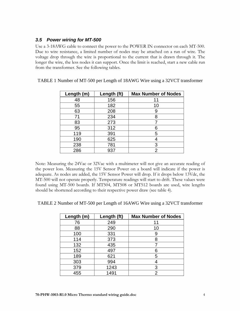
3.5 Power wiring for MT-500
Use a 3-18AWG cable to connect the power to the POWER IN connector on each MT-500. Due to wire resistance, a limited number of nodes may be attached on a run of wire. The voltage drop through the wire is proportional to the current that is drawn through it. The longer the wire, the less nodes it can support. Once the limit is reached, start a new cable run from the transformer. See the following tables.
TABLE 1 Number of MT-500 per Length of 18AWG Wire using a 32VCT transformer
Length (m) Length (ft) Max Number of Nodes
48 156 11
55 182 10
63 208 9
71 234 8
83 273 7
95 312 6
119 391 5
190 625 4
238 781 3
286 937 2
Note: Measuring the 24Vac or 32Vac with a multimeter will not give an accurate reading of the power loss. Measuring the 15V Sensor Power on a board will indicate if the power is adequate. As nodes are added, the 15V Sensor Power will drop. If it drops below 13Vdc, the MT-500 will not operate properly. Temperature readings will start to drift. These values were found using MT-500 boards. If MT504, MT508 or MT512 boards are used, wire lengths should be shortened according to their respective power draw (see table 4).
TABLE 2 Number of MT-500 per Length of 16AWG Wire using a 32VCT transformer
Length (m) Length (ft) Max Number of Nodes
76 249 11
88 290 10
100 331 9
114 373 8
132 435 7
152 497 6
189 621 5
303 994 4
379 1243 3
455 1491 2

70-PHW-1003-R1.0 Micro Thermo standard wiring guide.doc 5
3.6 Power draw of MT Boards
See 70-PHW-1016 Summary of Power Requirements for Micro Thermo Boards
3.7 Power wiring for MT-700
Use 2-16AWG stranded twisted pair unshielded
TABLE 3 Maximum load per Length for 16AWG cable
(using a 24Vac/100VA transformer)
Length Max Load (VA)
meters feet Distributed End of cable
30 140 70
100 140 70
60 80 40
200 80 40
300 58 29
100 54 27
400 46 23
150 40 20
500 40 20
600 34 17
200 32 16
800 28 14
250 26 13
300 22 11
1000 22 11

70-PHW-1003-R1.0 Micro Thermo standard wiring guide.doc 6
4 FTT10 network (also called Data, NET or LonWorks)
4.1 Cable type for FTT10
Use 2-18AWG stranded twisted pair unshielded Other recommended cables:
Belden: 8461 Belden: 8471
Description 1 twisted pair, unshielded 1 twisted pair, unshielded
Conductor size AWG #18 AWG #16
Stranding AWG #26 x7 AWG #29 x19
Conductor material Tinned copper Tinned copper
Lay length (twists /ft)
2 inches (6)
2 inches (6)
Inductance N.A. 0.19 uH /ft
Capacitance 22 pF /ft 33 pF /ft
DC resistance 5.86 ohms /1000ft 4.49 ohms /1000ft
Nominal outside diameter .234 inch .274 inch
Acceptable alternate suppliers
General Cable (Carol): C2830A General Cable (Carol): C2405A
- Windy City Wire: 104500
West Penn Wire: 224 West Penn Wire: 225
Daburn: 3029 Daburn: 3030
A more general list of approved LonWorks cables can be found in Echelon document "Junction box and wiring guideline for twisted pair LonWorks networks" (005-0023-01). For marine applications or harsh conditions where the network has to cope with high electrical noise level, it is recommended to use armored cable. AmerCable Gexol 37-102-610-BS has proven to perform well in such conditions.
4.2 Data wiring for Free Topology (FTT-10 and FT-X)
A twisted pair cable ensures communication between nodes, and with the PC. See the table for Echelon approved wire types. For proper system operation, the maximum node-to-node distance as well as the maximum total wire length must be respected.
Cable Maximum device-to-device distance (Feet)
Maximum total Wire length (Feet)
Belden 85102 1640 1640
Belden 8471 1312 1640

70-PHW-1003-R1.0 Micro Thermo standard wiring guide.doc 7
The maximum number of Free Topology nodes on a network is 64. The PC and routers also count as nodes. It is recommended to keep the number of node to 50 when designing the network. This will allow room for future additions. These limits apply to Case Controllers, MT-700, MT-500 and other Micro Thermo Free Topology nodes. When using a shielded twisted pair (not recommended), the cable shield must be grounded at one end using a capacitor and a resistor. A large resistor will bleed off any static electricity in the shield. The capacitor will prevent DC and 50/60 Hz ground paths from being conducted through the shield. Typical values for Rb and Cc are as follows:
Cc = 0.1uF, 10%, Metalized Polyester, 100V Rb = 470k. 1/4W, 5% The cable shield must be grounded at least once per segment, and preferably at each node. Grounding the shield at every node (using a resistor and capacitor) will assist in suppressing 50/60Hz standing waves. Figure 2 Shielded Data Cable
Ready-made grounding kit 950-0036 is sold by MTT
The data link is not polarity sensitive. Note that the MT-500 boards have two DATA connectors. Either one may be used (it is preferred to use the same if there are only 2 cables). The same applies to the POWER connectors.
4.3 Network Termination
The network must be terminated in an appropriate fashion. The following table shows the network terminator to use for free topology (FTT-10 and FT-X).
TABLE 4 Network Termination
Location Model Number
Free Topology Place on the network (preferably close to center)
FTNT-2 MTT # 950-0035

70-PHW-1003-R1.0 Micro Thermo standard wiring guide.doc 8
Warning! If power is accidentally connected to the data network, the terminator and the electronic modules will be damaged.
4.4 Network Recommendations and Troubleshooting Tips
Even when the recommended cable is used and is properly terminated, some precautions should be taken for reliable communication.
Network cable should not be routed close to high voltage wires and noise generating equipment. When the cable runs parallel to power line wires, keep a minimum distance of 8 inches for >400Vac, and 3 inches for 120Vac. Shorter distance is acceptable for cable crossing the power line wires at a right angle. Use the same minimum distance with VFD, lighting ballasts, motors and power switching devices. These rules also apply for electronic modules connected to the network.
At cable ends, do not remove cable sheath more than necessary (2 inches is usually sufficient). Do not untwist the wire pairs more than necessary.
If a VFD is interfering with network operation, make sure that the proper filters and/or chokes for EMI damping are installed (see drive manufacturer installation manual). Even with the VFD properly grounded, ground loops can exist and be a source of noise. Some sections of the network cables and/or nodes may have to be relocated.
Noise on High Voltage cables can “jump” conductors leading you to find noise where you wouldn’t expect to see it.
Nodes using the FTT-10A transceiver may be protected with a magnetic shield Echelon Model 51001R or MTT 220-0044
The common mode choke LonWorks filter (“life saver”) may also be used to reduce noise. P/N 180-0028 is available at MTT.
Belden type 8471 is the preferred cable for FTT. Shielded cable should be avoided.
Do not mix different cable types on the same network segment.
Do not exceed allowed number of nodes (64) on a single cable.
Use the Network Analyzer tool in MT-Alliance to determine the health of the network. A score of 0 to 10 indicates a trouble free network. A score of 10 to 20 is good. A score over 20 is a sign of a weak network and should be improved. This tool can also spot a node that is "talking" too much.
For Belden 8471 The Max Node-To-Node Distance of Network Wire that can be used is 400m (1312ft.). The Max Wire Length is 500m (1640ft.). Virtually all other cables have a lower quality, so keep that in mind when using Belden 8461 or a Belden 8471 Equivalent.
Generally speaking, resistance measurement at the end of a cable run should be under 58 ohms (when the termination resistor is 52 ohms). A resistance measurement over 65 ohms is unacceptable. Try to tighten each terminal screw on the wire path or remove wire from the segment. For instance, Belden 8471 adds 4.49 ohms per 1000 feet, which equates to 0.0049 ohms per foot. If you times that by 312 (to get 1312ft - the max node-to-node distance) and add the original resistance for 1000 feet, it will get you a resistance of 5.89088. So, if 1312 feet of Belden 8471

70-PHW-1003-R1.0 Micro Thermo standard wiring guide.doc 9
equates to 5.89088 ohms, you should not have anything over 57.89088 ohms of resistance on a Network Length of 1312 feet when using a 52 ohm resistor. If this is true, for any network that has over 58 ohms, network wire should be removed. If a technician considers the resistance on a network when commission a Project, many problems will be eliminated down the line.
Having a resistor to place in the network as you’re troubleshooting, along with cable markers helped calculate and find bad segments with ease.
After an optimal cable length has been determined with the resistor at one end of the network, it is standard practice to move the termination resistor to the center of the segment. The goal is to generally maintain the same amount of resistance on all ends.
An abnormal resistance reading can also be caused by noise on the network. Noise causes the multimeter to give false readings.
Abnormal resistance has also been seen on the network when blown-in-insulation was falling or hitting the wire.
Adding routers is a good way to improve the network performance and/or reliability. A router is the only way to create a new Segment.
Additional information can be found in the "LonWorks Installation Handbook"(ISBN 978-0-615-37794-0).
5 Relay Contact Output
Use unshielded cable according to the rating of the load.
For example, use 2-16AWG for a 200' run with a 0.5A to 1A solenoid.
If 24VAC or 32VAC is required it should come from a separate dedicated transformer
Warning! Pull a dedicated unshielded control cable for AC power. Many states do not accept that AC control power share the same shielded multiconductor cable as the sensor signal wires.

70-PHW-1003-R1.0 Micro Thermo standard wiring guide.doc 10
6 Sensor Wiring
6.1 Sensor cable type
Use shielded 4-22AWG stranded or shielded 2-18AWG (Belden 5502FE or equivalent)
Other sizes may be used, see below for details.
6.2 Thermistor
When the thermistor element senses a high temperature, its resistance is low (NTC). Added resistance from the wiring can affect accuracy. Use the table below for the maximum allowable length according to the higher monitored temperature.
TABLE 5 Max 2 conductor cable length to be used for a temperature reading error of less
than 0.1°C
Length vs. wire size at max monitored
temperature
16 AWG (feet)
18 AWG (feet)
20 AWG (feet)
22 AWG (feet)
24 AWG (feet)
0°C / 32°F 2000 2000 2000 2000 2000
25°C / 77°F 2000 2000 2000 1000 500
50°C / 122°F 1000 1000 500 400 200
100°C / 212°F 200 100 50 50 20
The thermistor is not polarity sensitive. When many thermistors use the same common wire, it shortens the max cable length allowed.
TABLE 6 Max cable length to be used for 3 thermistors using the same common wire
reading error of less than 0.1°C
Length vs. wire size at max monitored
temperature
18 AWG (feet)
20 AWG (feet)
22 AWG (feet)
0°C / 32°F 2 000 2 000 2 000
25°C / 77°F 1 000 1 000 600
50°C / 122°F 400 200 200
100°C / 212°F 50 10
0-10V (err <1%) 15 000 10 000 6 000
When a 4 conductor cable is used for 2 or 3 thermistors, the following color code is recommended:
Black – Common (SGND) (or Signal 1 return)
White – Signal 1
Green – Signal 2
Red – Signal 3 (or Signal 2 return)
Shield – Earth Ground at the node end only

70-PHW-1003-R1.0 Micro Thermo standard wiring guide.doc 11
Shielded cable is not necessary, but if used, the shield should be connected to the mechanical Ground of the node. Connection to earth ground must be made at a single point to avoid ground loops. Do not use GKT telephone cable (it is brittle and frequently damaged by rodents).
A humidity sensor usually needs power to operate. If it does not drain more than 10mA, it can be powered from the MT-500 node.
For sensors with power input, the following color code is recommended:
Red - 15V Humidity power (or 5V Pressure transducer power)
Green - Humidity 0-10V Signal
White or yellow – Temperature Signal
Black GND – Temperat-humid GND
Shield – Earth Ground at the node end only
See sensor specifications for the recommended voltage to use.
6.3 4-20mA Transmitter
4-20mA Transmitters work with any cable type and length of cable. The shunt resistor must be placed at the node input. If the shunt resistor is left at the transmitter terminal, the signal becomes a voltage signal type (255 ohms = 1-5V, 523 ohms = 2-10V) and will not be protected against EMI and signal loss. Many 4-20mA transmitters can share the same common, but each of them needs a dedicated transformer.
6.4 Voltage Transmitter (0-10V)
Voltage transmitters generally comes from a sensor that requires power. The signal itself loses accuracy on long wire lengths, especially if the power is generated from the sensor node. When both the signal return and the ground power share the same wire a voltage offset occurs. That is why the cable length is limited (see table 8) and a shielded cable is recommended.
6.5 Switches and Contacts
A switch may be connected to a node input to proof a state or to send a command. There is no accuracy issue with switches and any type of cable of any length may be used. Normally a four conductor cable is used. A dedicated common wire (Green) must be used for switches (Red). Don’t share the common wire (Black) with sensors (White).
Red – Switch Signal
Green – Switch Common
White or yellow – Temperature Signal
Black GND – Temperature - humidity GND

70-PHW-1003-R1.0 Micro Thermo standard wiring guide.doc 12
6.6 Pressure Transducer
We recommend using shielded 3-18AWG (Black/Red/White) (Belden 8770 or equivalent)
6.7 10 conductor cable coding
For contractor that don’t have their own coding for 10 conductor cable we recommend to follow this color coding for instance when extending sensor node input which has 16 inputs:
Input 1 or 9 – Brown
Input 2 or 10 – Red
Input 3 or 11 – Orange
Input 4 or 12 – Yellow
Input 5 or 13 – Green
Input 6 or 14 – Blue
Input 7 or 15 – Violet
Input 8 or 16 – Grey
Common of the set - Black
Common or power - White
7 EEPR Valves
7.1 Valve cable type
We recommend using shielded 4-18AWG stranded (Belden 5302FE or equivalent). The following chart indicates what size wire is required when running past 250 feet.
8 Revision History
REV Description Revised by Date
0.2 New guide plan RL 18-may-05
0.6 Merge version with Wiring Guide for MT products R0.5 RL 02-jun-05
0.7 Reviewed by Victor Trahan RL/VT 07-jun-05
0.8 Formatting reviewed by Roger Legault RL 02-mar-07
0.9 Update with d/t color code RL 09-apr-10
1.0 Updated for MT-700 application JR 18-feb-18

70-PHW-1003-R1.0 Micro Thermo standard wiring guide.doc 13
Annex 1
Annex 2