methane steam reformer re-tube evaluation
TRANSCRIPT
Methane Steam Reformer Re-Tube Evaluation
By Gerard B. Hawkins
Managing Director, CEO
Contents
Design methodology applied • Mechanical design • Process design
Case studies Why work with GBHE ?
Introduction
The tubes in a primary reformer are a key consumable
Different to the majority of hardware on a
synthesis gas plant They have a limited life They fail due to creep damage
Design Methodology
Understand present operation Base Case - simulate existing reformer
• At normal conditions • Using existing tube design • Determines the required minimum
performance for all other cases • Determines the base line life for all other cases
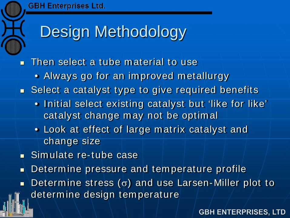
Design Methodology
Then select a tube material to use • Always go for an improved metallurgy
Select a catalyst type to give required benefits • Initial select existing catalyst but ‘like for like’
catalyst change may not be optimal • Look at effect of large matrix catalyst and
change size Simulate re-tube case Determine pressure and temperature profile Determine stress (σ) and use Larsen-Miller plot to
determine design temperature
Design Methodology
Must be careful with stress data Some tests have been conducted over a short
period of time • May not be representative
GBHE has reviewed manufacturers stress data and eliminated any dubious data
There is still a large degree of variation Therefore use a percentage of the average stress
data
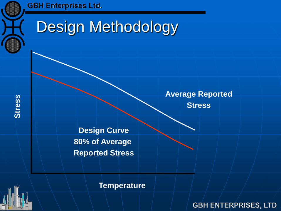
Design Methodology
Average Reported Stress
Design Curve 80% of Average Reported Stress
Temperature
Stre
ss
Design Methodology
Deduct off a margin to give Maximum Allowable Operating Temperature (MAOT)
Check if MAOT is greater than maximum
predicted temperature Increase/decrease tube wall thickness if required
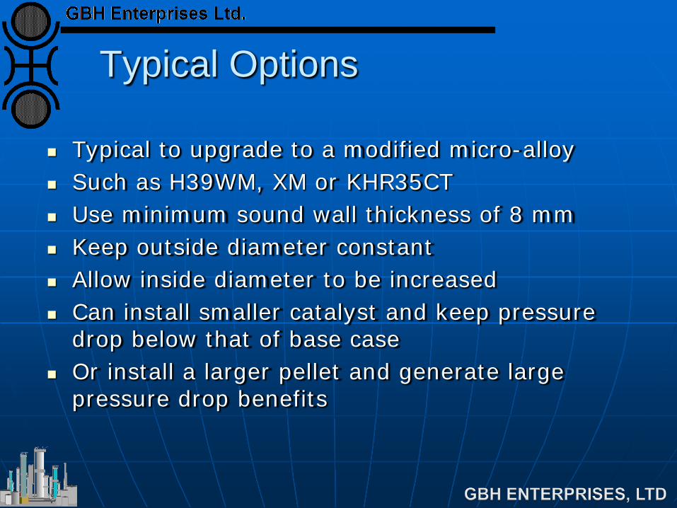
Typical Options
Typical to upgrade to a modified micro-alloy Such as H39WM, XM or KHR35CT Use minimum sound wall thickness of 8 mm Keep outside diameter constant Allow inside diameter to be increased Can install smaller catalyst and keep pressure
drop below that of base case Or install a larger pellet and generate large
pressure drop benefits
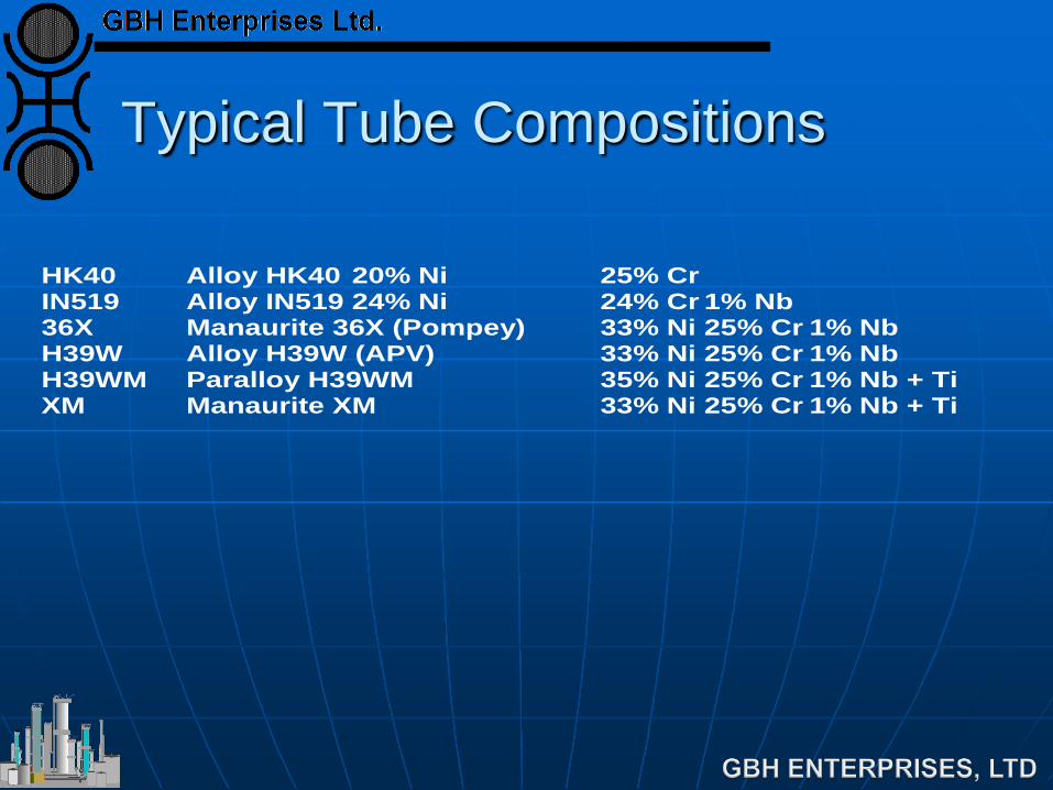
Typical Tube Compositions
HK40 Alloy HK40 20% Ni 25% Cr IN519 Alloy IN519 24% Ni 24% Cr 1% Nb 36X Manaurite 36X (Pompey) 33% Ni 25% Cr 1% Nb H39W Alloy H39W (APV) 33% Ni 25% Cr 1% Nb H39WM Paralloy H39WM 35% Ni 25% Cr 1% Nb + Ti XM Manaurite XM 33% Ni 25% Cr 1% Nb + Ti
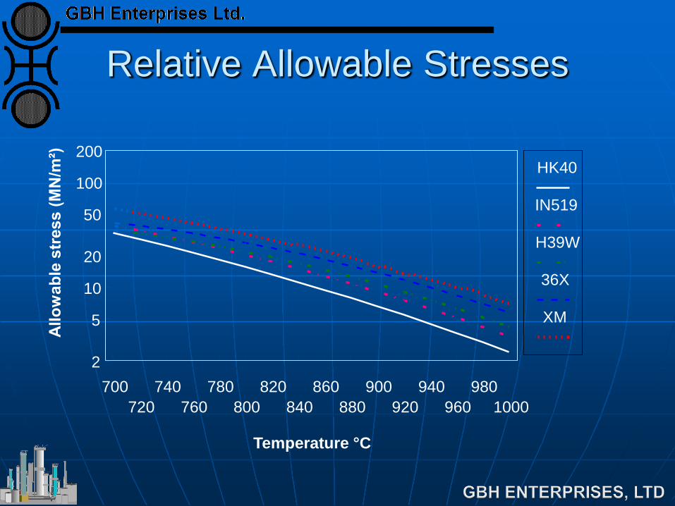
Relative Allowable Stresses
700 720
740 760
780 800
820 840
860 880
900 920
940 960
980 1000
2
5
10
20
50
100
200
Temperature °C
HK40
IN519
H39W
36X
XM
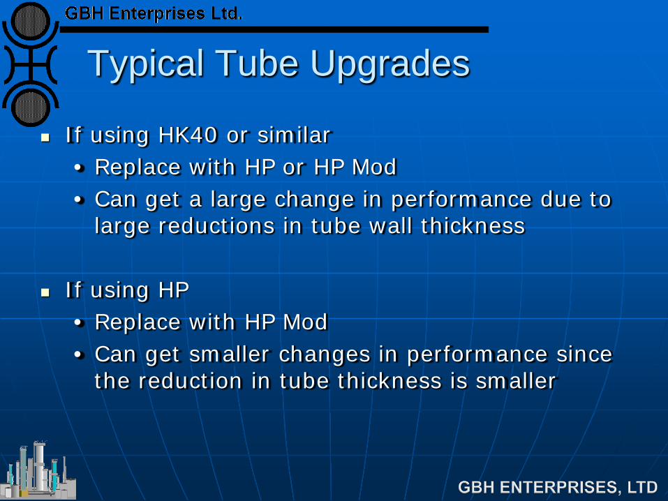
Typical Tube Upgrades
If using HK40 or similar • Replace with HP or HP Mod • Can get a large change in performance due to
large reductions in tube wall thickness
If using HP • Replace with HP Mod • Can get smaller changes in performance since
the reduction in tube thickness is smaller
Options for Catalyst Optimization
A re-tube can allow for an optimization of the catalyst loading since the tube ID can be increased
If tube wall temperature are limiting
• Re-tube will reduce peak tube wall temperatures since there is more catalyst and hence more reaction
• Can install a smaller shape - no increase in pressure drop
Options for Catalyst Optimization
Pressure drop will be reduced • Can reduce even further by installing larger
catalyst matrix • Allows plant rate increases
Reduce flue gas temperature • Allows for plant rate increases • Remove coil skin temperature limitations
Reduced ATE • Reduces methane slip
Example - Ammonia Plant
By optimizing both the tube ID and catalyst combination, achieved, • Reduction in ATE • Reduced pressure drop by 60% • Reduced maximum tube wall temperatures by
40°C • Increase radiant box efficiency • And can increase through put by 3%
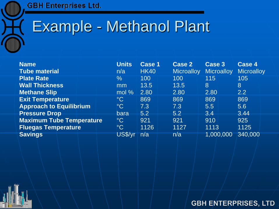
Example - Methanol Plant
Name Units Case 1 Case 2 Case 3 Case 4Tube material n/a HK40 Microalloy Microalloy MicroalloyPlate Rate % 100 100 115 105Wall Thickness mm 13.5 13.5 8 8Methane Slip mol % 2.80 2.80 2.80 2.2Exit Temperature °C 869 869 869 869Approach to Equilibrium °C 7.3 7.3 5.5 5.6Pressure Drop bara 5.2 5.2 3.4 3.44Maximum Tube Temperature °C 921 921 910 925Fluegas Temperature °C 1126 1127 1113 1125Savings US$/yr n/a n/a 1,000,000 340,000
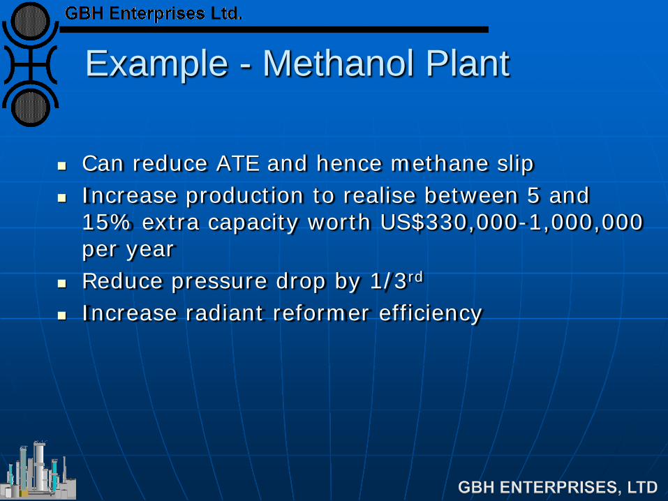
Example - Methanol Plant
Can reduce ATE and hence methane slip Increase production to realise between 5 and
15% extra capacity worth US$330,000-1,000,000 per year
Reduce pressure drop by 1/3rd Increase radiant reformer efficiency
Why Work with GBHE ?
GBHE has operating experience of steam reformers
GBHE has design experience of steam reformers and in particular re-tubes
GBHE understands the problems and issues associated with re-tubes
This means that GBHE is in a unique position to help with reformer re-tubes
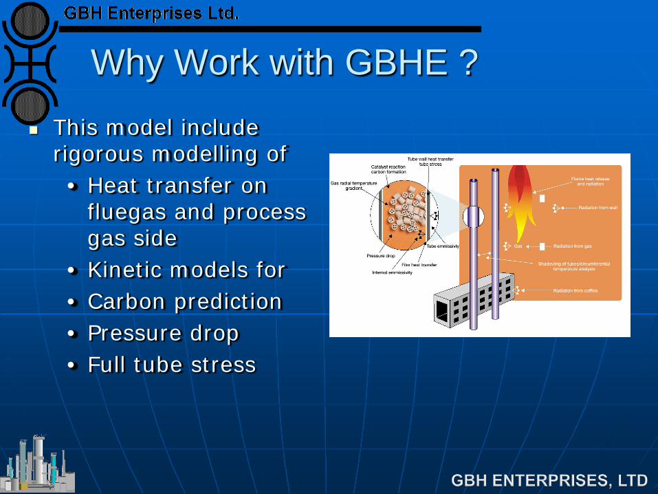
Why Work with GBHE ? This model include
rigorous modelling of • Heat transfer on
fluegas and process gas side
• Kinetic models for • Carbon prediction • Pressure drop • Full tube stress
Details of VULCAN REFORMER SIMULATION
Also includes effect of • Process conditions changes on tube life • Coffins • Tunnel port effects • Naphtha feeds
This means that VULCAN REFORMER SIMULATION is becoming a leading primary reformer simulation package
Other Issues
If the re-tube allows for a plant rate increase then must consider other parts of the plant
Fluegas rate will increase • Can the fluegas duct coils cope with the
increased duty ? Process gas rate through the reformed gas
cooling train will rise • Can the reformed gas cooling train cope ?
Other Issues
What will the effect be on the downstream catalytic units ? • For example - HTS/LTS
What will happen to plant production GBHE has models to perform this analysis Can simulate all unit operations in detail and
determine performance post re-tube
Middle Eastern Ammonia Plant
During discussions re-tube was mentioned Conducted 3 phase approach Process design - US$ 10,000 : 1 days work Fluegas modelling - US$ 20,000 : 10 days work Detailed tube design - US$ 75,000
• Performed by a Engineering Contractor
Conclusions
GBHE has an un-paralleled experience is design and operation of steam reformers
GBHE has project management experience of re-tubes
GBHE can determine the effect of a revamp using the world leading VULCAN REFORMER SIMULATION simulation model.
GBHE can optimize the catalyst loading using the world leading large matrix catalyst
GBHE can determine effect of re-tube on downstream and associated unit operations