melsec iq-r system recorder introduction guide (camera
TRANSCRIPT

MELSEC iQ-R System Recorder Introduction Guide(Camera Recorder Module)
GX Works3 data flow analysis
Offline monitor functionGX LogViewer GX Works3 GOT offline monitor
Analysis
Reproduction
GX VideoViewer
Recording function
Recording
Event history Video dataDevice/label
This guide describes the procedure for introducing a system recorder (camera recorder module), which is one of our maintenance solutions. The system recorder records the operation of the program data and error/event occurrences during the system operation using the camera recorder module. The recorded data can be replayed using the dedicated MELSOFT Software to check the past system operation. This makes it possible to reproduce the situation at the site where the trouble occurred, and to identify and analyze the cause of the error by using the video recorded by a camera together.
Camera Recorder Module

1
CONTENTSCHAPTER 1 OVERVIEW 31.1 Entire Process of Introduction . . . . . . . . . . . . . . . . . . . . . . . . . . . . . . . . . . . . . . . . . . . . . . . . . . . . . . . . . . . . . . 5
CHAPTER 2 PREPARATION 62.1 Wiring . . . . . . . . . . . . . . . . . . . . . . . . . . . . . . . . . . . . . . . . . . . . . . . . . . . . . . . . . . . . . . . . . . . . . . . . . . . . . . . . . . 62.2 Inserting SD Memory Cards . . . . . . . . . . . . . . . . . . . . . . . . . . . . . . . . . . . . . . . . . . . . . . . . . . . . . . . . . . . . . . . . 62.3 IP Address Setting. . . . . . . . . . . . . . . . . . . . . . . . . . . . . . . . . . . . . . . . . . . . . . . . . . . . . . . . . . . . . . . . . . . . . . . . 7
CHAPTER 3 CAMERA SETTINGS 93.1 Network Camera Settings . . . . . . . . . . . . . . . . . . . . . . . . . . . . . . . . . . . . . . . . . . . . . . . . . . . . . . . . . . . . . . . . . 10
CHAPTER 4 PROGRAMMABLE CONTROLLER SETTINGS 244.1 Creating a New Project . . . . . . . . . . . . . . . . . . . . . . . . . . . . . . . . . . . . . . . . . . . . . . . . . . . . . . . . . . . . . . . . . . . 244.2 Parameter Settings of Camera Recorder Module. . . . . . . . . . . . . . . . . . . . . . . . . . . . . . . . . . . . . . . . . . . . . . 264.3 Recording Setting . . . . . . . . . . . . . . . . . . . . . . . . . . . . . . . . . . . . . . . . . . . . . . . . . . . . . . . . . . . . . . . . . . . . . . . 33
When configuring multiple recording settings . . . . . . . . . . . . . . . . . . . . . . . . . . . . . . . . . . . . . . . . . . . . . . . . . . . 394.4 Parameter Settings of CPU Module . . . . . . . . . . . . . . . . . . . . . . . . . . . . . . . . . . . . . . . . . . . . . . . . . . . . . . . . . 424.5 Creating a Program . . . . . . . . . . . . . . . . . . . . . . . . . . . . . . . . . . . . . . . . . . . . . . . . . . . . . . . . . . . . . . . . . . . . . . 454.6 Writing . . . . . . . . . . . . . . . . . . . . . . . . . . . . . . . . . . . . . . . . . . . . . . . . . . . . . . . . . . . . . . . . . . . . . . . . . . . . . . . . 46
CHAPTER 5 GOT SETTINGS 485.1 Creating a New Project . . . . . . . . . . . . . . . . . . . . . . . . . . . . . . . . . . . . . . . . . . . . . . . . . . . . . . . . . . . . . . . . . . . 485.2 Setting for Creating Operation Log Files . . . . . . . . . . . . . . . . . . . . . . . . . . . . . . . . . . . . . . . . . . . . . . . . . . . . 495.3 Setting for Creating Alarm Log Files . . . . . . . . . . . . . . . . . . . . . . . . . . . . . . . . . . . . . . . . . . . . . . . . . . . . . . . . 515.4 Creating the Screen. . . . . . . . . . . . . . . . . . . . . . . . . . . . . . . . . . . . . . . . . . . . . . . . . . . . . . . . . . . . . . . . . . . . . . 535.5 Writing . . . . . . . . . . . . . . . . . . . . . . . . . . . . . . . . . . . . . . . . . . . . . . . . . . . . . . . . . . . . . . . . . . . . . . . . . . . . . . . . 53
CHAPTER 6 RECORDING 55
CHAPTER 7 CHECKING RECORDED RECORDING FILES 597.1 Reproducing the Trouble Situation . . . . . . . . . . . . . . . . . . . . . . . . . . . . . . . . . . . . . . . . . . . . . . . . . . . . . . . . . 597.2 Replay Synchronized with the Seek Bar . . . . . . . . . . . . . . . . . . . . . . . . . . . . . . . . . . . . . . . . . . . . . . . . . . . . . 687.3 Finding the Error Factor Device. . . . . . . . . . . . . . . . . . . . . . . . . . . . . . . . . . . . . . . . . . . . . . . . . . . . . . . . . . . . 71
CHAPTER 8 NETWORK CAMERA ADJUSTMENT 748.1 Adjustment with GOT /GT SoftGOT2000 . . . . . . . . . . . . . . . . . . . . . . . . . . . . . . . . . . . . . . . . . . . . . . . . . . . . . 748.2 Adjustment with GX Works3 . . . . . . . . . . . . . . . . . . . . . . . . . . . . . . . . . . . . . . . . . . . . . . . . . . . . . . . . . . . . . . 79
CHAPTER 9 OPERATION EXAMPLE 809.1 How to Check the Recording Result . . . . . . . . . . . . . . . . . . . . . . . . . . . . . . . . . . . . . . . . . . . . . . . . . . . . . . . . 80
Operation details . . . . . . . . . . . . . . . . . . . . . . . . . . . . . . . . . . . . . . . . . . . . . . . . . . . . . . . . . . . . . . . . . . . . . . . . . 80Analysis procedure . . . . . . . . . . . . . . . . . . . . . . . . . . . . . . . . . . . . . . . . . . . . . . . . . . . . . . . . . . . . . . . . . . . . . . . 81
APPENDIX 89Appendix 1 Troubleshooting. . . . . . . . . . . . . . . . . . . . . . . . . . . . . . . . . . . . . . . . . . . . . . . . . . . . . . . . . . . . . . . . . . . . 89
Errors in the camera recorder module. . . . . . . . . . . . . . . . . . . . . . . . . . . . . . . . . . . . . . . . . . . . . . . . . . . . . . . . . 89Appendix 2 Event History Function (Saving Device/Label Operations) . . . . . . . . . . . . . . . . . . . . . . . . . . . . . . . . . 93

CO
NTE
NTS
RELEVANT MANUALS . . . . . . . . . . . . . . . . . . . . . . . . . . . . . . . . . . . . . . . . . . . . . . . . . . . . . . . . . . . . . . . . . . . . .95REVISIONS. . . . . . . . . . . . . . . . . . . . . . . . . . . . . . . . . . . . . . . . . . . . . . . . . . . . . . . . . . . . . . . . . . . . . . . . . . . . . .96
2

3
1 OVERVIEWThe system recorder is a solution that integrates the following three steps performed in the breakdown maintenance phase.
This document describes the procedures for setting the MELSEC iQ-R series camera recorder module RD81RC96-CA and network camera, as well as each function of GX Works3 to perform these three steps.In addition, an example is provided to describle how to identify the cause of the error by monitoring data recorded by the recording module and using the video from the network camera, analysis function of GX Works3, and GX LogViewer.
Step Corresponding function
Description Required module or engineering tool
Recording Recording function In addition to all the devices of the programmable controller CPU, labels and videos recorded by cameras are sampled and recorded with timestamps.The recording function outputs the data of the CPU module and the video data recorded by a network camera to a recording file when a file saving trigger is satisfied, and saves the file to the destination specified in the recording setting.
• CPU module• Camera recorder module• GX Works3
Reproduction Offline monitor function Various recorded data can be replayed in synchronization to easily identify the timing at which an error occurs.The offline monitor function can be used to replay the recording files saved in the SD memory card or file server of the camera recorder module on the offline monitor. The GOT monitor display can also be replayed by starting the GOT offline monitor.
• CPU module• Camera recorder module• GX Works3• GX VideoViewer• GX LogViewer• GT Designer3
Analysis Data flow analysis function
The time required to determine the root cause of the error can be reduced by tracing the sequence program.The data flow analysis function searches for the event history of devices, labels, parameters, and current value changes in the program that cause the selected device or label to change, and displays the related items in a flowchart.
GX Works3
1 OVERVIEW

1
System configurationIn this document, the following system configuration is used as an example.*1 The version 1.077F is used in this document.*2 The version 1.115U is used in this document.*3 The version 1.245F is used in this document.*4 The version 1.009K is used in this document.
Refer to the following website to check whether the camera to be used supports ONVIF.https://www.onvif.org/conformant-products/
Device/software Model IP address(1) CPU module R16CPU 192.168.3.39 (default)
(2) Camera recorder module(When setting the SD memory card as the save destination of the recording file, an SD memory card must be inserted to the camera recorder module.)
RD81RC96-CA 192.168.3.49
(3) Personal computer for setting GX Works3*1 192.168.3.100
GX LogViewer*2
GT Designer3*3
GX VideoViewer*4
(4) ONVIF supported network camera M1065-L 192.168.3.1
M5054 192.168.3.2
(5) MELIPC MI3000 GT SoftGOT*3 MI3321G-W 192.168.3.30
(6) GOT GT2710-VTBA 192.168.3.18 (default)
(7) PoE switching hub GS108PE
(7)
(1)
(3)
(5) (4)
(6)
(2)
1 OVERVIEW 4

5
1.1 Entire Process of IntroductionFollow the steps below to configure and check the operation. For details, refer to Chapter 2 and later in this document.
Network camera setting
Preparation
Programmable controller setting
Do preparation such as wiring devices and inserting an SD memory card.Chapter 2
Chapter 4
Chapter 3
Operation example
Chapter 9
GOT setting Configure the settings on the GOT to sample resource data.Chapter 5
Recording Execute the program and read the recording file.Chapter 6
Checking the recorded recording file Open the read recording file, and monitor the program operation offline.Chapter 7
Configure the settings for connecting the network camera and programmable controller, and configure the settings for recording and saving videos.
Configure the settings of the programmable controller to use the recording function of the camera recorder module.
Investigate and analyze the cause of the error by using videos recorded with cameras, the offline monitor function of GX Works3, data flow analysis, and GX LogViewer.
1 OVERVIEW1.1 Entire Process of Introduction

2
2 PREPARATION
2.1 WiringThe following shows the wiring described in this document.Connect the personal computer, CPU module, camera recorder module, network camera, MI3000, and GOT to the PoE switching hub using the Ethernet cable.
Set the IP addresses for the programmable controller, network camera, MI3000, personal computer for setting, and GOT. The IP addresses must be set with the same segment.
2.2 Inserting SD Memory CardsInsert SD memory cards into the CPU module, camera recorder module, and GOT.Although an SD memory card is not required for the CPU module, it is recommended to be used.If the event logging is saved in ROM, the CPU life will be shortened due to the limited number of write cycles. An SD memory card is required to save recording files. *1
*1 An SD memory card is not required to be inserted when data is saved to the file server.
Programmable controller
MI3000 Network camera
GOT
Personal computer for setting
PoE switching hub
CPU module Camera recorder module
2 PREPARATION2.1 Wiring 6

7
2.3 IP Address SettingSet the IP of the personal computer for setting and MI3000.
Operating procedure1. Set the IP address in "Internet Protocol Version 4 (TCP/IPv4)".
Ex.
Personal computer for setting: 192.168.3.100
MI3000: 192.168.3.30
2 PREPARATION2.3 IP Address Setting

2
• Set the IP address so that it is in the same segment as the ones of the devices to be connected. • For the IP address setting of other devices, refer to the following.Network camera: Page 10 Network Camera SettingsProgrammable controller: Page 42 Parameter Settings of CPU ModuleGOT: GT Designer3 (GOT2000) Screen Design Manual
2 PREPARATION2.3 IP Address Setting 8

9
3 CAMERA SETTINGSConfigure the settings to establish communications between the camera recorder module and network cameras by Ethernet. This chapter mainly describes the setting of IP address and user account.
Network camera type Setting methodONVIF supported network camera Use the dedicated setting tool of each camera manufacturer. Depending on the network camera used, it may be
necessary to create an account for ONVIF communication.
PoEswitching
hub
Programmable controller
Personal computerfor setting
Network camera
3 CAMERA SETTINGS

3
3.1 Network Camera SettingsUse a web browser to configure the network camera settings. When the network camera is started for the first time, network settings such as the IP address setting are required. From the second time, you can access the network camera only by entering the password.
ONVIF supported network camera M1065-L■Initial start-up setting
Operating procedure1. Enter the IP address of the network camera in the web browser.
The IP address of the network camera can be checked on the network by using AXIS IP Utility.AXIS IP Utility can be downloaded from the following URL.www.axis.com/en
2. When the web server is accessed, the administrator password setting window appears.Set a password and the language, and click the [Create login] button.
3 CAMERA SETTINGS3.1 Network Camera Settings 10

11
• Set the password within 4 to 32 characters. • Do not use "$" in the password.
3. Sign-in to the network camera.Enter the user name and password set in step 2 to sign-in to the network camera. The user name and password are required to sign-in to the network camera next time.
3 CAMERA SETTINGS3.1 Network Camera Settings

3
4. Set the power line frequency to "60 Hz".
5. Set IPv4 to "Manual IP and manual DNS", and set network parameters.IP address: 192.168.3.1
6. Turn off "Automatic date and time" and set the time manually.
If the setting section for "Date and time" does not appear, set it after completing the initial start-up settings.
Ex.
3 CAMERA SETTINGS3.1 Network Camera Settings 12

13
7. Reassign the IP address of the personal computer for setting in the same segment as the network camera set in step 5.
8. Enter the IP address of the network camera in the web browser, and access the web server again.
9. After the setting is completed, the live view window appears.
10.Click the [Done] button.
3 CAMERA SETTINGS3.1 Network Camera Settings

3
■Creating an account for ONVIF communication
Operating procedure1. Sign-in to the network camera.
2. Display the ONVIF setting screen.
[Settings] [System] [ONVIF]
3. When the account creation screen is displayed, click the [Add] button.
3 CAMERA SETTINGS3.1 Network Camera Settings 14

15
4. Enter the user name and password in the setup window, select Administrator, and click the [OK] button.
5. The account is now created for ONVIF communication.
3 CAMERA SETTINGS3.1 Network Camera Settings

3
ONVIF supported network camera M5054■Initial start-up setting
Operating procedure1. Start AXIS IP Utility and select the target network camera from the list of connected cameras.
2. Click [Assign IP Address].
[Tools] [Assign IP Address]
3. Enter the IP address and click [Assign].IP address: 192.168.3.2
4. Click the [OK] button and restart the connected network camera.
Ex.
3 CAMERA SETTINGS3.1 Network Camera Settings 16

17
5. After the setting is completed, click the [OK] button again.
6. Click the [Home Page] button to start the Web browser.
7. After the Web browser is started, set the password and click the [OK] button.
8. Enter the user name and the password set in step 7, click the [Sign in] button.
3 CAMERA SETTINGS3.1 Network Camera Settings

3
9. Select the maximum frame rate of 30 fps for M5054 and click the [OK] button.
10. The live view window appears.
3 CAMERA SETTINGS3.1 Network Camera Settings 18

19
■Creating an account for ONVIFCreate an account for ONVIF communication.
Operating procedure1. Sign-in to the network camera.
2. Click [Setup].
3. Display the ONVIF window setting screen.
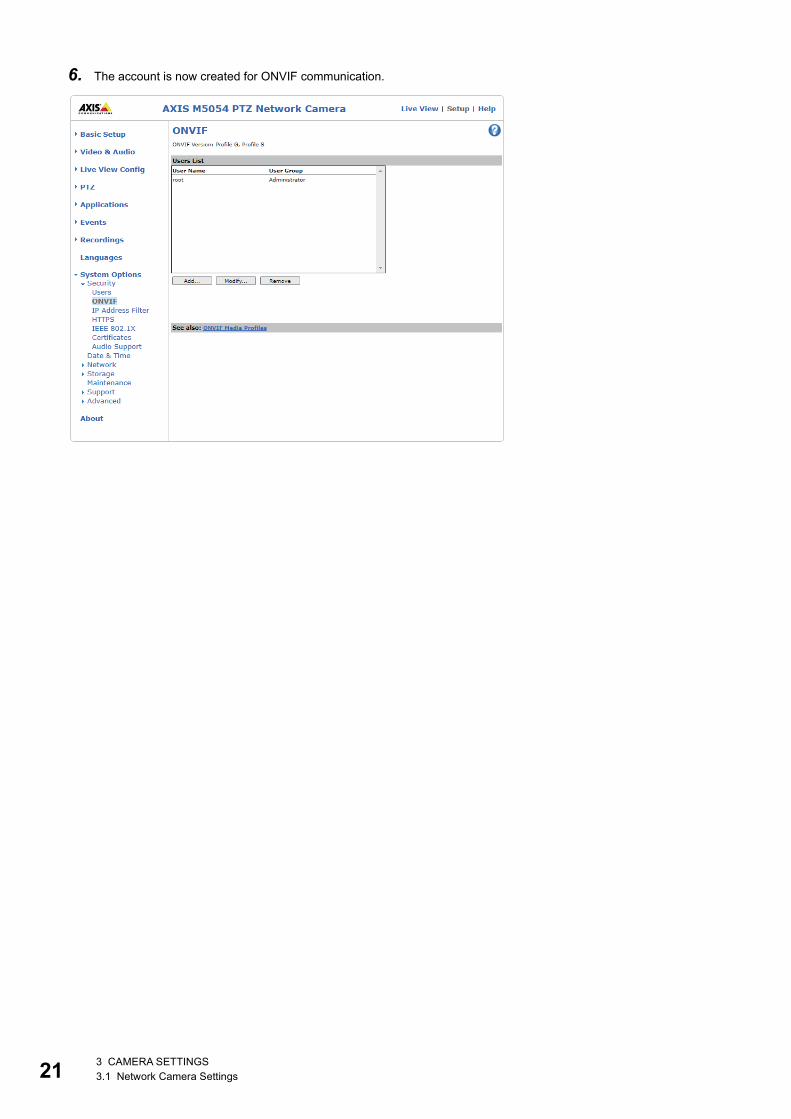
[System Options][Security][ONVIF]
3 CAMERA SETTINGS3.1 Network Camera Settings

3
4. Click the [Add] button.
5. Enter the user name and password in the setup window, select Administrator, and click the [OK] button.
3 CAMERA SETTINGS3.1 Network Camera Settings 20
21
6. The account is now created for ONVIF communication.
3 CAMERA SETTINGS3.1 Network Camera Settings

3
PTZ controlPTZ stands for Pan, Tilt, and Zoom to control the camera view. Pan enables horizontal movement of the camera lens, and Tilt enables vertical movement. With Zoom, you can zoom in or out on a part of the image.PTZ cameras can monitor large areas with a single camera.
Ex.
When adjusting the monitoring range of M5054 from the Web browser
Operating procedure1. Access the Web server. (Page 16 ONVIF supported network camera M5054)
2. The live view window appears.
Pan Tilt Zoom
3 CAMERA SETTINGS3.1 Network Camera Settings 22

23
3. Adjust the slide bar to adjust the Pan, Tilt, and Zoom movements.
4. Click the [Home] button to return the home position.
The PTZ control of the camera recorder module can be performed with the GOT.For the operation method, refer to the following.Page 74 NETWORK CAMERA ADJUSTMENT
3 CAMERA SETTINGS3.1 Network Camera Settings

4
4 PROGRAMMABLE CONTROLLER SETTINGS
4.1 Creating a New ProjectCreate a project for the CPU module.Set the following in GX Works3.
Operating procedure1. Create a new project.
2. Set the module configuration diagram.
[Navigation] [Module Configuration]
Set the series to RCPU.Set the type according to the system configuration.
Set the required modules (base unit, power supply module, CPU module, and information module "RD81RC96-CA") according to the system configuration.
4 PROGRAMMABLE CONTROLLER SETTINGS4.1 Creating a New Project 24

25
3. Confirm the parameters.
Right-click the module configuration diagram [Parameter] [Fix]
4. A camera recorder module is added.
When a camera recorder module is added, CPU parameters are automatically set.This is related to the following settings.Page 39 When configuring multiple recording settings, Page 93 Event History Function (Saving Device/Label Operations)
Click [Yes].
Click here.
These two items are automatically set.
4 PROGRAMMABLE CONTROLLER SETTINGS4.1 Creating a New Project

4
4.2 Parameter Settings of Camera Recorder ModuleUse GX Works3 to configure the parameter setting of the camera recorder module.For details on the parameter setting screen, refer to the following.MELSEC iQ-R System Recorder User's Manual (Application)
Module parameterSet the module parameters for the camera recorder module in the module parameter screen. When using multiple camera recorder modules, specify one as the main module and the others as sub modules.For details on the multiple module configuration, refer to the following.MELSEC iQ-R System Recorder User's Manual (Startup)
Operating procedure1. Set the module parameters for the camera recorder module.
[Navigation] window [Parameter] [Module Information] [RD81RC96-CA(Target module)] [Module Parameter] [Basic Settings]
IP address: 192.168.3.49 Recording operation setting: Main
When a recording file is saved in the SD memory card, the camera recorder module and personal computer must be connected via Ethernet to read the recording file. Therefore, set the IP address and subnet mask for the camera recorder module.
2. Write the parameters to the CPU module.For the detailed procedure, refer to the following.Page 46 Writing
Ex.
4 PROGRAMMABLE CONTROLLER SETTINGS4.2 Parameter Settings of Camera Recorder Module 26

27
Module extended parameterConfigure the settings of each network camera in the module extended parameter window.
Operating procedure1. Display the module extended parameter window of the camera recorder module. Click the [...] button in the "IP address"
field to open the camera individual settings window.
[Navigation] window [Parameter] [Module information] [(Camera recorder module)] [Module Extended Parameter]
2. Click the [Network Camera List] button in the camera individual settings window.
4 PROGRAMMABLE CONTROLLER SETTINGS4.2 Parameter Settings of Camera Recorder Module

4
3. Click the [Search] button.
4. When the searching is completed, click the [OK] button.
5. The ONVIF supported network cameras being connected are displayed in a list. Select the camera to set, and click the [OK] button.
4 PROGRAMMABLE CONTROLLER SETTINGS4.2 Parameter Settings of Camera Recorder Module 28

29
6. Click the [Communication Test] button.
7. Enter the user ID and password, and click the [Execute] button.
For the user ID and password to be entered in the communication test window, enter the account information for ONVIF communication created in Page 10 Network Camera Settings.
8. When the communication test is succeeded, the following window appears. Click the [OK] button.
4 PROGRAMMABLE CONTROLLER SETTINGS4.2 Parameter Settings of Camera Recorder Module

4
9. Check the connected camera in communication test result, and click the [Close] button.
10.Click the [Yes] button.
11. Click the [OK] button to complete the setting.
Adding a camera comment will make it easier to identify the camera later.
This is automatically inputted in step 10.
4 PROGRAMMABLE CONTROLLER SETTINGS4.2 Parameter Settings of Camera Recorder Module 30

31
12.Configure the settings for another ONVIF supported network camera in the same way as in steps 5 to 11.
13.Click the [Common Settings] button and configure the settings related to GOT linkage.
• By using the GOT linkage function, the live video of the network camera can be checked and PTZ control can be performed with the GOT connected to the CPU module in the same network as the network camera.
• GOT linkage requires the FTP server settings in advance.For details, refer to the following.Mitsubishi Electric Programmable Controller Camera Recorder Module RD81RC96-CA Sample Screen Manual (BCN-P5999-1333)
4 PROGRAMMABLE CONTROLLER SETTINGS4.2 Parameter Settings of Camera Recorder Module

4
14. After setting the following items, click the [OK] button.GOT Linkage Enable/Disable: Enable
IP Address: 192.168.3.30 Login Name: Login name set in the FTP server setting Password: Password set in the FTP server setting
• For the IP address, set the IP address of the connected GOT. When using GT SoftGOT, set the IP address of the personal computer.
• Perform an FTP communication test to verify that the entered values are correct.
15.Click the [OK] button to complete the settings of the camera recorder module.
Ex.
4 PROGRAMMABLE CONTROLLER SETTINGS4.2 Parameter Settings of Camera Recorder Module 32

33
4.3 Recording SettingThis section describes the setting method to use the recording function of the camera recorder module.The recording function stores the data (device or label) sampled by the CPU module and the video data recorded by the network camera in the camera recorder module, outputs the data for a saving period to a recording file when a file saving trigger is satisfied, and saves it to the SD memory card or file server.
Process of saving data■Saving devices and labels
: Sampling data
Setting 1
Setting 2
CPU module
Recording buffer
Setting 1
Setting 2
Camera recorder module SD memory card/file server
Recording file
Setting 1
Recording file
Setting 2
File saving trigger
A CPU module samples a device and label specified as a sampling target in the buffer area for data sampling.A camera recorder module accumulates the device and label sampled in the buffer area for data sampling in the recording buffer.The camera recorder module outputs data for a saving period to a recording file and saves it to a save destination specified in the recording setting when a file saving trigger is satisfied.
Device/label area
Buffer area for data sampling
4 PROGRAMMABLE CONTROLLER SETTINGS4.3 Recording Setting
4
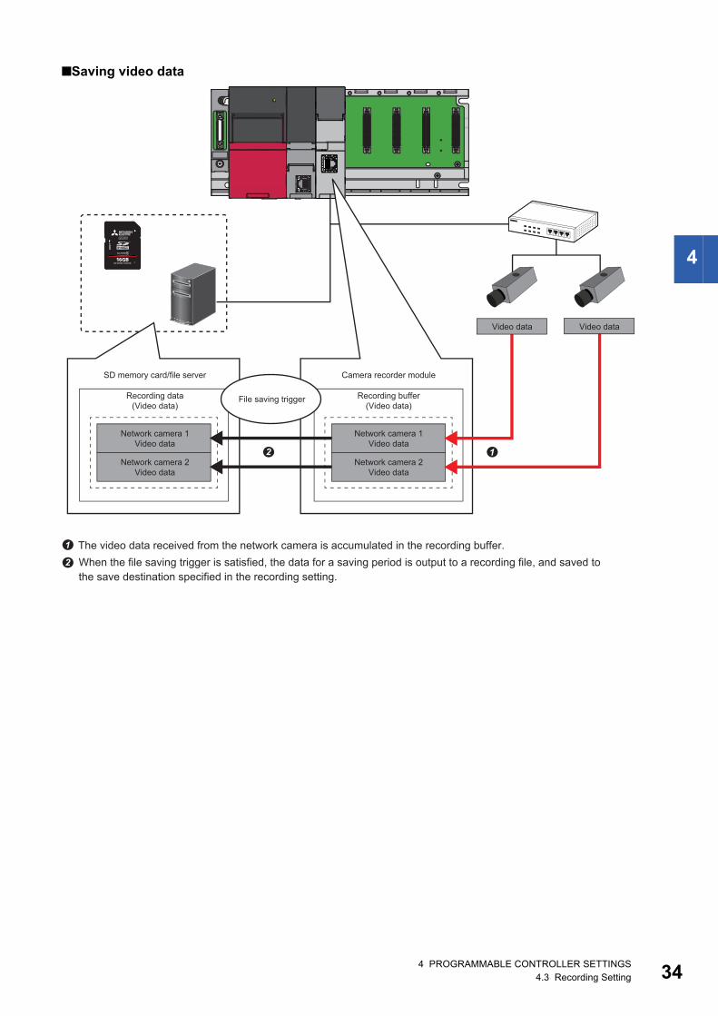
■Saving video data
Recording buffer(Video data)
Recording data(Video data)
Network camera 1Video data
SD memory card/file server Camera recorder module
Video data
Network camera 2Video data
Network camera 1Video data
Network camera 2Video data
File saving trigger
The video data received from the network camera is accumulated in the recording buffer.When the file saving trigger is satisfied, the data for a saving period is output to a recording file, and saved to the save destination specified in the recording setting.
Video data
4 PROGRAMMABLE CONTROLLER SETTINGS4.3 Recording Setting 34

35
Creating the recording settingUse GX Works3 to configure the recording setting of the camera recorder module.For details on the recording setting screen, refer to the following.MELSEC iQ-R System Recorder User's Manual (Application)There are two recording methods: "File Saving Trigger Only" and "Recording Startup Trigger + File Saving Trigger". The following shows the setting example with the recording method using only the file saving trigger for recording data from 10 seconds before to 5 seconds after the device M0 turns on.
Operating procedure1. Add a new recording setting.
[Navigation] window [Parameter] [Recording Setting] Right-click [New]*1
*1 A new setting can also be created from the recording menu.
Setting item DescriptionRecording Setting Configure the settings required for recording.
■Settings• Recording Method: File Saving Trigger Only• Specify the Devices/Labels in the Program in a Batch: Select• Device: M0• Saving Path Setting: SD memory card• Video Data Receiving Target Setting: Select all
Click here to configure the recording setting.
Click here.
4 PROGRAMMABLE CONTROLLER SETTINGS4.3 Recording Setting
4
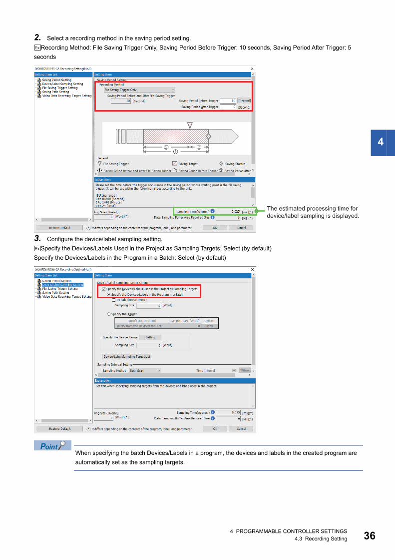
2. Select a recording method in the saving period setting.Recording Method: File Saving Trigger Only, Saving Period Before Trigger: 10 seconds, Saving Period After Trigger: 5
seconds
3. Configure the device/label sampling setting.Specify the Devices/Labels Used in the Project as Sampling Targets: Select (by default)
Specify the Devices/Labels in the Program in a Batch: Select (by default)
When specifying the batch Devices/Labels in a program, the devices and labels in the created program are automatically set as the sampling targets.
Ex.
The estimated processing time for device/label sampling is displayed.
Ex.
4 PROGRAMMABLE CONTROLLER SETTINGS4.3 Recording Setting 36

37
4. Set the device to be used as the file saving trigger in the file saving trigger setting.Device: M0 (turning ON)
5. Specify the saving destination in the saving path setting.SD Memory Card
The recording file can be saved to the file server.For details on saving to the file server, refer to the following.MELSEC iQ-R System Recorder User's Manual (Application)
Ex.
Ex.
4 PROGRAMMABLE CONTROLLER SETTINGS4.3 Recording Setting

4
6. Select the target network camera to receive video data, and click the [OK] button in the video data receiving target setting.
4 PROGRAMMABLE CONTROLLER SETTINGS4.3 Recording Setting 38

39
When configuring multiple recording settingsUp to four recording settings can be made. By default, the buffer area setting for data sampling of the CPU parameter in settings 2 to 4 and recording buffer setting of the module parameter in the recorder module are set to 0. Therefore, set the size for each setting.
Operating procedure1. Double-click [Recording Buffer Setting] at the lower part of the module parameter window.
4 PROGRAMMABLE CONTROLLER SETTINGS4.3 Recording Setting

4
2. Change the recording buffer size to be used for the recording setting.
• The device/label data size can be set when "Recording Operation Setting" is to "Main". • Up to 800 MB can be set in total for device/label data and video data.
3. Configure the buffer area setting for data sampling in the CPU parameter.
[Navigation] window [Parameter] CPU module to be used [CPU Parameter]
4 PROGRAMMABLE CONTROLLER SETTINGS4.3 Recording Setting 40

41
The required size to be specified in the buffer area setting for data sampling in the CPU parameter can be checked in the recording setting screen.
4 PROGRAMMABLE CONTROLLER SETTINGS4.3 Recording Setting

4
4.4 Parameter Settings of CPU ModuleSet the IP address and subnet mask of the CPU module, and configure the event history settings and clock settings.
Own node settings
Operating procedure1. Display the own node setting window.
[Navigation] window [Parameter] Module to be used [Module Parameter] [Basic Settings] [Own Node Settings]
2. Set the IP address and subnet mask of the module to be used.
• If the IP address is blank, it is automatically set to 192.168.3.39. • Set the IP address of the CPU in the same segment as the IP address of the network camera set in the
following.Page 10 Network Camera Settings
4 PROGRAMMABLE CONTROLLER SETTINGS4.4 Parameter Settings of CPU Module 42

43
Event history setting
Operating procedure1. Change the save destination to the memory card, and click [Apply].
[Navigation] window [Parameter] Module to be used [CPU Parameter] [RAS Setting] [Event History Setting]
• For details on the event history setting, refer to the following.Page 93 Event History Function (Saving Device/Label Operations) • When setting the save destination to the memory card, an SD memory card must be inserted to the CPU
module.
Click here after setting.
4 PROGRAMMABLE CONTROLLER SETTINGS4.4 Parameter Settings of CPU Module
4
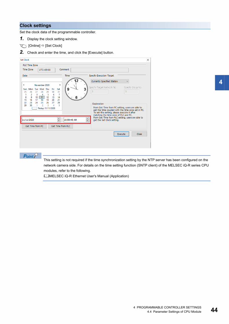
Clock settingsSet the clock data of the programmable controller.
1. Display the clock setting window.
[Online] [Set Clock]
2. Check and enter the time, and click the [Execute] button.
This setting is not required if the time synchronization setting by the NTP server has been configured on the network camera side. For details on the time setting function (SNTP client) of the MELSEC iQ-R series CPU modules, refer to the following.MELSEC iQ-R Ethernet User's Manual (Application)
4 PROGRAMMABLE CONTROLLER SETTINGS4.4 Parameter Settings of CPU Module 44

45
4.5 Creating a ProgramThe following program is used as a recording example.
Ex.
Set file saving trigger
4 PROGRAMMABLE CONTROLLER SETTINGS4.5 Creating a Program

4
4.6 WritingWrite the parameters, program, and recording setting to the CPU module.Then, reset the CPU module or turn off and on the power.
Operating procedure1. Start GX Works3 and connect to the personal computer.
[Online] [Current Connection Destination]
2. Write the data to the programmable controller.
[Online] [Write to PLC] from the menu
Configure the settings as shown on the right.
4 PROGRAMMABLE CONTROLLER SETTINGS4.6 Writing 46

47
3. Select [Parameter + Program], and then click the [Execute] button.
Click here to write the data.
Click here.
4 PROGRAMMABLE CONTROLLER SETTINGS4.6 Writing

5
5 GOT SETTINGSCreate a new GOT project and configure the settings to sample the resource data.
5.1 Creating a New ProjectCreate a new GOT project. Set the following in GT Designer3.
Operating procedure1. Start GT Designer3.
2. Set as follows in the New Project Wizard and create a new project.
5 GOT SETTINGS5.1 Creating a New Project 48

49
5.2 Setting for Creating Operation Log FilesConfigure the settings in GT Designer3 to collect operation logs of the GOT.For details on the operation log, refer to the following.GT Designer3 (GOT2000) Screen Design Manual
Operating procedure1. Select [Operation Log] to display the Environmental Setting window.
[Common] [GOT Environmental Setting] [Operation Log]
2. Select [Collect operation logs] and set the save destination.Save Destination: A: Standard SD CardEx.
5 GOT SETTINGS5.2 Setting for Creating Operation Log Files

5
3. Set the log target and click the [Apply] button. Click the [OK] button to complete the setting.
5 GOT SETTINGS5.2 Setting for Creating Operation Log Files 50

51
5.3 Setting for Creating Alarm Log FilesConfigure the settings in GT Designer3 to create alarm log files of the GOT.For details on the alarms, refer to the following.GT Designer3 (GOT2000) Screen Design Manual
System alarm observationConfigure the save setting for system alarm observation. Create the alarm target with the desired settings.
Operating procedure1. Display the [System Alarm Observation] dialog.
[Common] [Alarm] [System Alarm Observation]
2. Select [Save alarm log files] and set the save destination. Click the [OK] button to complete the setting.Drive Name: A: Standard SD CardEx.
5 GOT SETTINGS5.3 Setting for Creating Alarm Log Files

5
User alarm observationConfigure the save setting for user alarm observation. Create the alarm target with the desired settings.
Operating procedure1. Display the [User Alarm Observation] dialog.
[Common] [Alarm] [User Alarm Observation]
2. Create a new user alarm with the desired settings, select [Save alarm log files], and set the save destination. Click the [OK] button to complete the setting.
Drive Name: A: Standard SD CardEx.
5 GOT SETTINGS5.3 Setting for Creating Alarm Log Files 52
53
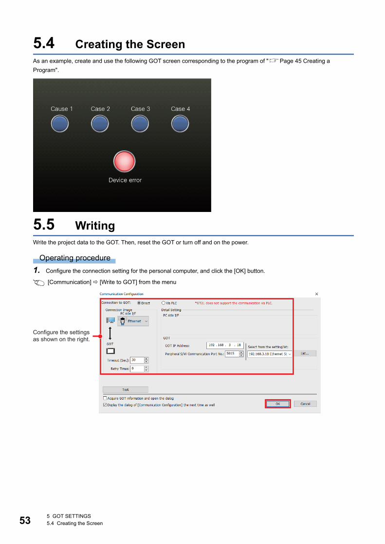
5.4 Creating the ScreenAs an example, create and use the following GOT screen corresponding to the program of "Page 45 Creating a Program".
5.5 WritingWrite the project data to the GOT. Then, reset the GOT or turn off and on the power.
Operating procedure1. Configure the connection setting for the personal computer, and click the [OK] button.
[Communication] [Write to GOT] from the menu
Configure the settings as shown on the right.
5 GOT SETTINGS5.4 Creating the Screen

5
If data cannot be written with Ethernet, connect the GOT and personal computer with USB and perform writing via USB.
2. Set the write data and write destination, and click the [GOT Write] button.
Configure the settings as shown on the right.
Click here to write the data.
5 GOT SETTINGS5.5 Writing 54

55
6 RECORDINGOperate the program of "Page 45 Creating a Program" and the GOT screen of "Page 53 Creating the Screen" to perform recording, and read the recorded data from the camera recorder module.
Operating procedure1. Switch the CPU module to the RUN state. Check that the RUN LED and OPR LED of the camera recorder module turn
on.
The recording function automatically starts when the CPU module is switched to the RUN state.
2. Open the program and intelligent function module monitor in GX Works3.
Right-click [(Target camera recorder module)] [Register to Intelligent Function Module Monitor].
3. Start monitoring (all the windows).
4. Check if the recording function operates normally on the intelligent function module monitor.
5. Turn on the switch (Cause 2) on the GOT.
6 RECORDING

6
6. M0 (file saving trigger) turns on.
7. When the file saving trigger is satisfied, the recording file is saved in the SD memory card of the camera recorder module.
Error cause 2 (M50) turns on.
Check that M0 (File saving trigger) is on.
6 RECORDING 56

57
With the recording monitor, the operation of the recording function can be stopped and restarted, and the status can be checked.
[Diagnostics] [Recording Monitor]Click the [Execution] button for the camera monitor to display the operation status of the network camera connected to the camera recorder module.
For details on the recording monitor, refer to the following.MELSEC iQ-R System Recorder User's Manual (Application)
6 RECORDING

6
8. Read the recording file from the camera recorder module.
[Recording] [Read Recording File]
9. When a window for checking the communication status appears, click the [OK] button.
10. Select the recording file to be read, and click the [Read to Personal Computer] button to save it in the personal computer.
Multiple recording files cannot be read.When multiple recording files are selected, the following window appears.
Click here to open the read screen.
Click here.
Select.
Click here to save the data in the personal computer.
6 RECORDING 58

59
7 CHECKING RECORDED RECORDING FILESThis chapter describes how to check the recorded recording files.
7.1 Reproducing the Trouble SituationCheck the situation of the error using the offline monitor function.The offline monitor function can be used to reproduce the situation of the error on the engineering tool by replaying device/ label data, video data, and event history saved in the programmable controller (camera recorder module) on the offline monitor.The following describes how to start the offline monitoring.
Operating procedure1. Use the recording file read from the programmable controller (camera recorder module) to perform offline monitoring.
[Recording] [Start Offline Monitor] [Recording File]
2. Select the recording file to open.
Click the [Open] button.
Select the MELRC file.
7 CHECKING RECORDED RECORDING FILES7.1 Reproducing the Trouble Situation

7
3. The offline monitoring starts.
■Seek barThe seek bar is a function for specifying the index (serial number to be recorded in the recording file per scan) of the data to be monitored.The seek bar can apply the specified index or the monitor value of the index to the linked monitor screen, "Event History (Offline Monitor)" window, and GX LogViewer.
■Event history (offline monitor)The event information (error information, operation history, system information, and current value change history) stored in the recording file being monitored can be checked.
By operating the slider of the seek bar, the event information of the specified index can be checked.In addition, selecting the event information whose background color is light green moves the slider of the seek bar to the corresponding index and applies the monitor value of the index to the monitor screen.
Seek bar
Event history (Offline monitor)
7 CHECKING RECORDED RECORDING FILES7.1 Reproducing the Trouble Situation 60

61
Checking the video in the camera (GX VideoViewer)The video data recorded by the network camera and saved in the camera recorder module can be replayed using GX VideoViewer.By adding log markers to the points which may cause the device error and reading the log marker information file (*.vms) in GX Works3, the log markers added in GX VideoViewer can be added to the seek bar of the offline monitoring in GX Works3 to synchronize and check the program operation.
Operating procedure1. Start GX VideoViewer.
[Tool] [GX VideoViewer]
2. Select the video data and click the [Open] button.
7 CHECKING RECORDED RECORDING FILES7.1 Reproducing the Trouble Situation

7
3. Replay the video with the button.
4. Add a log marker in the video with the button.
The parts of the video where log markers have been added can be played back frame by frame with the buttons.
The selected screen is highlighted in a light blue box.
Bars other than red indicate the points where log markers are added.
7 CHECKING RECORDED RECORDING FILES7.1 Reproducing the Trouble Situation 62

63
Checking the changes of waveform data (GX LogViewer)Display the devices/labels selected in the monitor screen of the offline monitor function in a graph in GX LogViewer.
Operating procedure1. Select a device in the program editor or watch window.
2. Select the waveform display.
Right-click shortcut menu [Wave Display]
3. The "Historical Trend" window of GX LogViewer is displayed.
PrecautionsUp to 32 devices/labels can be registered to GX LogViewer.
Select the device.
7 CHECKING RECORDED RECORDING FILES7.1 Reproducing the Trouble Situation

7
The seek bar in GX Works3 and the red cursor in GX LogViewer are linked.Moving the slider on the seek bar in GX Works3 moves the red cursor in GX LogViewer, and moving the red cursor in GX LogViewer moves the slider on the seek bar in GX Works3 in synchronization.
Checking the GOT operation status (GOT offline monitor)The monitor screen of the GOT when an error occurs can be displayed and checked.
Operating procedure1. Start offline monitoring. (Page 59 Reproducing the Trouble Situation)
2. Start the GOT offline monitor.
[Recording] [GOT Offline Monitor] [Start]
3. Select the project file of GT Designer3 to open.
Click the [Open] button.
7 CHECKING RECORDED RECORDING FILES7.1 Reproducing the Trouble Situation 64

65
4. The GOT offline monitor is displayed.
7 CHECKING RECORDED RECORDING FILES7.1 Reproducing the Trouble Situation

7
Checking the GOT operation history (Resource File Viewer)The operation logs and alarm history can be displayed in a list and confirmed from resource files recorded by the GOT.Read resource files from the GOT before using Resource File Viewer.For how to read files from the GOT, refer to the following.GT Designer3 (GOT2000) Screen Design Manual
Operating procedure1. Start offline monitoring. (Page 59 Reproducing the Trouble Situation)
2. Start the GOT offline monitor. (Page 64 Checking the GOT operation status (GOT offline monitor))
3. Configure the Resource File Viewer setting on the GOT offline monitor.
[Resource File Viewer] [Resource File Viewer Operation]
4. Set the resource files to be displayed and click [Start All]*1.
7 CHECKING RECORDED RECORDING FILES7.1 Reproducing the Trouble Situation 66

67
*1 When the Resource File Viewer Operation window is closed, Resource File Viewer can be started from [Start All] or [Start Resource File Viewer] in [Resource File Viewer].
5. Resource File Viewer appears.
7 CHECKING RECORDED RECORDING FILES7.1 Reproducing the Trouble Situation

7
7.2 Replay Synchronized with the Seek BarThe engineering tool can be synchronized and replayed by moving the slider of the seek bar in the offline monitor.
Editor, event history, and GX LogViewerIn synchronization with the movement of the slider on the seek bar, the editor being monitored offline, Event History (Offline Monitor) window, and red cursor in GX LogViewer move.
The movement of the slider on the seek bar is shown in the editor during offline monitoring.
Moving the slider moves the red cursor.
Moving the red cursor moves the slider.
Moving the slider moves the cursor to the event at the specified index.
Selecting an event moves the slider to the corresponding index.
7 CHECKING RECORDED RECORDING FILES7.2 Replay Synchronized with the Seek Bar 68

69
GOT offline monitorThe GOT monitor screen synchronized with the movement of the slider on the seek bar can be displayed and checked.
Offline monitor (GX Works3)
GOT offline monitor (GT Designer3)
Normal operation Device error
7 CHECKING RECORDED RECORDING FILES7.2 Replay Synchronized with the Seek Bar
7
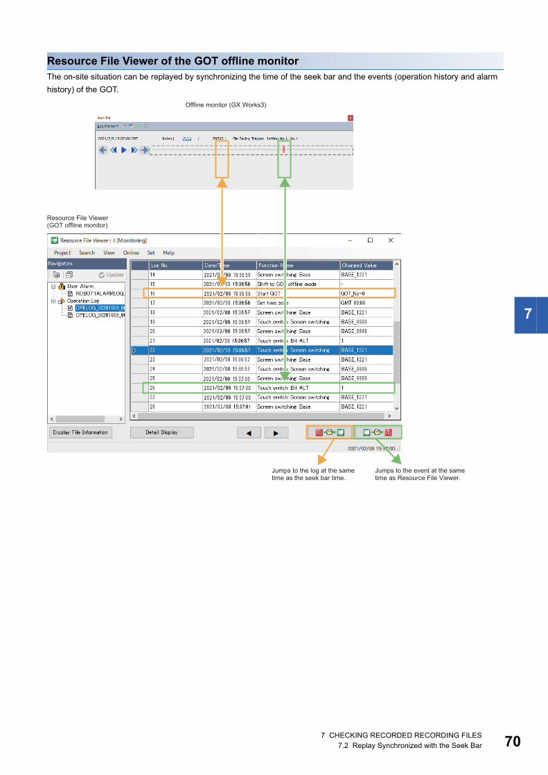
Resource File Viewer of the GOT offline monitorThe on-site situation can be replayed by synchronizing the time of the seek bar and the events (operation history and alarm history) of the GOT.
Offline monitor (GX Works3)
Resource File Viewer(GOT offline monitor)
Jumps to the log at the same time as the seek bar time.
Jumps to the event at the same time as Resource File Viewer.
7 CHECKING RECORDED RECORDING FILES7.2 Replay Synchronized with the Seek Bar 70

71
7.3 Finding the Error Factor DeviceThe data flow analysis function automatically creates a data flowchart from the program of GX Works3 to visually display the devices/labels to be the conditions for executing the basing point device/label to be analyzed or those affected by the execution.The following describes the procedure for starting the operation of the data flow analysis function.
Operating procedure1. Start GX Works3, and open the program.
2. Select a device to be the basing point, and execute the data flow analysis.
Right-click [Dataflow Analysis]
7 CHECKING RECORDED RECORDING FILES7.3 Finding the Error Factor Device

7
3. The data flow is displayed. Click the [Start Monitoring] button.
4. The monitor value of the device/label is displayed.
7 CHECKING RECORDED RECORDING FILES7.3 Finding the Error Factor Device 72
73
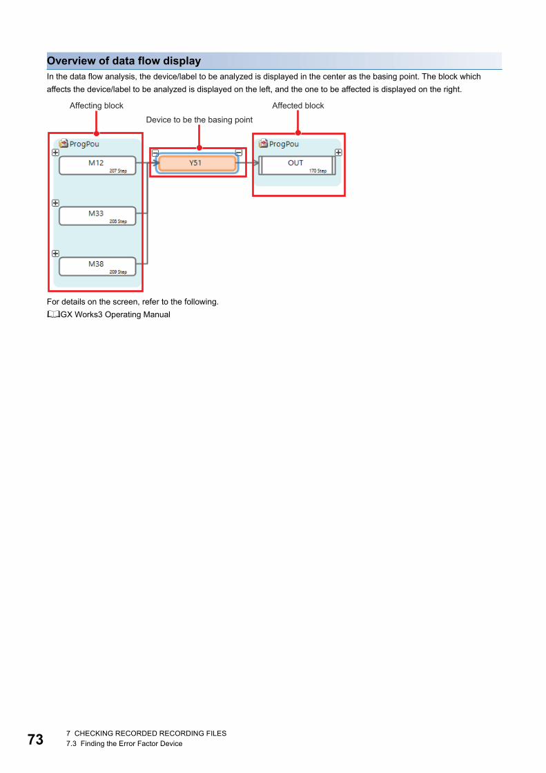
Overview of data flow displayIn the data flow analysis, the device/label to be analyzed is displayed in the center as the basing point. The block which affects the device/label to be analyzed is displayed on the left, and the one to be affected is displayed on the right.
For details on the screen, refer to the following.GX Works3 Operating Manual
Device to be the basing point
Affecting block Affected block
7 CHECKING RECORDED RECORDING FILES7.3 Finding the Error Factor Device

8
8 NETWORK CAMERA ADJUSTMENT
8.1 Adjustment with GOT /GT SoftGOT2000By using the GOT linkage function, the live video of network camera and the PTZ control can be performed with the GOT/SoftGOT connected to the CPU module in the same network as the network camera. The live video can be checked and the PTZ control can be adjusted by using the GOT sample screen.For details on the settings and sample screens used in this guide, refer to the following.Mitsubishi Electric Programmable Controller Camera Recorder Module RD81RC96-CA Sample Screen Manual (BCN-P5999-1333)*1
*1 It can be downloaded from the Mitsubishi Electric Factory Automation Global Website.www.mitsubishielectric.com/en
Operating procedure1. Start the GOT with the sample program written, or open the sample program on GT SoftGOT2000.
2. Select the target camera recorder module.
8 NETWORK CAMERA ADJUSTMENT8.1 Adjustment with GOT /GT SoftGOT2000 74
75
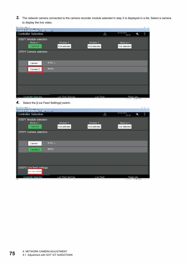
3. The network camera connected to the camera recorder module selected in step 2 is displayed in a list. Select a camera to display the live video.
4. Select the [Live Feed Settings] switch.
8 NETWORK CAMERA ADJUSTMENT8.1 Adjustment with GOT /GT SoftGOT2000

8
5. After selecting the video quality and video rotation angle, select the [Live Feed] switch.
6. When the live feed screen is displayed, select [Start] to display the live video of the selected camera.
8 NETWORK CAMERA ADJUSTMENT8.1 Adjustment with GOT /GT SoftGOT2000 76

77
7. P (pan), T (tilt), and Z (zoom) of the selected network camera can be changed by moving the slider bar.
The adjustment can be performed only on the ONVIF supported network camera that supports the PTZ function.
8 NETWORK CAMERA ADJUSTMENT8.1 Adjustment with GOT /GT SoftGOT2000

8
Registration of the preset positionThe following describes how to register the motoring range adjusted in the live feed screen as the preset position.
Operating procedure1. Select the preset position list screen of the sample program.
2. Enter the name with the [Slct.] switch of the target preset position No. selected, and select [ENTER].
8 NETWORK CAMERA ADJUSTMENT8.1 Adjustment with GOT /GT SoftGOT2000 78

79
3. Select [Register] to register the values of P (pan), T (tilt), and Z (zoom) used in the live feed screen as No.1 preset position.
4. Select the preset No. to execute the registered preset position in the live feed screen.
8.2 Adjustment with GX Works3The monitoring range of the network camera can be adjusted with the preset position setting of GX Works3. The adjusted monitoring range can be registered as the preset position to the camera recorder module.For details on the camera control function (PTZ), refer to the following.MELSEC iQ-R System Recorder User's Manual (Application)
8 NETWORK CAMERA ADJUSTMENT8.2 Adjustment with GX Works3

9
9 OPERATION EXAMPLEChapter 3 through Chapter 7 describe the settings and how to start the functions of the recording, reproduction, and analysis that are the three phases of the system recorder. This chapter shows examples of practical use of the system recorder.9.1 How to Check the Recording ResultReplay the data sampled by the camera recorder module and video recorded by the camera to predict the error cause, and then further investigate the cause by analysis.
Operation detailsThe following shows an operation example to investigate the cause of a device error occurred in the workpiece inspection process.
1. Workpieces flow on the belt conveyor.
2. The limit switch detects the flowing workpiece and its product No., and perform pass/fail inspection.
3. If any of four causes occurs, such as a failed product generation or detection of multiple workpieces, a device error occurs.
4. A device error triggers the data sampled by the camera recorder unit to be saved in the SD memory card.
Belt conveyor
Workpiece
Network camera
1.
2.
3. 4.
GOT
Workpiece
Switch
Device error cause
9 OPERATION EXAMPLE9.1 How to Check the Recording Result 80

81
Analysis procedureIf a device error which is a saving trigger of the camera recorder module turns on, the error cause is determined from among the four causes that are the conditions of turning on the device error. As an example, the arrival of a failed product is assumed to be the cause of the error. Then, check the device/label value which causes the error.The following describes the analysis procedure.
GX Works3 GX VideoViewerGX LogViewer
Log marker
Data flow analysis
Link
Use GX LogViewer to check the cause of the device error set as the saving trigger.
Check the device which is the execution condition of the error cause in the program of GX Works3. Click a device in the data flow analysis screen to jump to the program where the clicked device is located.
Check the operation of the destination program.
After the cause is determined, set the device as the basing point device, and check the execution condition of the basing point device by data flow analysis.
After the execution condition is determined, add a log marker at the point where the execution condition is operated with GX VideoViewer, and add the log marker information to the seek bar of GX Works3.
Synchronization reproduction
9 OPERATION EXAMPLE9.1 How to Check the Recording Result

9
Synchronous playback of GX Works3 and GX LogViewerCheck which one of the four error causes has caused the error.Operating procedure1. Start offline monitoring. (Page 59 Reproducing the Trouble Situation)
2. Double-click "File Saving Trigger Establishment" in the event history to open the program of the file saving trigger establishment condition.
At this point, you cannot tell which of the four devices causes the device error.
3. To determine the cause, display the waveform data in GX LogViewer.
Select a device/label Right-click [Wave Display]
Error cause Set file saving trigger
Select a device/label to display the waveform.
9 OPERATION EXAMPLE9.1 How to Check the Recording Result 82
83
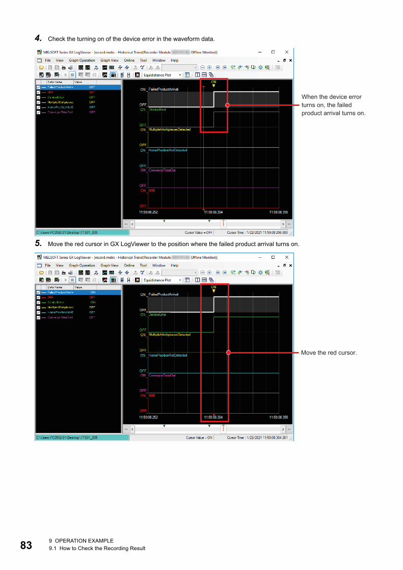
4. Check the turning on of the device error in the waveform data.
5. Move the red cursor in GX LogViewer to the position where the failed product arrival turns on.
When the device error turns on, the failed product arrival turns on.
Move the red cursor.
9 OPERATION EXAMPLE9.1 How to Check the Recording Result

9
6. The seek bar in GX Works3 moves in synchronization with the red cursor in GX LogViewer. Check that the error cause is ON in the program.
7. From the above, it is determined that the failed product arrival has caused the device error.
Error cause turns on.
It moves to the same operation position as the red cursor in GX LogViewer.
9 OPERATION EXAMPLE9.1 How to Check the Recording Result 84

85
Data flow analysisAnalyze the device/label error which has caused the device error to inspect the error cause.
Operating procedure1. Perform the data flow analysis based on the device/label that caused the error. (Page 71 Finding the Error Factor
Device)
Right-click [Dataflow Analysis]
2. Check the execution condition to turn on the failed product arrival.
3. It is determined that comparison of the product No. setting value and detected product No. value is the execution condition that turns on the product No. mismatch signal and failed product arrival.
Device to be the basing point
Expand items on the left side.
9 OPERATION EXAMPLE9.1 How to Check the Recording Result

9
Adding log markers of GX VideoViewer to GX Works3Add log markers at the point to check the program operation in GX VideoViewer, and synchronize them with the seek bar in GX Works3.Operating procedure1. Since the workflow analysis shows that the product No. mismatch signal is involved, add log markers at the part of the
video where the product No. of the workpiece is determined with GX VideoViewer. (Page 61 Checking the video in the camera (GX VideoViewer))
2. Synchronize the log markers with the offline monitoring in GX Works3.
[Log Marker] [Read]
9 OPERATION EXAMPLE9.1 How to Check the Recording Result 86

87
3. Open the log marker information file (*.vms).
*1 When GX VideoViewer is started and the video with log markers have been added is opened, they can be synchronized with the following procedure.
[Log Marker] [Read from GX VideoViewer]
4. The log markers added in GX VideoViewer are added to the seek bar.
9 OPERATION EXAMPLE9.1 How to Check the Recording Result

9
Jump to a device/labelCheck the detected product No. at the point where a log marker has been added.Operating procedure1. Double-click the detected product No. in the data flow analysis.
2. Jump to the label that contains the product No. read with the limit switch.
3. Since there is a mismatch between the set product No. and the detected product No., it can be determined that the product is not accepted and an error has occurred.
9 OPERATION EXAMPLE9.1 How to Check the Recording Result 88
89
APPENDIXAppendix 1 TroubleshootingThis section describes the details, causes, and corrective actions of errors which may occur.
Errors in the camera recorder moduleThe following shows how to check errors which may occur in the camera recorder module and their troubleshooting.
Error checking methodThere are three ways to check the errors of the camera recorder module.
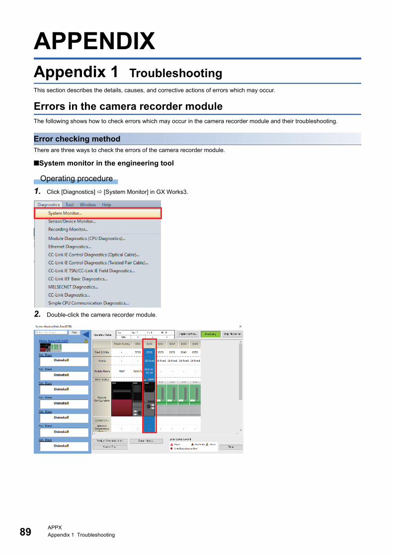
■System monitor in the engineering tool
Operating procedure1. Click [Diagnostics] [System Monitor] in GX Works3.
2. Double-click the camera recorder module.
APPXAppendix 1 Troubleshooting

A
3. In the module diagnostics window, check the details and corrective action of the error which has occurred.
■Buffer memoryError codes can be checked with the following buffer memory areas. • Current error area (Un\G140 to 149) • Error log (Un\G152 to 311)For details on the buffer memory, refer to the following.MELSEC iQ-R System Recorder User's Manual (Application)
APPXAppendix 1 Troubleshooting 90

91
■Recording monitorThe operation status of the recording function for each recording setting can be checked with the recording monitor.
Operating procedure1. Click [Diagnostics] [Recording Monitor] in GX Works3.
2. The error status and error codes for each recording setting can be checked with the recording monitor.
APPXAppendix 1 Troubleshooting
A
Troubleshooting by symptomFor troubleshooting related to each symptom, refer to the following.MELSEC iQ-R System Recorder User's Manual (Application)
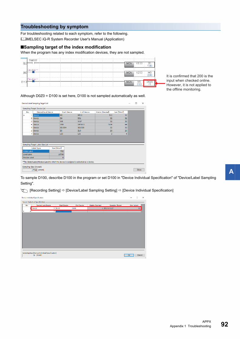
■Sampling target of the index modificationWhen the program has any index modification devices, they are not sampled.
Although D0Z0 = D100 is set here, D100 is not sampled automatically as well.
To sample D100, describe D100 in the program or set D100 in "Device Individual Specification" of "Device/Label Sampling Setting".
[Recording Setting] [Device/Label Sampling Setting] [Device Individual Specification]
It is confirmed that 200 is the input when checked online.However, it is not applied to the offline monitoring.
APPXAppendix 1 Troubleshooting 92

93
Appendix 2 Event History Function (Saving Device/Label Operations)
If "Save Device/Label Operations" is set in the event history setting of the CPU parameter, the event history is saved when a device/label operation is performed from an external device.It is automatically set to "Save" when the camera recorder module is added to the system configuration and the parameters are confirmed.Page 24 Creating a New Project
[CPU Parameter] [RAS Setting] [Event History Setting]
Since the data memory has a limited number of write cycles, the save destination is set to the memory card in this guide.For details on the event history setting, refer to the following.MELSEC iQ-R CPU Module User's Manual (Application)
APPXAppendix 2 Event History Function (Saving Device/Label Operations)

A
Operations to be loggedThe event history is saved when the device writing operations of the following operations and functions are selected.
Target device/label■DeviceAll the device writing operations that can be specified with the engineering tool and SLMP will be saved.
■LabelAll the label writing operations that can be specified with the engineering too (GX Works3 Version1.065T) will be saved.However, the label writing operations from the tools earlier than GX Works3 Version1.065T, GOT2000, and SLMP are displayed as GV, LV, LLV, or UV.
Operation and functionOperation from the engineering tool (Changing the current value) Watch window
Device/buffer memory batch monitor
SFC diagram editor (Activating and deactivating the selected steps)
Writing the device memory to the programmable controller
Writing the device/label by SLMP
Writing the device with an instruction (Writing operation from another station or another CPU)
Simple CPU communication function (Writing from the communication target)
APPXAppendix 2 Event History Function (Saving Device/Label Operations) 94

95
RELEVANT MANUALSThe following table lists the manuals related to the products described in this document.
Manual name [manual number] DescriptionMELSEC iQ-R System Recorder User's Manual (Startup)[SH-082279ENG]
Specifications, procedures before operation, and system configuration of the system recorder and specifications of the camera recorder module
MELSEC iQ-R System Recorder User's Manual (Application)[SH-082281ENG]
Functions, parameter settings, recording settings, and troubleshooting of the system recorder and detailed specifications of the camera recorder module
MELSEC iQ-R CPU Module User's Manual (Startup)[SH-081263ENG]
Specifications, procedures before operation, and troubleshooting of the CPU module
MELSEC iQ-R CPU Module User's Manual (Application)[SH-081264ENG]
Memory, functions, devices, and parameters of the CPU module
GX Works3 Operating Manual[SH-081215ENG]
System configuration, parameter settings, and online operations of GX Works3
MELSEC iQ-R Module Configuration Manual[SH-081262ENG]
Combinations of the available MELSEC iQ-R series modules, common information on the installation/wiring in the system configuration, and specifications of the power supply module, base unit, SD memory card, and battery
GX VideoViewer Version 1 Operating Manual[SH-082370ENG]
Basic operating procedure of GX VideoViewer and how to play video files
GT Designer3 (GOT2000) Screen Design Manual[SH-081220ENG]
Operations and settings of GT Designer3, screen design software for the GOT2000 series
GOT2000 Series User's Manual (Hardware)[SH-081194ENG]
Specifications, procedures before operation, and troubleshooting of the GOT2000 series
GOT2000 Series Connection Manual (Mitsubishi Electric Products) For GT Works3 Version1[SH-081197ENG]
How to connect the GOT2000 series to Mitsubishi Electric products such as the MELSEC iQ-R CPU

96
REVISIONS*The manual number is given on the bottom left of the back cover.
Japanese manual number: L-08781-C
2021 MITSUBISHI ELECTRIC CORPORATION
Revision date *Manual number DescriptionFebruary 2021 L(NA)08789ENG-A First edition
August 2021 L(NA)08789ENG-B ■Added or modified partsChapter 1, Section 3.1, 4.2
August 2021 L(NA)08789ENG-C The back cover has been modified.
This document confers no industrial property rights or any rights of any other kind, nor does it confer any patent licenses. Mitsubishi Electric Corporation cannot be held responsible for any problems involving industrial property rights which may occur as a result of using the contents noted in this document.
