mechanical and metallurgical characterization of friction stir welding joints of aa6061-t6 with...
TRANSCRIPT

Materials and Design 30 (2009) 180–187
Contents lists available at ScienceDirect
Materials and Design
journal homepage: www.elsevier .com/locate /matdes
Mechanical and metallurgical characterization of friction stir weldingjoints of AA6061-T6 with AA6082-T6
P.M.G.P. Moreira a,*, T. Santos b, S.M.O. Tavares a, V. Richter-Trummer a, P. Vilaça b, P.M.S.T. de Castro a
a FEUP – Faculdade de Engenharia, Universidade do Porto, R. Dr. Roberto Frias, 4200-465 Porto, Portugalb IST – Instituto Superior Técnico, Av. Rovisco Pais, 1049-001 Lisboa, Portugal
a r t i c l e i n f o
Article history:Received 6 December 2007Accepted 16 April 2008Available online 26 April 2008
Keywords:Friction stir weldingMetallographic analysisMechanical characterizationBending testDissimilar joints
0261-3069/$ - see front matter � 2008 Elsevier Ltd. Adoi:10.1016/j.matdes.2008.04.042
* Corresponding author. Tel.: +351 966631260; faxE-mail address: [email protected] (P.M.G.P. Moreir
a b s t r a c t
A mechanical and metallurgical characterization of friction stir welded butt joints of aluminium alloy6061-T6 with 6082-T6 was carried out. For comparison, similar material joints made from each one ofthe two alloys were used. The work included microstructure examination, microhardness, tensile andbending tests of all joints. An approximate finite element model of the joint, taking into account the spa-tial dependence of the tensile strength properties, was made, modelling a bending test of the weldments.This study shows that the friction stir welded dissimilar joint present intermediate mechanical propertieswhen compared with each base material. In tensile tests the dissimilar joint displayed intermediate prop-erties. For instance in the hardness profile the lowest values were obtained in the AA6082-T6 alloy plateside where rupture occurred, and in the nugget all type of joints present similar values.
� 2008 Elsevier Ltd. All rights reserved.
1. Introduction
Friction stir welding (FSW) [1], a solid-state joining processdeveloped and patented by the The Welding Institute (TWI),emerged as a welding technique to be used in high strength alloysthat were difficult to join with conventional techniques. The pro-cess was developed initially for aluminium alloys, but since thenFSW was found suitable for joining a large number of materials.Conventional fusion welding of aluminium alloys often producesa weld which suffers from defects, such as porosity developed asa consequence of entrapped gas not being able to escape fromthe weld pool during solidification. In contrast, with FSW the inter-action of a non consumable tool rotating and traversing along thejoint line creates a welded joint through visco-plastic deformationand consequent heat dissipation resulting in temperatures belowthe melting temperature of the materials being joined. Other inter-esting benefits of FSW compared to fusion processes are low dis-tortion, excellent mechanical properties in the weld zone,execution without a shielding gas, and suitability to weld all alu-minium alloys, [2].
Further to joints of similar alloys, FSW is being studied for weld-ing dissimilar alloys which can be of particular interest in someindustrial applications. Some works can be found in the literature,e.g. [3–7], but data is still scarce on the characterisation of thisjoint type. In this work the ability to join dissimilar alloys byFSW was studied using butt welded plates. The mechanical charac-
ll rights reserved.
: +351 22508 1584.a).
terization of friction stir welds of aluminium alloy 6061-T6 with6082-T6 was carried out. For comparison, similar joints made fromeach of the two alloys were also performed. The work includedmicrostructure examination, microhardness, tensile and bendingtests of all joint types. An approximate finite element model ofthe joint, taking into account the spatial dependence of the tensilestrength properties, was made, modelling a bending test of awelded specimen.
2. Material and methods
The alloys AA6082-T6 and AA6061-T6 are high strength Al–Mg–Si alloys that contain manganese to increase ductility and tough-ness. The chemical composition was determined before weldingby spectrometry using a SPECTROLAB M7, Table 1. For both alu-minium alloys a good agreement was found between the presentmeasurements and the supplier values. The T6 condition is ob-tained through artificial ageing at a temperature of approximately180 �C [8]. The friction stir welds of 3 mm thick plates were per-formed along the rolling direction. The process parameters imple-mented in this study resulted from a development process basedon visual analysis of top and bottom surfaces of the joint and pre-liminary bending tests with the root under tensile stresses en-abling to minimize the level of root defect. The selectedparameters were travel speed of 224 mm/min; tilt angle of 2.5�;rotating speed of 1120 rpm. In all trials, a modular tool was usedwith the following geometry: M5 threaded pin; shoulder wassmooth and 7� concave with 17 mm diameter.

Table 1Chemical composition (%) of the AA6082-T6 and AA6061-T6
Element AA6082-T6 AA6061-T6
SPECTROLAB M7 Supplier 6082-T6 SPECTROLAB M7 Supplier 6061-T6
Mg 0.69 0.6–1.2 0.84 0.9Al 97.4 Remaining 97.7 RemainingSi 0.91 0.7–1.3 0.54 0.59–0.62Mn 0.56 0.4–1 0.01 0.01Fe 0.23 0.5 0.40 0.5Cu 0.062 0.1 0.24 0.24–0.26Cr 0.035 0.25 0.18 0.18–0.19Zn 0.098 0.2 0.006 0.01–0.02Ti 0.019 0.1 0.031 0.02–0.03
Table 3Standard deviations for the tensile test results
Standard deviation (MPa) ry rr TP
FSW 6082-T6 1.8 0.8 5.6 0.2FSW 6082-T6 + 6061-T6 0.9 1.4 5.5 0.1FSW 6061-T6 0.3 1.2 1.0 0.1Base 6061-T6 5.0 4.2 4.8 0.5Base 6082-T6 0.3 0.4 3.2 1.3
P.M.G.P. Moreira et al. / Materials and Design 30 (2009) 180–187 181
Tensile tests of 3 mm thick specimens drawn transversal toweld line were performed according to ASTM E8-M [9] in orderto determine the mechanical properties (yield stress ry, rupturestress rt and Young’s modulus E) of the welded and base materials,using a 25 mm gage length and 1 mm/min cross-head speed. Thereduced section length is 60 mm and its width is 12.5 mm; theoverall specimen length is 200 mm and the width of the grip sec-tion is 20 mm. The specimen was obtained by CNC machining.
The hardness profiles can assist the interpretation of the weldmicrostructures and mechanical properties. Microhardness testswere performed in order to characterize the hardness profile inthe vicinity of the weld affected area. The microhardness testswere performed on a cross section perpendicular to the weld line,at mid thickness across the weld zone and into the parent material,using a 100 gf load.
For the analysis of microstructural changes due to the FSW pro-cess, the joints were cross-sectioned perpendicularly to the weld-ing direction and etched with HF reagent [10]. Microstructureswere acquired in different zones: transition between welded andbase material, welded material and base material.
Fig. 1. Tensile tests for welded material specimens.
Table 2Material properties for FS welded specimens, data acquired in tensile tests
FSW ry (MPa) rt (MP
Base 6082-T6 276.2 322.9Base 6061-T6 306.3 342.0FSW 6082-T6 134.3 221.3FSW 6082-T6 + 6061-T6 140.5 218.6
FSW 6061-T6 148.3 231.6
3. Results and discussion
3.1. Tensile tests
The stress/strain records of welded and base material speci-mens are presented in Fig. 1, whereas Table 2 presents the tensileproperties for friction stir welded specimens and base material ob-
Fig. 2. Microhardness profile of the FS welded specimens. (Data on a cross sectionperpendicular to the weld line, at mid thickness).
a) Elongation (%) Joint efficiency (%)
17.5 –17.1 –6.5 68.55.5 67.7 (6082-T6)
63.9 (6061-T6)5.9 64.2

182 P.M.G.P. Moreira et al. / Materials and Design 30 (2009) 180–187
tained through averaging the results from three stress/straincurves each. The standard deviation for each of the test sets is pre-sented in Table 3.
The friction stir welded and base material (BM) AA6061-T6specimens present the higher yield and rupture stresses. As con-cerns welded specimens, it was found that dissimilar joints presentan intermediate behaviour. These joints also present the smallestelongation value, and their ultimate stress is very close to thewelded AA6082-T6.
Fig. 3. Hardness profile thorough the joint thickness: (a) FS AA6
In the friction stir welded specimens, fracture occurred near theweld edge line, corresponding to the transition between the ther-mo-mechanically affected zone (TMAZ) and the heat affected zone(HAZ) and characterised by the lowest hardness as demonstratedin Fig. 2, a feature also documented in [11]. The fracture occurredaccording to 45� shear planes, as found in [12]. Considering jointefficiency as the ratio of the rupture stress of the base material di-vided by the rupture stress of the welded joint an analysis of alljoints was performed, Table 2. All joints presented approximately
082-T6; (b) FS AA6061-T6; (c) FS AA6082-T6 + AA6061-T6.

Fig. 4. Macrostructure of the dissimilar weld and each base material: (a) macrostructure of the FS AA6082-T6 weld; (b) macrostructure of the FS AA6061-T6 weld; (c)macrostructure of the dissimilar weld.
Fig. 5. FS welded AA6082-T6 joint microstructure: (a) stirred material limit, microstructure 1; (b) nugget structure detail, microstructure 2; (c) base material microstructure,microstructure 3.
P.M.G.P. Moreira et al. / Materials and Design 30 (2009) 180–187 183
184 P.M.G.P. Moreira et al. / Materials and Design 30 (2009) 180–187
the same efficiency; their values are similar to those presented byother authors for single material joints, e.g. [8,13,14].
3.2. Microhardness measurements
The Vickers hardness profiles for all welded specimens are pre-sented in Fig. 2. A hardness decrease occurs when approaching theTMAZ. The average hardness of the nugget zone (NZ) was found tobe significantly lower than the hardness of the base alloy. There is azone outside the nugget (transition between TMAZ and HAZ)which has the lower hardness value. In Harris and Norman’s work[13] it is suggested that the variation of the microhardness valuesin the welded area and parent material is due to the difference be-tween the microstructures of the base alloy and weld zone. Hard-ness in the dissimilar joints presented the lower values of all joints.The lower values occur in the AA6082-T6 alloy plate side. In thetensile tests of the dissimilar specimens it was observed that thefracture surface is coincident with this zone of lower values ofhardness. The hardness in the nugget area is similar for all jointsand it is always higher than the values in the transition betweenthe TMAZ and the HAZ.
A second hardness profile examination was carried out measur-ing the hardness through the specimen thickness, between theshoulder limits, for the three different joint types, Fig. 3. It was ver-ified in all joints that the minimum hardness values are coincidentwith the limits of the shoulder. It should be noticed that Fig. 3 isbased upon data obtained along three lines of measurement per-pendicular to the plate surface: two lines coinciding with shoulderlimits and one with the weld centre. In Fig. 3 root corresponds to
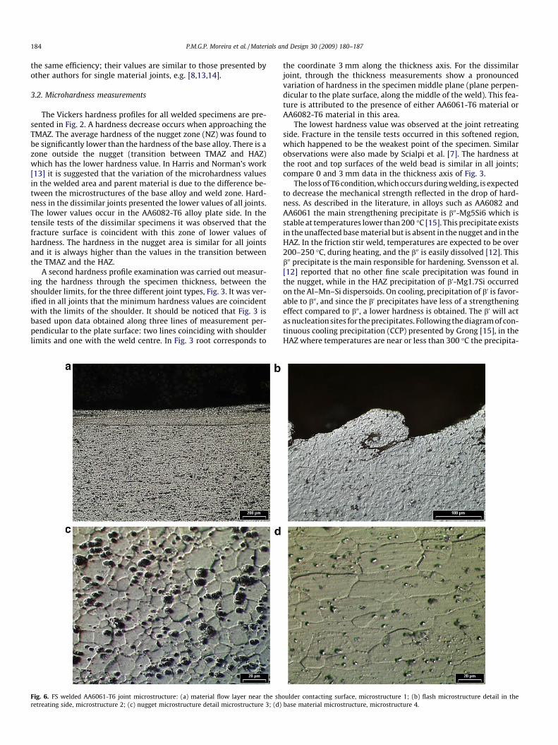
Fig. 6. FS welded AA6061-T6 joint microstructure: (a) material flow layer near the shretreating side, microstructure 2; (c) nugget microstructure detail microstructure 3; (d)
the coordinate 3 mm along the thickness axis. For the dissimilarjoint, through the thickness measurements show a pronouncedvariation of hardness in the specimen middle plane (plane perpen-dicular to the plate surface, along the middle of the weld). This fea-ture is attributed to the presence of either AA6061-T6 material orAA6082-T6 material in this area.
The lowest hardness value was observed at the joint retreatingside. Fracture in the tensile tests occurred in this softened region,which happened to be the weakest point of the specimen. Similarobservations were also made by Scialpi et al. [7]. The hardness atthe root and top surfaces of the weld bead is similar in all joints;compare 0 and 3 mm data in the thickness axis of Fig. 3.
The loss of T6 condition, which occurs during welding, is expectedto decrease the mechanical strength reflected in the drop of hard-ness. As described in the literature, in alloys such as AA6082 andAA6061 the main strengthening precipitate is b00-Mg5Si6 which isstable at temperatures lower than 200 �C [15]. This precipitate existsin the unaffected base material but is absent in the nugget and in theHAZ. In the friction stir weld, temperatures are expected to be over200–250 �C, during heating, and the b00 is easily dissolved [12]. Thisb00 precipitate is the main responsible for hardening. Svensson et al.[12] reported that no other fine scale precipitation was found inthe nugget, while in the HAZ precipitation of b0-Mg1.7Si occurredon the Al–Mn–Si dispersoids. On cooling, precipitation of b0 is favor-able to b00, and since the b0 precipitates have less of a strengtheningeffect compared to b00, a lower hardness is obtained. The b0 will actas nucleation sites for the precipitates. Following the diagram of con-tinuous cooling precipitation (CCP) presented by Grong [15], in theHAZ where temperatures are near or less than 300 �C the precipita-
oulder contacting surface, microstructure 1; (b) flash microstructure detail in thebase material microstructure, microstructure 4.

P.M.G.P. Moreira et al. / Materials and Design 30 (2009) 180–187 185
tion of b0 is very high, and as a consequence the transition from b00 tob0 by dissolution occurs. In the weld nugget, the temperature is ex-pected to be higher, therefore the MgSi precipitates go into solution.On cooling, the time for precipitation is limited, therefore only asmall volume fraction of the b0 precipitates are formed in the weldnugget. The nugget hardness recovery is due to recrystallization ofa very fine grain structure.
3.3. Metallographic analysis
AA6061-T6 has similar silicon and magnesium contents toAA6082-T6, but higher copper content and lower manganese con-tent. Aluminium alloys always contain some impurities, mainlyiron and silicon, [12]. For example, iron, silicon, manganese, cop-per, and chromium form fairly coarse intermetallic compounds.In the age hardenable alloys, hardening occurs through precipita-tion of very fine scale precipitates.
In Fig. 4 the macrostructure of friction stir welds of each singlematerial, and of dissimilar welds AA6082-T6 + AA6061-T6, are pre-sented. In each macrostructure the sites for microstructure exam-ination and different zones (NZ, TMAZ, and HAZ) are identified. Theretreating side, at the left side of each macrostructure, presentsmore flash and is also the location of the lower values of hardness.
FSW originates changes of microstructure. At the centre, nuggetzone, the mixture of the two different alloys is easily identified. Thenugget zone experiences high strain and is prone to recrystalliza-tion. Immediately at its side is the TMAZ which ends at the toolshoulder. Outside of the TMAZ there is a zone affected only bythe heat generated during the welding process, e.g. [11,16].
Fig. 7. Microstructure details of the dissimilar joint: (a) detail of the mixture of the two aof the two alloys, microstructure 2; (c) striations formed due to the pin rotation, microstmicrostructure 4.
Microstructural details of the friction stir welded AA6082-T6joint TMAZ are presented in Fig. 5. Since Fig. 5a represents the tran-sition of the stirred material to non-stirred material, the flow pat-terns can be easily identified at the left side of the microstructure.Fig. 5b, nugget microstructure detail, can be directly comparedwith Fig. 5c which represents its base material.
Microstructural details of the friction stir welded AA6061-T6joint TMAZ are presented in Fig. 6. Fig. 6a presents a material flowlayer near the shoulder contacting surface. Fig. 6b shows themicrostructure in the flash created at the retreating side duringwelding. Fig. 6c shows the weld nugget microstructure; whencompared with the base material microstructure, Fig. 6d, the smal-ler recrystallized grains of the nugget are identified.
Microstructural details of the dissimilar joint are presented inFig. 7. In the transition between the two alloys the lighter colour rep-resents the AA6061-T6. The different structure of the two alloys iseasily identified; the AA6061-T6 is characterized by larger grainsand the AA6082-T6 by precipitates dispersed in a finer matrix. It ispossible to notice a trace of particle concentration at the root ofthe weld bead, typical of the materials processing with conventionalFSW. This feature is more visible in the macrostructure of the dissim-ilar weld.
3.4. Bending tests
The mechanical resistance of all joint types and base materialspecimens was addressed using bending tests. These tests are verysensitive to defects near the surface of the weld bead, such as rootflaws.
lloys at the shoulder side, microstructure 1; (b) three different zones in the mixtureructure 3; (d) transition between friction stir welded materials in the weld nugget,

Fig. 8. Testing rig: (a) bending device test assemblage; (b) schematic representation and principal dimensions.
Fig. 9. Bending test results.
Fig. 10. Comparison between experimental results and FE results.
186 P.M.G.P. Moreira et al. / Materials and Design 30 (2009) 180–187
They were performed taking into consideration ASME code [17]and NP EN 910 standard [18], using specimens with dimensions of150 � 20 � 3 mm. During the test a 1 mm/min cross-head speedwas used and two specimens for each type of weld and base mate-rials were tested. The testing rig with its principal dimensions ispresented in Fig. 8. No root flaws or other defects were detectedin all joints. The load/displacement record was acquired duringtesting to identify the behaviour of each specimen, as shown inFig. 9.
Both base material specimens present a linear behaviour untilthe load of approximately 420 N is reached. For loads higher than420 N, for the same displacement the AA6061-T6 presents highermechanical resistance. The three welded joints present a linearbehaviour until a load of approximately 220 N. The friction stirwelded AA6061-T6 joint supports higher loads than the friction stirwelded AA6082-T6. The dissimilar weld joint shows an intermedi-ate behaviour.
3.4.1. Numerical simulation of bending testNumerical simulations of bending tests were performed using a
finite element model. As an approximation, stress–strain curves ofbase material and welded joints were used in relevant parts of thespecimen (a Poisson ratio of 0.33 was considered). These 2D planestrain simulations may give relevant information about these testsand about the mechanical properties of the welded material.
The software ABAQUS [19], taking into account material andgeometrical nonlinearities, was used in order to model the load
vs. displacement curves. In these models the stress–strain curvesused were obtained from tensile tests of base material and ofwelded zone. The rollers of the test device were defined by analyt-ical rigid surfaces and the frictionless contact between these sur-faces and the specimen was modelled. This is a complex problembecause large displacement theory and multiple stress-plasticstrain data were used.
The load vs. displacement behaviour was calculated and com-pared with experimental values for friction stir welded AA6082-T6, friction stir welded AA6061-T6 and friction stir weldedAA6082-T6 + AA6061-T6, Fig. 10, where a good agreement wasfound.
4. Conclusions
Friction stir butt welds of AA6082-T6 with AA6061-T6 wereproduced, as well as FS butt welds of each single alloy.
The friction stir welded AA6082-T6 material revealed loweryield and ultimate stresses, and the dissimilar joints displayedintermediate properties. In the tensile tests, failures occurred nearthe weld edge line where a minimum value of hardness was ob-served. The hardness profile of the dissimilar joint presents thelowest values of all joints in the AA6082-T6 alloy plate side; thiscorresponds to the location of rupture when tensile testing the dis-

P.M.G.P. Moreira et al. / Materials and Design 30 (2009) 180–187 187
similar joints. Nevertheless, in the nugget zone all three jointspresent similar values.
Microstructural changes induced by the friction stir weldingprocess were clearly identified in this study. Also, in the analysisof the dissimilar joint the mixture of the two alloys is easily iden-tified by the different etching response of both alloys.
It was possible to predict the joint bending behaviour using anapproximate finite element model. When compared with theexperimental tests, the simulation presented a good agreementup to approximately maximum load.
Acknowledgments
The work was partially supported by PhD scholarships FCT 299SFRH-BD-19281-2004, FCT SFRH-BD-29004-2006 and FP6 projectDaToN (Contract No. AST3-CT-2004–516053 of the European Un-ion). The laboratorial work of Rui Silva and the collaboration ofMiguel Figueiredo (FEUP) are also gratefully acknowledged.
References
[1] Thomas WM, Nicholas ED, Needham JC, Murch MG, Templesmith P, Dawes CJ,WO/1993/010935, International Patent Number PCT/GB92/02203, TWI,Improvements relating to friction welding; 1992.
[2] Mishra RM, Mahoney MW. Friction stir welding and processing. ASM Int; 2007.[3] Lee WB, Yeon YM, Jung SB. The joint properties of dissimilar formed Al alloys
by friction stir welding according to the fixed location of materials. ScriptaMater 2003;49:423–8.
[4] Lee WB, Yeon YM, Jung SB. The mechanical properties related to the dominantmicrostructure in the weld zone of dissimilar formed Al alloy joints by frictionstir welding. J Mater Sci 2003;38:4183–91.
[5] Srinivasan PB, Dietzel W, Zettler R, dos Santos JF, Sivan V. Stress corrosioncracking susceptibility of friction stir welded AA7075–AA6056 dissimilar joint.Mater Sci Eng A 2005;392:292–300.
[6] Cavaliere P, Nobile R, Panella FW, Squillace A. Mechanical and microstructuralbehaviour of 2024–7075 aluminium alloy sheets joined by friction stirwelding. Int J Mach Tools Manuf 2006;46:588–94.
[7] Scialpi A, de Giorgi M, de Filippis LAC, Nobile R, Panella FW. Mechanicalanalysis of ultra-thin FSW joined sheets with dissimilar and similar materials.Mater Des 2008;29:928–36.
[8] Ericsson M, Sandstrom R. Influence of welding speed on the fatigue of frictionstir welds, and comparison with MIG and TIG. Int J Fatigue 2003;25:1379–87.
[9] ASTM E8-3, Standard test methods for tension testing of metallic materials;2004.
[10] Metallography and microstructures. ASM handbook, vol. 9; 1985.[11] Scialpi A, De Filippis LAC, Cavaliere P. Influence of shoulder geometry on
microstructure and mechanical properties of friction stir welded 6082aluminium alloy. Mater Des 2007;28:1124–9.
[12] Svensson LE, Karlsson L, Larsson H, Karlsson B, Fazzini M, Karlsson J.Microstructure and mechanical properties of friction stir welded aluminiumalloys with special reference to AA 5083 and AA 6082. Sci Technol WeldJoining 2000;5:285–96.
[13] Harris D, Norman AF, Properties of friction stir welded joints: a review of theliterature, EUROSTIR, Progress report presented at the 6th PSG Meeting, 17–18June 2003.
[14] Dickerson TL, Przydatek J. Fatigue of friction stir welds in aluminium alloysthat contain root flaws. Int J Fatigue 2003;25:1399–409.
[15] Grong Ø. Metallurgical modelling of welding. 2nd ed. London: The Institute ofMaterials; 1997.
[16] Woo W, Choo H, Brown DW, Vogel SC, Liaw PK, Feng Z. Texture analysis of afriction stir processed 6061-T6 aluminum alloy using neutron diffraction. ActaMater 2006;54:3871–82.
[17] ASME – Boiler and Pressure Vessel Committee. ASME boiler and pressurevessel code qualification standard for welding and brazing procedures,welders, brazers, welding and brazing operators. New York: ASME; 2004.
[18] ISQ – Instituto Português da Qualidade, Ensaios destrutivos em soldadura demateriais metálicos – Ensaio de Dobragem; NP EN 910, ISQ; 1999.
[19] ABAQUS Users manual. Hibbitt, Karlsson, Sorenson; 2006.