me214-3 extreme revit® mep families: electrical
TRANSCRIPT

ME214-3 Extreme Revit® MEP Families: Electrical
Cristobal Bernal – Andekan, Project Manager Adam Pointer – Andekan, Senior Modeller
Session ID
Learn how to create extremely useful, visually appealing, and schedulable electrical trays and ladder-rack families. In-depth, step-by-step instructions to create them from scratch, how to choose the right template for the job, when to use type catalogs and/or lookup tables, how to create formulas, and best practices for metadata, shared parameters, naming conventions, and content organization.
ME214-3 Extreme Revit® MEP Families: Electrical
2
About the Speakers:
Cristobal brings over 4 years of experience with Revit to Andekan. As Project Coordinator, he is responsible for establishing modeling and representation standards for use in the Revit Family Editor.
Adam serves as a Senior Modeler at Andekan. Since joining the team, he has specialized in complex family creation, breaking new ground in family building methodologies.
ME214-3 Extreme Revit® MEP Families: Electrical
3
Introduction and Outline
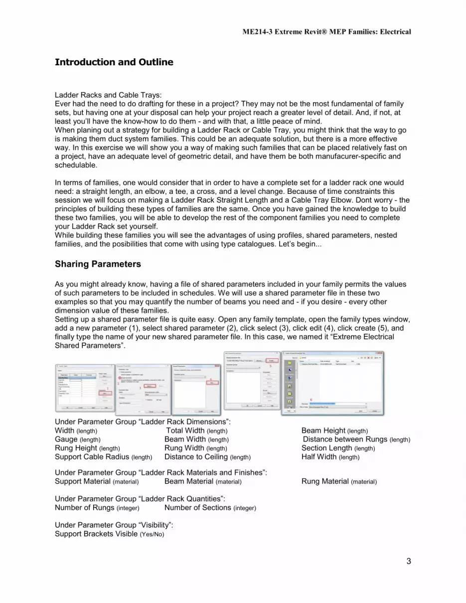
Ladder Racks and Cable Trays: Ever had the need to do drafting for these in a project? They may not be the most fundamental of family sets, but having one at your disposal can help your project reach a greater level of detail. And, if not, at least you’ll have the know-how to do them - and with that, a little peace of mind. When planing out a strategy for building a Ladder Rack or Cable Tray, you might think that the way to go is making them duct system families. This could be an adequate solution, but there is a more effective way. In this exercise we will show you a way of making such families that can be placed relatively fast on a project, have an adequate level of geometric detail, and have them be both manufacurer-specific and schedulable. In terms of families, one would consider that in order to have a complete set for a ladder rack one would need: a straight length, an elbow, a tee, a cross, and a level change. Because of time constraints this session we will focus on making a Ladder Rack Straight Length and a Cable Tray Elbow. Dont worry - the principles of building these types of families are the same. Once you have gained the knowledge to build these two families, you will be able to develop the rest of the component families you need to complete your Ladder Rack set yourself. While building these families you will see the advantages of using profiles, shared parameters, nested families, and the posibilities that come with using type catalogues. Let’s begin... Sharing Parameters As you might already know, having a file of shared parameters included in your family permits the values of such parameters to be included in schedules. We will use a shared parameter file in these two examples so that you may quantify the number of beams you need and - if you desire - every other dimension value of these families. Setting up a shared parameter file is quite easy. Open any family template, open the family types window, add a new parameter (1), select shared parameter (2), click select (3), click edit (4), click create (5), and finally type the name of your new shared parameter file. In this case, we named it “Extreme Electrical Shared Parameters”.
Under Parameter Group “Ladder Rack Dimensions”: Width (length) Total Width (length) Beam Height (length) Gauge (length) Beam Width (length) Distance between Rungs (length) Rung Height (length) Rung Width (length) Section Length (length) Support Cable Radius (length) Distance to Ceiling (length) Half Width (length) Under Parameter Group “Ladder Rack Materials and Finishes”: Support Material (material) Beam Material (material) Rung Material (material) Under Parameter Group “Ladder Rack Quantities”: Number of Rungs (integer) Number of Sections (integer) Under Parameter Group “Visibility”: Support Brackets Visible (Yes/No)
ME214-3 Extreme Revit® MEP Families: Electrical
4
Under Parameter Group “Ladder Rack Identity Data”: Model Type (text)
The Ladder Rack Straight Length The straight length is the backbone of our family system. When it is finished, the rest of the family components should fall into place very quickly. All of the most fundamental components for a ladder rack will have to be created for this family. This family consists of two profiles and two families nested within it. The families to nest are: a beam profile, a rung profile, a ladder rack support and a ladder rack section. Beam Profile – We’ll start out with the beam profile. This will be the main profile because it will be included in every part of the ladder rack set of families. We will model it half the length away from the insertion point as to facilitate placement. Please open a profile template (Profile.rft), and in its Family Types window, create the following parameters:
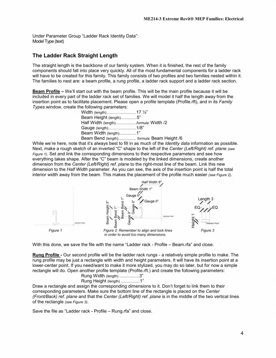
Width (length)..............................17 ½” Beam Height (length)................5” Half Width (length).....................formula: Width /2 Gauge (length)............................1/8” Beam Width (length).................1” Beam Bend (length).................. formula: Beam Height /6 While we’re here, note that it’s always best to fill in as much of the Identity data information as possible. Next, make a rough sketch of an inverted “C” shape to the left of the Center (Left/Right) ref. plane (see Figure 1). Set and link the corresponding dimensions to their respective parameters and see how everything takes shape. After the “C” beam is modeled by the linked dimensions, create another dimension from the Center (Left/Right) ref. plane to the right-most line of the beam. Link this new dimension to the Half Width parameter. As you can see, the axis of the insertion point is half the total interior width away from the beam. This makes the placement of the profile much easier (see Figure 2).
Figure 1 Figure 2: Remember to align and lock lines Figure 3 in order to avoid too many dimensions. With this done, we save the file with the name “Ladder rack - Profile – Beam.rfa” and close. Rung Profile - Our second profile will be the ladder rack rungs - a relatively simple profile to make. The rung profile may be just a rectangle with width and height parameters. It will have its insertion point at a lower-center point. If you need/want to make it more stylized, you may do so later, but for now a simple rectangle will do. Open another profile template (Profile.rft.) and create the following parameters:
Rung Width (length) ....................3” Rung Height (length) ...................1”
Draw a rectangle and assign the corresponding dimensions to it. Don’t forget to link them to their corresponding parameters. Make sure the bottom line of the rectangle is placed on the Center (Front/Back) ref. plane and that the Center (Left/Right) ref. plane is in the middle of the two vertical lines of the rectangle (see Figure 3). Save the file as “Ladder rack - Profile – Rung.rfa” and close.

ME214-3 Extreme Revit® MEP Families: Electrical
5
Support Bracket - Next up, we will make the ladder rack support. You wouldn’t want your ladder rack system floating in space, would you? This is also another simple family to make. Having supports in Ladder Racks or Cable Trays always brings about mixed reactions. When you have a complex layout of Ladder Racks, to some the supports can become a nuisance. For others that are interested in renders or high detail sections, making the brackets would be a valuable addition. This is why we are going to build them with a visibility parameter so you can choose whether you want them to show. In this family we are only going to create two solid geometries, but we must also create the parameter basis for the frame of the ladder rack. Open a generic template (Generic Model.rft), and create these parameters:
Total Width (length) .................................... formula: Width + (Beam Width * 2) Distance to ceiling (length) ...................... 40” Beam Width (length) ................................ 1” Width (length) .............................................. 17.5” Support Material (material)................Generic Support Cable Diameter (length)...........0.5”
Figure 4 Figure 5: You can use the geometry’s shape Figure 6
handles o extend the extrusions into position. Draw two ref. lines on both sides of the Center(front/back) ref plane and place a dimension linked to the Total Width parameter. Now create a solid extrusion, set at plan level and place two circles with 1/2” radii beside each ref. Line. Set and link dimensions from the center points of the circles to the ref. Lines and press finish sketch (see Figure 4). Now switch to left view and see the automatic length of the extrusion Revit has drawn up. Create a dimension from the top of the extrusion to the ref. Level and link it to the Distance to ceiling parameter. After that, select the extrusion and drag the bottom shape handle below the ref. Level (in this case, we lowered it 3”). Set another dimension from the ref. Level and lock it (see Figure 5). Now, switch back to plan view and create another solid extrusion. This new geometry is going to be the support bar. Draw a rectangle surrounding the cables - our first extrusion. Give a marginal offset to each side of the rectangle so that it encompasses the cables comfortly. We placed the same parameter for the radius of the cables as an offset to the support bar (see Figure 6). Set it to a depth of half the lower dimension of the support cables (see Figure 5). Once this is done, select the “join geometry” button and select both the cable geometry and the support bar geometry. Now you can see the geometry resembles of the ladder rack’s support bracket. Next, head to the family types window, and select a generic material (see Figure 7). Close the window and select any geometry, click on its properties and link Support Material to it. (see Figure 8)
ME214-3 Extreme Revit® MEP Families: Electrical
6
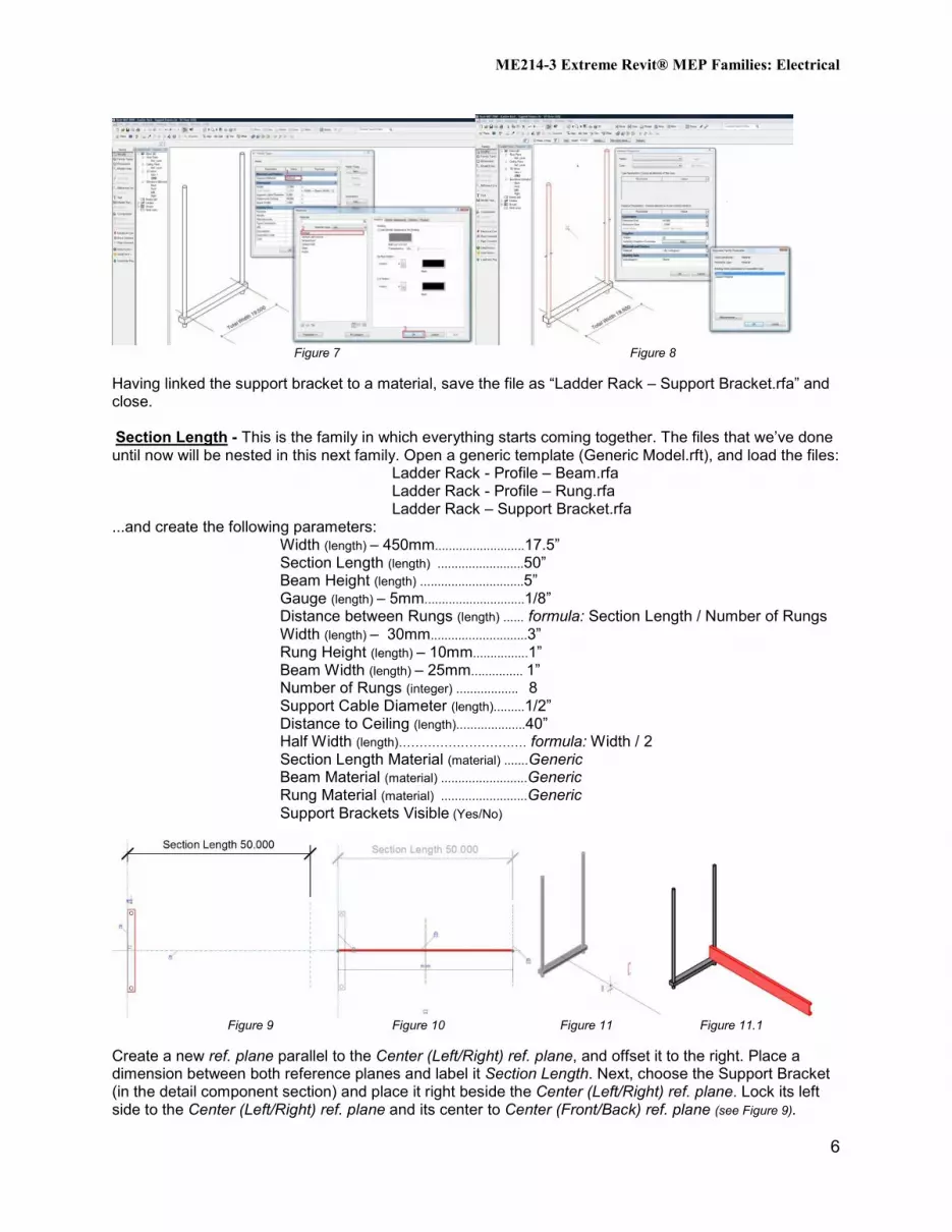
Figure 7 Figure 8 Having linked the support bracket to a material, save the file as “Ladder Rack – Support Bracket.rfa” and close. Section Length - This is the family in which everything starts coming together. The files that we’ve done until now will be nested in this next family. Open a generic template (Generic Model.rft), and load the files: Ladder Rack - Profile – Beam.rfa
Ladder Rack - Profile – Rung.rfa Ladder Rack – Support Bracket.rfa
...and create the following parameters: Width (length) – 450mm..........................17.5” Section Length (length) .........................50” Beam Height (length) ..............................5” Gauge (length) – 5mm.............................1/8” Distance between Rungs (length) ...... formula: Section Length / Number of Rungs Width (length) – 30mm............................3” Rung Height (length) – 10mm................1” Beam Width (length) – 25mm............... 1” Number of Rungs (integer) .................. 8 Support Cable Diameter (length).........1/2” Distance to Ceiling (length)....................40” Half Width (length)…………………………. formula: Width / 2 Section Length Material (material) .......Generic Beam Material (material) .........................Generic Rung Material (material) .........................Generic
Support Brackets Visible (Yes/No)
Figure 9 Figure 10 Figure 11 Figure 11.1 Create a new ref. plane parallel to the Center (Left/Right) ref. plane, and offset it to the right. Place a dimension between both reference planes and label it Section Length. Next, choose the Support Bracket (in the detail component section) and place it right beside the Center (Left/Right) ref. plane. Lock its left side to the Center (Left/Right) ref. plane and its center to Center (Front/Back) ref. plane (see Figure 9).
ME214-3 Extreme Revit® MEP Families: Electrical
7
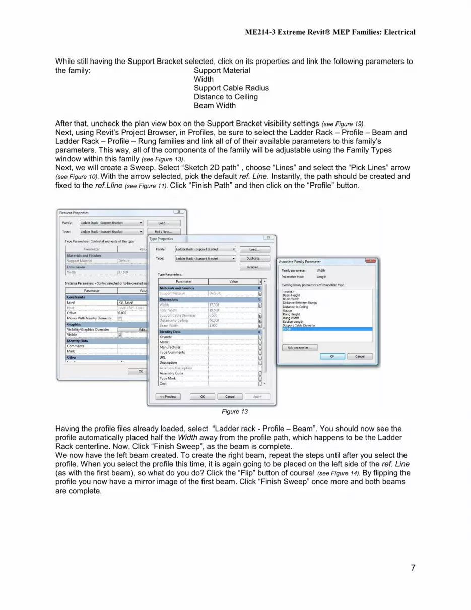
While still having the Support Bracket selected, click on its properties and link the following parameters to the family: Support Material Width
Support Cable Radius Distance to Ceiling Beam Width
After that, uncheck the plan view box on the Support Bracket visibility settings (see Figure 19). Next, using Revit’s Project Browser, in Profiles, be sure to select the Ladder Rack – Profile – Beam and Ladder Rack – Profile – Rung families and link all of of their available parameters to this family’s parameters. This way, all of the components of the family will be adjustable using the Family Types window within this family (see Figure 13). Next, we will create a Sweep. Select “Sketch 2D path” , choose “Lines” and select the “Pick Lines” arrow (see Figure 10). With the arrow selected, pick the default ref. Line. Instantly, the path should be created and fixed to the ref.Lline (see Figure 11). Click “Finish Path” and then click on the “Profile” button.
Figure 13
Having the profile files already loaded, select “Ladder rack - Profile – Beam”. You should now see the profile automatically placed half the Width away from the profile path, which happens to be the Ladder Rack centerline. Now, Click “Finish Sweep”, as the beam is complete. We now have the left beam created. To create the right beam, repeat the steps until after you select the profile. When you select the profile this time, it is again going to be placed on the left side of the ref. Line (as with the first beam), so what do you do? Click the “Flip” button of course! (see Figure 14). By flipping the profile you now have a mirror image of the first beam. Click “Finish Sweep” once more and both beams are complete.

ME214-3 Extreme Revit® MEP Families: Electrical
8
Figure 14 Figure 15 Figure 16 To make the rungs, we’ll need to do a sweep once again. Create a sweep in plan view and draw a line perpendicular to the beams. Set a dimension to the endpoints, label it Width (see Figure 15) and click “Finish Path”. For its profile, select “Ladder rack - Profile – Rung” and click on “Finish Sweep”. Next, move the newly created rung to the center of the Center (front/back) ref. plane and directly to the right of the Center (Left/Right) ref. plane. Whilst it is selected, click on the “Array” button and offset it at any distance to the right. Click away. Let the number or arrayed objects be 2. Align and lock both rungs (now groups) to the interior face of the beam. Either beam will do, as long as both rungs are locked to the same one (see Figure 16). Now, create a dimension from the Center (Left/Right) ref. plane to the left side of the right-most rung and label it Distance between Rungs. Then select a rung in order to make the number of instances show. Select the fine line that links the number of instances in the array and label it Number of Rungs. This should cause the whole length to become filled with rungs (see Figure 17).
Figure 17 Figure 18 Figure 19 Next, go back to plan view, and draw a rectangle with symbolic “Hidden Lines [projection]” (see Figure 18). Lastly, lock these to the extents of the geometry. With this, the Section length is finished. Purge and then save the file as “Ladder Rack – Section Length.rfa” and close. . Straight Length All that we’ve done until now is assemble this family quickly, retain control over parameters and - in case of change - the ability to modify only one component and nest it in. If the Section Length is where it all comes together, then this is the working piece. Start by choosing a Generic model line based template and create these parameters:

ME214-3 Extreme Revit® MEP Families: Electrical
9
Width (length) ..................................................17.5” Section Length (length) ...............................50” (Instance) Beam Height (length) ....................................5” Gauge (length) ................................................1/8” Distance between Rungs (length) ............ formula: Section Length/Number of Rungs Rung Width (length) .......................................3” Rung Height (length) .....................................1” Beam Width (length) ......................................1” Number of Rungs (integer) ........................ 8 (Instance) Number of Sections (integer) .................... 2 (Instance) Support Cable Diameter (length)...............1/2” Distance to Ceiling (length)..........................40” (Instance) Half Width (length)…………………………….. formula: Width / 2 Section Length Material (material) ............Generic Beam Material (material) ..............................Generic Rung Material (material) ..............................Generic
Support Brackets Visible (Yes/No) Model Type (text) Load the “Ladder rack - Section Length.fra” and “Ladder rack – Support Bracket.fra”. Place the Section Length in plan view. Place it on the right side of the Center (Left/Right) ref. plane and align it with said ref. plane. Lock its left side to the Center (Left/Right) ref. plane. Now select the Section Length instance, click on the properties button, and choose edit. Link the following parameters: Line Based Family Template to Ladder rack – Section Length
Width (length) ............................................................................................... Width Section Length (length) ........................................................................... Section Length Beam Height (length) ............................................................................... Beam Height Gauge (length) ............................................................................................. Gauge Rung Width (length) ................................................................................. Rung Width Rung Height (length) ................................................................................. Rung Height Beam Width (length) ................................................................................. Beam Width Number of Rungs (integer). ..................................................................... Number of Rungs Support Cable Diameter (length)........................................................... Support Cable Diameter Distance to Ceiling (length)...................................................................... Distance to Ceiling Section Length Material (material) ...................................................... Section Length Material Beam Material (material) ......................................................................... Beam Material Rung Material (material) ......................................................................... Rung Material Support Brackets Visible (Yes/No)........................................................ Support Brackets Visible
Now that the Ladder Rack is almost completely linked to this family template’s parameters, we will array it. As we did with the rungs, select the nested component (Ladder Rack – Section Length) and array it to the right side of the screen (make sure the array only makes 2 instances). Next, create a dimension from the Center (Left/Right) ref. plane to the left side of the right instance and label it Section Length. Click again, on any instance, to make the relation of number of insances appear. Select that reference and label it Number of Supports (see Figure 20).
ME214-3 Extreme Revit® MEP Families: Electrical
10
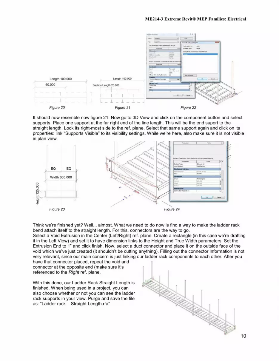
Figure 20 Figure 21 Figure 22
It should now resemble now figure 21. Now go to 3D View and click on the component button and select supports. Place one support at the far right end of the line length. This will be the end suport to the straight length. Lock its right-most side to the ref. plane. Select that same support again and click on its properties: link “Supports Visible” to its visibility settings. While we’re here, also make sure it is not visible in plan view.
Figure 23 Figure 24
Think we’re finished yet? Well... almost. What we need to do now is find a way to make the ladder rack bend attach itself to the straight length. For this, connectors are the way to go. Select a Void Extrusion in the Center (Left/Right) ref. plane. Create a rectangle (in this case we’re drafting it in the Left View) and set it to have dimension links to the Height and True Width parameters. Set the Extrusion End to 1” and click finish. Now, select a duct connector and place it on the outside face of the void which we’ve just created (it shouldn’t be cutting anything). Filling out the connector information is not very relevant, since our main concern is just linking our ladder rack components to each other. After you have that connector placed, repeat the void and connector at the opposite end (make sure it’s referenced to the Right ref. plane. With this done, our Ladder Rack Straight Length is finished. When being used in a project, you can also choose whether or not you can see the ladder rack supports in your view. Purge and save the file as: “Ladder rack – Straight Length.rfa”
ME214-3 Extreme Revit® MEP Families: Electrical
11
The Math….
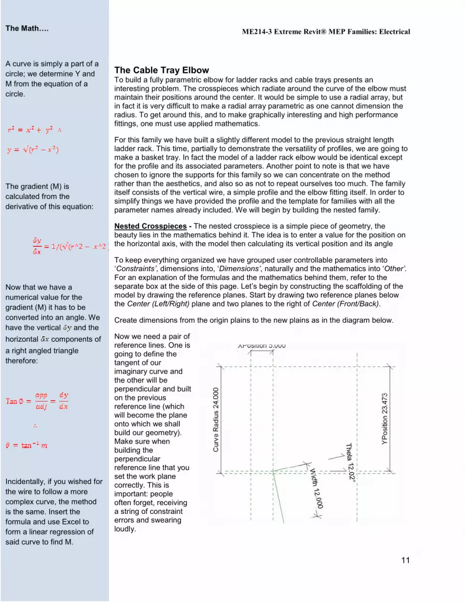
A curve is simply a part of a circle; we determine Y and M from the equation of a circle.
The gradient (M) is calculated from the derivative of this equation:
Now that we have a numerical value for the gradient (M) it has to be converted into an angle. We have the vertical and the
horizontal components of
a right angled triangle therefore:
Incidentally, if you wished for the wire to follow a more complex curve, the method is the same. Insert the formula and use Excel to form a linear regression of said curve to find M.
The Cable Tray Elbow To build a fully parametric elbow for ladder racks and cable trays presents an interesting problem. The crosspieces which radiate around the curve of the elbow must maintain their positions around the center. It would be simple to use a radial array, but in fact it is very difficult to make a radial array parametric as one cannot dimension the radius. To get around this, and to make graphically interesting and high performance fittings, one must use applied mathematics.
For this family we have built a slightly different model to the previous straight length ladder rack. This time, partially to demonstrate the versatility of profiles, we are going to make a basket tray. In fact the model of a ladder rack elbow would be identical except for the profile and its associated parameters. Another point to note is that we have chosen to ignore the supports for this family so we can concentrate on the method rather than the aesthetics, and also so as not to repeat ourselves too much. The family itself consists of the vertical wire, a simple profile and the elbow fitting itself. In order to simplify things we have provided the profile and the template for families with all the parameter names already included. We will begin by building the nested family.
Nested Crosspieces - The nested crosspiece is a simple piece of geometry, the beauty lies in the mathematics behind it. The idea is to enter a value for the position on the horizontal axis, with the model then calculating its vertical position and its angle
To keep everything organized we have grouped user controllable parameters into ‘Constraints’, dimensions into, ‘Dimensions’, naturally and the mathematics into ‘Other’. For an explanation of the formulas and the mathematics behind them, refer to the separate box at the side of this page. Let’s begin by constructing the scaffolding of the model by drawing the reference planes. Start by drawing two reference planes below the Center (Left/Right) plane and two planes to the right of Center (Front/Back).
Create dimensions from the origin plains to the new plains as in the diagram below.
Now we need a pair of reference lines. One is going to define the tangent of our imaginary curve and the other will be perpendicular and built on the previous reference line (which will become the plane onto which we shall build our geometry). Make sure when building the perpendicular reference line that you set the work plane correctly. This is important: people often forget, receiving a string of constraint errors and swearing loudly.
ME214-3 Extreme Revit® MEP Families: Electrical
12
Align the end point of each reference line to the correct plane and dimension the length and its angle from horizontal, as shown below.
At this stage it would be wise to flex the model and check everything that is working properly. Change the values of x and Length, but do not change the angle parameter as everything will break.
In either of the side elevation views, build a final horizontal reference plane above the existing one and label its dimension as Height. Now we can build some geometry.
We are going to build a sweep on the perpendicular reference line. How you do this depends on the family you want to make. For a ladder rack, the path would be a straight line constrained to the reference line and the profile would be the crosspiece as used in the previous example. The cable tray example we are following in this part of the tutorial is slightly more complex, but not by much.
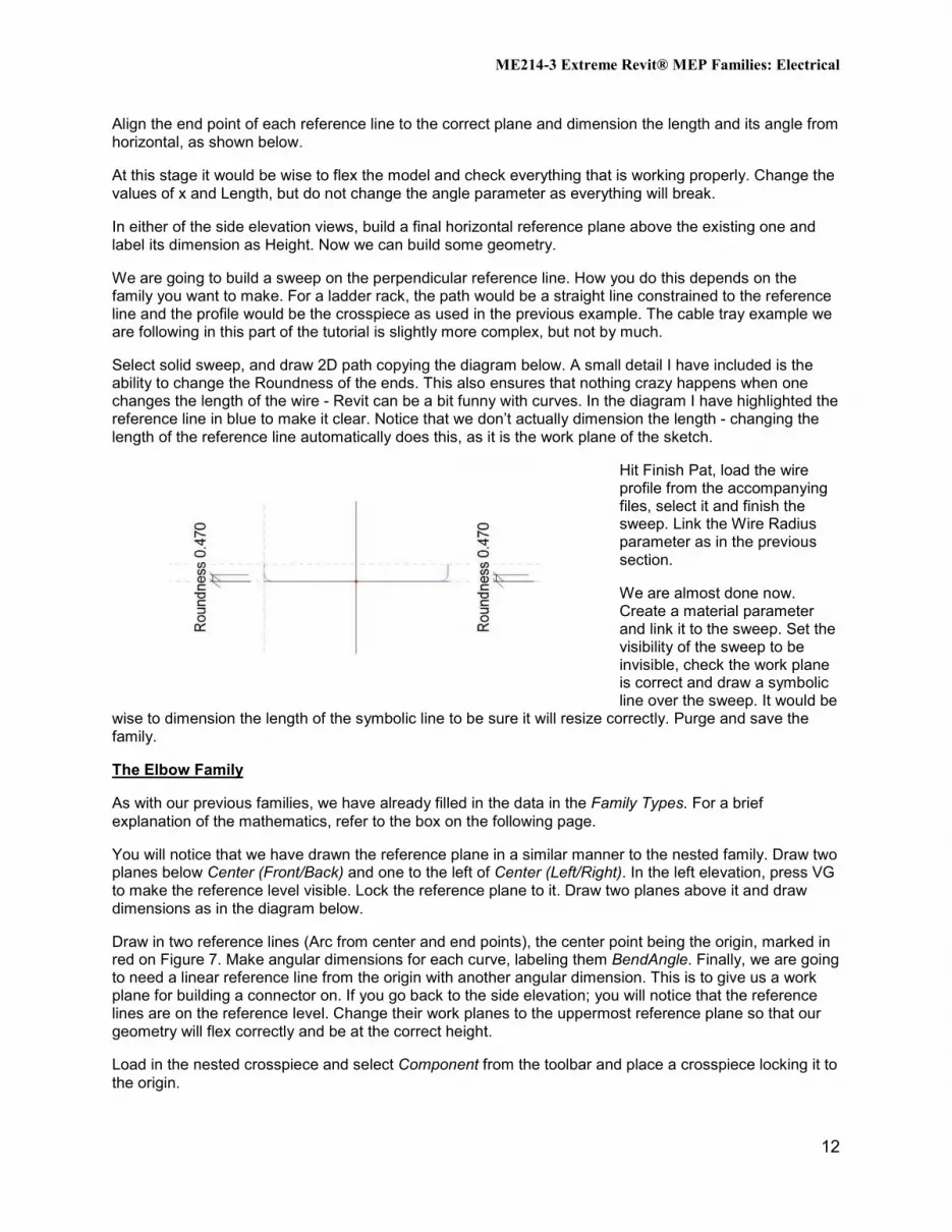
Select solid sweep, and draw 2D path copying the diagram below. A small detail I have included is the ability to change the Roundness of the ends. This also ensures that nothing crazy happens when one changes the length of the wire - Revit can be a bit funny with curves. In the diagram I have highlighted the reference line in blue to make it clear. Notice that we don’t actually dimension the length - changing the length of the reference line automatically does this, as it is the work plane of the sketch.
Hit Finish Pat, load the wire profile from the accompanying files, select it and finish the sweep. Link the Wire Radius parameter as in the previous section.
We are almost done now. Create a material parameter and link it to the sweep. Set the visibility of the sweep to be invisible, check the work plane is correct and draw a symbolic line over the sweep. It would be
wise to dimension the length of the symbolic line to be sure it will resize correctly. Purge and save the family.
The Elbow Family
As with our previous families, we have already filled in the data in the Family Types. For a brief explanation of the mathematics, refer to the box on the following page.
You will notice that we have drawn the reference plane in a similar manner to the nested family. Draw two planes below Center (Front/Back) and one to the left of Center (Left/Right). In the left elevation, press VG to make the reference level visible. Lock the reference plane to it. Draw two planes above it and draw dimensions as in the diagram below.
Draw in two reference lines (Arc from center and end points), the center point being the origin, marked in red on Figure 7. Make angular dimensions for each curve, labeling them BendAngle. Finally, we are going to need a linear reference line from the origin with another angular dimension. This is to give us a work plane for building a connector on. If you go back to the side elevation; you will notice that the reference lines are on the reference level. Change their work planes to the uppermost reference plane so that our geometry will flex correctly and be at the correct height.
Load in the nested crosspiece and select Component from the toolbar and place a crosspiece locking it to the origin.
ME214-3 Extreme Revit® MEP Families: Electrical
13
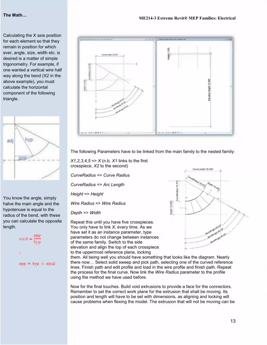
The following Parameters have to be linked from the main family to the nested family:
X1,2,3,4,5 => X (n.b. X1 links to the first crosspiece, X2 to the second)
CurveRadius => Curve Radius
CurveRadius => Arc Length
Height => Height
Wire Radius => Wire Radius
Depth => Width
Repeat this until you have five crosspieces. You only have to link X, every time. As we have set it as an instance parameter, type parameters do not change between instances of the same family. Switch to the side elevation and align the top of each crosspiece to the uppermost reference plane, locking them. All being well you should have something that looks like the diagram. Nearly there now… Select solid sweep and pick path, selecting one of the curved reference lines. Finish path and edit profile and load in the wire profile and finish path. Repeat the process for the final curve. Now link the Wire Radius parameter to the profile using the method we have used before.
Now for the final touches. Build void extrusions to provide a face for the connectors. Remember to set the correct work plane for the extrusion that shall be moving. Its position and length will have to be set with dimensions, as aligning and locking will cause problems when flexing the model. The extrusion that will not be moving can be
The Math…
Calculating the X axis position for each element so that they remain in position for which ever, angle, size, width etc. is desired is a matter of simple trigonometry. For example, if one wanted a vertical wire half way along the bend (X2 in the above example), you must calculate the horizontal component of the following triangle.
You know the angle, simply halve the main angle and the hypotenuse is equal to the radius of the bend, with these you can calculate the opposite length.
ME214-3 Extreme Revit® MEP Families: Electrical
14
constrained to the two reference planes. Place a duct connector (fitting) on each face and link the width and height parameters.
Finally, choose a material and link it to the material parameter. Set the material for all geometry and set the sweeps to be invisible in plan view and draw symbolic lines.
Type Catalogue
If you refer to the cutsheet of the ladder rack you will notice that there are specific types or models for example: Heavy Duty Ladder Rack Height = 5, Width = 36. Now that we have a fully parametric model, we need to limit the dimensions to match the available models so that we have manufacturer-specific content. There are two ways to do this. The first method is using a Lookup Table. A Lookup Table is a list of dimensions in a .csv file which can be referenced from the family using the text_file_lookup() function. This is appropriate for system families such as pipe fittings where the dimensions of the fitting rely on the nominal size of the pipe and place automatically in a project. As we are building families that do not place automatically, it is more appropriate to use a type catalog. A Type Catalog is essentially the same concept as a lookup table. As the name suggests, it’s a list of types and all their dimensions and other parameters such as electrical or mechanical data. When a family with a Type Catalog is loaded into a project the user can choose as many or as few types as possible for the project, thus helping in the selection process of the family types you wish to load into your project.
The cable tray comes in various sizes as well. The specific model depends on its height and width. If you look at how the elbow is built, it is completely customisable so the angle should be left as an instance parameter. We have included Type Catalogs for both families along with full versions of the families we have outlined - including the cable tray straight length and ladder rack elbow - so that you can load them into a project and see for yourselves how to go about building a full set of families for your future projects.
As an example we will make the following types for the Ladder Rack Straight Length:
Light Duty Ladder Rack, Height = 4, Width = 6 Light Duty Ladder Rack, Height = 4, Width = 12 Light Duty Ladder Rack, Height = 4, Width = 18 Light Duty Ladder Rack, Height = 4, Width = 24 Light Duty Ladder Rack, Height = 4, Width = 30 Light Duty Ladder Rack, Height = 4, Width = 36 Medium Duty Ladder Rack, Height = 5, Width = 6 Medium Duty Ladder Rack, Height = 5, Width = 12 Medium Duty Ladder Rack, Height = 5, Width = 18 Medium Duty Ladder Rack, Height = 5, Width = 24 Medium Duty Ladder Rack, Height = 5, Width = 30 Medium Duty Ladder Rack, Height = 5, Width = 36 Heavy Duty Ladder Rack, Height = 5, Width = 6 Heavy Duty Ladder Rack, Height = 5, Width = 12 Heavy Duty Ladder Rack, Height = 5, Width = 18 Heavy Duty Ladder Rack, Height = 5, Width = 24 Heavy Duty Ladder Rack, Height = 5, Width = 30 Heavy Duty Ladder Rack, Height = 5, Width = 36
Start out by opening an Excel spreadsheet. The first row and column of the sheet will be the reference which enables Revit to understand the family type parameters. Row 1 is reserved for the parameter references and Column A for the different types available for the family (cell Row 1, Column A is to be left empty)

ME214-3 Extreme Revit® MEP Families: Electrical
15
For parameter recognition of text: Parameter Name##other## (Example: Model Type##other##)
For parameter recognition of length: Parameter Name##length##Type of Units (Example: Distance from Ceiling##length##inches)
Column A is left for Revit’s reference only. We have added the “Model Type” to have the same reference in our family’s types. Next, you must save the file as a CSV (MS-DOS) with exactly the same name as the family. In this case it will be “Ladder Rack – Straight Length.csv”. Once stored in the computer’s files, copy the file and paste it in the same folder in which the Ladder Rack – Straight Length.rfa (both files need to be in the same folder in order for Revit to read the type catalogue). Next, choose to rename the file and change the suffix of the name from “.csv” to “.txt” (a warning message by windows will be displayed. Click “Yes”).
With this done, you are now able to load various types of the Ladder Rack – Straight Length into your project. Try it for yourself. When you load the family a new window appears prompting you to choose the types you want loaded. Click on the ones you like and let the drafting begin!