mathematical modelling of ambient air-breathing fuel cells for portable devices
TRANSCRIPT

A
scdvsdp©
K
1
cbmtasiaaa
mrpt
s
0d
Electrochimica Acta 52 (2007) 3849–3862
Mathematical modelling of ambient air-breathingfuel cells for portable devices
S. Litster 1, N. Djilali ∗Institute for Integrated Energy Systems, and Department of Mechanical Engineering, University of Victoria, Victoria, BC V8W 3P6, Canada
Received 27 November 2005; received in revised form 2 November 2006; accepted 5 November 2006Available online 30 November 2006
bstract
Competitive costs, instant recharge, and high energy density make fuel cells ideal for supplanting batteries in portable electronic devices. In thistudy, we derive a semi-analytical model to elucidate the transport of ions, heat and mass in air-breathing fuel cells. The model includes an empiricalorrelation for membrane conductivity that improves accuracy when modelling membrane dry-out. A detailed comparison with experimentalata demonstrates that the model accurately predicts fuel cell performance through detailed accounting of catalyst layer specifications, includingariable width, and electrochemical parameters. A comprehensive parametric study resolves the trends associated with a variety of design
pecifications and operating conditions. Membrane dry-out is identified as the primary limitation on current density, and is shown to be stronglyependent on heat transfer. The study also identifies some unique effects of coupling between ambient air temperature and humidity on theerformance of air-breathing fuel cells.2006 Elsevier Ltd. All rights reserved.
nsfer;
ipr
dffpopTcabI
eywords: Fuel cells; Analytical models; Portable devices; Convective heat tra
. Introduction
Techno-economic analyses have shown that portableonsumer electronics, currently powered by rechargeableatteries, present a more accessible market for proton exchangeembrane (PEM) fuel cells than transportation applications in
he immediate future, because a higher cost per unit of energy iscceptable at these smaller scales [1,2]. For example, Dyer [1]tated that the cost tolerance for fuel cells in portable equipments two orders of magnitude greater than that for automotivepplications. Another key advantage of fuel cells for portablepplications over batteries is longer continuous operation withlmost instantaneous refueling.
An increasingly more prevalent driver of fuel cell develop-ent for portable devices is the ever-increasing energy density
equirements of new consumer electronics, such as mobilehones with digital broadcast reception [2]. A key argument forhe integration of fuel cells into next-generation mobile phones
∗ Corresponding author. Tel.: +1 250 721 6034; fax: +1 250 721 6323.E-mail address: [email protected] (N. Djilali).
1 Present address: Department of Mechanical Engineering, Stanford Univer-ity, Stanford, CA 94305, USA.
f
Ff
1
013-4686/$ – see front matter © 2006 Elsevier Ltd. All rights reserved.oi:10.1016/j.electacta.2006.11.002
Membrane dry-out
s that even if the capacity of Li-ion batteries grows at 10%er year, they will still not be capable of meeting the powerequirements of future devices.
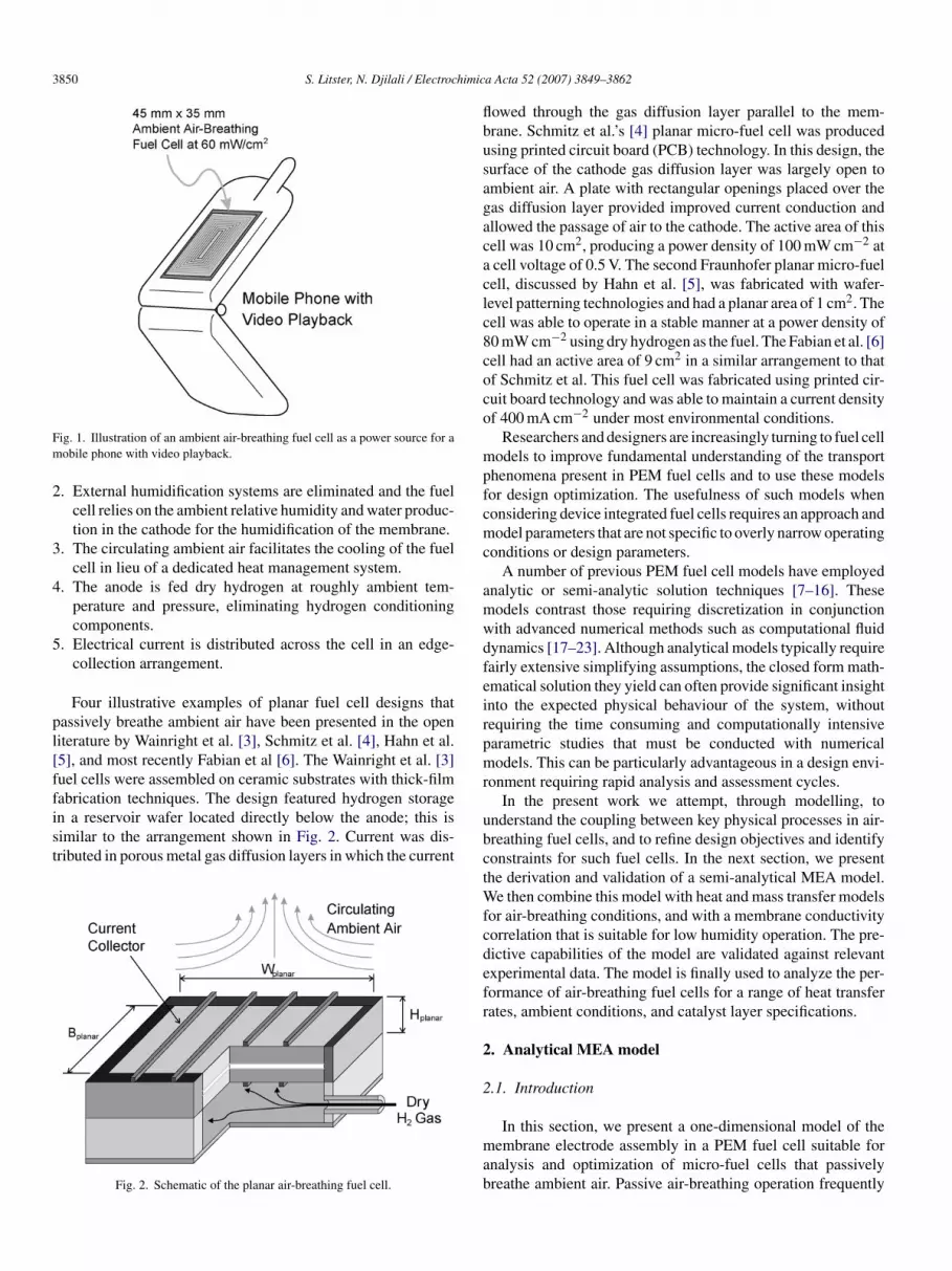
The envisaged implementation of PEM fuel cells for portableevices is in a device integrated form. This entails placing theuel cell either on, or within portable electronics. For example,uel cells can be mounted on the exterior surfaces of mobilehones, as illustrated in Fig. 1, and in notebook PCs. Basedn the predicted planar area available on a mobile phone, theower density requirement of the fuel cell is 60 mW cm−2 [2].he cathode gas diffusion layer is fed ambient air, rather thanonditioned air through flow channels, and the fuel is storednd distributed below the fuel cell. One advantage of an air-reathing cathode is that it eliminates the need for manifolding.n addition, the open surface facilitates heat transfer from theuel cell.
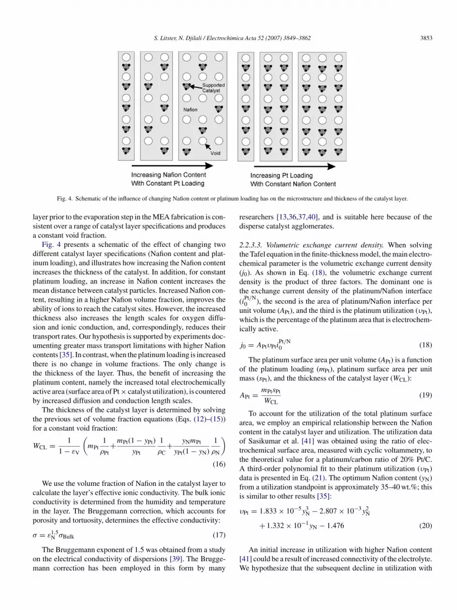
A schematic of such an air-breathing fuel cell is shown inig. 2. This arrangement incorporates multiple methodologiesor reducing the size and number of ancillary components:
. To alleviate the need for air distribution channels, along withthe necessary pumps and fans, the cathode gas diffusion layeris in direct contact with the ambient air.
3850 S. Litster, N. Djilali / Electrochimic
Fm
2
3
4
5
pl[ffist
flbusagacaclc8coco
mpfcmc
amwdfeirpmr
ig. 1. Illustration of an ambient air-breathing fuel cell as a power source for aobile phone with video playback.
. External humidification systems are eliminated and the fuelcell relies on the ambient relative humidity and water produc-tion in the cathode for the humidification of the membrane.
. The circulating ambient air facilitates the cooling of the fuelcell in lieu of a dedicated heat management system.
. The anode is fed dry hydrogen at roughly ambient tem-perature and pressure, eliminating hydrogen conditioningcomponents.
. Electrical current is distributed across the cell in an edge-collection arrangement.
Four illustrative examples of planar fuel cell designs thatassively breathe ambient air have been presented in the openiterature by Wainright et al. [3], Schmitz et al. [4], Hahn et al.5], and most recently Fabian et al [6]. The Wainright et al. [3]uel cells were assembled on ceramic substrates with thick-film
abrication techniques. The design featured hydrogen storagen a reservoir wafer located directly below the anode; this isimilar to the arrangement shown in Fig. 2. Current was dis-ributed in porous metal gas diffusion layers in which the currentFig. 2. Schematic of the planar air-breathing fuel cell.
ubctWfcdefr
2
2
mab
a Acta 52 (2007) 3849–3862
owed through the gas diffusion layer parallel to the mem-rane. Schmitz et al.’s [4] planar micro-fuel cell was producedsing printed circuit board (PCB) technology. In this design, theurface of the cathode gas diffusion layer was largely open tombient air. A plate with rectangular openings placed over theas diffusion layer provided improved current conduction andllowed the passage of air to the cathode. The active area of thisell was 10 cm2, producing a power density of 100 mW cm−2 atcell voltage of 0.5 V. The second Fraunhofer planar micro-fuelell, discussed by Hahn et al. [5], was fabricated with wafer-evel patterning technologies and had a planar area of 1 cm2. Theell was able to operate in a stable manner at a power density of0 mW cm−2 using dry hydrogen as the fuel. The Fabian et al. [6]ell had an active area of 9 cm2 in a similar arrangement to thatf Schmitz et al. This fuel cell was fabricated using printed cir-uit board technology and was able to maintain a current densityf 400 mA cm−2 under most environmental conditions.
Researchers and designers are increasingly turning to fuel cellodels to improve fundamental understanding of the transport
henomena present in PEM fuel cells and to use these modelsor design optimization. The usefulness of such models whenonsidering device integrated fuel cells requires an approach andodel parameters that are not specific to overly narrow operating
onditions or design parameters.A number of previous PEM fuel cell models have employed
nalytic or semi-analytic solution techniques [7–16]. Theseodels contrast those requiring discretization in conjunctionith advanced numerical methods such as computational fluidynamics [17–23]. Although analytical models typically requireairly extensive simplifying assumptions, the closed form math-matical solution they yield can often provide significant insightnto the expected physical behaviour of the system, withoutequiring the time consuming and computationally intensivearametric studies that must be conducted with numericalodels. This can be particularly advantageous in a design envi-
onment requiring rapid analysis and assessment cycles.In the present work we attempt, through modelling, to
nderstand the coupling between key physical processes in air-reathing fuel cells, and to refine design objectives and identifyonstraints for such fuel cells. In the next section, we presenthe derivation and validation of a semi-analytical MEA model.
e then combine this model with heat and mass transfer modelsor air-breathing conditions, and with a membrane conductivityorrelation that is suitable for low humidity operation. The pre-ictive capabilities of the model are validated against relevantxperimental data. The model is finally used to analyze the per-ormance of air-breathing fuel cells for a range of heat transferates, ambient conditions, and catalyst layer specifications.
. Analytical MEA model
.1. Introduction
In this section, we present a one-dimensional model of theembrane electrode assembly in a PEM fuel cell suitable for
nalysis and optimization of micro-fuel cells that passivelyreathe ambient air. Passive air-breathing operation frequently

S. Litster, N. Djilali / Electrochimic
etOtdt
2
otTtifimipmwols
2
taotcmpdocp
fM
(
w
i
o
E
waPtwmvgv
E
2
ctnactt[
nfoOsbd
g
w
Θ
iW
Fig. 3. Schematic of the one-dimensional analytical MEA model.
ntails low-humidity conditions and lower current densities dueo increased electrolyte resistance [6,24,25]. Thus, we expecthmic losses in the electrolyte to have a greater relative impor-
ance than the mass transfer limitations. Consequently, the modelerivation focuses on the Ohmic losses in the electrolyte ratherhan mass transport in the cathode.
.2. Model
The model domain, shown in Fig. 3, includes both cath-de and anode catalyst layers and the membrane. As shown inhe Figure, the MEA model consists of five main components.he potential summation algorithm calculates the distribu-
ion of losses through the MEA. Individual potential lossesn the cathode, anode, and membrane are calculated using anite-thickness catalyst layer model, an interface catalyst layerodel, and a linear membrane model with uniform conductiv-
ty, respectively. The finite-thickness model is implemented witharameters evaluated from a macrohomogeneous catalyst layerodel that correlates the required volume average quantitiesith the microstructure of the catalyst layer. A novel featuref the present macrohomogeneous model is the variable cata-yst layer thickness, which is determined from the catalyst layerpecifications.
.2.1. Potential summation algorithmThe potential summation algorithm is similar to the voltage-
o-current methods employed by Nguyen et al. [19] and Sivertsennd Djilali [21]. The algorithm allocates the difference betweenpen-circuit voltage and cell potential (EOC − Ecell). This poten-ial difference is the sum of the activation overpotentials in theathode and anode (ηC, ηA) and the potential drop through theembrane. We neglect the potential drop through the electrical
athways due to its minimal contribution to the overall potential
rop. The potential drop through the membrane is the productf the area-specific membrane resistance (WMem/σMem) and theurrent density (i). Taking current to be a result of the over-otential in the cathode catalyst layer (iC(ηC)), we obtain theviml
a Acta 52 (2007) 3849–3862 3851
ollowing expression for the potential summation through theEA:
EOC − Ecell) − ηC − ηA − WMem
σMemiC(ηC) = 0 (1)
hich is subject to the constraint of current conservation:
C(ηC) − iA(ηA) = 0 (2)
The reversible potential (Er) results from the Gibbs energyf formation (�G):
r = −�G
nF(3)
here n is the moles of product per electron transferred (n = 2)nd F is Faraday’s constant. In this section, the correlation fromarthasarathy et al. [28] is used to obtain �G as function of
emperature for the formation of liquid water. In Section 3,here an air-breathing fuel cell is considered, standard ther-odynamic tables determine �G for the formation of water
apour. The Nernst relation accounts for the activities of oxy-en and hydrogen (aO2 and aH2 ) and provides the open-circuitoltage:
OC = Er + RT
nF
(ln(aH2 ) + 1
2ln(aO2 )
)(4)
.2.2. Catalyst layer modelThe slow oxygen reduction reaction (ORR) distinguishes the
athode catalyst layer from the anode. When oxygen transport tohe catalyst layer is insufficient, the ORR occurs predominantlyear the GDL interface, whereas when the oxygen supply isbundant and the electrolyte conductivity is low, the ORR con-entrates by the membrane interface because of Ohmic losses inhe catalyst layer. Due to a much higher electrical conductivity,he electric potential is approximately uniform in comparison29].
In the finite-thickness catalyst layer model derived here, weeglect the gradient in oxygen concentration that is due to dif-usion. This is acceptable when considering low current densityperation typical of air-breathing fuel cells and in cases wherehmic losses are dominant. Eikerling and Kornyshev [30] pre-
ented a parameter that determines when these conditions prevailased on the Tafel slope (RT/αF), ionic conductivity (σ), and aiffusion parameter (Θ):
= αF
RT
Θ
σ(5)
here
= 4FPairDCLO2
RTWCL(6)
n which DCLO2
is the oxygen diffusivity in the catalyst layer andCL is the thickness of the catalyst layer. For the parameter
alues considered in this analysis g � 1, and oxygen transports rapid in comparison to proton conduction. Our catalyst layer
odel is similar to that of Eikerling and Kornyshev [30] for theimit of rapid oxygen transport. It is also similar to the model

3 himic
doet
c
i
wwb
σ
(pah
j
cec
η
w
A
waidbTp
i
2
icnmmv
[f
2lbsur
123
b(
ε
cl
ε
NtNcti
ε
at
ε
2otwntNctNt
852 S. Litster, N. Djilali / Electroc
erived by Gurau et al. [13] for their analytical half-cell modelf a PEM fuel cell, but with the important distinction that Guraut al. assumed a uniform overpotential within the catalyst layero solve oxygen distribution.
Our derivation begins with the governing equation for protononduction, Ohm’s law:
= −σdφ
dx(7)
here φ is the electrolyte potential. Cast in a conservative formith a source term for the current generation (jT) the equationecomes:
∇2φ = jT (8)
The rate of the ORR is locally dependent on the overpotentialthe difference between the potential of electrolyte and electricotential in the platinum η = φ − φs). Following Perry et al. [31]nd many other studies, we determine the reaction rate, assumingigh overpotentials (η � RT/αF), with the Tafel equation:
T = j0
(cO2
crefO2
)γ
exp
(αF
RTη
)(9)
In addition, the reaction rate depends on the average oxygenoncentration in the layer (cO2 ). The concentration dependencexponent (γ) specifies the sensitivity of the reaction to oxygenoncentration. We solve Eqs. (7)–(9) implicitly to obtain:
(x) = 1
bln
{tan2
[√bA exp(bη0)
2(x − WCL) + . . .
arctan
(√exp(bη1) − exp(bη0)√
exp(bη0)
)]+ 1
}+ η0
(10)
here
= j0
σ
(cO2
crefO2
)γ
and b = αF
RT,
here x is the location in the layer, WCL the thickness of the layer,nd η0 and η1 are the overpotentials at the GDL and membranenterfaces, respectively. η1 corresponds to ηC in Eq. (1). Theerivation of Eq. (10) is presented in ref. [32]. Eq. (10) is similar,ut not identical, to Eikerling and Kornyshev’s [30] expression.he derivative of overpotential multiplied by the conductivityrovides an expression for the protonic current into the cathode:
= σ
√2A
b
√exp(bη1) − exp(bη0) (11)
.2.3. Catalyst composition and variable thicknessWe utilize a macrohomogeneous catalyst layer model to
nvestigate the effect of catalyst layer composition. This modelonsiders the catalyst layer microstructure as a homoge-
eous medium with properties that reflect the heterogeneousicrostructure. As noted by Eikerling and Kornyshev [30], theacrohomogeneous model has been around for decades andariations in derivation and implementation continue to emerge
tlaW
a Acta 52 (2007) 3849–3862
13,30,33,34]. We propose a new implementation that accountsor variable catalyst layer thickness.
.2.3.1. Catalyst layer composition. The volume of the catalystayer is composed of four components: platinum, Nafion, car-on, and void space. By employing the standard catalyst layerpecifications and a known catalyst layer thickness, each vol-me fraction can be determined [34]. The typical specifications,anges, and units are [35]:
. Platinum loading, mPt (0.05 − 5 mg Pt cm−2).
. Platinum/carbon ratio, yPt (20 − 40% Pt/C).
. Nafion content, yN (20 − 60 wt.%).
The volume fraction of platinum is simply the loading dividedy the density of platinum (ρPt) and the catalyst layer thicknessWCL):
Pt = mPt1
ρPtWCL(12)
The volume fraction occupied by carbon is a function of thearbon loading (mC) that results from the specified platinumoading and the platinum/carbon ratio:
C = mC1
ρCWCL= mPt(1 − yPt)
yPt
1
ρCWCL(13)
As shown in Eq. (14), we evaluate the volume fraction ofafion from the area loading of the Nafion (mN) divided by
he Nafion density (ρN) and the thickness of the catalyst layer.afion loading is a function of three commonly documented
atalyst layer properties: Nafion content (weight percentage ofhe catalyst layer that is Nafion), platinum loading, and plat-num/carbon ratio:
N = mN1
ρNWCL= yNmPt
yPt(1 − yN)
1
ρNWCL(14)
nd since the volume fractions must add to unity, the void frac-ion (εV) is:
V = 1 − (εPt + εC + εN) (15)
.2.3.2. Variable-thickness implementation. Previous studiesf catalyst layer composition optimization based on similar rela-ions [34,36,37] have typically assumed the void fraction to varyith catalyst layer specifications and the catalyst layer thick-ess to remain constant regardless of specifications. However,he experimental results of Inoue et al. [38] demonstrate that theafion content and platinum loading have a significant effect on
atalyst layer thickness. Their results show that the catalyst layerhickness is proportional to platinum loading and that increasingafion content from 10 to 50 wt.% results in a 100% increase in
hickness.In contrast with previous work [34,36,37], in our analysis
he thickness of the catalyst layer is calculated from the catalystayer specifications and we hold the void fraction constant inccordance with the experimental results of Inoue et al. [38].e conjecture that the volume fraction of solvent in the catalyst
S. Litster, N. Djilali / Electrochimica Acta 52 (2007) 3849–3862 3853
inum
lsa
diipmtatstucttpab
tf
W
ccip
σ
om
rd
2tc(dt(uwi
j
om
A
acottAdfi
υ
Fig. 4. Schematic of the influence of changing Nafion content or plat
ayer prior to the evaporation step in the MEA fabrication is con-istent over a range of catalyst layer specifications and producesconstant void fraction.
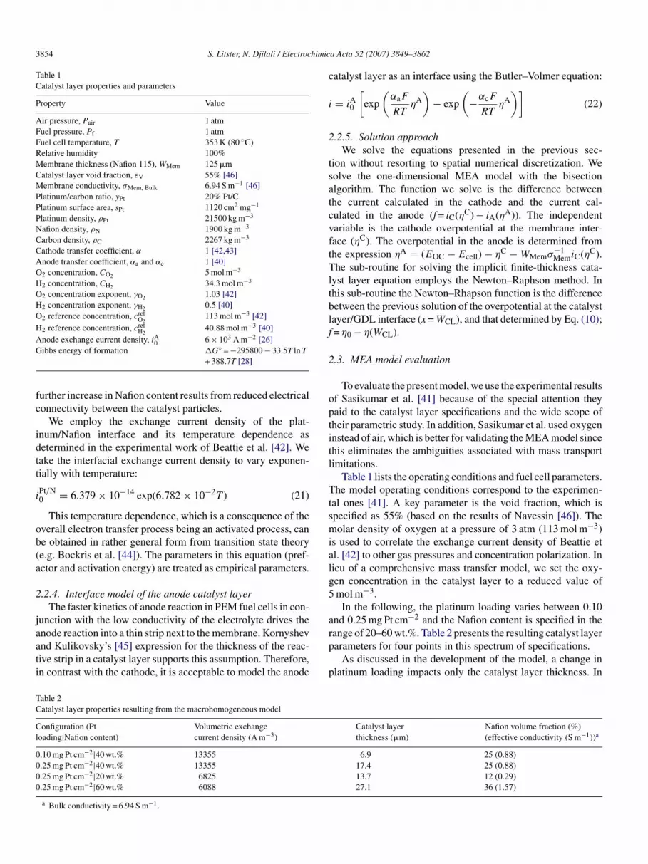
Fig. 4 presents a schematic of the effect of changing twoifferent catalyst layer specifications (Nafion content and plat-num loading), and illustrates how increasing the Nafion contentncreases the thickness of the catalyst. In addition, for constantlatinum loading, an increase in Nafion content increases theean distance between catalyst particles. Increased Nafion con-
ent, resulting in a higher Nafion volume fraction, improves thebility of ions to reach the catalyst sites. However, the increasedhickness also increases the length scales for oxygen diffu-ion and ionic conduction, and, correspondingly, reduces theirransport rates. Our hypothesis is supported by experiments doc-menting greater mass transport limitations with higher Nafionontents [35]. In contrast, when the platinum loading is increasedhere is no change in volume fractions. The only change ishe thickness of the layer. Thus, the benefit of increasing thelatinum content, namely the increased total electrochemicallyctive area (surface area of Pt × catalyst utilization), is counteredy increased diffusion and conduction length scales.
The thickness of the catalyst layer is determined by solvinghe previous set of volume fraction equations (Eqs. (12)–(15))or a constant void fraction:
CL = 1
1 − εV
(mPt
1
ρPt+mPt(1 − yPt)
yPt
1
ρC+ yNmPt
yPt(1 − yN)
1
ρN
)
(16)
We use the volume fraction of Nafion in the catalyst layer toalculate the layer’s effective ionic conductivity. The bulk ioniconductivity is determined from the humidity and temperaturen the layer. The Bruggemann correction, which accounts fororosity and tortuosity, determines the effective conductivity:
1.5
= εN σBulk (17)The Bruggemann exponent of 1.5 was obtained from a studyn the electrical conductivity of dispersions [39]. The Brugge-ann correction has been employed in this form by many
[W
loading has on the microstructure and thickness of the catalyst layer.
esearchers [13,36,37,40], and is suitable here because of theisperse catalyst agglomerates.
.2.3.3. Volumetric exchange current density. When solvinghe Tafel equation in the finite-thickness model, the main electro-hemical parameter is the volumetric exchange current densityj0). As shown in Eq. (18), the volumetric exchange currentensity is the product of three factors. The dominant one ishe exchange current density of the platinum/Nafion interfaceiPt/N0 ), the second is the area of platinum/Nafion interface pernit volume (APt), and the third is the platinum utilization (υPt),hich is the percentage of the platinum area that is electrochem-
cally active.
0 = APtυPtiPt/N0 (18)
The platinum surface area per unit volume (APt) is a functionf the platinum loading (mPt), platinum surface area per unitass (sPt), and the thickness of the catalyst layer (WCL):
Pt = mPtsPt
WCL(19)
To account for the utilization of the total platinum surfacerea, we employ an empirical relationship between the Nafionontent in the catalyst layer and utilization. The utilization dataf Sasikumar et al. [41] was obtained using the ratio of elec-rochemical surface area, measured with cyclic voltammetry, tohe theoretical value for a platinum/carbon ratio of 20% Pt/C.
third-order polynomial fit to their platinum utilization (υPt)ata is presented in Eq. (21). The optimum Nafion content (yN)rom a utilization standpoint is approximately 35–40 wt.%; thiss similar to other results [35]:
Pt = 1.833 × 10⁻⁵y3N − 2.807 × 10⁻³y2
N
+ 1.332 × 10⁻¹yN − 1.476 (20)
An initial increase in utilization with higher Nafion content41] could be a result of increased connectivity of the electrolyte.
e hypothesize that the subsequent decline in utilization with
3854 S. Litster, N. Djilali / Electrochimic
Table 1Catalyst layer properties and parameters
Property Value
Air pressure, Pair 1 atmFuel pressure, Pf 1 atmFuel cell temperature, T 353 K (80 ◦C)Relative humidity 100%Membrane thickness (Nafion 115), WMem 125 �mCatalyst layer void fraction, εV 55% [46]Membrane conductivity, σMem, Bulk 6.94 S m−1 [46]Platinum/carbon ratio, yPt 20% Pt/CPlatinum surface area, sPt 1120 cm2 mg−1
Platinum density, ρPt 21500 kg m−3
Nafion density, ρN 1900 kg m−3
Carbon density, ρC 2267 kg m−3
Cathode transfer coefficient, α 1 [42,43]Anode transfer coefficient, αa and αc 1 [40]O2 concentration, CO2 5 mol m−3
H2 concentration, CH2 34.3 mol m−3
O2 concentration exponent, γO2 1.03 [42]H2 concentration exponent, γH2 0.5 [40]O2 reference concentration, cref
O2113 mol m−3 [42]
H2 reference concentration, crefH2
40.88 mol m−3 [40]Anode exchange current density, iA 6 × 10³ A m−2 [26]G
fc
idtt
i
ob(a
2
jaati
c
i
2
tsatcvftTltblf
2
optitl
Ttsmialg5
a
TC
Cl
0000
0ibbs energy of formation �G◦ = −295800 − 33.5T ln T
+ 388.7T [28]
urther increase in Nafion content results from reduced electricalonnectivity between the catalyst particles.
We employ the exchange current density of the plat-num/Nafion interface and its temperature dependence asetermined in the experimental work of Beattie et al. [42]. Weake the interfacial exchange current density to vary exponen-ially with temperature:
Pt/N0 = 6.379 × 10⁻¹⁴ exp(6.782 × 10⁻²T ) (21)
This temperature dependence, which is a consequence of theverall electron transfer process being an activated process, cane obtained in rather general form from transition state theorye.g. Bockris et al. [44]). The parameters in this equation (pref-ctor and activation energy) are treated as empirical parameters.
.2.4. Interface model of the anode catalyst layerThe faster kinetics of anode reaction in PEM fuel cells in con-
unction with the low conductivity of the electrolyte drives the
node reaction into a thin strip next to the membrane. Kornyshevnd Kulikovsky’s [45] expression for the thickness of the reac-ive strip in a catalyst layer supports this assumption. Therefore,n contrast with the cathode, it is acceptable to model the anoderp
p
able 2atalyst layer properties resulting from the macrohomogeneous model
onfiguration (Ptoading|Nafion content)
Volumetric exchangecurrent density (A m−3)
.10 mg Pt cm−2|40 wt.% 13355
.25 mg Pt cm−2|40 wt.% 13355
.25 mg Pt cm−2|20 wt.% 6825
.25 mg Pt cm−2|60 wt.% 6088
a Bulk conductivity = 6.94 S m−1.
a Acta 52 (2007) 3849–3862
atalyst layer as an interface using the Butler–Volmer equation:
= iA0
[exp
(αaF
RTηA)
− exp
(−αcF
RTηA)]
(22)
.2.5. Solution approachWe solve the equations presented in the previous sec-
ion without resorting to spatial numerical discretization. Weolve the one-dimensional MEA model with the bisectionlgorithm. The function we solve is the difference betweenhe current calculated in the cathode and the current cal-ulated in the anode (f = iC(ηC) − iA(ηA)). The independentariable is the cathode overpotential at the membrane inter-ace (ηC). The overpotential in the anode is determined fromhe expression ηA = (EOC − Ecell) − ηC − WMemσ−1
MemiC(ηC).he sub-routine for solving the implicit finite-thickness cata-
yst layer equation employs the Newton–Raphson method. Inhis sub-routine the Newton–Rhapson function is the differenceetween the previous solution of the overpotential at the catalystayer/GDL interface (x = WCL), and that determined by Eq. (10);= η0 − η(WCL).
.3. MEA model evaluation
To evaluate the present model, we use the experimental resultsf Sasikumar et al. [41] because of the special attention theyaid to the catalyst layer specifications and the wide scope ofheir parametric study. In addition, Sasikumar et al. used oxygennstead of air, which is better for validating the MEA model sincehis eliminates the ambiguities associated with mass transportimitations.
Table 1 lists the operating conditions and fuel cell parameters.he model operating conditions correspond to the experimen-
al ones [41]. A key parameter is the void fraction, which ispecified as 55% (based on the results of Navessin [46]). Theolar density of oxygen at a pressure of 3 atm (113 mol m−3)
s used to correlate the exchange current density of Beattie etl. [42] to other gas pressures and concentration polarization. Inieu of a comprehensive mass transfer model, we set the oxy-en concentration in the catalyst layer to a reduced value ofmol m−3.
In the following, the platinum loading varies between 0.10nd 0.25 mg Pt cm−2 and the Nafion content is specified in the
ange of 20–60 wt.%. Table 2 presents the resulting catalyst layerarameters for four points in this spectrum of specifications.As discussed in the development of the model, a change inlatinum loading impacts only the catalyst layer thickness. In
Catalyst layerthickness (�m)
Nafion volume fraction (%)(effective conductivity (S m−1))a
6.9 25 (0.88)17.4 25 (0.88)13.7 12 (0.29)27.1 36 (1.57)
S. Litster, N. Djilali / Electrochimic
FSl
csmdie
cwl0nl
c
FSc
tcapaottflm
3
3
nii
1
234
5
3
a
ig. 5. Comparison between polarization curves obtained experimentally byasikumar et al. [41] and those calculated by the present model for platinum
oadings of 0.10 and 0.25 mg Pt cm−2.
ontrast, Table 2 shows that changing the Nafion content has aignificant impact on all three parameters, and there is a maxi-um exchange current density at approximately 40 wt.%. The
ecrease in exchange current density at higher Nafion contentss due to the diminishing platinum concentration as the layerxpands.
Fig. 5 presents the polarization curves of two validationases with platinum loadings of 0.10 and 0.25 mg Pt cm−2,ith a 40 wt.% Nafion content in both cases. There is excel-
ent agreement with the experimental curves, especially for.10 mg Pt cm−2, and the variable-thickness macrohomoge-eous model satisfactorily reproduces the influence of platinum
oading.Fig. 6 depicts the effect Nafion content on the polarizationurve. Again, the model is in good agreement with experimen-
ig. 6. Comparison between polarization curves obtained experimentally byasikumar et al. [41] and those calculated by the present model for Nafionontents of 20, 40 and 60 wt.%
w
11
3
tcI
a Acta 52 (2007) 3849–3862 3855
al observations. In the experimental data, increasing the Nafionontent from 20 to 40 wt.% significantly improves performance,nd a further increase from 40 to 60 wt.% marginally reduceserformance. The model captures this effect. Although the cat-lyst layer conductivity is almost doubled at a Nafion contentf 60 wt.%, the fuel cell voltage drops due to reduced utiliza-ion and a longer conduction distance. These results demonstratehat the macrohomogeneous model with the variable-thicknessormulation can correlate the catalyst layer specifications to theayer’s microstructure, and allows subsequent translation of the
icrostructure to volume-average parameters for modelling.
. Planar air-breathing fuel cells
.1. Model
Having established the validity of the MEA model, weow expand this model to include additional phenomena fornvestigating air-breathing fuel cells. The additional phenomenanclude:
. The transport of oxygen and water vapour between the sur-face of the GDL and the ambient air.
. The diffusion of gases through the GDL.
. The diffusion of oxygen into the catalyst layer.
. The influence of temperature and humidity on the conduc-tivity of the membrane.
. The heat transfer from the fuel cell to the ambient air.
.1.1. AssumptionsIn addition to the assumptions used in the derivation of the
nalytical MEA model, the following lists the major assumptionse use in developing the model.
1. Transport in the fuel cell is considered one-dimensional.2. The fuel cell operates in steady state conditions.3. Water vapour is produced in the cathode.4. The water exists only as vapour.5. There is zero net transport of water through the membrane.6. The hydrogen supply is “dead-ended” and is not recycled.7. The hydrogen supply is dry (zero humidity).8. Water does not accumulate in the hydrogen storage system.9. The water activity is uniform across the electrolyte in the
membrane and catalyst layers and is equal to the water activ-ity at the cathode interface of the gas diffusion layer and thecatalyst layer.
0. Potential losses due to electron conduction are neglected.1. The anode side of the fuel cell is perfectly insulated against
heat fluxes and heat only exits the fuel cell through thecathode surface.
.1.2. Gas diffusion
The flux of gases through the gas diffusion layer results fromhe consumption of reactants and the supply of products in theatalyst layer. Single-phase conditions are assumed to prevail.n the cathode, the consumption of oxygen is a function of the
3 himic
c
S
a
S
ioa
n
wtclti
D
btWu
D
wva(nbt
y
y
wm
miE
y
y
caagwlce
y
3
satrelaim
3
copma
σ
o
σ
iawbar
3
Pts
856 S. Litster, N. Djilali / Electroc
urrent density:
O2 = −MO2 i
4F(23)
nd the local source of water due to the reaction is:
H2O = MH2Oi
2F(24)
The governing equation for gas transport in the GDL, assum-ng negligible advection, is Fick’s law. When expressed in termsf a mass flux nA, the differential form of Fick’s law is expresseds:
˙A = −ρDeffA ∇yA (25)
here DeffA is the effective molecular diffusivity of species A in
he porous media and yA is the mass fraction of species A. Weorrect the density of air (ρ) for temperature with the ideal gasaw. We also correct the diffusivity with the porosity ε and theortuosity factor τ, which accounts for the longer diffusion pathn the porous gas diffusion media (see [48]):
effA = ε
τDA (26)
The form of Fick’s law employed herein is typically used forinary mixtures, and is justifiable given the low water concentra-ions, and the similar molecular weights of oxygen and nitrogen.
e calculate the binary diffusivity as a function of temperaturesing the empirical method presented by Cussler [48]:
AB = T 1.75
P
√(1/MA) + (1/MB)
φ1/3A + φ
1/3B
(27)
here φA and φB represent molecular volumes [48]. The con-ective mass transfer rates at the interface of the GDL with thembient air is quantified in terms of mass transfer coefficientshO2 , hH2O), which are functions of the mass transfer Nusseltumber (hA = NuDA/l). We calculate the interface mass fractionsy balancing the species production/consumption MAi/nAF withhe convective mass transfer ρhA(y0
A − yAmbA ):
0O2
= yAmbO2
− 1
ρhO2
MO2 i
4F(28)
0H2O = yAmb
H2O + 1
ρhH2O
MH2Oi
2F(29)
here i is the current density of the fuel cell and yAmbA is the
ass fraction in the ambient air.Considering the GDL as a homogeneous and isotropic porous
edium, we derive the oxygen and water mass fractions at thenterface between the GDL and the catalyst layer (yGDL/CL
A ) fromq. (26):
GDL/CL = y0 − WGDL MO2 i (30)
O2 O2 ρDGDLO24F
GDL/CLH2O = y0
H2O + WGDL
ρDGDLH2O
MH2Oi
2F(31)
dtsa
a Acta 52 (2007) 3849–3862
In addition, we approximate the oxygen mass fraction in theatalyst layer to capture the onset of reactant depletion, usingn approach similar to Berg et al. [15]. For the purpose ofpproximating this oxygen mass fraction, we assume a homo-eneously distributed reaction rate through the catalyst layer,hich is reasonable in the intermediate regime when the cata-
yst layer thickness is close to optimal [30]. The resulting oxygenoncentration is used to correct the reaction rate in the Tafelquation.
CLO2
= yGDL/CLO2
− MO2 iw2
32FρDCL (32)
.1.3. Water transport through the membraneSince we consider steady state operation and a dead-ended
upply of dry hydrogen, we assume zero net water transportcross the membrane. Kulikovsky [16] made a similar assump-ion. Moreover, this assumption is supported by the experimentalesults of Janssen and Overvelde [49] who report a very lowffective drag coefficient across the membrane (−0.01) at aow current density (400 mA cm−2) with dry air and hydrogent low stoichiometries. We also assume that the water activitys uniform across the membrane, which is justifiable for thin
embranes [32].
.1.4. Membrane conductivityThe potential drop through the electrolyte contributes signifi-
antly to the polarization of the fuel cell. We model the influencef humidity on ionic conductivity with an empirical fit to the dataresented by Sone et al. [47] for Nafion 117 without heat treat-ent. The polynomial for ionic conductivity as a function of
ctivity at 303 K is:
303 K = 3.46a3 + 0.0161a2 + 1.45a − 0.175 (33)
We model the influence of temperature with the expressionf Springer et al. [7]:
= exp
(1268
(1
303− 1
T
))σ303 K (34)
However, the influence of temperature on ionic conductivitys secondary in comparison to humidification. We also note thatlmost all conductivity is lost below a relative humidity of 20%hen using the correlation in Eq. (33). We chose this correlationecause the widely used model of Springer et al. [7] has poorccuracy in low humidity conditions [50,51], which is a criticalegime for air-breathing fuel cells.
.1.5. Heat transferTemperature assumes a critical role in the performance of
EM fuel cells because of its impact on relative humidity throughhe saturation pressure and reaction kinetics. Temperature is alsoignificant for air-breathing fuel cells because they passively
issipate the heat produced by the fuel cell without relying onhe cooling systems of larger PEMFC stacks. For a body with aufficiently uniform temperature distribution, a lumped systemnalysis that considers variation of temperature with time only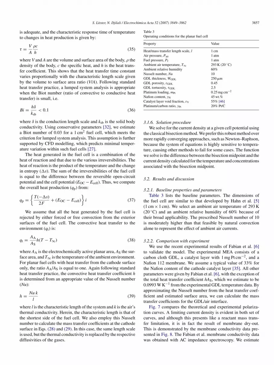
himica Acta 52 (2007) 3849–3862 3857
it
τ
wdfvbhwt
B
wcacsa
hhiipt
q
rse
q
wfFohi(
h
wttnsid
Table 3Operating conditions for the planar fuel cell
Property Value
Heat/mass transfer length scale, l 1 cmAir pressure, Pair 1 atmFuel pressure, Pf 1 atmAmbient air temperature, T∞ 293 K (20 ◦C)Ambient relative humidity 60%Nusselt number, Nu 10GDL thickness, WGDL 250 �mGDL porosity, εGDL 0.45GDL tortuosity, τGDL 2.5Platinum loading, mPt 0.25 mg cm−2
Nafion content, yN 45 wt.%CP
3
tmbtwca
3
3
t((tia
3
tcNtpt0afit
S. Litster, N. Djilali / Electroc
s adequate, and the characteristic response time of temperatureo changes in heat production is given by:
= V
A
ρc
h(35)
here V and A are the volume and surface area of the body, ρ theensity of the body, c the specific heat, and h is the heat trans-er coefficient. This shows that the heat transfer time constantaries proportionally with the characteristic length scale giveny the volume to surface area ratio (V/A). Following standardeat transfer practice, a lumped system analysis is appropriatehen the Biot number (ratio of convective to conductive heat
ransfer) is small, i.e.
i = hδ
ksb< 0.1 (36)
here δ is the conduction length scale and ksb is the solid bodyonductivity. Using conservative parameters [32], we estimateBiot number of 0.03 for a 1 cm2 fuel cell, which meets the
riterion for lumped system analysis. This assumption is furtherupported by CFD modelling, which predicts minimal temper-ture variation within such fuel cells [27].
The heat generated in the fuel cell is a combination of theeat of reaction and that due to the various irreversibilities. Theeat of reaction is the product of the temperature and the changen entropy (�s). The sum of the irreversibilities of the fuel cells equal to the difference between the reversible open-circuitotential and the cell potential (EOC − Ecell). Thus, we computehe overall heat production (qp) from:
p ={
T (−�s)
2F+ (EOC − Ecell)
}i (37)
We assume that all the heat generated by the fuel cell isejected by either forced or free convection from the exteriorurfaces of the fuel cell. The convective heat transfer to thenvironment (qt) is:
t = AA
ASh(T − T∞) (38)
here AA is the electrochemically active planar area, AS the sur-ace area, and T∞ is the temperature of the ambient environment.or planar fuel cells with heat transfer from the cathode surfacenly, the ratio AA/AS is equal to one. Again following standardeat transfer practice, the convective heat transfer coefficient hs determined from an appropriate value of the Nusselt numberNu):
= Nu k
l(39)
here l is the characteristic length of the system and k is the air’s
hermal conductivity. Herein, the characteristic length is that ofhe shortest side of the fuel cell. We also employ this Nusseltumber to calculate the mass transfer coefficients at the cathodeurface in Eqs. (28) and (29). In this case, the same length scales used, but the thermal conductivity is replaced by the respectiveiffusivities of the gases.tcfTsw
atalyst layer void fraction, εV 55% [46]latinum/carbon ratio, yPt 20% Pt/C
.1.6. Solution procedureWe solve for the current density at a given cell potential using
he classical bisection method. We prefer this robust method overore rapidly converging approaches, such as Newton–Raphson,
ecause the system of equations is highly sensitive to tempera-ure, causing other methods to fail for some cases. The functione solve is the difference between the bisection midpoint and the
urrent density calculated for the temperature and concentrationsssociated with the bisection midpoint.
.2. Results and discussion
.2.1. Baseline properties and parametersTable 3 lists the baseline parameters. The dimensions of
he fuel cell are similar to that developed by Hahn et al. [5]1 cm × 1 cm). We select an ambient air temperature of 293 K20 ◦C) and an ambient relative humidity of 60% because ofheir broad applicability. The prescribed Nusselt number of 10s moderately higher than that feasible by natural convectionlone to represent the effect of ambient air currents.
.2.2. Comparison with experimentWe use the recent experimental results of Fabian et al. [6]
o validate the model. The experimental MEA consists of aarbon cloth GDL, a catalyst layer with 1 mg Pt cm−2, and aafion 112 membrane. We assume a typical value of 33% for
he Nafion content of the cathode catalyst layer [35]. All otherarameters were given by Fabian et al. [6], with the exception ofhe total heat transfer coefficient hAS, which we estimate to be.0993 W K−1 from the experimental GDL temperature data. Bypproximating the Nusselt number from the heat transfer coef-cient and estimated surface area, we can calculate the mass
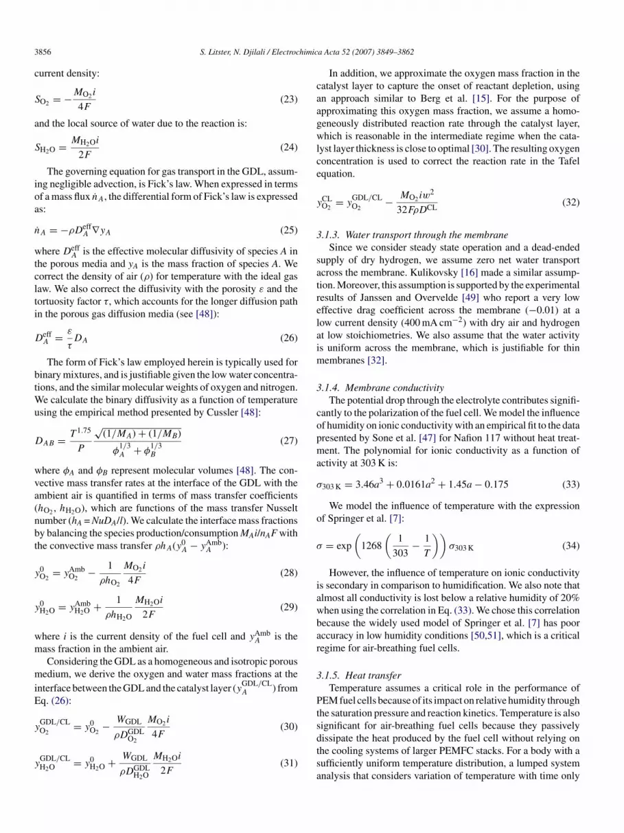
ransfer coefficients for the GDL/air interface.Fig. 7 compares the theoretical and experimental polariza-
ion curves. A limiting current density is evident in both set ofurves, and although this presents like a reactant mass trans-
er limitation, it is in fact the result of membrane dry-out.his is demonstrated by the membrane conductivity data pre-ented in Fig. 8. The Fabian et al. membrane conductivity dataas obtained with AC impedance spectroscopy. We estimate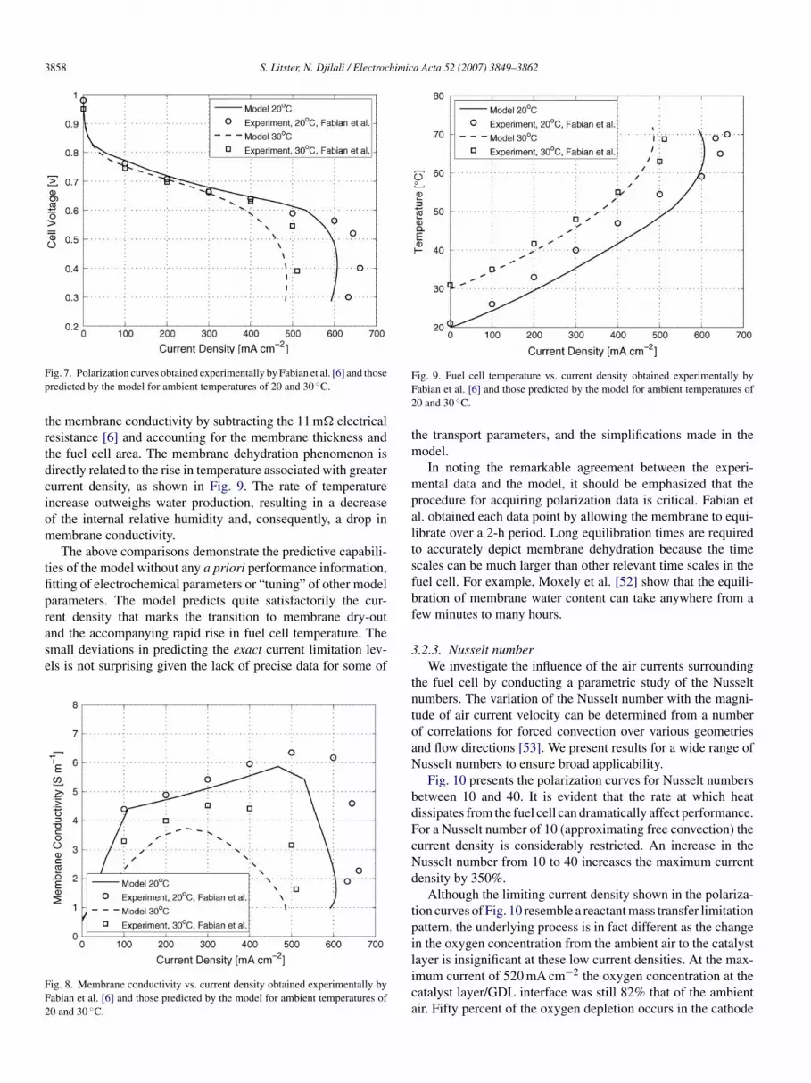
3858 S. Litster, N. Djilali / Electrochimica Acta 52 (2007) 3849–3862
Fp
trtdciom
tfiprase
FF2
FF2
tm
mpaltsfbf
ig. 7. Polarization curves obtained experimentally by Fabian et al. [6] and thoseredicted by the model for ambient temperatures of 20 and 30 ◦C.
he membrane conductivity by subtracting the 11 m� electricalesistance [6] and accounting for the membrane thickness andhe fuel cell area. The membrane dehydration phenomenon isirectly related to the rise in temperature associated with greaterurrent density, as shown in Fig. 9. The rate of temperaturencrease outweighs water production, resulting in a decreasef the internal relative humidity and, consequently, a drop inembrane conductivity.The above comparisons demonstrate the predictive capabili-
ies of the model without any a priori performance information,tting of electrochemical parameters or “tuning” of other modelarameters. The model predicts quite satisfactorily the cur-
ent density that marks the transition to membrane dry-outnd the accompanying rapid rise in fuel cell temperature. Themall deviations in predicting the exact current limitation lev-ls is not surprising given the lack of precise data for some ofig. 8. Membrane conductivity vs. current density obtained experimentally byabian et al. [6] and those predicted by the model for ambient temperatures of0 and 30 ◦C.
3
tntoaN
bdFcNd
tpilica
ig. 9. Fuel cell temperature vs. current density obtained experimentally byabian et al. [6] and those predicted by the model for ambient temperatures of0 and 30 ◦C.
he transport parameters, and the simplifications made in theodel.In noting the remarkable agreement between the experi-
ental data and the model, it should be emphasized that therocedure for acquiring polarization data is critical. Fabian etl. obtained each data point by allowing the membrane to equi-ibrate over a 2-h period. Long equilibration times are requiredo accurately depict membrane dehydration because the timecales can be much larger than other relevant time scales in theuel cell. For example, Moxely et al. [52] show that the equili-ration of membrane water content can take anywhere from aew minutes to many hours.
.2.3. Nusselt numberWe investigate the influence of the air currents surrounding
he fuel cell by conducting a parametric study of the Nusseltumbers. The variation of the Nusselt number with the magni-ude of air current velocity can be determined from a numberf correlations for forced convection over various geometriesnd flow directions [53]. We present results for a wide range ofusselt numbers to ensure broad applicability.Fig. 10 presents the polarization curves for Nusselt numbers
etween 10 and 40. It is evident that the rate at which heatissipates from the fuel cell can dramatically affect performance.or a Nusselt number of 10 (approximating free convection) theurrent density is considerably restricted. An increase in theusselt number from 10 to 40 increases the maximum currentensity by 350%.
Although the limiting current density shown in the polariza-ion curves of Fig. 10 resemble a reactant mass transfer limitationattern, the underlying process is in fact different as the changen the oxygen concentration from the ambient air to the catalyst
ayer is insignificant at these low current densities. At the max-mum current of 520 mA cm−2 the oxygen concentration at theatalyst layer/GDL interface was still 82% that of the ambientir. Fifty percent of the oxygen depletion occurs in the cathode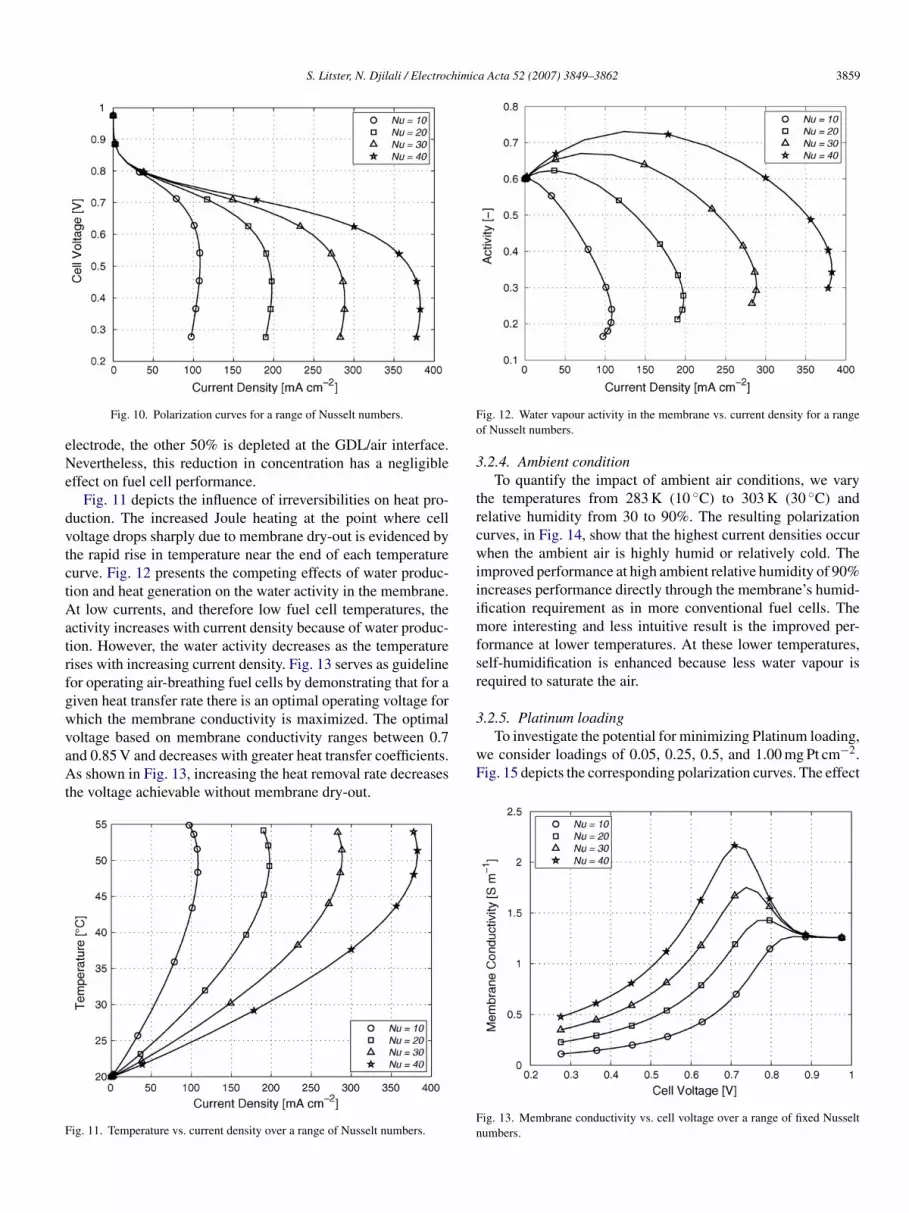
S. Litster, N. Djilali / Electrochimica Acta 52 (2007) 3849–3862 3859
eNe
dvtctAatrfgwvaAt
F
Fo
3
trcwiiimfsr
3.2.5. Platinum loading
Fig. 10. Polarization curves for a range of Nusselt numbers.
lectrode, the other 50% is depleted at the GDL/air interface.evertheless, this reduction in concentration has a negligible
ffect on fuel cell performance.Fig. 11 depicts the influence of irreversibilities on heat pro-
uction. The increased Joule heating at the point where celloltage drops sharply due to membrane dry-out is evidenced byhe rapid rise in temperature near the end of each temperatureurve. Fig. 12 presents the competing effects of water produc-ion and heat generation on the water activity in the membrane.t low currents, and therefore low fuel cell temperatures, the
ctivity increases with current density because of water produc-ion. However, the water activity decreases as the temperatureises with increasing current density. Fig. 13 serves as guidelineor operating air-breathing fuel cells by demonstrating that for aiven heat transfer rate there is an optimal operating voltage forhich the membrane conductivity is maximized. The optimal
oltage based on membrane conductivity ranges between 0.7nd 0.85 V and decreases with greater heat transfer coefficients.s shown in Fig. 13, increasing the heat removal rate decreaseshe voltage achievable without membrane dry-out.
ig. 11. Temperature vs. current density over a range of Nusselt numbers.
wF
Fn
ig. 12. Water vapour activity in the membrane vs. current density for a rangef Nusselt numbers.
.2.4. Ambient conditionTo quantify the impact of ambient air conditions, we vary
he temperatures from 283 K (10 ◦C) to 303 K (30 ◦C) andelative humidity from 30 to 90%. The resulting polarizationurves, in Fig. 14, show that the highest current densities occurhen the ambient air is highly humid or relatively cold. The
mproved performance at high ambient relative humidity of 90%ncreases performance directly through the membrane’s humid-fication requirement as in more conventional fuel cells. The
ore interesting and less intuitive result is the improved per-ormance at lower temperatures. At these lower temperatures,elf-humidification is enhanced because less water vapour isequired to saturate the air.
To investigate the potential for minimizing Platinum loading,e consider loadings of 0.05, 0.25, 0.5, and 1.00 mg Pt cm−2.ig. 15 depicts the corresponding polarization curves. The effect
ig. 13. Membrane conductivity vs. cell voltage over a range of fixed Nusseltumbers.
3860 S. Litster, N. Djilali / Electrochimica Acta 52 (2007) 3849–3862
owniirt
3
imeFicdo
Fc
Fl
6v
4
efencmaf
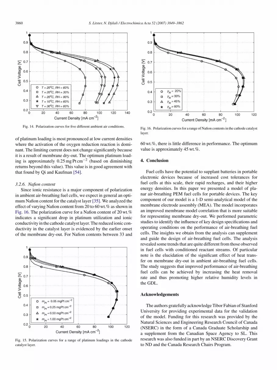
Fig. 14. Polarization curves for five different ambient air conditions.
f platinum loading is most pronounced at low current densitieshere the activation of the oxygen reduction reaction is domi-ant. The limiting current does not change significantly becauset is a result of membrane dry-out. The optimum platinum load-ng is approximately 0.25 mg Pt cm−2 (based on diminishingeturns beyond this value). This value is in good agreement withhat found by Qi and Kaufman [54].
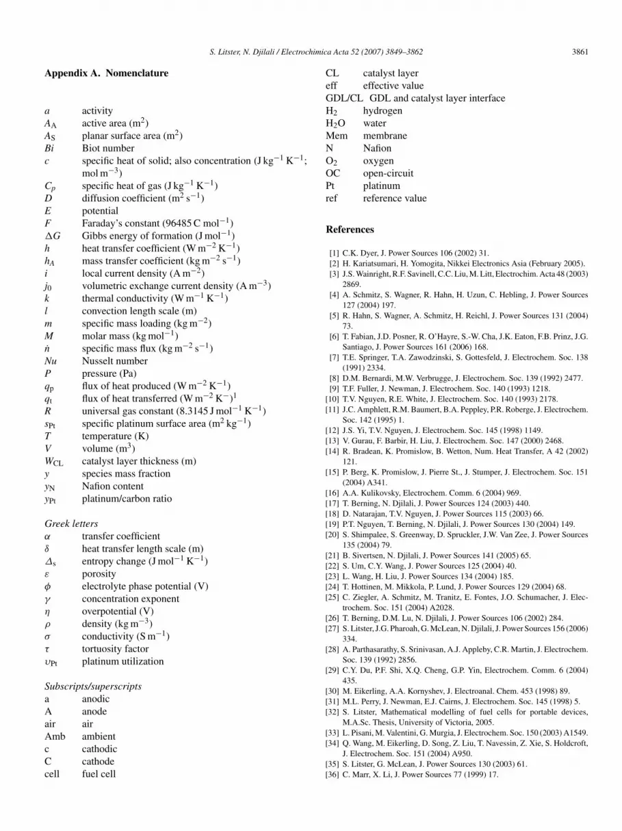
.2.6. Nafion contentSince ionic resistance is a major component of polarization
n ambient air-breathing fuel cells, we expect in general an opti-um Nafion content for the catalyst layer [35]. We analyzed the
ffect of varying Nafion content from 20 to 60 wt.% as shown inig. 16. The polarization curve for a Nafion content of 20 wt.%
ndicates a significant drop in platinum utilization and ioniconductivity in the cathode catalyst layer. The reduced ionic con-uctivity in the catalyst layer is evidenced by the earlier onsetf the membrane dry-out. For Nafion contents between 33 and
ig. 15. Polarization curves for a range of platinum loadings in the cathodeatalyst layer.
socarinfTfrt
A
UoN(art
ig. 16. Polarization curves for a range of Nafion contents in the cathode catalystayer.
0 wt.%, there is little difference in performance. The optimumalue is approximately 45 wt.%.
. Conclusion
Fuel cells have the potential to supplant batteries in portablelectronic devices because of increased cost tolerances foruel cells at this scale, their rapid recharges, and their highernergy densities. In this paper we presented a model of pla-ar air-breathing PEM fuel cells for portable devices. The keyomponent of our model is a 1-D semi-analytical model of theembrane electrode assembly (MEA). The model incorporates
n improved membrane model correlation that is more suitableor representing membrane dry-out. We performed parametrictudies to identify the influence of key design specifications andperating conditions on the performance of air-breathing fuelells. The insights we obtain from the analysis can supplementnd guide the design of air-breathing fuel cells. The analysisevealed some trends that are quite different from those observedn fuel cells with conditioned reactant streams. Of particularote is the elucidation of the significant effect of heat trans-er on membrane dry-out in ambient air-breathing fuel cells.he study suggests that improved performance of air-breathing
uel cells can be achieved by increasing the heat removalate and thus promoting higher relative humidity levels inhe GDL.
cknowledgements
The authors gratefully acknowledge Tibor Fabian of Stanfordniversity for providing experimental data for the validationf the model. Funding for this research was provided by theatural Sciences and Engineering Research Council of Canada
NSERC) in the form of a Canada Graduate Scholarship andsupplement from the Canadian Space Agency to SL. This
esearch was also funded in part by an NSERC Discovery Granto ND and the Canada Research Chairs Program.
himic
A
aAABc
CDEF�
hhijklmMn
NPqqRsTVWyyy
Gα
δ
Δ
ε
φ
γ
η
ρ
σ
τ
υ
SaAaAcCc
CeGHHMNOOPr
R
[[
[[[
[
[[[[[
[[[[[
[[
[
[
[[[
S. Litster, N. Djilali / Electroc
ppendix A. Nomenclature
activityA active area (m2)S planar surface area (m2)i Biot number
specific heat of solid; also concentration (J kg−1 K−1;mol m−3)
p specific heat of gas (J kg−1 K−1)diffusion coefficient (m2 s−1)potentialFaraday’s constant (96485 C mol−1)
G Gibbs energy of formation (J mol−1)heat transfer coefficient (W m−2 K−1)
A mass transfer coefficient (kg m−2 s−1)local current density (A m−2)
0 volumetric exchange current density (A m−3)thermal conductivity (W m−1 K−1)convection length scale (m)specific mass loading (kg m−2)molar mass (kg mol−1)
˙ specific mass flux (kg m−2 s−1)u Nusselt number
pressure (Pa)p flux of heat produced (W m−2 K−1)t flux of heat transferred (W m−2 K−)1
universal gas constant (8.3145 J mol−1 K−1)Pt specific platinum surface area (m2 kg−1)
temperature (K)volume (m3)
CL catalyst layer thickness (m)species mass fraction
N Nafion contentPt platinum/carbon ratio
reek letterstransfer coefficientheat transfer length scale (m)
s entropy change (J mol−1 K−1)porosityelectrolyte phase potential (V)concentration exponentoverpotential (V)density (kg m−3)conductivity (S m−1)tortuosity factor
Pt platinum utilization
ubscripts/superscriptsanodicanode
ir air
mb ambientcathodiccathode
ell fuel cell
[[
[[
a Acta 52 (2007) 3849–3862 3861
L catalyst layerff effective valueDL/CL GDL and catalyst layer interface2 hydrogen2O waterem membrane
Nafion2 oxygenC open-circuitt platinumef reference value
eferences
[1] C.K. Dyer, J. Power Sources 106 (2002) 31.[2] H. Kariatsumari, H. Yomogita, Nikkei Electronics Asia (February 2005).[3] J.S. Wainright, R.F. Savinell, C.C. Liu, M. Litt, Electrochim. Acta 48 (2003)
2869.[4] A. Schmitz, S. Wagner, R. Hahn, H. Uzun, C. Hebling, J. Power Sources
127 (2004) 197.[5] R. Hahn, S. Wagner, A. Schmitz, H. Reichl, J. Power Sources 131 (2004)
73.[6] T. Fabian, J.D. Posner, R. O’Hayre, S.-W. Cha, J.K. Eaton, F.B. Prinz, J.G.
Santiago, J. Power Sources 161 (2006) 168.[7] T.E. Springer, T.A. Zawodzinski, S. Gottesfeld, J. Electrochem. Soc. 138
(1991) 2334.[8] D.M. Bernardi, M.W. Verbrugge, J. Electrochem. Soc. 139 (1992) 2477.[9] T.F. Fuller, J. Newman, J. Electrochem. Soc. 140 (1993) 1218.10] T.V. Nguyen, R.E. White, J. Electrochem. Soc. 140 (1993) 2178.11] J.C. Amphlett, R.M. Baumert, B.A. Peppley, P.R. Roberge, J. Electrochem.
Soc. 142 (1995) 1.12] J.S. Yi, T.V. Nguyen, J. Electrochem. Soc. 145 (1998) 1149.13] V. Gurau, F. Barbir, H. Liu, J. Electrochem. Soc. 147 (2000) 2468.14] R. Bradean, K. Promislow, B. Wetton, Num. Heat Transfer, A 42 (2002)
121.15] P. Berg, K. Promislow, J. Pierre St., J. Stumper, J. Electrochem. Soc. 151
(2004) A341.16] A.A. Kulikovsky, Electrochem. Comm. 6 (2004) 969.17] T. Berning, N. Djilali, J. Power Sources 124 (2003) 440.18] D. Natarajan, T.V. Nguyen, J. Power Sources 115 (2003) 66.19] P.T. Nguyen, T. Berning, N. Djilali, J. Power Sources 130 (2004) 149.20] S. Shimpalee, S. Greenway, D. Spruckler, J.W. Van Zee, J. Power Sources
135 (2004) 79.21] B. Sivertsen, N. Djilali, J. Power Sources 141 (2005) 65.22] S. Um, C.Y. Wang, J. Power Sources 125 (2004) 40.23] L. Wang, H. Liu, J. Power Sources 134 (2004) 185.24] T. Hottinen, M. Mikkola, P. Lund, J. Power Sources 129 (2004) 68.25] C. Ziegler, A. Schmitz, M. Tranitz, E. Fontes, J.O. Schumacher, J. Elec-
trochem. Soc. 151 (2004) A2028.26] T. Berning, D.M. Lu, N. Djilali, J. Power Sources 106 (2002) 284.27] S. Litster, J.G. Pharoah, G. McLean, N. Djilali, J. Power Sources 156 (2006)
334.28] A. Parthasarathy, S. Srinivasan, A.J. Appleby, C.R. Martin, J. Electrochem.
Soc. 139 (1992) 2856.29] C.Y. Du, P.F. Shi, X.Q. Cheng, G.P. Yin, Electrochem. Comm. 6 (2004)
435.30] M. Eikerling, A.A. Kornyshev, J. Electroanal. Chem. 453 (1998) 89.31] M.L. Perry, J. Newman, E.J. Cairns, J. Electrochem. Soc. 145 (1998) 5.32] S. Litster, Mathematical modelling of fuel cells for portable devices,
M.A.Sc. Thesis, University of Victoria, 2005.
33] L. Pisani, M. Valentini, G. Murgia, J. Electrochem. Soc. 150 (2003) A1549.34] Q. Wang, M. Eikerling, D. Song, Z. Liu, T. Navessin, Z. Xie, S. Holdcroft,J. Electrochem. Soc. 151 (2004) A950.35] S. Litster, G. McLean, J. Power Sources 130 (2003) 61.36] C. Marr, X. Li, J. Power Sources 77 (1999) 17.

3 himic
[[[[[[
[[
[[
[
[
[[
[
862 S. Litster, N. Djilali / Electroc
37] W. Sun, B.A. Peppley, K. Karan, Electrochim. Acta 50 (2005) 3359.38] H. Inoue, H. Daiguji, E. Hihara, JSME Int. J. Ser. B 47 (2004) 228.39] R.E. De La Rue, C.W. Tobias, J. Electrochem. Soc. 106 (1959) 827.40] H. Ju, C.Y. Wang, J. Electrochem. Soc. 151 (2004) A1954.41] G. Sasikumar, J.W. Ihm, H. Ryu, Electrochim. Acta 50 (2004) 598.42] P.D. Beattie, V.I. Basura, S. Holdcroft, J. Electroanal. Chem. 468 (1999)
180.43] L. Zhang, C. Ma, S. Mukerjee, J. Electroanal. Chem. 568 (2004) 273.
44] J.O.M. Bockris, A.K.N. Reddy, M. Gamboa-Aldeco, Modern Electrochem-istry 2A: Fundamentals of Electronics, Kluwer/Plenum, New York, 1998.45] A.A. Kornyshev, A.A. Kulikovsky, Electrochim. Acta 46 (2001) 4389.46] T. Navessin, S. Holdcroft, Q. Wang, D. Song, Z. Liu, M. Eikerling, J.
Horsfall, K. Lovell, J. Electroanal. Chem. 567 (2004) 111.
[[
[
a Acta 52 (2007) 3849–3862
47] Y. Sone, P. Ekdunge, D. Simonsson, J. Electrochem. Soc. 143 (1996)1254.
48] E.L. Cussler, Diffusion–Mass Transfer in Fluid Systems, Cambridge Uni-versity Press, New York, NY, 1997.
49] G.J.M. Janssen, M.L.J. Overvelde, J. Power Sources 101 (2001) 117.50] J. Fimrite, B. Carnes, H. Struchtrup, N. Djilali, J. Electrochem. Soc. 152
(2005) A1815.51] T. Thampan, S. Malhotra, H. Tang, R. Datta, J. Electrochem. Soc. 147
(2000) 3242.52] J.F. Moxley, S. Tulyani, J.B. Benziger, Chem. Eng. Sci. 58 (2003) 4705.53] N.V. Suryanarayana, Engineering Heat Transfer, West Publishing Com-
pany, 1995.54] Z.G. Qi, A. Kaufman, J. Power Sources 113 (2003) 37.