manual of practical instruction in hand forging of - forgotten
TRANSCRIPT

MANUAL OF PRACT ICAL INSTRUCTION IN HAND FORGING OF
WROUGHT IRON ,MACH INE STEEL, AND TOOL STEEL ;
DROP FORG ING ; AND HEAT TREATMENT OF
STEEL,INCLUD ING ANNEALING ,
HARD
ENINC,AND TEMPERING
JOHN JERNBERG
INSTRUCTOR IN FORGE PRACTICE AND HEAT TREATMENT Ol'STEEL
WORCESTER POL"TECHN IC INSTITUTEI EHBER, SW EDISH ENGINEERING SOCIET"
ILLUSTRATED
AMERICAN TECHNICAL SOCIET"CHICAGO1919

009 1 1 33 111: 1911. 1919
3 1
AMERICAN TECHN ICAL SOCIET"
Copyr ig ht ed in Gree t Br it em
AllRig ht s Reserv ed
JUN17 l9l9
M I INTRODUCTIONAl,
“6
HE art of blacksm it hin g is an ancien t one and for cen turies,
probably, was the only m e tal-working profession . With
the dev elopm en t of the m et hod of cast ing iron , the cheapness
of this useful process brought about a wider adopt ion of cas t
iron form s than was just ified by the fragile nature of the cast ings
used. In lat er years the fie lds of usefulness of the two types
of m et al work hav e been v ery defin it ely fixed by the require
m en ts of const ruct ion , the elem en t of t ensile st rengt h, and the
expansion of the m et hods of product ion m anufactur ing . The
dev e lopm en t of drop forging had also a m arked effect upon
the return to forging m et hods , part icular ly in the sm all tool
field, the skill in the use of power hamm ers and the use of gang
dies hav ing m ade forging the v ery cheapest possible m e thod
of m anufacture
1] In the last few years the adopt ion of so m any n ew types
of st eel— part icularly of the high-speed and self-harden ing v ariety
— has m ade ext ensiv e dem ands on the m achin ist’
s knowledge
of heat treatm en t of these m etals . In fact , the im portance of
heat t reatm en t is oft en lost sight of in the business of select ing
a certain type of st eel for a giv en class of work . The com po
sit iou,of the st ee l and the processes Of forging, annealing, hard
ening , and t em pering the stock are of v it al im port an ce in
producing a fin ished art icle which will endure , and it therefore
behoov es ev ery m e tal worker to look carefully to the acquirem en t
of the inform at ion necessary to handle this kind of work.
(I The author of this art icle has had m any years of experience ,
not only in pract ical work but also in the field of inst ruct ion ,
and therefore the inform at ion which he has giv en should be
doubly v aluable . This discussion Of the heat treatm en t of st ee l
is part icularly t im e ly and is the result Of m any expe rim en ts with
differen t types Of st eel. It is the hope of the publishers that the
t reat ise will prov e of dist in ct v alue,not on ly to the t rained m an
but to the laym an who wishes to keep abreas t of the t im es .

CONTENTS
MECHANICAL DETAILS
Forging m at erials
Com m on tools
Machin e toolsDrop ham m ers
Power ham m ers
Bulldozers
We ldin g heat
Lap we lding
An gle welding
Sim ple bend forging
Calculat ion of stock for ben t shapes
Medium forged work
Calculat ion of stock
Tool-st ee l work .
Standard form s
Miscellaneous processesShrinking
Bending cast iron
CONTENTSPAGE
Forging operation s (con t inued )
Miscellaneous processes
Pipe bendingDuplicate work
HEAT TREATMENT
Test of heat effect
Gen eral process
High-speed st ee l
Copper and bras s
Measuring and t est ing inst rum en t s
Pyrom e t ers .
Reduct ion of brit tleness
Bat hs for t em pering .


PART I
MECHANICAL DETA ILS
MATERIALS AND EQUIPMENT
Forg ing Materials. Forging in general treats of the hammer
ing , working, or formn of heated m etals. The materials upon
which forging or blacksmithing is done, are wrought iron and stee l .
As explained in “Metallurgy”
, wrought iron is an iron from which
the silicon, phosphorus, and m ost Of the carbon has been removed .
Steel usually contains some of the impurities that are characteristicOf cast iron with the marked peculiarity of holding a varying per
centage of carbon . Mild steels are so called on account of the smallamount of carbon which they contain . As the percentage Of carbon
increases, it becomes more dificult toweld the m etal . Greater caremust also be used in heating lest the metal be burned and it s strengthdestroyed . Until recently all heavy forgings involving weldingwere m ade Of wrought iron, but n ew it is customary tomake most
forgings Of mild steel, particularly large ones, although wrought iron
is somewhat more satisfactory where a great am ount Of welding is
required.
Classes . These metalsmay be roughly divided into three generalclasses, although the division line may not be sharply drawn be
tween any two classes, as follows : (1) wrought iron (2) machine steel ;and (3 ) tool steel . The characteristics and method Of manufacture ofthe metals are described in “Metallurgy .
”A rough distinction
such as a blacksmith would use is about as follows : Wrought iron
has a fibrous structure with stringy streaks of slag running lengthwise Of the bar, giving it a decided fiber similar to wood . Machine
steel, more properly described as mild steel, or sometimes called soft
steel, has much the same properties as wrought iron excepting thatit lacks the fiber and is somewhat stronger . Tool steel differs from theother twomaterials in the fact that by suddenly cooling from a highheat it may be made very hard, or hardens, to use the technical term .
Wrought iron or machine steel are not hardened by the same treat
2 FORGING
ment . Tool steel is practically the same thing as wrought iron ormachine steel with a small percentage of carbon added . In fact,either Of the two m etals may be turned into tool steel by the additionof carbon . This principle is used in caseharden ing . Norway iron
or Swedish iron is a grade of very pure wrought iron containing littleslag . It is more expensive than ordinary wrought iron . Refined
iron is a grade of wrought iron not as good as Norway iron but betterthan ordinary iron . Norway iron costs about twice as much as
machine steel, which is somewhat cheaper than wrought iron of
almost any grade. Machine steel, made by both the Open-hearthand Bessemer processes, is used for forging .
Sizes of Stock. Material from which forgings are ordinarily madecomes to the forge shop in the shape Of bars hav ing uniform sections
throughout ; generally round, square, or rectangular in section, andvarying from i inch thick to 18 inches square . Heavier sizes maybe
had to order. Bars are ordinarily 12 to 20 feet in length . Thinstuff, i inch or less in thickness, usually comes in strips of about 40feet. This may be had from stock up to 6 or 8 inches wide . Toolsteel also comes in bars generally about 6 or 8 feet long. The ordinarysizes Of tool-steel stock are known as base . sizes and the price is fixed
on these base sizes . Stock of a larger or smaller s ize than the basesizes is generally charged for at an increase in price. Thus inchsquare tool steel, which is a base size, is worth in certain grades about14 cents a pound . Steel of exactly the same grade and character,
13g Of an inch square, costs about 18 cents.
Classificat ion of Equipm ent . The outfit of a forge shop consistsin general Of the heating apparatus— the forge, furnace s, e t c . ;
and the handling equipment— the anvil, the various tools, and themachines for shaping and working .
HEAT ING APPARATUS
Forges . While forges or fires are Of many shapes and sizes, theprinciples Of their construction remain the same . An ordinary
blacksmith forge is a fireplace in the bottom Of which there is a tuyerefor adm itting a blast of air to blow the fire . Where the air blast isfurnished by a hand bellows, the pipe leading therefrom to the tuyere
is open throughout . Where a power-driven blower furnishes the blast,there is a valve in the pipe for regulating it.
°
FORGING
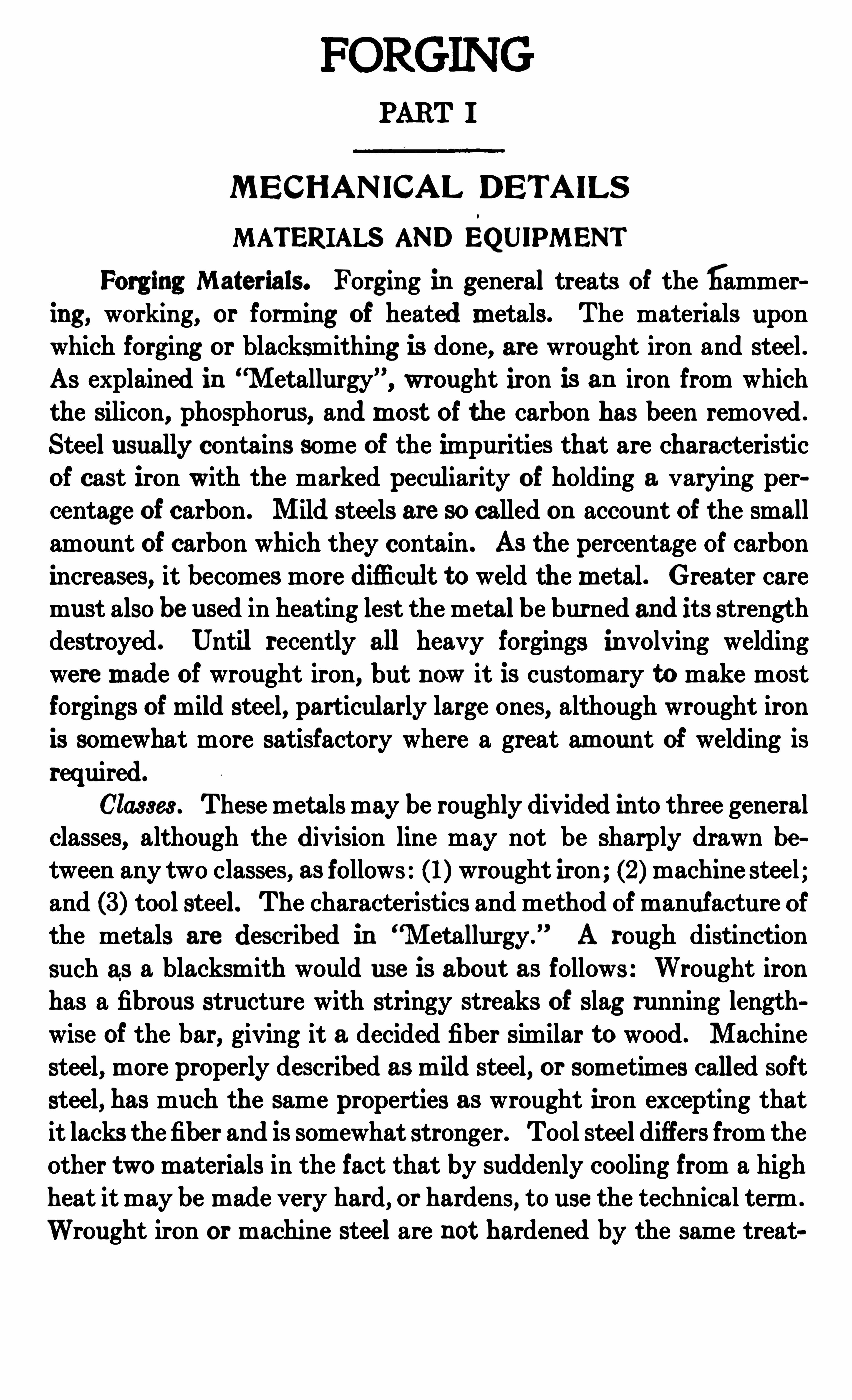
The usual form of tuyere consists Of a single blast pipe , open
ing into the bottom Of the fire pit . This may be a simple nozzle as
in Fig . 1, with the blast
regulated by a damper in
the pipe ; or , it may have aregulator at the mouth of
the tuyere as shown . Some
times the tuyerehas severalopenings, and is then in theform of a grate . Whatever
it s form , it should be possible to clean it from below,
in order that coal and clinkers falling into it may be removed.
Fig . 1 Tuye re
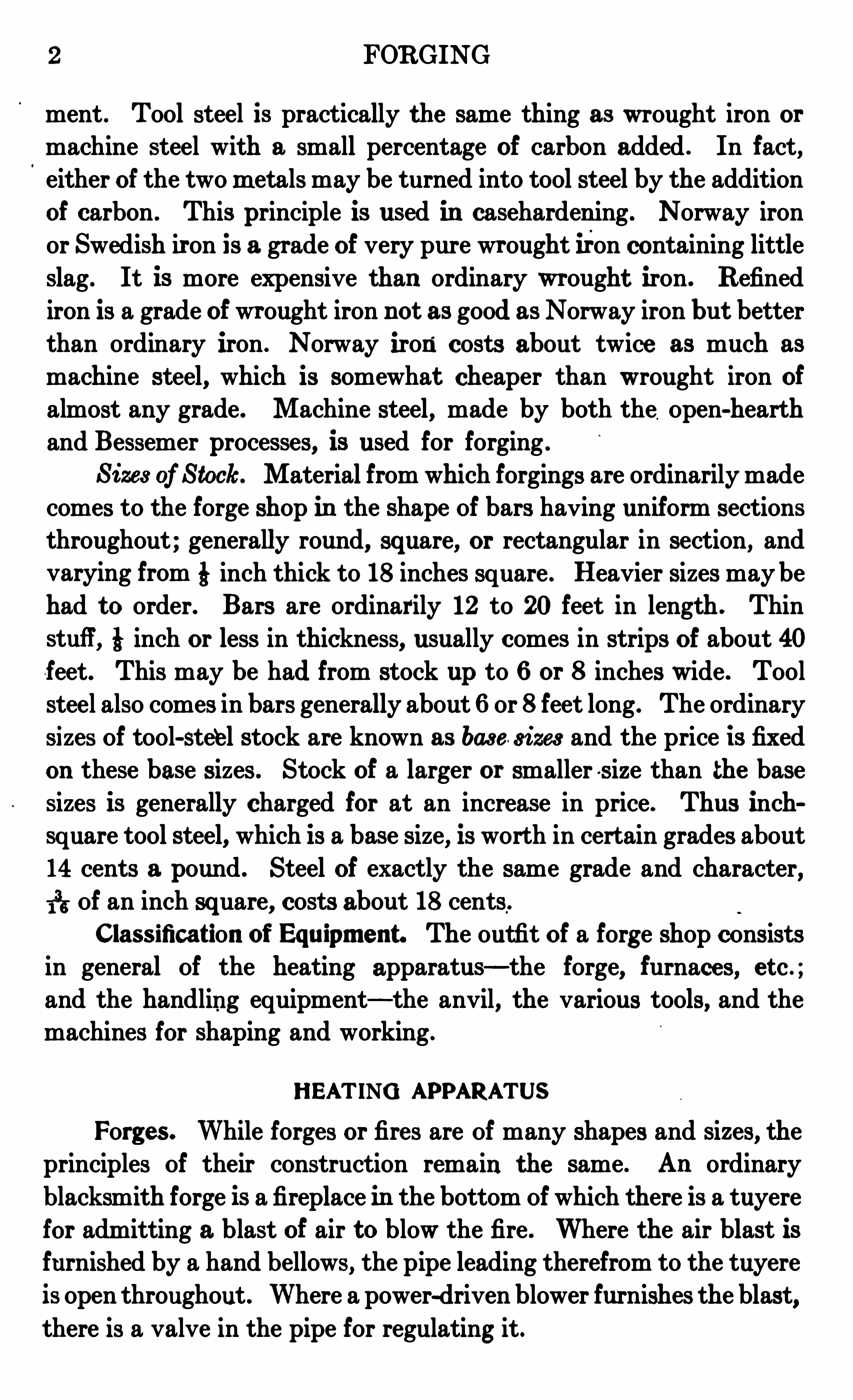
Fig . 2 . Mode rn Forg eCourtesy of BuflaloForge Com pany, Bafialo, New "ork
A modern type Of forge is shown in Fig. 2 . This is provided
with a hood for carrying Off the smoke . The pipe connected to the
4 FORGING
hood ext ends downward to an underground flue leading t o an
exhaust fan which draws out the air . The blast pipe is also underground, and a sm all pipe leads upward to the tuyere, the am ount ofblast admitted to the fire being regulated by a slide in this pipe.This system Of underground piping is known as the down-draft
system .
In some shops no provision is made for carrying off the smoke,while in others hoods are placed above the forges and connected to
Fig . 3 . MotorbDriv en Exhaus ter or BlowerCourtesy of Bufl
'
alo Forge Com pany. Bufi'
alo, New "ork
overhead pipes, which may be either connected to an exhaust fan orled directly to the roof. The down-draft system is the m ore modern
and generally the best.Blas t . The blast is furnished to the fires Of a blacksmith shop
by blowers of various kinds. For many years the ordinary bellows
was used . This has been superseded by the fan blower which is now
almost universally used, even for hand power.
Such a fan blower is shown in Fig . 3 . It is formed of a thin
cast-iron shell in which there are a se t Of rapidly revolving blades.
FORGING 5
These blades set up a current of air which presses against the side
of the shell and escapes through the tangential opening . Thepressure of the blast used for an open blacksmith fire v aries fromabout 2 to 7 ounces per square inch . The lower pressure is usedfor a light fire and light work. The higher pressure is suitablefor heavy classes Of work.
Fuel. The common fuel for small fires is soft or bituminous
coal, coke for large fires and furnaces, and occasionally hard coal insmall furnaces. The soft coal used is of a grade known as sm i thing
coal. It should be very clean and free from impurities. A lum p of
good forge coal breaks easily with a crum bly looking fracture andthe coal shows clean and bright on all faces. It will not break up
into layers as “steaming coal will, such seamy looking breaks being
caused by the more or less earthy impurities. If forge coal splitsand shows dull looking streaks or layers, it is poor coal . Good coalhas little clinker and breaks easily. When used , the coal is dampened and kept wet before putting on the fire . It should be brokenup fine before dam pening, and not used in lumps .
Fires . The fire must be carefully watched . It is very im portantthat it should be in first -class condition at all times for the work inhand. A certain depth of fire is always necessary . If the fire be tooshallow, the cold blast will penetrate the fire in spots, making itimpossible to heat the metal . There Should be depth enough tothe fire to prevent this. For small work there Should be at leastthree or four inches Of fire below the metal that is heating . Thereshould also be thickness enough of fire above the work being heatedto prevent the metal from losing heat to the outside air . The fireshould be kept as small as possible to heat the work properly . As a
general rule the fire will follow the blast . If the fire is wanted larger,
it may be made soby loosening the edges of the fire by a bar, allowingthe blast to come through around the sides, and causing the fire toSpread . When a small fire is wanted the damp coal should be packeddown tightly around the sides and the center of the fire loosened upslightly. For light work a small round fire is used . For heavier heating the fire is started by placing a large block on top of the tuyere,on each side of which green coal is packed down hard in the Shapeof an Oblong mound . The block is then removed and the fire startedin the hole left. These mounds are left undisturbed and fresh fuel is
6 FORGING
added to the fire in the shape Of coke which has either been previouslymade by loosely banking a quantity of green coalover the fire andpartially burning it to coke, or is bought readym ade. With a small
fire the fuel is constantly added around the sides where it is t urnedinto coke . This coke is raked in to the center Of the fire as wantedand more coal added around the sides and patted down to keep thefire in shape .
When too much blast is blown through the fire all the oxygenis not burned out of the air . This attacks the iron, form m g a heavy
Fig . 4 . Sm all Heat ing Furnace
coat Of oxide or scale (the black scale which falls from heated iron) .
This sort of fire is known as an oxidizing fire and should not be used
when it is possible to avoid it. When just enough air is being admitted
tokeep the fire burning brightly and all Of the Oxygen is burned, the
fire is in good condition for heating . Very little scale is formed and
some of the scale already formed may even be turned back to iron.
This sort Of a fire is known as a reducingfire . In other words, whenthe fire is in condition to give oxygen to anything, it is an oxidizingfire . If in condition to take away oxygen, it is a reducing fire.
FORGING 7
Banking . The fire may be kept for some tim e by placing a
block of wood in the cent er and covering over with fresh coal .
Furnaces. In nearly allmanufacturing work and in large work in
the jobbing shop, theheating is done in furnaces. The heat isgenerally
supplied by either hard coal, coke, oil, or gas— coke being more com
m only employed in jobbing shops. Sometimes ordinary coal is used .
Sm all Type . A furnace used for heating small work for manu
facturing is shown in Fig . 4 . This
may be used with either ordinary
coal or coke. Gas furnaces, a simple f
type of which for all around work ‘
is shown in Fig . 5, are used when
an even heat is wanted, particularly .
for hardening and tempering. Formanufacturing work the furnaces are
sometim es fixed to do the heatingautomatically. The pieces to be
hardened are carried through thefurnace on an endless chain which
moves at a speed so timed that the
pieces have just time enough to beheated to the right temperature as
they pass through the furnace. Such
a furnace is shown in Fig. 6 .
Reverberatory. A reverberatory,or air furnace, is a furn ace in which
Fig . 5 . Sim ple Gas Furnaceore , metal, or other material 15 Co mm 0,Am er ican Ga, Fur
-m e Com pany,
exposed to the action Of flame, butN ew "ork m y
not to the contact of burning fuel . The flame passes over a bridgeand then downward upon the material spread upon the hearth.
Such furnaces are ext ensively used in shops where heavy workis being executed. They are also used for melting iron or other metals.For this purpose, however, they are not economical, since they
require about twice as much fuel as that used in the cupola for theproduction of good hot iron. TO be effective the flame must be made
to reverberate from the low roof of the furnace down upon the heart hand work. The form Of the roof and the velocity Of the currents
determine the hottest part Of the furnace .
8 FORGING
A common form Of reverberatory furnace is shown in Fig . 7
The whole is lined with fire brick from the top Of the grates to the
Fig . 6 . Autom at ic Gas Furn ace
Courtesy of Am eri can Gas Furnace Com pany, N ew "ork City
top of the stack. The fuel is burned in a fire box separated from theheating portion Of the furnace by a low bridge wall D. Access to
Fi g . 7. Sect ion of Rev erbe ratory Furnace
the grate is Obtained by suitable doors both above and below. When
in service, both doors are tightly closed and a strong forced draft

10 FORGING
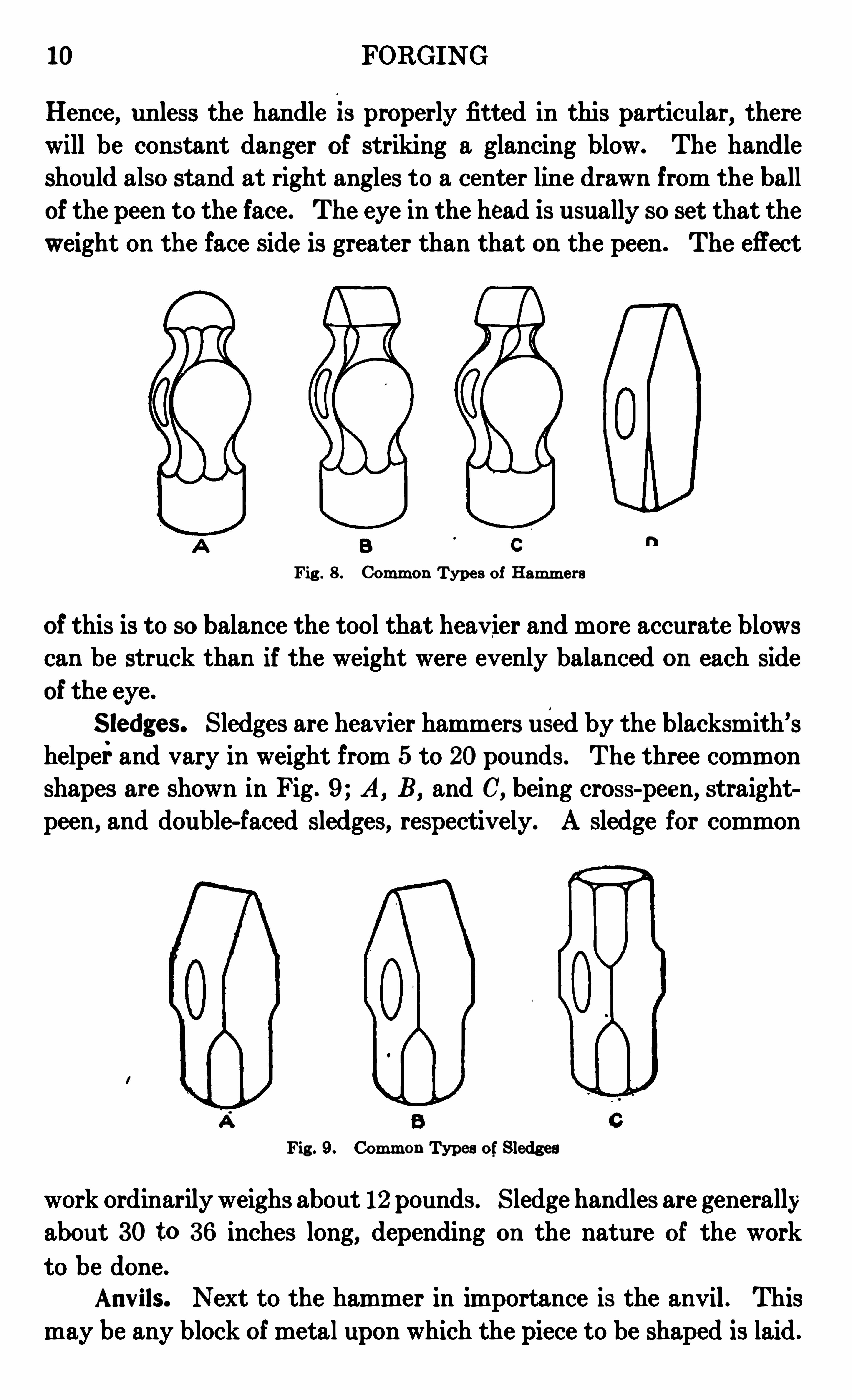
Hence, unless the handle 13 properly fitted in this particular, there
will be constant danger Of striking a glancing blow. The handle
should also stand at right angles to a center line drawn from the ballOf the peen to the face . The eye in the head is usually so se t that the
weight on the face side is greater than that on the peen . The effect
Fig . 8 . Com m on Type s of Ham m e rs
Of this is to so balance the tool that heav ier and more accurate blowscan be struck than if the weight were evenly balanced on each side
Of the eye.
Sledges. Sledges are heavier hammers used by the blacksmith’
s
helperand vary in weight from 5 to 20pounds. The three common
shapes are shown in Fig . 9 ; A, B, and C, being cross-peen, straight
peen, and double-faced Sledges, respectively. A sledge for common
Fig . 9 . Com m on Types of Sledg es
work ordinarily weighs about 12 pounds . Sledge handles are generallyabout 30 to 3 6 inches long, depending on the nature Of the work
to be done.
Anv ils. Next to the hammer in importance is the anvil . This
may be any block Ofmetal upon which the piece to be shaped is laid .

FORGING 11
The anvil must be of such aweightthat it can absorb the blows that arestruck upon it without experiencing any perceptible motion in itself.
The ordinary anvil, Fig. 10, has remained unchanged in form
for m any hundreds of years. Anvils are sometimes made Of specialshapes, but the on e here shown is the common on e . An anvil Of thisform serves for the execution Of any work that may be desired .
As now made, the body a is Of wrought iron to which a face of
hardened steel is welded . From one end there projects the horn b,and the overhang Of the body at the other end 0 is called the tail .At the bottom there are four projections d, called the feet, which serveto increase the base upon which the anvil rests as well as to affordthe means for clamping it down into position . In the tail there is
Fig . 10. An v i l
a square hole and a circular hole . The former is called the hardiehole , the latter the spud hole .
An v ils are also made of cast iron with the workin g faceschilled, thus giv ing a sort Of caseharden ing effect .
The anv il should be placed upon the end Of a heavy block of
wood sunk into the ground to a depth Of at least 2 feet, so thatit may rest upon a firm but elastic foundation . As the anv il is sub
ject ed to constant vibrations, by the nature of the work, it is necessarythat it should be firmly fastened to the block .
Weight Classification . Anvils are classed and sold by weight .
The weight is generally stamped on the side of the anv il . Three
numbers are used . The first to the left shows the weight in Englishhundredweight of 112 pounds each. The middle number Shows theadditional quarters of hundredweight and the right-hand figure thenumber of Odd pounds. For instance, an anvil marked 2-3 -4 would
12 FORGING
weigh of pounds = 3 l2 pounds and would beknown as about a 300-pound anv il .
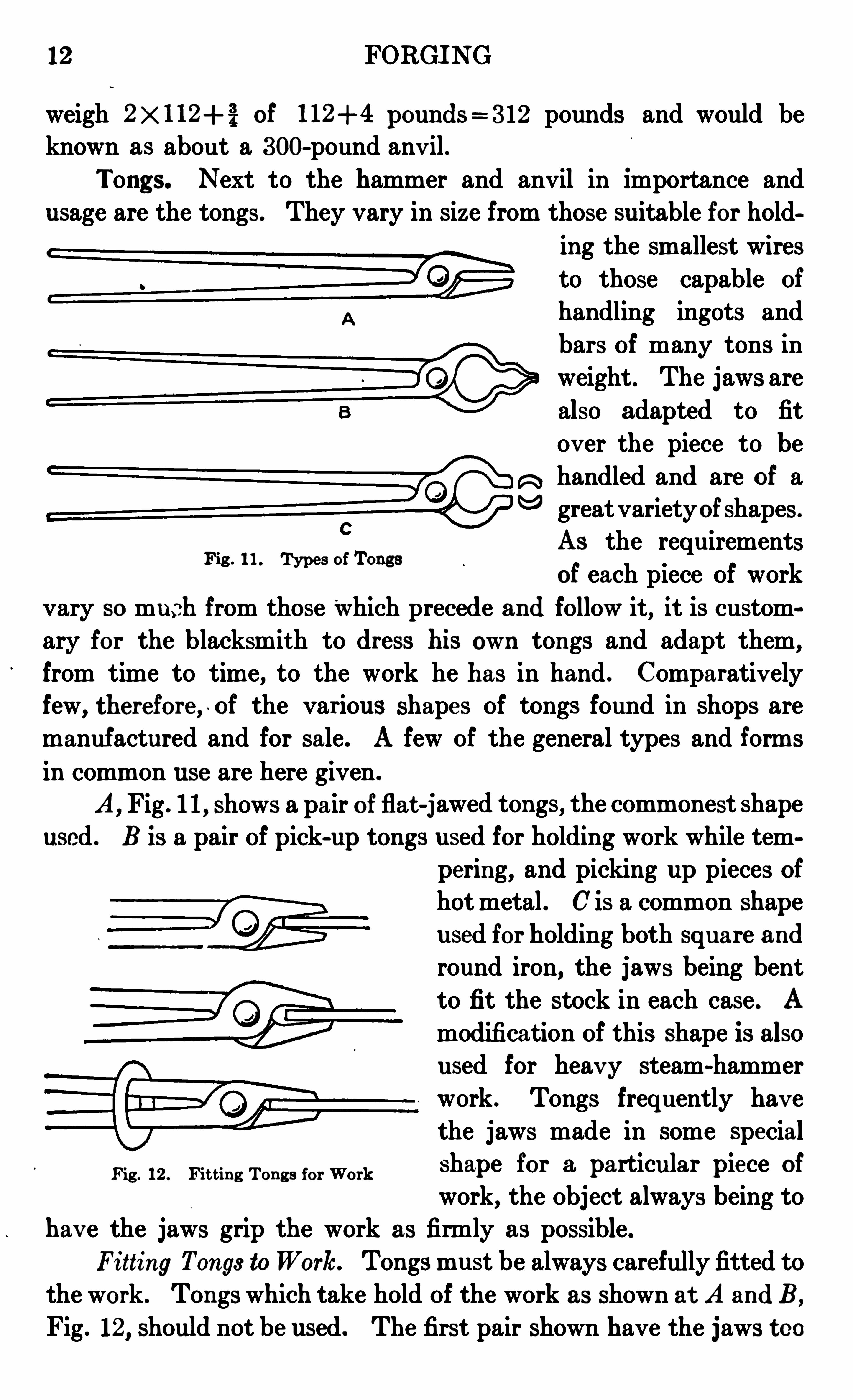
Tongs. Next to the hammer and anvil in importance andusage are the tongs . They vary in Size from those suitable for hold
ing the smallest wiresto those capable Of
handling ingots and
bars Of many tons inweight . The jaws are
also adapted to fit
ov er the piece to be
R handled and are of a“5 greatvarietyof shapes.
As the requirementsOf each piece Of work
vary so much from those Which precede and follow it, it is custom
ary for the blacksmith to dress his Own tongs and adapt them,
from time to time, to the work he has in hand . Comparativ elyfew
, therefore , . of the various shapes Of tongs found in shops are
manufactured and for sale. A few Of the general types and forms
in common use are here given .
A,Fig . 11, shows a pair of flat -jawed tongs, the commonest shape
used . B is a pair Of pick-up tongs used for holding work while tempering, and picking up pieces Ofhot metal . C is a common shape
used for holding both square andround iron, the jaws being bent
to fit the stock in each case . A
modification Of this shape is also
used for heav y steam-hammer
work . Tongs frequently hav ethe jaws made in some special
Fig . 12 . Fit t in g Ton g s for Work Shape for a’ particular piece Of
work, the Object always being tohav e the jaws grip the work as firmly as possible.
Fi tting Tongs toWork. Tongs must be always carefully fitted to
the work . Tongs which take hold Of the work as shown at A andB,
Fig. 12, should not be used . The first pair shown have the jaws too
Fig . 11 . Types of Tongs
FORGING 13
close together, the second, too far apart. When properly fitted thejaws should touch the work thr oughout the entire length as shown inthe lower sketch C. To fit tongs the jaws are heated red hot, the piece
to be held placed between them, and the jaws hammered down untilt ouching their entire length. Tongs which do not fit the workperfectly should never, under any circumstances, be used . When in useon all but the smallest work, a link is driven over the handles to gripthe tongs in position, as shown .
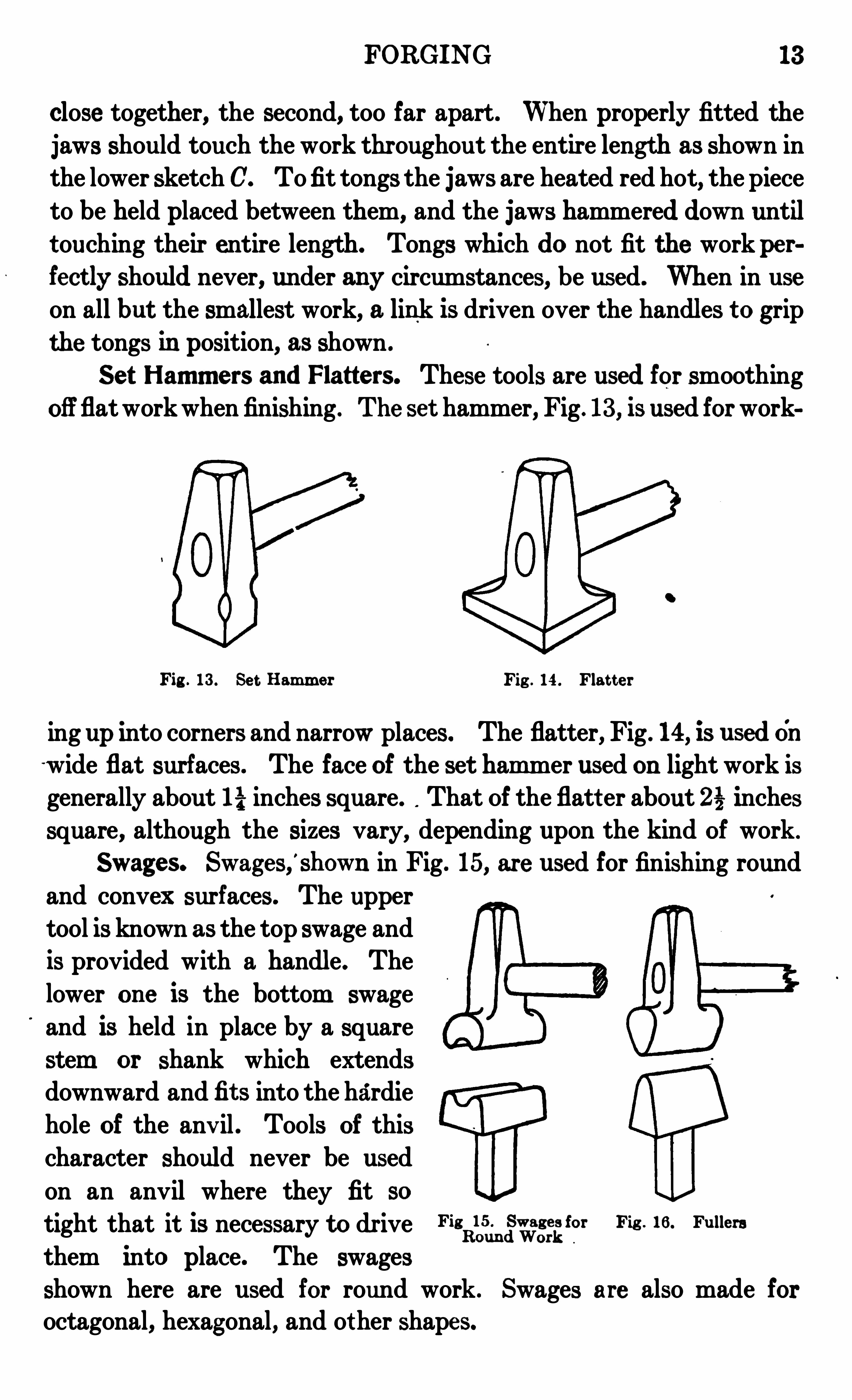
Se t Ham m e rs and Platte rs. These tools are used for smoothingoffflatworkwhen finishing . The set hammer, Fig . 13 , is used for work
Fig . 13 . Se t Ham m er Fig . 14 . Flat t er
ing up into corners and narrow places. The flatter, Fig . 14, is usedOnwide flat surfaces. The face of the set ham mer used on light work isgenerally about 17} inches square. That Of the flatt er about 2% inchessquare, although the sizes vary, depending upon the kind Of work .
Swages. Swages,'
shown in Fig. 15, are used for finishing round
and convex surfaces. The upper
tool is known as the top swage and
is provided with a handle. The
lower on e is the bottom swage
and is held in place by a square
stem or shank which extends
downward andfit s into the hardie
hole of the anv il . Tools Of this
character should never be used
on an anvil where they fit so
tight that it is necessary to dr ive Filjdnggggffl
for Fie 16 . Fullers
them into place. The swages
shown here are used for round work . Swages are also made foroctagonal
,hexagonal, and other shapes.
14 FORGING
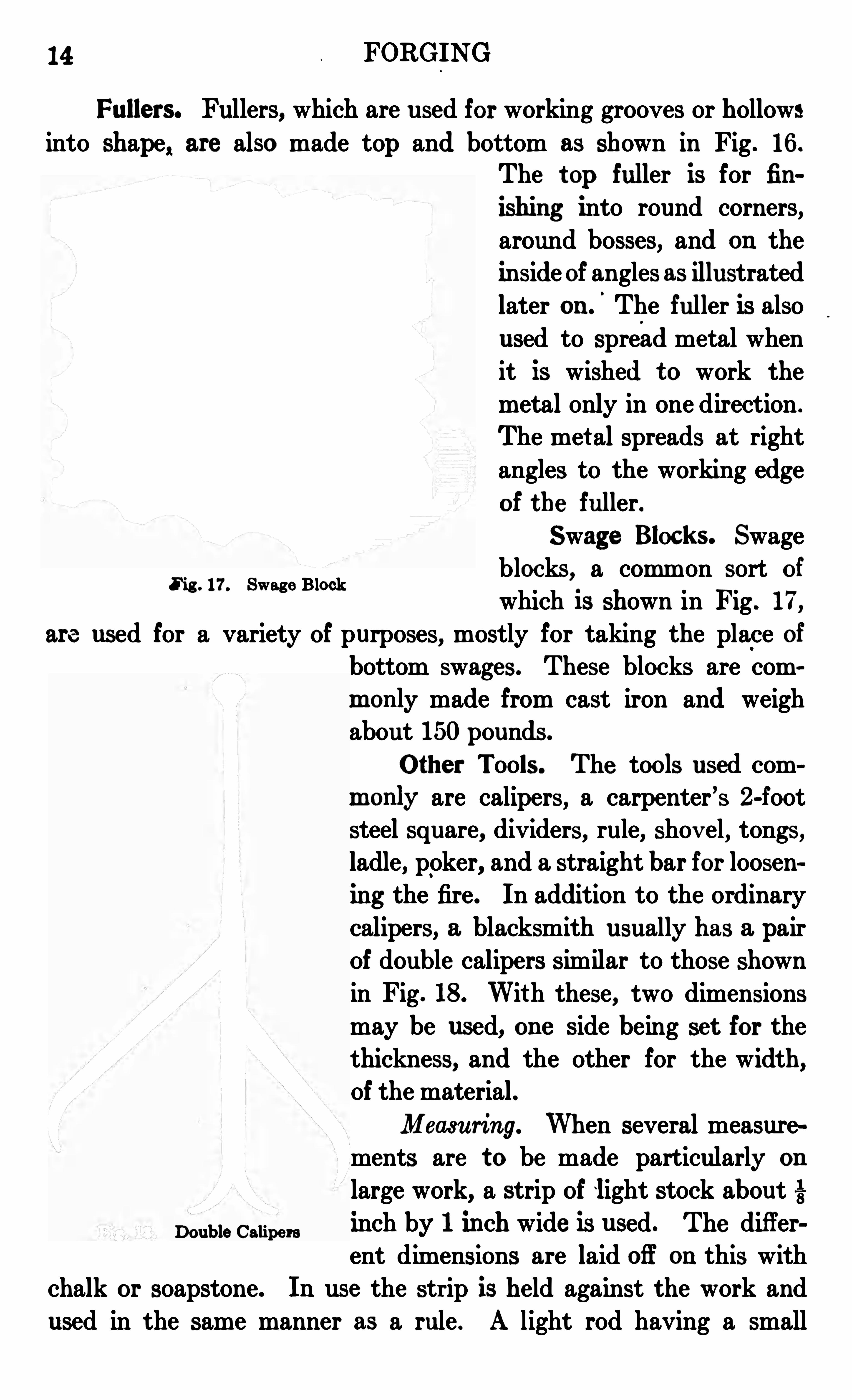
Fullers. Fullers, which are used for working grooves or hollows
into shape, are also made top and bottom as shown in Fig . 16 .
The t op fuller is for fin
ishing into round corners,around bosses, and on theinside Of angles as illustratedlater on .
'
The fuller is also
used to spread metal whenit is wished t o work themetal only in one direction .
The met al spreads at rightangles to the working edge
of the fuller.
Swage Blocks. Swage
blocks, a common sort Of
which is shown in Fig . 17,
are used for a variety of purposes, mostly for taking the place Of
bottom swages. These blocks are comm only made from cast iron and weighabout 150pounds .
Other Tools . The tools used com
m only are calipers, a carpenter’
s 2-footsteel square, dividers, rule, shov el, tongs,ladle, poker, and a straight bar for loosening the fire. In addition to the ordinarycalipers, a blacksmith usually has a pairOf double calipers similar to those shownin Fig . 18 . With these, two dimensions
may be used, on e side being set for the
thickness, and the other for the width,of the material .Measuring. When several measure
ments are to be made particularly on
large work, a strip Of light stock about
Double Caupeminch by 1 inch wide is used. The differ
ent dimensions are laid Off on this withchalk or soapstone. In use the str ip is held against the work and
used in the same manner as a rule . A light rod having a small
Fig . 17. Swage Block
FORGING 15
bent end, made by bending over about 5 inch of stock at right angles ,is also sometimes used, particularly when working under the steamhammer. The dimensions
may be laid Off from the
inside Of the hooked end .
When in use the hooked endis pulled against the end
of the material . Soapstone
crayon is ordinarily used for.
markingon iron . The marks
do not burn Off, but will not
show at a red heat. Marksto show at a high heat must
be made by nicking thecorner of the bar with a
chisel or by markin g withthe center pun ch . Another
common way Of makingmeasurements on hot mate
rial is to lay Off the different
distances on the side Of theanvil with chalk, thedim en
sions being laid Off from one
corner or end .
MACHINE TOOLS
M an ufac t ur in g Re
quirem e nt . The m anufac
turing shop differs very
essentially from the jobbingshop. Inthe latter shopveryfew forgings are made at the
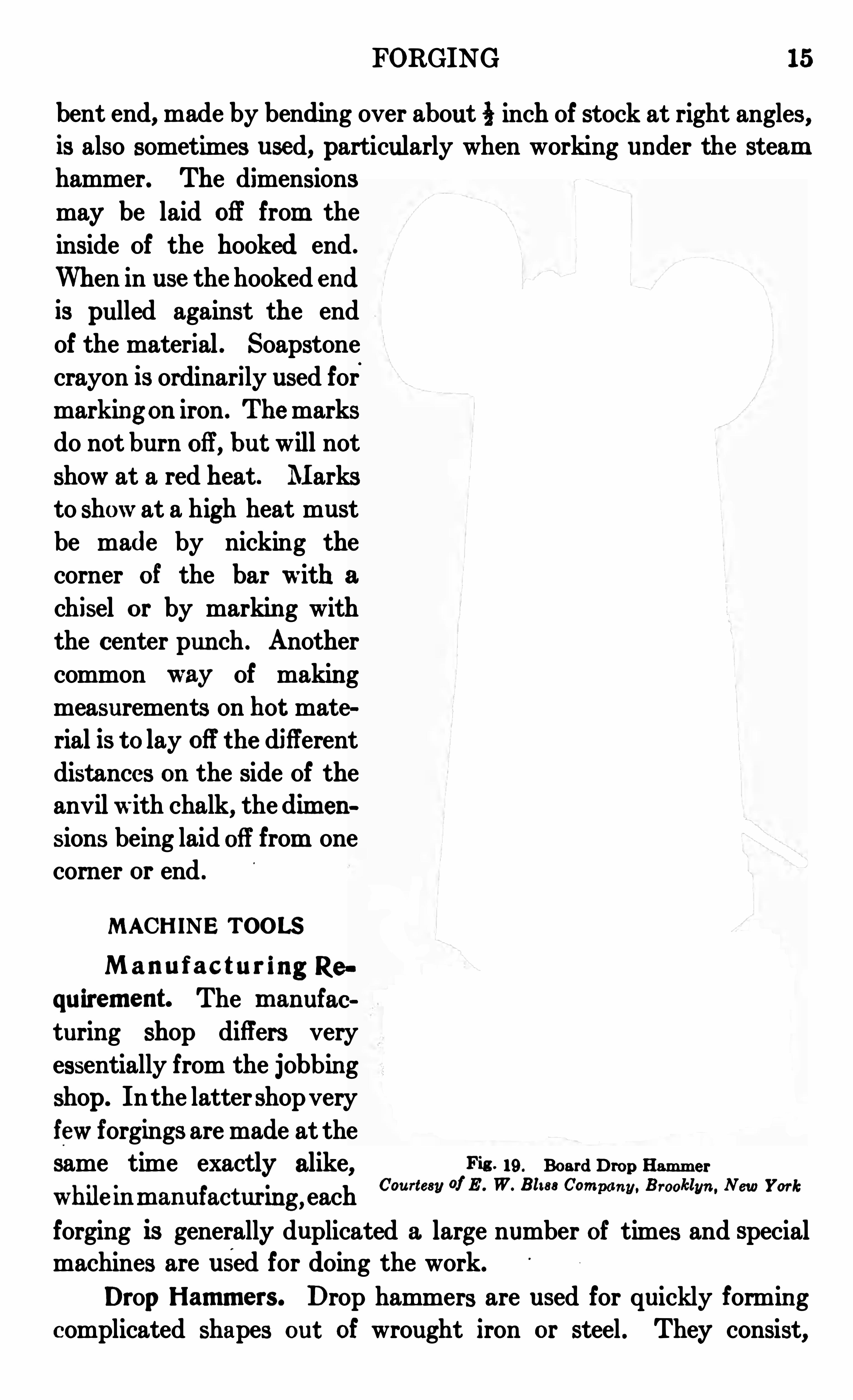
same time exactly alike, Pitt 19 . Board Drop Ham m er
Courtesy of E . W. Blt 88 Com B kl Nwhile m m anufacturm g , each
“ m” m " 11" 8” "ork
forging is generally duplicated a large number Of times and specialmachines are used for doing the work.
Drop Ham m ers. Drop hammers are used for quickly formingcomplicated shapes out Of wrought iron or steel . They consist,
16 FORGING
as the name indicates, of a head that may be dropped from any
desired height upon the piece to be shaped. The head Of the dropand the anvil are in the form of dies into which the metal is forced toflow, and thus take on the form desired . In drop-forging, the metal
must be heated to a high temperature so as to be soft and plastic .
A common type .Of drop hammer used for this kind Of work is
shown in Fig. 19 . The hammer in this case is fastened to a board
and is raised by the friction rollersat the top Of the frame bein gpressed against the board . When the
hammer reaches the top Of theframe it is dropped by releasing therollers from the board . This may bedone automatically or by a foot
treadle . Drop hammers are also
built in the same general way as
steam hammers, as referred to inthe sections on Heavy Forging andDrop Forgin g. Dies for drop forging
generally consist' Of a roughing or
breaking-down die where the rough
stock is first given approximately thedesired Shape and a smoothing diewhen the finishin g is don e. Thesedies have in their faces holes Of the
same shape as the required forging.
Power Ham m ers . Another tool
which is used to quite a large ext ent
in manufacturing, as well as in thejobbing shop, is the power hammer. These are run by belts andare used where a quick rapid blow is wanted . The type shown in
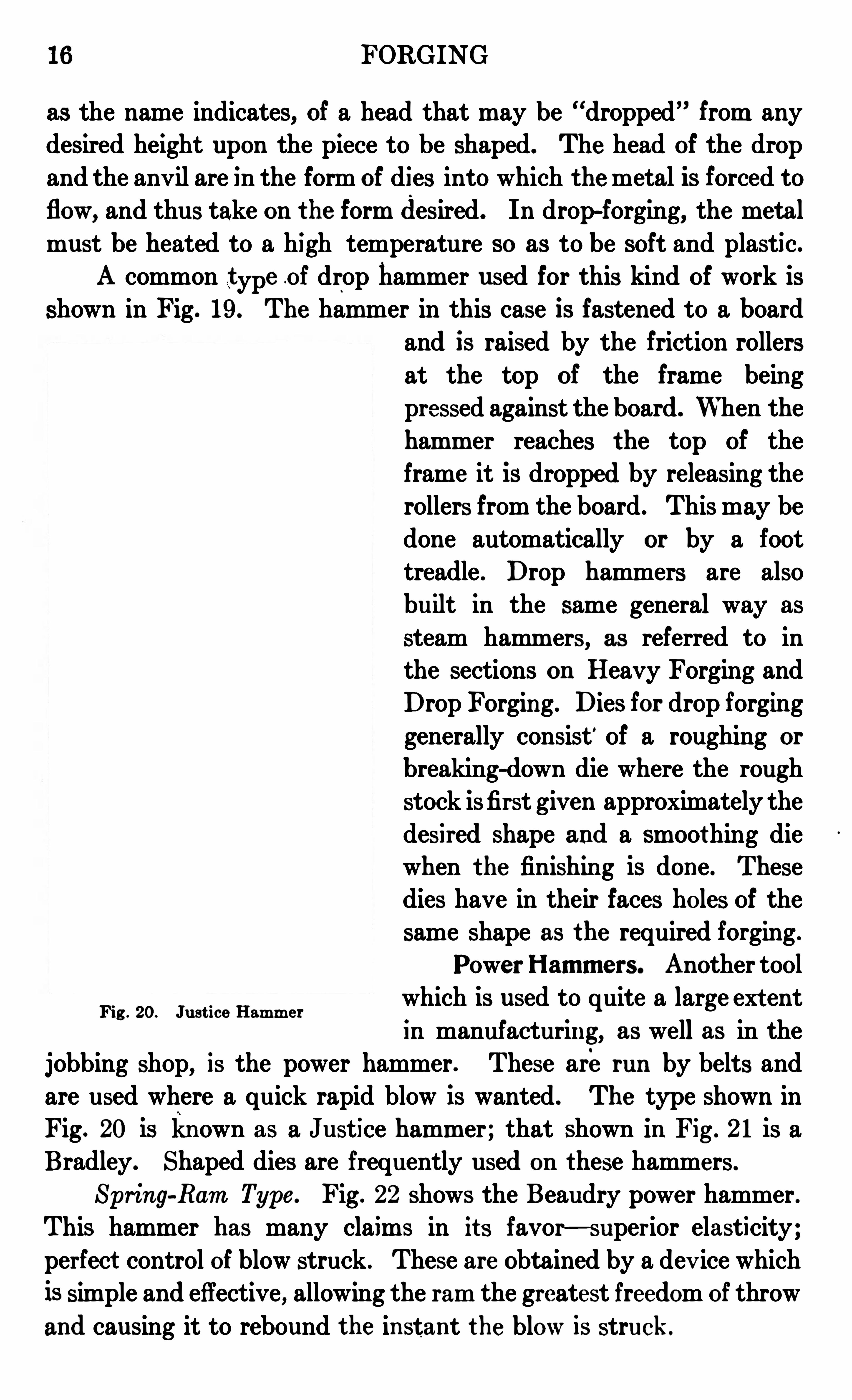
Fig. 20 is kn own as a J ustice hammer ; that shown in Fig . 21 is a
Bradley . Shaped dies are frequently used on these hammers .
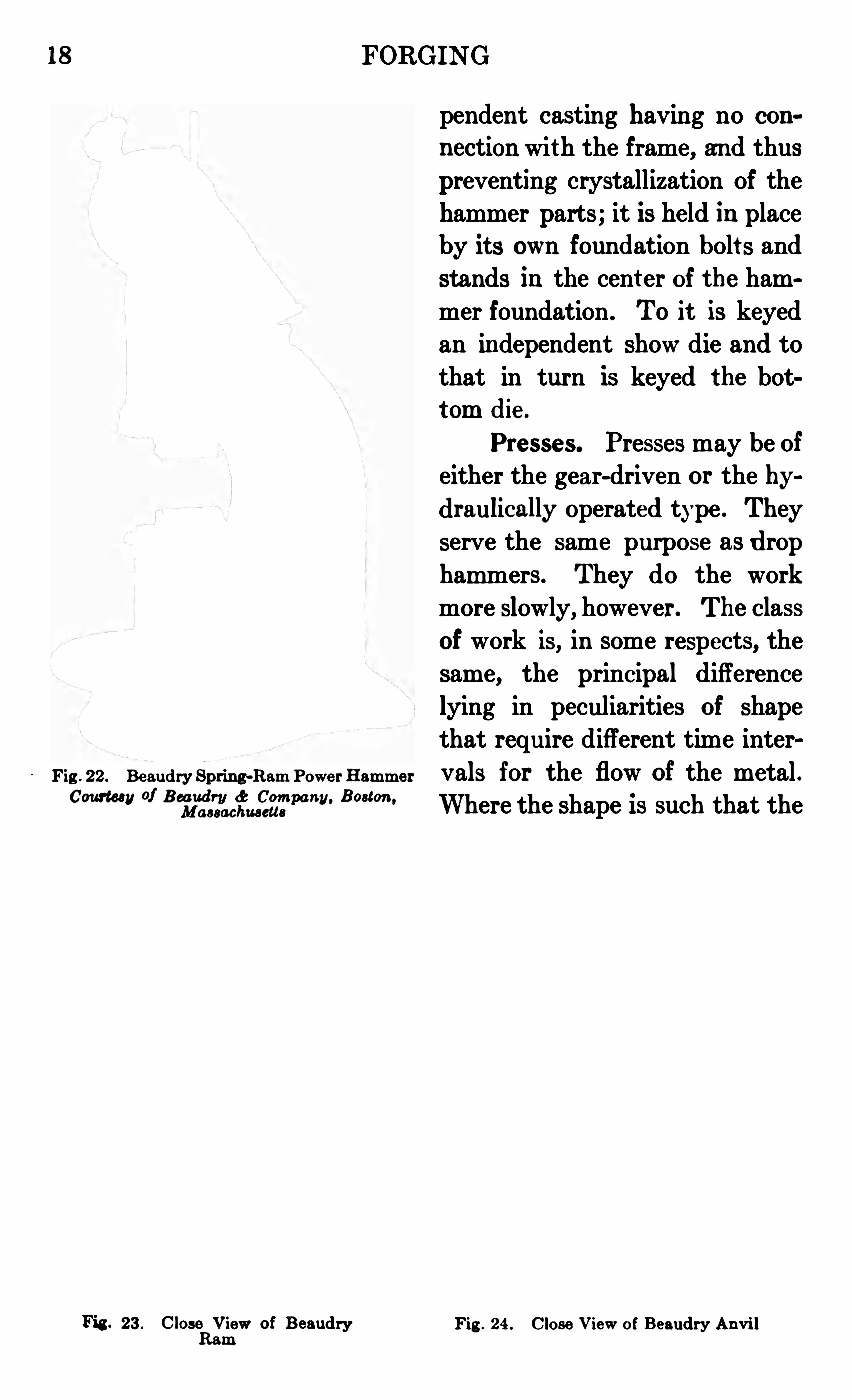
Spring-Ram Type . Fig . 22 shows the Beaudry power hammer.
This hammer has many claims in it s favor —super ior elasticity ;
perfect control Of blow struck . These are Obtained by a dev ice which
is simple and effective, allowing the ram the greatest freedom Of throw
and causing it to rebound the in stant the blow is struck .
Fig . 20. J ust ice Ham m er

18 FORGING
Fig . 22 . Beaudry Spring-Ram Powe r Ham m er
Courtesy of Beaudry d: Com pany. Boston ,
Massachusetts
Fig . 23 . Close V iew of BeaudryRam
Fig . 24 . Close V iew of Beaudry An v i l
pendent casting havin g no con
nect ion with the frame, and thuspreventing crystallization Of thehammer parts ; it is held in placeby it s own foundation bolt s andstands in the cent er Of the ham
mer foundation. TO it is keyedan independent show die and to
that in turn is keyed the bottom die .
Pre sse s. Presses may be of
either the gear-driven or the hydraulically Operated type . They
serve the same purpose as drop
ham mers . They do the work
more slowly, however . The class
of work is, in some respects, the
same, the principal difference
lying in peculiarities of shape
that require different time inter
vals for the flow of the metal .
Where the shape is such that the
FORGING 19
metal must move slowly in order to acquire it s new shape or fill the
die , the press Should be used .
Flonging Type . A particular type of forging press is the flangingpress. This is used more particularly in boiler work and is generallya heavy hydraulic press. The flanging is done by placing the heatedmetal on the bed Of the press and closing the dies together by hydrau
lic pressure.
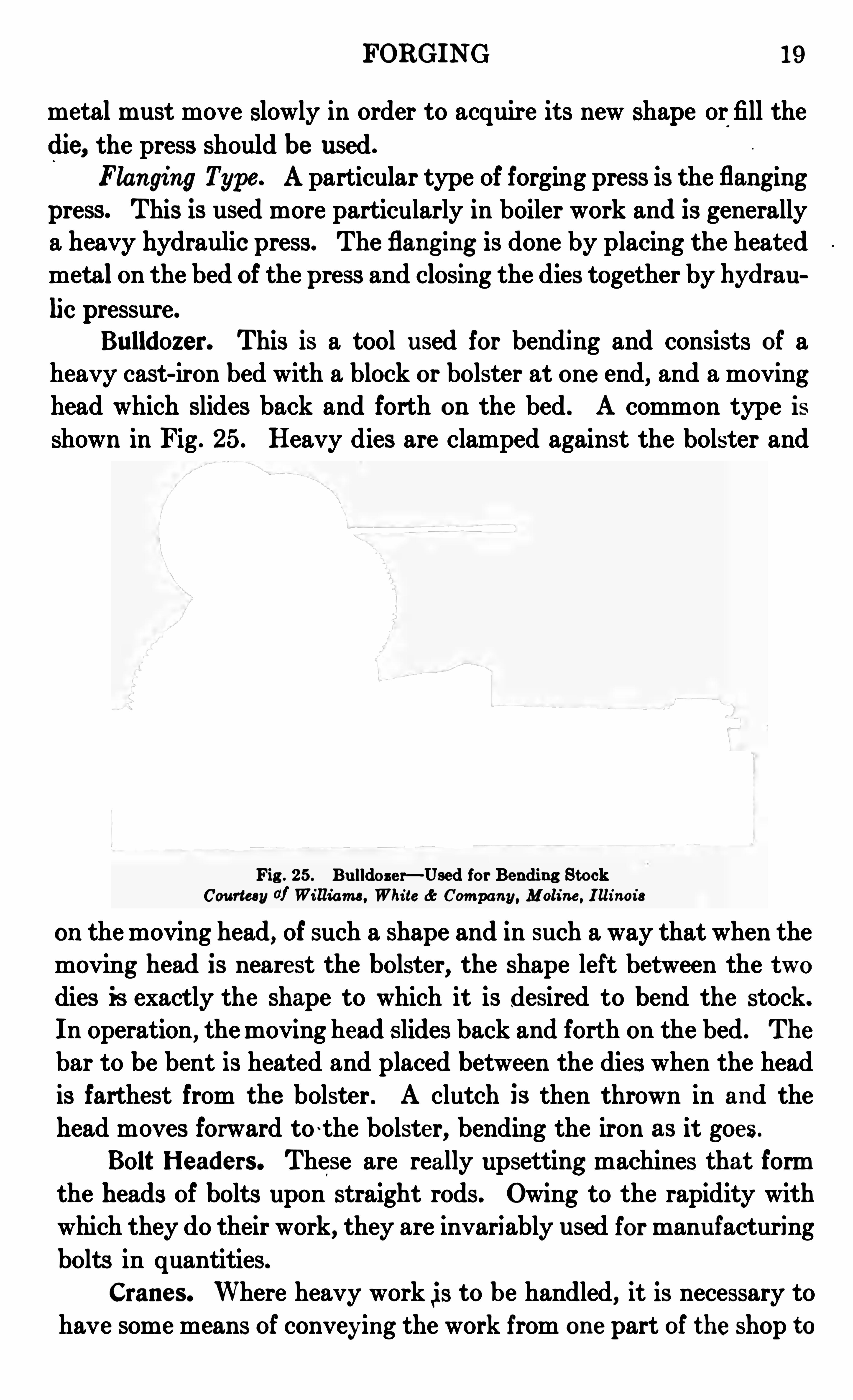
Bulldozer. This is a tool used for bending and consists Of aheavy cast-iron bed with a block or bolster at on e end, and a movinghead which slides back and forth on the bed. A common type is
shown in Fig . 25. Heavy dies are clamped against the bolster and
Fig . 25 . Bulldoze r— Used for Bending StockCourtesy of William s , Whi te dc Com pany, Moline , I llinois
on the moving head, of such a shape and in such a way that when the
moving head is nearest the bolster, the shape left between the twodies is exactly the shape to which it is desired to bend the stock.
In operation, the moving head slides back and fort h on the bed . The
bar to be bent is heated and placed between the dies when the headis farthest from the bolster. A clutch is then thrown in and the
head moves forward to ~the bolster, bending the iron as it goes.
Bolt Headers. These are really upsetting machines that form
the heads Of bolts upon straight rods. Owing to the rapidity with
which they do their work, they are invariably used for manufacturing
bolts in quantities.
Crane s. Where heavy work is to be handled, it is necessary tohave some means Of conveying the work from on e part Of the shop to
20 FORGING
another. This is done by means of cranes of two general types
(1) the traveling crane ; and (2) the jib crane. The former typeruns on an overhead track from one end of the shop to the other,generally.
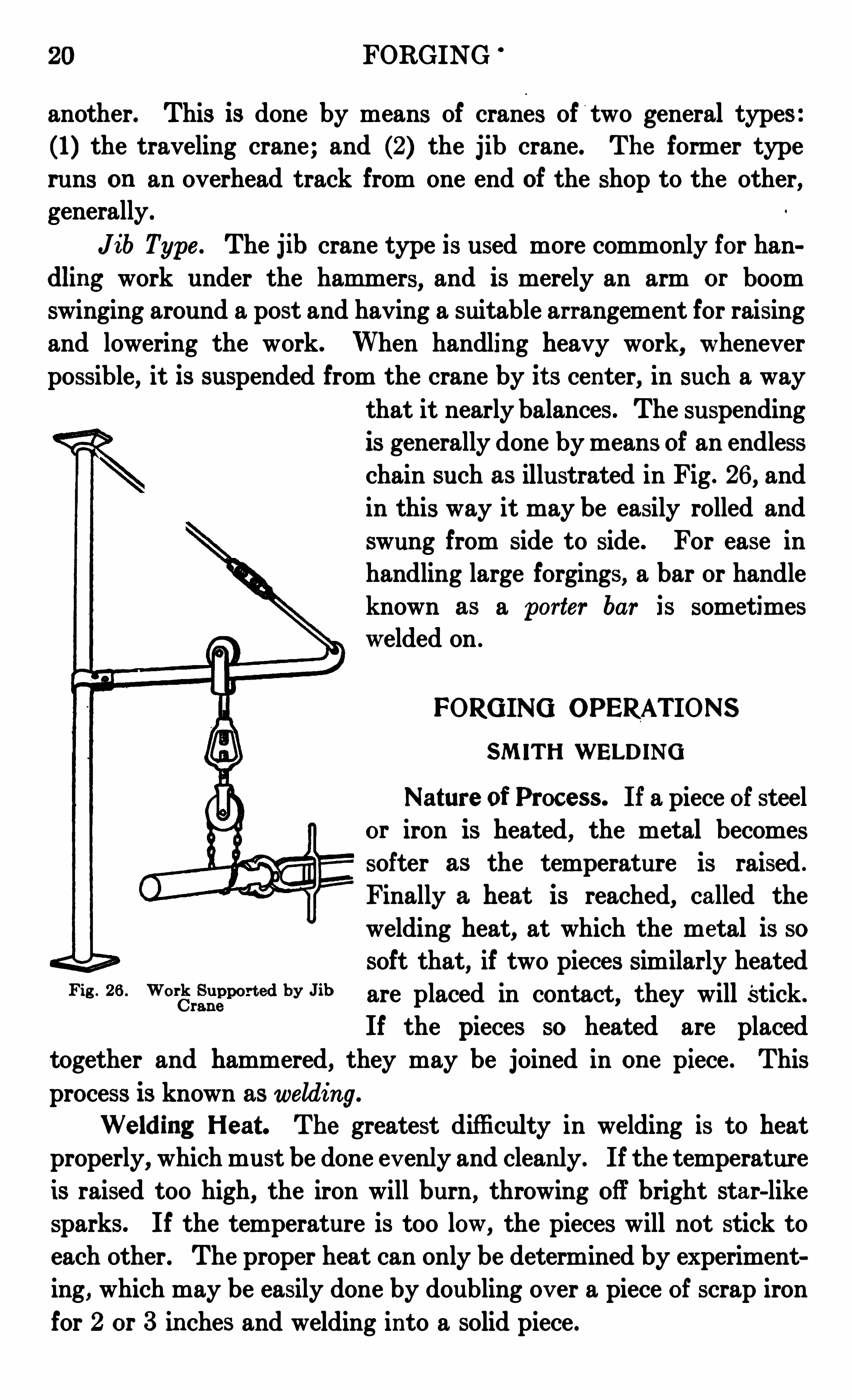
J ib Type . The Jlb crane type is used more commonly for handling work under the ham mers, and is merely an arm or boomswinging around a post and having a suitable arrangement for raisingand lowering the work. When handling heavy work, wheneverpossible, it is suspended from the crane by it s center, in such a way
that it nearly balances. The suspendingis generally done by means of an endless
chain such as illustrated in Fig . 26 , and
in this way it may be easily rolled andswung from side to side . For ease inhandling large forgings, a bar or handle
known as a porter bar is sometimeswelded on .
FORGING OPERATIONS
SMITH WELDING
Nature of Process. If a piece Of steel
or iron is heated, the metal becomessofter as the temperature is raised .
Finally a heat is reached, called the
welding heat, at which the metal is sosoft that, if two pieces Similarly heated
Fig 26 WO'
grfggmm d by J ib are placed in contact, they will Stick.
If the pieces so heated are placed
together and hammered,they may be joined in on e piece . This
process is known as welding .
Welding Heat . The greatest difficulty in welding is to heatproperly
,which must be done ev enly and clean ly. If the temperature
is raised too high, the iron will burn, throwing Off bright star- like
sparks. If the temperature is too low, the pieces will not stick toeach other. The proper heat can only be determined by experiment
ing,which may be easily done by doubling ov er a piece Of scrap iron
for 2 or 3 in ches and welding into a solid piece .
FORGING 2 1
As the welding heat is reached, in heating wrought iron and mildsteel, small particles of the metal are melted and blown upwardfrom the fire by the blast, and as these small part icles come in contactwith the air, they burn and form small explosive Sparks like littlewhite stars. Whenever these sparks are seen coming from the fire,it is a sure indication that the iron is burning; They are some
times used as a sort Of an indication Of the welding heat, but the onlysure way Of determining the heat is by the appearance Of the heated
iron, which might be described as sort Of creamy white. The welding
heat is sometimes described as a white heat. This is not correct,because iron or steel is nev er raised to a white heat ev en when
melted, as may be easily proved by comparing a piece Of wrought
iron at welding heat, with an ordinary arc lamp .
Scale . When two pieces Of metal are welded together theremust be nothing between them . Heated iron or steel is alwayscovered with scale (iron oxide) . This scale, if allowed to stay on
the surfaces to be joined, will prevent a good weld . It is necessarywhen welding, to heat the iron or steel to a high enough temperature
to melt this scale and when the two pieces are put together, if the
joint or scarf is properly made, most Of this melt ed scale is easilyforced from between the two pieces, leaving the clean surfaces of themetal in contact . This scale only melts at a very high heat, much
higher than the heat at which it would be possible to weld the ironif it could be kept free from scale .
Fluxes. Fluxes are used t o lower the melting point of the scale .
The flux is sprinkled OHthe surfaces to be joined just before the
metal reaches the welding heat . The met al is then put back into
the fire, raised to the welding heat and the weld made as usual . The
scale is acted upon by the flux and melts at a lower heat than when
no flux is used . As the flux melts it spreads or runs over the hotmetal and forms a sort of protectiv e covering, which, by keeping outthe air
,prevents to a large ext ent the formation of more scale . The
flux in no way acts as a cement or glue to stick the pieces together,but merely helps to melt Off the scale already formed, and prevents
the formation Of more .
Sand and Borax. These substances are common fluxes . Sand
m ay be used when weldin g wrought iron and machine steel ; boraxis substituted for sand for fine work and when welding tool steel.
22 FORGING
Borax is a better flux, as it melts at a lower temperature than sand,and thus makes welding possible at a lower heat . Borax and sal
ammoniac (ammonium-chloride) are sometimes mixed and used as a
welding compound or flux , the proportion being about 4 parts boraxto 1 part salammoniac . This mixt ure is also a good flux for brazing .
Borax contains a large amount Of water which makes it boil andfoam when melting and in this condition is very liable to drop awayfrom the heating metal . If borax is heated red hot and allowed tocool, the water is driv en Off and the borax is left in a glass-like condition . Borax treated this way and then powdered is the be st forwelding, as it melts and sticks to the metal without any boiling .
Welding Com pounds . These are fluxes serving the same purposeas sand or borax. Some of the better ones use borax as a basis .
Some Of these compounds are first class for their purpose and othersare not SO good, being simply intended as cheap substitutes forborax .
Proce sse s
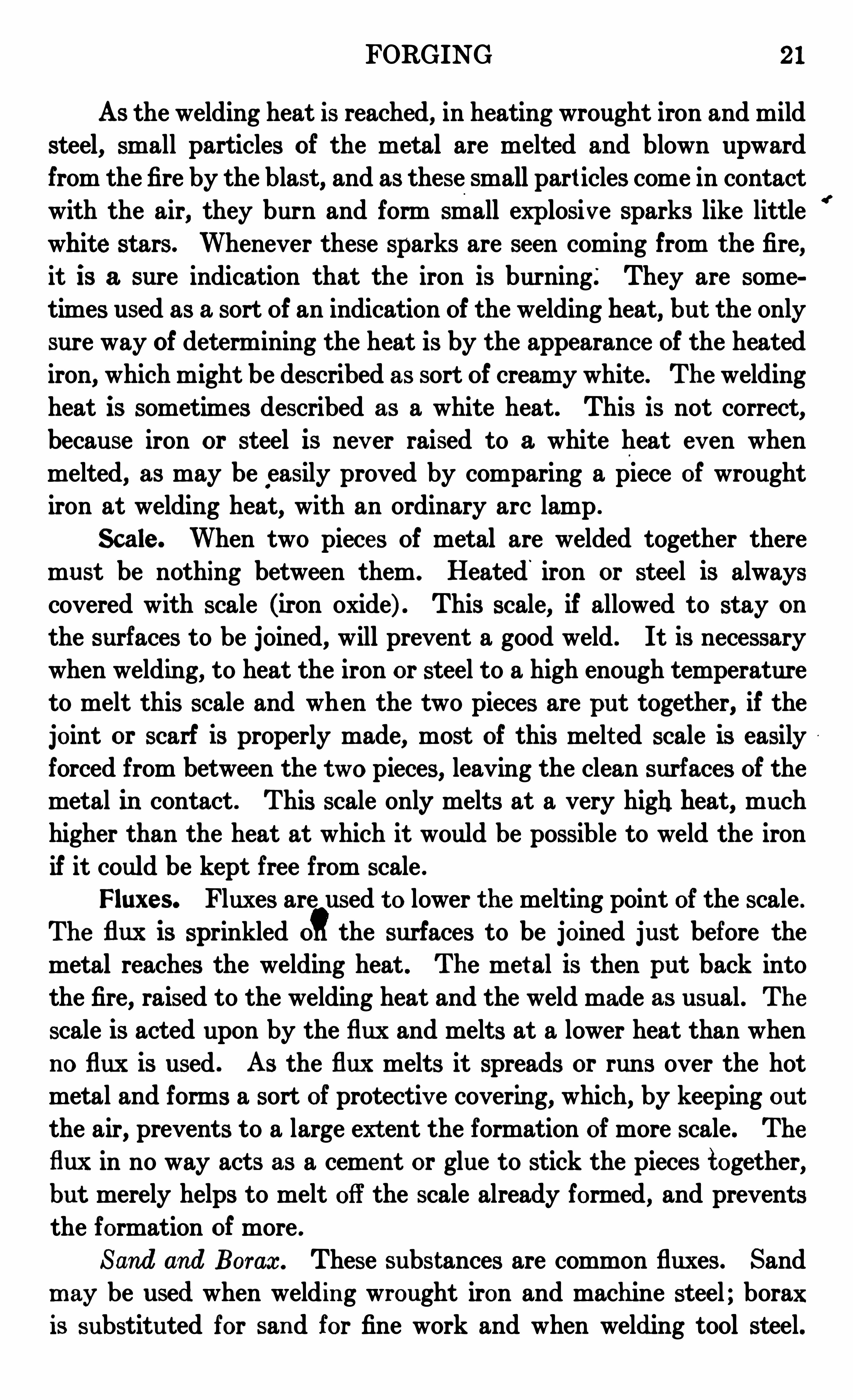
Scarfing. For most welding the ends of the pieces to be joinedmust be so shaped that when welded they make a smooth joint.
This Shaping Of theends is knownas scarfing, and the shaped
end is called a scarf.The s c a r f e d endsshould not fit tightlyb e f o r e welding butshould be so shapedthat they touch in the
center Of the joint ,leaving the sides some
what open . In thisFig . 27 . Work Scarf'ed for LapWeld way, when the weld is
made, the melted scale is forced from between the pieces . If the
scarfs were made to touch on the edge Of the joint, leaving the center
hollow, the scale not hav ing a chance to escape would be held in thecenter Of the joint, leavin g a weak place, and making a badweld .
LapWelding . This is the common weld used for join ing flat
bars together . The ends t o be welded are scarfed or Shaped as
FORGING 23
shown in Fig . 27 In preparing, the ends of the pieces t o be welded
Should be first upset until they are considerably thicker than therest of the bar. This is done to allow for the iron that burns off or is
lost by scalin g, and also to allow for the ham mering when weldingthe pieces t ogether. Tomake a proper weld the joint Should be wellhammered
,and as this reduces the Size of the iron at that point, the
pieces must be upset to allow for this reduct ion in size. For light
Fig . 28 . Shaping Scarf Fig . 29 . Fin ishing Scarf
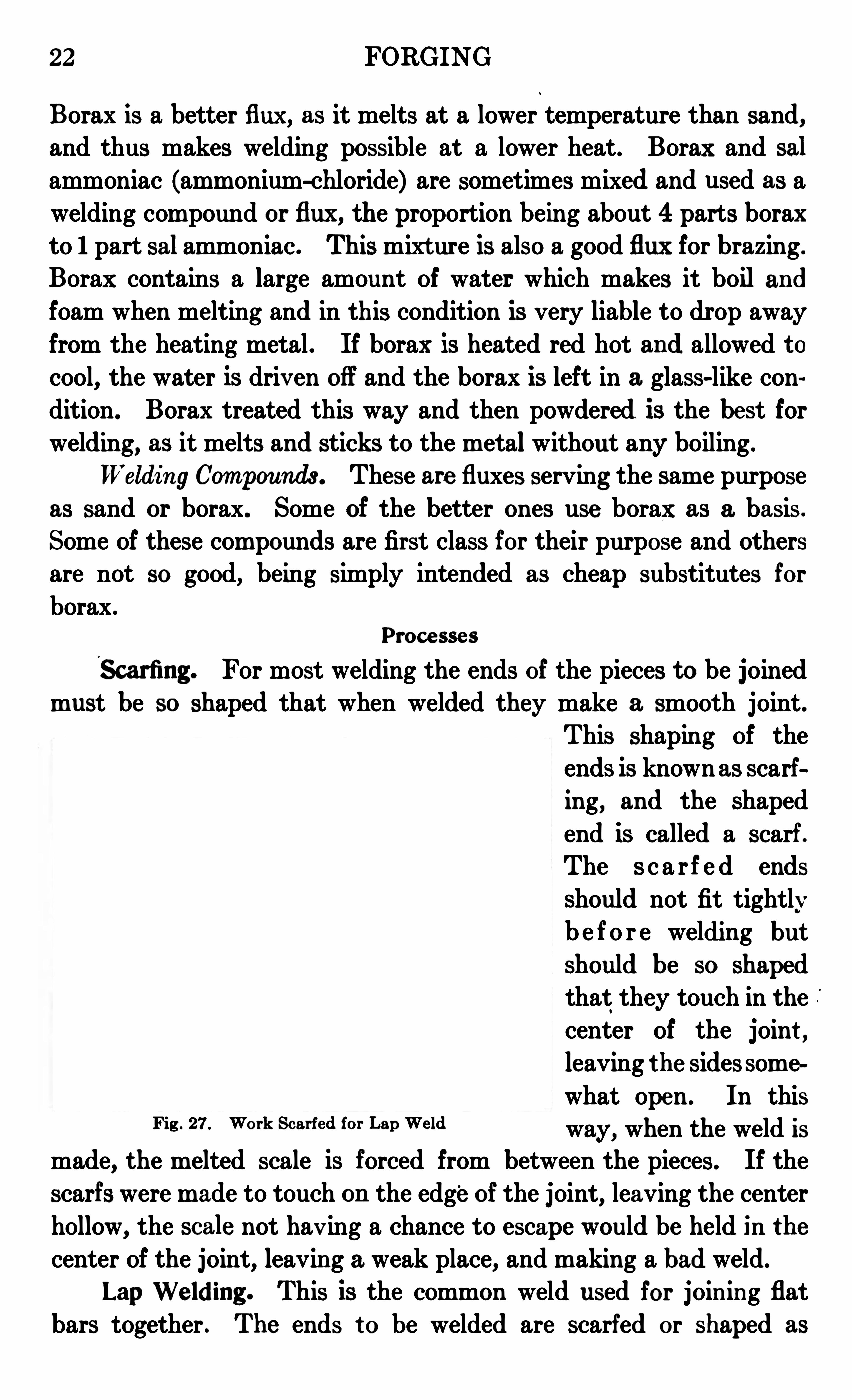
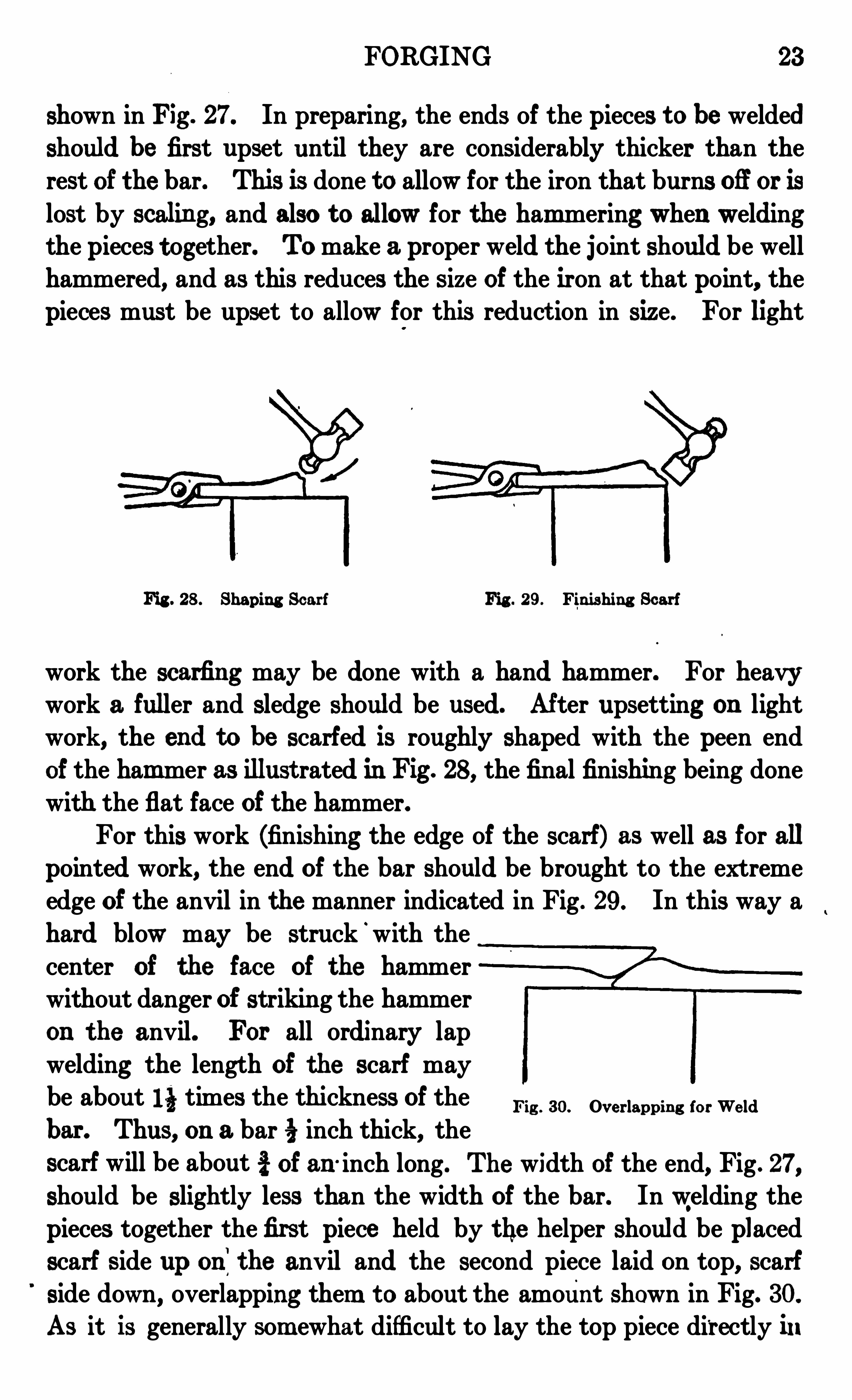
work the scarfing may be done with a hand hammer. For heavywork a fuller and sledge should be used. After upsetting on lightwork, the end to be scarfed is roughly shaped with the peen endof the ham mer as illust rated in Fig . 28, the final finishing being donewith the flat face of the hammer.
For this work (finishing the edge of the scarf) as well as for allpointed work, the end Of the bar Should be brought to the extremeedge of the anvil in the manner indicated in Fig . 29 . In this way ahard blow may be struck
‘
with thecenter of the face Of the hammerwithout danger of strikin g the hammer
on the anvil. For all ordinary lapwelding the length of the scarf maybe about 11} times the thickness Of the
bar . Thus, on a bar inch thick, the
scarf will be about i of an inch long. The width Of the end, Fig . 27,
should be slightly less than the width Of the bar. In welding thepieces together thefirst piece held by the helper should be placedscarf side up on?the anvil and the second piece laid on top, scarfside down, overlapping them t o about the amount shown in Fig. 30.
As it is generally som ewhat difficult to lay the top piece directly i n
Fig . 3 0. Ov er lappin g for We ld
24 FORGING
place, it should be steadied by resting light ly against the corner of
the anvil and thus guided into place .
Round LapWeld. This is the weld used to join round bars end
to end to form a continuous bar. Allthe precautions regarding the
scarf, etc . , used for making the lap weld should be taken with this aswell . The general shape of the scarf is shown in Fig . 27. It will benoticed that the end is hammered to a sharp point. If the scarf bemade with a flat or chisel-shaped end similar t o the flat lap weld,the corners will project beyond the sides of the bar in welding andcause considerable trouble, as it will then be n ecessary t o workentirely aroun d the bar before the joint is closed down . With
a pointed scarf the weld may be frequently made by hammering on two
Sides only. This is not so importantwhen weldin g between swages.
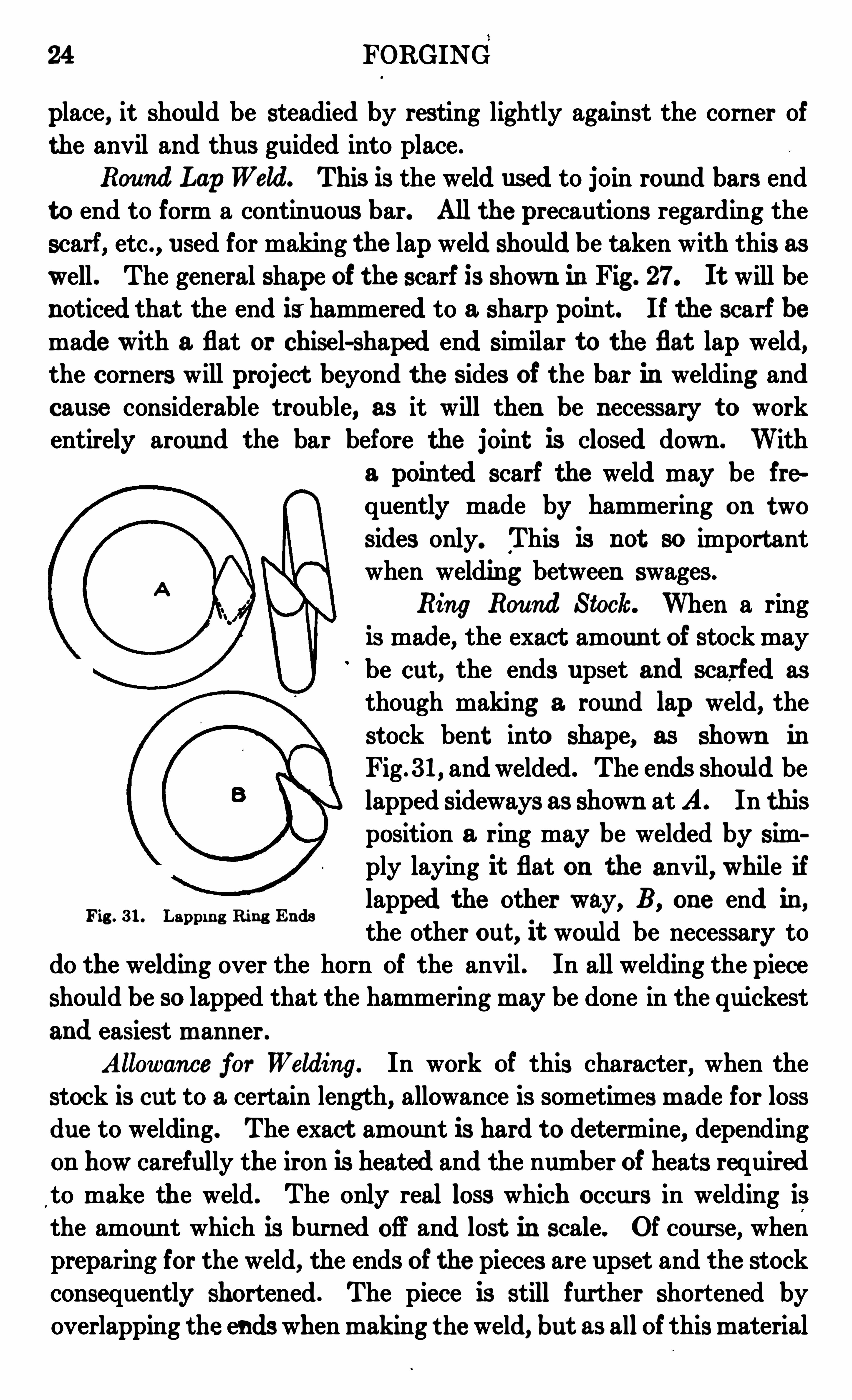
Ring Round Stock. When a ringis made, the exact amoun t of stock may
be cut , the ends upset and scarfed as
though making a round lap weld, the
stock bent into Shape, as shown in
Fig . 3 1, andwelded . The ends should belapped sideways as Shown at A . In thisposition a ring may be welded by sim
ply laying it flat on the anvil, while if
lapped the other way, B, one end in ,the other out , it would be necessary to
do the welding over the horn Of the anvil . In all welding the piece
Should be so lapped that the hammering may be done in the quickest
and easiest manner .
Allowance for Welding. In work of this character, when the
stock is cut to a cert ain length, allowance is sometimes made for lossdue to welding. The exact amount is hard t o determine, depending
on how carefully the iron is heated and the number of heats requiredto make the weld. The only real loss which occurs in welding is
the amount which is burned Off and lost in scale. Of course, when
preparing for the weld, the ends of the pieces are upset and the stockconsequently Shortened . The piece is still further short ened by
overlapping the endswhen making the weld, but as all Of thismaterial
Fig . 3 1. Lappi n g Ring Ends

26 FORGING
into shape and welded; the welding being done over the horn Of theanvil . The heat ing must be carefully done or the outside lap will
be burned before the inside isnearly hot enough to weld.
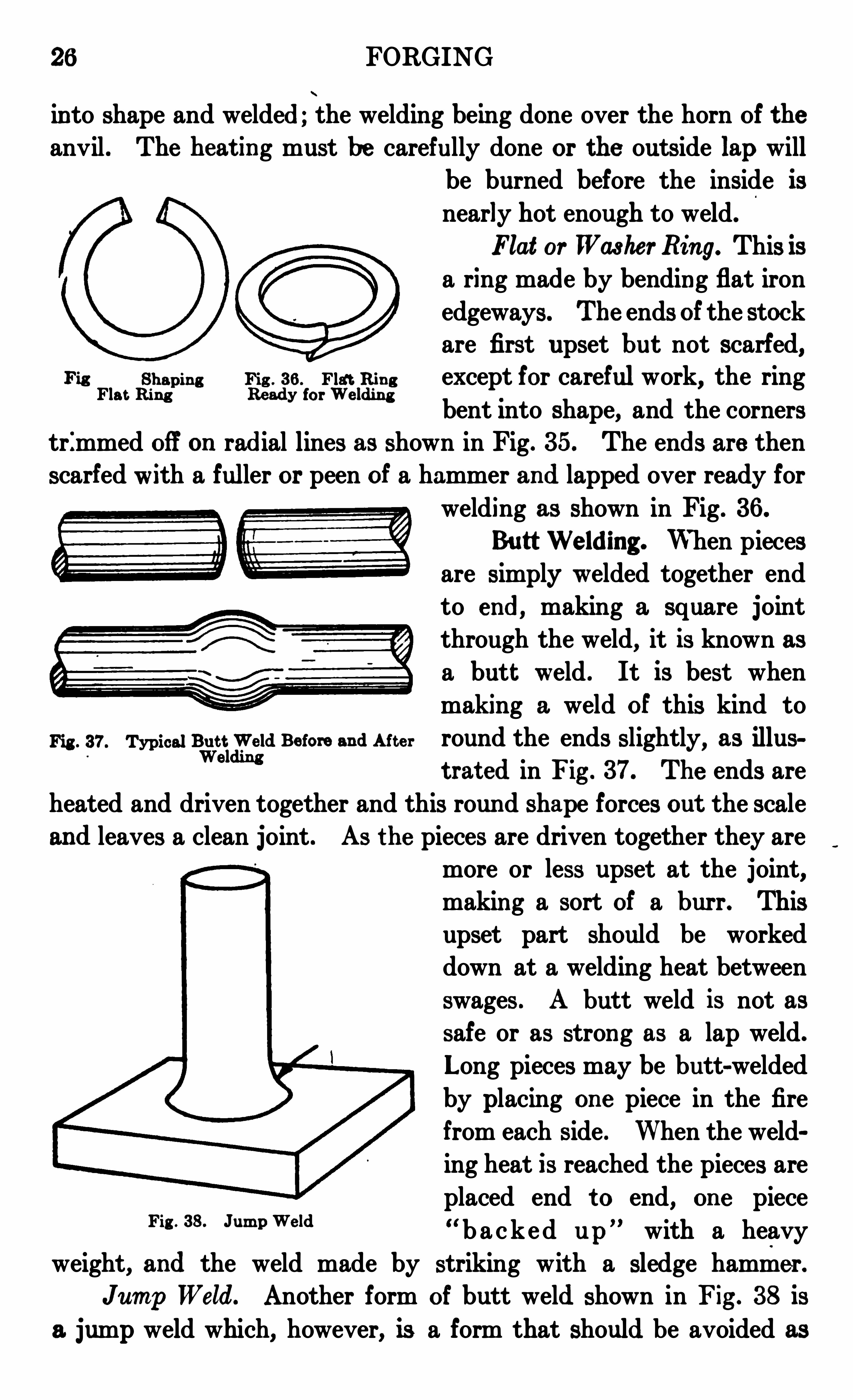
Flat or Washer Ring. This isa ring made by bending flat iron
edgeways. The ends Of the stockare first upset but not scarfed,
Shapin g Fig . 3 6 . Flat Rin g except for carefulwork, the ringFlat Ring Ready for W eldm g
bent Into Shape, and the cornerstrimmed Off on radial lines as shown in Fig. 3 5. The ends are then
scarfed with a fuller or peen of a hammer and lapped over ready for
welding as shown in Fig. 3 6 .
Butt Welding . When piecesare Simply welded together endto end, making a square jointthrough the weld, it is known asa butt weld . It is best whenmaking a weld Of this kind to
Fig . 3 7. TypicalBeatlm
d Be fore and Aft e r round the ends slightly, as illust rat ed in Fig . 3 7. The ends are
heated and driven together and this round shape forces out the scale
and leaves a clean joint . AS the pieces are driven together they aremore or less upset at the joint,making a sort Of a burr. Thisupset part should be worked
down at a welding heat between
swages . A butt weld is not assafe or as strong as a lap weld.
Long pieces may be butt-weldedby placing on e piece in the firefrom each side . When the welding heat is reached the pieces are
placed end t o end, on e piece“ b a c ked up
” with a heavy
weight, and the weld made by striking with a sledge hammer.
J ump Weld. Another form of butt weld Shown in Fig . 3 8 is
a jump weld which, however, is a form that should be avoided as
Fig . 3 8 . J um pWeld
FORGING 27
m uch as possible, as it is very liable to be weak. In making a weld
of this kind, the piece t o be butted on the other Should have it s end
upset in such a mann er as to flare out and form sort of a flange, thewider the better . When the weld is made, t hisflange may be worked down with a fuller or set
ham mer, thus making a fairly st rong weld .
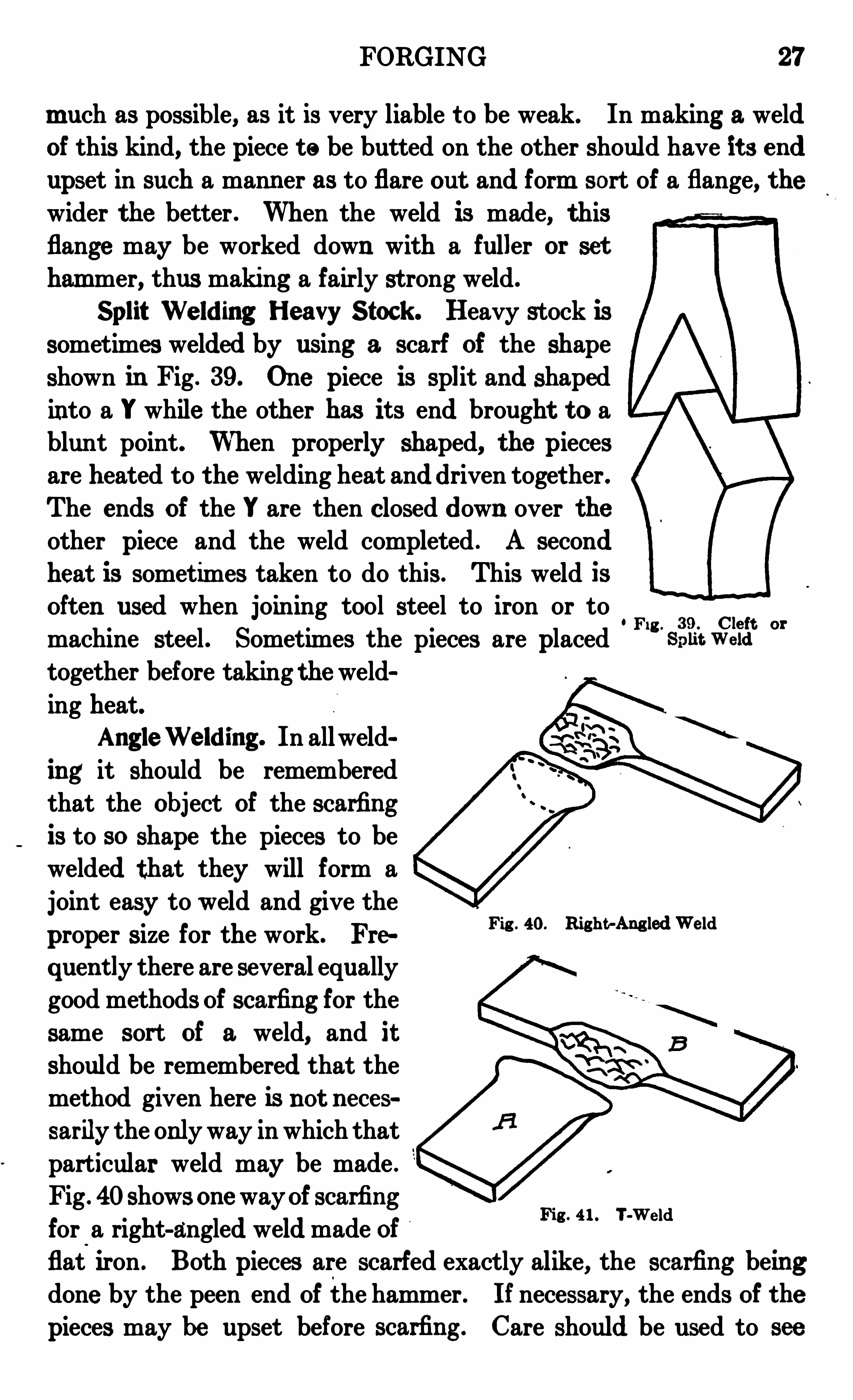
Split Welding Heavy Stock . Heavy stock is
sometimes welded by using a scarf of the Shapeshown in Fig . 3 9. One piece is split and shapedinto a "while the other has it s end brought to ablunt point. When properly Shaped, the piecesare heated to the welding heat anddriven toget her.
The ends of the "are then closed down over theother piece and the weld completed . A secondheat is sometimes taken to do this . This weld isOften used when joining tool steel to iron or to
machine steel . Sometimes the pieces are placedFig '
Siiiit vgiiit
together before taking the weld
ing heat.AngleWelding . In allweld
ing it should be rememberedthat the Object Of the scarfingis to so shape the pieces to bewelded that they will form a
joint easy to weld and give the
proper size for the work. Frs
quen tly there are several equallygood methods Of scarfing for the
same sort of a weld, and it
Should be remembered that themethod given here is not n eces
sarilythe onlyway in which that
particular weld may be made .
Fig . 40showsone wayOf scarfingfor a right-angled weld made Offlat iron . Both pieces are scarfed exactly alike, the scarflng beingdone by the peen end Of the hammer . If necessary, the ends of the
pieces may be upset before scarfing . Care should be used to see
Fig . 40. Ri ght-Ang ledWe ld
Fig . 41 . T-Weld
28 FORGING
that the pieces touch first in the center Of the scarf, otherwise apocket will be formed which will ret ain the scale and spoilthe weld.
T-Welding . A method Of scarfing for a I-weld is illust rated inFig . 41 . The scarf is formed mostly with the peen end Of the ham
mer the points are short for easy weldm g . The stem A should beplaced on the bar B, whenwelding, so that there is a ht tle lap-ov er.
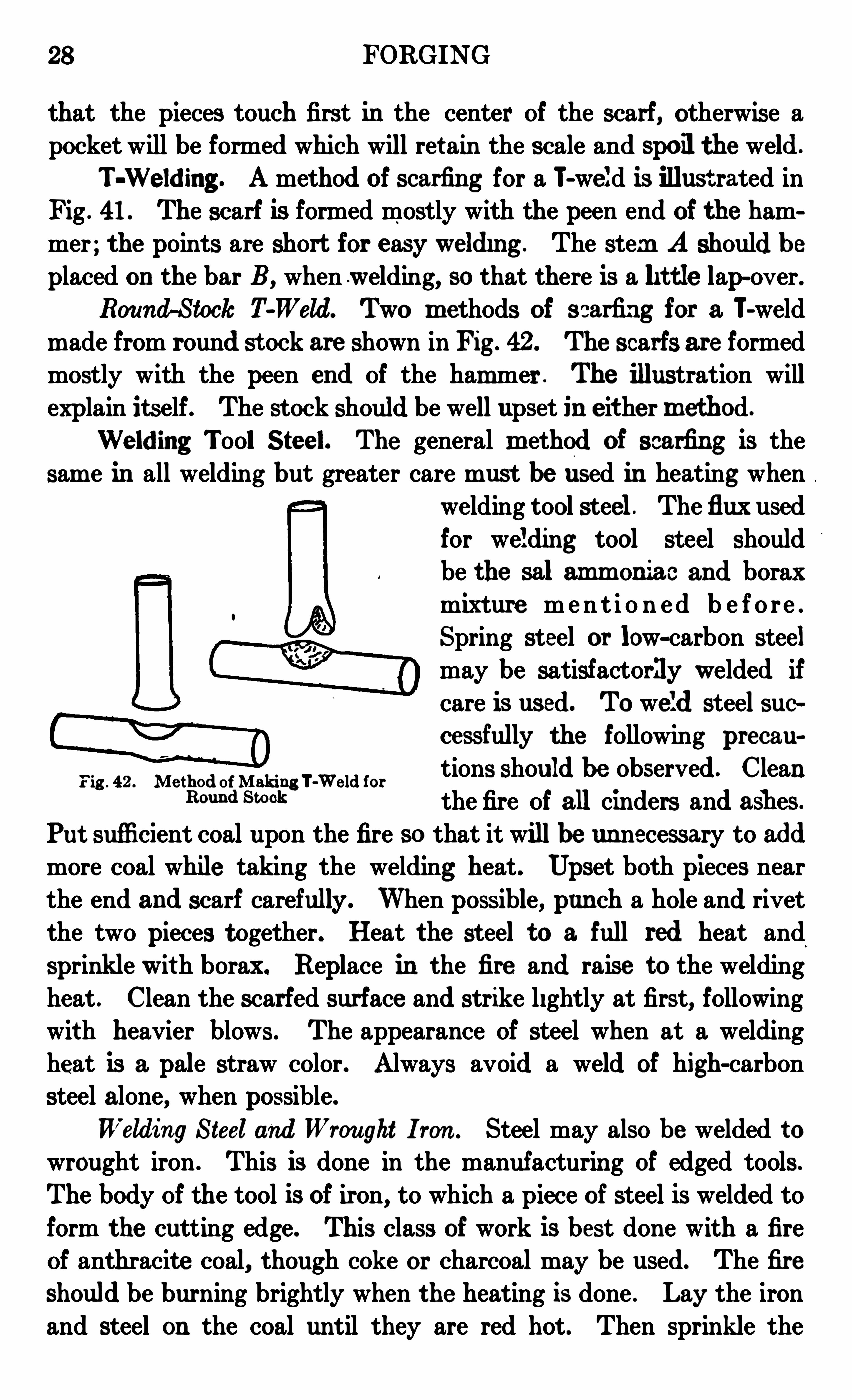
Round-Stock T-Weld. Two m ethods of scarfing for a T-weld
made from round st ock are shown in Fig . 42 . The scarfs are formed
mostly with the peen end Of the ham mer . The illustration willexplain itself . The stock should be well upset in e it he r m ethod .
Welding Tool Steel. The general m ethod Of scarfing is the
same in all welding but greater care must be used in heating whenwelding tool steel. The flux used
for welding tool steel Should
be the sal am m oniac and borax
mixture men t i o n ed b e f o re .
Spring steel or low-carbon steel
may be satisfactorily welded ifcare is used. TO weld steel successfully the following precau
Fig . 42 . Me thod ofMaking T-W e ld for tions Should be observed . CleanRm m d Sm “ the fire Of all cinders and ashes.
Put sufficient coal upon the fire SO that it will be unnecessary to addmore coal while taking the welding heat. Upset both pieces nearthe end and scarf carefully . When possible, pun ch a hole and rivetthe two pieces t ogether. Heat the steel to a full red heat and
sprinkle with borax. Replace in the fire and raise to the weldingheat . Clean the scarfed surface and strike lightly at first, followingwit h heavier blows . The appearance of steel when at a weldingheat is a pale straw color. Always avoid a weld Of high-carbon
steel alone, when possible .
Welding Steeland Wrought I ron . Steel may also be welded towrought iron . This is done in the manufacturin g of edged tools .
The body Of the tool is Of iron, to which a piece of steel is welded toform the cutting edge. This class of work is best done with a fire
Of anthracite coal, though coke or charcoal may be used. The fireshould be burning brightly when the heating is done . Lay the iron
and steel on the coal until they are red hot. Then sprinkle the
FORGING 29
surfaces of both withthe flux and le t it vitrify . A convenient method
of doing this is to have the powdered flux (borax preferred) in a pepper pot . As soon as the heat has changed the metals to a strawcolor lay them together and strike . A Single blow Of a drop hammer,or four or five with a light sledge will do the work. Be sure that
these'
pieces are wellcovered with a flux before attempting to weld .
S IMPLE BEND FORG INGFundam e n tal Forg in g Ope rat ion s
Shaping . After the metal has been heated it is shaped with the
hammer . This shaping may consist Of drawing, upsetting, or
bending . In drawing a bar Of iron it is made longer and of smaller
diamet er . Upsetting consists of Shortening the bar with a corre
sponding increase Of diameter. This work is usually done with
the assistance of a helper using a Sledge hammer ; the smith usinga light hand hammer . They st rike alternate blows . The helpe r must
watch the point upon which the smith strikes and strike in the same
place. Where two helpersare employed the smith st rikes after eachm an . A blow on the anvil by the sm ith is a signal to stop striking .
Fin ishing . As the hammer usually marks the metal , it iscustomary to leave the metal a little full and to finish by the use offlat t ers and swages. This applies to work that has been shapedunder the sledge . Light work can be dressed Smoothly, and thehammer can be made to oblit erate it s own marks.
Drawing Out . In drawm g out , as well as in all other forgingope rations where heavy work is to be done, it is always best to heatthe work to as high a tempera
ture as the metal will standw it h ou t in jury . Work cansometimes be drawn out muchfaster by working over the hornOf the anvil than on the face,the reason being this : When apiece Of work is ham mered onthe anv il face it flattens out and spreads nearly as much in widthas it does in length, working it out longer and wider . AS the pieceis not wanted wider but merely longer, all the work spent in in creasing the width Of the stock is wasted . If the ham mering is done
over the horn Of the anvil as illustrated in Fig . 43 , the rounded
Fig . 43 . Me thod of Drawing Out Work
30 FORGING
horn acts as a blunt wedge, forcing the metal lengthwise and thus
utilizes almost the entire energy of a blow in stretching the metalin the desired direct ion . Fullers are also used to serve the samepurpose and when working under the steam hammer a round bar
sometimes takes the place of
the fuller or horn of the anvil .
Rou n d S tock. Whendrawing out orpointing round
stock, it should always first
be forged down square to the required size and then rounded upin as few blows as possible. Fig. 44 illustrates, in a general way,the different steps in drawing down a round bar from a large toa smaller size, the first st ep bein g to hammer it down square as at B .
This square shape is then m ade octagonal as at Cand the octagon isfinally rounded upas atD. Ifan att empt be made to hammer the bar by pounding
.
it
round and round without the
preliminary squaring, the bar
Fig . 44 . Drawing Down Round Bar
45 . Wrong 46 . Sect ion Showingfigtlipd of DrawFIB
Result ofWrongIS v eryhable to Split thr
fnlgh
m “0“ m m “ the center, the action being agood deal as illustrated in Fig. 45, the effect of the blow coming as
shown by the arrowsA . Themetal is squee zed together in this direc
tion and forced apar t in the direct ion at right angles as indicated bythe arrows B . Then, if the piece be slightly rolled for another blow,
the sides will roll by each other, and cracks and splits will sooner
Fig . 47. Irregular Shapes Fig . 48 . Me thod of Squaring Up Bad Corn ers
or lat er develop, leaving the bar, if it should be sawed through thecenter, in a good deal the shape shown in Fig . 46 . Particular care
should be taken in making conical points as it is almost impossibleto work stock to a round point unless the point be first forged
down to a square or pyramidal shape .
FORGING 3 1
Truing UpWork . In drawing out it often happens that thebar becomes worked into an irregular or diam ond shape, sim ilar tothe section shown in Fig. 47. To remedy this, and square up thebad corners, the bar should be laid across the anvil and workedmuch as shown in Fig. 48, the blows coming in the direction indicated
by the arrow. J ust as the hammer strikes the work it should begiven a sort of slidin g motion. No att empt should be made to square
up a corn er by striking squarely down upon the work. The ham
mering should all be done in such a way -as t o force the metal back
into the bar and away from the high corner.
Upse tt ing. When a piece is worked in such a way that it s
length is shortened and either or both it s thickness and width
increased, the piece is said to be r
upset and the operat ion is known
as upsett ing . There are severalmethods of upsetting, the on e used
depending largely upon the shape
of the work. In short pieces the
work is generally stood on end
on the anvil , the hammering bein gdone directly down upon the upperend. The work should always be Fig . 49 . Upse t t ing mm ,
kept straight, and as soon as a
bend or kink is started, it should be st raightened out . When a
long piece is t o be upset it is generally swung back and forth horizon t ally and the upsetting done by ramming the end against the
anvil . The effect of the blow has a decided influence upon theshape of the upset piece, as shown in Fig . 49 . Light blows affectthemetal for a short distance only, as shown by the swelledout end;the heav ier blows are felt more uniformly throughout the entire length .
When rivets are to be driven to fill holes tightly, the blowsshould be heavy, thus upsetting the rivet tightly into the holes .
If a rivet is wanted to hold two pieces together in such a way that
they may move, as for instance the rivet in a pair of tongs, the headshould be formed with light blows, thus working only the end of
the rivet . The part of the work which is heated to the highesttemperature is the part whichwill be most upset, and when upsettingis wished at on e point only, that point should be heated to the
3 2 FORGING
highest temperature, leaving the other parts of the bar as cold as
possible. Upset ting long pieces is sometimes done by raising the
piece and allowing it to drop on a heavy cast-iron plate set in the
floor. These plates are known as upsetting plates .
Punching . Two kinds of
punches are commonly used for
making holes in hot metal ; the
straight hand pun ch used with
a hand hammer, and the on e used for heavier stock, provided with ahandle and used with a sledge hammer. Punches should of coursebe made of tool steel . For punching small holes in thin iron ahand punch is ordinarily used . This is a bar of round or octagonal
steel, 8 or 10 inches in length,with the end forged down tapering to the ‘
same shape, butslightly smaller than the hole tobe punched . Such a punch forround holes is shown in Fig . 50.
The end of thepunch should beperfectly square across, not at
all rounding . For heavier and faster work with a helper, a punch
similar to Fig . 51 isused, the striking being done with a sledge hammer.Correct Hand Method. Fig . 52 illustrates the successive steps
in punching a clean hole through a piece of hot iron . The work
isfirst laid flat on the
anvil and the pun ch‘
driven about half waythrough as shown at A .
This compresses t h e
W metal directly un der
Fig . 52 . St age s of Pun chin g Round Holen e
r
ath the end Of thepunch and raises
'
a slight
bulge on the opposite side of the bar. The piece is then turned over
and the punch driven into the bar from this side (the hole being
located by the bulge) while the bar is lying flat on the anvil . The
punchshould bedriven about half way through, leav ing the work asMFG; " The bar is then m oved over the small round hole in the end“(if the
i'
anv il, or is placed on some object having a hole slightly
Fig . 50. Punch for Round Holes
Fig . 51 . Pun ch for Heavy and Fast Work

3 4 FORGING
the first example : In this case, if the center line of the stock bemeasured, 75 inches will be the length for each leg, thus making atotal of 15 inches of stock required t o make that particular bend .
This is a universal rule which should always be followed when meas
uring stock, to take the length of the center line .
Circles . On circles and parts of cir
cles the length of stock may be easily
calculated. The circumference, or distance around a circle, is found by m ul
t iplying the diameter by 3 3, or , m ore
accurately, As an illustration,F ig . 55 .
figfalculat in g the stock necessary to bend up the ring
in Fig . 54,would be calculated as follows :
The in side diameter of the ring is 6 inches and the stock is 1 inchthick. This would make 7 inches the diameter C of the circle madeby the center line, which may be called the calculating diameter, andthe length of stock required would be 7X 3 3, or 22 inches .
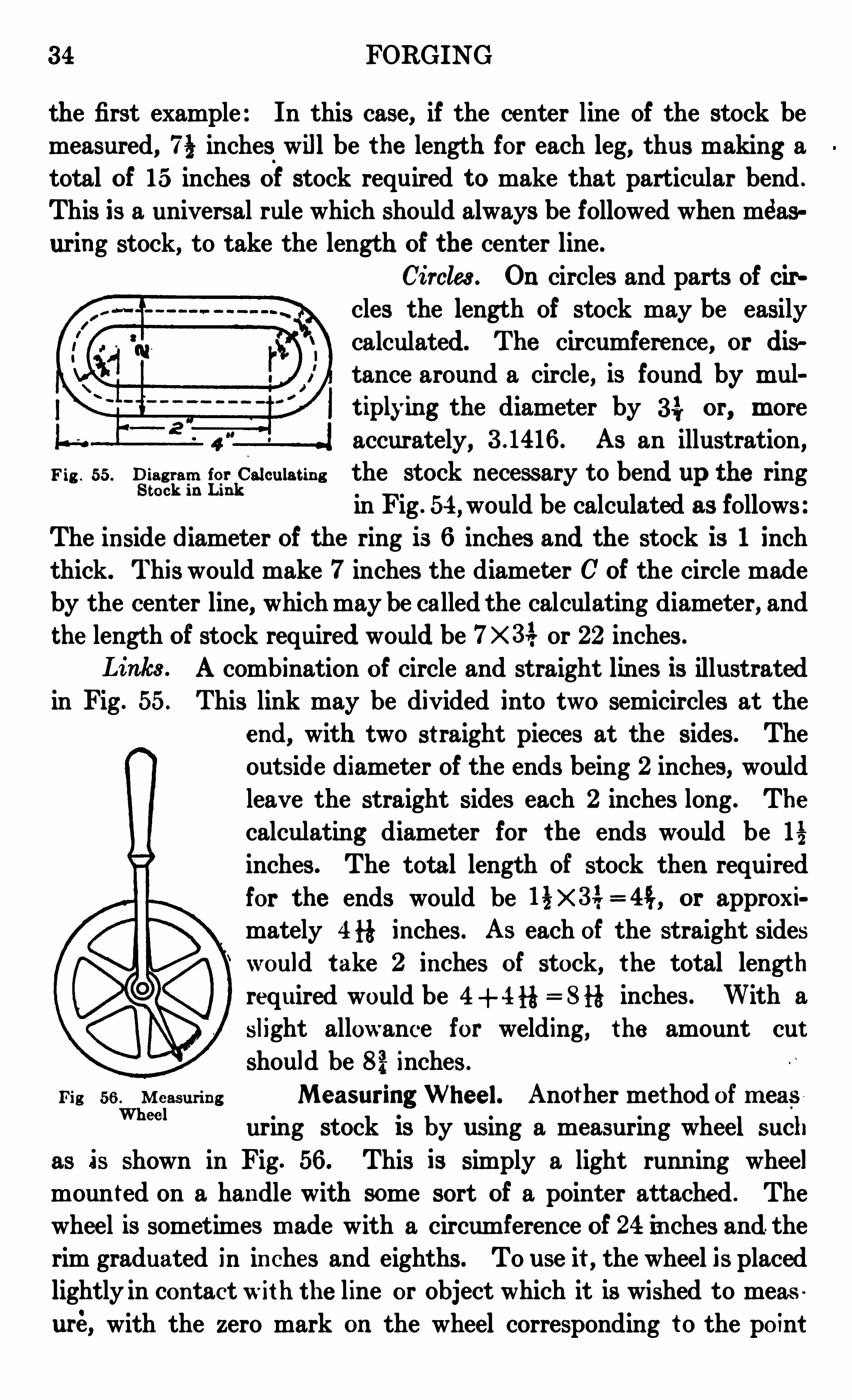
A combination of circle and straight lines is illustratedin Fig . 55. This link may be divided into two semicircles at the
end, with two st raight pieces at the sides . The
outside diameter of the ends being 2 inches, would
leave the straight sides each 2 inches long . The
calculating diameter for the ends would be 1—5inches . The total length of stock then required
for the ends would be I % X 3 3, = 4f; , or approxi
mately Ali-é inches. As each of the straight sides
would t ake 2 inches of stock, the total length
required would be 4+4fi= 8fl inches . With a
slight allowance for welding, the amount cut
should be 82; inches .
Fig 56 , Me asurin g Measuring Wheel. Another method of m easWhee l
uring stock is by using a measuring wheel such
as is shown in Fig. 56 . This is simply a light runn ing wheel
moun ted on a handle with some sort of a pointer attached . The
wheel is sometimes m ade with a circumference of 24 in ches and. the
rim graduated in in ches and eighths . To use it , the wheel is placedlightly in contact with the line or object which it is wished to meas
uré, with the zero mark on the wheel corresponding to the point
FORGING 3 5
from which the measurement is started . The wheel is then pushedalong the surface following the line to be measured, with justenough pressure to cause it to revolve . By counting the
—
revolu
t ion s and part s of a revolution made by the wheel, the requireddistance may be easily measured .
Measurem ent byString or Wire . Scrolls and I rregular Shapes .
Difficult shapes may be measured by either of two methods . The
commoner way is to lay the scroll or shape off full size and measurethe length by laying on this full-sized drawing a string or thin
piece of wire, causing the string or wire t o follow the center line
of the bent st ock. The wire or string is then straightened and thelength measured . This is about the easiest and best way of m easuring work of this character.
Measurem ent by Div iders. Another method, which is morepractical in the drafting room, consists of using a pair of dividers .
The points of the dividers are set fairly close t ogether and the centerline is then stepped off and the number of steps counted . The samenumber of spaces are then laid off along a straight line and the length
measured.
Be nd Types
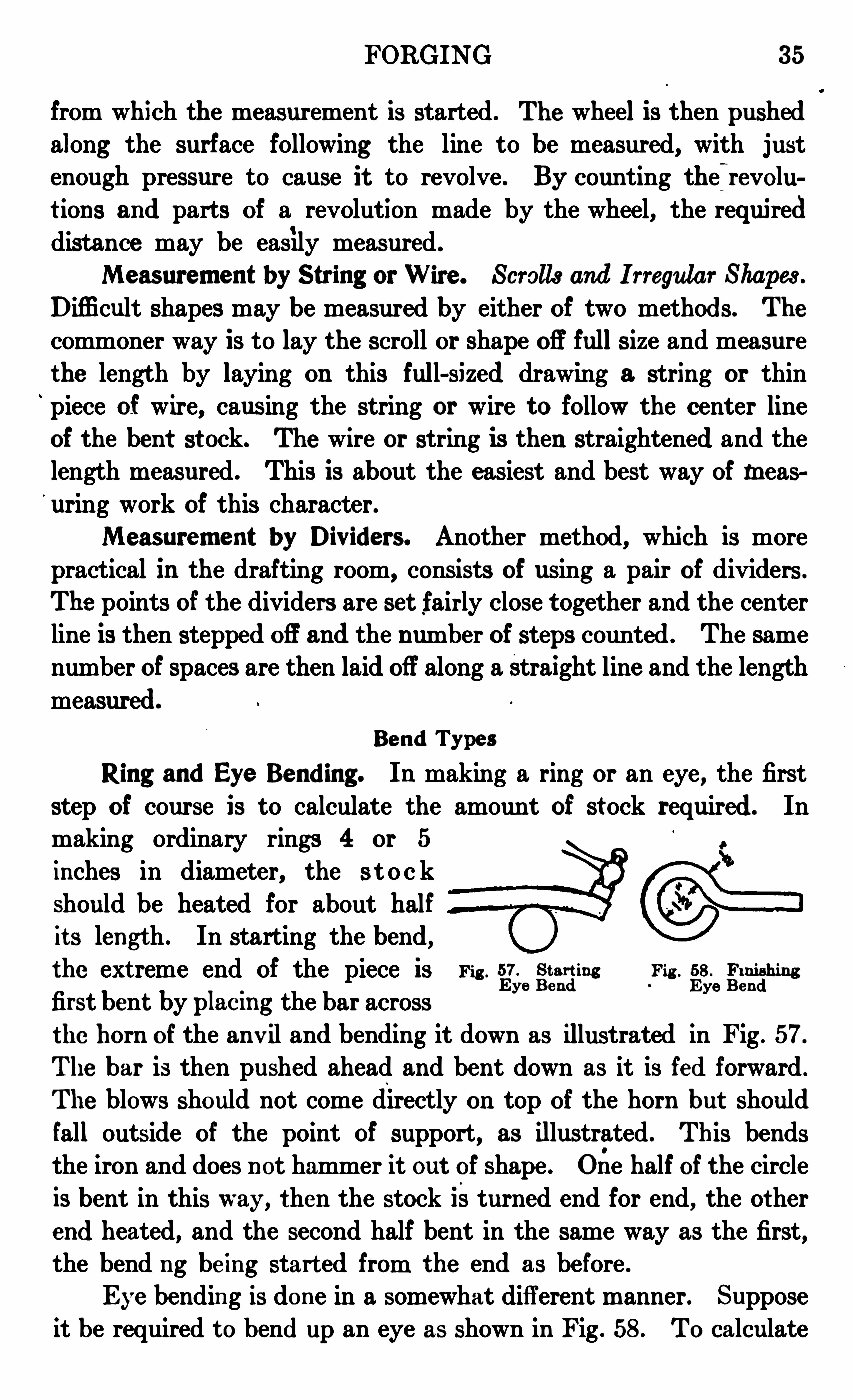
Ring and Eye Bending. In making a ring or an eye, the first
step of course is to calculate the amoun t of st ock required. Inmaking ordinary rings 4 or 5
inches in diameter, the s t o c k
should be heated for about half
it s length . In starting the bend,the ext reme end of the piece is Fig . 5
E7
§eFig .
gzfihins
first bent by placm g the bar acrossthe horn of the anv il and bending it down as illustrated in Fig . 57.
The bar is then pushed ahead and bent down as it is fed forward .
The blows should not come directly on top of the horn but should
fall outside of the point of support, as illustrated . This bendsthe iron and does not hammer it out of shape . Orie half of the circleis bent in this way, then the stock isturned end for end, the otherend heated, and the second half bent in the same way as the first,the bend ng be ing start ed from the end as before .
Eye bending is done in a somewhat different manner . Suppose
it be required t o bend up an eye as shown in Fig . 58 . To calculate
3 6 FORGING
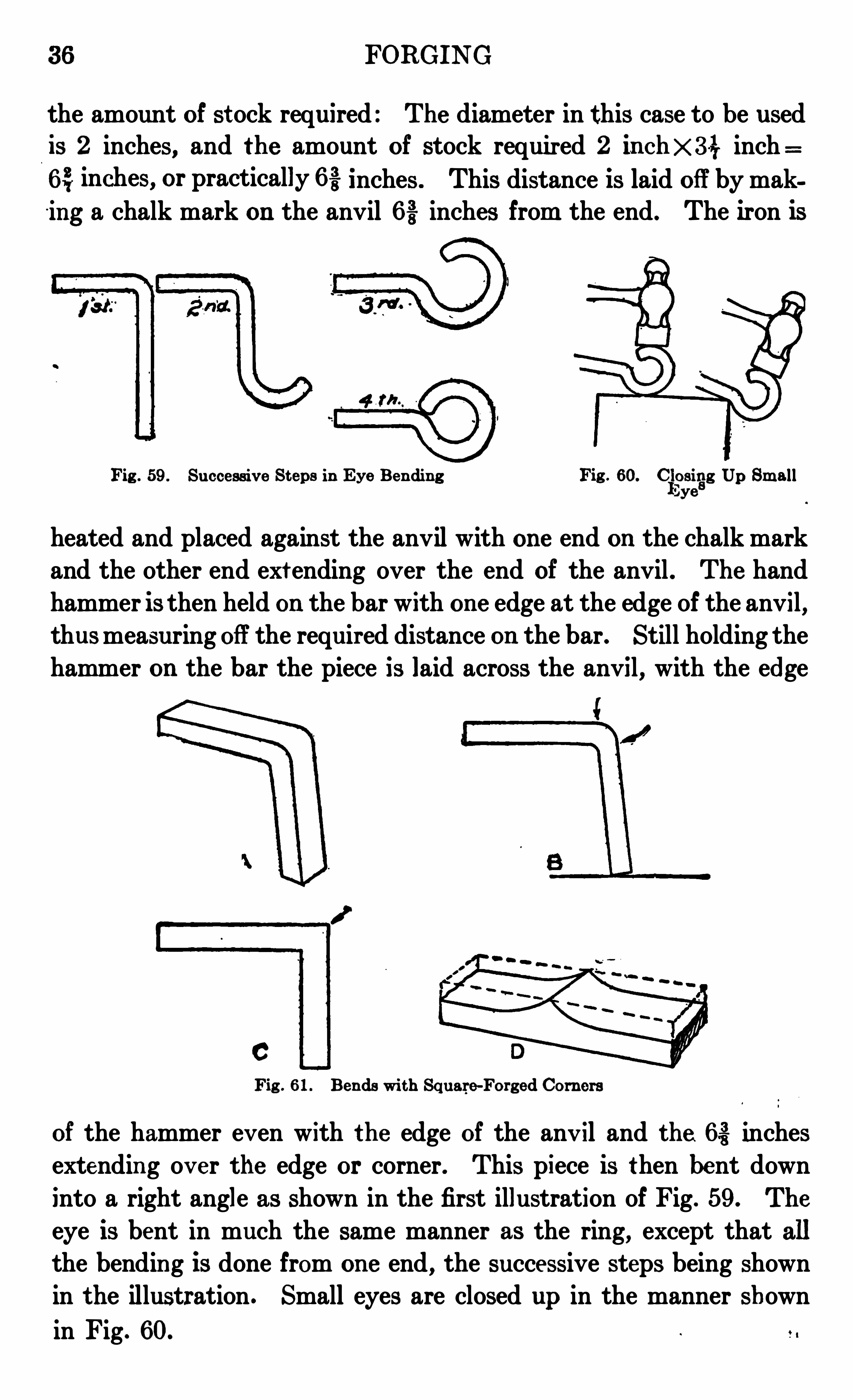
the amount of st ock required : The diameter in this case to be usedis 2 inches, and the amount of stock required 2 in chX 3 1} inch6 3, inches, or practically 6 -3 inches . This distance is laid off by making a chalk mark on the anvil inches from the end. The iron is
Fig . 59 . Successiv e St eps in Eye Ben din g Fig . 60. 011552
1
8
3 Up Sm all
heated and placed against the anvil with one end on the chalk markand the other end ext ending over the end of the anvil . The handhammer is then held on the bar with on e edge at the edge of the anvil ,thusmeasuring off the required distance on the bar. Still holding thehammer on the bar the piece is laid across the anvil , with the edge
Fig . 6 1 . Bends with Square-Forg ed Corn ers
of the hammer ev en with the edge of the anv il and the 6% inchesextending ov er the edge or corner. This piece is then bent down
into a right angle as shown in the first illustration of Fig . 59 . The
eye is bent in much the same manner as the ring, except that allthe bending is done from on e end , the successive steps being shownin the illustration . Small eyes are closed up in the manner shown
in Fig . 60.
FORGING 3 7
Bend with Square-Forged Corne r. Upsetting . Brackets and
other forgings are frequently made with the outside corner squareand sharp, as shown at C
’
, Fig . 6 1, and, of the two ways of doing this,one method is to use the size of stock required for the sides, first
shaping the corner as at A . This corner is then squared by upsetting
the metal at the bend, the blows coming as shown by the arrows atB. The work should rest on the anv il face, and not over one corner,while being hammered .
Drawing Down Large Stock. A second method is to use thicker
stock and to draw out the ends, leav ing a hump, shown at D, where
the outside corner of the bend is to come. The dotted lines show
the original shape of the bar ; the solid lines the shape before bending .
Sometimes stock of the size used in the first method is taken andis upset to form the ridge, in place of drawing out the heavier stock .
The first m ethod is the on e more commonly used on medium
sized work .
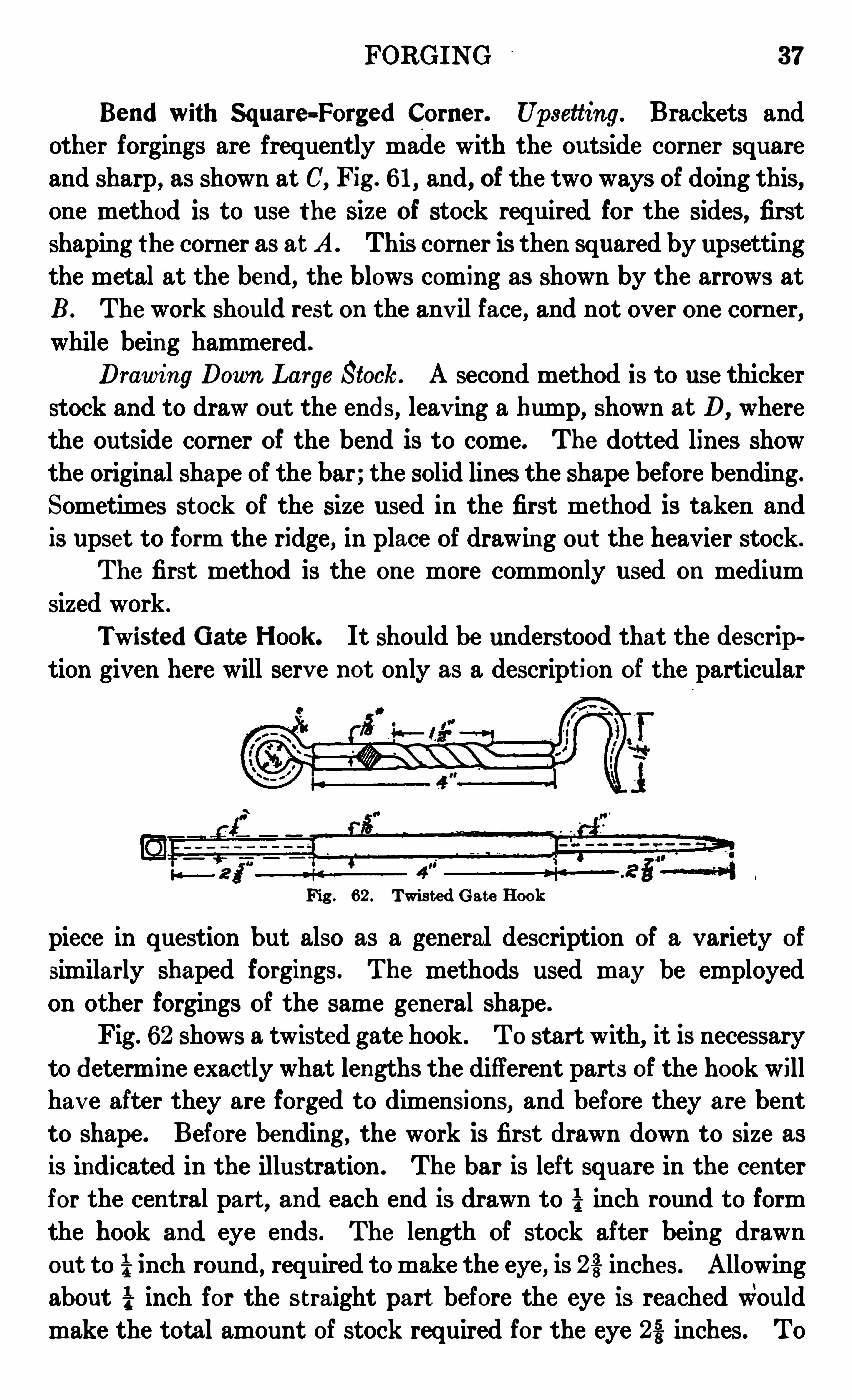
Twisted Gate Hook . It should be understood that the de scription given here will serv e not only as a descript ion of the particular
Fig . 6 2 . Twis t ed Gat e Hook
piece in question but also as a general description of a variety of
similarly shaped forgings. The methods used m ay be employedon other forgings of the same general shape .
Fig . 62 shows a twisted gate hook . To start with, it is necessary
to determine exact ly what lengths the different part s of the hook willhav e after they are forged to dimensions, and before they are bent
to shape. Before bending , the work is first drawn down to size asis indicated in the illustration . The bar is left square in the centerfor the central par t , and each end is drawn to inch round to form
the hook and eye ends . The length of stock after being drawn
out to inch round, required to make the eye, is 2 -3 inches . Allowingabout i inch for the s traight part before the eye is reached wouldmake the total amount of stock required for the eye 22 inches . To
3 8 FORGINGO
obtain the amount of stock for the hook it is n ecessary to lay off
the hook full size . If the drawing is full-sized, the measuring may
be done directly on the drawing, but if not, a rough sketch having
the proper dimensions should be laid off and the measuring doneon that, the measuring of course being done along the dotted center
line. This measur ing is done by simmy laying a string on the dottedline, then straightening out the st ring and measuring it s length .
In this way it will be found that 2—3 {inches is required by thehook . The first step is then to forge the work into the shape shown
in Fig . 6 2 .
Form ing Shoulders. The shoulder where the round stock
joins the square should be forged in the manner indicated in Fig. 6 3 .
The bar is laid across the anv ilwith the point where the shoulderis wished lyin g direct ly on the corner of the anvil. The set hammer
is then placed on t op of the work in such a way that the edge of the
Fig . 6 3 . Forg in g Shoulde r Fig . 6 4 . Making Shoulder On lyon On e S ide
se t hammer comes directly in line with the edge of the anvil . These t hammer is then driven into the work with a sledge hammer.The bar should be turned continually or an uneven shoulder willbe the result . If a shoulder is wanted on one side only, as illustrat edin Fig . 64, it should be worked in as indicat ed there ; that is, oneside of the iron should lie flat on the anvil face while the set hammerworks down the metal next to the shoulder.
After the two ends of the hook are drawn out , the eye and thehook are bent up into shape. The twist in the center of the hook
may be made either by using two pairs of tongs or by twisting in
a vise . By the latter method a mark is first made on the vise‘
in
such a way that, when the end of the hook is placed even with themark, the edge of the vise will come at the end of the point wherethe twist is wanted. The hook should be heated and placed in thev ise, the other e i lbeing grasped by a pair of tongs in such a way
that the distance between the tongs and the vise is just equal in
FORGING 3 9
length to the twist . The twist is made by simply revolving the
tongs aroun d . In making a twist of this kind, no allowance needbe made in length, as it practically has no‘
effect on the length of the stock.
Eye Bolts. Eye bolts are made bytwo general methods, being either solid or
welded . The solid eye bolt is much
stronger. A solid eye bolt, or forged eye,as it is sometimes called, may be st arted in
the general manner illust rated in Fig . 65 . Fig . Gsnyg
t
iigiigSolid
A nick is made on either side of a flat barby using top and bottom fullers as illustrated . The end is then
rounded up as shown in Fig. 6 6 . Particular attention should begiven to seeing that the eye isforged as nearly to a perfectcircle as possible before any
punchin g is done . The stock
around the eye is rounded up
ov er the horn of the anvil asat A, by swinging it back andfort h as it is hammered . The
hole when first punched is likeB
, but when finished should be
like C. The other end of the
bar is then drawn down to form0
B
the l‘
OUIld shank. If a v eryFig . 6 6 . Roundin g Up Solid Eye Bolt
long shank is wanted a short stub shank may be formed in
forging the eye and a round bar of the proper size welded on .
Welded eye bolt smay be madein two different ways . The easier
method produces an eye shaped as
in Fig . 6 7. To make such a bolt,first scarf the end so that it will
fit over the bend of the rod alongthe dotted line ab. Bend the eye Fig 6 7. W elded Eye Bolt
ov er the horn of the anv il . Finallybrin g t o a welding heat and weld in accordance with instructionsalready giv en .
40 FORGING
An eye of better appearance, as shown in Fig . 6 8, is made as
follows : Upset the body of the metalas a seat for the scarf at the
end, as shown at a. Scarf the end of the bar and bend over the ,
Fig . 6 8 . Eye Bolt of Som ewhat Be t t e r Form than Fig . 6 7
horn of the anvil into a true circle to fit the seat at a, and then weld
as before.
The length of metal required for an eye or ring is nearly equalto the lengt h of the circumference of a circle whose diameter is equalto the mean diameter of the ring . Thus in Fig . 68 the length required
for the eye will be approximat ely the length of the circle abcbwhose
diameter is ac.
Chain Hooks . These are made in a variety of shapes and with
solid or welded eyes, the general method of making the eyes bein gexactly as descr ibed before under Eye Bolts.
A common shape is shown in Fig . 6 9 . The stock
is forged into shape similar to Fig .
‘70 beforebeing bent. To determine the length A thedrawing ismeasured in the same way as described
in making the gate hook. The weakest point
in most hooks is the part lying between the linesmarked m s: in Fig . 69 . This part of the book
should be heavier and stronger than the otherpart s . When a strain is put on the hook, there is always a tendencyto straighten out or to assume the shape shown by the dotted lines .
When forging the hook into shape,the dimension B , Fig . 70, should bemade such that the heaviest part of
Fig . 70. Hook before Bending the hook comes in this weakest point .
After the hook is entirely forged tosize, it should be bent into shape . Hooks are also made from round
and from square iron. When made for hooking over a link,and so
Fig . 6 9 . Chain Hook
k - A — 4

42 FORGING
quart er of a ton. In the line marked T is found the load 4; direct lybelow it are the figures H , showing the size of stock to be used .
The dimensions of the hook are found as follows
D= .5 inches-i 1% inches (about)
Et c .
I .915, or about inch
When reducing the decimals the dimensions which have to doonly with the bending of the hook, i.e ., the opening, length,lengt h of point, etc . , may be t aken to the nearest l6 th, but thedimensions through the body of the hook or stock should be reducedto the n earest 3 2nd on small hooks . The completed dimensionsof the hook in question, of 500-pound capacity, would be as follows :
D= 1% in ches I = £3 inchE= 1% inches J = 1? inch
F= H inch inch
G= 1 inch inch
0= ifinch M= H inch
Q = 1§~ inches U inchH= inch
Bolts . Upset Head Types . Of the two methods of makingbolts, either by upsetting or by welding the heads, the first method
is more common on small bolts andmachin e made bolts. The welded headis more com monly used for heavy handforged bolts. The upset head is the
to stronger prov ided both are equally wellmade. The size of the
,bolt is always
given as the diameter and length of
shank or stem . Thus a bolt known as
m . 72 . Bolt s wi th Sq uaw and 73-inch by 6 -inch, or i -inch bolt 6 inchesHem ” Hm “ long, wouldmean a bolt hav in g a shank
5 inch in diameter and 6 inches long from the un der side of the headto the end of the stem, having the dimensions of the bolt shown inFig . 72 . The dimensions of the bolt heads are always the same forthe same sized bolt, and are determined from the diameter of the
shank. The diameter of the head at D, Fig . 72, is the distance
FORGING 43
across the head from flat side toflat side, and is known as thediam
eter across the flats . The thickness of the head is taken as shownat T. If 8 equals the diamet er of the shank of the bolt, the diman
sions of the head would be as follows .
inchT=S
For a two-in ch bolt the dimensions would be as follows
Diameter of head inches
The thickness of head Twould be equal to diameter of the shank,or 2 inches. These dimensions are for rough or unfinished heads.
Each dimension of a finished head is 115 inchless than the same dim ension of a rough
head . Bolts generally have the top cornersof the head roun ded or cham fered off. Thismay be done with a hand hammer ; or witha cupping tool, which is simply a set hammerwith the bottom face hollowed out into a Fig . 73 .
Effigt in g Bolt
cup shape .
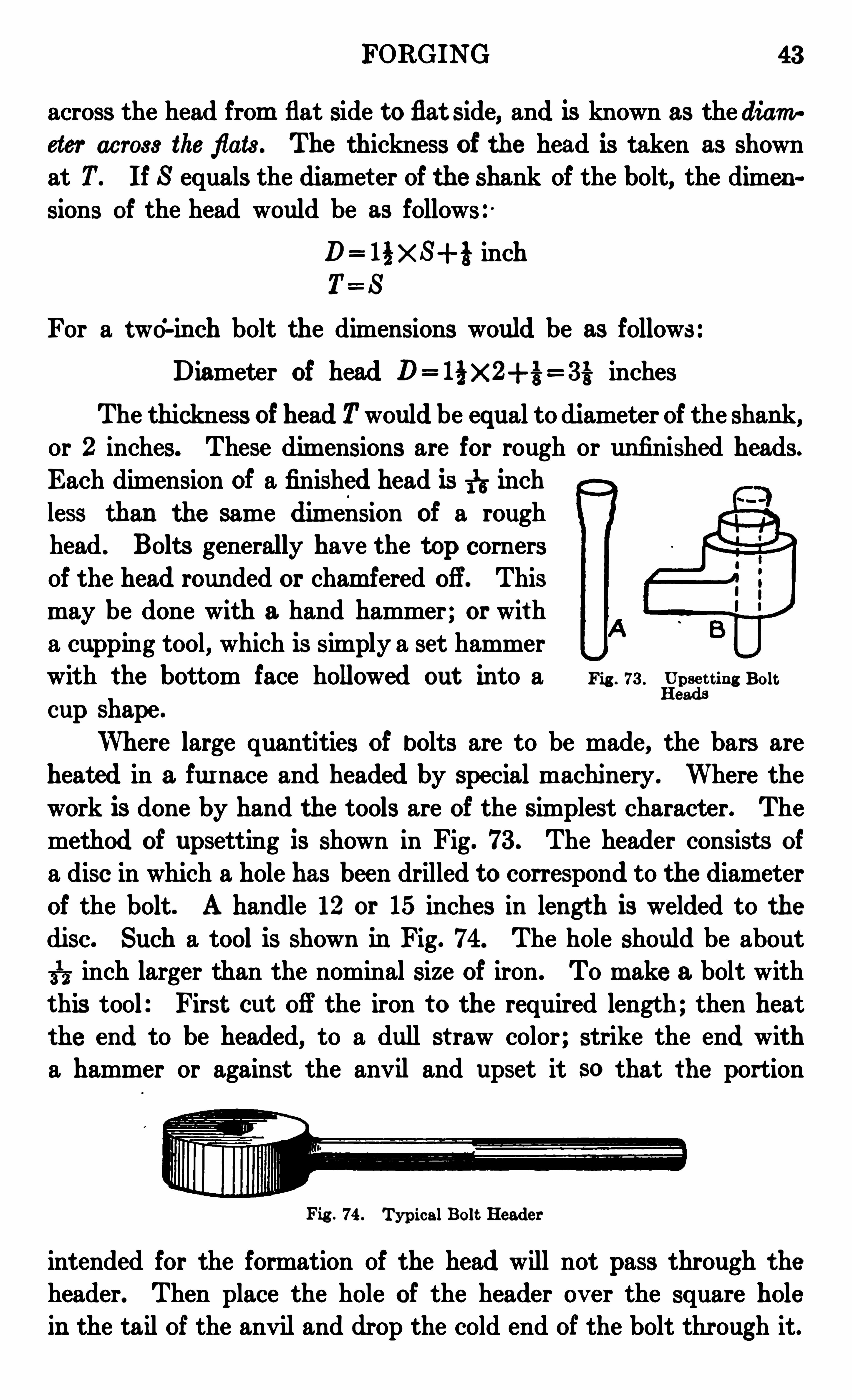
Where large quantities of bolts are to be made, the bars areheated in a furnace and headed by special machinery. Where the
work is done by hand the tools are of the simplest character. The
method of upsetting is shown in Fig. 73 . The header consists ofa disc in which a hole has been drilled to correspond to the diameterof the bolt. A handle 12 or 15 inches in lengt h is welded to thedisc. Such a tool is shown in Fig. 74. The hole should be about
£5 inch larger than the nominal size of iron . To make a bolt witht his tool : First cut off the iron t o the required lengt h ; then heatthe end to be headed, to a dull st raw color ; strike the end witha hammer or against the anvil and upset it so that the portion
Fig . 74 . Typical Bolt Header
intended for the formation of the head will not pass through the
header. Then place the hole of the header ov er the square hole
in the tailof the anviland drop the cold end of the bolt through it.
44 FORGING
Strike the project ing portion of the bar and upset it until the requisite thickness of head is obtained . This will probably leave a head ofcurved but irregular out line. Remove from the header and square the
head thus upset, on the face of the anvil . This will probably thickenthe head . Again drop the cold end through the header and strike
the head until it is reduced to proper thickness. After which, againsquare the edges on the face of the anvil. In doing this work, thesmit h will hold the header in his left hand . The work will be facilitat ed if a helper assists with a sledge hammer.
There are a number of simple t ools in use for clamping the
bar while it is bein g headed so as to avoid the preliminary upsetting.
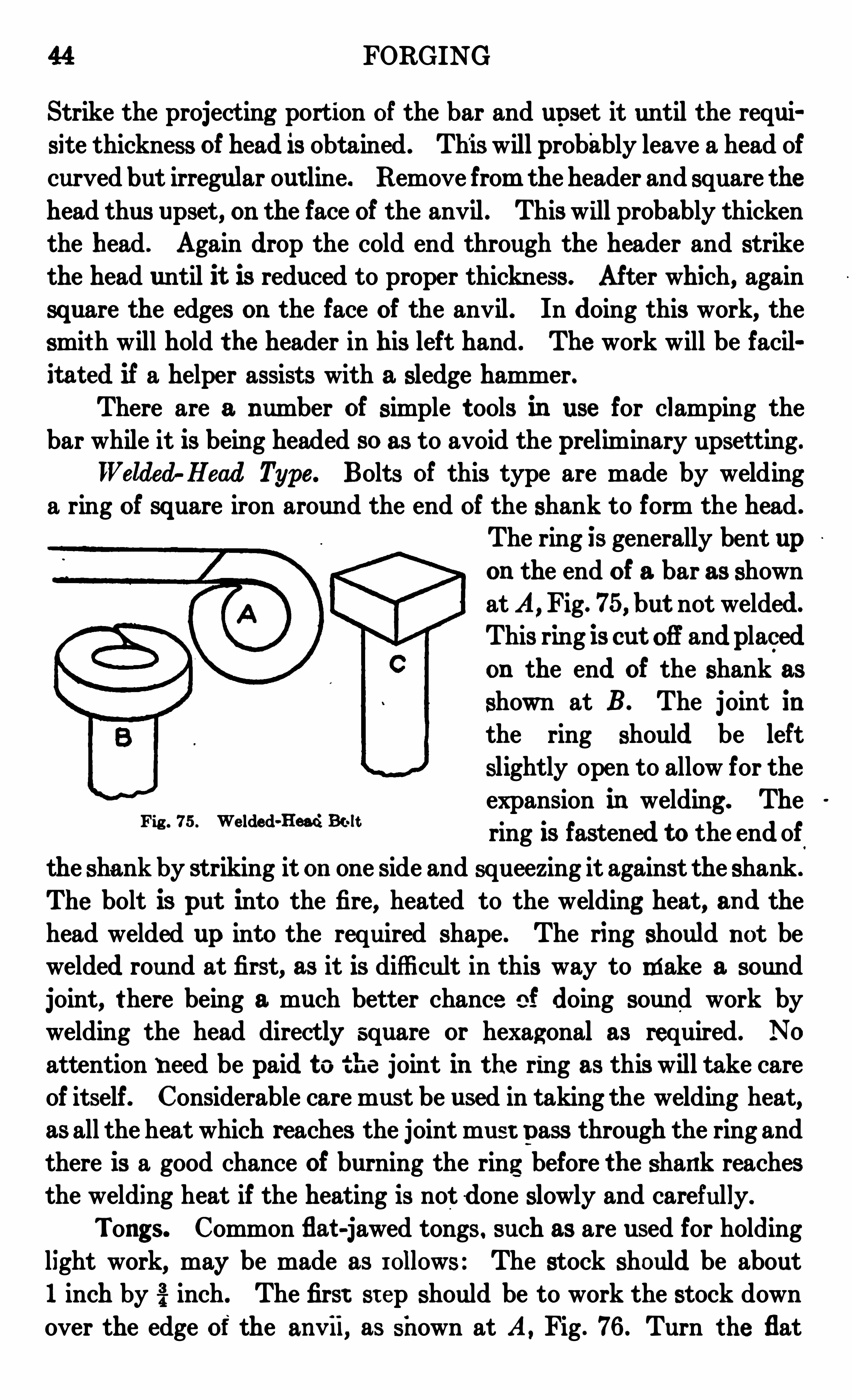
Welded Head Type. Bolts of this type are made by weldinga ring of square iron around the end of the shank to form the head .
The ring is generally bent upon the end of a bar as shownat A
,Fig. 75, but not welded.
This ring is cut off and placed
on the end of the shank as
shown at B. The joint in
the ring should be left
slightly open to allow for theexpansion in welding . Thering is fastened to the end of
the shank by striking it on one side and squeezing it against the shank .
The bolt is put into the fire, heated to the welding heat, and thehead welded up int o the required shape . The ring should not bewelded round at first, as it is difficult in this way to make a sound
joint, t here being a much better chance of doing sound work by
welding the head directly square or hexagonal as required. No
attention n eed be paid to the joint in the ring as this will take careof itself. Considerable care must be used in taking the welding heat,as all the heat which reaches the joint must pass through the ring andthere is a good chance of burning the ring before the shank reachesthe welding heat if the heating is not done slowly and carefully.
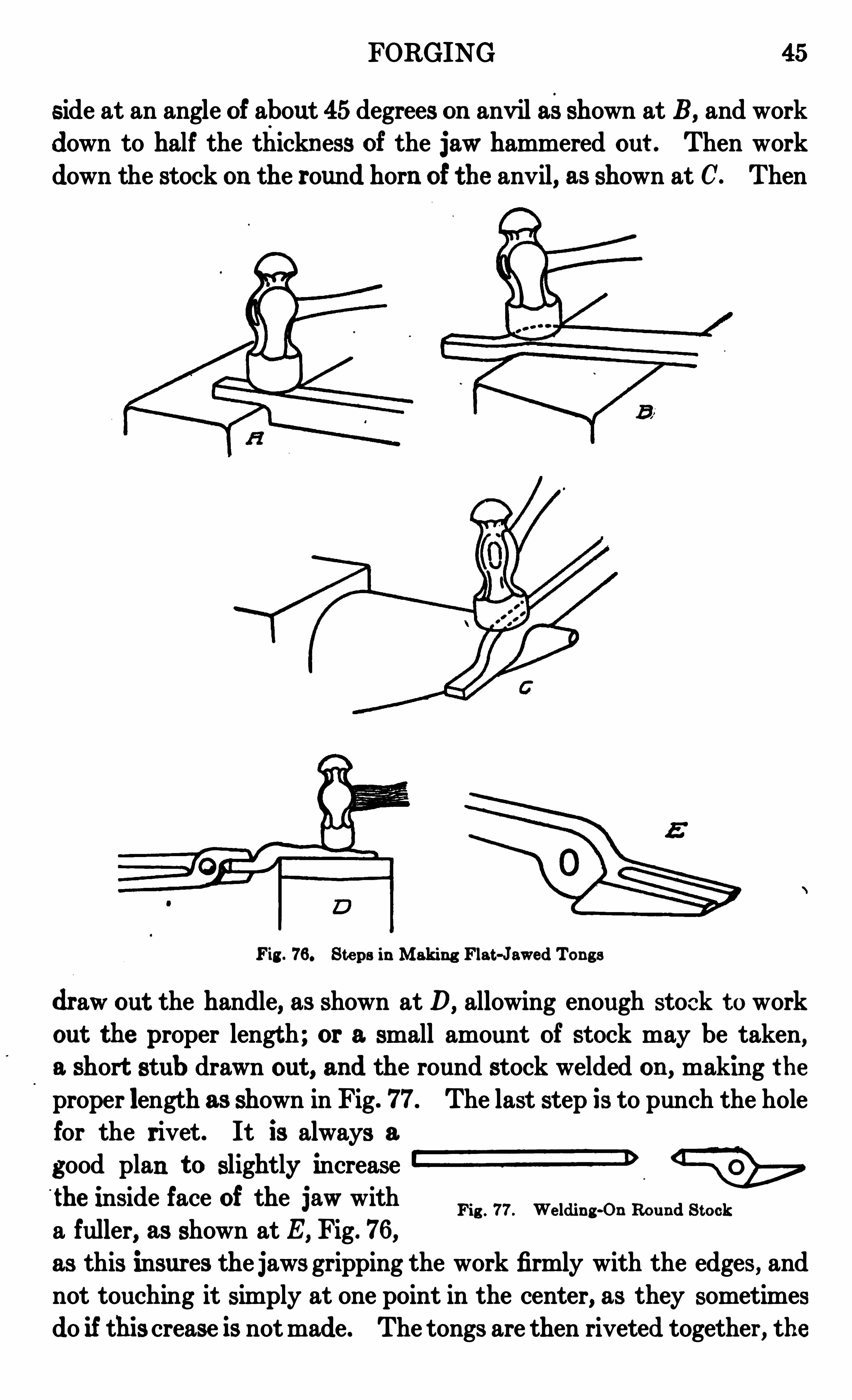
Tongs. Common fiat -jawed tongs. such as are used for holdinglight work, may be made as rollows : The stock should be about1 inch by inch. The first St ep should be to work the stock down
over the edge of the anv ii, as shown at A, Fig . 76 . Turn the flat
Fig . 75 . We lded-Head Bt-lt
FORGING 45
side at an angle of about 45 degrees on anv il asshown at B, and work
down to half the thickness of the jaw hammered out . Then work
down the stock on the round horn of the anvil, as shown at C. Then
Fig . 76 . Steps in Making Flat-J awed Tongs
dr aw out the handle, as shown at D, allowing enough stock t oworkout the proper lengt h ; or a small amount of stock may be taken,a short stub drawn out , and the round stock welded on , making the
proper length as shown in Fig. 77. The last step is to punch the holefor the rivet. It is always a
good plan t o slightly increaseZZZ D
the inside face of the jaw witha fuller, as shown at E, Fig. 76 ,
as this insures the jaws gripping the work firmly with the edges, andnot touching it simply at one point in the center, as they sometimes
do if this crease is notmade. The tongs are then riveted together , the
Fig . 77 . We lding-On Round S tock
46 FORGING
riveting being done with the round end of the ham mer ; in this wayahead is formed on the rivet without upsetting the shank of the rivetvery much where it passes through the hole. After riveting, the
tongs will probably be stiff or hardt omove. They may be loosenedup by heating the eye par t red hotand moving the handles forwardand backward two or three times.
They should then be firmly fitt edto the work to be handled.
‘
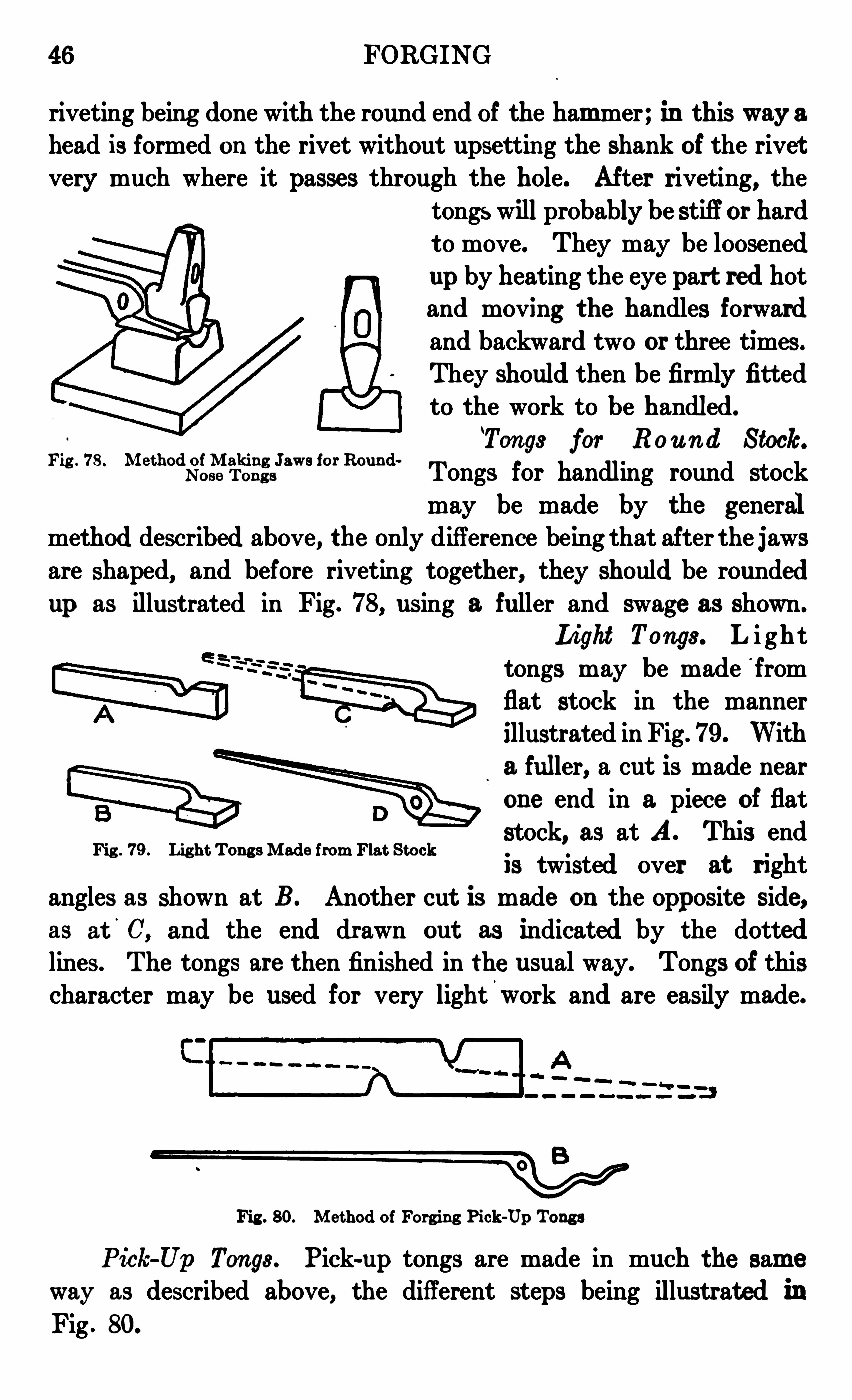
Ton gs for Rou n d Stock.
Fig ' 78 ° m e thOdiiii igir
‘fifigs
h m for Roun d.
Tongs for handling round stock
may be made by the generalmethod described above, the only difference being that after the jawsare shaped, and before riv eting together, they should be rounded
up as illustrated in Fig. 78, using a. fuller and swage as shown.
Light Tongs. L i gh ttongs may be made f romflat stock in the manner
illustrated in Fig . 79 . With
a fuller, a cut is made nearone end in a piece of flat
stock, as at A. This endis twisted over at right
angles as shown at B. Another cut is made on the opposite side,as at C, and the end drawn out as indicated by the dottedlines . The tongs are then finished in the usual way. Tongs of thischaracter may be used for very lightwork and are easily made.
Fig . 79 . Light Tong s Made from Flat Stock
Fig . 80. Method of Forging Pick-Up Tongs
Pick Up Tongs . Pick-up tongs are made in much the sam e
way as described above, the different steps being illustrat ed inFig . 80.
FORGING 47
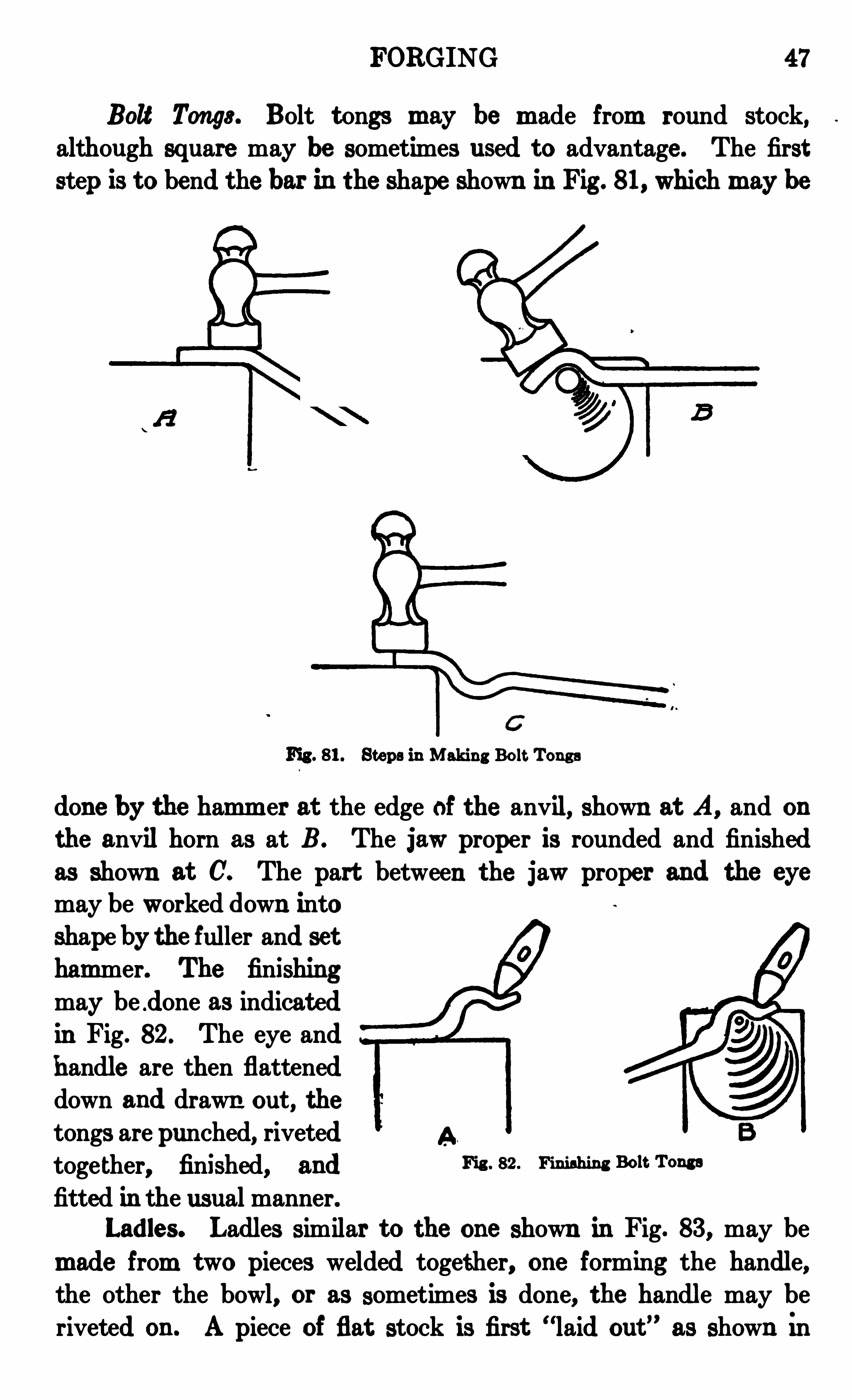
Bolt Tongs . Bolt t ongs m ay be m ade from round stock,although square may be sometimes used to advantage . The first
step is to bend the bar in the shape shown in Fig . 81, which m aybe
Fig . 81. Steps in Making Bolt Tongs
done by the ham m er at the edge of the anvil, shown at A, and on
the anvil horn as at B . The jaw proper is rounded and finishedas shown at C. The part between the jaw proper and
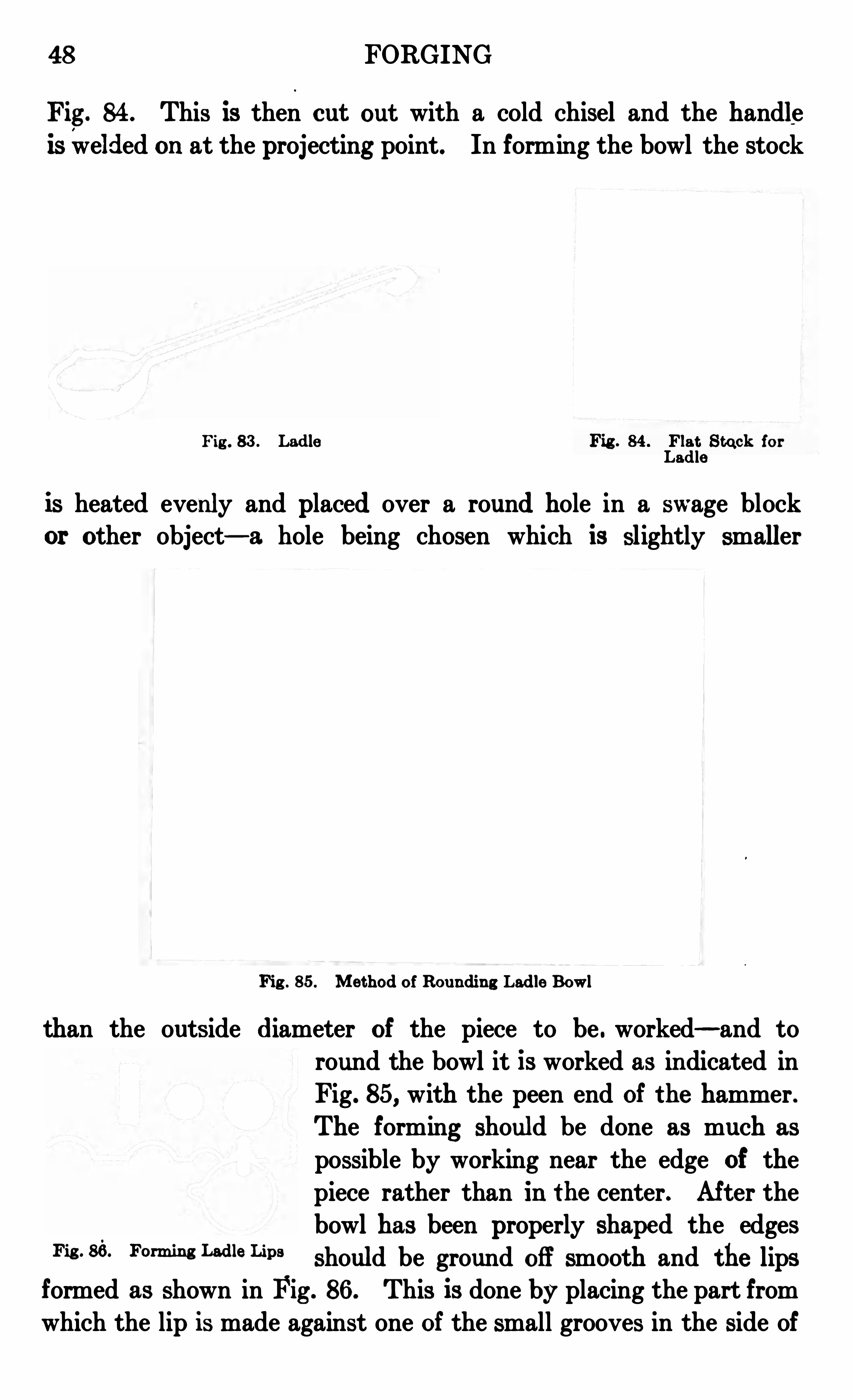
may be worked down into
shape by the fuller and sethammer. The finishingmay be .done as indicat edin Fig. 82 . The eye andhandle are then flatteneddown and drawn out , the
tongs are punched, rivetedtoge ther, finished, and Fic 82 “h im
fitted in the usual manner.Ladles. Ladles similar to the one shown in Fig. 83 , may be
m ade from two pieces welded together, one forming the handle,the other the bowl
, or as sometimes is done, the handle may beriveted on . A piece of flat stock is first
“laid out”as shown in
48 FORGING
Fig. 84. This is then cut out with a cold chisel and the handleis welded on at the projecting point. In forming the bowl the stock
Fig . 83 . Ladle Fig . 84 . Flat S tuck forLadle
is heated evenly and placed over a round hole in a swage blockor other object— a hole being chosen which is slightly smaller
Fig . 85 . Me thod of Roundin g Ladle Bowl
than the outside diameter of the piece to be . worked— and toround the bowl it is worked as indicated in
Fig. 85, with the peen end of the hammer.The forming should be done as much as
possible by working near the edge of thepiece rather than in the center. After thebowl has been properly shaped the edges
Fig ' 86 ° “ m m““a“Lips should be ground off smooth and the lipsformed as shown in Fig . 86 . This is done by placing the part fromwhich the lip is made against one of the small grooves in the side of

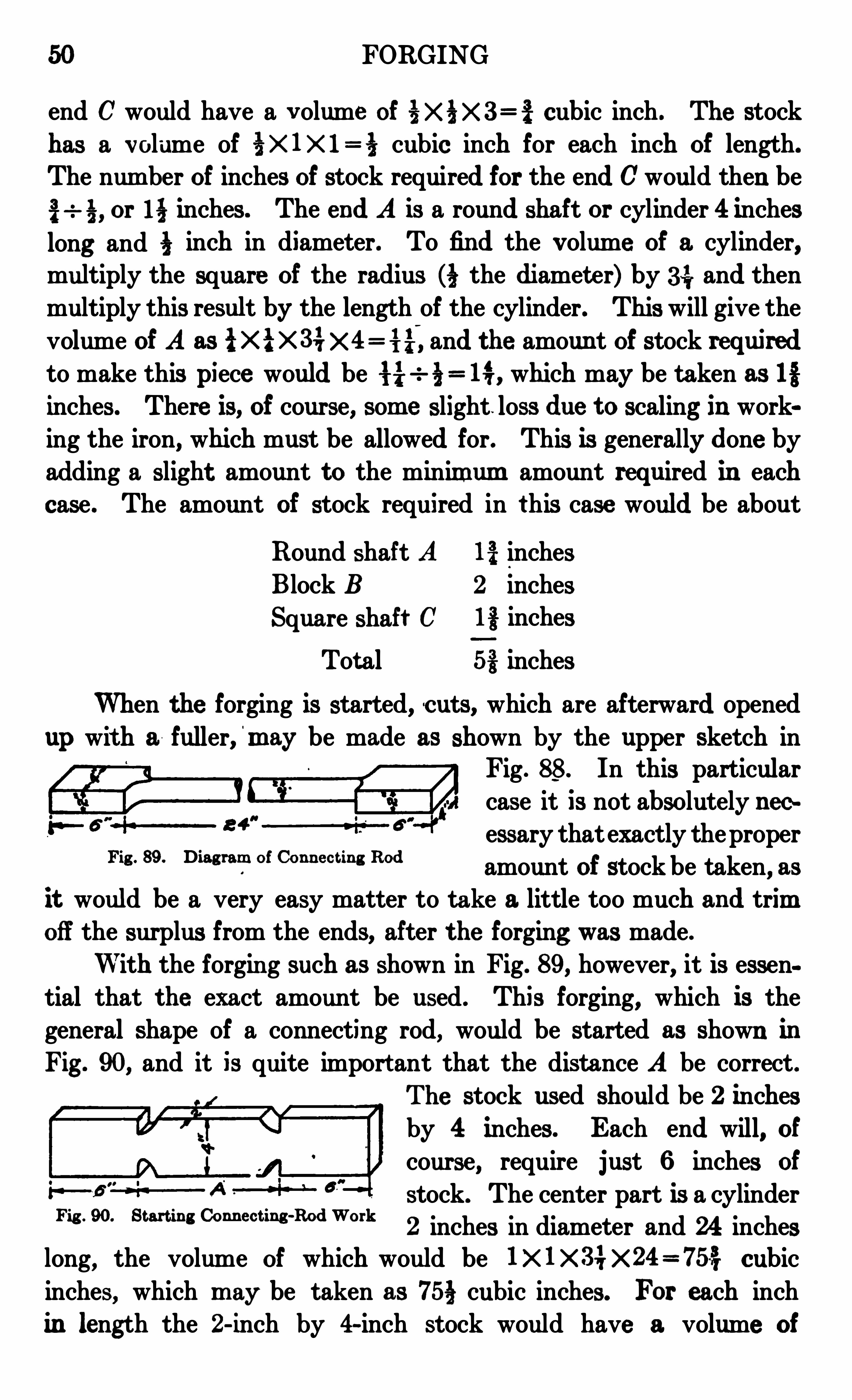
50 FORGING
end C would have a v olume of cubic inch . The stock
has a volume of % X 1X 1 cubic inch for each inch of length.
The num ber of inches of stock required for the end Cwould then be
or inches . The end A is a round shaft or cylinder 4 inches
long and 4} inch in diameter. To fin d the v olume of a cylinder,multiply the square of the radius the diameter) by 3 4; and thenmultiply this result by the length of the cylinder. This will give thevolume of A as {x i xsi and the amoun t of stock requiredto make this piece would be which may be taken as 13inches. There is, of course, som e slight . loss due t o scaling in working the iron, which must be allowed for. This is generally done byadding a slight amount to the minim um amount required in each
case . The amount of stock required in this case would be about
Round shaft A inches
Block B 2 inches
Square shaft C i s inches
Tot al 5% inches
When the forging is started, cuts, which are afterward opened
up wit h a fuller, m ay be made as shown by the upper sketch inFig . 88. In this particularcase it is not absolutely necessary thatexactly theproper
amount of stock be taken, asit would be a very easy matter to take a little too much and trimoff the surplus from the ends, after the forging was made.
With the forgin g such as shown in Fig. 89 , however, it is essen
tial that the exact amount be used . This forging, which is the
general shape of a connecting rod, would be started as shown inFig . 90, and it is quite import ant that the distance A be correct .
The stock used should be 2 inchesby 4 inches. Each end will
, of
course, require just 6 in ches of
stock. The center part is a cylinder2 inches in diameter and 24 inches
long, the volume of which would be 1X 1X 34X 24=75137 cubic
inches, which m ay be taken as 75§ cubic inches. For each inchin length the 2- inch by 4-inch stock would have a volume of
Fig . 89 . Diag ram of Conn ect in g Rod
Fig . 90. Start ing Conn ect ing-Rod Work
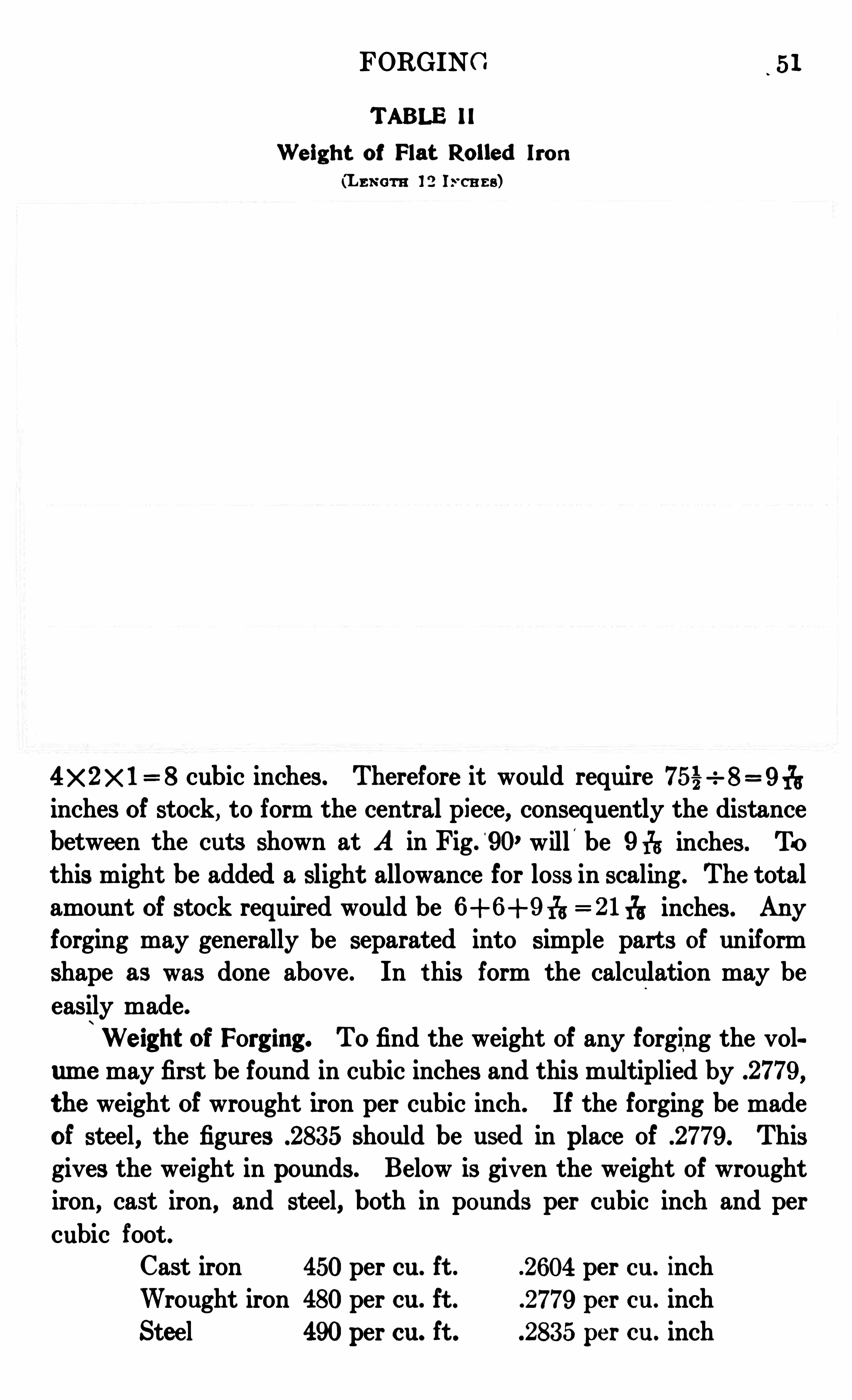
FORGING 51
TABLE 11
We ight of Flat Rolled Iron
(Lnx cm 12 Is ca ns)
4X 2 >< 1= 8 cubic inches. Therefore it would require
inches of stock, to form the central piece, consequently the distancebetween the cuts shown at A in Fig.
'
90, will'
be 9 175 inches. To
this might be added a slight allowance for loss in scalin g . The totalamount of stock required would be = 21 1
75 inches . Any
forging may generally be separated into simple parts of uniform
shape as was done above . In this form the calculation may be
easily made.
We ight of Forging . To find the weight of any forging the vol
um e may first be found in cubic inches and this multiplied by .2779 ,
the weight of wrought iron per cubic inch. If the forging be made
of steel, the figures .283 5 should be used in place of .2779 . Thisgives the weight in pounds. Below is giv en the weight of wroughtiron
,cast iron , and steel, both in pounds per cubic inch and per
cubic foot.Cast iron 450per cu. ft . 2604 per cu. inch
Wrought iron 480per cu. ft . 2779 per cu. inch
Steel 490per cu. ft . 283 5 per cu. inch
52 FORGING
Suppose it were required to find the weight of the forging shown
in Fig. 87. A has a volume of 4} cubic inch, C -2 cubic inch, and
B 1 cubic in ch, making a total of cubic inches . If the forgin gwere made of wrought iron it would weigh .7 pound .
The forging in Fig. 89 has a tot al volume of 1719; cubic inches andwould weigh, if made of wrought iron, pounds.
A much easier way to calculate weights is ‘
t o use tables such as
II and III giv en herewith . Table II gives the weights per footof flat iron bars. In Table III is given the weights for each footof length of round and square bars.
When using Table II to ascertain the weight of any size of
flat iron per foot of length, look in the first column at the left forthe thickness . Then follow out in a horizontal line to the column
givin g the width . The number given will be the weight in poundsof one foot of the desired size .
To use the table for calculating weights, the procedure wouldbe as follows :
Taking Fig . 89 as an example, each end is 2 inches by 4 inchesand 6 inches long, and, as far as the weight is concerned , the twoends would be equal to a bar 2 inches by 4 inches and 1 foot long .
From the table it will be seen that a bar 2 inches by 2 inches weighspounds, and a bar 2 in ches
.
by 4 inches , be ing twice as thickwould weigh twice t hat, or pounds . A bar 2 inches in diameter weighs pounds per foot and, as the central part of the forging is 2 feet long, it will weigh pounds , making the total weight
of the forging pounds.
Fin ish. Many forgings are machined or finished after leaving
the forge shop . The drawings are always made to represent the
Fig . 9 1 . Finished Sing le-Throw Crank Shaft
finished work and therefore give the finished dimensions, and it isnecessary when this finishing is to be done, to make allowance forit when making the forging, that all part s which hav e to be finishedor machined m ay be left with an extra metal to be remov ed in
FORGING 53
TABLE 111
We ights of Round and Square Rolled i ron
(m m 12 In cn ns)
finishing . The parts required to be finished are generally marked
on the drawing. Sometimes the finished surfaces have the word
fin ishedmarked on them . Sometimes the finishin g is shown simply
by the symbol f, as used in Fig. 91, showing that the shafts and pin
only of the crank are to be finished. When all surfaces of a pieceare to be finished the words fin ish all over are sometimes marked
on the drawing .
The allowance for finishing on small forgings is generally about
113 inch
'
on each surface. Thus, if a block were wanted to finish
4 inches by 2 inches by 1 inch, and 11
3 inch were allowed for fin ishing,
54 FORGING
the dimensions of the forging would be 4% inches by 2% inches by
li inches . On a forging like Fig. 89 , about 4 in ch allowance wouldbe made for finishin g, if it were called for . Thus the diameter
of the central shaft would be inches, the thickness of the ends'
2% inches, etc . On larger work 1} inch is sometimes allowed for
machining . The amount of finish allowed depends to a large extent
on the way the forging is to be finished . With hand finishin g, that
is, filing or scraping, inch or even 31; inch is enough ; when a
lathe or other machine is used, more material should be left .When a forging
'
calls for finish, in calculating the amoun t of
stock, or the weight, the dimensions taken should not be the actualones shown by the drawing, but these dimensions with the proper
auowai‘
i ce made for finish .
S tandard Large Type s
Crank Shafts . There are several methods of forging crank
shafts . The one more commonly used is the commercial method,as described in detail below . When forgings were mostly made ofwrought iron, the cranks were welded up of several pieces. One
piece is used for each of the shafts, one piece for each cheek or side,and another piece for the crank pin . Cranks are sometimes bent
up out of round stock, but this method is on ly used on small work.
Com m on Method of Making. The common method now
employed where machine steel is used , is to forge the crank fromone solid piece of mat erial. The stock istaken large enough toshape the largest partof the crank without
any upsettin g.0 If a
crank is r e qu i r edsimilar to Fig. 91, the
size of stock to be used should be lé inches by 4 inches insection.
The first thin g to do of course is to calculate the amount of stockrequired . The long end would contain cubic inches. As eachinch of stock con tains 6 cubic inches, it would require inches ofstock to form this end, provided there was no waste from scale.Waste does take place, however, and must be allowed for , so about
Fig . 92 . First S t eps in Making Crank Shaft
FORGING 55
2 inches of stock should be taken . The short end containscubic inches and would require inch of stock, without allowance for scale. About lfiinches should be taken . The total stock
then required would be 7% inches.
The first step is to make the cuts,and spread the ends as shown in Fig.
92 . These ends may then be forgeddown with a sledge hammer, as illust rat ed, or may be worked out under
the steam hammer, the finishing up
against the shoulders being done as
illustrated in Fig. 93 . The shaft may
be rounded down and finished between
swages. Care must be taken to see Fig 93 Fm UP Shm flfii e f
that the cuts are properly spread before drawing out the ends . If
the cuts are left without spreading, the metal acts somewhat after
the mann er shown in F ig . 94. The top part of the bar, as it is
worked down, folds over and leaves a crack
or cold-shut as illustrated. When the metal
starts to act in this way the fault shouldbe corrected by trimming off the overlap
ping corner along the dotted line shown inthe upper sketch.
When the forging leaves the shop, it
will be left in a shape similar to that shown Result s of Im prope r
by the solid lines in Fig. 95, the dimensionsSpreading
shown here allowing for the necessary finishing. The crank it self
would be left in a solid block, the throat being afterwards cut out asindicated by the dotted lines . A line of holes is first drilled as shown,
Fig . 95 . Crank-Shaft Forgin g Ready for Machinin g
and the block of metal to be taken out is removed by making two
slits with a cold saw and the block then knocked out with a sledge
hammer. It is possible to form this throat by chopping out the
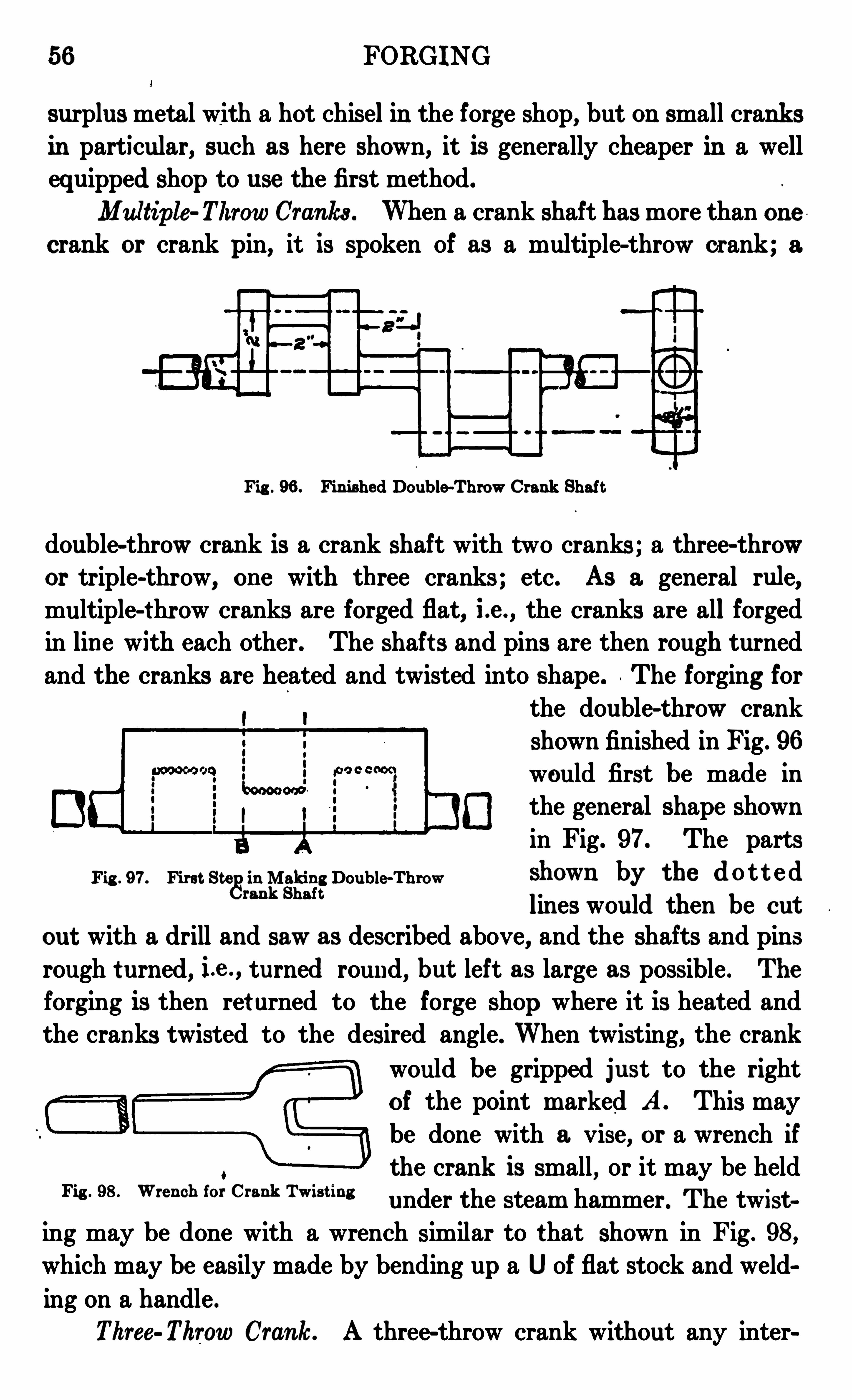
56 FORGING
surplus metal with a hot chisel 111 the forge shop, but on small cranksin particular, such as here shown, it is generally cheaper in a wellequipped shop to use the first method.
Multiple Throw Cranks . When a crank shaft has more than onecrank or crank pin, it is spoken of as a multiple-throw crank ; a
Fig . 96 . Finished Double-Throw Crank Shaft
double-throw crank is a crank shaft with two cranks ; a three-throwor triple-throw, one with three cranks ; etc. As a general rule
,
multiple-thr ow cranks are forged flat, i .e . , the cranks are all forgedin line with each other . The shaft s and pins are then rough turnedand the cranks are heated and twisted into shape . The forging for
the double-throw crankshown finished in Fig. 96
would first be made in
the general shape shownin Fig. 97. The parts
Fig . 97. First St eg
'
i n Making Double-Throw Showll by the d0t t edM k Shaft
lines would then be cut
out with a drill and saw as described above,and the shafts and pins
rough t urned, i .e . , turned round, but left as large as possible . The
forging is then ret urned to the forge shop where it is heated andthe cranks twisted to the desired angle. When twisting, the crank
would be gripped just to the rightof the point marked A . This may
be done with a vise, or a wrench if
the crank is small , or it may be held“3 ° 98 ° m m "m cm "Tw‘sm ‘
under the steam hammer. The twist
ing may be done with a wrench similar to that shown in Fig . 98,
which may be easily made by bending up a U of flat stock and weld
ing on a handle .
Three Throw Crank. A three-throw crank without any inter

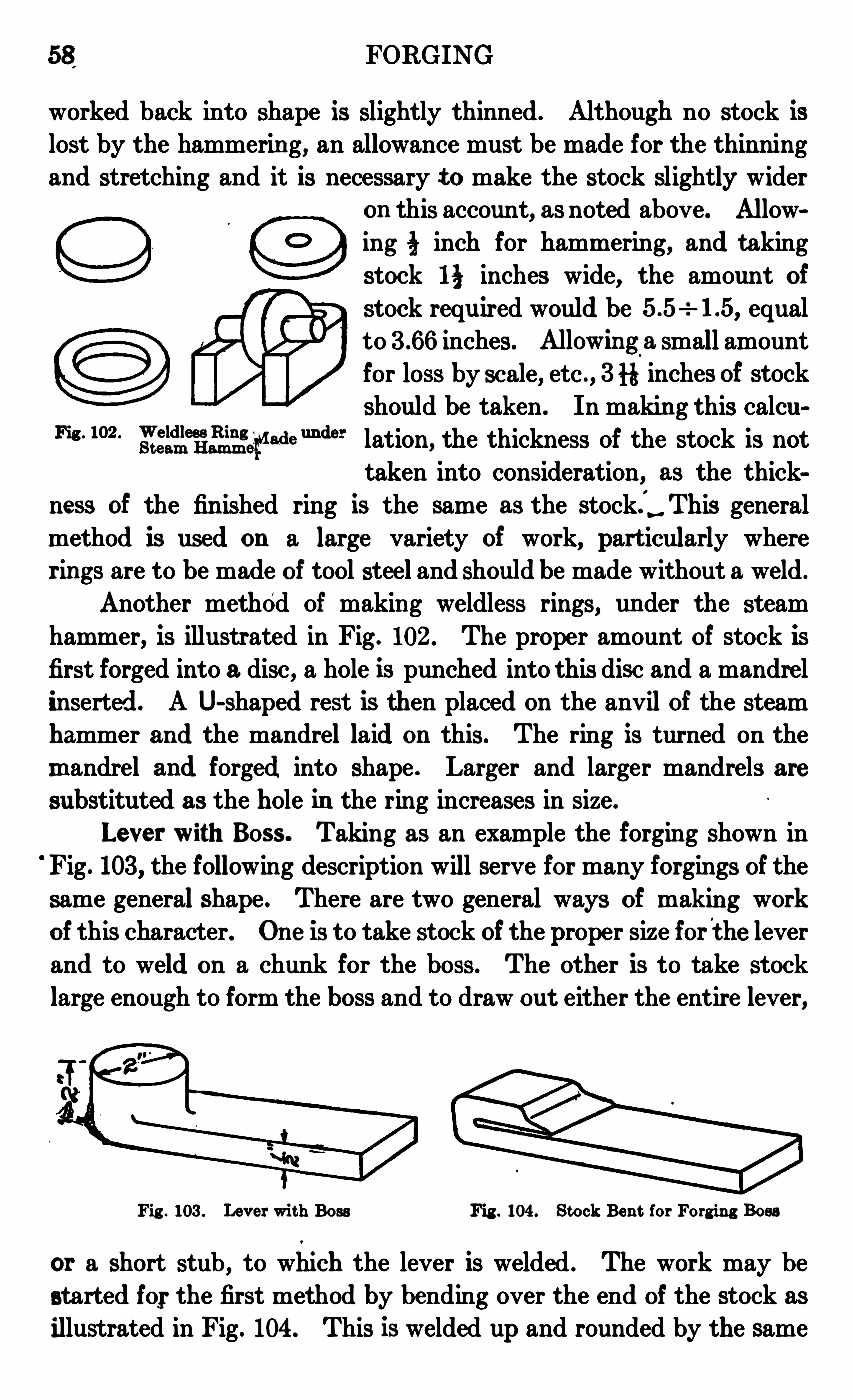
58 FORGING
worked back into shape is slightly thinned . Although no stock is
lost by the hammerin g, an allowance must be made for the thinningand stretching and it is necessary t o make the stock slightly wider
on this account, as noted above. Allow
ing inch for hammering, and taking
stock 1} inches wide, the amount of
stock required would be equalto inches. Allowing
o
a small amountfor loss by scale, etc . , 3 it inches of stock
should be taken . In makin g this caleu
Egg?Ring
}3
1243“ “ d ” lation, the thickness of the stock is not
taken into consideration, as the thick
ness of the fin ished ring is the same as the stock; This generalmethod is used on a large variety of work, par t icularly wherer ings are to be made of tool steel and should be made without a weld .
Another method of makin g weldless rings, under the steam
hammer, is illustrated in Fig . 102 . The proper amount of stock isfirst forged into a disc , a hole is punched into this disc and a mandrelinserted. A U-shaped rest is then placed on the anvil of the steamhammer and the mandrel laid on this . The ring is turned on the
m andrel and forged into shape . Larger and larger mandrels are
substituted as the hole in the ring increases in size .
Lever with Boss. Taking as an example the forging shown in
Fig . 103 , the following description will serve for many forgings of the
same general shape . There are two general ways of makin g workof this character. On e is to take stock of the proper size for the leverand to weld on a chunk for the boss . The other is to take stocklarge enough to form the boss and to draw out either the entire lever,
Fig . 103 . Le v er wi t h Boss Fig . 104 . Stock Ben t for Forg ing Boss
or a short stub, to which the lever is welded . The work may bestarted for the first method by bending over the end of the stock as
illustrated in Fig. 104 . This is welded up and rounded by the same
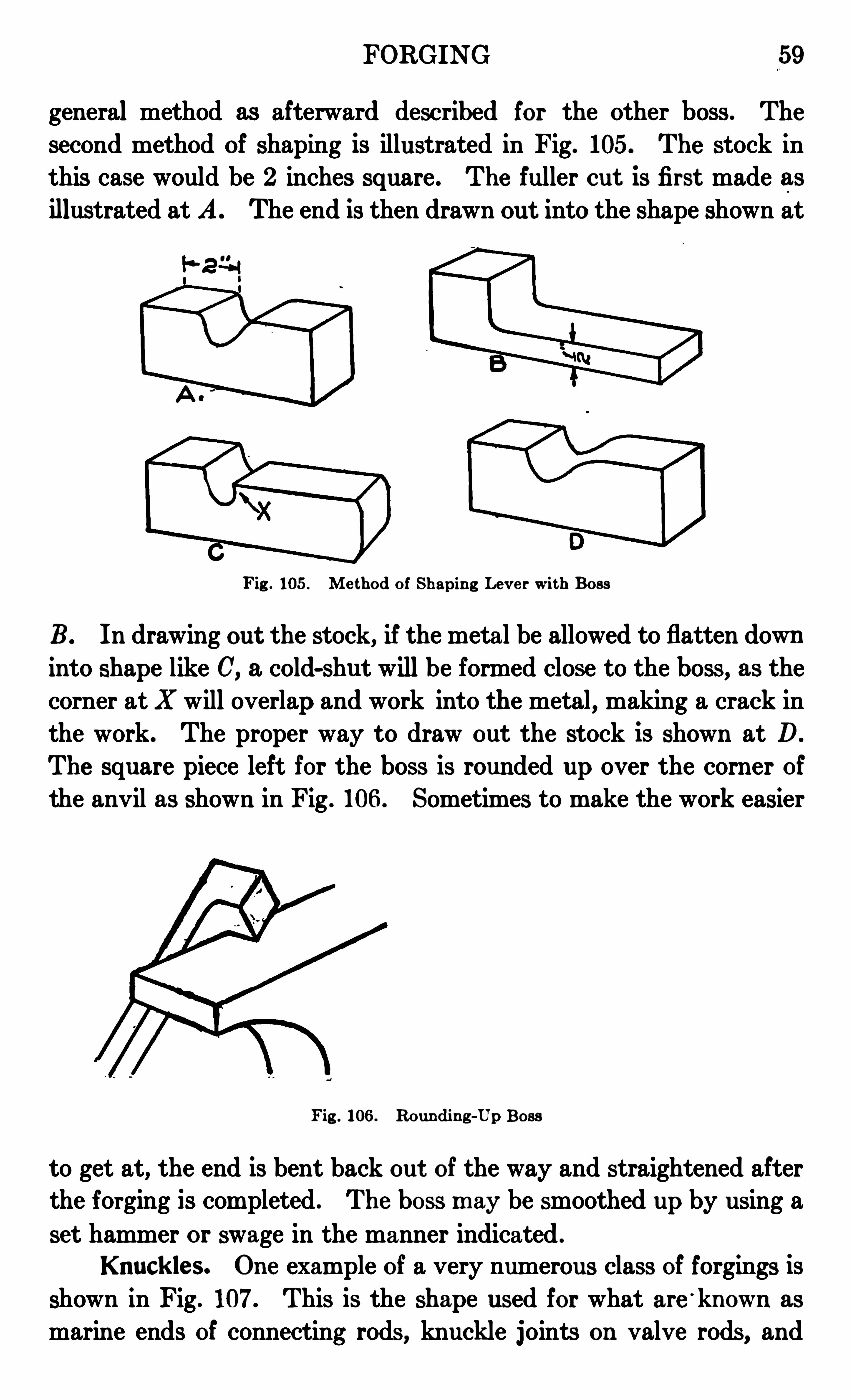
FORGING 59
general method as afterward described for the other boss . The
second method of shaping is illustrated in Fig. 105. The stock inthis case would be 2 inches square . The fuller cut is first made asillustrated at A. The end is then drawn out into the shape shown at
Fig . 105 . Me thod of Shapin g Lev e r wi th Boss
B. In drawing out the stock, if the metal be allowed to flatten down
into shape like C, a cold-shut will be formed close to the boss, as thecorner at X will overlap and work into the metal , making a crack inthe work. The proper way to draw out the stock is shown at D.
The square piece left for the boss is rounded up over the corner of
the anvil as shown in Fig . 106 . Sometimes to make the work easier
Fig . 106 . Roundin g -Up Boss
to get at,the end is bent back out of the way and straightened after
the forging is completed . The boss m ay be smoothed up by using a
set hammer or swage in the manner indicated .
Knuckle s. One example of a very numerous class of forgings is
shown in Fig . 107. This is the shape used for what are ‘
known as
marine ends of connecting rods , knuckle joints on valve rods, and
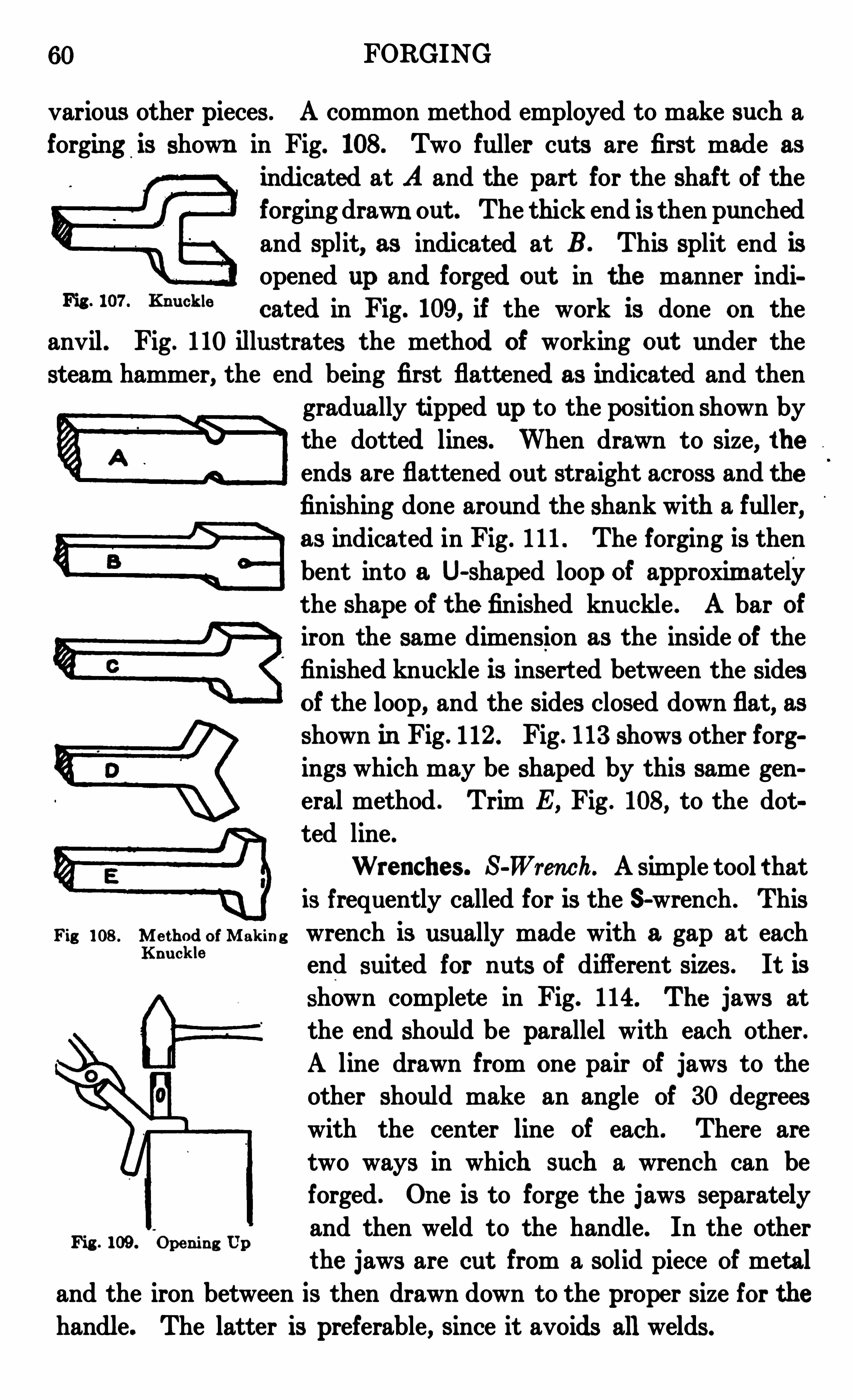
60 FORGING
various other pieces . A common method employed to make such a
forging is shown in Fig. 108. Two fuller cuts are first made as
Fig . 107. Knuckle
indicated at A and the part for the shaft of theforging drawn out . The thick end is then punched
and split, as indicated at B . This split end isopened up and forged out in the manner indicat ed in Fig. 109, if the work is done on the
anvil . Fig. 110 illustrates the method of working out under thesteam hammer, the end being fir st flatt ened as indicated and then
gradually t ipped up to the position shown by
the dotted lines. When drawn to size, theends are flattened out straight across and thefinishing done around the shank with a fuller,as indicat ed in Fig. 111 . The forging is then
bent into a U-shaped loop of approxim atelythe shape of the finished knuckle . A bar of
iron the same dimension as the inside of the
finished knuckle is insert ed between the sidesof the loop, and the sides closed down flat, asshown in Fig . 112 . Fig . 113 shows other forgings which may be shaped by this same gen
eral method . Trim E, Fig . 108, to the dot
ted line .
Wrenches . S-Wren ch. A simple tool t hatis frequently called for is the S-wrench . This
Fig 108 . M e thod of Mak in g wrench is usually made with a gap at eachKnuckle
Fig . 109 .
"
open in g Up
end suited for nuts of different sizes. It is
shown complet e in Fig. 114. The jaws at
the end should be parallel with each other.A line drawn from on e pair of jaws to the
other should make an angle of 30 degreeswith the center line of each . There are
two ways in which such a wrench can beforged . On e is to forge the jaws separatelyand then weld to the handle. In the other
the jaws are cut from a solid piece of metal
and the iron between is then drawn down to the proper size for thehandle. The latter is preferable, since it avoids allwelds.
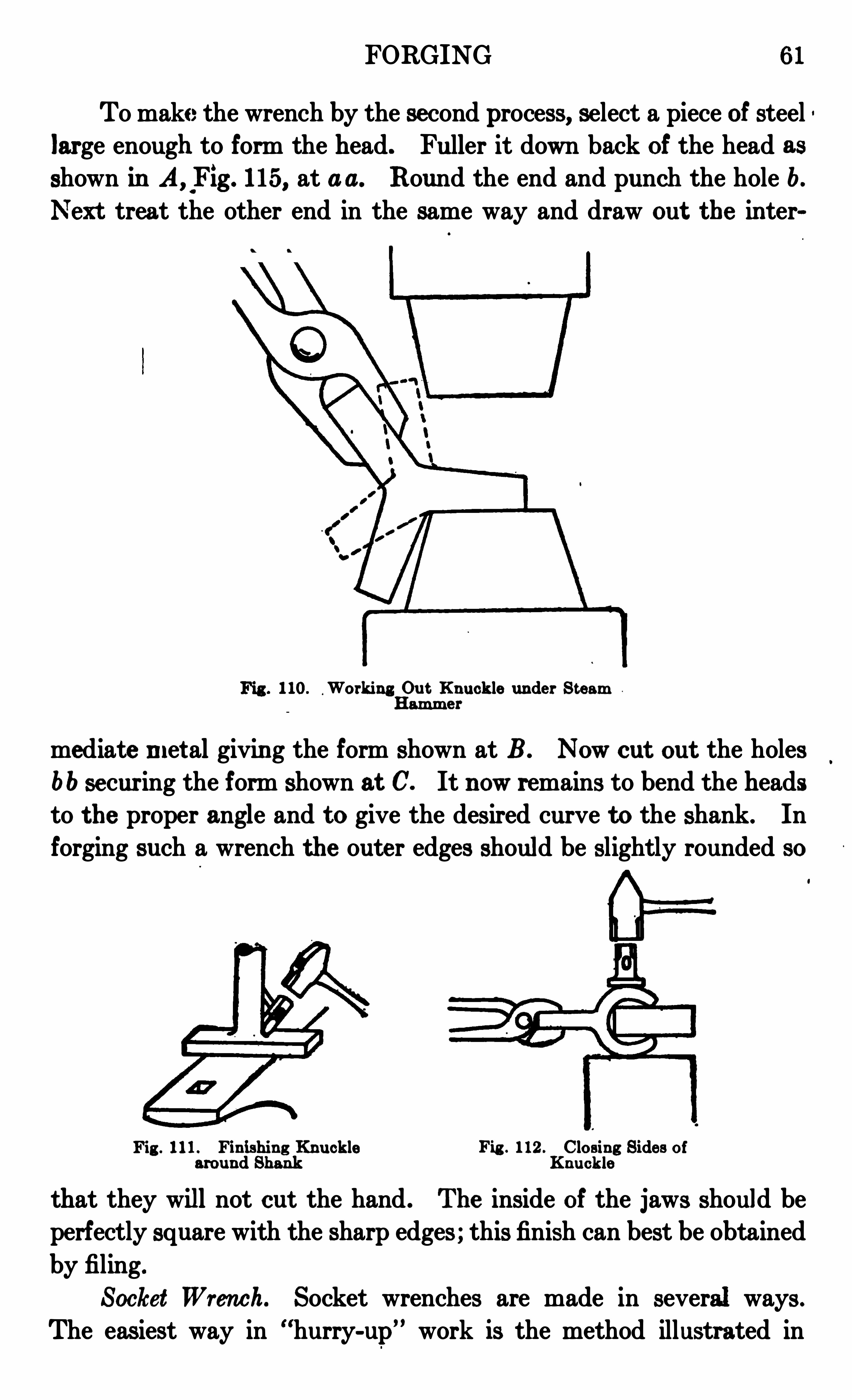
FORGING 6 1
To make the wrench by the second process, select a piece of steel
large enough to form the head. Fuller it down back of the head as
shown in A, _Fig . 115, at a a. Round the end and punch the hole b.
treat the other end in the same way and draw out the inter
1 10. Working Out Knuck le under S t eamHam m e r
mediate m et al givin g the form shown at B . Now cut out the holes
6 b secur ing the form shown at C. It now remains to bend the headsto the proper angle and to give the desired curve to the shank. Inforging such a wrench the outer edges should be slightly rounded so
Fig . 111 . Fin ishin g Knuck le Fig . 112 . Closing Sides ofaround Shank Knuckle
that they will not cut the hand . The inside of the jaws should beperfectly square with the sharp edges ; this finish can best be obtained
by filing.
Socket Wren ch. Socket wrenches are made in several ways .
The easiest way in hurry-up” work is the method illustrated in
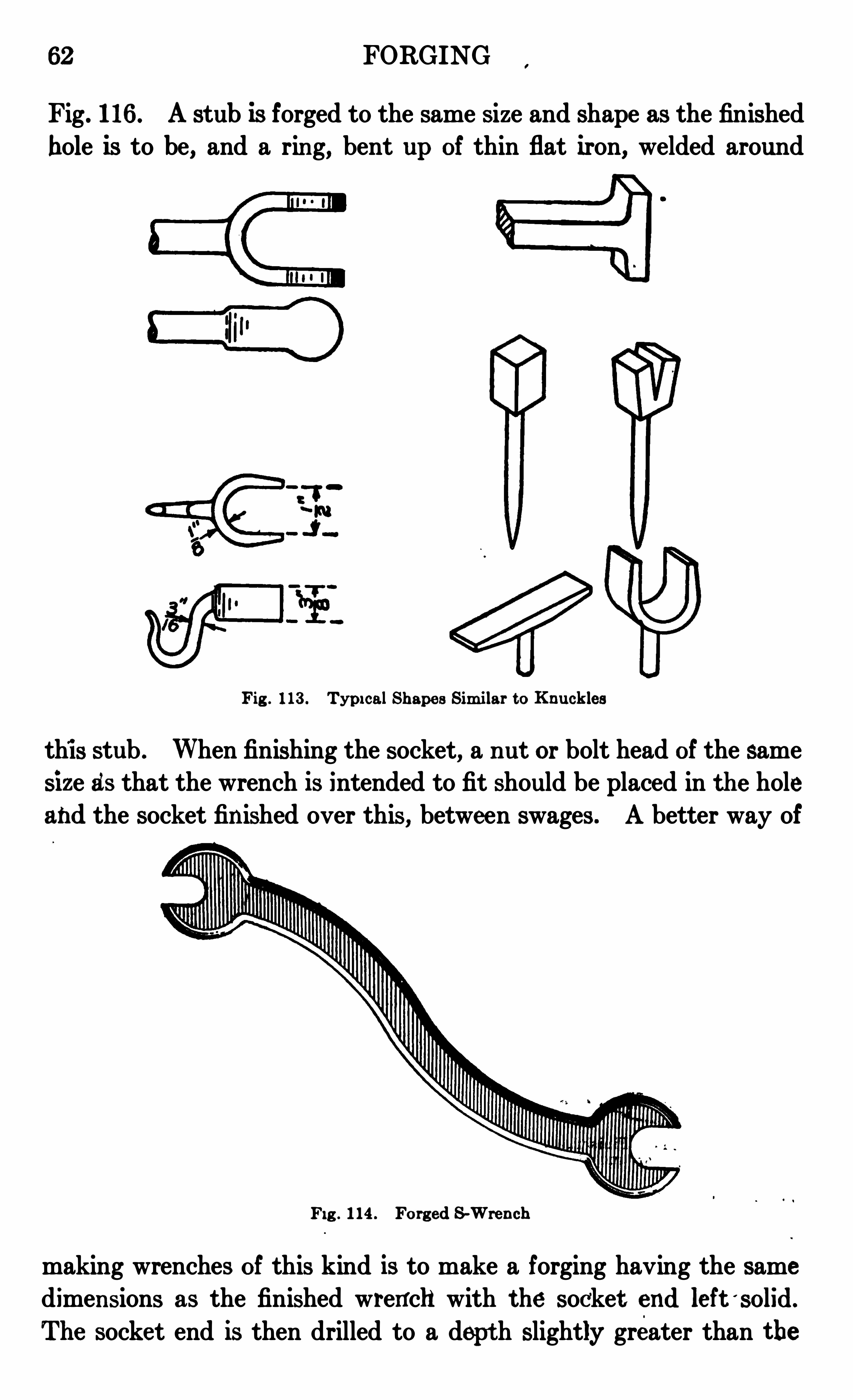
62 FORGING
Fig . 116 . A stub is forged to the same size and shape as the finished
hole is to be, and a rin g, bent up of thin flat iron, welded around
Fig . 113 . Typi calShape s Sim i lar to Knuck les
this stub . When finishing the socket, a n ut or bolt head of the samesize as that the wrench is intended to fit should be placed in the holeand the socket fin ished over this, between swages . A better way of
Fig . 114 . Forg ed S -Wre n ch
making wrenches of this kind is to make a forging having the samedimen sions as the finished wrench with the socket end left '
solid.
The socket end is then drilled to a dept h slightly greater than the
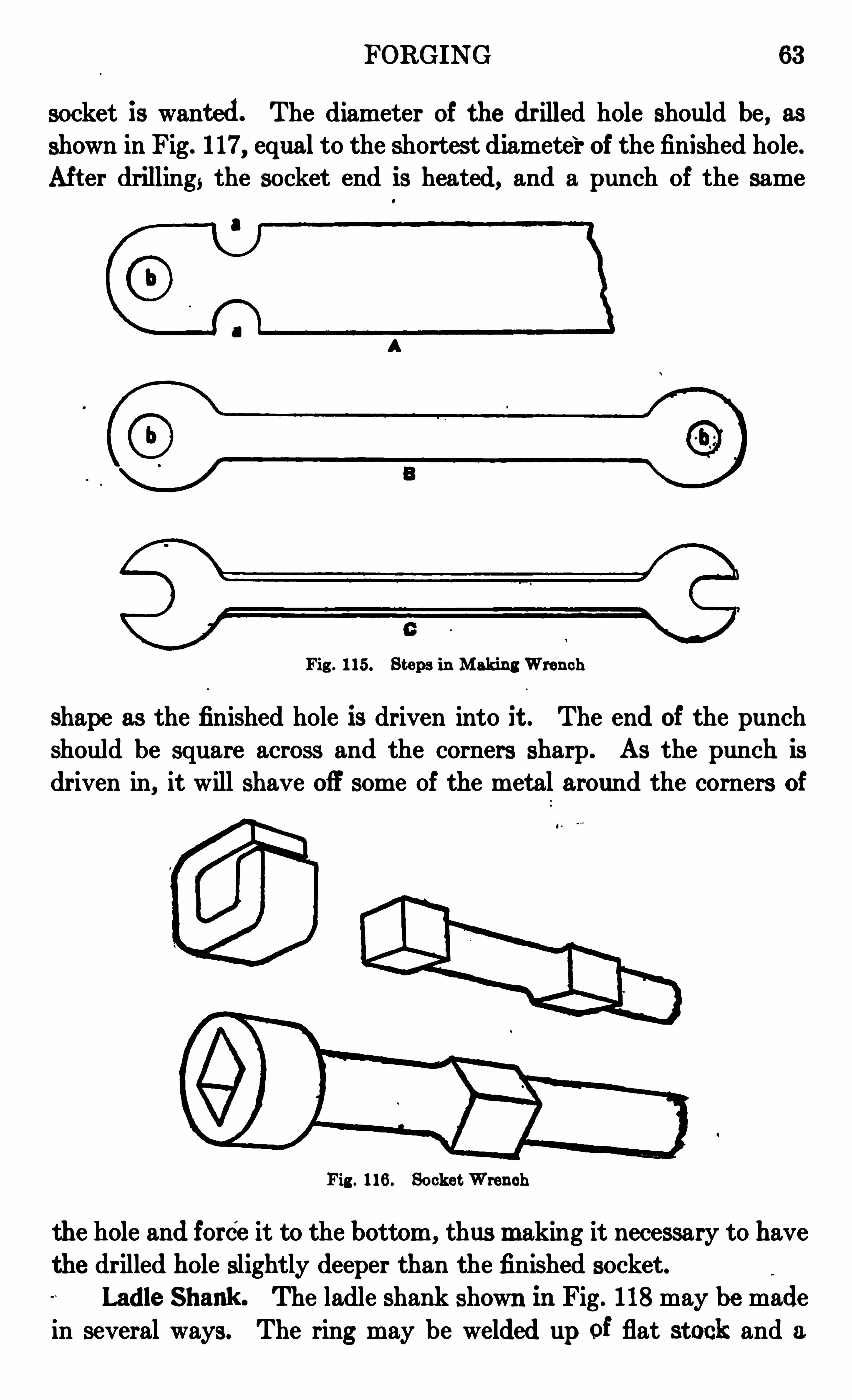
FORGING 6 3
socket is want ed. The diameter of the dr illed hole should be, as
shown in Fig. 117, equal to the shortest diameter of the finished hole.
Aft er drilling, the socket end is heated, and a punch of the same
Fig . 1 15. Steps in Making Wre n ch
shape as the finished hole is driven into it . The end of the punchshould be square across and the corners sharp . As the punch is
driven in, it will shave off some of the metal around the corners of
Fig . 116 . Socket W ren ch
the hole and force it to the bottom, thus m aking it necessary to havethe drilled hole slightly deeper than the finished socket.
Ladle Shank . The ladle shank shown in Fig. 118 may be made
in several ways. The ring may be welded up of flat stock and a
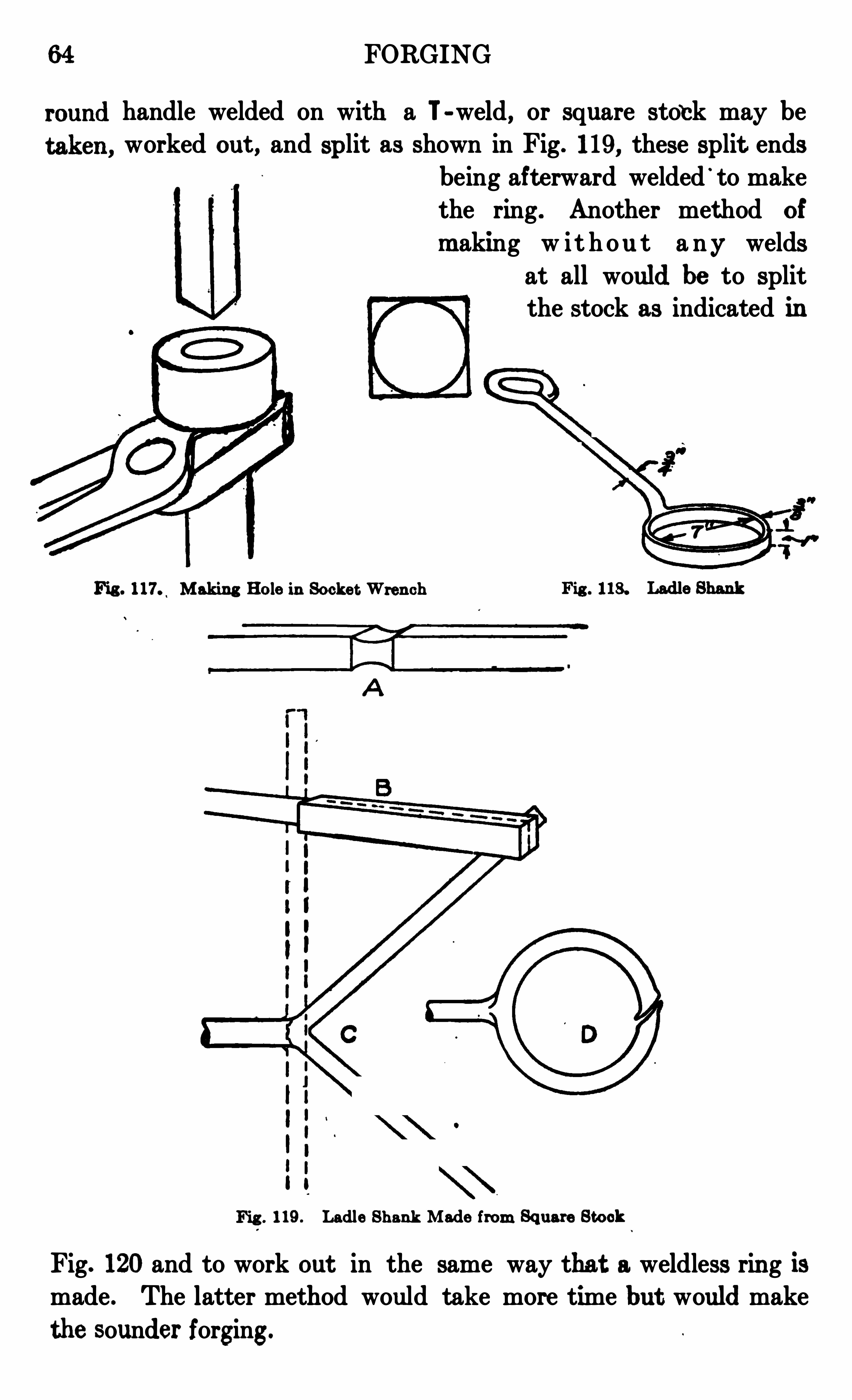
64 FORGING
handle welded on with a T-weld , or square sto‘ck may be
worked out , and split as shown in Fig. 119, these split endsbeing aft erward welded
'
to makethe ring . Another method of
m aking w i t h ou t a ny weldsat all would be to Splitthe stock as indicated in
Fig . 117. Makin g Hole in Socke t Wren ch
1 I
119 . Ladle Shank Made from Square Stock
Fig. 120 and to work out in the same way that a weldless rin g ismade . The latter method would take more time but would make
the sounder forging.


BEMENT STEAM DROP HAMMER
FORGING
PART II
FORGING OPERATIONS— (Cont inued)
TOOL-STEEL WORK
ToolSteel. Although not strictly true technically, for ordinarypurposes tool steel may be considered simply a combination of ironand carbon . The more common grade contains perhaps 1 per centof carbon. Machine steel and wrought tron do not contain thiselement carbon to any great extent . If a piece of wrought 1ron ormachine steel is heated red hot and then suddenly cooled, the m etalremains practically as itwas before heating, but if a piece of toolsteelbe subjected to this treatment, it
'
becomes very hard and brittle . By
a m odification of this heating and cooling, almost any degree of hardness may be impart ed to the steel .
Proper Forg ing Heat . Before attempting any work withtoolsteel, a piece of scrap steel i s to be experimented with, heated andhardened several times at various heats until the manipulator is sureof the eflect of the various heats upon the
_ grain of the steel . The
steel should also be experimented with to determine just how high aheat it will stand. When heavy forging is to be done, i .e . , when the
first rough shaping is done upon a t ool, a comparatively high heatshould be used. The steel should be forged at about what might becalled a good yellow heat . The lighter hammering, when finishing,should be done at a lower heat, about the hardening heat, thoughvery little, if any, hamm ering should be done below that point. If
the grain of the steel has been raised by too high a heat, it can generally be quite decidedly reduced by a litt le hammering at some heatabove the hardening temperature ;
St andard Form s
Cold Chisels . The stock should be heated to a good yellow heatand forged into shape and finished as smoothly as possible. When
properly forged, the end or cutting edge projects as shown at C in
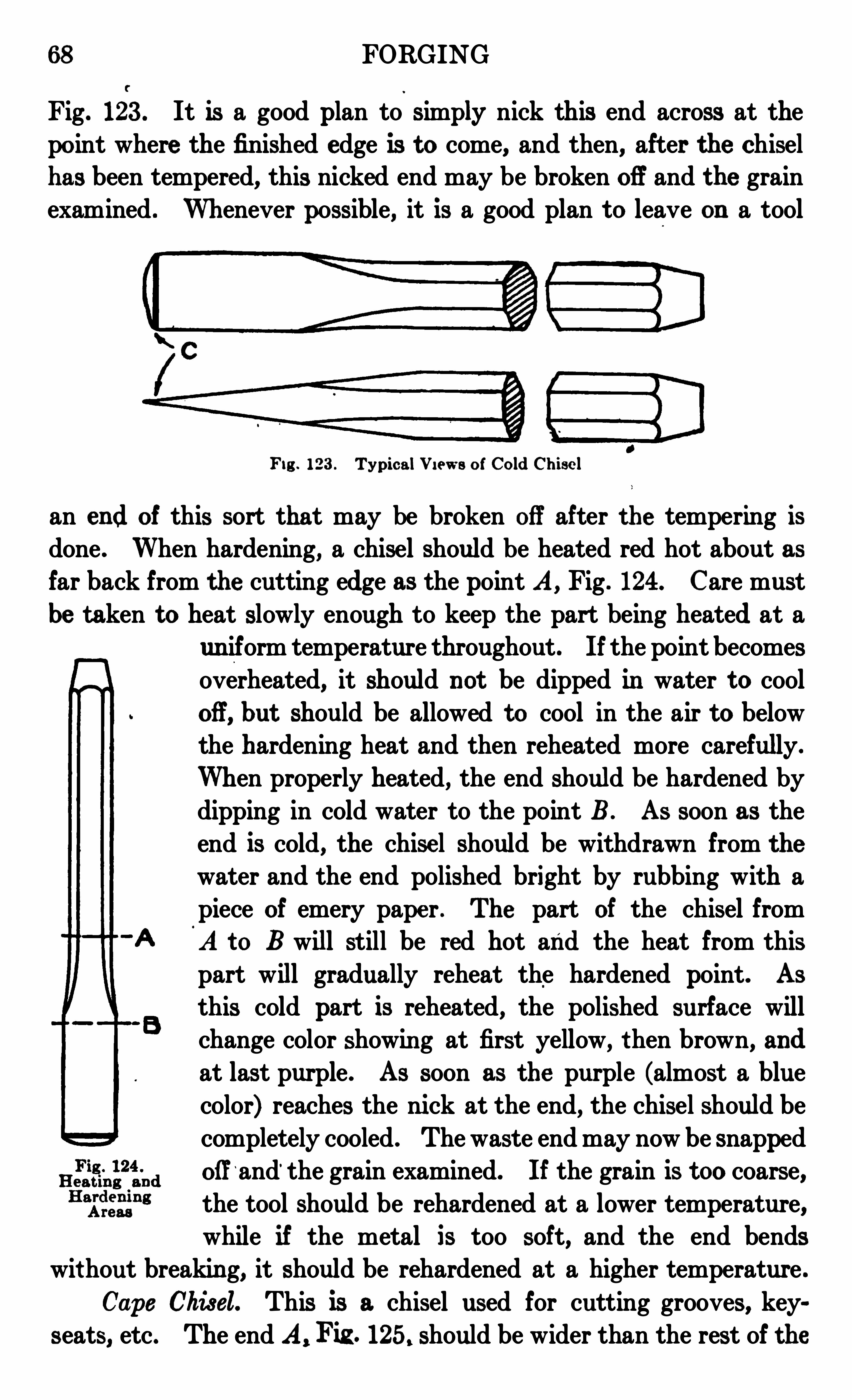
68 FORGING
Fig. 123 . It is a good plan to simmy nick this end across at thepoint where the finished edge is to come, and then, after the chisel
has been tempered, this nicked end may be broken off and the grainexamined . Whenever possible, it is a good plan to leave on a tool
Fig . 123 . TypicalV i ews of Cold Chise l
an end of this sort that may be broken off after the tempering is
done . When hardening, a chisel should be heated red hot about asfar back from the cutting edge as the point A , Fig . 124. Care mustbe taken to heat slowly enough to keep the part being heated at a
un iform temperature throughout . If the point becomes
overheated, it should not be dipped in water t o cooloff, but should be allowed to cool in the air to belowthe hardening heat and then reheated more carefully.
When properly heated, the end should be hardened bydipping in cold water to the point B . As soon as the
end is cold, the chise l should be withdrawn from the
water and the end polished bright by rubbing with apiece of emery pape r . The part of the chisel fromA to B will still be red hot and the heat from this
part will gradually reheat the hardened point. As
this cold part is reheated, the polished surface willchange color showin g at first yellow, t hen brown, and
at last purple . As soon as the purple (almost a bluecolor) reaches the nick at the end, the chisel should be
completely cooled . The waste end may now be snappedoff
‘and‘ the grain examined. If the grain is too coarse,the tool should be rehardened at a lower temperature,while if the metal is too soft, and the end bends
without breaking, it should be rehardened at a higher temperature .
Cape Chisel. This is a chisel used for cutting grooves, keyseats, etc . The end A, Fig . 125. should be wider than the rest of the
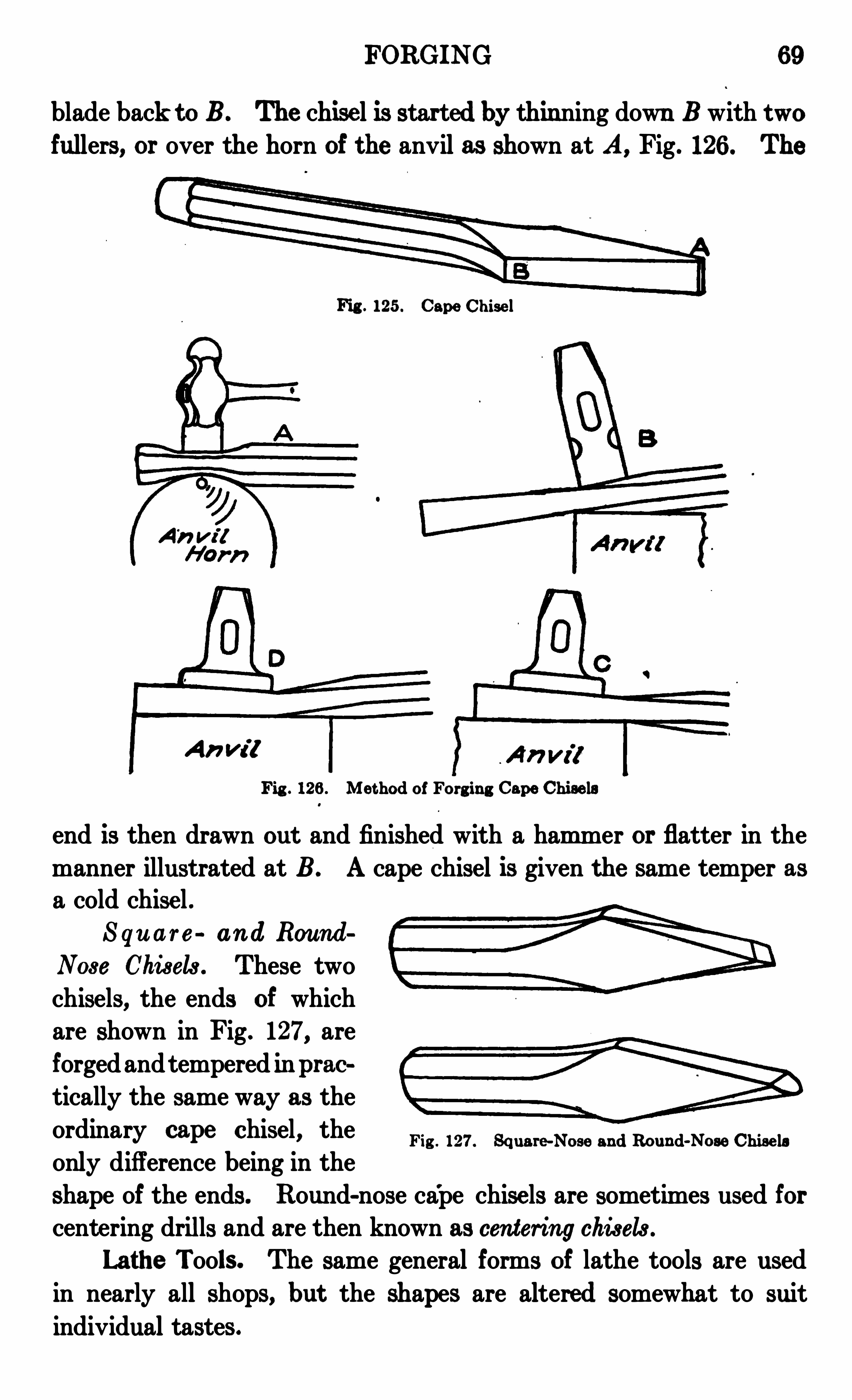
FORGING 6 9
blade back toB. The chise l is started by thinning down B with twofullers, or over the horn of the anvil as shown at A, Fig. 126 . The
Fig . 125 . Cape Chise l
A" W ?
An m ?
Fig . 126 . Met hod of Forg ing Cape Chise ls
end is then drawn out and finished with a ham mer or flatter in the
manner illustrated at B . A cape chisel is given the same temper asa cold chise l .
S qu a r e an d Round
Nose Chisels . These two
chisels, the ends of whichare shown in Fig. 127, areforged andtempered in prac
tically the same way as the
ordinary cape Chisel’ the Fig . 127. Square-Nose and Round-Nose Chise lsonly difference being in theshape of the ends. Round-nose ca
'
pe chise ls are sometimes used forcentering drills and are then known as cen tering chisels .
Lathe Tools. The same general forms of lathe tools are used
in nearly all shops, but the shapes are altered somewhat to suit
individual tastes .
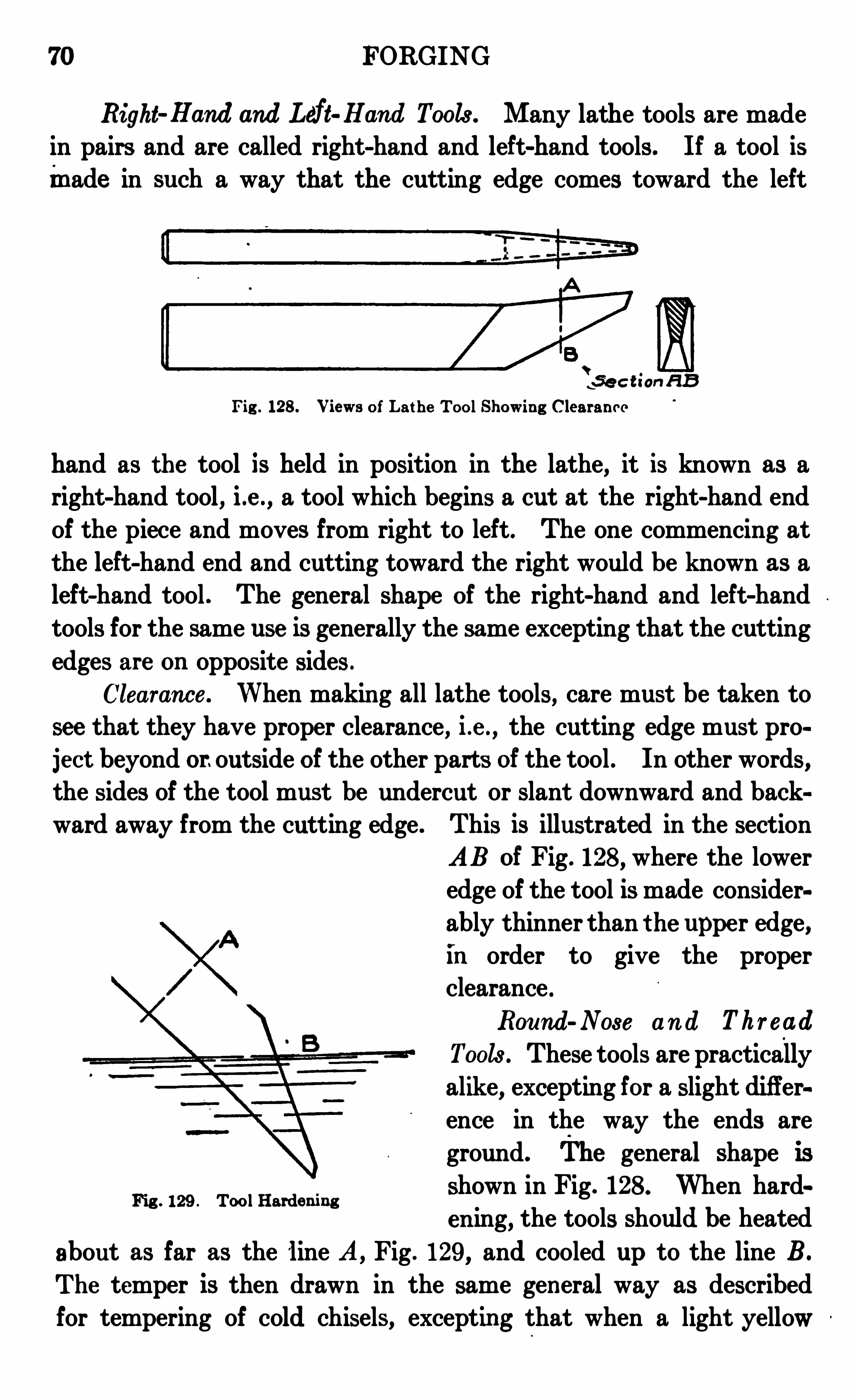
70 FORGING
Right Hand and Left Hand Tools . Many lathe tools are madein pairs and are called right-hand and left-hand tools . If a tool ismade in such a way that the cutting edge comes toward the left
t-se c t ian a sFig . 128 . Views of Lat he ToolShowing Clearan ce
hand as the tool is held in position in the lathe, it is known as a
right-hand tool, i .e . , a tool which begins a cut at the right-hand endof the piece and moves from right to left. The one commencing at
the left-hand end and cutting toward the right would be known as aleft-hand tool . The general shape of the right-hand and left-hand
tools for the same use is generally the same excepting that the cutting
edges are on opposite sides .
Clearance . When makin g all lathe tools, care must be taken to
see that they have proper clearance, i .e . , the cutting edge must pro
ject beyond or.outside of the other parts of the tool . In other words,the sides of the tool must be undercut or slant downward and backward away from the cutting edge . This is illustrated in the section
AB of Fig. 128, where the lower
edge of the tool is made consider
ably thinner than the uppe r edge,in order to give the properclearance .
Round-Nose an d Thr ead
Tools . These tools are practicallyalike, excepting for a slight difference in the way the ends are
ground. The general shape isshown in Fig. 128 . When hard
cuing, the tools should be heated
about as far as the line A, Fig . 129 , and cooled up to the line B.
The temper is then drawn in the same general way as described
for tempering of cold chisels, excepting that when a light yellow
Fig . 129 . Tool Harden ing
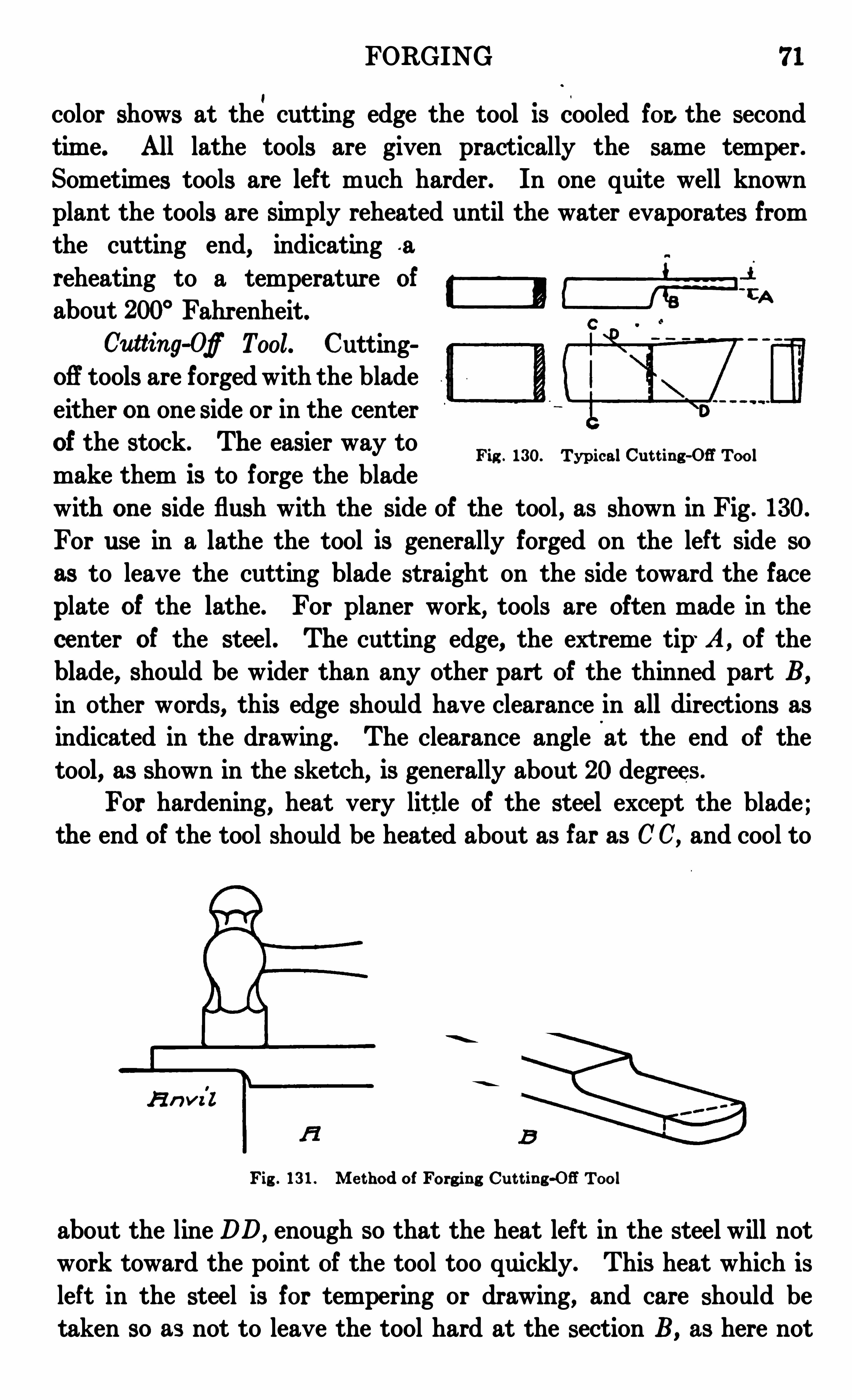
FORGING 71
color shows at the,
cutting edge the tool is cooled for. the second
tim e. All lathe tools are given practically the same tempe r.Sometimes tools are left much harder. In one quite well knownplant the tools are simply reheated until the water evaporates from
the cutting end, indicating -a
reheating to a temperature of
about 200° Fahrenheit.2
Cutting-Of Tool. Cuttingoff tools are forged with the bladeeither on one side or in the centerof the stock. The easier way tomake them is to forge the bladewith on e side flush with the side of the tool , as shown in Fig . 130.
For use in a lathe the tool is generally forged on the left side so
as to leave the cutting blade straight on the side toward the face
plate of the lathe. For planer work, tools are often made in the
center of the steel . The cutting edge, the ext reme tip' A, of the
blade, should be wider than any other part of the thinned part B,
in other words, this edge should have clearance in all di rections as
indicated in the drawing. The clearance angle at the end of the
tool, as shown in the sketch, is generally about 20degrees .
For hardening, heat very litt le of the steel except the blade ;the end of the tool should be heated about as far as CC, and cool to
Fig . 13 0. Typical Cut t ing -OE Tool
a n v il
Fig . 13 1 . Me thod of Forgin g Cut t ing-OB Tool
about the line DD,enough so that the heat left in the steel will not
work toward the point of the tool too quickly. This heat which is
left in the steel is for tempering or drawing, and care should betaken so as not to leave the tool hard at the section B, as here not
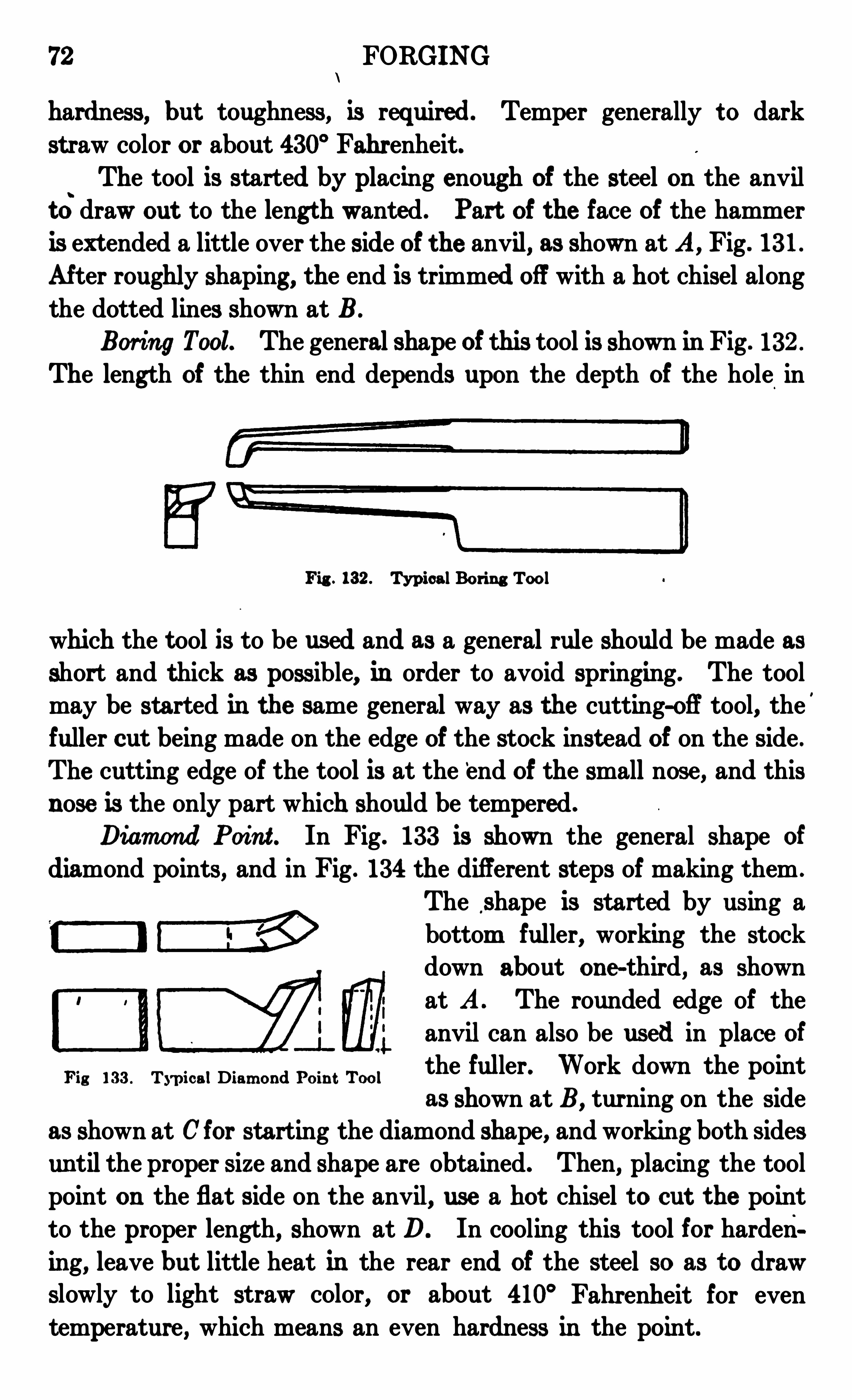
72 FORGING
hardness, but toughness, is required Temper generally t o dark
st raw color or about 430° Fahrenheit.The tool is started by placing enough of the steel on the anvil
t ci draw out to the lengt h wanted . Part of the face of the hammer
is ext ended a little over the side of the anvil, as shown at A, Fig . 13 1 .
After roughly shaping, the end is trimmed off with a hot chisel along
the dotted lines shown at BBoring Tool. The general shape of this tool is shown in Fig . 13 2 .
The length of the thin end depends upon the depth of the hole in
Fig . 13 2 . Typical Boring Tool
which the t ool is to be used and as a general rule should be made as
short and thick as possible, in order to avoid springing. The toolmay be started in the same general way as the cutting-off tool, the
'
fuller cut being made on the edge of the stock inst ead of on the side .
The cutting edge of the tool is at the ‘end of the small nose, and thisnose is the only part which should be tempered .
Diam ond Poin t . In Fig. 13 3 is shown the general shape of
diamond points, and in Fig . 13 4 the different steps of making them .
The shape is started by using abottom fuller, working the stockdown about one-third, as shown
at A . The rounded edge of the
anvil can also be used in place of
the fuller. Work down the pointas shown at B, turning on the side
as shown at Cfor starting the diamond shape, and workin g both sidesuntil the proper size and shape are obtained. Then, placing the tool
point on the flat side on the anvil, use a hot chisel t o cut the point
to the proper length, shown at D. In cooling this tool for hardenin g , leave but little heat in the rear end of the steel so as to drawslowly to light straw color, or about 410° Fahrenheit for eventemperature, which means an even hardness in the point.
Fig 13 3 . TypicalDiam ond Poin t Tool

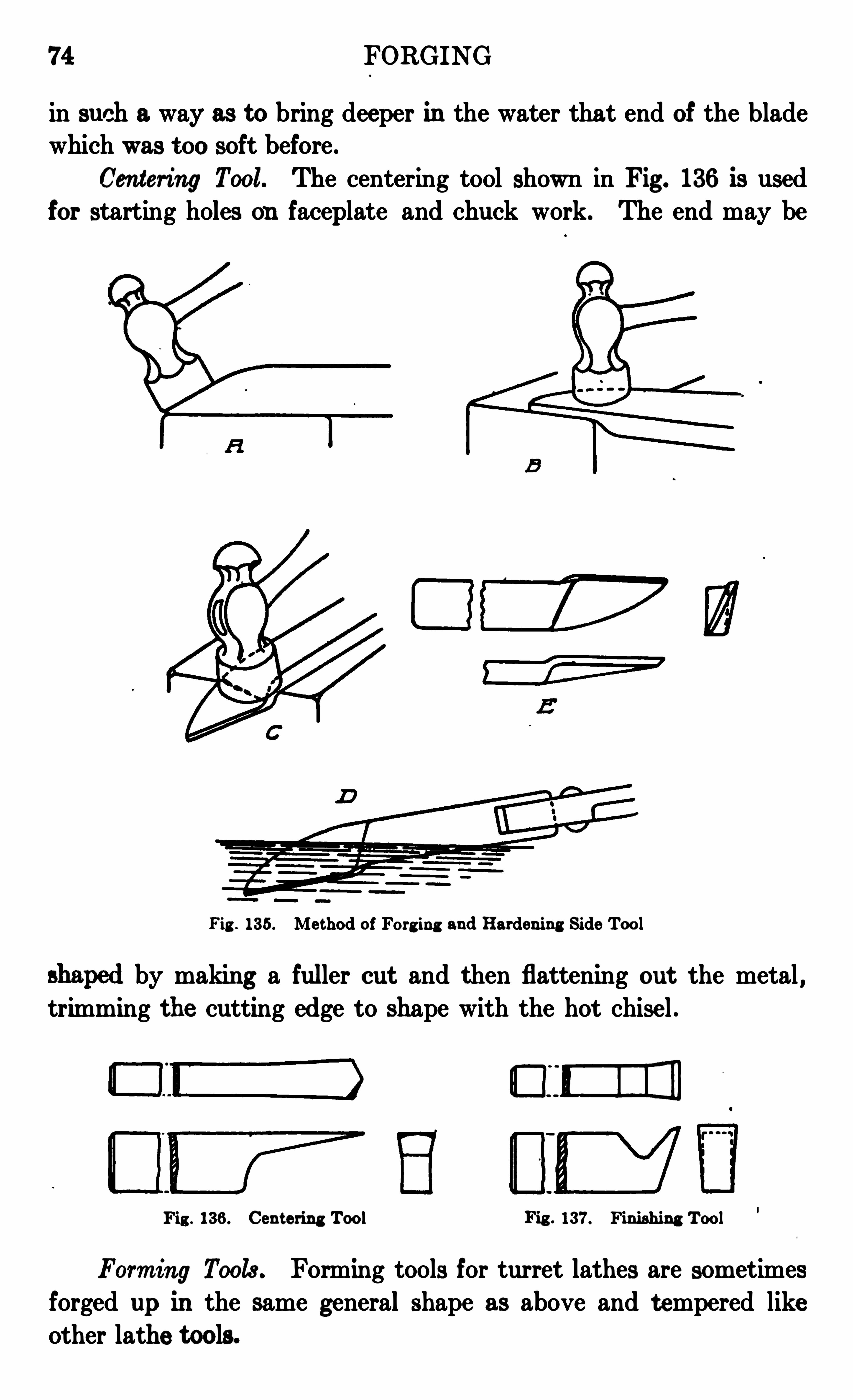
74 FORGING
in such a way as to bring deeper in the water that end of the bladewhich was too soft before .
Cen tering Tool. The centering tool shown in Fig . 13 6 is usedfor starting holes on faceplate and chuck work. The end may be
Fig . 13 5 . Me thod of Forg ing and Hardening Side Tool
by makin g a fuller cut and then flattening out the metal ,trimming the cutting edge to shape with the hot chise l .
DE ED]
Fig . 13 6 . Cen t ering Tool Fig . 13 7. Fin ishing Tool
Form ing Tools . Forming tools for turret lathes are sometimes
forged up in the same general shape as above and t empered like
other lathe tools.
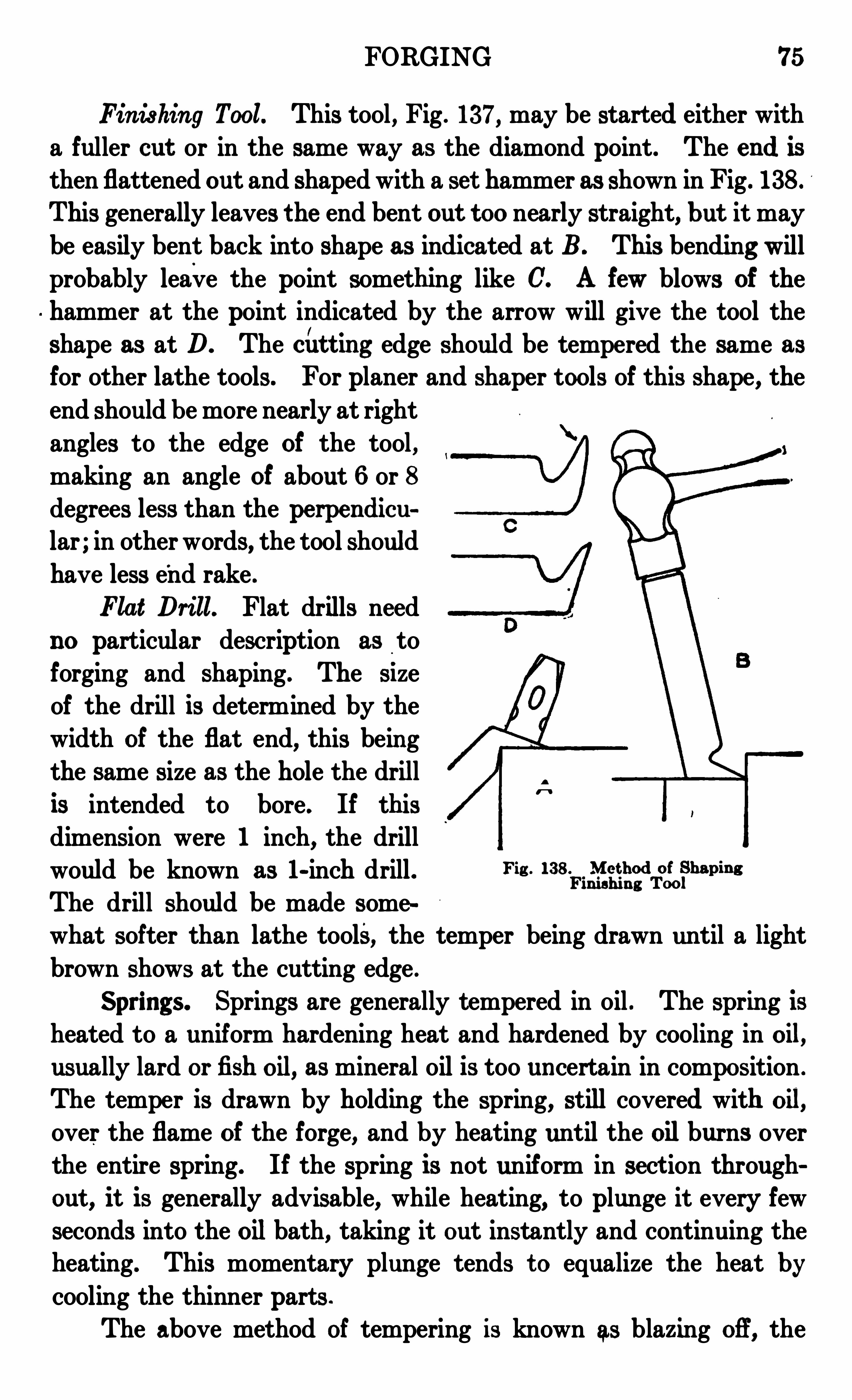
FORGING 75
Fin ishing Tool. This tool , Fig . 13 7, may be start ed either witha fuller cut or in the same way as the diamond point. The end is
then flattened out and shaped with a set hammer as shown in Fig. 13 8 .
This generally leaves the end bent out too nearly straight, but it maybe easily bent back into shape as indicated at B . This bending willprobably leave the point something like C. A few blows of thehammer at the point indicated by the arrow will give the tool theshape as at D. The cii t t ing edge should be tempered the same asfor other lathe tools. For planer and shaper tools of this shape, the
end should be more nearly at rightangles to the edge of the tool ,making an angle of about 6 or 8
degrees less than the perpendicular ; in other words, the tool shouldhave less e
'
nd rake .
Flat Drill. Flat drills needno particular description as to
forging and shaping. The Size
of the drill is determined by the
width of the flat end, this being
the same size as the hole the drillis intended to bore. If thisdimension were 1 inch, the drillwould be known as 1-inch drill . Fic B it-
Fixat
igzdfiof
hw ins
The drill should be made somewhat softer than lathe tools, the temper being drawn until a light
brown shows at the cutting edge .
Springs. Springs are generally tempered in oil . The spring is
heated to a uniform hardening heat and hardened by cooling in oil,usually lard or fishoil, as mineral oil is too uncertain in composition .
The temper is drawn by holding the spring, still covered with oil,
over the flame of the forge, and by heating until the oilburns overthe entire spring. If the spring is not uniform in sect ion throughout , it is generally advisable, while heating, to plunge it every fewseconds into the oilbath, taking it out instantly and continuing theheating. This momentary plunge tends t o equalize the heat bycooling the thinner parts .
The above method of tempering is known as blazing off , the
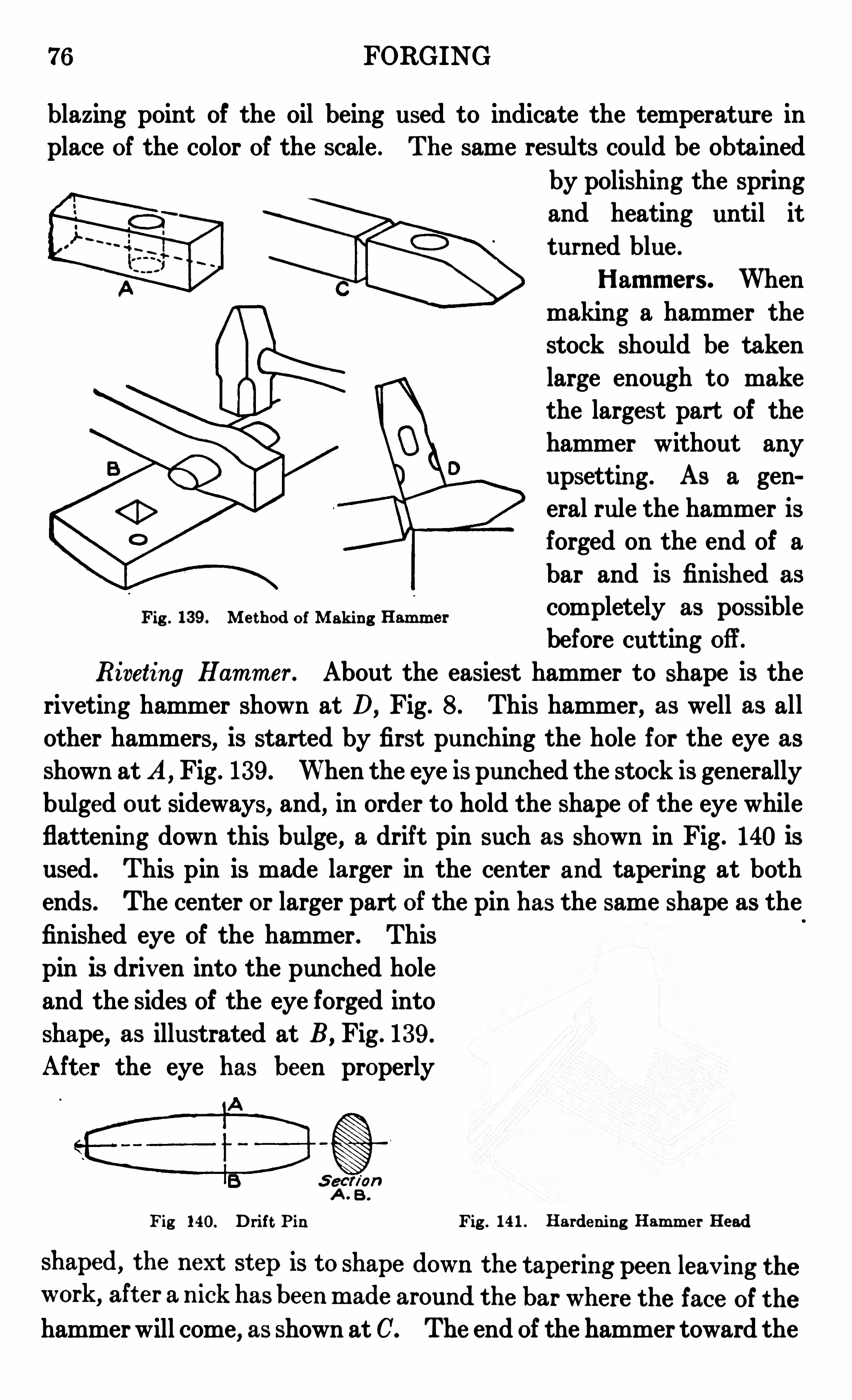
76 FORGING
blazing point of the oil being used to indicate the temperature inplace of the color of the scale . The same results could be obtained
by polishing the springand heating until it
turned blue .
Ham m ers . When
making a hammer the
stock should be takenlarge enough to makethe largest part of the
hammer without anyupsetting . As a gen
eral rule the hammer isforged on the end of a
bar and is finished as
completely as possiblebefore cutting ofl’.
Riveting Ham m er . About the easiest hammer to shape is the
rivetin g hammer shown at D, Fig . 8 . This hammer, as well as all
other hammers, is start ed by first punching the hole for the eye asshown at A, Fig . 13 9 . When the eye is punched the stock is generallybulged out sideways, and, in order to hold the shape of the eye whileflattening down this bulge, a drift pin such as shown in Fig . 140 is
used . This pin is made larger in the cen ter and tapering at bothends . The center or larger part of the pin has the same shape as the
finished eye of the hammer . This
pin is driv en into the punched hole
and the sides of the eye forged intoshape, as illustrated at B , Fig . 13 9 .
After the eye has been properly
Fig . 13 9 . Me thod of Makin g Ham m er
A . B .
Fig 140. Drift Pin Fig . 14 1 . Harde ni n g Ham m e r Head
hammer will come, as shown at C. The end of the hammer toward the
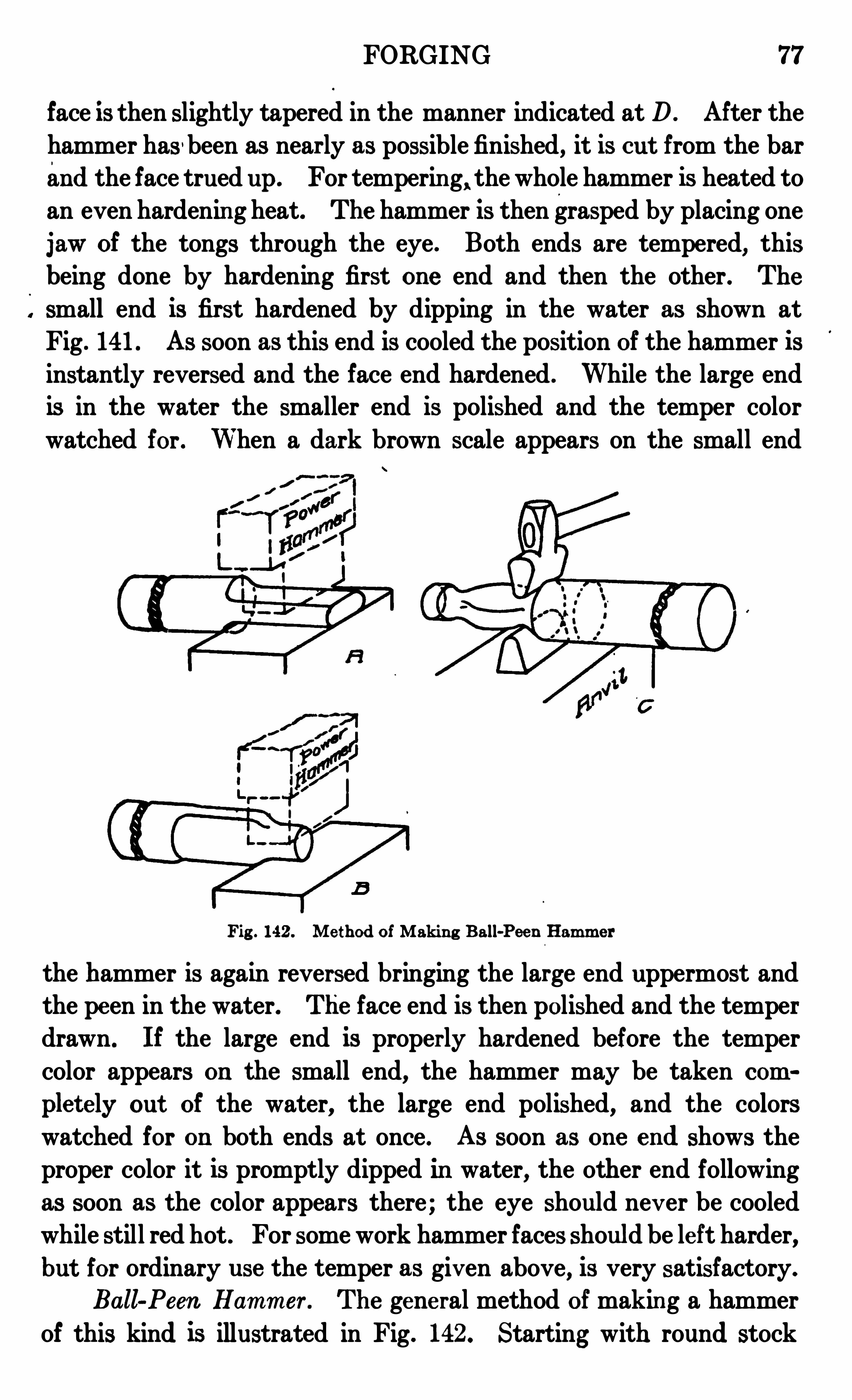
FORGING 77
face is then slightly tapered in the manner indicated at D. After the
hammer has 'been as nearly as possible finished, it is cut from the barand the face trued up. For temperin g, the whole hammer is heated to
an even hardenin g heat. The hammer is then grasped by placing one
jaw of the tongs through the eye . Both ends are tempered,this
being done by hardening first one end and then the other . The
small end is first hardened by dipping in the water as shown at
Fig . 141 . As soon as this end is cooled the position of the hammer isinstantly reversed and the face end hardened . While the large end
is in the water the smaller end is polished and the temper color
watched for . When a dark brown scale appears on the small end
Fig . 142 . Me thod of Makin g Ball-Pee n Ham m er
the hammer is again reversed bringing the large end uppermost andthe peen in the water. The face end is then polished and the temper
drawn . If the large end is properly hardened before the tempercolor appears on the small end, the hammer may be taken com
plet ely out of the water, the large end polished, and the colors
watched for on both ends at once . As soon as one end shows the
proper color it is promptly dipped in water, the other end following
as soon as the color appears there ; the eye should nev er be cooledwhile still red hot . For some work hammer faces should be le ft harder,but for ordinary use the temper as giv en above, is very satisfactory.
Ball-Peon Ham m er . The gene ral method of makin g a hammer
of this kind is illustrated in Fig . 142 . Starting with round stock
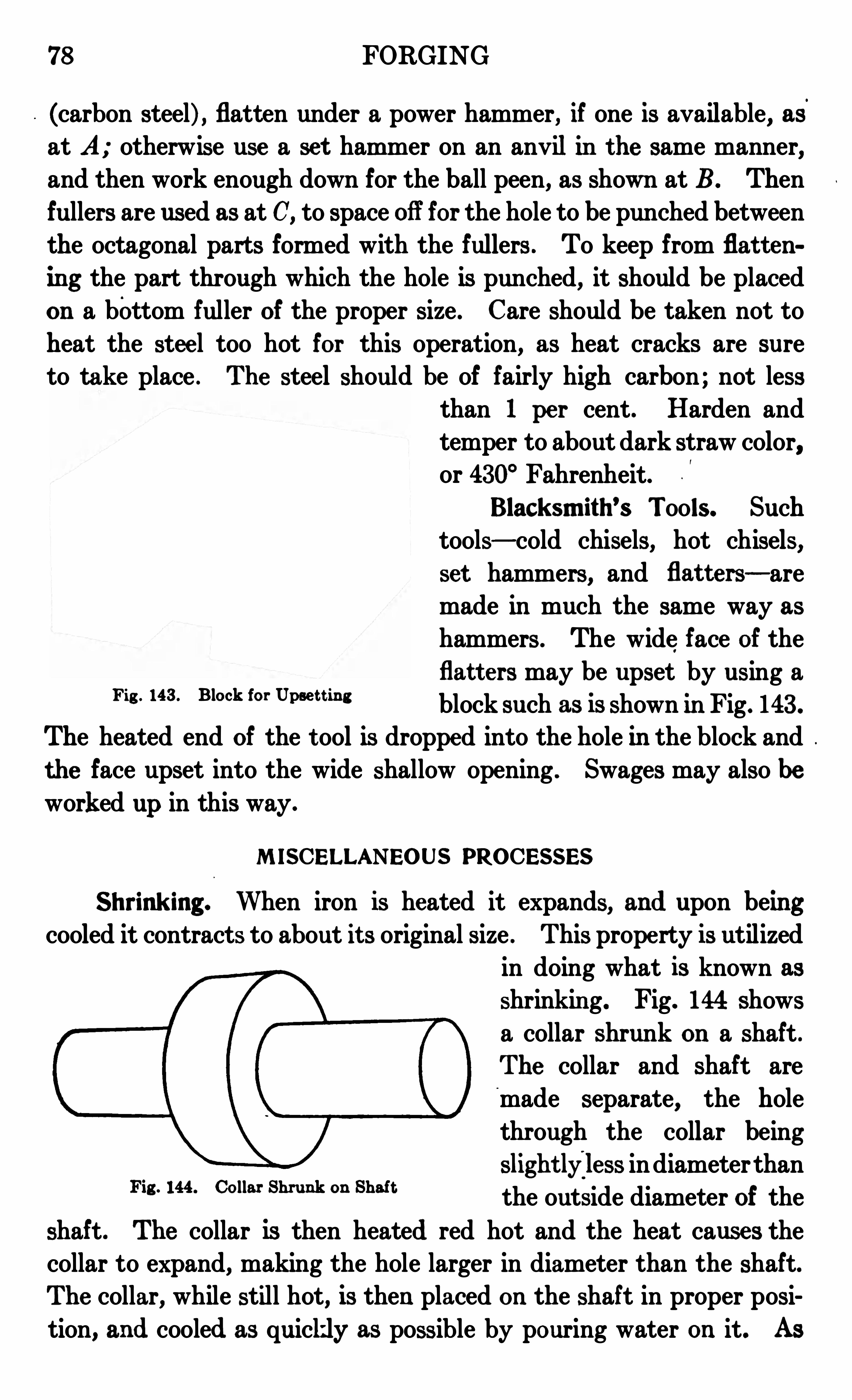
78 FORGING
(carbon steel) , flatten under a power hammer, if one is available, asat A ; otherwise use a set ham mer on an anvilin the same manner,and then work enough down for the ball peen, as shown at B . Thenfullers are used as at C, to space ofl
’for the hole to be punched between
the octagonal parts formed with the fullers . To keep from flat t en
ing the part through which the hole is punched, it should be placedon a bottom fuller of the proper size . Care should be taken not to
heat the stee l too hot for this operation, as heat cracks are sure
to take place . The steel should be of fairly high carbon ; not lessthan 1 pe r cent . Harden and
temper to about dark straw color,or 430° Fahrenheit
Blacksm ith’s Tools. Such
tools— cold chisels, hot chisels,set hammers, and flat t ers— are
made in much the same way as
hammers . The wide face of theflat t ers may be upset by using a
block such as is shown in Fig. 143 .
The heated end of the t ool is dropped into the hole in the block andthe face upset into the wide shallow opening . Swages may also be
worked up in this way .
Fig . 148 . Block for Upse t t in g
M ISCELLANEOUS PROCESSES
Shrink ing . When iron is heated it expands, and upon beingcooled it contracts to about it s original size . This prope rty is utilized
in doing what is known as
shrinkin g. Fig. 144 showsa collar shrunk on a shaft .
The collar and shaft are
made separate, the holethrough the collar being
slightlyiless in diameterthanthe outside diameter of the
shaft . The collar is then heated red hot and the heat causes thecollar to expand, making the hole larger in diameter than the shaft.
The collar, while still hot, is then placed on the shaft in proper posi
tion, and cooled as quickly as possible by pouring water on it. As
Fig . 144 . Collar Shrunk on Shaft
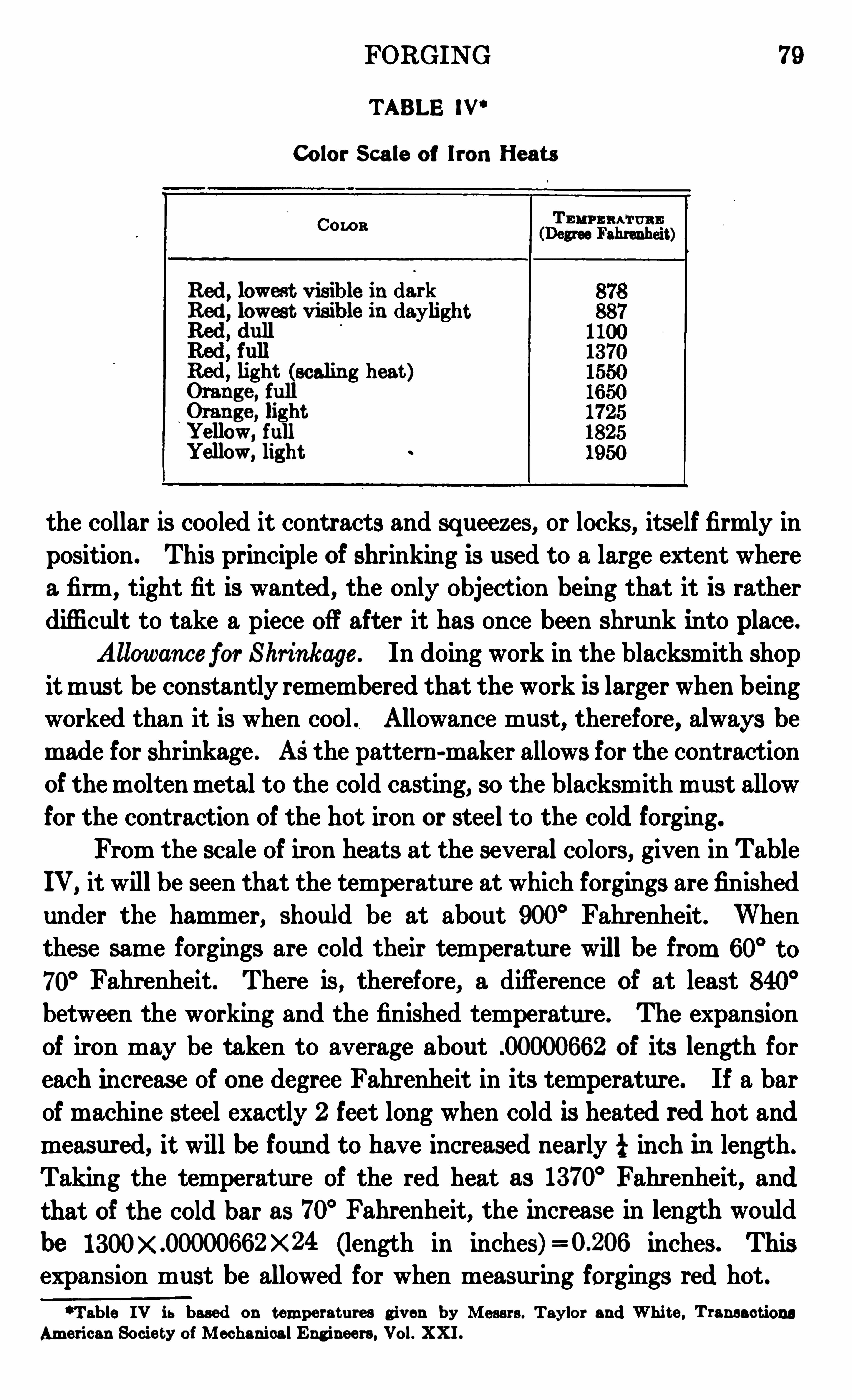
FORGING 79
TABLE IV “
Color Scale of Iron Heats
Cow s
Red, lowest v isible in darklowest v isible in daylight
light (scaling heat )ge , full
ge , light"ellow, full"ellow, light
the collar is cooled it cont racts and squeezes, or locks, itse lf firmly inposition . This principle of shrinking is used to a large ext ent wherea firm , tight fit is wanted , the only object ion being that it is ratherdifficult to take a piece off after it has once been shrunk into place .
Allowance for Shrinkage . In doing work in the blacksmith shopit must be constantly remembered that the work is larger when beingworked than it is when cool . Allowance must, therefore, always bemade for shrinkage . Asthe pattern -maker allows for the contraction
of the molten metal to the cold casting, so the blacksmith must allowfor the contraction of the hot iron or steel to the cold forging.
From the scale of iron heats at the several colors, given in Table
IV ,it will be seen that the temperature at which forgings are finished
under the hammer, should be at about 900° Fahr enheit . Whenthese same forgings are cold their temperature will be from 60
° to
70° Fahrenheit. There is , therefore, a difference of at least 840
°
between the working and the finished temperature . The expansion
of iron may be taken to average about .00000662 of it s length foreach increase of on e degree Fahr enheit in it s temperatur e. If a barof machine steel exactly 2 feet long when cold is heated red hot andmeasured, it will be foun d to have increased nearly i inch in length.
Taking the temperature of the red heat as 13 70° Fahrenheit, and
that of the cold bar as 70° Fahrenheit, the increase in length would
be X 24 (length in inches) inches. Thisexpansion must be allowed for when measuring forgings red hot.
“Table IV is based on t em pe rat ures g iv en by Messrs . Taylor and Whi t e , Transact ions
Am erican Socie ty of Mechanical Eng inee rs. Vol. XXI .
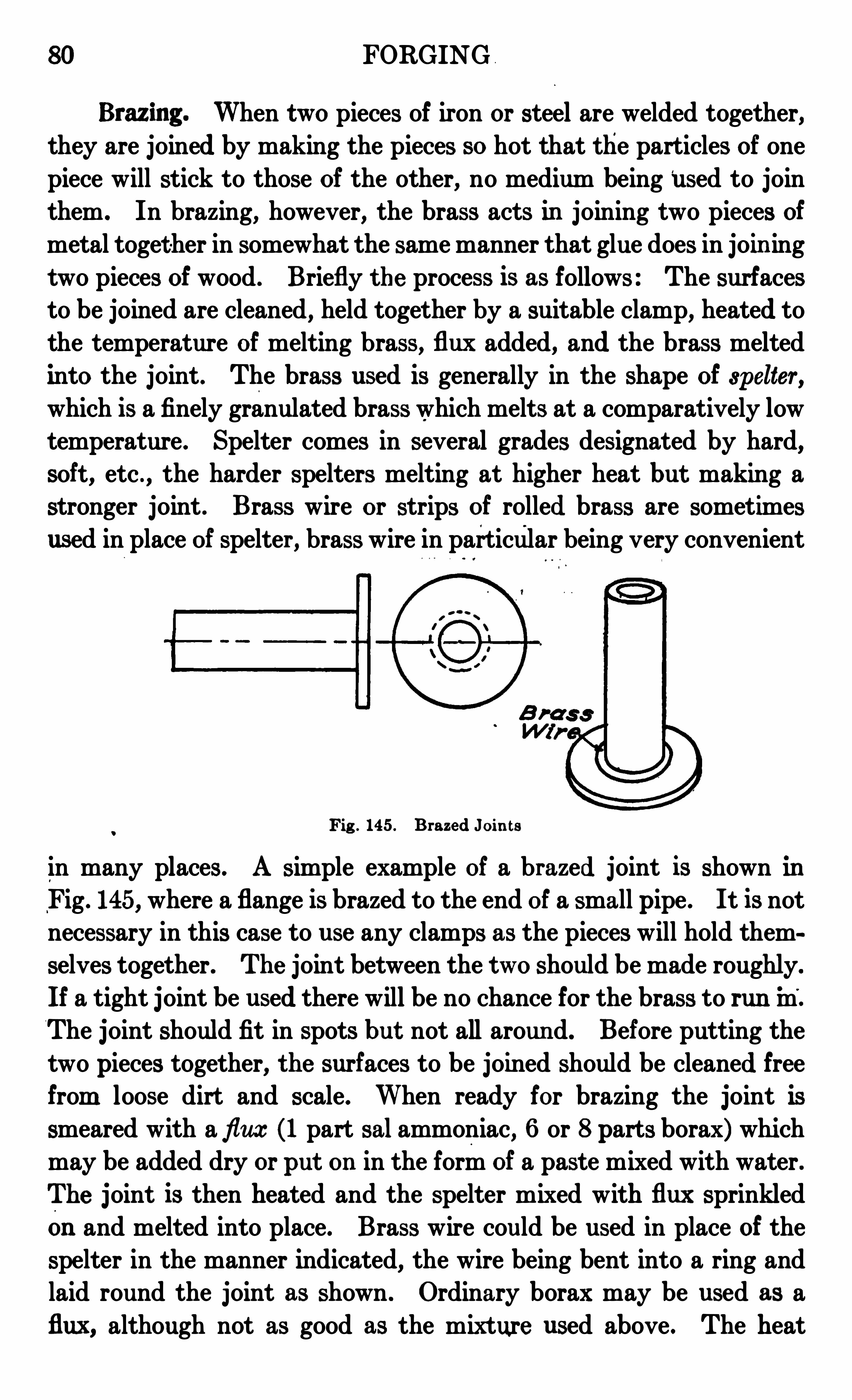
80 FORGING
Brazing . When two pieces of iron or steel are welded together,they are joined by making the pieces so hot that the particles of onepiece will stick to those of the other, no medium being
‘
used to join
them . In brazing, however, the brass acts in joining two pieces of
metal toget her in somewhat the same manner that glue does in join ing
two pieces of wood . Briefly the process is as follows : The surfaces
to be joined are cleaned, held together by a suitable clamp, heated tothe temperature of melting brass, flux added, and the brass meltedinto the joint . The brass used is generally in the shape of spelter ,which is a finely granulated brass which melts at a comparatively lowtemperature . Spelter comes in several grades designated by hard,soft, etc . , the harder spelters melting at higher heat but making a
stronger joint . Brass wire or strips of rolled brass are sometimes
used in place of spelter , brass wire in particular being very convenient
Fig . 145 . Brazed J oin ts
in many places. A simple example of a brazed joint is shown inFig . 145, where a flange is brazed to the end of a small pipe . It is notnecessary in this case to use any clamps as the pieces will hold them
selves together . The joint between the two should be made roughly.
If a tight joint be used there will be no chance for the brass to run m .
The joint should fit in spots but not all around. Before putting the
two pieces together, the surfaces to be joined should be cleaned freefrom loose dirt and scale. When ready for brazing the joint issmeared with aflux (1 part salammoniac, 6 or 8 parts borax) whichmay be added dry or put on in the form of a paste mixed with water .The joint is then heated and the spelter mixed with flux sprinkledon and melted into place. Brass wire could be used in place of the
spelter in the manner indicated, the wire being bent into a ring andlaid round the joint as shown . Ordinary borax may be used as a
flux, although not as good as the mixture used above . The heat

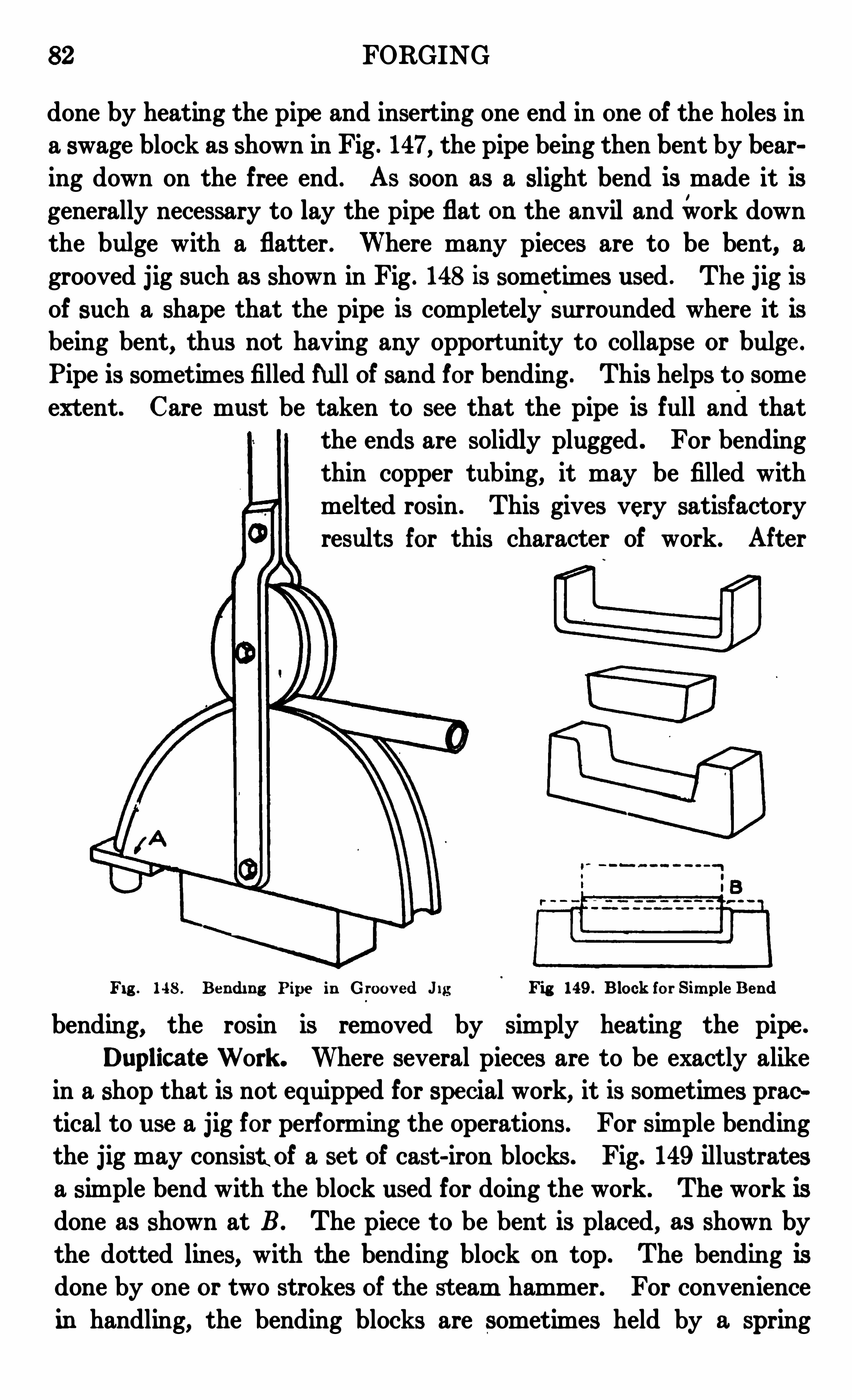
82 FORGING
done by heating the pipe and inserting one end in one of the holes ina swage block as shown in Fig . 147, the pipe being then bent by bearing down on the free end . As soon as a slight bend is made it is
generally necessary to lay the pipe flat on the anvil andwork downthe bulge with a flatter . Where many pieces are to be bent, a
grooved jig such as shown in Fig . 148 is sometimes used . The j ig is
of such a shape that the pipe is completely surrounded where it is
being bent, thus not having any opport unity to collapse or bulge .
Pipe is sometimes filled hi ll of sand for bending . This helps to some
extent. Care must be taken to see that the pipe is full and thatthe ends are solidly plugged . For bendingthin copper tubing, it may be filled with
melted rosin . This gives very satisfactory
results this character of work. After
Fig . 148 . Be ndin g Pipe in G roov ed J ig Fig 149 . B lock for Sim ple Bend
bending, the rosin is removed by simply heating the pipe .
Duplicate Work . Where several pieces are to be exactly alikein a shop that is not equipped for special work, it is sometimes practical to use a jig for performing the operations . For simple bendingthe jig may consist of a se t of cast-iron blocks . Fig. 149 illustratesa simple bend with the block used for doing the work . The work isdone as shown at B . The piece t o be bent is placed, as shown bythe dotted lines, with the bending block on top. The bending isdone by on e or two strokes of the st eam hammer. For convenience
in handling, the bending blocks are sometimes held by a spring
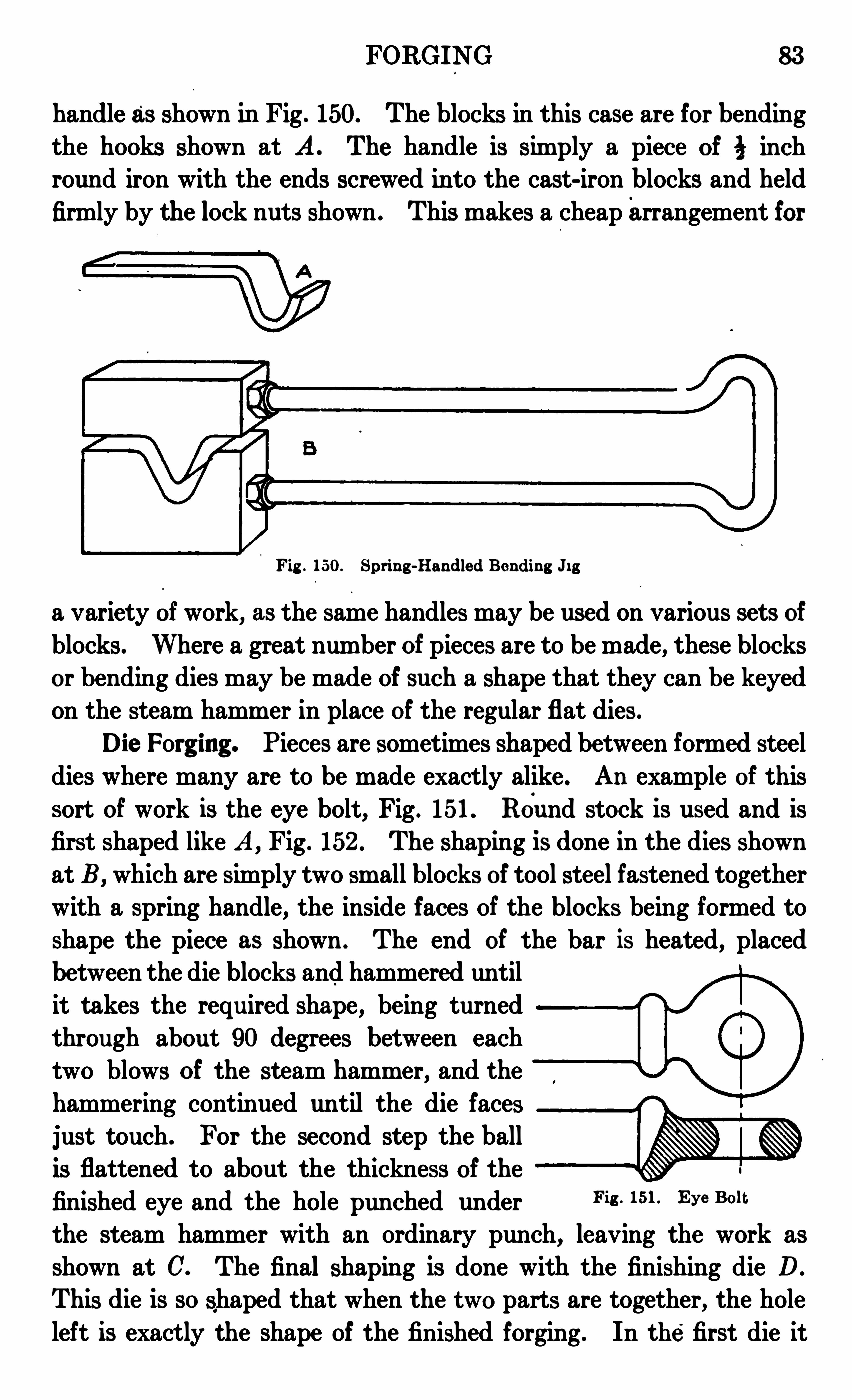
FORGING 83
handle as shown in Fig . 150. The blocks in this case are for bending
the hooks shown at A . The handle is simply a piece of 5 inchroun d iron with the ends screwed in to the cast-iron blocks and held
firmly by the lock nuts shown . This makes a cheaparrangement for
Fig . 150. Spring -Handled Bending J i g
a variety of work, as the same handles may be used on various sets ofblocks. Where a great number of pieces are to be made, these blocksor bending dies may be made of such a shape that they can be keyedon the steam hammer in place of the regular flat dies .
Die Forging . Pieces are sometimes shaped between formed steeldies where many are to be made exactly alike . An example of thissort of work is the eye bolt, Fig . 151 . Round stock is used and isfirst shaped like A , Fig . 152 . The shaping is done in the dies shown
at B, which are simply two small blocks of tool steel fastened togetherwith a spring handle, the inside faces of the blocks being formed toshape the piece as shown . The end of the bar is heated, placedbetween the die blocks and hammered untilit takes the required shape, being turnedthrough about 90 degrees between eachtwo blows of the steam hammer, and the
hammering continued until the die facesjust touch . For the second step the ballis flattened to about the thickness of thefinished eye and the hole punched under Fi8 - 151 Eye
the steam hammer with an ordinary punch, leaving the work as
shown at C. The final shaping is done with the finishing die D.
This die is so shaped that when the two parts are together, the hole
left is exact ly the shape of the fin ished forging . In the first die it
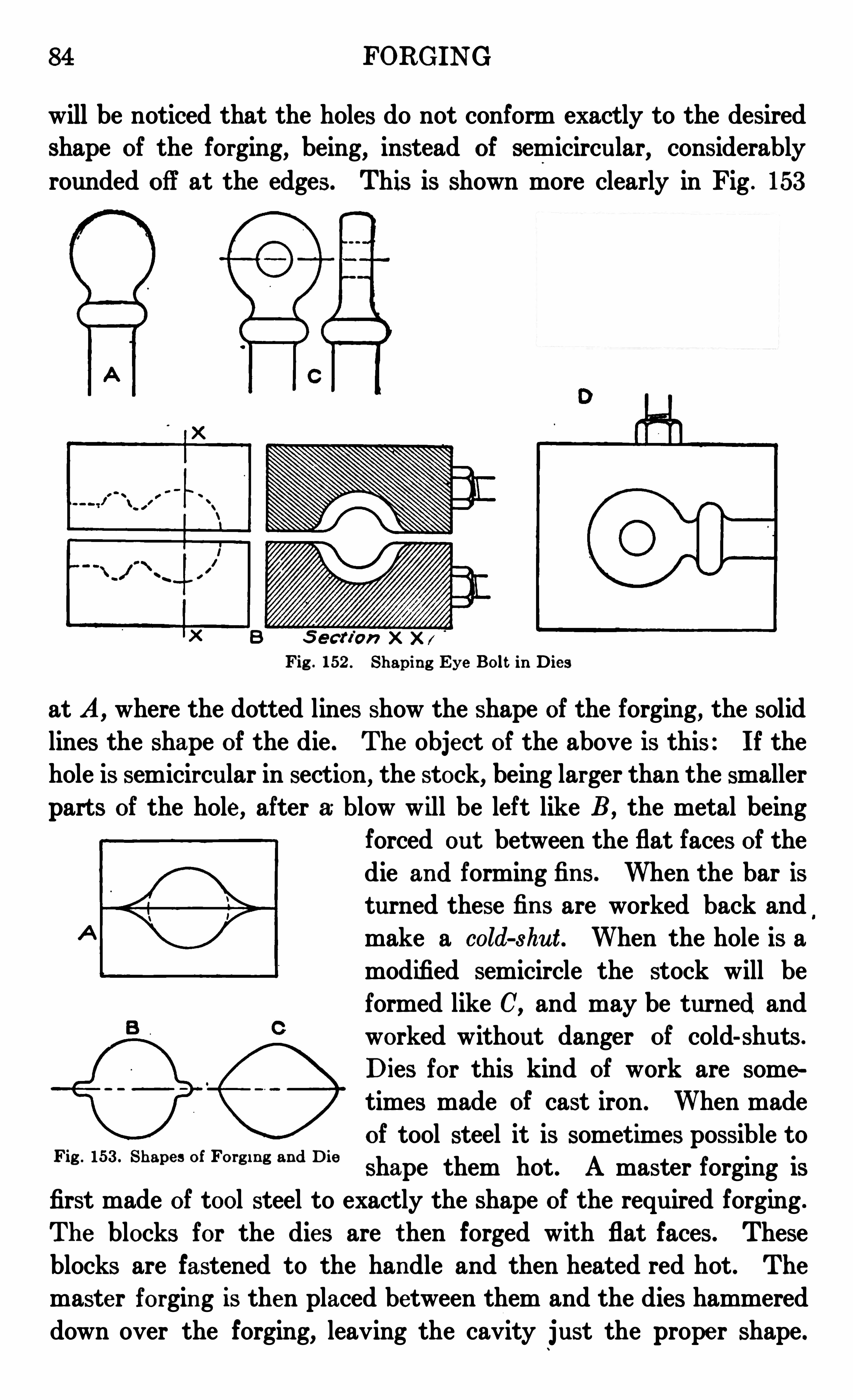
84 FORGING
will be noticed that the holes do not conform exactly to the desiredshape of the forging, being, instead of semicircular
,considerably
rounded off at the edges. This is shown more clearly in Fig . 153
Fig . 152 . Shapin g Eye Bol t in Dies
at A, where the dotted lines show the shape of the forging, the solidlines the shape of the die . The object of the above is this : If thehole is semicircular in section, the stock, being larger than the smallerparts of the hole , after a blow will be left like B , the metal being
forced out between the flat faces of thedie and forming fin s . When the bar isturned these fin s are worked back andmake a cold-shut . When the hole is a
modified semicircle the stock will beformed like C, and may be turned and
worked without danger of cold-shuts .
Dies for this kind of work are sometimes made of cast iron . When made
of tool steel it is sometimes possible to
shape them hot . A master forging is
first made of tool steel to exactly the shape of the required forging .
The blocks for the dies are then forged with flat faces. These
blocks are fastened to the handle and then heated red hot . The
master forgin g is then placed between them and the dies hammereddown over the forging, leaving the cavity just the prope r shape .
Fig . 153 . Shape s of Forg i n g and Die
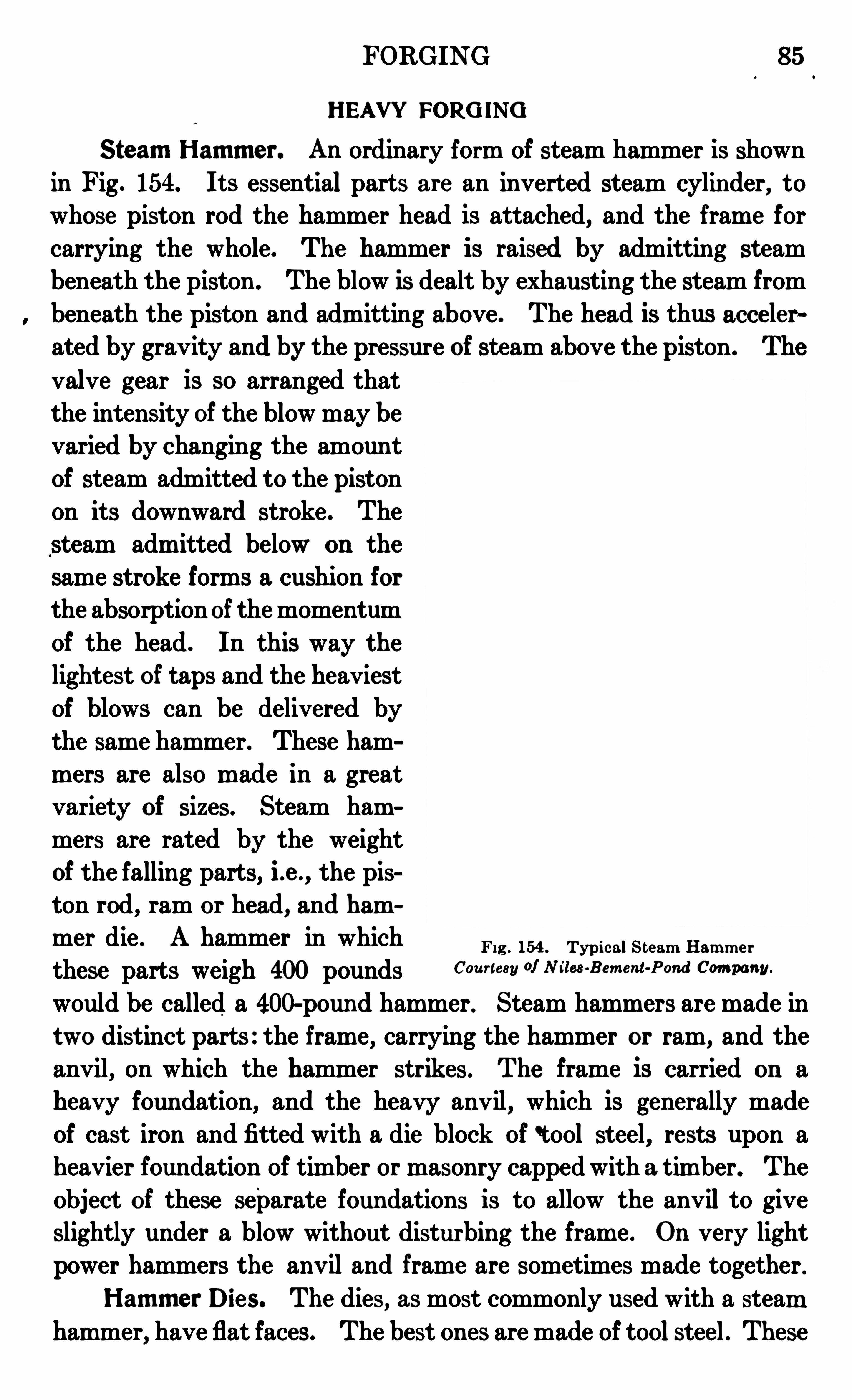
FORGING 85
HEAV" FORG ING
Steam Ham m er. An ordinary form of steam hammer is shown
in Fig. 154. It s essential parts are an inverted steam cylinder, towhose piston rod the hammer head is attached, and the frame forcarryin g the whole. The hammer is raised by admitting steambeneath the piston . The blow is dealt by exhausting the steam frombeneath the piston and admitting above . The head is thus acceler
ated by gravity and by the pressure of steam above the piston . The
valve gear is so arranged that
the intensity of the blow may bevaried by changing the amount
of steam admitted to the piston
on it s downward stroke . The
steam admitted below on the
same stroke forms a cushion for
the absorptionof the momentum
of the head . In this way thelightest of taps and the heaviestof blows can be delivered bythe same hammer. These hammers are also made in a great
variety of sizes. Steam ham
mers are rated by the weight
of the falling parts, i .e . , the pis
ton rod , ram or head, and ham
mer die . A hammer in whichF ig . 154 . TypicalS t eam Ham m e r
these parts weigh 400 pounds Cour tesy of N iles -Bem ent -Pond Com pany.
would be called a 400-pound hammer . Steam hammers are made in
two distinct parts : the frame, carrying the hammer or ram, and the
anvil, on which the hammer strikes . The frame is carried on a
heavy foundation, and the heavy anvil , which is generally madeof cast iron and fitted with a die block of ‘tool steel, rests upon a
heavier foundation of timber or masonry capped with a timber. Theobject of these separate foundations is to allow the anvil to giveslightly under a blow without disturbing the frame . On very light
power hammers the anvil and frame are sometimes made together .
Ham m er Dies. The dies, as most commonly used with a steamhammer, have flat faces. The best ones are made of tool steel . These
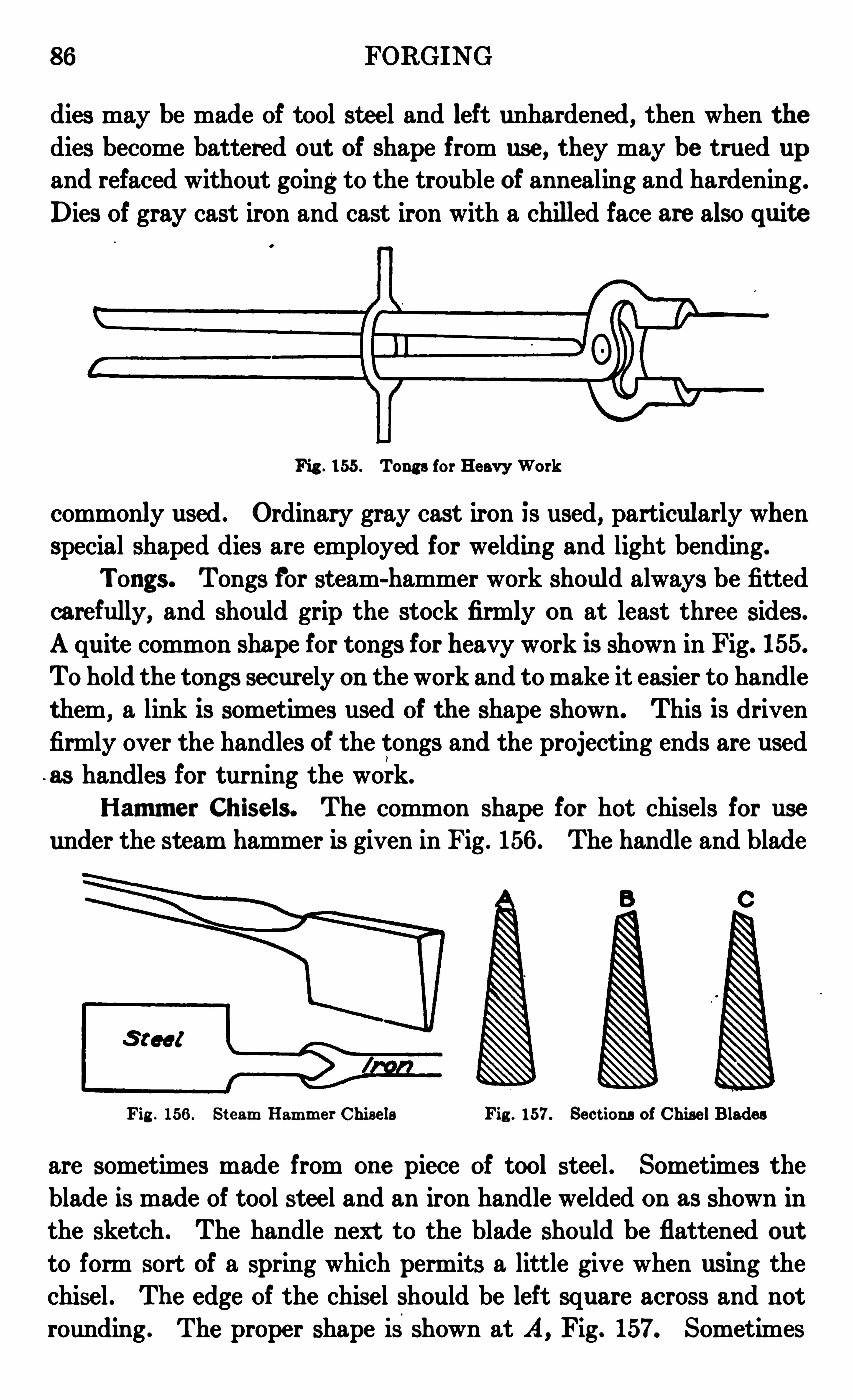
86 FORGING
dies may be made of tool stee l and left unhardened, then when thedies become battered out of shape from use , they may be trued up
and refaced without going to the trouble of annealing and hardening .
Dies of gray cast iron and cast iron with a chilled face are also quit e
Fig . 155 . Tongs for HeavyWork
commonly used . Ordinary gray cast iron is used, particularly whenspecial shaped dies are employed for weldin g and light bending.
Tongs. Tongs for steam-hammer work should always be fittedcarefully, and should grip the stock firmly on at least three sides .
A quite common shape for tongs for heavy work is shown in Fig. 155.
Tohold the tongs securely on the work and to make it easier to handlet hem, a link is sometimes used of the shape shown. This is driven
firmly over the handles of the tongs and the projecting ends are used
as handles for turning the work.
Ham m er Chisels. The common shape for hot chisels for use
under the steam hammer is given in Fig . 156 . The handle and blade
Fig . 156 . St eam Ham m er Chisels Fig . 157. Sect ions of Chise l Blades
are sometimes made from one piece of tool steel . Sometimes the
blade is made of tool steel and an iron handle welded on as shown in
the sketch . The handle next to the blade should be flattened out
to form sort of a spring which permits a little give when using thechisel . The edge of the chisel should be left square across and notrounding . The proper shape isshown at A, Fig. 157. Sometimes
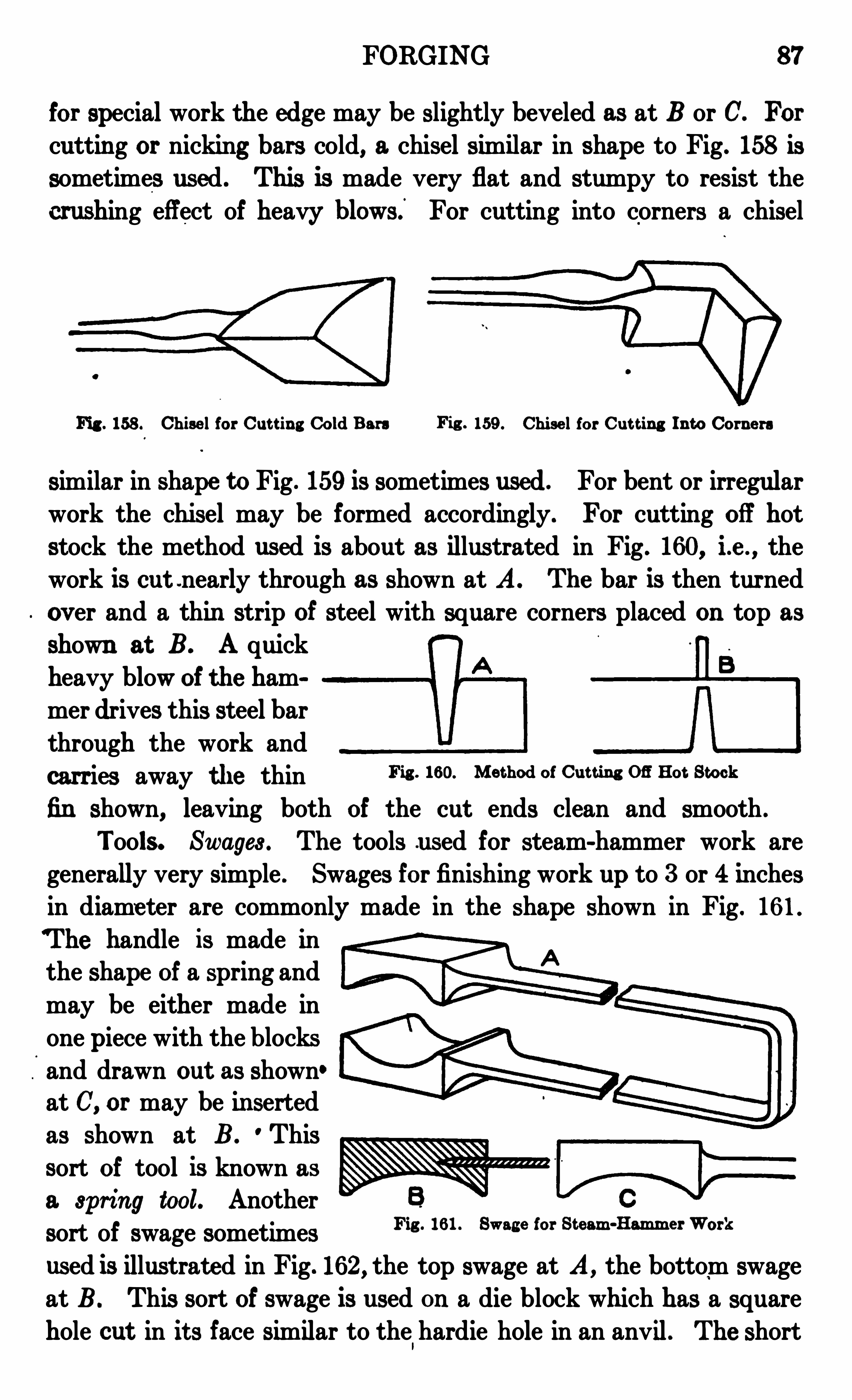
FORGING 87
for special work the edge may be slightly beveled as at B or C. For
cutting or nicking bars cold, a chisel similar in shape to Fig. 158 is
sometimes used . This is made very flat and stumpy to resist the
crushing effect of heavy blowsi For cutting into corners a chisel
Fig . 158 . Chise l for Cut t ing Cold Bars Fig . 159 . Chise l for Cut t ing In to Corne rs
similar in shape toFig . 159 is sometimes used . For bent or irregularwork the chisel may be formed accordingly. For cutting off hotstock the method used is about as illustrated in Fig . 160, i .e . , the
work is cut .nearly through as shown at A. The bar is then turned
ov er and a thin strip of steel with square corners placed on top as
shown at B. A quick
heavy blow of the hammer drives this steel barthrough the work andcarries away t he thin Fig . 160. Me t hod of Cut t ing on Hot Stock
fin shown, leaving both of the cut ends clean and smooth .
Tools. Swages . The tools used for steam-hammer work aregenerally very simple . Swages for finishing work up to 3 or 4 inchesin diame ter are commonly made in the shape shown in Fig. 16 1 .
T he handle is made inthe shape of a spring and
may be either made inone piece with the blocksand drawn out as shown°
at C, or may be in sertedas shown at B . Thissort of tool is known as
a spring tool. Anothersort of swage sometimesused is illustrate d in Fig. 162, the top swage at A, the bottom swage
at B . This sort of swage is used on a die block which has a square
hole cut in it s face similar to the hardie hole in an anvil . The short
Fig . 16 1 . Swage for St eam -Ham m er Work
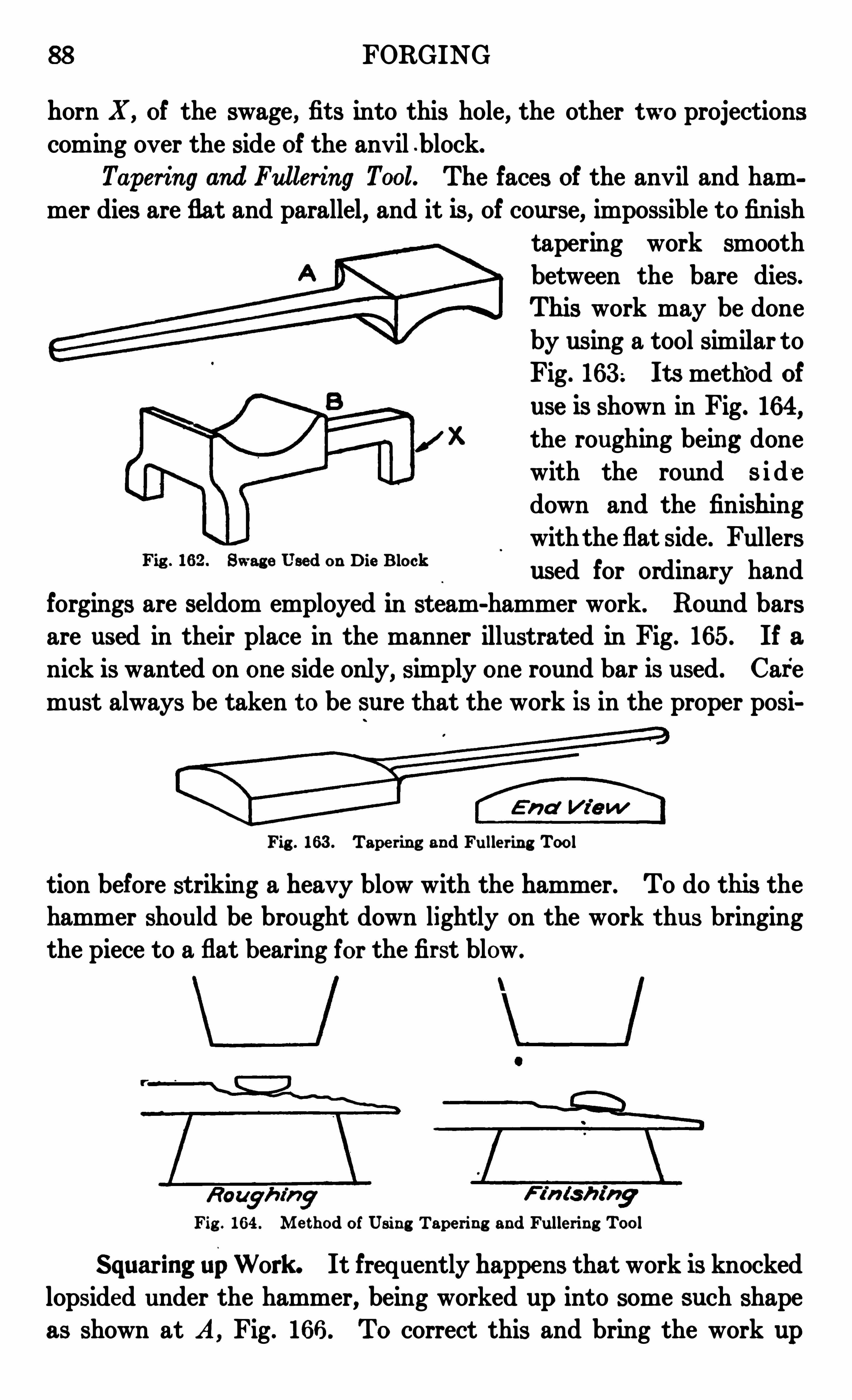
88 FORGING
horn X , of the swage, fit s into this hole, the other two projectionscoming over the side of the anv il b lock.
Taperin g and Fullering Tool. The faces of the anvil and ham
mer dies are flat and parallel, and it is, of course, impossible to fin ish
tapering work smooth
between the bare dies .
This work may be done
by using a tool similar toFig. 16 3 . It s method of
use is shown in Fig. 164,
the roughing being done
with the round s i dedown and the finishing
withthe flat side. Fullers
used for ordinary hand
forgings are seldom employed in steam-hammer work. Round barsare used in their place in the manner illustrated in Fig. 165 . If anick is wanted on one side only, simply one round bar is used. Care
must always be taken t o be sure that the work is in the proper posi
Fig . 16 2 . Swage Used on Die Block
Fig . 16 3 . Tape ring and Fulle rin g Tool
tion before striking a heavy blow with the hammer. To do this thehammer should be brought down lightly on the work t hus bringingthe piece to a flat bearing for the first blow .
Fig . 16 4 . Me thod of Usin g Tapering and Fullering Tool
Squaring upWork . It frequently happens that work is knockedlopsided under the hammer, being worked up into some such shapeas shown at A , Fig. 16 6 . To correct this and bring the work up

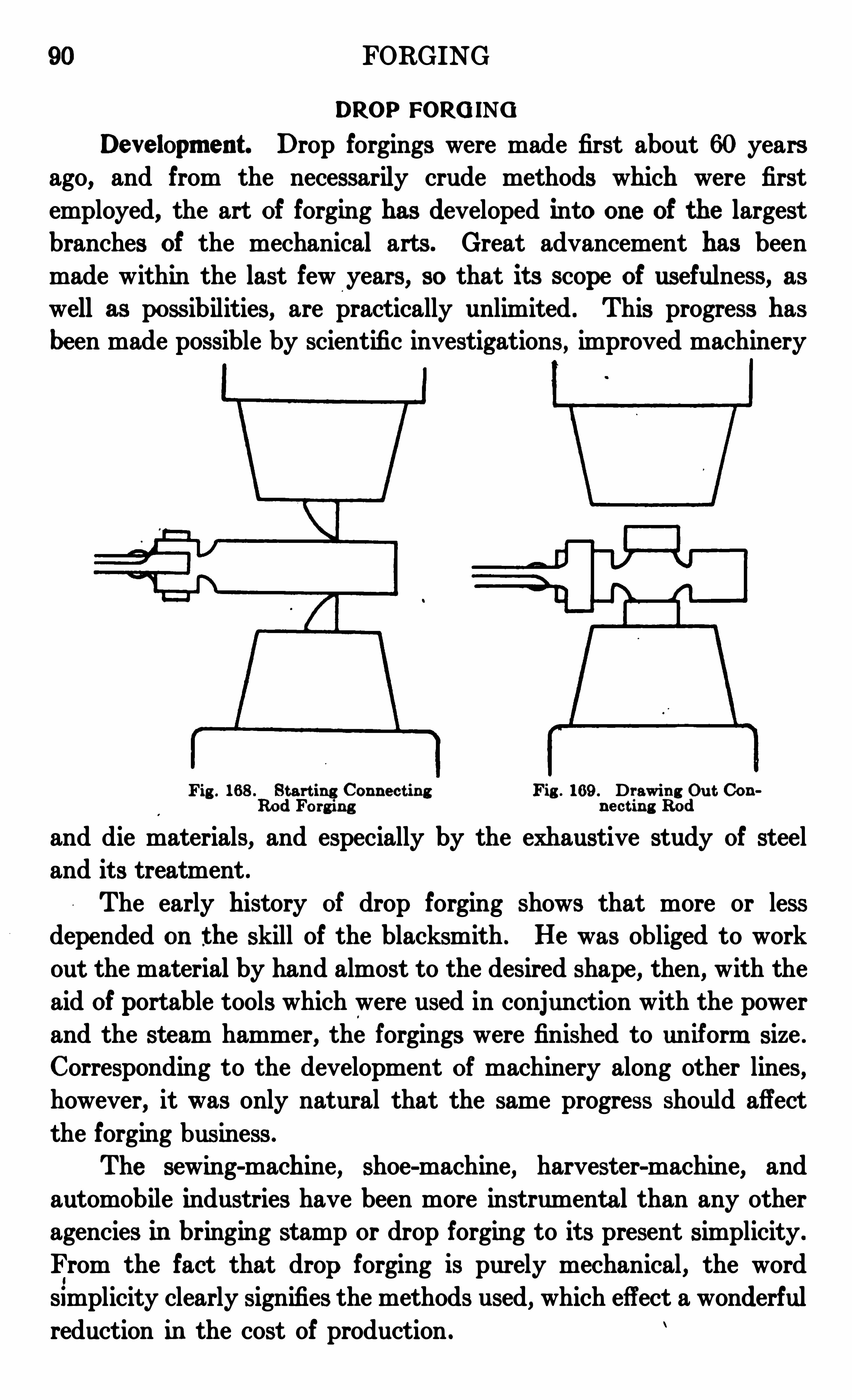
90 FORGING
DROP FORG INGDevelopm ent . Drop forgings were made first about 60 years
ago, and from the necessarily crude methods which were first
employed, the art of forging has developed into one of the largestbranches of the mechanical arts . Great advancement has beenmade within the last few years, so that it s scope of usefulness, aswell as possibilities, are practically unlimited . This progress hasbeen made possible by scientific inv estigations , improved machinery
Fig . 16 8 . Star t ing Conn ect in g Fig . 16 9 . Drawin g Ou t ConRod Forg in g n e ct in g Rod
and die materials, and especially by the exhaustive study of steel
and it s treatment .
The early history of drop forging shows that more or lessdepended on the skill of the blacksmith . He was obliged to workout the material by hand almost to the desired shape, then, with the
aid of portable tools which were used in conjunction with the powerand the steam hammer, the forgings were finished to uniform size .
Corresponding to the development of machinery along other lines,however, it was only natural that the same progress should affect
the forging business .
The sewing-machine, shoe-machine, harvester-machine, and
automobile industries have been more instrumental than any otheragencies in bringing stamp or drop forging to it s present simplicity .
From the fact that drop forging is purely mechanical , the word
simplicity clearly signifies the methods used, which effect a wonderfulreduction in the cost of production .
FORGING 9 1
Forgings can be made in greater variety, and those that are
most diffit or even impossible to finish over the anvil are madewith apparent ease under the drop hammer. There seems to be no
Fig . 170. TypicalDrop Forg e ToolsCourtesy of J . H . William s and Com pany, Brooklyn . Ncw "ork
limit to design, and the best feature of all is that the work is donemore accurately, imparting a finish to every detail .
From the fact that to a great extent drop forgings have replaced
malleable-iron castings, there is no doubt that n ew fields have opened
to create a demand for forgings greater than would have developed
if the mechanical world had been obliged to depend on the former
methods of hand forging .
92 FORGING
Proce ss . Drop forgings are made by the use of dies . These
dies are made in two parts and into them are sun k exact impressions
of the parts wanted . On e-half of the die is securely attached to
the base of the hammer, the upper part being fastened to the ramwhich travels vertically between two guides. By continually rais
ing and droppin g this ram, the heated metal which is held betweenthe two parts of the die is forced into the impressions cut into the
dies . In forcing the metal into the die, there is a small amount
called the flash, which overflows the impression . This flash isremoved by a heavy turning press to which are attached dies cut
to the correct size and shape to finish the forging .
In the process of forging, a thin scale is formed on the forging
proper . This scale has to be removed in order that the finished
F ig . 171 . S t eps in Forg in g Au tom ob ile Par t
forging may be clean and smooth, and this is accomplished by apickling process or by sand blasting . The pickling process consistsof dipping each forging in a strong solut ion of acid which eats offall the scale .
Drop Ham m er. To meet the requirements of an up-to—date
forge shop, either of the type s shown in Figs. 19 or 13 3 are suit
able . They are almost indestructible machines , the capacity of
which seems to be limited only by the ingenuity of the die sinker .The bases are of cast iron and in one piece, a we ight ration ofbetween base and hammer be ing adopted . If the hammer we ighs
pounds the base would we igh pounds .
Specim ens of Drop Forg ing . The light work illustrated in
Fig . 170 is a group of drop-forged tools made by J . H . Williams and


94 FORGING
are controlled by definite laws, and, with steels containing a high percent of carbon with other alloying elements, the operation of heattreating is a very delicate one, such that a slight variation even withthe best of steel would give very poor results .
The proper or m ost practical heat treatment s forthe varioussteels have been determined by their manufacturers before placingthem on the market, and the directions given should be carriedout . To make one heat treatment which is satisfactory for all
steels is impossible, so the manufacturers’ recommendations should
be followed .
Factors in Heat Treatm ent . Before going into the details of
heat treatment, it is necessary to know some of the properties whichent er into the steel, so as to understand the treatment more fully .
Steel , as we obtain it from the market at the present time, is a
combination of iron and carbon and some impurities such as sulphur
and phosphorus, though to produce particular results, these latter
sometimes are added together with many other elements such as
manganese, silicon, nickel, chromium, tungsten, molybdenum , vana
dium , etc . , either accidentally or purposely included for their effects .
Carbon PrincipalDeterm in ing Elem en t . The principal elementdetermining the properties of crucible tool steel is carbon . Pure
iron is very nearly as soft as copper, while, with an increasing amount
of carbon, stee l becomes harder and stronger, but less ductile, untila carbon cont ent of about pe r cent is reached . Steel of this
carbon content is the one mostly used for common m achine-shop
tools . Abov e this point other additions of carbon result in not only
increasing hardness but also increasin g brittleness .
Steels most generally use ful in the hardened state have carbon
from per cent to per cent, between which points the hardness is sufficient for almost every purpose . Steel containing carbon
up to about per cent carbon generally is called in got iron ; thatfrom per cent to per cent is m achin ery steel; that from
per cent to per cent is crucible m achinery steel; and that from
per cent up is tool steel. Steels containing on ly carbon with
small quantities of silicon , manganese, and the always present
sulphur and phosphorus, generally are called straight carbon steels .
Those owing their peculiar properties to some ingredients other than
carbon are called alloy steels .
FORGING 95
Cri tical Tem perature in Harden ing . For every grade of steelthere is a so-called cri tical temperature or point of transformation.
This temperature varies according to the various compositions and
the carbon content of the steels. The phenomenon probably ismore marked in the alloy steels than in straight carbon steels . On
heat ing through the critical temperature or critical range the steeltakes on hardness when cooled quickly, the hardness being according
to it s carbon content and the quickness of cooling.
When working a n ew steel for the first time, a blacksmith shouldacquaint himself with the particular hardening temperature of the
material, and in practice he should be very sure not to vary or
exceed it much .
Variation of Struc ture . To harden, steel must be heated to, ora little above, this critical temperature and be cooled sudden ly, thepercentage of hardnesswhich the steel is capable of assuming beingproportional to the speed of cooling— the quicker the cooling, theharder the steel . If heated below the critical temperature, even
though quenched, stee l does not take on hardness, but remains softor partly annealed. On heating through the critical temperature,the previously existing structure is obliterated or tends to becomeobliterated, and up to this temperature, or just above it, is whensteel possesses the finest structure which it is capable of assuming.
The rate of obliteration of the old struct ure in a piece of steel dependsupon the temperature reached and upon the time the steel is maintained at that temperature, the change proceeding more rapidly
with increase of temperature . So, with the obliteration of the oldstruct ure, a n ew st ructure begins to grow, and it s size increases withth e and temperature, but more rapidly with increase of tempera
ture than with increase of time at a lower temperature .
Once heated above the critical point and having reached the heat
of hardening, steel may be cooled slowly to a certain degree and not
lose it s power of hardening if cooled suddenly. But to so let steelcool is very bad practice, because, during slow cooling, the microconstituents of the steel tend to separate, as the coarser appearanceshows on breaking the steel for the purpose of examining the grain .
Below the critical temperature, slowness of cooling has no effect on
the size of grain, but leaves the steel soft .
A bad practice sometimes followed by users of steel is to break
96 FORGING
off a bar of steel as it comes from the storehouse, examine the fracture, and if the steel shows a coarse grain, to condemn the steel .
The appearance of the grain in the steel depends on it s heat whenit left the hammer or the rolling mill ; if the heat were high, it would
show a coarse grain ; if the heat were low, it would show a closer fin e
grain. If the steel is heated t o the proper hardening point after
ward,the grain is the same, and there is no difference in it s physical
properties.
PROCESSES OF TREATING
Different Purpose s. Steel is heated for four distinct purposes
(1) forging ; (2) annealing ; (3 ) hardening ; and (4) tempering.
HEAT ING FOR FORG ING
Un iform Heat ing Essential. In the first place, when steel is to
be heated in a blacksmith forge, a clean deep fire is necessary for
uniform results . If the fire is shallow, the steel oxidizes. The
trouble in a forge fire usually is un even heat, either too low or too
high. Uneven heating causes strains from which trouble may resultafterward in the form of
'
fire cracks when tools are being hardened .
It is essential that a piece of steel to be forged should be heated un iformly throughout it s section, because if it is hot on the surface, and
the interior is not yet up to heat, working it may break the centertransversely, while if it is hot in the center and cold on the sur face,
generally the small surface cracks . Heat should be raised slowlyand uniformly and should not be higher than is necessary for thework required. If through carelessness the heat rises t oo high, thetemperature of the steel should be allowed to drop below the criticalpoint and then should be raised to the proper point to avoid cracking
the steel .
Trouble wi th Quick Heatin g. Suppose the piece to be forged
has been put in a very hot fire and forced as quickly as possible tohigh yellow heat . If so treated, the outside will be soft and in goodcondition for forgin g, while the center parts will be not more than red
hot. The highly heated soft outside will hav e very little tenacity,that is to say, this part will be so far adv anced toward fusion thatthe particles will slide easily over on e another, while the inside parts
will be hard and possessed of high tenacity, and the part iéles will
not slide 80 easily over one another.

98 FORGING
and brittle . Soaking does steel more injury than any bad practice
known to the most experienced .
S im ple Test of Heat Effect. A very simple method by which
any worker in steel should be able to obtain a satisfactory test for
the effect of heat upon steel is to t ake a bar of steelof ordinary size,say about 1 inch by inch, heat 6 or 8 inches of one end to a low red
heat,and nick the heated part all aroun d the bar at intervals of v}
to of an inch, until eight or nine notches are cut . Next place the
end of the bar in a very hot fire and heat it white hot until it nearly
melts at the ext reme end, leaving the other parts enough out of the
fire so that they are heated by conduction . Le t the end remain in
the fire until the last piece nicked is not quite red hot, and the nextto the last barely red hot . Now, if the pieces are numbered from 1
to 8 , commencing at the outer end, No. 1 is whit e hot, No. 2 is
yellowish white , No. 3 is high yellow, No . 4 is yellow or orange hot,No. 5 is high red hot, No. 6 is red hot, No. 7 is low red hot, and No . 8
is black. As soon as
'
heat ed, let the bar be qii en ched in cold water
and kept there until quite cold.
After cooling , the bar should be wiped dry carefully, especially
on the notches . An examination by the file reveals the following,if high-carbon steel has been used : piece No . 1 scratches glass ; Nos.
2 , 3 , and 4 are excessively hard ; Nos . 5 and 6 are well hardened ;No. 7 is about hard enough for tap steel ; No. 8 is not hardened .
Now break off the pieces over the corner of the anvil— they shouldbe caught in a clean keg or box to keep the fracture clean and bright ;No. 1 is found to be as brittle as glass with a coarse yellowish and
very lustrous grain ; No. 2 is found to be nearly as brittle and notquite so coarse or yellow ; and so on, until Nos . 6 and 7 are reachedthese are very strong with a finer grain ; No. 8 is unhardened and
shows the original grain of the bar .
ANNEALING
General Proce ss. Steel is annealed for two d i stinct reasons
(1) t o soften the metal for machinin g ; and (2) to relieve the strainsin the steel caused by hammering or by bending in the mill or theforge shop .
The process is heatin g, and then slow cooling . The steel shouldbe heated a lit tle above it s criticaltemperature ; for if heated below
FORGING 99
this temperature, all strain in the steel is not released and warping
takes place when the hardening heat is reached .
As is noted under Hardening” , the rapidity of cooling determinesthe final hardness of the steel and if the steel is cooled very slowly it
will be left very soft ; while if cooled rapidly, it will be left hard.
This difference in the cooling time is the only difference between it shardening and it s annealing. Both should be done from the same heat .
Annealing H igh-Spe ed Steel. For good results in annealinghigh-speed steels, the following rules must be observed
(1) Heat should be as near to 1500degrees as possible . If the
heat reached were'
only 1250 degrees, the steel would retain it soriginal hardness. If heated to 1700 or 1800 degrees, the steelwould be soft but would show brittleness with a coarse grain . If
there were a further increase in heat, the steel would become hardand unannealed, and the fracture from this temperature would be
dull and lifeless and would show a marked decarbonization .
(2) The steel should be packed in boxes or pipes, in powderedcharcoal or lime, and sealed with fire clay, and in packing it shouldbe seen that no part of the steel comes in contact with the box orpipes. If the parts come together, that does no harm .
(3 ) The heatin g should be started '
slowly and there should begiven plenty of time for cooling . If a forge fire. is used for annealing,leave the box in the fire and le t it remain until cold, or if the forgefire has to be used for other purposes, the box can be put in some
place out of the way and then cov ered with ashes, lime , or better
still, charcoal . In all cases a slow cooling is n ece ssary . If a furnace
is used , heat slowly to full red or about 1500° Fahrenheit . Hold the
heat long enough to be sur e of penetration through the box and the
steel to be annealed, and then shut off the heat and let the steel cool
off with the furnace .0
Water Method. Another method is water annealing . If only a
few pieces are to be annealed for quick use , heat the steel to between
750°and 800
° Fahrenheit, plunge it into water which has been
heated to about 150° or 160° Fahrenheit, and allow it to remain
until it becomes the same temperature as the bath. The heating
should be slow and uniform for good result sf To heat rapidly will
cause internal strains and is apt to in crease the risk of rupture whenthe steel is plunged int o the wat er.
100 FORGING
This last method is not to be recommended as it is not effective
on all high-speed steels.
Annealing Copper and Brass. The treatment of these two
metals consists in heating them to a red heat and then cooling
suddenly in cold water. When Copper or brass is hammered to anyextent
,it becomes hard and springy, and , if it has to be further
worked,it must be annealed or softened, otherwise it is almost sure
to split .
HARDEN ING
Purpose . Hardening generally is understood to mean the heat
in g of a piece of steel to a certain temperature and plunging it into a
bath of some kind for the purpose of cooling it . While this defin i
tion holds good for most steels, a few alloy steels now on the market
rev erse this method ; steels kn own as air-hardened or self-hardening
obtain their hardest and toughest state by a slow cooling process
rather than by a sudden on e .
Two reasons may be mentioned for the desirability of hardening
steel : (1) to giv e the steela .cut t in g edge such as is required for allcutting tools ; and (2) to alter the static strength and dynamic
qualities of the metal so it will give the best results for the moving
parts of machinery.
Essen t ialFeatures. To harden steel , therefore, it is requisite
that the heating produce a change in the structure, and that the
quenching which follows the heating retain the whole or a part of
the elements produced by this change . It is therefore necessary, asin annealing, that the temperature of the steel be raised to
‘a pointslightly above the point of transformation .
Poin t of Transform ation . As the point of transformation varieswith the different ingredients which are alloyed with steel , it is
necessary t o find out where this poin t is in the steel to be hardened .
A steel may be heated to 13 00° Fahrenheit, which is above thepoint of transformation in some steels, and no change in structure
may occur ; therefore no result in hardness is obtained. If this samepiece is heated to 1450° Fahrenheit
,which may be considered the
point of transformation in this piece, the intermolecular transforma
tion which consists of the passage of the carbon from the combinedinto the dissolved state takes place, and the steel assumes the hardeststate possible, if properly cooled .

102 FORGING
Liquid Baths . The liquid baths commonly used for heatingsteel preparatory to hardening are molten lead, cyanide of potassium,
barium chloride, a mixt ure of barium and potassium chlorides and
other metallic salts.
Anyone using any of these different baths cannot be too carefulin preventing an accident . If there is ever so little moisture of anykind on the tool to be immersed; it causes the molten liquid to flyin all directions . Before putting any tool into the bath, be sure
that it is perfectly dry . The safe method is to pre-heat all tools
before immersing them .
Lead at any heat above 1200° Fahrenheit giv es off a slight vaporwhich is poisonous . Cyanide of potassium should be carefully used ,as it is a‘virulent poison . The furnaces for heating these liquid baths
should be equipped with hoods to carry away the fum e s. It is avery good idea to put powdered charcoal on t op of the molten liquid
as charcoal acts as a purifier .
Harden ing Bath. As it is necessary to maintain the steel inthe state it was at the mom ent quenching began, the quenching bathis a very important part of the process of hardening . The betterthe bath, the more nearly perfection is attained .
Various baths are used for coolin g steel when hardening, on
account'
of the different rates at which they cool the heated metal .
An oilbath is used when the steel is wanted tougher and not execssiv ely hard, as the oilcools the steel more Slowly than water . Brine
or an acid bath is used when the steel is wanted very hard, as theyabsorb heat more rapidly than water . For excessively hard workmercury or quicksilve r is sometimes used, as it absorbs the heat v eryrapidly.
In the hardenin g of steels, the influence of the bath dependsupon it s temperature, it s mass, and it s nature, or , to express this in
another way, upon it s specific heat, it s conductivity, it s volatility,and it s viscosity . With other things equal, the lower the tempera
ture of the bath, the quicker the metal cools and the more pronoun ced is the hardening effect . Thus water at 60 degrees makes
steel harder than does water at 150 degrees, and, when the bath isin constant use , the first piece quenched will be harder than thetwentieth, owing t o the rise in the temperature of the bath. There-3
fore, if uniform results are to be obtained, the bath must either be

FORGING 103
of a very large volum e or be kept cool by some mechanical means ;in other words, the bath must be kept at a constant temperature .
A bath consisting of a liquid which volatilizes easily at thehighest temperature it reaches, from plunging the metal into it,forms a space filled with vapor around the steel which retards the
cooling action of the liquid . Motion of the bath throws off this
vapor, as it brings the liquid in contact with the metal and tends toequalize the temperature. To agitate the piece to be hardened givesbetter results than trusting to the volatility of the bath, as it is
more energetic in distributing the vapor.
Q uenching Tanks. Essen tials . The main point t o be consid
ered in a quen chin g bath as mentioned before , is t o keep it at a un i
Fig 175 . Com m on Wat e r Fig . 176 . Double Wat er or Fig 177 . Oil uen hior Brin e Tank Brin e Tank Tan i?
0 ng
form temperature so that the successiv e pieces quenched will be sub
ject ed to the same heat. The next consideration is to keep the bathagitated, so that it will not be of different temperatures in different
places. If thoroughly agit ated and kept in motion as in connectionwith the tank shown in Fig . 176 , it is not ev en necessary t o keep thepieces in motion, as steam is not likely to form around the piecesquenched .
Com m on Tank. In Fig . 175 is shown a common water or brinetank . In this case, the wat er or brine is pum ped from the storagetank and returned to it continuously. If the storage tank containsa large volume of water, there is no need of special mean s for cooling .
The bath is agitated by the force with which the water is pumped
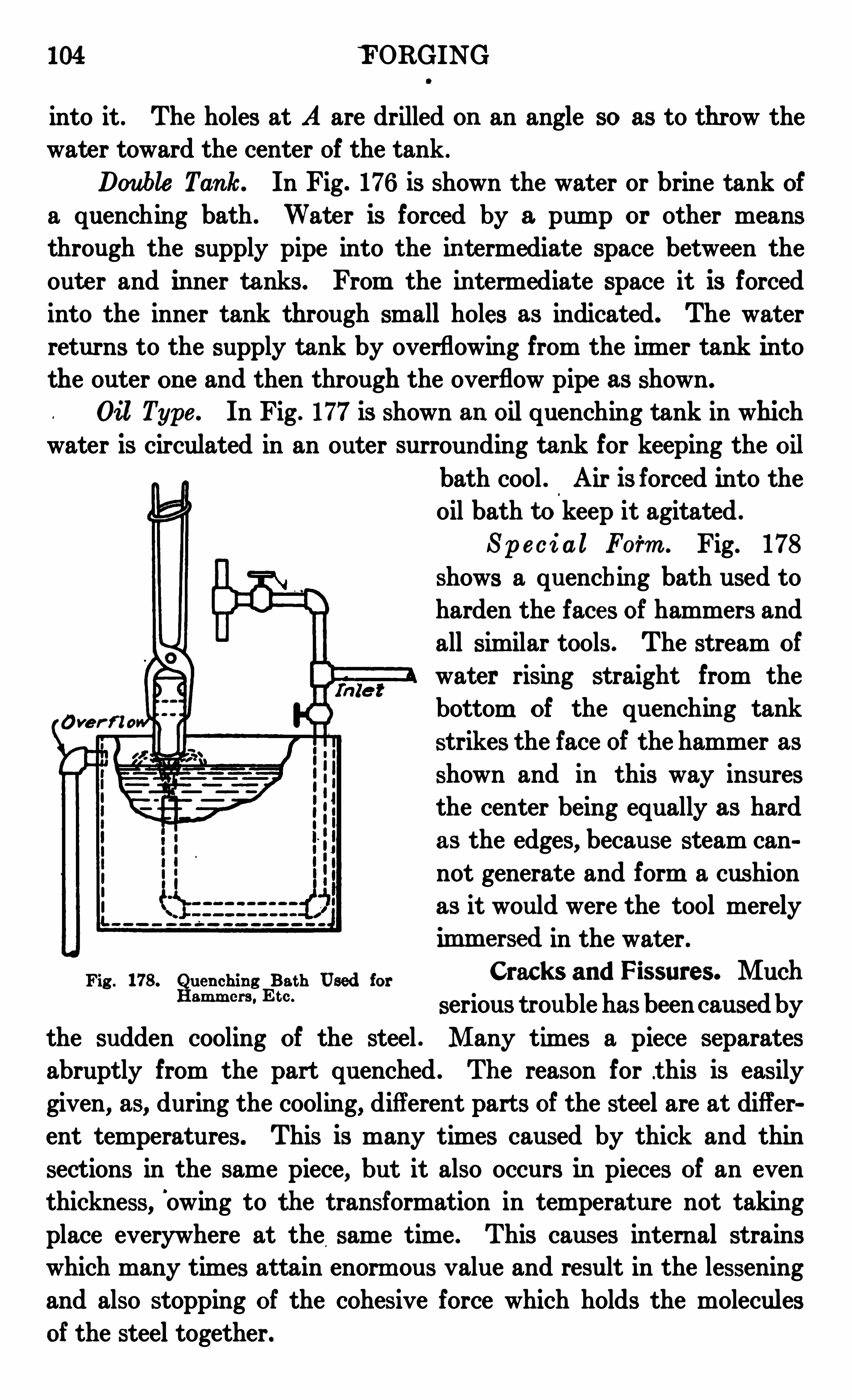
104 F ORGING
into it . The holes at A are drilled on an angle so as to throw thewater toward the center of the tank .
Double Tank. In Fig. 176 is shown the water or brine tank ofa quenching bath . Water is forced by a pump or other meansthrough the supply pipe into the in termediate space between the
out er and in ner tanks . From the in termediate space it is forced
into the inner tank through small holes as indicated. The water
returns to the supply tank by overflowing from the irmer tank intothe outer on e and then through the overflow pipe as shown.
Oil Type . In Fig . 177 is shown an oilquenching tank in which
water is circulated in an outer surrounding tank for keeping the oilbath cool . Air is forced into the
oil bath to keep it agitated .
Spe c i al Form . Fig. 178
shows a quenching bath used to
harden the faces of hammers and
all similar tools . The stream of
water rising straight from the
bottom of the quenching tank
strikes the face of the hammer asshown and in this way insuresthe center being equally as hard
as the edges, because steam can
not generate and form a cushion
as it would were the tool merely
im m a sed in the wat er .
Fig . 178. Q uen ching Bath Used for Cracks and Fissures. MuchHam m e r“ Em
serious troublehas been causedby
the sudden cooling of the steel . Many times a piece separates
abruptly from the part quenched . The reason for t his is easily
given, as, during the cooling, different part s of the steel are at different temperatures . This is many times caused by thick and thin
sections in the same piece, but it also occurs in pieces of an even
thickness,'
owing to the transformation in temperature not takin g
place everywhere at the same time . This causes internal strainswhich many times attain enorm ous value and result in the lessening
and also stopping of the cohesive force which holds the molecules
of the steel together.
Ove r t ?o

106 FORGING
be employed— something that possesses strength and resistance towear, and still conforms with standard practice of design regarding
the proport ions of parts. Such problems have come and have tobe met by the manufacturer and the mechanic ; they constitute the
problem of caseharden ing . It is not a n ew subject but is on e thatis not well understood and not always easy to control . This stat e
ment is justified by the diversity of opinion among different inv estigators in regard to the fundamental principles underlying the processof casehardening.
Pr inciples of Process. The process consists, as the name
implies, of forming a case of high carbon, which is capable of hardcuin g a surface of a low-carbon steel or wrought iron which in itselfhas not the property of hardness . The prevailing theory is based
on the followin g principles .
(1) The steel to be carburized must be placed in contact withcarbonaceous material .
(2) The high temperature at which the steel and the carbonaceous material is heated gasifies the carbon (if in a solid state) and
opens the pores of the stee l, allowing the gaseous carbon to penetrate.
(3 ) The penetration is aided if the gas is under pressure andin the presence of nitrogenousmatter acting as a carrier of the carbon.
Carbon izing Materials. The most important factor involved in
casehardening is the carbonizing material, for upon this dependsquality of case and un iformity of product . The great difficulty at
the present time is to obtain a definite uniform result, and to duplicate it at will . Many investigators are engaged in the solution ofthis problem which eventually will be solved by the discovery of areliable carbonizing material .
Old Process . In the older proce ss, charred organic matter
such as wood charcoal, charred leather, bone, horn, and the likewas used for packin g. Charred leather being rich in n itrogen gavea very good result, but leather scrap became useful for other purposes, thus becoming un available for carbonizin g. Granulated bone
was next resorted to and is used ext ensively yet, but , owing to it shigh phosphorus content, it is apt t o make parts brittle, and it
should be avoided on small parts. Charcoal does not seem t o find
much favor, although it is fully as efficient as bone if properly
prepared.
FORGING 107
Opposing Factors . Allof the materials mentioned are more orless unreliable for producing the desired effect on the steel . The
question then arises, What would constitute a re liable material?Before replying direct ly, there must be considered the followingfactors which hinder the carburization of the steel by bone, charcoal,or similar prepared compounds.
(1) Unequal heating of the steeldue to the manner of packing.
I t takes considerable time for heat to penetrate to the center containing the steel and packing ; consequently, the parts near the wallsof the crucible are heated sooner, and carbonizing begins earlier.
(2) Unequal composition of materials for packing causingv ariation in the amount of gas, and, therefore, unequal pressuregenerated in different sections of the crucible or packing box . To
obviate this trouble, a packin g material of perfectly uniform composit ion and high conductivity should be used . It should liberat ecarbon freely, yet not faste r than the steel can absorb it . Steelabsorbs carbon at certain rates depending on the temperature ; highheat gives faster penetration . If an excess of carbon is liberated,the surface of the steel becomes supersaturated with carbon, the
result being a brittle structure . The case should not be more than
from per cent to 1 per cent carbon, which is generally the resultif proper heat and good carboniz ing material are used . The packingmaterial should be free from sulphur, especially if moisture is present,for sulphur acidifies moisture, and the combined effect produces ascaled pitted surface .
Com pounds . There are a number of casehardening compounds
on the market claiming one or more of the ideal characteristics . Ingeneral these compounds consist of : carbon, volatile matter and
hydrocarbon,nitrogen
, ash, sulphur, and phosphorus. They are
likely to contain silica, alumina, lime, ammonia, and carbonate .
Use of Crucible . Packing . The parts to be casehardened
should be placed in the crucible in such a way that none of them
may come in contact with it,for otherwise the result would be soft
spots ; there should be a space of at least 1 inch from the wall of the
crucible and about 5 inch between the parts.
The packin g material should be well tamped down so as to leave
no open space . This is a very important and necessary precautionwhich must be observed to obtain a satisfactory result . After heat
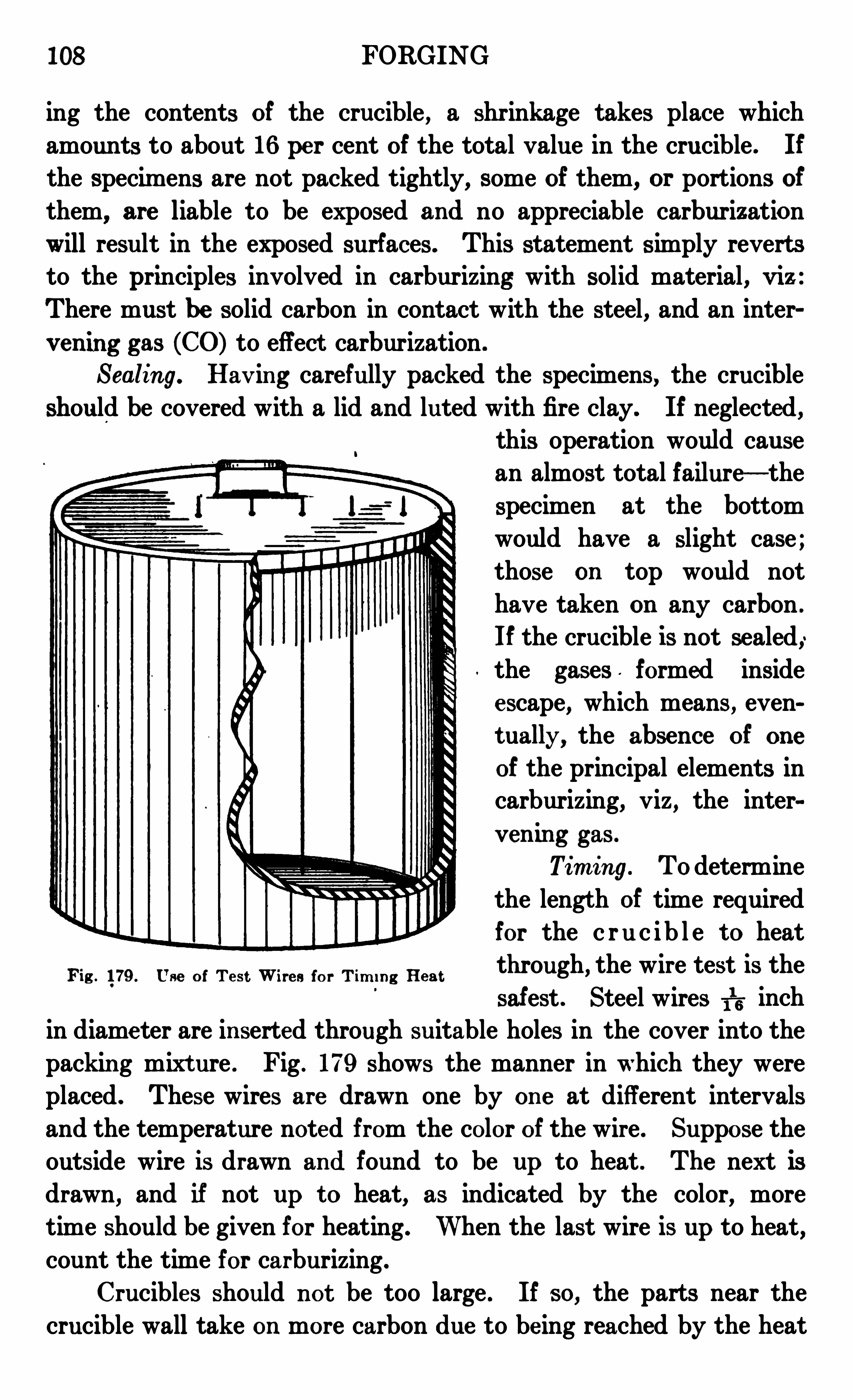
108 FORGING
ing the contents of the crucible , a shr inkage takes place whichamounts to about 16 pe r cent of the total value in the crucible . If
the specim ens are not packed tightly, some of them, or portions of
them, are liable to be exposed and no appreciable carburizationwill result in the exposed surfaces . This statement simply reverts
to the principles involved in carburizing with solid material , v iz :
There must be solid carbon in contact with the steel , and an interv en ing gas (CO) to effect carburization .
Sealing. Hav in g carefully packed the specimens, the crucible
should be covered with a lid and luted with fire clay. If neglected ,this operation would causean almost total failure— the
specimen at the bottom
would have a slight case ;those on top would not
have taken on any carbon .
If the crucible is not sealed ,the gases formed inside
e scape, which means , even
t ually, the absence of one
of the principal elements incarburizing, viz , the inter
v en ing gas .
Tim ing . Todetermine
the lengt h of time required
for the c ru c ib l e t o heatthrough, the wire test is the
safest . Steel wires TI
T; inch
in diame ter are in serted through suitable holes in the cover into thepackin g mixt ure . Fig . 179 shows the manner in which they were
placed . These wires are drawn one by on e at different intervalsand the temperature noted from the color of the wire . Suppose the
outside wire is drawn and found to be up to heat . The next isdrawn, and if not up t o heat, as indicated by the color, moretime should be given for heating . When the last wire is up to heat,count the time for carburizing .
Crucibles should not be too large . If so, the parts near the
crucible wall take on more carbon due to be ing reached by the heat
Fig . 179 . Use of Te s t Wire s for T im i n g He at

110 FORGING
the steel will be coarse and~
brittle . A carbon izing heat of about
1500° Fahrenheit is better though it means a slower penetration .
Fig . 180. Fractures of S t e e l Bars Showin g Various Te st s
Heat Treat m e n t aft e r Carbon iz in g
Shelland Core Dist inct ion . The heat treatment following car
bon izing should be done very carefully owing to the fact that the
FORGING 111
piece must have avery hard outer surface in order to resist wearand also a non-brittle core which will resist strains.
Fig . 18 1 . Fractures of St ee l Bars Showing Eflect of Heat Treat m en t aft er Carbon izin g
Double Quen chin g . For the best results, as the carbonizingtempe ratur e is a high one, the piece should be allowed to cool, then
1 12 FORGING
reheated to 1650° Fahrenheit and quenched , and reheated again t o
1400° Fahrenheit and quenched .
The reason for the double quenching is that the piece must be
heated above it s poin t of transformation to de stroy the cryst alliza
tion and consequent br ittleness which is liable to be in the core
when it is carbonized at a high temperature ; but this leav es the
carbon at ed surface layer not hard enough to resist wear ; thereforeit must be quenched again at 1400° Fahrenhe it .
This point of transformation var ies with the diffe ren t com
pon en t s of the high-grade alloy steels, and should be asce rt ained
before hardening the piece .
By quenching" directly from the carbonizing retort a
'
distinct
lin e is formed between the high-carbon outer she ll and the low
carbon core, and this is liable to cause the me t al t o crack on this
line, but if the work is prope rly heat-treated after carbonizing, this
distin ct line is made to d isappear , and the danger of the steel
crackin g is remov ed .
Spec im ens. Fig . 180 shows the fractures of different samples of
steel and the effect of time and temperature on the depth of case
harden in g of stee l wit h d ifferent pe rcen tages of carbon .
Fig . 181 shows the e ffect of heat-t reatmen t aft e r carbon izin g .
Un treated m ean s that the st ee l was quenched direct from the car
bon izing ret ort , which is t oo high a heat for good re sults . Fi rst treat
m en t shows that st ee l was allowed to cool and then reheated t o 1400°
or 1450°
Fahrenhe it and quen ched . This giv es a good case but not
a good core . Second treatm en t shows the re sults that come from
proper heat-treatm en t . The stee l was allowed t o cool, reheated t o
1650 degrees, quen ched, reheat ed t o 1450 degre e s and quen ched,which giv e s bot h a t ough core and a hard fin e -
grain case .
Cyan ide Harde n in g
Potass ium =Cyan ide Bath. Som e harden e rs pre fe r cyan ide of
potassium t o lead for heat ing cut t ing tools, dies, e t c . It is a whit e
transparen t salt which m e lt s at a fairly low t em pe rature , and should
be carefully used as it is a virulen t poison . The fum e s are ve ry
in jur ious and the furnace should be en closed with a hood con n ect ing
with a chim n ey or v en t ilat ing shaft . This bath is used a great
deal in gun shops for harden in g ce rt ain pie ce s on which it is wished

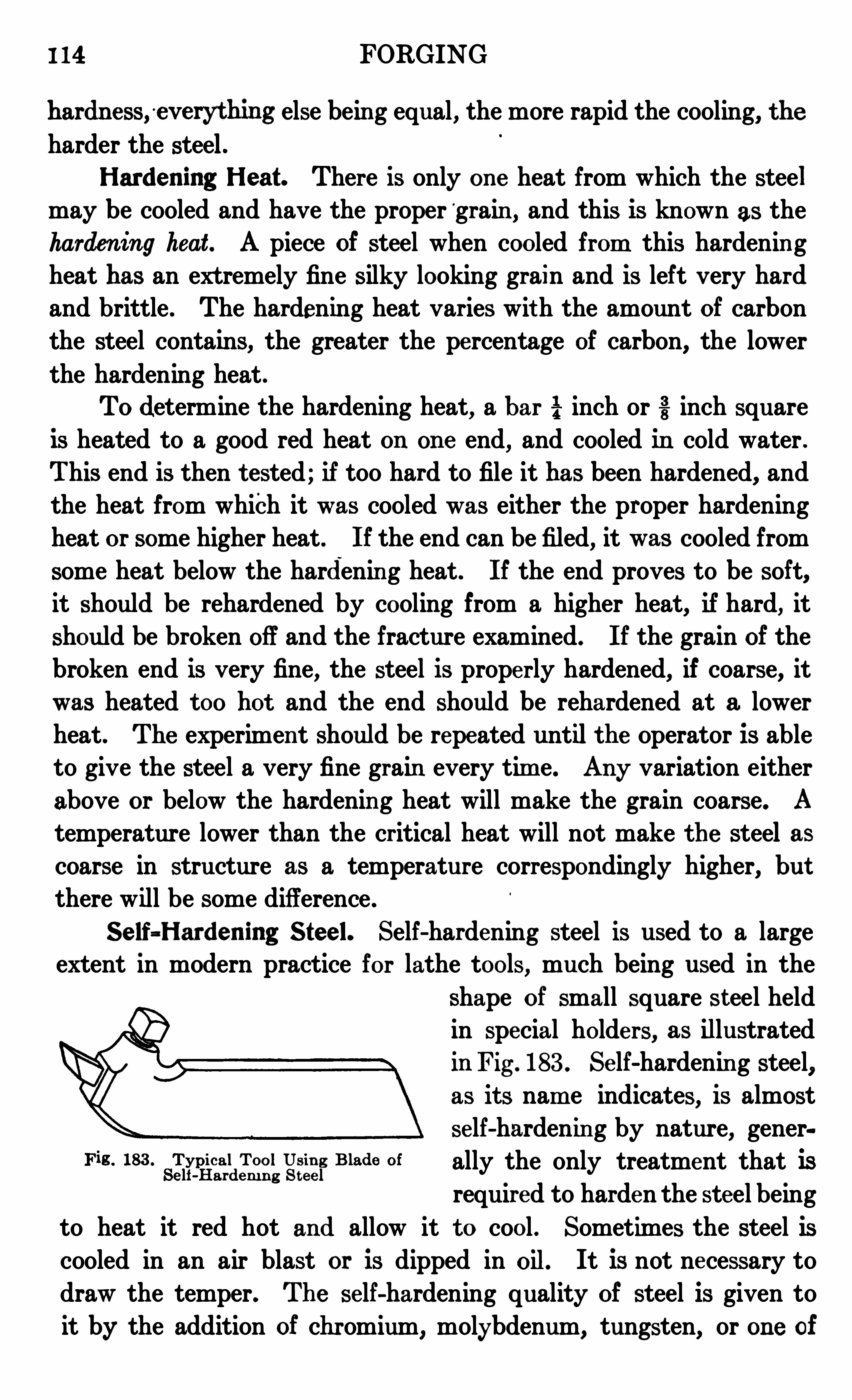
I 14 FORGING
hardn ess,°
ev erything else bein g equal , the more rapid the cooling, the
harder the steel .Harden ing Heat . There is only on e heat from which the steel
may be cooled and have the proper ‘grain , and this is known as the
harden ing heat . A piece of steel when cooled from this hardenin g
heat has an ext remely fine silky looking grain and is left very hardand brittle . The hardening heat varies wit h the amount of carbon
the steel contains, the greater the percentage of carbon, the lower
the hardening heat .
To determine the hardening heat, a bar i“ inch or inch square
is heated to a good red heat on on e end, and cooled in cold water .
This end is then t ested ; if too hard to file it has been hardened, and
the heat from which it was cooled was either the proper hardening
heat or some higher heat . If the end can be filed, it was cooled from
some heat below the hardenin g heat . If the end proves to be soft,it should be rehardened by cooling from a higher heat
, if hard, it
should be broken off and the fracture examined. If the grain of the
broken end is very fine, the steel is properly hardened, if coarse, it
was heated t oo hot and the end should be rehardened at a lower
heat . The experiment should be repeated until the Operator is ableto give the steel a very fine grain every tim e. Any variation either
above or below the hardenin g heat will make the grain coarse. A
temperature lower than the critical heat will not make the steel ascoarse in structure as a temperature correspondingly higher
, but
there will be some difference .
Self=Harden ing S teel. Self-hardening steel is used to a largeextent in modern practice for lathe tools, much being used in the
shape of small square steel heldin special holde rs, as illustratedin Fig . 183 . Se lf-hardenin g steel,as it s nam e indicates, is almost
se lf-hardenin g by nature, generis 183 . Typical Tool Usin g Blade of ally the only treatment that is
Self-Hardem n g S t e el
required to harden the steel being
to heat it red hot and allow it to cool . Sometimes the steel iscooled in an air blast or is dipped in oil. It is not necessary todraw the temper. The se lf-hardening quality of steel is given to
it by the addition of chromium, molybdenum, tungsten, or on e of
FORGING 115
that group of elements, in addition to the carbon which ordinary
tool steel contains. High spe ed steel is lowe r in carbon.
Self-hardening steel is comparatively expensive, costing from40 cents and upward per poun d, some of the more expensive gradescosting $1 or so. However, when in use , self-hardening steel willstand a much higher cutting speed than the ordinary se -called
carbon steel, and for this reason it is much more economical touse , although it s first cost is higher.
Self-hardening steel cannot be cut with a cold chise l and must
be either cut hot or nicked with an emery wheel and snapped off.
Great care must be used in forging it, as the range of temperature
through which it may be forged is comparatively slight, run ningfrom a good red heat to a yellow heat . Some grades of self-hard
cuin g steel may be annealed by heating the steel to a high heat inthe center of a good fire and allowing the fire and the steel t o cool
off together. Steel which has been annealed in this way may be
hardened by heating to the hardening heat and cooling in oil.
Taylor-Whi te Process . This method of treating special gradesof self-hardening steel was discovered some years ago by the men
after whom it is named . Itwas found that if a piece of self-hardening
steel is heated to a very high temperature (about the welding heat)and then suddenly cooled to about a low red heat, the steel wouldbe in a condition to stand very much harder usage and take a muchheavier cut . Steel treated in this way seemed to have the cutting
edge of the tools almost burned or melted off and considerablegr inding was necessary t o bring them into shape . When put in
use the edges would almost immediately be slightly rounded or
crumble off, but after this slight breaking down of the cutting edge,the steel would stand up under excessively trying conditions of
high speed and heavy cut . Tools of this character are of very
little or no use for fine finishing, but are of great value for heavy
and roughing cuts.
Harden ing H igh-Speed S teel. High-speed steel has a muchhigher critical tempe rature than carbon steels . A temperature of
about 13 50° to 1600° Fahrenheit is sufficient for carbon steels ingeneral . High-speed steels require heating from 1800
° to 23 00°
Fahrenheit, and to be cooled in oil such as machine, fish, or linseed .
Steel of this nature is close grained and should be heated slowly
116 FORGING
until red , then forcing the heat faster up to dazzlin g white . Whenit shows signs of melting down it should be quickly put in the coolingbath . The treatm ent varies for the different steels, and it is adv is
able to get directions from the steel maker as to the treatment,which varies according to the alloys of the steel . Air blast formerly
"
was recommended by some . steel makers, but at present oil is most
ext ensively used .
Barium -Chlor ide Bath. Abarium-chloride bath forheatinghighspeed '
steel has been used by some manufacturers for finished tools
such asmilling cutt ers, taps, and drills . Toget the high heat required
without oxidizing, a thin coating of the‘barium chloride is formed
on the steel , which, in transferring from the heating bath to the oil
bath, keeps , the steel from coming in‘
contact with air and thus
avoids oxidation . On e trouble with the barium chloride is thata thin surface about inch thick is soft, but for cutters that
have to be ground this disadvantage is of no account .
Special Shapes . For tools with special shapes that cannot beground— such as gear cut ters, twist drills, taps, threading dies,and m any other tools not permitting grinding after hardening— a
muffle furnace is be st t o use , as in this furnace tools do not come incontact with the flame and the thin cutting points are thus moreprot ected .
Measurin g and Te st in g In s t rum e n t s
Pyrom e te rs. Allupé to-date harden ing roomsnow are equipped
with pyrometers in order t o insure uniformity of the heat in thefurnaces, and also uniform results in the hardened products .
There ar e v arious types of pyrometers , depending upon different
principles for their workings such as the thermoelectric, resistance,radiation, and others . The most commonly used is the thermo
elect ric type . In this type, the temperature variation s are determined by the measuremen t of an electric current generated by the
action of heat on the junction of two dissimilar metals , that is ,when on e junction of the thermo couple has a temperature different
from the other, a current is developed which indicates on a meter .Therm oelectric Type . Fig. 184 shows the outlin es of the parts
of a complete Wm . H . Bristol therm oelectric pyrometer,with the
fire end applied for measuring the temperature in a bath of moltenlead . This particular fire end is bent so that the tip A , where the

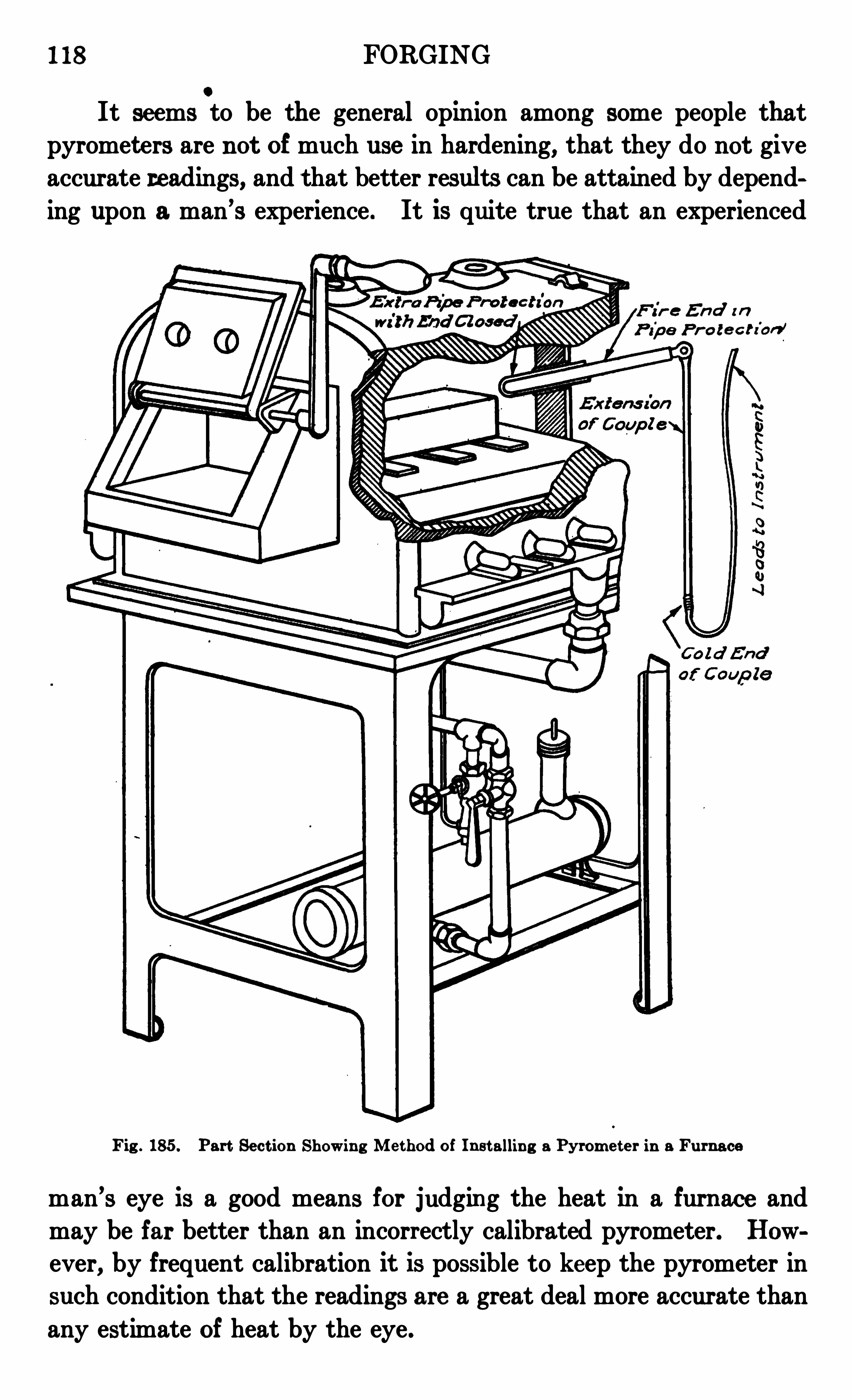
1 18 FORGINGO
It seems to be the general opinion among some people that
pyromet ers are not of much use in hardening, that they do not give
accurate readings, and that better results can be attained by depending upon a man’s experience . It is quite true that an experienced
3 En d i n
o t e c h'
on ’
Fig . 185 . Part Se ct ion Showin g Me thod of In st allin g a Pyrom e t e r in a Furnace
man’s eye is a good means for judgin g the heat in a furn ace and
may be far better than an incorrectly calibrated pyrometer. How
ever, by frequent calibration it is possible to keep the pyrometer in
such condition that the readings are a great deal more accurate than
any estimate of heat by the eye .
FORGING 119
Hardness Test ing . Few propert ies of iron and steel are of more
import ance than that of hardness, and ev en as far back as when menfirst began to harden steel, they probably sought some method of
testing for hardness . Although the file test for hardness is used
ext ensiv ely today, it is not considered accurate . In regard tomethods for testing hardn ess, it might be well to mention four ,though of these four there are only two that are very well known
Fi g . 186 . Br i n ellHardn e ss Tes t e r
and that are most commonly used— the Brine]. test, brought out
in 1900, and the Shore test, brought out in 1907.
Sclerom eter . In 1886 Prof. Thomas Turner brought out thesclerometer. In this form of test a weighted diamond point is
drawn across a smooth surface two or three times and the hardness
number is the we ight in grams required to produce a standardscratch .
Drill Test . Keeps te sting is known as the drill test and was
introduced in 1887. In this form of apparatus a standard steel drill
120 FORGING
is caused to make a definite number of rev olutions when pressedwith various standard forces against the piece to be tested . The
hardness is automatically recorded on a diagram .
Fi g . 187 . Scle roscope T e s t i n g S e t
Cour tesy of Shore I nstrum en t Com pany, N ew "ork Ci ty
Brin ell Te ster. Fig . 186 shows the Brinell method . In thismethod a hardened steel ball is pressed into a smooth surface of the
metal so as to make an indentat ion which is measur ed by a microscope . The spherical area of the indentation be ing calibrated andthe pressure being known, the stre ss per unit of area whe n the ball

122 FORGING
Fig . 187 shows a complete testing set , and Figs . 188 and 189 thedifferentmethodsof applying the instrumentto different kindsofwork .
Fig . 190 gives a general view of the working parts . In thescleroscope action the vital part is the diamond faced drop ham mer
which must always be raised to it s hanger hook at the top where itremains in readiness for the test . In the automatic instrumen t
Fig . 189 . Tes t in g Hardn ess of Proj ec t i lesCour tesy of Share I nstrum en t Com pany, New "ork City
now manufactured, the necessary valves, the suction for the hammerand it s release all are operat ed alternately by one bulb acting on the
cam B , Fig . 190, through the medium of the piston C,the adjustable
oscillator D and the end ratchets E . When the hammer is down
it will be foun d impossible to suck it up by the vacuum formed on
releasing the hold on the bulb because the valve is then’
wide openand is held so by the cam B.
FORGING 123
F i g . 190. De t ailed Drawin g Showin g Par t s of Shore b ole roscope
TEMPERING
Esse n t ials of Proce ss . To tem pe r st ee l is t o return it t o a
stat e of m olecular equilibr ium at atmosphe ric tem perature byre liev ing any st rain s in the me t al which hav e been caused by suddenquen chin g , and also t o correct any exagge ration of ce rt ain propertieswhich hav e been caused by the hardening process . In ot her words,the object of tempering is t o reduce the br ittlen ess in hardened
steel , and t o rem ov e the internal strain s caused by the sudden
cooling in the quen ching bath . The tem pering proce ss con sists inheat ing the piece of work by on e of various mean s t o a certain t em
perat ure , and in perm it t ing it to cool gradually .
Temperature Conditions . The temperature to which a pieceshould be raised for tempering depends on sev e ral condit ion s : the
use towhich it is t o be put ; the condit ion in which it has been left by
124 FORGING
quenching ; and the composition of the steel . The degree of heat t owhich the tool to be tempered is heated determines the degree of
toughness it has attained— the higher the tempering heat, the lessbrittle, and also the less hard , the t ool is . The maximum tempera
ture desired need be maintained only long enough to be sure thepiece is heated evenly. Steels which are reheated slightly after
hardening give a freedom to the molecular change that lessens themolecular rigidity set up by the hardening process .
Reduct ion of Br ittlene ss.a Tools are always left as hard as it
is possible to leave them and still have them tough enough for the
work for which they are intended . In reducing the brittleness of
the steel, some of the hardness is of necessity taken out , and tem
pering is therefore sometimes spoken of as a reduction of the hardness,but it is in reality merely a reduction of the brittleness. After a
tool or piece of steel has been hardened, some of the brittleness istaken out by a slight reheating to a low temperature . These tem
perat ures vary from 200° Fahrenheit, to about 6 50
° Fahrenheit,and are determined in various ways . The simplest and perhapsthe most commonly used method is to polish the steel after it hasbeen hardened and then to reheat the part to be tempered until
the surface shows a certain color .
If any bright piece of iron or steel is heated, when a temperature
of about 400° Fahrenheit is reached, the surface turns pale yellow .
As the temperature is increased, this yellow grows darker until atabout 500° Fahrenheit it is a decided brown . When 600° Fahren
heit is reached , a deep blue color shows on the surface . These colors
are produced by a thin scale which is formed on the surface of the
steel and are no indication whatever of hardness, merely showing
to what heat steel or iron has been raised .
Baths for Tem pering . As the object of tempering is simply
to reduce the brittleness and to remove the internal strains caused
by the sudden cooling in quenchin g, the composition of a tem
pering bath is of little importance as compared with that of a quench
ing bath . Aside from the operator’s convenience and the possiblebad effects upon his health, the different baths used for this operation
must be considered chiefly with regard to initial cost and lasting
quality, and also effect on finish .
Various Medium s . The two main points to be considered

126 FORGING
to heat the steel in a bath of red hot lead . The lead is heated
in a pot or crucible, to the hardening heat of the stee l . The top of
the lead is covered with powdered charcoal or coal to prevent the
formation of the slag or dross on top. When steel is heated in leadit must be perfectly clean, dry, and free from rust.
F i g . 193 . Double Door Furn ace for Heat ing andAn n eali n g Work
Cour tesy of Gilber t and Barker Man ufacturin "
Com pany, Spr rn gfield. Massachuset ts
Tem pering H igh-Speed fiteel. Tools of large size and for
hard usage, such as lathe and planer tools, do not require to be
tempered, and should be cooled in thin oil such as lard or kerosene
oil . In using kerosene oil care should be used not to let a red-hotpart be abov e the surface of the oil , as it will flash ; such a piece shouldbe kept in the bath until cooled t o the temperature .of the oil. Tools
FORGING 127
like milling cutters, drills, reamers, taps, are generally temperedat from 400
° to 500° Fahrenheit, depending on the size, as smalltools of the same kind require lettin g down a little more on hardness .
Furnaces for Tem pering . In tempering furnaces, as in all
other kinds of furnaces, the really important consideration is to
Fig . 194 . Larg e Size Furnace for Heat in g , An n ealin g , and Carbon izingCourtesy of S tron g , Carlzsle and Ham m ond Com pan y, Cleveland, Ohm
insure that the furnace is so built as to heat the bath un iformly.
The furnaces for tempering are practically the same as the onesused in hardening ; those are the best which permit of maintaininga constant temperature and hav e appliances for measuring theheat so that the correct temperature can be attained .
Fig . 191 shows an ordinary type of tempering furnace . The
general principles of combustion are the sam e as for the av erage
128 FORGING
oil burning furn ace, and the tools to be tempered are laid in the
receptacle which is immersed in the oil. Fig. 192 shows a thermometer
for indicating the t emperature of the oil bath . The thermomet er
is very much like the ordinary mercury thermometer except thatit registers as high as 500
° to 700° Fahrenheit.
SpecialOperation . In Figs. 193 and 194 are shown furnaces
for heating, annealing, and carbonizing. The burners enter the
Fig . 195 . Bot tom Brick of Sem i Fig . 196 . Furnace BridgeMuflled Furn ace Courtesy of S tron g , Carli sle and Ham
Cou r tesy of S tron g , Carlisle and m ond Com panyHam m ond Cornpany
combustion chamber underneat h the heatin g ov en ; the flame strikesa baffle and the tile floor of the ov en, and absolute com bustiontakes place . Heat free from oxidizing properties is produced and
is div erted to the heating ov en above with a reverberating motion,which produces a uniform circulation ; all materials are thoroughly
and uniformly heated . The surplus heat is vented through portson top of the furnace which can be utilized for pre-heating or
_
for
tempering . Blowers are usually
mounted upon brackets in therear, or they may be placed inany other conv enient location .
The air receiv er is underneath,and compressed air may be used
when reduced to the properFig . 197 . Brick for Muffled Furn ace
0024718821 Of S tron g , Carlisle and Ham m ond pre ssure °
com pany Advan tages of Gel and Gas
Types . Oil and gas-fired furnaces are a great improvement overcoke and coal furnaces, as with the latter it is almost impossible toregulate heat to a desired and giv en point, to say n othing of thein convenience of shov eling coal and of cleaning out ashes, while dust
and dirt that accumulate from these operations are, to say the least,

13 0 FORGING
Oil-Burn in g Furnace . Although the installation is more costlythan that of a gas furnace, oil furnaces are used a good deal foreconomy by large con cerns . A storage tank under groun d is gen
erally used together with a pum ping system to maintain a pressure
Fig s 201 and 202 . Fron t and Back V i ew of Gas Burn e r Fig 203 . S , C andH .
Cour tesy of Tate , J on es and Com pany, P i tts burghCas t -Iron P013
sufficient for forcing the oil t o the furnace . The oilflows througha simple regulating valv e and is im mediate ly atomized with e ither
steam or air at a pressure of from 3 5 to 100pounds per square inch .
At this point it enters the forcing hood in the form of fine mist
where a volum e of air at apressure of about 6 to 15 ounces per square
Fig . 204 . Cast -Iron Pot Fig . 205. W i re Baske t for Im m e rsin g WorkUsed for Lead Pot in 011Bath
in ch carries it along the com bust ion chambe r in which it ignitesand burn s with an inten se heat .
A good design of burn er should hav e e liminat ed the trouble
som e featur es of sput t erin g and dr ippin g oil, which cause an irregularflam e . The flame should be clear, whit e , and free from smoke, soot ,and dirt .
Details of Mufie Furnace . In Fig . 195 is shown the bottom
brick of a sem i-m uffle furnace . Fig . 196 shows another brick which
is called the furnace bridge . Fig . 197 shows the furnace brick for
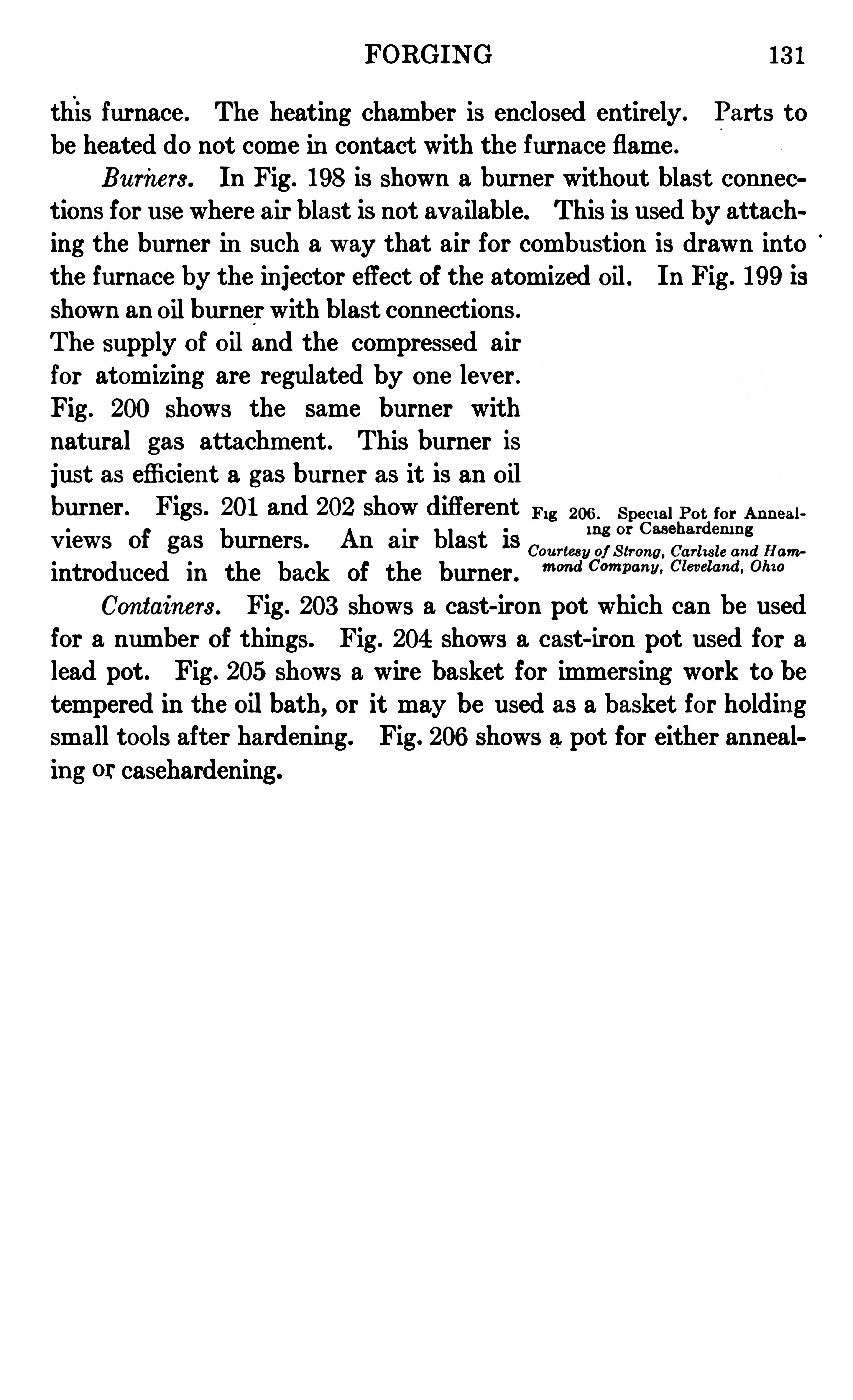
FORGING 13 1
this furnace . The heating chamber is enclosed entirely. Parts to
be heated do not come in contact with the furnace flame .
Burners . In Fig . 198 is shown a burner without blast connec
tions for use where air blast is not available. This is used by attaching the burner in such a way that air for combustion is drawn intothe furnace by the in jector effect of the atomized oil. In Fig . 199 is
shown an oilburner with blast conn ections .
The supply of oil and the compressed airfor atomizing are regulated by on e lev er .
Fig. 200 shows the same burner with
natural gas attachm ent . This burner is
just as efficien t a gas burner as it is an oil
burner . Figs. 201 and 202 show different m g 206 , spe c,”pot for An n eal,
i n g or Casehardem n gV leW S of gas burners. An air blast IS
Com m ”0, S tron g , and Haw
introduced in the back of the burner . m m “ m an“ “n ew“ Oh”
Con tain ers . Fig. 203 shows a cast- iron pot which can be used
for a number of things. Fig. 204 shows a cast-iron pot used for a
lead pot . Fig . 205 shows a wire basket for immersing work to betempered in the oilbath, or it may be used as a basket for holdingsmall tools after hardening. Fig. 206 shows a pot for either anneal
in g or casehardening .


INDEX
other tools
Sledges .
swages
ton gs .
Cran es .
Crank shaft s
Cyan ide harden ing .
caseharden ing
pot assium -cyan ide bath
Die forging
Drop forging .
drop ham m ers .
specim en s
Drop ham m ers .
Duplicat e work .
com m on tools
heat t reat m en t
heat in g apparatus
m achin e tools
m at e r ials and equipm en t
classificat ion
m echan ical de t ails .
operat ions .
Forging heatForging m at er ials .
Forging operat ion s
angle we lding
but t we lding .
drop forgin g
heavy forging
lap we lding
m edium forged work
m isce llan eous proce sse s
bendin g cast iron
brazing
INDEXPAGE
Forging operat ion s (con t inued)m isce llan eous processes
die
duplicat e
pipe bendin g
shrinking .
scarfin g
sim ple bending
sm it h we lding
split we lding heav y stock
T—we lding .
tool-st ee l work
we lding tool st eel
Forging operat ions (fundam en t al )drawing out
shaping .
t ruing up work
upse t t ing
FullersFurnaces .
Ham m er chisels .
Ham m er dies
Ham m ers
ball-peen
r iv e t ing .
Harden ing
bathcarbon izingcracks and fissure s
cyan ide harden ingessen t ial features
heat t reat m en t aft e r carbon izm
she ll and core dist in ct ion
specim en s
influen cing factors
m easur ing and t es t ing in st rum cv‘
n
preparatory heat ingpurpose
quen ching tanks
result s
tool work .
Heat t reat m en t
an n ealing
factors in
harden ing
INDEXPAGE
Heat t reat m en t (con t inued)
processes of t reat ing
st eel dev elopm en t , re lat ion to
t em perin g .
Heat ing apparatus
exam ples of work .
ham m er di es
squaring up work
Inst rum en ts,m easur ing and t est ing
Brine ll t est er
pyrom et ers .
Shore scleroscope .
Knuckles
Ladle shank
Lap we lding
allowan ce for we lding
ban d rin g
flat or washer rin g
rin g round stock .
Lat he toolsLev er wit h boss
Machin e tools .
bolt headersbulldozer
drop ham m ers
m anufactur in g requirem en t
power ham m ers .
presses

PAGETables (con t inued)
sizes of hois t ing hooks
weight of flat rolled iron
Tem pering .
bat hs for
essen t ials of process .
furnaces for
high-speed st ee l
reduct ion of br it t len essTongs
Tool work
harden ing heat
harden ing hlgh-spe ed st ee l
laws for harden ing
Tool-st ee l work .
proper forgm g heatstandard form s
blacksm ith ’
s tools
cold chise ls
ham m ers
lathe tools
spr ings .
0 0 0 0 0
T-we lding
We lding heat
We ldin g tool st ee l .
We ldless r in gs .