manual emu allrounder emu professional
TRANSCRIPT

• •
MANUAL EMU ALLROUNDER EMU PROFESSIONAL
34
EN
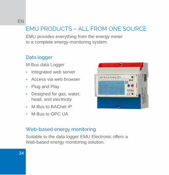
EMU PRODUCTS – ALL FROM ONE SOURCEEMU provides everything from the energy meter to a complete energy-monitoring system.
Data logger
M-Bus data Logger
• Integrated web server
• Access via web browser
• Plug and Play
• Designed for gas, water, head, and electricity
• M-Bus to BACnet IP
• M-Bus to OPC UA
Web-based energy monitoring
Suitable to the data logger EMU Electronic offers a Web-based energy monitoring solution.

35
Your benefits:
• Various locations monitored centrally
• Web-based software
• User-friendly operation
• Worldwide access
MENU NAVIGATION
Blue key Go to next unit Active energy, active power etc.
Red key
More information of unit E.g. phase L1, L2, L3, total, Min. / Max values
Yellow key
Service key, on the right side bellow the red terminal cover. To save a configuration, push the service key for 5 seconds.

36
EN
VIDEO ANIMATIONYou can find a video about the configuration and menu navigation on www.emuag.ch.
COMMISSIONING / CHECK-UPTo check for operation:
• Phase rotation
• Current per phase Negative energy direction
• Sequence of phase (L1 L2 L3)
• Current Transformer ratio
• Terminal tightening torque
• Read-out interface: Correct address
37
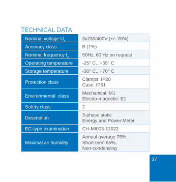
TECHNICAL DATANominal voltage U
n3x230/400V (+/- 20%)
Accuracy class B (1%)
Nominal frequency fn
50Hz, 60 Hz on request
Operating temperature -25° C...+55° C
Storage temperature -30° C...+70° C
Protection classClamps: IP20 Case: IP51
Environmental classMechanical: M1 Electro-magnetic: E1
Safety class 2
Description3-phase static Energy and Power Meter
EC-type examination CH-MI003-13022
Maximal air humidityAnnual average 75%, Short-term 95%, Non-condensing

38
EN
Direct connection
Current (Ist, I
min, I
tr, I
ref, I
max)
0.02 A / 0.25 A / 0.5 A / 5 A / 75 A (5(75))
Current transformer /5 und /1A
Current /5A (Ist, I
min, I
tr, I
ref, I
max)
0.01 A / 0.05 A / 0.25 A / 5 A / 6 A (5(6))
Current /1A (Ist, I
min, I
tr, I
ref, I
max)
0.002 A / 0.01 A / 0.05 A / 1 A / 1.2 A (1(1.2))
Installation instruction
Torque Connection
Flexible wire Direct max. 35mm2 strand
Current transformer max. 6mm2 strand
Input lead L1/L2/L3 2-3 Nm 1.3 - 1.6 Nm
Neutral conductor 2-3 Nm 1.3 - 1.6 Nm
S0 pulse output 0,4 Nm (max 2.5mm2 strand) Tariff control 0,4 Nm (max. 2.5mm2 strand)

39
Cable requirement >65A
Type: Wire (Cu) Cross-section: 35mm² Outside-Ø: 9,55 mm Example: E-Number 105502800, available from Swiss
electrical wholesale
DISPLAY LANGUAGEDisplay language can be selected between English and German (Deutsch).
Configure of display language
1. Blue key to Adjustments2. Red key to Language (Sprache)3. Push Service-Key briefly 4. Adjust Language by blue key5. Saving: Push Service key for 5 seconds,
until digits are not blinking

40
EN
TARIFF CONTROLTariff changeover takes place by 230V to corresponding terminal.
Tarif 2 = 230V on terminal E4 and E5 (N)
Double-tariff Four-tariff
E4 E4 E3
T1 0 T1 0 0
T2 1 T2 1 0
T3 0 0
T4 1 0
0 = No voltage 1 = Voltage

41
CURRENT TRANSFORMER RATIOCurrent transformer ratio can be adjusted from 5/5 to 20‘000/5A and 1/1 to 4’000/1A
Left (blue) key = Change of digit / number
Right (red) key = Go to next digit / number
Current transformer /5A
AABCC : 5A AA adjustable in steps of 1 B adjustable in steps of 1 CC adjustable in steps of 5
Current transformer /1A
YYYY : 1A Y adjustable in steps of 1

42
EN
Configuration of current transformer ratio
1. Blue key to Transformer ratio2. Push service key briefly3. Adjust secondary current by blue key4. Go to primary current by red key5. Adjust first two digits by blue key6. Go to next digit by red key7. Adjust digit by blue key8. Go to next digit by red key.9. Adjust next two digits by blue key.10. Saving: Push Service key for 5 seconds,
until digits are not blinking

43
S0 PULSE-OUTPUTThe four S0 pulse-outputs are designed according to EN62053-31 (DIN 83864).
Pulse rate and pulse lengths can be configured by the keys.
Default settings ex-factory
1. S0 Output = Active Energy Import (12+13)2. S0 Output = Reactive Energy Import (10 + 11)3. S0 Output = Active Energy Export (8 + 9)4. S0 Output = Reactive Energy Export (6 + 7)
Current transformer meter 10 Impulse / kWh Direct meter 1000 Impulse / kWh
EMU Allrounder
The EMU Allrounder only has one pulse-output for active energy import.

44
EN
Configuration of pulse rate
1. Blue key to Adjustments2. Red key to S0 Pulse Rate3. Push service key briefly4. Move decimal place by blue key5. Example 1000.000 = 1000 Impulse6. Saving: Push Service key for 5 seconds,
until digits are not blinking
Configuration of pulse length
1. Blue key to Adjustments2. Red key to S0 Pulse Duration3. Push service key briefly4. Adjust pulse length by blue key5. Saving: Push Service key for 5 seconds,
until digits are not blinking

45
S0 pulse-output
Opto Power MOSFEET
5 – 230 VAC or VDC, max. 90mA
Rate per kWh / kvarh
0.001, 0.01, 0.1, 1, 10, 100, 1000, 10‘000
Length
Adjustable from 4 to 250 milliseconds in steps of 2 ms

46
EN
M-BUS ADDRESS / CONFIGURATIONRecommended cable
Twisted pair, shielded, cross-section depending on cable length. Type: JY(St)Y 2x0.8 to 1.5 mm2
Default settings ex-factory
Secondary address = Serial number Primary address = 0 Baud rate = 2400
Configuration via M-Bus
Primary and secondary address, baud rate and read-out data can be configured by the free EMU MB-Connect software or by the keys. The M-Bus interface is designed according to EN 13757-2,-3 (formerly EN1434-3).
47
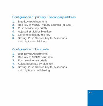
Configuration of primary / secondary address
1. Blue key to Adjustments2. Red key to MBUS Primary address (or Sec.)3. Push service key briefly4. Adjust first digit by blue key5. Go to next digit by red key6. Saving: Push Service key for 5 seconds,
until digit is not blinking.
Configuration of baud rate
1. Blue key to Adjustments2. Red key to MBUS Baud rate3. Push service key briefly4. Adjust baud rate by blue key5. Saving: Push Service key for 5 seconds,
until digits are not blinking

48
EN
TCP/IP INTERFACEDefault settings ex-factory
IP-Adresse = 192.168.1.100 Subnet = 255.255.255.0 Gateway = 0.0.0.0
Configuration of IP address
1. Blue key to Adjustments2. Red key to IP Address3. Push service key briefly4. Adjust first digit by blue key5. Go to next digit by red key6. Saving: Push Service key for 5 seconds,
until digits are not blinking
49
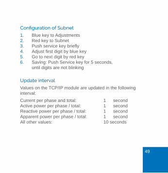
Configuration of Subnet
1. Blue key to Adjustments2. Red key to Subnet3. Push service key briefly4. Adjust first digit by blue key 5. Go to next digit by red key6. Saving: Push Service key for 5 seconds,
until digits are not blinking
Update interval
Values on the TCP/IP module are updated in the following interval:
Current per phase and total: 1 second Active power per phase / total: 1 second Reactive power per phase / total: 1 second Apparent power per phase / total: 1 second All other values: 10 seconds

50
EN
Factory reset
By factory reset (menu point Adjustments) the TCP / IP module is set to the default settings.
TCP/IP interface connected directly to computer
For a successful connection between an EMU Professional TCP / IP (not connected to network) and a computer, please consider the following points:
Counter and computer must be in the same subnet.
E.g. Subnet mask: 255.255.255.0 Network cable type: Cross
Computer requires a fixed IP address
Please contact your local / internal IT support for any ques-tions regarding the TCP/IP connection.

51
RELAY OUTPUTThe S0 pulse-outputs can be configured as a relay-output and can be switched via TCP/IP module or special M-Bus protocol.
Configuration of relay-output
1. Blue key to Adjustments2. Red key to Assignment output X3. Push service key briefly4. Adjust to Relay Output by blue key5. Saving: Push Service key for 5 seconds,
until digits are not blinking

52
EN
PEAK-CONTROL / THRESHOLDThreshold
The following values can be chooses as a threshold:
Active Power, Reactive power, Apparent power Current total Current per phase L1 / L2 / L3
Default settings ex-factory
Threshold: 5.000 kW Status: Not active
Response time / release time
The response and release time is adjustable between 0 and 9999 seconds.
Response time: Time, until contact switches Release time: Time, until contact switches after th-
reshold is not exceeded anymore.
The threshold function can be assigned to any output S0.
53
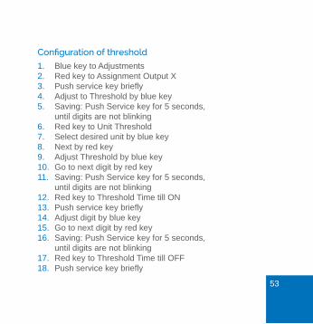
Configuration of threshold
1. Blue key to Adjustments2. Red key to Assignment Output X3. Push service key briefly4. Adjust to Threshold by blue key5. Saving: Push Service key for 5 seconds,
until digits are not blinking6. Red key to Unit Threshold7. Select desired unit by blue key8. Next by red key9. Adjust Threshold by blue key10. Go to next digit by red key11. Saving: Push Service key for 5 seconds,
until digits are not blinking12. Red key to Threshold Time till ON13. Push service key briefly14. Adjust digit by blue key15. Go to next digit by red key16. Saving: Push Service key for 5 seconds,
until digits are not blinking17. Red key to Threshold Time till OFF18. Push service key briefly

54
EN
19. Adjust digit by blue key20. Go to next digit by red key21. Saving: Push Service key for 5 seconds,
until digits are not blinking
DATE / TIMEConfiguration of date
1. Blue key to Date2. Push service key briefly3. Adjust first digit by blue key4. Go to next digit by red key5. Saving: Push service key for 5 seconds
Configuration of time
1. Blue key to Date2. Red key to Time3. Push service key briefly4. Adjust first digit by red key5. Go to next digit by red key6. Saving: Push service key for 5 seconds
55
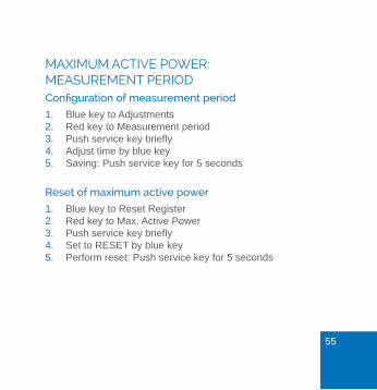
MAXIMUM ACTIVE POWER: MEASUREMENT PERIODConfiguration of measurement period
1. Blue key to Adjustments2. Red key to Measurement period3. Push service key briefly4. Adjust time by blue key5. Saving: Push service key for 5 seconds
Reset of maximum active power
1. Blue key to Reset Register2. Red key to Max. Active Power3. Push service key briefly4. Set to RESET by blue key5. Perform reset: Push service key for 5 seconds

56
EN
Start / synchronization measurement period
• Synchronization takes place by using a 230VAC control signal.
• In normal operation mode, voltage is connected to input E1, input E2 is dead (without voltage).
• To start a new measurement period, disconnect voltage from E1 and connect voltage to E2.
• For security reasons a voltage change has to take place at both inputs E1 and E2
Normal mode Start new measurement
E1 E2 E1 E2
1 0 0 1
0 = No voltage / 1 = Voltage

57
RESET MINIMUM AND MAXIMUM VALUES1. Blue key to Reset Register2. Red key to Min/Max Register3. Push service key briefly4. Set to RESET by blue key5. Perform reset: Push service key for 5 seconds
Reset power outages
1. Blue key to Reset2. Red key to Power outages3. Push service key briefly4. Set to RESET by blue key5. Perform reset: Push service key for 5 seconds
RESET OF TARIFF REGISTER EMU ALLROUNDERThe EMU Allrounder has a resettable tariff register. The resettable register is indicated by and arrow above the unit (kWh).

58
EN
Reset tariff register
1. Blue key to Reset Register2. Rote Taste bis Active energy NO RESET3. Push service key briefly4. Set to RESET by blue key 5. Perform reset: Push service key for 5 seconds
ERROR MESSAGESIf an internal error appears, an error message is dis-played.
F.F.0(00000000) No error, meter ok F.F.0(xxxxxxx0) Meter calibrated F.F.0(xxxxxxx1) Meter not calibrated F.F.0(xxxxxxx8) Calibration release, meter is calibra-
ted and can be re-calibrated.
F.F.0(xxxxxxx9) Calibration release, meter is not cali-brated and can be calibrated now.
59
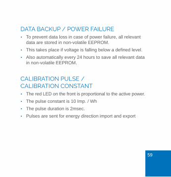
DATA BACKUP / POWER FAILURE • To prevent data loss in case of power failure, all relevant
data are stored in non-volatile EEPROM.
• This takes place if voltage is falling below a defined level.
• Also automatically every 24 hours to save all relevant data in non-volatile EEPROM.
CALIBRATION PULSE / CALIBRATION CONSTANT • The red LED on the front is proportional to the active power.
• The pulse constant is 10 Imp. / Wh
• The pulse duration is 2msec.
• Pulses are sent for energy direction import and export

60
EN
D0 INTERFACE ACCORDING TO EN 62056-21 • The D0 (optical) interface is located on the front, right next
to the display.
• The EMU Allrounder / Professional have a serial D0 interface according to EN 62056-21. The D0 interface can be configured as bidirectional (Mode A or C) or as a unidirectional (D0 mode) communication interface.
SAFETY INSTRUCTIONThe EMU Professional / Allrounder should only be used for measuring electrical energy and can not be operated outside the specified technical data.
When installing or replacing the meter, the conductor, to which the meter is connected, has to be dead (power / voltage off).
Touching live (voltage or power) components is dangerous! Therefore, the appropriate fuses are to remove and secure. No body shall be able to turn voltage / power on without prior notification.

61
Before opening / disconnect the clamps, short-circuit the secondary circuits of the current transformers. The resul-ting high voltage on the current transformer is extremely dangerous (dangerous to life) and could destroy the current transformer.
The usual local security and work rules must be observed. The installation of the meter must be carried out by qualified and trained personnel.
MAINTENANCEThe EMU Professional / Allrounder is maintenance free. In case of damage (for example shipping, incorrect connection or storage) repairs may only be done by EMU Electronic AG.
62
EN
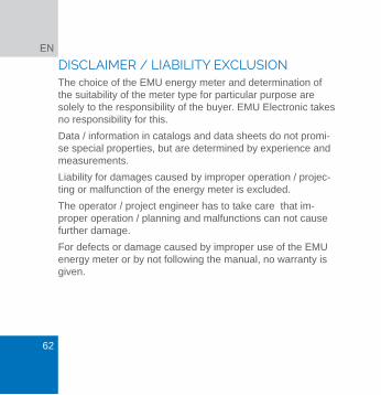
DISCLAIMER / LIABILITY EXCLUSIONThe choice of the EMU energy meter and determination of the suitability of the meter type for particular purpose are solely to the responsibility of the buyer. EMU Electronic takes no responsibility for this.
Data / information in catalogs and data sheets do not promi-se special properties, but are determined by experience and measurements.
Liability for damages caused by improper operation / projec-ting or malfunction of the energy meter is excluded.
The operator / project engineer has to take care that im-proper operation / planning and malfunctions can not cause further damage.
For defects or damage caused by improper use of the EMU energy meter or by not following the manual, no warranty is given.

63
DECLARATION OF CONFORMITYWe, EMU Electronic AG, CH-6340 Baar, declare under our sole responsibility that the products:
• 3-phase polyphase static meter
• EMU Professional / EMU Allrounder, accuracy class B
To which this declaration relates is in conformity with the requirements of the following directives:
MID 2014 32 / EU and harmonised EN-standards EN50470-1: 2006 and EN50470-3:2006
Number of EC-type examination certificat: CH-MI003-13022
Notified body: METAS-Cert (Nr. 1259) Lindenweg 50, CH-3003, Bern-Wabern
Issuer: EMU Electronic AG Jöchlerweg 2, CH-6340 Baar, Switzerland
Hans-Martin Koller, Managing director 1 October 2017

• •
EMU Electronic AG
Jöchlerweg 2 +41 (0)41 541 10 00
CH-6340 Baar [email protected]
Switzerland www.emuag.ch
Version 1.4 | Part no. 870132