magician simulator—a realistic simulator for heterogeneous teams of autonomous robots
TRANSCRIPT

ICARCV2010
Magician Simulator A realistic simulator for heterogenous teams of autonomous robots
Adham Atyabi
[email protected] Tom A.F. Anderson
[email protected] Kenneth Treharne
[email protected] David M. W. Powers
School of Computer, Science, Engineering, and Mathematics, Flinders University of South Australia
5042 Bedford Park, SA, Australia
Abstract— This paper is a report on an undergoing effort on providing a new simulating environment with the purpose of education to be used in studies based on Multi_Robot Learning, Swarm Robotics, and Robot Teaming. The simulator takes in account some aspects of an undergoing robotic competition called Magic2010 sponsored by US and Australia defense departments. The new simulator called Magician (named after Flinders robotic team which is nominated as one of the top 10 teams for Magic 2010 competition) provides a realistic environment for examining methods for navigation (including localization, obstacle avoidance, path planning) and training strategies based on various degrees of heterogeneity, robot teaming, networking, and human robot interaction.
I. INTRODUCTION Simulators are valuable tools in the development and
testing of control algorithm for mobile robots , allowing developers to gain estimates of feasibility of methods and to examine the algorithm before starting the implementation process, with a significant impact on reducing the costs. Simulation helps to improve development time, avoid damages caused by method failure, and find errors that occurred during the implementation process [11].
Simulations address a vast group of problems--from singular based to team/swarm based, and from humanoid to industrial robots, such as robotic arms. Robot teaming and robotic swarm is an active research domain, with a variety of organizations and researchers to invest in application such as search and rescue, threat detection, patrolling, and counter-terrorism. The high level of complexities in such areas increases the necessity of employing simulators with more realistic aspects that not only take in account aspects if the robots, but also the impacts of teamwork and human-to-robot interaction, in addition to addressing various complexities introduced by dynamic, uncertain, and time dependent nature of the real world problems.
This paper represents an undergoing effort for implementing a realistic simulating environment with educational purposes targeting studies on swarm robotics, multi-robot learning and robot teaming. Section 2 introduces some related works and similar simulators. Section 3 provides a brief introduction to the Magic 2010 competition from which the current simulator is inspired. Section 4 presents the Magician simulator, its units and their capabilities. Section 5 and 6 are dedicated to the simulation application and conclusion respectively.
II. RELATED WORK
A. Simulation environments for multi-robot teams Multi-robot simulation comprises diverse areas, such as
sensing, exploration, mapping, localization, planning, coordination, formation, and task allocation. Deployment in the real world is the end-goal of robotics, but simulation environments provide significant advantages for design over using real robots due to four factor: ease of installation, lower costs, rapid prototyping, and convenience [1].
Kramer and Scheutz [2] developed a metric for the evaluation of simulation environments for robot development, determining five factors that are vital to successful adoption: platform, components, system architecture, agent, and programming environment. They concluded that in the future, researchers would tend towards the adoption of autonomic systems with flexibility in infrastructure, ease of installation, and a mind to long term usage; on the other hand, their work does not consider higher-level operation of robots as members of teams, which we believe to be a crucial consideration. Optimizing global strategy considers the coordination of a team of heterogeneous robots in an environment towards completion of diverse tasks. Although each robot is autonomous, with responsibility for duties, communications between robots and the distribution of tasks across multiple robots leads to increased efficiency. For example, a team of robots can complete a mapping task faster than an individual robot, and work in optimization demonstrates that the information gained by a team is an improvement despite dynamism and uncertainty in the environment.
B. Human input in real-time robot teams Although a great deal of research seeks to demonstrate
accurate fine-grained replica of robots in the real world, simulation is also able to provide a great deal of valuable information for the higher-level team-based scenario. The formation of a robot team is largely dependent on the control of each robot in regards to its teammates as reference points. Hsu and Liu [3] used simulation to test strategies for maintaining formation by assigning inter-robot reference points, whether leader, predecessor or neighbor. In a hospital environment, simulation showed that a team of robots could provide a cost effective transportation and delivery service that was significantly faster than currently provided by humans [4]. This comparison was between human teams or robot teams, thus they did not consider a mixed team of humans and robots.

Report Documentation Page Form ApprovedOMB No. 0704-0188
Public reporting burden for the collection of information is estimated to average 1 hour per response, including the time for reviewing instructions, searching existing data sources, gathering andmaintaining the data needed, and completing and reviewing the collection of information. Send comments regarding this burden estimate or any other aspect of this collection of information,including suggestions for reducing this burden, to Washington Headquarters Services, Directorate for Information Operations and Reports, 1215 Jefferson Davis Highway, Suite 1204, ArlingtonVA 22202-4302. Respondents should be aware that notwithstanding any other provision of law, no person shall be subject to a penalty for failing to comply with a collection of information if itdoes not display a currently valid OMB control number.
1. REPORT DATE 18 JAN 2011
2. REPORT TYPE FInal
3. DATES COVERED 02-12-2009 to 31-09-2010
4. TITLE AND SUBTITLE MAGICIAN FINAL REPORT
5a. CONTRACT NUMBER FA23861014024
5b. GRANT NUMBER
5c. PROGRAM ELEMENT NUMBER
6. AUTHOR(S) David Powers; A Boeing; A Morgan; K Vinsen; T Braunl
5d. PROJECT NUMBER
5e. TASK NUMBER
5f. WORK UNIT NUMBER
7. PERFORMING ORGANIZATION NAME(S) AND ADDRESS(ES) Flinders University,IST Bldg,Carpark 15, ,Flinders University,AU,11
8. PERFORMING ORGANIZATIONREPORT NUMBER N/A
9. SPONSORING/MONITORING AGENCY NAME(S) AND ADDRESS(ES) AOARD, UNIT 45002, APO, AP, 96337-5002
10. SPONSOR/MONITOR’S ACRONYM(S) AOARD
11. SPONSOR/MONITOR’S REPORT NUMBER(S) AOARD-104024
12. DISTRIBUTION/AVAILABILITY STATEMENT Approved for public release; distribution unlimited
13. SUPPLEMENTARY NOTES
14. ABSTRACT The Multi-Autonomous Ground-robotic International Challenge (MAGIC) is an intelligent surveillanceand reconnaissance mission in a dynamic urban environment aimed at developing autonomous multi-robotsystems. The Australian MAGICian team have assembled a multidisciplinary team from a number ofleading industry and research institutes to enter the MAGIC challenge. Our approach leverages ourteam?s skills in Artificial Intelligence, Robotics Computer Vision, Signal Processing, Autonomous Agentsand Multi-Agent Systems, Human Computer Interfaces and Systems Engineering in order to deliver a wellengineered autonomous solution.
15. SUBJECT TERMS Artificial Intelligence, Robotics, Computer Vision, Signal Processing, Autonomous Agents and Multi-AgentSystems, Human Computer Interfaces, UGV
16. SECURITY CLASSIFICATION OF: 17. LIMITATION OF ABSTRACT Same as
Report (SAR)
18. NUMBEROF PAGES
15
19a. NAME OFRESPONSIBLE PERSON
a. REPORT unclassified
b. ABSTRACT unclassified
c. THIS PAGE unclassified
Standard Form 298 (Rev. 8-98) Prescribed by ANSI Std Z39-18

Robot simulation environments often provide simulation of humans, but investigations largely consider task allocation, coordination and human interaction as isolated aspects [5]; furthermore, simulation rarely integrates real-time human input as a factor. Through the implementation of a networked layer, Faust et al. [6] demonstrated that simulation environments support experiments into collaboration between man and machine, of particular interest because human behavior is often more difficult to simulate than the actions of robots. Furthermore, human input during a task can improve reliability, due to superiority of human judgments over those of robots at certain operations such as object identification that require higher-order concepts.
Designed with these goals in mind, Magician is a simulation environment that allows us to test different strategies and for the training of operators, providing for real-
time display of over twenty robots. The principles of this new simulator inspired from the rules of a novel competition called Multi Autonomous Ground-robotic International Challenge (Magic).
III. THE MAGIC 2010 COMPETITION The Multi Autonomous Ground-robotic International
Challenge (Magic) is a competition sponsored by the Australian and US defense departments. It addresses counter-terrorist scenarios in which teams of heterogeneous robots search for Object of Interests (OoI) 1 . The challenge is designed to investigate the complexities of semi-autonomous robot teaming in a real world scenario, with complexities
1 Official website of Magic 2010: http://www.dsto.defence.gov.au/MAGIC2010/
Figure 1: A screenshot of the simulated environment of the MAGICIAN Magic2010 simulator/HCI – (with expanded key inset).
Key

including: (i) robot heterogeneity (e.g., skill and capability variation in robot and teams of robots level); (ii) vision complications in rough terrains; (iii) networking and communication constrains; (iv) situational awareness in robots, (v) degree of autonomy in robots; and (vi) human factors. A brief overview of the competition and some of the basic rules are as follows:
• Robots should locate, identify, and neutralize (if
necessary) four different types of OoIs, comprised of Static Hostile OoI (SHOoI), Mobile Hostile OOI (MHOoI), Non-Combatant OoI (NCOoI) and Judges or Referees (JoR).
• Robots (called autonomous unmanned ground vehicles or UGVs) enter the three phases of the competition one after another, map the environment, and locate and neutralize MHOoIs and SHOoIs. UGVs are required to maintain their distance from M/SHOoIs and to prevent NCOoIs from interfering or from taking collateral damage. The neutralization process takes 15 to 30 seconds, depending on OOI type. Robots are also required to enter buildings and negotiate complex terrain (including elevated roads and ground surfaces such as sand and grass).
• A 300s interaction time is defined as the maximum time for human operators to communicate with robots for the entire time of the challenge. Exceeding the interaction time incurs a penalty for the team.
• A sniper, with the ability to freeze/take out any UGV that come near to its activation zone, is hidden somewhere in the challenge area.
A further constraint is heterogeneity—the rules define two types of robot, Disruptors and Sensors, that have different functions, and which can’t intercommunicate—Disruptors may not talk to Sensors, and can only communicate with the human operators. A further constraint is that there can be at most three Disruptors, whilst in addition there must at all times be at least twice as many Sensor UGVs as Disruptor UGVs.
Additionally, it is crucial for teams of robots to maintain communication with each other and the ground control room which is located outside of the competition environment (see Figure 1 for an example based on our simulation of the proposed Grand Challenge environment).
Communication is an issue in that data from the robots is expected to be provided at least once each second across an built up area that is up to 500m by 500m square. Similarly, UGVs are expected to be responsive to commands, and can be disabled (frozen) by the judges if deemed to engage in inappropriate, dangerous or unresponsive behavior. Robots are required to send live vision feedback to the central unit and to all operators checking/correction of labels from a OoI. Subsequent to confirmation, they are to initiate and conclude a neutralization (even when they are inside a building in which wireless communication with the outside is difficult). A major new task for swarm robots is thus the formation of dynamic relay networks, which also connects with research into self-repairing wireless mesh networks.
Robots need to provide a map of the environment with an accuracy of 0.5 meter, with updates expected every second. Other major issues included in the competition are as follows:
• Power limitations—Robots need to return to base or enter a designated service zone (DSZ, DSL) for refueling or service.
• Low precision of GPS—compared with the challenge resolution requirements, GPS is unreliable for underlying mapping and exploration task.
• The competition environment is 500×500 meter (similar to our previous simulated experiments in [9, 10]).
These additional levels of complexity provide considerable new challenges for robot swarm optimization and simulation.
A new simulation environment and an associated human computer interface have been developed. A snapshot of the simulated environment is illustrated in Figure 1. In addition to its use in the simulation, the human computer interface will also be used in the actual physical challenge to control physical robots which meet the specifications of the competition. An important feature of this set up is the training of human operators in the simulation. Conversely, human control of OoI can also provide dynamic input to the evolution that is qualitatively different from the fixed or random programmed trajectories. Note that only the block diagram showing the approximate layout of the terrain is known—the number and location of objects and doors are not known in advance, and they are thus not displayed and information about them is not available until detected and announced.
IV. THE MAGICIAN SIMULATOR Flinders University’s robotic team “Magician” is one of the
10 funded entries in the Grand Challenge. Due to various degrees of complexity defined in the competition, there is a need for a simulation environment to assess various strategies and methods. For the purpose of the challenge and future education of students in the field of robot teaming, swarm robotics, and multi-robot learning, a simulator called Magician Simulator is implemented. Considering the vast variety of future applications, the following capabilities are considered and implemented in the simulator.
A. The Environment The following issues are considered in the simulator: • The possibility of defining up to three phases, each
with a discrete number of buildings, obstacles, robots, enemies, and roads. Experiments can be run phase- independently or in sequence whenever predefined criteria achieved.
• The possibility of defining different environments, either by setting random numbers to buildings with randomly placed doors, or by loading from a file which the infrastructure parameters, which include the coordinates, the number of the doors, and the locations of all structures in the challenge areas.

• The possibility of defining various types of terrains, with different types of ground materials including grass and sand, is considered. In addition, road elevation is considered inside the structure.
• Various types of obstacles are defined, including trees, fences, holes, and trenches. In general, any type of obstacle which can be represented by a line or a circle can be defined inside the simulator.
B. The Robots The possibility of defining various types of robots with
various characteristics and capabilities is considered. In our simulator, it is possible to set following values for robots
• Robot type: up to 6 types can be defined, which allow for handling of various problems with different degrees of heterogeneities.
• Hardware devices, including i) up to 5 cameras in corners or center of robots, ii) up to 5 different communication devices, iii) battery life, iv) maximum speed2, and v) GPS.
C. The Enemy At the current stage, up to 3 types of enemies are
considered, each of which can be either static or dynamic. The movements of dynamic enemies are either random or according to predefined patterns that contain a sequence of 10 locations inside the environment. It is possible to define up to 50 enemies in each phase of the simulation. The current version of simulator allows up to 3 phases to be defined and used separately or all together. However, this can be easily expanded to encompass a higher number of phases if required.
D. The Ground Control Station (GCS) In addition to housing network and computing
infrastructure, the GCS is the designated location for human oversight of the robot teams. Additionally, the GCS is assumed to have a higher-level strategy planner (compared to the level of robots or clusters of robots). This planner can send information directly to robots without human interruption using multi-hop wireless networking.
E. The Vision Each type of robot has a unique configuration of vision
input devices. Based on the location of the cameras on the robots and the properties that are predefined for that type of camera (including resolution and zoom), it is possible to simulate vision by returning a fraction of the environment (defined as a matrix in the robots). The output of each camera in each iteration is influenced by aspects, such as the location of the camera on the robot, its current level of zoom, the current resolution, and the physical orientation of that robot
2 In the simulator, the speed of a robot influences from entities such as wheel slip and ground material (sandy and grassy areas). Therefore, two types of locations are defined addressing actual and faulty position of the robot inside the simulated environment. The existent of these two types of locations in robots’ memory provides possibility of studying various localization strategies.
F. The Network The networking configuration of the simulator makes it
possible to take into account various strategies, based on network constraints in a short-range multi-hop mesh networking structure for mobile robots. The main challenge is to provide guarantees for multicast over wireless TCP/IP service between mobile robots and the Human-Robot Interface (HRI) unit such that periods of outage are at most seconds. Robots/computers that are out of communication range of other robots/computers (according to predefined networking ranges and simulated locations in the environment), and those that uses different networking channels, cannot eavesdrop on packets sent from other robots. To ensure that communications in hostile environments between mobile robots, GCS, and HRI units are strictly maintained at all times, we have developed redundancy in intermediate hops as our primary strategy, and are using the simulator to investigate effects of path planning and formation.
The current version of the simulator loads the robots and runs the strategy all at one computer, allowing operators to interact with robots using predefined messages during operation. An updated version of the simulator, currently under development, allows the interconnection of any number of computers. In this new version, each computer can act as a robot or subcomponent thereof, a GCS unit or an HRI unit. The goal of this increase in modularity is to allow investigation of complex behaviors between independent agents, including humans.
V. SIMULATION APPLICATIONS Traditionally, simulators run quickly and repetitively to
contrast many parameter configurations and to examine optimal and sub-optimal outcomes, investigations that require very little moment-to-moment input from the analyst. Contrasts are drawn from global metrics summated and tabulated at the conclusion of simulations. Our use of simulation goes beyond numerically comparing one simulation run with another. We use simulation for strategy improvement, operator training, and HRI evaluation. In our case, moment-to-moment observation is necessary and critical for real-time operator situation awareness. As we have no access to the challenge arena prior to the competition, we have no way of evaluating our HRI and robot fleet or training human operators inside the arena. Training with a simulator is advantageous in that we may exercise careful control over an unfolding scenario. By controlling environment parameters dynamically, we intend to explore maximum operating limitations for individual operators, observe and record situation resolution, and explore innovative and alternative methods for workload assessment.
A. Evaluating Strategy Teams who engage in goal-based activities employ a
particular cache of cooperative strategies, whether playing a team sport or conducting a military mission. When strategy fails, the coach will intervene to change the strategy or to suggest why the current strategy is failing and how to prevent strategic failures. Analogically, during the robot competition, human operators, i.e. the coaches, supervise the autonomous robots. We note that robot autonomy is the ideal, as

minimizing intervention is rewarded, but in certain circumstances, human interventions may provide a benefit greater than the penalties that such actions incur.
An optimal strategy may underperform within an unsupervised simulation. As the competition unfolds, the human operators will at their discretion intervene and control errors in the strategy of the autonomous fleet. Our goal in refining strategies in the simulated mission is to adduce as many problems as possible beforehand to reduce the number of human interventions during the competition.
B. Operator Training Two human operators will passively observe the HRI
during the 3-hour challenge. However, we anticipate unexpected situations to occur. Hence, operators must be capable of rectifying situations in which robot autonomy fails. Penalties apply for human interaction and intervention affecting any aspect of robot or interface autonomy. Clearly, on occasion, emergency interaction is necessary in that the penalty of not acting far outweighs the smaller interaction penalty; for example, the interaction penalty for ordering a robot to cease neutralization of a non-combatant (NCO) is far smaller than the penalty incurred for neutralizing an NCO.
Operator proficiencies encompass many aspects of HRI information display, including and not limited to robot configuration and troubleshooting, goal and strategy management, event and report management, and communications. While operators train to resolve situations explicitly and manually, operators also train to work long side HRI autonomy; this necessitates understanding how the interface changes in response to events. Failing to do so will leave the operator wondering why the autonomous interface has changed some aspect of the configuration. The means to communicate steps taken by the interface’s autonomy is clearly an interface design consideration, however, to work as team players, as is suggested by Woods [8], the operator must take measures to understand the automated actions.
C. Interface Evaluation The main design challenge of the HRI is to ensure that the
arrival of robot messages captures the attention of operators and conveys as much information as is relevant and needed for understanding and decision making. We motivate the design of perceptually salient and cognitively rich representations in an earlier paper [7].
In addition to presenting the status and current activity of each robot and team, more complex situations necessitate deeper integration of assorted information. In situations involving moderate to high uncertainty, e.g. turning blind corners, risk to the robot fleet is higher and operators must decide whether the risk is too great in allowing the robot to make a particular decision. It is not however, that the more information we have for the situation the better; rather, having more information alleviates uncertainty. Knowing the level of information to display to operators and under what circumstances is likely only to come about through simulated scenarios, while under simulated time and operating restrictions, in contrast with offline use-case analysis.
Capture and analysis of operator training and performance data has greater overheads than a traditional simulation. Evaluation sessions involve two HRI operators, a simulation manager and a HRI manager. Operators sit or stand back from the HRI display—recorded with a video camera, they periodically engage in think-out-loud and report on workload estimation of information they need for decision making or situation awareness, and describe each interaction when resolving a situation. The simulation manager initiates the simulation, and controls environment parameters in real-time according to the evaluation or training goals. The HRI manager controls the display of information presented on the HRI when operators report a need for it. The outcome and information configuration of operator requests, with timestamps of the beginning and end of each event, are stored in event logs. The analysis of video data provides insight into the estimated operator workload for different event types, and furthermore provides an estimation of eye-gaze during event resolution or in times of quiet operating conditions.
A major outcome of the evaluation process will be in building autonomy into the HRI. Analysis of such a rich and broad data set should reveal where operators spend a majority of time observing HRI displays, and the information that operators regularly rely on for situation awareness. These two insights alone will influence how and when information appears onscreen, and how when the same information should disappear. Since operators cannot provide explicit feedback to indicate that they have received a piece of information, we must rely on a series of heuristics for the automation component to control information presentation. The utility of such heuristics will rely closely on an understanding of anticipated events and doing so relies on some kind of rehearsal, simulation and experimentation.
VI. CONCLUSION This paper presented an undergoing effort on providing a
new simulation environment for use in areas such as Multi-Robot Learning, Swarm Robotics, and Robot Teaming. The simulator takes into account some aspects from an undergoing robotic competition, Magic2010. In addition to strategy planning and navigation based studies, the Magician simulator is designed for use in training operators and evaluating their performance with the HRI unit.
Current efforts center on improving capabilities of the simulator, such as introducing factors such as incorporating the effect of walls on networking. We are also designing and testing a new version of the simulator used on multiple computers, in which the behavior of each UGV is performed on an independent computer connected with the simulated environment, to be used as a decision maker in actual UGVs in later stages.
ACKNOWLEDGEMENTS This material is based on research sponsored by the Air Force Research Laboratory, under agreement number FA2386-10-4024. The U.S. Government is authorized to reproduce and distribute reprints for Governmental purposes notwithstanding any copyright notation thereon. The views and conclusions contained herein are those of the authors and should not be

interpreted as necessarily representing the official policies or endorsements, either expressed or implied, of the Air Force Research Laboratory or the U.S. Government.
REFERENCES
[1] O. Michel, “Cyberbotics Ltd.--WebotsTM: Professional mobile robot simulation,” International Journal of Advanced Robotic Systems, vol. 1(9), p. 39-42, 2004.
[2] J. Kramer and M. Scheutz, “Development environments for autonomous mobile robots: A survey,” Autonomous Robots, Springer, Vol. 22, Num. 2, 2007, pp. 101-132.
[3] H.C.-H.Hsu and A. Liu, “Applying Various reference types to formation control of mobile robots,” Journal of Information Science and Engineering, Vol. 23, 2007, pp.1499-1522.
[4] M.D. Rosetti, A. Kumar, & R.A. Felder, “Mobile robot simulation of clinical laboratory deliveries,” Proceedings of the 30th conference on Winter simulation, 1998, pp. 1415 - 1422 .
[5] K. Konolige, D. Fox, C. Ortiz, A. Agno, M. Eriksen, B. Limketkai, J. Ko, B. Morisset, D. Schulz, B. Stewart, & R. Vincent, “Centibots: Very
large scale distributed robotic teams,” In M.H. Ang and O. Khatib (Eds.) Experimental Robotics IX, STAR 21, 2006, pp. 131-140.
[6] J. Faust, C. Simon, and W.D. Smart, “A video game-based mobile robot simulation environment,” In Proceedings of the 2006 IEEE/RSJ International Conference on Intelligent Robots and Systems (IROS), 2006.
[7] K. Treharne, D.M.W. Powers, S. Fitzgibbon, and M. Leuerssen, “Magical interfaces using mental gestures and multimodal cues,” Unpublished.
[8] D. Woods, 1996. “Decomposing automation: apparent simplicity, real complexity”, in automation and human performance: theory and applications, R. Parasuraman and M. Mouloua, Eds. New Jersey:Lawrence Erlbaum Associates, 1996, pp. 3-17.
[9] A. Atyabi, S. P. Amnuaisuk, and C. K. Ho, “Navigating a robotic swarm in an uncharted 2D landscape,” Applied Soft Computing 10, Elsevier, doi:10.1016/j.asoc.2009.06.017, 2010, pp. 149–169.
[10] A. Atyabi, S. P. Amnuaisuk, and C. K. Ho, “Applying Area Extension PSO in Robotic Swarm,” Journal of Intelligent and Robotic Systems, Springer Netherlands, DOI 10.1007/s10846-009-9374-2, 2009.
[11] T. Petrinic, E. Ivanjko, I. Petrovic, “AMORsim—A mobile robot simulator for Matlab”, Proceedings of the 15th International Workshop on Robotics, Balatonfüred, Hungary, 2006.

Land Warfare Conference 2010 Brisbane November 2010
MAGICian
A. Boeing, A. Morgan, D. Powers, K. Vinsen, T. Bräunl The University of Western Australia, Flinders University,
Edith Cowan University, Illiarc, Thales Australia
ABSTRACT The Multi-Autonomous Ground-robotic International Challenge (MAGIC) is an intelligent surveillance and reconnaissance mission in a dynamic urban environment aimed at developing autonomous multi-robot systems. The Australian MAGICian team have assembled a multi-disciplinary team from a number of leading industry and research institutes to enter the MAGIC challenge. Our approach leverages our team’s skills in Artificial Intelligence, Robotics, Computer Vision, Signal Processing, Autonomous Agents and Multi-Agent Systems, Human Computer Interfaces and Systems Engineering in order to deliver a well engineered autonomous solution.
1. Introduction
MAGIC is a traditional “systems of systems” integration challenge. Our team first had to produce vehicles that success-fully integrated hardware (sensors, vehicle platform) and software (planning, team coordination) into a cohesive unit capable of meeting the challenge's requirements and then implement communication and coordi-nation strategies for the group of vehicles to work as a collaborative team for a number of tasks. In particular, MAGIC is focussing on minimizing the human interaction in controlling our fleet of heterogeneous ground robots whilst completing the challenges.
The robotic hardware had to be capable of manoeuvring on a variety of surfaces, maintaining communications with team members and the base station, avoiding obstacles, detecting landmarks, and
identifying and tracking objects of interest. The disruptor robots had the additional requirement of neutralisation of a target via a laser pointer.
The primary focus of the challenge was that all tasks be performed with the minimum of human intervention whilst providing a maximum of controller information. Thus the robots were required to perform autonomous navigation and mapping, data fusion and automated multi-agent coordination and planning. They also had to be robust enough to meet the competition requirements and able to operate in a noisy environment [1].
Intuitive, simple and timely Human-Computer interactions were also of a key concern to allow the operators to control the team of robots with minimal intervention, breaking the one-robot one-operator paradigm.

Land Warfare Conference 2010 Brisbane November 2010
2. Conceptual Solution
2.1 Hardware
The MAGICian team employed a set of versatile heterogeneous robots. These included light “scout” vehicles and heavy “ranger” vehicles. Scout Sensor Unmanned Ground Vehicles (UGV) were designed to be light but robust and able to negotiate ramps and gutters with ease, as well as the widest variety of terrains. The Scout vehicles were equipped with multiple cameras and structured light ranging solutions, wireless communications, solar panels, and low power computer control. All components and peripherals were packaged as interchangeable modules, four per scout. Scouts were intended to operate in pairs but could be deployed separately. They were designed to be able to look around corners with their compass point camera and mirror arrangements. Scout UGVs had the primary responsibility for exploring and mapping, and usually escorted a Disruptor UGV (DUGV), with their overriding responsibility to protect the DUGV.
The Ranger vehicles were versatile all-terrain platforms that can operate as Sensor UGVs (SUGV) or Disruptor UGVs, depending on their payload. The SUGVs included vision, GPS/IMU, and LIDAR systems for identifying and tracking mobile OOI at long range (>20m), providing early warnings and allowing neutralization from a considerable distance. They contained high performance computing and wireless relay equipment to extend the effective range of the frontline units.
2.2 Software
The MAGIC challenge required systems-of-systems software integration. This was achieved by using a Service Oriented Architecture (SOA) using the Data Distribution Service (DDS) standard from
the Object Modelling Group. DDS is a real-time publish/subscribe middleware for distributed systems providing important infrastructure services. DDS is currently being used as part of the US Navy Open Architecture Computing Environment.
There were five key tasks the software had to address: Team planning and coordina-tion, Searching (Exploration and Patroll-ing), Tracking, Mapping, Navigation and interfacing with the operators. Each of these tasks was achieved with efficient, proven, fault-tolerant approaches. The robots followed search patterns to locate areas to explore and map, or to patrol to locate mobile OOI. During searching or mapping any potential OOI that was found caused the robot to engage in object tracking and identification behaviour. Any OOI located caused the robot to communicate its discovery to its team mates and formulate a plan to neutralise the object.
Multi-agent systems poved to be effective in solving autonomous team coordination and planning tasks. The exploration and patrolling tasks were solved using global and local influence maps and sweeping frontier based exploration. These were standard approaches that have been employed by all the MAGICian research groups.
Objects of interest were tracked using standard LIDAR and Computer Vision template-based feature tracking approaches. Mapping was solved through Multi-Agent particle-filter based Simultaneous Locali-zation and Mapping (SLAM). Our system contains two maps, a physical map and an influence map (location of hostile OOI, explored and unexplored regions, UGVs history of time-stamped locations, GPS/ WiFi connectivity, etc) for determining behaviours and a structural map containing information about the environment (locations of buildings, doors, etc) for navigation.
Land Warfare Conference 2010 Brisbane November 2010
Navigation was performed by building potential field maps using proven path-planning approaches, collision detection for collision avoidance, and the influence map to avoid undesirable encounters with hostile OOI. The driveable region was determined from LIDAR and stereo vision.
The primary focus of our solution was maximizing the autonomy of the individual UGVs as well as the coordination of groups and subgroups of UGVs. The operator interface at the GCS consisted of informative displays indicating the current system state and allowed operators to provide input. The most effective interactions were determined using simulated evolutionary techniques and the cognitive load and situation awareness were evaluated using proven psychological and neurological measures.
Throughout all of these areas sensor and data fusion techniques were employed to ensure reliable data at all levels. Robots continuously broadcasted any new mapping, pose, and OOI information they obtain to the other Ranger UGVs and GCS
for global distribution. The conceptual solution and heuristic strategy outlined here aimed to systematically and efficiently solve the mapping and neutralization tasks in the minimum possible time whilst maintaining as a higher priority the safety of the vehicles.
3. Systems Architecture
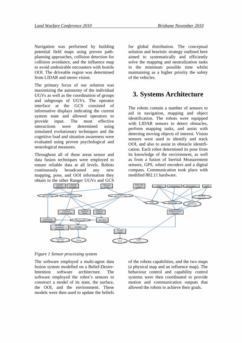
The robots contain a number of sensors to aid in navigation, mapping and object identification. The robots were equipped with LIDAR sensors to detect obstacles, perform mapping tasks, and assist with detecting moving objects of interest. Vision sensors were used to identify and track OOI, and also to assist in obstacle identifi-cation. Each robot determined its pose from its knowledge of the environment, as well as from a fusion of Inertial Measurement sensors, GPS, wheel encoders and a digital compass. Communication took place with modified 802.11 hardware.
Figure 1 Sensor processing system
The software employed a multi-agent data fusion system modelled on a Belief-Desire-Intention software architecture. The software employed the robot’s sensors to construct a model of its state, the surface, the OOI, and the environment. These models were then used to update the beliefs
of the robots capabilities, and the two maps (a physical map and an influence map). The behaviour control and capability control systems were then coordinated to provide motion and communication outputs that allowed the robots to achieve their goals.

Land Warfare Conference 2010 Brisbane November 2010
The block architecture and sensor processing system are shown in Figure 1.
From an initial high-level view of the Ranger prototype the following conceptual services were identified:
• Vehicle Controller: Received a trajectory plan from the path planner and vehicle synthesis information and created and executed a movement plan.
• OOI: Provided an interface with the LIDAR and video cameras and broadcasted an id and position of an OOI or Region of Interest.
• LIDAR: Provided an interface with the LIDAR (long and short) range equipment and broadcasted distances and land features.
• Vehicle Management: Received position and heading information and coalesced the information into consistent vehicle synthesis data for other services. It also interacted with the Inertial Navigation Unit to ensure that the vehicle's position was always known even when a GPS signal was lost.
• Path Planner: Received vehicle synthesis messages and the desired goal from the goal services and used the local map to determine the optimal trajectory for the vehicle.
• Goal Planner: Given the global and local maps and the vehicle's current state, it
determined what the goal of the vehicle currently had.
• Video Management: Received the global and local maps, as well as video features. It generated a pointcloud and determined the position and velocity of the vehicle.
• Collision Avoidance: Received a pointcloud of objects and the id's of OOIs in the vicinity, and generated a distance map for the vehicle.
• Landmark Detection: Received video and land features and local maps as well as distances of these landmarks, and generated a new local map for the vehicle.
• Map Generation: Provided interface with the SLAM; received local maps OOI ids, video and land features and an influence map, it generated a new local map with updated features.
4. Ground Vehicle Components and Systems
The MAGICian team consists of two ground vehicle platforms, the Ranger robot developed by the Western Australian team members and the Scout robot developed by the South Australian team members. Both robot types are shown in Figure 2.
Figure 2 WA ‘Ranger’ robot and SA ‘Scout’ robot

Land Warfare Conference 2010 Brisbane November 2010
4.1 Scout and Protector UGVs
Scout UGVs were a rugged lightweight Sensor UGV design that could negotiate 10cm steps with a payload of up to 2.5kg (total weight 8kg). The design mapping speed was 3.6km/h (1m/s) that matched well with the expected mapping resolution. Level and 1:4 (~15°) incline speed was up to 6km/h allowing the Scout UGV to escape from hostile OOI and 1:4 incline negotiation has been demonstrated at full payload.
The scout had 360° camera coverage at up to 30fps, as well as stereo vision, structured light and LIDAR ranging at the 8 (45°) compass points at the same framerate, giving it a resolution exceeding 80px/m at 6m at up to 30fps. At 5fps this resolution increases to over 200px/m at 6m. They were designed to be able to look round corners with their compass point camera and mirror arrangements. This allowed the Scout to assist in mapping and object tracking and neutralization activities.
The scout was based on a dual RS540 1/8 scale Remote Control Rock Crawler modifed with the addition of rear steering and a servo-actuated parking-brake. It carried up to a 8kg payload including: 4 50Wh LiPo batteries, Razor 9DoF Inertial Motion Measurement Unit, FSA03 GPS unit, 4 CPUs (1 FIT-PC2i with 802.11bg and DLink DWA-160 for 802.11abgn, 2 FIT-PC2 with 802.11bgn, Cerebot), a DLINK DIR-1522 or 855 Access Point (for 802.11abgn on 2.4 and 5GHz alternately resp. concurrently), and 6 Logitech cameras (4 C905 with side mirrors, enabling continuous 360° low resolution coverage at 25fps, and 2 Sphere PT cameras enabling 360 high resolution coverage at 10fps by panning).
The computational power was provided by 3 Atom Z530 processors at 5W, each controlling two USB cameras, with Gigabit
Ethernet and 802.11n WiFi, contributing another 5W. A Beagleboard+Cerebot 32MX4 servo board provided control. Logitech QuickCam Pro’s were packaged with an internal Class 2 laser on the Disruptor and a Class 2 9-laser array for ranging.
A variant on the Scout, the ‘Protector’, used the same chassis and similar payload. They were intended to provide protection to two Scout SUGVs and one Disruptor UGV by providing early warning of approaching hostile or non-combatant mobile OoI. In addition they recognized and tracked hostile mobile OoIs (HOoIs) at over 25m from their detection and lethality zones, and could thus participate in a neutralization from a considerable distance, providing redundancy and protection against interference in conjunction with a pair of such Scouts. The SA Disruptor designator was achieved by building a laser into the PT head of a Logitech Sphere, providing considerable flexibility in designation. Both Spheres of Protector designs were modified when converting to a Disruptor, so a single Disruptor could simultaneously designate two targets.
A lighter weight FastScout based on the Lynxmotion A4WD1 was tested too. It had a reduced payload including only 2 FIT-PCs/Z530s) and was designed for fast deployment and provision of wireless relay services based on the NEPSi protocol [2], as well as long range monitoring of enemy movements and detection of incursions by hostiles into swept areas.
4.2 WAMBot
The WA Ranger robot was based on the Pioneer AT3. It is equipped with SICK LMS 111 LIDAR scanners for medium-range operations, and Hoyuku laser scanners for short range operations. The robots include: a GPS, a digital compass, wheel encoders and an IMU for navigation tasks. The robot was equipped with a

Land Warfare Conference 2010 Brisbane November 2010
Logitech Sphere PT camera for identifying and tracking objects of interest, and a stereo camera system for detecting obstacles, determining the drivable surface and object recognition. All computing was performed on a set of high performance PC laptops with 802.11 WiFi/ethernet router using custom software to provide wireless mesh functionality.
The PIONEER 3-AT was a highly versatile all-terrain robotic platform, with 252 watt-hours of hot-swappable batteries providing up to six hours of charge. The WA team added an additional set of batteries and chargers enabling continuous operation. The platform measured 50cm x 49cm x 26cm and had a solid aluminium body with 21.5cm wheels enabling all-terrain operation. The P3-AT's powerful motors and four monster wheels could sustain 2.8 km/h over a variety of rugged terrain, enabling it to climb a 45% grade, and could carry a payload of up to 30 kg. The P3-AT base already came with a set of standard software functionality that has been extended over the years by the UWA/EECE Robotics&Automation lab.
The P3-AT robot included 100 tick encoders with inertial correction enabling dead reckoning and compensation for skid steering. The WA robot also contained a Vector 2X digital compass and used the stereo cameras for additional motion estimation allowing more precise pose estimation. The robot was also equipped with a MEMsense IMU/Gyro enabling further data fusion for determining the robot's pose when GPS was not available.
The SICK LMS 111 compact outdoor LIDAR provided high-resolution, high-accuracy planar range data, reliably detecting objects up to 18m away and was used in mapping operations. It had an ethernet interface to connect directly to the PC. The Hokuyo URG-04LX-UG01 Scanning Laser Rangefinder was angled towards the ground and provides distance
measurements for collision avoidance, and was interfaced directly via USB.
A Disruptor based on the Pioneer platform was acheived by substituting Logitech Sphere cameras modified by the SA team to include a laser designator.
5. UVS Autonomy and Coordination Strategy
All MAGICian units were autonomous in the sense that they prioritized and chose an action without requiring operator intervention. Multi-agent systems proved to be effective in modelling the interactions in large complex systems that involved multiple self-interested entities. To facilitate UGV communication and coordination at any time during the challenge, we needed to be able to find the agent, know its capabilities (eg: neutralising), and affect its decision-making should any manual intervention become desirable. Manual intervention included selecting sweep patterns, overall strategies, or target confirmation.
We addressed the following aspects using existing proven technologies as a starting point, and improving them to suit the challenge as we developed:
• System level UGV management
• High level UGV communication and task coordination
• Individual UGV
Figure 3 illustrates the overall Searching and Mapping operation. This covers exploration, which involved navigating to an unmapped region, and mapping the region with SLAM. Patrolling/Discovery involved searching an already mapped area for an object of interest or resource. During these tasks an object of interest may be detected which triggers the object identification and tracking behaviours, as illustrated in Figure 4.

Land Warfare Conference 2010 Brisbane November 2010
Figure 3 Search and Mapping Operations
Figure 4 Tracking Behaviour
The tracking behaviour involved locating a target by focusing the appropriate sensors on the region of interest and identifying the object with object recognition routines. If the object was a mobile object a following behaviour was executed in parallel. During the tracking of one OOI another OOI may come into view, requiring the parallel detection of additional regions of interest. The follow behaviour required navigation which was broken down into obstacle avoidance, hostile avoidance and path planning activities. The decision of which behaviour to activate was determined by a set of interacting agents:
• UGV Agent: In addition to the programs that conducted low-level sensor input analysis and actuator control, each UGV had a software agent that was goal oriented and responsible for high-level representation of its capabilities, resolving conflict goals, selecting plans based on the context and communicating with other agents when necessary.
• Personal Assistant Agent for Human Operators: To maximise the interoperability, each human operator sent information and commands via the GCS to the UGVs through their personal assistant agents, which assumed the same agent communication language and the same set of communication protocols to ensure unambiguous communication.
5.1 Mapping and Patrolling
At the system level, the Personal Assistant agent maintained an up-to-date Physical Map as well as an Influence Map. A standard influence map contained data regarding the location of hostile and friendly units allowing the identification of safe areas, dangerous areas, and conflict points. Our influence maps differed from the standard approach in that ours not only stored information of the dangerous enemy zone, it also had layers of information describing numerically where the desirable zone was for each of the team tasks. For example, in terms of mapping, an unexplored area would be more desirable than a fully mapped area. The Influence Map was also time based, so if an area had not been checked for a long time it would have a higher priority for patrolling behaviours. Individual agents would also maintain a local influence map. Therefore, the influence map serves as a data source for team level and individual level decision making, which is especially useful in determining patrol strategies. Maps were available in machine representation for use by UGVs as well as overlay and view formats for operators.

Land Warfare Conference 2010 Brisbane November 2010
5.2 Exploration
The exploration of an unknown space used a Multi-Robot Frontier-Based Exploration approach. This technique is based on the concept of frontiers, the boundary between explored and unexplored space. Our robots used a combination of "exploration groups" and pattern matching algorithms. Exploration groups were based on vehicles that were geographically close. These groups then coordinated their frontier selection to minimise the wasted effort that could arise from multiple vehicles selecting the same frontier. Pattern matching algorithms used experience from previous operational scenarios to determine the ideal exploration trajectories.
5.3 Tracking
Object tracking was a very difficult problem due to abrupt object motion, shadows, camera motion, and object occlusion. Our team had existing robust visual object tracking systems from previous work, such as, identifying overtaking vehicles for automotive applications. Our approach involved colour and template-based object tracking from regions of interest identified by the LIDAR and vision sensors. These classifiers were combined to provide fused responses using boosting techniques. As the operator confirmed OOI, these systems were configured towards favouring false-positives rather than missing identifications. Kinematic models of moving objects were maintained to enable tracking of occluded or shadowed OOI, coupled with standard state estimation techniques. These models were globally shared in the physical map, minimizing the likelihood of operators needing to re-identify non-combatant OOI and false positives.
5.4 Navigation
Navigation was an area of strength for our team. We have extensive experience with
robot navigation and collision avoidance for a number of platforms. Our approach used cameras to determine a ground plane to identify a driveable area, this approach has been proven in the development of automotive lane-change assistance by the WA team. This data was fused with information from the short range distance sensors to determine likely obstacles and modify the robots trajectory. The robot path was generated from the mapping information using a progressive realtime path planning implementation.
5.5 Coordination Protocols
Coordinating a group of vehicles to work together as a team is an area in which our team has extensive expertise from RoboCup and FIRA competitions, Ant colony optimization tasks and from industry work. We used a Market-Oriented-Programming (MOP) approach to the team coordination tasks. Participants in a MOP system may only offer to buy or sell quantities of a commodity at a fixed price. MOP techniques have been shown to solve distributed resource allocation problems effectively.
A distributed auctioneering algorithm was applied to team coordination tasks. Vehicles wishing to participate in the auction submited their prices for performing the task; the price based on the amount of resources they would need to expend in order to perform the task. This approach has been shown to be fault-tolerant in noisy and dynamic environments, and produced a distributed approximation to a global optimum of resource usage. Some modifications needed to be undertaken due to the different types of tasks that were to be performed (explore, track, neutralise.
Land Warfare Conference 2010 Brisbane November 2010
6. Sensors, processing and mapping for UGVs
All UGVs were fitted with Inertial Navigation System (INS), Wheel Encoders, Cameras, Global Positioning System (GPS) devices, and a Digital Compass. An integrated 6-DOF MEMS IMU, Compass and GPS module has been developed by the Flinders ISE group for this purpose. Position estimates were computed on-board using a dead-reckoning process based on an Extended Kalman Filter or using an Unscented Particle Filter with additional measurement data.
For the Protector UGV, a monocular 360° vision based target detection and tracking system was developed to enable the UGVs to accurately localize themselves within their surroundings. The system used a spinning mirror to allow all-round vision. Images were first deblurred then enhanced using super-resolution reconstruction and finally stitched together to form an all-round panorama. Features located within successive panorama frames were used to determine motion from optical-flow and facilitate simultaneous localization and mapping (SLAM) methods from pose-estimates. Additional pose information was extracted from measurement data obtained from the LIDAR units. Similar methods have been successfully applied in our Autonomous Underwater Vehicle project, which has no access to GPS below the water surface. In addition, four 7° FoV cameras provided longrange 360° coverage with partial overlap. The standard Scouts were identical except they used 8 static 66° FoV with 21° overlap and stereo+laser ranging.
The BU-353 USB GPS receiver was specified for navigation checks on the Scouts, and GPS (plus gyros etc) was built
into our navigation boards on other classes of vehicle, but given urban canyon conditions, accuracy to even 2m with GPS or DGPS was not expected. Thus primary reliance was dead reckoning corrected against UAV waypoints and GPS as available. Our camera-based servo technology increased accuracy for dead reckoning beyond what might be expected from DGPS between UAV mapped waypoints, which will be used to correct drift and GPS error.
7. Acknowledgements
This material is based on research sponsored by the Air Force Research Laboratory, under agreement number FA2386-10-4024. The U.S. Government is authorized to reproduce and distribute reprints for Governmental purposes notwithstanding any copyright notation thereon. The views and conclusions contained herein are those of the authors and should not be interpreted as necessarily representing the official policies or endorsements, either expressed or implied, of the Air Force Research Laboratory or the U.S. Government.
8. References
[1] L.S. Smith, Unsolved military noise, J. Acoust. Soc. Am. 24: 769-772, 1952; [2] Darryl K Sharman and David M W Powers (1999) Hardware System Simulation, pp395-417 in Rajkumar Buyya, Hi Performance Cluster Computing V2: Programming and applications, Prentice-Hall