mack t13 task force meeting - test monitoring center
TRANSCRIPT
Mack T13 Task Force Meeting:
Location: San Antonio, TX at IAR and SwRI
Date: 8/27/13
Summary:
Stand Inspections and Setup Discussion
Stand inspections were conducted in the morning at both IAR and SwRI. The location of measurement probes for the intake air and exhaust were found to have a large discrepancy between labs. It was asked that labs share location information to develop a specification.
• EGR Outlet thermocouple was found to be commonly located between IAR and SwRI at ~5” above the crossover pipe clamp on the right side of the engine.
• It was brought up that exhaust probe measurements should be located at a distance from the end of the factory turbo diffuser (21040354) rather than the turbine outlet.
• For intake air, each lab will define pipe diameter, total distance from compressor inlet, straight length which temperature and pressure are measured, and number of elbows/bends after ports.
• The length of lines running to the external oil cooler need to be defined. It was noted that the same cooler is used for the C13 (ASTM D7549). For reference, the following wording is used in Annex A12 of D7549:
o A12.3 Oil Lines and Fittings—Use two size No.16 oil lines with a maximum length of 914 mm (Total of both lines), preferably made from stainless steel braided hose . Use size No.16 NPT threaded fittings for the line connections.
• Oil Samples should be taken from the engine so that analysis can continue if/when the oil adder system is empty. The method IAR is using, pulling sample from the external oil cooler, was presented as a possible option. The option of pulling directly off the galley to obtain post-filter oil was mentioned, but there was concern that a sample taken here may result in galley pressure protection limits to be tripped and result in unintended engine shutdowns.
• A pressurized fill location for the engine needs to be defined for commonality between labs. • Coolant outlet was measured at different locations between labs. Each lab is to report the
distance from the factory outlet block for thermocouple location o Jim Moritz had placed two thermocouples in the coolant outlet stream, offered to
provide data on the delta between measurement directly on the outlet block compared to a measurement taken downstream of his sight gage.
• The auxiliary oil system setup should utilize the same size lines as the T12 test procedure. A ½” threaded coupling is being used by Riccardo in his pan that has a fixed pickup location.
• The charge air intercooler differs lab to lab. It was mentioned that it may be beneficial to specify a delta pressure from inlet to outlet rather than a Modine part number requirement.
o Jim Moritz has used another type of intercooler with theT13 test with positive results

o Jim McCord mentioned another Modine-like cooler available from a supplier near San Antonio at a reduced cost.
• The mounting of the engine should be flat front-to-back with a 4° tilt to the ECM side of the engine.
• Oil Sump thermocouple location in the pan is set based upon the documentation provided by Riccardo. The adder pickup location is still being developed based on targeting a specific oil adder volume at one hour of test time
• CO2 measurements should be conducted using a sampling device which cools to <5°C to remove moisture.
Test Operation Discussion:
Currently, tests run at XOM, IAR, and SwRI have been conducted using an adjustable oil adder pickup which is set to target an adder system volume of 3000-3500grams at a test time of one hour. The “full level” utilized for the oil adds/drains during the test is set as the adder system volume at 4 hours of test time. There was some discussion if this was too early in the test to establish a full mark. Both IAR and SwRI had a much larger volume of oil force drained at the first oil add (24 hours) than XOM did in the test data that was presented.
For oil consumption calculations, a value should be calculated each 12-hour interval (sample interval later in test) rather than 24 hour interval (oil addition interval)
Bob Campbell brought up the question of what parameter actually ranks the oils. Looking at the various chemical data presented, different oils may have different oxidation peak, area, PDSC, and other parameter responses which could rank oils differently depending on the importance of each.
It is desired that labs report piston deposit ratings along with other post-test data at this point for possible future use. At this point, Riccardo has been using the Volvo method for ratings. Greg will be looking into the distribution of this method which differs from the CRC method.
A lack of power at the start of test can be indicative of incorrect cam/crank timing. Riccardo provided a method for checking this with a scope once the engine is built.
Pre/post test cylinder head inspections have, so far, shown that a head will last about 2 runs. At this point they should be rebuilt with new seats, guides, valves, seals, etc. The procedure for seat replacement in the service manual involves notching and welding onto the valve seat, however this may not be necessary to remove the component.
Operational Data Presented:
A comparison of operational data between the three labs which have run the T12 reference oil was presented and is attached. There seems to be consistency between labs in engine operation.
The first run at SwRI showed a very mild response compared to those conducted at IAR and Exxon. Mark Cooper (Oronite) presented findings related to the large copper level seen over the first 125 hours of the test. This copper appeared to be tied back to an anti-seize compound used for injector installation. The compound was dissolved in ULSD and ICP run on it. Findings showed very high levels of Cu, which Bob Campbell pointed out sometimes has an impact on Pb readings from ICP testing. Pat Fetterman also noted that the levels of moly seen in the anti-seize may have played a part in driving the test mild, although they did not show up in the used oil like the copper did.
Greg Shank covered the data that was presented to the NCDT group the prior week. Oils are beginning to be run which show a differing response from the T12 reference oil in oxidation. These oils are using a PC11A technology. Some liner wear may be measured on EOT components as well.
Engine Control, Vision, CAN communications:
John Doub (Volvo) called in to address some of the questions regarding the CAN throttle which will be utilized on stands going forward in the PC-11 matrix. The two largest concerns were:
• Output signals for correct throttle response • Control of VGT and EGR position outside of using Vision software
John indicated that the main component required in each lab was a bridge from whatever data acquisition and control system the labs use to a CAN bus for the pedal demand. Since each lab has unique installation set-up, John will be working with each individually to address specific issues.
There is concern with the long term use of Vision on both license updates and cost. John may have a windows passed application to provide similar control of just these two items. He indicated that as long as the proper memory location was being written to, there shouldn’t be any issue with providing this control outside of Vision.
The list of fault codes seen while running was presented. John indicated that a number of these can be eliminated by providing additional signals through the CAN bus along with the desired throttle output. This information is covered in the CAN application documented he provided to the labs. He may be able to create a new flash file which hides these flags.
Riccardo brought up further flattening the engine response to manifold boost, compressor discharge, and ambient pressure sensors. Since the boost and compressor discharge is varied throughout the test to control the CO2 rates, the engine operation may shift based on these parameters.
Kevin indicated that there may be a chance of limiting engine response in the calibration, but we may also want to look at providing the sensors with false signals (resistor in the harness or voltage from instrumentation stand) to accomplish this goal.

Critical Parts and Hardware Issues:
Mark Sutherland (TEI) informed the group that the T13 power assembly is currently available as a kit. There are some items in the kit which will not be used, but it is the only way that some of the required components are currently available.
Mark will be determining how many sets of components can be ordered for T13 rebuilds at once. Based upon this, a decision will be made on receiving batch quantities and sizes.
Other Business:
Riccardo and Sean Moyer (TMC) will work on the development of a data dictionary based on the T12 form. They will indicate what changes are needed on each page of the report to modify it for T13 purposes
Mike Birke (SwRI) will be addressing the need to tighten up the chemical test results from the various labs. He will need a contact at each lab to discuss test methodology and consistency. Please provide this contact to Jim McCord or Robert Warden
Scope and Objectives were reviewed and will be updated to include an expected completion date for each of the listed objectives. Lubricant oxidation will become a primary test parameter, while top ring side wear will be removed. Piston deposits will be added to the list of secondary test parameters.
A workshop will be organized, preferably at one of the San Antonio labs, to develop commonality of approach in rebuilding engines and cylinder heads.
The next Face-to-Face meeting will be hosted by Afton in Richmond before 11/12/2013
Key Action Item Recap:
• All labs: instrumentation measurement ports • All labs: Provide point-of-contact information for chemistry test discussions to Robert Warden • TEI: determine how many kits are available for distribution • Riccardo: provide final oil pickup location once validated • Volvo: Distribution of information regarding Volvo piston rating method • John Doub: Supporting lab transition to CAN
Volvo T13 CPD Report
Mark Sutherland 8/25/2013

Volvo T13 CPD Report Contents
• Issues/Updates/Observations – Engine Parts
Mark Sutherland 8/25/2013
Volvo T13 CPD Report Parts
• No parts currently on order
Mark Sutherland 8/25/2013

Volvo T13 CPD Report Parts List
MACK MP8 T-13 OVERHAUL KIT
PART No. Combine DESCRIPTION 21170742 P06 85124806 Piston 20852790 P05 Liner 21251596 P03 Ring – top 20590309 P32 Ring - second 20568155 P34 Ring - oil 20569833 P32 Pin 914531 P01 Snap Rings 470922 P03 Liner Seal – top at flange 470190 P05 Liner Seal – lower – top and middle 21430623 P01 Liner Seal – lower – bottom 20530902 20530916 Main Bearings – Upper 20530900 Main Bearings – Lower 20508264 20580558 Rod Bearings – Upper 20530094 Rod Bearings – Lower 276948 KIT, Injector O-Ring 469846 O-RING, Oil Pressure Relief INNER 471626 SEAL, Oil Filter Hsng. Tubes ( rear adptr plug )
943177 O-RING, Gear Plate Stud ( Lwr idler gear mounting block )
947760 BOLT, Crank Gear 948610 SEAL. Oil Press. Relief COVER 967343 O-RING, Venturi /EGR X-over 974320 PETCOCK, EGR Cooler 975675 O-RING, Coolant Pipe ( lower extension ) 977030 O-RING, Fuel Pmp/Pwr. Strng Combination Pump 983475 BOLT, Idler Gear 984735 BOLT, Gear Plate (attaches to rear cyl head ) 984738 FLANGE, Screw 984761 BOLT, Cam Cap ( outboard ) 984815 BOLT, Vibration Damper 990861 BOLT, Crankcase Girdle 992065 O-RING, Crank Gear/Comp. block-off plate 993167 SPACER, Exh. Manifold 994445 BOLT, Piston Oil Jet 1544733 CLAMP, Turbo Inlet Elbow ( SMALL end ) 1547254 SEAL, Upper Coolant Manifold 1547255 SEAL, Oil Supply/Return Tubes 1677370 SEAL, Crossover Tube ( dummy oil solnd ) 8192804 BOLT, Cam Gear/Inj. Hold-Down 20412482 BOLT, Rear Cam Cap 20430678 SEAL, Water Pmp to Oil Cooler 20451487 SEAL, Oil Pump ( p/u tube ) 20483919 BOLT, Dual Idler to Block
Mark Sutherland 8/25/2013
20486228 BOLT, Connecting Rod 24 20504408 CLAMP, Venturi/EGR Crossover Pipe 3 20526428 SEAL, Turbo, EGR, Oil Dummy Solnd. Supply 4 20532891 GASKET, CC Separator to Block 1 20538793 SEAL, Rocker Cover 1
20551483 SEAL, Oil Cooler ( utilized for internal cooler block-offs ) 2
20590125 CLAMP, Turbo Inlet Elbow ( BIG end ) 1 20781146 GASKET, Turbo to Exh. Manifold 1
20787167 GASKET, Oil Filter Housing 1 20805850 SEAL, Intake Manifold 1 20817742 GASKET, Rear Upper Timing Cvr. 1 20852765 SEAL, Fuel System Banjos 8 20855371 Gasket, Exhhaust Manifold 6 20972295 FILTER, Fuel 1 20999623 BEARING, Cam ( Caps 1 - 6 ) 6 21007187 GASKET, Turbo to Diffuser Pipe ( metal shim-type ) 1 21050240 BOLT, Lwr. Idler ( small ) Gear 1 21092243 SEAL, Oil Pump Tubes 7 21095721 GASKET, Diffuser ( pipe end ) 1 21119814 PIPE, EGR rear 1 21122541 OIL SEPARATOR Assm. 1 21164790 SENSOR, EGR Temp. 1 21185132 SEAL, End Cap ( rear upper timng cvr. ) 2 21228220 HOSE, Turbo Inlet 1 21293367 GASKET, Oil Pan 1 21294062 SEAL, Oil Cooler Hsng. Cover 1 21298915 SEAL, Coolant Housing to Cyl. Head 1 21344746 BOLT, Flywheel 14 21344778 BOLT, Cam Caps ( 1 thru 6 ) 12 21344787 BOLT, Exh. Manifold 12 21345129 BOLT, Main BEARING 14 21345131 BOLT, Cyl. Head 38 21347087 SEAL, Crankshaft Front 1 21510072 GASKET, Cyl Head 1 21532258 O-RING, CC Separator Tube ( to Valv. Cvr. ) 1 21707135 FILTER, Oil - Bypass 1 21707136 FILTER, Oil - Full Flow 2 21713917 SENSOR, Diiferential Press. 1 21780371 O-RING, Oil Fltr. Hsng Cooling Tube (front adptr ) 1 21937327 FILTER, Coolant 1 21948053 VENTURI 1 85131446 BEARING, Cam ( Cap #7 ) 1 85133799 KIT, EGR Valve Replacement 1 CORE DEPOSIT 85136428 KIT, EGR Cooler 1 CORE DEPOSIT

Questions ?
Mark Sutherland 8/25/2013
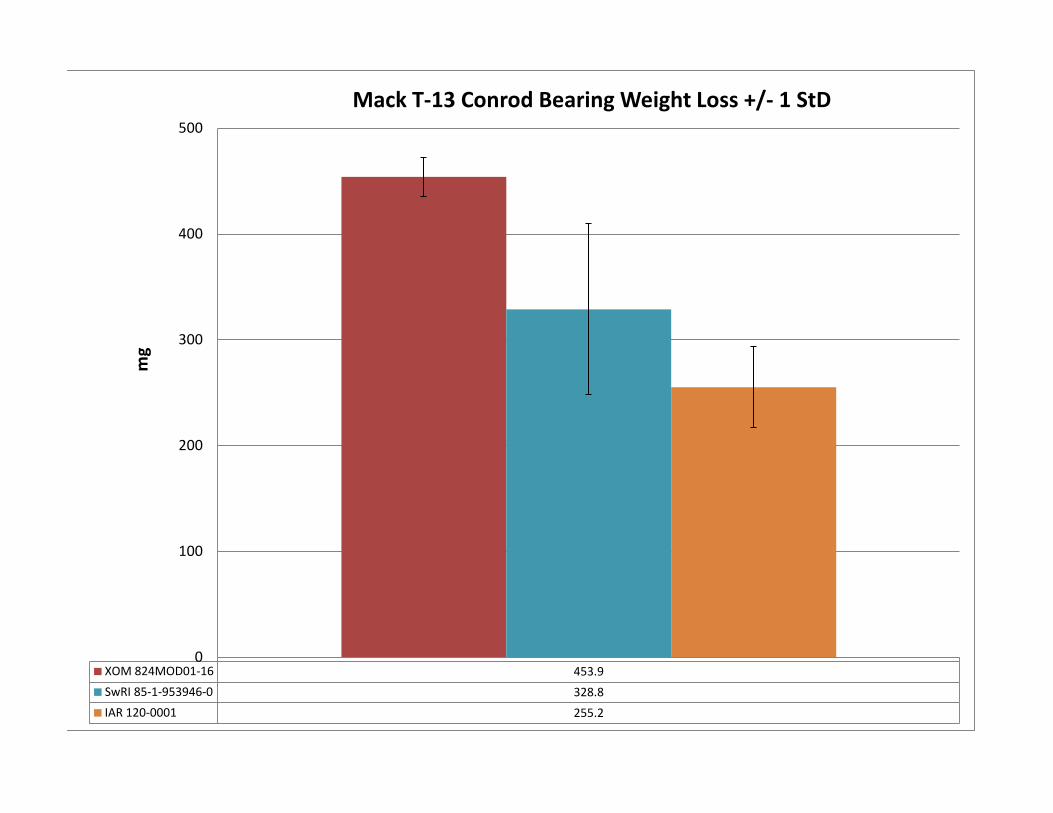
XOM 824MOD01-16 453.9 SwRI 85-1-953946-0 328.8 IAR 120-0001 255.2
0
100
200
300
400
500 m
g
Mack T-13 Conrod Bearing Weight Loss +/- 1 StD
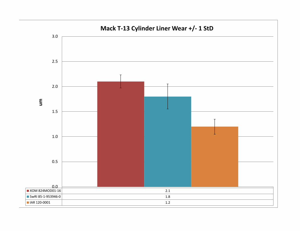
XOM 824MOD01-16 2.1 SwRI 85-1-953946-0 1.8 IAR 120-0001 1.2
0.0
0.5
1.0
1.5
2.0
2.5
3.0 um
Mack T-13 Cylinder Liner Wear +/- 1 StD
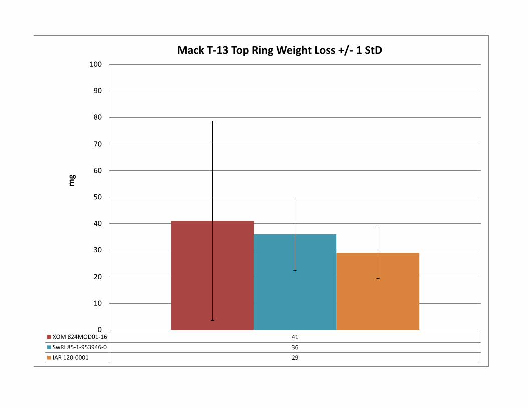
XOM 824MOD01-16 41 SwRI 85-1-953946-0 36 IAR 120-0001 29
0
10
20
30
40
50
60
70
80
90
100 m
g
Mack T-13 Top Ring Weight Loss +/- 1 StD
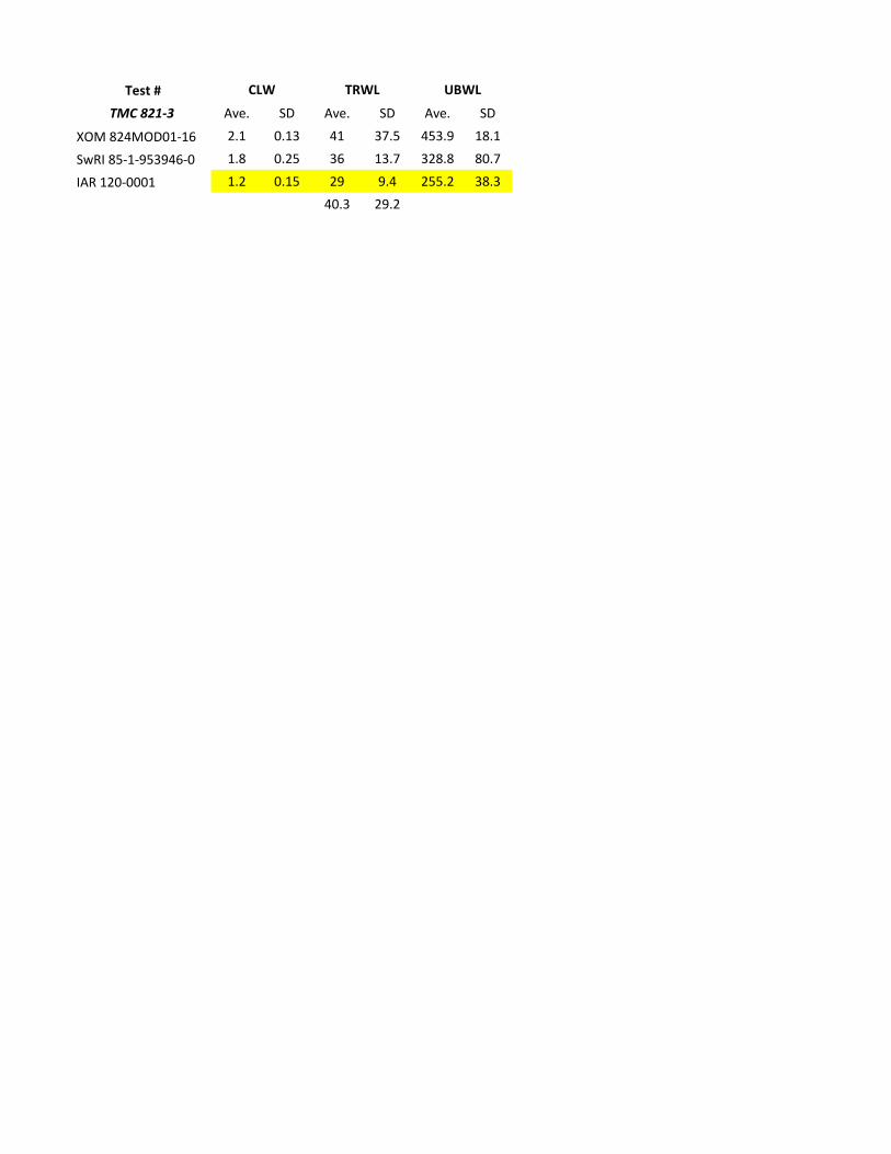
Test #TMC 821-3 Ave. SD Ave. SD Ave. SD
XOM 824MOD01-16 2.1 0.13 41 37.5 453.9 18.1
SwRI 85-1-953946-0 1.8 0.25 36 13.7 328.8 80.7
IAR 120-0001 1.2 0.15 29 9.4 255.2 38.340.3 29.2
CLW TRWL UBWL
1
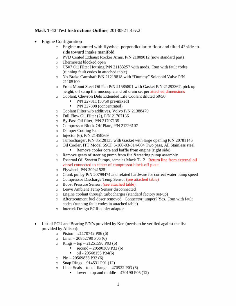
Mack T-13 Test Instructions Outline, 20130821 Rev.2 • Engine Configuration
o Engine mounted with flywheel perpendicular to floor and tilted 4° side-to-side toward intake manifold
o PVD Coated Exhaust Rocker Arms, P/N 21809012 (now standard part) o Thermostat blocked open o US07 Oil Filter Housing P/N 21183257 with mods. Run with fault codes
(running fault codes in attached table) o No-Brake Camshaft P/N 21219818 with “Dummy” Solenoid Valve P/N
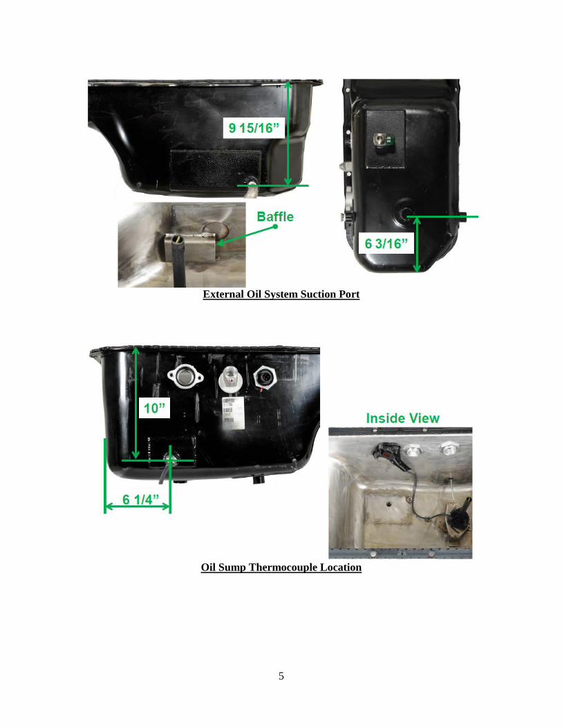
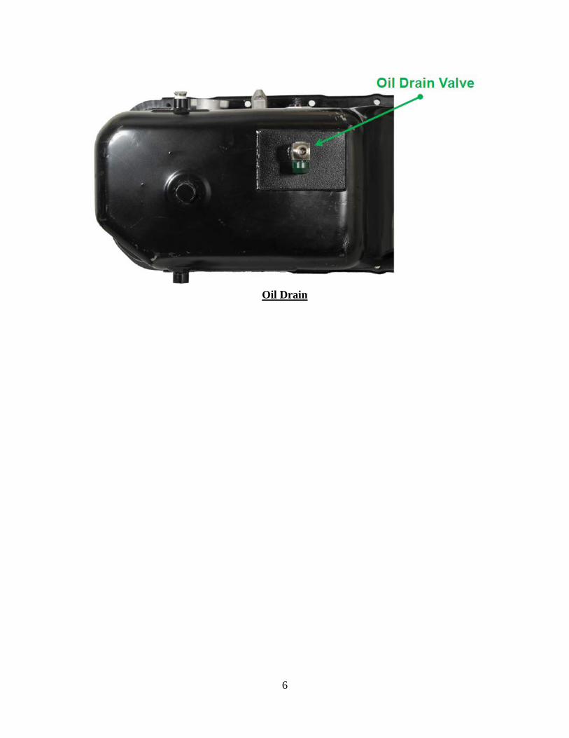
21105100 o Front Mount Steel Oil Pan P/N 21585801 with Gasket P/N 21293367, pick up
height, oil sump thermocouple and oil drain set per attached dimensions o Coolant, Chevron Delo Extended Life Coolant diluted 50/50
P/N 227811 (50/50 pre-mixed) P/N 227808 (concentrated)
o Coolant Filter w/o additives, Volvo P/N 21388479 o Full Flow Oil Filter (2), P/N 21707136 o By-Pass Oil filter, P/N 21707135 o Compressor Block-Off Plate, P/N 21226107 o Damper Cooling Fan o Injector (6), P/N 21458369 o Turbocharger, P/N 85128135 with Gasket with large opening P/N 20781146 o Oil Cooler, ITT Model SSCF 5-160-03-014-004 Two pass, All Stainless steel
Remove cooler core and baffle from engine (right side) o Remove gears of steering pump from fuel&steering pump assembly o External Oil System Pumps, same as Mack T-12. Return line from external oil
vessel connected to center of compressor block-off plate. o Flywheel, P/N 20941525 o Crank pulley P/N 20799474 and related hardware for correct water pump speed o Compressor Discharge Temp Sensor (see attached table) o Boost Pressure Sensor, (see attached table) o Leave Ambient Temp Sensor disconnected o Engine coolant through turbocharger (standard factory set-up) o Aftertreatment fuel doser removed. Connector jumper? Yes. Run with fault
codes (running fault codes in attached table) o Intertek Design EGR cooler adaptor
• List of PCU and Bearing P/N’s provided by Ken (needs to be verified against the list provided by Allison):
o Piston – 21170742 P06 (6) o Liner – 20852790 P05 (6) o Rings – top – 21251596 P03 (6)
second – 20590309 P32 (6) oil - 20568155 P34(6)
o Pin – 20569833 P32 (6) o Snap Rings – 914531 P01 (12) o Liner Seals – top at flange – 470922 P03 (6)
lower – top and middle – 470190 P05 (12)
2
lower – bottom – 21430623 P01 (6) o Main Bearings – Upper – 20530902 (7)
Lower – 20530900 (7) o Rod Bearings – Upper – 20508264 (6)
Lower – 20530094 (6)
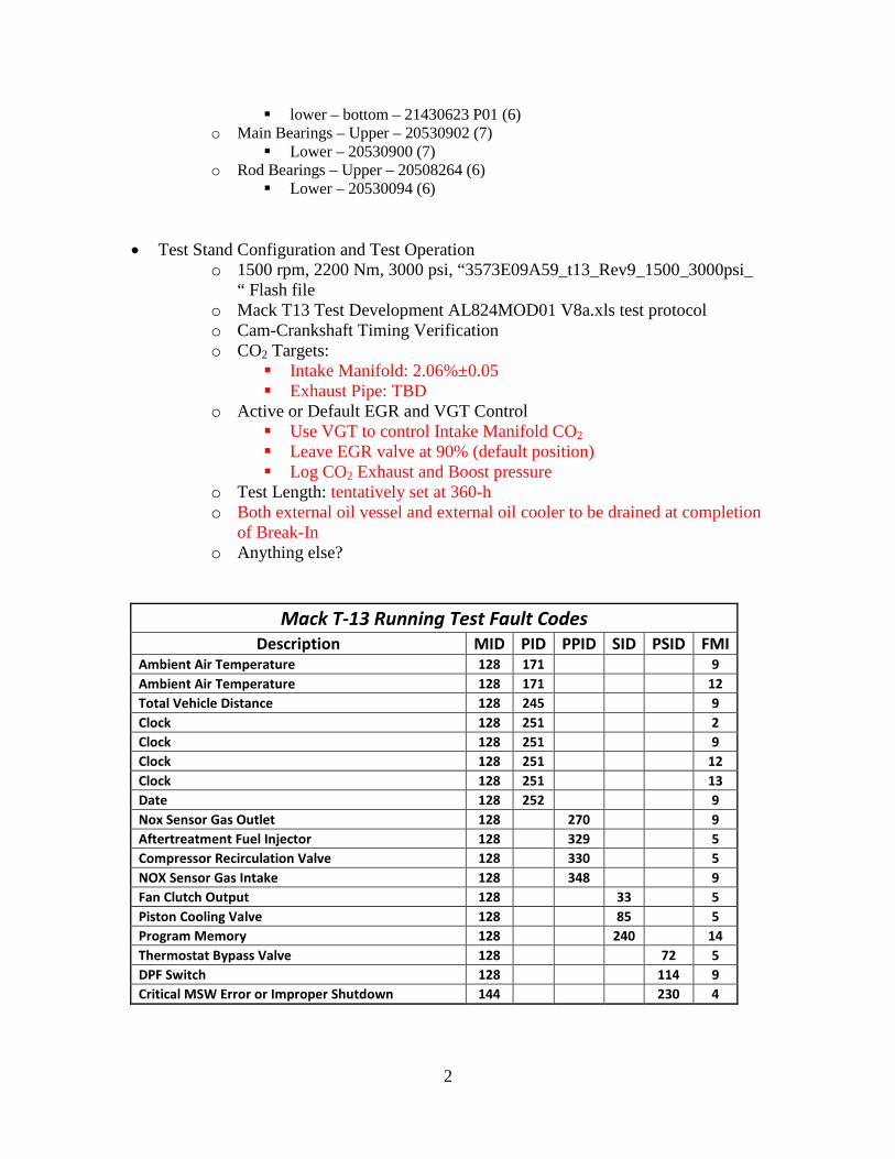
• Test Stand Configuration and Test Operation
o 1500 rpm, 2200 Nm, 3000 psi, “3573E09A59_t13_Rev9_1500_3000psi_ “ Flash file
o Mack T13 Test Development AL824MOD01 V8a.xls test protocol o Cam-Crankshaft Timing Verification o CO2 Targets:
Intake Manifold: 2.06%±0.05 Exhaust Pipe: TBD
o Active or Default EGR and VGT Control Use VGT to control Intake Manifold CO2 Leave EGR valve at 90% (default position) Log CO2 Exhaust and Boost pressure
o Test Length: tentatively set at 360-h o Both external oil vessel and external oil cooler to be drained at completion
of Break-In o Anything else?
Mack T-13 Running Test Fault Codes Description MID PID PPID SID PSID FMI
Ambient Air Temperature 128 171 9 Ambient Air Temperature 128 171 12 Total Vehicle Distance 128 245 9 Clock 128 251 2 Clock 128 251 9 Clock 128 251 12 Clock 128 251 13 Date 128 252 9 Nox Sensor Gas Outlet 128 270 9 Aftertreatment Fuel Injector 128 329 5 Compressor Recirculation Valve 128 330 5 NOX Sensor Gas Intake 128 348 9 Fan Clutch Output 128 33 5 Piston Cooling Valve 128 85 5 Program Memory 128 240 14 Thermostat Bypass Valve 128 72 5 DPF Switch 128 114 9 Critical MSW Error or Improper Shutdown 144 230 4
3
4
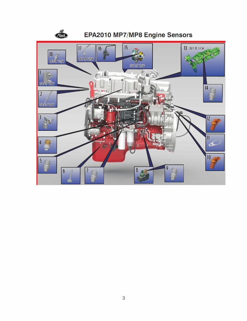
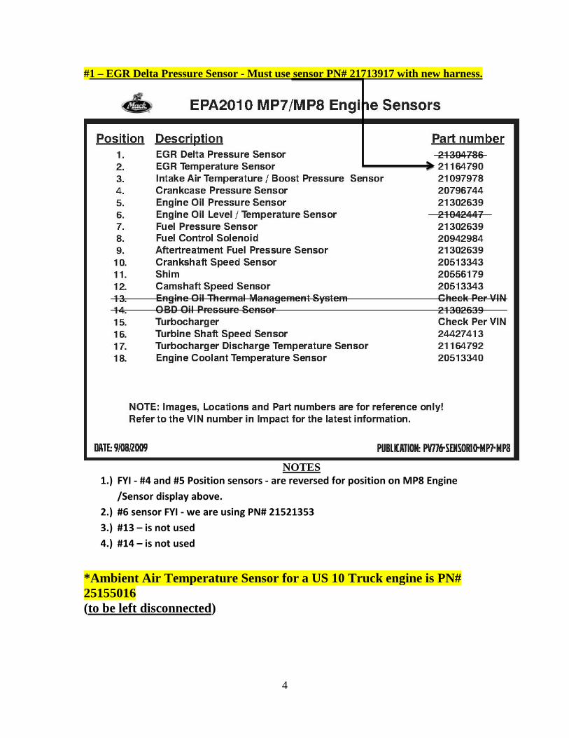
#1 – EGR Delta Pressure Sensor - Must use sensor PN# 21713917 with new harness.
NOTES
1.) FYI - #4 and #5 Position sensors - are reversed for position on MP8 Engine /Sensor display above.
2.) #6 sensor FYI - we are using PN# 21521353 3.) #13 – is not used 4.) #14 – is not used
*Ambient Air Temperature Sensor for a US 10 Truck engine is PN# 25155016 (to be left disconnected)
5
External Oil System Suction Port
Oil Sump Thermocouple Location
6
Oil Drain
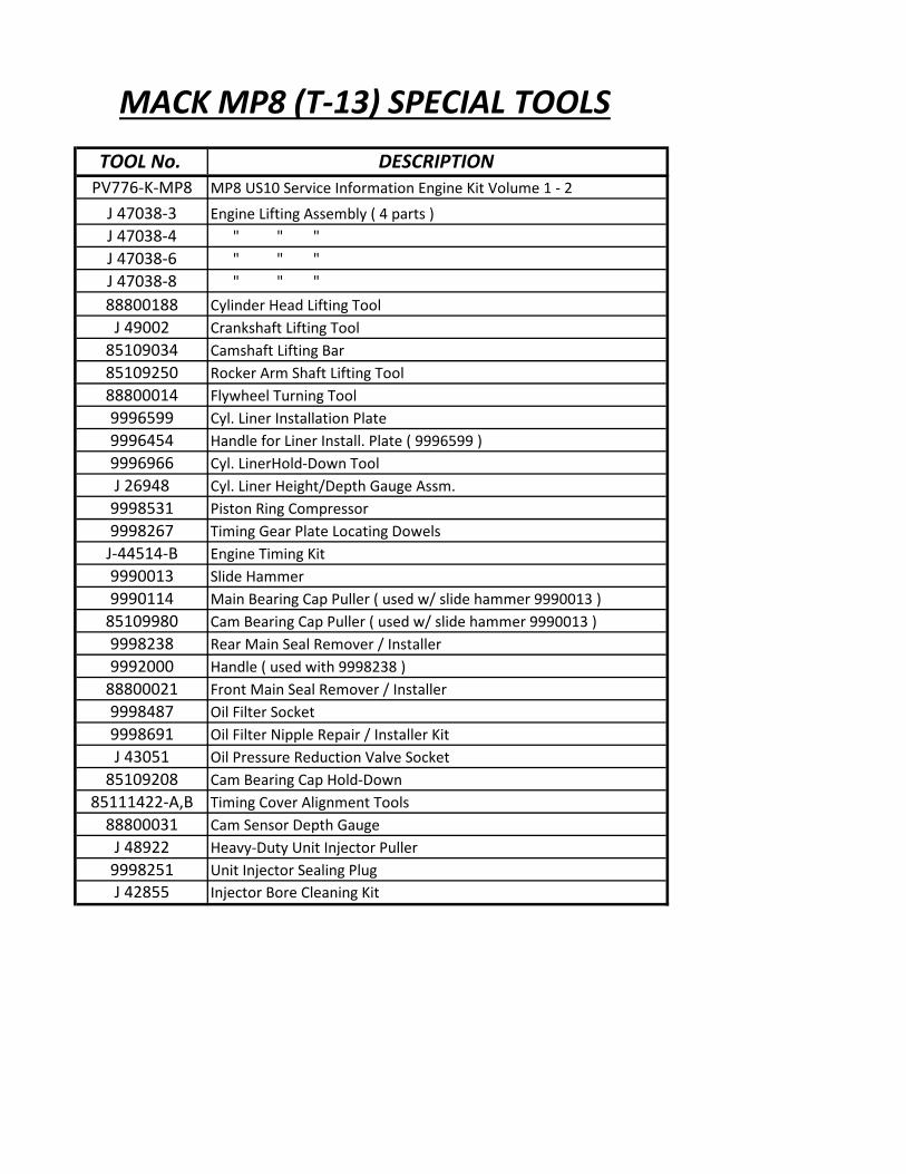
MACK MP8 (T-13) SPECIAL TOOLSTOOL No. DESCRIPTION
PV776-K-MP8 MP8 US10 Service Information Engine Kit Volume 1 - 2J 47038-3 Engine Lifting Assembly ( 4 parts )J 47038-4 " " "J 47038-6 " " " J 47038-8 " " " 88800188 Cylinder Head Lifting Tool
J 49002 Crankshaft Lifting Tool85109034 Camshaft Lifting Bar85109250 Rocker Arm Shaft Lifting Tool88800014 Flywheel Turning Tool9996599 Cyl. Liner Installation Plate9996454 Handle for Liner Install. Plate ( 9996599 )9996966 Cyl. LinerHold-Down ToolJ 26948 Cyl. Liner Height/Depth Gauge Assm.
9998531 Piston Ring Compressor9998267 Timing Gear Plate Locating Dowels
J-44514-B Engine Timing Kit9990013 Slide Hammer9990114 Main Bearing Cap Puller ( used w/ slide hammer 9990013 )
85109980 Cam Bearing Cap Puller ( used w/ slide hammer 9990013 )9998238 Rear Main Seal Remover / Installer 9992000 Handle ( used with 9998238 )
88800021 Front Main Seal Remover / Installer9998487 Oil Filter Socket9998691 Oil Filter Nipple Repair / Installer KitJ 43051 Oil Pressure Reduction Valve Socket
85109208 Cam Bearing Cap Hold-Down 85111422-A,B Timing Cover Alignment Tools
88800031 Cam Sensor Depth GaugeJ 48922 Heavy-Duty Unit Injector Puller
9998251 Unit Injector Sealing PlugJ 42855 Injector Bore Cleaning Kit
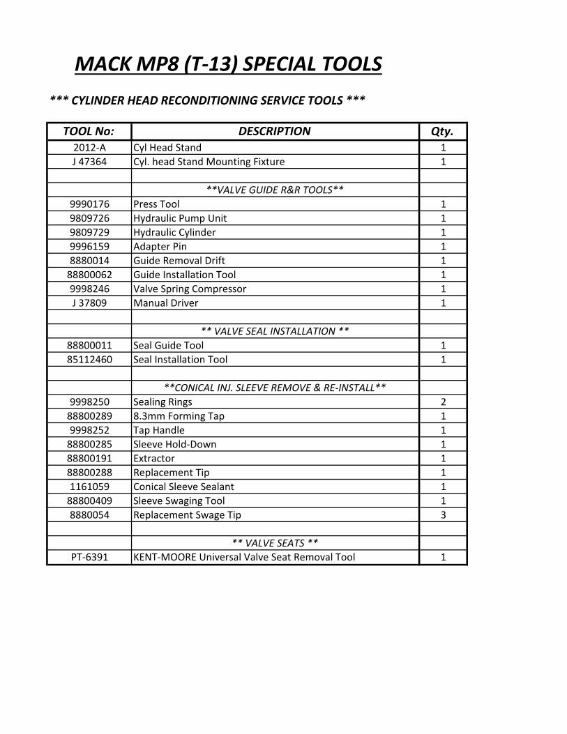
MACK MP8 (T-13) SPECIAL TOOLS*** CYLINDER HEAD RECONDITIONING SERVICE TOOLS ***
TOOL No: DESCRIPTION Qty.2012-A Cyl Head Stand 1J 47364 Cyl. head Stand Mounting Fixture 1
**VALVE GUIDE R&R TOOLS**9990176 Press Tool 19809726 Hydraulic Pump Unit 19809729 Hydraulic Cylinder 19996159 Adapter Pin 18880014 Guide Removal Drift 1
88800062 Guide Installation Tool 19998246 Valve Spring Compressor 1J 37809 Manual Driver 1
** VALVE SEAL INSTALLATION **88800011 Seal Guide Tool 185112460 Seal Installation Tool 1
**CONICAL INJ. SLEEVE REMOVE & RE-INSTALL**9998250 Sealing Rings 2
88800289 8.3mm Forming Tap 19998252 Tap Handle 1
88800285 Sleeve Hold-Down 188800191 Extractor 188800288 Replacement Tip 11161059 Conical Sleeve Sealant 1
88800409 Sleeve Swaging Tool 18880054 Replacement Swage Tip 3
** VALVE SEATS **PT-6391 KENT-MOORE Universal Valve Seat Removal Tool 1
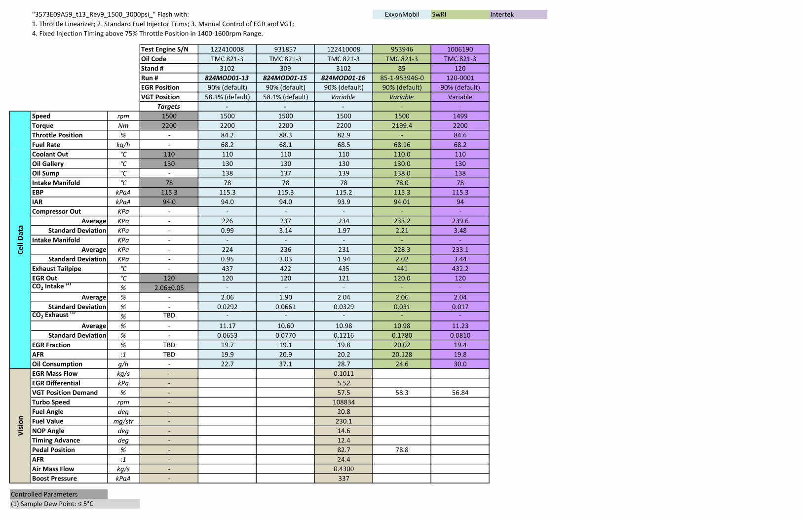
"3573E09A59_t13_Rev9_1500_3000psi_" Flash with: ExxonMobil SwRI Intertek1. Throttle Linearizer; 2. Standard Fuel Injector Trims; 3. Manual Control of EGR and VGT;4. Fixed Injection Timing above 75% Throttle Position in 1400-1600rpm Range.
Test Engine S/N 122410008 931857 122410008 953946 1006190Oil Code TMC 821-3 TMC 821-3 TMC 821-3 TMC 821-3 TMC 821-3Stand # 3102 309 3102 85 120Run # 824MOD01-13 824MOD01-15 824MOD01-16 85-1-953946-0 120-0001EGR Position 90% (default) 90% (default) 90% (default) 90% (default) 90% (default)VGT Position 58.1% (default) 58.1% (default) Variable Variable Variable
Targets - - - - -Speed rpm 1500 1500 1500 1500 1500 1499Torque Nm 2200 2200 2200 2200 2199.4 2200Throttle Position % - 84.2 88.3 82.9 - 84.6Fuel Rate kg/h - 68.2 68.1 68.5 68.16 68.2Coolant Out °C 110 110 110 110 110.0 110Oil Gallery °C 130 130 130 130 130.0 130Oil Sump °C - 138 137 139 138.0 138Intake Manifold °C 78 78 78 78 78.0 78EBP kPaA 115.3 115.3 115.3 115.2 115.3 115.3IAR kPaA 94.0 94.0 94.0 93.9 94.01 94Compressor Out KPa - - - - - -
Average KPa - 226 237 234 233.2 239.6Standard Deviation KPa - 0.99 3.14 1.97 2.21 3.48
Intake Manifold KPa - - - - - -Average KPa - 224 236 231 228.3 233.1
Standard Deviation KPa - 0.95 3.03 1.94 2.02 3.44Exhaust Tailpipe °C - 437 422 435 441 432.2EGR Out °C 120 120 120 121 120.0 120CO2 Intake (1)
% 2.06±0.05 - - - - -Average % - 2.06 1.90 2.04 2.06 2.04
Standard Deviation % - 0.0292 0.0661 0.0329 0.031 0.017CO2 Exhaust (1)
% TBD - - - - -Average % - 11.17 10.60 10.98 10.98 11.23
Standard Deviation % - 0.0653 0.0770 0.1216 0.1780 0.0810EGR Fraction % TBD 19.7 19.1 19.8 20.02 19.4AFR :1 TBD 19.9 20.9 20.2 20.128 19.8Oil Consumption g/h - 22.7 37.1 28.7 24.6 30.0EGR Mass Flow kg/s - 0.1011EGR Differential kPa - 5.52VGT Position Demand % - 57.5 58.3 56.84Turbo Speed rpm - 108834Fuel Angle deg - 20.8Fuel Value mg/str - 230.1NOP Angle deg - 14.6Timing Advance deg - 12.4Pedal Position % - 82.7 78.8AFR :1 - 24.4Air Mass Flow kg/s - 0.4300Boost Pressure kPaA - 337
Controlled Parameters(1) Sample Dew Point: ≤ 5°C
Visi
onCe
ll Da
ta
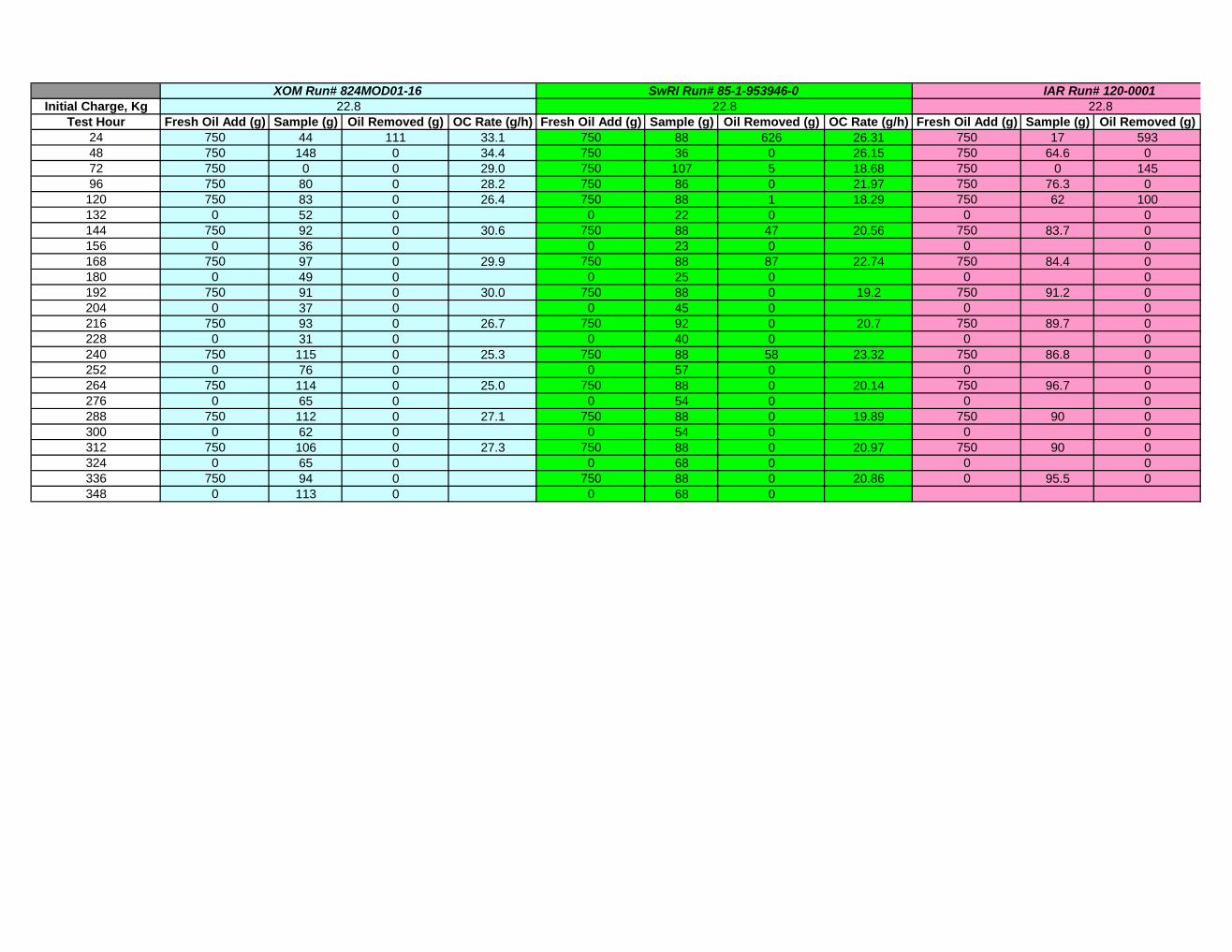
Initial Charge, KgTest Hour Fresh Oil Add (g) Sample (g) Oil Removed (g) OC Rate (g/h) Fresh Oil Add (g) Sample (g) Oil Removed (g) OC Rate (g/h) Fresh Oil Add (g) Sample (g) Oil Removed (g)
24 750 44 111 33.1 750 88 626 26.31 750 17 59348 750 148 0 34.4 750 36 0 26.15 750 64.6 072 750 0 0 29.0 750 107 5 18.68 750 0 14596 750 80 0 28.2 750 86 0 21.97 750 76.3 0
120 750 83 0 26.4 750 88 1 18.29 750 62 100132 0 52 0 0 22 0 0 0144 750 92 0 30.6 750 88 47 20.56 750 83.7 0156 0 36 0 0 23 0 0 0168 750 97 0 29.9 750 88 87 22.74 750 84.4 0180 0 49 0 0 25 0 0 0192 750 91 0 30.0 750 88 0 19.2 750 91.2 0204 0 37 0 0 45 0 0 0216 750 93 0 26.7 750 92 0 20.7 750 89.7 0228 0 31 0 0 40 0 0 0240 750 115 0 25.3 750 88 58 23.32 750 86.8 0252 0 76 0 0 57 0 0 0264 750 114 0 25.0 750 88 0 20.14 750 96.7 0276 0 65 0 0 54 0 0 0288 750 112 0 27.1 750 88 0 19.89 750 90 0300 0 62 0 0 54 0 0 0312 750 106 0 27.3 750 88 0 20.97 750 90 0324 0 65 0 0 68 0 0 0336 750 94 0 750 88 0 20.86 0 95.5 0348 0 113 0 0 68 0
IAR Run# 120-000122.8
SwRI Run# 85-1-953946-022.8
XOM Run# 824MOD01-1622.8