low voltage transformers with doe 2016 updates
TRANSCRIPT

usa.siemens.com/distribution-transformers
Supplement to SPEEDFAX™ Catalog Section 8
Low Voltage Transformers with DOE 2016 updatesIncluding Series H and Series J Addendums

Speedfax Section 8
See page 8-1 for Table of Contents 8-1 – 8-27
H Series Transformers
Series H Data Charts H-2 – H-9
Wiring Diagrams H-11 – H-14
Enclosure Drawings H-15 – H-16
Termination Details H-17
Typical Performance Data H-18 – H-25
J Series Transformers
Aluminum K1 3-Phase Delta Primary Series J J-4 – J-6
Aluminum K4 3-Phase Delta Primary Series J J-7 – J-9
Aluminum K13 3-Phase Delta Primary Series J J-10 – J-12
Aluminum K20 3-Phase Delta Primary Series J J-13 – J-15
Copper K1 3-Phase Delta Primary Series J J-16 – J-18
Copper K4 3-Phase Delta Primary Series J J-19 – J-21
Copper K13 3-Phase Delta Primary Series J J-22 – J-24
Copper K20 3-Phase Delta Primary Series J J-25 – J-27
T-Wiring Diagrams J-28 – J-33
Typical Performance Data J-34 – J-38
Contents

Siemens Industry, Inc. SPEEDFAX™ 2017 Product Catalog 8-1
8TRA
NSFO
RMERS
Scan to connect online to the most up-to-date version of this Section of SPEEDFAX.
Transformers SPEEDFAXTM 2017 Section
Harmonic Mitigating Transformers
Sentron Power Centers
Buck-Boost Transformers
C o n t e n t sTransformer—Dry Type Distribution 8-2 – 8-3Features and Technical Information 8-4Catalog Coding System 8-5 – 8-8Single Phase—Distribution Dry Type 8-9 - 8-10Three Phase—Distribution Dry Type 8-11 - 8-14Filtered Isolation and Motor Drive 8-15Sentron Power Centers 8-16 - 8-17High Efficiency Transformers 8-18Harmonic Mitigation Transformers 8-19 - 8-20Buck-Boost Transformers Buck-Boost Application, Selection Tables 8-21 - 8-24Buck Boost Single Phase and Three Phase Connection Diagrams 8-25 - 8-26Accessories for Transformers: Lugs, Drip Shields and Wall Brackets 8-27
(Section was last modified on 01/08/20)

Siemens Industry, Inc. SPEEDFAX™ 2017 Product Catalog8-2
8TR
AN
SFO
RMER
S
TransformersDry Type Distribution 600 Volt Class
General
Encapsulated Transformer Ventilated Transformer
�NEMA Premium will no longer be available after January 1, 2016 due to DOE 2016 requirements.
Siemens dry type distribution transform-ers are rated 600 volt class and are available in a wide variety of ratings to provide versatile electrical distribution for general purpose, lighting and power loads in commercial and industrial applications.
Ratings are available from 0.25 through 167 kVA single phase, and 3 through 1000 kVA 3-phase. A variety of primary and secondary voltage ratings are available to match the load requirements to the distribution system. All units meet applicable ANSI and NEMA standards. Standard designs are UL Listed. Transformers are designed, manufac-tured, and tested in accordance with ANSI, NEMA and IEEE Standards and are UL Listed. All units are fungus resis-tant. Fungus proof is not an option.
Encapsulatedn The self-cooled kVA rating shall be
suitable for 30°C average, 40°C maximum ambient temperature.
n Ratings from 0.25 kVA through 25 kVA,1-phase, and from 3 kVA through 15 kVA 3-phase are available.
n Feature indoor/outdoor enclosures with integral wall mounting brackets, and either a 135°C rise, 180°C insula-tion system or a 95°C rise, 130°C insulation system.
Ventilatedn Ratings from 15 kVA through 167 kVA
1- phase, and from 15 kVA through 1000 kVA 3-phase are available.
n Indoor NEMA 1/3R enclosures with 150oC rise and 220oC insulation systems are standard. Many options are available.
n Most three phase designs (15 kVA through 75kVA) and single phase designs (15 kVA through 50kVA)
include primary and secondary terminal lugs. For more information, refer to lug table on page 8-8 Call customer support for confirmation if needed.
n 1-phase up to 167 kVA and 3-phase up to 750kVA are Seismic certified for floor mounting. Call customer sup-port for larger kVA certification or wall mounting applications.
Comparison of 3-Phase LV Transformer Efficiency
kVA TP1NEMA Premium
DOE2016
15 97.00% 97.90% 97.89%30 97.50% 98.25% 98.23%45 97.70% 98.39% 98.40%75 98.00% 98.60% 98.60%
112.5 98.20% 98.74% 98.74%150 98.30% 98.81% 98.83%225 98.50% 98.95% 98.94%300 98.60% 99.02% 99.02%500 98.70% 99.09% 99.14%750 98.80% 99.16% 99.23%
1000 98.90% 99.23% 99.28%
n Department of Energy (DOE) 10 CFR 431 released efficiency standards which will take effect January 1, 2016.
n New efficiency standards apply to dry-type three-phase ventilated transformers, including Harmonic Mitigating Transformers from 15 kVA to 1000kVA
n New standards will surpass and supersede NEMA TP1 standards and will make NEMA Premium obsolete.
n DOE 2016 designs have grain-oriented, non-aging silicon steel.
n Dry type, three phase ventilated transformers must be manufactured to DOE 2016 standards after January 1, 2016
n NEMA TP1 rated transformers will still be available for single phase transformers after January 1, 2016
n See accompanying chart for efficiency increases for DOE 2016 standards.
DOE 2016 Efficiency Standards

Siemens Industry, Inc. SPEEDFAX™ 2017 Product Catalog 8-3
8TRA
NSFO
RMERS
Distribution Dry Type Transformers600 Volts Class — Single and Three Phase Selection
600 Volts ClassSingle Phase 0.25-167 kVAThree Phase 3-1000 kVA
Featuresn Standard units are UL listed and are
designed in accordance with ANSI, NEMA (ST20) and IEEE standards
Encapsulatedn UL listed designs (UL 506)
n Totally enclosed, non-ventilated, heavy gauge steel enclosure
n Core and coil completely embedded within a resin compound for quiet, low temperature operation
n Encapsulation seals out moisture and air
n UL listed indoor/outdoor enclosure features integral wall mounting brackets
n Rugged design resists weather, dust, and corrosion
n Efficient, compact, lightweight, easy to install
n Flexible wiring leads that terminate within the bottom wiring compartment
n Large wiring compartment on the bottom with convenient knockouts
n High quality non-aging electrical grade core steel
n Precision wound coils
Ventilatedn UL listed designs (UL 1561)n Designed for indoor NEMA 2 installa-
tions. NEMA 3R enclosures suitable for outdoor locations available as an option
n All D16 catalog numbers include NEMA 3R enclosures as standard unless other options chosen change or remove the enclosure
n Core and coils are designed with UL listed high-temperature materials rated for 220°C; standard units feature 150°C winding temperature rise
n Optional low temperature rise of 115° C or 80° C winding temperature rise for increased efficiency and additional over-load capability
n Rugged sheet steel enclosure per UL1561, UL506 standards with remov-able panels for access to the internal wiring area
n Neoprene noise dampening pads isolate the core and coil from the enclosure
n Optional drip shields/weathershield and wall brackets available
n High quality grain-oriented, non-aging silicon steel core for 3 Phase units �Temp rise and insulation system values shown are
typical. Variation in these values may exist depending on size, design and series. but will comply with the requirements of UL506 and UL1561
Single Phase Transformer Ampere RatingsSingle Phase Full Load Amperes (FLC)
kVA 120V 208V 240V 277V 480V 600V
0.25 2.0 1.2 1.0 0.9 0.5 0.40.50 4.2 2.4 2.1 1.8 1.0 0.80.75 6.3 3.6 3.1 2.7 1.6 1.31 8.3 4.8 4.2 3.6 2.1 1.71.5 12.5 7.2 6.2 5.4 3.1 2.52 16.7 9.6 8.3 7.2 4.2 3.33 25 14.4 12.5 10.8 6.2 55 41 24 20.8 18.0 10.4 8.37.5 62 36 31 27 15.3 12.5
10 83 48 41 36 20.8 16.715 125 72 62 54 31 2525 206 120 104 90 52 4137.5 312 180 156 135 76 6250 416 240 208 180 104 8375 625 340 312 270 156 125
100 833 480 416 361 208 166167 1391 803 695 603 347 278
Three Phase Transformer Ampere RatingsThree Phase Full Load Amperes (FLC)
kVA 208V 240V 480V 600V
3 8.3 7.2 3.6 2.96 16.6 14.4 7.2 5.89 25 21.6 10.8 8.6
15 41.7 36.1 18.0 14.430 83.4 72.3 36.1 28.945 124 108 54.2 43.475 208 180 90 72
112.5 312 270 135 108150 416 360 180 144225 624 541 270 216300 832 721 360 288500 1387 1202 601 481750 2084 1806 903 723
1000 2779 2408 1204 963
Insulation Class and Temperature Rise
kVA Insulation
1-Phase 3-Phase Temperature Class Temperature Rise
0.25-1 N/A 130° C 95° C1.5-25 3-15 180° C 135° C15-167 15-1000 220° C 150° C
Sound Level in Decibels – 600V ClassSelf Cooled Ventilated Self
Cooled Sealed
Self Cooled Ventilated Self Cooled SealedkVA
K Factor: 1, 4, 9
K Factor: 13, 20 kVA
K Factor: 1, 4, 9
K Factor: 13, 20
NEMA Average DB NEMA Average DB
0-3.00 40 40 45 112.51-150.00 50 53 553.01-9.00 40 40 45 150.01-225.00 55 58 579.01-15.00 45 45 50 225.01-300.00 55 58 5715.01-30.00 45 45 50 300.01-500.00 60 63 5930.01-50.00 45 48 50 500.01-700.00 62 65 6150.01-75.00 50 53 55 700.01-1000.00 64 67 6375.01-112.50 50 53 55
Revised on 04/17/17

Siemens Industry, Inc. SPEEDFAX™ 2017 Product Catalog8-4
8TR
AN
SFO
RMER
S
TransformersDry Type Distribution 600 Volt Class
Specifications
�Temp rise and insulation system values shown are typical. Variation in these values may exist depending on size, design and series, but all will comply with the requirements of UL506 and UL1561.
Standard Construction Features
Transformers rated 15 kVA and larger shall be a ventilated dry type with a UL Listed 220°C insulation system. Units shall be designed to operate with a rated maximum temperature rise of 150°C (Optional 115°C or 80°C rise can be specified).
Construction shall consist of aluminum windings and arranged to brace coil layers and provide maximum ventilation. (Optional copper windings can be speci-fied). 3-Phase cores shall be constructed of grain-oriented, non-aging silicon steel with high magnetic permeability and low loss characteristics.
Core laminations shall be tightly assembled. The complete core and coil assembly shall be impregnated with non-hydroscopic thermo-setting varnish to provide a high dielectric, moisture resistant, flame retardant seal that is inherently fungus-resistant.
Core and coil assemblies shall be constructed to provide short circuit with stand capability as defined by ANSI and NEMA standards. The complete assem-bly shall be installed on vibration damp-ening pads to reduce noise and will be securely bolted to the enclosure base. A flexible grounding conductor shall be installed between the core and coil assembly and the transformer enclosure.
Enclosures shall be ventilated, heavy gauge steel construction finished with light gray paint. Front and rear covers shall be removable to provide access to the terminal compart-ment. Terminals shall be fully sized to carry the transformer full load cur-rent and shall be arranged to accept required UL-Listed cable connectors. Units installed outdoors shall have a UL-Listed type 3R outdoor enclosure, or shall be UL Listed with optional weathershields installed. Standard voltage ratings shall be supplied with NEMA standard taps for the high-voltage windings. Unless specified otherwise, average sound levels (150°C rise) shall meet the NEMA ST20 standards.
Each transformer shall have a securely attached nameplate providing complete electrical ratings, wiring diagram, tap connections, and catalog number, as applicable.
K-Factor Rated for Non-Linear Loads
Siemens offers transformer designs which meet K-Factor ratings. K-Factor is a ratio between the additional losses due to harmonics and the eddy losses at 60Hz. It is used to specify trans-formers for non-linear loads. Note that K-Factor transformers do not eliminate harmonic distortion; they withstand the non-linear load condition without over-heating.
K-Factor Featuresn Designed to ANSI and NEMA
Standards
n UL K-Factor Listed per UL 1561
n K-Factor Rating Designed to IEEE c57.110
n Aluminum Wound Coils
n Core, Conductors designed for Harmonics and Eddy Currents 150°C
n Rise, 220°C Insulation
n Electrostatic Shield to Attenuate Line Transients
n 200% Neutral Bar (2X Phase current)
n NEMA 3R Enclosure standard for D16 catalog numbers
Transformers shall be designed, manu-factured, and tested in accordance with ANSI, NEMA and IEEE Standards and shall be UL Listed. The self-cooled kVA rating shall be suitable for 30°C average, 40°C maximum ambient temperature. Non-Linear rated transformers shall be suitable for nonsinusoidal loads and harmonic distortion as indicated in IEEE C57.110, and shall be designed with the following K-Factor rating (choose one):
n��K4 for 50% Non-Linear load
n��K13 for 100% Non-Linear load
n��K20 for 150% Non-Linear load
n��K30 for 200% Non-Linear load
Non-Linear rated transformers shall be UL Listed and shall bear the UL marking on the nameplate along with the speci-fied K-Factor rating. Non-Linear rated transformers shall include the following design features:
a) Core designed to withstand voltage distortion and high frequency har-monic currents. Magnetic flux density designed to reduce eddy currents and prevent saturation or overheating of the core
b) Primary and secondary coils designed to minimize stray losses, skin effect losses, and excessive heating from harmonic currents. Coils shall not exceed the specified winding tem-perature rise, the corresponding hot spot temperature rating, or the 220°C insulation rating while carrying the specified Non-Linear load.
c) Neutral bus sized for 200% of rated current to withstand circulating cur-rents and triplen harmonics.
d) An Electrostatic Shield between the primary and secondary winding and grounded to a common point within the transformer enclosure. When properly grounded, the shield shall provide noise isolation and attenuate common mode and transverse mode noise transients under normal loading conditions.
e) The design and materials used shall enable the transformers to comply with NEMA TP1 efficiency standards.
Optionsn Special K-Factor ratings
n Special voltage ratings
n NEMA 3R provided for Series J Single-Phase with Drip Shield (DS)
n 80° or 115°C temperature rise
n Low noise designs
n Copper windings
n Drip Shields (when not provided as standard – see chart on page 8-8)
n Wall mounting brackets (15–75 kVA) (standard in most cases)
n NEMA Premium® Efficiencies available only until January 1st, 2016 on 3-Phase but will continue to be available on Single-Phase
Revised on 04/17/17

Siemens Industry, Inc. SPEEDFAX™ 2017 Product Catalog 8-5
8TRA
NSFO
RMERS
Distribution Dry Type TransformersOverview of Transformer Offerings Selection
Single Phase Transformers
Siemens offers single phase transform-ers from 0.25 kVA to 167 kVA with aluminum windings. Common optional modifiers include Low Temperature Rise, Electrostatic Shield, Copper Windings, Wall Mounting Brackets and Drip Shields. See Page 8-10 for common single-phase transformer offerings.
Three Phase Transformers
Siemens offers three phase trans-formers from 3 kVA through 1000kVA with aluminum windings. Common optional modifiers include K factor, Low Temperature Rise, Electrostatic Shield, Copper Windings, Low Noise, Wall Mounting Brackets, and Drip Shields. All three phase dry-type ventilated transformers will be manufactured to DOE 2016 efficiency standards after January 1, 2016. See page 8-12 for common three-phase transformer offerings.
Motor Drive Isolation Transformers
Siemens Drive Isolation Transformers are designed to meet the rugged demands of AC and DC variable speed drives and to provide circuit isolation from SCR’s. The separate primary and secondary windings provide isolation between the incoming line and the load, minimizing line disturbances, feedback and transients caused by SCR firing. Common optional modifiers include low temperature rise, electrostatic shields, copper windings, thermal switches, wall mounting brackets and drip shields. See page 8-15 for more details.
Sentron Power Centers
Siemens Sentron Power Center is a pre-wired combination of a primary breaker disconnect, dry type shielded transformer, secondary breaker discon-nect and a secondary power panel all in one convenient package. You save time, space and money by not having to individually assemble, mount and wire these components. Simply add the branch breakers and you’re ready to go. Both plug-on and bolt-on breaker panels are available. All Sentron Power Centers are UL-3R listed for indoor and outdoor use. See page 8-17 for more details.
Harmonic Mitigating Transformers
The Sentron Harmonic Mitigating Transformers (HMTs) are designed to meet the needs of modern power distribution systems that contain a large percentage of non-linear equipment that produces harmonics. The Sentron HMTs are specially designed to operate under high non-linear load conditions and have the additional benefit of improving the overall power system reliability. Siemens Sentron Harmonic Mitigating Transformers are only avail-able in three-phase with either one or two secondaries (outputs). See page 8-20 for more details. DOE 2016 efficiency standards apply after January 1, 2016.
Buck-Boost Transformers
The Buck-Boost Transformer has four separate windings; two windings in the primary and two windings in the secondary. It can be used as either an insulating transformer or autotrans-former. As an autotransformer, the unit can be corrected to Buck (decrease) or Boost (increase) a supply voltage. Since autotransformers may transmit line disturbances directly, they may be prohibited in some areas by local build-ing codes. As insulating transformers, these units can accommodate a high voltage of 120, 240, or 480 volts. For units with two 12 volt secondaries, two 16 volt secondaries, or two 24 volt sec-ondaries, the output can be wired for either secondary voltage, or for 3-wire secondary. The unit is rated (kVA) as any conventional unit. See Page 8-23 for more details.
Harmonic Mitigating TransformersSentron Power Centers Buck-Boost Transformers
Revised on 04/17/17
Siemens Industry, Inc. SPEEDFAX™ 2017 Product Catalog8-6
8TR
AN
SFO
RMER
S
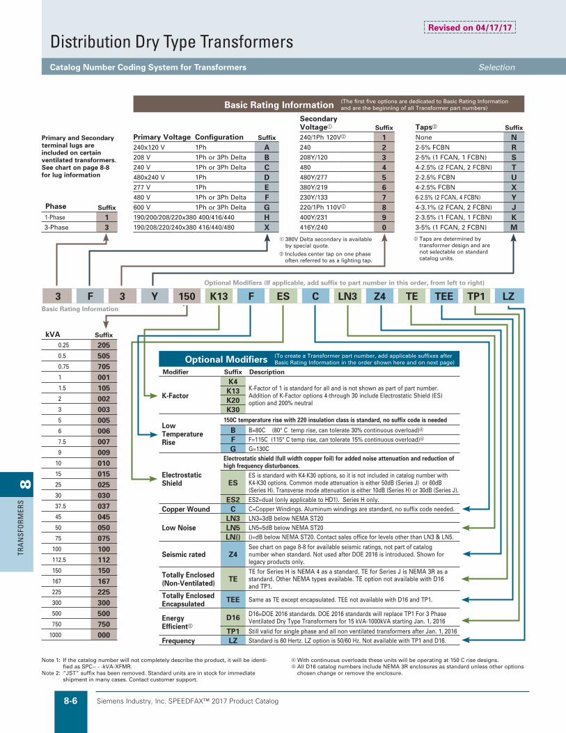
Distribution Dry Type TransformersCatalog Number Coding System for Transformers Selection
3 F 3 Y 150 K13 F ES C LN3 Z4 TE TEE TP1 LZ
kVA Suffix
0.25 2050.5 5050.75 7051 0011.5 1052 0023 0035 0056 0067.5 0079 009
10 01015 01525 02530 03037.5 03745 04550 05075 075
100 100112.5 112150 150167 167225 225300 300500 500750 750
1000 000
Note 1: If the catalog number will not completely describe the product, it will be identi-fied as SPC-- - -kVA-XFMR.
Note 2: “JST” suffix has been removed. Standard units are in stock for immediate shipment in many cases. Contact customer support.
With continuous overloads these units will be operating at 150 C rise designs.e All D16 catalog numbers include NEMA 3R enclosures as standard unless other options
chosen change or remove the enclosure.
Taps are determined by transformer design and are not selectable on standard catalog units.
Includes center tap on one phase often referred to as a lighting tap.
Basic Rating Information
Optional Modifiers (If applicable, add suffix to part number in this order, from left to right)
380V Delta secondary is available by special quote.
Basic Rating Information (The first five options are dedicated to Basic Rating Information and are the beginning of all Transformer part numbers)
Secondary Voltage Suffix Taps Suffix
Primary Voltage Configuration Suffix 240/1Ph 120V 1 None N240x120 V 1Ph A 240 2 2-5% FCBN R208 V 1Ph or 3Ph Delta B 208Y/120 3 2-5% (1 FCAN, 1 FCBN) S240 V 1Ph or 3Ph Delta C 480 4 4-2.5% (2 FCAN, 2 FCBN) T480x240 V 1Ph D 480Y/277 5 2-2.5% FCBN U277 V 1Ph E 380Y/219 6 4-2.5% FCBN X480 V 1Ph or 3Ph Delta F 230Y/133 7 6-2.5% (2 FCAN, 4 FCBN) Y
Phase Suffix 600 V 1Ph or 3Ph Delta G 220/1Ph 110V 8 4-3.1% (2 FCAN, 2 FCBN) J1-Phase 1 190/200/208/220x380 400/416/440 H 400Y/231 9 2-3.5% (1 FCAN, 1 FCBN) K3-Phase 3 190/208/220/240x380 416/440/480 X 416Y/240 0 3-5% (1 FCAN, 2 FCBN) M
Primary and Secondary terminal lugs are included on certain ventilated transformers. See chart on page 8-8 for lug information
Optional Modifiers (To create a Transformer part number, add applicable suffixes after Basic Rating Information in the order shown here and on next page)
Modifier Suffix Description
K-Factor
K4K-Factor of 1 is standard for all and is not shown as part of part number.Addition of K-Factor options 4-through 30 include Electrostatic Shield (ES) option and 200% neutral
K13K20K30
Low Temperature Rise
150C temperature rise with 220 insulation class is standard, no suffix code is needed
B B=80C (80° C temp rise, can tolerate 30% continuous overload)
F F=115C (115° C temp rise, can tolerate 15% continuous overload)
G G=130C
Electrostatic Shield
Electrostatic shield (full width copper foil) for added noise attenuation and reduction of high frequency disturbances.
ESES is standard with K4-K30 options, so it is not included in catalog number with K4-K30 options. Common mode attenuation is either 50dB (Series J) or 60dB (Series H). Transverse mode attenuation is either 10dB (Series H) or 30dB (Series J).
ES2 ES2=dual (only applicable to HD1). Series H only.Copper Wound C C=Copper Windings. Aluminum windings are standard, no suffix code needed.
Low NoiseLN3 LN3=3dB below NEMA ST20LN5 LN5=5dB below NEMA ST20LN() ()=dB below NEMA ST20. Contact sales office for levels other than LN3 & LN5.
Seismic rated Z4See chart on page 8-8 for available seismic ratings, not part of catalog number when standard. Not used after DOE 2016 is introduced. Shown for legacy products only.
Totally Enclosed (Non-Ventilated) TE
TE for Series H is NEMA 4 as a standard. TE for Series J is NEMA 3R as a standard. Other NEMA types available. TE option not available with D16 and TP1.
Totally Enclosed Encapsulated TEE Same as TE except encapsulated. TEE not available with D16 and TP1.
Energy Efficiente
D16 D16=DOE 2016 standards. DOE 2016 standards will replace TP1 For 3 Phase Ventilated Dry Type Transformers for 15 kVA-1000kVA starting Jan. 1, 2016
TP1 Still valid for single phase and all non ventilated transformers after Jan. 1, 2016Frequency LZ Standard is 60 Hertz. LZ option is 50/60 Hz. Not available with TP1 and D16.
Revised on 04/17/17

Siemens Industry, Inc. SPEEDFAX™ 2017 Product Catalog 8-7
8TRA
NSFO
RMERS
Distribution Dry Type TransformersCatalog Number Coding System for Transformers Selection
HD1 NP 30 TS7 TV TB SS SSN4X I3 CC W VG DS
Optional Modifiers (continued)
Modifier Suffix Description
Harmonic Mitigation
HD1 for DOE 2016 standard 3 phase dry type ventilated transformers only. Series H only.
HD1 HD1=1 secondary/single output
“NEMA Premium” NP
Surpasses NEMA-TP1 (Combine NP with available combined options as shown: “TP1…NP”, “HM1…NP”, “HM2…NP“). DOE 2016 standards surpass NP. NP not available after January 1 , 2016 for DOE 2016 3 phase ventilated dry type transform-ers (15kVA-1000kVA). NP 1-phase will continue to be available after this date.
Phase Shift for HD1
Only to be used with suffix code HD1
0 0 degree lagging
30 30 degree lagging
Optional Product Offerings1. For non-standard or non-cataloged
voltages or non-cataloged primary taps refer to sales office.
2. Non-standard application, 50/60 Hz, special impedance, voltage, etc.-consult sales office.
3. Auto transformers (A)- see page 8-11.4. Non-standard paint color-contact sales
office.5. Harmonic mitigating transformers-see
page 8-15.6. Transformer and panel combinations-
see page 8-13 & 8-14.
Optional Modifiers—continued (If applicable, add suffix to part number in this order, from left to right)
The W and DS codes are not always part of the catalog number. Only shown as reference when it is not a standard feature of the device.
e Not available with D16 or TP1.
Optional Modifiers (continued)
Modifier Suffix Description
Thermal Switches
Typical Thermal Switch is 2.5 A and 250V max, typical installation is one TS per coil with wires brought to a modular screw terminal block on top of the transformer. Customer must specify NO or NC contacts. Contact customer support for special requirements. TS7 ( ) 170C ( ) =no value: 1 switchTS8 ( ) 180C ( ) = 2: 2 switchesTS0 ( ) 200C ( ) = 6: 6 switches
TVSS/SPD TV Filter Capacitors Secondary Side with Surge Suppression. Available for Series H only. Must specify 100kA or 200kA surge rating.
Terminal Block TB Contact customer support for standard terminal block availability. If special terminating requirements please advise
Stainless Steel Enclosure
SS 304 stainless (NEMA 3R if no NEMA type qualifier is specified)SS316 316 stainless (NEMA 3R if no NEMA type qualifier is specified)
Enclosure Types
304 stainless is standard. Stainless steel 316 available with a special quote.SSN4X Non-Metallic NEMA 4X option not available.e
Standard is grey painted steel. 304 is standard for stainless steel option and 316 Stainless steel is available with a special quote.
N12 NEMA 12 (SSN12 with 304 stainless) 316 available with special quotee
N4 NEMA 4 (SSN4 with 304 stainless) 316 available with special quotee
Special Impedance
The impedance tolerance per ANSI is +/- 7.5% nominal which is the “I” value shown on Impedance charts. (see SpeedFax Supplement - Addendums H and J) Contact customer support for special requirements (if max or min or min/max range is required.) (If no Min or Max is specified - catalog number will NOT include an “I” value)
Ix.x or Ix I2.5 = 2.5% max. or I3 = 3% max. for example. I2.5 to I6.5 are typical values.
IMx.x IM2.5 = 2.5% min. or IM3 = 3% min. for example.
IMx.xIx.x IM2.5I5.5 = 2.5% min. and 5.5% max. impedance range or IM21I5 = 2% min. and 5% max. range are examples.
Core and Coil Assembly CC Name plate is displayed on frame bracket. Product may be shipped with or without
enclosure.
Wall Mounting Brackets W Some DOE 2016 3 Phase Dry Type Ventilated Transformers include Wall Brackets.
See chart on next page for non-DOE availability and DOE 2016 details.
Vent Guard VG Vent Guard is a Mesh screen to prevent vent opening access.
Drip Shields (weathershields) DS Most DOE 2016 Dry Type Ventilated Transformers include Drip Shields from 15kVA to
1000kVA. See chart on next page for availability. Also see non-DOE availability.

Siemens Industry, Inc. SPEEDFAX™ 2017 Product Catalog8-8
8TR
AN
SFO
RMER
S
Distribution Dry Type TransformersCatalog Number Coding System for Transformers Selection
Seismic Rated: All others not listed below are not seismic rated (contact customer support for Wall Mounting Ratings if needed)
Phase
Encapsulated Ventilated Non Ventilated
Series J Series J Series H Series J
1 1-25kVA (Wall Mounted)SDS=2.00g ; z/h = 1.00 ; Ip = 1.5
1-250 kVA (Floor Mounted)SDS=2.00g ; z/h = 1.00 ; Ip = 1.5
15-167kVA (Floor Mounted Only)SDS=2.00g ; z/h = 1.00 ; Ip = 1.5
1-250kVA (Floor Mounted Only)SDS=2.00g ; z/h = 1.00 ; Ip = 1.5
3 3-75kVA (Floor Mounted)SDS=2.00g ; z/h = 1.00 ; Ip = 1.5
1-1000kVA (Floor Mounted)SDS=2.00g ; z/h = 1.00 ; Ip = 1.5
15-750kVA (Floor Mounted Only)
SDS=2.00g ; z/h = 1.00 ; Ip = 1.5
1-500kVA (Floor Mounted Only)SDS=2.00g ; z/h = 1.00 ; Ip = 1.5
DOE 2016 3 Phase Ventilated
3 NA 1-1000kVA (Floor Mounted)
15-750kVA (Floor Mounted Only)
NA
Seismic labels are standard up to 750kVA with 150C temperature rise.Series J Results are filed with OSHPD per OSP-0109-10.Series H results are filed with OSHPD per OSP-0136-10.
Standard Terminal Lug Offerings
(Primary and Secondary) for Ventilated Transformers (150 Degree Rise - Series J only - Without a K rating)
1-Phase 3-Phase
kVA 120/240V 208V 480V 600V kVA 120/240V 208V 480V 600V
0-15 Contact customer support 0-15 Contact customer support15 #2/0-6 #14-2 #14-2 #14-2 15 #14-2 #14-2 #14-2 #14-225 250MCM-6 250MCM-6 #14-2 #14-2 30 #2/0-6 #2/0-6 #14-2 #14-237.5 350MCM-6 350MCM-6 #14-2 #14-2 45 250MCM-6 250MCM-6 #14-2 #14-250 600MCM-2 600MCM-2 #2/0-6 #2/0-6 75 600MCM-2 350MCM-6 #2/0-6 #2/0-6>50 Contact customer support >75 Contact customer support
Values listed above are for standard configurations. There may be slight variations depending on requirements. Contact Customer Support for special requirements
For Series H, see chart in Series H Addendum - Page H-16. Lug sizes are not available except on cutsheets. Contact Customer Support for special requirements.
1. Standard with DH1 and DH2 enclosures. For DH3 enclosure, Series H transformers 1000 lbs or less can be wall mounted with kit p/n TWB75H. The DH3 designation is found on the lower left corner of the Front View Outline on the transformer drawing.
2. Optional except with copper windings or options B, K13, K20. See table page 8-27.
Seismic Qualified according to: • International Building Code (IBC) 2012• American Society of Civil Engineers (ASCE) 7-10
Wall Mounting Brackets and Drip Shields1 Phase Dry Type Wall Brackets/Drip Shields
kVA
Wall Mounting Brackets (W) Drip Shields (DS)
Series J Series H Series J Series H
0.25-25 Encapsulated Wall Mount only NA NA NA
All items below are Ventilated
15, 25 Optional** Standard Standard Standard
37.5 Optional** See Note 1 Standard Standard
50 Optional** See Note 1 Standard Standard
75 NA See Note 1 Standard Standard
100-500 NA Standard Standard
3 Phase Dry Type Ventilated DOE 2016 Wall Brackets/Drip Shields
kVA
Wall Mounting Brackets (W) Drip Shields (DS)
Series J Series H Series J Series H
15, 30 Optional** Standard Standard Standard
45 Optional** See Note 1 Standard Standard
75 See Note 2 See Note 1 Standard Standard
112.5-1000 N/A See Note 1 Standard Standard
3 Phase Dry Type Encapsulated
kVA
Wall Mounting Brackets (W) Drip Shields (DS)
Series J Series H Series J Series H
3-15 Standard Standard N/A N/A
**For DOE 2016 and 1-Phase ventilated, cost of transformer will not include wall brackets. Wall brackets will be an additional charge.
Revised on 05/31/18

Siemens Industry, Inc. SPEEDFAX™ 2017 Product Catalog 8-9
8TRA
NSFO
RMERS
Distribution Dry Type TransformersSingle Phase Selection
Product Category XFMR
Actual taps may vary based on volts/turn ratio. Wall designations for units having standard features. For outdoor application. Ventilated transformers
requiring drip shields/weathershields are UL listed for outdoor use. All are NEMA 3R rated.
Encapsulated transformers are UL listed for indoor/ outdoor use. NEMA 3R rated.
e Items marked floor and wall can be wall mounted with optional wall bracket.
f See table on page 8-8 for available kits.g Series H Tap Standard.h Series J Tap Standard.
TapsDescription Designation
None N 2–5% FCBN R 2–5% (1 FCAN, 1 FCBN) S 2–2.5% FCBN U 6–2.5% (2 FCAN, 4 FCBN) Y
Optional Modifications Table (Contact Sales office for List Price)
Optional (commonly used) Catalog Modifications Suffix Code
1a. 115° C Rise F 1b. 80° C Rise B 2. Electrostatic Shield ES 3. Copper Windings C 4. Wall Mounting Brackets1 W5. Drip Shields DS
kVACatalogNumber Taps
TemperatureRise Insulation
MountingTypeef
Drip ShieldProvided
EnclosureStyle – Type
OptionalModifications
208 Volts Primary, 120/240 Volts Secondary1. 1B1N001 N 95° C 130° C Wall No Encapsulated – NEMA 3R 1, 2, 42 1B1N002 N 135° C 180° C Wall No 1, 2, 43 1B1N003 N 135° C 180° C Wall No 1, 2, 45 1B1N005 N 135° C 180° C Wall No 1, 2, 47.5 1B1N007 N 135° C 180° C Wall No 1, 2, 4
010 1B1N010 N 135° C 180° C Wall No 1, 2, 4015 1B1N015 N 135° C 180° C Wall No 1, 2, 415 1B1Y015TP1 Y 150° C 220° C Floor & Wall Yes Ventilated – NEMA 3R 1, 2, 3
025 1B1Y025TP1 Y 150° C 220° C Floor & Wall Yes 1, 2, 3037.5 1B1Y037TP1 Y 150° C 220° C Floor & Wall Yes 1, 2, 3050 1B1S050TP1 YgSh 150° C 220° C Floor & Wall Yes 1, 2, 3075 1B1S075TP1 YgSh 150° C 220° C Floor Yes Ventilated – NEMA 3R 1, 2, 3
0100 1B1S100TP1 YgSh 150° C 220° C Floor Yes 1, 2, 30167 1B1S167TP1 YgSh 150° C 220° C Floor Yes 1, 2, 3
240 @ 480 Volts Primary, 120/240 Volts Secondary.25 1D1N205 N 95° C 130° C Wall No Encapsulated – NEMA 3R 1, 2, 4.50 1D1N505 N 95° C 130° C Wall No 1, 2, 4.75 1D1N705 N 95° C 130° C Wall No 1, 2, 4
1.0 1D1N001 N 95° C 130° C Wall No 1, 2, 41.5 1D1N105 N 135° C 180° C Wall No Encapsulated – NEMA 3R 1, 2, 42.0 1D1N002 N 135° C 180° C Wall No 1, 2, 43.0 1D1N003 N 135° C 180° C Wall No 1, 2, 45.0 1D1N005 N 135° C 180° C Wall No 1, 2, 47.5 1D1N007 N 135° C 180° C Wall No 1, 2, 4
10.0 1D1N010 N 135° C 180° C Wall No 1, 2, 415 1D1N015 N 135° C 180° C Wall No 1, 2, 415 1D1Y015TP1 Y 150° C 220° C Floor & Wall Yes Ventilated – NEMA 3R 1, 2, 325 1D1Y025TP1 Y 150° C 220° C Floor & Wall Yes 1, 2, 337.5 1D1Y037TP1 Y 150° C 220° C Floor & Wall Yes 1, 2, 350 1D1Y050TP1 Y 150° C 220° C Floor & Wall Yes 1, 2, 375 1D1Y075TP1 Y 150° C 220° C Floor & Wall Yes Ventilated – NEMA 3R 1, 2, 3
100 1D1Y100TP1 Y 150° C 220° C Floor Yes 1, 2, 3167 1D1Y167TP1 Y 150° C 220° C Floor Yes 1, 2, 3
277 Volts Primary, 120/240 Volts Secondary3 1E1U003 U 135° C 180° C Wall No Encapsulated – NEMA 3R 1, 2, 45 1E1U005 U 135° C 180° C Wall No 1, 2, 47.5 1E1U007 U 135° C 180° C Wall No 1, 2, 4
10 1E1U010 U 135° C 180° C Wall No 1, 2, 415 1E1U015 U 135° C 180° C Wall No 1, 2, 425 1E1U025 U 135° C 180° C Wall No 1, 2, 4
480 Volts Primary, 120/240 Volts Secondary3 1F1R003 R 135° C 180° C Wall No Encapsulated – NEMA 3R 1, 2, 45 1F1R005 R 135° C 180° C Wall No 1, 2, 47.5 1F1R007 R 135° C 180° C Wall No 1, 2, 4
10 1F1R010 R 135° C 180° C Wall No 1, 2, 415 1F1R015 R 135° C 180° C Wall No 1, 2, 425 1F1R025 R 135° C 180° C Wall No 1, 2, 4
Revised on 05/31/18

Siemens Industry, Inc. SPEEDFAX™ 2017 Product Catalog8-10
8TR
AN
SFO
RMER
S
Distribution Dry Type TransformersSingle Phase Selection
Product Category XFMR
TapsDescription Designation
None N 2–5% FCBN R 2–5% (1 FCAN, 1 FCBN) S 2–2.5% FCBN U 6–2.5% (2 FCAN, 4 FCBN) Y
Optional Modifications Table (Contact Sales office for List Price)
Optional (commonly used) Catalog Modifications Suffix Code
1a. 115° C Rise F 1b. 80° C Rise B 2. Electrostatic Shield ES 3. Copper Windings C 4. Wall Mounting Brackets1 W5. Drip Shields DS
kVACatalogNumber Taps
TemperatureRise Insulation
MountingTypeef
Drip ShieldProvided
EnclosureStyle
OptionalModifications
600 Volts Primary, 120/240 Volts Secondary3 1G1R003 R 135° C 180° C Wall No Encapsulated – NEMA 3R 1, 2, 45 1G1R005 R 135° C 180° C Wall No 1, 2, 47.5 1G1R007 R 135° C 180° C Wall No 1, 2, 4
10 1G1R010 R 135° C 180° C Wall No 1, 2, 415 1G1R015 R 135° C 180° C Wall No 1, 2, 425 1G1R025 R 135° C 180° C Wall No 1, 2, 425 1G1T025TP1 YgTh 150° C 220° C Floor & Wall Yes Ventilated – NEMA 3R 1, 2, 337.5 1G1T037TP1 YgTh 150° C 220° C Floor & Wall Yes 1, 2, 350 1G1T050TP1 YgTh 150° C 220° C Floor & Wall Yes 1, 2, 375 1G1T075TP1 YgTh 150° C 220° C Floor Yes Ventilated – NEMA 3R 1, 2, 3
100 1G1T100TP1 YgTh 150° C 220° C Floor Yes 1, 2, 3167 1G1T167TP1 YgTh 150° C 220° C Floor Yes 1, 2, 3
Overseas Model 190/200/208/220 x 380/400/416/440 Volts Primary, 120/240 Volts Secondary—1Ø, 50/60 Hz1 1H1N001 N 95° C 130° C Wall No Encapsulated – NEMA 3R 2, 32 1H1N002i N 135° C 180° C Wall No 2, 33 1H1N003i N 135° C 180° C Wall No 2, 35 1H1N005i N 135° C 180° C Wall No 2, 37.5 1H1N007 N 135° C 180° C Wall No 2, 3
10 1H1N010 N 135° C 180° C Wall No 2, 315 1H1N015 N 135° C 180° C Wall No 2, 325 1H1N025 N 135° C 180° C Wall No 2, 3
Overseas Model 190/208/220/240 x 380/416/440/480 Volts Primary, 120/240 Volts Secondary—1Ø, 50/60 Hz1 1X1N001 N 95° C 130° C Wall No Encapsulated – NEMA 3R 2, 32 1X1N002i N 135° C 180° C Wall No 2, 33 1X1N003i N 135° C 180° C Wall No 2, 35 1X1N005i N 135° C 180° C Wall No 2, 37.5 1X1N007 N 135° C 180° C Wall No 2, 3
10 1X1N010 N 135° C 180° C Wall No 2, 315 1X1N015 N 135° C 180° C Wall No 2, 325 1X1N025 N 135° C 180° C Wall No 2, 3
Overseas Model 190/200/208/220 x 380/400/416/440 Volts Primary, 110/220 Volts Secondary—1Ø, 50/60 Hz1 1H8N001 N 95° C 130° C Wall No Encapsulated – NEMA 3R 2, 32 1H8N002i N 135° C 180° C Wall No 2, 33 1H8N003i N 135° C 180° C Wall No 2, 35 1H8N005i N 135° C 180° C Wall No 2, 37.5 1H8N007 N 135° C 180° C Wall No 2, 3
Revised on 12/31/19
Actual taps may vary based on volts/turn ratio. Wall designations for units having standard features. For outdoor application. Ventilated transformers
requiring drip shields/weathershields are UL listed for outdoor use. All are NEMA 3R rated.
Encapsulated transformers are UL listed for indoor/ outdoor use. NEMA 3R rated.
e Items marked floor and wall can be wall mounted with optional wall bracket.
f See table on page 8-8 for available kits.g Series H Tap Standard.h Series J Tap Standard.i Available with CE mark.

Siemens Industry, Inc. SPEEDFAX™ 2017 Product Catalog 8-11
8TRA
NSFO
RMERS
Distribution Dry Type TransformersThree Phase Selection
Product Category XFMR
�Actual taps may vary based on volts/turn ratio.�Wall designations for units having standard features.�Ventilated transformers with drip shields are UL listed
for outdoor use. NEMA 3R rated.�Encapsulated transformers are UL listed for indoor/
outdoor use. NEMA 3R rated.
eSee table on page 8-8 for available kits.f�240 volt secondary (3F2) is available in 3-phase 3 to
15kVA only.g�TE units will have inrush equal to 2 sizes
larger than rated kVA.
h�Items marked floor and wall can be wall mounted with optional wall bracket that may be identified with “W” suffix on catalog number.
i�Wall mounting for 150˚C temperature rise.j�Series H Tap Standard.k�Series J Tap Standard.
TapsDescription Designation
None N 2–5% FCBN R 2–5% (1 FCAN, 1 FCBN) S 2–2.5% FCBN U 6–2.5% (2 FCAN, 4 FCBN) Y
Optional Modifications Table (Contact Sales office for List Price)
Optional (commonly used) Catalog Modifications Suffix Code
1a. 115°C Rise F 1b. 80°C Rise B 2. Electrostatic Shield ES 3. Copper Windings C 4. Wall Mounting Brackets1 W6. Low noise — XdB below std. LNX
kVACatalogNumber Taps
TemperatureRise Insulation
MountingTypeeh
Drip ShieldProvided
EnclosureStyle
OptionalModifications
480 Volts ∆ Primary, 240 Volts ∆ Secondary With 120 Volt Tap On B Phasee
15 3F1Y015D16 Y 150° C 220° C Floor & Wall Yes Ventilated – NEMA 3R 1, 2, 3, 430 3F1Y030D16 Y 150° C 220° C Floor & Wall Yes 1, 2, 3, 445 3F1Y045D16 Y 150° C 220° C Floor & Wall Yes 1, 2, 3, 475 3F1Y075D16 Y 150° C 220° C Floor Yes Ventilated – NEMA 3R 1, 2, 3, 4
112.5 3F1Y112D16 Y 150° C 220° C Floor Yes 1, 2, 3, 4150 3F1Y150D16 Y 150° C 220° C Floor Yes 1, 2, 3225 3F1Y225D16 Y 150° C 220° C Floor Yes 1, 2, 3300 3F1Y300D16 Y 150° C 220° C Floor Yes 1, 2, 3500 3F1T500D16 Yj, Tk 150° C 220° C Floor Yes 1, 2, 3750 3F1T750D16 Yj, Tk 150° C 220° C Floor Yes 1, 2, 3
480 Volts ∆ Primary, 240 Volts ∆ Secondary3 3F2R003f R 135° C 180° C Wall No Encapsulated – NEMA 3R 1, 2, 36 3F2R006f R 135° C 180° C Wall No 1, 2, 39 3F2R009f R 135° C 180° C Wall No 1, 2, 3
15 3F2R015f R 135° C 180° C Wall No 1, 2, 3
480 Volts ∆ Primary, 208Y/120 Volts Secondary3 3F3R003 R 135° C 180° C Wall No Encapsulated – NEMA 3R 1, 2, 36 3F3R006 R 135° C 180° C Wall No 1, 2, 39 3F3R009 R 135° C 180° C Wall No 1, 2, 3
15 3F3R015 R 135° C 180° C Wall No 1, 2, 315 3F3Y015D16 Y 150° C 220° C Floor & Wall Yes Ventilated – NEMA 3R 1, 2, 3, 4, 630 3F3Y030D16 Y 150° C 220° C Floor & Wall Yes 1, 2, 3, 4, 645 3F3Y045D16 Y 150° C 220° C Floor & Wall Yes 1, 2, 3, 4, 675 3F3Y075D16 Y 150° C 220° C Floor & Wall Yes Ventilated – NEMA 3R 1, 2, 3, 4, 6
112.5 3F3Y112D16 Y 150° C 220° C Floor Yes 1, 2, 3, 6150 3F3Y150D16 Y 150° C 220° C Floor Yes 1, 2, 3, 6225 3F3Y225D16 Y 150° C 220° C Floor Yes 1, 2, 3, 6300 3F3Y300D16 Y 150° C 220° C Floor Yes 1, 2, 3, 6500 3F3T500D16 Yj, Tk 150° C 220° C Floor Yes 1, 2, 3, 6750 3F3T750D16 Yj, Tk 150° C 220° C Floor Yes 1, 2, 3, 6
1000 3F3T000D16 T 150° C 220° C Floor Yes 1, 2, 3, 6
kVACatalogNumber Taps
TemperatureRise Insulation
MountingType
Drip ShieldRequired
OptionalModifications
Avg. SoundLevel
Totally Enclosed Transformers, Indoor/Outdoor Use 480 Volts ∆ Primary, 208Y/120 Volts Secondaryg
15 3F3Y015TE Y 150° C 220° C Floor No 1, 2, 3 50dB30 3F3Y030TE Y 150° C 220° C Floor No 1, 2, 3 50dB45 3F3Y045TE Y 150° C 220° C Floor No 1, 2, 3 50dB75 3F3Y075TE Y 150° C 220° C Floor No 1, 2, 3 55dB
112.5 3F3Y112TE Y 150° C 220° C Floor No 1, 2, 3 55dB150 3F3Y150TE Y 150° C 220° C Floor No 1, 2, 3 55dB1225 3F3Y225TE Y 150° C 220° C Floor No 1, 2, 3 57dB1300 3F3Y300TE Y 150° C 220° C Floor No 1a, 2, 3 57dB1
480 Volts ∆ Primary, 240 Volts ∆ Secondary with 120V Lighting Tap on B Phaseg
15 3F1Y015TE Y 150° C 220° C Floor No 1, 2, 3 50dB30 3F1Y030TE Y 150° C 220° C Floor No 1, 2, 3 50dB45 3F1Y045TE Y 150° C 220° C Floor No 1, 2, 3 50dB75 3F1Y075TE Y 150° C 220° C Floor No 1, 2, 3 55dB
112.5 3F1Y112TE Y 150° C 220° C Floor No 1, 2, 3 55dB150 3F1Y150TE Y 150° C 220° C Floor No 1, 2, 3 55dB225 3F1Y225TE Y 150° C 220° C Floor No 1, 2, 3 57dB300 3F1Y300TE Y 150° C 220° C Floor No 1a, 2, 3 57dB
Revised on 05/31/18

Siemens Industry, Inc. SPEEDFAX™ 2017 Product Catalog8-12
8TR
AN
SFO
RMER
S
Product Category XFMR
Distribution Dry Type TransformersThree Phase Selection
�Actual taps may vary based on volts/turn ratio.�Wall designations for units having standard features.�Ventilated transformers drip shields are UL listed for
outdoor use.�Encapsulated transformers are UL listed for indoor/
outdoor use. 15kVA with R taps also available in ventilated enclosure.
TapsDescription Designation
None N 2–5% FCBN R 2–5% (1 FCAN, 1 FCBN) S 2–2.5% FCBN U 6–2.5% (2 FCAN, 4 FCBN) Y
Optional Modifications Table (Contact Sales office for List Price)
Optional (commonly used) Catalog Modifications Suffix Code
1a. 115°C Rise F 1b. 80°C Rise B 2. Electrostatic Shield ES 3. Copper Windings C 4. Wall Mounting Brackets1 W6. Low noise — XdB below std. LNX
kVACatalogNumber Taps
TemperatureRise Insulation
MountingTypefg
Drip ShieldProvided
EnclosedType
OptionalModifications
480 Volts ∆ Primary, 480Y/277 Volts Secondary15 3F5R015 R 135° C 180° C Wall No Encapsulated – NEMA 3R 1, 2, 315 3F5Y015D16 Y 150° C 220° C Floor & Wall Yes Ventilated – NEMA 3R 1, 2, 3, 4, 630 3F5Y030D16 Y 150° C 220° C Floor & Wall Yes Ventilated 1, 2, 3, 4, 645 3F5Y045D16 Y 150° C 220° C Floor & Wall Yes Ventilated 1, 2, 3, 4, 675 3F5Y075D16 Y 150° C 220° C Floor Yes Ventilated – NEMA 3R 1, 2, 3, 6
112.5 3F5Y112D16 Y 150° C 220° C Floor Yes Ventilated 1, 2, 3, 6150 3F5Y150D16 Y 150° C 220° C Floor Yes Ventilated 1, 2, 3, 6225 3F5Y225D16 Y 150° C 220° C Floor Yes Ventilated 1, 2, 3, 6300 3F5Y300D16 Y 150° C 220° C Floor Yes Ventilated 1, 2, 3, 6500 3F5T500D16 Yh, Ti 150° C 220° C Floor Yes Ventilated 1, 2, 3, 6
3-Phase 480 ∆ — 208Y/120 K-4 (50% Non-Linear Load)e
15 3F3Y015K4D16 Y 150° C 220° C Floor & Wall Yes Ventilated – NEMA 3R 1, 3, 4, 630 3F3Y030K4D16 Y 150° C 220° C Floor & Wall Yes Ventilated 1, 3, 4, 645 3F3Y045K4D16 Y 150° C 220° C Floor & Wall Yes Ventilated 1, 3, 4, 675 3F3Y075K4D16 Y 150° C 220° C Floor Yes Ventilated – NEMA 3R 1, 3, 6
112.5 3F3Y112K4D16 Y 150° C 220° C Floor Yes Ventilated 1, 3, 6150 3F3Y150K4D16 Y 150° C 220° C Floor Yes Ventilated 1, 3, 6225 3F3Y225K4D16 Y 150° C 220° C Floor Yes Ventilated 1, 3, 6300 3F3Y300K4D16 Y 150° C 220° C Floor Yes Ventilated 1, 3, 6500 3F3T500K4D16 Yh, Ti 150° C 220° C Floor Yes Ventilated 1, 3, 6
3-Phase 480 ∆ — 208Y/120 K-13 (100% Non-Linear Load)e
15 3F3Y015K13D16 Y 150° C 220° C Floor & Wall Yes Ventilated – NEMA 3R 1, 3, 4, 630 3F3Y030K13D16 Y 150° C 220° C Floor & Wall Yes Ventilated 1, 3, 4, 645 3F3Y045K13D16 Y 150° C 220° C Floor & Wall Yes Ventilated 1, 3, 4, 675 3F3Y075K13D16 Y 150° C 220° C Floor Yes Ventilated – NEMA 3R 1, 3, 6
112.5 3F3Y112K13D16 Y 150° C 220° C Floor Yes Ventilated 1, 3, 6150 3F3Y150K13D16 Y 150° C 220° C Floor Yes Ventilated 1, 3, 6225 3F3Y225K13D16 Y 150° C 220° C Floor Yes Ventilated 1, 3, 6300 3F3Y300K13D16 Y 150° C 220° C Floor Yes Ventilated 1, 3, 6500 3F3T500K13D16 Yh, Ti 150° C 220° C Floor Yes Ventilated 1, 3, 6
3-Phase 480 ∆ — 208Y/120 K-20 (125% Non-Linear Load)e
15 3F3Y015K20D16 Y 150° C 220° C Floor & Wall Yes Ventilated – NEMA 3R 1, 3, 4, 630 3F3Y030K20D16 Y 150° C 220° C Floor & Wall Yes Ventilated 1, 3, 4, 645 3F3Y045K20D16 Y 150° C 220° C Floor & Wall Yes Ventilated 1, 3, 4, 675 3F3Y075K20D16 Y 150° C 220° C Floor Yes Ventilated – NEMA 3R 1, 3, 6
112.5 3F3Y112K20D16 Y 150° C 220° C Floor Yes Ventilated 1, 3, 6150 3F3Y150K20D16 Y 150° C 220° C Floor Yes Ventilated 1, 3, 6225 3F3Y225K20D16 Y 150° C 220° C Floor Yes Ventilated 1, 3, 6300 3F3Y300K20D16 Y 150° C 220° C Floor Yes Ventilated 1, 3, 6500 3F3T500K20D16 Yh, Ti 150° C 220° C Floor Yes Ventilated 1, 3, 6
3-Phase 480 ∆ — 208Y/120 K-30 (150% Non-Linear Load)e
15 3F3Y015K30D16 Y 150° C 220° C Floor & Wall Yes Ventilated – NEMA 3R 1, 3, 4, 630 3F3Y030K30D16 Y 150° C 220° C Floor & Wall Yes Ventilated 1, 3, 4, 645 3F3Y045K30D16 Y 150° C 220° C Floor & Wall Yes Ventilated 1, 3, 4, 675 3F3Y075K30D16 Y 150° C 220° C Floor Yes Ventilated – NEMA 3R 1, 3, 6
112.5 3F3Y112K30D16 Y 150° C 220° C Floor Yes Ventilated 1, 3, 6150 3F3Y150K30D16 Y 150° C 220° C Floor Yes Ventilated 1, 3, 6225 3F3Y225K30D16 Y 150° C 220° C Floor Yes Ventilated 1, 3, 6300 3F3Y300K30D16 Y 150° C 220° C Floor Yes Ventilated 1, 3, 6500 3F3T500K30D16 Yh, Ti 150° C 220° C Floor Yes Ventilated 1, 3, 6
e �K-Factor transformers equipped with electrostatic shield and 200% neutral as standard features.
f�See table on page 8-8 for available kits.g�Items marked floor and wall can be wall mounted
with optional wall bracket that may be identified with
“W” suffix on catalog number. Wall mounting brackets will not be available for Series J 75kVA with copper winding options.
h�Series H Tap Standard.i�Series J Tap Standard.
Revised on 05/15/18

Siemens Industry, Inc. SPEEDFAX™ 2017 Product Catalog 8-13
8TRA
NSFO
RMERS
Distribution Dry Type TransformersThree Phase Selection
Product Category XFMR
�Actual taps may vary based on volts/turn ratio. �Wall designations for units having standard features.�Ventilated transformers drip shields are UL listed for
outdoor use.�Encapsulated transformers are UL listed for indoor/
outdoor use. 15kVA with R taps also available in ventilated enclosure.
Seismic RatingsSeries Jh Rating Information (see page 8-8)
Phase 1 1kVA-500kVA (Floor Mounted)SDS=2.00g ; z/h = 1.00 ; Ip = 1.5Phase 3
TapsDescription Designation
None N2–5% FCBN R2–5% (1 FCAN, 1 FCBN) S2–2.5% FCBN U6–2.5% (2 FCAN, 4 FCBN) Y
Optional Modifications Table Optional (commonly used) Modifications
CatalogSuffix Code
1a. 115° C Rise F1b. 80° C Rise B2. Electrostatic Shield ES3. Copper Windings C4. Wall Mounting Brackets1 W6. Low noise—XdB below std. LNX
e�See table on page 8-8 for available kits.f�Items marked floor and wall can be wall mounted
with optional wall bracket that may be identified with “W” suffix on catalog number. Wall mounting brackets will not be available for Series J 75kVA with copper winding options.
g�Reduced capacity 1-phase tap— When utilizing 1-phase tap at 5%, the 3-phase load is reduced to 85% max. (5% reduction on 3 coils). 10% of rated kVA absolute maximum (evenly balanced on each side of lighting tap). When utilizing 1-phase tap at 10%, the 3-phase load is reduced to 70% max. (10% reduction on 3 coils).
hResults are filed with OSHPD per OSP-0109-10.i�Series H Tap Standard.j�Series J Tap Standard.
Product Category XFMR
kVACatalogNumber Taps
TemperatureRise Insulation
MountingTypeef
Drip ShieldProvided
EnclosureStyle – Type
OptionalModifications
208 Volts ∆ Primary, 208Y/120 Volts Secondary3 3B3R003 R 135° C 180° C Wall No Encapsulated – NEMA 3R 1, 2, 36 3B3R006 R 135° C 180° C Wall No 1, 2, 39 3B3R009 R 135° C 180° C Wall No 1, 2, 3
15 3B3R015 R 135° C 180° C Wall No 1, 2, 315 3B3Y015D16 Y 150° C 220° C Floor & Wall Yes Ventilated – NEMA 3R 1, 2, 3, 4, 630 3B3Y030D16 Y 150° C 220° C Floor & Wall Yes 1, 2, 3, 4, 645 3B3Y045D16 Y 150° C 220° C Floor & Wall Yes 1, 2, 3, 4, 675 3B3Y075D16 Y 150° C 220° C Floor Yes Ventilated – NEMA 3R 1, 2, 3, 6
112.5 3B3Y112D16 Y 150° C 220° C Floor Yes 1, 2, 3, 6150 3B3M150D16 Yi, Mj 150° C 220° C Floor Yes 1, 2, 3, 6225 3B3M225D16 Si, Mj 150° C 220° C Floor Yes Ventilated – NEMA 3R 1, 2, 3, 6300 3B3M300D16 Si, Mj 150° C 220° C Floor Yes 1, 2, 3, 6500 3B3M500D16 Si, Mj 150° C 220° C Floor Yes 1, 2, 3, 6
208 Volt ∆ Primary, 240 ∆ Secondary with 120 Volt TAP on B Phaseg
15 3B1Y015D16 Y 150° C 220° C Floor & Wall Yes Ventilated – NEMA 3R 1, 2, 3, 4, 630 3B1Y030D16 Y 150° C 220° C Floor & Wall Yes 1, 2, 3, 4, 645 3B1Y045D16 Y 150° C 220° C Floor & Wall Yes 1, 2, 3, 4, 675 3B1Y075D16 Y 150° C 220° C Floor Yes Ventilated – NEMA 3R 1, 2, 3, 6
112.5 3B1Y112D16 Y 150° C 220° C Floor Yes 1, 2, 3, 6150 3B1M150D16 Yi, Mj 150° C 220° C Floor Yes 1, 2, 3, 6225 3B1M225D16 Yi, Mj 150° C 220° C Floor Yes 1, 2, 3, 6
208 Volts ∆ Primary, 480Y/277 Volts Secondary9 3B5R009 R 135° C 180° C Wall No Encapsulated – NEMA 3R 1, 2, 3
15 3B5R015 R 135° C 180° C Wall No 1, 2, 315 3B5Y015D16 Y 150° C 220° C Floor & Wall Yes Ventilated – NEMA 3R 1, 2, 3, 4, 630 3B5Y030D16 Y 150° C 220° C Floor & Wall Yes 1, 2, 3, 4, 645 3B5Y045D16 Y 150° C 220° C Floor & Wall Yes 1, 2, 3, 4, 675 3B5Y075D16 Y 150° C 220° C Floor Yes Ventilated – NEMA 3R 1, 2, 3, 6
112.5 3B5Y112D16 Y 150° C 220° C Floor Yes 1, 2, 3, 6150 3B5M150D16 Yi, Mj 150° C 220° C Floor Yes 1, 2, 3, 6225 3B5M225D16 Si, Mj 150° C 220° C Floor Yes Ventilated – NEMA 3R 1, 2, 3, 6300 3B5M300D16 Si, Mj 150° C 220° C Floor Yes 1, 2, 3, 6500 3B5M500D16 Si, Mj 150° C 220° C Floor Yes 1, 2, 3, 6
240 Volts ∆ Primary, 208Y/120 Volts Secondary15 3C3Y015D16 Y 150° C 220° C Floor & Wall Yes Ventilated – NEMA 3R 1, 2, 3, 4, 630 3C3Y030D16 Y 150° C 220° C Floor & Wall Yes 1, 2, 3, 4, 645 3C3Y045D16 Y 150° C 220° C Floor & Wall Yes 1, 2, 3, 4, 675 3C3Y075D16 Y 150° C 220° C Floor Yes Ventilated – NEMA 3R 1, 2, 3, 6
112.5 3C3Y112D16 Y 150° C 220° C Floor Yes 1, 2, 3, 6150 3C3Y150D16 Y 150° C 220° C Floor Yes 1, 2, 3, 6225 3C3M225D16 Si, Mj 150° C 220° C Floor Yes Ventilated – NEMA 3R 1, 2, 3, 6300 3C3M300D16 Si, Mj 150° C 220° C Floor Yes 1, 2, 3, 6500 3C3M500D16 Si, Mj 150° C 220° C Floor Yes 1, 2, 3, 6
240 Volts ∆ Primary, 480Y/277 Volts Secondary15 3C5Y015D16 Y 150° C 220° C Floor & Wall Yes Ventilated – NEMA 3R 1, 2, 3, 4, 630 3C5Y030D16 Y 150° C 220° C Floor & Wall Yes 1, 2, 3, 4, 645 3C5Y045D16 Y 150° C 220° C Floor & Wall Yes 1, 2, 3, 4, 675 3C5Y075D16 Y 150° C 220° C Floor Yes Ventilated – NEMA 3R 1, 2, 3, 6
112.5 3C5Y112D16 Y 150° C 220° C Floor Yes 1, 2, 3, 6150 3C5Y150D16 Y 150° C 220° C Floor Yes 1, 2, 3, 6225 3C5M225D16 Si, Mj 150° C 220° C Floor Yes Ventilated – NEMA 3R 1, 2, 3, 6300 3C5M300D16 Si, Mj 150° C 220° C Floor Yes 1, 2, 3, 6500 3C5M500D16 Si, Mj 150° C 220° C Floor Yes 1, 2, 3, 6
Revised on 05/31/18

Siemens Industry, Inc. SPEEDFAX™ 2017 Product Catalog8-14
8TR
AN
SFO
RMER
S
Distribution Dry Type TransformersThree Phase Selection
Product Category XFMR
�Actual taps may vary based on volts/turn ratio. �Wall designations for units having standard features.�Ventilated transformers drip shields are UL listed for
outdoor use.�Encapsulated transformers are UL listed for indoor/
outdoor use.
e�If used on unbalanced loads, these auto transformers will need to be used on a 4-wire system with the supply neutral connected to the transformer. If used on motor loads, then they may be used on a 3-wire system without a neutral or fourth wire. Review in NEC 450-4 and 450-5.
f�Items marked floor and wall can be wall mounted with optional wall bracket that may be identified
with “W” suffix on catalog number. Wall mounting brackets will not be available for Series J 75kVA with copper winding options. See pages 8-8 and 8-27 for details.
g�Series H Tap Standard.h�Series J Tap Standard.i�See table on page 8-8 for available kits.
TapsDescription Designation
None N 2–5% FCBN R 2–5% (1 FCAN, 1 FCBN) S 2–2.5% FCBN U 6–2.5% (2 FCAN, 4 FCBN) Y
Optional Modifications Table (Contact Sales office for List Price)
Optional (commonly used) Catalog Modifications Suffix Code
1a. 115° C Rise F 1b. 80° C Rise B 2. Electrostatic Shield ES 3. Copper Windings C 4. Wall Mounting Brackets1 W6. Low noise - XdB below std. LNX
kVACatalogNumber Taps
TemperatureRise Insulation
MountingTypefi
Drip ShieldProvided
EnclosureStyle
OptionalModifications
600 Volts ∆ Primary, 208Y/120 Volts Secondary3 3G3R003 R 135° C 180° C Wall No Encapsulated – NEMA 3R 1, 2, 36 3G3R006 R 135° C 180° C Wall No 1, 2, 39 3G3R009 R 135° C 180° C Wall No 1, 2, 3
15 3G3R015 R 135° C 180° C Wall No 1, 2, 315 3G3T015D16 Yg, Th 150° C 220° C Floor & Wall Yes Ventilated – NEMA 3R 1, 2, 3, 4, 630 3G3T030D16 Yg, Th 150° C 220° C Floor & Wall Yes 1, 2, 3, 4, 645 3G3T045D16 Yg, Th 150° C 220° C Floor & Wall Yes 1, 2, 3, 4, 675 3G3T075D16 Yg, Th 150° C 220° C Floor Yes Ventilated – NEMA 3R 1, 2, 3, 6
112.5 3G3T112D16 Yg, Th 150° C 220° C Floor Yes 1, 2, 3, 6150 3G3T150D16 Yg, Th 150° C 220° C Floor Yes 1, 2, 3, 6225 3G3T225D16 Yg, Th 150° C 220° C Floor Yes 1, 2, 3, 6300 3G3T300D16 Yg, Th 150° C 220° C Floor Yes 1, 2, 3, 6500 3G3T500D16 Yg, Th 150° C 220° C Floor Yes 1, 2, 3, 6
600 Volts ∆ Primary, 480Y/277 Volts Secondary3 3G5R003 R 135° C 180° C Wall No Encapsulated – NEMA 3R 1, 2, 36 3G5R006 R 135° C 180° C Wall No 1, 2, 39 3G5R009 R 135° C 180° C Wall No 1, 2, 3
15 3G5R015 R 135° C 180° C Wall No 1, 2, 315 3G5T015D16 Yg, Th 150° C 220° C Floor & Wall Yes Ventilated – NEMA 3R 1, 2, 3, 4, 630 3G5T030D16 Yg, Th 150° C 220° C Floor & Wall Yes 1, 2, 3, 4, 645 3G5T045D16 Yg, Th 150° C 220° C Floor & Wall Yes 1, 2, 3, 4, 675 3G5T075D16 Yg, Th 150° C 220° C Floor Yes Ventilated – NEMA 3R 1, 2, 3, 6
112.5 3G5T112D16 Yg, Th 150° C 220° C Floor Yes 1, 2, 3, 6150 3G5T150D16 Yg, Th 150° C 220° C Floor Yes 1, 2, 3, 6225 3G5T225D16 Yg, Th 150° C 220° C Floor Yes 1, 2, 3, 6300 3G5T300D16 Yg, Th 150° C 220° C Floor Yes 1, 2, 3, 6500 3G5T500D16 Yg, Th 150° C 220° C Floor Yes 1, 2, 3, 6
Dual Purpose Auto Transformerse
kVA
CatalogNumber Taps
TemperatureRise Insulation
MountingType
Drip ShieldRequired
EnclosureStyle
OptionalModifications
600V Pri480V Sec
480V Pri380V Sec
600 Volts Primary, 480 Volts Secondary 3Ø 60 Hz OR—480 Volts Primary 380 Volts Secondary 3Ø 50/60 Hz Alternate Rating15 12 3G4N015A N 80° C 130° C Wall No Encapsulated – NEMA 3R —30 24 3G4N030A N 115° C 180° C Wall No —45 36 3G4N045A N 150° C 220° C Floor & Wall Yes Ventilated – NEMA 3R 4, 575 60 3G4N075A N 150° C 220° C Floor & Wall Yes 4, 5
112.5 90 3G4N112A N 150° C 220° C Floor & Wall Yes 4, 5150 120 3G4N150A N 150° C 220° C Floor & Wall Yes 4, 5225 180 3G4N225A N 150° C 220° C Floor & Wall Yes 4, 5300 240 3G4N300A N 150° C 220° C Floor Yes 5500 400 3G4N500A N 150° C 220° C Floor Yes 51
Revised on 05/15/18
Siemens Industry, Inc. SPEEDFAX™ 2017 Product Catalog 8-15
8TRA
NSFO
RMERS
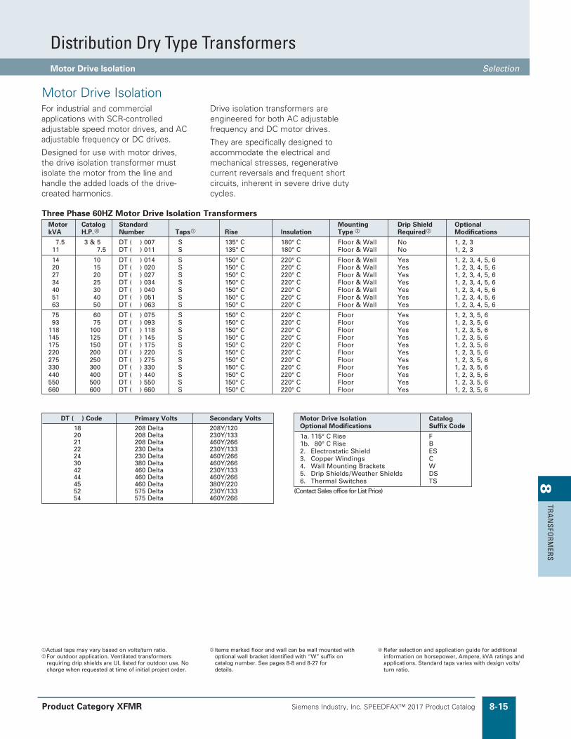
Distribution Dry Type TransformersMotor Drive Isolation Selection
�Actual taps may vary based on volts/turn ratio.�For outdoor application. Ventilated transformers
requiring drip shields are UL listed for outdoor use. No charge when requested at time of initial project order.
�Items marked floor and wall can be wall mounted with optional wall bracket identified with “W” suffix on catalog number. See pages 8-8 and 8-27 for details.
Refer selection and application guide for additional information on horsepower, Ampere, kVA ratings and applications. Standard taps varies with design volts/turn ratio.
DT ( ) Code Primary Volts Secondary Volts 18 208 Delta 208Y/120 20 208 Delta 230Y/133 21 208 Delta 460Y/266 22 230 Delta 230Y/133 24 230 Delta 460Y/266 30 380 Delta 460Y/266 42 460 Delta 230Y/133 44 460 Delta 460Y/266 45 460 Delta 380Y/220 52 575 Delta 230Y/133 54 575 Delta 460Y/266
Motor Drive Isolation Catalog Optional Modifications Suffix Code
1a. 115° C Rise F 1b. 080° C Rise B2. Electrostatic Shield ES 3. Copper Windings C 4. Wall Mounting Brackets W 5. Drip Shields/Weather Shields DS 6. Thermal Switches TS
(Contact Sales office for List Price)
Motor Catalog Standard Mounting Drip Shield OptionalkVA H.P. Number Taps Rise Insulation Type Required Modifications
7.5 3 & 5 DT ( ) 007 S 135° C 180° C Floor & Wall No 1, 2, 3 11 7.5 DT ( ) 011 S 135° C 180° C Floor & Wall No 1, 2, 3
14 10 DT ( ) 014 S 150° C 220° C Floor & Wall Yes 1, 2, 3, 4, 5, 6 20 15 DT ( ) 020 S 150° C 220° C Floor & Wall Yes 1, 2, 3, 4, 5, 6 27 20 DT ( ) 027 S 150° C 220° C Floor & Wall Yes 1, 2, 3, 4, 5, 6 34 25 DT ( ) 034 S 150° C 220° C Floor & Wall Yes 1, 2, 3, 4, 5, 6 40 30 DT ( ) 040 S 150° C 220° C Floor & Wall Yes 1, 2, 3, 4, 5, 6 51 40 DT ( ) 051 S 150° C 220° C Floor & Wall Yes 1, 2, 3, 4, 5, 6 63 50 DT ( ) 063 S 150° C 220° C Floor & Wall Yes 1, 2, 3, 4, 5, 6
75 60 DT ( ) 075 S 150° C 220° C Floor Yes 1, 2, 3, 5, 6 93 75 DT ( ) 093 S 150° C 220° C Floor Yes 1, 2, 3, 5, 6 118 100 DT ( ) 118 S 150° C 220° C Floor Yes 1, 2, 3, 5, 6 145 125 DT ( ) 145 S 150° C 220° C Floor Yes 1, 2, 3, 5, 6 175 150 DT ( ) 175 S 150° C 220° C Floor Yes 1, 2, 3, 5, 6 220 200 DT ( ) 220 S 150° C 220° C Floor Yes 1, 2, 3, 5, 6 275 250 DT ( ) 275 S 150° C 220° C Floor Yes 1, 2, 3, 5, 6 330 300 DT ( ) 330 S 150° C 220° C Floor Yes 1, 2, 3, 5, 6 440 400 DT ( ) 440 S 150° C 220° C Floor Yes 1, 2, 3, 5, 6 550 500 DT ( ) 550 S 150° C 220° C Floor Yes 1, 2, 3, 5, 6 660 600 DT ( ) 660 S 150° C 220° C Floor Yes 1, 2, 3, 5, 6
Three Phase 60HZ Motor Drive Isolation Transformers
Motor Drive IsolationFor industrial and commercial applications with SCR-controlled adjustable speed motor drives, and AC adjustable frequency or DC drives.
Designed for use with motor drives, the drive isolation transformer must isolate the motor from the line and handle the added loads of the drive-created harmonics.
Drive isolation transformers are engineered for both AC adjustable frequency and DC motor drives.
They are specifically designed to accommodate the electrical and mechanical stresses, regenerative current reversals and frequent short circuits, inherent in severe drive duty cycles.
Product Category XFMR
Siemens Industry, Inc. SPEEDFAX™ 2017 Product Catalog8-16
8TR
AN
SFO
RMER
S
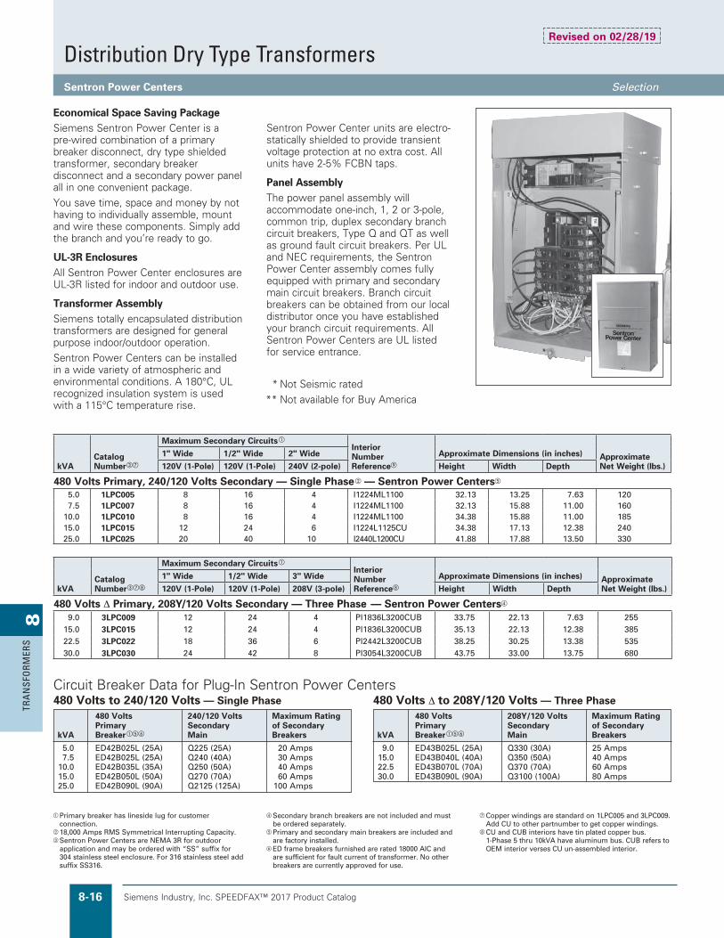
Distribution Dry Type TransformersSentron Power Centers Selection
Economical Space Saving PackageSiemens Sentron Power Center is a pre-wired combination of a primary breaker disconnect, dry type shielded transformer, secondary breaker disconnect and a secondary power panel all in one convenient package.
You save time, space and money by not having to individually assemble, mount and wire these components. Simply add the branch and you’re ready to go.
UL-3R EnclosuresAll Sentron Power Center enclosures are UL-3R listed for indoor and outdoor use.
Transformer AssemblySiemens totally encapsulated distribution transformers are designed for general purpose indoor/outdoor operation.
Sentron Power Centers can be installed in a wide variety of atmospheric and environmental conditions. A 180°C, UL recognized insulation system is used with a 115°C temperature rise.
Sentron Power Center units are electro-statically shielded to provide transient voltage protection at no extra cost. All units have 2-5% FCBN taps.
Panel AssemblyThe power panel assembly will accommodate one-inch, 1, 2 or 3-pole, common trip, duplex secondary branch circuit breakers, Type Q and QT as well as ground fault circuit breakers. Per UL and NEC requirements, the Sentron Power Center assembly comes fully equipped with primary and secondary main circuit breakers. Branch circuit breakers can be obtained from our local distributor once you have established your branch circuit requirements. All Sentron Power Centers are UL listed for service entrance.
Primary breaker has lineside lug for customer connection.
18,000 Amps RMS Symmetrical Interrupting Capacity.Sentron Power Centers are NEMA 3R for outdoor
application and may be ordered with “SS” suffix for 304 stainless steel enclosure. For 316 stainless steel add suffix SS316.
Secondary branch breakers are not included and must be ordered separately.
ePrimary and secondary main breakers are included and are factory installed.
fED frame breakers furnished are rated 18000 AIC and are sufficient for fault current of transformer. No other breakers are currently approved for use.
gCopper windings are standard on 1LPC005 and 3LPC009. Add CU to other partnumber to get copper windings.
hCU and CUB interiors have tin plated copper bus. 1-Phase 5 thru 10kVA have aluminum bus. CUB refers to OEM interior verses CU un-assembled interior.
480 Volts 240/120 Volts Maximum Rating Primary Secondary of Secondary kVA Breakeref Main Breakers
5.0 ED42B025L (25A) Q225 (25A) 20 Amps 7.5 ED42B025L (25A) Q240 (40A) 30 Amps 10.0 ED42B035L (35A) Q250 (50A) 40 Amps 15.0 ED42B050L (50A) Q270 (70A) 60 Amps 25.0 ED42B090L (90A) Q2125 (125A) 100 Amps
480 Volts to 240/120 Volts — Single Phase 480 Volts 208Y/120 Volts Maximum Rating Primary Secondary of Secondary kVA Breakeref Main Breakers
9.0 ED43B025L (25A) Q330 (30A) 25 Amps 15.0 ED43B040L (40A) Q350 (50A) 40 Amps 22.5 ED43B070L (70A) Q370 (70A) 60 Amps 30.0 ED43B090L (90A) Q3100 (100A) 80 Amps
480 Volts ∆ to 208Y/120 Volts — Three PhaseCircuit Breaker Data for Plug-In Sentron Power Centers
kVACatalogNumberg
Maximum Secondary Circuits
InteriorNumberReferencei
Approximate Dimensions (in inches) ApproximateNet Weight (lbs.)
1" Wide 1/2" Wide 2" Wide
120V (1-Pole) 120V (1-Pole) 240V (2-pole) Height Width Depth
480 Volts Primary, 240/120 Volts Secondary — Single Phase — Sentron Power Centerse
5.0 1LPC005 8 16 4 I1224ML1100 32.13 13.25 7.63 1207.5 1LPC007 8 16 4 I1224ML1100 32.13 15.88 11.00 160
10.0 1LPC010 8 16 4 I1224ML1100 34.38 15.88 11.00 18515.0 1LPC015 12 24 6 I1224L1125CU 34.38 17.13 12.38 24025.0 1LPC025 20 40 10 I2440L1200CU 41.88 17.88 13.50 330
kVACatalogNumbergh
Maximum Secondary Circuits
InteriorNumberReferenceh
Approximate Dimensions (in inches) ApproximateNet Weight (lbs.)
1" Wide 1/2" Wide 3" Wide
120V (1-Pole) 120V (1-Pole) 208V (3-pole) Height Width Depth
480 Volts ∆ Primary, 208Y/120 Volts Secondary — Three Phase — Sentron Power Centers
9.0 3LPC009 12 24 4 Pl1836L3200CUB 33.75 22.13 7.63 25515.0 3LPC015 12 24 4 Pl1836L3200CUB 35.13 22.13 12.38 38522.5 3LPC022 18 36 6 Pl2442L3200CUB 38.25 30.25 13.38 53530.0 3LPC030 24 42 8 Pl3054L3200CUB 43.75 33.00 13.75 680
Revised on 02/28/19
* Not Seismic rated
** Not available for Buy America

Siemens Industry, Inc. SPEEDFAX™ 2017 Product Catalog 8-17
8TRA
NSFO
RMERS
Distribution Dry Type TransformersSentron Power Centers Selection
Bolt-on Breaker Option
The same economical space saving package, NEMA 3R rated enclosure, and UL listed transformer of the original Sentron Power Center but now available with more robust BOLT-ON BREAKERS.
Panel AssemblyThis version of the Sentron Power Center uses our UL Recognized P1 Lighting Panel interior with the following ratings & features:J 200 kA Short Circuit ratingJ 240 Volts maximum (when using type BL branch devices) J 250 Amps maximum J Copper busJ 18 circuit panel for 15kVA and below J 30 circuit panel for designs above 15kVA
The power panel assembly will accommodate one-inch, 1, 2, or 3-pole type BL, BLH, HBL branch Breakers, to include the BL family of AFCI, GFCI, Ground Fault, Switching Neutrals, HID Lighting, Tungsten Lighting, and Molded Case Switches.
The Sentron Power Center assembly comes fully equipped with transformer primary and secondary main circuit breakers. Branch circuit breakers can be obtained from our local distributor once you have established your branch circuit requirements. All Sentron Power Centers are UL listed for service entrance applications.
* Not Seismic rated
** Buy America may be available on some models. Catalog numbers will end in “BA.” Lead times will be affected. Please contact Customer Support for more information.
Primary breaker has lineside lug for customer connection.
18,000 Amps RMS Symmetrical Interrupting Capacity.Sentron Power Centers are NEMA 3R for outdoor
application and may be ordered with “SS” suffix for 304 stainless steel enclosure. For 316 stainless steel add suffix SS316.
Secondary branch breakers are not included and must be ordered separately.
ePrimary and secondary main breakers are included and are factory installed.
fED frame breakers furnished are rated 18000 AIC and are sufficient for fault current of transformer. No other breakers are currently approved for use.
gStandard windings are aluminum. Add “CU” at end for copper windings. Contact customer support for assistance.
hExcluding Secondary Main Breaker that takes up 2 poles.
iExcluding Secondary Main Breaker that takes up 3 poles.
Circuit Breaker Data for Bolt-on Sentron Power Centers
Voltage rating: 480 - 240/120, Single Phase, Sentron Power Centere
kVACatalog Number
Maximum Secondary Circuitsh
Interior Part Number
Approximate Dimensions (inches) Approximate Weight (lbs.)1” Wide 2” Wide Height Width Depth
5 1LPC005JA 16 8 K11D255001 38.00 15.88 11.00 1657.5 1LPC007JA 16 8 K11D255001 38.00 15.88 11.00 165
10 1LPC010JA 16 8 K11D255001 38.00 17.13 12.38 24015 1LPC015JA 16 8 K11D255001 38.00 17.13 12.38 240
25 1LPC025JA 28 14 K11D255002 45.19 17.88 13.50 330
Voltage rating: 480 Delta - 208Y/120, Three Phase, Sentron Power Center
kVACatalog Number
Maximum Secondary Circuitsi
Interior Part Number
Approximate Dimensions (inches) Approximate Weight (pounds)1” Wide 2” Wide Height Width Depth
9 3LPC009JAg 15 7 K11D255201 33.75 22.13 7.63 25515 3LPC015JAg 15 7 K11D255201 35.13 22.13 12.38 38522.5 3LPC022JAg 27 13 K11D255202 43.75 33.00 13.75 68030 3LPC030JAg 27 13 K11D255202 43.75 33.00 13.75 680
For Single Phase Sentron Power Centers
kVATransformer Primary Breakeref
Panel Secondary Main Breaker
Maximum rating of Branch Breakers (Amps)
5 ED42B025L (25A) B230H (30A) 207.5 ED42B025L (25A) B240H (40A) 30
10 ED42B035L (35A) B250H (50A) 4015 ED42B050L (50A) B270 (70A) 6025 ED42B090L (90A) B2125 (125A) 100
For Three Phase Sentron Power Centers
kVATransformer Primary Breakeref
Panel Secondary Main Breaker
Maximum rating of Branch Breakers (Amps)
9 ED43B025L (25A) B330H (30A) 2515 ED43B040L (40A) B350H (50A) 4022.5 ED43B070L (70A) B370 (70A) 6030 ED43B090L (90A) B3100 (100A) 80
Revised on 05/15/18
Siemens Industry, Inc. SPEEDFAX™ 2017 Product Catalog8-18
8TR
AN
SFO
RMER
S
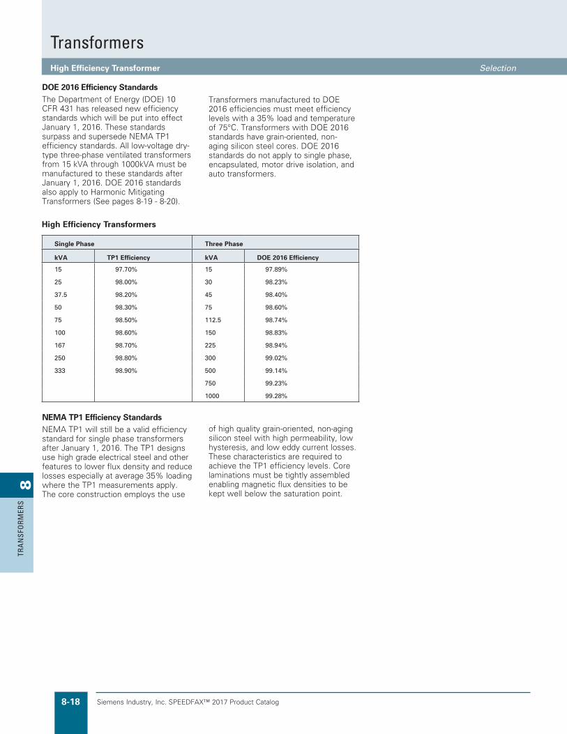
TransformersHigh Efficiency Transformer Selection
DOE 2016 Efficiency StandardsThe Department of Energy (DOE) 10 CFR 431 has released new efficiency standards which will be put into effect January 1, 2016. These standards surpass and supersede NEMA TP1 efficiency standards. All low-voltage dry-type three-phase ventilated transformers from 15 kVA through 1000kVA must be manufactured to these standards after January 1, 2016. DOE 2016 standards also apply to Harmonic Mitigating Transformers (See pages 8-19 - 8-20).
High Efficiency Transformers
Single Phase Three Phase
kVA TP1 Efficiency kVA DOE 2016 Efficiency
15 97.70% 15 97.89%
25 98.00% 30 98.23%
37.5 98.20% 45 98.40%
50 98.30% 75 98.60%
75 98.50% 112.5 98.74%
100 98.60% 150 98.83%
167 98.70% 225 98.94%
250 98.80% 300 99.02%
333 98.90% 500 99.14%
750 99.23%
1000 99.28%
Transformers manufactured to DOE 2016 efficiencies must meet efficiency levels with a 35% load and temperature of 75°C. Transformers with DOE 2016 standards have grain-oriented, non-aging silicon steel cores. DOE 2016 standards do not apply to single phase, encapsulated, motor drive isolation, and auto transformers.
NEMA TP1 Efficiency StandardsNEMA TP1 will still be a valid efficiency standard for single phase transformers after January 1, 2016. The TP1 designs use high grade electrical steel and other features to lower flux density and reduce losses especially at average 35% loading where the TP1 measurements apply. The core construction employs the use
of high quality grain-oriented, non-aging silicon steel with high permeability, low hysteresis, and low eddy current losses. These characteristics are required to achieve the TP1 efficiency levels. Core laminations must be tightly assembled enabling magnetic flux densities to be kept well below the saturation point.
Siemens Industry, Inc. SPEEDFAX™ 2017 Product Catalog 8-19
8TRA
NSFO
RMERS
TransformersSentron Harmonic Mitigating Transformers (HD1) Selection
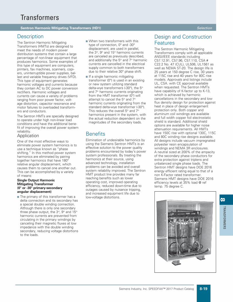
DescriptionThe Sentron Harmonic Mitigating Transformers (HMTs) are designed to meet the needs of modern power distribution systems that contain a large percentage of non-linear equipment that produces harmonics. Some examples of this type of equipment are computers, printers, fax machines, scanners, copi-ers, uninterruptible power supplies, bal-last and variable frequency drives (VFD). This type of equipment generates harmonic voltages and currents because they contain AC to DC power conversion rectifiers. Harmonic voltages and currents can cause a variety of problems ranging from poor power factor, volt-age distortion, capacitor resonance and motor failures to overloaded transform-ers and conductors.
The Sentron HMTs are specially designed to operate under high non-linear load conditions and have the additional bene-fit of improving the overall power system reliability. ApplicationOne of the most effective ways to eliminate power system harmonics is to use a technique known as “phase shifting.” In this method power system harmonics are eliminated by pairing together harmonics that have 180° relative angular displacement, which causes them to cancel one another out. This can be accomplished by a variety of means:Single Output Harmonic Mitigating Transformer (0° or -30° primary-secondary angular displacement)n The primary of this transformer has a
delta connection and its secondary has a special double winding connection. Although there is only one secondary three phase output, the 3rd, 9th and 15th harmonic currents are prevented from circulating in the primary windings by canceling their magnetic fluxes at low impedance with the double winding secondary, reducing voltage distortions to the loads.
n When two transformers with this type of connection, 0° and -30° displacement, are used in parallel, the 3rd, 9th and 15th harmonic currents are canceled as previously described, and additionally the 5th and 7th harmonic currents are cancelled in the electrical supply common to both transformers due to their relative 30° phase shift.
n If a single harmonic mitigating transformer (0°) is used in an existing or new system utilizing standard delta-wye transformers (-30°), the 5th and 7th harmonic currents originating from the HMT transformer (0°) will attempt to cancel the 5th and 7th harmonic currents originating from the standard delta-wye transformer (-30°). This reduces the overall 5th and 7th harmonics present in the system, with the actual reduction dependent on the magnitudes of the secondary loads.
BenefitsElimination of undesirable harmonics by using the Siemens Sentron HMTs is an effective solution to the power quality problems encountered by today’s power system professionals. By treating the harmonics at their source, using advanced technology, installation problems can be avoided and overall system reliability improved. The Sentron HMT product line provides many far reaching benefits such as lower operating cost, improved operating efficiency, reduced down-time due to outages caused by nuisance tripping, and increased equipment life due to low-voltage distortions.
Design and Construction FeaturesThe Sentron Harmonic Mitigating Transformers comply with all applicable ANSI/IEEE standards including C57.12.91, C57.96, C57.110, CSA # C22.2 No. 47 (CUL), UL506, UL1561 as well as NEMA ST-20. The design life is 25 years at 150 degree C rise, 30 years at 115C rise and 40 years for 80C rise models. Approvals and listings include UL, CSA. with CE approval available when requested. The Sentron HMTs have capability of K-factor up to K-13, which is achieved by harmonic cancellations in the secondary and low flux density design for protection against heat in place of design enlargement protection only. Both copper and aluminum coil windings are available and full width copper foil electrostatic shield is standard. Additional shield options are available for higher noise attenuation requirements. All HMTs have 150C rise with optional 130C, 115C and 80C winding rise designs available. All designs include vacuum impregnated polyester resin encapsulation of windings and NEMA 3R enclosures. A neutral sized at 200% of the ampacity of the secondary phase conductors for extra protection against triplens and unbalanced single phase loads. The Sentron HMT designs have DOE 2016 energy efficient rating equal to that of a non K-Factor rated transformer. Siemens HMT designs have DOE 2016 efficiency levels at 35% load @ ref temp. 75 degree C.

Siemens Industry, Inc. SPEEDFAX™ 2017 Product Catalog8-20
8TR
AN
SFO
RMER
S
TransformersSentron Harmonic Mitigating Transformers (HD1) Selection
Catalog Number Coding:Single output (1 secondary) = HD1,Phase Shift Options: HD1 followed by > (00) or (30) degree.HMT, 480 Volt Primary 208Y/120 Volt Secondary (3F3)–150C (standard), 115C and 80C Winding Rise displayed on this page.HMTs are also available with 480–480Y/277 (3F5), 208–208Y/120 (3B3), 208–480Y/277 (3B5).
Standard Features Include:n K-13 Load profile rating.n DOE 2016 Efficiencies at 35% load.n (C) Copper windings or Aluminum windings (no suffix code)
n (ES) Electrostatic shield.n 150 C Winding rise. Changes after January 1, 2016: 2 output, 15 & 45 deg Lag &
130 deg C temp rise will no longer be standard. They can be provided with a special quote from MAP.
kVA
150C (Std) Rise HMT Catalog Number
115C Rise HMT Catalog Number
80C Rise HMT Catalog Number
Secondary ConfigurationEnclosure Style
Optional HMT ModificationsOutputs Phase Shift
15 3F3Y015CHD100 3F3Y015FCHD100 3F3Y015BCHD100 1 Zero Degree Vented A,B,C,D,E,F,G
15 3F3Y015CHD130 3F3Y015FCHD130 3F3Y015BCHD130 1 30 Deg Lagging Vented A,B,C,D,E,F,G
30 3F3Y030CHD100 3F3Y030FCHD100 3F3Y030BCHD100 1 Zero Degree Vented A,B,C,D,E,F,G
30 3F3Y030CHD130 3F3Y030FCHD130 3F3Y030BCHD130 1 30 Deg Lagging Vented A,B,C,D,E,F,G
45 3F3Y045CHD100 3F3Y045FCHD100 3F3Y045BCHD100 1 Zero Degree Vented A,B,C,D,E,F,G
45 3F3Y045CHD130 3F3Y045FCHD130 3F3Y045BCHD130 1 30 Deg Lagging Vented A,B,C,D,E,F,G
75 3F3Y075CHD100 3F3Y075FCHD100 3F3Y075BCHD100 1 Zero Degree Vented A,B,C,D,E,F,G
75 3F3Y075CHD130 3F3Y075FCHD130 3F3Y075BCHD130 1 30 Deg Lagging Vented A,B,C,D,E,F,G
112.5 3F3Y112CHD100 3F3Y112FCHD100 3F3Y112BCHD100 1 Zero Degree Vented A,B,C,D,E,F,G
112.5 3F3Y112CHD130 3F3Y112FCHD130 3F3Y112BCHD130 1 30 Deg Lagging Vented A,B,C,D,E,F,G
150 3F3Y150CHD100 3F3Y150FCHD100 3F3Y150BCHD100 1 Zero Degree Vented A,B,C,D,E,F,G
150 3F3Y150CHD130 3F3Y150FCHD130 3F3Y150BCHD130 1 30 Deg Lagging Vented A,B,C,D,E,F,G
225 3F3Y225CHD100 3F3Y225FCHD100 3F3Y225BCHD100 1 Zero Degree Vented A,B,C,D,E,F,G
225 3F3Y225CHD130 3F3Y225FCHD130 3F3Y225BCHD130 1 30 Deg Lagging Vented A,B,C,D,E,F,G
300 3F3Y300CHD100 3F3Y300FCHD100 3F3Y300BCHD100 1 Zero Degree Vented A,B,C,D,E,F,G
300 3F3Y300CHD130 3F3Y300FCHD130 3F3Y300BCHD130 1 30 Deg Lagging Vented A,B,C,D,E,F,G
500 3F3Y500CHD100 3F3Y500FCHD100 3F3Y500BCHD100 1 Zero Degree Vented C,D,E,F,G
500 3F3Y500CHD130 3F3Y500FCHD130 3F3Y500BCHD130 1 30 Deg Lagging Vented C,D,E,F,G
Optional Modifications Table for HMTs
Thermal Sensors 170° C= (TS7), 185° C= (TS8) or 200° C= (TS0)
G TS7 = 1 sensor center coilG TS72 = 2 sensors center coilG TS76 = 6 sensors, (2) on each coilG TS8 = 1 sensor center coilG TS82 = 2 sensors center coilG TS86 = 6 sensors, (2) on each coilG TS0 = 1 sensor center coilG TS02 = 2 sensors center coilG TS06 = 6 sensors, (2) on each coil
Sound Level
A LN3= (3dB below NEMA standard)B LN5= (5dB below NEMA standard)
Attenuation—Single shield—60dB Common Mode Std.C ES2= Double shield—80dB Common Mode >
Filtering & Attenuation
E TV= Secondary side TVSS (100kA & 200kA available)with common mode noise attenuation
F TB= Terminal Block
Contact Sales Office for pricing. ES2 Common Mode: Transverse Mode: 100dB: Between 60 Hz – 1 kHz 10dB: @ 10kHz 90 dB: Between 1 kHz – 10 kHz 20dB: @ 100 kHz 80dB: Between 10 kHz – 1000 kHz 40db: @ 1000 kHz
Catalog Numbers shown with “C” include Copper windings. Remove “C” for Aluminum windings. COMPAS will configure Aluminum version unless Copper windings are selected.
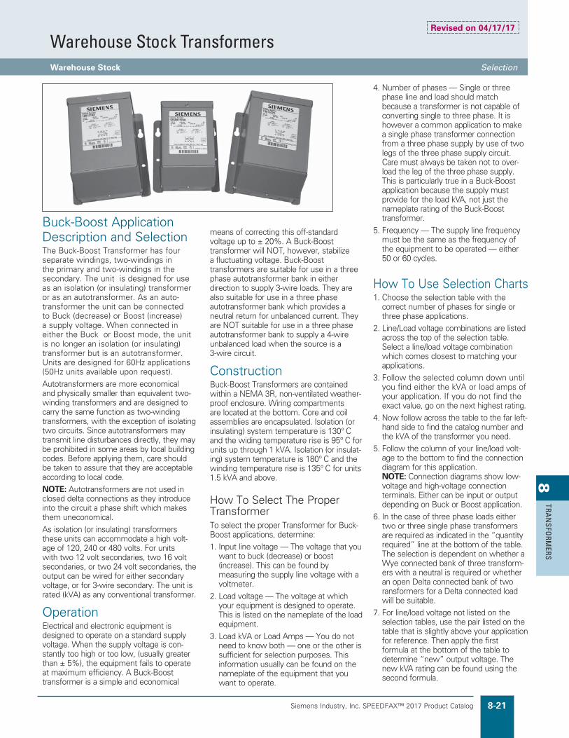
Siemens Industry, Inc. SPEEDFAX™ 2017 Product Catalog 8-21
8TRA
NSFO
RMERS
Warehouse Stock TransformersWarehouse Stock Selection
Buck-Boost Application Description and SelectionThe Buck-Boost Transformer has four separate windings, two-windings in the primary and two-windings in the secondary. The unit is designed for use as an isolation (or insulating) transformer or as an autotransformer. As an auto-transformer the unit can be connected to Buck (decrease) or Boost (increase) a supply voltage. When connected in either the Buck or Boost mode, the unit is no longer an isolation (or insulating) transformer but is an autotransformer. Units are designed for 60Hz applications (50Hz units available upon request).
Autotransformers are more economical and physically smaller than equivalent two-winding transformers and are designed to carry the same function as two-winding transformers, with the exception of isolating two circuits. Since autotransformers may transmit line disturbances directly, they may be prohibited in some areas by local building codes. Before applying them, care should be taken to assure that they are acceptable according to local code.
NOTE: Autotransformers are not used in closed delta connections as they introduce into the circuit a phase shift which makes them uneconomical.
As isolation (or insulating) transformers these units can accommodate a high volt-age of 120, 240 or 480 volts. For units with two 12 volt secondaries, two 16 volt secondaries, or two 24 volt secondaries, the output can be wired for either secondary voltage, or for 3-wire secondary. The unit is rated (kVA) as any conventional transformer.
OperationElectrical and electronic equipment is designed to operate on a standard supply voltage. When the supply voltage is con-stantly too high or too low, (usually greater than ± 5%), the equipment fails to operate at maximum efficiency. A Buck-Boost transformer is a simple and economical
4. Number of phases — Single or three phase line and load should match because a transformer is not capable of converting single to three phase. It is however a common application to make a single phase transformer connection from a three phase supply by use of two legs of the three phase supply circuit. Care must always be taken not to over-load the leg of the three phase supply. This is particularly true in a Buck-Boost application because the supply must provide for the load kVA, not just the nameplate rating of the Buck-Boost transformer.
5. Frequency — The supply line frequency must be the same as the frequency of the equipment to be operated — either 50 or 60 cycles.
How To Use Selection Charts1. Choose the selection table with the
correct number of phases for single or three phase applications.
2. Line/Load voltage combinations are listed across the top of the selection table. Select a line/load voltage combination which comes closest to matching your applications.
3. Follow the selected column down until you find either the kVA or load amps of your application. If you do not find the exact value, go on the next highest rating.
4. Now follow across the table to the far left-hand side to find the catalog number and the kVA of the transformer you need.
5. Follow the column of your line/load volt-age to the bottom to find the connection diagram for this application. NOTE: Connection diagrams show low-voltage and high-voltage connection terminals. Either can be input or output depending on Buck or Boost application.
6. In the case of three phase loads either two or three single phase transformers are required as indicated in the “quantity required” line at the bottom of the table. The selection is dependent on whether a Wye connected bank of three transform-ers with a neutral is required or whether an open Delta connected bank of two ransformers for a Delta connected load will be suitable.
7. For line/load voltage not listed on the selection tables, use the pair listed on the table that is slightly above your application for reference. Then apply the first formula at the bottom of the table to determine “new” output voltage. The new kVA rating can be found using the second formula.
means of correcting this off-standard voltage up to ± 20%. A Buck-Boost transformer will NOT, however, stabilize a fluctuating voltage. Buck-Boost transformers are suitable for use in a three phase autotransformer bank in either direction to supply 3-wire loads. They are also suitable for use in a three phase autotransformer bank which provides a neutral return for unbalanced current. They are NOT suitable for use in a three phase autotransformer bank to supply a 4-wire unbalanced load when the source is a 3-wire circuit.
ConstructionBuck-Boost Transformers are contained within a NEMA 3R, non-ventilated weather-proof enclosure. Wiring compartments are located at the bottom. Core and coil assemblies are encapsulated. Isolation (or insulating) system temperature is 130° C and the widing temperature rise is 95° C for units up through 1 kVA. Isolation (or insulat-ing) system temperature is 180° C and the winding temperature rise is 135° C for units 1.5 kVA and above.
How To Select The Proper TransformerTo select the proper Transformer for Buck-Boost applications, determine:
1. Input line voltage — The voltage that you want to buck (decrease) or boost (increase). This can be found by measuring the supply line voltage with a voltmeter.
2. Load voltage — The voltage at which your equipment is designed to operate. This is listed on the nameplate of the load equipment.
3. Load kVA or Load Amps — You do not need to know both — one or the other is sufficient for selection purposes. This information usually can be found on the nameplate of the equipment that you want to operate.
Revised on 04/17/17

Siemens Industry, Inc. SPEEDFAX™ 2017 Product Catalog8-22
8TR
AN
SFO
RMER
S
Warehouse Stock TransformersBuck-Boost Selection
120 @ 240 Volts Primary — 12/24 Volts Secondary, 60 Hz, No Taps, Wall Mounted
•Output voltage for lower input voltage can be found by:Rated Output VoltageRated Input Voltage
@ Input Actual Voltage = Output New Voltage.•Output kVA available at reduced input voltage can be found by:Actual Input VoltageRated Input Voltage
@ Output kVA = New kVA Rating.• Inputs and outputs may be reversed
without affecting kVA capacity. See note on page 8-25.
* All Buck-Boost transformers listed are available for immediate shipment.
Single Phase — Table 1 Boosting Bucking
Catalog Line Voltage 96 100 105 109 189 208 215 220 125 132 229 245 250 252Number* (Available)
Insulating Load VoltageTransformer (Output) 115 120 115 120 208 229 237 242 114 120 208 222 227 240Rating
050BB1224J kVA .24 .25 .50 .50 .43 .48 .49 .50 .52 .55 .48 .51 .52 1.05.050 kVA Load Amps 2.08 2.08 4.17 4.17 2.08 2.08 2.08 2.08 4.59 4.59 2.29 2.29 2.29 4.38
100BB1224J kVA .48 .50 .96 1.00 .87 .95 .99 1.01 1.04 1.10 .95 1.02 1.04 2.10.100 kVA Load Amps 4.17 4.17 8.33 8.33 4.17 4.17 4.17 4.17 9.16 9.16 4.58 4.58 4.58 8.75
150BB1224J kVA .72 .75 1.44 1.50 1.30 1.43 1.48 1.51 1.55 1.65 1.43 1.53 1.56 3.15.150 kVA Load Amps 6.25 6.25 12.50 12.50 6.25 6.25 6.25 6.25 13.75 13.75 6.88 6.88 6.88 13.13
205BB1224J kVA 1.19 1.25 2.40 2.50 2.17 2.38 2.47 2.52 2.60 2.75 2.38 2.54 2.60 5.25.250 kVA Load Amps 10.42 10.42 20.83 20.83 10.42 10.42 10.42 10.42 22.92 22.92 11.46 11.46 11.46 21.88
505BB1224J kVA 2.37 2.50 4.80 5.00 4.33 4.77 4.94 5.04 5.18 5.50 4.77 5.09 5.20 10.50.500 kVA Load Amps 20.83 20.83 41.67 41.67 20.83 20.83 20.83 20.83 45.83 45.83 22.92 22.92 22.92 43.75
705BB1224J kVA 3.56 3.75 7.19 7.50 6.50 7.15 7.41 7.56 7.77 8.25 7.15 7.63 7.80 15.75.750 kVA Load Amps 31.25 31.25 62.50 62.50 31.25 31.25 31.25 31.25 68.75 68.75 34.38 34.38 34.38 65.63
1BB1224J kVA 4.75 5.00 9.58 10.00 8.67 9.53 9.88 10.08 10.36 11.00 9.53 10.17 10.40 21.001.00 kVA Load Amps 41.67 41.67 83.33 83.33 41.67 41.67 41.67 41.67 91.66 91.66 45.83 45.83 45.83 87.50
105BB1224J kVA 7.13 7.50 14.38 15.00 13.00 14.30 14.81 15.13 15.54 16.50 14.30 15.26 15.61 31.501.50 kVA Load Amps 62.50 62.50 125.00 125.00 62.50 62.50 62.50 62.50 137.50 137.50 68.75 68.75 68.75 131.25
2BB1224J kVA 9.50 10.00 19.17 20.00 17.33 19.07 19.75 20.17 20.72 22.00 19.07 20.35 20.81 42.002.00 kVA Load Amps 83.33 83.33 166.66 166.66 83.33 83.33 83.33 83.33 183.33 183.33 91.66 91.66 91.66 175.00
3BB1224J kVA 14.25 15.00 28.75 30.00 26.00 28.60 29.63 30.25 31.08 33.00 28.60 30.53 31.21 63.003.00 kVA Load Amps 125.00 125.00 250.00 250.00 125.00 125.00 125.00 125.00 275.00 275.00 137.50 137.50 137.50 262.50
5BB1224J kVA 23.75 25.00 47.92 50.00 43.33 47.67 49.37 50.42 51.79 55.00 47.67 50.88 52.02 105.005.00 kVA Load Amps 208.33 208.33 416.66 416.66 208.33 208.33 208.33 208.33 458.33 458.33 229.17 229.17 229.17 437.50
Connection Diagram (pg. 8-25) 2 2 1 1 4 4 4 4 4 1 4 4 4 3
Three Phase — Table 2 Boosting Bucking
Catalog Line Voltage 189Y/ 195Y/ 200Y/ 208Y/ 416Y/ 416Y/ Number* (Available) 109 113 115 120 240 240 189 208 220 218 229 250 255 264
Insulating Load VoltageTransformer (Output) 208Y/ 234Y/ 240Y/ 229Y/ 458Y/ 437Y/ 208 229 242 208 208 227 232 240
Rating 120 135 139 132 264 252
050BB1224J kVA 1.50 .84 .86 1.65 1.65 3.15 .75 .83 .87 1.58 .83 .90 .92 .95.050 kVA Load Amps 4.17 2.08 2.08 4.17 2.08 4.17 2.08 2.08 2.08 4.39 2.29 2.29 2.29 2.29
100BB1224J kVA 3.00 1.69 1.73 3.30 3.30 6.29 1.50 1.65 1.75 3.15 1.65 1.80 1.84 1.90.100 kVA Load Amps 8.33 4.17 4.17 8.33 4.17 8.33 4.17 4.17 4.17 8.75 4.58 4.58 4.58 4.58
150BB1224J kVA 4.50 2.54 2.60 4.96 4.96 9.44 2.26 2.48 2.62 4.73 2.48 2.71 2.76 2.86.150 kVA Load Amps 12.50 6.25 6.25 12.50 6.25 12.50 6.25 6.25 6.25 13.13 6.88 6.88 6.88 6.88
205BB1224J kVA 7.50 4.22 4.33 8.30 8.25 15.75 3.75 4.13 4.37 7.88 4.13 4.50 4.61 4.76.250 kVA Load Amps 20.83 10.42 10.42 20.83 10.42 20.83 10.42 10.42 10.42 21.88 11.46 11.46 11.46 11.46
505BB1224J kVA 15.01 8.44 8.66 16.60 16.50 31.50 7.50 8.26 8.73 15.76 8.26 9.01 9.21 9.53.500 kVA Load Amps 41.67 20.83 20.83 41.67 20.83 41.67 20.83 20.83 20.83 43.75 22.92 22.92 22.92 22.92
705BB1224J kVA 22.52 12.67 12.99 24.90 24.75 47.25 11.26 12.39 13.10 23.64 12.39 13.52 13.82 14.29.750 kVA Load Amps 62.50 31.25 31.25 62.50 31.25 62.50 31.25 31.25 31.25 65.63 34.38 34.38 34.38 34.38
1BB1224J kVA 30.02 16.89 17.32 33.20 33.00 63.00 15.01 16.51 17.47 31.52 16.51 18.02 18.42 19.051.00 kVA Load Amps 83.33 41.67 41.67 83.33 41.67 83.33 41.67 41.67 41.67 87.50 45.83 45.83 45.83 45.53
105BB1224J kVA 45.03 25.33 25.98 49.80 49.50 94.50 22.52 24.77 26.20 47.28 24.77 27.03 27.63 28.531.50 kVA Load Amps 125.00 62.50 62.50 125.00 62.50 125.00 62.50 62.50 62.50 131.25 68.75 68.75 68.75 68.75
2BB1224J kVA 60.06 33.77 34.64 66.40 66.00 126.00 30.02 33.03 34.93 63.05 33.03 36.04 36.84 38.112.00 kVA Load Amps 166.67 83.33 83.33 166.67 83.33 166.66 83.33 83.33 83.33 175.00 91.67 91.67 91.67 91.67
3BB1224J kVA 90.07 50.66 51.96 99.59 99.00 189.00 45.03 49.54 52.39 94.57 49.54 54.06 55.25 57.163.00 kVA Load Amps 250.00 125.00 125.00 250.00 125.00 250.00 125.00 125.00 125.00 262.50 137.50 137.50 137.50 137.50
5BB1224J kVA 150.11 84.44 86.60 165.99 165.00 318.00 75.05 82.56 87.32 157.62 82.56 90.10 92.09 95.265.00 kVA Load Amps 416.67 208.33 208.33 416.67 208.33 416.66 208.33 208.33 208.33 437.50 229.17 229.17 229.17 229.17
Quantity Required 3 3 3 3 3 3 2 2 2 2 2 2 2 2
Connection Diagram (pg. 8-25) 5 6 6 5 8 7 12 12 12 11 12 12 12 12

Siemens Industry, Inc. SPEEDFAX™ 2017 Product Catalog 8-23
8TRA
NSFO
RMERS
* All Buck-Boost transformers listed are available for immediate shipment.
120 @ 240 Volts Primary — 16/32 Volts Secondary, 60 Hz, No Taps, Wall Mounted
•Output voltage for lower input voltage can be found by:Rated Output VoltageRated Input Voltage
@ Input Actual Voltage = Output New Voltage.•Output kVA available at reduced input voltage can be found by:Actual Input VoltageRated Input Voltage
@ Output kVA = New kVA Rating.
Single Phase — Table 3 Boosting Bucking
Catalog Line Voltage 95 100 105 208 215 215 220 225 135 240 240 245 250 255Number* (Available)
Insulating Load VoltageTransformer (Output) 120 113 119 236 244 229 235 240 120 212 225 230 234 239Rating
050BB1632J kVA .19 .36 .37 .37 .38 .72 .73 .73 .42 .37 .75 .77 .78 .80.050 kVA Load Amps 1.56 3.12 3.12 1.56 1.56 3.12 3.12 3.12 3.54 1.77 3.33 3.33 3.33 3.33
100BB1632J kVA .38 .72 .74 .74 .76 1.44 1.46 1.50 .84 .74 1.50 1.54 1.56 1.60.100 kVA Load Amps 3.13 6.25 6.25 3.13 3.13 6.25 6.25 6.25 7.09 3.54 6.66 6.66 6.66 6.66
150BB1632J kVA .56 1.06 1.12 1.12 1.14 2.16 2.20 2.26 1.26 1.10 2.26 2.30 2.34 2.40.150 kVA Load Amps 4.69 9.38 9.38 4.69 4.69 9.38 9.38 9.38 10.64 5.30 10.02 10.02 10.02 10.02
205BB1632J kVA .94 1.78 1.86 1.88 1.91 3.59 3.67 3.75 2.11 1.84 3.75 3.83 3.90 3.98.250 kVA Load Amps 7.81 15.63 15.63 7.81 7.81 15.63 15.63 15.63 17.71 8.85 16.67 16.67 16.67 16.67
505BB1632J kVA 1.88 3.56 3.72 3.75 3.81 7.19 7.34 7.50 4.21 3.68 7.50 7.67 7.80 7.97.500 kVA Load Amps 15.63 31.25 31.25 15.63 15.63 31.25 31.25 31.25 35.42 17.71 33.33 33.33 33.33 33.33
705BB1632J kVA 2.81 5.34 5.58 5.63 5.72 10.78 11.02 11.25 6.32 5.53 11.25 11.50 11.70 11.95.750 kVA Load Amps 23.44 46.88 46.88 23.44 23.44 46.88 46.88 46.88 53.13 26.56 50.00 50.00 50.00 50.00
1BB1632J kVA 3.75 7.13 7.44 7.50 7.63 14.38 14.69 15.00 8.43 7.37 15.00 15.33 15.60 15.931.00 kVA Load Amps 31.25 62.50 62.50 31.25 31.25 62.50 62.50 62.50 70.83 35.42 66.67 66.67 66.67 66.67
105BB1632J kVA 5.63 10.69 11.16 11.25 11.44 21.56 22.03 22.50 12.64 11.05 22.50 23.00 23.40 23.901.50 kVA Load Amps 43.90 93.80 93.80 46.90 46.90 93.80 93.80 93.80 106.30 53.10 100.00 100.00 100.00 100.00
2BB1632J kVA 7.50 14.25 14.88 15.00 15.25 28.75 29.38 30.00 16.86 14.73 30.00 30.67 31.20 31.872.00 kVA Load Amps 62.50 125.00 125.00 62.50 62.50 125.00 125.00 125.00 141.70 70.80 133.30 133.30 133.30 133.30
3BB1632J kVA 11.25 21.38 22.31 22.50 22.88 43.13 44.06 45.00 25.29 22.10 45.00 46.00 46.80 47.803.00 kVA Load Amps 93.80 187.50 187.50 93.80 93.80 187.50 187.50 187.50 212.50 106.30 200.00 200.00 200.00 200.00
5BB1632J kVA 18.75 35.63 37.19 37.50 38.13 71.88 73.44 75.00 42.15 36.83 75.00 76.67 78.00 79.675.00 kVA Load Amps 156.30 312.50 312.50 156.30 156.30 312.50 312.50 312.50 354.20 177.10 333.30 333.30 333.30 333.30
Connection Diagram (pg. 8-25) 2 1 1 4 4 3 3 3 1 4 3 3 3 3
Three Phase — Table 4 Boosting Bucking
Catalog Line Voltage 183Y/ 208Y/ Number* (Available) 106 120 195 208 225 240 245 250 256 265 272
Insulating Load Voltage 208Y/Transformer (Output) 236Y/ 208 236 240 208 230 234 240 234 240Rating 120 136
050BB1632J kVA 1.13 1.28 1.13 .62 1.30 .56 1.33 1.35 1.39 .72 .74.050 kVA Load Amps 3.13 3.13 3.13 1.56 3.13 1.56 3.34 3.34 3.34 1.77 1.77
100BB1632J kVA 2.25 2.55 2.25 1.30 2.60 1.13 2.66 2.70 2.77 1.44 1.48.100 kVA Load Amps 6.25 6.25 6.25 3.13 6.25 3.13 6.67 6.67 6.67 3.55 3.55
150BB1632J kVA 3.38 3.83 3.38 1.95 3.90 1.69 3.98 4.05 4.16 2.15 2.21.150 kVA Load Amps 9.38 9.38 9.38 4.69 9.38 4.69 10.00 10.00 10.00 5.31 5.31
205BB1632J kVA 5.63 6.39 5.63 3.17 6.50 2.81 6.64 6.76 6.93 3.59 3.68.250 kVA Load Amps 15.63 15.63 15.63 7.81 15.63 7.81 16.67 16.67 16.67 8.85 8.85
505BB1632J kVA 11.26 12.77 11.26 6.33 12.99 5.63 13.28 13.50 13.86 7.17 7.36.500 kVA Load Amps 31.25 31.26 31.25 15.63 31.25 15.63 33.33 33.33 33.33 17.69 17.71
705BB1632J kVA 16.89 19.16 16.89 9.50 19.49 8.44 19.92 20.26 20.78 10.76 11.04.750 kVA Load Amps 46.88 46.88 46.88 23.44 46.88 23.44 50.00 50.00 50.00 26.54 26.56
1BB1632J kVA 22.52 25.55 22.52 12.67 25.98 11.26 26.56 27.02 27.71 14.34 14.721.00 kVA Load Amps 62.50 62.50 62.50 31.25 62.50 31.25 66.67 66.67 66.67 35.39 35.42
105BB1632J kVA 33.77 38.32 33.77 19.00 38.97 16.89 39.84 40.53 41.57 21.52 22.081.50 kVA Load Amps 93.75 93.75 93.75 46.88 93.75 46.88 100.00 100.00 100.00 53.08 53.13
2BB1632J kVA 45.03 51.10 46.03 25.33 51.96 22.52 53.11 54.04 55.43 28.69 29.442.00 kVA Load Amps 125.00 125.00 125.00 62.50 125.00 62.50 133.33 133.33 133.33 70.78 70.83
3BB1632J kVA 67.55 76.64 67.55 38.00 77.94 33.77 79.67 81.06 83.14 43.03 44.173.00 kVA Load Amps 187.50 187.50 187.50 93.75 187.50 93.75 200.00 200.00 200.00 106.17 106.25
5BB1632J kVA 112.58 127.74 112.58 63.33 129.90 56.29 132.79 135.09 138.56 71.72 73.615.00 kVA Load Amps 312.50 312.50 312.50 156.25 312.50 156.25 333.33 333.33 333.33 176.95 177.08
Quantity Required 3 3 2 2 2 2 2 2 2 2 2
Connection Diagram (pg. 8-25) 5 5 11 12 11 12 11 11 11 12 12
• Inputs and outputs may be reversedwithout affecting kVA capacity. See note on page 8-25.
Revised on 04/17/17
Warehouse Stock TransformersBuck-Boost Selection

Siemens Industry, Inc. SPEEDFAX™ 2017 Product Catalog8-24
8TR
AN
SFO
RMER
S
Warehouse Stock TransformersBuck-Boost Selection
240 @ 480 Volts Primary — 24/48 Volts Secondary, 60 Hz, No Taps, Wall Mounted
•Output voltage for lower input can be found by:Rated Output VoltageRated Input Voltage
@ Input Actual Voltage = Output New Voltage.•Output kVA available at reduced input voltage can be found by:Actual Input VoltageRated Input Voltage
@ Output kVA = New kVA Rating.
Single Phase — Table 5 Boosting Bucking
Catalog Line Voltage 230 380 416 425 430 435 440 450 450 460 277 480 480 504Number* (Available)
Insulating Load VoltageTransformer (Output) 276 418 458 468 473 457 462 495 472 483 231 436 457 480Rating
050BB2448J kVA .29 .44 .48 .49 .49 .95 .96 .52 .98 1.01 .29 .50 1.00 1.05.050 kVA Load Amps 1.04 1.04 1.04 1.04 1.04 2.08 2.08 1.04 2.08 2.08 1.25 1.15 2.19 2.19
100BB2448J kVA .58 .87 .95 .97 .99 1.90 1.93 1.03 1.97 2.01 .58 1.00 2.00 2.10.100 kVA Load Amps 2.08 2.08 2.08 2.08 2.08 4.17 4.17 2.08 4.17 4.17 2.50 2.29 4.38 4.38
150BB2448J kVA .86 1.31 1.43 1.46 1.48 2.86 2.89 1.55 2.95 3.02 .86 1.50 3.00 3.15.150 kVA Load Amps 3.13 3.13 3.13 3.13 3.13 6.25 6.25 3.13 6.25 6.25 3.75 3.44 6.56 6.56
205BB2448J kVA 1.44 2.18 2.38 2.43 2.46 4.76 4.81 2.58 4.92 5.03 1.44 2.50 5.00 5.25.250 kVA Load Amps 5.21 5.21 5.21 5.21 5.21 5.21 10.42 5.21 10.42 10.42 6.25 5.73 10.94 10.94
505BB2448J kVA 2.88 4.35 4.77 4.87 4.93 9.52 9.62 5.16 9.83 10.06 2.88 5.00 10.00 10.50.500 kVA Load Amps 10.42 10.42 10.42 10.42 10.42 20.83 20.83 10.42 20.83 20.83 12.50 11.46 21.88 21.88
705BB2448J kVA 4.31 6.53 7.15 7.30 7.39 14.28 14.44 7.73 14.75 15.09 4.31 7.49 15.00 15.75.750 kVA Load Amps 15.63 15.63 15.62 15.63 15.63 31.25 31.25 15.63 31.25 31.25 18.75 17.19 32.81 32.81
1BB2448J kVA 5.75 8.71 9.53 9.74 9.85 19.04 19.25 10.31 19.67 20.13 5.75 9.99 20.00 21.001.00 kVA Load Amps 20.83 20.83 20.83 20.83 20.83 41.67 41.67 20.83 41.67 41.67 25.00 22.92 43.75 43.75
105BB2448J kVA 8.63 13.06 14.30 14.61 14.78 28.56 28.88 15.47 29.50 30.19 8.63 14.99 30.00 31.501.50 kVA Load Amps 31.25 31.25 31.25 31.25 31.25 62.50 62.50 31.25 62.50 62.50 37.50 34.38 65.63 65.63
2BB2448J kVA 11.50 17.42 19.07 19.48 19.71 38.08 38.50 20.63 39.33 40.25 11.50 19.98 40.00 42.002.00 kVA Load Amps 41.67 41.67 41.67 41.67 41.67 83.33 83.33 41.67 83.33 83.33 50.00 45.83 87.50 87.50
3BB2448J kVA 17.25 26.13 28.60 29.22 29.56 57.13 57.75 30.94 59.00 60.38 17.25 29.98 60.00 63.003.00 kVA Load Amps 62.50 62.50 62.50 62.50 62.50 125.00 125.00 62.50 125.00 125.00 75.00 68.80 131.25 131.25
5BB2448J kVA 28.75 43.54 47.67 48.70 49.30 95.20 96.20 51.56 98.30 100.60 28.80 50.00 100.00 105.005.00 kVA Load Amps 104.17 104.17 104.17 104.17 104.20 208.30 208.30 104.17 208.30 208.30 125.00 114.60 218.75 218.75
Connection Diagram (pg. 8-25) 2 4 4 4 4 3 3 4 3 3 2 4 3 3
Three Phase — Table 6 Boosting Bucking
Catalog Line Voltage 399Y/ Number* (Available) 230 380 430 440 460 460 480 480 440 440 460 460 480 480 500 500
Insulating Load VoltageTransformer (Output) 480Y/ 418 473 462 506 483 528 504 400 419 438 418 457 436 455 476
Rating 277
050BB2448J kVA .86 .75 .85 1.66 .91 1.74 .95 1.82 .79 1.58 1.66 .83 1.73 .86 .90 1.80.050 kVA Load Amps 1.04 1.04 1.04 2.08 1.04 2.08 1.04 2.08 1.14 2.18 2.18 1.14 2.18 1.14 1.14 2.19
100BB2448J kVA 1.73 1.51 1.70 3.33 1.82 3.48 1.90 3.63 1.59 3.17 3.31 1.66 3.46 1.73 1.80 3.61.100 kVA Load Amps 2.08 2.08 2.08 4.16 2.08 4.16 2.08 4.16 2.29 4.37 4.37 2.29 4.37 2.29 2.29 4.38
150BB2448J kVA 2.60 2.26 2.56 4.99 2.73 5.22 2.85 5.45 2.38 4.75 4.97 2.48 5.19 2.59 2.70 5.41.150 kVA Load Amps 3.12 3.13 3.12 6.24 3.12 6.25 3.12 6.24 3.43 6.55 6.55 3.43 6.55 3.43 3.43 6.56
205BB2448J kVA 4.33 3.77 4.26 8.32 4.56 8.70 4.76 9.08 3.96 7.92 8.28 4.14 8.64 4.32 4.51 9.02.250 kVA Load Amps 5.20 5.21 5.20 10.40 5.20 10.40 5.20 10.40 5.72 10.92 10.92 5.72 10.92 5.72 5.72 10.94
505BB2448J kVA 8.60 7.54 8.52 16.64 9.11 17.40 9.51 18.16 7.93 15.85 16.57 8.28 17.29 8.64 9.02 18.04.500 kVA Load Amps 10.40 10.42 10.40 20.80 10.40 20.80 10.40 20.80 11.44 21.84 21.84 11.44 21.84 11.44 11.44 21.88
705BB2448J kVA 12.90 11.31 12.77 24.97 13.67 26.10 14.27 27.24 11.89 23.77 24.85 12.42 25.93 12.96 13.52 27.06.750 kVA Load Amps 15.60 15.63 15.60 31.20 15.60 31.20 15.60 31.20 17.16 32.76 32.76 17.16 32.76 17.16 17.16 32.81
1BB2448J kVA 17.30 15.08 17.03 33.29 18.23 34.80 19.02 36.31 15.85 31.70 33.14 16.57 34.57 17.28 18.03 36.081.00 kVA Load Amps 20.80 20.83 20.80 41.60 20.80 41.60 20.80 41.60 22.88 43.68 43.68 22.88 43.68 22.88 22.88 43.75
105BB2448J kVA 25.90 22.62 25.55 49.93 27.34 52.50 28.53 54.47 23.78 47.55 49.71 24.85 51.86 25.92 27.05 54.131.50 kVA Load Amps 31.20 31.25 31.20 62.40 31.20 62.40 31.20 62.40 34.32 65.52 65.52 34.32 65.62 34.32 34.32 65.63
2BB2448J kVA 34.60 30.17 34.07 66.58 36.46 69.60 38.04 72.63 31.70 63.40 66.27 33.13 69.15 34.56 36.06 72.172.00 kVA Load Amps 41.60 41.67 41.60 83.20 41.60 83.20 41.60 83.20 45.76 87.36 87.36 45.76 87.36 45.76 45.76 87.50
3BB2448J kVA 52.00 45.25 51.18 100.03 54.69 104.57 57.07 109.12 47.63 95.25 99.57 49.77 103.89 51.92 54.18 108.253.00 kVA Load Amps 62.50 62.50 62.50 125.00 62.50 125.00 62.50 125.00 68.75 131.25 131.25 68.75 131.25 68.75 68.75 131.25
5BB2448J kVA 86.10 75.42 85.17 166.44 91.15 174.01 95.11 181.57 79.26 158.50 165.69 82.83 172.87 86.39 90.16 180.425.00 kVA Load Amps 104.00 104.17 104.00 208.00 104.00 208.00 104.00 208.00 114.40 218.40 218.40 114.40 218.40 114.40 114.40 218.75
Quantity Required 3 2 2 2 2 2 2 2 2 2 2 2 2 2 2 2
Connection Diagram (pg. 8-25) 6 12 12 11 12 11 12 11 12 11 11 12 11 12 12 11
• Inputs and outputs may be reversedwithout affecting kVA capacity. See note on page 8-25.
* All Buck-Boost transformers listed are available for immediate shipment.
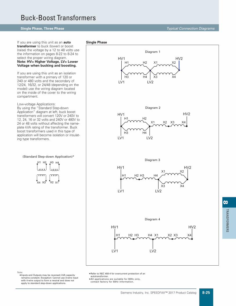
Siemens Industry, Inc. SPEEDFAX™ 2017 Product Catalog 8-25
8TRA
NSFO
RMERS
Buck-Boost TransformersSingle Phase, Three Phase Typical Connection Diagrams
Single Phase
(Standard Step-down Application)*
Diagram 2
Diagram 3
Diagram 4
Diagram 1
If you are using this unit as an auto transformer to buck (lower) or boost (raise) the voltage by a 12 to 48 volts use the information on pages 8-22 to 8-24 to select the proper wiring diagram. Note: HV= Higher Voltage, LV= Lower Voltage when bucking and boosting.
If you are using this unit as an isolation transformer with a primary of 120 or 240 or 480 volts and the secondary of 12/24, 16/32, or 24/48 (depending on the model) use the wiring diagram located on the inside of the cover to the wiring compartment.
Low-voltage Applications: By using the “Standard Step-down Application” diagram at left, buck boost transformers will convert 120V or 240V to 12, 24, 16 or 32 volts and 240V or 480V to 24 or 48 volts without affecting the name-plate kVA rating of the transformer. Buck boost transformers used in this type of application will become isolation or insulat-ing type transformers.
Note: • Inputs and Outputs may be reversed; kVA capacity
remains constant. Exception: Cannot use 3-wire input with 4-wire output to form a neutral and does not apply to standard step-down applications.
• Refer to NEC 450-4 for overcurrent protection of an autotransformer.
• All applications are suitable for 60Hz only, contact factory for 50Hz information.
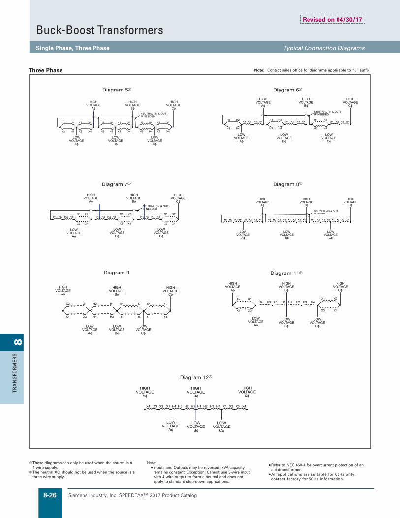
Siemens Industry, Inc. SPEEDFAX™ 2017 Product Catalog8-26
8TR
AN
SFO
RMER
S
Buck-Boost TransformersSingle Phase, Three Phase Typical Connection Diagrams
Note: Contact sales office for diagrams applicable to “J” suffix.
These diagrams can only be used when the source is a 4-wire supply.
The neutral XO should not be used when the source is a three wire supply.
Note: • Inputs and Outputs may be reversed; kVA capacity
remains constant. Exception: Cannot use 3-wire input with 4-wire output to form a neutral and does not apply to standard step-down applications.
• Refer to NEC 450-4 for overcurrent protection of an autotransformer.
• All applications are suitable for 60Hz only, contact factory for 50Hz information.
Three Phase
Diagram 5 Diagram 6
Diagram 12
Diagram 9 Diagram 11
Diagram 8Diagram 7
Revised on 04/30/17

Siemens Industry, Inc. SPEEDFAX™ 2017 Product Catalog 8-27
8TRA
NSFO
RMERS
Warehouse Stock TransformersAccessories and Details Selection
Product Category XFMR
Series J Drip Shield Kits are available as a special order. Add “XD” to the catalog number.
Wall Mounting Brackets for Ventilated Transformers For Series H transformers, wall brackets are integral to the enclosure up to 30kVA and most 45kVA. A Wall Bracket Kit is available for 45kVA transformers that do not include wall brackets and for most 75kVA transformers. They should be ordered separately for field installation rather than including the W option in the catalog number. Series H wall brackets are not seismic certified. For Series J, include W option code for wall brackets to come with Series J transformers up to 75kVA or order separately for field installation. Call factory for price and availability.
Drip Shield/Weather Shield Kits for Ventilated Transformers
Drip shields are integral to enclosure for Series H transformers and all DOE 2016 Series J transformers. Include DS option code to catalog number to include with single phase Series J transformers. Drip shield kits are available for field installation for Series J and other previously sold series transformers. Call factory for price and availability. See page 8-8 for additional information.
May be used on “JST” suffix and “non JST” suffix transformers. Terminal lugs are screw type, lug connectors suitable for both copper and aluminum cable. All lugs are single barrel and suitable for cable ranges shown. 750kcmil lugs are capable of holding (2) 250kcmil cables in lieu of (1) 750kcmil cable. All lugs are rated 90˚C.
Lug kits contain quantity required for each kVA based NEC ampacities for cable range indicated. For cable sizes outside the range, hole size of terminal may not be the correct size to mount other lugs. Bolt size in Hardware included column provides indication of hole size.
ePrimary and secondary terminal lugs are included on most ventilated transformers. (15kVA - 75kVA 3PH & 15kVA - 50kVA 1PH). Some 45 or 75kVA may not have secondary lugs depending on number and type of addi-tional options. Call factory for confirmation.
Terminal Lug Kits For Ventilated Transformerse
CatalogNumber
Single PhasekVA Sizes
Three PhasekVA Sizes
PrimaryTerminal Lug
Qty. Range
SecondaryTerminal Lug
Qty.CableRange
PrimaryHardware Included
SecondaryHardware Included
Qty. Bolt Size Qty. Bolt Size
TLK14Q 75, 100 — 4 #6-350 kcmil 8 #6-350 kcmil 4 3/8 x 1 1/2 8 3/8 x 1 1/2TLK15Q 167.5 — 8 #6-350 kcmil 12 1/0-750 kcmil 8 3/8 x 1 1/2 12 1/2 x 1 1/2TLK34Q — 112.5 3 #6-350 kcmil 8 #6-350 kcmil 3 3/8 x 1 1/2 8 3/8 x 1 1/2TLK35Q — 150 3 #6-350 kcmil 8 1/0-750 kcmil 3 3/8 x 1 1/2 8 3/8 x 1 1/2TLK36Q — 225 6 #6-350 kcmil 16 #6-350 kcmil 6 3/8 x 1 1/2 16 3/8 x 1 1/2TLK37Q — 300 6 #6-350 kcmil 16 1/0-750 kcmil 6 3/8 x 1 1/2 16 1/2 x 1 1/2TLK38Q — 500 9 #6-350 kcmil 24 1/0-750 kcmil 9 3/8 x 1 1/2 24 1/2 x 1 1/2TLK39Q — 750 12 #6-350 kcmil 28 1/0-750 kcmil 12 3/8 x 1 1/2 28 1/2 x 1 1/2
UL Listed for indoor and outdoor use with dripshield installed.
Wall Bracket Kits for Series J DOE 2016 3 Phase TransformersSeries J Wall Bracket Kitsi
kVA
Temp Rise K Factor
150C 115C 80C K1 K4 K13 K20
15 TWB15J TWB15J TWB75J TWB15J TWB15J TWB75J TWB75J
30 TWB75J TWB75J TWB75J TWB75J TWB75J TWB75J TWB75J
45 TWB75J TWB75J NA TWB75J TWB75J NA NA
75h TWB75J TWB75J NA TWB75J TWB75J NA NAh Wall Bracket Kit not available for 75kVA with Copper Windings.i See Wall Bracket/Drip Shield Table on Page 8-8 for availability information.
Wall Bracket for Series J SIngle Phase TransformersSeries J Wall Bracket Kits
kVA
Temp Rise
150C 115C 80C
15 TWB15J TWB15J TWB75J
25 TWB75J TWB75J TWB75J
37.5 TWB75J TWB75J TWB75J
50 TWB75J TWB75J TWB75J
75 NA NA NA
100 NA NA NA
Revised on 05/31/18
Standard Terminal Lug Offeringsg
(Primary and Secondary) for Ventilated Transformers (150 Degree Rise - Series J only - Without a K rating)
1-Phase 3-Phase
kVA 120/240V 208V 480V 600V kVA 120/240V 208V 480V 600V
0-15 Contact customer supportf 0-15 Contact customer supportf
15 #2/0-6 #14-2 #14-2 #14-2 15 #14-2 #14-2 #14-2 #14-2
25 250MCM-6 250MCM-6 #14-2 #14-2 30 #2/0-6 #2/0-6 #14-2 #14-2
37.5 350MCM-6 350MCM-6 #14-2 #14-2 45 250MCM-6 250MCM-6 #14-2 #14-2
50 600MCM-2 600MCM-2 #2/0-6 #2/0-6 75 600MCM-2 350MCM-6 #2/0-6 #2/0-6
>50 Contact customer support >75 Contact customer supportf Values listed above are for standard configurations. There may be slight variations depending on requirements. Contact Customer Support for special requirements. Encapsulated units
less than or equal to 15kVA do not have lugs. Lead wires are provided.g For Series H, see chart in Series H Addendum - Page H-17 Lug Pad sizes are not available except on cutsheets. Contact Customer Support for special requirements.
Siemens Industry, Inc. SPEEDFAX™ 2017 Product Catalog8-28
8TR
AN
SFO
RMER
S
TransformersNotes

DOE 2016 Transformer Series H Addendum H-1
Series H A
ddendu
m
Contents
Series H Data Charts – Copper and Aluminum H-2 – H-9
K1, K4, K13 208V Delta 3-Phase Primary 208Y/120 Secondary Series H H-2
K1, K4, K13 208V Delta 3-Phase Primary 480YY/277 Secondary Series H H-3
K1, K4, K13 240V Delta 3-Phase Primary 208Y/120 Secondary Series H H-4
K1, K4, K13 240V Delta 3-Phase Primary 480YY/277 Secondary Series H H-5
K1, K4, K13 480V Delta 3-Phase Primary 240Delta/120CT Secondary Series H H-6
K1, K4, K13 480V Delta 3-Phase Primary 208Y/120 Secondary Series H H-7
K1, K4, K13 480V Delta 3-Phase Primary 480YY/277 Secondary Series H H-8
K1, K4, K13 600V Delta 3-Phase Primary 208Y/120 Secondary Series H H-9
K1, K4, K13 600V Delta 3-Phase Primary 480YY/277 Secondary Series H H-10
Wiring Diagrams H-11 – H-14
Enclosure Drawings H-15 – H-16
Termination Details H-17
Typical Performance Data H-18 – H-25
Series H Transformers2016 DOE Compliant

H-2 DOE 2016 Transformer Series H Addendum
Seri
es H
Add
endu
mDOE 2016 3-Phase Dry Type Ventilated Transformer
K1 208V Delta 3-Phase Primary Series H
Primary: 3-Phase Delta 208V Secondary: 208Y/120VK-Factor: K-1
Temperature Rise 150C [Blank] Temperature Rise 115C [F] Temperature Rise 80C [B]
Wiring Diagram
Mounting Type
3B3xyyyD16 3B3xyyyCD16 3B3xyyyFD16 3B3xyyyFCD16 3B3xyyyBD16 3B3xyyyBCD16
Phase/Voltage
Tap [x]
kVA [yyy] Aluminum Copper Aluminum Copper Aluminum Copper
kVA yyyEncl. Type Weight
Encl. Type Weight
Encl. Type Weight
Encl. Type Weight
Encl. Type Weight
Encl. Type Weight
3B3 Y 15 015 DH1 210 DH1 210 TBD TBD TBD TBD TBD TBD TBD TBD SCD 19 F or W*/C*3B3 Y 30 030 DH2 310 DH2 340 TBD TBD DH2 325 TBD TBD TBD TBD SCD 19 F or W*/C*3B3 Y 45 045 DH2 380 DH2 400 TBD TBD DH2 435 TBD TBD TBD TBD SCD 19 F or W*/C*3B3 Y 75 075 DH3 510 DH3 590 TBD TBD TBD TBD TBD TBD TBD TBD SCD 19 F (Opt W/C)3B3 Y 112.5 112 DH3 680 DH3 740 TBD TBD TBD TBD TBD TBD TBD TBD SCD 19 F (Opt W/C)3B3 Y 150 150 DH4 870 DH4 930 TBD TBD TBD TBD TBD TBD TBD TBD SCD 19 F3B3 S 225 225 DH5 1350 DH4 1350 TBD TBD TBD TBD TBD TBD TBD TBD SCD 7A F3B3 S 300 300 DH5 1800 DH5 1800 TBD TBD DH5 2150 TBD TBD TBD TBD SCD 7A F3B3 S 500 500 DH6 2750 DH6 3200 TBD TBD TBD TBD TBD TBD TBD TBD SCD 8 F3B3 N 750 750 DH7 4100 DH6 4050 TBD TBD TBD TBD TBD TBD TBD TBD SCD 60 F3B3 N 1000 000 DH8 5400 DH7 5200 TBD TBD TBD TBD TBD TBD TBD TBD SCD 60 FW*/C*: Built-in Wall/Ceiling Mounting **OSHPD Certified for Floor Mounting Only Opt W/C: Wall/Ceiling Mounting Kit “DW3” Available
Primary: 3-Phase Delta 208VSecondary: 208Y/120VK -Factor: K-4
Temperature Rise 150C [Blank] Temperature Rise 115C [F] Temperature Rise 80C [B]
Wiring Diagram
Mounting Type
3B3xyyyK4D16 3B3xyyyK4CD16 3B3xyyyK4FD16 3B3xyyyK4FCD16 3B3xyyyK4BD16 3B3xyyyK4BCD16
Phase/Voltage
Tap [x]
kVA [yyy] Aluminum Copper Aluminum Copper Aluminum Copper
kVA yyyEncl. Type Weight
Encl. Type Weight
Encl. Type Weight
Encl. Type Weight
Encl. Type Weight
Encl. Type Weight
3B3 Y 15 015 DH1 TBD DH1 TBD TBD TBD TBD TBD TBD TBD DH1 255 SCD 19 F or W*/C*3B3 Y 30 030 DH2 TBD DH2 TBD TBD TBD TBD TBD TBD TBD TBD TBD SCD 19 F or W*/C*3B3 Y 45 045 DH2 TBD DH2 TBD TBD TBD TBD TBD TBD TBD TBD TBD SCD 19 F or W*/C*3B3 Y 75 075 DH3 TBD DH3 TBD TBD TBD TBD TBD TBD TBD TBD TBD SCD 19 F (Opt W/C)3B3 Y 112.5 112 DH3 TBD DH3 TBD TBD TBD TBD TBD TBD TBD TBD TBD SCD 19 F (Opt W/C)3B3 Y 150 150 DH4 TBD DH4 TBD TBD TBD TBD TBD TBD TBD TBD TBD SCD 19 F3B3 S 225 225 DH5 TBD DH4 TBD TBD TBD TBD TBD TBD TBD TBD TBD SCD 7A F3B3 S 300 300 DH5 TBD DH5 TBD TBD TBD TBD TBD TBD TBD TBD TBD SCD 7A F3B3 S 500 500 DH6 TBD DH6 TBD TBD TBD TBD TBD TBD TBD TBD TBD SCD 8 F3B3 N 750 750 DH7 TBD DH6 TBD TBD TBD TBD TBD TBD TBD TBD TBD SCD 60 F3B3 N 1000 000 DH8 TBD DH7 TBD TBD TBD TBD TBD TBD TBD TBD TBD SCD 60 FW*/C*: Built-in Wall/Ceiling Mounting **OSHPD Certified for Floor Mounting Only Opt W/C: Wall/Ceiling Mounting Kit “DW3” Available
Primary: 3-Phase Delta 208VSecondary: 208Y/120VK-Factor: K-13
Temperature Rise 150C [Blank] Temperature Rise 115C [F] Temperature Rise 80C [B]
Wiring Diagram
Mounting Type
3B3xyyyK13D16 3B3xyyyK13CD16 3B3xyyyK13FD16 3B3xyyyK13FCD16 3B3xyyyK13BD16 3B3xyyyK13BCD16
Phase/Voltage
Tap [x]
kVA [yyy] Aluminum Copper Aluminum Copper Aluminum Copper
kVA yyyEncl. Type Weight
Encl. Type Weight
Encl. Type Weight
Encl. Type Weight
Encl. Type Weight
Encl. Type Weight
3B3 Y 15 015 DH1 TBD DH1 TBD TBD TBD TBD TBD TBD TBD TBD TBD SCD 19 F or W*/C*3B3 Y 30 030 DH2 TBD DH2 TBD TBD TBD TBD TBD TBD TBD TBD TBD SCD 19 F or W*/C*3B3 Y 45 045 DH2 TBD DH2 TBD TBD TBD TBD TBD TBD TBD TBD TBD SCD 19 F or W*/C*3B3 Y 75 075 DH3 TBD DH3 TBD TBD TBD TBD TBD TBD TBD TBD TBD SCD 19 F (Opt W/C)3B3 Y 112.5 112 DH3 TBD DH3 TBD TBD TBD TBD TBD TBD TBD TBD TBD SCD 19 F (Opt W/C)3B3 Y 150 150 DH4 TBD DH4 TBD TBD TBD TBD TBD TBD TBD TBD TBD SCD 19 F3B3 S 225 225 DH5 TBD DH4 TBD TBD TBD TBD TBD TBD TBD TBD TBD SCD 7A F3B3 S 300 300 DH5 TBD DH5 TBD TBD TBD TBD TBD TBD TBD TBD TBD SCD 7A F3B3 S 500 500 DH6 TBD DH6 TBD TBD TBD TBD TBD TBD TBD TBD TBD SCD 8 F3B3 N 750 750 DH7 TBD DH6 TBD TBD TBD TBD TBD TBD TBD TBD TBD SCD 60 F3B3 N 1000 000 DH8 TBD DH7 TBD TBD TBD TBD TBD TBD TBD TBD TBD SCD 60 FW*/C*: Built-in Wall/Ceiling Mounting **OSHPD Certified for Floor Mounting Only Opt W/C: Wall/Ceiling Mounting Kit “DW3” Available

DOE 2016 Transformer Series H Addendum H-3
Series H A
ddendu
mDOE 2016 3-Phase Dry Type Ventilated Transformer
K1 208V Delta 3-Phase Primary Series H
Primary: 3-Phase Delta 208V Secondary: 480Y/277K-Factor: K-1
Temperature Rise 150C [Blank] Temperature Rise 115C [F] Temperature Rise 80C [B]
Wiring Diagram
Mounting Type
3B5xyyyD16 3B5xyyyCD16 3B5xyyyFD16 3B5xyyyFCD16 3B5xyyyBD16 3B5xyyyBCD16
Phase/Voltage
Tap [x]
kVA [yyy] Aluminum Copper Aluminum Copper Aluminum Copper
kVA yyyEncl. Type Weight
Encl. Type Weight
Encl. Type Weight
Encl. Type Weight
Encl. Type Weight
Encl. Type Weight
3B5 Y 15 015 DH1 210 DH1 210 TBD TBD TBD TBD TBD TBD TBD TBD SCD 53 F or W*/C*3B5 Y 30 030 DH2 310 DH2 340 TBD TBD TBD TBD TBD TBD TBD TBD SCD 53 F or W*/C*3B5 Y 45 045 DH2 380 DH2 400 TBD TBD DH2 420 TBD TBD TBD TBD SCD 53 F or W*/C*3B5 Y 75 075 DH3 510 DH3 590 TBD TBD TBD TBD TBD TBD TBD TBD SCD 53 F (Opt W/C)3B5 Y 112.5 112 DH3 680 DH3 740 TBD TBD TBD TBD TBD TBD TBD TBD SCD 53 F (Opt W/C)3B5 Y 150 150 DH4 870 DH4 930 TBD TBD TBD TBD TBD TBD TBD TBD SCD 53 F3B5 S 225 225 DH5 1350 DH4 1350 TBD TBD DH4 1550 TBD TBD TBD TBD SCD 56 F3B5 S 300 300 DH5 1800 DH5 1800 TBD TBD TBD TBD TBD TBD TBD TBD SCD 56 F3B5 S 500 500 DH6 2750 DH6 3200 TBD TBD TBD TBD TBD TBD TBD TBD SCD 23A F3B5 N 750 750 DH7 4100 DH6 4050 TBD TBD TBD TBD TBD TBD TBD TBD SCD 61 F3B5 N 1000 000 DH8 5400 DH7 5200 TBD TBD TBD TBD TBD TBD TBD TBD SCD 61 FW*/C*: Built-in Wall/Ceiling Mounting **OSHPD Certified for Floor Mounting Only Opt W/C: Wall/Ceiling Mounting Kit “DW3”
Primary: 3-Phase Delta 208VSecondary: 480Y/277K -Factor: K-4
Temperature Rise 150C [Blank] Temperature Rise 115C [F] Temperature Rise 80C [B]
Wiring Diagram
Mounting Type
3B5xyyyK4D16 3B5xyyyK4CD16 3B5xyyyK4FD16 3B5xyyyK4FCD16 3B5xyyyK4BD16 3B5xyyyK4BCD16
Phase/Voltage
Tap [x]
kVA [yyy] Aluminum Copper Aluminum Copper Aluminum Copper
kVA yyyEncl. Type Weight
Encl. Type Weight
Encl. Type Weight
Encl. Type Weight
Encl. Type Weight
Encl. Type Weight
3B5 Y 15 015 DH1 TBD DH1 TBD TBD TBD TBD TBD TBD TBD TBD TBD SCD 53 F or W*/C*3B5 Y 30 030 DH2 TBD DH2 TBD TBD TBD TBD TBD TBD TBD TBD TBD SCD 53 F or W*/C*3B5 Y 45 045 DH2 TBD DH2 TBD TBD TBD TBD TBD TBD TBD TBD TBD SCD 53 F or W*/C*3B5 Y 75 075 DH3 TBD DH3 TBD TBD TBD TBD TBD TBD TBD TBD TBD SCD 53 F (Opt W/C)3B5 Y 112.5 112 DH3 TBD DH3 TBD TBD TBD TBD TBD TBD TBD TBD TBD SCD 53 F (Opt W/C)3B5 Y 150 150 DH4 TBD DH4 TBD TBD TBD TBD TBD TBD TBD TBD TBD SCD 53 F3B5 S 225 225 DH5 TBD DH4 TBD TBD TBD TBD TBD TBD TBD TBD TBD SCD 56 F3B5 S 300 300 DH5 TBD DH5 TBD TBD TBD TBD TBD TBD TBD TBD TBD SCD 56 F3B5 S 500 500 DH6 TBD DH6 TBD TBD TBD TBD TBD TBD TBD TBD TBD SCD 23A F3B5 N 750 750 DH7 TBD DH6 TBD TBD TBD TBD TBD TBD TBD TBD TBD SCD 61 F3B5 N 1000 000 DH8 TBD DH7 TBD TBD TBD TBD TBD TBD TBD TBD TBD SCD 61 FW*/C*: Built-in Wall/Ceiling Mounting **OSHPD Certified for Floor Mounting Only Opt W/C: Wall/Ceiling Mounting Kit “DW3”
Primary: 3-Phase Delta 208VSecondary: 480Y/277K-Factor: K-13
Temperature Rise 150C [Blank] Temperature Rise 115C [F] Temperature Rise 80C [B]
Wiring Diagram
Mounting Type
3B5xyyyK13D16 3B5xyyyK13CD16 3B5xyyyK13FD16 3B5xyyyK13FCD16 3B5xyyyK13BD16 3B5xyyyK13BCD16
Phase/Voltage
Tap [x]
kVA [yyy] Aluminum Copper Aluminum Copper Aluminum Copper
kVA yyyEncl. Type Weight
Encl. Type Weight
Encl. Type Weight
Encl. Type Weight
Encl. Type Weight
Encl. Type Weight
3B5 Y 15 015 DH1 TBD DH1 TBD TBD TBD TBD TBD TBD TBD TBD TBD SCD 53 F or W*/C*3B5 Y 30 030 DH2 TBD DH2 TBD TBD TBD TBD TBD TBD TBD TBD TBD SCD 53 F or W*/C*3B5 Y 45 045 DH2 TBD DH2 TBD TBD TBD TBD TBD TBD TBD TBD TBD SCD 53 F or W*/C*3B5 Y 75 075 DH3 TBD DH3 TBD TBD TBD TBD TBD TBD TBD TBD TBD SCD 53 F (Opt W/C)3B5 Y 112.5 112 DH3 TBD DH3 TBD TBD TBD TBD TBD TBD TBD TBD TBD SCD 53 F (Opt W/C)3B5 Y 150 150 DH4 TBD DH4 TBD TBD TBD TBD TBD TBD TBD TBD TBD SCD 53 F3B5 S 225 225 DH5 TBD DH4 TBD TBD TBD TBD TBD TBD TBD TBD TBD SCD 56 F3B5 S 300 300 DH5 TBD DH5 TBD TBD TBD TBD TBD TBD TBD TBD TBD SCD 56 F3B5 S 500 500 DH6 TBD DH6 TBD TBD TBD TBD TBD TBD TBD TBD TBD SCD 23A F3B5 N 750 750 DH7 TBD DH6 TBD TBD TBD TBD TBD TBD TBD TBD TBD SCD 61 F3B5 N 1000 000 DH8 TBD DH7 TBD TBD TBD TBD TBD TBD TBD TBD TBD SCD 61 FW*/C*: Built-in Wall/Ceiling Mounting **OSHPD Certified for Floor Mounting Only Opt W/C: Wall/Ceiling Mounting Kit “DW3”

H-4 DOE 2016 Transformer Series H Addendum
Seri
es H
Add
endu
mDOE 2016 3-Phase Dry Type Ventilated Transformer
K1 240V Delta 3-Phase Primary Series H
Primary: 3-Phase Delta 240V Secondary: 208Y/120V K-Factor: K-1
Temperature Rise 150C [Blank] Temperature Rise 115C [F] Temperature Rise 80C [B]
Wiring Diagram
Mounting Type
3C3xyyyD16 3C3xyyyCD16 3C3xyyyFD16 3C3xyyyFCD16 3C3xyyyBD16 3C3xyyyBCD16
Phase/Voltage
Tap [x]
kVA [yyy] Aluminum Copper Aluminum Copper Aluminum Copper
kVA yyyEncl. Type Weight
Encl. Type Weight
Encl. Type Weight
Encl. Type Weight
Encl. Type Weight
Encl. Type Weight
3C3 Y 15 015 DH1 210 DH1 210 TBD TBD TBD TBD TBD TBD TBD TBD SCD 19 F or W*/C*3C3 Y 30 030 DH2 310 DH2 340 TBD TBD TBD TBD TBD TBD TBD TBD SCD 19 F or W*/C*3C3 Y 45 045 DH2 380 DH2 400 TBD TBD TBD TBD TBD TBD TBD TBD SCD 19 F or W*/C*3C3 Y 75 075 DH3 510 DH3 590 TBD TBD TBD TBD TBD TBD TBD TBD SCD 19 F (Opt W/C)3C3 Y 112.5 112 DH3 680 DH3 740 TBD TBD TBD TBD TBD TBD TBD TBD SCD 19 F (Opt W/C)3C3 Y 150 150 DH4 870 DH4 930 TBD TBD TBD TBD TBD TBD TBD TBD SCD 19 F3C3 S 225 225 DH5 1350 DH4 1350 TBD TBD TBD TBD TBD TBD TBD TBD SCD 7A F3C3 S 300 300 DH5 1800 DH5 1800 TBD TBD TBD TBD TBD TBD TBD TBD SCD 7A F3C3 S 500 500 DH6 2750 DH6 3200 TBD TBD TBD TBD TBD TBD TBD TBD SCD 8 F3C3 N 750 750 DH7 4100 DH6 4050 TBD TBD TBD TBD TBD TBD TBD TBD SCD 60 F3C3 N 1000 000 DH8 5400 DH7 5200 TBD TBD TBD TBD TBD TBD TBD TBD SCD 60 FW*/C*: Built-in Wall/Ceiling Mounting **OSHPD Certified for Floor Mounting Only Opt W/C: Wall/Ceiling Mounting Kit “DW3”
Primary: 3-Phase Delta 240V Secondary: 208Y/120VK -Factor: K-4
Temperature Rise 150C [Blank] Temperature Rise 115C [F] Temperature Rise 80C [B]
Wiring Diagram
Mounting Type
3C3xyyyK4D16 3C3xyyyK4CD16 3C3xyyyK4FD16 3C3xyyyK4FCD16 3C3xyyyK4BD16 3C3xyyyK4BCD16
Phase/Voltage
Tap [x]
kVA [yyy] Aluminum Copper Aluminum Copper Aluminum Copper
kVA yyyEncl. Type Weight
Encl. Type Weight
Encl. Type Weight
Encl. Type Weight
Encl. Type Weight
Encl. Type Weight
3C3 Y 15 015 DH1 TBD DH1 TBD TBD TBD TBD TBD TBD TBD TBD TBD SCD 19 F or W*/C*3C3 Y 30 030 DH2 TBD DH2 TBD TBD TBD TBD TBD TBD TBD TBD TBD SCD 19 F or W*/C*3C3 Y 45 045 DH2 TBD DH2 TBD TBD TBD TBD TBD TBD TBD TBD TBD SCD 19 F or W*/C*3C3 Y 75 075 DH3 TBD DH3 TBD TBD TBD TBD TBD TBD TBD TBD TBD SCD 19 F (Opt W/C)3C3 Y 112.5 112 DH3 TBD DH3 TBD TBD TBD TBD TBD TBD TBD TBD TBD SCD 19 F (Opt W/C)3C3 Y 150 150 DH4 TBD DH4 TBD TBD TBD TBD TBD TBD TBD TBD TBD SCD 19 F3C3 S 225 225 DH5 TBD DH4 TBD TBD TBD TBD TBD TBD TBD TBD TBD SCD 7A F3C3 S 300 300 DH5 TBD DH5 TBD TBD TBD TBD TBD TBD TBD TBD TBD SCD 7A F3C3 S 500 500 DH6 TBD DH6 TBD TBD TBD TBD TBD TBD TBD TBD TBD SCD 8 F3C3 N 750 750 DH7 TBD DH6 TBD TBD TBD TBD TBD TBD TBD TBD TBD SCD 60 F3C3 N 1000 000 DH8 TBD DH7 TBD TBD TBD TBD TBD TBD TBD TBD TBD SCD 60 FW*/C*: Built-in Wall/Ceiling Mounting **OSHPD Certified for Floor Mounting Only Opt W/C: Wall/Ceiling Mounting Kit “DW3”
Primary: 3-Phase Delta 240V Secondary: 208Y/120VK-Factor: K-13
Temperature Rise 150C [Blank] Temperature Rise 115C [F] Temperature Rise 80C [B]
Wiring Diagram
Mounting Type
3C3xyyyK13D16 3C3xyyyK13CD16 3C3xyyyK13FD16 3C3xyyyK13FCD16 3C3xyyyK13BD16 3C3xyyyK13BCD16
Phase/Voltage
Tap [x]
kVA [yyy] Aluminum Copper Aluminum Copper Aluminum Copper
kVA yyyEncl. Type Weight
Encl. Type Weight
Encl. Type Weight
Encl. Type Weight
Encl. Type Weight
Encl. Type Weight
3C3 Y 15 015 DH1 TBD DH1 TBD TBD TBD TBD TBD TBD TBD TBD TBD SCD 19 F or W*/C*3C3 Y 30 030 DH2 TBD DH2 TBD TBD TBD TBD TBD TBD TBD TBD TBD SCD 19 F or W*/C*3C3 Y 45 045 DH2 TBD DH2 TBD TBD TBD TBD TBD TBD TBD TBD TBD SCD 19 F or W*/C*3C3 Y 75 075 DH3 TBD DH3 TBD TBD TBD TBD TBD TBD TBD TBD TBD SCD 19 F (Opt W/C)3C3 Y 112.5 112 DH3 TBD DH3 TBD TBD TBD TBD TBD TBD TBD TBD TBD SCD 19 F (Opt W/C)3C3 Y 150 150 DH4 TBD DH4 TBD TBD TBD TBD TBD TBD TBD TBD TBD SCD 19 F3C3 S 225 225 DH5 TBD DH4 TBD TBD TBD TBD TBD TBD TBD TBD TBD SCD 7A F3C3 S 300 300 DH5 TBD DH5 TBD TBD TBD TBD TBD TBD TBD TBD TBD SCD 7A F3C3 S 500 500 DH6 TBD DH6 TBD TBD TBD TBD TBD TBD TBD TBD TBD SCD 8 F3C3 N 750 750 DH7 TBD DH6 TBD TBD TBD TBD TBD TBD TBD TBD TBD SCD 60 F3C3 N 1000 000 DH8 TBD DH7 TBD TBD TBD TBD TBD TBD TBD TBD TBD SCD 60 FW*/C*: Built-in Wall/Ceiling Mounting **OSHPD Certified for Floor Mounting Only Opt W/C: Wall/Ceiling Mounting Kit “DW3”

DOE 2016 Transformer Series H Addendum H-5
Series H A
ddendu
mDOE 2016 3-Phase Dry Type Ventilated Transformer
K1 240V Delta 3-Phase Primary Series H
Primary: 3-Phase Delta 240V Secondary: 480Y/277VK-Factor: K-1
Temperature Rise 150C [Blank] Temperature Rise 115C [F] Temperature Rise 80C [B]
Wiring Diagram
Mounting Type
3C5xyyyD16 3C5xyyyCD16 3C5xyyyFD16 3C5xyyyFCD16 3C5xyyyBD16 3C5xyyyBCD16
Phase/Voltage
Tap [x]
kVA [yyy] Aluminum Copper Aluminum Copper Aluminum Copper
kVA yyyEncl. Type Weight
Encl. Type Weight
Encl. Type Weight
Encl. Type Weight
Encl. Type Weight
Encl. Type Weight
3C5 Y 15 015 DH1 210 DH1 210 TBD TBD TBD TBD TBD TBD TBD TBD SCD 53 F or W*/C*3C5 Y 30 030 DH2 310 DH2 340 TBD TBD TBD TBD TBD TBD TBD TBD SCD 53 F or W*/C*3C5 Y 45 045 DH2 380 DH2 400 TBD TBD TBD TBD TBD TBD TBD TBD SCD 53 F or W*/C*3C5 Y 75 075 DH3 510 DH3 590 TBD TBD TBD TBD TBD TBD TBD TBD SCD 53 F (Opt W/C)3C5 Y 112.5 112 DH3 680 DH3 740 TBD TBD TBD TBD TBD TBD TBD TBD SCD 53 F (Opt W/C)3C5 Y 150 150 DH4 870 DH4 930 TBD TBD TBD TBD TBD TBD TBD TBD SCD 53 F3C5 S 225 225 DH5 1350 DH4 1350 TBD TBD TBD TBD TBD TBD TBD TBD SCD 56 F3C5 S 300 300 DH5 1800 DH5 1800 TBD TBD TBD TBD TBD TBD TBD TBD SCD 56 F3C5 S 500 500 DH6 2750 DH6 3200 TBD TBD TBD TBD TBD TBD TBD TBD SCD 23A F3C5 N 750 750 DH7 4100 DH6 4050 TBD TBD TBD TBD TBD TBD TBD TBD SCD 61 F3C5 N 1000 000 DH8 5400 DH7 5200 TBD TBD TBD TBD TBD TBD TBD TBD SCD 61 FW*/C*: Built-in Wall/Ceiling Mounting **OSHPD Certified for Floor Mounting Only Opt W/C: Wall/Ceiling Mounting Kit “DW3”
Primary: 3-Phase Delta 240V Secondary: 480Y/277VK -Factor: K-4
Temperature Rise 150C [Blank] Temperature Rise 115C [F] Temperature Rise 80C [B]
Wiring Diagram
Mounting Type
3C5xyyyK4D16 3C5xyyyK4CD16 3C5xyyyK4FD16 3C5xyyyK4FCD16 3C5xyyyK4BD16 3C5xyyyK4BCD16
Phase/Voltage
Tap [x]
kVA [yyy] Aluminum Copper Aluminum Copper Aluminum Copper
kVA yyyEncl. Type Weight
Encl. Type Weight
Encl. Type Weight
Encl. Type Weight
Encl. Type Weight
Encl. Type Weight
3C5 Y 15 015 DH1 TBD DH1 TBD TBD TBD TBD TBD TBD TBD TBD TBD SCD 53 F or W*/C*3C5 Y 30 030 DH2 TBD DH2 TBD TBD TBD TBD TBD TBD TBD TBD TBD SCD 53 F or W*/C*3C5 Y 45 045 DH2 TBD DH2 TBD TBD TBD TBD TBD TBD TBD TBD TBD SCD 53 F or W*/C*3C5 Y 75 075 DH3 TBD DH3 TBD TBD TBD TBD TBD TBD TBD TBD TBD SCD 53 F (Opt W/C)3C5 Y 112.5 112 DH3 TBD DH3 TBD TBD TBD TBD TBD TBD TBD TBD TBD SCD 53 F (Opt W/C)3C5 Y 150 150 DH4 TBD DH4 TBD TBD TBD TBD TBD TBD TBD TBD TBD SCD 53 F3C5 S 225 225 DH5 TBD DH4 TBD TBD TBD TBD TBD TBD TBD TBD TBD SCD 56 F3C5 S 300 300 DH5 TBD DH5 TBD TBD TBD TBD TBD TBD TBD TBD TBD SCD 56 F3C5 S 500 500 DH6 TBD DH6 TBD TBD TBD TBD TBD TBD TBD TBD TBD SCD 23A F3C5 N 750 750 DH7 TBD DH6 TBD TBD TBD TBD TBD TBD TBD TBD TBD SCD 61 F3C5 N 1000 000 DH8 TBD DH7 TBD TBD TBD TBD TBD TBD TBD TBD TBD SCD 61 FW*/C*: Built-in Wall/Ceiling Mounting **OSHPD Certified for Floor Mounting Only Opt W/C: Wall/Ceiling Mounting Kit “DW3”
Primary: 3-Phase Delta 240V Secondary: 480Y/277VK-Factor: K-13
Temperature Rise 150C [Blank] Temperature Rise 115C [F] Temperature Rise 80C [B]
Wiring Diagram
Mounting Type
3C5xyyyK13D16 3C5xyyyK13CD16 3C5xyyyK13FD16 3C5xyyyK13FCD16 3C5xyyyK13BD16 3C5xyyyK13BCD16
Phase/Voltage
Tap [x]
kVA [yyy] Aluminum Copper Aluminum Copper Aluminum Copper
kVA yyyEncl. Type Weight
Encl. Type Weight
Encl. Type Weight
Encl. Type Weight
Encl. Type Weight
Encl. Type Weight
3C5 Y 15 015 DH1 TBD DH1 TBD TBD TBD TBD TBD TBD TBD TBD TBD SCD 53 F or W*/C*3C5 Y 30 030 DH2 TBD DH2 TBD TBD TBD TBD TBD TBD TBD TBD TBD SCD 53 F or W*/C*3C5 Y 45 045 DH2 TBD DH2 TBD TBD TBD TBD TBD TBD TBD TBD TBD SCD 53 F or W*/C*3C5 Y 75 075 DH3 TBD DH3 TBD TBD TBD TBD TBD TBD TBD TBD TBD SCD 53 F (Opt W/C)3C5 Y 112.5 112 DH3 TBD DH3 TBD TBD TBD TBD TBD TBD TBD TBD TBD SCD 53 F (Opt W/C)3C5 Y 150 150 DH4 TBD DH4 TBD TBD TBD TBD TBD TBD TBD TBD TBD SCD 53 F3C5 S 225 225 DH5 TBD DH4 TBD TBD TBD TBD TBD TBD TBD TBD TBD SCD 56 F3C5 S 300 300 DH5 TBD DH5 TBD TBD TBD TBD TBD TBD TBD TBD TBD SCD 56 F3C5 S 500 500 DH6 TBD DH6 TBD TBD TBD TBD TBD TBD TBD TBD TBD SCD 23A F3C5 N 750 750 DH7 TBD DH6 TBD TBD TBD TBD TBD TBD TBD TBD TBD SCD 61 F3C5 N 1000 000 DH8 TBD DH7 TBD TBD TBD TBD TBD TBD TBD TBD TBD SCD 61 FW*/C*: Built-in Wall/Ceiling Mounting **OSHPD Certified for Floor Mounting Only Opt W/C: Wall/Ceiling Mounting Kit “DW3”
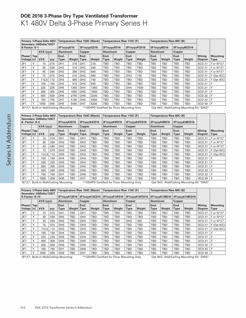
H-6 DOE 2016 Transformer Series H Addendum
Seri
es H
Add
endu
mDOE 2016 3-Phase Dry Type Ventilated Transformer
K1 480V Delta 3-Phase Primary Series H
Primary: 3-Phase Delta 480V Secondary: 240Delta/120CTK-Factor: K-1
Temperature Rise 150C [Blank] Temperature Rise 115C [F] Temperature Rise 80C [B]
Wiring Diagram
Mounting Type
3F1xyyyD16 3F1xyyyCD16 3F1xyyyFD16 3F1xyyyFCD16 3F1xyyyBD16 3F1xyyyBCD16
Phase/Voltage
Tap [x]
kVA [yyy] Aluminum Copper Aluminum Copper Aluminum Copper
kVA yyyEncl. Type Weight
Encl. Type Weight
Encl. Type Weight
Encl. Type Weight
Encl. Type Weight
Encl. Type Weight
3F1 Y 15 015 DH1 210 DH1 210 TBD TBD TBD TBD TBD TBD TBD TBD SCD 21 F or W*/C*3F1 Y 30 030 DH2 310 DH2 340 TBD TBD TBD TBD TBD TBD TBD TBD SCD 21 F or W*/C*3F1 Y 45 045 DH2 380 DH2 400 TBD TBD TBD TBD TBD TBD TBD TBD SCD 21 F or W*/C*3F1 Y 75 075 DH3 510 DH3 590 TBD TBD DH3 730 TBD TBD TBD TBD SCD 21 F (Opt W/C)3F1 Y 112.5 112 DH3 680 DH3 740 TBD TBD TBD TBD TBD TBD TBD TBD SCD 21 F (Opt W/C)3F1 Y 150 150 DH4 870 DH4 930 TBD TBD TBD TBD TBD TBD TBD TBD SCD 21 F3F1 Y 225 225 DH5 1350 DH4 1350 TBD TBD DH4 1500 TBD TBD TBD TBD SCD 21 F3F1 Y 300 300 DH5 1800 DH5 1800 TBD TBD TBD TBD TBD TBD TBD TBD SCD 21 F3F1 Y 500 500 DH6 2750 DH6 3200 TBD TBD TBD TBD TBD TBD TBD TBD SCD 22 F3F1 Y 750 750 DH7 4100 DH6 4050 TBD TBD TBD TBD TBD TBD TBD TBD SCD 22 F3F1 T 1000 000 DH8 5400 DH7 5200 TBD TBD TBD TBD TBD TBD TBD TBD SCD 59 FW*/C*: Built-in Wall/Ceiling Mounting **OSHPD Certified for Floor Mounting Only Opt W/C: Wall/Ceiling Mounting Kit “DW3”
Primary: 3-Phase Delta 480V Secondary: 240Delta/120CTK -Factor: K-4
Temperature Rise 150C [Blank] Temperature Rise 115C [F] Temperature Rise 80C [B]
Wiring Diagram
Mounting Type
3F1xyyyK4D16 3F1xyyyK4CD16 3F1xyyyK4FD16 3F1xyyyK4FCD16 3F1xyyyK4BD16 3F1xyyyK4BCD16
Phase/Voltage
Tap [x]
kVA [yyy] Aluminum Copper Aluminum Copper Aluminum Copper
kVA yyyEncl. Type Weight
Encl. Type Weight
Encl. Type Weight
Encl. Type Weight
Encl. Type Weight
Encl. Type Weight
3F1 Y 15 015 DH1 TBD DH1 TBD TBD TBD TBD TBD TBD TBD TBD TBD SCD 21 F or W*/C*3F1 Y 30 030 DH2 TBD DH2 TBD TBD TBD TBD TBD TBD TBD TBD TBD SCD 21 F or W*/C*3F1 Y 45 045 DH2 TBD DH2 TBD TBD TBD TBD TBD TBD TBD TBD TBD SCD 21 F or W*/C*3F1 Y 75 075 DH3 TBD DH3 TBD TBD TBD TBD TBD TBD TBD TBD TBD SCD 21 F (Opt W/C)3F1 Y 112.5 112 DH3 TBD DH3 TBD TBD TBD TBD TBD TBD TBD TBD TBD SCD 21 F (Opt W/C)3F1 Y 150 150 DH4 TBD DH4 TBD TBD TBD TBD TBD TBD TBD TBD TBD SCD 21 F3F1 Y 225 225 DH5 TBD DH4 TBD TBD TBD TBD TBD TBD TBD TBD TBD SCD 21 F3F1 Y 300 300 DH5 TBD DH5 TBD TBD TBD TBD TBD TBD TBD TBD TBD SCD 21 F3F1 Y 500 500 DH6 TBD DH6 TBD TBD TBD TBD TBD TBD TBD TBD TBD SCD 22 F3F1 Y 750 750 DH7 TBD DH6 TBD TBD TBD TBD TBD TBD TBD TBD TBD SCD 22 F3F1 T 1000 000 DH8 TBD DH7 TBD TBD TBD TBD TBD TBD TBD TBD TBD SCD 59 FW*/C*: Built-in Wall/Ceiling Mounting **OSHPD Certified for Floor Mounting Only Opt W/C: Wall/Ceiling Mounting Kit “DW3”
Primary: 3-Phase Delta 480V Secondary: 240Delta/120CTK-Factor: K-13
Temperature Rise 150C [Blank] Temperature Rise 115C [F] Temperature Rise 80C [B]
Wiring Diagram
Mounting Type
3F1xyyyK13D16 3F1xyyyK13CD16 3F1xyyyK13FD16 3F1xyyyK13FCD16 3F1xyyyK13BD16 3F1xyyyK13BCD16
Phase/Voltage
Tap [x]
kVA [yyy] Aluminum Copper Aluminum Copper Aluminum Copper
kVA yyyEncl. Type Weight
Encl. Type Weight
Encl. Type Weight
Encl. Type Weight
Encl. Type Weight
Encl. Type Weight
3F1 Y 15 015 DH1 TBD DH1 TBD TBD TBD TBD TBD TBD TBD TBD TBD SCD 21 F or W*/C*3F1 Y 30 030 DH2 TBD DH2 TBD TBD TBD TBD TBD TBD TBD TBD TBD SCD 21 F or W*/C*3F1 Y 45 045 DH2 TBD DH2 TBD TBD TBD DH2 450 TBD TBD TBD TBD SCD 21 F or W*/C*3F1 Y 75 075 DH3 TBD DH3 TBD TBD TBD TBD TBD TBD TBD TBD TBD SCD 21 F (Opt W/C)3F1 Y 112.5 112 DH3 TBD DH3 TBD TBD TBD TBD TBD TBD TBD TBD TBD SCD 21 F (Opt W/C)3F1 Y 150 150 DH4 TBD DH4 TBD TBD TBD TBD TBD TBD TBD TBD TBD SCD 21 F3F1 Y 225 225 DH5 TBD DH4 TBD TBD TBD TBD TBD TBD TBD TBD TBD SCD 21 F3F1 Y 300 300 DH5 TBD DH5 TBD TBD TBD TBD TBD TBD TBD TBD TBD SCD 21 F3F1 Y 500 500 DH6 TBD DH6 TBD TBD TBD TBD TBD TBD TBD TBD TBD SCD 22 F3F1 Y 750 750 DH7 TBD DH6 TBD TBD TBD TBD TBD TBD TBD TBD TBD SCD 22 F3F1 T 1000 000 DH8 TBD DH7 TBD TBD TBD TBD TBD TBD TBD TBD TBD SCD 59 FW*/C*: Built-in Wall/Ceiling Mounting **OSHPD Certified for Floor Mounting Only Opt W/C: Wall/Ceiling Mounting Kit “DW3”

DOE 2016 Transformer Series H Addendum H-7
Series H A
ddendu
mDOE 2016 3-Phase Dry Type Ventilated Transformer
K1 480V Delta 3-Phase Primary Series H
Primary: 3-Phase Delta 480V Secondary: 208Y/120VK-Factor: K-1
Temperature Rise 150C [Blank] Temperature Rise 115C [F] Temperature Rise 80C [B]
Wiring Diagram
Mounting Type
3F3xyyyD16 3F3xyyyCD16 3F3xyyyFD16 3F3xyyyFCD16 3F3xyyyBD16 3F3xyyyBCD16
Phase/Voltage
Tap [x]
kVA [yyy] Aluminum Copper Aluminum Copper Aluminum Copper
kVA yyyEncl. Type Weight
Encl. Type Weight
Encl. Type Weight
Encl. Type Weight
Encl. Type Weight
Encl. Type Weight
3F3 Y 15 015 DH1 210 DH1 210 DH2 335 DH1 215 DH2 335 DH1 230 SCD 19 F or W*/C*3F3 Y 30 030 DH2 310 DH2 340 DH2 380 DH2 410 DH2 380 DH2 410 SCD 19 F or W*/C*3F3 Y 45 045 DH2 380 DH2 400 DH3 550 DH3 615 DH3 550 DH3 615 SCD 19 F or W*/C*3F3 Y 75 075 DH3 510 DH3 590 DH3 685 DH3 775 DH3 685 DH3 775 SCD 19 F (Opt W/C)3F3 Y 112.5 112 DH3 680 DH3 740 DH4 915 DH3 1000 DH4 TBD DH3 1050 SCD 19 F (Opt W/C)3F3 Y 150 150 DH4 870 DH4 930 DH5 1450 DH5 1400 DH5 1450 DH4 1350 SCD 19 F3F3 Y 225 225 DH5 1350 DH4 1350 DH5 1900 DH5 1800 DH5 1900 DH5 2050 SCD 19 F3F3 Y 300 300 DH5 1800 DH5 1800 DH5 TBD DH5 2050 DH6 TBD DH6 2650 SCD 19 F3F3 Y 500 500 DH6 2750 DH6 3200 DH7 4100 DH6 3050 DH7 3400 DH6 3800 SCD 20 F3F3 Y 750 750 DH7 4100 DH6 4050 DH8 TBD DH6 TBD TBD TBD DH8 TBD SCD 20 F3F3 T 1000 000 DH8 5400 DH7 5200 TBD TBD TBD TBD TBD TBD TBD TBD SCD 10 FW*/C*: Built-in Wall/Ceiling Mounting **OSHPD Certified for Floor Mounting Only Opt W/C: Wall/Ceiling Mounting Kit “DW3”
Primary: 3-Phase Delta 480V Secondary: 208Y/120VK -Factor: K-4
Temperature Rise 150C [Blank] Temperature Rise 115C [F] Temperature Rise 80C [B]
Wiring Diagram
Mounting Type
3F3xyyyK4D16 3F3xyyyK4CD16 3F3xyyyK4FD16 3F3xyyyK4FCD16 3F3xyyyK4BD16 3F3xyyyK4BCD16
Phase/Voltage
Tap [x]
kVA [yyy] Aluminum Copper Aluminum Copper Aluminum Copper
kVA yyyEncl. Type Weight
Encl. Type Weight
Encl. Type Weight
Encl. Type Weight
Encl. Type Weight
Encl. Type Weight
3F3 Y 15 015 DH1 220 DH1 220 DH2 335 DH1 235 TBD TBD DH1 230 SCD 19 F or W*/C*3F3 Y 30 030 DH2 320 DH2 350 TBD TBD DH2 TBD TBD TBD DH2 TBD SCD 19 F or W*/C*3F3 Y 45 045 DH2 390 DH2 410 DH3 550 DH3 615 TBD TBD DH2 490 SCD 19 F or W*/C*3F3 Y 75 075 DH3 530 DH3 600 DH3 685 DH3 TBD TBD TBD DH3 740 SCD 19 F (Opt W/C)3F3 Y 112.5 112 DH3 690 DH3 760 TBD TBD DH4 TBD TBD TBD DH4 990 SCD 19 F (Opt W/C)3F3 Y 150 150 DH4 900 DH4 950 DH5 1450 DH4 TBD TBD TBD DH4 1200 SCD 19 F3F3 Y 225 225 DH5 1380 DH4 1380 DH5 1900 DH5 1800 TBD TBD DH5 2050 SCD 19 F3F3 Y 300 300 DH5 1830 DH5 1830 TBD TBD DH5 TBD TBD TBD DH5 2150 SCD 19 F3F3 Y 500 500 DH6 2800 DH6 3250 TBD TBD TBD TBD TBD TBD TBD TBD SCD 20 F3F3 Y 750 750 DH7 4200 DH6 4100 TBD TBD TBD TBD TBD TBD TBD TBD SCD 20 F3F3 T 1000 000 DH8 5500 DH7 5300 TBD TBD TBD TBD TBD TBD TBD TBD SCD 10 FW*/C*: Built-in Wall/Ceiling Mounting **OSHPD Certified for Floor Mounting Only Opt W/C: Wall/Ceiling Mounting Kit “DW3”
Primary: 3-Phase Delta 480V Secondary: 208Y/120VK-Factor: K-13
Temperature Rise 150C [Blank] Temperature Rise 115C [F] Temperature Rise 80C [B]
Wiring Diagram
Mounting Type
3F3xyyyK13D16 3F3xyyyK13CD16 3F3xyyyK13FD16 3F3xyyyK13FCD16 3F3xyyyK13BD16 3F3xyyyK13BCD16
Phase/Voltage
Tap [x]
kVA [yyy] Aluminum Copper Aluminum Copper Aluminum Copper
kVA yyyEncl. Type Weight
Encl. Type Weight
Encl. Type Weight
Encl. Type Weight
Encl. Type Weight
Encl. Type Weight
3F3 Y 15 015 DH1 240 DH1 240 DH2 335 DH1 220 DH2 335 DH2 TBD SCD 19 F or W*/C*3F3 Y 30 030 DH2 340 DH2 370 TBD TBD DH2 TBD TBD TBD DH2 TBD SCD 19 F or W*/C*3F3 Y 45 045 DH2 420 DH2 430 TBD TBD DH3 615 TBD TBD DH3 565 SCD 19 F or W*/C*3F3 Y 75 075 DH3 560 DH3 620 DH3 685 DH3 775 TBD TBD DH3 TBD SCD 19 F (Opt W/C)3F3 Y 112.5 112 DH3 730 DH3 840 DH4 915 DH4 1000 TBD TBD DH4 1100 SCD 19 F (Opt W/C)3F3 Y 150 150 DH4 1070 DH4 1100 DH5 1450 DH4 1250 TBD TBD DH4 1550 SCD 19 F3F3 Y 225 225 DH5 1500 DH4 1620 DH5 1900 DH5 2000 TBD TBD DH5 TBD SCD 19 F3F3 Y 300 300 DH5 1950 DH5 2060 TBD TBD DH5 1950 TBD TBD DH6 2800 SCD 19 F3F3 Y 500 500 DH6 2900 DH6 3400 TBD TBD DH6 3900 TBD TBD TBD TBD SCD 20 F3F3 Y 750 750 DH7 4400 DH6 4500 TBD TBD TBD TBD TBD TBD TBD TBD SCD 20 F3F3 T 1000 000 DH8 5700 DH7 5700 TBD TBD TBD TBD TBD TBD TBD TBD SCD 10 FW*/C*: Built-in Wall/Ceiling Mounting **OSHPD Certified for Floor Mounting Only Opt W/C: Wall/Ceiling Mounting Kit “DW3”

H-8 DOE 2016 Transformer Series H Addendum
Seri
es H
Add
endu
mDOE 2016 3-Phase Dry Type Ventilated Transformer
K1 480V Delta 3-Phase Primary Series H
Primary: 3-Phase Delta 480V Secondary: 480Y/277K-Factor: K-1
Temperature Rise 150C [Blank] Temperature Rise 115C [F] Temperature Rise 80C [B]
Wiring Diagram
Mounting Type
3F5xyyyD16 3F5xyyyCD16 3F5xyyyFD16 3F5xyyyFCD16 3F5xyyyBD16 3F5xyyyBCD16
Phase/Voltage
Tap [x]
kVA [yyy] Aluminum Copper Aluminum Copper Aluminum Copper
kVA yyyEncl. Type Weight
Encl. Type Weight
Encl. Type Weight
Encl. Type Weight
Encl. Type Weight
Encl. Type Weight
3F5 Y 15 015 DH1 210 DH1 210 TBD TBD TBD TBD TBD TBD TBD TBD SCD 19 F or W*/C*3F5 Y 30 030 DH2 310 DH2 340 TBD TBD DH2 425 TBD TBD TBD TBD SCD 19 F or W*/C*3F5 Y 45 045 DH2 380 DH2 400 TBD TBD DH3 645 TBD TBD TBD TBD SCD 19 F or W*/C*3F5 Y 75 075 DH3 510 DH3 590 TBD TBD TBD TBD TBD TBD TBD TBD SCD 19 F (Opt W/C)3F5 Y 112.5 112 DH3 680 DH3 740 TBD TBD TBD TBD TBD TBD TBD TBD SCD 19 F (Opt W/C)3F5 Y 150 150 DH4 870 DH4 930 TBD TBD DH4 1050 TBD TBD TBD TBD SCD 19 F3F5 Y 225 225 DH5 1350 DH4 1350 TBD TBD TBD TBD TBD TBD TBD TBD SCD 19 F3F5 Y 300 300 DH5 1800 DH5 1800 TBD TBD TBD TBD TBD TBD TBD TBD SCD 19 F3F5 Y 500 500 DH6 2750 DH6 3200 TBD TBD TBD TBD TBD TBD TBD TBD SCD 20 F3F5 Y 750 750 DH7 4100 DH6 4050 TBD TBD TBD TBD TBD TBD TBD TBD SCD 20 F3F5 T 1000 000 DH8 5400 DH7 5200 TBD TBD TBD TBD TBD TBD TBD TBD SCD 10 FW*/C*: Built-in Wall/Ceiling Mounting **OSHPD Certified for Floor Mounting Only Opt W/C: Wall/Ceiling Mounting Kit “DW3”
Primary: 3-Phase Delta 480V Secondary: 480Y/277K -Factor: K-4
Temperature Rise 150C [Blank] Temperature Rise 115C [F] Temperature Rise 80C [B]
Wiring Diagram
Mounting Type
3F5xyyyK4D16 3F5xyyyK4CD16 3F5xyyyK4FD16 3F5xyyyK4FCD16 3F5xyyyK4BD16 3F5xyyyK4BCD16
Phase/Voltage
Tap [x]
kVA [yyy] Aluminum Copper Aluminum Copper Aluminum Copper
kVA yyyEncl. Type Weight
Encl. Type Weight
Encl. Type Weight
Encl. Type Weight
Encl. Type Weight
Encl. Type Weight
3F5 Y 15 015 DH1 220 DH1 220 TBD TBD TBD TBD TBD TBD TBD TBD SCD 19 F or W*/C*3F5 Y 30 030 DH2 320 DH2 350 DH2 300 TBD TBD TBD TBD TBD TBD SCD 19 F or W*/C*3F5 Y 45 045 DH2 390 DH2 410 DH2 395 TBD TBD TBD TBD TBD TBD SCD 19 F or W*/C*3F5 Y 75 075 DH3 530 DH3 600 DH3 560 DH3 775 TBD TBD TBD TBD SCD 19 F (Opt W/C)3F5 Y 112.5 112 DH3 690 DH3 760 DH4 915 DH4 1000 TBD TBD TBD TBD SCD 19 F (Opt W/C)3F5 Y 150 150 DH4 900 DH4 950 TBD TBD TBD TBD TBD TBD TBD TBD SCD 19 F3F5 Y 225 225 DH5 1380 DH4 1380 TBD TBD TBD TBD TBD TBD TBD TBD SCD 19 F3F5 Y 300 300 DH5 1830 DH5 1830 TBD TBD DH5 2450 TBD TBD TBD TBD SCD 19 F3F5 Y 500 500 DH6 2800 DH6 3250 TBD TBD TBD TBD TBD TBD TBD TBD SCD 20 F3F5 Y 750 750 DH7 4200 DH6 4100 TBD TBD TBD TBD TBD TBD TBD TBD SCD 20 F3F5 T 1000 000 DH8 5500 DH7 5300 TBD TBD TBD TBD TBD TBD TBD TBD SCD 10 FW*/C*: Built-in Wall/Ceiling Mounting **OSHPD Certified for Floor Mounting Only Opt W/C: Wall/Ceiling Mounting Kit “DW3”
Primary: 3-Phase Delta 480V Secondary: 480Y/277K-Factor: K-13
Temperature Rise 150C [Blank] Temperature Rise 115C [F] Temperature Rise 80C [B]
Wiring Diagram
Mounting Type
3F5xyyyK13D16 3F5xyyyK13CD16 3F5xyyyK13FD16 3F5xyyyK13FCD16 3F5xyyyK13BD16 3F5xyyyK13BCD16
Phase/Voltage
Tap [x]
kVA [yyy] Aluminum Copper Aluminum Copper Aluminum Copper
kVA yyyEncl. Type Weight
Encl. Type Weight
Encl. Type Weight
Encl. Type Weight
Encl. Type Weight
Encl. Type Weight
3F5 Y 15 015 DH1 TBD DH1 TBD TBD TBD TBD TBD TBD TBD TBD TBD SCD 19 F or W*/C*3F5 Y 30 030 DH2 TBD DH2 TBD TBD TBD TBD TBD TBD TBD TBD TBD SCD 19 F or W*/C*3F5 Y 45 045 DH2 TBD DH2 TBD TBD TBD TBD TBD TBD TBD TBD TBD SCD 19 F or W*/C*3F5 Y 75 075 DH3 TBD DH3 TBD TBD TBD TBD TBD TBD TBD TBD TBD SCD 19 F (Opt W/C)3F5 Y 112.5 112 DH3 TBD DH3 TBD TBD TBD TBD TBD TBD TBD TBD TBD SCD 19 F (Opt W/C)3F5 Y 150 150 DH4 TBD DH4 TBD TBD TBD TBD TBD TBD TBD TBD TBD SCD 19 F3F5 Y 225 225 DH5 TBD DH4 TBD TBD TBD TBD TBD TBD TBD TBD TBD SCD 19 F3F5 Y 300 300 DH5 TBD DH5 TBD TBD TBD TBD TBD TBD TBD TBD TBD SCD 19 F3F5 Y 500 500 DH6 TBD DH6 TBD TBD TBD TBD TBD TBD TBD TBD TBD SCD 20 F3F5 Y 750 750 DH7 TBD DH6 TBD TBD TBD TBD TBD TBD TBD TBD TBD SCD 20 F3F5 T 1000 000 DH8 TBD DH7 TBD TBD TBD TBD TBD TBD TBD TBD TBD SCD 10 FW*/C*: Built-in Wall/Ceiling Mounting **OSHPD Certified for Floor Mounting Only Opt W/C: Wall/Ceiling Mounting Kit “DW3”
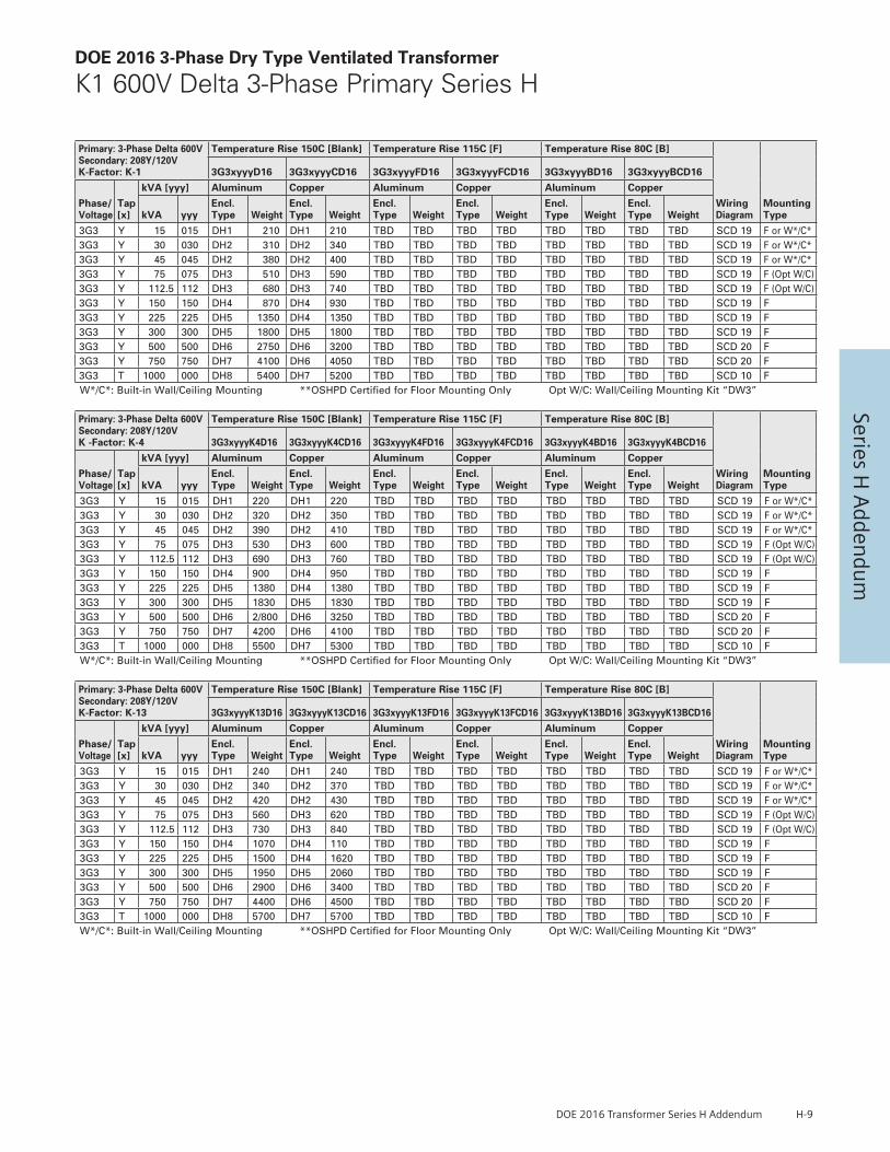
DOE 2016 Transformer Series H Addendum H-9
Series H A
ddendu
mDOE 2016 3-Phase Dry Type Ventilated Transformer
K1 600V Delta 3-Phase Primary Series H
Primary: 3-Phase Delta 600VSecondary: 208Y/120V K-Factor: K-1
Temperature Rise 150C [Blank] Temperature Rise 115C [F] Temperature Rise 80C [B]
Wiring Diagram
Mounting Type
3G3xyyyD16 3G3xyyyCD16 3G3xyyyFD16 3G3xyyyFCD16 3G3xyyyBD16 3G3xyyyBCD16
Phase/Voltage
Tap [x]
kVA [yyy] Aluminum Copper Aluminum Copper Aluminum Copper
kVA yyyEncl. Type Weight
Encl. Type Weight
Encl. Type Weight
Encl. Type Weight
Encl. Type Weight
Encl. Type Weight
3G3 Y 15 015 DH1 210 DH1 210 TBD TBD TBD TBD TBD TBD TBD TBD SCD 19 F or W*/C*3G3 Y 30 030 DH2 310 DH2 340 TBD TBD TBD TBD TBD TBD TBD TBD SCD 19 F or W*/C*3G3 Y 45 045 DH2 380 DH2 400 TBD TBD TBD TBD TBD TBD TBD TBD SCD 19 F or W*/C*3G3 Y 75 075 DH3 510 DH3 590 TBD TBD TBD TBD TBD TBD TBD TBD SCD 19 F (Opt W/C)3G3 Y 112.5 112 DH3 680 DH3 740 TBD TBD TBD TBD TBD TBD TBD TBD SCD 19 F (Opt W/C)3G3 Y 150 150 DH4 870 DH4 930 TBD TBD TBD TBD TBD TBD TBD TBD SCD 19 F3G3 Y 225 225 DH5 1350 DH4 1350 TBD TBD TBD TBD TBD TBD TBD TBD SCD 19 F3G3 Y 300 300 DH5 1800 DH5 1800 TBD TBD TBD TBD TBD TBD TBD TBD SCD 19 F3G3 Y 500 500 DH6 2750 DH6 3200 TBD TBD TBD TBD TBD TBD TBD TBD SCD 20 F3G3 Y 750 750 DH7 4100 DH6 4050 TBD TBD TBD TBD TBD TBD TBD TBD SCD 20 F3G3 T 1000 000 DH8 5400 DH7 5200 TBD TBD TBD TBD TBD TBD TBD TBD SCD 10 FW*/C*: Built-in Wall/Ceiling Mounting **OSHPD Certified for Floor Mounting Only Opt W/C: Wall/Ceiling Mounting Kit “DW3”
Primary: 3-Phase Delta 600VSecondary: 208Y/120V K -Factor: K-4
Temperature Rise 150C [Blank] Temperature Rise 115C [F] Temperature Rise 80C [B]
Wiring Diagram
Mounting Type
3G3xyyyK4D16 3G3xyyyK4CD16 3G3xyyyK4FD16 3G3xyyyK4FCD16 3G3xyyyK4BD16 3G3xyyyK4BCD16
Phase/Voltage
Tap [x]
kVA [yyy] Aluminum Copper Aluminum Copper Aluminum Copper
kVA yyyEncl. Type Weight
Encl. Type Weight
Encl. Type Weight
Encl. Type Weight
Encl. Type Weight
Encl. Type Weight
3G3 Y 15 015 DH1 220 DH1 220 TBD TBD TBD TBD TBD TBD TBD TBD SCD 19 F or W*/C*3G3 Y 30 030 DH2 320 DH2 350 TBD TBD TBD TBD TBD TBD TBD TBD SCD 19 F or W*/C*3G3 Y 45 045 DH2 390 DH2 410 TBD TBD TBD TBD TBD TBD TBD TBD SCD 19 F or W*/C*3G3 Y 75 075 DH3 530 DH3 600 TBD TBD TBD TBD TBD TBD TBD TBD SCD 19 F (Opt W/C)3G3 Y 112.5 112 DH3 690 DH3 760 TBD TBD TBD TBD TBD TBD TBD TBD SCD 19 F (Opt W/C)3G3 Y 150 150 DH4 900 DH4 950 TBD TBD TBD TBD TBD TBD TBD TBD SCD 19 F3G3 Y 225 225 DH5 1380 DH4 1380 TBD TBD TBD TBD TBD TBD TBD TBD SCD 19 F3G3 Y 300 300 DH5 1830 DH5 1830 TBD TBD TBD TBD TBD TBD TBD TBD SCD 19 F3G3 Y 500 500 DH6 2/800 DH6 3250 TBD TBD TBD TBD TBD TBD TBD TBD SCD 20 F3G3 Y 750 750 DH7 4200 DH6 4100 TBD TBD TBD TBD TBD TBD TBD TBD SCD 20 F3G3 T 1000 000 DH8 5500 DH7 5300 TBD TBD TBD TBD TBD TBD TBD TBD SCD 10 FW*/C*: Built-in Wall/Ceiling Mounting **OSHPD Certified for Floor Mounting Only Opt W/C: Wall/Ceiling Mounting Kit “DW3”
Primary: 3-Phase Delta 600VSecondary: 208Y/120V K-Factor: K-13
Temperature Rise 150C [Blank] Temperature Rise 115C [F] Temperature Rise 80C [B]
Wiring Diagram
Mounting Type
3G3xyyyK13D16 3G3xyyyK13CD16 3G3xyyyK13FD16 3G3xyyyK13FCD16 3G3xyyyK13BD16 3G3xyyyK13BCD16
Phase/Voltage
Tap [x]
kVA [yyy] Aluminum Copper Aluminum Copper Aluminum Copper
kVA yyyEncl. Type Weight
Encl. Type Weight
Encl. Type Weight
Encl. Type Weight
Encl. Type Weight
Encl. Type Weight
3G3 Y 15 015 DH1 240 DH1 240 TBD TBD TBD TBD TBD TBD TBD TBD SCD 19 F or W*/C*3G3 Y 30 030 DH2 340 DH2 370 TBD TBD TBD TBD TBD TBD TBD TBD SCD 19 F or W*/C*3G3 Y 45 045 DH2 420 DH2 430 TBD TBD TBD TBD TBD TBD TBD TBD SCD 19 F or W*/C*3G3 Y 75 075 DH3 560 DH3 620 TBD TBD TBD TBD TBD TBD TBD TBD SCD 19 F (Opt W/C)3G3 Y 112.5 112 DH3 730 DH3 840 TBD TBD TBD TBD TBD TBD TBD TBD SCD 19 F (Opt W/C)3G3 Y 150 150 DH4 1070 DH4 110 TBD TBD TBD TBD TBD TBD TBD TBD SCD 19 F3G3 Y 225 225 DH5 1500 DH4 1620 TBD TBD TBD TBD TBD TBD TBD TBD SCD 19 F3G3 Y 300 300 DH5 1950 DH5 2060 TBD TBD TBD TBD TBD TBD TBD TBD SCD 19 F3G3 Y 500 500 DH6 2900 DH6 3400 TBD TBD TBD TBD TBD TBD TBD TBD SCD 20 F3G3 Y 750 750 DH7 4400 DH6 4500 TBD TBD TBD TBD TBD TBD TBD TBD SCD 20 F3G3 T 1000 000 DH8 5700 DH7 5700 TBD TBD TBD TBD TBD TBD TBD TBD SCD 10 FW*/C*: Built-in Wall/Ceiling Mounting **OSHPD Certified for Floor Mounting Only Opt W/C: Wall/Ceiling Mounting Kit “DW3”

H-10 DOE 2016 Transformer Series H Addendum
Seri
es H
Add
endu
mDOE 2016 3-Phase Dry Type Ventilated Transformer
K1 600V Delta 3-Phase Primary Series H
Primary: 3-Phase Delta 600VSecondary: 480Y/277K-Factor: K-1
Temperature Rise 150C [Blank] Temperature Rise 115C [F] Temperature Rise 80C [B]
Wiring Diagram
Mounting Type
3G5xyyyD16 3G5xyyyCD16 3G5xyyyFD16 3G5xyyyFCD16 3G5xyyyBD16 3G5xyyyBCD16
Phase/Voltage
Tap [x]
kVA [yyy] Aluminum Copper Aluminum Copper Aluminum Copper
kVA yyyEncl. Type Weight
Encl. Type Weight
Encl. Type Weight
Encl. Type Weight
Encl. Type Weight
Encl. Type Weight
3G5 Y 15 015 DH1 210 DH1 210 TBD TBD TBD TBD TBD TBD TBD TBD SCD 19 F or W*/C*3G5 Y 30 030 DH2 310 DH2 340 TBD TBD TBD TBD TBD TBD TBD TBD SCD 19 F or W*/C*3G5 Y 45 045 DH2 380 DH2 400 TBD TBD TBD TBD TBD TBD TBD TBD SCD 19 F or W*/C*3G5 Y 75 075 DH3 510 DH3 590 TBD TBD TBD TBD TBD TBD TBD TBD SCD 19 F (Opt W/C)3G5 Y 112.5 112 DH3 680 DH3 740 TBD TBD TBD TBD TBD TBD TBD TBD SCD 19 F (Opt W/C)3G5 Y 150 150 DH4 870 DH4 930 TBD TBD TBD TBD TBD TBD TBD TBD SCD 19 F3G5 Y 225 225 DH5 1350 DH4 1350 TBD TBD TBD TBD TBD TBD TBD TBD SCD 19 F3G5 Y 300 300 DH5 1800 DH5 1800 TBD TBD TBD TBD TBD TBD TBD TBD SCD 19 F3G5 Y 500 500 DH6 2750 DH6 3200 TBD TBD TBD TBD TBD TBD TBD TBD SCD 20 F3G5 Y 750 750 DH7 4100 DH6 4050 TBD TBD TBD TBD TBD TBD TBD TBD SCD 20 F3G5 T 1000 000 DH8 5400 DH7 5200 TBD TBD TBD TBD TBD TBD TBD TBD SCD 10 FW*/C*: Built-in Wall/Ceiling Mounting **OSHPD Certified for Floor Mounting Only Opt W/C: Wall/Ceiling Mounting Kit “DW3”
Primary: 3-Phase Delta 600VSecondary: 480Y/277K -Factor: K-4
Temperature Rise 150C [Blank] Temperature Rise 115C [F] Temperature Rise 80C [B]
Wiring Diagram
Mounting Type
3G5xyyyK4D16 3G5xyyyK4CD16 3G5xyyyK4FD16 3G5xyyyK4FCD16 3G5xyyyK4BD16 3G5xyyyK4BCD16
Phase/Voltage
Tap [x]
kVA [yyy] Aluminum Copper Aluminum Copper Aluminum Copper
kVA yyyEncl. Type Weight
Encl. Type Weight
Encl. Type Weight
Encl. Type Weight
Encl. Type Weight
Encl. Type Weight
3G5 Y 15 015 DH1 220 DH1 220 TBD TBD TBD TBD TBD TBD TBD TBD SCD 19 F or W*/C*3G5 Y 30 030 DH2 320 DH2 350 TBD TBD TBD TBD TBD TBD TBD TBD SCD 19 F or W*/C*3G5 Y 45 045 DH2 390 DH2 410 TBD TBD TBD TBD TBD TBD TBD TBD SCD 19 F or W*/C*3G5 Y 75 075 DH3 530 DH3 600 TBD TBD TBD TBD TBD TBD TBD TBD SCD 19 F (Opt W/C)3G5 Y 112.5 112 DH3 690 DH3 760 TBD TBD TBD TBD TBD TBD TBD TBD SCD 19 F (Opt W/C)3G5 Y 150 150 DH4 900 DH4 950 TBD TBD TBD TBD TBD TBD TBD TBD SCD 19 F3G5 Y 225 225 DH5 1380 DH4 1380 TBD TBD TBD TBD TBD TBD TBD TBD SCD 19 F3G5 Y 300 300 DH5 830 DH5 1830 TBD TBD TBD TBD TBD TBD TBD TBD SCD 19 F3G5 Y 500 500 DH6 2800 DH6 3250 TBD TBD TBD TBD TBD TBD TBD TBD SCD 20 F3G5 Y 750 750 DH7 4200 DH6 4100 TBD TBD TBD TBD TBD TBD TBD TBD SCD 20 F3G5 T 1000 000 DH8 5500 DH7 5300 TBD TBD TBD TBD TBD TBD TBD TBD SCD 10 FW*/C*: Built-in Wall/Ceiling Mounting **OSHPD Certified for Floor Mounting Only Opt W/C: Wall/Ceiling Mounting Kit “DW3”
Primary: 3-Phase Delta 600VSecondary: 480Y/277K-Factor: K-13
Temperature Rise 150C [Blank] Temperature Rise 115C [F] Temperature Rise 80C [B]
Wiring Diagram
Mounting Type
3G5xyyyK13D16 3G5xyyykK13CD16 3G5xyyyK13FD16 3G5xyyyK13FCD16 3G5xyyyK13BD16 3G5xyyyK13BCD16
Phase/Voltage
Tap [x]
kVA [yyy] Aluminum Copper Aluminum Copper Aluminum Copper
kVA yyyEncl. Type Weight
Encl. Type Weight
Encl. Type Weight
Encl. Type Weight
Encl. Type Weight
Encl. Type Weight
3G5 Y 15 015 DH1 TBD DH1 TBD TBD TBD TBD TBD TBD TBD TBD TBD SCD 19 F or W*/C*3G5 Y 30 030 DH2 TBD DH2 TBD TBD TBD TBD TBD TBD TBD TBD TBD SCD 19 F or W*/C*3G5 Y 45 045 DH2 TBD DH2 TBD TBD TBD TBD TBD TBD TBD TBD TBD SCD 19 F or W*/C*3G5 Y 75 075 DH3 TBD DH3 TBD TBD TBD TBD TBD TBD TBD TBD TBD SCD 19 F (Opt W/C)3G5 Y 112.5 112 DH3 TBD DH3 TBD TBD TBD TBD TBD TBD TBD TBD TBD SCD 19 F (Opt W/C)3G5 Y 150 150 DH4 TBD DH4 TBD TBD TBD TBD TBD TBD TBD TBD TBD SCD 19 F3G5 Y 225 225 DH5 TBD DH4 TBD TBD TBD TBD TBD TBD TBD TBD TBD SCD 19 F3G5 Y 300 300 DH5 TBD DH5 TBD TBD TBD TBD TBD TBD TBD TBD TBD SCD 19 F3G5 Y 500 500 DH6 TBD DH6 TBD TBD TBD TBD TBD TBD TBD TBD TBD SCD 20 F3G5 Y 750 750 DH7 TBD DH6 TBD TBD TBD TBD TBD TBD TBD TBD TBD SCD 20 F3G5 T 1000 000 DH8 TBD DH7 TBD TBD TBD TBD TBD TBD TBD TBD TBD SCD 10 FW*/C*: Built-in Wall/Ceiling Mounting **OSHPD Certified for Floor Mounting Only Opt W/C: Wall/Ceiling Mounting Kit “DW3”
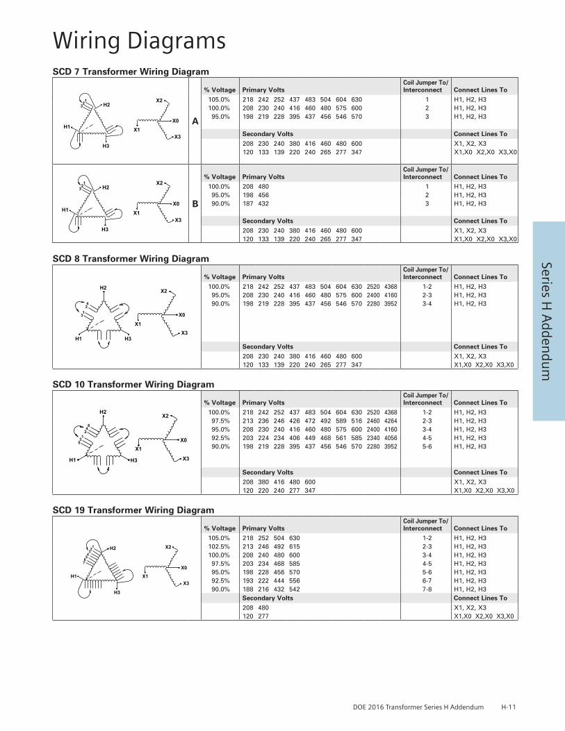
DOE 2016 Transformer Series H Addendum H-11
Series H A
ddendu
m
SCD 7 Transformer Wiring Diagram
H2
H3
H1 X1
X2
X0
X3
123
SCD 7A
H2
H3
H1 X1
X2
X0
X3
123
SCD 7B
A
% Voltage Primary VoltsCoil Jumper To/Interconnect Connect Lines To
105.0% 218 242 252 437 483 504 604 630 1 H1, H2, H3100.0% 208 230 240 416 460 480 575 600 2 H1, H2, H3
95.0% 198 219 228 395 437 456 546 570 3 H1, H2, H3
Secondary Volts Connect Lines To208 230 240 380 416 460 480 600 X1, X2, X3120 133 139 220 240 265 277 347 X1,X0 X2,X0 X3,X0
H2
H3
H1 X1
X2
X0
X3
123
SCD 7A
H2
H3
H1 X1
X2
X0
X3
123
SCD 7B
B
% Voltage Primary VoltsCoil Jumper To/Interconnect Connect Lines To
100.0% 208 480 1 H1, H2, H395.0% 198 456 2 H1, H2, H390.0% 187 432 3 H1, H2, H3
Secondary Volts Connect Lines To208 230 240 380 416 460 480 600 X1, X2, X3120 133 139 220 240 265 277 347 X1,X0 X2,X0 X3,X0
SCD 8 Transformer Wiring Diagram
H2 X2
X0
X3H3H1
X1
4213
SCD 8
% Voltage Primary VoltsCoil Jumper To/Interconnect Connect Lines To
100.0% 218 242 252 437 483 504 604 630 2520 4368 1-2 H1, H2, H395.0% 208 230 240 416 460 480 575 600 2400 4160 2-3 H1, H2, H390.0% 198 219 228 395 437 456 546 570 2280 3952 3-4 H1, H2, H3
Secondary Volts Connect Lines To208 230 240 380 416 460 480 600 X1, X2, X3120 133 139 220 240 265 277 347 X1,X0 X2,X0 X3,X0
SCD 10 Transformer Wiring Diagram
H2
H1 H3
X0X1
X2
X3
64213
5
SCD 10
% Voltage Primary VoltsCoil Jumper To/Interconnect Connect Lines To
100.0% 218 242 252 437 483 504 604 630 2520 4368 1-2 H1, H2, H397.5% 213 236 246 426 472 492 589 516 2460 4264 2-3 H1, H2, H395.0% 208 230 240 416 460 480 575 600 2400 4160 3-4 H1, H2, H392.5% 203 224 234 406 449 468 561 585 2340 4056 4-5 H1, H2, H390.0% 198 219 228 395 437 456 546 570 2280 3952 5-6 H1, H2, H3
Secondary Volts Connect Lines To208 380 416 480 600 X1, X2, X3120 220 240 277 347 X1,X0 X2,X0 X3,X0
SCD 19 Transformer Wiring DiagramSCD 19
X2H2
H1
H3
X1X3
X0
1234567
% Voltage Primary VoltsCoil Jumper To/Interconnect Connect Lines To
105.0% 218 252 504 630 1-2 H1, H2, H3102.5% 213 246 492 615 2-3 H1, H2, H3100.0% 208 240 480 600 3-4 H1, H2, H397.5% 203 234 468 585 4-5 H1, H2, H395.0% 198 228 456 570 5-6 H1, H2, H392.5% 193 222 444 556 6-7 H1, H2, H390.0% 188 216 432 542 7-8 H1, H2, H3
Secondary Volts Connect Lines To208 480 X1, X2, X3120 277 X1,X0 X2,X0 X3,X0
Wiring Diagrams
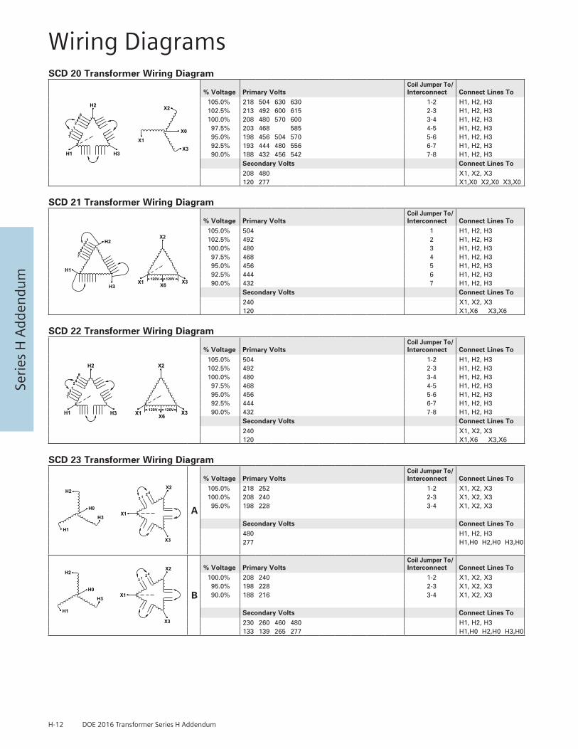
H-12 DOE 2016 Transformer Series H Addendum
Seri
es H
Add
endu
m
SCD 20 Transformer Wiring Diagram
X2H2
H1 H3
X1X3
X0
8642
357
1
SCD 20
% Voltage Primary VoltsCoil Jumper To/Interconnect Connect Lines To
105.0% 218 504 630 630 1-2 H1, H2, H3102.5% 213 492 600 615 2-3 H1, H2, H3100.0% 208 480 570 600 3-4 H1, H2, H397.5% 203 468 585 4-5 H1, H2, H395.0% 198 456 504 570 5-6 H1, H2, H392.5% 193 444 480 556 6-7 H1, H2, H390.0% 188 432 456 542 7-8 H1, H2, H3
Secondary Volts Connect Lines To208 480 X1, X2, X3120 277 X1,X0 X2,X0 X3,X0
SCD 21 Transformer Wiring Diagram
X2H2
H1
H3X1 X3X6
1234567
120V 120V
SCD 21
% Voltage Primary VoltsCoil Jumper To/Interconnect Connect Lines To
105.0% 504 1 H1, H2, H3102.5% 492 2 H1, H2, H3100.0% 480 3 H1, H2, H397.5% 468 4 H1, H2, H395.0% 456 5 H1, H2, H392.5% 444 6 H1, H2, H390.0% 432 7 H1, H2, H3
Secondary Volts Connect Lines To240 X1, X2, X3120 X1,X6 X3,X6
SCD 22 Transformer Wiring Diagram
X2H2
H1 H3 X1 X3X6120V 120V
8642
357
1
SCD 22
% Voltage Primary VoltsCoil Jumper To/Interconnect Connect Lines To
105.0% 504 1-2 H1, H2, H3102.5% 492 2-3 H1, H2, H3100.0% 480 3-4 H1, H2, H397.5% 468 4-5 H1, H2, H395.0% 456 5-6 H1, H2, H392.5% 444 6-7 H1, H2, H390.0% 432 7-8 H1, H2, H3
Secondary Volts Connect Lines To240 X1, X2, X3120 X1,X6 X3,X6
SCD 23 Transformer Wiring DiagramSCD 23A
SCD 23B
H2X2
H1
H3X1
X3
12
34
H0
H2X2
H1
H3X1
X3
12
34
H0
A
% Voltage Primary VoltsCoil Jumper To/Interconnect Connect Lines To
105.0% 218 252 1-2 X1, X2, X3100.0% 208 240 2-3 X1, X2, X395.0% 198 228 3-4 X1, X2, X3
Secondary Volts Connect Lines To480 H1, H2, H3277 H1,H0 H2,H0 H3,H0
SCD 23A
SCD 23B
H2X2
H1
H3X1
X3
12
34
H0
H2X2
H1
H3X1
X3
12
34
H0B
% Voltage Primary VoltsCoil Jumper To/Interconnect Connect Lines To
100.0% 208 240 1-2 X1, X2, X395.0% 198 228 2-3 X1, X2, X390.0% 188 216 3-4 X1, X2, X3
Secondary Volts Connect Lines To230 260 460 480 H1, H2, H3133 139 265 277 H1,H0 H2,H0 H3,H0
Wiring Diagrams

DOE 2016 Transformer Series H Addendum H-13
Series H A
ddendu
m
SCD 52 Transformer Wiring DiagramSCD 52
76
12
345
H1
H3
H2
X0
X2
D
X3
X1
CBA
% Voltage Primary VoltsCoil Jumper To/Interconnect Connect Lines To
105.0% 504 1 H1, H2, H3102.5% 492 2 H1, H2, H3100.0% 480 3 H1, H2, H397.5% 468 4 H1, H2, H395.0% 456 5 H1, H2, H392.5% 444 6 H1, H2, H390.0% 432 7 H1, H2, H3
Secondary Volts Connect Lines To107.5% 430 A X1, X2, X3104.0% 416 B X1, X2, X3100.0% 400 C X1, X2, X395.0% 380 D X1, X2, X3
248 A X1,X0 X2,X0 X3,X0240 B X1,X0 X2,X0 X3,X0231 C X1,X0 X2,X0 X3,X0219 D X1,X0 X2,X0 X3,X0
SCD 53 Transformer Wiring DiagramSCD 53
H0
H3
H2
H1
76541 2
3
X1
X2
X3
% Voltage Primary VoltsCoil Jumper To/Interconnect Connect Lines To
95.0% 218 252 1 X1, X2, X392.5% 213 246 2 X1, X2, X390.0% 208 240 3 X1, X2, X390.0% 203 234 4 X1, X2, X387.5% 198 228 5 X1, X2, X385.0% 192 222 6 X1, X2, X382.5% 187 216 7 X1, X2, X3
Secondary Volts Connect Lines To480 H1, H2, H3277 H1,H0 H2,H0 H3,H0
SCD 54 Transformer Wiring DiagramSCD 54
H3
H2
H1
54321
67
X3
X2
X1
% Voltage Primary VoltsCoil Jumper To/Interconnect Connect Lines To
105.0% 630 1 H1, H2, H3102.5% 615 2 H1, H2, H3100.0% 600 3 H1, H2, H397.5% 585 4 H1, H2, H395.0% 570 5 H1, H2, H392.5% 555 6 H1, H2, H390.0% 540 7 H1, H2, H3
Secondary Volts Connect Lines To240 X1, X2, X3
SCD 56 Transformer Wiring DiagramSCD 56
H0
H3
H2
H1
1 23
X1
X2
X3
% Voltage Primary VoltsCoil Jumper To/Interconnect Connect Lines To
105.0% 218 252 1 X1, X2, X3100.0% 208 240 2 X1, X2, X395.0% 198 228 3 X1, X2, X3
Secondary Volts Connect Lines To480 H1, H2, H3277 H1,H0 H2,H0 H3,H0
Wiring Diagrams
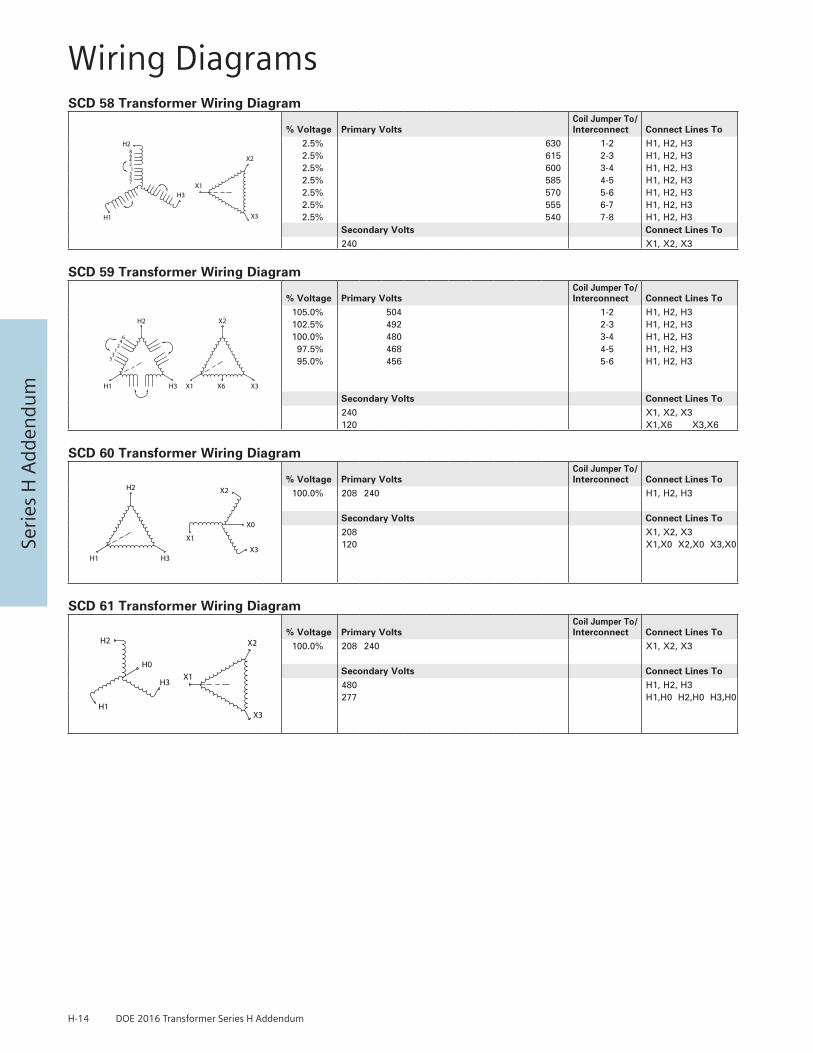
H-14 DOE 2016 Transformer Series H Addendum
Seri
es H
Add
endu
m
SCD 58 Transformer Wiring DiagramSCD 58
642135
H2
H3
H1
8
7
X3
X2
X1
% Voltage Primary VoltsCoil Jumper To/Interconnect Connect Lines To
2.5% 630 1-2 H1, H2, H32.5% 615 2-3 H1, H2, H32.5% 600 3-4 H1, H2, H32.5% 585 4-5 H1, H2, H32.5% 570 5-6 H1, H2, H32.5% 555 6-7 H1, H2, H32.5% 540 7-8 H1, H2, H3
Secondary Volts Connect Lines To240 X1, X2, X3
SCD 59 Transformer Wiring DiagramSCD 59
H2
H3
124
53
H1
6
X2
X3X1 X6
% Voltage Primary VoltsCoil Jumper To/Interconnect Connect Lines To
105.0% 504 1-2 H1, H2, H3102.5% 492 2-3 H1, H2, H3100.0% 480 3-4 H1, H2, H397.5% 468 4-5 H1, H2, H395.0% 456 5-6 H1, H2, H3
Secondary Volts Connect Lines To240 X1, X2, X3120 X1,X6 X3,X6
SCD 60 Transformer Wiring DiagramSCD 60
H2
H3H1X3
X1
X2
X0
% Voltage Primary VoltsCoil Jumper To/Interconnect Connect Lines To
100.0% 208 240 H1, H2, H3
Secondary Volts Connect Lines To208 X1, X2, X3120 X1,X0 X2,X0 X3,X0
SCD 61 Transformer Wiring DiagramSCD 61
H0
H3
H2
H1X3
X2
X1
% Voltage Primary VoltsCoil Jumper To/Interconnect Connect Lines To
100.0% 208 240 X1, X2, X3
Secondary Volts Connect Lines To480 H1, H2, H3277 H1,H0 H2,H0 H3,H0
Wiring Diagrams

DOE 2016 Transformer Series H Addendum H-15
Series H A
ddendu
m
Case Style
Dimensions in Inches
A A1 B B1 C D E F G H K L MA MB
DH1 21.5 18.8 20.1 15 22 12.6 2 7 8.3 6.6 1.38 X 1.75 K.O. 2.6 20 9
DH2 25.8 23.3 23.8 18 28.8 17 2 8 10.3 8.6 1.75 X 2.50 K.O. 3.8 24.6 9
Case Style
Dimensions in Inches
A B B1 C D E H K L M MA MB
DH3 28.3 27 22 36 22 3 12 1.38 X 1.75 K.O. 1 26 21.5 24
DH4 31.5 29.5 24.5 44.5 27.5 3 14.5 1.75 X 2.50 K.O. 1 28.5 23.5 26.5
Enclosure Drawings – Series H

H-16 DOE 2016 Transformer Series H Addendum
Seri
es H
Add
endu
m Case Style
Dimensions in Inches
A B B1 C D E F H L M MA MB
DH5 37.5 34 29 52 32 6 8 6.6 1 33 24 31
Case Style
Dimensions in Inches
A B B1 C D E F G H L M MA MB
DH6 49 41.5 35 64 32 6 10 6 9.3 1 39 30 37
DH7 54 46.5 40 72 40 8 10 6 8.8 1 44 36 44
DH8 60 49.5 43 82 50 10 10 6 9.8 1 47 40 45
DH9 68 49.5 43 72 40 10 10 6 11.8 1 47 44 45
DH10 78 54.5 48 78 46 10 10 6 14.8 1 52 48 50
Enclosure Drawings – Series H

DOE 2016 Transformer Series H Addendum H-17
Series H A
ddendu
m
Single Phase, Aluminum and Copper Termination – Lugs Or Pads
kVA
VOLTAGE
120 120/240 208 240 277 347 380 416 480 600 2400 4160
0.25 Leads Leads Leads Leads Leads Leads Leads Leads Leads Leads — —0.5 Leads Leads Leads Leads Leads Leads Leads Leads Leads Leads — —0.75 Leads Leads Leads Leads Leads Leads Leads Leads Leads Leads — —1 Leads Leads Leads Leads Leads Leads Leads Leads Leads Leads — —1.5 Leads Leads Leads Leads Leads Leads Leads Leads Leads Leads — —2 Leads Leads Leads Leads Leads Leads Leads Leads Leads Leads — —3 Leads Leads Leads Leads Leads Leads Leads Leads Leads Leads — —5 Leads Leads Leads Leads Leads Leads Leads Leads Leads Leads — —7.5 Lugs Lugs Lugs Lugs Lugs Lugs Lugs Lugs Lugs Lugs — —
10 Lugs Lugs Lugs Lugs Lugs Lugs Lugs Lugs Lugs Lugs — —15 Lugs Lugs Lugs Lugs Lugs Lugs Lugs Lugs Lugs Lugs Dia. 1A Dia. 1A25 Lugs Lugs Lugs Lugs Lugs Lugs Lugs Lugs Lugs Lugs Dia. 1A Dia. 1A37.5 Dia. 2 Lugs Lugs Lugs Lugs Lugs Lugs Lugs Lugs Lugs Dia. 1A Dia. 1A50 Dia. 2 Lugs Lugs Lugs Lugs Lugs Lugs Lugs Lugs Lugs Dia. 1A Dia. 1A75 Dia. 3 Dia. 2 Dia. 2 Dia. 2 Lugs Lugs Lugs Lugs Lugs Lugs Dia. 1A Dia. 1A
100 Dia. 3 Dia. 2 Dia. 2 Dia. 2 Dia. 2 Dia. 2 Lugs Lugs Lugs Lugs Dia. 1A Dia. 1A150 Dia. 3 Dia. 3 Dia. 3 Dia. 3 Dia. 2 Dia. 2 Dia. 2 Dia. 2 Dia. 2 Lugs Dia. 1A Dia. 1A167 Dia. 3 Dia. 3 Dia. 3 Dia. 3 Dia. 3 Dia. 2 Dia. 2 Dia. 2 Dia. 2 Dia. 2 Dia. 1A Dia. 1A
Three Phase, Aluminum and Copper Termination – Lugs Or Pads
kVA
VOLTAGE
208 230 240 277 380 416 480 600 2400 4160
2 Leads Leads Leads Leads Leads Leads Leads Leads — —3 Leads Leads Leads Leads Leads Leads Leads Leads — —6 Leads Leads Leads Leads Leads Leads Leads Leads — —9 Lugs Lugs Lugs Lugs Lugs Lugs Lugs Lugs — —
15 Lugs Lugs Lugs Lugs Lugs Lugs Lugs Lugs Dia. 1A Dia. 1A30 Lugs Lugs Lugs Lugs Lugs Lugs Lugs Lugs Dia. 1A Dia. 1A45 Lugs Lugs Lugs Lugs Lugs Lugs Lugs Lugs Dia. 1A Dia. 1A75 Lugs Lugs Lugs Lugs Lugs Lugs Lugs Lugs Dia. 1A Dia. 1A
112.5 Lugs** Dia. 1B Lugs Lugs Lugs Lugs Lugs Lugs Dia. 1A Dia. 1A150 Dia. 1B Dia. 1B Dia. 1B Dia. 1B Lugs Lugs Lugs Lugs Dia. 1A Dia. 1A225 Dia. 2 Dia. 1B Dia. 1B Dia. 1B Dia. 1B Dia. 1B Lugs Lugs Dia. 1A Dia. 1A300 Dia. 2 Dia. 2 Dia. 2 Dia. 2 Dia. 1B Dia. 1B Dia. 1B Dia. 1B Dia. 1A Dia. 1A500 Dia. 3 Dia. 3 Dia. 3 Dia. 3 Dia. 3 Dia. 2 Dia. 2 Dia. 1B Dia. 1A Dia. 1A600 Dia. 3 Dia. 3 Dia. 3 Dia. 3 Dia. 3 Dia. 2 Dia. 2 Dia. 1B Dia. 1A Dia. 1A750 Dia. 3 Dia. 3 Dia. 3 Dia. 3 Dia. 3 Dia. 3 Dia. 3 Dia. 2 Dia. 1B Dia. 1A
** Lugs only supplied standard on 600V primary to 208Y/120V secondary units.(excluding K-Factor transformers)All other voltages supplied standard with Diagram 1B pads.
Termination Details – Type 3R – Series H
1A = 0.28” Dia.
1B = 0.44” Dia.
DIAGRAM 1
0.56” x 1.0 Slot (Qty. 4)
DIAGRAM 3DIAGRAM 2
0.56” Dia. (Qty. 2)

H-18 DOE 2016 Transformer Series H Addendum
Seri
es H
Add
endu
m
Co
pp
er 3
-Ph
ase
Del
ta 4
80V
Pri
mar
y T
emp
Ris
e 15
0° C
K
1 20
8Y/1
20V
Sec
on
dar
y
Cata
log
Num
ber
kVA
No
Load
Loss
Wat
ts
Load
Loss
Wat
tsIm
peda
nce
Regu
latio
n%
Effi
cien
cy a
t diff
eren
t % o
f rat
ed lo
adPa
geN
umbe
rEn
clos
ure
Type
at 3
5% lo
adat
100
% lo
adpf
= 1
pf
= 0
.8pf
= 1
pf
= 0
.815
%25
%35
%50
%65
%75
%10
0%3F
3Y01
5CD
1615
6440
03.
90%
0.93
%1.
10%
2.68
%3.
15%
96.8
6%97
.68%
97.8
9%97
.86%
97.6
7%97
.50%
97.0
0%H-
7DH
13F
3Y03
0CD
1630
9676
04.
00%
0.89
%1.
17%
2.57
%3.
35%
97.5
6%98
.13%
98.2
3%98
.13%
97.9
0%97
.72%
97.2
2%H-
7DH
23F
3Y04
5CD
1645
135
990
3.70
%0.
77%
1.12
%2.
22%
3.20
%97
.72%
98.2
8%98
.40%
98.3
3%98
.15%
98.0
0%97
.57%
H-7
DH2
3F3Y
075C
D16
7519
414
703.
50%
0.69
%1.
05%
1.98
%3.
02%
98.0
2%98
.50%
98.6
0%98
.53%
98.3
6%98
.22%
97.8
4%H-
7DH
33F
3Y11
2CD
1611
2.5
275
1850
3.50
%0.
58%
1.04
%1.
68%
2.97
%98
.16%
98.6
3%98
.74%
98.7
0%98
.57%
98.4
6%98
.14%
H-7
DH3
3F3Y
150C
D16
150
335
2330
3.80
%0.
55%
1.12
%1.
61%
3.21
%98
.31%
98.7
3%98
.83%
98.7
9%98
.66%
98.5
6%98
.25%
H-7
DH4
3F3Y
225C
D16
225
440
3300
3.80
%0.
52%
1.11
%1.
52%
3.18
%98
.50%
98.8
6%98
.94%
98.8
9%98
.76%
98.6
6%98
.36%
H-7
DH4
3F3Y
300C
D16
300
560
3930
4.00
%0.
47%
1.14
%1.
38%
3.26
%98
.58%
98.9
4%99
.02%
98.9
8%98
.87%
98.7
8%98
.53%
H-7
DH5
3F3Y
500C
D16
500
808
5860
4.50
%0.
42%
1.23
%1.
26%
3.53
%98
.76%
99.0
7%99
.14%
99.1
0%99
.00%
98.9
2%98
.68%
H-7
DH6
3F3Y
750C
D16
750
980
8710
5.20
%0.
42%
1.37
%1.
28%
3.96
%98
.97%
99.1
9%99
.23%
99.1
6%99
.05%
98.9
7%98
.72%
H-7
DH6
3F3T
000C
D16
1000
1250
1040
05.
20%
0.38
%1.
36%
1.16
%3.
91%
99.0
2%99
.25%
99.2
8%99
.24%
99.1
4%99
.07%
98.8
6%H-
7DH
7
Co
pp
er 3
-Ph
ase
Del
ta 4
80V
Pri
mar
y T
emp
Ris
e 11
5°C
K
1 20
8Y/1
20V
Sec
on
dar
y
Cata
log
Num
ber
kVA
No
Load
Loss
Wat
ts
Load
Loss
Wat
tsIm
peda
nce
Regu
latio
n%
Effi
cien
cy a
t diff
eren
t % o
f rat
ed lo
adPa
geN
umbe
rEn
clos
ure
Type
at 3
5% lo
adat
100
% lo
adpf
= 1
pf
= 0
.8pf
= 1
pf
= 0
.815
%25
%35
%50
%65
%75
%10
0%3F
3Y01
5FCD
1615
6547
03.
8%0.
92%
1.17
%2.
65%
3.35
%96
.82%
97.6
7%97
.89%
97.8
7%97
.68%
97.5
1%97
.03%
H-7
DH1
3F3Y
030F
CD16
3096
900
3.4%
0.88
%1.
05%
2.53
%2.
99%
97.5
5%98
.13%
98.2
3%98
.13%
97.9
1%97
.73%
97.2
4%H-
7DH
23F
3Y04
5FCD
1645
146
1070
3.4%
0.70
%1.
06%
2.03
%3.
04%
97.5
9%98
.23%
98.4
0%98
.38%
98.2
3%98
.10%
97.7
3%H-
7DH
33F
3Y07
5FCD
1675
187
1810
3.6%
0.72
%1.
14%
2.07
%3.
27%
98.0
7%98
.52%
98.6
0%98
.51%
98.3
2%98
.17%
97.7
6%H-
7DH
33F
3Y11
2FCD
1611
2.5
270
2250
3.3%
0.60
%1.
02%
1.73
%2.
91%
98.1
8%98
.63%
98.7
4%98
.69%
98.5
5%98
.43%
98.1
0%H-
7DH
33F
3Y15
0FCD
1615
035
325
703.
7%0.
52%
1.11
%1.
53%
3.18
%98
.24%
98.7
1%98
.83%
98.8
1%98
.70%
98.6
0%98
.32%
H-7
DH5
3F3Y
225F
CD16
225
440
3820
3.3%
0.52
%1.
01%
1.52
%2.
88%
98.5
0%98
.86%
98.9
4%98
.88%
98.7
5%98
.65%
98.3
5%H-
7DH
53F
3Y30
0FCD
1630
050
051
604.
9%0.
53%
1.38
%1.
59%
3.98
%98
.68%
98.9
7%99
.02%
98.9
4%98
.80%
98.6
8%98
.38%
H-7
DH5
3F3Y
500F
CD16
500
740
6400
6.3%
0.47
%1.
66%
1.47
%4.
80%
98.8
4%99
.10%
99.1
4%99
.07%
98.9
5%98
.86%
98.5
9%H-
7DH
63F
3Y75
0FCD
1675
097
088
106.
1%0.
43%
1.59
%1.
35%
4.60
%98
.97%
99.2
0%99
.23%
99.1
6%99
.05%
98.9
6%98
.71%
H-7
DH6
3F3Y
000F
CD16
1000
1100
1188
05.
3%0.
43%
1.41
%1.
32%
4.07
%99
.10%
99.2
7%99
.28%
99.1
9%99
.07%
98.9
7%98
.72%
H-7
TBD
Co
pp
er 3
-Ph
ase
Del
ta 4
80V
Pri
mar
y T
emp
Ris
e 80
° C
K
1 20
8Y/1
20V
Sec
on
dar
y
Cata
log
Num
ber
kVA
No
Load
Loss
Wat
ts
Load
Loss
Wat
tsIm
peda
nce
Regu
latio
n%
Effi
cien
cy a
t diff
eren
t % o
f rat
ed lo
adPa
geN
umbe
rEn
clos
ure
Type
at 3
5% lo
adat
100
% lo
adpf
= 1
pf
= 0
.8pf
= 1
pf
= 0
.815
%25
%35
%50
%65
%75
%10
0%3F
3Y01
5BCD
1615
7236
52.
7%0.
79%
0.85
%2.
26%
2.43
%96
.59%
97.5
8%97
.89%
97.9
6%97
.85%
97.7
2%97
.34%
H-7
DH1
3F3Y
030B
CD16
3012
557
02.
8%0.
62%
0.92
%1.
78%
2.62
%97
.05%
97.9
4%98
.23%
98.3
2%98
.25%
98.1
6%97
.87%
H-7
DH2
3F3Y
045B
CD16
4516
877
02.
7%0.
56%
0.89
%1.
61%
2.54
%97
.35%
98.1
4%98
.40%
98.4
8%98
.42%
98.3
4%98
.08%
H-7
DH3
3F3Y
075B
CD16
7523
711
902.
9%0.
52%
0.92
%1.
51%
2.63
%97
.73%
98.3
9%98
.60%
98.6
5%98
.57%
98.4
9%98
.24%
H-7
DH3
3F3Y
112B
CD16
112.
530
517
202.
7%0.
50%
0.88
%1.
45%
2.51
%98
.02%
98.5
8%98
.74%
98.7
6%98
.67%
98.5
9%98
.33%
H-7
DH3
3F3Y
150B
CD16
150
392
2000
2.8%
0.44
%0.
87%
1.28
%2.
48%
98.1
1%98
.66%
98.8
3%98
.87%
98.8
0%98
.73%
98.5
1%H-
7DH
43F
3Y22
5BCD
1622
545
534
004.
4%0.
51%
1.28
%1.
51%
3.66
%98
.46%
98.8
5%98
.94%
98.9
0%98
.78%
98.6
8%98
.40%
H-7
DH5
3F3Y
300B
CD16
300
560
4230
4.5%
0.47
%1.
26%
1.40
%3.
63%
98.5
8%98
.94%
99.0
2%98
.98%
98.8
7%98
.78%
98.5
2%H-
7DH
63F
3Y50
0BCD
1650
084
554
205.
1%0.
40%
1.36
%1.
21%
3.93
%98
.73%
99.0
6%99
.14%
99.1
3%99
.04%
98.9
7%98
.76%
H-7
DH6
3F3Y
750B
CD16
750
1100
7700
5.4%
0.38
%1.
40%
1.17
%4.
05%
98.8
8%99
.16%
99.2
3%99
.20%
99.1
1%99
.04%
98.8
4%H-
7DH
83F
3Y00
0BCD
1610
0012
3010
810
5.1%
0.39
%1.
36%
1.21
%3.
91%
99.0
3%99
.24%
99.2
8%99
.22%
99.1
2%99
.03%
98.8
1%H-
7TB
D
Series H Typical Performance DataDry Type 600 Volt Transformers 60 Hz, 10 kv BIL

DOE 2016 Transformer Series H Addendum H-19
Series H A
ddendu
m
Alu
min
um
3-P
has
e D
elta
480
V P
rim
ary
Tem
p R
ise
80°C
K
1 20
8Y/1
20V
Sec
on
dar
y
Cata
log
Num
ber
kVA
No
Load
Loss
Wat
ts
Load
Loss
Wat
tsIm
peda
nce
Regu
latio
n%
Effi
cien
cy a
t diff
eren
t % o
f rat
ed lo
adPa
geN
umbe
rEn
clos
ure
Type
at 3
5% lo
adat
100
% lo
adpf
= 1
pf
= 0
.8pf
= 1
pf
= 0
.815
%25
%35
%50
%65
%75
%10
0%3F
3Y01
5BD
1615
6344
53.
3%0.
96%
1.06
%2.
75%
3.03
%96
.89%
97.6
9%97
.89%
97.8
4%97
.63%
97.4
5%96
.94%
H-7
DH2
3F3Y
030B
D16
3011
070
03.
3%0.
76%
1.08
%2.
18%
3.09
%97
.31%
98.0
3%98
.23%
98.2
2%98
.07%
97.9
4%97
.54%
H-7
DH2
3F3Y
045B
D16
4514
598
03.
6%0.
71%
1.18
%2.
06%
3.37
%97
.61%
98.2
4%98
.40%
98.3
7%98
.22%
98.0
9%97
.71%
H-7
DH3
3F3Y
075B
D16
7520
015
205.
7%0.
68%
1.64
%2.
03%
4.72
%97
.98%
98.4
9%98
.60%
98.5
5%98
.39%
98.2
6%97
.89%
H-7
DH3
3F3Y
112B
D16
112.
527
020
305.
8%0.
61%
1.64
%1.
84%
4.72
%98
.18%
98.6
4%98
.74%
98.6
9%98
.55%
98.4
4%98
.11%
H-7
DH4
3F3Y
150B
D16
150
350
2360
3.9%
0.52
%1.
16%
1.54
%3.
33%
98.2
5%98
.72%
98.8
3%98
.81%
98.7
0%98
.60%
98.3
2%H-
7DH
53F
3Y22
5BD
1622
547
832
404.
4%0.
48%
1.24
%1.
42%
3.57
%98
.41%
98.8
3%98
.94%
98.9
2%98
.82%
98.7
3%98
.47%
H-7
DH5
3F3Y
300B
D16
300
510
4600
5.6%
0.52
%1.
54%
1.57
%4.
45%
98.6
7%98
.97%
99.0
2%98
.96%
98.8
2%98
.72%
98.4
3%H-
7DH
63F
3Y50
0BD
1650
085
054
805.
4%0.
40%
1.43
%1.
24%
4.12
%98
.72%
99.0
5%99
.14%
99.1
2%99
.03%
98.9
6%98
.75%
H-7
DH7
3F3Y
750B
D16
750
1040
8240
5.1%
0.40
%1.
37%
1.22
%3.
94%
98.9
2%99
.18%
99.2
3%99
.18%
99.0
8%99
.00%
98.7
8%H-
7TB
D3F
3Y00
0BD
1610
0012
7010
470
5.3%
0.38
%1.
38%
1.18
%3.
98%
99.0
1%99
.24%
99.2
8%99
.23%
99.1
3%99
.05%
98.8
4%H-
7TB
D
Alu
min
um
3-P
has
e D
elta
480
V P
rim
ary
Tem
p R
ise
115°
C
K1
208Y
/120
V S
eco
nd
ary
Cata
log
Num
ber
kVA
No
Load
Loss
Wat
ts
Load
Loss
Wat
tsIm
peda
nce
Regu
latio
n%
Effi
cien
cy a
t diff
eren
t % o
f rat
ed lo
adPa
geN
umbe
rEn
clos
ure
Type
at 3
5% lo
adat
100
% lo
adpf
= 1
pf
= 0
.8pf
= 1
pf
= 0
.815
%25
%35
%50
%65
%75
%10
0%3F
3Y01
5FD
1615
6250
54.
1%0.
99%
1.28
%2.
84%
3.67
%96
.94%
97.7
1%97
.89%
97.8
2%97
.60%
97.4
1%96
.88%
H-7
DH2
3F3Y
030F
D16
3010
582
03.
5%0.
80%
1.09
%2.
31%
3.11
%97
.39%
98.0
7%98
.23%
98.1
9%98
.02%
97.8
6%97
.43%
H-7
DH2
3F3Y
045F
D16
4512
013
204.
8%0.
87%
1.49
%2.
53%
4.27
%97
.89%
98.3
4%98
.40%
98.2
7%98
.03%
97.8
5%97
.35%
H-7
DH3
3F3Y
075F
D16
7519
017
704.
7%0.
71%
1.42
%2.
07%
4.08
%98
.05%
98.5
1%98
.60%
98.5
2%98
.34%
98.2
0%97
.81%
H-7
DH3
3F3Y
112F
D16
112.
524
025
304.
2%0.
67%
1.29
%1.
97%
3.68
%98
.32%
98.6
9%98
.74%
98.6
4%98
.46%
98.3
2%97
.92%
H-7
DH4
3F3Y
150F
D16
150
320
2900
3.7%
0.58
%1.
13%
1.70
%3.
22%
98.3
6%98
.75%
98.8
3%98
.76%
98.6
2%98
.50%
98.1
7%H-
7DH
53F
3Y22
5FD
1622
536
045
505.
9%0.
63%
1.65
%1.
91%
4.76
%98
.69%
98.9
3%98
.94%
98.8
2%98
.63%
98.4
9%98
.12%
H-7
DH5
3F3Y
300F
D16
300
580
4400
4.0%
0.44
%1.
13%
1.32
%3.
26%
98.5
5%98
.93%
99.0
2%99
.00%
98.9
0%98
.82%
98.5
8%H-
7DH
53F
3Y50
0FD
1650
078
060
905.
2%0.
44%
1.39
%1.
34%
4.01
%98
.79%
99.0
8%99
.14%
99.0
9%98
.98%
98.8
9%98
.64%
H-7
DH7
3F3Y
750F
D16
750
860
9630
7.5%
0.48
%1.
95%
1.56
%5.
65%
99.0
5%99
.23%
99.2
3%99
.14%
99.0
0%98
.90%
98.6
2%H-
7DH
83F
3Y00
0FD
1610
0011
0011
820
6.7%
0.44
%1.
72%
1.40
%4.
97%
99.1
0%99
.27%
99.2
8%99
.20%
99.0
7%98
.98%
98.7
2%H-
7TB
D
Alu
min
um
3-P
has
e D
elta
480
V P
rim
ary
Tem
p R
ise
150°
C
K1
208Y
/120
V S
eco
nd
ary
Cata
log
Num
ber
kVA
No
Load
Loss
Wat
ts
Load
Loss
Wat
tsIm
peda
nce
Regu
latio
n%
Effi
cien
cy a
t diff
eren
t % o
f rat
ed lo
adPa
geN
umbe
rEn
clos
ure
Type
at 3
5% lo
adat
100
% lo
adpf
= 1
pf
= 0
.8pf
= 1
pf
= 0
.815
%25
%35
%50
%65
%75
%10
0%3F
3Y01
5D16
1562
420
4.0%
0.98
%1.
12%
2.81
%3.
21%
96.9
2%97
.70%
97.8
9%97
.82%
97.6
1%97
.42%
96.8
9%H-
7DH
13F
3Y03
0D16
3086
840
4.1%
0.98
%1.
19%
2.82
%3.
40%
97.7
2%98
.19%
98.2
3%98
.06%
97.7
9%97
.58%
97.0
0%H-
7DH
23F
3Y04
5D16
4512
011
104.
5%0.
87%
1.36
%2.
51%
3.89
%97
.90%
98.3
5%98
.40%
98.2
7%98
.03%
97.8
4%97
.34%
H-7
DH3
3F3Y
075D
1675
190
1490
5.0%
0.71
%1.
46%
2.08
%4.
18%
98.0
5%98
.51%
98.6
0%98
.52%
98.3
5%98
.20%
97.8
1%H-
7DH
33F
3Y11
2D16
112.
522
622
605.
0%0.
71%
1.46
%2.
10%
4.18
%98
.38%
98.7
1%98
.74%
98.6
1%98
.41%
98.2
6%97
.84%
H-7
DH3
3F3Y
150D
1615
031
525
005.
0%0.
60%
1.42
%1.
77%
4.07
%98
.38%
98.7
6%98
.83%
98.7
6%98
.61%
98.4
9%98
.16%
H-7
DH4
3F3Y
225D
1622
540
535
805.
4%0.
57%
1.51
%1.
72%
4.33
%98
.58%
98.8
9%98
.94%
98.8
6%98
.70%
98.5
9%98
.26%
H-7
DH5
3F3Y
300D
1630
054
040
404.
8%0.
48%
1.32
%1.
45%
3.79
%98
.62%
98.9
5%99
.02%
98.9
8%98
.86%
98.7
7%98
.50%
H-7
DH5
3F3Y
500D
1650
084
055
905.
2%0.
41%
1.37
%1.
24%
3.95
%98
.73%
99.0
6%99
.14%
99.1
1%99
.02%
98.9
5%98
.73%
H-7
DH6
3F3Y
750D
1675
010
2083
705.
8%0.
41%
1.50
%1.
27%
4.35
%98
.94%
99.1
8%99
.23%
99.1
8%99
.07%
98.9
9%98
.76%
H-7
DH7
3F3T
000D
1610
0011
8011
180
5.8%
0.41
%1.
50%
1.28
%4.
35%
99.0
5%99
.25%
99.2
8%99
.21%
99.1
0%99
.01%
98.7
8%H-
7DH
8
Series H Typical Performance DataDry Type 600 Volt Transformers 60 Hz, 10 kv BIL

H-20 DOE 2016 Transformer Series H Addendum
Seri
es H
Add
endu
m
Series H Typical Performance DataDry Type 600 Volt Transformers 60 Hz, 10 kv BIL
Co
pp
er 3
-Ph
ase
Del
ta 4
80V
Pri
mar
y T
emp
Ris
e 15
0° C
K
4 20
8Y/1
20V
Sec
on
dar
y
Cata
log
Num
ber
kVA
No
Load
Loss
Wat
ts
Load
Loss
Wat
tsIm
peda
nce
Regu
latio
n%
Effi
cien
cy a
t diff
eren
t % o
f rat
ed lo
adPa
geN
umbe
rEn
clos
ure
Type
at 3
5% lo
adat
100
% lo
adpf
= 1
pf
= 0
.8pf
= 1
pf
= 0
.815
%25
%35
%50
%65
%75
%10
0%3F
3Y01
5K4C
D16
1568
480
3.5%
0.86
%0.
98%
2.46
%2.
81%
96.7
1%97
.62%
97.8
9%97
.91%
97.7
6%97
.61%
97.1
7%H-
7DH
13F
3Y03
0K4C
D16
3010
787
03.
8%0.
78%
1.13
%2.
26%
3.22
%97
.35%
98.0
5%98
.23%
98.2
0%98
.04%
97.9
0%97
.48%
H-7
DH2
3F3Y
045K
4CD
1645
142
1150
3.8%
0.70
%1.
16%
2.02
%3.
31%
97.6
6%98
.28%
98.4
4%98
.41%
98.2
6%98
.13%
97.7
6%H-
7DH
23F
3Y07
5K4C
D16
7518
819
503.
6%0.
71%
1.10
%2.
05%
3.14
%98
.06%
98.5
1%98
.60%
98.5
1%98
.33%
98.1
9%97
.79%
H-7
DH3
3F3Y
112K
4CD
1611
2.5
256
2570
3.9%
0.63
%1.
18%
1.85
%3.
38%
98.2
5%98
.66%
98.7
4%98
.67%
98.5
1%98
.38%
98.0
2%H-
7DH
33F
3Y15
0K4C
D16
150
290
3450
5.1%
0.65
%1.
47%
1.92
%4.
21%
98.4
6%98
.79%
98.8
3%98
.72%
98.5
4%98
.41%
98.0
3%H-
7DH
43F
3Y22
5K4C
D16
225
410
4400
3.7%
0.56
%1.
12%
1.64
%3.
20%
98.5
7%98
.89%
98.9
4%98
.85%
98.7
0%98
.59%
98.2
6%H-
7DH
43F
3Y30
0K4C
D16
300
560
4940
3.8%
0.47
%1.
08%
1.38
%3.
10%
98.5
8%98
.94%
99.0
2%98
.98%
98.8
7%98
.78%
98.5
2%H-
7DH
53F
3Y50
0K4C
D16
500
740
6380
5.5%
0.46
%1.
48%
1.42
%4.
26%
98.8
4%99
.10%
99.1
4%99
.07%
98.9
5%98
.86%
98.6
0%H-
7DH
63F
3Y75
0K4C
D16
750
860
9710
6.7%
0.48
%1.
75%
1.51
%5.
05%
99.0
5%99
.22%
99.2
3%99
.13%
98.9
9%98
.89%
98.6
1%H-
7DH
63F
3Y00
0K4C
D16
1000
1170
1130
05.
0%0.
41%
1.32
%1.
24%
3.81
%99
.06%
99.2
5%99
.28%
99.2
1%99
.09%
99.0
1%98
.77%
H-7
DH7
Co
pp
er 3
-Ph
ase
Del
ta 4
80V
Pri
mar
y T
emp
Ris
e 11
5°C
K
4 20
8Y/1
20V
Sec
on
dar
y
Cata
log
Num
ber
kVA
No
Load
Loss
Wat
ts
Load
Loss
Wat
tsIm
peda
nce
Regu
latio
n%
Effi
cien
cy a
t diff
eren
t % o
f rat
ed lo
adPa
geN
umbe
rEn
clos
ure
Type
at 3
5% lo
adat
100
% lo
adpf
= 1
pf
= 0
.8pf
= 1
pf
= 0
.815
%25
%35
%50
%65
%75
%10
0%3F
3Y01
5K4F
CD16
1565
475
3.8%
0.93
%1.
19%
2.68
%3.
41%
96.8
4%97
.67%
97.8
9%97
.86%
97.6
7%97
.50%
97.0
0%H-
7DH
13F
3Y03
0K4F
CD16
3010
087
03.
4%0.
86%
1.06
%2.
45%
3.03
%97
.48%
98.0
9%98
.23%
98.1
5%97
.95%
97.7
8%97
.30%
H-7
DH2
3F3Y
045K
4FCD
1645
155
980
3.2%
0.65
%1.
02%
1.86
%2.
92%
97.4
9%98
.20%
98.4
0%98
.42%
98.3
1%98
.20%
97.8
7%H-
7DH
33F
3Y07
5K4F
CD16
7520
316
403.
2%0.
65%
1.02
%1.
88%
2.92
%97
.96%
98.4
8%98
.60%
98.5
5%98
.41%
98.2
8%97
.92%
H-7
DH3
3F3Y
112K
4FCD
1611
2.5
270
2250
3.3%
0.60
%1.
02%
1.73
%2.
93%
98.1
8%98
.63%
98.7
4%98
.69%
98.5
5%98
.43%
98.1
0%H-
7DH
43F
3Y15
0K4F
CD16
150
310
2950
4.7%
0.60
%1.
37%
1.77
%3.
94%
98.4
0%98
.77%
98.8
3%98
.76%
98.6
1%98
.49%
98.1
5%H-
7DH
43F
3Y22
5K4F
CD16
225
440
3820
3.4%
0.52
%1.
04%
1.52
%2.
97%
98.5
0%98
.86%
98.9
4%98
.88%
98.7
5%98
.65%
98.3
5%H-
7DH
53F
3Y30
0K4F
CD16
300
540
4770
4.9%
0.49
%1.
36%
1.48
%3.
90%
98.6
1%98
.95%
99.0
2%98
.96%
98.8
4%98
.75%
98.4
7%H-
7DH
53F
3Y50
0K4F
CD16
500
770
6070
5.7%
0.44
%1.
50%
1.36
%4.
33%
98.8
1%99
.09%
99.1
4%99
.09%
98.9
8%98
.90%
98.6
5%H-
7TB
D3F
3Y75
0K4F
CD16
750
980
8640
6.1%
0.43
%1.
59%
1.33
%4.
60%
98.9
7%99
.20%
99.2
3%99
.17%
99.0
6%98
.97%
98.7
3%H-
7TB
D3F
3Y00
0K4F
CD16
1000
1200
1104
04.
4%0.
40%
1.19
%1.
19%
3.43
%99
.04%
99.2
5%99
.28%
99.2
1%99
.11%
99.0
2%98
.79%
H-7
TBD
Co
pp
er 3
-Ph
ase
Del
ta 4
80V
Pri
mar
y T
emp
Ris
e 80
°C
K
4 20
8Y/1
20V
Sec
on
dar
y
Cata
log
Num
ber
kVA
No
Load
Loss
Wat
ts
Load
Loss
Wat
tsIm
peda
nce
Regu
latio
n%
Effi
cien
cy a
t diff
eren
t % o
f rat
ed lo
adPa
geN
umbe
rEn
clos
ure
Type
at 3
5% lo
adat
100
% lo
adpf
= 1
pf
= 0
.8pf
= 1
pf
= 0
.815
%25
%35
%50
%65
%75
%10
0%3F
3Y01
5K4B
CD16
1573
350
2.7%
0.76
%0.
87%
2.17
%2.
49%
96.5
4%97
.56%
97.8
9%97
.98%
97.8
9%97
.78%
97.4
2%H-
7DH
13F
3Y03
0K4B
CD16
3012
061
02.
9%0.
66%
0.96
%1.
91%
2.73
%97
.14%
97.9
7%98
.23%
98.2
9%98
.19%
98.0
9%97
.77%
H-7
DH2
3F3Y
045K
4BCD
1645
165
800
2.8%
0.58
%0.
92%
1.67
%2.
64%
97.3
8%98
.16%
98.4
0%98
.47%
98.3
9%98
.30%
98.0
2%H-
7DH
23F
3Y07
5K4B
CD16
7522
513
002.
7%0.
57%
0.88
%1.
63%
2.50
%97
.81%
98.4
2%98
.60%
98.6
1%98
.51%
98.4
2%98
.13%
H-7
DH3
3F3Y
112K
4BCD
1611
2.5
290
1870
3.0%
0.55
%0.
96%
1.58
%2.
74%
98.0
9%98
.60%
98.7
4%98
.73%
98.6
2%98
.52%
98.2
3%H-
7DH
43F
3Y15
0K4B
CD16
150
394
2000
3.0%
0.44
%0.
91%
1.28
%2.
61%
98.1
0%98
.66%
98.8
3%98
.86%
98.8
0%98
.73%
98.5
1%H-
7DH
43F
3Y22
5K4B
CD16
225
460
3160
4.4%
0.50
%1.
27%
1.50
%3.
66%
98.4
6%98
.85%
98.9
4%98
.90%
98.7
8%98
.69%
98.4
1%H-
7DH
53F
3Y30
0K4B
CD16
300
560
4250
4.5%
0.47
%1.
28%
1.41
%3.
68%
98.5
8%98
.94%
99.0
2%98
.98%
98.8
7%98
.78%
98.5
2%H-
7DH
53F
3Y50
0K4B
CD16
500
845
5490
5.3%
0.40
%1.
40%
1.23
%4.
05%
98.7
3%99
.06%
99.1
4%99
.12%
99.0
4%98
.96%
98.7
5%H-
7TB
D3F
3Y75
0K4B
CD16
750
1060
8050
6.1%
0.40
%1.
57%
1.25
%4.
55%
98.9
1%99
.17%
99.2
3%99
.19%
99.0
9%99
.02%
98.8
0%H-
7TB
D3F
3Y00
0K4B
CD16
1000
1200
1105
05.
7%0.
41%
1.49
%1.
26%
4.30
%99
.04%
99.2
5%99
.28%
99.2
1%99
.11%
99.0
2%98
.79%
H-7
TBD

DOE 2016 Transformer Series H Addendum H-21
Series H A
ddendu
m
Series H Typical Performance DataDry Type 600 Volt Transformers 60 Hz, 10 kv BILA
lum
inu
m 3
-Ph
ase
Del
ta 4
80V
Pri
mar
y T
emp
Ris
e 15
0° C
K
4 20
8Y/1
20V
Sec
on
dar
y
Cata
log
Num
ber
kVA
No
Load
Loss
Wat
ts
Load
Loss
Wat
tsIm
peda
nce
Regu
latio
n%
Effi
cien
cy a
t diff
eren
t % o
f rat
ed lo
adPa
geN
umbe
rEn
clos
ure
Type
at 3
5% lo
adat
100
% lo
adpf
= 1
pf
= 0
.8pf
= 1
pf
= 0
.815
%25
%35
%50
%65
%75
%10
0%3F
3Y01
5K4D
1615
5167
05.
0%1.
19%
1.42
%3.
42%
4.06
%97
.30%
97.8
4%97
.89%
97.6
8%97
.34%
97.0
9%96
.40%
H-7
DH1
3F3Y
030K
4D16
3085
1110
5.2%
1.00
%1.
56%
2.89
%4.
46%
97.7
3%98
.19%
98.2
3%98
.06%
97.7
8%97
.56%
96.9
8%H-
7DH
23F
3Y04
5K4D
1645
132
1320
3.7%
0.79
%1.
10%
2.27
%3.
15%
97.7
6%98
.30%
98.4
0%98
.32%
98.1
2%97
.97%
97.5
2%H-
7DH
23F
3Y07
5K4D
1675
190
1920
4.6%
0.70
%1.
35%
2.05
%3.
88%
98.0
5%98
.51%
98.6
0%98
.53%
98.3
5%98
.21%
97.8
2%H-
7DH
33F
3Y11
2K4D
1611
2.5
230
2850
6.0%
0.71
%1.
71%
2.14
%4.
93%
98.3
7%98
.70%
98.7
4%98
.62%
98.4
2%98
.27%
97.8
6%H-
7DH
33F
3Y15
0K4D
1615
028
535
004.
6%0.
65%
1.36
%1.
92%
3.90
%98
.48%
98.7
9%98
.83%
98.7
2%98
.53%
98.3
9%98
.01%
H-7
DH4
3F3Y
225K
4D16
225
365
4860
5.6%
0.63
%1.
58%
1.88
%4.
55%
98.6
7%98
.93%
98.9
4%98
.82%
98.6
3%98
.50%
98.1
3%H-
7DH
53F
3Y30
0K4D
1630
050
556
504.
6%0.
52%
1.29
%1.
55%
3.71
%98
.68%
98.9
7%99
.02%
98.9
4%98
.80%
98.6
9%98
.39%
H-7
DH5
3F3Y
500K
4D16
500
820
5770
5.2%
0.42
%1.
38%
1.28
%3.
99%
98.7
5%99
.06%
99.1
4%99
.10%
99.0
1%98
.93%
98.7
0%H-
7DH
63F
3Y75
0K4D
1675
089
094
707.
0%0.
47%
1.80
%1.
49%
5.21
%99
.03%
99.2
2%99
.23%
99.1
4%99
.01%
98.9
1%98
.64%
H-7
DH7
3F3Y
000K
4D16
1000
1100
1188
06.
4%0.
44%
1.64
%1.
38%
4.76
%99
.10%
99.2
7%99
.28%
99.1
9%99
.07%
98.9
7%98
.72%
H-7
DH8
Alu
min
um
3-P
has
e D
elta
480
V P
rim
ary
Tem
p R
ise
115°
C
K4
208Y
/120
V S
eco
nd
ary
Cata
log
Num
ber
kVA
No
Load
Loss
Wat
ts
Load
Loss
Wat
tsIm
peda
nce
Regu
latio
n%
Effi
cien
cy a
t diff
eren
t % o
f rat
ed lo
adPa
geN
umbe
rEn
clos
ure
Type
at 3
5% lo
adat
100
% lo
adpf
= 1
pf
= 0
.8pf
= 1
pf
= 0
.815
%25
%35
%50
%65
%75
%10
0%3F
3Y01
5K4F
D16
1558
540
4.5%
1.06
%1.
41%
3.04
%4.
03%
97.0
7%97
.76%
97.8
9%97
.78%
97.5
2%97
.31%
96.7
2%H-
7DH
23F
3Y03
0K4F
D16
3011
077
03.
4%0.
75%
1.08
%2.
17%
3.09
%97
.31%
98.0
4%98
.23%
98.2
2%98
.08%
97.9
4%97
.55%
H-7
TBD
3F3Y
045K
4FD
1645
140
1130
4.3%
0.75
%1.
32%
2.17
%3.
77%
97.6
7%98
.26%
98.4
0%98
.35%
98.1
8%98
.04%
97.6
4%H-
7DH
33F
3Y07
5K4F
D16
7519
517
204.
8%0.
69%
1.43
%2.
02%
4.11
%98
.02%
98.5
0%98
.60%
98.5
3%98
.37%
98.2
3%97
.85%
H-7
DH3
3F3Y
112K
4FD
1611
2.5
255
2390
4.2%
0.64
%1.
26%
1.87
%3.
61%
98.2
5%98
.66%
98.7
4%98
.66%
98.5
0%98
.37%
98.0
1%H-
7TB
D3F
3Y15
0K4F
D16
150
295
3150
4.2%
0.63
%1.
27%
1.86
%3.
63%
98.4
5%98
.78%
98.8
3%98
.73%
98.5
6%98
.42%
98.0
5%H-
7DH
53F
3Y22
5K4F
D16
225
390
4280
6.3%
0.60
%1.
73%
1.84
%4.
99%
98.6
2%98
.90%
98.9
4%98
.84%
98.6
7%98
.55%
98.2
0%H-
7DH
53F
3Y30
0K4F
D16
300
550
4660
4.5%
0.47
%1.
27%
1.41
%3.
65%
98.6
0%98
.95%
99.0
2%98
.98%
98.8
7%98
.78%
98.5
2%H-
7TB
D3F
3Y50
0K4F
D16
500
780
6000
5.3%
0.44
%1.
41%
1.33
%4.
05%
98.7
9%99
.08%
99.1
4%99
.10%
98.9
9%98
.90%
98.6
6%H-
7TB
D3F
3Y75
0K4F
D16
750
840
9880
7.5%
0.49
%1.
93%
1.59
%5.
59%
99.0
7%99
.23%
99.2
3%99
.12%
98.9
8%98
.87%
98.5
9%H-
7TB
D3F
3Y00
0K4F
D16
1000
1100
1188
06.
8%0.
44%
1.74
%1.
41%
5.03
%99
.10%
99.2
7%99
.28%
99.1
9%99
.07%
98.9
7%98
.72%
H-7
TBD
Alu
min
um
3-P
has
e D
elta
480
V P
rim
ary
Tem
p R
ise
80°C
K4
208Y
/120
V S
eco
nd
ary
Cata
log
Num
ber
kVA
No
Load
Loss
Wat
ts
Load
Loss
Wat
tsIm
peda
nce
Regu
latio
n%
Effi
cien
cy a
t diff
eren
t % o
f rat
ed lo
adPa
geN
umbe
rEn
clos
ure
Type
at 3
5% lo
adat
100
% lo
adpf
= 1
pf
= 0
.8pf
= 1
pf
= 0
.815
%25
%35
%50
%65
%75
%10
0%3F
3Y01
5K4B
D16
1564
435
3.2%
0.94
%1.
04%
2.69
%2.
96%
96.8
6%97
.68%
97.8
9%97
.85%
97.6
6%97
.49%
96.9
9%H-
7TB
D3F
3Y03
0K4B
D16
3011
070
03.
3%0.
76%
1.10
%2.
19%
3.15
%97
.31%
98.0
3%98
.23%
98.2
2%98
.07%
97.9
4%97
.54%
H-7
TBD
3F3Y
045K
4BD
1645
150
930
3.6%
0.68
%1.
15%
1.96
%3.
29%
97.5
5%98
.22%
98.4
0%98
.40%
98.2
7%98
.15%
97.8
0%H-
7TB
D3F
3Y07
5K4B
D16
7523
012
504.
4%0.
55%
1.28
%1.
63%
3.68
%97
.77%
98.4
1%98
.60%
98.6
3%98
.54%
98.4
5%98
.18%
H-7
TBD
3F3Y
112K
4BD
1611
2.5
298
1800
3.4%
0.53
%1.
04%
1.54
%2.
99%
98.0
5%98
.59%
98.7
4%98
.74%
98.6
4%98
.55%
98.2
7%H-
7TB
D3F
3Y15
0K4B
D16
150
350
2390
4.1%
0.53
%1.
21%
1.56
%3.
47%
98.2
5%98
.71%
98.8
3%98
.80%
98.6
9%98
.59%
98.3
0%H-
7TB
D3F
3Y22
5K4B
D16
225
470
3270
4.5%
0.48
%1.
27%
1.44
%3.
64%
98.4
3%98
.84%
98.9
4%98
.92%
98.8
1%98
.72%
98.4
6%H-
7TB
D3F
3Y30
0K4B
D16
300
512
4600
5.7%
0.52
%1.
57%
1.58
%4.
53%
98.6
7%98
.97%
99.0
2%98
.96%
98.8
2%98
.72%
98.4
3%H-
7TB
D3F
3Y50
0K4B
D16
500
810
5840
6.3%
0.43
%1.
63%
1.36
%4.
72%
98.7
6%99
.07%
99.1
4%99
.10%
99.0
0%98
.92%
98.6
9%H-
7TB
D3F
3Y75
0K4B
D16
750
1020
8400
5.4%
0.41
%1.
42%
1.26
%4.
09%
98.9
4%99
.18%
99.2
3%99
.17%
99.0
7%98
.99%
98.7
6%H-
7TB
D3F
3Y00
0K4B
D16
1000
1260
1057
05.
6%0.
39%
1.45
%1.
20%
4.18
%99
.01%
99.2
4%99
.28%
99.2
3%99
.13%
99.0
5%98
.83%
H-7
TBD

H-22 DOE 2016 Transformer Series H Addendum
Seri
es H
Add
endu
m
Series H Typical Performance DataDry Type 600 Volt Transformers 60 Hz, 10 kv BIL
Co
pp
er 3
-Ph
ase
Del
ta 4
80V
Pri
mar
y T
emp
Ris
e 15
0° C
K
13
208Y
/120
V S
eco
nd
ary
Cata
log
Num
ber
kVA
No
Load
Loss
Wat
ts
Load
Loss
Wat
tsIm
peda
nce
Regu
latio
n%
Effi
cien
cy a
t diff
eren
t % o
f rat
ed lo
adPa
geN
umbe
rEn
clos
ure
Type
at 3
5% lo
adat
100
% lo
adpf
= 1
pf
= 0
.8pf
= 1
pf
= 0
.815
%25
%35
%50
%65
%75
%10
0%3F
3Y01
5K13
CD16
1563
537
4.3%
0.96
%1.
27%
2.77
%3.
64%
96.8
9%97
.69%
97.8
9%97
.84%
97.6
3%97
.45%
96.9
3%H-
7DH
13F
3Y03
0K13
CD16
3010
985
33.
7%0.
77%
1.11
%2.
22%
3.17
%97
.32%
98.0
4%98
.23%
98.2
1%98
.06%
97.9
2%97
.51%
H-7
DH2
3F3Y
045K
13CD
1645
143
1200
3.6%
0.72
%1.
08%
2.08
%3.
07%
97.6
3%98
.25%
98.4
0%98
.36%
98.2
1%98
.07%
97.6
8%H-
7DH
23F
3Y07
5K13
CD16
7518
819
503.
6%0.
71%
1.10
%2.
05%
3.14
%98
.06%
98.5
1%98
.60%
98.5
1%98
.33%
98.1
9%97
.79%
H-7
DH3
3F3Y
112K
13CD
1611
2.5
240
2760
3.8%
0.67
%1.
13%
1.95
%3.
24%
98.3
2%98
.69%
98.7
4%98
.64%
98.4
5%98
.31%
97.9
2%H-
7DH
33F
3Y15
0K13
CD16
150
350
2800
3.8%
0.52
%1.
11%
1.54
%3.
19%
98.2
5%98
.71%
98.8
3%98
.81%
98.7
0%98
.60%
98.3
2%H-
7DH
43F
3Y22
5K13
CD16
225
420
4320
3.4%
0.55
%1.
01%
1.59
%2.
90%
98.5
4%98
.88%
98.9
4%98
.87%
98.7
2%98
.61%
98.2
9%H-
7DH
43F
3Y30
0K13
CD16
300
500
5570
5.0%
0.53
%1.
40%
1.59
%4.
01%
98.6
8%98
.97%
99.0
2%98
.94%
98.8
0%98
.68%
98.3
8%H-
7DH
53F
3Y50
0K13
CD16
500
790
5910
4.9%
0.43
%1.
33%
1.29
%3.
82%
98.7
8%99
.08%
99.1
4%99
.10%
99.0
0%98
.91%
98.6
8%H-
7DH
63F
3Y75
0K13
CD16
750
970
8800
6.1%
0.43
%1.
57%
1.35
%4.
55%
98.9
7%99
.20%
99.2
3%99
.16%
99.0
5%98
.96%
98.7
1%H-
7DH
63F
3Y00
0K13
CD16
1000
1165
1134
05.
0%0.
41%
1.32
%1.
25%
3.82
%99
.06%
99.2
6%99
.28%
99.2
1%99
.09%
99.0
0%98
.76%
H-7
DH7
Co
pp
er 3
-Ph
ase
Del
ta 4
80V
Pri
mar
y T
emp
Ris
e 11
5°C
K
13
208Y
/120
V S
eco
nd
ary
Cata
log
Num
ber
kVA
No
Load
Loss
Wat
ts
Load
Loss
Wat
tsIm
peda
nce
Regu
latio
n%
Effi
cien
cy a
t diff
eren
t % o
f rat
ed lo
adPa
geN
umbe
rEn
clos
ure
Type
at 3
5% lo
adat
100
% lo
adpf
= 1
pf
= 0
.8pf
= 1
pf
= 0
.815
%25
%35
%50
%65
%75
%10
0%3F
3Y01
5K13
FCD
1615
6547
53.
8%0.
93%
1.19
%2.
68%
3.41
%96
.84%
97.6
7%97
.89%
97.8
6%97
.67%
97.5
0%97
.00%
H-7
DH1
3F3Y
030K
13FC
D16
3011
077
03.
2%0.
76%
1.01
%2.
18%
2.88
%97
.31%
98.0
3%98
.23%
98.2
2%98
.07%
97.9
4%97
.54%
H-7
DH2
3F3Y
045K
13FC
D16
4516
094
02.
7%0.
62%
0.84
%1.
77%
2.40
%97
.43%
98.1
7%98
.40%
98.4
3%98
.34%
98.2
4%97
.93%
H-7
DH3
3F3Y
075K
13FC
D16
7520
016
803.
4%0.
67%
1.06
%1.
92%
3.04
%97
.98%
98.4
8%98
.60%
98.5
4%98
.39%
98.2
6%97
.89%
H-7
DH3
3F3Y
112K
13FC
D16
112.
528
021
503.
0%0.
57%
0.93
%1.
65%
2.65
%98
.13%
98.6
2%98
.74%
98.7
1%98
.58%
98.4
7%98
.16%
H-7
DH4
3F3Y
150K
13FC
D16
150
350
2610
3.1%
0.53
%0.
95%
1.52
%2.
71%
98.2
5%98
.71%
98.8
3%98
.80%
98.6
9%98
.59%
98.3
0%H-
7DH
43F
3Y22
5K13
FCD
1622
547
534
803.
2%0.
48%
0.98
%1.
39%
2.80
%98
.42%
98.8
3%98
.94%
98.9
1%98
.81%
98.7
2%98
.46%
H-7
DH5
3F3Y
300K
13FC
D16
300
500
5240
4.9%
0.53
%1.
37%
1.58
%3.
94%
98.6
8%98
.97%
99.0
2%98
.94%
98.8
0%98
.69%
98.3
8%H-
7DH
53F
3Y50
0K13
FCD
1650
075
062
005.
8%0.
45%
1.52
%1.
39%
4.40
%98
.83%
99.1
0%99
.14%
99.0
9%98
.97%
98.8
8%98
.63%
H-7
DH6
3F3Y
750K
13FC
D16
750
1010
8470
6.0%
0.42
%1.
55%
1.30
%4.
48%
98.9
4%99
.19%
99.2
3%99
.17%
99.0
7%98
.98%
98.7
5%H-
7TB
D3F
3Y00
0K13
FCD
1610
0012
1010
940
5.1%
0.40
%1.
34%
1.21
%3.
88%
99.0
4%99
.25%
99.2
8%99
.22%
99.1
1%99
.03%
98.8
0%H-
7TB
D
Co
pp
er 3
-Ph
ase
Del
ta 4
80V
Pri
mar
y T
emp
Ris
e 80
°C
K
13
208Y
/120
V S
eco
nd
ary
Cata
log
Num
ber
kVA
No
Load
Loss
Wat
ts
Load
Loss
Wat
tsIm
peda
nce
Regu
latio
n%
Effi
cien
cy a
t diff
eren
t % o
f rat
ed lo
adPa
geN
umbe
rEn
clos
ure
Type
at 3
5% lo
adat
100
% lo
adpf
= 1
pf
= 0
.8pf
= 1
pf
= 0
.815
%25
%35
%50
%65
%75
%10
0%3F
3Y01
5K13
BCD
1615
7137
52.
7%0.
81%
0.84
%2.
32%
2.39
%96
.62%
97.5
9%97
.89%
97.9
4%97
.82%
97.6
9%97
.29%
H-7
DH2
3F3Y
030K
13B
CD16
3012
557
02.
8%0.
62%
0.92
%1.
78%
2.63
%97
.05%
97.9
4%98
.23%
98.3
2%98
.25%
98.1
6%97
.87%
H-7
DH2
3F3Y
045K
13B
CD16
4515
887
02.
6%0.
63%
0.87
%1.
81%
2.49
%97
.46%
98.1
8%98
.40%
98.4
3%98
.32%
98.2
2%97
.90%
H-7
DH3
3F3Y
075K
13B
CD16
7523
012
602.
7%0.
55%
0.88
%1.
58%
2.51
%97
.77%
98.4
1%98
.60%
98.6
3%98
.54%
98.4
5%98
.17%
H-7
DH3
3F3Y
112K
13B
CD16
112.
532
216
002.
8%0.
47%
0.87
%1.
35%
2.48
%97
.94%
98.5
5%98
.74%
98.7
8%98
.71%
98.6
4%98
.41%
H-7
DH4
3F3Y
150K
13B
CD16
150
405
1910
2.6%
0.42
%0.
80%
1.22
%2.
29%
98.0
6%98
.64%
98.8
3%98
.88%
98.8
2%98
.76%
98.5
6%H-
7DH
43F
3Y22
5K13
BCD
1622
546
533
504.
4%0.
50%
1.26
%1.
47%
3.63
%98
.44%
98.8
4%98
.94%
98.9
1%98
.80%
98.7
0%98
.43%
H-7
DH5
3F3Y
300K
13B
CD16
300
525
4550
5.5%
0.51
%1.
51%
1.55
%4.
34%
98.6
4%98
.96%
99.0
2%98
.95%
98.8
3%98
.72%
98.4
4%H-
7DH
63F
3Y50
0K13
BCD
1650
086
054
205.
6%0.
40%
1.46
%1.
23%
4.23
%98
.71%
99.0
5%99
.14%
99.1
2%99
.04%
98.9
7%98
.76%
H-7
TBD
3F3Y
750K
13B
CD16
750
1310
6010
5.2%
0.30
%1.
30%
0.93
%3.
76%
98.7
3%99
.11%
99.2
3%99
.26%
99.2
2%99
.17%
99.0
3%H-
7TB
D3F
3Y00
0K13
BCD
1610
0011
9011
020
4.0%
0.39
%1.
12%
1.18
%3.
20%
99.0
5%99
.25%
99.2
8%99
.22%
99.1
1%99
.02%
98.7
9%H-
7TB
D

DOE 2016 Transformer Series H Addendum H-23
Series H A
ddendu
m
Series H Typical Performance DataDry Type 600 Volt Transformers 60 Hz, 10 kv BILA
lum
inu
m 3
-Ph
ase
Del
ta 4
80V
Pri
mar
y T
emp
Ris
e 15
0° C
K
13
208Y
/120
V S
eco
nd
ary
Cata
log
Num
ber
kVA
No
Load
Loss
Wat
ts
Load
Loss
Wat
tsIm
peda
nce
Regu
latio
n%
Effi
cien
cy a
t diff
eren
t % o
f rat
ed lo
adPa
geN
umbe
rEn
clos
ure
Type
at 3
5% lo
adat
100
% lo
adpf
= 1
pf
= 0
.8pf
= 1
pf
= 0
.815
%25
%35
%50
%65
%75
%10
0%3F
3Y01
5K13
D16
1551
669
5.0%
1.19
%1.
42%
3.42
%4.
06%
97.3
0%97
.84%
97.8
9%97
.68%
97.3
4%97
.09%
96.4
0%H-
7DH
13F
3Y03
0K13
D16
3090
1060
4.1%
0.95
%1.
19%
2.72
%3.
39%
97.6
5%98
.16%
98.2
3%98
.09%
97.8
3%97
.64%
97.0
9%H-
7DH
23F
3Y04
5K13
D16
4512
014
404.
0%0.
86%
1.19
%2.
49%
3.41
%97
.90%
98.3
5%98
.40%
98.2
7%98
.03%
97.8
5%97
.35%
H-7
DH2
3F3Y
075K
13D
1675
190
1930
4.8%
0.71
%1.
42%
2.07
%4.
06%
98.0
5%98
.51%
98.6
0%98
.52%
98.3
5%98
.20%
97.8
1%H-
7DH
33F
3Y11
2K13
D16
112.
525
326
204.
3%0.
64%
1.27
%1.
88%
3.65
%98
.26%
98.6
6%98
.74%
98.6
6%98
.50%
98.3
6%98
.00%
H-7
DH3
3F3Y
150K
13D
1615
030
533
004.
6%0.
62%
1.34
%1.
81%
3.84
%98
.41%
98.7
7%98
.83%
98.7
4%98
.58%
98.4
5%98
.10%
H-7
DH4
3F3Y
225K
13D
1622
544
040
405.
0%0.
53%
1.39
%1.
58%
4.01
%98
.50%
98.8
6%98
.94%
98.8
8%98
.76%
98.6
5%98
.36%
H-7
DH5
3F3Y
300K
13D
1630
050
856
304.
6%0.
52%
1.29
%1.
55%
3.71
%98
.67%
98.9
7%99
.02%
98.9
4%98
.81%
98.7
0%98
.40%
H-7
DH5
3F3Y
500K
13D
1650
078
060
605.
3%0.
44%
1.41
%1.
34%
4.06
%98
.79%
99.0
8%99
.14%
99.0
9%98
.98%
98.8
9%98
.65%
H-7
DH6
3F3Y
750K
13D
1675
090
093
807.
5%0.
47%
1.91
%1.
52%
5.53
%99
.02%
99.2
1%99
.23%
99.1
4%99
.01%
98.9
1%98
.65%
H-7
DH7
3F3Y
000K
13D
1610
0011
0011
860
6.7%
0.44
%1.
72%
1.40
%4.
98%
99.1
0%99
.27%
99.2
8%99
.19%
99.0
7%98
.97%
98.7
2%H-
7DH
8
Alu
min
um
3-P
has
e D
elta
480
V P
rim
ary
Tem
p R
ise
115°
C
K13
20
8Y/1
20V
Sec
on
dar
y
Cata
log
Num
ber
kVA
No
Load
Loss
Wat
ts
Load
Loss
Wat
tsIm
peda
nce
Regu
latio
n%
Effi
cien
cy a
t diff
eren
t % o
f rat
ed lo
adPa
geN
umbe
rEn
clos
ure
Type
at 3
5% lo
adat
100
% lo
adpf
= 1
pf
= 0
.8pf
= 1
pf
= 0
.815
%25
%35
%50
%65
%75
%10
0%3F
3Y01
5K13
FD16
1558
540
4.5%
1.06
%1.
41%
3.04
%4.
03%
97.0
7%97
.76%
97.8
9%97
.78%
97.5
2%97
.31%
96.7
2%H-
7DH
23F
3Y03
0K13
FD16
3010
681
03.
6%0.
79%
1.14
%2.
29%
3.26
%97
.37%
98.0
6%98
.23%
98.1
9%98
.03%
97.8
8%97
.45%
H-7
TBD
3F3Y
045K
13FD
1645
137
1150
4.5%
0.76
%1.
38%
2.21
%3.
96%
97.7
0%98
.28%
98.4
0%98
.35%
98.1
7%98
.02%
97.6
1%H-
7TB
D3F
3Y07
5K13
FD16
7518
018
605.
3%0.
75%
1.57
%2.
20%
4.50
%98
.12%
98.5
4%98
.60%
98.5
0%98
.30%
98.1
5%97
.72%
H-7
DH3
3F3Y
112K
13FD
1611
2.5
240
2530
4.0%
0.67
%1.
23%
1.96
%3.
51%
98.3
2%98
.69%
98.7
4%98
.64%
98.4
6%98
.32%
97.9
3%H-
7DH
43F
3Y15
0K13
FD16
150
350
2600
4.4%
0.53
%1.
28%
1.57
%3.
67%
98.2
5%98
.71%
98.8
3%98
.80%
98.6
9%98
.59%
98.3
1%H-
7DH
53F
3Y22
5K13
FD16
225
440
3930
5.0%
0.53
%1.
41%
1.59
%4.
05%
98.5
0%98
.86%
98.9
4%98
.88%
98.7
5%98
.65%
98.3
5%H-
7DH
53F
3Y30
0K13
FD16
300
540
4840
6.4%
0.50
%1.
69%
1.56
%4.
89%
98.6
2%98
.95%
99.0
2%98
.97%
98.8
5%98
.75%
98.4
7%H-
7TB
D3F
3Y50
0K13
FD16
500
770
6170
6.1%
0.45
%1.
59%
1.41
%4.
59%
98.8
0%99
.08%
99.1
4%99
.08%
98.9
7%98
.88%
98.6
3%H-
7TB
D3F
3Y75
0K13
FD16
750
995
8610
6.3%
0.42
%1.
62%
1.33
%4.
68%
98.9
5%99
.19%
99.2
3%99
.17%
99.0
6%98
.97%
98.7
4%H-
7TB
D3F
3Y00
0K13
FD16
1000
1100
1188
06.
2%0.
44%
1.61
%1.
37%
4.66
%99
.10%
99.2
7%99
.28%
99.1
9%99
.07%
98.9
7%98
.72%
H-7
TBD
Alu
min
um
3-P
has
e D
elta
480
V P
rim
ary
Tem
p R
ise
80°C
K13
20
8Y/1
20V
Sec
on
dar
y
Cata
log
Num
ber
kVA
No
Load
Loss
Wat
ts
Load
Loss
Wat
tsIm
peda
nce
Regu
latio
n%
Effi
cien
cy a
t diff
eren
t % o
f rat
ed lo
adPa
geN
umbe
rEn
clos
ure
Type
at 3
5% lo
adat
100
% lo
adpf
= 1
pf
= 0
.8pf
= 1
pf
= 0
.815
%25
%35
%50
%65
%75
%10
0%3F
3Y01
5K13
BD
1615
6344
53.
1%0.
96%
0.98
%2.
75%
2.81
%96
.89%
97.6
9%97
.89%
97.8
4%97
.63%
97.4
5%96
.94%
H-7
DH2
3F3Y
030K
13B
D16
3011
566
03.
1%0.
71%
1.03
%2.
06%
2.94
%97
.22%
98.0
0%98
.23%
98.2
5%98
.12%
98.0
0%97
.64%
H-7
TBD
3F3Y
045K
13B
D16
4516
085
04.
0%0.
62%
1.22
%1.
81%
3.50
%97
.44%
98.1
8%98
.40%
98.4
4%98
.35%
98.2
5%97
.94%
H-7
TBD
3F3Y
075K
13B
D16
7524
011
802.
9%0.
51%
0.91
%1.
48%
2.61
%97
.70%
98.3
8%98
.60%
98.6
5%98
.58%
98.5
1%98
.26%
H-7
TBD
3F3Y
112K
13B
D16
112.
525
721
704.
1%0.
63%
1.27
%1.
85%
3.64
%98
.24%
98.6
6%98
.74%
98.6
7%98
.51%
98.3
8%98
.03%
H-7
TBD
3F3Y
150K
13B
D16
150
406
1880
4.0%
0.41
%1.
12%
1.23
%3.
21%
98.0
6%98
.65%
98.8
3%98
.89%
98.8
4%98
.78%
98.5
9%H-
7TB
D3F
3Y22
5K13
BD
1622
550
229
803.
5%0.
44%
1.02
%1.
28%
2.93
%98
.36%
98.8
2%98
.94%
98.9
5%98
.87%
98.8
0%98
.57%
H-7
TBD
3F3Y
300K
13B
D16
300
585
4020
5.8%
0.46
%1.
55%
1.41
%4.
47%
98.5
3%98
.92%
99.0
2%99
.00%
98.9
0%98
.82%
98.5
8%H-
7TB
D3F
3Y50
0K13
BD
1650
086
054
405.
3%0.
40%
1.41
%1.
22%
4.06
%98
.71%
99.0
5%99
.14%
99.1
2%99
.04%
98.9
7%98
.76%
H-7
TBD
3F3Y
750K
13B
D16
750
1015
8440
5.6%
0.41
%1.
46%
1.27
%4.
22%
98.9
4%99
.18%
99.2
3%99
.17%
99.0
7%98
.99%
98.7
6%H-
7TB
D3F
3Y00
0K13
BD
1610
0012
5010
640
4.4%
0.38
%1.
19%
1.15
%3.
43%
99.0
2%99
.24%
99.2
8%99
.22%
99.1
2%99
.04%
98.8
2%H-
7TB
D

H-24 DOE 2016 Transformer Series H Addendum
Seri
es H
Add
endu
m
Har
mo
nic
Mit
igat
ing
Co
pp
er 3
-Ph
ase
Del
ta 4
80V
Pri
mar
y T
emp
Ris
e 15
0° C
K
1 20
8Y/1
20V
Sec
on
dar
y
Cata
log
Num
ber
kVA
No
Load
Loss
Wat
ts
Load
Loss
Wat
tsIm
peda
nce
Regu
latio
n%
Effi
cien
cy a
t diff
eren
t % o
f rat
ed lo
adPa
geN
umbe
rat
35%
load
at 1
00%
load
pf =
1
pf =
0.8
pf =
1
pf =
0.8
15%
25%
35%
50%
65%
75%
100%
3F3Y
015C
HD
1xx
1573
320
3.00
%0.
75%
0.83
%2.
16%
2.37
%96
.56%
97.5
8%97
.90%
97.9
9%97
.90%
97.7
9%97
.43%
8-20
3F3Y
030C
HD
1xx
3011
659
03.
50%
0.70
%1.
05%
2.01
%3.
01%
97.2
1%98
.00%
98.2
3%98
.27%
98.1
5%98
.04%
97.6
9%8-
203F
3Y04
5CH
D1x
x45
145
900
3.50
%0.
71%
1.05
%2.
04%
3.01
%97
.61%
98.2
4%98
.40%
98.3
8%98
.23%
98.1
0%97
.72%
8-20
3F3Y
075C
HD
1xx
7519
514
604.
00%
0.69
%1.
20%
2.00
%3.
43%
98.0
1%98
.50%
98.6
0%98
.53%
98.3
6%98
.22%
97.8
4%8-
203F
3Y11
2CH
D1x
x11
2.5
280
1800
4.50
%0.
58%
1.29
%1.
71%
3.71
%98
.13%
98.6
2%98
.74%
98.7
0%98
.58%
98.4
7%98
.16%
8-20
3F3Y
150C
HD
1xx
150
330
2400
4.50
%0.
57%
1.29
%1.
68%
3.71
%98
.32%
98.7
4%98
.83%
98.7
8%98
.64%
98.5
3%98
.22%
8-20
3F3Y
225C
HD
1xx
225
510
2750
4.00
%0.
44%
1.12
%1.
29%
3.22
%98
.33%
98.8
0%98
.94%
98.9
5%98
.87%
98.7
9%98
.57%
8-20
3F3Y
300C
HD
1xx
300
600
3620
5.50
%0.
44%
1.46
%1.
35%
4.20
%98
.51%
98.9
1%99
.02%
99.0
1%98
.92%
98.8
4%98
.61%
8-20
3F3Y
500C
HD
1xx
500
1000
4250
5.00
%0.
31%
1.27
%0.
97%
3.67
%98
.56%
99.0
0%99
.14%
99.1
8%99
.15%
99.1
0%98
.96%
8-20
3F3Y
750C
HD
1xx
750
1200
6800
6.00
%0.
34%
1.50
%1.
08%
4.35
%98
.81%
99.1
4%99
.23%
99.2
3%99
.17%
99.1
1%98
.94%
8-20
3F3Y
000C
HD
1xx
1000
1380
9550
6.00
%0.
36%
1.51
%1.
13%
4.38
%98
.95%
99.2
2%99
.28%
99.2
5%99
.17%
99.1
1%98
.92%
8-20
Har
mo
nic
Mit
igat
ing
Alu
min
um
3-P
has
e D
elta
480
V P
rim
ary
Tem
p R
ise
150°
C
K1
208Y
/120
V S
eco
nd
ary
Cata
log
Num
ber
kVA
No
Load
Loss
Wat
ts
Load
Loss
Wat
tsIm
peda
nce
Regu
latio
n%
Effi
cien
cy a
t diff
eren
t % o
f rat
ed lo
adPa
geN
umbe
rat
35%
load
at 1
00%
load
pf =
1
pf =
0.8
pf =
1
pf =
0.8
15%
25%
35%
50%
65%
75%
100%
3F3Y
015H
D1x
x15
6836
03.
70%
0.86
%1.
07%
2.46
%3.
07%
96.7
2%97
.63%
97.9
0%97
.92%
97.7
7%97
.62%
97.1
9%8-
203F
3Y03
0HD
1xx
3096
760
5.50
%0.
90%
1.63
%2.
62%
4.68
%97
.55%
98.1
2%98
.23%
98.1
3%97
.91%
97.7
3%97
.23%
8-20
3F3Y
045H
D1x
x45
134
1000
5.00
%0.
79%
1.48
%2.
31%
4.24
%97
.73%
98.2
8%98
.40%
98.3
2%98
.13%
97.9
7%97
.54%
8-20
3F3Y
075H
D1x
x75
195
1450
5.00
%0.
69%
1.45
%2.
03%
4.16
%98
.02%
98.5
0%98
.60%
98.5
3%98
.37%
98.2
3%97
.85%
8-20
3F3Y
112H
D1x
x11
2.5
290
1750
4.50
%0.
55%
1.28
%1.
63%
3.68
%98
.09%
98.6
0%98
.74%
98.7
2%98
.61%
98.5
1%98
.22%
8-20
3F3Y
150H
D1x
x15
032
024
805.
00%
0.59
%1.
42%
1.75
%4.
07%
98.3
6%98
.75%
98.8
3%98
.76%
98.6
2%98
.50%
98.1
7%8-
203F
3Y22
5HD
1xx
225
500
2800
6.00
%0.
46%
1.58
%1.
43%
4.55
%98
.36%
98.8
1%98
.94%
98.9
4%98
.85%
98.7
7%98
.54%
8-20
3F3Y
300H
D1x
x30
060
036
206.
00%
0.44
%1.
57%
1.38
%4.
53%
98.5
1%98
.91%
99.0
2%99
.01%
98.9
2%98
.84%
98.6
1%8-
203F
3Y50
0HD
1xx
500
780
6090
6.50
%0.
45%
1.68
%1.
42%
4.86
%98
.79%
99.0
8%99
.14%
99.0
9%98
.98%
98.8
9%98
.64%
8-20
3F3Y
750H
D1x
x75
010
5081
306.
50%
0.40
%1.
65%
1.29
%4.
78%
98.9
2%99
.18%
99.2
3%99
.18%
99.0
9%99
.01%
98.7
9%8-
203F
3Y00
0HD
1xx
1000
1280
1040
06.
50%
0.39
%1.
64%
1.24
%4.
76%
99.0
0%99
.23%
99.2
8%99
.23%
99.1
3%99
.06%
98.8
5%8-
20
C
atal
og n
umbe
r w
ill e
nd in
00
for
Zero
Deg
ree
Phas
e S
hift
and
30
for
30 D
egre
e La
ggin
g Ph
ase
Shi
ft
Series H Typical Performance DataDry Type 600 Volt Transformers 60 Hz, 10 kv BIL

DOE 2016 Transformer Series H Addendum H-25
Series H A
ddendu
mDOE 2016 Energy Efficient Harmonic Mitigating TransformersAluminum or Copper Windings 80 to 150° C Rise
kVAEfficiency at 35% ofRated Load, @ 750 C Impedance
Peak Inrush Current Multiple of RMS current
15 97.89% 2.5 to 4.5% 12 to 1530 98.23% 2.5 to 4.5% 12 to 1545 98.40% 3 to 5% 12 to 1575 98.60% 3 to 5% 10 to 12
112.5 98.74% 4 to 6% 10 to 12150 98.83% 4 to 6% 10 to 12225 98.94% 4 to 6% 10 to 12300 99.02% 4 to 6% 10 to 12500 99.14% 4 to 6% 8 to 10750 99.23% 5 to 7% 8 to 10
1000 99.28% 5 to 7% 8 to 10
The sizing of the overcurrent protection for transformer primaries must be approved by the engineer of record based on many factors, including the system coordination required and the preferred use of “absolute” or “practical” values for the application. The minimum breaker size for transformer primaries is typically larger than the “practical” maximum inrush amps by some percentage (usually at least 125% of the “practical” inrush value). “Practical” inrush is typically 1/3 of “peak” inrush for calculation purposes.
Series H Typical Performance DataEfficiency Tables
DOE 2016 Energy Efficient General Purpose Distribution TransformersAluminum or Copper Windings 80 to 150° C Rise
kVAEfficiency at 35% ofRated Load, @ 750 C Impedance
Peak Inrush Current Multiple of RMS current
15 97.89%1.8 to 6% 12 to 1530 98.23%
45 98.40%75 98.60%
2 to 6% 10 to 12112.5 98.74%150 98.83%225 98.94%300 99.02%500 99.14% 4 to 6% 8 to 10750 99.23%
4.5 to 6.5% 8 to 101000 99.28%
The sizing of the overcurrent protection for transformer primaries should be approved by the engineer of record for the panel/location and is based on many factors, including the system coordination required. The minimum breaker size for transformer primaries is typically sized larger than the “practical” maximum inrush calculations by some percentage (usually at least 125% of the “practical” inrush value). “Practical” inrush is typically approximately 1/3 of “Absolute Peak” inrush for calculation purposes. Siemens provides inrush values from our suppliers in charts based on a limited set of catalog numbers. These can be used as a reference, but variations in configurations and the installation environment may result in variations in the actual inrush seen by the system.

H-26 DOE 2016 Transformer Series H Addendum
Seri
es H
Add
endu
m
Notes

DOE 2016 Transformer Series J Addendum J-1
Series J Adden
dum
Aluminum K1 3-Phase Delta Primary Series J J-4 – J-6 Standard Temp Rise – 150° C J-4 “F” Temp Rise – 115° C J-5 “B” Temp Rise – 80° C J-6Aluminum K4 3-Phase Delta Primary Series J J-7 – J-9 Standard Temp Rise – 150° C J-7 “F” Temp Rise – 115° C J-8 “B” Temp Rise – 80° C J-9Aluminum K13 3-Phase Delta Primary Series J J-10 – J-12 Standard Temp Rise – 150° C J-10 “F” Temp Rise – 115° C J-11 “B” Temp Rise – 80° C J-12Aluminum K20 3-Phase Delta Primary Series J J-13 – J-15 Standard Temp Rise – 150° C J-13 “F” Temp Rise – 115° C J-14 “B” Temp Rise – 80° C J-15Copper K1 3-Phase Delta Primary Series J J-16 – J-18 Standard Temp Rise – 150° C J-16 “F” Temp Rise – 115° C J-17 “B” Temp Rise – 80° C J-18Copper K4 3-Phase Delta Primary Series J J-19 – J-21 Standard Temp Rise – 150° C J-19 “F” Temp Rise – 115° C J-20 “B” Temp Rise – 80° C J-21Copper K13 3-Phase Delta Primary Series J J-22 – J-24 Standard Temp Rise – 150° C J-22 “F” Temp Rise – 115° C J-23 “B” Temp Rise – 80° C J-24Copper K20 3-Phase Delta Primary Series J J-25 – J-27 Standard Temp Rise – 150° C J-25 “F” Temp Rise – 115° C J-26 “B” Temp Rise – 80° C J-27T-Wiring Diagrams J-28 – J-33Typical Performance Data J-34 – J-38
Series J Transformers2016 DOE Compliant

J-2 DOE 2016 Transformer Series J Addendum
Seri
es J
Add
endu
m
Quick Reference for J Series Transformers
Impedance Ratings for J Series Transformers
Dry Type 600 Volt Transformers — DOE-2016 60 Hz, 10 kv BIL
Siemens # KVA Cond. Ph. K Shield Temp. Rise Voltage Impedance IZ%
3F3Y015D16 15 AL 3 1 NO 150 480D-208Y 4.0
3F3Y030D16 30 AL 3 1 NO 150 480D-208Y 4.3
3F3Y045D16 45 AL 3 1 NO 150 480D-208Y 3.8
3F3Y075D16 75 AL 3 1 NO 150 480D-208Y 4.6
3F3Y112D16 112.5 AL 3 1 NO 150 480D-208Y 6.0
3F3Y150D16 150 AL 3 1 NO 150 480D-208Y 3.8
3F3Y225D16 225 AL 3 1 NO 150 480D-208Y 5.1
3F3Y300D16 300 AL 3 1 NO 150 480D-208Y 6.1
3F3Y500D16 500 AL 3 1 NO 150 480D-208Y 5.3
3F3T750D16 750 AL 3 1 NO 150 480D-208Y 3.7
3F3S000D16 1000 AL 3 1 NO 150 480D-208Y 4.7
Impedence values = +/- 7.5%
Copper Reference Code / Table DrawingK-factor Temp Rise degrees C
Std = K1 K4 K13 K20
150 (Std.)
115 80 Page Numbers
K1 J216 J217 J218 J-16 / J-17 / J-18
K4 J221 J222 J223 J-19 / J-20 / J-21
K13 J224 J225 J229 J-22 / J-23 / J-24
K20 J226 J227 J231 J-25 / J-26 / J-27
Aluminum Reference Code / Table Drawing
K-factor Temp Rise degrees C
Std = K1 K4 K13 K20
150 (Std.)
115 80 Page Numbers
K1 J201 J202 J203 J-4 / J-5 / J-6
K4 J209 J210 J211 J-7 / J-8 / J-9
K13 J212 J213 J228 J-10 / J-11 / J-12
K20 J214 J215 J230 J-13 / J-14 / J-15
Aluminum D16 Drawings and Wiring Diagrams
AL
3 Phase Primary/ Secondary Primary Secondary
Reference Wiring diagram (Tap = diagram #)
Page Number
AL 3B1 208 240D/120 Y=T208K, M=T208L J-28 / J-29
AL 3B3 208 208Y/120 Y=T208B, M=T208F, N=T208I J-28
AL 3B5 208 480Y/277 Y=T208D, M=T208G, N=T208J J-28
AL 3C3 240 208Y/120 Y=T240B, M=T240F, N=T240I J-29
AL 3C5 240 480Y/277 Y=T240D, M=T240E, N=T240H J-29
AL 3F1 480 240D/120 Y=T480G, T=T480N J-30 / J-31
AL 3F3 480 208Y/120 Y=T480E, T=T480M J-30 / J-31
AL 3F5 480 480Y/277 Y=T480J, T=T480P J-31
AL 3F6 480 380Y/219 T=T480K J-31
AL 3G3 600 208Y/120 T=T600G J-32
AL 3G5 600 480Y/277 T=T600I J-33
Copper D16 Drawings and Wiring Diagrams
CU
3 Phase Primary/ Secondary Primary Secondary
Reference Wiring diagram (Tap = diagram #)
Page Number
CU 3B1 208 240D/120 Y=T208K, M=T208L J-28 / J-29
CU 3B3 208 208Y/120 Y=T208B, M=T208F, N=T208I J-28
CU 3B5 208 480Y/277 Y=T208D, M=T208G, N=T208J J-28
CU 3C3 240 208Y/120 Y=T240B, M=T240F, N=T240I J-29
CU 3C5 240 480Y/277 Y=T240D, M=T240E, N=T240H J-29
CU 3F1 480 240D/120 Y=T480G, T=T480N J-30 / J-31
CU 3F3 480 208Y/120 Y=T480E, T=T480M J-30 / J-31
CU 3F5 480 480Y/277 Y=T480J, T=T480P J-31
CU 3F6 480 380Y/219 T=T480K J-31
CU 3G3 600 208Y/120 T=T600G J-32
CU 3G5 600 480Y/277 T=T600I J-33
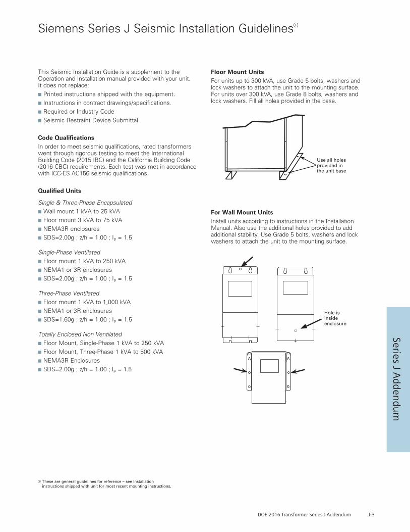
DOE 2016 Transformer Series J Addendum J-3
Series J Adden
dum
Siemens Series J Seismic Installation Guidelines
These are general guidelines for reference – see Installation instructions shipped with unit for most recent mounting instructions.
This Seismic Installation Guide is a supplement to the Operation and Installation manual provided with your unit. It does not replace:
n Printed instructions shipped with the equipment.
n Instructions in contract drawings/specifications.
n Required or Industry Code
n Seismic Restraint Device Submittal
Code QualificationsIn order to meet seismic qualifications, rated transformers went through rigorous testing to meet the International Building Code (2015 IBC) and the California Building Code (2016 CBC) requirements. Each test was met in accordance with ICC-ES AC156 seismic qualifications.
Qualified Units
Single & Three-Phase Encapsulated
n Wall mount 1 kVA to 25 kVA
n Floor mount 3 kVA to 75 kVA
n NEMA3R enclosures
n SDS=2.00g ; z/h = 1.00 ; Ip = 1.5
Single-Phase Ventilated
n Floor mount 1 kVA to 250 kVA
n NEMA1 or 3R enclosures
n SDS=2.00g ; z/h = 1.00 ; Ip = 1.5
Three-Phase Ventilated
n Floor mount 1 kVA to 1,000 kVA
n NEMA1 or 3R enclosures
n SDS=1.60g ; z/h = 1.00 ; Ip = 1.5
Totally Enclosed Non Ventilated
n Floor Mount, Single-Phase 1 kVA to 250 kVA
n Floor Mount, Three-Phase 1 kVA to 500 kVA
n NEMA3R Enclosures
n SDS=2.00g ; z/h = 1.00 ; Ip = 1.5
Floor Mount UnitsFor units up to 300 kVA, use Grade 5 bolts, washers and lock washers to attach the unit to the mounting surface. For units over 300 kVA, use Grade 8 bolts, washers and lock washers. Fill all holes provided in the base.
For Wall Mount UnitsInstall units according to instructions in the Installation Manual. Also use the additional holes provided to add additional stability. Use Grade 5 bolts, washers and lock washers to attach the unit to the mounting surface.
Use all holes provided in the unit base
Hole isinsideenclosure
Use all holes provided in the unit base
Hole isinsideenclosure

J-4 DOE 2016 Transformer Series J Addendum
Seri
es J
Add
endu
m
Reference Wiring Diagram Number Below: T208B T208DT208F T208GT208I T208JT208K T208LT240B T240DT240E T240FT240H T240IT480E T480GT480J T480KT480M T480NT480P T600GT600I plus others
Reference Siemens Series below:
3BxxyyyD16
3CxxyyyD16
3FxxyyyD16
3GxxyyyD16
plus others
Aluminum K1 3-Phase Delta Primary Series JDOE 2016 3-Phase Dry Type Ventilated Transformer Standard Temp Rise – 150° C

DOE 2016 Transformer Series J Addendum J-5
Series J Adden
dum
Reference Wiring Diagram Number Below: T208B T208DT208F T208GT208I T208JT208K T208LT240B T240DT240E T240FT240H T240IT480E T480GT480J T480KT480M T480NT480P T600GT600I plus others
Reference Siemens Series below:
3BxxyyyFD16
3CxxyyyFD16
3FxxyyyFD16
3GxxyyyFD16
plus others
Aluminum K1 3-Phase Delta Primary Series JDOE 2016 3-Phase Dry Type Ventilated Transformer “F” Temp Rise – 115° C

J-6 DOE 2016 Transformer Series J Addendum
Seri
es J
Add
endu
m
Reference Wiring Diagram Number Below: T208B T208DT208F T208GT208I T208JT208K T208LT240B T240DT240E T240FT240H T240IT480E T480GT480J T480KT480M T480NT480P T600GT600I plus others
Reference Siemens Series below:
3BxxyyyBD16
3CxxyyyBD16
3FxxyyyBD16
3GxxyyyBD16
plus others
Aluminum K1 3-Phase Delta Primary Series JDOE 2016 3-Phase Dry Type Ventilated Transformer “B” Temp Rise – 80° C

DOE 2016 Transformer Series J Addendum J-7
Series J Adden
dum
Reference Wiring Diagram Number Below: T208B T208DT208F T208GT208I T208JT208K T208LT240B T240DT240E T240FT240H T240IT480E T480GT480J T480KT480M T480NT480P T600GT600I plus others
Reference Siemens Series below:
3BxxyyyK4D16
3CxxyyyK4D16
3FxxyyyK4D16
3GxxyyyK4D16
plus others
Aluminum K4 3-Phase Delta Primary Series JDOE 2016 3-Phase Dry Type Ventilated Transformer Standard Temp Rise – 150° C

J-8 DOE 2016 Transformer Series J Addendum
Seri
es J
Add
endu
m
Reference Wiring Diagram Number Below: T208B T208DT208F T208GT208I T208JT208K T208LT240B T240DT240E T240FT240H T240IT480E T480GT480J T480KT480M T480NT480P T600GT600I plus others
Reference Siemens Series below:
3BxxyyyK4FD16
3CxxyyyK4FD16
3FxxyyyK4FD16
3GxxyyyK4FD16
plus others
Aluminum K4 3-Phase Delta Primary Series JDOE 2016 3-Phase Dry Type Ventilated Transformer “F” Temp Rise – 115° C

DOE 2016 Transformer Series J Addendum J-9
Series J Adden
dum
Reference Wiring Diagram Number Below: T208B T208DT208F T208GT208I T208JT208K T208LT240B T240DT240E T240FT240H T240IT480E T480GT480J T480KT480M T480NT480P T600GT600I plus others
Reference Siemens Series below:
3BxxyyyK4BD16
3CxxyyyK4BD16
3FxxyyyK4BD16
3GxxyyyK4BD16
plus others
Aluminum K4 3-Phase Delta Primary Series JDOE 2016 3-Phase Dry Type Ventilated Transformer “B” Temp Rise – 80° C

J-10 DOE 2016 Transformer Series J Addendum
Seri
es J
Add
endu
m
Reference Wiring Diagram Number Below: T208B T208DT208F T208GT208I T208JT208K T208LT240B T240DT240E T240FT240H T240IT480E T480GT480J T480KT480M T480NT480P T600GT600I plus others
Reference Siemens Series below:
3BxxyyyK13D16
3CxxyyyK13D16
3FxxyyyK13D16
3GxxyyyK13D16
plus others
Aluminum K13 3-Phase Delta Primary Series JDOE 2016 3-Phase Dry Type Ventilated Transformer Standard Temp Rise – 150° C

DOE 2016 Transformer Series J Addendum J-11
Series J Adden
dum
Reference Wiring Diagram Number Below: T208B T208DT208F T208GT208I T208JT208K T208LT240B T240DT240E T240FT240H T240IT480E T480GT480J T480KT480M T480NT480P T600GT600I plus others
Reference Siemens Series below:
3BxxyyyK13FD16
3CxxyyyK13FD16
3FxxyyyK13FD16
3GxxyyyK13FD16
plus others
Aluminum K13 3-Phase Delta Primary Series JDOE 2016 3-Phase Dry Type Ventilated Transformer “F” Temp Rise – 115° C

J-12 DOE 2016 Transformer Series J Addendum
Seri
es J
Add
endu
m
Reference Wiring Diagram Number Below: T208B T208DT208F T208GT208I T208JT208K T208LT240B T240DT240E T240FT240H T240IT480E T480GT480J T480KT480M T480NT480P T600GT600I plus others
Reference Siemens Series below:
3BxxyyyK13BD16
3CxxyyyK13BD16
3FxxyyyK13BD16
3GxxyyyK13BD16
plus others
Aluminum K13 3-Phase Delta Primary Series JDOE 2016 3-Phase Dry Type Ventilated Transformer “B” Temp Rise – 80° C
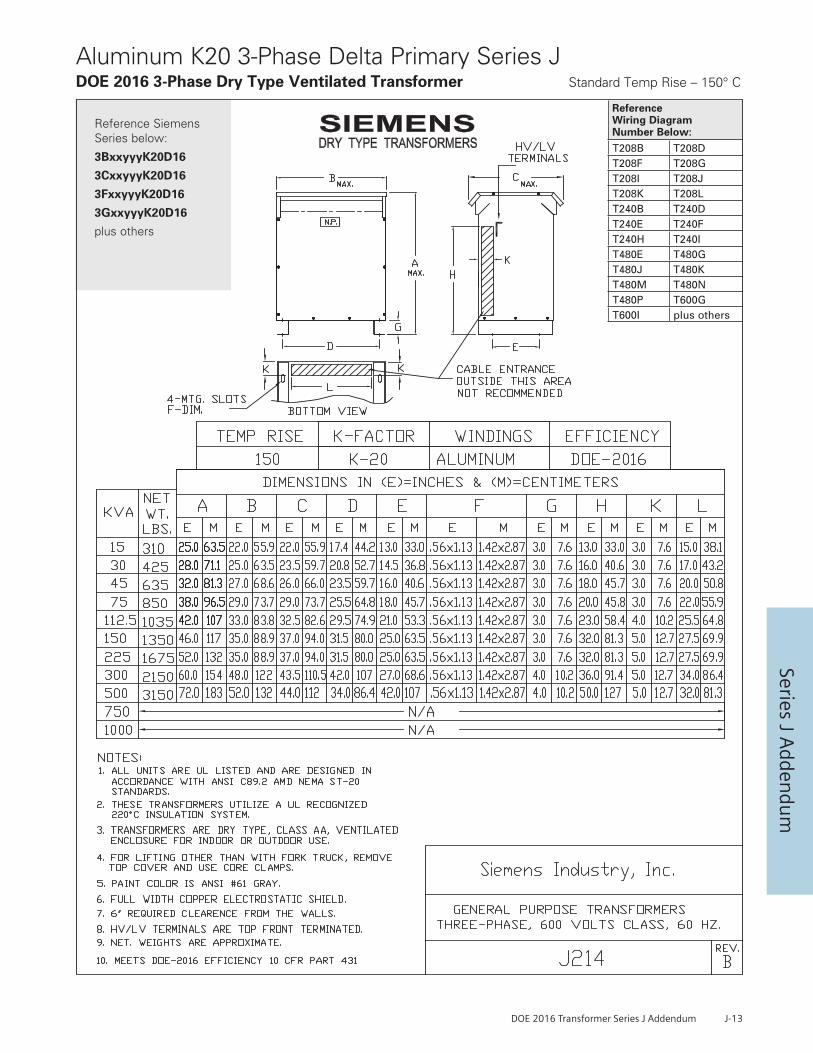
DOE 2016 Transformer Series J Addendum J-13
Series J Adden
dum
Reference Wiring Diagram Number Below: T208B T208DT208F T208GT208I T208JT208K T208LT240B T240DT240E T240FT240H T240IT480E T480GT480J T480KT480M T480NT480P T600GT600I plus others
Reference Siemens Series below:
3BxxyyyK20D16
3CxxyyyK20D16
3FxxyyyK20D16
3GxxyyyK20D16
plus others
Aluminum K20 3-Phase Delta Primary Series JDOE 2016 3-Phase Dry Type Ventilated Transformer Standard Temp Rise – 150° C
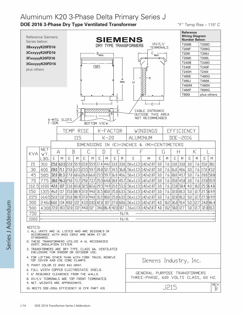
J-14 DOE 2016 Transformer Series J Addendum
Seri
es J
Add
endu
m
Reference Wiring Diagram Number Below: T208B T208DT208F T208GT208I T208JT208K T208LT240B T240DT240E T240FT240H T240IT480E T480GT480J T480KT480M T480NT480P T600GT600I plus others
Reference Siemens Series below:
3BxxyyyK20FD16
3CxxyyyK20FD16
3FxxyyyK20FD16
3GxxyyyK20FD16
plus others
Aluminum K20 3-Phase Delta Primary Series JDOE 2016 3-Phase Dry Type Ventilated Transformer “F” Temp Rise – 115° C

DOE 2016 Transformer Series J Addendum J-15
Series J Adden
dum
Reference Wiring Diagram Number Below: T208B T208DT208F T208GT208I T208JT208K T208LT240B T240DT240E T240FT240H T240IT480E T480GT480J T480KT480M T480NT480P T600GT600I plus others
Reference Siemens Series below:
3BxxyyyK20BD16
3CxxyyyK20BD16
3FxxyyyK20BD16
3GxxyyyK20BD16
plus others
Aluminum K20 3-Phase Delta Primary Series JDOE 2016 3-Phase Dry Type Ventilated Transformer “B” Temp Rise – 80° C
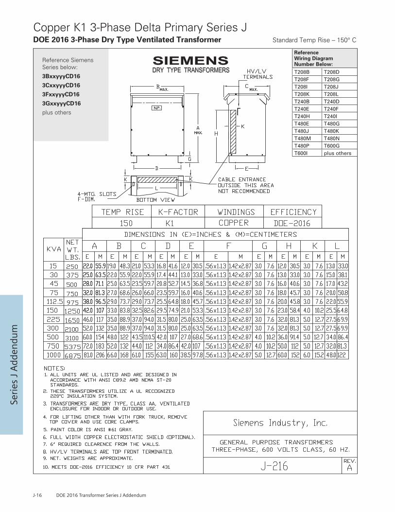
J-16 DOE 2016 Transformer Series J Addendum
Seri
es J
Add
endu
m
Reference Wiring Diagram Number Below: T208B T208DT208F T208GT208I T208JT208K T208LT240B T240DT240E T240FT240H T240IT480E T480GT480J T480KT480M T480NT480P T600GT600I plus others
Reference Siemens Series below:
3BxxyyyCD16
3CxxyyyCD16
3FxxyyyCD16
3GxxyyyCD16
plus others
Copper K1 3-Phase Delta Primary Series JDOE 2016 3-Phase Dry Type Ventilated Transformer Standard Temp Rise – 150° C

DOE 2016 Transformer Series J Addendum J-17
Series J Adden
dum
Reference Wiring Diagram Number Below: T208B T208DT208F T208GT208I T208JT208K T208LT240B T240DT240E T240FT240H T240IT480E T480GT480J T480KT480M T480NT480P T600GT600I plus others
Reference Siemens Series below:
3BxxyyyFCD16
3CxxyyyFCD16
3FxxyyyFCD16
3GxxyyyFCD16
plus others
Copper K1 3-Phase Delta Primary Series JDOE 2016 3-Phase Dry Type Ventilated Transformer “F” Temp Rise – 115° C
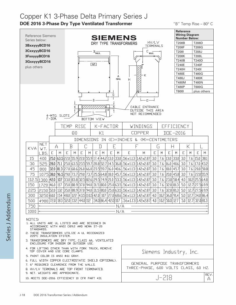
J-18 DOE 2016 Transformer Series J Addendum
Seri
es J
Add
endu
m
Reference Wiring Diagram Number Below: T208B T208DT208F T208GT208I T208JT208K T208LT240B T240DT240E T240FT240H T240IT480E T480GT480J T480KT480M T480NT480P T600GT600I plus others
Reference Siemens Series below:
3BxxyyyBCD16
3CxxyyyBCD16
3FxxyyyBCD16
3GxxyyyBCD16
plus others
Copper K1 3-Phase Delta Primary Series JDOE 2016 3-Phase Dry Type Ventilated Transformer “B” Temp Rise – 80° C
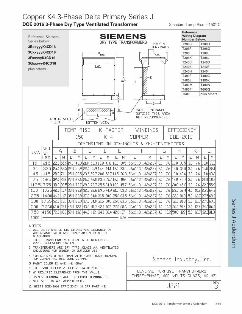
DOE 2016 Transformer Series J Addendum J-19
Series J Adden
dum
Reference Wiring Diagram Number Below: T208B T208DT208F T208GT208I T208JT208K T208LT240B T240DT240E T240FT240H T240IT480E T480GT480J T480KT480M T480NT480P T600GT600I plus others
Reference Siemens Series below:
3BxxyyyK4CD16
3CxxyyyK4CD16
3FxxyyyK4CD16
3GxxyyyK4CD16
plus others
Copper K4 3-Phase Delta Primary Series JDOE 2016 3-Phase Dry Type Ventilated Transformer Standard Temp Rise – 150° C

J-20 DOE 2016 Transformer Series J Addendum
Seri
es J
Add
endu
m
Reference Wiring Diagram Number Below: T208B T208DT208F T208GT208I T208JT208K T208LT240B T240DT240E T240FT240H T240IT480E T480GT480J T480KT480M T480NT480P T600GT600I plus others
Reference Siemens Series below:
3BxxyyyK4FCD16
3CxxyyyK4FCD16
3FxxyyyK4FCD16
3GxxyyyK4FCD16
plus others
Copper K4 3-Phase Delta Primary Series JDOE 2016 3-Phase Dry Type Ventilated Transformer “F” Temp Rise – 115° C
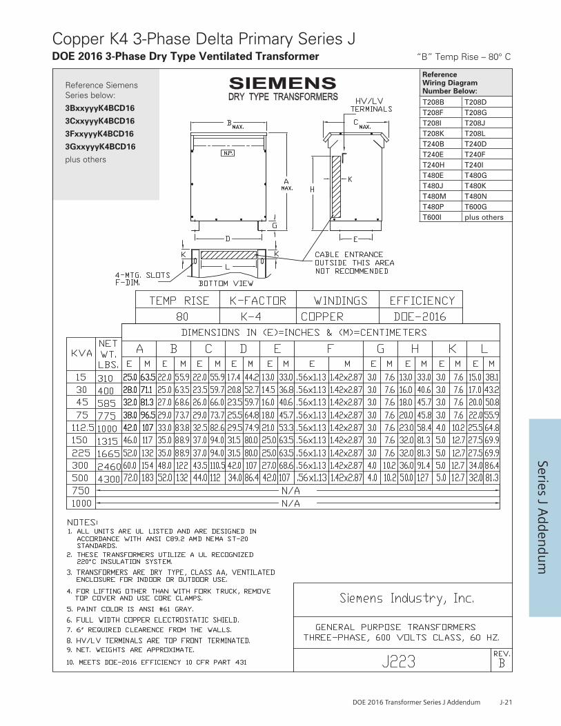
DOE 2016 Transformer Series J Addendum J-21
Series J Adden
dum
Reference Wiring Diagram Number Below: T208B T208DT208F T208GT208I T208JT208K T208LT240B T240DT240E T240FT240H T240IT480E T480GT480J T480KT480M T480NT480P T600GT600I plus others
Reference Siemens Series below:
3BxxyyyK4BCD16
3CxxyyyK4BCD16
3FxxyyyK4BCD16
3GxxyyyK4BCD16
plus others
Copper K4 3-Phase Delta Primary Series JDOE 2016 3-Phase Dry Type Ventilated Transformer “B” Temp Rise – 80° C

J-22 DOE 2016 Transformer Series J Addendum
Seri
es J
Add
endu
m
Reference Wiring Diagram Number Below: T208B T208DT208F T208GT208I T208JT208K T208LT240B T240DT240E T240FT240H T240IT480E T480GT480J T480KT480M T480NT480P T600GT600I plus others
Reference Siemens Series below:
3BxxyyyK13CD16
3CxxyyyK13CD16
3FxxyyyK13CD16
3GxxyyyK13CD16
plus others
Copper K13 3-Phase Delta Primary Series JDOE 2016 3-Phase Dry Type Ventilated Transformer Standard Temp Rise – 150° C

DOE 2016 Transformer Series J Addendum J-23
Series J Adden
dum
Reference Wiring Diagram Number Below: T208B T208DT208F T208GT208I T208JT208K T208LT240B T240DT240E T240FT240H T240IT480E T480GT480J T480KT480M T480NT480P T600GT600I plus others
Reference Siemens Series below:
3BxxyyyK13FCD16
3CxxyyyK13FCD16
3FxxyyyK13FCD16
3GxxyyyK13FCD16
plus others
Copper K13 3-Phase Delta Primary Series JDOE 2016 3-Phase Dry Type Ventilated Transformer “F” Temp Rise – 115° C

J-24 DOE 2016 Transformer Series J Addendum
Seri
es J
Add
endu
m
Reference Wiring Diagram Number Below: T208B T208DT208F T208GT208I T208JT208K T208LT240B T240DT240E T240FT240H T240IT480E T480GT480J T480KT480M T480NT480P T600GT600I plus others
Reference Siemens Series below:
3BxxyyyK13BCD16
3CxxyyyK13BCD16
3FxxyyyK13BCD16
3GxxyyyK13BCD16
plus others
Copper K13 3-Phase Delta Primary Series JDOE 2016 3-Phase Dry Type Ventilated Transformer “B” Temp Rise – 80° C

DOE 2016 Transformer Series J Addendum J-25
Series J Adden
dum
Reference Wiring Diagram Number Below: T208B T208DT208F T208GT208I T208JT208K T208LT240B T240DT240E T240FT240H T240IT480E T480GT480J T480KT480M T480NT480P T600GT600I plus others
Reference Siemens Series below:
3BxxyyyK20CD16
3CxxyyyK20CD16
3FxxyyyK20CD16
3GxxyyyK20CD16
plus others
Copper K20 3-Phase Delta Primary Series JDOE 2016 3-Phase Dry Type Ventilated Transformer Standard Temp Rise – 150° C
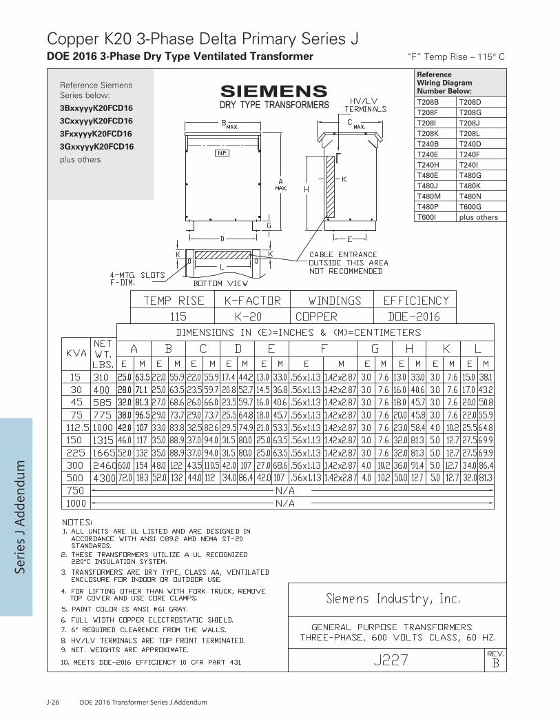
J-26 DOE 2016 Transformer Series J Addendum
Seri
es J
Add
endu
m
Reference Wiring Diagram Number Below: T208B T208DT208F T208GT208I T208JT208K T208LT240B T240DT240E T240FT240H T240IT480E T480GT480J T480KT480M T480NT480P T600GT600I plus others
Reference Siemens Series below:
3BxxyyyK20FCD16
3CxxyyyK20FCD16
3FxxyyyK20FCD16
3GxxyyyK20FCD16
plus others
Copper K20 3-Phase Delta Primary Series JDOE 2016 3-Phase Dry Type Ventilated Transformer “F” Temp Rise – 115° C

DOE 2016 Transformer Series J Addendum J-27
Series J Adden
dum
Reference Wiring Diagram Number Below: T208B T208DT208F T208GT208I T208JT208K T208LT240B T240DT240E T240FT240H T240IT480E T480GT480J T480KT480M T480NT480P T600GT600I plus others
Reference Siemens Series below:
3BxxyyyK20BCD16
3CxxyyyK20BCD16
3FxxyyyK20BCD16
3GxxyyyK20BCD16
plus others
Copper K20 3-Phase Delta Primary Series JDOE 2016 3-Phase Dry Type Ventilated Transformer “B” Temp Rise – 80° C

Seri
es J
Add
endu
m
Primary On Each Coil Primary LinesVolts Jumper Taps To Connect To218 1 H1, H2, H3213 2 H1, H2, H3208 3 H1, H2, H3203 4 H1, H2, H3198 5 H1, H2, H3192 6 H1, H2, H3187 7 H1, H2, H3Sec. Secondary LinesVolts Connect To208 X1, X2, X3120 Between X0 and
1 Phase X1 or X2 or X3
Wiring Diagram
Connections
T208B Wiring Diagram & Connections*
SECONDARY
PRIMARY
Primary: 208 Volts DeltaSecondary: 208Y/120 Volts
Primary On Each Coil Primary LinesVolts Jumper Taps To Connect To218 1 X1, X2, X3208 2 X1, X2, X3198 3 X1, X2, X3187 4 X1, X2, X3Sec. Secondary LinesVolts Connect To480 H1, H2, H3277 Between H0 and
1 Phase H1 or H2 or H3
Wiring Diagram
Connections
T208G Wiring Diagram & Connections*
SECONDARY
PRIMARY
Primary: 208 Volts DeltaSecondary: 480Y/277 Volts
Primary On Each Coil Primary LinesVolts Jumper Taps To Connect To208 1 X1, X2, X3Sec. Secondary LinesVolts Connect To480 H1, H2, H3277 Between H0 and
1 Phase H1 or H2 or H3
Wiring Diagram
Connections
T208J Wiring Diagram & Connections*
Primary: 208 Volts DeltaSecondary: 480Y/277 Volts PRIMARY
SECONDARY
Primary Jumper Primary LinesVolts Taps To Connect To208 1 X1, X2, X3198 2 X1, X2, X3187 3 X1, X2, X3
seniL yradnoceS.ceSoT tcennoCstloV3H ,2H ,1H084
dna 0H neewteB7723H ro 2H ro 1HesahP 1
Wiring Diagram
Connections
T208A Wiring Diagram & Connections*
Primary: 208 Volts DeltaSecondary: 480Y/277 Volts PRIMARY
SECONDARY
Primary On Each Coil Primary LinesVolts Jumper Taps To Connect To218 1 H1, H2, H3208 2 H1, H2, H3198 3 H1, H2, H3187 4 H1, H2, H3Sec. Secondary LinesVolts Connect To208 X1, X2, X3120 Between X0 and
1 Phase X1 or X2 or X3
Wiring Diagram
Connections
T208F Wiring Diagram & Connections*
SECONDARY
PRIMARY
Primary: 208 Volts DeltaSecondary: 208Y/120 Volts
Primary On Each Coil Primary LinesVolts Jumper Taps To Connect To208 1 H1, H2, H3Sec. Secondary LinesVolts Connect To208 X1, X2, X3120 Between X0 and
1 Phase X1 or X2 or X3
Wiring Diagram
Connections
T208I Wiring Diagram & Connections*
Primary: 208 Volts DeltaSecondary: 208Y/120 Volts PRIMARY
SECONDARY
Primary On Each Coil Primary LinesVolts Jumper Taps To Connect To218 1 X1, X2, X3213 2 X1, X2, X3208 3 X1, X2, X3203 4 X1, X2, X3198 5 X1, X2, X3192 6 X1, X2, X3187 7 X1, X2, X3Sec. Secondary LinesVolts Connect To480 H1, H2, H3277 Between H0 and
1 Phase H1 or H2 or H3
Wiring Diagram
Connections
T208D Wiring Diagram & Connections*
SECONDARY
PRIMARYPrimary: 208 Volts DeltaSecondary: 480Y/277 Volts
Primary Jumper Primary LinesVolts Taps To Connect To208 1 H1, H2, H3198 2 H1, H2, H3187 3 H1, H2, H3
seniL yradnoceS.ceSoT tcennoCstloV3X ,2X ,1X802
dna 0X neewteB0213X ro 2X ro 1XesahP 1
Wiring Diagram
Connections
T208H Wiring Diagram & Connections*
Primary: 208 Volts DeltaSecondary: 208Y/120 Volts PRIMARY
SECONDARY
Primary On Each Coil Primary LinesVolts Jumper Taps To Connect To218 1 X1, X2, X3213 2 X1, X2, X3208 3 X1, X2, X3203 4 X1, X2, X3198 5 X1, X2, X3
187 7 X1, X2, X3192 6 X1, X2, X3
Sec. Secondary LinesVolts Connect To240 H1, H2, H3120 H1 and H4 or
1 Phase H2 and H4
Wiring Diagram
Connections
T208K Wiring Diagram & Connections*
SECONDARY
PRIMARYPrimary: 208 Volts DeltaSecondary: 240 Volts Delta/ 120 Volts
Wiring Diagrams

DOE 2016 Transformer Series J Addendum J-29
Series J Adden
dum
Primary Jumper Primary LinesVolts Taps To Connect To240 1 H1, H2, H3228 2 H1, H2, H3216 3 H1, H2, H3Sec. Secondary LinesVolts Connect To208 X1, X2, X3120 Between X0 and
1 phase X1 or X2 or X3
Wiring Diagram
Connections
T240A Wiring Diagram & Connections*
PRIMARY
SECONDARY
Primary: 240 Volts DeltaSecondary: 208Y/120 Volts
Primary On Each Coil Primary LinesVolts Jumper Taps To Connect To252 1 X1, X2, X3240 2 X1, X2, X3228 3 X1, X2, X3216 4 X1, X2, X3Sec. Secondary LinesVolts Connect To480 H1, H2, H3277 Between H0 and
1 Phase H1 or H2, or H3
Wiring Diagram
Connections
T240E Wiring Diagram & Connections*
PRIMARY
SECONDARY
Primary: 240 Volts DeltaSecondary: 480Y/277 Volts
Primary On Each Coil Primary LinesVolts Jumper Taps To Connect To240 1 X1, X2, X3Sec. Secondary LinesVolts Connect To480 H1, H2, H3277 Between H0 and
1 Phase H1 or H2 or H3
Wiring Diagram
Connections
T240H Wiring Diagram & Connections*
PRIMARY
SECONDARY
Primary: 240 Volts DeltaSecondary: 480Y/277 Volts
Primary On Each Coil Primary LinesVolts Jumper Taps To Between Lines218 1 H1, H2, H3208 2 H1, H2, H3198 3 H1, H2, H3187 4 H1, H2, H3
H1, H2, H3
Sec. Secondary LinesVolts Connect To240120 H1 and H4 or
1 Phase H2 and H4
Wiring Diagram
Connections
T208L Wiring Diagram & Connections*
PRIMARY
SECONDARY
Primary: 208 Volts Delta Secondary: 240 Volts Delta/
120 Volts
Primary On Each Coil Primary LinesVolts Jumper Taps To Connect To252 1 X1, X2, X3246 2 X1, X2, X3240 3 X1, X2, X3234 4 X1, X2, X3228 5 X1, X2, X3222 6 X1, X2, X3216 7 X1, X2, X3Sec. Secondary LinesVolts Connect To480 H1, H2, H3277 Between H0 and
1 Phase H1 or H2 or H3
Wiring Diagram
Connections
T240D Wiring Diagram & Connections*
PRIMARY
SECONDARY
Primary: 240 Volts DeltaSecondary: 480Y/277 Volts
Primary Jumper Primary LinesVolts Taps To Connect To240 1 X1, X2, X3228 2 X1, X2, X3216 3 X1, X2, X3Sec. Secondary LinesVolts Connect To480 H1, H2, H3277 Between X0 and
1 phase H1 or H2 or H3
Wiring Diagram
Connections
T240G Wiring Diagram & Connections*
PRIMARY
SECONDARY
Primary: 240 Volts DeltaSecondary: 480Y/277 Volts
Primary On Each Coil Primary LinesVolts Jumper Taps To Connect To252 1 H1, H2, H3246 2 H1, H2, H3240 3 H1, H2, H3234 4 H1, H2, H3228 5 H1, H2, H3222 6 H1, H2, H3216 7 H1, H2, H3Sec. Secondary LinesVolts Connect To208 X1, X2, X3120 Between X0 and
1 Phase X1 or X2 or X3
Wiring Diagram
Connections
T240B Wiring Diagram & Connections*
PRIMARY
SECONDARY
Primary: 240 Volts DeltaSecondary: 208Y/120 Volts
Primary On Each Coil Primary LinesVolts Jumper Taps To Connect To252 1 H1, H2, H3240 2 H1, H2, H3228 3 H1, H2, H3216 4 H1, H2, H3Sec. Secondary LinesVolts Connect To208 X1, X2, X3120 Between X0 and
1 Phase X1 or X2, or X3
Wiring Diagram
Connections
T240F Wiring Diagram & Connections*
PRIMARY
SECONDARY
Primary: 240 Volts DeltaSecondary: 208Y/120 Volts
Primary On Each Coil Primary LinesVolts Jumper Taps To Connect To240 1 H1, H2, H3Sec. Secondary LinesVolts Connect To208 X1, X2, X3120 Between X0 and
1 Phase X1 or X2 or X3
Wiring Diagram
Connections
T240I Wiring Diagram & Connections*
PRIMARY
SECONDARY
Primary: 240 Volts DeltaSecondary: 208Y/120 Volts PRIMARY
Wiring Diagrams

Seri
es J
Add
endu
m
Primary Jumper Primary LinesVolts Taps To Connect To480 1 H1, H2, H3456 2 H1, H2, H3432 3 H1, H2, H3Sec. Secondary LinesVolts Connect To208 X1, X2, X3120 Between X0 and
1 phase X1 or X2 or X3
Wiring Diagram
Connections
T480A Wiring Diagram & Connections*
PRIMARY
SECONDARY
Primary: 480 Volts DeltaSecondary: 208Y/120 Volts
seniL ylppuSyramirPVolts Interconnect Connect To480 H1 & 6 H1, H2, H3
H2 & 4H3 & 5
456 H1 & 9 H1, H2, H3H2 & 7H3 & 8
432 H1 & 12 H1, H2, H3H2 & 10H3 & 11
seniL daoL.ceSoT tcennoCstloV3X ,2X ,1X802
dna 0X neewteB0213X ro 2X ro 1XesahP 1
Wiring Diagram
Connections
T480D Wiring Diagram & Connections*
PRIMARY
SECONDARY
Primary: 480Secondary: 208Y/120
Primary On Each Coil Primary LinesVolts Jumper Taps To Connect To504 1 H1, H2, H3492 2 H1, H2, H3480 3 H1, H2, H3468 4 H1, H2, H3456 5 H1, H2, H3444 6 H1, H2, H3432 7 H1, H2, H3Sec. Secondary LinesVolts Connect To240 X1, X2, X3120 X1 and X4 or
1 Phase X2 and X4
Wiring Diagram
Connections
T480G Wiring Diagram & Connections*
Primary: 480 Volts Delta Secondary: 240 Volts Delta/
120 Volts
SECONDARY
PRIMARY
Primary On Each Coil Primary LinesVolts Jumper Taps To Connect To483 1 H1, H2, H3472 2 H1, H2, H3460 3 H1, H2, H3448 4 H1, H2, H3437 5 H1, H2, H3425 6 H1, H2, H3414 7 H1, H2, H3
seniL yradnoceS.ceSoT tcennoCstloV3X ,2X ,1X022
dna 0X neewteB7213X ro 2X ro 1XesahP 1
Wiring Diagram
Connections
T460A Wiring Diagram & Connections*
Primary: 460 Volts DeltaSecondary: 220Y/127 Volts
PRIMARY
SECONDARY
Primary Jumper Primary LinesVolts Taps To Connect To480 1 H1, H2, H3456 2 H1, H2, H3432 3 H1, H2, H3Sec. Secondary LinesVolts Connect To480 X1, X2, X3277 Between X0 and
1 phase X1 or X2 or X3
Wiring Diagram
Connections
T480C Wiring Diagram & Connections*
Primary: 480 Volts DeltaSecondary: 480Y/277 Volts
PRIMARY
SECONDARY
Primary On Each Coil Primary LinesVolts Jumper Between Taps Connect To504 1 H1, H2, H3492 2 H1, H2, H3480 3 H1, H2, H3468 4 H1, H2, H3456 5 H1, H2, H3
seniL yradnoceS.ceSoT tcennoCstloV3X ,2X ,1X084
T480F Wiring Diagram & Connections
Primary: 480 Volts DeltaSecondary: 480 Volts Delta
Wiring Diagram
Connections
SECONDARY
PRIMARY
Primary Jumper Primary LinesVolts Taps To Connect To480 1 H1, H2, H3456 2 H1, H2, H3432 3 H1, H2, H3Sec. Secondary LinesVolts Connect To240 X1, X2, X3
Wiring Diagram
Connections
T480B Wiring Diagram & Connections*
PRIMARY
SECONDARY
Primary: 480 Volts DeltaSecondary: 240 Volts Delta
Primary On Each Coil Primary LinesVolts Jumper Taps To Connect To504 1 H1, H2, H3492 2 H1, H2, H3480 3 H1, H2, H3468 4 H1, H2, H3456 5 H1, H2, H3444 6 H1, H2, H3432 7 H1, H2, H3Sec. Secondary LinesVolts Connect To208 X1, X2, X3120 Between X0 and
1 Phase X1 or X2 or X3
Wiring Diagram
Connections
T480E Wiring Diagram & Connections*
Primary: 480 Volts DeltaSecondary: 208Y/120 Volts
PRIMARY
SECONDARY
Primary On Each Coil Primary LinesVolts Jumper Taps To Connect To504 1 H1, H2, H3492 2 H1, H2, H3480 3 H1, H2, H3468 4 H1, H2, H3456 5 H1, H2, H3444 6 H1, H2, H3432 7 H1, H2, H3
seniL yradnoceS.ceSoT tcennoCstloV3X ,2X ,1X083
dna 0X neewteB0223X ro 2X ro 1XesahP 1
Wiring Diagram
Connections
T480I Wiring Diagram & Connections*
Primary: 480 Volts DeltaSecondary: 380Y/220 Volts PRIMARY
SECONDARY
Wiring Diagrams
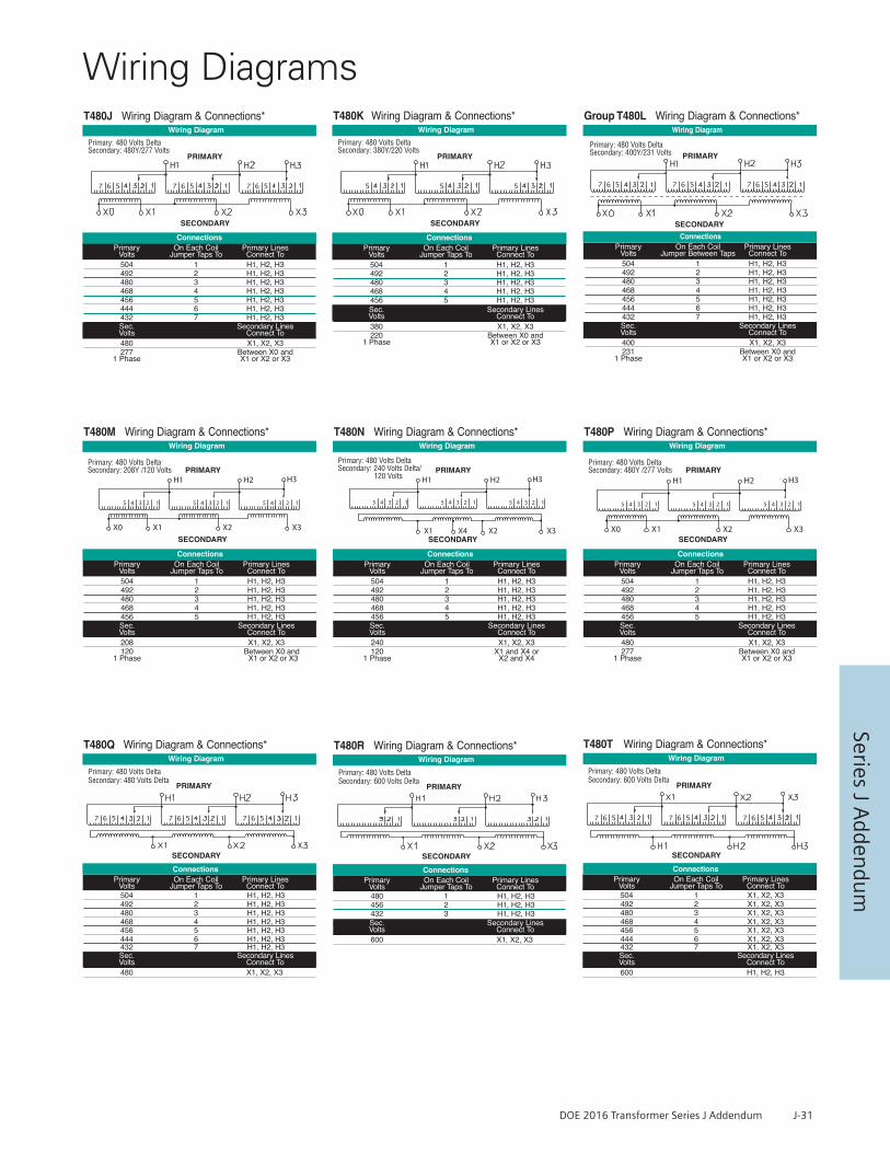
DOE 2016 Transformer Series J Addendum J-31
Series J Adden
dum
Primary On Each Coil Primary LinesVolts Jumper Taps To Connect To504 1 H1, H2, H3492 2 H1, H2, H3480 3 H1, H2, H3468 4 H1, H2, H3456 5 H1, H2, H3Sec. Secondary LinesVolts Connect To380 X1, X2, X3220 Between X0 and
1 Phase X1 or X2 or X3
Wiring Diagram
Connections
T480K Wiring Diagram & Connections*
Primary: 480 Volts DeltaSecondary: 380Y/220 Volts
PRIMARY
SECONDARY
Primary On Each Coil Primary LinesVolts Jumper Taps To Connect To504 1 H1, H2, H3492 2 H1, H2, H3480 3 H1, H2, H3468 4 H1, H2, H3456 5 H1, H2, H3Sec. Secondary LinesVolts Connect To240 X1, X2, X3120 X1 and X4 or
1 Phase X2 and X4
Wiring Diagram
Connections
T480N Wiring Diagram & Connections*
PRIMARY
SECONDARY
Primary: 480 Volts Delta Secondary: 240 Volts Delta/
120 Volts
Primary On Each Coil Primary LinesVolts Jumper Taps To Connect To480 1 H1, H2, H3456 2 H1, H2, H3432 3 H1, H2, H3Sec. Secondary LinesVolts Connect To600 X1, X2, X3
Wiring Diagram
Connections
T480R Wiring Diagram & Connections*
SECONDARY
PRIMARY
Primary: 480 Volts DeltaSecondary: 600 Volts Delta
Primary On Each Coil Primary LinesVolts Jumper Taps To Connect To504 1 H1, H2, H3492 2 H1, H2, H3480 3 H1, H2, H3468 4 H1, H2, H3456 5 H1, H2, H3444 6 H1, H2, H3432 7 H1, H2, H3Sec. Secondary LinesVolts Connect To480 X1, X2, X3277 Between X0 and
1 Phase X1 or X2 or X3
Wiring Diagram
Connections
T480J Wiring Diagram & Connections*
Primary: 480 Volts DeltaSecondary: 480Y/277 Volts
PRIMARY
SECONDARY
Primary On Each Coil Primary LinesVolts Jumper Taps To Connect To504 1 H1, H2, H3492 2 H1, H2, H3480 3 H1, H2, H3468 4 H1, H2, H3456 5 H1, H2, H3Sec. Secondary LinesVolts Connect To208 X1, X2, X3120 Between X0 and
1 Phase X1 or X2 or X3
Wiring Diagram
Connections
T480M Wiring Diagram & Connections*
PRIMARY
SECONDARY
Primary: 480 Volts Delta Secondary: 208Y /120 Volts
Primary On Each Coil Primary LinesVolts Jumper Taps To Connect To504 1 H1, H2, H3492 2 H1, H2, H3480 3 H1, H2, H3468 4 H1, H2, H3456 5 H1, H2, H3
432 7 H1, H2, H3444 6 H1, H2, H3
Sec. Secondary LinesVolts Connect To480 X1, X2, X3
Wiring Diagram
Connections
T480Q Wiring Diagram & Connections*
SECONDARY
PRIMARY
Primary: 480 Volts DeltaSecondary: 480 Volts Delta
Wiring DiagramGroup T480L Wiring Diagram & Connections*
SECONDARY
Primary On Each Coil Primary LinesVolts Jumper Between Taps Connect To504 1 H1, H2, H3492 2 H1, H2, H3480 3 H1, H2, H3468 4 H1, H2, H3456 5 H1, H2, H3444 6 H1, H2, H3432 7 H1, H2, H3Sec. Secondary LinesVolts Connect To400 X1, X2, X3231 Between X0 and
1 Phase X1 or X2 or X3
Connections
Primary: 480 Volts DeltaSecondary: 400Y/231 Volts PRIMARY
Primary On Each Coil Primary LinesVolts Jumper Taps To Connect To504 1 H1, H2, H3492 2 H1, H2, H3480 3 H1, H2, H3468 4 H1, H2, H3456 5 H1, H2, H3Sec. Secondary LinesVolts Connect To480 X1, X2, X3277 Between X0 and
1 Phase X1 or X2 or X3
Wiring Diagram
Connections
T480P Wiring Diagram & Connections*
PRIMARY
SECONDARY
Primary: 480 Volts Delta Secondary: 480Y /277 Volts
Primary On Each Coil Primary LinesVolts Jumper Taps To Connect To504 1 X1, X2, X3492 2 X1, X2, X3480 3 X1, X2, X3468 4 X1, X2, X3456 5 X1, X2, X3
432 7 X1, X2, X3444 6 X1, X2, X3
Sec. Secondary LinesVolts Connect To600 H1, H2, H3
Wiring Diagram
Connections
T480T Wiring Diagram & Connections*
SECONDARY
PRIMARY
Primary: 480 Volts DeltaSecondary: 600 Volts Delta
Wiring Diagrams

Seri
es J
Add
endu
m
Primary Jumper Primary LinesVolts Taps To Connect To600 1 H1, H2, H3570 2 H1, H2, H3540 3 H1, H2, H3Sec. Secondary LinesVolts Connect To208 X1, X2, X3120 Between X0 and
1 phase X1 or X2 or X3
Wiring Diagram
Connections
T600A Wiring Diagram & Connections*
PRIMARY
SECONDARY
Primary: 600 Volts DeltaSecondary: 208Y/120 Volts
600 1 H1, H2, H3570 2 H1, H2, H3540 3 H1, H2, H3Sec. Secondary LinesVolts Connect To240 X1, X2, X3
Wiring Diagram
Connections
T600E Wiring Diagram & Connections*
PRIMARY
SECONDARY
Primary: 600 Volts DeltaSecondary: 240 Volts Delta
Primary Jumper Primary LinesVolts Taps To Connect To
600 1 H1, H2, H3570 2 H1, H2, H3540 3 H1, H2, H3
seniL yradnoceS.ceSoT tcennoCstloV3X ,2X ,1X084
dna 0X neewteB7723X ro 2X ro 1XesahP 1
Wiring Diagram
Connections
T600H Wiring Diagram & Connections*
PRIMARY
SECONDARY
Primary: 600 Volts DeltaSecondary: 480Y/277 Volts
PrimaryVolts
JumperTaps to
Primary LinesConnect To
Primary On Each Coil Primary LinesVolts Jumper Taps To Connect To504 1 H1, H2, H3492 2 H1, H2, H3480 3 H1, H2, H3468 4 H1, H2, H3456 5 H1, H2, H3
seniL yradnoceS.ceSoT tcennoCstloV3X ,2X ,1X004
dna 0X neewteB1323X ro 2X ro 1XesahP 1
Wiring Diagram
Connections
T480U Wiring Diagram & Connections*
Primary: 480 Volts DeltaSecondary: 400Y/231 Volts PRIMARY
SECONDARY
Primary On Each Coil Primary LinesVolts Jumper Taps To Connect To504 1 X1, X2, X3492 2 X1, X2, X3480 3 X1, X2, X3468 4 X1, X2, X3456 5 X1, X2, X3Sec. Secondary LinesVolts Connect To600 H1, H2, H3
Wiring Diagram
Connections
T480V Wiring Diagram & Connections*
Primary: 480 Volts Delta Secondary: 600 Volts Delta
SECONDARY
PRIMARY
Primary On Each Coil Primary LinesVolts Jumper Taps To Between Lines630 1 H1, H2, H3615 2 H1, H2, H3600 3 H1, H2, H3585 4 H1, H2, H3570 5 H1, H2, H3555 6 H1, H2, H3540 7 H1, H2, H3Sec. Secondary LinesVolts Connect To240 X1, X2, X3120 X1 and X4 or
1 Phase X2 and X4
Wiring Diagram
Connections
T600D Wiring Diagram & Connections*
PRIMARY
SECONDARY
Primary: 600 VoltsSecondary: 240 Volts Delta/
120 Volts
Primary On Each Coil Primary LinesVolts Jumper Taps To Between Lines630 1 H1, H2, H3615 2 H1, H2, H3600 3 H1, H2, H3585 4 H1, H2, H3570 5 H1, H2, H3
seniL yradnoceS.ceSoT tcennoCstloV3X ,2X ,1X802
dna 0X neewteB0213X ro 2X ro 1XesahP 1
Wiring Diagram
Connections
T600G Wiring Diagram & Connections*
PRIMARY
SECONDARY
Primary: 600 VoltsSecondary: 208Y/120 Volts
Primary On Each Coil Primary LinesVolts Jumper Taps To Between Lines630 1 H1, H2, H3615 2 H1, H2, H3600 3 H1, H2, H3585 4 H1, H2, H3570 5 H1, H2, H3555 6 H1, H2, H3540 7 H1, H2, H3Sec. Secondary LinesVolts Connect To208 X1, X2, X3120 Between X0 and
1 Phase X1 or X2 or X3
Wiring Diagram
Connections
T600B Wiring Diagram & Connections*
PRIMARYPrimary: 600 VoltsSecondary: 208Y/120 Volts
SECONDARY
Primary On Each Coil Primary LinesVolts Jumper Taps To Between Lines630 1 H1, H2, H3615 2 H1, H2, H3600 3 H1, H2, H3585 4 H1, H2, H3570 5 H1, H2, H3Sec. Secondary LinesVolts Connect To240 X1, X2, X3120 Between X0 and
1 Phase X1 or X2 or X3
Wiring Diagram
Connections
T600F Wiring Diagram & Connections*
PRIMARY
SECONDARY
Primary: 600 Volts Secondary: 240 Volts Delta/
120 Volts
Wiring Diagrams

DOE 2016 Transformer Series J Addendum J-33
Series J Adden
dum
Wiring Diagrams
Primary On Each Coil Primary LinesVolts Jumper Taps To Between Lines630 1 H1, H2, H3615 2 H1, H2, H3600 3 H1, H2, H3585 4 H1, H2, H3570 5 H1, H2, H3Sec. Secondary LinesVolts Connect To480 X1, X2, X3277 Between X0 and
1 Phase X1 or X2 or X3
Wiring Diagram
Connections
T600I Wiring Diagram & Connections*
PRIMARY
Primary: 600 VoltsSecondary: 480Y/277 Volts
SECONDARY
Primary On Each Coil Primary LinesVolts Jumper Taps To Between Lines630 1 H1, H2, H3615 2 H1, H2, H3600 3 H1, H2, H3585 4 H1, H2, H3570 5 H1, H2, H3555 6 H1, H2, H3540 7 H1, H2, H3Sec. Secondary LinesVolts Connect To480 X1, X2, X3
Wiring Diagram
Connections
T600K Wiring Diagram & Connections*
PRIMARY
SECONDARY
Primary: 600 VoltsSecondary: 480 Volts Delta
600 1 H1, H2, H3570 2 H1, H2, H3540 3 H1, H2, H3Sec. Secondary LinesVolts Connect To480 X1, X2, X3
Wiring Diagram
Connections
T600J Wiring Diagram & Connections*
PRIMARY
SECONDARY
Primary: 600 Volts DeltaSecondary: 240 Volts Delta
Primary Jumper Primary LinesVolts Taps To Connect To
Primary On Each Coil Primary LinesVolts Jumper Taps To Between Lines630 1 H1, H2, H3615 2 H1, H2, H3600 3 H1, H2, H3585 4 H1, H2, H3570 5 H1, H2, H3555 6 H1, H2, H3540 7 H1, H2, H3Sec. Secondary LinesVolts Connect To480 X1, X2, X3277 Between X0 and
1 Phase X1 or X2 or X3
Wiring Diagram
Connections
T600M Wiring Diagram & Connections*
PRIMARYPrimary: 600 VoltsSecondary: 480Y/277 Volts
SECONDARY
Primary On Each Coil Primary LinesVolts Jumper Taps To Between Lines630 1 H1, H2, H3615 2 H1, H2, H3600 3 H1, H2, H3585 4 H1, H2, H3570 5 H1, H2, H3Sec. Secondary LinesVolts Connect To480 X1, X2, X3
Wiring Diagram
Connections
T600L Wiring Diagram & Connections*
PRIMARY
SECONDARY
Primary: 600 Volts DeltaSecondary: 480 Volts Delta

J-34 DOE 2016 Transformer Series J Addendum
Seri
es J
Add
endu
m
NOT
ES1.
Tol
eran
ces:
wat
ts v
alue
s =
+/- 1
0%.
Impe
danc
e va
lues
= +
/- 7
.5%
.2.
Dim
ensi
ons
and
wei
ghts
sub
ject
to c
hang
e w
ithou
t not
ifica
tion.
3. T
rans
form
ers
conf
orm
to
appl
icab
le A
NSI
, NEM
A an
d IE
EE s
tand
ards
.*
4. U
nit w
ill m
eet o
r exc
eed
DOE-
2016
min
imum
effi
cien
cy.
FOR
HEA
T O
UTP
UT
(BTU
/ H
R) M
ULT
IPLY
TO
TAL
LO
SS B
Y 3
.414
DA
TA
FO
R 6
00 V
OLT
CLA
SS
PR
OD
UC
T L
INE
Series J Typical Performance DataDry Type 600 Volt Transformers 60 Hz, 10 kv BIL
T
he s
izin
g of
the
ove
rcur
rent
pro
tect
ion
for
tran
sfor
mer
pri
mar
ies
mus
t be
app
rove
d by
the
eng
inee
r of
rec
ord
base
d on
man
y fa
ctor
s, in
clud
ing
the
syst
em c
oord
inat
ion
requ
ired
and
the
pre
ferr
ed u
se o
f “a
bsol
ute”
or
“pr
actic
al”
valu
es f
or t
he a
pplic
atio
n. T
he m
inim
um b
reak
er s
ize
for
tran
sfor
mer
pri
mar
ies
is t
ypic
ally
larg
er t
han
the
“pra
ctic
al”
max
imum
in
rush
am
ps b
y so
me
perc
enta
ge (
usua
lly a
t le
ast
125%
of
the
“pra
ctic
al”
inru
sh v
alue
).
Alu
min
um
3-P
has
e D
ry T
ype
K1
wit
ho
ut
Ele
ctro
stat
ic S
hie
ld
KVA
Cond
.Ph
.K
Shie
ldTe
mp.
Rise
Volta
ge
Siem
ens
Part
Num
ber
Ref.
Temp
C
No
Load
Loss
Wat
ts
Full
Load
Loss
Wat
ts
Tota
lLo
ssW
atts
IMPE
DA
NCE
CHA
RACT
ERIS
TICS
REGU
LATI
ONPo
wer
Fac
tor
(PF)
Effic
ienc
ies
at %
of R
ated
KVA
Load
s A
ssum
ed to
be
Sinu
soid
al
App
roxi
mat
eEn
clos
ure
Dim
ensi
ons
Appr
ox.
Tota
lW
eigh
t
Abso
l.Pe
ak
Inru
shrm
s am
ps
Prac
tical
Max
In
rush
rms
amps
Ref.
Dra
win
g
IRIX
IZ
(Imp)
X/R
10.
825
%35
%*
50%
75%
100%
H
(in)
W
(in)
D
(in)
No.
Page
15AL
31
NO
150
480D
-208
Y3F
3Y01
5D16
170
5665
070
64.
451.
444.
680.
324.
46
4.44
97
.46
97.8
997
.11
96.3
0 95
.40
2219
2121
519
565
J201
J-4
30AL
31
NO
150
480D
-208
Y3F
3Y03
0D16
170
8910
8611
753.
822.
364.
490.
623.
84
4.47
97
.89
98.2
397
.55
96.8
4 96
.05
2522
2233
033
711
2J2
01J-
445
AL3
1N
O15
048
0D-2
08Y
3F3Y
045D
1617
012
714
5115
783.
291.
863.
780.
573.
31
3.75
98
.08
98.4
097
.83
97.2
3 96
.55
2825
23.5
415
210
70J2
01J-
475
AL3
1N
O15
048
0D-2
08Y
3F3Y
075D
1617
016
623
2924
953.
393.
454.
841.
023.
44
4.78
98
.36
98.6
097
.94
97.2
6 96
.53
3227
2658
557
819
3J2
01J-
411
2.5
AL3
1N
O15
048
0D-2
08Y
3F3Y
112D
1617
019
533
1935
143.
335.
226.
191.
563.
47
5.82
98
.54
98.7
498
.05
97.3
6 96
.62
3829
2978
552
317
4J2
01J-
415
0AL
31
NO
150
480D
-208
Y3F
3Y15
0D16
170
293
3560
3853
2.52
2.95
3.88
1.17
2.56
3.
79
98.6
1 98
.83
98.3
8 97
.90
97.3
6 42
3332
.510
3512
2340
8J2
01J-
422
5AL
31
NO
150
480D
-208
Y3F
3Y22
5D16
170
361
5057
5418
2.41
4.69
5.27
1.95
2.51
4.
77
98.7
8 98
.94
98.5
0 98
.03
97.5
0 46
3537
1430
1172
391
J201
J-4
300
AL3
1N
O15
048
0D-2
08Y
3F3Y
300D
1617
044
458
0362
472.
155.
826.
202.
712.
31
5.26
98
.88
99.0
298
.65
98.2
3 97
.76
5235
3717
5513
4344
8J2
01J-
450
0AL
31
NO
150
480D
-208
Y3F
3T50
0D16
170
798
7438
8236
1.69
5.07
5.35
3.00
1.82
4.
44
99.0
0 99
.14
98.8
7 98
.56
98.1
9 60
4843
.524
6024
6482
1J2
01J-
475
0AL
31
NO
150
480D
-208
Y3F
3T75
0D16
170
1023
1038
511
408
1.46
3.37
3.67
2.31
1.52
3.
20
99.1
0 99
.23
99.0
1 98
.74
98.4
3 72
5244
4055
4570
1523
J201
J-4
1000
AL3
1N
O15
048
0D-2
08Y
3F3T
000D
1617
012
3713
082
1431
91.
744.
524.
842.
591.
84
4.14
98
.87
98.9
498
.79
98.4
8 98
.11
8166
6155
0047
8915
96J2
01J-
4
15AL
31
NO
115
480D
-208
Y3F
3Y01
5FD
1613
556
615
671
4.10
1.82
4.48
0.44
4.12
4.
37
97.5
4 97
.89
97.2
8 96
.55
95.7
2 22
1921
215
199
66J2
02J-
530
AL3
1N
O11
548
0D-2
08Y
3F3Y
030F
D16
135
8910
5311
423.
681.
874.
130.
513.
69
4.07
97
.92
98.2
397
.62
96.9
4 96
.18
2522
2233
034
111
4J2
02J-
545
AL3
1N
O11
548
0D-2
08Y
3F3Y
045F
D16
135
128
1346
1474
2.99
2.26
3.75
0.76
3.02
3.
75
98.1
5 98
.40
97.9
8 97
.44
96.8
3 28
2523
.541
548
516
2J2
02J-
575
AL3
1N
O11
548
0D-2
08Y
3F3Y
075F
D16
135
160
2198
2358
2.99
3.80
4.84
1.27
3.06
4.
68
98.4
2 98
.60
98.1
1 97
.53
96.8
9 32
2726
585
524
175
J202
J-5
112.
5AL
31
NO
115
480D
-208
Y3F
3Y11
2FD
1613
518
132
8434
652.
925.
496.
221.
883.
07
5.66
98
.65
98.7
498
.25
97.6
5 97
.01
3829
2978
545
115
0J2
02J-
515
0AL
31
NO
115
480D
-208
Y3F
3Y15
0FD
1613
527
236
9639
682.
463.
364.
171.
362.
52
3.99
98
.68
98.8
398
.43
97.9
5 97
.42
4233
32.5
1250
1122
374
J202
J-5
225
AL3
1N
O11
548
0D-2
08Y
3F3Y
225F
D16
135
334
5322
5656
2.37
4.74
5.29
2.00
2.47
4.
76
98.8
3 98
.94
98.5
4 98
.07
97.5
5 46
3537
1430
1617
539
J202
J-5
300
AL3
1N
O11
548
0D-2
08Y
3F3Y
300F
D16
135
411
7070
7481
2.36
6.41
6.83
2.72
2.56
5.
79
98.8
8 99
.02
98.5
7 98
.09
97.5
7 52
3537
1875
1258
419
J202
J-5
500
AL3
1N
O11
548
0D-2
08Y
3F3T
500F
D16
135
738
8138
8876
1.63
5.47
5.71
3.36
1.77
4.
64
99.0
1 99
.14
98.9
0 98
.60
98.2
6 60
4843
.529
0023
7579
2J2
02J-
575
0AL
31
NO
115
480D
-208
Y3F
3T75
0FD
1613
5—
——
——
——
——
—99
.23
——
——
——
——
—J2
02J-
510
00AL
31
NO
115
480D
-208
Y3F
3T00
0FD
1613
5—
——
——
——
——
——
——
——
——
——
—J2
02J-
5
15AL
31
NO
8048
0D-2
08Y
3F3Y
015B
D16
100
6050
856
83.
391.
993.
930.
593.
41
3.90
97
.61
97.8
997
.57
97.0
2 96
.35
2522
2231
017
358
J203
J-6
30AL
31
NO
8048
0D-2
08Y
3F3Y
030B
D16
100
9197
610
673.
172.
944.
330.
933.
34.
598
.12
98.2
397
.99
97.3
996
.54
2825
23.5
400
254
85J2
03J-
645
AL3
1N
O80
480D
-208
Y3F
3Y04
5BD
1610
013
911
0912
482.
462.
163.
270.
872.
49
3.26
98
.18
98.4
098
.18
97.7
9 97
.30
3227
2658
549
916
6J2
03J-
675
AL3
1N
O80
480D
-208
Y3F
3Y07
5BD
1610
018
817
3619
242.
313.
484.
181.
502.
37
3.95
98
.44
98.6
098
.37
97.9
7 97
.50
3829
2977
553
217
7J2
03J-
611
2.5
AL3
1N
O80
480D
-208
Y3F
3Y11
2BD
1610
024
324
7027
132.
204.
895.
362.
232.
31
4.72
98
.61
98.7
498
.49
98.1
0 97
.65
4233
32.5
1000
591
197
J203
J-6
150
AL3
1N
O80
480D
-208
Y3F
3Y15
0BD
1610
035
826
1529
731.
742.
883.
371.
651.
78
3.13
98
.63
98.8
398
.67
98.4
0 98
.06
4635
3715
3012
9543
2J2
03J-
622
5AL
31
NO
8048
0D-2
08Y
3F3Y
225B
D16
100
400
3924
4324
1.74
4.52
4.84
2.59
1.84
4.
14
98.8
7 98
.94
98.7
9 98
.48
98.1
1 52
3537
1660
1250
417
J203
J-6
300
AL3
1N
O80
480D
-208
Y3F
3Y30
0BD
1610
065
535
4542
001.
082.
572.
842.
381.
12.
598
.88
99.0
299
.05
98.9
98.6
360
4843
.529
0526
9189
7J2
03J-
650
0AL
31
NO
8048
0D-2
08Y
3F3T
500B
D16
100
878
6072
6950
1.06
5.42
5.59
5.13
1.2
2.5
99.0
499
.14
99.1
198
.93
98.6
472
5244
3305
2501
834
J203
J-6
750
AL3
1N
O80
480D
-208
Y3F
3T75
0BD
1610
0—
——
——
——
——
—99
.23
——
——
——
——
—J2
03J-
610
00AL
31
NO
8048
0D-2
08Y
3F3T
000B
D16
100
——
——
——
——
——
——
——
——
——
——
J203
J-6

DOE 2016 Transformer Series J Addendum J-35
Series J Adden
dum
Series J Typical Performance DataDry Type 600 Volt Transformers 60 Hz, 10 kv BIL
NOT
ES1.
Tol
eran
ces:
wat
ts v
alue
s =
+/- 1
0%.
Impe
danc
e va
lues
= +
/- 7
.5%
.2.
Dim
ensi
ons
and
wei
ghts
sub
ject
to c
hang
e w
ithou
t not
ifica
tion.
3. T
rans
form
ers
conf
orm
to
appl
icab
le A
NSI
, NEM
A an
d IE
EE s
tand
ards
.*
4. U
nit w
ill m
eet o
r exc
eed
DOE-
2016
min
imum
effi
cien
cy.
FOR
HEA
T O
UTP
UT
(BTU
/ H
R) M
ULT
IPLY
TO
TAL
LO
SS B
Y 3
.414
DA
TA
FO
R 6
00 V
OLT
CLA
SS
PR
OD
UC
T L
INE
T
he s
izin
g of
the
ove
rcur
rent
pro
tect
ion
for
tran
sfor
mer
pri
mar
ies
mus
t be
app
rove
d by
the
eng
inee
r of
rec
ord
base
d on
man
y fa
ctor
s, in
clud
ing
the
syst
em c
oord
inat
ion
requ
ired
and
the
pre
ferr
ed u
se o
f “a
bsol
ute”
or
“pr
actic
al”
valu
es f
or t
he a
pplic
atio
n. T
he m
inim
um b
reak
er s
ize
for
tran
sfor
mer
pri
mar
ies
is t
ypic
ally
larg
er t
han
the
“pra
ctic
al”
max
imum
in
rush
am
ps b
y so
me
perc
enta
ge (
usua
lly a
t le
ast
125%
of
the
“pra
ctic
al”
inru
sh v
alue
).
Alu
min
um
3-P
has
e D
ry T
ype
K1
wit
h E
lect
rost
atic
Sh
ield
KVA
Cond
.Ph
.K
Shie
ldTe
mp.
Rise
Volta
ge
Siem
ens
Part
Num
ber
Ref.
Temp
C
No
Load
Loss
Wat
ts
Full
Load
Loss
Wat
ts
Tota
lLo
ssW
atts
IMPE
DA
NCE
CHA
RACT
ERIS
TICS
REGU
LATI
ONPo
wer
Fac
tor
(PF)
Effic
ienc
ies
at %
of R
ated
KVA
Load
s A
ssum
ed to
be
Sinu
soid
al
App
roxi
mat
eEn
clos
ure
Dim
ensi
ons
Appr
ox.
Tota
lW
eigh
t
Abso
l.Pe
ak
Inru
shrm
s am
ps
Prac
tical
Max
In
rush
rms
amps
Ref.
Dra
win
g
IRIX
IZ
(Imp)
X/R
10.
825
%35
%*
50%
75%
100%
H
(in)
W
(in)
D
(in)
No.
Page
15AL
31
YES
150
480D
-208
Y3F
3Y01
5ESD
1617
056
692
748
4.50
1.65
4.76
0.37
4.60
4.
70
97.7
5 97
.90
97.6
0 96
.77
95.3
7 22
1921
215
195
65J2
01J-
430
AL3
1YE
S15
048
0D-2
08Y
3F3Y
030E
SD16
170
8911
9112
803.
742.
514.
510.
673.
80
4.60
98
.14
98.2
397
.94
97.2
0 96
.02
2522
2233
033
711
2J2
01J-
445
AL3
1YE
S15
048
0D-2
08Y
3F3Y
045E
SD16
170
127
1524
1651
3.54
2.04
3.93
0.58
3.40
4.
00
98.3
0 98
.40
98.1
9 97
.56
96.5
0 28
2523
.541
549
516
5J2
01J-
475
AL3
1YE
S15
048
0D-2
08Y
3F3Y
075E
SD16
170
154
2503
2657
3.21
3.59
4.82
1.12
3.30
4.
90
98.6
1 98
.60
98.3
7 97
.71
96.6
7 32
2726
585
570
190
J201
J-4
112.
5AL
31
YES
150
480D
-208
Y3F
3Y11
2ESD
1617
018
837
6839
563.
095.
326.
161.
723.
30
6.00
98
.75
98.7
498
.43
97.7
4 96
.69
3829
2978
551
717
2J2
01J-
415
0AL
31
YES
150
480D
-208
Y3F
3Y15
0ESD
1617
027
140
7643
482.
503.
083.
951.
232.
63.
998
.81
98.8
398
.63
98.1
97.2
742
3332
.510
3512
2340
8J2
01J-
422
5AL
31
YES
150
480D
-208
Y3F
3Y22
5ESD
1617
036
056
7760
372.
324.
655.
172.
002.
40
4.80
98
.92
98.9
498
.74
98.2
7 97
.55
4635
3714
3012
1840
6J2
01J-
430
0AL
31
YES
150
480D
-208
Y3F
3Y30
0ESD
1617
044
366
5370
961.
975.
876.
142.
992.
15.
499
.02
99.0
298
.88
98.4
897
.89
5235
3717
5513
4344
8J2
01J-
450
0AL
31
YES
150
480D
-208
Y3F
3T50
0ESD
1617
073
887
2794
661.
445.
175.
383.
581.
64.
599
.199
.14
99.0
598
.74
98.2
760
4843
.524
6024
6482
1J2
01J-
475
0AL
31
YES
150
480D
-208
Y3F
3T75
0ESD
1617
010
2311
343
1236
61.
293.
383.
682.
621.
43.
299
.19
99.2
399
.17
98.8
998
.44
7252
4436
60
--
J201
J-4
1000
AL3
1YE
S15
048
0D-2
08Y
3F3T
000E
SD16
170
1237
1439
715
634
1.19
4.06
4.37
3.42
1.3
3.6
99.2
599
.28
99.2
198
.95
98.5
381
6661
5995
-
-J2
01J-
4
15AL
31
YES
115
480D
-208
Y3F
3Y01
5FES
D16
135
5663
469
04.
211.
934.
630.
464.
34.
797
.75
97.9
097
.62
96.8
395
.622
1921
215
199
66J2
02J-
530
AL3
1YE
S11
548
0D-2
08Y
3F3Y
030F
ESD
1613
589
1108
1197
3.61
2.61
4.46
0.72
3.70
4.
60
98.1
4 98
.23
97.9
6 97
.26
96.2
0 25
2222
330
323
108
J202
J-5
45AL
31
YES
115
480D
-208
Y3F
3Y04
5FES
D16
135
127
1385
1512
3.02
2.45
3.88
0.81
3.10
4.
00
98.3
0 98
.40
98.2
2 97
.66
96.8
2 28
2523
.541
583
015
9J2
02J-
575
AL3
1YE
S11
548
0D-2
08Y
3F3Y
075F
ESD
1613
515
322
9824
512.
944.
095.
051.
393.
10
5.00
98
.60
98.6
098
.36
97.7
4 96
.83
3227
2658
550
816
9J2
02J-
511
2.5
AL3
1YE
S11
548
0D-2
08Y
3F3Y
112F
ESD
1613
518
135
4437
242.
976.
767.
492.
283.
20
7.00
98
.75
98.7
498
.40
97.7
2 96
.77
3829
2978
544
614
9J2
02J-
515
0AL
31
YES
115
480D
-208
Y3F
3Y15
0FES
D16
135
338
3029
3367
1.91
2.47
3.12
1.30
1.9
3.1
98.7
298
.83
98.7
498
.497
.85
4233
32.5
1250
1122
374
J202
J-5
225
AL3
1YE
S11
548
0D-2
08Y
3F3Y
225F
ESD
1613
533
354
9558
282.
264.
775.
242.
112.
44.
998
.94
98.9
498
.72
98.2
297
.51
4635
3714
3016
1753
9J2
02J-
530
0AL
31
YES
115
480D
-208
Y3F
3Y30
0FES
D16
135
410
7030
7441
1.93
6.30
6.59
3.27
2.1
5.6
99.0
499
.02
98.8
698
.43
97.8
252
3537
1875
1258
419
J202
J-5
500
AL3
1YE
S11
548
0D-2
08Y
3F3T
500F
ESD
1613
573
880
8688
241.
415.
335.
533.
781.
64.
599
.199
.14
99.0
498
.75
98.3
6048
43.5
2835
2375
792
J202
J-5
750
AL3
1YE
S11
548
0D-2
08Y
3F3T
750F
ESD
1613
5—
——
——
——
——
—99
.23
——
——
——
——
—J2
02J-
510
00AL
31
YES
115
480D
-208
Y3F
3T00
0FES
D16
135
——
——
——
——
——
——
——
——
——
——
J202
J-5
15AL
31
YES
8048
0D-2
08Y
3F3Y
015B
ESD
1610
060
508
568
3.39
1.99
3.93
0.59
3.41
3.
90
97.6
1 97
.90
97.5
7 97
.02
96.3
5 25
2222
310
173
58J2
03J-
630
AL3
1YE
S80
480D
-208
Y3F
3Y03
0BES
D16
100
9292
710
193.
122.
864.
230.
923.
16
4.22
98
.03
98.2
397
.87
97.3
2 96
.68
2825
23.5
400
254
85J2
03J-
645
AL3
1YE
S80
480D
-208
Y3F
3Y04
5BES
D16
100
138
1164
1303
2.45
2.39
3.43
0.98
2.5
3.5
98.2
598
.40
98.2
997
.87
97.2
532
2726
585
499
166
J203
J-6
75AL
31
YES
8048
0D-2
08Y
3F3Y
075B
ESD
1610
018
817
6519
532.
233.
694.
321.
662.
30
4.20
98
.51
98.6
098
.47
98.0
5 97
.46
3829
2977
552
517
5J2
03J-
611
2.5
AL3
1YE
S80
480D
-208
Y3F
3Y11
2BES
D16
100
243
2477
2720
2.03
5.04
5.45
2.48
2.2
4.9
98.6
898
.74
98.6
298
.23
97.6
742
3332
.510
0059
119
7J2
03J-
615
0AL
31
YES
8048
0D-2
08Y
3F3Y
150B
ESD
1610
035
726
2929
871.
623.
073.
501.
891.
73.
398
.69
98.8
398
.77
98.5
98.0
846
3537
1530
1295
432
J203
J-6
225
AL3
1YE
S80
480D
-208
Y3F
3Y22
5BES
D16
100
399
3925
4324
1.59
4.56
4.91
2.87
1.7
4.2
98.9
398
.94
98.8
998
.58
98.1
552
3537
1660
1241
414
J203
J-6
300
AL3
1YE
S80
480D
-208
Y3F
3Y30
0BES
D16
100
535
4417
4952
1.31
4.94
5.15
3.78
1.4
4.2
98.9
899
.02
9998
.76
98.3
960
4843
.529
0526
9189
7J2
03J-
650
0AL
31
YES
8048
0D-2
08Y
3F3T
500B
ESD
1610
087
860
7269
501.
065.
425.
595.
131.
22.
599
.04
99.1
499
.11
98.9
398
.64
7252
4432
7025
0183
4J2
03J-
675
0AL
31
YES
8048
0D-2
08Y
3F3T
750B
ESD
1610
0—
——
——
——
——
—99
.23
——
——
——
——
—J2
03J-
610
00AL
31
YES
8048
0D-2
08Y
3F3T
000B
ESD
1610
0—
——
——
——
——
——
——
——
——
——
—J2
03J-
6

J-36 DOE 2016 Transformer Series J Addendum
Seri
es J
Add
endu
m
NOT
ES1.
Tol
eran
ces:
wat
ts v
alue
s =
+/- 1
0%.
Impe
danc
e va
lues
= +
/- 7
.5%
.2.
Dim
ensi
ons
and
wei
ghts
sub
ject
to c
hang
e w
ithou
t not
ifica
tion.
3. T
rans
form
ers
conf
orm
to
appl
icab
le A
NSI
, NEM
A an
d IE
EE s
tand
ards
.*
4. U
nit w
ill m
eet o
r exc
eed
DOE-
2016
min
imum
effi
cien
cy.
FOR
HEA
T O
UTP
UT
(BTU
/ H
R) M
ULT
IPLY
TO
TAL
LO
SS B
Y 3
.414
DA
TA
FO
R 6
00 V
OLT
CLA
SS
PR
OD
UC
T L
INE
Series J Typical Performance DataDry Type 600 Volt Transformers 60 Hz, 10 kv BIL
Alu
min
um
3-P
has
e D
ry T
ype
K4
wit
h E
lect
rost
atic
Sh
ield
KVA
Cond
.Ph
.K
Shie
ldTe
mp.
Rise
Volta
ge
Siem
ens
Part
Num
ber
Ref.
Temp
C
No
Load
Loss
Wat
ts
Full
Load
Loss
Wat
ts
Tota
lLo
ssW
atts
IMPE
DA
NCE
CHA
RACT
ERIS
TICS
REGU
LATI
ONPo
wer
Fac
tor
(PF)
Effic
ienc
ies
at %
of R
ated
KVA
Load
s A
ssum
ed to
be
Sinu
soid
al
App
roxi
mat
eEn
clos
ure
Dim
ensi
ons
Appr
ox.
Tota
lW
eigh
t
Abso
l.Pe
ak
Inru
shrm
s am
ps
Prac
tical
Max
In
rush
rms
amps
Ref.
Dra
win
g
IRIX
IZ
(Imp)
X/R
10.
825
%35
%*
50%
75%
100%
H
(in)
W
(in)
D
(in)
No.
Page
15AL
34
YES
150
480D
-208
Y3F
3Y01
5K4D
1617
060
605
665
3.28
2.14
3.92
0.65
3.40
4.
00
97.7
5 97
.90
97.7
8 97
.18
96.2
5 22
1921
210
193
64J2
09J-
730
AL3
4YE
S15
048
0D-2
08Y
3F3Y
030K
4D16
170
8911
0811
973.
622.
614.
460.
723.
70
4.60
98
.14
98.2
397
.96
97.2
6 96
.20
2522
2231
032
310
8J2
09J-
745
AL3
4YE
S15
048
0D-2
08Y
3F3Y
045K
4D16
170
127
1385
1512
3.02
2.45
3.88
0.81
3.10
4.
00
98.3
0 98
.40
98.2
2 97
.66
96.8
2 28
2523
.540
047
715
9J2
09J-
775
AL3
4YE
S15
048
0D-2
08Y
3F3Y
075K
4D16
170
153
2298
2451
2.94
4.09
5.03
1.39
3.10
5.
00
98.6
0 98
.60
98.3
6 97
.74
96.8
3 32
2726
585
508
169
J209
J-7
112.
5AL
34
YES
150
480D
-208
Y3F
3Y11
2K4D
1617
018
837
6839
563.
095.
326.
161.
723.
30
6.00
98
.75
98.7
498
.43
97.7
4 96
.69
3829
2977
551
717
2J2
09J-
715
0AL
34
YES
150
480D
-208
Y3F
3Y15
0K4D
1617
027
146
7249
442.
433.
394.
171.
402.
50
4.10
98
.73
98.8
398
.48
97.8
6 96
.94
4233
32.5
1000
10
9636
5J2
09J-
722
5AL
34
YES
150
480D
-208
Y3F
3Y22
5K4D
1617
038
262
0765
892.
134.
314.
772.
022.
20
4.40
98
.82
98.9
498
.59
98.0
4 97
.21
4635
3713
15
1209
403
J209
J-7
300
AL3
4YE
S15
048
0D-2
08Y
3F3Y
300K
4D16
170
410
8669
9079
2.15
5.90
6.27
2.75
2.3
5.6
98.9
399
.02
98.6
298
.03
97.1
652
3537
1660
12
9843
3J2
09J-
750
0AL
34
YES
150
480D
-208
Y3F
3T50
0K4D
1617
010
1170
8180
920.
803.
163.
353.
970.
80
2.60
98
.94
99.1
499
.06
98.8
9 98
.62
6048
43.5
2645
34
2511
42J2
09J-
775
0AL
34
YES
150
480D
-208
Y3F
3T75
0K4D
1617
0—
——
——
——
——
—99
.23
——
——
——
——
—J2
09J-
710
00AL
34
YES
150
480D
-208
Y3F
3T00
0K4D
1617
0—
——
——
——
——
—99
.28
——
——
——
——
—J2
09J-
7
15AL
34
YES
115
480D
-208
Y3F
3Y01
5K4F
D16
135
6055
461
33.
282.
294.
000.
703.
44.
197
.75
97.9
097
.78
97.1
896
.24
-19
2122
0 18
261
J210
J-8
30AL
34
YES
115
480D
-208
Y3F
3Y03
0K4F
D16
135
9111
1212
033.
122.
333.
880.
753.
20
4.00
98
.11
98.2
397
.95
97.2
8 96
.31
2522
2234
031
210
4J2
10J-
845
AL3
4YE
S11
548
0D-2
08Y
3F3Y
045K
4FD
1613
513
812
3913
772.
512.
183.
330.
872.
60
3.40
98
.27
98.4
098
.30
97.8
7 97
.19
2825
23.5
430
552
184
J210
J-8
75AL
34
YES
115
480D
-208
Y3F
3Y07
5K4F
D16
135
153
2298
2451
2.94
4.09
5.05
1.39
3.10
5.
00
98.6
0 98
.60
98.3
6 97
.74
96.8
3 32
2726
615
508
169
J210
J-8
112.
5AL
34
YES
115
480D
-208
Y3F
3Y11
2K4F
D16
135
206
3364
3570
2.57
5.10
5.74
1.98
2.70
5.
40
98.6
8 98
.74
98.4
0 97
.77
96.9
0 38
2929
860
630
210
J210
J-8
150
AL3
4YE
S11
548
0D-2
08Y
3F3Y
150K
4FD
1613
535
732
0635
631.
662.
683.
181.
621.
70
3.00
98
.64
98.8
398
.67
98.3
2 97
.77
4233
32.5
1165
14
3547
8J2
10J-
822
5AL
34
YES
115
480D
-208
Y3F
3Y22
5K4F
D16
135
400
5410
5809
1.91
3.84
4.29
2.01
22
98.8
398
.94
98.6
798
.297
.53
4635
3714
40
1480
493
J210
J-8
300
AL3
4YE
S11
548
0D-2
08Y
3F3Y
300K
4FD
1613
565
547
6954
241.
162.
742.
972.
351.
22.
798
.82
99.0
298
.91
98.6
798
.28
5235
3720
10
2726
909
J210
J-8
500
AL3
4YE
S11
548
0D-2
08Y
3F3T
500K
4FD
1613
510
1163
5373
640.
872.
252.
362.
600.
92.
198
.94
99.1
499
.07
98.8
998
.57
6048
43.5
2660
43
0914
36J2
10J-
875
0AL
34
YES
115
480D
-208
Y3F
3T75
0K4F
D16
135
——
——
——
——
——
99.2
3—
——
——
——
——
J210
J-8
1000
AL3
4YE
S11
548
0D-2
08Y
3F3T
000K
4FD
1613
5—
——
——
——
——
——
——
——
——
——
—J2
10J-
8
15AL
34
YES
8048
0D-2
08Y
3F3Y
015K
4BD
1610
091
214
305
1.25
0.84
1.51
0.67
1.2
1.5
97.3
397
.90
98.1
998
.26
98.1
2522
2234
0 40
413
5J2
11J-
930
AL3
4YE
S80
480D
-208
Y3F
3Y03
0K4B
D16
100
127
585
712
1.71
1.25
2.12
0.73
1.7
2.1
97.9
398
.23
98.3
398
.14
97.7
528
2523
.542
5 54
318
1J2
11J-
945
AL3
4YE
S80
480D
-208
Y3F
3Y04
5K4B
D16
100
138
1164
1303
2.50
2.44
3.50
0.98
2.6
3.6
98.2
598
.40
98.2
897
.85
97.2
132
2726
475
606
202
J211
J-9
75AL
34
YES
8048
0D-2
08Y
3F3Y
075K
4BD
1610
018
817
6519
532.
233.
694.
321.
662.
34.
298
.51
98.6
098
.47
98.0
597
.46
3829
2966
0 52
517
5J2
11J-
911
2.5
AL3
4YE
S80
480D
-208
Y3F
3Y11
2K4B
D16
100
271
2350
2621
1.74
2.87
3.36
1.64
1.8
3.2
98.6
198
.74
98.6
198
.26
97.7
642
3332
.588
5 96
932
3J2
11J-
915
0AL
34
YES
8048
0D-2
08Y
3F3Y
150K
4BD
1610
035
728
2331
801.
513.
183.
562.
111.
63.
298
.66
98.8
398
.71
98.4
197
.646
3537
1155
12
4941
6J2
11J-
922
5AL
34
YES
8048
0D-2
08Y
3F3Y
225K
4BD
1610
040
043
2047
191.
534.
604.
933.
001.
60
4.20
98
.89
98.9
498
.80
98.4
4 97
.96
5235
3715
30
1243
414
J211
J-9
300
AL3
4YE
S80
480D
-208
Y3F
3Y30
0K4B
D16
100
655
4719
5374
1.12
3.30
3.55
2.95
1.20
3.
00
98.8
2 99
.02
98.9
3 98
.72
98.3
9 60
4843
.523
85
2357
786
J211
J-9
500
AL3
4YE
S80
480D
-208
Y3F
3T50
0K4B
D16
100
1011
5930
6941
0.79
2.71
2.77
3.44
0.8
2.3
98.9
499
.14
99.0
798
.91
98.6
472
5244
3315
36
6312
21J2
11J-
975
0AL
34
YES
8048
0D-2
08Y
3F3T
750K
4BD
1610
0—
——
——
——
——
——
——
——
——
——
—J2
11J-
910
00AL
34
YES
8048
0D-2
08Y
3F3T
000K
4BD
1610
0—
——
——
——
——
——
——
——
——
——
—J2
11J-
9
T
he s
izin
g of
the
ove
rcur
rent
pro
tect
ion
for
tran
sfor
mer
pri
mar
ies
mus
t be
app
rove
d by
the
eng
inee
r of
rec
ord
base
d on
man
y fa
ctor
s, in
clud
ing
the
syst
em c
oord
inat
ion
requ
ired
and
the
pre
ferr
ed u
se o
f “a
bsol
ute”
or
“pr
actic
al”
valu
es f
or t
he a
pplic
atio
n. T
he m
inim
um b
reak
er s
ize
for
tran
sfor
mer
pri
mar
ies
is t
ypic
ally
larg
er t
han
the
“pra
ctic
al”
max
imum
in
rush
am
ps b
y so
me
perc
enta
ge (
usua
lly a
t le
ast
125%
of
the
“pra
ctic
al”
inru
sh v
alue
).

DOE 2016 Transformer Series J Addendum J-37
Series J Adden
dum
NOT
ES1.
Tol
eran
ces:
wat
ts v
alue
s =
+/- 1
0%.
Impe
danc
e va
lues
= +
/- 7
.5%
.2.
Dim
ensi
ons
and
wei
ghts
sub
ject
to c
hang
e w
ithou
t not
ifica
tion.
3. T
rans
form
ers
conf
orm
to
appl
icab
le A
NSI
, NEM
A an
d IE
EE s
tand
ards
.*
4. U
nit w
ill m
eet o
r exc
eed
DOE-
2016
min
imum
effi
cien
cy.
FOR
HEA
T O
UTP
UT
(BTU
/ H
R) M
ULT
IPLY
TO
TAL
LO
SS B
Y 3
.414
DA
TA
FO
R 6
00 V
OLT
CLA
SS
PR
OD
UC
T L
INE
Series J Typical Performance DataDry Type 600 Volt Transformers 60 Hz, 10 kv BIL
T
he s
izin
g of
the
ove
rcur
rent
pro
tect
ion
for
tran
sfor
mer
pri
mar
ies
mus
t be
app
rove
d by
the
eng
inee
r of
rec
ord
base
d on
man
y fa
ctor
s, in
clud
ing
the
syst
em c
oord
inat
ion
requ
ired
and
the
pre
ferr
ed u
se o
f “a
bsol
ute”
or
“pr
actic
al”
valu
es f
or t
he a
pplic
atio
n. T
he m
inim
um b
reak
er s
ize
for
tran
sfor
mer
pri
mar
ies
is t
ypic
ally
larg
er t
han
the
“pra
ctic
al”
max
imum
in
rush
am
ps b
y so
me
perc
enta
ge (
usua
lly a
t le
ast
125%
of
the
“pra
ctic
al”
inru
sh v
alue
).
Alu
min
um
3-P
has
e D
ry T
ype
K13
wit
h E
lect
rost
atic
Sh
ield
KVA
Cond
.Ph
.K
Shie
ldTe
mp.
Rise
Volta
ge
Siem
ens
Part
Num
ber
Ref.
Temp
C
No
Load
Loss
Wat
ts
Full
Load
Loss
Wat
ts
Tota
lLo
ssW
atts
IMPE
DA
NCE
CHA
RACT
ERIS
TICS
REGU
LATI
ONPo
wer
Fac
tor
(PF)
Effic
ienc
ies
at %
of R
ated
KVA
Load
s A
ssum
ed to
be
Sinu
soid
al
App
roxi
mat
eEn
clos
ure
Dim
ensi
ons
Appr
ox.
Tota
lW
eigh
t
Abso
l.Pe
ak
Inru
shrm
s am
ps
Prac
tical
Max
In
rush
rms
amps
Ref.
Dra
win
g
IRIX
IZ
(Imp)
X/R
10.
825
%35
%*
50%
75%
100%
H
(in)
W
(in)
D
(in)
No.
Page
15AL
313
YES
150
480D
-208
Y3F
3Y01
5K13
D16
170
6072
378
23.
441.
593.
790.
463.
50
3.80
97
.61
97.9
097
.48
96.6
8 95
.43
2522
2240
020
468
J212
J-10
30AL
313
YES
150
480D
-208
Y3F
3Y03
0K13
D16
170
9114
4615
383.
353.
024.
520.
903.
50
4.70
97
.97
98.2
397
.66
96.8
0 95
.56
2825
23.5
775
271
90J2
12J-
1045
AL3
13YE
S15
048
0D-2
08Y
3F3Y
045K
13D
1617
013
818
1419
532.
732.
023.
400.
742.
80
3.50
98
.08
98.4
097
.91
97.2
0 96
.14
3227
2615
3054
118
0J2
12J-
1075
AL3
13YE
S15
048
0D-2
08Y
3F3Y
075K
13D
1617
018
827
1729
052.
442.
643.
601.
082.
50
3.60
98
.31
98.6
098
.03
97.2
9 96
.20
3829
2931
063
521
2J2
12J-
1011
2.5
AL3
13YE
S15
048
0D-2
08Y
3F3Y
112K
13D
1617
024
324
7727
202.
035.
055.
452.
492.
20
4.90
98
.68
98.7
498
.62
98.2
3 97
.67
4233
32.5
585
585
195
J212
J-10
150
AL3
13YE
S15
048
0D-2
08Y
3F3Y
150K
13D
1617
035
726
2929
871.
623.
063.
501.
881.
70
3.30
98
.69
98.8
398
.77
98.5
0 98
.08
4635
3710
0012
7342
4J2
12J-
1022
5AL
313
YES
150
480D
-208
Y3F
3Y22
5K13
D16
170
431
7590
8022
1.80
3.77
4.18
2.09
1.90
3.
80
98.6
1 98
.94
98.3
2 97
.65
96.7
1 52
3537
1660
1493
498
J212
J-10
300
AL3
13YE
S15
048
0D-2
08Y
3F3Y
300K
13D
1617
065
579
8586
401.
243.
163.
392.
541.
30
3.00
98
.63
99.0
298
.52
98.0
5 97
.38
6048
43.5
2460
24
4681
5J2
12J-
1050
0AL
313
YES
150
480D
-208
Y3F
3T50
0K13
D16
170
1011
1123
812
249
0.90
2.48
2.64
2.75
0.90
2.
30
98.7
6 99
.14
98.6
9 98
.28
97.6
7 72
5244
4055
39
3913
13J2
12J-
1075
0AL
313
YES
150
480D
-208
Y3F
3T75
0K13
D16
170
——
——
——
——
——
99.2
3—
——
8166
6160
10
——
J212
J-10
1000
AL3
13YE
S15
048
0D-2
08Y
3F3T
000K
13D
1617
0—
——
——
——
——
——
——
——
——
0 —
—J2
12J-
10
15AL
34
YES
115
480D
-208
Y3F
3Y01
5K13
FD16
135
6055
461
33.
282.
294.
000.
703.
44.
197
.75
97.9
097
.78
97.1
896
.24
-19
2122
0 18
261
J213
J-11
30AL
34
YES
115
480D
-208
Y3F
3Y03
0K13
FD16
135
9111
1212
033.
122.
333.
880.
753.
20
4.00
98
.11
98.2
397
.95
97.2
8 96
.31
2522
2234
031
210
4J2
13J-
1145
AL3
4YE
S11
548
0D-2
08Y
3F3Y
045K
13FD
1613
513
812
3913
772.
512.
183.
330.
872.
60
3.40
98
.27
98.4
098
.30
97.8
7 97
.19
2825
23.5
430
552
184
J213
J-11
75AL
34
YES
115
480D
-208
Y3F
3Y07
5K13
FD16
135
153
2298
2451
2.94
4.09
5.05
1.39
3.10
5.
00
98.6
0 98
.60
98.3
6 97
.74
96.8
3 32
2726
615
508
169
J213
J-11
112.
5AL
34
YES
115
480D
-208
Y3F
3Y11
2K13
FD16
135
206
3364
3570
2.57
5.10
5.74
1.98
2.70
5.
40
98.6
8 98
.74
98.4
0 97
.77
96.9
0 38
2929
860
630
210
J213
J-11
150
AL3
4YE
S11
548
0D-2
08Y
3F3Y
150K
13FD
1613
535
732
0635
631.
662.
683.
181.
621.
70
3.00
98
.64
98.8
398
.67
98.3
2 97
.77
4233
32.5
1165
14
3547
8J2
13J-
1122
5AL
34
YES
115
480D
-208
Y3F
3Y22
5K13
FD16
135
400
5410
5809
1.91
3.84
4.29
2.01
22
98.8
398
.94
98.6
798
.297
.53
4635
3714
40
1480
493
J213
J-11
300
AL3
4YE
S11
548
0D-2
08Y
3F3Y
300K
13FD
1613
565
547
6954
241.
162.
742.
972.
351.
22.
798
.82
99.0
298
.91
98.6
798
.28
5235
3720
10
2726
909
J213
J-11
500
AL3
4YE
S11
548
0D-2
08Y
3F3T
500K
13FD
1613
510
1163
5373
640.
872.
252.
362.
600.
92.
198
.94
99.1
499
.07
98.8
998
.57
6048
43.5
2660
43
0914
36J2
13J-
1175
0AL
34
YES
115
480D
-208
Y3F
3T75
0K13
FD16
135
——
——
——
——
——
99.2
3—
——
——
——
——
J213
J-11
15AL
313
YES
8048
0D-2
08Y
3F3Y
015K
13B
D16
100
6061
267
13.
262.
163.
910.
663.
34
97.6
197
.90
97.5
96.8
95.8
225
2222
340
167
56J2
28J-
1230
AL3
13YE
S80
480D
-208
Y3F
3Y03
0K13
BD
1610
012
772
385
01.
811.
612.
430.
891.
82.
597
.83
98.2
398
.12
97.8
197
.29
2825
23.5
425
483
161
J228
J-12
45AL
313
YES
8048
0D-2
08Y
3F3Y
045K
13B
D16
100
142
1337
1479
2.13
2.49
3.29
1.17
2.2
3.3
98.1
398
.40
98.0
997
.57
96.8
432
2726
615
434
145
J228
J-12
75AL
313
YES
8048
0D-2
08Y
3F3Y
075K
13B
D16
100
174
2691
2865
2.49
4.33
5.00
1.74
2.60
4.
80
98.3
3 98
.60
97.9
8 97
.24
96.2
7 38
2929
850
443
148
J228
J-12
112.
5AL
313
YES
8048
0D-2
08Y
3F3Y
112K
13B
D16
100
357
2138
2496
1.15
2.00
2.33
1.74
1.2
2.2
98.3
498
.74
98.5
398
.27
97.8
542
3332
.512
1514
6848
9J2
28J-
1215
0AL
313
YES
8048
0D-2
08Y
3F3Y
150K
13B
D16
100
399
3400
3799
1.21
2.82
2.98
2.33
1.2
2.7
98.4
698
.83
98.4
798
.09
97.5
646
3537
1390
13
5445
1J2
28J-
1222
5AL
313
YES
8048
0D-2
08Y
3F3Y
225K
13B
D16
100
655
3754
4408
0.75
2.64
2.77
3.53
0.80
2.
20
98.4
8 98
.94
98.6
6 98
.45
98.1
0 52
3537
2010
23
1877
3J2
28J-
1230
0AL
313
YES
8048
0D-2
08Y
3F3Y
300K
13B
D16
100
780
4368
5147
0.65
2.56
2.67
3.95
0.70
2.
10
98.6
3 99
.02
98.8
0 98
.62
98.3
2 60
4843
.525
10
2619
873
J228
J-12
500
AL3
13YE
S80
480D
-208
Y3F
3T50
0K13
BD
1610
010
6484
9295
560.
732.
752.
893.
790.
82.
398
.79
99.1
498
.82
98.5
498
.13
7252
4460
30
3860
1287
J228
J-12

J-38 DOE 2016 Transformer Series J Addendum
Seri
es J
Add
endu
m
NOT
ES1.
Tol
eran
ces:
wat
ts v
alue
s =
+/- 1
0%.
Impe
danc
e va
lues
= +
/- 7
.5%
.2.
Dim
ensi
ons
and
wei
ghts
sub
ject
to c
hang
e w
ithou
t not
ifica
tion.
3. T
rans
form
ers
conf
orm
to
appl
icab
le A
NSI
, NEM
A an
d IE
EE s
tand
ards
.*
4. U
nit w
ill m
eet o
r exc
eed
DOE-
2016
min
imum
effi
cien
cy.
FOR
HEA
T O
UTP
UT
(BTU
/ H
R) M
ULT
IPLY
TO
TAL
LO
SS B
Y 3
.414
DA
TA
FO
R 6
00 V
OLT
CLA
SS
PR
OD
UC
T L
INE
Series J Typical Performance DataDry Type 600 Volt Transformers 60 Hz, 10 kv BIL
Ser
ies
J T
ypic
al H
eat
Loss
Dat
a fo
r S
erie
s J
TP
1 S
ing
le P
has
e T
ran
sfo
rmer
s
KVA
Cond
.Ph
.K
Shie
ldTe
mp.
Rise
Volta
ge
Siem
ens
Part
Num
ber
Ref.
Tem
pC
No
Load
Loss
Wat
ts
Full
Load
Loss
Wat
ts
Tota
lLo
ssW
atts
IMPE
DA
NCE
CHA
RACT
ERIS
TICS
REGU
LATI
ONPo
wer
Fac
tor
(PF)
Effic
ienc
ies
at %
of R
ated
KVA
Load
s A
ssum
ed to
be
Sinu
soid
al
App
roxi
mat
eEn
clos
ure
Dim
ensi
ons
Appr
ox.
Tota
lW
eigh
t
Abs
ol.
Peak
In
rush
rms
amps
Prac
tical
Max
In
rush
rms
amps
IR
IXIZ
(Im
p)X/
R1
0.8
25%
35%
*50
%75
%10
0%H
(in
)W
(in
)D
(in
)15
AL1
1N
O15
048
0-24
0/12
01D
1Y01
5TP1
170
7065
072
04.
332.
495.
000.
584.
36
4.97
97
.13
97.7
0 96
.99
96.2
7 95
.42
2715
1518
047
016
025
AL1
1N
O15
048
0-24
0/12
01D
1Y02
5TP1
170
100
900
1000
3.60
4.02
5.40
1.12
3.68
5.
30
97.5
6 98
.00
97.4
7 96
.87
96.1
5 29
1717
250
580
195
37AL
11
NO
150
480-
240/
120
1D1Y
037T
P117
012
512
7514
003.
454.
545.
701.
323.
54
5.42
97
.84
98.2
0 97
.66
97.0
5 96
.35
3120
1831
569
023
050
AL1
1N
O15
048
0-24
0/12
01D
1Y05
0TP1
170
175
1425
1600
2.85
5.51
6.20
1.93
2.93
4.
76
97.9
3 98
.30
97.9
2 97
.46
96.9
0 32
2220
400
1210
405
75AL
11
NO
150
480-
240/
120
1D1Y
075T
P117
021
024
2526
353.
235.
526.
401.
713.
36
5.64
98
.11
98.5
0 97
.87
97.2
8 96
.61
3422
2252
012
3041
010
0AL
11
NO
150
480-
240/
120
1D1Y
100T
P117
026
527
5030
152.
755.
446.
101.
982.
92
5.78
98
.28
98.6
0 98
.13
97.6
4 97
.07
3622
2462
514
9050
016
7AL
11
NO
150
480-
240/
120
1D1Y
167T
P117
042
538
2542
502.
29—
——
2.40
4.
73
98.4
3 98
.70
98.3
7 97
.98
97.5
2 46
3530
—23
5078
5
T
he s
izin
g of
the
ove
rcur
rent
pro
tect
ion
for
tran
sfor
mer
pri
mar
ies
mus
t be
app
rove
d by
the
eng
inee
r of
rec
ord
base
d on
man
y fa
ctor
s, in
clud
ing
the
syst
em c
oord
inat
ion
requ
ired
and
the
pre
ferr
ed u
se o
f “a
bsol
ute”
or
“pr
actic
al”
valu
es f
or t
he a
pplic
atio
n. T
he m
inim
um b
reak
er s
ize
for
tran
sfor
mer
pri
mar
ies
is t
ypic
ally
larg
er t
han
the
“pra
ctic
al”
max
imum
in
rush
am
ps b
y so
me
perc
enta
ge (
usua
lly a
t le
ast
125%
of
the
“pra
ctic
al”
inru
sh v
alue
).
Exp
lain
atio
n o
f In
rush
Cu
rren
t C
alcu
lati
on
s
Inru
sh c
urr
ent
was
cal
cula
ted
cu
rren
t b
y th
e m
eth
od
sh
ow
n in
IEE
E P
ub
licat
ion
38
9-19
90.
Th
is c
alcu
lati
on
is b
ased
up
on
max
imu
m r
esid
ual
mag
net
ism
of
the
core
st
ruct
ure
an
d a
ssu
mes
zer
o s
yste
m im
ped
ance
an
d n
o d
rop
in s
ou
rce
volt
age
du
rin
g
the
tim
e in
rush
cu
rren
t fl
ow
s.
Th
e va
lue
is a
th
eore
tica
l max
imu
m.
In t
he
pra
ctic
al w
orl
d, t
he
tran
sfo
rmer
win
din
g b
ein
g e
ner
giz
ed h
as im
ped
ance
, th
e vo
ltag
e so
urc
e h
as im
ped
ance
, an
d t
his
res
ult
s in
a d
rop
in v
olt
age
wh
ile in
rush
cu
rren
t
flo
ws.
W
e al
so m
ake
a se
con
d in
rush
cu
rren
t ca
lcu
lati
on
bas
ed u
po
n t
his
red
uce
d
sou
rce
volt
age
typ
ical
of
wh
at w
ou
ld b
e se
en in
a p
ract
ical
dis
trib
uti
on
sys
tem
.
Th
e fi
rst
and
larg
er o
f th
e tw
o n
um
ber
s lis
ted
fo
r in
rush
cu
rren
t is
th
e th
eore
tica
l m
axim
um
. T
he
seco
nd
is a
typ
cial
val
ue
of
inru
sh c
urr
ent
that
will
be
exp
erie
nce
d
by
the
tran
sfo
rmer
in a
typ
ical
inst
alla
tio
n.
Ap
pro
xim
ate
du
rati
on
is .1
sec
on
ds.
DOE 2016 Transformer Series J Addendum J-39
Series J Adden
dum
Series J Typical Performance DataNotes

Siemens Industry, Inc.5400 Triangle ParkwayNorcross, GA 30092
Order No. PDPC-TRSUP-0120
© 2018 Siemens Industry, Inc.
usa.siemens.com/distribution-transformers
The technical data presented in this document is based on an actual case or on as-designed parameters, and therefore should not be relied upon for any specific application and does not constitute a performance guarantee for any projects. Actual results are dependent on variable conditions. Accordingly, Siemens does not make representations, warranties, or assurances as to the accuracy, currency or completeness of the content contained herein. If requested, we will provide specific technical data or specifications with respect to any customer’s particular applications. Our company is constantly involved in engineering and development. For that reason, we reserve the right to modify, at any time, the technology and product specifications contained herein.